StarUML 5 Star UML 5.0 Developer Guide
User Manual: Pdf
Open the PDF directly: View PDF ![]() .
.
Page Count: 123 [warning: Documents this large are best viewed by clicking the View PDF Link!]
StarUML5.0DeveloperGuide
http://staruml.sourceforge.net/docs/developer-guide(en)/toc.html
StarUML 5.0 Developer Guide
Copyright © 2005 Minkyu Lee.
Copyright © 2005 Hyunsoo Kim.
Copyright © 2005 Jeongil Kim.
Copyright © 2005 Jangwoo Lee.
Permission is granted to copy, distribute and/or modify this document under the terms of the GNU Free
Documentation License, Version 1.2 or any later version published by the Free Software Foundation; with no
Invariant Sections, no Front-Cover Texts, and no Back-Cover Texts. A
copy of the license is included in the section
entitled "GNU Free Documentation License".
Table of Contents
Chapter 1.
Introduction
StarUML Overview
Why UML/MDA Platform
Chapter 2.
StarUML Architecture
Platform Architecture
Organizing a Module
Open API Overview
Chapter 3.
HelloWorld Example
"Hello, world" Example
Creating Script
Creating Menu Extension File
Add-In Deployment
Add-In Registration
Verification and Excution of Added Add-In
Chapter 4.
Using Open API
Using APIs for Projects
Using APIs for Elements
Using APIs for Application Objects
Using APIs for Meta-Objects
Chapter 5.
Writing Approaches
Basic Concept of Approach
Registering New Approach
Using Approach-Related Methods
Chapter 6.
Writing Frameworks
Basic Concepts of Model Framework
Creating New Model Framework
Registering New Model Framework
Using Model Framework-Related Methods
StarUML5.0DeveloperGuide
http://staruml.sourceforge.net/docs/developer-guide(en)/toc.html
Using Model Framework-Related Methods
Chapter 7.
Writing UML Profiles
Basic Concept of UML Profile
Creating UML Profile
Registering UML Profile
Extension Element Object Management
Chapter 8.
Extending Menu
Basic Concepts of Menu Extension
Creating Menu Extension File
Registering Menu Extension File
Chapter 9.
Writing Add-in COM Object
Basic Concepts of Add-In COM Object
IStarUMLAddIn Interface Methods
Add-In COM Object Example
Writing Add-In Description File
Registering Add-In Description File
Option Extension
Writing Option Schema
Registering Option Schema
Accessing Option Values
Basic Concepts of Event Subscription
Kinds of Events
Subscribing to Events
Chapter 10.
Extending Notation
Why Notation Extension?
Notation Extension Language
Creating a New Type of Diagram
Chapter 11. Writing Templates
Component elements of Template
Writing a Text-Based Template
Writing a Word Template
Writing an Excel Template
Writing a PowerPoint Template
Registering Templates
Making a Template Distribution Package

StarUML5.0DeveloperGuide(Introduction)
http://staruml.sourceforge.net/docs/developer-guide(en)/ch01.html
Chapter 1. Introduction
The StarUML™ Developer Guide
provides essential information for developers to use the extension me
chanism of StarUML™, a UML-based software
modeling platform, to develop StarUML™ Add-Ins.
StarUML OverView
StarUML™ is a software modeling platform which supports UML (Unified Modeling Language). It is based on UML
version 1.4 and provides UML version 2.0 notations and eleven different types of diagram. It actively supports the
MDA (Model Driven Architecture) approach by supporting the UML profile concept. StarUML™ is excellent in
customizability to the user’s environment and has a high extensibility in its functionality.
UML Tool which Adjusts to the User
StarUML™ provides maximum customization to the user’s environment by offering customizing variables that can
be applied in the user’s software development methodology, project platform, and language.
True MDA Support
Software architecture is a critical process that can reach 10 years or more into the future. The intention of the OMG
(Object Management Group) is to use MDA (Model Driven Architecture) technology to create platform independent
models and allow automatic acquisition of platform dependent models or codes from platform independent models.
StarUML™ complies truly with UML 1.4 standards and supports UML 2.0 notations. It provides the UML Profile
concept, allowing creation of platform independent models. Users can
easily obtain their end products with simple
scripting through external COM interfaces or writing document template.

StarUML5.0DeveloperGuide(Introduction)
http://staruml.sourceforge.net/docs/developer-guide(en)/ch01.html
Excellent Extensibility and Flexibility
StarUML™ provides excellent extensibility and flexibility. It provides Add-In frameworks for extending the
functionality of the tool. It is designed to allow access to all functions of the model/meta-model and tool through
COM Automation, and it provides extension of menu and option items. A
lso, users can create their own approaches
and frameworks according to their methodologies. The tool can also be integrated with any external tools.
Why UML/MDA Platform
StarUML™ is a Software Modeling Platform. Why do we need a modeling platform rather than just a UML tool?
End users want customizable tools. Providing a variety of customizing
variables to meet the requirements of
the user environment can ensure high productivity and quality.
No modeling tool provides a complete set of all possible functionalities. A good tool must allow future addition
of functions to protect the user’s investment costs in purchasing the tool.
MDA (Model Driven Architecture) technology requires not only independent platforms but multi-platform
functionality. Modeling tools confined to specific development environments are not suitable for MDA. The tool
itself should become a modeling platform to provide functionality for various platform technologies and tools.
Integration with other tools is vital for maximization of the tool’s
efficiency. The tool must provide a high level
of extensibility, and allow integration with existing tools or user’s legacy tools.
StarUML5.0DeveloperGuide(StarUMLArchitecture)
http://staruml.sourceforge.net/docs/developer-guide(en)/ch02.html
Chapter 2. StarUML Architecture
This chapter discusses the basic architecture of StarUML™. It mainly describes the structures of the platform
architecture, Add-Ins, and external API.
Platform Architecture
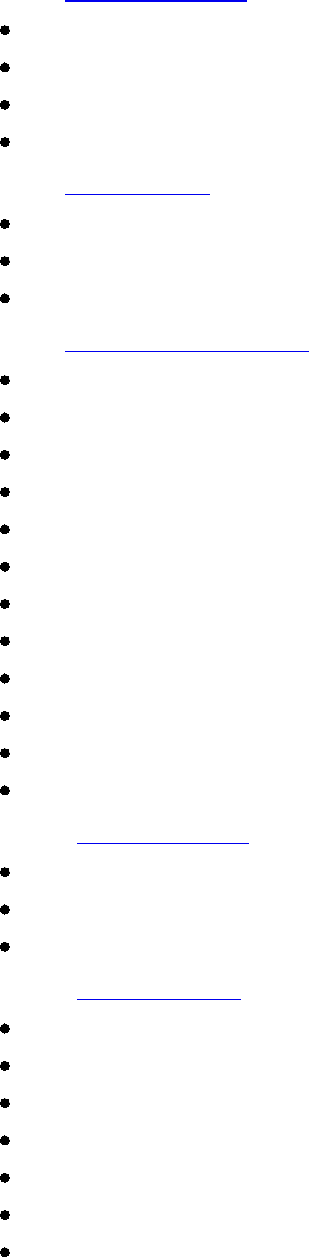
StarUML™ is an extensible software modeling platform; it does not just provide pre-defined functions but allows
addition of new functions. The diagram below illustrates the architecture of StarUML™. Blue indicates the platform
and green the extensible parts. The extensible parts can be developed by the user or a third party and then added
to the platform for integration.
Approach: Approach defines the model of the project and basic organization of
the diagrams. For details on
approach, see
"
Chapter 5. Writing Approaches".
UML Profile & Notation Extension
: UML Profile allows extension of expression for the software model through the extension mechanism of UML.
For details on UML profile, see
"
Chapter 7. Writing UML Profiles" and "
Chapter 10. Extending
Notation
"
Model Framework
: Model Framework makes software models reusable and allows them to be used when
defining other software models. For details on model framework, see
"
Chapter 6. Writing Frameworks".
Add-In COM Object: Add-In COM allows addition of new functionality to StarUML™. For details on Add-In
COM objects, see
"
Chapter 9. Writing Add-In COM Object".
Menu Extension
: The StarUML™ application menu (main menu and pop-up menu) can be added by the
user. For details on menu extension, see "Chapter 8. Extending Menu".
Option Extension
: The StarUML™ option items can be added by the user. For details on option extension,
see "Chapter 9. Writing Add-in COM Object".
Event Subscription: Various events occurring in StarUML™ can be subscribed to. For details on subscribing
to events, see
"
Chapter 9. Writing Add-in COM Object".
External API: The external API from StarUML™ allows access to various functionalities and information.
Details on API are discussed throughout this developer guide, and the example included in StarUML™
installation 'StarUML Application Model.uml'
provides a good illustration. See
"Appendix A. Plastic
Application Model."
Organizing a Module
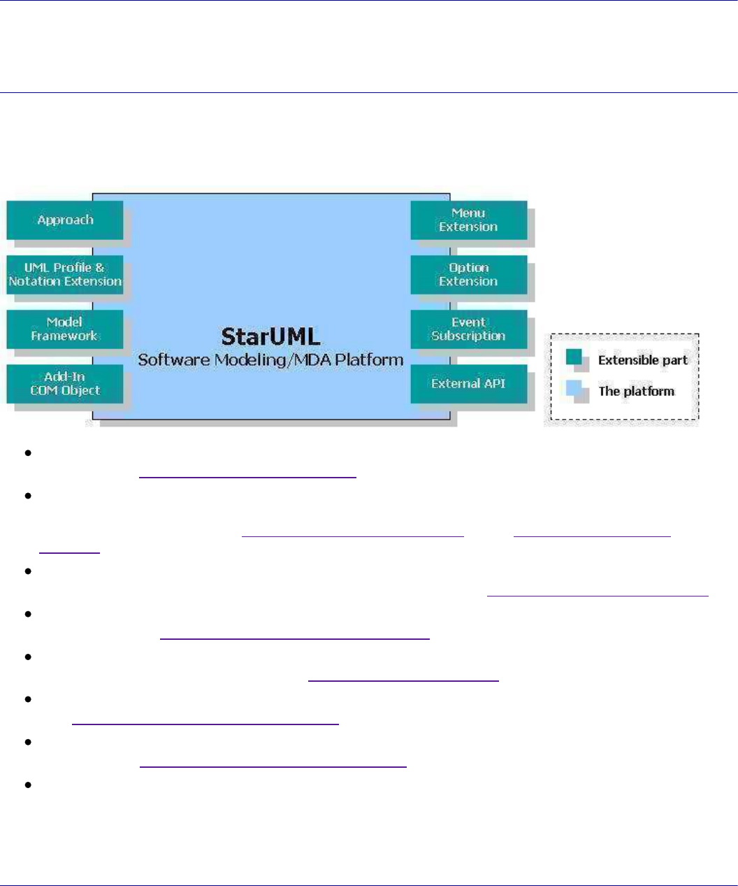
Module is a software package which allows addition of new functionali
ties and features by extending StarUML™.
Module consists of various extension mechanisms of StarUML™. As illustrated in the diagram below, an Add-In
package can consist of various approaches, various model frameworks, various UML profiles, various scripts, menu
extensions, option extensions, help, and Add-In COM Objects.
StarUML5.0DeveloperGuide(StarUMLArchitecture)
http://staruml.sourceforge.net/docs/developer-guide(en)/ch02.html
extensions, option extensions, help, and Add-In COM Objects.
Application of Modules
Modules can contain various elements, it can be developed for differe
nt purposes. Modules can be used for
supporting specific processes, languages or platforms, integrating with other tools, or extending functions.
Support for Specific Processes
: UML Components, RUP, Catalysis, XP, ...
Support for Specific Programming Languages
: C/C++, Python, C#, Visual Basic, Java, Perl, Object
Pascal, ...
Integration with Specific Tools
: Visual SourceSafe, CVS, MS Word, Eclipse, Visual Studio.NET, ...
Extension of Other Functionalities
: Traceability Manager, Design Patterns Support, Rule Checking, ...
Building Individual (or Enterprise) Specific Environment
Elements of Module
Approach: Approach is applied in the beginning of the project to determine the initial model structure. For
example, when making an Add-In for a specific process, approach can be used to pre-define the structure
which manages the models produced at each stage of the process.
Model Framework
: When developing a module related to specific languages or platforms, model framework
can produce Class Library or Application Framework. Other basic services (e.g. Event, Transaction, Security,
Directory, ...) can also be developed and added as models.
UML Profile
: UML Profile can be defined to extend expression of UML for specific
processes, languages or
frameworks, or to use additional properties. This has a global effect
in the module.
Menu Extension
: Menu Extension is used to add most of the new functionality in Add-In, and to extend the
main menu or pop-up menu to allow the user to select and run the functions. This is a critical element in
Add-In development.
Option Extension
: Add-In itself can have various selection items. Utilizing them allows use of option dialogs
in StarUML™ as option items.
Add-In COM Object: Extensible functionalities can be created using languages and tools
like Visual Basic,
Delphi, Visual C++, and C#. In general, COM objects are used for additional GUI or complex functionalities,
and Scripts are used for simple functionalities. This is usually prog
rammed through external API.
Script: Simple functionality extension can be done by using Scripting Languages (JScript, VBScript, Python,
...). This is usually programmed through external API.
Help: Help for Add-In can be created as HTML and registered with local or remote path.
Open API Overview
StarUML™ provides a wide array of API (Application Programming Interf
ace). The external API of StarUML™ is a
standardized programming interface that allows use of the internal program functionalities from outside.
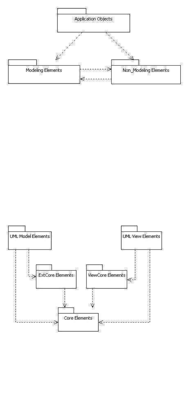
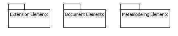
As illustrated in the diagram below, the external API of StarUML™ can be divided into three main parts: Modeling
Elements, Non_Modeling Elements and
Application Objects
. The Modeling Elements part provides an
interface for access to modeling elements, and the
Non_Modeling Elements part provides an interface for MOF
(Meta-Object Facility) and various elements other than modeling eleme
nts. The
Application Objects
part provides
StarUML5.0DeveloperGuide(StarUMLArchitecture)
http://staruml.sourceforge.net/docs/developer-guide(en)/ch02.html
(Meta-Object Facility) and various elements other than modeling eleme
nts. The
Application Objects
part provides
various interfaces which manage the application itself.
The Application Objects Part
The
Application Objects
part includes interfaces which manage the application itself. The interfaces included in this part are
IStarUMLApplication as the basic interface, ISelectionManager for managing element selection, IUMLFactory
for creating elements,
IProjectManager
for managing projects, and interfaces related to events and GUI.
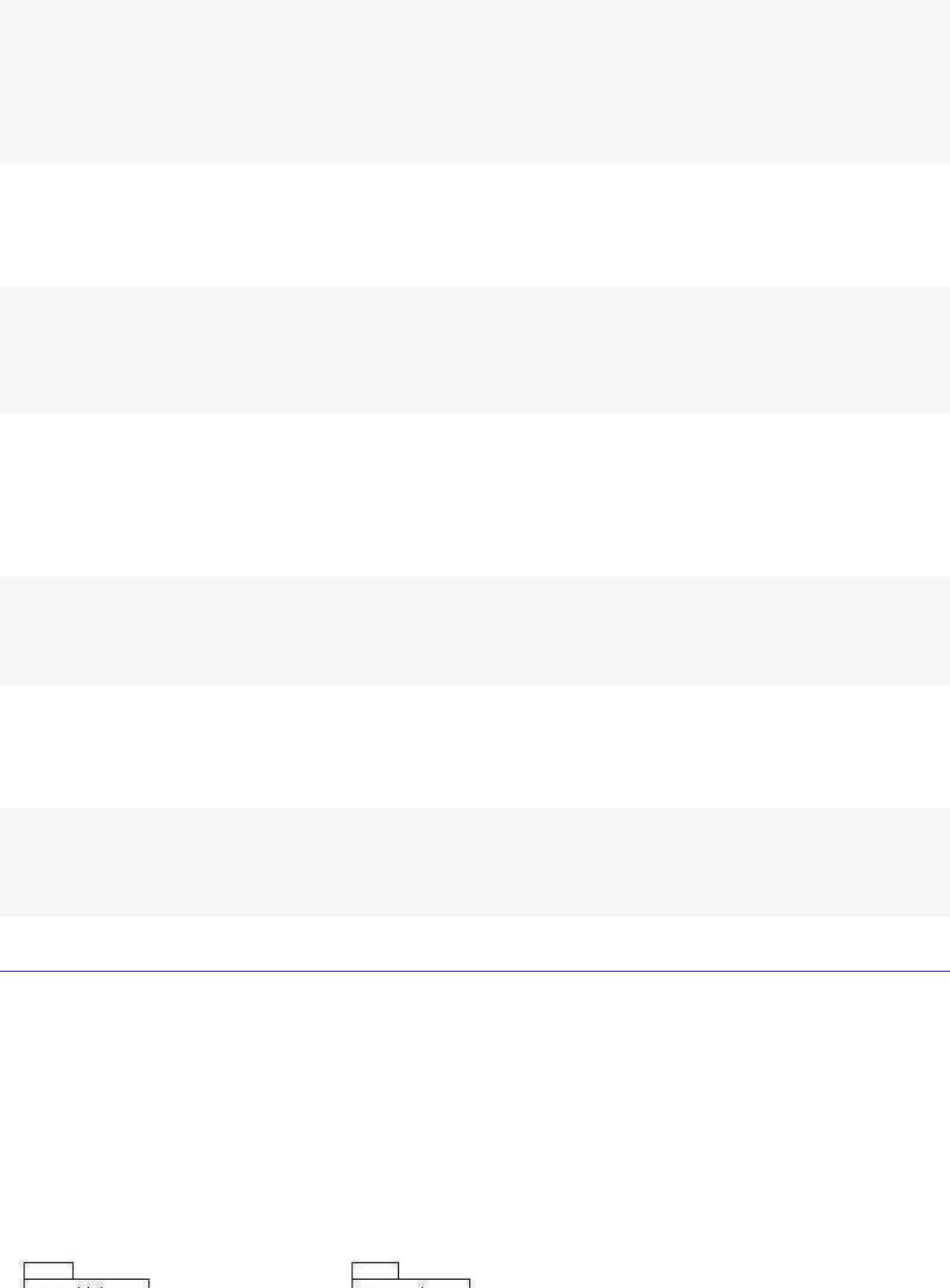
The Modeling Elements Part
The Modeling Elements
part includes interfaces for managing modeling elements. This part can be further divided into many parts. The
Core Elements part defines the top interface of model, view, and diagram elements. The ExtCore Elements
part
includes interfaces for extensible model elements, and the UML Model Elements part defines the UML modeling
elements based on the ExtCore Elements. The
ViewCore Elements
part includes interfaces for basic components
of view elements, and the
UML View Elements
part also defines the UML view elements based on the ViewCore Elements.
The Non_Modeling Elements Part
The Non_Modeling Elements
part includes interfaces for elements other than modeling elements. This part can be further divided into many
parts: the
Extension Elements
part which includes interfaces for elements related to the UML extension mechanism, the Document Elements part
which manages StarUML™’s saved files, and the Metamodeling Elements part which manages meta-level
elements.
StarUML5.0DeveloperGuide(StarUMLArchitecture)
http://staruml.sourceforge.net/docs/developer-guide(en)/ch02.html
StarUML5.0DeveloperGuide(HelloWordExample)
http://staruml.sourceforge.net/docs/developer-guide(en)/ch03.html
Chapter 3. HelloWord Example
This chapter briefly describes methods and processes of developing Add-In, using the "Hello, world" example.
"Hello, world" Example
The "Hello, world" example is the first and easiest example for learn
ing any technique. In this chapter, we will use
this example to learn about Add-Ins. The "Hello, world" example does
not use all Add-In elements, but only the
basic ones. It comprises the following elements.
One Menu Extension
One Script
This "Hello, world" example adds [Hello, world!]
to the menu, and adds a function to change the project title to "Hell
oworld" when the user selects the menu item.
Creating Script
First, use Jscript to create a script that changes the project title to "Helloworld." Use a text editor to enter the script
source code as below and save it as
helloworld.js
.
varapp=newActiveXObject("StarUML.StarUMLApplication");
varprj=app.GetProject();
prj.Title="Helloworld";
The first line of the script creates an object called StarUMLApplicat
ion. This object must be created as it provides
the initial point for handling StarUML™. The second line acquires an object for the project, and the third line assigns
the title of the project object acquired as "Helloworld."
Creating Menu Extension File
A menu extension file (.mnu) must be created in order to extend the StarUML™ menu. In this example, we will add
[Hello, world!] under the menu item
[Tools]
.
<?xmlversion="1.0"?>
<ADDINMENUaddInID="StarUML.HelloworldAddIn">
<BODY>
<MAINMENU>
<MAINITEMbase="TOOLS"caption="Hello,world!"availableWhen="PROJECT_OPENED"
script="helloworld.js"/>
</MAINMENU>
</BODY>
</ADDINMENU>
A menu extension file starts with the <ADDINMENU> tag and consists of <HEADER> and <BODY>. The <HEADER>
section may be omitted, and the <BODY> section contains the information for menu extension. In this example, the
<MAINITEM> element is added under the <MAINMENU> item for extending t
he main menu. For the <MAINITEM>
element, the 'base' attribute is the location of the menu item to be
added, 'caption' is the menu item name,
'availableWhen' is the condition for activating the menu, and 'script' is the script to execute when the menu item is
selected.
Note:
For details on menu extension, see
"Chapter 8. Extending Menu".
Add-In Deployment
StarUML5.0DeveloperGuide(HelloWordExample)
http://staruml.sourceforge.net/docs/developer-guide(en)/ch03.html
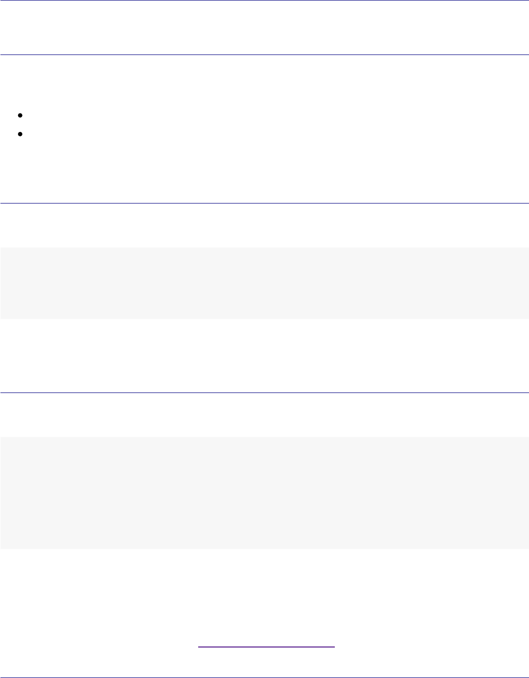
The script file (helloworld.js) and menu extension file (helloworld.m
nu) must be placed in the same directory. Under
the installation directory of StarUML™, there is a directory called "modules." Make a subdirectory called
"HelloworldAddIn" under this directory and place the two files in it.
Add-In Registration
If you deployed the Add-In files properly, you must write Add-In desc
ription file so as to recognize the Add-In to
StarUML. Add-In Description file is a XML document file which extension file name is '.aid'. It contains overall
information about the Add-In that is a name of Add-In, COM object name, file name of executable module, menu
extension file name, help url, and so on. For details on Add-In Description file, see "Chapter 9. Writing Add-in
COM Object".
The following is Add-In Description file of HelloWord example.
<?xmlversion="1.0"encoding="UTF-8"?>
<ADDIN>
<NAME>HelloworldAddIn</NAME>
<DISPLAYNAME>HelloworldSample</DISPLAYNAME>
<COMPANY>PlasticSoftware,Inc.</COMPANY>
<COPYRIGHT>Copyright2005PlasticSoftware,Inc.Allrightsreserved.</COPYRIGHT>
<HELPFILE>http://www.staruml.com</HELPFILE>
<ICONFILE>Helloworld.ico</ICONFILE>
<ISACTIVE>True</ISACTIVE>
<MENUFILE>helloworld.mnu</MENUFILE>
<VERSION>1.0.1.35</VERSION>
</ADDIN>
Save the Add-In description file in the directory that Add-In is deployed.
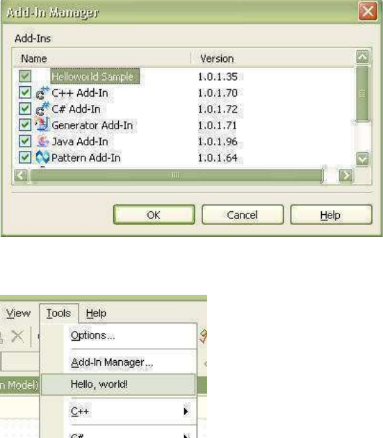
Verification and Excution of Added Add-In
If the steps above have been performed properly, the "Hello, world" Add-In should have been added to StarUML™.
Start StarUML™ and select [Tools] →
[Add-In Manager]
to check whether the Add-In has been added correctly.
StarUML5.0DeveloperGuide(HelloWordExample)
http://staruml.sourceforge.net/docs/developer-guide(en)/ch03.html
If the installation was successful, it can be verified that [Hello, world!] has been added under the
[Tools]
menu.
When this menu is selected, the file helloworld.js will be executed to change the project title to "Helloworld."
StarUML5.0DeveloperGuide(UsingOpenAPI)
http://staruml.sourceforge.net/docs/developer-guide(en)/ch04.html
Chapter 4. Using Open API
StarUML™ supports COM automation and exposes API to outside to access most programs that is uml meta model,
application object and so on.
This chapter discuss that using the external API of StarUML™.
Using APIs for Projects
This section describes methods of managing projects, units and model fragments in StarUML™.
Basic Concepts of Project Management
In order to manage projects, it is important to understand the concepts related to projects (projects, units, and
model fragments).
Project
A project is the most basic unit of management in StarUML™. A project manages one or more software models, and
it can be understood as a top-level package that does not change. One project is usually saved as one file. A project
contains and manages the following modeling elements.
Element Description
Model Element for managing one software model.
Subsystem Element for managing the elements that express one subsystem.
Package Most basic element for managing elements.
Project files are saved in the XML format, and the extension name is ".UML". While all models, views, and diagrams
created in StarUML™ are saved in one project file, a project may be divided and saved in multiple files by using
units that are described in the next section. The following informati
on is saved in project files.
UML profiles referenced by the project
Unit files referenced by the project
All model information contained in the project
All diagram and view information contained in the project
Unit
While a project is usually saved in one file, there may be cases where a project has to be divided and saved in
multiple files because many people have to work on it concurrently and so on. In cases such as this, a project can
be managed in multiple units. Units can be organized hierarchically, and one unit can have many sub-units. A unit
is saved in a ".UNT" file, and it is referenced by project files (.UML) and other unit files (.UNT).
Only a package, subsystem, or model element can be one unit. Any element belonging to these groups is saved as
a respective unit file (.UNT).
Just as a project can manage multiple units under it, a unit can manage many sub-units. Upper units have
references to sub-units, and units form a hierarchical structure.

StarUML5.0DeveloperGuide(UsingOpenAPI)
http://staruml.sourceforge.net/docs/developer-guide(en)/ch04.html
Model Fragment
A model fragment is a part of a project saved in a separate file. Onl
y a model, subsystem, or package element can
be a model fragment, and it is saved as a ".MFG" file. A model fragme
nt file can easily be added to any project at
any time. Model fragments are essentially different from units because they can completely be merged.
Document Object Management
Concept of Document
A document is an abstracted object of a part saved as a file in StarUML™. In other words, it provides various
properties and methods to access a .UML or .UNT part as one object. While a model fragment (.MFG) is also one
file, it does not have a document object as it is used for importing/exporting and is not internally managed by the
StarUML™ application. The following diagram illustrates hierarchical structure of document interfaces.
IDocument
: The top interface for documents.
IUMLDocument
: Upper interface for documents related to UML models.
IUMLUnitDocument
: Interface for documents managed as units (.UNT) in StarUML™.
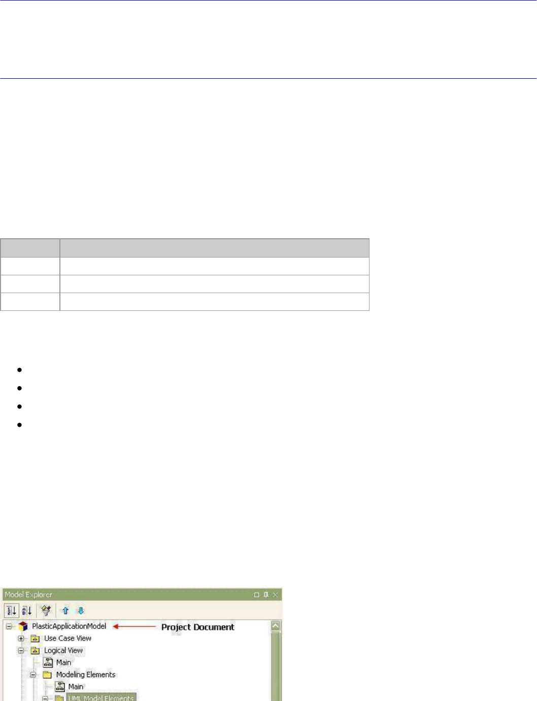
IUMLProjectDocument: Interface for documents managed as projects (.UML) in StarUML™. Since a project
document is regarded as a unit document, it inherits its properties f
rom the unit document interface.
Accessing Document Objects
StarUML5.0DeveloperGuide(UsingOpenAPI)
http://staruml.sourceforge.net/docs/developer-guide(en)/ch04.html
Accessing Document Objects
In order to access a project or unit document object, the
IProjectManager
object reference must be acquired. This
allows direct access to the project or unit document object.
varapp=newActiveXObject("StarUML.StarUMLApplication");
varprjmgr=app.ProjectManager;
//Getprojectdocumentobject.
varprj_doc=prjmgr.ProjectDocument;
//Getunitdocumentobjects.
for(vari=0;i<prjmgr.GetUnitDocumentCount();i++){
varunit_doc=prjmgr.GetUnitDocumentAt(i);
}
While IProjectManager
allows direct access to documents, document objects can also be acquired through the respective modeling
elements that contain them. The following example illustrates acquiring reference for a project document object
from an element and saving it.
varelem=...//Assignspecificelement(i.e.Class,Package,etc)
varelem_doc=elem.GetContainingDocument();
elem_doc.Save();
Document Properties and Methods
The IDocument interface provides the following properties and methods.
Property Description
FileName: String Acquires file name of the document. File name includes the full path and
extension.
Version: String Acquires version of the document.
Modified: Boolean Determines if the document has been modified by the user.
ReadOnly: Boolean Determines if the document file is read-only.
Method Description
GetDocumentSymbol(): String Acquires document symbol. Returns 'PROJECT' string for project documents and
'UNIT' string for unit documents.
GetDocumentElement():
IElement
Returns the top element for the document.
Save() Saves the document with the current file name.
SaveAs(FileName: String) Saves the document with a different file name and changes the current file
name.
Project Object Management
Accessing Project Object
In order to directly manage a project, reference for the project object must be acquired. The following is the Jscript
code for acquiring reference for a project object.
varapp=newActiveXObject("StarUML.StarUMLApplication");
StarUML5.0DeveloperGuide(UsingOpenAPI)
http://staruml.sourceforge.net/docs/developer-guide(en)/ch04.html
varprj=app.GetProject();
...
While reference for project objects can be acquired directly from the application object (app), project objects can
also be accessed using the following method.
varapp=newActiveXObject("StarUML.StarUMLApplication");
varprjmgr=app.ProjectManager;
varprj=prjmgr.Project;
...
Modifying Project Title and Properties
Once reference for a project object has been acquired, the title, properties and various methods of the project
become accessible. In order to change the title of the project, the "Title" property must be modified. Other
properties like "Copyright", "Author", and "Company can also be modified in the same way.
...
prj.Title="MyProject";
...
Caution:
Although generic modeling elements use the "Name" property, project objects must not use the "Name" property. A
project is a top package and it cannot have a name. This is because p
athnames are commonly used for reference
between elements and all pathnames can become invalid if the project
title is modified.
Adding Packages under Project
Only model, subsystem, and package elements can be added under a project. The IUMLFactory object must be
used to create and add new elements. See the following example for adding packages under a project.
varapp=newActiveXObject("StarUML.StarUMLApplication");
varfactory=app.UMLFactory;
varprj=app.GetProject();
varnewPackage=factory.CreatePackage(prj);
newPackage.Name="NewPackage";
Creating New Project
To make a new project, acquire reference for the IProjectManager object and call up the NewProject method.
varapp=newActiveXObject("StarUML.StarUMLApplication");
varprjmgr=app.ProjectManager;
prjmgr.NewProject();
To create a new project with a specific approach rather than creating an empty project, use the
NewProjectByApproach
method. The following example illustrates creating a new project usin
g the "UMLComponents" approach.
varapp=newActiveXObject("StarUML.StarUMLApplication");

StarUML5.0DeveloperGuide(UsingOpenAPI)
http://staruml.sourceforge.net/docs/developer-guide(en)/ch04.html
varprjmgr=app.ProjectManager;
prjmgr.NewProjectByApproach("UMLComponents");
Opening Project
To open a project file (.UML), acquire reference for the IProjectManager
object and then use the
OpenProject
method.
varapp=newActiveXObject("StarUML.StarUMLApplication");
varprjmgr=app.ProjectManager;
prjmgr.OpenProject("C:\\MyProject.uml");
Saving Project
To save the project currently open in StarUML™, acquire reference for the IProjectManager object and then use
the SaveProject method. Use the SaveProjectAs method to save with a different name, and use the
SaveAllUnits method to save all units under the project.
varapp=newActiveXObject("StarUML.StarUMLApplication");
varprjmgr=app.ProjectManager;
prjmgr.SaveProject();
prjmgr.SaveProjectAs("MyProject2.uml");
prjmgr.SaveAllUnits();
Closing Project
To close a project, acquire reference for the IProjectManager
object and then use the
CloseProject
method.
varapp=newActiveXObject("StarUML.StarUMLApplication");
varprjmgr=app.ProjectManager;
prjmgr.CloseProject();
Unit Managment
Separating New Unit
To separate a new unit for managing a package, model, or subsystem as a separate file, acquire reference for the
IProjectManager
object and then use the
SeparateUnit method.
varapp=newActiveXObject("StarUML.StarUMLApplication");
varprjmgr=app.ProjectManager;
varpkg=...//Assignreferenceforthepackagetoseparateasanewunit.
varnew_unit=prjmgr.SeparateUnit(pkg,"NewUnit.unt");
Merging Unit
If a separated package, model, or subsystem unit does not need to be managed as a separate file and needs to be
merged, acquire reference for the
IProjectManager
object and then use the
MergeUnit
method.
StarUML5.0DeveloperGuide(UsingOpenAPI)
http://staruml.sourceforge.net/docs/developer-guide(en)/ch04.html
varapp=newActiveXObject("StarUML.StarUMLApplication");
varprjmgr=app.ProjectManager;
varpkg=...//Assignsreferenceforthepackagethatwillnolongerbemanagedasaunit.
prjmgr.MergeUnit(pkg);
Accessing Sub-Unit
Units can be organized hierarchically. A project can have many units under it, and each unit can have many
sub-units. The following example illustrates accessing the sub-units within a unit.
varunit=...//Assignsreferencefortheunitthatcontainssub-unitstoaccess.
for(vari=0;i<unit.GetSubUnitDocumentCount();i++){
varsub_unit=unit.GetSubUnitDocumentAt(i);
...
}
Model Fragment Management
Making Model Fragment from Package
Package, model, or subsystem can be saved as a separate model fragment file. Acquire reference for the
IProjectManager
object and then use the
ExportModelFragment method.
varapp=newActiveXObject("StarUML.StarUMLApplication");
varprjmgr=app.ProjectManager;
varpkg=...
//Assignspackagetomakeasamodel.
prjmgr.ExportModelFragment(pkg,"MyFragment.mfg");
Importing Model Fragment
A model fragment file can be added to a package, model, or subsystem. Acquire reference for the
IProjectManager
object and then use the
ImportModelFragment method.
varapp=newActiveXObject("StarUML.StarUMLApplication");
varprjmgr=app.ProjectManager;
varpkg=...//Assignspackagetoaddamodelfragment.
prjmgr.ImportModelFragment(pkg,"MyFragment.mfg");
Using APIs for Elements
This section introduces interface types that are modeling elements of
StarUML™ external API, and describes their
usage. Modeling elements refer to the UML model, view, and diagram el
ements that are used when modeling
software. Model elements such as package, class, and actor, view elements that correspond to each model element,
and diagram elements such as class diagram and use case diagram are e
xamples of modeling elements. Model,
view, and diagram elements can be created, deleted or modified using external API for modeling elements.
Note: Please refer to
"Appendix B. List of UML Modeling Elements"
for a complete listing of UML modeling
elements.
Modeling Element Structure
Modeling elements are organized in the following logical groups.
StarUML5.0DeveloperGuide(UsingOpenAPI)
http://staruml.sourceforge.net/docs/developer-guide(en)/ch04.html
Core Elements: The Core Elements group defines the top interface for model, view, and diagram elements.
ExtCore Elements
: The ExtCore Elements group defines the common top interface for extensible model
elements.
ViewCore Elements
: The ViewCore Elements group defines the core types for view elements.
UML Model Elements: Defines the UML model elements. The UML standard modeling elements fall into this
category.
UML View Elements
: The UML View Elements group defines the UML view elements.
Modeling elements are largely divided into
model
, view, and diagram
types. However, the diagram type is
actually a part of the model or view types, and thus it is more accur
ate for the division to be made into
model
type
and view
type. Model is the element that contains actual information for the s
oftware model, and view is a visual expression
of information contained in a specific model. One model can have multiple views and a view generally has reference
to one model.
Simple Example of Using Modeling Elements
Before introducing the external API interfaces for modeling elements, let us look at a simple example of using
modeling elements. Suppose we want to track StarUML™ application’s top-level project element through
namespace type elements like package, class, and interface, all the way down to the sub-elements of each
namespace type element. In this case, the modeling element structure must be utilized. The following is the Jscript
code for utilizing the modeling element structure.
varapp,prj;
app=newActiveXObject("StarUML.StarUMLApplication");
prj=app.GetProject();
VisitOwnedElement(prj);
functionVisitOwnedElement(owner){
varelem;
for(vari=0;i<owner.GetOwnedElementCount();i++){
elem=owner.GetOwnedElementAt(i);
...
if(elem.IsKindOf("UMLNamespace"))VisitOwnedElement(elem);
}
}
In this example, all sub-elements that are in "OwnedElement" relationships with the top project element are
recursively obtained. The most crucial part of this code is the user-
defined function called
VisitOwnedElement
.
This function takes an IUMLNamespace type element (which is a modeling element) as an argument and uses
GetOwnedElementCount and GetOwnedElementAt, which are IUMLNamespace
interface methods.
Information required for structuring the
VisitOwnedElement
function can be obtained from the relationships of the
StarUML5.0DeveloperGuide(UsingOpenAPI)
http://staruml.sourceforge.net/docs/developer-guide(en)/ch04.html
Information required for structuring the
VisitOwnedElement
function can be obtained from the relationships of the
modeling elements. The following diagram illustrates the relationship
s between StarUML™ external API interface
types that are related to the IMULNamespace interface example above.
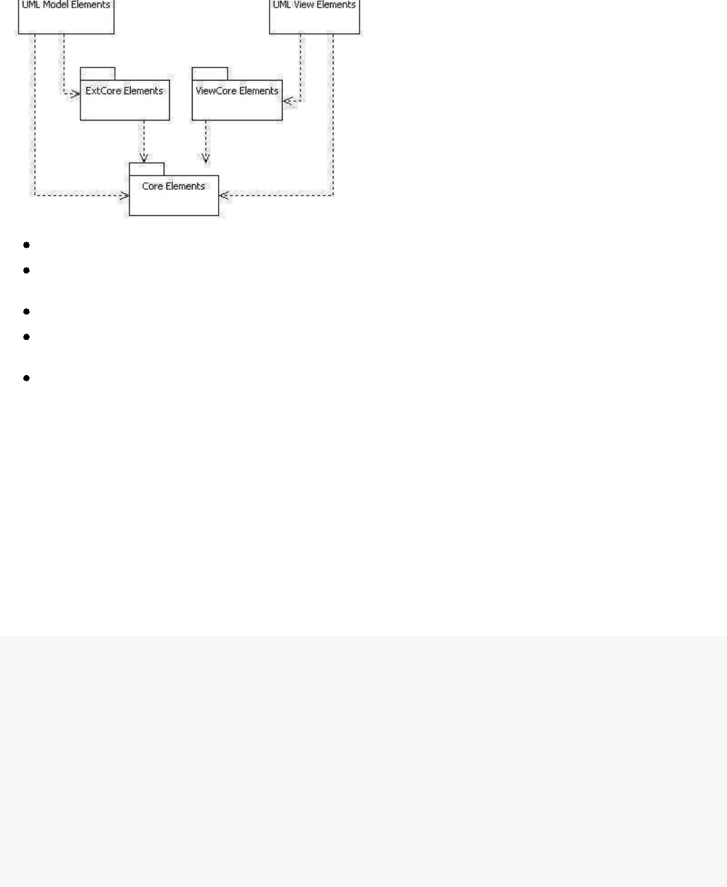
The
IUMLNamespace
interface is inherited from IUMLModelElement
, which is a shared upper type for
IUMLPackage, IUMLClass, and IUMLInterface
types.
IUMLNamespce
also has an association called
Namespace-OwnedElement
. The diagram illustrates that the
IUMLNamespace
type modeling elements like
IUMLPackage, IUMLClass, etc. have IUMLModelElement type elements below them known as
OwnedElements.
As such, external API modeling elements interfaces are defined according to the relationships between the modeling
elements.
Note: Modeling element names that fall into the category of standard UML elements start with an "
UML
" prefix
before the standard UML element names. For example, the name of a UML element called Actor is UMLActor
. And
for external API, the prefix "I" is used according to coding procedures, as in IUMLActor. Please refer to "Appendix
B. List of UML Modeling Elements"
for a complete listing of UML modeling elements and their names.
Convention for Expressing Association for External API
The diagram above illustrates that IUMLModelElement and IUMLNamespace
interface types have an
OwnedElement-Namespace association. Such associations are expressed a
s references in StarUML™'s external API
interface. For example, Namespace association in the IUMLModelElement interface is expressed as below.
IUMLModelElement
Namespace: IUMLNamespace
Further,
OwnedElement
association in the
IUMLNamespace
interface is expressed as below. This is because the
Multiplicity attribute of the metamodel is * and groups or list struc
tures are used in the internal implementation of
the program. As all associations in external API interface definition are expressed using the same convention, this
applies to all other interfaces as well as IUMLModelElement-IUMLNamespace.
IUMLNamespace
function GetOwnedElementCount(): Integer;
function GetOwnedElementAt(Index: Integer): IUMLModelElement;
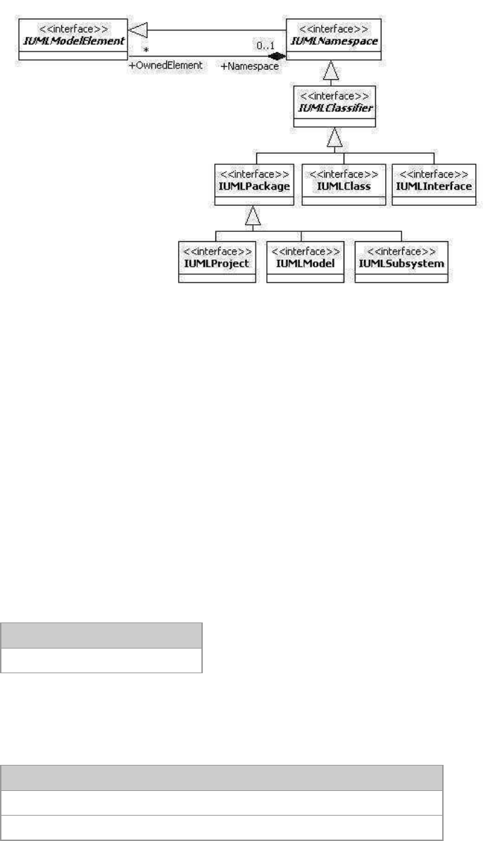
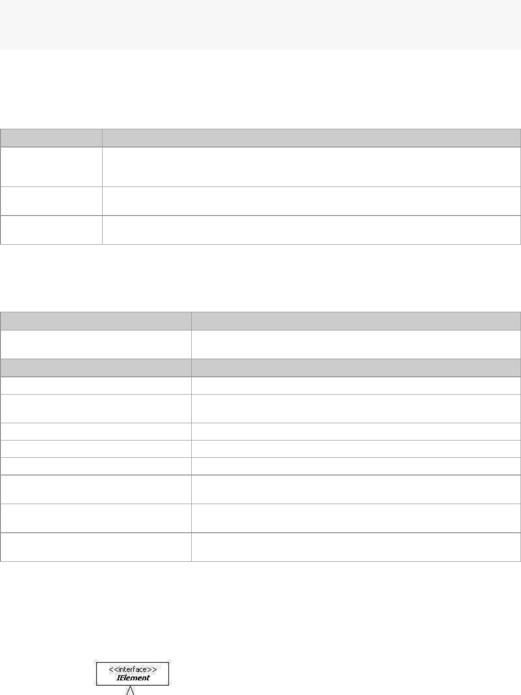
Core Elements
Core Elements are top parent interfaces for modeling elements.
IElement
,
IModel
, IView, IDiagram, and
IDiagramView
interfaces fall into this category, and they are organized as illustrated in the diagram below. The organization below
should be given special attention as core group interface types are quite frequently used and they play critical roles.
Associations between the interfaces should be given special emphasis
here.
StarUML5.0DeveloperGuide(UsingOpenAPI)
http://staruml.sourceforge.net/docs/developer-guide(en)/ch04.html
Associations between the interfaces should be given special emphasis
here.
Interface name Description
IElement Interface type that defines the top shared element for all modeling elements.
IModel Interface type that defines the shared parent element for model elements.
IView Interface type that defines the shared parent element for view elements.
IDiagram Interface type that defines the shared parent element for diagram mod
el elements.
IDiagramView Interface type that defines the shared parent element for diagram view elements.
IElement
IElement
interface defines the top shared type for all modeling elements, and provides the following main methods.
Main method Description
GetGUID(): String
Function that returns the GUID (Global Unique Identifier) of
modeling elements. GUID is encoded as Base64.
GetClassName(): String Function that returns class names of modeling elements. Return
value example: "UMLClass"
IsKindOf(ClassName: String): Boolean Function that verifies whether the modeling element is the same
type of element received as an argument. Argument value
example: "UMLClass"
IsReadOnly(): Boolean Function that verifies whether the modeling element is read-only.
Attributes of read-only modeling elements cannot be modified.
MOF_GetAttribute(Name: String): String Returns in strings the default type attribute values of modeling
elements as defined by arguments.
MOF_GetReference(Name: String): IElement
Returns the reference type attribute (object reference) values of
modeling elements as defined by arguments.
MOF_GetCollectionCount(Name: String):
Integer
Returns the count number of items in reference collection as
defined by arguments.
MOF_GetCollectionItem(Name: String;
Index: Integer): IElement
Returns the attribute value (object reference) of the 'index' order
item in the reference collection of modeling elements as defined
by arguments.
Among the methods of
IElement
interface, the
MOF_
XXX
methods provide consistent ways to access the attribute
values of each modeling element by string names. For instance, IUMLModelElement, a sub-type of IElement
,
has an attibribute called "Visibility". In general, the expression IUMLModelElement.Visibilty is used to get the
value of this attribute. But the
IElement.MOF_GetAttribute
method can be used as illustrated below to get the
StarUML5.0DeveloperGuide(UsingOpenAPI)
http://staruml.sourceforge.net/docs/developer-guide(en)/ch04.html
value of this attribute. But the
IElement.MOF_GetAttribute
method can be used as illustrated below to get the
value of the attribute by a string name called "Visibility". As such,
MOF_
XXX
methods allow access to the attributes
of basic type / reference type / reference collection type of each modeling element by string names, and this is very
useful in many cases.
Note:
String names of attributes, which are used as arguments in
MOF_
XXX
methods, are the same as the
respective attribute names.
The following example reads the value of the attribute "Visibility" o
f an
IUMLModelElement type element using
the IElement.MOF_GetAttribute method. It should be noted that the MOF_GetAttribute method uses strings as
return values. In this example, return values can be "vkPrivate", "vkPublic", etc.
...
varelem=...//GetreferencetoIUMLModelElementtypeelementobject.
varval=elem.MOF_GetAttribute("Visibility");
...
The IElement.MOF_GetReference
method is used when reading reference type attribute values of modeling elements. The MOF_GetReference
method returns reference to the
IElement
type objects. The following example reads the "Namespace" reference attribute value of IUMLModelElement type
elements.
...
varelem=...//GetreferencetoIUMLModelElementtypeelementobject.
varrefElem=elem.MOF_GetReference("Namespace");
...
The IElement.MOF_GetCollectionItem
method is used when reading reference collection type attribute value
s of modeling elements. The
MOF_GetCollectionItem
method receives the name of the reference collection type attribute a
nd the item index as arguments. Collection
item count number can be obtained using the MOF_GetCollectionCount method. Also, the
MOF_GetCollectionItem method, like the MOF_GetReference method, returns reference to the
IElement
type
objects. The following example reads the "Attributes" reference collection attribute values of
IUMLClassifier
type
elements.
...
varelem=...//GetreferencetoIUMLClassifiertypeelementobject.
varcolCount=elem.MOF_GetCollectionCount("Attributes");
for(vari=0;i<colCount;i++){
varcolItem=elem.MOF_GetCollectionItem("Attributes",i);
...
}
Note:
An error occurs if argument values for
MOF_
XXX
methods are not defined with names of existing attributes.
IModel
IModel
interface defines the shared parent type of model elements, and provides the following main properties and
methods.
Main Property Description
Name: String
Name attribute.
Documentation: String Documentation attribute.
Pathname: String Path name of model element. Path name format includes the "::" indica
tor
for all upper level elements except the top project element. Path name
example: "::Application Model::Modeling Elements::UML Model Elements"
.
StarUML5.0DeveloperGuide(UsingOpenAPI)
http://staruml.sourceforge.net/docs/developer-guide(en)/ch04.html
example: "::Application Model::Modeling Elements::UML Model Elements"
.
* Read-only.
Main Method Description
AddAttachment(Attach: String); Adds values to attachment file attributes (file path, URL).
FindByName(AName: String):
IModel
Returns names of lower level model elements that are identical to the
names received as arguments.
FindByRelativePathname(RelPath:
String): IModel
Returns relative path names of overlapped lower level model elements
that
are identical to the relative path names received as arguments. The N
ame
of the model itself is excluded in the argument. Argument value example:
"Model_Management::UMLPackage"
ContainsName(AName: String):
Boolean
Verifies whether there exists a lower level model element with the same
name as defined by the argument.
CanDelete(): Boolean Verifies whether the current model element is read-only.
GetViewCount: Integer
Returns count of view elements of the current model.
GetViewAt(Index: Integer): IView
Returns the (index)th view element of the current model.
GetOwnedDiagramCount: Integer Returns count of diagram elements contained in the current model.
GetOwnedDiagramAt(Index:
Integer): IDiagram
Returns the (index)th diagram element contained in the current model.
The following example shows reading basic attribute values of a model element and resetting them.
functionDoingSomething(elem){
if(elem.GetClassName()=="UMLClass"){
if(elem.IsReadOnly()!=true){
elem.Name="class_"+elem.Name;
elem.Documentation="Iamaclass";
elem.AddAttachment("http://www.staruml.com");
}
}
}
The FindByName
method and
FindByRelativePathname method can be used to find lower level elements of a
model element. The FindByName
method returns the name of the first lower level element that is iden
tical to the string value received as argument.
The FindByName
method performs a search only for the lower levels of the model element. To search for all lower level elements
when the lower level elements are in an overlapped structure, the FindByRelativePathname
method can be used.
The following example shows how to use the
FindByName
and FindByRelativePathname methods.
varapp=newActiveXObject("StarUML.StarUMLApplication");
varrootElem=app.FindByPathname("::ApplicationModel::ModelingElements::UMLModelElements");
varelem=rootElem.FindByName("Model_Management");
varelem2=rootElem.FindByRelativePathname("Model_Management::UMLPackage");
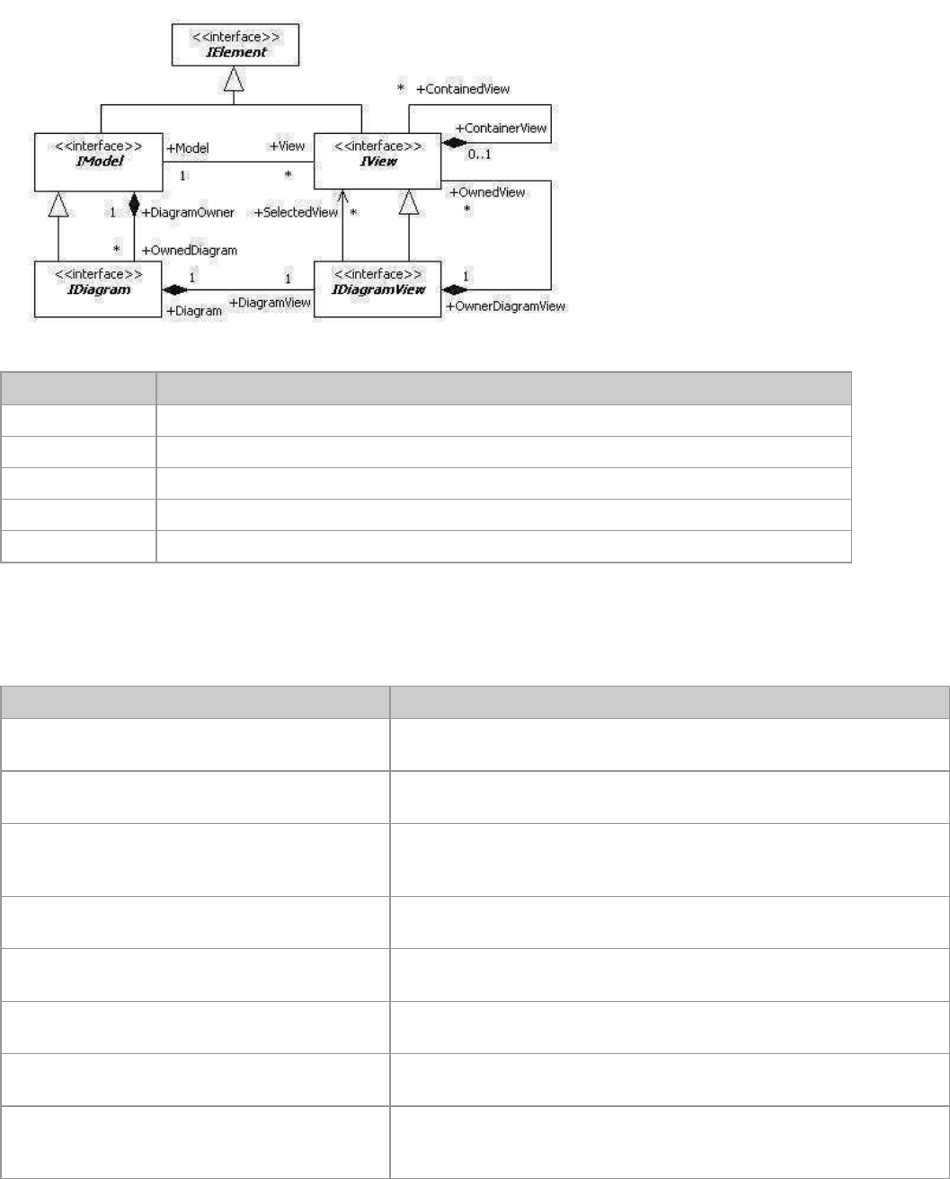
As shown in the diagram above,
IModel
interface and IView interface are in a Model-View association. An
IModel
type element can have many IView type elements, and each IView type element must have one
IModel
type
element. The following example shows how to get reference to all IView type elements for each IUMLClass type
element.
varelem=...//GetreferencetoIModeltypeelement.
if(elem.GetClassName()=="UMLClass"){
for(vari=0;i<elem.GetViewCount();i++){
varview=elem.GetViewAt(i);
...
StarUML5.0DeveloperGuide(UsingOpenAPI)
http://staruml.sourceforge.net/docs/developer-guide(en)/ch04.html
}
}
As illustrated in the diagram above, the
IModel
interface and IDiagram
interface are in a
DiagramOwner-OwnedDiagram association. Since the IDiagram interface is a parent type for all diagram model
types, reference to diagram elements contained in the model element can be obtained using the method shown in
the following example.
varelem=...//IModeltypeelement
for(inti=0;i<elem.GetOwnedDiagramCount();i++){
vardgm=elem.GetOwnedDiagramAt(i);
...
}
IView
IView interface defines the shared parent type of view elements, and provides the following main properties.
Main property Description
LineColor: String Defines line color. Uses BGR format.
Examples: "0xff0000" (blue); "0x00ff00" (green); "0x0000ff" (red); "0x000000"
(black); "0xffffff" (white)
FillColor: String Defines fill color. Uses BGR format.
FontFace: String
Defines font. Example: "Times New Roman"
FontColor: String Defines font color. Uses BGR format.
FontSize: String Defines font size.
FontStyle: Integer Defines font style. Integers 1 (bold), 2 (italic), 3 (underline), and
4 (strikeout) can
be used separately or in combination. Example: 1 + 2 (bold & italic)
* Does not apply to view elements with pre-defined default styles.
Selected: Boolean Defines whether the current view element is selected.
* Read-only.
Model: IModel Defines reference to model element corresponding to the current view
element.
* Read-only.
OwnerDiagramView:
IDiagramView
Defines diagram view element containing the current view element.
* Read-only.
The following example shows setting basic attribute values for an IVew type element.
varview=...//IViewtypeelement
view.LineColor="0x0000ff";
view.FillColor="0x00ffff";
view.FontFace="TimesNewRoman";
view.FontColor="0x0000ff";
view.FontSize="12";
view.FontStyle=1;
View elements other than IUMLNoteView, IUMLNoteLinkView, and IUMLTextView type view elements have
references to the model element. The following code can be used to obtain information on an
IModel
type element
referenced by an IView type element.
varview=...//IViewtypeelement
varmdl=view.Model;
...
The following code can be used to obtain information on diagrams that
contain an
IView
type element.
StarUML5.0DeveloperGuide(UsingOpenAPI)
http://staruml.sourceforge.net/docs/developer-guide(en)/ch04.html
The following code can be used to obtain information on diagrams that
contain an
IView
type element.
varview=...//IViewtypeelement
vardgmView=view.OwnerDiagramView;
...
IDiagram
IDiagram interface is inherited from
IModel
interface, and is the shared parent type of all diagram type model el
ements.
IDiagram interfaces have the
following main properties.
Main property Description
DefaultDiagram:
Boolean
Defines whether the current diagram is the Default Diagram. Default Diagram is the
diagram that automatically opens when a project is opened. Only class / use case /
component / deployment diagrams can be set as the Default Diagram.
DiagramOwner:
IModel
Defines an upper level model element that contains the current diagram.
* Read-only.
DiagramView:
IDiagramView
Defines the diagram view element that corresponds to the current diagram model.
* Read-only.
IDiagramView
IDiagramView interface is inherited from IView
interface, and is the shared parent type of all diagram view elements.
Main property Description
Diagram: IDiagram
Defines diagram model elements that correspond to the current
diagram view element.* Read-only.
Main method Description
GetSelectedViewCount: Integer
Returns count of view elements currently selected in the diagram.
GetSelectedViewAt(Index: Integer):
IView
Returns the (index)th view element that is currently selected in the
diagram.
GetOwnedViewCount: Integer
Returns count of view elements contained in the diagram.
GetOwnedViewAt(Index: Integer): IView Returns the (index)th view element contained in the diagram.
LayoutDiagram() Automatically reorganizes the diagram layout.
ExportDiagramAsBitmap(FileName:
String)
Converts the diagram into a bitmap image and saves it as a file using
the path name and file name defined.
ExportDiagramAsMetafile(FileName:
String)
Converts the diagram into a Windows Metafile and saves it as a file
using the path name and file name defined.
ExportDiagramAsJPEG(FileName: String) Converts the diagram into a JPEG image and saves it as a file using the
path name and file name defined.
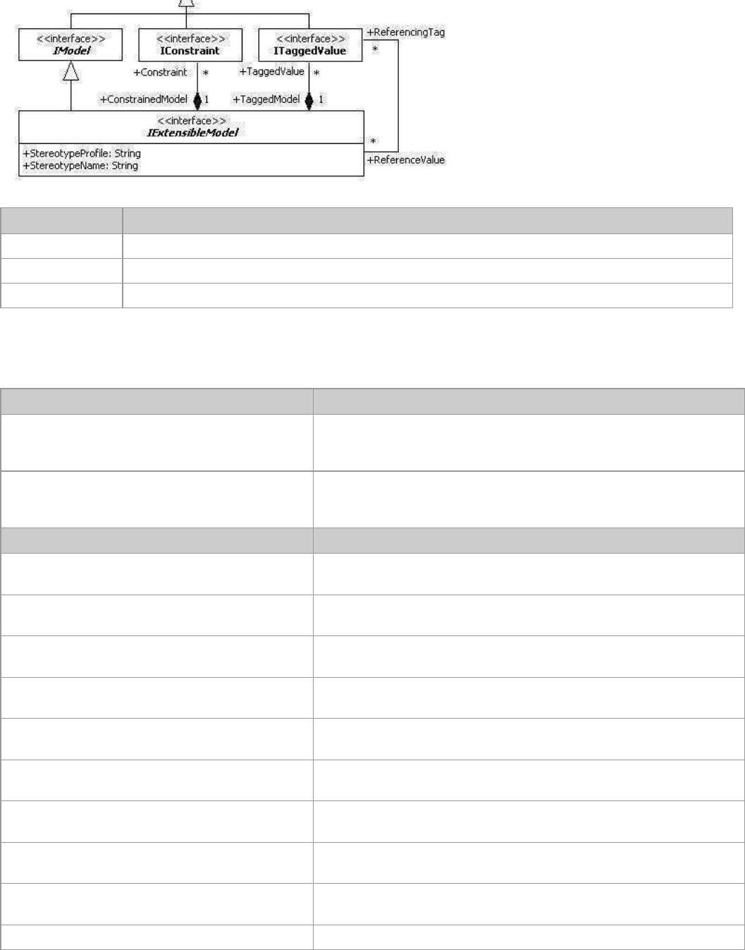
ExtCore Elements
ExtCore elements provide a platform structure for model elements where UML extension functions can be applied.
All model elements, which are applied with UML extension functions, are inherited from the IExtensibleModel
interface. IExtensibleModel interface can have many
constraints
and tagged values as illustrated in the
diagram below.
StarUML5.0DeveloperGuide(UsingOpenAPI)
http://staruml.sourceforge.net/docs/developer-guide(en)/ch04.html
Interface name Description
IExtensibleModel Shared upper level type of model elements that can be applied with UML extension functions.
IConstraint Constraint element.
ITaggedValue Tagged value element.
IExtensibleModel
IExtensibleModel interface defines the following main properties and methods.
Main property Description
StereotypeProfile: String Defines name of the UML profile that defines the stereotype
applied in the current model element.
* Read-only.
StereotypeName: String Defines name of the stereotype applied in the current model
element.
* Read-only.
Main method Description
GetConstraintCount: Integer
Returns count of constraint elements contained in the current
model element.
GetConstraintAt(Index: Integer): IConstraint
Returns (index)th constraint element contained in the current
model element.
AddConstraint(Name: String; Body: String):
IConstraint
Creates a constraint element with name and value defined by
arguments.
IndexOfConstraint(AConstraint: IConstraint):
Integer
Returns index of the constraint element defined by arguments.
DeleteConstraint(Index: Integer) Deletes (index)th constraint element contained in the current
model element.
GetTaggedValueCount: Integer
Returns count of tagged value elements contained in the current
model element.
GetTaggedValueAt(Index: Integer):
ITaggedValue
Returns (index)th tagged value element contained in the current
model element.
GetStereotype: IStereotype Returns stereotype element applied in the current model
element.
SetStereotype(const Name: WideString)
Defines stereotype value with string instead of using IStereotype
element.
SetStereotype2(Profile: String; Name: String)
Defines UML profile with stereo definition and stereotype values.
By convention, stereotype and tagged values should be defined through the UML profile. However, StarUML™ allows
definition of stereotypes by string values for those unfamiliar with UML profiles. The following example shows
reading the stereotype value from a certain IExtensibleModel type element and resetting it.
StarUML5.0DeveloperGuide(UsingOpenAPI)
http://staruml.sourceforge.net/docs/developer-guide(en)/ch04.html
varelem=...//Getreferencetomodelelement.
if(elem.IsKindOf("ExtensibleModel")){
varstereotypeStr=elem.StereotypeName;
if(stereotypeStr==""){
elem.SetStereotype("Stereotype1");
}
}
Unlike stereotype, tagged values must be defined through the UML profile only. Please refer to "Chapter 7.
Writing UML Profiles" for a detailed description of UML profile, stereotypes, and tagged values.
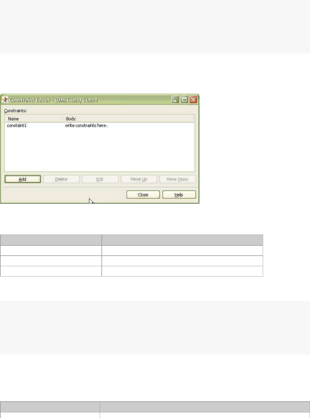
IConstraint
Constraints can be added or edited at the constraints editor in the StarUML™ application as illustrated above. In
external API, constraints can be added or edited using the IConstraint interface. The IConstraint interface
provides the following properties.
Main property Description
Name: String Name of constraint.
Body: String
Contents of constraint.
ConstrainedModel: IExtensibleModel IExtensibleModel type element applied with the constraint.
Constraint elements can be created through the method provided by an
IExtensibleModel type element. The
following example shows adding, editing, and deleting a constraint for a certain IExtensibleModel type element.
varelem=...//GetreferencetoIExtensibleModeltypeelement.
varAConstraint=elem.AddConstraint("Constraint1","ConstraintValue1");
varconstrName=AConstraint.Name;
varconstrValue=AConstraint.Body;
varidx=elem.IndexOfConstraint(AConstraint);
elem.DeleteConstraint(idx);
ITaggedValue
ITaggedValue
interface defines tagged value elements, and provides the following p
roperties and methods. Please refer to
"Chapter 7. Writing UML Profiles" for a detailed description of tagged value elements.
Main property Description
ProfileName: String
Defines the name of the UML profile that defines the current tagged v
alue.

StarUML5.0DeveloperGuide(UsingOpenAPI)
http://staruml.sourceforge.net/docs/developer-guide(en)/ch04.html
ProfileName: String
Defines the name of the UML profile that defines the current tagged v
alue.
* Read-only.
TagDefinitionSetName: String Defines the tag definition set that contains the current tagged value
.
* Read-only.
Name: String Defines the name of the tagged value defined in the UML profile.
* Read-only.
DataValue: String Defines tagged value.
* Read-only.
TaggedModel: IExtensibleModel Defines reference to the IExtensibleModel type element applied with the
current tagged value.
* Read-only.
Main method Description
GetTagDefinition: ITagDefinition Returns tag definition element for the current tagged value.
GetTagDefinitionSet:
ITagDefinitionSet
Returns tag definition set element for the current tagged value.
GetProfile: IProfile Returns the UML profile element that defines the current tagged value.
ViewCore Elements
ViewCore group interface types are inherited from IView
interface and provide a platform structure for all view type elements. ViewCore group contains many interface
types. This section describes INodeView and IEdgeView
interfaces, which are the most important interfaces.
Interface name Description
INodeView The top level interface type for node type views.
IEdgeView The top level interface type for edge type views.
INodeView
INodeView
interface is a platform type for node type view elements. A node type view is a view element that has an area like
class views. INodeView interface provides the following main properties.
Main property Description
Left: Integer
Location information of the view (Left).
Top: Integer
Location information of the view (Top).
Width: Integer Size information of the view (Width).
Height: Integer
Size information of the view (Height).
MinWidth: Integer
Defines the minimum size of the current view element (Width).
* Read-only.
MinHeight: Integer
Defines the minimum size of the current view element (Height).
* Read-only.
StarUML5.0DeveloperGuide(UsingOpenAPI)
http://staruml.sourceforge.net/docs/developer-guide(en)/ch04.html
AutoResize: Boolean
Defines the autoresize property of the current view element.
The following example shows changing the location and size of an
INodeView type view.
varnodeView=...//GetreferencetoINodeViewtypeelement.
varl=nodeView.Left;
vart=nodeView.Top;
varw=nodeView.Width;
varh=nodeView.Height;
nodeView.Left=l*2;
nodeView.Top=t*2;
nodeView.Width=w*2;
nodeView.Height=h*2;
IEdgeView
IEdgeView
interface is a platform type for edge type view elements. An edge type view is a line-based view element like
dependency views.
IEdgeView
interface provides the following main properties.
Main property Description
LineStyle: LineStyleKind Defines line style.
Points: IPoints Defines line coordinates.
Tail: IView
Defines view element at the starting point of the line.
Head: IView
Defines view element at the ending point of the line.
The following values defined in
LineStyleKind
enumeration can be used for the line style of edge type views.
Value Description
lsRectilinear
Rectilinear shape line style.
lsOblique Oblique shape line style.
The following example shows changing the line style for an edge type view.
lsRectilinear=0;
lsOblique=1;
varview=...//Getreferencetoviewelement.
if(view.IsKindOf("EdgeView")){
view.LineStyle=lsRectilinear;
}
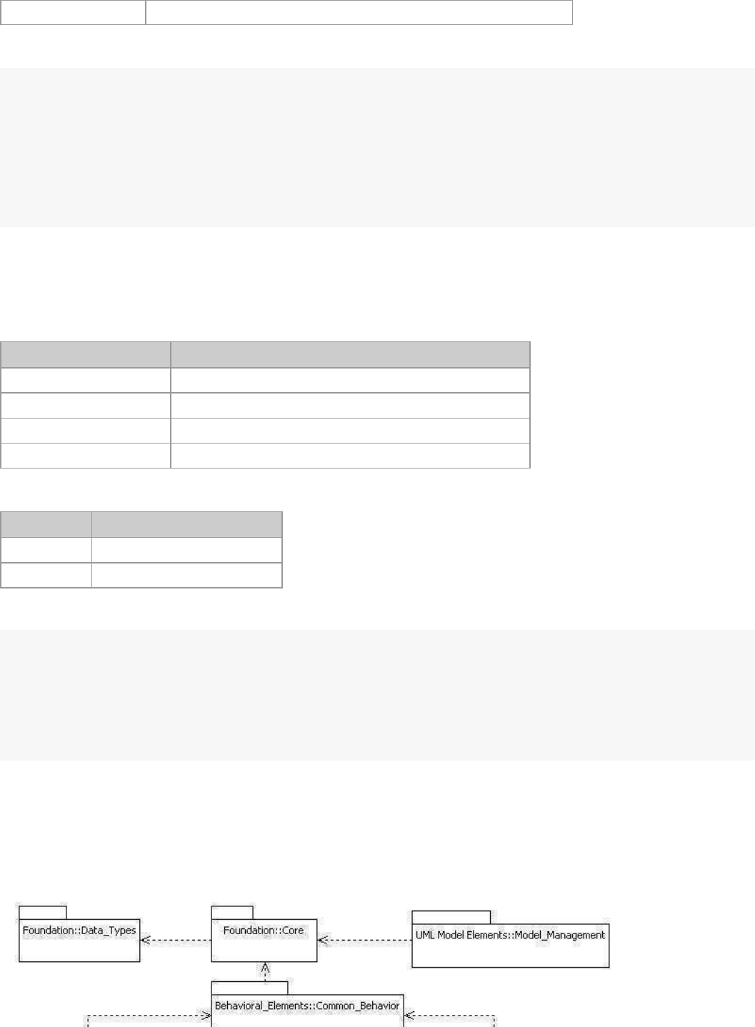
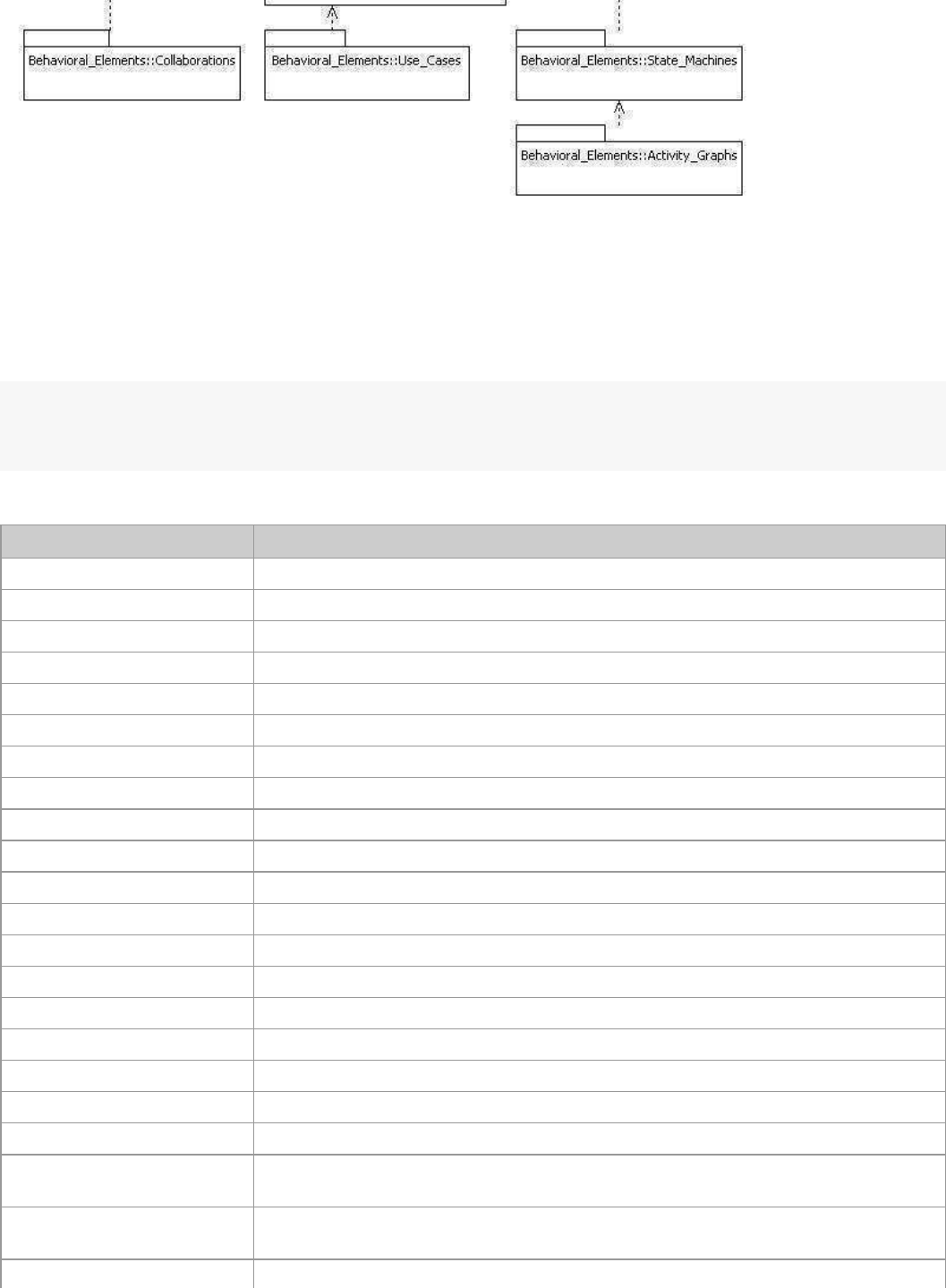
Accessing UML Model Elements
UML Model Elements group is further grouped into various packages as illustrated below. It should be noted that the
UML model elements defined in the UML Model Elements group are StarUML™'s implementation of standard UML
elements as defined in the UML standard specifications; they are almost identical to the standard UML elements. We
will skip the detailed description of UML model elements in the UML Model Elements group here.
StarUML5.0DeveloperGuide(UsingOpenAPI)
http://staruml.sourceforge.net/docs/developer-guide(en)/ch04.html
Creating UML Model Elements
When creating a UML model element,
IUMLFactory
interface must be used.
IUMLFactory interface provides
creation methods not only for UML model elements but also UML diagram
elements, UML view elements and all
other UML modeling elements. An IUMLFactory type object can be obtained through an IStarUMLApplication
type object as illustrated below.
varapp=newActiveXObject("StarUML.StarUMLApplication");
varfacto=app.UMLFactory;
...
IUMLFactory provides the following UML model element creation methods.
UML model element Creation method
UMLModel CreateModel(AOwner: UMLNamespace): IUMLModel
UMLSubsystem CreateSubsystem(AOwner: UMLNamespace): IUMLSubsystem
UMLPackage CreatePackage(AOwner: UMLNamespace): IUMLPackage
UMLClass CreateClass(AOwner: UMLNamespace): IUMLClass
UMLInterface CreateInterface(AOwner: UMLNamespace): IUMLInterface
UMLEnumeration CreateEnumeration(AOwner: UMLNamespace): IUMLEnumeration
UMLSignal CreateSignal(AOwner: UMLNamespace): IUMLSignal
UMLException CreateException(AOwner: UMLNamespace): IUMLException
UMLComponent CreateComponent(AOwner: UMLNamespace): IUMLComponent
UMLComponentInstance CreateComponentInstance(AOwner: UMLNamespace): IUMLComponentInstance
UMLNode CreateNode(AOwner: UMLNamespace): IUMLNode
UMLNodeInstance CreateNodeInstance(AOwner: UMLNamespace): IUMLNodeInstance
UMLUseCase CreateUseCase(AOwner: UMLNamespace): IUMLUseCase
UMLActor
CreateActor(AOwner: UMLNamespace): IUMLActor
UMLActivityGraph CreateActivityGraph(AContext: UMLModelElement): IUMLActivityGraph
UMLStateMachine CreateStateMachine(AContext: UMLModelElement): IUMLStateMachine
UMLCompositeState CreateCompositeState(AOwnerState: UMLCompositeState): IUMLCompositeState
UMLCollaboration CreateCollaboration(AOwner: UMLClassifier): IUMLCollaboration
UMLCollaboration CreateCollaboration2(AOwner: UMLOperation): IUMLCollaboration
UMLCollaborationInstanceSet CreateCollaborationInstanceSet(AOwner: UMLClassifier):
IUMLCollaborationInstanceSet
UMLCollaborationInstanceSet CreateCollaborationInstanceSet2(AOwner: UMLOperation):
IUMLCollaborationInstanceSet
UMLInteraction CreateInteraction(ACollaboration: UMLCollaboration): IUMLInteraction

StarUML5.0DeveloperGuide(UsingOpenAPI)
http://staruml.sourceforge.net/docs/developer-guide(en)/ch04.html
UMLInteractionInstanceSet CreateInteractionInstanceSet(ACollaborationInstanceSet:
UMLCollaborationInstanceSet): IUMLInteractionInstanceSet
UMLActionState CreateActionState(AOwnerState: UMLCompositeState): IUMLActionState
UMLSubactivityState CreateSubactivityState(AOwnerState: UMLCompositeState): IUMLSubactivityState
UMLPseudostate CreatePseudostate(AOwnerState: UMLCompositeState): IUMLPseudostate
UMLFinalState CreateFinalState(AOwnerState: UMLCompositeState): IUMLFinalState
UMLPartition CreatePartition(AActivityGraph: UMLActivityGraph): IUMLPartition
UMLSubmachineState CreateSubmachineState(AOwnerState: UMLCompositeState):
IUMLSubmachineState
UMLAttribute CreateAttribute(AClassifier: UMLClassifier): IUMLAttribute
UMLAttribute CreateQualifier(AAssociationEnd: UMLAssociationEnd): IUMLAttribute
UMLOperation CreateOperation(AClassifier: UMLClassifier): IUMLOperation
UMLParameter
CreateParameter(ABehavioralFeature: UMLBehavioralFeature): IUMLParame
ter
UMLTemplateParameter
CreateTemplateParameter(AClass: UMLClass): IUMLTemplateParameter
UMLTemplateParameter CreateTemplateParameter2(ACollaboration: UMLCollaboration):
IUMLTemplateParameter
UMLEnumerationLiteral CreateEnumerationLiteral(AEnumeration: UMLEnumeration):
IUMLEnumerationLiteral
UMLUninterpretedAction CreateEntryAction(AState: UMLState): IUMLUninterpretedAction
UMLUninterpretedAction CreateDoAction(AState: UMLState): IUMLUninterpretedAction
UMLUninterpretedAction CreateExitAction(AState: UMLState): IUMLUninterpretedAction
UMLUninterpretedAction CreateEffect(ATransition: UMLTransition): IUMLUninterpretedAction
UMLSignalEvent CreateSignalEvent(ATransition: UMLTransition): IUMLSignalEvent
UMLCallEvent CreateCallEvent(ATransition: UMLTransition): IUMLCallEvent
UMLTimeEvent CreateTimeEvent(ATransition: UMLTransition): IUMLTimeEvent
UMLChangeEvent CreateChangeEvent(ATransition: UMLTransition): IUMLChangeEvent
UMLClassifierRole CreateClassifierRole(ACollaboration: UMLCollaboration): IUMLClassifierRole
UMLObject CreateObject(ACollaborationInstanceSet: UMLCollaborationInstanceSet):
IUMLObject
UMLObject CreateObject2(AOwner: UMLNamespace): IUMLObject
UMLTransition CreateTransition(AStateMachine: UMLStateMachine; Source: UMLStateVertex;
Target: UMLStateVertex): IUMLTransition
UMLDependency CreateDependency(AOwner: UMLNamespace; Client: UMLModelElement; Supplier:
UMLModelElement): IUMLDependency
UMLAssociation CreateAssociation(AOwner: UMLNamespace; End1: UMLClassifier; End2:
UMLClassifier): IUMLAssociation
UMLAssociationClass CreateAssociationClass(AOwner: UMLNamespace; AAssociation: UMLAssociation;
AClass: UMLClass): IUMLAssociationClass
UMLGeneralization CreateGeneralization(AOwner: UMLNamespace; Parent: UMLGeneralizableEl
ement;
Child: UMLGeneralizableElement): IUMLGeneralization
UMLLink CreateLink(ACollaborationInstanceSet: UMLCollaborationInstanceSet; En
d1:
UMLInstance; End2: UMLInstance): IUMLLink
UMLAssociationRole CreateAssociationRole(ACollaboration: UMLCollaboration; End1: UMLClas
sifierRole;
End2: UMLClassifierRole): IUMLAssociationRole
UMLStimulus CreateStimulus(AInteractionInstanceSet: UMLInteractionInstanceSet; Sender:
UMLInstance; Receiver: UMLInstance; Kind: UMLFactoryMessageKind):
StarUML5.0DeveloperGuide(UsingOpenAPI)
http://staruml.sourceforge.net/docs/developer-guide(en)/ch04.html
UMLInstance; Receiver: UMLInstance; Kind: UMLFactoryMessageKind):
IUMLStimulus
UMLStimulus CreateStimulus2(AInteractionInstanceSet: UMLInteractionInstanceSet; Sender:
UMLInstance; Receiver: UMLInstance; CommunicationLink: UMLLink; Kind:
UMLFactoryMessageKind): IUMLStimulus
UMLMessage CreateMessage(AInteraction: UMLInteraction; Sender: UMLClassifierRole;
Receiver: UMLClassifierRole; Kind: UMLFactoryMessageKind): IUMLMessage
UMLMessage CreateMessage2(AInteraction: UMLInteraction; Sender: UMLClassifierRole;
Receiver: UMLClassifierRole; CommunicationConnection: UMLAssociationRole;
Kind: UMLFactoryMessageKind): IUMLMessage
UMLInclude CreateInclude(AOwner: UMLNamespace; Includer: UMLUseCase; Includee:
UMLUseCase): IUMLInclude
UMLExtend CreateExtend(AOwner: UMLNamespace; Extender: UMLUseCase; Extendee:
UMLUseCase): IUMLExtend
UMLRealization CreateRealization(AOwner: UMLNamespace; Client: UMLModelElement; Supplier:
UMLModelElement): IUMLRealization
The following example shows creating UML model elements using IUMLFactory.
varapp=newActiveXObject("StarUML.StarUMLApplication");
varfacto=app.UMLFactory;
varpjt=app.GetProject();
varmdlElem=facto.CreateModel(pjt);//CreateUMLModelelement.
varpkgElem=facto.CreatePackage(mdlElem);//CreateUMLPackageelement.
varclsElem1=facto.CreateClass(pkgElem);//CreateUMLClasselement.
varclsElem2=facto.CreateClass(pkgElem);//CreateUMLClasselement.
varattrElem=facto.CreateAttribute(clsElem1);//CreateUMLAttributeelement.
varopElem=facto.CreateOperation(clsElem1);//CreateUMLOperationelement.
varparamElem1=facto.CreateParameter(opElem);//CreateUMLParameterelement.
varparamElem2=facto.CreateParameter(opElem);//CreateUMLParameterelement.
paramElem1.TypeExpression="String";
paramElem2.Type_=clsElem2;
...
Deleting UML Model Element
The DeleteModel
method of
IStarUMLApplication
interface can be used to delete UML model elements. The
CanDelete
method of
IModel
interface can be used to check whether the current model element can be deleted. If the current model element is
read-only, the CanDelete
method returns "false". Additional caution should be taken because when a model element is deleted, all its lower
level model elements, and all the view elements related to the current model element are automatically deleted
altogether. The following example is a continuation of the example above, showing deleting a class element.
...
if(clsElem1.CanDelete()==true){
app.DeleteModel(clsElem1);
}
...
Managing UML Diagram
Creating UML Diagram Elements
IUMLFactory can be used to create UML diagram elements like creating UML model elements. IUMLFactory
provides the following diagram-related creation methods.
UML diagram element
Creation method
StarUML5.0DeveloperGuide(UsingOpenAPI)
http://staruml.sourceforge.net/docs/developer-guide(en)/ch04.html
UML diagram element
Creation method
UMLClassDiagram CreateClassDiagram(AOwner: Model): IUMLClassDiagram
UMLUseCaseDiagram CreateUseCaseDiagram(AOwner: Model): IUMLUseCaseDiagram
UMLSequenceDiagram CreateSequenceDiagram(AOwner: UMLInteractionInstanceSet):
IUMLSequenceDiagram
UMLSequenceRoleDiagram CreateSequenceRoleDiagram(AOwner: UMLInteraction):
IUMLSequenceRoleDiagram
UMLCollaborationDiagram CreateCollaborationDiagram(AOwner: UMLInteractionInstanceSet):
IUMLCollaborationDiagram
UMLCollaborationRoleDiagram CreateCollaborationRoleDiagram(AOwner: UMLInteraction):
IUMLCollaborationRoleDiagram
UMLStatechartDiagram CreateStatechartDiagram(AOwner: UMLStateMachine): IUMLStatechartDiagram
UMLActivityDiagram
CreateActivityDiagram(AOwner: UMLActivityGraph): IUMLActivityDiagram
UMLComponentDiagram CreateComponentDiagram(AOwner: Model): IUMLComponentDiagram
UMLDeploymentDiagram
CreateDeploymentDiagram(AOwner: Model): IUMLDeploymentDiagram
The method for creating UML diagram elements is almost identical to the method for creating UML model elements.
One difference for UML diagram elements is that view type elements are automatically created when creating model
type elements. The following example shows creating a UML diagram element and accessing the automatically
created UML diagram view element.
varapp=newActiveXObject("StarUML.StarUMLApplication");
varpkgElem=...//UpperlevelmodelelementtocontainUMLdiag
vardgmElem=facto.CreateClassDiagram(pkgElem);//CreateUMLClassDiagram.
vardgmViewElem=dgmElem.DiagramView;//Automaticallycreateddiagramviewelement.
app.OpenDiagram(dgmElem);
...
Deleting UML Diagram Element
Since UML diagram elements are regarded as UML model elements, they can be deleted using the DeleteModel
method of IStarUMLApplication interface, like deleting UML model elements. The
CanDelete
method of
IModel
interface can be used to check whether the diagram element can be deleted.
Handling View Elements
Creating View Elements
IUMLFactory
can also be used when creating view elements.
IUMLFactory methods related to view element
creation are as follows.
UML view element Creation method
UMLNoteView CreateNoteView(ADiagramView: DiagramView): IUMLNoteView
UMLNoteLinkView CreateNoteLinkView(ADiagramView: DiagramView; ANote: UMLNoteView;
LinkTo: View): IUMLNoteLinkView
UMLTextView CreateTextView(ADiagramView: DiagramView): IUMLTextView
UMLModelView CreateModelView(ADiagramView: DiagramView; AModel: UMLModel):
IUMLModelView
UMLSubsystemView CreateSubsystemView(ADiagramView: DiagramView; AModel:
UMLSubsystem): IUMLSubsystemView
UMLPackageView
CreatePackageView(ADiagramView: DiagramView; AModel: UMLPackage):
IUMLPackageView
StarUML5.0DeveloperGuide(UsingOpenAPI)
http://staruml.sourceforge.net/docs/developer-guide(en)/ch04.html
IUMLPackageView
UMLClassView CreateClassView(ADiagramView: DiagramView; AModel: UMLClass):
IUMLClassView
UMLInterfaceView
CreateInterfaceView(ADiagramView: DiagramView; AModel: UMLInterface):
IUMLInterfaceView
UMLEnumerationView
CreateEnumerationView(ADiagramView: DiagramView; AModel:
UMLEnumeration): IUMLEnumerationView
UMLSignalView CreateSignalView(ADiagramView: DiagramView; AModel: UMLSignal):
IUMLSignalView
UMLExceptionView CreateExceptionView(ADiagramView: DiagramView; AModel: UMLException):
IUMLExceptionView
UMLComponentView CreateComponentView(ADiagramView: DiagramView; AModel:
UMLComponent): IUMLComponentView
UMLComponentInstanceView CreateComponentInstanceView(ADiagramView: DiagramView; AModel:
UMLComponentInstance): IUMLComponentInstanceView
UMLNodeView CreateNodeView(ADiagramView: DiagramView; AModel: UMLNode):
IUMLNodeView
UMLNodeInstanceView CreateNodeInstanceView(ADiagramView: DiagramView; AModel:
UMLNodeInstance): IUMLNodeInstanceView
UMLActorView CreateActorView(ADiagramView: DiagramView; AModel: UMLActor):
IUMLActorView
UMLUseCaseView CreateUseCaseView(ADiagramView: DiagramView; AModel: UMLUseCase):
IUMLUseCaseView
UMLCollaborationView CreateCollaborationView(ADiagramView: DiagramView; AModel:
UMLCollaboration): IUMLCollaborationView
UMLCollaborationInstanceSetView CreateCollaborationInstanceSetView(ADiagramView: DiagramView; AModel:
UMLCollaborationInstanceSet): IUMLCollaborationInstanceSetView
UMLGeneralizationView CreateGeneralizationView(ADiagramView: DiagramView; AModel:
UMLGeneralization; Parent: View; Child: View): IUMLGeneralizationView
UMLAssociationView CreateAssociationView(ADiagramView: DiagramView; AModel:
UMLAssociation; End1: View; End2: View): IUMLAssociationView
UMLAssociationClassView CreateAssociationClassView(ADiagramView: DiagramView; AModel:
UMLAssociationClass; AssociationView: View; ClassView: View):
IUMLAssociationClassView
UMLDependencyView
CreateDependencyView(ADiagramView: DiagramView; AModel:
UMLDependency; Client: View; Supplier: View): IUMLDependencyView
UMLRealizationView CreateRealizationView(ADiagramView: DiagramView; AModel: UMLRealizati
on;
Client: View; Supplier: View): IUMLRealizationView
UMLIncludeView CreateIncludeView(ADiagramView: DiagramView; AModel: UMLInclude; Base:
View; Addition: View): IUMLIncludeView
UMLExtendView CreateExtendView(ADiagramView: DiagramView; AModel: UMLExtend; Base:
View; Extension: View): IUMLExtendView
UMLColObjectView CreateObjectView(ADiagramView: DiagramView; AModel: UMLObject):
IUMLColObjectView
UMLSeqObjectView CreateSeqObjectView(ADiagramView: UMLSequenceDiagramView; AModel:
UMLObject): IUMLSeqObjectView
UMLColClassifierRoleView CreateClassifierRoleView(ADiagramView: DiagramView; AModel:
UMLClassifierRole): IUMLColClassifierRoleView
UMLSeqClassifierRoleView CreateSeqClassifierRoleView(ADiagramView: UMLSequenceRoleDiagramView;
AModel: UMLClassifierRole): IUMLSeqClassifierRoleView
StarUML5.0DeveloperGuide(UsingOpenAPI)
http://staruml.sourceforge.net/docs/developer-guide(en)/ch04.html
UMLLinkView CreateLinkView(ADiagramView: DiagramView; AModel: UMLLink; End1: View;
End2: View): IUMLLinkView
UMLAssociationRoleView CreateAssociationRoleView(ADiagramView: DiagramView; AModel:
UMLAssociationRole; End1: View; End2: View): IUMLAssociationRoleView
UMLColStimulusView CreateStimulusView(ADiagramView: UMLCollaborationDiagramView; AModel:
UMLStimulus; LinkView: View): IUMLColStimulusView
UMLSeqStimulusView CreateSeqStimulusView(ADiagramView: UMLSequenceDiagramView; AModel:
UMLStimulus; Sender: View; Receiver: View): IUMLSeqStimulusView
UMLColMessageView CreateMessageView(ADiagramView: UMLCollaborationRoleDiagramView;
AModel: UMLMessage; AssociationRoleView: View): IUMLColMessageView
UMLSeqMessageView CreateSeqMessageView(ADiagramView: UMLSequenceRoleDiagramView;
AModel: UMLMessage; Sender: View; Receiver: View): IUMLSeqMessageView
UMLStateView CreateStateView(ADiagramView: UMLStatechartDiagramView; AModel:
UMLCompositeState): IUMLStateView
UMLSubmachineStateView CreateSubmachineStateView(ADiagramView: UMLStatechartDiagramView;
AModel: UMLSubmachineState): IUMLSubmachineStateView
UMLPseudostateView CreatePseudostateView(ADiagramView: DiagramView; AModel:
UMLPseudostate): IUMLPseudostateView
UMLFinalStateView CreateFinalStateView(ADiagramView: DiagramView; AModel: UMLFinalState):
IUMLFinalStateView
UMLActionStateView CreateActionStateView(ADiagramView: UMLActivityDiagramView; AModel:
UMLActionState): IUMLActionStateView
UMLSubactivityStateView CreateSubactivityStateView(ADiagramView: UMLActivityDiagramView;
AModel: UMLSubactivityState): IUMLSubactivityStateView
UMLSwimlaneView CreateSwimlaneView(ADiagramView: UMLActivityDiagramView; AModel:
UMLPartition): IUMLSwimlaneView
UMLTransitionView CreateTransitionView(ADiagramView: DiagramView; AModel: UMLTransition;
Source: View; Target: View): IUMLTransitionView
The following example creates IUMLClassView type elements in the class diagram view, and creates the
IUMLDependencyView and
IUMLAssociationView
that link the two elements. As model elements are required for creati
ng view elements, model elements are created
first.
varapp=newActiveXObject("StarUML.StarUMLApplication");
varfactory=app.UMLFactory;
//Getreferencetoexistingmodelelements.
varrootElem=app.FindByPathname("::LogicalView");
if(rootElem!=null){
app.BeginUpdate();
try{
//Createmodelelements.
varclass1=factory.CreateClass(rootElem);
varclass2=factory.CreateClass(rootElem);
vardependency=factory.CreateDependency(rootElem,class1,class2);
varassociation=factory.CreateAssociation(rootElem,class1,class2);
vardiagram=factory.CreateClassDiagram(rootElem);
vardiagramView=diagram.DiagramView;
//Createviewelements.
varclassView1=factory.CreateClassView(diagramView,class1);
varclassView2=factory.CreateClassView(diagramView,class2);
vardependencyView=factory.CreateDependencyView(diagramView,dependency,
classView1,classView2);
varassociationView=factory.CreateAssociationView(diagramView,association,
classView1,classView2);
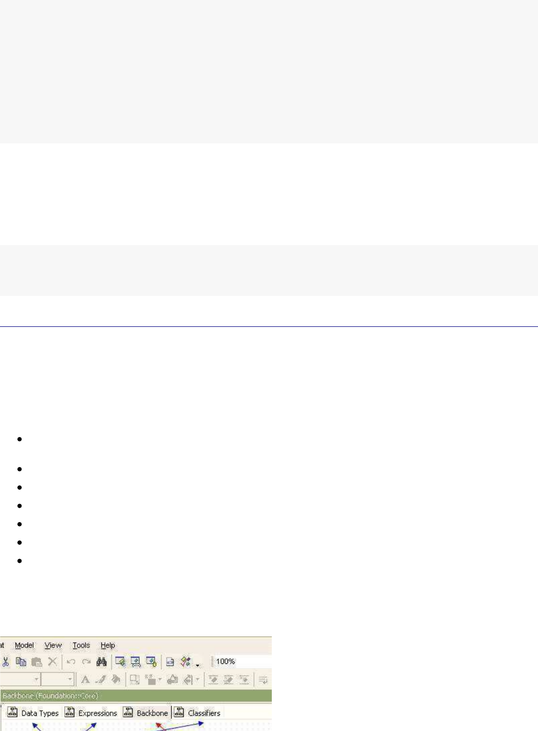
StarUML5.0DeveloperGuide(UsingOpenAPI)
http://staruml.sourceforge.net/docs/developer-guide(en)/ch04.html
classView1,classView2);
//Adjustviewelementattributes.
classView1.Left=100;
classView1.Top=100;
classView2.Left=300;
classView2.Top=100;
app.OpenDiagram(diagram);
}
finally{
app.EndUpdate();
}
}
Deleting UML View Elements
The DeleteView method of IStarUMLApplication interface can be used to delete UML view elements. Caution
should be taken in that when a model element is deleted, its view elements are automatically deleted together, but
when a view element is deleted its model element is not deleted.
The following example shows deleting view elements that were created in the example above.
...
app.DeleteView(dependencyView);
app.DeleteView(associationView);
Using APIs for Application Objects
Application Object Management
StarUMLApplication Object
The first thing to acquire in order to use StarUML™'s external API is
reference to a
StarUMLApplication
object. All
other objects can be access through this. The IStarUMLApplication interface is an abstraction of the StarUML™
application itself and contains the following methods.
User action related methods (Undo, Redo, ClearHistory, BeginUpdate, EndUpdate, BeginGroupAction,
EndGroupAction, ...)
Element editing related methods (Copy, Cut, Paste, ...)
Model, view, and diagram deletion related methods (DeleteModel, DeleteView, ...)
Reading values of option items (GetOptionValue)
Log, message, and web browsing related methods (Log, AddMessageItem, NavigateWeb, ...)
Opened diagram management (OpenDiagram, CloseDiagram, ...)
Others (FindByPathname, SelectInModelExplorer, ...)
Managing Opened Diagrams
In the StarUML™'s diagram area, opened diagrams
are managed under tabs as illustrated below. The currently
activated diagram is called active diagram.
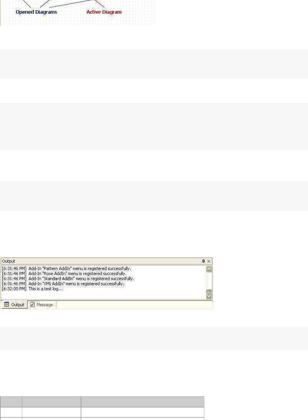
StarUML5.0DeveloperGuide(UsingOpenAPI)
http://staruml.sourceforge.net/docs/developer-guide(en)/ch04.html
To open a diagram, use the following code. If the diagram is not currently open, the diagram will open and
automatically become active. If the diagram is already opened, it will be set as the active diagram.
varapp=newActiveXObject("StarUML.StarUMLApplication");
vardgm=...//Assignadiagramtoopen.
app.OpenDiagram(dgm);
To obtain reference to opened diagrams, use the GetOpenedDiagramCount and GetOpenedDiagramAt
methods.
varapp=newActiveXObject("StarUML.StarUMLApplication");
...
for(i=0;i<app.GetOpenedDiagramCount();i++){
vardgm=app.GetOpenedDiagramAt(i);
...
}
Opened diagrams can also be closed. In this case, the CloseDiagram
method can be used. Use the
CloseAllDiagram method to close all diagrams, or use the CloseActiveDiagram method to close the active
diagram.
varapp=newActiveXObject("StarUML.StarUMLApplication");
vardgm=...//Assignadiagramtoclose.
app.CloseDiagram(dgm);
Recording Log
The [Output]
tab in StarUML™'s information area provides the interface for recoding and showing the application execution log to
the user.
To record log in the [Output] section, use the Log
method as shown in the following example.
varapp=newActiveXObject("StarUML.StarUMLApplication");
app.Log("Thisisatestlog...");
Managing Message Items
StarUML™ uses message items to display specific messages to the user. Message items are used to notify details or
elements that were not found in element find or did not pass model verification. There are three types of message
item: general items, element find result items, and model verification result items.
Value literal Description
0
mkGeneral
General message items.
1
mkFindResult
Message items for element find results.
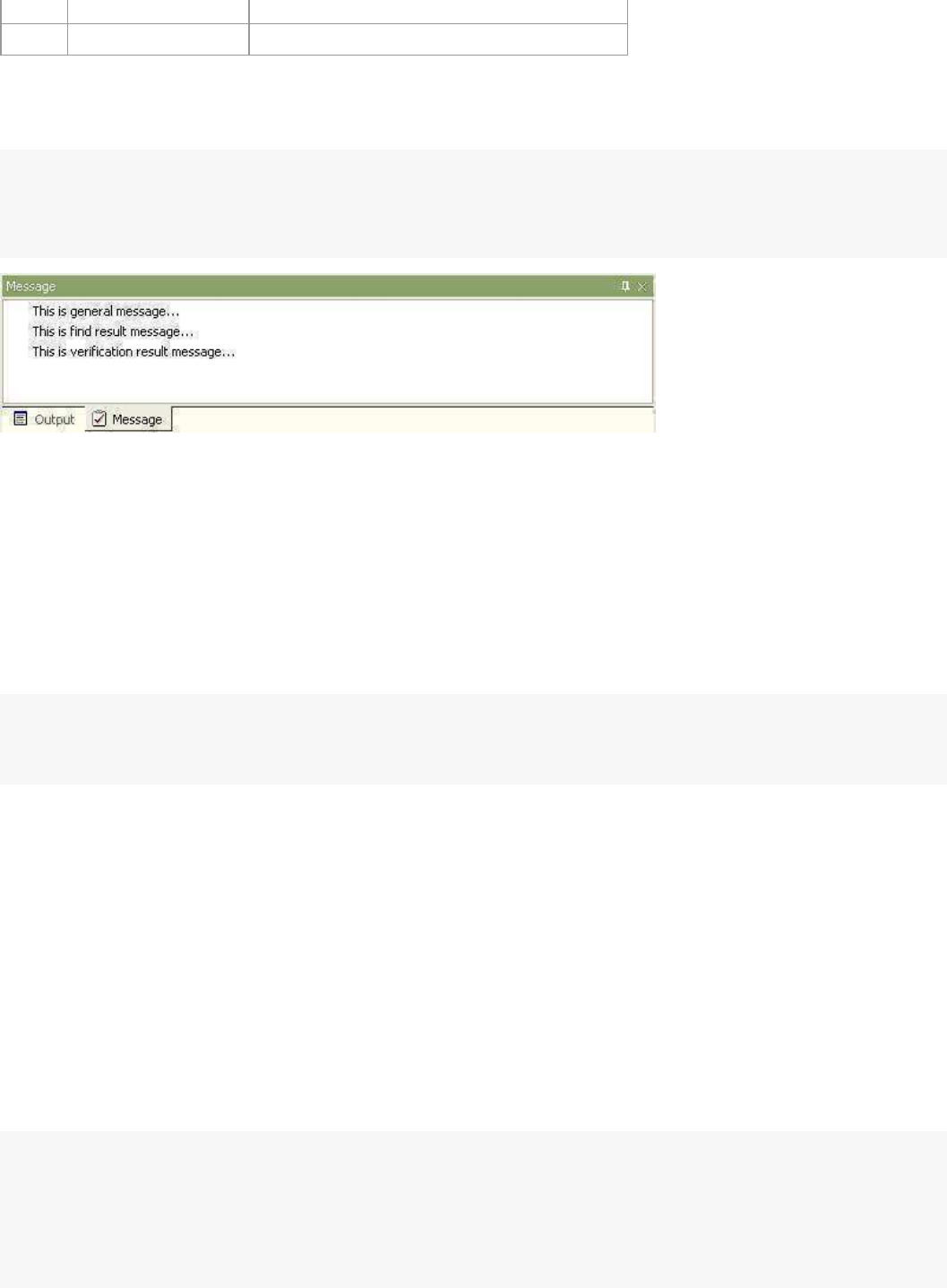
StarUML5.0DeveloperGuide(UsingOpenAPI)
http://staruml.sourceforge.net/docs/developer-guide(en)/ch04.html
1
mkFindResult
Message items for element find results.
2
mkVerificationResult
Message items for model verification results.
When adding a message item, the message item's type, content and related element must be referenced. The
following example shows adding three types of message with different message contents to reference a project
element. The result is shown in the following illustration.
varapp=newActiveXObject("StarUML.StarUMLApplication");
app.AddMessageItem(0,"Thisisgeneralmessage...",app.GetProject());
app.AddMessageItem(1,"Thisisfindresultmessage...",app.GetProject());
app.AddMessageItem(2,"Thisisverificationresultmessage...",app.GetProject());
Double-clicking a message automatically selects the related element in the model explorer, and if the element is
expressed in a diagram, the diagram becomes active.
Finding Element by Pathname
Elements can be searched by pathnames. For example, the pathname for element Class1 located under Package2
and under Package1 is "
::Package1::Package2::Class1"
. A pathname is a series of element names linked by the
"::" delimiter. The search always starts from the top level project. Since the name of the top level project is always
a null string, any pathname starts with "::". However, it is possible to omit the initial "::". In other words, an
expression such as "Package1::Package2::Class2
" is regarded as the same pathname as the one above. The
following example shows obtaining reference to a model element by pathname.
varapp=newActiveXObject("StarUML.StarUMLApplication");
varelem=app.FindByPathname("::LogicalView::Class1");
...
Controlling Application Updates
When the user makes a specific modification or performs a specific command through API, the modification is
immediately updated and shown in StarUML™. However, when performing complex tasks through API, many
commands have to be executed in one go, and if each task is applied each time, the display will clog up and
processing speed will decrease. In such a case, it is better to stop the modification update, perform the various
complex tasks, and then apply the changes all together at the same time. StarUMLApplication object provides
such functions through the BeginUpdate and EndUpdate
methods.
The user can call the BeginUpdate method before performing complex and long process tasks, and call the
EndUpdate
method immediately after the tasks to apply the changes. Care must be taken in that no changes will be applied at
all if
EndUpdate cannot be called, due to errors or other problems while processing tasks after calling
BeginUpdate. To prevent such problems, exception process techniques (especially, try … finally) should be used as
shown in the following example.
varapp=newActiveXObject("StarUML.StarUMLApplication");
...
app.BeginUpdate();
try{
...//Placetaskstoprocesshere.
}
finally{
app.EndUpdate();//Thefinallyblockwillbeexecutedevenifanexceptionoccursinthetryb
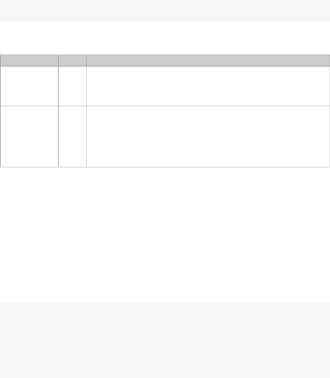
StarUML5.0DeveloperGuide(UsingOpenAPI)
http://staruml.sourceforge.net/docs/developer-guide(en)/ch04.html
app.EndUpdate();//Thefinallyblockwillbeexecutedevenifanexceptionoccursinthetryb
}
...
For indicating the end of modifications and triggering application of the changes, the EndUpdate2 method can also
be used instead of the
EndUpdate
method. Both methods have the same effect, but
EndUpdate2 allows more
detailed control. This method performs more detailed control through the following two arguments.
Argument Type Description
CompletelyRebuild Boolean Rebuilds all tree structures displayed in the model explorer from the beginning.
Setting the value of this argument to 'True' may allow faster application of changes
if the changes include creation or modification of large quantities o
f model
elements. The
EndUpdate() method is the same as having this value set as
'False'.
UseUpdateLock Boolean Applies the insert/delete/modify results of the tree items in the model explorer in
one go. In other words, changes in the tree items are not visually displayed in the
GUI but are processed at at the same time. Setting the value of this argument to
'True' when the model is very large will cause the process to take a relatively
longer time, even if the model elements modified are few. When this value is 'True',
the process time is proportional to the total number of model elements rather than
the number of model elements modified. The
EndUpdate() method is the same as
having this value set as 'True'.
Using Group Actions
It is possible to undo or redo any user-performed actions. The same applies for any commands performed through
API. If a command is executed twice and the user wishes to undo the tasks, undo must be performed twice.
However, there are many cases where the user wants a combination of different commands to be processed as a
single action. For instance, when performing undo after writing code to automatically add Get function and Set
function for a specific attribute, the undo should be able to revert
the code to the time before Get function and Set
function were added. However, to add Get/Set functions, many commands must be used together in combinations.
In such a case, multiple commands can be handled as a single group and processed as one action.
StarUMLApplication object allows the execution of many commands as a single action by using the
BeginGroupAction and EndGroupAction methods. When calling the BeginGroupAction method, a new virtual
group action is created. All other tasks performed after this are added to the group action, and when the
EndGroupAction method is called, the action grouping is complete. After executing BeginGroupAction, even if an
error occurs in the tasks included in the group,
EndGroupAction must be called, and therefore exception processes
(especially try … finally) must be handled properly. This group action can be managed as a single action through
undo or redo.
varapp=newActiveXObject("StarUML.StarUMLApplication");
...
app.BeginGroupAction();
try{
...
}
finally{
app.EndGroupAction();
}
...
When calling the
BeginGroupAction
method, the result is the same as calling
BeginUpdate
. In the same way,
when calling the EndGroupAction method, the result is the same as calling EndUpdate. In other words, changes
are not applied until the group is properly completed. Therefore the BeginUpdate
or
EndUpdate methods must
not be used between
BeginGroupAction
and EndGroupAction.
Element Selection Management
StarUML™ allows ways to acquire information on the model elements or view elements selected by the user, and to
select certain elements by force. All of these functions are defined in ISelectionManager
interface.

StarUML5.0DeveloperGuide(UsingOpenAPI)
http://staruml.sourceforge.net/docs/developer-guide(en)/ch04.html
Acquiring Selected Elements
In order to acquire the list of model elements or view elements currently selected, reference to SelectionManager
must be acquired first. And then codes like the following example can be used to acquire reference to the selected
model elements or view elements.
varapp=newActiveXObject("StarUML.StarUMLApplication");
varselmgr=app.SelectionManager;
//Listselectedmodelelements.
for(i=0;i<selmgr.GetSelectedModelCount();i++){
varm=selmgr.GetSelectedModelAt(i);
...
}
//Listselectedviewelements.
for(i=0;i<selmgr.GetSelectedViewCount();i++){
varv=selmgr.GetSelectedViewAt(i);
...
}
Acquiring Currently Active Diagram
Reference can be made to the currently active diagram (the diagram currently displayed on the StarUML™ screen).
A diagram is always managed by two separate objects: Diagram and DiagramView
. References to both
Diagram
object and DiagramView
object can be acquired directly.
varapp=newActiveXObject("StarUML.StarUMLApplication");
varselmgr=app.SelectionManager;
vardgm=selmgr.ActiveDiagram//Diagramobjectofthecurrentlyactivediagram
vardgmview=selmgr.ActiveDiagram//DiagramViewobjectofthecurrentlyactivediagram
Selecting Model Elements
To select specific model elements (e.g. Class, Interface, Component, ...), use the SelectModel method. Calling this
method deselects all of the currently selected elements and selects j
ust one of the elements. To maintain the
current selection and add model elements to the selection, the SelectAdditionalModel method must be used.
varapp=newActiveXObject("StarUML.StarUMLApplication");
varselmgr=app.SelectionManager;
varm=...//Assignreferencetomodelelementtoselect.
...
selmgr.SelectModel(m);//Selectonlythemodelelement'm'.
...
selmgr.SelectAdditionalModel(m);//Addmodelelement'm'toselection.
...
To cancel the selection of model elements, use the DeselectModel method as shown in the example below.
varapp=newActiveXObject("StarUML.StarUMLApplication");
varselmgr=app.SelectionManager;
varm=...//Assignreferencetomodelelementtodeselect.
...
selmgr.DeselectModel(m);//Deselectmodelelement'm'.
...
selmgr.DelselectAllModels();//Deselectallmodelelements.
...
Selecting View Elements
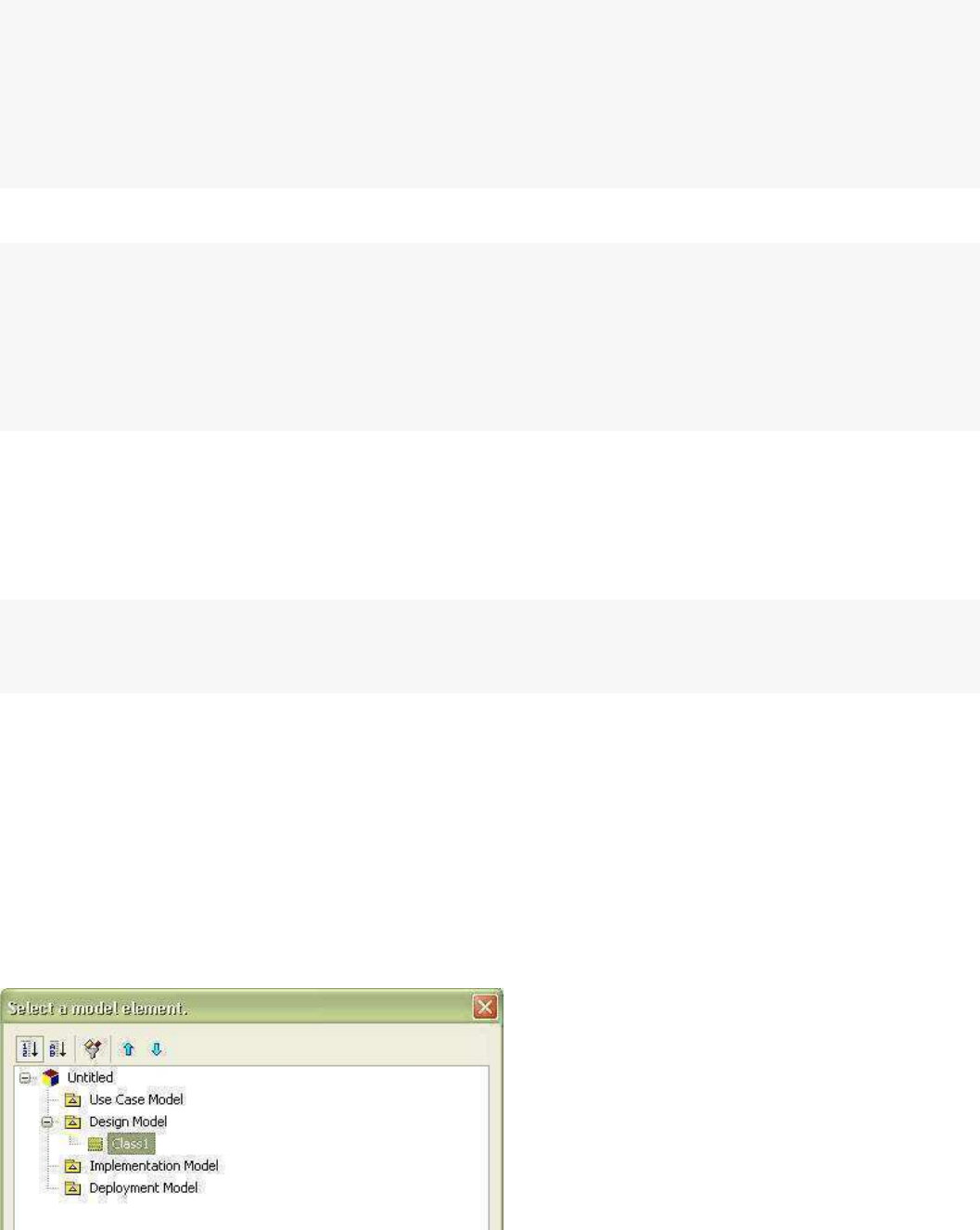
StarUML5.0DeveloperGuide(UsingOpenAPI)
http://staruml.sourceforge.net/docs/developer-guide(en)/ch04.html
To select view elements illustrated in a diagram, use the
SelectView
method. Calling this method deselects all of
the currently selected view elements and selects just one of them. To maintain the current selection and add model
view elements to the selection, the
SelectAdditionalView
method must be used.
varapp=newActiveXObject("StarUML.StarUMLApplication");
varselmgr=app.SelectionManager;
varv=...
...
selmgr.SelectView(v);
...
selmgr.SelectAdditionalView(v);
...
To cancel the selection of view elements, use the DeselectView method as shown in the example below.
varapp=newActiveXObject("StarUML.StarUMLApplication");
varselmgr=app.SelectionManager;
varv=...//Assignreferencetoviewelementtoadd.
...
selmgr.DeselectView(v);//Selectonlytheviewelement'v'.
...
selmgr.DelselectAllViews();//Addviewelement'v'totheselection.
...
Selecting Diagram Areas
View elements in certain areas can be selected by entering coordinates for the area in the currently active diagram.
Use the SelectArea method to do this, or use the SelectAdditionalArea method to add elements to the selection.
The following example selects all view elements located within the area of the coordinates (100, 100, 500, 300) in
the currently active diagram.
varapp=newActiveXObject("StarUML.StarUMLApplication");
varselmgr=app.SelectionManager;
selmgr.SelectArea(100,100,500,300);
Element Selection Dialog Management
StarUML™ provides two types of dialog for selecting specific elements: a tree view type,
ElementSelector,
and a
list view type, ElementListSelector
.
ElementSelector is the most commonly used method as it allows selection
of elements in a tree view structure just as in the model explorer. ElementListSelector is used to list and select
elements of the same types.
Managing ElementSelector Object
ElementSelector
is a dialog that displays a tree view structure and allows the user t
o select an element just like the model explorer
as shown in the illustration below. The user can select an element or set it to select nothing at all (set a null value).
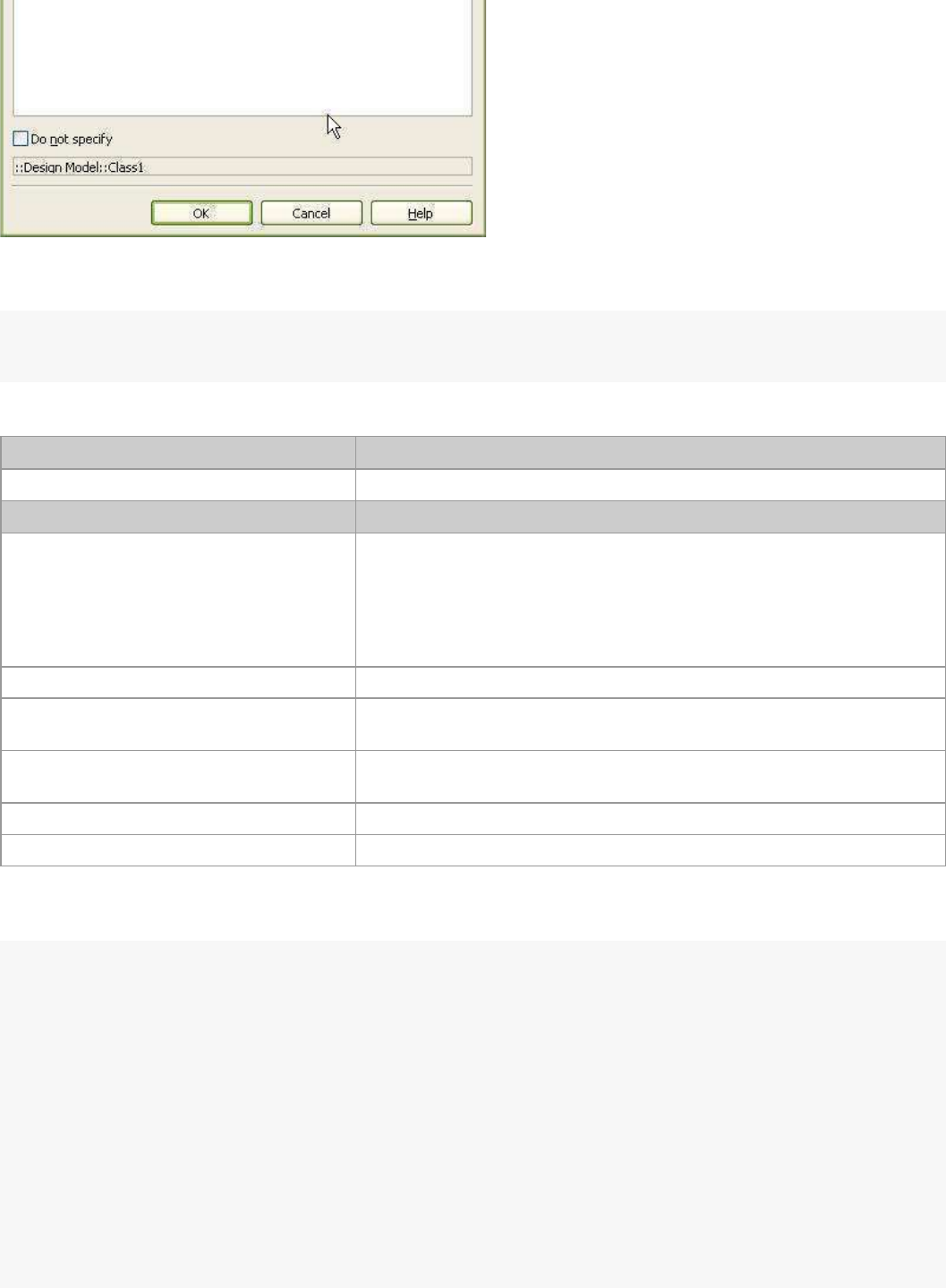
StarUML5.0DeveloperGuide(UsingOpenAPI)
http://staruml.sourceforge.net/docs/developer-guide(en)/ch04.html
Reference to an
ElementSelector dialog object can be acquired through a StarUMLApplication object as shown
in the example below.
varapp=newActiveXObject("StarUML.StarUMLApplication");
varsel_dlg=app.ElementSelector;
ElementSelector dialog provides the following property and methods.
Main property Description
AllowNull: Boolean Defines whether to allow no selection (setting a null value).
Main method Description
Filter(Filtering: ElementFilteringKind) Defines what type of modeling elements to display. Value can be any
one of the following.
fkAll (0): Shows all modeling elements.
fkPackages (1): Shows UMLPackage type elements (UMLPackage,
UMLModel, UMLSubsystem) only.
fkClassifiers (2): Shows UMLClassifier type elements only.
ClearSelectableModels Clears selectable element type list.
AddSelectableModel(ClassName: String) Adds the selected type to the selectable element type list. Argument
value example: "UMLClass"
RemoveSelectableModel(ClassName:
String)
Removes the selected type from the selectable element type list.
Argument value example: "UMLClass"
Execute(Title: String): Boolean Executes the dialog. Sets the dialog title with the argument string.
GetSelectedModel: IModel Returns reference to the user-selected elements.
The following example shows the whole process of executing ElementSelector dialog and acquiring the selected
elements.
fkClassifiers=2;
varapp=newActiveXObject("StarUML.StarUMLApplication");
varsel_dlg=app.ElementSelector;
sel_dlg.AllowNull=false;
sel_dlg.Filter(fkClassifiers)
sel_dlg.ClearSelectableModels();
sel_dlg.AddSelectableModel("UMLModel");
sel_dlg.AddSelectableModel("UMLSubsystem");
sel_dlg.AddSelectableModel("UMLPackage");
if(sel_dlg.Execute("Selectaclassifiertypeelement."
)){
varelem=sel_dlg.GetSelectedModel;
...
}
else{
//Ifcanceled,...
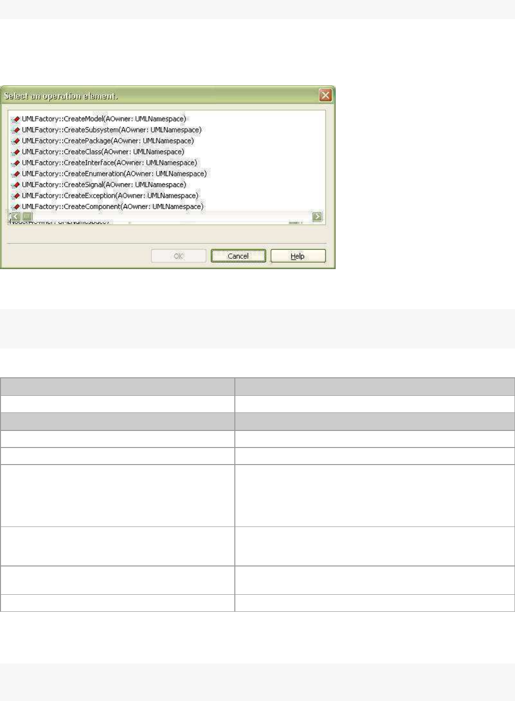
StarUML5.0DeveloperGuide(UsingOpenAPI)
http://staruml.sourceforge.net/docs/developer-guide(en)/ch04.html
}
Managing ElementListSelector Object
ElementListSelector
is a dialog that displays a list of selectable elements in a list vie
w and allows the user to select an element.
Reference to an
ElementListSelector dialog object can be acquired through a StarApplication object as shown in
the example below.
varapp=newActiveXObject("StarUML.StarUMLApplication");
varsel_dlg=app.ElementListSelector;
ElementListSelector dialog provides the following property and methods.
Main property Description
AllowNull: Boolean Defines whether to allow no selection (setting a null value).
Main method Description
ClearListElements Clears the list.
AddListElement(AModel: IModel) Adds the model element defined by argument to the list.
AddListElementsByCollection(AModel: IModel;
CollectionName: String; ShowInherited: Boolean)
Adds the collection elements of the model element defined
by argument to the list. 'ShowInherited' argument defines
whether to trace the inheritance structure of the selected
model element and add collection items of upper level
elements to the list.
AddListElementsByClass(MetaClassName: String;
IncludeChildInstances: Boolean)
Adds the elements of the types defined by argument to the
list. If the 'IncludeChildInstances' argument is 'true', child
elements of the selected type are also added to the list.
Execute(Title: String): Boolean
Executes the dialog. Sets the dialog title with the argument
string.
GetSelectedModel: IModel Returns reference to the user-selected elements.
The following example executes ElementListSelector
dialog, and prompts the user to select an element from the
operation collection of a specific class element. Since the "ShowInherited" argument is "true", if there are parent
classes for the selected class element, the operation collection of t
his class element can also be selected.
varapp=newActiveXObject("StarUML.StarUMLApplication");
varsel_dlg=app.ElementListSelector;

StarUML5.0DeveloperGuide(UsingOpenAPI)
http://staruml.sourceforge.net/docs/developer-guide(en)/ch04.html
sel_dlg.AllowNull=false;
sel_dlg.ClearListElements();
varclass=...//Getreferencetoclasselement.
sel_dlg.AddListElementsByCollection(class,"Operations",true);
if(sel_dlg.Execute("Selectanoperationelement.")){
varselElem=sel_dlg.GetSelectedModel;
...
}
else{
//Ifcanceled,...
}
The example above used the
AddListElementsByCollection
method. The following example now uses the
AddListElementsByClass
method. Since the "IncludeChildInstances" argument is "true", elements of the selected types and all their child
elements are added to the list.
varapp=newActiveXObject("StarUML.StarUMLApplication");
varsel_dlg=app.ElementListSelector;
sel_dlg.AllowNull=false;
sel_dlg.ClearListElements();
sel_dlg.AddListElementsByClass("UMLClassifier",true);
if(sel_dlg.Execute("Selectaclassifiertypeelement.")){
varselElem=sel_dlg.GetSelectedModel;
...
}
else{
//Ifcanceled...
}
Using APIs for Meta-Objects
This section describes the concept of StarUML™ meta-model elements and their usage. As introduced in "Chapter
2. StarUML Architecture" StarUML™ meta-model elements are elements that belong to the Non_Modeling
Elements::MetaModeling Elements package.
Basic Concept of Meta-Model
StarUML™ meta-model elements provide methods for meta-level access to the StarUML™ modeling elements
described in above section. In short, meta-model elements are the ele
ments that define these modeling elements.
Using meta-model elements allows listing of elements for each modelin
g element and accessing information on
modeling elements in the currently open project. Although the concept of meta-model may seem difficult for novice
users, it is highly recommended that you read the following descriptions, as meta-model comes in really handy
when using StarUML™.
Simple Example of Using Meta-Model
Before explaining the meta-model concept, let us look at the following simple example for a brief overview of using
StarUML™ meta-model elements. First, suppose we need to get a list of all
Class
elements in the currently running
StarUML™ application through external API. Although a search can be conducted from the top-level project element
through all of the lower level elements, using meta-model elements can simplify the process. Look at the following
code.
varapp=newActiveXObject("StarUML.StarUMLApplication");
varmeta=app.MetaModel;
varmetaClass=meta.FindMetaClass("UMLClass");
for(vari=0;i<metaClass.GetInstanceCount();i++){
StarUML5.0DeveloperGuide(UsingOpenAPI)
http://staruml.sourceforge.net/docs/developer-guide(en)/ch04.html
for(vari=0;i<metaClass.GetInstanceCount();i++){
varAClassElem=metaClass.GetInstanceAt(i);
...
}
This example uses meta-model elements to get reference to all
Class
elements. The modeling element name
"UMLClass" is given as the argument of the
IMetaModel.FindMetaClass
method to access the
Class
elements.
The argument can be replaced by "UMLAttribute" if a list of all Attribute
elements is required. In other words,
this can be applied to all modeling elements in the same way.
Note: See "Appendix B. List of UML Modeling Elements"
for element name conventions.
The second example shows how to access information for modeling elements. How do we find out what attributes
Class
elements—which are UML modeling elements—have in the program implementation code? This question is not
about what attributes are defined in a user-created Class element, but what attributes are defined in the Class
element itself, which is a UML modeling element. For instance, Class modeling elements have attributes such as
"Name", "Visibility", and "IsAbstract".
varapp=newActiveXObject("StarUML.StarUMLApplication");
varmeta=app.MetaModel;
varmetaClass=meta.FindMetaClass("UMLClass");
for(vari=0;i<metaClass.GetMetaAttributeCount();i++){
varmetaAttr=metaClass.GetMetaAttributeAt(i);
varattrName=metaAttr.Name;
...
}
This example acquires the names of all the attributes owned by the Class modeling element. Just like the first
example, the argument for the IMetaModel.FindMetaClass method can be changed to perform the same task on
other modeling elements.
UML Metamodeling Architecture
This section briefly introduces the UML metamodeling architecture. This is helpful for understanding StarUML™
meta-model.
The OMG (Object Management Group) uses a method called metamodeling architecture for defining specifications
for UML elements. This meta-modeling architecture consists of the following layers.
Meta-metamodel
Metamodel
Model
User Objects
The definitions of UML modeling elements described in the UML Specifi
cation fall into the category of
metamodel.
In other words, the common elements in UML like Package, Class, Use C
ase, and Actor are
metamodel elements.
And the UML elements that are created during software modeling, i.e.,
the Class elements named as "Class1" or
"Class2" are instances of
metamodels
, which fall into the category of model. More specifically put, "Class1" and
"Class2" are instances of a
metamodel element called Class (UMLClass in StarUML™).
The platform layer for defining UML metamodels like Package, Class, Use Case, and Actor is meta-metamodel;
StarUML™ meta-models fall into this meta-metamodel layer. In other words, all modeling elements can be seen
as instances of the MetaClass type explained below. However, StarUML™ meta-model plays the role of facilitating
consistent access to modeling elements at the meta-level rather than defining modeling elements.
Meta-Model Organization
The following diagram illustrates the components and organization of StarUML™ meta-model elements. Some
components are omitted due to space constraints. Please refer to the
::Application Model::Non_Modeling
Elements::Metamodeling Elements
package of
StarUML Application Model
for the complete diagram.
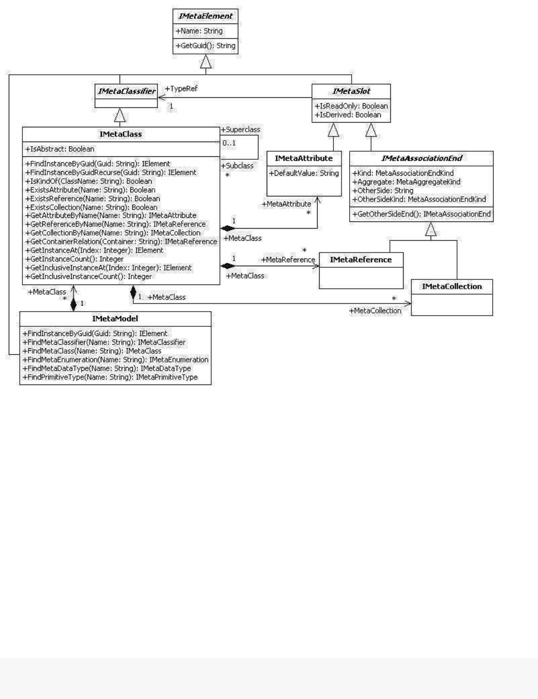
StarUML5.0DeveloperGuide(UsingOpenAPI)
http://staruml.sourceforge.net/docs/developer-guide(en)/ch04.html
Elements::Metamodeling Elements
package of
StarUML Application Model
for the complete diagram.
StarUML™ meta-model comprises the relatively small number of meta-model elements as shown in the diagram.
IMetaElement is the top-level element of meta-model elements and has attributes of Name and GUID
. Since
modeling elements are instances of a meta-model element (specifically, IMetaClass), the Name
attribute value of
IMetaElement
should be one of the modeling elements' names described in
"Chapter 5. Modeling Element
Management". Examples are "Model", "View", "UMLClass", and "UMLAttribute".
The top-level IMetaElement has meta-model elements like IMetaClassifier and IMetaSlot. IMetaClassifier is a
meta-element for the definition of modeling elements themselves, and IMetaSlot is for the definition of modeling
element attributes and reference attributes. Also, concrete elements like IMetaClass, IMetaAttribute,
IMetaReference, IMetaCollection, and IMetaModel are derived from IMetaClassifier and IMetaSlot; they play the
most important roles in the StarUML™ meta-model architecture.
Meta-Model Element Management
IMetaModel
IMetaModel
element maintains and manages meta-model elements as a collection and provides use of other meta-model
elements. Only one IMetaModel
exists in one StarUML™ application. Reference to the object can be obtained through the IStarUMLApplication
interface.
varapp=newActiveXObject("StarUML.StarUMLApplication");
varmeta=app.MetaModel;
It has been mentioned that
IMetaModel

StarUML5.0DeveloperGuide(UsingOpenAPI)
http://staruml.sourceforge.net/docs/developer-guide(en)/ch04.html
It has been mentioned that
IMetaModel
element provides use of other meta-model elements. The following exam
ple shows obtaining reference to
IMetaClass
meta-elements by using
IMetaModel. It will be explained again in the IMetaClass
element section
that the number of references to IMetaClass
types and the number of modeling elements are the same (check with th
e following example).
varapp=newActiveXObject("StarUML.StarUMLApplication");
varmeta=app.MetaModel;
for(vari=0;i<meta.GetMetaClassCount();i++){
varmetaClass=meta.GetMetaClassAt(i);
...
}
Although omitted in the class diagram above, there are IMetaEnumeration,
IMetaDataType
, and
IMetaPrimitiveType meta-model elements in similar relationships with IMetaClass, and the IMetaModel interface
provides reference to these elements. The IMetaEnumeration element is a meta-element for defining
enumeration type related to modeling elements. UMLVisibilityKind and UMLAggregationKind
are examples of
IMetaEnumeration element instances. IMetaDataType is a meta-element for defining data type other than
enumeration and primitive type. Points type is the only instance of this. And IMetaPrimitiveType element is a
meta-element for defining primitive types, which are Integer
,
Real, Boolean, and String.
The IMetaModel
interface provides a find method for meta-elements. The following example is a section of the first example in this
chapter. It shows the obtaining of reference to IMetaClass elements for the UMLClass modeling element using the
IMetaModel.FindMetaClass
method (the number of references to IMetaClass types is same as the number of the modeling elements).
varapp=newActiveXObject("StarUML.StarUMLApplication");
varmeta=app.MetaModel;
varmetaClass=meta.FindMetaClass("UMLClass");
...
Like the IMetaClass, the IMetaModel interface provides a find method to other meta-elements like
FindMetaClassifier, FindMetaEnumeration,
FindMetaDataType
, and FindPrimitiveType
.
The IMetaModel interface is a GUID for modeling elements and provides the FindInstanceByGuid method that
acquires reference to respective modeling elements. The FindInstanceByGuid method returns the IElement type
reference. The following code can be used as an extension of the exam
ple above.
...
varguid=...
varelem=meta.FindInstanceByGuid(guid);
...
IMetaClass
The IMetaClass
element is a meta-element that provides definition for each modeling element, and maintains and manages
instances of each modeling element as a collection. In the StarUML™ application, the number of IMetaClass
elements is the same as the number of modeling elements. The following code shows obtaining IMetaClass type
reference for each modeling element using the IMetaModel.FindMetaClass method.
varapp=newActiveXObject("StarUML.StarUMLApplication");
varmeta=app.MetaModel;
varmetaClassOfPackage=meta.FindMetaClass("UMLPackage");
varmetaClassOfClass=meta.FindMetaClass("UMLClass");
varmetaClassOfAttribute=meta.FindMetaClass("UMLAttribute");
...

StarUML5.0DeveloperGuide(UsingOpenAPI)
http://staruml.sourceforge.net/docs/developer-guide(en)/ch04.html
Another way to obtain reference to the
IMetaClass
type elements is to use the GetMetaClass method of the IElement interface, which is the top-level type of modeling
element.
elem=...//Getreferencetomodelingelements.
varmetaClass=elem.GetMetaClass();
The
IMetaClass
interface provides methods to obtain superclasses and subclasses in the inheritance structure of each modeling
element. The superclass of the IElement type element—which is the top
-level modeling element—is null.
varmetaClass=...//GetIMetaClasstypereference.
varsuperCls=metaClass.Superclass;
...
for(vari=0;i<metaClass.GetSubclassCount();i++){
varsubCls=metaClass.GetSubclassAt(i);
...
}
The IMetaClass interface is a GUID for modeling elements and provides the FindInstanceByGuid method, which
is similar to IMetaModel.FindInstanceByGuid, to obtain reference to respective modeling elements.
IMetaClass's
method is more efficient than IMetaModel's method since it searches f
or modeling elements of specific types only. If
no matching result is found in the respective type, FindInstanceByGuidRecurse can be used to search all
derivative modeling elements as well.
The first example in this section illustrated searching for instances of a specific modeling element using the
GetInstanceCount and GetInstanceAt methods of the IMetaClass interface. Instances of modeling elements
refer to user-created elements.
varmetaClass=...//GetIMetaClasstypereference.
for(vari=0;i<metaClass.GetInstanceCount();i++){
varAElem=metaClass.GetInstanceAt(i);
...
}
IMetaAttribute
The
IMetaAttribute
interface can be used to read the specifications for attributes of ea
ch modeling element. Reference to
IMetaAttribute can be obtained through the IMetaClass
interface as shown below. The
IMetaClass
interface also
provides the ExistsAttribute method that checks for the existence of an attribute with a specific
name, and the
GetAttributeByName
method that returns
IMetaAttribute type elements of a specific name.
varapp=newActiveXObject("StarUML.StarUMLApplication");
varmetaClass=app.MetaModel.FindMetaClass("UMLClass");
for(vari=0;i<metaClass.GetMetaAttributeCount();i++){
varmetaAttr=metaClass.GetMetaAttributeAt(i);
...
}
The following example shows reading the specifications for attributes
of modeling elements.
varmetaAttr=...//GetIMetaAttributetypereference.
varmetaType=metaAttr.TypeRef;
varattrName=metaAttr.Name;
varattrType=metaType.Name;
StarUML5.0DeveloperGuide(UsingOpenAPI)
http://staruml.sourceforge.net/docs/developer-guide(en)/ch04.html
varattrType=metaType.Name;
...
Also, IMetaSlot, the upper-level interface for
IMetaAttribute
, provides the
IsReadOnly and
IsDerived
properties. IsReadOnly indicates whether the respective attribute is read-only, and IsDerived
indicates whether
the respective attribute actually does not exist but is resembled by other attributes.
IMetaReference and IMetaCollection
The IMetaReference and IMetaCollection
elements define the reference attributes that specify references between different modeling elements. These
references all express associations. While
IMetaReference
shows references with multiplicity of '1' or less,
IMetaCollection
shows references that have to be expressed as collections. This is the only difference between the
IMetaReference
and IMetaCollection
interfaces (
IMetaReference and IMetaCollection
are both derived from the
IMetaAssociationEnd interface).
First, let us look at an example of obtaining reference to
IMetaReference and IMetaCollection
objects. Just like
IMetaAttribute
, the
IMetaClass interface can be used.
varmetaClass=...//GetIMetaClasstypereferenceforaspecificmodelingelement.
//GetreferencestoIMetaReferencetypeobjects.
for(vari=0;i<metaClass.GetMetaReferenceCount();i++){
varmetaAttr=metaClass.GetMetaReferenceAt(i);
...
}
//GetreferencestoIMetaCollectiontypeobjects.
for(vari=0;i<metaClass.GetMetaCollectionCount();i++){
varmetaAttr=metaClass.GetMetaCollectionAt(i);
...
}
The IMetaAssociationEnd
interface, the shared upper-level type for
IMetaReference and IMetaCollection
,
provides properties and methods for defining specifications of reference attributes (associations) for the respective
modeling element.
The Kind
property simply determines whether the respective association is a simple reference type or a collection reference
type. The
IMetaReference
type is a simple reference type and the IMetaCollection type is a collection reference
type. The Aggregate
property shows the
AggregationKind attribute of the respective association. This value is an
enumerative type and can be one of the following values:
makNone (0): None
makAggregate (1): Aggregation association, or
makComposite (2): Composition association.
The OtherSide property shows the name of the
AssociationEnd
on the other side of the association, and the
OtherSideKind property shows whether the AssociationEnd
on the other side is a simple reference type or a
collection reference type.
The GetOtherSideEnd method returns the
IMetaAssociationEnd
type reference at the
AssociationEnd
on the
other side of the association. The following example shows how to use
the properties and methods provided by the
IMetaAssociationEnd interface that is the shared upper-level type of IMetaReference and IMetaCollection
.
varmetaSlot=...//GetIMetaReferenceorIMetaCollectiontypereference.
varkind=metaSlot.Kind;
varaggregate=metaSlot.Aggregate;
varotherSide=metaSlot.OtherSide;
varotherSideKind=metaSlot.OtherSideKind;
varotherSideEnd=metaSlot.GetOtherSideEnd();

StarUML5.0DeveloperGuide(UsingOpenAPI)
http://staruml.sourceforge.net/docs/developer-guide(en)/ch04.html
varotherSideEnd=metaSlot.GetOtherSideEnd();
...
The
TypeRef
reference attribute of the IMetaSlot interface can be used to find out the IMetaClass
element for an
IMetaReference
or
IMetaCollection
type object. The following example shows how to read the element on the opposite side of the association for a
modeling element.
varmetaSlot=...//GetIMetaReferenceorIMetaCollectiontypereference.
varotherSideEnd=metaSlot.GetOtherSideEnd();
varotherSideMetaClass=otherSideEnd.TypeRef;
...
StarUML5.0DeveloperGuide(WritingApproaches)
http://staruml.sourceforge.net/docs/developer-guide(en)/ch05.html
Chapter 5. Writing Approaches
Basic Concept of Approach
There are countless methodologies for software development, and each
company or organization has its own, or
uses an existing one that is modified to meet the requirements of its development team or projects. Application
domains, programming languages, and platforms are also different for each piece of software developed.
Consequently, many items have to be configured in the initial phase of software modeling. Approaches to facilitate
this initial configuration of the environment for a project depend on
the software development methodology or
platform requirements. Users can specify appropriate approaches in order to create projects in certain forms.
Approaches perform the following tasks in creating projects.
Approaches configure profiles for use in projects. The profiles defined in approaches are automatically included
in projects when the projects are being created.
Approaches determine the package structures. The package structures are usually dependent on the software
development process models. For example, using the 4+1 View Model App
roach selects the five packages
"Logical View", "Physical View", "Process View", "Development View" and "Use Case View".
Approaches configure frameworks to reference. For projects that are dependent on specific programming
languages or platforms, the respective frameworks can be specified in the approaches to be loaded when
creating projects. For example, if the current project is developed i
n Java, the JFC (Java Foundation Classes)
framework can be specified in the approach, so that it is included in the project as a package for direct
reference.
Approaches import model fragments to include basically.
Follow the steps below to create a new approach.
Create an approach document file (.apr) to define the new approach.1.
Copy the approach document file (.apr) to subdirectory of module directory.2.
Creating New Approach
Basic Structure of Approach Document File
Approach document files are created according to XML document conventions, and the extension name is .apr
(approach file). The approach contents are contained within the APPROACH element, and there must not be any
errors in syntax or contents.
<?xmlversion=”1.0”encoding=”
...”?>
<APPROACHversion="...
">
<HEADER>
...
</HEADER>
<BODY>
...
</BODY>
</APPROACH>
encoding property: Specifies the encoding property value for the XML
document (e.g. UTF-8, EUC-KR). For
details on this property value, see XML-related resources.
version property (APPROACH element): Version information for the approach document format (e.g. 1.0).
HEADER element: See the
Header Contents
section.
BODY element: See the
Body Contents
section.
Header Contents
The HEADER section of an approach document contains general informati
on for the approach such as the approach
StarUML5.0DeveloperGuide(WritingApproaches)
http://staruml.sourceforge.net/docs/developer-guide(en)/ch05.html
The HEADER section of an approach document contains general informati
on for the approach such as the approach
name and description.
<HEADER>
<NAME>...</NAME>
<DISPLAYNAME>...</DISPLAYNAME>
<DESCRIPTION>...</DESCRIPTION>
</HEADER>
NAME element: Contains the name of the approach. It is a unique name to identify the approach from the
others.
DISPLAYNAME element: Contains the name of the approach that is shown to users in New Project dialog.
DESCRIPTION element: Contains detailed description of the approach.
Body Contents
The BODY section of an approach document largely consists of the IMPORTPROFILES element and the
MODELSTRUCTURE
element. The IMPORTPROFILES element specifies the name of the profile to load when creating projects, and the
MODELSTRUCTURE element contains information for the initial project model structure and the framework to load.
<BODY>
<IMPORTPROFILES>
<PROFILE>...
</PROFILE>
...
</IMPORTPROFILES>
<MODELSTRUCTURE>
...
</MODELSTRUCTURE>
</BODY>
IMPORTPROFILES element: Lists the profiles to include in projects using multiple PROFILE elements.
PROFILE element: Contains the name of a profile to include in projects.
MODELSTRUCTURE element: See the
Model Structure
section.
Model Structure
The MODELSTRUCTURE element expresses the initial package structure for projects. Model, SubSystem, Package
and Frameworks are hierarchically organized. For instance, model, subsystem, package or framework elements can
further be defined under the SUBSYSTEM element. While a framework is a package element by itself, it cannot
contain other package elements.
The following shows the syntax structure for a MODELSTRUCTURE element.
<MODELSTRUCTURE>
model_expression*
</MODELSTRUCTURE>
model_expression::=model_element
|package_element
|subsystem_element
|import_framework
|import_model_fragment.
model_element::=<MODELname=”...
”stereotypeProfile=”
...”stereotypeName=”...
”>model_expression<
package_element::=<PACKAGEname=”...”stereotypeProfile=”
...
”stereotypeName=”
...
”>model_express
subsystem_element::=<SUBSYSTEMname=”...”stereotypeProfile=”...”stereotypeName=”...
”>model_exp
import_framework::=<IMPORTFRAMEWORKname=”...”/>.
import_model_fragment::=<IMPORTMODELFRAGMENTfileName=”...”/>.
name property (MODEL, PACKAGE, SUBSYSTEM elements): The name of each
UML model element.
StarUML5.0DeveloperGuide(WritingApproaches)
http://staruml.sourceforge.net/docs/developer-guide(en)/ch05.html
name property (MODEL, PACKAGE, SUBSYSTEM elements): The name of each
UML model element.
stereotypeProfile property (MODEL, PACKAGE, SUBSYSTEM elements): The name of profile that defines the
stereotype applying to the model element.
stereotypeName property (MODEL, PACKAGE, SUBSYSTEM elements): The name of stereotype that apply to
the model element.
name property (IMPORTFRAMEWORK element): The name of the registered framework to include.
fileName property (IMPORTMODELFRAGMENT element): The file name of model fragment to import to parent
model element.
Approach Document Example
The following is an example of an approach for a 4+1 View Model.
<?xmlversion=”1.0”encoding=”UTF-8”?>
<APPROACHversion="1">
<HEADER>
<TITLE>4+1ViewModel</TITLE>
<DESCRIPTION>Thisisanapproachtosupport4+1ViewModelin.NETplatform.</DESCRIPTION>
</HEADER>
<BODY>
<IMPORTPROFILES>
<PROFILE>4+1Profile</PROFILE>
<PROFILE>CSharpProfile</PROFILE>
</IMPORTPROFILES>
<MODELSTRUCTURE>
<MODELname=”UseCaseView”/>
<MODELname=”LogicalView”>
<IMPORTFRAMEWORKname=”dot_net_framework”/>
</MODEL>
<MODELname=”DevelopmentView”/>
<MODELname=”ProcessView”/>
<MODELname=”DeploymentView”/>
</MODELSTRUCTURE>
</BODY>
</APPROACH>
Registering New Approach
To make an approach to be recognized automatically by StarUML, must place it in the subdirectory of StarUML
module directory(<install-dir>\modules). StarUML searches and reads all approaches in the module directory and
registers them at the program automatically when StarUML is initializing. If approach file is invalid or it's extension
file name is not .apr, StarUML will not read the approach and ignore it. It is recommended that make a subdirectory
in the StarUML module directory and place the approach in there to avoid modules being out of order .
Note:
To register approach icon, Make icon file for the approach and place it in the directory of the approach. Icon of the
approach is displayed with the name at approaches list in the New Project dialog. If there is no icon file which name
is same of the approach's, default icon is registered as icon of the approach.
Note:
Delete files of the approach from the StarUML module directory(<install-dir>\modules) not to use the
approach any more.
Using Approach-Related Methods
Reading Information for Approaches Installed in the
System
Since approaches are for initial project configurations, they usually do not need to be accessed by programs
directly. Therefore, StarUML™ does not support COM automation objects for managing approaches. Nevertheless,
the GetAvailableApproachCount() and GetAvailableApporachAt() of
IProjectManager
can be used to obtain
the count and names of the approaches installed in the system.

StarUML5.0DeveloperGuide(WritingApproaches)
http://staruml.sourceforge.net/docs/developer-guide(en)/ch05.html
IProjectManager.GetAvailableApproachAt(Index:Integer):String
IProjectManager.GetAvailableApproachCount():Integer
Creating Project with Approach
A new project can be created with a given approach by calling IProjectManager.NewProjectByApproach(). The
ApproachName entered as a parameter must be the name of one of the ap
proaches installed in the system.
Otherwise, this will result in an empty project. The expression for NewProjectByApproach()
in
IProjectManager
is as follows.
IProjectManager.NewProjectByApproach(ApproachName:String)
The following is a Jscript example for creating a new project with th
e "UMLComponents" approach.
varapp=newActiveXObject("StarUML.StarUMLApplication");
varprjMgr=app.ProjectManager;
prjMgr.NewProjectByApproach("UMLComponents");
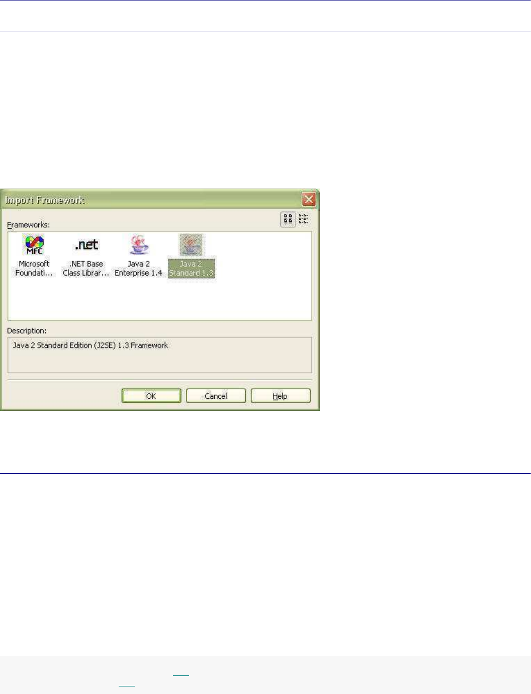
StarUML5.0DeveloperGuide(WritingFrameworks)
http://staruml.sourceforge.net/docs/developer-guide(en)/ch06.html
Chapter 6. Writing Frameworks
Basic Concepts of Model Framework
A model framework enables use of application frameworks or class libraries in StarUML™. For instance, JFC (Java
Foundation Classes), MFC (Microsoft Foundation Classes), and VCL (Vis
ual Component Library) can be the objects
for a model framework. As will be described later in this chapter, the user can define his or her own model
framework as well. The biggest advantage of using model frameworks is
that it facilitates shared use and reuse of
the common and basic modeling elements and structures.
The "Import Model Framework" dialog (illustration below), accessible through the
[File]-[Import]-[Framework…]
menu in the StarUML™ application, displays a list of the model frameworks installed in the system. Selecting an
item from the list and running it results in automatic inclusion of t
he modeling structure defined by the model
framework in the path specified. A model framework consists of many unit files, and the model frameworks included
in StarUML™ are treated in the same way as the units.
The list of the model frameworks installed in the system can be obtained, or specific model frameworks can be
included in projects, by using StarUML™'s external API as illustrated above. Details on this will be discussed later.
Creating New Model Framework
A model framework consists of many unit files (.unt) and one model framework definition document file (.frw), and
it may have an optional icon file (.ico). Follow the steps below to define a new model framework.
Create unit files that contain model information for the model framew
ork (see
"Chapter 4. Using Open
API").
1.
Create a model framework document file (.frw) that defines the model framework.2.
Copy unit files, model framework document file and icon file to subdirectory of module directory.3.
Basic Structure of Model Framework Document File
Model framework document files are created according to XML document
conventions, and the extension name
is.frw (Framework File). Information for a model framework is contained within the FRAMEWORK
tag, and there
must not be any errors in syntax or contents.
<?xmlversion="1.0"encoding="
..."?>
<FRAMEWORKversion="
...
">
<HEADER>
StarUML5.0DeveloperGuide(WritingFrameworks)
http://staruml.sourceforge.net/docs/developer-guide(en)/ch06.html
<HEADER>
...
</HEADER>
<BODY>
...
</BODY>
</FRAMEWORK>
encoding property: Specifies the encoding property value for the XML document (e.g. UTF-8, EUC-KR). For
details on this property value, see XML-related resources.
version property (FRAMEWORK element): Version information for the fra
mework document format (e.g. 1.0).
HEADER element: See the
Header Contents
section.
BODY element: See the
Body Contents
section.
Header Contents
The HEADER section contains general information for the model framework such as the model framework name and
description.
<HEADER>
<NAME>
...
</NAME>
<DISPLAYNAME>
...
</DISPLAYNAME>
<DESCRIPTION>
...
</DESCRIPTION>
</HEADER>
Name element: Contains the name of the model framework. This acts as the unique ID for the model
framework and must be identical with the name of the registry registr
ation key.
DISPLAYNAME element: Contains the display name used in the "Import Mo
del Framework" dialog, etc.
DESCRIPTION element: Contains description for the model framework.
Body Contents
The BODY section contains actual information for the model framework
and largely consists of the
IMPORTPROFILES section and the FRAMEWORKMODELS
section.
<BODY>
<IMPORTPROFILES>
<PROFILE>
...
</PROFILE>
...
</IMPORTPROFILES>
<FRAMEWORKMODELS>
<UNIT>...</UNIT>
...
</FRAMEWORKMODELS>
</BODY>
IMPORTPROFILES element: Lists the UML profiles to load when the model
framework is included.
PROFILE element: Specifies the name of each UML profile to load.
FRAMEWORKMODELS element: Lists the unit files that constitute the mod
el framework.
UNIT element: Specifies the name of each unit file. Only file names are specified, without the path names.
The unit files that constitute a model framework must be located unde
r the same path as the model
framework document file.
Note:
The "UNIT element" specifies only those unit files that belong to the top-level units. As discussed in "Chapter 4.
Using Open API", when a unit contains lower-level units, all the lower-level units are loaded together when the
upper-level unit is loaded.

StarUML5.0DeveloperGuide(WritingFrameworks)
http://staruml.sourceforge.net/docs/developer-guide(en)/ch06.html
Model Framework Document Example
The following is an example of a model framework document that defines the Java 2 Standard Edition (J2SE) 1.3
model framework.
<?xmlversion="1.0"encoding="UTF-8"?>
<FRAMEWORKversion="1.0">
<HEADER>
<NAME>J2SE1.3</NAME>
<DISPLAYNAME>Java2Standard1.3</DISPLAYNAME>
<DESCRIPTION>Java2StandardEdition(J2SE)1.3Framework.</DESCRIPTION>
</HEADER>
<BODY>
<FRAMEWORKMODELS>
<UNIT>J2SE13(java).pux</UNIT>
<UNIT>J2SE13(javax).pux</UNIT>
<UNIT>J2SE13(org).pux</UNIT>
</FRAMEWORKMODELS>
</BODY>
</FRAMEWORK>
Registering New Model Framework
To make a framework to be recognized automatically by StarUML, must place it in the subdirectory of StarUML
module directory(<install-dir>\modules). StarUML searches and reads a
ll frameworks in the module directory and
registers them at the program automatically when StarUML is initializing. If framework file is invalid or it's
extension file name is not .frw, StarUML will not read the framework
and ignore it. It is recommended that make a
subdirectory in the StarUML module directory and place the framework
in there to avoid modules being out of
order.
Note:
To register framewordk icon, Make icon file for the framework and pla
ce it in the directory of the framework. Icon of
the framework is displayed with the name at frameworks list in the [Import Framework] dialog. If there is no
icon file which name is same of the framework's, default icon is registered as icon of the framework.
Note:
Delete files of the framework from the StarUML module directory(<install-dir>\modules) not to use the
framework any more.
Using Model Framework-Related Methods
Reading Information for Model Frameworks Installed i
n the System
The list of the model frameworks installed in the system can be viewed through external API. The external APIs for
this are the GetAvailableFrameworkCount method and the GetAvailableFrameworkAt method of the
IProjectManager
interface. The following are the expressions of these two methods.
IProjectManager.GetAvailableFrameworkAt(Index:Integer):String
IProjectManager.GetAvailableFrameworkCount():Integer
Importing Model Framework
The IProjectManager.ImportFramework
method can be used to include a registered model framework in the current project. The method expression is as
follows. The
OwnerPackage
argument specifies the upper-level model element where the model framework will be included. This must be an
IUMLPackage
type model element. And the
FrameworkName
argument is the name of the model framework to
load. This is a string value for the accurate name (ID) of the model framework.
IProjectManager.ImportFramework(OwnerPackage:IUMLPackage;FrameworkName:String)
StarUML5.0DeveloperGuide(WritingFrameworks)
http://staruml.sourceforge.net/docs/developer-guide(en)/ch06.html
The following example shows importing the "J2SE1.3" model framework using the
IProjectManager.ImportFramework method.
varapp=newActiveXObject("StarUML.StarUMLApplication");
varprjMgr=app.ProjectManager;
varowner=...//GetreferencetoIUMLPackagetypeelement.
prjMgr.ImportFramework(owner,"J2SE1.3");
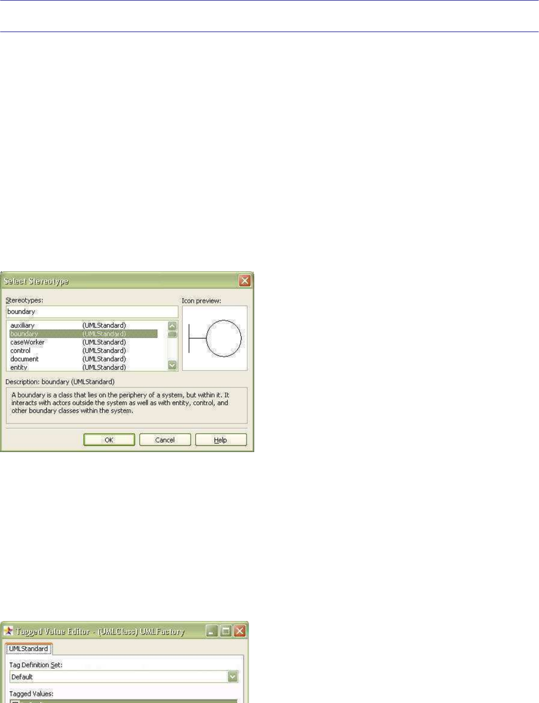
StarUML5.0DeveloperGuide(WritingUMLProfiles)
http://staruml.sourceforge.net/docs/developer-guide(en)/ch07.html
Chapter 7. Writing UML Profiles
Basic Concept of UML Profile
UML Extension Mechanisms
UML is a universal software modeling language that provides an abundance of well-defined modeling concepts and
notations to meet all the requirements of general software modeling. Nevertheless, the software
modeling/development environment today can take many different forms, and there may be requirements for
elements or semantics that do not exist in the UML standard. By default, UML provides concepts for supporting such
requirements, and they are called the UML Extension Mechanisms.
UML Extension Mechanisms use
Stereotypes,
Constraints
,
Tag Definitions
,
and Tagged Values
to extend the
semantics of UML modeling elements or define the UML modeling elements with new semantics.
Stereotype
A stereotype is a modeling element that has definitions for adding new properties and constraints to the standard
UML modeling elements. A stereotype can also have definitions to provide new notations for modeling elements. The
illustration below is the stereotype selection dialog that appears when clicking on the stereotype selection button in
the StarUML™ application. The stereotype selection dialog displays a list of the selectable stereotypes defined in the
UML profile that is included in the current project. Stereotypes can also be configured or modified through external
API. Details on this will be described later.
Note:
Although the UML standard allows each extensible modeling element to have multiple stereotypes, StarUML™ limits
each modeling element to only one stereotype.
Tag Definitions
Tag definition is an element that defines new properties that can be added to certain modeling elements. And
definitions of the values of the properties added to elements by tag
definitions are called Tagged Values. A tagged
value can be a basic datatype value, a reference to other modeling el
ements, or a collection. The following
illustration is the extension property editor screen in the StarUML™
application. The extension property editor
displays a list of the tag definition items that belong to the selected modeling element as defined by the UML profile.
Tagged values of modeling elements can also be configured or modified through external API. Details on this will be
described later.
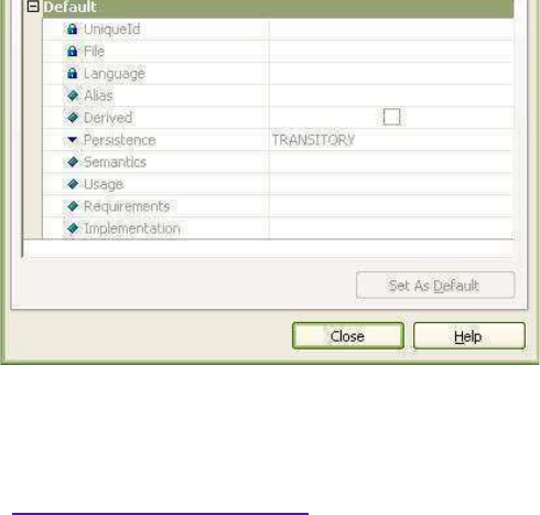
StarUML5.0DeveloperGuide(WritingUMLProfiles)
http://staruml.sourceforge.net/docs/developer-guide(en)/ch07.html
Constraints
A constraint adds a specific constraint to a certain modeling element
to allow redefinition of the semantics for the
selected modeling element. For descriptions of constraints, please refer to the section
"ExtCore Elements"
in
"
Chapter 4. Using Open API".
Note:
StarUML™ UML profile excludes definitions of constraints.
UML Profile
UML profile is a package of UML extension mechanisms. In other words,
it is a collection of stereotypes, constraints,
tag definitions, and data types that are required for a certain software domain or development platform.
A UML profile consists of Stereotype, Constraint, Tag Definition, and Data Type
elements. Although the UML
standard requires a profile to be defined as a package element with the "<<profile>>" stereotype, StarUML™
allows it to be defined as an XML formatted file for easier use.
Additional Extension Mechanism in the StarUML
StarUML profile supports a few of additional extension mechanism with
predefined in UML. They are the
Diagram
Type, Element Prototype
,
Model Prototype
,
Palette Extension
. These extension mechanism extend semantics
of the existing elements or provide regular methods for creating the element and apply it to user interface.
Diagram Type
Diagram Type is extension element to define new diagram that has additional semantics based on UML standard
diagram. It is useful to define specialized diagram in each phase of design that is data model diagram, robustness
analysis diagram, and so on or to apply many kind of diagrams used in various domains to StarUML. Diagram type
name is assigned as the "DiagramType" property of the diagram. "Diagr
amType" property can't be changed as
opposed to stereotype. When profile is included in project, it is add
ed in the
[Add Diagram]
menu and let user be
able to create a diagram as the diagram type.
Element Prototype
Element prototype defines a sample for element creating which propert
ies are preset. User can create an element
with copy of sample by registering element prototype in the palette or using external API.
Model Prototype
Model prototype only can be applied to model even if it is similar to element prototype. It is inserted in the [Add
Model]
as submenu on element prototype in palette. A model element that is copy of the sample can be created by the
menu.
Palette Extension
Palette extension allows to insert additional palette that appears in the left of main form. Added palette can
designate element prototypes or UML standard elements defined in the
profile as palette items.
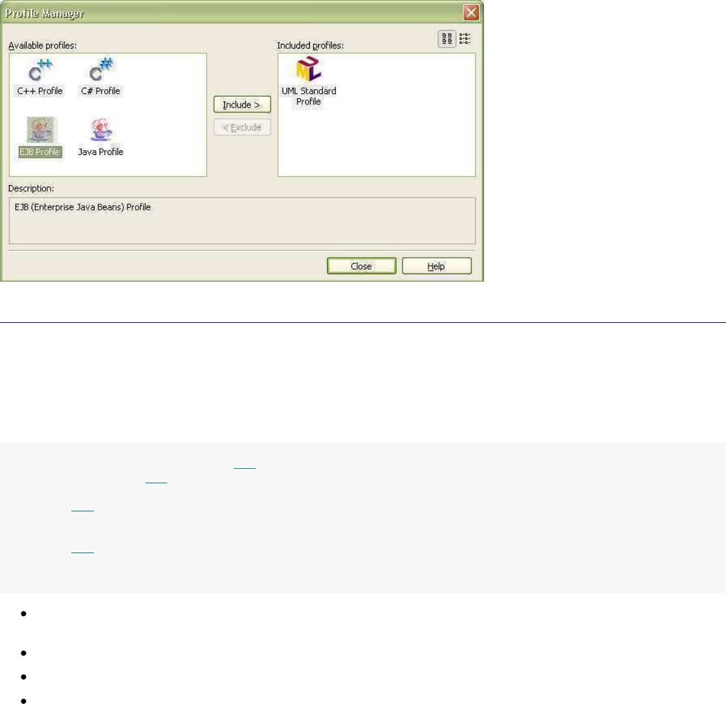
StarUML5.0DeveloperGuide(WritingUMLProfiles)
http://staruml.sourceforge.net/docs/developer-guide(en)/ch07.html
Profile Includes and Excludes
If a UML profile is required for the current project in the StarUML™ application, the profile must be added to the
project. This is because no profiles other than "UML Standard Profile" are added automatically. To add profiles in
the StarUML™ application, use the profile dialog (illustrated below) that can be executed by clicking the [Model] ->
[Profiles…]
menu. The
"Available Profiles" list on the left shows the list of the profiles currently registered in the
user system, and the
"Included Profiles"
list on the right shows the list of the profiles included in the current project. Adding a profile can be done simply by
selecting a profile from the "Available Profiles" list, and clicking the "Include" button in the center. Once a profile is
added, the stereotypes and tag definitions defined in the new profile are added to the stereotype selection dialog
and extension property editor as shown above. If a profile is no long
er required in the current project, simply click
the "Exclude" button to remove it from the project. Care should be ta
ken, since excluding a profile results in the
removal of all information referenced by the profile in the project.
Profiles can also be included or excluded through
external API. Details on this will be described later.
Creating UML Profile
Basic Structure of Profile Document File
A profile document file is defined in the XML format, and the extensi
on name is .prf (PLASTIC Profile File). The
contents of the profile are enclosed by the
PROFILE tag. There must not be any errors in syntax or contents.
The basic profile document structure is as follows.
<?xmlversion=”1.0”encoding=”
...”?>
<PROFILEversion="...">
<HEADER>
...
</HEADER>
<BODY>
...
</BODY>
</PROFILE>
encoding property: Defines value for encoding the property of the XML
document (e.g. UTF-8, EUC-KR). For
details on this value, see XML reference resources.
version property (PROFILE element): This is the version of the PRF document (e.g. 1.0).
HEADER element: See the
Header Contents
section.
BODY element: See the
Body Contents
section.
Header Contents
StarUML5.0DeveloperGuide(WritingUMLProfiles)
http://staruml.sourceforge.net/docs/developer-guide(en)/ch07.html
The HEADER section of a profile document contains general information for the profile, such as the profile name and
description.
<HEADER>
<NAME>
...
</NAME>
<DISPLAYNAME>
...
</DISPLAYNAME>
<DESCRIPTION>
...
</DESCRIPTION>
<AUTOINCLUDE>
...
</AUTOINCLUDE>
</HEADER>
NAME element: Contains the profile name. This acts as the profile ID.
DISPLAYNAME element: This is the caption name used in the profile dialog and other user interfaces.
DESCRIPTION element: Contains the description of the profile.
AUTOINCLUDE element: Specifies whether includes the profile automatic
ally when creates new project.
Body Contents
The BODY section of a profile document contains the actual contents of the profile. This section can contain
information for Stereotypes, Datatypes, TagDefinitionSets, and addtional extension elements.
<BODY>
<STEREOTYPELIST>
...
</STEREOTYPELIST>
<TAGDEFINITIONSETLIST>
...
</TAGDEFINITIONSETLIST>
<DATATYPELIST>
...
</DATATYPELIST>
<ELEMENTPROTOTYPELIST>
...
</ELEMENTPROTOTYPELIST>
<MODELPROTOTYPELIST>
...
</MODELPROTOTYPELIST>
<PALETTELIST>
...
</PALETTELIST>
<DIAGRAMTYPELIST>
...
</DIAGRAMTYPELIST>
</BODY>
STEREOTYPELIST element: Defines multiple stereotypes (STEREOTYPE elements). For definition of stereotypes,
see the Stereotype
section.
TAGDEFINITIONSETLIST element: Defines multiple tag definition sets (T
AGDEFINITIONSET elements). For
definition of tag definition sets, see the TagDefinitionSet
section.
DATATYPELIST element: Defines multiple data types (DATATYPE elements). For definition of data types, see
the DataType
section.
ELEMENTPROTOTYPELIST element: Defines multiple element prototypes (EL
EMENTPROTOTYPE elements). For
definition of element prototypes, see the ElementPrototype
section.
MODELPROTOTYPELIST element: Defines multiple model prototypes (MODELPROTOTYPE elements). For
definition of model prototypes, see the ModelPrototype
section.
PALETTELIST element: Defines multiple palette extensions (PALETTE ele
ments). For definition of palette
extension, see
Palette
section.
DIAGRAMTYPELIST element: Defines multiple diagram types (DIAGRAMTYPE
elements). For definition of
diagram type, see DiagramType
section.
StarUML5.0DeveloperGuide(WritingUMLProfiles)
http://staruml.sourceforge.net/docs/developer-guide(en)/ch07.html
Stereotype
The STEREOTYPE element defines information for stereotype and the inheritance structure.
<STEREOTYPE>
<NAME>
...
</NAME>
<DESCRIPTION>
...
</DESCRIPTION>
<BASECLASSES>
<BASECLASS>
...
</BASECLASS>
...
</BASECLASSES>
<PARENT>
...
</PARENT>
<RELATEDTAGDEFINITIONSET>...</RELATEDTAGDEFINITIONSET>
<ICONminWidth=”
...”minHeight=”
...
”>
...
</ICON>
<NOTATION>...</NOTATION>
</STEREOTYPE>
NAME element: Contains the name of the stereotype. This has to be a unique value within the profile.
DESCRIPTION element: Contains the description for the stereotype.
BASECLASSES element: May contain names of multiple UML modeling eleme
nts that can be applied with the
stereotype. The names of the elements used here are the names of the UML elements (e.g., UMLClass,
UMLClassifier, UMLAttribute, UMLPackage, ...).
Note: If the name of an abstract class like UMLClassifier is used, all the elements inherited from it are
applied. If the upper-level stereotype (PARENT element) is defined, this section is not defined; any definition in
this section is ignored and the BASECLASSES value of the upper-level stereotype is applied.
PARENT element: Stereotypes can have inheritance relationships. The P
ARENT element contains the name of
the upper-level stereotype. Stereotypes in an inheritance relationship must be defined within the same profile.
This can be left undefined or omitted if there is no upper-level stereotype.
RELATEDTAGDEFINITIONSET element: Contains the name of the TagDefinitionSet related to the stereotype.
This can be interpreted as a set of additional properties provided by
the stereotype to the elements, may be
omitted if there is none. The tag definition set defined here must also be defined within the same profile.
ICON element: A stereotype can also be indicated by an icon, dependin
g on user selection. This element
contains the name of the icon file for the stereotype. Stereotype icon files can be .WMF, .EMF or .BMP files.
Icon files must be located in the same directory as the profile document. The profile document contains the
icon file names without the path names.
minWidth property (ICON element): Defines the minimum width of the stereotype icon.
minHeight property (ICON element): Defines the minimum height of the stereotype icon.
NOTATION element: Stereotype can not be displayed by iconic style but also redefine drawing method by using
notation description language. This element contains the name of the
notation extension file(.nxt) to define the
notation. The element with notation extension will draw as described by notation extension file not to draw as
UML standard. Notation extension file must be placed in the directory
of profile document. It must be specified
only the file name except directory path in this element.
TagDefinitionSet
TAGDEFINITIONSET , TADDEFINITIONLIST
TAGDEFINITION .
The TAGDEFINITIONSET element contains basic information on tag defini
tion set, and includes multiple
TAGDEFINITION elements under the TADDEFINITIONLIST element to list tag definitions included in the tag
definition set.
<TAGDEFINITIONSET>
<NAME>
...
</NAME>
<BASECLASSES>
<BASECLASS>
...
</BASECLASS>
...
</BASECLASSES>
<TAGDEFINITIONLIST>
StarUML5.0DeveloperGuide(WritingUMLProfiles)
http://staruml.sourceforge.net/docs/developer-guide(en)/ch07.html
<TAGDEFINITIONLIST>
...
</TAGDEFINITIONLIST>
</TAGDEFINITIONSET>
NAME element: Contains the name of the tag definition set. If the tag
definitions concern a specific stereotype,
using the name of the stereotype is recommended (in this case, if a tag definition set of the same name as a
stereotype exists, it will be displayed first in the user interface).
BASECLASSES element: Contains the names of the UML elements to apply the tag definition set (applied in the
same way as the BASECLASSES element of the STEREOTYPE). If the tag de
finition set is defined as related to a
specific stereotype, this element is not defined; any definition in t
his element is ignored and is recognized as
BASECLASSES of the respective stereotype.
TAGDEFINITIONLIST element: Contains multiple TagDefinitions included in the set. See the TagDefinition
section.
TagDefinition
TAGDEFINITIONLIST element: Contains multiple TagDefinitions included in the set. See the
TagDefinition
section.
<TAGDEFINITIONlock=”...
”>
<NAME>
...
</NAME>
<TAGTYPEreferenceType=”...
”>
...
</TAGTYPE>
<DEFAULTDATAVALUE>...</DEFAULTDATAVALUE>
<LITERALS>
<LITERAL>
...
</LITERAL>
....
</LITERALS>
</TAGDEFINITION>
lock property (TAGDEFINITION element): Configures whether to allow ed
iting of tagged values from the UI. If
set as "True", tagged values can be edited only through an external C
OM interface and the extension property
editor cannot be used. This property may be omitted, in which case the default value is "False".
NAME element: This is the name of the tag. This must be unique within the TagDefinitionSet.
TAGTYPE element: This is the type of the tag. This can be any of the 5 types: Integer, Boolean, Real, String,
Enumeration, Reference, or Collection.
referenceType property (TAGTYPE element): Defines what types of object references are allowed when the tag
type is Reference or Collection. For example, defining this as "UMLClass" permits connection of Class types
only. If omitted, the default value is "UMLModelElement". This property is ignored if the tag type is Integer,
Boolean, Real, String, or Enumeration.
DEFAULTVALUE element: Contains the default value of the tag. This element is ignored and the default value is
set as null for Reference Type or Collection Type.
LITERALS element: Defines the literals to enumerate if the tag type i
s Enumeration. This is ignored for other
types.
DataType
DATATYPE element defines one data type. This element has a sub-element called NAME.
<DATATYPE>
<NAME>
...
</NAME>
</DATATYPE>
NAME element: Contains the name of the data type.
ElementPrototype
ELEMENTPROTOTYPE element describes information of element prototype that defines the pattern of element
creating.
StarUML5.0DeveloperGuide(WritingUMLProfiles)
http://staruml.sourceforge.net/docs/developer-guide(en)/ch07.html
<ELEMENTPROTOTYPE>
<NAME>....</NAME>
<DISPLAYNAME>....</DISPLAYNAME>
<ICON>....</ICON>
<DRAGTYPE>....</DRAGTYPE>
<BASEELEMENTargument=”
...
”>
....</BASEELEMENT>
<STEREOTYPENAME>
....
</STEREOTYPENAME>
<STEREOTYPEDISPLAY>
....</STEREOTYPEDISPLAY>
<SHOWEXTENDEDNOTATION>....
</SHOWEXTENDEDNOTATION>
<MODELPROPERTYLIST>
<MODELPROPERTYname=”...
”>
....
</MODELPROPERTY>
....
</MODELPROPERTYLIST>
<VIEWPROPERTYLIST>
<VIEWPROPERTYname=”...
”>
....</VIEWPROPERTY>
....
</VIEWPROPERTYLIST>
<TAGGEDVALUELIST>
<TAGGEDVALUEprofile=”
...
”tagDefinitionSet=”
...”tagDefinition=”
...
”></TAGGEDVALUE>
....
</TAGGEDVALUELIST>
</ELEMENTPROTOTYPE>
NAME element: This is the name of the element prototype. This must be
unique within the profile.
DISPLAYNAME element: Contains the display name used in the user interface like a palette.
ICON element: This element contains the name of the icon file for the
element prototype using in the user
interface like a palette. The icon file of the element prototype must
be .BMP formatted image file 16 X 16
sized. The icon file must be placed in the directory of profile document. It must be specified only the file name
except directory path in this element.
DRAGTYPE element: In order to create the relative element for the ele
ment prototype, the user specifies how
to show when specifying location and size as the user dragging mouse
on diagram. It's value must be one of:
Rect or Line.
BASEELEMENT element: Specifies the name of UML standard element based to create copy of element
prototype. This element can not be omitted. If this element is not specified, the element prototype can't be
recognized.
The names of available UML standard elements are as follows.
!
Element names
Text
Note
NoteLink
Model
Subsystem
Package
Class
Interface
Enumeration
Signal
Exception
Component
ComponentInstance
Node
NodeInstance
Actor
UseCase
StateMachine
ActivityGraph
Collaboration
CollaborationInstanceSet
Interaction
InteractionInstanceSet
CompositeState
State
ActionState
Activity
SubactivityState
Pseudostate
FinalState
Partition
Swimlane
SubmachineState
Attribute
Operation
Parameter
TemplateParameter
EnumerationLiteral
UninterpretedAction
SignalEvent
CallEvent
TimeEvent
ChangeEvent
ClassifierRole
Object
Transition
Dependency
Association
AssociationClass
Generalization
Link
AssociationRole
Stimulus
Message
Include
Extend
Realization
ObjectFlowState
FlowFinalState
SystemBoundary
SignalAcceptState
SignalSendState
Artifact
AttributeLink
Port
Part
Connector
CombinedFragment
InteractionOperand
Frame
ExtensionPoint
Rectangle
Ellipse
RoundRect
Line
Image
argument property: For some kind of elements which base element is one of Association, Pseudostate, and so
on, it needs an argument to create. Specific property values of these
elements are preset as argument of
them. Default value of this property is 0. In most of case, it doesn'
t need to specify.
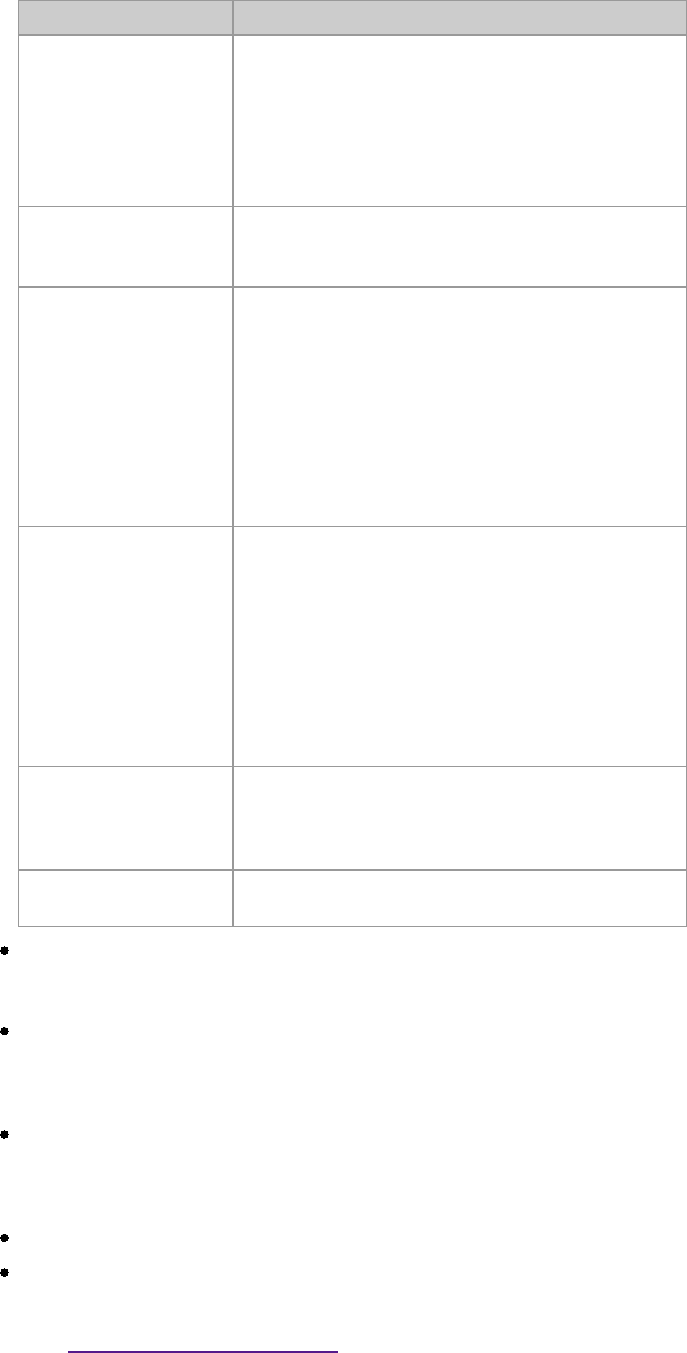
StarUML5.0DeveloperGuide(WritingUMLProfiles)
http://staruml.sourceforge.net/docs/developer-guide(en)/ch07.html
them. Default value of this property is 0. In most of case, it doesn'
t need to specify.
Argument values used in StarUML are as follows.
!
Element name
Meaning and Value
Pseudostate
Decision = 0,
InitialState = 1,
Synchronization = 2,
Junction Point = 3,
Choice Point = 4,
Deep History = 5,
Shallow History = 6
UninterpretedAction
Entry Action = 0,
Do Activity = 1,
Exit Action = 2
Stimulus
Stimulus with Call Action = 0,
Stimulus with Send Action = 1,
Stimulus with Return Action = 2,
Stimulus with Create Action = 3,
Stimulus with Destroy Action = 4,
Reverse Stimulus with Call Action = 5,
Reverse Stimulus with Send Action = 6,
Reverse Stimulus with Return Action = 7,
Reverse Stimulus with Create Action = 8,
Reverse Stimulus with Destroy Action = 9
Message
Message with Call Action = 0,
Message with Send Action = 1,
Message with Return Action = 2,
Message with Create Action = 3,
Message with Destroy Action = 4,
Reverse Message with Call Action = 5,
Reverse Message with Send Action = 6,
Reverse Message with Return Action = 7,
Reverse Message with Create Action = 8,
Reverse Message with Destroy Action = 9
Association
Assocation = 0,
Directed Association = 1,
Aggregation = 2,
Composition = 3;
Swimlane Vertical Swimlane = 0,
Horizontal Swimlane = 1;
STEREOTYPENAME element: Specifies the Stereotype name of the element
prototype. If specifies the value of
this element, it is inputted as value of "Stereotype" property when create the model element. This element
may be omitted.
STEREOTYPEDISPLAY element: Specifies how to display the stereotype when create element the model
element. Value of this element must be one of: sdkText(display as text), sdkIcon(display as icon),
sdkNone(does not display), sdkDecoration(display as decoration). This
element may be omitted. Default value
is sdkText.
SHOWEXTENDEDNOTATION element: Specifies whether to draw the element a
s notation extension in case of
existing notation extension file(.nxt) specified in the STEREOTYPENAM
E element. If value is True, StarUML
draws view of the element that created by element prototype as described in notation extension file. This
element may be omitted. Default value is False.
MODELPROPERTYLIST element: Contains list of MODELPROPERTY elements.
MODELPROPERTY element: Specifies the value of model property in creating element. The name property that
defines name of model property must be specified certainly. If value of name is not property name of base
element or is invalid, the element would not be created properly.
See
"
Chapter 4. Using Open API
"
for available property names and range of the each property value.
VIEWPROPERTYLIST element: Contains list of VIEWPROPERTY elements.
StarUML5.0DeveloperGuide(WritingUMLProfiles)
http://staruml.sourceforge.net/docs/developer-guide(en)/ch07.html
VIEWPROPERTYLIST element: Contains list of VIEWPROPERTY elements.
VIEWPROPERTY element: Specifies the value of view property in creating element. The name property that
defines name of view property must be specified certainly. If value of name is not property name of base
element or is invalid, the element would not be created properly.
See
"
Chapter 4. Using Open API
"
for available property names and range of the each property value.
TAGGEDVALUELIST element: Contains list of TAGGEDVALUE elements.
TAGGEDVALUE element: Specifies the tagged value of model element in creating element. To assign tagged
value, you must specify the tagDefinition defining it.
profile property (TAGGEDVALUE element)
: Specifies the profile name that contains the tag definition. This e
lement may be omitted. If omitted, the
profile that ELEMENENTPROTOTYPE element belongs to is applied.
tagDefinitionSet property (TAGGEDVALUE element)
: Specifies the tagDefinitionSet name containing the
tagDefinition.
tagDefinition property (TAGGEDVALUE element): Specifies the name of the tagDefinition.
ModelPrototype
MODELPROTOTYPE element describes information of model prototype that defines the pattern of model creating.
<MODELPROTOTYPE>
<NAME>....</NAME>
<DISPLAYNAME>....</DISPLAYNAME>
<ICON>....</ICON>
<BASEMODELargument=”...
”>
....</BASEMODEL>
<STEREOTYPENAME>
....
</STEREOTYPENAME>
<PROPERTYLIST>
<PROPERTYname=”
...
”>....</PROPERTY>
....
</PROPERTYLIST>
<TAGGEDVALUELIST>
<TAGGEDVALUEprofile=”
...
”tagDefinitionSet=”
...”tagDefinition=”
...
”></TAGGEDVALUE>
....
</TAGGEDVALUELIST>
<CONTAINERMODELLIST>
<CONTAINERMODELtype="
...."stereotype="....
"/>
....
</CONTAINERMODELLIST>
</MODELPROTOTYPE>
NAME element: This is the name of the model prototype. This must be u
nique within the profile.
DISPLAYNAME element: Contains the display name used in the user inter
face like the
[Add Model] menu.
ICON element: This element contains the name of the icon file for the
model prototype using in the user
interface like the [Add Model]
menu. The icon file of the model prototype must be .BMP formatted image file 16 X 16 sized. The icon file
must be placed in the directory of profile document. It must be specified only the file name except directory
path in this element.
BASEMODEL element: Specifies the name of UML standard element based to create copy of model prototype.
This element can not be omitted. If this element is not specified, the element prototype can't be recognized.
Available names of UML standard elements are the same of what is enum
erated in the BASEELEMENT part of
the ElementPrototype section. Elements that own only view can't be used.
argument property:
For some kind of elements which base model element is one of Association, Pseudostate, and so on, it needs
an argument to create. Specific property values of these model elements are preset as argument of them.
Default value of this property is 0. In most of case, it doesn't need to specify.
Available argument values are the same of what is enumerated in the argument part of the ElementPrototype
section.
STEREOTYPENAME element: Specifies the Stereotype name of the model pr
ototype. If specifies the value of
this element, it is inputted as value of "Stereotype" property when create the model element. This element
may be omitted.
StarUML5.0DeveloperGuide(WritingUMLProfiles)
http://staruml.sourceforge.net/docs/developer-guide(en)/ch07.html
may be omitted.
PROPERTYLIST element: Contains list of PROPERTY elements.
PROPERTY element: Specifies the value of model property in creating model element. The name property that
defines name of model property must be specified certainly. If value of name is not property name of base
model or is invalid, the model element would not be created properly.
See
"
Chapter 4. Using Open API
"
for available property names and range of the each property value.
TAGGEDVALUELIST element: Contains list of TAGGEDVALUE elements.
TAGGEDVALUE element: Specifies the tagged value of model element in creating element. To assign tagged
value, you must specify the tagDefinition defining it.
profile property (TAGGEDVALUE element)
: Specifies the profile name that contains the tag definition. This e
lement may be omitted. If omitted, the
profile that MODELPROTOTYPE element belongs to is applied.
tagDefinitionSet property (TAGGEDVALUE element)
: Specifies the tagDefinitionSet name containing the
tagDefinition.
tagDefinition property (TAGGEDVALUE element): Specifies the name of the tagDefinition.
CONTAINERMODELLIST element: Contains list of CONTAINERMODEL elements.
CONTAINERMODEL element: Constrains the parent model element that can
own model element defined by the
model prototype. If the value specified, creation submenu of [Add Model] menu will be activated just only
when model element specified in this element is selected.
Palette
PALETTE element describes additional palette and it's items.
<PALETTE>
<NAME>....</NAME>
<DISPLAYNAME>....</DISPLAYNAME>
<PALETTEITEMLIST>
<PALETTEITEM>....</PALETTEITEM>
....
</PALETTEITEMLIST>
</PALETTE>
NAME element: This is the name of the palette. This must be unique wi
thin the profile.
DISPLAYNAME element: This is the name being displayed.
PALETTEITEMLIST element: Lists palette items contained in the palette
.
PALETTEITEM element: Specifies an element name for palette item. The
value of this element must be the
name of element prototype defined in the profile or the name of UML s
tandard element. Available names of
UML standard elements are the same of what is enumerated in the BASEELEMENT part of the
ElementPrototype section.
DiagramType
DIAGRAMTYPE element describes overall information of diagram type.
<DIAGRAMTYPELIST>
<DIAGRAMTYPE>
<NAME>....</NAME>
<DISPLAYNAME>....</DISPLAYNAME>
<BASEDIAGRAM>....</BASEDIAGRAM>
<ICON>....</ICON>
<AVAILABLEPALETTELIST>
<AVAILABLEPALETTE>
....</AVAILABLEPALETTE>
....
</AVAILABLEPALETTELIST>
</DIAGRAMTYPE>
</DIAGRAMTYPELIST>

StarUML5.0DeveloperGuide(WritingUMLProfiles)
http://staruml.sourceforge.net/docs/developer-guide(en)/ch07.html
NAME element: This is the name of the palette. This must be unique wi
thin the profile.
DISPLAYNAME element: This is the display name used in the user interface like the [Add Diagram] menu.
ICON element: This element contains the name of the icon file for the diagram type using in the user interface
like the
[Add Diagram]
menu. The icon file of the diagram type must be .BMP formatted image file 16 X 16 sized. The icon file must
be placed in the directory of profile document. It must be specified only the file name except directory path in
this element.
BASEDIAGRAM element: Specifies the name of UML standard diagram based to create a diagram of the
diagram type. The names of available UML standard diagrams are as following.
!
Diagram names
ClassDiagram
UseCaseDiagram
SequenceDiagram
SequenceRoleDiagram
CollaborationDiagram
CollaborationRoleDiagram
StatechartDiagram
ActivityDiagram
ComponentDiagram
DeploymentDiagram
CompositeStructureDiagram
AVAILABLEPALETTELIST
element: Specifies the list of activating palettes when a diagram of
the diagram type is created.
AVAILABLEPATTE
element: Specifies activating palette when a diagram of the diagram type is created. The value of this element
must be the name of palette defined in the profile or built-in palette name included in StarUML basically.
Built-in palettes of StarUMLare as following.
!
Built-in palette names
UseCase
Class
SequenceRole
Sequence
CollaborationRole
Collaboration
Statechart
Activity
Component
Deployment
CompositeStructure
Annotation
Registering UML Profile
To make a profile to be recognized automatically by StarUML, must place it in the subdirectory of StarUML module
directory(<install-dir>\modules). StarUML searches and reads all profiles in the module directory and registers
them at the program automatically when StarUML is initializing. If profile file is invalid or it's extension file name is
not .prf, StarUML will not read the profile and ignore it. It is recommended that make a subdirectory in the StarUML
module directory and place the profile in there to avoid modules being out of order.
Note:
To register profile icon, Make icon file for the profile and place it
in the directory of the profile. Icon of the profile is
displayed with the name at profiles list in the
[Profiles]
dialog. If there is no icon file which name is same of the profile's, default icon is registered as icon of the profile.
Note:
Delete files of the profile from the StarUML module directory
(<install-dir>\modules)
not to use the profile
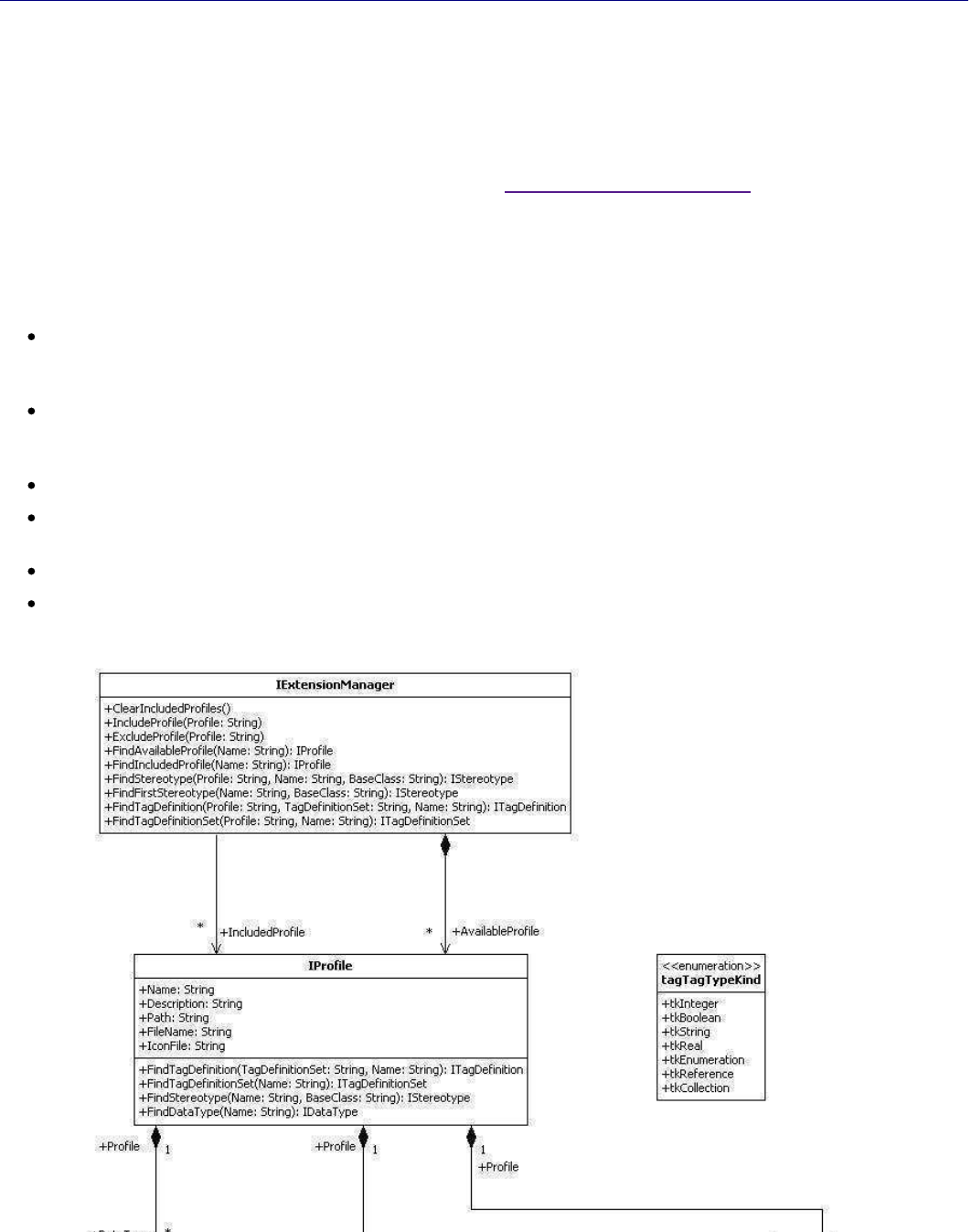
StarUML5.0DeveloperGuide(WritingUMLProfiles)
http://staruml.sourceforge.net/docs/developer-guide(en)/ch07.html
Note:
Delete files of the profile from the StarUML module directory
(<install-dir>\modules)
not to use the profile
any more.
Extension Element Object Management
Description of Extension Elements
The extension elements defined in the profile can be accessed through
StarUML™'s external API. The COM interface
related to extension in StarUML™ is organized in the same way as the actual UML extension structure, and is
managed through IExtensionManager. It is rare for the developer to directly manage extension element objects.
On the contrary, it is much more usual for the developer to obtain stereotypes or tagged values from the actual
model elements extended. In this case, the methods provided by the IExtensionModel can be used. For details on
the IExtensibleModel interface and modeling elements, see
"
Chapter 4. Using Open API".
As mentioned earlier, extension elements are not created during the a
ctual modeling process but are definitions of
extension structures. Since they should not be modified during the in
itial loading of a program or a project, most of
the properties defined in these interfaces are read-only.
The following interfaces are available for managing extension element objects.
IExtensionManager: Manages profiles registered in a program, and provides a method for searching
extension elements. IExtensionManager is the first interface that accesses the profile or the extension
elements defined in the profile.
IProfile: Manages the extension elements defined in the profile, and provides methods for accessing and
searching them. It also contains information for the profile. IProfile maintains the extension elements defined
in the profile as collections of IStereotype, ITagDefinition, and IDa
taType.
IStereotype: Provides information for stereotypes.
ITagDefinitionSet: Provides information for TagDefinitionSets, and manages tag definitions defined in
TagDefinitionSets as a collection of ITagDefintion.
ITagDefintion: Provides information for TagDefinition.
IDataType
: Provides information for DataType.
The diagram below illustrates the organization of the COM interface for StarUML's extension elements.
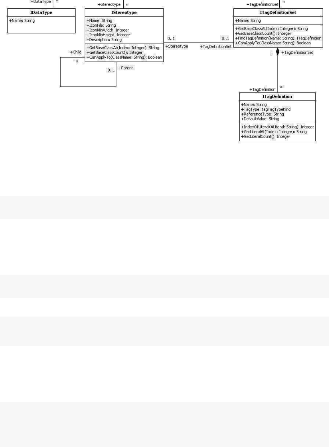
StarUML5.0DeveloperGuide(WritingUMLProfiles)
http://staruml.sourceforge.net/docs/developer-guide(en)/ch07.html
Accessing IExtensionManager
In order to manage profiles and extension elements, reference to the IExtensionManager interface must be
acquired first. IStarUMLApplication provides properties for accessing the ExtensionManager object. The following
code is a Jscript example of obtaining reference to IExtensionManager
.
varapp=newActiveXObject("StarUML.StarUMLApplication");
varext=app.ExtensionManager;
Including/Excluding Profile
IExtensionManager provides methods for including or excluding profiles in/from projects. IncludeProfile()
includes the profile entered in the current project, and ExcludeProfile()
excludes the profile entered from the
current project. The profile entered as the parameter for the methods
must be registered in the system. An error
occurs if the profile entered is not present or registered in the system. The method usage is as follows.
IExtensionManager.IncludeProfile(Profile:String)
IEXtensionManager.ExcludeProfile(Profile:String)
The following is a JScript example of excluding a profile named "StandardProfile" from the current project.
varapp=newActiveXObject("StarUML.StarUMLApplication");
varext=app.ExtensionManager;
ext.ExcludeProfile("UMLStandard");
Acquiring Extension Elements Defined in Profile
The extension objects that constitute a profile can be accessed through the IProfile interface. IProfile
provides the
following collection access methods for accessing the interfaces of extension objects (IStereotype,
ITagDefinitionSet
, and IDataType). The Index argument used in GetStereotypeAt(),
GetTagDefinitionSetAt()
,GetDataType(), etc. must be equal to or less than Count - 1 of the collection.
IProfile.GetStereotypeCount():Integer
IProfile.GetStereotypeAt(Index:Integer):IStereotype
IProfile.GetTagDefinitionSetCount():Integer
IProfile.GetTagDefinitionSetAt(Index:Integer):ITagDefinitionSet
IProfile.GetDataTypeCount():Integer
IProfile.GetDataTypeAt(Index:Integer):IDataType
StarUML5.0DeveloperGuide(WritingUMLProfiles)
http://staruml.sourceforge.net/docs/developer-guide(en)/ch07.html
The following is a Jscript example of looping the sterotypes defined in the profile.
varapp=newActiveXObject("StarUML.StarUMLApplication");
varext=app.ExtensionManager;
varprf=ext.FindIncludedProfile("UMLStandard");
if(prf!=null){
varst;
for(i=0;i<=prf.GetStereotypeCount()-1;i++){
st=prf.GetStereotypeAt(i);
//dosomething...
}
}
Finding Extension Elements
The IProfile interface provides methods for searching interfaces of extension elements defined in the profile.
FindTagDefinition(TagDefinitionSet:String,Name:String):ITagDefinition
FindTagDefinitionSet(Name:String):ITagDefinitionSet
FindStereotype(Name:String,BaseClass:String):IStereotype
FindDataType(Name:String):IDataType
Managing Stereotype
The IStereotype
interface provides information for stereotypes defined in the profile. Basic stereotype information such as the name,
description, and icon file can be obtained through the read-only property of the IStereotype interface. IStereotype
includes definitions of methods for recognizing the UML elements that can be applied with stereotypes:
GetBaseClassCount(), GetBaseClassAt(),
CanApplyTo()
, etc. The
GetBaseClassCount() and
GetBaseClassAt()
methods allow names of the UML elements that can be applied with ster
eotypes to be obtained. The
CanApplyTo()
method indicates whether the UML element received as an argument can be applied with the current stereotype by
returning a Boolean value The BaseClass of a stereotype can specify n
ot only the UML elements expressible in
diagrams, but also more of the upper-level elements like UMLClassifier. In this case, the selected stereotype can be
applied to all the lower-level elements under the upper-level elements. For example, suppose UMLClassifier is
defined as the BaseClass, then it works the same as if all lower-level elements like UMLClass, UMLInterface,
UMLUseCase, and UMLActor are defined as the BaseClass. For the inheritance structure between elements, see
Plastic Application Model.
GetStereotype() of IExtensibleModel
returns
IStereotype
objects from stereotyped models. If the stereotype of
a model is not defined in the profile, a null value is returned. In this case, the
StereotypeName
property of
IExtensibleModel can be used to obtain the name of the stereotype.
The following is a JScript example of displaying in the message box t
he descriptions of the stereotypes for the
currently selected model.
varapp=newActiveXObject("StarUML.StarUMLApplication");
varselMgr=app.SelectionManager;
if(selMgr.GetSelectedModelCount()>0){
varselModel=selMgr.GetSelectedModelAt(0);
varst=selModel.GetStereotype();
if(st!=null){
WScript.Echo(st.Description)
}
}
Managing TagDefinition
The ITagDefinition interface provides information for tag definitions defined in the profile. ITagDefinition provides
the following properties.
StarUML5.0DeveloperGuide(WritingUMLProfiles)
http://staruml.sourceforge.net/docs/developer-guide(en)/ch07.html
the following properties.
Property
Description
Name: String Name of the tag definition. Tag definition name must be unique within the
TagDefinitionSet.
TagType:
tagTagTypeKind
Type of tag.
The following tag types are available.
tkInteger = 0 (integer)
tkBoolean = 1 (boolean)
tkString = 2 (string)
tkReal = 3 (real number)
tkEnumeration = 4 (enumeration)
tkReference = 5 (reference)
tkCollection = 6 (collection)
Different methods are used for obtaining tagged values from models depending on the
tag type. IExtensibleModel includes definitions of methods for obtaining tagged values
according to each tag type.
ReferenceType: String Indicates the types of object reference available for definition by tagged values when the
TagType is tkReference or tkCollection. For example, setting this to "UMLClass" allows
connection of Class type only. If the definition for ReferenceType is omitted in the profile
document, "UMLModelElement" is taken as the default value. If TagType is not tkReferece
or tkCollection, this property has no effect.
DefaultValue: String Defines the default value of a tag. If the TagType is tkEnumeration,
it is a string value for
the enumeration order. If the TagType is tkReference or tkCollection,
the default value is
set as null and this property has no effect.
The following is a JScript example of displaying the default value of
a tag in the message box.
varapp=newActiveXObject("StarUML.StarUMLApplication");
varext=app.ExtensionManager;
vartag=ext.FindTagDefinition("UMLStandard","Default","Derived");
WScript.Echo(tag.DefaultValue);
StarUML5.0DeveloperGuide(ExtendingMenu)
http://staruml.sourceforge.net/docs/developer-guide(en)/ch08.html
Chapter 8. Extending Menu
Basic Concepts of Menu Extension
In order to provide ways for the user to call the Add-In functions, t
he StarUML™ menu system can be extended. For
this, Add-In developers must provide menu extension files. This invol
ves the following steps.
Creating a menu extension file.
1.
Registering a menu extension file.
2.
An Add-In menu extension file (*.mnu) is an XML-formatted text file. Each Add-In must provide one menu
extension file. StarUML™ uses the definition contents of this menu file to extend the application's main and popup
menus to add new menu items, to execute defined actions, or to send messages to related Add-In objects.
StarUML™'s Add-In menu extension file can contain the following definitions.
New menu items to add
Division of main menu items and popup menu items
StarUML's basic menu items where the new menu items would be added
Display names and hot-keys for menu items
Points for activation and deactivation of menu items
Script files to execute when menu items are selected
IDs of the menu items that are sent to Add-In objects when selected
Locations of the menu items in their upper-level group menus
Icon files for menu items
A menu extension file is written in the XML format. It has to be a well-formed document and its contents must be
valid. This chapter discusses the XML DTD (Document Type Definition), which has to be observed to ensure the
validity of menu extension files, and the structure of menu extension
files, and also provides related examples.
Note:
Add-In menu extension file must have *.mnu extension file name and pl
aced in the subdirectory of StarUML™
module directory(<insall-dir>\modules).
Creating Menu Extension File
DTD of Menu Extension File
StarUML™'s Add-In menu extension file must be a valid XML that conforms to the defined DTD. The following is the
entire contents of the DTD defined for a menu extension file.
<?xmlversion="1.0"encoding="UTF-8"?>
<!ELEMENTNAME(#PCDATA)>
<!ELEMENTVERSION(#PCDATA)>
<!ELEMENTDESCRIPTION(#PCDATA)>
<!ELEMENTCOMPANY(#PCDATA)>
<!ELEMENTCOPYRIGHT(#PCDATA)>
<!ELEMENTMAINITEM(MAINITEM)*>
<!ATTLISTMAINITEM
base(FILE|EDIT|FORMAT|MODEL|VIEW|TOOLS|HELP|UNITS|IMPORT|EXPORT|NEW_TOP)#IMPLIED
captionCDATA#REQUIRED
indexCDATA#IMPLIED
beginGroupCDATA#IMPLIED
scriptCDATA#IMPLIED
actionIdCDATA#IMPLIED
availableWhen(ALWAYS|PROJECT_OPENED|MODEL_SELECTED|VIEW_SELECTED|UNIT_SELECTED|DIAGRAM_
iconFileCDATA#IMPLIED>
StarUML5.0DeveloperGuide(ExtendingMenu)
http://staruml.sourceforge.net/docs/developer-guide(en)/ch08.html
<!ELEMENTPOPUPITEM(POPUPITEM)*>
<!ATTLISTPOPUPITEM
location(EXPLORER|DIAGRAM|BOTH)“BOTH”
captionCDATA#REQUIRED
indexCDATA#IMPLIED
beginGroupCDATA#IMPLIED
scriptCDATA#IMPLIED
actionIdCDATA#IMPLIED
availableWhen(ALWAYS|PROJECT_OPENED|MODEL_SELECTED|VIEW_SELECTED|UNIT_SELECTED|DIAGRAM_
iconFileCDATA#IMPLIED>
<!ELEMENTMAIMENU(MAINITEM)*>
<!ELEMENTPOPUPMENU(POPUPITEM)*>
<!ELEMENTHEADER(NAME?,VERSION?,DESCRIPTION?,COMPANY?,COPYRIGHT?)>
<!ELEMENTBODY(MAINMENU?,POPUPMENU?)>
<!ELEMENTADDINMENU(HEADER?,BODY)>
<!ATTLISTADDINMENUaddInIDCDATA#REQUIRED>
Note:
Names of all XML elements must be written in upper case letters, and names of all attributes start with lower case
ones. Pre-defined symbol values are represented in upper case with '_' (underscores). Such conventions must be
observed throughout the whole menu file, and the pre-defined symbol v
alues must be used properly.
Overall Structure of Menu Extension File
Menu extension files follow the XML document conventions, and user-defined menu items are contained within the
'ADDINMENU' element.
<?xmlversion="1.0"encoding="
..."?>
<ADDINMENUaddInID="
...
">
<HEADER>...
</HEADER>
<BODY>
...
</BODY>
</ADDINMENU>
encoding property: Defines the encoding property value of the XML document (e.g. UTF-8, EUC-KR). For details
on this property value, see XML-related resources.
addInID property: Unique ID of each Add-In. This must be a unique value that identifies the current Add-In
from others. It is recommended that the company name or product name be used as a part of the value (e.g.
StarUML.StandardAddIn).
HEADER element: Contains general information for the Add-In. See the
Header Contents
section.
BODY element: Contains information for actual menu items. See the
Body Contents
section.
Header Contents
The Header element of a menu extension file contains information for the Add-In and menu file. The contents in the
Header section do not have any effect on the actual structure of the
menu items. Although this section may be
omitted, it is recommended to include it to provide menu extension files that are self-explanatory.
<HEADER>
<NAME>
...
</NAME>
<VERSION>...</VERSION>
<DESCRIPTION>
...
</DESCRIPTION>
<COMPANY>...</COMPANY>
<COPYRIGHT>
...
</COPYRIGHT>
</HEADER>
NAME element: Contains the explanatory name of the Add-In (string value).
VERSION element: Contains the version information (string value).
StarUML5.0DeveloperGuide(ExtendingMenu)
http://staruml.sourceforge.net/docs/developer-guide(en)/ch08.html
VERSION element: Contains the version information (string value).
DESCRIPTION element: Contains brief description of the Add-In (string
value).
COMPANY element: Contains information of the Add-In developer company
/ individual (string value).
COPYRIGHT element: Contains the copyright notice (string value).
BODY CONTENTS
The Body element of a menu extension file contains the actual menu items to add. Information in this section must
be accurate.
<BODY>
<MAINMENU>
<MAINITEM>...</MAINITEM>
<MAINITEM>...</MAINITEM>
</MAINMENU>
<POPUPMENU>
<POPUPITEM>
...
</POPUPITEM>
<POPUPITEM>
...
</POPUPITEM>
</POPUPMENU>
</BODY>
The Body element can largely be divided into definitions of the main menu and definitions of the popup menu.
MAINMENU element: Contains the main menu items to add.
POPUPMENU element: Contains the popup menu items to add.
MAINITEM element: Contains information of an actual menu item (main menu).
POPUPITEM element: Contains information of an actual menu item (popup menu).
Main menu items and popup menu items are written separately. According to the functions provided by each
Add-In, a menu item can be added to the main menu or to the popup menu. Either the MAINMENU element or the
POPUPMENU element may be omitted, but not both. If a menu item of the same functionality needs to be added
both to the main menu and to the popup menu, information should be entered appropriately in MAINMENU and
POPUPMENU. In this case, the two items should have identical script or actionID properties. However, when adding
a lower-level menu item to an StarUML™ basic menu item such as [Format] and [Unit], that is shared by both the
main menu and the popup menu, the information should be contained in MAINMENU only.
MAINMENU
The MAINMENU element can contain multiple MAINITEM elements. Each MAINITEM element constitutes one main
menu item. For defining a group menu item with sub menu items, the MA
INITEM element can in turn contain
multiple MAINITEM elements.
<MAINITEMbase=”
...”caption=”...
”index=”
...”beginGroup=”...
”script=”
...”actionId=”...
”availa
<MAINITEM>...</MAINITEM>
<MAINITEM>...</MAINITEM>
</MAINITEM>
Property Description Range of Value Omission
base
This is one of the StarUML™ basic
menu items to which the new menu
item will be added. This property has
no effect if the MAINITEM element
belongs to another upper-level
MAINITEM element.
Must be FILE, EDIT, FORMAT,
MODEL, VIEW, TOOLS, HELP,
UNITS, IMPORT, EXPORT, or
NEW_TOP.
*
If omitted, the new
menu item is added as a
sub menu item under
the
[Tools]
menu.
caption Specifies the display name for the
menu item. This value may contain
the hot-key. To define the hot-key,
add '&' and the hot-key
character at the end of this value.
String value Cannot be omitted.
StarUML5.0DeveloperGuide(ExtendingMenu)
http://staruml.sourceforge.net/docs/developer-guide(en)/ch08.html
character at the end of this value.
Note that the StarUML™ program
does not check for duplication of the
hot-key with other menu items.
index
Specifies the order of this menu item
under the upper-level menu. For
instance, if this value is '0', the menu
item becomes the first sub menu for
the base menu item. If the value of
this property conflicts with the values
of other menu items, the menu may
not be displayed accurately.
An integer greater than 0.
Generally omitted. If
omitted, Add-Ins are
added in the order they
are registered.
beginGroup Determines whether to add the
separator in front of the menu item.
Must be TRUE or FALSE. FALSE if omitted.
script
Specifies the pathname and filename
of the script to run, if any. The
pathname is relative to the location of
the Add-In program. This value can
also be a website URL.
String value Can be omitted.
actionId Set this to an integer greater than 0
in order to process the menu
command through a COM object. If
the Add-In adds more than one menu
item, each menu item can be
distinguished by its unique actionId
value.
An integer greater than 0.
Can be omitted.
availableWhen
Specifies when the menu item
becomes enabled.
Must be ALWAYS,
PROJECT_OPENED,
MODEL_SELECTED,
VIEW_SELECTED,
UNIT_SELECTED, or
DIAGRAM_ACTIVATED. **
PROJECT_OPENED is
selected if omitted.
iconFile
Specifies the pathname and filename
for the menu item icon file, if any. The
pathname is relative to the location of
the Add-In program.
String value Can be omitted.
Note:
Unless the menu item groups its sub menu items, the property value for either script or actionId must be defined.
* base property value range
FILE: The menu item is added as a sub menu item of the [File] menu.
EDIT: The menu item is added as a sub menu item of the [Edit] menu.
FORMAT: The menu item is added as a sub menu item of the [Format] menu.
MODEL: The menu item is added as a sub menu item of the
[Model]
menu.
VIEW: The menu item is added as a sub menu item of the [View] menu.
TOOLS: The menu item is added as a sub menu item of the
[Tools]
menu. (default)
HELP: The menu item is added as a sub menu item of the [Help] menu.
UNITS: The menu item is added as a sub menu item of the
[File]
->
[Unit] menu.
IMPORT: The menu item is added as a sub menu item of the [File]
->
[Import] menu.
EXPORT: The menu item is added as a sub menu item of the [File]
->
[Export] menu.
NEW_TOP: The menu item is created as a new top-level main menu item.
**
availableWhen property value range
StarUML5.0DeveloperGuide(ExtendingMenu)
http://staruml.sourceforge.net/docs/developer-guide(en)/ch08.html
availableWhen property value range
ALWAYS: Enabled as long as the StarUML™ application is running.
PROJECT_OPENED: Enabled when a project element is present. (default)
MODEL_SELECTED: Enabled when a model element is selected.
VIEW_SELECTED: Enabled when a view element is selected.
UNIT_SELECTED: Enabled when a unit element is selected.
DIAGRAM_ACTIVATED: Enabled when a diagram is opened.
POPUPMENU
The POPUPMENU element can contain multiple POPUPITEM elements. Each POPUPITEM element constitutes one
popup menu item. For defining a menu item with sub menu items, the POPUPITEM element can in turn contain
multiple POPUPITEM items.
<POPUPITEMlocation=”...”caption=”...
”index=”
...”beginGroup=”
...
”script=”...”actionId=”
...
”a
<POPUPITEM>
...
</POPUPITEM>
<POPUPITEM>
...
</POPUPITEM>
</POPUPITEM>
Property Description Range of Value Omission
location
Specifies the popup menu system
where the new popup menu item will
be added. This property has no effect
if the POPUPITEM belongs to another
upper-level POPUPITEM element.
Must be EXPLORER, DIAGRAM,
or BOTH.
*
BOTH if omitted.
caption Specifies the display name for the
menu item. This value may contain
the hot-key. To define the hot-key,
add '&' and the hot-key character
at the end of this value. Note that the
StarUML™ program does not check for
duplication of the hot-key with other
menu items.
String value Cannot be omitted.
index
Specifies the order of this menu item
under the upper-level menu. For
instance, if this value is '0', the menu
item becomes the first sub menu for
the base menu item. If the value of
this property conflicts with the values
of other menu items, the menu may
not be displayed accurately.
An integer greater than 0.
Generally omitted. If
omitted, menu items are
added in the order the
Add-In is registered.
beginGroup Determines whether to add the
separator in front of the menu item.
Must be TRUE or FALSE. FALSE if omitted.
script
Specifies the pathname and filename
of the script to run, if any. The
pathname is relative to the location of
the Add-In program. This value can
also be a website URL.
String value
Can be omitted.
actionId
Set this to an integer greater than 0 in
order to process the menu command
through a COM object. If the Add-In
adds more than one menu item, each
menu item can be distinguished by its
unique actionId value.
An integer greater than 0.
Can be omitted.
availableWhen
Specifies when the menu item
becomes enabled.
Must be ALWAYS,
PROJECT_OPENED,
MODEL_SELECTED,
Set to PROJECT_OPENED
if omitted.
StarUML5.0DeveloperGuide(ExtendingMenu)
http://staruml.sourceforge.net/docs/developer-guide(en)/ch08.html
MODEL_SELECTED,
VIEW_SELECTED,
UNIT_SELECTED, or
DIAGRAM_ACTIVATED
**
iconFile
Specifies the pathname and filename
for the menu item icon file, if any. The
pathname is relative to the location of
the Add-In program.
String value
Can be omitted.
Note:
Unless the menu item is grouping its sub menu items, the property value for either script or actionId must be
defined.
* location property value range
EXPLORER: The menu item is added to the
Model Explorer
popup menu.
DIAGRAM: The menu item is added to the Diagram popup menu.
BOTH: The menu item is added to both the
Model Explorer
and Diagram popup menus.
(default)
** availableWhen property value range - Same as the MAINMENU element.
Example of Menu Extension File
The following example is the complete menu file for the StarUML™ default extension pack that is installed together
with the StarUML™ program.
<?xmlversion="1.0"encoding="UTF-8"?>
<ADDINMENUaddInID="StarUML.StandardAddIn">
<HEADER>
<NAME>DefaultmoduleofStarUML</NAME>
<VERSION>1.0.0</VERSION>
<DESCRIPTION>DefaultextensionpackofAgoraPlastictoconvertdiagram</DESCRIPTION>
<COMPANY>PlasticSoftware,Inc.</COMPANY>
<COPYRIGHT>Copyright(C)2005PlasticSoftware,Inc.Allrightsreserved.</COPYRIGHT>
</HEADER>
<BODY>
<MAINMENU>
<MAINITEMbase="MODEL"caption="ConvertDiagram"beginGroup="TRUE"availableWhen="MODE
<MAINITEMcaption="ConvertSequence(Role)toCollaboration(Role)"script="ConvSeq2Col.
<MAINITEMcaption="ConvertCollaboration(Role)toSequence(Role)"script="ConvCol2Seq.
</MAINMENU>
</BODY>
</ADDINMENU>
Registering Menu Extension File
To make a menu extension to be recognized automatically by StarUML, must place it in the subdirectory of StarUML
module directory(<install-dir>\modules). StarUML searches and reads all menu extension files in the module
directory and registers them at the program automatically when StarUML is initializing. If menu extension file is
invalid or it's extension file name is not .mnu, StarUML will not read the menu extension file and ignore it. It is
recommended that make a subdirectory in the StarUML module directory
and place the profile in there to avoid
modules being out of order.
Note: Delete the menu extension file from the StarUML module directory(<install-dir>\modules) not to use the
menu extension any more.
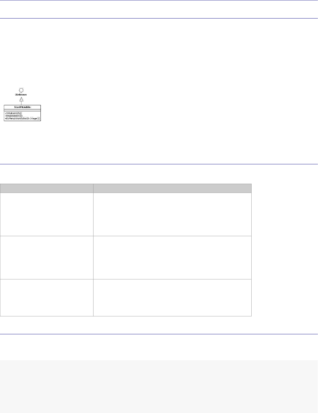
StarUML5.0DeveloperGuide(WritingAdd-InCOMObject)
http://staruml.sourceforge.net/docs/developer-guide(en)/ch09.html
Chapter 9. Writing Add-In COM Object
Basic Concepts of Add-In COM Object
As discussed in
'Chapter 3. Hello world Example'
simple Script codes can be defined to add new functionalities to Star
UML™. However, to facilitate more complex and
useful functionalities, it is better to use a program development env
ironment that supports COM objects. For
implementing StarUML™ Add-In COM Objects, it does not matter whether
Delphi, Visual Basic or any other
programming environment is used, as long as it supports COM technology.
The most important point about implementing StarUML™ Add-In COM Objec
ts is that the
IStarUMLAddIn interface
defined by StarUML™ must be used.
As illustrated above, the IStarUMLAddIn
interface inherits IUnknown and defines the three additional interface methods: InitializeAddIn()
,
FinalizeAddIn(), and DoMenuAction().
IStarUMLAddIn Interface Methods
The methods to be defined for implementing the IStarUMLAddIn interface are as follows.
Method Description
InitializeAddIn() The InitializeAddIn() method is used by the
StarUMLApplication object to initialize each Add-In COM
Object when it is created. As will be discussed in below
section this is used to define the actions required for
initialization of an Add-In COM Object such as event
subscription registration.
FinalizeAddIn() The FinalizeAddIn() method is called by the
StarUMLApplication object just before disconnecting
reference from an Add-In COM Object. As will be
discussed in below section this is used to define the
actions required before terminating an Add-In COM
Object such as event subscription removal.
DoMenuAction(ActionID: Integer)
As seen in
'Chapter 8. Extending Menu' the
DoMenuAction() method is called when the user selects
an extension menu item defined by each Add-In. The
'
actionId' value of each menu item defined by the menu
extension file is passed on as an argument.
Add-In COM Object Example
The following is a simple example of an StarUML™ Add-In COM Object implementing the IStarUMLAddIn interface.
This is written in the Delphi Pascal syntax.
type
AddInExample=class(TComObject,IStarUMLAddIn)
private
StarUMLApp:IStarUMLApplication;
protected
functionInitializeAddIn:HResult;stdcall;
functionFinalizeAddIn:HResult;stdcall;
functionDoMenuAction(ActionID:Integer):HResult;stdcall;
...

StarUML5.0DeveloperGuide(WritingAdd-InCOMObject)
http://staruml.sourceforge.net/docs/developer-guide(en)/ch09.html
...
public
procedureInitialize;override;
destructorDestroy;override;
...
end;
...
implementation
procedureAddInExample.Initialize;
begin
inherited;
StarUMLApp:=CreateOleObject('StarUML.StarUMLApplication')asIStarUMLApplication;
...
end;
destructorAddInExample.Destroy;
begin
...
StarUMLApp:=nil;
inherited;
end;
functionAddInExample.InitializeAddIn:HResult;
begin
...
Result:=S_OK;
end;
functionAddInExample.FinalizeAddIn:HResult;
begin
...
Result:=S_OK;
end;
functionAddInExample.DoMenuAction(ActionID:Integer):HResult;stdcall;
begin
Result:=S_OK;
...
end;
Writing Add-In Description File
Basic Concept of Add-In Description File
Add-In Description file(*.aid) is XML based text file. All add-Ins plug-ined in StarUML must offer one add-in
description file. StarUML registers Add-In object at system registry and initializes the Add-In object and menu
extension file associated with it on the reference of add-in description file context.
Note:
Add-In description file must have *.aid extension file name and place
d in the subdirectory of StarUML module
directory(<install-dir>\modules).
Structure of Approach Document File
Add-In description files follow the XML document conventions, and user-defined menu items are contained within the
'ADDIN' element.
<?xmlversion="1.0"encoding="
...
"?>
<ADDIN>
<NAME>
...
</NAME>
<DISPLAYNAME>
...
</DISPLAYNAME>
<COMOBJ>
...
</COMOBJ>
<FILENAME>...</FILENAME>
<COMPANY>
...
</COMPANY>
StarUML5.0DeveloperGuide(WritingAdd-InCOMObject)
http://staruml.sourceforge.net/docs/developer-guide(en)/ch09.html
<COMPANY>
...
</COMPANY>
<COPYRIGHT>...</COPYRIGHT>
<HELPFILE>...</HELPFILE>
<ICONFILE>...</ICONFILE>
<ISACTIVE>...</ISACTIVE>
<MENUFILE>...</MENUFILE>
<VERSION>
...</VERSION>
<MODULES>
<MODULEFILENAME>
...
</MODULEFILENAME>
</MODULES>
</ADDIN>
encoding property: Defines the encoding property value of the XML document (e.g. UTF-8, EUC-KR). For details
on this property value, see XML-related resources.
NAME element: Defines the name of Add-In. (string value)
DISPALYNAME element: Defines the name of Add-In that is shown to user
s in user interface. (string value)
COMOBJ element: Specifies a ProgID of COM object. This element is used only in case of COM object based
add-in. (string value)
FILENAME element: Specifies Add-In file name. (string value)
COMPANY element: Describes information of the Add-In developer company / individual. (string value)
COPYRIGHT element: Describes the copyright notice. (string value)
HELPFILE element: Specifies URL that contains help of the Add-In. (st
ring value)
ICONFILE element: Specifies icon file name of Add-In. (string value)
ISACTIVE element: Specifies whether activates Add-in automatically in the starting of the program. (boolean
value)
MENUFILE element: Specifies menu extension file name associated to th
e Add-In. (string value)
MODULES/MODULEFILENAME element: Specifies file names for additional C
OM objects in case that an Add-In
object uses another COM objects. StarUML registers all additional COM objects specified in this element on
execution. (string value)
Registering Add-In Description File
To make an add-in description file to be recognized automatically by StarUML, must place the file in the subdirectory
of StarUML module directory(<install-dir>\modules). StarUML searches and reads all add-in description files in the
module directory and registers them at the program automatically when StarUML is initializing. If add-in description
file is invalid or it's extension file name is not .aid, StarUML will
not read the add-in description file and ignore it. It is
recommended that make a subdirectory in the StarUML module directory and place the add-in description file in
there to avoid modules being out of order.
Note: Delete the add-in description file from the StarUML module directory
(<install-dir>\modules)
not to use the
add-in any more.
Option Extension
Basic Concept of Option Extension
StarUML supports setup options to adjust environment and detail functions of StarUML. Options are necessary not to
StarUML application self but also add-ins supplies by third-party ven
dors. StarUML option extension enables Add-Ins
to equip option configuring function without additional implementatio
n. For using option extension, Add-In developer
just defines option items with text file and places it in the Add-In
directory. These option definitions are loaded on
the program in initializing and displayed on option dialog. Add-In de
veloper can save their time and efforts for
implementing Add-In, and provide consistent user interface to users.
Follow the steps below to support setup options in Add-In.
Create an option schema document file (.opt) to define option items for the Add-In.1.
Copy the option schema document file (.opt) to subdirectory of module directory.2.
Hierarchy of Option Schema
StarUML5.0DeveloperGuide(WritingAdd-InCOMObject)
http://staruml.sourceforge.net/docs/developer-guide(en)/ch09.html
StarUML constructs the option schema hierarchically as follows to manage many option items that defined in the
application and add-ins in integrative.
Option Schema: Option schema is the highest classification of option structure and is unit of option schema file.
It appears as folder icon on the top level in the treeview that is placed in the left of option dialog.
Option Category:
Option category is the division of option schema by function, and dis
played as lower level of treeview in the left of
option dialog.
Option Classification:
Option classification classifies option items in detail, and corresponds to category row of inspector in option dialog.
It has several option items that can be edited.
Option Item:
Option item is a unit of editing option value and corresponds to one row of inspector in option dialog.
Writing Option Schema
Option schema file to define option items is XML based text file whic
h extension file name is *.opt. The option
schema contents are contained within the OPTIONSCHEMA element, and there must not be any errors in syntax or
contents.
<?xmlversion=”1.0”encoding=”
...”?>
<OPTIONSCHEMAid="...">
<HEADER>
...
</HEADER>
<BODY>
...
</BODY>
</OPTIONSCHEMA>
encoding property: Specifies the encoding property value for the XML document (e.g. UTF-8, EUC-KR). For details
on this property value, see XML-related resources.
id property (OPTIONSCHEMA element): Specifies the name of the option schema. It is a unique name to identify
the option schema from the others.
HEADER element: See the
Header Contents
section.
BODY element: See the
Body Contents
section.
Header Contents
The HEADER section of an option schema document contains general info
rmation for the option schema such as the
option schema title and description. Structure of the header section is as follows.
<HEADER>
<CAPTION>
...</CAPTION>
<DESCRIPTION>
...
</DESCRIPTION>
</HEADER>
CAPTION element: This is a title of the option schema and displayed a
s caption of node in treeview of option
dialog.
DESCRIPTION element: Contains the description of the option schema.
Body Contents
The BODY section of an option schema document contains definition of
all option items hierarchically.
<BODY>
<OPTIONCATEGORY>
<CAPTION>
...
</CAPTION>
<DESCRIPTION>...
</DESCRIPTION>
<OPTIONCLASSIFICATION>
<CAPTION>...
</CAPTION>
StarUML5.0DeveloperGuide(WritingAdd-InCOMObject)
http://staruml.sourceforge.net/docs/developer-guide(en)/ch09.html
<DESCRIPTION>
...
</DESCRIPTION>
<OPTIONITEM>
...
</OPTIONITEM>
...
</OPTIONCLASSIFICATION>
...
</OPTIONCATEGORY>
...
</BODY>
OPTIONCATEGORY element: Defines structure of option category.
CAPTION element: Specifies caption of the option category displayed as node in treeview of the option dialog.
DESCRIPTION element: Contains brief description of the option category that displayed at option description
memo box appears in the option dialog.
OPTIONITEM element: Defines a number of option items. See the
Option Item Definition
section.
Option Item Definition
OPTIONCLASSIFICATION element can contain a number of option item definitions. Option item type are defined as
several types such as integer, real, boolean, enumeration and so on. Option dialog supports information for inputting
value or restricts value according to option item type.
Available types of option item are as follows.
Option item type XML element name
Input in the option dialog
Integer
OPTIONITEM-INTEGER
Input only integer value.
Real OPTIONITEM-REAL
Input only real number.
String OPTIONITEM-STRING Input only string.
Boolean
OPTIONITEM-BOOLEAN
Input true or false with check box.
Text OPTIONITEM-TEXT
Input multiple line of text in pop-up text box.
Enumeration OPTIONITEM-ENUMERATION
Select one of items that defined with
OPTION-ENUMERATIONITEM in combo box.
Font name
OPTIONITEM-FONTNAME
Select one of font names installed in the system.
File name OPTIONITEM-FILENAME Input file name or select the file in the open file dialog.
Path name OPTIONITEM-PATHNAME Input directory name or select the directory in the open
directory dialog.
Color
OPTIONITEM-COLOR
Select a color in the color combo box or select the color in the
color dialog.
Range OPTIONITEM-RANGE
Input an integer value within specified range. Can change the
value as amount of specified step with spin button.
The following represents format of option item definitions that belongs to OPTIONCLASSIFICATION in the option
schema file.
<OPTIONCLASSIFICATION>
<OPTIONITEM-INTEGERkey="...
">
<CAPTION>
...
</CAPTION>
<DESCRIPTION>...
</DESCRIPTION>
<DEFAULTVALUE>...</DEFAULTVALUE>
</OPTIONITEM-INTEGER>
<OPTIONITEM-REALkey="
...
">
<CAPTION>
...
</CAPTION>
<DESCRIPTION>...
</DESCRIPTION>
<DEFAULTVALUE>...</DEFAULTVALUE>
</OPTIONITEM-REAL>
<OPTIONITEM-STRINGkey="
...
">
<CAPTION>
...
</CAPTION>
<DESCRIPTION>...
</DESCRIPTION>
<DEFAULTVALUE>...</DEFAULTVALUE>
</OPTIONITEM-STRING>
<OPTIONITEM-BOOLEANkey="
...
">
StarUML5.0DeveloperGuide(WritingAdd-InCOMObject)
http://staruml.sourceforge.net/docs/developer-guide(en)/ch09.html
<OPTIONITEM-BOOLEANkey="
...
">
<CAPTION>
...
</CAPTION>
<DESCRIPTION>...
</DESCRIPTION>
<DEFAULTVALUE>...</DEFAULTVALUE>
</OPTIONITEM-BOOLEAN>
<OPTIONITEM-TEXTkey="
...
">
<CAPTION>
...
</CAPTION>
<DESCRIPTION>...
</DESCRIPTION>
<DEFAULTVALUE>...</DEFAULTVALUE>
</OPTIONITEM-TEXT>
<OPTIONITEM-ENUMERATIONkey="
...
">
<CAPTION>
...
</CAPTION>
<DESCRIPTION>...
</DESCRIPTION>
<DEFAULTVALUE>...</DEFAULTVALUE>
<ENUMERATIONITEM>...</ENUMERATIONITEM>
...
</OPTIONITEM-ENUMERATION>
<OPTIONITEM-FONTNAMEkey="
...
">
<CAPTION>
...
</CAPTION>
<DESCRIPTION>...
</DESCRIPTION>
<DEFAULTVALUE>...</DEFAULTVALUE>
</OPTIONITEM-FONTNAME>
<OPTIONITEM-FILENAMEkey="
...
">
<CAPTION>
...
</CAPTION>
<DESCRIPTION>...
</DESCRIPTION>
<DEFAULTVALUE>...</DEFAULTVALUE>
</OPTIONITEM-FILENAME>
<OPTIONITEM-PATHNAMEkey="
...
">
<CAPTION>
...
</CAPTION>
<DESCRIPTION>...
</DESCRIPTION>
<DEFAULTVALUE>...</DEFAULTVALUE>
</OPTIONITEM-PATHNAME>
<OPTIONITEM-COLORkey="
...
">
<CAPTION>
...
</CAPTION>
<DESCRIPTION>...
</DESCRIPTION>
<DEFAULTVALUE>...</DEFAULTVALUE>
</OPTIONITEM-COLOR>
<OPTIONITEM-RANGEkey="
...
">
<CAPTION>
...
</CAPTION>
<DESCRIPTION>...
</DESCRIPTION>
<DEFAULTVALUE>...</DEFAULTVALUE>
<MINVALUE>...</MINVALUE>
<MAXVALUE>...</MAXVALUE>
<STEP>...</STEP>
</OPTIONITEM-RANGE>
...
</OPTIONITEMCLASSIFICATION>
key property (all OPTIONITEM elements): Specifies it's own key value of the option item which is unique in the
option schema. It is used in reading option values with COM interface.
CAPTION element: Specifies caption of option item used in option dialog.
DESCRIPTION element: Contains brief description of the option item that displayed at option description memo
box appears in the option dialog.
DEFAULTVALUE
: Specifies default value of the option item. It must be in the range of valid values as follows.
If default value is not valid as the type specified, can't edit value in the option dialog.
Option item type
Range of valid values
OPTIONITEM-INTEGER
Integer in -2147483648 ~ 2147483647
OPTIONITEM-REAL
Integer or floating-point value
OPTIONITEM-STRING String value
OPTIONITEM-BOOLEAN
True or False
OPTIONITEM-TEXT String value
OPTIONITEM-ENUMERATION
String defined in ENUMERATIONITEM element
OPTIONITEM-FONTNAME
Font name. e.g. Tahoma
OPTIONITEM-FILENAME
File name with full path or empty string
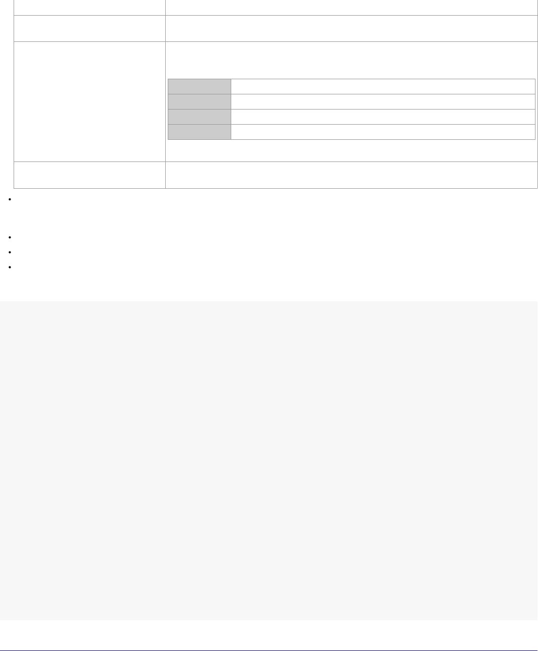
StarUML5.0DeveloperGuide(WritingAdd-InCOMObject)
http://staruml.sourceforge.net/docs/developer-guide(en)/ch09.html
OPTIONITEM-FILENAME
File name with full path or empty string
e.g. C:\My Document\Default.xml
OPTIONITEM-PATHNAME
Valid path name or empty string
e.g. C:\My Document
OPTIONITEM-COLOR
Formatted string as follows
${W}{B}{G}{R}
{W}
Reserved . Must be 00
{B}
Blue of the color. Hexadecimal value in 0 ~ 255 (00 ~ FF)
{G} Green of the color. Hexadecimal value in 0 ~ 255 (00 ~ FF)
{R} Red of the color. Hexadecimal value in 0 ~ 255 (00 ~ FF)
i.e. $00FF0000 , $00A0A0A0, $00FF00FF
OPTIONITEM-RANGE
Integer value between minimum value specified in MINVALUE and maximum
value specified in MAXVALUE
ENUMERATIONITEM element: Enumerate items that selectable in the enumeration typed option
item(OPTION-ENUMERATION). OPTION-ENUMERATION element must have at least one ENUMERATIONITEM
element.
MINVALUE element: Specifies minimum integer value in range typed option item(OPTION-RANGE).
MAXVALUE element: Specifies maximum integer value in range typed option item(OPTION-RANGE).
STEP element: Specifies an increment of range typed option value when click the spin button for editing.
The following example is the part of option schema file for StarUML.
<?xmlversion="1.0"encoding="UTF-8"?>
<OPTIONSCHEMAid="ENVIRONMENT">
<HEADER>
<CAPTION>Environment</CAPTION>
<DESCRIPTION></DESCRIPTION>
</HEADER>
<BODY>
<OPTIONCATEGORY>
<CAPTION>General</CAPTION>
<DESCRIPTION>GeneralConfigurationisagroupofthebasicandgeneraloptionitemsfor
<OPTIONCLASSIFICATION>
<CAPTION>General</CAPTION>
<DESCRIPTION></DESCRIPTION>
<OPTIONITEM-RANGEkey="UNDO_LEVEL">
<CAPTION>Max.numberofundoactions</CAPTION>
<DESCRIPTION>Specifiesthemaximumnumberofactionsforundoandredo.</DESCRI
<DEFAULTVALUE>30</DEFAULTVALUE>
<MINVALUE>1</MINVALUE>
<MAXVALUE>100</MAXVALUE>
<STEP>1</STEP>
</OPTIONITEM-RANGE>
<OPTIONITEM-BOOLEANkey="CREATE_BACKUP">
<CAPTION>Createbackupfiles</CAPTION>
<DESCRIPTION>Specifieswhethertocreatebackupfileswhensavingchanges.</DES
<DEFAULTVALUE>True</DEFAULTVALUE>
</OPTIONITEM-BOOLEAN>
</OPTIONCLASSIFICATION>
</OPTIONCATEGORY>
</BODY>
</OPTIONSCHEMA>
Registering Option Schema
To make a option schema to be recognized automatically by StarUML, mu
st place the file in the subdirectory of
StarUML module directory(<install-dir>\modules). StarUML searches and
reads all option schema files in the module
directory and registers them at the program automatically when StarUML is initializing. If option schema file is invalid
or it's extension file name is not .opt, StarUML will not read the op
tion schema file and ignore it. It is recommended
that make a subdirectory in the StarUML module directory and place th
e add-in description file in there to avoid
modules being out of order.
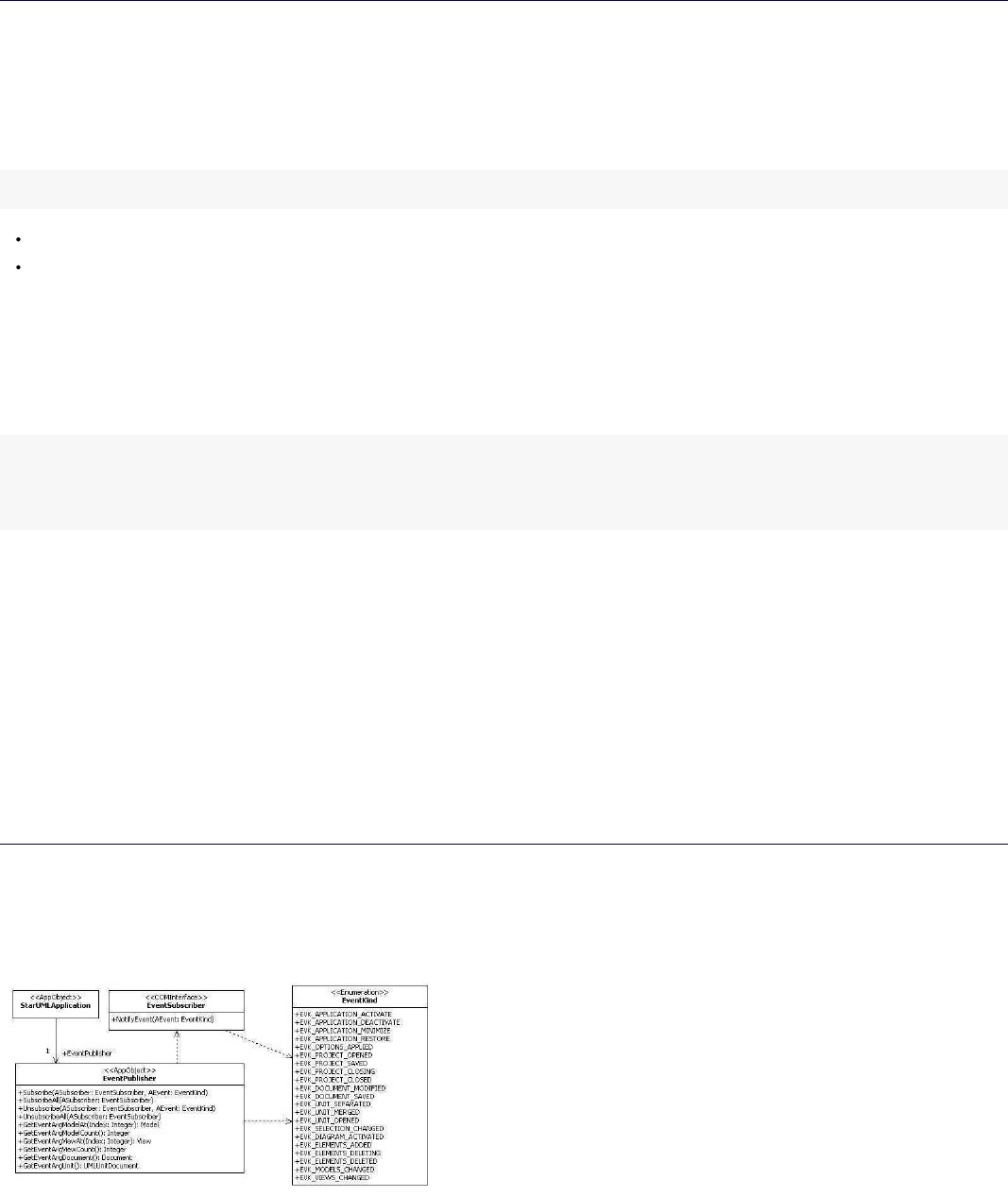
StarUML5.0DeveloperGuide(WritingAdd-InCOMObject)
http://staruml.sourceforge.net/docs/developer-guide(en)/ch09.html
modules being out of order.
Note: Delete option schema file from the StarUML module directory
(<install-dir>\modules)
not to use the option
extension any more.
Accessing Option Values
Accessing Option Values with COM Interface
You can access the option values that user changed in option dialog by using COM interface of StarUML.
GetOptionValue() of IStarUMLApplication returns option value depends on SchemaID and Key inputted as
variant.
The method usage is as follows.
IStarUMLApplication.GetOptionValue(SchemaID:String,Key:String):Variant
SchemaID: Schema id that defined in the option schema file.
Key: Key of option item that defined in the option schema file.
Use the
Variant
typed return value of GetOptionValue() by casting it according to the type of each option item. You can read the
value directly without additional type casting in script languages such as JScript and VBScript.
The following is JScript example that reads "UNDO_LEVEL" option value defined in the StarUML environment option
schema and output it to message box.
varapp=newActiveXObject("StarUML.StarUMLApplication");
varundoLevel=app.GetOptionValue("ENVIRONMENT","UNDO_LEVEL");
WScript.Echo("Max.numberofundoactions:"+undoLevel);
Processing change event of option value
StarUML propagates events that occurs in using the program to Add-ins
that implement
IEventSubscriber
interface. If user changes option values in option dialog, Application invokes event handler-
NotifyEvent()
- of
Add-ins that implement
IEventSubscriber
. If you want to apply option values promptly to the Add-in when user
changes the option values, implement IEventSubscriber interface and NotifiyEvent() to read the option values by
using
IStarUMLApplication.GetOptionValue()
method in case of
EVK_OPTIONS_APPLIED
event. Add-Ins that
use script such as VBScript and JSCript cannot apply option values to
the Add-in becase they can't implement
IEventSubscriber
interface.
For the details of event handling, it will be featured in the next section.
Basic Concepts of Event Subscription
An Add-In Object that implements the IEventSubscriber interface can subscribe to various internal events of the
StarUML™ application. Whenever an internal event occurs, the StarUML™ application calls the NotifyEvent method
of the registered
IEventSubscriber
type objects.
The class diagram below illustrates the organization of the external API interfaces related to event subscription.
Kinds of Events
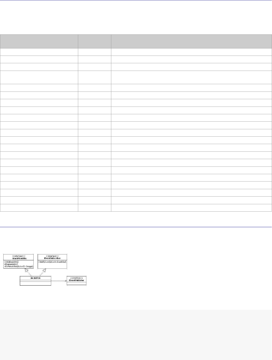
StarUML5.0DeveloperGuide(WritingAdd-InCOMObject)
http://staruml.sourceforge.net/docs/developer-guide(en)/ch09.html
Kinds of Events
As illustrated above, the EventKind
enumeration defines the kinds of internal events of the StarUML™ application that can be subscribed by Add-In
objects that implement the
IEventSubscriber
interface.
The table below describes each literal of the
EventKind
enumeration.
Event Kind (literal)
Integer
Value
Event Description
EVK_APPLICATION_ACTIVATE 0 Occurs when the StarUML™ application window is activated.
EVK_APPLICATION_DEACTIVATE 1
Occurs when the StarUML™ application window is deactivated.
EVK_APPLICATION_MINIMIZE 2
Occurs when the StarUML™ application window is minimized.
EVK_APPLICATION_RESTORE 3 Occurs when the minimized StarUML™ application window is
restored to the previous size.
EVK_OPTIONS_APPLIED 4 Occurs when an option value is modified.
EVK_PROJECT_OPENED 5
Occurs when a project element is created or a project file is opened.
EVK_PROJECT_SAVED 6 Occurs whenever a project is saved.
EVK_PROJECT_CLOSING 7 Occurs when "Close Project" is selected.
EVK_PROJECT_CLOSED 8 Occurs when a project is closed.
EVK_DOCUMENT_MODIFIED 9 Occurs when a document (project or unit) is modified.
EVK_DOCUMENT_SAVED 10
Occurs when a document (project or unit) is saved.
EVK_UNIT_SEPARATED 11 Occurs when a unit element is separated.
EVK_UNIT_MERGED 12
Occurs when a separated unit element is merged.
EVK_UNIT_OPENED 13 Occurs when a unit is opened.
EVK_SELECTION_CHANGED 14 Occurs when the modeling element selection is changed.
EVK_DIAGRAM_ACTIVATED 15
Occurs when a diagram is opened.
EVK_ELEMENTS_ADDED 16 Occurs whenever a new modeling element is created.
EVK_ELEMENTS_DELETING 17
Occurs when deleting a modeling element.
EVK_ELEMENTS_DELETED 18
Occurs when a modeling element is deleted.
EVK_MODELS_CHANGED 19 Occurs when a model element property value is modified.
EVK_VIEWS_CHANGED 20
Occurs when a view element property value is modified.
Subscribing to Events
In order for an Add-In to subscribe to the StarUML™ application events, it needs to implement the
IEventSubscriber interface in addition to the IStarUMLAddIn interface, which is the common interface for all
StarUML™ Add-Ins.
The following example shows the class definition of an StarUML™ Add-In object that implements the
IStarUMLAddIn interface and the IEventSubscriber
interface. This example is written in Delphi Pascal.
type
AddInExample=class(TComObject,IStarUMLAddIn,IEventSubscriber)
private
StarUMLApp:IStarUMLApplication;
EventPub:IEventPublisher;
protected
functionInitializeAddIn:HResult;stdcall;
functionFinalizeAddIn:HResult;stdcall;
functionDoMenuAction(ActionID:Integer):HResult;stdcall;
functionNotifyEvent(AEvent:EventKind):HResult;stdcall;
StarUML5.0DeveloperGuide(WritingAdd-InCOMObject)
http://staruml.sourceforge.net/docs/developer-guide(en)/ch09.html
functionNotifyEvent(AEvent:EventKind):HResult;stdcall;
...
public
procedureInitialize;override;
destructorDestroy;override;
...
end;
Event Subscription Registration and Removal
In order for an Add-In object, which implements the IEventSubscriber interface, to subscribe to events, the event
subscription must be registered. Event subscription registration and removal can be done through the
IEventPublisher type object. Reference to the IEventPublisher type object can be obtained through the
IStarUMLApplication element. The following Delphi Pascal example shows obtaining referen
ce to
IStarUMLApplication and the IEventPublisher
type object.
implementation
procedureAddInExample.Initialize;
begin
inherited;
StarUMLApp:=CreateOleObject('StarUML.StarUMLApplication')asIStarUMLApplication;
EventPub:=StarUMLApp.EventPublisher;
end;
destructorAddInExample.Destroy;
begin
EventPub:=nil;
StarUMLApp:=nil;
inherited;
end;
The IEventPublisher
interface provides the following methods for registration and removal
of event subscription. The "ASubscriber"
argument for each method represents the actual Add-In object that implements the IEventSubscriber
interface.
Method Description
Subscribe(ASubscriber: IEventSubscriber; AEvent:
EventKind)
Registers subscription to an event specified by the
AEvent argument.
SubscribeAll(ASubscriber: IEventSubscriber)
Registers subscription to all events.
Unsubscribe(ASubscriber: IEventSubscriber; AEvent:
EventKind)
Removes subscription to an event specified by the AEvent
argument.
UnsubscribeAll(ASubscriber: IEventSubscriber) Removes subscription to all events.
Use the Subscribe
method if an Add-In object needs to subscribe to certain events only. For instance, for subscribing to two specific
events, call the Subscribe method for each event. Use the
SubscribeAll
method to subscribe to all events. In
general, the Subscribe and SubscribeAll
methods are called by the
IPlasticAddIn.InitializeAddIn method.
If an Add-In object no longer needs to subscribe to the registered events (e.g. when the object is terminated), all the
events registered must be unregistered. Use the
Unsubscribe
method if the subscription was registered by the
Subscribe method, and use the
UnsubscribeAll
method if the subscription was registered by the
SubscribeAll
method. In general, the Unsubscribe and SubscribeAll
methods are called by the
IStarUMLAddIn.FinalizeAddIn method.
The following example shows registration and removal of subscription
to the EVK_ELEMENTS_ADDED and
EVK_ELEMENTS_DELETED events.
implementation
functionAddInExample.InitializeAddIn:HResult;
begin
EventPub.Subscribe(Self,EVK_ELEMENTS_ADDED);
EventPub.Subscribe(Self,EVK_ELEMENTS_DELETED);
StarUML5.0DeveloperGuide(WritingAdd-InCOMObject)
http://staruml.sourceforge.net/docs/developer-guide(en)/ch09.html
EventPub.Subscribe(Self,EVK_ELEMENTS_DELETED);
...
Result:=S_OK;
end;
functionAddInExample.FinalizeAddIn:HResult;
begin
EventPub.Unsubscribe(Self,EVK_ELEMENTS_ADDED);
EventPub.Unsubscribe(Self,EVK_ELEMENTS_DELETED);
...
Result:=S_OK;
end;
Acquiring Event Argument
When an event occurs, it is necessary to acquire the related arguments. For instance, when an event related to the
creation of a modeling element occurs (EVK_ELEMENTS_ADDED), it is necessary to identify which modeling
element is created. The
IEventPublisher
interface provides the following methods in respect of event arguments.
Method Description
GetEventArgModelCount (): Integer
Returns the model element count related to the event.
GetEventArgModelAt(Index: Integer):
IModel
Returns reference to the (index)th model element related to the
event.
GetEventArgViewCount: Integer
Returns the view element count related to the event.
GetEventArgViewAt(Index: Integer): IView Returns reference to the (index)th view element related to the event.
GetEventArgDocument: IDocument Returns reference to the document element related to the event.
GetEventArgUnit: IUMLUnitDocument Returns reference to the unit element related to the event.
Processing Events
When a subscribed event occurs, the Add-In needs to execute appropriate processes. Whenever a subscribed event
occurs, the StarUML™ application calls the
NotifyEvent
method of the respective Add-In and passes the event kind as an argum
ent. The event kind is passed as an
argument for the NotifyEvent
method because it is possible for an Add-In to subscribe to more than one event. Each Add-In needs to implements
the NotifyEvent method to arrive at a logic to execute various processes according to
the event kinds.
The following example shows implementation of the NotifyEvent method. This example verifies the semantic
validity of the element connections when the association element (UMLAssociation) or the generalization element
(UMLGeneralization) is created in the StarUML™ application. (This example is a continuation of the examples
above. For definition of the Add-In object, see the examples above.)
implementation
functionAddInExample.NotifyEvent(AEvent:EventKind):HResult;
var
M:IModel;
Assoc:IUMLAssociation;
Gen:IUMLGeneralization;
End1,End2:IUMLClassifier;
begin
ifAEvent=EVK_ELEMENTS_ADDEDthen
begin
ifEventPub.GetEventArgModelCount=1then
begin
M:=EventPub.GetEventArgModelAt(0);
//Association
ifM.QueryInterface(IUMLAssociation,Assoc)=S_OKthen
begin
End1:=Assoc.GetConnectionAt(0).Participant;
End2:=Assoc.GetConnectionAt(1).Participant
ifEnd1.IsKindOf('UMLPackage')orEnd2.IsKindOf('UMLPackage')then
ShowMessage('Packagescannothaveassociations.')
...

StarUML5.0DeveloperGuide(WritingAdd-InCOMObject)
http://staruml.sourceforge.net/docs/developer-guide(en)/ch09.html
end;
//Generalization
ifM.QueryInterface(IUMLGeneralization,Gen)=S_OKthen
begin
ifGen.Child.IsRootthen
ShowMessage('Rootelementscannothaveparentelements.');
ifGen.Parent.IsLeafthen
ShowMessage('Leafelementscannothavechildelements.');
end;
end;
end;
Result:=S_OK;
end;
StarUML5.0DeveloperGuide(ExtendingNotation)
http://staruml.sourceforge.net/docs/developer-guide(en)/ch10.html
Chapter 10. Extending Notation
This chapter gives an introduction of Notation Extension. It gives basic concepts of Notation Extension and simple
specification of language syntax for Notation Extension. For example, it shows how to add new sort diagram to take
advantage of Notation Extension.
Why Notation Extension?
Notation Extension is a extension concept for user to define and use user's own notation for UML model. StarUML
supports platform to operate the featrue of Notation Extension. Well, why Notation Extension is needed?
Profile supports iconic and decoration view but it can't express exactly in required form for notation.
For mapping ER-Diagram to UML, mapping ER model to UML model looks proper but mapping notation to UML
notation looks unnatural.
UML meta model is an enough data container to contain all kinds of modeling semantics. If UML tool can
extend its notation freely, it can play a meta-modeling tool role in all modeling area.
By expressing notation(form) in the same way as before but describing
model with UML model, it gives to users
mutual supplement, efficiency, and compatibility between old area and UML area.
Notation Extension Language
Basic Syntax
Syntax of Notation Extension Language is similar to Scheme language(d
ialect of LISP). Basic unit is expression and
whole statement consists of one expression. Expression is composed of value or operation expression. Value means
real, integer, string, boolean, identifier. Operation expression star
ts with "(" and ends with ")". Operator and
operands(they describe another expressions) appear in parentheses. Op
erator and identifier are not case-sensitive.
Comment style follows the comment rule of C++ and Java. Comment uses "//" on one line and "/* */" on multiple
lines.
expr::=flt|int|str|bool|nil|ident|"("oper(expr)*")";
First statement of Notation Extension Language is "notation" expression. Operator is "notation", and arguments are
"onarrange" and "ondraw" expressions. A "notation" expression corresp
onds to a "stereotype" in profile. The
"notation" expression describes how stereotype shape is shown. When s
tereotyped element is shown in diagram,
the expression is executed. First, "onarrange" expression executes argumented expressions to recalculate element
position . "ondraw" expression is executed to draw element after "onarrange" expression execution.
(notation
(onarrange...)
(ondraw...)
)
The followings are available argument expression for "onarrange" and "ondraw" expression.
sequence
if
for
set
logical, comparison operator
built-in function
sequence expression

StarUML5.0DeveloperGuide(ExtendingNotation)
http://staruml.sourceforge.net/docs/developer-guide(en)/ch10.html
"sequence" expression groups and executes arguments in order. The arguments of "sequence" expression are also
expression and the number of them is not limited.
(sequenceexpr1expr2...)
The following example shows that one "sequence" expression groups 3 e
xpressions.
(sequence
(+1020)//10+20
(-203040)//20-30-40
(/1020)//10/20
)
if expression
"if" expression represents conditional syntax. First argument is condition, second argument is executed if condition
is true, and third argument is executed if condition is not. Third argument appears optionally. If third argument is
omitted and condition is false, "if" expression doesn't execute anything.
(ifcondition-expron-true-expron-false-expr?)
The following example shows that expression increases "count" variable if "i" value is between 0 and 30, but
decreases "count" variable if not.
(if(or(<=i0)(>=i30))//if(i<=0||i>=30)
(setcount(+count1))//count++;
(setcount(-count1))//else
)//count--;
for expression
"for" expression repeats expression while specified variable is from initial value to end value. First argument is a
variable name to be used for repetition. Second is initial value and third is end value. The last is expression to be
executed on each step of repetition.
(for
identifierinit-exprend-exprexpr
)
The following is example which prints 1 to 10 on the screen.
(fori110//for(inti=1;i<=10;i++)
(textout100(+100(*i20))//textout(100,100+(i*20),i);
i
)
)
set expression
"set" expression assigns variable to value. Variable declaration is not required. It is declared automatically and
bounded as global variable when it is used.
(set
identifiervalue-expr
)
The following example shows that it assigns a, b variables, concatena
tes a and b, and assigns result to c variable.
(seta'Mynameis')//a="Mynameis";
StarUML5.0DeveloperGuide(ExtendingNotation)
http://staruml.sourceforge.net/docs/developer-guide(en)/ch10.html
(seta'Mynameis')//a="Mynameis";
(setb'foo')//b="foo";
(setc(concatab))//c=a+b;
arthmetic, logical, comparison operator
Supported mathematical operators are "+", "-", "*", "/", and logical
operators are "and", "or", "not". And it supports
"=", "!=", "<", "<=", ">", ">=" operators for comparison.
(+1(/105)(-(*23)6))//1+(10/5)+(2*3-6)
(and(<i10)(not(=j20)))//(i<10)&&(!(j==20))
built-in function
Built-in functions supported on Notation Extension Language are grouped by the followings:
Mathematical functions
String functions
List functions
Model access functions
Graphic functions
Mathematical functions
The following is list of built-in functions related to mathematic.
Signature Description
(sin angle)
returns the sine of the angle.
(cos angle) returns the cosine of the angle.
(tan angle) returns the tangent of the angle.
(trunc val) truncates a real-type value to an integer-type value. val is a
real-type expression.
(round val) returns an integer value that is the value of val rounded to the
nearest whole number. If val is exactly halfway between two
whole numbers, the result is always the even number.
String functions
The following is list of built-in functions related to string processing.
Signature Description
(concat str1 str2...) concatenates all argument strings to one string.
(trim str)
removes leading and trailing spaces and control characters from
the given string.
(length str) returns the number of characters in argument string.
(tokenize str deli) returns the list of strings that results when a string is separated
by deli delimiter.
List functions
The following is list of built-in functions related to list processin
g.
Signature Description
(list val1 val2 ...) returns list which is composed of arguments.
StarUML5.0DeveloperGuide(ExtendingNotation)
http://staruml.sourceforge.net/docs/developer-guide(en)/ch10.html
(append lst lst) appends item to the end of list list.
(append lst item)
(itemat lst index) returns an item at index in list.
(itemcount lst) returns the number of items in argument list.
Mode access functions
The following is list of built-in functions related to model acess.
Signature Description
(mofattr elem attr)
returns in strings the default type attribute values of modeling
elements as defined by arguments.
(mofsetattr elem attr val) assigns "val" value to "attr" attribute of modeling elements.
(mofref elem ref)
returns the reference type attribute (object reference) values of
modeling elements as defined by arguments.
(mofcolat elem col at)
returns the attribute value (object reference) of the "at" order
item in the reference collection of modeling elements as defined
by arguments.
(mofcolcount elem col) returns the count number of items in reference collection as
defined by arguments.
(constraintval elem name) returns constraint contained in the element.
(tagval elem tagset name) returns taggedvalue, whose type is primitive type, of element in
tagd efinition set.
(tagref elem tagset name) returns taggedvalue, whose type is reference, of element in tag
definition set.
(tagcolat elem tagset name
at)
returns item in taggedvalue(collectio type) of element in tag
definition set.
(tagcolcount elem tagset
name)
returns length of items in taggedvalue(collectio type) of element
in tag definition set.
Graphic functions
The following is list of built-in functions related to style.
Signature Description
(setpencolor color) set Color to change the color used to draw lines or outline
shapes. The way the color is used by the pen depends on the
Mode and Style properties.
Color can have one of the following values:
Value
Meaning
clNone White
clAqua Aqua
clBlack
Black
clBlue
Blue
clCream
Cream
clDkGray
Dark Gray
clFuchsia
Fuchsia
clGray
Gray
clGreen
Green
StarUML5.0DeveloperGuide(ExtendingNotation)
http://staruml.sourceforge.net/docs/developer-guide(en)/ch10.html
clGreen
Green
clLime Lime green
clLtGray
Light Gray
clMaroon
Maroon
clMedGray Medium Gray
clMoneyGreen
Mint green
clNavy Navy blue
clOlive Olive green
clPurple
Purple
clRed
Red clGrayText
clSilver
Silver
clSkyBlue Sky blue
clTeal Teal
clWhite White
clYellow Yellow
(setpenstyle style) Use Style to draw a dotted or dashed line, or to omit the line
that appears as a frame around shapes.
Style can have one of the following values:
Value
Meaning
psSolid A solid line.
psDash
A line made up of a series of dashes.
psDot A line made up of a series of dots.
psDashDot
A line made up of alternating dashes and
dots.
psDashDotDot
A line made up of a series of dash-dot-dot
combinations.
psClear
No line is drawn (used to omit the line around
shapes that draw an outline using the current
pen).
psInsideFrame A solid line, but one that may use a dithered
color if Width is greater than 1.
(setbrushcolor color) set the color of the brush. Color can have one of the color list
above.
(setbrushstyle style) bsSolid, bsClear, bsHorizontal, bsVertical, bsFDiagonal,
bsBDiagonal, bsCross, bsDiagCross
(setfontface font) set the typeface of the font.
(setfontcolor color) set the color of the font. Color can have one of the color list
above.
(setfontsize size) set size of the font.
(setfontstyle style) set the style of the font. Style is composed of the followings and
seperator is "|" character.
Value
Meaning
fsBold
The font is boldfaced.
fsItalic he font is italicized.
fsUnderline
The font is underlined.
StarUML5.0DeveloperGuide(ExtendingNotation)
http://staruml.sourceforge.net/docs/developer-guide(en)/ch10.html
fsUnderline
The font is underlined.
fsStrikeOut The font is displayed with a horizontal line
through it.
(setdefaultstyle)
Restore the Pen, Brush, Font informations to the default value.
The following is list of built-in functions related to graphic.
Signature Description
(textheight str) Returns the height of a string in pixels, rendered in the current
font.
(textwidth str) Returns the width of a string rendered in the current font (in
pixels).
(textout x y str) Writes a string on the screen, starting at the point (X,Y).
(textbound x1 y1 x2 y2
yspace text clipping)
writes a string on area (x1, y1) to (x2, y2) of screen. yspace is
line space. if clipping is true, string bounded to area is written.
(textrect x1 y1 x2 y2 x y str) writes a string on area (x1, y1) to (x2, y2) of screen, starting at
the point (X,Y).
The following is list of built-in functions related to shape.
Signature Description
(rect x1 y1 x2 y2)
Draws a rectangle defined by the points (X1,Y1) and (X2,Y2).
(filerect x1 y1 x2 y2) Fills the specified rectangle on the canvas using the current
brush.
(ellipse x1 y1 x2 y2)
Draws the ellipse defined by a bounding rectangle on the screen.
(roundrect x1 y1 x2 y2 x3 y3) Draws a rectangle with rounded corners on the screen.
(arc x1 y1 x2 y2 x3 y3 x4 y4) draws an arc inside an ellipse bounded by the rectangle defined
by (X1,Y1) and (X2,Y2). The arc starts at the intersection of the
line drawn between the ellipse center ((X1+X2) / 2.0,(Y1+Y2) /
2.0) and the point (X3,Y3) and is drawn counterclockwise until it
reaches the intersection of the line drawn between the ellipse
center and the point (X4,Y4)
(pie x1 y1 x2 y2 x3 y3 x4 y4) draws a pie-shaped wedge on the image. The wedge is defined
by the ellipse bounded by the rectangle determined by the
points (X1, Y1) and X2, Y2). The section drawn is determined by
two lines radiating from the center of the ellipse through the
points (X3, Y3) and (X4, Y4)
(drawbitmap x y img
transparent)
renders the image specified by the parameter on the screen at
the location given by the coordinates (X, Y). Use transparent
argument to specify that the image be drawn transparently. Use
x2, y2 argument to stretch image.
(drawbitmap x1 y1 x2 y2 img
transparent)
(moveto x y) changes the current drawing position to the point (X,Y).
(lineto x y) draws a line on the canvas from pen position to the position
specified by X and Y, and sets the pen position to (X, Y).
(line x1 y1 x2 y2) draws a line on the canvas from (x1, y1) position to the position
specified by (x2, y2).
(pt x y)
returns a Point structure from a pair of coordinates.
(polygon (pt x1 y1) (pt x2 y2)
...)
draws a series of lines on the canvas connecting the points
passed in and closing the shape by drawing a line from the last
point to the first point.
(polyline (pt x1 y1) (pt x2 y2)
...)
draws a series of lines on the canvas with the current pen,
connecting each of the points passed to it in Points.
(polybezier (pt x1 y1) (pt x2
draws a set of Bezier curves.
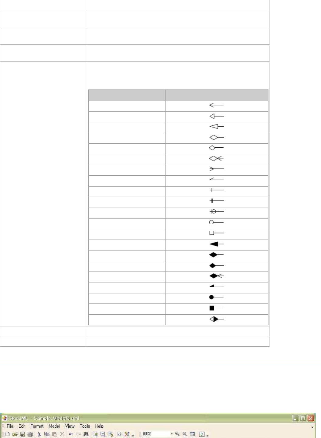
StarUML5.0DeveloperGuide(ExtendingNotation)
http://staruml.sourceforge.net/docs/developer-guide(en)/ch10.html
(polybezier (pt x1 y1) (pt x2
y2) ...)
draws a set of Bezier curves.
(ptatx index) It is available when current view element is edge element. it
returns x value of point structure at index of edge.
(ptaty index) It is available when current view element is edge element. it
returns y value of point structure at index of edge.
(ptcount) It is available when current view element is edge element. it
returns the number of points of edge.
(drawedge headOrTail
endStyle)
It is available when current view element is edge element. it
draws end of edge in argument style. Style is composed of the
followings and seperator is "|" character.
Value
Shape
esStickArrow
esSolidArrow
esTriangle
esDiamond
esMiniDiamond
esArrowDiamond
esCrowFoot
esHalfStickArrow
esBar
esDoubleBar
esBelowCircle
esCircle
esRect
esFilledTriangle
esFilledDiamond
esMiniFilledDiamond
esArrowFilledDiamond
esFilledHalfStickArrow
esFilledCircle
esFilledRect
esMiniHalfDiamond
(drawobject elem) draws element in original style.
(arrangeobject elem) arranges element in original style.
Creating a New Type of Diagram
There are some preparations to utilize Notation Extension. First, pro
file is needed. It describes which stereotype it
applies Notation Extension to. Second, Notation Extension file(*.NXT)
is needed. It describes how notation is drawn.
You should connect Notation Extension to stereotype in profile. Prope
rties to be used in Notation Extension should
also be inserted as tagged value in profile. Let me introduce to you
how to create ER-Diagram notations for
example of Notation Extension.
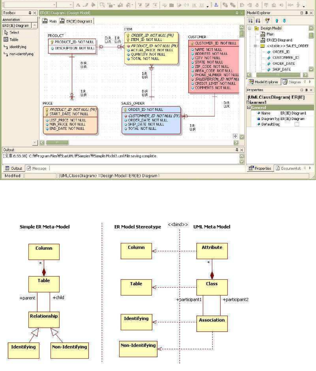
StarUML5.0DeveloperGuide(ExtendingNotation)
http://staruml.sourceforge.net/docs/developer-guide(en)/ch10.html
Profile Definition
Looking around elements in ER-Diagram, it consists of several elements (Table, Column, Relationship, etc.).
You should make stereotypes for table, column, relationship, etc. and apply stereotypes to UML models (Class,
Association, Attribute) to map ER models to UML models. These are des
cribed like the followings in profile. You add
<STEREOTYPE> sub element named "table" to <STEREOTYPELIST> element and assign <BASECLASS> element's
value as "UMLClass" to apply stereotype to "UMLClass" typed model. In order for the class stereotyped "table" to be
shown as ER notation, Notation Extension filename("table.nxt") should be specified to <NOTATOIN> element.
For "column" stereotype, Additional tagged values are required to indicate whether column is PK, FK, AK, or IK. So
tag definition set name("table" in this case) that define these tagged values are defined is described in
<RELATEDTAGDEFINITIONSET> element.

StarUML5.0DeveloperGuide(ExtendingNotation)
http://staruml.sourceforge.net/docs/developer-guide(en)/ch10.html
<RELATEDTAGDEFINITIONSET> element.
<PROFILEversion="1.0">
<HEADER>
...
</HEADER>
<BODY>
<STEREOTYPELIST>
<STEREOTYPE>
<NAME>table</NAME>
<BASECLASSES>
<BASECLASS>UMLClass</BASECLASS>
</BASECLASSES>
<NOTATION>table.nxt</NOTATION>
</STEREOTYPE>
<STEREOTYPE>
<NAME>column</NAME>
<BASECLASSES>
<BASECLASS>UMLAttribute</BASECLASS>
<RELATEDTAGDEFINITIONSET>table</RELATEDTAGDEFINITIONSET>
</BASECLASSES>
</STEREOTYPE>
...
</STEREOTYPELIST>
Tag definition set is described in <TAGDEFINITIONSET> element of <TAGDEFINITIONSETLIST> and
<TAGDEFINITIONSET> element is composed of <TAGDEFINITION> elements that describe tagged value's
properties(name, type, and default value) added for column stereotype. In the following example, tagged values to
Identify PK and FK are added, each tagged value's type is boolean, and each default value is false. (it means that
every column is neither primary key nor foreign key at the first time
after construction)
...
</STEREOTYPELIST>
<TAGDEFINITIONSETLIST>
<TAGDEFINITIONSET>
<NAME>column</NAME>
<BASECLASSES>
<BASECLASS>UMLAttribute</BASECLASS>
</BASECLASSES>
<TAGDEFINITIONLIST>
...
<TAGDEFINITIONlock="False">
<NAME>PK</NAME>
<TAGTYPE>Boolean</TAGTYPE>
<DEFAULTDATAVALUE>false</DEFAULTDATAVALUE>
</TAGDEFINITION>
<TAGDEFINITIONlock="False">
<NAME>FK</NAME>
<TAGTYPE>Boolean</TAGTYPE>
<DEFAULTDATAVALUE>false</DEFAULTDATAVALUE>
</TAGDEFINITION>
...
</TAGDEFINITIONLIST>
</TAGDEFINITIONSET>
</TAGDEFINITIONSETLIST>
To select diagram that shows stereotypes after definition of stereotypes, define new diagram named "ER Diagram"
to <DIAGRAMTYPE> element in <DIAGRAMTYPELIST> element, describe <BASEDIAGRAM> element's value as
"ClassDiagram" for diagram to be based on class diagram, and describe pallette reference name("ERD(IE)") to
<AVALIABLEPALLETTE> element.

StarUML5.0DeveloperGuide(ExtendingNotation)
http://staruml.sourceforge.net/docs/developer-guide(en)/ch10.html
<DIAGRAMTYPELIST>
<DIAGRAMTYPE>
<NAME>ER(IE)Diagram</NAME>
<DISPLAYNAME>ER(IE)Diagram</DISPLAYNAME>
<BASEDIAGRAM>ClassDiagram</BASEDIAGRAM>
<ICON>DataModelDiagram.bmp</ICON>
<AVAILABLEPALETTELIST>
<AVAILABLEPALETTE>ERD(IE)</AVAILABLEPALETTE>
</AVAILABLEPALETTELIST>
</DIAGRAMTYPE>
</DIAGRAMTYPELIST>
The pallette informations are described in <PALLETTE> element. <PALLE
TTE> element is list that has reference of
pallete button item.The detail informations for pallette button item are described to <ELEMENTPROTOTYPE>
element. <NAME> element describes the element's name to be created, <
DISPLAYNAME> and <ICON> elements
describes the button item's name and image file name on pallette, <DRAGTYPE> element means whether mouse
action style is like rectangle or edge style, <BASEELEMENT> and <STER
EOTYPENAME> elements mean that created
element is "Class" element and the element's stereotype is assigned t
o "table". To draw element by notation
extension at once after element creation, <SHOWEXTENSION> element's value should be set to true.
<PALETTELIST>
<PALETTE>
<NAME>ERD(IE)</NAME>
<DISPLAYNAME>ERD(IE)Diagram</DISPLAYNAME>
<PALETTEITEMLIST>
<PALETTEITEM>Table</PALETTEITEM>
<PALETTEITEM>identifying</PALETTEITEM>
<PALETTEITEM>non-identifying</PALETTEITEM>
</PALETTEITEMLIST>
</PALETTE>
</PALETTELIST>
<ELEMENTPROTOTYPELIST>
<ELEMENTPROTOTYPE>
<NAME>Table</NAME>
<DISPLAYNAME>Table</DISPLAYNAME>
<ICON>Table.bmp</ICON>
<DRAGTYPE>Rect</DRAGTYPE>
<BASEELEMENT>Class</BASEELEMENT>
<STEREOTYPENAME>table</STEREOTYPENAME>
<SHOWEXTENDEDNOTATION>True</SHOWEXTENDEDNOTATION>
</ELEMENTPROTOTYPE>
...
<ELEMENTPROTOTYPELIST>
...
Writing Notation Extension
Though data modeling is available by defining profile only, Notation Extension file(*.nxt) that is described to
profile's <NOTATION> element should be written in order that models a
re shown in ER notation.
The following is summary of "table.nxt" file that draw notation for "
table" stereotype. "onarrange" expression
configures status required to draw "table". "ondraw" expression draws
parts of table name, PK column, and other
columns.
(notation
(onarrange...)
(ondraw
//drawnamepart...
//drawPKcolumnpart...
//drawothercolumnpart...
)
)
StarUML5.0DeveloperGuide(ExtendingNotation)
http://staruml.sourceforge.net/docs/developer-guide(en)/ch10.html
)
The first part (name compartment) is that variables for drawing are c
onfigured and name string got from model is
written starting at the point (x, y).
(setxleft)
(setytop)
...
(setname(mofattrmodel'Name'))
(textoutxyname)
...
Here, "left" and "top" variables are reserved variables. They take va
lues from StarUML platform on each time of
executing Notation Extension, and may return values to StarUML platform again on end time of execution Notation
Extension. The followings behaving like this are reserved variables.
Variable
View
element
Returns to StarUML
platform Description
view Node,Edge not return target view to be drawn
model Node,Edge not return model of target view to be drawn
left Node return target view's left-most position
top Node return target view's top-most position
right Node return target view's right-most position
bottom Node return target view's bottom-most position
width Node return target view's width
height
Node return target view's height
minwidth Node not return minimum width of target view
minheight
Node not return minimum height of target view
points Edge not return point collection of target edge view
head Edge not return head element of target edge view
tail Edge not return tail element of target edge view
The following checks whether current table is dependent on others and draws property table shape. Repeating
current table(class)'s association, if association's head end connect
s to current table, it means table is dependent,
table is drawn as rounded rectangle. Unless, table is drawn as rectangle and it means that table is independent on
others.
(setisSuperTypetrue)
(setc(mofcolcountmodel'Associations'))
(fori0(-c1)
(sequence
(setassocEnd(mofcolatmodel'Associations'i))
(if(=assocEnd(mofcolat(mofrefassocEnd'Association')'Connections'1))
(setisSuperTypefalse)
nil)))
...
//outline
(setdefaultstyle)
(ifisSuperType
(rectxyrightbottom)
(roundrectxyrightbottom1010))
When displaying columns, repeating all the columns that table contains, elements whose PK tagged value is true are
drawn over the other columns, PK icon is drawn on the left side and column name is drawn on the right side.
...
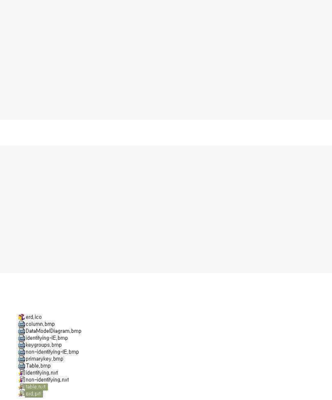
StarUML5.0DeveloperGuide(ExtendingNotation)
http://staruml.sourceforge.net/docs/developer-guide(en)/ch10.html
...
(fori0(-(mofColCountmodel'Attributes')1)
(sequence
//selecti-thcolumn
(setattr(mofColAtmodel'Attributes'i))
...
//columnisPK?
(if(tagValattr'ERD''column''PK')
(sequence
...
(setattrName(mofAttrattr'Name'))
...
(drawbitmapxy'primarykey.bmp'true)
(textout(+x16)yattrName)
(setdefaultstyle)
...))))
...
(lineleftyrighty)
And so repeating all the columns again, elements whose PK tagged valu
e is not true are drawn with column icon
and name under the PK columns.
...
(fori0(-(mofColCountmodel'Attributes')1)
(sequence
//selecti-thcolumn
(setattr(mofColAtmodel'Attributes'i))
(setkeys'')
...
//columnisnotPK?
(if(=(tagValattr'ERD''column''PK')false)
(sequence
...
(setattrName(mofAttrattr'Name'))
...
//drawcolumn
(drawbitmapxy'column.bmp'true))
(textout(+x16)yattrName)
(setdefaultstyle)
...))))
Installing and Using Notation Extension
The Notation Extension file must exist in path that is described in profile. In this case of "table" stereotype, because
path is not described and file name is only described, put profile and notation extension file in same folder.
If you have done all, do the following steps for installation.
Create new module folder in staruml/modules folder.1.
Put profile, notation extension file, and related image files into the module folder.2.
Restart StarUML and installation is done.3.
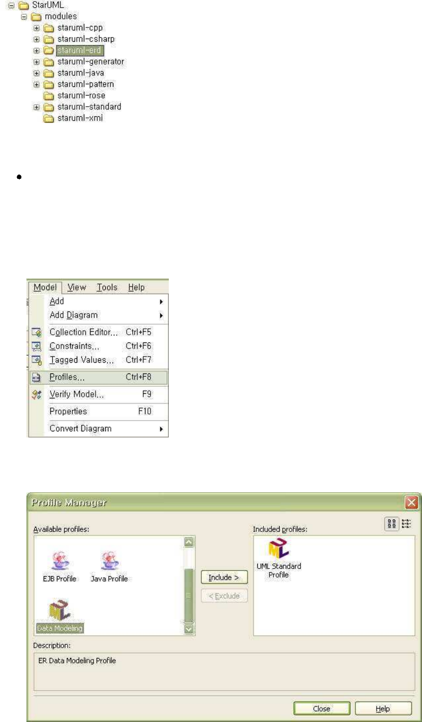
StarUML5.0DeveloperGuide(ExtendingNotation)
http://staruml.sourceforge.net/docs/developer-guide(en)/ch10.html
Reference
Download complete notation extension file, profile, etc. for ER-Diagr
am from module downloads of StarUML
official homepage of StarUML and install according to above steps.
The following is how to take advantage of notation extension.
Start StarUML.
1.
Click
[Model]
->
[Profiles...] menu.
2.
[Profile Manager] dialog box appears and select Data Modeling profile in [Available profiles] listbox and
click
[Include] button.
3.
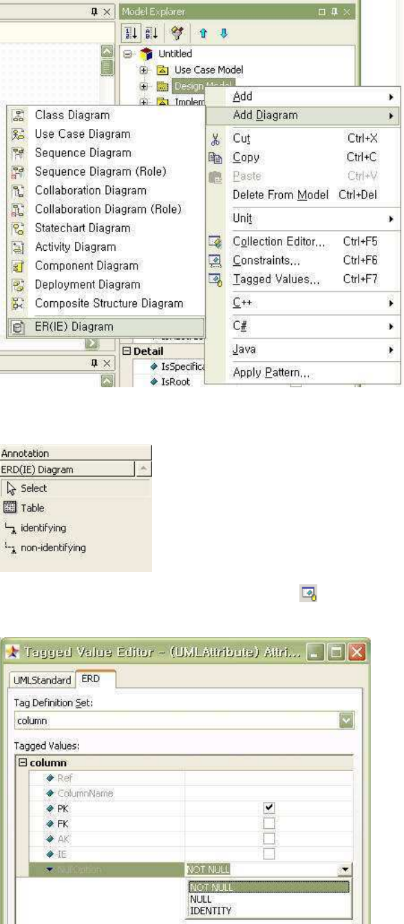
StarUML5.0DeveloperGuide(ExtendingNotation)
http://staruml.sourceforge.net/docs/developer-guide(en)/ch10.html
Select package that is going to contain ER-Diagram on
[Model Explorer]
, and click [Add Diagram] ->
[ER(IE) Diagram]
popup menu.
4.
ER-Diagram appears on [Main] window and pallette for ER modeling is shown on [toolbox].5.
Use notation on pallette and do modeling. Click
button and set tagged values on [Tagged Value Editor]'s
[ERD]
tab to configure column property.
6.
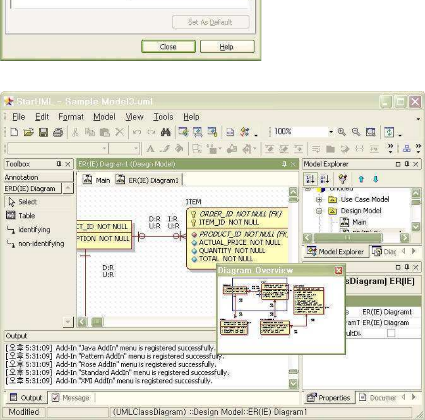
StarUML5.0DeveloperGuide(ExtendingNotation)
http://staruml.sourceforge.net/docs/developer-guide(en)/ch10.html
Write ER Modeling.7.
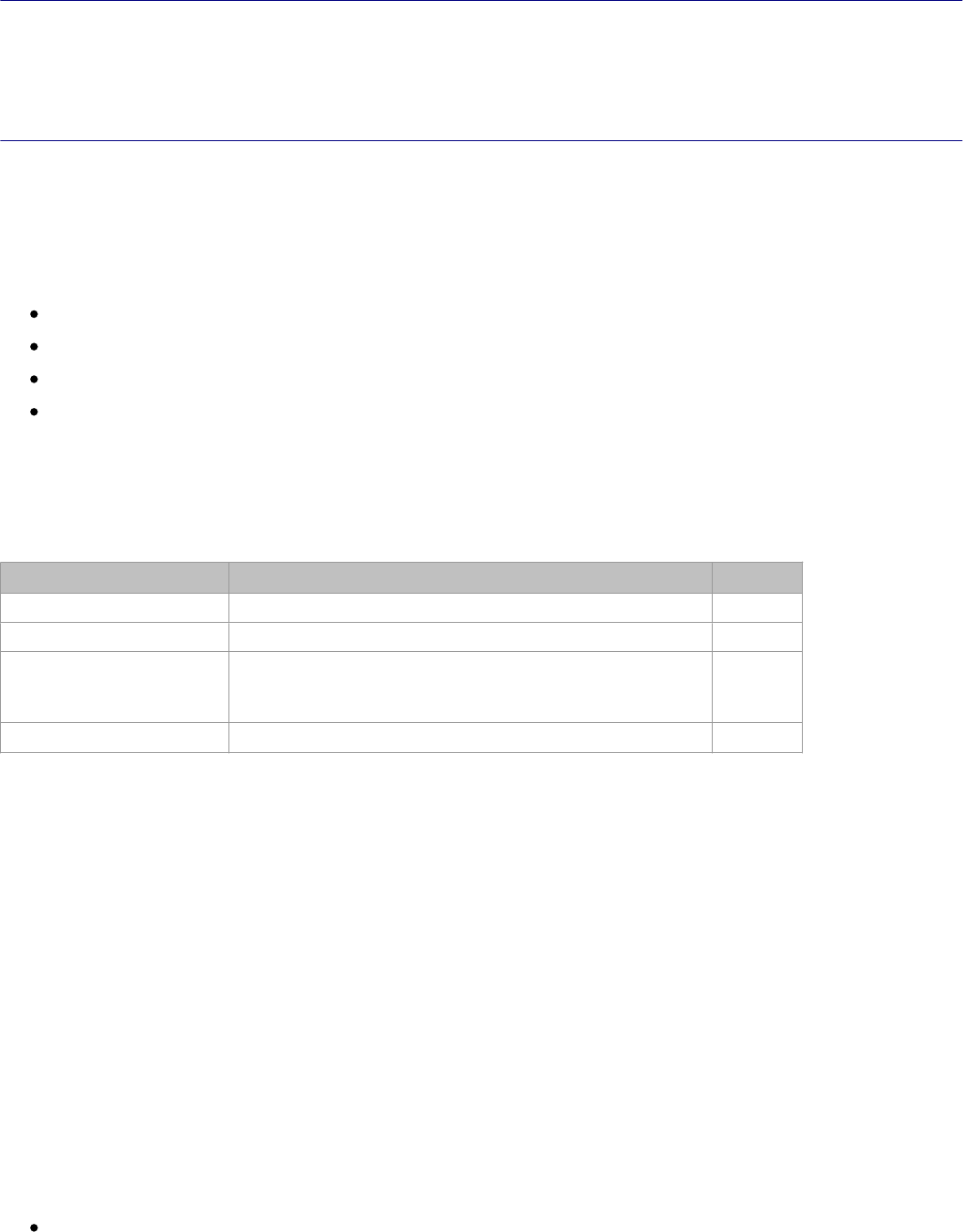
StarUML5.0DeveloperGuide(WritingTemplates)
http://staruml.sourceforge.net/docs/developer-guide(en)/ch11.html
Chapter 11. Writing Templates
This chapter gives an introduction of composition element used for generating artifacts like Microsoft Word,
Microsoft Excel, Microsoft PowerPoint, Code. It shows how user defines, registers, and distributes his own template
by example.
Component elements of Template
StatUML Generator Template consists of two area. one is style area th
at defines document form style and the other
is command area defining which model element the generator get from UML model. To represent command in
command area, MS Office templates(Word, Excel, PowerPoint) use MS Office's comment and code template uses
text surrounded with special characters. Command area contains commands like iteration, comparison, evaluation,
drawing for UML model. Commands of each template command are different slightly but common commands like
the followings are used.
REPEAT ~ ENDREPEAT
IF ~ ENDIF
DISPLAY
SCRIPT
REPEAT command
REPEAT is command that iterates model satisfying arguments. Repeating style existing between REPEAT and
ENDREPEAT command, generator writes the style to generated document at each time. REPEAT command has the
following four arguments.
Argument Description
Remarks
Pathname Repeats the elements existing below Pathname. Optional
FilterType
Repeats the element whose type is FilterType.
Optional
CollectionName Repeats elements in collections named by
CollectionName of elements that are selected by
Pathname and FilterType.
Optional
Condition Repeats elements that satisfy Condition. Optional
The first argument "Pathname" specifies the starting point of UML model repetition. It is in the form of path name
separated by "::" string. The element's pathname is shown in status b
ar. There are two sort of Pathname (absolute
and relative). Absolute pathname starts with "::". For example, "::A
" means element named "B" under top of
project, "A" means element named "A" under current element. Also "{R
}" string can be appear in front of
pathname string. "{R}" string means that it iterates recursively all
the elements existing in all the sub path under
pathname. If pathname is omitted, it repeats element under last path
selected by command.
The second argument "FilterType" means repeat element type. If argument value is "UMLClass", it iterates only
elements whose type is "UMLClass". If argument is omitted, it iterates all element regardless of type.
The third argument "CollectionName" means that it iterates elements in selected element's collection named by
CollectionName. For example, first argument is "::A", second argument is "UMLClass", and third argument is
"OwnedElements", it means that it iterates elements in "OwnedElements" collection of typed "UMLClass" elements
existing under "::A" path.
The fourth argument "Condition" means condition for repeat element to
satisfy. If argument value is
"current().StereotypeName == 'boundary'", it iterates elements that selected element's stereotype is "boundary".
The argument default value is true. If the argument is omitted, it do
repetition for all element regardless of
condition.
Reference
current() is Built-in function to be used in Generator. Refer to "Element composing template > Built-in
Functions" for details.
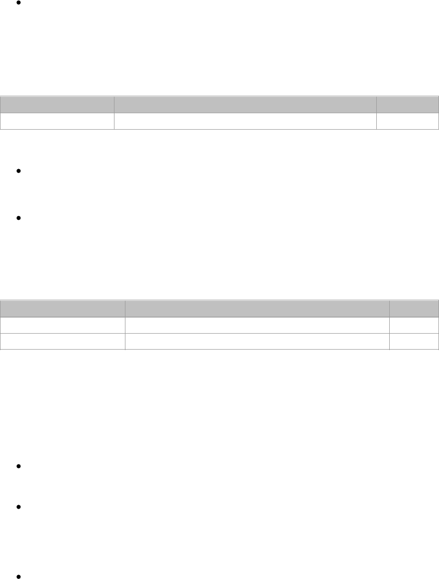
StarUML5.0DeveloperGuide(WritingTemplates)
http://staruml.sourceforge.net/docs/developer-guide(en)/ch11.html
Functions" for details.
Variation of command in WORD template.
Not only ENDREPEAT but also ENDREPEATTR corresonds to REPEAT command. REPEAT and ENDREPTR are
used for repetition of table row. For example, to make list of classe
s, put REPEAT command in the first cell of
row, put ENDREPTR command in the last cell of row. And so it makes table's rows iterating elements.
IF command
In case of satisfying argument condition, IF command displays styles existing between IF and ENDIF commands. IF
command has the following arguments. The argument value is expressed in JScript.
Argument Description Remarks
Condition condition to be satisfying Mandatory
Reference
IF command is not available in Excel and Powerpoint Templates. (to be implemented in the future)
Variation of command in WORD template.
There exists command variation "IF..ENDIFTR" for IF command. It shows table's row in the only case that
condition is true. Argument settings are equal to "REPEAT..ENDREPTR"c
ase. Put IF command in the first cell of
row and put ENDIFTR command in the last cell of row.
DISPLAY command
DISPLAY command print value of model element. DISPLAY command has the following arguments.
Argument Description
Remarks
Pathname Path of element to select Optional
Expression
Expression for value to be written
Optional
The first argument is the pathname that the second argument refers. T
he pathname is expressed in the form of
absolute and relative path. If pathname is omitted, current path is the last path selected by previous command.
The second argument is expression for value to be written. If first argument is "::A" and second argument is
"current().Documentation", it selects element named "A" under top project and writes the element's property value
named "Documentation".
Variation of command in WORD template.
In WORD template, DISPLAY command usage is slightly different. If the
type of element selected by the first
argument is UMLDiagram and second argument is omitted, Selected diagram image is inserted to generated
document.
In WORD template, DISPLAY command has third argument unlike in the other templates. The third argument
means whether written value is marked as index. It is required to gen
erate the list of indices automatically. If
the argument is set to "I", it marks word written by DISPLAY as index
.
Variation of command in POWERPOINT template.
In POWERPOINT template, two kinds of DISPLAY command exist (DISPLAY-TEXT and DISPLAY-IMAGE).
DISPLAY-TEXT command is explicitly used to write text and DISPLAY-IMAGE command is explicitly used to
draw diagram image. The argument settings are equal to DISPLAY command's. For DISPLAY-IMAGE
command, the first argument should be pathname to select diagram and the second argument sholud be
omitted.
SCRIPT command
Use SCRIPT command to express something except common commands. The argument is composed of JScript
statements. SCRIPT command's argument unlike the other argument expre
ssion has several
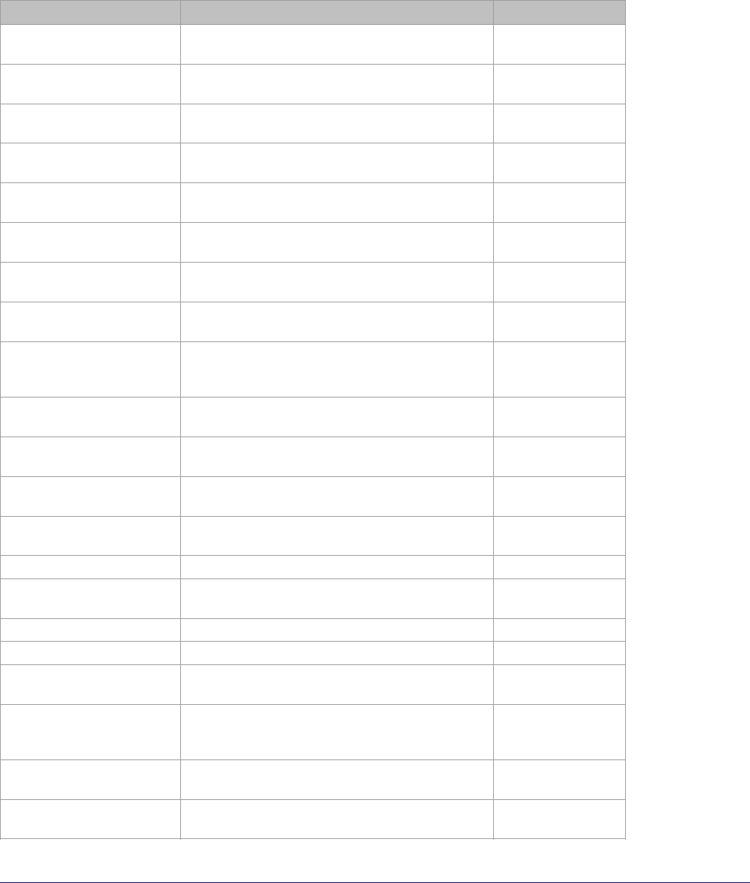
StarUML5.0DeveloperGuide(WritingTemplates)
http://staruml.sourceforge.net/docs/developer-guide(en)/ch11.html
statements. SCRIPT command's argument unlike the other argument expre
ssion has several
expression(statements).
Built-In Functions
The followings are available Built-In functions in command.
Signature Description Target template
StarUMLApp():
IStarUMLApplication
Returns StarUML Application COM object. WORD,EXCEL,
POWERPOINT
StarUMLProject():
IUMLProject
Returns COM object on top of project of
StarUML Application.
TEXT
MSWord():
WordApplication
Returns Word Application COM object. WORD
MSExcel():
ExcelApplication
Returns Excel Application COM object. EXCEL
MSPPT():
PowerpointApplication
Returns Powerpoint Application COM object. POWERPOINT
findByFullpath(Path):
IElement
Returns element existing at argument path. WORD,EXCEL,
POWERPOINT,TEXT
findByLocalpath(RootElem,
Path): IElement
Returns element existing at relative path on
RootElem.
WORD,EXCEL,
POWERPOINT,TEXT
itemCount(RootElem,
CollectionName): int
Returns count of elements in collection named
as CollectionName.
WORD,EXCEL,
POWERPOINT,TEXT
item(RootElem,
CollectionName, Index):
IElement
Returns element existing at index in collection
named as ColletionName.
WORD,EXCEL,
POWERPOINT,TEXT
attr(Elem, AttrName):
Value
Returns attribute or reference value named as
AttrName of Elem element.
WORD,EXCEL,
POWERPOINT,TEXT
current(): IElement
Returns the last selected element.
WORD,EXCEL,
POWERPOINT,TEXT
pos(): int
Returns the index of current element in
container element.
WORD,EXCEL,
POWERPOINT
createFile(path):
TextStream
Creates file at argument path and returns file
object.
TEXT
deleteFile(path)
Deletes file existing at argument path.
TEXT
createFolder(path): Folder
Creates folder at argument path and returns
folder object.
TEXT
deleteFolder (path) Deletes folder existing at argument path. TEXT
fileExists(path): Boolean Return whether file exists at argument path. TEXT
folderExists(path):
Boolean
Return whether folder exists at argument path. TEXT
fileBegin(path) Creates file at argument path and all the
outputs by commands will be printed to the file
while fileEnd is not called.
TEXT
fileEnd(path) Corresponds to fileBegin function and stops
printing to file assigned by fileBegin.
TEXT
getTarget(path): String
Returns configured output path on StarUML
Generator UI by user.
TEXT
Writing a Text-Based Template
Before writing text template, the following steps should be executed.

StarUML5.0DeveloperGuide(WritingTemplates)
http://staruml.sourceforge.net/docs/developer-guide(en)/ch11.html
Download sample document(template-text.zip) for generating text templ
ate from downloads/templates of
StarUML official hompage.
1.
Create new folder named "template-text" and unzip downloaded file under the folder.2.
Run StarUML.3.
Click
[Tools]
->
[StarUML Generator...] menu.4.
Select "Default Code Template" template on
[Select templates for generator]
page.
5.
Click [Clone Template]
button, specify template name and path to be stored, and click
[OK] button.6.
Select new created template in
[List of templates]
, click [Open Template] button, and new text template
will be opened on the editor screen.
7.
Make commands as following on the editor screen.8.
The commands described in "Element composing template" paragraphs are represented differently in each
template. The command in text template is surrounded by "<@" and "@>". Command name appears next to "<@",
first argument appears after one space character, the other arguments separated by ";" appear. Texts existing out
of "<@" and "@>" are treated as style, and they are printed to generated document the way they are.
To iterate "UMLClass" typed element existing in all sub path under "::Design Model" path, do as following.
<@REPEAT{R}::DesignModel;UMLClass;;@>
...
<@ENDREPEAT@>
You want to print java class definition from model information. Between REPEAT and ENDREPEAT command, place
text like "class", "{", "}" for java style and DISPLAY command for class name, documentation as following.
<@REPEAT{R}::DesignModel;UMLClass;;@>
class
<@DISPLAY;current().Name@>
{
//<@DISPLAY;current().Documentation@>
}
<@ENDREPEAT@>
In text template, there is shortcut-command similar to DISPLAY comman
d but it hasn't path argument. It is in the
form of "<@=expression@>" and uses only second argument of DISPLAY command. If above template is expressed
in term of "<@= .. @>", it is like following.
<@REPEAT{R}::DesignModel;UMLClass;;@>
class<@=current().Name@>
{
//<@=current().Documentation@>
}
<@ENDREPEAT@>
Take advantage of IF and ENDIF commands and you can print something selectively. In the following case, class
documentation is shown if any.
<@REPEAT{R}::DesignModel;UMLClass;;@>
class<@DISPLAY;current().Name@>{
<@IFcurrent().Documentation!=""@>
//<@DISPLAY;current().Documentation@>
<@ENDIF@>
}
<@ENDREPEAT@>
Expression used as command argument is expressed in JScript. At this time, Built-In function can be used. If you
want to use other function except built-in functions, define new function on SCRIPT command and call new function
at other command argument. The following example defines myfunc funct
ion and displays the returned value after
calling myfunc function.
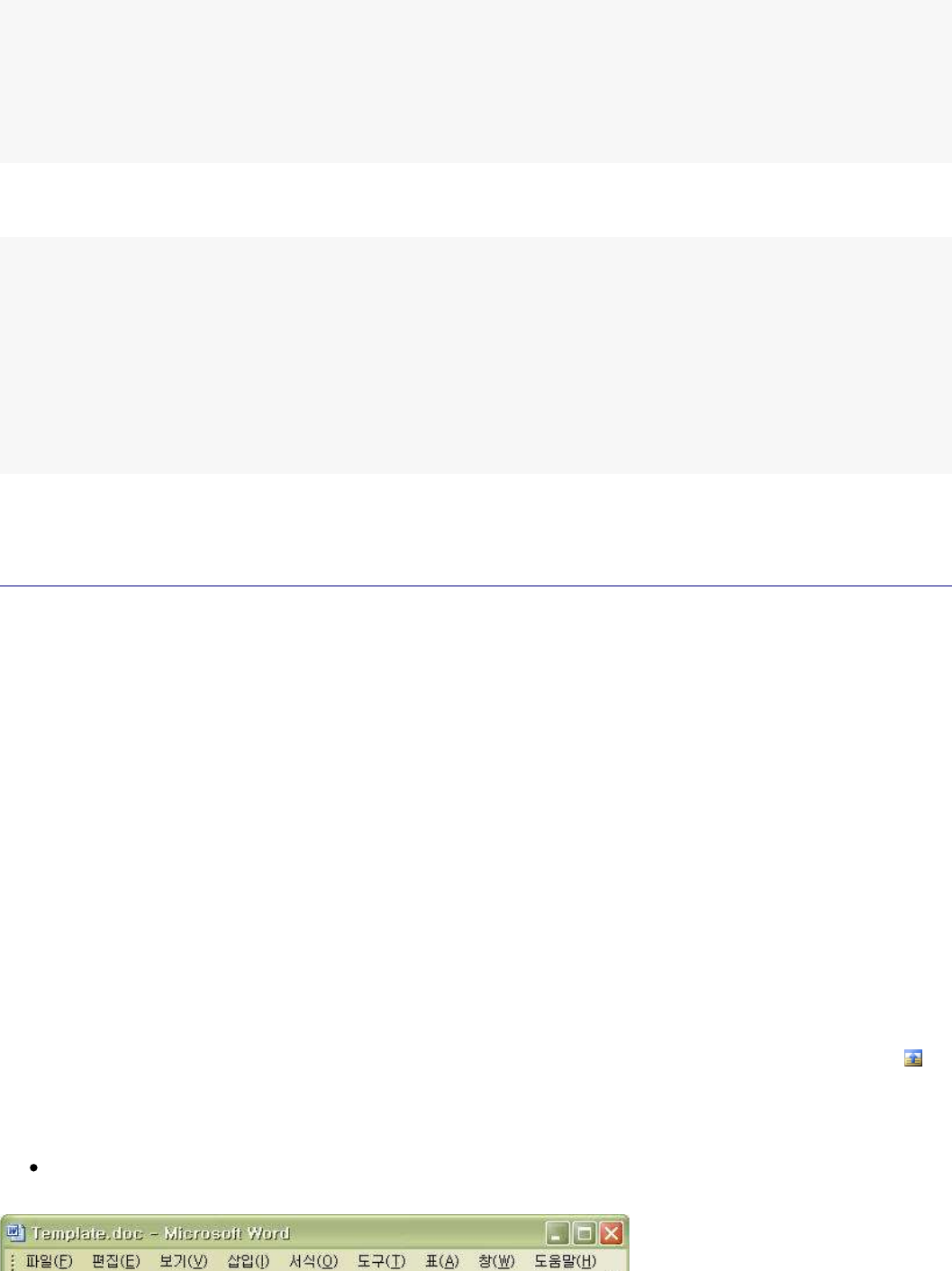
StarUML5.0DeveloperGuide(WritingTemplates)
http://staruml.sourceforge.net/docs/developer-guide(en)/ch11.html
calling myfunc function.
<@SCRIPT
functionmyfunc(a,b){
...
}
@>
<@DISPLAY;myfunc(1,2)
@>
SCRIPT command can be used in other cases. The following shows other example of SCRIPT command, it stores
each class to file named by self-name.
<@REPEAT{R}::DesignModel;UMLClass;;@>
<@SCRIPTfileBegin(getTarget()+"\\"+current().Name+".java");@>
class<@DISPLAY;current().Name@>{
//<@DISPLAY;current().Documentation@>
}
<@SCRIPTfileEnd();@>
<@ENDREPEAT@>
If editing template is done for all the commands and document is stored, you can generate codes utilizing your own
text template. Refer to "Generating by template" chapter for the detailed steps.
Writing a Word Template
Before writing WORD template, the following steps should be executed.
Download sample document(template-word.zip) generating WORD document
from downloads/templates of
StarUML official hompage.
1.
Create new folder named "template-word" and unzip downloaded file under the folder.2.
Run StarUML.3.
Click
[Tools]
->
[StarUML Generator...] menu.4.
Select "Default Word Template" template on [Select templates for generator]
page.
5.
Click [Clone Template]
button, specify template name and path to be stored, and click
[OK] button.6.
Select new created template in
[List of templates]
, click [Open Template] button, and new WORD
template will be opened on the editor screen.
7.
Make commands as following on the MS Word application.8.
In WORD template, command area is expressed in WORD's comment. Command name is specified at comment
author property and arguments are specified at comment text. Argument
separator is ";" character. all areas but
comment areas are regarded as style area and they are printed to generated document the way they are.
To iterate "UMLClass" typed element existing in all sub path under ":
:Design Model" path, copy
[REPEAT] and
[ENDREPEAT]
comment, paste them. Select [REPEAT]
comment and click WORD's comment inspect button
to
set REPEAT command argument. Inspector Window appears, input [REPEAT] comment's property as following.
Remarks
Comment author property is not set by user. Therefore copy existing comment in current template and paste
it position where you want.
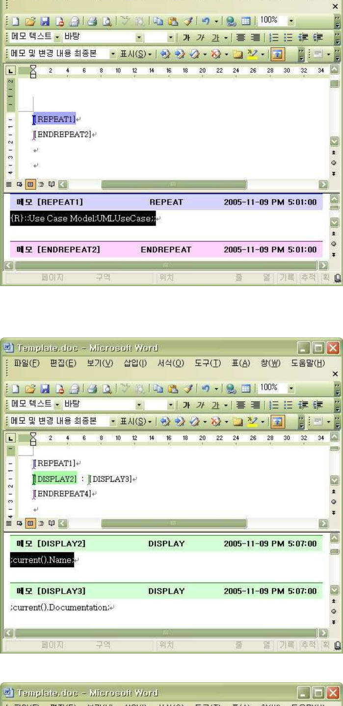
StarUML5.0DeveloperGuide(WritingTemplates)
http://staruml.sourceforge.net/docs/developer-guide(en)/ch11.html
Copy [DISPLAY] comment and paste it between
[REPEAT]
and [ENDREPEAT]
comment, fill argument value in
comment text like the following. Repeating all usecases under "::Use case Model", it prints its name and
documentation.
To do something in the only case of satisfying special condition, make [IF] and [ENDIF]
comment as following.
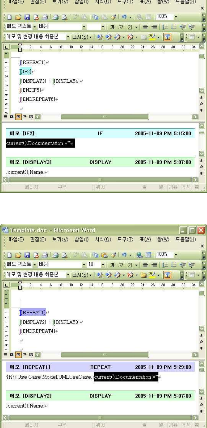
StarUML5.0DeveloperGuide(WritingTemplates)
http://staruml.sourceforge.net/docs/developer-guide(en)/ch11.html
The combination of
[REPEAT] and [IF] comment is replaceable by one [REPEAT] comment. Move [IF]
command's condition argument to [REPEAT] command's one and delete [IF] and [ENDIF] commands. It does
equal the action.
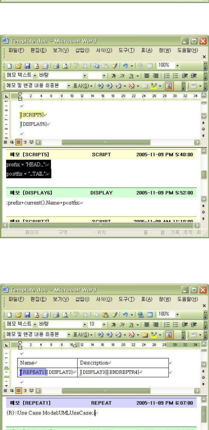
StarUML5.0DeveloperGuide(WritingTemplates)
http://staruml.sourceforge.net/docs/developer-guide(en)/ch11.html
Like other templates, WORD template can execute JScript statements with SCRIPT command. If you want to print
result value evaluated by JScript, fill JScript statements that has v
ariable assignment statement into
[SCRIPT]
comment's text and place variable in
[DISPLAY]
command's argument.
In WORD template, You can iterate special row of table. To do this, use [REPEAT] and [ENDREPTR] command.
The arguments are same in the case of
[REPEAT]
and [ENDREPEAT]. But
[REPEAT]
comment should be placed in
the first cell of row and
[ENDREPTR]
comment should be placed in the last cell of row. The following is example that generates table with Usecase's
name and documentation.
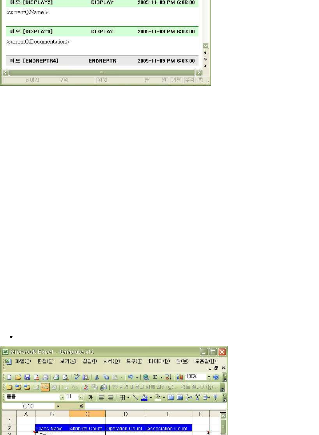
StarUML5.0DeveloperGuide(WritingTemplates)
http://staruml.sourceforge.net/docs/developer-guide(en)/ch11.html
If WORD template editing is done, store the template document. Then
you can generate word document from your
own WORD template. Refer to "Generating by template" chapter for the detailed steps.
Writing an Excel Template
Before writing EXCEL template, the following steps should be executed
.
Download sample document(template-excel.zip) generating EXCEL documen
t from downloads/templates of
StarUML official hompage.
1.
Create new folder named "template-excel" and unzip downloaded file under the folder.2.
Run StarUML.3.
Click
[Tools]
->
[StarUML Generator...] menu.4.
Select "Default Excel Template" template on [Select templates for generator]
page.
5.
Click [Clone Template]
button, specify template name and path to be stored, and click
[OK] button.6.
Select new created template in
[List of templates]
, click [Open Template]
button, and new EXCEL
template will be opened on the editor screen.
7.
Make commands as following on the MS Excel application.8.
In EXCEL template, command area is expressed in EXCEL's comment. Comm
and name and arguments are specified
at comment text property. Comment text is composed of command name and arguments sequentially. Name and
arguments in comment text is separated by ";" character. all areas but comment areas are regarded as style area
and they are printed to generated document the way they are.
EXCEL template can analyze and assess model information by utilizing
EXCEL's feature (statistics, chart). This
paragraph shows how to extract numerical value related to class from model and make a graph of it.
To make data for statistics, you need to iterate all the classes in the model by using REPEAT command. Place
REPEAT and ENDREPEAT command at the start and end cells of target row
.
Notice
In EXCEL template, REPEAT command repeats for only row and not for co
lumn.
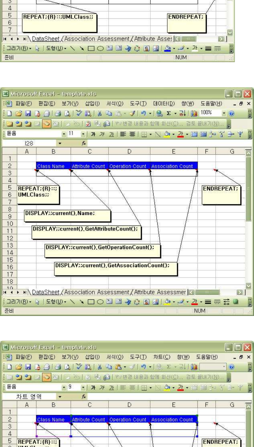
StarUML5.0DeveloperGuide(WritingTemplates)
http://staruml.sourceforge.net/docs/developer-guide(en)/ch11.html
And insert DISPLAY commands that print class name, the number of attributes, the number of operations, the
number of associations, between REPEAT and ENDREPEAT commands as foll
owing.
To make a graph of information for classes, insert EXCEL chart here and select attribute, operation, and association
count as source data.
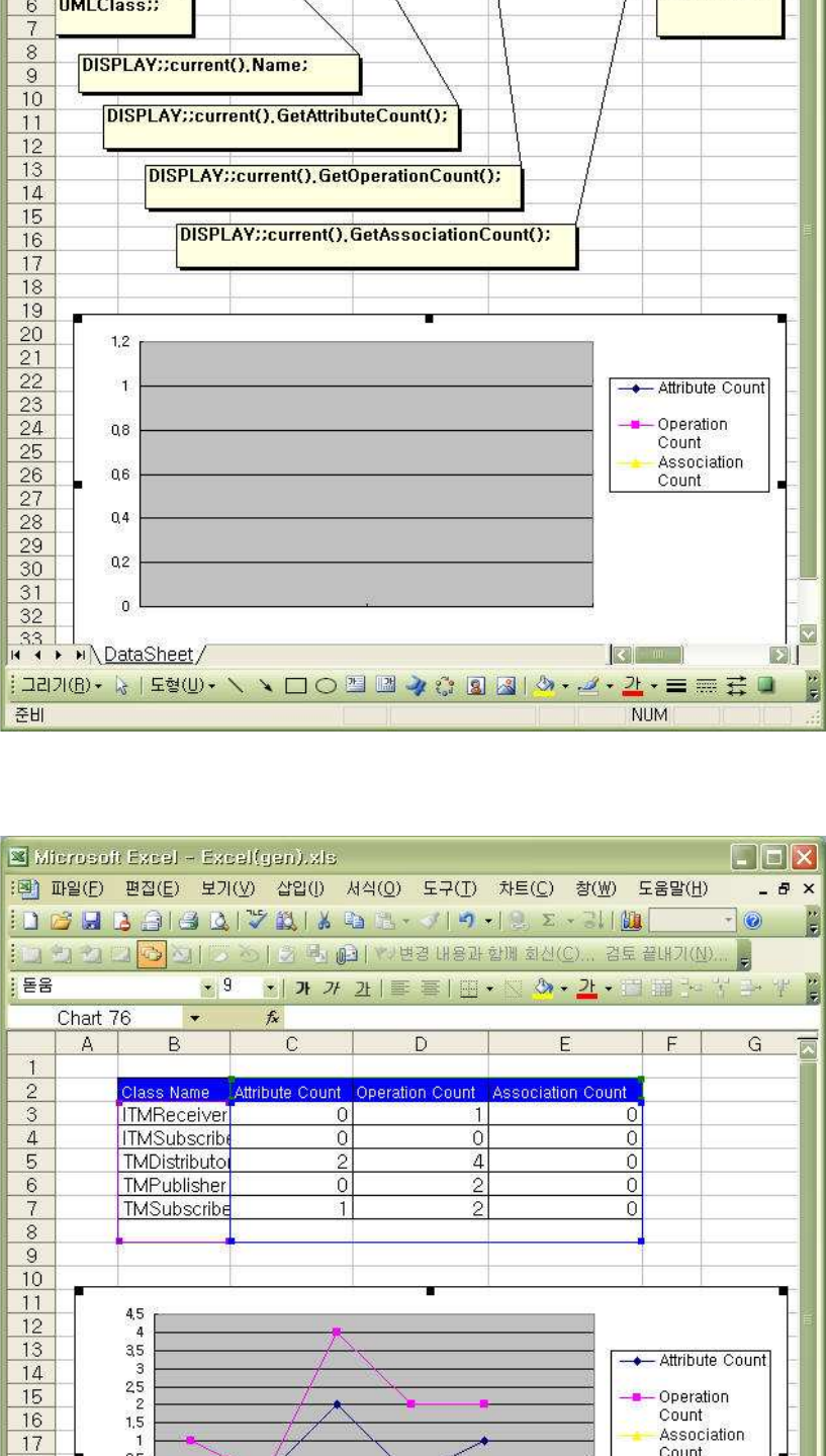
StarUML5.0DeveloperGuide(WritingTemplates)
http://staruml.sourceforge.net/docs/developer-guide(en)/ch11.html
If EXCEL template editing is done, store the template document. Then you can generate EXCEL document from
your own EXCEL template. Refer to "Generating by template" chapter for the detailed steps. The following is result
generated automatically from model information.

StarUML5.0DeveloperGuide(WritingTemplates)
http://staruml.sourceforge.net/docs/developer-guide(en)/ch11.html
Writing a PowerPoint Template
Before writing POWERPOINT template, the following steps should be executed.
Download sample document(template-powerpoint.zip) generating POWERPOINT document from
downloads/templates of StarUML official hompage.
1.
Create new folder named "template-powerpoint" and unzip downloaded file under the folder.2.
Run StarUML.3.
Click
[Tools]
->
[StarUML Generator...] menu.4.
Select "Default Powerpoint Template" template on [Select templates for generator]
page.
5.
Click [Clone Template]
button, specify template name and path to be stored, and click
[OK] button.6.
Select new created template in
[List of templates]
, click [Open Template] button, and new text template
will be opened on the editor screen.
7.
Make commands as following on the MS Powerpoint application.8.
In POWERPOINT template, command area is expressed in POWERPOINT's comment. Command name is surrounded
by "<<" and ">>" at the first line of comment text and arguments are specified at the second line of comment text.
The separator among the arguments is ";" character. all areas but comment areas are regarded as style area and
they are printed to generated document the way they are.
For example, let me introduce how to write POWERPOINT template that generates slides consisting of diagrams and
documentations of diagrams. First of all to place a diagram in a slide, insert comment at left-top corner of slide and
set comment text as following. At this time you must not insert ENDREPEAT comment. The reason will be explained
later.
Notice
Before writing POWERPOINT template, REPEAT command repeats slide but
not anything except slide.
StarUML5.0DeveloperGuide(WritingTemplates)
http://staruml.sourceforge.net/docs/developer-guide(en)/ch11.html
Next, To print diagram name as slide title, insert textbox and DISPLAY-TEXT comment, and input text as following.
And insert "$$" string into textbox for DISPLAY-TEXT command to know where to print text. DISPLAY-... command
prints for the only time when text or image box contain boundary of t
he command exactly. Therefore you must
place DISPLAY command in boundary of text or image box.
To draw diagram in the middle of slide, insert textbox and resize it. Also insert DISPLAY-IMAGE command, place it
in the textbox, and input text as following.

StarUML5.0DeveloperGuide(WritingTemplates)
http://staruml.sourceforge.net/docs/developer-guide(en)/ch11.html
To print diagram documentation at the bottom of slide, insert DISPLAY-TEXT command and textbox, set comment
text as following.
Last of all to mark boundary of repetition, insert ENDREPEAT command at the bottom of slide. The reason inserting
ENDREPAT last of all is that in POWERPOINT template generator's inter
pretation order is not depend on position of
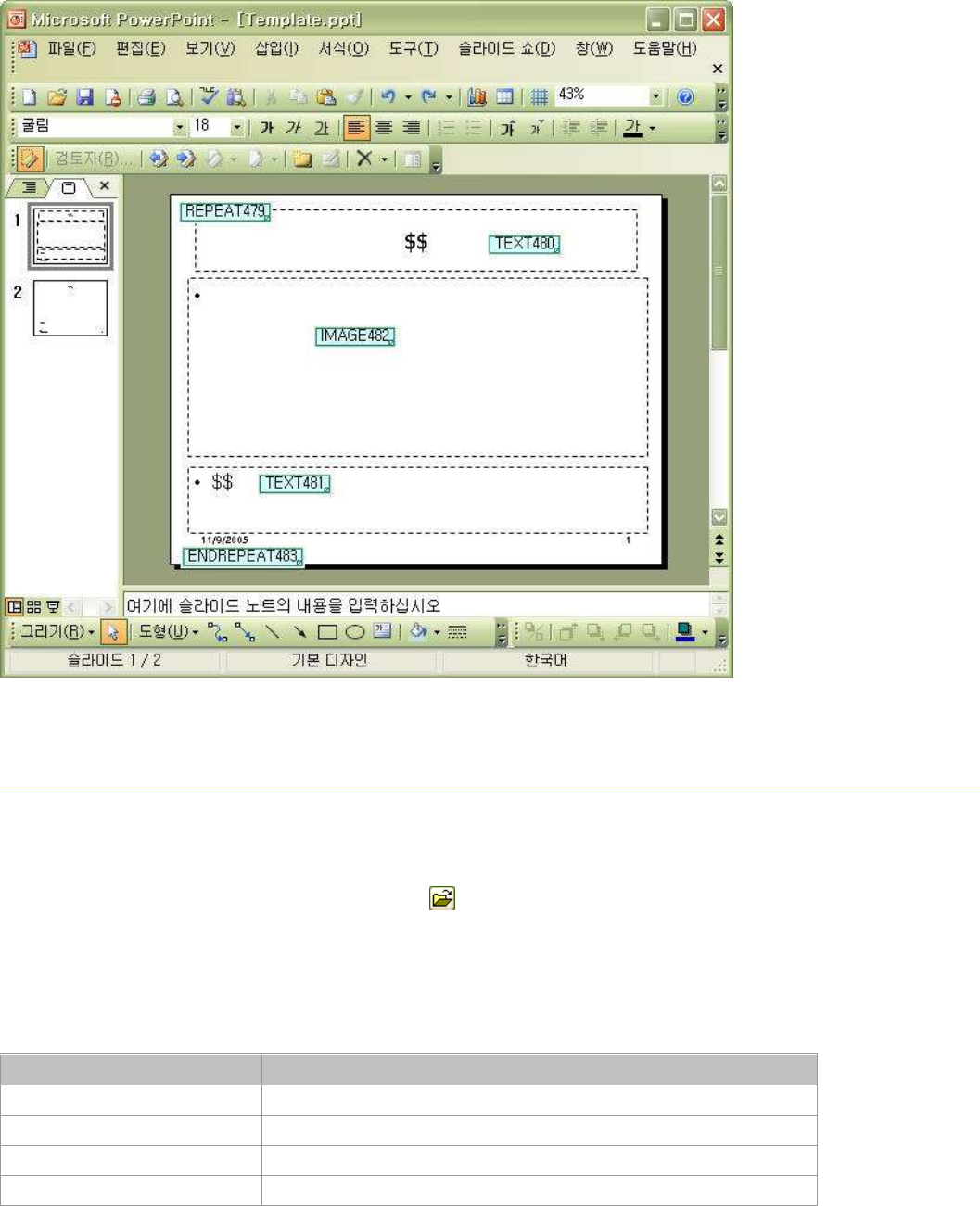
StarUML5.0DeveloperGuide(WritingTemplates)
http://staruml.sourceforge.net/docs/developer-guide(en)/ch11.html
ENDREPAT last of all is that in POWERPOINT template generator's inter
pretation order is not depend on position of
comment but creation order of comment. Command is not executed because it is higher position than other but
executed because it creation is prior to other. If you insert REPEAT, ENDREPEAT, DISPLAY-TEXT in order, generator
interprets there exists no command between REPEAT and ENDREPEAT. To r
epeat other commands by REPEAT
command, you must create REPEAT command, target ones of repetition, and ENDREPEAT one in order.
If POWERPOINT template editing is done, store the template document.
Then you can generate powerpoint
document from your own POWERPOINT template. Refer to "Generating by template" chapter for the detailed steps.
Registering Templates
User can register his own template document to generator.
Click [Register Template]
button on the
[Select templates for generation]
page.
1.
If
[Register Template] dialog appear, click button and select template description file's path.2.
Input template information on
[Properties:]
window, click [OK]
button and registration is done.
3.
Basic Information
Set information for template name, group, category, and description.
Item Description
Template Name Specifies target template name.
Group Specifies group containing target template.
Category Specifies template category under group.
Description Specifies description for template.
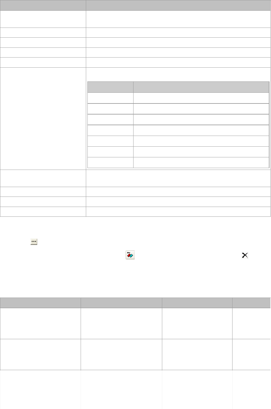
StarUML5.0DeveloperGuide(WritingTemplates)
http://staruml.sourceforge.net/docs/developer-guide(en)/ch11.html
Detail Information
Set detail information for template.
Item Description
Document Type Specifies type of document. Select one of DOCUMENT, REPORT,
CODE.
Format Specifies result document format.
Version Specifies version information of template.
Related Profile Specifies profile related to template.
Related Approach Specifies approach related to template.
Translator Type Specifies type of generator. One of the followings is available.
Value Meaning
WORD word document generator
EXCEL excel document generator
POWERPOINT
Powerpoint document generator
TEXT code generator
COM
COM-based generator defined by user
SCRIPT
Script-based generator defined by user
EXE Executable file-typed generator made by user
Translator Specifies generator file name. It is available for user-defined
generator.
Example Specifies sample model file name that template applies to.
Parameters Specifies required parameters.
Related files Specifies related files for generation.
Parameters
Click button on parameters property.1.
If
[Parameters]
dialog appears, click
button to insert new parameter, click
button to delete
parameter.
2.
If
[New Parameter] dialog appears, fill parameter name, type, and default value, and click [OK] button.3.
Set parameters for each translator type as following.
Item Type Translator type Description
TemplateFile FILENAME or STRING WORD,EXCEL,
POWERPOINT
Specifies
template
document
file name.
OutputFile FILENAME or STRING WORD,EXCEL,
POWERPOINT,
TEXT
Specifies
result
document
file name.
Keep Comment BOOLEAN WORD,EXCEL,
POWERPOINT
Specifies
whether
result
document
contains
command
StarUML5.0DeveloperGuide(WritingTemplates)
http://staruml.sourceforge.net/docs/developer-guide(en)/ch11.html
command
information.
ShowGenerationProcess BOOLEAN WORD,EXCEL,
POWERPOINT
Specifies
whether it
shows
progress on
MS Office. If
the value is
set to true,
generation
performance
may be
slowed.
Normal Generation BOOLEAN WORD Specifies
starting
target path
for
generation.
If it is set to
false, the
starting
element for
generation
is selected
element on
the
StarUML.
Generate Index BOOLEAN WORD Specifies
whether
indices is
generated.
intermediate STRING TEXT Specifies
whether
intermediate
files for
generation
are
generated.
target STRING TEXT Specifies
folder path
that
contains
generated
code files.
Reference
Setting parameters, you can use environment constants supported by StarUML Generator as following.
Name Description
$PATH$
means folder path which template and template description
file exist in.
$GROUP$ means value of group property of template.
$CATEGORY$
means value of category property of template.
$NAME$
means template name
$TARGET$
means folder path that user select on
[Generator] dialog.
About managing registered template, refer to "Generating by Template"
paragraph in User Guide "Chapter7.
Generating Codes and Templates".
StarUML5.0DeveloperGuide(WritingTemplates)
http://staruml.sourceforge.net/docs/developer-guide(en)/ch11.html
Generating Codes and Templates".
Making a Template Distribution Package
Template is installed under "staruml-generator" folder. All the templ
ates and batch tasks exist in "templates" folder
under "staruml-generator" folder. Generally All the resource files related to one template exist in one folder. The
folder must be right under "templates" folder. A template is composed of template description file (*.tdf) and
template document (*.doc, *.ppt, *.xls, *.cot, etc.). The template de
scription file contains the configurations at
user guide "chatpter7.Generating Codes and Documents > Registering template". Batch task is described to batch
task file. Batch task file is with ".btf" in "batches" folder under "staruml-generator" folder. The following is the
summary of file extensions.
File extension name description
BTF
contains batch task list, parameters for each task.
TDF contains template information (name, type, template file name,
parameters, etc.)
DOC, DOT
contains commands and style information for word template
XLS, XLT contains commands and style information for excel template
PPT, POT contains commands and style information for powerpoint
template
COT contains commands and style information for code template
Folder structure for generator
The folder structure for generator is composed as following.
staruml-generator\
templates\
template1\
template1.tdf
template1.doc
template2\
...
batches\
batch1.btf
...
Installing and removing template
To install template is very simple. Copy folder (under "staruml-generator\templates" folder) that contains template
to be distributed, and paste it under "staruml-generator\templates" folder in target computer. Then the installation
is complete.
To remove template is also very simple. Remove the folder that has th
e template you want to remove.
Packaging template
Folder structure is available under "staruml-generator\templates" folder. Therefore you can arrange templates
without changing batch list and template information. It makes you ea
sy to manage and distribute templates. For
example, you can collect several template folders under one folder, compress them into a archive file like zip, and
distribute it to some computer. What the receiver should do to instal
l is only to extract the file under
"staruml-generator\templates" folder. Installing and removing batch task)
To install batch task is very simple. Before installing batch, instal
l templates used in batch task. Next, copy batch
task file(*.btf) under "staruml-generator\batches" folder and paste it under "staruml-generator\batches" folder in
target computer. Then the installation is complete.
To remove batch task is also very simple. Remove the batch task file(*.btf) you want to remove.
