Startup Guide HRP
Startup%20Guide%20HRP
User Manual: Pdf
Open the PDF directly: View PDF ![]() .
.
Page Count: 20

Startup Guide HRP Mower
Version 1.1 2017-06-01
1 (20)
Startup Guide
HRP Mower
1 Introduction
HRP stands for Husqvarna Research Platform and is a way for Husqvarna to provide an
open robust robot platform for various research projects both within universities and
industry.
This document describes how to setup and control a HRP Mower.
It also describes how you can install extra equipment inside the mower, and shows two
examples for this using a Raspberry Pi and a BeagleBone Black.
If you are unfamiliar with robot mowers you can find how a normal installation is made in
a garden here Garden Installation.
A printed user manual is sent together with the machine. It can also be found here:
Automower 430X User Manual
2 Boundary Wire
The robot requires a boundary wire to define the cutting area.
The safety of the mower is guaranteed with the boundary wire. If the robot comes outside
the boundary it will automatically stop. When running in the HRP mode the robot will stop
after being about 10 seconds outside the boundary wire.
2.1 Running the mower without boundary wire
When running the robot in a safe area indoors, it is possible to deactivate the boundary
wire detection. This can be done in two different ways:
Deactivating boundary wire from user interface:
1. Activate the robot on the control panel by entering the pin code “1111”.
2. Then enter menu.
3. Press the buttons 7 and 9 simultaneously for a few seconds. A new symbol
for the tools menu will be visible.
4. Enter the tools menu and select special settings.
5. Select override loop detection.

Startup Guide HRP Mower
Version 1.1 2017-06-01
2 (20)
Deactivating boundary wire via software interface
The simple remote control ROS node hrp_teleop.py, see chapter 4.4, implements a
software deactivating of the loop.
3 Software Environment
With the software installed on a host computer with Linux and ROS you are able to both
run a simulated environment and also remotely control the mower.
3.1 Install software on host computer
The software is developed to run under Linux with Ubuntu 16.04 and ROS Kinetic. The
software also works under Ubuntu 14.04 and ROS Indigo.
Installations steps are:
• Unpack the latest delivery file,i.e. hrp.2017-02-28-17-03.tar.gz into the source
folder of a catkin workspace (tar -xvf [delivery file])
• Install dependencies
sudo apt-get install ros-indigo-gazebo-ros-control
sudo apt-get install ros-indigo-joint-state-controller
sudo apt-get install ros-indigo-hector-gazebo-plugins
sudo apt-get install ros-indigo-hector-gazebo
sudo apt-get install python-pygame
• Build all new ROS parts
catkin_make
• setup the model path:
export GAZEBO_MODEL_PATH=[the source folder]/hrp/am_gazebo/models:$GAZEBO_MODEL_PATH
3.2 Run simulated environment on host
• Start the simulation
roslaunch am_gazebo am_gazebo_hrp.launch gui:=true
• Launch keyboard control with
rosrun am_driver hrp_teleop.py
• You can now hopefully drive around in the simulated garden in gazebo!

Startup Guide HRP Mower
Version 1.1 2017-06-01
3 (20)
3.3 Installing software on target
The software is developed to run under Linux with Ubuntu 16.04 and ROS Kinetic. The
software also works OK under Ubuntu 14.04 and ROS Indigo. Other Linux versions is
likely OK also, but has not been verified by Husqvarna. Example of target boards which
have been used by Husqvarna are: Beaglebone Black, Odroid XU4, Raspberry Pi2 and
Raspberry Pi3.
The target software is a subset of the host software.
Installation steps:
• unpack and build the latest target software (file hrp_target.201XXXX.tar.gz) on the
target computer.
• make sure that the serialPort defined in the launch file
(am_driver_safe/launch/automower_hrp.launch) match that on your target
computer.
• Unless you already have it, setup a WiFi-connection to the host so you can
access the target computer. One possibility is to setup the target computer as an
WiFi access point. It is also possible to use an Ethernet cable from target to host
computer.
4 Remote Control Of Mower
The mower can be externally controlled from an external (host) LINUX computer. This
can be done in two different ways:
4.1 USB-cable connection without target computer
It is possible to control the HRP mower directly from the host computer, without any
modification of the mower. It shall be noted that Husqvarna has loaded the HRP mower
with a special software version which opens up the external interface. A standard mower
with original software is not possible to control in this way.
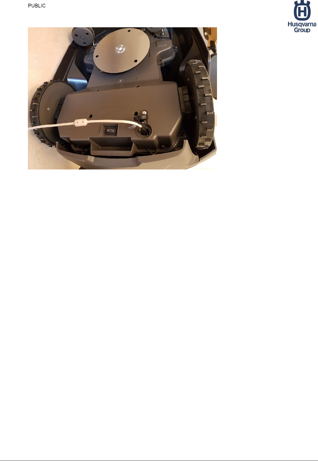
The USB cable is connected at the underside in the rear end, see Figure 1.
Startup Guide HRP Mower
Version 1.1 2017-06-01
4 (20)
Figure 1 USB cable connection
On the automower:
Turn on main power switch, or open lid to wake it up from standby.
Enter pin code (1111)
On the host computer:
In a terminal window start am_driver (make sure the correct USB-port is set as
serial port in the launch file)
roslaunch am_driver_safe automower_hrp.launch
In another terminal window start the keyboard control
rosrun am_driver hrp_teleop.py
On the automower:
Press Start button
Close the lid
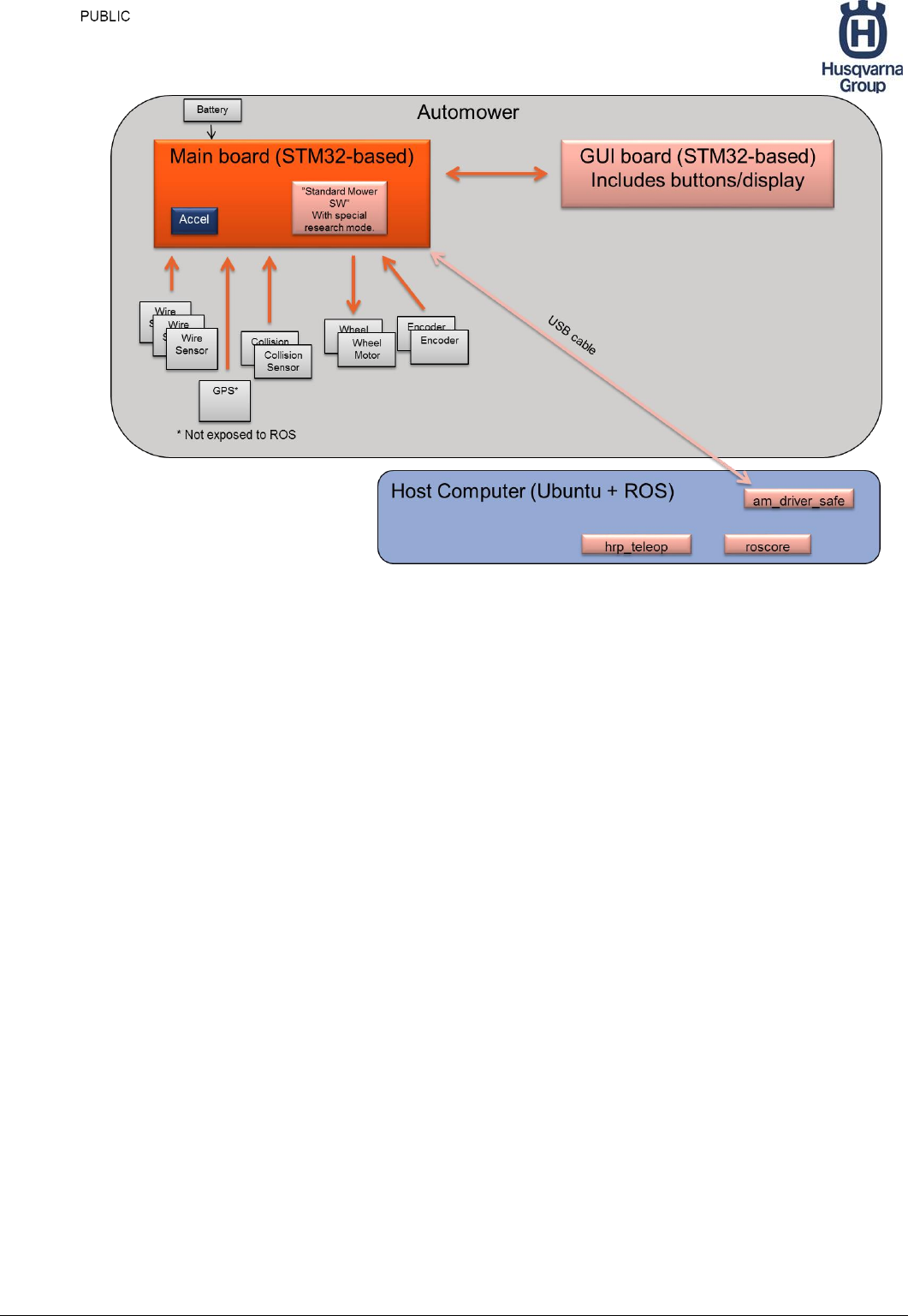
Now you can control the automower from the keyboard terminal. An overview of the
system is shown in Figure 2.
Startup Guide HRP Mower
Version 1.1 2017-06-01
5 (20)
Figure 2 Remote controlling mower via USB
4.2 WiFi/Ethernet control of Linux system on target board
mounted inside automower.
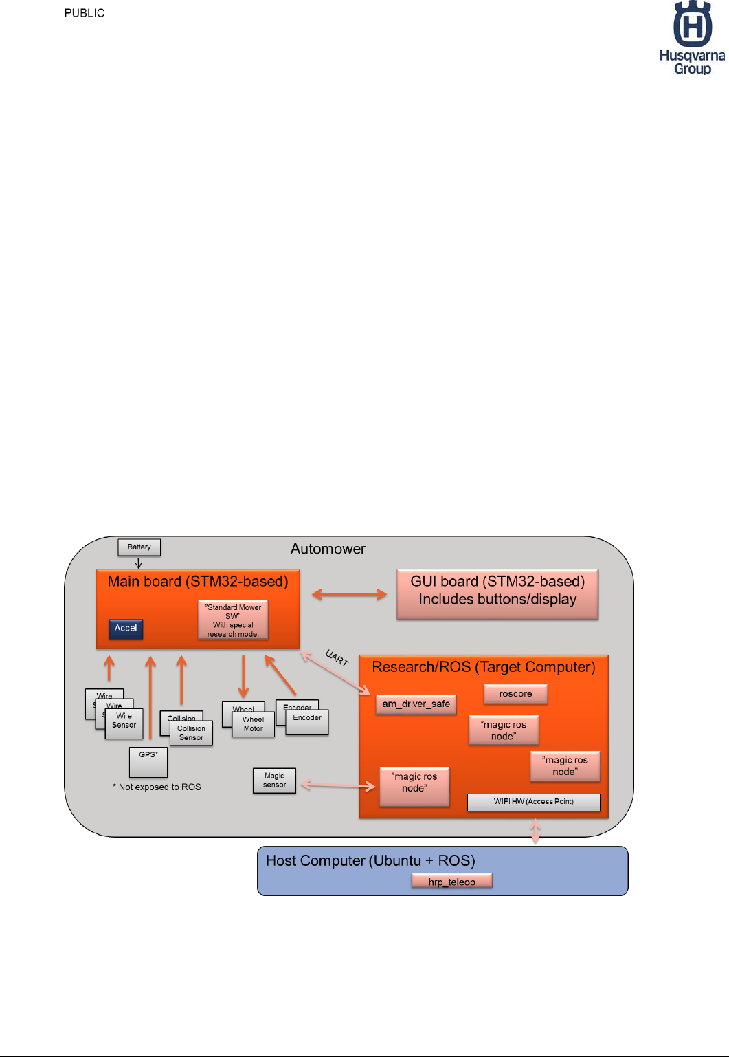
It is more practical to control the automower wireless with help of a target computer on
the automower. To get a rugged implementation the target computer should be installed
inside the mower. In chapter XX, you can find two examples of how this can be done. The
system structure for this is shown in Figure 3 Controlling mower with WiFi and target
computerFigure 3. It is possible to add more sensors and ROS nodes in the system, as
indicated with “Magic”. You can also run the mower standalone without any host
computer.
On the automower:
Turn on main power switch, or open lid to wake it up from standby.
Enter pin code (1111)
On the target computer:
In a terminal window start am_driver (make sure the correct port is set as serial port in
the launch file)
roslaunch am_driver_safe automower_hrp.launch
Startup Guide HRP Mower
Version 1.1 2017-06-01
6 (20)
On the host computer:
Tell host that ros master is on target by exporting correct ROS_IP,
ROS_HOSTNAME and ROS_MASTER_URI
Start the keyboard control
rosrun am_driver hrp_teleop.py
On the automower:
Press Start
Close the lid
Now you can wireless control the automower from the keyboard control. An overview of
the system is shown in Figure 3.
Figure 3 Controlling mower with WiFi and target computer

Startup Guide HRP Mower
Version 1.1 2017-06-01
7 (20)
4.3 Node: am_driver_safe
Description: Interface to the Automower via serial port. It also implements a PID-
regulator for controlling the wheel motors when the mower is manually controlled.
As long as this driver is communicating with the mower main board, the mower will not
enter standby. If the battery charge level becomes too low, the mower will however
shutdown anyway.
Published topics:
/odom - position of robot given encoder data
/loop - status of boundary loop sensors
/sensor_status - status of collision sensors
/wheel_encoder - ticks read from the automower
/battery_status - voltage and current for the Li-Ion battery in the automower.
Subscribed topics:
/cmd_vel - speed to assign to mower (linear and angular)
/cmd_mode - mode of control for mower
4.4 ROS node hrp_teleop
Description: A simple ROS node to control the automower from keyboard. It is run in a
terminal window, and all keys are explained in the printout. It communicates with the
automower by publishing topics which am_driver_safe listens to and then sends to the
automower.
Published topics:
/cmd_vel - speed to assign to mower (linear and angular)
/cmd_mode - mode of control for mower
Subscribed topics:
/sensor_status - status of collision sensors
/battery_status - voltage and current for the Li-Ion battery in the automower.
Startup Guide HRP Mower
Version 1.1 2017-06-01
8 (20)
5 Power Options
5.1 Power alternatives
When adding a target computer and different sensors to the mower you want to access
power from the automower. This can be done either by connecting to internal auxiliary
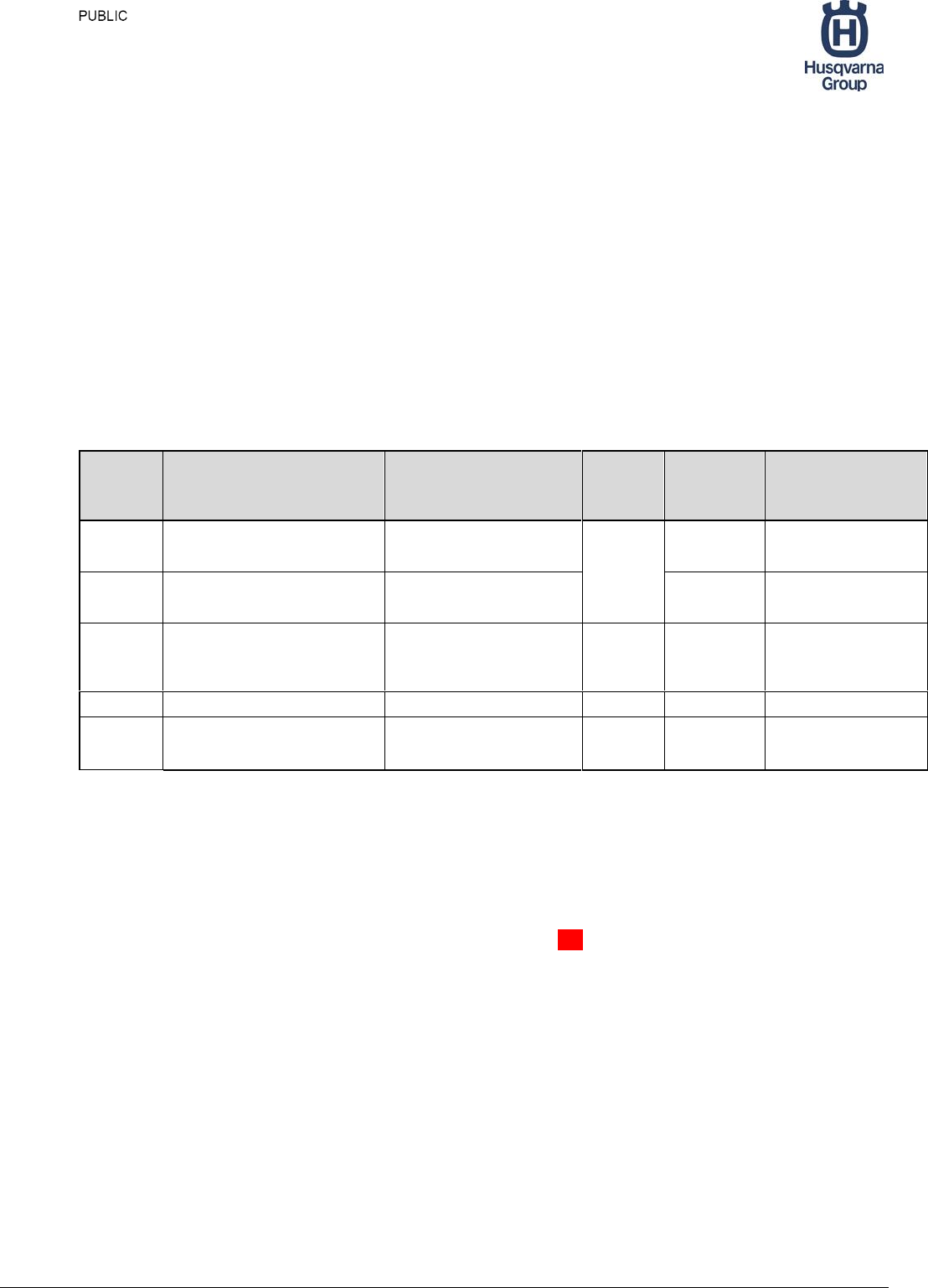
connectors or accessing Battery Power directly. In Table 1 you have an overview of the
different options. The two alternatives are described in detail in the following sections.
See chapter 7.1, for how to disassemble the automower, to access the interior.
Voltage
Connector
Max Current
Common
limits
Main
Switch
Controlled
Protection
5V
AUX1, AUX2, AUX3, AUX4,
MMI:AUX5
750 mA
Total
Max 750
mA
Yes
Fast Logic
3.3V
AUX1,AUX2,
AUX3,AUX4,MMI:AUX5
400 mA,
400-750 mA (3,2V)
Yes
Fast Logic
~18 V
AUX1,AUX2, AUX3,AUX4
1000 mA
Total
max
1000 mA
Yes
Fast Logic
~18 V
MMI:AUX5/MMI Solder
1000 mA
N/A
Yes
Slow SMD Fuse 2A
~18 V
Main Board Solder
5000 mA, mowing
10000 mA, no mowing
N/A
No
Battery Protection
Circuit
Table 1 Internal Power options
5.2 Auxiliary connectors
There are 5 different auxiliary connectors in the automower from which power can be
fetched. Common for all of these are that power is only available when the automower is
powered on. If the automower is left passive for more than XX minutes, it will
automatically go down to standby mode, and the power to the auxiliary connectors are
shutdown.
Startup Guide HRP Mower
Version 1.1 2017-06-01
9 (20)
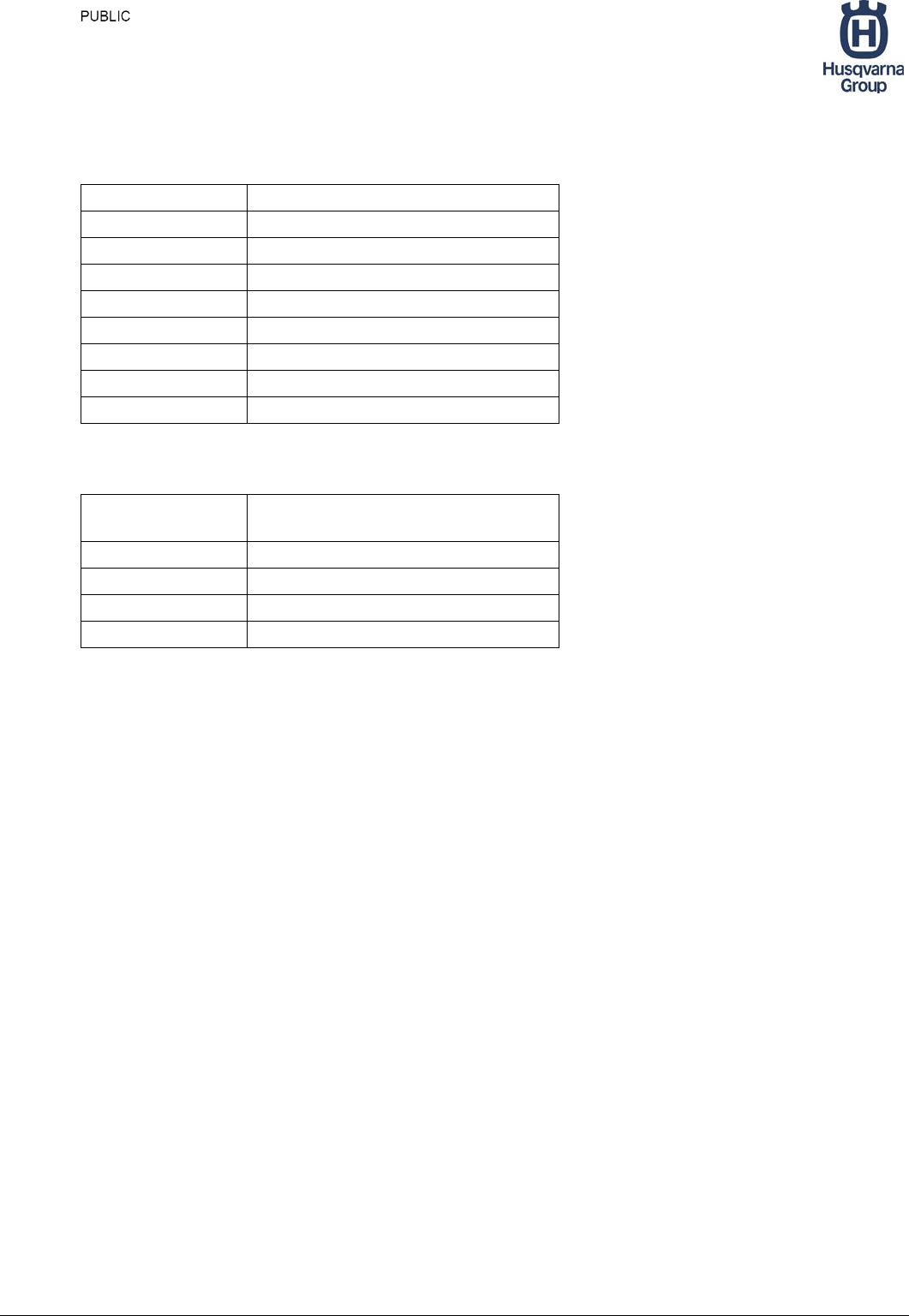
The pinout of the micro-Match connector for AUX1 to 5 is:
Pin
Signal
1
UART_TX
2
UART_RX
3
GND
4
AUX_GPIO
5
3.3 V, max 400 mA
6
5 V, max 750 mA
7
18 V, max 1000 mA
8
GND
Table 2 AUX connector pinout
Auxiliary Connectors on mainboard
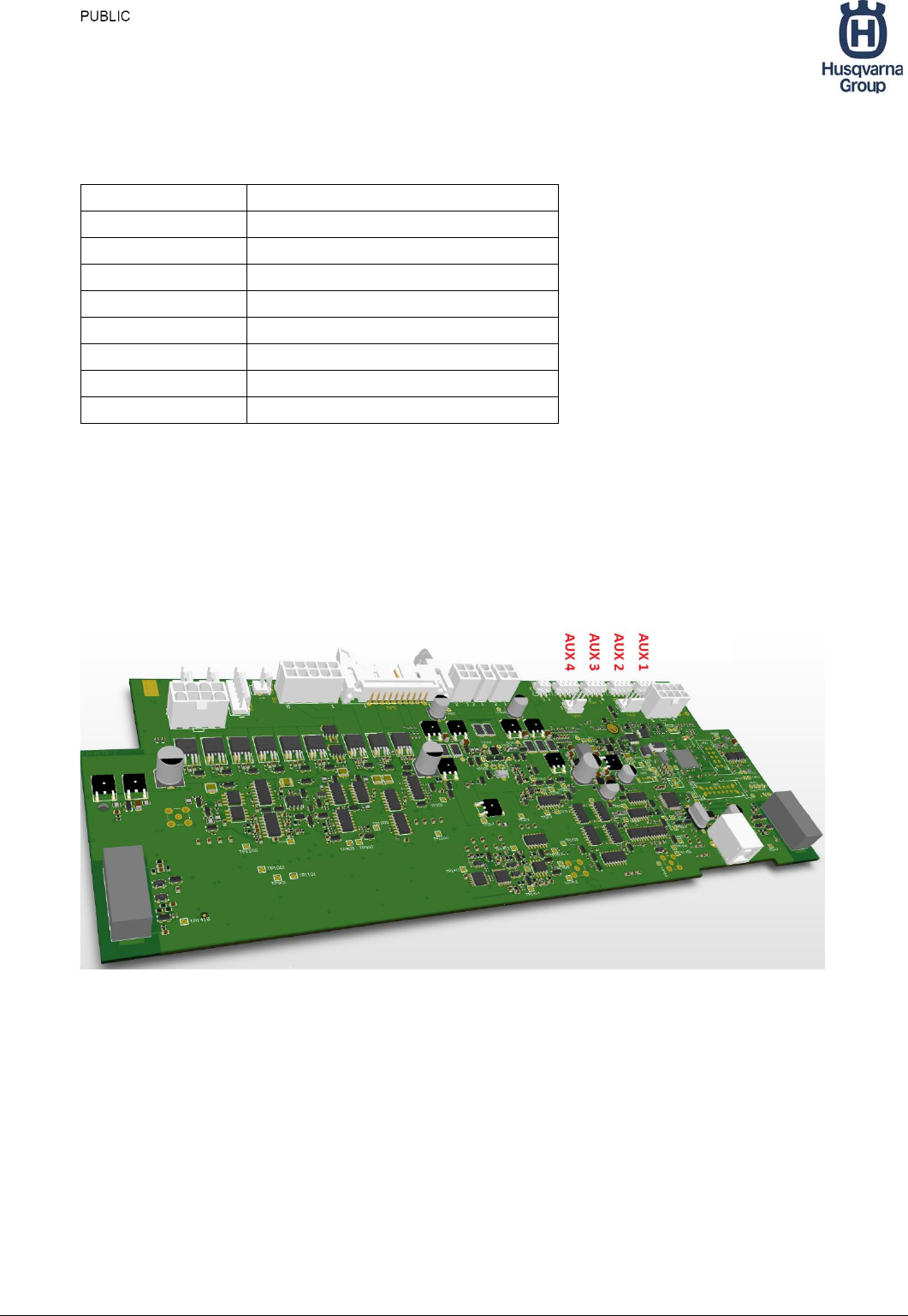
There are 4 auxiliary connectors (AUX1 – AUX4) on the mainboard, see Figure 4.
Figure 4 Aux connectors on mower main board
From these it is possible to take.
5V, max 750 mA, max 750 mA in total for all AUX connectors.
18V, max 1000 mA, max 1000 mA in total for AUX1-AUX4 connectors.
These power outlets has a built in current protection which will shut down both 5V and
18V if one of them is overloaded. Note that the response is quite fast, so even a short

Startup Guide HRP Mower
Version 1.1 2017-06-01
10 (20)
transient will cause the supply to be shutdown.. The automower needs to be restarted
with the main switch if the current protection is activated.
Auxiliary Connectors on mmi board
There is one auxiliary connector, AUX5, on the MMI board. The MMI board is located
below the display. Available supplies:
5V, max 750 mA, max 750 mA in total for all AUX connectors.
~18V, max 1000 mA, (varies from 16-21 V due to charge level of battery)
The 5V share the same protection logic as the AUX1-AUX4, see above.
The 18V is protected by a slow SMD 2A fuse on the main board. If this fuse is broken, the
SMD need to be replaced on the main board.
In the 430x mower is the GPRS/GPS board connected to AUX5.
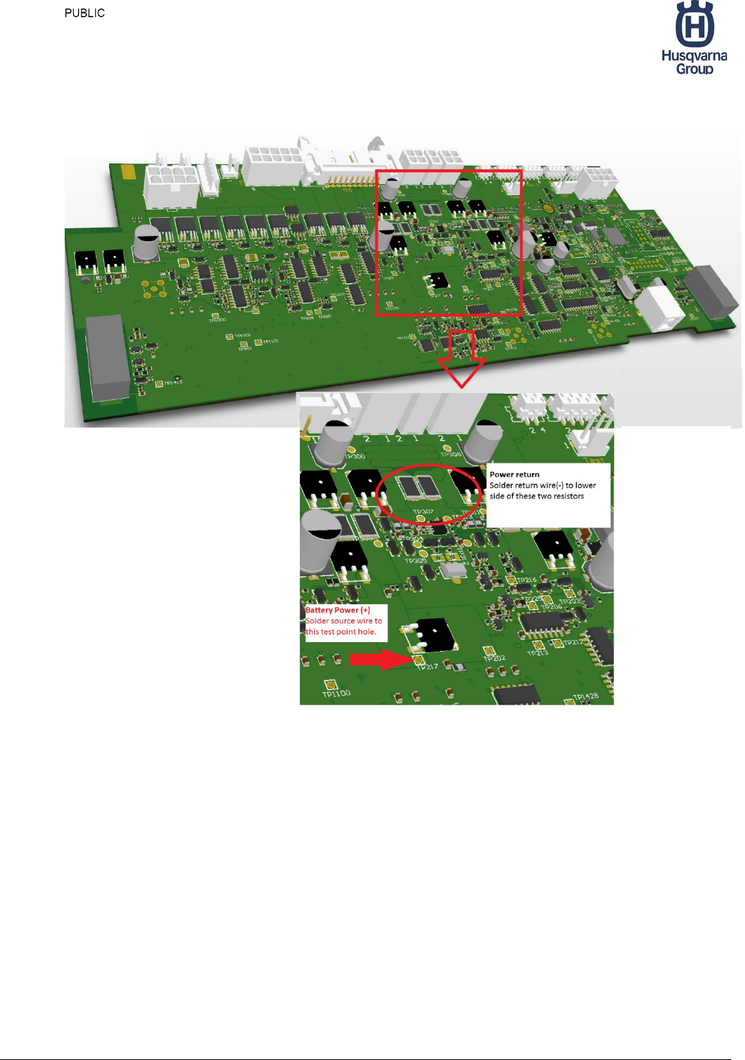
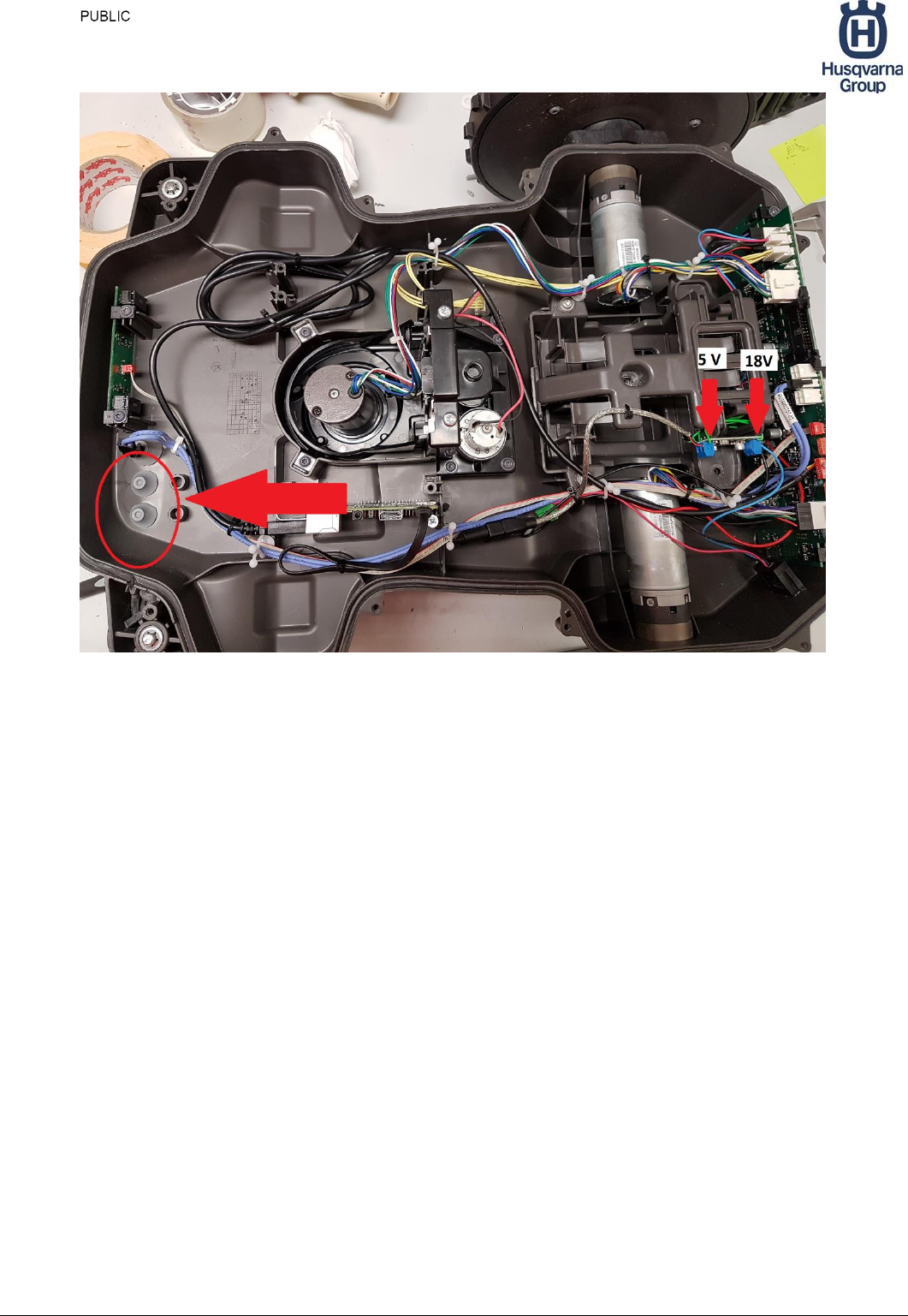
5.3 Powering directly from the battery
If you need access to high power or you want to have power at all times, even when the
mower has entered standby mode, you can connect directly to battery power. To do so
you need to solder to wires directly to the mainboard. See Figure 5, for the location of
these. It is recommended to add an extra power switch for this. In section 7.3 you can
find an example of this type of installation. The voltage will vary from 16 to 21 V,
depending on battery charge level. It is recommended to install some kind of DC/DC
converter to get stable voltage at your required level.
The Robot has internal Li-Ion batteries. These are charged when the mower is parked in
the charging station. The Raspberry Pi is powered directly from the internal Li-ion
batteries. Power is activated with the extra “Pi Power” switch, see below.
This means that the power to the Pi is independent of the Mower Power.
The charge level of the batteries can be checked in the mower control panel. It is also
available as a voltage level in the topic Battery_status. It is also visible in the hrp_teleop
node.

Startup Guide HRP Mower
Version 1.1 2017-06-01
11 (20)
If you run the mower for too long time without charging there is risk to drain the
batteries to a too low level. With fully charged batteries the mower can run about two
hours without charging.
Note that the standard mower electronics are surveying the battery voltage and will in
case of low battery voltage do one of two things:
Go back to charging station, if the mode is set to random.
or
Stop and shut down main power for mower electronics. Note that the power
directly from the battery will still be on. To prevent draining the batteries you
must shut down your internal equipment . If the battery voltage drop too low
the charging station will not charge the mower.
If you have installed an extra switch is also possible to power only you extra equipment.
If doing so outside the charging station the same restriction applies. Meaning: Don’t
power you equipment to long outside the charging station . If the battery voltage
drop too low the charging station will not charge the mower. The available time
depends on the power consumption. A 430X has a Li-ion battery of nominal 18V and
5,2Ah.
Startup Guide HRP Mower
Version 1.1 2017-06-01
12 (20)
Figure 5 Soldering points for direct access to battery power.
6 Cutting blades
The cutting blades on the HRP mower are very sharp if you use the mower for other tests
then cutting grass, we recommend you to remove them, to prevent anyone getting
injured.
Startup Guide HRP Mower
Version 1.1 2017-06-01
13 (20)
7 Installation examples
7.1 Overview
In this chapter two different examples of target computer installation will be shown.
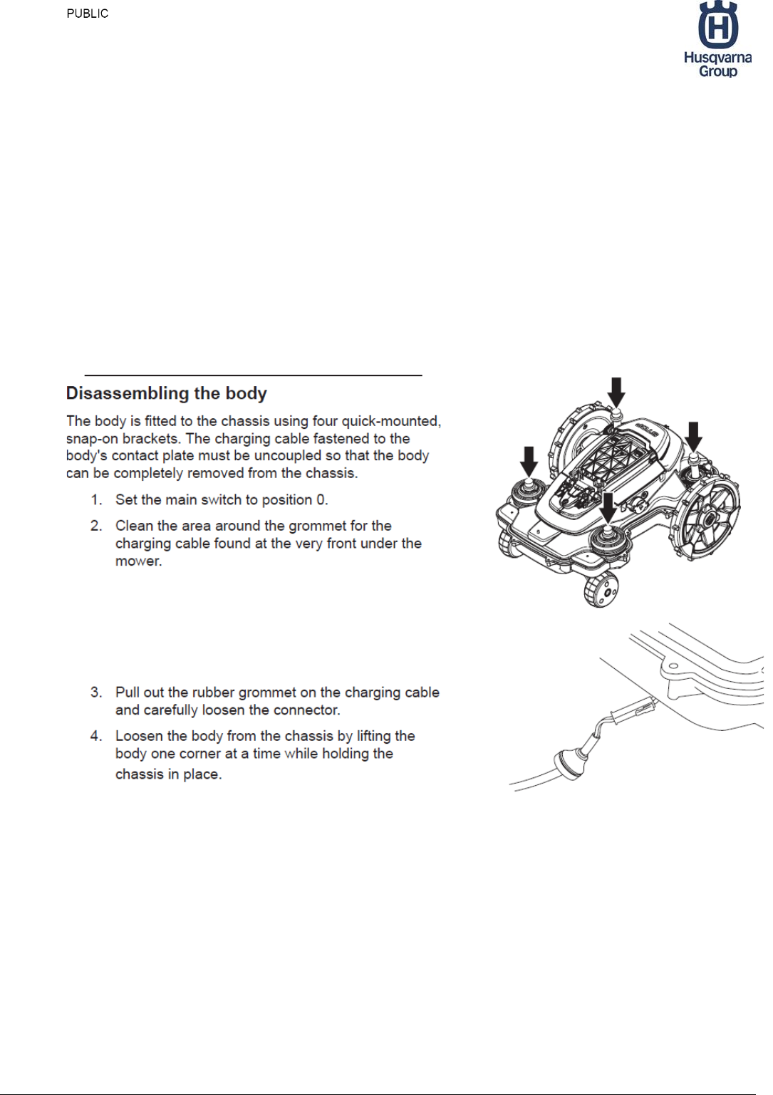
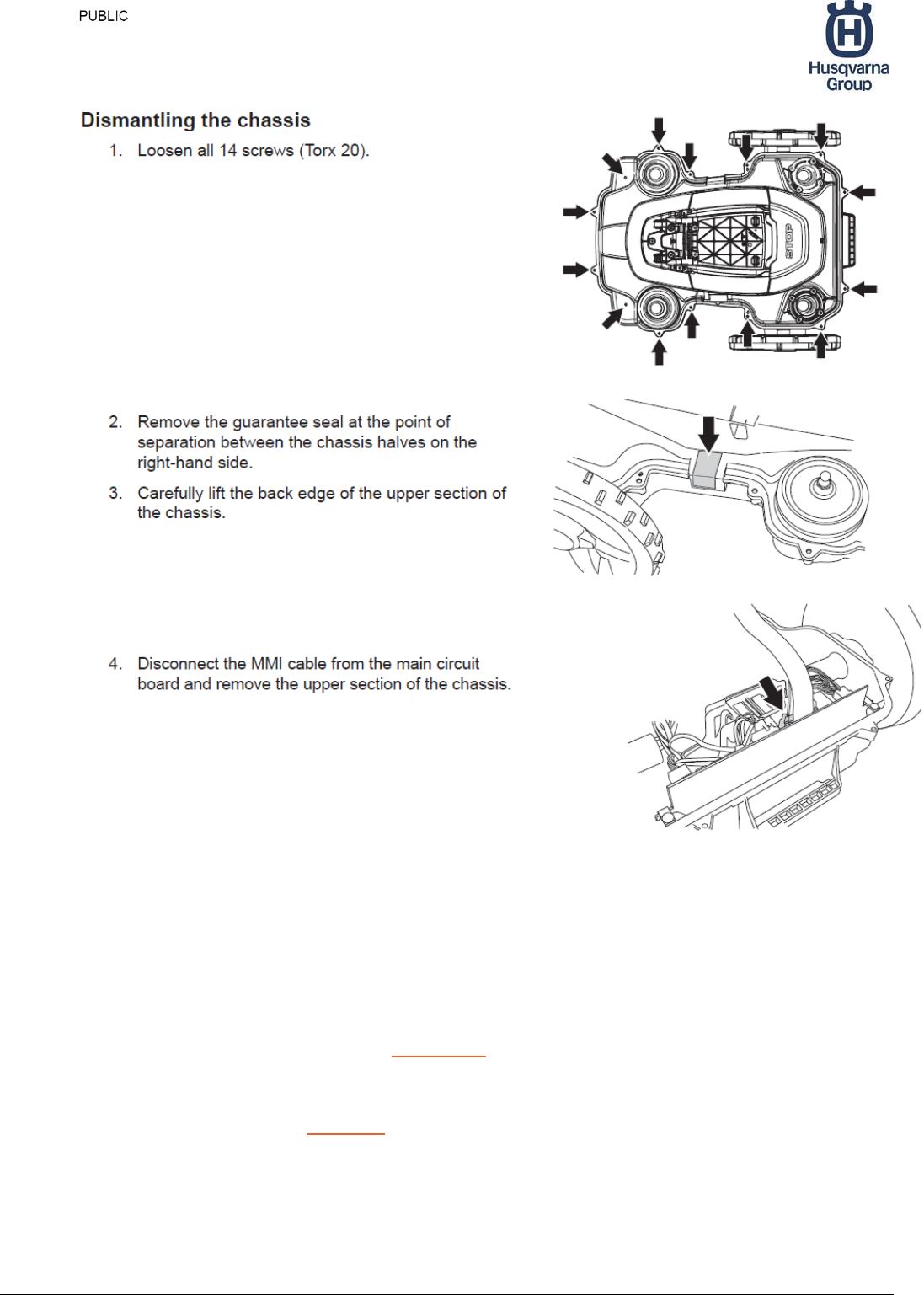
Common for both examples are that you need to access the interior of the mower. Below
is a cutout from the manual describing how to disassemble the mower:
Startup Guide HRP Mower
Version 1.1 2017-06-01
14 (20)
7.2 Example 1 - BeagleBone Black installation
For this installation we use the following:
BeagleBone Black
16 GB SD card memory
8 wire ribbon cable
8-pin Micro-MaTch connector, 7-215083-8
DC plug (optional)
Connectors to expansion connector P9 on Beagelbone.
ASUS WiFi-adapter USB-N13
The ribbon cable is prepared with a Micro-MaTch connector in one end.
Startup Guide HRP Mower
Version 1.1 2017-06-01
15 (20)
The pinout of the AUX4 is:
AUX4 Pin
Signal
1
UART_TX
2
UART_RX
3
GND
4
AUX_GPIO
5
3.3 V, max 400 mA
6
5 V, max 750 mA
7
18 V, max 1000 mA
8
GND
The used pins On the Beagle Bone connector P9 are:
BeagleBone Black
Connector P9
Signal
1,2
GND
5,6
VDD_5V
11
RX
13
TX
The ribbon cable is connected to Beagle Bone Black as follows:
(Power can be connected to DC jack or via P9)
Wire 1 => P9:11 Mower Tx => BBB Rx
Wire 2 => P9:13 BBB Tx => Mower Rx
Wire 3 => P9:1 GND
Wire 4 not connected
Wire 5 not connected
Wire 6 => P9:5 or to DC-plug + 5V
Wire 7 not connected
Wire 8=> P9:8 or to DC-plug - GND
The installation is shown in Figure 6. In this installation is the power to the beagle bone
connected via a Power plug.
A complete software installation for this configuration is available as a disk image. This
image has a complete setup of linux Ubuntu 14.04, ROS Indigo and a version of the HRP
software.
The disk image is named bb_image_hrp_2017-03-06.img.tar.gz.
Startup Guide HRP Mower
Version 1.1 2017-06-01
16 (20)
To use this you must have a SD card of 16GB, or larger and the specified WiFi-adapter
from Asus. The image is copied with the linux dd command to the SD card.
After installing this to the SD-card the BeagleBone Black will act as an Wifi-spot with the
SSID HVA_BBB_AP. The key is “1234567890”.
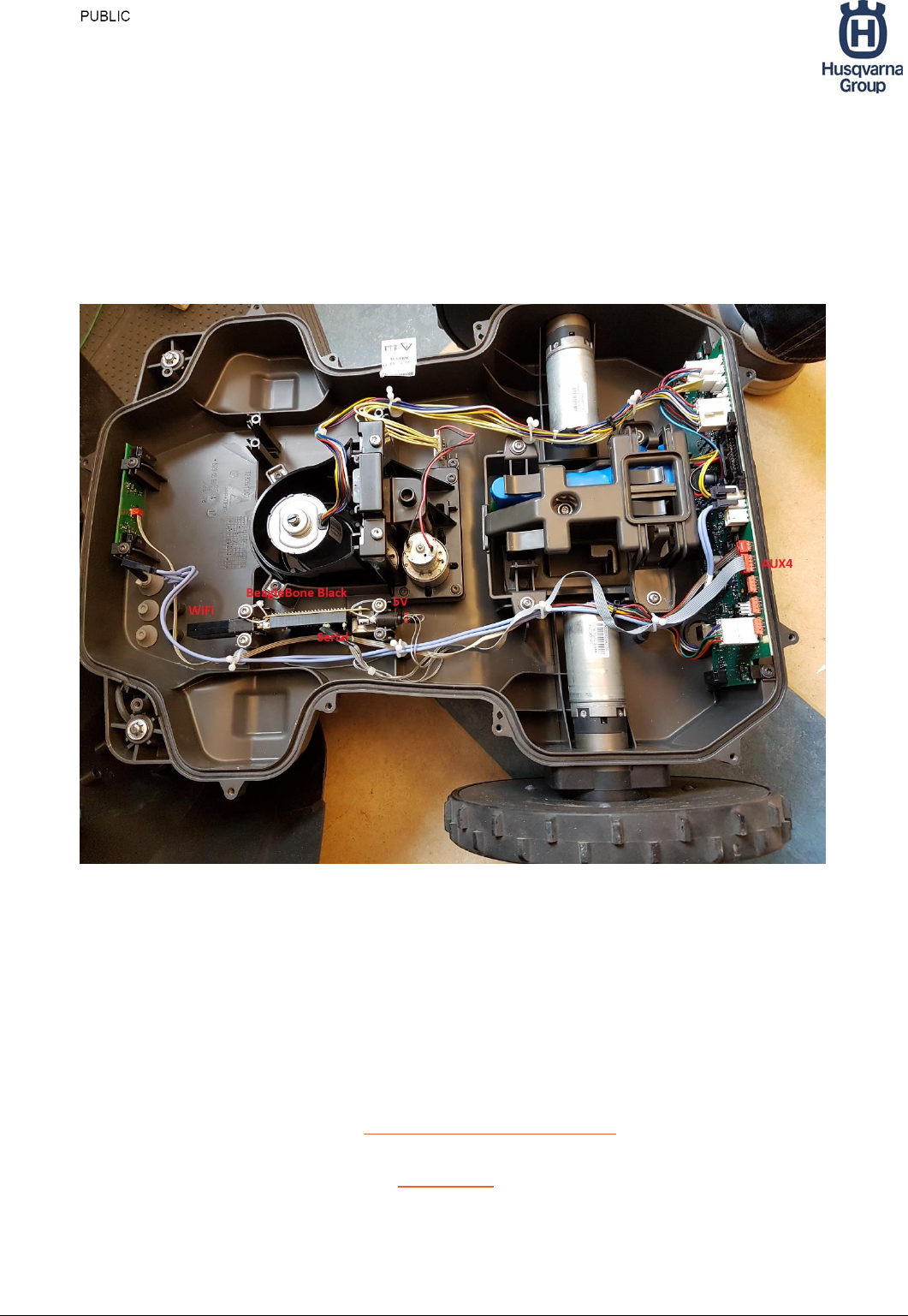
Figure 6 Beagle Bone Black installation
7.3 Example 2 - Raspberry Pi installation
For this installation we used the following:
Raspberry Pi2
WiFi USB-dongle - WiPi
DC/DC-converter 5V, 9A, www.pololu.com/product/2866
USB to UART converter, FTDI, with cable.
8-pin Micro-MaTch connector, 7-215083-8
USB cable for powering the Raspberry PI
Connection cables.
Power switch, same type as the Mower Power.
Startup Guide HRP Mower
Version 1.1 2017-06-01
17 (20)
An extra power switch is mounted by making a whole in the plastic cover.
The DC/DC converter is connected to Battery Power via the extra power switch, by
soldering directly on the main board, see chapter 5.3. 5V output from the DC/DC is
connected to the mini-USB connector on the Raspberry PI.
The serial communication to the mainboard is accomplished by connecting an FTDI
(USB to UART converter) on one of the USB-ports on the Raspberry PI. The other
end of this cable (Rx, Tx and GND signals, is wired to a Micro-MaTch connector. The
pinout is found in Table 2. This is then connected to the AUX3 connector on the
mainboard. (Any of the four different AUX connectors can be used).
The WiFi dongle is connected to a USB port on the Raspberry Pi.
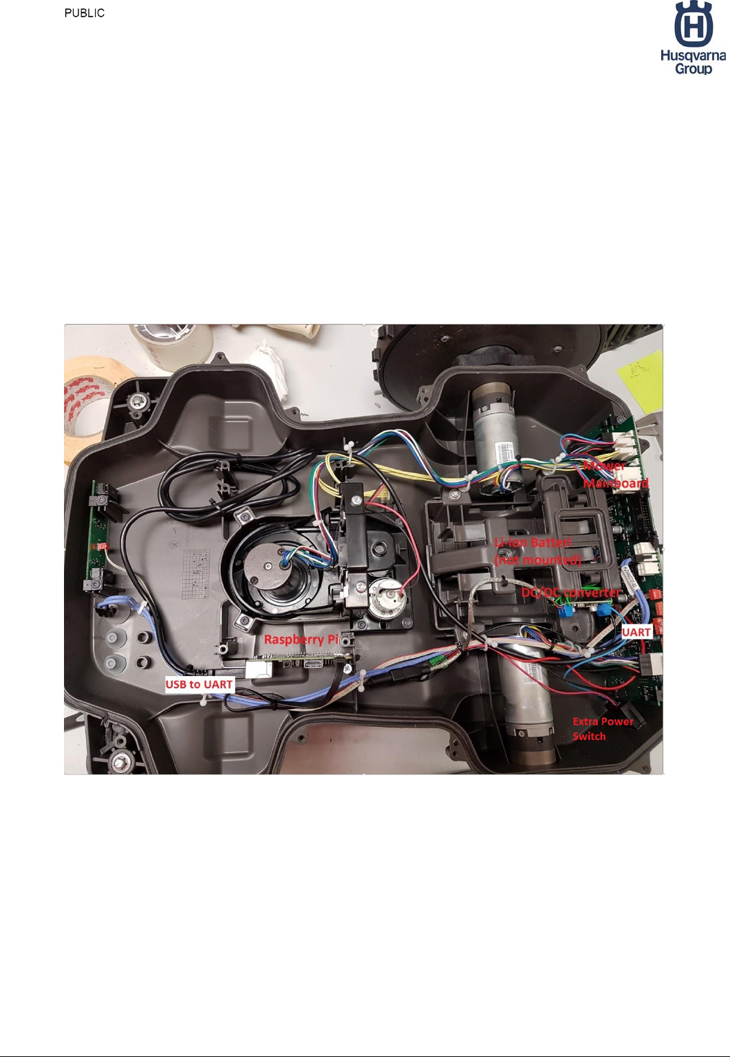
Figure 7 Raspberry Pi installation
Startup Guide HRP Mower
Version 1.1 2017-06-01
18 (20)
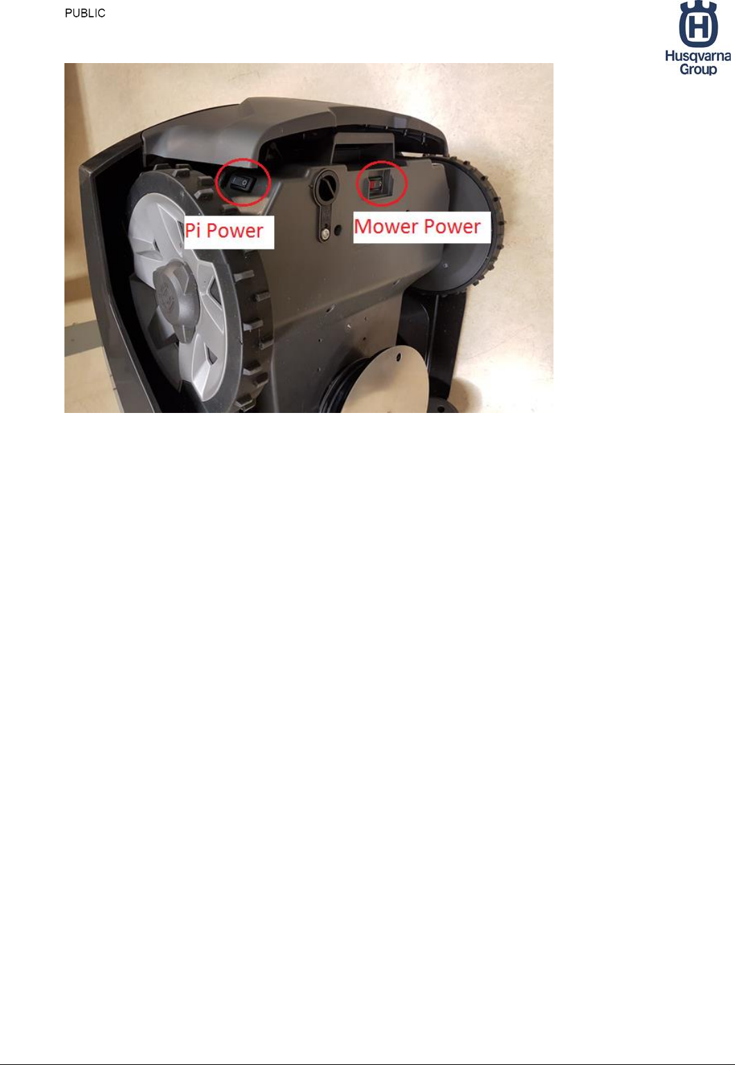
Figure 8 Power Switches, The original Mower Power, and the extra Pi Power.
7.4 Adding outside sensors outside Raspberry Pi installation
To connect the cables to the Raspberry Pi you need to make holes in the top cover. If you
want to keep the mower weather proof, you should enter the interior cover via the rubber
grommet, see picture below. Of course you can make more holes in the interior cover and
add similar grommet.
Startup Guide HRP Mower
Version 1.1 2017-06-01
19 (20)
Free cable holes with rubber grommets, and available voltages.
To power external devices you can access a regulated 5V from the internal DC/DC
converter, or from Raspberry Pi USB.
The DC/DC converter is capable of delivering 9A, and the Raspberry Pi only use a small
part of this.
You can also access the unregulated 18V voltage, which is simplest accessed from the
input connecter to the DC/DC. This 18V is switched on/off with the “Pi Power” button as
described in chapter Error! Reference source not found..
Maximum power consumption on 18V and 5V all together is 100 W.
Startup Guide HRP Mower
Version 1.1 2017-06-01
20 (20)
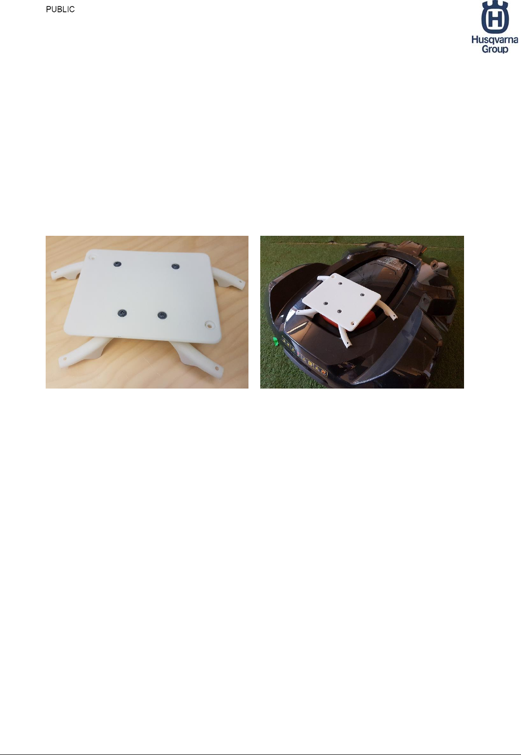
8 Adding extra equipment
Additional equipment like cameras, scanners etc, can be mounted on top of the mower.
Husqvarna has designed an accessory rig which fits on the top cover. Husqvarna
provides STL-files for this so you can produce them in your own 3D-printer.
The rig can be fixed to the mower by four screws. It is OK to make holes in the plastic
cover for these.
Accessory rig Accessory rig mounted
