T111221S01_ZAVIO_B7210 T111221S01 ZAVIO B7210
2016-04-12
: Pdf T111221S01 Zavio B7210 T111221S01_ZAVIO_B7210 CertsReports 551069 ProductFiles
Open the PDF directly: View PDF ![]() .
.
Page Count: 75

Compliance Certification Services Inc. Report No:T111221S01-LV
TEST REPORT
IEC / EN 60950-1
Information Technology Equipment – Safety – Part 1:General requirements
Report reference No……………….: T111221S01-LV
Date of Issue.……………………. .: Mar. 09, 2012
Total number of pages.………..….: 75
Testing laboratory …………………: Compliance Certification Services Inc.
Location……………………………..: No.8,Jiucengling, Xinhua Dist., Tainan City 712, Taiwan (R.O.C.)
Test Place…………………………..: 6 F,No.605,Zhongshan Rd.,Xinhua Dist., Tainan City 712, Taiwan
(R.O.C.)
Applicant…………………………….: ZAVIO Inc.
Address:……………………………..: 2F, No.13, R&D Rd.II, Science Based Industrial Park, Hsinchu, Taiwan
Standards……………………………: EN 60950-1:2006 + A11:2009+A1:2010+A12:2011
IEC 60950-1:2005+A1:2009
Procedure deviation………………..: N/A
Non-standard test method…………: N/A
Type of test equipment ……………: IP Cam
Trade mark………………………….: ZAVIO
Model/Type designation…………: B7210
Manufacturer……………………….: ZAVIO Inc.
Address:……………………………..: 2F, No.13, R&D Rd.II, Science Based Industrial Park, Hsinchu, Taiwan
Rating……………………………….: Optional, DC 12V, 1.5A, max. (by external adapter) and DC 48V, 0.5A
(by POE)
Copyright TRF………….…………..: This test report is based on a blank TRF(IEC60950_1C) that was
prepared by Fimko. The copyright of blank test report is belong to the
CCB body of SGS.
Declaration:
CCS represents to the client that testing is done in accordance with standard procedures as applicable and
that test instruments used has been calibrated with the standards traceable to National Measurement
Laboratory (NML) of R.O.C., or National Institute of Standards and Technology (NIST) of U.S.A.
CCS's reports apply only to the specific samples tested under conditions. It is manufacture’s res-ponsibility to
ensure that additional production units of this model are manufactured with the identical electrical and
mechanical components.CCS shall have no liability for any declarations, inferences or generalizations drawn
by the client or others from CCS issued reports.
CCS’s reports must not be used by the client to claim product endorsement by the authorities or any agency
of the Government.
This report is the confidential property of the client. As a mutual protection to the clients, the public and CCS-
self, extracts from the test report shall not be reproduced except in full with CCS’s authorized written approval.
Tested by:
Eason Chiang
Reviewed by:
Kane Wang
Compliance Certification Services Inc. Report No:T111221S01-LV
Page 2 of 75
Test item particulars:
Equipment mobility ...........…......……......................... Movable
Connection to the mains…..…………………………… Not directly connected to the mains
Operating Condition..…………………………………… Continuous
Overvoltage category (OCV)…………………………… Other : no connection to the mains.
Access location ………………………………….……… Operator accessible
Mains supply tolerance (%)………………………..…… --
Tested for IT power systems…………….…………….. NO
IT testing, phase-phase voltage ( V)………………….. N/A
Class of equipment……………………………………… Class III
Altitude during operation (m)………………………….. Up to 2000
Pollution degree (PD)…………………………………... PD 2
Protection against ingress of water…………………… IPX0
Considered current rating (A)……..…………………… --
Mass of equipment.(Kg)……………………………….. Approx. 2.1 Kg
Testing :
Date of receipt of test item Feb., 2012
Date(s) of performance of tests Feb., 2012- Mar., 2012
Possible test case verdicts:
-Test case does not apply to the test object. N(.A.)
-Test object does meet the requirement. P(ass)
-Test object does not meet the requirement. F(ail)
General Remarks:
The test results presented in this report relate only to the object tested.
This report shall not be reproduced, except in full, without the written approval of the testing laboratory.
"(see Enclosure #) refers to additional information appended to the report.
“(see appended table)” refers to a table appended to the report.
This report shall not be reproduced except in full without the written approval of the testing laboratory.
Factory :
1. ZAVIO Inc.
2F, No.13, R&D Rd.II, Science Based Industrial Park, Hsinchu, Taiwan
1 Report Page 1-60
2 Attachment - A. EUT Photos Page 61-69
3 Attachment - B. Product ID Label Page 70-71
4 Attachment - C. Schematics and Layout Page 72
5 Attachment - D. Users Instruction Page 73
6 Attachment - E. Measuring Instrument List Page 74-75

Compliance Certification Services Inc. Report No:T111221S01-LV
Page 3 of 75
Comments:
Sample Number: Test sample(s) without serial number(s).
General product information :
1. The equipment is a IP Cam for general use in information technology equipment.
2. The equipment is intended to be supplied from an external power adapter or PoE (must be complied with
LPS) and subject to overvoltage.
3. The external power adapters are approved products which were evaluated according to IEC 60950-1, for
detail information see appended table 1.5.1.
4. The equipment’s top enclosure is secured to bottom enclosure by snap ring.
5. The equipment is incorporated with following critical parts :
1) Metal enclosure.
2) Main board.
3) LED board.
4) Lens board.
Engineering Considerations :
1. The product was submitted and tested for use at the maximum ambient temperature(Tma) permitted by
the manufacturer’s specification of : +40℃。
2. The load conditions used during testing :
- The unit operated under all connectors connected and transmit data continuously, LED lamp operating.
3. The following forced-air cooling was used during tests:
- DC Fan : 7.0 CFM.
4. The PoE interface is considered to TNV-1 circuit.
5. The external power adapter was in compliance with Limited Power Sources requirements. See appended
table 1.5.1 for detail.
6. The product is in compliance with the requirement of IEC/EN 60950-1.
Compliance Certification Services Inc. Report No:T111221S01-LV
Page4 of 75
Report revise record:
No. Issue Date Report Number Rev. Revisions Effect Page
00 2012-03-09 T111221S01-LV 00 Original report N/A
Compliance Certification Services Inc. Report No:T111221S01-LV
IEC/EN 60950-1
Clause Requirement - Test Result - Remark
Verdict
Page5 of 75
1 General P
1.5 Components P
1.5.1 General P
Comply with IEC 60950 or relevant component
standard
Components that were found to affect
safety aspects comply with the
requirements of this standard or with the
safety aspects of the relevant IEC
component standards. (see appended
table 1.5.1)
P
1.5.2 Evaluation and testing components Components that were certified to IEC
and/or national standards are used
correctly within their ratings. Components
not covered by IEC standards are tested
under the conditions present in the
equipment.
P
1.5.3 Thermal controls No thermal controls. N
1.5.4 Transformers Class III equipment. N
1.5.5 Interconnecting cables No interconnecting cables. N
1.5.6 Capacitors bridging insulation Not direct connect to the mains supply. N
1.5.7 Resistors bridging insulation Not direct connect to the mains supply. N
1.5.7.1 Resistors bridging functional, basic or
supplementary insulation
N
1.5.7.2 Resistors bridging double or reinforced
insulation between a.c. mains and other circuits
N
1.5.7.3 Resistors bridging double or reinforced
insulation between a.c. mains and antenna or
coaxial cable
N
1.5.8 Components in equipment for IT power
systems
Class III equipment. N
1.5.9 Surge suppressors N
1.5.9.1 General N
1.5.9.2 Protection of VDRs N
1.5.9.3 Bridging of functional insulation by a VDR N
1.5.9.4 Bridging of basic insulation by a VDR N
1.5.9.5 Bridging of Supplementary, double or
reinforced insulation by a VDR
N
1.6 Power interface P
1.6.1 AC power distribution systems Not direct connect to the mains supply. N
1.6.2 Input current (see appended table 1.6.2) P
1.6.3 Voltage limit of hand-held equipment Not hand-held equipment. N
1.6.4 Neutral conductor Class III equipment N
1.7 Marking and instructions P
1.7.1 Power rating and identification markings See below P
1.7.1.1 Power rating markings P
Compliance Certification Services Inc. Report No:T111221S01-LV
IEC/EN 60950-1
Clause Requirement - Test Result - Remark
Verdict
Page 6 of 75
Multiple mains supply connections Not connect to the mains supply. N
Rated voltage(s) or voltage range(s) (V) Optional. (not connect to the mains
supply)
P
Symbol for nature of supply for d.c. only. Optional, IEC 60417, Symbol No. 5031
used. (not connect to the mains supply)
N
Rated frequency or rated frequency range (Hz) (not connect to the mains supply) N
Rated current (mA or A) Optional. (not connect to the mains
supply).
P
1.7.1.2 Identification markings See below. P
Manufacturer’s name or Trade-mark or
identification mark
Trade-mark : ZAVIO P
Model identification or type reference B7210 P
Symbol for Class II equipment only Class III equipment. N
Other markings and symbols Additional symbols or markings do not
cause misunderstanding. P
Certification marks CE marking. P
1.7.2 Safety instructions and marking See below. P
1.7.2.1 General The user’s manual contains information
for operation, installation and technical. P
1.7.2.2 Disconnect devices Class III equipment. N
1.7.2.3 Overcurrent protective device No such part. N
1.7.2.4 IT power distribution system Class III equipment. N
1.7.2.5 Operator access with a tool No operator access with a tool. N
1.7.2.6 Ozone No such part. N
1.7.3 Short duty cycles Unit is designed for continuous operation. N
1.7.4 Supply voltage adjustment Class III equipment. N
Methods and means of adjustment;reference
to installation instructions
N
1.7.5 Power outlets on the equipment No outlet. N
1.7.6 Fuse identification (marking, special fusing
characteristics, cross-reference)
N
1.7.7 Wiring terminals See below N
1.7.7.1 Protective earthing and bonding terminals Class III equipment. N
1.7.7.2 Terminal for a.c. mains supply conductors Class III equipment. N
1.7.7.3 Terminal for d.c. mains supply conductors Class III equipment. N
1.7.8 Controls and indicators No safety involved controls or indicators. N
1.7.8.1 Identification, location and marking N
1.7.8.2 Colours N
1.7.8.3 Symbols according to IEC 60417 N
1.7.8.4 Markings using figures No figures used. N
1.7.9 Isolation of multiple power sources Class III equipment. N
1.7.10 Thermostats and other regulating devices No thermostats or other regulating
devices. N
Compliance Certification Services Inc. Report No:T111221S01-LV
IEC/EN 60950-1
Clause Requirement - Test Result - Remark
Verdict
Page 7 of 75
1.7.11 Durability The label was subjected to the
permanence of marking test. The label
was rubbed with cloth soaked with water
for 15s and then again for 15s with the
cloth soaked with petroleum spirit. After
this test there was no damage to the
label. The marking on the label did not
fade. There was no curling nor lifting of
the label edge.
P
1.7.12 Removable parts No removable parts. N
1.7.13 Replaceable batteries No such component. N
Language(s) ─
1.7.14 Equipment for restricted access locations No restricted access locations. N
2 Protection from hazards P
2.1 Protection from electric shock and energy hazards P
2.1.1 Protection in operator access areas All parts are safe to access be operator. P
2.1.1.1 Access to energized parts Compliance of protection against contact
with hazardous energized parts checked. P
Test by inspection Complied. P
Test with test finger(Figure 2A) Complied. P
Test with test pin(Figure 2B) Complied. P
Test with test probe(Figure 2C) Complied. P
2.1.1.2 Battery compartments N
2.1.1.3 Access to ELV wiring No ELV wiring in operator accessible
area. N
Working voltage (Vpeak or Vrms); minimum
distance through insulation(mm) N
2.1.1.4 Access to hazardous voltage circuit wiring No hazardous voltage wiring in operator
accessible area. N
2.1.1.5 Energy hazards No energy hazards in equipment. N
2.1.1.6 Manual controls No manual controls. N
2.1.1.7 Discharge of capacitors in equipment Class III equipment. N
Measured voltage(V);time-constant(s) N
2.1.1.8 Energy hazard-d.c. mains supply Not connect to the mains supply. N
a) Capacitor connected to the d.c. mains
supply
N
b) Internal battery connected to the d.c. mains
supply
N
2.1.1.9 Audio amplifiers No such parts. N
2.1.2 Protection in service access areas No maintenance work in operation mode
necessary. N
2.1.3 Protection in restricted access locations The unit is not intended to be used in
restricted locations. N
2.2 SELV circuits P
2.2.1 General requirements See below. P
Compliance Certification Services Inc. Report No:T111221S01-LV
IEC/EN 60950-1
Clause Requirement - Test Result - Remark
Verdict
Page 8 of 75
2.2.2 Voltage under normal conditions (V) See appended table 2.2.2 on
measurement section. P
2.2.3 Voltage under fault conditions (V) See appended table 2.2.3 on
measurement section. P
2.2.4 Connection of SELV circuits to other circuits Complied with 2.2.2 and 2.2.3. P
2.3 TNV circuits P
2.3.1 Limits See below P
Type of TNV circuit There is TNV-1 circuit within the EUT, is
intended to receive signals during normal
operation, which is connected to PoE
interface, which is considered to be TNV-
1 circuit.
P
2.3.2 Separation from other circuits and from
accessible parts N
2.3.2.1 General requirements N
2.3.2.2 Protection by basic insulation N
2.3.2.3 Protection by earthing N
2.3.2.4 Protection by other constructions N
2.3.3 Separation from hazardous voltages See above. P
Insulation employed TNV circuits connected to SELV circuit. ─
2.3.4 Connection of TNV circuits to other circuits See above. P
Insulation employed TNV circuits connected to SELV circuit. ─
2.3.5 Test for operating voltages generated externally No operating voltages generated
externally. N
2.4 Limited current circuits N
2.4.1 General requirements N
2.4.2 Limit values N
Frequency (Hz) --
Measured current (mA) --
Measured voltage (V) --
Measured circuit capacitance (nF or μF) --
2.4.3 Connection of limited current circuits to other
circuits
N
2.5 Limited power source P
a) Inherently limited output N
b) Impedance limited output N
c) Regulating network limited output under
normal operating and single fault condition
(see appended table 2.5) P
d) Overcurrent protective device limited output N
Max. output voltage (V), max. output current
(A), max. apparent power (VA)
(see appended table 2.5) P
Current rating of overcurrent protective device
(A)
N
Compliance Certification Services Inc. Report No:T111221S01-LV
IEC/EN 60950-1
Clause Requirement - Test Result - Remark
Verdict
Page 9 of 75
Use of integrated circuit (IC) current limiters N
2.6 Provisions for earthing and bonding N
2.6.1 Protective earthing Class III equipment. N
2.6.2 Functional earthing N
2.6.3 Protective earthing and protective bonding
conductors
N
2.6.3.1 General N
2.6.3.2 Size of protective earthing conductors N
Rated current (A), cross-sectional area (mm²),
AWG
─
2.6.3.3 Size of protective bonding conductors N
Rated current (A), cross-sectional area (mm²),
AWG
─
2.6.3.4 Resistance of earthing conductors and their
terminations, resistance (Ω), voltage drop (V),
test current (A), duration (min)
N
2.6.3.5 Colour of insulation N
2.6.4 Terminals N
2.6.4.1 General N
2.6.4.2 Protective earthing and bonding terminals N
Rated current (A), type nominal thread diameter
(mm)
─
2.6.4.3 Separation of the protective earthing conductor
from protective bonding conductors
N
2.6.5 Integrity of protective earthing N
2.6.5.1 Interconnection of equipment N
2.6.5.2 Components in protective earthing conductors
and protective bonding conductors
N
2.6.5.3 Disconnection of protective earth N
2.6.5.4 Parts that can be removed by an operator N
2.6.5.5 Parts removed during servicing N
2.6.5.6 Corrosion resistance N
2.6.5.7 Screws for protective bonding N
2.6.5.8 Reliance on telecommunication network or
cable distribution system
No telecommunication network. N
2.7 Overcurrent and earth fault protection in primary circuits N
2.7.1 Basic requirements Class III equipment. N
Instruction when protection relies on building
installation
N
2.7.2 Faults not simulated in 5.3.7 N
2.7.3 Short-circuit backup protection N
2.7.4 Number and location of protective devices N
2.7.5 Protection by several devices N
Compliance Certification Services Inc. Report No:T111221S01-LV
IEC/EN 60950-1
Clause Requirement - Test Result - Remark
Verdict
Page 10 of 75
2.7.6 Warning to service personnel N
2.8 Safety interlocks N
2.8.1 General principles No safety interlocks. N
2.8.2 Protection requirements N
2.8.3 Inadvertent reactivation N
2.8.4 Fail-safe operation N
2.8.5 moving parts N
2.8.6 Overriding N
2.8.7 Switches, relays and their related circuits N
2.8.7.1 Separation distances for contact gaps and their
related circuits (mm)
N
2.8.7.2 Overload test N
2.8.7.3 Endurance test N
2.8.7.4 Electric strength test N
2.8.8 Mechanical actuators N
2.9 Electrical insulation P
2.9.1 Properties of insulating materials Natural rubber, asbestos or hygroscopic
materials are not used. P
2.9.2 Humidity conditioning Class III equipment. N
Relative humidity (%), temperature (℃) ⎯
2.9.3 Grade of insulation Insulation materials comply with relevant
requirements.
P
2.9.4 Separation from hazardous voltage Class III equipment. N
Method (s) used ⎯
2.10 Clearance, creepage distances and distances through insulation
Only SELV and TNV-1 circuit inside the unit. (See also sub clause 5.3.4)
N
2.10.1 General N
2.10.1.1 Frequency N
2.10.1.2 Pollution degrees N
2.10.1.3 Reduced values for functional insulation N
2.10.1.4 Intervening unconnected conductive parts N
2.10.1.5 Insulation with varying dimensions N
2.10.1.6 Special separation requirements N
2.10.1.7 Insulation in circuits generating Starting pulses N
2.10.2 Determination of working voltage N
2.10.2.1 General N
2.10.2.2 RMS working voltage N
2.10.2.3 Peak working voltage N
2.10.3 Clearances N
2.10.3.1 General N
Compliance Certification Services Inc. Report No:T111221S01-LV
IEC/EN 60950-1
Clause Requirement - Test Result - Remark
Verdict
Page 11 of 75
2.10.3.2 Main Transient voltage N
a)AC mains supply N
b)Earthed d.c. mains supplies N
c)Unearthed d.c. mains supply N
d)Battery operation N
2.10.3.3 Clearance in primary circuits N
2.10.3.4 Clearance in secondary circuits N
2.10.3.5 Clearance in circuits having starting pulses N
2.10.3.6 Transients from a.c. mains supply N
2.10.3.7 Transients from d.c. mains supply N
2.10.3.8 Transients from telecommunication networks
and cable distribution systems
N
2.10.3.9 Measurement of transient voltage levels N
a)Transients from a mains supply N
For an a.c. mains supply N
For a d.c. mains supply N
b)Transients from a telecommunication network N
2.10.4 Creepage distance N
2.10.4.1 General N
2.10.4.2 Material group and caomparative tracking index N
CTI tests N
2.10.4.3 Minimum creepage distances N
2.10.5 Solid insulation N
2.10.5.1 General N
2.10.5.2 Distances through insulation N
2.10.5.3 Insulating compound as solid insulation N
2.10.5.4 Semiconductor devices N
2.10.5.5 Cemented joints N
2.10.5.6 Thin sheet material-General N
2.10.5.7 Separable thin sheet material N
Number of layers (pcs) N
2.10.5.8 Non-separable thin sheet material N
2.10.5.9 Thin sheet material-standard test procedure N
Electric strength test N
2.10.5.10 Thin sheet material-alternative test procedure N
Electric strength test N
2.10.5.11 Insulation in wound components N
2.10.5.12 Wire in wound components N
Working voltage N
a)basic insulation not under stress N
b)basic supplementary, reinforced insulation N
c)Compliance with Annex U N
Compliance Certification Services Inc. Report No:T111221S01-LV
IEC/EN 60950-1
Clause Requirement - Test Result - Remark
Verdict
Page 12 of 75
Tow wires in contact inside wound
component;angle between 45° and 90°
N
2.10.5.13 Wire with solvent-based enamel in wound
components
N
Electric strength test N
Routine test N
2.10.5.14 Additional insulation in wound components N
Working voltage N
-basic insulation not under stress N
-supplementary, reinforced insulation N
2.10.6 Construction of printed boards N
2.10.6.1 Uncoated printed boards N
2.10.6.2 Coated printed boards N
2.10.6.3 Insulation between conductors on the same
inner surface of a printed board
N
2.10.6.4 Insulation between conductors on different
layers of a printed board
N
Distance through insulation N
Number of insulation layers (pcs) N
2.10.7 Component external terminations N
2.10.8 Test on coated printed boards and coated
components
N
2.10.8.1 Sample preparation and preliminary inspection N
2.10.8.2 Thermal conditioning N
2.10.8.3 Electric strength test N
2.10.8.4 Abrasion resistance test N
2.10.9 Thermal cycling N
2.10.10 Test for Pollution Degree 1 environment and
insulation compound
N
2.10.11 Test for semiconductor devices and cemented
joints
N
2.10.12 Enclosed and sealed parts N
3 WIRING, CONNECTIONS AND SUPPLY P
3.1 General P
3.1.1 Current rating and overcurrent protection All internal wires are UL recognized wiring
which is PVC insulated, rated VW-1, min.
80°C. Internal wiring is PVC insulated, the
wiring gauge is suitable for current
intended to be carried.
P
3.1.2 Protection against mechanical damage Class III equipment. N
3.1.3 Securing of internal wiring Class III equipment. N
3.1.4 Insulation of conductors Class III equipment. N
3.1.5 Beads and ceramic insulators Not used. N
3.1.6 Screws for electrical contact pressure No such screws used. N
Compliance Certification Services Inc. Report No:T111221S01-LV
IEC/EN 60950-1
Clause Requirement - Test Result - Remark
Verdict
Page 13 of 75
3.1.7 Insulation materials in electrical connections No contact pressure through insulating
material. P
3.1.8 Self-tapping and spaced thread screws No self-tapping or spaced thread screw. P
3.1.9 Termination of conductors Class III equipment. N
10N pull test N
3.1.10 Sleeving on wiring No sleeving used. N
3.2 Connection to a main supply
Class III equipment, not connect to the mains supply. N
3.2.1 Means of connection N
3.2.1.1 Connection to an a.c. mains supply N
3.2.1.2 Connection to a d.c. mains supply N
3.2.2 Multiple supply connections N
3.2.3 Permanently connected equipment N
Number of conductors, diameter (mm) of cable
and conduits
─
3.2.4 Appliance inlets N
3.2.5 Power supply cords N
3.2.5.1 AC Power supply cords N
Type ─
Rated current (A), cross-sectional area (mm²),
AWG
─
3.2.5.2 DC Power supply cords N
3.2.6 Cord anchorages and strain relief N
Mass of equipment (kg), pull (N) ─
Longitudinal displacement (mm) ─
3.2.7 Protection against mechanical damage N
3.2.8 Cord guards N
Diameter or minor dimension D (mm); test mass
(g)
─
Radius of curvature of cord (mm) ─
3.2.9 Supply wiring space N
3.3 Wiring terminals for connection of external conductors
Class III equipment. N
3.3.1 Wiring terminals N
3.3.2 Connection of non-detachable power supply
cords
N
3.3.3 Screw terminals N
3.3.4 Conductor sizes to be connected N
Rated current (A), type and nominal thread
diameter (mm)
N
3.3.5 Wiring terminal sizes N
Rated current (A), type and nominal thread
diameter (mm)
N
Compliance Certification Services Inc. Report No:T111221S01-LV
IEC/EN 60950-1
Clause Requirement - Test Result - Remark
Verdict
Page 14 of 75
3.3.6 Wiring terminals design N
3.3.7 Grouping of wiring terminals N
3.3.8 Standard wire N
3.4 Disconnection from the mains supply
Class III equipment, not connect to the mains supply.
N
3.4.1 General requirement N
3.4.2 Disconnect devices N
3.4.3 Permanently connected equipment N
3.4.4 Parts which remain energized N
3.4.5 Switches in flexible cords N
3.4.6 Single-phase equipment N
3.4.7 Three-phase equipment N
3.4.8 Switches as disconnect devices N
3.4.9 Plugs as disconnect devices N
3.4.10 Interconnected equipment N
3.4.11 Multiple power source N
3.5 Interconnection of equipment P
3.5.1 General requirements See below. P
3.5.2 Types of interconnection circuits SELV circuit. P
3.5.3 ELV circuits as interconnection circuits No ELV interconnections. N
3.5.4 Data ports for additional equipment (see appended table 2.5) P
4 Physical requirements P
4.1 Stability See below N
Mass of the equipment exceeding 7 kg………: Mass of equipment: 2.1 kg N
Angle of 10° N
Test force (N) Equipment is not a floorstanding unit. N
4.2 Mechanical strength P
4.2.1 General See below. N
4.2.2 Steady force test, 10N Class III equipment. N
4.2.3 Steady force test, 30N N
4.2.4 Steady force test, 250N Class III equipment. N
4.2.5 Impact test Class III equipment. N
Fall test N
Swing test N
4.2.6 Drop test Movable equipment. N
4.2.7 Stress relief Class III equipment. N
4.2.8 Cathode ray tubes No cathode ray tubes --
Picture tube separately certified N

Compliance Certification Services Inc. Report No:T111221S01-LV
IEC/EN 60950-1
Clause Requirement - Test Result - Remark
Verdict
Page 15 of 75
Picture tubes > 16 cm intrinsically protected N
Non-intrinsically protected tubes > 16 m used
with protective screen
N
Intrinsically protected tubes : tests on 12
samples
N
Samples subject to ageing : 6 N
Samples subject to implosion test : 6 N
Samples subject to mechanical strength test
(steel ball) : 6
N
Non-intrinsically protected tubes tested N
4.2.9 High pressure lamps No high pressure lamp. N
4.2.10 Wall or ceiling mounted equipment The equipment and its associated
mounting means shall remain secure
during test. 2.1kg x 3=6.3kg
(3 times weight of equipment)
P
force (N) 6.3Kg/1min P
4.2.11 Rotating solid media No such device. N
Test to cover on the door --
4.3 Design and construction P
4.3.1 Edges and corners All edges and corners judged to be
sufficiently well rounded. P
4.3.2 Handles and manual controls; force (N) No such controls. N
4.3.3 Adjustable controls No adjustable controls. N
4.3.4 Securing of parts No loosening of parts impairing clearance
or creepage distance is likely to occur. P
4.3.5 Connection of plugs and sockets IEC60083 and IEC60320 connectors are
not used in equipment. N
4.3.6 Direct plug-In equipment No direct plug-In equipment. N
Torque N
Compliance with the relevant mains plug
standard
N
4.3.7 Heating elements in earthed equipment No heating elements. N
4.3.8 Batteries No batteries. N
-Overcharging of a rechargeable battery N
-Unintentional charging of a non-rechargeable
battery
N
-Reverse charging of a rechargeable battery N
-Excessive discharging rate for any battery N
4.3.9 Oil and grease N
4.3.10 Dust, powders, liquids and gases Equipment in intended use not considered
to be exposed to these. N
4.3.11 Containers for liquids or gases No container for liquid or gases. N
4.3.12 Flammable liquids No flammable liquids. N
Quantity of liquid (l) N
Flash point (℃) N

Compliance Certification Services Inc. Report No:T111221S01-LV
IEC/EN 60950-1
Clause Requirement - Test Result - Remark
Verdict
Page 16 of 75
4.3.13 Radiation; type of radiation N
4.3.13.1 General N
4.3.13.2 Ionizing radiation N
Measured radiation (Pa/kg) N
Measured High-voltage (Kv) N
Measured focus voltage (Kv) N
CRT markings N
4.3.13.3 Effect of ultraviolet (UV) radiation on materials N
Part, property, retention after test, flammability
classification
N
4.3.13.4 Human exposure to ultraviolet (UV) radiation N
4.3.13.5 Laser (including laser diodes) and LEDs N
4.3.13.5.1 Laser (including laser diodes) N
Laser class --
4.3.13.5.2 Light emitting diodes (LEDs) N
4.3.13.6 Other types N
4.4 Protection against hazardous moving parts P
4.4.1 General DC fan is certified used in the EUT, Not
accessible to the user. P
4.4.2 Protection in operator access areas The test finger cannot touch DC fan. P
Household and home/office document/media
shredders
--
4.4.3 Protection in restricted access locations N
4.4.4 Protection in service access areas Unintentional contact with hazardous
moving parts is unlikely during servicing
operations.
P
4.4.5 Protection against moving fan blades See below P
4.4.5.1 General P
Not considered to cause pain or injury. a) < 1
However, DC fan is protected by
enclosure. The test finger cannot touch
DC fans.
P
Is considered to cause pain, not injury. b) N
Considered to cause injury. c) N
4.4.5.2 Protection for users N
Use of symbol or warning N
4.4.5.3 Protection for service persons N
Use of symbol or warning N
4.5 Thermal requirements P
4.5.1 General See below P
4.5.2 Temperature rise (see appended table 4.5) P
Normal load condition per Annex L Maximum normal load according to the
operation manual. P
Compliance Certification Services Inc. Report No:T111221S01-LV
IEC/EN 60950-1
Clause Requirement - Test Result - Remark
Verdict
Page 17 of 75
4.5.3 Temperature limits for materials (see appended table 4.5) P
4.5.4 Touch temperature limits (see appended table 4.5) P
4.5.5 Resistance to abnormal heat No such part. N
4.6 Openings in enclosures N
4.6.1 Top and side openings No electrical and fire enclosure required. N
Dimensions (mm) --
4.6.2 Bottom of fire enclosures No electrical and fire enclosure required. N
Construction of the bottom, dimensions (mm) --
4.6.3 Doors or covers in fire enclosures No fire enclosure. N
4.6.4 Openings in transportable equipment Hand-held equipment. N
4.6.4.1 Constructional design measures N
Dimensions(mm) N
4.6.4.2 Evaluation measures for larger openings N
4.6.4.3 Use of metalized parts N
4.6.5 Adhesives for constructional purposes No adhesives for constructional purpose. N
Conditioning temperature (℃),time (weeks) N
4.7 Resistance to fire P
4.7.1 Reducing the risk of ignition and spread of
flame
See below. P
Method 1, selection and application of
components wiring and materials
Use of materials with the required
flammability classes. P
Method 2, application of all of simulated fault
condition tests
Method 1 used. N
4.7.2 Conditions for a fire enclosure With having the following parts :
-The EUT is supplied by limited power
sources and components are mounted
on PWB of flammability Class V-1.
The fire enclosure is not required.
P
4.7.2.1 Parts requiring a fire enclosure See clause 4.7.2 N
4.7.2.2 Parts no requiring a fire enclosure See clause 4.7.2 P
4.7.3 Materials See below. P
4.7.3.1 General PCB rated V-1 or better. P
4.7.3.2 Materials for fire enclosures See clause 4.7.2. N
4.7.3.3 Materials for components and other parts
outside fire enclosures
See sub-clause 4.7.2 N
4.7.3.4 Materials for components and other parts inside
fire enclosures.
Internal components except small parts
are V-2 or better. P
4.7.3.5 Materials for air filter assemblies No air filter assemblies N
4.7.3.6 Materials used in high-components No high voltage components. N
5 ELECTRICAL REQUIREMENTS AND SIMULATED ABNORMAL CONDITIONS P
5.1 Touch current and protective conductor current N
5.1.1 General Class III equipment. N
Compliance Certification Services Inc. Report No:T111221S01-LV
IEC/EN 60950-1
Clause Requirement - Test Result - Remark
Verdict
Page 18 of 75
5.1.2 Configuration of equipment under test (EUT) N
5.1.2.1 Single connection to an a.c. mains supply N
5.1.2.2 Redundant multiple connections to an a.c.
mains supply
N
5.1.2.3 Simultaneous multiple connections to an a.c.
mains supply
N
5.1.3 Test circuit N
5.1.4 Application of measuring instrument N
5.1.5 Test procedure N
5.1.6 Test measurements N
Supply voltage (V) --
Measured touch current (mA) --
Max. allowed touch current (mA) --
Measured protective conductor current (mA) --
Max. allowed protective conductor current (mA) --
5.1.7 Equipment with touch current exceeding 3.5
mA
N
5.1.7.1 General N
5.1.7.2 Simultaneous multiple connections to the
supply
N
5.1.8 Touch currents to telecommunication networks
and cable distribution systems and from
telecommunication networks
N
5.1.8.1 Limitation of the touch current to a
telecommunication network or to a cable
distribution system
N
Supply voltage (V) --
Measured touch current (mA) --
Max. allowed touch current (mA) --
5.1.8.2 Summation of touch current from
telecommunication networks
N
a)EUT with earthed telecommunication ports --
b)EUT whose telecommunication ports have no
reference to protective earth
--
5.2 Electric strength
Class III equipment. N
5.2.1 General N
5.2.2 Test procedure N
5.3 Abnormal operating and fault conditions P
5.3.1 Protection against overload and abnormal
operation
DC Fan locked test.
(see appended table 5.3)
P
5.3.2 Motors Approved DC fans used. P
5.3.3 Transformers In approved SPS. N
Compliance Certification Services Inc. Report No:T111221S01-LV
IEC/EN 60950-1
Clause Requirement - Test Result - Remark
Verdict
Page 19 of 75
5.3.4 Functional insulation Method c) short-circuit test, results see
appended table 5.3. P
5.3.5 Electromechanical components No electromechanical components. N
5.3.6 Audio amplifiers in ITE No such parts. N
5.3.7 Simulation of faults (see appended table 5.3) P
5.3.8 Unattended equipment No thermostat, temperature limiter or
thermal cut-off. N
5.3.9 Compliance criteria for abnormal operating and
fault conditions
See below P
5.3.9.1 During the tests No fire, no emit and no shrinkage,
distortion or loosening if any enclosure
part was noticeable on the equipment.
P
5.3.9.2 After the tests Electric strength test primary to secondary
and primary to ground were passed. P
6 CONNECTION TO TELECOMMUNICATION NETWORKS P
6.1 Protection of telecommunication network service persons, and users of other equipment
connected to the network, from hazards in the equipment. N
6.1.1 Protection from hazardous voltages N
6.1.2 Separation of the telecommunication network
from earth
N
6.1.2.1 Requirements N
Supply voltage (V) ─
Current in the test circuit (mA) ─
6.1.2.2 Exclusions N
6.2 Protection of equipment users from overvoltages on telecommunication networks P
6.2.1 Separation requirements Equipment provide adequate electrical
separation between TNV-1 circuit and
SELV circuit.
P
6.2.2 Electric strength test procedure See below. P
6.2.2.1 Impulse test N
6.2.2.2 Steady-state test (see appended table 6.2.2.2) P
6.2.2.3 Compliance criteria P
6.3 Protection of telecommunication wiring system from overheating N
Max. output current (A) ─
Current limiting method ─
7 CONNECTION TO CABLE DISTRIBUTION SYSTEMS N
7.1 General N
7.2 Protection of cable distribution system service
personnel, and users of other equipment
connected to the system, from hazards voltage
in the equipment.
N
7.3 Protection of equipment users from
overvoltages on the cable distribution system
N
Compliance Certification Services Inc. Report No:T111221S01-LV
IEC/EN 60950-1
Clause Requirement - Test Result - Remark
Verdict
Page 20 of 75
7.4 Insulation between primary circuits and cable
distribution system
N
7.4.1 General ─
7.4.2 Voltage surge test ─
7.4.3 Impulse test ─
A ANNEX A, TESTS FOR RESISTANCE TO HEAT AND FIRE N
A.1 Flammability test for fire enclosures of movable equipment having a total mass
exceeding 18 kg, and of stationary equipment(see 4.7.3.2) N
A.1.1 Samples N
Wall thickness(mm) …………………………… : ─
A.1.2 Conditioning of samples; temperature(℃) …. : N
A.1.3 Mounting of samples ……………………….… : N
A.1.4 Test flame(see IEC 60695-11-3) N
Flame A, B, C or D ─
A.1.5 Test procedure N
A.1.6 Compliance criteria N
Sample 1 burning time(s) ……………………. : ─
Sample 2 burning time(s) ………………..….. : ─
Sample 3 burning time(s) ………………..….. : ─
A.2
Flammability test for fire enclosures of movable equipment having a total mass not
exceeding 18 kg, and for material and components located inside fire enclosures
(see 4.7.3.2 and 4.7.3.4)
N
A.2.1 Samples material N
Wall thickness(mm) ………………………….. : ─
A.2.2 Conditioning of samples; temperature(℃) … : N
A.2.3 Mounting of samples …………………….….. : N
A.2.4 Test flame(see IEC 60695-11-4) N
A.2.5 Test procedure N
A.2.6 Compliance criteria N
Sample 1 burning time(s) ……………….….. : ─
Sample 2 burning time(s) ……………….….. : ─
Sample 3 burning time(s) ……………….….. : ─
A.2.7 Alternative test acc. To IEC 60695-11-5, cl.
5 and 9 N
Sample 1 burning time(s) ……………….….. : ─

Compliance Certification Services Inc. Report No:T111221S01-LV
IEC/EN 60950-1
Clause Requirement - Test Result - Remark
Verdict
Page 21 of 75
Sample 2 burning time(s) ……………….….. : ─
Sample 3 burning time(s) ………….……….. : ─
A.3 Hot flaming oil test(see 4.6.2) N
A.3.1 Mounting of Samples N
A.3.2 Test procedure N
A.3.3 Compliance criterion N
B ANNEX B, MOTOR TESTS UNDER ABNORMAL CONDITIONS(see 4.7.2.2 and 5.3.2) N
B.1 General requirements N
Position ……………………………………. : ─
Manufacturer ……………………………… : ─
Type ……………………………………….. : ─
Rated values ……………………………… : ─
B.2 Test conditions N
B.3 Maximum temperatures N
B.4 Running overload test N
B.5 Locked-rotor overload test N
Test duration (days) ………….……..……. : ─
Electric strength test: test voltage (V) ….. : ─
B.6 Running overload test for DC motors in
secondary circuits N
B.6.1 General ─
B.6.2 Test procedure ─
B.6.3 Alternative test procedure ─
B.6.4 Electric strength test; test voltage (V) ─
B.7 Locked-rotor overload test for DC motors in secondary circuits N
B.7.1 General N
B.7.2 Test procedure N
B.7.3 Alternative test procedure N
B.7.4 Electric strength test; test voltage (V) N
B.8 Test for motors with capacitors N
B.9 Test for three-phase motors N
B.10 Test for series motors N
Compliance Certification Services Inc. Report No:T111221S01-LV
IEC/EN 60950-1
Clause Requirement - Test Result - Remark
Verdict
Page 22 of 75
Operating voltage (V) …………………….. : ─
C ANNEX C, TRANSFORMERS(see 1.5.4 and 5.3.3) N
Position ……………………………………. : ─
Manufacturer ……………………………… : ─
Type ……………………………………….. : ─
Rated values ……………………………… : ─
Method of protection……………………..: ─
C.1 Overload test N
C.2 Insulation N
Protection from displacement of winding ─
D ANNEX D, MEASURING INSTRUMENTS FOR TOUCH-CURRENT TESTS
(see 5.1.4) N
D.1 Measuring instrument N
D.2 Alternative measuring instrument N
E ANNEX E, TEMPERATURE RISE OF A WINDING(see 1.4.13) N
F ANNEX F, MEASUREMENT OF CLEARANCES AND CREEPAGE
DISTANCES (see 2.10 and Annex G) N
G ANNEX G, ALTERNATIVE METHOD FOR DETERMINING MINIMUM
CLEARANCES N
G.1 Clearances N
G.1.1 General ─
G.1.2 Summary of the procedure for determining
minimum clearances ─
G.2
Determination of mains transient voltage
(V) ……………………………………………….
:
N
G.2.1 AC mains supply ─
G.2.2 Earthed d.c. mains supplies ─
G.2.3 Unearthed d.c. amins supplies ─
G.2.4 Battery operation ─
G.3 Determination of telecommunication
network transient voltage (V) ………..……….. : N
G.4 Determination of required withstand
voltage(V) ……………………….…………….. : N
Compliance Certification Services Inc. Report No:T111221S01-LV
IEC/EN 60950-1
Clause Requirement - Test Result - Remark
Verdict
Page 23 of 75
G.4.1 Mains transients and internal repetitive peaks ─
G.4.2 Transients from telecommunication networks ─
G.4.3 Combination of transients ─
G.4.4 Transients from cable distribution systems ─
G.5 Measurement of transient levels (V) ………… : N
a)transients from a mains supply ─
For an a.c. mains supply ─
For a d.c. mains supply ─
b)transients from a telecommunication network ─
G.6 Determination of minimum clearances …….. : N
H ANNEX H, IONIZING RADIATION (see 4.3.13) N
J ANNEX J, TABLE OF ELECTROCHEMICAL POTENTIALS (see 2.6.5.6) N
Metal used ………………………………..…… : ─
K ANNEX K, THERMAL CONTROLS (see 1.5.3 and 5.3.8) N
K.1 Making and breaking capacity N
K.2 Thermostat reliability; operating voltage(V).. : N
K.3 Thermostat endurance test; operating
voltage(V) ………………………………..……. : N
K.4 Temperature limiter endurance; operating
voltage(V) ……………………………..………. : N
K.5 Thermal cut-out reliability N
K.6 Stability of operation N
L ANNEX L, NORMAL LOAD CONDITIONS FOR SOME TYPES OF ELECTRICAL
BUSINESS EQUIPMENT (see 1.2.2.1 and 4.5.2) P
L.1 Typewriters N
L.2 Adding machines and cash registers N
L.3 Erasers N
L.4 Pencil sharpeners N
L.5 Duplicators and copy machines N
L.6 Motor-operated files N
L.7 Other business equipment Max. normal load operation. P
Compliance Certification Services Inc. Report No:T111221S01-LV
IEC/EN 60950-1
Clause Requirement - Test Result - Remark
Verdict
Page 24 of 75
M ANNEX M, CRITERIA FOR TELEPHONE RINGING SIGNALS (see 2.3.1) N
M.1 Introduction N
M.2 Method A N
M.3 Method B N
M.3.1 Ringing signal N
M.3.1.1 Frequency(Hz) ……………….……………….. : N
M.3.1.2 Voltage(V) …………………………….…….… : N
M.3.1.3 Cadence; time(s), voltage(V) ……….……..… : N
M.3.1.4 Single fault current (Ma) …………………..….. : N
M.3.2 Tripping device and monitoring voltage …: N
M.3.2.1 Conditions for use of a tripping device or a
monitoring voltage N
M.3.2.2 Tripping device N
M.3.2.3 Monitoring voltage (V) ……….……………..…. : N
N ANNEX N, IMPULSE TEST GENERATIORS(see 1.5.7.2, 1.5.7.3, 2.10.3.9, 6.2.2.1,
7.3.2, 7.4.3 and Clause G.5) N
N.1 ITU-T impulse test generators N
N.2 IEC 60065 impulse test generators N
P ANNEX P, NORMATIVE REFERENCES N
Q ANNEX Q, Voltage dependent resistors (VDRs)(see 1.5.9.1) N
a)preferred climatic categories N
b)Maximum continuous voltage N
c)Pulse current N
R ANNEX R, EXAMPLES OF REQUIREMENTS FOR QUALITY CONTROL
PROGRAMMES N
R.1 Minimum separation distances for unpopulated
coated printed boards(see 2.10.6.2) N
R.2 Reduced clearances (see 2.10.3) N
S ANNEX S, PROCEDURE FOR IMPULSE TESTING(see 6.2.2.3) N
S.1 Test equipment N
S.2 Test procedure N
Compliance Certification Services Inc. Report No:T111221S01-LV
IEC/EN 60950-1
Clause Requirement - Test Result - Remark
Verdict
Page 25 of 75
S.3 Examples of waveforms during impulse testing N
T ANNEX T, GUIDANCE ON PROTECTION AGAINST INGRESS OF WATER(see 1.1.2) N
U ANNEX U, INSULATED WINDING WIRES FOR USE WITHOUT INTERLEAVED
INSULATION (see 2.10.5.4) N
V ANNEX V, AC POWER DISTRIBUTION SYSTEMS(see 1.6.1) N
V.1 Introduction N
V.2 TN power distribution systems N
W ANNEX W, SUMMATION OF TOUCH CURRENTS N
W.1 Touch current from electronic circuits N
W.1.1 Floating circuits N
W.1.2 Earthed circuits N
W.2 Interconnection of several equipments N
W.2.1 isolation N
W.2.2 Common return, isolated from earth N
W.2.3 Common return, connected to protective earth N
X ANNEX X, MAXIMUM HEATING EFFECT IN TRANSFORMER TESTS(see clause c.1) N
X.1 Determination of maximum input current N
X.2 Overload test procedure N
Y ANNEX Y, ULTRAVIOLET LIGHT CONDITIONING TEST (see 4.3.13.3) N
Y.1 Test apparatus ................................................. N
Y.2 Mounting of test samples ................................. N
Y.3 Carbon-arc light-exposure apparatus .............. N
Y.4 Xenon-arc light exposure apparatus ................ N
Z ANNEX Z, OVERVOLTAGE CATEGORIES (see 2.10.3.2 and Clause G.2) N
AA ANNEX AA, MANDREL TEST (see 2.10.5.8) N
BB ANNEX BB, CHANGES IN THE SECOND EDITION --
Compliance Certification Services Inc. Report No:T111221S01-LV
IEC/EN 60950-1
Clause Requirement - Test Result - Remark
Verdict
Page 26 of 75
CC ANNEX CC, Evaluation of integrated circuit (IC) current limiters N
CC.1 General N
CC.2 Test program 1 N
CC.3 Test program 2 N
DD ANNEX DD, Requirements for the mounting means of rack-mounted equipment N
DD.1 General N
DD.2 Mechanical strength test, variable N N
DD.3 Mechanical strength test, 250N, including end
stops N
DD.4 Compliance N
EE ANNEX EE, Household and home/office document/media shredders N
EE.1 General N
EE.2 Markings and instructions N
Use of markings or symbols N
Information of user instructions, maintenance
and/or servicing instructions N
EE.3 Inadvertent reactivation test N
EE.4 Disconnection of power to hazardous moving
parts N
Use of markings or symbols N
EE.5 Protection against hazardous moving parts N
Test with test finger (Figure 2A) N
Test with wedge probe (Figure EE1 and EE2) N
Compliance Certification Services Inc. Report No:T111221S01-LV
Page27 of 75
1.5.1 TABLE: List of critical components P
Object/part No. Manufacturer/
trademark
Type/model Technical data Standard
(Edition / year)
Mark(s) of
conformity1)
Power Adaptor Dee Van
Enterprise Co.,
Ltd.
DSA-12CA-12
120150
I/P:100-240Vac,
50/60Hz, 0.8A
O/P : 12Vdc,
1.5A Class II,
+40℃, LPS
EN 60950-1:
2006+A11
TÜV
Enclosure -- -- Metal, thickness
min. 5.0 mm
-- --
T1 (used in
main board)
GENERAL
COMPONENTS
INDUSTRY
CORP.
EF12V6D6-
Z019
105°C -- --
Various Various
105°C -- --
LED lamps -- -- 1.5Vdc max. -- --
Polyswitch
(F101) (J103
protector)
Tyco Electronics
Corp.
MF-NSMF020 PTC type, Vmax
= 24Vdc, Ih =
0.2A, It =0.46A,
IEC/EN 60730-
1: 2000 Tested
to clauses 15,
17, J15 and J17
TÜV, UL
DC Fan (one
provided)
(Inward)
SUNON KDE1204PFV2 DC 12V, 0.08A,
7 CFM
EN/IEC 60950-1 TÜV, UL
All PCBs
material
-- -- V-1 or better ,
105°C min.
UL 796 UL
1) An asterisk indicates a mark which assures the agreed level of surveillance
Supplementary information:
1.6.2 TABLE: Electrical data (in normal conditions) P
U (Vdc) I (A) Irated (A) P (W) Fuse # Ifuse (A) Condition/status
Supplied from PoE :
48 0.20 0.50 9.60 -- -- Maximum normal load with LED
lamp operating.
48 0.13 0.50 6.24 -- -- Maximum normal load with DC FAN
operating.
Supplied from external power adapter :
12 0.69 1.5 8.28 -- -- Maximum normal load LED and DC
FAN operating.
Supplementary information:
2.1.1.5 TABLE: max. V, A, VA test N
Voltage (rated)
(V)
Current (rated)
(A)
Voltage (max.)
(V)
Current (max.)
(A)
VA (max.)
(VA)
--
Supplementary information :
Compliance Certification Services Inc. Report No:T111221S01-LV
Page 28 of 75
2.1.1.7 TABLE : discharge test N
Location τ calculated
(S)
τ measured
(S)
t u → 0V
(S)
Comments
--
Supplementary information :
2.2.2 TABLE : SELV measurement (under normal conditions) P
max. voltage Component Location
V peak V rms
Voltage limitation
component
For main board :
T401 Pin 10 to Pin 6 34.8 16.6
Supplementary information:
2.2.3 TABLE : SELV measurement (under fault conditions) P
Location Voltage measured (V) Comments
For main board :
12Vdc Æ GND 0 T1 (1–6) shorted, no hazards. The
o/p-voltage did not exceed 42.4Vpk.
12Vdc Æ GND 0 T1 (1–10) shorted, no hazards. The
o/p-voltage did not exceed 42.4Vpk.
12Vdc Æ GND 0 T1 (3–6) shorted, no hazards. The
o/p-voltage did not exceed 42.4Vpk.
12Vdc Æ GND 0 T1 (3–10) shorted, no hazards. The
o/p-voltage did not exceed 42.4Vpk.
12Vdc Æ GND 0 T1 (4–6) shorted, no hazards. The
o/p-voltage did not exceed 42.4Vpk.
12Vdc Æ GND 0 T1 (4–10) shorted, no hazards. The
o/p-voltage did not exceed 42.4Vpk.
12Vdc Æ GND 0 T1 (5–6) shorted, no hazards. The
o/p-voltage did not exceed 42.4Vpk.
12Vdc Æ GND 0 T1 (5–10) shorted, no hazards. The
o/p-voltage did not exceed 42.4Vpk.
12Vdc Æ GND 0 ISO401 (3–1) shorted, no hazards.
The o/p-voltage did not exceed
42.4Vpk.
12Vdc Æ GND 0 ISO401 (3–2) shorted, no hazards.
The o/p-voltage did not exceed
42.4Vpk.
12Vdc Æ GND 0 ISO401 (4–1) shorted, no hazards.
The o/p-voltage did not exceed
42.4Vpk.
12Vdc Æ GND 0 ISO401 (4–2) shorted, no hazards.
The o/p-voltage did not exceed
42.4Vpk.
Supplementary information:
Compliance Certification Services Inc. Report No:T111221S01-LV
Page 29 of 75
2.4.2 TABLE : limited current circuit measurement N
Location Voltage
(V)
Current
(mA)
Freq.
(kHz)
Limit
(mA)
Comments
--
Note :
2.5 TABLE : limited power source measurement P
Limits Measured Verdict
According to Table 2B/2C (Normal condition) : J301, RJ45 port , Uoc=0V
Current (in A) ≤80 P
Power (in VA) ≤100 0 P
According to Table 2B/2C (Normal condition) : J102, Vedio out port, Uoc=0V
Current (in A) ≤80 P
Power (in VA) ≤100 0 P
According to Table 2B/2C (Normal condition) : J103 pin 4 to GND, Connection port , Uoc=11.618V
Current (in A) ≤8 0.464 P
Power (in VA) ≤100 4.62 P
Note :
1. J103 port : No fault condition was considered necessary for protection by polyswitch (F101) and PTC pass
the tests specified in IEC 60730-1, Clause 15, 17, J15 and J17, see table 1.5.1 for detail information.
2.10.2 TABLE : Working voltage measurement N
Location Peak voltage (V) RMS voltage (V) Comments
For main board :
T401 pin 1 to T1 pin 6 48.4 45.5
T401 pin 1 to T1 pin 10 79.0 48.8
T401 pin 3 to T1 pin 6 95.0 58.5
T401 pin 3 to T1 pin 10 84.0 50.1
T401 pin 4 to T1 pin 6 44.8 20.4
T401 pin 4 to T1 pin 10 28.0 4.15
T401 pin 5 to T1 pin 6 0 0
T401 pin 5 to T1 pin 10 29.6 16.4
ISO401 pin 4 to U5 pin 1 3.14 2.38
ISO401 pin 3 to U5 pin 2 5.72 4.88
Supplementary information:
For reference only.
Compliance Certification Services Inc. Report No:T111221S01-LV
Page 30 of 75
2.10.3 and 2.10.4 TABLE: Clearance and creepage distance measurements N
Clearance (cl) and creepage
distance (cr) at/of/between:
U peak
(V)
U r.m.s.
(V)
Required cl
(mm)
cl
(mm)
Required cr
(mm)
cr
(mm)
--
Note :
4.3.8 TABLE: Batteries N
The tests of 4.3.8 are applicable only when appropriate battery
data is not available
--
Is it possible to install the battery in a reverse polarity position? Yes
Non-rechargeable batteries Rechargeable batteries
Discharging Charging Discharging Reversed charging
Meas.
current
Manuf.
Specs.
Un-
intentional
charging Meas.
current
Manuf.
Specs.
Meas.
current
Manuf.
Specs.
Meas.
current
Manuf.
Specs.
-- -- -- -- -- --
-- -- -- -- -- --
-- -- -- -- -- --
Test results: Verdict
- Chemical leaks No
- Explosion of the battery No
- Emission of flame or expulsion of molten metal No
- Electric strength tests of equipment after completion of tests N/A N/A
Supplementary information:
4.5 TABLE: Thermal requirements P
Supply voltage (V) 12Vdc 12Vdc 48Vdc 48Vdc 12Vdc 12Vdc 48Vdc ⎯
Ambient Tmin (°C) -- -- -- -- -- -- ⎯
Ambient Tmax (°C) -- -- -- -- -- -- ⎯
Operating condition A : System : I/P : 12Vdc (Horizontal mode, at ambient : 40°C)
B : System : I/P : 12Vdc (Vertical mode, at ambient : 40°C)
C : System : I/P : 48Vdc (Horizontal mode, at ambient : 40°C)
D : System : I/P : 48Vdc (Vertical mode, at ambient : 40°C)
E : System : I/P : 12.0Vdc (Vertical mode, at ambient : 25°C)
F : System : I/P : 12.0Vdc (Vertical mode, at ambient : 33°C)
G : System : I/P : 48Vdc (Vertical mode, at ambient : 25°C)
T (°C)
Maximum measured temperature T
of part/at::
Allowed
Tmax
(°C)
Operating condition A B C D E F G --
1. Main board : PCB near D406 59.2 60.6 71.7 72.4 56.3 56.7 77.1 105
Compliance Certification Services Inc. Report No:T111221S01-LV
Page 31 of 75
2. Main board : PCB near U301 50.4 52.0 61.6 63.3 47.1 47.4 68.6 105
3. Main board : T401 coil 49.5 50.8 73.7 76.8 45.7 45.9 82.9 105
4. Main board : T401 core 49.8 51.0 76.9 80.5 46.1 46.2 86.8 105
5. Main board : PCB near U202 52.6 53.8 74.4 76.1 50.0 50.2 81.2 105
6. Main board : PCB near U101 73.9 75.0 88.0 88.6 72.6 73.0 92.3 105
7. Main board : PCB near U203 56.8 58.2 67.5 67.9 53.8 54.1 72.8 105
8. Main board : PCB near U602 54.5 55.8 64.2 63.6 51.3 51.3 68.0 105
9. LED board : PCB near U1 63.1 63.3 74.7 76.5 65.0 64.4 82.5 105
10. LED board : PCB near LED1 64.3 65.4 43.6 73.5 62.6 62.6 79.3 105
11. Metal enclosure inside 47.1 48.7 49.3 50.8 38.2 41.5 55.0 --
12. Metal enclosure outside 46.4 47.9 48.3 49.7 37.6 40.9 54.3 70
Tma 40.0 40.0 40.0 40.0 25.0 33.0 25.0 --
Tamb 39.7 39.2
--
Temperature T of winding: t1 (°C) R1 (Ω)t2 (°C) R2 (Ω)T (°C) Allowed
Tmax
(°C)
Insulatio
n class
--
Supplementary information:
The temperatures were measured under worst case normal mode defined in 1.2.2.1 and as described in
sub-clause 1.6.2 and at voltages as described above.
The maximum ambient temperature permitted by the manufacturer’s specification is +40°C.
Electrolyte capacitor or components with :
-PWB of 105℃
-Surface of equipment which may be touched :
-Plastic Tmax = 95℃
-Metal Tmax = 70℃
4.5.5 TABLE: Ball pressure test of thermoplastic parts N
Allowed impression diameter (mm) .......... ≤ 2 mm ⎯
Part Test temperature
(°C)
Impression diameter
(mm)
--
Supplementary information:
4.6.1 & 4.6.2 Ventilation opening N
Location Dimensions (mm) Remark
Note :
Compliance Certification Services Inc. Report No:T111221S01-LV
Page 32 of 75
4.7 TABLE: Resistance to fire N
Part Manufacturer of
material
Type of material Thickness
(mm)
Flammability
class
Evidence
--
Supplementary information:
1) see appended table 1.5.1.
5.1.6 TABLE: Touch currents to and from telecommunication networks N
Condition L1 Æ terminal A
(mA)
N Æ terminal A
(mA)
Limit (mA) Comments
--
Note :
5.2 TABLE: Electric strength tests, impulse tests and voltage surge tests N
Test voltage applied between: Voltage shape
(AC, DC,
impulse, surge)
Test voltage
(V)
Breakdown
Yes/No
--
Supplementary information:
5.3 TABLE: Fault condition tests N
Ambient temperature (°C) ...................................: 25, if not specified. ⎯
Power source for EUT: Manufacturer, model/type,
output rating ........................................................ :
-- ⎯
Component
No.
Fault Supply
voltage
(V)
Test
time
Fuse # Fuse
current
(A)
Observation
DC Fan locked 12Vdc 1hr
51min
-- --
Normal operation, no hazards.
Ambient=38.5℃, T401 coil=54.7℃,
T401 core=55.3℃, PCB near
U101=82.4℃
Supplementary information: s-c : short circuit ; o-c : open circuit.
6.2.2.2 TABLE: Electric strength tests, impulse tests and voltage surge tests P
Test voltage applied between: Voltage shape
(AC, DC,
impulse, surge)
Test voltage
(V)
Breakdown
Yes/No
RJ45 (PoE) to Metal enclosure AC 1000 NO
Supplementary information:
Compliance Certification Services Inc. Report No:T111221S01-LV
National Differences
Clause Requirement − Test Result – Remark Verdict
Page33 of 75
EN 60950-1:2006/A11:2009/A1:2010/A12:2011 – CENELEC COMMON MODIFICATIONS
IEC60950-1, GROUP DIFFERENCES (CENELEC common modifications EN)
Contents Add the following annexes :
Annex ZA (normative) Normative references to international publications with their
corresponding Europearn publications.
Annex ZB (normative) Special national conditions.
P
General Delete all the “country” notes in the reference
document (IEC 60950-1:2005) according to
the following list:
Deleted. N
1.4.8
1.5.1
1.5.7.1
1.5.8
1.5.9.4
1.7.2.1
2.2.3
2.2.4
2.3.2
2.3.2.1
2.3.4
2.6.3.3
2.7.1
2.10.3.2
2.10.5.13
3.2.1.1
3.2.4
2.5.1
Note 2
Note 2 & 3
Note
Note 2
Note
Note 4,5 & 6
Note
Note
Note
Note 2
Note 2
Note 2 & 3
Note
Note 2
Note 3
Note
Note 3
Note 2
4.3.6
4.7
4.7.2.2
4.7.3.1
5.1.7.1
5.3.7
6
6.1.2.1
6.1.2.2
6.2.2
6.2.2.1
6.2.2.2
7.1
7.2
7.3
G.2.1
Annex H
Note 1& 2
Note 4
Note
Note 2
Note 3& 4
Note 1
Note 2& 5
Note 2
Note
Note
Note 2
Note
Note 3
Note
Note 1& 2
Note 2
Note 2
General
(A1:2010) In IEC 60950-1:2005/A1 delete all the
“country” notes according to the following list :
- 1.5.7.1 : Note
- 6.1.2.1 : Note 2
- 6.2.2.1 : Note 2
- EE.3 : Note
For special national conditions, see Annex
ZB.
N
1.3.Z1 Add the following subclause :
1.3.Z1 Exposure to excessive sound
pressure
The apparatus shall be so designed and
constructed as top resent no danger when
used for its intended purpose, either in
normal operating conditions or under fault
Not such equipment. N

Compliance Certification Services Inc. Report No:T111221S01-LV
National Differences
Clause Requirement − Test Result – Remark Verdict
Page 34 of 75
conditions, particularly providing protection
against exposure to excessive sound
pressures from headphones or earphones.
NOTE Z1 A new method of measurement is
described in EN50332-1, Sound system
equipment :
Headphones and earphones associated with
portable audio equipment - Maximum sound
pressure level measurement methodology
and limit considerations –Part 1: General
method for “one package equipment”, and in
EN50332-2, Sound system equipment :
Headphones and earphones associated with
portable audio equipment –Maximum sound
pressure level measurement methodology
and limit considerations Part 2 : Guidelines to
associate sets with headphones coming from
different manufacturers.
(A12:2011) In EN 60950-1:2006/A12:2011
Delete the addition of 1.3.Z1 / EN 60950-1:
2006
Delete the addition of 1.2.3.Z1 / EN 60950-1:
2006 / A1:2010
N
1.5.1 Add the following NOTE:
NOTE Z1 The use of certain substances in
electrical and electronic equipment is
restricted within the EU: see Directive
2002/95/EC
Added. P
1.7.2.1
(A1:2010) Delete NOTE Z1 :
Add the following paragraph at the end of the
subclause :
In addition, for a PORTABEL SOUND
SYSTEM, the instructions shall include a
warning that excessive sound pressure from
earphones and headphones can cause
hearing loss.
N
1.7.2.1
(A12:2011) In EN 60950-1:2006 / A12:2011
Delete NOTE Z1 and the addition for Portable
Sound System.
Add the following clause and annex to the
existing standard and amendments.
N
Zx Protection against excessive sound
pressure from personal music players. N
Zx.1 General
This sub-clause specifies requirements for
protection against excessive sound pressure
from personal music players that are closely
coupled to the ear. It also specifies
requirements for earphones and headphones
intended for use with personal music players.
A personal music player is a portable
equipment for personal use, that:
N

Compliance Certification Services Inc. Report No:T111221S01-LV
National Differences
Clause Requirement − Test Result – Remark Verdict
Page 35 of 75
− is designed to allow the user to listen to
recorded or broadcast sound or video; and
− primarily uses headphones or earphones
that can be worn in or on or around the
ears; and
− allows the user to walk around while in use.
NOTE 1 Examples are hand-held or body-worn portable
CD players, MP3 audio players, mobile phones with MP3
type features, PDA’s or similar equipment.
A personal music player and earphones or
headphones intended to be used with
personal music players shall comply with the
requirements of this sub-clause.
The requirements in this sub-clause are valid
for music or video mode only.
The requirements do not apply:
− while the personal music player is
connected to an external amplifier; or
− while the headphones or earphones are not
used.
NOTE 2 An external amplifier is an amplifier which is not
part of the personal music player or the listening device,
but which is intended to play the music as a standalone
music player.
The requirements do not apply to:
− hearing aid equipment and professional
equipment;
NOTE 3 Professional equipment is equipment sold
through special sales channels. All products sold through
normal electronics stores are considered not to be
professional equipment. k
− analogue personal music players (personal
music players without any kind of digital
processing of the sound signal) that are
brought to the market before the end of
2015.
NOTE 4 This exemption has been allowed because this
technology is falling out of use and it is expected that
within a few years it will no longer exist. This exemption
will not be extended to other technologies.
For equipment which is clearly designed or
intended for use by young children, the limits
of EN 71-1 apply.
Zx.2 Equipment requirements
No safety provision is required for equipment
that complies with the following:
- equipment provided as a package (personal
music player with its listening device), where
the acoustic output LAeq, T is ≤ 85 dBA
measured while playing the fixed
“programme simulation noise” as described
N
Compliance Certification Services Inc. Report No:T111221S01-LV
National Differences
Clause Requirement − Test Result – Remark Verdict
Page 36 of 75
in EN 50332-1; and
- a personal music player provided with an
analogue electrical output socket for a
listening device, where the electrical output
is ≤ 27 mV measured as described in EN
50332-2, while playing the fixed “programme
simulation noise” as described in EN 50332-
1.
NOTE 1 Wherever the term acoustic output is used in
this clause, the 30 s A-weighted equivalent sound
pressure level LAeq,T is meant. See also Zx.5 and Annex
Zx.
All other equipment shall:
a) protect the user from unintentional acoustic
outputs exceeding those mentioned above;
and
b) have a standard acoustic output level not
exceeding those mentioned above, and
automatically return to an output level not
exceeding those mentioned above when
the power is switched off; and
c) provide a means to actively inform the user
of the increased sound pressure when the
equipment is operated with an acoustic
output exceeding those mentioned above.
Any means used shall be acknowledged by
the user before activating a mode of
operation which allows for an acoustic
output exceeding those mentioned above.
The acknowledgement does not need to be
repeated more than once every 20 h of
cumulative listening time; and
NOTE 2 Examples of means include visual or audible
signals. Action from the user is always required.
NOTE 3 The 20 h listening time is the accumulative
listening time, independent how often and how long the
personal music player has been switched off.
d) have a warning as specified in Zx.3; and
e) not exceed the following:
1) equipment provided as a package (player
with Its listening device), the acoustic output
shall be ≤ 100 dBA measured while playing
the fixed “programme simulation noise”
described in EN 50332-1; and
2) a personal music player provided with an
analogue electrical output socket for a
listening device, the electrical output shall be
≤ 150 mV measured as described in EN
50332-2, while playing the fixed “programme
simulation noise” described in EN 50332-1.
For music where the average sound pressure
(long term LAeq,T) measured over the duration
of the song is lower than the average
Compliance Certification Services Inc. Report No:T111221S01-LV
National Differences
Clause Requirement − Test Result – Remark Verdict
Page 37 of 75
produced by the programme simulation noise,
the warning does not need to be given as
long as the average sound pressure of the
song is below the basic limit of 85 dBA. In this
case T becomes the duration of the song.
NOTE 4 Classical music typically has an average sound
pressure (long term LAeq,T) which is much lower than the
average programme simulation noise. Therefore, if the
player is capable to analyse the song and compare it
with the programme simulation noise, the warning does
not need to be given as long as the average sound
pressure of the song is below the basic limit of 85 dBA.
For example, if the player is set with the programme
simulation noise to 85 dBA, but the average music level
of the song is only 65 dBA, there is no need to give a
warning or ask an acknowledgement as long as the
average sound level of the song is not above the basic
limit of 85 dBA.
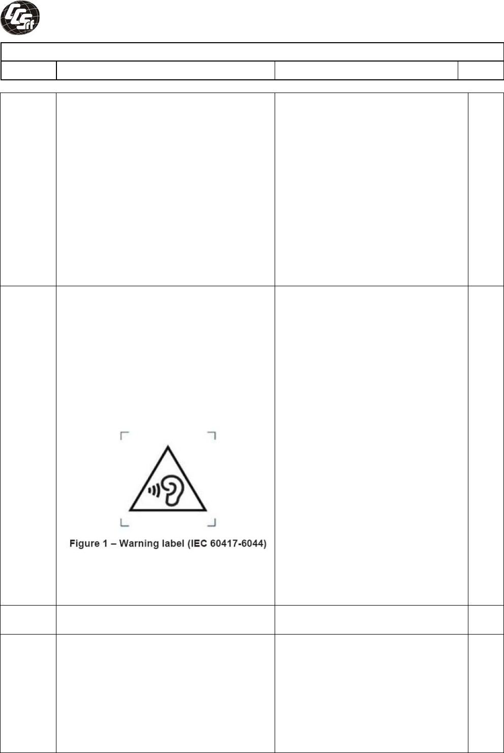
Zx.3 Warning
The warning shall be placed on the
equipment, or on the packaging, or in the
instruction manual and shall consist of the
following:
− the symbol of Figure 1 with a minimum
height of 5 mm; and
− the following wording, or similar:
“To prevent possible hearing damage, do not
listen at high volume levels for long periods.”
Alternatively, the entire warning may be given
through the equipment display during use,
when the user is asked to acknowledge
activation of the higher level.
N
Zx.4 Requirements for listening devices
(headphones and earphones) N
Zx.4.1 Wired listening devices with
analogue input
With 94 dBA sound pressure output LAeq,T, the
input voltage of the fixed “programme
simulation noise” described in EN 50332-2
shall be ≥ 75 mV.
This requirement is applicable in any mode
where the headphones can operate (active or
passive), including any available setting (for
N

Compliance Certification Services Inc. Report No:T111221S01-LV
National Differences
Clause Requirement − Test Result – Remark Verdict
Page 38 of 75
example built-in volume level control).
NOTE The values of 94 dBA – 75 mV correspond with
85dBA – 27 mV and 100 dBA – 150 mV.
Zx.4.2 Wired listening devices with digital
input
With any playing device playing the fixed
“programme simulation noise” described in
EN 50332-1 (and respecting the digital
interface standards, where a digital interface
standard exists that specifies the equivalent
acoustic level), the acoustic output LAeq,T of
the listening device shall be ≤ 100 dBA.
This requirement is applicable in any mode
where the headphones can operate, including
any available setting (for example built-in
volume level control, additional sound feature
like equalization, etc.).
NOTE An example of a wired listening device with digital
input is a USB headphone.
N
Zx.4.3 Wireless listening devices
In wireless mode :
- with any playing and transmitting device
playing the fixed programme simulation
noise described in EN 50332-1; and
- respecting the wireless transmission
standards, where an air interface standard
exists that specifies the equivalent acoustic
level; and
- with volume and sound settings in the
listening device (for example built-in volume
level control, additional sound feature like
equalization, etc.) set to the combination of
positions that maximize the measured
acoustic output for the above-mentioned
programme simulation noise, the acoustic
output LAeq,T of the listening device shall be ≤
100 dBA.
NOTE An example of a wireless listening device is a
Bluetooth headphone.
N
Zx.5 Measurement methods
Measurements shall be made in accordance
with EN 50332-1 or EN 50332-2 as
applicable. Unless stated otherwise, the time
interval T shall be 30 s.
NOTE Test method for wireless equipment provided
without listening device should be defined. k
N
2.7.1 Replace the subclause as follows:
Basic requirements
To protect against excessive current, short-
circuits and earth faults in PRIMARY
CIRCUITS, protective devices shall be
included either as integral parts of the
Replaced. P
Compliance Certification Services Inc. Report No:T111221S01-LV
National Differences
Clause Requirement − Test Result – Remark Verdict
Page 39 of 75
equipment or as parts of the building
installation, subject to the following, a), b) and
c):
a) except as detailed in b) and c), protective
devices necessary to comply with the
requirements of 5.3 shall be included as parts
of the equipment;
b) for components in series with the mains
input to the equipment such as the supply
cord, appliance coupler, r.f.i. filter and switch,
shortcircuit and earth fault protection may be
provided by protective devices in the building
installation;
c) it is permitted for PLUGGABLE
EQUIPMENT TYPE B or PERMANENTLY
CONNECTED EQUIPMENT, to rely on
dedicated overcurrent and shortcircuit
protection in the building installation, provided
that the means of protection, e.g. fuses or
circuit breakers, is fully specified in the
installation instructions. If reliance is placed
on protection in the building installation, the
installation instructions shall so state, except
that for PLUGGABLE EQUIPMENT TYPE A
the building installation shall be regarded as
providing protection in accordance with the
rating of the wall socket outlet.
2.7.2 This subclause has been declared ‘void’. N
3.2.3 Delete the NOTE in Table 3A, and delete also
in this table the conduit sizes in parentheses. Deleted. N
3.2.5.1 Replace
“60245 IEC 53” by “H05 RR-F” ;
“60227 IEC 52” by “H03 VV-F or H03 VVH2-F”;
“60227 IEC 53” by “H05 VV-F or H05 VVH2-F2”.
In Table 3B, replace the first four lines by the
following:
| Up to and including 6
| 0,75
a) |
| Over 6 up to and including 10
| (0,75)
b) 1,0 |
| Over 10 up to and including 16
| (1,0)
c) 1,5 |
In the conditions applicable to Table 3B
delete the words “in some countries” in
condition a) .
In NOTE 1, applicable to Table 3B, delete the
second sentence.
Replaced. N
3.3.4 In Table 3D, delete the fourth line: conductor
sizes for 10 to 13 A, and replace with the
following:
| Over 10 up to and including 16
| 1,5 to 2,5 | 1,5 to 4 |
Delete the fifth line: conductor sizes for 13 to
16 A.
Deleted. N
Compliance Certification Services Inc. Report No:T111221S01-LV
National Differences
Clause Requirement − Test Result – Remark Verdict
Page 40 of 75
4.3.13.6
(A1:2010)
Replace the existing NOTE by the following :
NOTE Z1 Attention is drawn to :
1999/519/EC: Council Recommendation on
the limitation of exposure of the general
public to electromagnetic fields 0 Hz to 300
GHz, and
2006/25/EC : Directive on the minimum
health and safety requirements regarding the
exposure of workers to risks arising from
physical agents (artificial optical radiation).
Standards taking into account this
Recommendation which demonstrate
compliance with the applicable EU Directive
are indicated in the OJEC.
Added. N
Annex H Replace the last paragraph of this annex by:
At any point 10 cm from the surface of the
OPERATOR ACCESS AREA, the dose rate
shall not exceed 1 µSv/h (0,1 mR/h) (see
NOTE). Account is taken of the background
level.
Replace the notes as follows:
NOTE These values appear in Directive
96/29/Euratom.
Delete NOTE 2.
Replaced. N
Biblio-
graphy
Additional EN standards. --
ZA NORMATIVE REFERENCES TO INTERNATIONAL PUBLICATIONS WITH THEIR
CORRESPONDING EUROPEAN PUBLICATIONS --
ZB SPECIAL NATIONAL CONDITIONS P
1.2.4.1 In Denmark, certain types of Class I
appliances (see 3.2.1.1) may be provided
with a plug not establishing earthing
conditions when inserted into Danish socket-
outlets.
Class III equipment. N
1.2.13.14 In Norway and Sweden, for requirements see
1.7.2.1 and 7.3 of this annex.
N
1.5.7.1 Replace the existing SNC by the following:
In Finland, Norway and Sweden, resistors
bridging BASIC INSULATION in CLASS I
PLUGGABLE EQUIPMENT TYPE A must
comply with the requirements in 1.5.7.1. In
addition when a single resistor is used, the
resistor must withstand the resistor test in
1.5.7.2.
N
1.5.8 In Norway, due to the IT power system used
(see annex V, Figure V.7), capacitors are
required to be rated for the applicable line-to-
line voltage (230 V).
Class III equipment. N
1.5.9.4 In Finland, Norway and Sweden, the third
dashed sentence is applicable only to
equipment as defined in 6.1.2.2 of this annex.
No such construction. N
Compliance Certification Services Inc. Report No:T111221S01-LV
National Differences
Clause Requirement − Test Result – Remark Verdict
Page 41 of 75
1.7.2.1 Add as new SNC:
In Norway and Sweden, the screen of the
cable distribution system is normally not
earthed at the entrance of the building and
there is normally no equipotential bonding
system within the building. Therefore the
protective earthing of the building installation
need to be isolated from the screen of a cable
distribution system. It is however accepted to
provide the insulation external to the
equipment by an adapter or an
interconnection cable with galvanic isolator,
which may be provided by e.g. a retailer. The
user manual shall then have the following or
similar information in Norwegian and Swedish
language respectively, depending on in what
country the equipment is intended to be used
in: “Equipment connected to the protective
earthing of the building installation through
the mains connection or through other
equipment with a connection to protective
earthing – and to a cable distribution system
using coaxial cable, may in some
circumstances create a fire hazard.
Connection to a cable distribution system has
therefore to be provided through a device
providing electrical isolation below a certain
frequency range (galvanic isolator, see EN
60728-11).”
NOTE In Norway, due to regulation for
installations of cable distribution systems, and
in Sweden, a galvanic isolator shall provide
electrical insulation below 5 MHz. The
insulation shall withstand a dielectric strength
of 1,5 kV r.m.s., 50 Hz or 60 Hz, for 1 min.
Translation to Norwegian (the Swedish text
will also be accepted in Norway): “Utstyr som
er koplet til beskyttelsesjord via nettplugg
og/eller via annet jordtilkoplet utstyr – og er
tilkoplet et kabel -TV nett, kan forårsake
brannfare.
For å unngå dette skal det ved tilkopling av
utstyret til kabel -TV nettet installeres en
galvanisk isolator mellom utstyret og kabel -
TV nettet.”
Translation to Swedish:
”Utrustning som är kopplad till skyddsjord via
jordat vägguttag och/eller via annan
utrustning och samtidigt är kopplad till kabel -
TV nät kan i vissa fall medföra risk för brand.
För att undvika detta skall vid anslutning av
utrustningen till kabel-TV nät galvanisk
isolator finnas mellan utrustningen och kabel-
TV nätet.”
N
1.7.5 Add the following paragraph to the existing
SNC for Denmark:
Added. N
Compliance Certification Services Inc. Report No:T111221S01-LV
National Differences
Clause Requirement − Test Result – Remark Verdict
Page 42 of 75
For CLASS II EQUIPMENT the socket outlet
shall be in accordance with Standard Sheet
DKA 1-4a.
2.2.4 In Norway, for requirements see 1.7.2.1,
6.1.2.1 and 6.1.2.2 of this annex.
N
2.3.2 In Finland, Norway and Sweden there are
additional requirements for the insulation.
See 6.1.2.1 and 6.1.2.2 of this annex.
N
2.3.4 In Norway, for requirements see 1.7.2.1,
6.1.2.1 and 6.1.2.2 of this annex.
N
2.6.3.3 In the United Kingdom, the current rating of
the circuit shall be taken as 13 A, not 16 A.
Class III equipment. N
2.7.1 In the United Kingdom, to protect against
excessive currents and short-circuits in the
PRIMARY CIRCUIT of DIRECT PLUG-IN
EQUIPMENT, tests according to 5.3 shall be
conducted, using an external protective
device rated 30 A or 32 A. If these tests fail,
suitable protective devices shall be included
as integral parts of the DIRECT PLUG-IN
EQUIPMENT, so that the requirements of 5.3
are met.
Class III equipment. N
2.10.5.13 In Finland, Norway and Sweden, there are
additional requirements for the insulation, see
6.1.2.1 and 6.1.2.2 of this annex.
N
3.2.1.1 In Switzerland, supply cords of equipment
having a RATED CURRENT not exceeding
10 A shall be provided with a plug complying
with SEV 1011 or IEC 60884-1 and one of the
following dimension sheets:
SEV 6532-2.1991 Plug Type 15 3P+N+PE
250/400 V, 10 A
SEV 6533-2.1991 Plug Type 11 L+N
250 V, 10 A
SEV 6534-2.1991 Plug Type 12 L+N+PE
250 V, 10 A
In general, EN 60309 applies for plugs for
currents exceeding 10 A. However, a 16 A
plug and socket-outlet system is being
introduced in Switzerland, the plugs of which
are according to the following dimension
sheets, published in February 1998:
SEV 5932-2.1998 Plug Type 25 3L+N+PE
230/400 V, 16 A
SEV 5933-2.1998 Plug Type 21 L+N
250 V, 16 A
SEV 5934-2.1998 Plug Type 23 L+N+PE
250 V, 16 A
N
3.2.1.1 In Denmark, supply cords of single-phase
equipment having a rated current not
exceeding13 A shall be provided with a plug
according to the Heavy Current Regulations,
Section 107-2-D1.
CLASS I EQUIPMENT provided with socket-
outlets with earth contacts or which are
intended to be used in locations where
N

Compliance Certification Services Inc. Report No:T111221S01-LV
National Differences
Clause Requirement − Test Result – Remark Verdict
Page 43 of 75
protection against indirect contact is required
according to the wiring rules shall be provided
with a plug in accordance with standard sheet
DK 2-1a or DK 2-5a.
If poly-phase equipment and single-phase
equipment having a RATED CURRENT
exceeding 13 A is provided with a supply cord
with a plug, this plug shall be in accordance
with the Heavy Current Regulations, Section
107-2-D1 or EN 60309-2.
3.2.1.1 In Spain, supply cords of single-phase
equipment having a rated current not
exceeding 10 A shall be provided with a plug
according to UNE 20315:1994.
Supply cords of single-phase equipment
having a rated current not exceeding 2,5 A
shall be provided with a plug according to
UNE-EN 50075:1993.
CLASS I EQUIPMENT provided with socket-
outlets with earth contacts or which are
intended to be used in locations where
protection against indirect contact is required
according to the wiring rules, shall be
provided with a plug in accordance with
standard UNE 20315:1994.
If poly-phase equipment is provided with a
supply cord with a plug, this plug shall be in
accordance with UNE-EN 60309-2.
N
3.2.1.1 In the United Kingdom, apparatus which is
fitted with a flexible cable or cord and is
designed to be connected to a mains socket
conforming to BS 1363 by means of that
flexible cable or cord and plug, shall be fitted
with a ‘standard plug’ in accordance with
Statutory Instrument 1768:1994-The Plugs
and Sockets etc.
(Safety) Regulations 1994, unless exempted
by those regulations.
NOTE ‘Standard plug’ is defined in SI
1768:1994 and essentially means an
approved plug conforming to BS 1363 or an
approved conversion plug.
N
3.2.1.1 In Ireland, apparatus which is fitted with a
flexible cable or cord and is designed to be
connected to a mains socket conforming to
I.S. 411 by means of that flexible cable or
cord and plug, shall be fitted with a 13 A plug
in accordance with Statutory Instrument
525:1997 -National Standards Authority of
Ireland (section 28) (13 A Plugs and
Conversion Adaptors for Domestic Use)
Regulations 1997.
N
3.2.4 In Switzerland, for requirements see 3.2.1.1
of this annex.
N
3.2.5.1 In the United Kingdom, a power supply cord
with conductor of 1,25 mm2 is allowed for
N
Compliance Certification Services Inc. Report No:T111221S01-LV
National Differences
Clause Requirement − Test Result – Remark Verdict
Page 44 of 75
equipment with a rated current over 10 A and
up to and including 13 A.
3.3.4 In the United Kingdom, the range of
conductor sizes of flexible cords to be
accepted by terminals for equipment with a
RATED CURRENT of over 10 A up to and
including 13 A is:
• 1,25 mm2 to 1,5 mm2 nominal cross-
sectional area.
N
4.3.6 In the United Kingdom, the torque test is
performed using a socket outlet complying
with BS 1363 part 1:1995, including
Amendment 1:1997 and Amendment 2:2003
and the plug part of DIRECT PLUG-IN
EQUIPMENT shall be assessed to BS 1363:
Part 1, 12.1, 12.2, 12.3, 12.9, 12.11, 12.12,
12.13, 12.16 and 12.17, except that the test
of 12.17 is performed at not less than 125 °C.
Where the metal earth pin is replaced by an
Insulated Shutter Opening Device (ISOD), the
requirements of clauses 22.2 and 23 also
apply.
N
4.3.6 In Ireland, DIRECT PLUG-IN EQUIPMENT is
known as plug similar devices. Such devices
shall comply with Statutory Instrument
526:1997 -National Standards Authority of
Ireland (Section 28) (Electrical plugs, plug
similar devices and sockets for domestic use)
Regulations, 1997.
N
5.1.7.1 In Finland, Norway and Sweden TOUCH
CURRENT measurement results exceeding
3,5 mA r.m.s. are permitted only for the
following equipment:
• STATIONARY PLUGGABLE EQUIPMENT
TYPE A that
- is intended to be used in a
RESTRICTED ACCESS
LOCATION where equipment
bonding has been applied, for
example, in a telecommunication
centre; and –
- has provision for a permanently
connected PROTECTIVE
EARTHING CONDUCTOR; and
- is provided with instructions for the
installation of that conductor by a
SERVICE PERSON;
• STATIONARY PLUGGABLE EQUIPMENT
TYPE B;
• STATIONARY PERMANENTLY
CONNECTED EQUIPMENT.
Class III equipment. N
6.1.2.1
(A1:2010)
In Finland, Norway and Sweden, add the
following text between the first and second
paragraph of the compliance clause:
If this insulation is solid, including insulation
forming part of a component, it shall at least
No TNV. N

Compliance Certification Services Inc. Report No:T111221S01-LV
National Differences
Clause Requirement − Test Result – Remark Verdict
Page 45 of 75
consist of either
- two layers of thin sheet material,
each of which shall pass the
electric strength test below, or
- one layer having a distance
through insulation of at least 0,4
mm, which shall pass the electric
strength test below.
If this insulation forms part of a
semiconductor component (e.g. an
optocoupler), there is no distance through
insulation requirement for the insulation
consisting of an insulating compound
completely filling the casing, so that
CLEARANCES and CREEPAGE
DISTANCES do not exist, if the component
passes the electric strength test in
accordance with the compliance clause below
and in addition
- passes the tests and inspection
criteria of 2.10.11 with an electric
strength test of 1,5 kV multiplied
by 1,6 (the electric strength test of
2.10.10 shall be performed using
1,5 kV), and
- is subject to ROUTINE TESTING
for electric strength during
manufacturing, using a test voltage
of 1,5 kV.
It is permitted to bridge this insulation with an
optocoupler complying with 2.10.5.4 b) .
It is permitted to bridge this insulation with a
capacitor complying with EN 60384-14:2005,
subclass Y2.
A capacitor classified Y3 according to EN
60384-14:2005, may bridge this insulation
under the following conditions:
- the insulation requirements are
satisfied by having a capacitor
classified Y3 as defined by EN
60384-14:2005, which in addition to
the Y3 testing, is tested with an
impulse test of 2,5 kV defined in EN
60950-1:2006, 6.2.2.1;
- the additional testing shall be
performed on all the test
specimens as described in EN
60384-14:2005;
- the impulse test of 2,5 kV is to be
performed before the endurance
test in EN 60384-14, in the
sequence of tests as described in
EN 60384-14:2005.
6.1.2.2 In Finland, Norway and Sweden, the
exclusions are applicable for
PERMANENTLY CONNECTED
N
Compliance Certification Services Inc. Report No:T111221S01-LV
National Differences
Clause Requirement − Test Result – Remark Verdict
Page 46 of 75
EQUIPMENT, PLUGGABLE EQUIPMENT
TYPE B and equipment intended to be used
in a RESTRICTED ACCESS LOCATION
where equipment bonding has been applied,
e.g. in a telecommunication centre, and which
has provision for a permanently connected
PROTECTIVE EARTHING CONDUCTOR
and is provided with instructions for the
installation of that conductor by a SERVICE
PERSON.
7.2 In Finland, Norway and Sweden, for
requirements see 6.1.2.1 and 6.1.2.2 of this
annex. The term TELECOMMUNICATION
NETWORK in 6.1.2 being replaced by the
term CABLE DISTRIBUTION SYSTEM.
Not connected to cable distribution
system. N
7.3 In Norway and Sweden, there are many
buildings where the screen of the coaxial
cable is normally not connected to the earth
in the building installation.
Not connected to cable distribution
system. N
7.3 In Norway, for installation conditions see EN
60728-11:2005.
Not connected to cable distribution
system. N
Compliance Certification Services Inc. Report No:T111221S01-LV
National Differences
Clause Requirement − Test Result – Remark Verdict
Page 47 of 75
FINLAND NATIONAL DIFFERENCES
(EN 60950-1:2006/A11:2009/A1:2010/A12:2011) P
1.5.7.1 In Finland resistors bridging BASIC
INSULATION in CLASS I PLUGGABLE
EQUIPMENT TYPE A must comply with the
requirements in 1.5.7.1. In addition when a
single resistor is used, the resistor must
withstand the resistor test in 1.5.7.2.
Class III equipment. N
1.5.9.4 The third dashed sentence is applicable only
to equipment as defined in 6.1.2.2 of this
annex.
No such construction. N
1.7.2.1 CLASS I PLUGGABLE EQUIPMENT TYPE A
intended for connection to other equipment or
a network shall, if safety relies on connection
to protective earth or if surge suppressors are
connected between the network terminals
and accessible parts, have a marking stating
that the equipment must be connected to an
earthed mains socket-outlet.
The marking text in the applicable countries
shall be as follows:
"Laite on liitettävä
suojamaadoituskoskettimilla varustettuun
pistorasiaan"
Class III equipment. N
2.3.2 There are additional requirements for the
insulation. See 6.1.2.1 and 6.1.2.2 of this
annex.
N
2.10.5.13 There are additional requirements for the
insulation, see 6.1.2.1 and 6.1.2.2 of this
annex.
N
5.1.7.1 TOUCH CURRENT measurement results
exceeding 3,5 mA r.m.s. are permitted only
for the following equipment:
• STATIONARY PLUGGABLE EQUIPMENT
TYPE A that
- is intended to be used in a
RESTRICTED ACCESS
LOCATION where equipment
bonding has been applied, for
example, in a telecommunication
centre; and –
- has provision for a permanently
connected PROTECTIVE
EARTHING CONDUCTOR; and
- is provided with instructions for the
installation of that conductor by a
SERVICE PERSON;
• STATIONARY PLUGGABLE EQUIPMENT
TYPE B;
• STATIONARY PERMANENTLY
CONNECTED EQUIPMENT.
Class III equipment. N
Compliance Certification Services Inc. Report No:T111221S01-LV
National Differences
Clause Requirement − Test Result – Remark Verdict
Page 48 of 75
6.1.2.1
(A1:2010)
In Finland, add the following text between
the first and second paragraph of the
compliance clause:
If this insulation is solid, including insulation
forming part of a component, it shall at least
consist of either
- two layers of thin sheet material,
each of which shall pass the
electric strength test below, or
- one layer having a distance
through insulation of at least 0,4
mm, which shall pass the electric
strength test below.
If this insulation forms part of a
semiconductor component (e.g. an
optocoupler), there is no distance through
insulation requirement for the insulation
consisting of an insulating compound
completely filling the casing, so that
CLEARANCES and CREEPAGE
DISTANCES do not exist, if the component
passes the electric strength test in
accordance with the compliance clause below
and in addition
- passes the tests and inspection
criteria of 2.10.11 with an electric
strength test of 1,5 kV multiplied
by 1,6 (the electric strength test of
2.10.10 shall be performed using
1,5 kV), and
- is subject to ROUTINE TESTING
for electric strength during
manufacturing, using a test voltage
of 1,5 kV.
It is permitted to bridge this insulation with an
optocoupler complying with 2.10.5.4 b) .
It is permitted to bridge this insulation with a
capacitor complying with EN 60384-14:2005,
subclass Y2.
A capacitor classified Y3 according to EN
60384-14:2005, may bridge this insulation
under the following conditions:
- the insulation requirements are
satisfied by having a capacitor
classified Y3 as defined by EN
60384-14:2005, which in addition to
the Y3 testing, is tested with an
impulse test of 2,5 kV defined in EN
60950-1:2006, 6.2.2.1;
- the additional testing shall be
performed on all the test
specimens as described in EN
60384-14:2005;
- the impulse test of 2,5 kV is to be
performed before the endurance
test in EN 60384-14, in the
N
Compliance Certification Services Inc. Report No:T111221S01-LV
National Differences
Clause Requirement − Test Result – Remark Verdict
Page 49 of 75
sequence of tests as described in
EN 60384-14:2005.
6.1.2.2 The exclusions are applicable for
PERMANENTLY CONNECTED
EQUIPMENT, PLUGGABLE EQUIPMENT
TYPE B and equipment intended to be used
in a RESTRICTED ACCESS LOCATION
where equipment bonding has been applied,
e.g. in a telecommunication centre, and which
has provision for a permanently connected
PROTECTIVE EARTHING CONDUCTOR
and is provided with instructions for the
installation of that conductor by a SERVICE
PERSON.
N
7.2 For requirements see 6.1.2.1 and 6.1.2.2 of
this annex. The term
TELECOMMUNICATION NETWORK in 6.1.2
being replaced by the term CABLE
DISTRIBUTION SYSTEM.
Not connected to cable distribution
system. N
Compliance Certification Services Inc. Report No:T111221S01-LV
National Differences
Clause Requirement − Test Result – Remark Verdict
Page 50 of 75
GERMANY NATIONAL DIFFERENCES
(VDE 0805-1:2011-01) P
Annex
ZC,
1.7.2.1
According to GPSG, section 2, clause 4:
If certain rules on the use, supplementation or
maintenance of an item of technical work
equipment or ready-to-use commodity must
be observed in order to guarantee safety and
health, instructions for use in German must
be supplied when it is brought into circulation.
N
Compliance Certification Services Inc. Report No:T111221S01-LV
National Differences
Clause Requirement − Test Result – Remark Verdict
Page 51 of 75
KOREAN NATIONAL DIFFERENCES
(K60950-1) P
1.5.101 Addition: Plugs for the connection of the
apparatus to the supply mains shall comply
with the Korean requirement (KSC 8305).
No supply cord provided. N
8 Addition: EMC The apparatus shall comply
with the relevant CISPR standards.
Compliance shall be evaluated during
national approval. N
Compliance Certification Services Inc. Report No:T111221S01-LV
National Differences
Clause Requirement − Test Result – Remark Verdict
Page 52 of 75
CANADIAN NATIONAL DIFFERENCES
(CAN/CSA C22.2 No. 60950-1-07, Second Edition) P
1.1.1 All equipment is to be designed to allow
installation in accordance with the National
Electrical Code (NEC), ANSI/NFPA 70, the
Canadian Electrical Code (CEC), Part I,
CAN/CSA C22.1, and when applicable, the
National Electrical Safety Code, IEEE C2.
Also, unless marked or otherwise identified,
installation is allowed per the Standard for the
Protection of Electronic Computer/Data-
Processing Equipment, ANSI/NFPA 75.
Equipment able to be installed in
accordance with the National
Electrical Code ANSI/NFPA 70 and
the Canadian Electrical Code, Part 1.
P
1.4.14 For Pluggable Equipment Type A, the
protection in the installation is assumed to be
20A.
N
1.5.5 For lengths exceeding 3.05 m, external
interconnecting flexible cord and cable
assemblies are required to be a suitable
cable type (e.g., DP, CL2) specified in the
CEC/NEC. For lengths 3.05 m or less,
external interconnecting flexible cord and
cable assemblies that are not types specified
in the CEC are required to have special
construction features and identification
markings.
No such cables or cords provided. N
1.7.1 Equipment for use on a.c. mains supply
systems with a neutral and more than one
phase conductor (e.g. 120/240 V, 3-wire)
require a special marking format for electrical
ratings. A voltage rating that exceeds an
attachment plug cap rating is only permitted if
it does not exceed the extreme operating
conditions in Table 2 of CAN/CSA C22.2 No.
235, and if it is part of a range that extends
into the Table 2 "Normal Operating
Conditions." Likewise, a voltage rating shall
not be lower than the specified "Normal
Operating Conditions," unless it is part of a
range that extends into the "Normal
Operating Conditions."
Class III equipment. N
1.7.7 Wiring terminals intended to supply Class 2
outputs in accordance with CEC Part 1 or
NEC shall be marked with the voltage rating
and “Class 2” or equivalent. Marking shall be
located adjacent to the terminals and shall be
visible during wiring.
No such parts provided. N
2.5 Where a fuse is used to provide Class 2,
Limited Power Source, or TNV current
limiting, it shall not be operator-accessible
unless it is not interchangeable.
No such fuse provided. N
2.7.1 Suitable NEC/CEC branch circuit protection
rated at the maximum circuit rating is required
for all standard supply outlets and
receptacles (such as supplied in power
No such components provided. N
Compliance Certification Services Inc. Report No:T111221S01-LV
National Differences
Clause Requirement − Test Result – Remark Verdict
Page 53 of 75
distribution units) if the supply branch circuit
protection is not suitable. Power distribution
transformers distributing power at 100 volts or
more, and rated 10 kVA or more, require
special transformer overcurrent protection.
3.2 Wiring methods (terminals, leads, etc.) used
for the connection of the equipment to the
mains shall be in accordance with the
NEC/CEC.
Class III equipment. N
3.2.1 Power supply cords are required to have
attachment plugs rated not less than 125
percent of the rated current of the equipment.
No supply cord provided. N
3.2.1.2 Equipment connected to a centralized d.c.
power system, and having one pole of the DC
mains input terminal connected to the main
protective earthing terminal in the equipment,
is required to comply with special earthing,
wiring, marking and installation instruction
requirements.
Class III equipment. N
3.2.3 Permanent connection of equipment to the
mains supply by a power supply cord is not
permitted, except for certain equipment, such
as ATMs.
Class III equipment. N
3.2.5 Power supply cords are required to be no
longer than 4.5 m in length. Flexible power
supply cords are required to be compatible
with Tables 11 and 12 of the CEC and Article
400 of the NEC.
No supply cord provided. N
3.2.9 Permanently connected equipment is
required to have a suitable wiring
compartment and wire bending space.
Class III equipment. N
3.3 Wiring terminals and associated spacings for
field wiring connections shall comply with
CSA C22.2 No. 0.
No such terminals provided. N
3.3.3 Wire binding screws are not permitted to
attach conductors larger than 10 AWG (5.3
mm2).
No such screws provided. N
3.3.4 Terminals for permanent wiring, including
protective earthing terminals, are required to
be suitable for Canadian/US wire gauge
sizes, rated 125 percent of the equipment
rating, and be specially marked when
specified (1.7.7).
No such terminals provided. N
3.4.2 Motor control devices are required for cord-
connected equipment with a motor if the
equipment is rated more than 12 A, or if the
motor has a nominal voltage rating greater
than 120 V, or is rated more than 1/3 hp
(locked rotor current over 43 A).
No such device. N
3.4.8 Vertically-mounted disconnect switches and
circuit breakers are required to have the "on"
position indicated by the handle in the up
position.
No such device. N
3.4.11 For computer room applications, equipment
with battery systems capable of supplying
Not such application. N
Compliance Certification Services Inc. Report No:T111221S01-LV
National Differences
Clause Requirement − Test Result – Remark Verdict
Page 54 of 75
750 VA for five minutes are required to have
a battery disconnect means that may be
connected to the computer room remote
poweroff circuit.
4.3.12 The maximum quantity of flammable liquid
stored in equipment is required to comply
with NFPA 30.
No flammable liquid. N
4.3.13.5 Equipment with lasers is required to meet the
Canadian Radiation Emitting Devices Act,
REDR C1370 and/or Code of Federal
Regulations 21 CFR 1040, as applicable.
No laser provided. N
4.7 For computer room applications, automated
information storage systems with combustible
media greater than 0.76 m3 (27 cu ft) are
required to have a provision for connection of
either automatic sprinklers or a gaseous
agent extinguishing system with an extended
discharge.
Not such application. N
4.7.3.1 For computer room applications, enclosures
with combustible material measuring greater
than 0.9 m 2 (10 sq ft) or a single dimension
greater than 1.8 m (6 ft) are required to have
a flame spread rating of 50 or less. For other
applications, enclosures with the same
dimensions require a flame spread rating of
200 or less.
Not such application. N
Annex H Equipment that produces ionizing radiation is
required to comply with the Canadian
Radiation Emitting Devices Act, REDR C1370
and/or Code of Federal Regulations, 21 CFR
1020, as applicable.
No CRTs. N
OTHER DIFFERENCES
1.5.1 Some components and materials associated
with the risk of fire, electric shock, or personal
injury are required to have component or
material ratings in accordance with the
applicable national (Canadian and/or U.S.)
component or material standard
requirements. These components include:
attachment plugs, battery packs
(rechargeable type, used with transportable
equipment), cathode ray tubes, circuit
breakers, communication circuit accessories,
connectors (used for current interruption of
nonLPS circuits), cord sets and power supply
cords, direct plugin equipment, enclosures
(outdoor), flexible cords and cables, fuses
(branch circuit), fuseholders, groundfault
current interrupters, industrial control
equipment, insulating tape, interconnecting
cables, lampholders, limit controls, printed
wiring, protectors for communications circuits,
receptacles, solid state controls,
supplementary protectors, switches (including
interlock switches), thermal cutoffs,
Complied. Components are UL or
CSA approved, see component list
1.5.1.
P

Compliance Certification Services Inc. Report No:T111221S01-LV
National Differences
Clause Requirement − Test Result – Remark Verdict
Page 55 of 75
thermostats, (multilayer) transformer winding
wire, transient voltage surge suppressors,
tubing, wire connectors, and wire and cables.
1.6.1.2 A circuit for connection to the DC Mains
Supply is classified as either a SELV Circuit,
TNV-2 Circuit or Hazardous Voltage Circuit
depending on the maximum operating voltage
of the supply. This maximum operating
voltage shall include consideration of the
battery charging “float voltage” associated
with the intended supply system, regardless
of the marked power rating of the equipment.
N
2.3.1 For TNV-2 and TNV-3 circuits with other than
ringing signals and with voltages exceeding
42.4 Vpeak or 60 Vd.c., the maximum
acceptable current through a 2000 ohm
resistor (or greater) connected across the
voltage source with other loads disconnected
is 7.1 mA peak or 30 mA d.c. under normal
operating conditions.
N
2.3.2.1 In the event of a single fault between TNV
and SELV circuits, the limits of 2.2.3 apply to
SELV Circuits and accessible conductive
parts.
N
2.6.3.3 The current rating of the circuit shall be taken
as 20 A not 16 A
Class III equipment. N
2.6.3.4 Protective bonding conductors of non-
standard protective bonding constructions
(e.g., printed circuit traces) may be subjected
to the additional limited short circuit test
conditions specified.
N
4.2.8.1 Enclosures around CRTs with a face
diameter of 160 mm or more are required to
reduce the risk of injury due to the implosion
of the CRT.
No CRTs. N
4.3.2 Equipment with handles is required to comply
with special loading tests.
No handles. N
5.1.8.3 Equipment intended to receive
telecommunication ringing signals is required
to comply with a special touch current
measurement tests.
N
5.3.7 Internal (e.g., card cage) SELV circuit
connectors and printed wiring board
connectors that are accessible to the operator
and that deliver power are to be overloaded.
During abnormal operating testing, if a circuit
is interrupted by the opening of a component,
the test shall be repeated twice (three tests
total) using new components as necessary.
N
6.4 Equipment intended for connection to
telecommunication network outside plant
cable is required to be protected against
overvoltage from power line crosses in
accordance with 6.4 and Annex NAC.
N
M.2 Continuous ringing signals up to 16 mA only N

Compliance Certification Services Inc. Report No:T111221S01-LV
National Differences
Clause Requirement − Test Result – Remark Verdict
Page 56 of 75
are permitted if the equipment is subjected to
special installation and performance
restrictions.
Annex
NAD
Equipment connected to a telecommunication
and cable distribution networks and supplied
with an earphone intended to be held against,
or in the ear is required to comply with special
acoustic pressure requirements.
N

Compliance Certification Services Inc. Report No:T111221S01-LV
National Differences
Clause Requirement − Test Result – Remark Verdict
Page 57 of 75
US NATIONAL DIFFERENCES
(UL 60950-1, Second Edition) P
1.1.1 All equipment is to be designed to allow
installation in accordance with the National
Electrical Code ANSI/NFPA 70, and when
applicable, the National Electrical Safety
Code, IEEE C2. Also, unless marked or
otherwise identified, installation is allowed per
the Standard for the Protection of Electronic
Computer/Data-Processing Equipment,
ANSI/NFPA 75.
Complied. P
1.4.14 For Pluggable Equipment Type A, the
protection in the installation is assumed to be
20 A.
Class III equipment. N
1.5.5 For lengths exceeding 3.05 m, external
interconnecting flexible cord and cable
assemblies are required to be a suitable
cable type specified in the NEC. For lengths
3.05 m or less, external interconnecting
flexible cord and cable assemblies that are
not types specified in the NEC are required to
have special construction features and
identification markings.
N
1.7.1 Equipment for use on a.c. mains supply
systems with a neutral and more than one
phase conductor (e.g. 120/240 V, 3-wires)
require a special marking format for electrical
ratings.
Class III equipment. N
2.5 Where a fuse is used to provide Class 2,
Limited Power Source, or TNV current
limiting, it shall not be operator-accessible
unless it is not interchangeable.
No such parts provided. N
2.7.1 Suitable NEC branch circuit protection rated
at the maximum circuit rating is required for
all standard supply outlets and receptacles
(such as supplied in power distribution units)
if the supply branch circuit protection is not
suitable. Power distribution transformers
distributing power at 100 volts or more, and
rated 10 kVA or more, require special
transformer overcurrent protection.
No such components provided. N
3.2 Wiring methods permit connection of
equipment to primary power supply in
accordance with the NEC
Class III equipment. N
3.2.1 Power supply cords are required to have
attachment plugs rated not less than 125
percent of the rated current of the equipment.
No such cords provided. N
3.2.1.2 Equipment connected to a centralized d.c.
power system, and having one pole of the DC
mains input terminal connected to the main
protective earthing terminal in the equipment,
is required to comply with special earthing,
wiring, marking and installation instruction
requirements.
Class III equipment. N
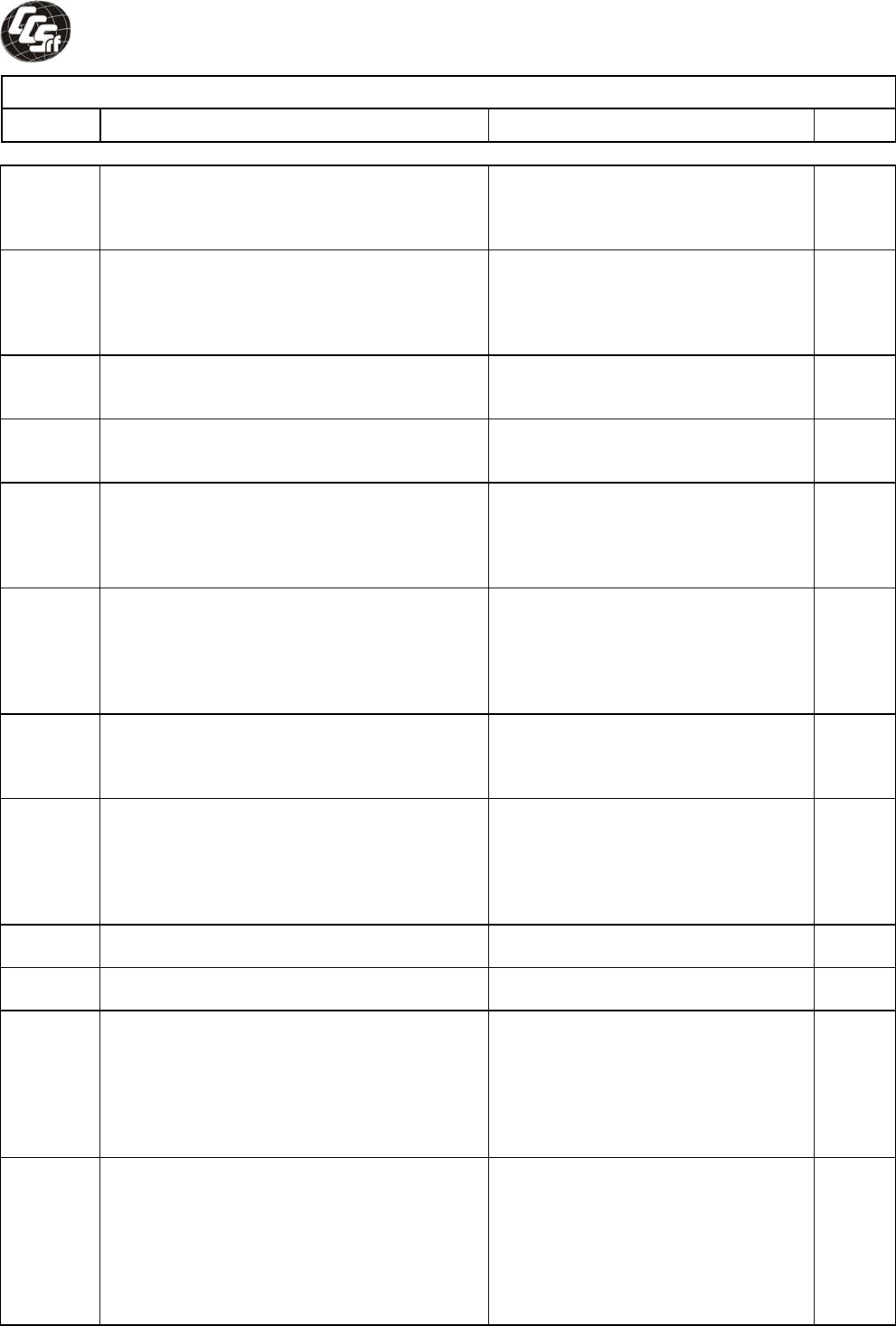
Compliance Certification Services Inc. Report No:T111221S01-LV
National Differences
Clause Requirement − Test Result – Remark Verdict
Page 58 of 75
3.2.3 Permanent connection of equipment to the
mains supply by a power supply cord is not
permitted, except for certain equipment, such
as ATMs.
Class III equipment. N
3.2.5 Power supply cords are required to be no
longer than 4.5 m in length and minimum
length shall be 1.5 m. Flexible power supply
cords are required to be compatible with
Article 400 of the NEC.
No such cord provided. N
3.2.9 Permanently connected equipment must
have a suitable wiring compartment and wire
bending space.
N
3.3.3 Wire binding screw terminal are not permitted
to attach connectors larger than 10 AWG (5.3
mm²).
No such screws provided. N
3.3.4 Terminals for permanent wiring, including
protective earthing terminals, must be
suitable for U.S wire gauge sizes, rated 125
percent of the equipment rating, and be
specially marked when specified (1.7.7)
No such terminals provided. N
3.4.2 Motor control devices are required for cord-
connected equipment with a motor if the
equipment is rated more than 12 A, or if the
motor has a nominal voltage rating greater
than 120 V, or is rated more than 1/3 hp
(locked rotor current over 43 A)
N
3.4.8 Vertically mounted disconnect switches and
circuit breakers are required to have the “on”
position indicated by the handle in the up
position.
No such devices incorporated. N
3.4.11 For computer-room applications, equipment
with battery systems capable of supplying
750 VA for five minutes are required to have
a battery disconnect means that may be
connected to the computer room remote
power-off circuit.
Not such application. N
4.3.12 The max. quantity of flammable liquid stored
in equipment per ANSI/NFPA 30.
No flammable liquid. N
4.3.13.5 Equipment with lasers is required to meet the
Code of Federal Regulations 21 CFR 1040.
No lasers. N
4.7 For computer room applications, automated
information storage systems with combustible
media greater than 0.76 m³ (27 cu ft) are
required to have a provision for connection of
either automatic sprinklers or a gaseous
agent extinguishing system with an extended
discharge.
Not such application. N
4.7.3.1 For computer room applications, enclosures
with combustible material measuring greater
tha 0.9 m2 (10 sq ft) or a single dimension
greater than 1.8 m (6ft) are required to have a
flame spread rating of 50 or less. For other
applications, enclosures with the same
dimensions require a flame spread rating of
200 or less.
Not such application. N
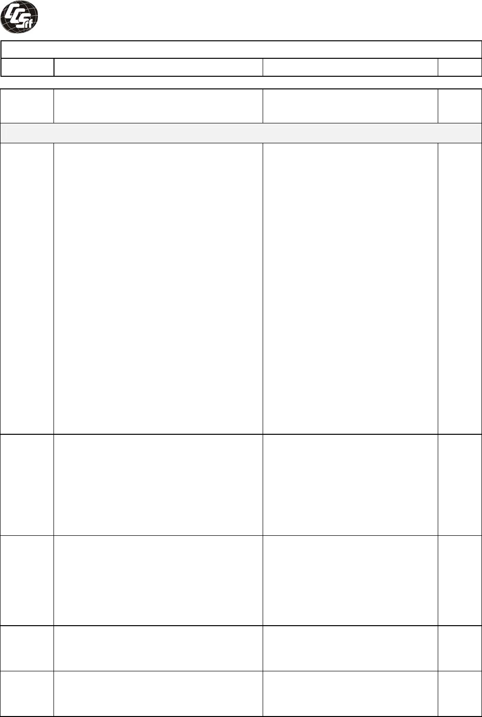
Compliance Certification Services Inc. Report No:T111221S01-LV
National Differences
Clause Requirement − Test Result – Remark Verdict
Page 59 of 75
Annex H Equipment that produces ionizing radiation
must comply with Federal Regulations, 21
CFR 1020
No CRTs. N
OTHER NATIONAL DIFFERENCES
1.5.1 Some components and materials associated
with the risk of fire, electric shock, or personal
injury are required to have component or
material ratings in accordance with the
applicable national (Canadian and/or U.S.)
component or material standard
requirements. These components include:
attachment plugs, battery packs
(rechargeable type, used with transportable
equipment), cathode ray tubes, circuit
breakers, communication circuit accessories,
connectors (used for current interruption of
nonLPS circuits), cord sets and power supply
cords, direct plugin equipment, enclosures
(outdoor), flexible cords and cables, fuses
(branch circuit), fuseholders, groundfault
current interrupters, industrial control
equipment, insulating tape, interconnecting
cables, lampholders, limit controls, printed
wiring, protectors for communications circuits,
receptacles, solid state controls,
supplementary protectors, switches (including
interlock switches), thermal cutoffs,
thermostats, (multilayer) transformer winding
wire, transient voltage surge suppressors,
tubing, wire connectors, and wire and cables.
Complied. Components are UL or
CSA approved, see component list
1.5.1.
P
1.6.1.2 A circuit for connection to the DC Mains
Supply is classified as either a SELV Circuit,
TNV-2 Circuit or Hazardous Voltage Circuit
depending on the maximum operating voltage
of the supply. This maximum operating
voltage shall include consideration of the
battery charging “float voltage” associated
with the intended supply system, regardless
of the marked power rating of the equipment.
N
2.3.1 For TNV-2 and TNV-3 circuits with other than
ringing signals and with voltages exceeding
42.4 Vpeak or 60 Vd.c., the maximum
acceptable current through a 2000 ohm
resistor (or greater) connected across the
voltage source with other loads disconnected
is 7.1 mA peak or 30 mA d.c. under normal
operating conditions.
N
2.3.2.1 In the event of a single fault between TNV
and SELV circuits, the limits of 2.2.3 apply to
SELV Circuits and accessible conductive
parts.
N
2.6.3.4 Protective bonding conductors of non-
standard protective bonding constructions
(e.g., printed circuit traces) may be subjected
to the additional limited short circuit test
N
Compliance Certification Services Inc. Report No:T111221S01-LV
National Differences
Clause Requirement − Test Result – Remark Verdict
Page 60 of 75
conditions specified.
4.2.8.1 Enclosures around CRTs with a face
diameter of 160 mm or more are required to
reduce the risk of injury due to the implosion
of the CRT.
No CRTs. N
4.2.11 For equipment intended for mounting on
racks and provided with slide/rails allowing
the equipment to slide away from the rack for
installation, service and maintenance,
additional construction, performance and
marking requirements are applicable to
determine the adequacy of the slide/rails.
No such device. N
4.3.2 Equipment with handles is required to comply
with special loading tests.
No handles. N
5.1.8.3 Equipment intended to receive
telecommunication ringing signals is required
to comply with a special touch current
measurement tests.
N
5.3.7 Internal (e.g., card cage) SELV circuit
connectors and printed wiring board
connectors that are accessible to the operator
and that deliver power are to be overloaded.
During abnormal operating testing, if a circuit
is interrupted by the opening of a component,
the test shall be repeated twice (three tests
total) using new components as necessary.
N
6.4 Equipment intended for connection to
telecommunication network outside plant
cable is required to be protected against
overvoltage from power line crosses in
accordance with 6.4 and Annex NAC.
N
M.2 Continuous ringing signals up to 16 mA only
are permitted if the equipment is subjected to
special installation and performance
restrictions.
N
Annex
NAD
Equipment connected to a telecommunication
and cable distribution networks and supplied
with an earphone intended to be held against,
or in the ear is required to comply with special
acoustic pressure requirements.
N
Annex
NAF
Document (paper) shredders likely to be used
in a home or home office (Pluggable
Equipment Type A plug configuration) are
required to comply with additional
requirements, including markings/instructions,
protection against inadvertent reactivation of
a safety interlock, disconnection from the
mains supply (via provision of an isolating
switch), and protection against operator
access (accessibility determined via new
accessibility probe & probe/wedge).
N

Compliance Certification Services Inc. Report No:T111221S01-LV
Page61 of 75
Attachment –A.
EUT Photos
Compliance Certification Services Inc. Report No:T111221S01-LV
Page 62 of 75
Photo # 1
Photo # 2
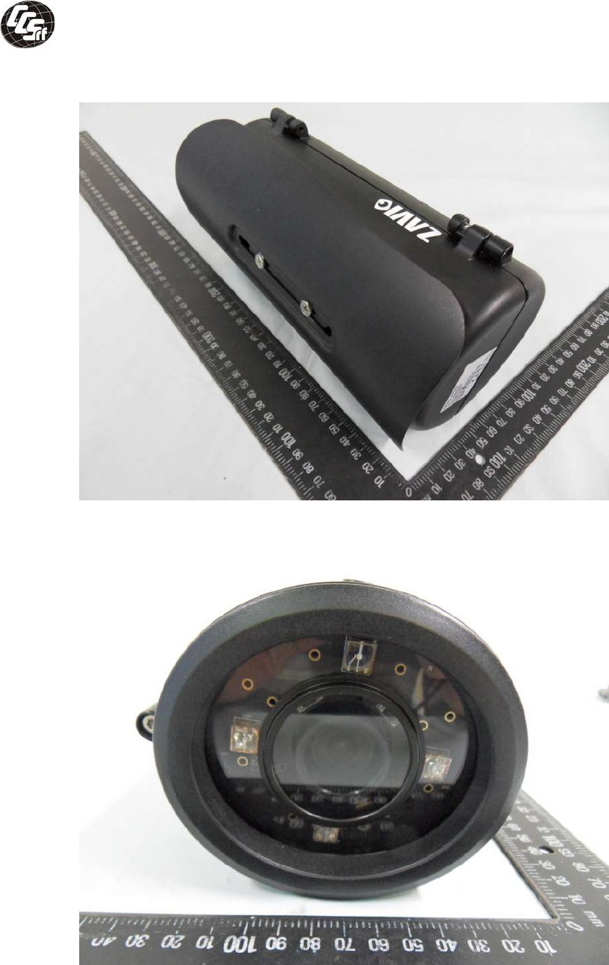
Compliance Certification Services Inc. Report No:T111221S01-LV
Page 63 of 75
Photo # 3
Photo # 4
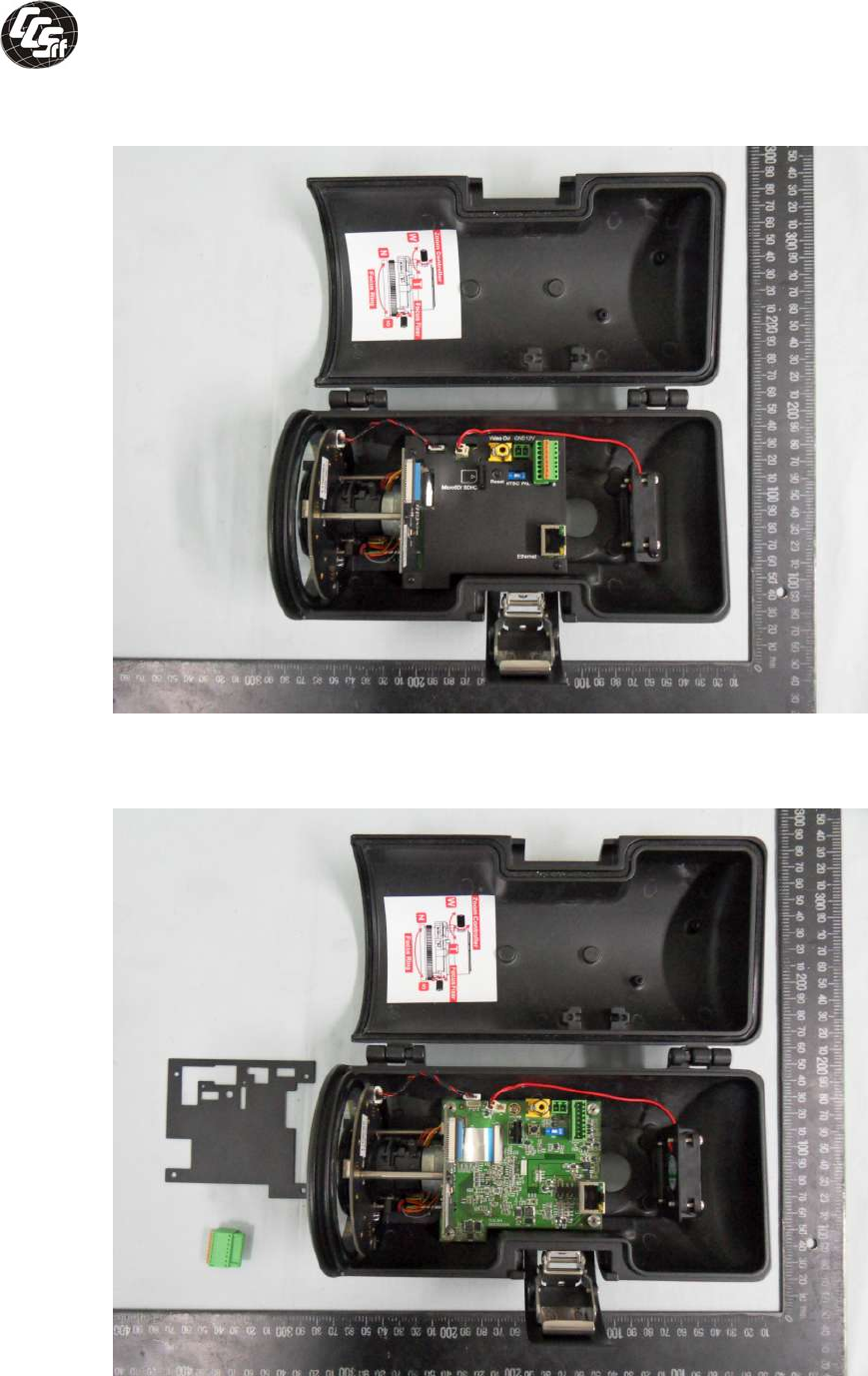
Compliance Certification Services Inc. Report No:T111221S01-LV
Page 64 of 75
Photo # 5
Photo # 6
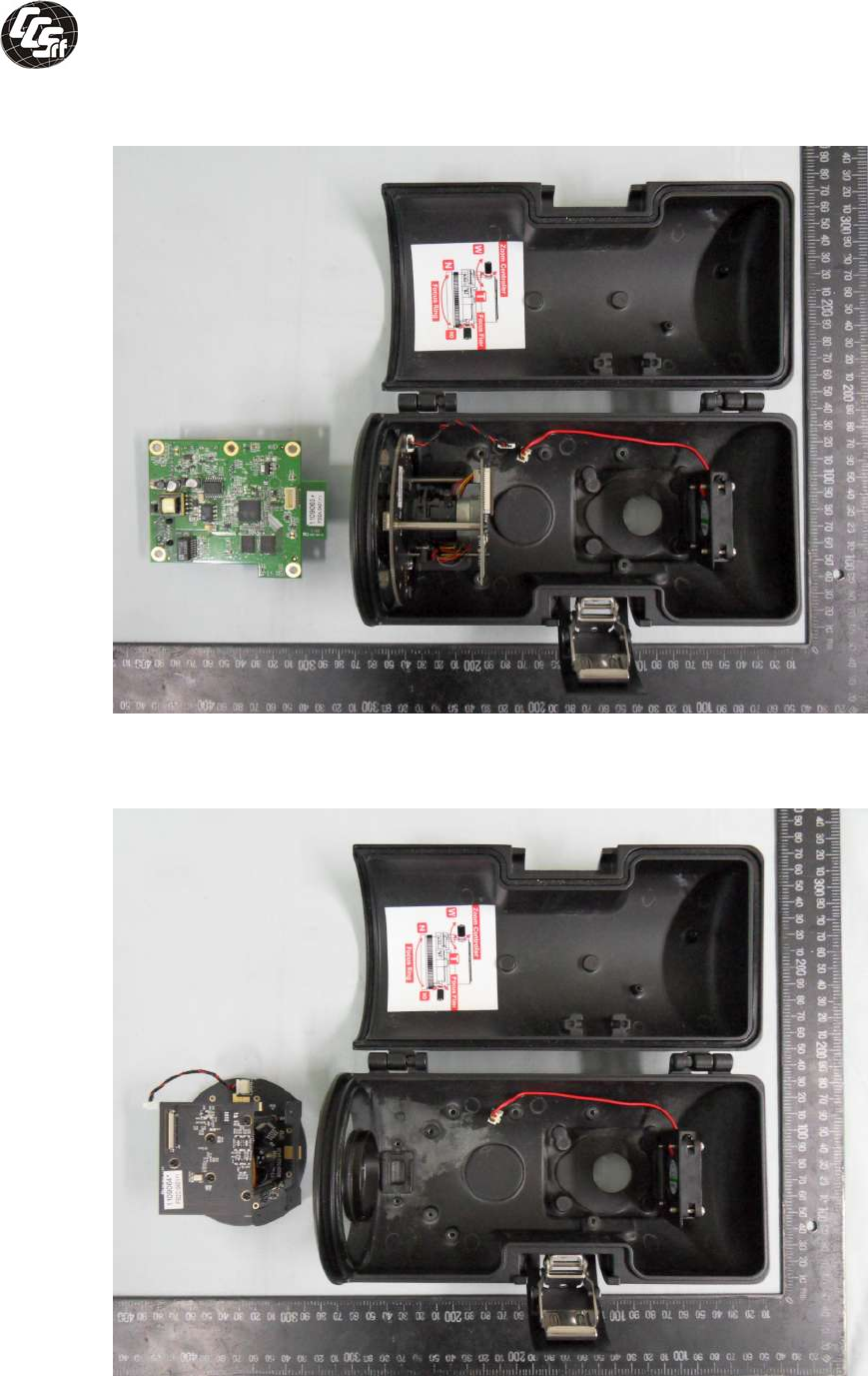
Compliance Certification Services Inc. Report No:T111221S01-LV
Page 65 of 75
Photo # 7
Photo # 8
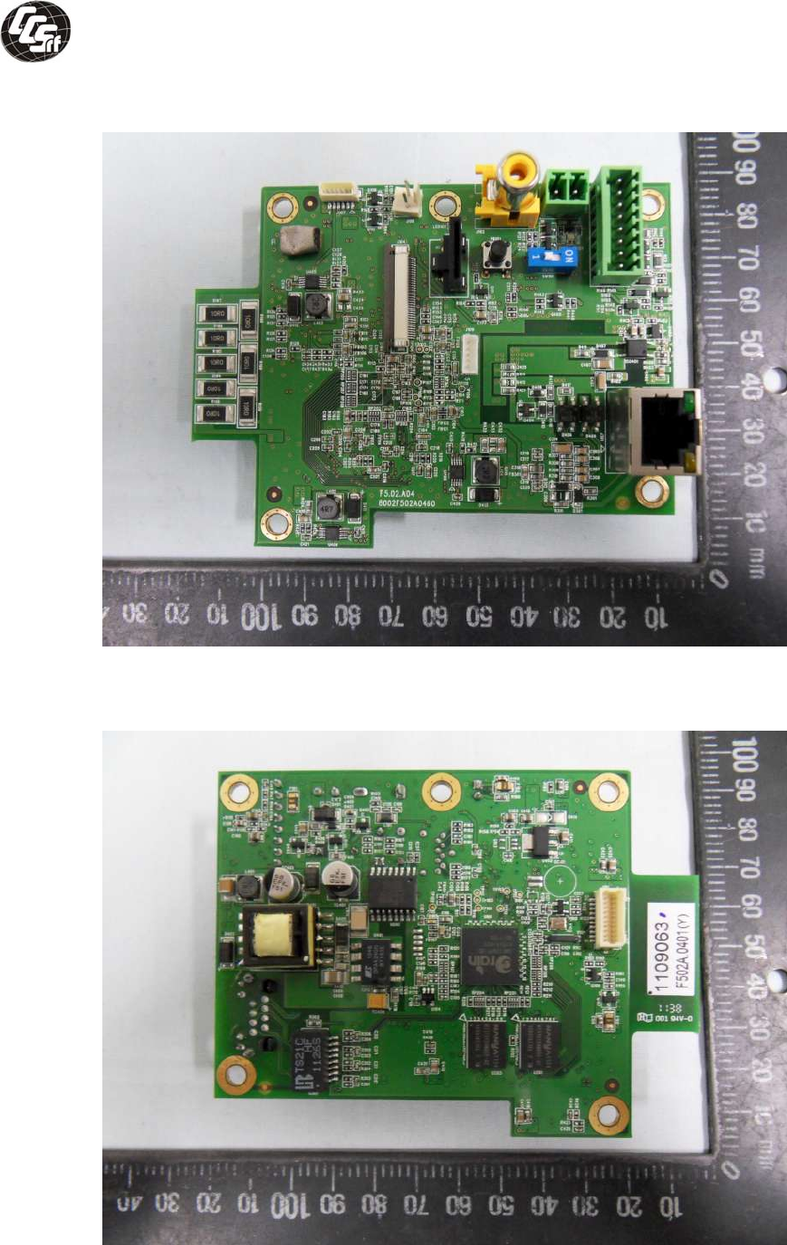
Compliance Certification Services Inc. Report No:T111221S01-LV
Page 66 of 75
Photo # 9
main board
Photo # 10
main board
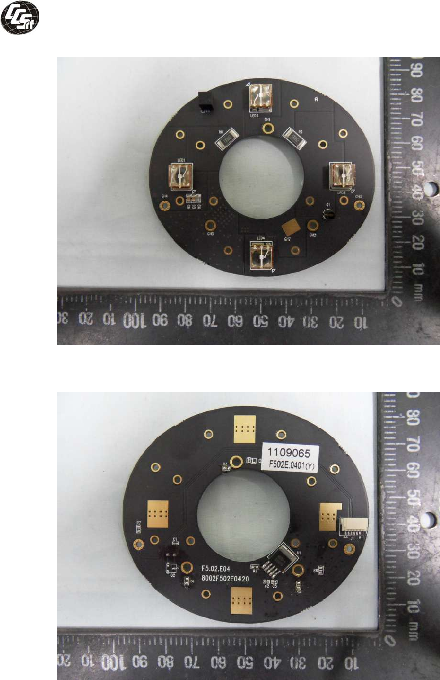
Compliance Certification Services Inc. Report No:T111221S01-LV
Page 67 of 75
Photo # 11
led board
Photo # 12
led board
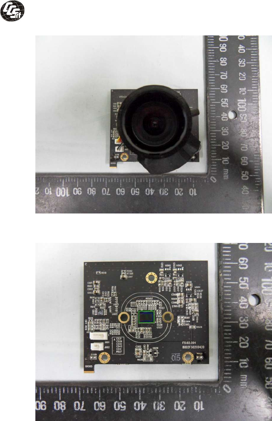
Compliance Certification Services Inc. Report No:T111221S01-LV
Page 68 of 75
Photo # 13
lens board
Photo # 14
Lens board
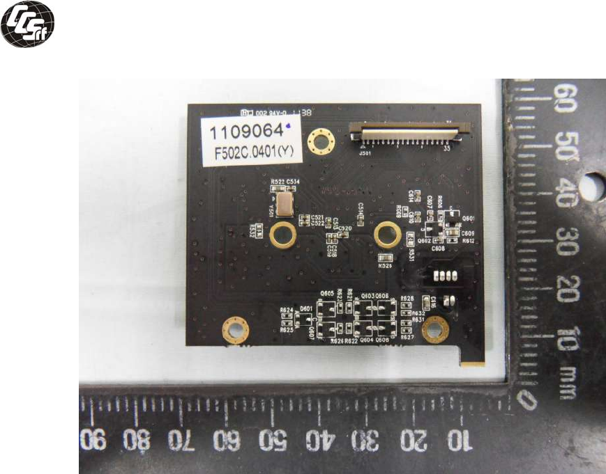
Compliance Certification Services Inc. Report No:T111221S01-LV
Page 69 of 75
Photo # 15
Lens board

Compliance Certification Services Inc. Report No:T111221S01-LV
Page 70 of 75
Attachment - B.
Product ID Label
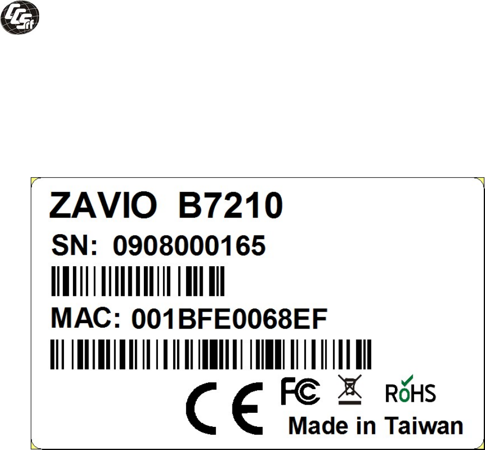
Compliance Certification Services Inc. Report No:T111221S01-LV
Page71 of 75

Compliance Certification Services Inc. Report No:T111221S01-LV
Page 72 of 75
Attachment – C.
Schematic and Layout
(See attachment software copy)

Compliance Certification Services Inc. Report No:T111221S01-LV
Page73 of 75
Attachment - D.
User manual
(See attachment software copy)

Compliance Certification Services Inc. Report No:T111221S01-LV
Page74 of 75
Attachment - E.
Measuring Instrument List
Compliance Certification Services Inc. Report No:T111221S01-LV
Page 75 of 75
Id Code Kind of Instrument Manufacturer Model / type Serial No. Specification Acceptability Calibrated
Date
Calibrated
until
a0~150W
b0~60Vdc
V K5E123 DC Electronic Load Prodigit 3310C 30402C216
c0~30A
±1.5% 05.02.2011 05.01.2012
V K5E159 Electrical Safety
Compliance Analyzer EXTECH 7451 1990884 Withstand Voltage
Insulation test
±1.5%
±5% 11.09.2011 11.08.2012
V K5E168 Digital Timer -- 5117 5823Q011 100hrs (H/M/S) ±1% 10.08.2011 10.07.2012
V K5E179 Electronic Scale G.TECH 100kg 6504Q311 5g~100Kg ±1% 05.10.2011 05.09.2012
V K5E216 Mobile Recorder YOKOGAWA MV230-1-2-
1-1D S5E805255 K Type -
200°C~1370°C ±2% 10.26.2011 10.25.2012
a 0~1000 (Vac/dc)
V K5E218 Digital Multimeter FLUKE 15B 11390159 b 0~10A (ac/dc) ±1.5% 12.08.2011 12.07.2012
