T2000 Programming Application User’s Manual T2000/T2000 WIN Manual/T2000 User's
T2000/T2000 programming manual/T2000 Programming Application User's Manual T2000 Programming Application User's Manual
T2000/T2000 WIN Programming Manual/T2000 Programming Application User's Manual T2000 Programming Application User's Manual
T2000/T2000 programming manual/T2000 Programming Application User's Manual T2000 Programming Application User's Manual
T2000/T2000 WIN Programming Manual/T2000 Programming Application User's Manual T2000 Programming Application User's Manual
T2000/T2000 programming manual/T2000 Programming Application User's Manual T2000 Programming Application User's Manual
User Manual: Pdf T2000/T2000 WIN Programming Manual/T2000 Programming Application User's Manual
Open the PDF directly: View PDF ![]() .
.
Page Count: 184 [warning: Documents this large are best viewed by clicking the View PDF Link!]
- Contents
- Part A Getting Started
- Part B Getting and Using Help
- Part C Programming Conventional Features
- Part D Programming Trunked Features
- What’s New - T2000 Trunked Radios
- Programming Trunked Radios
- Changing Network Settings
- Changing Fleet Settings
- Changing Radio Unit Settings
- Part E Concepts
- Part F Troubleshooting
- Glossary
- Index

v2.1
CONNECTIVITY RELIABILITY FLEXIBILITY
TAIT
T
2
OOO
MOBILES
T2000 Programming
Application
User’s Manual
October 2002
M2000-00-003-806
v2.1

T2000 Programming Application User’s Manual Contents i
Contents
Part A: Getting Started .....................................................................................1
Installation ...................................................................................................3
Minimum System Requirements ............................................................3
Equipment Supplied ...............................................................................3
Application Installation ...........................................................................3
Connecting a Radio to your PC .............................................................3
Reading and Programming T2000 Radios ...................................................4
Reading a Radio ....................................................................................4
Opening a Radio Programming Database ...............................................4
Creating a New Database ........................................................................5
Programming a Radio ............................................................................5
Select a Different Radio Model ..............................................................5
Changing Access Levels ..........................................................................6
Navigating Between Forms .....................................................................6
Application Menu Commands .....................................................................7
File Menu ...............................................................................................7
Edit Menu ..............................................................................................8
Radio Menu ...........................................................................................9
Network Menu .................................................................................... 10
Tools Menu ..........................................................................................11
Help Menu ...........................................................................................11
Changing Data ........................................................................................... 13
Text Box ..............................................................................................13
Combo Box ......................................................................................... 13
Check Box ...........................................................................................14
Grids ....................................................................................................14
Transferring Data .......................................................................................15
Copying Data Into Grids From Excel ...................................................15
Copying Fields .....................................................................................15
Part B: Getting and Using Help ......................................................................17
Getting and Using Help ............................................................................. 19
Online Help .........................................................................................19
What’s This? Help ................................................................................ 19
Help on the Internet .............................................................................19
Part C: Programming Conventional Features ................................................21
What’s New - T2000 Conventional Radios ...............................................23
Basic Radio Settings ...................................................................................24
Specifications (Conventional) Form ...................................................... 24
Receiver Monitoring Form ..................................................................26
Transmitter Setup Form ........................................................................28
Setting Up Signalling Options ....................................................................30
Subaudible Signalling Form ..................................................................30
Signalling Tab ................................................................................. 30
Presets Tab ......................................................................................31
Selcall Identity Form .............................................................................32
Selcall Identity Tab ..........................................................................32
Selcall Setup Tab .............................................................................36
Selcall Sequences Tab ......................................................................39

ii Contents M2000-00-003-806 © Tait Electronics Ltd 2002
Selcall Features Form ........................................................................... 40
Selcall Status Form ............................................................................... 41
Selcall Emergency Form ....................................................................... 43
Setting Up Channels and Scan Groups ...................................................... 46
Channels Form .................................................................................... 46
Scan Groups Form ............................................................................... 48
Scan Group Members Grid ............................................................. 49
Scan Settings ................................................................................... 50
Enhanced Scan Form ........................................................................... 51
Enhanced Scanning Grid ................................................................. 52
Birdie Channels Form .......................................................................... 52
Special Features ......................................................................................... 54
Power Saving (Conventional) Form ..................................................... 54
DTMF Form ....................................................................................... 54
Alpha Symbols Form ............................................................................ 56
CCI Setup (Conventional) Form .......................................................... 57
Radio Interface Options ............................................................................ 59
Key Settings Form ............................................................................... 59
User Selectable Form ........................................................................... 61
Part D: Programming Trunked Features ....................................................... 65
What’s New - T2000 Trunked Radios ...................................................... 67
Programming Trunked Radios .................................................................. 68
Programming Sequence ....................................................................... 68
Working with Multiple Networks ........................................................ 68
Setting up a network template .............................................................. 68
Importing a network ............................................................................ 69
Specifications (Trunked) Form ............................................................. 69
Radio Model Information ............................................................... 69
Installed Options ............................................................................. 71
ESN ............................................................................................... 72
Network ......................................................................................... 72
Startup ............................................................................................ 72
Identity ........................................................................................... 73
Changing Network Settings ...................................................................... 74
Trunked Channel Blocks Form ............................................................ 74
Network Identity Form ....................................................................... 75
Network Parameters Form ................................................................... 77
Control Channel Acquisition/Retention ......................................... 77
Signalling Parameters ...................................................................... 78
Background Hunt Parameters ......................................................... 79
Hunting Parameters Form .................................................................... 79
Normal Hunt Channels Grid .......................................................... 80
Non Applicable Channels Grid ....................................................... 80
Parameters ...................................................................................... 81
ANN Interfleet Form ........................................................................... 81
Changing Fleet Settings ............................................................................. 83
Fleet Identity Form .............................................................................. 83
Settings ........................................................................................... 83
Fleet Structure Defintion ................................................................ 84
Fleet Parameters Form ......................................................................... 86
Conventional Channels (Trunked) Form .............................................. 87
Changing Radio Unit Settings .................................................................. 89
Radio Unit ID Form ........................................................................... 89

T2000 Programming Application User’s Manual Contents iii
Identity ...........................................................................................89
Group Membership Grid .................................................................90
Restrict Calls ................................................................................... 91
Settings ............................................................................................92
Acquisition Data Form .........................................................................92
Acquisition Authorisation Grid ........................................................92
NDD Preference Data Grid .............................................................93
Zones ..............................................................................................93
CCI Setup (Trunked) Form ..................................................................94
Data Parameters Form ..........................................................................95
Short Data Messages ........................................................................95
Tait Data Protocol ...........................................................................96
Status Messages Form ............................................................................97
Power Saving (Trunked) Form .............................................................97
Preset Calls Form ..................................................................................99
5 Digit Lookup Form ......................................................................... 100
External Calls Form ............................................................................ 101
Call Options Form ............................................................................. 102
External Alert Form ............................................................................ 105
Key Settings (Trunked) Form .............................................................107
Interface Options Form ...................................................................... 108
Initial Settings ................................................................................ 108
Call Initiation ................................................................................ 108
DTMF .......................................................................................... 109
Diagnostics .................................................................................... 109
Audible Indicators ......................................................................... 109
Part E: Concepts .............................................................................................111
Introduction to Channels and Scan Groups .............................................. 113
Squelch and Signalling: Filtering Out Unwanted Noise and Traffic .....113
Squelch ......................................................................................... 113
Signalling ...................................................................................... 113
Selcall ............................................................................................ 115
Monitor: Listening In On Channel Traffic .......................................... 116
Introduction to Scan Groups ............................................................... 116
Scanning ....................................................................................... 116
Voting ........................................................................................... 117
Introduction to Trunking ........................................................................ 119
Control Channel Communication ...................................................... 119
Early Trunking Systems ...................................................................... 120
Addressing .......................................................................................... 121
MPT 1327 Numbering .................................................................. 122
MPT 1343 Numbering .................................................................. 122
CPSX Dialling .............................................................................. 123
Trunking Call Strings ............................................................................... 126
Part F: Troubleshooting ................................................................................129
No appropriate licence to use this functionality ........................................ 131
Cannot see the forms tree ........................................................................ 131
Cannot find a field ................................................................................... 131
Cannot enable a field ............................................................................... 131
Radio won’t read or program .................................................................. 131
Checksum Error ...................................................................................... 131
Subaudible Signalling Does Not Work ..................................................... 131

iv Contents M2000-00-003-806 © Tait Electronics Ltd 2002
Scanning Does Not Work ........................................................................131
Glossary ......................................................................................................... 133
Index .............................................................................................................. 167


2 Part A: Getting Started M2000-00-003-806 © Tait Electronics Ltd 2002

T2000 Programming Application User’s Manual Installation 3
Installation
Before you can begin reading and programming radios using the T2000
programming application, you must install the required software and hardware.
Minimum System Requirements
The application requires the following minimum configuration:
■an IBM compatible PC with a Pentium 100 microprocessor (Pentium 166
recommended)
■Windows® 95, Windows 98, Windows 2000 or Windows NT® 4
■32 MB of RAM (64 MB recommended)
■a VGA colour graphics display (600 x 800 resolution recommended)
■a hard disk drive with 35 MB of free space
■CD-ROM drive
■a Microsoft or compatible mouse and driver (if you wish to use the program
with a mouse)
■a free serial port for connection to the radio
Equipment Supplied
■application CD
■radio programming cable with a 9 or 25-pin serial connector at one end and
an RJ-11 telephone-style plug at the other
Note: If your serial connector is 25-pin and your computer has a 9-pin
serial port, you will need an adaptor. This is available from your PC
dealer.
Application Installation
To install the application:
1. Insert the installation CD into your CD-ROM drive.
2. If the autorun does not automatically start, select Start > Run.
3. Type “D:\setup.exe” where “D” is the letter that identifies the CD-ROM
drive containing the install CD.
4. Click OK.
The installation program will guide you through the installation process. Read
the information presented on the screen carefully.
Connecting a Radio to your PC
To connect a T2000 radio to your PC:
1. Connect the radio programming cable’s 9 or 25 pin connector to the
computer’s serial port.
2. Connect the radio programming cable’s RJ-11 telephone-style plug to the
radio’s microphone socket.
Tip: You can change the COM port the application uses to
communicate with the radio using the Tools > Options command.
4 Part A: Getting Started M2000-00-003-806 © Tait Electronics Ltd 2002
Reading and Programming T2000 Radios
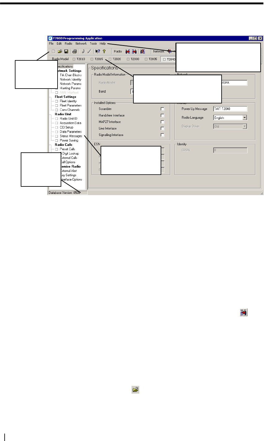
When you first start the T2000 Programming Application, the main window
appears with the default data file loaded:
A common workflow in the programming application is to:
1. read a radio, or open a radio programming database file
2. change settings using the various forms, then
3. program one or more radios.
Reading a Radio
To read a radio:
1. Connect a radio to your PC. See “Connecting a Radio to your PC” on page
3 for more information.
2. Make sure the radio is connected to a power source and the power is on.
3. Switch the radio on.
4. Select the Radio > Read menu option, or select the Read button from
the toolbar.
As the programming database is read from the radio, the application indi-
cates the radio model, and the software and database version numbers.
Opening a Radio Programming Database
To open a radio programming database file saved to disk:
■select File > Open or
■select the Open button from the toolbar or
■drag a file from an open window outside the application onto the left pane
(forms tree) of the application.
Menus: A series of menus along the
top of the window. See “Application
Menu Commands” on page 7.
Radio model toolbar: Lists available
radio models. See “Select a Different
Radio Model” on page 5.
Forms tree: A list of forms.
See “Navigating Between
Forms” on page 6.
Status bar.
Shows database
version and field
information.
Standard, Radio
and Network
toolbars.

T2000 Programming Application User’s Manual Reading and Programming T2000 Radios 5
Creating a New Database
To create a new database when you first launch the application, start changing
the default data in the various forms. See “Navigating Between Forms” on page
6 for more information.
To begin a new database from an existing database, select File > Reset To
Defaults.
To save the database, select File > Save.
Programming a Radio
To program a radio:
1. Connect a radio to the PC. See “Connecting a Radio to your PC” on page
3 for more information.
2. Make sure the radio is connected to a power source and the power is on.
3. Switch the radio on.
Tip: Select Radio > Read, and then File > Save to backup the radio’s
current data.
4. Make sure the correct radio model and data that you want to program is
showing in the programming application.
Caution: Do not program the application’s default data into the radio.
5. Select the Radio > Program menu option, or select the Program button
from the toolbar.
As the programming database is programmed to the radio, the application
indicates the radio model, and the software and database version numbers.
Select a Different Radio Model
The radio model toolbar displays the various radio models available in the
conventional programming application.
Caution: You cannot read a radio, change the radio model and then re-pro-
gram the radio.
To select a specific radio model using a mouse, click on one of the buttons on
the radio model toolbar.
To select a radio model using the keyboard:
1. Press Alt+R to select the Radio menu.
2. Press M to select the Model sub-menu option.
3. Use the cursor keys to highlight a radio model.
4. Press the Enter key.
Changing the model name will change the Radio Model field (Specifications
form). This must be set correctly as not all programmable features are available
for all radio models. Changing the value of the radio model will:

6 Part A: Getting Started M2000-00-003-806 © Tait Electronics Ltd 2002
■make fields relevant to the new radio model selectable, where they were
previously greyed out
■grey-out fields not relevant to the new radio model
If a radio model on the toolbar has a green indicator next to it, there is unsaved
data for that radio model database. Select the radio model and File > Save if you
want to keep changes made.
Changing Access Levels
Access levels allow you to control access to various fields in the programming
application. This can be useful when programming trunked radios, to prevent
unwanted changes to critical network and fleet-related fields.
■To provide access to all fields, select Options > Access Level > High.
■Trunked radios only: to prevent access and changes to forms and fields in
Network Settings, select Options > Access Level > Medium.
■Trunked radios only: to prevent access and changes to forms and fields in
Network and Fleet settings (except Conventional Channels), select
Options > Access Level > Low.
■To prevent access to everything except the radio language and power up
message, select Options > Access Level > ID and Personalisation.
Tip: You can change the default access level when the application is
first started by selecting Tools > Options.
Navigating Between Forms
The forms tree on the left side of the main window lists the forms available.
To navigate:
■Keyboard: Scroll through the forms using the up and down arrow keys.
Press the Enter key to open the form.
■Mouse: Left-click once on the name of a form to open it and begin changing
data.
If a form has a green indicator next to it, there is unsaved data on that form.
Select File > Save if you want to keep changes made.

T2000 Programming Application User’s Manual Application Menu Commands 7
Application Menu Commands
The bar along the top of the main window shows the following menus:
■File Menu
■Edit Menu
■Radio Menu
■Network Menu
■Tools Menu
■Help Menu
These menus show various commands, some of which also appear as an icon on
the toolbar.
To navigate the various menu commands:
Keyboard: Select a menu by pressing the Alt key, then the first letter of the
menu’s name. Use the up and down arrow keys to scroll through the list of
commands, and press the Enter key to select a command. Select another menu
using the left and right arrow keys. Press the Esc key to close a menu; the menu
bar remains selected. Press the Esc key again to return to the main window.
Mouse: Select a menu by clicking on it, then clicking on the required
command.
File Menu
The commands available from the File menu are:
■Reset To Defaults
■Open
■Import Network
■Revert to Saved
■Save
■Save As
■Printer Settings
■Print
■Exit
■Recent Files List
Reset To Defaults Selecting the File > Reset To Defaults command loads the application’s default
data for the current radio model.
■Shortcut key: Ctrl+D
■Toolbar icon:
Open Selecting the File > Open command opens an existing file.
If a file was saved with comments, the comments will be displayed in the
Comments window and the radio information will be displayed in the Radio
Information window.
■Shortcut key: Ctrl+O
■Toolbar icon:

8 Part A: Getting Started M2000-00-003-806 © Tait Electronics Ltd 2002
Import Network Selecting the File > Import Network command prompts for a file, from which
the network will be imported. See “Importing a network” on page 69 for more
information.
Revert to Saved Selecting the File > Revert to Saved command returns to the last saved version
of the current file.
Save Selecting the File > Save command saves all data to the current file. If no file
has been saved for the current data, the Save As dialog will display, prompting
for a file name and location.
■Shortcut key: Ctrl+S
■Toolbar icon:
Save As Selecting the File > Save As command opens the Save As dialog, which
prompts for a file name and location. Any comments you enter in the
Comments window will be saved with the file, together with the information
displayed in the Radio Information window.
Printer Settings Selecting the File > Printer Settings command opens the Print Setup dialog in
which you can select and configure the printer you wish to print to.
Print Selecting the File > Print command opens the Print Selection window. You
can then select one or more forms, and print data in those forms using the Print
button.
■Shortcut key: Ctrl+P
■Toolbar icon:
Recent Files List The list of recent files displays the names of files you have most recently opened
in the application. To open a file, select File > [filename].
Exit Selecting the File > Exit command exits the application.
Edit Menu
The commands available from the Edit menu are:
■Undo
■Cut
■Copy
■Paste
■Delete
■Select All
■Validate Form
■Revert Form
Undo Selecting the Edit > Undo command reverses the last command or deletes the
last entry typed. This is greyed out if there is no action to undo.
■Shortcut key: Ctrl+Z
Cut Selecting the Edit > Cut command places the text in a field on the clipboard,
and deletes it from the field. This will be greyed out if there is no text to cut.
■Shortcut key: Ctrl+X

T2000 Programming Application User’s Manual Application Menu Commands 9
Copy Selecting the Edit > Copy command places a copy of the selected grid data into
the clipboard buffer. It will also copy the text in a field. This will be greyed out
if there is no text to copy.
■Shortcut key: Ctrl+C
Paste Selecting the Edit > Paste command enters data into a grid from the clipboard.
The data will be validated before it is entered. It will also paste text from the
clipboard into a text field. This will be greyed out if there is no text to paste.
■Shortcut key: Ctrl+V
Delete Selecting the Edit > Delete command clears the currently selected data, or the
next character in a text field.
■Shortcut key: Del
Select All Selecting the Edit > Select All command highlights all the text in the current
field, or all the data in a grid.
■Shortcut key: Ctrl+A
Validate Form Selecting the Edit > Validate Form command checks the data in the current
form for validity. This option will only appear if there are changes to validate,
and will cause a green indicator to appear next to the form name in the forms
tree. This indicates that there are changes to the form which need to be saved.
Select File > Save or Ctrl+S to save the database and reset all green indicators
to their original state.
Shortcut key: Ctrl+Y
Toolbar icon:
Revert Form Selecting the Edit > Revert Form command discards any changes made to the
current form.
Shortcut key: Ctrl+T
Toolbar icon:
Radio Menu
The commands available from the Radio menu are:
■Read
■Program
■Interrogate
■Model
Read Selecting the Radio > Read command reads the radio’s programming database
and loads the relevant information into the application’s forms.
Shortcut key: Ctrl+R
Toolbar icon:
Program Selecting the Radio > Program command programs the radio’s programming
database with the settings in the application’s forms.
Shortcut key: Ctrl+M
Toolbar icon:
10 Part A: Getting Started M2000-00-003-806 © Tait Electronics Ltd 2002
Interrogate Selecting the Radio Interrogate command displays the radio model, software
version and database version, without loading the database into the application.
Shortcut key: Ctrl+I
Toolbar icon:
Model The Radio > Model options switch between the various T2000 radio models.
See “Select a Different Radio Model” on page 5 for more information. Options
are:
■T2010
■T2015
■T2020
■T2030
■T2035
■T2040
Network Menu
The commands available from the Network menu are:
■Add Network
■Delete Network
■Previous Network
■Next Network
For more information, see “Working with Multiple Networks” on page 68.
Add Network Selecting the Network > Add command creates a new network database
containing separate network, fleet and radio information.
You can also add a network saved as a file on disk by selecting the File>Import
Network command.
Toolbar icon:
Delete Network Selecting the Network > Delete command deletes the currently selected
network.
Toolbar icon:
Previous Network Selecting the Network > Previous Network command switches to the
previous network. This is only available if two networks have been defined, and
you are currently on Network 2. See “Working with Multiple Networks” on
page 68 for more information.
Shortcut key: Ctrl+J
Toolbar icon:
Next Network Selecting the Network > Next Network command switches to the next
network. This is only available if two networks have been defined, and you are
currently on Network 1. See “Working with Multiple Networks” on page 68
for more information.
Shortcut key: Ctrl+K
Toolbar icon:

T2000 Programming Application User’s Manual Application Menu Commands 11
Tools Menu
The commands available from the Tools menu are:
■Access Level
■Options
Access Level Selecting one of the options under Tools > Access Level will restrict or add
access to certain fields in the application. See “Changing Access Levels” on page
6 for more information.
Options Selecting the Tools > Options command opens the Options window. The
options are:
■Communication Port: The port used for communicating with radios
■Caption Position: Select Left to align captions to the left, or Centre to place
captions and checkboxes to the centre of each group box.
■Show General Dialogs: Check this box to display general warnings, such as
confirmations when starting or closing the application. Clear this box to
hide these dialogs.
■Default Access Level: Defines the access level when the application is
started. See “Changing Access Levels” on page 6 for more information.
■Startup Position: The state of the window when the application is started.
Select Maximise to start the application window in a maximised state,
Centre to start the application window reduced in the centre of the screen,
or Previous to remember a custom window size when closing and restarting
the application.
■Web Address: The address used when the Help > Internet > Taitworld
command is selected.
Help Menu
The commands available from the Help menu are:
■Contents and Index
■What’s This?
■Internet
■About
Contents and
Index Selecting the Help > Contents and Index command launches Online Help for
the application, open at the Contents tab.
Shortcut Key: F1
Toolbar Icon:
What’s This? Selecting the Help > What’s This? command changes the cursor to an arrow
with a question mark, and enables you to click on a field to get popup help for
that field. See “What’s This? Help” on page 19 for more information.
Shortcut Key: Shift+F1
Toolbar Icon:

12 Part A: Getting Started M2000-00-003-806 © Tait Electronics Ltd 2002
Internet Selecting the Internet > Mobiles Support command launches your default
browser and loads the address specified in the Website Address field (Tools >
Options). Selecting the Internet > Taitworld command launches the Tait
home page (http://www.taitworld.com).
About Selecting the Help > About command displays information about the
application.
T2000 Programming Application User’s Manual Changing Data 13
Changing Data
If a field’s data is greyed out, then that data is displayed for information only and
cannot be changed. If a field name is greyed out, then that option is not
available for the radio being programmed. For information on how to enable a
field that is greyed out, select What’s This? Help , then click on the field
label you want information on.
Where a range of possible numeric values is available for a field, then that range
is shown in the bottom left corner of the form.
How you change and add data for each field depends on how that data is
displayed. There are four options:
■Text Box
■Combo Box
■Check Box
■Grids
Text Box
A text box is used for numeric and alphanumeric data.
To change data in a text box:
■Keyboard: Select a text box using the Tab key. Enter the required data.
■Mouse: Select a text box by clicking on it with the mouse. Enter the
required data.
Combo Box
A combo box is used for fields that have a range of possible values and appears
as a box with an arrow at the right side.
To change data in a combo box:
■Keyboard: Select a combo box using the Tab key. You can then display the
options available by pressing the Alt key and the down arrow key at the same
time. Use the up and down arrow keys to scroll through the options until
the required value is displayed, then press the Enter key. You can also press
a letter to cycle through entries starting with that letter.
■Mouse: Select a combo box by clicking on it, which displays the list of
values. Select the required value from the combo box.

14 Part A: Getting Started M2000-00-003-806 © Tait Electronics Ltd 2002
Check Box
A check box is used for fields that are either enabled or disabled. If the box is
checked, the field is enabled; if the box is blank, the field is disabled.
To change data in a check box:
Keyboard: Select a check box using the Tab key. Use the space bar to enable
and disable the field.
Mouse: Select a check box and change its value by clicking on it with the
mouse.
Grids
A grid is used where many lines of data are required, each containing the same
type of information. The data in a grid is displayed in text boxes and combo
boxes. Combo boxes in a grid appear to be text boxes until they are selected,
when an arrow appears on the right side.
Tip: You can sort information in a grid by clicking on the various
column headers.
Forms that contain grids also contain additional buttons:
■Add: Adds a new row for data entry.
■Insert (Channels form): Inserts a new row using the next available ID.
■Repeat: Duplicates the data from the selected row, giving it a new name.
■Delete: Removes the currently selected row of data.
To change data within a grid:
■Keyboard: Select the different fields in a grid using the Tab key or the right
and left arrow keys. Pressing the up or down arrow keys moves up or down
a row of data. Start typing in a cell to replace the existing data, or press F2
to edit a cell’s contents without deleting existing data.
■Mouse: Single click on the required field and begin typing to replace
existing data. Click twice on the required field to edit a cell’s contents
without replacing the existing data.

T2000 Programming Application User’s Manual Transferring Data 15
Transferring Data
You can copy and paste or drag and drop single cells or rows to a grid from a
Microsoft® Excel spreadsheet. You can also copy fields or groups of fields
between radio models.
Copying Data Into Grids From Excel
You can enter data into a Microsoft® Excel spreadsheet, and then copy or drag
and drop that data into a grid. This can be useful when there are a large number
of records to configure, such as the 1200 channel functionality of conventional
T2020 radios with firmware version 7.01 or higher.
To copy data into a grid from Excel:
1. In Excel, type the information exactly as it will appear in the grid.
For the Channels form, columns such as “ID”, “Channel”, “RX Fre-
quency” should appear as a unique cell, sharing the same row.
For each column under the header name, enter data that you want to
import.
2. In Excel, select the block of data you have entered, either using Shift and
the cursor keys on the keyboard or left click and drag using the mouse.
3. Select Edit > Copy to copy the information to the clipboard.
4. Open the T2000 Conventional Programming Application, and navigate to
the grid where you want to paste the data (for example, the Channels form).
5. Click on a cell in the grid to bring focus to the grid.
6. Select Edit > Paste.
If the information on the clipboard is valid it will appear in the grid, replacing
any current data.
The T2000 programming application also supports drag and drop from
Microsoft® Excel to the various grids.
Copying Fields
To copy a field to another radio model:
1. Right click on the field or field label that you want to copy.
The cursor will change to an arrow with a plus sign, and the status bar will
display the text “copy the [Field] setting ...”
2. While still holding the right mouse button, drag the field to another radio
model on the radio model toolbar.
The status bar will display the text “copy the [Field] setting to the [radio
model] radio model”.
3. Release the left mouse button.
If the copy was successful and general dialogs are enabled
(Tools > Options), an information box will state “[Field] successfully copied
to [radio model]”.

16 Part A: Getting Started M2000-00-003-806 © Tait Electronics Ltd 2002
To copy a group of fields to another radio model:
1. Right click on the group box or box label that contains the fields that you
want to copy.
The status bar will display the text “copy the [Label] details ...”
2. While still holding the right mouse button, drag the group box to another
radio model on the radio model toolbar.
The cursor will change to an arrow with a plus sign and the status bar will
display the text “copy the [Label] details to the [radio model] radio model”.
3. Release the left mouse button.
If the copy was successful and general dialogs are enabled
(Tools > Options), one or more information boxes will state “[Field] suc-
cessfully copied to [radio model]”.


18 Part B: Getting and Using Help M2000-00-003-806 © Tait Electronics Ltd 2002

T2000 Programming Application User’s Manual Getting and Using Help 19
Getting and Using Help
There are 3 ways of getting help in the T2000 Programming Application:
■Online Help
■What’s This? Help
■Help on the Internet
Online Help
Press F1 or select Help > Contents and Index.
The series of buttons along the top of the help window include:
■Hide/Show: Select the Hide or Show button to display or hide the left most
pane of the Help window, containing Contents, Search and Favorites.
■Back: Select the Back button to go back to the topic you last viewed.
■Print: Select the Print button to print either the current topic or the current
topic and subtopics.
■Options: Select the Options button to change Internet Options, print topics
and turn the Search Highlight on or off.
■Click blue underlined text to jump to another topic.
Useful Help File Features
In the help file you can:
■Search topics: From the Search tab, enter one or more keywords and select
the List Topics button. Highlight a topic from the list and select the Display
button to show the topic in the pane to the right.
■Save topics as a Favorite: With a topic displayed, select the Favorites tab. If
you want to reference the topic by a different name, you can enter another
title in the Current topic box. Select the Add button to save the topic in the
Topics list for future reference.
What’s This? Help
1. Press Shift+F1 or Select Help > What’s This?.
The cursor will change to an arrow with a question mark.
2. Move the cursor to the field you want help on.
3. Left click once on the field or the field label.
A popup defintion of the field will appear.
4. Left click again anywhere on the screen to make the popup disappear.
Click blue underlined text to jump to the relevant information in the Online
Help file.
Help on the Internet
Select Help >Internet >Mobiles Support.
The mobiles section of the support website allows you to access support
material such as operator’s manuals and user guides. If you have password access,
you can also search through Technical Support documentation, and gain access
to product updates.


T2000 Programming Application User’s Manual Programming Conventional Features 21
Part C Programming Conventional
Features
This part contains detailed information on programming T2010,
T2015 and T2020 radios.
Topics
■What’s New - T2000 Conventional Radios
■Basic Radio Settings
■Setting Up Signalling Options
■Setting Up Channels and Scan Groups
■Special Features
■Radio Interface Options

22 Part C: Programming Conventional Features M2000-00-003-806 © Tait Electronics Ltd 2002

T2000 Programming Application User’s Manual What’s New - T2000 Conventional Radios 23
What’s New - T2000 Conventional Radios
Key:
■N/A = Not Applicable.
■* = not a full release.
Feature Form
Radio Firmware Version Database
Version
T2010/T2015 T2020
Reverse Tone Burst
Duration
Subaudible Signalling N/A 5.24 2.07
Fast PTT Via AUX Line Transmitter Setup 3.05 N/A 2.01
Tx Call Channels 3.05 N/A 2.01
BCD Polarity Inverted Channels 3.02* N/A 2.01
BCD Channel Selection Channels 3.01* N/A 2.01
24 Part C: Programming Conventional Features M2000-00-003-806 © Tait Electronics Ltd 2002
Basic Radio Settings
This section contains detailed information on changing basic radio settings.
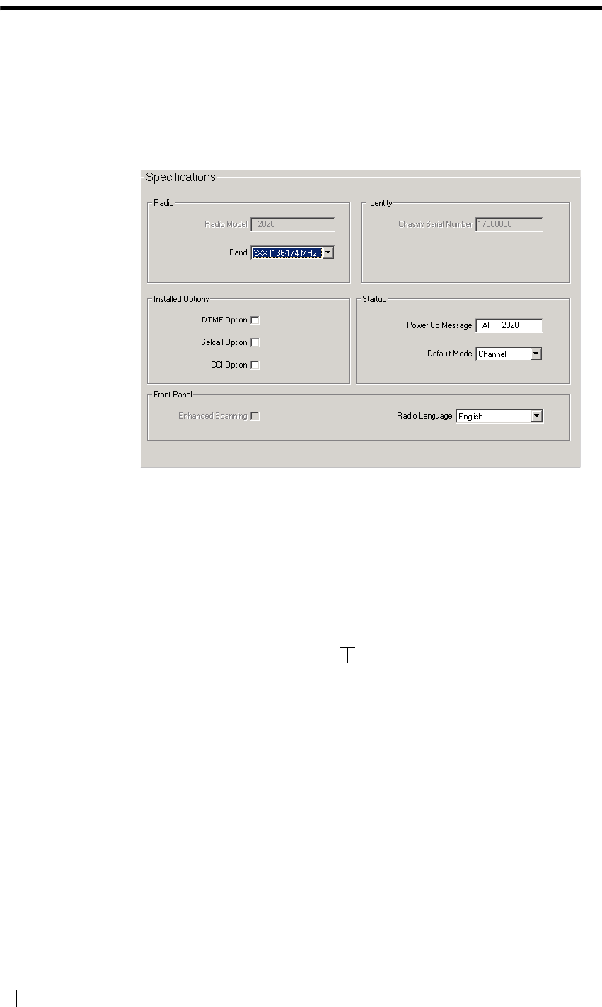
Specifications (Conventional) Form
The Specifications form shows basic radio information such as the radio model
and the frequency band. You can also set various radio interface options in this
form, such as the power-up message, and specify installed hardware options.
You may wish to read data from a radio of a different type and use the settings
as a template for programming radios of another variant. If so, change the values
of radio model and/or radio band after loading the template file but before
changing any other radio settings.
Radio Model The Radio Model field indicates the radio’s feature set, which is indicated by
the fourth and fifth positions of the radio part number.
10 indicates the T2010 feature set, 15 indicates the T2015 feature set and 20
indicates the T2020 feature set.
The Radio Model field is set using the radio model toolbar (see “Select a
Different Radio Model” on page 5). This must be set correctly as not all
programmable features are available for all radio models. Changing the value of
the radio model will:
■make fields relevant to the new radio model selectable, where they were
previously greyed out
■grey-out fields not relevant to the new radio model
radio model
T2010-343

T2000 Programming Application User’s Manual Basic Radio Settings 25
Radio Band The Radio Band field sets the frequency band in which the radio operates, and
is indicated by the sixth position (first after the hyphen) in the radio part
number.
This number indicates the frequency band as follows:
Note: Contact your local dealer for information on the availability of
different frequency bands.
The Radio Band field must be set correctly in order to validate channel settings,
and changing the value of the radio band will set the values of the Rx and Tx
Frequencies field (Channels form) to 0, as any frequency values previously
entered may be invalid for the new radio band.
DTMF Option T2020 radios only.
The DTMF Option field is checked if dual tone multiple frequency (DTMF)
hardware is installed in the radio. Settings for this option are made in the DTMF
form.
Selcall Option Select this option if signalling hardware is installed in the radio that allows
Selcall multi-tone (Selcall) signalling to be used. Once this option is selected,
the Selcall forms will become available in the forms tree. The number of Selcall
forms available depend on the radio model.
The checkbox will be greyed out if there is no signalling hardware installed in
the radio.
CCI Option T2020 radios only.
The CCI field is checked if computer controlled interface (CCI) hardware has
been installed in the radio. CCI hardware is for data communication, which is
configured in the CCI form.
Enhanced
Scanning
T2015 radios only.
The Enhanced Scanning Field enables or disables enhanced scanning for T2015
radios. Selecting this field will enable the Enhanced Scan Form and will enable
priority scanning (primary and secondary) in the Channels Form >Scan field.
Chassis Serial
Number
The Chassis Serial Number is automatically read from the radio’s memory and
is used for identification only. The chassis serial number has no effect on the
normal operation of the radio.
Band Frequency Range Band Frequency Range
0 500-530 MHz 5 400-470 MHz
1 220-270 MHz 6 450-520 MHz
2 66-88 MHz 7 330-366 MHz
3 136-174 MHz 8 800-870 MHz
4 175-225 MHz 9 360-400 MHz
frequency band
T2010-343

26 Part C: Programming Conventional Features M2000-00-003-806 © Tait Electronics Ltd 2002
Power Up
Message
T2020 radios only.
The Power Up Message field sets the power-up message, which can be up to
24 characters. Choose from: A to Z 0 to 9 * + - < > / \ space
Enter up to 12 characters, including leading spaces if you want the message to
be centred.
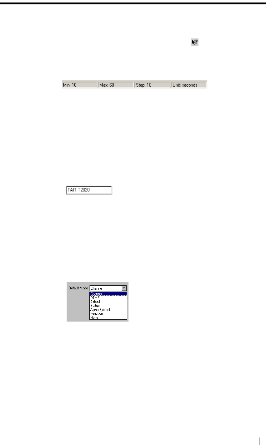
Default Mode T2020 radios only.
The Default Mode field sets the mode the radio reverts to at power-up and after
10 seconds of no user activity. If default mode is set to None, the radio powers
up in the mode selected when the radio was last on.
The modes available are outlined below:
Radio Language T2020 radios only
The Radio Language field sets the language of messages that appear on the radio
LCD. Select French, German, or English.
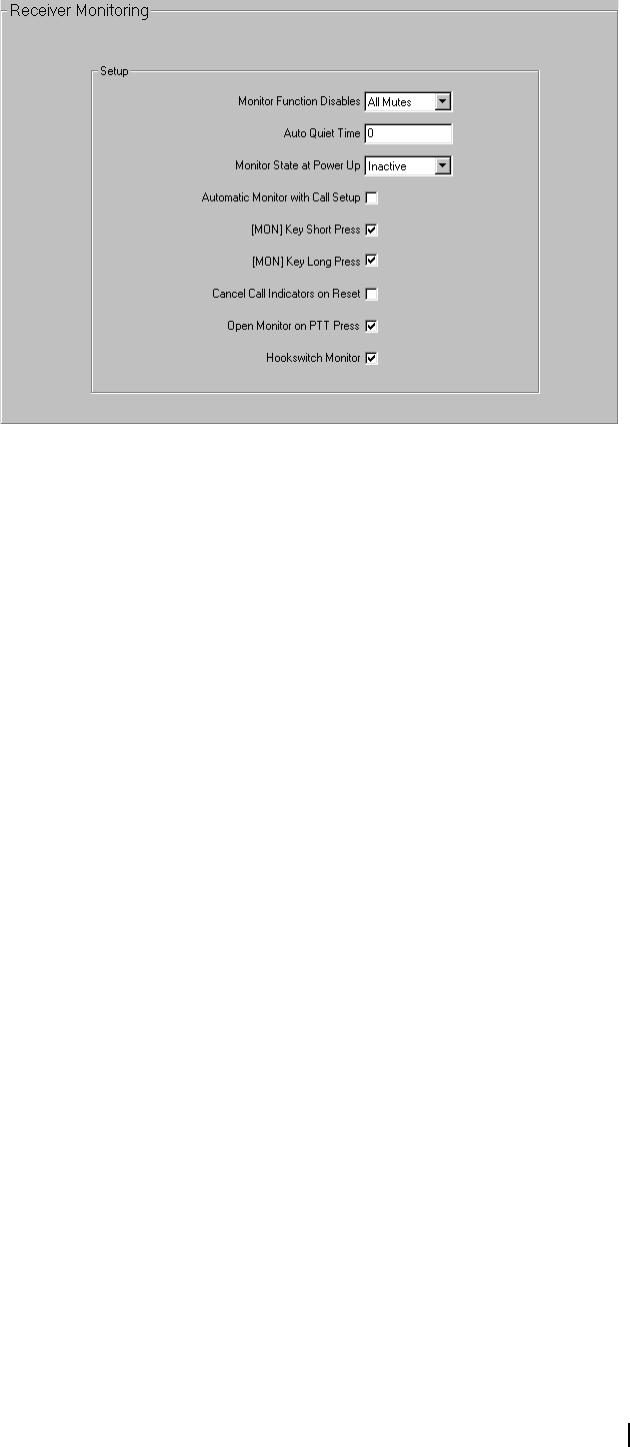
Receiver Monitoring Form
The fields in the Receiver Monitoring form set properties related to the
operation of the radio’s monitor function.
Table 1: Default modes available for T2020 radios
Option Description
Channel Channel Entry/Selection Mode. In channel entry mode, or
channel selection mode, the user can change to a different
channel or scan group.
DTMF DTMF Dialling Mode. In DTMF dialling mode, the user can dial
DTMF strings. DTMF dialling mode is available when the Manual
Dialling field in the DTMF form is enabled.
Selcall Selcall Dialling Mode. Using Selcall dialling, the user can dial
Selcall sequences using the keypad.
Status Status Entry Mode. In status entry mode, the radio user can
change the status to reflect their current activity. The
corresponding status digit is sent with Selcall sequences that
include variable status (V).
Alpha Symbol Alphanumeric Entry Mode. In alphanumeric entry mode, the user
can select and execute up to 20 alpha symbols.
Functions User Function Menu Entry Mode. In user function menu entry
mode, the user can customise radio options.
None No Default Mode. When no default mode has been
programmed, the radio powers up in the mode selected when
the radio was last on.
T2000 Programming Application User’s Manual Basic Radio Settings 27
Monitor Function
Disables
The Monitor Function Disables field determines which mutes are to be disabled
by the monitor function.
■None (T2010 only): When the monitor function becomes active, no mutes
are disabled.
■All Mutes: Both the selective call mute and the subaudible signalling mute
(CTCSS and DCS) are overridden when monitor is activated. The radio
user is able to hear all traffic.
■Selcall Mute: Only the Selcall mute is overridden when monitor is activated.
The radio user only hears traffic that has subaudible signalling.
Auto Quiet Time The Auto Quiet Time field sets the duration of the auto quiet timer. When the
programmed duration of the auto quiet timer expires, monitor deactivates and
the radio resumes normal operation. Enter a value between 1 and 250 seconds
(T2010 and T2015 radios) or 255 seconds (T2020 radios) in steps of 1 second,
or 0 to disable the auto quiet timer.
Monitor State at
Power Up
T2020 radios only.
The Monitor State at Power Up field determines whether monitor is inactive
or active when the radio is turned on.
Automatic
Monitor with Call
Setup
T2020 radios only.
The Automatic Monitor with Call Setup field determines whether monitor is
activated when an outgoing Selcall call is made. For this field to be available,
Selcall hardware must be installed in the radio.
■Checked: Monitor is activated when a Selcall call is successfully sent.
■Unchecked: The radio can transmit Selcall calls without activating monitor.
Monitor must be activated via another method before communication
commences.
[MON] Key Short
Press
The [MON] Key Short Press field sets the behaviour of the radio when the
monitor key is given a short press.
28 Part C: Programming Conventional Features M2000-00-003-806 © Tait Electronics Ltd 2002
When the [MON] Key Short Press field is checked, a short press of the monitor
key toggles monitor on and off. If unchecked, a short press of the monitor key
only disables monitor.
[MON] Key Long
Press
The [MON] Key Long Press field sets the behaviour of the radio when the
monitor key is given a long press.
When the [MON] Key Long Press field is checked, a long press of the monitor
key activates the squelch override function. This can be useful where there is
activity in marginal areas and the signal is too weak to be reliably heard.
If squelch override is already active when the monitor key is pressed, then
squelch override is deactivated and monitor is activated.
Cancel Call
Indicators on
Request
T2020 radios only.
When the Cancel Call Indicators on Request field is checked, the ringing tone
and the call indicator light will be cancelled if a radio monitor reset is received.
This option is only available if Selcall is fitted.
Open Monitor on
PTT Press
T2020 radios only.
When the Open Monitor on PTT Press field is checked, the audio monitor
opens when the PTT key is pressed.
Hookswitch
Monitor
When the Hookswitch Monitor field is checked, the monitor is activated when
the hookswitch is open. Setting this option does not affect any other scanning
functions of the hookswitch.
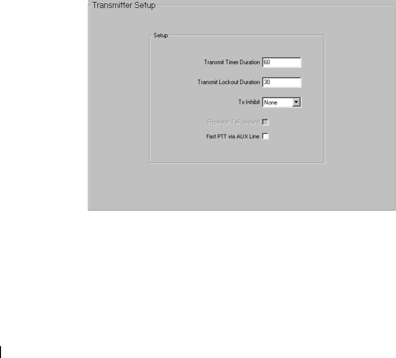
Transmitter Setup Form
Transmitter options are set in the Transmitter Setup form.
Transmit Timer
Duration
The Transmit Timer Duration field sets the duration of the transmit timer,
which determines the longest continuous transmission permitted by the radio.
Enter a value between 1 and 250 seconds in steps of 1 second, or 0 to disable
the transmit timer. The recommended value is 60 seconds.

T2000 Programming Application User’s Manual Basic Radio Settings 29
Caution: It is recommended that you do not disable the transmit timer, as fre-
quent lengthy transmissions, whether intentional or accidental, could damage
the radio’s transmitter and can be a nuisance to others.
Once the transmit timer expires, the radio may be prevented from transmitting
for the duration of the transmit lockout timer, which is set in the Transmit
Lockout Duration field.
Transmit Lockout
Duration
The Transmit Lockout Duration field sets the duration of the transmit lockout
timer. Enter a value between 1 and 250 seconds in steps of 1 second, or 0 to
disable the transmit lockout timer. The recommended value is 30 seconds.
Tx Inhibit The Tx Inhibit field sets the transmit inhibit conditions (None, Busy or Mute).
■None: The radio transmits when the PTT is pressed, even when there is
traffic on the channel.
■Busy: The radio does not transmit when the PTT is pressed if there is
activity on the channel, whether it is valid or invalid.
■Mute: The radio does not transmit when the PTT is pressed if there is
activity on the channel and the mute is active. This could be caused by an
invalid CTCSS/DCS code or an active Selcall mute. If monitor has been
activated, the radio transmits regardless of valid or invalid activity.
A Selcall call initiation (via the press of the auxiliary key, call key or a function
key) follows the conditions set in Tx Inhibit.
Repeater Talk
Around
T2020 radios only.
When the Repeater Talk Around field is checked, a long press of the channel
key activates repeater talkaround. Repeater talkaround allows the radio user to
bypass repeater operation and so communicate directly with other radios. While
repeater talkaround is active, all transmissions are made on the receive
frequency programmed for the channel.
Fast PTT via AUX
Line
T2010/T2015 radios only.
When the Fast PTT via AUX Line field is checked, and the PTT is wired to
the AUX line on the options connector, the AUX output line is used as the
PTT input line. This results in more frequent polling, and faster PTT for data
applications.
30 Part C: Programming Conventional Features M2000-00-003-806 © Tait Electronics Ltd 2002
Setting Up Signalling Options
This section contains detailed information on setting up subaudible and Selcall
signalling.
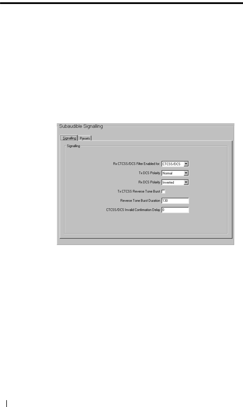
Subaudible Signalling Form
The Subaudible Signalling form is divided into two tabs. For T2010/T2015
radios, only Signalling is available.
■Signalling tab
■Presets tab
Signalling Tab
Settings for CTCSS and DCS transmissions are determined in the Signalling
tab. CTCSS and DCS for individual channels are set in the CTCSS/DCS Rx/
Tx fields (Channels form).
Rx CTCSS/DCS
Filter Enabled For
The Rx CTCSS/DCS Filter Enabled For field determines the settings for the
radio’s CTCSS/DCS filter. The filter can be automatically switched off for
channels that do not have CTCSS or DCS.
■All: The filter is active on all channels, regardless of whether they are
programmed with CTCSS or DCS.
■CTCSS/DCS: The filter is active only on channels that have CTCSS or
DCS programmed for the receive frequency.
Tx DCS Polarity The Tx DCS Polarity field sets the polarity of all transmitted DCS codes
defined in the Tx Sig field (Channels form). Some systems require the DCS
code to be inverted when transmitted. Select Normal or Inverted.
Rx DCS Polarity The Rx DCS Polarity field sets the polarity of all received DCS codes defined
in the Rx Sig field (Channels form). Select Normal or Inverted.
T2000 Programming Application User’s Manual Setting Up Signalling Options 31
Tx CTCSS Reverse
Tone Burst
When the Tx CTCSS Reverse Tone Burst field is checked, a reverse tone burst
on the end of a CTCSS transmission speeds up the shut down of CTCSS
decodes, providing your decoder is capable of detecting a reverse tone burst.
When this field is unchecked, no reverse tone burst is transmitted.
Reverse Tone
Burst Duration
T2020 radios only.
The Reverse Tone Burst Duration field specifies how long a CTCSS reverse
tone burst is transmitted. Reverse tone burst transmission increases the speed of
receiver shutdown in some repeaters and associated equipment.
Set a value from 0 to 250 ms in steps of 1 ms. Setting this field to 0 disables
reverse tone burst transmission.
The recommended value is 130 ms, which works for all CTCSS tones between
67.0 and 250.3 Hz. Longer durations may be used for lower CTCSS
frequencies and shorter durations for higher CTCSS frequencies. However, it
should not be necessary to deviate from 130 ms unless your system has specific
requirements.
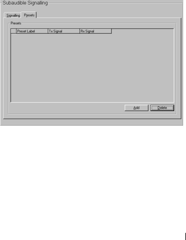
Presets Tab
T2020 radios only.
In the Subaudible Signalling Presets tab, user selectable signalling pairs are
defined. The radio user selects the preset from the radio control head and the
selected frequency pair overrides the programmed subaudible signalling
frequency for the current channel, as set in the Rx/Tx Sig fields (Channels
form). A maximum of 20 signalling presets can be set.
Preset Label The Preset Label field defines an identification label for each preset. This label
is displayed on the radio control head during the channel signalling
programming session.
Enter a label of up to 8 characters, chosen from A to Z 0 to 9 * + - < > / \
space.
A default label is generated, starting with PRESET0, and this can then be
edited. Do not allocate the same label for different presets.
32 Part C: Programming Conventional Features M2000-00-003-806 © Tait Electronics Ltd 2002
Rx/Tx Signals The Tx Signal field sets the frequency of the subaudible signal that accompanies
each transmission made on the channel. The Rx Signal field sets the subaudible
signal frequency that the radio must receive before the activity is regarded as
valid and the mute opened.
For both fields, select the required CTCSS frequency or DCS code from the
drop-down list.
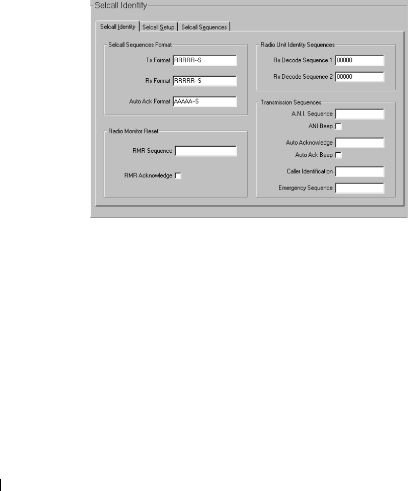
Selcall Identity Form
Selcall systems are set up in the Selcall Identity form, which is divided into three
tabs:
■Selcall Identity tab
■Selcall Setup tab
■Selcall Sequences tab
Selcall Identity Tab
The transmit and receive tone sequence formats are defined in the Selcall
Identity tab, together with sequences the radio responds to.
Tx Format Define the transmit (Tx) format, using the characters B, R, C, - (gap) and S.
The transmit format consists of up to seven bursts of these characters, where a
burst is made up of a group of the same character e.g. RRR (a three digit
receiver identity).
The five characters used to define the transmit format are:
■B (repeater identity). Optional. This is only defined once in the sequence
and is positioned at the beginning of the sequence. For T2010/T2015
radios, the B burst must have a minimum of 2 digits.
■R (receiver identity). Required. This is only defined once in the sequence.
For T2010/T2015 radios, the R burst must have a minimum of 2 digits.
■C (caller identity). Optional. This is only defined once in the sequence. For
T2010/T2015 radios, the C burst must have a minimum of 2 digits.
■- (gap). Optional. A gap burst can occur more than once in a sequence, but
the sequence cannot start or end with a gap burst. Do not place more than
eight characters in a row without a gap burst.

T2000 Programming Application User’s Manual Setting Up Signalling Options 33
■S (status). Optional. This is only defined once in the sequence and is
positioned at the end, separated from the other characters by a - (gap). The
status burst has a maximum length of two digits.
Rx Format Define the receive (Rx) format, using the characters R, C, - (gap) and S. The
receive format consists of up to five bursts of these characters, where a burst is
made up of a group of the same character e.g. RRRRRRRR (an eight digit
receiver identity).
The four characters used to define the receive format are:
■R (receiver identity). Required. This is only defined once in the sequence.
For T2010/T2015 radios, the R burst must have a minimum of 2 digits.
■C (caller identity). Optional. This is only defined once in the sequence. The
total length of the C burst is less than or equal to the length of the R burst
in the transmit format. For T2010/T2015 radios, the C burst must have a
minimum of 2 digits.
■- (gap). Optional. A gap burst can occur more than once in a sequence but
the sequence cannot start or end with a gap burst. Do not place more than
eight characters in a row without a gap burst.
■S (status). Optional. This is only defined once in the sequence and is
positioned at the end, separated from the other characters by a - (gap). The
length of the status burst in the Rx format must be the same as the status
burst in the Tx Format.
Auto Ack Format Define the auto ack (Auto Acknowledge) format using the characters B, A, C,
- (gap) and S. The auto acknowledge format consists of up to seven bursts of
characters, where a burst is made up of a group of the same character e.g.
AAAAA (a five digit auto acknowledge identity).
The five characters used to define the auto acknowledge format are:
■B (repeater identity). Optional. This is only defined once in the sequence
and is positioned at the beginning of the sequence. For T2010/T2015
radios, the B burst must have a minimum of 2 digits.
■A (auto acknowledge identity). Required. This is only defined once in the
sequence. For T2010/T2015 radios, the A burst must have a minimum of
2 digits.
■C (caller identity). Optional. This is only defined once in the sequence. The
total length of the C burst is less than or equal to the length of the C burst
in the Tx Format. For T2010/T2015 radios, the C burst must have a
minimum of 2 digits.
■- (gap). Optional. A gap burst can occur more than once in a sequence, but
the sequence cannot start or end with a gap burst. Do not place more than
eight characters in a row without a gap burst.
■S (status). Optional. This is only defined once in the sequence and is
positioned at the end, separated from the other characters by a - (gap). The
length of the status burst in the auto acknowledge format must be the same
as the status burst in the Tx Format.
Radio Monitor
Reset (RMR)
Sequence
The Radio Monitor Reset Sequence field sets the Selcall sequence that, when
received, deactivates monitor and squelch override. If the Cancel Call
Indicators on Request field (Receiver Monitoring form) has been checked,
then the ringing tone and call indicator light is cancelled on receipt of a radio
monitor reset sequence.

34 Part C: Programming Conventional Features M2000-00-003-806 © Tait Electronics Ltd 2002
The sequence entered must match the R burst (receiver identity) in the Selcall
system’s Rx Format. Use characters 0 to 9, B, C, D or F. On T2020 radios a *
wild card tone can also be used, representing any other tone.
If the Emergency Sequence is defined, then the Radio Monitor Reset
Sequence must also be defined.
Radio Monitor
Reset (RMR)
Acknowledge
T2020 radios only.
When the Radio Monitor Reset Acknowledge field is checked, an auto
acknowledge is sent when a valid radio monitor reset sequence is received.
An auto acknowledge sequence must be defined in the Auto Acknowledge field
for an auto acknowledge to be sent.
Rx Decode
Sequences
The Rx Decode 1 and Rx Decode 2 sequences can be defined for each Selcall
system the radio operates on. At least one of the Rx Decode fields must be set,
and the sequence entered must match the R burst (receiver identity) in the
Selcall system’s Rx Format field. On T2010/T2015 radios, only one Rx decode
sequence can be set.
Use characters 0 to 9, B, C, D or F to define each sequence. On T2020 radios
a * wild card tone can also be used, representing any other tone. If the second
Rx decode sequence is not required, leave it set to 00000.
ANI Sequence The ANI sequence field defines the ANI sequence transmitted whenever the
PTT is pressed, according to the ANI encoding properties set in the Selcall
Setup tab. The length of the ANI sequence entered must match the length of
the R burst (receiver identity) in the Tx Format field.
Use characters 0 to 9, B, C, D, F or G. The G represents a group tone, which
identifies incoming Selcall sequences as group calls.
If status is required, it must come last in the sequence and is separated from the
Selcall address by a - (gap). If there is one status digit in the Tx Format then the
values 0 to 15 can be used. If there are two status digits used in the Tx Format,
then the values 0 to 99 can be entered. If variable status is required (T2020
only), then enter V instead of the status number.
Note: In all instances, the ANI sequence is only transmitted if the ANI
suppression time has expired.
At least one of Leading ANI, Random ANI and Trailing ANI must be enabled
if ANI transmission is to be valid. If no ANI sequence is required either check
the ANI Beep field or leave the ANI sequence field blank.
ANI Beep When the ANI Beep field is checked, the ANI sequence is in the form of a
single beep, which is tone 6 of the Selcall system’s tone set, transmitted for 500
ms. When this field is checked, the ANI Sequence field is unavailable.
Auto
Acknowledge
The Auto Acknowledge Sequence field defines the auto acknowledge sequence
transmitted whenever the radio has decoded a valid Selcall sequence and an auto
acknowledge is required. The format of the auto acknowledge sequence
entered in this field must match the format defined in the Auto Ack Format
field.
Use characters 0 to 9, B, C, D, F or G. The G represents a group tone, which
identifies incoming Selcall sequences as group calls.

T2000 Programming Application User’s Manual Setting Up Signalling Options 35
If status is required, it must come last in the sequence and is separated from the
Selcall address by a - (gap). If there is one status digit in the Auto Ack Format
then the values 0 to 15 can be used. If there are two status digits used in the
Auto Ack Format, then the values 0 to 99 can be entered. If variable status is
required (T2020 only), then enter V instead of the status number.
Note: in all instances, the auto acknowledge sequence is only
transmitted if the Auto Acknowledge Delay has expired.
Auto
Acknowledge
Beep
When the Auto Acknowledge Beep field is checked, the auto acknowledge
sequence is in the form of a single beep, which is tone 6 of the Selcall system’s
tone set, transmitted for 500 ms. When this field is checked, the Auto
Acknowledge field is unavailable.
Caller
Identification
Sequence
The Caller Identification Sequence field defines the identity of the radio
transmitting the Selcall sequence. The length of this sequence matches the
length of the C burst (caller identity) in the Tx Format. Use characters 0 to 9,
B, C, D or F to define the caller identification sequence.
Emergency
Sequence
The sequence defined in the Emergency Sequence field is the Selcall sequence
that is transmitted when an emergency call is made. The sequence entered in
this field mirrors the sequence defined in the Selcall Emergency form (T2020
only). If the sequence is modified in one form, the sequence appearing in the
other is automatically updated.
The length of the emergency sequence matches the length of the R burst
(receiver identity) in the Tx Format. Use characters 0 to 9, B, C, D, F or G to
define the emergency Selcall sequence. If status is required, it must come last in
the sequence and is separated from the Selcall address by a - (gap). If there is one
status digit in the Tx Format then the values 0 to 15 can be used. If there are
two status digits used in the Tx Format, then the values 0 to 99 can be entered.
If variable status is required (T2020 only), then enter V instead of the status
number.
For T2010/T2015 radios, the emergency sequence will transmit on the current
channel.
36 Part C: Programming Conventional Features M2000-00-003-806 © Tait Electronics Ltd 2002
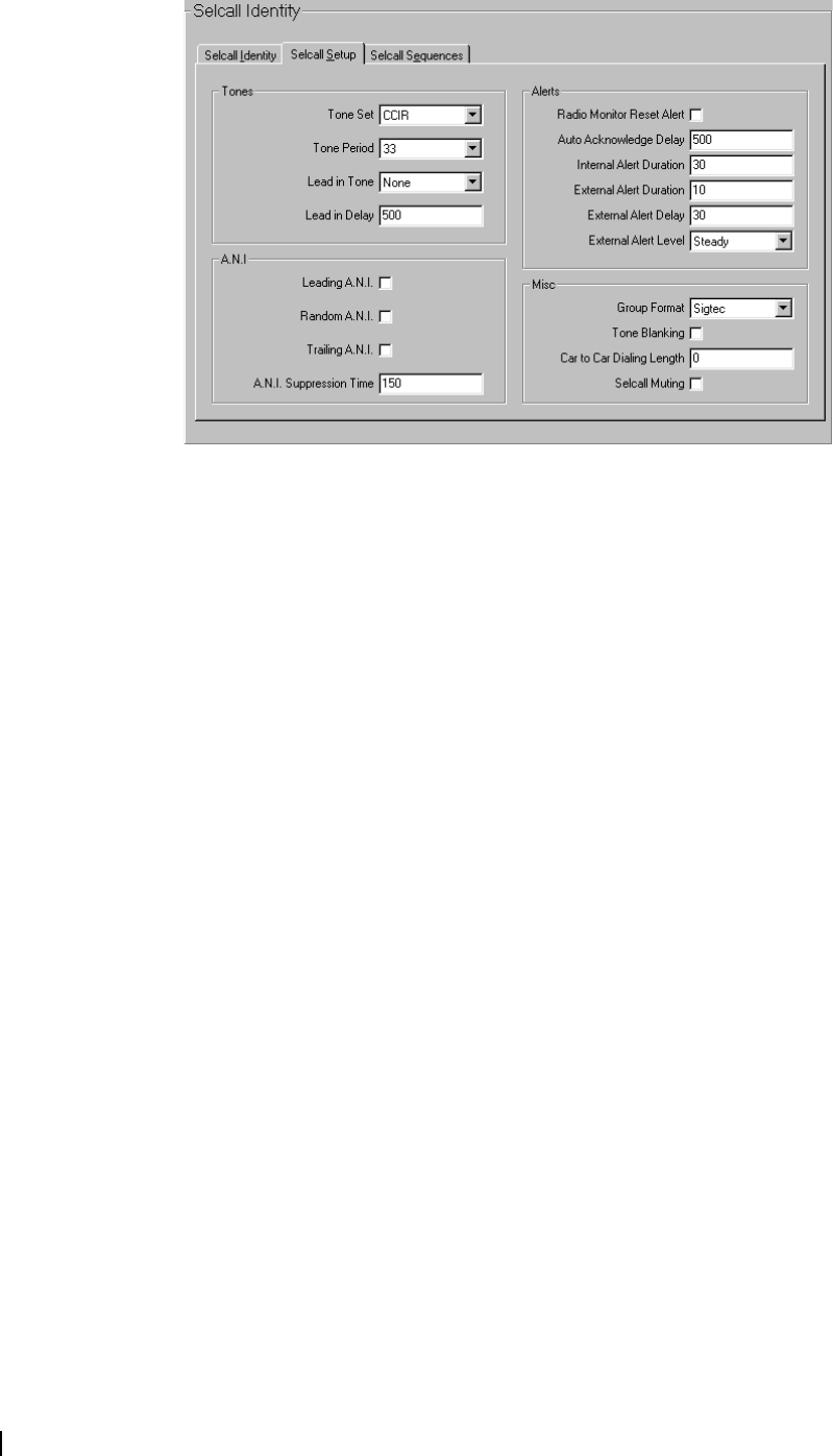
Selcall Setup Tab
Basic Selcall characteristics are set in the Selcall Setup tab.
Tone Set The Tone Set field specifies the tone set a Selcall system operates on. The radio
can operate with any of the tone sets supported by the radio software. The
available tone sets are: CCIR, EIA, EEA, ZVEI-I, ZVEI-II, ZVEI-III, PZVEI,
NATEL and DZVEI. The available tone sets are described in Table 2 on page
37.
Tone Period The Tone Period field sets the duration of each tone in a Selcall sequence. Set
the tone period to 20, 33, 40, 50, 60, 70 or 100 ms. Note that 20 is not
selectable if the EIA tone set has been chosen in the Tone Set field.
Lead In Tone The Lead In Tone field sets the tone which is sent during the lead in delay,
before any Selcall sequences. It can be used to halt scanning on a called radio
before critical tones are sent or to allow the called radio time to come out of
economy mode. Set this tone to any of the valid tones in the current tone set
(0-9, A-F) or None. If the Lead In Tone field is set to None, then the radio
transmits for the Lead In Delay time without sending any tone.
If a lead in tone is set to a value other than None, the lead in tone is transmitted
for the duration of the lead in delay for all outgoing Selcall sequences except for
random and trailing ANI.
Lead In Delay The Lead In Delay field sets the duration of the Lead In Tone before all Selcall
sequence transmissions, except random and trailing ANI. Set this field to
between 0 and 5,000 ms in steps of 20 ms.
If Selcall is being used with scanning, then the lead in delay should be set to a
value equivalent to the time it takes for a scan group to do one complete scan
of all channels.
If Selcall is being used on a repeater system, add an additional 200 ms to the
lead-in delay.
Leading ANI When the Leading ANI field is checked, the ANI sequence is sent whenever
the PTT is pressed, after the specified Lead In Delay time has expired.
A valid ANI sequence must be defined in the ANI Sequence field.

T2000 Programming Application User’s Manual Setting Up Signalling Options 37
Random ANI When the Random ANI field is checked, the ANI sequence is sent during the
transmission at some random time (0 to 15 seconds) after the PTT is pressed.
There is no Lead In Delay for random ANI transmissions.
If the transmission is terminated (PTT released or transmit timeout) before the
first random ANI has been sent and Trailing ANI is unchecked, then the ANI
sequence is sent in the trailing position, subject to the expiry of the ANI
Suppression Time.
A valid ANI sequence must be defined in the ANI Sequence field.
Trailing ANI When the Trailing ANI field is checked, the ANI sequence is sent at the end
of the transmission, subject to the expiry of the ANI Suppression Time. The
ANI sequence is sent after release of the PTT but before any subaudible
signalling termination sequence (i.e. CTCSS reverse tone burst, DCS stop
code). There is no Lead In Delay for trailing ANI transmissions.
A valid ANI sequence must be defined in the ANI Sequence field.
ANI Suppression
Time
The ANI Suppression Time field sets the amount of time between the end of
the transmission of the ANI Sequence and when it is next transmitted, if the
PTT has been pressed. Set this field to between 0 and 155 seconds in steps of 5
seconds.
Radio Monitor
Reset Alert
T2020 radios only.
Table 2: Selcall tone sets and frequencies (Hz). Note: E is the repeat tone.
Tone CCIR EIA EEA ZVEI-I ZVEI-II ZVEI-III PZVEI NATEL DZVEI
0 1981 600 1981 2400 2400 2400 2400 1633 2200
1 1124 741 1124 1060 1060 1060 1060 631 970
2 1197 882 1197 1160 1160 1160 1160 697 1060
3 1275 1023 1275 1270 1270 1270 1270 770 1160
4 1358 1164 1358 1400 1400 1400 1400 852 1270
5 1446 1305 1446 1530 1530 1530 1530 941 1400
6 1540 1446 1540 1670 1670 1670 1670 1040 1530
7 1640 1587 1640 1830 1830 1830 1830 1209 1670
8 1747 1728 1747 2000 2000 2000 2000 1336 1830
9 1860 1869 1860 2200 2200 2200 2200 1477 2000
A 2400 2151 1055 2800 885 885 970 1995 825
B 930 2433 930 810 825 810 810 571 740
C 2247 2010 2400 970 740 2800 2800 2205 2600
D 991 2292 991 885 680 680 885 2437 885
E 2110 459 2110 2600 970 970 2600 1805 2400
F 1055 1091 2247 680 2600 2600 680 2694 680

38 Part C: Programming Conventional Features M2000-00-003-806 © Tait Electronics Ltd 2002
When the Radio Monitor Reset Alert field is checked, the radio activates an
audible alert when a valid Radio Monitor Reset (RMR) Sequence is received.
Auto
Acknowledge
Delay
The Auto Acknowledge Delay Time field sets the delay between receiving an
incoming Selcall sequence and sending an Auto Acknowledge. Set a value from
100 to 8,000 ms in steps of 100 ms.
Internal Alert
Duration
The Internal Alert Duration field sets the maximum duration of the internal
audible alert which sounds when an individual Selcall call is received. This alert
sounds until either the timer expires or the call is answered. Set a value from 0
to 250 seconds (T2020 radios) in steps of 1 second, or from 0 to 30 seconds
(T2010/T2015 radios) in steps of 2 seconds. If set to 0, the radio rings until the
call is answered.
Note: This setting has no effect on the internal alert that is sounded
when a group Selcall call is received. When a group Selcall is received,
the radio only rings once. This setting also has no effect on Selcall calls
with a Priority Call Control Status, which will ring until answered.
External Alert
Duration
The External Alert Duration field sets the maximum duration of the audible
alert which sounds an external device when an individual call is received. This
external device becomes active only after the External Alert Delay has expired.
Set a value from 0 to 250 seconds (T2020 radios) in steps of 1 second, or from
0 to 30 seconds (T2010/T2015 radios) in steps of 2 seconds.
For T2010/T2015 radios, the setting in this field has no effect if the Internal
Alert Duration has been set to 0 (continuous).
External Alert
Delay
T2020 radios only.
The External Alert Delay field sets the time the radio waits before activating the
external device (e.g. a car horn) after receiving an individual call. Set value from
0 to 250 seconds in steps of 1 second.
External Alert
Level
T2020 radios only.
The External Alert Level field sets the type of signal provided for the external
device (e.g. a car horn). Select either Pulsed or Steady.
Group Format The Group Format field sets the group format used for group calling. The
format selected depends on the system in use. For International, the first tone
in the sequence defined cannot be a group tone. Any of the subsequent tones
can be the group tone. For Sigtec, the first tone in the sequence defined cannot
be a group tone. All following the first group tone must also be a group tone.
All radios operating on the Selcall system should use the same group format.
Tone Blanking The Tone Blanking field enables tone blanking for received Selcall sequences
on all Selcall systems. Tone blanking blanks out the tones of a received Selcall
sequence so that the user does not hear them. The user may, however, hear the
first few tones. The Tone Blanking field has no other effect on Selcall
operation.
Car to Car Dialling
Length
T2020 radios only.
The Car to Car Dialling Length field sets the number of digits that can be
dialled from the control head of the radio. Enter a number between 0 and 8, in
steps of 1. If set to 0, dialling is disabled. Note that the maximum value that can
be entered is equal to the number of Rs in the Tx Format.
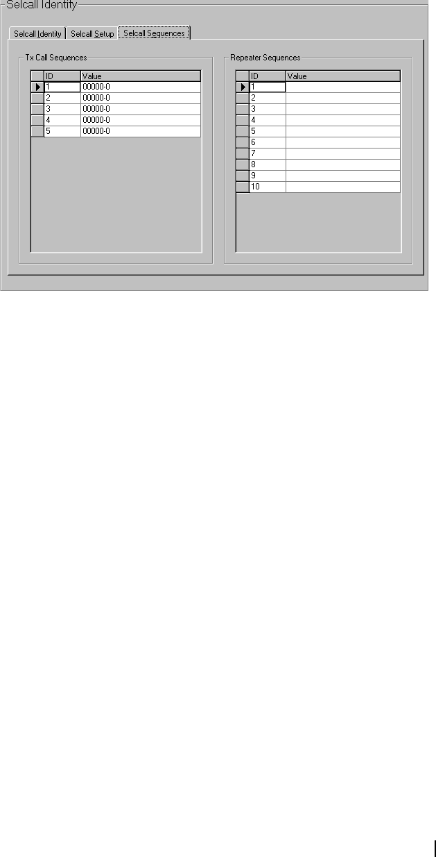
T2000 Programming Application User’s Manual Setting Up Signalling Options 39
Selcall Muting T2010/T2015 radios only.
When the Selcall Muting field is checked, the radio only unmutes when a valid
Selcall sequence is received. The radio user cannot initiate calls using the PTT
unless monitor is active, but can make Selcall calls.
Selcall Sequences Tab
The tone sequences for Selcall calls are defined in the Selcall Sequences tab.
These sequences are then assigned to channels.
Tx Call Identity The Tx Call Identity is used to refer to the associated Tx Call Value, and cannot
be shared by any other transmit call identity. For T2010/T2015 radios, up to 4
transmit call identities are available. For T2020 radios, up to 5 transmit call
identities are available.
Tx Call Value The Tx Call Value field defines the transmit call sequence associated with the
Tx Call Identity. The length of the sequence entered must match the length of
the R (receiver identity) burst in the Tx Format field.
Use characters 0 to 9, B, C, D, F or G. The G represents a group tone, which
identifies incoming Selcall sequences as group calls.
If status is required, it must come last in the sequence and is separated from the
Selcall address by a - (gap). If there is one status digit in the Tx Format then the
values 0 to 15 can be used. If there are two status digits used in the Tx Format,
then the values 0 to 99 can be entered. If variable status is required (T2020
only), then enter V instead of the status number.
Repeater Identity The Repeater Identity is used to refer to the associated Repeater Value, and
cannot be shared by any other repeater identity. For T2010/T2015 radios, enter
up to 4 repeater identities. For T2020 radios, enter up to 10 repeater identities.
Repeater Value The Repeater Sequence field defines the repeater sequence associated with the
Repeater Identity. The length of the sequence entered must match the length
of the B (repeater identity) burst in the Tx Format or Auto Ack Format fields.
Use characters 0 to 9, B, C, D, E, F or G (note that G is valid for T2010/T2015
radios only).

40 Part C: Programming Conventional Features M2000-00-003-806 © Tait Electronics Ltd 2002
Selcall Features Form
T2020 radios only.
Various advanced Selcall features are selected in the Selcall Features form.
Group Dialling If the Group Dialling field is checked, then Selcall group calls are permitted.
Selcall group calls are made by including group tones in the Selcall sequence to
replace all uncommon digits. The digits common to all users in the Selcall group
are dialled, then the # key is used as a substitute for the remaining digits in the
sequence. For example, dialling 12# sends the sequence 12GGG (5 digit
receiver identity in the Tx Format).
The Car to Car Dialling Length (Selcall Setup tab) sets the number of digits that
can be dialled from the radio control head. This must be greater that 0 before
group dialling can be enabled.
Group Selective
Dialling
If the Group Selective Dialling field is checked, then the group tone digit can
be dialled individually when dialling a Selcall sequence. This digit is dialled
using the * key to produce a single G in the sequence. For example, dialling
12*45 sends the sequence 12G45 (5 digit receiver identity in the Tx Format).
The Car to Car Dialling Length (Selcall Setup tab) sets the number of digits that
can be dialled from the radio control head. This must be greater that 0 before
group dialling can be enabled.
Deferred Calling If the Deferred Calling field is checked then a Selcall call to a busy channel can
be stored and redialed as soon as the channel becomes free. The Tx Inhibit field
(Transmitter Setup form) must be set to Busy or Mute before deferred calling
can be enabled.
The deferred calling feature is always active in T2010 radios and is active in
T2015 radios as long as the Tx Inhibit field is set to Busy or Mute.
Third Tone
Monitor Reset
If the Third Tone Monitor Reset field is checked then any call carrying tones
matching the first three tones of the Rx decode sequence deactivates the radio’s
monitor, if it is active. The third tone monitor reset option is only valid if there
are more than three Rs in the Rx Format R (receiver identity) burst.

T2000 Programming Application User’s Manual Setting Up Signalling Options 41
Automatic Caller
Identification
If the Automatic Caller Identification field is checked, then the identity of the
caller is displayed when an incoming call is received that matches the radio’s Rx
decode sequence. The caller identity is displayed as a number or as a label.
Automatic caller identification only operates when there is a C (caller identity)
burst in the Rx Format.
ANI Decoding When the ANI Decoding field is checked, the identity of any caller matching
the radio’s Rx Format is displayed. If the Rx Format contains a C (caller
identity) burst, then ANI Decoding cannot be enabled.
Called Unit Status
Display
When the Called Unit Status Display field is checked, the radio displays any
status messages returned with an auto acknowledge sequence from a called
radio. The Rx Format must contain an S (status) burst before call unit status
display is enabled.
Rx Call Sub-
sequence
Decoding
When Rx Call Sub-sequence Decoding is checked, the detection and
validation of incoming Selcall sequences depends only on the R (receiver
identity) burst, and so if the caller identity and status are absent from the
incoming sequence, the call is still detected as valid. This feature is useful in
areas of marginal signal strength where some of the bursts may be missing or
corrupted.
Received Call
Queuing
When the Received Call Queuing field is checked, a queue is set for holding
up to 10 unanswered Selcall calls. Call queuing can only be enabled when the
Automatic Caller Identification field is checked and when there is a C (caller
identity) burst in the Rx Format.
Tx Tolerance
Factor
The Tx Tolerance Factor field determines how long the radio continues
transmitting once the last tone in a Selcall sequence has been transmitted. This
extra tail time ensures that the called radio is able to decode the Selcall sequence.
Set a value from 0 to 12 in steps of 1, where 0 is the shortest possible tail time.
Call Diversion If the Call Diversion field is checked then the call diversion feature can be
activated from the radio control head. Once call diversion is activated,
incoming calls can be diverted to a third party.
Call Diversion
Channel
The Call Diversion Channel field sets the channel the radio switches to so that
communication can be established when a called radio is in call diversion mode.
Select a channel identity from the combo box.
Call Diversion
Status
The Call Diversion Status field sets the status digit that identifies the status of
the radio when it is in call diversion mode. Enter a number between 0 and 15
if a single status digit is used in the Rx Format, or 0 to 99 if a double status digit
is used in the Rx Format.
The status number entered in this field mirrors the status number defined in the
Call Diversion Status field (Selcall Status form). This status value cannot be the
same as any other control status value entered on the Selcall Status form.
Selcall Status Form
T2020 radios only.
The following status features are set in the Selcall Status form.
■Control Status Digits: these initiate a particular radio operation, such as
activate/deactivate the stun function.

42 Part C: Programming Conventional Features M2000-00-003-806 © Tait Electronics Ltd 2002
■Status Digits: these can be added at the end of a Selcall sequence to indicate
the caller’s present activity or status. The digits are associated with a
descriptive label, such as “AT LUNCH”.
Priority Call
Control Status
The Priority Call Control Status field sets the status digit that when received
identifies a call as a priority call. Enter None if no priority call detection is
required. Enter a number from 0 to 15 if a single status digit is used in the Rx
Format, or 0 to 99 if a double status digit is used in the Rx Format. This status
value cannot be the same as any other control status value.
Quiet
Interrogation
Control
The Quiet Interrogation Control field sets the status digit that when received
causes the radio to transmit the auto acknowledge sequence without alerting the
radio user to the receipt of the Selcall sequence. Enter None if no quiet
interrogation control status detection is required. Enter a number from 0 to 15
if a single status digit is used in the Rx Format, or 0 to 99 if a double status digit
is used in the Rx Format. This status value cannot be the same as any other
control status value.
Activate Stun
Control Status
The Activate Stun Control Status field sets the status digit that when received
causes the radio to cease normal operation. The radio resumes normal operation
when the Deactivate Stun Control Status is received. Enter None if no activate
stun control status detection is required. Enter a number from 0 to 15 if a single
status digit is used in the Rx Format, 0 to 99 if a double status digit is used in
the Rx Format. This status value cannot be the same as any other control status
value.
Deactivate Stun
Control Status
The Deactivate Stun Control Status field sets the status digit that when received
causes a stunned radio to resume normal operation. Enter None if no deactivate
stun control status detection is required. Enter a number from 0 to 15 if a single
status digit is used in the Rx Format, or 0 to 99 if a double status digit is used
in the Rx Format. This status value cannot be the same as any other control
status value.
This field must be given a status value if the Activate Stun Control Status field
has a status value.

T2000 Programming Application User’s Manual Setting Up Signalling Options 43
User Alert Control
Status
The User Alert Control Status field sets the status digit that causes the radio to
issue an audible alert. Enter None if no user alert control status detection is
required. Enter a number from 0 to 15 if a single status digit is used in the Rx
Format, or 0 to 99 if a double status digit is used in the Rx Format. This status
value cannot be the same as any other control status value.
Call Diversion
Status
The Call Diversion Status field sets the status digit that identifies that a radio is
in call diversion mode. Enter None if no call diversion control status detection
is required. Enter a number from 0 to 15 if a single status digit is used in the Rx
Format, or 0 to 99 if a double status digit is used in the Rx Format. This status
value cannot be the same as any other control status value.
This field is only available if the Call Diversion field has been checked in the
Selcall Features form. The status value set in the Call Diversion Status field
mirrors the status value set in the Call Diversion Status field (Selcall Features
form).
Status Labels The Status Labels fields set the status message which can be sent with a call to
indicate the current activity of the radio operator. The number of status
messages available depends on the number of status digits in the Tx Format. If
there is one status digit in the Tx Format, then up to 16 status messages can be
defined. If there are two status digits used in the Tx Format, then up to 100
status messages can be defined.
Select the Add button to add a status message, or select the Delete button to
delete the currently selected status message.
Status Label
Identity
The Status field sets the status digit that is transmitted. If the Tx Format has one
S, then there are 16 possible status digits, numbered 0 to 15. If the Tx Format
has two Ss, there are 100 possible status digits, numbered from 0 to 99. Select
the Add button to add the next available status identity.
Status Label
Display Message Enter an 8 character status label to correspond with each status identity, chosen
from A to Z 0 to 9 * + - < > / \ space.
The status labels defined in this field are also listed in the New Status field
(Alpha Symbols form), where they can be associated with an alpha symbol.
Selcall Emergency Form
T2020 radios only.
The behaviour of the radio while in emergency mode is set in the Selcall
Emergency form. An emergency call can be assigned to the control head
auxiliary key (Key Settings form), which is then used to activate emergency
mode. Once emergency mode is activated, an emergency sequence is
transmitted. Emergency mode is made up of three parts.
■Emergency Activation: Emergency mode is requested and an emergency
Selcall sequence is transmitted.
■Emergency Callout: Once emergency mode has been requested, the radio
begins emergency callout, where the emergency sequence is transmitted
either once, or repeatedly until an acknowledge sequence is received.
■Emergency Transmit/Receive Cycling: After emergency callout, the radio
may then cycle between receiving and transmitting, allowing the recipient
of the emergency call to monitor activity near the radio.
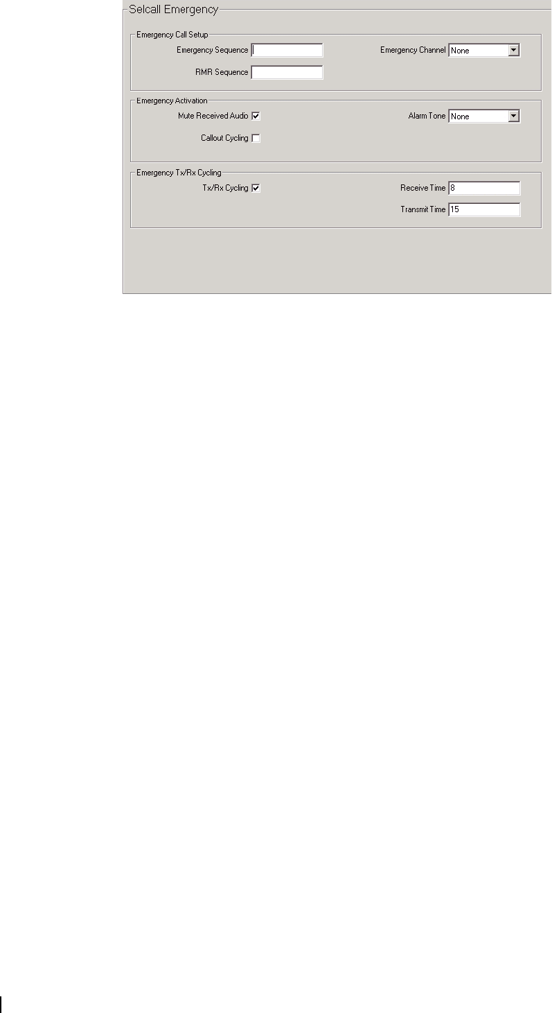
44 Part C: Programming Conventional Features M2000-00-003-806 © Tait Electronics Ltd 2002
Emergency
Sequence
The sequence defined in the Emergency Sequence field is the Selcall sequence
that is transmitted when an emergency call is made. The sequence entered in
this field mirrors the sequence defined in the Emergency Sequence field (Selcall
Identity tab). If the sequence is modified in one form, the sequence appearing
in the other is automatically updated.
The length of the emergency sequence matches the length of the R burst
(receiver identity) in the Tx Format. Use characters 0 to 9, B, C, D, F or G to
define the emergency Selcall sequence.
If status is required, it must come last in the sequence and is separated from the
Selcall address by a - (gap). If there is one status digit in the Tx Format then the
values 0 to 15 can be used. If there are two status digits used in the Tx Format,
then the values 0 to 99 can be entered. If variable status is required (T2020
only), then enter V instead of the status number.
RMR Sequence The sequence defined in the RMR Sequence field sets the Selcall sequence
that, when received, deactivates monitor and squelch override. The sequence
entered in this field mirrors the sequence defined in the Radio Monitor Reset
(RMR) Sequence field (Selcall Identity tab). If the sequence is modified in one
form, the sequence appearing in the other is automatically updated.
The sequence entered must match the R burst (receiver identity) in the Selcall
system’s Rx Format. Use characters 0 to 9, B, C, D or F. A * wild card tone
can also be used, representing any other tone.
Emergency
Channel
The Emergency Channel field determines the channel the radio switches to
when the emergency call is made. Select a Channel ID from the combo list to
send the emergency call sequence on that channel. If None is selected, the
emergency call sequence will go out on the current channel.
Mute Received
Audio When the Mute Received Audio field is checked, the radio’s receive audio
remains muted while in emergency mode and so the radio does not broadcast
noise that may draw attention in an emergency situation. If unchecked, the
mute state in emergency mode obeys the standard muting operation.

T2000 Programming Application User’s Manual Setting Up Signalling Options 45
Alarm Tone The Alarm Tone field sets the trailing alarm tone to be sent with the emergency
sequence. Select any hex character (0-9, A-F). Select None if you do not want
to transmit the alarm tone.
Callout Cycling The setting of the Callout Cycling field determines how the emergency call is
sent. If checked, the radio resends the emergency Selcall sequence periodically
until a call is received that matches one of the radio’s Rx decode sequences and
does not contain a control status. If unchecked, the radio transmits the
emergency sequence once, then leaves the emergency callout state, either
returning to normal operation or entering the emergency cycling state.
Tx/Rx Cycling This field sets whether the radio enters an emergency cycling state after the
emergency sequence is acknowledged. This allows the recipient of the
emergency call to monitor activity near the radio. If checked, the radio
repeatedly cycles between transmit and receive until it is switched off and then
on. The period of transmit and receive is set in the Receive/Transmit Time
fields. If unchecked, the radio returns to normal operation after the emergency
callout.
Receive/Transmit
Time
The Receive Time and Transmit Time fields set the amount of time the radio
transmits and receives while in emergency cycling mode. For both the Transmit
Time and the Receive Time fields, set a value from 0 to 30 seconds in steps of
1 second. If the Transmit Time field is set to 0, the radio will only receive while
in emergency cycling mode.
These fields are only selectable if Tx/Rx Cycling is checked.
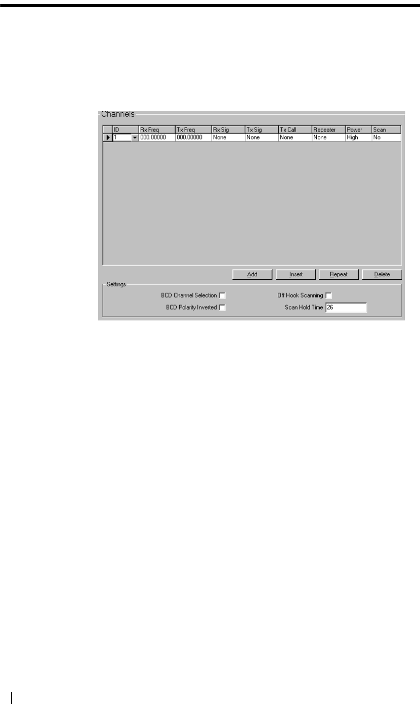
46 Part C: Programming Conventional Features M2000-00-003-806 © Tait Electronics Ltd 2002
Setting Up Channels and Scan Groups
This section contains detailed information on setting up channels and scan
groups.
Channels Form
The main settings for channels are set up in the Channels form. The Channels
form for T2010/T2015 radios is shown below.
The Channels form contains default values for one channel. Select the Add
button to add a new channel, select the Delete button to delete the currently
selected channel, or select the Repeat button to duplicate the current channels
settings, except for the Channel ID and Channel Name fields.
There must be at least one channel in the list. The number of channels
permitted depends on the radio model, as follows:
■T2010: up to 24 channels
■T2015: up to 24 channels
■T2020: up to 100 channels
■T2020 firmware version 7.01 or higher: up to 1200 channels.
Channel ID The channel ID field sets the channel number, which cannot be shared by any
other channel or scan group.
■For T2010 radios, set up to 24 channel identities, between 1 and 24.
■For T2015 radios, set up to 24 channel identities, between 1 and 24.
■For T2020 radios, set up to 100 channel identities, between 1 and 255.
■For T2020 radios (firmware version 7.01 or higher), set up to 1200 channel
identities, between 1 and 4999.
Channel Name T2020 radios only.

T2000 Programming Application User’s Manual Setting Up Channels and Scan Groups 47
The Channel Name field sets the name which is appears in the control head
display on T2020 radios when the radio is in channel mode. The radio enters
channel entry or channel select mode when the radio channel key is pressed.
Enter a name of up to 8 characters, chosen from A to Z 0 to 9 * + - < > / \
space.
A default name is generated from the channel identity. For example, the first
channel defaults to CHAN1.
Note: Do not allocate the same name for different channels or scan
groups, since both are accessed in the same way.
Rx and Tx
Frequencies
The Rx Freq field sets the receive frequency (in MHz) for the channel, and the
Tx Freq field sets the transmit frequency (in MHz). For each channel, enter a
frequency within the radio’s frequency band that is a multiple of 5 kHz or 6.25
kHz.
The minimum channel spacing is dependant on the radio band and IF
bandwidth. The letter in the sixth position in the radio part number (first after
the hyphen) indicates the radio’s frequency band, as outlined in the table below.
Rx and Tx
Signalling
The Rx Sig field sets the subaudible signalling the radio must receive before the
activity is regarded as valid and the mute opened. The Tx Sig field sets the
subaudible signalling that accompanies each transmission made on the channel.
For both fields, select the required frequency from the drop-down list. Both
fields must be either CTCSS (tones starting with C) or DCS (tones starting with
D). Leave these fields set to None if no subaudible signalling is used on the
channel.
Tx Call The Tx Call field provides a list of transmit Selcall sequence identities. These
are identities that have been defined in the Tx Call Identity field (Selcall
Sequences tab). Select the transmit call identity required from the drop-down
list. To disable Selcall on the channel, select None.
Band Receive Frequency
(MHz)
Transmit Frequency
(MHz)
0 500-530 MHz 500-530 MHz
1 220-270 MHz 220-270 MHz
2 66-88 MHz 66-88 MHz
3 136-174 MHz 136-174 MHz
4 175-225 MHz 175-225 MHz
5 400-470 MHz 400-470 MHz
6 450-520 MHz 450-520 MHz
7 330-366 MHz 330-366 MHz
8 800-870 MHz 800-870 MHz
9 360-400 MHz 360-400 MHz

48 Part C: Programming Conventional Features M2000-00-003-806 © Tait Electronics Ltd 2002
Repeater The Repeater field provides a list of Selcall repeater sequence identities. These
are identities that have been defined in the Repeater Identity field (Selcall
Sequences tab). Select the repeater identity required from the drop-down list.
To transmit no repeater sequence on the channel, select None.
Power The Power field sets the transmit power level. Select a power level setting of
Off, Low High or Max (maximum - T2020 radios only), within the limits
permitted for the region in which the radio operates.
Bandwidth T2020 radios only
The Bandwidth field sets the transmitter deviation and the receiver audio
sensitivity for systems using different channel spacing. Select either Narrow
(narrowband) or Wide (wideband) for each channel.
Scan T2010/T2015 radios only.
Select Yes for the channel to be included in the scan operation. While scanning,
the radio cycles through all the included channels until it detects valid activity.
When activity is detected, the radio stops on that channel until the activity
stops, then waits for the time set in the Scan Hold Time field before returning
to scan mode.
If Enhanced Scanning (Specifications form) is checked for T2015 radios, then
two additional options are available, Pri and Sec. Both options add the channel
to the scan list, 'Pri' specifies that the channel is the primary priority scan
channel and 'Sec' specifies that the channel is the secondary priority scan
channel. Scan types in the Enhanced Scan Form will take precedence over these
settings, unless the radio is switched on while the PTT is pressed.
BCD Channel
Selection
T2010/T2015 radios only.
When the BCD Channel Selection field is checked, it is possible to select the
radio channel using the internal BCD channel select lines. In this case, the
control head channel keys are disabled.
BCD Polarity
Inverted
T2010/T2015 radios only.
When the BCD Polarity field is checked, a high voltage input is considered to
be a ’0’ and a low voltage input is considered to be a ’1’.
Off Hook
Scanning
T2010/T2015 radios only.
When the Off Hook Scanning field is checked, scanning is possible when the
hookswitch is open.
Scan Hold Time T2010/T2015 radios only.
The Scan Hold Time field determines how long the radio remains on a channel
after valid activity finishes, before scanning is resumed. Enter a time between 0
and 15 seconds in steps of 1 second.
Scan Groups Form
T2020 radios only.
Scanning and voting groups are set up in the Scan Groups form, which is
divided into two sections:
■Scanning and voting groups are set in the Scan Group Members grid.
■General scanning and voting rules are set in the Scan Settings section.
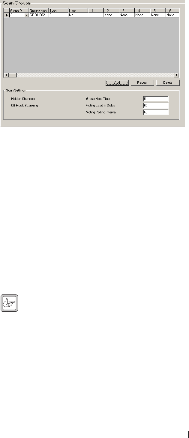
T2000 Programming Application User’s Manual Setting Up Channels and Scan Groups 49
Scan Group Members Grid
Scanning and voting groups are set up in the Scan Group Members Grid. Up
to 16 scan groups are permitted for T2020 radios, and up to 240 scan groups for
T2020 radios with firmware version 7.06 or higher.
Select the Add button to add a scan group, select the Delete button to delete
the currently selected scan group, or select the Repeat button to duplicate the
current scan group’s Type and User fields and the scan group membership list.
Scan Group ID The scan Group ID field sets the scan group identity, which cannot be shared
by any other channel or group. For T2020 radios, set up to 20 scan group
identities, between 1 and 255. For T2020 radios with firmware version 7.06 or
higher, you can set up to 240 scan group identities, between 1 and 4999.
Scan Group Name The scan group Name field sets the group name which appears in the radio
control head display window when the radio is in channel selection mode. The
radio enters channel mode when the radio channel key is pressed. Enter a name
of up to 8 characters, chosen from A to Z 0 to 9 * + - < > / \ space.
A default name is generated from the scan group identity. For example, if three
channels are defined, then the first scan group defaults to GROUP4.
Note: Do not allocate the same name for different scan groups or
channels since both are accessed in the same way.
Scan Group Type The Type field sets the type of scanning/voting used for the group.
Options:
■Scanning (S). See page 117 for more information.
■Priority Scanning (P). See page 117 for more information.
■Dual Priority Scanning (DP). See page 117 for more information.
■Voting (V). See page 118 for more information.
■Voting With Signalling (VS). See page 118 for more information.
■Double Voting (D). See page 118 for more information.
■Double Voting With Signalling (DS). See page 118 for more information.

50 Part C: Programming Conventional Features M2000-00-003-806 © Tait Electronics Ltd 2002
Scan Group User
Reprogram
The User field determines whether the scan group can be reprogrammed by the
radio user. If checked, the radio user can reprogram the group. If unchecked,
the scan group can only be changed by reprogramming the radio.
Scan Group
Membership List
Member channels are added to scan groups in the group membership list.
Select a channel identity from the drop-down list. There must be at least 2 and
no more than 16 entries for each scan group, and a channel can appear in a
particular scan group only once. There can be no gaps in the list of member
channels.
For scanning groups (Group Type S, P or DP), the first channel in the group
membership list is the home channel. For priority scanning (PS), the first
channel is the priority channel. For dual priority scanning (DPS), the first and
second channels are the priority channels, and the first channel listed has higher
priority than the second.
For voting groups (V, VS, D and DS), the first channel in the group
membership list is the home channel if no other channel has been voted as the
home channel.
Scan Settings
Set general scanning and voting rules in Scan Settings.
Hidden Channels
Off Hook Scanning
Group Hold Time
Voting Lead In Delay
Voting Polling Interval
Hidden Channels Scan groups contain between 2 and 16 channels, and normally these channels
can also be accessed individually.
When the Hidden Channels field is checked, channels that are assigned to a scan
group are hidden from the user and so cannot be selected individually. This
setting has the effect of making a group of channels appear as one channel. If
you wish to access the channels within a group, uncheck the Hidden Channels
field.
Off Hook
Scanning
The Off Hook Scanning field sets whether scanning is allowed when the
hookswitch is open. If the user initiates a call while the radio is off hook
scanning, the radio transmits on the home channel.
Group Hold Time The Group Hold Time field specifies the length of the pause before scanning
resumes once valid activity has ceased on a channel.
Enter a time between 0 and 250 seconds in steps of 1 second. If set to 0, the
hold timer is not enabled regardless of channel activity and scanning resumes
immediately after a channel becomes invalid, which would not allow for any
pauses in a conversation.
Voting Lead In
Delay
The Voting Lead In Delay field sets the delay between the radio detecting
activity on a channel in a voting group and voting taking place. The voting lead
in delay gives the repeaters in the system time to come to full power. Enter a
value between 0 and 2550 ms in steps of 10 ms.
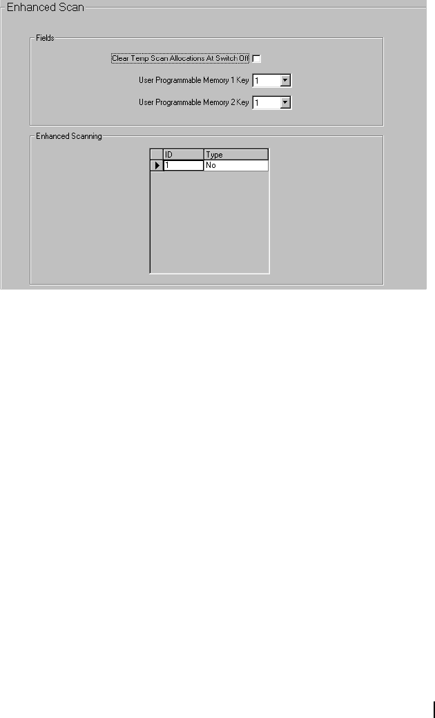
T2000 Programming Application User’s Manual Setting Up Channels and Scan Groups 51
Voting Polling
Interval
The Voting Polling Interval field sets the time between votes when channels
are carrying invalid activity. Enter a value between 1 and 250 seconds in steps
of 1 second.
Enhanced Scan Form
T2015 radios only.
The Enhanced Scan form can read or program enhanced scanning features such
as the temporary scan list and channels assigned to the memory keys. You can
also define whether these settings are cleared when the radio is switched off. To
access this form, Enhanced Scanning must be checked in the Specifications
form.
Any settings in this form that are programmed into the radio will hold
precedence over settings in the Channels Form and Key Settings Form until
either the radio is turned off (and the Clear Temporary Scan Allocation at
Switch Off field is selected), or the radio is turned on while the PTT pressed.
Clear Temporary
Scan Allocation at
Switch Off
When this field is checked, any modifications the user has made to the scan list
(and channel memory keys) will be lost when the radio is switched off. Selecting
this field will disable the other fields on this form.
Holding down the PTT when the radio is turned on will clear the user's
modifications, resetting the scan list to the default defined in the Channels
Form.
Uncheck this field if you want the radio to remember any changes when the
radio is switched off.
User
Programmable
Memory One
Channel
This is the channel that the user has programmed to be selected when memory
key [M1] is pressed.
User
Programmable
Memory Two
Channel
This is the channel that the user has programmed to be selected when memory
key [M2] is pressed.
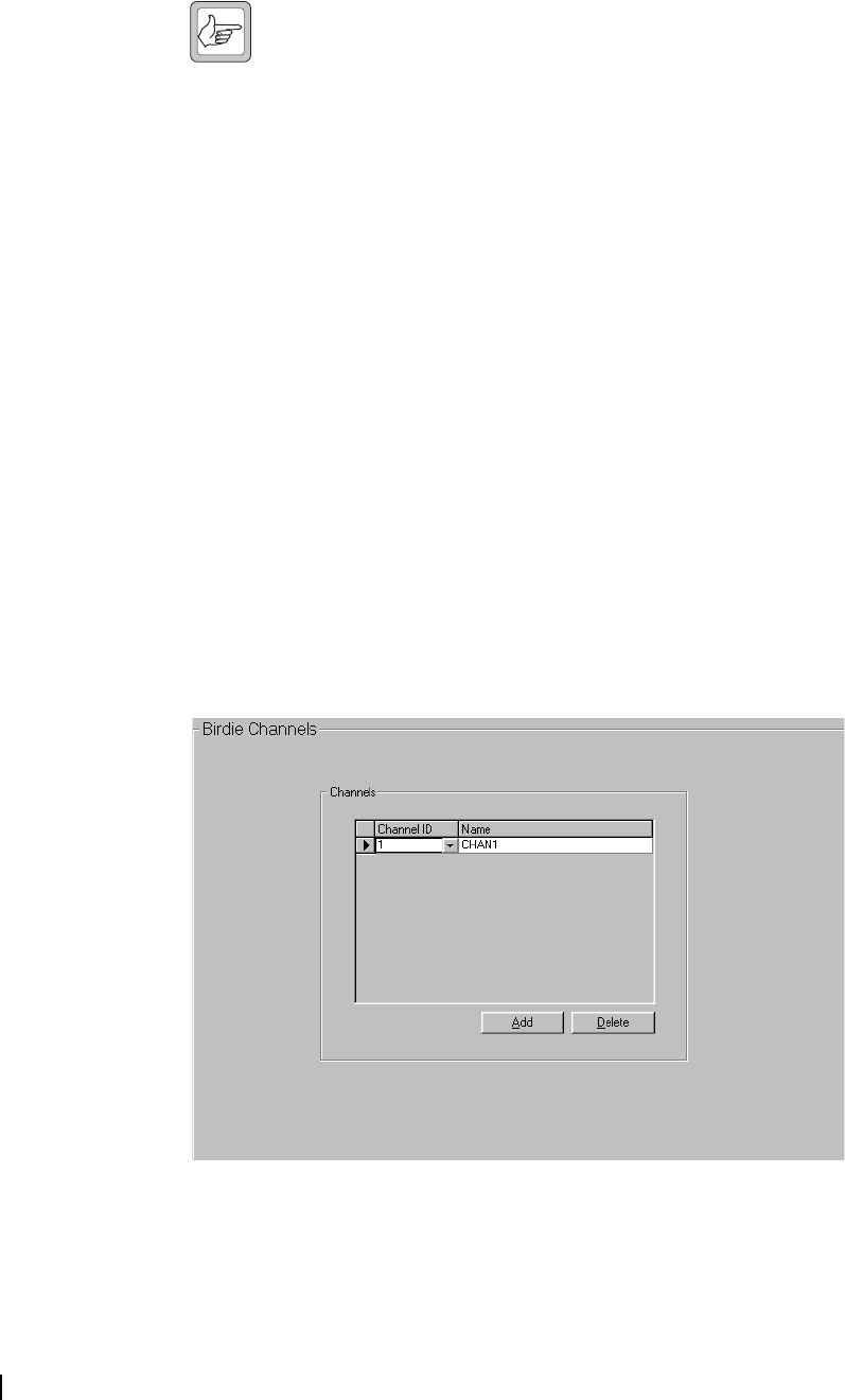
52 Part C: Programming Conventional Features M2000-00-003-806 © Tait Electronics Ltd 2002
Enhanced Scanning Grid
The Enhanced Scanning Grid lists all channels and enhanced scan settings the
user has programmed from the front panel of the radio. These can be read here
for diagnostic and maintenance purposes, or the radio can be preprogrammed
with new data.
Note: These settings will be reset to the default settings defined in the
Channels Form >Scan field if the radio is switched off and the Clear
Temporary Scan Allocation at Switch Off field is checked, or switched
on while the PTT is pressed.
Enhanced
Scanning ID
The Enhanced Scanning ID field lists all the channel IDs specified in the
Channels Form.
Enhanced
Scanning Type
The Enhanced Scanning Type field lists whether or not the channel is included
in the scan operation, and which channels have priority.
The following options are available:
■Yes: the channel will be included in the scan list.
■No: the channel will not be included in the scan list.
■Pri: the channel will be included in the scan list, as the primary priority scan
channel.
■Sec: the channel will be included in the scan list, as the secondary priority
scan channel.
Birdie Channels Form
T2020 radios only.
Birdie channels are identified in the Birdie Channels form. A birdie channel is
a channel on which receiver sensitivity is degraded by internal interference.
This interference is eliminated from birdie channels by activation of birdie killer
circuitry.
Select the Add button to add a channel or select the Delete button to delete the
currently selected channel.

T2000 Programming Application User’s Manual Setting Up Channels and Scan Groups 53
Channel ID Select the required channel identity from the drop-down list. The channel
identities available have been previously added in the Channels form.
Note that if the receive frequency of a birdie channel is changed in the
Channels form, then that channel is removed from the birdie channels list.
Channel Name Once a channel identity has been selected in the Channel ID field, the channel
associated with that identity appears in the Channel Name field.
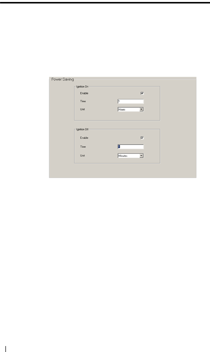
54 Part C: Programming Conventional Features M2000-00-003-806 © Tait Electronics Ltd 2002
Special Features
This part contains detailed information on setting up special features such as
alpha symbols, CCI operation, DTMF and economy mode.
Power Saving (Conventional) Form
Economy mode settings are made in the Power Saving form, allowing the
current drawn by the radio to be reduced after a specified period of inactivity.
Any traffic on the radio returns it to a fully operational state. On T2020 radios,
the display backlighting may dim or switch off while in economy mode,
depending on the setting in the User Selectable form.
Ignition On The Ignition On fields set the amount of time before the radio enters economy
mode when the vehicle ignition is on (ignition sense line is at 12 volts). Select
the Enable check box, enter a value in Time text box and specify a Unit in the
combo box (Secs, Mins, Hrs). The minimum value is 0 and the maximum is 18
hours or 59 minutes/seconds. Uncheck the Enable field to disable economy
mode.
Ignition Off The Ignition Off fields set the amount of time before the radio enters economy
mode when the vehicle ignition is off (ignition sense line is at 0 volts). Select
the Enable check box, enter a value in the Time text box and specify a Unit in
the combo box (Secs, Mins, Hrs). The minimum value is 0 and the maximum
is 18 hours or 59 minutes/seconds. Uncheck the Enable field to disable
economy mode.
DTMF Form
T2020 radios only.
DTMF tone encoding and DTMF dialling features are set in the DTMF form.
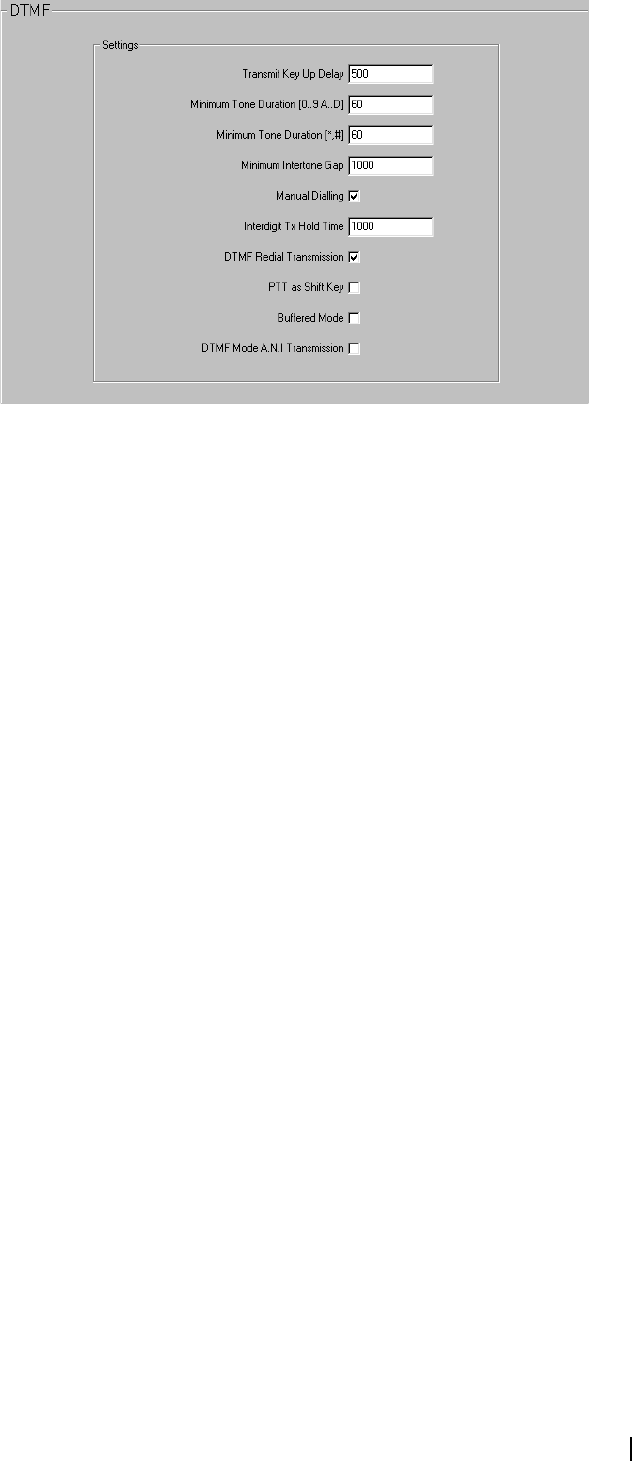
T2000 Programming Application User’s Manual Special Features 55
Transmit Key Up
Delay
The Transmit Key Up Delay field sets a delay for the start of tone transmissions
so that a repeater has time to stabilise. Enter a value from 10 to 2550 ms in steps
of 10 ms.
Minimum Tone
Duration (0-9, A-
D)
The Minimum Tone Duration (0-9, A-D) field sets the minimum amount of
time tones 0 to 9 and A to D are encoded. Enter a value from 8 to 1020 ms in
steps of 4 ms.
Minimum Tone
Duration (*, #)
The Minimum Tone Duration (*, #) field sets the minimum amount of time
tones * and # are encoded. Enter a value from 8 to 1020 ms in steps of 4 ms.
Minimum
Intertone Gap
The Minimum Intertone Gap field sets the minimum amount of time between
encoded tones. Enter a value from 10 to 2550 ms in steps of 10 ms.
Manual Dialling The Manual Dialling field is checked if DTMF calls are to be made from the
control head numeric keypad. If unchecked, DTMF calls can still be made using
alphanumeric symbols.
Interdigit Tx Hold
Time
The Interdigit Tx Hold Time field determines how long the radio keeps
transmitting between the encoding of each tone. This provides a delay for the
user to dial the next digit without transmission stopping and restarting again.
Some systems require continuous transmission between DTMF tones and
therefore a long hold time. Enter a value between 10 and 2550 ms, in steps of
10 ms.
DTMF Redial
Transmission
When the DTMF Redial Transmission field is checked, the user can retransmit
the last DTMF call by pressing the enter key when in DTMF dialling mode.
When the radio enters DTMF dialling mode and this function is enabled, the
DTMF string transmitted when the radio was last in DTMF dialling mode is
displayed. If this is the string the user wishes to transmit, they only have to press
the enter key to transmit the string again.
Buffered Mode If Buffered Mode is checked, the DTMF sequence is stored as it is dialled, and
transmitted when the Enter key is pressed. Uncheck the Buffered Mode
checkbox to encode and transmit the DTMF tones as each digit is dialled.
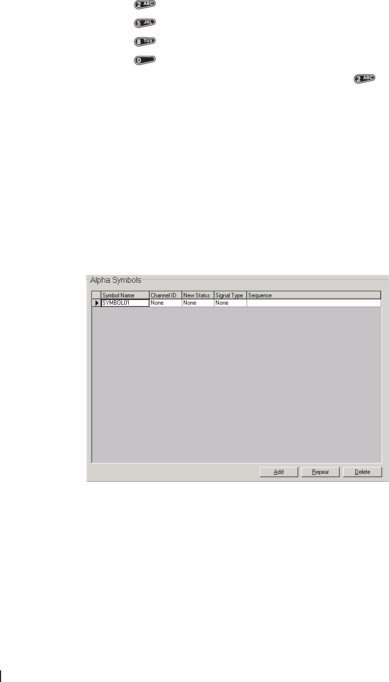
56 Part C: Programming Conventional Features M2000-00-003-806 © Tait Electronics Ltd 2002
PTT as Shift Key If the PTT as Shift Key field is checked, the PTT can be used as a shift key in
conjunction with the numeric keypad to dial tones A to D.
PTT + = A
PTT + = B
PTT + = C
PTT + = D
For example, pressing the PTT key, holding it, then pressing the key
enters tone A in the DTMF string.
DTMF Mode ANI
Transmission
If the DTMF Mode ANI Transmission field is checked, the ANI sequence for
the current channel can still be sent when a DTMF call is made. Some systems
may experience interference if an ANI sequence is sent during a DTMF
transmission, and in this case this field should be disabled.
Alpha Symbols Form
T2020 radios only.
In the Alpha Symbols form, a list of labels is defined and each label is associated
with a channel or scan group, a Selcall sequence or DTMF string, a status
message, or any combination of these items. The list of alpha symbols can be
accessed by the radio user in alphanumeric entry mode, and a maximum of 20
alpha symbols can be set.
Select the Add button to add a new alpha symbol, select the Delete button to
delete the currently selected alpha symbol, or select the Repeat button to
duplicate the current alpha symbol’s Channel ID, New Status, Signal Type and
Sequence fields.
Symbol Name The Symbol Name field defines an alphanumeric name for each symbol, and
must be unique. Enter up to 8 characters, chosen from A to Z 0 to 9 * + - <
> / \ space.

T2000 Programming Application User’s Manual Special Features 57
Because the user must be able to spell out the symbol name using the radio
keypad, the characters allowed for the symbol name are different than for other
labels. A default name is generated when the Add button is selected, with the
first symbol name defaulting to SYMBOL01.
Alpha Symbol
Channel ID
The Channel ID field sets the channel or scan group number (Channels and
Scan Groups forms) to be selected when the alpha symbol is selected. Select a
channel or scan group identity from the drop-down list. Select None if the
channel is not to be changed when the alpha symbol is selected.
Alpha Symbol
New Status
The New Status field sets the status message to be transmitted when the alpha
symbol is selected. Enter None for no new status, or select a control status label
of an existing status message from the drop-down list (defined in the Selcall
Status form).
Selcall hardware must be installed in the radio before the status message feature
can be used.
Alpha Symbol
Signal Type
The Signal Type field sets a call signalling type for the alpha symbol, which
determines the signalling sequence used when the symbol is activated. Enter
Selcall, DTMF or None.
Selcall or DTMF hardware must be installed in the radio before the signalling
Type field can be set to either Selcall or DTMF.
If the New Channel field is set to None and signalling type is set to Selcall, then
the Selcall option must be fitted or the call assigned to the symbol is not
transmitted. If the New Channel field is set to a specific channel, then a Selcall
system must be assigned to that channel or the Selcall call assigned to the symbol
will not be transmitted.
Alpha Symbol
Sequence
The Sequence field sets the Selcall sequence or DTMF string that is transmitted
when the alpha symbol is selected. The signalling Type field must be set to
Selcall or DTMF before the signalling number can be set.
If the signalling Type field is set to Selcall, enter a Selcall sequence using
characters 0 to 9, B, C, D, F or G. The G represents a group tone, which
identifies incoming Selcall sequences as group calls. The length of the sequence
entered must match the length of the R (receiver identity) burst in the Tx
Format field.
If the signalling Type field is set to DTMF, enter a valid DTMF string of up to
32 characters, using 0 to 9, A to D * #.
CCI Setup (Conventional) Form
T2020 radios only.
The computer controlled interface (CCI) allows the radio to be used for data
transmission or to be remotely controlled by computer equipment. This form
sets the parameters for the radio’s communications ports.

58 Part C: Programming Conventional Features M2000-00-003-806 © Tait Electronics Ltd 2002
Tx Baud Rate The Tx Baud Rate fields set the required transmit baud rate for the CCI
interface port. Select the required rate from the combo box. This will usually
be the same as the receive baud rate setting for the port.
Rx Baud Rate The Rx Baud Rate fields set the required receive baud rate for the CCI
interface port. Select the required rate from the combo box. This will usually
be the same as the transmit baud rate setting for the port.
Bits Per Character The Bits Per Character fields set the required data length. Select either 7 or 8
bit ASCII from the combo box for each port.
Number Of Stop
Bits
The Number of Stop Bits fields set the number of stop bits to append to each
character. Select either 1 or 2 from the combo box for each port.
Parity Type The Parity Type fields set the required parity checking type. Select Odd, Even
or None from the combo box for each port.
Handshaking
Mode
The Handshaking Mode fields sets the handshaking mode for Ports A and B.
Handshaking allows control over the flow of data being sent and prevents data
from being lost between the radio and the computer equipment
communicating with it in CCI mode. Select Software, Hardware or None from
the combo box for each port. If Software is selected, values must be added in
the XON Character and XOFF Character fields.
Inter Port Link The Inter Port Link field is used to switch the CCI into or out of transparent
mode. If checked, the CCI is in transparent mode, and the data flows directly
from port A to port B. If unchecked, the CCI operates as normal.
XON/OFF
Character
The XON Character and XOFF Character fields are used if Software
Handshaking has been selected in the Handshaking Mode field.
XON Character sets the character that indicates the start of a flow of data, and
XOFF Character sets the character that indicates the end of a flow of data.
Set both fields to a hexadecimal number between 0 and FF.
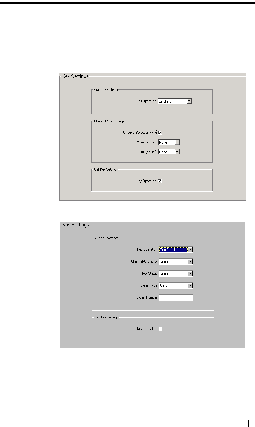
T2000 Programming Application User’s Manual Radio Interface Options 59
Radio Interface Options
This part contains detailed information setting radio interface options, such as
auxiliary key settings and user function menu options.
Key Settings Form
The operation of various radio control head keys is set in the Key Settings form.
The Key Settings form for T2010/T2015 radios is shown below.
The Key Settings form for T2020 radios is shown below.
Key Operation The Key Operation field sets the way the radio behaves when the control head
auxiliary key is pressed. The options available in the combo box are dependant
on the radio model.

60 Part C: Programming Conventional Features M2000-00-003-806 © Tait Electronics Ltd 2002
■Momentary: A press of the auxiliary key activates the internal AUX line on
the options connector while the key is depressed. This can be used to
activate an option, such as Selcall.
■Latching: A press of the auxiliary key toggles the internal AUX line on the
options connector on and off. This can be used to turn an option such as a
scrambler on and off.
■External (T2010/T2015 only): The auxiliary key activates an external alert
device (Selcall hardware installed).
■Emergency (T2020 only): A press of the auxiliary key activates the Selcall
emergency function (Selcall hardware installed).
■One Touch (T2020 only): When the auxiliary key is pressed, the radio sends
a predefined call. The parameters for this call are set in the Channel/Group
ID, New Status, Signal Type and Signal Number fields.
Channel Selection
Keys
T2010/T2015 radios only
The Channel Selection Keys field enables or disables channel selection from the
front panel. Clear this checkbox to disable the channel keys (T2010/T2015)
and channel memory keys (T2015) on the front panel, for external channel
selection.
Memory Key
Operation
T2015 radios only.
The Memory Key 1 and Memory Key 2 fields associate the control head
memory keys with a channel defined in the Channels form. Select None for the
channel to remain unchanged, or select the required channel identity from the
combo box.
Channel/Group ID T2020 radios only.
The Channel/Group ID field is only available when the Key Operation field is
set to One Touch. Select None if the channel is to remain unchanged, or select
the required channel or scan group identity from the drop-down list.
New Status T2020 radios only.
The New Status field is only available when the Key Operation field is set to
One Touch and Selcall hardware is installed. This field sets the status to be
selected when the one touch call is made. Enter None for no new status, or
select a control status label of an existing status message from the drop-down list
(defined in the Selcall Status form).
Signal Type T2020 radios only.
The Signal Type field is only available when the Key Operation field is set to
One Touch and sets a call signalling type for the one touch auxiliary key call.
Set to None, Selcall (Selcall hardware installed) or DTMF (DTMF hardware
installed).
Signal Number T2020 radios only.
The Signal Number field is only available when the Key Operation field is set
to One Touch. This field sets the Selcall sequence or DTMF string to be sent
when the one touch call is made. The Signal Type field must be set to Selcall
or DTMF before the Signal Number field can be set. Enter a valid Selcall
sequence or DTMF string.

T2000 Programming Application User’s Manual Radio Interface Options 61
Key Operation The call key can be used to make a call to an assigned user if Selcall hardware
is installed in the radio. If checked, the radio is able to initiate a Selcall call using
the call key. If unchecked, the radio is unable to initiate a Selcall call using the
call key.
User Selectable Form
Initial settings for various radio features and options are set in the User
Selectable form. The In User Menu check boxes select items for the T2020
radio’s user function menu.
Economiser
Backlighting Level
The Economiser Backlighting Level field selects whether economy mode
affects the control head display.
Check this field to dim the display when the radio is in economy mode. If this
field is unchecked, then the control head display is switched off while the radio
is in economy mode. Economy mode settings are made in the Power Saving
form.
If you wish the radio user to be able to change the economy mode display
lighting, check the In User Menu box.
Normal
Backlighting Level
The Normal Backlighting Level field sets the control head display to either Full
or Dim, during normal operation.
If you wish the radio user to be able to change the control head display lighting,
check the In User Menu box.
External Mute The External Mute field sets whether the HUSH line on the options connector
responds when the radio mute opens. This can then be used to control an
external device, such as a car radio.
Check this field to activate the HUSH line when the audio mute opens.
If you wish the radio user to be able to enable and disable the external mute
feature, check the In User Menu box.
External Alert
Function
The External Alert Function field sets whether the HORN line on the options
connector switches an external alert device, such as a car horn.

62 Part C: Programming Conventional Features M2000-00-003-806 © Tait Electronics Ltd 2002
Check this field to enable external alert. External alert settings are made in the
Selcall Setup tab.
If you wish the radio user to be able to enable and disable the external alert
feature, check the In User Menu box.
Keypress
Confidence Tones
The Keypress Confidence Tones field enables and disables keypress confidence
tones. For T2020 radios, the volume is set in the Keypress Confidence Tones
Level field.
If you wish the radio user to be able to enable and disable keypress confidence
tones from the T2020 user function menu, check the In User Menu box.
Keypress
Confidence Tones
Level
The Keypress Confidence Tones Level field sets the volume of the radio’s
keypress confidence tones to either High or Low. If the field Keypress
Confidence Tones is disabled, then the setting of this field has no effect.
If you wish the radio user to be able to change the keypress confidence tones
level, check the In User Menu box.
Short Status
Display
The Short Status Display field switches the control head Selcall status message
display between a status label and a status digit. If checked, the status message is
displayed on the control head as a status digit only. The channel or group name
is also shown, but is shortened to 6 digits. If unchecked, the status message label
is shown on the control head display (e.g. “AT HOME”).
If you wish the radio user to be able to change between long and short status
display, check the In User Menu box.
DTMF Auto
Transmit
The DTMF Auto Transmit field selects the way in which the dialled DTMF
string is sent. The default DTMF dialling type and other DTMF features are set
in the DTMF form. If enabled, the DTMF string is transmitted separately, as
each individual key is pressed. If disabled, the DTMF string is transmitted in its
entirety, once the enter key is pressed.
If you wish the radio user to be able to change between normal and buffered
DTMF dialling, check the In User Menu box.
In User Menu
Options
The options available in the user function menu are summarised in Table 3 on
page 63.

T2000 Programming Application User’s Manual Radio Interface Options 63
Table 3: User function menu options for T2020 radios
Display Settings Description To Add Option to Function Menu:
ELIT DIM/OFF Sets the economy mode
control head display
backlighting level to either
dim or off.
Check the In User Menu box for
Economy Backlighting Level.
LITE FULL/DIM Sets the required
backlighting level at power
up.
Check the In User Menu box for
Normal Backlighting Level.
HUSH ON/OFF Sets whether the HUSH line
on the options connector
responds when the radio
mute opens.
Check the In User Menu box for
External Mute.
HORN ON/OFF Switches the external alert
function on and off.
Check the In User Menu box for
External Alert.
BEEP ON/OFF Turns keypress confidence
tones on and off.
Check the In User Menu box for
Keypress Confidence Tones.
BEEP HI/LOW Changes the level of keypress
confidence tones.
Check the In User Menu box for
Keypress Confidence Tones Level.
STAT NORM/FIX Switches the Selcall status
display between a status
label and a status digit.
Check the In User Menu box for
Short Status Display.
A--TX ON/OFF Switches the DTMF dialling
type.
Check the In User Menu box for
Auto Transmit.


T2000 Programming Application User’s Manual Programming Trunked Features 65
Part D Programming Trunked
Features
This part contains detailed information on programming T2030,
T2035 and T2040 radios.
Topics
■What’s New - T2000 Trunked Radios
■Programming Trunked Radios
■Changing Network Settings
■Changing Fleet Settings
■Changing Radio Unit Settings

66 Part D: Programming Trunked Features M2000-00-003-806 © Tait Electronics Ltd 2002

T2000 Programming Application User’s Manual What’s New - T2000 Trunked Radios 67
What’s New - T2000 Trunked Radios
Key:
■N/A = Not Applicable.
■* = not a full release.
Feature Form
Radio Firmware Version Database Version
T2030 T2035 T2040 T2030/
T2035 T2040
Hook Signalling Data Parameters N/A 3.53 N/A 5.05 N/A
Display Driver Specifications N/A 3.50* N/A 5.04 N/A
Join Busy Group Call Options N/A 3.53 5.65 5.05 5.06
Single Press PTT Call Interface Options N/A N/A 5.63 N/A 5.04
Auto Register at Power
On
Interface Options 3.30 3.49 5.63 5.04 5.05
SOS Mute External Calls 3.30 3.47 5.60 5.03 5.04
MPT Dynamic
Regrouping
Fleet Parameters 3.27 3.44 5.55 5.03 5.04
Radio Language -
Portuguese
Specifications N/A N/A 5.52 N/A 5.03
ECR Call Clear External Calls N/A N/A 5.49 N/A 5.02
CPSX Dialling Fleet Identity N/A 3.44 5.46* 5.03 5.02
User Group Select Radio Unit ID N/A 3.44 5.46* 5.03 5.02
Site Select And
Resuming Hunt
Hunting Params N/A 3.44 5.46* 5.03 5.02

68 Part D: Programming Trunked Features M2000-00-003-806 © Tait Electronics Ltd 2002
Programming Trunked Radios
When programming T2030, T2035 or T2040 radios, you will find that possible
entries and availability of certain features often depends upon settings in other
forms. The order in which the screen data is entered is, therefore, important.
See “Programming Sequence” below for more information.
Access to some programming information is restricted by the access level. See
“Changing Access Levels” on page 6 for more information.
Programming Sequence
The recommended sequence for changing radio settings is:
■network settings, then
■fleet settings, then
■radio unit settings
1. Changing Network Settings
Network data should be imported or changed first. Networks are typically
set up as templates, to ensure that network settings remain consistent.
2. Changing Fleet Settings
With the network data added, add or change values to the fleet settings.
3. Changing Radio Unit Settings
After editing fleet settings, you can alter data in the other various radio unit
forms.
Working with Multiple Networks
The T2040 can operate in two completely separate trunking networks. To do
this, the radio must be programmed with the parameters of both networks.
Some radio unit settings are common to both networks.
You may wish to change networks because you are out of reach of the current
network (the SVC indicator is flashing) or you need to have access to the
second trunking network.
Click the toolbar icon (or select Network > Add) to add a second network
to the current database. Select File > Import to import a network. Use the
Network > Previous (Ctrl+J) and Network > Next (Ctrl+K), or the network
combo box to switch between the networks when entering fleet
and network information.
Setting up a network template
It is useful to have a file set up as a template to use when setting up other radio
units on the same network.
1. Enter network-specific data for (Network and Fleet settings).
2. Click File > Save As...
3. Enter a descriptive name such as “Network_Template.t2t”.
4. Click Save.

T2000 Programming Application User’s Manual Programming Trunked Radios 69
Importing a network
T2040 radios only.
Importing a network will add another network (all the fields in the Fleet and
Network settings) to the current database.
Note: Before importing, only one network can be currently defined
to leave space for the additional network. Select Network > Delete
to delete Network 2.
1. Select File > Import Network.
2. Select the “*.t2t” file that contains the network or networks to be imported.
3. Click Open.
4. You can assign a descriptive name to the additional network using the
Network Name field (Specifications form).
Specifications (Trunked) Form
The Specifications form shows basic radio information such as the radio model
and the frequency band. You can also set various radio interface options in this
form, such as the power-up message, the network name and installed hardware
options.
Radio Model Information
The radio model information fields show the radio model and frequency band,
which form part of the radio’s part number (e.g. T2040-523).
If you change the Radio Model and/or Band, fields that are not relevant to the
different radio band and/or radio model are automatically set to their default
values.
frequency band
model (T2030/T2035/T2040)
IF bandwidth (narrow/wide/programmable)
T2040-523
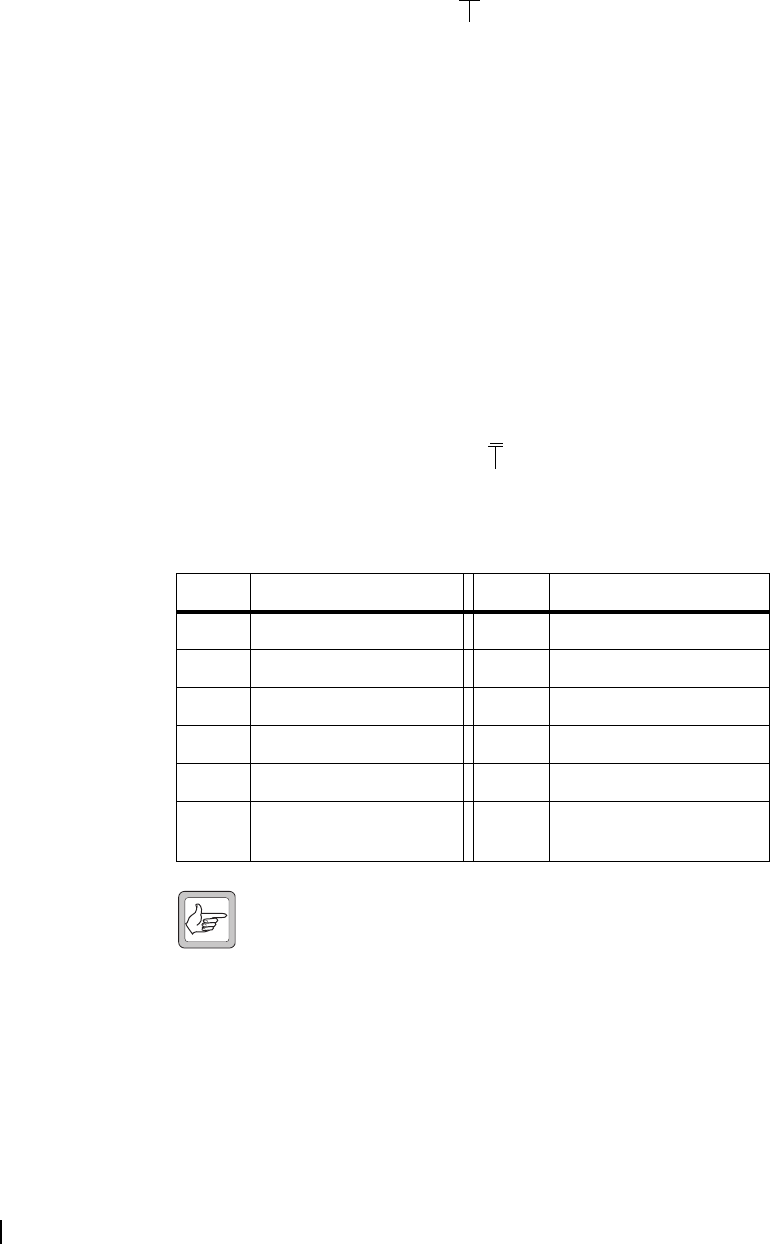
70 Part D: Programming Trunked Features M2000-00-003-806 © Tait Electronics Ltd 2002
You may wish to read data from a radio of a different type and use the settings
as a template for programming radios of another variant. If so, change the values
of radio model and/or radio band after loading the template file but before
changing any other radio settings.
Radio Model The Radio Model field indicates the radio’s feature set, which is indicated by
the fourth and fifth positions of the radio part number.
30 indicates the T2030 feature set, 35 indicates the T2035 feature set and 40
indicates the T2040 feature set.
The Radio Model field is set in the radio model toolbar (see “Select a Different
Radio Model” on page 5). This must be set correctly as not all programmable
features are available for all radio models. Changing the value of the radio model
will:
■make fields relevant to the new radio model selectable, where they were
previously greyed out
■grey-out fields not relevant to the new radio model
Band The Band field sets the frequency band in which the radio operates, and is
indicated by the sixth position (first after the hyphen) in the radio part number.
This number indicates the frequency band as follows:
Note: Contact your local dealer for information on the availability of
different frequency bands.
The Band field must be set correctly in order to validate channel settings, and
changing the value of the radio band will set the values of the Rx Frequency
and Tx Frequency fields (Conventional Channels form) to 0, as any frequency
values previously entered may be invalid for the new radio band.
radio model
T2040-523
Band Frequency Range Band Frequency Range
0 500-530 MHz 6 450-520 MHz
1 220-270 MHz 7 330-366 MHz
2 66-88 MHz 8 800-870 MHz
3 136-174 MHz 9 360-400 MHz
4 175-225 MHz K 896-941 MHz
5 400-470 MHz W 300-338 MHz (T2040
radios only)
frequency band
T2040-523

T2000 Programming Application User’s Manual Programming Trunked Radios 71
Installed Options
The Installed Options fields indicate what option boards are fitted to the radio.
With database version 5.01 and later two or more option boards can be fitted
providing the board combinations are compatible (see Table 4). With pre 5.01
database radios when they are fitted with a MAP27 board, or a line interface
board they will read back with both boards enabled. This does not affect the
radio operation.
Note: Contact your local dealer for more information on the
availability of the following option boards:
■Scrambler
■Handsfree Interface
■MAP27 Interface
■Line Interface
■Signalling InterfaceZ
Scrambler Select this option if the voice inversion scrambler module has been installed in
the radio. The party you call must also have a similar scrambler. The scrambler
encodes transmissions so that even if they are overheard, the voice sounds
garbled.
Handsfree
Interface
Select this option if the T2000 Handsfree interface has been installed. This
allows use of either a foot switch or voice (VOX) activation to automatically
key the radio transmitter. The microphone can either be the normal radio mic
or a remotely placed unit.
If VOX is used then the Mode (Key Settings form) must be set to Auxiliary
Output and Key Operation must be set to Latching.
Enable the Handsfree Call Initiation option (Interface Options form) to call the
number in the display when using a footswitch. This field should be disabled
when using VOX.
Table 4: Compatibility of T2000 option boards
Option Hands-
free
MAP27
Double
MAP27
Single
Line
Interface Signalling Scrambler
Hands-
free
No Yes No Yes No
MAP27
Double
No No No Yes No
MAP27
Single
Yes No Yes Yes Yes
Line
Interface
No No Yes Yes No
Signalling Yes Yes Yes Yes No
Scrambler No No Yes No No
Key: Yes = Compatible, No = Not Compatible.

72 Part D: Programming Trunked Features M2000-00-003-806 © Tait Electronics Ltd 2002
MAP27 Interface Select this option if the MAP27 Interface has been installed. MAP27 (Mobile
Access Protocol for MPT 1327 equipment) permits data exchange between
T2000 trunked radios and 3rd party equipment such as data terminals.
This option will enable the CCI Setup Form and the Data Parameters Form,
where you can configure the radio to send short data messages.
To set whether the MAP27 board is single or dual port, enable the MAP27
board, and then change the UIM field (CCI Setup form).
Line Interface Select this option if the Line Interface module has been installed in the radio.
This feature allows a two wire, 600 ohm telephone line connection to directly
interface with the radio’s transmit and receive audio paths.
Signalling
Interface
Select this option if the Signalling Interface has been installed. This allows the
use of conventional channels and repeater systems that have CTCSS signalling
as part of their operating protocol.
ESN
The fields under ESN uniquely identity the radio, and who manufactured the
radio. These fields are view only.
Chassis Serial
Number
This is the serial number printed on the side of the radio.
Manufacturers
Code
This is the code used to represent the manufacturer of the radio.
Model Code This is the code used to represent the model for the manufacturer of the radio.
Electronic Serial
Number
This is the serial number used by the manufacturer to identify the radio.
Network
The field in Network is Network Name.
Network Name T2040 radios only.
The Network Name field specifies the name of the selected network, which is
displayed during the radio's power up sequence.
Enter a name of up to 8 characters, selected from A-Z 0-9 * / - + < > \ space.
Startup
The startup fields enable you to configure how the radio will appear when it is
first switched on.
Power Up
Message
T2040 radios only.
The Power Up Message field sets the power-up message, which can be up to
24 characters. Choose from A to Z 0 to 9 * + - < > / \ space.
Enter up to 12 characters, including leading spaces if you want the message to
be centred.
Radio Language T2040 radios only
The Radio Language field sets the language that messages appear on the radio
LCD. Select French, German, English or Portuguese.


74 Part D: Programming Trunked Features M2000-00-003-806 © Tait Electronics Ltd 2002
Changing Network Settings
This part contains detailed information on changing network settings. To
change the fields on these forms, you require high-level access. See “Changing
Access Levels” on page 6 for more information.
Trunked Channel Blocks Form
Trunked channel blocks specify the operating frequencies of all channels on a
network. Up to 30 blocks can be defined. Select the Add button to add a new
block, or select the Delete button to delete the currently selected block. At least
one channel block must be defined, and so the last remaining channel block
cannot be deleted.
Start Channel and
Stop Channel
The Channel Start field sets the first number of each trunked channel block, and
the Channel Stop field sets the last channel. Enter a value from 1 to 1023 for
Channel Start, and a value greater than or equal to the Channel Start value for
Channel Stop. Channel Stop cannot be set higher than 1023. If more than one
block is defined, the Channel Start value for all subsequent blocks must be at
least one greater than the Channel Stop value for the previous block.
Start Rx Freq and
Start Tx Freq
The Start Rx and Tx fields set the receive (Rx) frequency and transmit (Tx)
frequency for the first channel in the trunked channel block. The receive and
transmit frequencies for all other channels in the block will be calculated from
these values using the value of the Rx Spacing and Tx Spacing fields. For both
fields, enter the values assigned by your network operator, which will be a
multiple of either 5 kHz or 6.25 kHz and will be within the radio’s frequency
band. The first channel in a block always has the lowest frequency, and the
frequency range for a block cannot overlap with any other block’s frequencies.

T2000 Programming Application User’s Manual Changing Network Settings 75
Rx Spacing and Tx
Spacing
The Rx and Tx Spacing fields sets the channel spacing (in kHz) for all channels
in the trunked channel block and is the value that will be used to calculate
receive and transmit frequencies from the values of the Start Rx and Start Tx
fields. Enter the value assigned by your network operator, which will be a
multiple of either 5 kHz or 6.25 kHz. Different blocks can have different
channel spacing values.
Power The Power field sets the transmit power level for the trunked channel block.
Select a power level setting (either High or Low) within the limits permitted
for the region in which the radio operates.
Network Identity Form
The fields in the Network Identity form tell the radio about the network so that
the radio can communicate with it. Appropriate values for the fields in this form
will be assigned by your network operator.
Network Type and
NIC Code
Together the Network Type and Network Identity Code determine whether
a control channel is considered an adequate candidate for acquisition. If the
relevant bits decoded from the control channel do not correspond to the values
programmed for the radio, the radio will not consider that control channel a
candidate.
The Network Type field sets the network type, which can be either National
or Regional. Consult your network operator for the correct setting.
The network identity codes (NIC) set in the grid are dependent on the
Network Type:
■National: Enter a code from 0 to 3.
■Regional: Enter up to 8 codes, from 0 to 127.
Enter the value assigned by your network operator.
SYNC Sequence The SYNC Sequence field displays the bit sequence used to synchronise
signalling on the channel in hexadecimal format. MPT1327 and MPT1343
define SYNC as C4D7. PAA2424 defines SYNC as B433. Consult your
network operator for the correct SYNC sequence.

76 Part D: Programming Trunked Features M2000-00-003-806 © Tait Electronics Ltd 2002
Area Field Length The Area Field Length field sets the value of LA, which is used in a test carried
out by the radio to see if it can acquire a control channel. The value depends
on whether Network Type is National or Regional. In MPT 1327, if the
Network Type is National enter a value from 0 to 9. If the Network Type is
Regional enter a value from 0 to 4.
Consult your network operator for the correct field length value.
Zone Field Length The Zone Field Length field sets the value of LZ, which is used in a test carried
out by the radio to see if it can acquire a control channel. The value depends
on whether Network Type is National or Regional. In MPT1327, if the
Network Type is National enter a value from 0 to 9. If the Network Type is
Regional enter a value from 0 to 4.
Consult your network operator for the correct field length value.
SIL Field Length The SIL Field Length field is used in a test by the radio to check whether the
clear down message received is from the correct TSC (trunking system
controller). Consult your network operator for the correct field length value.
Pressel On
Messages
The Pressel On Messages field determines how many Pressel On Messages are
sent to the system when the PTT is pressed during a speech call. Enter a value
from 1 to 5. Obtain the correct value from your network operator.
Pressel Off
Messages
The Pressel Off Messages field determines how many Pressel Off Messages are
sent to the system when the PTT is released during a speech call. Enter a value
from 1 to 5. Obtain the correct value from your network operator.
Multiple
Registration
The Multiple Registration field determines whether the radio can register
simultaneously on up to three control channels.
Checked: The radio can store up to three registration records and thereby be
simultaneously registered on up to three control channels. It can then roam
between those control channels and acquire any of them without re-registering.
The oldest registration records expire and are deleted after a period TD
following registration (Network Parameters Form). The most recent record is
known as the Prime record and does not expire. The trunking system
announces how many registration records (either 1, 2 or 3) a radio shall
maintain, via the BCAST SYSDEF 3 message.
Unchecked: Only a single registration record is maintained and any previous
registration record will be discarded when the radio registers on a control
channel.
Transmit Slot
Timing
The Transmit Slot Timing field controls the time relative to the start of the
control channel slot when a synchronous codeword is transmitted. There are 2
options:
MPT: the slot timing conforms to MPT1327 section 6.2.
Tait: the preamble is shortened by 4ms which results in the codeword
transmission being advanced by approximately 5 bits. Only select this option if
early codeword transmission is required.
Value Of INFO In
RQR
The Value of INFO in RQR field defines a 15 bit value which is added to the
INFO field when a radio requests registration.
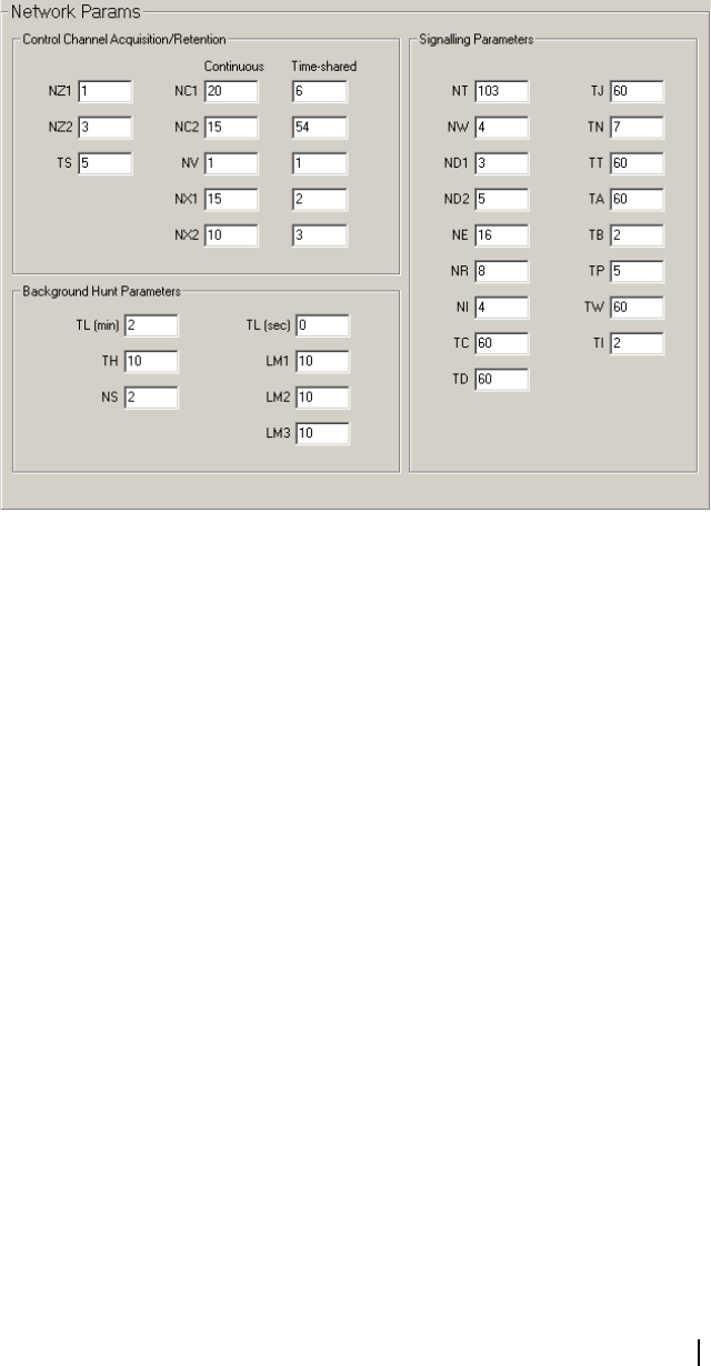
T2000 Programming Application User’s Manual Changing Network Settings 77
This INFO value can be used to convey additional information to the trunking
system controller (TSC). This is usually set to 0. If the Dialling Scheme (Fleet
Identity form) is Nokia ANN, set this value to 16. Consult your network
operator if in any doubt.
Network Parameters Form
The fields in the Network Parameters form set variables used in communicating
with the trunking system control channel.
Control Channel Acquisition/Retention
The fields listed under Continuous and Time-Shared parameters set parameters
the radio uses when attempting to acquire and retain a continuous or time-
shared control channel.
NZ1 NZ1 sets the number of contiguous error check samples containing no error
events. Enter a value from 1 to 255.
NZ2 NZ2 sets the number of contiguous error check samples each generating a
codeword error event following an initial error event. Enter a value from 1 to
255.
TS TS sets the delay before leaving a control channel. Enter a value from 1 to 10
seconds.
NC1, NC2, NX1,
NX2
The combination of parameters NC and NX set the error threshold at which
the control channel performance is considered inadequate. Separate values of
NC and NX are set for use during hunting (NC1 and NX1) and during
continuous monitoring of a confirmed control channel (NC2 and NX2).
Parameters NC1 and NC2 are the number of contiguous positions in which
codewords are expected that will be monitored in each codeword.
Parameters NX1 and NX2 are the number of errored codewords that must be
exceeded in the count of the respective NC codewords before the sample of
NC codewords is considered an error evenpot.

78 Part D: Programming Trunked Features M2000-00-003-806 © Tait Electronics Ltd 2002
NC1, NC2: Set a value from 1 to 255 for both continuous and time-shared
channels.
NX1: Set a value from 0 to the value of the corresponding NC1 parameter for
continuous and time-shared channels.
NX2: Set a value from 0 to the value of the corresponding NC2 parameter for
continuous and time-shared channels.
NV Parameter NV sets the number of consecutive CCSCs (codewords) with the
same value of SYS field that must be received before the radio will attempt to
verify that value.
Enter a value from 1 to 16 for both continuous and time-shared channels.
Signalling Parameters
The fields listed under Signalling parameters set various parameters used in
communication with the control channel.
NT NT sets the maximum trunking system controller (TSC) response delay to
unsolicited traffic channel messages. Enter a value from 103 to 1236 in steps of
103.
NW NW sets the response delay (in slots). Enter a value from 1 to 15.
ND1 ND1 sets the number of disconnect messages sent by an individually called radio
unit. Enter a value from 1 to 5.
ND2 ND2 sets the number of disconnect messages sent by a calling radio. Enter a
value from 1 to 5.
NE NE determines the maximum number of random access transmissions of RQE
(emergency call request). Enter a value from 1 to 255.
NR NR determines the maximum number of random access transmission of RQS,
RQD, RQX, RQT, RQR or RQQ (non-emergency call requests). Enter a
value from 1 to 255.
NI NI sets the maximum number of include request access attempts. Enter a value
from 1 to 255.
TC TC sets the random access timeout. Enter a value from 10 to 120 seconds, in
steps of 10.
TD TD sets the registration record timeout used when Multiple Registration
(Network Identity screen) is enabled. Enter a value from 5 to 70 minutes, in
steps of 5.
TJ TJ sets the further signalling timeout. Enter a value from 10 to 60 seconds, in
steps of 10.
TN TN sets the traffic channel inactivity timeout. Enter a value from 1 to 10
seconds.
TT TT sets the maximum transmit duration. Enter a value from 10 to 60 seconds,
in steps of 10.

T2000 Programming Application User’s Manual Changing Network Settings 79
TA TA sets the timeout for the radio unit after receiving an AHY. Enter a value
from 1 to 255 seconds.
TB TB determines the time barred from calling the same ident after ACK (general
acknowledgement), ACKX (message rejected), ACKV (called unit unavailable)
or any ident after an ACKT (try on given address) or ACKB (call back, negative
ack). Enter a value from 1 to 255 seconds.
TP TP determines the maximum interval between periodic messages (within
speech limits) to be assumed at switch-on. Enter a value from 1 to 255 seconds.
TW TW sets the timeout for the radio unit waiting for a call. Enter a value from 1
to 255 seconds.
TI TI sets the include timer. This sets the maximum time to wait for a response to
an include request. Enter a value from 1 to 255 seconds.
Background Hunt Parameters
The fields listed under Background Hunt Parameters set parameters the radio
uses when carrying out a background search. The Background Hunt field
(Hunting Parameters Form) must be enabled for these parameters to have effect.
TL (min) and TL
(sec)
TL specifies how long the radio will spend on an acquired control channel
before leaving to begin a background hunt. Enter a time between 0 min 10 sec
and 30 min 0 sec. This value is network dependent.
TH TH specifies how long the radio will spend on each timed sampling activity in
the background hunt, before returning to the acquired channel. Enter a number
of slots between 1 and 99. This value is network dependent.
NS NS specifies how many timed sampling activities must return qualifying signal
strength readings for a channel before the radio will identify that channel as a
prospective new control channel. Enter a number between 1 and 10.
LM1, LM2 and
LM3
A sampled channel must exceed the confirmed channel’s signal strength by one
of these margins in order to become a prospective control channel. Enter values
between 0 and 40dB.
■LM1: margin effective when neither the confirmed channel or the sampled
channel have preferential status.
■LM2: margin effective when both the confirmed and sampled channels have
preferential status.
■LM3: margin effective when the confirmed channel does not have
preferential status, but the sampled channel does.
These values are network dependent.
Hunting Parameters Form
The fields in the Hunting Parameters form relate to network hunts carried out
by the radio. If the radio fails to find a suitable control channel among these
channels, it will search through all channels if the Comprehensive Hunt field is
enabled.
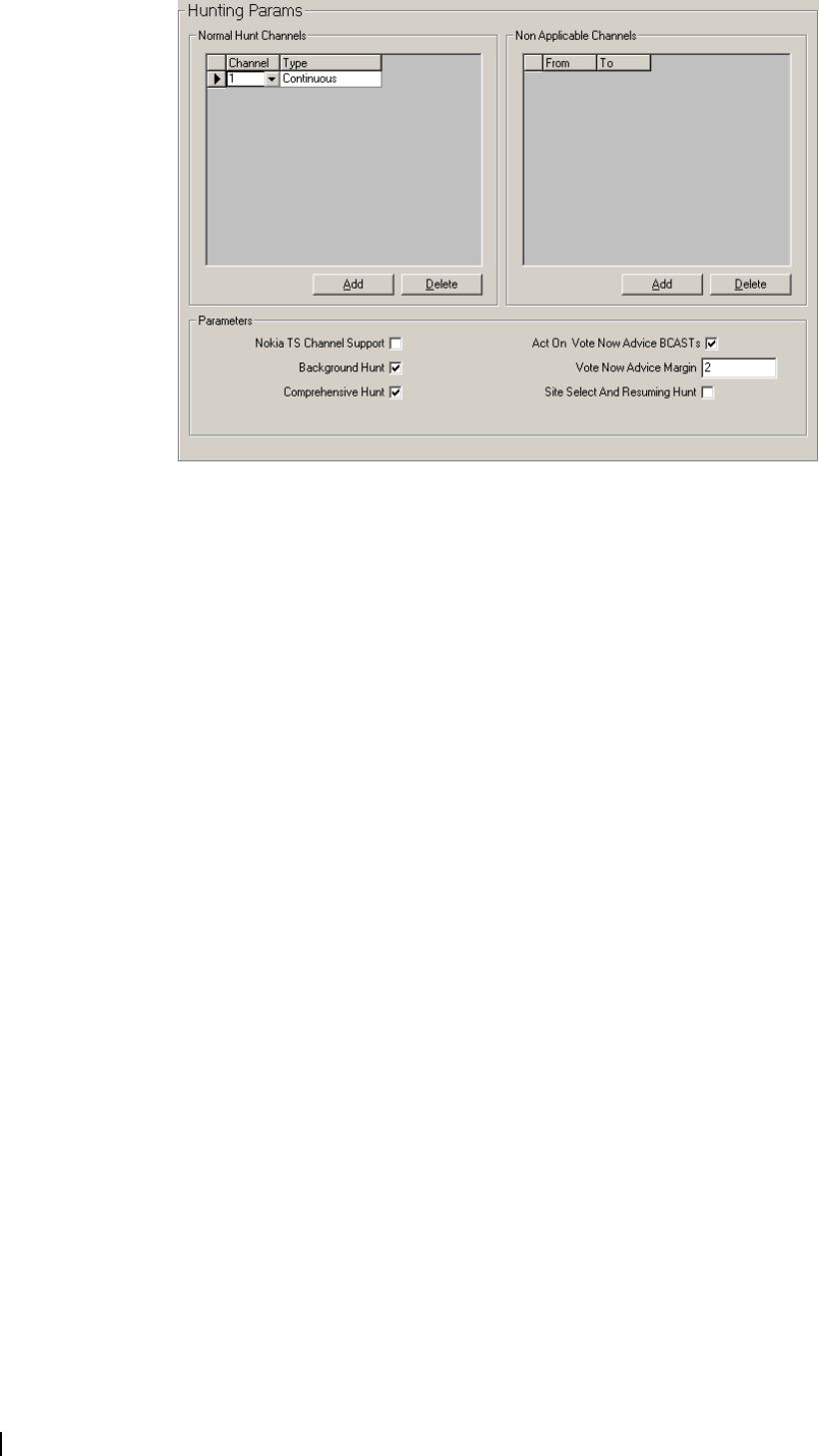
80 Part D: Programming Trunked Features M2000-00-003-806 © Tait Electronics Ltd 2002
Normal Hunt Channels Grid
The Normal Hunt Channels grid defines the channels that will be examined
during a normal background search sequence to see if they can be acquired as a
control channel. The channels available to the radio are defined in the Trunked
Channel Blocks Form.
Up to 32 normal hunt channels can be defined. At least one channel must be
defined, and so the last remaining channel cannot be deleted.
Channel For the Channel field, enter any channel number between the lowest and
highest channel defined for the network. See your network operator for these
values.
Type For the Type field, select Continuous or Time-shared. See your network
operator for the channel type. This is usually Continuous.
Non Applicable Channels Grid
The Non Applicable Channels grid defines the upper and lower limits of the
channel range that will not be included in comprehensive hunt sequences.
Select the Add button to add a new range of channels, or select the Delete
button to delete the currently selected range.
You can define up to ten channel ranges, where the From field defines the start
of the range not included in the hunt and the To field defines the end of the
range not included in the hunt. See your network operator for these values.
If Comprehensive Hunt is disabled or if you do not wish to limit the range of
channels the radio will search, this list can be left blank.
From The From field defines the start of channel range not included in
comprehensive hunt sequences.
To The To field defines the end of channel range not included in comprehensive
hunt sequences.

T2000 Programming Application User’s Manual Changing Network Settings 81
Parameters
The fields under Parameters define additional hunting features.
Nokia TS Channel
Support
Nokia TS Channel Support enables the radio to recognise Nokia time-shared
control channels. This significantly improves background hunting performance
on time-shared channels.
If Nokia TS Channel Support is enabled, the radio will no longer be compliant
with MPT 1343.
Background Hunt Background hunt is a method prescribed in MPT 1343 for monitoring other
control channels and migrating to a superior channel when one is found.
The search is performed by periodically leaving the current control channel and
sampling other control channels. What channels are sampled is defined in the
Normal Hunt Channels Grid. If a channel is consistently found for a certain
number of consecutive samples to be preferred (according to the NDD
preference data defined in the Acquisition Data Form) or stronger than the
current control channel by a certain margin, the radio acquires the new control
channel.
Enable the Background Hunt field to allow the radio to carry out background
searches.
Advanced settings also influence background hunts. See “Background Hunt
Parameters” on page 79.
Comprehensive
Hunt
Comprehensive Hunt determines whether a comprehensive hunt is carried out
if a normal hunt fails to acquire a control channel. This will search through all
channels in the trunked channel blocks defined for the radio, rather than just those
specified in the Normal Hunt Channels Grid.
Act On Vote Now
Advice BCASTs
Some trunking systems use the vote now advice BCAST codeword to help
radios find the best control channel.
Enable this field to take advantage of this feature.
Vote Now Advice
Margin
A channel sending a Vote Now Advice BCAST must exceed the current
control channel’s signal strength by this margin at the radio before being
acquired as the new control channel. Enter a value between 1 and 15dB.
Site Select And
Resuming Hunt
The site select feature allows a user to select a control channel to which the
radio must adhere and attempt to register on without continuing any other hunt
process.
This is available for T2035 radios using the Queue key, or T2040 radios using
the Enter key.
ANN Interfleet Form
The ANN Interfleet form contains details of other fleets that the radio is able
to call when Interfleet Calls or Interfleet Group Calls (Call Options form) are
disabled and the Dialling Scheme (Fleet Identity form) is Nokia ANN.

82 Part D: Programming Trunked Features M2000-00-003-806 © Tait Electronics Ltd 2002
You can enter up to 8 interfleet numbers. Each number entered must be a valid
Nokia ANN interfleet number with the correct number of digits for the
selected ANN Numbering Model. The radio user may then call any party
within the group or individual fleet to which the entered interfleet number
belongs. Before any numbers are entered, the Fleet Structure Defintion and
ANN Numbering Model must have been entered on the Fleet Identity form.
ANN Lead The ANN Lead field is the start of the ANN number. This will be 7 for units
that belong to large and small fleets, or 7, 8 or 9 for units that belong to mini
fleets.
ANN Prefix Enter the prefix of the ANN unit number. This will be a 1 digit number if the
ANN Numbering Model (Fleet Identity form) is Medium, a 2 digit number if
the numbering model is Large, and a number between 00 and 99 or 100 and
127 if the numbering model is Extra Large. This field will be greyed out if the
numbering model is Small.
ANN Fleet Enter the fleet number of the ANN unit number. This will be a 2 digit number
for small and mini fleets, and a 1 digit number for large fleets.
ANN Unit ID Enter the individual unit number. This will be a 2 digit number for small and
mini fleets, and a 3 digit number for large fleets.
T2000 Programming Application User’s Manual Changing Fleet Settings 83
Changing Fleet Settings
This part contains detailed information on changing fleet settings. To change
the fields on these forms, you will require at least medium-level access. See
“Changing Access Levels” on page 6 for more information. The Dialling
Scheme selected also changes which fields you can or cannot access.
Fleet Identity Form
The fields in the Fleet Identity form provide information about the fleet to
which a radio unit belongs. These properties are generally common to all radios
in a fleet.
Dialling Scheme The Dialling Scheme field describes the dialled digit sequence categories used
by the radio for interfleet and intrafleet calls. The dialling scheme is system-
dependent and so must be used only with compatible trunking systems. T2000
radios support five options.
■MPT 1343: Suitable for all MPT 1343 networks.
■ZVEI: Suitable for Regionet 43 networks.
■Number Presets: Suitable for all MPT 1343 networks. However, dialling
will be limited to the preset calls programmed for the radio (in the Preset
Calls form).
■Nokia ANN: Suitable for all Nokia Actionet networks.
■CPSX dialling: Suitable for Chinese networks that utilise 5-digit interfleet
dialling. It is compatible only with other CPSX dialling trunking systems.
Consult your network operator for the appropriate Dialling Scheme.
Settings
The fields in Settings define the numbering of the fleet that the radio belongs to.

84 Part D: Programming Trunked Features M2000-00-003-806 © Tait Electronics Ltd 2002
Fleet Num Prefix Fleet Num Prefix is an MPT1343 value which must be common to all units in
a fleet. This prefix forms part of the address of individual radios. Enter an
assigned value from 200 to 327.
Fleet Individual
Num
Fleet Individual Num is used to calculate the individual base identity for a fleet.
This value is used with the Radio Unit ID and Fleet Num Prefix to uniquely
identify the unit within the system. Enter a number between 2001 and 6050.
Fleet High
Individual Num
Fleet High Individual Num defines the highest individual number that may be
called by any unit within a fleet. It is assigned by the network operator. If the
Dialling Scheme is ZVEI then this value must be between 20 and 79 or 200 and
799. For any other dialling scheme, this field will accept a value between 20 and
89 or 200 and 899. The value of Fleet Individual Num may reduce the upper
value in these ranges.
Fleet Group Num The Fleet Group Num field is used with the group memberships defined in the
Group Membership Grid (Radio Identity form) to identify groups of radios in
a network. Enter the value assigned by your network operator, which will be
from 2001 to 6050. If the user is not allowed group calls, enter 0.
Fleet High Group
Num
The Fleet High Group Num field defines the highest group number that can
be called by any unit within a fleet. If the Dialling Scheme is ZVEI then this
value must be between 90 and 99 or 200 - 299 900 and 999. For any other
dialling scheme, this field will accept a value between 90 and 99 or 900 and 998.
The value of Fleet Individual Num may reduce the upper value in these ranges.
If the value of Fleet Group Number is 0, then this field should also be set to 0.
Fleet Structure Defintion
The Fleet Structure Definition grid defines the Nokia ANN or CPSX
(Algorithmic Network Numbering) fleet structure, which differs from MPT
1343 numbering in the way it divides fleets.
Up to 128 blocks can be defined. Select the Add button to add a new block, or
select the Delete button to delete the currently selected block. For each block,
you must set: Start Prefix, Stop Prefix, FPP and MEP.
ANN Numbering
Model
Nokia ANN dialling scheme only.
The ANN Numbering Model field defines the length of strings to be used for
interfleet numbers. Select either Small, Medium, Large or Extended Large.
■Small: Interfleet numbers contain 5 digits and fleets with prefix 0 are
accessible.
■Medium: Interfleet numbers contain 6 digits and fleets with prefixes from 0
to 9 are accessible.
■Large: Interfleet numbers contain 7 digits and fleets with prefixes from 0 to
99 are accessible.
■Extended Large: Interfleet numbers contain either 7 or 8 digits. Fleets with
prefixes from 0 to 127 are accessible, although in some cases dialling may be
abbreviated to 7 digits.
Prefix Start The first prefix of the range to which the values given for FPP and MEP (Nokia
ANN dialling scheme) or Large, Medium and Small (CPSX dialling scheme)
apply. For Nokia ANN, the range of numbers available for this field depends
on the ANN Numbering Model selected.

T2000 Programming Application User’s Manual Changing Fleet Settings 85
This number is assigned by the network operator.
Prefix Stop The last prefix of the range to which the values given for FPP and MEP (Nokia
ANN dialling scheme) or Large, Medium and Small (CPSX dialling scheme)
apply. For Nokia ANN, the range of numbers available for this field depends
on the ANN Numbering Model selected.
This number is assigned by the network operator.
FPP Nokia ANN dialling scheme only.
FPP (Fleet Partitioning Parameter) is used with MEP to define the fleet
structure of a Prefix range. Enter a value between 0 and 10.
This number is assigned by the network operator.
MEP Nokia ANN dialling scheme only.
MEP (the Miniaturisation Extent Parameter) is used with FPP to define the
fleet structure of a Prefix range. Enter a value between 0 and 10.
This number is assigned by the network operator.
Large, Medium
and Small
CPSX dialling scheme only.
How many large, medium, small and tiny fleets there are is determined by the
values of the parameters Large, Medium and Small.
Using these parameters, the network operator can configure a system in which
interfleet and interprefix dialling are possible from any radio in any other fleet
of any other prefix. Interfleet calls are made by dialling a five-digit number, and
interprefix calls are made by dialling an eight-digit number.
Because each type of fleet is fixed in size, the values of the fields in the Fleet
Structure Defintion grid will determine the values of Individual Call Min and
Max and Group Call Min and Max fields (Radio Identity form) and Fleet High
Individual Num and Fleet High Group Num fields (Fleet Identity form).
See “CPSX Dialling” on page 123 for more information.
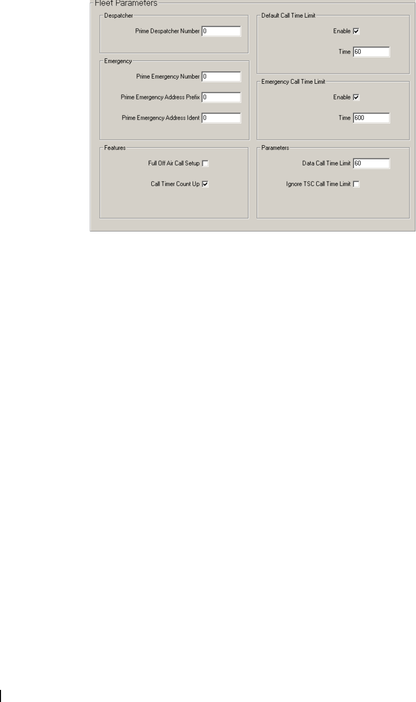
86 Part D: Programming Trunked Features M2000-00-003-806 © Tait Electronics Ltd 2002
Fleet Parameters Form
The fields in the Fleet Parameters form define how calls are controlled.
Prime Despatcher
Number
The Prime Despatcher Number defines the number which the mobile calls
when a despatcher call (* 0) is dialled without specifying a unit number. For
fleets without a despatcher, enter 0.
Prime Emergency
Number
The Prime Emergency Number defines the number the mobile calls when an
emergency call (* 9) is dialled without specifying a radio number. Enter a valid
unit number within the radio’s own fleet. If the prime emergency address is not
a valid unit number within the radio’s own fleet, then the number may be
entered in MPT1327 format using the Prime Emergency Address Prefix and
Prime Emergency Address Ident fields. In this case, enter 0 here.
Disable the prime emergency address by setting this field to 0.
Prime Emergency
Address Prefix
Prime Emergency Address Prefix specifies the prefix in the MPT1327 prefix/
ident format. Enter a value between 0 and 127.
Prime Emergency
Address Ident
Prime Emergency Address Ident specifies the ident in the MPT1327 prefix/
ident format. Enter a value between 1 and 8100.
Full Off Air Call
Setup
Some systems can seek acknowledgement from the called party before setting
up a call. This field specifies whether such acknowledgement is required. If
checked, an acknowledgement is sought from the called party. If unchecked,
calls are set up without acknowledgement from the called party.
Call Timer Count
Up
If Call Timer Count Up is checked, and Default Call Time Limit is set to 0, the
radio displays the current call time length.
Default Call Time
Limit
Default Call Time Limit defines the maximum time that a call may be set up
for. In MPT1327, this value can be overwritten by a BROADCAST message
from the system. If the Enable field is not checked, there will be no limit on call
time. To enter a time limit on calls, select Enable, and enter a time between 10
and 254 seconds in steps of 1 or 300 to 780 seconds in steps of 60.
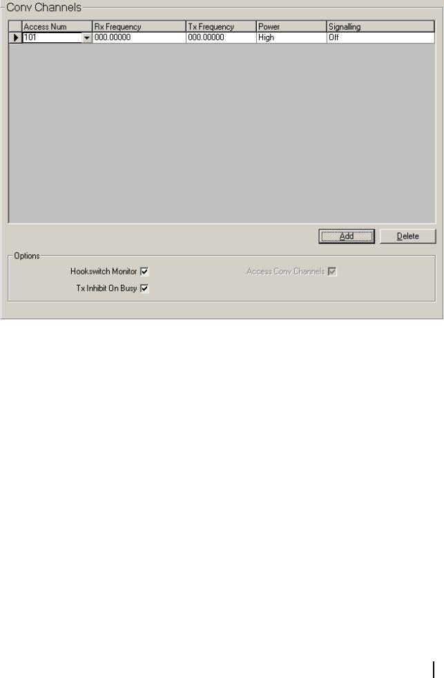
T2000 Programming Application User’s Manual Changing Fleet Settings 87
Emergency Call
Time Limit
Emergency Call Time Limit defines the maximum time that an emergency call
may be set up for. If the Enable field is not checked, there will be no limit on
call time. To enter a time limit on emergency calls, select Enable and enter a
time between 10 and 254 seconds in steps of 1 or 300 to 780 seconds in steps
of 60.
Data Call Time
Limit
Data Call Time Limit defines the maximum time that a data call may be set up
for. Enter any value between 30 and 180 in steps of 30 seconds, or 0 for
unlimited data call time.
Ignore TSC Call
Time Limit
If Ignore TSC Call Time Limit is checked, the radio ignores the network's call
time limit and counts down using the Default Call Time Limit as programmed.
Conventional Channels (Trunked) Form
A trunked radio can switch between trunked and conventional modes of
operation. You can define up to ten conventional channels for T2040 radios,
and four channels for T2030 and T2035 radios in the Conventional Channels
form.
Access Num Access Num defines the string that will change the unit to a predefined channel.
For T2030 or T2035 radios, enter a value from 101 to 104. You will need to
define this Access Number as a preset on the Preset Calls Form.
For T2040 radios, enter a value from 101 to 110. The Access Number can be
entered from the front panel of the T2040, so define it as a preset only if
specifically required.
Rx Frequency RX Frequency defines the receive frequency for the conventional channel.
Enter a frequency between the upper and lower frequency limits defined in the
Specifications form > Band field. For 100 to 700MHz radios, enter a multiple
of either 5kHz or 6.25kHz. For 800MHz radios, enter a multiple of 12.5kHz.

88 Part D: Programming Trunked Features M2000-00-003-806 © Tait Electronics Ltd 2002
Tx Frequency TX Frequency defines the transmit frequency for the conventional channel.
Enter a frequency between the upper and lower frequency limits defined in the
Specifications form > Band field. For 100 to 700MHz radios, enter a multiple
of either 5kHz or 6.25kHz. For 800MHz radios, enter a multiple of 12.5kHz.
Power The Power field sets the transmit power level for the conventional channel.
Select a power level setting (either High or Low) within the limits permitted
for the region in which the radio operates.
Signalling Signalling defines the Signalling Interface. This requires an option board to be
fitted and is enabled when the channel is selected. Set to On or Off.
Hookswitch
Monitor
When the Hookswitch Monitor field is checked, the monitor is activated when
the hookswitch is open.
Tx Inhibit On Busy If TX Inhibit on Busy is checked, the radio will not transmit when the PTT is
pressed and there is activity on a channel.
Access Conv
Channels
The Access Conv Channels field determines whether the radio can operate in
conventional mode. This field is read only, and enabled by default to allow the
radio to operate on the conventional channels defined in the Conventional
Channels grid.
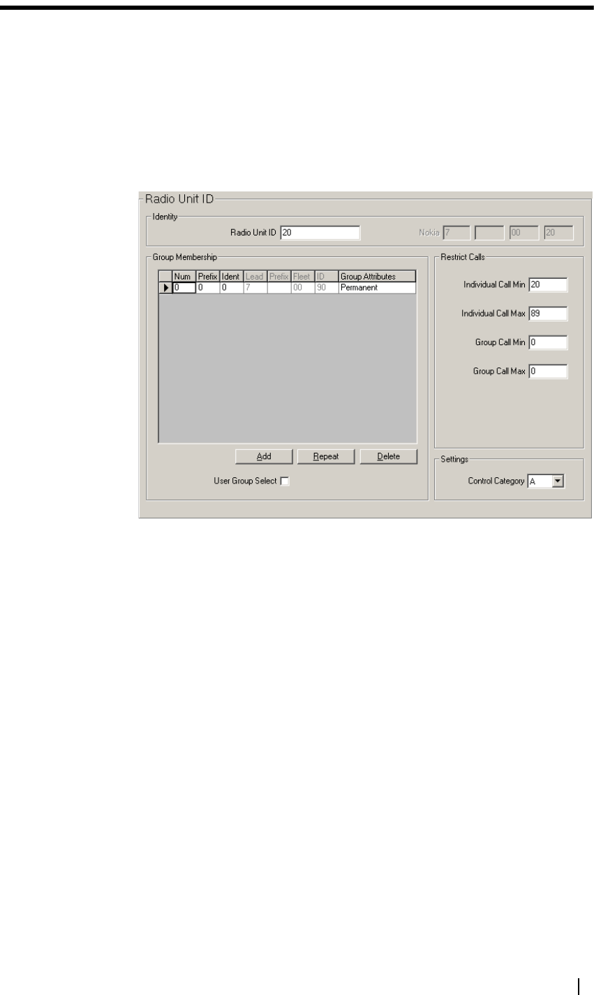
T2000 Programming Application User’s Manual Changing Radio Unit Settings 89
Changing Radio Unit Settings
This part contains detailed information on changing radio unit settings, radio
calls and radio customisation. To change the fields on these forms, you will
require at least low-level access. See “Changing Access Levels” on page 6 for
more information.
Radio Unit ID Form
The fields in the Radio Unit ID form set the individual and group addresses for
the radio, and help identify the radio on the network.
Identity
The fields under Identity define the radio’s unique identifying number.
Radio Unit ID The Radio Unit ID field sets the MPT1343 number which uniquely identifies
this radio within its fleet. If the Fleet High Individual Num (Fleet Identity
Form) is a 2 digit number, enter a value between 20 and the Highest Individual
Number in Fleet. If the Fleet High Individual Num field is a 3 digit number,
then enter a value between 200 and the Highest Individual Number in Fleet.
Nokia The Nokia field sets the ANN Group Number which uniquely identifies this
radio within its fleet. This field is only available when the Dialling Scheme
(Fleet Identity form) is Nokia ANN.
■1st box: The start of the ANN number. This will be 7 for units that belong
to large and small fleets, or 7, 8 or 9 for units that belong to mini fleets.
■2nd box: The prefix of the ANN unit number. This will be a 1 digit number
if the ANN Numbering Model (Fleet Identity form) is Medium, a 2 digit
number if the numbering model is Large, and a number between 00 and 99
or 100 and 127 if the numbering model is Extra Large. This field will be
greyed out if the numbering model is Small.
■3rd box: The fleet number of the ANN unit number. This will be a 2 digit
number for small and mini fleets, and a 1 digit number for large fleets.

90 Part D: Programming Trunked Features M2000-00-003-806 © Tait Electronics Ltd 2002
■4th box: The individual unit number. This will be a 2 digit number for small
and mini fleets, and a 3 digit number for large fleets.
Group Membership Grid
The Group Membership grid defines what groups the radio belongs to. A radio
can belong to up to 4 groups (T2030 radios) or 32 groups (T2035 and T2040
radios). Select the Add button to add a new group address, select the Delete
button to delete the currently selected group address, or select the Repeat
button to duplicate the current group address’ settings.
How group addresses are entered depends on the Dialling Scheme (Fleet
Identity form).
■If the dialling scheme is MPT 1343, ZVEI or Number Presets, group
addresses can be entered in MPT 1343 format (in the Number field) or in
MPT 1327 format (in the Prefix and Ident fields). For MPT 1343 format,
the numbers entered are dependent on the Fleet High Group Num field
(Fleet Identity form). If Fleet High Group Num has two digits, enter a value
from 90 to the Fleet High Group Num. If Fleet High Group Num has three
digits, enter a value from 900 to Fleet High Group Num. For MPT 1327
format, enter a Prefix from 0 to 127 and an Ident from 1 to 8100.
■If the dialling scheme is CPSX Dialling, enter a group number (in the
Number field) within the range specified by Group Call Min and Max. If
the group is in a different fleet, enter the full interfleet dialling number.
■If the dialling scheme is Nokia ANN, group addresses must be entered in
the Lead, Prefix, Fleet and ID fields.
Number MPT1343, ZVEI, Number Presets, CPSX dialling schemes only.
Group addresses may be entered in MPT1343 or CPSX (number) or MPT1327
(Prefix/Ident) format. If you enter a value in one of these formats, the other
must be left blank.
The value in the Number field is dependant on the Fleet High Group Num
field in the Fleet Identity Form.
■If Fleet High Group Num has two digits, this value must be between 90 and
Fleet High Group Num.
■If Fleet High Group Num has three digits, this value must be between 900
and Fleet High Group Num.
Enter 0 if you do not require a group number, or if you intend to specify a
group address in MPT1327 format.
Prefix and Ident MPT1327 number format only.
Enter a Prefix (from 0 to 127) and an Ident (from 1 to 8100). If you do not
require a group address in this format, enter 0 in both fields.
Lead Nokia ANN dialling scheme only.
Lead is the start of the Nokia ANN number. This will be 7 for groups that
belong to large and small fleets, or 7, 8 or 9 for groups that belong to mini fleets.
Prefix Nokia ANN dialling scheme only.

T2000 Programming Application User’s Manual Changing Radio Unit Settings 91
Prefix is the Nokia ANN Prefix number. This will be a 1 digit number if the
ANN Numbering Model (Fleet Identity form) is Medium, a 2 digit number if
the numbering model is Large, and a number between 00 and 99 or 100 and
127 if the numbering model is Extra Large. This field will be greyed out if the
numbering model is Small.
Fleet Nokia ANN dialling scheme only.
Fleet is the Nokia ANN fleet number. This will be a 2 digit number for small
and mini fleets, and a 1 digit number for large fleets.
ID Nokia ANN dialling scheme only.
ID is the Nokia ANN group number. This will be a 2 digit number for small
and mini fleets, and a 3 digit number for large fleets.
Group Attributes This gives the attribute of the group. The options available depend on the
setting of the User Group Select field.
If User Group Select is unchecked, only Permanent is available and the user
cannot select the group from the front panel.
If User Group Select is checked, select Permanent, Selectable, Scan+Selectable
or Scan.
■Permanent - the group is permanently enabled.
■Selectable - the user can select the group individually.
■Selectable + Scan - the group can be accessed individually, and is also added
to the block of scan groups, which appears as ‘---’ on T2035 radios and
‘***’ on T2040 radios.
■Scan - the group is added to the block of scan groups, which appears as ‘---’
on T2035 radios and ‘***’ on T2040 radios.
User Group Select If the User Group Select Feature is enabled, and groups are set to Selectable or
Scan in the Group Attributes field, then a user can select a group or group of
groups (scan group) from the mobile. User Group Select is accessed using a long
press of the alphanumeric key (T2040 radios) or queue key (T2035 radios) from
the front panel.
Restrict Calls
The fields under Restrict Calls restrict the calls that the radio can make to a
defined number range.
Individual Call Min
and Max
Individual Call Min and Max define the range of individual numbers a radio
can call. The setting of these fields can restrict the calls a radio can make to other
radios in the fleet. The range entered is dependent on the Fleet High Individual
Num field in the Fleet Identity Form.
■If Fleet High Individual Num has two digits, the number range for
Individual Call Min and Max can be anywhere from 20 to Fleet High
Individual Num.
■If Fleet High Individual Num has three digits, the number range for
Individual Call Min and Max can be anywhere from 200 to Fleet High
Individual Num.
If you wish to prevent the radio from making individual calls to other radios in
its fleet, enter 0 in both fields.
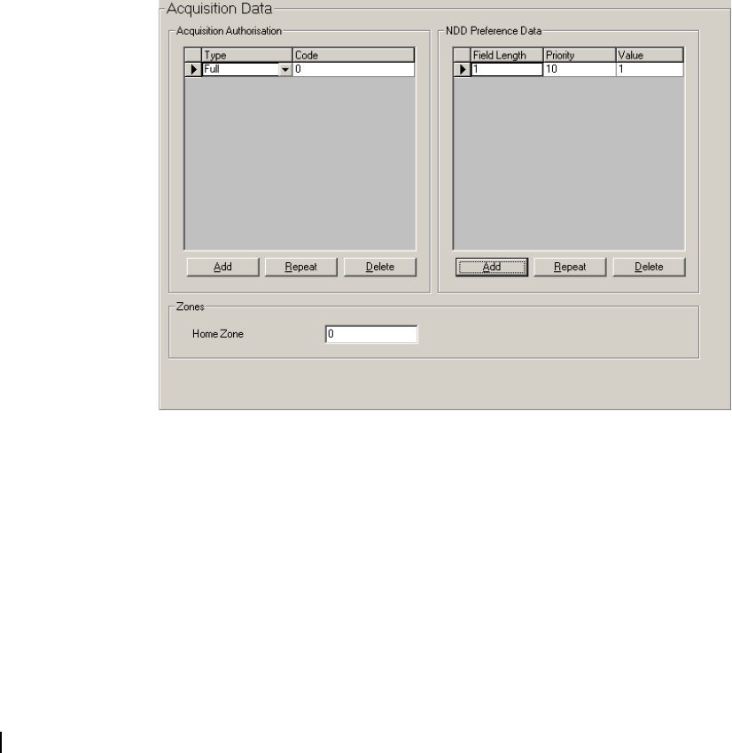
92 Part D: Programming Trunked Features M2000-00-003-806 © Tait Electronics Ltd 2002
Group Call Min
and Max
Group Call Min and Max define the range of group numbers a radio can call.
The setting of these fields can restrict the calls a radio can make to groups of
radios in the fleet. The range entered is dependent on the Fleet High Group
Num field in the Fleet Identity Form.
■If Fleet High Group Num has two digits, the Number Range for Group
Calls can be anywhere from 90 to Fleet High Group Num.
■If Fleet High Group Num has three digits, the Number Range for Group
Calls can be anywhere from 900 to Fleet High Group Num.
If you wish to prevent the radio from making group calls to other radios in its
fleet, enter 0 in both fields.
Settings
The field under Settings is Control Category.
Control Category The Control Category field governs the radio’s rights of access to the control
channels on a network. A radio can only access a control channel when it agrees
with the value of the LAB field in the system identity code. Select one of the
categories A, B, C, or D.
Acquisition Data Form
The grids in the Acquisition Data form define data used when the radio is
attempting to acquire a control channel.
Acquisition Authorisation Grid
The fields in the Acquisition Authorisation grid specify how the radio identifies
a control channel on which it can operate. Up to eight definitions are
permitted. Select the Add button to add a new definition, select the Delete
button to delete the currently selected definition, or select the Repeat button
to duplicate the current definition’s settings.
Type The Type field specifies the areas of the trunking network in which the radio
may operate. Enter the value assigned by your network operator, which will be
Full, Area or Zone.

T2000 Programming Application User’s Manual Changing Radio Unit Settings 93
Code The Code field sets the specific code for acquisition authorisation. On some
networks, this field is left blank. Possible entries are constrained by the values
of the fields Area Field Length and Zone Field Length (Network Identity form).
If the Network Type (Network Identity form) is National, enter a value from
0 to 511. If the Network Type is Regional, set a value from 0 to 15.
NDD Preference Data Grid
The fields in the NDD Preference Data grid define the information used to
encourage the radio to acquire certain control channels during a preferential
hunt. Up to four definitions are permitted. Select the Add button to add a new
definition, select the Delete button to delete the currently selected definition,
or select the Repeat button to duplicate the current definition’s settings. For
each definition, you must specify Field Length, Priority and Value.
Field Length The Field Length field specifies how many bits of the SYS code are used to
determine the identity of the site to be allocated a priority. The maximum
number is dependent on the Network Type (Network Identity form).
If the Network Type is National, enter a value from 1 to 9 for Field Length. If
the Network Type is Regional, enter a value from 1 to 4 for Field Length.
Priority The Priority field specifies the priority of the entry, from 1 (high) to 10.
Value The Value field specifies the decimal value of the binary bits derived from the
SYS code to determine the site to be given priority. Value must be storable in
the number of bits specified by Field Length.
Zones
The field under Zones is Home Zone.
Home Zone The Home Zone field specifies the network zone in which the radio is normally
working. The radio also uses the home zone to determine whether re-
registration is required on a network when registration records for the network
have only been maintained on a temporary basis.
The maximum value of Home Zone depends on the value of Zone Field
Length (Network Identity form).
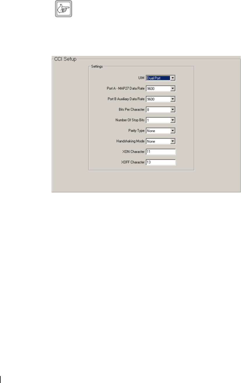
94 Part D: Programming Trunked Features M2000-00-003-806 © Tait Electronics Ltd 2002
CCI Setup (Trunked) Form
The CCI (Computer Controlled Interface) Setup form allows the radio to
communicate with a PC, to allow remote control of the radio and data
transmission. For this form to be enabled, the MAP27 Interface must be
installed and selected (Specifications Form).
Note: CCI is also referred to as UIM (UART Interface Module).
The requirements for many of the settings on this page are variable, depending
on the type of device the UIM must communicate with.
The Port B option in the UIM Setup screen is disabled (grey) and cannot be
used if Single has been selected in the UIM field.
UIM UIM is the type of module fitted to the radio. Select Single Port (T2000-66
fitted), or Dual Port (T2000-60 fitted).
Port A - MAP27
Data Rate
Port A - MAP 27 Data Rate sets the baud rate on Port A. Select 1200 or 9600.
Port B Auxiliary
Data Rate
Port B - Auxiliary Data Rate sets the baud rate on Port B. Select 600, 1200,
2400, 4800 or 9600.
Bits Per Character The number of bits per character can be set for each port. The most common
character set is 7 bit ASCII (CCITT alphabet No. 5). Select 7 or 8.
Number Of Stop
Bits
The Number of Stop Bits sets the number of stop bits to append to each
character for each port. Select from 1 or 2 stop bits.
Parity Type Sets the parity for each port. Select from Even, Odd or None.
Handshaking
Mode
Handshaking Mode enables the control of data flow for each port. Select from
Hardware, Software or None.
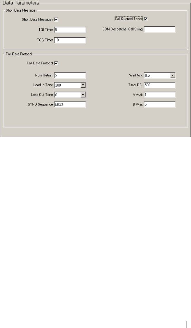
T2000 Programming Application User’s Manual Changing Radio Unit Settings 95
XON Character If Handshaking Mode is Software, the XON character must be defined. When
the radio detects this character, it will turn the flow of data on. Enter a hex
number between 0 and FF.
XOFF Character If the Handshaking Mode is Software, the XOFF character must be defined.
When the radio detects this character, it will turn the flow of data off. Enter a
hex number between 0 and FF.
Data Parameters Form
The Data Parameters form is used to define the parameters that govern data
exchange via the Short Data Message facility and the Tait Data Protocol (TDP).
For the Tait Data Protocol fields in this form to be enabled, the MAP27
Interface must be selected (Specifications Form).
Short Data Messages
These settings govern whether the radio can send Short Data Messages (ASCII
data) via a long press of the Status key and Alphanumeric key.
Short Data
Messages
T2040 radios only.
The Short Data Messages field enables T2040 radios to send Short Data
Messages using a long press of the Status key. Data Calls (Call Options form)
must be enabled for the radio to attempt to send a short data message.
TGI Timer TGI Timer defines the length of time the radio is to wait for further signalling
during short data calls for individual calls.
If this timer lapses, any future short data signalling is assumed to be a new
transaction. Enter a value from 0 to 16.
TGG Timer TGG Timer defines the length of time the radio is to wait for further signalling
during short data calls for group calls.
If this timer lapses, any future short data signalling is assumed to be a new
transaction. Enter a value from 1 to 30.

96 Part D: Programming Trunked Features M2000-00-003-806 © Tait Electronics Ltd 2002
Call Queued
Tones
When Call Queued Tones is enabled, the radio beeps periodically to indicate
that there are calls in the queue.
SDM Despatcher
Call String
Short Data Messages are sent to a radio identity (nn) by entering *nn# after the
message. This field defines the call string that the message is sent to when # is
pressed immediately after the message. Enter the radio identity of your data
despatcher. Any trailing # symbols will be removed.
Hook Signalling When Hook Signalling is enabled, the radio sends an off-hook signal to
acknowledge the acceptance of the SDM or STATUS call setup request, and
an on-hook signal once the call has been completed. This enables the radio to
work correctly with certain mobile data terminal equipment (MDTs).
Tait Data Protocol
Tait Data Protocol (TDP) is a non-prescribed data (NPD) format that requires
the use of a traffic channel.
Tait Data Protocol When Tait Data Protocol is enabled, the radio may send or receive Non-
Prescribed Data (NPD) calls using MAP27 over a traffic channel.
Num Retries Num Retries sets the number of times the radio will attempt to resend a failed
Tait Data Protocol codeword before clearing down the call. Enter a value from
1 to 16.
Lead In Tone Lead In Tone sets the duration of the leader tone that is placed before all Tait
Data Protocol codewords. This tone ensures that all repeaters are on and ready
to receive the codeword. Select a time from the available options.
Lead Out Tone Lead Out Tone sets the duration of the tone that follows all Tait data protocol
codewords. This is used to ensure that squelch tail eliminators do not interfere
with codewords. Select a time from the available options.
SYND Sequence The SYND sequence defines the synchronisation data sequence to be used by
Tait Data Protocol codewords. The definition must be different to both SYNC
and SYNT to ensure that the system controller (TSC) doesn't try to decode the
Tait Data Protocol codewords. Enter an appropriate hex number between 0
and FFFF.
Wait Ack Wait Ack sets how long the radio is to wait for acknowledgement after sending
a packet. Once this time has elapsed, the radio will resend the packet. Select a
time from 5 to 15.
Timer DCI Timer DCI sets how long the radio is to wait after each receive or transmit
activity, before sending an empty packet to retain the link. Enter a value
between 100 and 2000 in steps of 100.
A Wait A Wait sets the length of time the radio is to wait before the first transmission
after initiating a group call. This pause ensures that all parties have received the
Go To Channel message. Enter a value between 1 and 15.
B Wait B Wait sets the length of time the radio is to wait for contact during call setup
before assuming that the channel has failed and clearing down the call. Enter a
value between 5 and 15.
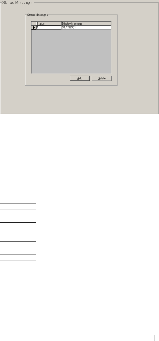
T2000 Programming Application User’s Manual Changing Radio Unit Settings 97
Status Messages Form
Use the Status Messages form to set a list of status messages for the mobile.
Status The Status field sets the status value for the radio to transmit. Enter a value from
1 to 30.
Display Message The Display Message field assigns a meaningful label to the status value. Status
Calls (Call Options form) must be enabled before Status messages may be sent.
Enter a string between 1 and 8 characters in length in any combination of the
characters A to Z, 0 to 9 or -.
Labels must be unique. Usable characters are in 10 groups. Characters in each
group are regarded as identical, so that the label AGE is the same as the label
BID.
The groups are as follows:
Power Saving (Trunked) Form
You can use the Power Saving form to set the mobile to minimise power
consumption by switching off unnecessary circuitry when there is no traffic on
the selected channel.
1
2,A,B,C
3,D,E,F
4,G,H,I
5,J,K,L
6,M,N,O
7,P,Q,R,S
8,T,U,V
9,W,X,Y,Z
0
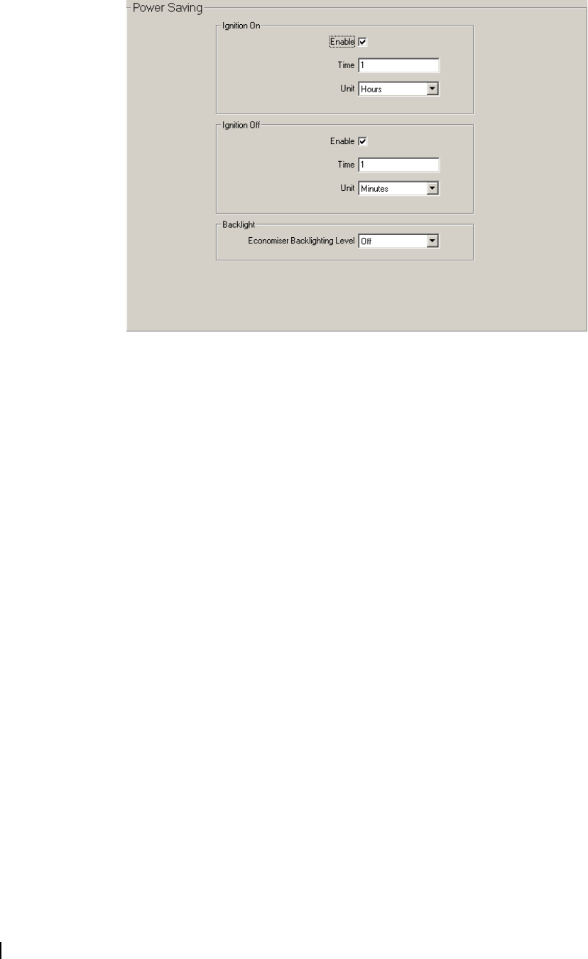
98 Part D: Programming Trunked Features M2000-00-003-806 © Tait Electronics Ltd 2002
If the appropriate vehicle connections are present, the mobile will detect
whether the vehicle’s ignition is on or off, and respond appropriately. Any
activity on the selected channel, or input from the user, will return the mobile
to a fully active state.
Ignition On Enable If enabled, the radio will enter economy mode when the vehicle ignition is on
and after the period indicated by the Ignition On Time and Unit. This will
occur if there has been no activity on the selected channel or input from the
user.
If this field is unchecked, economy mode with the ignition on will be disabled.
Ignition On Time
and Unit
Enter a valid time and unit before the radio enters economy mode with the
ignition on. This will occur if there has been no activity on the selected channel
or input from the user. Ignition On Enable must be checked for these fields to
be valid.
Ignition Off
Enable
If enabled, the radio will enter economy mode when the vehicle ignition is off
and after the period indicated by the Ignition Off Time and Unit. This will only
occur if there has been no activity on the selected channel or input from the
user.
If this field is unchecked, economy mode with the ignition on will be disabled.
Ignition Off Time
and Unit
Enter a valid time and unit before the radio enters economy mode with the
ignition off. This will occur if there has been no activity on the selected channel
or input from the user. Ignition Off Enable must be checked for these fields to
be valid.
Economiser
Backlighting Level
Sets the backlighting level for the radio to use when the radio enters economy
mode. Select Dim or Off.
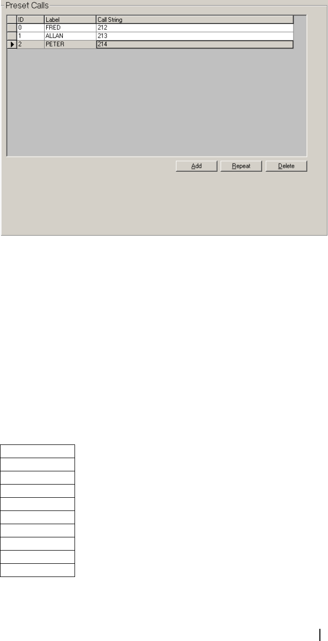
T2000 Programming Application User’s Manual Changing Radio Unit Settings 99
Preset Calls Form
The Preset Calls form is used to set a list of preset calls for the mobile. T2030
radios can have 4 preset calls, assigned to keys C1 to C4. T2035 radios can have
up to 20 preset calls, accessed using the 1, 10 and 100 keys followed by the call
key. T2040 radios can have up to 100 preset calls, accessed using the numeric
keypad and the # key, or the scroll keys. T2040 radios also store these numbers
(and optional label) as an alphanumeric entry.
ID The ID field sets the number of the preset call. MPT1343 recommends that
preset 0 be used for calls to a PABX operator and that presets 1 to 9 be used for
despatchers.
Label T2040 radios only.
The Label field sets an optional label for a preset call string. If a label is assigned
to a preset call string then the user can activate the call string by entering or
selecting the label using the alphanumeric key/cursor keys then #. The label
will also be displayed if an incoming caller's identity matches the call string.
Enter a string of 1 to 8 characters in any combination of the characters A to Z,
0 to 9, or - . Labels must be unique. Usable characters are in 10 groups.
Characters in each group are regarded as identical, so that the label AGE is the
same as the label BID.
The groups are as follows:
If no label is required, leave this field blank.
1
2,A,B,C
3,D,E,F
4,G,H,I
5,J,K,L
6,M,N,O
7,P,Q,R,S
8,T,U,V
9,W,X,Y,Z
0
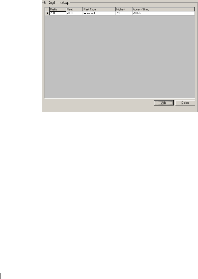
100 Part D: Programming Trunked Features M2000-00-003-806 © Tait Electronics Ltd 2002
Call String Sets the string that the radio is to dial when the preset call is selected. Enter any
valid dialling sequence. Allowable characters are 0 to 9, * and #. Any trailing
# symbols will be removed.
5 Digit Lookup Form
The Lookup Table for 5 Digit Interfleet Calls form is used to define 5-digit
access strings that can be used to make interfleet calls. This form applies only to
fleets that use MPT numbering. If your network is not MPT 1343 compliant,
consult your network operator.
At least one of the Interfleet Calls or Interfleet Group Calls fields (in the Call
Options form must be enabled before any lookup entries can be made.
Prefix In MPT1343, the number prefix must be from 200 to 327. If you do not know
the number prefix of the fleet to be called, or the network is not MPT1343
compliant, consult your network operator.
Fleet Number In MPT1343, the fleet number must be from 2001 to 6050. If you do not know
the fleet number of the fleet to be called, or the network is not MPT1343
compliant, consult your network operator.
Fleet Type Fleet Type specifies whether the call is an Individual or a Group call. The types
are the same for Interfleet calls as they are for normal in-fleet calls.
Before individual Interfleet calls may be made Interfleet Calls (Call Options
form) must be checked; before group Interfleet calls may be made Interfleet
Group Calls (Call Options form) must be checked. Select Individual or Group.
Highest Highest defines the highest number in the fleet the user might wish to call. For
the MPT1343 Dialling Scheme, if this lookup entry is being defined for
individual calls then the number range is 20 to 89 or 200 to 899. If the lookup
entry is being defined for group calls then the number range is 90 to 99, or 900
to 998. If you are unsure as to the correct highest number in the fleet for the
fleet to be called, or your network is not MPT1343 compliant, consult your
network operator.
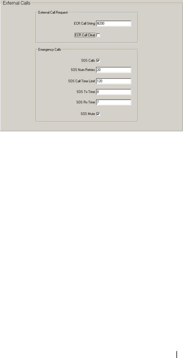
T2000 Programming Application User’s Manual Changing Radio Unit Settings 101
Access String The Access String displays the five digit, short form number that will dial the
interfleet number.
External Calls Form
The External Calls form is used to set the parameters for external calls initiated
by internal logic input, such as a footswitch that activates an emergency (SOS)
call. This form is available for T2040 radios only.
ECR Call String The ECR (External Call Request) Call String sets the number the mobile will
dial when the external line to the radio’s logic board is activated, for example,
using a footswitch. Enter any valid dialling sequence using the characters 0-9,
*, #.
ECR Call Clear If ECR Call Clear is checked, any current trunked call will end when the ECR
(External Call Request) detection changes from active to inactive, for example
when the user’s foot is taken off the footswitch. This will mean that the
recipient of the call cannot respond. If ECR Call Clear is disabled, then the call
will remain active until it is ended manually using the Clear key.
This field is only valid if the Silent SOS Calls field is disabled.
Silent SOS Calls Silent SOS Calls sets whether the mobile should process the ECR (External
Call Request) Call String silently, with no audible or visual indicators. This is
useful if the external call facility is to be used in emergency situations.
SOS Num Retries SOS Num Retries sets the number of attempts the mobile will make to set up
a call to the ECR Call String after failing to gain a traffic channel. Enter a
number between 0 and 255.
SOS Call Time
Limit
SOS Call Time Limit sets a total call time limit in seconds for SOS Calls. This
time limit overrides any other time limits that might be in effect. Enter a value
between 10 and 120.
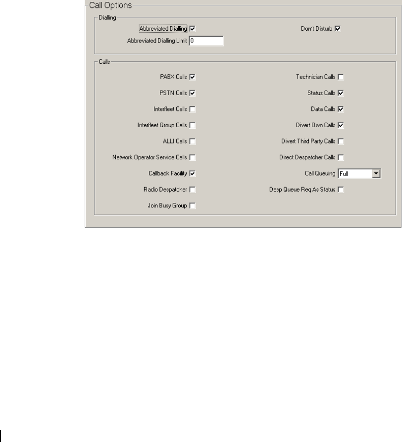
102 Part D: Programming Trunked Features M2000-00-003-806 © Tait Electronics Ltd 2002
SOS Tx Time The mobile automatically cycles between Receiving and Transmitting when it
makes an SOS Call. SOS Tx Time sets how long the mobile should spend
transmitting. Enter a value between 0 and 120 seconds.
Ensure that the sum of SOS Tx Time and SOS Rx Time do not exceed the
SOS Call Time Limit.
SOS Rx Time The mobile automatically cycles between Receiving and Transmitting when it
makes an SOS Call. SOS Rx Time sets how long the mobile should spend
receiving. Enter a value between 0 and 120 seconds.
Ensure that the sum of SOS Tx Time and SOS Rx Time do not exceed the
SOS Call Time Limit.
SOS Mute When this field is enabled and an SOS call (Emergency Mode Tx/Rx cycling)
is made the Rx on the radio that initiated the call is muted. When disabled the
Rx is unmuted. This allows the despatcher to talk to the unit making the call.
Call Options Form
The fields in the Call Options form determine the types of calls a radio unit is
permitted to make and how they are made. For information on the call strings
that operate the various features on this form, see “Trunking Call Strings” on
page 126.
Abbreviated
Dialling
T2040 radios only.
The trunking system can be configured so that radios on the system can make
a call to the PSTN without dialling the full number. Enable the Abbreviated
Dialling field to allow the radio to make use of this feature. Abbreviated dialling
will only work if the system node has been programmed with abbreviated
number sequences. See your network operator for more information.
If Abbreviated Dialling is enabled, you should also set the Abbreviated Dialling
Limit.
Abbreviated
Dialling Limit
T2040 radios only.

T2000 Programming Application User’s Manual Changing Radio Unit Settings 103
The Abbreviated Dialling Limit defines how many different abbreviated
dialling numbers a unit can use. Abbreviated Dialling must be enabled for this
field to be valid.
The radio permits entry of up to 49 abbreviated dialling calls but the network
may not provide that many. Enter a value between 0 and 49. Consult your
network operator to determine how many abbreviated dialling calls are
available.
Don’t Disturb T2040 radios only.
Don’t Disturb permits the user to set the radio to ignore incoming calls while
still allowing outgoing calls to be made as usual. If disabled, the mobile always
receives calls while it is switched on and in range of the network. These calls
may be accepted or queued.
PABX Calls T2040 radios only.
The PABX Calls field permits the user to set up a PABX (Private Automatic
Branch Exchange) call.
PSTN Calls T2040 radios only.
The PSTN Calls field permits the user to set up a call to a PSTN (Public
Switched Telephone Network) subscriber.
Interfleet Calls T2040 radios only.
If enabled, permits the user to set up an interfleet call. Mobiles on a network
are grouped into ‘fleets’ of users. An ‘Interfleet call’ is a call between two users
who are members of different fleets.
This setting only makes individual Interfleet calls available. Group Interfleet
calls can be made if Interfleet Group Calls is enabled. Interfleet calls can be made
using 5 digit access strings. See the “5 Digit Lookup Form” on page 100 for
more information.
Unless there is a specific reason to allow this type of call, disable this field.
Interfleet Group
Calls
T2040 radios only.
When the Interfleet Group Calls field is enabled, the radio can make calls to
groups of radios in other fleets (interfleet group call). Individual interfleet calls
can be made if Interfleet Calls is enabled. Interfleet group calls can be made
using 5 digit access strings. See the “5 Digit Lookup Form” on page 100 for
more information.
Unless there is a specific reason to allow this type of call, disable this field.
ALLI Calls T2040 radios only.
The ALLI Calls field permits the user to set up an ALLI call (a call to all idents
on a site). This facility is normally only used by network technicians.
Network Operator
Service Calls
T2040 radios only.
If Network Operator Service Calls is enabled, the user can set up a network
operator service call. This service may be provided by the network operator to
report faults, for example.

104 Part D: Programming Trunked Features M2000-00-003-806 © Tait Electronics Ltd 2002
Callback Facility If the Callback facility is enabled, when an answered incoming call is cleared
down, its number is displayed. The radio user can then call back the calling
radio by pressing the PTT.
Radio Despatcher Use this field to set the radio to operate as a Despatcher. In this mode, the radio
accepts the special ‘Enter Despatch Queue’ and ‘Leave Despatcher Queue’ calls
and the radio never automatically switches between queue and normal display
modes.
These changes in operation are designed to be compatible with how a fixed
location radio would be used compared to a mobile. Despatch radio operation
is designed to use a call queue, so ensure that Call Queuing is set to Full or
Unanswered.
Join Busy Group The Join Busy Group feature automatically directs the radio to the traffic
channel of a busy group, when calling that group. If checked, and the radio calls
a group that is already involved in a call, the radio is directed to the traffic
channel that the group is using. Do not enable this field unless authorised to do
so by your network operator.
Note: On systems that support group call amalgamation, the radio
will automatically join busy groups regardless of the setting of this
field.
Technician Calls T2040 radios only.
If enabled, the user can set up a special call to directly access any unit on the
network. This facility is normally only used by network technicians.
Note: Do not enable this facility unless you are authorised to do so
for this mobile by the network operator.
Status Calls T2040 radios only.
If enabled, the user can send a status call. This is a coded message sent as a
number from 1 to 30. It is used between two parties where the number has a
prearranged meaning.
If status calls are enabled, you should define status messages (Status Messages
Form) with the prearranged messages used in this fleet.
Data Calls T2040 radios only.
Sets whether the user may set up Data Calls such as Short Data Messages
(SDMs) and other data over a traffic channel. The Short Data Messages field
(Data Parameters form) must be enabled to send SDMs. To send other data, the
MAP27 Interface (Specifications Form) must be enabled, and other fields on the
CCI Setup (Trunked) Form and Data Parameters Form must be set correctly.
Divert Own Calls T2040 radios only.
If Divert Own Calls is enabled, the user can divert incoming calls to another
unit or PSTN number.
Divert Third Party
Calls
T2040 radios only.
If Divert Third Party Calls is enabled, the user can divert another unit’s
incoming calls to another unit or PSTN number.
Direct Despatcher
Calls
T2040 radios only.
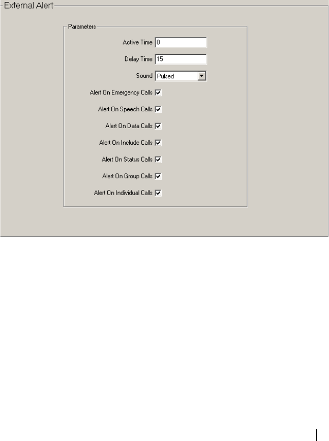
T2000 Programming Application User’s Manual Changing Radio Unit Settings 105
If Direct Despatcher Calls is enabled, the user can make normal speech calls to
the despatcher. The despatcher’s number is defined in the Prime Despatcher
Number field (Fleet Parameters form).
If Direct Despatcher Calls is disabled, users can still enter and leave the
despatcher’s queue (if available) using the dial strings *0# and #0#.
Call Queuing Call Queuing sets a queue to hold unanswered calls, automatically queued calls
and status calls. Select Full, Unanswered or None.
■Full: Up to 20 calls will be queued.
■Unanswered: Only unanswered calls and status calls will be queued.
■None: Only a single unanswered call will be queued.
Desp Queue Req
As Status
Desp Queue Req As Status allows queue add or delete requests to be treated as
a status. With this field checked, the full range of status labels (0 to 31) will be
available.
If Desp Queue Req As Status is unckecked, two status labels are reserved for
adding and deleting from the queue.
External Alert Form
Use the External Alert form to set the mobile to activate an external device,
such as the car horn or lights, in response to an incoming call.
Active Time Active Time sets how long the external alert remains on, once started. Enter a
value between 1 and 60 seconds. Enter 0 to disable the External Alert.
Delay Time Sets how long the mobile pauses after receiving an incoming call, before
activating the external alert. Enter a value between 1 and 60 seconds. Enter 0
to activate the external alert immediately when receiving an incoming call.
Sound Sets the signal pattern for the external alert. Select from Steady, Pulsed or
Ringing.

106 Part D: Programming Trunked Features M2000-00-003-806 © Tait Electronics Ltd 2002
Alert On
Emergency Calls
Enables or disables the external alert when receiving an emergency call (see
“Trunking Call Strings” on page 126). The alert will differ according to the
settings in Active Time, Delay Time and Sound.
If you want to disable the external alert on all emergency calls, uncheck this
field and disable Alert On Speech Calls and Alert On Individual Calls.
Alert On Speech
Calls
Enables or disables the external alert when receiving a speech call (see
“Trunking Call Strings” on page 126). The alert will differ according to the
settings in Active Time, Delay Time and Sound.
If you want to disable the external alert on all speech calls, uncheck this field
and disable Alert On Individual Calls.
Alert On Data
Calls
Enables or disables the external alert receiving a status message, short data
message or other data call (see “Trunking Call Strings” on page 126). The alert
will differ according to the settings in Active Time, Delay Time and Sound.
If you want to disable the external alert on all data calls, uncheck this field and
disable Alert On Individual Calls.
Alert On Include
Calls
Enables or disables the external alert on Include Calls.
Alert On Status
Calls
Use Alert On Data Calls to enable or disable the external alert for Status Calls.
Alert On Group
Calls
Enables or disables the external alert when receiving a group speech call (see
“Trunking Call Strings” on page 126). The alert will differ according to the
settings in Active Time, Delay Time and Sound.
If you want to disable the external alert on all group speech calls, uncheck this
field and disable Alert On Speech Calls.
Alert On
Individual Calls
Enable or disables the external alert when receiving all individual speech, data
and emergency calls (see “Trunking Call Strings” on page 126). The alert will
differ according to the settings in Active Time, Delay Time and Sound.
If you want to disable the external alert for all individual calls, uncheck this field
and disable Alert On Emergency Calls, Alert On Speech Calls, and Alert On
Data Calls.
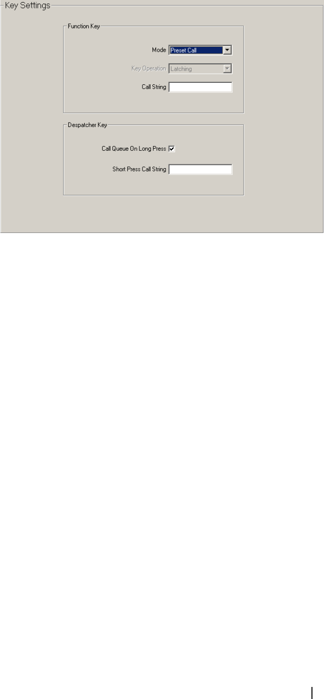
T2000 Programming Application User’s Manual Changing Radio Unit Settings 107
Key Settings (Trunked) Form
The operation of various radio control head keys is set in the Key Settings form.
Mode The Mode field sets an operation for the Function Button to perform. Select
Auxiliary Output, External Alert, Preset Call or Disabled.
Key Operation Key Operation controls the operation of the auxiliary output line when Mode
is set to Auxiliary Output. Select Momentary to switch the Auxiliary Output
line for only as long as the Function Button is pressed.
Select Latching to toggle the Auxiliary Line permanently between settings each
time the Function Button is pressed.
Call String The Call String field defines a Preset Call String for the Function Button. Only
available if Mode is set to Preset Call. Enter any valid dial string using the
characters 0 - 9, * and #. See “Trunking Call Strings” on page 126 for more
information on the different types of call strings available.
Call Queue On
Long Press
If Call Queue On Long Press is enabled, a long press on the despatcher button
will change the mode of operation between call queuing and normal mode
(equivalent to dialling *48#). If this field is disabled, a long press on the
despatcher button will be treated as a short press command, and the call string
entered in Short Press Call String will be dialled.
Short Press Call
String
Short Press Call String assigns a call string to a short press of the Despatcher
button. Enter any valid dialling sequence. Allowable characters are 0 to 9, * and
#.
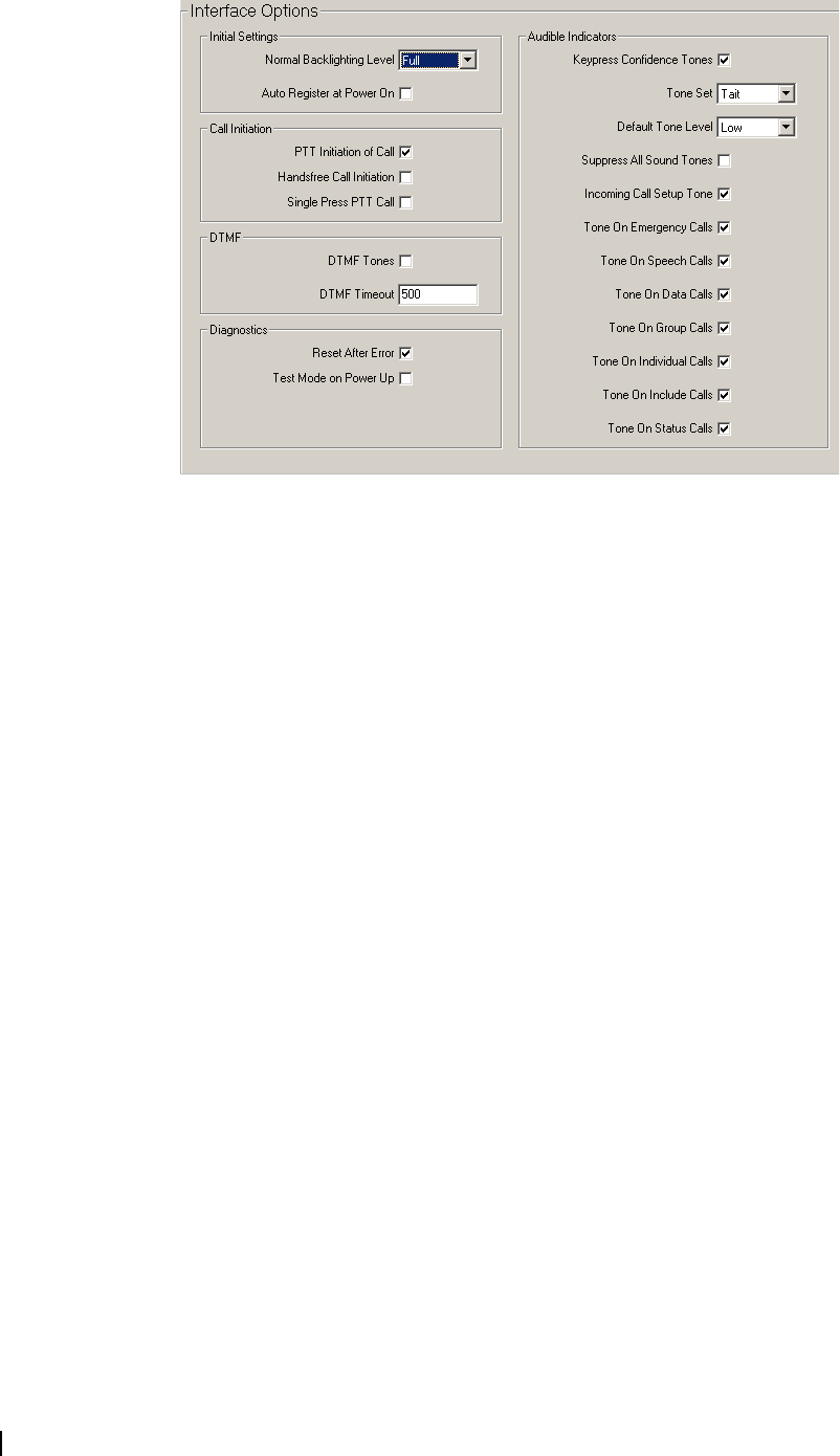
108 Part D: Programming Trunked Features M2000-00-003-806 © Tait Electronics Ltd 2002
Interface Options Form
Initial settings for various radio features are set in the Interface Options form.
Initial Settings
Fields in Initial Settings control how the radio will operate when it is first
powered on.
Normal
Backlighting Level
Normal Backlighting Level sets the backlighting level for the mobile when not
in economy mode. Select from Full, Dim and Off.
Auto Register at
Power On
When Auto Register at Power On is enabled, this option forces the radio to
automatically re-register with the trunked network whenever the radio is
powered up.
Call Initiation
Fields in Call Initiation control how calls are made.
PTT Initiation of
Call
If PTT Initiation of Call is enabled, a call is made to the number in the display
when the user presses the PTT with the radio in an idle state and in trunked
mode.
Handsfree Call
Initiation
If Handsfree Call Initiation is enabled, a call is made to the number in the
display when the footswitch is activated. For this to be valid the Handsfree
Interface (Specifications form) must be selected, and voice activation must be
disabled (refer to the T2000 Service Manual and relevant fitting instructions).
Single Press PTT
Call
T2040 radios only.
If Single Press PTT Call is enabled and a call is initiated by the PTT, the radio
user can begin talking while still pressing the PTT. When Single Press PTT Call
is disabled and a call is initiated by the PTT, the PTT must be released then
pressed again to begin talking. PTT Initiation of Call must be enabled for this
to be valid.

T2000 Programming Application User’s Manual Changing Radio Unit Settings 109
DTMF
Fields in DTMF control DTMF settings for T2040 radios with a DTMF
module fitted.
DTMF Tones T2040 radios only.
Allows DTMF dialling on a traffic channel, if a DTMF module is fitted.
DTMF Timeout T2040 radios only.
DTMF Timeout sets the time between the release of the last key in a DTMF
sequence, and the end of transmission. Enter a number between 100 and 2500
(ms).
Diagnostics
Diagnostics sets the various radio states for diagnostics, such as what happens
after a system error.
Reset After Error If Reset After Error is enabled, the radio will reset five seconds after a system
error.
Test Mode on
Power Up
If Test Mode on Power Up is checked, the radio will power up in Test Mode
after programming. The test mode facility enables the trunked radio to emulate
a multichannel radio, utilising the frequencies reserved for trunking. The radio
can then be tested and aligned. Refer to your T2000 Service Manual for more
information on Test Mode.
If unchecked, the radio will power-up in Trunked Mode after programming.
Audible Indicators
Audible Indicators control the various tones that the mobile makes on certain
events, such as powering up or down, or sending and receiving calls.
Keypress
Confidence Tones
Keypress Confidence Tones enables or disables the audible confidence
indicators that sound whenever a key is pressed. This setting does not affect
warning or other tones.
Tone Set Tone Set defines the style of audible indicators produced by the radio. Select
Tait or MPT1343.
■Tait (for example, a ring each time a call is sent and received, or answered,
and 4 short tones when a call is ended).
■MPT1343 (for example, 2 short tones each time a call is sent and received,
or answered and a high then low tone when a call is ended).
The choice should be the same for all radios in the fleet.
Default Tone Level Default Tone Level sets the sound level for audible indicators. Select Low or
High.
Incoming Call
Setup Tone
Incoming Call Setup Tone specifies whether the radio is to sound tones while
incoming calls are being set up.
Suppress All
Sound Tones
If Suppress All Sound Tones is enabled, any tone generated through the speaker
will be silenced. This will not affect External Alert signals.

110 Part D: Programming Trunked Features M2000-00-003-806 © Tait Electronics Ltd 2002
Tone On
Emergency Calls
Enables or disables the tone when successfully sending, receiving or ending an
emergency call (see “Trunking Call Strings” on page 126). The sound of the
tone will differ according to the Tone Set.
If this field is enabled, Suppress All Sound Tones must be disabled.
If you want to disable the tone on all emergency calls, uncheck this field and
disable Tone On Speech Calls and Tone On Individual Calls.
Tone On Speech
Calls
Enables or disables the tone when successfully sending, receiving or ending a
speech call (see “Trunking Call Strings” on page 126). The sound of the tone
will differ according to the Tone Set.
If this field is enabled, Suppress All Sound Tones must be disabled.
If you want to disable the tone on all speech calls, uncheck this field and disable
Tone On Individual Calls.
Tone On Data
Calls
Enables or disables the tone when successfully sending, receiving or ending a
status message, short data message or other data call (see “Trunking Call
Strings” on page 126). The sound of the tone will differ according to the Tone
Set.
If this field is enabled, Suppress All Sound Tones must be disabled.
If you want to disable the tone on all data calls, uncheck this field and disable
Tone On Individual Calls.
Tone On Group
Calls
Enables or disables the tone when successfully sending, receiving or ending a
group speech call (see “Trunking Call Strings” on page 126). The sound of the
tone will differ according to the Tone Set.
If this field is enabled, Suppress All Sound Tones must be disabled.
If you want to disable the tone on all group speech calls, uncheck this field and
disable Tone On Speech Calls.
Tone On
Individual Calls
Enable or disables the tone when successfully sending, receiving or ending
individual speech, data and emergency calls.(see “Trunking Call Strings” on
page 126). The sound of the tone will differ according to the Tone Set.
If this field is enabled, Suppress All Sound Tones must be disabled.
If you want to disable the tone on all individual calls, uncheck this field and
disable Tone On Emergency Calls, Tone On Speech Calls, and Tone On Data
Calls.
Tone On Include
Calls
Enables or disables the tone on include calls.
Tone On Status
Calls
Use Tone On Data Calls to enable or disable the tone for Status Calls.


112 Part E: Concepts M2000-00-003-806 © Tait Electronics Ltd 2002

T2000 Programming Application User’s Manual Introduction to Channels and Scan Groups 113
Introduction to Channels and Scan Groups
This section contains basic concepts related to channels and scan groups.
Squelch and Signalling: Filtering Out Unwanted Noise and Traffic
Without some mechanism for filtering what the radio broadcasts to the user, the
radio’s speaker would operate continuously and the user would hear not only
any speech on a channel, but also all noise. This would be annoying for the
radio user and so the radio filters out unwanted signals using various methods.
Squelch
The squelch feature ensures that the speaker only unmutes when an intelligible
signal is received. A signal is considered intelligible when it is strong enough to
exceed a predetermined squelch threshold.
Note: Note that squelch is a preprogrammed feature present in all
radios.
Squelch Override
Squelch override is a programmable feature that allows the user to disable the
radio’s squelch and so hear all traffic on a channel, including noise.
In areas where signal strength is too weak to continually exceed the
preprogrammed squelch threshold and so activate the speaker, a message may
be periodically cut off by the squelch although it is still intelligible. Squelch
override can then be activated by a long press of the monitor key, and the
speaker is unmuted.
Signalling Mutes
There are two signalling mutes available as programmable options which
control the circumstances under which a received signal is passed to the radio’s
speaker. When a mute is active, the radio’s speaker only unmutes under certain
conditions, determined by the type of signalling operating on a channel.
Note: If your radio has been programmed for hookswitch monitor,
removing the microphone from the microphone clip also overrides the
signalling mutes.
There are two types of signalling mute.
■Subaudible signalling mute: The radio unmutes when a signal is received
that has subaudible (CTCSS and DCS) signalling the radio recognises.
■Selective call mute: The radio unmutes when a signal is received that
matches the radio’s Selcall identity.
Signalling
Squelch ensures that the radio user only hears intelligible signals, but the user
hears all traffic on a channel. This could become a nuisance, particularly if
several companies are using the same channel. Signalling provides a way of
isolating groups of users so they only hear traffic intended for that group. It does
not provide privacy since anyone tuning to a channel can hear its traffic if they
wish, but it does minimise the possibility of radio users hearing nuisance traffic.

114 Part E: Concepts M2000-00-003-806 © Tait Electronics Ltd 2002
Signalling is non-voice coding on a channel for the purpose of identifying
parties and/or segregating user groups. If a radio receives signalling that matches
that programmed for the radio, the signalling is said to be valid and the radio’s
mute opens. Otherwise, the transmission is ignored and the radio remains silent,
although the radio’s channel busy indicator is activated.
The types of signalling available for T2010/T2015/T2020 radios are CTCSS,
DCS and Selcall (Selcall multi-tone). Each channel can be programmed with
different types of signalling, and subaudible signalling can be used on the same
channel as Selcall signalling.
CTCSS and DCS
CTCSS and DCS use subaudible signalling to segregate groups of users by
transmitting additional information with normal speech.
For CTCSS the additional information is transmitted in the form of subaudible
tones in the frequency band 67 to 250.3 Hz. For DCS the additional
information is transmitted as digital data using frequencies between 10 and 134
Hz. The inverted DCS code may also be used, depending on the setting of the
Rx DCS Polarity and Tx DCS Polarity fields in the Subaudible Signalling form.
Subaudible signalling is assigned on a per channel basis (in the CTCSS/DCS
Rx/Tx fields, Channels form) and each channel can have different receive and
transmit signalling.
T2020 radios also have 20 additional subaudible presets available, which are user
selectable from the user function menu option. These presets override the
signalling programmed for a channel in the Channels form and are set up in the
Subaudible Signalling Presets tab.
The following tables show the CTCSS frequencies and DCS codes T2010/
T2015/T2020 radios support.

T2000 Programming Application User’s Manual Introduction to Channels and Scan Groups 115
CTCSS Tone Frequencies
Standard DCS Codes and Their Inverses
Non-Standard DCS Codes and Their Inverses
Selcall
Selcall uses sequences of audible tones to isolate calls in a manner similar to
CTCSS and DCS. However, Selcall also allows individual radios to have a
unique identity and so calls can be directed to specific individuals within a
67.0 79.7 94.8 110.9 131.8 156.7 186.2 233.6
69.3 82.5 97.4 114.8 136.5 162.2 192.8 241.8
71.9 85.4 100.0 118.8 141.3 167.9 203.5 250.3
74.4 88.5 103.5 123.0 146.2 173.8 210.7
77.0 91.5 107.2 127.3 151.4 179.9 225.7
Code : Inv Code : Inv Code : Inv Code : Inv Code : Inv Code : Inv
023 : 047 114 : 712 174 : 074 315 : 423 445 : 043 631 : 606
025 : 244 115 : 152 205 : 263 331 : 654 464 : 026 632 : 624
026 : 464 116 : 754 223 : 134 343 : 532 465 : 331 654 : 743
031 : 627 125 : 365 226 : 411 346 : 612 466 : 662 662 : 466
032 : 051 131 : 364 243 : 351 351 : 243 503 : 162 664 : 311
043 : 445 132 : 546 244 : 025 364 : 131 506 : 073 703 : 565
047 : 023 134 : 223 245 : 072 365 : 125 516 : 432 712 : 114
051 : 032 143 : 412 251 : 165 371 : 734 532 : 343 723 : 431
054 : 413 152 : 115 261 : 732 411 : 226 546 : 132 731 : 155
065 : 271 155 : 731 263 : 205 412 : 143 565 : 703 732 : 261
071 : 306 156 : 265 265 : 156 413 : 054 606 : 631 734 : 371
072 : 245 162 : 503 271 : 065 423 : 315 612 : 346 743 : 654
073 : 506 165 : 251 306 : 071 431 : 723 624 : 632 754 : 116
074 : 174 172 : 036 311 : 664 432 : 516 627 : 031
Code : Inv Code : Inv Code : Inv Code : Inv Code : Inv Code : Inv
017 : 050 122 : 225 246 : 523 274 : 145 446 : 255 462 : 252
036 : 172 145 : 274 252 : 462 325 : 526 452 : 053 523 : 246
050 : 017 212 : 356 255 : 446 332 : 455 454 : 266 526 : 325
053 : 452 225 : 122 266 : 454 356 : 212 455 : 332

116 Part E: Concepts M2000-00-003-806 © Tait Electronics Ltd 2002
group of radio users. Selcall is configured in a number of forms, depending on
the radio model.
■Installed Selcall hardware is activated in the Selcall Option field
(Specifications form).
■Selcall formats and sequences are set up in the Selcall Identity form. Three
additional Selcall forms are available to T2020 radios (the Selcall Features,
Selcall Status Definitions, and Selcall Emergency forms).
■Selcall sequences are associated with channels in the Channels form, Tx Call
field.
■T2020 radios: Selcall emergency calling is configured in the Selcall
Emergency form.
Monitor: Listening In On Channel Traffic
Monitor allows the radio user to override a channel’s signalling mutes and so
hear all traffic on a channel.
When monitor is active, the mute is said to be open, or unmuted. When
monitor is inactive, the radio is said to be in the quiet state, or muted.
The mutes (subaudible signalling mute, selective call mute) monitor disables is
set in the Monitor Function Disables field (Receiver Monitoring form).
Introduction to Scan Groups
A scan group is a group of 2 to 16 channels. Each channel that belongs to a scan
group is called a member channel. Each member channel in a scan group is
routinely sampled for valid activity (scanning) or greatest signal strength
(voting).
There are three types of scanning and four types of voting available on T2010/
T2015/T2020 radios.
Scanning
In scanning, a group of channels is systematically sampled for activity. The
member channels are scanned in the order in which they are assigned to the scan
group (Scan Group Members tab).
The main benefit of scanning is that all channels of interest can be sampled for
activity in a regular sequence. However, scanning takes a finite time (120 ms
per channel, plus up to 350 ms for channels with subaudible signalling) to
sample each member channel and so a short call could be missed within a large
multi-member group.
Each scan group has a limited number of channels. Coverage of a large number
of channels can be accomplished using several scan groups.
Types of Scanning
There are three types of scanning available, and the type of scanning for a
particular group is set in the Scan Group Type field (Scan Group Members tab).
The three types of scanning are:
■Scanning (S)
■Priority Scanning (P)
■Dual Priority Scanning (DP)

T2000 Programming Application User’s Manual Introduction to Channels and Scan Groups 117
Scanning (S)
When scan group type is S (scanning), the radio scans all member channels to
find a channel that is busy and has valid signalling. When valid activity is found,
the radio remains on that channel until there is no longer valid activity and the
group hold time has expired.
Priority Scanning (P)
When scan group type is PS (priority scanning), the group’s priority channel is
scanned more frequently than other channels. If valid activity is found on
another channel, the radio continues to scan the priority channel at regular
intervals.
Dual Priority Scanning (DP)
When scan group type is DPS (dual priority scanning), the radio behaves as for
Priority Scanning (P), but there are two channels that are given higher priority.
If valid activity is found on the first priority channel, no further scanning takes
place. If valid activity is found on the second priority channel, the first channel
continues to be scanned at regular intervals. If valid activity is found on a non-
priority channel, the two priority channels are scanned periodically.
Scanning Regime
The amount of time each channel is sampled depends on whether there is
signalling on the channel, and on what type of signalling it is. When valid
activity is found on a channel in the scan group, the channel is said to be
captured and the radio stays on that channel until the activity ceases or is no
longer valid. When activity is no longer valid, the radio stays on the last
captured channel for the period of time specified by the Group Hold Time field
(Scan Groups tab). Scanning then resumes.
If one or two priority channels have been assigned and the captured channel is
not a priority channel (P1 or P2), the radio periodically leaves the captured
channel to sample the priority channel(s) for activity. The user may notice the
signal blanking out while the priority channel is sampled. If activity is found on
a higher priority channel, the radio switches to that channel.
If for dual priority scanning the P2 channel is captured, the P1 channel
continues to be scanned. If the P1 channel is captured, no further scanning takes
place until the activity on the P1 channel is no longer valid.
Transmitting While Scanning
While a scanning group is selected, all transmissions are made on the home
channel, unless a channel is captured. While a channel is captured, all
transmissions are made on that channel.
The home channel is the first channel defined as a group member in the Scan
Group Members tab.
Voting
In voting, a group of channels all carrying the same traffic (e.g. via linked
repeaters) is systematically sampled (polled) for greatest signal strength. Voting
provides wide area coverage and ensures that the strongest channel is always
available for a call.

118 Part E: Concepts M2000-00-003-806 © Tait Electronics Ltd 2002
The member channels are polled in the order in which they are assigned to the
scan group (Scan Group Members tab) until valid activity is found on one of
the channels. After a delay specified in the Voting Lead In Delay field (Scan
Groups tab), the received signal strength is measured for each channel. The
strongest channel is then “voted” as the home channel on which all
transmissions are made.
Initiating Polling
Voting polling is initiated whenever:
■valid activity is detected on a channel or
■at a regular interval (the Voting Polling Interval (Scan Groups tab).
Types of Voting
There are four types of voting available, and the type of voting for a particular
group is set in the Scan Group Type field (Scan Group Members tab). The four
types of voting are:
■Voting (V)
■Voting With Signalling (VS)
■Double Voting (D)
■Double Voting With Signalling (DS)
Voting (V)
When Group Type is V (voting), the radio polls all member channels to find a
busy channel. The radio then measures the signal strength of all channels and
makes the channel with the strongest signal the home channel on which
transmissions are made.
Voting With Signalling (VS)
When Group Type is VS (voting with signalling), the radio behaves as for
Voting (V), but a channel must have valid signalling if it is to be made the home
channel.
Double Voting (D)
When Group Type is D (double voting), the radio behaves as for Voting (V)
but the signal strength of each channel is measured twice.
Double Voting With Signalling (DS)
When Group Type is DS (double voting with signalling), the radio behaves as
for Voting With Signalling (VS), but the signal strength of each channel is
measured twice.
Transmitting While Voting
While a voting group is selected, all transmissions are made on the home
channel. The home channel is the channel determined to have the strongest
signal. If no channel has been selected as the strongest channel, the home
channel is the first channel defined as a group member in the Scan Group
Members tab.
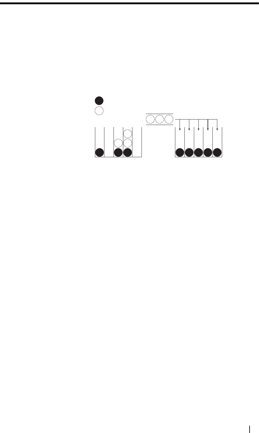
T2000 Programming Application User’s Manual Introduction to Trunking 119
Introduction to Trunking
A trunking system is an efficient alternative to a conventional repeater-based
system. In a conventional system, radio users compete for access to individual
channels, and one channel can be overloaded with traffic while others are
virtually unused. A trunking system allows the automatic sharing of several
channels by a number of radio users. Channels are pooled and allocated on
demand for the duration of a call. As calls are completed, the channels are
returned to the pool for allocation for other calls. Channel use is, therefore,
optimised and the time each user must wait to make a call is reduced, as shown
below.
Thus each user has access to any free channel in a system. However, this access
is under control of the trunking system and not under user control in much the
same way as subscribers on the public switched telephone network make calls
with equal priority but do not dictate the route that their call takes.
The function of the trunking system is complex; however, radio operation is
simple because the system protocol and internal processing are transparent to
the radio user. The use of microprocessors throughout the system adds features
not found on conventional systems. Automatic call logging assists in monitoring
the general performance on the system and provides data to bill trunking system
subscribers according to their individual on air time.
Control Channel Communication
One channel is designated the control channel, which the trunking system
controller (TSC) uses to communicate with all radios on the system. Radios
listen to the control channel until they are directed to a traffic channel to
participate in a call. Traffic channels are allocated by the channel control
module for the duration of the call. At the end of a call, the radios revert back
to monitor the control channel. The traffic channel is released into a standby
mode awaiting the next allocation for a call.
The control channel communicates with the radios on the system using
codewords. Every codeword is 64 bits long and consists of 48 bits of data and a
16-bit cyclical redundancy code (CRC), which is used for error checking. The
codewords are sent over the control channel using fast frequency shift keying
(FFSK), where a 1200 Hz tone represents digital one and an 1800 Hz tone
represents digital zero.
Key:
Call in progress
Caller waiting
Conventional Radio
Channels
Trunked Radio
Channels

120 Part E: Concepts M2000-00-003-806 © Tait Electronics Ltd 2002
A protocol called “slotted Aloha” is used to communicate over the control
channel. All radios monitor the control channel’s frequency, communicating
continuously with the TSC using the appropriate codewords. Every second the
TSC broadcasts approximately 20 codewords to the radios, and every second
there are approximately 10 opportunities for radios to send codewords to the
TSC. In simple terms, the codewords sent from the TSC ask each radio in turn
“do you want to make a call?” If the radio user has not initiated a call, the radio
will respond “no”. If a call has been initiated, the radio will respond “yes”,
together with the identity of the called party and the type of call.
The system can be set up so that different channels act as the control channel at
different times. The system can also be set up so that if a priority call is
attempted when there are no free channels, the control channel can temporarily
act as a traffic channel.
A radio remains on the control channel until it requests and receives permission
to make a call or until it is notified that a call is being set up. The call setup
process for a radio-to-radio call in which the called radio is free and the calling
radio ends the call is illustrated below.
When the call is cleared down, both radios again monitor the control channel.
Early Trunking Systems
Early trunking systems were usually based on five-tone Selcall or DTMF
signalling but they had no common standard.
Over time, the radio spectrum became more crowded and so having some
channels overloaded while others were virtually unused became less acceptable.
In the early 1980s it become apparent that more efficient management of the
frequency spectrum was necessary. The MPT 1327 and MPT 1343 standards
were developed as part of the drive to make more efficient use of the frequency
spectrum.
Radio
A
Radio
B
TSC
Control
channel
signalling
Traffic
channel
signalling
Radio B accepts
incoming voice call
Radio A requests a
call to Radio B TSC informs
Radio B that a call
is incoming
Radio A goes to
channel allocated
for call
Radio A requests
disconnection
Call in progress
Radio B goes
channel allocated
for call
Call in progress
TSC directs Radio B
to clear down call
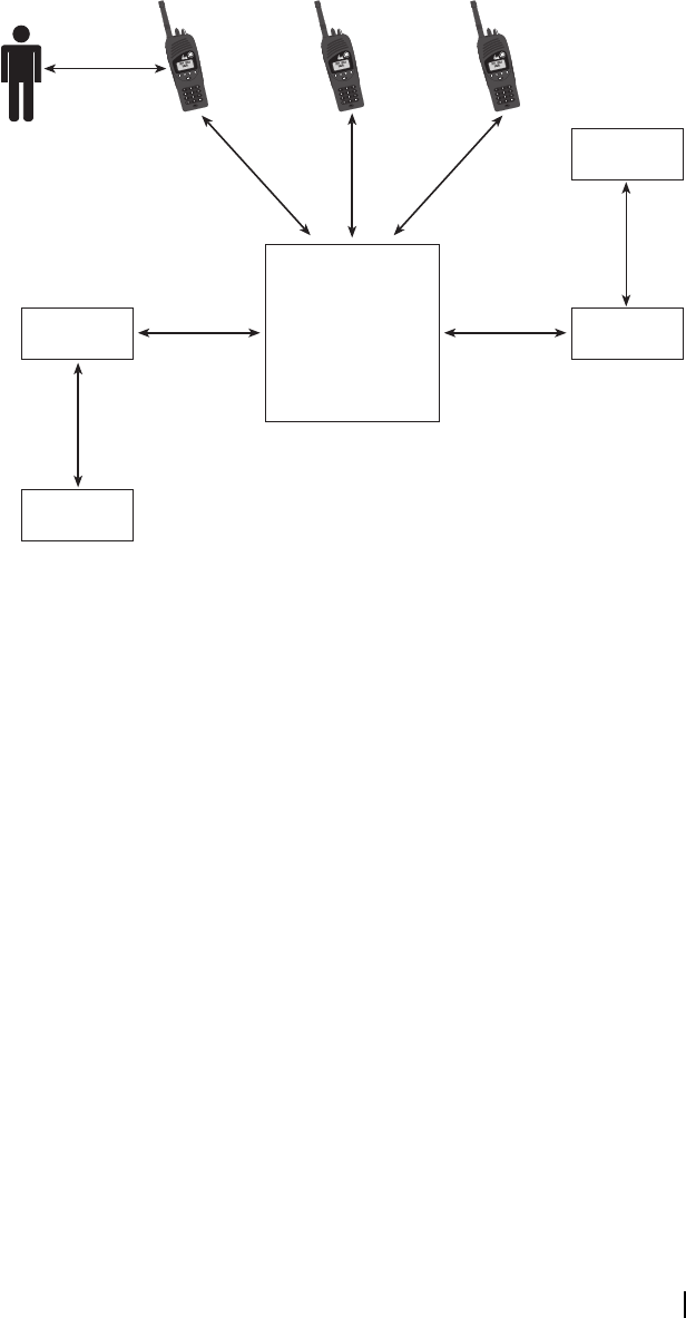
T2000 Programming Application User’s Manual Introduction to Trunking 121
Both standards were published by the United Kingdom Department of Trade
and Industry. MPT 1327 describes a signalling standard for trunked private land
mobile radio systems. It describes the protocol used for communication
between a trunking system controller (TSC) and the radios on the network.
MPT 1343 describes the radio interface and outlines the minimum performance
requirements for radios operating on MPT 1327-compliant networks. In short,
MPT 1327 describes the communications protocol used between the network
and the radios on the network, whereas MPT 1343 describes the radio
performance and the interface between the radio and the radio user. The
interactions on an MPT network are illustrated below.
Since MPT 1327 and MPT 1343 were published, a number of variants of the
MPT 1343 specification have arisen that offer different radio-user interfaces,
which are commonly referred to as dialling schemes. Tait trunked radios are
designed to operate on MPT 1327-compliant networks and support the
following MPT 1327-compatible dialling schemes:
■MPT 1343
■CPSX
■Nokia ANN
■ZVEI
■Number Presets
Addressing
A unique identity number is programmed into each radio operating on a
trunking network so the radio can be contacted by the TSC and, thus, by the
other users of the system. The identity number consists of a unique number for
the radio and numerical information shared with the other members of the same
organisation, or fleet. The identity of each radio provides a unique address that
allows it to be contacted by members of the same fleet and other fleets using the
same trunking network.
MPT 1343
MPT 1327
MPT
1327
MPT
1327
MPT
1327
MPT
1327
Trunking Network
Telephone
PSTN
MPT
1327
PABX
Telephone
MPT 1327

122 Part E: Concepts M2000-00-003-806 © Tait Electronics Ltd 2002
MPT 1327 and MPT 1343 specify different but related numbering schemes for
addressing trunked radios.
■MPT 1327 specifies the numbering scheme used for identifying radios on a
network. MPT 1327 numbers are used for all communications between all
elements of the trunking network, including the radios operating on that
network.
■MPT 1343 specifies the numbering scheme used by radio users. The MPT
1343 numbering scheme is simpler than the MPT 1327 format and allows
radio users to address radios without having to remember long addresses.
Typically it is possible to make a call by dialling only a two- or three-digit
number.
As discussed in “Early Trunking Systems” on page 120, variants of the MPT
1343 specification have arisen that offer different radio-radio user interfaces,
which are commonly referred to as dialling schemes. These dialling schemes
include:
■CPSX dialling
■Nokia ANN
■ZVEI
MPT 1327 Numbering
MPT 1327 numbers are used by the trunking system controller for
communicating with radios and other devices on the network.
Under MPT 1327, each radio is assigned a unique identity as follows:
The 3-digit prefix merely extends the range of numbers available for addressing.
The available idents (1 to 8100) are divided to provide individual and group
addresses. A block of idents are usually allocated for use by a particular fleet.
Idents 0 and above 8100 are reserved for addressing special destinations, such as
PABX and PSTN numbers.
MPT 1343 Numbering
Under MPT 1343, radios on a network are divided into fleets. Since a trunking
system is used by many different organisations, a fleet usually includes all the
radios of a single organisation, although a large organisation could have several
fleets on the network.
All radios within a fleet have the same fleet number and it is usually possible to
make calls between radios in different fleets. Each radio in a fleet has a two- or
three-digit unit number that is assigned to only one radio in the fleet. If the
radio number is two digits, there can be up to 70 radios in that fleet; if the radio
number is three digits, there can be up to 700 radios in the fleet. The diagram
below illustrates MPT 1343 radio numbering.
p p p / i i i i
3 digit prefix
between 0
and 127
4 digit ident
between 1
and 8100

T2000 Programming Application User’s Manual Introduction to Trunking 123
MPT 1343 allows radios to be grouped together so that calls can be received
simultaneously. A range of numbers (called group numbers) are reserved for
identifying groups of radios, and one or more radio units may be associated with
that group number (subscribed to the group). These two- or three-digit group
numbers are used in place of the radio unit number, as illustrated below.
To make a call to another radio, the radio user dials an MPT 1343 number,
which is converted to MPT 1327 for communication with the TSC and the
receiving radio. In the receiving radio, the MPT 1327 number is converted to
MPT 1343 for displaying to the radio user.
In order for the addresses to be converted correctly:
■the trunking system must be aware of how the available idents are
partitioned into fleets, and
■the radios must be aware of the base ident of their own fleet.
CPSX Dialling
As with MPT 1343 numbering, radios using CPSX dialling have a prefix, fleet
number and unit number, as illustrated below.
The prefix allocation is identical to MPT 1343, but:
■the fleet number is two digits, from 20 to 79
■the unit number is three digits, from 200 to 999
■unit numbers from 900 to 999 are reserved for groups
p p p / f f f f / u u
3-digit prefix between
200 and 327
p p p / f f f f / u u u
4-digit fleet number
between 2001 and 6050
2-digit unit number
between 20 and 89,
or a 3-digit unit
number between
200 and 899
p p p / f f f f / g g
p p p / f f f f / g g g
2-digit group number
between 90 and 99,
or a 3-digit group
number between 900
and 998
p p p / f f / u u u
3-digit prefix
between 200
and 327
2-digit fleet
number from
20 to 79
3-digit unit
number from
200 to 999*
*Unit numbers 900 to 999 are
reserved for groups.

124 Part E: Concepts M2000-00-003-806 © Tait Electronics Ltd 2002
■individual and group numbers use the same fleet number.
Within each prefix, there are 8100 user addresses, which are divided into ten
blocks of 810 addresses each. Three parameters, Large, Medium and Small,
specify how the number and size of fleets within those blocks of 810 addresses.
There are four options for fleet size:
■Large: 700 units
■Medium: 354 units
■Small: 236 units
■Tiny: 118 units.
The number of blocks allocated as large, medium, small and tiny fleets in a
prefix is calculated as follows.
So if parameters Large, Medium and Small are 2, 7 and 9 respectively, there are:
■2 blocks of large fleets = 2 large fleets
■5 blocks of medium fleets = 10 medium fleets
■2 blocks of small fleets = 6 small fleets
■1 block of tiny fleets = 6 tiny fleets
The allocation of fleets throughout the prefix’s 8100 idents, for this example, is
as illustrated in the diagram below.
Note that within each prefix, fleets are grouped together according to size. That
is, all large fleets will be allocated to the lower idents and all tiny fleets will be
allocated to the higher idents.
Within each fleet, there is a range of individual and group addresses. For each
fleet size, the possibilities are:
Large fleets = l
Medium fleets = 2 (m - l)
Small fleets = 3 (s - m)
Tiny fleets = 6 (10 - s)
810 16200 2430 3240 4050 4860 5670 6480 7290
1619 2429809 3239 4049 4859 5669 6479 7289 8100
Large fleet
Medium fleet
Small fleet
Tiny fleet

T2000 Programming Application User’s Manual Introduction to Trunking 125
Under CPSX dialling, the number of digits the radio user is required to dial is
only five for interfleet calls (as opposed to 6 or 7 under MPT 1343) and eight
for interprefix calls (as opposed to 9 or 10 under MPT 1343). Radios can display
the caller’s identity for interfleet and interprefix calls, whereas under MPT 1343
radios can only indicate that the call is from outside the fleet or prefix.
Fleet Size Radios Groups Radio Number
Range
Group Number
Range
Large 700 100 200 to 899 900 to 999
Medium 354 51 200 to 553 900 to 950
Small 236 34 200 to 435 900 to 933
Tiny 118 17 200 to 317 900 to 916

126 Part E: Concepts M2000-00-003-806 © Tait Electronics Ltd 2002
Trunking Call Strings
Note that you cannot enter these strings directly into T2030 and T2035 radios.
They will have to be set up as preset calls (using the Preset Calls Form).
Table 5: MPT1343 Common Call Setup
Dialling String Call To Example
0PSTN number 0 03 3456789 #
20 to 89 Radio in same fleet as you (nn) 89 #
200 to 899 Radio in same fleet as you (nnn) 899 #
2001 to 6050 Radio in another fleet with same
prefix as you
6050 nn #
200 to 327 Radio in another fleet with
different prefix to you
327 6050 nn #
90 to 99 Group in same fleet as you (GG) 90 #
900 to 999 Group in same fleet as you
(GGG)
900 #
Table 6: ANN Fleet Calls
Fleet Size Call To Example
Large Radio 234 in Fleet 1 with same
prefix as you
7 1 234 #
Radio 235 in Fleet 2 with
different prefix i.e. 32
7 32 2 235 #
Medium Radio 23 in Fleet 51 with same
prefix as you
7 51 23 #
Radio 23 in Fleet 52 with
different prefix i.e. 126
7 126 52 23 #
Small Radio 23 in Fleet 80 with same
prefix as you
7 (8or9) 80 23 #
Radio 23 in Fleet 81 with
different prefix to you i.e. 3
9 3 81 23 #
Table 7: CPSX Dialling Calls
Call Type Call To Example
Own fleet Radio 213 in Fleet 34 in same
fleet as you
213 #
Interfleet Radio 215 in Fleet 36 (another
fleet)
36 215 #
Interprefix Radio 217 in Fleet 38 (another
fleet) of Prefix 202
202 38 217 #

T2000 Programming Application User’s Manual Trunking Call Strings 127
Table 8: Preset Calls
Dialling String To Example
0 then 0 to 99 # Preset strings (leading zero) 069 #
Table 9: Conventional Channels
Dialling String To Example
101 to 110 # Conventional channels 106 #
Table 10: Special Functions using “*...#”
Dialling Code Function Example
*0# Request Base Despatcher Callback *0#
*0*nnn# Request another Despatcher Callback *0*234#
*0ss*nn# Status Call (ss = Status 01 to 30) *015*23#
*0ss# Status Call to Despatcher (ss = Status 01 to 30) *015#
*1*nn# Conference Call to Group nn *1*92#
*11*nn# Broadcast Call to Group nn *11*923#
*31*nn# Non-prescribed Data Calls *31*23#
*41*nn# Divert Own Calls to Radio nn *41*23#
*41*0nn...#
*44*nn*mm#
Divert Own Calls to PSTN nn
Divert 3rd Party Calls nn to mm
*41*00335...#
*44*23*21#
*48# Queue Incoming Calls *48#
*49# Do Not Disturb *49#
*700# Display name of the current network *700#
*70n# Change to network n (1 or 2) *701#
*8*nn# Priority Call to Radio nn *8*23#
*8*1*9n# Priority Conference Call to Group nn *9*1*923#
*9*nn# Emergency Call to Radio nn *9*23#
*9*1*9n# Emergency Conference Call to Group nn *9*1*92#
**nn# Abbreviated Dialled Codes (1 * 49) **3#
Table 11: Special Functions Using “#...#”
Dialling Code Function Example
#0# Cancel Base Despatcher Callback #0#
#0*nnn# Cancel another Despatcher Callback #0*234#
#41# Cancel Own Call Diversion #41#
#44*nn# Cancel 3rd Party Call Diversion #44*23#
#45# Cancel Incoming Call Diversions #45#
#48# Cancel Queuing of Incoming Calls #48#
#49# Cancel Do Not Disturb #49#


T2000 Programming Application User’s Manual Troubleshooting 129
Part F Troubleshooting
This part outlines common problems related to the T2000
Programming Application.
Topics
■No appropriate licence to use this functionality
■Cannot see the forms tree
■Cannot find a field
■Cannot enable a field
■Radio won’t read or program
■Checksum Error

130 Part F: Troubleshooting M2000-00-003-806 © Tait Electronics Ltd 2002

T2000 Programming Application User’s Manual Troubleshooting 131
No appropriate licence to use this functionality
The application displays the following message when starting:
“You do not have an appropriate license to use this functionality”.
One or more system files have not been registered during installation due to the
computer not restarting when prompted. Restart your PC.
Cannot see the forms tree
The windows have been resized so the forms tree is no longer visible. Click and
drag the bar to the right of the tree view to display it.
Cannot find a field
■Field is factory only and can only be viewed with a dongle.
■Field is on another form. Search the online help for more information on
the field and where to find it.
Cannot enable a field
■Field is disabled for that access level. Select a higher Access Level
(Tools > Access Levels).
■Another field is be disabling it. Use What’s This help (click the toolbar icon
or press Shift+F1) for help on how to enable the field.
Radio won’t read or program
■The wrong Communication Port has been selected. Select another
Communication Port in Tools > Options.
■The programming cable between the Communication Port and the Radio
is not connected properly. Make sure all cables are working and are
connected.
Checksum Error
The application displays a message: “Checksum failed for item ...” when
attempting to load a file.
This means that some of the data in the file is corrupt. The application will
attempt to load what data it can.
After the file is loaded, check each field carefully for values that have been set
back to the default, and change where necessary.
Subaudible Signalling Does Not Work
Check that the Monitor Function Disables field (Receiver Monitoring form) is
set to Selcall Mute. If set to All Mutes then the radio will hear all activity on the
channel, even with different Rx and Tx Signalling values (Channels form).
Scanning Does Not Work
Check that Off Hook Scanning is enabled (Channels form for T2010/T2015
radios, Scan Groups form for T2020 radios).


T2000 Programming Application User’s Manual Glossary 133
Glossary
This part contains a list of key words and phrases used in the programming
application.
A
abbreviated dialling The trunking system can be configured so that radios on the system can make
a call to a PABX/PSTN number without dialling the full number. Abbreviated
dialling will only work if the system node has been programmed with
abbreviated number sequences.
access level The access level determines the fields and forms that are editable. The access
level depends on the option selected under Tools > Access Level.
ACK ACK is short for acknowledgement. An acknowledgment is a signal sent by a
called radio unit as part of the call setup procedure.
acquisition Trunked radios only.
When a radio has successfully acquired a control channel, it is permitted to
transmit and receive on that channel. The radio will listen to the control
channel until it is directed to a traffic channel to participate in a call.
address Trunked radios only.
The address is the 20-bit number by which a radio unit or group of units is
known on a network
address codeword Trunked radios only.
An address codeword is a 64-bit codeword that conforms to the requirements
of MPT 1327 and in which the first bit is set to 1. An address codeword is
always the first codeword in any message and defines the nature of the message.
ALLI call Trunked radios only.
An ALLI (all idents) call is a call to all radio units on a trunking system.
alpha symbol Alpha symbols are a T2020 feature.
An alpha symbol is a sequence of commands that can change to a specific
channel, dial a Selcall or DTMF call, change the radio’s status, or any
combination of these three tasks. Up to 20 alpha symbols can be defined and
these are available through alphanumeric entry mode.
Alpha symbols are defined in the Alpha Symbols form.
alphanumeric entry
mode In alphanumeric entry mode on T2020 radios, the user can select and execute
up to 20 alpha symbols. Alphanumeric entry mode is available once an alpha
symbol has been defined in the Alpha Symbols form.

134 Glossary M2000-00-003-806 © Tait Electronics Ltd 2002
For T2040 radios, alphanumeric mode allows the user to execute a call using a
predefined label set in the Preset Calls form, and also send short data messages.
ANI ANI is a Selcall feature.
ANI (automatic number identification) is a tone sequence transmitted during
voice transmission in order to identify the radio in use.
Selcall calls can be set up so that each radio automatically transmits its ANI
identity on each exchange of transmissions (each press of the PTT), unless the
ANI suppression time has not expired. ANI makes it possible to set up a log of
a radio’s channel activity.
T2020 radios can also decode a Selcall ANI call and display the identity of the
caller. To do this, the call must match the receive (Rx) format, and there can
be no C (caller identity) burst in the Rx format.
The key difference between ANI and automatic caller identification is that with
automatic caller identification, only the radio receiving the call displays the
identity of the radio transmitting on the channel. For ANI, any radio that has
ANI decoding enabled can see which radios are using a channel.
Selcall ANI encoding is setup in the Selcall Setup and Selcall Identity tabs and
Selcall ANI decoding is enabled in the Selcall Features form.
ANI suppression
time The ANI suppression time is the minimum amount of time between
subsequent transmissions of an ANI sequence.
The ANI suppression time is set in the Selcall Setup tab (Selcall ANI).
audible indicators T2000 radios use combinations of audible indicators and visual displays to
indicate the radio’s current state and activity.
Audible indicators include keypress confidence tones, received call signals, low
battery and high temperature warnings, transmit timer and unanswered call
signals.
Audible indicators are enabled in the User Selectable form (conventional radios)
and Interface Options form (trunked radios)
auto acknowledge Auto acknowledge is a Selcall feature.
When a radio receives a Selcall sequence that contains its identity, it can be
programmed to transmit an auto acknowledge sequence.
An auto acknowledge sequence can also include a status digit. On T2020 radios,
if the called unit status display feature is enabled, a status is displayed upon
receipt of the auto acknowledge.
Auto acknowledge is setup in the Selcall Setup and Selcall Identity tabs.
auto quiet timer The auto quiet timer determines how long monitor remains active. The auto
quiet timer is suspended while the radio is transmitting or while there is valid
activity on a channel. Once a transmission is complete or when the radio is
switched to another channel, the auto quiet timer resets to the programmed
duration of the auto quiet timer.
The duration of the auto quiet timer is set in the Receiver Monitoring form.

T2000 Programming Application User’s Manual Glossary 135
automatic caller
identification Automatic caller identification is a T2020 Selcall feature.
When an incoming call is received that matches the radio’s Rx decode
sequence, the caller identity is displayed so the radio user can identify the caller
before responding.
Automatic caller identification only works if there is a C (caller identity) burst
in the receive (Rx) format, and is enabled in the Selcall Features form.
B
background hunt Trunked radios only.
A background hunt is carried out as part of the control channel acquisition
procedure. The background hunt is a method prescribed in MPT 1343 for
monitoring other control channels and migrating to a superior channel when
one is found. The background search is performed by periodically leaving the
current control channel and sampling other control channels. What channels
are sampled is specified in the Normal Hunt Channels Grid (Hunting
Parameters form). If a channel is consistently found for a certain number of
consecutive samples to be preferred (according to the NDD preference data
defined in the Acquisition Data form) or stronger than the current control
channel by a certain margin, the radio will perform a preferential hunt to
acquire the new control channel.
backlighting On T2020 and T2040 radios the control head LCD lights up when there is
activity on the radio, such as when a key is pressed or when a call is received.
The LCD backlighting can be set to either bright or dim and, on T2020 and
T2040 radios, can also be dimmed when the radio is in economy mode.
Backlighting settings are made in the User Selectable form (conventional radios)
and the Interface Options form (trunked radios).
birdie A birdie is a hum or whistle on a channel caused by internal interference. A
birdie can be eliminated by activating a birdie killer on the channel.
birdie killer A birdie killer is an internal circuitry switch that greatly reduces the effect of a
birdie on a channel.
Channels needing birdie killers are assigned in the Birdie Channels form
(conventional radios only).
bit Bit is an abbreviation for a binary digit consisting of either a 0 or a 1. Eight bits
are equivalent to one byte.
broadcast call Trunked radios only.
A broadcast call is a group call in which only the radio user who initiated the
call may speak. Contrast with conference call.
In a broadcast call, all radios in the group are directed to the same traffic channel
for the duration of the call. However, the call is cleared down as soon as the
announcement is delivered and the recipients are not given an opportunity to
respond.

136 Glossary M2000-00-003-806 © Tait Electronics Ltd 2002
buffered dialling When a DTMF string is dialled, the string is either transmitted separately as each
individual key is pressed (normal dialling) or in its entirety once the enter key
is pressed (buffered dialling).
The DTMF dialling type is set in the DTMF form (conventional radios only).
burst A burst is a series of tones (a tone burst) or gaps (a gap burst) in a Selcall
sequence.
byte A byte is a group of 8 bits. Half of a byte is a nibble. Computer memory is
measured in kilobytes or megabytes.
C
call diversion For T2020 radios, call diversion allows the radio user to divert received calls to
another channel. The radio recognises a call diversion message from another
radio, and switches to the designated channel. T2020 radios can only divert calls
to a portable radio (such as a Tait Orca), not to another T2000 mobile radio.
For call diversion to operate correctly, an auto acknowledge is required (Selcall
Identity tab). Call diversion is enabled in the Selcall Features form.
For trunked radios, call diversion allows the radio user to divert received calls
to another address, such as another radio or a PSTN or PABX number. Call
diversion is enabled in the Call Options Form.
call queuing If the radio user is unable to answer calls immediately, they can be stored in the
call queue so that the user can call back later. Up to 10 calls can be stored for
T2020 radios and up to 20 calls can be queued for trunked radios.
Call queuing is enabled in the Selcall Features form for T2020 radios and the
Call Options form for trunked radios.
callback Trunked radios only.
When an incoming call is terminated, a radio may be programmed to display
the caller’s identity. If the radio user wishes to call the party back, they can do
so by pressing the enter key.
called unit status
display Called unit status display is a T2020 Selcall feature.
When a called radio responds with an auto acknowledge that contains a status
digit, the auto acknowledge sequence is displayed on the calling radio, together
with any attached status message.
Called unit status display is enabled in the Selcall Features form.
caller identity In a Selcall sequence, the caller identity is the part of the sequence that identifies
the radio transmitting the sequence. In the transmit (Tx) format and receive
(Rx) format, the caller identity is represented by the character C, and so this
part of a sequence is known as the C burst.

T2000 Programming Application User’s Manual Glossary 137
captured channel When the radio is scanning a group of channels and valid activity is found on
one of those channels, the radio remains on that channel until the activity is no
longer valid and the group hold time (scan hold time on T2010 radios) has
expired or until valid activity is found on a higher priority channel. While the
radio is stopped on that channel, the channel is said to be captured, and
transmissions are on the captured channel rather than on the home channel.
captured priority
sample timer The value of the captured priority sample timer determines how often priority
channels are scanned when a lower priority channel is captured.
The duration of the captured priority sample timer is set in the Scan Groups tab.
CCI See computer controlled interface.
CCIR CCIR is one of the Selcall tone sets the T2000 Programming Application
supports. Note that E is the repeat tone.
CCSC Trunked radios only.
CCSC stands for Control Channel System Codeword. The CCSC is used in
MPT 1327 and MPT 1343 to identify the system to radio units and provides
synchronisation for the address codeword that follows.
channel A channel is a pair of radio frequencies, one used for transmitting and one used
for receiving.
For conventional radios, channels are set up in the Channels form. For trunked
radios, channels used by the trunking system are set up in the Trunked Channel
Blocks form. The channels used in conventional channel operation are set up
in the Conventional Channels form.
channel entry/
selection mode In channel entry mode, or channel selection mode, the user can change to a
different channel or scan group. Channel entry mode is automatically available
on all conventional radios.
Tone : Frequency (Hz) Tone : Frequency (Hz)
0 : 1981 8 : 1747
1 : 1124 9 : 1860
2 : 1197 A : 2400
3 : 1275 B : 930
4 : 1358 C : 2247
5 : 1446 D : 991
6 : 1540 E : 2110
7 : 1640 F : 1055

138 Glossary M2000-00-003-806 © Tait Electronics Ltd 2002
channel spacing Channel spacing is the interval between channels. For T2000 radios, this is 12.5,
20 or 25 kHz. Wideband radios can be programmed for 20 and 25 kHz channel
spacing only. Narrowband radios can be programmed for 12.5, 20 and 25 kHz
channel spacing.
Channel spacing depends on IF bandwidth (wide or narrow), which is
hardware dependant and is defined in the Channels form (conventional radios).
For trunked radios, channel spacing for the trunking system channels is set in
the Trunked Channel Blocks form. Channel spacing for conventional channel
operation is set in the Conventional Channels form.
codeword Messages on a trunking system are transmitted as codewords. Every codeword
is 64 bits long and consists of 48 bits of data and a 16-bit cyclical redundancy
code (CRC), which is used for error checking. The codewords are sent over
the control channel using fast frequency shift keying (FFSK), where a 1200 Hz
tone represents digital one and an 1800 Hz tone represents digital zero.
The two types of codeword are: address codeword and data codeword.
comprehensive
hunt Trunked radios only.
A comprehensive hunt is carried out as part of the control channel acquisition
procedure. When the control channel acquisition procedure has failed to
identify a suitable control channel, the radio will then search through all
channels in the trunked channel blocks defined for the radio, except those
specified as non-applicable in the Non Applicable Channels Grid.
computer
controlled interface The computer controlled interface (CCI) provides a means of controlling
T2020/T2030/T2035/T2040 radios from some form of computer equipment.
The CCI allows for the implementation of semi- and fully-automatic
communications systems such as short data messaging (SDM), computerised
despatch terminals, remote outstations and data radio terminals.
Settings for the computer controlled interface are made in the CCI form, and
Data Parameters form (trunked radios only).
conference call Trunked radios only.
A conference call is a group call in which all group members can participate in
the conversation. Contrast with broadcast call.
In a conference call, all radios in the group are directed to the same traffic
channel for the duration of the call. All radios participate freely, as they would
for a normal radio-to-radio call.
confidence
indicators Confidence indicators provide feedback to the radio user on how the current
operation is proceeding. For example, keypress confidence tones are the tones
heard when a keypad key or a function key is pressed and tell the user whether
or not an action is permitted.
control channel In a trunking system, the control channel is used by the site to let the radio units
in the site’s coverage area know when they can transmit their call information.
control channel
acquisition Trunked radios only.

T2000 Programming Application User’s Manual Glossary 139
Control channel acquisition is the procedure by which a radio that is not
currently on a traffic channel attempts to select a control channel. Control
channel acquisition consists of hunting for a control channel and confirming
that any candidate control channels are suitable to acquire.
control status Control status is a T2020 Selcall feature.
A control status is a status digit that when received, initiates a particular radio
operation. For example, when a radio receives a quiet interrogation status digit,
it transmits its auto acknowledge sequence with its current status appended
without activating the call received indicator.
conventional
channel operation A trunked radio can switch between trunking and conventional modes of
operation. In conventional mode, a radio communicates directly with other
radios or via a repeater rather than through the trunking system.
CPSX dialling CPSX dialling is a dialling scheme designed for use on Chinese networks that
use 5-digit interfleet dialling. It is compatible only with other CPSX dialling
trunking systems.
Unlike radios using MPT 1343 dialling, radios using CPSX dialling can display
the caller’s identity for interfleet and interprefix calls.
CTCSS CTCSS (continuous tone controlled squelch system) is a type of signalling used
for segregating groups of users. CTCSS uses subaudible tones between 67 and
250.3 Hz to identify a group of radio users.
CTCSS/DCS filter The CTCSS/DCS filter removes any CTCSS or DCS tones that may be
present on the received audio. The filter limits the range of frequencies the
radio passes from the incoming signal to the speaker and so in some situations
affects signal quality. Filtering can be automatically switched off for channels
that do not have CTCSS or DCS.
The CTCSS/DCS filter is enabled in the Subaudible Signalling tab
(conventional radios only).
D
data See computer controlled interface.
data codeword A data codeword is a 64-bit codeword that conforms to the requirements of
MPT 1327 in which the first bit is set to 0. Data codewords are linked to an
address codeword and supplement the information in the address codeword.
DCS DCS (digital coded squelch) is a type of signalling used for segregating groups
of users. DCS uses subaudible tones between 10 and 134 Hz to transmit digital
data to identify a group of radio users.
DCS codes take the form of a continuously repeating 23-bit digital codeword
that represents a user group. Codewords are identified by a three-digit octal
number, which forms part of the codeword. The remainder of the codeword
includes a sequence of bits derived mathematically from the three-digit code.

140 Glossary M2000-00-003-806 © Tait Electronics Ltd 2002
When assigning DCS signalling for a channel, it is only necessary to specify the
three-digit code. See “Standard DCS Codes and Their Inverses” on page 115
and “Non-Standard DCS Codes and Their Inverses” on page 115 for the DCS
codes T2000 conventional radios support.
DCS polarity DCS signals are susceptible to polarity inversion at various points in the signal
path from originator to recipient. On some systems, consistent inversions can
be compensated for by forcing the radio to decode the inverse of every
codeword.
Tx and Rx DCS polarity is set in the Subaudible Signalling form.
default mode Default mode is a T2020 feature.
The default mode is the mode the radio enters into once the power-up
sequence is complete and after 10 seconds of no user activity.
Possibilities are:
■channel entry/selection mode
■DTMF dialling mode
■Selcall dialling
■status entry mode
■alphanumeric entry mode
■user function menu entry mode
No default mode is also an option.
When no default mode has been programmed, the radio powers up in the mode
selected when the radio was last on.
Default mode is set in the Specifications form.
deferred calling Deferred calling is a Selcall feature.
When the transmit inhibit conditions are Busy or Mute, a Selcall call cannot be
transmitted on a busy channel. When the deferred calling feature is enabled, the
call is stored and sent at a random time between 1 and 10 seconds after the
channel becomes free.
When a call has been deferred, scanning is suspended until the call is successfully
sent or until the deferred call is cancelled (by pressing any key or switching to
another channel).
Deferred calling is enabled in the Selcall Features form for T2020 radios and is
always enabled for T2010/T2015 radios, as long as the Tx Inhibit field is set to
Busy or Mute (Transmitter Setup form).
despatcher Trunked radios only.
A despatcher is a person who gives official instructions by radio to a fleet.
despatcher callback
request Trunked radios only.
A despatcher callback request is a call sent to the fleet’s despatcher. The
despatcher will then call back the calling radio at a convenient time.
dialling scheme Trunked radios only.

T2000 Programming Application User’s Manual Glossary 141
The dialling scheme determines how a radio user makes calls to other radios in
and outside the fleet, groups of radios, PABX extensions and PSTN numbers.
The dialling scheme is the set of numbers a radio user can dial.
T2000 radios support the following dialling schemes:
■MPT 1343
■CPSX Dialling
■Nokia ANN
■ZVEI
■Number Presets
do not disturb Trunked radios only.
Do not disturb allows the radio user to ignore incoming calls while still making
outgoing calls as usual. Do not disturb can be activated by dialling *49# and
can be deactivated by dialling #49#.
double voting Double voting is a type of voting in which the signal strength of each channel
in the group is measured twice.
double voting with
signalling Double voting with signalling is a type of voting in which a channel must have
valid signalling before it is made the home channel. The channel’s signal
strength is measured twice.
DTMF DTMF is a T2020 or T2040 feature.
DTMF (dual tone multiple frequency) is the tone-based system used for the
world’s telephone networks. A DTMF “tone” consists of a pair of tones, which
are sometimes referred to as “touch tones”.
T2020 radios can encode DTMF tones and make DTMF calls (see DTMF
string), but cannot decode and receive DTMF calls.
T2040 radios can dial DTMF strings with a DTMF options board fitted. DTMF
options are enabled in the Interface Options form.
DTMF call See DTMF string.
DTMF dialling The DTMF dialling feature allows the radio user to dial DTMF strings using
the numeric keypad or a DTMF microphone.
DTMF dialling mode DTMF dialling mode is a T2020 feature.
In DTMF dialling mode, the user can dial DTMF strings. DTMF dialling mode
is available when the Manual Dialling field in the DTMF form is enabled.
DTMF redial DTMF redial is a T2020 feature.
DTMF redial is a feature of DTMF dialling mode. When the radio user enters
DTMF dialling mode, the last DTMF string transmitted is displayed. The user
can transmit that string by pressing the enter key.
DTMF redial is enabled in the DTMF form.

142 Glossary M2000-00-003-806 © Tait Electronics Ltd 2002
DTMF string A DTMF string is a series of DTMF tone pairs. When defining DTMF strings,
the different tones are represented by the characters 0-9, A-D, * and #. The
frequencies used are determined by an internationally accepted standard.
dual priority
scanning Dual priority scanning is a type of scanning in which two of the member
channels are designated as priority channels. The priority channels are scanned
more often than the other member channels.
DZVEI DZVEI is one of the Selcall tone sets the T2000 Programming Application
supports. Note that E is the repeat tone.
E
economy mode Economy mode reduces the radio’s power consumption when it is idle. When
economy mode is enabled, and there has been no valid activity on a channel for
the duration of the economy time out, the radio enters economy mode. On
T2020 and T2040 radios, the LCD backlighting may dim or switch off when
the radio enters economy mode.
The beginning of a transmission may be lost if it is received after a period of
inactivity has caused the radio to enter economy mode.
The timeout times for economy mode are set in the Power Saving form. The
economy mode backlighting level for T2020 radios is set in the User Selectable
form, and for T2040 radios is set in the Power Saving form.
economy time out The economy time out sets the time between when valid activity was last
detected on a channel and the start of economy mode.
The economy mode time out with ignition on and off is set in the Power
Saving form.
Tone : Frequency (Hz) Tone : Frequency (Hz)
0 : 2200 8 : 1830
1 : 970 9 : 2000
2 : 1060 A : 825
3 : 1160 B : 740
4 : 1270 C : 2600
5 : 1400 D : 885
6 : 1530 E : 2400
7 : 1670 F : 680

T2000 Programming Application User’s Manual Glossary 143
EEA EEA is one of the Selcall tone sets the T2000 Programming Application
supports. Note that E is the repeat tone.
EIA EIA is one of the Selcall tone sets the T2000 Programming Application
supports. Note that E is the repeat tone.
emergency call For conventional radios, when the emergency call is transmitted, the radio
enters emergency mode. An emergency call can be assigned to the auxiliary key
(T2020 radios), or to an external device. The Selcall emergency sequence is
defined in the Selcall Identity tab. Emergency operation is set up in the Selcall
Emergency form (T2020 radios only).
For trunked radios, an emergency call is a call that pre-empts other calls on the
trunking system when there are no free channels. Emergency calls can have a
different call time limit than normal calls. An emergency call is dialled
emergency mode Emergency mode is a T2020 Selcall feature, and a T2040 external call feature.
When in emergency mode, the radio transmits an emergency sequence or a call
string. The radio can be programmed to then cycle between receiving and
transmitting, so that the called party can hear activity near the radio and so
decide how to respond. The control head indicators on the radio remain
unchanged while in emergency mode.
Tone : Frequency (Hz) Tone : Frequency (Hz)
0 : 1981 8 : 1747
1 : 1124 9 : 1860
2 : 1197 A : 1055
3 : 1275 B : 930
4 : 1358 C : 2400
5 : 1446 D : 991
6 : 1540 E : 2110
7 : 1640 F : 2247
Tone : Frequency (Hz) Tone : Frequency (Hz)
0 : 600 8 : 1728
1 : 741 9 : 1869
2 : 882 A : 2151
3 : 1023 B : 2433
4 : 1164 C : 2010
5 : 1305 D : 2292
6 : 1446 E : 459
7 : 1587 F : 1091

144 Glossary M2000-00-003-806 © Tait Electronics Ltd 2002
Emergency operation is set up in the Selcall Emergency form for T2020 radios,
and External Calls form for T2040 radios.
enhanced scanning Enhanced Scanning is a T2015 radio feature.
When enabled, the radio user can define a temporary scan list using the front
panel of the radio. Priority channels can be assigned to the list, as well as
designated channels for the [M1] and [M2] keys. The list will be reset to the
default either when the radio is switched off, or when the radio is switched on
with the PTT pressed.
Enhanced Scanning is enabled in the Specifications (Conventional) Form, the
temporary list can be read or programmed in the Enhanced Scan Form, and the
default scan list is set in the Channels Form.
ESN ESN stands for electronic serial number. This number is a unique identifier
given to each radio unit by the manufacturer. Radio units may be validated by
this number.
F
FFSK FFSK (fast frequency shift keying) is the signalling method employed in trunked
radios. Data is represented by 1 cycle of 1200 Hz (logic 1) or 1.5 cycles of 1800
Hz (logic 0) and is transmitted at 1200 baud.
fleet Each customer on a trunked network is assigned their own fleet. This keeps
each customer unique so that their activities can be monitored and controlled
separately from each other. Each radio unit on the network belongs to their
associated customer’s fleet.
FOACSU FOACSU stands for full off-air call set up. In full off-air call setup, a traffic
channel is not allocated for a call until the called party has answered.
frequency band The radio’s frequency band is the range of frequencies it is capable of
transmitting and receiving on.
The frequency band is set in the Specifications form.
G
gap A gap is a pause in the transmission of tones in a Selcall sequence. When
constructing Selcall sequences, a gap is represented by a hyphen (-).
A series of gaps makes up a gap burst.
gap burst A gap burst is a series of gaps. The gap burst length is determined by the number
of gaps in the burst.
Gap bursts are used to separate tone bursts in a Selcall sequence.

T2000 Programming Application User’s Manual Glossary 145
group For conventional radios, a group can refer to a scan group or to a group of radios
that is the recipient of a Selcall group call.
For trunked radios, group refers to one or more radio units that are the recipient
of a group call. In MPT 1327, each group is given a unique address, to which
radio units subscribe to be part of that group. The maximum number of groups
permitted is four for T2030 radios, and 32 for T2035 and T2040 radios.
group call For conventional radios, a Selcall call can be made to a group of radios by
including a group tone in the Selcall sequence. On T2020 radios, a single group
tone (G) can be dialled using the * key, and the # key fills the remainder of the
sequence with Gs. To make a Selcall group call using the # key, group dialling
must be enabled in the Selcall Features form. To make a Selcall group call using
the * key, group selective dialling must be enabled in the Selcall Features form.
For trunked radios, a group call is a call that involves more than two radios
simultaneously. Group calls can only be heard by radios subscribed to the group.
Group calls can be conference calls or broadcast calls. Groups are defined in the
Radio Unit ID form.
group hold time Conventional radios only.
The group hold time is the pause between when valid activity on a scan group
member channel ceases and when scanning resumes.
The group hold time is set in the Scan Groups tab.
group select Trunked radios only.
Group select allows the radio user to select a group or group of groups (scan
group) from the front panel of T2035 and T2040 radios.
Group Select is enabled in the Radio Unit ID form.
group tone Group tones are a Selcall feature.
The group tone, G, acts as a wild card tone and so is equivalent to all of tones
0 to 9, B, C, D or F. For example, when a Selcall sequence containing 123GG
for the receiver identity is transmitted, all radios with a five tone Rx decode
sequence starting with tones 123 recognise the Selcall sequence, and respond to
it.
To make a Selcall group call using the keypad, group dialling and group
selective dialling must be enabled in the Selcall Features form.
group user
programmable See programmable scanning and voting groups.
GTC Trunked radios only.
GTC stands for go to channel. A GTC message is sent by the control channel
as part of the call setup procedure. The GTC tells the radio units involved in
the call to switch to the traffic channel designated for the call.

146 Glossary M2000-00-003-806 © Tait Electronics Ltd 2002
H
handshaking Handshaking refers to the character definitions used to begin and end data flow
in CCI (computer controlled interface) operation. The handshaking characters
prevent the loss of data between the radio unit and the computer equipment.
Handshaking options are set in the CCI form.
hidden channel A hidden channel is a scan group member channel that is not accessible as an
individual channel.
Hidden channels are enabled in the Scan Groups tab.
home channel For scanning, the home channel is the channel in a scan group on which
transmissions are made, unless another channel has been captured. The home
channel is the first channel included in the group in the Scan Group Members
list.
For voting, the home channel is the channel that has been determined as having
the greatest signal strength. If no channel has been selected, then the home
channel is the first channel included in the group in the Scan Group Members
list.
hookswitch The microphone hookswitch is closed when the microphone button is
connected to the earthed microphone clip. Note that if the microphone clip is
not earthed, the hookswitch is disabled. To open the hookswitch, remove the
microphone from the microphone clip.
The operation of the hookswitch is affected by the following settings:
■The Hookswitch Monitor field (Receiver Monitoring form for
conventional radios, Conventional Channels form for trunked radios).
When this field is checked, opening the hookswitch activates the monitor
function.
■The Off Hook Scanning field (Channels form for T2010/T2015 radios and
the Scan Groups tab for T2020 radios). When this field is checked, scanning
continues when the hookswitch is open.
hunting Hunting is a procedure used by the radio unit to select an appropriate control
channel to allow a session with a trunking system to be initiated or continued.
The hunting process consists of systematic sampling of the forward channel
frequencies by the radio unit until it selects and confirms one of the forward
channels, which together with its paired return channel is an appropriate
control channel.
Types of hunting include:
■background hunt
■comprehensive hunt
■normal hunt
■preferential hunt
■resuming hunt
■single channel hunt
■vote now

T2000 Programming Application User’s Manual Glossary 147
IJK
ident The ident is the part of the radio’s address that uniquely identifies that radio. In
MPT 1327, radios are identified by a three-digit prefix and a four-digit ident.
All radios in a fleet usually have the same prefix, but no two radios should have
the same ident.
indicator Indicators provide feedback to the radio user on how the current operation is
proceeding and on the operating state of the radio. T2000 radios use
combinations of audible and visual indicators.
individual call Trunked radios only.
An individual call is a call from one radio to another. Because individual calls
take place on a traffic channel allocated specifically for that call, they cannot be
overheard by other radios in the fleet or on the same trunking network.
Individual calls are the most common type of trunking call.
interfleet call Trunked radios only.
An interfleet call is a call between two radio units that belong to different fleets.
interfleet group call Trunked radios only.
An interfleet group call is a group call in which participating radios belong to
different fleets.
invalid activity Invalid activity is traffic on a channel that carries signalling that does not match
that of the receiving radio.
keypress confidence
tones Keypress confidence tones are confidence indicators that tell the radio user
whether or not an action is permitted by emitting a tone whenever a keypad
key or function key is pressed.
Keypress confidence tones are enabled in the User Selectable form for
conventional radios and the Interface Options form for trunked radios.
L
label A label is a sequence of up to eight characters that can give the radio user
additional information about the radio’s current state. For example, a label can
be set that indicates which channel is currently selected.
In the case where the label stands for a string that is to be transmitted, e.g. for a
status message, it is not the status label that is transmitted but rather the status
digits. In order for the correct status label to be displayed on the receiving radio,
status messages (status digit plus status label) should be set the same for all radios
in a fleet.
LCD T2020 and T2040 radios have a control head LCD (liquid crystal display). In
combination with the radio’s LED indicators and audible indicators, the display
provides the radio user with information on the state of the radio.

148 Glossary M2000-00-003-806 © Tait Electronics Ltd 2002
lead in delay A lead in delay is the delay between when the radio starts transmitting and when
the first tones in a sequence are sent. A lead in delay gives the receiver time to
prepare to decode the incoming transmission (e.g. time to halt scanning, come
to full power or come out of economy mode).
LED indicator The light-emitting diodes on the radio control head assist in displaying the state
the radio is in. The audible indicators and the control head display provide
information intended to supplement that provided by the LED.
low power transmit The low power transmit feature can be used to change the transmit power from
the programmed level to low.
M
member channel Conventional radios only.
A member channel is a channel that belongs to a scanning or voting group.
monitor Monitor allows the radio user to override a conventional channel’s signalling
and so hear all traffic on a channel.
Note that monitor is not permitted in some countries.
MPT 1327 MPT 1327 is a radio unit signalling standard published by the United Kingdom
Department of Trade and Industry that describes the signalling standard for
trunked private land mobile radio systems.
MPT 1343 MPT 1343 is a performance specification standard published by the United
Kingdom Department of Trade and Industry that describes the system interface
specification for radio equipment to be used with commercial trunking
networks operating in Band III, sub-bands 1 and 2.
MPT 1343 also refers to the set of numbers a radio user can dial (the dialling
scheme).
mute A mute controls the circumstances under which a received signal is passed to
the radio’s speaker. When a mute is active, the radio’s speaker only unmutes
under certain conditions, determined by the type of signalling operating on a
channel.
mute received
audio Mute received audio is part of the T2015/T2020 Selcall emergency mode.
When mute received audio is enabled, the radio’s mute remains active while in
emergency mode and so the radio does not broadcast noise that may draw
attention in an emergency situation.
Mute received audio is enabled in the Selcall Emergency form.

T2000 Programming Application User’s Manual Glossary 149
N
NATEL NATEL is one of the Selcall tone sets the T2000 Programming Application
supports. Note that E is the repeat tone.
NDD NDD stands for network dependent data. NDD is an MPT 1343 term and is a
means of identifying specific control channel transmissions that originates
within a network.
network A network is a number of interconnected trunking systems.
non-captured
priority sample
timer
The value of the non-captured priority sample timer determines how often
priority channels are scanned when there is no captured channel.
The duration of the non-captured priority sample timer is set in the Scan
Groups tab.
Nokia ANN Nokia ANN (Algorithmic Network Numbering) is a dialling scheme designed
for use on Nokia Actionet networks. It differs from MPT 1343 in the way it
divides up fleets. Nokia ANN numbering reduces the number of digits that
must be dialled for calls between fleets.
non-prescribed data
call A non-prescribed data call is a data call of a non-MPT format that requires the
use of a traffic channel.
normal dialling Conventional radios only.
When a DTMF string is dialled, the string is either transmitted as each
individual key is pressed (normal dialling) or in its entirety once the enter key
is pressed (buffered dialling).
The DTMF dialling type is set in the DTMF form.
normal hunt A normal hunt is carried out as part of the control channel acquisition
procedure. A normal hunt covers all channel numbers likely to be used as
control channels on the selected network. For a normal hunt, the radio will
undergo registration on a new control channel, if necessary.
Tone : Frequency (Hz) Tone : Frequency (Hz)
0 : 1633 8 : 1336
1 : 631 9 : 1477
2 : 697 A : 1995
3 : 770 B : 571
4 : 852 C : 2205
5 : 941 D : 2437
6 : 1040 E : 1805
7 : 1209 F : 2694

150 Glossary M2000-00-003-806 © Tait Electronics Ltd 2002
The channels that will be searched as part of the normal hunt procedure are
defined in the Normal Hunt Channels Grid (Hunting Parameters form). If the
radio fails to find a suitable control channel among these channels, it will, if
programmed, carry out a comprehensive hunt.
NPD See non-prescribed data call.
number presets Number presets is a dialling scheme based on the MPT 1343 dialling scheme.
Number presets, however, limits the calls a radio can make to those
programmed as preset calls at radio programming time. The calls programmed
can be any number the radio user would normally be able to dial using MPT
1343 numbering.
O
off-air Trunked radios only.
The term off-air is used to describe the call setup procedure used when the
channels are setup and allocated even though the called party has not yet
answered. This usually occurs when it is known that the called party is available.
on/off volume
control The on/off/volume control is the round knob on the control head of T2000
radios.
one touch call One touch calls are a T2020 feature.
The auxiliary key on a T2020 radio can be set to transmit a predefined one
touch call. This call can be a Selcall or DTMF call.
The auxiliary key one touch call is set in the Key Settings form.
P
PABX PABX stands for private automatic branch exchange. A trunking system can be
connected to a PABX and so radios using that system can make calls to and
receive calls from PABX extensions.
PABX extension A PABX extension is a line on a PABX system.
polling Polling is the sampling of member channels to measure their signal strength
when the radio is voting a scan group.
polling interval The polling interval is how often the member channels in a voting group are
sampled (“polled”) for greatest signal strength.
power-up message The power-up message is the message displayed by T2020 and T2040 radios
after the radio is turned on.
The power-up message is programmable (Specifications form).

T2000 Programming Application User’s Manual Glossary 151
preferential hunt A preferential hunt is carried out as part of the control channel acquisition
procedure. A preferential hunt covers all channel numbers likely to be used as
control channels on the selected network. For a preferential hunt, the radio will
only acquire a control channel for which a preference exists.
Preference data is defined in the Acquisition Data form.
prefix In MPT 1327, radios are identified by a three-digit prefix and a four-digit ident.
Radio units in a fleet usually have the same prefix.
priority call For T2020 radios, a priority call is a Selcall sequence that has a priority control
status appended. When the receiving radio decodes the priority status digit, it
alerts the user that a priority call has been received. This alert does not end after
a period of time, the user must either answer the call, or clear it down using any
of the control head keys. The priority call control status is set in the Selcall
Status form.
For trunked radios, a priority call is a call that pre-empts other calls on the
trunking system when there are no free channels. Priority calls do not,
however, pre-empt emergency calls.
priority channel Conventional radios only.
A priority channel is a scan group member channel that is scanned more often
than the other member channels.
priority sample
timers Conventional radios only.
The captured priority sample timer and non-captured priority sample timer
determine how often priority channels in a scan group are scanned.
priority scanning Conventional radios only.
Priority scanning is a type of scanning in which one of the member channels is
designated the priority channel, which is scanned more often than the other
member channels.
programmable
channel signalling Programmable channel signalling is a T2020 feature.
The programmable channel signalling feature allows the radio user to change
the subaudible signalling used on a channel.
programmable
scanning and voting
groups
Conventional radios only.
The programmable scanning and voting groups feature allows the radio user to
change the mix of channels that belong to scanning and voting groups.
programming
database The programming database is the information that is altered using the T2000
Programming Application.
When the Radio > Read command is selected, the radio’s programming
database is read and the information in it is loaded into the fields and forms in
the programming application. When the Radio > Program command is
selected, the radio’s programming database is overwritten with the information
altered in the programming application.

152 Glossary M2000-00-003-806 © Tait Electronics Ltd 2002
PSTN PSTN stands for public switched telephone network, the public telephone
network on which subscribers own or rent tethered communications devices
(telephones, facsimiles, modems) as opposed to untethered communications
devices (radio telephones, cellular phones). A trunking system can be connected
to the PSTN and so radios using that system can make calls to and receive calls
from PSTN numbers.
PTT key The PTT (press-to-talk) key is the key pressed to transmit. The radio cannot
receive while the PTT is pressed.
For conventional radios, the amount of time the radio is permitted to transmit
is limited by the transmit timer. When the transmit timer expires, the radio
emits a series of warning tones before returning to the receive state.
Once the transmit timer expires, the radio may be prevented from transmitting
for the duration of the transmit lockout timer.
PTT as shift key The PTT as shift key feature is part of the T2020 DTMF dialling function. If
the user wishes to dial tones A to D, the PTT can be used as a “shift” key in
conjunction with the numeric keypad. For example:
PTT + = A
PTT + = B
PTT + = C
PTT + = D
PTT as shift key is enabled in the DTMF form.
PZVEI PZVEI is one of the Selcall tone sets the T2000 Programming Application
supports. Note that E is the repeat tone.
Q
quiet state Quiet state is the state the radio is in when monitor is inactive and the radio
user does not have to listen to traffic that is not intended for them.
Tone : Frequency (Hz) Tone : Frequency (Hz)
0 : 2400 8 : 2000
1 : 1060 9 : 2200
2 : 1160 A : 970
3 : 1270 B : 810
4 : 1400 C : 2800
5 : 1530 D : 885
6 : 1670 E : 2600
7 : 1830 F : 680

T2000 Programming Application User’s Manual Glossary 153
quiet status
interrogation Quiet status interrogation is a T2020 Selcall feature.
The quiet status interrogation feature allows a radio to send a control status to
another radio requesting that the radio transmit its current status without
alerting the radio user. Upon receiving the control status, the called radio
responds by transmitting its auto acknowledge sequence with its current status
appended.
The quiet interrogation control status is set in the Selcall Status form.
R
radio identity For conventional radios, when a radio is operating on a Selcall system, it can
have a unique identity assigned. This identity is defined by the Rx decode
sequence. The radio’s Rx decode sequences are set in the Selcall Identity tab.
For trunked radios, each radio operating on a trunking system is assigned its
own unique identity. How that identity is assigned depends on the dialling
scheme. In MPT 1327, a radio’s identity is made up of a three-digit prefix and
a four-digit ident.
radio monitor reset Radio monitor reset is a Selcall feature.
When the radio receives a radio monitor reset sequence and the radio monitor
reset function has been enabled, the radio deactivates monitor, squelch override
and/or emergency cycling, if they are active.
receive (Rx) format The receive (Rx) format is a Selcall feature.
The receive format defines the format all incoming Selcall sequences must
follow in order to be correctly decoded by the receiving radio. The receive
format should be the same for all radios using a particular Selcall system.
If the receive format has an S burst, it must match the S burst for the Selcall
system’s transmit (Tx) format.
The receive format for the Selcall system is set in the Selcall Identity tab.
receive (Rx)
frequency The receive frequency is the frequency that a radio is currently tuned to. For
conventional radios, the receive frequency for each channel is set in the
Channels form. For trunked radios, the receive frequency for each channel is
set in the Trunked Channel Blocks form and the Conventional Channels form.
receive signalling The receive signalling is the signalling that must accompany incoming
transmissions in order for the radio to recognise the signal as valid and so open
the radio’s mute. For conventional radios, the receive signalling for each
channel is set in the Channels form. For trunked radios, the receive signalling
for each channel is set in the Conventional Channels form.
received call
queuing See call queuing.

154 Glossary M2000-00-003-806 © Tait Electronics Ltd 2002
receiver identity In a Selcall sequence, the receiver identity is the part of the sequence that
identifies the radio the sequence is intended for. In the transmit (Tx) format and
receive (Rx) format, the receiver identity is represented by the character R, and
so this part of a sequence is known as the R burst.
registration Trunked radios only.
A radio unit must let the trunking system know its current location, especially
if the radio unit roams throughout the network. Knowledge of its location
allows for an efficient call setup process when the radio unit is called. A radio
unit will attempt to register if the area code of the new site’s system identity
code is different to that of the previous site.
repeat tone Repeat tones are a Selcall feature.
A repeat tone is used to ensure that Selcall sequences are correctly decoded by
a receiving radio. When two adjacent tones in a Selcall sequence are the same
tone, the repeat tone is substituted for the second occurrence of the duplicated
tone. The repeat tone is always tone E.
repeater A repeater receives a radio signal and retransmits it. Use of a repeater increases
the coverage area of a two-way radio system and ensures more reliable
performance in areas where signals are reflected or attenuated by buildings or
terrain.
In a repeater-based system, the radio’s transmit frequency is the frequency the
repeater is listening on, and the radio’s receive frequency is the frequency the
repeater rebroadcasts signals on.
repeater identity In a Selcall sequence, the repeater identity is the part of the sequence that the
radio transmits so that the repeater recognises the radio as having access to the
repeater. In the transmit (Tx) format, the repeater identity is represented by the
character B, and so this part of a sequence is known as the B burst. If the
transmit format includes a repeater burst, it must come before all other bursts.
repeater talkaround Conventional radios only.
Repeater talkaround allows the radio user to bypass repeater operation and so
communicate directly with other radios. While repeater talkaround is active, all
transmissions are made on the receive frequency programmed for the channel.
Repeater talkaround may be required if the radio is operating outside the range
of the repeater. Note that repeater talkaround is not permitted in some
countries.
Repeater talkaround is enabled in the Transmitter Setup form.
resuming hunt A resuming hunt is carried out as part of the control channel acquisition
procedure. When a call is cleared down and a radio leaves a traffic channel, a
resuming hunt allows the radio to resume the control channel on which it was
last confirmed prior to going to the traffic channel.
reverse tone burst Conventional radios only.

T2000 Programming Application User’s Manual Glossary 155
Reverse tone bursts can be used when CTCSS subaudible signalling is used.
When reverse tone bursts are enabled, the phase of the generated tones is
reversed for a number of cycles just before transmission ceases, which can
increase the speed of receiver shutdown in some repeaters and associated
equipment.
For conventional radios, the phase reversal occurs after any ANI transmission.
The reverse tone burst duration is set in the Subaudible Signalling form.
revive See stun and revive.
roaming Trunked radios only.
When a radio unit moves around the network, it reaches a point where the
signal strength is approaching the preprogrammed lower limit. At this point it
will automatically search for a better signal. Once it has received a suitable signal
from a valid site, it will register on the new site.
Rx Rx is an abbreviation for receive.
Rx decode sequence The Rx decode sequence is a Selcall feature.
The Rx decode sequence is the radio’s unique identity on a Selcall system.
When the radio’s Rx decode sequence is decoded as the receiver identity in an
incoming Selcall sequence, the radio recognises the sequence as intended for it
and responds appropriately.
T2015/T2020 radios operating on a Selcall system can have one or two Rx
decode sequences assigned. T2010 radios only have one Rx decode sequence
assigned. In addition to tones 0 to 9, B, C, D or F, a * wild card tone can be
used in the Rx decode sequence (T2015/T2020 radios only). This means that
a radio that has an Rx decode sequence of 456** responds to all call sequences
with a receiver identity five tones long starting with 456.
S
scan group For conventional radios, a scan group is a group of 2 to 16 channels. Each scan
group member channel is routinely sampled for activity (scanning) or greatest
signal strength (voting). Scan groups are set up in the Scan Groups form.
For trunked radios, a scan group is a collective group of groups (*** on the
T2040 display), that is regularly sampled for activity. Groups belong to the scan
group when they are either Scan or Scan+Selectable in the Group Membership
Grid (Radio Identity form).
scan hold time The scan hold time is the pause between when valid activity on a scan group
member channel ceases and when scanning resumes.
The scan hold time is set in the Channels form.
scanning Scanning is the systematic sampling of a group of channels (a scan group) for
valid activity. There are two variations of normal scanning: priority scanning
and dual priority scanning.

156 Glossary M2000-00-003-806 © Tait Electronics Ltd 2002
SDM T2040 radios only.
A short data message is a message that carries more data than a status message
but still does not require an audio channel. The user data is contained in the
signalling between the site and the radio unit. Short Data Messages are enabled
in the Data Parameters form.
Selcall Selcall stands for “selective calling”, which is a signalling system that uses
sequences of audible tones to isolate calls intended for specific radios. Each radio
operating on a Selcall system can have a unique identity assigned. Also known
as Selcall multi-tone.
Selcall dialling Selcall dialling is a T2020 feature.
Using Selcall dialling, the user can dial Selcall sequences using the keypad.
Selcall mute When the Selcall mute is enabled, the radio only unmutes when a valid Selcall
identity is received. The radio user cannot initiate calls using the PTT unless
monitor is active, but can make Selcall calls using the call key (T2010/T2020),
or auxiliary key (T2020).
Selcall Muting is enabled in the Selcall Setup tab.
Selcall sequence A Selcall sequence is a series of tones and gaps that for a simple Selcall system
represents the identity of a radio (the receiver identity). A Selcall sequence can
also contain the identity of the calling radio (the caller identity), the repeater
identity and the caller’s current activity (status).
Selcall system A Selcall system is the call sequence formats and tone options the radios on that
system must use to communicate with one another.
selective system A selective system is one that isolates groups of users on a system by using some
form of selective calling e.g. Selcall.
short data message See SDM.
signal programming
mode Signal programming mode is part of the programmable channel signalling
feature. In signal programming mode, the radio user can change a channel’s
subaudible signalling.
signalling Signalling is non-voice coding on a channel for the purpose of identifying
parties and segregating groups of users. If a radio receives signalling that matches
that programmed for the radio, the signalling is said to be valid and the radio’s
mute opens. Otherwise, the transmission is ignored and the radio remains silent,
although the radio’s channel busy indicator is activated. See CTCSS, DCS and
Selcall.
single channel hunt Trunked radios only.
A single channel hunt is carried out as part of the control channel acquisition
procedure. A single channel hunt occurs when the trunking system controller
directs a radio to a specific control channel.

T2000 Programming Application User’s Manual Glossary 157
site A site consists of a control unit, a control channel and one or more traffic
channels. A number of connected sites make up a trunking system.
site select Trunked radios only.
The site select feature allows the radio user to specify the control channel the
radio must acquire. The site select feature overrides the radio’s normal
acquisition processes. Site Select is enabled in the Hunting Parameters form.
squelch The squelch feature ensures that the radio’s speaker only unmutes when an
intelligible signal is received. A signal is considered intelligible when it is strong
enough to exceed a predetermined squelch threshold.
squelch override Squelch override allows the user to disable the radio’s squelch and so hear all
activity on a channel, including noise.
For conventional radios, squelch override is enabled in the Receiver
Monitoring form.
squelch threshold The squelch threshold is the level the signal must reach before it is regarded as
intelligible and the radio’s mute is opened.
status On conventional systems, status is a Selcall feature.
Status signalling is typically used to report job status to a fleet despatcher.
Numerical status digits are assigned some meaning in the fleet operation
context, which must be understood by all parties. In some systems, a status label
or alphanumeric mnemonic is also defined to make status selection and
recognition easier for users.
Conventional radios have a second type of status, control status, which when
received, initiate a particular radio operation. Control status need not be
associated with a status label.
status digit A status digit is the data transmitted to send a status message.
On conventional systems, the status digit is the part of the Selcall sequence that
identifies the current activity of the radio transmitting the sequence. In the
transmit (Tx) format and receive (Rx) format, the status digit is represented by
the character S, and so this part of a sequence is known as the S burst.
On trunking systems, the status digit will be between 0 and 31. Because of the
brevity of the message, no audio channel is used. All the required information
can be transferred in the signalling between the network and the radio unit.
status label A status label is a label (alphanumeric mnemonic) that is associated with a
particular status digit.
If a receiving radio has been programmed with a status label that corresponds to
the message transmitted, it displays that label, which is why it is important that
all radios in a fleet are programmed with the same status labels.
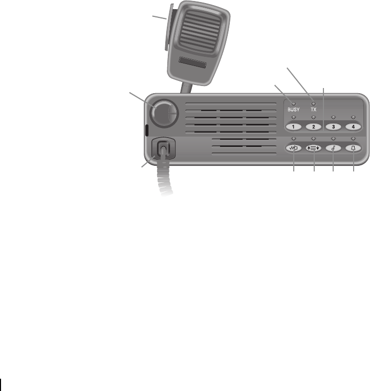
158 Glossary M2000-00-003-806 © Tait Electronics Ltd 2002
stun and revive For conventional radios Stun and revive is a T2020 Selcall feature. At radio
programming time, two control status can be assigned, one to stun the radio,
which makes it inoperable, and the other to revive the radio, which returns it
to a usable state. The stun and revive control status values are set in the Selcall
Status form.
On trunking systems, a “stun” message can be sent from the network to a radio
and will render the radio inoperable. The radio remains in communication with
the trunking system controller but cannot be used to send or receive calls. A
“revive” message sent by the network will return the radio to normal operation.
subaudible
signalling Subaudible signalling is signalling that is at the bottom end of the range of
audible frequencies. T2010/T2015/T2020 radios support CTCSS and DCS
subaudible signalling.
SYNC In MPT 1327 and MPT 1343, SYNC refers to the control channel codeword
synchronisation sequence.
SYS In MPT 1327 and MPT 1343, SYS refers to the system identity code of the
transmitting system. Values of SYS which result in the production of the
control channel codeword synchronisation sequence, SYNC, in any part of the
48 information bits of the CCSC are not permitted.
T
T2010
PTT Key
On/Off/Volume
Control
Busy LED
Transmit
LED
Microphone
Socket
Channel
Keys
Monitor Key
Scan Key
Call Key
Auxiliary Key
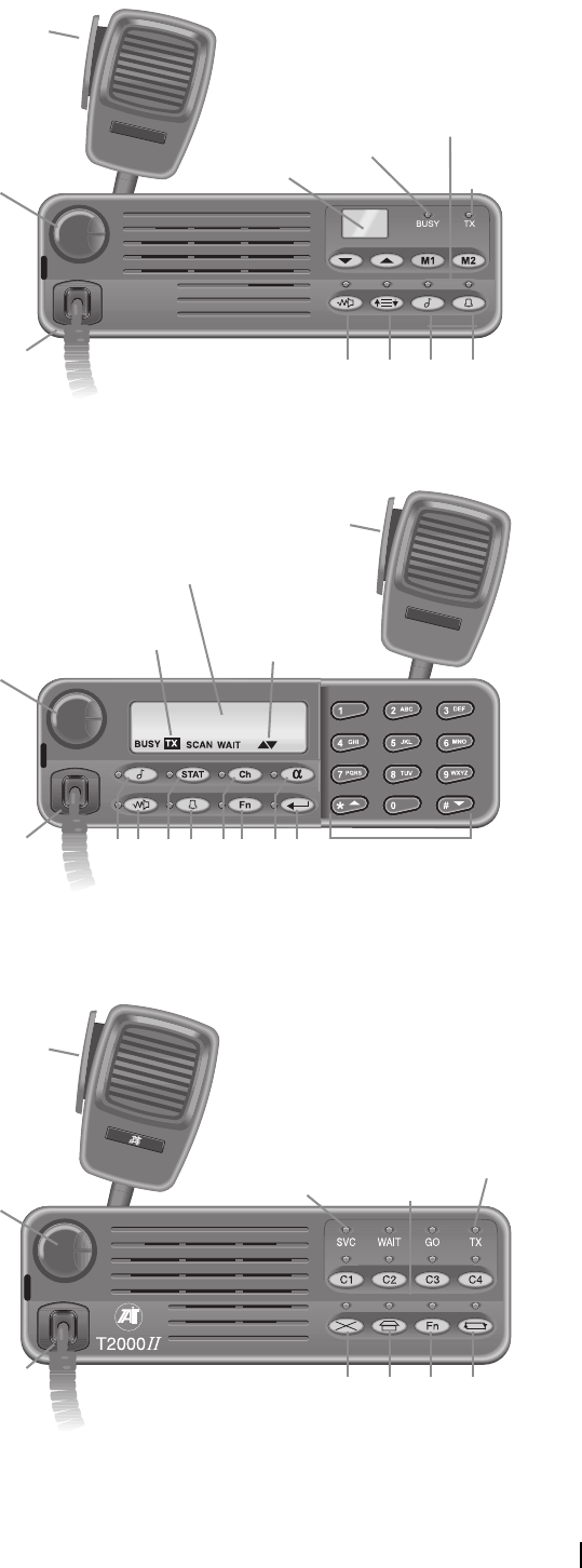
T2000 Programming Application User’s Manual Glossary 159
T2015
T2020
T2030
PTT Key
On/Off/Volume
Control
Busy
LED Transmit
LED
Microphone
Socket
Memory Keys
Monitor Key
Scan Key
Control Head
Display
Call Key
Auxiliary Key
PTT Key
On/Off/Volume
Control
Transmit
Indicator
Microphone
Socket Keypad
Enter Key
Control Head
Display
Scrolling Available
Indicator
Monitor Key
Call Key
Auxiliary Key
Status Key
Channel Key
Function Key
Alphanumeric Key
PTT Key
On/Off/Volume
Control
Service
Indicator
Transmit
LED
Microphone
Socket
Preset Call
Keys
Clear Key
D
espatcher Key
Function Key
Callback Key
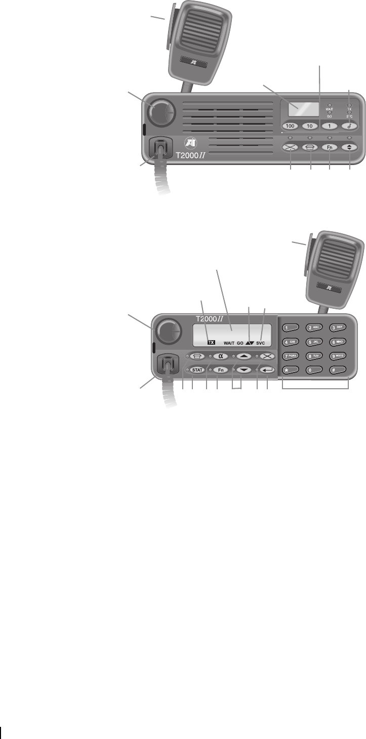
160 Glossary M2000-00-003-806 © Tait Electronics Ltd 2002
T2035
T2040
third tone monitor
reset Third tone monitor reset is a T2020 Selcall feature.
The monitor and squelch override are deactivated when the first three tones of
the receiver identity for an incoming Selcall sequence match the first three tones
of one of the radio’s Rx decode sequences.
Third tone monitor reset is enabled in the Selcall Features form.
time-out Trunked radios only.
Time-out is when a time limit has been reached and the active call is terminated
as a result.
toggle The term toggle is used to describe the switching between two states.
tone A tone is a sound wave of a particular frequency.
PTT Key
On/Off/Volume
Control Call Key
Microphone
Socket
Numeric Keys
Clear Key
Despatcher Key
Control Head
Display
Function Key
Queue Key
PTT Key
On/Off/Volume
Control
Transmit
Indicator
Microphone
Socket Keypad
Enter Key
Control Head
Display
Scrolling
Available
Indicator
Status Key
Despatcher Key
Function Key
Alphanumeric Key
Scroll Keys
Clear Key
Service
Indicator

T2000 Programming Application User’s Manual Glossary 161
For CTCSS and DCS, the tone is transmitted continuously as long as the radio
is transmitting. For Selcall sequences and DTMF strings, the transmit time of
each tone is programmable (see tone duration/period).
When constructing Selcall sequences, different tones are represented by the
characters 0 to 9, B, C, D, E, F or G. A series of tones makes up a tone burst.
The frequencies used for tones 0-9 and B-F are dependent upon the tone set.
When defining DTMF strings, the different tones are represented by the
characters 0-9, A-D, * and #. The frequencies used are determined by an
internationally accepted standard.
tone blanking Tone blanking is a Selcall feature.
Tone blanking blanks out the tones of a received Selcall sequence so that the
user does not hear them. The user may, however, hear the first few tones.
The radio’s Rx decode sequences are set in the Selcall Identity tab.
Tone blanking is enabled in the Selcall Setup tab.
tone burst A tone burst is a series of tones in a Selcall sequence. A burst can correspond to
a particular piece of information, as follows:
■receiver identity (R burst),
■caller identity (C burst),
■repeater identity (B burst) and
■status (S burst).
For example, the R burst defines the receiver identity and can be up to eight
tones long. An R burst of five tones would be defined in the Tx and Rx
Formats as RRRRR. For a Selcall sequence that places a call to radio 12345,
the R burst would be 12345.
How long a tone burst lasts is determined by the tone duration/period and the
number of tones in the burst. Tone bursts are usually, but not always, separated
by a gap burst.
tone duration/
period The tone period, or tone duration in the case of DTMF, is how long a tone is
transmitted. For example, if the tone period for a Selcall sequence is 10 ms, then
a tone burst of three tones lasts for 30 ms.
For Selcall sequences, the tone period is set in the Selcall Setup tab. For DTMF
strings, the tone duration is set in the DTMF form.
tone set The tone set is the set of frequencies represented by the characters 0-9 and A-
F used to make up Selcall sequences.
There are a number of internationally accepted standard tone sets available.
There is a finite number of frequencies available to represent the various
characters in a Selcall sequence; it is the frequencies used and their order that
distinguishes one tone set from another.
The T2000 Programming Application supports the following tone sets: CCIR,
EIA, EEA, ZVEI-I, ZVEI-II, ZVEI-III, PZVEI, NATEL and DZVEI.
The tone set for the Selcall system is set in the Selcall Setup tab.
traffic Traffic is an intelligible signal on a channel that exceeds the radio’s squelch
threshold.

162 Glossary M2000-00-003-806 © Tait Electronics Ltd 2002
traffic channel The traffic channel is the channel on a trunking system to which parties
participating in a call are directed for the duration of the call. When the call
ends, the traffic channel is returned to the pool of channels for use in a new call.
transmit (Tx) format The transmit (Tx) format is a Selcall feature.
The transmit format defines the format all outgoing Selcall sequences must
follow in order to be correctly decoded by other radios using the same Selcall
system. The transmit format should be the same for all radios using a particular
Selcall system.
The transmit format is set in the Selcall Identity tab.
transmit (Tx)
frequency The transmit frequency is the frequency that all outgoing transmissions are
made on.
For conventional radios, the transmit frequency for each channel is set in the
Channels form. For trunked radios, the transmit frequency for each channel is
set in the Trunked Channel Blocks form and the Conventional Channels form.
transmit inhibit The transmit inhibit feature determines under what conditions a press of the
PTT results in the radio not transmitting. This feature can prevent transmissions
that may interrupt other users on the channel.
The radio can be prevented from transmitting whenever there is activity on the
channel, whether it is valid or invalid (Busy option), or whenever there is
invalid activity on a channel (Mute option).
For conventional radios, the conditions under which transmission is inhibited
are set in the Tx Inhibit field (Transmitter Setup form). For trunked radios, the
conditions under which transmission is inhibited during conventional channel
operation are set in the Conventional Channels form (Tx Inhibit On Busy field).
transmit lockout Conventional radios only.
The transmit lockout feature prevents the radio from transmitting once the
transmit timer has expired.
How long transmission is locked out is set in the Transmitter Setup form.
transmit signalling The transmit signalling is the signalling that accompanies all outgoing
transmissions made.
The transmit signalling for each channel is set in the Channels form
(conventional radios) or Conventional Channels form (trunked radios).
transmit timer The transmit timer determines the longest continuous transmission permitted
by a radio. When the transmit timer expires, the radio emits a series of warning
tones before returning to the receive state.
For conventional radios, how long the radio can transmit continuously is set in
the Transmit Timer Duration field (Transmitter Setup form).
trunked channel
block A trunked channel block is a set of equally spaced channels on which a trunking
system operates.

T2000 Programming Application User’s Manual Glossary 163
trunking Trunking is a radio communications system that dynamically shares a number
of communications channels among a large number of users. This ensures equal
channel loading and permits significantly higher loading per channel than found
in conventional systems.
trunking system The term trunking system refers to the equipment required to provide the
trunking communication facilities at one location.
TSC See trunking system controller.
trunking system
controller In MPT 1327 the trunking system controller (TSC) is the central intelligence
necessary to enable the trunking system to function. The TSC communicates
with all radios on the network via the control channel.
Tx Tx is an abbreviation for transmit.
UVW
user function menu
entry mode User function menu entry mode is a T2020 feature.
In user function menu entry mode, the user can customise radio options. This
mode is available under the following conditions:
■a function is selected to be in the user menu (at least one In User Menu box
checked in the User Selectable form)
■a scan group is set to be user programmable (Scan Group Members tab)
■call queuing is enabled (Selcall Features form) and a call is queued
■programmable channel signalling presets are programmed to allow the user
to change the channel's subaudible signalling
valid activity Valid activity is traffic on a channel that carries signalling that matches that
programmed for the receiving radio. The radio’s mute opens upon detecting
valid activity.
variable status Variable status is a T2020 Selcall feature.
The S burst of a Selcall sequence can be programmed with a V. When the
sequence is transmitted, the status digit included corresponds to the status
identity last selected in status entry mode.
vote now Trunked radios only.
Vote now is carried out as part of the control channel acquisition procedure.
Some trunking systems use a vote now BCAST codeword to help the radio find
the best control channel. When the radio receives a vote now BCAST
codeword, the radio will switch to the channel specified by the system and
monitor its RSSI level. If the RSSI on the new channel is not greater than the
current control channel by a particular value, the radio will return to the current
control channel. Otherwise it will switch to the control channel specified by
the trunking system.

164 Glossary M2000-00-003-806 © Tait Electronics Ltd 2002
voting Conventional radios only.
Voting is the systematic sampling of a group of channels (a scan group) for the
channel with the greatest signal strength. There are three variations of normal
voting: voting with signalling, double voting and double voting with signalling.
voting with
signalling Voting with signalling is a type of voting in which a channel must have valid
signalling before it is made the home channel.
XYZ
ZVEI Trunked radios only.
ZVEI is a dialling scheme based on the MPT 1343 dialling scheme. The ZVEI
dialling scheme is used on Regionet 43 networks.
ZVEI-I, ZVEI-II, ZVEI-
III Conventional radios only.
ZVEI-I, ZVEI-II and ZVEI-III are among the Selcall tone sets the T2000
Programming Application supports.
ZVEI-I Note that E is the repeat tone.
Tone : Frequency (Hz) Tone : Frequency (Hz)
0 : 2400 8 : 2000
1 : 1060 9 : 2200
2 : 1160 A : 2800
3 : 1270 B : 810
4 : 1400 C : 970
5 : 1530 D : 885
6 : 1670 E : 2600
7 : 1830 F : 680

T2000 Programming Application User’s Manual Glossary 165
ZVEI-II Note that E is the repeat tone.
ZVEI-III Note that E is the repeat tone.
Tone : Frequency (Hz) Tone : Frequency (Hz)
0 : 2400 8 : 2000
2 : 1060 9 : 2200
3 : 1160 A : 885
4 : 1270 B : 825
5 : 1400 C : 740
6 : 1530 D : 680
7 : 1670 E : 970
8 : 1830 F : 2600
Tone : Frequency (Hz) Tone : Frequency (Hz)
0 : 2400 8 : 2000
1 : 1060 9 : 2200
2 : 1160 A : 885
3 : 1270 B : 810
4 : 1400 C : 2800
5 : 1530 D : 680
6 : 1670 E : 970
7 : 1830 F : 2600

166 Glossary M2000-00-003-806 © Tait Electronics Ltd 2002

T2000 Programming Application User’s Manual Index 167
Index
Symbols
# key 40
# tone 55
* key 40
* tone 34, 44, 55
1, 10 and 100 keys 99
25-pin serial connector 3
5 digit access string 101
5 Digit Lookup form 100
A
abbreviated dialling 102, 127
abbreviated dialling limit 103
about 12
access level 6, 11, 68, 74, 83, 89, 131
access number 87
access string 101
acknowledgement 86
Acquisition Data form 92
add button 14
add network 10
addressing 121
AHY 79
alarm tone 45
ALLI 103
Alpha Symbols form 56
alphanumeric
entry 99
entry mode 56
key 91
Alt key 7
ANI
beep 34
decoding 41
DTMF mode transmission 56
leading 36
random 37
sequence 34
suppression time 37
trailing 37
ANN
fleet call string 126
group number 89
Interfleet form 81
numbering 84
application installation 3
arrow keys 7
audible alert 43
audible indicators 109
auto acknowledge
beep 35
delay time 38
format 33
identity 33
auto quiet timer 27
automatic caller identification 41
AUX line 29, 60, 107
auxiliary
latching 107
momentary 107
auxiliary key 29
emergency call 43
one touch call 60
operation 59
B
background hunt 79, 81
background search 79, 81
backlighting 54, 61, 98
BCD channel selection 48
BCD polarity 48
birdie channel 52
birdie killer 52
bits per character 94
broadcast 86
broadcast call 127
C
C1 to C4 keys 99
call
abbreviated 127
broadcast 127
clear 101
conference 127
despatcher 127
diversion 41, 104, 127
diversion channel 41
diversion status 41, 43
emergency 101, 127
external alert 106
handsfree initiation 108
indicators 28

168 Index M2000-00-003-806 © Tait Electronics Ltd 2002
interfleet 103
key 29, 61
one touch 60
preset 99
priority 127
PTT initiation 108
queue 96, 104
queuing 41, 105, 127
single press PTT 108
SOS 101
status 127
string 100, 107
string ECR 101
time limit 86
tone 110
unit status display 41
Call Options form 102
callback 104
caller identity 32
caption position 11
car
horn 105
lights 105
to car dialling length 38
CCI Setup form
conventional radios 57
trunked radios 94
CCIR 36
change data
check box 14
combo box 13
grid 14
text box 13
channel
birdie 52
hunting type 80
identity 46, 53, 60, 60
key 29, 49, 60
mode 47
power level 75, 88
selection keys 60
signalling 88
spacing 47, 75
start 74
stop 74
trunked 119
trunked blocks 74
Channels form 46
chassis serial number 25
check box 14
checksum 131
clear temporary scan allocation 51
codeword 76, 78, 96, 119
COM port 3, 57
combo box 13
communication port 11
compatibility
options boards 71
comprehensive hunt 79, 80, 81
computer controlled interface (CCI)
conventional radio setup 57
data transmission 57
installation 25
trunked radio setup 94
conference call 127
contents and index 11
continuous 80
control category 92
control channel 75, 76, 92, 92, 119, 120
control channel priority 93
control head
Selcall dialling 38
signaling preset select 31
control status
activate stun 42
call diversion 43
digits 41
priority call 42
quiet interrogation 42
user alert 43
conventional channels 88, 127
Conventional Channels form 87
copy 9, 15
copying fields 15
corrupt file 131
CPSX 121
call strings 126
dialling 83
dialling strings 126
fleet size 124
identity 125
create new database 5
CTCSS
assign to channel 47
concept 114
filter 30
frequency range 114
reverse tone burst 31
settings 30
cut 8
D
data
call time limit 87

T2000 Programming Application User’s Manual Index 169
calls 95, 104
external alert on call 106
length (CCI) 58
rate 94
tone on call 110
transmission (CCI) 57
Data Parameters form 95
database
new 5
DCS
assign to channel 47
description 114
filter 30
frequency range 114
polarity 30, 30, 114
settings 30
default
access level 6, 11
alphanumeric symbol name 57
channel name 47
data 5
mode 26
power-up mode 26
preset label 31
scan group name 49
default SDM call string 96
deferred calling 40
delete 9
delete button 14
delete network 10
dependant fields 13
despatcher 96
direct 105
enable radio as 104
key call string 107
key long press 107
key short press 107
number 86
queue 105
request callback 127
diagnostics 109
dialling
abbreviated 102
DTMF 26, 54, 63, 109
group 40
length (Selcall) 38
manual DTMF 55
scheme 83
Selcall 26
Selcall group tone 40
dim 98
direct despatcher 105
disabled fields 13, 131
disconnect messages 78
diversion
channel 41
description 41
status 41
trunked call 104, 127
don’t disturb 103, 127
drag and drop 15
DTMF
ANI transmission 56
dialling 109
dialling type 62
installation 25
interdigit Tx hold time 55
manual dialling 55
minimum intertone gap 55
minimum tone duration 55
one touch call 60
PTT as shift key 56
redial transmission 55
string 55
timeout 109
transmit key up delay 55
dual port 94
DZVEI 36
E
economy mode 54, 61
backlighting level 98
ignition off 98
ignition on 98
ECR call clear 101
ECR call string 101
Edit menu 8
EEA 36
EIA 36
emergency
auxiliary key activates 60
call 43, 127
call time limit 87, 101
callout 45
cycling 45, 102
external alert 106
ident 86
mode 43
mute received audio 44
number for trunked radios 86
prefix 86
receive time 45
retries 101
RMR sequence 44
Selcall sequence 35, 44

170 Index M2000-00-003-806 © Tait Electronics Ltd 2002
tone 110
transmit time 45
Enhanced Scan form 51
enhanced scanning 25, 48, 51
clear user changes 51
grid 52
ID 52
type 52
enter key 55, 62
equipment supplied 3
error
reset after 109
Esc key 7
Excel 15
exit 8
external alert
auxiliary key activates 60
data call 106
delay 38
duration 38
emergency calls 106
group calls 106
include calls 106
individual calls 106
level 38
signal pattern 105
speech calls 106
status calls 106
time delayed 105
time on 105
user selectable 61
External Alert form 105
External Call form 101
external mute 61
F
fast PTT 29
feature set 24, 70
FFSK 119
field
can’t enable 131
can’t find 131
data 13
disabled 13
File menu 7
files
recent 8
fleet
ANN interfleet 81
call string 126
CPSX large 124
CPSX medium 124
CPSX small 124
CPSX Tiny 124
dialling string 126
group number 84
highest group number 84
highest individual number 84
highest number 100
individual number 84
MPT 1343 122
number 100
partitioning parameter. See FPP
prefix 84, 100
restrict calls 91
settings 68, 83
type 100
Fleet Identity form 83
Fleet Parameters form 86
footswitch 71
forms tree 4, 6, 6, 131
FPP 85
frequency band 25, 47, 70
full queue 105
function 29
function key 29
call string 107
latching 107
mode 107
momentary 107
function menu. See user function menu
G
green indicator 6, 6, 9
greyed out fields 13, 131
grid 14
grids
copy 15
drag and drop 15
group
attributes 91
call string 126
dialling 40
dialling string 126
format 38
interfleet call 100
join busy 104
permanent 91
scan 91
select 91, 91
selectable 91
selectable + scan 91
selective dialling 40
group calls

T2000 Programming Application User’s Manual Index 171
external alert 106
interfleet 103
membership 90
restrict 92
tone 110
group number
CPSX 124
MPT 1343 123
H
handsfree
call initiation 108
enable 71
handshaking mode 94
handshaking mode (CCI) 58
hardware
computer controlled interface (CCI) 25
DTMF 25
signaling 25
Help menu 11
hidden channels 50
hide error messages 11
hide messages 11
home channel 117, 118
home zone 93
hookswitch 28, 48, 50
hookswitch monitor 88
HORN line 61
hunting
background 79, 81
comprehensive 79, 80, 81
control channel priority 93
non applicable channels 80
normal 81
normal channels 80
preferential 93
Hunting Parameters form 79
HUSH line 61
I
ident
MPT 1327 122
identity 125
auto acknowledge 33
caller 32, 33, 35, 41
channel 41, 46, 50, 60
number 121
receiver 32, 33, 34, 35, 39, 40, 44, 57
repeater 32, 33, 39
scan group 49, 60
Selcall 32
Tx call 39
IF bandwidth 48
ignition off
economy mode 98
ignition on
economy mode 98
import network 8, 69
include calls 106
tone 110
include request 78
include timer 79
individual calls
external alert 106
restrict 91
individual interfleet call 100
INFO field 76
insert button 14
install application 3
installed options 71
Interface Options form 108
interfleet
ANN 81
call 103
call string 126
calls 100
CPSX 125
dialling string 126
group calls 100, 103
individual calls 103
internal alert duration 38
International group format 38
internet 12
internet help 19
interrogate radio 10
J
join busy group 104
K
key
# 40
* 40
auxiliary 29, 43, 59, 60
call 29, 61
channel 29, 47, 48, 49
enter 55
function 29
memory 60
monitor 27, 113

172 Index M2000-00-003-806 © Tait Electronics Ltd 2002
PTT 28, 56
Key Settings form
conventional radios 59
trunked radios 107
keypress confidence tones 109
L
LA 76
label
alpha symbol 57
preset call 99
signaling preset 31
status 43, 97
license 131
line interface 72
list of recent files 8
LM1 79
LM2 79
LM3 79
lookup table 100
LZ 76
M
main window 4
MAP27 72, 94
memory key 51, 51, 60, 60
menu commands 7
menus 4
MEP 85
microphone socket 3
Miniaturisation Extent Parameter. See MEP
mobiles support 12
mode
alphanumeric entry 26, 56
channel entry/selection 26, 47, 49
DTMF dialling 26, 55
emergency 43
power-up 26
scan 48
Selcall dialling 26
status entry 26
user function menu 26
model 10
monitor
deactivation 27
description 116
hookswitch 88
hookswitch activation 28
key 113
key press 28
mute disable 27
power-up state 27
PTT opens 28
radio monitor reset 33, 44
Selcall call activates 27
MPT 1327 90, 120
MPT 1327 numbering 122
MPT 1327 prefix 122
MPT 1343 83, 120
MPT 1343 identity 125
MPT 1343 number 89
MPT 1343 numbering 122
multiple networks 68, 127
multiple registration 76, 78
mute
disable 27
selective call 27, 116
signaling 113
subaudible signaling 27, 113, 116
N
name
alphanumeric 56
channel 47
scan group 49
NATEL 36
navigate
forms tree 6
menu commands 7
radio model toolbar 5
ND1 78
ND2 78
NE 78
Network Identity form 75
Network menu 10
network operator service call 103
network settings 68, 74
networks
CPSX dialling 83
identity code 75
importing 69
MPT 1343 83
multiple 68, 127
multiple registration 76, 78
name 72
national 75, 93
Nokia Actionet 83
Nokia ANN 83, 84
Number Presets 83
radio registration 108
regional 75, 93

T2000 Programming Application User’s Manual Index 173
Regionet 43 83
template 68
type 75
ZVEI 83
new database 5
next network 10
NI 78
NIC. see Networks - Identity Code
noise 113
Nokia Actionet 83
Nokia ANN 81, 81, 89, 121, 126
non applicable hunt channels 80
non-emergency call requests 78
normal backlighting level 108
normal hunt 81
normal hunt channels 80
NPD 96, 127
NR 78
NS 79
NT 78
Number Presets 83, 121
NW 78
O
off hook scan 50
off hook scanning 48
one touch call 60
one touch calls 60
online help 11, 19
open 7
operation
scan 48
option boards 71
compatibility 71
options 11
computer controlled interface (CCI) 25
connector 60, 61
DTMF 25
signaling 25
P
PABX 103, 122
parity 94
parity type (CCI) 58
paste 9
permanent group 91
polarity 114
polling 117
power level 48
Power Saving form
conventional radios 54
trunked radios 97
power-up
message 26, 72
mode 26
preferences 11
preferential hunt 93, 93
prefix 84
MPT 1327 122
preset call
call string 100, 127
dialling string 127
function key 107
label 99
number 99
Preset Calls form 99
preset label 31
presets
signaling 31
subaudible signaling 114
pressel off 76
pressel on 76
previous network 10
primary priority scan 48, 52
print 8
printer settings 8
priority call 120, 127
priority call detection 42
Program button 5
program radio 5, 9, 131
programming database 4
programming sequence 68
PSTN 103, 122
PTT 108, 108
PTT key 28, 29, 29, 56
PZVEI 36
Q
queue 127
queue key 91
queuing 105
quiet interrogation 42
quiet state 116
R
radio
chassis serial number 25
communications ports 57

174 Index M2000-00-003-806 © Tait Electronics Ltd 2002
feature set 24, 70
frequency band 24, 25, 69, 70
hardware options 24, 69
identification 25
information 69
language 72
model 24, 24, 46, 59, 69, 70
monitor function 26, 27
part number 25, 69, 70
power-up message 26, 72
power-up mode 26
program 5, 131
programming 24, 70
programming cable 3
programming database 4
read 4, 131
registration 108
unit ID 89
unit settings 89
user function menu 61
Radio menu 4, 5
radio model 4, 5, 10
radio model toolbar 5
radio monitor reset
acknowledge 34
alert 38
sequence 34
Radio Unit ID form 89
radio unit settings 68
range 13
Read button 4
read radio 4, 9, 131
receive baud rate (CCI) 58
Receive Monitoring form 26
received call queuing 41
receiver identity 32
recent file list 8
Regionet 43 83
register 108
registration 76
remote control 57
repeat button 14
repeater
identity 32, 39
sequence 39
talkaround 29
reset after error 109
reset to defaults 7
restrict calls 91
reverse tone burst 31
revert form 9
revert to saved 8
RQE 78
RX
channel frequency 87
trunked channel blocks 74
Rx
audio sensitivity 48
call sub-sequence decoding 41
channel frequency 47
CTCSS/DCS 47
CTCSS/DCS filter 30
DCS polarity 30
decode sequence 34
format 33
start 74
S
save 8
save as 8
scan
channels 48
description 116
dual priority 49
enhanced 25, 48, 51
group 48, 49, 118
hold time 48, 48
off hook 48, 50
polling 51
primary priority 48, 52
priority 49
secondary priority 48, 52
voting 49, 50
scan group 91
identity 49, 60
membership list 50
name 49
type 49
user reprogram 50
scan group hold time 50
Scan Group Members tab 49
Scan Groups form 48
Scan Groups tab 50
scrambler 60
scrambler module 71
scroll keys 99
SDM 72, 95, 104
secondary priority scan 48, 52
Selcall
alpha symbols 57
auto acknowledge format 33
automatic caller identification 41
call key 61
caller identification 35

T2000 Programming Application User’s Manual Index 175
description 114, 115
emergency sequence 35
installation 25
internal alert 38
lead in delay 36
lead in tone 36
mute 39, 113
one touch call 60
PTT calls 39
radio monitor reset 33
repeater sequence 48
RMR sequence 44
Rx format 33
tone period 36
tone set 36
tone set table 37
Tx call identity 39
Tx format 32
Selcall Control Status Definitions form 41
Selcall Features form 40
Selcall Identity and Setup form 32
Selcall Identity tab 32
Selcall multi-tone. See Selcall 114
Selcall Setup tab 36
select all 9
selectable + scan group 91
selectable group 91
selection keys
channel 60
selective call mute 27, 113, 116
serial connector 3
serial port 3
short data messages. See SDM
short status display 62
show general dialogs 11
signal strength 41, 117
signaling
alpha symbol 57
CTCSS 114
DCS 114
installed 25
override 114
presets 31
Selcall 25, 114
squelch 113
subaudible 114
signalling
channel 88
Signalling Interface 72
Sigtec group format 38
SIL 76
single port 94
single press 108
site select 81
slot timing 76
slotted Aloha 120
software version number 4, 5
SOS
call time limit 101
calls 101
retries 101
Rx time 102
Tx time 102
SOS mute 102
speaker 113
Specifications form
conventional radios 24
trunked radios 69
spreadsheet 15
squelch
description 113
disable 113
override 28, 113
threshold 113
startup position 11
status 104, 127
bar 4
burst 33
calls 97
digit 33, 41, 43
external alert 106
identity 43
key 95
label 43
message 43, 57, 60
short display 62
tone 110
value 97
variable 34, 35, 39, 44
Status Labels form 97
stop bits (CCI) 58
stun 42
subaudible signaling
assign to channel 47
description 114
mute 27, 113, 116
override 31
presets 114
Subaudible Signaling Presets tab 31
Subaudible Signaling Setup form 30
Subaudible Signaling tab 30
SYNC 75
SYS code 93
system requirements 3

176 Index M2000-00-003-806 © Tait Electronics Ltd 2002
T
TA 79
tail time 41
Tait Data Protocol. See TDP
taitworld 12
TB 79
TC 78
TD 78
TDP 96
acknowledge 96
contact wait 96
group wait 96
synchronisation 96
timer DCI 96
tone 96
technician 104
telephone plug 3
template 24, 70
test mode 109
text box 13
TGG timer 95
TGI timer 95
TH 79
third tone monitor reset 40
TI 79
timer 86
time-shared 80
TJ 78
TL 79
TN 78
toggle 28, 60
tone
data calls 110
emergency calls 110
group calls 110
include calls 110
incoming call 109
individual calls 110
keypress 109
level 109
set 109
speech calls 110
status calls 110
suppress all 109
tone blanking 38
tones 96
toolbars 4
Tools menu 11
TP 79
traffic channel 78, 119
transmit 29
baud rate (CCI) 58
duration 78
inhibit 29
lockout 29
timer 28, 29
Transmitter Setup form 28
transparent mode (CCI) 58
trunked channel blocks 81
Trunked Channel Blocks form 74
trunked mode 109
trunking
address 121
trunking network 92
trunking system 119
TSC 77, 78, 87, 119, 120
TT 78
TW 79
Tx
call identity 39
call sequence 39
channel frequency 47, 88
CTCSS reverse tone burst 31
CTCSS/DCS 47
DCS polarity 30
deviation 48
format 32
inhibit 29, 88
lockout 29
power level 48
repeater sequence 48
Selcall sequence 47
start 74
timer 29
tolerance factor 41
trunked channel blocks 74
U
UIM 94
unanswered calls 105
undo 8
user function menu 61, 62, 114
user group select 91, 91
user groups segregation 114
user selectable 114
User Selectable Parameters form 61
V
validate form 9
variable status 34, 35, 39, 44
version number 4, 5

T2000 Programming Application User’s Manual Index 177
voice inversion 71
voting 49, 117
definition 48
lead in delay 50, 118
polling interval 51
VOX 71
W
Web Address 11
what’s this? help 11, 13, 19
wide area coverage 117
wild card tone 34
window state on startup 11
X
XOFF character 95
XON character 95
Z
ZVEI 121
ZVEI-I 36
ZVEI-II 36
ZVEI-III 36

178 Index M2000-00-003-806 © Tait Electronics Ltd 2002
