T2000/T2004 Multi Head System For T2020 T2040 Radios/T2004 Radios T2004
User Manual: Pdf T2000/T2004 multi head system for T2020-T2040 radios/T2004 multi head system for T2020-T2040 radios
Open the PDF directly: View PDF ![]() .
.
Page Count: 74
T2000 mobiles
T2004 Multi Control Head
System Manual
M2004-00-000-814
May 2004 © Tait Electronics Limited

2T2004 Multi-Control Head System Manual
May 2004 © Tait Electronics Limited
Contact Information
Tait Radio Communications http://www.taitworld.com
Corporate Head Office
New Zealand
Tait Electronics Ltd.
P.O. Box 1645
Christchurch
New Zealand
E-mail (Marketing): taitnet@taitworld.com
E-mail (Sales): sales@taitworld.com
Technical Support
Technical Support Manager
Tait Electronics Ltd
P.O. Box 1645
Christchurch
New Zealand
Telephone: (64) (3) 358-3399
Facsimile: (64) (3) 358-6486
E-mail: support@taitworld.com
Oceania
New Zealand
Tait Communications Ltd.
E-mail: headoffice@tcl.tait.co.nz
Australia
Tait Electronics (Aust) Pty Ltd.
E-mail: australia@taitworld.com
Tait Europe
Regional Head Office - United Kingdom
Tait Mobile Radio Ltd.
E-mail: teusales@tait.co.uk
Tait North America
Regional Head Office - Canada
Tait North America Inc.
E-mail: canada@taitworld.com
United States of America
Tait North America Inc.
E-mail: usa@taitworld.com
Latin America
Tait Latin America
E-mail: latinamerica@taitworld.com
Tait North Asia
Regional Head Office - Hong Kong
Tait Mobile Radio (Hong Kong) Ltd.
E-mail: hongkong@taitworld.com
Beijing
Tait Mobile Radio (Hong Kong) Ltd.
E-mail: beijing@taitworld.com
Tait South Asia
Regional Head Office - Singapore
Tait Electronics (Far East) Pte. Ltd.
E-mail: singapore@taitworld.com
Thailand
Tait Mobile Radio Ltd.
E-mail: thailand@taitworld.com

T2004 Multi-Control Head System Manual 3
© Tait Electronics Limited May 2004
Contents
Contact Information . . . . . . . . . . . . . . . . . . . . . . . . . . . . . . . . . . . . . . . . 2
Preface . . . . . . . . . . . . . . . . . . . . . . . . . . . . . . . . . . . . . . . . . . . . . . . . . 7
Scope of Manual. . . . . . . . . . . . . . . . . . . . . . . . . . . . . . . . . . . . . . . . . . . . . . . . . 7
Copyright . . . . . . . . . . . . . . . . . . . . . . . . . . . . . . . . . . . . . . . . . . . . . . . . . . . . . 7
Disclaimer . . . . . . . . . . . . . . . . . . . . . . . . . . . . . . . . . . . . . . . . . . . . . . . . . . . . . 7
Enquiries and Comments . . . . . . . . . . . . . . . . . . . . . . . . . . . . . . . . . . . . . . . . . . 7
Associated Documentation . . . . . . . . . . . . . . . . . . . . . . . . . . . . . . . . . . . . . . . . . 7
Updates of Manual and Equipment . . . . . . . . . . . . . . . . . . . . . . . . . . . . . . . . . . . 8
Publication Record. . . . . . . . . . . . . . . . . . . . . . . . . . . . . . . . . . . . . . . . . . . . . . . 8
Part A System Information
1 Introduction . . . . . . . . . . . . . . . . . . . . . . . . . . . . . . . . . . . . . . . . . . 11
1.1 Document Navigation . . . . . . . . . . . . . . . . . . . . . . . . . . . . . . . . . . . . . . . 11
1.2 Product Codes . . . . . . . . . . . . . . . . . . . . . . . . . . . . . . . . . . . . . . . . . . . . 12
2 System Overview . . . . . . . . . . . . . . . . . . . . . . . . . . . . . . . . . . . . . . . 13
2.1 System Specifications. . . . . . . . . . . . . . . . . . . . . . . . . . . . . . . . . . . . . . . . 14
2.2 System Diagram . . . . . . . . . . . . . . . . . . . . . . . . . . . . . . . . . . . . . . . . . . . 15
2.3 System Equipment . . . . . . . . . . . . . . . . . . . . . . . . . . . . . . . . . . . . . . . . . 16
2.4 System Connections . . . . . . . . . . . . . . . . . . . . . . . . . . . . . . . . . . . . . . . . 19
3 System Installation. . . . . . . . . . . . . . . . . . . . . . . . . . . . . . . . . . . . . . 20
4 System Operation . . . . . . . . . . . . . . . . . . . . . . . . . . . . . . . . . . . . . . 21
5 System Equipment Specifications. . . . . . . . . . . . . . . . . . . . . . . . . . . . 22
5.1 Multi-Drop Cable Specifications . . . . . . . . . . . . . . . . . . . . . . . . . . . . . . . 22
5.2 Micromatch to RJ45 Cable (IPN 219-02900-00) . . . . . . . . . . . . . . . . . . . 23
5.3 RJ45 Wallbox . . . . . . . . . . . . . . . . . . . . . . . . . . . . . . . . . . . . . . . . . . . . . 24
5.4 DC Power and Speaker connections . . . . . . . . . . . . . . . . . . . . . . . . . . . . . 25
6 System Testing . . . . . . . . . . . . . . . . . . . . . . . . . . . . . . . . . . . . . . . . 27
5 System Fault Finding . . . . . . . . . . . . . . . . . . . . . . . . . . . . . . . . . . . . 28
4T2004 Multi-Control Head System Manual
© Tait Electronics Limited May 2004
Part B T2004 Control Heads
1 Introduction . . . . . . . . . . . . . . . . . . . . . . . . . . . . . . . . . . . . . . . . . . 33
1.1 The T2004 Control Heads . . . . . . . . . . . . . . . . . . . . . . . . . . . . . . . . . . . 33
1.2 Features . . . . . . . . . . . . . . . . . . . . . . . . . . . . . . . . . . . . . . . . . . . . . . . . . 33
1.3 Product Codes . . . . . . . . . . . . . . . . . . . . . . . . . . . . . . . . . . . . . . . . . . . . 35
2 Circuit Description . . . . . . . . . . . . . . . . . . . . . . . . . . . . . . . . . . . . . 36
3 Functionality. . . . . . . . . . . . . . . . . . . . . . . . . . . . . . . . . . . . . . . . . . 38
3.1 Software . . . . . . . . . . . . . . . . . . . . . . . . . . . . . . . . . . . . . . . . . . . . . . . . . 38
4 I/O Connections . . . . . . . . . . . . . . . . . . . . . . . . . . . . . . . . . . . . . . . 40
4.1 J6: Power and Speaker Connector . . . . . . . . . . . . . . . . . . . . . . . . . . . . . . 40
4.2 J5: 8way Micromatch Socket . . . . . . . . . . . . . . . . . . . . . . . . . . . . . . . . . . 41
4.3 S10: 6way RJ Socket (Microphone) . . . . . . . . . . . . . . . . . . . . . . . . . . . . . 41
5 Assembly/Disassembly Instructions . . . . . . . . . . . . . . . . . . . . . . . . . . 42
5.1 Mechanical Parts. . . . . . . . . . . . . . . . . . . . . . . . . . . . . . . . . . . . . . . . . . . 42
5.2 Disassembling the Control Head . . . . . . . . . . . . . . . . . . . . . . . . . . . . . . . 43
6 X2H2xx PCB Information . . . . . . . . . . . . . . . . . . . . . . . . . . . . . . . . 45
6.1 X2H221 Rev 007 Parts List. . . . . . . . . . . . . . . . . . . . . . . . . . . . . . . . . . . 47
6.2 X2H221 Rev 007 Grid Reference. . . . . . . . . . . . . . . . . . . . . . . . . . . . . . 49
6.3 228-23722-02 PCB Top Side . . . . . . . . . . . . . . . . . . . . . . . . . . . . . . . . . 52
6.4 228-23722-02 PCB Bottom Side. . . . . . . . . . . . . . . . . . . . . . . . . . . . . . . 53
6.5 X2H221- PCB Circuit Diagram (page 1 of 1) . . . . . . . . . . . . . . . . . . . . . 55
7 Testing the X2H2xx control heads . . . . . . . . . . . . . . . . . . . . . . . . . . . 57
Part C X2AM01 Radio Interface
1 Introduction . . . . . . . . . . . . . . . . . . . . . . . . . . . . . . . . . . . . . . . . . . 60
1.1 The X2AM01 Multi-Head Radio Interface PCB . . . . . . . . . . . . . . . . . . . 60
2 Circuit Description . . . . . . . . . . . . . . . . . . . . . . . . . . . . . . . . . . . . . 61
T2004 Multi-Control Head System Manual 5
© Tait Electronics Limited May 2004
3 I/O Connections . . . . . . . . . . . . . . . . . . . . . . . . . . . . . . . . . . . . . . . 62
3.1 SK1: 8 Way Micromatch Socket to Radio . . . . . . . . . . . . . . . . . . . . . . . . 62
3.2 SK3: 8 Way Micromatch Socket to Control Heads . . . . . . . . . . . . . . . . . . 62
4 Fitting PCB into Radio . . . . . . . . . . . . . . . . . . . . . . . . . . . . . . . . . . 63
5 X2AM01 Multi-Head Radio Interface PCB . . . . . . . . . . . . . . . . . . . . . 65
5.1 X2AM01 Rev 008 Parts List . . . . . . . . . . . . . . . . . . . . . . . . . . . . . . . . . . 65
5.2 X2AM01 Rev 008 Grid Reference . . . . . . . . . . . . . . . . . . . . . . . . . . . . . 69
5.3 228-23721-01 PCB Top Side. . . . . . . . . . . . . . . . . . . . . . . . . . . . . . . . . . 70
5.4 228-23721-01 PCB Bottom Side . . . . . . . . . . . . . . . . . . . . . . . . . . . . . . . 71
5.5 X2MA01 PCB Circuit Diagram (page 1 of 1). . . . . . . . . . . . . . . . . . . . . . 72
6 Testing the X2AM01 radio interface . . . . . . . . . . . . . . . . . . . . . . . . . . 73
6T2004 Multi-Control Head System Manual
© Tait Electronics Limited May 2004

T2004 Multi-Control Head System Manual 7
© Tait Electronics Limited May 2004
Preface
Scope of Manual
This manual contains general and technical information about the T2004
Multi-Control Head system for use with a T2000 radio.
Copyright
All information contained in this manual is the property of Tait Electronics
Ltd. All rights are reserved. This manual may not, in whole or in part, be
copied, photocopied, reproduced, translated, stored, or reduced to any
electronic medium or machine-readable form, without prior written
permission from Tait Electronics Limited. All trade names referenced are
the service mark, trademark or registered trademark of the respective
manufacturers.
Disclaimer
There are no warranties extended or granted by this manual. Tait
Electronics Ltd accepts no responsibility for damage arising from use of the
information contained in the manual or of the equipment and software it
describes. It is the responsibility of the user to ensure that use of such
information, equipment and software complies with the laws, rules and
regulations of the applicable jurisdictions.
Enquiries and Comments
If you have any enquiries regarding this manual, or any comments,
suggestions and notifications of errors, please contact Customer Support,
Tait Electronics Ltd, Christchurch, New Zealand (refer to “Contact
Information” on page 2).
Associated Documentation
T2004 Multi-Control Head Installation Manual M2004-00-000-315

8T2004 Multi-Control Head System Manual
© Tait Electronics Limited May 2004
Updates of Manual and Equipment
In the interests of improving the performance, reliability or servicing of the
equipment, Tait Electronics Ltd reserves the right to update the equipment
or this manual or both without prior notice.
Publication Record
Issue Publication Date Description
0 April 2004 new manual
T2004 Multi-Control Head System Manual 9
© Tait Electronics Limited May 2004
Part A System Information
This part provides general information about the TM8000 , and
describes how to install and operate the
system.
The following topics are covered in this part:
■Section 1 Introduction
■Section 2 System Overview
■Section 3 System Installation
■Section 4 System Operation
■Section 5 System Equipment Specifications
■Section 6 System Testing
■Section 7 System Fault Finding
10 T2004 Multi-Control Head System Manual
© Tait Electronics Limited May 2004

T2004 Multi-Control Head System Manual Introduction 11
© Tait Electronics Limited May 2004
1 Introduction
1.1 Document Navigation
System Manual
This System Manual is divided into three parts.
■Part A provides general information about the system, how the
components are connected together, system installation and operation
instructions, and specifications for equipment in the system, excluding
the control heads and radio.
■Part B provides technical information about the control heads, including
a circuit description, PCB layout and circuit diagram, and testing
information.
■Part C provides technical information about the Radio Interface PCB,
including a circuit description, PCB layout and circuit diagram, and
testing information.
Control Head/Radio User Guide
Installation and operation instructions included in Part A of the System
Manual provide instructions unique to this system. For more detailed
operation instructions, refer to the user guide.
Radio Service Manual
The System Manual does not contain information about the T2020 or
T2040 radio used with the system. For information about the radio, refer to
the T2000 Series II Service Manual (M2000-00-301).

12 Introduction T2004 Multi-Control Head System Manual
© Tait Electronics Limited May 2004
1.2 Product Codes
The T2004 Multi-Control Head system replaces the STA6682 Multi
Control Head system, previously manufactured by Tait Communications
Ltd. (TCL).
Note The T2004 is not compatible with existing STA6682 heads or
interface boards.
The table below provides the product numbers for both systems.
Product Code Description TCL Code
T2004-A20 T2020 Primary Multi-Control Head Kit
T2004-A21 T2020 Secondary Multi-Control Head Kit
T2004-A40 T2040 Primary Multi-Control Head Kit
T2004-A41 T2040 Secondary Multi-Control Head Kit
X2H221 T2020 Primary Control Head only STA6682-4H
X2H222 T2020 Secondary Control Head only STA6682-4H
X2H241 T2040 Primary Control Head only STA6682-4H
X2H242 T2040 Secondary Control Head only STA6682-4H
X2AM01 T2020/40 Multi-Control Head Radio Interface PCB STA6682-1H

T2004 Multi-Control Head System Manual System Overview 13
© Tait Electronics Limited May 2004
2 System Overview
The T2004 Multi-Control Head system allows the use of between one and
five control heads with a single T2020 or T2040 radio. The control heads
are configured as one Primary and up to four Secondary. The Primary
control head is the only one which controls the radio’s power, as well as
power to each Secondary control head, otherwise the functionality of all the
control heads is the same. Advantages: radio to control head length able to
be greater than the standard 6m cable.
The Multi-Control Head system consists of two kits, designed to connect to
your existing Series II T2020 or T2040 radio and T2008 power supply:
■the T2004-A20 (T2020) or the T2004-A40 (T2040) Primary Multi-
Control Head Kit (one required per system).
■the T2004-A21 (T2020) or T2004-A41 (T2040) Secondary Multi-
Control Head Kit (not required if only one control head is used in the
system).
The T2004-A20 or T2004-A40 Primary Head Kit provides the Primary
control head as well as the Radio Interface PCB. This PCB is housed inside
a dummy (Clayton’s) control head and replaces the standard control head on
the radio. The radio can be concealed if required, as all radio controls are
now done via the Primary control head.
The T2004-A21 or T2004-A41 Secondary Head Kit provides one
Secondary control head and other equipment needed to install the control
head for use with the radio.

14 System Overview T2004 Multi-Control Head System Manual
© Tait Electronics Limited May 2004
Each control head can be installed anywhere on a multi-drop line up to
2000m long (not included), and is powered locally by a mains-operated DC
plug pack. A speaker plugs into each control head to provide local Tx and
Rx audio.
Note The DC Plug pack is not supplied as part of the kit. The correct
plug pack for each country can be ordered separately as per the
table on page 18.
The control heads provide the same functionality as the standard T2000
control head, but will not provide for a DTMF module to be fitted. In
addition, the control heads provide some extra functions:
■Global Mute
The Global Mute function is provided to avoid the possibility of
audio feedback when two or more control heads are placed in close
proximity. This function is individually selectable on each control
head, via a link JP1 on the control head PCB. Refer to Part B, Con-
trol Head for further information.
■Power Switch Selection
The Power Switch Selection function is provided so that only one
control head in the system (the Primary control head) is able to con-
trol the system’s power. This function is selectable by the fitting of a
jumper (JP2) on the control head PCB of the Primary control head.
Refer to Part B, Control Head for further information.
2.1 System Specifications
General Specifications
Radios supported Series II T2020 and T2040 radios
Possible number of control heads Between one and five
Control head DC supply & speaker connector Phoenix MCV 1,5/4-G-3,81 4 way jack
Control head DC supply voltage (at 800mA) +13.8V nominal
+10.8V minimum
+16.0V maximum
Balanced line Audio levels -10dBm for receiver audio
-15dBm for transmitter audio
Control head dimensions Standard T2000 control head dimensions
Recommended cable 4 x twisted pair with overall screen
T2004 Multi-Control Head System Manual System Overview 15
© Tait Electronics Limited May 2004
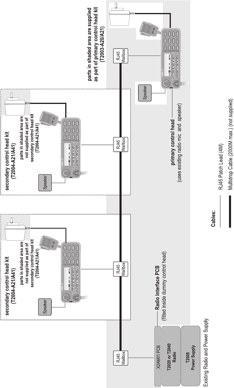
2.2 System Diagram

16 System Overview T2004 Multi-Control Head System Manual
© Tait Electronics Limited May 2004
2.3 System Equipment
The Multi-Control Head system includes the following components:
■one T2020 or T2040 radio with T2008 power supply unit (existing)
■2km maximum Multidrop Line (not supplied)
■one T2004-A20 or T2004-A40 Primary Multi-Control Head Kit
■between one and four T2004-A21 or T2004-A41 Secondary Multi-
Control Head Kit (optional)
T2004-A20 and T2004-A40 Primary Multi-Control Head Kit Parts
The T2004-A20 or T2004-A40 Primary Multi-Control Head Kit are listed
below:
This kit provides the Primary control head as well as the Radio Interface
PCB. This PCB is housed inside a dummy (Clayton’s) control head and
replaces the standard control head on the radio. The radio can be concealed
if required, as all radio controls are now done via the Primary control head.
Qty IPN Description
1 X2H221 or X2H241 T2020 or T2040 Primary Control Heada
a. For more information about the X2H221 or X2H241 Primary Control Head, see Part
B of this manual.
1 X2AM01 T2020/40 Multi-Control Head Radio Interfaceb
b. For more information about the X2AM01 T2020/40 Multi-Control Head Radio Inter-
face board, see Part C of this manual.
2 219-02900-00 Micromatch to RJ45 cable
2 240-04051-00 RJ45 Screw Terminal Wallbox
2 349-00010-33 Screw, #6*3/4: S/T P/P (bracket to wall)
4 349-00010-22 Screw, 4-20x3/8 P/P Trilb-P BZ (dummy head to radio)
1 316-06433-02 Dummy (Clayton’s) control head
1 316-85125-00 T2000 Plate cover
1 219-02907-00 Power/ Speaker cable (no plug pack)
1 M2004-00-000-315 Installation manual
1 252-00010-49 Microphone clip
1 302-05211-00 Head mounting bracket
2 350-01007-00 Head thumb screws
4 360-01057-00 Screw hole covers

T2004 Multi-Control Head System Manual System Overview 17
© Tait Electronics Limited May 2004
A speaker and microphone are not provided as part of the Primary Multi-
Control Head Kit, as the Primary control head uses the speaker and
microphone already supplied with the radio.
T2004-A21 and T2004-A41 Secondary Multi-Control Head Kit Parts
The T2004-A21 or T2004-A41 Secondary Multi-Control Head Kit parts
are listed below:
This kit provides one Secondary control head and other equipment needed
to install the control head for use with the radio. Between one and four
Secondary Multi-Control Head Kits can be installed as part of your system.
Each control head can be installed anywhere on a multi-drop line up to
2000M long, and is powered locally by a mains-operated DC plug pack. A
speaker plugs into each control head to provide local Rx audio and Tx audio
from other control heads in the system.
Qty IPN Description
1 X2H222 or X2H242 T2020 or T2040 Secondary Control Heada
a. For more information about the X2H222 or X2H242 Secondary Control Head, see
Part B of this manual.
1 219-02900-00 Micromatch to RJ45 cable
1 240-04051-00 RJ45 Screw Terminal Wallbox
2 349-00010-33 Screw, #6*3/4: S/T P/P (bracket to wall)
1 005-00000-40 T2000 Speaker Kit (incl. mount)
1 252-00010-76 T2000 microphone
1 219-02907-00 Power/ Speaker cable (no plug pack)
1 M2004-00-000-315 Installation manual
1 252-00010-49 Microphone clip
1 302-05211-00 Head mounting bracket
2 350-01007-00 Head thumb screws

18 System Overview T2004 Multi-Control Head System Manual
© Tait Electronics Limited May 2004
DC Plug packs for powering multi -control heads
Each multi-control head requires a separate DC plug pack. This is not
supplied as part of the kit because the exact plug pack requirements differ
between countries.
With each T2004 multi-control head kit you can order one of the following
plug packs
Order Code Input Voltage Country
T952-012 230V Australia/ New Zealand
T952-022 230V United Kingdom
T952-032 230V Europe
T952-042 110V United States of America
T2004 Multi-Control Head System Manual System Overview 19
© Tait Electronics Limited May 2004
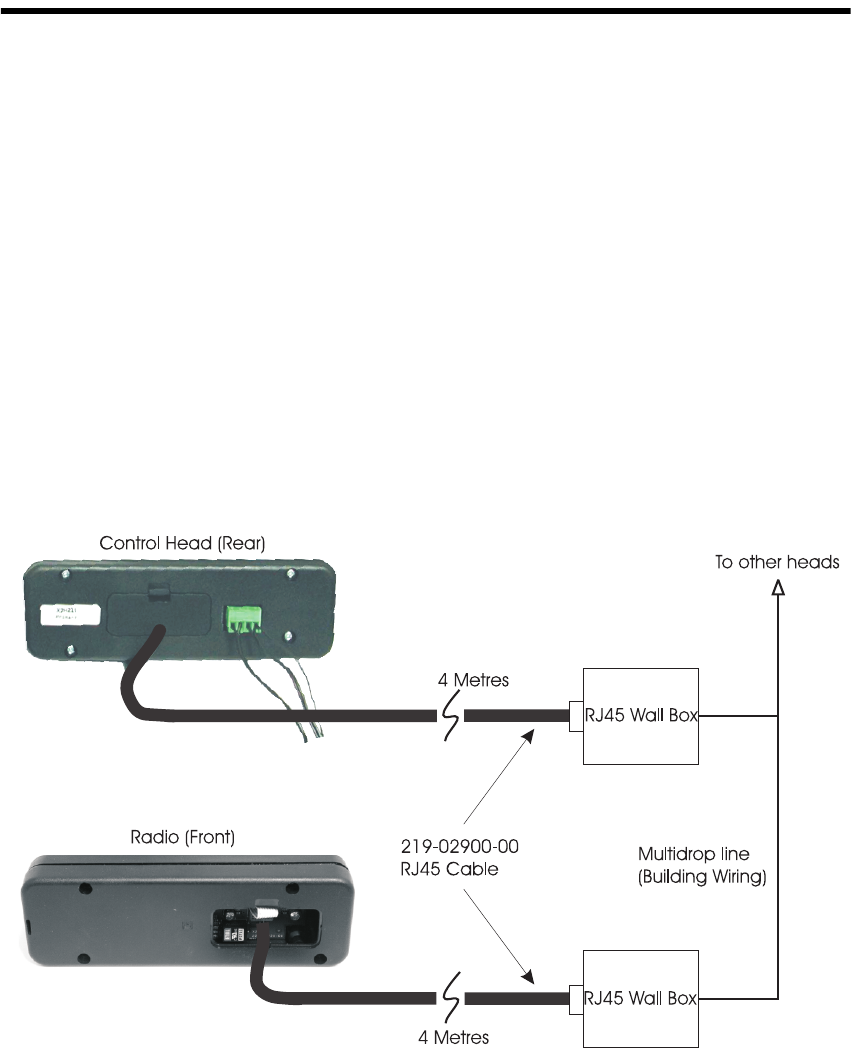
2.4 System Connections
Each control head connects to the system network via the Micromatch to
RJ45 Cable, which plugs into the RJ45 Wallbox. The RJ45 Wall boxes are
fitted at intervals along a multi-drop cable.
The radio also connects to the system network via the Micromatch to RJ45
Cable, which plugs into the X2AM01 Multi-Head Radio Interface. The
other end of the cable plugs into an RJ45 Wallbox, which is fitted at one
end of the multi-drop cable. See system diagram earlier for block overview
of system.

20 System Installation T2004 Multi-Control Head System Manual
© Tait Electronics Limited May 2004
3 System Installation
The T2004 Multi-Control Head Installation Manual M2004-00-000-315
should be referred to for the installation process.

T2004 Multi-Control Head System Manual System Operation 21
© Tait Electronics Limited May 2004
4 System Operation
The primary control head provides the same user functionality as the
original T2020/T2040 control head, including the On/Off power control
to the entire multi-head system.
The Secondary control heads have the same functionality except for the
On/Off power control. The power switch is disabled in the Secondary
heads, because only one control head (Primary) can provide system power
On/Off control.
Secondary control heads can not be individually powered off.
Note The DC plug pack for the Secondary head should be connected
to a 24-hour mains outlet in order for the Secondary heads to
always function correctly. Display errors will occur if power is
removed and replaced without resetting the radio via the Primary
head. Secondary heads have a programmed delay of 10 seconds
from initial power on, where key presses will not be actioned.
22 System Equipment Specifications T2004 Multi-Control Head System Manual
© Tait Electronics Limited May 2004
5 System Equipment Specifications
5.1 Multi-Drop Cable Specifications
Note This cable is not supplied by TEL as part of the Multi-Control
Head system.
The Multi-Drop Cable is a 4x twisted pair overall screen cable (Cat5 or
similar) which is used for cabling within the building. The length of this
cable can be a maximum of 2000M.
The recommended cable type used for the multi-drop cable is M&M cables
b2004 ESCS 4 x twisted pair/overall screen.
RJ45 Wall boxes are fitted at intervals along this multi-drop cable, which
provide the junction between the remote control heads and connection to
the building network.
T2004 Multi-Control Head System Manual System Equipment Specifications 23
© Tait Electronics Limited May 2004
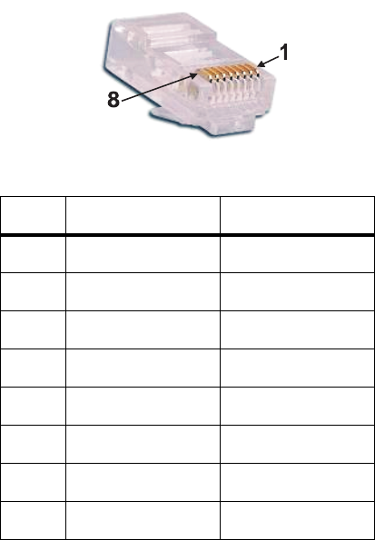
5.2 Micromatch to RJ45 Cable (IPN 219-02900-00)
The Micromatch to RJ45 Cable is the means by which the radio and control
heads connect to the building network.
The cable connects the radio at SK3 on the X2AM01 Multi-Head Interface
PCB to the radio’s RJ45 Wallbox. The cable connects each control head at
J5 to the corresponding RJ45 Wallbox.
The table below shows the pin assignment for the RJ45 cable which
connects to the wallboxes:
Pin Colour Description
1 Black Data from radio 1B
2 Brown Data from radio 1A
3 Red Ground
4 Orange Balanced audio
5 Yellow Balanced audio
6 Green Power switch
7 Blue Data to radio 2B
8 Violet Data to radio 2A
24 System Equipment Specifications T2004 Multi-Control Head System Manual
© Tait Electronics Limited May 2004
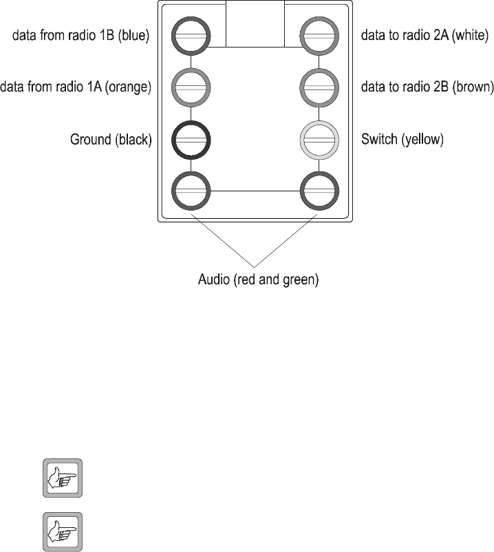
5.3 RJ45 Wallbox
Wall boxes are connected in a multi drop arrangement (i.e. all wiresare
connected in parallel), with one wallbox for each control head and one
wallbox for the radio. View below of the RJ45 Wallbox terminals is from
the top.
The following pins should be paired:
■Power Switch line and Ground
■Audio
■Data 1A & 1B
■Data 2A & 2B
Note Polarity of the data pairs is important. Earthing of the cable screen
should only occur at the radio interface wallbox.
Note Some Cat 5 cable installations (normally used for network or
PABX connection) have pin reversal on some or all pins. Check
connection polarities if control heads do not function as expected.
T2004 Multi-Control Head System Manual System Equipment Specifications 25
© Tait Electronics Limited May 2004
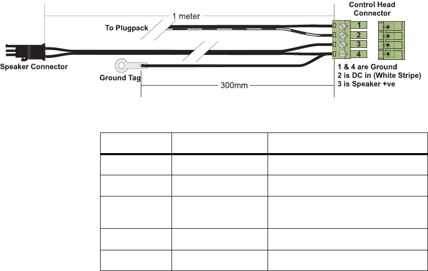
5.4 DC Power and Speaker connections
The control head is connected to the external speaker and the DC plug pack
via the 219-02907-00 Multi-head DC power cable.
Quantity IPN Description
300mm 201-00030-10 Wire T/C 7/0.2mm Pvc Blk
1 meter 205-00010-03 Cable twin cycle 2/7/0.2mm black
1 240-02011-35 Connector 4w Phoenix MCV 1,5/4-G-
3,81 4 way jack
1 240-04021-63 Connector 2w 24awg black inline
1 356-00010-05 Tag Solder 4mm long M6144/4.2
26 System Equipment Specifications T2004 Multi-Control Head System Manual
© Tait Electronics Limited May 2004

T2004 Multi-Control Head System Manual System Testing 27
© Tait Electronics Limited May 2004
6System Testing
Install all interface boards, control heads and components as per the
installation guide (IPN M2004-00-100-315).
Power up all control heads, followed by the radio. Check the Primary
control head causes the radio and all heads to power on and off.
Check all control heads show the same information in the LCD
Check all control heads keypad functionality.
Note Secondary head user input is disabled for 10 seconds after power
on.
Check transmit and receive audio functionality from all control heads. The
radio should function normally from each control head.
If Global mute is enabled check the following
■All control heads have audio when all mics are on hook (Hang up stud is
earthed)
■When one microphone is lifted off hook the audio remains enabled for
that head and all other heads are muted.
■When a microphone is off hook in the system, check that lifting another
microphone off hook enables audio for that head.
Verify the radio can be read/ programmed by a computer connected to any
remote head.

28 System Fault Finding T2004 Multi-Control Head System Manual
© Tait Electronics Limited May 2004
7 System Fault Finding
Problem
System will not power up, all heads appear dead.
Suggestion
■Check radio has power connected and two micromatch connectors on
the interface board are not reversed.
■Check pin 1 of interface board SK3 appears at J5 pin 1 at control heads.
SK3 pin 2 connects to J5 pin 2 etc.
■Check for 13.8V at control heads.
■Check Primary head is correctly fitted and turned on.
Problem
System will not power off.
Suggestion
■Check all multi-drop wiring for shorts or faults.
■Check only one Primary head is installed.
Problem
Head displays information but keypad, mic, etc. are dead.
Suggestion
■This happens for ten seconds after power up on Secondary heads only.
■If condition is permanent check data pair 2A/2B paying attention to
polarity.
Problem
Transmit/ Receive audio is very quiet.
Suggestion
Check for cable losses or faults. Max multi drop line length is 2km.
T2004 Multi-Control Head System Manual System Fault Finding 29
© Tait Electronics Limited May 2004
Problem
Transmit/ Receive audio is excessively noisy.
Suggestion
■Confirm radio is OK by removing multi-drop network and connecting
a Primary control head directly to the interface board SK3.
■If problem is in the network, check for cable faults, remove noise sources
or re-route cable away from noise sources.
■Ensure mic clip is isolated from metal work to avoid earth loops.
Problem
Global mute is not functioning.
Suggestion
■Check JP1 is fitted in the control head.
■Check microphone clip is correctly earthed.
Problem
Control head only shows 2372A510 on power on or all digits and LEDs
flash.
Suggestion
■One of the keys on the keypad is stuck down.
■Keypad PCB has become contaminated with chemicals or liquids.
30 System Fault Finding T2004 Multi-Control Head System Manual
© Tait Electronics Limited May 2004
T2004 Multi-Control Head System Manual 31
© Tait Electronics Limited May 2004
Part B T2004 Control Heads
This part provides general and technical information about the
T2020 and T2040 Primary and Secondary control heads used in
the T2004 Multi-Control Head system.
The control heads covered in this section are:
■X2H221 T2020 Primary Control Head
■X2H222 T2020 Secondary Control Head
■X2H241 T2040 Primary Control Head
■X2H242 T2040 Secondary Control Head
The following topics are covered in this part:
■Section 1 Introduction
■Section 2 Circuit Description
■Section 3 Functionality
■Section 4 I/O Connections
■Section 5 Assembly/Disassembly Instructions
■Section 6 X2H2xx PCB Information
■Section 7 Testing the X2H2xx control heads
32 T2004 Multi-Control Head System Manual
© Tait Electronics Limited May 2004

T2004 Multi-Control Head System Manual Introduction 33
© Tait Electronics Limited May 2004
1 Introduction
1.1 The T2004 Control Heads
The T2004 Multi-Control Head system allows the use of between one and
five control heads with a single T2020 or T2040 radio. The control heads
are configured as one Primary and up to four Secondary. The Primary
control head is the only one which controls the radio’s power, as well as
power to each Secondary control head, otherwise the functionality of all the
control heads is the same.
1.2 Features
The remote control heads provide the same functionality as the standard
T2000 control head, except it does not provide for a DTMF module to be
fitted. If DTMF dialling capability is required, a T2000-A07 DTMF
microphone is required.
In addition, the remote control heads provide two extra functions:
■Power Switch Selection (Primary/ Secondary mode selection
■Global Mute
Power Switch Selection
The Power Switch Selection function is provided so that only one control
head in the system (the Primary head) is able to control the system’s power.
This function is selectable by the fitting of a jumper (JP2) on the control
head PCB of the Primary head. This is factory fitted by default.
Only the Primary head should have JP2 fitted. The system will not power
on correctly if more than one control head in the system has this jumper
fitted.
Global Mute
The Global Mute function is provided to avoid the possibility of audio
feedback when two or more control heads are placed in close proximity (for
example, within the same room or the same vehicle). The Global Mute
function is individually selectable on each control head, via a link on the
control head PCB. This is factory fitted by default.
If a control head has this jumper fitted, its speaker will only unmute when
the microphone is taken off hook (i.e. to answer or make a call). All other

34 Introduction T2004 Multi-Control Head System Manual
© Tait Electronics Limited May 2004
control heads with the global mute function enabled will mute their
speakers. If all microphones are on-hook then all the speakers will unmute
when a call is received. A user shall be able to join a conversation by picking
up the microphone. This will unmute the speaker audio at that control head.
With Global Mute disabled (i.e. the jumper is not fitted), received audio is
present at all control heads, and transmit audio is heard at all heads except
the head that is transmitting.
Not all control heads in the system must be set to the same Global Mute
setting. For example:
■Where a despatcher station has two control heads in the same room, both
heads would need Global Mute enabled to avoid audio feedback.
■Where a supervisor may have a control head installed in their office, and
wants to hear all incoming and outgoing traffic, Global Mute would not
be enabled. Note that in this example, outgoing transmit audio from this
control head would be heard at the despatcher’s station heads.
General Specifications
Radios supported Series II T2020 and T2040 radios
Possible number of control heads Between one and five
Control head DC supply & Speaker connector Phoenix MCV 1,5/4-G-3,81 4 way jack
Control head DC supply voltage (at 800mA) +13.8V nominal
+10.8V minimum
+16.0V maximum
Balanced line audio levels Preset to -10dBm for receiver audio
Preset to -15dBm for transmitter audio
Control head dimensions Standard T2000 control head dimensions

T2004 Multi-Control Head System Manual Introduction 35
© Tait Electronics Limited May 2004
1.3 Product Codes
Product Code Description TCL Code
T2004-A20 T2020 Primary Multi-Control Head Kit
T2004-A21 T2020 Secondary Multi-Control Head Kit
T2004-A40 T2040 Primary Multi-Control Head Kit
T2004-A41 T2040 Secondary Multi-Control Head Kit
X2H221 T2020 Primary Control Head only STA6682-4H
X2H222 T2020 Secondary Control Head only STA6682-4H
X2H241 T2040 Primary Control Head only STA6682-4H
X2H242 T2040 Secondary Control Head only STA6682-4H
X2AM01 T2020/40 Multi-Control Head Radio Interface PCB STA6682-1H
36 Circuit Description T2004 Multi-Control Head System Manual
© Tait Electronics Limited May 2004
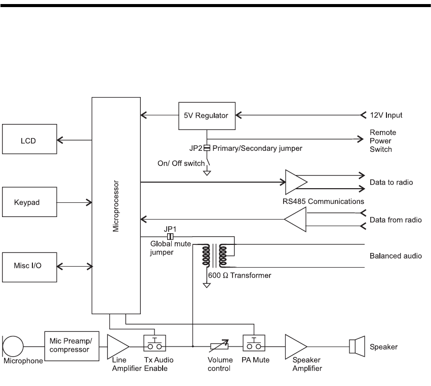
2 Circuit Description
This section provides circuit information for the T2004 Primary and
Secondary control heads as shown in the X2H2xx control head block
diagram.
Audio
An internal power amplifier drives a speaker connected to the control head
for local audio.
The PCB provides a 600 Ohm interface for both the Tx and Rx audio.
A microphone amplifier/ compressor followed by a line driver stage outputs
microphone audio to the balanced line.
Microphone
The standard T2000-A02 microphone is used.
T2004 Multi-Control Head System Manual Circuit Description 37
© Tait Electronics Limited May 2004
Power
The control head is supplied with 13.8V from an AC to DC plug pack.
The remote power switch line J5-3 (controlled by the Primary control head)
controls the 5V regulators on the Secondary heads and interface board.
Data
A separate RS-485 transmitter and receiver in each control head provide the
data communications between the radio and control heads.
Connections
Connection to the remote control heads is via the micromatch to RJ45 cable
at J5, which connects to the RJ45 Wallbox. The wallbox connects to the
multi-drop cable, which connects to the RJ45 Wallbox for each control
head and the radio.
DC Input and speaker output is via a 4 way phoenix connector at J6. The
supplied cable 219-02907-00 connects to J6. The plug pack (supplied
separately) connects to this cable assembly.
The DC input is polarity protected so that in the event of reverse polarity
being applied the head will not function, no damage will occur.

38 Functionality T2004 Multi-Control Head System Manual
© Tait Electronics Limited May 2004
3 Functionality
3.1 Software
Software version 2372A510 is programmed into the microprocessor on all of
the remote control heads.
The software allows the remote control heads to work in the same way as
standard T2000 control heads, with additional features detailed below.
Primary Secondary Configuration
The control head design is altered to allow a system of multiple heads to
function with one radio. The heads are divided into Primary and Secondary
via hardware, i.e. by linking a port bit on the head processor (Secondary =
high, Primary = low). Only one Primary is possible per system.
RS485
The serial line driver in each head feeds its output to a common serial line
back to the radio. This raises the problem of multiple devices trying to drive
one line. To overcome this, the RS485 line drivers are held in a tri-state
condition until the head generates serial data. Hardware on the circuit board
enables the driver at the appropriate time. The radio can still be programmed
from a PC via any head.
Avoiding Data Clashes
The heads share a common serial data link with the radio, so in order to
overcome data clashes at power up time, Secondary heads have a 10 second
timeout during which all user input and all serial output is stopped. After
the timeout, normal operation resumes.
Note that there is no mechanism to prevent data clashes during normal
operation; the system must rely on the probability of a clash being very
small.
Controlling the Speaker Path
Muting the speaker output of one head by another head is accomplished in
hardware by phantoming a DC control signal onto commonly connected
audio lines which link all heads in the group. This line can be either driven
or its state sensed by the head microprocessor and the audio output is

T2004 Multi-Control Head System Manual Functionality 39
© Tait Electronics Limited May 2004
controlled accordingly. This is enabled by fitting JP1, for the Global Mute
feature.
In order to accomplish this, some I/O lines of the microprocessor have been
reassigned to new functions. The control of the audio output is based on a
truth table that uses the state of the PTT, Hook and Line Sense inputs as its
control elements.
The audio truth table is shown below.
Scenario
(All heads in this
condition)
JP1
(In = Global
Mute Active)
PTT
(0= Active i.e
Transmitting)
Hook
Switch
(1= On hook)
Global Mute
Line Drive
(1= mute other heads)
Global
Mute Line
Sense
(1= activate mute)
Spkr
Mute
(1=mute active
i.e.no audio)
Comment
On hook, no
Rx audio
IN110 0 0
On hook, no
Rx audio
OUT110 0 0
On hook, Rx
audio
IN 1 1 0 0 0 Everyone can hear
audio
On hook, Rx
audio
OUT 1 1 0 0 0 Everyone can hear
audio
Off hook
(local)
IN 1 0 1 1 0 Only local head has Rx
audio
Off hook
(local)
OUT 1 0 0 1 0 Because jumper is out,
line drive does not
affect other heads
Off hook
(remote)
IN110 1 1 Everyone else muted
Off hook
(remote)
OUT 1 1 0 0 0 Hear everything
Off hook
(local+remote)
IN 1 0 1 1 0 Everyone off hook
hears audio
Off-hook
(local+remote)
OUT 1 0 0 1 0 Hear everything
PTT (local) off
hook
IN011 1 1 Mute local
PTT (local) off
hook
OUT010 1 1 Mute local
PTT (local) on
hook
IN 0 1 1 1 1 All muted
PTT (local) on
hook
OUT 0 1 0 1 1 Mute local but no-one
else
PTT (remote)
on hook local
IN 1 1 0 1 1 Mute local (same as
‘Off hook remote’)
PTT (remote)
on hook local
OUT 1 1 0 1 0 Hear everything
PTT (remote)
off hook local
IN 1 0 1 1 0 Hear everything
PTT (remote)
off hook local
OUT 1 0 0 1 0 Hear everything
40 I/O Connections T2004 Multi-Control Head System Manual
© Tait Electronics Limited May 2004
4 I/O Connections
This section describes the I/O connections on the board.
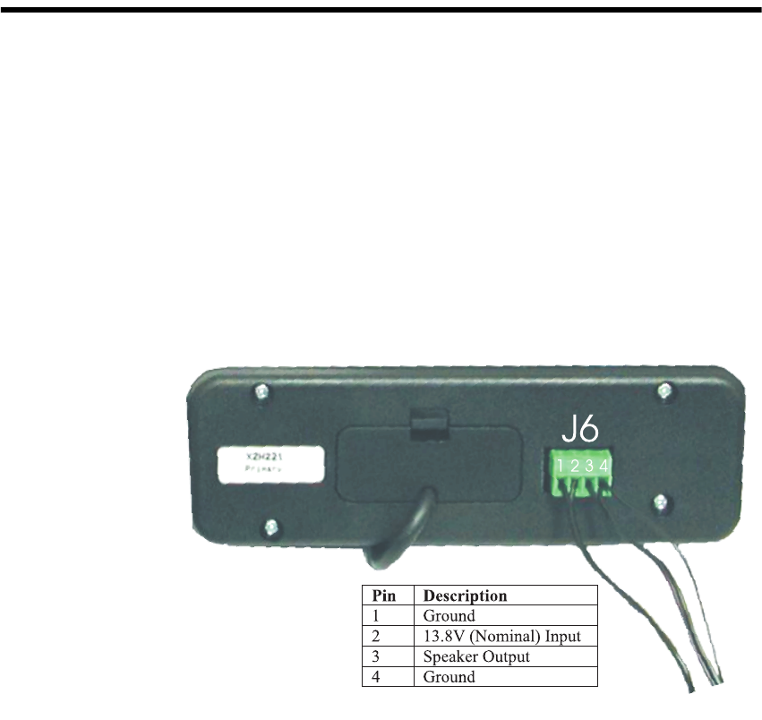
4.1 J6: Power and Speaker Connector
J6 on the rear panel of the control head provides connections for power,
speaker and microphone clip ground. The connector provides screw
terminals for fitting the microphone clip earth wire and speaker wires.

T2004 Multi-Control Head System Manual I/O Connections 41
© Tait Electronics Limited May 2004
4.2 J5: 8way Micromatch Socket
4.3 S10: 6way RJ Socket (Microphone)
Pin Signal Description
1 Tx Data 2A Data to radio A
2 Tx Data 2B Data to radio B
3 Pwr Sw Remote power switch, low = power on
4 Audio Balanced audio line
5 Audio Balanced audio line
6 Gnd Common ground
7 Rx Data 1A Data from radio A
8 Rx Data 1B Data from radio B
Pin Signal Description
1 +13V8 Low current supply for programming interface
2 TXD Data from radio to computer
3 PTT low = transmit condition
4 MIC Microphone audio
5 GND Common ground
6 RXD Data from computer to radio

42 Assembly/Disassembly Instructions T2004 Multi-Control Head System Manual
© Tait Electronics Limited May 2004
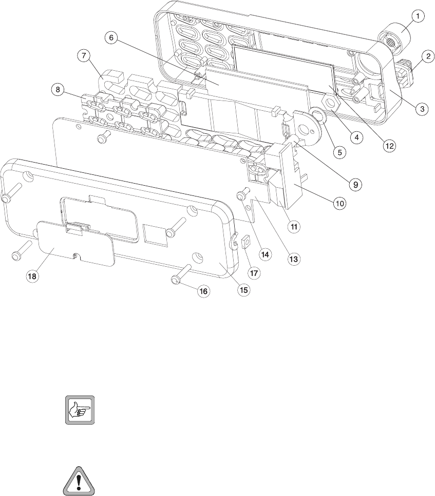
5 Assembly/Disassembly Instructions
This section provides mechanical parts information and disassembly
instructions for the control heads.
5.1 Mechanical Parts
The T2004 Multi-Control Head includes the following mechanical parts.
Please use the IPN number and description when ordering replacement
parts.
Note All PCB and cable components are specified separately. For infor-
mation for these items, refer to the sections listed below:
■For PCB information, refer to Section 6, “X2H2xx PCB
Information”.
■For external cable information, refer to Part A, Section 5, “System
Equipment Specifications”.
Item Description IPN Qty
1 Knob A3M2530 T2K SII 311-01042-01 1
2 Microphone with Grommet 252-00010-76 1
3 Panel Frt Scrn T2020/40/50 SII 316-06430-02 1
4 Volume Pot Nut part of 040-05100-20 1
5 Volume Pot Washer part of 040-05100-20 1
6 LCD Display 008-02029-00 1
7 Lightspreader 20 Bttn T2K SII 304-07036-02 1
8 Keypad SII International 311-03076-01(T2020) 311-03078-01(T2040) 1
9 Volume Pot 040-05100-20 1
10 Pot PCB part of 228-23722-xx 1
11 Microphone Connector 240-04021-61 1
12 Lens LCD Display T2K FM2/TR2 312-01046-05 1
13 Control Head PCB 228-23722-xx 1
14 Screw 4-20x3/8 P/P Trilobe-P BZ (Control Head Screws) 349-00010-22 2
15 Back Panel 316-02001-00 1
16 Screw 4-20x5/8 P/P Trilobe-P BZ (Remote Back Screws) 349-00010-24 4
17 Captive Nut M4 Pressed 352-00010-17 2
18 Remoting Connector Cover 316-85125-00 1
T2004 Multi-Control Head System Manual Assembly/Disassembly Instructions 43
© Tait Electronics Limited May 2004
5.2 Disassembling the Control Head
To disassemble the control heads, refer to the parts list opposite, and the
instructions and illustration below.
1. Remove the four retaining screws(16) and two captive nuts (17) from
the back panel.
2. Remove the two retaining screws (14) from the control head PCB.
Note When replacing the screws, tighten to a torque of 8in.lb (0.9N).
3. With the control head face down, gently remove the PCB (13),
keypad (8), and lightspreader (7) from the front panel (3)
Caution Do not disturb the positioning or height of the
LEDs, as this is critical for reassembly.

44 Assembly/Disassembly Instructions T2004 Multi-Control Head System Manual
© Tait Electronics Limited May 2004
4. Carefully remove the LCD (6) and lens (12).
5. Lay the assembly on a horizontal surface, with the light spreader (7)
in place.
6. Remove the volume knob (1) and volume knob nut (4) to access the
lightspreader and keypad.
7. Before reassembly, the LCD and PCB edge connectors should be
wiped with alcohol.
Caution Take care to ensure the alcohol does not come into
contact with the coating on the lightspreader, as this
will dissolve on contact with alcohol.

T2004 Multi-Control Head System Manual X2H2xx PCB Information 45
May 2004 © Tait Electronics Limited
6 X2H2xx PCB Information
This section contains all PCB information for the X2H2xx Multi-Head Control Head PCB.
The following information is included:
■PCB parts list
■Grid references
■PCB layout drawings for both sides of the board
■Circuit diagram.
46 X2H2xx PCB Information T2004 Multi-Control Head System Manual
May 2004 © Tait Electronics Limited

T2004 Multi-Control Head System Manual X2H2xx PCB Information 47
May 2004 © Tait Electronics Limited
6.1 X2H221 Rev 007 Parts List
IPN 228-23722-02
Ref IPN Description
BF1 008-00010-25 LED 2mm Grn Tower 3.8 Base
BF2 008-00010-25 LED 2mm Grn Tower 3.8 Base
BF3 008-00010-25 LED 2mm Grn Tower 3.8 Base
BF4 008-00010-25 LED 2mm Grn Tower 3.8 Base
BF5 008-00010-25 LED 2mm Grn Tower 3.8 Base
BF6 008-00010-25 LED 2mm Grn Tower 3.8 Base
BF7 008-00010-25 LED 2mm Grn Tower 3.8 Base
BF8 008-00010-25 LED 2mm Grn Tower 3.8 Base
BL1 008-00020-31 LED 3mm Yel Clear Sunpwr
BL2 008-00020-31 LED 3mm Yel Clear Sunpwr
BL3 008-00020-31 LED 3mm Yel Clear Sunpwr
BL4 008-00020-31 LED 3mm Yel Clear Sunpwr
BL5 008-00020-31 LED 3mm Yel Clear Sunpwr
C1 016-08100-03 Cap Elec SMD 10uF 35V 105/2000
C2 015-27100-10 Cap Cer 0805 1m+80-20% Y5v 16v
C3 016-09100-03 Cap Elec SMD 100u 16v 20%
C4 015-25220-08 Cap Cer 0805 22n 10% X7r 50v
C5 015-24100-08 Cap Cer 0805 1n 10% X7r 50v
C6 016-09100-03 Cap Elec SMD 100u 16v 20%
C7 015-26100-08 Cap Cer 0805 100n 10% X7r 50v
C8 015-24100-08 Cap Cer 0805 1n 10% X7r 50v
C9 015-27100-10 Cap Cer 0805 1m+80-20% Y5v 16v
C10 016-08100-01 Cap Elec SMD 10m 4*5.2 16v 20%
C15 015-25150-08 Cap Cer 0805 15n 10% X7r 50v
C20 015-26100-08 Cap Cer 0805 100n 10% X7r 50v
C21 015-26100-08 Cap Cer 0805 100n 10% X7r 50v
C22 015-26100-08 Cap Cer 0805 100n 10% X7r 50v
C23 015-26100-08 Cap Cer 0805 100n 10% X7r 50v
C24 015-26100-08 Cap Cer 0805 100n 10% X7r 50v
C25 015-22100-01 Cap Cer 0805 10p+-0.5p NPO 50v
C26 015-26100-08 Cap Cer 0805 100n 10% X7r 50v
C27 015-23100-01 Cap Cer 0805 100p 5% NPO 50v
C28 015-26100-08 Cap Cer 0805 100n 10% X7r 50v
C29 015-23150-01 Cap Cer 0805 150p 5% NPO 50v
C30 015-23150-01 Cap Cer 0805 150p 5% NPO 50v
C31 015-23150-01 Cap Cer 0805 150p 5% NPO 50v
C32 015-23150-01 Cap Cer 0805 150p 5% NPO 50v
C33 015-23150-01 Cap Cer 0805 150p 5% NPO 50v
C34 015-26100-08 Cap Cer 0805 100n 10% X7r 50v
C35 015-24470-08 Cap Cer 0805 4n7 10% X7r 50v
C36 015-25150-08 Cap Cer 0805 15n 10% X7r 50v
C37 015-24470-08 Cap Cer 0805 4n7 10% X7r 50v
C38 015-22220-05 Cap 0805 22p 1% 200v
C39 015-22220-05 Cap 0805 22p 1% 200v
C40 015-23150-01 Cap Cer 0805 150p 5% NPO 50v
C41 015-26100-08 Cap Cer 0805 100n 10% X7r 50v
C42 015-26100-08 Cap Cer 0805 100n 10% X7r 50v
C43 015-26100-08 Cap Cer 0805 100n 10% X7r 50v
C44 016-07470-01 Cap Elec SMD 4u7 6*4 16v 20%
C45 015-24100-08 Cap Cer 0805 1n 10% X7r 50v
C46 015-24100-08 Cap Cer 0805 1n 10% X7r 50v
C47 016-08470-01 Cap Elec SMD 47uf 6*4 16v
C48 015-26100-08 Cap Cer 0805 100n 10% X7r 50v
C49 015-26100-08 Cap Cer 0805 100n 10% X7r 50v
C50 015-27100-10 Cap Cer 0805 1m+80-20% Y5v 16v
C51 015-27100-10 Cap Cer 0805 1m+80-20% Y5v 16v
C52 016-07220-06 Cap Elec SMD Bi-P 22u 16v 20%
C53 016-09100-03 Cap Elec SMD 100u 16v 20%
C55 015-23100-01 Cap Cer 0805 100p 5% NPO 50v
C56 015-22330-01 Cap Cer 0805 33p 5% NPO 50v
C57 016-09100-03 Cap Elec SMD 100u 16v 20%
C58 015-27100-10 Cap Cer 0805 1m+80-20% Y5v 16v
C59 015-23100-01 Cap Cer 0805 100p 5% NPO 50v
C62 015-26100-08 Cap Cer 0805 100n 10% X7r 50v
C67 015-26100-08 Cap Cer 0805 100n 10% X7r 50v
C731 015-25100-08 Cap Cer 0805 10n 10% X7r 50v
C732 015-25100-08 Cap Cer 0805 10n 10% X7r 50v
C733 015-25220-08 Cap Cer 0805 22n 10% X7r 50v
C734 015-24100-08 Cap Cer 0805 1n 10% X7r 50v
D1 001-10001-60 Diode SMD BAS16
D2 001-10070-01 Diode BAV70W Dual Ss SOT323
D3 001-10001-60 Diode SMD BAS16
D4 001-10001-60 Diode SMD BAS16
D5 001-10011-74 Diode SMD MRA4004T3 1a/400v
J4 240-00020-87 Hdr 2x5w Ra Pcb Mtg
J5 240-10000-05 Conn SMD 8w 2r Skt M/Match
J6 240-06000-00 Conn 4W Hdr Vrt3.81mm Combicon
JP1 036-10000-00 Res M/F SMD 0805 0e 0.125w
JP2 036-10000-00 Res M/F SMD 0805 0e 0.125w
LCD1 008-02029-00 LCD 8 Chr 14 Seg Alpha T2K
PT501 040-05100-20 Pot 10k Log 3a 16vDC Spst Pcb
Q1 000-10008-17 Xstr SMD BC817-25 NPN SOT23
Q2 000-10008-17 Xstr SMD BC817-25 NPN SOT23
Q3 000-10008-17 Xstr SMD BC817-25 NPN SOT23
Q4 000-10085-71 Xstr SMD BC857BW PNP SOT323
Q5 000-10008-17 Xstr SMD BC817-25 NPN SOT23
Q6 000-10085-71 Xstr SMD BC857BW PNP SOT323
Q7 000-10008-17 Xstr SMD BC817-25 NPN SOT23
Q8 000-10085-71 Xstr SMD BC857BW PNP SOT323
Q9 000-10008-17 Xstr SMD BC817-25 NPN SOT23
Q10 000-10008-17 Xstr SMD BC817-25 NPN SOT23
Q11 000-10008-17 Xstr SMD BC817-25 NPN SOT23
R1 036-16100-00 Res M/F SMD 0805 100k 5%
R5 036-15270-00 Res M/F SMD 0805 27k 5%
R6 036-16100-00 Res M/F SMD 0805 100k 5%
R7 036-15100-10 Res M/F SMD 0805 10k 1%
R8 036-14470-10 Res M/F SMD 0805 4k7 1%
R09 036-17100-00 Res M/F SMD 0805 1m 5%
R10 036-16100-00 Res M/F SMD 0805 100k 5%
R11 036-16100-00 Res M/F SMD 0805 100k 5%
R12 036-16100-00 Res M/F SMD 0805 100k 5%
R13 036-16100-00 Res M/F SMD 0805 100k 5%
R14 036-16100-00 Res M/F SMD 0805 100k 5%
R15 036-15270-00 Res M/F SMD 0805 27k 5%
R16 036-16100-00 Res M/F SMD 0805 100k 5%
R17 036-15180-00 Res M/F SMD 0805 18k 5%
R18 036-15560-10 Res M/F SMD 0805 56k 1%
R19 036-14100-00 Res M/F SMD 0805 1k 5%
R20 036-16100-00 Res M/F SMD 0805 100k 5%
R21 036-15470-10 Res M/F SMD 0805 47k 1%
R22 036-15100-10 Res M/F SMD 0805 10k 1%
R23 036-15100-10 Res M/F SMD 0805 10k 1%
R24 036-15270-00 Res M/F SMD 0805 27k 5%
R25 036-15100-10 Res M/F SMD 0805 10k 1%
Ref IPN Description

48 X2H2xx PCB Information T2004 Multi-Control Head System Manual
May 2004 © Tait Electronics Limited
R26 036-15100-10 Res M/F SMD 0805 10k 1%
R28 036-10000-00 Res M/F SMD 0805 0e 0.125w
R34 036-14470-10 Res M/F SMD 0805 4k7 1%
R35 036-14470-10 Res M/F SMD 0805 4k7 1%
R42 036-15470-10 Res M/F SMD 0805 47k 1%
R43 036-15470-10 Res M/F SMD 0805 47k 1%
R44 036-15470-10 Res M/F SMD 0805 47k 1%
R53 036-15470-10 Res M/F SMD 0805 47k 1%
R69 036-15470-10 Res M/F SMD 0805 47k 1%
R79 036-15470-10 Res M/F SMD 0805 47k 1%
R80 036-15100-10 Res M/F SMD 0805 10k 1%
R81 036-15100-10 Res M/F SMD 0805 10k 1%
R82 036-15100-10 Res M/F SMD 0805 10k 1%
R83 036-15100-10 Res M/F SMD 0805 10k 1%
R84 036-13560-00 Res M/F SMD 0805 560e 5%
R85 036-13560-00 Res M/F SMD 0805 560e 5%
R86 036-13560-00 Res M/F SMD 0805 560e 5%
R87 036-13560-00 Res M/F SMD 0805 560e 5%
R88 036-16180-00 Res M/F SMD 0805 180k 5%
R89 036-13470-00 Res M/F SMD 0805 470e 5%
R90 036-15100-10 Res M/F SMD 0805 10k 1%
R91 036-14120-00 Res M/F SMD 0805 1k2 5%
R92 036-14270-00 Res M/F SMD 0805 2k7 5%
R93 036-14100-00 Res M/F SMD 0805 1k 5%
R94 036-14270-00 Res M/F SMD 0805 2k7 5%
R95 036-14120-00 Res M/F SMD 0805 1k2 5%
R96 036-14270-00 Res M/F SMD 0805 2k7 5%
R97 036-13470-00 Res M/F SMD 0805 470e 5%
R98 036-13390-00 Res M/F SMD 0805 390e 5%
R99 036-13470-00 Res M/F SMD 0805 470e 5%
R100 036-14270-00 Res M/F SMD 0805 2k7 5%
R101 036-14270-00 Res M/F SMD 0805 2k7 5%
R102 036-15470-10 Res M/F SMD 0805 47k 1%
R103 036-15100-10 Res M/F SMD 0805 10k 1%
R104 036-18100-00 Res M/F SMD 0805 10m 5%
R105 036-14330-00 Res M/F SMD 0805 3k3 5%
R106 036-15470-10 Res M/F SMD 0805 47k 1%
R107 036-15100-10 Res M/F SMD 0805 10k 1%
R108 036-15100-10 Res M/F SMD 0805 10k 1%
R109 036-15100-10 Res M/F SMD 0805 10k 1%
R110 036-15100-10 Res M/F SMD 0805 10k 1%
R111 036-13560-00 Res M/F SMD 0805 560e 5%
R112 036-13560-00 Res M/F SMD 0805 560e 5%
R113 036-13560-00 Res M/F SMD 0805 560e 5%
R114 036-13560-00 Res M/F SMD 0805 560e 5%
R117 036-13120-00 Res M/F SMD 0805 120e 5%
R119 036-15100-10 Res M/F SMD 0805 10k 1%
R120 036-16150-00 Res M/F SMD 0805 150k 5%
R121 036-14220-00 Res M/F SMD 0805 2k2 5%
R123 036-13470-00 Res M/F SMD 0805 470e 5%
R124 036-13470-00 Res M/F SMD 0805 470e 5%
R125 036-15470-10 Res M/F SMD 0805 47k 1%
R126 036-15470-10 Res M/F SMD 0805 47k 1%
R127 036-14470-10 Res M/F SMD 0805 4k7 1%
R128 036-15270-00 Res M/F SMD 0805 27k 5%
R129 036-15470-10 Res M/F SMD 0805 47k 1%
R130 036-15220-10 Res M/F SMD 0805 22k 1%
R133 036-16270-00 Res M/F SMD 0805 270k 5%
R135 036-13120-00 Res M/F SMD 0805 120e 5%
R136 036-13120-00 Res M/F SMD 0805 120e 5%
R138 036-15100-10 Res M/F SMD 0805 10k 1%
R139 036-15390-00 Res M/F SMD 0805 39k 5%
R140 036-16220-00 Res M/F SMD 0805 220k 5%
R141 036-15270-00 Res M/F SMD 0805 27k 5%
Ref IPN Description
R142 036-15150-10 Res M/F SMD 0805 15k 1%
R143 036-15270-00 Res M/F SMD 0805 27k 5%
R144 036-12390-00 Res M/F SMD 0805 39e 5%
R145 036-15270-00 Res M/F SMD 0805 27k 5%
R146 036-10000-00 Res M/F SMD 0805 0e 0.125w
R147 036-14100-00 Res M/F SMD 0805 1k 5%
R148 036-15100-10 Res M/F SMD 0805 10k 1%
R149 036-15100-10 Res M/F SMD 0805 10k 1%
R595 036-12100-10 Res M/F SMD 0805 10e 1%
RLY2 002-10117-00 IC SMD TS117 Opto 8p Fpak
S10 240-04021-61 Skt 6w Phone Jack S-Ent
S11 240-00020-87 Hdr 2x5w Ra Pcb Mtg
T2 054-00010-20 Xmfr SMD Ct Etal2782
U1 002-10018-77 IC SMD LM1877M Dual Af Pwr Amp
U2 002-10003-58 IC SMD LM358 Dual 0-Amp
U13 240-04020-42 Skt 44 Pin SMD Plcc
U14 002-10340-64 IC SMD MC34064 L-Volt Sense
U15 002-74900-04 IC SMD 74HC04D 6x Inv Buffd
U16 002-74900-04 IC SMD 74HC04D 6x Inv Buffd
U17 002-10085-76 IC SMD PCF8576T LCD Dvr
U19 002-10004-83 IC SP483EEN RS485 Xcvr/Esd S08
U20 002-10016-51 IC SMD SSM2165-1s Preamp S0-8
U21 002-10004-83 IC SP483EEN RS485 Xcvr/Esd S08
U22 002-12951-00 IC SMD LP2951CM Adj Vltge Reg
U23 002-10021-42 IC SMD TLE2142CD Opamp S08
X2 274-01070-00 Xtal 4.000MHz Hc-49u/S Lo-Prof
002-20068-07 IC MC68HC705C8AFN Otp Micro
209-01027-00 Strip A3m2544 SI Impregnated
228-23722-01 Pcb T2020/40 Multi/Ctrl Head
304-07036-02 Light Sprdr 20 Bttn T2K SII
311-01042-01 Knob A3M2530 T2K SII
311-03076-01 K/Pad T2020 SII International
312-01046-05 Lens LCD Dsply T2K FM2/TR2
316-02001-00 Pnl M/Ctrl Hd Back T2K
316-06430-02 Pnl Frt Scrn T2020/40/50 SII
316-85125-00 Plate Cvr T2K
365-01516-01 Lbl T2K Model Id T/A
399-00010-53 Bag Plstc 150*250mm
349-00010-22 Scrw 4-20x3/8 P/P Trilobe-P BZ
352-00010-17 Nut M4 Pressed Sq S/T Bz
349-00010-24 Scrw 4-20x5/8 P/P Trilobe-P BZ
Ref IPN Description

T2004 Multi-Control Head System Manual X2H2xx PCB Information 49
May 2004 © Tait Electronics Limited
6.2 X2H221 Rev 007 Grid Reference
IPN 228-23722-02
Grid
Ref
PCB Circuit Diagram
B0 D4 1F2
B1 E7 1G2
B2 D7 1G2
B3 B7 1G1
B4 E6 1G2
B5 D6 1G2
B6 B6 1G1
B7 E5 1G2
B8 D5 1G2
B9 B5 1G1
B# B4 1F1
B* E4 1F2
BF1 N5 1H12
BF2 M5 1J12
BF3 K5 1F12
BF4 H5 1G12
BF5 N3 1H12
BF6 M3 1H12
BF7 K3 1F12
BF8 H3 1G12
BL1 K4 1D9
BL2 C4 1D9
BL3 C6 1D9
BL4 F6 1D10
BL5 P7 1D10
C1 A7 1C12
C2 L5 1C6
C3 A6 1B14
C4 C6 1E11
C5 C5 1B11
C6 B7 1C13
C7 K7 1J8
C8 P6 1E6
C9 A4 1B7
C10 A5 1B10
C15 M6 1J7
C20 B5 1J3
C21 F4 1B2
C22 C5 1E12
C23 D4 1J4
C24 F8 1J1
C25 A4 1B8
C26 L6 1K9
C27 B4 1B9
C28 D7 1D12
C29 K5 1B14
C30 E5 1E13
C31 F6 1D13
C32 G4 1D13
C33 E5 1E14
C34 J4 1H7
C35 D5 1H4
C36 D5 1H5
C37 G5 1H5
C38 K6 1H9
C39 K7 1H9
C40 F6 1D14
C41 E4 1A1
C42 E3 1B3
C43 E4 1B3
C44 P6 1E6
C45 E6 1E6
C46 D6 1D6
C47 J4 1B6
C48 D5 1E13
C49 C6 1D13
C50 F5 1B1
C51 N5 1C4
C52 F3 1A3
C53 N5 1C5
C55 D3 1B4
C56 D3 1B4
C57 C4 1C3
C58 D4 1B5
C59 D5 1B5
C60 D5 1B6
C62 B6 1B11
C67 C7 1C13
C68 A5 1B13
C731 S3 1D2
C732 R4 1D2
C733 R4 1D2
C734 R4 1D1
D1 D6 1D6
D2 N6 1D5
D3 B5 1B9
D4 G7 1F10
D5 M5 1C14
F1 N5 1G5
F2 L5 1G4
F3 J5 1G4
F4 G5 1G3
F5 N4 1G5
F6 L4 1G4
F7 J4 1G4
F8 G4 1G3
J4 R5 1E4
J5 G5 1B7 1C7 1D14 1E14
J6 L5 1B14
JP1 G6 1F10
JP2 F6 1D4
LCD1 K8 1J13
P1 G7 1E10
P2 P5 1H4
P3 E3 1B3
PHH1 A4 1A8
PT501 S1 1D2 1D3
PTH2 N4 1A9
PTH3 P4 1A9
PTH4 P5 1A10
Grid
Ref
PCB Circuit Diagram

50 X2H2xx PCB Information T2004 Multi-Control Head System Manual
May 2004 © Tait Electronics Limited
PTH5 P7 1A10
PTH6 C3 1A11
PTH7 B7 1A11
PTH8 D7 1A12
Q1 B6 1B11
Q2 B5 1B10
Q3 G7 1G9
Q4 H4 1E9
Q5 G7 1F10
Q6 D6 1E11
Q7 H4 1E9
Q8 E5 1H6
Q9 P6 1F6
Q10 D6 1D6
Q11 G7 1E9
R1 H7 1H8
R4 A6 1B13
R5 C6 1B11
R6 C6 1E11
R7 B5 1B10
R8 A4 1B7
R9 A4 1B8
R10 B4 1B9
R11 A4 1A7
R12 B5 1B10
R13 B4 1B8
R14 B4 1A8
R15 B5 1B10
R16 B6 1B11
R17 C5 1B8
R18 A4 1B7
R19 B5 1B9
R20 G6 1G10
R21 G7 1G9
R22 G7 1F9
R23 G7 1G10
R24 G6 1F9
R25 B6 1B10
R26 B5 1B11
R28 R1 1D2
R34 K6 1J8
R35 L6 1J8
R42 J5 1G5
R43 J5 1G5
R44 J5 1G6
R53 J5 1G6
R69 J5 1G6
R79 J4 1J7
R80 E6 1J11
R81 E7 1H11
R82 F7 1H11
R83 F7 1G11
R84 L5 1J12
R85 L4 1H12
R86 N5 1H12
R87 N4 1H12
R88 L6 1J9
R89 L6 1K9
R90 M6 1K9
R91 M6 1K9
R92 G6 1G6
R93 G4 1E9
R94 G6 1G5
Grid
Ref
PCB Circuit Diagram
R95 G4 1E10
R96 G6 1G5
R97 H4 1E9
R98 G4 1D9
R99 D5 1H5
R100 G6 1G6
R101 E5 1H5
R102 D5 1H5
R103 E6 1H6
R104 K6 1H8
R105 G7 1E8
R106 G7 1F9
R107 F7 1G11
R108 E7 1G11
R109 E7 1F11
R110 E7 1F11
R111 H5 1G12
R112 H4 1G12
R113 K5 1F12
R114 J4 1F12
R117 E4 1B1
R118 P5 1F5
R119 E4 1B3
R120 E4 1B3
R121 P6 1F6
R123 D6 1E5
R124 E6 1E5
R125 D6 1D6
R126 D6 1D6
R127 D6 1E7
R128 C4 1B3
R129 D6 1D7
R130 C4 1C3
R133 A6 1B13
R135 C6 1D13
R136 D5 1E13
R137 E5 1A1
R138 M5 1D4
R139 E4 1A3
R140 D4 1B4
R141 D4 1B4
R142 C4 1C3
R143 D4 1B5
R144 J4 1B6
R145 D5 1B5
R146 D5 1B6
R147 K4 1A7
R148 A6 1B12
R149 G7 1F8
R595 S3 1E2
RLY2 M4 1A6
S10 S3 1E1
S11 S3 1E3
T2 L4 1C7
U1 B6 1B13
U13 J6 1G7
U14 L5 1H6
U15 F7 1F11 1G11 1K1 1H11
U16 E6 1E6 1H11 1J11 1K2 1D8 1C7
U17 M7 1J9
U19 C5 1E12
U2 B4 1K3 1B8 1B9
U20 F4 1A2
Grid
Ref
PCB Circuit Diagram

T2004 Multi-Control Head System Manual X2H2xx PCB Information 51
May 2004 © Tait Electronics Limited
U21 D7 1D12
U22 M5 1C5
U23 D4 1B6 1K4 1B4
X2 K7 1H8
Grid
Ref
PCB Circuit Diagram
52 X2H2xx PCB Information T2004 Multi-Control Head System Manual
May 2004 © Tait Electronics Limited
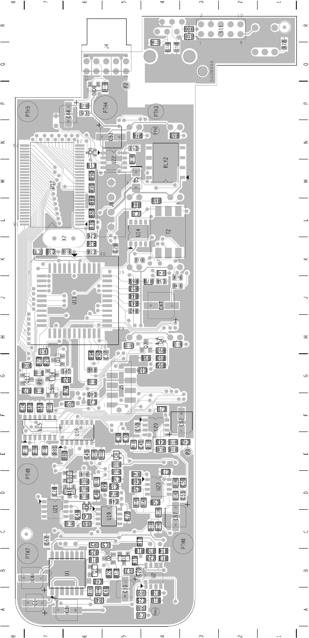
6.3 228-23722-02 PCB Top Side
T2004 Multi-Control Head System Manual X2H2xx PCB Information 53
May 2004 © Tait Electronics Limited
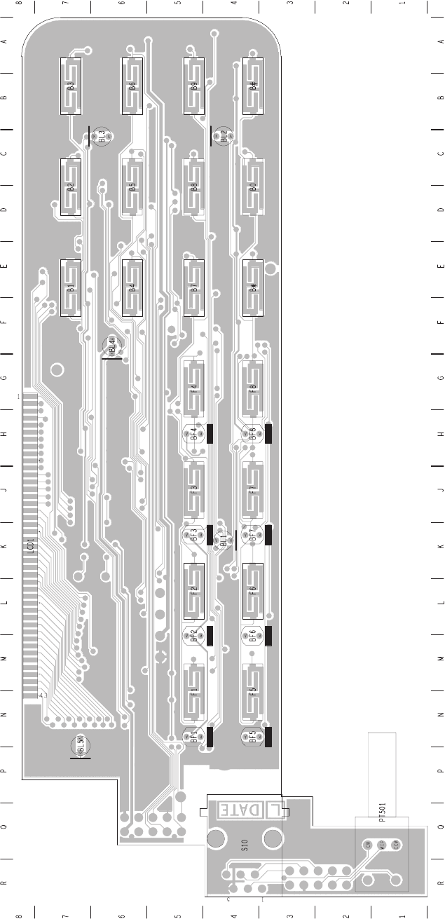
6.4 228-23722-02 PCB Bottom Side
54 X2H2xx PCB Information T2004 Multi-Control Head System Manual
May 2004 © Tait Electronics Limited
T2004 Multi-Control Head System Manual Part B T2004 Control Heads 55
May 2004 © Tait Electronics Ltd
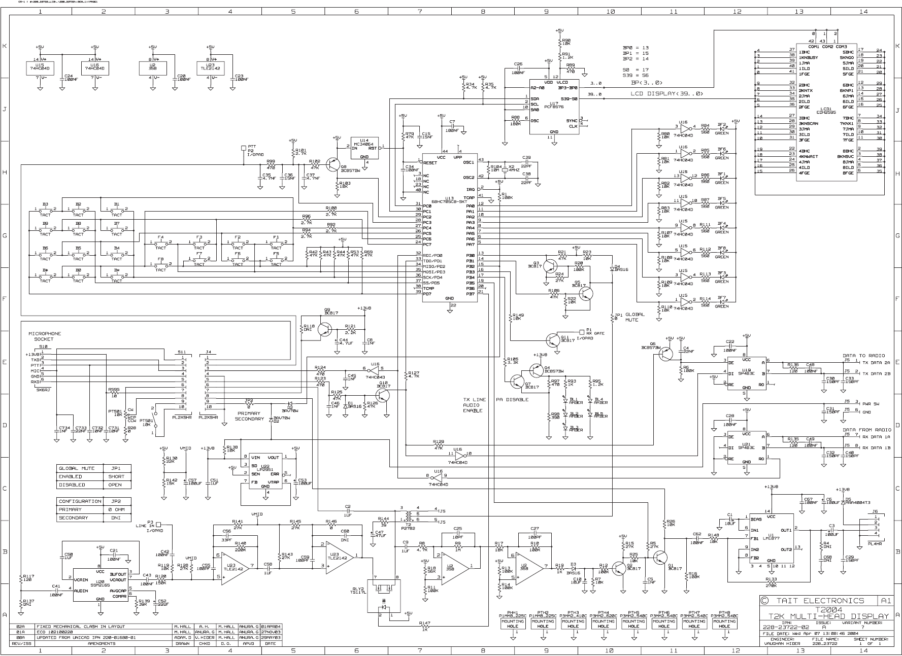
6.5 X2H221- PCB Circuit Diagram (page 1 of 1)
56 Part B T2004 Control Heads T2004 Multi-Control Head System Manual
May 2004 © Tait Electronics Ltd

T2004 Multi-Control Head System Manual Part B T2004 Control Heads 57
© Tait Electronics Ltd May 2004
7 Testing the X2H2xx control heads
Test equipment
■T2020 or T2040 radio with power supply in known working order.
■X2AM01 radio interface board in known working order.
■Microphone, speaker and power supply for control head.
■8 way micromatch loom to connect X2AM01 to radio.
■8 way micromatch loom to connect primary head under test.
■Radio communications test set.
■Multimeter.
■20MHz oscilloscope, preferably digital storage.
■Standard tools, screwdrivers, etc.
Setting up
1. If T2004 control head under test is not configured as a primary head,
temporarily fit shorting link to position JP2.
2. Connect SK1 of the X2AM01 board to connector S9 of radio logic
board.
3. Connect SK3 of the X2AM01 board to connector J5 of the control
head under test.
4. Connect power and microphone to the primary control head as usual.
5. Connect the radio's antenna jack to the RF input/output of the
communication test set.
6. Connect a suitable 13.8VDC 10A power supply to the radio.
Te st i n g
Power
■Check there is always +13.8V on U22 pin 8 and U1 pin 14.
■Check U22 pin 3 is high when the control head switch (volume control)
is off, and around 0V when the control head is switched on.
■Check there is 5V on U22 pin 1 when control head is on.
■Check 1/2 VCC rail on C57 is around 2-3V.
58 Part B T2004 Control Heads T2004 Multi-Control Head System Manual
© Tait Electronics Ltd May 2004
Microprocessor
■Check reset line U14 pin 1 is at 5V.
■Use oscilloscope to check for 4MHz oscillation on crystal X2 or resistor
R104.
■With micromatch cable on J5 removed, switch on control head with any
key held down. On power up the display should always show software
version number (2372A510). When key is released, all display segments
and LEDs should flash.
Audio
■Transmit on microphone and apply audio (E.G. whistle into
microphone), check for approx. -15dBm line audio on RLY2 pins 7 and
8. Radio should enter transmit mode and have normal TX deviation.
"TX" should appear on the LCD.
■With the radio in receive mode, generate a test signal of -70dBm RF
level, 60% system deviation (1.5kHz for narrow band, 3kHz for wide
band). Check for approx. -10dBm line audio at C2. Check Q1 base is at
0V, so PA is not muted. Check that audio level into PA on U1 pin 7
varies with volume control. Check for high level audio output on U1 pin
2.
Global mute
■Ensure link JP1 is fitted to enable global mute.
■When not transmitting and microphone off hook (hang up stud not
earthed), check that JP1 is at 5V.
■With microphone on hook (hang up stud connected to 0V), check that
JP1 is at 0V.
■Temporarily fit a 1k ohm resistor between JP1 and U22 pin 1. Make
radio receive a test signal and adjust volume so audio can be heard in
control head speaker while microphone is off hook. Speaker should mute
when microphone is placed on hook. Remove link resistor when
finished.
Data
■Turn radio off then on using control head volume switch. Use
oscilloscope to check for 5V TTL data on U21 pin 1. Note that data only
lasts a few seconds after power on.
■After power up, confirm that key presses on control head appear as 5V
TTL data on U19 pin 4. Connect oscilloscope channel 1 on J5 pin 1,
channel 2 on J5 pin 2. Verify differential mode data exists on RS485 line
when keys are pressed.
PC programming
■Connect T2000 programming cable to microphone socket, check for
approx. 13.8V on microphone socket S10 pin 1.
■Verify that radio can be read correctly with appropriate radio
programming software.
T2004 Multi-Control Head System Manual Part C X2AM01 Radio Interface 59
© Tait Electronics Ltd May 2004
Part C X2AM01 Radio Interface
This part provides general and technical information about the
X2AM01 Multi-Head Radio Interface.
The following topics are covered in this part:
■Section 1 Introduction
■Section 2 Circuit Description
■Section 3 I/O Connections
■Section 4 Fitting PCB into Radio
■Section 5 X2AM01 Multi-Head Radio Interface PCB
■Section 6 Testing the X2AM01 radio interface

60 Part C X2AM01 Radio Interface T2004 Multi-Control Head System Manual
© Tait Electronics Ltd May 2004
1 Introduction
1.1 The X2AM01 Multi-Head Radio Interface PCB
The X2AM01 Multi-Head Radio Interface PCB is the interface between a
standard T2020 or T2040 radio and the remote control heads in the T2004
Multi-Control Head system.
The PCB fits inside a dummy (Clayton’s) control head, which replaces the
standard control head of the radio. Only one X2AM01 Multi-Head Radio
Interface PCB is used in the system.
T2004 Multi-Control Head System Manual Part C X2AM01 Radio Interface 61
© Tait Electronics Ltd May 2004
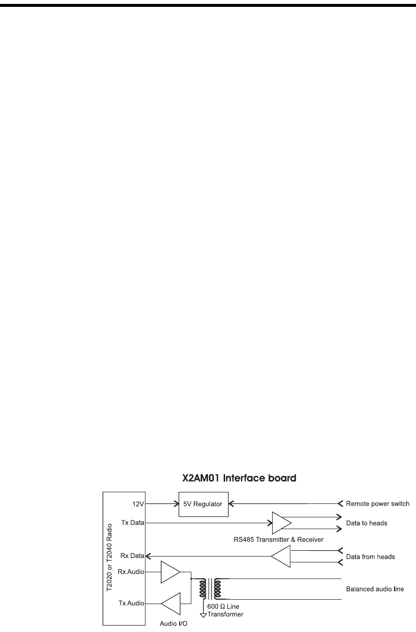
2 Circuit Description
This section provides circuit information for the X2AM01 Multi-Head
Radio Interface PCB.
Audio
The PCB provides a balanced 600 Ohm line interface for both the Tx and
Rx audio.
Power
The PCB is supplied with 13.8V from the radio. A single 5V supply is
provided for circuitry on the X2AM01 Interface PCB only.
The remote power switch line SK3-3 (controlled by the Primary head)
enables the 5V regulator, which in turn draws current from the radio (SK1-
1) and causes the radio to power up.
Data
A separate RS485 transmitter and receiver provide the data communications
between the radio and control heads.
Connections
The connection to the radio is the same as for a standard T2000 control head
(micromatch cable to SK1). Connection to the remote control heads is via
the micromatch loom at SK3, which connects to the RJ45 Wallbox. The
wallbox connects to the multi-drop cable, which connects to the RJ45
Wallbox for each control head.

62 Part C X2AM01 Radio Interface T2004 Multi-Control Head System Manual
© Tait Electronics Ltd May 2004
3 I/O Connections
This section describes the I/O connections on the board.
3.1 SK1: 8 Way Micromatch Socket to Radio
3.2 SK3: 8 Way Micromatch Socket to Control Heads
Pin Signal Description
1 +13.0V_UNSW Unswitched 13.8V from radio
2 GND Common ground
3 RX_DATA Data from heads to radio, 5V logic levels
4 TX_DATA Data from radio to heads, 5V logic levels
5 GND Common ground
6 AF Receiver audio, approx. -4dBm
7 MIC_IN Transmitter audio, approx. -30dBm
8 N/C Not connected
Pin Signal Description
1 DATA 2A Data from heads A
2 DATA 2B Data from heads B
3 PWR SW Remote power switch, Low=power on
4 Audio Balanced audio line
5 Audio Balanced audio line
6 GND Common ground
7 DATA 1A Data to heads A
8 DATA 1B Data to heads B

T2004 Multi-Control Head System Manual Part C X2AM01 Radio Interface 63
© Tait Electronics Ltd May 2004
4 Fitting PCB into Radio
The T2004 Multi-Control Head Installation Manual M2004-00-100-315
should be referred to for the installation process.
64 Part C X2AM01 Radio Interface T2004 Multi-Control Head System Manual
© Tait Electronics Ltd May 2004

T2004 Multi-Control Head System Manual Part B T2004 Control Heads 65
May 2004 © Tait Electronics Ltd
5 X2AM01 Multi-Head Radio Interface PCB
This section contains all PCB information for the Multi-Head interface PCB.
The following information is included for the board:
■PCB parts list
■Grid references
■PCB layout drawings for both sides of the board
■Circuit diagram.
66 Part B T2004 Control Heads T2004 Multi-Control Head System Manual
May 2004 © Tait Electronics Ltd

T2004 Multi-Control Head System Manual Part B T2004 Control Heads 67
May 2004 © Tait Electronics Ltd
5.1 X2AM01 Rev 008 Parts List
IPN 228-23721-01
Ref IPN Description
C1 015-27100-10 Cap Cer 0805 1m+80-20% Y5v 16v
C2 015-26100-08 Cap Cer 0805 100n 10% X7r 50v
C3 015-26100-08 Cap Cer 0805 100n 10% X7r 50v
C6 015-23100-01 Cap Cer 0805 100p 5% NPO 50v
C7 015-24100-08 Cap Cer 0805 1n 10% X7r 50v
C8 015-24100-08 Cap Cer 0805 1n 10% X7r 50v
C9 016-09100-01 Cap Elec SMD 100u 6.6*6.6 6.3v
C10 015-26100-08 Cap Cer 0805 100n 10% X7r 50v
C11 015-24100-08 Cap Cer 0805 1n 10% X7r 50v
C14 015-24100-08 Cap Cer 0805 1n 10% X7r 50v
C15 015-26100-08 Cap Cer 0805 100n 10% X7r 50v
C18 015-26100-08 Cap Cer 0805 100n 10% X7r 50v
C21 016-08100-01 Cap Elec SMD 10m 4*5.2 16v 20%
C26 015-22330-01 Cap Cer 0805 33p 5% NPO 50v
C36 015-22330-01 Cap Cer 0805 33p 5% NPO 50v
C39 015-23100-01 Cap Cer 0805 100p 5% NPO 50v
D1 001-10284-51 Diode SMD BZX284B5V1 Zensod110
R1 036-14180-00 Res M/F SMD 0805 1k8 5%
R2 036-15560-00 Res M/F SMD 0805 56k 5%
R3 036-14100-00 Res M/F SMD 0805 1k 5%
R4 036-14150-00 Res M/F SMD 0805 1k5 5%
R5 036-14150-00 Res M/F SMD 0805 1k5 5%
R7 036-15270-00 Res M/F SMD 0805 27k 5%
R8 036-12390-00 Res M/F SMD 0805 39e 5%
R9 036-15270-00 Res M/F SMD 0805 27k 5%
R10 036-15220-10 Res M/F SMD 0805 22k 1%
R12 036-15120-10 Res M/F SMD 0805 12k 1%
R13 036-15270-00 Res M/F SMD 0805 27k 5%
R17 036-15560-00 Res M/F SMD 0805 56k 5%
R18 036-15220-10 Res M/F SMD 0805 22k 1%
R25 036-14150-00 Res M/F SMD 0805 1k5 5%
R26 036-14150-00 Res M/F SMD 0805 1k5 5%
R27 036-13150-00 Res M/F SMD 0805 150e 5%
R28 036-13150-00 Res M/F SMD 0805 150e 5%
R38 036-14820-10 Res M/F SMD 0805 8k2 1%
R42 036-15270-00 Res M/F SMD 0805 27k 5%
SK1 240-10000-05 Conn SMD 8w 2r Skt M/Match
SK3 240-10000-05 Conn SMD 8w 2r Skt M/Match
T1 054-00010-20 Xmfr SMD Ct Etal2782
U1 002-10021-42 IC SMD TLE2142CD Opamp S08
U2 002-12951-00 IC SMD LP2951CM Adj Vltge Reg
U4 002-10004-83 IC SP483EEN RS485 Xcvr/Esd S08
U5 002-10004-83 IC SP483EEN RS485 Xcvr/Esd S08
219-02013-00 T2K 8way Loom Logic-Ctrl Hd
228-23721-01 Pcb T2020/40 M/Ctrl Hd Rad I/F
365-00011-54 Lbl White R1556/2 90*24mm
399-00010-51 Bag Plstc 75*100mm
399-00010-86 Bag Static Shlding 127x203mm
349-00020-32 Scrw M3*8mm T/T P/P Bz
353-00010-16 Wshr M3 Fibre 8mm Od*1.5mm
68 Part B T2004 Control Heads T2004 Multi-Control Head System Manual
May 2004 © Tait Electronics Ltd

T2004 Multi-Control Head System Manual Part B T2004 Control Heads 69
May 2004 © Tait Electronics Ltd
5.2 X2AM01 Rev 008 Grid Reference
Ref PCB Circuit Diagram
C1 A2 1C3
C2 B3 1E6
C3 B2 1B9
C6 C1 1C6
C7 D4 1D8
C8 E2 1D8
C9 A1 1C2
C10 C4 1E3
C11 G2 1D9
C14 G3 1D10
C15 B1 1B7
C18 C1 1B6
C21 A4 1E5
C26 C1 1C6
C36 B1 1C4
C39 B1 1C5
D1 F1 1F8
MT1 D3 1D8
MT2 D2 1D8
MT3 G2 1D9
MT4 G3 1D10
R1 C4 1C3
R2 C1 1C6
R3 C4 1B2
R4 B2 1G7
R5 C2 1F7
R7 C1 1C6
R8 C1 1D6
R9 C1 1C6
R10 A2 1D2
R12 A2 1C3
R13 C1 1C5
R17 A1 1C4
R18 C4 1B3
R25 B3 1E7
R26 C3 1E7
R27 C3 1E7
R28 C2 1F7
R38 C4 1B3
R42 C2 1C5
SK1 F4 1B2 1G2 1C2 1D2 1E2
SK3 F2 1C9 1G9 1F9 1E9
T1 D1 1C7
TP1 C1 1D4
TP2 C1 1C7
U1 B1 1B9 1C4 1C6
U2 B4 1E5
U4 B2 1F7
U5 B3 1E7
70 Part B T2004 Control Heads T2004 Multi-Control Head System Manual
May 2004 © Tait Electronics Ltd
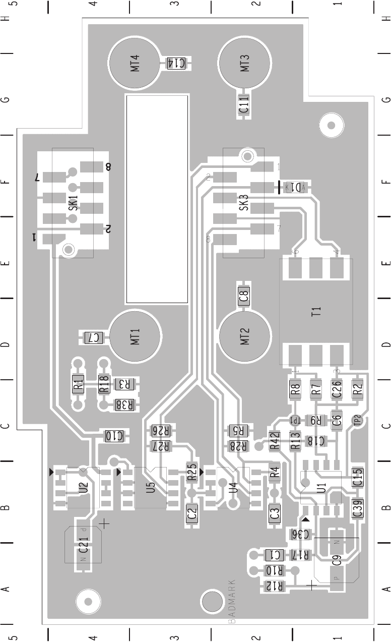
5.3 228-23721-01 PCB Top Side
T2004 Multi-Control Head System Manual Part B T2004 Control Heads 71
May 2004 © Tait Electronics Ltd
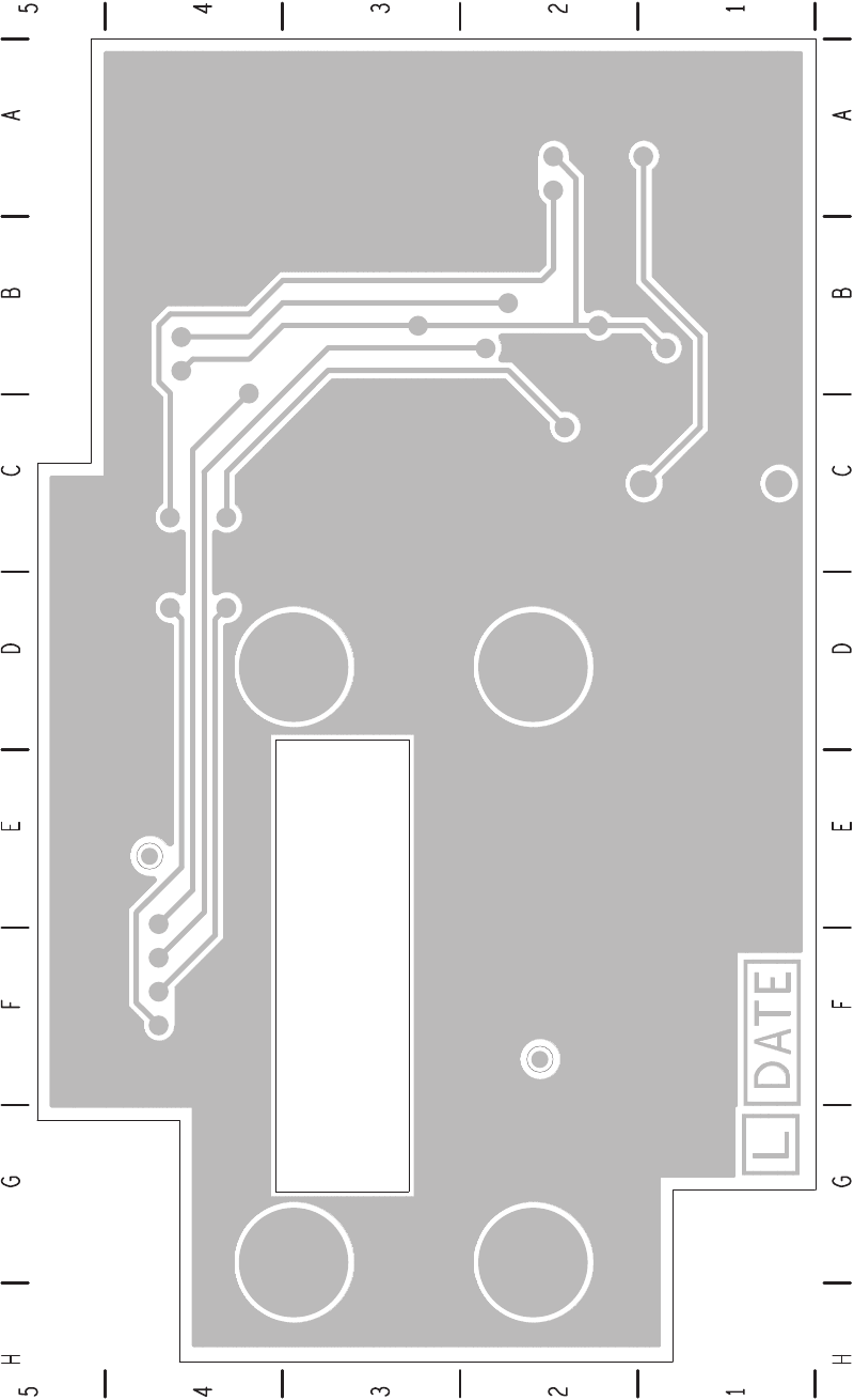
5.4 228-23721-01 PCB Bottom Side
72 Part B T2004 Control Heads T2004 Multi-Control Head System Manual
May 2004 © Tait Electronics Ltd
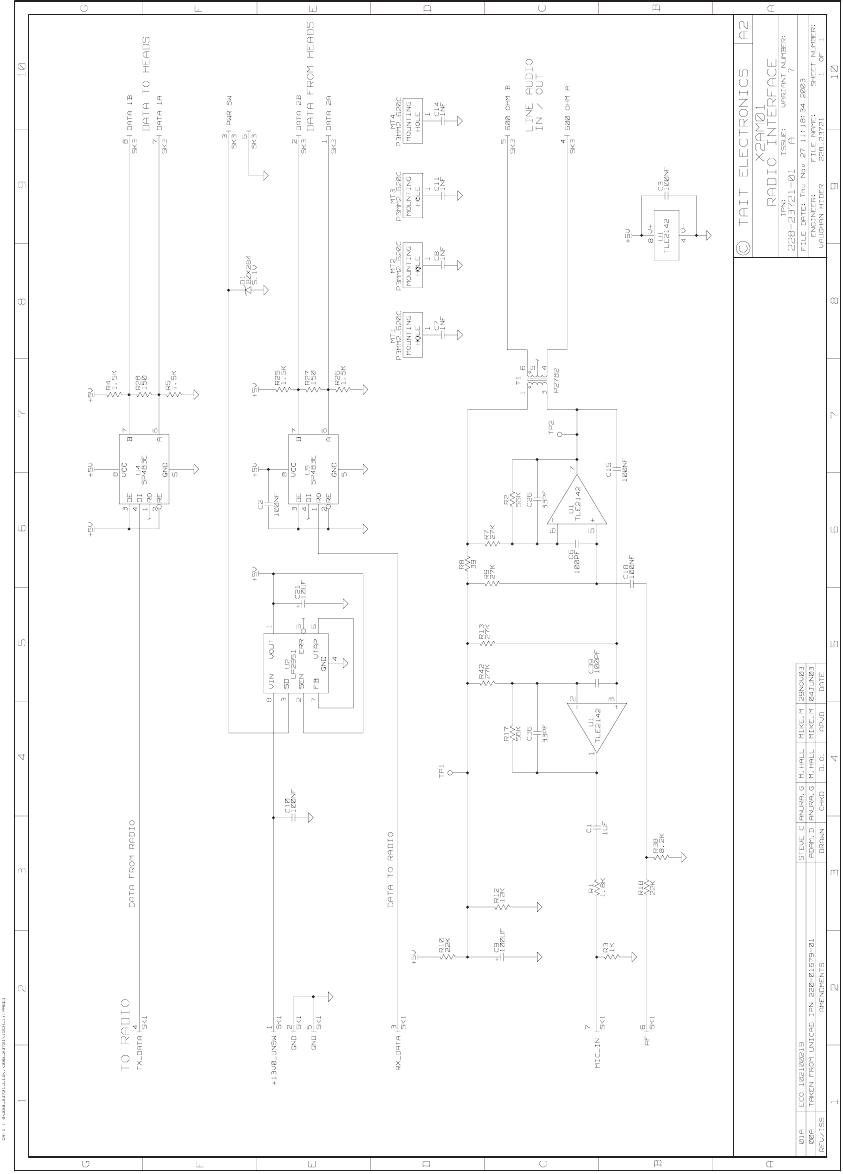
5.5 X2MA01 PCB Circuit Diagram (page 1 of 1)

T2004 Multi-Control Head System Manual Part B T2004 Control Heads 73
© Tait Electronics Ltd May 2004
6 Testing the X2AM01 radio interface
Test equipment
■T2020 or T2040 radio with power supply in known working order.
■X2H2x1 Primary control head in known working order.
■Microphone, speaker and power supply for control head.
■8 way micromatch loom to connect X2AM01 to radio.
■8 way micromatch loom to connect primary head.
■Radio communications test set.
■Multimeter.
■20MHz oscilloscope, preferably digital storage.
■Standard tools, screwdrivers, etc.
Setting up
7. Connect SK1 of the X2AM01 board to connector S9 of radio logic
board.
8. Connect SK3 of the X2AM01 board to connector J5 of the primary
control head.
9. Connect power and microphone to the primary control head as usual.
10. Connect the radio's antenna jack to the RF input/output of the
communication test set.
11. Connect a suitable 13.8VDC 10A power supply to the radio.
Te st i n g
Power
■Check there is always +13.8V on U2 pin 8.
■Check U2 pin 3 is high when the control head switch (volume control)
is off, and around 0V when the control head is switched on.
■Check there is 5V on U2 pin 1 when control head is on.
■Check 1/2 VCC rail at TP1 is around 2-3V.
■Check radio turns off (0V on radio logic board S14 pin 1) when control
head is off, check radio is on (+13.8V on S14 pin 1) when control head
is on.
74 Part B T2004 Control Heads T2004 Multi-Control Head System Manual
© Tait Electronics Ltd May 2004
Audio
■Transmit on microphone and apply audio (E.G. whistle into
microphone), check for approx. -15dBm line audio at TP2, check for
approx. -30dBm mic audio on SK1 pin 7. Radio should enter transmit
mode and have normal TX deviation.
■With the radio in receive mode, generate a test signal of -70dBm RF
level, 60% system deviation (1.5kHz for narrow band, 3kHz for wide
band). Check for approx. -4dBm of receiver audio on SK1 pin 6. Check
for approx. -10dBm line audio on TP2. Ensure audio appears on 600
ohm balanced line (measure between SK3 pins 4 and 5).
Data
■Turn radio off then on using control head volume switch. Use
oscilloscope to check for 5V TTL data on SK1 pin 4. Note that data only
lasts a few seconds after power on. Connect oscilloscope channel 1 on
SK3 pin 7, channel 2 on SK3 pin 8. Verify differential mode data exists
on RS485 line at radio power on.
■After power up, confirm that key presses on control head appear as 5V
TTL data on SK1 pin 3.
