TB8100 Installation And Operation Manual Manuals/TB8100 Inst Ops Jul 05
TB8000/TB8100 Install and Operation Manual/MBA_00005_06 TB8100 Install and Operation Manual MBA_00005_06 TB8100 Install and Operation Manual
User Manual: Pdf TB8100 Manuals/TB8100 Inst and Ops Manual - Jul 05
Open the PDF directly: View PDF ![]() .
.
Page Count: 144 [warning: Documents this large are best viewed by clicking the View PDF Link!]
- Installation and Operation Manual
- Tait Contact Information
- Contents
- Preface
- 1 Description
- 2 Circuit Description
- 3 Operating Controls
- 4 Functional Description
- 5 Installation
- 6 Replacing Modules
- 6.1 Saving the Base Station’s Configuration
- 6.2 Preliminary Disassembly
- 6.3 Replacing the Control Panel
- 6.4 Replacing the Reciter
- 6.5 Replacing the Power Amplifier
- 6.6 Replacing the Power Management Unit
- 6.7 Replacing the Front Panel Fans
- 6.8 Replacing the Module Guide Rails
- 6.9 Replacing the Subrack Interconnect Board
- 6.10 Final Reassembly
- 7 Connection
- 8 Preparation for Operation
- 9 Maintenance Guide
- Glossary
- Tait General Software Licence Agreement
- Directive 1999/5/EC Declaration of Conformity

TB8100 base station
Installation and
Operation Manual
MBA-00005-06
Issue 6
June 2005

2TB8100 Installation and Operation Manual
© Tait Electronics Limited June 2005
Tait Contact Information
Tait Radio Communications
Corporate Head Office
Tait Electronics Ltd
P.O. Box 1645
Christchurch
New Zealand
For the address and telephone number of
regional offices, refer to the TaitWorld
website:
We b si t e: http://www.taitworld.com
Technical Support
For assistance with specific technical issues,
contact Technical Support:
E-mail: support@taitworld.com
Web si te: http://support.taitworld.com
To our European customers:
Tait Electronics Limited is an environmentally responsible company which
supports waste minimization and material recovery. The European Union's
Waste and Electrical and Electronic Equipment Directive requires that this
product be disposed of separately from the general waste stream when its
service life is over. Please be environmentally responsible and dispose
through the original supplier, your local municipal waste “separate
collection” service, or contact Tait Electronics Limited.

TB8100 Installation and Operation Manual 3
© Tait Electronics Limited June 2005
Contents
Preface . . . . . . . . . . . . . . . . . . . . . . . . . . . . . . . . . . . . . . . . . . . . . . . . . . . . . 6
Scope of Manual . . . . . . . . . . . . . . . . . . . . . . . . . . . . . . . . . . . . . . . . . . . . . . . . . . . . 6
Enquiries and Comments . . . . . . . . . . . . . . . . . . . . . . . . . . . . . . . . . . . . . . . . . . . . . . 6
Updates of Manual and Equipment . . . . . . . . . . . . . . . . . . . . . . . . . . . . . . . . . . . . . . . 6
Copyright . . . . . . . . . . . . . . . . . . . . . . . . . . . . . . . . . . . . . . . . . . . . . . . . . . . . . . . . . 6
Disclaimer . . . . . . . . . . . . . . . . . . . . . . . . . . . . . . . . . . . . . . . . . . . . . . . . . . . . . . . . . 6
Document Conventions . . . . . . . . . . . . . . . . . . . . . . . . . . . . . . . . . . . . . . . . . . . . . . . 7
Associated Documentation . . . . . . . . . . . . . . . . . . . . . . . . . . . . . . . . . . . . . . . . . . . . . 7
Publication Record . . . . . . . . . . . . . . . . . . . . . . . . . . . . . . . . . . . . . . . . . . . . . . . . . . 8
1 Description. . . . . . . . . . . . . . . . . . . . . . . . . . . . . . . . . . . . . . . . . . . . . . . . 9
1.1 The TB8100 BSS Modules . . . . . . . . . . . . . . . . . . . . . . . . . . . . . . . . . . . . . . . . 10
1.2 Mechanical Assembly . . . . . . . . . . . . . . . . . . . . . . . . . . . . . . . . . . . . . . . . . . . . 12
2 Circuit Description . . . . . . . . . . . . . . . . . . . . . . . . . . . . . . . . . . . . . . . . . 15
2.1 Reciter. . . . . . . . . . . . . . . . . . . . . . . . . . . . . . . . . . . . . . . . . . . . . . . . . . . . . . . 16
2.2 PA . . . . . . . . . . . . . . . . . . . . . . . . . . . . . . . . . . . . . . . . . . . . . . . . . . . . . . . . . . 19
2.3 PMU . . . . . . . . . . . . . . . . . . . . . . . . . . . . . . . . . . . . . . . . . . . . . . . . . . . . . . . . 22
2.4 Control Panel. . . . . . . . . . . . . . . . . . . . . . . . . . . . . . . . . . . . . . . . . . . . . . . . . . 24
3 Operating Controls . . . . . . . . . . . . . . . . . . . . . . . . . . . . . . . . . . . . . . . . . 27
3.1 Control Panel. . . . . . . . . . . . . . . . . . . . . . . . . . . . . . . . . . . . . . . . . . . . . . . . . . 28
3.1.1 Standard Control Panel . . . . . . . . . . . . . . . . . . . . . . . . . . . . . . . . . . . 28
3.1.2 Dual Base Station Control Panel . . . . . . . . . . . . . . . . . . . . . . . . . . . . 30
3.1.3 Power Save Control Panel . . . . . . . . . . . . . . . . . . . . . . . . . . . . . . . . . 32
3.2 Reciter. . . . . . . . . . . . . . . . . . . . . . . . . . . . . . . . . . . . . . . . . . . . . . . . . . . . . . . 33
3.3 PA . . . . . . . . . . . . . . . . . . . . . . . . . . . . . . . . . . . . . . . . . . . . . . . . . . . . . . . . . . 34
3.4 PMU . . . . . . . . . . . . . . . . . . . . . . . . . . . . . . . . . . . . . . . . . . . . . . . . . . . . . . . . 35
4 Functional Description . . . . . . . . . . . . . . . . . . . . . . . . . . . . . . . . . . . . . . . 37
4.1 Base Station System Overview. . . . . . . . . . . . . . . . . . . . . . . . . . . . . . . . . . . . . . 38
4.1.1 Single Base Station System . . . . . . . . . . . . . . . . . . . . . . . . . . . . . . . . . 38
4.1.2 Dual Base Station System. . . . . . . . . . . . . . . . . . . . . . . . . . . . . . . . . . 38
4.1.3 Single and Dual 12V PA Base Station Systems . . . . . . . . . . . . . . . . . . 41
4.2 System Control Bus . . . . . . . . . . . . . . . . . . . . . . . . . . . . . . . . . . . . . . . . . . . . . 42
4.3 Signal Path . . . . . . . . . . . . . . . . . . . . . . . . . . . . . . . . . . . . . . . . . . . . . . . . . . . . 46
4.4 Power Distribution . . . . . . . . . . . . . . . . . . . . . . . . . . . . . . . . . . . . . . . . . . . . . . 49
4.5 PMU Operation on DC Input. . . . . . . . . . . . . . . . . . . . . . . . . . . . . . . . . . . . . . 51
4.6 Data, Control and Monitoring Paths . . . . . . . . . . . . . . . . . . . . . . . . . . . . . . . . . 54
4TB8100 Installation and Operation Manual
© Tait Electronics Limited June 2005
4.7 Fan Operation . . . . . . . . . . . . . . . . . . . . . . . . . . . . . . . . . . . . . . . . . . . . . . . . . 56
4.8 Power Saving. . . . . . . . . . . . . . . . . . . . . . . . . . . . . . . . . . . . . . . . . . . . . . . . . . 57
4.8.1 Power Saving Measures . . . . . . . . . . . . . . . . . . . . . . . . . . . . . . . . . . . 58
4.8.2 Power Saving Modes. . . . . . . . . . . . . . . . . . . . . . . . . . . . . . . . . . . . . 60
4.8.3 Overview of Operation . . . . . . . . . . . . . . . . . . . . . . . . . . . . . . . . . . . 62
4.8.4 Using the Service Kit with Power Save Base Stations . . . . . . . . . . . . . 63
4.8.5 Configuring Receiver Gating for Base Stations with Power Save. . . . . 65
5 Installation . . . . . . . . . . . . . . . . . . . . . . . . . . . . . . . . . . . . . . . . . . . . . . . 73
5.1 Personal Safety . . . . . . . . . . . . . . . . . . . . . . . . . . . . . . . . . . . . . . . . . . . . . . . . . 73
5.1.1 Lethal Voltages . . . . . . . . . . . . . . . . . . . . . . . . . . . . . . . . . . . . . . . . . 73
5.1.2 Explosive Environments . . . . . . . . . . . . . . . . . . . . . . . . . . . . . . . . . . 73
5.1.3 Proximity to RF Transmissions . . . . . . . . . . . . . . . . . . . . . . . . . . . . . 74
5.1.4 High Temperatures . . . . . . . . . . . . . . . . . . . . . . . . . . . . . . . . . . . . . . 74
5.2 Equipment Safety . . . . . . . . . . . . . . . . . . . . . . . . . . . . . . . . . . . . . . . . . . . . . . . 74
5.2.1 ESD Precautions . . . . . . . . . . . . . . . . . . . . . . . . . . . . . . . . . . . . . . . . 74
5.2.2 Antenna Load . . . . . . . . . . . . . . . . . . . . . . . . . . . . . . . . . . . . . . . . . . 75
5.2.3 Equipment Grounding . . . . . . . . . . . . . . . . . . . . . . . . . . . . . . . . . . . 75
5.2.4 Installation and Servicing Personnel . . . . . . . . . . . . . . . . . . . . . . . . . . 75
5.3 Regulatory Information . . . . . . . . . . . . . . . . . . . . . . . . . . . . . . . . . . . . . . . . . . 75
5.3.1 Distress Frequencies . . . . . . . . . . . . . . . . . . . . . . . . . . . . . . . . . . . . . 75
5.3.2 FCC Compliance . . . . . . . . . . . . . . . . . . . . . . . . . . . . . . . . . . . . . . . 75
5.3.3 Unauthorised Modifications. . . . . . . . . . . . . . . . . . . . . . . . . . . . . . . . 75
5.3.4 Health, Safety and Electromagnetic Compatibility in Europe. . . . . . . . 76
5.4 Environmental Conditions . . . . . . . . . . . . . . . . . . . . . . . . . . . . . . . . . . . . . . . . 76
5.4.1 Operating Temperature Range . . . . . . . . . . . . . . . . . . . . . . . . . . . . . 76
5.4.2 Humidity . . . . . . . . . . . . . . . . . . . . . . . . . . . . . . . . . . . . . . . . . . . . . 76
5.4.3 Dust and Dirt . . . . . . . . . . . . . . . . . . . . . . . . . . . . . . . . . . . . . . . . . . 76
5.5 Grounding and Lightning Protection. . . . . . . . . . . . . . . . . . . . . . . . . . . . . . . . . 77
5.5.1 Electrical Ground . . . . . . . . . . . . . . . . . . . . . . . . . . . . . . . . . . . . . . . 77
5.5.2 Lightning Ground. . . . . . . . . . . . . . . . . . . . . . . . . . . . . . . . . . . . . . . 77
5.6 Recommended Tools. . . . . . . . . . . . . . . . . . . . . . . . . . . . . . . . . . . . . . . . . . . . 77
5.7 Ventilation. . . . . . . . . . . . . . . . . . . . . . . . . . . . . . . . . . . . . . . . . . . . . . . . . . . . 78
5.7.1 Ambient Air Temperature Sensor . . . . . . . . . . . . . . . . . . . . . . . . . . . 78
5.7.2 Cabinet and Rack Ventilation . . . . . . . . . . . . . . . . . . . . . . . . . . . . . . 78
5.8 Installing the Base Station System . . . . . . . . . . . . . . . . . . . . . . . . . . . . . . . . . . . 81
5.8.1 Unpacking the Equipment. . . . . . . . . . . . . . . . . . . . . . . . . . . . . . . . . 81
5.8.2 Mounting the Subrack. . . . . . . . . . . . . . . . . . . . . . . . . . . . . . . . . . . . 82
5.8.3 Auxiliary Support Bracket . . . . . . . . . . . . . . . . . . . . . . . . . . . . . . . . . 83
5.8.4 Optional Slide Mounting Rails . . . . . . . . . . . . . . . . . . . . . . . . . . . . . 84
5.8.5 Cabling . . . . . . . . . . . . . . . . . . . . . . . . . . . . . . . . . . . . . . . . . . . . . . 84
6 Replacing Modules . . . . . . . . . . . . . . . . . . . . . . . . . . . . . . . . . . . . . . . . . 87
6.1 Saving the Base Station’s Configuration. . . . . . . . . . . . . . . . . . . . . . . . . . . . . . . 87
6.2 Preliminary Disassembly . . . . . . . . . . . . . . . . . . . . . . . . . . . . . . . . . . . . . . . . . . 88
6.3 Replacing the Control Panel. . . . . . . . . . . . . . . . . . . . . . . . . . . . . . . . . . . . . . . 89
TB8100 Installation and Operation Manual 5
© Tait Electronics Limited June 2005
6.4 Replacing the Reciter. . . . . . . . . . . . . . . . . . . . . . . . . . . . . . . . . . . . . . . . . . . . 90
6.5 Replacing the Power Amplifier . . . . . . . . . . . . . . . . . . . . . . . . . . . . . . . . . . . . . 92
6.6 Replacing the Power Management Unit . . . . . . . . . . . . . . . . . . . . . . . . . . . . . . 93
6.7 Replacing the Front Panel Fans . . . . . . . . . . . . . . . . . . . . . . . . . . . . . . . . . . . . . 94
6.8 Replacing the Module Guide Rails . . . . . . . . . . . . . . . . . . . . . . . . . . . . . . . . . . 97
6.9 Replacing the Subrack Interconnect Board . . . . . . . . . . . . . . . . . . . . . . . . . . . . 98
6.10 Final Reassembly . . . . . . . . . . . . . . . . . . . . . . . . . . . . . . . . . . . . . . . . . . . . . . 101
7 Connection . . . . . . . . . . . . . . . . . . . . . . . . . . . . . . . . . . . . . . . . . . . . . . .103
7.1 Overview of Inputs and Outputs . . . . . . . . . . . . . . . . . . . . . . . . . . . . . . . . . . . 103
7.2 Power Supply Connections . . . . . . . . . . . . . . . . . . . . . . . . . . . . . . . . . . . . . . . 110
7.2.1 AC Power . . . . . . . . . . . . . . . . . . . . . . . . . . . . . . . . . . . . . . . . . . . 110
7.2.2 DC Power . . . . . . . . . . . . . . . . . . . . . . . . . . . . . . . . . . . . . . . . . . . 110
7.2.3 Auxiliary DC Power . . . . . . . . . . . . . . . . . . . . . . . . . . . . . . . . . . . . 112
7.3 RF Connections. . . . . . . . . . . . . . . . . . . . . . . . . . . . . . . . . . . . . . . . . . . . . . . 115
7.4 System Connections . . . . . . . . . . . . . . . . . . . . . . . . . . . . . . . . . . . . . . . . . . . . 116
7.4.1 Digital Interface. . . . . . . . . . . . . . . . . . . . . . . . . . . . . . . . . . . . . . . . 117
7.4.2 System Interface Connections . . . . . . . . . . . . . . . . . . . . . . . . . . . . . 118
7.5 Service Kit Connections . . . . . . . . . . . . . . . . . . . . . . . . . . . . . . . . . . . . . . . . . 123
7.6 Microphone Connection. . . . . . . . . . . . . . . . . . . . . . . . . . . . . . . . . . . . . . . . . 124
7.7 12V PA Power Saving Control Connection. . . . . . . . . . . . . . . . . . . . . . . . . . . 124
8 Preparation for Operation. . . . . . . . . . . . . . . . . . . . . . . . . . . . . . . . . . . . .127
8.1 Tuning. . . . . . . . . . . . . . . . . . . . . . . . . . . . . . . . . . . . . . . . . . . . . . . . . . . . . . 127
8.2 Configuration. . . . . . . . . . . . . . . . . . . . . . . . . . . . . . . . . . . . . . . . . . . . . . . . . 127
8.3 Applying Power . . . . . . . . . . . . . . . . . . . . . . . . . . . . . . . . . . . . . . . . . . . . . . . 128
8.4 Test Transmissions . . . . . . . . . . . . . . . . . . . . . . . . . . . . . . . . . . . . . . . . . . . . . 129
9 Maintenance Guide . . . . . . . . . . . . . . . . . . . . . . . . . . . . . . . . . . . . . . . . .131
Glossary . . . . . . . . . . . . . . . . . . . . . . . . . . . . . . . . . . . . . . . . . . . . . . . . . . . .133
Tait General Software Licence Agreement . . . . . . . . . . . . . . . . . . . . . . . . . . . .141
Directive 1999/5/EC Declaration of Conformity . . . . . . . . . . . . . . . . . . . . . . . .143

6TB8100 Installation and Operation Manual
© Tait Electronics Limited June 2005
Preface
Scope of Manual
Welcome to the TB8100 base station system Installation and Operation
Manual. This manual provides information on installing and operating the
TB8100 hardware. Also included in this manual are a high level circuit
description, a functional description and a maintenance guide.
The 100W PA is not available in all markets. A lower power level is also
available if required. Consult your nearest Tait Dealer or Customer Service
Organisation for more information.
Enquiries and Comments
If you have any enquiries regarding this manual, or any comments,
suggestions and notifications of errors, please contact Technical Support
(refer to “Tait Contact Information” on page 2).
Updates of Manual and Equipment
In the interests of improving the performance, reliability or servicing of the
equipment, Tait Electronics Ltd reserves the right to update the equipment
or this manual or both without prior notice.
Copyright
All information contained in this manual is the property of Tait Electronics
Ltd. All rights are reserved. This manual may not, in whole or in part, be
copied, photocopied, reproduced, translated, stored, or reduced to any
electronic medium or machine-readable form, without prior written
permission from Tait Electronics Ltd. All trade names referenced are the
service mark, trademark or registered trademark of the respective
manufacturers.
Disclaimer
There are no warranties extended or granted by this manual. Tait
Electronics Ltd accepts no responsibility for damage arising from use of the
information contained in the manual or of the equipment and software it
describes. It is the responsibility of the user to ensure that use of such

TB8100 Installation and Operation Manual 7
© Tait Electronics Limited June 2005
information, equipment and software complies with the laws, rules and
regulations of the applicable jurisdictions.
Document Conventions
“File > Open” means “click File on the menu bar, then click Open on the
list of commands that pops up”. “Monitor > Module Details > Reciter”
means “click the Monitor icon on the toolbar, then in the navigation pane
find the Module Details group, and select Reciter from it”.
Within this manual, four types of alerts are given to the reader: Warning,
Caution, Important and Note. The following paragraphs illustrate each type
of alert and its associated symbol.
Warning!! This alert is used when there is a potential risk
of death or serious injury.
Caution This alert is used when there is a risk of minor or
moderate injury to people.
Important This alert is used to warn about the risk of equipment dam-
age or malfunction.
Note This alert is used to highlight information that is required to
ensure procedures are performed correctly.
Associated Documentation
TB8100 Installation Guide (a subset of this manual).
TB8100 Service Manual.
TB8100 Specifications Manual.
TB8100 Service Kit and Alarm Center User’s Manuals and online Help.
TB8100 Calibration Kit User’s Manual and online Help.
Technical notes are published from time to time to describe applications for
Tait products, to provide technical details not included in manuals, and to
offer solutions for any problems that arise.
All available TB8100 product documentation is provided on the Product
CD supplied with the base station. Updates may also be published on the
Tait Technical Support website (http://support.taitworld.com).

8TB8100 Installation and Operation Manual
© Tait Electronics Limited June 2005
Publication Record
Issue Publication Date Description
1 June 2003 First release
2 March 2004 Chapter 4 “Functional Description” added
3 September 2004
(MBA-00005-03)
information added for 24VDC and 48VDC
PMU, TaitNet RS-232 system interface board,
and B-band & C-band equipment
4 December 2004 information added for K-band equipment;
improved description of PMU auxiliary DC
power supply, and system interface inputs and
outputs
5 March 2005 information added for 12V PA, and L-band
equipment (850MHz to 960MHz); improved
description of dual base station systems
6 June 2005 ■information added about PMU operation
on DC input
■corrections to K-band and L-band
frequenciesa
■minor corrections and additions
a. Refer to “Frequency Bands and Sub-bands” on page 16 for the actual frequency cov-
erage in these bands.

TB8100 Installation and Operation Manual Description 9
© Tait Electronics Limited June 2005
1 Description
The TB8100 is a software-controlled base station system (BSS) which is
designed for operation on most standard frequency ranges1. It makes
extensive use of digital and DSP technology. Many operating parameters
such as channel spacing, audio bandwidth, signalling, etc. are controlled by
software. It is also capable of generating alarms for remote monitoring.
The TB8100 BSS comprises a number of separate modules. Each module
is inserted into the TB8100 4U subrack from the front and is secured at the
front with a metal clamp. Both clamp and module are easily removed for
rapid module replacement. The modules are secured laterally with plastic
guides which clip into the top and bottom of the subrack. These guides can
be easily repositioned to change the configuration of a subrack. The heavier
modules are also secured laterally by metal tabs at the rear of the subrack.
All modules are interconnected at the front of the subrack. The only
connections at the rear of the subrack are:
■RF input from and output to the antenna
■external frequency reference input
■AC and/or DC power supply input
■auxiliary DC output (optional)
■system inputs and outputs (via the optional system interface board fitted
to the reciter).
The TB8100 BSS features rugged construction with generous heatsinks and
fan-forced cooling for continuous operation from –30°C to +60°C (–22°F
to +140°F). Several different configurations are possible. The most
common are:
■one 5W or 50W base station plus accessory modules or extra receivers
■two 5W or 50W base stations
■one 100W base station plus accessory modules or extra receivers.
1. Consult your nearest Tait Dealer or Customer Service Organisation for
information on the most suitable equipment for your area and application.
10 Description TB8100 Installation and Operation Manual
© Tait Electronics Limited June 2005
1.1 The TB8100 BSS Modules
The modules which make up the TB8100 BSS are described briefly below.
You can find more detailed information on these modules in the other
chapters in this manual, and also in the service manual.
Reciter The receiver, exciter and digital
control circuitry is located in the
reciter module. It also incorporates an
optional system interface board which
provides standard system inputs and
outputs.
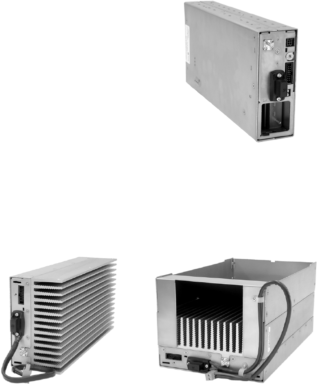
Power Amplifier The power amplifier (PA) amplifies the RF output from the reciter and is
available in 5W, 50W and 100W models.
The 5W and 50W models mount vertically in the subrack, while the 100W
model mounts horizontally as it has a wider heatsink. The 100W PA is also
fitted with an airflow duct.
All three models of PA are designed to operate on the 28VDC output
provided by the TB8100 power management unit. In addition, 5W and
50W models are available for operation on 12VDC. These two 12V PAs
are fitted with an internal boost regulator board, which converts the 12V
nominal DC input to a 28VDC output to power the PA circuit boards. The
boost regulator board also provides a 12VDC output to power the reciter.
5/50W PA 100W PA
TB8100 Installation and Operation Manual Description 11
© Tait Electronics Limited June 2005
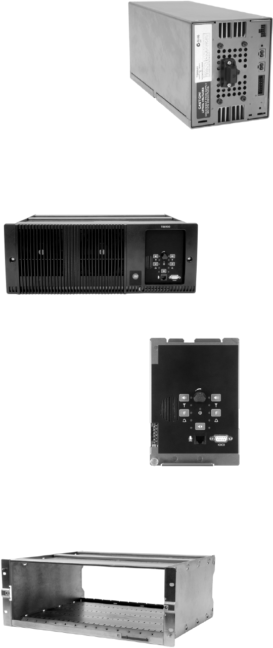
Power
Management Unit The power management unit (PMU)
provides the 28VDC power supply for
the modules in the TB8100 BSS. The
input voltage can be AC, DC or both
AC and DC, depending on the
model. An auxiliary DC output is
also available when the optional
power supply board is fitted. This
board is available with an output of
13.65VDC, 27.3VDC, or 54.6VDC.
Front Panel The TB8100 front panel is mounted onto the subrack with two quick-
release fasteners. It incorporates the cooling fans for the PA and PMU.
Control Panel The TB8100 control panel is
mounted onto the subrack and is
accessible through an opening in the
front panel. The control panel
provides the user with hardware
controls and connections for direct
control of the BSS. Three models are
available: standard, dual base station,
and Power Save.
Subrack The TB8100 4U subrack is made of passivated steel and is designed to fit
into a standard 19 inch rack or cabinet.
AC and DC PMU shown
standard control panel shown
12 Description TB8100 Installation and Operation Manual
© Tait Electronics Limited June 2005
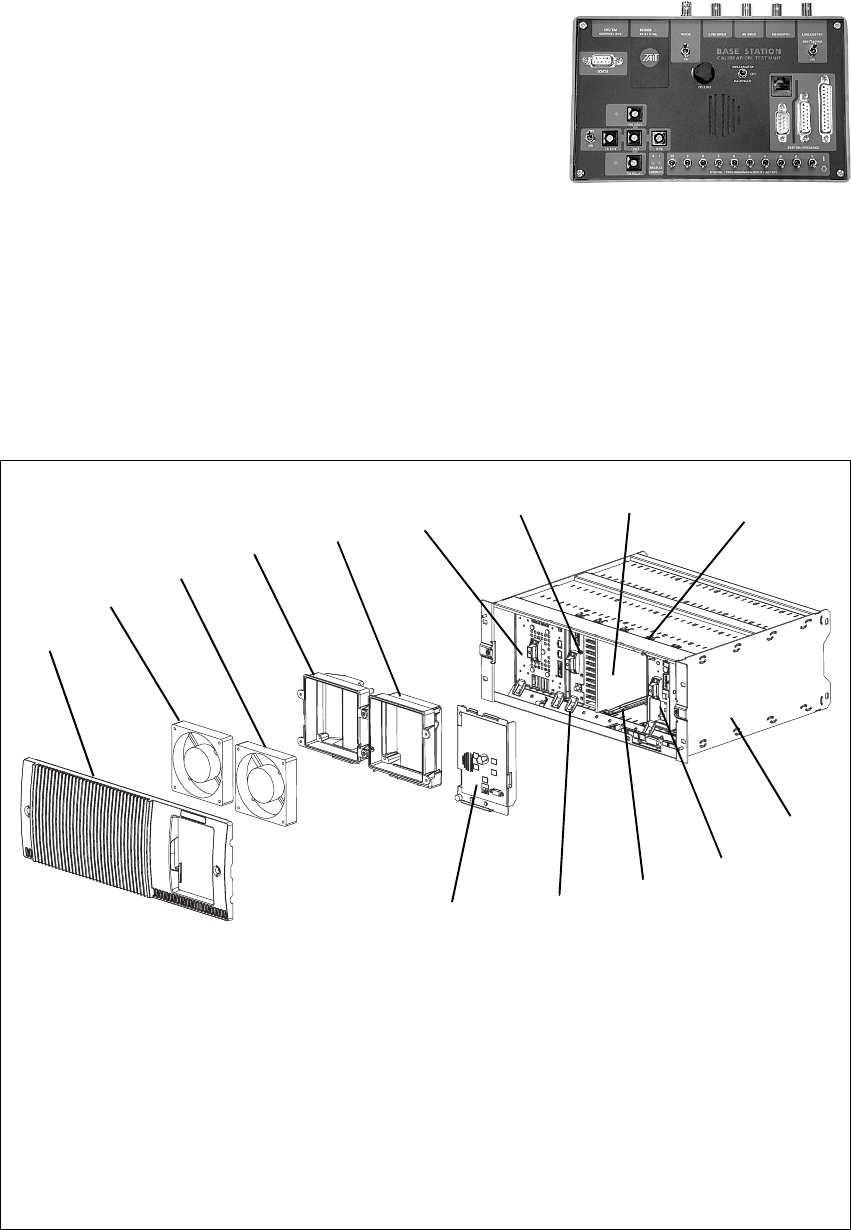
Calibration Test Unit The TB8100 calibration test unit
(CTU) provides a selection of inputs
and outputs which allows the TB8100
BSS to be connected to standard test
equipment, and also to a PC running
the Service Kit or Calibration Kit
software. Refer to TN-778 for more
details.
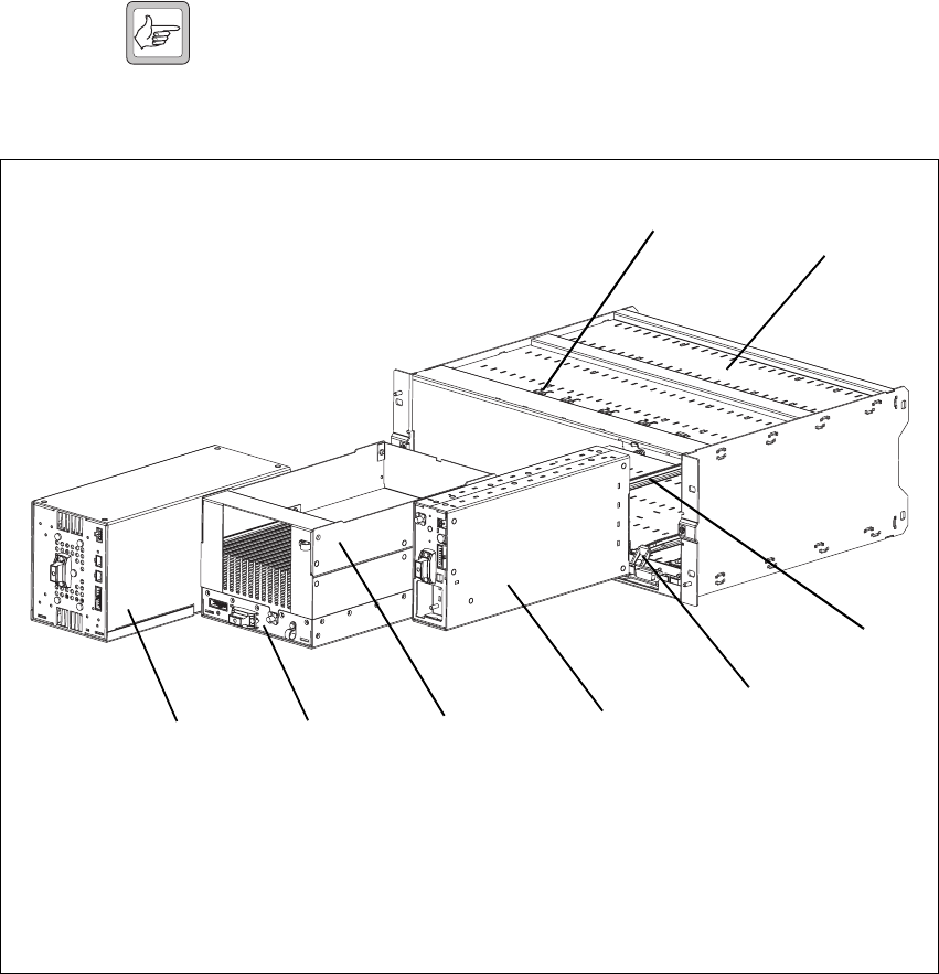
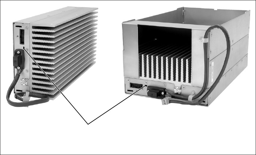
1.2 Mechanical Assembly
The main mechanical components of the TB8100 BSS are shown in the
following illustrations.
The front panel can be easily removed from the subrack by undoing two
quick-release fasteners. Once the front panel is removed, the control panel
Figure 1.1 Mechanical assembly - front panel, fans and control panel
bfront panel iairflow separator
cPMU fan jcable retaining clip
dPA fan 1) subrack
ePMU fan duct 1! reciter
fPA fan duct 1@ plastic guide rail
gPMU 1# module retaining clamp
hPA 1$ control panel
b
c
defghij
1)
1!
1@
1#
1$
single 5W or 50W base station shown
TB8100 Installation and Operation Manual Description 13
© Tait Electronics Limited June 2005
can also be removed from the subrack by undoing a single screw. Refer to
“Replacing Modules” on page 87 for more details.
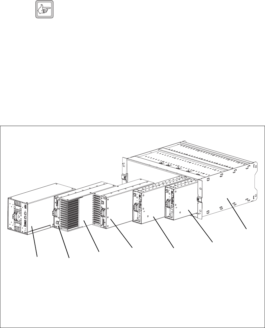
Note Figure 1.1 shows the cooling fans and their ducts detached from
the front panel only for the clarity of the illustration. The cooling
fans and ducts are normally screwed to the rear of the front panel.
Figure 1.1 also shows the configuration for a typical single 5W or 50W base
station. The PMU occupies the slot at the left end of the subrack, with the
PA directly beside it. The single reciter normally occupies the second slot
from the right of the subrack.
The single PA is mounted vertically with the heatsink facing the centre of
the subrack. This positions the cooling fins directly behind the PA fan. The
airflow separator is fitted directly beside the PA to help direct the cooling
airflow through the heatsink.
Figure 1.2 above shows the configuration for a typical dual 5W or 50W base
station. The PMU occupies its normal slot at the left end of the subrack,
with the reciters in the two right-hand slots.
The two PAs are mounted vertically in the middle of the subrack with the
heatsinks facing each other. This positions the cooling fins directly behind
Figure 1.2 Mechanical assembly - dual 5W or 50W base station
bPMU freciter for base station 1
cPA for base station 1 greciter for base station 2
dairflow separator hsubrack
ePA for base station 2
bcdef
h
g
14 Description TB8100 Installation and Operation Manual
© Tait Electronics Limited June 2005
the PA fan. The airflow separator between the PAs helps to direct the
cooling airflow evenly through each heatsink.
Note The configuration for single and dual 12V PA base stations is the
same as shown in Figure 1.1 and Figure 1.2, but the PMU and its
cooling fan are not fitted.
Figure 1.3 above shows the configuration for a typical single 100W base
station. The PMU occupies its normal slot at the left end of the subrack,
with the PA directly beside it. The single reciter occupies the slot
immediately to the right of the PA.
Unlike the 5W and 50W PAs, the 100W PA is mounted horizontally with
the heatsink facing upwards. It is also fitted with an airflow duct to channel
the airflow from the cooling fan through the heatsink fins.
Figure 1.3 Mechanical assembly - single 100W base station
bPMU fmodule retaining clamp
cPA gplastic guide rail
dairflow duct hsubrack
ereciter icable retaining clip
bcdef
g
h
i
TB8100 Installation and Operation Manual Circuit Description 15
© Tait Electronics Limited June 2005
2 Circuit Description
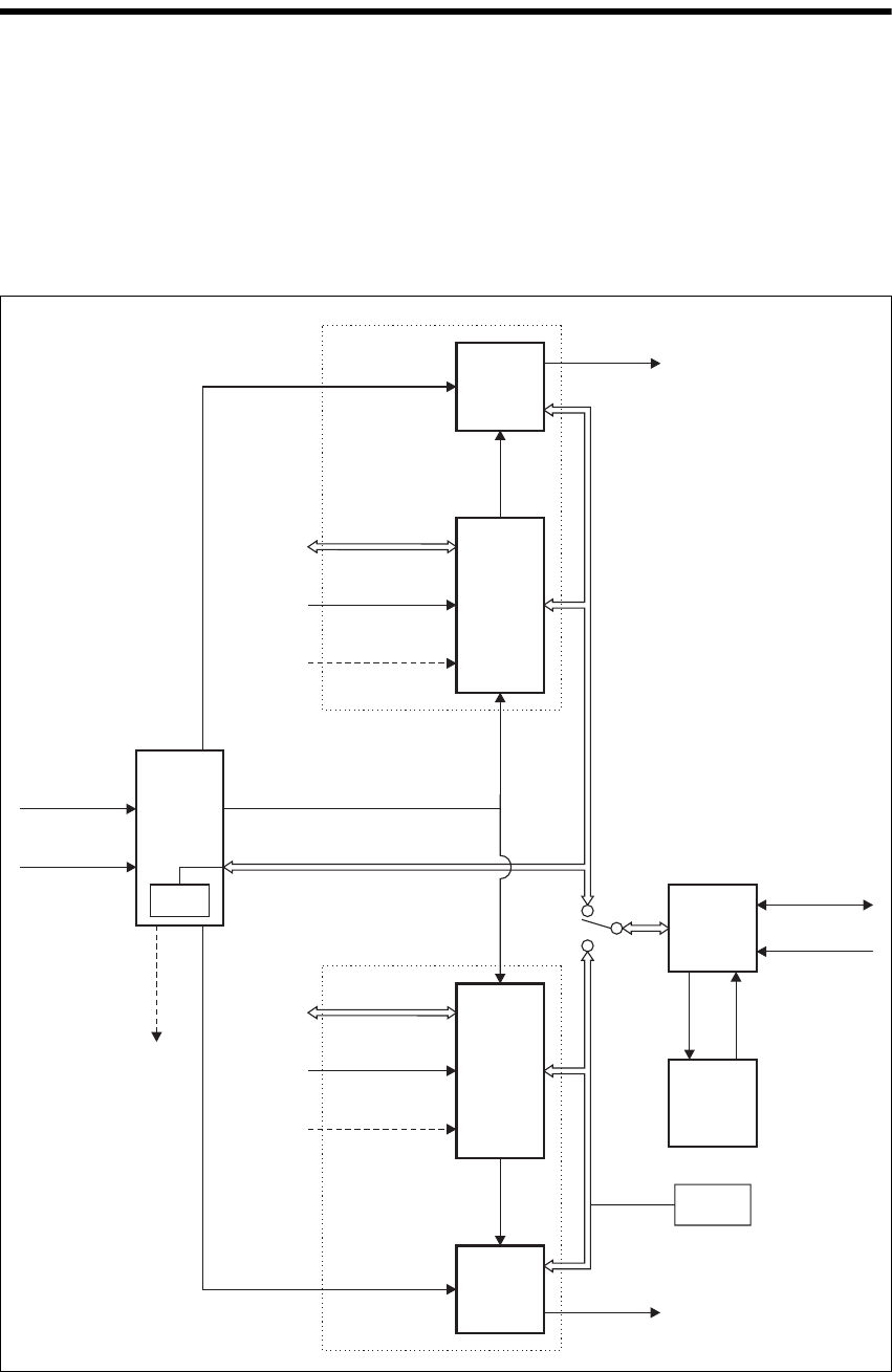
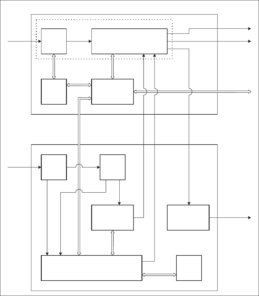
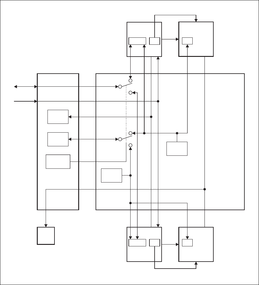
Figure 2.1 below shows a typical TB8100 dual base station system of 5W or
50W. It illustrates the main inputs and outputs for power, RF and control
signals, as well as the interconnection between modules. The circuitry of
the individual modules that make up the BSS is described in more detail in
the following sections.
Figure 2.1 Dual base station system high level block diagram
Reciter 2
Reciter 1
PMU
PA 2
PA 1
System Control Bus
RF From
Antenna
Base Station 2 *located on subrack
interconnect board
Base Station 1
RF To
Antenna
RF To
Antenna
System I/O
External Reference
Frequency
(if used)
(if used)
RF From
Antenna
System I/O
External Reference
Frequency
AC I/P
DC I/P
28VDC
(low current)
Control
Panel
Cooling
Fans
Microphone I/P
Rotation
Sensor
RS-232
DC
RF +
PA Key
RF +
PA Key
Auxiliary
DC O/P
(Optional)
28VDC
(high current)
28VDC
(high current)
I C Current
Source
2
I C Current
Source*
2

16 Circuit Description TB8100 Installation and Operation Manual
© Tait Electronics Limited June 2005
Frequency Bands
and Sub-bands Much of the circuitry in the TB8100 base station modules is common to
both VHF and UHF frequency bands, and is therefore covered by a single
description in this manual. Where the circuitry differs between VHF and
UHF, separate descriptions are provided for each frequency band. In some
cases the descriptions refer to specific VHF or UHF bands or sub-bands, and
these are identified with the letters listed in the following table.
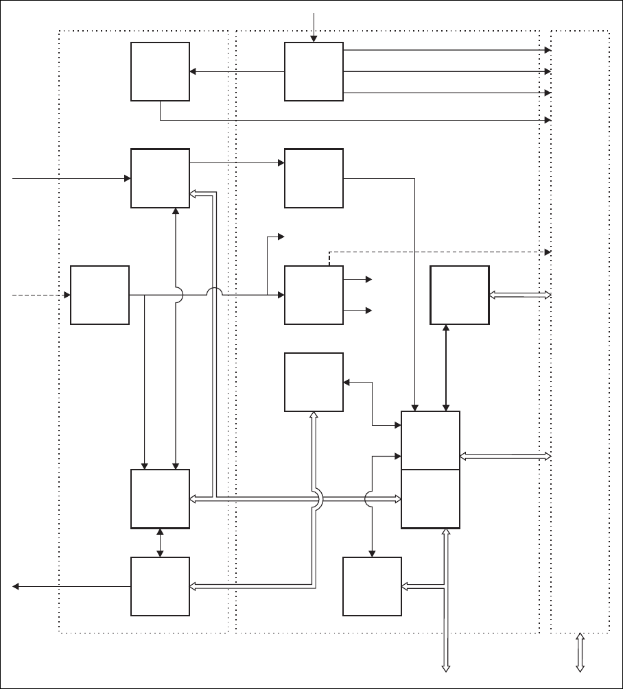
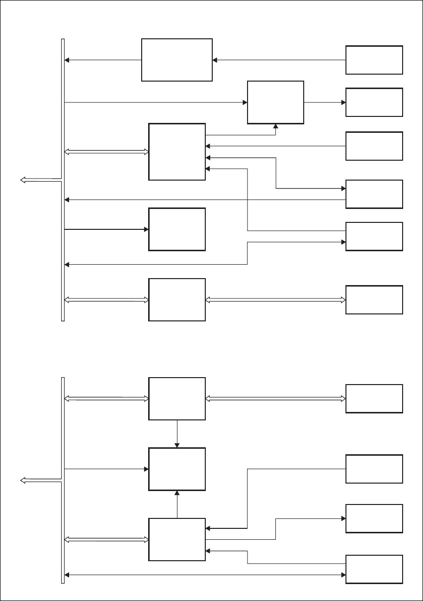
2.1 Reciter
The reciter comprises three boards: an RF, a digital, and an optional system
interface board. These boards are mounted on a central chassis/heatsink.
Figure 2.2 on page 18 shows the configuration of the main circuit blocks,
and the main inputs and outputs for power, RF and control signals.
Receiver RF -
VHF Reciter The incoming RF signal is fed through a low pass filter, then through a
band-pass “doublet” filter, and finally through a high-pass filter. The signal
is then amplified and passed through another band-pass “doublet” filter
before being passed to the mixer, where it is converted down to the
16.9MHz IF (intermediate frequency). A VCO (voltage controlled
oscillator) provides a +17dBm input to the mixer, and a diplexer terminates
the mixer IF port in 50 Ω.. The signal from the mixer is fed through a 2-pole
crystal filter to the IF amplifier which provides enough gain to drive the
digital receiver. Note that there are two 2-pole crystal filters, one for narrow
bandwidth and one for wide bandwidth. The appropriate filter is selected
by software-controlled PIN switches, according to the bandwidth selected
Frequency
Identification Frequency Band and Sub-band
VHF
B band B1 = 136MHz to 174MHz
B2 = 136MHz to 156MHz
B3 = 148MHz to 174MHz
C band C0 = 174MHz to 225MHz
C1 = 174MHz to 193MHz
C2 = 193MHz to 225MHz
UHF
H band H0 = 400MHz to 520MHz
H1 = 400MHz to 440MHz
H2 = 440MHz to 480MHz
H3 = 470MHz to 520MHz
K band K4 = 762MHz to 870MHza
a. The actual frequency coverage in this band is:
Transmit: 762MHz to 776MHz, and 850MHz to 870MHz
Receive: 792MHz to 824MHz
L Band L0 = 850MHz to 960MHz
L1 = 852MHz to 854MHz, and 928MHz to 930MHz
L2 = 896MHz to 902MHz (receive only)
L2 = 927MHz to 941MHz (transmit only)

TB8100 Installation and Operation Manual Circuit Description 17
© Tait Electronics Limited June 2005
in the Service Kit software. The signal is finally passed to the ADC
(analogue-to-digital converter) in the digital receiver via an anti-alias filter.
Receiver RF -
UHF Reciter The incoming RF signal is fed through a band-pass filter, followed by a
simple low-pass network. It then passes through further stages of filtering,
amplification and AGC1 (automatic gain control) before being fed to the
mixer where it is converted down to the 70.1MHz IF (intermediate
frequency). A VCO (voltage controlled oscillator) provides a +17dBm
input to the mixer, and a diplexer terminates the mixer IF port in 50Ω.. The
signal from the mixer is fed through a 4-pole crystal filter to the IF amplifier
which provides enough gain to drive the digital receiver. The signal is finally
passed to the ADC (analogue-to-digital converter) in the digital receiver via
an anti-alias filter.
Exciter RF Audio signals from the line or microphone input are fed to the exciter RF
circuitry via the DSP (digital signal processor) and CODECs (encoder/
decoder). These modulating signals are applied to the exciter at two points
(dual point modulation): low frequency modulation is via the FCL
(frequency control loop), which modulates the exciter synthesizer’s
frequency reference, and speech band modulation is supplied directly to the
VCO.
The VCO is phase-locked to the frequency reference via the synthesizer.
The output from the VCO passes through the VCO buffer to the exciter
amplifier, which increases the RF signal to +20dBm. This signal is then
attenuated through a pad to +11dBm. An 8VDC PA Key signal is mixed
in with the RF signal which is then fed to the PA.
The K-band and L-band reciters use two VCOs, with the appropriate VCO
stage being selected for operation according to the frequency of the channel
in use. Only one VCO can be operational at any one time.
Digital Circuitry The IF from the receiver RF circuitry is passed through an ADC and a DDC
(digital downconverter) to the DSP. The DSP provides demodulation, RSSI
calculation, SINAD calculations, muting, and decoding of subaudible
signals. Audio and RSSI from the DSP is passed via CODECs to the system
interface board.
Incoming audio from the system interface board or microphone is passed to
the exciter RF circuitry via the DSP and CODECs. The DSP provides the
audio characteristics, generates subaudible signals (e.g. DCS, CTCSS), and
controls the CODECs for line audio input.
1. AGC is available in H-band reciters only. It can be disabled using the Serv-
ice Kit software.
18 Circuit Description TB8100 Installation and Operation Manual
© Tait Electronics Limited June 2005
Control Circuitry The RISC controls the operating functions of the reciter and provides the
interface to the outside world. Some of the functions it controls are:
■Tx key and Rx gate
■communications to the system interface board
■digital input from the system interface board
■communication with the other modules in the TB8100 BSS via the I2C
bus
■communications with the Service Kit software.
Figure 2.2 Reciter high level block diagram
DSP
CODEC
CODEC
CODEC
40MHz
Clock
Receiver
Exciter
Synthesizer
Subsystem
Reference
Frequency
Subsystem
Digital
Receiver
Power
Supply
Power
Supply
RISC
DSP/RISC
CODECs
IF
12.8MHz
Ref.
RF I/P
28VDC I/P
28V
28V 5V
3.3V
8.5V
RF O/P +
PA Key Audio
System
Control Bus System I/O
Digital
Receiver
Audio &
RSSI
Control &
Communications
Control &
Communications
Modulation
& Frequency
Control
Control &
Communications
External
Reference
Frequency
(if used)
RF Board Digital Board
System
Interface
Board
TB8100 Installation and Operation Manual Circuit Description 19
© Tait Electronics Limited June 2005
System Interface
Board The reciter can be fitted with an optional system interface board which
provides the links between the reciter’s internal circuitry and external
equipment. The circuitry on the system interface board provides additional
signal processing so that the outputs meet standard system requirements.
Several different types of system interface board are available, although only
one board can be fitted to a reciter at any one time. Each system interface
board can identify itself to the reciter control circuitry.
Power Supply The reciter operates off a +28 VDC (nominal) supply. The supply is fed to
two separate power supplies, one on the RF board and a second on the
digital board. The power supply on the RF board also powers some of the
circuitry on the system interface board.
The power supply on the RF board provides 5.3V and 8.5V regulated
supplies. This 5.3V supply is boosted to 23V and also provides a 3.3V
regulated supply. The power supply on the digital board provides 3.3V and
5.3V regulated supplies. It is also fed through to provide a 2.5V supply.
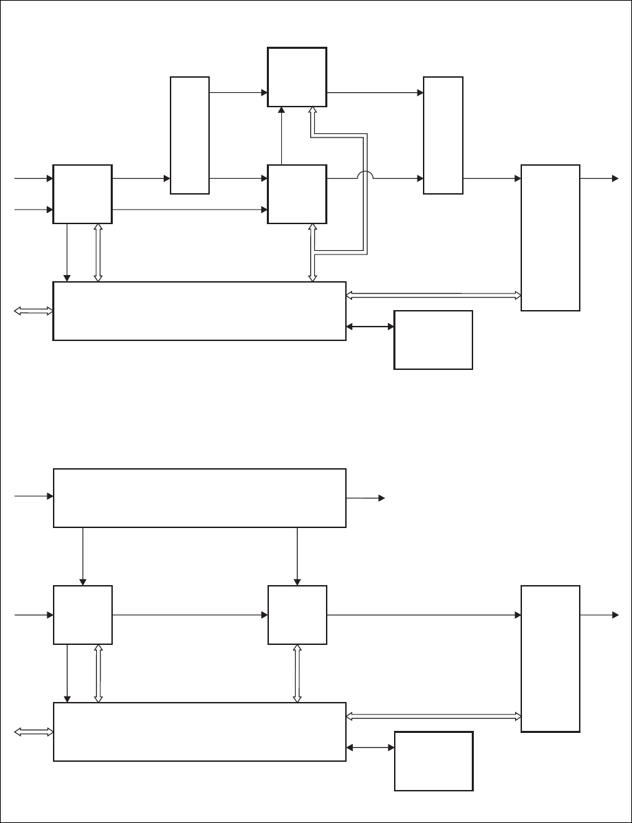
2.2 PA
The TB8100 PA is a modular design with the circuitry divided among
separate boards which are assembled in different configurations in different
models. Interconnect boards are used in certain models to connect boards
that are physically separated on the heatsink. The 5W, 50W and 100W PAs
are available for operation on 28VDC, while the 5W and 50W PAs are also
available for operation on 12VDC. Figure 2.3 on page 21 shows the
configurations of a 100W 28V PA and a 50W 12V PA, along with the main
inputs and outputs for power, RF and control signals.
RF Circuitry The RF output from the reciter is fed first to the 6W board. In the 100W
model shown in Figure 2.3, the output from the 6W board is fed into a
–3dB hybrid coupler on a separate splitter board and then to two 60W
boards in quadrature. The outputs from these two boards are then combined
by another –3dB hybrid coupler on a separate combiner board before being
fed to the low-pass filter (LPF)/directional coupler board.
In the 50W model, the output from the 6W board is fed to one 60W board
and then to the LPF/directional coupler board. In the 5W model, the
output from the 6W board is fed directly to the LPF/directional coupler
board.
Control Circuitry The microprocessor located on the control board monitors and controls the
operation of the PA. There are no manual adjustments in the PA because
all the calibration voltages and currents required to control and protect the
PA are monitored by the microprocessor. The software also automatically
detects the PA configuration and controls the PA accordingly.
20 Circuit Description TB8100 Installation and Operation Manual
© Tait Electronics Limited June 2005
If any of the monitored conditions exceeds its normal range of values, the
microprocessor will generate an alarm and reduce the output power to a
preset level (foldback). If the measured values do not return within the
normal range after foldback, the PA will be shut down.
The alarms and diagnostic functions are accessed through I2C bus messages
on the system control bus via the reciter, control panel and Service Kit
software. Some measurements are logged by the microprocessor and this
information can also be accessed through the system control bus.
The operation of the cooling fan mounted on the front panel is determined
by the temperature limits set in the PA software. If two PAs are fitted in a
TB8100 subrack, either PA will turn on the fan when required.
Power Supply The 100W PA operates off a 28VDC external power supply only, while the
5W and 50W PAs can operate off a 28VDC or 12VDC external power
supply, depending on the model. The 12V PAs are fitted with an internal
boost regulator board (refer to “Boost Regulator” below).
The PA also has four internal power supplies which produce –3, +2.5, +5
and +10VDC.
Boost Regulator 5W and 50W 12V PAs are fitted with a boost regulator board. Figure 2.3
on page 21 shows the configuration for a 50W PA, along with the main
inputs and outputs for power, RF and control signals. Note that the 60W
board is only fitted to the 50W PA.
The boost regulator board accepts an input of 12VDC nominal. The input
is firstly fed through the DC input filter, and then through an output filter
and switch which is controlled by a battery control circuit. This output is
fed to the reciter, which operates from 12VDC instead of the standard
28VDC provided when a PMU is used. The output from the DC input
filter is also fed to the power stage where the voltage is boosted to 28VDC,
and is then fed through an output filter to provide the 28VDC output for
the PA circuit boards.
The battery control circuitry monitors the DC input voltage from the
battery. Protection is provided against the wrong input voltage being
supplied. Reverse polarity protection is provided by a diode between
positive and ground, and requires a user-provided fuse or circuit breaker in
series with the DC input line. The fuse or circuit breaker should be rated
at 15A to 18A at 30VDC.
The startup voltage is 12VDC or higher. Once started, the boost regulator
will operate down to 10.25VDC ±0.25V before it shuts down to prevent
deep discharge of the battery.
TB8100 Installation and Operation Manual Circuit Description 21
© Tait Electronics Limited June 2005
Figure 2.3 PA high level block diagrams
6W
Board
Control Board
Boost Regulator
60W
Board
Ambient Air
Temperature
Sensor
Board
Low-Pass
Filter
&
Directional
Coupler
Board
RF I/P +
PA Key RF O/P
12VDC
I/P
12VDC O/P
(Reciter)
DC
28VDC28VDC
RF RF
Control &
Monitor
Control &
Monitor
Control &
Monitor
System
Control
Bus
6W
Board
Control Board
60W
Board
60W
Board
Ambient Air
Temperature
Sensor
Board
Splitter
Board
Combiner
Board
Low-Pass
Filter
&
Directional
Coupler
Board
RF I/P +
PA Key RF O/P
28VDC
I/P
DC
DC
DC
RF RF RF RF
RF RF
Control &
Monitor
Control &
Monitor
Control &
Monitor
System
Control
Bus
100W 28V PA
50W 12V PA
22 Circuit Description TB8100 Installation and Operation Manual
© Tait Electronics Limited June 2005
2.3 PMU
The TB8100 PMU provides stable, low-noise 28VDC outputs to power the
TB8100 BSS. The PMU is made up of a number of individual boards and
cards which comprise two main modules, the AC module and the DC
module. The standby power supply card and auxiliary power supply board
are optional. Figure 2.4 shows the configuration for an AC and DC PMU,
along with the main inputs and outputs for power and control signals.
The PMU is available in three main configurations:
■AC PMU (AC input only)
■DC PMU (DC input only)
■AC and DC PMU (both AC and DC converters are fitted to allow both
AC and DC inputs).
AC Module The AC module accepts an input of 115/230VAC 50/60Hz nominal. The
input is fed via the PFC (power factor control) input stage to the HVDC
(high voltage DC) stage on the AC converter board. The HVDC circuitry
generates the final 28VDC outputs and provides galvanic isolation between
the mains input and DC output. The output stage on the AC converter
board provides a common output filter and current monitoring circuit
which is used by both AC and DC modules.
Each power stage is controlled by its own plug-in control card. The
microprocessor is also located on the HVDC control card. The
microprocessor is used by both the AC and DC modules and is fitted to all
PMU models.
The leaded high-power components are situated on the AC converter
board, while the plug-in cards have only SMD control components.
DC Module The DC module accepts an input of 12VDC, 24VDC or 48VDC nominal
(depending on the model). The input is fed through the DC input filter to
the input of the power stage on the DC converter board. This circuitry
provides PWM (pulse width modulation) conversion to produce the final
DC output. It also provides galvanic isolation, allowing the DC input to be
positive or negative ground. The final DC output is fed back to the output
stage on the AC convertor board.
The battery control card monitors the DC input voltage and prevents the
PMU from starting if an incorrect input voltage is applied. It also operates
as a fail-safe to prevent deep discharge of the battery, and provides
information to the microprocessor to allow the Service Kit software to
display information about the battery.
The DC control card controls the power stage of the DC converter. It also
provides protection from overload and short circuit conditions.
TB8100 Installation and Operation Manual Circuit Description 23
© Tait Electronics Limited June 2005
The leaded high-power components are situated on the DC converter
board, while the plug-in cards have only SMD control components.
Standby Power
Supply This optional power supply card plugs into the DC converter board and
provides power to the reciter output. This allows the main DC unit to be
switched off to reduce current consumption in low-power situations, e.g.
when the PA is not transmitting. Also, when battery capacity is low, it will
maintain the power supply to the microprocessor and shut down the rest of
the PMU. This card must be fitted to enable the software-controlled power
Figure 2.4 PMU high level block diagram
PFC
Circuitry
PFC
Control
Card
DC Input
Filter
Card
DC
Control
Card
Auxiliary
Power Supply
Board*
Battery
Control
Card
Standby
Power Supply
Card*
HVDC Control &
Microprocessor
Card
HVDC Circuitry
DC Converter Board
28V
28V
28V O/P (PA)
System
Control Bus
28V O/P (Reciter)
AC I/P
115/230V
50/60Hz 400VDC
DC I/P
12/24/48V
28V
DC O/P
13.65/27.3/54.6V
*optional
AC Converter Board
AC Module
DC Module

24 Circuit Description TB8100 Installation and Operation Manual
© Tait Electronics Limited June 2005
saving feature to operate. Refer to “Power Saving” on page 57 for more
information.
Auxiliary Power
Supply This optional power supply board is mounted on the DC module. The
input power is provided from the PA output of the HVDC circuitry on the
AC converter board. It provides a high quality 13.65VDC, 27.3VDC or
54.6VDC output (depending on the model) to power external accessory
equipment, or can be used to trickle-charge batteries. It can be configured
using the Service Kit software to operate whenever mains voltage is
available, or whenever the PA output is available.
Microprocessor The microprocessor on the HVDC control card monitors and controls the
operation of the PMU. There are no manual adjustments in the PMU
because all the calibration voltages and currents required to control and
protect the PMU are monitored by the microprocessor. The software also
automatically detects the PMU configuration and controls the PMU
accordingly.
If any of the monitored conditions exceeds its normal range of values, the
microprocessor will generate an alarm and take appropriate action,
depending on the configuration of the PMU.
The alarms and diagnostic functions are accessed through I2C bus messages
on the system control bus via the reciter, control panel and Service Kit
software.
The operation of the cooling fan mounted on the front panel is determined
by the temperature limits set in the PMU software.
Important In base station systems which use a PMU, the PMU must
be connected to the system control bus at all times. The
I2C current source is located in the PMU, and if the PMU
is disconnected, the state of much of the bus will be unde-
fined. This may cause corrupted data to be present on the
bus when the reciter reads the states of the switches on the
control panel. This in turn may result in random actuations
of microphone PTT, carrier, or speaker key, causing the
BSS to transmit or the speaker to be actuated incorrectly.
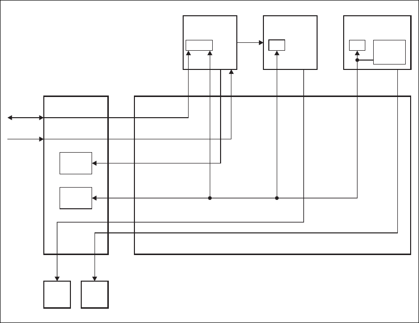
2.4 Control Panel
The control panel is designed to be the link between the user and the
TB8100 BSS. The circuitry for the operation of the control panel is located
on a board mounted behind its front face. All communication between the
BSS and the control panel is via the system control bus. Figure 2.5 on
page 25 shows the configuration of the main circuit blocks, and the main
inputs and outputs for power, audio and control signals for the standard,
dual base station, and Power Save control panels.
TB8100 Installation and Operation Manual Circuit Description 25
© Tait Electronics Limited June 2005
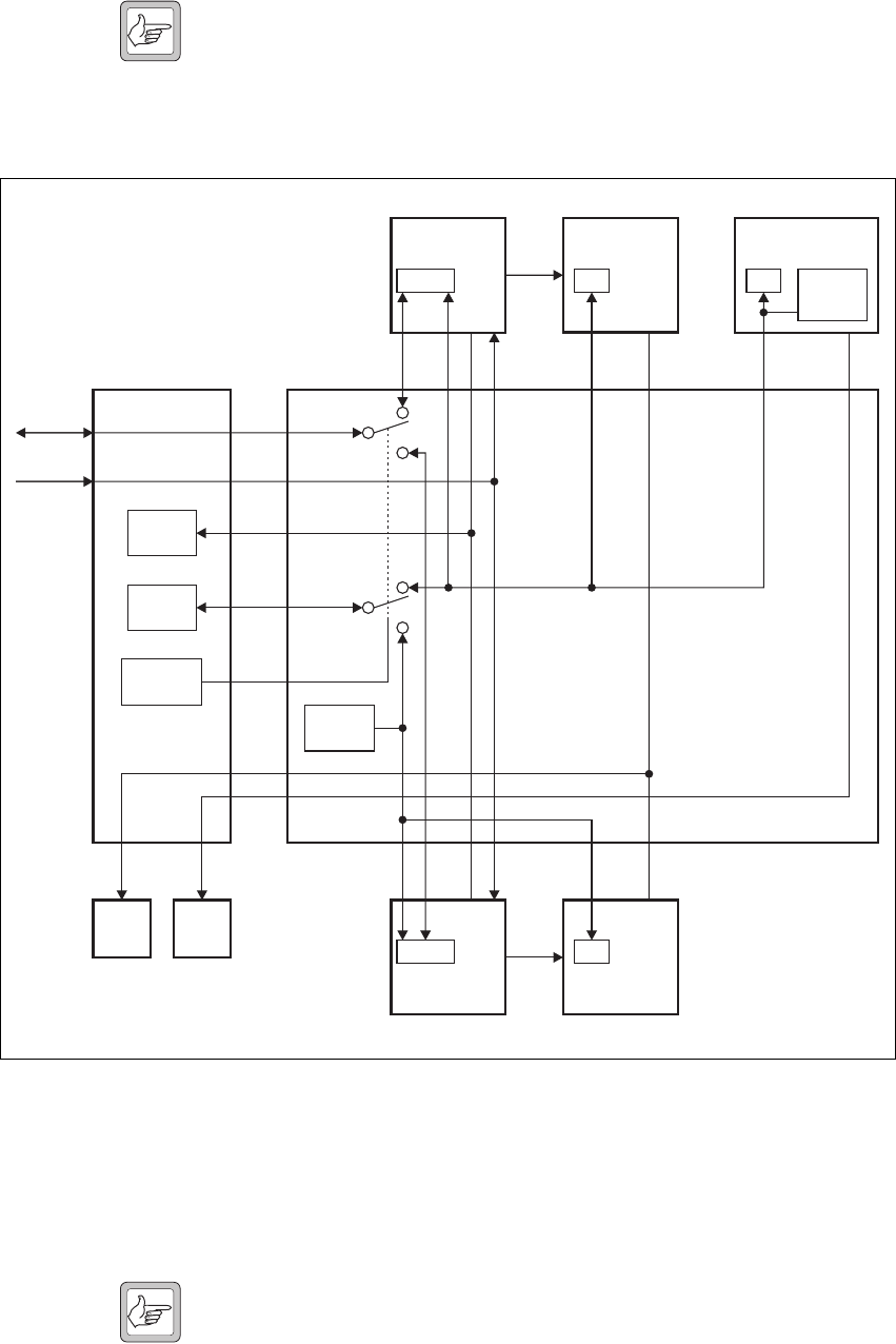
Figure 2.5 Control panel high level block diagram
IC
Translation
2
RS-232
Translation
Microphone
Pre-emphasis
& Gain Control
Speaker
Volume &
Gain Control
LEDs &
Switches
Control
Panel Type
Microphone
Connector
Speaker
Fan Inputs
RS-232
Connector
Power
Supply
Microphone Audio
System
Control Bus
Speaker
Enable
Speaker Audio
I C Bus
2
28V, GND
Fan Power & GND
Open Collector RS-232 RS-232 Bus
Channel Select (dual base station only)
IC
Translation
2
RS-232
Translation
LEDs
Control
Panel Type
Fan Inputs
RS-232
Connector
Power
Supply
System
Control Bus
Full Power On
Power Save On
I C Bus
2
28V, GND
Fan Power & GND
Open Collector RS-232 RS-232 Bus
Standard and Dual Base Station Control Panels
Power Save Control Panel

26 Circuit Description TB8100 Installation and Operation Manual
© Tait Electronics Limited June 2005
Control Circuitry The control panel board translates:
■I2C messages from the reciter into an appropriate response on the LEDs
■control panel key inputs and fan rotation inputs from both fans into
appropriate I2C messages
■RS-232 communications from the programming port into 0V to 5V
open-collector signals which can feed from and drive up to six reciters.
Note When a reciter fitted with a TaitNet RS-232 system interface
board is used in a TB8100 BSS, the RS-232 port on the control
panel is disabled. In this situation you must connect to the
RS-232 port at the rear of the reciter. Refer to “TaitNet
RS-232” on page 122 for more details.
Audio Circuitry The standard and dual base station control panels provide a volume knob to
control the volume of the speaker. In addition, the control panel circuitry
performs gain control so that the power output into a 16Ω speaker is ≥0.5W
at the maximum position of the knob, with an input of 167mVpp.
Power Supply The control panel operates off a +28VDC (nominal) power supply provided
by the reciter. The power supply for the cooling fans mounted on the front
panel is fed through the control panel.

TB8100 Installation and Operation Manual Operating Controls 27
© Tait Electronics Limited June 2005
3 Operating Controls
The TB8100 BSS has a number of hardware controls which are available to
the user. These controls are located on the control panel, reciter and PMU.
This chapter identifies and describes these controls.
28 Operating Controls TB8100 Installation and Operation Manual
© Tait Electronics Limited June 2005
3.1 Control Panel
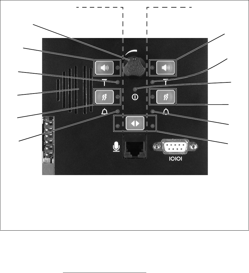
3.1.1 Standard Control Panel
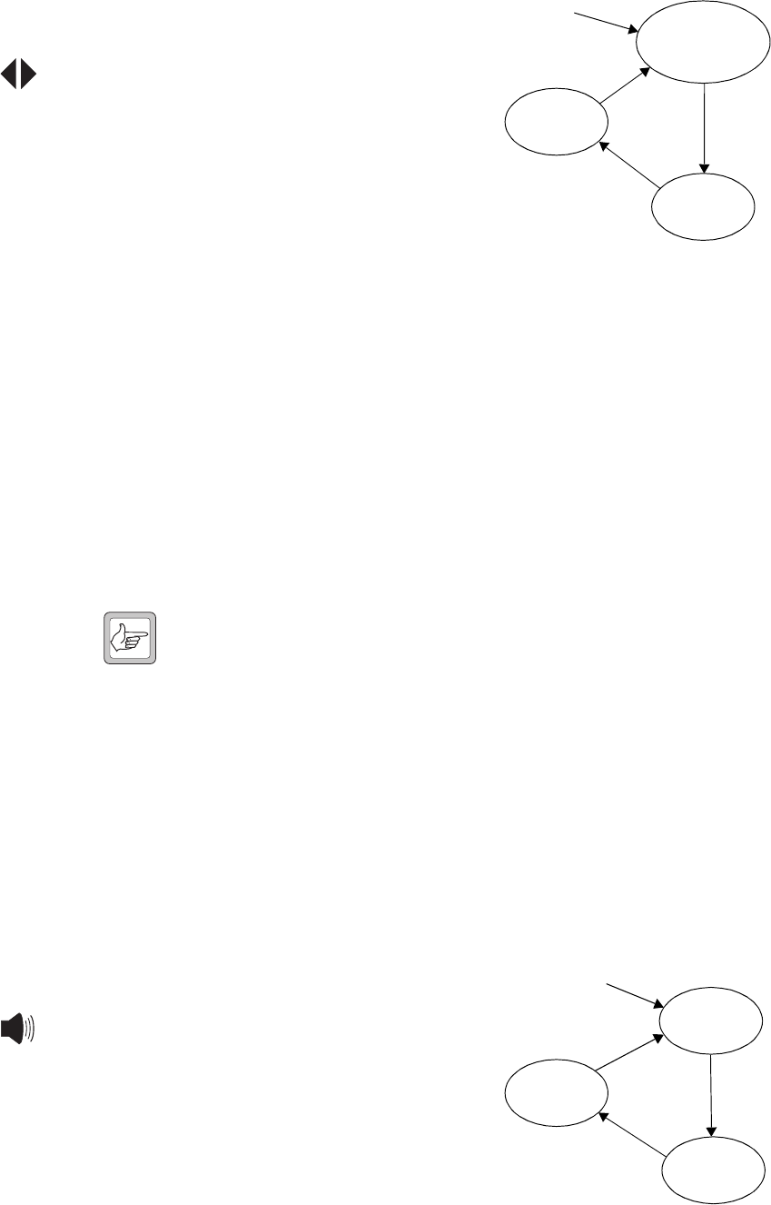
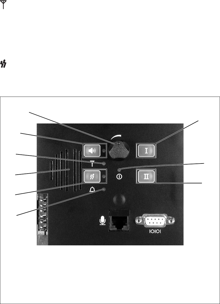
The operating controls on the standard control panel allow some manual
control of one or two1 base stations in a TB8100 BSS. These controls and
their associated LED indicators are identified in Figure 3.1 below, and their
functions are explained in the paragraphs which follow. Refer to
“Connection” on page 103 for information on the connectors located on
the control panel.
Speaker Volume Controls the volume of the speaker mounted behind the control panel.
Rotate clockwise to increase the volume, and anticlockwise to decrease the
volume.
1. Control of two base stations will be available in a future release.
Figure 3.1 Operating controls on the standard control panel
bspeaker volume fpower LED
cspeaker button and LED gcarrier button and transmit LED
dreceive LED halarm LED
espeaker imicrophone channel button and LEDs
controls for base station 1 (reciter 1)
or single base station
c
d
f
g
h
i
h
g
e
d
c
b
controls for base station 2 (reciter 2)
(future release)
TB8100 Installation and Operation Manual Operating Controls 29
© Tait Electronics Limited June 2005
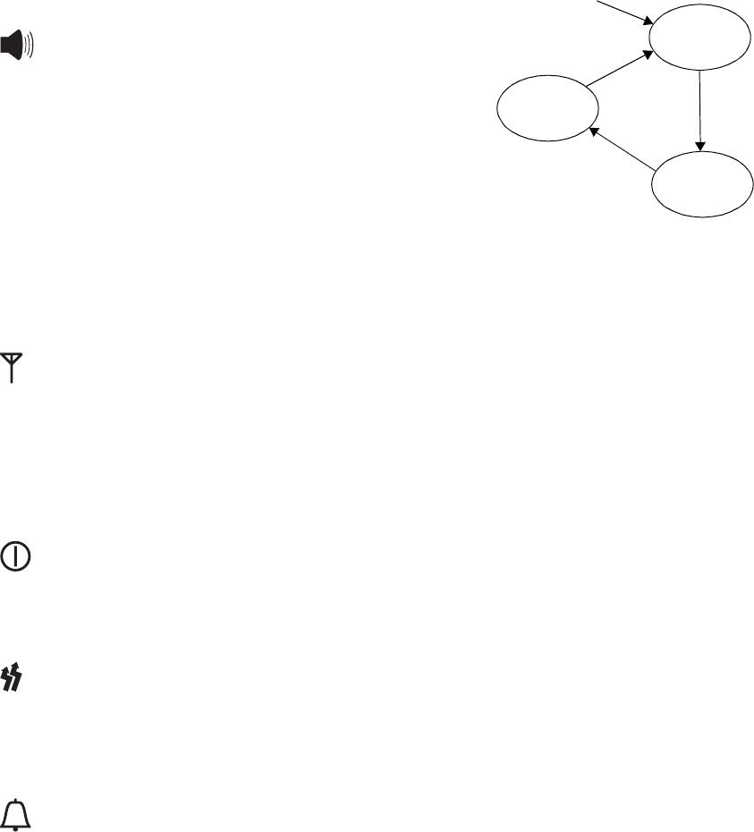
Speaker Button and
LED The speaker button cycles the base
station audio through three states. At
power-on the speaker is off. Pressing
the button once turns the speaker on,
but leaves the audio gated (muted).
Pressing the button a second time
leaves the speaker on and ungates the
audio (monitor mode). Pressing the
button for a third time returns to the
start of the sequence, with the speaker
off.
The green speaker LED is lit when the speaker is turned on.
Receive LED The green receive LED is lit when a valid signal is received on its associated
base station.
Speaker The control panel is fitted with a 0.5W speaker. Audio from either or both
base stations can be connected to this speaker.
Power LED The green power LED is lit when the PMU is turned on and supplying
power to the TB8100 BSS.
Carrier Button and
Transm i t LED The carrier button is a momentary press switch. When held down, it keys
the transmitter while disabling the 600Ω balanced and unbalanced line, and
microphone audio. The transmitted signal is unmodulated, i.e. carrier only.
The red transmit LED is lit while its associated transmitter is transmitting.
Alarm LED The red alarm LED will flash at a rate of 2 to 5Hz when an alarm has been
generated by any of the TB8100 BSS modules. It will continue to flash until
the alarm is cancelled or the fault is fixed. Note that only those alarms
which are enabled using the Service Kit (Configure > Alarms > Alarm
Control) will cause this LED to flash. Refer to the Service Kit
documentation for more information.
power on
speaker off
speaker on,
audio gated
speaker on,
audio ungated press
press
press
30 Operating Controls TB8100 Installation and Operation Manual
© Tait Electronics Limited June 2005
Microphone
Channel Button and
LEDs
The microphone channel button
selects which base station (BS) the
microphone is connected to. At
power-on both base stations are
selected. Pressing the button once
will connect the microphone audio to
base station 1. Pressing the button a
second time will connect the audio to
base station 2. Pressing the button for
a third time returns to the start of the
sequence, with the microphone audio
connected to both base stations.
The green LED is lit when the microphone audio is connected to its
associated base station.
3.1.2 Dual Base Station Control Panel
The operating controls on the dual base station control panel allow some
manual control of two base stations in a TB8100 BSS. These controls and
their associated LED indicators are identified in Figure 3.2 on page 31, and
their functions are explained in the paragraphs which follow. Refer to
“Connection” on page 103 for information on the connectors located on
the control panel.
Note When you change base station, the LEDs on the control panel do
not change. They continue to reflect the last changed status of the
previous base station until you press a control panel button, or the
reciter issues an instruction to update an LED. If one LED needs
to change, the status of all LEDs is updated. To overcome this
limitation, we recommend that you cycle through all three
speaker modes immediately after changing base station, finally
selecting the speaker mode you want. This forces the base station
to refresh the control panel LED display.
Speaker Volume Controls the volume of the speaker mounted behind the control panel.
Rotate clockwise to increase the volume, and anticlockwise to decrease the
volume.
Speaker Button and
LED The speaker button cycles the base
station audio through three states. At
power-on the speaker is off. Pressing
the button once turns the speaker on,
but leaves the audio gated (muted).
Pressing the button a second time
leaves the speaker on and ungates the
audio (monitor mode). Pressing the
button for a third time returns to the
start of the sequence, with the speaker
off.
power on
BS1 selected
BS1 LED on
BS2 selected
BS2 LED on
BS1 and BS2 selected
BS1 and BS2 LEDs on
press
press
press
power on
speaker off
speaker on,
audio gated
speaker on,
audio ungated press
press
press
TB8100 Installation and Operation Manual Operating Controls 31
© Tait Electronics Limited June 2005
The green speaker LED is lit when the speaker is turned on.
Receive LED The green receive LED is lit when a valid signal is received on the selected
base station.
Speaker The control panel is fitted with a 0.5W speaker. Audio from either base
station can be connected to this speaker.
Carrier Button and
Transmit LED The carrier button is a momentary press switch. When held down, it keys
the transmitter while disabling the 600Ω balanced and unbalanced line, and
microphone audio. The transmitted signal is unmodulated, i.e. carrier only.
The red transmit LED is lit while the selected transmitter is transmitting.
Figure 3.2 Operating controls on the dual base station control panel
bspeaker volume galarm LED
cspeaker button and LED hbase station 1 select button
dreceive LED ipower LED
espeaker jbase station 2 select button
fcarrier button and transmit LED
h
i
j
g
f
e
d
c
b
32 Operating Controls TB8100 Installation and Operation Manual
© Tait Electronics Limited June 2005
Alarm LED The red alarm LED will flash at a rate of 2 to 5Hz when an alarm has been
generated by any of the TB8100 BSS modules. It will continue to flash until
the alarm is cancelled or the fault is fixed. Note that only those alarms which
are enabled using the Service Kit (Configure > Alarms > Alarm Control)
will cause this LED to flash. Refer to the Service Kit documentation for
more information.
Base Station 1
Select Button Pressing this button selects base station 1. Pressing the button again while
base station 1 is selected has no effect. When the BSS is powered up, the
control panel selects base station 1.
Power LED The green power LED is lit when the PMU is turned on and supplying
power to the BSS.
Base Station 2
Select Button Pressing this button selects base station 2. Pressing the button again while
base station 2 is selected has no effect.
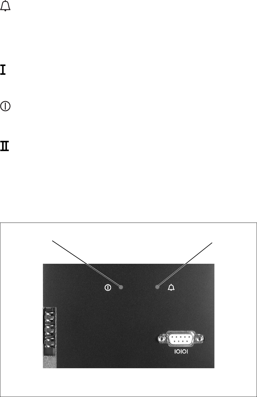
3.1.3 Power Save Control Panel
The indicator LEDs on the power save control panel are identified in
Figure 3.3 below.
Figure 3.3 LED indicators on the power save control panel
bpower LED calarm LED
c
b
TB8100 Installation and Operation Manual Operating Controls 33
© Tait Electronics Limited June 2005
Indicator LEDs The power LED and alarm LED behave in the same way as for the standard
control panel. Refer to “Power Saving” on page 57 for information about
the behaviour of the LEDs when in power saving mode.
3.2 Reciter
The only controls on the reciter are the rotary hex switch mounted on the
front panel, and the indicator LEDs visible through a slot in the front panel.
Hex Switch This switch is used to assign an identity number to each base station in the
BSS1. For example, the reciters in a dual base station system would be
numbered “1” and “2”. The reciter with the lowest hex number becomes
the “control” reciter. In a single base station system, the hex switch on the
reciter is set to “1”.
Indicator LEDs These LEDs provide the following information about the state of the reciter:
■steady green - the reciter is powered up
■flashing red - one or more alarms have been generated; you can use the
Service Kit software to find out more details about the alarms.
Figure 3.4 Operating controls on the reciter
bindicator LEDs chex switch
c
b
1. This feature will be available in a future release.
34 Operating Controls TB8100 Installation and Operation Manual
© Tait Electronics Limited June 2005
3.3 PA
The only controls on the PA are the indicator LEDs visible through a slot in
the front panel.
Indicator LEDs These LEDs provide the following information about the state of the PA:
■steady green - the PA is powered up
■flashing green - the PA has no application firmware loaded; you can use
the Service Kit software to download the firmware
■flashing red - one or more alarms have been generated; you can use the
Service Kit software to find out more details about the alarms.
Figure 3.5 Operating controls on the PA
bindicator LEDs
b
5/50W PA
100W PA
TB8100 Installation and Operation Manual Operating Controls 35
© Tait Electronics Limited June 2005
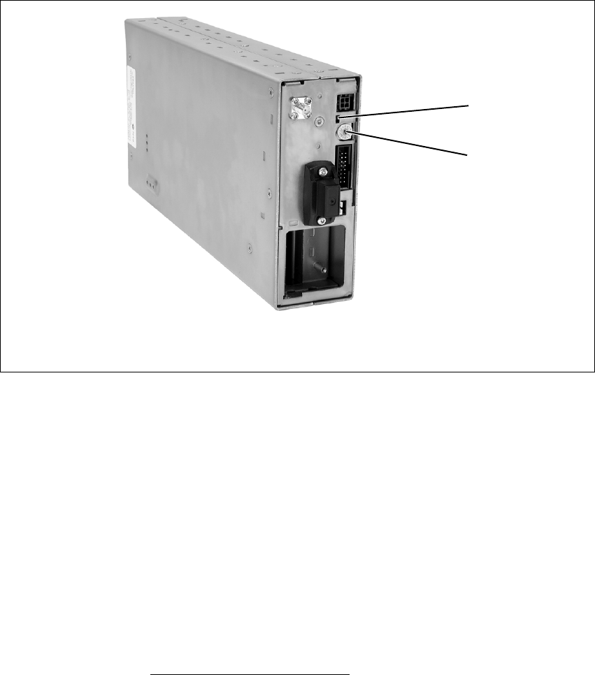
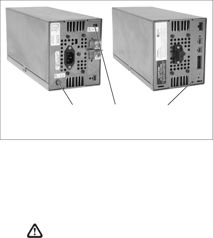
3.4 PMU
The only controls on the PMU are the on/off switches on the rear panel for
the AC and DC modules, and the indicator LEDs visible through a slot in
the front panel.
AC Module On/Off
Switch This switch turns the AC input to the PMU on and off. Note that this
switch breaks only the phase circuit, not the neutral.
DC Module On/Off
Switch This switch turns the DC output from the PMU on and off. It is recessed
to prevent the DC module being accidentally switched off, thus disabling
the battery back-up supply.
Note that this switch disables only the control circuitry - the DC input is
still connected to the power circuitry.
Warning!! These switches do not totally isolate the internal
circuitry of the PMU from the AC or DC power
supplies. You must disconnect the AC and DC
supplies from the PMU before dismantling or
carrying out any maintenance. Refer to the
service manual for the correct servicing
procedures.
Figure 3.6 Operating controls on the PMU
bAC module on/off switch dindicator LEDs
cDC module on/off switch
bc
rear view
d
front view
36 Operating Controls TB8100 Installation and Operation Manual
© Tait Electronics Limited June 2005
Indicator LEDs These LEDs provide the following information about the state of the PMU:
■steady green - the PMU is powered up
■flashing green - the PMU has no application firmware loaded; you can
use the Service Kit software to download the firmware
■flashing red - one or more alarms have been generated; you can use the
Service Kit software to find out more details about the alarms.
Refer to “Indicator LEDs” on page 53 for more detailed information.

TB8100 Installation and Operation Manual Functional Description 37
© Tait Electronics Limited June 2005
4 Functional Description
This chapter describes some principles of the TB8100 BSS operation.
Information is provided on the following topics:
■base station system overview
■system control bus operation
■signal path
■power distribution
■data, control and monitoring paths
■fan control
■Power Saving.
Unless stated otherwise, the circuit descriptions are based on a single 50W
base station system. Power Saving is an optional feature, enabled by a
specific hardware and software configuration.
38 Functional Description TB8100 Installation and Operation Manual
© Tait Electronics Limited June 2005
4.1 Base Station System Overview
4.1.1 Single Base Station System
The single base station system comprises a reciter, a PA, and a PMU. The
standard control panel and single base station subrack interconnect board are
used in this type of system. Figure 4.1 below illustrates the main
communication paths. Note that the fans have power supplied from the
relevant module, with the rotation sensor alarm signal interfaced into the
control panel. This signal is processed via the reciter.
4.1.2 Dual Base Station System
In a dual base station system the second base station’s reciter and PA are
isolated from the first base station’s reciter, PA, and PMU. This is achieved
through the use of the dual base station subrack interconnect board and the
dual base station control panel. Solid state relays and control logic on the
interconnect board isolate the two base station communication channels
from each other. All other signals remain in parallel. The relays are
controlled by a key press of the base station select buttons on the control
panel.
Figure 4.1 Single base station system communication paths
Microphone
Fan
I C
2
I C
2I C
2
I C
2
RS-232
Mic
Speaker
Fan
RS-232
PA
µP
Subrack Interconnect Board
Reciter
µP
Control Panel
PMU
Fan
PA
Fan
User
Controls
Speaker
PMU
µPI C Current
Source
2
TB8100 Installation and Operation Manual Functional Description 39
© Tait Electronics Limited June 2005
Note The dual base station subrack interconnect board has a set of
switches which must be set according to the type of base station
system in the subrack. Refer to “Replacing the Subrack Intercon-
nect Board” on page 98 for details of the switch settings.
The dual base station control panel imposes a number of constraints on the
operation of a TB8100 BSS. These are listed below.
Subrack ■The front panel LEDs, switches, and RS-232 interface are controlled by
the currently selected base station.
Note When you change base station, the LEDs on the control panel do
not change. They continue to reflect the last changed status of the
previous base station until you press a control panel button, or the
reciter issues an instruction to update an LED. If one LED needs
to change, the status of all LEDs is updated. To overcome this
Figure 4.2 Dual base station system communication paths
Microphone
Fan
Fan
I C
2
I C
2
I C
2
I C
2
I C
2
I C
2
RS-232
RS-232
Mic Mic
Speaker Speaker
Fan
RS-232
PA 1
µP
Subrack Interconnect Board
PA 2
µP
Reciter 1
µP
Control Panel
PMU
Fan
PA
Fan
Reciter 2
µP
I C Current
Source
2
User
Controls
Speaker
Base Station
Selection
PMU
µPI C Current
Source
2

40 Functional Description TB8100 Installation and Operation Manual
© Tait Electronics Limited June 2005
limitation, we recommend that you cycle through all three
speaker modes immediately after changing base station, finally
selecting the speaker mode you want. This forces the base station
to refresh the control panel LED display.
■The second base station does not communicate with the PMU, but the
PMU does provide power to it.
■Email alarm outputs are only possible from the currently selected base
station1.
■PA and PMU fan rotation detection should be turned off. This is not
supported by the system control bus, which can be switched IN/OUT
based on the currently selected base station. Refer to “Fan Signals” on
page 43 for more information on fan operation.
Service Kit ■The Service Kit can only log on to the currently selected base station (1
or 2).
■On the Monitor > Module Details > Reciter screen, the Module field
will state “Reciter 1” irrespective of the base station.
■On the Monitor > Module Details > Power Amplifier screen, the
Module field will state “Power Amplifier 1” irrespective of the base
station.
■As there is no PMU on base station 2, no PMU settings for this base
station will function. This includes the PMU battery voltage display,
monitoring, diagnostics, and power management display.
■All PMU alarm LEDs on the Alarm screen of base station 2 will be grey.
■In the Configure > Base Station > Miscellaneous form for base station
2, the Power configuration areas will display voltages of zero, and
error messages will be displayed when you leave the form.
■All fan faults will not be detected, displayed, or acted on (if disabled).
■The display of fan states in Diagnostic forms may be incorrect.
■If you read a configuration from base station 2 and then go to Configure
> Alarms > Thresholds, the PMU battery voltages will be at zero. If you
want to click OK to confirm any changes to the screen, you need to re-
enter the PMU voltages. If not, just click Cancel.
Recommended
Service Kit Settings The following Service Kit settings are recommended for dual base station
operation:
■Disable the fan alarm for the PA on base stations 1 and 2.
■Disable the fan alarm for the PMU on base station 1.
■Disable Alarm Center and Email on base stations 1 and 2.
■Disable the “No PMU detected” alarm on base station 2.
1. Email alarm outputs are available from both base stations if both reciters are
fitted with a TaitNet RS-232 system interface board (refer to “TaitNet
RS-232” on page 122 for more details).
TB8100 Installation and Operation Manual Functional Description 41
© Tait Electronics Limited June 2005
4.1.3 Single and Dual 12V PA Base Station Systems
The TB8100 platform also supports the operation of one or two 12V PA
base stations in one subrack. Figure 4.3 below shows the main
communication paths in a dual 12V PA base station system. The 12V PA
base station system does not require a PMU, as the DC input is connected
directly to the 12V PA. An internal boost regulator board converts the 12V
nominal DC input to a 28VDC output to power the PA circuit boards. The
boost regulator board also provides a 12VDC output to power the reciter.
A single or dual base station control panel is fitted, according to the type of
system. However, both single and dual 12V PA base stations use the dual
base station subrack interconnect board. This board is mandatory for dual
Figure 4.3 Dual 12V PA base station system communication paths
Microphone
Power Saving Control
Power Saving Control
SIF = system interface board
Fan
Fan
I C
2
I C
2
I C
2
I C
2
I C
2
RS-232
RS-232
Mic Mic
Speaker Speaker
RS-232
12V PA 1
µP
Subrack
Interconnect
Board
12V PA 2
µP
Reciter 1
µPSIF
Control Panel
PA
Fan SIF
Reciter 2
µP
I C Current
Source
2
I C Current
Source
2
User
Controls
Speaker
Base Station
Selection

42 Functional Description TB8100 Installation and Operation Manual
© Tait Electronics Limited June 2005
base station operation, but is also used for single base station operation
because it provides the I2C current source normally provided by the PMU.
Note The dual base station subrack interconnect board has a set of
switches which must be set according to the type of base station
system in the subrack. Refer to “Replacing the Subrack Intercon-
nect Board” on page 98 for details of the switch settings.
Power Saving operation in a 12V PA base station requires an external
connection between the reciter and 12V PA (refer to “12V PA Power
Saving Control Connection” on page 124). For details on Power Saving in
a 12V PA base station, refer to “12V PA Operation” on page 60.
Constraints The dual base station control panel imposes the same constraints on the
operation of a dual 12V PA BSS as those described in “Service Kit” on
page 40, except that those which refer to the PMU do not apply.
In addition, because there is no PMU fitted, we recommend the following
Service Kit settings for 12V PA base station operation:
■Disable the “No PMU detected” alarm on base stations 1 and 2.
4.2 System Control Bus
The system control bus, see Figure 4.4 on page 44, provides the
communications link between the modules in the TB8100 BSS. It provides
the following physical paths:
■I2C communications between modules
■RS-232 communications between the reciter and Service Kit and
Calibration Kit software, via the control panel port
■fan power from the PA and PMU
■speaker and microphone signals to and from the control panel
■power connections for the control panel.
The system control bus has been designed so that, if a major fault occurs on
the bus, the basic operation of the base station is unaffected, but some
features will not operate correctly. For example, if the PA is disconnected
from the bus:
■the ‘PA not detected’ alarm is generated in the reciter; however,
transmission still takes place because the transmit RF and key signals are
transmitted from the reciter to the PA via the interconnecting coaxial
cable
■the PA is unable to turn on its fan. Depending on the ambient
temperature at the site and the transmit duty cycle, this could allow the
PA to heat up to the point where it reaches the upper temperature
threshold. At this point it will begin power foldback, protecting the
equipment from damage.
TB8100 Installation and Operation Manual Functional Description 43
© Tait Electronics Limited June 2005
The PMU behaves in a similar way to the PA.
The system control bus has been designed to operate only within the
TB8100 subrack. It has not been designed for use outside the subrack or to
interconnect two subracks.
I2C Signals The TB8100 BSS uses the I2C bus and a proprietary software protocol to
provide communications between any modules connected to the bus.
Typically this involves the reciter assuming ‘primary’ status, and PAs and
PMUs ‘secondary’ status. The reciter co-ordinates the entire subrack
operation, reading from and writing to all modules, including the control
panel. The I2C bus allows the reciter to perform the following functions:
■monitoring (e.g. operating status, module details, operating temperatures
etc.)
■diagnostics (execution of tests to confirm correct operation)
■firmware upgrades
■configuration (of operational parameters).
The I2C current source is located in the PMU so that the TB8100 BSS can
operate with the control panel removed. However, the PMU must be
powered up to enable the I2C communications to operate. Base stations
which use the 12V PA do not require a PMU, and in this case the I2C
current source is located on the dual base station subrack interconnect
board.
RS-232 Signals Service Kit, Alarm Center and Calibration Kit serial communications all
occur directly between the connected computer (or modem) and the reciter
over the RS-232 serial lines. When the connected computer needs to
communicate with the PA, PMU or control panel, the reciter routes the
RS-232 data stream to the I2C bus. Only reciters use the RS-232 interface.
Because RS-232 is a peer-to-peer physical interface, the control panel
converts RS-232 to open collector logic. Open collector logic allows a
single control panel to communicate with one or more reciters. This same
logic level conversion is also performed in the Calibration Test Unit when
the control bus interface is connected directly to the reciter.
Fan Signals The power and ground signals for the PA and PMU fans are routed from the
modules to the front panel (via the control panel) along the system control
bus. These signals are electrically isolated from all other system signals to
ensure fan noise is not transferred to other sensitive system components.
Protective diodes prevent the PA in one base station from being back-
powered by the PA in the other base station via the fan power lines.
In a dual base station, either PA can power the PA fan at any time. Thus the
PA that needs the cooling from the fan can control and receive it, while the
other PA will also be cooled even if it does not require it.
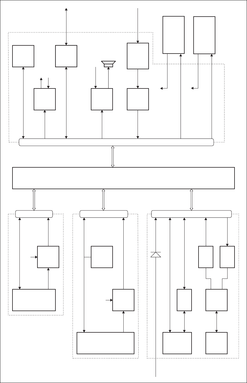
44 Functional Description TB8100 Installation and Operation Manual
© Tait Electronics Limited June 2005
Figure 4.4 System control bus high level block diagram
Power
Supply
Fan
Switch
Fan
Switch
3mA
Current
Source
Micro-
processor
Micro-
processor
Microphone
Compressor
Speaker
Buffer
Buffer
PMU Fan
RS-232
Converter
Microphone
28V
Service Kit &
Calibration Kit
Microphone Switch
RS-232 Open Collector TTL
Open Collector TTL
Speaker
PA Fan
(To I C Port
Expander)
2
(To I C Port
Expander)
2
Microphone
Rotation Output
Power/Ground
PMU Fan
IC
2
IC
2
IC
2
IC
2
IC
2
IC
2
IC
2
RS-232
PMU Fan
PA Fan
28V
UART
28V Input
from PMU
28V
28V
Subrack Interconnect Board
RISC
CODECsDSP
Buffer
Buffer
Buffer
Microphone
Speaker Control Panel
Reciter
PMU
PA
I C Port
Expander
2Digital Outputs
Digital Inputs
15-Way D-range
16-Way IDC 16-Way IDC 16-Way IDC
PA Fan
Rotation Output
Power/Ground
TB8100 Installation and Operation Manual Functional Description 45
© Tait Electronics Limited June 2005
Although the PA and PMU modules provide the power and ground for their
respective fans, the fan rotation detection is performed in the control panel.
The result is then read and processed by the reciter via the I2C interface.
The PA and PMU do not know if their fan has been correctly enabled,
however, if there is a fault in the fan circuitry, each module is protected from
overheating by its internal foldback circuitry.
In a dual base station, the fan rotation sensors report only to the currently
selected base station. The other base station will conclude that the fan is not
working and generate false alarms. We therefore recommend that you
disable all fan failure alarms (refer to “Dual Base Station System” on
page 38).
Speaker Signal Received audio can be sent from the reciter to the control panel. This
function is controlled by the speaker button on the control panel. The audio
signal is then amplified and passed to the control panel speaker for
monitoring purposes.
The audio output impedance of each reciter is fixed at approximately 2k
ohms. If two reciters are in the same subrack, either or both can drive audio
onto the bus. The system control bus will sum the two audio outputs
together and both will be passed through to the speaker. The summed audio
levels will vary, depending on the number of reciters in the subrack. The
volume range of the control panel speaker has been configured so that the
maximum number of reciters will still drive the speaker to the required
audio level.
Microphone Signal When you press the microphone PTT button, the reciter enables the
transmitter and connects the audio signal from the microphone input to the
modulator. The microphone PTT signal is read via the control panel using
the I2C bus and this then enables the transmitter. Note that the PTT
response times are slower than the response times for the TX_KEY input
from the system interface board.
The audio output from the control panel’s microphone is distributed to the
microphone audio inputs of each reciter. The low audio output impedance
of the control panel is not affected by the number of reciters connected as
the microphone audio inputs have a high input impedance.
Power and Ground The PMU provides power to the control panel via the reciters. Each reciter
has a series diode to ‘diode OR’ the power to the control panel, but not to
backpower a reciter that does not have a power cable connected.
Pin Allocations The subrack interconnect board at the front of the TB8100 subrack provides
a parallel interconnection between all connectors on the board.
The following table gives the pin allocations for the IDC connectors to the
reciter, PA and PMU, and for the D-range connector to the control panel.

46 Functional Description TB8100 Installation and Operation Manual
© Tait Electronics Limited June 2005
4.3 Signal Path
This section details what happens to an audio signal as it passes through the
various processes within a TB8100 BSS, either from the RF input to the
system interface, or from the system interface to the RF output.
Figure 4.10 on page 68 shows the four main components of a single 50W
VHF base station system: the reciter, PA, PMU and control panel.
Figure 4.11 on page 69 and Figure 4.12 on page 70 provide the same
information for UHF systems.
The majority of all Tx/Rx signal processing is performed within the reciter.
All receiver functionality occurs within the reciter while the PA provides RF
amplification of the modulated signal to be transmitted.
The reciter sections of Figure 4.10, Figure 4.11 and Figure 4.12 show the
entire reciter, which is then broken down into the individual digital, RF and
system interface boards. In the digital board, the solid line shows the
functions provided by the DSP (Digital Signal Processor).
Also refer to “Circuit Description” on page 15 for more detailed circuit
descriptions of the individual sub-systems that make up the BSS.
The following sections explain the basic operation of the base station system
by describing the basic signal paths.
Signal
Reciter, PA & PMU
IDC Pin
Standard and Power
Save Control Panel
D-range Pin
Dual Base Station
Control Panel
D-range Pin
I2C interrupt 1 (not used) 8 (not used) channel 2 select
I2C data 2 15 15
ground (I2C) 3 no connection no connection
I2C clock 4 7 7
+28V (control panel power) 5 14 14
RS-232 Tx data 6 6 6
ground (control panel power) 7 13 13
RS-232 Rx data 8 5 5
ground (analogue) 9 12 12
control panel speaker 10 4 4
control panel microphone 11 11 11
PSU back-up 12 (not used) 3 (not used) channel 1 select
+24V switched (PA fan) 13 2 2
ground (PA fan) 14 10 10
+24V switched (PMU fan) 15 9 9
ground (PMU fan) 16 1 1
TB8100 Installation and Operation Manual Functional Description 47
© Tait Electronics Limited June 2005
Receiver Path On the receiver side, an RF input signal is received via the RF input BNC
connector, filtered, amplified then mixed down to the IF frequency. The IF
signal is further filtered and then transferred from the RF to the digital board
via a coaxial interconnection cable. On the digital board the IF signal is then
sampled and further sample-rate-reduced by the DDC. The DSP then
demodulates the signal and generates RSSI, SINAD and sub-audible
signalling values and passes these to the RISC. The demodulated signal is
then split and processed using the configured options as set by the user for
Path A & Path B responses. The Rx crosspoint switch patches the recovered
audio signals to the correct output paths, reflecting the current status of the
receiver.
The final received signal is then set to CODECs which convert the digital
signal back to audio. The system interface board provides level adjustments
and final output impedance buffering. The signal finally appears as audio
signals on the rear panel interface connector.
Transmit Path Audio signals presented to the system interface connector on the system
interface board are buffered and level-converted based on the user input gain
settings. These signals are then passed to the digital board and digitized via
the CODECs, read into the DSP, and passed to the Tx crosspoint switch.
Microphone audio is passed into the Tx crosspoint switch from the control
panel via the system control bus. Based on the current base station status,
the different audio inputs can be fed into either path A or B, which are then
further processed depending on the user-configured path options. Audio
from both paths is then added together and processed via the channel
limiter/low pass filter. This signal then has any sub-audible signalling added
to it that is needed for the active channel before it is sent to the FCL
(Frequency Control Loop). The FCL performs a dual point modulation
process to modulate the VCXO and exciter VCO simultaneously. The final
modulated carrier signal is then buffered and passed, along with the DC
PA_KEY signal, to the PA (Power Amplifier) via an SMA interconnection
cable.
The PA detects and keys the PA based on this DC signal, also amplifying the
+11dBm input signal from the reciter to the final RF output power, which
is determined by the current channel output power setting. The amplified
RF output signal is then processed through a harmonic filter and a
directional coupler. The direction coupler provides power level information
to the PA to monitor and respond to the VSWR conditions on the PA
output.
Clock Processing The reciter reference clock can be selected from an external or internal
source (external reference or internal TCXO). Once the clock source has
been selected (based on the configuration and current operating status of the
base station), the 12.8MHz signal is passed from the RF board to the digital
board. On the digital board, the 12.8MHz signal is used by the CODECs,
and also generates the 40MHz clock for the DSP/RISC. This clock
structure ensures all clocks on the reciter are phase locked together to limit
48 Functional Description TB8100 Installation and Operation Manual
© Tait Electronics Limited June 2005
possible clock interference from unlocked clock sources, generating
interference or deaf channels.
Direct Signal Paths It is possible to bypass a lot of the signal processing within the DSP on both
the Tx and Rx paths via user configuration. The demodulated audio signals
can be fed directly to the output CODECs, and the transmit CODEC
inputs are connected directly to the modulator. This allows wide band
audio signals to be processed via external equipment, if required, without
the DSP overheads usually needed for path A and B audio processing.
Digital I/O The bottom of the reciter section of Figure 4.10 shows the time-critical
RX_GATE, TX_KEY and COAX RELAY signals that interface directly
with the RISC. Less time-critical signals, such as digital I/O, interface to
the RISC via a synchronous serial I/O interface.
Module
Communication
Paths
The reciter RISC supports two main inter-module communication paths:
an asynchronous (RS-232) path to the control panel and a synchronous
(I2C) interface to all other modules and the control panel. Both of these
paths are interconnected via the system control bus cable on the front of the
modules.
The RS-232 signals from a connected computer or modem are buffered and
sent to the reciter on-board UART via the system control bus. The system
control bus uses an open collector TTL interface.
The inter-module I2C bus provides a path for the RISC to communicate
with all other modules and the control panel. This supports module alarms,
diagnostics, monitoring and control panel LED/keypad traffic.
The Power
Management Unit
(PMU)
The PMU section of Figure 4.10 shows the major functional blocks of the
PMU. Each converter is under the control of the PMU microprocessor,
which is also under the control of the reciter RISC processor via the I2C
communication path.
The high current DC-DC converter and high efficiency standby card are
both powered directly from the DC input. This means that the high power
DC converter can be switched off to conserve power when not transmitting
during modes.
The HVDC control and microprocessor card also provides current sources
(effectively pull-up resistors) for the system control bus I2C inter-module
communications path.
TB8100 Installation and Operation Manual Functional Description 49
© Tait Electronics Limited June 2005
4.4 Power Distribution
This section details how the input power feed is distributed throughout the
base station system to power its various sub-systems. The high level block
diagrams in Figure 4.5 on page 50 show the power distribution paths in
single and dual base station systems, while Figure 4.9 on page 67 provides
more detailed information on a typical single base station system. Also refer
to “Circuit Description” on page 15 for more detailed circuit descriptions
of the individual sub-systems that make up the BSS.
The TB8100 can receive input power from either the AC or DC input.
Internal seamless switching between the AC or DC input ensures there are
no power interruptions should a changeover occur between the two inputs.
The base station will default to the AC input if both AC and DC inputs are
provided.
The AC converter has a series switch which isolates the mains input from
the converter. The DC input, however, has much higher current ratings,
and supports an on/off switch on the converter only.
The outputs from both the AC and DC high power converters are added
together and fed to the PA via the PA1 and PA2 outputs. The auxiliary
output is also tapped off this summed output.
When a DC module is fitted, a high efficiency standby card can be used to
power up the receiver circuitry. If required, the high power but low
efficiency converters can then be disabled, saving considerable power during
periods of no channel activity, by using the standby card to power the reciter
more efficiently.
Base stations fitted with a 12V PA do not require a PMU. In this case the
DC input is connected directly to the PA, where it is fed to the internal
boost regulator board. This board provides a 12VDC output for the reciter
and a 28VDC output for the PA circuit boards.
The reciter input power feed is distributed to all internal reciter boards.
Local regulation ensures that noise and common mode interface signals are
kept to a minimum between sub-assemblies. Various power supplies in the
reciter further power and isolate critical sub-sections.
The reciter also powers the control panel, via a backpower protection diode.
The system control bus is used to route power to the control panel, thus
whenever a reciter is powered, and plugged into the control bus, if a control
panel is connected there will always be a reciter present to drive the control
bus functions.
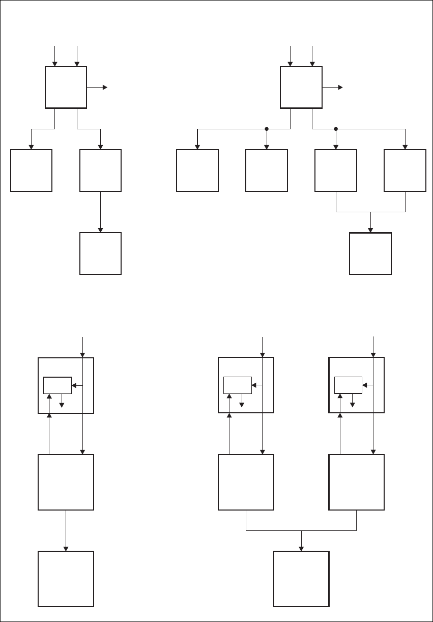
50 Functional Description TB8100 Installation and Operation Manual
© Tait Electronics Limited June 2005
Figure 4.5 TB8100 BSS power distribution high level block diagrams
DC DC
12V
Power Saving
Control
Power Saving
Control
12V
12V
12V
12V
12V
AC AC
28V 28V
28V
Aux. DC Aux. DC
28V
28V 28V
PMU PMU
PA PA 1 PA 2
Reciter Reciter 1 Reciter 2
Control
Panel
Control
Panel
Reciter 1 Reciter 2
Control
Panel
Control
Panel
28V
PA 2
Boost
Regulator
28V
PA 1
Boost
Regulator
12V
Power Saving
Control 12V
Reciter
28V
PA
Boost
Regulator
Single Base Station System
Single 12V PA Base Station System Dual 12V PA Base Station System
Dual Base Station System
TB8100 Installation and Operation Manual Functional Description 51
© Tait Electronics Limited June 2005
Reciter Power
Control Signals The power control signals PWD_EX, PWD_RX and PWR_ON (refer to
Figure 4.9 on page 67) are control lines internal to the reciter that originate
from the DSP on the digital board and are distributed to the RF and system
interface boards. These lines allow the power control software to selectively
turn on or off different reciter circuit blocks depending on the depth of
power savings configured.
PWD_EX controls the circuitry associated with the exciter RF path, such
as the exciter buffer amplifier, VCO and synthesizer.
PWD_RX controls the circuitry associated with the receiver RF path, such
as the receiver VCO and synthesizer.
PWR_ON turns off all non-critical control logic that is not required to
maintain a minimum level of RISC and DSP activity. This ensures a timed
power-up and activity cycling process. The RF and system interface board
are shut down completely.
4.5 PMU Operation on DC Input
The operation of the PMU on DC input is controlled by three sets of
parameters:
■user-programmable alarms
■user-programmable startup and shutdown limits
■battery protection limits.
The voltage range for each of these parameters is provided in Table 4.1 on
page 53. Figure 4.6 on page 52 illustrates how these parameters interact,
and how they control the operation of the PMU over a range of DC input
voltages.
Alarms User-programmable alarms can be set for low or high battery voltage. The
alarms will be triggered when the set voltage levels are reached.
To set the alarms, run the Service Kit and select Configure > Alarms >
Thresholds. In the Thresholds form, enter the required minimum and
maximum values in the PMU battery voltage fields.
Startup and
Shutdown Limits The user-programmable startup and shutdown limits allow for adjustable
startup and shutdown voltages. These limits can be adjusted for different
numbers of battery cells, or for the particular requirements of the base
station operation. Once the limits are reached, the PMU will shutdown.
To set the startup and shutdown limits, run the Service Kit and select
Configure > Base Station > Miscellaneous. In the Power Configuration
area, enter the required values in the Power shutdown voltage and
Power startup voltage fields.
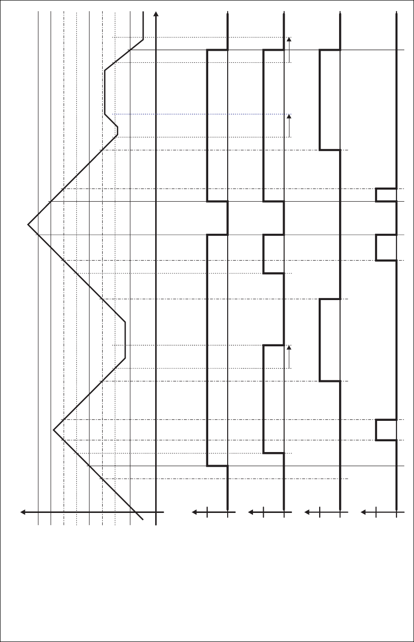
52 Functional Description TB8100 Installation and Operation Manual
© Tait Electronics Limited June 2005
Figure 4.6 PMU alarm thresholds and voltage limits when operating on DC
Time
0V
DC Input Voltage
Overvoltage Shutdown (HW)
Undervoltage Shutdown (HW)
Overvoltage Shutdown Reset (HW)
High Battery Voltage Alarm (SW Alarm)
Low Battery Voltage Alarm (SW Alarm)
Startup Voltage (SW)
Shutdown Voltage (SW)
Startup Voltage (HW)
Run
Run
Stop
Stop
Active
Active
Off
Off
Software Control &
Hardware Combined
Hardware Behaviour
Software Alarm
(Low Battery Voltage)
Software Alarm
(High Battery Voltage)
30s delay 30s delay 30s delay

TB8100 Installation and Operation Manual Functional Description 53
© Tait Electronics Limited June 2005
Battery Protection
Limits The battery protection limits are set in hardware at the factory, and cannot
be adjusted by the user. These limits will not be reached under normal
operation conditions, but are provided as “fail-safe” measures to protect the
battery from deep discharge. They also remove the need for low-voltage
disconnect modules.
Indicator LEDs The indicator LEDs on the front panel are used to indicate the state of the
PMU and its microcontroller. There are two LEDs, one red and one green.
Each LED can be on, off, or flashing at two rates (fast or slow). The state
of these LEDs can indicate a number of operating modes or fault conditions,
as described in Table 4.2 on page 54.
Table 4.1 PMU DC voltage limitsa
Parameter
Voltage Range
12V PMU 24V PMU 48V PMU
User-programmable Alarmsb
Low Battery Voltage
High Battery Voltage
10V to 14V
14V to 17.5V
20V to 28V
28V to 35V
40V to 56V
56V to 70V
User-programmable Limitsbc
Startup Voltage
(after shutdown)
Shutdown Voltage
12V to 15.0V
10V to 13.5V
23.9V to 30V
20V to 27V
47.8V to 60V
40V to 54V
Battery Protection (Fail-safe) Limits
Startup Voltage
Undervoltage Shutdown
Overvoltage Shutdown
Overvoltage Shutdown Reset
11.7V ±0.3V
9.5V ±0.3V
18.1V ±0.3V
17.1V ±0.3V
23.4V ±0.5V
19V ±0.5V
36.2V ±0.5V
34.2V ±0.5V
46.8V ±1V
38V ±1V
72.4V ±1V
68.4V ±1V
a. The information in this table is extracted from the TB8100 Specifications Manual. Refer to the latest issue of this
manual (MBA-00001-xx) for the most up-to-date and complete PMU specifications.
b. Using the Service Kit software.
c. Only available if the standby power supply card is fitted.

54 Functional Description TB8100 Installation and Operation Manual
© Tait Electronics Limited June 2005
4.6 Data, Control and Monitoring Paths
This section describes the types of data and the methods used to move the
data around a TB8100 BSS. Refer to Figure 4.13 on page 71 for more
information.
The reciter RISC is the central command and control entity in a base station
system. As such it will often command modules to change state, based on
the information received in a module poll message reply. Messages from the
reciter over the I2C bus can control actions in the PA and PMU hardware,
such as changing Hysteresis mode in the PMU based on the current status
of any active power cycling modes, or reading the ambient temperature via
the PA module.
Table 4.2 PMU indicator LED states
Green Red PMU condition
off off power off (input above or below safe operating range)
flashing
(3Hz)
off no application firmware loaded; use the Service Kit software to
download the firmware
on off the microcontroller is operating; no alarm detected
on flashing
(3Hz)
one or more alarm conditions detected:
■output is overvoltage
■output is undervoltage
■output is current-limiting
■overtemperature
■mains failure
■battery voltage is low
■battery voltage is high
■shutdown is imminent
■DC converter is faulty
■battery is faulty, or DC converter is switched off
■auxiliary power supply is faulty
■PMU is not calibrated
■self-test has failed
■PMU is not configured
flashing
(on 300ms,
off 2700ms)
flashing
(on 300ms,
off 2700ms)
PMU is in battery protection mode
flashing
(on 300ms,
off 4700ms)
flashing
(on 300ms,
off 4700ms)
PMU is in Deep Sleep mode
flashing
(3Hz)
flashing
(3Hz)
Service Kit LED test - LEDs flash alternately
TB8100 Installation and Operation Manual Functional Description 55
© Tait Electronics Limited June 2005
Serial Service Kit communications are transferred from the attached serial
device (e.g. a personal computer running the TB8100 Service Kit), buffered
on the control panel and passed into the RISC’s UART.
Inter-module communications traffic (for example monitoring, diagnostics
and firmware download messages) is passed between the reciter and
PA/PMU via the I2C bus, which runs a Tait proprietary protocol. The
reciter acts as a router, in that messages to and from the PA and PMU are
passed through the reciter between the UART and I2C ports.
When each PA/PMU module powers up for the first time, it requests the
RISC, via the I2C bus, to allocate a unique address to that module for use
across the I2C bus. Each module on the I2C bus must have a unique address.
The reciter assumes ‘primary’ status, while all PAs and PMUs assume
‘secondary’ status. Consequently, the reciter polls modules and the modules
reply, forming a poll-response architecture with unique addresses and
associations.
There is no information passed over the system control bus that is real-time
dependent. All real-time processing needs, such as fault recovery for all
modules, are supported by the microprocessor present in each module. The
only real time signal in the system is the PA_KEY signal that is passed
between the reciter and the PA. This signal is a critical part of the TX_KEY
ramp up and down operation and is summed with the exciter RF output to
the PA over the coaxial interconnection cable.
For example, when a TX_KEY signal is passed to the reciter system
interface board, the following actions occur:
1. The TX_KEY signal is read and processed by the RISC
microprocessor which, depending on the configuration and status of
the reciter, will then initiate a transmission.
2. The RISC will instruct the DSP via the host port to initiate a
transmission and start modulating the RF carrier.
3. The DSP will enable the PA_KEY line to the PA microprocessor.
4. The PA microprocessor will then initiate a controlled PA output ramp
up.
Depending on the channel selected for the transmission, the RISC will also
re-configure the synthesizer as required, though this does not automatically
occur at the start of a Tx/Rx event.
At an appropriate time, the reciter’s RISC processor will poll the PA and
PMU modules for their status (including any alarm conditions) and process
the results accordingly. Whenever a user selects a PA/PMU monitor or
diagnostic screen in the Service Kit, the information is read from that
module via the I2C bus. It is then transferred through the RISC and passed
to the Service Kit computer using the Tait proprietary Service Kit protocol
over the serial port.

56 Functional Description TB8100 Installation and Operation Manual
© Tait Electronics Limited June 2005
The PA and PMU sections on Figure 4.13 show most of the monitored
parameters in each module and the control outputs from the
microprocessors, which are also available to the reciter RISC via the I2C bus
and form the basis of the TB8100 monitored alarms.
Each reciter, PA and PMU module also stores the following information
specific to that module:
■calibration parameters
■serial and product number
■factory configuration.
This ensures that the module is a true entity in its own right, thus helping
to support simple ‘plug and play’ site module replacement procedures.
The TB8100 control panel provides several important functions.
Depending on the control panel version these functions include, but are not
limited to, the following:
■an interface point to monitor and respond to failure alarm outputs from
the fans
■a point to read key presses and display base station status on output LEDs
■speaker control and amplifier for on-site monitor audio.
All control panel logic inputs and outputs are implemented by using an I2C
port expander that performs a serial (I2C) to parallel conversion (and vice
versa) over the I2C bus. The control panel port expanders are fixed address
8-bit input and output interfaces. The heaviest user of the I2C bus is actually
the control panel keypad read polls which occur on average every 50ms.
4.7 Fan Operation
The cooling fans are mounted on the front panel. One fan is in front of the
PA and another in front of the PMU. The fans do not operate continuously
but are switched on and off as needed by the reciter firmware. When the
base station is switched on, both fans come on for a short time and are then
normally switched off. The operation of the PA fan is configurable via the
Service Kit but the PMU fan is not. It has fixed on/off thresholds and a
defined set of duty cycles based on the PMU temperature, as follows:
PMU Temperature Duty Cycle
<65°C (<149°F) Increases with increasing current draw
65°C to 75°C (149°F to 167°F) On two minutes, off one minute
>75°C (>167°F) Always on
TB8100 Installation and Operation Manual Functional Description 57
© Tait Electronics Limited June 2005
Fans used in the TB8100 must have the correct wiring: power and ground
(2-wire fans), or power, ground and rotation detect (3-wire fans). Both fans
in the subrack must be of the same type.
If 3-wire fans are fitted, the reciter can monitor whether the fans are rotating
and generate an alarm if the fan fails. Refer to the Service Kit and Alarm
Center documentation for more details. Refer also to “Dual Base Station
System” on page 38 for information on the constraints of fan rotation
detection in dual base station systems.
4.8 Power Saving
TB8100 base stations can be equipped with Power Saving. This set of
sophisticated current-reducing measures is made available through the
optional Power Saving Modes licence. Under the control of the reciter, all
modules in the subrack work together to offer many levels of current
reduction. The receiver circuitry can cycle on and off, parts of the PA
circuitry can be switched off, and the PMU can enter a power-saving
Hysteresis mode or even shut down its main DC-DC converter. These
measures can achieve a dramatic reduction in power consumption during
idle periods.
Power Saving is available for 5W, 50W and 100W base stations. There can
only be one base station in the subrack and most Power Saving measures are
only available when the base station is running on battery power. Dual base
stations cannot have Power Saving, but they can be configured to provide
modest reductions in current consumption. The same configuration can be
used for single base stations without a Power Saving licence. This brings
their power consumption in line with the Tait T800 range.
Two optional hardware items are needed to maximise the amount of power
that the base station can save. The TBA2010 Power Save Control Panel (for
further information, see “Power Save Control Panel” on page 32) is
designed for base stations with Power Saving; most of its circuitry can be
switched off. The PMU standby power supply card enables it to run in
Hysteresis mode or to turn off its DC-DC converter.
Power Saving is implemented in three different modes: Normal, Sleep, and
Deep Sleep. This makes it possible for the extent of the power saving
measures to vary depending on the amount of traffic on the channel. Each
mode combines a number of power saving measures and is enabled and
configured through the Service Kit.
58 Functional Description TB8100 Installation and Operation Manual
© Tait Electronics Limited June 2005
4.8.1 Power Saving Measures
The following describes the different ways that the modules of a Power Save
base station are able to reduce their power consumption. Service Kit users
select these measures indirectly by selecting values for the Rx cycling time
and the Tx keyup time.
Receiver Signal Path
Cycling The receiver can be cycled off for a user-definable time, then switched back
on. If a signal is detected, the receiver stays on, otherwise it cycles off again.
There are two levels of cycling: the first involves only the receiver, the
second involves most circuitry in the reciter.
If the Rx cycling time is 100 ms or less, only the PWD_RX power rail is
turned off. This turns off the receiver front end, receiver ADC (Analog to
Digital Converter) and DDC (Digital Down Converter). Once the cycling
time has elapsed, the following occurs:
1. The DSP turns on the PWD_RX power rail.
2. The DSP initialises the DDC. This results in a working receiver.
3. The DSP measures the RSSI to see whether there is a signal on the
channel.
4. If the RSSI does not exceed the threshold, the DSP turns the power
rail off.
The whole process takes about 10ms.
If the Rx cycling time is greater than 100ms, more circuitry (including the
receiver VCO) cycles on and off. In this case, the DSP turns the PWD_RX
and the PWR_ON power rails off (see “Power Distribution” on page 49 for
more information about reciter power rails). Once the cycling time has
elapsed, the following occurs:
1. The DSP turns the PWR_ON rail back on and tells the RISC.
2. The RISC programs the receiver synthesizer and waits for it to lock.
This takes around 20ms.
3. The RISC tells the DSP that the synthesizer is locked.
4. The DSP turns on the PWD_RX power rail back on, and the process
continues as for receiver cycling above.
Transmitt er Keying Normally, the PA uses special Fast Key circuitry to give a fast but controlled
ramp-up of the PA’s power output. In Sleep and Deep Sleep modes (and in
Normal mode, with a Tx keyup time of 5ms or longer), this function is
disabled by turning off the PA 10V power rail (see “Power Distribution” on
page 49 for more information about power rails). This turns off most of the
PA analogue circuitry. The process of keying the transmitter then works like
this:
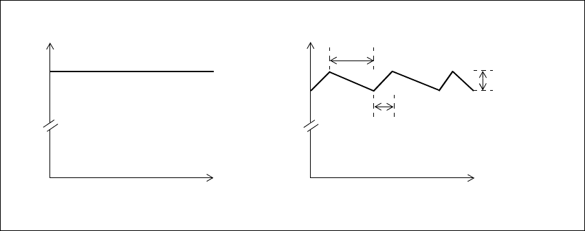
TB8100 Installation and Operation Manual Functional Description 59
© Tait Electronics Limited June 2005
1. The PA receives a PA_KEY_COAX signal instructing it to key up.
This is a DC signal on the coaxial cable that goes from reciter to PA.
2. The PA microprocessor turns the 10V power rail on, and then waits
for 20-30ms for the regulator to stabilise the power.
3. The microprocessor sets the power level.
4. The microprocessor provides its usual ramping signal. This has the
form of a raised cosine.
PMU Hysteresis
Mode Hysteresis mode is the first means of reducing current consumption in the
PMU. It requires a PMU standby power supply card and is not available if
the PMU’s auxiliary power output is on.
While the PMU DC converter is highly efficient for output currents in the
range of 1-15A, it is not efficient for low output currents. This is mainly due
to the current drive requirements for the heavy-duty switching FETs (field
effect transistors).
Hysteresis mode resolves this issue by setting the output voltage to swing
between two fixed levels. This allows the FETs drive signal to be turned off
for periods of time. The FET off time is dependent on the load current
drawn. Figure 4.7 on page 59 illustrates the output voltages for the PMU
DC converter in both normal and Hysteresis modes.
You can confirm whether the PMU is in Hysteresis mode by connecting an
oscilloscope to the PMU’s 28V output power connector. You should see the
voltage ripple.
Hysteresis mode is used only when the base station is not transmitting. The
ripple generated by Hysteresis mode does not degrade the performance of
the receiver. However, when the base station is transmitting, Hysteresis
mode is turned off because the PA should never transmit with the ripple
voltage present.
Figure 4.7 DC converter output voltages in PMU operation modes
Time
Voltage
27.9
Time
Voltage
27.9
Normal mode Hysteresis mode
27.5
FET switches OFF once upper
threshold reached
Output voltage
ripple
(hysteresis voltage)
FET switches ON once lower
threshold reached

60 Functional Description TB8100 Installation and Operation Manual
© Tait Electronics Limited June 2005
PMU Standby
Operation In Deep Sleep mode, the second means of reducing PMU current
consumption takes effect. The PMU microprocessor turns the DC-DC
converter off, removing all power to the PA. Only the reciter and the control
panel receive power (see Figure 4.9 on page 67 for details).
The PA LEDs go off. The PMU’s green Power LED also goes off, but the
red Alarm LED flashes briefly about every 20 seconds (these LEDs are only
visible when the subrack front panel is removed).
Control Panel
Shutdown In Sleep and Deep Sleep modes, the reciter instructs the Power Save control
panel to shut down. This turns off most of its circuitry (fan detection, I2C
interface, RS-232). However, it is still monitoring the RS-232 lines for
activity.
Note The Power Save control panel does not shut down in Sleep and
Deep Sleep modes if the reciter is fitted with a TaitNet RS-232
system interface board (TBA10L0).
The red alarm LED goes off. This means that it cannot light up if an alarm
is generated. If an alarm is present when the control panel shuts down, it
cannot be displayed.
The Power LED flashes under hardware control to indicate that the base
station is in Sleep or Deep Sleep mode.
If the base station needs to communicate with an Alarm Center, or a Service
Kit attempts to connect, activity is detected on the RS-232 lines and the
Control Panel turns itself on. Immediately after the Service Kit disconnects,
the Control Panel shuts itself down again.
Note The standard and dual base station control panels cannot shut
themselves down, but their LEDs (except the Power LED) also
flash in Sleep and Deep Sleep modes.
12V PA Operation Power Saving is also available in base stations using a 12V PA. Both Sleep
and Deep Sleep modes can be configured, with the same receiver cycling
and Tx keyup options as a base station with a PMU. In Deep Sleep mode,
the reciter shuts down the PA by shutting down the boost regulator board
in the PA (refer to “12V PA Power Saving Control Connection” on
page 124 for more information on this connection). The 12VDC output
from the boost regulator board is unswitched and continues to power the
reciter even when the rest of the circuitry on the board is shut down.
4.8.2 Power Saving Modes
The Power Saving Modes licence makes two power saving modes available:
Sleep and Deep Sleep. The base station runs in Normal mode when there
is activity on the channel but can transition to Sleep and/or Deep Sleep
mode after it has been idle for a period of time.
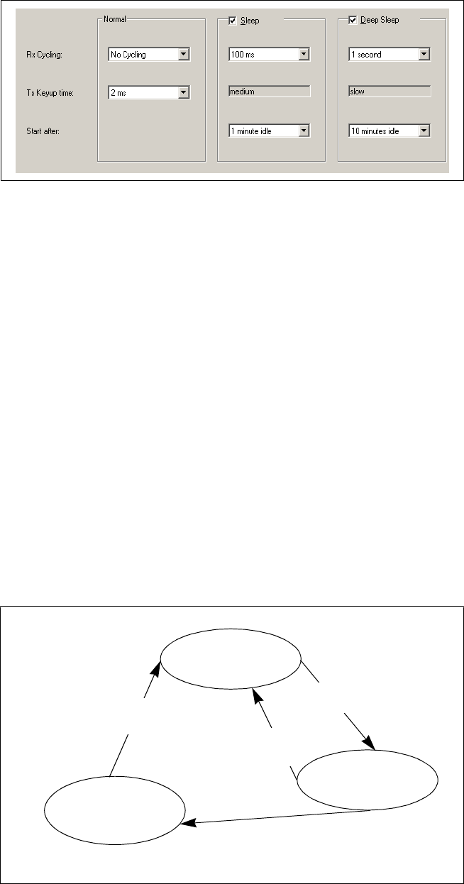
TB8100 Installation and Operation Manual Functional Description 61
© Tait Electronics Limited June 2005
Once the base station’s Power Saving Modes licence is enabled, you can use
the Service Kit to enable and configure its Sleep and Deep Sleep modes (see
the Service Kit online Help for details).
Each mode is defined by a receiver cycling time and a Tx keyup time and
the values of these parameters determine which power saving measures are
used. The transitions from Normal mode to Sleep and from Sleep to Deep
Sleep modes are initiated by an idle timer.
Normal mode needs no enabling and can be configured without a Power
Saving Modes licence. The configuration can involve no current reduction
at all (no receiver cycling and the fastest possible Tx Keyup time), or a
modest reduction to give similar performance to the T800.
The transitions between modes are shown in Figure 4.8. On startup, the
base station operates in Normal mode. A timer starts as soon as there is no
channel activity. PTT, front-panel carrier-only transmission, CWID bursts,
and alarm tones do not count as activity, and can all occur in Sleep and Deep
Sleep modes without affecting the timer.
When the timer reaches the value set in the Service Kit (in the ‘Start after’
box) for Sleep mode, the base station enters Sleep mode. If the receiver
Figure 4.8 Transitions between sleep modes
Normal Mode
User-selected Rx cycling time
and Tx keyup time
Deep Sleep Mode
User-selected Rx cycling time.
Tx keyup time Slow
Tx Key is activated or receiver
detects activity and determines
that the signal is valid
Idle timer continues until it
reaches the Deep Sleep value
Idle timer reaches Sleep
mode value
Tx Key is activated or receiver
detects activity and determines
that the signal is valid
Sleep Mode
User-selected Rx cycling time.
Tx keyup time Medium

62 Functional Description TB8100 Installation and Operation Manual
© Tait Electronics Limited June 2005
detects activity and determines that the signal is valid (or the Tx key line is
activated), it reverts to Normal mode. Otherwise, the timer continues
running.
When the timer reaches the value for Deep Sleep mode, the base station
enters Deep Sleep mode.
If the base station is running on AC power, the timer operates as usual.
However, the base station will continue to run in Normal mode, as
configured in the Service Kit, even after reaching the value for Sleep or
Deep Sleep mode. It only enters these modes after it has changed over to
DC power. If it changes back to AC power, it returns to Normal mode.
4.8.3 Overview of Operation
The following tables show the receiver cycling times and Tx keyup times
available for Normal, Sleep, and Deep Sleep modes and the power saving
measures they correspond to. For more details on power and current
consumption refer to the TB8100 Specifications Manual.
Table 4.3 Power Saving measures selected by receiver cycling time
Power
Saving
Mode
Receiver
Cycling
Reciter Power Rails
PWR_ON PWD_EX PWD_RX
Normal No cycling on on on
5ms on on cycling
10ms on on cycling
20ms on on cycling
Sleep No cycling on on on
20ms on on cycling
50ms on on cycling
100ms on on cycling
200ms cycling off cycling
Deep
Sleep
No cycling on on on
200ms cycling off cycling
500ms cycling off cycling
1s cycling off cycling
5 s cycling off cycling

TB8100 Installation and Operation Manual Functional Description 63
© Tait Electronics Limited June 2005
Further
Considerations
■Hysteresis mode is only available if a standby power supply card is fitted
and the auxiliary power output has not been turned on by Task Manager
action.
■Auxiliary power is not available in Sleep or Deep Sleep modes.
■There may be a significant delay in the setting of digital outputs if
PWR_ON is cycling. A change, such as the state of a digital input, is
only read when the power cycles on. Task Manager carries out the action
to set the digital output while the power is off, but this action only takes
effect next time the power cycles on.
■During receiver cycling, the base station is unable to provide a
continuous output on its audio output lines. When the receiver cycles
off, so does its line output, even if the outputs are not gated.
4.8.4 Using the Service Kit with Power Save Base Stations
You can connect the Service Kit to a base station in Sleep or Deep Sleep
mode and log on. The reciter is still able to communicate with the Service
Kit when powered by the standby power supply card. The control panel
needs to wake up, but the rest of the base station does not change mode. The
reciter can also initiate communications via the control panel to an Alarm
Center.
You can use the Service Kit to monitor Power Save operation and see what
power saving measures are currently active.
Important Displaying any PA monitoring or diagnostic screen turns
the PA on. The PA stays on until the screen is closed. Make
sure that you do not waste power by leaving any of these
screens on.
Table 4.4 Power Saving measures selected by Tx keyup time
Power
Saving
Mode
Tx Keyup
Time
PMU PA
28V Power Fast key
Normal 2msab
a. The Tx Keyup time you select using the Service Kit refers to the amount of time need-
ed to key the transmitter AFTER the reciter detects valid RF or receives a Tx Key signal.
The total time needed is increased by receiver cycling and varies according to where
in the cycle the RF or Tx Key is applied. The reciter only looks for RF or Tx Key when
the PWD_RX rail is on.
b. The actual Tx Keyup time may be slightly shorter or longer than this value. Refer to
the TB8100 Specifications Manual for further details.
on enabled
5msaon disabled
20msaon disabled
Sleep Medium Hysteresis mode disabled
Deep Sleep Slow off n/a: PA is off
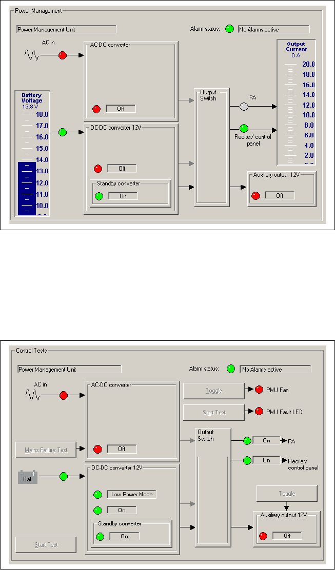
64 Functional Description TB8100 Installation and Operation Manual
© Tait Electronics Limited June 2005
A monitoring screen shows you whether the DC-DC converter has shut
down. Select Monitor > Monitoring > Power Management.
The display shows that the DC-Converter is off, and that there is no power
to the PA.
To check whether Hysteresis mode is active, select Diagnose > Power
Management > Control Tests.
When the DC-DC converter display shows that Low Power Mode is on, the
PMU is in Hysteresis mode.
TB8100 Installation and Operation Manual Functional Description 65
© Tait Electronics Limited June 2005
4.8.5 Configuring Receiver Gating for Base Stations with Power Save
Settings for receiver gating can adversely affect Power Save.
In low-noise situations, Tait recommends that you use the default settings
(RSSI disabled, SINAD enabled at 12dB).
In high-noise situations, follow these guidelines:
■Use RSSI and SINAD gating.
■Set the RSSI level to be above the ambient noise level, for example
–113dBm (0.5µV).
■Set the SINAD level as desired.
■Set the gating logic to OR.
■Have no receiver cycling in Normal mode.
■Set short idle times (for example 1 minute for Sleep mode and 10
minutes for Deep Sleep mode).
The background to these recommendations is as follows:
Receiver gating operates differently when the receiver is cycling. Whenever
the receiver cycles on, it first measures the RSSI, even if its configuration
disabled RSSI gating (this is because detecting the RSSI is very quick). If the
RSSI exceeds the threshold, power stays on. (If the configuration doesn’t
specify a threshold, –117dBm is used.)
If gating is configured for RSSI alone, the receiver unmutes straight away. If
SINAD gating is enabled, the base station must first determine whether the
SINAD is above the threshold. If it is, the base station stays on, otherwise it
returns to cycling in its existing mode.
To ensure the full benefits of power saving, it is important to use an RSSI
level that prevents the base station unnecessarily turning the receiver on
while it checks the SINAD. For example, if the RSSI gate is turned off, the
SINAD gate is set to 20dB, and the receiver cycling time is 100ms, the
following can happen in the presence of channel noise:
1. The receiver cycles on.
2. It detects a signal that is above the RSSI threshold.
3. It stays on for 100ms to check whether the SINAD is good enough.
4. The SINAD is too low, so the receiver cycles off.
5. 100ms later, it’s time for the receiver to cycle on again and repeat the
procedure.
The result is that the receiver is on for about 120ms out of every 220ms,
instead of for about 20ms out of every 120ms.

66 Functional Description TB8100 Installation and Operation Manual
© Tait Electronics Limited June 2005
The recommendations for noisy sites have the following effects.
■A high RSSI level means that the base station rarely wastes power by
holding the receiver on to check the SINAD. (This may mean that users
find it more difficult to gain access to the site. However, once they have
access and the base station is in Normal mode, the relatively low SINAD
makes access easy.)
■Receiver cycling in Normal mode is not selected so that the higher RSSI
level is not required in order to open the gate.
■The ‘OR’ setting for gating logic provides optimal gating when the base
station is in Normal mode: quick opening when the signal is strong,
reliable opening when it is weaker.
■Short idle times maximise the proportion of time that the base station is
in Sleep and Deep Sleep modes.
Note If the base station is part of a CTCSS/DCS system, the base station
will use additional power whenever it hears a signal with the
wrong subtone. For example, if the receiver has the same settings
as above, it would be on for 320ms out of every 420ms (a subau-
dible check can take up to 230ms). The only way to minimise the
effects of this is to set a very long receiver cycling time, such as 5
seconds.
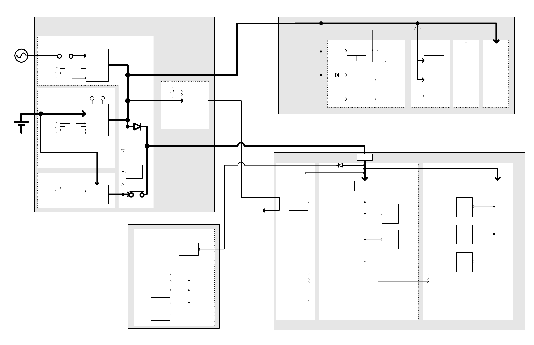
TB8100 Installation and Operation Manual Functional Description 67
© Tait Electronics Limited June 2005
Figure 4.9 TB8100 BSS power distribution
b
Temperature
Mains good
To /
from
µP Shutdown
Rear panel
ON/OFF switch
AC input
(115-230VAC
50/60Hz)
DC input
12/24/48VDC
Data
To /
from
µP Run
Rear panel
ON/OFF switch
Temperature
Hysteresis enable
Standby present
Shutdown
To /
from
µP
PMU µP
&
I
2
C pull-ups
Standby isolate
(from uP)
Auxiliary
28 to 12/24/48V
(optional)
Front panel
PA1 & PA2
outputs
Front panel
Reciter outputs
Rear panel aux output
(SIF / trickle
charger output)
Data
To /
from
µP Run
28 to 10V
regulator
(switched)
28 to 5V
regulator
(permanent)
28 to -3V
regulator
(permanent)
Control board
Power
Management
Unit
(PMU)
28 to 2.5V
regulator
(permanent)
28 to 5V
regulator
(permanent)
6W board 60W board
Low pass
filter board
Power
Amplifier
(PA)
Digital board
RX/EX/EX
Ref
Synths &
VCO's
RF boardSystem interface board
Reciter
System
interface
analogue
circuitry
System interface
D-range supply
output
System interface
power input
Diagnostics
and power
control
circuitry
Analogue
power control
circuitry
Power
control
circuitry
RF circuits
RF circuits RF circuits
Power supply
connectors
DSP
-Codec
-ADC
-DDC
-Power control logic
PWD_EX
PWD_RX
PWR_ON
28 to 5V
Speaker
amplifier
I
2
C
control
signal
Control
Panel
AC module
DC module
Auxiliary power
supply board
SIF_28V
Not connected
Standby power supply card
Protection
Fuse
Power supply
connectors
AC converter
(500W)
(optional)
DC converter
(40/500W)
(optional)
Standby
28-29V
(optional)
µP Control
µP Control
System
Control bus
Microphone
circuitry
RS-232
circuitry
I
2
C
circuitry
System
interface
digital
logic
Exciter
RF
circuitry
Receiver
RF
circuitry
Receiver
digital
logic
RISC
-memory
-clock
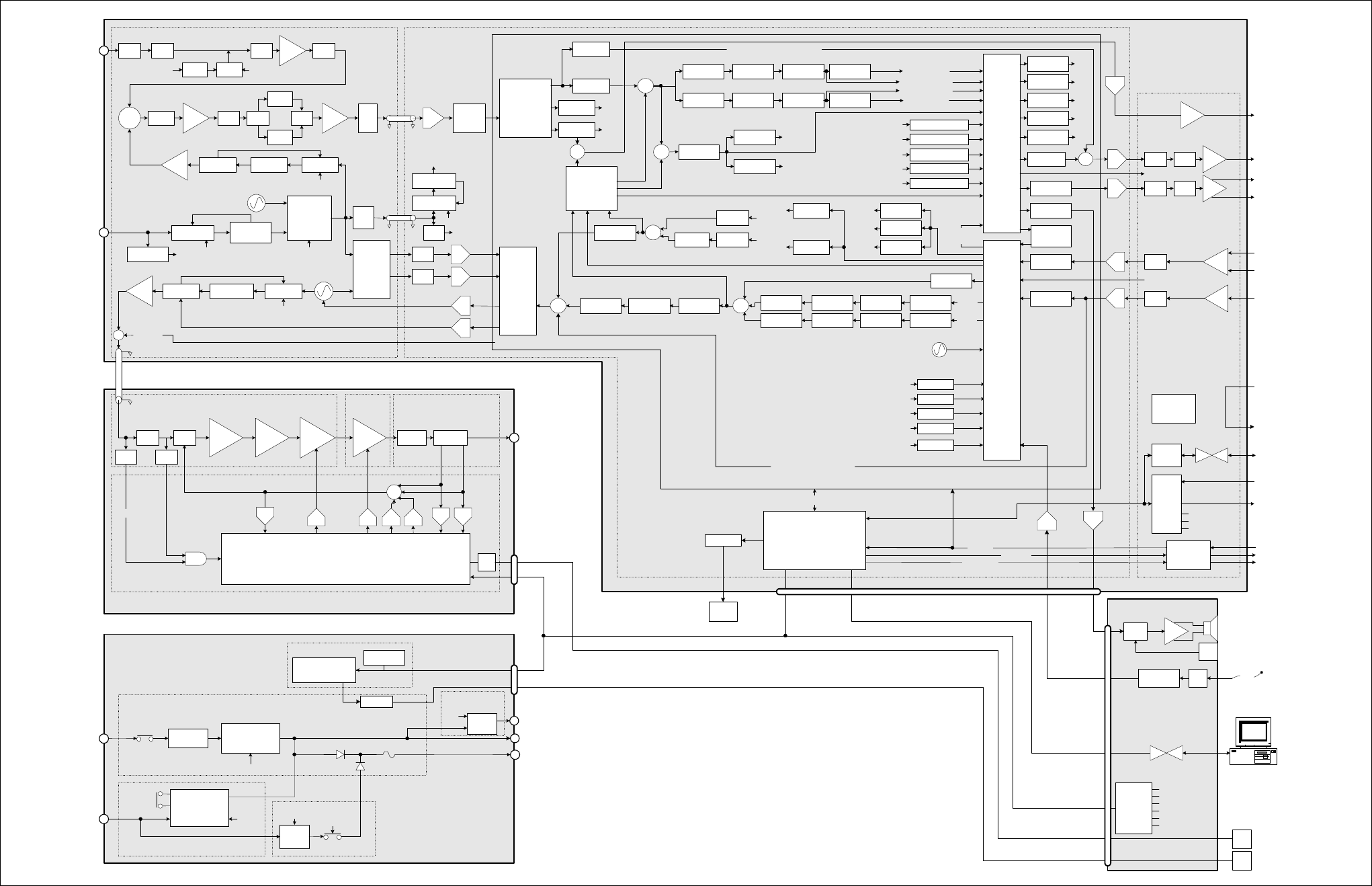
68 Functional Description TB8100 Installation and Operation Manual
© Tait Electronics Limited June 2005
Figure 4.10 TB8100 BSS VHF signal path
RX
Cross
Point
Switch
(CPS)
Balanced
audio
input
Balanced
audio
output
Unbalanced
audio input
Unbalanced
audio output
Decimation
filter
Interpolation
filter
Decimation
filter
Interpolation
filter
Mic.
Test Signal
generator
PIP tones
FFSK
CWID
Selcall
Test tone
OTA
generators
FFSK
Tone remote
Selcall OTL decoders
Unbalanced
Balanced
Line input level
measurements
HPF
HPF
Notch filter
Notch filter
Pre-emphasis
Pre-emphasis
Variable delay
Variable delay
Voice filter
Service Kit
Interpolating
filter
Hard limiterLimiter filter
Voice reject
filter
Interpolating
filter DCS
encoder
CTCSS
encoder
TX sub-band signalling
TX path audio processing
Path A
Variable delay
Variable delay
Mute switch
Mute switch
De-emphasis
De-emphasis
HPF
HPF
CTCSS
decoder
DCS decoder
Voice reject
RX path audio processing
Rx sub-band
signalling
Interpolation
filter
BO audio
measurement
UO audio
measurement
Test signal
sink
Selcall decode
FFSK decode
Voting tones
FFSF
Pip tones
Line out test tone.
Tone remote
Frequency
control
loop
Decimating
filter
Loopback
Cross
Point
Switch
(CPS)
SINAD
processing
Normalisation,
FM Demod,
RSSI & SINAD
measurement
LPF
LPF
BPF1
Frequency
control loop
quadrature
mixer +
buffers
Change over
switch
Ex SynthEx Loop filterEx VCO
LPF
Switch
RF
Input*
RF
Amp BPF2
Mixer Diplexer Buffer Pad
NB Xtal
filter
IF
Amp
Anti-
alias
filter
Digital
down
converter
(DDC) RSSI,
processing
RX SynthLoop filterRX VCO
Ref VCXO
(12.8MHz)
REF Synth
Ref detect.
Ext.
Ref.
40MHz VCXO
40MHz Synth
To RISC, DSP,
ADC, DDC
100mW
PIN
atten. 1W 6W 60W Harmonic
filter
Directional
coupler
PA
Microprocessor
DAC
LPF
PA_KEY
DAC
AC converter
DC converter
10W
standby
AC
input
DC
input
PA1/PA2 output
40W
Converter
Aux. out (SIF) or
Trickle charger
µP
Standby
Isolate
Reciter output
Rear panel
ON/OFF
µP
µP
µP
Rear
panel
ON/OFF
µP
RF
output
Exciter to
PA RF
Reduced instruction
set computer
(RISC)
ADC
ADC
ADC
DAC
DAC
DAC
DAC
ADC
ADC
TX_KEY
RX_GATE
COAX Relay
I
2
C
I
2
CUART
LPF / Directional
Coupler Board
60W
Board
6W Board
Control Board
50W Power Amplifier
I
2
C current
sources
PMU
micro-
processor
I
2
C
Power factor
correction
Power Management
Unit
System
Control
bus
System
Control
bus
System Control bus
System
Control
bus
System
Interface Board
Digital Board
RF Board
Path B
Buffer 12.8MHz to
CODECs
Host port
RISC
RISC
RISC
RISC
RISC
Digital Signal Processor (DSP)
IF Receiver
front end
Decimating
filter
Reciter
Repeater AC
coupling filter
Line
loopback
*Frequency Bands & Sub-bands
B2 = 136-156MHz
B3 = 148-174MHz
C1 = 174-193MHz
C2 = 193-225MHz
152.9-241.9MHz
high side
VCXO
Buffer
+ coax
driver
VCO
modulation
VCXO
modulation
12.8MHz TCXO
TX
Cross
Point
Switch
(CPS)
Micro Card
AC Converter Board
DC Converter Board
ADCADC
DACDAC
Transient
wave shape
RF power
setting
Forward
power
Reverse
power
Bias
Bias
ADC
Power
control
RX_GATE
RISC
RISC
RISC
RISC
RISC
RISC
RISC
RISC
RISC
RISC
RISC
RISC
RISC
RISC
RISC
RISC
RISC
RISC
RISC
RISC
RISC
I
Q
SIO
OTL
encoders
DAC
ADC
Fan
buff.
Fan buffer
PA
fan
PMU
fan
Standby PS card
Auxiliary PS
PCB
RISC
RISC
RISC RISC
RISC
RISC
Buff
EPOT Buff
EPOT Mute
Sw.
Mute
Sw.
Digital audio output
Buff
Buff
EPOT
EPOT
Digital audio input
Digital
inputs
Digital
outputs
RSSI
output
voltage
Power
from PMU
Power to
external
equipment
Buff
Third party
interface
connections
Discrete
Logic
Conventional
signalling
buffers
EPOTs
Mute Switches
SIF ID
Amp
Amp &
Switch
Vol.
Knob
Compressor Amp.
I
2
C port
expanders
Speaker ON/OFF
Fan rotation
Control panel ID
LEDs
Keypad
Mic PTT
Standard
Control Panel
2.5A
polyfuse
Noise
source
PIN
switch
RISC
Buffer
10 or 12.8MHz
Buffer
General I/O
PA_KEY
DAC
Demodulated
audio
Direct demodulated audio output
Direct modulation audio input
Speaker
SIO to
UART RS-232
converter
Rear
panel
RS-232
TX_KEY
COAX Relay
General I/O
Reciter
fan
Fan buffer
RS-232
converter
HPF
RF
Detect
AND
Path A
Path B
Path A (muted)
Path A (un-muted)
Path B (un-muted)
Path B (muted)
HPF
WB Xtal
filter
Switch
RISC
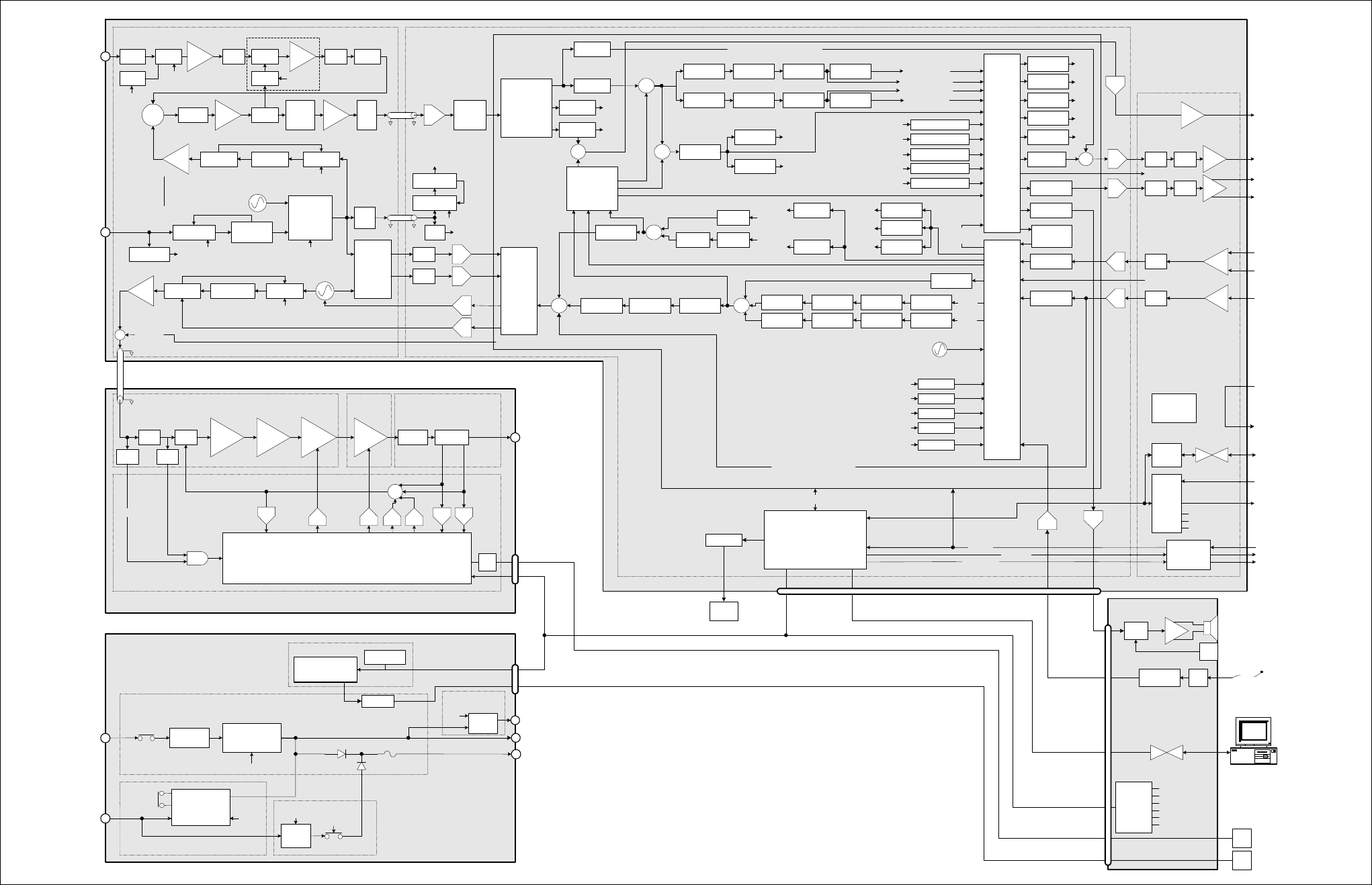
TB8100 Installation and Operation Manual Functional Description 69
© Tait Electronics Limited June 2005
Figure 4.11 TB8100 BSS UHF signal path - H band and K band
RX
Cross
Point
Switch
(CPS)
Balanced
audio
input
Balanced
audio
output
Unbalanced
audio input
Unbalanced
audio output
Decimation
filter
Interpolation
filter
Decimation
filter
Interpolation
filter
Mic.
Test Signal
generator
PIP tones
FFSK
CWID
Selcall
Test tone
OTA
generators
FFSK
Tone remote
Selcall OTL decoders
Unbalanced
Balanced
Line input level
measurements
HPF
HPF
Notch filter
Notch filter
Pre-emphasis
Pre-emphasis
Variable delay
Variable delay
Voice filter
Service Kit
Interpolating
filter
Hard limiterLimiter filter
Voice reject
filter
Interpolating
filter DCS
encoder
CTCSS
encoder
TX sub-band signalling
TX path audio processing
Path A
Variable delay
Variable delay
Mute switch
Mute switch
De-emphasis
De-emphasis
HPF
HPF
CTCSS
decoder
DCS decoder
Voice reject
RX path audio processing
Rx sub-band
signalling
Interpolation
filter
BO audio
measurement
UO audio
measurement
Test signal
sink
Selcall decode
FFSK decode
Voting tones
FFSF
Pip tones
Line out test tone.
Tone remote
Frequency
control
loop
Decimating
filter
Loopback
Cross
Point
Switch
(CPS)
SINAD
processing
Normalisation,
FM Demod,
RSSI & SINAD
measurement
LPF
LPF
BPF
Frequency
control loop
quadrature
mixer +
buffers
Change over
switch
Ex SynthEx Loop filterEx VCO
LPF PIN
Atten.
RF
Amp
RF
Input*
RF
Amp BPF
Mixer Diplexer Buffer Pad
70.1MHz
XTAL
filter
AGC
Det.
IF
Amp
Anti-
alias
filter
Digital
down
converter
(DDC) RSSI,
processing
RX SynthLoop filterRX VCO
Ref VCXO
(12.8MHz)
REF Synth
Ref detect.
Ext.
Ref.
40MHz VCXO
40MHz Synth
To RISC, DSP,
ADC, DDC
100mW
PIN
atten. 1W 6W 60W Harmonic
filter
Directional
coupler
PA
Microprocessor
DAC
LPF
PA_KEY
DAC
AC converter
DC converter
10W
standby
AC
input
DC
input
PA1/PA2 output
40W
Converter
Aux. out (SIF) or
Trickle charger
µP
Standby
Isolate
Reciter output
Rear panel
ON/OFF
µP
µP
µP
Rear
panel
ON/OFF
µP
RF
output
Exciter to
PA RF
Reduced instruction
set computer
(RISC)
ADC
ADC
ADC
DAC
DAC
DAC
DAC
ADC
ADC
TX_KEY
RX_GATE
COAX Relay
I
2
C
I
2
CUART
LPF / Directional
Coupler Board
60W
Board
6W Board
Control Board
50W Power Amplifier
I
2
C current
sources
PMU
micro-
processor
I
2
C
Power factor
correction
Power Management
Unit
System
Control
bus
System
Control
bus
System Control bus
System
Control
bus
System
Interface Board
Digital Board
RF Board
Path B
Buffer 12.8MHz to
CODECs
Host port
RISC
RISC
RISC
RISC
RISC
Digital Signal Processor (DSP)
IF Receiver
front end
Decimating
filter
Reciter
Repeater AC
coupling filter
Line
loopback
Pad
369.9-510.1MHz
H1 = high side
H2 = low side
H3 = low side
VCXO
Buffer
+ coax
driver
VCO
modulation
VCXO
modulation
12.8MHz
TCXO
TX
Cross
Point
Switch
(CPS)
Micro Card
AC Converter Board
DC Converter Board
ADCADC
DACDAC
Transient
wave shape
RF power
setting
Forward
power
Reverse
power
Bias
Bias
ADC
Power
control
RX_GATE
RISC
RISC
RISC
RISC
RISC
RISC
RISC
RISC
RISC
RISC
RISC
RISC
RISC
RISC
RISC
RISC
RISC
RISC
RISC
RISC
RISC
I
Q
SIO
OTL
encoders
DAC
ADC
Fan
buff.
Fan buffer
PA
fan
PMU
fan
Standby PS card
Auxiliary PS
PCB
RISC
RISC
RISC RISC
RISC
RISC
Buff
EPOT Buff
EPOT Mute
Sw.
Mute
Sw.
Digital audio output
Buff
Buff
EPOT
EPOT
Digital audio input
Digital
inputs
Digital
outputs
RSSI
output
voltage
Power
from PMU
Power to
external
equipment
Buff
Third party
interface
connections
Discrete
Logic
Conventional
signalling
buffers
EPOTs
Mute Switches
SIF ID
Amp
Amp &
Switch
Vol.
Knob
Compressor Amp.
I
2
C port
expanders
Speaker ON/OFF
Fan rotation
Control panel ID
LEDs
Keypad
Mic PTT
Standard
Control Panel
2.5A
polyf us e
Noise
source
PIN
switch
RISC
RISC RISC
Buffer
10 or 12.8MHz
Buffer
General I/O
PA_KEY
DAC
Demodulated
audio
Direct demodulated audio output
Direct modulation audio input
Speaker
SIO to
UART RS-232
converter
Rear
panel
RS-232
TX_KEY
COAX Relay
General I/O
Reciter
fan
Fan buffer
RS-232
converter
HPF
RF
Detect
AND
Path A
Path B
Path A (muted)
Path A (un-muted)
Path B (un-muted)
Path B (muted)
*Frequency Bands & Sub-bands
H1 = 400-440MHz
H2 = 440-480MHz
H3 = 470-520MHz
K4 = Rx 792-824MHz
Tx 762-776MHz & 850-870MHz
AGC not fitted to
K band reciters
721.9-753.9MHz
K4 = low side
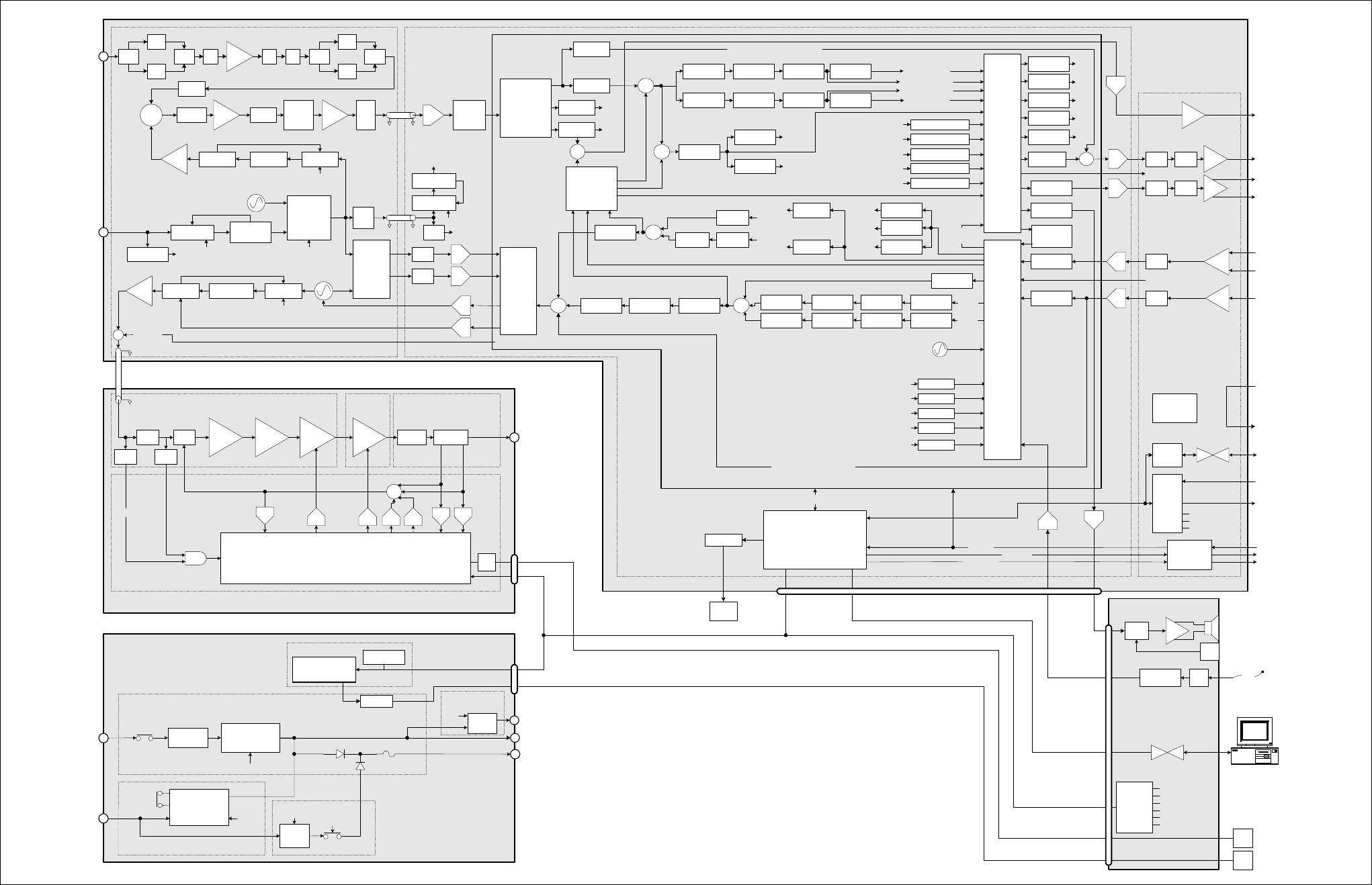
70 Functional Description TB8100 Installation and Operation Manual
© Tait Electronics Limited June 2005
Figure 4.12 TB8100 BSS UHF signal path - L band
RX
Cross
Point
Switch
(CPS)
Balanced
audio
input
Balanced
audio
output
Unbalanced
audio input
Unbalanced
audio output
Decimation
filter
Interpolation
filter
Decimation
filter
Interpolation
filter
Mic.
Test Signal
generator
PIP tones
FFSK
CWID
Selcall
Test tone
OTA
generators
FFSK
Tone remote
Selcall OTL decoders
Unbalanced
Balanced
Line input level
measurements
HPF
HPF
Notch filter
Notch filter
Pre-emphasis
Pre-emphasis
Variable delay
Variable delay
Voice filter
Service Kit
Interpolating
filter
Hard limiterLimiter filter
Voice reject
filter
Interpolating
filter DCS
encoder
CTCSS
encoder
TX sub-band signalling
TX path audio processing
Path A
Variable delay
Variable delay
Mute switch
Mute switch
De-emphasis
De-emphasis
HPF
HPF
CTCSS
decoder
DCS decoder
Voice reject
RX path audio processing
Rx sub-band
signalling
Interpolation
filter
BO audio
measurement
UO audio
measurement
Test signal
sink
Selcall decode
FFSK decode
Voting tones
FFSF
Pip tones
Line out test tone.
Tone remote
Frequency
control
loop
Decimating
filter
Loopback
Cross
Point
Switch
(CPS)
SINAD
processing
Normalisation,
FM Demod,
RSSI & SINAD
measurement
LPF
LPF
Switch
Frequency
control loop
quadrature
mixer +
buffers
Change over
switch
Ex SynthEx Loop filterEx VCO
LPF RF
Amp
RF
Input*
Mixer Diplexer Buffer Pad
70.1MHz
XTAL
filter
IF
Amp
Anti-
alias
filter
Digital
down
converter
(DDC) RSSI,
processing
RX SynthLoop filterRX VCO
Ref VCXO
(12.8MHz)
REF Synth
Ref detect.
Ext.
Ref.
40MHz VCXO
40MHz Synth
To RISC, DSP,
ADC, DDC
100mW
PIN
atten. 1W 6W 60W Harmonic
filter
Directional
coupler
PA
Microprocessor
DAC
LPF
PA_KEY
DAC
AC converter
DC converter
10W
standby
AC
input
DC
input
PA1/PA2 output
40W
Converter
Aux. out (SIF) or
Trickle charger
µP
Standby
Isolate
Reciter output
Rear panel
ON/OFF
µP
µP
µP
Rear
panel
ON/OFF
µP
RF
output
Exciter to
PA RF
Reduced instruction
set computer
(RISC)
ADC
ADC
ADC
DAC
DAC
DAC
DAC
ADC
ADC
TX_KEY
RX_GATE
COAX Relay
I
2
C
I
2
CUART
LPF / Directional
Coupler Board
60W
Board
6W Board
Control Board
50W Power Amplifier
I
2
C current
sources
PMU
micro-
processor
I
2
C
Power factor
correction
Power Management
Unit
System
Control
bus
System
Control
bus
System Control bus
System
Control
bus
System
Interface Board
Digital BoardRF Board
Path B
Buffer 12.8MHz to
CODECs
Host port
RISC
RISC
RISC
RISC
RISC
Digital Signal Processor (DSP)
IF Receiver
front end
Decimating
filter
Reciter
Repeater AC
coupling filter
Line
loopback
Pad
L1 = 781.9-783.9MHz
L1 = 857.9-859.9MHz
L2 = 825.9-831.9MHz
low side
VCXO
Buffer
+ coax
driver
VCO
modulation
VCXO
modulation
12.8MHz
TCXO
TX
Cross
Point
Switch
(CPS)
Micro Card
AC Converter Board
DC Converter Board
ADCADC
DACDAC
Transient
wave shape
RF power
setting
Forward
power
Reverse
power
Bias
Bias
ADC
Power
control
RX_GATE
RISC
RISC
RISC
RISC
RISC
RISC
RISC
RISC
RISC
RISC
RISC
RISC
RISC
RISC
RISC
RISC
RISC
RISC
RISC
RISC
RISC
I
Q
SIO
OTL
encoders
DAC
ADC
Fan
buff.
Fan buffer
PA
fan
PMU
fan
Standby PS card
Auxiliary PS
PCB
RISC
RISC
RISC RISC
RISC
RISC
Buff
EPOT Buff
EPOT Mute
Sw.
Mute
Sw.
Digital audio output
Buff
Buff
EPOT
EPOT
Digital audio input
Digital
inputs
Digital
outputs
RSSI
output
voltage
Power
from PMU
Power to
external
equipment
Buff
Third party
interface
connections
Discrete
Logic
Conventional
signalling
buffers
EPOTs
Mute Switches
SIF ID
Amp
Amp &
Switch
Vol.
Knob
Compressor Amp.
I
2
C port
expanders
Speaker ON/OFF
Fan rotation
Control panel ID
LEDs
Keypad
Mic PTT
Standard
Control Panel
2.5A
polyfuse
Buffer
10 or 12.8MHz
Buffer
General I/O
PA_KEY
DAC
Demodulated
audio
Direct demodulated audio output
Direct modulation audio input
Speaker
SIO to
UART RS-232
converter
Rear
panel
RS-232
TX_KEY
COAX Relay
General I/O
Reciter
fan
Fan buffer
RS-232
converter
HPF
RF
Detect
AND
Path A
Path B
Path A (muted)
Path A (un-muted)
Path B (un-muted)
Path B (muted)
*Frequency Bands & Sub-bands
L1 = 852-854MHz, and 928-930MHz
L2 = 896-902MHz (receive only)
L2 = 927-941MHz (transmit only)
SAW
Filter
SAW
Filter
Switch LPF HPF Switch
SAW
Filter
SAW
Filter
Switch
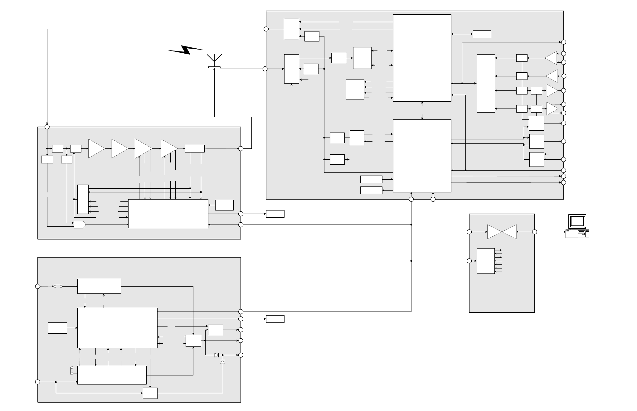
TB8100 Installation and Operation Manual Functional Description 71
© Tait Electronics Limited June 2005
Figure 4.13 TB8100 BSS data, control and monitoring path
100mW 1W 6W 60W Directional
coupler
Power Amplifier
Microprocessor
Bias
AC converter
DC converter
Standby
PS card
AC
input
DC
input
Auxiliary
PS Board
Aux. out (SIF) or
Trickle charger
Reciter
output
Rear panel
ON/OFF
Rear
panel
ON/OFF
RF
output
TB8100 50W Power Amplifier
Power Management Unit
Microprocessor
TB8100 Power
Management Unit
Reverse
power
Forward
power
PA fan
Temperature ON/
OFF
Temperature ON/OFF Input
voltage
Input
current ON/OFF
ON/
OFF
Sum
Output voltage PA1/PA2
output
Hysteresis
ON/OFF
PMU fan
Ambient
temperature
Current
Temperature
Bias
Current
Temperature
Sum
Control voltage
Transient wave
shape
RF power setting
Power control
Ambient
temperature
I
2
C port
expanders
RS232
converter
Speaker ON/OFF
Control panel ID
LEDs
Keypad
Mic PTT
TB8100
Standard
Control Panel
Reduced
Instruction
Set
Computer
(RISC)
Digital
Signal
Processor
(DSP)
Host
port
RF signal
Exciter
External
reference
Power
supply
sub-section
SYS_PWR
PWR_EX
PWR_RX
PWR_GOOD
PA_KEY
Temperature
CODECs
Balanced
audio input
Balanced
audio output
Unbalanced
audio input
Unbalanced
audio output
Buff
EPOT Buff
EPOT Mute
Sw.
Mute
Sw.
Digital audio I/O
Buff
Buff
EPOT
EPOT
Serial
to
parallel
Parallel
to
serial
Digital
outputs
Digital
inputs
SIF_ID
SYNC to
UART
Rear
panel
RS-232
PA fan rotation
PMU fan rotation
Ext REF
Det
Ext REF
Select
I
2
C Protocol
Service Kit
Protocol
Possible Over The Air (OTA) interfaces are:
- OTA Service Kit protocol
- CCDI(1&2) protocol
- Tait High Speed Data
- C4FM
DDCADC
Receiver
Data
Control
Connection types could be:
- Local Service Kit
- Modem to remote Service Kit
- Modem to ISP (E-mail alarms)
- Tait High Speed Data
- CCDI2
I
2
C
peripheral UART
Synchronous
port 1
Synchronous
port 2
MCSPORT 2
Data
bus
MCSPORT 1
Output current
Serial port
(Not used)
MCSPORT 3
Control
panel
RS-232
TX_KEY
TB8100 Reciter
RX_GATE
COAX_RELAY
PIN
atten.
LPF
PA_KEY
HPF
RF
Detect
AND
Reciter Fan
AGC
Noise source
ON /OFF
EX
Synth
RX
Synth
Ref
Synth
40MHz
Synth
40MHz
clock
72 Functional Description TB8100 Installation and Operation Manual
© Tait Electronics Limited June 2005

TB8100 Installation and Operation Manual Installation 73
© Tait Electronics Limited June 2005
5 Installation
This chapter describes how to install the TB8100 BSS in a standard 19 inch
rack or cabinet. It also provides some general information on safety
precautions and site requirements. We recommend that you read the entire
chapter before beginning the installation.
5.1 Personal Safety
5.1.1 Lethal Voltages
Warning!! The PMU contains voltages that may be lethal.
Refer to the ratings label on the rear of the
module.
The TB8100 BSS must be installed so that the rear of the PMU is located
in a service access area. The PMU must be connected to the mains supply
source by trained personnel in accordance with local and national
regulations.
Disconnect the mains IEC connector and wait for five minutes for
the internal voltages to self-discharge before dismantling. The AC
power on/off switch does not isolate the PMU from the mains. It
breaks only the phase circuit, not the neutral.
The PMU should be serviced only by qualified technicians. There are no
user-replaceable parts inside. If the PMU is damaged and does not function
properly, stop the module safely and contact your nearest Tait Dealer or
Customer Service Organisation immediately.
All servicing should be carried out only when the PMU is powered through
a mains isolating transformer of sufficient rating. We strongly
recommend that the mains power to the whole of the repair and test area
is supplied via an earth leakage circuit breaker.
5.1.2 Explosive Environments
Warning!! Do not operate TB8100 BSS equipment near
electrical blasting caps or in an explosive atmos-
phere. Operating the equipment in these envi-
ronments is a definite safety hazard.
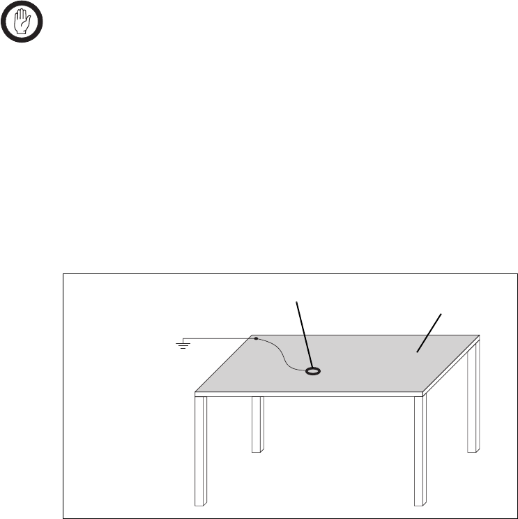
74 Installation TB8100 Installation and Operation Manual
© Tait Electronics Limited June 2005
5.1.3 Proximity to RF Transmissions
Do not operate the transmitter when someone is standing within 90cm (3ft)
of the antenna. Do not operate the transmitter unless you have checked that
all RF connectors are secure.
5.1.4 High Temperatures
Take care when handling a PMU or PA which has been operating recently.
Under extreme operating conditions (+60°C [+140°F] ambient air
temperature) or high duty cycles the external surfaces of the PMU and PA
can reach temperatures of up to +80°C (+176°F).
5.2 Equipment Safety
5.2.1 ESD Precautions
Important This equipment contains devices which are susceptible to
damage from static charges. You must handle these devices
carefully and according to the procedures described in the
manufacturers’ data books.
We recommend you purchase an antistatic bench kit from a reputable
manufacturer and install and test it according to the manufacturer’s
instructions. Figure 5.1 shows a typical antistatic bench set-up.
You can obtain further information on antistatic precautions and the dangers
of electrostatic discharge (ESD) from standards such as ANSI/ESD
S20.20-1999 or BS EN 100015-4 1994.
Figure 5.1 Typical antistatic bench set-up
common point ground
(building ground or
mains ground via 1M
ohm series resistor)
conductive wrist strap dissipative rubber
bench mat

TB8100 Installation and Operation Manual Installation 75
© Tait Electronics Limited June 2005
5.2.2 Antenna Load
Important The PA may be damaged if the load is removed or switched
while the PA is transmitting.
To protect the PA output stage from load transients (i.e. switching or
removing the load), we recommend that you fit an isolator between the PA
and the load. Fit the isolator as close as possible to the RF output connector
on the PA. Do not connect any switching or combining equipment
between the isolator and the PA.
5.2.3 Equipment Grounding
To ensure safe operation the TB8100 BSS equipment must be correctly
grounded as described in these installation instructions.
5.2.4 Installation and Servicing Personnel
The TB8100 BSS should be installed and serviced only by qualified
personnel.
5.3 Regulatory Information
5.3.1 Distress Frequencies
The 406 to 406.1MHz frequency range is reserved worldwide for use by
Distress Beacons. Do not program transmitters to operate in this frequency
range.
5.3.2 FCC Compliance1
This device complies with part 15 of the FCC Rules. Operation is subject
to the condition that this device does not cause harmful interference.
5.3.3 Unauthorised Modifications
Any modifications you make to this equipment which are not authorised by
Tait Electronics Ltd may invalidate your compliance authority’s approval to
operate the equipment.
1. Refer to the TB8100 Specifications Manual for more information on the compliance standards to
which the TB8100 BSS equipment has been tested and approved.

76 Installation TB8100 Installation and Operation Manual
© Tait Electronics Limited June 2005
5.3.4 Health, Safety and Electromagnetic Compatibility in Europe
In the European Community, radio and telecommunications equipment is
regulated by Directive 1999/5/EC, also known as the Radio and
Telecommunications Terminal Equipment (R&TTE) directive. The
requirements of this directive include protection of health and safety of users,
as well as electromagnetic compatibility.
Intended Purpose of
Product This product is an FM radio transceiver. Its intended purpose is for radio
communication in Private Mobile Radio (PMR) services or Public Access
Mobile Radio (PAMR) services.
Important This product can be programmed for frequencies or emis-
sions that may make its use illegal. A license must be
obtained before this product is used. All license require-
ments must be observed. Limitations may apply to trans-
mitter power, operating frequency, channel spacing, and
emission.
Declaration of
Conformity Brief Declarations of Conformity appear on page 143. You can download
the formal Declaration of Conformity from http://eudocs.taitworld.com/.
You can also obtain a signed and dated paper copy of the Declaration of
Conformity from Tait Europe Ltd.
5.4 Environmental Conditions
5.4.1 Operating Temperature Range
The operating temperature range of the TB8100 BSS is –30°C to +60°C
(–22°F to +140°F) ambient temperature. Ambient temperature is defined
as the temperature of the air at the intake to the cooling fans.
5.4.2 Humidity
The humidity should not exceed 95% relative humidity through the
specified operating temperature range.
5.4.3 Dust and Dirt
For uncontrolled environments, the level of airborne particulates must not
exceed 100µg/m3.
TB8100 Installation and Operation Manual Installation 77
© Tait Electronics Limited June 2005
5.5 Grounding and Lightning Protection
5.5.1 Electrical Ground
The TB8100 BSS modules are grounded by physical contact between the
module case and the subrack. To ensure a good ground connection you
must tighten each module retaining clamp securely (refer to “Final
Reassembly” on page 101 for the correct torque).
A threaded grounding connector is provided on the rear of the subrack for
connection to the site ground point (refer to “Connection” on page 103 for
more details).
5.5.2 Lightning Ground
It is extremely important for the security of the site and its equipment that
you take adequate precautions against lightning strike. Because it is outside
the scope of this manual to provide comprehensive information on this
subject, we recommend that you conform to your country’s standards
organisation or regulatory body.
5.6 Recommended Tools
It is beyond the scope of this manual to list every tool that an installation
technician should carry. However, the following tools are specifically
required for installing the TB8100 BSS:
■Pozidriv PZ3 screwdriver for the M6 screws used in the DC input
terminals on the PMU; M6 screws are also used to secure the subrack to
the cabinet in Tait factory-assembled systems
■Pozidriv PZ2 screwdriver for the M4 screws used to secure the module
retaining clamps
■0.25in or 6mm flat blade screwdriver for the fasteners used to secure the
front panel to the subrack
■8mm AF spanner for the SMA connectors.
You can also obtain the TBA0ST2 tool kit from your nearest Tait Dealer or
Customer Service Organisation. It contains the basic tools needed to install,
tune and service the TB8100 BSS.
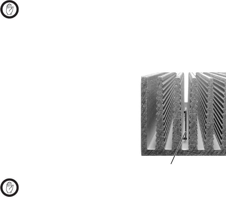
78 Installation TB8100 Installation and Operation Manual
© Tait Electronics Limited June 2005
5.7 Ventilation
Always ensure there is adequate ventilation around the TB8100 BSS. Do
not operate it in a sealed cabinet. You must keep the ambient temperature
within the specified range, and we strongly recommended that you ensure
that the cooling airflow is not restricted.
Important The cooling fans are mounted on the front panel and will
only operate when the panel is fitted correctly to the front
of the subrack. To ensure adequate airflow through the
BSS, do not operate it for more than a few minutes with the
front panel removed (e.g. for servicing purposes).
5.7.1 Ambient Air Temperature Sensor
The ambient air temperature reading
for the TB8100 BSS is provided by
the ambient air temperature sensor
board b fitted to the PA control
board.
The sensor board is inserted through
slots in the control board and heatsink
to be positioned between the heatsink
fins.
Important If the sensor board is to provide accurate ambient tempera-
ture readings, it must have forced airflow and must not
come into contact with the metal of the heatsink fins. Do
not stack PAs with the fins together. It is possible for
the fins on one heatsink to slide between the fins on the
other heatsink. This can damage the sensor board, and pos-
sibly result in the heatsink fins becoming locked together.
5.7.2 Cabinet and Rack Ventilation
Refer to Figure 5.2 on page 79.
The cooling airflow for the TB8100 BSS enters through the front panel and
exits at the rear of the subrack. For optimum thermal performance, the
heated air that has passed through a BSS must not be allowed to re-enter the
air intakes on the front panel. Any space at the front of the cabinet not
occupied by equipment should be covered by a blanking panel.
b
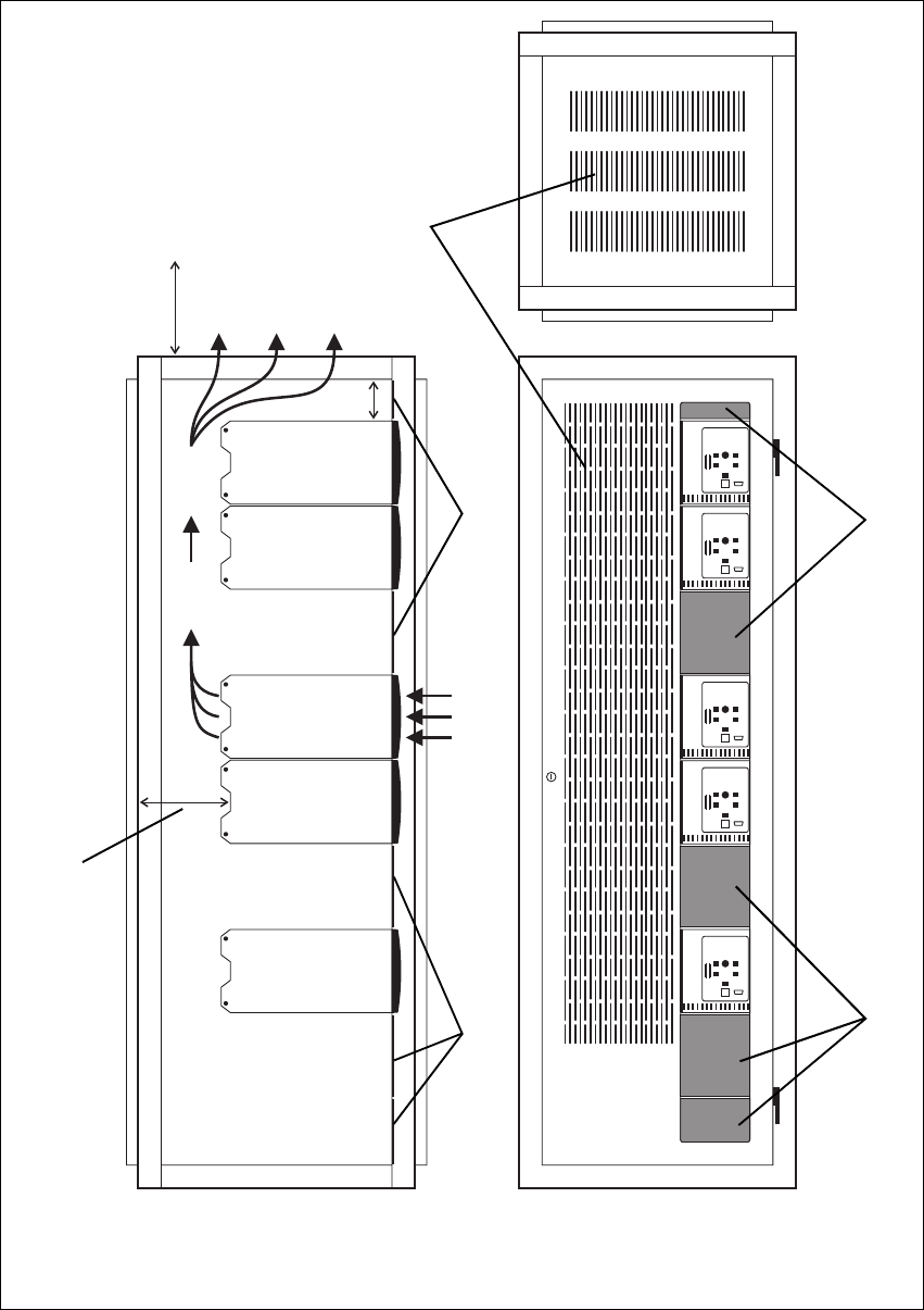
TB8100 Installation and Operation Manual Installation 79
© Tait Electronics Limited June 2005
Figure 5.2 Typical cabinet ventilation requirements
bventilation slots dairflow entry
cblanking panels eairflow exit
20cm
(8in)
2U
≥17.5cm
(≥7in)
side view front view
top view
c
c
d
e
b
c
c

80 Installation TB8100 Installation and Operation Manual
© Tait Electronics Limited June 2005
To allow enough cooling airflow through a cabinet-mounted BSS, we
recommend the following:
■an area of at least 150cm2 (23in2) of unrestricted ventilation slots or holes
in front of the air intakes for the fans for each subrack; for example,
thirty 6x85mm (0.25x3.3in) slots will allow the recommended airflow
■a vent in the top of the cabinet with an area of approximately 150cm2
(23in2) per subrack, or a similar area of ventilation per subrack at the rear
of the cabinet behind each subrack
■a 2U gap at the top of the cabinet.
Note The ventilation opening must be unrestricted. If the slots or holes
are covered with a filter, mesh or grille, the open area must be
increased to allow the same airflow as an unrestricted opening.
The maximum ambient temperature entering the cabinet must not exceed
+60°C (+140°F).
If the TB8100 BSS is installed in a rack or cabinet with other equipment
with different ventilation requirements, we recommend that the TB8100 be
positioned below this equipment.
Auxiliary Extractor
Fans The TB8100 BSS does not require auxiliary extractor fans mounted in the
top of the cabinet. If your cabinet is already fitted with fans, the following
procedures apply:
■if there are six or more 120mm (4.75in) fans, each capable of extracting
160m3 per hour (94.2CFM), they must run continuously
■if there are fewer than six fans, you must remove them and ensure the
vent in the top of the cabinet has an area of approximately 150cm2
(23in2) per subrack.
If you have any other configuration, the performance of your system will
depend on how closely you comply with the TB8100 BSS airflow
requirements described above.
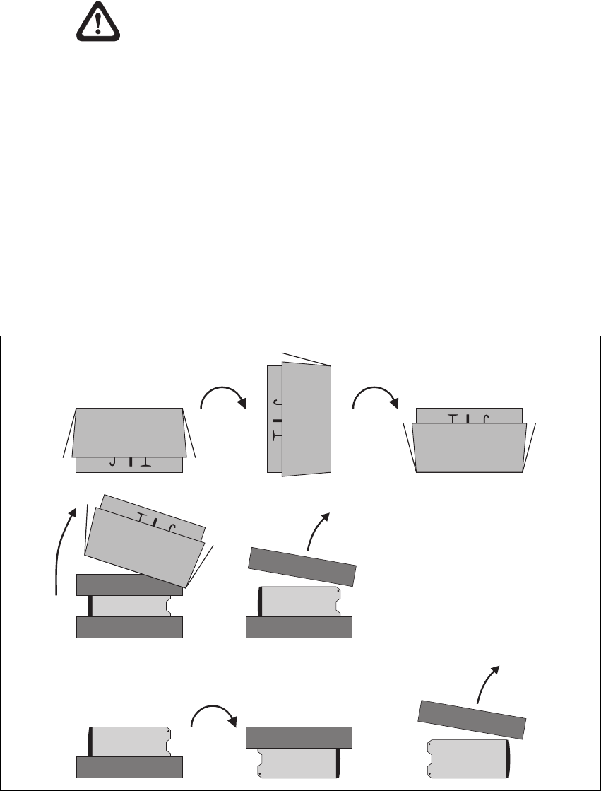
TB8100 Installation and Operation Manual Installation 81
© Tait Electronics Limited June 2005
5.8 Installing the Base Station System
Caution A TB8100 subrack complete with modules can
weigh up to 28kg (62lb), or up to 30kg (66lb) com-
plete with packaging. We recommend that, once
the equipment is out of the carton, you remove the
modules from the subrack before moving the equip-
ment again. Otherwise, have another person help
you with the lifting. In all cases follow safe lifting
practices.
5.8.1 Unpacking the Equipment
Unpacking the
TB8100 BSS The TB8100 BSS is packed in a strong corrugated cardboard carton with
top and bottom foam cushions. To prevent personal injury and damage to
the equipment, we recommend that two people unpack the BSS.
1. Cut the tape securing the flaps at the top of the carton and fold them
flat against the sides b.
2. Rotate the carton carefully onto its side c and then onto its top d,
ensuring that none of the flaps is trapped underneath.
Figure 5.3 Unpacking the TB8100 BSS
b
e
g
f
hi
cd
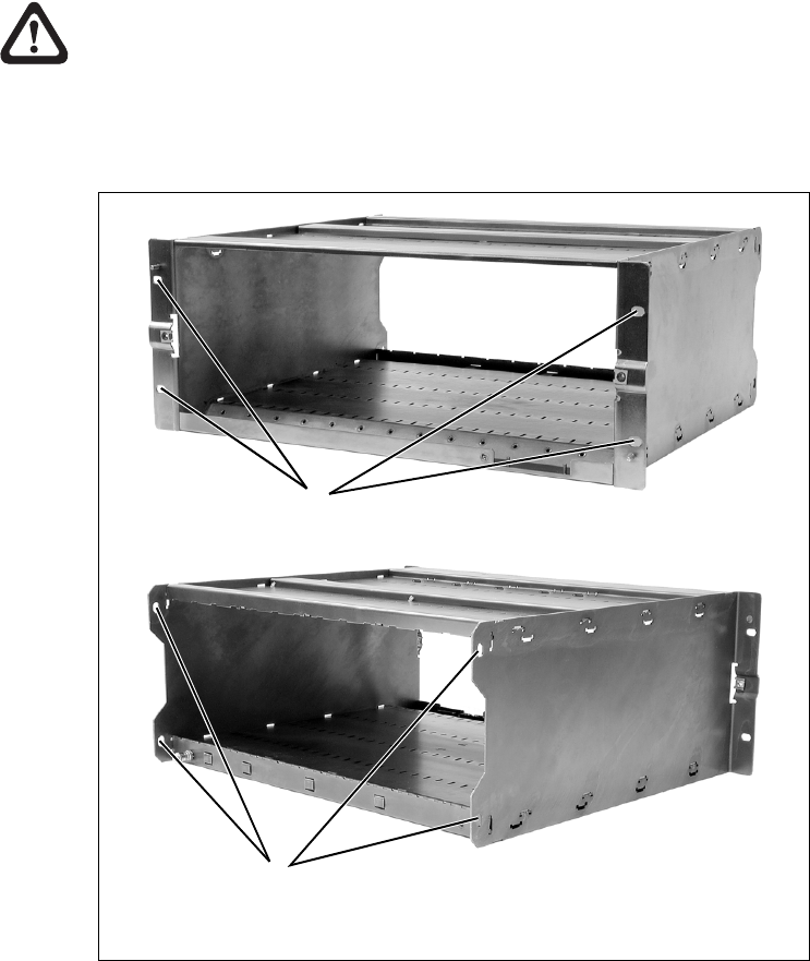
82 Installation TB8100 Installation and Operation Manual
© Tait Electronics Limited June 2005
3. Slide the carton upwards over the foam cushions and lift it away e.
Remove the cushion from the bottom of the BSS f.
4. Rotate the BSS and cushion carefully over the rear of the BSS g so
that the BSS is the right way up with the cushion on top h. Remove
the cushion from the top of the BSS i.
Disposal of
Packaging If you do not need to keep the packaging, we recommend that you recycle
it according to your local recycling methods. The foam cushions are CFC-
and HCFC-free and may be burnt in a suitable waste-to-energy combustion
facility, or compacted in landfill.
5.8.2 Mounting the Subrack
Caution We recommend that you remove the modules from
the subrack before lifting it (refer to “Replacing
Modules” on page 87), or have another person help
you with the lifting.
Figure 5.4 Subrack mounting points
bmain mounting holes - front cauxiliary mounting holes - rear
front view
rear view
b
c
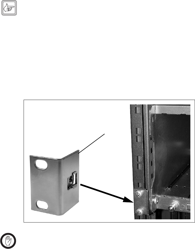
TB8100 Installation and Operation Manual Installation 83
© Tait Electronics Limited June 2005
1. Remove the front panel, as described in “Preliminary Disassembly”
on page 88.
2. Fit the subrack into the cabinet or rack and secure it firmly with an
M6 (or 0.25in if you are using imperial fittings) screw, flat and spring
washer in each of the four main mounting holes b, as shown in
Figure 5.4 on page 82.
Note If you need extra mounting security, there are additional mount-
ing holes c provided at the rear of the subrack for auxiliary sup-
port brackets.
5.8.3 Auxiliary Support Bracket
TBA2140 auxiliary support brackets can be fitted to the rear of the TB8100
subrack to provide additional mounting security. Figure 5.5 below shows a
standard TBA2140 bracket b fitted in a typical Tait Electronics cabinet c.
If you are not using a Tait cabinet, you may have to make your own brackets
to suit your installation.
Important You must fit the auxiliary support brackets if you intend to
transport a cabinet fitted with a fully built-up TB8100 BSS.
We also recommend that you fit the brackets under the following
conditions:
■when the installation is in an area prone to earthquakes
■when third party equipment is installed hard up underneath the TB8100
BSS subrack.
Figure 5.5 Auxiliary support bracket
c
b
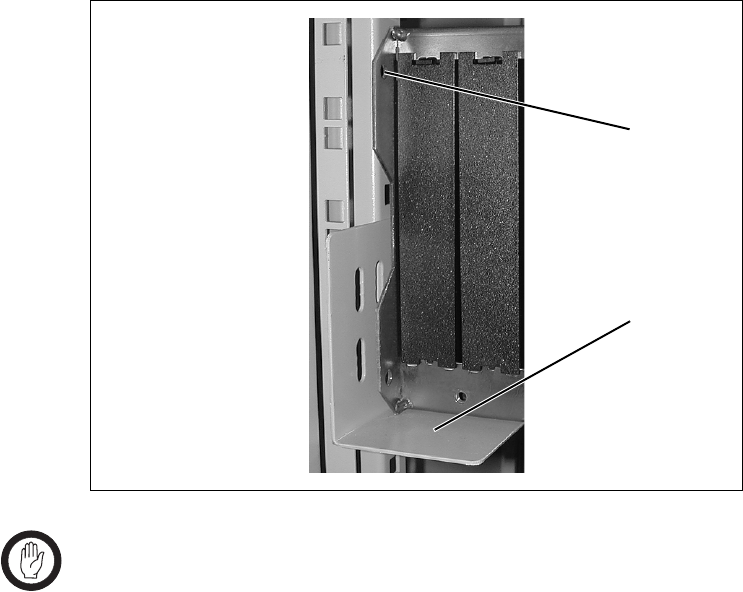
84 Installation TB8100 Installation and Operation Manual
© Tait Electronics Limited June 2005
5.8.4 Optional Slide Mounting Rails
You can also use TBA2141 slide mounting rails b when mounting the
TB8100 BSS in a cabinet, as shown in Figure 5.6 below. These rails will
support the BSS while you slide it into the cabinet.
However, you must still secure the BSS to the cabinet with four M6 (0.25in)
screws through the main mounting holes on the front of the subrack, as
shown in Figure 5.4 on page 82.
Important The slide mounting rails are not suitable for transporting a
cabinet fitted with a fully built-up TB8100 BSS. In this
case, you must also fit the TBA2140 auxiliary support
brackets to the upper set of rear mounting holes c.
5.8.5 Cabling
General We recommend that you try to route all cables to and from the TB8100 BSS
along the side of the cabinet so the cooling airflow is not restricted.
DC Power Cabling DC power cables should be well supported so that the terminals on the
PMU and on the ends of the cables do not have to support the full weight
of the cables.
Figure 5.6 Optional slide mounting rail - rear view
b
c
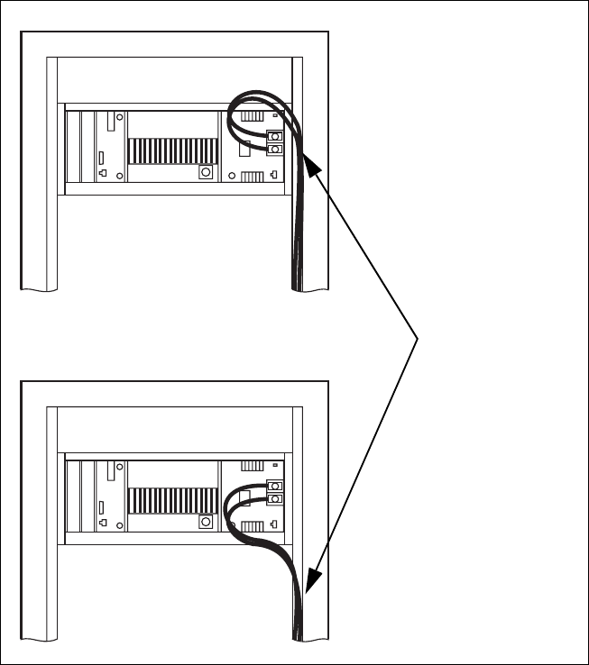
86 Installation TB8100 Installation and Operation Manual
© Tait Electronics Limited June 2005

TB8100 Installation and Operation Manual Replacing Modules 87
© Tait Electronics Limited June 2005
6 Replacing Modules
Caution The TB8100 PA and PMU weigh between 4.6kg
(10.1lb) and 5.8kg (12.8lb) each. Take care when
handling these modules to avoid personal injury.
Important The cooling fans are mounted on the front panel and will
only operate when the panel is fitted correctly to the front
of the subrack. To ensure adequate airflow through the base
station, do not operate it for more than a few minutes with
the front panel removed (e.g. for servicing purposes). Both
the PMU and PA modules have built-in protection mech-
anisms to prevent damage from overheating.
6.1 Saving the Base Station’s Configuration
Before replacing a module in the TB8100 BSS, you should decide whether
you need to save its configuration data. If you are unsure whether you have
a record of the configuration, use the Service Kit to read the base station and
save the configuration file before removing any modules. Once you have
replaced the module, you will be able to restore the original configuration
by programming the saved configuration back into the base station. If one
or more of the modules is faulty, you may be unable to read the base station.
In this case, you will have to restore the configuration from a back-up file.
Refer to the Service Kit and its associated documentation for more
information.
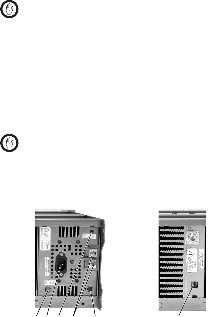
88 Replacing Modules TB8100 Installation and Operation Manual
© Tait Electronics Limited June 2005
6.2 Preliminary Disassembly
Hot-pluggable
Modules The reciter, PA and control panel are hot-pluggable and can be removed
from the TB8100 BSS without powering down the whole BSS. These
modules can also be removed without disrupting the system control bus
communications with the other modules in the BSS.
Important In base station systems which use a PMU, the PMU must
be connected to the system control bus at all times. The
I2C current source is located in the PMU, and if the PMU
is disconnected, the state of much of the bus will be unde-
fined. This may cause corrupted data to be present on the
bus when the reciter reads the states of the switches on the
control panel. This in turn may result in random actuations
of microphone PTT, carrier, or speaker key, causing the
BSS to transmit or the speaker to be actuated incorrectly.
In a dual base station system, you can remove the reciter and/or PA from
one base station without disrupting the operation of the other base station.
If you want to disconnect the power before working on the BSS, carry out
the instructions in “Disconnect the Power” below.
Important Before removing a PA, disconnect the DC input and RF
input first, followed by the RF output (and DC output on
the 12V PA). After refitting the PA, reconnect the RF
output (and DC output on the 12V PA) first, followed by
the RF input, and then the DC input.
Disconnect the
Power 1. Turn off the AC b and DC c switches at the rear of the PMU.
bcdef g
PMU 12V PA
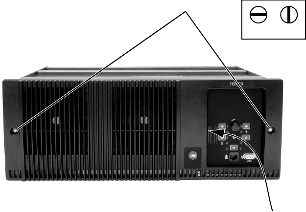
TB8100 Installation and Operation Manual Replacing Modules 89
© Tait Electronics Limited June 2005
2. Also at the rear of the PMU disconnect the mains d and battery e
supply leads, and the auxiliary DC supply lead f (if fitted).
3. If the base station is using a 12V PA, disconnect the battery supply
lead g.
Remove the Front
Panel 1. Undo the fastener at each end of the front panel b with a quarter
turn anti-clockwise.
2. While supporting the left end of the front panel, place your fingers in
the recess provided on the left side of the control panel opening c
and pull the right end of the front panel away from the subrack. You
will need to overcome the resistance of the spring clip securing the
front panel to the control panel.
6.3 Replacing the Control Panel
Removal 1. If you have not already done so, carry out the instructions in
“Preliminary Disassembly” on page 88.
2. Undo the retaining screw b. Note that the screw stays attached to
the control panel.
3. Pull the bottom of the control panel away from the subrack c to
disconnect the D-range socket on the back of the panel from the plug
d on the subrack.
4. Pull the control panel down e to disengage the centre tab f from
the subrack.
b
lockedunlocked
c
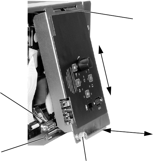
90 Replacing Modules TB8100 Installation and Operation Manual
© Tait Electronics Limited June 2005
Refitting 1. Fit the top of the control panel to the subrack so that the centre tab
is behind the lip of the subrack and between the two locating tabs
formed in the lip. Push the control panel firmly upwards g.
2. Align the D-range socket on the back of the control panel with the
plug on the subrack. Gently push the bottom of the panel home
against the subrack h to engage the plug into the socket.
3. Insert the securing screw into the floating nut i in the subrack and
tighten. Note that you may have to push the screw in and down to
pick up the floating nut.
4. Carry out the instructions in “Final Reassembly” on page 101.
6.4 Replacing the Reciter
Removal 1. If you have not already done so, carry out the instructions in
“Preliminary Disassembly” on page 88, and remove the control
panel, as described in “Replacing the Control Panel” on page 89.
2. At the rear of the reciter, unplug the RF input cable b, any system
cables c and the external reference cable d (if fitted).
b
de
f
g
c
h
i
standard control panel shown
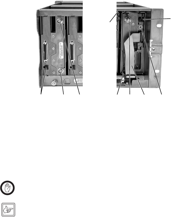
TB8100 Installation and Operation Manual Replacing Modules 91
© Tait Electronics Limited June 2005
3. At the front of the reciter, unplug the DC input cable e and the RF
output cable f, and move both cables to one side. Unplug both ends
of the system control bus g and remove it.
4. Loosen the screw securing the retaining clamp h and rotate the
clamp through 90° to clear the module.
5. Slide the reciter out of the subrack, taking care not to damage any of
the cables.
Refitting 1. Slide the replacement reciter into the subrack and secure it with the
retaining clamp. Ensure that you set its hex switch i to the same
number as the original reciter.
2. Reconnect all the front and rear panel cables previously disconnected.
Ensure the front panel cables are retained by the cable retaining clips
j in the top of the subrack.
Important Do not force the system control bus behind the reciter
handle as this may damage the ribbon cable.
Note If you need to remove any front panel cables, simply pull the front
of the cable retaining clip down and then slide it out from the sub-
rack until it reaches the end of its travel.
3. Tighten the nut on the SMA connector to a torque of 0.9Nm
(8lbf·in).
4. Refit the control panel, as described in “Replacing the Control
Panel” on page 89.
5. Carry out the instructions in “Final Reassembly” on page 101.
bcd igfh
e
j
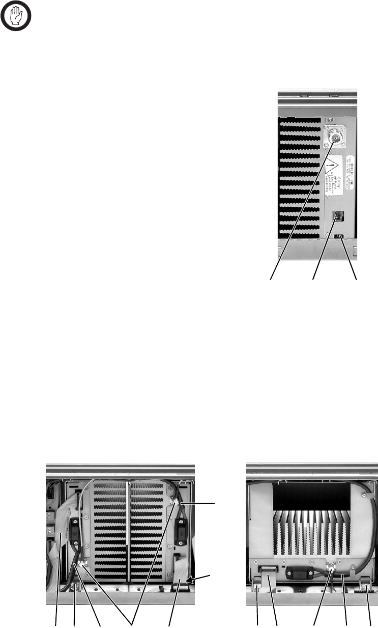
92 Replacing Modules TB8100 Installation and Operation Manual
© Tait Electronics Limited June 2005
6.5 Replacing the Power Amplifier
Important Before removing a PA, disconnect the DC input and RF
input first, followed by the RF output (and DC output on
the 12V PA). After refitting the PA, reconnect the RF
output (and DC output on the 12V PA) first, followed by
the RF input, and then the DC input.
Removal 1. If you have not already done so, carry
out the instructions in “Preliminary
Disassembly” on page 88. If
necessary, remove the control panel,
as described in “Replacing the
Control Panel” on page 89.
2. At the rear of the PA, unplug the RF
output cable b. 12V PA only: also
unplug the battery supply lead c,
and Power Saving control cable d
(if fitted).
3. At the front of the PA, unplug the DC input cable (DC output cable
on the 12V PA) b and the RF input cable c, and move both cables
to one side. Unplug both ends of the system control bus d and
remove it.
4. Loosen the screw securing the retaining clamp(s) e and rotate the
clamp(s) through 90° to clear the module.
5. Slide the PA out of the subrack, taking care not to damage any of the
cables.
cdb
bed
cb
b
ddec
e
e
(obscured)
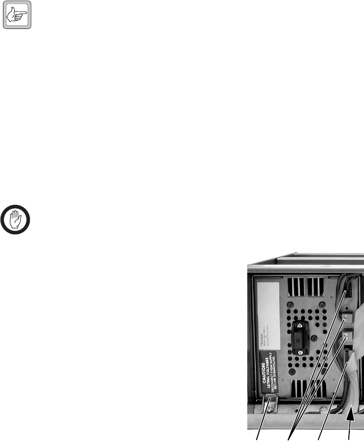
TB8100 Installation and Operation Manual Replacing Modules 93
© Tait Electronics Limited June 2005
Refitting 1. Slide the replacement PA into the subrack and secure it with the
retaining clamp(s).
2. Reconnect all the front and rear panel cables previously disconnected.
Ensure the front panel cables are retained by the cable retaining clips
in the top of the subrack.
Note If you need to remove any front panel cables, simply pull the front
of the cable retaining clip down and then slide it out from the sub-
rack until it reaches the end of its travel.
3. Tighten the nut on the SMA connector to a torque of 0.9Nm
(8lbf·in).
4. If necessary, refit the control panel, as described in “Replacing the
Control Panel” on page 89.
5. Carry out the instructions in “Final Reassembly” on page 101.
6.6 Replacing the Power Management Unit
Important You must disconnect the AC and DC power cables before
removing the PMU from the subrack.
Removal 1. If you have not already done so, carry
out the instructions in “Preliminary
Disassembly” on page 88.
2. At the front of the PMU, unplug the
output power cable(s) b and system
control bus c, and move them to
one side.
3. Loosen the screw securing the
retaining clamps d and rotate the
clamps through 90° to clear the
module.
4. Slide the PMU out of the subrack,
taking care not to damage any of the
cables.
Refitting 1. Slide the replacement PMU into the subrack and secure it with the
retaining clamps.
2. Reconnect all the front and rear panel cables previously disconnected.
Connect the DC power cables on the rear panel as shown in
Figure 5.7 on page 85. Ensure the front panel cables are retained by
the cable retaining clips in the top of the subrack.
dbcd
(obscured)

94 Replacing Modules TB8100 Installation and Operation Manual
© Tait Electronics Limited June 2005
Note If you need to remove any front panel cables, simply pull the front
of the cable retaining clip down and then slide it out from the sub-
rack until it reaches the end of its travel.
3. Carry out the instructions in “Final Reassembly” on page 101.
6.7 Replacing the Front Panel Fans
Unless otherwise indicated, the following instructions refer to Figure 6.1 on
page 96.
Removal 1. If you have not already done so, carry out the instructions in
“Preliminary Disassembly” on page 88.
2. PA Fan
a. Remove the four screws labelled b and remove the duct and fan
assembly from the front panel.
b. Unplug the fan from the fan contact board c.
c. Remove the fours screws holding the fan into the duct d and
remove the fan.
3. PMU Fan
a. Remove the PA fan/duct assembly as described above.
b. Remove the two screws labelled e and remove the PMU fan/
duct assembly.
c. Unplug the fan from the fan contact board f.
d. Remove the fours screws holding the fan into the duct g and
remove the fan.
Refitting 1. Fit the replacement fan into the duct with the power wires located in
the slot in the side of the duct h.
2. Refit the four screws securing the fan into the duct. Do not
overtighten these screws or you will distort the fan body.
3. PMU Fan
a. Refit the PMU fan/duct assembly onto its mounting bosses. Note
that the two inner mounting tabs i fit over the bosses.
b. Plug the fan into the fan contact board f and route the wires
around the PA fan opening j.
c. Refit the two screws labelled e.
d. Refit the PA fan as described below.

TB8100 Installation and Operation Manual Replacing Modules 95
© Tait Electronics Limited June 2005
4. PA Fan
a. Plug the power wires into the fan contact board c and route the
wires around the PA fan opening j.
b. Refit the PA fan/duct assembly onto its mounting bosses. Note
that the two inner mounting tabs 1) fit over the inner tabs of the
PMU fan. Ensure that all the power wires are secured under the
retaining hooks 1! and are not crimped.
c. Refit the fours screws labelled b.
5. Carry out the instructions in “Final Reassembly” on page 101.
Important You must connect the fans to the correct sockets on the fan
contact board. If the fan connections are reversed, the
wrong fan will be activated when a module needs cooling.
The module may then fold back and shut down. When you
power-up the TB8100 BSS, check that the PMU fan runs
first, followed by the PA fan. Each fan will run for about
five seconds.
Important You must refit the correct duct to the PA fan. There are
several small but important differences between the duct for
a 5W or 50W PA and the duct for a 100W PA. Refer to
Figure 6.3 on page 101 for more details.
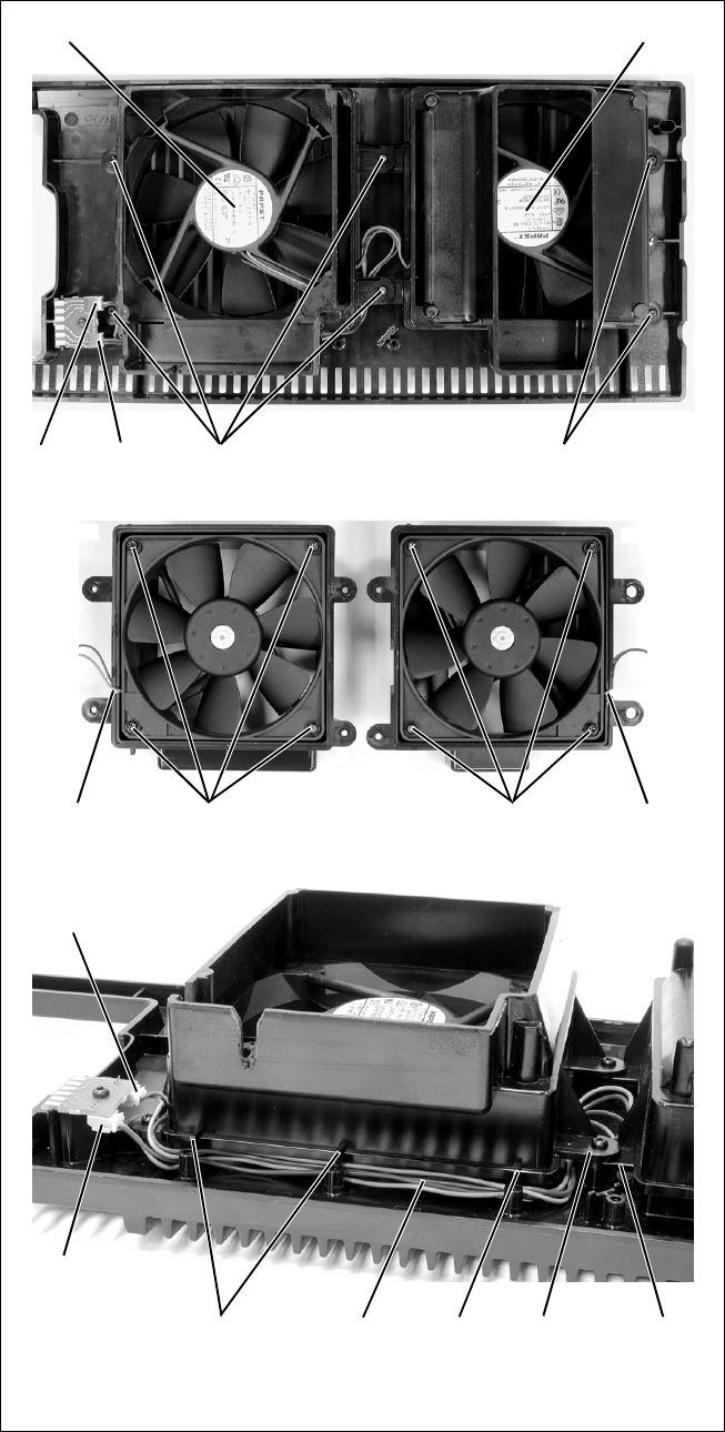
96 Replacing Modules TB8100 Installation and Operation Manual
© Tait Electronics Limited June 2005
Figure 6.1 Replacing the front panel fans
bc
d
e
f
hhg
ij1)1!
1!
PA fan PMU fan
PA fan PMU fan
PA fan connector
PMU fan connector
100W base station front panel shown
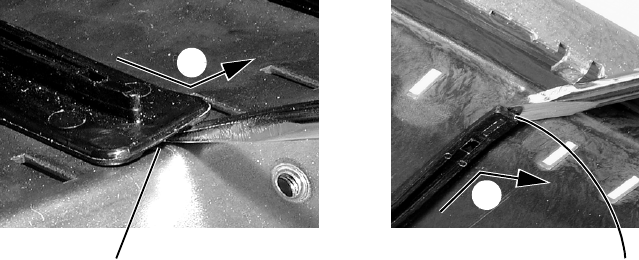
TB8100 Installation and Operation Manual Replacing Modules 97
© Tait Electronics Limited June 2005
6.8 Replacing the Module Guide Rails
The module guide rails are held in place by four hooks that fit through the
slots in the top and bottom of the subrack. There is also a locking tab which
prevents the guide rails from working loose.
Removal 1. Bottom Guide Rails
a. Insert a small flat-blade screwdriver under the front end of the
guide rail and lift it slightly b. This will ensure the small locking
tab is clear of the slot in the subrack.
b. Whilst holding the front end of the guide rail up, pull the guide
rail towards the front of the subrack c and lift it clear of the slots.
2. Top Rails
a. Insert a small flat-blade screwdriver under the rear end of the
guide rail and lift it slightly d. This will ensure the small locking
tab is clear of the slot in the subrack.
b. Whilst holding the rear end of the guide rail up, pull the guide rail
towards the rear of the subrack e and lift it clear of the slots.
Refitting 1. Bottom Guide Rails
a. With the locating hooks pointing towards the rear of the subrack,
insert the hooks into the slots in the subrack.
b. Push the guide rail towards the rear of the subrack until you hear
the locking tab “click” into place.
2. Top Guide Rails
a. With the locating hooks pointing towards the front of the subrack,
insert the hooks into the slots in the subrack.
b. Push the guide rail towards the front of the subrack until you hear
the locking tab “click” into place.
bottom guide rail top guide rail
b
c
d
e

98 Replacing Modules TB8100 Installation and Operation Manual
© Tait Electronics Limited June 2005
6.9 Replacing the Subrack Interconnect Board
There are two types of subrack interconnect board available, as described in
the following table.
Figure 6.2 on page 99 shows the two types of board, and “Switch Settings”
on page 100 explains the settings for the switches on the dual base station
board.
Removal 1. If you have not already done so, carry out the instructions in
“Preliminary Disassembly” on page 88, and remove the control
panel, as described in “Replacing the Control Panel” on page 89.
2. Disconnect any system control bus cables.
3. Remove the M3 nuts and spring washers b securing the
interconnect board to the subrack, as shown in Figure 6.2.
4. Remove the board. If you are changing the type of board, also
remove the insulator c.
Refitting 1. If previously removed, replace the insulator. If you are changing the
type of board, you must fit the matching insulator.
2. Refit the board and secure with the M3 nuts and spring washers.
3. If you have fitted a dual base station interconnect board, set the
switches of S1 d as described in “Switch Settings” on page 100.
4. Reconnect the system control bus cables as shown in Figure 6.2.
Note The system control bus connections shown in Figure 6.2 apply to
all single and dual base station systems.
Interconnect Board Description
single base station for single base stations with PMU
dual base station ■for dual base stations with PMU
■for single and dual base stations with 12V PA
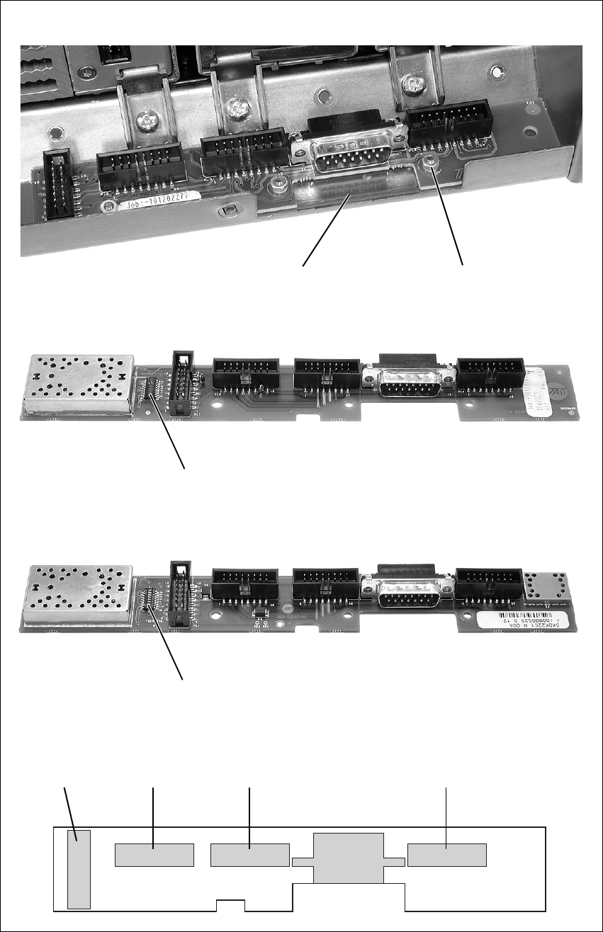
TB8100 Installation and Operation Manual Replacing Modules 99
© Tait Electronics Limited June 2005
Figure 6.2 Replacing the subrack interconnect board
bc x3
single base station
dual base station - IPN 220-02037-02
d
dual base station - IPN 220-02037-04 and later
d
reciter 2reciter 1
PA 2
PA 1/PMU
system control bus connections

100 Replacing Modules TB8100 Installation and Operation Manual
© Tait Electronics Limited June 2005
Switch Settings You must set the switches on the dual base station interconnect board
correctly. The switch settings depend on the type of base station(s) installed
in the subrack, and on the part number (IPN) of the board itself.
Table 6.1 gives the switch settings for older boards with the part number
220-02037-02. This board can only be used with dual base stations using a
PMU.
Table 6.2 gives the switch settings for newer boards with the part number
220-02037-04 and later. These boards can be used with dual base stations
using a PMU, and with single or dual 12V PA base stations.
Table 6.1 Switch S1 settings - IPN 220-02037-02
Switch Function
Dual Base Station
with PMU
State
1CH1 select button active on
2CH2 select button active on
3independent CH1 and CH2 channels Tait use only - leave on
4channel 2 I2C_CLK pullup on
5channel 2 I2C_DATA pullup on
6unused off
7grounded CAN off
8connected CH1 and CH2 channels Tait use only - leave off
Table 6.2 Switch S1 settings - IPN 220-02037-04 and later
Switch Function
Dual Base Station
with PMU
Single or Dual Base
Station with 12V PA
State State
1CH1 select button active on single - off
dual - on
2CH2 select button active on single - off
dual - on
3independent CH1 and CH2 channels Tait use only - leave on Tait use only - leave on
4channel 1 I2C_CLK pullup off on
5channel 1 I2C_DATA pullup off on
6channel 2 I2C_CLK pullup on on
7channel 2 I2C_DATA pullup on on
8connected CH1 and CH2 channels Tait use only - leave off Tait use only - leave off
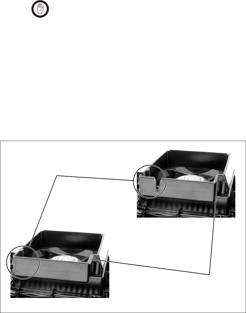
TB8100 Installation and Operation Manual Replacing Modules 101
© Tait Electronics Limited June 2005
6.10 Final Reassembly
Important You must refit the correct type of front panel to your
TB8100 BSS. There are several small but important differ-
ences between the front panel for a 5W or 50W BSS and
the front panel for a 100W BSS. These differences are in
the duct for the PA fan and are described in the following
paragraphs.
5W or 50W Front
Panel The PA fan duct does not have the cut-outs b required for the 100W PA
RF and DC cables. The break-off tab c will also still be present and will
jam on the system control bus. Do not try to fit this front panel to a 100W
BSS or you will damage these cables and possibly the front panel itself.
100W Front Panel Do not fit this front panel to a 5W or 50W BSS. The presence of the cut-
outs and absence of the break-off tab will allow air to escape and reduce the
velocity of air directed through the heatsink.
Figure 6.3 Identifying the correct front panel
b
c
100W front panel:
the PA fan duct has cut-outs
but no break-off tab
5W or 50W front panel:
the PA fan duct has the break-
off tab but no cut-outs
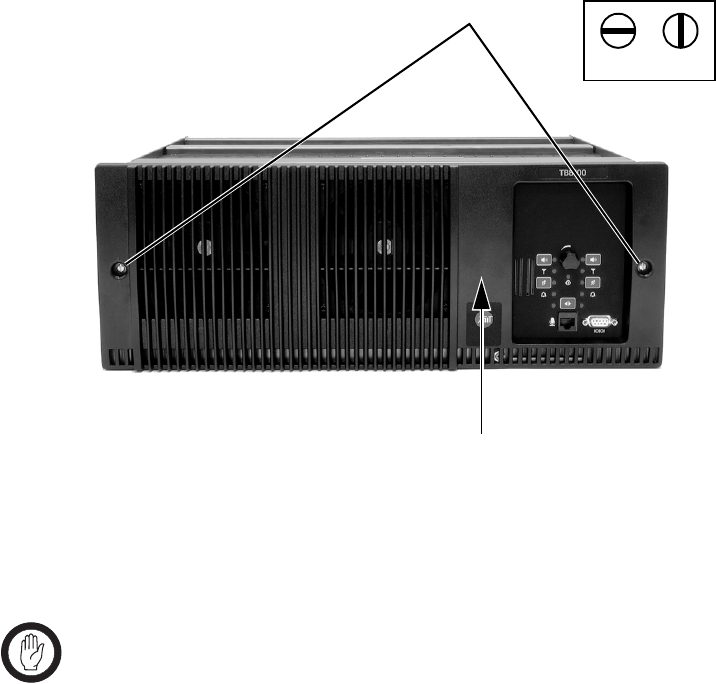
102 Replacing Modules TB8100 Installation and Operation Manual
© Tait Electronics Limited June 2005
1. Before fitting the front panel, ensure that all cables are secured and
positioned correctly so they are clear of the fan ducts (refer to
Figure 7.1 on page 104 and Figure 7.3 on page 106). Otherwise the
panel may not fit properly, or you may damage the cables.
2. Refit the Front Panel
a. Fit the front panel onto the locating pegs on the subrack Fit the
left end first, followed by the right end, pressing the panel in the
centre as shown b to secure the spring clip behind the control
panel.
b. Secure the fastener at each end c with a quarter turn clockwise.
Align the slot horizontally, then press the fastener in and turn to
lock.
3. Before powering up the base station, check that all power, RF and
system cables are connected correctly and securely at the rear of the
base station.
Important When refitting modules, make sure they are fitted correctly
into the subrack and all retaining clamps are securely tight-
ened. The recommended torque for the retaining clamp
screws is 1.9Nm (17lbf·in). As well as holding the modules
in place, the retaining clamps push the modules hard against
the rear rail of the subrack to ensure a good ground connec-
tion between the modules and subrack.
c
lockedunlocked
b

TB8100 Installation and Operation Manual Connection 103
© Tait Electronics Limited June 2005
7 Connection
Once the TB8100 BSS hardware is installed, you need to connect the
individual modules to each other, and to any ancillary equipment required
in your system. This chapter provides information on all the inputs and
outputs available on the TB8100 BSS.
7.1 Overview of Inputs and Outputs
This section identifies the main input and output connections for the
TB8100 BSS.
■Figure 7.1 on page 104 identifies the connections at the front of a dual
base station, and Figure 7.4 on page 107 identifies those at the rear.
■Figure 7.2 on page 105 identifies the connections at the front of a dual
12V PA base station, and Figure 7.5 on page 108 identifies those at the
rear.
■Figure 7.3 on page 106 identifies the connections at the front of a single
100W base station.
■Figure 7.6 on page 108, and Figure 7.7 and Figure 7.8 on page 109
identify the connections on the standard, dual base station, and Power
Save control panels.
Refer to the following sections in this chapter for more details on these
connections.
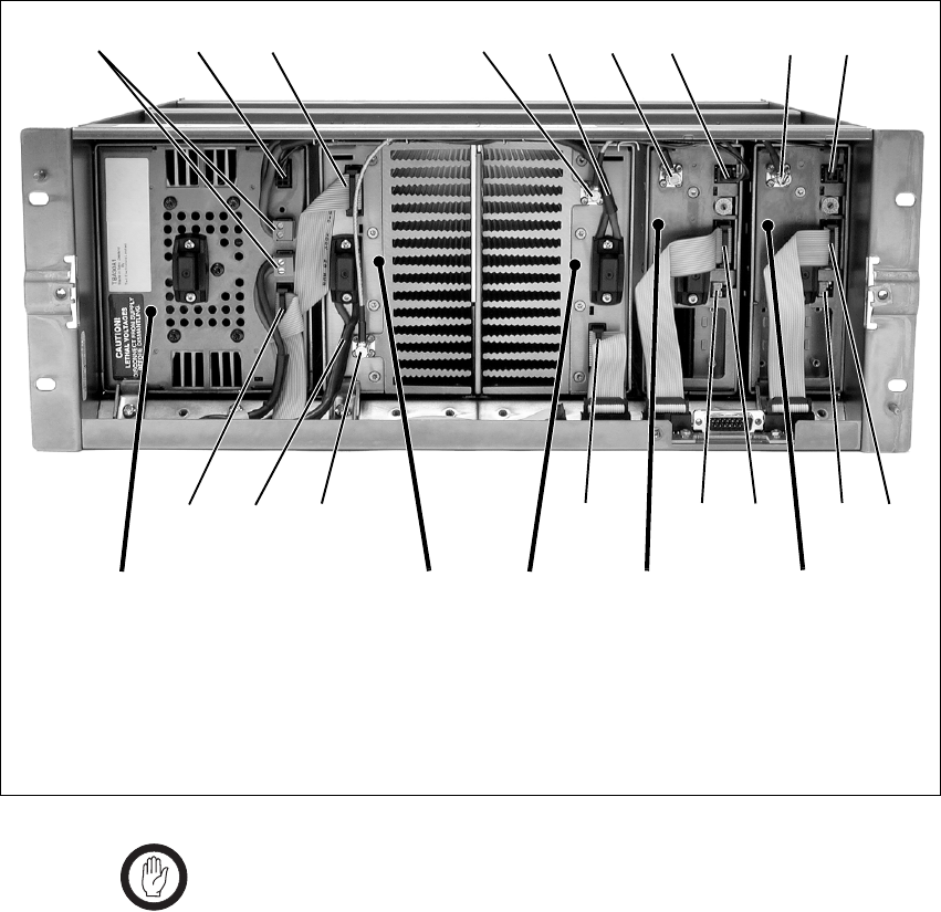
104 Connection TB8100 Installation and Operation Manual
© Tait Electronics Limited June 2005
Important In base station systems which use a PMU, the PMU must
be connected to the system control bus at all times. The
I2C current source is located in the PMU, and if the PMU
is disconnected, the state of much of the bus will be unde-
fined. This may cause corrupted data to be present on the
bus when the reciter reads the states of the switches on the
control panel. This in turn may result in random actuations
of microphone PTT, carrier, or speaker key, causing the
BSS to transmit or the speaker to be actuated incorrectly.
Figure 7.1 Dual 5W or 50W base station inputs and outputs - front view
b28VDC high current output for PA f28VDC high current input cable from PMU
c28VDC low current output for reciter gRF output to PA
dsystem control bus h28VDC low current input from PMU
eRF input from reciter iDC output (for optional reciter fan only)
bcd e ghfgh
ddidiefd
PA 1 PA 2 reciter 2PMU reciter 1
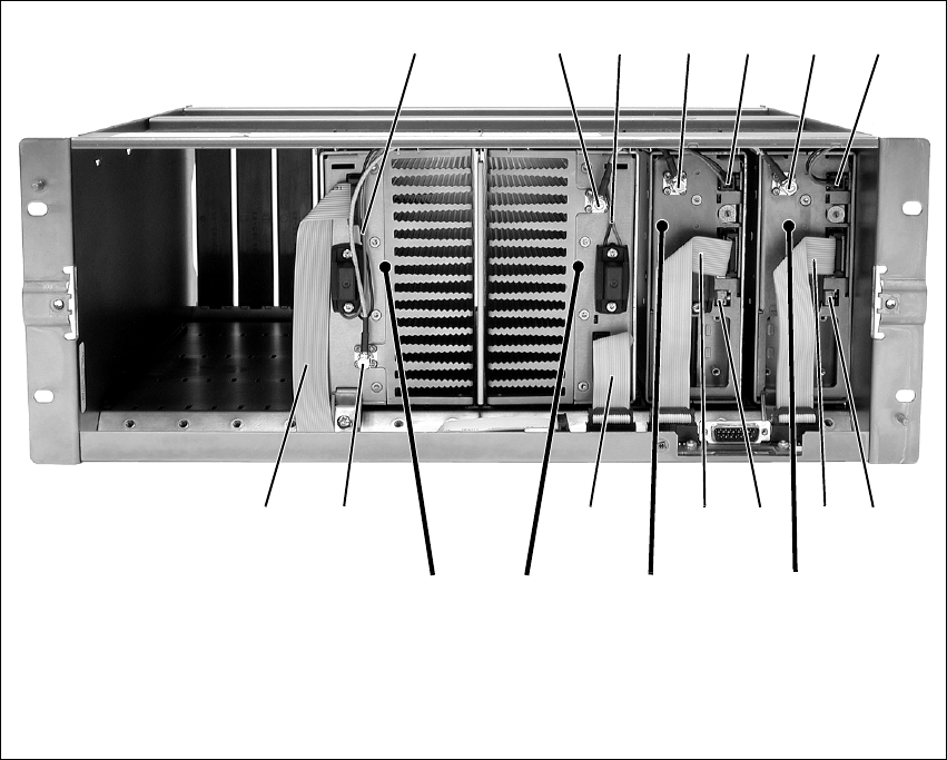
TB8100 Installation and Operation Manual Connection 105
© Tait Electronics Limited June 2005
Figure 7.2 Dual 5W or 50W 12V PA base station inputs and outputs - front view
b12VDC output for reciter e12VDC input from PA
cRF input from reciter fDC output (for optional reciter fan only)
dRF output to PA gsystem control bus
cdeb
gfg
PA 2 reciter 1
ed
f
g
reciter 2
b
gc
PA 1
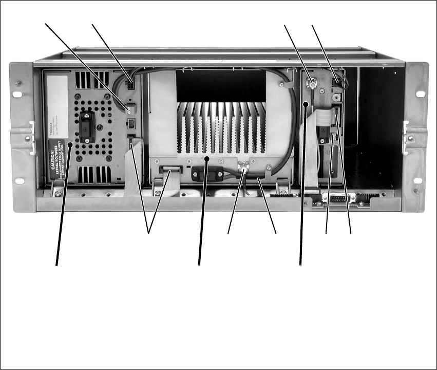
106 Connection TB8100 Installation and Operation Manual
© Tait Electronics Limited June 2005
Figure 7.3 Single 100W base station inputs and outputs - front view
b28VDC high current output for PA fsystem control bus
c28VDC low current output for reciter gDC output (for optional reciter fan only)
dRF output to PA h28VDC high current input cable from PMU
e28VDC low current input from PMU iRF input from reciter
bc de
hfgfi
PA reciter
PMU
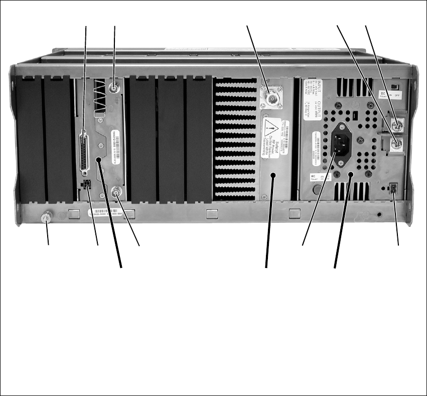
TB8100 Installation and Operation Manual Connection 107
© Tait Electronics Limited June 2005
Figure 7.4 Single 5W or 50W base station inputs and outputs - rear view
bsystem interface connector gauxiliary DC output
cexternal reference frequency input hAC mains input
dRF output (to antenna) iRF input (from antenna)
e–VDC input jauxiliary DC input for system interfacea
f+VDC input 1) subrack ground connector
a. Older system interface boards use the 4-way connector shown in the photograph, while the TaitNet RS-232 board
and all other boards manufactured after March 2005 use a 2-way connector. Refer to “Reciter Auxiliary DC Input
from PMU” on page 113 for more details.
cdfe
hgij
PAreciter PMU
b
1)
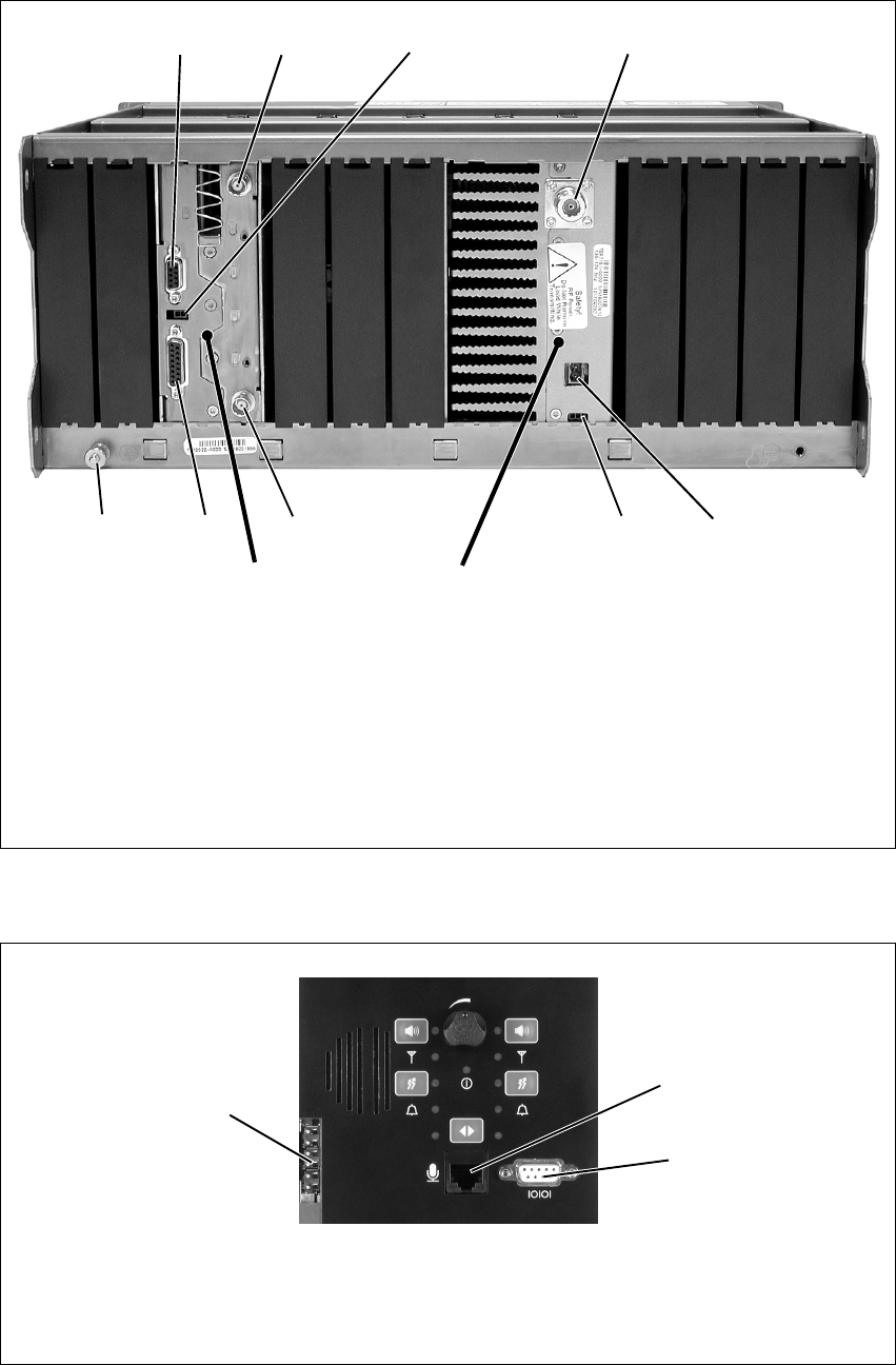
108 Connection TB8100 Installation and Operation Manual
© Tait Electronics Limited June 2005
Figure 7.5 Single 5W or 50W 12V PA base station inputs and outputs - rear view
bRS-232 connector gPower Saving control input
cexternal reference frequency input hRF input (from antenna)
dauxiliary DC input for system interface iTaitNet system interface connector
eRF output (to antenna) jsubrack ground connector
f12VDC input
cd
fhi
PA
reciter
b
j
e
g
reciter shown with TaitNet RS-232
system interface board
Figure 7.6 Standard control panel inputs and outputs
bDC outputs for fans mounted on front panel;
also used for fan rotation detectors (if fitted)
dRS-232 programming port
cmicrophone connector
b
c
d
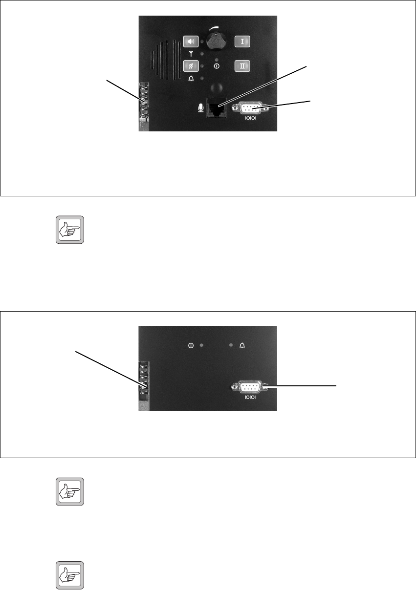
TB8100 Installation and Operation Manual Connection 109
© Tait Electronics Limited June 2005
Note The microphone input feeds simultaneously to both base station 1
and base station 2. However, the PTT can only be used on the
currently selected base station. The RS-232 connection is only to
the reciter on the currently selected base station. You should dis-
connect the Service Kit before switching base stations.
Note When a reciter fitted with a TaitNet RS-232 system interface
board is used in a TB8100 BSS, the RS-232 port on the control
panel is disabled. In this situation you must connect to the
RS-232 port at the rear of the reciter. Refer to “TaitNet
RS-232” on page 122 for more details.
Note If high-power HF equipment is located close to the TB8100 BSS,
it can sometimes cause interference to RS-232 serial port commu-
nications. If this interference does occur, we recommend fitting
ferrites on the serial cable close to the control panel. This recom-
mendation only applies to communication equipment perma-
nently connected to the BSS.
Figure 7.7 Dual base station control panel inputs and outputs
bDC outputs for fans mounted on front panel;
also used for fan rotation detectors (if fitted)
dRS-232 programming port
cmicrophone connector
b
c
d
Figure 7.8 Power Save control panel inputs and outputs
bDC outputs for fans mounted on front panel;
also used for fan rotation detectors (if fitted)
cRS-232 programming port
b
c
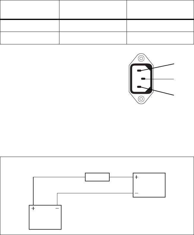
110 Connection TB8100 Installation and Operation Manual
© Tait Electronics Limited June 2005
7.2 Power Supply Connections
7.2.1 AC Power
The TB8100 PMU is designed to accept a mains input of 88 to 264VAC at
45 to 65Hz. We recommend that a standard 3-wire grounded outlet is used
to supply the AC power. The socket-outlet must be installed near the
equipment and must be easily accessible. This outlet should be connected
to an AC power supply capable of providing a maximum of 600W. The
requirements of two typical AC supplies are given in the following table.
Your TB8100 BSS should come supplied
with a power supply cord to connect the
male IEC connector on the PMU to the
local AC supply. The pins of the IEC
connector on the PMU are identified at
right.
7.2.2 DC Power
DC Power with PMU The TB8100 PMU is designed to accept a nominal 12VDC, 24VDC or
48VDC input (depending on the model) with negative or positive ground.
There is a minimum DC startup threshold to prevent damaging a battery
which has little capacity left.
You must connect the DC supply from the battery to the PMU via a fuse or
DC-rated circuit breaker with the appropriate rating, as shown in the table
Nominal Supply
Voltage Current Requirement Circuit Breaker/Fuse
Rating
115VAC 8A 10A
230VAC 4A 6A
ground
external view
neutral
phase
Figure 7.9 Recommended DC power connection
Battery
PMU or
12V PA
Circuit Breaker
or Fuse

TB8100 Installation and Operation Manual Connection 111
© Tait Electronics Limited June 2005
below. The DC input leads should be of a suitable gauge to ensure less than
0.2V drop at maximum load over the required length of lead.
Terminate and insulate the DC input leads so they are protected from
accidentally shorting to the subrack if the PMU is removed before the leads
are disconnected.
DC Power with 12V
PA The TB8100 12V PA is designed to accept a nominal 12VDC input with
negative ground. There is a minimum DC startup threshold to prevent
damaging a battery which has little capacity left.
You must connect the DC supply from the battery to the PA via a fuse or
DC-rated circuit breaker with the appropriate rating, as shown in the table
below. The DC input leads should be of a suitable gauge to ensure less than
0.2V drop at maximum load over the required length of lead.
The pin allocations for the 2-way DC input connector are shown below.
Nominal Supply
Voltage
Circuit Breaker/Fuse
Rating
Recommended Wire
Gaugea
a. For a length of 1.5m to 2m (5ft to 6.5ft) (typical).
12VDC 60A 2AWG / 35mm2
24VDC 30A 5AWG / 16mm2
48VDC 15A 8AWG / 8mm2
Nominal Supply
Voltage
Circuit Breaker/Fuse
Rating
Recommended Wire
Gaugea
a. For a length of 1.5m to 2m (5ft to 6.5ft) (typical).
12VDC 15A to 18A 8AWG / 8mm2
Pin Description
1+V input
2 ground
2-way connector - external view
b
c
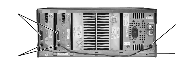
112 Connection TB8100 Installation and Operation Manual
© Tait Electronics Limited June 2005
7.2.3 Auxiliary DC Power
PMU Auxiliary DC
Output The PMU can provide an auxiliary DC output when it is fitted with the
optional auxiliary power supply board. This board is available with an
output of 13.65VDC, 27.3VDC, or 54.6VDC (depending on the model),
and is current limited to 3A, 1.5A or 750mA respectively. This optional
power supply is available on the auxiliary DC output connector b on the
rear panel. DC from this output can be supplied to the +AUX_V pin on
the system interface connector c on the reciter via the auxiliary DC input
connector d on the system interface board (see “Reciter Auxiliary DC
Input from PMU” below). The auxiliary DC power cables e are described
in “Auxiliary DC Power Supply Connections” on page 114.
The auxiliary power supply is configured with the Service Kit (Configure >
Base Station > Miscellaneous > Power configuration > Auxiliary power
control). Its operation can be controlled by Task Manager statements, for
example:
IF Digital input 01 active THEN Enable auxiliary supply.
Refer to the Service Kit documentation for more details.
We do not recommend connecting two or more auxiliary power supply
boards in parallel to increase the current supply to external equipment. In
this situation, the auxiliary board with the highest voltage will try to supply
all the current required, until it goes into current limit and the voltage
reduces to the level where another board will begin to supply power.
Running an auxiliary board continuously in current limit will reduce its life
span and reliability. Also, if one auxiliary board fails or is switched off when
a base station is powered down for some reason, the remaining auxiliary
boards will be unable to supply the required current and will go into current
limit, possibly causing the external equipment to shut down.
It is, however, acceptable to connect two or more auxiliary power supply
boards in parallel (e.g. for redundancy), as long as the current consumption
of the external equipment is less than the rating of one board. This means
that, even if only one auxiliary board is functioning, it will still be able to
supply the current requirements of the external equipment.
Figure 7.10 Auxiliary DC power supply connections
b
c
de
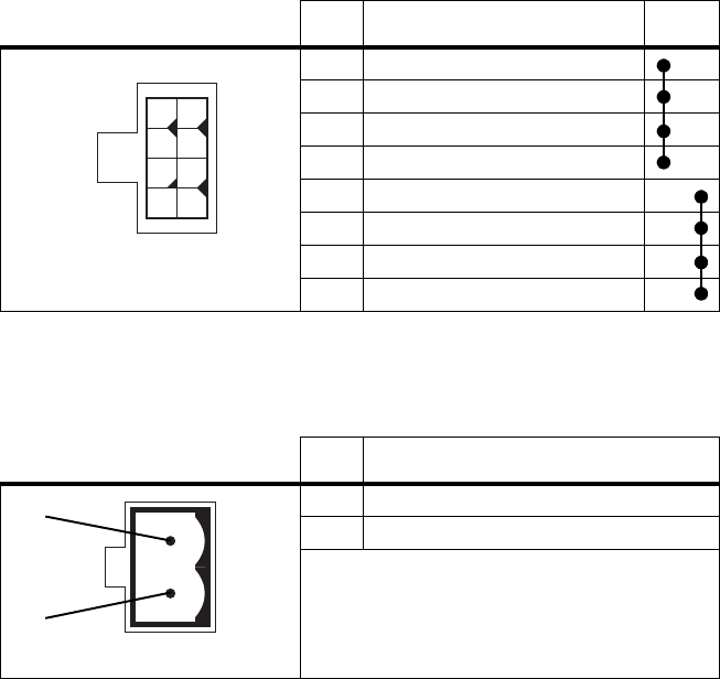
TB8100 Installation and Operation Manual Connection 113
© Tait Electronics Limited June 2005
Two different types of auxiliary DC output connector have been fitted to
the PMU. The pin allocations for the 8-way connector fitted to PMUs
manufactured before August 2004 are given in the following table. Note
that pins 1 to 4 and pins 5 to 8 on this connector are linked.
The pin allocations for the 2-way connector fitted to PMUs manufactured
from August 2004 onwards are given in the following table.
Reciter Auxiliary DC
Input from PMU The system interface board in the reciter has an auxiliary DC input
connector. DC from the auxiliary DC output on the PMU can be supplied
to the +AUX_V pin on the system interface connector via this input (see
“PMU Auxiliary DC Output” above).
The pin allocations for the auxiliary DC input on the system interface board
are given in the following table. Older boards use the 4-way connector,
while the TaitNet RS-232 board and all other boards manufactured after
March 2005 use the 2-way connector. Note that pins 1 & 3 and pins 2 & 4
on the 4-way connector are linked. Refer to “System Connections” on
page 116 for the pin allocations for +AUX_V on each system interface
board.
Pin Description Links
1 +V output
2 +V output
3 +V output
4 +V output
5 ground
6 ground
7 ground
8 ground
Pin Description
1 +V output
2 ground
1
5
26
37
48
8-way connector - external view
2-way connector - external view
b
c
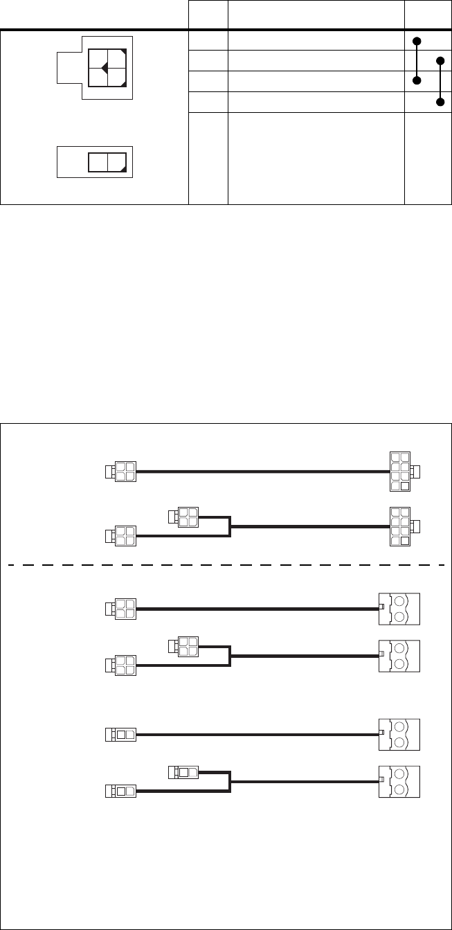
114 Connection TB8100 Installation and Operation Manual
© Tait Electronics Limited June 2005
The DC output from the PMU is 13.65VDC, 27.3VDC, or 54.6VDC
(depending on the model). Although this power output is isolated, the
negative side of the supply is grounded on the system interface board to give
a +V output.
Auxiliary DC Power
Supply Connections Figure 7.11 below shows the standard Tait auxiliary DC power cables
available. Details of the individual connector types are also provided in case
you want to make up your own cables.
Pin Description Links
1 +V input
2ground
3 +V input
4ground
2-way connector - external view
1
2
3
4
12
4-way connector - external view
Figure 7.11 Auxiliary DC power cables
b2x2-way Molex 43025-0400/
crimp socket 43030-0001 female
dPhoenix MVSTBR2.5HC/2-ST/5.08
female
c2x4-way Molex 43025-0800/
crimp socket 43030-0001 female
e2x1-way Molex 43025-0200/
crimp socket 43030-0001 female
b
b
b
b
b
b
c
c
d
d
219-02895-00
(was TBA2241)
219-02896-00
(was TBA2242)
TBA2241
TBA2242
as sold up to
August 2004
as sold from August
2004 onwards
d
d
e
e
e
TBA2243
TBA2244
for use with the TaitNet RS-232 system interface
board, and all other boards made after March 2005
Obsolete
Current

TB8100 Installation and Operation Manual Connection 115
© Tait Electronics Limited June 2005
Note that the PMU connector used in the TBA2241 and TBA2242 cables
was changed in August 2004 to match the change of connector in the PMU.
The old cables are still available under Tait part numbers 219-02895-00
(single) and 219-02896-00 (double). Contact your nearest Tait Dealer or
Customer Service Organisation for details on the full range of wiring kits
available.
7.3 RF Connections
Important The PA may be damaged if the load is removed or switched
while the PA is transmitting.
To protect the PA output stage from load transients (i.e. switching or
removing the load), we recommend that you fit an isolator between the PA
and the load. Fit the isolator as close as possible to the RF output connector
on the PA. Do not connect any switching or combining equipment
between the isolator and the PA.
The RF input to the TB8100 BSS is via the lower BNC/TNC connector
on the rear panel of the reciter. The RF output is via the N-type connector
on the rear panel of the PA (refer to Figure 7.4 on page 107).
We recommend that you use dual-screened coaxial cable such as RG223 for
the BNC/TNC connections, and RG214 for the N-type connections.
When the base station is used in simplex mode using a single antenna with
a coaxial changeover relay, the isolation of this relay must be ≥40dB.
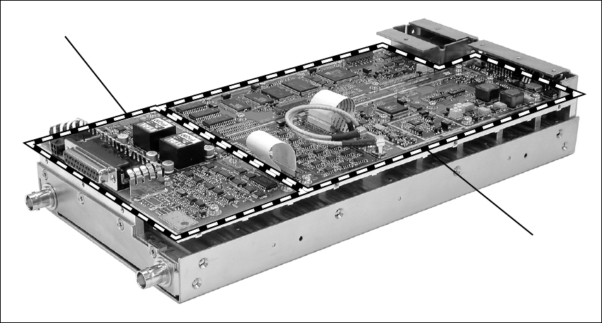
116 Connection TB8100 Installation and Operation Manual
© Tait Electronics Limited June 2005
7.4 System Connections
The reciter can be fitted with an optional system interface board which
provides the links between the reciter’s internal circuitry and external
equipment. This board is securely mounted to the reciter’s chassis and is
connected to the digital board with a flexible connector. The system
interface board is fitted with industry-standard connectors and several
standard types are available for different applications.
The circuitry on the system interface board provides additional signal
processing so that the outputs meet standard system requirements. It also
enables the board to identify itself to the reciter control circuitry. The
system interface board is removable, which makes it possible to change the
application of a reciter by removing one type of board and fitting another.
Only one system interface board can be fitted to a reciter at any one time.
This section provides details on the system interface boards available at the
time of publication. Other types may be developed for future applications.
Figure 7.12 System interface board
system interface board*
digital board
*standard system interface board shown

TB8100 Installation and Operation Manual Connection 117
© Tait Electronics Limited June 2005
7.4.1 Digital Interface
The system interface board provides several different types of digital
interface connections. The type and number of connections available
depends on the type of system interface board. These connections are
described in “System Interface Connections” on page 118, and also in the
Service Kit (Configure > Base Station > System Interface). For details on
the interface levels for these connections refer to the Specifications Manual.
The digital interface signals supported by the TB8100 base station are
described below.
Digital Inputs Digital inputs are read by the reciter RISC and can be used to perform
various actions based on the configuration of the reciter. The two major
uses for digital inputs are Channel Change and Task Manager. For example,
to send a status email when the status of a digital input line is changed, you
can use the following Task Manager statement: IF Digital input 01 active
THEN Email status now.
Digital Outputs All digital outputs are controlled by Task Manager statements. For example,
when any enabled base station alarm goes active, you can indicate this by
turning on digital output 1 with the following Task Manager statement: IF
Base station alarm on THEN Activate digital output 1.
Note Digital outputs 1 and 2 on the reciter may be active while the
TB8100 base station is powering up. This applies to reciters fitted
with a version 0 (zero) system interface board, but does not apply
to reciters fitted with a TaitNet RS-232 system interface board. If
this will cause problems for external equipment connected to the
base station, disconnect the system interface connector when
resetting the base station. To check the version of a system inter-
face board, run the Service Kit and select Monitor > Module
Details > Reciter. In the Versions area, the System Interface
field displays the version number.
Bidirectional Inputs/
Outputs Bidirectional signals can operate as either digital inputs or digital outputs,
based on how Task Manager is configured. Bidirectional signals use the
same processes described above to set and read the status of digital inputs and
outputs. When a bidirectional pin has its output activated, a reading of that
pin will reflect the current status on that line. Thus, it is possible to use a
bidirectional pin for input-only or output-only actions, if only that specific
action is configured for that digital pin number in Task Manager.

118 Connection TB8100 Installation and Operation Manual
© Tait Electronics Limited June 2005
7.4.2 System Interface Connections
Standard The standard system interface board is fitted to reciters bearing the product
code TBA4xxx-0A0x. If purchased separately, it has the product code
TBA10A0. It provides the following:
It is fitted with a 25-way female D-range connector and a 4-way auxiliary
DC input connector. The pin allocations for the D-range are listed in the
table below, and the pin allocations for the DC input connector are provided
in “Reciter Auxiliary DC Input from PMU” on page 113.
■non-isolated 600Ω balanced audio I/O
■high impedance unbalanced audio I/O
■digital I/O (2 outputs, 6 inputs, 4 bi-directional)
■Tx key
■Tx relay
■Rx gate
■RSSI
Pin Signal Name Signal Type Notes
1 Rx line out + audio output non-isolated
AC coupled line
2 Rx line out –
3 Rx audio out audio output AC coupled
4 ground ground
5 Tx audio in audio input AC coupled
6 Tx line in + audio input non-isolated
AC coupled line
7 Tx line in –
8 RSSI DC signal
9 Rx gate output open collector
10 Tx key input active low
11 digital out 1a
output open collector
12 digital out 2
13 +AUX_V power output from auxiliary DC input
14 digital in 1
input 5V TTL logic
active low
15 digital in 2
16 digital in/out 3b
17 digital in/out 4b
18 digital in/out 5b
19 digital in/out 6b
20 digital in 7
21 digital in 8
22 digital in 9
23 digital in 10
24 Tx relay output open collector
25 ground ground
a. If a base station with a 12V PA is configured for Deep Sleep, digital out 1 is dedicated to Power Saving control and
should not be used for any other Task Manager function.
b. On version 1 and later system interface boards, digital inputs 3, 4, 5, and 6 may also be configured as outputs using
a Task Manager statement. For more details refer to “Digital Interface” on page 117 and to the Service Kit docu-
mentation.
B
C
D
E
F
G
H
I
J
1)
1!
1@
1#
1$
1%
1^
1&
1*
1(
2)
2!
2@
2#
2$
2%
external view

TB8100 Installation and Operation Manual Connection 119
© Tait Electronics Limited June 2005
Isolated This system interface board is fitted to reciters bearing the product code
TBA4xxx-0B0x or TBA5xxx-0B0x. If purchased separately, it has the
product code TBA10B0. It is the same as the standard model, except that
the balanced audio interfaces are galvanically (transformer) isolated. It
provides the following:
It is fitted with a 25-way female D-range connector and a 4-way auxiliary
DC input connector. The pin allocations for the D-range are listed in the
table below, and the pin allocations for the DC input connector are provided
in “Reciter Auxiliary DC Input from PMU” on page 113.
■transformer isolated 600Ω balanced audio I/O
■high impedance unbalanced audio I/O
■digital I/O (2 outputs, 6 inputs, 4 bi-directional)
■Tx key
■Tx relay
■Rx gate
■RSSI
Pin Signal Name Signal Type Notes
1 Rx line out + audio output transformer isolated line
2 Rx line out –
3 Rx audio out audio output AC coupled
4 ground ground
5 Tx audio in audio input AC coupled
6 Tx line in + audio input transformer isolated line
7 Tx line in –
8 RSSI DC signal
9 Rx gate output open collector
10 Tx key input active low
11 digital out 1a
output open collector
12 digital out 2
13 +AUX_V power output from auxiliary DC input
14 digital in 1
input 5V TTL logic
active low
15 digital in 2
16 digital in/out 3b
17 digital in/out 4b
18 digital in/out 5b
19 digital in/out 6b
20 digital in 7
21 digital in 8
22 digital in 9
23 digital in 10
24 Tx relay output open collector
25 ground ground
a. If a base station with a 12V PA is configured for Deep Sleep, digital out 1 is dedicated to Power Saving control and
should not be used for any other Task Manager function.
b. On version 1 and later system interface boards, digital inputs 3, 4, 5, and 6 may also be configured as outputs using
a Task Manager statement. For more details refer to “Digital Interface” on page 117 and to the Service Kit docu-
mentation.
external view
B
C
D
E
F
G
H
I
J
1)
1!
1@
1#
1$
1%
1^
1&
1*
1(
2)
2!
2@
2#
2$
2%

120 Connection TB8100 Installation and Operation Manual
© Tait Electronics Limited June 2005
Isolated E&M This system interface board is fitted to reciters bearing the product code
TBA4xxx-0C0x or TBA5xxx-0C0x. If purchased separately, it has the
product code TBA10C0. It provides the following:
It is fitted with a 25-way female D-range connector and a 4-way auxiliary
DC input connector. The pin allocations for the D-range are listed in the
table below, and the pin allocations for the DC input connector are provided
in “Reciter Auxiliary DC Input from PMU” on page 113.
■transformer isolated 600Ω balanced audio I/O
■opto-isolated keying
■opto-isolated gate output
■digital I/O (2 outputs, 2 inputs, 4 bi-directional)
■Tx key
■Tx relay
■Rx gate
■RSSI
Pin Signal Name Signal Type Notes
1 Rx line out + audio output transformer isolated line
2 Rx line out –
3 Rx audio out audio output
4 audio ground ground
5 Tx audio in audio input
6 Tx line in + audio input transformer isolated line
7 Tx line in –
8 RSSI DC signal
9 Rx gate output open collector
10 Tx key input active low
11 digital out 1a
output open collector
12 digital out 2
13 +AUX_V power output from auxiliary DC input
14 digital in 1
input 5V TTL logic
active low
15 digital in 2
16 digital in/out 3b
17 digital in/out 4b
18 digital in/out 5b
19 digital in/out 6b
20 opto +/– isolated keying input input voltage range
±10VDC to ±60VDC
21 opto –/+
22 relay +/– isolated gate output
23 relay –/+
24 Tx relay output open collector
25 ground ground
a. If a base station with a 12V PA is configured for Deep Sleep, digital out 1 is dedicated to Power Saving control and
should not be used for any other Task Manager function.
b. On version 1 and later system interface boards, digital inputs 3, 4, 5, and 6 may also be configured as outputs using
a Task Manager statement. For more details refer to “Digital Interface” on page 117 and to the Service Kit docu-
mentation.
external view
B
C
D
E
F
G
H
I
J
1)
1!
1@
1#
1$
1%
1^
1&
1*
1(
2)
2!
2@
2#
2$
2%

TB8100 Installation and Operation Manual Connection 121
© Tait Electronics Limited June 2005
Ta it N et This system interface board is fitted to reciters bearing the product code
TBA4xxx-0T1x. If purchased separately, it has the product code TBA10T1.
It is designed for use with MPT trunking systems. It provides the following:
It is fitted with a 15-way female D-range connector and a 4-way auxiliary
DC input connector. The pin allocations for the D-range are listed in the
table below, and the pin allocations for the DC input connector are provided
in “Reciter Auxiliary DC Input from PMU” on page 113.
■transformer isolated 600Ω balanced audio I/O
■high impedance unbalanced audio I/O
■digital I/O (3 outputs, 1 input)
■Tx key
■Rx gate
Pin Signal Name Signal Type Notes
1 Rx line out + audio output transformer isolated line
2 Rx line out –
3 Rx audio out audio output
4 Rx gate output open collector
5 Tx key input
6 Tx audio in audio input
7 Tx line in + audio input transformer isolated line
8 Tx line in –
9 +AUX_V power output from auxiliary DC input
10 digital out 3 output open collector
11 no connection
12 digital out 1a
output open collector
13 digital out 2
14 digital in 1 input 5V logic
15 ground ground
a. If a base station with a 12V PA is configured for Deep Sleep, digital out 1 is dedicated to Power Saving control and
should not be used for any other Task Manager function.
external view
J
B
C
D
E
F
G
H
I
1)
1!
1@
1#
1$
1%
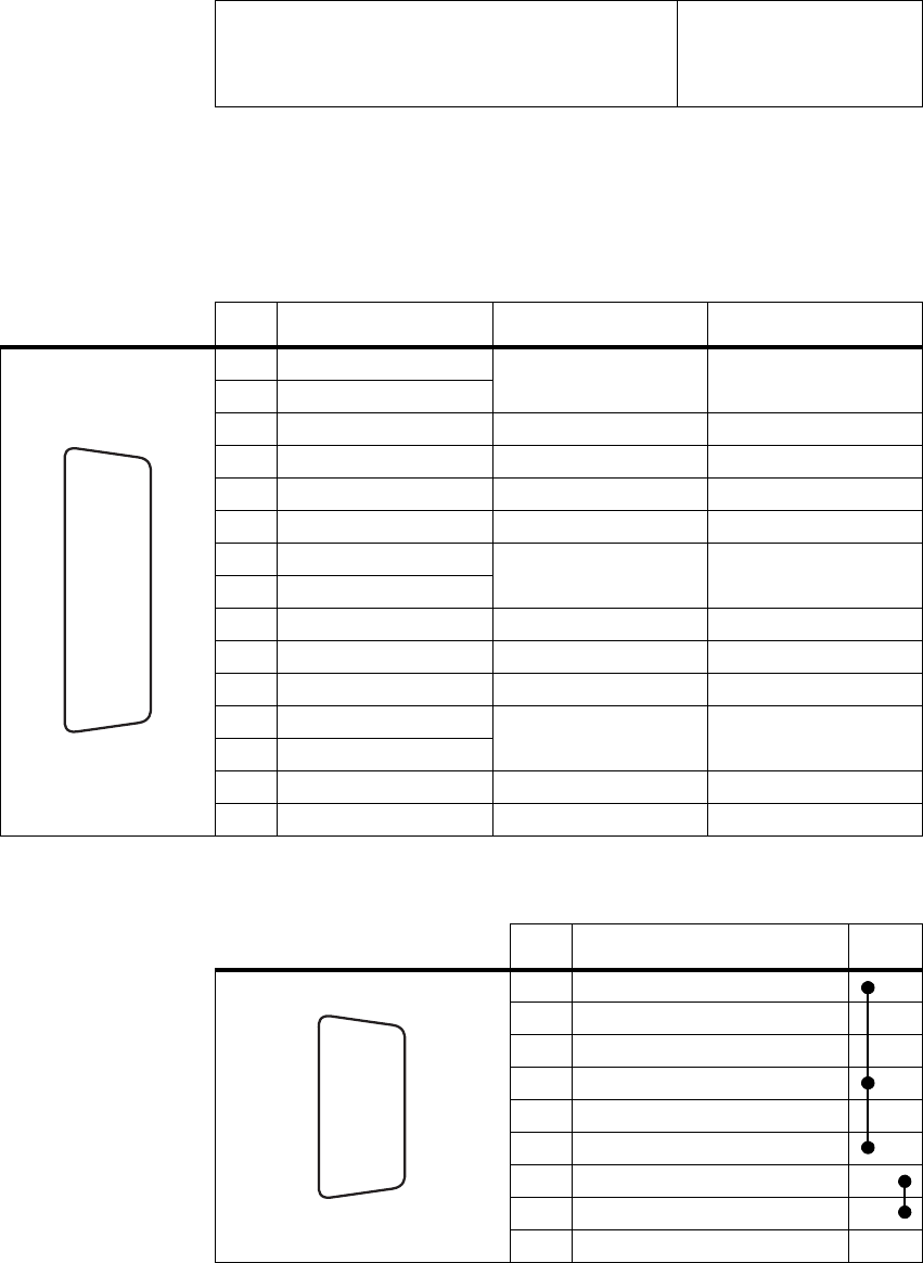
122 Connection TB8100 Installation and Operation Manual
© Tait Electronics Limited June 2005
TaitNet RS-232 This system interface board is fitted to reciters bearing the product code
TBA4xxx-0L0x or TBA5xxx-0L0x. If purchased separately, it has the
product code TBA10L0. It is designed for use with MPT trunking systems,
and also for use with multiple base station systems. It provides the following:
It is fitted with a 15-way female D-range connector (TaitNet), a 9-way
female D-range connector (RS-232), and a 2-way auxiliary DC input
connector. The pin allocations for the D-ranges are listed in the following
tables, and the pin allocations for the DC input connector are provided in
“Reciter Auxiliary DC Input from PMU” on page 113.
The rear-mounted RS-232 serial port facilitates the connection of multiple
base stations to a Service Kit or Alarm Center using an APS (asynchronous
■transformer isolated 600Ω balanced audio I/O
■high impedance unbalanced audio I/O
■digital I/O (3 outputs, 1 input)
■Tx key
■Rx gate
Pin Signal Name Signal Type Notes
1 Rx line out + audio output transformer isolated line
2 Rx line out –
3 Rx audio out audio output
4 Rx gate output open collector
5 Tx key input
6 Tx audio in audio input
7 Tx line in + audio input transformer isolated line
8 Tx line in –
9 +AUX_V power output from auxiliary DC input
10 digital out 3 output open collector
11 no connection
12 digital out 1a
output open collector
13 digital out 2
14 digital in 1 input 5V logic
15 ground ground
a. If a base station with a 12V PA is configured for Deep Sleep, digital out 1 is dedicated to Power Saving control and
should not be used for any other Task Manager function.
external view
J
B
C
D
E
F
G
H
I
1)
1!
1@
1#
1$
1%
Pin Description Links
1 not connected
2 receive data
3 transmit data
4 not connected
5ground
6 not connected
7 not connected
8 not connected
9 not connected
h
j
bg
i
c
d
e
f
external view
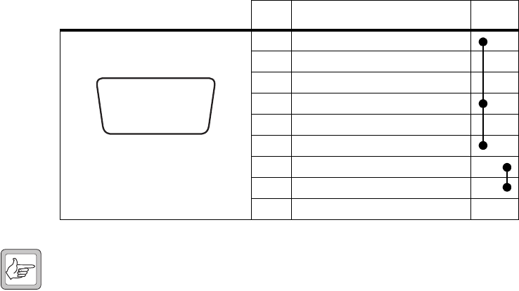
TB8100 Installation and Operation Manual Connection 123
© Tait Electronics Limited June 2005
port switch) and modem or radio modem. Refer to TN-906 for more
details on using an APS with TB8100 base stations.
7.5 Service Kit Connections
The TB8100 Service Kit is connected to the BSS via the RS-232 serial port
on the control panel. This port is a 9-way female D-range connector. Use
a straight through cable, as supplied with the Service Kit, to connect your
programming computer to the BSS. The pin allocations for the serial port
are given in the following table. Note that pins 1, 4 & 6 and pins 7 & 8 are
linked. This port is also used for remote connection to the Service Kit or
Alarm Center software via a modem or radio modem.
Note When a reciter fitted with a TaitNet RS-232 system interface
board is used in a TB8100 BSS, the RS-232 port on the control
panel is disabled. In this situation you must connect to the
RS-232 port at the rear of the reciter. Refer to “TaitNet
RS-232” on page 122 for more details.
Pin Description Links
1 not connected
2receive data
3 transmit data
4 not connected
5 ground
6 not connected
7 not connected
8 not connected
9 not connected
hj
b
gi
cdef
external view

124 Connection TB8100 Installation and Operation Manual
© Tait Electronics Limited June 2005
7.6 Microphone Connection
You can connect a microphone to the TB8100 BSS via the standard RJ45
socket on the control panel. If a standard TB8100 microphone has not been
supplied with your BSS, you should use an electret microphone. The pin
allocations for the microphone socket are given in the following table.
7.7 12V PA Power Saving Control Connection
To enable Power Saving in the 12V PA, you must connect digital out 1 on
the reciter’s system interface connector to pin 1 of the Power Saving control
connector on the rear panel of the PA. Once this connection is made, the
PA will shut down whenever the reciter goes into Deep Sleep mode. For
more information on the operation and configuration of Power Saving, refer
to “Power Saving” on page 57.
Note When a base station with a 12V PA is configured for Deep Sleep,
digital out 1 is dedicated to Power Saving control and should not
be used for any other Task Manager function.
Two ways of making the Power Saving control connection between the 12V
PA and reciter are described below. The circled numbers in the following
instructions refer to Figure 7.13 on page 125.
Method 1 1. Connect one end of the Power Saving control cable b (Tait part
number 219-02971-00) to the Power Saving control connector c at
the rear of the PA. Connect the other end to the auxiliary DC input
connector d at the rear of the reciter.
Note If you are using an older reciter with a 4-way connector, you will
need to use Method 2.
2. On the D-range plug that is fitted to the system interface connector
e on the reciter, link digital out 1 to +AUX_V.
Pin Description
1 not connected
2 not connected
3 not connected
4PTT
5 voice band (microphone) input
6 microphone ground
7 not connected
8 not connected
12345678
external view
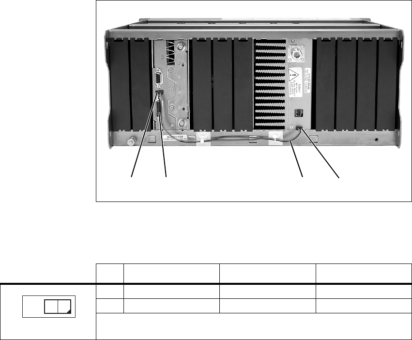
TB8100 Installation and Operation Manual Connection 125
© Tait Electronics Limited June 2005
Method 2 1. Connect one end of the Power Saving control cable b to the Power
Saving control connector c at the rear of the PA.
2. Cut the socket off the other end of the cable. Connect the wires
directly to the D-range plug fitted to the system interface connector
e as follows:
■red - digital out 1
■black - ground.
The pin allocations for the Power Saving control connector on the PA are
given in the following table.
If you wish to make up your own cable, use the following connector for
both the PA and reciter connections:
■2x1-way Molex 43025-0200/crimp socket 43030-0001 female.
Figure 7.13 Fitting the Power Saving control cable to a 12V PA
becd
reciter shown with TaitNet RS-232
system interface board
Pin Signal Name Signal Type Notes
1 PA shutdown input active low
2 ground ground
external view
12
126 Connection TB8100 Installation and Operation Manual
© Tait Electronics Limited June 2005

TB8100 Installation and Operation Manual Preparation for Operation 127
© Tait Electronics Limited June 2005
8 Preparation for Operation
Once the TB8100 BSS has been installed and connected, it is time to
prepare it for operation. The main procedures required to ensure your BSS
is ready for operation are as follows:
■tuning
■configuration
■applying power
■test transmissions.
The following sections provide more detail on these procedures. Some
sections provide only an overview, as the full procedures are described in
other documents.
8.1 Tuning
If you have not already done so, you must tune the TB8100 BSS reciter
modules before operating them in your radio system. To do this you will
need to use the Calibration Kit software included on the Product CD, plus
the TB8100 calibration test unit (CTU).
Refer to the Calibration Kit documentation for full details on the tuning
procedures.
8.2 Configuration
Software The TB8100 BSS can be configured using software to operate in many
different ways. Although it is programmed with a default configuration at
the factory, you will need to use the Service Kit software to configure your
BSS to suit the requirements of your radio system.
Refer to the Service Kit and its associated documentation for full details of
all the options available in the complete configuration process.
Note The BSS will be programmed at the factory with default pass-
words which you will need to use to log on for the first time.
Refer to the Service Kit Help for more information on these pass-
words and how to change them.

128 Preparation for Operation TB8100 Installation and Operation Manual
© Tait Electronics Limited June 2005
Hardware Each base station in a TB8100 BSS must be assigned an identity1. This
identity is used to identify the base station to the Service Kit and Calibration
Kit software, and to the control panel.
You set the identity of each base station with the hex switch on the front
panel of its reciter (refer to Figure 3.4 on page 33). For example, the reciters
in a dual base station system would be numbered “1” and “2”. The reciter
with the lowest hex number becomes the “control” reciter. In a single base
station system, set the hex switch on the reciter to “1”.
Note Reciters and PAs are normally numbered from left to right when
facing the front of the BSS (refer to Figure 7.1 on page 104). In
a single base station system, fit the reciter and PA into the positions
allocated for “reciter 1” and “PA 1”. These positions also corre-
spond to the layout of the controls on the control panel (refer to
Figure 3.1 on page 28).
8.3 Applying Power
1. Before turning the TB8100 BSS on:
■check that the PMU is turned off (refer to Figure 3.6 on page 35)
■12V PA only: check that the battery supply lead is disconnected
(refer to “Replacing the Power Amplifier” on page 92)
■remove the front panel (refer to “Preliminary Disassembly” on
page 88)
■check that all looms and cables at the front and rear of the BSS are
fitted correctly (refer to “Overview of Inputs and Outputs” on
page 103)
■check that all connectors are secure
■refit the front panel - ensure it is fitted correctly so that the fans
will operate if needed (refer to “Final Reassembly” on page 101).
2. Apply power by turning on the PMU, or by connecting the battery
supply lead to the 12V PA.
3. Check that the BSS powers up correctly:
■check that the cooling fans in the front panel turn on in the
correct order after power-up: the PMU fan will run first, followed
by the PA fan; each fan will run for about five seconds and then
switch off (note that the PMU fan is not fitted to a 12V PA BSS)
■check that the power and microphone channel LEDs on the
standard control panel turn on after about five seconds, and all
other LEDs remain off (refer to “Control Panel” on page 28)
■at this point you can also safely press the speaker and microphone
channel buttons and check that they are operating correctly.
1. This feature will be available in a future release.

TB8100 Installation and Operation Manual Preparation for Operation 129
© Tait Electronics Limited June 2005
8.4 Test Transmissions
Once you have completed the procedures described in the previous sections,
you may want to make some test transmissions. These will verify that your
TB8100 BSS is operating correctly.
Note You may wish to have the Service Kit software running during
these tests so that you can monitor the performance of the BSS.
1. Ensure that the BSS is correctly connected to an appropriate antenna
and that all RF connectors are secure.
1. Plug the microphone into the RJ45 socket on the control panel (refer
to “Control Panel” on page 28).
2. Select the base station you wish to transmit on with the microphone
channel button.
3. Turn on the speaker audio for the selected base station with the
speaker button.
4. Press the PTT switch on the microphone and make your
transmission. Check that:
■the red transmit LED turns on
■there are no alarms generated
■the audio quality on the receiving radio is good.
5. When the other radio answers your transmission, check that:
■the green receive LED turns on
■the audio quality from the speaker in the control panel is good
(adjust the speaker volume as required).
130 Preparation for Operation TB8100 Installation and Operation Manual
© Tait Electronics Limited June 2005

TB8100 Installation and Operation Manual Maintenance Guide 131
© Tait Electronics Limited June 2005
9 Maintenance Guide
The TB8100 BSS is designed to be very reliable and should require little
maintenance. However, performing regular checks will prolong the life of
the equipment and prevent problems from happening.
It is beyond the scope of this manual to list every check that you should
perform on your BSS. The type and frequency of maintenance checks will
depend on the location and type of your system. The checks and procedures
listed below can be used as a starting point for your maintenance schedule.
Remote Monitoring You can monitor the performance of your TB8100 BSS remotely by using
the Service Kit and Alarm Center software provided with the equipment.
You can use the Service Kit to configure the BSS to generate alarms when
its performance falls outside your own pre-defined limits. Refer to the
Service Kit and Alarm Center documentation for more details.
Performance Checks We suggest you monitor the following operational parameters using the
Service Kit:
■VSWR
■DC input voltage, especially on transmit
■receiver sensitivity
■the setting of the receiver gate opening
■any temperature alarms.
These basic checks will provide an overview of how well your BSS is
operating.
Reciter There are no special maintenance requirements for the reciter. You may,
however, choose to recalibrate the TCXO frequency periodically. Refer to
the Calibration Kit documentation for more details.
PA There are no special maintenance requirements for the PA.
PMU There are no special maintenance requirements for the PMU. However, if
you are using battery back-up, you should check the batteries regularly in
accordance with the manufacturer’s recommendations.
Ventilation The TB8100 BSS has been designed to have a front-to-back cooling airflow.
We strongly recommend that you periodically check and maintain the
ventilation requirements described in “Ventilation” on page 78 to ensure a
long life and trouble-free operation for your BSS.
132 Maintenance Guide TB8100 Installation and Operation Manual
© Tait Electronics Limited June 2005
Cooling Fans The cooling fans have a long service life and have no special maintenance
requirements. You can use the Service Kit to configure the BSS to generate
an alarm if either of the cooling fans fails. Refer to the Service Kit and
Alarm Center documentation for more details.

TB8100 Installation and Operation Manual Glossary 133
© Tait Electronics Limited June 2005
Glossary
This glossary contains an alphabetical list of terms and abbreviations related
to the TB8100 base station system. For information about trunking,
mobile, or portable terms, consult the glossary provided with the relevant
documentation.
A B C D E F G H I K L N P R S T U V W
A
access level There are three different levels of access to a base station: Administrator,
User, and Read-only. The User access level has a configurable access profile;
the Administrator decides which functions that access level can carry out.
action An action is the second part of a Task Manager task. It specifies what the
base station must do when the first part (the input) becomes true.
active Digital outputs are active when the base station pulls their voltage low and
current is flowing. Digital inputs are active when external equipment is
pulling them to ground. All base station digital inputs and outputs are open
collector.
ADC Analog-to-Digital Converter. A device for converting an analog signal to a
digital signal that represents the same information.
Alarm log The alarm log is a list of the last 50 alarms that the base station generated.
This list is stored in the base station. To view it, select Monitor > Alarms >
Reported Alarms.
Alarm Center Alarm Center is a utility provided with the Service Kit that is able to receive,
store, and display alarms from any number of base stations with dial-up
connections. Participating base stations need an Alarm Reporting licence.
Alarm Center also routes emailed messages to the email server.
alarm notification Alarm notification is the process by which the base station passes on
information about an alarm condition. It can notify alarms over the air, over
the line, via email, or to an Alarm Center. It can also activate a digital
output. If the Service Kit is logged on to the base station, it is automatically
notified of any alarms.
air intake
temperature The temperature of the air as measured at the PA’s air intake.
134 Glossary TB8100 Installation and Operation Manual
© Tait Electronics Limited June 2005
anti-kerchunking Anti-kerchunking is a base station configuration that discourages users from
kerchunking.
B
balanced line A balanced line has two wires carrying equal and opposite signals. It is
typically used in a line-connected base station for connecting to the
despatcher console. The system interface identifies the balanced line in as
Rx+ and Rx-, and the balanced line out as Tx+ and Tx-.
BCD BCD (binary coded decimal) is a code in which a string of four binary digits
represents a decimal number.
BSS A BSS (base station system) is a subrack containing at least one TB8100 base
station.
C
Calibration Kit The TB8100 Calibration Kit is a utility for defining the switching ranges of
the receiver and the exciter and for flattening the receiver response across its
switching range. It can also be used to calibrate various parts of the reciter
and the PA circuitry.
CCDI2 CCDI2 (computer controlled data interface version 2) is a proprietary Tait
command protocol used between computer equipment and a Tait radio.
The TB8100 base station does not support CCDI2.
CCI CCI (computer controlled interface) is a proprietary Tait command protocol
used between computer equipment and a Tait radio. The TB8100 base
station supports CCI (refer to TN-947-AN).
channel A channel is:
■A frequency pair (or just a single frequency in a simplex system).
■A set of configuration information that defines the frequency pair and
other settings. Also referred to as a channel configuration. Generally,
‘channel’ has this meaning in the Service Kit.
channel profile A channel profile is a named set of configuration items relating to the base
station’s RF configuration, transmitter power output and power saving
modes. Like the signalling profile, it can be applied to any channel.
Together, these profiles define most configuration items.
channel spacing Channel spacing is the bandwidth that a channel nominally occupies. If a
base station has a channel spacing of 12.5 kHz, there must be a separation of
TB8100 Installation and Operation Manual Glossary 135
© Tait Electronics Limited June 2005
at least 12.5 kHz between its operating frequencies and those of any other
equipment.
channel table The channel table is the base station’s database of channel configurations. To
view it, select Configure > Base Station > Channel Table.
CODEC An IC which combines analog-to-digital conversion (coding) and digital-
to-analog conversion (decoding).
configuration file A configuration file consists of all the configuration settings needed for a
base station, stored as a file in the configurations folder. Configuration files
have the extension *.t8c.
connection A connection is a named group of settings that the Service Kit uses when
establishing communications with a BSS.
control bus The control bus is used for communications between modules in a base
station system. It is an I2C bus, a bi-directional two-wire serial bus which
is used to connect integrated circuits (ICs). I2C is a multi-master bus, which
means that multiple chips can be connected to the same bus, and each one
can act as a master by initiating a data transfer.
control panel The control panel is an area at the front of the BSS with buttons, LEDs and
other controls that let you interact with the BSS.
CTCSS CTCSS (continuous tone controlled squelch system), also known as PL
(private line), is a type of signalling that uses subaudible tones to segregate
groups of users.
custom action A custom action is a user-defined Task Manager action that consists of more
than one pre-defined action.
custom input A custom input is a user-defined Task Manager input that consists of a
combination of pre-defined inputs.
CWID CWID (Continuous Wave IDentification) is a method of automatically
identifying the base station using a Morse code. Continuous wave means
transmission of a signal with a single frequency that is either on or off, as
opposed to a modulated carrier.
D
DAC Digital-to-Analog Converter. A device for converting a digital signal to an
analog signal that represents the same information.
136 Glossary TB8100 Installation and Operation Manual
© Tait Electronics Limited June 2005
DCS DCS (digital coded squelch), also known as DPL (digital private line), is a
type of subaudible signalling used for segregating groups of users. DCS
codes are identified by a three-digit octal number, which forms part of the
continuously repeating code word. When assigning DCS signalling for a
channel, you specify the three-digit code.
de-emphasis De-emphasis is a process in the receiver that restores pre-emphasised audio
to its original relative proportions.
duty cycle Duty cycle is used in relation to the PA. It is the proportion of time
(expressed as a percentage) during which the PA is operated. The TB8100
PA can be operated continuously.
E
EIA Electronic Industries Alliance. Accredited by the American National
Standards Institute (ANSI) and responsible for developing
telecommunications and electronics standards in the USA.
EMC Electromagnetic Compatibility. The ability of equipment to operate in its
electromagnetic environment without creating interference with other
devices.
ETSI European Telecommunications Standards Institute. The non-profit
organisation responsible for producing European telecommunications
standards.
F
flag A flag is a programming term for a “yes/no” indicator used to represent the
current status of something. The base station has a set of system flags that
are read and set by Task Manager. There is also a separate set of flags that
you can use in your own Task Manager tasks.
frequency band The range of frequencies that the equipment is capable of operating on.
front panel The cover over the front of the BSS containing fans for the PA and PMU.
G
gating Gating is the process of opening and closing the receiver gate. When a valid
signal is received, the receiver gate opens.
TB8100 Installation and Operation Manual Glossary 137
© Tait Electronics Limited June 2005
H
hiccup mode Many power supplies switch off in the event of a short-circuit and try to start
again after a short time (usually after a few seconds). This “hiccup”-type of
switching off and on is repeated until the problem is eliminated.
hysteresis Hysteresis is the difference between the upper and lower trigger points. For
example, the receiver gate opens when the upper trigger point is reached,
but will not close until the level falls to the lower trigger point. An adequate
hysteresis prevents the receiver gate from repeatedly opening and closing
when the level is about that of the trigger point.
Hysteresis mode A mode of PMU operation designed to save power. The PMU is mainly
turned off, but switches back on intermittently to maintain output voltage
when the output current is low.
I
inactive Digital outputs are inactive if the base station is doing nothing to them.
They are floating, open collector outputs. Digital inputs are inactive when
they are open circuit.
Intercom mode Intercom mode makes it possible for the operator at the dispatch centre and
the servicing technician at the base station to communicate with each other
over the line. It connects the base station microphone to line out.
isolator An isolator is a passive two-port device which transmits power in one
direction, and absorbs power in the other direction. It is used in a PA to
prevent damage to the RF circuitry from high reverse power.
K
kerchunking Kerchunking is transmitting for a second or less without saying anything in
order to test the base station. This results in a ‘kerchunk’ sound.
L
line-controlled base
station A TB8100 is a line-controlled base station when it receives audio (sending
it out via its systems interface), transmits audio received over its systems
interface, and its transmitter is keyed via the Tx Key line.
logging on Once you are connected to a BSS, you log on to a base station. This
establishes communications between the Service Kit and a particular base
station.
138 Glossary TB8100 Installation and Operation Manual
© Tait Electronics Limited June 2005
N
navigation pane The navigation pane is the left-hand pane of the Service Kit application
window. It displays a hierarchical list of items. When you click an item, the
main pane displays the corresponding form.
0
operating range Operating range is another term for switching range.
P
PA The PA (power amplifier) is a base station module that boosts the exciter
output to transmit level.
PMU The PMU (power management unit) is a module that provides power to the
BSS.
pre-emphasis Pre-emphasis is a process in the transmitter that boosts higher audio
frequencies.
R
reciter The reciter is a module of a TB8100 base station that acts as receiver and
exciter.
reverse tone burst Reverse tone bursts can be used with CTCSS. When reverse tone bursts are
enabled, the phase of the generated tones is reversed for a number of cycles
just before transmission ceases. If the receiver is configured for reverse tone
burst, it responds by closing its gate.
RSSI RSSI (Received Signal Strength Indicator) is a level in dBm or volts that
indicates the strength of the received signal.
Run mode Run mode is the normal operating mode of the base station.
signalling profile A signalling profile is a named set of configuration items related to signalling
that can be applied to any channel. Items include subaudible signalling and
transmit timers.
TB8100 Installation and Operation Manual Glossary 139
© Tait Electronics Limited June 2005
S
sensitivity The sensitivity of a radio receiver is the minimum input signal strength
required to provide a useable signal.
SINAD SINAD (Signal plus Noise and Distortion) is a measure of signal quality. It
is the ratio of (signal + noise + distortion) to (noise + distortion). A SINAD
of 12dB corresponds to a signal to noise ratio of 4:1. The TB8100 can
provide an approximate SINAD value while in service by comparing the in-
band audio against out-of-band noise. This value should not be relied upon
to make calibrated measurements.
Sleep mode Sleep mode is a power saving state in which a part of the base station is
switched off, and then periodically switched on again.
Standby mode Standby mode is a mode of base station operation in which active service is
suspended so that special operations can be carried out, such as
programming the base station with a new configuration.
status message A status message is a set of information about the base station that can be
emailed. It identifies the base station, indicates the current operating
channel, lists the status of all alarms, and gives the current values of a number
of other monitored parameters. It also contains the alarm log.
subaudible
signalling Subaudible signalling is signalling that is at the bottom end of the range of
audible frequencies. The TB8100 base station supports CTCSS and DCS
subaudible signalling.
subtone A subtone (subaudible signalling tone) is a CTCSS tone or a DCS code.
switching range The switching range is the range of frequencies (about 10MHz) that the
equipment is tuned to operate on. This is a subset of the equipment’s
frequency band.
system flag System flags are binary indicators that are read and set by Task Manager.
Generally, they are used to disable or enable configured base station
functions.
system interface The system interface is the set of inputs to and outputs from the base station
(excluding power and RF), provided by a board inside the reciter. A range
of different boards are available for different applications.
T
TB8100 Base Station A Tait TB8100 base station consists of the equipment necessary to receive
and transmit on one channel. Generally, this means a reciter, a PA, and a
PMU. Often abbreviated to TB8100 or base station.
140 Glossary TB8100 Installation and Operation Manual
© Tait Electronics Limited June 2005
Talk Through
Repeater A TB8100 is a talk through repeater when its audio path is configured to
pass the audio it receives on to the transmitter.
Task Manager Task Manager is a part of the TB8100 base station firmware that carries out
tasks in response to inputs. These tasks are formulated using the Service Kit.
template file A template file contains configuration information that can be used to create
a new base station configuration. Template files have the extension *.t8t.
transmit lockout The transmit lockout feature prevents the base station from transmitting for
a time once the transmit timer has expired. It is designed to prevent users
from monopolising the base station.
U
Unbalanced line An unbalanced line has one wire earthed. It is typically used for short
connections, for example, between a base station and a repeater on the same
site. The system interface identifies the wires of unbalanced lines with Rx
audio, Tx audio, and Audio Ground. Audio Ground is common to line-in
and line-out.
V
valid signal A valid signal is a signal that the receiver responds to by opening the receiver
gate. A signal is valid for example when it is stronger than a minimum level
and when it has the specified subtone.
VSWR Voltage Standing Wave Ratio (VSWR) is the ratio of the maximum peak
voltage anywhere on the line to the minimum value anywhere on the line.
A perfectly matched line has a VSWR of 1:1. A high ratio indicates that the
antenna subsystem is poorly matched.
W
Watchdog A watchdog circuit checks that the system is still responding. If the system
does not respond (because the firmware has locked up), the circuit resets the
system.

TB8100 Installation and Operation Manual 141
© Tait Electronics Limited June 2005
Tait General Software Licence Agreement
This legal document is an Agreement between
you (the “Licensee”) and Tait Electronics
Limited (“Tait”). By using any of the Software
or Firmware items prior-installed in the
related Tait product, included on CD or
downloaded from the Tait website,
(hereinafter referred to as “the Software or
Firmware”) you agree to be bound by the
terms of this Agreement. If you do not agree
to the terms of this Agreement, do not install
and use any of the Software or Firmware.
If you install and use any of the Software or
Firmware that will be deemed to be
acceptance of the terms of this
licence agreement.
The terms of this Agreement shall apply
subject only to any express written terms of
agreement to the contrary between Tait and
the Licensee.
Licence
TAIT GRANTS TO YOU AS LICENSEE THE NON-
EXCLUSIVE RIGHT TO USE THE SOFTWARE OR
FIRMWARE ON A SINGLE MACHINE PROVIDED
YOU MAY ONLY:
1. COPY THE SOFTWARE OR FIRMWARE INTO
ANY MACHINE READABLE OR PRINTED FORM
FOR BACKUP PURPOSES IN SUPPORT OF YOUR
USE OF THE PROGRAM ON THE SINGLE MACHINE
(CERTAIN PROGRAMS, HOWEVER, MAY INCLUDE
MECHANISMS TO LIMIT OR INHIBIT COPYING,
THEY ARE MARKED “COPY PROTECTED”),
PROVIDED THE COPYRIGHT NOTICE MUST BE
REPRODUCED AND INCLUDED ON ANY SUCH
COPY OF THE SOFTWARE OR FIRMWARE;
AND / OR
2. MERGE IT INTO ANOTHER PROGRAM FOR
YOUR USE ON THE SINGLE MACHINE (ANY
PORTION OF ANY SOFTWARE OR FIRMWARE
MERGED INTO ANOTHER PROGRAM WILL
CONTINUE TO BE SUBJECT TO THE TERMS AND
CONDITIONS OF THIS AGREEMENT).
THE LICENSEE MAY NOT DUPLICATE, MODIFY,
REVERSE COMPILE OR REVERSE ASSEMBLE ANY
SOFTWARE OR FIRMWARE IN WHOLE OR PART.
Important Notice
THE SOFTWARE OR FIRMWARE MAY CONTAIN
OPEN SOURCE SOFTWARE COMPONENTS
(“OPEN SOURCE COMPONENTS”). OPEN SOURCE
COMPONENTS ARE EXCLUDED FROM THE TERMS
OF THIS AGREEMENT EXCEPT AS EXPRESSLY
STATED IN THIS AGREEMENT AND ARE COVERED
BY THE TERMS OF THEIR RESPECTIVE LICENCES
WHICH MAY EXCLUDE OR LIMIT ANY
WARRANTY FROM OR LIABILITY OF THE
DEVELOPERS AND/OR COPYRIGHT HOLDERS OF
THE OPEN SOURCE COMPONENT FOR THE
PERFORMANCE OF THOSE OPEN SOURCE
COMPONENTS. YOU AGREE TO BE BOUND BY
THE TERMS AND CONDITIONS OF EACH SUCH
LICENCE. FOR MORE INFORMATION SEE:
http://support.taitworld.com/go/opensource
Title to Software
THIS AGREEMENT DOES NOT CONSTITUTE A
CONTRACT OF SALE IN RELATION TO THE
SOFTWARE OR FIRMWARE SUPPLIED TO THE
LICENSEE. NOT WITHSTANDING THE LICENSEE
MAY OWN THE MAGNETIC OR OTHER PHYSICAL
MEDIA ON WHICH THE SOFTWARE OR
FIRMWARE WAS ORIGINALLY SUPPLIED, OR HAS
SUBSEQUENTLY BEEN RECORDED OR FIXED, IT IS
A FUNDAMENTAL TERM OF THIS AGREEMENT
THAT AT ALL TIMES TITLE AND OWNERSHIP OF
THE SOFTWARE OR FIRMWARE, WHETHER ON
THE ORIGINAL MEDIA OR OTHERWISE, SHALL
REMAIN VESTED IN TAIT OR THIRD PARTIES
WHO HAVE GRANTED LICENCES TO TAIT.
Term a n d Ter m i na t ion
THIS LICENCE SHALL BE EFFECTIVE UNTIL
TERMINATED IN ACCORDANCE WITH THE
PROVISIONS OF THIS AGREEMENT. THE LICENSEE
MAY TERMINATE THIS LICENCE AT ANY TIME BY
DESTROYING ALL COPIES OF THE SOFTWARE OR
FIRMWARE AND ASSOCIATED WRITTEN
MATERIALS. THIS LICENCE WILL BE TERMINATED
AUTOMATICALLY AND WITHOUT NOTICE FROM
TAIT IN THE EVENT THAT THE LICENSEE FAILS TO
COMPLY WITH ANY TERM OR CONDITION OF
THIS AGREEMENT. THE LICENSEE AGREES TO
DESTROY ALL COPIES OF THE SOFTWARE OR
FIRMWARE AND ASSOCIATED WRITTEN
MATERIALS IN THE EVENT OF
SUCH TERMINATION.
142 TB8100 Installation and Operation Manual
© Tait Electronics Limited June 2005
Limited Warranty
THE SOFTWARE OR FIRMWARE (INCLUDING
OPEN SOURCE COMPONENTS) IS SUPPLIED BY
TAIT AND ACCEPTED BY THE LICENSEE “AS IS”
WITHOUT WARRANTY OF ANY KIND EITHER
EXPRESSED OR IMPLIED, INCLUDING BUT NOT
BEING LIMITED TO ANY IMPLIED WARRANTIES AS
TO MERCHANTABILITY OR FITNESS FOR ANY
PARTICULAR PURPOSE. THE LICENSEE
ACKNOWLEDGES THAT THE SOFTWARE OR
FIRMWARE (INCLUDING OPEN SOURCE
COMPONENTS) IS USED BY IT IN BUSINESS AND
ACCORDINGLY TO THE MAXIMUM EXTENT
PERMITTED BY LAW NO TERMS OR WARRANTIES
WHICH ARE IMPLIED BY LEGISLATION SHALL
APPLY TO THIS AGREEMENT. TAIT DOES NOT
WARRANT THAT THE FUNCTIONS CONTAINED
IN THE SOFTWARE OR FIRMWARE (INCLUDING
OPEN SOURCE COMPONENTS) WILL MEET THE
LICENSEE’S REQUIREMENTS OR THAT THE
OPERATION OF THE SOFTWARE OR FIRMWARE
(INCLUDING OPEN SOURCE COMPONENTS) WILL
BE UNINTERRUPTED OR ERROR FREE.
Exclusion of Liability
IN NO CIRCUMSTANCES SHALL TAIT BE UNDER
ANY LIABILITY TO THE LICENSEE, OR ANY
OTHER PERSON WHATSOEVER, WHETHER IN
TORT (INCLUDING NEGLIGENCE), CONTRACT
(EXCEPT AS EXPRESSLY PROVIDED IN THIS
AGREEMENT), EQUITY, UNDER ANY STATUTE,
OR OTHERWISE AT LAW FOR ANY LOSSES OR
DAMAGES WHETHER GENERAL, SPECIAL,
EXEMPLARY, PUNITIVE, DIRECT, INDIRECT OR
CONSEQUENTIAL ARISING OUT OF OR IN
CONNECTION WITH ANY USE OR INABILITY OF
USING THE SOFTWARE OR FIRMWARE
(INCLUDING OPEN SOURCE COMPONENTS).
THE LICENSEE’S SOLE REMEDY AGAINST TAIT
WILL BE LIMITED TO BREACH OF CONTRACT
AND TAIT’S SOLE AND TOTAL LIABILITY FOR ANY
SUCH CLAIM SHALL BE LIMITED AT THE OPTION
OF TAIT TO THE REPAIR OR REPLACEMENT OF
THE SOFTWARE OR FIRMWARE OR THE REFUND
OF THE PURCHASE PRICE OF THE SOFTWARE
OR FIRMWARE.
General
THE LICENSEE CONFIRMS THAT IT SHALL
COMPLY WITH THE PROVISIONS OF LAW IN
RELATION TO THE SOFTWARE OR FIRMWARE.
Law and Jurisdiction
THIS AGREEMENT SHALL BE SUBJECT TO AND
CONSTRUED IN ACCORDANCE WITH
NEW ZEALAND LAW AND DISPUTES BETWEEN
THE PARTIES CONCERNING THE PROVISIONS
HEREOF SHALL BE DETERMINED BY THE NEW
ZEALAND COURTS OF LAW. PROVIDED HOWEVER
TAIT MAY AT ITS ELECTION BRING PROCEEDINGS
FOR BREACH OF THE TERMS HEREOF OR FOR
THE ENFORCEMENT OF ANY JUDGEMENT IN
RELATION TO A BREACH OF THE TERMS HEREOF
IN ANY JURISDICTION TAIT CONSIDERS FIT FOR
THE PURPOSE OF ENSURING COMPLIANCE WITH
THE TERMS HEREOF OR OBTAINING RELIEF FOR
BREACH OF THE TERMS HEREOF.
No Dealings
THE LICENSEE MAY NOT SUBLICENSE, ASSIGN OR
TRANSFER THE LICENCE OR THE PROGRAM
EXCEPT AS EXPRESSLY PROVIDED IN THIS
AGREEMENT. ANY ATTEMPT OTHERWISE TO
SUBLICENSE, ASSIGN OR TRANSFER ANY OF THE
RIGHTS, DUTIES OR OBLIGATIONS HEREUNDER
IS VOID.
No Other Terms
THE LICENSEE ACKNOWLEDGES THAT IT HAS
READ THIS AGREEMENT, UNDERSTANDS IT AND
AGREES TO BE BOUND BY ITS TERMS AND
CONDITIONS. THE LICENSEE FURTHER AGREES
THAT SUBJECT ONLY TO ANY EXPRESS WRITTEN
TERMS OF AGREEMENT TO THE CONTRARY
BETWEEN TAIT AND THE LICENSEE THIS IS THE
COMPLETE AND EXCLUSIVE STATEMENT OF THE
AGREEMENT BETWEEN IT AND TAIT IN
RELATION TO THE SOFTWARE OR FIRMWARE
WHICH SUPERSEDES ANY PROPOSAL OR PRIOR
AGREEMENT, ORAL OR WRITTEN AND ANY
OTHER COMMUNICATIONS BETWEEN THE
LICENSEE AND TAIT RELATING TO THE
SOFTWARE OR FIRMWARE.

TB8100 Installation and Operation Manual 143
© Tait Electronics Limited June 2005
Directive 1999/5/EC Declaration of Conformity
da Dansk
Undertegnede Tait Electronics Limited
erklærer herved, at følgende udstyr TBAB1,
TBAC0 & TBAH0 overholder de væsentlige
krav og øvrige relevante krav i direktiv 1999/
5/EF.
Se endvidere: http://eudocs.taitworld.com/
de Deutsch
Hiermit erklärt Tait Electronics Limited die
Übereinstimmung des Gerätes TBAB1,
TBAC0 & TBAH0 mit den grundlegenden
Anforderungen und den anderen relevanten
Festlegungen der Richtlinie 1999/5/EG.
Siehe auch: http://eudocs.taitworld.com/
el Ελληνικός
Με την παρουσα Tait Electronics Limited
δηλωνει οτι TBAB1, TBAC0 & TBAH0
συµµορφωνεται προσ τισ ουσιωδεισ
απαιτησεισ και τισ λοιπεσ σχετικεσ διαταξεισ
τησ οδηγιασ 1999/5/ΕΚ.
βλέπε και: http://eudocs.taitworld.com/
en English
Tait Electronics Limited declares that this
TBAB1, TBAC0 & TBAH0 complies with
the essential requirements and other relevant
provisions of Directive 1999/5/EC.
See also: http://eudocs.taitworld.com/
es Español
Por medio de la presente Tait Electronics
Limited declara que el TBAB1, TBAC0 &
TBAH0 cumple con los requisitos esenciales y
cualesquiera otras disposiciones aplicables o
exigibles de la Directiva 1999/5/CE.
Vea también: http://eudocs.taitworld.com/
fi Suomi
Tait Electronics Limited vakuuttaa täten että
TBAB1, TBAC0 & TBAH0 tyyppinen laite
on direktiivin 1999/5/EY oleellisten
vaatimusten ja sitä koskevien direktiivin
muiden ehtojen mukainen.
Katso: http://eudocs.taitworld.com/
fr Français
Par la présente, Tait Electronics Limited
déclare que l'appareil TBAB1, TBAC0 &
TBAH0 est conforme aux exigences
essentielles et aux autres dispositions
pertinentes de la directive 1999/5/CE.
Voir aussi: http://eudocs.taitworld.com/
it Italiano
Con la presente Tait Electronics Limited
dichiara che questo TBAB1, TBAC0 &
TBAH0 è conforme ai requisiti essenziali ed
alle altre disposizioni pertinenti stabilite dalla
direttiva 1999/5/CE.
Vedi anche: http://eudocs.taitworld.com/
nl Nederlands
Hierbij verklaart Tait Electronics Limited dat
het toestel TBAB1, TBAC0 & TBAH0 in
overeenstemming is met de essentiële eisen en
de andere relevante bepalingen van richtlijn
1999/5/ EG.
Zie ook: http://eudocs.taitworld.com/
pt Português
Tait Electronics Limited declara que este
TBAB1, TBAC0 & TBAH0 está conforme
com os requisitos essenciais e outras provisões
da Directiva 1999/5/CE.
Veja também: http://eudocs.taitworld.com/
sv Svensk
Härmed intygar Tait Electronics Limited att
denna TBAB1, TBAC0 & TBAH0 står I
överensstämmelse med de väsentliga
egenskapskrav och övriga relevanta
bestämmelser som framgår av direktiv 1999/
5/EG.
Se även: http://eudocs.taitworld.com/
144 TB8100 Installation and Operation Manual
© Tait Electronics Limited June 2005
