TM 19A_Philco_2000_PERT_System_Feb1963 19A Philco 2000 PERT System Feb1963
User Manual: Pdf TM-19A_Philco_2000_PERT_System_Feb1963
Open the PDF directly: View PDF ![]() .
.
Page Count: 47
ELECTRONIC
A A P
OCESSI
G
SYSTEMS
COMP
T R
DIVISI
PHILeo
2000
PERT
SYSTEM
February
1963
PHILCO
CORPORATION
A SUBSIDIARY
OF
~Aotor?!?~jzan~
Computer
Division.
3900
Welsh
Road
Willow
Grove,
Pennsylvania
TM-19A

@
Copyright
1963,
Philco
Corporation
PREFACE
The
PERT
Manual
is
a
reference
manual
for
the
Philco
2000
PERT
System;
it
is
intended
for
persons
having
a
general
knowledge
of
PERT.
Chapter
I
is
a
general
review
of
PERT
terms
as
they
are
used
in
this
manual.
The
remainder
of
the
manual
describes
specifically
how
to
submit
and
run
PERT
problems
on
the
Philco
2000.
This
manual
(TM-19A)
incorporates
all
changes
announced
for
the
Philco
2000
PERT
Manual
TM-19,
dated
April
1962.
iii

Chapter
I
II
ill
IV
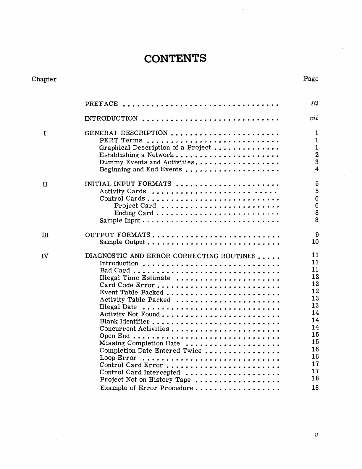
CONTENTS
PREFACE
•••••••••••••••••••••••••••••••••
INTRODUCTION
•••••••••••••••••••••••••••••
GENERAL
DESCRIPTION
••••••••••••••
PERT
Terms
•••••
•
•••••••
Graphical
Description
of a
Project
Establishing
a
Network
•••••
Dummy
Events
and
Activities.
Beginning
and
End
Events
INITIAL
INPUT
FORMATS
Activity
Cards
Control
Cards
•••
Project
Card
Ending
Card
Sample
Input.
. . . • . . . . . •
OUTPUT
FORMATS.
Sample
Output . .
DIAGNOSTIC
AND
ERROR CORRECTING ROUTINES
Introduction
• • • • • • • •
Bad
Card
••••••••••
Illegal
Time
Estimate
Card
Code
Error
•••••
Event
Table
Packed
•••
Activity
Table
Packed
Illegal
Date
Activity
Not
Found
•••
Blank
Identifier
••••••
Concurrent
Activities
Open
End
••••••••
..
..
Missing
Completion
Date
•••••
Completion
Date
Entered
Twice
Loop
Error
•••••••••
Control
Card
Error
•••••••
Control
Card
Intercepted
Project
Not on
History
Tape
•••••
Example
of
Error
Procedure
• .
, .
Page
iii
vii
1
1
1
2
3
4
5
5
6
6
8
8
9
10
11
11
11
12
12
12
13
13
14
14
14
15
15
16
16
17
17
18
18
v
Chapter
v
VI
VII
Appendix
A
B
C
vi
CONTENTS (Cont'd)
SUCCESSIVE RUNS
The
History
Tape
Updating
••••••
Input
Data
for
Successive
Runs
Activity
Cards
Control
Cards
A New ID
Card
•••••
Error
Correction
SERVICE
ROUTINES
Introduction
PERTSERV
Card
Formats
••
PRINTHIST
PUNCHIST
••
DELETE
COMPRESS
COpy
ADD
LIST
••••
WRTSENT
REWIND
TAPE-TO-CARD
•
BININPUT
MESSAGE
HALT
INPUT
PREPARATION
AND
OPERATING
INSTRUCTIONS
••
Input
Preparation
Program
Halts
Output'
Processing
TYPE-OUTS
••
PROJECT
SIZE
ADAPTING
PERT
TO
AN
OPERATING
SYSTEM
••••••••
Page
21
21
21
22
22
23
23
24
25
25
25
26
26
26
27
27
28
28
28
29
29
29
30
31
31
31
31
33
35
37
INTRODUCTION
The
Philco
2000
PERT
System
allows
PERT
computations
to
be
performed
on the
Philco
2000.
The
following
are
special
features
of
the
Philco
2000
PERT
System:
•
•
•
•
o
o
•
o
•
•
•
•
•
Handles
projects
consisting
of
up-
to
7400
activities
and
3700
events.
Operates
at
extremely
high
speeds.
PERT
projects
of 1000.
activities
have
been
run
on
the
Philco
212
in
7
seconds,
including
input/output
time.
Permits
the
use
of
symbolic
event
names.
Allows
activities
to
be
submitted
in
random
order;
the
Philco
2000
PERT
System
resequences
them
and
creates
the
project
network.
Provides
the
option of giving
either
one
or
three
time
estimates
for
each
event.
PERT
input
may
be
on a
special
PERT
tape
or
on
the
general
operating
system
input
tape.
Allows
for
buffered
input
if
the
special
PERT
input
tape
is
used.
Program
data
for
any
project
is
contained
in
memory,
thus
eliminating
the
need
for
intermediate
tapes.
Includes
a
complete
set
of
integrated
prognostic,
diagnostic,
and
service
routines.
Incorporates
automatic
machine
methods
of
testing
PERT
networks
for
consistency
and
legitimacy
of input
data.
Computes
variance
to
determine
the
probability
of
meeting
scheduled
dates.
The
system
maintains
a
complete
history
tape
which
permits
subsequent
runs,
and
easy
project
modification
and updating.
Input
for
successive
runs
may
be
on punched
cards
or
on
the
history
tape.
vii

viii
• Allows
changes
to
be
made
to
initial
program
data
through
the
use
of a new ID
Card,
without
destroying
the
original
data.
• Does not
require
a knowledge of any
computer
or
of
pro-
gramming
logic.
I.
GENERAL DESCRIPTION
PERT
TERMS
GRAPHICAL
DESCRIPTION
OF
A
PROJECT
PERT
is
a
process
by which,
after
designating
the
tasks
comprising
a
project,
establishing
the
interrelations
between
the
various
tasks,
and
specifying
the
amount
of
time
required
to
complete
each
task,
the
crucial
tasks
of the
project
may
be
determined.
Any
delay in
accomplishing
these
crucial
tasks
will delay
the
final
completion
of the
entire
project.
In
describing
PERT
as
prepared
manually
or
as
solved
on the
Philco
2000,
the
following
common
PERT
terms
are
used:
o A
project
is
defined
as
a
network
of
activities
and
events.
o
Activities
are
time
consuming
el~ments;
tasks
to
be
achieved.
•
Events
are
the
termini
of
activities.
They
designate
either
specific
accomplishments
or
points
at
which
the
programs
start.
Activities
are
separated
from
each
other
by
events
which
are
used
as
activity
identifiers.
o
The
duration of
an
activity
is
the
time
period
required
to
complete
an
activity
successfully.
•
The
critical
path
is
the
specific
sequence
of
events
which
comprises
the
most
rigorous
time
constraint
in
the
accom-
plishment
of
the
end event.
If
any
event
on the
critical
path
is
delayed
beyond
the
expected
date of
accomplishment,
the
final
completion
date
of
the
entire
project
can
be
expected
to
be
delayed
by
the
same
amount of
time.
• The
slack
of
an
event
is
defined
as
the
time
interval
by which
the
completion
of a
certain
event
can
be
delayed
without
delaying the final
completion
date
of
the
end event.
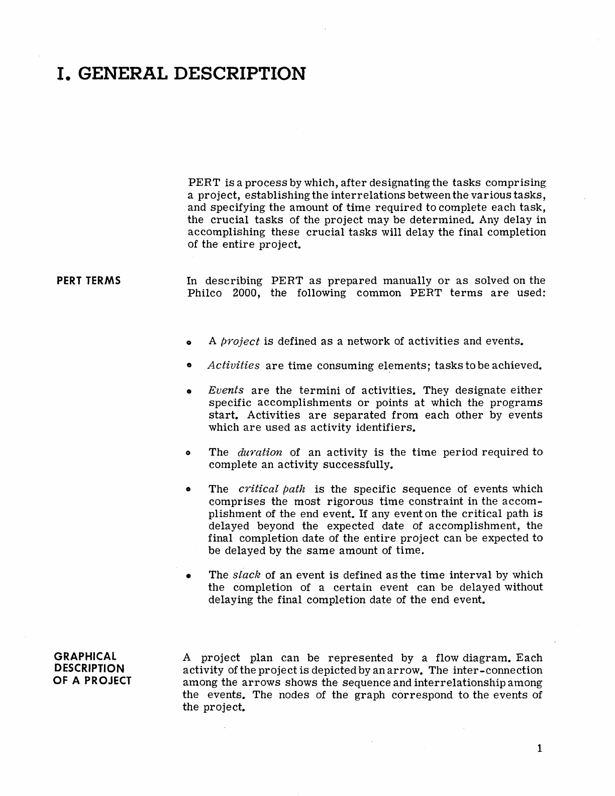
A
project
plan
can
be
represented
by a flow
diagram.
Each
activity
of
the
project
is
depicted
by
an
arrow.
The
inter-connection
among
the
arrows
shows
the
sequence
and
interrelationship
among
the
events.
The nodes of
the
graph
correspond
to
the
events
of
the
project.
1
EST
ABLISHING
A NETWORK
2
Ot-----~
)--------II~
5
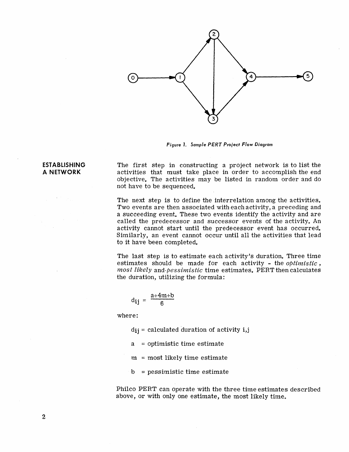
Figure
1.
Sample
PERT
Pro;ect Flow Diagram
The
first
step
in
constructing
a
project
network
is
to
list
the
activities
that
must
take
place
in
order
to
accomplish
the
end
objective.
The
activities
may
be
listed
in
random
order
and do
not have
to
be
sequenced.
The next
step
is
to define
the
interrelation
among
the
activities.
Two
events
are
then
associated
with
each
activity,
a
preceding
and
a
succeeding
event.
These
two
events
identify
the
activity
and
are
called
the
predecessor
and
successor
events
of the
activity.
An
activity
cannot
start
until
the
predecessor
event
has
occurred.
Similarly,
an
event
cannot
occur
until
all
the
activities
that
lead
to
it
have
been
completed.
The
last
step
is
to
estimate
each
activity's
duration.
Three
time
estimates
should
be
made
for
each
activity
-
the
optinzistic ,
most
likely
and·pessimistic
time
estimates.
PERT
then
calculates
the
duration,
utilizing
the
formula:
where:
dij =
calculated
duration
of
activity
i,j
a =
optimistic
time
estimate
m =
most
likely
time
estimate
b =
pessimistic
time
estimate
Philco
PERT
can
operate
with
the
three
time
estimates
described
above,
or
with only one
estimate,
the
most
likely
time"
DUMMY
EVENTS
AND
ACTIVITIES
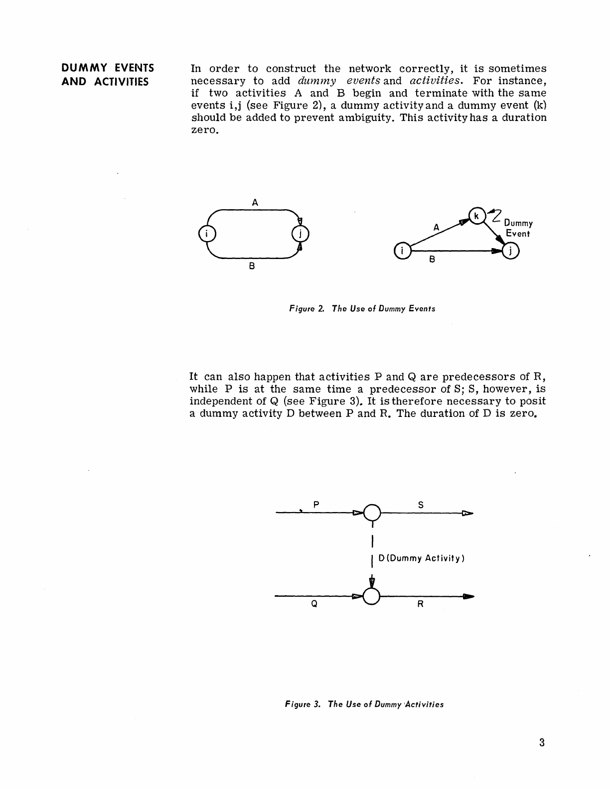
In
order
to
construct
the
network
correctly,
it
is
sometimes
necessary
to
add
dummy
events
and
activities.
For
instance,
if two
activities
A and B
begin
and
terminate
with
the
same
events
i,j
(see
Figure
2), a
dummy
activity
and a dummy
event
(k)
should
be
added
to
prevent
ambiguity.
This
activity
has
a
duration
zero.
A
~mY
Event
i j
B
B
Figure
2.
The
Use
of Dummy
Events
It
can
also
happen
that
activities
P and Q
are
predecessors
of R,
while P
is
at
the
same
time
a
predecessor
of S; S,
however,
is
independent of Q (see
Figure
3).
It
is
therefore
necessary
to
posit
a dummy
activity
D
between
P and R. The
duration
of D
is
zero.
p
~
S
,
0>
I
D(Dummy
Activity)
~
..
Q R
Figure
3.
The
Use
of
Dummy
'Activities
3

BEGINNING
AND
END EVENTS
4
It
is
necessary
to
introduce
a unique
event
which
initiates
the
project.
This
event
is
the
only one which
has
no
predecessor.
Similarly,
a unique
event
should
terminate
the
project.
This
is
the
. only event
that
has
no
successor.
If
a
project
starts
with
several
events
(or
ends
with
more
than
one event), one
particular
event
should
be
selected
as
the
initiating
(or
terminating)
event,
and
the
rest
should
succeed
(or
precede)
it,
utilizing
dummy
activities
as
connectors.
II. INITIAL INPUT FORMATS
ACTIVITY
CARDS
The input
data
for
the
initial
run
consists
of a
list
of
the
activities
of
the
project,
each
activity
being
identified
by
its
predecessor
and
successor
events.
For
each
activity
there
should
be
one
or
three
time
estimates.
If
there
is
a
scheduled
date
for
the
comple-
tion
of
an
activity,
this
date
can
be
submitted
with
that
activity.
In
addition
to
the
information
given with
each
activity,
the
project
starting
date
must
be
given;
specifying
a deadline date
is
optional.
Activity
cards
may
be
submitted
in
any
order
and
should
be
pre-
pared
in
the
following
format:
Column
Content
1
Card
code. Should
be
1
to
indicate
an
initial
run.
2-10
A
nine-character
predecessor
event
identifier.
The
characters
can
be
any
legitimate
Philco
2000
characters,*
provided
they
are
not
all
spaces.
11-19
A
nine-character
successor
identi-
fier,
restricted
as
above.
20-23
Optimistic
time
estimate.
**
24-27
Most
likely
time
estimate.
**
28-31
Pessimistic
time
estimate.
**
*
Refer
to
Philco
2000 Code
Combinations,
TF
17.
**
The
time
estimates
are
four
digits
each
and
are
given
in
tenths
of a week. The
decimal
point
is
not punched.
If
only one
time
estimate
is
given,
it
should
be
punched
in
columns
24-27.
For
example,
a
time
estimate
of 2
weeks
is
represented
as
0020.
5
CONTROL
CARDS
Project
Card
6
000000000000000000
0
00
00001000000001000000001000000010
0
010
00001000000
1 l l • 5 , 1 I I " II
12
1J
14 15
"
II
" "
10
21
12
21 24
15
U n n
1I.
3t
J2
Ui
~tl1
11 11
••
q"
ulu
44
4\
U
4141"
!II1~1
U U
~
'fa
!II
\1
!illS."
11
\)
...
e
,,'"
....
n
12
n lIh, .. n
11
JI.
11111111111111111111·
111··
11111'
1"1111111
11111111111111111111111'
111'111111-1-'111111
I I I I I' I
o
222222222222"
2 2 2 2 2 2 2 2 2 2 2 2 2 2 2
2'
2
2"
212
2'
22222122222222122
22222122222222122
2'
Z Z"
ZIZ
Z - Z Z Z
.. I I I I I 1
:::
333333
33
3333333
3 3 3 3 3 3 3 3
33333333
3
313
3 3 3 3 3 3
313
3 3 3
33313333
3 3 3
313
3 3
333331333333331333333
o I I I I 1 1
o
4444444444
4444444444444
44444444
441444444441444444441
44444441444444441444444441444444
ee
5555
55 55
555
5555555555
5555555:
555555
5:5
5 55
5:5
555
55:555555
5
5~
555555
S}
55555
f 1 I I I I 1
666666666666666666666666
6 6
6666666616
66666
616
6 6 6 6 6 6
61&
6 6 6 6 6 6
616
6 6 6 6 6 6
616
I 6 I • & &
III'
6
III
I I I I I I
777777777
7777
777777777777777777717777777717
7 7 7 7 7 7
17777
77717777777717
7 7 7 7 7 7
717
7 7 7 7 7
I I 1 I I I
8
8888888888888888888888888888888818888888
1888888881888888881888888'
818
8 8
8888
II'
I
II"
ID:~TI:fYN~~D
L LOCAT'I')N
COMMAND
1 2
------1
:J
ADDUls
AND
:MAUS
: S : 6 I 1
1 4 i I I
12
1
14
I~
I TfIT1§" lr21
11
13
4
~
5 1 1 I
42
.]44
d U
41
ij
d
!lI
51
51
il
!tot
i
Si
5j
$I
!d
iii
Ii
4
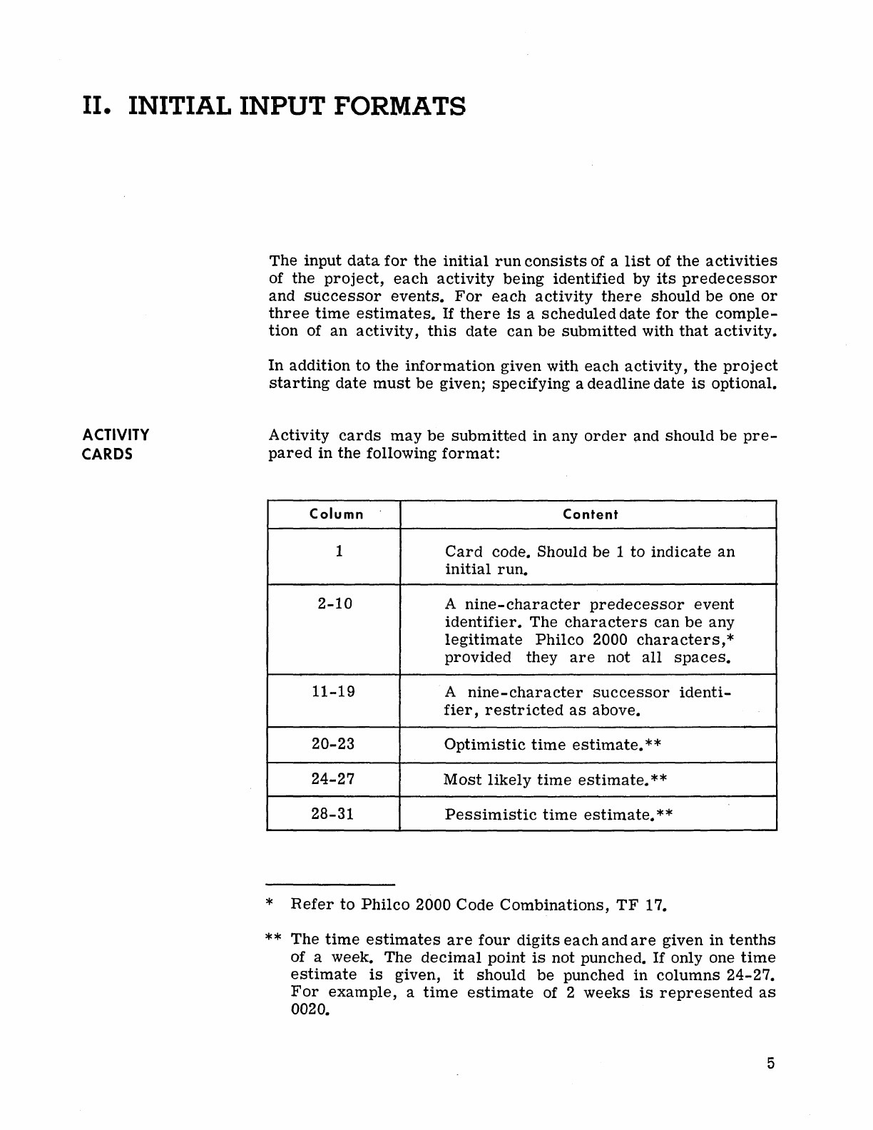
Figure
4.
Sample
Activity
Carel
Predecessor
and
Successor
Events:
HIRE
3ENG
and
DESIGN
Time
Estimates:
One Week, One
and
One-Half
Weeks,
and
Two
Weeks
Scheduled
Date:
December
15, 1962
A
project
card
must
head
each
project
deck
and
is
punched
as
follows:
Column
Content
1-7
PROJECT
8 I
(Indicates
initial
run)
9-24
Project
identification
25-30
Project's
beginning
date
33-38
Project's
end
date
(optional)
41
1,
if
one
time
estimate
is
given;
blank,
if
three
time
estimates
are
given.
49-53
CARDS,
if
the
history
is
on
cards;
blank,
if
the
history
is
on
the
history
tape.
55-80
Remarks
D01OOO_o
0~00DTI0
-
0000000
000
a 0 0
D10
0 0 0 0 0 0
010
0 0 0 0 0 0
010
0000
D 0
010
0 0 0 0 0 0
010
O'
D a a 0
DID.
a 0 D G
1 J I • I I J I I
'1
II
11
IJ
MIS"
n
..
11
M
21
n n
24
It
,.
n a
II
•
31
Jl
JJ
1111$
• U
....
u
ulu«
4$
,..
c,
.....
hl
II U
)01
• " u
./
••
1111 U
....
)I1
•••
"
II
q
.hl
• "
II"
•
III
11111111111111111111
1111'
11111111111111111111111111111111111111111111111111111111
- I I I , I I
: 2
222
2 2 2 2 2 2 Z Z Z 2 Z Z 2 Z Z Z Z 2 2 2 2 2 2 Z Z
2122
2 2 2 2 2
Z12
2 2 2 2 2 2
212
2 2 2 2 2 2
212
2 2 2 2 2 2
212
2 2 2 2 2 2
212
2 2 2 2 2
1 I I I I 1
..
33333
333
3
3333
333
33333333333
II
313
3 3 3 3 3
3313333333313
333333313333333313333333313
3 3 3 3 3
o I 1 I I 1 I
o
444444444
44 4
444444444444444
(444144444444144444444144444444144444444144444444144
4
444
e~
5555
555
5 5 5 5 5 5 5 5 5 5 5 5
555
5 5 5 5
555555:555555
55:55555555:55555555:55
5
~
5 5 5
5:5
5 5 5 5 5 S
5:5
5 5 5 5 5
~
I 1 J 1 I 1
II.
16
& & 6 6 6 & & 6 6 6 6 6 6 & 6 6 & 6 6
6666
66666166666666166&666661666666661666666
I
616
6&
6
III
61111111
I I 1 I I I
77
777
7 7 7 7 7
777
7 7 7 7 1 7 1 7 7 7 7 7 1
11117
11111 7
11111111111
7 11111 7
11
7
111
7 1 7 1111111 7 7 7 7
7717
7 7 7 7 7
• I 1 I I I 1
1.888.8
I 8
••••
8 • 8
.8888888
8 8 8
888888818
a 8 a 8 8 8
818
8 8 8
•••
818
8 8 8 8 • 8
818
8 8 • 8 8 8
818
a 8 8 8 • 8
811
I I •
II
ID:I~~l(:~:D
I
'OCAJJO,",
(",,)MMAND'
, I 1
ADOIf~S
AND
.:1114
...
"'5
: s : • I 7
I " I
111
41"
44'"
4
~1T1I"lf1flfn"ll
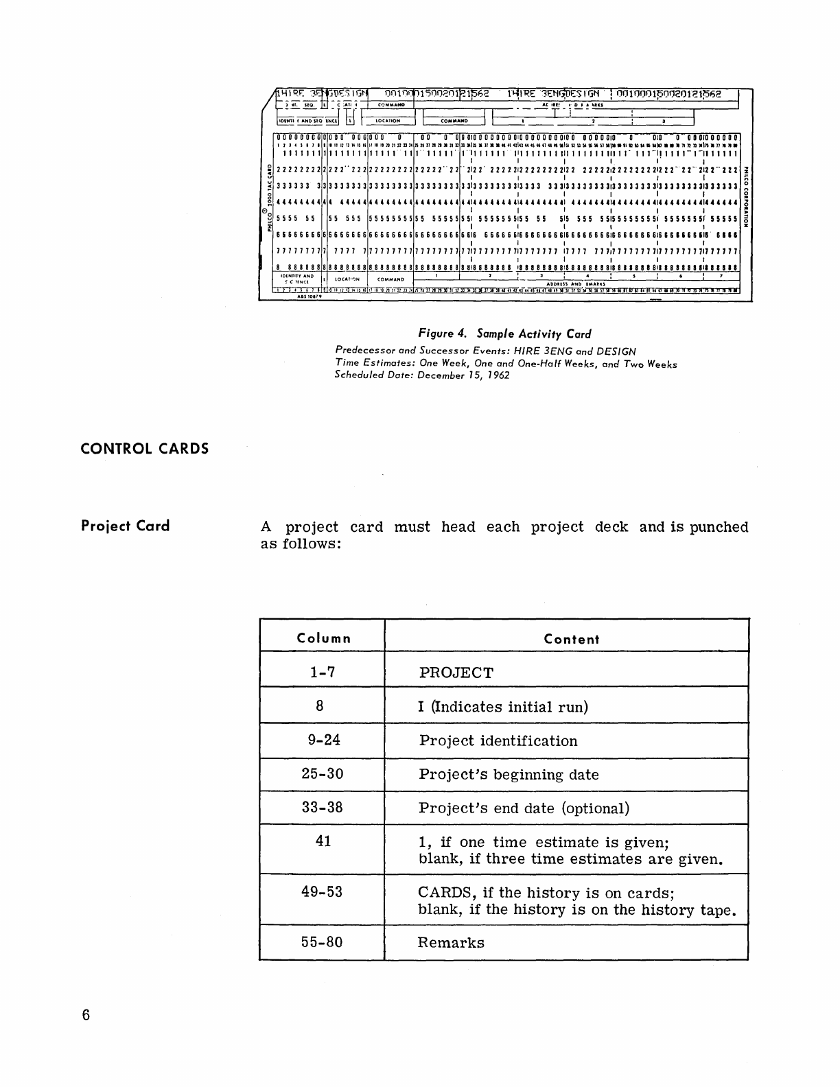
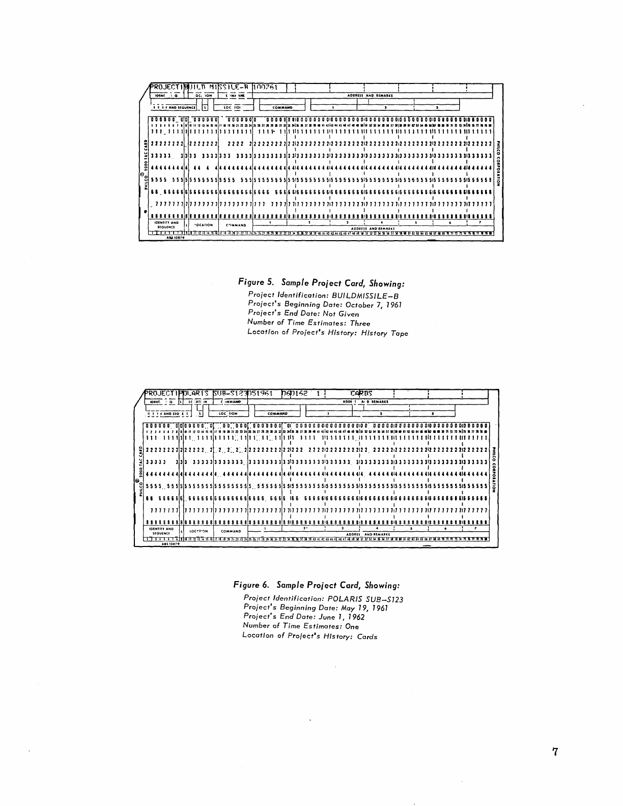
Figure
5.
Sample
Project
Carel,
Showing:
Project
Identification:
BUILDMISSILE-B
Project's
Beginning
Date:
October
7,
1961
Project's
End
Date:
Not
Given
Number
of
Time
Estimates:
Three
Location
of
Project's
History:
History
Tope
o 0 0 0 0
o.
0 0 0 0 0 0
0"
0
,,0
0"
0 0 0 . 0 0 0 0 0 0
O.
01.
0 0 0 0 0 0
ala
a a a 0 a 0
010
0 0 0 0 0
010
0 0 0 0 0 0
010
0 0 0 a 0 0
DID
DODO
D
I , J f J , J
••
"II
""
Ie
IS
11
IF
lilt
.11
n n
24
a H
112121.'1
U
~
1111$."
••
41
U 41143"
cs
..
n _ u
.111
U U
~
55
51
5151131
.1112
U
M.
_kr
•••
n
J2
n
Min.
n
•••
111
1111111,,111111111::1111::11:.111111
1111
,1
1,1"".,11,1,111111,1111111111111111111111
I I I I I I
5
2222
2 2 2 2 2 2 2 2 2
2"
2
.2"
2:. 2:. 2 2
22222
2 2 22:2 22
2222:22222222:22
22222;22
2 2 22 2
2:2
2 2 2 2 2
22:22222
2
~
33333
333
333333333333.,
3333333333:33333333:333333.
3:33333333;33333333:33333333;333333
~
44
4 4
44
4 4 4 4 4 4 4
4444
.. 4
44
4
44
4 4 4 4 4 4 4 4 4
414
44
4
44
4
414
4 4 4 4 44414.
44444414444
4 4 4
414
4
44
U 4
4144
4 4
44
8 I I I I I I
~
5555
..
5 5 5 5
5555555
5 5 5 5 5 5 5 5
5.,5555555
515555555515555555515555555515555555
515
5 5 5 5
5551555555
ill
I I I 1
..
II
6 6 6 6 6 6 , 6 6 & 6 6 6 & & 6 6 6 6 & 6 6 6 &
6,
& & 6 &
1&
& & 6 6 6
616
6 6 6 6 6 6
616
6 6 6 6 6 6
616
6 & & 6 & 6
&1&
6 6 & & 6 I
616
& 6 6
II
I I I I I I
1717111
717117171117711777177111711117711111771711111117
711
71111717
7
7117
7 7 71
71171717
7
I I I I I I
a 8 8 8 8 8 8 8 8 8 8 8 8 8 8 8 8 8 8 8 8 8 8 8 8 8 8
88888
8
818
8 8
888
8
818
8 8 8 8 8 8
818
a 8 a
888
818
8 8 8 8 8 8
818
8 8 8 8 8 a
III
8 •
II
•
IO:~~~l'N~~O
L
LOC"''',)N
COMMAND
~
I
2-
1 1
ADD.I~
AND
.:MAUS
: " 1 • I 7
Figure
6.
Sample
Project
Carel,
Showing:
Pro;ect
Identification:
POLARIS
SUB-S123
Pro;ect's
Begi~nin9
Dote:
May 19, 1961
Pro;ect's
End
Dote:
June
1, 1962
Number
of
Time
Estimates:
One
Location
of
Project's
History:
Cords
7
Ending Card
SAMPLE
INPUT
8
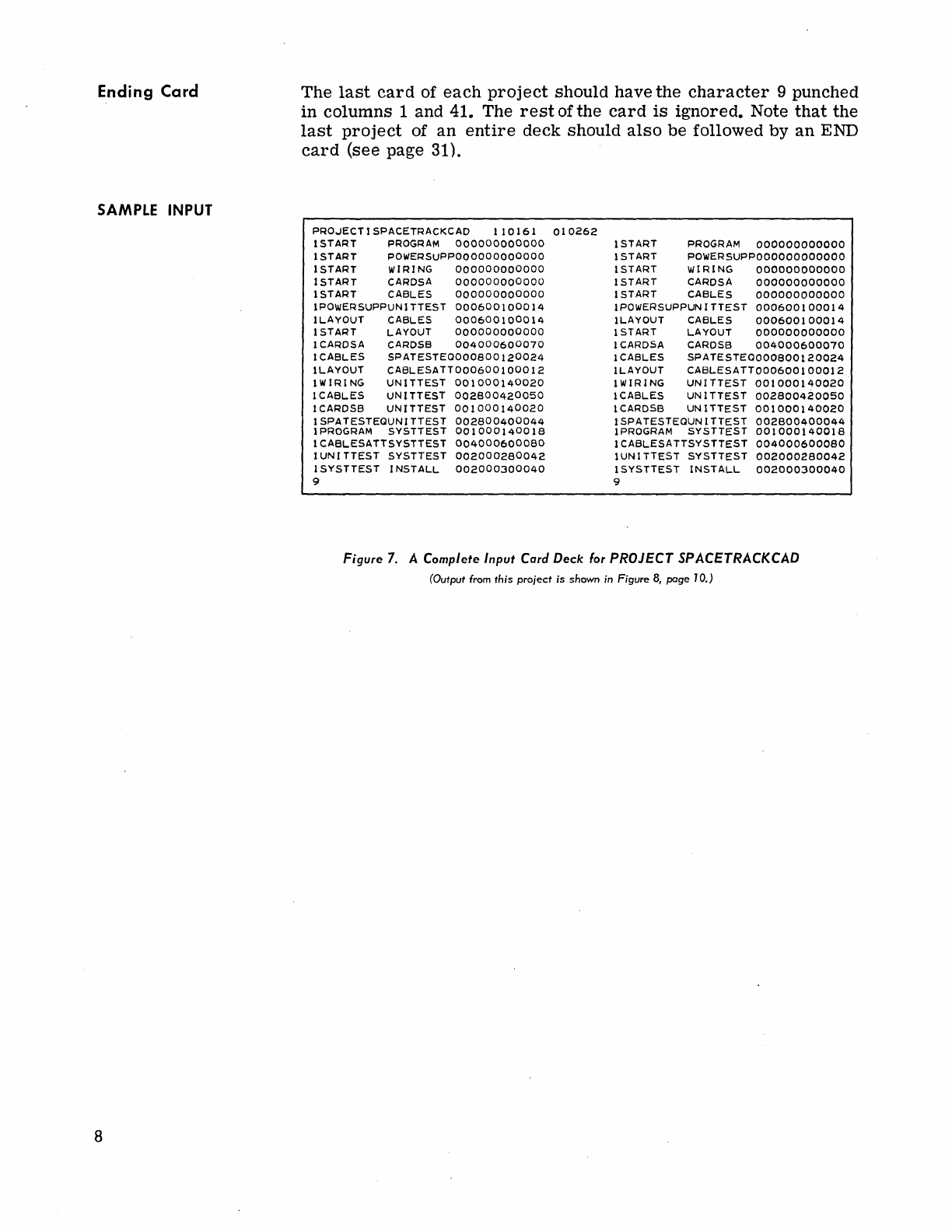
The
last
card
of
each
project
should
have
the
character
9 punched
in
columns
1 and 41. The
rest
of
the
card
is
ignored.
Note
that
the
last
project
of
an
entire
deck
should
also
be
followed
by
an
END
card
(see page 31).
P~O~ECTISPACET~ACKCAD
110161
010262
lSTA~T
P~OG~AM
000000000000
ISTART
POWERSUPPOOOOOOOOOOOO
lSTART WIRING
000000000000
ISTART
CARDSA
000000000000
ISTART CABLES
000000000000
IPOWERSUPPUNITTEST
000600100014
lLAYOUT CABLES
000600100014
lSTART
LAYOUT
000000000000
lCA~DSA
CARDSB
004000600070
lCABLES SPATESTEOOOOB00120024
lLAYOUT
CABLESATT000600100012
lWI~ING
UNITTEST
001000140020
lCABLES UNITTEST
002800420050
lCARDSB UNITTEST
001000140020
lSPATESTEOUNITTEST
002800400044
IPROG~AM
SYSTTEST
001000140018
lCABLESATTSYSTTEST
004000600080
lUNITTEST
SYSTTEST
002000280042
ISYSTTEST
INSTALL
002000300040
9
lSTA~T
PROG~AM
000000000000
ISTA~T
POWE~SUPPOOOOOOOOOOOO
ISTA~T
WI~ING
000000000000
ISTA~T
CA~DSA
000000000000
ISTA~T
CABLES
000000000000
IPOWE~SUPPUNITTEST
000600100014
lLAYOUT CABLES
000600100014
ISTA~T
LAYOUT
000000000000
lCARDSA
CA~DSB
004000600070
lCABLES
SPATESTE0000800120024
lLAYOUT
CABLESATT000600100012
lWI~ING
UNITTEST
001000140020
lCABLES UNITTEST
002800420050
lCARDSB UNITTEST
001000140020
ISPATESTEOUNITTEST
002800400044
IPROGRAM
SYSTTEST
001000140018
lCABLESATTSYSTTEST
004000600080
lUNITTEST
SYSTTEST
002000280042
ISYSTTEST INSTALL
002000300040
9
Figure
7.
A Complete Input
Card
Deck
for
PROJECT SPACETRACKCAD
(Output from
this
project
is
shown
in Figure
8,
poge
10.)
III
0
OUTPUT
FORMATS
The output
from
a
PERT
program
consfsts
of a
complete
list
of
all
the
activities
of
the
project
including
the
dummy
activities.
Each
activity
is
identified
by
the
original
predecessor
and
successor
events
of the
activity
card.
The
printed
output
for
each
activity
is
described
below.
o
o
o
o
o
o
o
The
expected
date
is
the
earliest
possible
completion
date of
the
activity.
Calculation
of
this
date
is
based
on
the
beginning
date
of
the
project,
the
durations
of
the
activities
and
the
inter-
relations
among
the
preceding
activities.
The
late
date
is
the
latest
possible
date
for
completion
of
an
activity
without delaying
the
completion
of the end event.
The
slack
of
an
activity
is
the
difference
between
the
late
date
and
the
earliest
expected
date
for
completion
of
the
activity.
The
activities
with
slack
zero
are
the
critical
path
activities.
The
slack
is
printed
in weeks..
For
example,
a
slack
of 2.5
is
a
slack
of two and a
half
weeks
..
The
schedule
date
is
the
date
specified
on
the
activity
card
in
columns
32-37
..
The actual completion date
is
the
date
on which
an
activity
was
actually
completed.
(See Updating, page
21
and Input
Data
for
Successive
Runs,
page 22.)
The
duration of
an
activity
is
the
calculated
value
a+4m+b/6
if
three
time
estimates
were
made
..
(See
Establishing
a
Net-
work,
page 2.)
If
only one
time
estimate
is
made,
the
duration
is
equal
to
that
time
estimate.
The
program
also
calculates
the
variance
of
the
duration.
Utilizing
the
computed
'variance
it
is
possible
to
estimate
the
probability
of
actually
meeting
scheduled
dates.
9
SAMPLE
OUTPUT
10
PERT
calculates
the
variance
using
the
formula
where:
V" _
(b-a)
2
1J
-6
Vij = The
variance
of
activity
i,j
a =
Optimistic
time
estimate
b =
Pessimistic
time
estimate
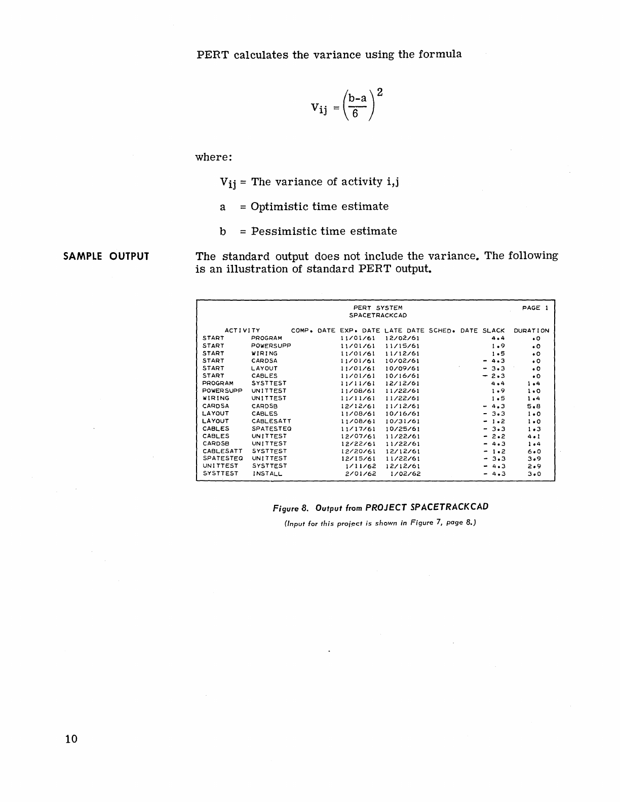
The
standard
output
does
not include
the
variance.
The
following
is
an
illustration
of
standard
PERT
output.
ACTIVITY
COMPo
START
PROGRAM
START
POWERSUPP
START
WIRING
START
CARDSA
START
LAYOUT
START
CABLES
PROGRAM
SYSTTEST
POWERSUPP
UNlTTEST
WIRING UNITTEST
CARDSA
CARDSB
LAYOUT
CABLES
LAYOUT
CABLESATT
CABLES SPATESTEO
CABLES UNITTEST
CARDSB
UNITTEST
CABLESATT SYSTTEST
SPATESTEO UNITTEST
UNITTEST SYSTTEST
SYSTTEST INSTALL
Figure 8.
DATE
PERT
SYSTEM
SPACETRACKCAD
EXP.
DATE
LATE
DATE
11/01/61
12/02/61
11/01/61 11/15/61
11/01161
11/12/61
11/01/61
10/02/61
11/01161
10/09/61
11/01/61
10/16/61
11/11/61
12/12/61
11/08/61
11/22/61
11/11/61
11/22/61
12/12/61
11/12/61
11/08/61
10/16/61
11/08/61
10/31/61
11/17/61
10/25/61
12/07/61
11/22/61
12/22/61 11/22/61
12/20/61
12/12/61
12/15/61
11/22/61
1/11/62
12/12/61
2/01/62
1/02/62
SCHED.
DATE
SLACK
4.4
1.9
1.5
-
4.3
-
3.3
-
2.3
4.4
1.9
1.5
-
4.3
-
3.3
-
1.2
-
3.3
-
2.2
-
4.3
-
1.2
-
3.3
-
4.3
-
4.3
Output
from
PROJECT SPACETRACKCAD
(Input
for
this
proi.ect
is
shown
in
Figure
7,
page
8.)
PAGE
1
DURATION
.0
.0
.0
.0
.0
.0
1.4
1.0
1.4
5.8
1.0
1.0
1.3
4.1
1.4
6.0
3.9
2.9
3.0
IV. DIAGNOSTIC
AND
ERROR CORRECTING
ROUTINES
INTRODUCTION
BAD
CARD
Description
Print-out
Format
Procedure
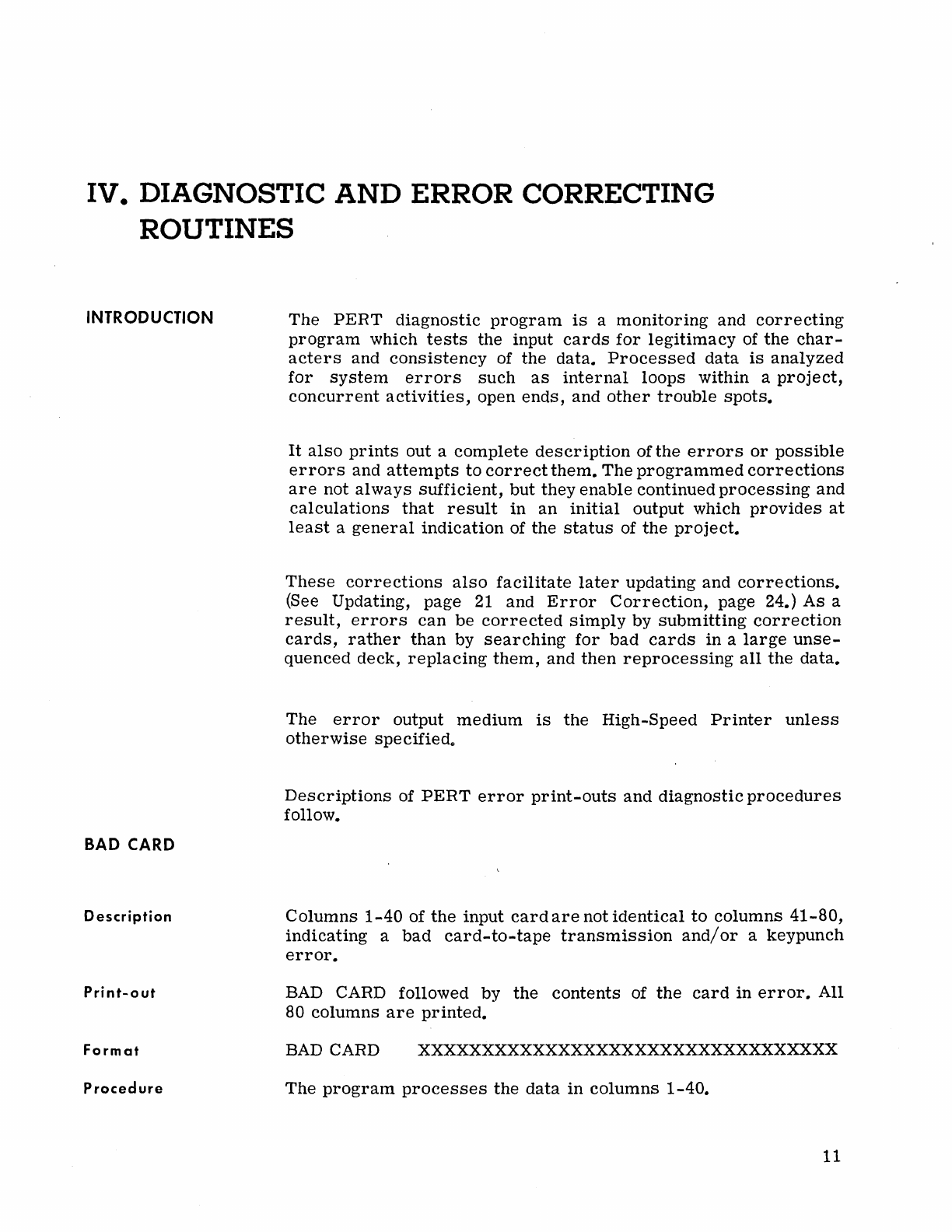
The
PERT
diagnostic
program
is
a
monitoring
and
correcting
program
which
tests
the input
cards
for
legitimacy
of
the
char-
acters
and
consistency
of the
data.
Processed
data
is
analyzed
for
system
errors
such
as
internal
loops within a
project,
concurrent
activities,
open
ends,
and
other
trouble
spots.
It
also
prints
out a
complete
description
of
the
errors
or
possible
errors
and
attempts
to
correct
them.
The
programmed
corrections
are
not
always
sufficient,
but
they enable continued
processing
and
calculations
that
result
in
an
initial
output which
provides
at
least
a
general
indication
of the
status
of
the
project.
These
corrections
also
facilitate
later
updating and
corrections.
(See Updating, page
21
and
Error
Correction,
page 24.) As a
result,
errors
can
be
corrected
simply
by
submitting
correction
cards,
rather
than
by
searching
for
bad
cards
in a
large
unse-
quenced deck,
replacing
them,
and
then
reprocessing
all
the
data.
The
error
output
medium
is
the
High-Speed
Printer
unless
otherwise
specified"
Descriptions
of
PERT
error
print-outs
and
diagnostic
procedures
follow.
Columns
1-40
of
the
input
card
are
not
identical
to
columns
41-80,
indicating
a
bad
card-to-tape
transmission
and/or
a keypunch
error.
BAD
CARD followed by
the
contents
of
the
card
in
error.
All
80
columns
are
printed.
BAD
CARD xxxxxxxxxxxxxxxxxxxxxxxxxxxxxxxxx
The
program
processes
the
data
in
columns
1-40.
11
ILLEGAL
TIME
ESTIMATE
Description
Print-out
Format
Procedure
CARD
CODE
ERROR
Description
Print-out
Format
Procedure
EVENT
TABLE
PACKED
Descri
pti
on
Print-out
Format
Procedure
Remarks
12
A
time
estimate
is
illegal
if any of
its
characters
are
not
numeric
(space
is
an
illegitimate
character),
or
if
the
three
time
estimates
do not
satisfy
the
inequality
a
~
m :s
b.
ILLEGAL
TIME ESTIMATE followed
by
the
contents
of
the
activity
card
in
error.
ILLEGAL
TIME ESTIMATE XXXXXXXXXXXXXXXXXXXXX
PERT
assigns
the
value
zero
to
the
duration
and
the
value.
01
to
the
variance.
An
illegitimate
character
is
detected
in
column
1 of
the
activity
card.
CODE followed
by
the
contents
of
the
card
in
error.
CODE XXXXXXXXXXXXXXXXXXXXXXXXXXXXXXXX
The
program
interprets
the
code
as
code 1
and
continues
the
processing.
The
number
of
events
of a
project
is
larger
than
the
maximum
allowable
number
of
events
(see
Appendix
B).
EVENT
TABLE
PACKED followed
by
the
contents
of
the
card
that
caused
the
error
or
by
the
activity
identifiers
only.
EVENT
TABLE
PACKED XXXXXXXXXXXXXXXXXXX
or
CONCURRENT ACTIVITIES
EVENT
TABLE
PACKED I J
The
event
is
ignored
and
the
program
completes
the
processing
of
the
input
data
but
does
not
perform
the
analysis
and
scheduling.
The
processed
data
is
put
on
the
history
tape
or
on
cards;
adjust-
ments
should
be
made
during
successive
runs.
(See
Chapter
V,
Successive
Runs,
page
21.)
The
event
table
could
be
packed
as
a
result
of
too
many
events
in
the
input
data,
in
which
case
the
contents
of
the
card
containing
the
event
that
could
not
be
entered
into
the
event
table
is
printed.
If
the
event
table
is
packed
due
to
the
need
to
add
a
dummy
event
(see
Concurrent
Activities,
page
14),
the
identifying
events
of
the
concurrent
activities
are
printed.
ACTIVITY
TABLE
PACKED
Description
Print-out
Formats
Procedure
Remarks
ILLEGAL
DATE
Description
Print-out
Format
The
number
of
activities
is
larger
than
the
maximum
allowable
number
of
activities
(refer
to
Appendix
B).
ACTIVITY
TABLE
PACKED followed
by
the
contents
of
the
card
or
the
identifying
events
of
the
activity
that
could
not
be
entered
into
the
activity
table.
ACTIVITY
TABLE
PACKED
or
CONCURRENT ACTIVITIES
or
OPEN
END
or
OPEN
END
xxxxxxxxxxxxxxxxxxxxxx
ACTIVITY
TABLE
PACKED
IJ
ACTIVITY
TABLE
PACKED
HAS
NO
PREDECESSOR
ACTIVITY
TABLE
PACKEDI
HAS
NO
SUCCESSOR
The
activity
is
ignored
and
the
program
completes
the
processing
'of
the
input
data,
but
does
not
perform
the
analysis
and
scheduling.
The
processed
data
is
stored
on
the
history
tape
or
on
cards.
Adjustments
should
be
made
during
successive
runs"
The
activity
table
could
be
packed
as
a
result
of
too
many
activities
in
the
input
data.
In
this
case,
the
card
which
contains
the
activity
that
could
not
be
entered
into
the
activity
table
is
printed.
If
the
activity
which
cannot
be
entered
into
the
activity
table
is
a
pro-
grammed
dummy
activity,
this
information
will
be
printed"
(Refer
to
Formats
above;
Blank
Identifier,
page
14;
and
Concurrent
Activities,
page
14.)
An
illegal
date
is
detected
on
an
activity
card"
The
following
are
illegal
dates:
• A
date
with
a
non-numeric
character
(e"g.,
spaces)
o A
date
that
does
not
exist,
such
as
15/1/60
• A
date
in
a
year
previous
to
the
year
or
to
the
beginning
of
the
project.
ILLEGAL
DATE
followed
by
the
contents
of
the
card
which
contains
an
illegal
date"
ILLEGAL
DATE XXXXXXXXXXXXXXXXXXXXXXXXXXXXXXXX
13
Procedure
ACTIVITY
NOT FOUND
Description
Print-out
Format
Procedure
BLANK
IDENTIFIER
Description
Print-out
Format
Procedure
The
date
is
ignored"
If
the
date
error
concerns
the
initial
date
of
the
project
during
an
initial
run,
PERT
processes
the
input
and
puts
the
data
on
the
history
tape
or
on
cards,
but
does
not
proceed
with
the
analysis
and
scheduling.
If
the
date
error
concerns
the
initial
date
during
a
successive
run,
the
program
uses
the
initial
date
used
in
the
previous
run,
and
ignores
the
new
starting
date.
An
activity
with
a
code
different
from
1 (new
activity
card)
is
not
in
the
activity
table
(see
Successive
Runs,
page
21).
ACTIVITY NOT FOUND followed
by
the
contents
of
the
activity
card.
ACTIVITY NOT FOUND
XXXXXXXXXXXXXXXXXXXXXXXXXX
The
activity
card
is
ignored.
An
identifier
event
which
is
all
spaces
(9
spaces)
is
detected.
BLANK
IDENTIFIER
followed
by
the
contents
of
the
card.
BLANK
IDENTIFIER
XXXXXXXXXXXXXXXXXXXXXXXXXXXX
The
identifier
is
changed
to
?????????
and
the
program
continues
processing.
CONCURRENT
ACTIVITIES
Description
Print-out
Formats
14
Concurrent
activities
are
activities
with
identical
predecessor
and
successor
identifiers.
CONCURRENT ACTIVITIES
followed
by
the
predecessor
and
successor
identifiers
of
the
two
activities
which
are
formed
by
dividing
one of
the
concurrent
activities
(see
Procedure).
The
first
activity
printed
has
the
same
duration
and
variance
as
the
original
undivided
activit
Yo
The
second
activity
is
an
added
dummy
activit
Yo
If
a
dummy
activity
cannot
be
added,
a
further
explana-
tion
is
printed.
CONCURRENT ACTIVITIES I DUMMYn DUMMYn J
or
CONCURRENT ACTIVITIES
EVENT
TABLE
PACKED I J
or
CONCURRENT ACTIVITIES ACTIVITY
TABLE
PACKED I J
Procedure
Remarks
OPEN
END
o
escri
pti
on
Print-out
Formats
Procedure
One of
the
concurrent
activities
I,
J
is
broken
into
two
activities
I,
DUMMYn
and
DUMMYn,
J.
I,
DUMMYn
has
the
same
duration
and
variance
as
the
original
activity
I,
J;
DUMMYn, J
is
a
dummy
activity
with
the
duration
zero
and
variance.
01.
The
dummy
event
DUMMYn
is
added
to
the
event
table
and
the
dummy
activity
is
added
to
the
activity
table.
The
addition
of
events
and
activities
may
result
in
packing
the
activity
table
or
event
table.
Should
that
happen,
the
dummy
activity
and
dummy
event
are
not
added
and
an
appropriate
error
indication
is
printed.
PERT
sequences
the
dummy
events
added
to
the
project.
The
first
added
event
is
denoted
by DUMMY1,
the
second
by DUMMY2
and
the
nth
by
DUMMYn.
(Refer
to
Card
Code
Error,
page
12;
Event
Table
Packed,
page
12; and
Error
Correction,
page
24.)
An
event
without a
successor
event
which
is
not
the
end
event,
or
an
event
without a
predecessor
event
which
is
not
the
initial
event,
indicates
an
open
end.
OPEN
END followed
by
the
identifiers
of
the
added
dummy
activity.
OPEN
END B I
or
OPEN
END I E
or
OPEN
END ACTIVITY
TABLE
PACKED I
HAS
NO
PREDECESSOR
or
OPEN
END ACTIVITY
TABLE
PACKED I
HAS
NO
SUCCESSOR
The
program
adds
a
dummy
activity
B,
I
in
the
case
of
an
event
I
without
a
predecessor
(B
being
the
initial
event).
It
adds
a
dummy
activity
I,
E
in
the
case
of
an
event
without a
successor
.
(E
is
the.
end
event).
The
dummy
activities
have
durations
zero
and
variances
.01.
MISSING
COMPLETION
DATE
D
escri
ption
Upon
the
submission
of
the
completion
date
of
an
activity
i,
j,
PERT
detects
that
the
completion
date
of
some
activity
k,
i
ter-
minating
with
i
is
missing
(see
Updating,
page
21).
15
Print-out
Format
Procedure
Remarks
MISSING
COMPLETION
DATE followed
by
the
contents
of
the
completed
activity
card.
MISSING
COMPLETION
DATE xxxxxxxxxxxxxxxxxxxxx
The
date
is
stored
in
a
date
list,
but
the
processing
associated
with
the
completion
date
is
not done.
Adjustment
has
to
be
made
during
successive
runs.
The
printed
message
does
not
indicate
which
completion
date
is
missing.
COMPLETION
DATE
ENTERED
TWICE
Description
Print-out
Format
Procedure
RemC'uks
LOOP
ERROR
Description
16
Upon
the
submission'
of
the
completion
date
of
an
activity
i,
j,
PERT
detects
that
the
completion
date
of
some
other
activity
terminating
with j
was
entered
twice.
(See Updating,
page
21
and
Error
Correction,
page
24.)
COMPLETION
DATE
ENTERED
TWICE followed
by
the
contents
of
the
completed
activity
card.
COMPLETION
DATE
ENTERED
TWICE XXXXXXXXXXXXXXX
The.
completion
date
is
stored
in
a
date
list,
but
the
processing
associated
with
the
completion
date
of
an
acitivity
is
not
done.
Adjustment
has
to
be
made
during
successive
runs.
The
printed
message
does
not
indicate
which
completion
date
was
entered
twice.
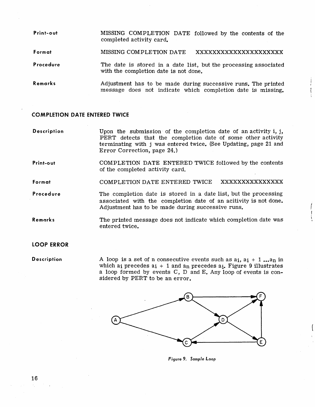
A loop
is
a
set
of n
consecutive
events
such
as
ai,
ai
+ 1
•••
an
in
which
ai
precedes
ai
+ 1
and
an
precedes
ai.
Figure
9
illustrates
a
loop
formed
by
events
C,
D and
E.
Any loop of
events
is
con-
sidered
by
PERT
to
be
an
error.
Figure
9.
Sample
Loop
I
!
I
.
Print-out
Type-out
Printer
Format
Proced
ure
CONTROL
CARD
ERROR
1.
Description
Procedure
2.
Description
Procedure
3.
Description
Procedure
4.
Description
Procedure
5.
Description
Procedure
Remarks·
A
list
of
all
elements
of
the
loop and
the
elements
attached
to
the
loop.
LOOP ERROR
will
be
typed
on
the
Console
Typewriter.
11
12
13
••••••
A loop
error
is
a
serious
error
which
the
program
cannot
cor-
rect.
When a loop
error
is
detected,
the
data
is
put
on
the
history
tape
or
on
cards
without any
further
processing.
An
illegal
character
is
detected
in
column
8 of
the
PROJECT
card.
The
project
is
ignored
and a
search
is
made
for
the
next
control
card.
BININPUT
card
is
not
preceded
by
a
PROJECT
card.
The
contents
of
the
BININPUT
card
is
typed
and a
search
is
made
for
the
next
control
card.
A
character
other
than
a
blank
or
1
is
detected
in
column
41
of
a
PROJECT
card.
One
time
estimate
is
assumed
and
the
project
is
processed.
An
illegal
tape
unit
is
specified
in
columns
57
-58
of
the
PERTSERV
card,
i.e.,
a
unit
other
than
0-15.
The
PERTSERV
card
is
ignored
and
a
search
is
made
for
the
next
control
card.
An
illegal
PERTSERV
routine
is
specified
in
columns
17
-26.
The
PERTSERV
card
is
ignored
and
the
next
control
card
is
searched
for.
All
CONTROL
CARD
ERROR
type-outs
occur
immediately
fol-
lowing
the
card
in
error.
CONTROL
CARD
INTERCEPTED
Description
A
PROJECT,
PERTSERV
or
END
card
is
detected
among
the
cards
of
another
project
while
processing,
i.e.,
before
a
card
with
code
9
is
found. (See Input
Preparation
and
Operating
Instructions,
Chapter
VII,
page
31;
also
see
PERTSERV,
page
25.)
17
Type-out
Formats
Procedure
CONTROL CARD INTERCEPTED followed
by
the contents of the
detected
control
card
is
typed by the
Console
Typewriter.
PROJECT
CARD
INTERCEPTED xxxxxxxxxxxxxxxxx
PERSERV CARD INTERCEPTED xxxxxxxxxxxxxxxxx
END CARD INTERCEPTED xxxxxxxxxxxxxxxxx
Action
is
initiated
according
to
which
control
card (PROJECT,
PERTSERV
or
END)
is
intercepted.
PROJECT
NOT
ON
HISTORY
TAPE
Description
Type-out
Form
at
Procedure
A
project
searched
for
by PERT
or
PERTSERV
is
not found on
the
history
tape.
PROJECT NOT FOUND followed by the contents of the
control
card.
PROJECT NOT FOUND xxxxxxxxxxxxxxxxxxxxxx
PERT
will
search
for
the next control card.
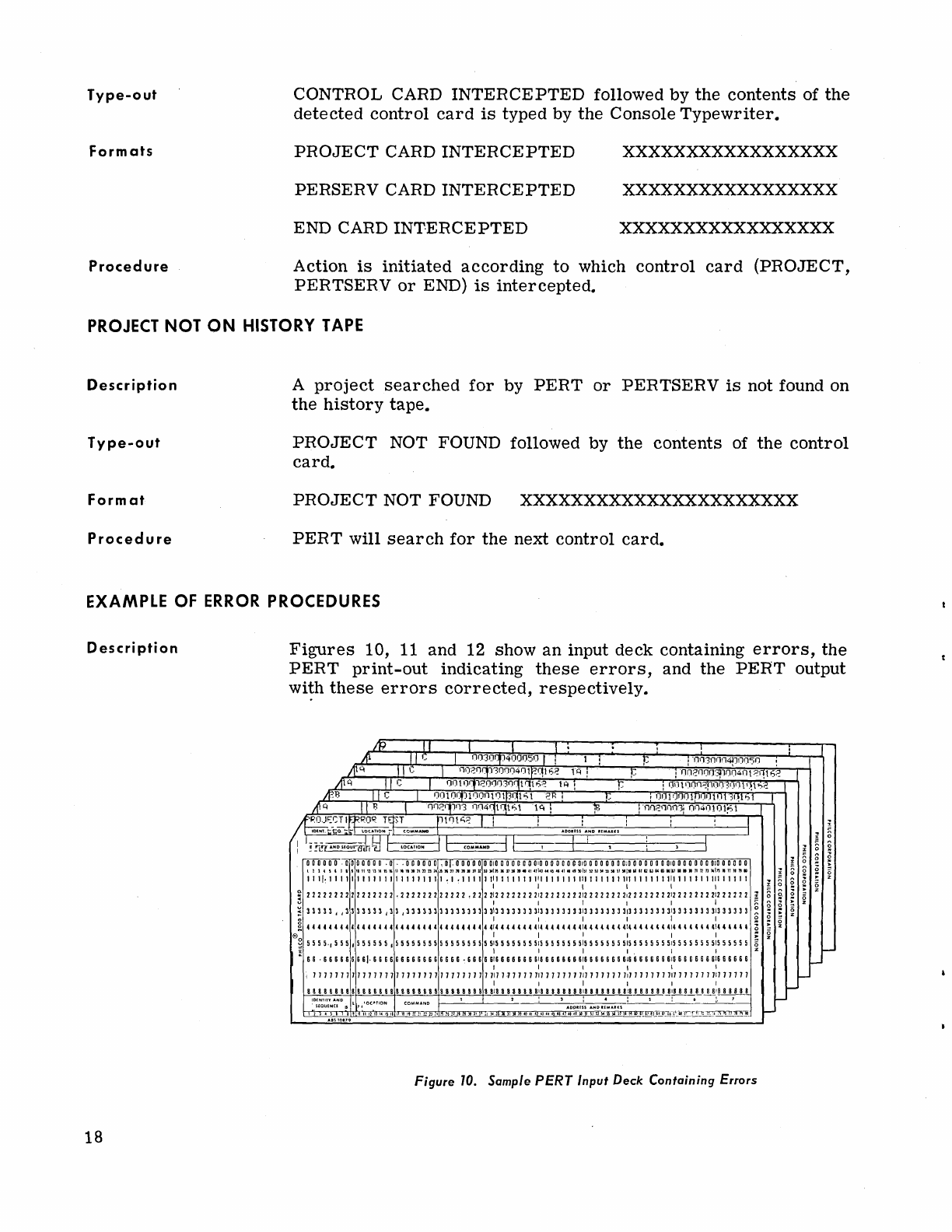
EXAMPLE
OF
ERROR
PROCEDURES
Description
18
Figures
10,
11
and 12
show
an input deck containing
errors,
the
PERT
print-out
indicating
these
errors,
and the
PERT
output
wi!h
these
errors
corrected,
respectively.
IP
1/
I I 1 . !
Ifl I I IJ I Ofnor:p4fJOfJ50
IiI
i
.
~
POJ~~~lfFROR
Tq.~'~T===-rrr_tO_.t_~?_-~~
____
~~==~~=-~
__
~
____
~
__
~1
I
~-t;Q.
':t:-~:-
CI)MMANO
AOOIUS
AND
'(M"',U
~ ~ ~ ~ ~ ~
;
~ ~
,~~
~
~,~ ~
~
,;
~
~ ~ ~
~
~~.
~!
~::
~~,
~ ~
~:~
~ ~
~ ~
~
~
~:~
~
~
~
~
~
~
~:~
~
~ ~
~!~,
!;,~
~ ~
~ ~
~!
~:~
~:
~
~
~
~
~:~
~
~
~
~
~
1 1 1 I
~
1 1 1 1 1 1 1 1 1 1 1 1 1 1 1 1 1 1 1 1 1 , 1
,1
1 1 1 1
111
1 1 1 1 1 1
111
1 1 1 1 1 1
111
1 1 1 1 1 1
111
1 1 1 1 1 1
111
1 1 1 1 1 1
111
1 1 1 1 1
I I I I I I
3
2222222222222222
.222222222222
.2222:22222222:222222
22:2 2 2 2 2 2 2
2:2
2 2 2 2 2 2 2:22 2 2
2222:22
2
222
~
~
33333,
,3333333,33,333
3111313113131i133
333
3
313
3 3 3 3 3
3313333
333313
3 3 3 3 3
33
1
3
33333
3
313
33
3 3 3
~
~
4444444444444444444444444444444444:4444'
4 4 4:' 4 4 4 4 4 4
4:4
4 4 4
4"
,:,
4 4
4' 4'
,:,
4 4
4"
4
,:,
4""
~
e I I I I I I
;::
~
5555.,555,555555,5555555555555555551555555551555555
5
515
5 5
555551555555551555555551555555
is
x I 1 I 1 I I Z
L
66
.666666661.
6 6 6 6 6 6 6 6 6 6 6 6 6 6 6
6,6666616666666616666666616666666616666666616666666
616
6 6
666
I I
tit
I
I
111111111111111111111111111111111111.)1111111111111
111
111111111111111111111111
111
11111
I I I I I I
8&8 8
88
888 888
88 8 8
88888&88
88888
B8
8 8
818
8
88888818
8 8 8 88 8
818
8 8 8 8 8 8
818
8 8 8 8 8 8
818
8 8 8 8 8 8
~I!!.!!ll
!o:(~~EYN~~D
1$
l
11
'OCJoYION COMMAND 1
2:
1
AODU;S
AND
':MAUI
: 5 :
_6
:.
1
2'
11I111.1~ll11.:'1211,1.
6
401141'144445",')115151
~~~ffT1615l1(t.\_~"t")iTl;;~IT1'i"lO_
-
Figure
70.
Sample
PERT
Input Deck Containing Errors
-
l-
i-
BAD
CA~D
BAD
CARD
BAD
CARD
BAD
CARD
BAD
CARD
ILLEGAL
TIME
ESTIMATE
ILLEGAL
DATt::
CODE
ILLEGAL
DATE
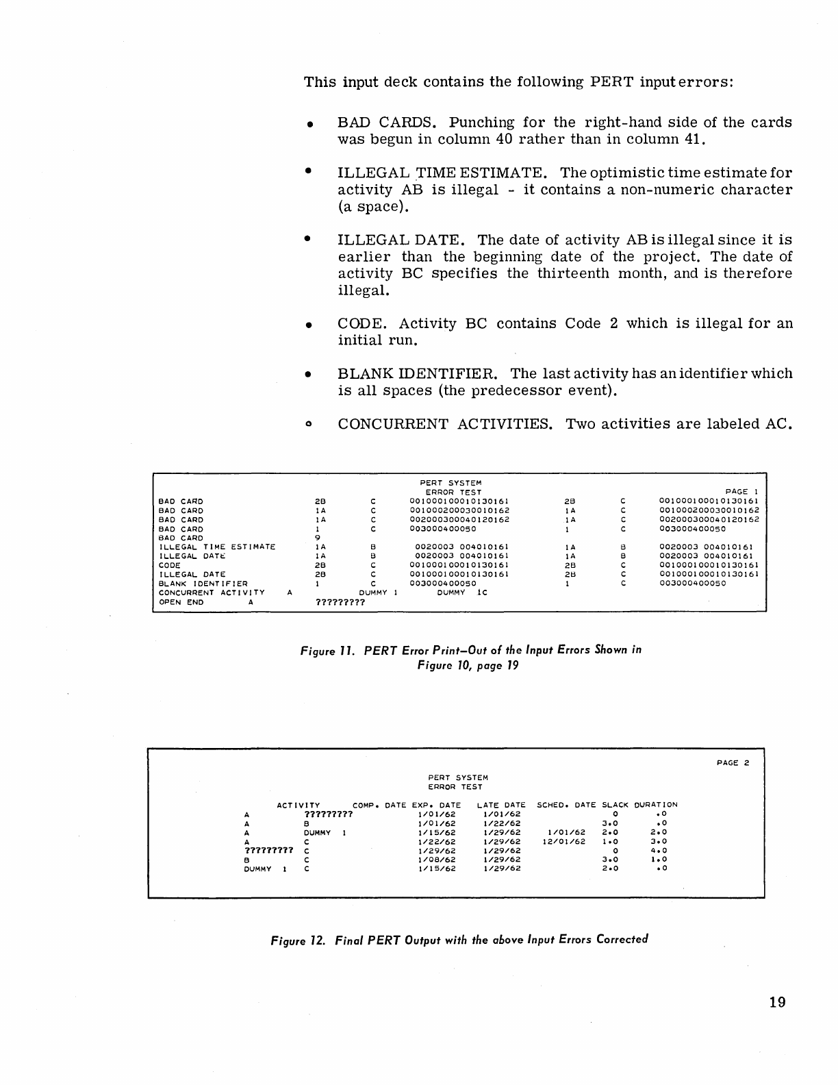
This
input
deck
contains
the
following
PERT
input
errors:
•
•
•
•
•
BAD CARDS.
Punching
for
the
right-hand
side
of
the
cards
was
begun
in
column
40
rather
than
in
column
41.
ILLEGAL
rIME
ESTIMATE.
The
optimistic
time
estimate
for
activity
AB
is
illegal
-
it
contains
a
non-numeric
character
(a
space).
ILLEGAL
DATE.
The
date
of
activity
AB
is
illegal
since
it
is
earlier
than
the
beginning
date
of
the
project.
The
date
of
activity
BC
specifies
the
thirteenth
month,
and
is
therefore
illegal.
CODE.
Activity
BC
contains
Code
2
which
is
illegal
for
an
initial
run.
BLANK
IDENTIFIER.
The
last
activity
has
an
identifier
which
is
all
spaces
(the
predecessor
event).
o CONCURRENT ACTIVITIES. Two
activities
are
labeled
AC.
PERT
SYSTEM
ERROR
TEST
PAGE I
2B
C
001000100010130161
2B
C
001000100010130161
IA
C
001000200030010162
IA
C
001000200030010162
IA
C
002000300040120162
IA
C
002000300040120162
I C
003000400050
I C
003000400050
9
IA
B
0020003
004010161
IA
B
0020003
004010161
IA
B
0020003
004010161
IA
B
0020003
004010161
2B
C
001000100010130161
2B
C
001000100010130161
2B
C
001000100010130161
2tl
C
001000100010130161
BLANK
IDENTIFIER
I C
003000400050
I C
003000400050
CONCURRENT
OPEN
END
ACTIVITY
A
A
DUMMY
1
DUMMY
lc
?7?7?7??7
Figure 77.
PERT
Error
Print-Out
of
the
Input
Errors
Shown in
Figure
70,
page
79
PERT
SYSTEM
ERROR
TEST
ACTIVITY
COMPo
DATE
EXP.
DATE
LATE
DATE
SCHED.
DATE
SLACK DURATION
A
111111711
A B
A
DUMMY
1
A C
177171177
C
B C
DUMMY
1 C
i/O
1/62
1/01/62
1/01/62
1/22/62
1/15/62
1/29/62
1/22/62
1/29/62
1/29/62
1/29/62
1/08/62
1/29/62
1/15/62
1/29/62
0
3.0
1/01/62
2.0
12/01/62
1.0
0
3.0
2.0
Figure
72.
Final
PERT
Output
with
the
above
Input
Errors
Corrected
.0
.0
2.0
3.0
4.0
1.0
.0
PAGE 2
19

v. SUCCESSIVE RUNS
THE HISTORY
TAPE
UPDATING
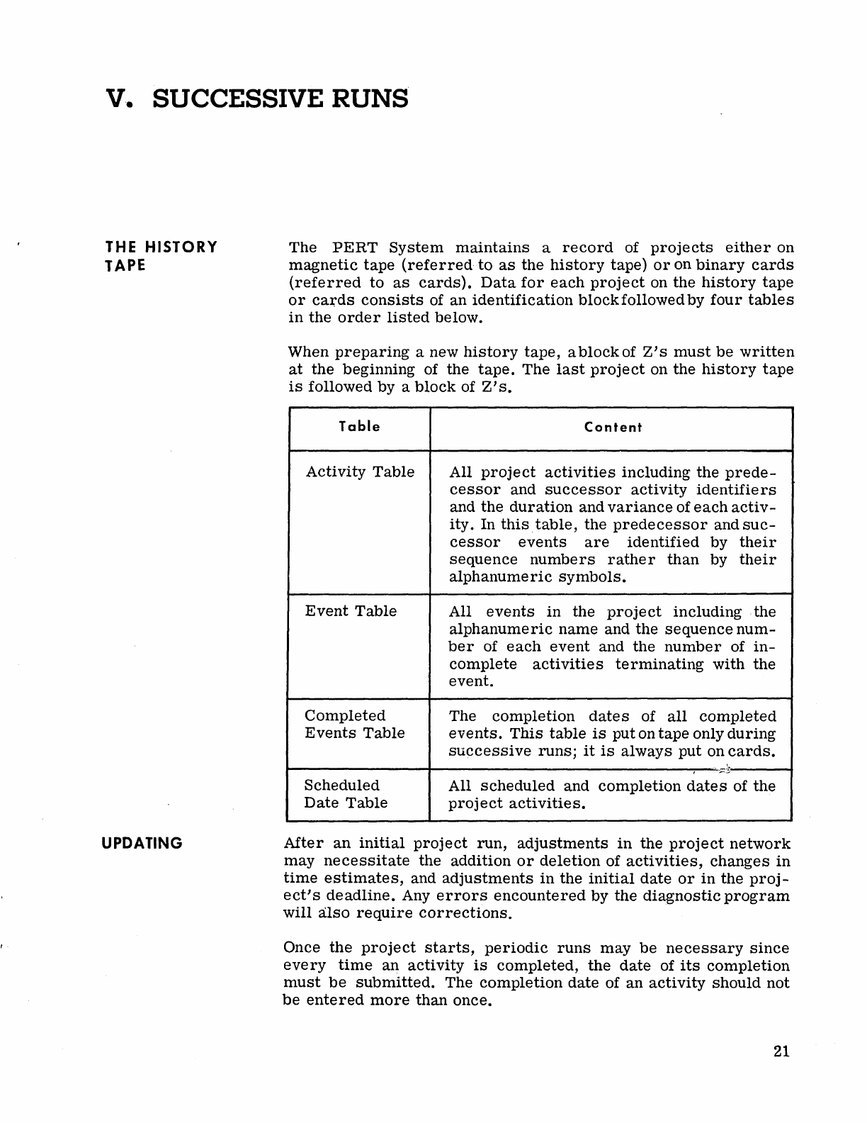
The
PERT
System
maintains
a
record
of
projects
either
on
magnetic
tape
(referred
to
as
the
history
tape)
or
on
binary
cards
(referred
to
as
cards).
Data
for
each
project
on the
history
tape
or
caJ;ds
consists
of an
identification
block
followed by
four
tables
in
the
order
listed
below.
When
preparing
a new
history
tape,
ablockof
Z's
must
be
written
at
the beginning of the
tape.
The
last
project
on the
history
tape
is
followed by a
block
of
Z's.
Table
Activity
Table
Event
Table
Completed
Events
Table
Content
All
project
activities
including the
prede-
cessor
and
successor
activity
identifiers
and the
duration
and
variance
of
each
activ-
ity. In
this
table,
the
predecessor
and
suc-
cessor
events
are
identified
by
their
sequence
numbers
rather
than
by
their
alphanumeric
symbols.
All
events
in
the
project
including . the
alphanumeric
name and the
sequence
num-
ber
of
each
event
and the
number
of
in-
complete
activities
terminating
with the
event.
The
completion
dates
of
all
completed
events.
This
table
is
put on
tape
only
during
successive
runs;
it
is
always
put
on
cards.
~--------------~--------------------------~--~~
..
~-------~
Scheduled
Date
Table
All
scheduled
and
completion
dates
of
the
project
activities.
After
an
initial
project
run,
adjustments
in
the
project
network
may
necessitate
the addition
or
deletion
of
activities,
changes
in
time
estimates,
and
adjustments
in
the
initial
date
or
in
the
proj-
ect's
deadline.
Any
errors
encountered
by the
diagnostic
program
will
also
require
corrections.
Once
the
project
starts,
periodic
runs
may
be
necessary
since
every
time
an
activity
is
completed,
the
date
of
its
completion
must
be
submitted.
The
completion
date
of an
activity
should
not
be
entered
more
than
once.
21
INPUT
DATA
FOR
SUCCESSIVE
RUNS
Activity
Cards
22
When the
history
tape
is·
maintained,
the
obsolete
history
is
deleted
from
the
history
tape
and the new
history
is
added,
un-
less
a
NEW
ID
card
follows the
project
card
of the deck.
(Refer
to
A NEW
ID
Card,
page 23.)
When
the
history
is
maintained
on
cards,
the
order
of
cards
for
a
successive
run
is
as
follows:
The
Project
Card
A PERTSERV BININPUT
Card
PERT
Binary
History
Cards
Activity
Cards
An Ending
Card
(Code
9)
When
the
history
is
on
the
history
tape,
the
PERTSERV BININPUT
card
and
the
binary
history
cards
are
omitted.
The
activity
cards
for
successive
runs
have
exactly
the
same
fields
as
those
for
an
initiial
run,
i.e.,
Columns
2-10
and
11-19,
are
the
activity
predecessor
and
successor
events,
respectively;
Columns
20-23,
24-27,
and 28-31
are
the
three
time
estimates;
and Columns 32-37
contain
the
date (if any
is
submitted)
of
either
the
actual
completion
date
or
the
scheduled
date.
On
cards
for
successive
runs,
columns
41-80
must
be
a
duplicate
of
columns
1-40.
The
major
difference
between
initial
and
successive
activity
cards
is
in
the
card
code (Column
1)0
The
card
code
indicates
the
type of
changes
to
be
made
and
may
be
any
number
between
1-
5.
Code 1:
Indicates
a new
activity
to
be
added
to
the
program.
Code 2:
Indicates
a change
in
the
time
estimates.
If,
in
addition
to
a change
in
the
time
estimates,
a new
scheduled
completion
date
is
required,
it
may
be
indicated
in
the
date
field
of a Code 2
card.
However,
for
change of
date
only, Code 3
must
be
used..
Code 3:
Indicates
a change
in
the
scheduled
date.
The
date
field
is
the
only field
processed
on Code 3
cards.
A
legal
date
in
the
date
field
will
be
interpreted
as
a new
scheduled
date
to
be
in-
serted,
while a
zero
in
the
date
field
will
be
interpreted
as
a
cancellation
of
the
scheduled
date
of
the
activity.
Code 4:
Indicates
a
completed
activity.
The
date
field
is
the
only
field
processed
on Code 4
cards.
The
date
will
be
stored
by
the
program
as
the
completion
date
of
the
activity.
Code 5:
Indicates
a
deleted
activity.
The
activity
will
be
deleted
from
the
activity
table.
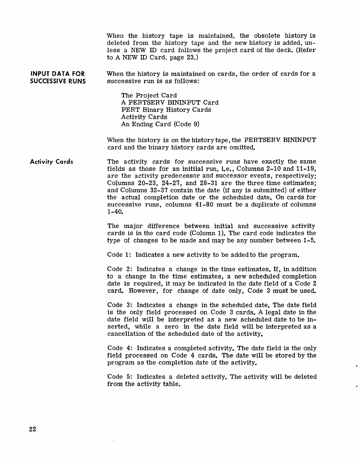
Control
Cards
A
New
10
Card
The
deck
of
cards
for
a
successive
run,
as
for
an
intial
run,
should
be
headed
by
a
PROJECT
card.
The
last
card
of
the
project
should
be
a
code
9
card
as
in
the
initial
run.
A
PROJECT
card
could
be
followed
by
a new ID·
card.
The
deck
of
cards
for
a
successive
run,
as
for
an
initial
run,
should
be
headed
by
a
PROJECT
card.
The
for.mat of
the
PROJECT
card
is
as
follows.
Column
Content
1-7
PROJECT
8
S,
indicating
the
history
is
on
the
history
tape
C,
indicating
the
history
is
on
cards.
9-24
The
project
ID -
This
should
be
the
same
as
that
of
the
initial
run
of
the
project"
25-30
The
initial
date
of
the
project.
33-38
Ending
date"
If
this
field
is
blank,
there
is
no
change
in
the
deadline.
A
legal
date
re-
places
the
formerly
used
date;
an
illegal
date
is
ignored.
39-80
Ignored.
When
making
changes,
it
might
be
desirable
to
keep
both
the
changed
and
unchanged
history
on
tape.
This
could,
for
example,
be
desirable
for
comparison
purposes.
Should
this
be
the
case,
a NEW
ill
card
must
follow
the
PROJECT
card.
The
updated
history
will
then
be
on
the
history
tape
under
the
new
identifica-
tion.
The
NEW
ill
card
feature
may
be
used
only
when
the
proj-
ect's
history
is
maintained
on
the
history
tape.
An
illustration
of a NEW
ill
card
for
a
project
is
shown
in
Figure
13.
00
000000
D.
00000000000000000000001000000001
00000001
000000100000
a 0
010
0 a a 0 0 a
010
a a
DOD
• 2 2 • I I I I I
11
" '2 II
MIS.
II
...
II 2' n D "
"Jt
JIll
1111
1I!lIl
11111
lIl1l1l1
..
II
12111
..
11
II
""
It
_1M
U
1111
• _ II
_I_
.
1112
12
II
••
iII
••
II n n n
lIllI
• n II II •
111111111111111-
11-11111111111111111111111111111111
1111111-111-11111111111111111111111
I I I I I I
:
2222222222
- - 2 2 2 2
222222222222222221222222221222222221-
- 2 2 22 -
212
2 2
22222122222222122222
2
~n
1 1 I 1 I 1
•
333333333
3 3
3:-:
3 3 3 3 3 3 3
33333333333333133333333133333333133"
3 3 3 3
313
3 3 3 3 3 3
313
3 3 3 3 3 3
313
3 3
333
~
I 1 I 1 I I g
444
4 4 - 4 4
44444444444444
4
444444444414444444414
4 4 -
44
-
414
4
44
4 4 4
414
44
44 44
4144
4
44
H
41H
44
U
~
e~_
-5 5
555555555
- 5 5 5 - 5 5 5 5 5 5 5 5 5 5 5 5 5 5 5
5:5
5
5555
-
":55555555:555
- 5
55
-:555555
5
5:5
5 5 5 5 5 5
5:5
55
5
55
::!
f I I I I
I'
I
~
, 6 -
666666
6 6 6 6 6 6 6 6
666666666666666
6
616
6 6
666661-
6 & & 6 6 6
61&
66666661666
I 6 6 6
118
8 8
III
I
118
6 I I I I
. I I 1 I 1 I
7 7 7 7 7 7 7 7 1 7 7 7 7 7 7 1 1 7 7 7 7 7 7 7 1 7 7 7 1 7 7 1 7
717
7 7 7 7 7 7
717
7 7 7 7 7 7
711
7 7 7 7 7 7
7.7
7 7 7 7 7 7
717
7 7 7 7 7 1
717
7 7
11
7
I 1 I I 1
I·
8 8 8 8 8 8 8 8 8 8 8 8 8 8 8 I 8 I 8 8 8 8 8 8 8 8 8 8 8 8 8 8 8
818
8 8 8 8 8 8 81
8 8 8 8 8 8 8
81
a 8 8 8 8 I a
818
I 8 8 8 8 a
818
a I I I I I a
18
I
••
I I
IDS((N~~l;'~:D
L
~
LOCATION COMMAND 1 2 I 1
AOO.;$
AND
.:MA.KS
: S : • I 7
1114"1111111]41&
.1441444~!IISI52ijSi56Si5JSlSiCilI1
Figure
13. New
10
Card
Sample
23
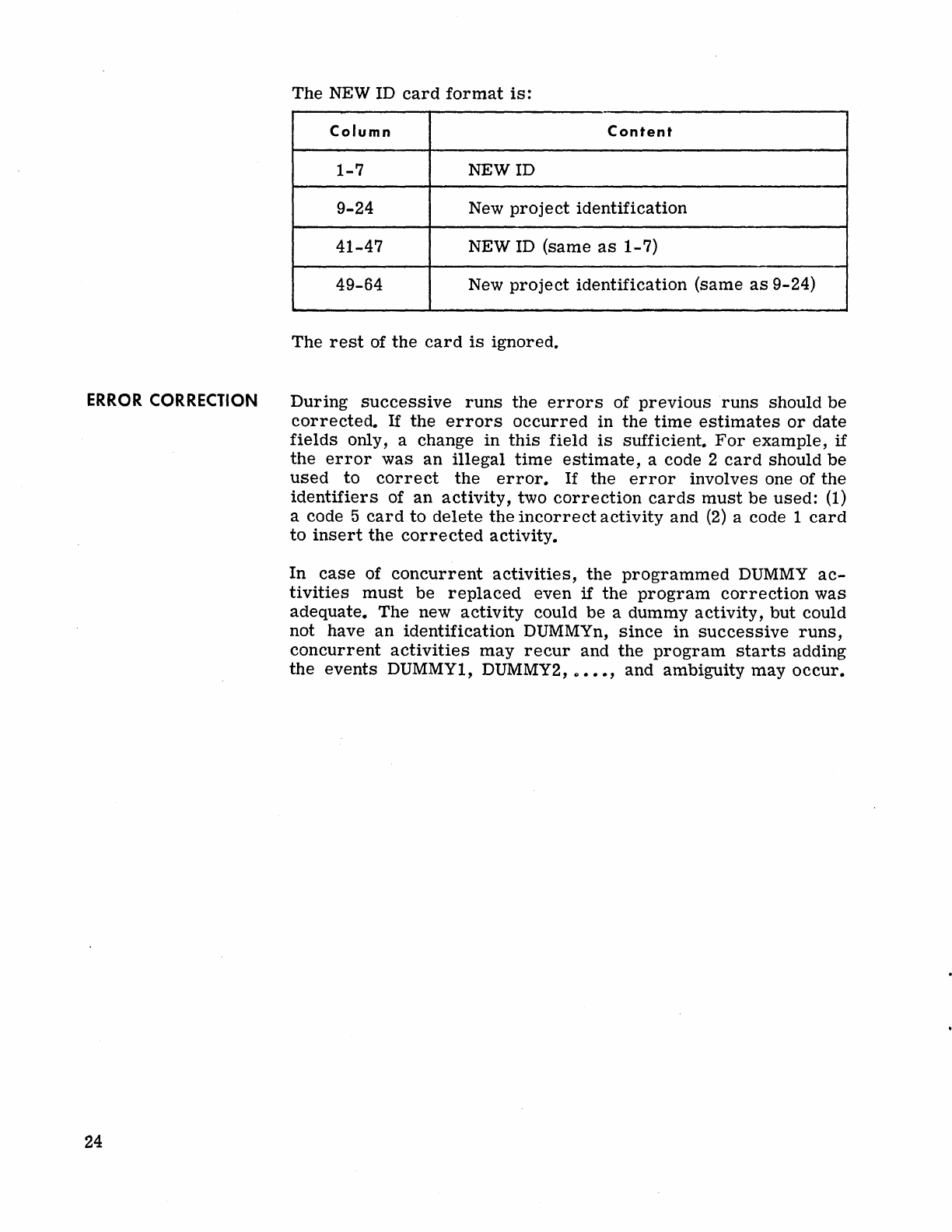
ERROR
CORRECTION
24
The
NEW ID
card
format
is:
Column
Content
1-7
NEWID
9-24
New
project
identification
41-47
NEW ID
(same
as
1-7)
49-64 New
project
identification
(same
as
9-24)
The
rest
of
the
card
is
ignored.
During
successive
runs
the
errors
of
previous
runs
should
be
corrected.
If
the
errors
occurred
in
the
time
estimates
or
date
fields
only, a change
in
this
field
is
sufficient.
For
example,
if
the
error
was
an
illegal
time
estimate,
a code 2
card
should
be
used
to
correct
the
error.
If
the
error
involves one of
the
identifiers
of
an
activity,
two
correction
cards
must
be
used:
(1)
a code 5
card
to
delete
the
incorrect
activity
and
(2)
a code 1
card
to
insert
the
corrected
activity.
In
case
of
concurrent
activities,
the
programmed
DUMMY
ac-
tivities
must
be
replaced
even
if
the
program
correction
was
adequate.
The
new
activity
could
be
a
dummy
activity,
but
could
not have
an
identification
DUMMYn,
since
in
successive
runs,
concurrent
activities
may
recur
and
the
program
starts
adding
the
events
DUMMY1, DUMMY2, "
•••
, and ambiguity
may
occur.
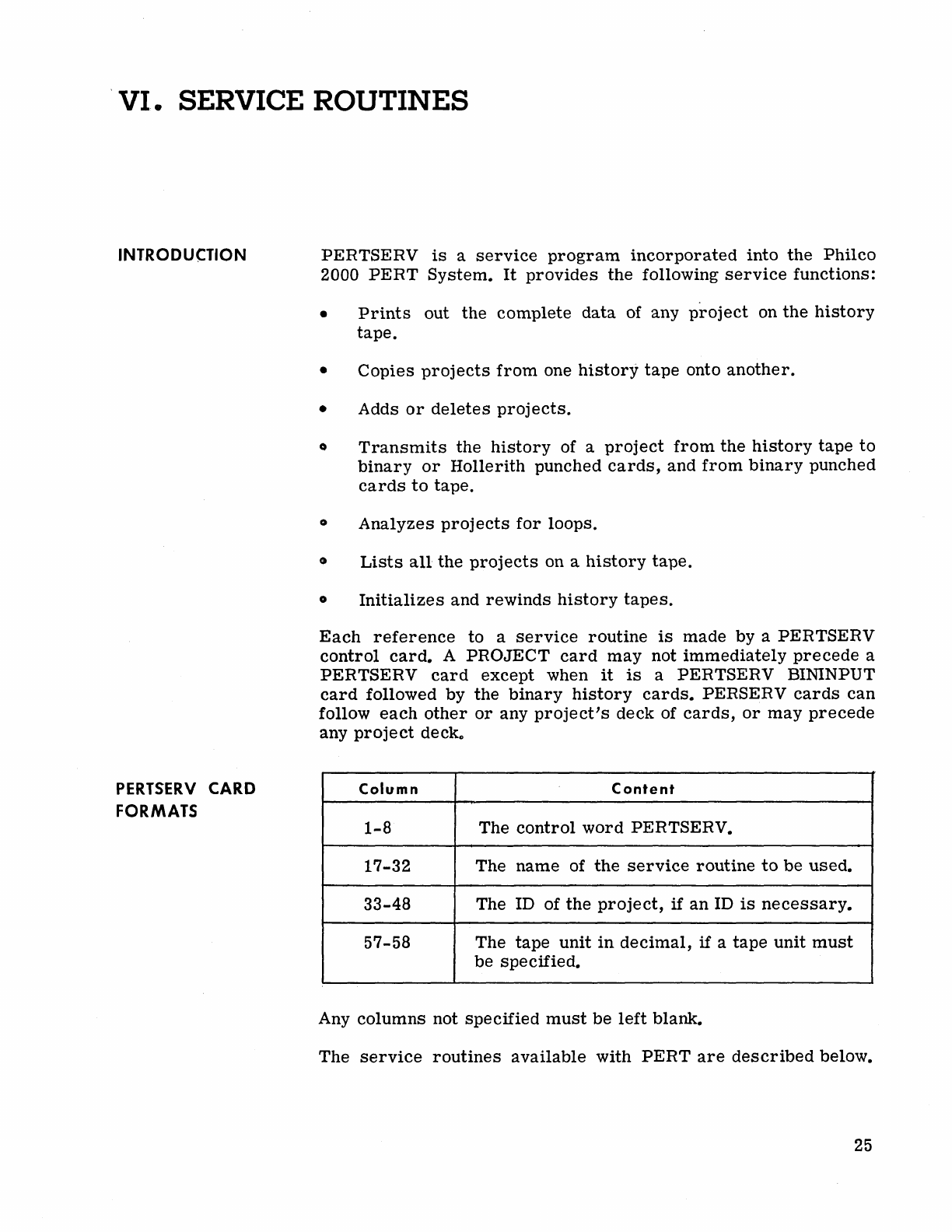
'VI.
SERVICE ROUTINES
INTRODUCTION
PERTSERV
CARD
FORMATS
PERTSERV
is
a
service
program
incorporated
into
the
Philco
2000
PERT
System.
It
provides
the
following
service
functions:
•
Prints
out
the
complete
data
of any
project
on
the
history
tape.
•
Copies
projects
from
one
history
tape
onto
another.
• Adds
or
deletes
projects.
o
Transmits
the
history
of a
project
from
the
history
tape
to
binary
or
Hollerith
punched
cards,
and
from
binary
punched
cards
to
tape.
o
Analyzes
proj
ects
for
loops.
•
Lists
all
the
projects
on a
history
tape.
o
Initializes
and
rewinds
history
tapes.
Each
reference
to a
service
routine
is
made
by a PERTSERV
control
card.
A
PROJECT
card
may
not
immediately
precede
a
PERTSERV
card
except
when
it
is
a PERTSERV BININPUT
card
followed by
the
binary
history
cards.
PERSERV
cards
can
follow
each
other
or
any
project's
deck
of
cards,
or
may
precede
any
project
decko
Column
Content
1-8 The
control
word
PERTSERV.
17-32 The
name
of
the
service
routine
to
be
used.
33-48 The ID of
the
project,
if
an
ID
is
necessary.
57-58 The
tape
unit
in
decimal,
if a
tape
unit
must
be
specified.
Any
columns
not
specified
must
be
left
blank.
The
service
routines
available
with
PERT
are
described
below.
25
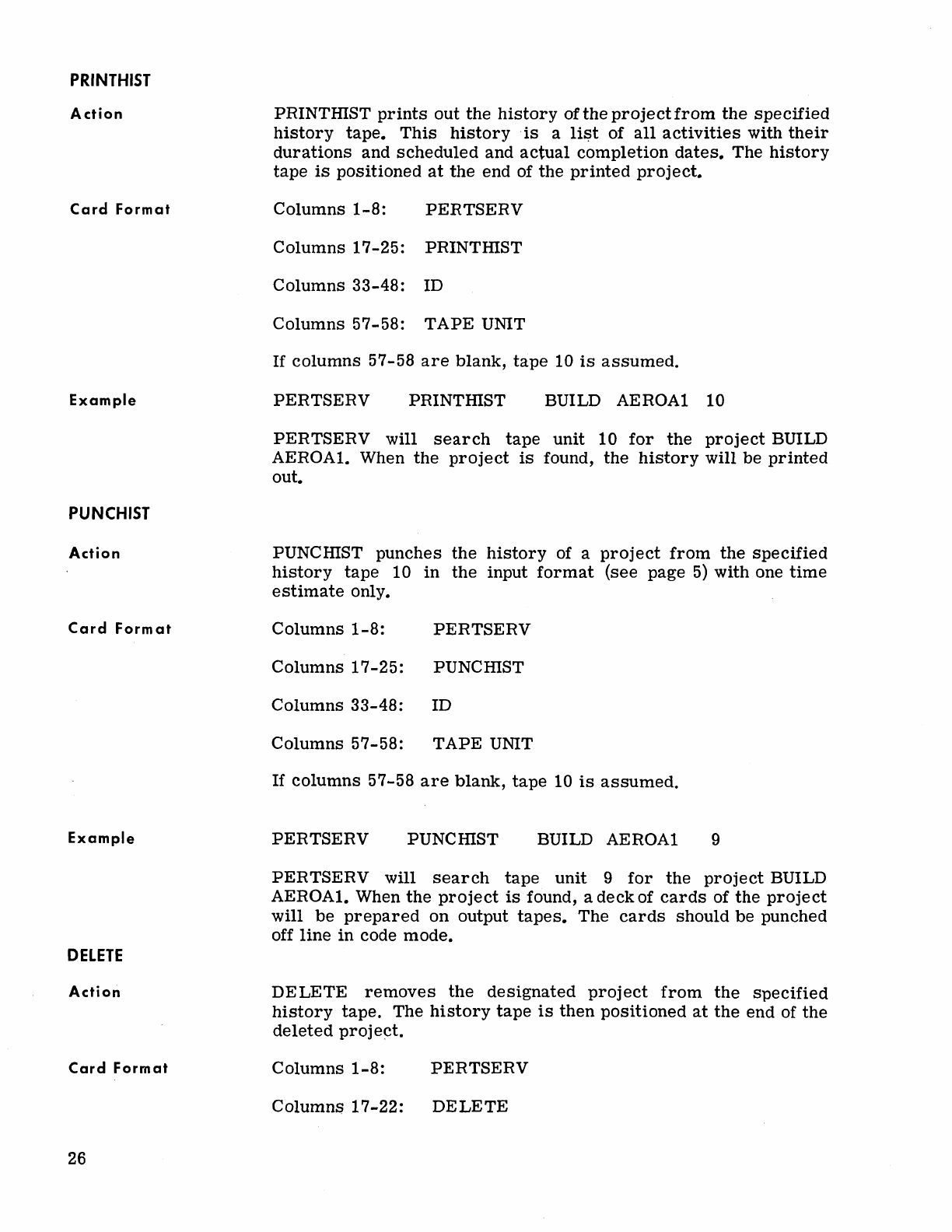
PRINTHIST
Action
Card
Format
Example
PUNCHIST
Action
Card
Format
Example
DELETE
Action
Card
Format
26
PRINTInST
prints
out
the
history
of
the
project
from
the
specified
history
tape.
This
history
.
is
a
lif;)t
of
all
activities
with
their
durations
and
scheduled
and
actual
completion
dates.
The
history
tape
is
positioned
at
the
end
of
the
printed
project.
Columns
1-8:
PERTSERV
Columns
17-25:
PRINTInST
Columns
33-48:
ID
Columns
57-58:
TAPE
UNIT
If
columns
57-58
are
blank,
tape
10
is
assumed.
PERTSERV
PRINTmST
BUILD AEROA1 10
PERTSERV
will
search
tape
unit
10
for
the
project
BUILD
AEROAl.
When
the
project
is
found,
the
history
will
be
printed
out.
PUNCInST
punches
the
history
of a
project
from
the
specified
history
tape
10
in
the
input
format
(see
page
5)
with
one
time
estimate
only.
Columns
1-8:
PERTSERV
Columns
17-25:
PUNCmST
Columns
33-48:
ID
Columns
57-58:
TAPE
UNIT
If
columns
57-58
are
blank,
tape
10
is
assumed.
PERTSERV
PUNcmST
BUILD AEROA1 9
PERTSERV
will
search
tape
unit
9
for
the
project
BUILD
AEROA1. When
the
project
is
found, a
deck
of
cards
of
the
project
will
be
prepared
on
output
tapes.
The
cards
should
be
punched
off
line
in
code
mode.
DELETE
removes
the
designated
project
from
the
specified
history
tape.
The
history
tape
is
then
positioned
at
the
end
of
the
deleted
proj
ect.
Columns
1-8:
PERTSERV
Columns
17-22:
DELETE
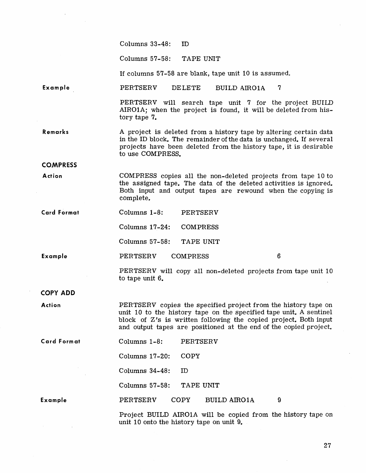
Example
Remarks
COMPRESS
Action
Card
Format
Example
COpy
ADD
Action
Card
Format
Example
Columns
33-48:
ID
Columns
57-58:
TAPE
UNIT
If
columns
57-58
are
blank,
tape
unit
10
is
assumed.
PERTSERV
DELETE
BUILD AIR01A 7
PERTSERV
will
search
tape
unit
7
for
the
project
BUILD
AIR01A;
when
the
project
is
found,
it
will
be
deleted
from
his-
tory
tape
7.
A
project
is
deleted
from
a
history
tape
by
altering
certain
data
in
the
ID
block.
The
remainder
of
the
data
is
unchanged.
If
several
projects
have
been
deleted
from
the
history
tape,
it
is
desirable
to
use
COMPRESS.
COMPRESS
copies
all
the
non-deleted
projects
from
tape
10
to
the
assigned
tape.
The
data
of
the
deleted
activities
is
ignored.
Both
input
and
output
tapes
are
rewound
when
the
copying
is
complete.
Columns
1-8:
PERTSERV
Columns
17-24:
COMPRESS
Columns
57-58:
TAPE
UNIT
PERTSERV
COMPRESS 6
PERTSERV
will
copy
all
non-deleted
projects
from
tape
unit
10
to
tape
unit
6.
PERTSERV
copies
the
specified
project
from
the
history
tape
on
unit
10
to
the
history
tape
on
the
specified
tape
unit.
A
sentinel
block
of Z's
is
written
following
the
copied
project.
Both
input
and
output
tapes
are
positioned
at
the
end
of
the
copied
project.
Columns
1-8:
PERTSERV
Columns
17-20:
COpy
Columns
34-48:
ID
Columns
57-58:
TAPE
UNIT
PERTSERV
COpy
BUILD AIR01A 9
Project
BUILD AIR01A
will
be
copied
from
the
history
tape
on
unit
10
onto
the
history
tape
on
unit
9.
27
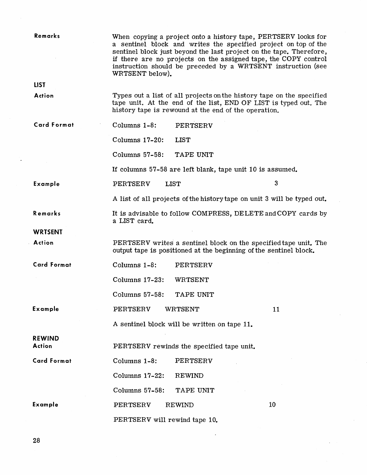
Remarks
LIST
Action
Card
Format
Example
Remarks
WRTSENT
Action
Card
Format
Example
REWIND
Action
Card
Format
Example
28
When copying a
project
onto a
history
tape,
PERTSERV
looks
for
a
sentinel
block
and
writes
the
specified
project
on
top
of
the
sentinel
block
just
beyond
the
last
project
on
the
tape.
Therefore,
if
there
are
no
projects
on
the
assigned
tape,
the
COpy
control
instruction
should
be
preceded
by
a WRTSENT
instruction
(see
WRTSENT below).
Types
out a
list
of
all
projects
on
the
history
tape
on
the
specified
tape
unit.
At
the
end
of
the
list,
END
OF
LIST
is
typed
out.
The
history
tape
is
rewound
at
the
end
of
the
operation.
Columns
1-8:
PERTSERV
Columns
17-20:
LIST
Columns
57-58:
TAPE
UNIT
If
columns
57-58
are
left
blank,
tape
unit
10
is
assumed.
PERTSERV
LIST 3
A
list
of
all
projects
of
the
history
tape
on
unit
3
will
be
typed
out.
It
is
advisable
to
follow COMPRESS,
DELETE
and
COpy
cards
by
a LIST
card.
PERTSERV
writes
a
sentinel
block
on
the
specified
tape
unit.
The
output
tape
is
positioned
at
the
beginning
of
the
sentinel
block.
Columns
1-8:
PERTSERV
Columns
17-23:
WRTSENT
Columns
57-58:
TAPE
UNIT
PERTSERV
WRTSENT
11
A
sentinel
block
will
be
written
on
tape
11.
PERTSERV
rewinds
the
specified
tape
unit.
Columns
1-8:
PERTSERV
Columns
17-22:
REWIND
Columns
57-58:
TAPE
UNIT
PERTSERV
REWIND 10
PERTSERV
will
rewind
tape
10.
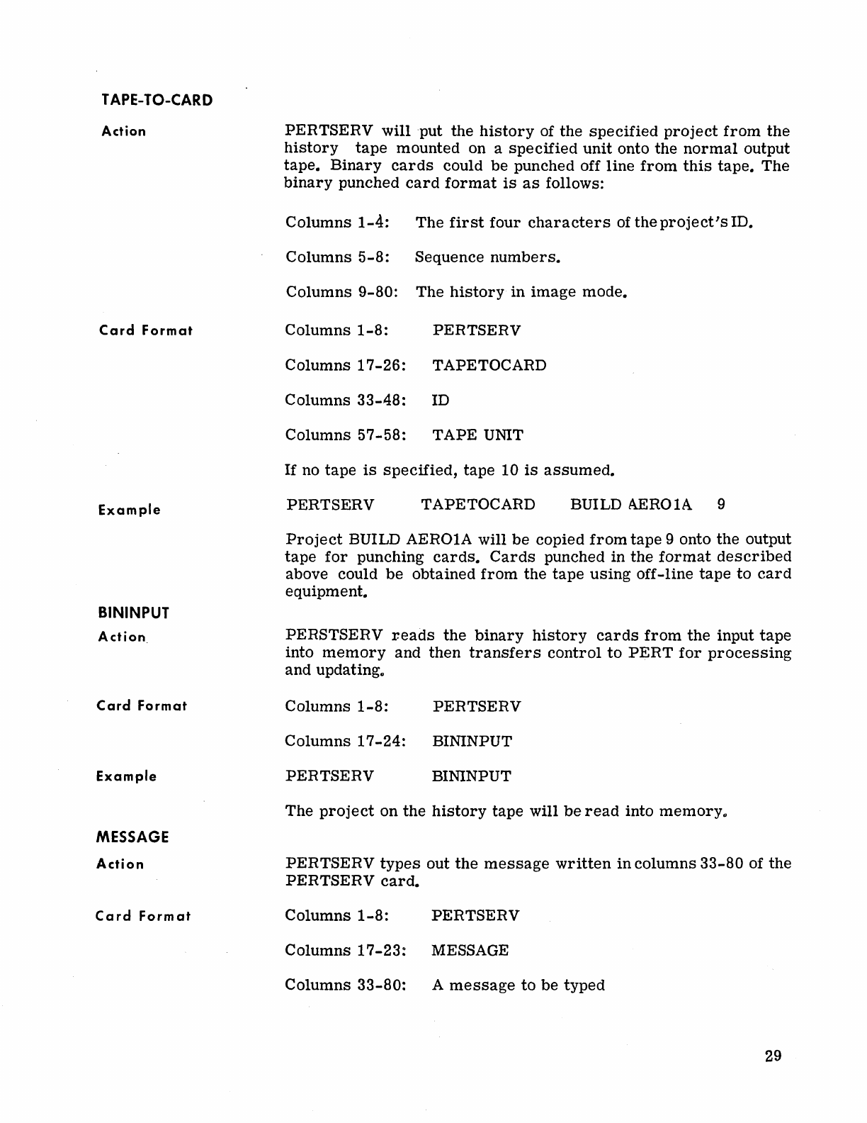
TAPE-TO-CARD
Action
Card
Format
Example
BININPUT
Action.
Card
Format
Example
MESSAGE
Action
Card
Format
PERTSERV
will
'put
the
history
of
the
specified
project
from
the
history
tape
mounted
on a
specified
unit
onto
the
normal
output
tape.
Binary
cards
could
be
punched off
line
from
this
tape.
The
binary
punched
card
format
is
as
follows:
Columns
1-4:
The
first
four
characters
of
the
project's
ID.
Columns
5-8:
Sequence
numbers.
Columns
9-80:
The
history
in
image
mode.
Columns
1-8:
PERTSERV
Columns
17-26:
TAPETOCARD
Columns
33-48:
ID
Columns
57-58:
TAPE
UNIT
If
no
tape
is
specified,
tape
10
is
assumed.
PERTSERV TAPETOCARD BUILD AEROIA 9
Project
BUILD AEROIA will
be
copied
from
tape
9 onto
the
output
tape
for
punching
cards.
Cards
punched in
the
format
described
above could
be
obtained
from
the
tape
using
off-line
tape
to
card
equipment.
PERSTSERV r.eads
the
binary
history
cards
from
the
input
tape
into
memory
and
then
transfers
control
to
PERT
for
processing
and
updating
..
Columns
1-8:
PERTSERV
Columns
17-24:
BININPUT
PERTSERV
BININPUT
The
project
on
the
history
tape
will
be
read
into
memory
..
PERTSERV
types
out
the
message
written
in
columns
33-80
of
the
PERTSERV
card.
Columns
1-8:
PERTSERV
Columns
17-23:
MESSAGE
Columns
33-80:
A
message
to
be
typed
29
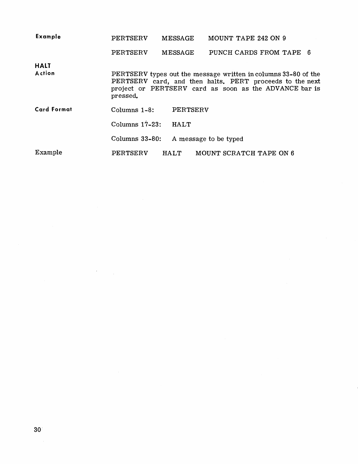
Example
HALT
Action
Card
Format
Example
PERTSERV
MESSAGE MOUNT
TAPE
242 ON 9
PERTSERV
MESSAGE PUNCH CARDS FROM
TAPE
6
PERTSERV
types
out
the
message
written
in
columns
33-80
of
the
PERTSERV
card,
and
then
halts.
PERT
proceeds
to
the
next
project
or
PERTSERV
card
as
soon
as
the
ADVANCE
bar
is
pressed.
Columns
1-8:
PERTSERV
Columns
17-23:
HALT
Columns
33-80:
A
message
to
be
typed
PERTSERV
HALT
MOUNT SCRATCH
TAPE
ON 6
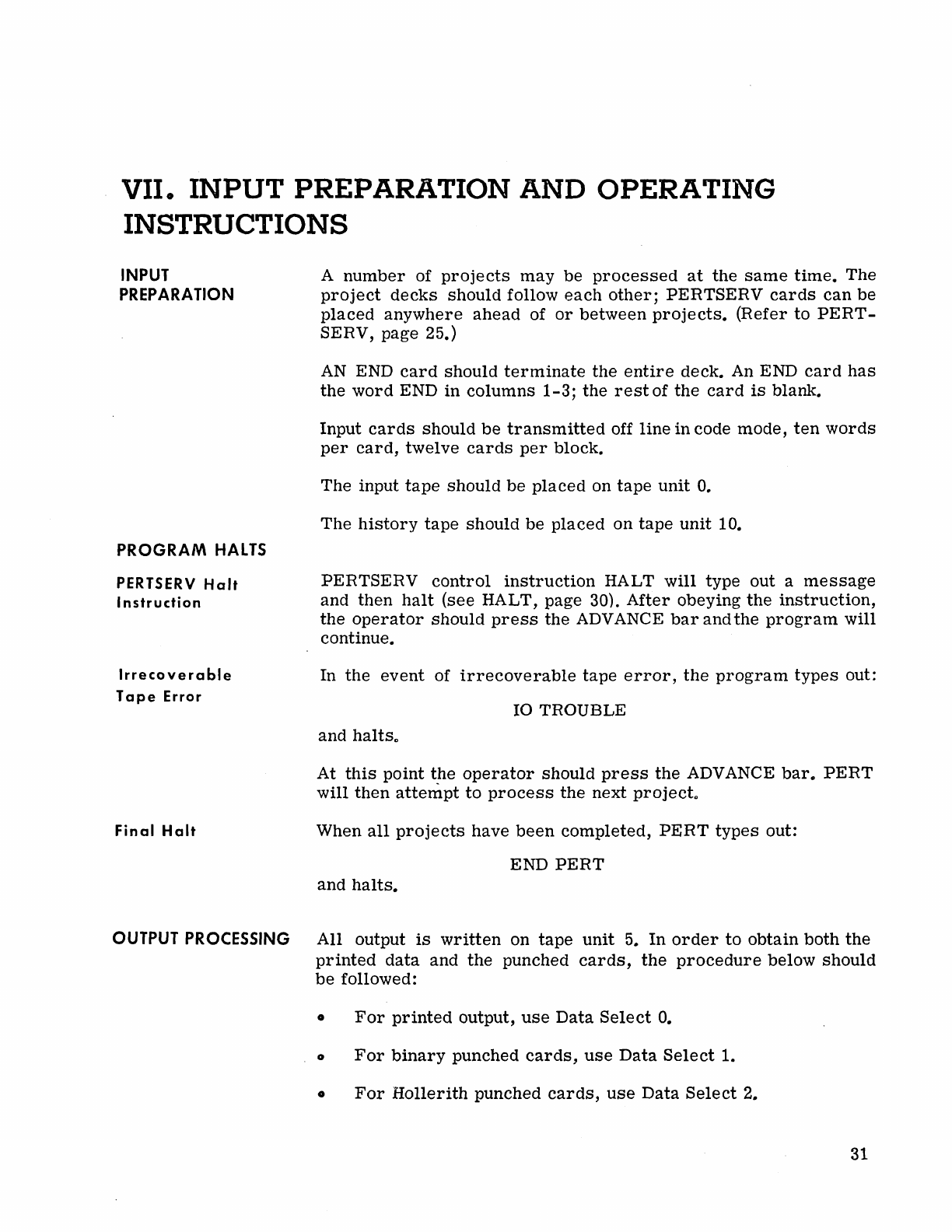
VII. INPUT PREPARATION
AND
OPERATING
INSTRUCTIONS
INPUT
PREPARATION
PROGRAM
HALTS
PERTSERV
Halt
Instruction
Irrecoverable
Tape
Error
Final
Halt
A
number
of
projects
may
be
processed
at
the
same
time.
The
project
decks
should
follow
each
other;
PERTSERV
cards
can
be
placed
anywhere
ahead
of
or
between
projects.
(Refer
to
PERT-
SERV, page 25.)
AN
END
card
should
terminate
the
entire
deck. An END
card
has
the
word
END
in
columns
1-3;
the
rest
of
the
card
is
blank.
Input
cards
should
be
transmitted
off
line
in code
mode,
ten
words
per
card,
twelve
cards
per
block.
The input
tape
should
be
placed
on
tape
unit
o.
The
history
tape
should
be
placed
on
tape
unit
10.
PERTSERV
control
instruction
HALT
will
type out a
message
and then
halt
(see HALT, page 30).
After
obeying
the
instruction,
the
operator
should
press
the
ADVANCE
bar
and
the
program
will
continue.
In
the
event
of
irrecoverable
tape
error,
the
program
types
out:
10
TROUBLE
and
halts
o
At
this
point
the
operator
should
press
the
ADVANCE
bar.
PERT
will
then
attempt
to
process
the
next projecto
When
all
projects
have
been
completed,
PERT
types
out:
END
PERT
and
halts.
OUTPUT
PROCESSING
All output
is
written
on
tape
unit
5.
In
order
to
obtain
both
the
printed
data
and
the
punched
cards,
the
procedure
below
should
be
followed:
•
For
printed
output,
use
Data
Select
o.
o
For
binary
punched
cards,
use
Data
Select
1.
o
For
Hollerith
punched
cards,
use
Data
Select
2.
31
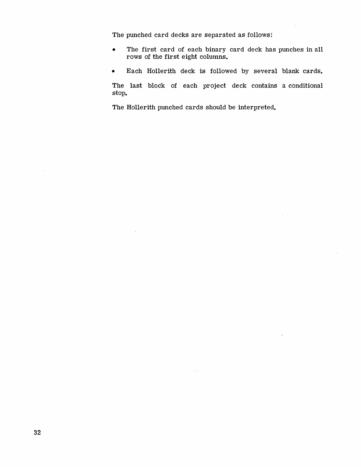
32
The
punched
card
decks
are
separated
as
follows:
• The
first
card
of
each
binary
card
deck
has
punches
in
all
rows
of
the
first
eight
columns.
•
Each
Hollerith
deck
is
followed by
several
blank
cards.
The
last
block
of
each
project
deck
contains a conditional
stop.
The
Hollerith
punched
cards
should
be
interpreted.
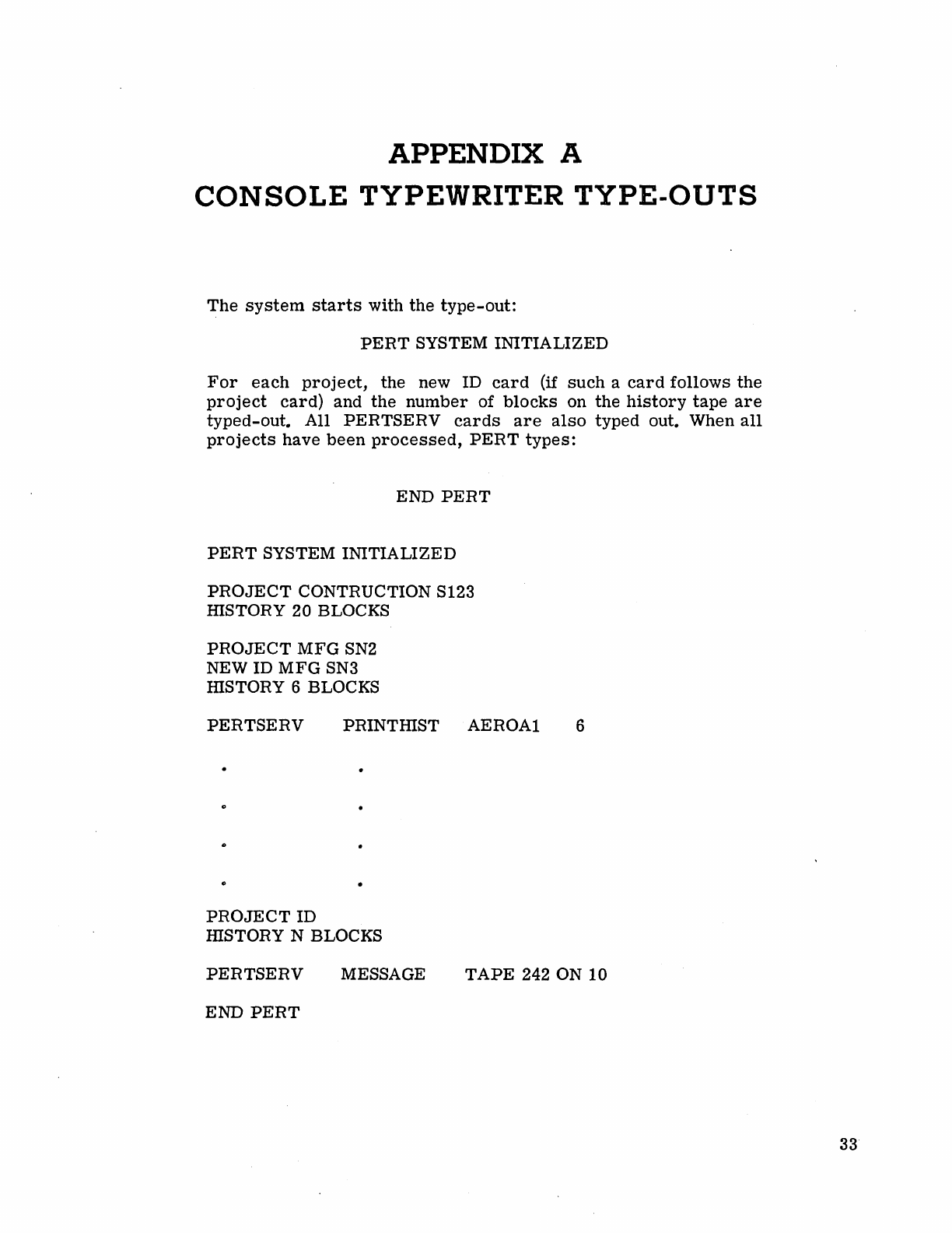
APPENDIX A
CONSOLE
TYPEWRITER
TYPE-OUTS
The
system
starts
with
the
type-out:
PERT
SYSTEM
INITIALIZED
For
each
project,
the
new
ID
card
(if
such
a
card
follows
the
project
card)
and
the
number
of
blocks
on
the
history
tape
are
typed-out.
All
PERTSERV
cards
are
also
typed
out.
When
all
projects
have
been
processed,
PERT
types:
END
PERT
PERT
SYSTEM
INITIALIZED
PROJECT
CONTRUCTION S123
HISTORY
20
BLOCKS
PROJECT
MFG
SN2
NEW ID
MFG
SN3
HISTORY 6 BLOCKS
PERTSERV
PRINTHIST
AEROA1
PROJECT
ID
mSTORY
N BLOCKS
6
PERTSERV
MESSAGE
TAPE
242 ON
10
END
PERT
33
34
In
the
event
of
an
irrecoverable
tape
error
the
program
types
out:
10
TROUB~E
and
halts.
If
the
ADVANCE
bar
is
pressed,
the
program
proceeds
to
the
next
project.
Notes:
The
error
type-outs
are
described
in
Chapter
IV,
Diagnostic
and
Error
Correcting
Routines,
pages
11-19.
PERTSERVtype-outs
are
described
in
Chapter
VI,
Service
Routines,
pages
25-31.
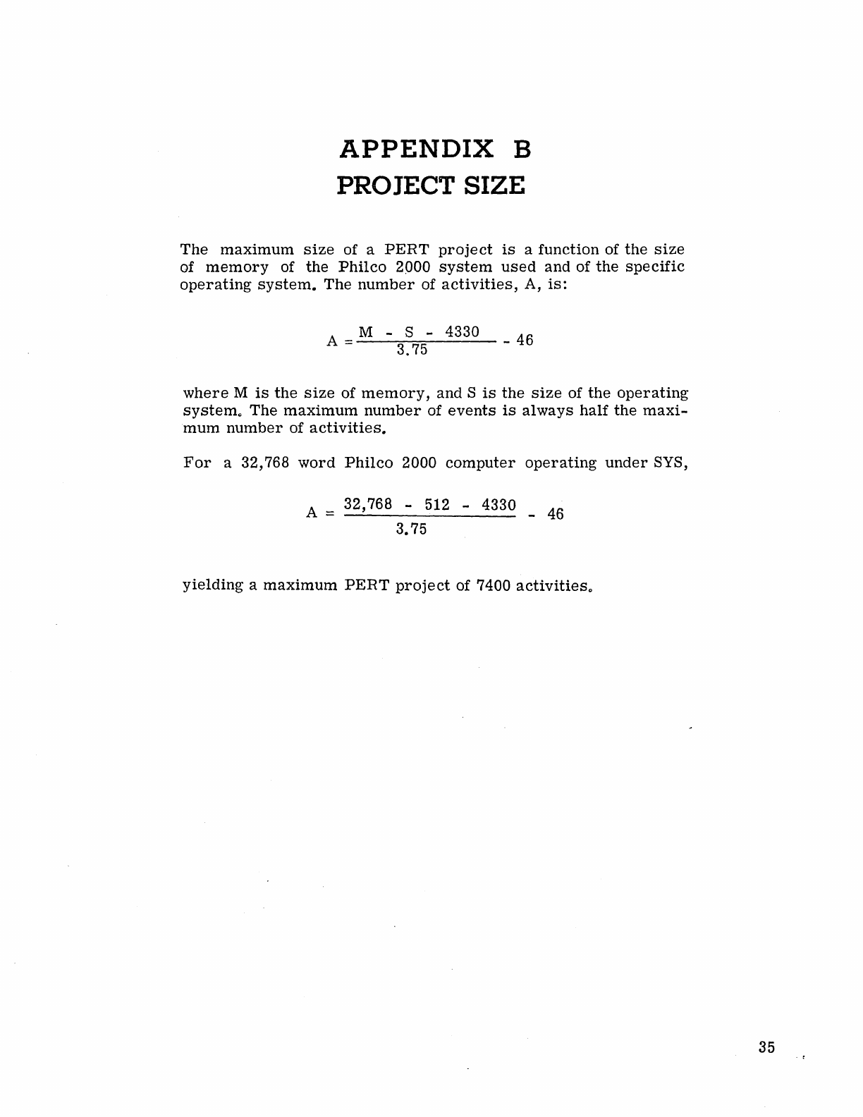
APPENDIX
B
PRO
JECT
SIZE
The
maximum
size
of a
PERT
project
is
a function of
the
size
of
memory
of the
Philco
2000
system
used
and of
the
specific
operating
system.
The
number
of
activities,
A,
is:
A
__
M - S - 4330
---:::--::::-::-----
-46
3.75
where
M
is
the
size
of
memory,
and S
is
the
size
of
the
operating
system"
The
maximum
number
of
events
is
always
half
the
maxi-
mum
number
of
activities.
For
a 32,768
word
Philco
2000
computer
operating
under
SYS,
A = 32,768 -512 -4330 -
46
3.75
yielding
a
maximum
PERT
project
of 7400
activities"
35

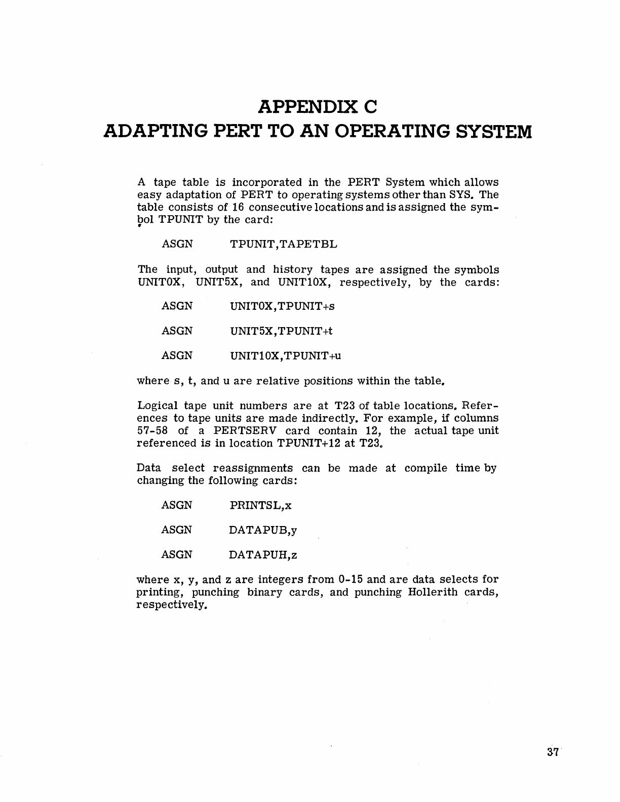
APPENDIX C
ADAPTING PERT TO
AN
OPERATING SYSTEM
A
tape
table
is
incorporated
in
the
PERT
System
which
allows
easy
adaptation
of
PERT
to
operating
systems
other
than
SYS.
The
table
consists
of 16
consecutive
locations
and
is
assigned
the
sym-
bol TPUNIT by
the
card:
•
ASGN
TPUNIT,TAPETBL
The input, output
and
history
tapes
are
assigned
the
symbols
UNITOX, UNIT5X,
and
UNIT10X,
respectively,
by
the
cards:
ASGN UNITOX,
TPUNIT
+s
ASGN UNIT5X,TPUNIT+t
ASGN UNIT10X, TPUNIT+u
where
s,
t,
and u
are
relative
positions
within
the
table.
Logical
tape
unit
numbers
are
at
T23
·of
table
locations.
Refer-
ences
to
tape
units
are
made
indirectly.
For
example,
if
columns
57-58 of a
PERTSERV
card
contain
12,
the
actual
tape
unit
referenced
is
in
location
TPUNIT+12
at
T23"
Data
select
reassignments
can
be
made
at
compile
time
by
changing
the
following
cards:
ASGN
PRINTSL,x
ASGN
DATAPUB,y
ASGN DATAPUH,z
where
x, y,
and
z
are
integers
from
0-15
and
are
data
selects
for
printing,
punching
binary
cards,
and punching
Hollerith
cards,
respectively.
37