TM9100/TP9100 Radio API/P25 API Protocol Manual TM8000/TM8000 CCDI Manual/TM8000 MMA 00038 02 TM8000
User Manual: Pdf TM8000/TM8000 CCDI Protocol Manual/TM8000 CCDI Protocol Manual MMA-00038-02
Open the PDF directly: View PDF ![]() .
.
Page Count: 76
- Computer-Controlled Data Interface (CCDI) Protocol Manual
- Contents
- Preface
- 1 CCDI
- 2 CCR
- 2.1 Introduction
- 2.2 Programmable Parameters
- 2.3 Command Protocol
- 2.4 Command Description
- 2.5 CCR Mode Commands
- 2.6 CCR Positive Acknowledgements
- 2.7 CCR Negative Acknowledgements
- 2.8 CCR Commands
- 2.8.1 Summary and Examples
- 2.8.2 Go to Receive Frequency
- 2.8.3 Load Transmit Frequency
- 2.8.4 Set Volume Level
- 2.8.5 Receive CTCSS Value
- 2.8.6 Transmit CTCSS Value
- 2.8.7 Receive DCS Value
- 2.8.8 Transmit DCS Value
- 2.8.9 Encode Selcall Sequence
- 2.8.10 Set Selcall Parameters
- 2.8.11 Set ANI
- 2.8.12 Monitor
- 2.8.13 Transmitter Output Power
- 2.8.14 Set Bandwidth
- 2.8.15 Query Radio Pulse
- 2.8.16 Exit CCR Mode
- 2.9 Unsolicited Messages from the Radio
- Tait General Software Licence Agreement

TM8100 mobiles
TM8200 mobiles
Computer-Controlled
Data Interface (CCDI)
Protocol Manual
MMA-00038-02
Issue 2
April 2007

2TM8100/TM8200 Computer-Controlled Data Interface (CCDI) Protocol Manual
© Tait Electronics Limited April 2007
Contact Information
Tait Radio Communications
Corporate Head Office
Tait Electronics Limited
P.O. Box 1645
Christchurch
New Zealand
For the address and telephone number of regional
offices, refer to the TaitWorld website:
We b s i t e : http://www.taitworld.com
Technical Support
For assistance with specific technical issues, contact
Technical Support:
E-mail: support@taitworld.com
We b s i t e : http://support.taitworld.com
Copyright and Trademarks
All information contained in this manual is the property
of Tait Electronics Limited. All rights reserved.
This manual may not, in whole or in part, be copied,
photocopied, reproduced, translated, stored, or reduced
to any electronic medium or machine-readable form,
without prior written permission from Tait Electronics
Limited.
The word TAIT and the TAIT logo are trademarks of
Tait Electronics Limited.
All trade names referenced are the service mark,
trademark or registered trademark of the respective
manufacturers.
Disclaimer
There are no warranties extended or granted by this
manual. Tait Electronics Limited accepts no
responsibility for damage arising from use of the
information contained in the manual or of the
equipment and software it describes. It is the
responsibility of the user to ensure that use of such
information, equipment and software complies with the
laws, rules and regulations of the applicable
jurisdictions.
Enquiries and Comments
In the interests of improving the performance, reliability
or servicing of the equipment, Tait Electronics Limited
reserves the right to update the equipment or this
manual or both without prior notice.
Updates of Manual and Equipment
In the interests of improving the performance, reliability
or servicing of the equipment, Tait Electronics Limited
reserves the right to update the equipment or this
manual or both without prior notice.
Intellectual Property Rights
This product may be protected by one or more patents
of Tait Electronics Limited together with their
international equivalents, pending patent applications
and registered trade marks: NZ338097, NZ508054,
NZ508340, NZ508806, NZ508807, NZ509242,
NZ509640, NZ509959, NZ510496, NZ511155,
NZ511421, NZ516280/519742, NZ519118,
NZ519344, NZ520650/537902, NZ522236,
NZ524369, NZ524378, NZ524509, NZ524537,
NZ524630, NZ530819, NZ534475, NZ534692,
NZ535471, NZ536945, NZ537434, NZ546295,
NZ547713, NZ521450, AU2003281447,
AU2002235062, AU2004216984, AU2005207405,
CA2439018, CA2554213, EU03784706.8,
EU02701829.0, EU04714053.8, EU05704655.9,
GB23865476, GB2386010, GB2413249,
GB0516092.4, US11,232716, US10/597339, US10/
520827, US10/468740, US5,745,840, US10/547653,
US10/546696, US10/547964, US10/523952, US11/
572700.
To Our European Customers
Tait Electronics Limited is an
environmentally responsible company
which supports waste minimization and
material recovery. The European Union’s
Waste Electrical and Electronic Equipment
Directive requires that this product be disposed of
separately from the general waste stream when its
service life is over. Please be environmentally
responsible and dispose through the original supplier,
your local municipal waste “separate collection” service,
or contact Tait Electronics Limited.

TM8100/TM8200 Computer-Controlled Data Interface (CCDI) Protocol Manual 3
© Tait Electronics Limited April 2007
Contents
Preface . . . . . . . . . . . . . . . . . . . . . . . . . . . . . . . . . . . . . . . . . . . . . . . . . . . . . 7
Scope of Manual . . . . . . . . . . . . . . . . . . . . . . . . . . . . . . . . . . . . . . . . . . . . . . . . . . . . 7
Associated Documentation . . . . . . . . . . . . . . . . . . . . . . . . . . . . . . . . . . . . . . . . . . . . . 7
Publication Record . . . . . . . . . . . . . . . . . . . . . . . . . . . . . . . . . . . . . . . . . . . . . . . . . . 7
Alert Notices . . . . . . . . . . . . . . . . . . . . . . . . . . . . . . . . . . . . . . . . . . . . . . . . . . . . . . . 8
Abbreviations . . . . . . . . . . . . . . . . . . . . . . . . . . . . . . . . . . . . . . . . . . . . . . . . . . . . . . . 8
1 CCDI. . . . . . . . . . . . . . . . . . . . . . . . . . . . . . . . . . . . . . . . . . . . . . . . . . . 11
1.1 Compatibility . . . . . . . . . . . . . . . . . . . . . . . . . . . . . . . . . . . . . . . . . . . . . . . . . . 12
1.2 Serial Ports . . . . . . . . . . . . . . . . . . . . . . . . . . . . . . . . . . . . . . . . . . . . . . . . . . . . 12
1.2.1 Data Characteristics . . . . . . . . . . . . . . . . . . . . . . . . . . . . . . . . . . . . . . 12
1.2.2 Logic Level Compatibility . . . . . . . . . . . . . . . . . . . . . . . . . . . . . . . . . 13
1.2.3 GPS Port . . . . . . . . . . . . . . . . . . . . . . . . . . . . . . . . . . . . . . . . . . . . . 13
1.2.4 MAP27 Port . . . . . . . . . . . . . . . . . . . . . . . . . . . . . . . . . . . . . . . . . . . 13
1.3 Before Operating . . . . . . . . . . . . . . . . . . . . . . . . . . . . . . . . . . . . . . . . . . . . . . . 14
1.4 Limitations . . . . . . . . . . . . . . . . . . . . . . . . . . . . . . . . . . . . . . . . . . . . . . . . . . . . 14
1.5 Programming . . . . . . . . . . . . . . . . . . . . . . . . . . . . . . . . . . . . . . . . . . . . . . . . . . 14
1.6 CCDI Flow Control. . . . . . . . . . . . . . . . . . . . . . . . . . . . . . . . . . . . . . . . . . . . . 15
1.6.1 XON/XOFF Software Flow Control. . . . . . . . . . . . . . . . . . . . . . . . . 15
1.6.2 Hardware Flow Control . . . . . . . . . . . . . . . . . . . . . . . . . . . . . . . . . . 15
1.7 CCDI Transparent Mode . . . . . . . . . . . . . . . . . . . . . . . . . . . . . . . . . . . . . . . . . 16
1.7.1 Entering Transparent Mode . . . . . . . . . . . . . . . . . . . . . . . . . . . . . . . . 16
1.7.2 Exiting Transparent Mode . . . . . . . . . . . . . . . . . . . . . . . . . . . . . . . . . 17
1.7.3 Transparent Mode Format . . . . . . . . . . . . . . . . . . . . . . . . . . . . . . . . . 17
1.8 Command Mode . . . . . . . . . . . . . . . . . . . . . . . . . . . . . . . . . . . . . . . . . . . . . . . 18
1.8.1 Entering Command Mode . . . . . . . . . . . . . . . . . . . . . . . . . . . . . . . . . 19
1.8.2 CCDI Command Prompt . . . . . . . . . . . . . . . . . . . . . . . . . . . . . . . . . 19
1.8.3 CCDI Command Format . . . . . . . . . . . . . . . . . . . . . . . . . . . . . . . . . 20
1.8.4 Restrictions. . . . . . . . . . . . . . . . . . . . . . . . . . . . . . . . . . . . . . . . . . . . 20
1.8.5 Calculating the CCDI [CHECKSUM]. . . . . . . . . . . . . . . . . . . . . . . . 20
1.9 Commands to the Radio. . . . . . . . . . . . . . . . . . . . . . . . . . . . . . . . . . . . . . . . . . 22
1.9.1 CANCEL . . . . . . . . . . . . . . . . . . . . . . . . . . . . . . . . . . . . . . . . . . . . . 22
1.9.2 DIAL . . . . . . . . . . . . . . . . . . . . . . . . . . . . . . . . . . . . . . . . . . . . . . . . 24
1.9.3 FUNCTION . . . . . . . . . . . . . . . . . . . . . . . . . . . . . . . . . . . . . . . . . . 24
1.9.4 GO_TO_CHANNEL. . . . . . . . . . . . . . . . . . . . . . . . . . . . . . . . . . . . 29
1.9.5 QUERY. . . . . . . . . . . . . . . . . . . . . . . . . . . . . . . . . . . . . . . . . . . . . . 30
1.9.6 SEND_ADAPTABLE_SDM . . . . . . . . . . . . . . . . . . . . . . . . . . . . . . . 31
1.9.7 SEND_SDM. . . . . . . . . . . . . . . . . . . . . . . . . . . . . . . . . . . . . . . . . . . 35
1.9.8 TDMA . . . . . . . . . . . . . . . . . . . . . . . . . . . . . . . . . . . . . . . . . . . . . . . 36
1.9.9 TRANSPARENT (FFSK and THSD) . . . . . . . . . . . . . . . . . . . . . . . . 38
1.10 Messages from the Radio . . . . . . . . . . . . . . . . . . . . . . . . . . . . . . . . . . . . . . . . . 39
1.10.1 CCTM_QUERY_RESULTS . . . . . . . . . . . . . . . . . . . . . . . . . . . . . . 40
1.10.2 ERROR . . . . . . . . . . . . . . . . . . . . . . . . . . . . . . . . . . . . . . . . . . . . . 41
4TM8100/TM8200 Computer-Controlled Data Interface (CCDI) Protocol Manual
© Tait Electronics Limited April 2007
1.10.3 GET_SDM. . . . . . . . . . . . . . . . . . . . . . . . . . . . . . . . . . . . . . . . . . . . 42
1.10.4 MODEL . . . . . . . . . . . . . . . . . . . . . . . . . . . . . . . . . . . . . . . . . . . . . 43
1.10.5 PROGRESS . . . . . . . . . . . . . . . . . . . . . . . . . . . . . . . . . . . . . . . . . . 44
1.10.6 QUERY_DISPLAY_RESPONSE . . . . . . . . . . . . . . . . . . . . . . . . . . 47
1.10.7 RADIO_SERIAL. . . . . . . . . . . . . . . . . . . . . . . . . . . . . . . . . . . . . . . 50
1.10.8 RADIO_VERSIONS. . . . . . . . . . . . . . . . . . . . . . . . . . . . . . . . . . . . 50
1.10.9 RING . . . . . . . . . . . . . . . . . . . . . . . . . . . . . . . . . . . . . . . . . . . . . . . 51
1.10.10TDMA_DATA . . . . . . . . . . . . . . . . . . . . . . . . . . . . . . . . . . . . . . . . 52
1.10.11TRANSACTION OK. . . . . . . . . . . . . . . . . . . . . . . . . . . . . . . . . . . 52
2 CCR . . . . . . . . . . . . . . . . . . . . . . . . . . . . . . . . . . . . . . . . . . . . . . . . . . . 53
2.1 Introduction. . . . . . . . . . . . . . . . . . . . . . . . . . . . . . . . . . . . . . . . . . . . . . . . . . . 53
2.1.1 Configurable Parameters . . . . . . . . . . . . . . . . . . . . . . . . . . . . . . . . . . 53
2.1.2 Potential Applications . . . . . . . . . . . . . . . . . . . . . . . . . . . . . . . . . . . . 54
2.2 Programmable Parameters. . . . . . . . . . . . . . . . . . . . . . . . . . . . . . . . . . . . . . . . . 54
2.2.1 Requirements . . . . . . . . . . . . . . . . . . . . . . . . . . . . . . . . . . . . . . . . . . 54
2.3 Command Protocol . . . . . . . . . . . . . . . . . . . . . . . . . . . . . . . . . . . . . . . . . . . . . 55
2.4 Command Description . . . . . . . . . . . . . . . . . . . . . . . . . . . . . . . . . . . . . . . . . . . 55
2.4.1 Message Format . . . . . . . . . . . . . . . . . . . . . . . . . . . . . . . . . . . . . . . . 55
2.4.2 Calculating [CHECKSUM]. . . . . . . . . . . . . . . . . . . . . . . . . . . . . . . . 56
2.5 CCR Mode Commands . . . . . . . . . . . . . . . . . . . . . . . . . . . . . . . . . . . . . . . . . . 57
2.5.1 Entering CCR Mode . . . . . . . . . . . . . . . . . . . . . . . . . . . . . . . . . . . . 57
2.5.2 CCR/CCDI Mode Independence. . . . . . . . . . . . . . . . . . . . . . . . . . . 57
2.5.3 CCR Mode Activated. . . . . . . . . . . . . . . . . . . . . . . . . . . . . . . . . . . . 57
2.5.4 CCR Mode Busy . . . . . . . . . . . . . . . . . . . . . . . . . . . . . . . . . . . . . . . 57
2.5.5 Blocked Functions . . . . . . . . . . . . . . . . . . . . . . . . . . . . . . . . . . . . . . 57
2.5.6 CCR Persistence. . . . . . . . . . . . . . . . . . . . . . . . . . . . . . . . . . . . . . . . 58
2.5.7 CCR Response Time . . . . . . . . . . . . . . . . . . . . . . . . . . . . . . . . . . . . 58
2.5.8 Exiting CCR Mode . . . . . . . . . . . . . . . . . . . . . . . . . . . . . . . . . . . . . 58
2.6 CCR Positive Acknowledgements . . . . . . . . . . . . . . . . . . . . . . . . . . . . . . . . . . 58
2.7 CCR Negative Acknowledgements . . . . . . . . . . . . . . . . . . . . . . . . . . . . . . . . . 59
2.7.1 Invalid CCR Command . . . . . . . . . . . . . . . . . . . . . . . . . . . . . . . . . . 59
2.7.2 Validation Checksum Error . . . . . . . . . . . . . . . . . . . . . . . . . . . . . . . . 60
2.7.3 Invalid Validation Command. . . . . . . . . . . . . . . . . . . . . . . . . . . . . . . 60
2.7.4 Validation Parameter Error . . . . . . . . . . . . . . . . . . . . . . . . . . . . . . . . 60
2.7.5 Radio Busy Message . . . . . . . . . . . . . . . . . . . . . . . . . . . . . . . . . . . . . 60
2.7.6 Command Not Accepted Message . . . . . . . . . . . . . . . . . . . . . . . . . . . 60
2.8 CCR Commands . . . . . . . . . . . . . . . . . . . . . . . . . . . . . . . . . . . . . . . . . . . . . . . 61
2.8.1 Summary and Examples. . . . . . . . . . . . . . . . . . . . . . . . . . . . . . . . . . . 61
2.8.2 Go to Receive Frequency . . . . . . . . . . . . . . . . . . . . . . . . . . . . . . . . . 62
2.8.3 Load Transmit Frequency . . . . . . . . . . . . . . . . . . . . . . . . . . . . . . . . . 62
2.8.4 Set Volume Level . . . . . . . . . . . . . . . . . . . . . . . . . . . . . . . . . . . . . . . 63
2.8.5 Receive CTCSS Value . . . . . . . . . . . . . . . . . . . . . . . . . . . . . . . . . . . 64
2.8.6 Transmit CTCSS Value. . . . . . . . . . . . . . . . . . . . . . . . . . . . . . . . . . . 64
2.8.7 Receive DCS Value . . . . . . . . . . . . . . . . . . . . . . . . . . . . . . . . . . . . . 65
2.8.8 Transmit DCS Value. . . . . . . . . . . . . . . . . . . . . . . . . . . . . . . . . . . . . 65
2.8.9 Encode Selcall Sequence . . . . . . . . . . . . . . . . . . . . . . . . . . . . . . . . . . 65
2.8.10 Set Selcall Parameters . . . . . . . . . . . . . . . . . . . . . . . . . . . . . . . . . . . . 66
2.8.11 Set ANI . . . . . . . . . . . . . . . . . . . . . . . . . . . . . . . . . . . . . . . . . . . . . . 67
TM8100/TM8200 Computer-Controlled Data Interface (CCDI) Protocol Manual 5
© Tait Electronics Limited April 2007
2.8.12 Monitor . . . . . . . . . . . . . . . . . . . . . . . . . . . . . . . . . . . . . . . . . . . . . . 68
2.8.13 Transmitter Output Power . . . . . . . . . . . . . . . . . . . . . . . . . . . . . . . . 69
2.8.14 Set Bandwidth. . . . . . . . . . . . . . . . . . . . . . . . . . . . . . . . . . . . . . . . . . 69
2.8.15 Query Radio Pulse . . . . . . . . . . . . . . . . . . . . . . . . . . . . . . . . . . . . . . 70
2.8.16 Exit CCR Mode . . . . . . . . . . . . . . . . . . . . . . . . . . . . . . . . . . . . . . . . 70
2.9 Unsolicited Messages from the Radio . . . . . . . . . . . . . . . . . . . . . . . . . . . . . . . . 72
2.9.1 Summary and Examples . . . . . . . . . . . . . . . . . . . . . . . . . . . . . . . . . . . 72
2.9.2 PTT exceeds max transmit limit. . . . . . . . . . . . . . . . . . . . . . . . . . . . . 72
2.9.3 Selcall Decode Sequence . . . . . . . . . . . . . . . . . . . . . . . . . . . . . . . . . . 73
2.9.4 Notify Buffer Size . . . . . . . . . . . . . . . . . . . . . . . . . . . . . . . . . . . . . . . 73
Tait General Software Licence Agreement . . . . . . . . . . . . . . . . . . . . . . . . . . . . 75
6TM8100/TM8200 Computer-Controlled Data Interface (CCDI) Protocol Manual
© Tait Electronics Limited April 2007

TM8100/TM8200 Computer-Controlled Data Interface (CCDI) Protocol Manual 7
© Tait Electronics Limited April 2007
Preface
Scope of Manual
This manual contains reference information about the CCDI and CCR
protocols for the TM8100 and TM8200 mobiles. It applies to CCDI version
3.00 and later and CCR version 2.00.
Associated Documentation
Technical notes are published from time to time to describe applications for
Tait products, to provide technical details not included in manuals, and to
offer solutions for any problems that arise.1
■Technical Note TN-855-AN: TM8000 and TB7100 Data Modem
Facilities
■Technical Note TN-919-AN: Configuring the TM8100 for Data
Operation
■Technical Note TN-1075-AN: MAP27 Implementation Form
(Appendix A7)
Publication Record
1. Technical notes are available in PDF format from the Tait support website. Consult your nearest
Tait Dealer or Customer Service Organization for more information.
Issue Publication Date Description
1 March 2006 First issue
2 April 2007 ■Description of CCDI command prompt
(TIMS 38465)
■QUERY command 7 (display) added
(TIMS 59393)
■FUNCTION command 0 (functions),
subfunction 4, qualifiers 2 and 3 (keypress
progress message) added (TIMS 59393)
■FUNCTION command 0 (functions),
subfunction 5, qualifiers 0, 1, and 2 (channel
progress message) added (TIMS 59393)
■TDMA command added (TIMS 59393)
■PROGRESS message types 22 and 23 added
(TIMS 59393)
■QUERY_DISPLAY_RESOPNSE message added
(TIMS 59393)
■TDMA_DATA message added (TIMS 59393)
■CCR section added (TIMS 57777)

8TM8100/TM8200 Computer-Controlled Data Interface (CCDI) Protocol Manual
© Tait Electronics Limited April 2007
Alert Notices
Within this manual, four types of alerts are given to the reader: warning,
caution, important and note. The following paragraphs illustrate each type
of alert and its associated symbol.
Warning!! This alert is used when there is a potential risk
of death or serious injury.
Caution This alert is used when there is the risk of minor or
moderate injury to people.
Important This alert is used to warn about the risk of equipment dam-
age or malfunction.
Note This alert is used to highlight information that is required to
ensure that procedures are performed correctly.
Abbreviations
Abbreviation Description
ASCII American Standard Code for Information Interchange
AVL Automatic Vehicle Location
CCDI Computer Controlled Data Interface
CCR Computer Controlled Radio
CDP Conventional Data Protocol. A Tait over-air protocol.
CRC Cyclic Redundancy Check
CTCSS Continuous Tone Coded Squelch System
CTS Clear to Send
DCE Data Circuit-Terminating Equipment
DCS Data Carrier System
DTE Data Terminal Equipment
DTMF Dual Tone Multi-Frequency
FFSK Fast Frequency Shift Keying
GFI General Format Information for an SDM
GPIO General Purpose Input/Output
IPN Internal Part Number
LED Light-Emitting Diode
MSD Most Significant Digit
NMEA National Marine Electronics Association standard. Combined
electrical and data specification for communication between
marine electronics and GPS receivers.
PC Personal Computer
PTT Press To Talk

TM8100/TM8200 Computer-Controlled Data Interface (CCDI) Protocol Manual 9
© Tait Electronics Limited April 2007
RMC Recommended Minimum sentence C. NMEA GPS message
type for the minimum recommended transmit/GPS data.
RTS Request to Send (ready to receive)
Rx Receive
RXD Receive Data
SDM Short Data Message
SFI Specific Format Information for an SDM
THSD Tait High Speed Data
TIA Telecommunications Industry Association
TOP Tait Orca Portable
Tx Transmit
TXD Transmit Data
UART Universal Asynchronous Receiver-Transmitter
XON Transmitter On
XOFF Transmitter Off
Abbreviation Description
10 TM8100/TM8200 Computer-Controlled Data Interface (CCDI) Protocol Manual
© Tait Electronics Limited April 2007
TM8100/TM8200 Computer-Controlled Data Interface (CCDI) Protocol Manual CCDI 11
© Tait Electronics Limited April 2007
1CCDI
The Computer Controlled Data Interface (CCDI) protocol is a Tait
proprietary command protocol embedded in the TM8100 and TM8200
radios, and used for communicating with the radio via asynchronous serial
ports and over-air.
The radio is the DCE and is connected directly to the DTE, usually a PC,
via the serial port.
Two modes of operation are available:
■Command mode
■Transparent mode
When in Command mode, commands and response messages are passed
between the PC and the radio using the CCDI protocol. CCDI commands
can also be used to obtain GPS data and NMEA messages from the radio.
Refer to “QUERY” and “SEND_ADAPTABLE_SDM”. The baud rate is
set to 1200, 2400, 4800, 9600, 14400, 19200, 28800 or 115200 (TM8200
only) baud, using the programming application.
When in Transparent mode, communication between the PC and the radio
is set to 1200, 2400, 4800, 9600, 14400, 19200, 28800 or 115200 (TM8200
only) baud, using the programming application.
The over-air data rate is 1200 or 2400 bit/s for FFSK data,
12 kbit/s for Tait High Speed Data (THSD) narrow band and wide band,
and can be set to 19200 bit/s for THSD wide band.
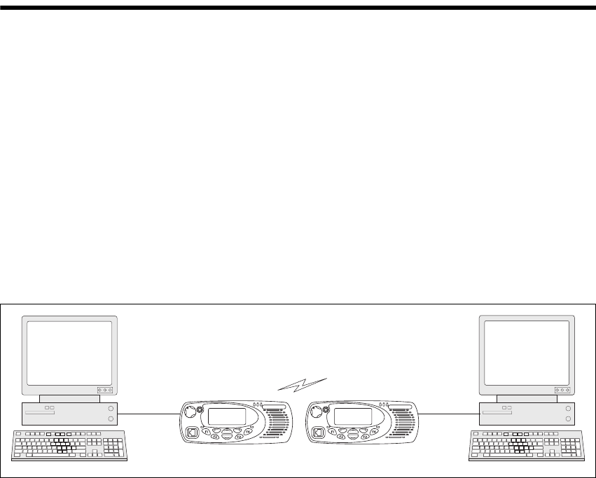
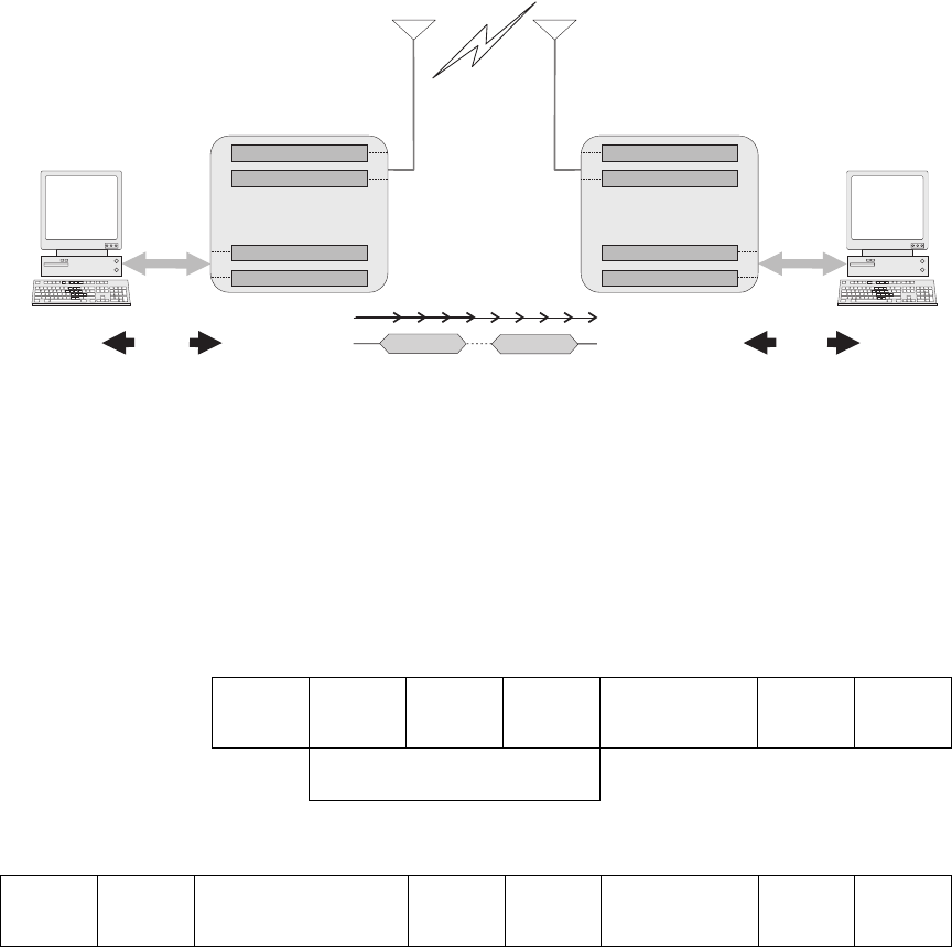
Figure 1.1 Modes of operation
PC Serial Port
PC running
terminal application
PC running
terminal application
PC Serial Port

12 CCDI TM8100/TM8200 Computer-Controlled Data Interface (CCDI) Protocol Manual
© Tait Electronics Limited April 2007
1.1 Compatibility
This manual describes CCDI version 3.00 and later.
The radio programming application used should be the latest released
version for both the TM8100 and TM8200 radios. Refer to the
Ta i t Wo r ld we b s i t e http://www.taitworld.com for the latest versions of
programming application.
1.2 Serial Ports
Three ports are available for CCDI asynchronous serial communication
with the radio. The microphone and auxiliary ports are accessed externally,
and the internal options connector is internal to the radio.
Only one of these ports can be used for CCDI transmission and reception
at any time. The port is selected in the Data form of the programming
application, Serial Communications tab. Select “Mic”, “Aux” or “Internal
Connector”.
■Mic: The radio will transmit and receive data via the MIC_TXD and
MIC_RXD lines on the microphone connector.
■Aux: The radio will transmit and receive data via the AUX_TXD and
AUX_RXD lines on the auxiliary connector.
■Internal Connector: The radio will transmit and receive data via the
IOP_TXD and IOP_RXD lines on the internal options connector.
This connector is used to fit an internal options board into the radio.
For more information on these connectors, refer to the service manual.
1.2.1 Data Characteristics
Parameter
Standard
Comments
min. typ. max. units
Serial port
Baud rate: 1200, 2400, 4800, 9600,
14400, 19200, 28800, 115200
bit/s All UART parameters are
fixed and common to all
UARTs except for the
baud rate which is
configurable and
different for different
modes/applications
Data bits: 8
Start bit: 1
Stop bit: 1
Parity: None
Flow control:
Software
Hardware
XON/XOFF
RTS/CTS Requires two GPIO lines
to be programmed as
flow control

TM8100/TM8200 Computer-Controlled Data Interface (CCDI) Protocol Manual CCDI 13
© Tait Electronics Limited April 2007
1.2.2 Logic Level Compatibility
The following table show the compatibility of the radio’s digital I/O used
for CCDI with common industry logic standards.
Digital Input
Compatibility and
Toler a n ce
Digital Output
Compatibility
1.2.3 GPS Port
The GPS receiver/antenna is also connected to an asynchronous serial port
and must be different to the CCDI UART Port. The GPS receiver/antenna
is set in the Data form of the programming application, GPS tab, and can be
set to Mic, Aux or Internal Options.
If set to Aux, the GPS receiver will send NMEA messages to the radio via
the AUX_RXD line on the auxiliary connector.
If set to Internal Options, the GPS receiver will send NMEA messages to
the radio via the IOP_RXD line on the internal options connector.
1.2.4 MAP27 Port
MAP27 data transmission and reception also requires an asynchronous serial
port and must be different to the CCDI UART Port. The MAP27 port is
set in the Data form of the programming application, MAP27 tab, and can
be set to Mic, Aux or Internal Options.
If set to Mic, the radio will use the MIC_TXD and MIC_RXD lines on the
microphone connector.
Digital Input
Line
Logic standard input compatibility and tolerance
3.3V CMOS 5V CMOS 5V TTL RS-232
AUX_RXD Yes Yes Yes Yes
IOP_RXD Yes Yes Yes Noa
a. Level compatible but not tolerant. Inputs can be made RS-232 tolerant by using 3.3kΩ series
resistance inserted at the radio end.
CH_RXD
MIC_RXD
PRG_RXD
Yes Yes Yes Yes
Digital Output
Line
Logic standard input compatibility and tolerance
3.3V CMOS 5V CMOS 5V TTL RS-232
AUX_TXD Yes No Yes No
IOP_TXD Yes Noa
a. These outputs can be made 5V CMOS compatible using a 3.3kΩ pull-up resistor to 5V that is
provided by the device being driven.
Yes No
CH_TXD
MIC_TXD
PRG_TXD
Yes No Yes No

14 CCDI TM8100/TM8200 Computer-Controlled Data Interface (CCDI) Protocol Manual
© Tait Electronics Limited April 2007
If set to Aux, the radio will use the AUX_TXD and AUX_RXD lines on
the auxiliary connector.
If set to Internal Options, the radio will use the IOP_TXD and IOP_RXD
lines on the internal options connector.
For more information on MAP27 data transmission, refer to Technical Note
TN-1075-AN, MAP27 Implementation Form (Appendix A7).
1.3 Before Operating
Before using CCDI, the following is useful to check.
■The radio must be correctly programmed for use with the CCDI
protocol. See “Programming” on page 14 for configuration information.
■At power on, the radio will select its default channel. To change the
channel, select the channel using the normal radio interface or using the
CCDI Go_To_Channel command. Refer to “GO_TO_CHANNEL”
on page 29.
■The radio will power on into the mode selected in the ‘Powerup State’
field in the Data form.
■Power, Tx and Rx LED indicators are helpful for establishing proper
operation. The radio speaker can be used to listen to data coming in.
■Data flow is controlled either by the customer’s embedded computer
system or by a PC running a data-sending application such as
Hyperterminal.
1.4 Limitations
Important Some data applications require extended transmission
times. This may be for larger file transfers or for real-time
telemetry information. This may put undue stress on the
radio transmitter and care must be taken to control trans-
mission times using flow control. Refer to “Hardware Flow
Control” on page 15.
1.5 Programming
For information on the parameters in the Data form of the programming
application, refer to:
■the Help of the programming application
■Technical Note TN-919-AN Configuring the TM8100 for Data
Operation.

TM8100/TM8200 Computer-Controlled Data Interface (CCDI) Protocol Manual CCDI 15
© Tait Electronics Limited April 2007
1.6 CCDI Flow Control
Flow control is a method of controlling the data so that a faster DTE-DCE
baud rate can be used to that of the over the air baud rate. This allows the
radio (DCE) to inform the DTE that its buffer is becoming full and that the
DTE needs to wait before sending more data to the radio.
Flow control should only be needed when the amount of data to send is
larger than the radios buffer (512 bytes for TM8100, 600 bytes for
TM8200).
Note Some older versions of the firmware have a buffer size of 128
bytes.
Available options: None, Hardware Software
1.6.1 XON/XOFF Software Flow Control
When the serial communications are set-up for software flow control, the
radio will use pre-programmed bytes for XOFF and XON.
Important When using XON/XOFF software handshaking, the data
stream (or the data file) must not include the programmed
XON and XOFF characters. It is recommended that only
ASCII text be used with software flow control.
The XOFF character is sent when there is less than 35 bytes of empty space
in the buffer.
The XON character is sent when XOFF had previously been sent and there
is now less than 10 bytes of data in the buffer.
1.6.2 Hardware Flow Control
When the serial communications are set-up for hardware flow control, two
of the programmable I/O lines are enabled for RTS and CTS. Hardware
flow control is not available for the mic port.
RTS Important The RTS line has been implemented as a “Ready to
Receive” line as per RS-232-E.
When the RTS line is inactive the radio will not output any serial data.
It will buffer any data and output it when the line is activated.
Important The RTS line does not stop the radio from receiving data
across the air so leaving this line inactive for any length of
16 CCDI TM8100/TM8200 Computer-Controlled Data Interface (CCDI) Protocol Manual
© Tait Electronics Limited April 2007
time could cause the buffer to overflow and for data to be
lost.
CTS The CTS line is deactivated when there is less than 35 bytes of empty space
in the buffer.
The CTS line is activated when the CTS line had previously been
deactivated and there is now less than 10 bytes of data in the buffer.
1.7 CCDI Transparent Mode
In Transparent mode, the radio acts as a modem, automatically transmitting
in FFSK or THSD format the serial data received from the PC. In this mode,
the baud rate between the PC (DTE) and the radio (DCE) can be set to
either 1200, 2400, 4800, 9600, 14400, 19200, 28800 or 115200 (TM8200
only) baud using the programming application. The over-air data rate is
1200 or 2400 bps for FFSK data, 12 kbit/s for Tait High Speed Data
(THSD) narrow band and 19200 bit/s for THSD wide band. The serial data
input buffer is 512 bytes for the TM8100 and 600 bytes for the TM8200, to
adequately cope with the data flow.
Communication in Transparent mode is free-format, with the protocol
determined entirely by the PC and the modem. It is transparent to the
CCDI, allowing the PC to send and receive data without passing through
the CCDI. CTCSS and DCS subaudible signalling is available in FFSK
Tra ns parent mode on ly.
1.7.1 Entering Transparent Mode
Transparent mode can be set as the default mode at power on by selecting
FFSK or THSD Transparent Mode in the ‘Powerup State’ field in the
programming application. Refer to “Programming” on page 14.
You can change to Transparent mode while operating in Command mode
by sending a TRANSPARENT command to the radio or using a
programmable I/O line programmed for THSD. Example: t01zB1 sends a
TRANSPARENT command, requesting that the radio be put into
Transparent mode. The escape character specified here is “z” (ASCII code
= $7A). Once acknowledged, any further data is linked directly to the radio
in Transparent mode.
If the radio default is set to Transparent mode at power on, the default escape
character is “+”.
TM8100/TM8200 Computer-Controlled Data Interface (CCDI) Protocol Manual CCDI 17
© Tait Electronics Limited April 2007
1.7.2 Exiting Transparent Mode
To change to Command mode while operating in Transparent mode, you
can:
■send the escape sequence consisting of a 2 second idle time, followed by
three escape characters (sent within 2 seconds), followed by a further 2
second idle time.
Example: If the escape character is “+” (default), send
[2 second idle] +++ [2 second idle].
■exit via the I/O line programmed for THSD, if Transparent Mode was
entered using this line.
1.7.3 Transparent Mode Format
Transparent Mode
Packetisation
Transparent mode data is packetised into data blocks before it is sent over-
air. The start and stop bits are removed and a header is sent at the start of
each data block.
FFSK Transmission
Format The Transparent Mode transmission format is as follows:
Singe Data Block:
Multiple Data Blocks:
Lead-In
Delay
Lead-Out
Delay
time...
data block 1 data block n
over-air
PC data
RS232
data
RS232
PC
air-interface data out
serial data out
air-interface data in
serial data in
processing...
radio
Flow
Control
Flow
Control
no Flow Control
air-interface data out
serial data out
air-interface data in
serial data in
processing...
radio
Lead-In
Delay
preamble
2 bytes
sync
2 bytes
size
2 bytes
FFSK data block
max 46 bytes
CRC
2 bytes
Lead-Out
Delay
HEADER
Lead-In
Delay
HEADER
6 bytes
FFSK data block . . . .
max 46 bytes
CRC
2 bytes
HEADER
6 bytes
FFSK data block
max 46 bytes
CRC
2 bytes
Lead-Out
Delay
18 CCDI TM8100/TM8200 Computer-Controlled Data Interface (CCDI) Protocol Manual
© Tait Electronics Limited April 2007
THSD Transmission
Format For more information, refer to Technical Note TN-855-AN TM8000 and
TB7100 Data Modem Facilities.
Effective Over-Air
Data Rate The effective over-the-air data rate is lower than the set data rate.
For more information, refer to Technical Note TN-855-AN TM8000 and
TB7100 Data Modem Facilities.
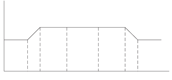
Lead-In Delay The lead-in delay begins after the transmitter key-up time. It gives the
receiver(s) at the other end time to open before data is sent.
When data is detected at the radio’s input buffer, the following occurs:
■The transmitter keys up.
■A carrier is sent from the transmitter. When the carrier reaches its full
potential, the lead-in delay begins.
■If the receiving base station is set to Repeater mode, the carrier is
detected and Rx Gate becomes active (opens), which in turn makes the
PTT line active.
■The active PTT line keys up the transmitter.
This sequence is repeated with as many base stations as are in the chain.
The optimum length of the lead-in delay should be set keeping in mind the
number of base stations that need to be activated before any data is sent.
The lead-in delay must also allow for subaudible signalling decoding, if it is
enabled, when used in conjunction with FFSK data.
1.8 Command Mode
Command mode uses the Tait proprietary Computer Controlled Data
Interface (CCDI), a command protocol embedded in the radio firmware.
It is accessed using the serial port lines from the PC. In this mode, the baud
rate between the computer equipment (DTE) and the radio (DCE) can be
set to either 1200, 2400, 4800, 9600, 14400, 19200, 28800 or 115200
(TM82000 only) baud using the programming application
Tx
key-up
time
Lead In
Delay data
Lead Out
Delay Tx
key-down
Tx

TM8100/TM8200 Computer-Controlled Data Interface (CCDI) Protocol Manual CCDI 19
© Tait Electronics Limited April 2007
In Command mode, the PC sends command sequences to the radio and
waits for a prompt before beginning the next transaction. Some commands
require the radio to send a CCDI message in response. Messages sent to the
radio will always be responded to by the prompt.
Unsolicited messages such as PROGRESS or ERROR messages are sent by
the radio if there is a significant change in its state that the PC should be
aware of. When errors are detected, an unsolicited ERROR message is sent
by the radio to the PC. The radio cannot send messages that require a reply.
The SEND_SDM, SEND_ADAPTABLE_SDM and GET_SDM
commands require that SDMs are sent and received as over-the-air FFSK
data by the radio while in Command mode. If an SDM is received from the
over-air interface while the radio is in Command mode, the SDM data is
buffered and a ‘SDM Received’ RING messages are generated by the radio
to indicate that SDM data has been received. When using FFSK, an ‘FFSK
Data Received’ PROGRESS message will also be generated.
1.8.1 Entering Command Mode
Command mode can be set as the default mode at power on by selecting
‘Command Mode’ in the ‘Powerup State’ field in the programming
application. Refer to “Programming” on page 14.
To change to Command mode while operating in Transparent mode, you
can:
■send the escape sequence consisting of a 2 second idle time, followed by
three escape characters (sent within 2 seconds), followed by a further 2
second idle time.
Example: If the escape character is “+” (default), send
[2 second idle] +++ [2 second idle].
■exit via the I/O line programmed for THSD, if Transparent Mode was
entered using this line.
1.8.2 CCDI Command Prompt
After entering Command mode, the radio sends a “.” character to the PC
which is displayed as a command prompt. The command prompt indicates
that the radio is ready for another command. The prompt is also sent after
the radio has sent a message.
Note In early CCDI versions, the command prompt after messages was
not sent for all messages.
20 CCDI TM8100/TM8200 Computer-Controlled Data Interface (CCDI) Protocol Manual
© Tait Electronics Limited April 2007
1.8.3 CCDI Command Format
All CCDI message packets take the general form:
[IDENT] [SIZE] [PARAMETERS] [CHECKSUM] <CR>
■[IDENT] = The message identifier. Identifiers are single ASCII
characters (lower-case alphabetical) which categorise the message type.
■[SIZE] = The number of characters which make up the
[PARAMETERS] field. [SIZE] is an 8-bit number expressed in ASCII
hex notation (two characters).
■[PARAMETERS] = An optional field, depending upon the command.
Parameter values are generally character strings unless explicitly stated
otherwise. Parameter type is dependent upon the command, and often
has multiple parts.
■[CHECKSUM] = An 8-bit checksum of the [IDENT], [SIZE] and
[PARAMETERS] fields. Expressed in two character ASCII hex
notation.
■<CR> = The carriage return (0Dh) packet terminator.
1.8.4 Restrictions
■All characters in a message are printable ASCII.
■Where numeric values are represented in ASCII hex notation (two
characters per byte), characters A to F are upper case.
■The minimum length of a command packet is 5 characters. For example
q002F is the QUERY command where [SIZE] = 00 as there is no
[PARAMETERS] field required.
■The maximum length of the [PARAMETERS] field is 255 characters.
The maximum length of the command packet is therefore 260
characters.
1.8.5 Calculating the CCDI [CHECKSUM]
[CHECKSUM] is calculated by applying the following algorithm:
1. Take the modulo-2 sum of all message bytes preceding
[CHECKSUM].
2. Retain bits 0 to 7, discarding any higher order bits resulting from the
summation.
3. Form the two’s complement of the remainder.
4. Convert the binary number into two ASCII hex digits, MSD first.
Example s0D050800TESTHi!DA
1. Take the modulo-2 sum of all message bytes preceding
[CHECKSUM].
TM8100/TM8200 Computer-Controlled Data Interface (CCDI) Protocol Manual CCDI 21
© Tait Electronics Limited April 2007
■s = 73h, 0 = 30h, D = 44h etc. therefore the modulo-2 sum is:
73 + 30 + 44 + 30 + 35 + 30 + 38 + 30 + 30 + 54 + 45 + 53 +
54 + 48 + 69 + 21 = 426h
2. Retain bits 0 to 7, discarding any higher order bits resulting from the
summation.
26h
3. Form the two’s complement of the remainder.
26h = 0010 0110
two’s complement = 1101 1010
4. Convert the binary number into two ASCII hex digits, MSD first.
1101 1010 = DA
Checksum Software
Application A software application is available from Tait Technical Support which will
calculate the checksum for any given command and parameters.
Please contact Technical Support (refer to “Contact Information” on
page 2).

22 CCDI TM8100/TM8200 Computer-Controlled Data Interface (CCDI) Protocol Manual
© Tait Electronics Limited April 2007
1.9 Commands to the Radio
The following commands are available to send from the PC to control the
radio.
In all cases, if a command is received without error by the radio and all
parameters are valid, the command is executed.
The prompt character ‘.’ is returned to the PC immediately after receiving a
command, to signify that another may begin. If an error arises, the PC is
notified with an appropriate ERROR response.
1.9.1 CANCEL
The CANCEL command tells the PC to abort the current action that the
radio is performing.
Format c [SIZE] [CANCEL_TYPE] [CHECKSUM]
Command Character Function Valid in Mode
Mode radio must be
in or switch to, to act
upon the message
(TM8200 only)
CANCEL c Cancel current activities Conventional Conventional
DIAL d Initiate a conventional
call
Trunked
Conventional
Conventional
FUNCTION f Implement RU function Trunked
Conventional
Dependent on function
GO_TO_CHANNEL g Tune to conventional
channel
Trunked
Conventional
Conventional
QUERY q Query RU Model, data
parameters, software
versions, etc. Query
SDM.
Trunked
Conventional
Either, no change
required
SEND_ADAPTABLE_SDM a Send conventional SDM
with SFI/GFI field
formatting
Trunked
Conventional
Conventional
SEND_SDM s Send conventional SDM Trunked
Conventional
Conventional
TDMA z Configure and open
TDMA channel
Queue TDMA data for
sending
Close TDMA channel
Conventional Conventional
TRANSPARENT (FFSK and
THSD)
t Switch to Transparent
mode (FFSK or THSD)
Conventional
Trunked
Conventional

TM8100/TM8200 Computer-Controlled Data Interface (CCDI) Protocol Manual CCDI 23
© Tait Electronics Limited April 2007
■‘c’ is sent as a single ASCII character and represents the CANCEL
command.
■[CANCEL_TYPE] is a single ASCII character representing the
cancelling type.
Note If no [CANCEL_TYPE] is sent, then the CANCEL command
will default to CANCEL_TYPE = 0.
Examples c0100C a command to cancel the existing call.
c003D also a command to cancel the existing call.
c0110B a command to delete the currently held SDM.
[CANCEL_TYPE] Function
0
(cancel call)
Cancel Call
In conventional mode, Cancel can do the following:
■clear down a Selcall call, including retries
■cancel deferred calling
■take the radio out of emergency operation if in Emergency
Tx/Rx cycles by resetting the radio
In trunked mode, Cancel can do the following:
■act as though the front panel ‘Cancel’ key has been
pressed.
1
(delete SDM)
Delete SDM data of the last received SDM (if any). Available in
conventional mode only.

24 CCDI TM8100/TM8200 Computer-Controlled Data Interface (CCDI) Protocol Manual
© Tait Electronics Limited April 2007
1.9.2 DIAL
The DIAL command allows access to the full conventional mode dialling
capability of the radio. Selcall and DTMF sequences can be dialled on the
current channel. An TM8200 trunked radio must change to a conventional
channel using a function key before executing this command. The function
key is set to “Switch Mode” in the MPT Key Settings form of the TM8200
programming application.
Format d [SIZE] [DTYPE] [NUMBER_STR] [CHECKSUM]
■‘d’ is sent as a single ASCII character and represents the DIAL command.
■[DTYPE] is a single ASCII character representing the type of dialling
required.
■[NUMBER_STR] represents the dialled sequence. The range of allowed
characters depends upon the value of [DTYPE].
Note The DIAL command initiates the calling process only. The call
may take some time to get through, especially if the channel is
busy or the system heavily loaded. The receiver will return a
prompt as soon as the DIAL command is accepted, but the PC
may have to wait for a PROGRESS message advising successful
call set-up before proceeding.
Examples d0601234507 a command to initiate Selcall dialling of the number
1 2 3 4 5.
d0611234506 a command to initiate DTMF dialling of the number
1 2 3 4 5.
1.9.3 FUNCTION
The FUNCTION command provides access to various hardware and
miscellaneous functions.
Format f [SIZE] [FUNCTION] [SUBFUNCTION] [QUALIFIER]
[CHECKSUM]
[DTYPE] [NUMBER_STR]
0
(Selcall)
0...9, A...F, -, V (maximum of 32 digits).
Selcall strings usually use the digits 0 to 9 as some of the tones A to
F have special meaning, e.g. A = Group; C = Reset; E = Repeat.
Selcall calls are made within the bounds of the following
parameters, as programmed into the radio: tone period, tone set
and Lead-In Delay, etc.
1
(DTMF
conventional)
0...9, A...D, *, #,-(maximum of 32 digits)
DTMF calls are made within the bounds of the following
parameters, as programmed into the radio, e.g. key-up delay, tone
period and inter-tone gap.

TM8100/TM8200 Computer-Controlled Data Interface (CCDI) Protocol Manual CCDI 25
© Tait Electronics Limited April 2007
■‘f ’ is sent as a single ASCII character and represents the FUNCTION
command.
■[FUNCTION] is a single ASCII characters representing the required
function category.
■[SUBFUNCTION] is up to two ASCII characters and is used to extend
the range of the [FUNCTION] parameter.
■[QUALIFIER] is an ASCII character string representing the action to be
taken, depending on the value of [FUNCTION] and
[SUBFUNCTION].
[FUNCTION] [SUBFUNCTION] [QUALIFIER] Action Support
0
(functions)
0 none Switch to CCR mode. TM8100: Yes
TM8200: No
1 0 Disable CCDI volume control. Yes
1 Enable CCDI volume control (refer to
SUBFUNCTION=2).
Yes
2 0-9 Set volume level. 0=off, 1-9=loudness. TM8100:
before v2.06
TM8200: No
2 0-25 Set volume level. 0=off, 1-25=loudness. TM8100:
from v2.06
TM8200: Yes
3 0 Disable selcall output RING messages. Yes
1 Enable selcall output RING messages. Yes
4 0 Disable PROGRESS output messages. Yes
1 Enable PROGRESS output messages. Yes
2 Enable KEYPRESS progress messages. TM8100: No
TM8200:
from v2.05
3 Disable KEYPRESS progress messages
(default).
5 0 Disable channel PROGRESS output
messages (default).
TM8100:
from v2.03
TM8200:
from v2.05
1 Enable channel PROGRESS output
messages (unsolicited).
Refer to “PROGRESS” on page 44, [PTYPE]
= 21 User Initiated Channel Change.
2 Report current channel (solicited).

26 CCDI TM8100/TM8200 Computer-Controlled Data Interface (CCDI) Protocol Manual
© Tait Electronics Limited April 2007
1
(SDM control)
0 0 Disable SDM output on reception. Yes
1 Enable SDM output on reception, QUERY
command not required.
Yes
1 0 Disable SDM caller ID encode. Yes
1 Enable SDM caller ID encode. The caller ID
is sent as a separate SDM before sending
the SDM itself.
Yes
2 0 Disable SDM caller ID decode. Yes
1 Enable SDM caller ID decode. The caller ID
SDM is decoded before the incoming SDM.
Yes
2
(emergency
mode)
2 0 Activate non-stealth emergency mode. Yes
1 Activate stealth emergency mode. Yes
3
(simulate key
presses)
none 000-009 PTT keypress length, 0=constantly off, 1-
8=x/8 seconds on, 9=constantly on.
Yes
010-019 Hookswitch keypress length, 0=constantly
off,
1-8=x/8 seconds on, 9=constantly on.
Yes
020-029 ‘On/off’ keypress length, 0=constantly off,
1-8=x/8 seconds on, 9=constantly on.
Yes
030-039 ‘Up’ keypress length, 0=constantly off,
1-8=x/8 seconds on, 9=constantly on.
Yes
040-049 ‘Down’ keypress length, 0=constantly off,
1-8=x/8 seconds on, 9=constantly on.
Yes
050-059 ‘FN1’ keypress length, 0=constantly off,
1-8=x/8 seconds on, 9=constantly on.
Yes
060-069 ‘FN2’ keypress length, 0=constantly off,
1-8=x/8 seconds on, 9=constantly on.
Yes
070-079 ‘FN3’ keypress length, 0=constantly off,
1-8=x/8 seconds on, 9=constantly on.
Yes
080-089 ‘FN4’ keypress length, 0=constantly off,
1-8=x/8 seconds on, 9=constantly on.
Yes
[FUNCTION] [SUBFUNCTION] [QUALIFIER] Action Support

TM8100/TM8200 Computer-Controlled Data Interface (CCDI) Protocol Manual CCDI 27
© Tait Electronics Limited April 2007
Examples f0241D3 a command to disable user input command.
f0250D3 a command to mute the receiver audio.
f0271D0 a command to validate subaudible signalling.
f0281CF a command to activate Monitor function.
4
(user controls)
none 0 Disable all user controls, display and
indicators.The radio indicates “CCDI
BUSY”.
Yes
1 Disable user input only. Display and
indicators still operational. Any attempted
user input will result in the invalid keypress
tone.
Yes
2 Enable all user controls except when CCDI
commands are being processed. During this
time the radio indicates “CCDI BUSY”.
Set as default at power on.
Yes
5
(Rx audio
mute control)
none 0 Cancel CCDI request for Rx audio mute. Yes
1 Mute Rx audio. Can only be overridden by
Squelch Override. Conventional mode only.
Yes
7
(subaudible
signalling)
none 0 Deactivate validation of CTCSS and DCS
subaudible signalling. Incoming data will be
processed regardless of the subaudible
signalling.
The default radio setting at power on
depends on the ‘Ignore DCS/CTCSS’ option
set in the Data form of the programming
application.
Yes
1 Activate validation of CTCSS and DCS
subaudible signalling. Incoming FFSK data
will only be processed if the subaudible
signalling matches.
Only effective if current channel is
programmed for subaudible signalling.
Conventional or traffic channel mode only.
Yes
8
(monitor)
none 0 Deactivate monitor function. Yes
1 Activate monitor function. Conventional
mode only.
Yes
9
(Rx/Tx)
none 0 Forces radio into a Rx state.
Conventional or traffic channel mode only.
Yes
1 Forces radio into a Tx state. Note that the
Rx CCDI command is required to take the
radio out of Tx mode when this mode is
activated. The Tx will not terminate on
expiry of the Tx timer.
Conventional or traffic channel mode only.
Yes
[FUNCTION] [SUBFUNCTION] [QUALIFIER] Action Support
28 CCDI TM8100/TM8200 Computer-Controlled Data Interface (CCDI) Protocol Manual
© Tait Electronics Limited April 2007
f0291CE a command to activate the transmitter.
f0290CF a command to deactivate the transmitter following an “activate
transmitter” command.
f0200D8 enter CCR Mode.
f03011A5 enable volume control.
f03010A6 disable volume control.
f03020A5 set volume level off.
f0402256D set volume level to the maximum of ‘25’.
f03025A0 set volume level to ‘5’.
f03031A3 enable Selcall output.
f03030A4 disable Selcall output.
f03041A2 enable progress message output.
f03040A3 disable progress message output.
f03101A5 enable output SDM on reception.
f03100A6 disable output SDM on reception.
f03111A4 enable caller ID encoder.
f03110A5 disable caller ID encoder.
f03121A3 enable caller ID decoder.
f03120A4 disable caller ID decoder.
f03051A1 enable channel progress message.

TM8100/TM8200 Computer-Controlled Data Interface (CCDI) Protocol Manual CCDI 29
© Tait Electronics Limited April 2007
1.9.4 GO_TO_CHANNEL
The GO_TO_CHANNEL command tells the radio to change to another
conventional mode channel. The specified channel can be assigned to a
scan/vote group in the radio. A trunked radio must change to a conventional
channel before executing this command.
Format g [SIZE] [ZONE] [CHANNEL_NO] [CHECKSUM]
■‘g’ is sent as a single ASCII character and represents the
GO_TO_CHANNEL command.
■[ZONE] (optional for TM8200, not applicable for TM8100) is a two-
character string representing the new zone. When [ZONE] is omitted,
the radio stays in the current zone.
■[CHANNEL_NO] is a maximum of four characters representing the
new channel number. The range of allowed characters is 0 to 9. and must
be a valid channel for the radio. If used with the [ZONE] parameter, this
will always be a four-character string.
Note If the radio is using a scan/vote group when it receives this com-
mand, it will retune to the specified channel.
Note If the radio is in emergency mode then no channel change will
occur, and a ‘not ready’ error message is returned.
Examples g0223D2 go to channel 23.
g0414995E go to channel 1499.
g060100120F go to zone 1, channel 12.

30 CCDI TM8100/TM8200 Computer-Controlled Data Interface (CCDI) Protocol Manual
© Tait Electronics Limited April 2007
1.9.5 QUERY
The QUERY command requests information from the radio.
Format q [SIZE] [QUERY_TYPE] [DATA] [CHECKSUM]
■‘q’ is sent as a single ASCII character and represents the QUERY
command.
■[QUERY_TYPE] is a single ASCII character representing the query
type required.
■[DATA] is a number with up to three-digits which identifies the CCTM
command which is sent.
Note If no [QUERY_TYPE] is sent, then the QUERY command will
default to [QUERY_TYPE] = 0.
[QUERY_TYPE] [DATA] Function Support
0
(model and CCDI
version)
none Query the radio model and CCDI version. Data is returned
as a MODEL message.
Yes
1
(query SDM)
none The buffered SDM data is returned to the PC as a
GET_SDM message. The SDM buffer is then cleared.
Available in conventional mode only.
Yes
3
(version)
none Query the radio version information. The data is returned
to the PC as a RADIO_VERSION message. Refer to
“RADIO_VERSIONS”.
Yes
4
(serial number)
none Query the serial number. Refer to “RADIO_SERIAL”.Yes
5
(CCTM)
047 PA temperature. Returned to the PC as a
CCTM_QUERY_RESULT message. Refer to
“CCTM_QUERY_RESULTS”.
TM8100: from v2.10
TM8200: No
063 Averaged RSSI level. Returned to the PC as a
CCTM_QUERY_RESULT message.
TM8100: from v2.09
TM8200: No
064 Raw RSSI level. Returned to the PC as a
CCTM_QUERY_RESULT message.
318 Forward power. Returned to the PC as a
CCTM_QUERY_RESULT message.
319 Reverse power. Returned to the PC as a
CCTM_QUERY_RESULT message.
6
(GPS)
none Query GPS. GPS data is returned packetised as though the
TM8100/TM8200 is a polling radio.
TM8100: from v2.10
TM8200: No
7
(display)
0 Returns the text of the entire display. Non-ASCII text is
ignored.
TM8100: No
TM8200: from v3.03

TM8100/TM8200 Computer-Controlled Data Interface (CCDI) Protocol Manual CCDI 31
© Tait Electronics Limited April 2007
Examples q010FE a command requesting a MODEL message.
q002F also a command requesting a MODEL message.
q011FD a command requesting a GET_SDM message.
q013FB query the software version.
1.9.6 SEND_ADAPTABLE_SDM
The SEND_ADAPTABLE_SDM command requests the radio to send a
fixed format ASCII Short Data Message (SDM). An SDM can be received
when the radio is in Command and Transparent modes.
Format a [SIZE] [LEAD_IN_DELAY] [GFI] [SFI] [DATA_MESSAGE_ID]
[MESSAGE] [CHECKSUM]
After an SDM is sent, if the ‘SDM Auto Acknowledge’ field is set in the
programming application, the radio waits for an acknowledgement before it
generates a PROGRESS message. The PROGRESS message is either type
1D0 ‘SDM auto-acknowledge not received’ or 1D1 ‘SDM auto-
acknowledge received’. Refer to “PROGRESS” on page 44.
Note that the delay before the acknowledgement is sent and how long the
radio waits is also set in the programming application.
In Command mode, when any SDM is received, whether valid or not, the
radio sends an ‘FFSK Data Received’ PROGRESS message to the PC. If
the SDM is valid with a [MESSAGE] component, the radio also sends an
‘SDM Call’ RING message to the PC. RING will be type ‘Data Call’.
When in Command mode, when a valid SDM is received the radio beeps.
Note The radio can not receive any further SDMs if one is already
stored in the buffer. The buffer must be cleared using a CANCEL
command.
■‘a’ is sent as a single ASCII character and represents the
SEND_ADAPTABLE_SDM command.
■[LEAD_IN_DELAY] is two ASCII hex characters representing the delay
after the radio transmitter keys-up and the start of data transmission. The
range is 00 to FFh.
The actual delay is calculated by multiplying the number by 20 ms. This
corresponds to a Lead-In Delay between 00 ms and 5.1 seconds, in steps
of 20 ms. A minimum of at least 20 ms of Lead-In Delay is required for
the radio.
■[GFI] is a single ASCII character giving the General Format Information
(GFI) of the SDM.

32 CCDI TM8100/TM8200 Computer-Controlled Data Interface (CCDI) Protocol Manual
© Tait Electronics Limited April 2007
Valid GFI values are:
■[SFI] is two ASCII characters giving the Specific Format Information
(SFI) of the SDM.
Valid SFI values are:
The following table shows valid GFI/SFI combinations. All other GFI/SFI
field values which are not shown in the table are available for future formats.
GFI Description Comment
0 As per “s” format (i.e. Text) Default for “s” command (ASCII SDM)
1 Binary Binary SDM
2 Text ASCII SDM
3 - 7 Spare Available for future GFIs
SFI Description Comment
00 Default Value Default Value
01 GPS_0 GPS related, CDP only.
02 Tex t Te xt
03 CCR SDM is directed to the CCR module. Refer to
“CCR SDM (TM8100 only)” on page 33.
04 Extended SDM Up to 128 bytes, split into multiple SDMs. Refer
to “Extended SDM” on page 33.
05 Extended SDM
Continuation
Continuation of an Extended SDM.Refer to
“Extended SDM” on page 33.
06 NMEA Request Request for radio to return a specified NMEA
string. Refer to “NMEA Request SDM” on
page 33.
07 - 31 Spare Available for future SFIs
GFI SFI Description Comment
000 As per “s” command (Text) General ASCII SDM
100 Binary General binary SDM
200 Tex t General ASCII SDM
101 GPS_0 GPS-related binary, non-CCDI2
compatible format
202 Tex t General ASCII SDM
203 CCR SDM for CCR control
104/05 Binary Binary SDM up to 128 bytes

TM8100/TM8200 Computer-Controlled Data Interface (CCDI) Protocol Manual CCDI 33
© Tait Electronics Limited April 2007
■[DATA_MESSAGE_ID] is an 8-character string representing the SDM
data identity of the radio to which the SDM is being sent. It can be any
alphanumeric characters. “*” is the wildcard for any character. e.g.
12**5678. The first four bytes are generally the fleet identity, the second
four the radio identity.
When a radio receives a SDM message, the data identity is checked
against the ‘Unit Data Identity’ set in the Data form of the programming
application. Refer to “Programming” on page 14. If the data identity
matches, the received SDM data is stored and the radio sends a response.
If the data identity does not match then the SDM data is ignored.
■[MESSAGE] is optional and contains up to 32 characters of SDM text,
or 128 characters for extended SDM. Either standard 8-bit ASCII range
or binary can be sent, depending on the GFI.
Example a0FFF20012345678Hi4A
This message transmits text data message ID
“12345678” and SDM data “Hi” with 5.1s
lead-in delay through the current channel.
Extended SDM An adaptable SDM with a SFI of 04 can have up to 128 bytes of data. This
is split up into multiple SDMs where the following SDMs will have a SFI of
05. The SDM can be either Text or Binary.
CCR SDM
(TM8100 only) An adaptable SDM with a GFI of 2 and a SFI of 03 is passed to the CCR
module, in radios that support CCR and are currently in CCR mode. The
[MESSAGE] part of the SDM is stripped out of the SDM and passed to the
CCR module as a CCR command.
The SDM can only be text as CCR commands are in ASCII.
Example a130520312345678M01D0E36
transmits data message ID “12345678” and the CCR
command “M01D0E” with 100 ms lead in delay through the
current channel.
NMEA Request SDM An adaptable SDM with a GFI of 2 and a SFI of 06 requests the receiving
radio to return an Extended SDM, with the next NMEA message received
of the requested type. The SDM may only be Text as NMEA messages are
in ASCII.
The message of the SDM can contain a radio ID return address.
Format [MESSAGE]=[NMEA_ADDRESS_FIELD][,][RADIO_ID]
204/05 Te x t ASCII SDM up to 128 bytes
206 NMEA Request Requests an NMEA string to be
returned as a Text SDM
34 CCDI TM8100/TM8200 Computer-Controlled Data Interface (CCDI) Protocol Manual
© Tait Electronics Limited April 2007
■[NMEA_ADDRESS_FIELD] is a five character NMEA address field
such as “GPRMC”.
■[,] is a delimiter to separate the address field from the radio id. This
should only be added if there are more fields in the message.
■[RADIO_ID] is the radio ID that the NMEA message is to be returned
to. If not in the message then the message shall be returned to the default
GPS dispatcher.
Examples a120520612345678GPRMC22
This message transmits data message to ID “12345678” and a
request for the next “GPRMC” message to be returned to the
default GPS dispatcher with 100 ms Lead-In Delay through the
current channel.
a1B0520612345678GPGGA,8765432155
transmits data message to ID “12345678” and a request for the
next “GPGGA” message to be returned to the radio
“87654321” with 100 ms Lead-In Delay through the current
channel.

TM8100/TM8200 Computer-Controlled Data Interface (CCDI) Protocol Manual CCDI 35
© Tait Electronics Limited April 2007
1.9.7 SEND_SDM
The SEND_SDM command tells the radio to send a Short Data Message
(SDM) but the “SEND_ADAPTABLE_SDM” is normally used instead.
An SDM can be received when the radio is in Command mode.
Format s [SIZE] [LEAD_IN_DELAY] [DATA_MESSAGE_ID]
[MESSAGE] [CHECKSUM]
After an SDM is sent, if the ‘SDM Auto Acknowledge’ field is set in the
programming application, the radio waits for an acknowledgement before it
generates a PROGRESS message. The PROGRESS message is either type
1D0 ‘SDM auto-acknowledge not received’ or 1D1 ‘SDM auto-
acknowledge received’. Refer to “PROGRESS” on page 44.
Note that the delay before the acknowledgement is sent and how long the
radio waits is also set in the programming application.
In Command mode, when any SDM is received, whether valid or not, the
radio sends an ‘FFSK Data Received’ PROGRESS message to the PC.
If the SDM is valid with a [MESSAGE] component, the radio also sends an
‘SDM Call’ RING message to the PC. If no [MESSAGE] component is
received, RING will be type ‘Data Call’.
The radio can be programmed to issue an audible indicator when a valid
SDM is received while in Command mode.
Note The radio can not receive any further SDMs if one is already
stored in the buffer. The buffer must be cleared using a CANCEL
command.
■‘s’ is sent as a single ASCII character and represents the SEND_SDM
command.
■[LEAD_IN_DELAY] is two ASCII hex characters representing the delay
after the radio transmitter keys-up and the start of data transmission,
while the radio is in Command mode.
The range is 00 to FFh. The actual delay is calculated by multiplying the
number by 20ms. This corresponds to a Lead-In Delay between 00ms
and 5.1s, in steps of 20ms. A minimum of at least 20ms of Lead-In Delay
is required for the radio.
■[DATA_MESSAGE_ID] is an 8-character string representing the SDM
data identity of the radio to which the SDM is being sent. It can be any
alphanumeric characters. “*” is the wildcard for any character, e.g.
12**5678. The first four bytes are generally the fleet identity, the second
four the radio identity.
When a radio receives a SDM message, the data identity is checked
against the ‘Unit Data Identity’ set in the Data form of the programming
application. Refer to “Programming” on page 14. If the data identity
matches, the received SDM data is stored and the radio sends a response.
If the data identity does not match then the SDM data is ignored.

36 CCDI TM8100/TM8200 Computer-Controlled Data Interface (CCDI) Protocol Manual
© Tait Electronics Limited April 2007
■[MESSAGE] is optional. The field is limited to 32 hex characters in
standard ASCII range 20h to 2Fh. Characters between 00 and FFh can
be sent but characters above 7Fh can not be displayed.
Examples s0A051234567813
transmits data identity “12345678” with 100ms
lead-in delay through current channel.
s0CFF12345678Hi39
transmits data identity “12345678” and SDM
data “Hi” with 5.1s lead-in delay through current channel.
1.9.8 TDMA
The TDMA commands consist of three sub-functions for opening a TDMA
channel, sending TDMA data, and closing a TDMA channel.
Opening a TDMA
Channel Before sending or receiving TDMA data, a TDMA channel must be opened
using the OPEN_TDMA_CHANNEL command.
The OPEN_TDMA_CHANNEL command instructs the RU to prepare
TDMA services on a specified TDMA channel (conventional mode) and to
configure the modulation scheme and packet size according to the settings
in the database.
Note A TDMA channel is different to a “normal” channel with the
same channel number.
Sending TDMA Data Sending TDMA data requires a second TDMA command,
QUEUE_TDMA_DATA_FOR_SENDING. This command requests the
RU to queue data in a dedicated TDMA data buffer for transmission.
The QUEUE_TDMA_DATA_FOR_SENDING command passes a
maximum of 128 data bytes to the TDMA module. However, the data size
actually used for over-the-air transmission is a programmable parameter for
each channel. The TDMA transmission module will ignore any data
exceeding the programmed packet size of the current channel.
Should the data size in the CCDI command exceed 128 bytes, then an error
message (Command not accepted error) will be returned.
If the specified channel is not programmed for TDMA data transfer, or if the
specified channel had not been opened for TDMA using the
OPEN_TDMA_CHANNEL command, then CCDI will return a TDMA
status message indicating the failure of the command execution.
A second QUEUE_TDMA_DATA_FOR_SENDING command can only
be accepted after the progress message “TDMA DATA QUEUED FOR
TM8100/TM8200 Computer-Controlled Data Interface (CCDI) Protocol Manual CCDI 37
© Tait Electronics Limited April 2007
SENDING” has been sent to the DTE. Otherwise, the RU will return an
error message (RU busy error).
TDMA requires an input transition from inactive to active on a TDMA
input to commence the transmission over the air.
The TDMA input “GTC” (Go to Channel) has to be activated and TDMA
data transmission will commence with the transition from inactive to active
on the TDMA input “Send Packet”.
Closing a TDMA
Channel The CLOSE_TDMA_DATA_CHANNEL command requests the RU to
unassign a currently configured TDMA data channel. This channel will
subsequently be unavailable for TDMA data transmission or reception.
Format z [SIZE] [SUB_FUNCTION] [CHANNEL_NO] [DATA]
[CHECKSUM]
■‘z’ is a single ASCII character and represents the TDMA command.
■[SUB_FUNCTION] is a one-digit ASCII character specifying the
TDMA sub-function.
■0 = OPEN_TDMA_CHANNEL
■1 = QUEUE_TDMA_DATA_FOR_SENDING
■2 = CLOSE_TDMA_CHANNEL
■[CHANNEL_NO] is a two-digit string specifying the TDMA decimal
channel number. The value of the channel number must be a valid
TDMA channel for the RU being controlled (range of allowed values
depends upon the RU’s programming). If the RU is in emergency mode
then no channel change occurs and the radio will return an error message
indicating it is busy. The RU will not give any audible indications for
channel change requests. Should the channel not be a TDMA channel,
then CCDI will return an error message (Command not accepted error)
and the RU will not change channel.
■[DATA] is a maximum of 128 bytes of TDMA data (only used with
[SUB_FUNCTION] 0 (QUEUE_TDMA_DATA_FOR_SENDING).
Valid in conventional mode only.
Examples z030458A specifies a channel change to TDMA channel 45.
z0B10412345678DB stores “12345678” in the TDMA data buffer for
TDMA channel 04.
z032058C closes the TDMA services on TDMA channel 05.

38 CCDI TM8100/TM8200 Computer-Controlled Data Interface (CCDI) Protocol Manual
© Tait Electronics Limited April 2007
1.9.9 TRANSPARENT (FFSK and THSD)
The TRANSPARENT command changes the radio to Transparent mode
and sends the escape character required to change it back to Command
mode. Refer to “CCDI Transparent Mode” on page 16 for details about
Tra ns parent mode.
Format t [SIZE] [ESC_CHAR] [MODE] [CHECKSUM]
■‘t’ is sent as a single ASCII character and represents the
TRANSPARENT command.
■[ESC_CHAR] is a single ASCII character representing the escape
character. The escape sequence is three consecutive escape characters
sent within two seconds, with two seconds of idle time each side. When
the escape sequence is sent to the radio, it is forced into Command mode.
See “Entering Transparent Mode” on page 16 for details.
■[MODE] is a single ASCII character representing the modulation
scheme. If [MODE] is left blank then the modulation scheme is assumed
to be FFSK.
Note When data is transmitted in Transparent mode it has the Lead-In
Delay set in the Data form of the programming application.
Examples t01zB1 a command requesting that the radio be put into Transparent
mode. The escape character specified here is “z”
(ASCII code = $7A).
t02z080 enter FFSK transparent mode, with the escape character set to
‘z’.
t02yH69 enter THSD transparent mode, with the escape character set to
‘y’.
[MODE] Function
0
(FFSK mode)
The radio will use FFSK modulation when in transparent mode.
H
(THSD mode)
The radio will use Tait High Speed Data (THSD) modulation
when in transparent mode.

TM8100/TM8200 Computer-Controlled Data Interface (CCDI) Protocol Manual CCDI 39
© Tait Electronics Limited April 2007
1.10 Messages from the Radio
The following messages are sent from the radio to the PC in conventional
mode. Some are solicited by commands from the PC, while others are
unsolicited and are sent because of changes within the radio.
The prompt character ‘.’ is returned to the PC immediately after receiving a
command to signify that another may begin. If the command initiates a
return message, then when the return message has been sent the radio sends
another prompt.
If the radio sends an unsolicited message, it sends a prompt after the message.
Message Character Function
CCTM_QUERY_RESULTS j Results from a CCTM query command
ERROR e Transaction failure or other error
condition
GET_SDM s Get original format SDM data
MODEL m Identify RU type
PROGRESS p Call progress report
QUERY_DISPLAY_RESPONSE d Response from query display command
RADIO_SERIAL n RU serial number
RADIO_VERSIONS v Version numbers of software
components
RING r Incoming call alert
TDMA_DATA z raw TDMA data
TRANSACTION OK . Transaction processed OK

40 CCDI TM8100/TM8200 Computer-Controlled Data Interface (CCDI) Protocol Manual
© Tait Electronics Limited April 2007
1.10.1 CCTM_QUERY_RESULTS
Solicited
The CCTM_QUERY_RESULTS message is issued as a result of the
QUERY CCTM command. For more information on the QUERY
command, refer to “QUERY” on page 30.
Format j [SIZE] [CCTM_COMMAND] [CCTM_RESULT] [CHECKSUM]
■‘j’ is sent as a single ASCII character and represents the
CCTM_QUERY_RESULTS command.
■[CCTM_COMMAND] is a three digit character string representing a
decimal number in the range of 000 to 999, which identifies the CCTM
command requested.
■[CCTM_RESULT] is a variable length character string representing the
CCTM value requested.
Note If the CCTM command gives multiple results then a separate
query result will be given for each one.
Examples q0450475B This command queries the PA temperature.
Typical responses could be:
j050472331 where temp is 23 degrees, or
j06047481F8 where the millivolt value is 481.
QUERY CCTM Command Returns...
047
(Read PA Temperature Level)
TM8100:
Temperature in °C (–1200 to 1200) [CR]
ADC value in mV (0 to 1200)
TM8200:
ADC value in mV (0 to 1200)
With:
(Temperature in °C) = (ADC value)/(–1.98)+230
063
(Read averaged RSSI level)
int value of averaged RSSI in 0.1dB
064
Read raw RSSI level)
int16 value of instantaneous RSSI in 0.1dB
318
(Report forward Power)
uint 16 value of the forward power (0 to 1200mV)
319
(Report reverse power)
uint 16 value of the reverse power (0 to 1200mV)

TM8100/TM8200 Computer-Controlled Data Interface (CCDI) Protocol Manual CCDI 41
© Tait Electronics Limited April 2007
1.10.2 ERROR
Solicited and unsolicited.
The ERROR message advises the PC that the radio has detected an error
condition and cannot proceed with the current transaction. In some cases,
an exception condition in the radio may cause an ERROR message to be
sent to the PC independently of any control transactions. This is a system
error, which is an unsolicited message.
Format e [SIZE] [ETYPE] [ERRNUM] [CHECKSUM]
■‘e’ is sent as a single ASCII character and represents the ERROR
command.
■[ETYPE] is a single character representing the error category.
■[ERRNUM] is two ASCII hex characters which identify the specific
error condition.
Examples e03003A5 This message indicates that the parameters of the currently
received message are incorrect.
[ETYPE] [ERRNUM] Error
0
(Transaction
Error)
01 Unsupported Command
Unsupported command errors can arise when the PC
expects a later version of CCDI than is attached and
attempts to use a command which is not recognised by
the radio.
02 Checksum Error
A checksum error indicates that the checksum calculated
by the radio did not match the one received in the
command packet.
03 Parameter Error
Parameter errors encompass values out of range or
missing fields.
05 TM8000 Not Ready Error
TM8000 not ready error occurs when another new
message is receiving from PC even before a prompt
character “.” is sent from radio.
06 Command Error
The command has not been accepted as the radio is not
configured to accept this command or execution of the
command will interfere with current radio operation.
Example: An SDM was sent but Scams are not enabled in
the programming application.
1
(System
Error)
Fatal system error - contact Tait Technical Support

42 CCDI TM8100/TM8200 Computer-Controlled Data Interface (CCDI) Protocol Manual
© Tait Electronics Limited April 2007
1.10.3 GET_SDM
Solicited.
The GET_SDM message is sent to the PC in response to a QUERY
command. It sends the SDM data buffered by the radio.
Format s [SIZE] [SDM_DATA] [CHECKSUM]
■‘s’ is sent as a single ASCII character and represents the GET_SDM
command.
■[SDM_DATA] is a optional string of up to 32 character, or 128 for an
extended SDM.
Note If no [SDM_DATA] is sent, then the GET_SDM command will
default to [SDM_DATA] = 0.
If there is buffered SDM data in the radio, the SDM data will be
sent to the PC.
Examples s002D This message indicates that the radio has no SDM data
available.
s02Hi7A This message indicates that the radio has a valid SDM data
“Hi”.

TM8100/TM8200 Computer-Controlled Data Interface (CCDI) Protocol Manual CCDI 43
© Tait Electronics Limited April 2007
1.10.4 MODEL
Solicited.
The MODEL message is sent to the PC in response to a QUERY 0 (model)
command (q010FE). It identifies the type of radio and the version of CCDI
software operating in the radio.
Format m [SIZE] [RUTYPE] [RUMODEL] [RUTIER] [VERSION]
[CHECKSUM]
■‘m’ is sent as a single ASCII character and represents the MODEL
command.
■[RUTYPE] is a single character representing the type of radio.
■[RUMODEL] is a single character representing the model of the radio.
■[RUTIER] is a single character representing the tier of the radio.
Character Function
1 Conventional radio
2 Reserved for Trunked radio
3 North American Signalling Conventional radio
4 Dual mode radio
Character Analog radios P25 radios
1 Tait Orca Portable (TOP)
conventional unit
TM9100 mobile
2 TM8200 mobile TP9100 portable
3 TM8100 mobile
Character TM8100/TM8200 Tait Orca portables TM9100/TP9100
1 TM8105, TM8115,
all TM8200 models
Conventional Tait Orca
Elan
all TM9100 models
2 TM8110 Tait Orca Excel all TP9100 models
3 Tait Orca Eclipse
4 Tait Orca 5010/5011
5 Tait Orca 5018
6 Tait Orca 5020/5021
7 Tait Radio Modem
(TRM)
8 Tait Orca 5015

44 CCDI TM8100/TM8200 Computer-Controlled Data Interface (CCDI) Protocol Manual
© Tait Electronics Limited April 2007
■[VERSION] is the CCDI software version. A character string, in the
format of XX.XX, identifying the capabilities of the radio operating in
CCDI mode.
Example m0813102.03A3
This message is sent is response to a QUERY q002F
command. It indicates that the radio is a Conventional,
TM8105/TM8115 radio with a small display, and the
CCDI version is 02.03.
1.10.5 PROGRESS
Unsolicited.
The PROGRESS message advises the PC of the radio status when some
significant change of state in the radio occurs (typically during call
processing). PROGRESS messages are not sent by the radio while the radio
is in Transparent mode.
Format p [SIZE] [PTYPE] [PARA1] [PARA2] [CHECKSUM]
■‘p’ is sent as a single ASCII character and represents the PROGRESS
command.
■[PTYPE] is two ASCII hex characters which identify the progress
message category.
■[PARA2] is appended if [PTYPE] is 21, 22, or 23.
[PTYPE] [PARA1] Function
00 none Call Answered
A standard Selcall or Type 99 call has been answered. This message will be sent when
the call has been answered either by the PC or manually by the user.
01 none Deferred Calling
Deferred calling is in progress. This message will be sent every three seconds while the
radio is still waiting to make the deferred call.
02 none Tx Inhibited
Transmission has been inhibited. This message will be sent whenever transmission is
requested but is inhibited.
03 none Emergency Mode Initiated
The radio has been put into emergency mode. This message will be sent when the
radio’s emergency mode switch is activated.
04 none Emergency Mode Terminated
The radio is no longer in emergency mode. This message will be sent when the radio
receives a “reset” to take it out of emergency mode. The reset can be a Remote
Monitor Reset (enabled in programming application), a power off and on, or a CANCEL
command.
05 none Receiver Busy
The receiver has detected an RF signal on the current channel. This message will be sent
when the current channel becomes busy.

TM8100/TM8200 Computer-Controlled Data Interface (CCDI) Protocol Manual CCDI 45
© Tait Electronics Limited April 2007
06 none Receiver Not Busy
The receiver no longer detects an RF signal on the current channel. This message will be
sent when the current channel becomes not busy.
07 none PTT Mic Activated
The PTT has been pressed. This message will be sent whenever the PTT is pressed in an
attempt to transmit.
08 none PTT Mic Deactivated
The PTT has been released. This message will be sent whenever the PTT is released after
attempting to transmit.
16 none Selcall Retry
17 none Radio Stunned
18 none Radio Revived
19 none FFSK Data Received
Indicates to that the radio has received valid FFSK data in Command mode, and will be
sent to the PC when Transparent mode is next entered.
Note that if FFSK data is received in Transparent mode, it will be sent directly to the PC
without sending this progress message.
1C Selcall Auto-acknowledge
Indicates whether an auto-acknowledge was received from the last Selcall call.
Note that this progress message will only be generated if the radio has been
programmed to transmit Selcall Auto Acknowledge in the programming application.
0 no acknowledge received.
1 acknowledge received.
1D SDM Auto-acknowledge
Indicates whether an Auto Acknowledge was received from the last SDM call.
Note that this progress message will only be generated if the radio has been
programmed to transmit SDM Auto Acknowledge in the programming application.
0 No acknowledge received.
1 Acknowledge received.
1E SDM GPS Data Received
1 Data received.
1F Radio Restarted
Indicates when the radio has been restarted.
0 Radio will restart in Command mode.
1 Radio will restart in FFSK Transparent mode.
2 Radio will restart in THSD Transparent mode.
3 Radio will restart in P25 Transparent mode.
20 none Single In-band Tone Received
[PTYPE] [PARA1] Function

46 CCDI TM8100/TM8200 Computer-Controlled Data Interface (CCDI) Protocol Manual
© Tait Electronics Limited April 2007
Example p0202CC This message sends the progress message to say that Tx has
been inhibited.
21 User Initiated Channel Change
Indicates the details of the current channel
[PARA2] is a fixed length field of 6-digits which indicate zone (2 digits) and the channel
or scan/vote group ID (4 digits).
0 Single channel.
1 Scan/vote group of channels.
2 A channel captured within a scan/vote group.
3 Temporary channel e.g. one used for GPS.
9 The channel is not available or invalid.
22 2-digit
decimal
channel
ID
TDMA channel ID
[PARA2]: 2-digit hexadecimal number
00 = TDMA open accepted
01 = TDMA not available
02 = TDMA channel invalid
03 = TDMA open slot not assigned
04 = TDMA already open
05 = TDMA closed successfully
06 = TDMA service not open
07 = TDMA data buffered
08 = TDMA data buffer emptied
09 = TDMA invalid packet size
0A = TDMA data failure not open
0B = TDMA normal operation suspended
0C = TDMA normal operation not suspended
0D = TDMA normal operation unable to suspend
23 Keycode
Indicates key actions
[PARA2]: 0 = key down action, 1 = key up action, 2 = short keypress, 3 = long keypress
00 PTT
01 Hookswitch
02 On/Off key
03 Up key
04 Down key
05 Function key 1
06 Function key 2
07 Function key 3
08 Function key 4
[PTYPE] [PARA1] Function

TM8100/TM8200 Computer-Controlled Data Interface (CCDI) Protocol Manual CCDI 47
© Tait Electronics Limited April 2007
1.10.6 QUERY_DISPLAY_RESPONSE
Solicited.
The QUERY_DISPLAY_RESPONSE message is sent to the PC in
response to a QUERY 7(display) command (q0270C6).
The QUERY_DISPLAY_RESPONSE message shows the contents of the
control head display.
A QUERY_DISPLAY_RESPONSE message always consists of at least two
progress messages:
■Start of the query display response
■End of the query display response.
Between those messages are multiple separate messages given for each
display object (i.e. a text line or an icon).
If the QUERY 7 (display) command is applied before a previous QUERY
7 (display) has been completed (i.e. if the QUERY DISPLAY RESPONSE
“End of Query Display Response” has not been sent to the CCDI port)
then the error “RU not ready” will be returned.
Format d [SIZE] [PTYPE] [PARA1] [PARA2] [CHECKSUM]
■‘d’ is sent as a single ASCII character representing the
QUERY_DISPLAY_RESPONSE command.
[PTYPE] is a single-digit character (hexadecimal value) indicating either
start or end of the display response, or representing the display object type:
[PTYPE] [PARA1] [PARA2] Function
0
(Start)
Start of the Query Display response.
F
(End)
0 End of the Query Display response. No error.
1 End of the Query Display response. Refresh disabled.
2 End of the Query Display response. Query Display
busy.
1
(Display string text,
ASCII only)
[X_POSITION]
[Y_POSITION]
[FONT] (9 digits)
variable length
display string
[X_POSITION], = display string x-position
(3 hexadecimal digits)
[Y_POSITION], = display string y-position
(3 hexadecimal digits)
[FONT] = display string font number (3 hexadecimal
digits)
2
(Display icon)
[X_POSITION]
[Y_POSITION]
[FONT]
[ICON_ID]
(11 digits)
[X_POSITION] = displayed icon x-position
(3 hexadecimal digits)
[Y_POSITION] = displayed icon y-position
(3 hexadecimal digits)
[FONT] = display string font number (3 hexadecimal
digits)
[ICON_ID] = display icon ID (2 hexadecimal digits)
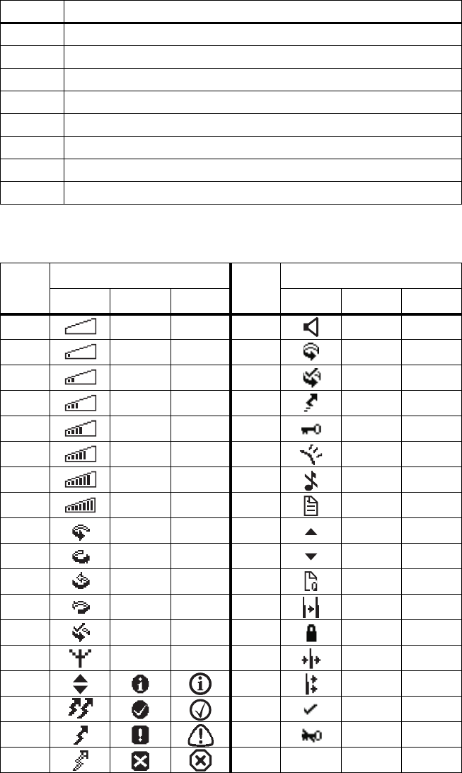
48 CCDI TM8100/TM8200 Computer-Controlled Data Interface (CCDI) Protocol Manual
© Tait Electronics Limited April 2007
X- and Y-positions The x and y positions of the display object (string or icon) are pointing to
the top left pixel of the object pixel field, relative to the pixel in the upper
left corner of the LCD display (max. number of x pixels = 4000,
max. number of y-pixels = 4000).
Font The following table shows the font identifiers for text strings and icons:
Icon ID The following table shows the icon IDs. IDs not listed in the table are not used.
Font ID Font Name
1 FontDispatch 10
2 FontDispatch 16
3 FontDispatch 24
4 FontDispatch Bold 10
5 FontDispatch Monospace Numeric 16
6 Icon Dispatch 16
7 Icon Dispatch 20
8 Icon Dispatch 48
Icon
ID
Icon Dispatch Icon
ID
Icon Dispatch
16 20 48 16 20 48
0x31 0x65
0x32 0x68
0x33 0x69
0x34 0x6a
0x35 0x6b
0x36 0x6c
0x37 0x6d
0x38 0x6e
0x41 0x6f
0x42 0x70
0x43 0x71
0x44 0x72
0x45 0x73
0x4a 0x74
0x61 0x75
0x62 0x76
0x63 0x77
0x64
TM8100/TM8200 Computer-Controlled Data Interface (CCDI) Protocol Manual CCDI 49
© Tait Electronics Limited April 2007
Control heads with
1-, 2- or 3-digit
display
If the QUERY_DISPLAY command is applied on a radio with a 1-, 2- or
3-digit display control head, a response message with the current text for
each line is returned including a preceding Start of display response message
and a trailing End of display message response. A flashing display is treated
as it was not flashing.
Control heads
without display If the QUERY_DISPLAY command is applied on a radio with a control
head without display, then only two progress messages are returned:
■Start of the query display response
■End of the query display response.
Radios with
multiple control
heads
If the QUERY_DISPLAY command is applied on a radio with multiple
control heads, then only the display content of the master control head is
reported with response messages.
Limitations The QUERY DISPLAY RESPONSE messages should represent a sequence
of text and Icon data, which are used during a complete display refresh
process. There is no absolute guaranty that the reported displayed items are
actually visible on the screen.
Embedded control characters in text strings on the display (i.e. ascii value
less than 0x20) may interfere with the terminal attached to the CCDI port
when a QUERY DISPLAY RESPONSE message is returned.
The CCDI port on the radio must not be configured for software
handshake!
Examples d0100B This message indicates the start of a display response message.
d02F0C4 This message indicates the end of a display response message
(no error).
d0E107803E005Menu85
This message indicates that there is currently a string “Menu”
displayed on the radio, positioned at x=078h, y=03Eh and font
ID=005h (FontDispatch Monospace Numeric 16).
d0C200800B00744BE
This message indicates that there is currently an icon displayed
on the radio, positioned at x=008h, y=00Bh, fontID=007h,
icon ID=44h.

50 CCDI TM8100/TM8200 Computer-Controlled Data Interface (CCDI) Protocol Manual
© Tait Electronics Limited April 2007
1.10.7 RADIO_SERIAL
Solicited.
The RADIO_SERIAL message is sent to the PC in response to a
QUERY 4 (serial number) command. It conveys the serial number of the
radio.
Format n [SIZE] [SERIAL_NUMBER] [CHECKSUM]
■‘n’ is sent as a single ASCII character and represents the
RADIO_SERIAL command.
■[SERIAL_NUMBER] is a string identifying the serial number in the
radio.
Example n08190011898D This message indicates that the RU has serial number
19001189.
1.10.8 RADIO_VERSIONS
Solicited.
The RADIO_VERSION message is sent to the PC in response to a
QUERY 3 (version) command. It conveys the versions of the various
software and hardware components in the radio.
Format v [SIZE] [RECORD NUMBER] [VERSION] [CHECKSUM]
■‘v’ is sent as a single ASCII character and represents the VERSION
command
■[RECORD NUMBER] is two ASCII characters identifying the record
number.
■[VERSION] is a variable length string identifying the version number of
each hardware and software component in the radio. Multiple
RADIO_VERSION messages are returned in response to a QUERY
command. The messages can be distinguished using the record number.
Example v1200TMAB12-H500_010115
This message indicates that the RU has a model name of
TMAB12-H500_0101.
Record Number Radio
00 Model Name
01 Software Version
02 Database Versions
03 FPGA Version

TM8100/TM8200 Computer-Controlled Data Interface (CCDI) Protocol Manual CCDI 51
© Tait Electronics Limited April 2007
1.10.9 RING
Unsolicited.
The RING message advises the PC that an incoming call has been received.
Format r [SIZE] [RCATEGORY] [TYPE1] [TYPE2] [TYPE3] [TYPE4]
[STATUS] [CALLER_ID] [CHECKSUM]
■‘r’ is sent as a single ASCII character representing the RING command.
■[RCATEGORY] is a single character representing the category of the
incoming call.
■The RING type is a four character string qualifying the type of call
received.
Character Function
0 Selcall
1 Undefined
2Type 99
Type Character Function
[TYPE1] 0 Voice Call received
1 reserved for Trunked non-prescribed data call
2 Status Call received
3 Interrogation Call received
4SDM received
5 Data Call received
6 Remote Monitor Call received
[TYPE2] 0 Normal Priority Call received
1 Emergency Priority Call received
[TYPE3] 0 Individual Call received
1 Group Call received
2 Super Group call received
[TYPE4] 0 reserved
1 Call alert
2 Radio check
3 Radio inhibit
4 Radio uninhibit
5RUM

52 CCDI TM8100/TM8200 Computer-Controlled Data Interface (CCDI) Protocol Manual
© Tait Electronics Limited April 2007
■[STATUS] is a two digit string representing the received status for status
calls. If a [STATUS] value is not received, then [STATUS] will be “FF”.
■[CALLER_ID] is a caller’s ID which is optional and of variable length.
If the ID is different to the radio’s ID, the destination ID is placed in front
of the caller ID, separated by a “-”. This required Selcall output to be
enabled using the FUNCTION command. Refer to “FUNCTION”,
[FUNCTION]=0, [SUBFUNCTION]=3.
Note By checking [SIZE] in RING message, PC will be able to know
if the whole [CALLER_ID] part is missed or not.
Example r0714000FFA6 This message indicates that the received call is an
SDM call.
1.10.10 TDMA_DATA
Unsolicited. TM8200 only.
The TDMA_DATA message is sent to the DTE in response to a reception
of a TDMA data packet.
Format z [SIZE] [TDMA_DATA] [CHECKSUM]
■‘z’ is sent as a single ASCII character representing the TDMA_DATA
message.
■[TDMA_DATA] is raw TDMA message data.
Example z15Hi_TDMA_data_receivedcc
indicates that the RU has valid TDMA packet, which is
“Hi_TDMA_data_received”.
cc is a placeholder of the CCDI message checksum.
1.10.11 TRANSACTION OK
The Transaction OK response is a single ASCII full stop character (2Eh).
This message is sent when the radio receives a command from the PC and
confirms that the command has been received.
6 Message
7 Status query
8 Status update
9 Emergency alarm rqt [?]
10 P25 acknowledgement

TM8100/TM8200 Computer-Controlled Data Interface (CCDI) Protocol Manual CCR 53
© Tait Electronics Limited April 2007
2CCR
2.1 Introduction
Overview This section provides details of the Computer-Controlled Radio (CCR)
protocol, version 2.00. It describes the radio to Data Terminal Equipment
(DTE) protocol. This is an advanced radio control feature.
Note CCR applies to TM8100 radio terminals only.
The CCR protocol provides a means of temporarily reprogramming a
channel from some form of DTE via a serial interface (PC, AVL application,
Telemetry Application, MDT).
In CCR mode, the radio no longer uses a non-volatile database. A number
of radio parameters are uploaded and changed during run-time from an
external application. In this way, the external application provides the non-
volatile data storage.
All serial ports on the radio support CCR (Microphone, Auxiliary and
Internal Options).
The CCR mode is a sub-mode of CCDI. Entry into CCR is via a CCDI
command (“f0200D8”). Once, in CCR mode the radio will accept serial
CCR commands and will no longer process CCDI commands.
The TM8100 ser ies of radios are able to support USER, CCDI Transparent
and CCR modes of operation.
Benefits Most of the radio functionality can be controlled by the external device
operating over a serial communications link. This allows system integrators
to develop their own intelligent control device. They can develop complex
solutions with a low cost RF platform.
In essence, a radio which has access to all the channels in its operating range
could be made. The limit is no longer in the mobile but in the external
intelligence driving it. A wider range of methods can be employed to alter
or modify the way the radio is controlled by the user; a step forward in
control evolution.
2.1.1 Configurable Parameters
Channel information:
■Tx/Rx frequencies
■Tx & Rx CTCSS/DCS frequencies

54 CCR TM8100/TM8200 Computer-Controlled Data Interface (CCDI) Protocol Manual
© Tait Electronics Limited April 2007
■Tx power level
■Channel bandwidth
The unit can accept or send Selcall in:
■All the international tone formats
■Between 2 and 8 tones per sequence.
■Tone durations from 20 - 100ms
■ANI leading/trailing sequence
Other features:
■Audio volume level
■Enable/disable monitor
2.1.2 Potential Applications
■Complex conventional radio units (multi-system)
■MDT controlled radio
■Remote off-air monitoring
■System integration
■Self healing RF networks
■Rapid deployment - inter operability
■Hybrid solutions
2.2 Programmable Parameters
CCR depends on the same programmable parameters as those used to
configure CCDI command mode.
2.2.1 Requirements
The following needs to be enabled as a minimum:
■Enable CCDI
■Enable a serial port for communications (Auxiliary, Mic or Internal
Options connector) as follows:
Note The recommended configuration parameters are in Bold.
Parameter Value
Baud rate 1200, 2400, 4800, 9600, 14400, or 19200
Number of data bits 8
Parity None
Number of stop bits 1
TM8100/TM8200 Computer-Controlled Data Interface (CCDI) Protocol Manual CCR 55
© Tait Electronics Limited April 2007
The serial port is capable of driving only a limited cable length.
For more information on the serial port, refer to the service man-
ual.
Radio operation while in CCR mode also requires, as a minimum, the
following to be defined:
■Enable at least one channel
■Enable at least one PTT & microphone for voice
For selcall commands it is also necessary to enable at least one network using
selcall signalling, as follows:
■Enable network to be selcall
The radio will, upon entry to CCR, inherit programmable parameters from
the channel that was active when CCR was entered. Modifications while in
CCR mode to channel/network characteristics will be compared to this
baseline. All CCR changes are temporary, nothing is saved to the database,
therefore they are lost on power cycling.
2.3 Command Protocol
The DTE is connected to the RU via a serial link. Command and response
messages are generated between the DTE and the RU.
2.4 Command Description
This section details the standard messages.
2.4.1 Message Format
All CCR mode message packets take the following general form:
[IDENT][SIZE][PARAMETERS][CHECKSUM]<CR>

56 CCR TM8100/TM8200 Computer-Controlled Data Interface (CCDI) Protocol Manual
© Tait Electronics Limited April 2007
Where:
General characteristics of the message format worth noting are as follows:
■All characters in a message are printable ASCII
■Where numeric values are represented in ASCII-hex notation (two
characters per byte), digits A...F are upper case
■The minimum length of a command packet is 5 characters; i.e. when
[SIZE] = 00. For example, c003D is the CANCEL command which is
5 characters.
■The maximum length of the [PARAMETERS] field is 32 characters, so
that the maximum length of the command packet is therefore
37 ([SIZE]=“20”) characters
2.4.2 Calculating [CHECKSUM]
[CHECKSUM] is calculated by applying the following algorithm:
5. Take the modulo-2 sum of all message bytes preceding
[CHECKSUM].
6. Retain bits 0...7, discarding any higher order bits resulting from the
summation.
7. Form the two's complement of the remainder.
8. Convert the binary number into two ASCII-hex digits, MSD first.
Checksum Example s0D050800TESTHi!DA
9. Take the modulo-2 sum of all message bytes preceding
[CHECKSUM].
■s = 73h, 0 = 30h, D = 44h etc. therefore the modulo-2 sum is:
73 + 30 + 44 + 30 + 35 + 30 + 38 + 30 + 30 + 54 + 45 + 53 + 54
+ 48 + 69 + 21 = 426h
Parameter Value
[IDENT] is the message identifier. Identifiers are single ASCII characters
which categorise the message type
[SIZE] is the number of characters which make up the [PARAMETERS]
field. [SIZE] is an 8-bit number expressed in ASCII-hex notation
(two characters)
[PARAMETERS] is an optional field, depending upon the command. Parameter
values are generally character strings unless explicitly stated
otherwise. Parameter type is dependent upon the command -
there is no explicit type definition.
[CHECKSUM] s an 8-bit checksum of the [IDENT], [SIZE] and [PARAMETERS]
fields. It is expressed in ASCII-hex notation (two characters)
<CR> is the packet terminator. It is the ASCII “carriage return”
character (0Dh).
TM8100/TM8200 Computer-Controlled Data Interface (CCDI) Protocol Manual CCR 57
© Tait Electronics Limited April 2007
10. Retain bits 0 to 7, discarding any higher order bits resulting from the
summation.
26h
11. Form the two’s complement of the remainder.
26h = 0010 0110
two’s complement = 1101 1010
12. Convert the binary number into two ASCII hex digits, MSD first.
1101 1010 = DA
2.5 CCR Mode Commands
2.5.1 Entering CCR Mode
CCR mode is entered from CCDI with the function zero command,
“f0200D8”. This command is described in the CCDI specifications.
Entry to CCR mode will be denied if the radio is busy scanning,
transmitting or processing emergency mode activities. CCR mode is not,
however, blocked when the radio is stunned; CCR can run in this state.
2.5.2 CCR/CCDI Mode Independence
CCDI and CCR are independent from each other in that commands and
responses for either command interpreter can only be processed in its own
mode. There are, for instance, no CCDI progress messages when the radio
is in CCR mode.
2.5.3 CCR Mode Activated
The radio sends the string “M01R00” to the DTE when CCR mode is
activated.
2.5.4 CCR Mode Busy
It is possible to program an output line for busy detect status in CCR mode.
2.5.5 Blocked Functions
CCR mode denies the following functions (that are available in user mode)
and indicates them as invalid if they are attempted from a front panel or
programmable input:
■Channel selection

58 CCR TM8100/TM8200 Computer-Controlled Data Interface (CCDI) Protocol Manual
© Tait Electronics Limited April 2007
■Scanning
■Emergency
■SDM (No GPS)
■User mode selcalling:
■No call setups with the front panel controls, programmable I/O
or PTT
■No selcall alerting for identities defined in the database
CCR is intended for headless radio units. Third parties can, upon
integration, add their own implementations for things like scanning & selcall
alerts.
Note PTT initiated functionality will only be suppressed, not indicated,
notably, PTT call setup.
2.5.6 CCR Persistence
When a radio is reset nothing is saved from the current CCR session to the
next power up. Third party devices can check that the radio is alive with the
pulse command and “reprogram” it when a power outage has been detected.
2.5.7 CCR Response Time
The receive frequency in CCR mode can be changed at least every 20ms.
2.5.8 Exiting CCR Mode
When exiting CCR mode, the radio reboots. For more information, refer
to “Exit CCR Mode” on page 70.
2.6 CCR Positive Acknowledgements
The radio validates the received strings since the last command on the serial
port versus the CCR protocol when it sees an instance of the terminating
character <CR>. It returns either a positive or negative acknowledgement.
The positive acknowledgement has the following format.
Response +ssxcc
Where:

TM8100/TM8200 Computer-Controlled Data Interface (CCDI) Protocol Manual CCR 59
© Tait Electronics Limited April 2007
Effect An ACK response is sent back when a command has been accepted, the
radio does not wait until the command has been executed. The ACK may
be delayed, in some cases, but usually it is sent back immediately.
2.7 CCR Negative Acknowledgements
The radio validates the received strings since the last command on the serial
port versus the CCR protocol when it sees an instance of the terminating
character <CR>. It returns either a positive or negative acknowledgement.
The negative acknowledgements are as follows.
2.7.1 Invalid CCR Command
If a string does not conform to the protocol, or there is something else
inhibiting its execution, it is rejected and a negative acknowledgement is
sent to the user. The negative acknowledgement has the following format.
Response -ssrrxcc
Where:
Note A command is only ever rejected with one error code.
Parameter Value
+ ASCII ‘+’ character indicates that the command was accepted
ss ASCII hex number ss is the size of the ack (always “01”)
x echoes back the command identity, the first letter (R, T, A, B, S, M…)
cc ASCII hex number cc is the checksum
Parameter Value
- ASCII ‘–’ character indicates that the command was rejected
ss ASCII hex number ss is the number of characters for parameters
rr indicates the reason for rejecting the command as follows:
■‘02’ Checksum error
■‘01’ Invalid command
■‘03’ Parameter error in command
■‘05’ Radio is busy
■‘06’ Command is not accepted
x echoes back the command identity, but only if the checksum in the
command was correct
cc ASCII hex number cc is the checksum
60 CCR TM8100/TM8200 Computer-Controlled Data Interface (CCDI) Protocol Manual
© Tait Electronics Limited April 2007
Effect The implementation exits the validation as soon as an error has been struck
- it will not check the parameters if the command does not pass the
checksum test.
2.7.2 Validation Checksum Error
If the input string does not have the correct checksum, a checksum error is
immediately reported and no further checks are done.
2.7.3 Invalid Validation Command
If the input string passes the checksum test but the identity contained is not
a recognised CCR command, an invalid command is reported.
2.7.4 Validation Parameter Error
If the input string passes the general message format but not the command
specific tests, a parameter error is sent. For details on validation rules see the
specific commands.
■data length check
■range check on message data
■correct sequence of commands
2.7.5 Radio Busy Message
If the input string passes both the general and command specific validation
criteria, it is processed only if the following conditions are true:
■Radio is not in transmitting state
■Radio is not busy processing the last sent command
The radio rejects the commands and returns the busy error code in these
instances.
2.7.6 Command Not Accepted Message
Some commands trigger sequence errors if they are sent when the radio
cannot process the command, for example:
■Radio is attempting to use a selcall command when there is no selcall
configuration defined.
This error is, for instance, sent if a selcall command is received, but the CCR
channel is not activated with a network using selcall signalling.

TM8100/TM8200 Computer-Controlled Data Interface (CCDI) Protocol Manual CCR 61
© Tait Electronics Limited April 2007
2.8 CCR Commands
2.8.1 Summary and Examples
The messages in the following table are sent from the DTE to the RU.
In all cases, if the command is received without error by the RU and all the
parameters are valid, the command will be executed and the prompt will be
returned to the DTE. If an error arises, the DTE will be notified with an
appropriate response.
Examples f0200D8 Enter ccr from ccdi
E005B Exit - same effect as “^”
R0945320000087 Set Rx frequency to 453.2MHz
T0945320000085 Set Tx frequency to 453.2MHz
Q01PFE Pulse command, returns “P” when minimum config
exists
P0111E Set power to Very Low
P0141B Set power to High
H01324 Set bandwidth to Wide
H01126 Set bandwidth to Narrow
A0406708E Set Rx ctcss to 67Hz
A0400009B Set Rx ctcss to 0Hz
B0406708D Set Tx ctcss to 67Hz
B0400009A Set Tx ctcss to 0Hz
C03023C5 Set Rx DCS to 23
C03000CA Set Rx DCS to 0
D03023C4 Set Tx DCS to 23
D03000C9 Set Tx DCS to 0
S051234549 Dial 12345
Message Cmd Function
Rssxxxxxxxxxcc R Go to Receive Frequency
Tssxxxxxxxxxcc T Load Transmit Frequency
Hssxcc H Set Bandwidth
Jssxxxcc J Set Volume Level
Assxxxxcc A Receive CTCSS Value
Bssxxxxcc B Transmit CTCSS Value
Cssxxxxcc C Receive DCS Value
Dssxxxxcc D Transmit DCS Value
Sssxxxxxcc S Encode Selcall Sequence
Isstplcc I Set Selcall Parameters
Nsspxxxxxcc N Set ANI
Pssxcc P Transmitter Output Power
Qssxcc Q Query Radio Pulse
Esscc E Exit CCR Mode

62 CCR TM8100/TM8200 Computer-Controlled Data Interface (CCDI) Protocol Manual
© Tait Electronics Limited April 2007
I03015BE Select toneset 0, ccir, 20ms tones and 5 tones notify
N04112387 Set ani to leading and tones 123
M01D0E Monitor “on”
M01E0D Monitor “off”
J03000C3 Volume level 0 (range is 0-255)
J03104BE Volume level 104 (range is 0-255)
2.8.2 Go to Receive Frequency
Description On receipt of this command, the radio checks the format and does a range
check on the frequency. If it is valid, the radio sends an ACK response and
then initialises the synthesizer with the new frequency. One should allow
20ms for the synthesizer to settle at the new frequency. If the command is
invalid, a NAK response will be sent and the receiver will remain at the last
selected frequency. If the radio is transmitting then a NAK response will also
be sent.
Command Rssxxxxxxxxxcc
Where:
Effect This command has immediate effect with the receiver retuning to this
channel. If the synthesizer is out of lock then a NAK response will be sent.
2.8.3 Load Transmit Frequency
Description On receipt of this command, the radio checks the format and does a range
check on the frequency. If it is valid, the radio sends an ACK response. If the
command is invalid, a NAK response will be sent and the transmit frequency
will not change. If the radio is transmitting then a NAK response will also
be sent.
Parameter Value
R ASCII letter R denotes the go to Receive frequency
ss ASCII hex number ss is the number of characters for parameters
(“08” or “09”)
xxxxxxxxx ASCII number xxxxxxxxx is the receive frequency, as follows:
■Minimum is a number representing the bottom of the radio model
frequency band
■Maximum is a number representing the top of the radio model
frequency band
cc ASCII hex number cc is the checksum

TM8100/TM8200 Computer-Controlled Data Interface (CCDI) Protocol Manual CCR 63
© Tait Electronics Limited April 2007
Important The radio may restrict the transmitter output power
depending on the programmed transmit frequency, in
accordance with regulatory requirements.
Command Tssxxxxxxxxxcc
Where:
Effect This command loads the transmit frequency into a memory location for use
when the PTT or Selcall encoder is next active. The radio will not transmit
if the synthesizer is out of lock.
2.8.4 Set Volume Level
Description This command sets the volume level for received audio. If the index number
is out of range the radio does not act on the command and sends a NAK
(range error) back.
Command J03xxxcc
Where:
Effect This command has immediate effect.
If there is a volume knob on the radio there is no guarantee that the value
set with this command will be the volume. The radio will use the level last
set with any control.
Parameter Value
T ASCII letter T denotes the Load Transmit Frequency command
ss ASCII hex number ss is the number of characters for parameters
“08” or “09”)
xxxxxxxxx ASCII number xxxxxxxxx is the transmit frequency, as follows:
■Minimum is a number representing the bottom of the radio model
frequency band
■Maximum is a number representing the top of the radio model
frequency band
cc ASCII hex number cc is the checksum
Parameter Value
J ASCII letter J denotes the Set Volume Level command
03 ASCII hex number 03 is the number of characters for parameters
xxx ASCII number xxx is a volume level value in the range of 0 to 255
(255 is the maximum)
cc ASCII hex number cc is the checksum

64 CCR TM8100/TM8200 Computer-Controlled Data Interface (CCDI) Protocol Manual
© Tait Electronics Limited April 2007
2.8.5 Receive CTCSS Value
Description This command disables (if xxxx=0), or enables (if xxxx>0), Rx CTCSS.
If enabled, the audio mute is opened only when a given subaudible CTCSS
tone is being received (otherwise the audio mute is closed). If disabled,
muting on CTCSS is disabled. If the frequency is out of range, the radio
does not act on the command and sends a NAK (range error) back.
Command A04xxxxcc
Where:
Effect This command has immediate effect and closes the mute to signals without
a valid CTCSS tone if enabled, or opens the mute on disabling CTCSS
muting.
2.8.6 Transmit CTCSS Value
Description This command disables (if xxxx=0) or enables (if xxxx>0), Tx CTCSS. If
enabled, a CTCSS tone is transmitted whenever the radio is transmitting
audio. If the reference number is out of range, the radio does not act on the
command and sends a NAK (range error) back to the radio. If the radio is
already transmitting then a NAK response will also be sent.
Command Bssxxxcc
Where:
Effect On receipt of the request the radio stores the CTCSS tone to generate. The
radio will then generate the tone at the next PTT or Selcall encode activity.
Parameter Value
A ASCII letter A denotes the Receive CTCSS Value load command
04 ASCII hex number 04 is the number of characters for parameters
xxxx ASCII number xxxx is a receive subaudible frequency in 0.1Hz. The
valid range is 67Hz to 254.1 Hz.
cc ASCII hex number cc is the checksum
Parameter Value
B ASCII letter B denotes the transmit CTCSS value to be sent on
transmit
04 ASCII hex number 04 is the number of characters for parameters
xxxx ASCII number xxxx is a transmit CTCSS frequency in 0.1Hz. The valid
range is 67Hz to 254.1 Hz.
cc ASCII hex number cc is the checksum

TM8100/TM8200 Computer-Controlled Data Interface (CCDI) Protocol Manual CCR 65
© Tait Electronics Limited April 2007
2.8.7 Receive DCS Value
Description This command disables the DCS filter if the code is “000”. If the code is not
recognized as an octal, the radio does not act on the command and sends a
NAK (range error) back.
Command C03xxxcc
Where:
Effect This command has immediate effect and closes the mute to signals without
a valid DCS tone.
2.8.8 Transmit DCS Value
Description This command disables the DCS encoding if the code is “000”. If the code
is not recognized as an octal, the radio does not act on the command and
sends a NAK (range error) back.
Command D03xxxcc
Where:
Effect This command loads the value into memory ready for the next PTT or
Selcall encode activity.
2.8.9 Encode Selcall Sequence
Description This command turns the transmitter on and sends the Selcall string
following a short delay (network 1 lead-in delay). If the number of tones is
incorrect the command is rejected (NAK-format error).
Parameter Value
C ASCII letter C denotes the Receive DCS Value load command
03 ASCII hex number 03 is the number of characters for parameters
xxx ASCII number xxx represents a DCS code in octal
cc ASCII hex number cc is the checksum
Parameter Value
D ASCII letter D denotes the transmit DCS value to be sent on transmit
03 ASCII hex number 03 is the number of characters for parameters
xxx ASCII number xxx represents a DCS code in octal
cc ASCII hex number cc is the checksum

66 CCR TM8100/TM8200 Computer-Controlled Data Interface (CCDI) Protocol Manual
© Tait Electronics Limited April 2007
Command Sssx...xcc
Where:
The Set Selcall Parameter command (see below) allows the user to change
the Selcall parameter defaults.
Effect This command has immediate effect, provided that the receiver and
transmitter frequency values have been initialised and the radio is not
transmitting at the time (PTT active causes busy error)
2.8.10 Set Selcall Parameters
Description This command allows the user to modify the Selcall default parameters (tone
set to use, tone period, number of tones in Tx sequence and number of
tones in Rx sequence). If any of the command parameters are out of range,
a NAK (range error) will be sent back to the control head.
Command I03tplcc
Parameter Value
S ASCII letter S denotes the Transmit Selcall tone sequence
ss ASCII hex number ss is the number of characters for parameters
x...x ASCII number x...x is the tone sequence. Minimum is 2 tones and
maximum is 33.
cc ASCII hex number cc is the checksum

TM8100/TM8200 Computer-Controlled Data Interface (CCDI) Protocol Manual CCR 67
© Tait Electronics Limited April 2007
Where:
Effect The Selcall modem is immediately re-initialised with the new decode
parameter map. These new parameters are applied for the next Selcall
decode/encode sequence.
CCR default parameters are those loaded from the network associated to the
selected channel when the radio enters CCR mode. This includes selcall
parameters like ‘lead in delay’, which it is not possible to alter in CCR
mode.
2.8.11 Set ANI
Description This command disables or enables ANI. It configures what ANI sequence is
to be sent and when the ANI sequence is to be sent. If p is not ‘0’, the tone
sequence gets stored.
If the number of tones (xx...xx) does not match the currently configured
length, then the command is rejected (NAK- format error). It is also
rejected if p is out of range (range error).
Parameter Value
I the ASCII letter I denotes the Set Selcall Parameter command
03 ASCII hex number 03 is the number of characters for parameters
t specifies the Tone Set to use. This can be one of the following:
■’0’ccIR
■’1’EIA
■’2’EEA
■’3’ZVEI-I
■’4’ZVEI-II
■’5’ZVEI-III
■’6’PZVEI
■’7’NATEL
■’8’DZVEI
p specifies the Tone Period to use. This can be one of the following:
■’1’20ms
■’2’33ms
■’3’40ms
■’4’50ms
■’5’60ms
■’6’70ms
■’7’100ms
l sets the decode buffer time and message filter as defined in “Notify
Buffer Size” on page 73 and “Selcall Decode Sequence” on page
73.
cc ASCII hex number cc is the checksum

68 CCR TM8100/TM8200 Computer-Controlled Data Interface (CCDI) Protocol Manual
© Tait Electronics Limited April 2007
Command Nsspx...xcc
Where:
Effect If enabled, the ANI tones get stored and any subsequent use of the PTT
button activates ANI.
2.8.12 Monitor
Description This command is the same as the monitor function available on the function
keys in normal user mode. When it is active, it overrides any active
subaudible signalling filters. The squelch mute is not overridden.
Command M01xcc
Where:
Effect Immediate.
If there is a front panel key or programmable input with monitor configured,
there is no guarantee that the value set with this command will represent the
monitor state. The radio will use the state last set with any control.
Parameter Value
N ASCII letter N denotes the Automatic Number Identification
command
ss ASCII hex number ss is the number of characters for parameters
p denotes the ANI position with regard to PTT presses. Valid values are:
■’0’ disables ANI (in this case the tone sequence x...x is not
required)
■’1’ leading ANI (ANI is sent soon after PTT is pressed)
■’2’ trailing ANI (ANI is sent when PTT is released)
■’3’ combination of 1 and 2
x...x is the 5 to 8 tone sequence. It is optional if p is set to 0.
cc ASCII hex number cc is the checksum
Parameter Value
M ASCII letter M indicates it is a monitor command
01 ASCII hex number 01 is the number of characters for parameters
x is the mute state wanted, as follows:
■’D’for disable mute (monitor)
■’E’for enable mute
cc ASCII hex number cc is the checksum

TM8100/TM8200 Computer-Controlled Data Interface (CCDI) Protocol Manual CCR 69
© Tait Electronics Limited April 2007
2.8.13 Transmitter Output Power
Description The transmitter output power is set to the value selected. If the index is
incorrect the command is rejected (NAK-format error).
Important The radio may restrict the transmitter output power
depending on the programmed transmit frequency, in
accordance with regulatory requirements.
Command P01xcc
Where:
Effect The modified power level takes effect on the next Tx activity; either PTT
or Selcall.
Note If there is a front panel key or programmable input with low power
configured, there is no guarantee that the value set with this com-
mand will represent the effective output power. The radio will use
the state last set with any control.
2.8.14 Set Bandwidth
Description This command sets the operating transmit/receive bandwidth. If the index
number is out of range, the radio does not act on the command and sends a
NAK (range error) back.
Command Hssxcc
Where:
Parameter Value
P ASCII letter P indicates it is a power command
01 ASCII hex number 01 is the number of characters for parameters
x is an index to transmit power level, as follows:
■‘1’very low power
■‘2’low power
■‘3’medium power
■‘4’high power
cc ASCII hex number cc is the checksum

70 CCR TM8100/TM8200 Computer-Controlled Data Interface (CCDI) Protocol Manual
© Tait Electronics Limited April 2007
Effect This command has immediate effect.
2.8.15 Query Radio Pulse
Description The purpose of this command is to give the user a way to “ping” the radio.
The radio pulse command allows you to check that the radio is still
responding. The control device may use the radio pulse command every ten
seconds in the absence of other activity.
Command Q01PFE
Where:
Response The radio will send back one of two responses:
■QssPcc - if the radio has got its minimum configuration, which typically
consists of having received a ‘set receive frequency’ command.
■QssDcc - is returned if the radio has loaded its default set-up and has not
yet received a ‘set receive frequency’ command.
Effect These commands invoke an immediate reply.
2.8.16 Exit CCR Mode
Description The radio initiates a software reset (same as for “^”), and exits CCR mode.
Parameter Value
H ASCII letter denotes the Set Bandwith command
01 ASCII hex number 01 is the number of characters for parameters
x is the Bandwith Index, as follows:
■‘1’narrowband
■‘2’mediumband
■‘3’wideband
cc ASCII hex number cc is the checksum
Parameter Value
Q ASCII letter Q indicates it is a query command as opposed to a set-up
command
01 ASCII hex number 01 is the number of characters for parameters
P ASCII letter P indicates it is the radio pulse command
FE ASCII hex number FE is the checksum

TM8100/TM8200 Computer-Controlled Data Interface (CCDI) Protocol Manual CCR 71
© Tait Electronics Limited April 2007
Command E005B
Where:
Effect This command is immediate. The radio will reset.
Parameter Value
E ASCII letter E indicates it is an exit command
00 ASCII hex number 00 indicates that there are no parameters
5B ASCII hex number 5B is the checksum

72 CCR TM8100/TM8200 Computer-Controlled Data Interface (CCDI) Protocol Manual
© Tait Electronics Limited April 2007
2.9 Unsolicited Messages from the Radio
2.9.1 Summary and Examples
The following messages may be returned to the DTE without user
intervention.
Examples: V0612345-18 Sequence 12345 detected
V065E5E5-EE Sequence 55555 detected (E is repeat tone in this case)
M01P02 Transmit timeout warning (10s before inhibit)
M01R00 CCR mode entered
2.9.2 PTT exceeds max transmit limit
Description The radio uses this response to advise the control head that PTT is about to
timeout.
For control heads with user interfaces, the warning threshold is the duration
timer configured for the network minus 10s.
Response Msspcc
Where:
Effect Whenever the radio reaches its maximum transmit period the radio will
inform the control head. After a further short delay the radio will turn off
the transmitter.
Message Cmd Function
Vssx...xcc V Selcall decode sequence
Msspcc MP Ptt exceeds max transmit limit
Mssrcc MR CCR initialised
Parameter Value
M ASCII letter M denotes the message
ss ASCII hex number ss is the number of parameters (always “01”)
P ASCII letter P denotes a PTT being applied that has exceeded the
default transmit timer warning threshold
cc ASCII hex number cc is the checksum

TM8100/TM8200 Computer-Controlled Data Interface (CCDI) Protocol Manual CCR 73
© Tait Electronics Limited April 2007
2.9.3 Selcall Decode Sequence
Description The radio sends this message every time the decoder tone buffer is emptied,
in accordance with the notification criteria set by the “I” command. See
“Set Selcall Parameters” on page 66 and “Notify Buffer Size” on page 73.
The sequences received are represented with the tones from the toneset.
Repeat tones and gaps will be forwarded as is.
Response Vssx...xcc
Where:
Effect When the radio receives the given SELCALL sequence the radio sends the
decoded sequence to the DTE.
2.9.4 Notify Buffer Size
Description The number of tones to notify, set by the selcall parameter command, allow
the user to define the size of the decode tone buffer. This buffer sets the
maximum time period that the radio will decode and log tones before
reporting to the user, when continuously receiving valid selcall tones. The
timer is calculated as follows:
Tmax = (N x P) + P
Where:
The buffer timer is started after at least one valid tone has been detected.
The buffer timer is reset if a gap is detected prior to expiry.
Parameter Value
V ASCII letter V denotes the Selcall decode message
ss ASCII hex number ss is the number of parameters
x...x are the tones decoded within the time window specified by the
notify parameters as follows:
■ASCII digits 0 to 9
■Special tones are represented with ASCII letters A to F
■Gap. A gap in CCR is equal to the tone period set by the Selcall
Parameter command
cc ASCII hex number cc is the checksum
Parameter Value
Tmax Notify buffer maximum time
N Number of tones
P Tone period
74 CCR TM8100/TM8200 Computer-Controlled Data Interface (CCDI) Protocol Manual
© Tait Electronics Limited April 2007
The notify parameter also sets a filter that allows the user to suppress decode
sequences from being reported if they consist of less than the selected
number of tones in a continuous sequence, as follows:
■If the decode buffer contains less than the selected number of tones when
it is reset the contents shall be discarded.
If a radio in CCR receives a speech call it is very likely that the user will see
this response with garbage decode sequences (1 or 2 tones) if the filter is
removed.
The additional tone period added to the buffer time allows the radio to
detect and report if a gap was present or not after the sequence detected.

TM8100/TM8200 Computer-Controlled Data Interface (CCDI) Protocol Manual 75
© Tait Electronics Limited April 2007
Tait General Software Licence Agreement
This legal document is an Agreement between
you (the “Licensee”) and Tait Electronics
Limited (“Tait”). By using any of the Software
or Firmware items prior-installed in the
related Tait product, included on CD or
downloaded from the Tait website,
(hereinafter referred to as “the Software or
Firmware”) you agree to be bound by the
terms of this Agreement. If you do not agree
to the terms of this Agreement, do not install
and use any of the Software or Firmware.
If you install and use any of the Software or
Firmware that will be deemed to be
acceptance of the terms of this
licence agreement.
The terms of this Agreement shall apply
subject only to any express written terms of
agreement to the contrary between Tait and
the Licensee.
Licence
TAIT GRANTS TO YOU AS LICENSEE THE NON-
EXCLUSIVE RIGHT TO USE THE SOFTWARE OR
FIRMWARE ON A SINGLE MACHINE PROVIDED
YOU MAY ONLY:
1. COPY THE SOFTWARE OR FIRMWARE INTO
ANY MACHINE READABLE OR PRINTED FORM
FOR BACKUP PURPOSES IN SUPPORT OF YOUR
USE OF THE PROGRAM ON THE SINGLE MACHINE
(CERTAIN PROGRAMS, HOWEVER, MAY INCLUDE
MECHANISMS TO LIMIT OR INHIBIT COPYING,
THEY ARE MARKED “COPY PROTECTED”),
PROVIDED THE COPYRIGHT NOTICE MUST BE
REPRODUCED AND INCLUDED ON ANY SUCH
COPY OF THE SOFTWARE OR FIRMWARE;
AND / OR
2. MERGE IT INTO ANOTHER PROGRAM FOR
YOUR USE ON THE SINGLE MACHINE (ANY
PORTION OF ANY SOFTWARE OR FIRMWARE
MERGED INTO ANOTHER PROGRAM WILL
CONTINUE TO BE SUBJECT TO THE TERMS AND
CONDITIONS OF THIS AGREEMENT).
THE LICENSEE MAY NOT DUPLICATE, MODIFY,
REVERSE COMPILE OR REVERSE ASSEMBLE ANY
SOFTWARE OR FIRMWARE IN WHOLE OR PART.
Important Notice
THE SOFTWARE OR FIRMWARE MAY CONTAIN
OPEN SOURCE SOFTWARE COMPONENTS
(“OPEN SOURCE COMPONENTS”). OPEN SOURCE
COMPONENTS ARE EXCLUDED FROM THE TERMS
OF THIS AGREEMENT EXCEPT AS EXPRESSLY
STATED IN THIS AGREEMENT AND ARE COVERED
BY THE TERMS OF THEIR RESPECTIVE LICENCES
WHICH MAY EXCLUDE OR LIMIT ANY
WARRANTY FROM OR LIABILITY OF THE
DEVELOPERS AND/OR COPYRIGHT HOLDERS OF
THE OPEN SOURCE COMPONENT FOR THE
PERFORMANCE OF THOSE OPEN SOURCE
COMPONENTS. YOU AGREE TO BE BOUND BY
THE TERMS AND CONDITIONS OF EACH SUCH
LICENCE. FOR MORE INFORMATION SEE:
http://support.taitworld.com/go/opensource
Title to Software
THIS AGREEMENT DOES NOT CONSTITUTE A
CONTRACT OF SALE IN RELATION TO THE
SOFTWARE OR FIRMWARE SUPPLIED TO THE
LICENSEE. NOT WITHSTANDING THE LICENSEE
MAY OWN THE MAGNETIC OR OTHER PHYSICAL
MEDIA ON WHICH THE SOFTWARE OR
FIRMWARE WAS ORIGINALLY SUPPLIED, OR HAS
SUBSEQUENTLY BEEN RECORDED OR FIXED, IT IS
A FUNDAMENTAL TERM OF THIS AGREEMENT
THAT AT ALL TIMES TITLE AND OWNERSHIP OF
THE SOFTWARE OR FIRMWARE, WHETHER ON
THE ORIGINAL MEDIA OR OTHERWISE, SHALL
REMAIN VESTED IN TAIT OR THIRD PARTIES
WHO HAVE GRANTED LICENCES TO TAIT.
Term and Termination
THIS LICENCE SHALL BE EFFECTIVE UNTIL
TERMINATED IN ACCORDANCE WITH THE
PROVISIONS OF THIS AGREEMENT. THE LICENSEE
MAY TERMINATE THIS LICENCE AT ANY TIME BY
DESTROYING ALL COPIES OF THE SOFTWARE OR
FIRMWARE AND ASSOCIATED WRITTEN
MATERIALS. THIS LICENCE WILL BE TERMINATED
AUTOMATICALLY AND WITHOUT NOTICE FROM
TAIT IN THE EVENT THAT THE LICENSEE FAILS TO
COMPLY WITH ANY TERM OR CONDITION OF
THIS AGREEMENT. THE LICENSEE AGREES TO
DESTROY ALL COPIES OF THE SOFTWARE OR
FIRMWARE AND ASSOCIATED WRITTEN
MATERIALS IN THE EVENT OF
SUCH TERMINATION.
76 TM8100/TM8200 Computer-Controlled Data Interface (CCDI) Protocol Manual
© Tait Electronics Limited April 2007
Limited Warranty
THE SOFTWARE OR FIRMWARE (INCLUDING
OPEN SOURCE COMPONENTS) IS SUPPLIED BY
TAIT AND ACCEPTED BY THE LICENSEE “AS IS”
WITHOUT WARRANTY OF ANY KIND EITHER
EXPRESSED OR IMPLIED, INCLUDING BUT NOT
BEING LIMITED TO ANY IMPLIED WARRANTIES AS
TO MERCHANTABILITY OR FITNESS FOR ANY
PARTICULAR PURPOSE. THE LICENSEE
ACKNOWLEDGES THAT THE SOFTWARE OR
FIRMWARE (INCLUDING OPEN SOURCE
COMPONENTS) IS USED BY IT IN BUSINESS AND
ACCORDINGLY TO THE MAXIMUM EXTENT
PERMITTED BY LAW NO TERMS OR WARRANTIES
WHICH ARE IMPLIED BY LEGISLATION SHALL
APPLY TO THIS AGREEMENT. TAIT DOES NOT
WARRANT THAT THE FUNCTIONS CONTAINED
IN THE SOFTWARE OR FIRMWARE (INCLUDING
OPEN SOURCE COMPONENTS) WILL MEET THE
LICENSEE’S REQUIREMENTS OR THAT THE
OPERATION OF THE SOFTWARE OR FIRMWARE
(INCLUDING OPEN SOURCE COMPONENTS) WILL
BE UNINTERRUPTED OR ERROR FREE.
Exclusion of Liability
IN NO CIRCUMSTANCES SHALL TAIT BE UNDER
ANY LIABILITY TO THE LICENSEE, OR ANY
OTHER PERSON WHATSOEVER, WHETHER IN
TORT (INCLUDING NEGLIGENCE), CONTRACT
(EXCEPT AS EXPRESSLY PROVIDED IN THIS
AGREEMENT), EQUITY, UNDER ANY STATUTE,
OR OTHERWISE AT LAW FOR ANY LOSSES OR
DAMAGES WHETHER GENERAL, SPECIAL,
EXEMPLARY, PUNITIVE, DIRECT, INDIRECT OR
CONSEQUENTIAL ARISING OUT OF OR IN
CONNECTION WITH ANY USE OR INABILITY OF
USING THE SOFTWARE OR FIRMWARE
(INCLUDING OPEN SOURCE COMPONENTS).
THE LICENSEE’S SOLE REMEDY AGAINST TAIT
WILL BE LIMITED TO BREACH OF CONTRACT
AND TAIT’S SOLE AND TOTAL LIABILITY FOR ANY
SUCH CLAIM SHALL BE LIMITED AT THE OPTION
OF TAIT TO THE REPAIR OR REPLACEMENT OF
THE SOFTWARE OR FIRMWARE OR THE REFUND
OF THE PURCHASE PRICE OF THE SOFTWARE
OR FIRMWARE.
General
THE LICENSEE CONFIRMS THAT IT SHALL
COMPLY WITH THE PROVISIONS OF LAW IN
RELATION TO THE SOFTWARE OR FIRMWARE.
Law and Jurisdiction
THIS AGREEMENT SHALL BE SUBJECT TO AND
CONSTRUED IN ACCORDANCE WITH
NEW ZEALAND LAW AND DISPUTES BETWEEN
THE PARTIES CONCERNING THE PROVISIONS
HEREOF SHALL BE DETERMINED BY THE NEW
ZEALAND COURTS OF LAW. PROVIDED HOWEVER
TAIT MAY AT ITS ELECTION BRING PROCEEDINGS
FOR BREACH OF THE TERMS HEREOF OR FOR
THE ENFORCEMENT OF ANY JUDGEMENT IN
RELATION TO A BREACH OF THE TERMS HEREOF
IN ANY JURISDICTION TAIT CONSIDERS FIT FOR
THE PURPOSE OF ENSURING COMPLIANCE WITH
THE TERMS HEREOF OR OBTAINING RELIEF FOR
BREACH OF THE TERMS HEREOF.
No Dealings
THE LICENSEE MAY NOT SUBLICENSE, ASSIGN OR
TRANSFER THE LICENCE OR THE PROGRAM
EXCEPT AS EXPRESSLY PROVIDED IN THIS
AGREEMENT. ANY ATTEMPT OTHERWISE TO
SUBLICENSE, ASSIGN OR TRANSFER ANY OF THE
RIGHTS, DUTIES OR OBLIGATIONS HEREUNDER
IS VOID.
No Other Terms
THE LICENSEE ACKNOWLEDGES THAT IT HAS
READ THIS AGREEMENT, UNDERSTANDS IT AND
AGREES TO BE BOUND BY ITS TERMS AND
CONDITIONS. THE LICENSEE FURTHER AGREES
THAT SUBJECT ONLY TO ANY EXPRESS WRITTEN
TERMS OF AGREEMENT TO THE CONTRARY
BETWEEN TAIT AND THE LICENSEE THIS IS THE
COMPLETE AND EXCLUSIVE STATEMENT OF THE
AGREEMENT BETWEEN IT AND TAIT IN
RELATION TO THE SOFTWARE OR FIRMWARE
WHICH SUPERSEDES ANY PROPOSAL OR PRIOR
AGREEMENT, ORAL OR WRITTEN AND ANY
OTHER COMMUNICATIONS BETWEEN THE
LICENSEE AND TAIT RELATING TO THE
SOFTWARE OR FIRMWARE.
