TMAA10 02_handset_instA6 TM8000/TMAA10 02 Handset/TMAA10 Handset
TM8000/TMAA10-02 Handset/TMAA10-02 Handset TMAA10-02 Handset
User Manual: Pdf TM8000/TMAA10-02 Handset/TMAA10-02 Handset
Open the PDF directly: View PDF ![]() .
.
Page Count: 4
TMAA10-02 Handset Installation Instructions
402-00009-01 Page 1
Introduction
The TMAA10-02 handset provides the user with
privacy and also improves the audio quality in noisy
environments. The handset uses a dynamic microphone
capsule, therefore control heads must support dynamic
microphone operation. For example, TMAA02-06
(support kit for dynamic microphones) must be fitted to
TMAC20-0T.
When your radio receives a call and the handset is
mounted in its locking cradle, the radio unmutes and
you can hear the call from your radio’s internal speaker
and from any connected remote speaker.
If you remove the handset from its cradle when you
receive a call, the radio unmutes and you can hear the call
from your radio’s internal speaker, from any connected
remote speaker and from the handset earpiece.
Using private handset mode, the radios internal and external speakers are muted and
the call can only be heard from the handset earpiece.
Installation
Installing the TMAA02-06 Support Kit for Dynamic Microphones
Install this kit if necessary – refer to the TMAA02-06 installation instructions provided
with the TMAA02-06 kit.
Handset Wiring
The circled numbers in the following instructions refer to items in the diagram on the
following page.
1. Drill a hole in the chosen mounting surface for the radio to handset cord and pass
the cord through the hole.
2. Prepare the radio to handset cord, as follows.
■Cut the radio to handset cord to the required length.
■Strip away about 60mm (2 inches) of the cable outer sheath on the end without
a connector.
■Cut off the exposed orange, red, black and bare wires.
■Strip about 6mm (0.2 inches) of the coating off each of the five remaining wires.
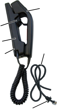
locking
cradle
push-
button
handset
grommet
radio to
handset cord
mounting
plate
TMAA10-02 Handset Installation Instructions
Page 2 402-00009-01
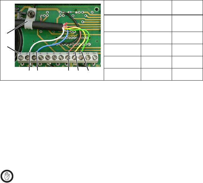
3. Secure the radio to handset cord in the handset PCB P-clip b, as shown in the
diagram below.
4. Connect the five wires to the handset PCB connector c.
Handset Installation
1. Press the pushbutton and remove the handset from the locking cradle.
2. Disassemble the locking cradle by removing the four locking cradle screws.
3. Screw the handset mounting plate to the required mounting surface. Note that
mounting screws are not provided in this kit.
4. Clamp the top part of the locking cradle onto the mounting plate, and secure it
with the four locking cradle screws.
Connecting the Handset to the Radio
Important: The handset microphone grommet must be installed whenever
the handset to radio cord is plugged into the microphone socket. When
installed, the grommet has two functions:
■to prevent damage to the microphone socket when there is movement of
the microphone cord, and
■to ensure that the control head is sealed against water, dust and other
environmental hazards.
1. Plug the microphone cord into the microphone socket on the radio control head.
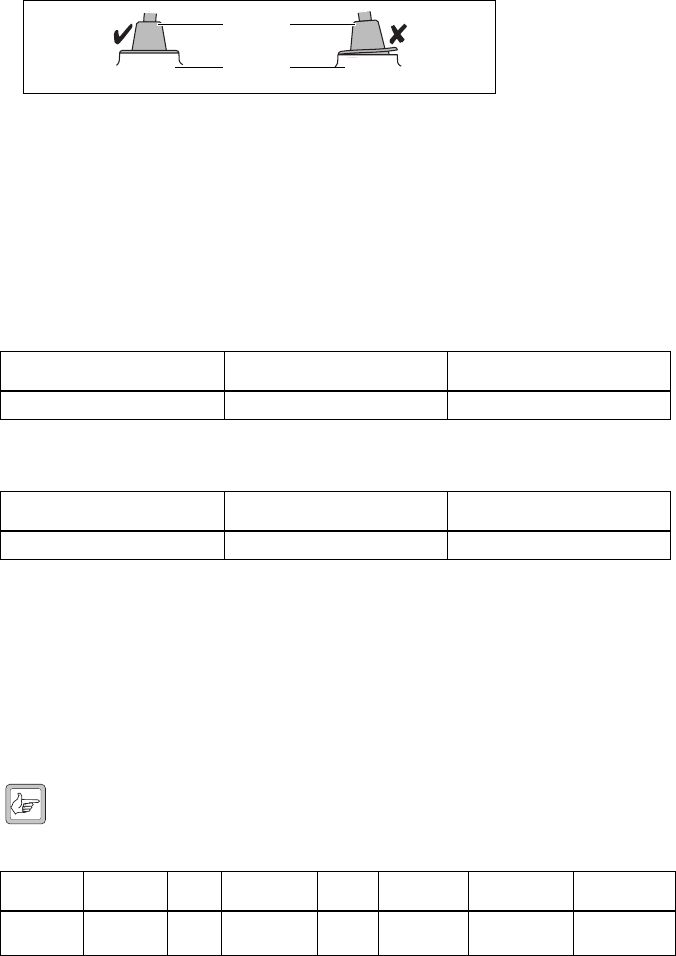
2. Slide the grommet along the cord and push two adjacent corners of the grommet
into the microphone socket cavity.
3. Squeeze the grommet and push the remaining corners into position.
4. Check that the grommet is seated correctly in the cavity (see the diagram on the
next page).
Handset PCB connector wiring
Handset PCB
Connector
Colour Reference
2 white or
violet
d
3blue e
8brown f
9 yellow g
10 green h
b
c
de f g h
TMAA10-02 Handset Installation Instructions
402-00009-01 Page 3
Radio Programming
Dynamic Microphone Support
Dynamic microphone support must be enabled in the UI Preferences form of the
radio’s programming application, so that audio is optomized for dynamic
microphones. Refer to the online help of the programming application for more
information.
Private Handset Mode
If private handset mode is required, the radio needs to be programmed to mute the
audio power amplifier when the handset is out of the cradle. The audio path is then
only through the RX AUDIO line to the handset earpiece.
The following table shows the settings required in the Programmable I/O form of the
radio’s programming application. Refer to the online help of the programming
application for more information.
Note: If private handset mode is programmed, then no audio will be heard
from the speakers if the handset is unplugged.
Correct desktop microphone grommet seating
Handset settings in the UI Preferences form (TM8100 Programming Application)
Field Setting Selected/Cleared
Audio Setup Enable Options Board Preamp selected
Handset settings in the UI Preferences form (TM8200, TM9000/TP9000 Programming
Applications)
Field Setting Selected/Cleared
Audio tab > Audio Setup Dynamic Mic Support selected
Handset settings in the Programmable I/O form
Pin Direction Label Action Active Debounce Signal State Mirrored To
CH_GPIO1 Input None
Force Audio
PA Off
High 25 None None
microphone
grommet
control head
122 TMAA10-02 Handset TM8100/TM8200 Accessories Manual
© Tait Electronics Limited August 2005
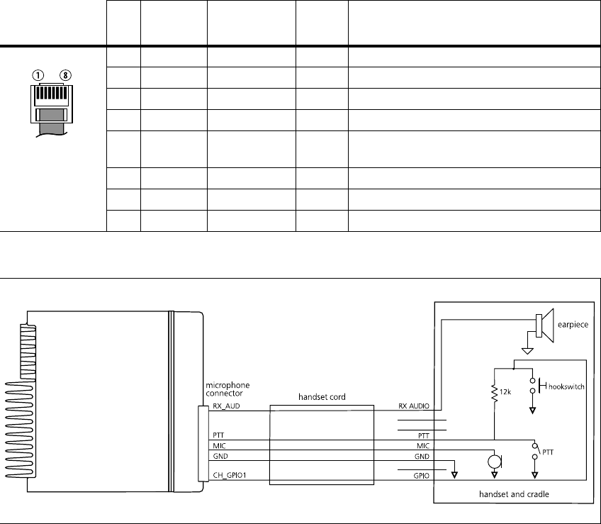
15.3 Interface Specification
The following table and diagram summarizes the signals used for the handset
on the radio’s microphone connector and shows the interface between the
handset and the radio.
.
Table 15.5 Handset microphone connector—pins and signals
Pin Signal Handset PCB
Connector Colour Description
1 RX_AUD 8 brown receive audio to handset
2—— —not connected
3—— —not connected
4 PTT 2 white PTT and hookswitch
5 MIC 9 yellow audio from the handset to dynamic-mic
support board
6 GND 10 green analogue ground
7—— —not connected
8 CH_GPIO1 3 blue programmable line controlling private mode
Figure 15.2 Handset to radio interface
