Connecting To TB8100 Base Stations Via An Asynchronous Port Switch TECHNOTE/TN 906 TN
TECHNOTE/TN-906-AN - Connecting to TB8100 Base Stations via an Asynchronous Port Switch TN-906-AN - Connecting to TB8100 Base Stations via an Asynchronous Port Switch
TECHNOTE/TB8000/TN-906-AN - Connecting to TB8100 Base Stations via an Asynch TN-906-AN - Connecting to TB8100 Base Stations via an Asynch
User Manual: Pdf TECHNOTE/TN-906-AN - Connecting to TB8100 Base Stations via an Asynchronous Port Switch
Open the PDF directly: View PDF ![]() .
.
Page Count: 20
- Connecting to TB8100 Base Stations via an Asynchronous Port Switch
- Contents
- Document Conventions
- Associated Documentation
- 1 The Purpose of an APS
- 2 Supported APS Units and their Main Features
- 3 Physical Connections
- 4 Configuring the Service Kit and Base Station
- 5 Configuring the APS
- 6 Testing the Connection
- 7 Essential Modem Features
- 8 Known Issues or Limitations
- Issuing Authority
- Publication History
- Amendment Record
- Tait Contact Information

TB8100 base station
Connecting to TB8100
Base Stations via an
Asynchronous Port Switch
Application Note TN-906
30 September 2004
Page 2 of 20 TN-906
© Tait Electronics Limited 30 September 2004
Contents
1 The Purpose of an APS . . . . . . . . . . . . . . . . . . . . . . . . . . . . . . . . . . . . . . . 3
2 Supported APS Units and their Main Features . . . . . . . . . . . . . . . . . . . . . . . . 4
2.1 Units Supported. . . . . . . . . . . . . . . . . . . . . . . . . . . . . . . . . . . . . . . . . . . . . . . . . 4
2.2 Main Features . . . . . . . . . . . . . . . . . . . . . . . . . . . . . . . . . . . . . . . . . . . . . . . . . . 4
3 Physical Connections . . . . . . . . . . . . . . . . . . . . . . . . . . . . . . . . . . . . . . . . . 5
4 Configuring the Service Kit and Base Station . . . . . . . . . . . . . . . . . . . . . . . . 9
4.1 Configuring the Service Kit for Dial-in via an APS . . . . . . . . . . . . . . . . . . . . . . . 9
4.2 Configuring the Service Kit for a Direct Connection via an APS . . . . . . . . . . . . 11
4.3 Configuring the Base Station to Dial Out to an Alarm Center . . . . . . . . . . . . . . 11
5 Configuring the APS . . . . . . . . . . . . . . . . . . . . . . . . . . . . . . . . . . . . . . . . 13
5.1 Ensuring the Security of Configuration Data . . . . . . . . . . . . . . . . . . . . . . . . . . . 13
5.2 Configuring the Set-up Switches. . . . . . . . . . . . . . . . . . . . . . . . . . . . . . . . . . . . 13
5.3 Configuring the Ports . . . . . . . . . . . . . . . . . . . . . . . . . . . . . . . . . . . . . . . . . . . . 14
6 Testing the Connection . . . . . . . . . . . . . . . . . . . . . . . . . . . . . . . . . . . . . . 17
7 Essential Modem Features. . . . . . . . . . . . . . . . . . . . . . . . . . . . . . . . . . . . . 18
8 Known Issues or Limitations . . . . . . . . . . . . . . . . . . . . . . . . . . . . . . . . . . . 18
Document Conventions
‘Configure > Communications > Alarm Center’ means ‘click the
Configure icon on the toolbar, then in the navigation pane find the
Communications group, and select Alarm Center from it’.
Associated Documentation
TN-742: Remotely Monitoring and Configuring the TB8100 Base Station
TB8100 Installation and Operation Manual
TB8100 Service Kit and Alarm Center User’s Manuals and online Help
Your APS User’s Guide
TN-906 Page 3 of 20
© Tait Electronics Limited 30 September 2004
This Application Note provides information on how to connect multiple
TB8100 base stations to a Service Kit or Alarm Center using an
Asynchronous Port Switch (APS). It covers connection via direct serial link,
and via PSTN lines using modems. Typical physical connections, APS
configurations, base station configurations, Service Kit configurations, and
modem settings are also described.
1 The Purpose of an APS
One of the most powerful features of the TB8100 base station is its ability
to be remotely configured and monitored. This feature includes Service Kit
access, for remote configuration, monitoring, and diagnostics, and
automatic dial-out to an Alarm Center, as a result of an error condition or
Task Manager stimulus. TN-742 describes the use of this feature in detail.
Without using an APS, however, a dedicated PSTN line is required for each
base station installed on a site. The cost of these lines is very high, especially
when the base stations are installed in remote locations. Using an APS
allows a single phone line to service up to 31 base stations.
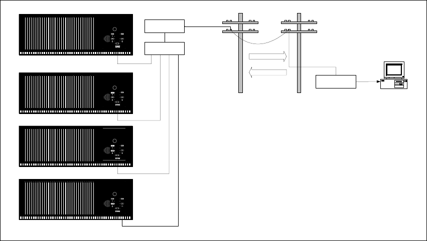
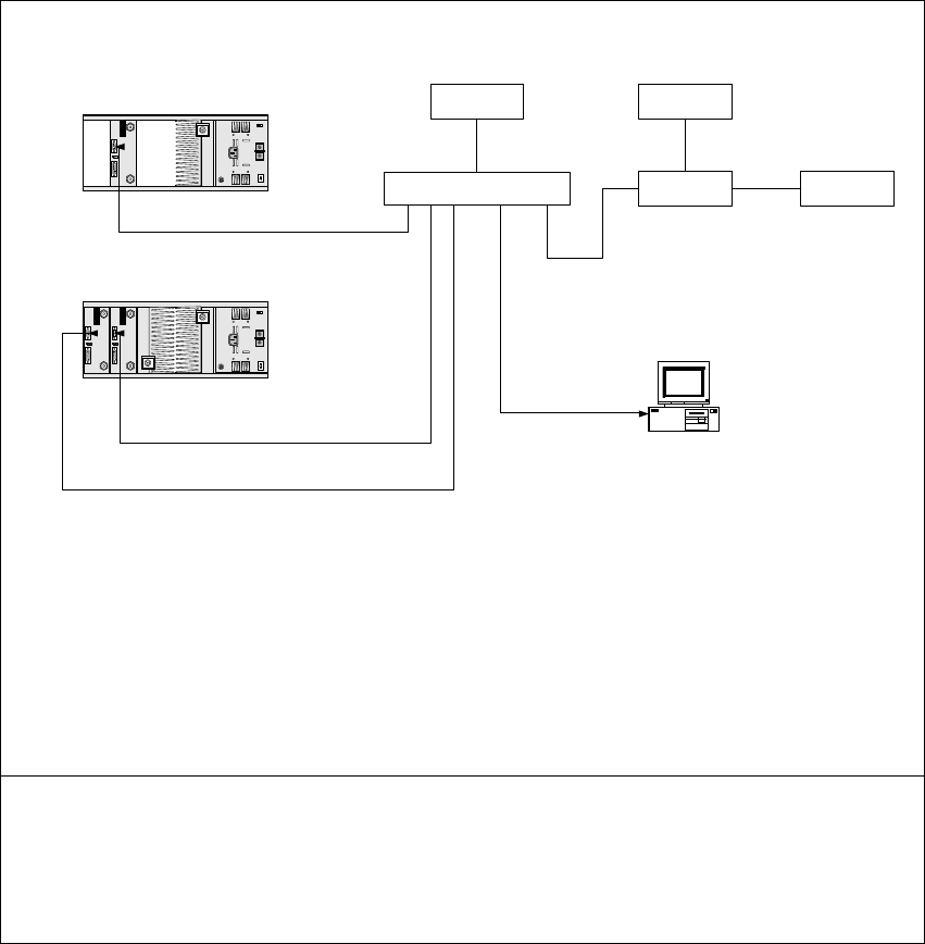
A typical connection scenario is shown in Figure 1 below. The diagram
shows:
■four base stations connected to various ports on an APS
■the dial-up modem at the remote site
■the PSTN connection
■the modem at the local site
■a PC running either Service Kit or Alarm Center software.
Figure 1 Typical APS Connection
Dial-up Modem
Dial-up Modem
Calls initiated
Calls initiated
TB8100
APS
Service Kit
Page 4 of 20 TN-906
© Tait Electronics Limited 30 September 2004
2 Supported APS Units and their Main Features
2.1 Units Supported
The APS support feature in the TB8100 base station is intended to work
with third party products. Tait Electronics Limited does not manufacture its
own unit. The following third party units are supported:
■Western Telematic Inc. (WTI) APS-4, APS-8, APS-16, CMS-16, and
CMS-32
■Black Box SW543A.
Any other APS that uses simple ASCII connect and disconnect commands
and responses may work satisfactorily.
2.2 Main Features
These features are standard on the supported APS units listed above.
■You can connect up to 3, 7, 15, or 31 base stations per site to a single
PSTN line or PC, depending on the APS chosen.
■The units are configured as DTE (Data Terminal Equipment).
■The units will support all baud rates recognised by the base station, i.e.
1200, 2400, 9600, 19200, 38400, 57600, and 115200.
■Although the APS ports can be individually configured, and may be
password protected, the TB8100 base station does not support this.
(Note that in “Common Configuration for all Ports” on page 14 the
password is left undefined)
■The APS configurations are stored in non-volatile memory.
■Data clashes are prevented using a Busy response, i.e. if one base station
tries to dial out while another is connected, it will receive a Busy
response, and can try again later if configured to do so.
■The Service Kit or base station alarm dial-out software handle all
common errors such as busy, lack of response, or communications failure.
■The APS can be powered from 115/230VAC or –48VDC. The power
consumption is approximately 5W.
TN-906 Page 5 of 20
© Tait Electronics Limited 30 September 2004
3 Physical Connections
In all the following connection types, only two or three base stations are
shown connected to the APS for graphical convenience.
The modem is shown connected to the highest numbered port of the APS.
This is for user convenience only, and allows an easy mapping between the
base station number and port number when configuring the Service Kit.
Any port could be used if desired.
A single null modem cable is supplied with the APS. The user must supply
all other cables.
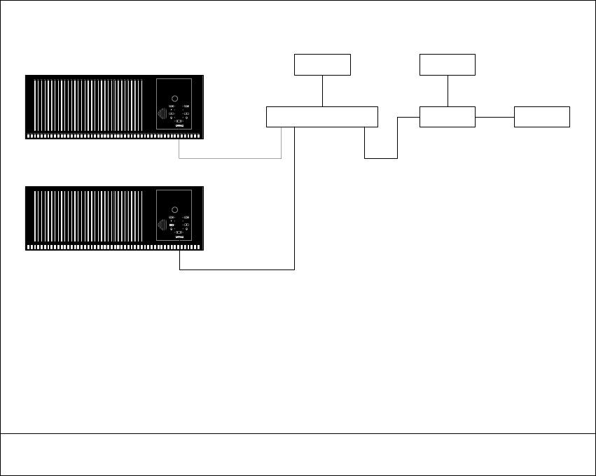
Figure 2 PSTN connection to base stations without a TaitNet RS-232 system interface board
Cables 1, 2 & 3 9-way straight through (not null modem) RS-232 cable
Cable 4 APS power cable, either AC mains or –48VDC, depending on the model chosen
Cable 5 modem power cable, usually AC mains
Cable 6 Telco connection, usually RJ11
Notes ■RS-232 connections are made via the control panel at the front of the base station.
Dial-up ModemAPS PSTN
APS Power Modem Power
Cable 1
Cable 2
Cable 3
Cable 4 Cable 5
Cable 6
Page 6 of 20 TN-906
© Tait Electronics Limited 30 September 2004
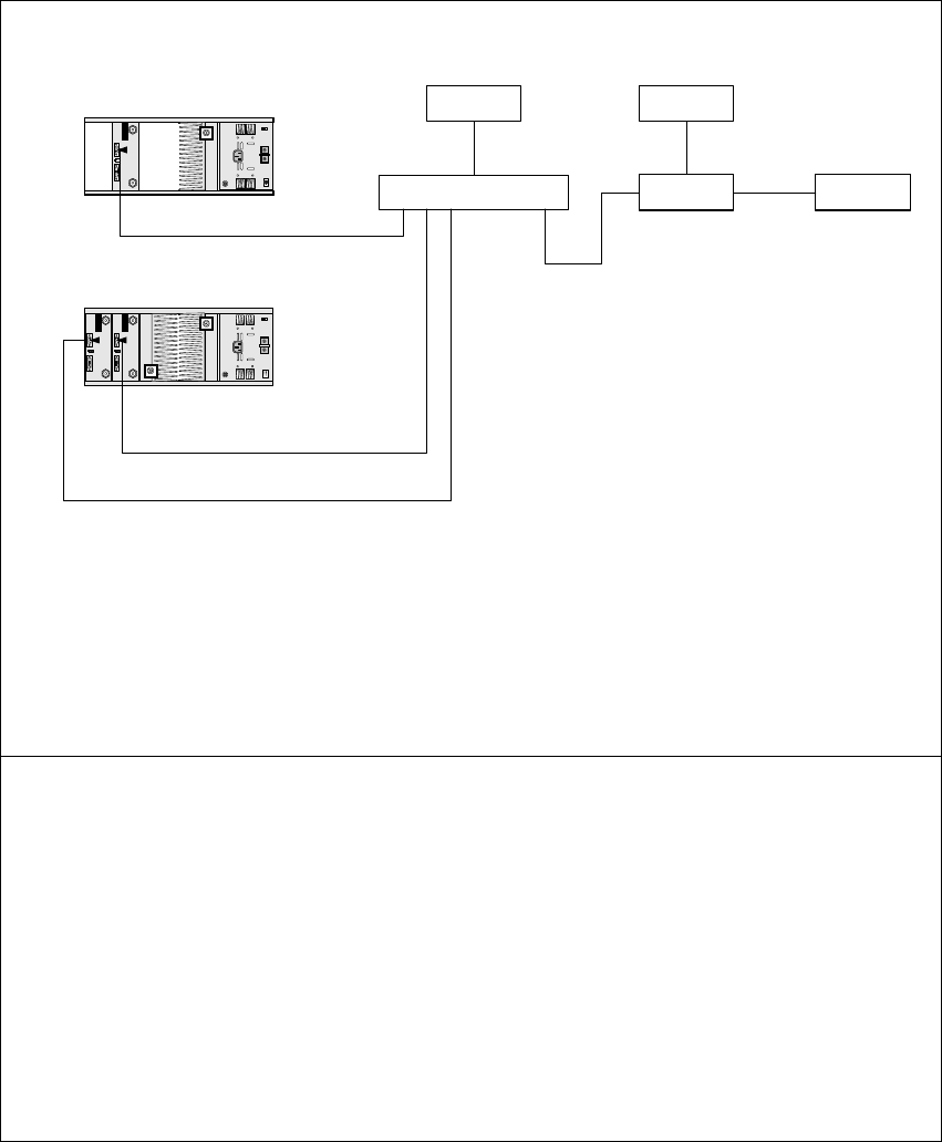
Figure 3 PSTN connection to base stations with a TaitNet RS-232 system interface board
Cables 1, 2, 3 & 4 9-way straight through (not null modem) RS-232 cable
Cable 5 APS power cable, either AC mains or –48VDC, depending on the model chosen
Cable 6 modem power cable, usually AC mains
Cable 7 Telco connection, usually RJ11
Notes ■The TaitNet RS-232 system interface board is essential if you want remote
diagnostics to both channels in dual channel subracks. It is optional for single
channel subracks.
■Connections to the TaitNet RS-232 system interface board are on the rear panel of
the reciter.
■Front or rear panel connections to single channel subracks can be mixed with rear
panel connections to dual channel subracks, in any combination, on a single APS.
■The TaitNet RS-232 system interface board can be installed by the user, with care
(refer to the TB8100 Service Manual). The reciter firmware will automatically
detect the system interface board type, and route the RS-232 signals appropriately.
■If the TaitNet RS-232 system interface board is fitted, the control panel does not
shut down in Power Saving modes, resulting in a small compromise in power
saving effectiveness.
Dial-up ModemAPS PSTN
APS Power Modem Power
Cable 1
Cable 2
Cable 4
Cable 5 Cable 6
Cable 7
Cable 3
Dual channel
Single channel
TN-906 Page 7 of 20
© Tait Electronics Limited 30 September 2004
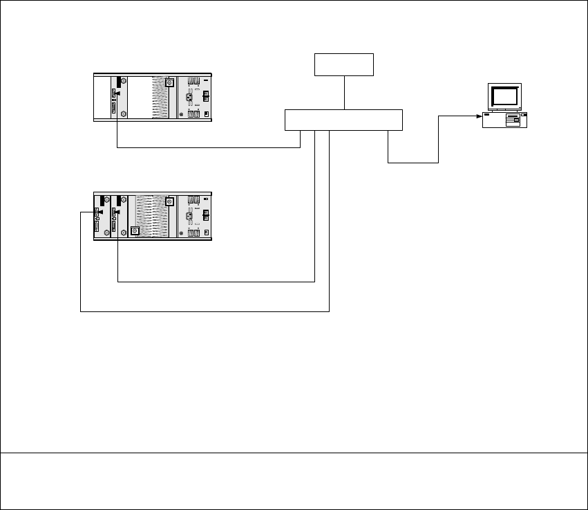
Figure 4 Direct connection to base stations with or without a TaitNet RS-232 system interface
board
Cables 1, 2 & 3 9-way straight through (not null modem) RS-232 cable
Cable 4 9-way null modem RS-232 cable
Cable 5 APS power cable, either AC mains or –48VDC, depending on the model chosen
Notes ■The illustration above shows base stations with TaitNet RS-232 system interface
boards, but front or rear connection can be used.
APS
APS Power
Cable 1
Cable 2
Cable 4
Cable 5
Cable 3
Service Kit
Single channel
Dual channel
Page 8 of 20 TN-906
© Tait Electronics Limited 30 September 2004
Figure 5 Combined PSTN and direct connections
Cables 1, 2, 3 & 4 9-way straight through (not null modem) RS-232 cable
Cable 5 9-way null modem RS-232 cable
Cable 6 APS power cable, either AC mains or –48VDC, depending on the model chosen
Cable 7 modem power cable, usually AC mains
Cable 8 Telco connection, usually RJ11
Notes ■The illustration above shows base stations with TaitNet RS-232 system interface
boards, but front or rear connection can be used.
■If possible, the PC should be connected to a spare APS port so that normal dial-in
and dial-out is not disrupted. If there is no spare port available, any port can be
used, but some disruption may then possibly occur.
?
Dial-up ModemAPS PSTN
APS Power Modem Power
Cable 1
Cable 2
Cable 4
Cable 6 Cable 7
Cable 8
Cable 3
Service Kit
Cable 5
Dual channel
Single channel
TN-906 Page 9 of 20
© Tait Electronics Limited 30 September 2004
4 Configuring the Service Kit and Base Station
4.1 Configuring the Service Kit for Dial-in via an APS
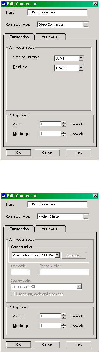
1. Run the Service Kit and select Connect > New Connection. The
Edit Connection screen appears.
2. In the Connection type list, select Modem Dialup. The Edit
Connection screen changes to the one shown below.
Page 10 of 20 TN-906
© Tait Electronics Limited 30 September 2004
3. Set up the parameters in the Connection tab as usual (use the online
Help if required).
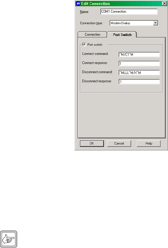
4. In the Port Switch tab, select the Port switch check box.
5. In the Connect command field, enter ^M/Cx^M.
This means:
Note Use the ^ (carat) symbol to instruct the Service Kit that this is a
control character. Do not use the control key.
6. In the Connect response field, enter 1.
7. In the Disconnect command field, enter ^Mxxx^M/X^M.
This means:
8. In the Disconnect response field, enter 3.
^M instructs the APS to enter command modea
a. This is equivalent to the carriage return character.
/C requests a connection
x the port number of the base station you wish to connect to
^M terminates the sequence
^M instructs the APS to enter command mode
xxx three instances of the logoff charactera
a. This must match the logoff character chosen when setting up the modem (L
was chosen in this case). Refer to “Common Configuration for all Ports” on
page 14.
^M terminates the sequence
/X^M exits command mode
TN-906 Page 11 of 20
© Tait Electronics Limited 30 September 2004
4.2 Configuring the Service Kit for a Direct Connection via an APS
This configuration is similar to the one described in the previous section,
except that you set the Connection type to Direct Connection. You can
then connect the computer running the Service Kit software to any spare
port on the APS, and connect to any base station that is not currently busy
with either a dial-in or dial-out session.
4.3 Configuring the Base Station to Dial Out to an Alarm Center
This section provides details on configuring the Alarm Center connection,
the port switch, and the connection timing. For full details on configuring
the modem, refer to TN-742.
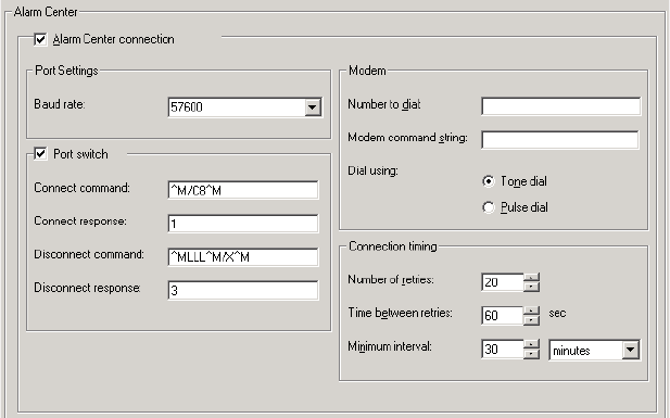
1. Run the Service Kit and select Configure > Communications >
Alarm Center.
2. In the Alarm Center form, enable the Alarm Center connection and
the Port switch (use the on-line Help if required).
3. In the Baud rate list, select 57600. If you select a different baud rate,
ensure that the APS is set to the same rate (refer to “Configuring the
Set-up Switches” on page 13).
4. In the Connect command field, enter ^M/Cx^M.
This means:
The site modem is usually (but does not have to be) connected to the
highest port number available. The above screen shows the settings
for port 8 of an 8-port APS.
^M instructs the APS to enter command modea
a. This is equivalent to the carriage return character.
/C requests a connection
x the port number to which the site modem is connected
^M terminates the sequence

Page 12 of 20 TN-906
© Tait Electronics Limited 30 September 2004
5. In the Connect response field, enter 1.
6. In the Disconnect command field, enter ^Mxxx^M/X^M.
This means:
7. In the Disconnect response field, enter 3.
8. In the Connection timing area, we recommend the following
settings:
■Set the number of retries to 20, the maximum allowed.
■Set the time between retries to 60s for the first base station, and
increment in steps of 5s for other base stations (e.g. set base station
2 to 65s, base station 3 to 70s, etc.). This prevents all base stations
from retrying at the same time if a fault occurs that affects them all.
■Set the minimum interval to at least 30 minutes. The interval
should be long enough to allow all base stations to dial out if
necessary; we suggest 30 minutes plus an extra 3 minutes for each
base station on the site.
Note If there is a particular condition that can be guaranteed to affect all
base stations (e.g. mains failure), we recommend that you enable
this alarm on only two base stations. This precaution will prevent
a mass dial-out attempt, but will still allow you to check for false
alarms.
^M instructs the APS to enter command mode
xxx three instances of the logoff charactera
a. This must match the logoff character chosen when setting up the modem (L
was chosen in this case). Refer to “Common Configuration for all Ports” on
page 14.
^M terminates the sequence
/X^M exits command mode

TN-906 Page 13 of 20
© Tait Electronics Limited 30 September 2004
5 Configuring the APS
5.1 Ensuring the Security of Configuration Data
The configuration data of many APS units is stored in RAM which has a
battery back-up. This battery should have a life of approximately 3 years
when the APS is not powered up, and may need to be changed periodically.
You may also wish to replace the battery before installing your APS to ensure
maximum battery life and security of configuration data. A typical symptom
of battery failure is the loss of configuration data when the APS is powered
down for some time.
The battery is typically a BR1225 and is located under a clip on the main
board of the APS. To replace the battery, proceed as follows:
1. Disconnect the AC mains power.
2. Remove the top cover.
3. Carefully replace the battery, observing normal antistatic precautions.
4. Replace the cover.
5.2 Configuring the Set-up Switches
1. Power up the APS.
2. Configure the set-up switches as shown below. These switches are
located on the rear panel of APS units with up to 8 ports, and on the
bottom cover of units with 16 or more ports.
The settings for SW1, SW2, and SW3 are optional, however the set-
tings for all other switches are mandatory. We recommend a baud rate
of 57k6, as it will give the highest possible data transfer rate through
the modem on a “good” PSTN connection. If you select a different
Switch Setting Function
SW1 ON (down) sets the baud rate to 57k6
SW2 OFF
SW3 OFF
SW4 OFF no handshaking
SW5 OFF
SW6 OFF terse messages
SW7 OFF echo disabled
SW8 ––– currently not used

Page 14 of 20 TN-906
© Tait Electronics Limited 30 September 2004
rate, you must select the same rate for the Alarm Center connection
(Configure > Alarm Center > Port Settings > Baud rate; refer to
“Configuring the Base Station to Dial Out to an Alarm Center” on
page 11).
3. After you have set the switches, you must validate the set-up as
follows:
a. Simultaneously press the SET and CLEAR buttons on the front of
the APS.
b. Release the CLEAR button, wait for the port ACTIVITY LEDs
to flash, then release the SET button.
5.3 Configuring the Ports
Connect a PC running a terminal program (HyperTerminal, ProComm,
TerraTerm or similar) to any unused port on the APS, using a null modem
cable.
Note Refer to the APS User’s Guide for a detailed explanation of all the
command codes. The commands shown in the following section
are in upper case for clarity, however you can use lower case if you
prefer.
Common
Configuration for
all Ports
1. Enter Command Mode using the [Enter] key.
2. Type the following commands:
/CP [Enter] copies port parameters
7 [Enter] 1 [Enter] sets all ports to Any-to-Any mode
9 [Enter] x [Enter] where x sets the logoff character
Note that this must be the same character you
chose in the Service Kit procedures described
in Section 4.1 and Section 4.3 (L in the
examples shown). It must also be different
from the character used to take the modem
out of data mode, which is usually “+”, but
can be changed by the user. You can also
choose control characters, which are shown by
a preceding ^ (carat).
10 [Enter] 1 [Enter] sets the disconnect sequence to 3 consecutive
logoff characters, instead of just 1
Note that this is essential to avoid the
possibility of random logoffs.
11 [Enter] 6 [Enter] enables the timeout to 1 minute
12 [Enter] 3 [Enter] sets the response type to Terse
13 [Enter] 1 [Enter] disables the command echo
[Esc] copies to all ports
Y [Enter] answers the question “Are you sure (y/n)?”
/W [Enter] displays port parameters
TN-906 Page 15 of 20
© Tait Electronics Limited 30 September 2004
3. Verify that the following is displayed.
PORT PARAMETERS #01:
1. Port Name: (undefined)
2. Password: (undefined)
3. Baud Rate: 57.6K
4. Bits/Parity: 8-None
5. Stop Bits: 1
6. Handshake Mode: None
7. Port Mode: Any-to-Any
74. DTR Output: Pulse
8. Supervisor Mode: Permit
9. Logoff Character: L
10. Sequence Disconnect: Three Characters
11. Timeout Disconnect: 1 Min
12. Response Type: Terse
13. Command Echo: Off
14. Accept Break: Yes
If everything is correct, proceed to step 4, or re-enter the incorrect
parameter as required.
4. WTI APS-4, APS-8 and APS-16 Units Only
This step is required because of a bug in the firmware of the APS-4,
APS-8 and APS-16 units. The Copy Port Parameters command does
not work for the timeout setting.
Type the following commands:
Repeat this procedure for all ports.
5. If you do not want to configure a port as a modem port (refer to
“Configuration for a Modem Port (if a modem is used)” below), exit
Command mode by typing:
Otherwise, continue with “Configuration for a Modem Port (if a
modem is used)” on page 16.
/Pn [Enter] sets RS-232 parameters
where n is the port number
11 [Enter] 6 [Enter] enables the timeout to 1 minute
[Esc]
/X [Enter] exits command mode
Page 16 of 20 TN-906
© Tait Electronics Limited 30 September 2004
Configuration for a
Modem Port
(if a modem is used)
We recommend that you configure the port to which the modem is
connected as a modem port. This will ensure that the modem is re-
configured after a power outage, and prevent it from using the wrong serial
baud rate.
Type the following commands:
/Pn [Enter] sets RS-232 parameters
where n is the number of the port to which
the modem is connected, usually the highest
numbered port
Verify that the timeout has been set correctly
to 1 minute. If not, type 11 [Enter] 6 [Enter].
7 [Enter] 4 [Enter] configures the port as a modem port
71 [Enter] AT [Enter] sets the reset string to AT
72 [Enter] AT [Enter] sets the initialisation string to AT
This is just to ensure that no unwanted
commands are issued to the modem.
73 [Enter] +++~~ATH0
[Enter]
ensures that modem hangs up after a timeout
Note that the double ~ (tilde) puts a 2s delay
between +++ and ATH0, allowing the modem
to enter command mode.
[Esc]
/X [Enter] exits Command mode
TN-906 Page 17 of 20
© Tait Electronics Limited 30 September 2004
6 Testing the Connection
Connecting to the
Base Station via the
APS
Once everything has been configured, dial in to the base station via the APS.
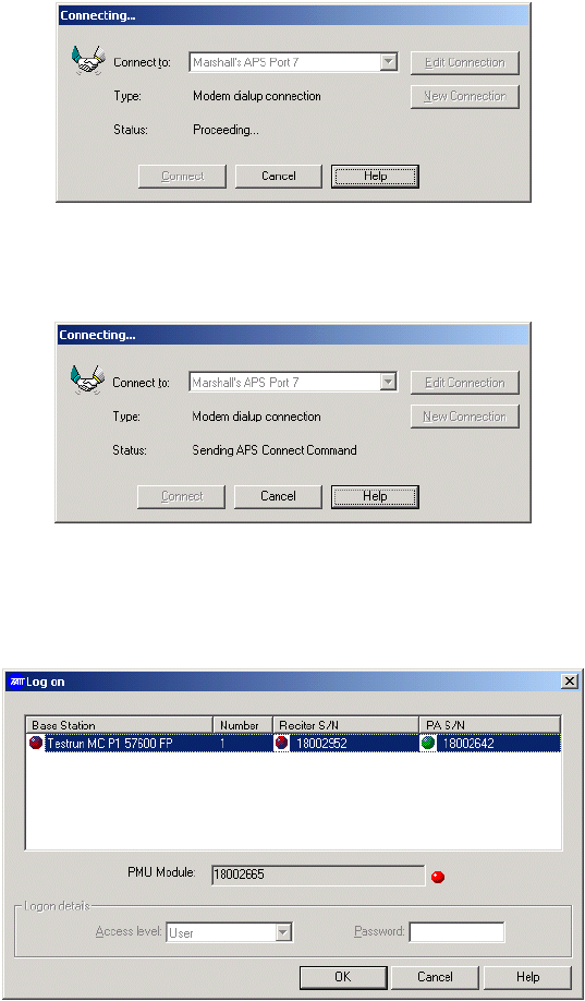
1. Run the Service Kit software and click Connect.
2. Select the APS connection previously set up. The following screen
appears, as for a normal (non-APS) connection.
Once the modems have connected and established their protocol, the
following screen appears. This screen is unique to APS connections.
Shortly afterwards, the correct port is connected, and the base station
responds to its connection protocol. The normal base station logon
screen now appears.
3. Continue with the connection session as normal.
4. When you have completed your session, disconnect in the normal
way.
Page 18 of 20 TN-906
© Tait Electronics Limited 30 September 2004
If the Connection is
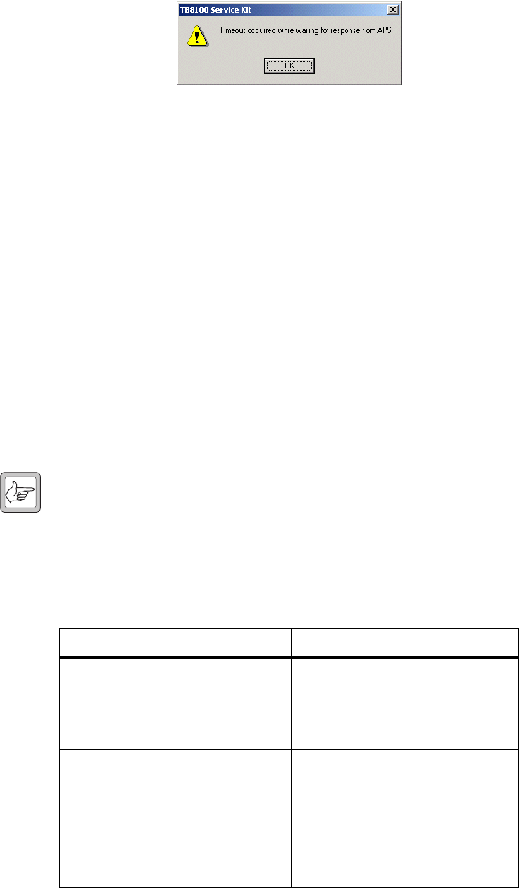
Unsuccessful 1. If an error occurs which is related to the APS, the following screen
will appear.
2. If this screen appears, check the settings of both the APS and the
Service Kit very carefully. If the you cannot resolve the problem, it
may be useful to insert a serial communications monitor between the
Service Kit PC and the modem. Compare the strings actually
transmitted with those expected, and consult the APS User’s Guide.
7 Essential Modem Features
The ATX0 command must be available in any modem which is used with
the APS. This command limits the result codes to 0-4, i.e:
■0 – OK
■1 – connect
■2 – ring
■3 – no carrier
■4 – error
Note Some modems will include result code 8 (no answer) in the list for
ATX0. This is also acceptable. Refer to TN-742 for modem set-
tings and configurations.
8 Known Issues or Limitations
Known Issue or Limitation Solution
Some APS units store their configuration
data in RAM with battery back-up. This
data will be lost if the unit is powered
down and the battery fails.
If you are unsure about the condition of
the back-up battery, replace it before
installing the APS (refer to “Ensuring the
Security of Configuration Data” on
page 13).
Applies to WTI APS-4, APS-8 and APS-16
units:
You cannot use the Copy Port Parameters
command to set the timeout.
You must set the port timeout on each
port individually.
If you try to set this parameter globally, it
will appear to be successful, but the
timeout will not work. Refer to
“Common Configuration for all Ports”
on page 14.

TN-906 Page 19 of 20
© Tait Electronics Limited 30 September 2004
Issuing Authority
This TN was issued by: John Crossland
Technical Publications Manager
Publication History
Amendment Record
Tait Contact Information
Corporate Head
Office
New Zealand
Tait Electronics Limited, P.O. Box 1645, Christchurch, New Zealand
E-mail (Marketing): taitnet@taitworld.com
E-mail (Sales): sales@taitworld.com
Technical Support Technical Support Manager
Tait Electronics Ltd, P.O. Box 1645, Christchurch, New Zealand
E-mail: support@taitworld.com
Internet http://www.taitworld.com
Publication Date Author
30 September 2004 D Reynolds
Publication Date Page Amendment
30 September 2004 First release
Page 20 of 20 TN-906
© Tait Electronics Limited 30 September 2004
