TPA AA 202 Accessory Cable Kit Installation Instructions Tx9000/TM9000 TP9000/TP9100 Connector 402 00029 00/TP9100 00 TP9100
User Manual: Pdf Tx9000/TM9000 -TP9000/TP9100 TPA-AA-202 Accessory Cable Connector 402-00029-00/TP9100 TPA-AA-202 Accessory Cable Connector 402-00029-00
Open the PDF directly: View PDF ![]() .
.
Page Count: 4
TPA-AA-202 Accessory Cable Kit Installation Instructions
402-00029-00 Page 1
Caution: The radio produces a specific audio level at the
maximum rated power. It is the sole responsibility of the end-
user to ensure applicability and compliance with the relevant
legal regulations defining the noise level an individual can be
subjected to.
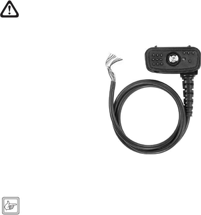
Introduction
The TPA-AA-202 accessory cable kit is used
to connect external third-party accessories,
such as speaker microphones and headsets,
to the accessory connector at the rear of the
radio.
Connecting an Accessory
1. Verify that your accessory is compatible
with the accessory connector, refer to
Table 1.1.
2. When connecting an accessory, make
sure it meets the following specifications:
■speaker impedance: 32Ω (16Ω
min.)
■speaker power: 0.25Wrms (min.)
■microphone: electret, approximately 1kΩ
■PTT switch: not in series with microphone.
Note: If your accessory has a PTT switch in series with the microphone,
the accessory cannot be used. The PTT needs to be a separate signal and
must be made available at the connector separately; it must not be
multiplexed on any other signal.
3. Disassemble the kit as described in “Disassembly and Reassembly” on page 3.
4. Solder the wires of the accessory cable kit to the interface of your accessory (refer
to Table 1.1 on page 2).
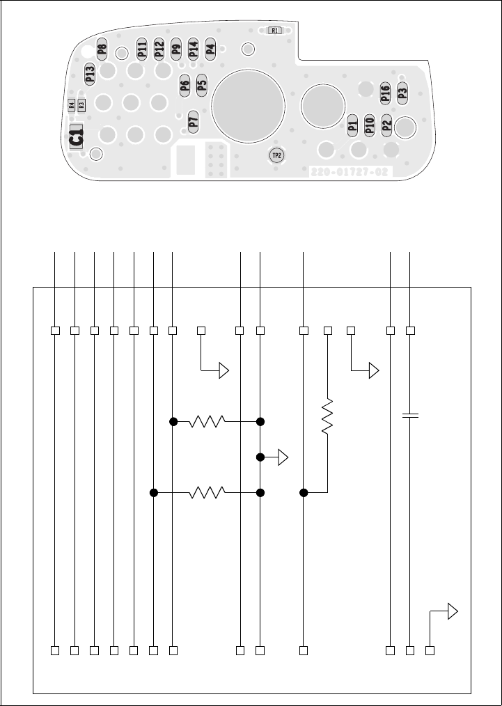
5. Modify the components on the accessory connector PCB as follows (refer to Fig-
ure 1.2). Note that some components may already be fitted by default.
■For all accessories with differential speaker (not referenced to ground), fit a
0Ω link (1206) at position C1.
■For all accessories with a single-ended speaker (referenced to ground), fit a
4.7µF capacitor (ceramic, 1206, X7R, 16V) at position C1 instead of the
fitted 0Ω link (1206).

TPA-AA-202 Accessory Cable Kit Installation Instructions
Page 2 402-00029-00
■To disable the radio’s internal speaker, fit a 0Ω link (0603) at position R3.
■When using an external switch to control the ACC PTT line, for example in
a hands-free vehicle kit, fit a 0Ω (0603) link at position R4.
■To enable an external function button, fit a 12kΩ resistor (0603, 1/
10W±5%) at position R1.
Reassemble the kit as described in “Disassembly and Reassembly” on page 3.
Table 1.1 Accessory cable – wires and signals
Signal name Wire Description Signal type Signal level
Output
impedance/
current
Input
impedance
AUD TAP OUT white/
blue stripe
Programmable tap point
out of the Rx or Tx audio
chain, DC-coupled
Analog audio 0.69Vpp for 60%
deviation at 1kHz
(–10dBm into 600Ω)
600Ω–
AUD TAP IN blue Programmable tap point
into the Rx or Tx audio
chain, DC-coupled
Analog audio 0.69Vpp for 60%
deviation at 1kHz
(–10dBm into 600Ω)
– 100kΩ
DC to
100kHz
ACC PWR brown Accessory power DC supply 3.3V nominal 100mA (max) –
ACC RXD yellow Serial receive data 3V3 CMOS high = 0
low = 1
––
ACC TXD green Serial transmit data 3V3 CMOS high = 0
low = 1
1mA (max) –
ACC GPIO1 violet Accessory sense (internal
speaker disable)
3V3 CMOS high = 1
low = 0
1mA (max) –
ACC GPIO2 white/
red stripe
Accessory sense 3V3 CMOS high = 1
low = 0
1mA (max) –
ACC MIC orange External microphone
input (electret)
Dynamic microphones
are not supported.
Analog audio 9.5Vrms for 60%
modulation at 1 kHz,
DC-coupled
–2.2kΩ
GND black Analog ground Ground – – –
ACC PTT gray External press-to-talk
input
Analog DC 0 to 2.5V, PTT=0 – 27kΩ
ACC SPKR– white External speaker
differential output
Analog audio +6.5Vppa differential
a Dependent on battery charge level.
To drive 16Ω
differentially
–
ACC SPKR+ red External speaker
differential output
Analog audio +6.5Vppa differential To drive 16Ω
differentially
–
TPA-AA-202 Accessory Cable Kit Installation Instructions
402-00029-00 Page 3
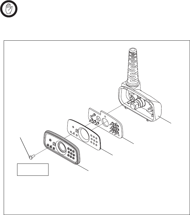
Disassembly and Reassembly
1. Use a Torx T6 screwdriver to remove the screw B, and remove the accessory
housing seal C, and the accessory seal plate D.
2. Fold out the accessory connector PCB E.
Important: During reassembly, make sure that the accessory housing
seal C is inserted correctly inside the accessory connector housing F.
Reassembly is carried out in reverse order of the disassembly.
Figure 1.1 Components of the accessory cable kit
BTorx T6 s cre w Eaccessory connector PCB
Caccessory housing seal Faccessory connector housing
Daccessory seal plate
Torx T6
3lb·in (0.34N·m) C
D
E
F
B
TPA-AA-202 Accessory Cable Kit Installation Instructions
Page 4 402-00029-00
Figure 1.2 Accessory connector PCB and circuit diagram
PL4 P8
PL8 P9
PL2
PL3
PL5
PL10
PL7
P10
P11
P12
P13
P14
P16
AUD TAP OUT
AUD TAP IN
ACC PWR
ACC RXD
ACC TXD
ACC GPIO1
ACC GPIO2
R4
0Ω
ACC MIC
GND
PL6
PL1
P1
P2
PL12 ACC PTT P3
R1
12kΩ
P4
P5
BUTTON1
PL9 P6
P7
PL11
C1
4.7µF
ACC SPKR–
ACC SPKR+
PL13
R3
0Ω
orange
gray
white
red
black
white/red stripe
green
yellow
blue
brown
white/blue stripe
violet
Accessory Connector PCB
