TUG VECTO Engine Manual
User Manual: Pdf
Open the PDF directly: View PDF ![]() .
.
Page Count: 9

Institute of Internal Combustion Engines and Thermodynamics
1
HDV CO2test procedure –VECTO Engine
IVT-EM
VECTO Engine
Short documentation and user manual
App Version 1.4
10.08.2017
Institute of Internal Combustion Engines and Thermodynamics
2
HDV CO2test procedure –VECTO Engine
IVT-EM
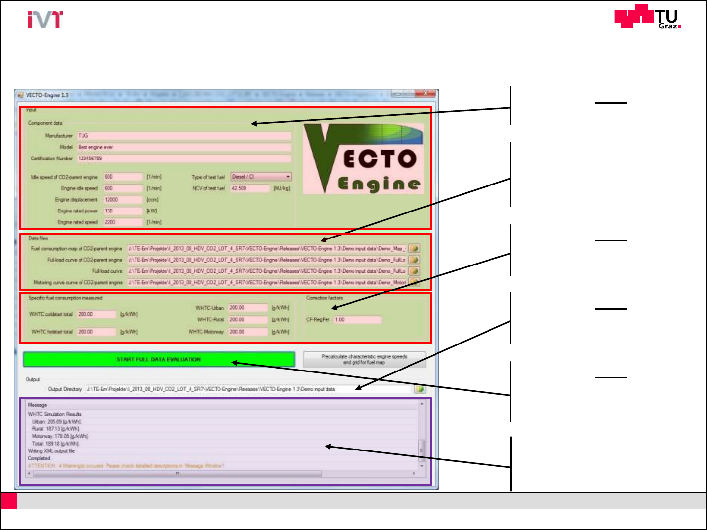
VECTO Engine –GUI
Step 2
Load all required input files via
separate open file buttons
(for file format please see demo files)
Step 4
Define directory where output files
are stored
Step 5
Press „Start“ button for full evaluation
(OR press other button to precalculate grid for fuel
map from CO2-parent full-load curve)
„Message“ window will display
errors (red), warnings (orange),
informations and results
Step 3
Input measured specific FC values
and correction factor
Step 1
Input all component data

Institute of Internal Combustion Engines and Thermodynamics
3
HDV CO2test procedure –VECTO Engine
IVT-EM
VECTO Engine –Input files
VECTO Engine needs 4 separate input files (determined according to the current version of
the technical annex):
Fuel consumption map of CO2-parent engine
Full-load curve of CO2-parent engine
Full-load curve of engine to be certified
Motoring curve of CO2-parent engine
Input file formats
For file formats please refer to the technical annex or supplied demo files!
Demo data supplied
Two different full-load curves for two power ratings of one engine CO2-family supplied
Child: full-load of lower power rating
Parent: full-load of highest power rating

Institute of Internal Combustion Engines and Thermodynamics
4
HDV CO2test procedure –VECTO Engine
IVT-EM
VECTO Engine –Output files
VECTO Engine produces one XML output file:
File name is created based on GUI input data accodring to the following scheme:
“OutPath” + “Manufacturer” + "_" + Model + "_" + “Certification Number” + ".xml"

Institute of Internal Combustion Engines and Thermodynamics
5
HDV CO2test procedure –VECTO Engine
IVT-EM
VECTO Engine –Operations performed (p1/4)
1. Reading of input files and automatic check of input data
1.1 Check of requirements for input data according to the definitions in paragraph 6.1 of the technical annex
1.2 Check of requirements for recorded FCMC data according to the definitions in paragraph 4.3.5.2 and subpoint (1) of
paragraph 4.3.5.5 of the technical annex
2. Calculation of characteristic engine speeds from full load curves of parent engine and actual engine for certification according to
the definitions in paragraph 4.3.5.2.1 of the technical annex
3. Processing of fuel consumption (FC) map
3.1 FC values at nidle are copied to engine speed (nidle –100 min-1) in the map
3.2 FC values at n95h are copied to engine speed (n95h + 500 min-1) in the map
3.3 Extrapolation of FC values at all engine speed setpoints to a torque value of (1.1 times Tmax_overall) by using least
squares linear regression based on the 3 measured FC points with the highest torque values at each engine speed
setpoint in the map
3.4 Adding of FC = 0 for interpolated motoring torque values at all engine speed setpoints in the map
3.5 Adding of FC = 0 for minimum of interpolated motoring torque values from subpoint (3.4) minus 100 Nm at all engine
speed setpoints in the map

Institute of Internal Combustion Engines and Thermodynamics
6
HDV CO2test procedure –VECTO Engine
IVT-EM
VECTO Engine –Operations performed (p2/4)
4. Simulation of FC and cycle work over WHTC and respective subparts for actual engine for certification
4.1. WHTC reference points are denormalized using the full load curve input in originally recorded resolution
4.2. FC is calculated for WHTC denormalized reference values for engine speed and torque from subpoint 4.1
4.3. FC is calculated with engine inertia set to 0
4.4. FC is calculated with standard PT1-function (as in main vehicle simulation) for engine torque response active
4.5. FC for all motoring points is set to 0
4.6. FC for all non-motoring engine operation points is calculated from FC map by Delaunay interpolation method (as in
main vehicle simulation)
4.7. Cycle work and FC are calculated according to equations defined in paragraphs 5.1 and 5.2 of the technical annex
4.8. Simulated specific FC values are calculated analogous to equations defined in paragraphs 5.3.1 and 5.3.2 of the
technical annex for measured values

Institute of Internal Combustion Engines and Thermodynamics
7
HDV CO2test procedure –VECTO Engine
IVT-EM
VECTO Engine –Operations performed (p3/4)
5. Calculation of WHTC correction factors
5.1. Measured values from input to pre-processing tool and simulated values from point (4) are used in accordance with
the equations in points (5.2) to (5.4)
5.2. CFUrban = SFCmeas,Urban / SFCsimu,Urban
5.3. CFRural = SFCmeas,Rural / SFCsimu,Rural
5.4. CFMW = SFCmeas,MW / SFCsimu,MW
5.5. In case that the calculated value for a correction factor is lower than 1, the respective correction factor is set to 1
6. Calculation of cold-hot emission balancing factor
6.1. This factor is calculated in accordance with the equation in point (6.2)
6.2. BFcold-hot = 1 + 0.1 x (SFCmeas,cold –SFCmeas,hot) / SFCmeas,hot
6.3. In case that the calculated value for this factor is lower than 1, the factor is set to 1

Institute of Internal Combustion Engines and Thermodynamics
8
HDV CO2test procedure –VECTO Engine
IVT-EM
VECTO Engine –Operations performed (p4/4)
7. Correction of FC values in FC map to standard NCV
7.1. This correction is performed in accordance with the equation in point (7.2)
7.2. FCcorrected = FCmeasured,map x NCVmeas / NVCstd
7.3. FCmeasured,map shall be the FC value in the FC map input data processed in accordance with point (3)
7.4. NCVmeas and NVCstd shall be defined in accordance with paragraph 5.3.3.1 of the technical annex
7.5. In the case that reference fuel of the type B7 (Diesel / CI) in accordance with paragraph 3.2 of the technical annex
was used during testing, the correction in accordance with points (7.1) to (7.4) is not performed.
8. Converting of engine full load and motoring torque values of the actual engine for certification to a logging frequency of the
engine speed of 8 min-1 if the average engine speed stepwidth is smaller than 6 min-1
9.1. The conversion is performed by arithmetical averaging over intervals of ±4 min-1 of the given setpoint for the output
data based on the full load curve input in originally recorded resolution

Institute of Internal Combustion Engines and Thermodynamics
9
HDV CO2test procedure –VECTO Engine
IVT-EM
Contact data
•Please be aware that from now on all questions, user support and bug reports need to be handled
via the CITnet service of the EU-COM.
•Also future updates of the tool will be released only via this platform
(https://webgate.ec.europa.eu/CITnet/confluence/display/VECTO/vecto-engine+releases).
•If you do not already have an account for this service please contact jrc-vecto@ec.europa.eu.
