Technical Manual
2016-12-09
: Pdf Technical Manual Technical_Manual pdf
Open the PDF directly: View PDF ![]() .
.
Page Count: 48
- Bookmark 1
- Bookmark 2
- Bookmark 3
- Bookmark 4
- Bookmark 5
- Bookmark 6
- Bookmark 7
- Bookmark 8
- Bookmark 9
- Bookmark 10
- Bookmark 11
- Bookmark 12
- Bookmark 13
- Bookmark 14
- Bookmark 15
- Bookmark 16
- Bookmark 17
- Bookmark 18
- Bookmark 19
- Bookmark 20
- Bookmark 21
- Bookmark 22
- Bookmark 23
- Bookmark 24
- Bookmark 25
- Bookmark 26
- Bookmark 27
- Bookmark 28
- Bookmark 29
- Bookmark 30
- Bookmark 31
- Bookmark 32
- Bookmark 33
- Bookmark 34
- Bookmark 35
- Bookmark 36
- Bookmark 37
- Bookmark 38
- Bookmark 39
- Bookmark 40
- Bookmark 41
- Bookmark 42
- Bookmark 43
- Bookmark 44
- Bookmark 45
- Bookmark 46
- Bookmark 47
- Bookmark 48
Quick-Fit
Technical Manual
Made in the USA
Easy & fast to install
Leak-tight laser welded seams
Easy Clean-Outs
Re-useable
14001:2004
9001:2008
Ducting The world’s [
FASTEST
] ducting
ID: 030112866-455-2130 www.ductingsystems.com
Cuts installation and downtime
by more than 45%
8 30 • ZZZGXFWLQJV\VWHPVFRP
Click to go to the Table of Contents
THE WORLD’S FASTEST DUCTING
Quick-Fit
Ducting
2
DESCRIPTION PAGE
TABLE OF CONTENTS
ZZZGXFWLQJV\VWHPVFRP
TABLE OF CONTENTS
ADJUSTABLE NIPPLE ASSEMBLY FOR DRY APPLICATION 41
AIR VOLUME CHART 46
BLAST GATE (AUTO) 22-23
BRANCH STYLES 15
CLAMP GASKET ALTERNATIVES 8
CLAMP DIAGRAM 7
COLLAPSIBILITY & LEAKAGE 6
CONSTRUCTION METHODS 12
DIVERTER VALVE 26
DRY SYSTEM INSTALLATION 38
FITTINGS
10
ELBOWS 14
ENGINEERING SPECIFICATIONS 4-5
FLANGED DUCT SPECIFICATIONS
11
FLASHING (WALL & ROOF) 40
FUME ARMS 28
GRIPPLE HANGER SYSTEM 35
INLINE SILENCER 33
INSTALLING AN IN-CUT OR TAP-IN 32
installing tHE lEaK-FREE gasKEt
43
INSTALLING THE LEAK-FREE O-RING 44
REDUCER STYLES 18
RIGID & ULTRA FLEX METAL HOSE 21
RUBBER FLEX HOSE
20
SIZING A SYSTEM & USING THE CHART 45
SIZING BRANCHES 16
SIZING ELBOWS & SPECIAL COMPONENTS
13
STRUCTURAL INTEGRITY & LEAKAGE CLASS
3
TAKE-OFF SHEET 47
THINGS TO BE AWARE OF WHEN ORDERING
9
TYPICAL CEILING HANGING METHOD 37
WALL MOUNTING BRACE 36
WET APPLICATION MATERIALS
42
WET SYSTEM INSTALLATION 39
sliding access panel 34
sd diverter valve 27
sd blast gate auto 24-25
flex hose styles 19
explosion isolation flap 30-31
mist recycler 34
GAUGE DATA SHEET & ORDERING INFORMATION 9
NO LOSS STACKHEAD 29
jET cAP 29
Return to Contents
TRANSITION STYLES 17
THE WORLD’S FASTEST DUCTING
Quick-Fit
Ducting
3
Duct Size Avg. leakage per 100 ft. SMACNA CLASS
5” SP IO” SP
4” 6” 5 CFM 6 CFM 3
7” 10” 2.5 CFM 3.5 CFM 3
11” 24” 2 CFM 4 CFM 3
STRUCTURAL INTEGRITY
NORDFAB
December 16, 2011
To whom it may concern
Reference: Structural integrity of “QF” Piping System
The Nordfab Laser “Quick-Fit” Piping System has been used in many different industrial applications, and under
various negative static pressures.
The typical design range we see in our applications range from -2” wg to -28” wg, however we have some systems
operating at vacuums of -32” wg to -42” wg under normal operating parameters.
Please take into account that our pipe comes in 5’ lengths with a rolled lip on each end, thus providing reinforcement
every 5’, which presents a sound structural design that should be stronger than any pipe in its class according to
SMACNA guidelines and regulations.
Sincerely,
Tom Ballus
President
All fi t together ducting systems allow for some degree of leakage. “Q-F” ducting is no exception and is not sold
as an airtight system. In addition to our standard Nitrile gasket, NORDFAB offers special clamp gasket material
for high heat, food applications, etc. However, the “Q-F” system is sold as a quick way of installing and modifying
duct-work while at the same time retaining the usability of each component. In short, “Q-F” is meant to be able to
be taken apart, re-assembled, stored or moved. Completely eliminating the possibility for leakage jeopardizes the
inherent benefi ts of the duct.
While NORDFAB is currently unaware of any method of evaluating dust collection piping alone, the following data
is presented using the criteria for all duct, including HVAC. This data is presented only for the purpose of indicating
acceptability of the “Q-F” in dust/fume removal in a negative pressure situation and should not be confused with the
ducting that uses tape or gaskets as sealant in the positive conveyance of air.
LEAKAGE CLASS DETERMINED IN ACCORDANCE WITH SMACNA
ZZZGXFWLQJV\VWHPVFRP
STRUCTURAL INTEGRITY &
LEAKAGE CLASS
Return to Contents

THE WORLD’S FASTEST DUCTING
Quick-Fit
Ducting
4
MANUFACTURING PROFILE:
Nordfab Quick-Fit Ducting is manufactured in Thomasville, NC and Sparks, NV. Nordfab duct is a clamp-together
design using a rolled edge design with a single lever clamp. The ducting and clamps are made of similar materials.
During manufacturing the duct material sheet blanks, which are fi ve feet long, are rolled and fused together with a
laser weld process along the longitudinal seam. Each pipe is checked with a light apparatus for any welding fl aws
or gaps. The rolled edge is then die-formed after inspection by rolling each end of the pipe simultaneously. The
laser weld prevents any gaps in the rolled edge from forming. This rolled end is used for clamping components to-
gether as well as offering reinforcement every fi ve feet. All clamps contain a standard gasket made of Nitrile which
is suitable for most applications, including oil mist, as long as high temperatures are not an issue. An ePTFE gasket
option is available for food grade and high temp applications. Nordfab Quick-Fit Ducting is available in 1” incre-
ments sized 3” to 24” diameter.
Engineering Specifi cation:
1. Ducting shall consist of the following:
a. Galvanized: ASTM A527 with a G90 rating
i. Temp rating is 500° F with no breakdown of zinc - Zinc melting point is 740° F
b. 304SS: Finish meets ASTM A240
i. Temp rating is 1,100° F
c. 316SS: Finish meets ASTM A240
i. Temp rating is 1,100° F
2. Ducting manufacturing techniques:
a. Diameters 3” - 24” pipe, adjustable nipples, and collars attached to other components will have one
or both ends die formed-rolled to provide a uniform edge around the circumference of the rolled
end. The pipe and adjustable nipples shall have the longitudinal seam laser welded to allow for a
tighter slip joint and reduce system pressure losses. All laser welded seams will undergo a light test to
ensure there are no voids or imperfections in the system. Pipe lengths using laser welded seams will
not exceed a nominal 60” length. The rolled edges provide structural support at 5’ intervals or less
and can be interpreted as a stiffener where SMACNA specifi cations are required. An adjustable
nipple is used for adjustment during the install process. Pipe is cut to appropriate length and the
adjustable nipple secures the pipe for install.
b. Pipe and other components larger than 24” shall utilize either an angle fl ange or fl at fl ange attached
loosely and retained in place using a 3/8” vanstone lip. The pipe shall have a compressed-interlocking
lap form seam and not exceed 78” in length. The angle or fl at fl anges provide structural support at
6’-6” intervals or less and are considered as stiffeners where SMACNA specifi cations are required.
c. There will be times when certain components will be air direction sensitive. These components will
have an arrow sticker attached showing the proper fl ow direction.
d. All ducting and its components shall have been tested to 80” WG using the following
gauged reference:
i. 3” will use 18ga material thickness
ii. 4” through 12” will use 22ga material thickness
iii. 13” through 29” will use 20ga material thickness
iv. 30” and above will use 18ga material thickness
Engineering Specifi cation (cont.):
GENERAL ENGINEERING SPECIFICATION FOR
NORDFAB QUICK FIT DUCTING
ZZZGXFWLQJV\VWHPVFRP
ENGINEERING SPECIFICATION
Return to Contents

THE WORLD’S FASTEST DUCTING
Quick-Fit
Ducting
5
3. Clamping rolled edged duct:
a. Clamps shall be constructed with an over-center, spring-lever action for quick connecting of two pieces
of ducting. A retaining pin shall be inserted in the handle and an eyelet on the clamp as a safety feature
to ensure the handle does not prematurely come undone.
b. When closing the clamp, the internal seal shall be compressed in such a manner as to cover both rolled
beads for optimum sealing capacity in a full 360° pattern.
4. Optional caulking and other materials governing system temperature ratings if applicable:
a. Approved caulk is 3M Scotch Seal Metal Sealant 2084 or equivalent for system temperatures of 250°F or lower
b. Optional approved caulk is 3M DP460 two part epoxy or equivalent for system temperatures of 375°F or lower
c. Optional approved caulk is RTV 100 Series, Mil-A-46106B Compliance, UL/FDA/NSF or equivalent for
system temperatures of 400°F or lower
d. Optional approved caulk is Permatex RTV Silicone Rubber Adhesive High Temperature Caulk (red in color) or
equivalent for system temperatures of 500°F or lower
e. Sealing gaskets
i. Buna-N, 70 Duro-Meter hardness with a temperature rating of 250°F maximum and is black in color,
used with the adjustable nipple
ii. Silicon rubber, ZZ-R-765 Class 2A and 2B grade 770 AMS-3304E and 3304F and 3303G, FDA approved
and is red in color, used with the adjustable nipple
iii. Molded gaskets shall meet the material classifi cation of ASTM D-2000 M2BG510 A24 B34 EO14 EO34
EF11 EF21 and used in systems where the temperature rating is 225°F or less and are black in color.
This component shall be made using conductive materials for conductivity.
iv. Sponge o-ring shall meet the material classifi cation of either ASTM D-1056-68 – SBE43 or ASTM
D1056-85, 91, 98 – 2B3
v. Clamp seals shall be made of either of the following:
1. Nitrile to meet or exceed ASTM D 1056 standards with a temperature rating not to exceed 158°F
constant temperature (or intermittent temperature of 194°F).
2. ePTFE to meet or exceed FDA /pharmaceutical standards for food usage and not be degraded
by any common chemicals in the 0-14 PH range. Temperature rating shall not exceed 600°F.
5. Conductivity:
a. Metal-to-metal contact shall be obtained at all joint connections. Die-formed rolled edges are uniform in shape
which provides the most consistent contact. The ears of the clamp contact with the rolled edges and provide
maximum conductivity. Conductivity shall be adhered to per NFPA 77 paragraph 8.4.1.1; states all parts of the
continuous metal piping system should have a resistance level that does not exceed 10 ohms. Testing is the
responsibility of the owner.
ZZZGXFWLQJV\VWHPVFRP
ENGINEERING SPECIFICATION
Return to Contents
THE WORLD’S FASTEST DUCTING
Quick-Fit
Ducting
6
Dia Inches 3 WG 5 WG 7.5 WG 10 WG 15 WG 20 WG 25 WG 30 WG
40.20 0.25 0.30 0.30 0.35 0.50 0.60 0.80
50.20 0.25 0.30 0.30 0.35 0.50 0.60 0.80
60.20 0.25 0.30 0.30 0.35 0.50 0.60 0.80
70.20 0.25 0.30 0.30 0.35 0.50 0.60 0.80
80.20 0.25 0.30 0.30 0.35 0.50 0.60 0.80
9 0.20 0.25 0.30 0.30 0.35 0.50 0.60 0.80
10 0.20 0.25 0.30 0.30 0.35 0.50 0.60 0.80
12 0.30 0.30 0.40 0.40 0.40 0.60 0.70 0.90
14 0.30 0.30 0.50 0.70 0.80 0.80 0.90 1.10
16 0.30 0.40 0.60 0.70 1.00 1.10 1.20 1.40
18 0.40 0.40 0.70 0.80 1.10 1.30 1.50 1.70
20 0.40 0.60 0.80 0.90 1.20 1.50 1.70 2.00
22 0.40 0.60 0.80 1.10 1.40 1.50 2.00 2.20
COLLAPSIBILITY & LEAKAGE DATA
COLLAPSIBILITY STRENGTH OF “Q-F” PIPING
Each size of piping has been tested for strength against collapsing. The piping was exposed to constant
positive pressure and constant vacuum. Each pipe was exposed to a maximum capacity of the test equipment
of 80” WG of vacuum and positive pressure. None of the pipe showed any form of deformation during the test.
Please take into account that our pipe comes in 5’ lengths with a rolled lip on each end, thus providing
reinforcement every 5’, which presents a sound structural design that should be stronger than any pipe in
its class. Pipe and fi ttings must be installed in accordance with NORDFAB’s standard specifi cations and
standard accepted practices.
LEAKAGE RATE
All fi t together ducting systems allow for some degree of leakage where they are joined. “Q-F”
ducting is no exception and is not sold as an airtight system. However, versus the other ducting
typically used in fi t together systems, Nordfab’s Quick-Fit (Q-F) ducting has fully welded, leak-tight
laser welded seams. Spiral and other ducting with lock form seams are NOT fully welded at the seams
and can be expected to have higher leakage rates than “Q-F”.
In addition to our standard Nitrile gasket, NORDFAB also offers special clamp gasket material for high heat,
food applications, etc. Further, the applying of sealants to the individual rolled ends can enhance the tightness
of the system. However, the “Q-F” system is sold as a quick way of installing and modifying duct-work while at
the same time retaining the usability of each component. In short, “Q-F” is meant to be able to be taken apart,
re-assembled, stored, or moved. Completely eliminating the possibility for leakage jeopardizes the inherent
benefi ts of the duct. Standard “Q-F” is designed to provide tight sealing and effi cient airfl ow under negative
pressures. To that end, we are providing the following information for piping situations where fan sizing is of
extreme importance. The following data was obtained using standard components and was performed in ac-
cordance with the SMACNA, “ HVAC AIR DUCT LEAKAGE TEST MANUAL”. The information gives the leak-
age rate per joint of duct at various pressures. To utilize the chart, count the number of clamps, (this equals the
number of pieces), per size and multiply by the number given beside the corresponding diameter and under the
applicable pressure. These numbers assume that the product is correctly installed; free of dents in the joining
ends and that the gasket is in place. Special gasket material and sealants will increase the sealing capabilities.
LEAKAGE RATE IN CFM PER QF JOINT
ZZZGXFWLQJV\VWHPVFRP
COLLAPSIBILITY & LEAKAGE DATA
Return to Contents
THE WORLD’S FASTEST DUCTING
Quick-Fit
Ducting
7
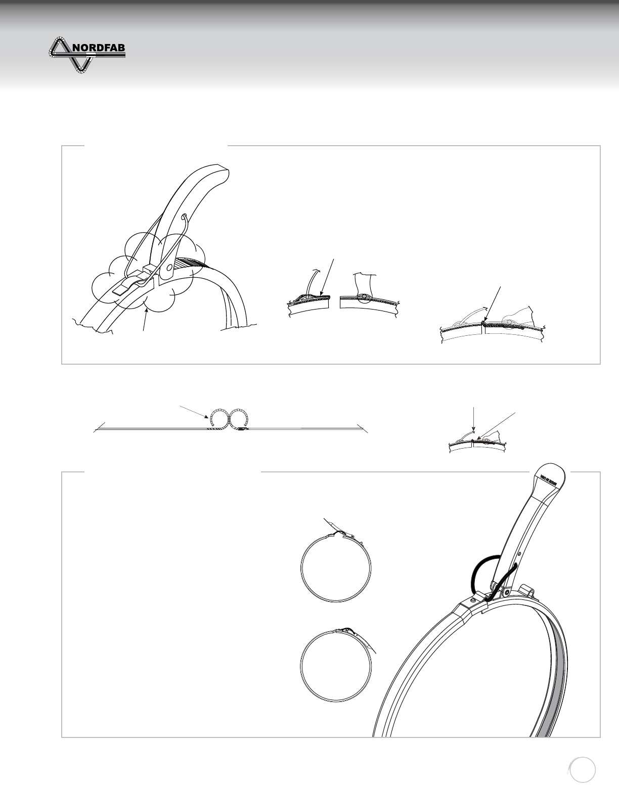
Q-F CLAMP
See Detail on Right
Seal Will Be Installed And Folded Over At
the Factory. It Will Release Easily Due
To The Pressure Sensitive Backing. While Clamping Down, Slowly Tuck
Extra Seal Underneath The Opposing
Side Of Clamp.
Position # 1
Position # 2
“QF” Clamp Nitrile Gasket
Die Formed Rolled Edge
Quick-Seal Clamps
Since 1986, the Nordfab Quick-Fit clamp has
been the world’s best selling and best sealing
duct clamp. It has set the standard for use in
industrial dust, mist, smoke and fume collection.
Many have tried to imitate it, but we’ve found
none who have ever matched, or improved upon,
its tight, leak-resistant seal.
Until now...
The New Nordfab Quick-Seal clamp uses our
new revolutionary “overlap” design. This ensures
the tightest seal possible.
Additionally, we have lengthened the handle for
the Quick-Seal clamp and made it stronger, giv-
ing you more leverage to clamp down for super
tight seals.
Stainless Style
Galvanized Style
ZZZGXFWLQJV\VWHPVFRP
CLAMP DIAGRAM
Return to Contents

THE WORLD’S FASTEST DUCTING
Quick-Fit
Ducting
8
“Q-F” CLAMP GASKETING ALTERNATIVES
1. NITRILE GASKET-STANDARD
• Service temperature: -104° F to +158 ° F with an intermittent max temp of +194° F.
• Standard seal installed in clamp
• The standard specifi cations meet ASTM D 1056.
• 3/8” Gasket for 4”,5”,6”
• 1/2 ” Gasket for 7” - 11”
• 21/32” Gasket for 12” - 24”
2. ePTFE GASKET
• Service temperature -450 DEG F. to 600 DEG F
• FDA suitable for use in food and pharmaceutical industries
• Not degraded by any common chemicals [0-14 PH range]
• Non-contaminating and non-aging
• 3/8” gasket for 4”,5”,6”
• 1/2” gasket for 7” and larger
• 21/32” Gasket for 12” - 24”
O-RINGS
Temperature Rating:
250° F - O-ring Black: Included with adjustable nipples as standard
500° F - O-ring Red: Optional for higher temperatures and FDA approval -
Order separately and replace on site
Material Specifi cations:
O-ring Black: Buna-N, 70 Duro-Meter hardness
O-ring Red: Silicon rubber, ZZ-R-765 Class 2A and 2B grade 70 AMS-3304E and 3304F and 3303G, FDA
approved ordered separately and replace on site.
ZZZGXFWLQJV\VWHPVFRP
CLAMP GASKET ALTERNATIVES
Return to Contents
THE WORLD’S FASTEST DUCTING
Quick-Fit
Ducting
9
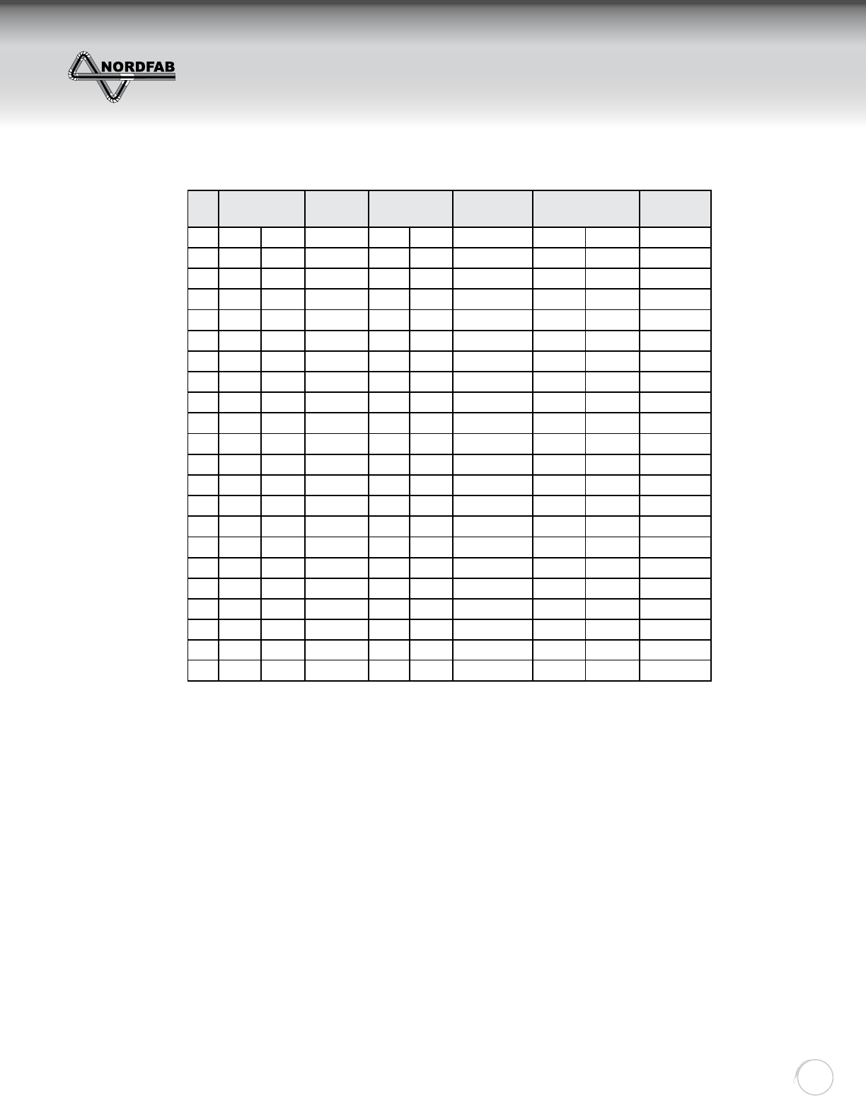
DIA PIPE PIPE STD
GAUGE
NIPPLE NIPPLE STD
GAUGE
MAX GALV GA MAX SS GA
UPGRADE
ID OD ID OD PIPE NIPPLE
3” 2.90 3.00 18 3.07 3.15 22 N/A N/A 20
4” 3.86 3.93 22 3.96 4.03 22 18 18 20
5” 4.87 4.94 22 4.96 5.03 22 18 18 20
6” 5.89 5.96 22 5.99 6.06 22 18 18 20
7” 6.89 6.96 22 7.00 7.07 22 18 18 20
8” 7.88 7.95 22 8.00 8.06 22 16 16 20
9” 8.88 8.95 22 9.00 9.06 22 16 16 20
10” 9.89 9.95 22 10.00 10.07 22 16 16 20
11” 10.88 10.94 22 11.12 11.19 22 16 16 20
12” 11.97 12.04 22 12.11 12.17 22 16 16 20
13” 12.97 13.05 20 13.12 13.20 20 16 16 20
14” 13.96 14.04 20 14.10 14.18 20 16 16 20
15” 14.97 15.04 20 15.12 15.20 20 16 16 20
16” 15.97 16.04 20 16.10 16.18 20 16 16 20
17” 16.97 17.05 20 17.07 17.15 20 16 16 20
18” 17.96 18.04 20 18.10 18.18 20 16 16 20
19” 18.91 19.00 20 19.07 19.15 20 16 16 20
20” 19.96 20.04 20 20.10 20.18 20 16 16 20
21” 20.92 21.01 20 21.07 21.15 20 16 16 20
22” 21.97 22.05 20 22.11 22.19 20 16 16 20
23” 22.91 23.00 20 23.07 23.15 20 16 16 20
24” 23.94 24.02 20 24.06 24.14 20 16 16 20
THINGS TO BE AWARE OF WHEN ORDERING “Q-F”
1. Order one clamp per “Q-F” component.
• One duct = one clamp
• Two elbows = two clamps
2. Specify dimensional information to speed up process:
• Transitions A,B,D,L,X, Y and fl ange style
• Branches A x B x C, or A x B x D, or A x B x C x D
• Tap-In or In-cuts A, B
• Reducer All diameters and end style
THERE IS NO SUCH THING AS TOO MUCH INFORMATION !
3. Look for 60 degree elbows to compliment standard branch orders with 30˚ tap. This is typical application
since the two components will create a perpendicular run to the trunk line.
4. Ask for fl ange styles, hole patterns, ID, OD, when applicable. Typical components
requiring fl anges will be parts that connect to fi lters, fans, or other types of equipment.
QUICK-FIT GAUGE DATA SHEET
ZZZGXFWLQJV\VWHPVFRP
GAUGE DATA SHEET &
ORDERING INFORMATION
Return to Contents
THE WORLD’S FASTEST DUCTING
Quick-Fit
Ducting
10
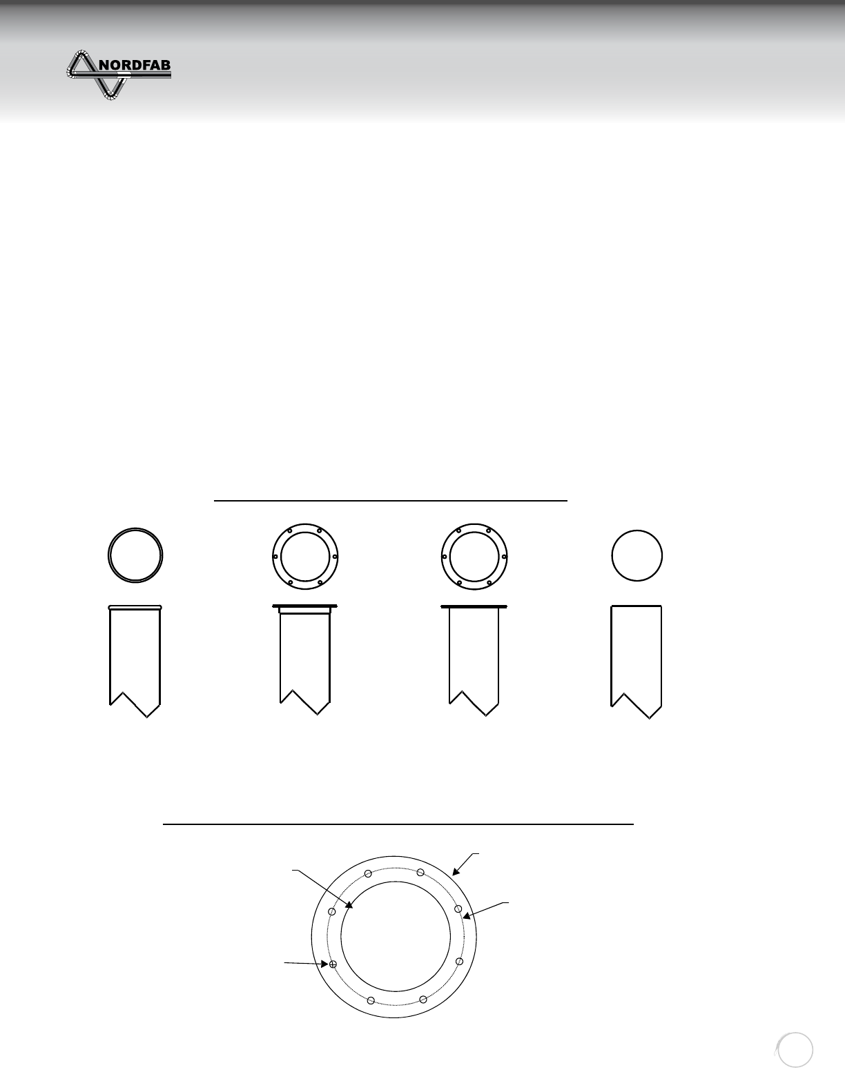
FITTINGS
A) Branch fi ttings are produced to have a concentric design, as they taper to a specifi c dimension.
Joints are lapped, spot welded, cleaned, and painted with KRYLON Industrial Tough Coat, Acrylic
Enamel #1760 Aluminum. Seams are sealed with 3M Scotch-Seal (R) 2084 grey sealant.
B) Fitting gauges vary from 22 to 16 gauge depending on the confi guration of the branch or fi tting.
Gauge can generally be determined by using the corresponding QF Pipe diameter gauge. If
exact gauge is required, contact factory for more information.
C) All standard branch fi ttings are produced on a 30 degree angle, however other angles (7.5˚ - 90˚)
are available upon request.
D) As a normal practice, internal welds are not cleaned or painted. Cleaning or painting the inside
is an option based on the customer’s application and is done only at the customer’s request with
an upcharge.
QF
STANDARD
ANGLE
FLANGE
STANDARD
FLAT
FLANGE
CUSTOM
NO
FIT
CUSTOM
EXAMPLES OF VARIOUS FITTINGS AVAILABLE
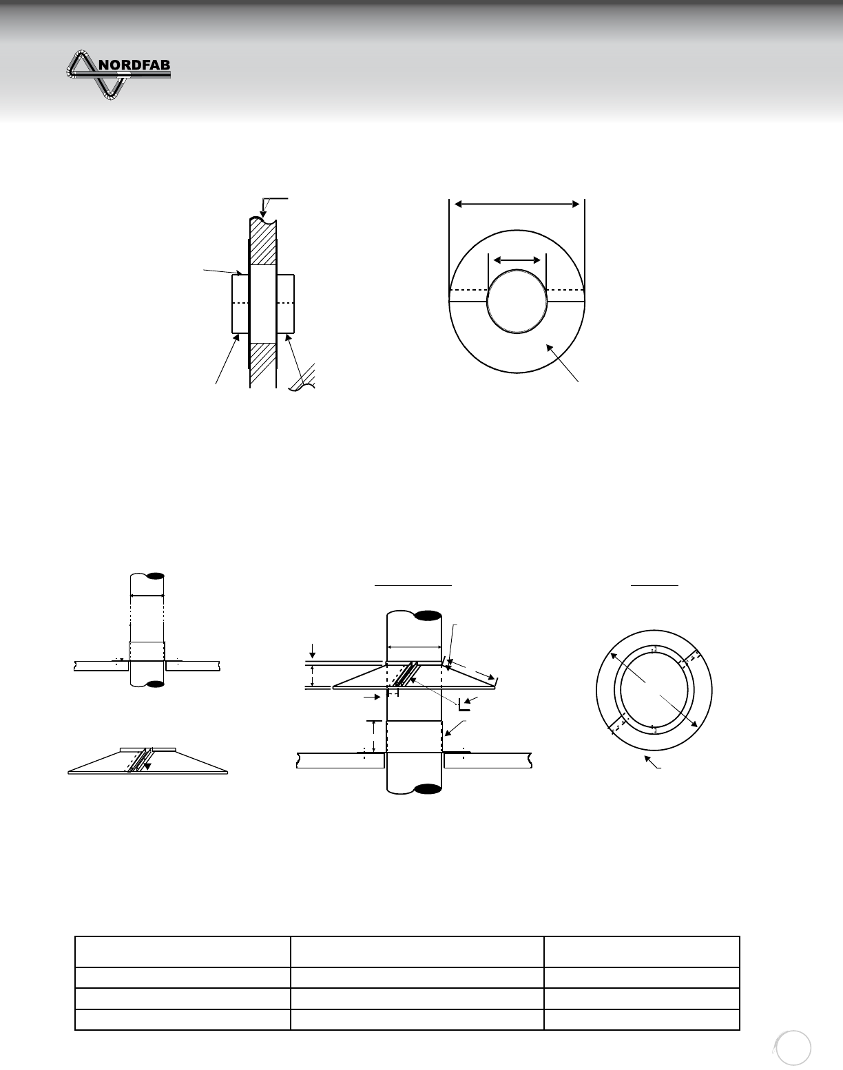
INFORMATION NEEDED TO ORDER A CUSTOM FLANGE
Flange O.D.
Bolt Center
Flange I.D.
Dia. & Number
of Bolt Holes
ZZZGXFWLQJV\VWHPVFRP
FITTINGS
Return to Contents
THE WORLD’S FASTEST DUCTING
Quick-Fit
Ducting
11
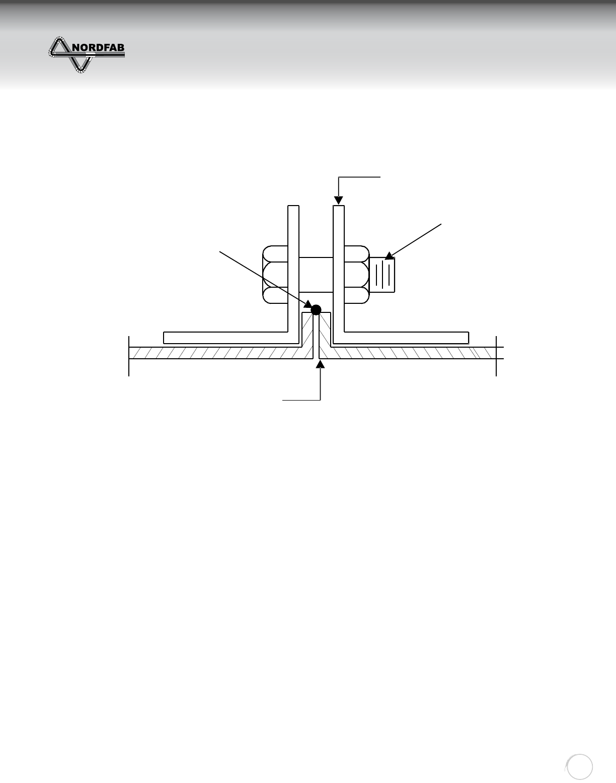
FLANGE DUCT SPECIFICATION
Standard Angle Flange
Bolt & Nut
(Not supplied by
Nordfab)
3/8” Lip On Pipe
Sealant
(Not supplied by Nordfab)
A) “Flanged” = Material sheet blanks are 78.75” lg. and rolled with a longitudinal lock formed
seam. An angle fl ange made from angle bar stock rolled on edge is placed on
the end of the duct using a Van Stone Lip Connection as illustrated above.
(See Nordfab Catalog for sizes)
B) Refer to your local guidelines and codes for how ducting should be supported
C) Duct diameters for FLANGE DUCT as follows:
3” through 40” available in 1” increments
ZZZGXFWLQJV\VWHPVFRP
FLANGED DUCT SPECIFICATION
Return to Contents
THE WORLD’S FASTEST DUCTING
Quick-Fit
Ducting
12
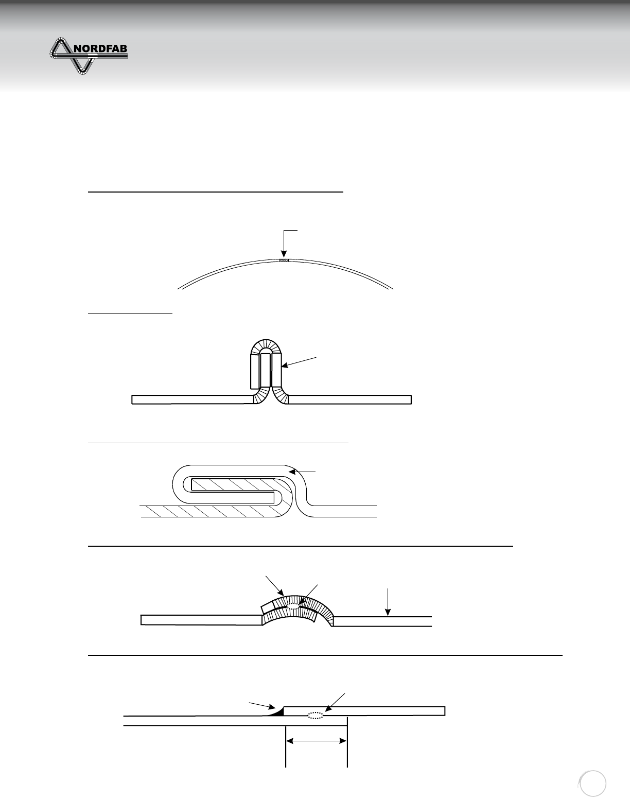
EXAMPLES OF CONSTRUCTION METHODS
1. LONGITUDINAL LASER WELD SEAM FOR “Q-F” PIPE
* Applies to all straight duct up to 24”, adapters, nipples, collars, and most elbows.
All Reno made elbows are supplied with standard seam - see fi gure 5 below
Laser Weld
Cross Section Through Pipe
2. STANDING SEAM
* Applied to segmented elbows, offsets and end caps.
3. LONGITUDINAL LOCK FORM SEAM ON FLANGE PIPE
* Applies to all straight duct fl anged lengths.
4. OVERLAPPED, SPOT WELDED SEAM CONSTRUCTION AND QF COLLAR CONNECTION
* Applies to all branches, reducers, in-cuts, etc.
5. STANDARD SEAM JOINING METHOD ON HOODS, BOXES, TRANSITIONS, AND SPECIALTY ITEMS
* Lapped, spot welded, and caulked.
Receiving Lip is
Pressed Over
By Machine
Lock Form Performed in 3-stages
1- Edges Formed
2- Pipe is Rolled
3- Seam Is Pressed Tight
Cross Section of Standing Seam
“Q-F”Collar
Overlapped
Construction
Spot Welded
Around
Circumference
Caulk
Spot Welded
Around Circumference
Typ. 1 /2“ Lap
ZZZGXFWLQJV\VWHPVFRP
CONSTRUCTION METHODS
Return to Contents

THE WORLD’S FASTEST DUCTING
Quick-Fit
Ducting
13
SIZING ELBOWS
The catalog lists the standard sizes and the standard gauges; however, NORDFAB also makes elbows in long
radius and in heavier gauges. The elbows can be made in segments or can be made smooth walled. Pricing for
the various sizes and gauges should be obtained by calling NORDFAB.
SPECIAL COMPONENTS
As with the elbows, NORDFAB is able to provide special hoods or special designed pieces for almost any dust
collection application. To obtain help in design or pricing, call NORDFAB.
ADAPTING TO EXISTING SYSTEMS
There will be instances where the customer will desire to apply “QF” duct to an existing ducting system;
NORDFAB makes adapters for this purpose. We can provide these in fl ange to “QF” or through simply
supplying “raw to QF” adapters that can be attached to the end of existing spiral duct so that “QF” can be
coupled to the duct.
CAULK SELECTION AVAILABLE ON ALL COMPONENTS
Temperature Rating:
250° F - Standard Caulk - 3M Scotch Seal Metal Sealant 2084 - Standard (contact your dealer for pricing and
other options)
250° F - Optional Oil Mist - 3M 2084 Scotch Seal Metal Sealant
375 ° F - Optional Epoxy Caulk - 3M DP460
400° F - Optional RTV 100 Series, Mil-A-46106B Compliance, UL/FDA/NSF
500° F - Optional Permatex RTV Silicone Rubber Adhesive High Temperature Caulk - Red in color - 26C
Material Specifi cations:
Galvanized: ASTM A527 with a G-90 rating
500° F - Galvanized with little or no breakdown of zinc - zinc melting point is 740° F
500° F - Optional galvanized and seams solid welded
304SS: Finish meets ASTM A240
1100° F - 304SS bluing may occur at temperatures of 800° F
1100° F - Optional 304SS and seams solid welded
316SS: Finish meets ASTM A240
Note: For temperatures 250° F. to 500° F. please request RTV High temp silicone caulk on components. Contact
NORDFAB for adder.
Galvanized: Ducting will accommodate systems 0 to 500° F. with little or no breakdown of the zinc coating - zinc
melting point is 740° F.
304SS: Ducting will accommodate systems 500 to 1100° F with no problems. With temps above 800° F, a small
amount of “bluing” may occur.
PAINTING GALVANIZED COMPONENTS
Step 1. Wash down all components with an industrial de-greaser, insuring that no oils or residues are left behind.
Step 2. Apply an epoxy primer in a light coating.
Step 3. For a fi nal coat, apply an acrylic water base paint. (Example: Glidden Lifemaster)
ZZZGXFWLQJV\VWHPVFRP
SIZING ELBOWS
& SPECIAL COMPONENTS
Return to Contents
THE WORLD’S FASTEST DUCTING
Quick-Fit
Ducting
14
ANGLE IN DEGREES NUMBER OF GORES
15º (2) 7.5º + 2 tangents
30º (1) 15º + (2) 7.5º + 2 tangents
45º (2) 15º + (2) 7.5º + 2 tangents
60º (3) 15º + (2) 7.5º + 2 tangents
90º (5) 15º + (2) 7.5º + 2 tangents
ELBOWS
A) Standard elbows will have a centerline radii of 1 x dia & 1.5 x dia as specifi ed in catalog .Longer
radius elbows are available upon request.
B) Standard elbows 3” to 7” are pressed formed, 8” and larger are gored construction with a lock
form standing seam every 15 degrees. Gore type elbows are produced as follows:
ELBOW
DIAMETER
GALV STD
GAUGE SS STD GAUGE ONE GAUGE
UPGRADE
MAX HEAVY
WALL STYLE
ELBOW
3” 24 14 TUBED N/A N/A
4” 24 14 TUBED N/A N/A
5” 24 14 TUBED N/A N/A
6” 24 14 TUBED N/A N/A
7” 24 22 18 16
8” 22 22 18 16
9” 22 22 18 16
10” 22 22 18 16
11” 22 22 18 16
12” 22 22 18 16
13” 20 20 18 16
14” 20 20 18 16
15” 20 20 18 16
16” 20 20 18 16
17” 20 20 18 16
18” 20 20 18 16
19” 20 20 18 16
20” 20 20 18 16
21” 20 20 18 16
22” 20 20 18 16
23” 20 20 18 16
24” 20 20 18 16
26” 18 18 16 16
28” 18 18 16 16
30” 18 18 16 16
32” 18 18 16 16
34” 16 16 16 16
36” 16 16 16 16
38” 16 16 16 16
40” 16 16 16 16
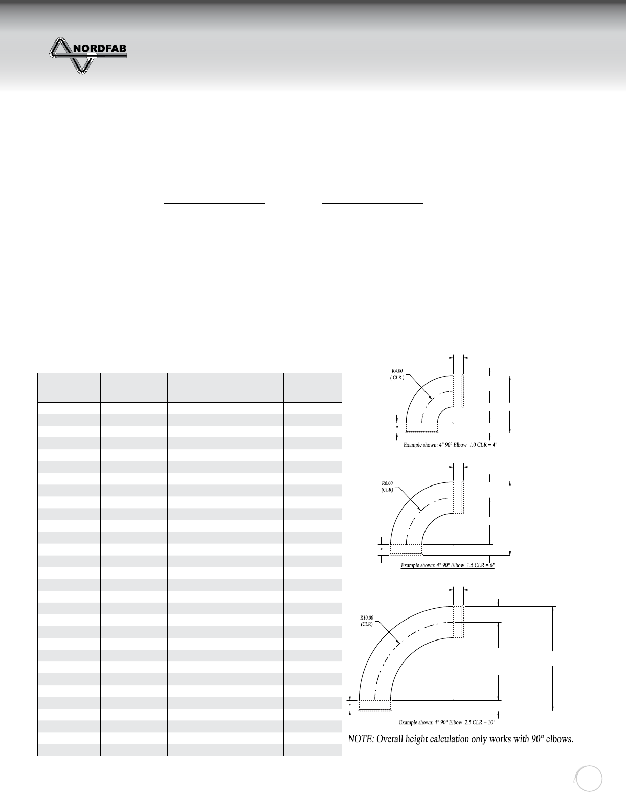
ELBOW STANDARD AND UPGRADES FOR
QF AND ANGLE FLANGE 4” GALV. ELBOW CLR
EXAMPLE
NOTE: TUBED ELBOWS ARE AVAILABLE @ 14 GA
EXCEPT 3-4” GAL @ 16GA 1.32”
1.32”
2”
4” 7.32”
1.32”
1.32”
2”
6” 9.32”
1.32”
1.32”
2”
10” 13.32”
3210-0490-104000
3210-0490-106000
3210-0490-110000
ZZZGXFWLQJV\VWHPVFRP
ELBOWS
Return to Contents
THE WORLD’S FASTEST DUCTING
Quick-Fit
Ducting
15
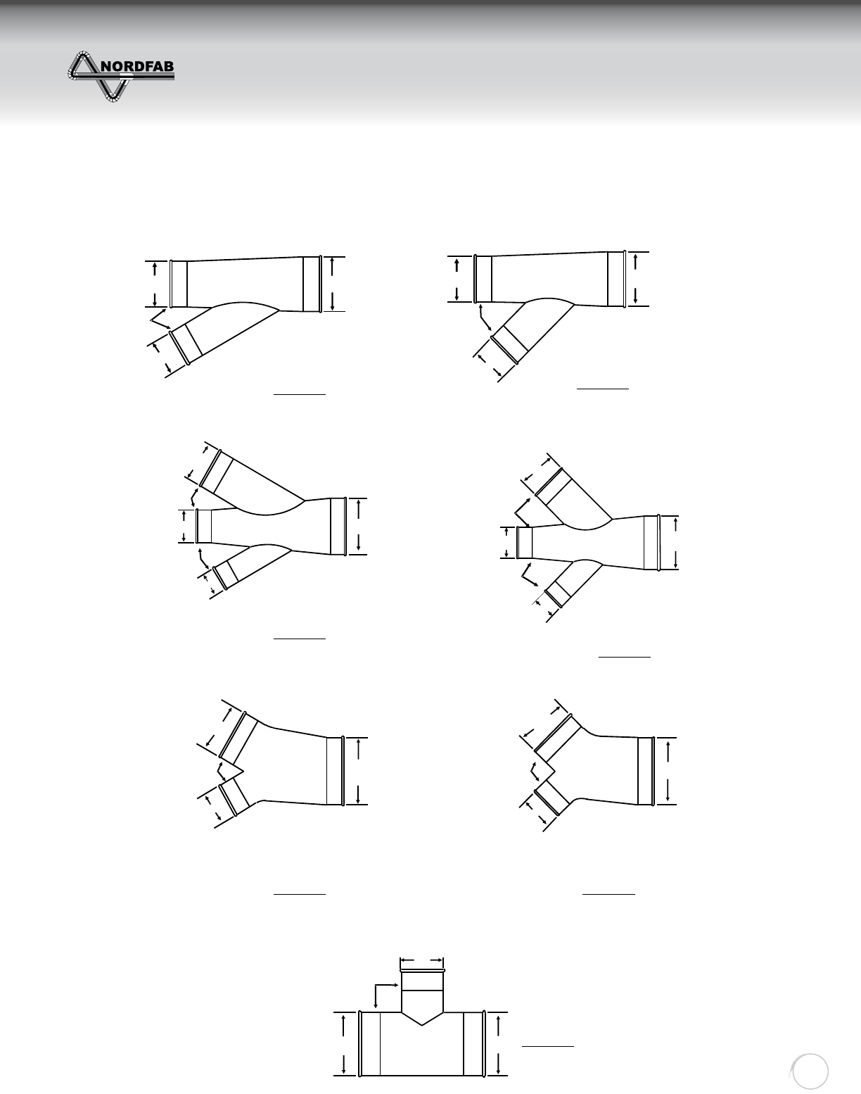
BRANCH STYLES
A
C
B
5”
4”
6”
30 DEG A=6, B=4, C=5
@ 30 Deg Standard
Part #: 3220-06xx. When
Ordering, Provide Part #
and Description.
Examples:
3220-06 6-4-5
or Branch 6-4-5
A
C
B
5”
4”
6”
45 DEG A=6, B=4, C=5
@ 45 Deg Custom
Part #: 3220-06xx. When
Ordering, Provide Part #
and Description.
Examples:
3220-06 6-4-5 @ 45 Deg
or Branch 6-4-5 @ 45 Deg
A
C
B
5”
4” 7”
30 DEG A=7, B=5, C=4, D=3
@ 30 Deg Standard
Part #: 3226-07xx. When
Ordering, Provide Part #
and Description.
Examples:
3226-07 7-5-4-3
or Double Branch 7-5-4-3
D
30 DEG
3”
AC
B
5”
4” 7”
45 DEG A=7, B=5, C=4, D=3
@ 45 Deg Custom
Part #: 3226-07xx. When
Ordering, Provide Part #
and Description.
Examples:
3226-07 7-5-4-3 @ 45 Deg or
Double Branch 7-5-4-3 @ 45 Deg
D
45 DEG
3”
A
B
6”
4”
8”
60 DEG
A=8, B=6, D=4
@ 60 Deg Standard
Part #: 3221-08xx. When
Ordering, Provide Part #
and Description.
Examples:
3221-08 8-6-4
or Y- Branch 8-6-4
D
A
B
6”
4”
8”
90 DEG
A=8, B=6, D=4
@ 90 Deg Custom
Part #: 3221-08xx. When
Ordering, Provide Part #
and Description.
Examples:
3221-08 8-6-4 @ 90 Deg
or Y- Branch 8-6-4 @ 90 Deg
D
A
B
6”
4”
6”
90 DEG A=6, B=4
@ 90 Deg Standard
Part #: 3227-0604. When
Ordering, Provide Part #
and Description.
Examples:
3227-0604
or T- Branch 6-4
A
ZZZGXFWLQJV\VWHPVFRP
BRANCH STYLES
Return to Contents
THE WORLD’S FASTEST DUCTING
Quick-Fit
Ducting
16
SIZING BRANCHES
____” (____CFM)
Branch Typ. @ 30 Deg
6” x 60 Deg Elbow
6” Dia @ 885 CFM
5” x 90 Deg Elbow
5” Dia @ 615 CFM
8” dia (1500 CFM)
From Air Volume
Chart
Branch Typ. @ 30 Deg
6” x 60 Deg Elbow
6” Dia @ 885 CFM
5” Dia @ 615 CFM
5” x 90 Deg Elbow
EXAMPLE: Always work from your machines back toward the fi lter. Suppose that you have
a 5” drop that rises and runs back to join with a 6” drop as sketched above. What size
branch will you need?
The 5” pipe carries 615 CFM at 4500 FPM, (See Chart). The 6” pipe will need 885 CFM at
the same velocity (See Chart). Added together you have a total of (615 + 885) 1500 CFM
coming together. Looking again at the chart under 4500 FPM, you fi nd that 1500 CFM is not
listed, but falls very close to the 1570 CFM listed for an 8” pipe. This indicates that the 5”
joined to the 6” will require an 8” pipe to carry all of the material at the right velocity.
The branch, therefore, will be 8” on the downstream end reducing down to a 5” with a 6”
branching off of it. That is listed as a 8-6-5 branch.
ZZZGXFWLQJV\VWHPVFRP
SIZING BRANCHES
Return to Contents
THE WORLD’S FASTEST DUCTING
Quick-Fit
Ducting
17
Item
#Qty. “D” “A” “B” “X”
Std 2”
“Y”
Std 2” “L” Gauge Flange
Material
Flg
Dwg Special Notes
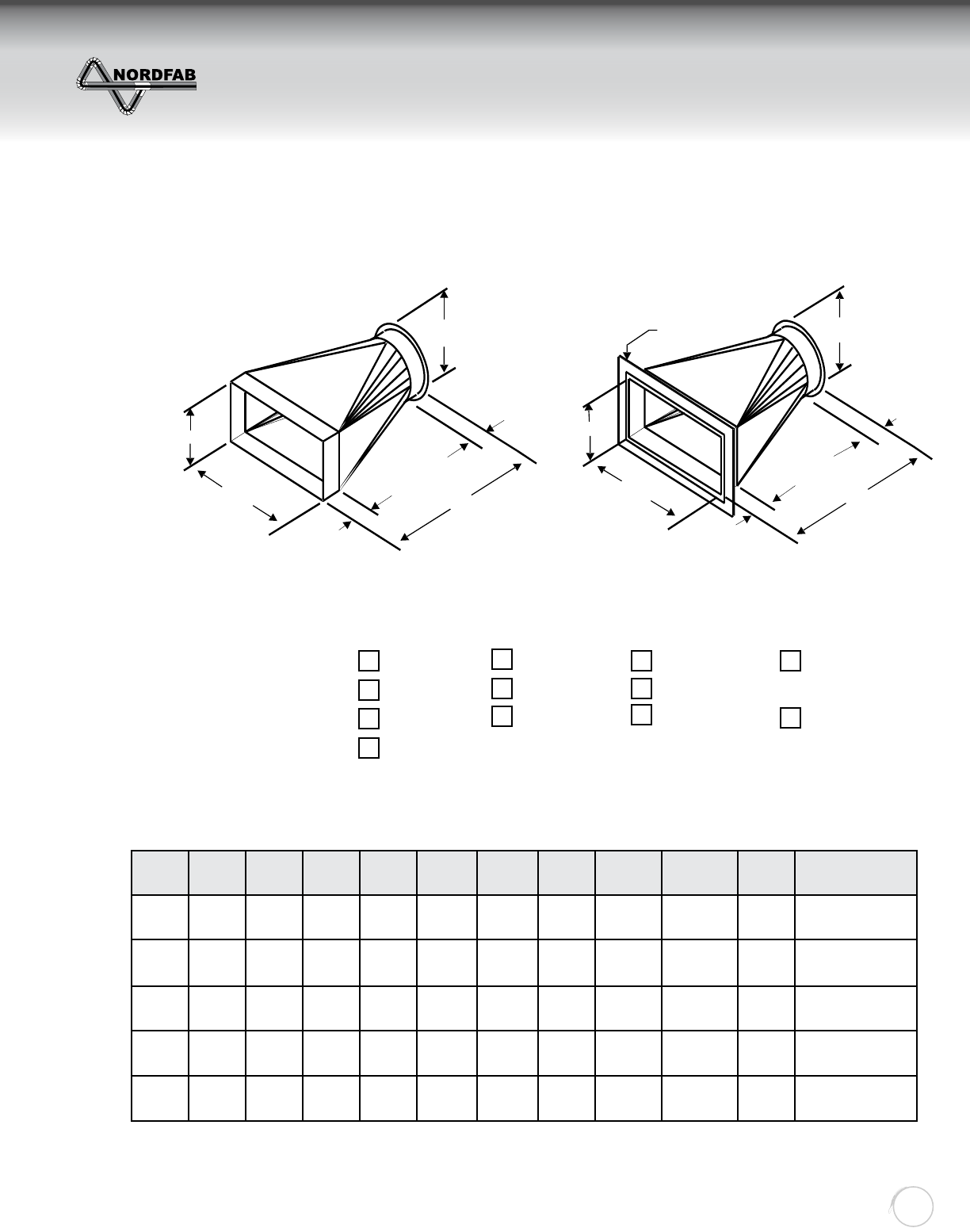
TRANSITION STYLES
“A”
“B”
“X”
“L”
“Y”
“D”
“A”
“B”
“X”
“L”
“Y”
1- ½” FLANGE
STYLE #1 STYLE #2
Built to your specifi cations. Please list all required dimensions and details.
Specify Rectangle End:
Flange Type:
Specify Round End:
Raw End I.D. Raw End O.D.
Angle Flange
Angle Flange
Angle Flange
Flat Flange
Flat Flange
Flat Flange
Sheet Metal
QF Hose Conn.
Raw I.D. Or O.D.
NOTE: If no hole pattern is supplied for fl anges, they will be supplied “Blank” to be fi eld drilled.
“L” = to the greater of B or D NOTE: Minimum L for Sq to Rd is B x 0.75
ZZZGXFWLQJV\VWHPVFRP
TRANSITION STYLES
Return to Contents
THE WORLD’S FASTEST DUCTING
Quick-Fit
Ducting
18
DIA. GALV. GAUGE SS GAUGE
4” - 12” 22 22
14” - 22” 20 20
Item# Qty “A”
Style
“Q-F”
“Flange”
“Raw”
“B”
Style
“Q-F”
“Flange”
“Raw”
“L”
(A-B+6)
“X”
STD-2”
“Y”
STD-2”
Part
Gauge
Flange
Material
Flg
Dwg Special Notes
“A”
“B”
“X”
“Y”
“L” “A”
“B”
“X”
“Y”
“L” “A”
“B”
“X”
“Y”
“L”
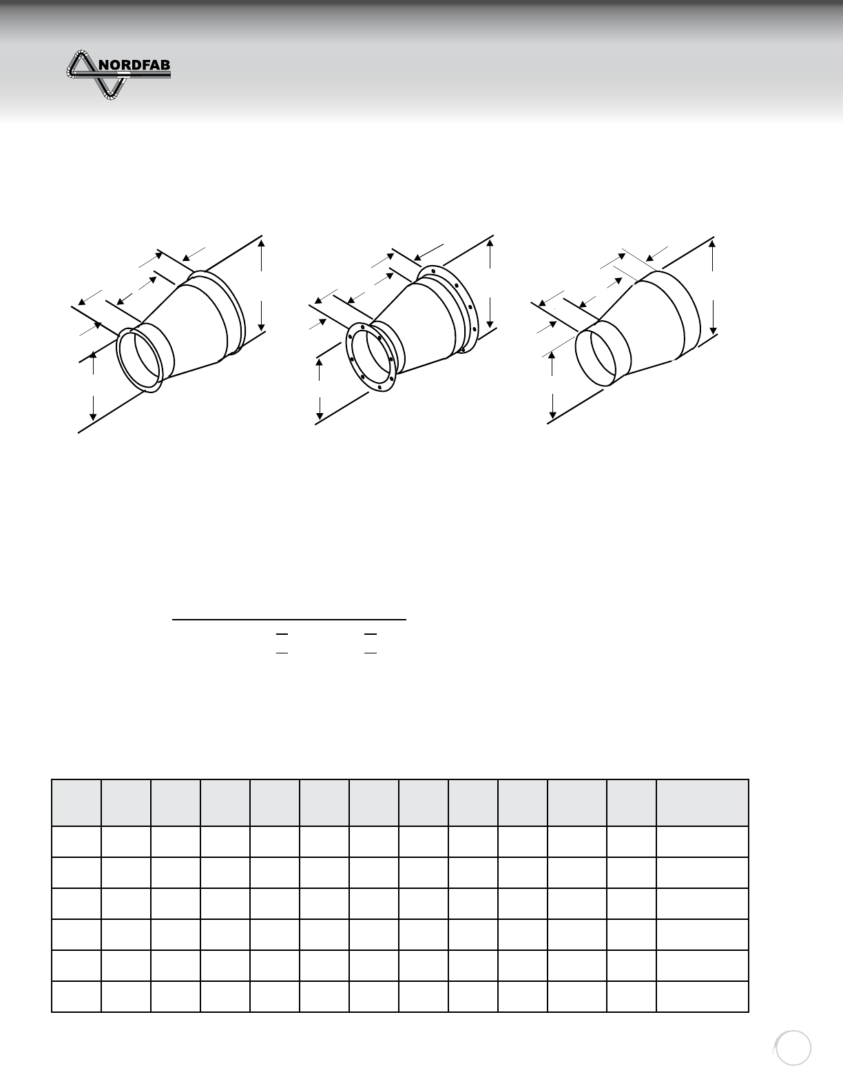
REDUCER STYLES
“Q-F STYLE” “FLANGED STYLE” “RAW END STYLE”
A) Reducers are produced by the following formula:
“QF” LENGTH = (A-B) + 6” [7” MIN]
“FL” LENGTH = (A-B) + 8” [9” MIN]
B) Standard material gauges as follows: (Heavier gauges available contact NORDFAB)
NOTE: Any combination of the above style are available upon request. Please specify all the
required dimensions and all reducer end confi gurations (Raw ID, Raw OD Style, QF Style,
Flange Style, Etc.).
ZZZGXFWLQJV\VWHPVFRP
REDUCER STYLES
Return to Contents
THE WORLD’S FASTEST DUCTING
Quick-Fit
Ducting
19
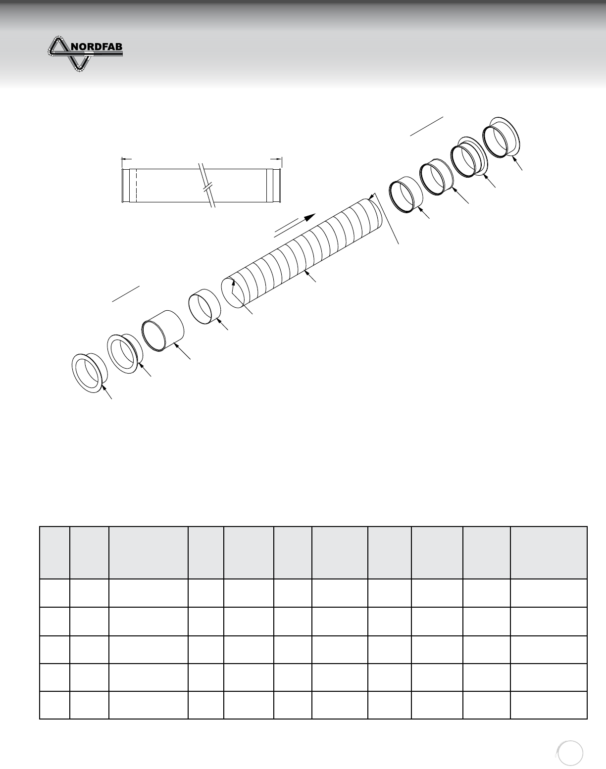
Item
#
Inlet
Dia.
Inlet End Style
(QF, NF, AF, FFL,
RID, ROD)
Flex
Dia.
Flex
Hose
(RF, UF)
Outlet
Dia.
Outlet
End Style
Length
(in.)
Material
(G, SS)
Drawing
(Y/N) Special Notes
Flat Flange (FFL)
Angle Flange (AF)
Quick Fit (QF) end
Length=End of Fitting to End of Fitting
Flat Flange (FFL)
Angle Flange (AF)
Quick Fit (QF) end
For raw end denote
RawID (RID)
RawOD (ROD)
NOTE: When ordering Flex Pipe
with no ttings (NF) order in 5’-0”
increments. (5’0”, 10’0”, 15’0”, etc.)
For raw end denote
RawID (RID)
RawOD (ROD)
Outlet End
NOTE: one end is expanded to t
over the outside of the ex tube.
Inlet End
NOTE: one end is designed
to t inside of the ex tube. AirFlow
Flex Hose Select
Rigid
Ultra Flex (UF)
For no tting (NF) tack welded
For no tting (NF) tack welded
FLEX HOSE STYLES
NOTES:
1. If no hole pattern is supplied for fl anges, you will receive blank fl anges (fl anges without holes).
2. Any combination of the above style are available upon request. Please specify the inlet diameter, fl ex hose
diameter, and outlet diameter.
3. Note the length is based on the fl ex hose being stretched out before cutting (not compressed).
4. Special Notes: SP=Spot Weld (Std), ST=Stitch Weld, SO=Solid Weld, BY=Buff Yes, BN=Buff No (Std),
note other requirements.
5. Rigid and Ultra Flex hose is produced in 5’ lengths in diameters 7” and above.
ZZZGXFWLQJV\VWHPVFRP
FLEX HOSE STYLES
Return to Contents
THE WORLD’S FASTEST DUCTING
Quick-Fit
Ducting
20
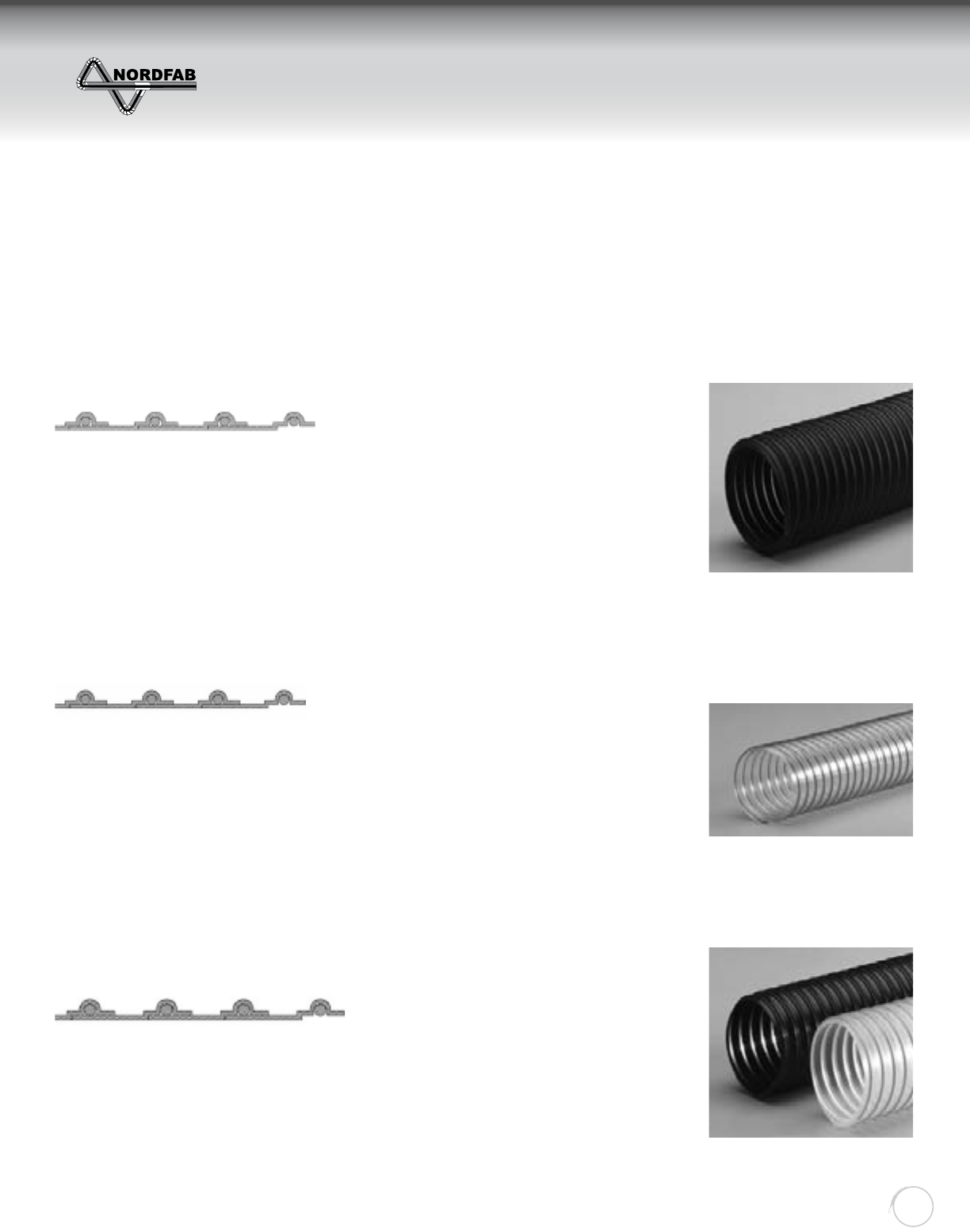
RUBBER FLEXIBLE HOSE
T-7
R-4
FLX-THANE® MD
• Wide Temperature Range • Superior Chemical Resistance • No Cement
• Versatility • Better Abrasion Resistance • Air Tight
• Better UV, Moisture and Weathering Resistance • Outstanding Flex Resistance
• Will Not Set to The Shape of the Box When Packed • Better Looking Product
Size Range (in) ..............................stock 2” to 24”
Standard Length (ft).................................. 25’, 50’
Standard Colors........................................... black
Temp Range (˚F) ...............................-60˚ to 275˚
Size Range (in) ..............................stock 2” to 24”
Standard Length (ft)........................... 10’, 25’, 50’
Standard Colors............................................clear
Temp Range (˚F) ................................ 20˚ to 160˚
Size Range (in) ..............................stock 2” to 24”
Standard Length (ft).................................. 25’, 50’
Standard Colors................................. black, clear
Temp Range (˚F) ...............................-60˚ to 225˚
• Medium weight thermoplastic rubber hose rein-
forced with a spring steel wire helix
• Good abrasion resistance
• Designed for applications with wide temperature
ranges
• Great moisture & UV resistance
• Excellent chemical resistance
• Smooth interior assures minimal friction loss &
effi cient air fl ow
• Wall Thickness = .030”
• Available in metric sizes, consult sales team on
pricing & minimums
• Medium weight PVC hose reinforced with a spring
steel wire helix
• Good for positive pressure applications
• Great compressibility
• Construction allows for value packaging by reduc-
ing the box size, reducing warehouse space &
shipping costs
• Ideal for dust and woodworking applications
• Good chemical & moisture resistance
• Manufactured with FDA acceptable materials
• Wall Thickness = .028”
• Medium weight polyurethane hose reinforced
with a bronze coated spring steel wire helix
• Good compressibility
• Great abrasion resistance & high tear strength
• Superior chemical resistance
• Excellent fl exibility
• Designed for applications with wide temperature
ranges
• Very good low temperature fl exibility
• Clear is manufactured with FDA acceptable
materials
• Available in metric sizes, consult sales team on
pricing & minimums
• Wall Thickness = .030”
ZZZGXFWLQJV\VWHPVFRP
RUBBER FLEXIBLE HOSE
Return to Contents
THE WORLD’S FASTEST DUCTING
Quick-Fit
Ducting
21
Inside Dia.
(Inches)
Appox.
Outside Dia.
(Inches)
Min. CLR
Bend Radius
Appox.
Weight Per
Foot (LBS)
Inside Dia.
(Inches)
Appox.
Outside Dia.
(Inches)
Min. CLR
Bend Radius
Appox.
Weight Per
Foot (LBS)
1 1/2 1 3/4 12.0 1.00 66 1/4 44.0 3.60
22 1/4 16.0 1.30 77 1/4 50.0 4.20
2 1/2 2 3/4 18.0 1.60 88 1/4 56.0 4.70
33 1/4 22.0 2.00 9 9 1/4 61.0 5.30
3 1/2 3 3/4 25.0 2.30 10 10 1/4 65.0 5.90
44 1/4 29.0 2.60 12 12 1/4 76.0 7.00
55 1/4 34.0 3.00 14 14 1/4 106.0 8.10
Inside Dia.
(Inches)
Min. CLR Bend
Radius
Appox. Weight
Per Foot (LBS)
Inside Dia.
(Inches)
Min. CLR Bend
Radius
Appox. Weight
Per Foot (LBS)
321 2.15 6 43 3.55
4 30 2.65 7 52 4.15
5 35 2.95 8 60 4.55
RIGID METAL FLEX HOSE
ULTRA FLEX METAL HOSE
Part # 3281-XX00
Part # 3283-XX00
MEDIUM-HEAVY GALVANIZED OR STAINLESS .017- .020 Strip Thickness
Manufactured in sizes ranging from 3” dia thru 8” dia of
stainless steel or galvanized. Some Applications would
include Air Handling, and Dust Collection.
Square Lock: ID Tolerance: +1/4 “ , - 0
Specifi cation: 3”-6” manufactured out of .019 material
7”-8” manufactured out of .024 material
RIGID AND ULTRA FLEX STEEL HOSE CONFIGURATIONS
Steel Flex Hose With Raw Ends (Standard) Steel Flex Hose With Q-F Ends (Custom)
Steel Flex Hose With Raw Pipe Ends (Custom)Steel Flex Hose With Flange Ends (Custom)
NOTE: When ordering steel hose, you have the option of having the hose fi tted with several different
style end fi ttings in any number of combinations. Raw hose is priced per foot, and sold only in 5 Ft.
increments on 7” and above. 6” and below can be sold in any length. Contact your sales rep for
pricing on specifi c lengths and end fi ttings.
ZZZGXFWLQJV\VWHPVFRP
RIGID & ULTRA FLEX METAL HOSE
Return to Contents
THE WORLD’S FASTEST DUCTING
Quick-Fit
Ducting
22
NFES AUTOMATIC BLAST GATE
“D”
Open Close
Cylinder Shaft
Sd11
1/4” poly
ethylene
tubing
Wiring Diagram
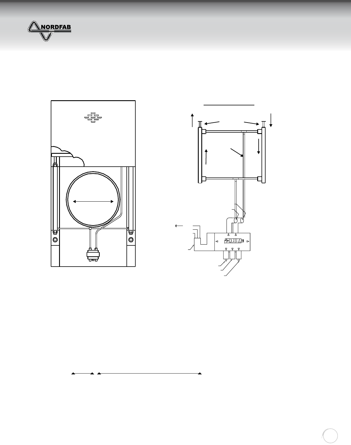
DESCRIPTION:
Automatic energy saving blast gates operated by double-acting compressed air cylinders. Cylinders are
controlled by electrically-connecting solenoid to machines or remote switch. Gates are constructed
with a special sealing device that reduces air loss and friction in operation.
APPLICATIONS:
Gates are used as energy-saving devices for industrial dust extraction where extraction is not always
needed on a constant basis or where manual control needs to be eliminated.
AVAILABILITY:
Material: GALVANIZED or STAINLESS STEEL
Sizes in inch: 4, 5, 6, 7, 8, 9, 10, 12, 14, 16, 18, 20, 22, 24, 26
Part numbers: 3245-XX00 (where XX is the diameter)
Standard Requirements: 120 Volt power source and 80 psi minimum air pressure horizontally mounted.
240, 24 and 12 volt AC. 24 and 12 volt DC models also available upon request.
One cylinder Two cylinder
42
12
3
1
5
14
Parker
EZ11NBB553A
145 PSIG (1000 kPa) max
Assembled in: USA
42
513
02/10
GREEN
WHITE
BLACK
Speed control for closing motion
Air Input (80 PSI min to 145 PSI Max)
Speed control for openning motion
Air output to rod side of cylinder
Air output to base side of cylinder
Single Solenoid 3 prong
connection provided
120V or 24V AC
White is neutral
Black is line voltage
24V DC
White is negative (-)
Black is positive (+)
ZZZGXFWLQJV\VWHPVFRP
NFES BLAST GATE (AUTO)
Return to Contents

THE WORLD’S FASTEST DUCTING
Quick-Fit
Ducting
23
NFES AUTOMATIC BLAST GATE
Temperature Rating:
120°F Solenoid (solenoid is on the outside of the housing and may handle higher duct temperatures
due to its location)
140°F Poly tube (poly tube is on the outside of the housing and may handle higher duct temperatures
due to its location)
158°F Gasket Spring (intermittent to 250°F)
165°F Cylinder
194°F 3M #540 Polyurethane Sealant (collar adhesive)
200°F UHMW Seal
250°F Optional Oil Mist - 3M 2084 Scotch Seal Metal Sealant
375°F Optional Epoxy Caulk - 3M DP460
500°F Galvanized Parts: with little or no breakdown of zinc - zinc melting point is 740°F
1100°F 304SS: bluing may occur at temperatures of 800°F and above
Material Specifi cations:
Galvanized Body: Galvanized is ASTM A527 with a G-90 rating
304SS Body: fi nish meets ASTM A240
314SS Body: Finish meets ASTM A240
UHMW Seal: Ultra High Molecular Weight
Gasket Spring: Poron® Cellular Urethane material
Cylinders: Crimped round body, 304 Stainless Steel tube only, Aluminum end caps, Non-repairable
Bore size is 1-1/16"
Ports are 1/8" NPT Standard
Piston rod diameter is 0.312"
Piston rod material: 304 Stainless steel only
Single acting end
Standard fl uid: Filtered air
Operating medium: Pneumatic, 250 PSI maximum (normal operating pressure is (80 PSI minimum)
Poly tube: 1/4" 0D x 0.040 wall poly tube, 120 PSI, Grade E5 LIP, Type 1
Solenoid: 0.8Cv fl ow characteristics
1/8" NPT ports
Solenoid is constant pressure
Structural Integrity:
Automatic, energy saving blast gates are operated by double acting compressed air cylinders
Cylinders are controlled by electrically-connected solenoid to machines or remote switch
Standard hookup is 120 volt AC
Optional: 24 volt AC (Must be stated on PO)
Optional: 24 volt DC (Must be stated on PO)
Single cylinder gates: 3" up to 8" diameters
Double cylinder gates: 9" and up diameters (second cylinder depicted by phantom lines)
ZZZGXFWLQJV\VWHPVFRP
NFES BLAST GATE (AUTO)
Return to Contents
THE WORLD’S FASTEST DUCTING
Quick-Fit
Ducting
24
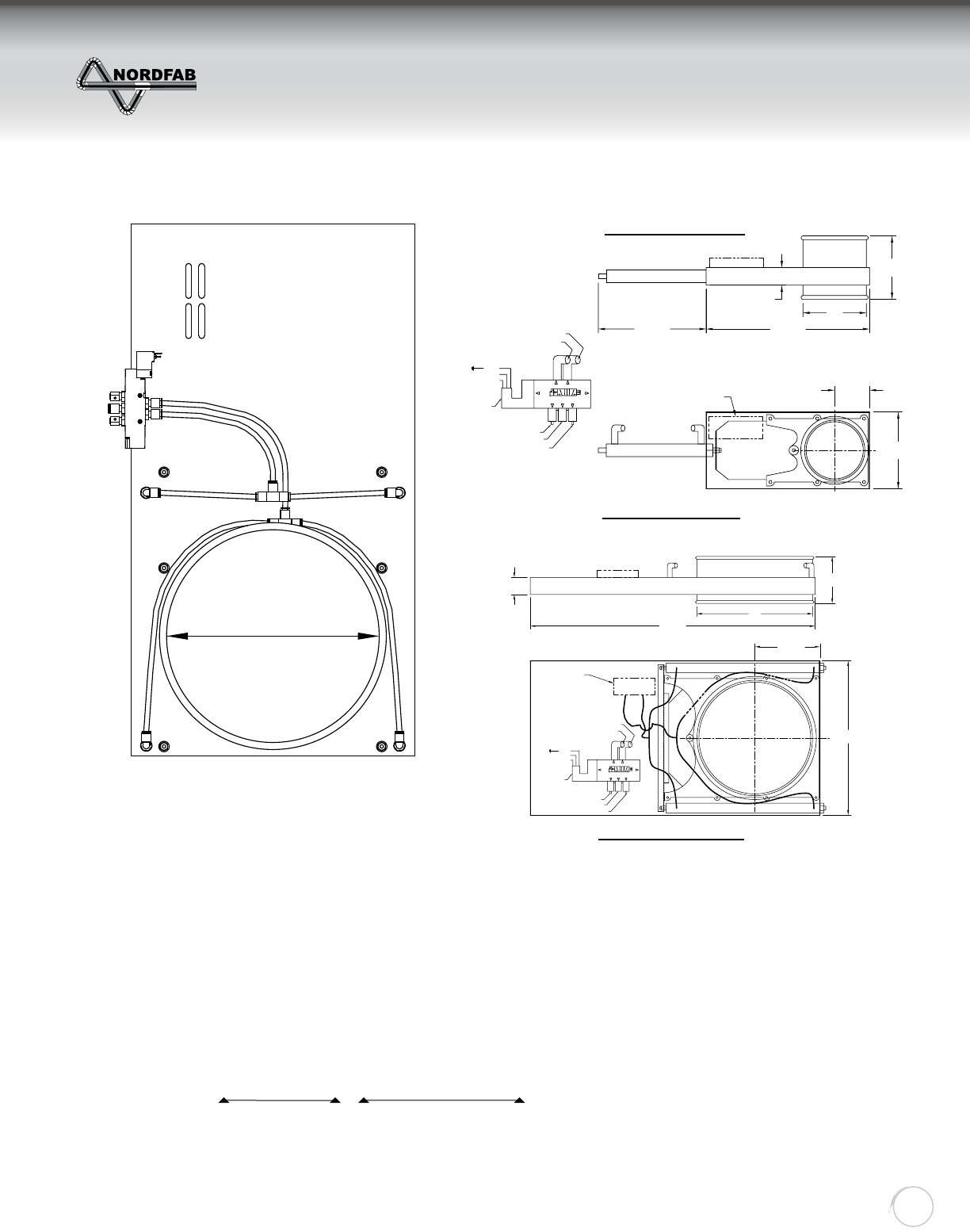
SD AUTOMATIC BLAST GATE
Wiring Diagram
Single Cylinder
Double Cylinder
DESCRIPTION:
Automatic standard duty blast gates operated by double-acting compressed air cylinders. The SD
version is a less expensive alternative to the NFES gate due to omission of the seals. Cylinders are
controlled by electrically-connecting solenoid to machines or remote switch.
APPLICATIONS:
Gates are used as energy-saving devices for industrial dust extraction where extraction is not needed on a
constant basis and where manual control needs to be eliminated.
AVAILABILITY:
Material: GALVANIZED
Sizes in inch: 4, 5, 6, 7, 8, 9, 10, 12, 14, 16, 18, 20, 22, 24
Part numbers: 3242-XX00 (where XX is the diameter)
Standard Requirements: 120 Volt power source and 80 psi minimum air pressure horizontally mounted.
240, 24 and 12 volt AC. 24 and 12 volt DC models also available upon request.
One cylinder Two cylinder
Ø
Category
Diameter
Material
Connection
Angle
taperDiameter
BranchDiameter
Branch2Diameter
Serial
Length
Ø
Dim "F"
Dim "A"
Dim "C"
Dim "B"
42
12
3
1
5
14
Parker
EZ11NBB553A
145 PSIG (1000 kPa) max
Assembled in: USA
42
513
02/10
GREEN
WHITE
BLACK
Speed control for closing motion
Air Input (80 PSI min to 145 PSI Max)
Speed control for openning motion
Air output to rod side of cylinder
Air output to base side of cylinder
Single Solenoid 3 prong
connection provided
120V or 24V AC
White is neutral
Black is line voltage
24V DC
White is negative (-)
Black is positive (+)
Cover removed for clarity
Dim "E"
Solenoid Dim "D"
Category
Diameter
Material
Connection
Angle
taperDiameter
BranchDiameter
Branch2Diameter
Serial
Length
Ø
Dim "F"
Dim "A"
Dim "C"
Dim "B"
Dim "D"
42
12
3
1
5
14
Parker
EZ11NBB553A
145 PSIG (1000 kPa) max
Assembled in: USA
42
513
02/10
GREEN
WHITE
BLACK
Speed control for closing motion
Air Input (80 PSI min to 145 PSI Max)
Speed control for openning motion
Air output to rod side of cylinder
Air output to base side of cylinder
Single Solenoid 3 prong
connection provided
120V or 24V AC
White is neutral
Black is line voltage
24V DC
White is negative (-)
Black is positive (+)
Cover removed for clarity
Solenoid
ZZZGXFWLQJV\VWHPVFRP
SD BLAST GATE (AUTO)
Return to Contents

THE WORLD’S FASTEST DUCTING
Quick-Fit
Ducting
25
SD AUTOMATIC BLAST GATE
Temperature Rating:
120°F Solenoid (solenoid is on the outside of the housing and may handle higher duct temperatures
due to its location)
140°F Poly tube (poly tube is on the outside of the housing and may handle higher duct temperatures
due to its location)
165°F Cylinder
194°F 3M #540 Polyurethane Sealant (collar adhesive)
250°F Optional Oil Mist - 3M 2084 Scotch Seal Metal Sealant
375°F Optional Epoxy Caulk - 3M DP460
500°F Galvanized Parts: 18ga or thicker - cannot be changed
1100°F 304SS: 18ga or thicker - cannot be changed - bluing may occur at temperatures of
800°F and above
Material Specifi cations:
Galvanized Body: Galvanized is ASTM A527 with a G-90 rating
304SS Body: Stainless is 304 with a fi nish meeting ASTM A240 - Keeps alum cast housing & replaces galv'd
parts with 304SS
314SS Body: Stainless is 316 with a fi nish meeting ASTM A240 - Keeps alum cast housing & replaces galv'd
parts with 316SS
Gasket Spring: Poron® Cellular Urethane material
Cylinders: Crimped round body, 304 Stainless Steel tube only, Aluminum end caps, Non-repairable
Bore size is 1-1/16"
Ports are 1/8" NPT Standard
Piston rod diameter is 0.312"
Piston rod material: 304 Stainless steel only
Single acting end
Standard fl uid: Filtered air
Operating medium: Pneumatic, 250 PSI maximum (normal operating pressure is (80 PSI minimum)
Poly tube: 1/4" 0D x 0.040 wall poly tube, 120 PSI, Grade E5 LIP, Type 1
Solenoid: 0.8Cv fl ow characteristics
1/8" NPT ports
Solenoid is constant pressure
Structural Integrity:
Automatic, energy saving blast gates are operated by double acting compressed air cylinders.
Cylinders are controlled by electrically-connected solenoid to machines or remote switch.
Standard hookup is 120 volt AC
Optional: 24 volt AC (Must be stated on PO)
Optional: 24 volt DC (Must be stated on PO)
Single cylinder gates: 3" up to 8" diameters
Double cylinder gates: 9" and up diameters (second cylinder depicted by phantom lines)
ZZZGXFWLQJV\VWHPVFRP
SD BLAST GATE (AUTO)
Return to Contents
THE WORLD’S FASTEST DUCTING
Quick-Fit
Ducting
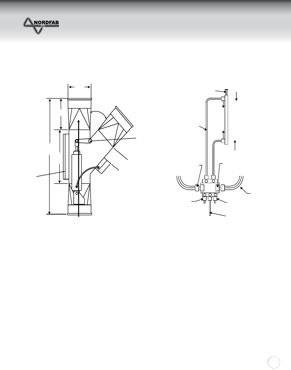
26
45° only
Shaft w/
Bearing
Bolted
Access
Plate
This length is 6” on Ø 16”
This length is 5” on Ø 22”
18 Gauge
“A”
“L”
“B”
Air Flow
Automatic
NOTE: 6.9va Coil
75 psi
Closing Motion
Tubing
Opening Motion
115 Volt AC
Provided
115 Volt
Solenoid
Open
Close
Sd25
Blk
W
G
Blk
W
G
Term
Block
1
2
3
4
5
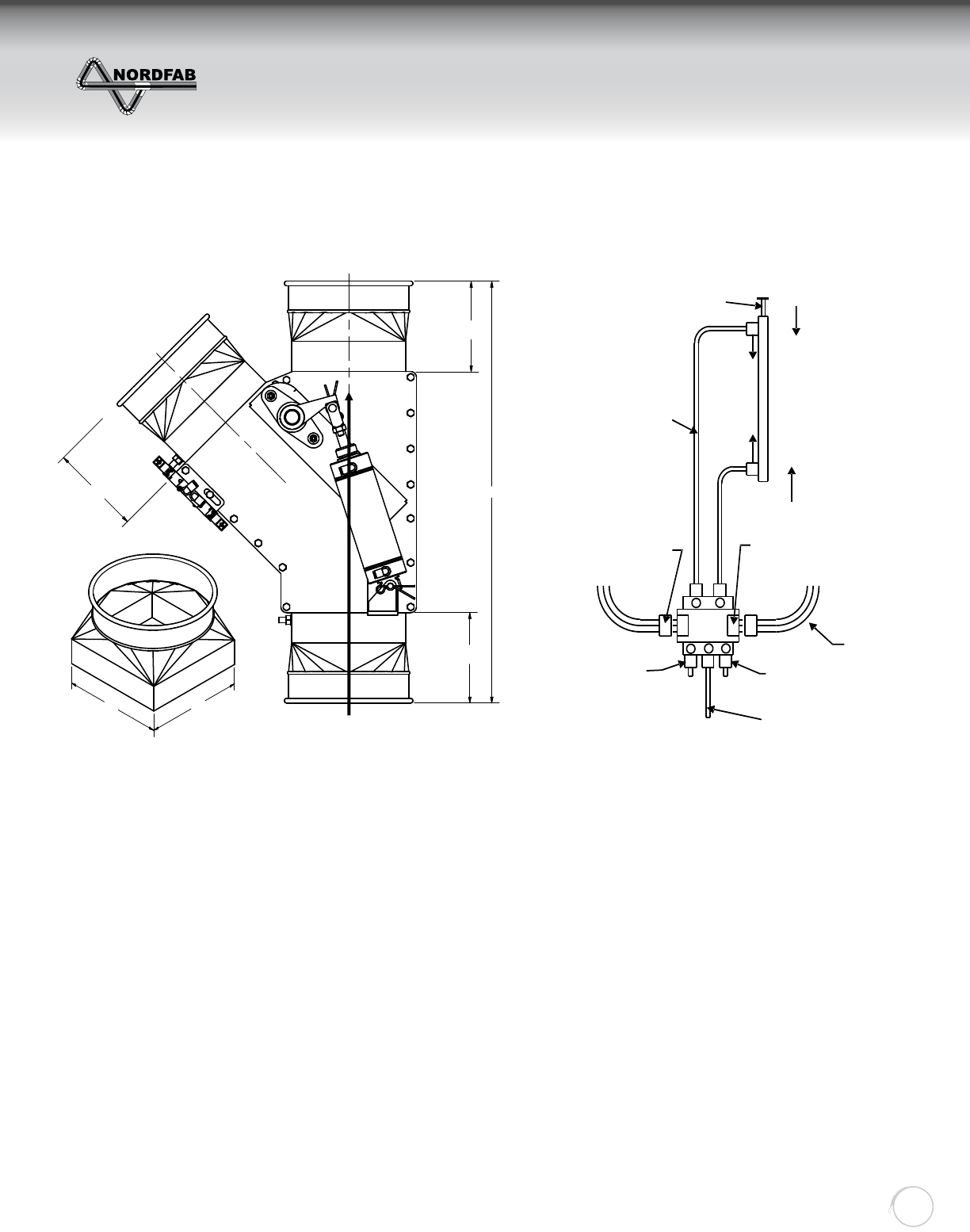
DESCRIPTION:
Highly effi cient, economical method of diverting fl ow of material or air. Designed with Q-F or fl anged,
manual, or air operated.
APPLICATIONS:
Diverter valves are used for diverting material or air to one of two possible directions at a time.
AVAILABILITY:
Material: BLACK METAL or STAINLESS STEEL 3/16” thick
Sizes in inch: 3, 4, 5, 6, 7, 8, 9, 10,11, 12, 13, 14, 15, 16, 17 ,18, 20, 22, 24
Larger sizes available upon request.
Please NOTE: 45 lateral angle only
Part numbers: 3235-XX00 for manual (where XX is the diameter)
3236-XX00 for automatic, PLUS read “Special”.
Standard Requirements: 120 Volt power source and 75 psi minimum air pressure.
240, 24 and 12 volt AC as well as 24 and 12 volt DC models are
available upon request.
DIVERTER VALVE
“D”
ZZZGXFWLQJV\VWHPVFRP
DIVERTER VALVE
Return to Contents
THE WORLD’S FASTEST DUCTING
Quick-Fit
Ducting
27
28.00”
6.00”
7.57”
7.72”
6.00”
6.00”
18 Gauge
Air Flow
NOTE: 6.9va Coil
75 psi
Closing Motion
Tubing
Opening Motion
115 Volt AC
Provided
115 Volt
Solenoid
Open
Close
Sd25
Blk
W
G
Blk
W
G
Term
Block
1
2
3
4
5
DESCRIPTION:
Highly effi cient, economical method of diverting fl ow of material or air. Designed with Q-F or fl anged,
manual, or air operated. Lighter weight than our heavy duty diverter valve.
APPLICATIONS:
Diverter valves are used for diverting material or air to one of two possible directions at a time.
AVAILABILITY:
Material: GALVANIZED or STAINLESS STEEL, 14ga construction
Sizes in inch: 3, 4, 5, 6, 7, 8, 9, 10,11, 12, 13
Larger sizes available upon request.
Please NOTE: 45 lateral angle only
Part numbers: 3233-XX00 for manual (where XX is the diameter)
3234-XX00 for automatic, PLUS read “Special”.
Standard Requirements: 120 Volt power source and 75 psi minimum air pressure.
240, 24 and 12 volt AC as well as 24 and 12 volt DC models are
available upon request.
SD DIVERTER VALVE
ZZZGXFWLQJV\VWHPVFRP
SD DIVERTER VALVE
Return to Contents
THE WORLD’S FASTEST DUCTING
Quick-Fit
Ducting
28
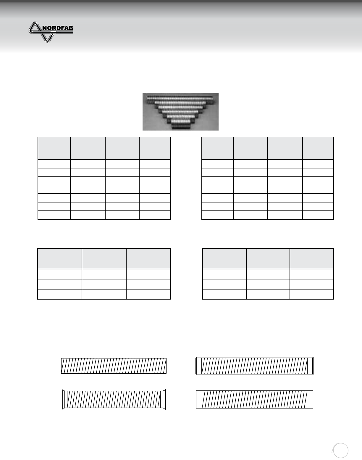
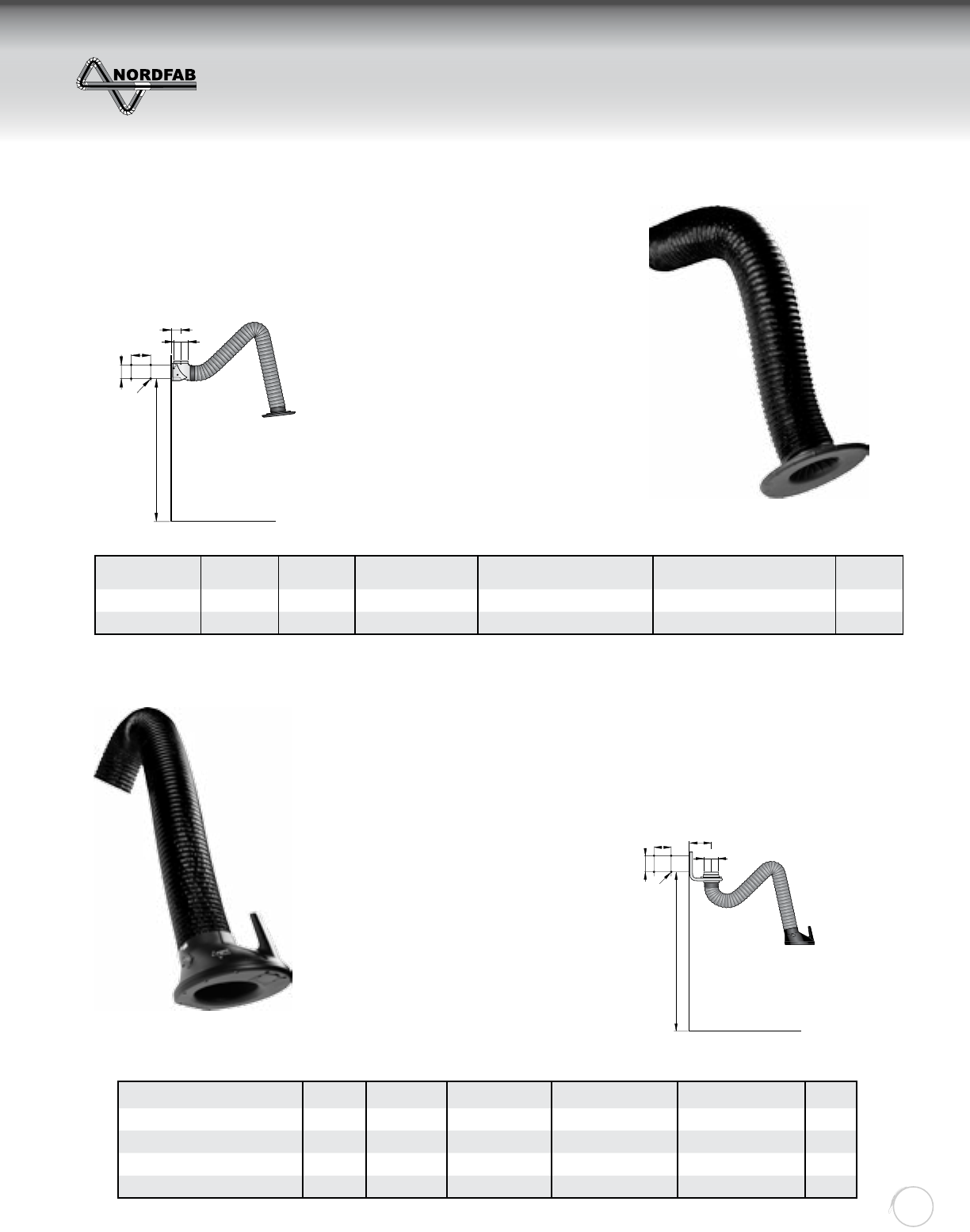
Description Working
range, ft
Air ow,
CFM Connection Ø, in Max. fume temperature, °F Noise level at hood, dB(A) Weight,
lbs
Standard arm, 6.5 ft 6.5 353-530 6158 67 24
Standard arm, 10 ft 10 353-530 6158 67 29
Description Working
range, ft Air ow, CFM Connection Ø, in Max. fume
temperature, °F
Noise level at hood,
dB(A)
Weight,
lbs
Original arm 6.5 ft 6.5 412-589 6158 63-75 24
Original arm 10 ft 10 412-589 6158 63-75 28
Original arm 13 ft, vertical 13 412-589 6158 63-75 35
Original arm 13 ft, horizontal 13 412-589 6158 63-75 35
3.7in
Ø6 in.
8 in.
5.7 in.
63 in - 91.5 in.
Ø .5in (x4)
Nordfab standard extraction arm is
specially designed for working
environments with fumes, vapors or
non-explosive dust, where the demands for
higher airfl ows and temperatures are
moderate. Typical workplaces can be
welding schools and different types of
applications in light production. The
applications can be welding, grinding, or
other industrial processes where an
easily positioned arm is required. The arm
is available in two lengths, 2 and 3 m, and
equipped with a high effi ciency extraction hood.
• The arm is exible in all directions and
simple to position
• Designed for wall mounting with
integra ted wall bracket/90° bend
• Can be rotated 180°
• Can be equipped with a damper placed
in the bend as an accessory
• The hood can be tilted in all directions
It is specially designed for working
environments with fumes, vapors
or non-explosive dust. Typical
workplaces are the metal fabrication
industry or other types of industries
where extraction is needed. The
applications can be welding, grinding,
or other industrial processes where
an easily positioned arm is required.
The product is equipped with a
damper in the hood as standard.
• A swivel allows the product to rotate 360°.
• The arm is exible in all directions and
simple to position.
• The product is equipped with a damper in
the hood as standard.
• The hood on all models can be tilted in
all directions.
Extraction arm Original
Ø .35in. (x4)
9in. 12in
Ø 6in. QF
7.8in.
~94in.
ZZZGXFWLQJV\VWHPVFRP
FUME ARMS
Return to Contents
THE WORLD’S FASTEST DUCTING
Quick-Fit
Ducting
29
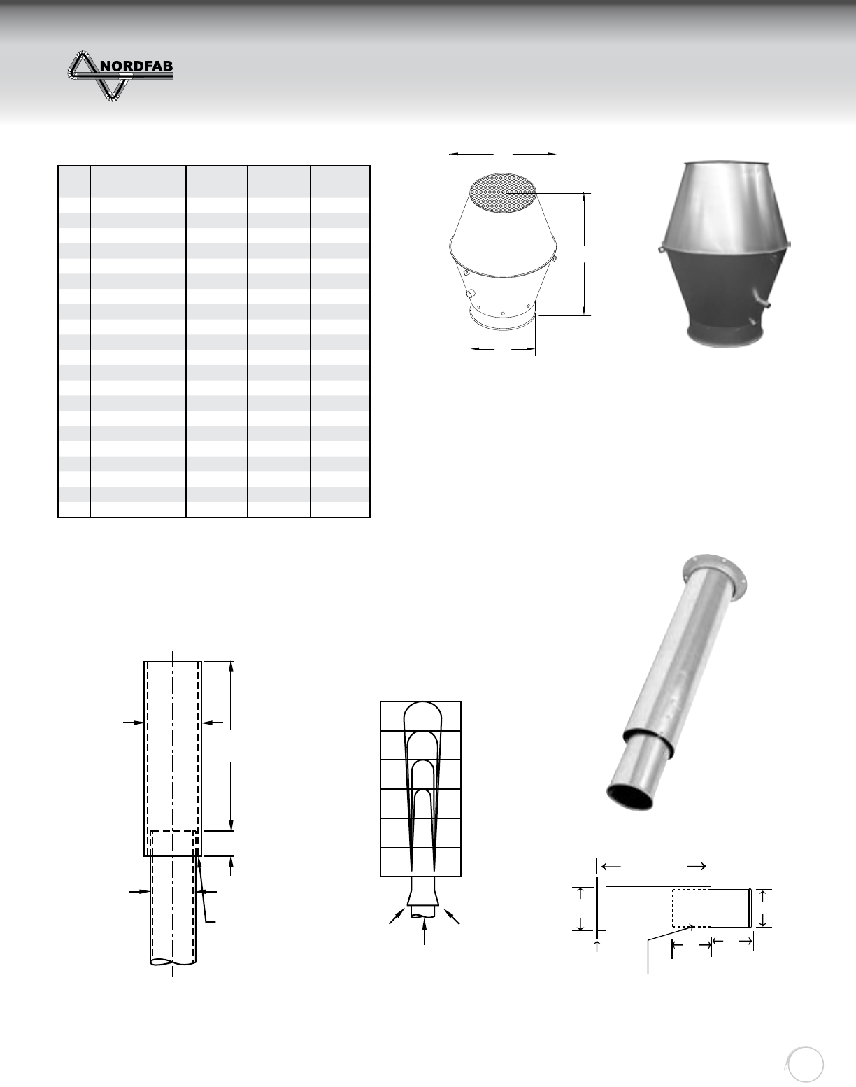
• Prevents rain from entering duct work
• Inner funnel piece allows rain to drain out of ductwork even when
system is not running
• Has three angle brackets for guide wire attachment
• Installs In Seconds with Standard Q-F Clamp
STACKHEAD
PREFERRED
Air proceeds upward
100
60
50 12
10
8
6
4
2
0
75
V
D+1”
4D6”
D
Bracket upper
stack to
discharge duct
VERTICAL DISCHARGE
NO LOSS
Ø
H
W
D + 1
4 x D +6 = L
Bracket Upper
Stack To Short
QF Duct Section
6
D
Angle Flange
for Guying
6
Angle Flange used for
securing with guyed wires
Recommended Industrial Ventilation Guidelines
QF Connection
Ø PART NO. ENDS W
(inches)
H
(inches)
6” 3258-0600 QF 10.12 14.40
8” 3258-0800 QF 13.25 18.40
10” 3258-1000 QF 16.50 22.40
12” 3258-1200 QF 20.00 27.00
13” 3258-1300 QF 21.50 30.00
14” 3258-1400 QF 23.12 32.80
15” 3258-1500 QF 24.50 34.00
16” 3258-1600 QF 26.50 36.40
17” 3258-1700 QF 27.70 38.00
18” 3258-1800 QF 29.50 40.00
20” 3258-2000 QF 32.50 44.40
22” 3258-2200 QF 35.40 47.50
24” 3258-2400 QF 38.60 51.50
26” 3258-2600 FLANGE 42.20 55.00
28” 3258-2800 FLANGE 45.20 59.00
30” 3258-3000 FLANGE 48.20 63.00
32” 3258-3200 FLANGE 51.20 67.00
34” 3258-3400 FLANGE 54.60 71.00
36” 3258-3600 FLANGE 58.20 74.70
38” 3258-3800 FLANGE 61.20 79.00
40” 3258-4000 FLANGE 64.20 83.00
JET CAP
NO-LOSS STACKHEAD
ZZZGXFWLQJV\VWHPVFRP
JET CAP
NO LOSS STACKHEAD
Return to Contents
THE WORLD’S FASTEST DUCTING
Quick-Fit
Ducting
30
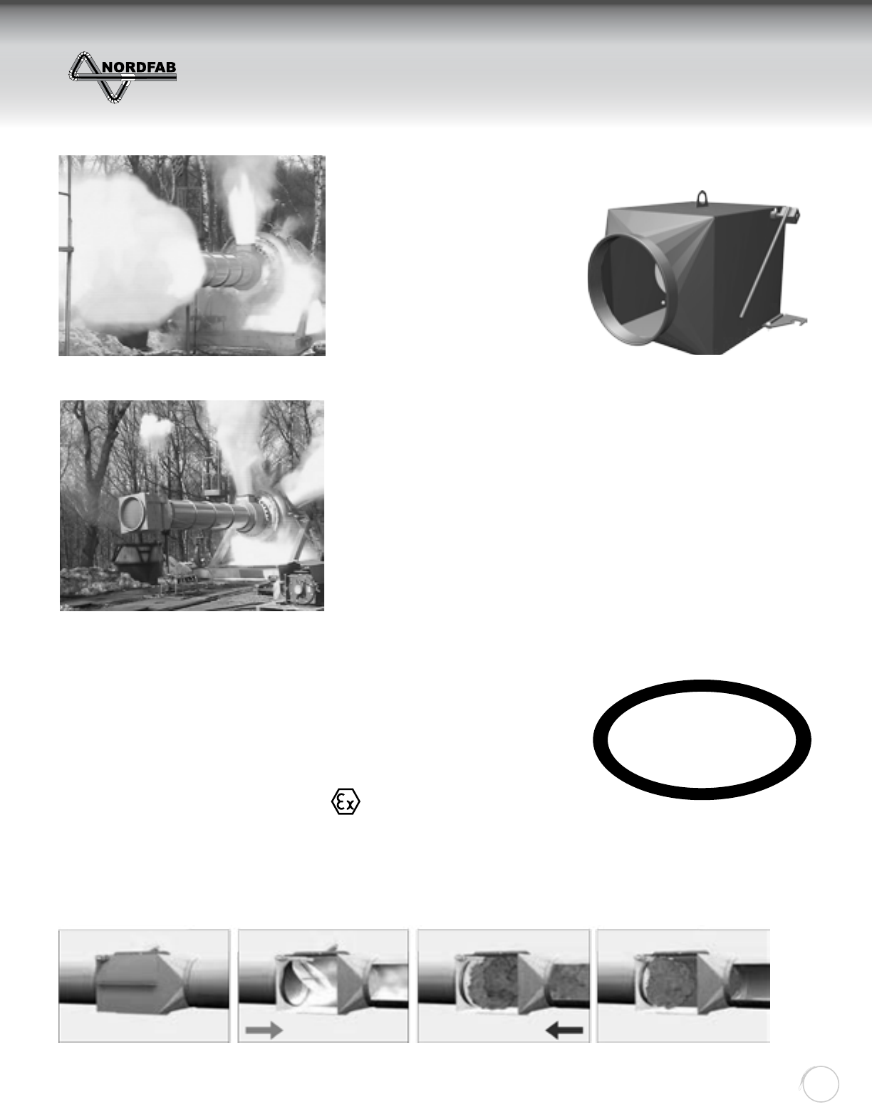
The Standards
Various NFPA standards require that a dust collection system
has a means of preventing the
transmission of energy from a fi re
or explosion to the building/work
area. Through extensive testing by
a third party testing facility, Nordfab
has developed the Explosion
Isolation Flap (EIF) type CARZ to
be installed upstream of the dust
collector.
How it works
Under normal operation the fl ap will open as the downstream air
moving device generates a fl ow in the ductwork. Should an explosion
happen in the downstream equipment - like a dust collector - a
pressure front develops in the ductwork within milliseconds and due to
the design of the EIF, the internal fl ap will be forced closed and seal off
the approaching fl ame front. This prevents glowing embers and
burning material from
entering into upstream equipment
and spaces.
The Design
The design of the EIF is critical as the fl ap must function in millisec-
onds and therefore must be of light construction but must be strong
enough to withstand the explosion pressure.
Many full scale tests were performed to arrive at the proper design and
assure proper function.
The Tests
Since the EIF is a safety device, Nordfab submitted the EIF to rigorous
testing by an accredited testing facility in accordance with 94/9/EC Directive.
Normal Operation
Without EIF
With EIF
Explosion/defl agration
Explosion Isolation Flap
Label: ATS.096 CARZ (0120-0500)
Label: ATS.098 CARZ (0560-01000)
The marking is based on product certifi cation by N.B. 1026.
The certifi cates allow max Pred 0.5 bar pressure resistance for sizes dia 22” (560mm) and smaller. Sizes 630mm-1000mm: 0.30 bar
CE1180 D St1
ATEX
Compliant
New design to be released in Q2
ZZZGXFWLQJV\VWHPVFRP
EXPLOSION ISOLATION FLAP
Return to Contents
THE WORLD’S FASTEST DUCTING
Quick-Fit
Ducting
31
Actual diameter Length (L) Body (B) Weight (lbs)
6” 19 1/4” 16 7/8” 29
7" 20 1/8“ 17 5/8“ 35
8" 21” 18 7/16” 42
10" 23” 20 7/16” 44
12" 25 1/2” 23” 60
14" 27” 24 3/8” 73
16" 29” 26 3/8” 93
18" 31” 28 3/8” 99
20” 33” 30 1/4” 108
22” 42 1/4“ 32“ 176
24” AF 44 7/16” 34 3/4” 229
28” AF 48” 38” 267
32” AF 51 5/8” 41 1/2” 309
36” AF 55 1/2” 45 3/8” 353
40” AF 59 1/2” 49 3/8” 397
Above dimension chart is for general information. Please consult
factory for dimensions based on the connection options
L
B
H
Application:
Dimensions:
Material Types: Dry Dusts (not designed for combustible
gas and vapors and hybrid mixtures of these substances.)
Kst Value of Dust < 200 Bar-M / Sec
NOT SUITABLE for greater than ST1 dust.
Transport Medium: Standard Air
Air Velocity In the Device: > than the minimum transport velocity of the conveyed dust.
Inspection door 22” and larger
KST verifi cation form required / Lead time is 25 working days after receipt.
EIF Designed for Max. Reduced Pressure Pred
Size Pred
CARZ 6”-22” 0.5 bar
CARZ 24”-40” AF 0.3 bar
Design conditions for ductwork and Air Material Separator
(Dust Collector)
Installation:
Min. Distance Between EIF and AMS
Size Min A Max A
CARZ 6”-20” 7’ 16’
CARZ 24” - 40” AF 16’ 28’
41
1
2
3
4
L1
2
L1 34
Fan
Vessel (fi lter, container, silo, ect.)
CARZ Explosion Isolation Flap
Normal process fl ow
Installation distance from vessel, where
explosion could occur
New design to be released in Q2
ZZZGXFWLQJV\VWHPVFRP
EXPLOSION ISOLATION FLAP
Return to Contents
THE WORLD’S FASTEST DUCTING
Quick-Fit
Ducting
32
INSTALLING TAP-IN OR CUT-IN
STEP 1:
Temporarily place the in-cut on the main trunk in the required position, and while holding in place,
place hand inside of branch and trace the interior of the branch on trunk line where it needs to be cut out.
STEP 2:
Take down in-cut and drill a starter hole in the main trunk along the line traced from the branch. Then
using metal snips or a reciprocating saw, cut out metal piece that has been traced. File or grind any
sharp edges to insure effi cient fl ow.
STEP 3:
Now use an industrial strength silicone sealant to seal between in-cut base and main trunk.
STEP 4:
Use small sheet metal screws or a banding type clamp material to secure in-cut to the main trunk line.
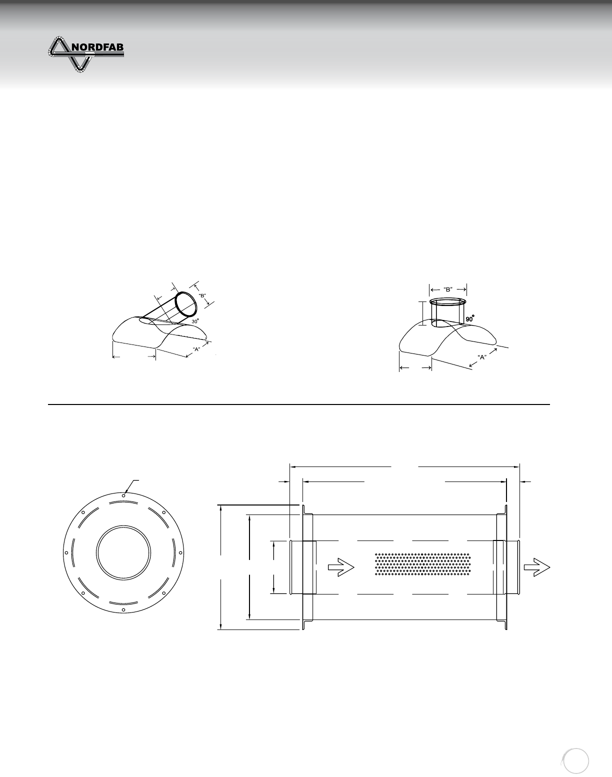
INLINE SILENCER
1. Silencer to be placed in process line down stream of fan or cyclone collector.
2. Silencer housing constructed of 18-20 gauge galvanized metal.
3. Silencer should be properly supported in process line.
4. NORDFAB reserves the right to modify the design of the silencer without notice.
5. Effi ciencies of Silencer have not been tested, nor are there any guarantees of sound level attenuation.
4”
Saddle length + width = 3”
all directions from Branch
Tube (B). Saddle length + width = 2”
all directions from Branch
Tube (B).
NOTE: Gauge based on “A”
A = Pipe Diameter
A = Pipe Diameter
5 1/2”
MIN
"A"
"OD"
Length
TANTAN
(Length - Tan - Tan) = Ref
Air FlowAir FlowPerforated Tube
Absorbent Material: 3-1/2" thick stranded Fiberglass
FLG
Ref
Absorbent Material: 3-1/2" thick stranded Fiberglass
Reference Angle
Flange hole pattern
ZZZGXFWLQJV\VWHPVFRP
INSTALLING A TAP-IN OR CUT-IN
Return to Contents
THE WORLD’S FASTEST DUCTING
Quick-Fit
Ducting
33
“A”
“OD”
PART NO.
ENDS
LENGTH
(C)
GAUGE
HOUSING
WEIGHT
(GALV)
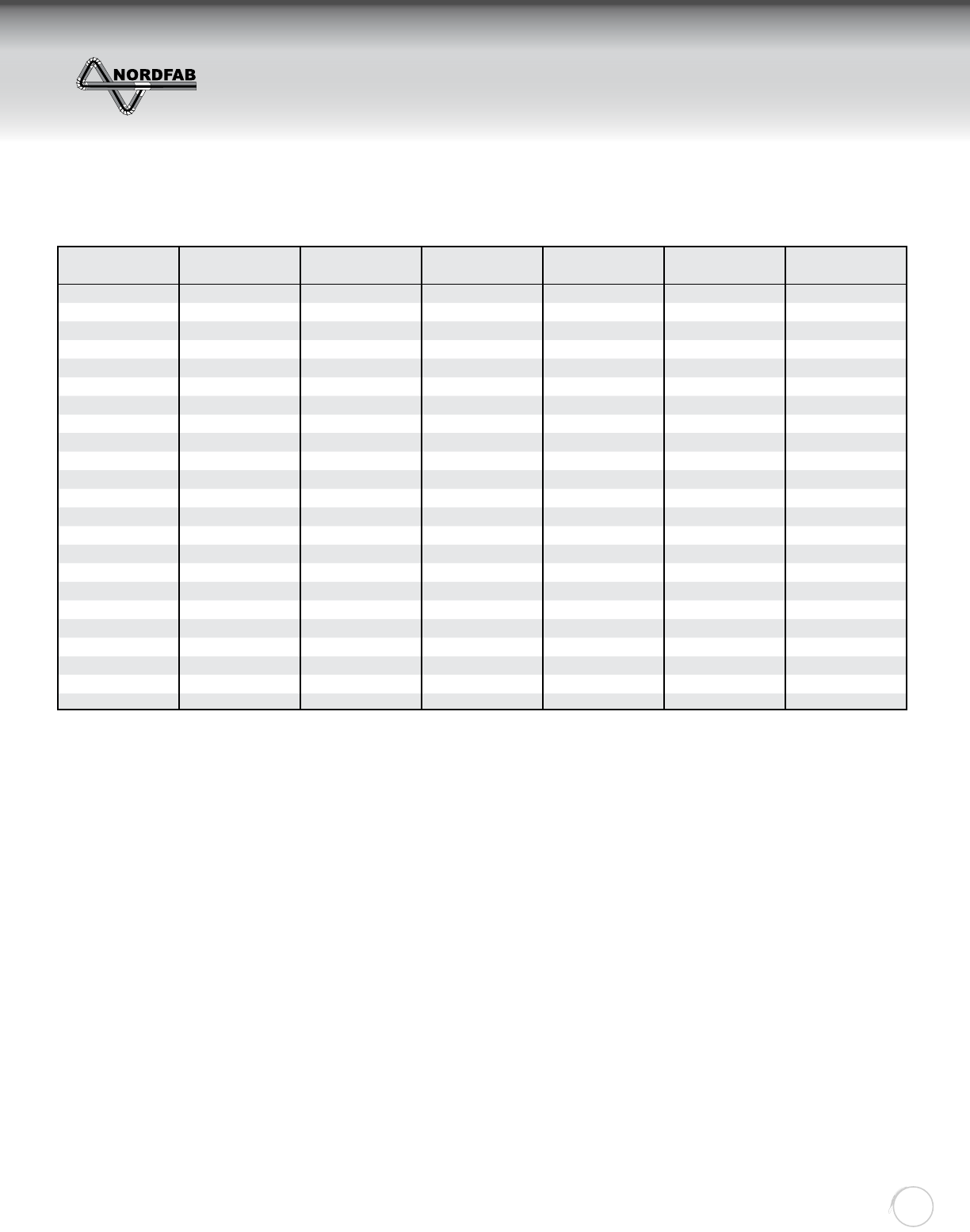
3” 12” 3106-0300 QF 28” 20 10.00
4” 12” 3106-0400 QF 28” 20 21.00
5” 13” 3106-0500 QF 28” 20 35.00
6” 14” 3106-0600 QF 30” 20 43.00
7” 15” 3106-0700 QF 30” 20 54.00
8” 16” 3106-0800 QF 35” 20 65.00
9” 17” 3106-0900 QF 40” 20 76.00
10” 18” 3106-1000 QF 48” 20 89.00
12” 20” 3106-1200 QF 54” 20 104.00
14” 22” 3106-1400 QF 60” 20 122.00
16” 24” 3106-1600 QF 64” 20 176.00
18” 26” 3106-1800 QF 68” 20 225.00
20” 28” 3106-2000 QF 72” 20 265.00
22” 30” 3106-2200 QF 76” 18 310.00
24” 32” 3106-2400 QF 80” 18 406.00
26” 34” 3106-2600 FLANGE 80” 18 546.00
28” 36” 3106-2800 FLANGE 80” 18 600.00
30” 38” 3106-3000 FLANGE 80” 18 678.00
32” 40” 3106-3200 FLANGE 80” 18 700.00
34” 42” 3106-3400 FLANGE 80” 18 770.00
36” 44” 3106-3600 FLANGE 80” 18 897.00
38” 46” 3106-3800 FLANGE 80” 18 974.00
40” 48” 3106-4000 FLANGE 80” 18 1,118.00
INLINE SILENCER (cont.)
Material Specifi cations:
Galvanized: ASTM A527 with a G-90 rating
Perforated Tube: ASTM A653
304SS: Finish meets ASTM A240
316SS: Finish meets ASTM A240
Absorbent Material:
3-1/2" thick fi berglass stranded bats
Structural Integrity:
Outer Tube: Longitudinal seam is laser welded to 15" diameter pipe and lock formed 16" and greater
Air fl ow directional:
Yes - arrows are painted on product for installation.
Special Notes:
Standard QF end can be changed to RawID, RawOD, No Fitting, Hose Adapter, Flat Flange, and Angle Flange.
ZZZGXFWLQJV\VWHPVFRP
INLINE SILENCER
Return to Contents
THE WORLD’S FASTEST DUCTING
Quick-Fit
Ducting
34
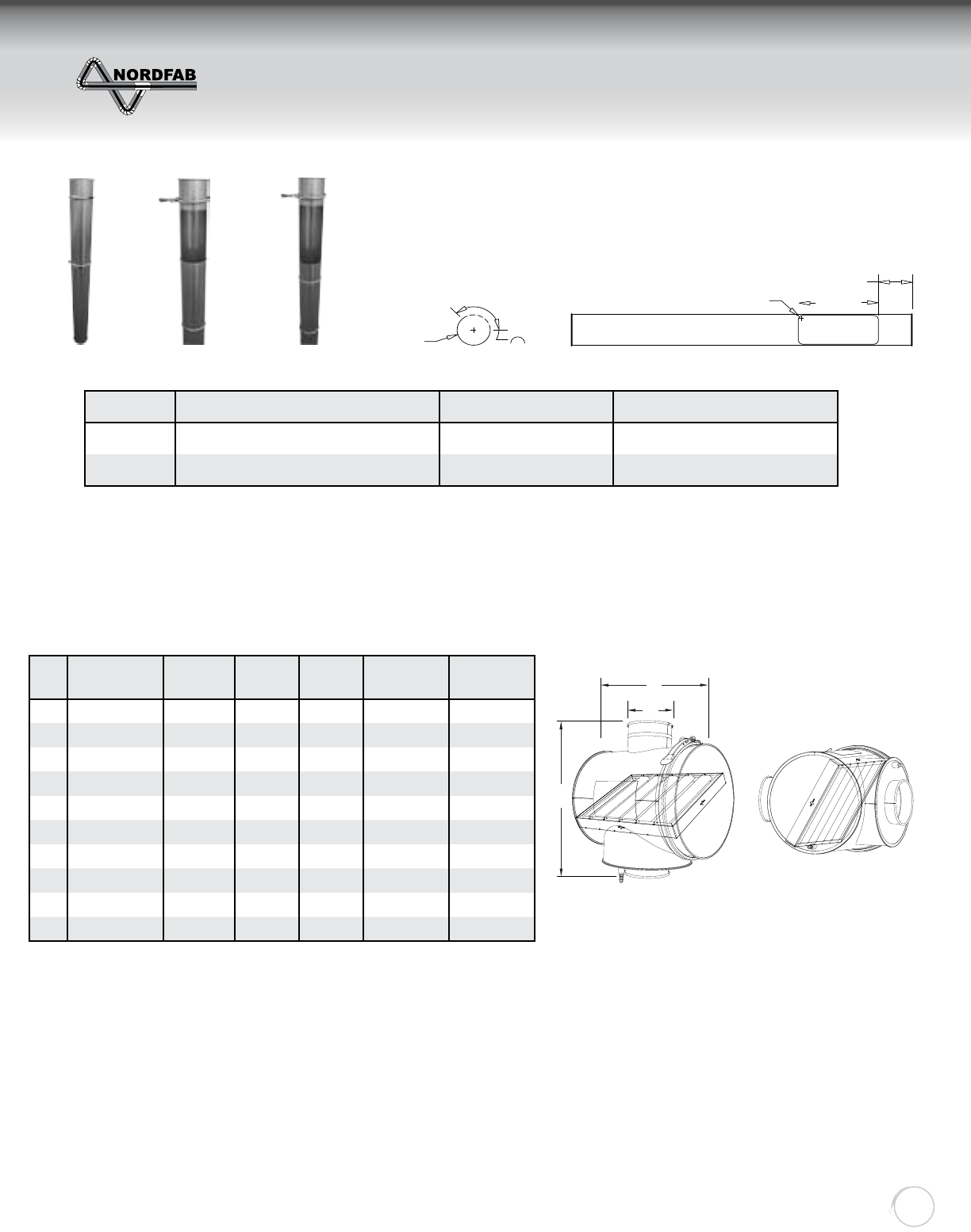
The SAP consists of a standard length of QF pipe with an access opening laser cut into it, a pre-mounted 18-
inch sleeve with two clamps and two rubber o-rings that covers and allows access.
SLIDING ACCESS PANEL
Closed position Partially Open Fully Open
ØPipe Length/Slide Length Access Hole Part Number
6”-8” 59.25 inches/18 Inches 7” x 14” 3103-XX00-100000
9”-24” 58.75 inches/18 Inches 7” x 14” 3103-XX00-100000
The 7” dimension of the
opening is measured around
the pipe as shown. Because of this
panels are not available under 6”.
7.000
ø6.000
14.000
6.000
R0.500
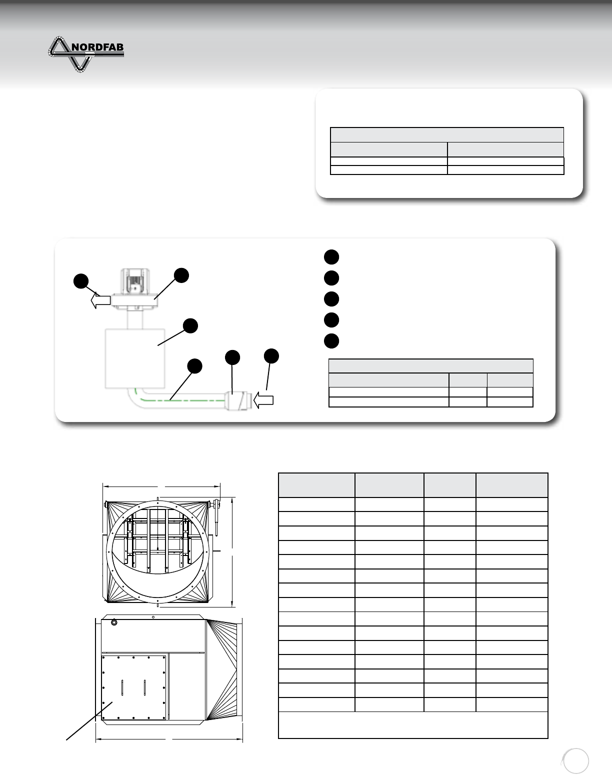
Ø PART NO. GAUGE (A)
INCH
(B)
INCH
BAFFLE
SIZE
WEIGHT
(GALV)
3” 3192-0300 22 14.00 18.00 10” x 14” 11.10
4” 3192-0400 22 14.00 18.00 10” x 14” 11.25
5” 3192-0500 22 14.00 18.00 10” x 14” 11.45
6” 3192-0600 22 14.00 18.00 10” x 14” 11.60
7” 3192-0700 22 20.00 24.00 16” x 20” 22.70
8” 3192-0800 22 20.00 24.00 16” x 20” 22.85
9” 3192-0900 22 20.00 24.00 16” x 20” 23.10
10” 3192-1000 22 20.00 24.00 16” x 20” 23.30
11” 3192-1100 22 20.00 28.00 20” x 20” 32.65
12” 3192-1200 22 20.00 28.00 20” x 20” 32.85
A
B
Ø
MIST RECYCLER
DESCRIPTION:
The Nordfab Mist Recycler (MR) can extend fi lter media life, reduce maintenance costs and decrease
issues caused by excessive fl uids in the system..
APPLICATIONS:
Mist recyclers are used to extract mist particles from the air to be recycled back to the machine. The baffl e acts
as a system prefi lter and mechanically extracts droplets and mist from the airstream. Liquid collected in the MR
drains into a sump and is returned to the machine via a drain port.
AVAILABILITY:
Material: GALVANIZED OR SS304
ZZZGXFWLQJV\VWHPVFRP
SLIDING ACCESS PANEL
MIST RECYCLER
Return to Contents
THE WORLD’S FASTEST DUCTING
Quick-Fit
Ducting
35
ITEM # LENGTH WEIGHT AVAILABILITY
3266-1500-022LBS 15’ 22 LBS IN STOCK
3266-1500-100LBS 15’ 100 LBS IN STOCK
3266-1500-200LBS 15’ 200 LBS IN STOCK
3266-1500-495LBS 15’ 495 LBS IN STOCK
3266-1500-715LBS 15’ 715 LBS IN STOCK
GRIPPLE HANG-FAST
Gripple Hang-Fast is a complete solution for hanging mechanical and electrical services. It comes as a
ready-to-use suspension kit, with load ratings from 22lbs to 715lbs. The comprehensive range ensures
that installation times are minimized and high productivity is achieved on site.
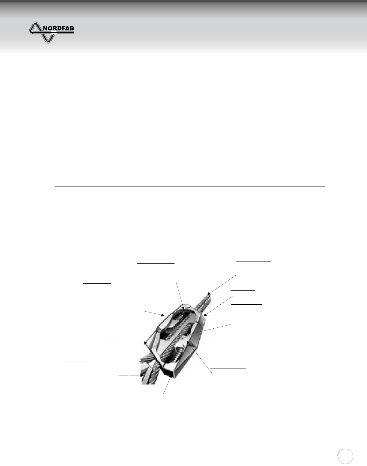
The principal element of all Gripple Hang-Fast assemblies is the Gripple Hang-Fast Grip, which is not
only used to terminate the rope but is also the means by which object height can be adjusted.
Gripple Hang-Fast
Sizes & Working Load Limits ...
Zinc Housing
By using zinc, the product is
able to combine major
anti-corrosion properties
with strength and consistent
manufacturing quality.
Stainless Springs
The springs, one in each channel,
are manufactured in type 302
S26 Stainless steel
Wire Rope Entry
The wire rope is pushed into
the Gripple in the direction
of the white arrows
Setting Key
Entry hole
Serrated Teeth
Each wedge makes
contact with the rope
using serrated teeth.
These bite onto the
wire rope and spread
the load across the
length of the wedge
maximizing grip while
maintaining wire rope
strength.
Locking Wedges
Oil impregnated steel locking
wedges, one in each channel,
allow entry of the rope in one
direction as the spring is
compressed, but creates
a vice-like grip as the load
is applied in the opposite direction.
End-Cap
The plastic end-cap, which is
made from a UV stabilized
homopolymer polypropylene
simply holds the spring in place.
Anchor Point
As the wire rope passes
through one channel, it is
wrapped around a suitable
anchor point before being
pushed through the second
channel.
Setting Key
Entry Hole
ZZZGXFWLQJV\VWHPVFRP
GRIPPLE HANGER SYSTEM
Return to Contents

THE WORLD’S FASTEST DUCTING
Quick-Fit
Ducting
36
QTY “A” “B” “C” “D1” “D” “E”
TYPICAL WALL MOUNTING BRACE
“D1” Hanger Size
“D” Pipe Size
“A”
Weld
Weld 1.5” x 3/16”
Flat Bar
“C”
Weld
4”
“E”
“E”
4”
“B”
Typ. Material 1- 1/2”x 3/16”
Angle Bar
1/2” Dia Hole Typ. 3-Places
Weld
ZZZGXFWLQJV\VWHPVFRP
WALL MOUNTING BRACE
Return to Contents
THE WORLD’S FASTEST DUCTING
Quick-Fit
Ducting
37
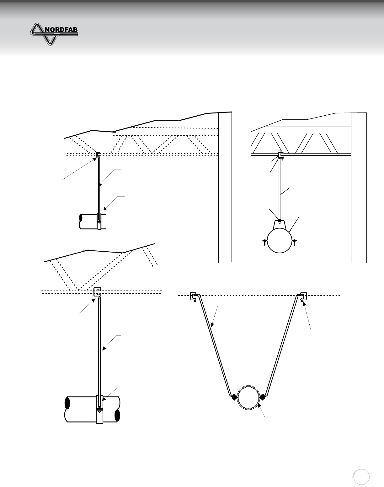
TYPICAL CEILING HANGING METHOD
Beam Clamp
½” Conduit
Pipe Hanger
Beam Clamp
½”Conduit
Pipe Hanger
½”Conduit
Pipe Hanger
Beam Clamp
NOTE: Refer to your local codes when choosing how to support QF ducting.
(Check local building codes, Nordfab is not responsible for building code violations)
Gripple hangers are also a typical ceiling hanging method.
HJ Pipe Hanger
Beam Clamp
Nut
Nut(2x)
3/8 - 16 Threaded Rod
ZZZGXFWLQJV\VWHPVFRP
TYPICAL CEILING HANGING METHOD
Return to Contents
THE WORLD’S FASTEST DUCTING
Quick-Fit
Ducting
38
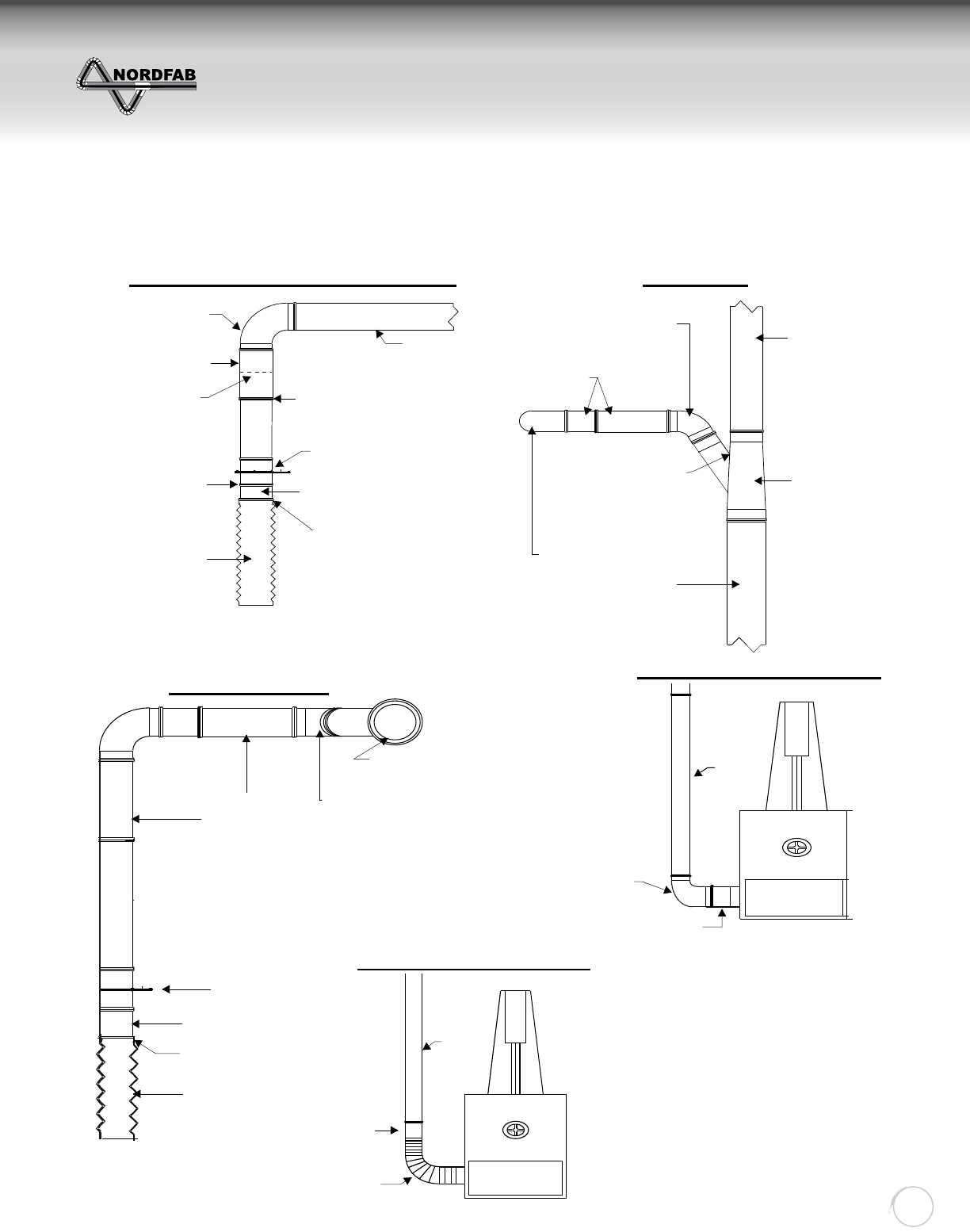
90 Deg Elbow
Adjustable Nipple
Cut End of Pipe
Place in the
Direction of Airfl ow
Clamp the Hose Adapter
To Pipe, Slide Flexhose
Over Hose Adapter and
Clamp with Hose
(Wormgear) Clamp
Flex Hose
to Machine
Pipe from Branch
Nipple Fits Over Cut Pipe.
Place O-Ring On Pipe
And Clamp Nipples Rolled
End to Black O-Ring.
Blast Gate (Manual Damper)
Hose Clamp
(Wormgear Clamp)
Hose Adapter
5.5” in Length
Cut Pipe and
Adjustable Nipple
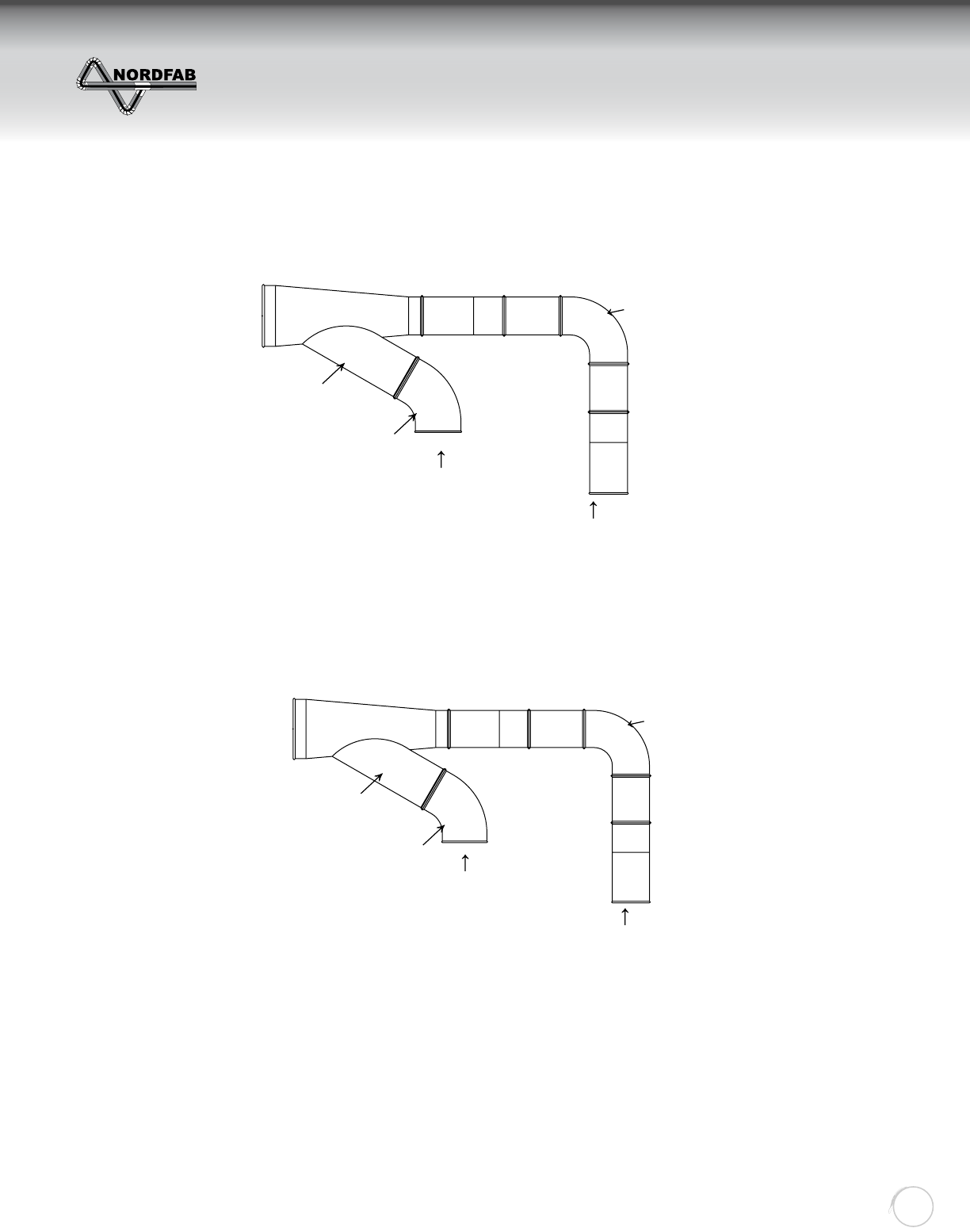
4” 60 Deg Elbow Completes 90
Deg Turn To Machine Drop 5” Dia Pipe
6-4-5 Standard Branch
A=6, B=4, C=5
6” Dia Pipe
4” 90 Deg Elbow Down
To Machine Connection
Standard Branches
Come Off At a 30
Deg Angle.
Cut Pipe and
Adjustable Nipple
4” 60 Deg Elbow
6-4 -5 Branch
4” Blast Gate
(Manual Damper)
4” Hose Adapter
4” Hose Clamp
(Wormgear Clamp)
4” Flex Hose
Machine Adapter
(Q-F to Raw)
90 Deg. Elbow
Pipe
Band Saw
A
BC
A
B
Band Saw
Hose Adapter
(For Rubber Hose Only)
Steel or Rubber
Flex Duct To Machine
Pipe
TYPICAL DROP FOR DRY SYSTEMS PLAN VIEW
ELEVATION VIEW HARD DUCT TO MACHINE
FLEX HOSE TO MACHINE
TYPICAL DRY SYSTEM INSTALLATION
ZZZGXFWLQJV\VWHPVFRP
DRY SYSTEM INSTALLATION
Return to Contents
THE WORLD’S FASTEST DUCTING
Quick-Fit
Ducting
39
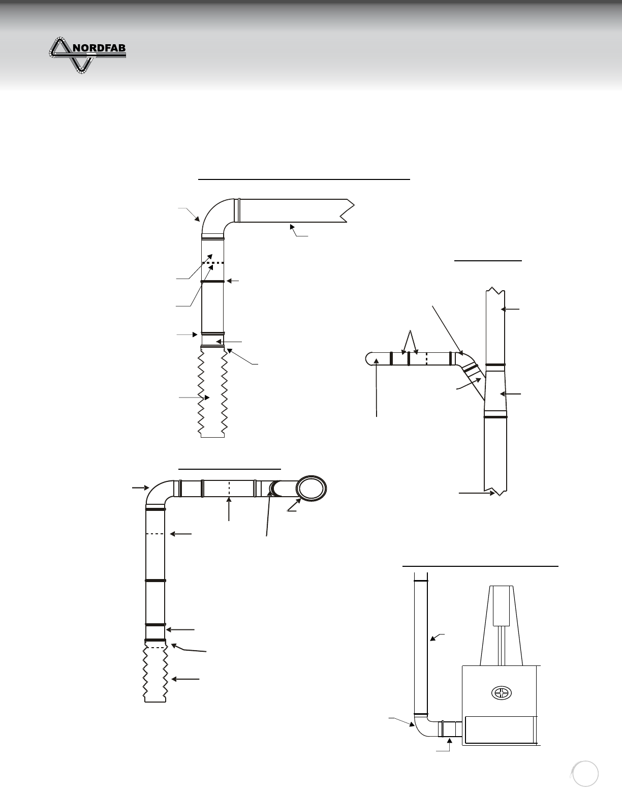
Band Saw
90 Deg. Elbow
Epoxy Caulked
**Cut End of Pipe. Place
With the Direction of
Airfl ow. see pg 41
Adjustable
Nipple
Clamp the Hose Adapter
to Pipe. Slide Flexhose
Over Hose Adapter and
Clamp with Hose Clamp
(Wormgear Clamp)
Flex Hose
to Machine
Hose Clamp
(Wormgear Clamp)
Hose Adapter
5.5” in Length
Nipple Fits Over Cut Pipe.
Place O-Ring on Pipe and
Clamp Nipples Rolled End
To Oil Mist O-Ring.
Pipe From
Branch
4” 60 Deg. Epoxy Completes
90 Deg. Turn to Machine Drop.
Epoxy Caulked
Cut Pipe and
Adjustable Nipple
Standard Branches
Come Off at a
30 Deg. Angle.
4” 90 Deg. Elbow Down
to Machine Connection
5” Dia. Pipe
6-4-5
Branch.
A=6, B=4, C=5
Epoxy Caulked
6” Dia.
Pipe
NOTE:
**Use Q-F clamps
& Leak-Free gasketing
A
BC
A
B
4” 90 Deg.Elbow
Fully Welded
Cut Pipe and
Adjustable Nipple
with Oil Mist O-ring 4” 60 Deg.Elbow
Epoxy Caulked
6-4-5 Branch
Epoxy Caulked
4” Hose
Adapter
4” Hose Clamp
(Wormgear Clamp)
4” Flexhose
NOTE:
Blast gates are not commonly used for
wet systems. Use butterfl y valves for fl ow control.
***Use Q-F clamps & Leak-Free gasketing
90 Deg.
Elbow
Machine Adapter
(Q-F to Raw)
Pipe
TYPICAL DROP FOR WET SYSTEMS
PLAN VIEW
ELEVATION VIEW
HARD DUCT TO MACHINE
TYPICAL WET SYSTEM INSTALLATION
ZZZGXFWLQJV\VWHPVFRP
WET SYSTEM INSTALLATION
Return to Contents
THE WORLD’S FASTEST DUCTING
Quick-Fit
Ducting
40
Quantity Dia. Of Pipe # of Sets
--------
--------
Can be ordered
with or without
collar.
WALL FLASHING
Wall
Outside Flashing
Inside Flashing
Made in Two Halves
Outside Dia. + 8”
Inside Dia.
Elevation View
3/4” (LIP)
4 1/8”
3” Overlap
6”
Roof Line
Roof Flashing Attached
To Roof
3-1/4” Dia. Holes
In Each PC.
12”
SKIRTS
Counter Flashing Attached
To Duct-work
DIA. Pipe
See Chart
Top View
Roof Flashing Made
In 2 Halves, Caulked
And Riveted.
O.D.
DESCRIPTION:
Provides weather protection for Wall
penetration. Ordering one fl ashing
provides you with both 1 inside and
1 outside fl ashing (4 halves).
AVAILABILITY:
Material: GALVANIZED or STAINLESS STEEL
Sizes in inch: 4, 5, 6, 7, 8, 9, 10, 11, 12, 13, 14, 15, 16, 17,
18, 20, 22, 24, 26, 28, 30, 32, 34, 36, 38, 40
DESCRIPTION:
Provides weather protection for roof
penetration.
Roof Flashing
Roof Skirt
AVAILABILITY:
Material: GALVANIZED or STAINLESS STEEL
Sizes in inch: 4, 5, 6, 7, 8, 9, 10, 11, 12, 13, 14, 15, 16, 17,
18, 20, 22, 24, 26, 28, 30, 32, 34, 36, 38, 40
NOTE: Please specify Wall or Roof Flashing
ROOF FLASHING & SKIRT (SOLD SEPARATELY)
ZZZGXFWLQJV\VWHPVFRP
FLASHING (WALL, ROOF)
Return to Contents
THE WORLD’S FASTEST DUCTING
Quick-Fit
Ducting
41
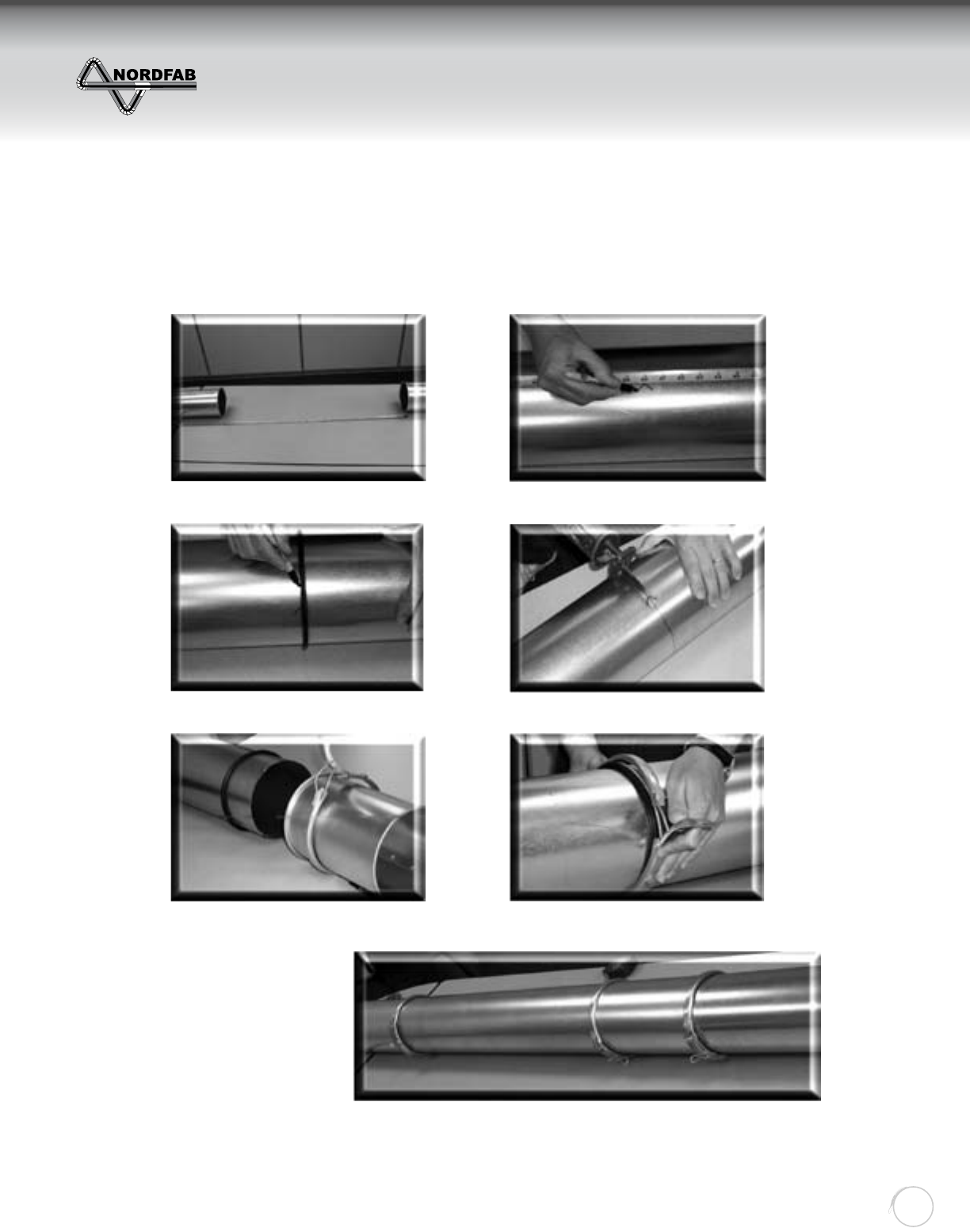
INSTRUCTIONS FOR USING THE “QF” ADJUSTABLE NIPPLE
WITH RUBBER O-RING FOR DRY SYSTEM
Each QF pipe section is 5 ft. in length. To accommodate an existing span, an adjustable nipple is used to shorten.
Measure distance to be spanned.
Use O-ring provided and mark for cut.
Cut piece of pipe put O-ring on
cut pipe, slide nipple over
Mark distance to be spanned less 4”.
Drill access hole then cut with saw
Snap clamp over O-ring and one
end of nipple.
FINISHED CONNECTION
USING THE ADJUSTABLE
NIPPLE ASSEMBLY.
NOTE: KEEP CUT PIPE IN THE DIRECTION AS THE AIR FLOW.
STEP 1 STEP 2
STEP 4
STEP 6
STEP 3
STEP 5
ZZZGXFWLQJV\VWHPVFRP
ADJUSTABLE NIPPLE ASSEMBLY
FOR DRY APPLICATION
Return to Contents
THE WORLD’S FASTEST DUCTING
Quick-Fit
Ducting
42
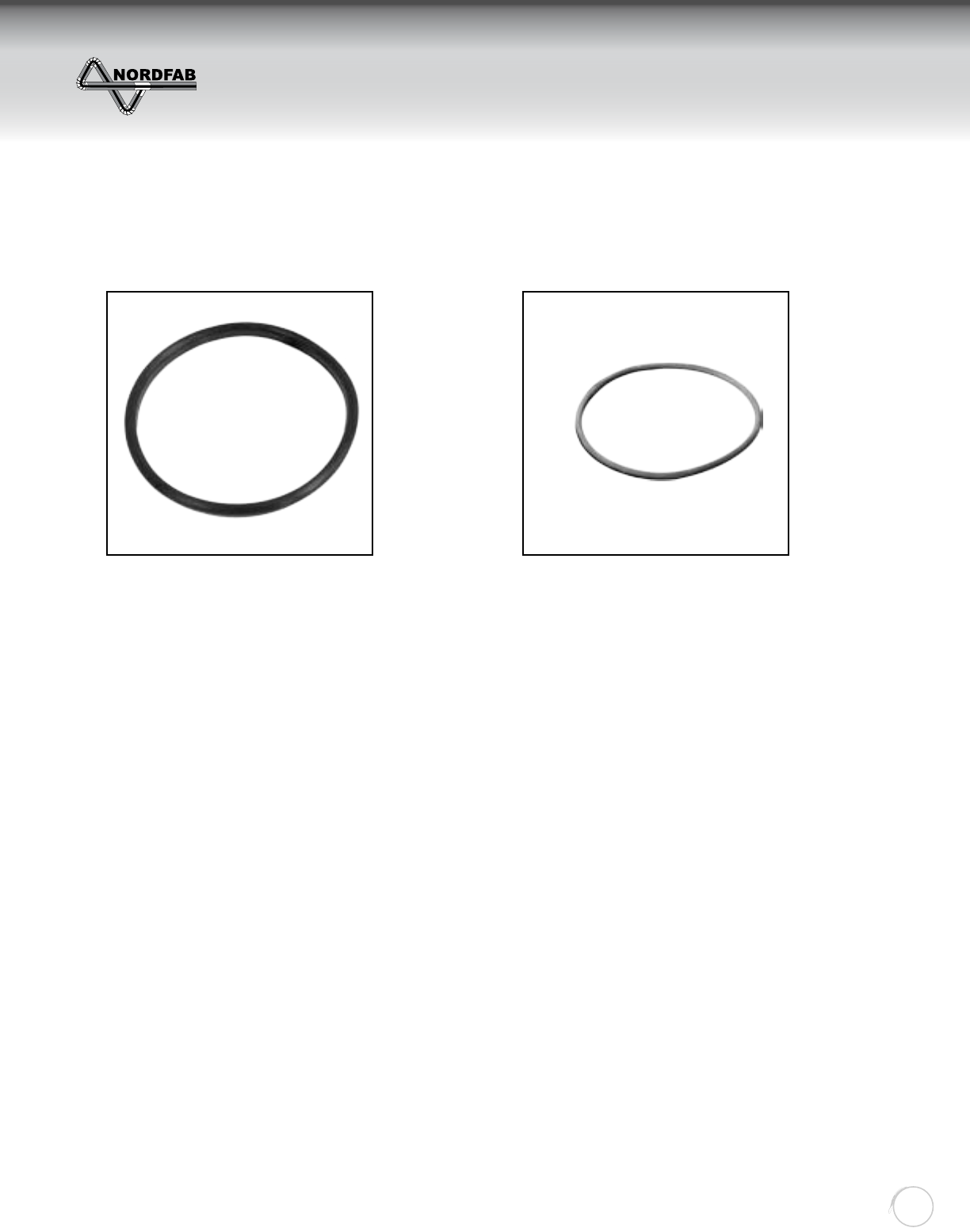
NORDFAB’S LEAK-FREE GASKET AND O-RING
LEAK-FREE GASKET LEAK-FREE O-RING
• General purpose oil resistant polymer
• Preforms well with many oil, water and
hydraulic fl uid
• Good tear resistance
• Should not be used with solvents such as
acetone, and MEK, ozone, chlorinated
hydrocarbons and nitro hydrocarbons
• Fabricated with conductive material
Classifi cation:
1. ASTM D-2000 M2BG510 A24 B34 EO14
EO34 EF11 EF21
Temperature Range:
Low Temperature Range: -30° F to +225° F
Intermittent: +280° F
• Resists corrosion from weather
• Preforms well with many oils and chemicals
• Resistant to wide temperature range
• Tough
• Can’t damage by fl exing and twisting
• Grey or black with grey mark
Classifi cation:
1. ASTM D-1056-68.......................SBE43
2. ASTM D-1056-85, 91, 98................2B3
Temperature Range:
Low Temperature Range: -30° F to 225° F
Intermittent +280° F
NOTE: These materials work in conjunction with Nordfab’s standard O-Ring. It does not replace it.
See Installation Guidelines enclosed.
NORDFAB can’t guarantee that these materials will work on every application. Please see above
for manufacturer’s classifi cations on these materials. When ordering for mist application specify
epoxy caulk.
ZZZGXFWLQJV\VWHPVFRP
WET APPLICATION MATERIALS
Return to Contents
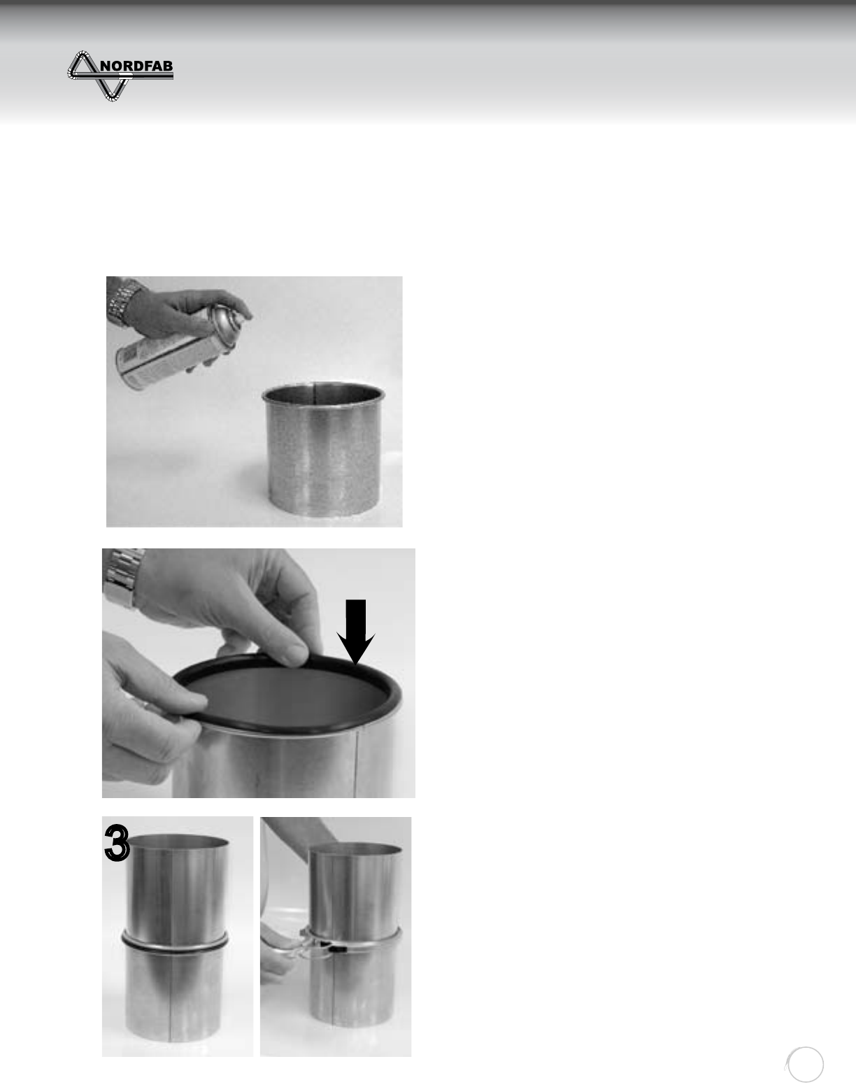
THE WORLD’S FASTEST DUCTING
Quick-Fit
Ducting
43
2) Carefully place the gasket along the rolled edge
of the part, being careful to avoid kinks or voids.
Only one gasket is needed per joint.
3) Join the gasketed end of the pipe to a
non-gasketed end of the next part in the ducting
run using a standard Q-F clamp. The oil-mist
gasket, in addition to the gasket inside the Q-F
clamp, provides dual protection against leakage.
2Airfl ow
1) Wipe rolled edge with clean cloth. Then apply a
high tack gasket adhesive per the manufacturer’s
instructions. High tack gasket adhesives can be
purchased locally at industrial or automotive
suppliers in either aerosol spray or brushable
formulations.
1
3
LEAK-FREE GASKET INSTALLATION
The molded Nitrile gaskets slip easily onto one end of the duct and are connected with a standard Q-F clamp to form
a tight and re-useable seal. Note the direction of the airfl ow when installing the duct.
ZZZGXFWLQJV\VWHPVFRP
INSTALLATION OF LEAK-FREE GASKET
Return to Contents
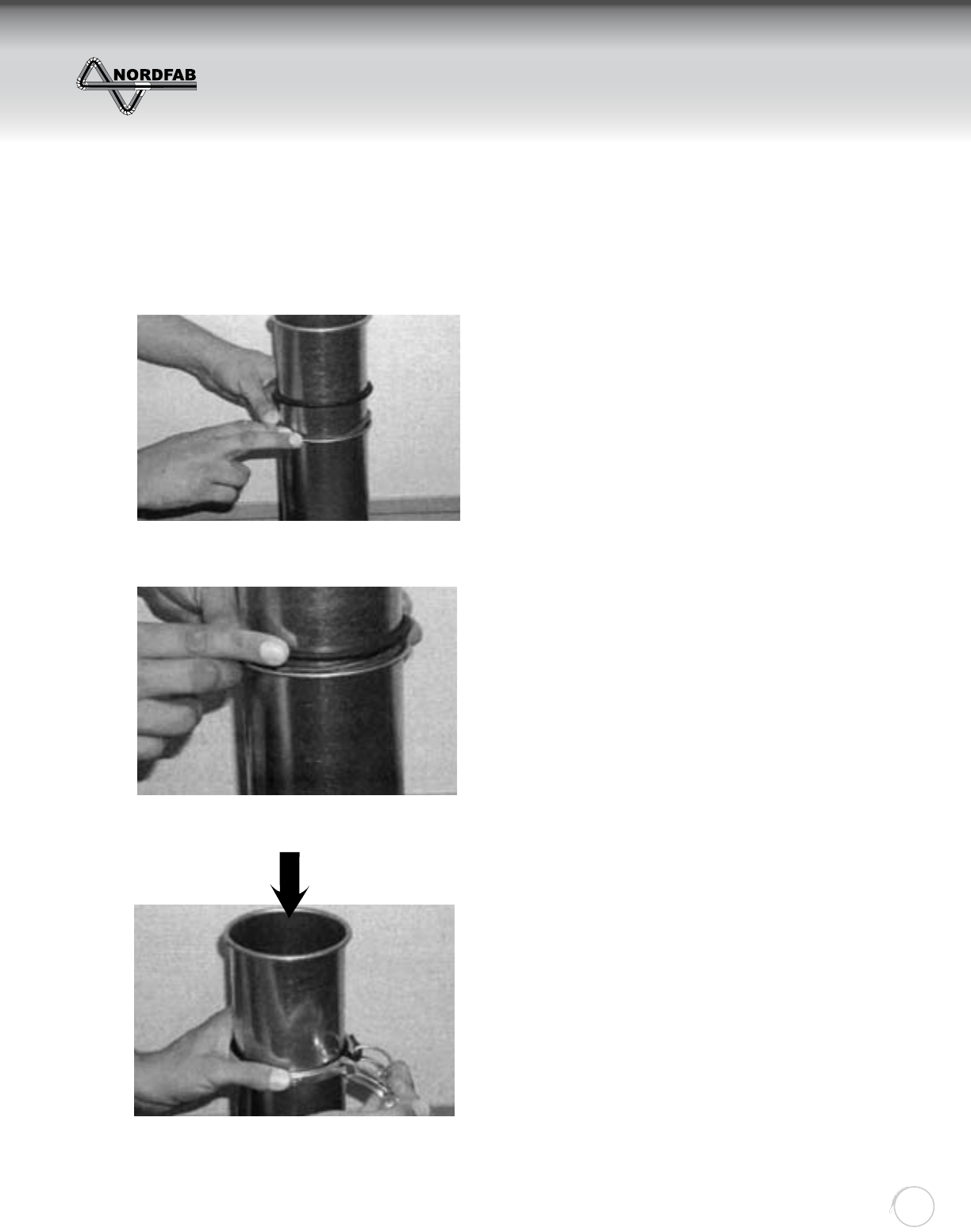
THE WORLD’S FASTEST DUCTING
Quick-Fit
Ducting
44
INSTALLATION OF ADJUSTABLE NIPPLE
FOR OIL MIST OR WET APPLICATIONS
The patented Nordfab “adjustable nipple” provides
unlimited fl exibility in the length of a duct run.
1. Cut a standard piece of pipe to length and insert
it into the short adjustable nipple section. This
assembly will telescope to any length. Place the
soft grey (or black with grey mark) o-ring seal
onto the cut (inside) piece of pipe and seat it
evenly against the rolled metal edge of the
adjustable nipple.
2. Place the harder black o-ring seal against the
outside of the inner grey seal.
The order should be as follows:
a) rolled edge or nipple; against
b) soft, small-diameter o-ring; against
c) standard Nordfab o-ring
3. Finally clamp the standard Q-F clamp over the
rolled metal edge of the adjustable nipple and
the hard rolled black o-ring for a leak-free con-
nection. [Make sure both seals fi t completely
under the clamp and that the air-fl ows from the
cut pipe towards the adjustable nipple].
1
2
3
Airfl ow
ZZZGXFWLQJV\VWHPVFRP
INSTALLATION OF
LEAK-FREE O-RING
Return to Contents
THE WORLD’S FASTEST DUCTING
Quick-Fit
Ducting
45
Description of Conveyed Material Velocity FPM Example
Gases 1,000 - 2,000 All Vapors, Gases and Smoke
Fumes 2,000 - 2,500 Welding
Oil Mist 2,000 - 2,500 Oily Vapor or Oily Smoke
Very Fine Light Dust 2,500 - 3,000 Cotton Lint, Litho Powder, Wood Flour
Dry Dusts and Powders 3,500 - 4,000 Light Shavings, Rubber Dust, Soap Dust
Typical Industrial Dust 3,000 - 4,000 Grinding or Buffi ng Dust, Granite/Brick/Clay Dust
Heavy Dusts 4,000 - 4,500 Heavy or Wet Sawdust, Metal Turnings, Sand Blast Dust,
Wood Blocks
Heavy or Moist 4,500 + Moist Cement Dust, Quick-Lime Dust, Sticky Buffi ng Lint
SIZING A “Q-F” SYSTEM
NORDFAB offers assistance to those sales people and customers who have never designed a ducting system
before. We can assist you in determining the correct duct size and confi guration that will supply you with the
correct fl ow.
We have the ability to assist customers in designing a blast-gated system; taking into account fl ow dynamics
that will be affected by blast gates. While blast gates can be used to effectively utilize an undersized fi ltering
system, they can also destroy the fl ow if not properly placed.
USING THE CFM / FPM CHART
Different materials need to be moved at different velocities to prevent the material from falling out of the air
stream. For example: wood chips and saw dust fl ow well at 4500 feet per minute. Referring to the chart on the
next page, you will see that a 4” duct will convey 395 CFM at 4500 FPM. This will mean that a 4” pick-up on a
machine will take 395 CFM from your fi ltering system; or working in reverse, if you know that a machine will
require approximately 400 CFM to remove the waste, then you should design a 4” duct for the purpose.
ZZZGXFWLQJV\VWHPVFRP
SIZING A SYSTEM &
USING THE CHART
Return to Contents
AIR VOLUME IN DUCTS IN CUBIC FEET PER MINUTE (CFM)
VELOCITY IN FEET PER MINUTE (FPM)
DUCT Ø 2000 2500 3000 3500 4000 4500 5000 5500 6000 6500 7000
3100 125 150 170 195 220 245 270 295 320 345
4175 220 260 305 350 395 440 485 525 570 615
5 275 340 410 475 545 615 680 750 820 885 955
6395 490 590 685 785 885 980 1080 1180 1275 1375
7 535 670 800 935 1070 1205 1335 1470 1605 1735 1870
8 700 875 1050 1220 1395 1570 1745 1920 2095 2270 2445
9885 1105 1325 1545 1765 1990 2210 2430 2650 2870 3090
10 1090 1365 1635 1910 2180 2455 2725 3000 3270 3545 3820
11 1320 1650 1980 2310 2640 2970 3300 3630 3960 4290 4620
12 1570 1965 2355 2750 3140 3535 3925 4320 4710 5105 5500
13 1850 2300 2770 3225 3685 4150 4610 5070 5530 5990 6450
14 2140 2675 3205 3740 4275 4810 5345 5880 6415 6950 7485
15 2450 3070 3680 4300 4900 5520 6130 6750 7360 7970 8590
16 2790 3490 4190 4885 5585 6285 6980 7680 8380 9075 9775
17 3150 3940 4730 5515 6300 7090 7880 8670 9450 10240 11030
18 3535 4420 5300 6185 7070 7950 8835 9720 10600 11485 12370
20 4365 5455 6545 7635 8725 9815 10910 12000 13090 14180 15270
22 5280 6600 7920 9240 10560 11880 13200 14520 15840 17160 18480
24 6285 7855 9425 10995 12656 14135 15710 17280 18850 20420 21995
26 7370 9210 11055 12900 14740 16580 18420 20270 22110 23950 25800
28 8550 10685 12820 14960 17100 19230 21310 23500 25650 27780 29920
30 9800 12260 14700 17170 19625 22080 24530 26990 29440 31890 34350
32 11160 13950 16750 19541 22330 25120 27910 30700 33490 26280 39070
34 12600 15755 18905 22055 25210 28360 31510 34660 37810 40965 44115
36 14130 17665 21195 24730 28260 31800 35325 38860 42390 45925 49455
38 15745 19680 23615 27550 31490 35425 39360 43295 47230 51170 55100
40 17445 21800 26170 30530 34890 39250 43610 47975 52330 56700 61055
46
ZZZGXFWLQJV\VWHPVFRP
AIR VOLUME CHART (CFM)
Return to Contents
Fax: ___ of ___
Phone:
90
o
60
o
45
o
30
o
ABCDQTY
3"
4"
5"
6"
7"
8"
9"
10"
11"
12"
13"
14"
15"
16"
17"
18"
20"
22"
24"
Your Name:
Company Name:
Page
Date:
___________________________
___________________________
__________________________
"QF" PARTS LIST TAKE-OFF WORKSHEET
FLEX
HOSE
CLAMP
QF
DIA.
PIPE 5'0"
LONG
BLAST
GATES
ADJ.
NIPPLE
INCL
O-RING
FLOOR
SWEEP
MACHINE
ADAPTOR
STAND. IS
QF TO ID
FLEX
HOSE
ADAPT.
__________
ELBOWS QF
CLAMP
PIPE
HANGER
FLEX
HOSE
RUBBER
OR STEEL
________________
________________ Project:
MISC. FITTINGS (REDUCERS,
ADAPTORS, TRANSITIONS, ANY
FITTINGS THAT CAN NOT BE
SPECIFIED ELSEWHERE)
BRANCH, DOUBLE
BRANCH &
Y BRANCH
(3 Ø 39") "
QUICK-FIT FAST FAX: 888-922-5040
47
ZZZGXFWLQJV\VWHPVFRP
TAKE OFF SHEET
Return to Contents
HAVE $ DUCTING EXPERT CONTACT ME
NAME: COMPANY:
ADDRESS: CITY: S T: ZIP:
PHONE: FAX: EMAIL:
CURRENT NEED:
DATE NEEDED:
AIR CLEANING SPECIALISTS, INC.
26 Horan Drive • Fenton, MO 63026
Toll Free 866-455-2130
Fax: 888-922-5040
QUICK-FIT FAST FAX TO: 888-922-5040
Ducting
Ducting The world’s [
FASTEST
] ducting
www.ductingsystems.com
