TPR 6 Instruction Manual 01 06 10
2016-06-07
: Pdf Tpr-6 Instruction Manual 01 06 10 TPR-6 Instruction Manual 01_06_10 Specs Solcon
Open the PDF directly: View PDF ![]() .
.
Page Count: 28
- Table of Contents
- Introduction
- Wiring Diagram
- Terminals Review
- Front Panel Description
- Mode Pages Display
- Resistance/Temperature Conversion Table Pt. 100 as per Din 43760
- Dip switches Settings for PT100/Thermistor Inputs Designation
- Tripping / Alarm Default Settings
- Flash Messages
- TPR-6 Communication
- Technical Specifications
- Dimensions and Cut-Out Dimensions
- Ordering Information
- Notes
T
TP
PR
R-
-6
6
T
Te
em
mp
pe
er
ra
at
tu
ur
re
e
P
Pr
ro
ot
te
ec
ct
ti
io
on
n
R
Re
el
la
ay
y
I
In
ns
st
tr
ru
uc
ct
ti
io
on
n
M
Ma
an
nu
ua
al
l
Ver. June 1st 2010

2 • Table of Contents
________________________________________________________________________________________________
1. TABLE OF CONTENTS
1. Table of Contents .................................................................................................................. 2
2. Introduction ............................................................................................................................ 3
3. Wiring Diagram ...................................................................................................................... 5
4. Terminals Review .................................................................................................................. 6
5. Front Panel Description ........................................................................................................ 8
6. Mode Pages Display .............................................................................................................. 9
6.1 Parameter Setting – Temperature Settings ............................................................................ 10
6.2 Parameter Setting – I/O Settings ............................................................................................ 12
6.3 Parameter Setting – Tripping and Alarm Options ................................................................... 14
6.4 Actual Data ............................................................................................................................ 17
6.5 Statistical Data ....................................................................................................................... 18
6.6 Service Mode ......................................................................................................................... 19
7. Resistance/Temperature Conversion Table Pt. 100 as per Din 43760.............................. 20
8. Dip switches Settings for PT100/Thermistor Inputs Designation ..................................... 20
8.1 Dismantling the Main PCB and the Input PCB ....................................................................... 21
9. Tripping / Alarm Default Settings ....................................................................................... 22
10. Flash Messages .................................................................................................................. 23
11. TPR-6 Communication ........................................................................................................ 24
12. Technical Specifications ..................................................................................................... 25
13. Dimensions and Cut-Out Dimensions ................................................................................ 26
14. Ordering Information ........................................................................................................... 27
15. Notes .................................................................................................................................... 28
Safety notes
Read this manual carefully before operating the equipment and follow its
instructions.
Installation, operation and maintenance should be in strict accordance with this
manual, national codes and good practice. Installation or operation not performed
in strict accordance with these instructions will void manufacturer’s warranty.
Disconnect all power inputs before servicing the relay.
For use in a pollution degree 2 environment or equivalent.
This device is not intended to provide motor overload protection, and suitable
protection should be provided in the end product.
DANGER - Electrocution Hazard - RTDs or other sensors connected to this
device must be provided with electrical isolation sufficient for the voltage present
on the motor windings (or other equipment being monitored). Sensors must also
be provided with shielded cables, and all shields must be reliably grounded.
The company reserves the right to make any improvements or modifications to its
products without prior notice
.

3 • Introduction
________________________________________________________________________________________________
2. INTRODUCTION
The TPR-6, Temperature Protection Relay is a new generation of micro-processor based relay, designed to
protect electric motors, transformers and other systems from over temperature.
The TPR-6 has 6 or 14 temperature inputs that can be programmed to measure Thermistors (PTC or
NTC) and RTDs (Pt100).
Each temperature input can be Disabled or Enabled, designated as Thermistor-PTC or Thermistor-NTC or
RTD (Pt100). Protection levels and time delay are programmable as well as grouping for combining the
data in the analogue output.
Temperature sensors types & mode of operation.
Number of sensors - can be set from 1-6 or 1-14
Sensor type – Each sensor can be set as RTD, Thermistor-PTC, Thermistor-NTC or Not Used
(requires changing sensor type from RTD to Thermistor and Vice Versa and includes internal dip
switches modification – refer to page 18 for dip switches settings).
Level 1 (for example Alarm) – Different levels can be set for each sensor. Levels are set in degrees
C for RTD type sensors or KΏ for Thermistor type sensors.
Level 2 (for example Trip) - Different levels can be set for each sensor. Levels are set in degrees C
for RTD type sensors or KΏ for Thermistor type sensors.
Time delay level 1 – A time delay can be set for level 1.
Time delay level 2 - A time delay can be set for level 2.
Group of sensors – Used for analogue output.
Input / Output configuration
Unique Tripping / Alarm options makes it possible to designate any fault as an Alarm, Trip, both or none.
This unique facility also enables controlled fault Reset possibilities.
Alarm relay as Alarm, Alarm-fail safe or Tripping / Alarm.
Trip relay as Trip, Trip-fail safe or Tripping / Alarm.
Input 1 (discrete) – As Remote Reset, External Fault 1 – N.O. or N.C. contact
Input 2 (discrete) – As Remote Reset, External Fault 2 – N.O. or N.C. contact
Analogue output – As 0-20mA Normal or 4-20mA Normal or Inverted
Analogue output group – Group Minimum, Average, Maximum
Communication RS485 – can be locked or unlocked, address numbers for each sensor and baud
rate.
Trip / Alarm configuration
Each sensor as well as two discrete inputs, communication fault and internal fault can be configured,
separately for level 1 and 2, as follows:
Trip function – Enabled or Disabled
Alarm function – Enabled or Disabled
Auto Reset function – Enabled or Disabled
Operating Relay A – Enabled or Disabled
Operating Relay B – Enabled or Disabled
Operating Relay C – Enabled or Disabled
Operating Relay D – Enabled or Disabled
Displaying Actual data
Temperature (RTD) or resistance (Thermistors) of each sensor, Failure of sensor connecting wires.

4 • Introduction
________________________________________________________________________________________________
Statistical data
Max. value of each sensor
Last trip
Last alarm
Total number of trips
Temperature / Resistance of each sensor at time of trip
All above parameters can be individually configured through a keypad on the front panel or through
communication.
The Liquid Crystal Display (LCD), together with a Keypad and LEDs enables user friendly interface, accurate
digital parameters setting, actual parameters readings, and detailed trip and alarm message displays.
Changes can easily be prevented by the usage of the parameter lock feature.
RS485 serial link (with MODBUS communication protocols), operating at baud rate of 1200 to 19200 bits/sec.
enables monitoring of both the set points and actual parameters. Changes of the set points parameters
through the serial link makes it very easy to enter customer set points in place of the factory default
parameters. Parameter setting through the serial link may be easily disabled through manual keypad setting.
Up to 32 TPR-6 units can be connected on the same link to the host computer.
5 • Wiring Diagram
________________________________________________________________________________________________
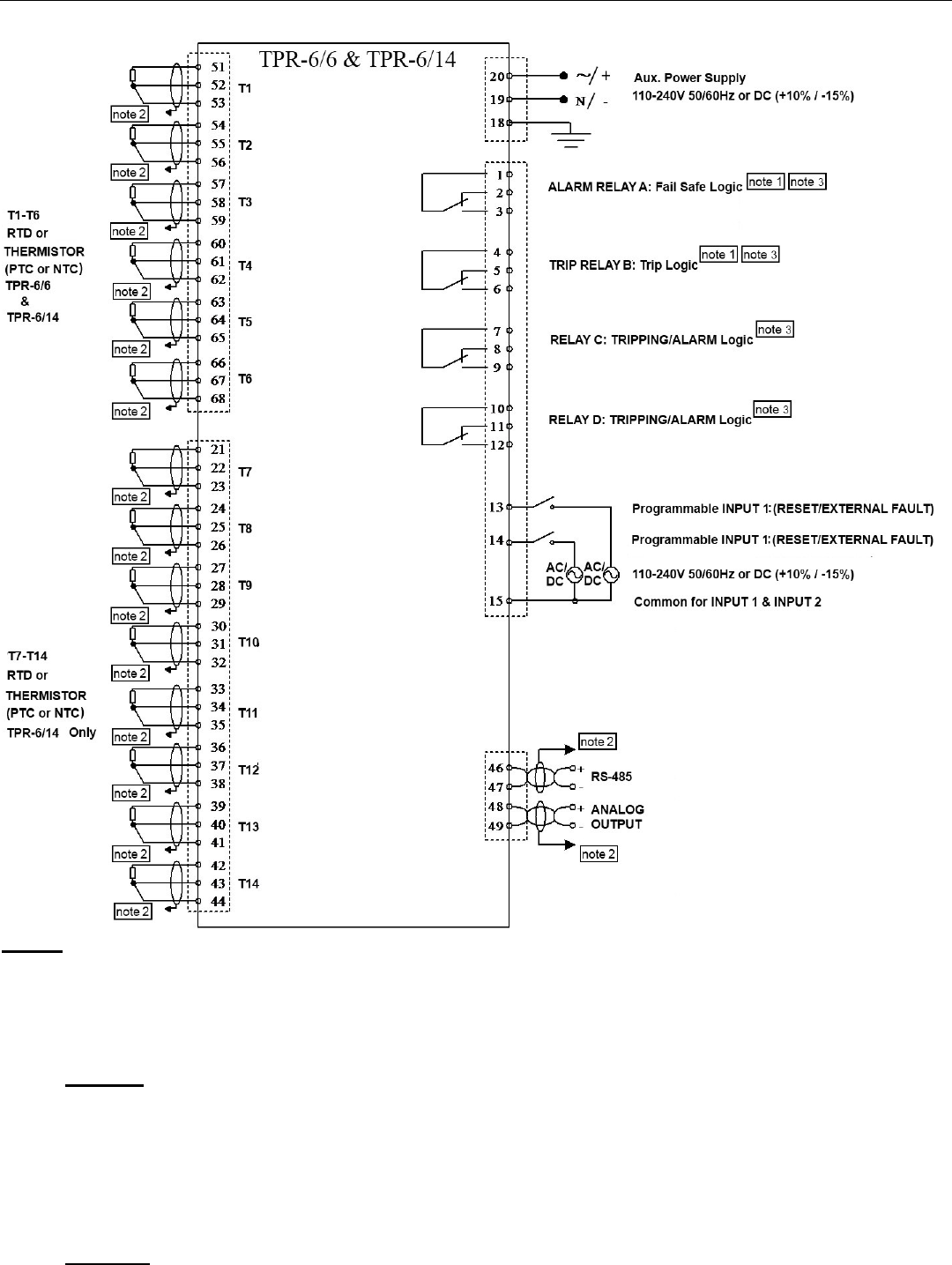
3. WIRING DIAGRAM
Notes:
1. ALARM RELAY A can be programmed as ALARM or ALARM FAIL SAFE (default setting) or
TRIPPING/ALARM.
TRIP RELAY B can be programmed as TRIP (default setting) or TRIP FAIL SAFE or
TRIPPING/ALARM.
Refer to section 6.2 Parameter Setting – I/O Settings page 12 for more information.
2. Warning: The analog output circuit is isolated as a group together with the RS-485 communication.
When using both connections, verify that analog out user (or RS-485 user) is using an isolated
circuitry.
Connect all shield wires to ground (a short busbar may be used)
3. Relays Contacts:
Rated load: 8A/250 VAC (VDE, UL, cUL); 8A/24VDC (UL, cUL).
Maximum breaking capacity AC: 2000 VA
Max. DC Load Breaking Capacity: 8A at 30VDC.
4. DANGER - Electrocution Hazard - RTDs or other sensors connected to this device must be provided
with electrical isolation sufficient for the voltage present on the motor windings (or other equipment
being monitored). Sensors must also be provided with shielded cables, and all shields must be reliably
grounded.

6 • Terminals Review
________________________________________________________________________________________________
4. TERMINALS REVIEW
General Notes:
Use 75°C copper wires only
Control Supply
110-240V 50/60Hz or DC (+10% / -15%)
Phase/Positive Lead ....................................
Neutral/Negative Lead .................................
Ground .........................................................
The TPR-6 incorporates four relays, each with 1-C/O contact, rated 8A/250 VAC, 2000VA resistive.
See I/O SETTINGS (page 2).
Note:
Tighten terminals 18, 19, 20 to 7 in-lbs
Output Relay A - Alarm
Relay contacts can be configured as one of:
ALARM RELAY – contact changes upon fault and returns after reset (after fault has been removed).
ALARM FAIL-SAFE logic – contact changes when control voltage is connected and returns upon fault.
Relay is energized when control voltage is connected. Upon fault, which is designated as Alarm, the
relay de-energizes. This relay can be used to sense control supply outage.
TRIPPING / ALARM - Relay can be assigned to specific faults that are enabled as alarm or trip.
Common ........................ .............................. 1
N.C ............................................................. 2
N.O .........................................…................. 3
Output Relay B - Trip
Relay contacts can be configured as one of:
TRIP Relay – contact changes upon fault and returns after reset (after fault has been removed).
TRIP FAIL-SAFE logic – contact changes when control voltage is connected and returns upon fault.
TRIPPING / ALARM - Relay can be assigned to specific faults that are enabled as alarm or trip.
Common ……………………………………... 4
N.C ............................................................. 5
N.O .............................................................. 6
Output Relay C - Programmable
Relay can be assigned to specific faults that are enabled as alarm or trip.
Common ………………………………......….. 7
N.C .............................................................. 8
N.O .............................................................. 9
Output Relay D - Programmable
Relay can be assigned to specific faults that are enabled as alarm or trip.
Common …………………………………….. 10
N.C .............................................................. 11
N.O .............................................................. 12
Discrete Logic Inputs
Programmable inputs from N.O or N.C. contacts (See I/O Settings)
Input voltages are 110-240V 50/60Hz or DC (+10% / -15%)
Input 1 ......................................................... 13
Input 2 ......................................................... 14
Common ...................................................... 15

7 • Terminals Review
________________________________________________________________________________________________
Thermal Inputs
The TPR-6 can accept inputs from the following types of thermal sensors:
RTD - Platinum 100 Ohm (Pt100) - Three-wire measurement system to be used to compensate for
cable resistance.
Thermistors - field Programmable as PTC or NTC (Two wire)
Notes:
1. Shielded cables must be used. Connect shield to external ground.
2. For RTD maximum cable resistance allowed is 25 Ohm.
3. LCD display in Celsius degrees for RTD and in kOHMS for Thermistors
4. If a sensor is not used, leave relevant terminals open, and set in TEMPERATURE SETTING, Tx
SENSPR TYPE – NOT USED. This will prevent the display of the non-used sensors and to disable the
relevant Trip and Alarms.
For 6 thermal inputs
Thermistor 1 ……… 51+52 RTD 1 ............ 51+52, 53
Thermistor 2 ……… 54+55 RTD 2 ............ 54+55, 56
Thermistor 5 ……… 57+58 RTD 3 ............ 57+58, 59
Thermistor 4 ……… 60+61 RTD 4 ............ 60+61, 62
Thermistor 5 ……… 63+64 RTD 5 …........ 63+64, 65
Thermistor 6 ……… 66+67 RTD 6 ............ 66+67, 68
For a 14 thermal inputs
Thermistor 7 ……… 21+22 RTD 7 ............ 21+22, 23
Thermistor 8 ……… 24+25 RTD 8 ............ 24+25, 26
Thermistor 9 ……… 27+28 RTD 9 ........... 27+28, 29
Thermistor 10 …..… 30+31 RTD 10 ........... 30+31, 32
Thermistor 11 …….. 33+34 RTD 11 …....... 33+34, 35
Thermistor 12 …….. 36+37 RTD 12 ........... 36+37, 38
Thermistor 13 …….. 39+40 RTD 13 …....... 39+40, 41
Thermistor 14 …….. 42+43 RTD 14 ........... 42+43, 44
Note: Disconnected sensors do not trip the unit!
Serial Link
Standard RS485 Half Duplex, with MODBUS protocol.
Twisted & shielded pair should be used for wiring.
Acceptable baud rates: 1200, 2400, 4800, 9600 and 19200 BPS.
Serial Port (+) ......................................................... 46
Serial Port (-) .......................................................... 47
Notes:
1. Auxiliary Power Supply must be turned Off after changing baud rate value.
2. In order to match the line, connect 120 Ohm resistors between + and - at the end and the beginning of
the line.
Analogue Output
See isolation Warning (this page) . The output is programmable to 0-20mA, 4-20mA, Normal or Inverted
designated to any single sensor, minimum, average or maximum of a group of sensors.
Serial Port (+) ......................................................... 48
Serial Port (-) .......................................................... 49
Warning
The analogue output circuit is isolated as a
group together with the RS485
communication. When using both
connections, verify that analogue out user
(or RS-485 user) is using isolated circuitry.
8 • Front Panel Description
________________________________________________________________________________________________
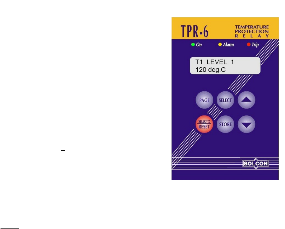
5. FRONT PANEL DESCRIPTION
LEDs
On - Illuminates when auxiliary power supply voltage is
connected.
Alarm - Illuminates in Alarm condition. Stays lit even if alarm
condition disappears, turns off after resetting.
Trip - Illuminates in Trip condition. Stays lit even if trip condition
disappears, turns off after resetting.
Keys Overview
PAGE - Press to change set point pages in positive cyclical
order.
SELECT - Press to scroll parameters within page in forward
cyclic order. Short press on the Reset key will reverse scrolling
direction. A small line will appear under the first letter of the
lower line (for example RTD).
▲ - Press once to increase parameter value. Press and
hold to increase value at a fast rate.
▼ - Press once to decrease parameter value. Press and
hold to decrease value at a fast rate .
STORE - Press to store displayed parameter value in the non-volatile memory.
RESET/SELECT – This key has two functions:
Press for more than 1 second to cancel displayed Alarm or Trip (after fault has been removed).
This key can also be used to change direction of Select operation. See above Select key.
Notes:
1. Changing and storing new parameters is possible only if PARAMETER LOCK is set to NO.
2. If PARAMETER LOCK is set to LOCKED, parameters can only be viewed.
LCD
Illuminated, two lines of 16 characters each, presenting, Top line, parameter name. Bottom Line, parameter
value, or all other data, statistics and messages.
9 • Mode Pages Display
________________________________________________________________________________________________
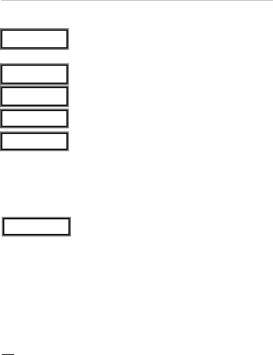
6. MODE PAGES DISPLAY
Upon initiation the LCD will display:
By pressing PAGE key the following pages can be reviewed
In order to review details of above page settings, press SELECT key.
Messages are displayed on the LCD in two lines.
* Upper line describes the parameter's name.
* Lower line shows its value.
To change settings, when PARAMETER LOCK is set NOT LOCKED, press ▲ or▼ keys and save the new
value by pressing STORE key. Once data was properly stored in the non-volatile memory the LCD displays
the 2 sec. flash message:
Notes:
1. Pressing STORE key while the LCD displays an ACTUAL DATA parameter, will store this
parameter as default display. If no key is pressed for more than five minutes, this parameter will be
constantly displayed.
2. A new parameter setting becomes effective upon setting, even before storing it in the non-volatile
memory. However, setting a parameter without storing and moving to another page will return the
parameter to its previously stored value.
3. Any set parameter can be viewed, altered and stored at any time (provided that PARAMETER
LOCK is set NOT LOCKED). However, it is not recommended to change and store parameters
while motor is running.
4. Any stored parameter is kept indefinitely in the non-volatile memory.
Returning to Factory Default Values:
Press PAGE and ▼ keys simultaneously, the LCD displays: SERVICE OPTIONS
Press SELECT key three times, the LCD will displays: STORE NOW DEFAULT PARAMETERS ?
Press STORE and PAGE keys simultaneously, the LCD will display: DATA SAVED OK
Note: Storing Default parameters erases all previously updated parameters
I / O
*** SETTINGS ***
TEMPERATURE
*** SETTINGS ***
TRIPPING / ALARM
*** OPTIONS ***
ACTUAL DATA
****
STATISTICAL DATA
****
DATA SAVED OK

10 • Mode Pages Display
________________________________________________________________________________________________
6.1 Parameter Setting – Temperature Settings
Press ▲ or▼ keys to set actual number of connected sensors
Range: 1-6 in TPR-6/6 and 1-14 in TPR-6/14.
Press SELECT
Type of temperature sensor in temperature input x.
x represents any number between 1-6 in TPR-6/6 and any number between 1-14 in TPR-6/14.
Press ▲ or▼ keys to set actual type of sensors.
Sensor type must be modified via internal dip switches (Refer to section 8 page 20.) as well as via the
software.
Range: NOT USED, RTD, PTC THERMISTOR, NTC THERMISTOR
If more than one sensor is used (as set in parameter NO. OF SENSORS above) it will show T2 SENSOR
TYPE, T3 SENSOR TYPE .. etc.
Press SELECT
Tx LEVEL 1 (represents T1 LEVEL 1, T2 LEVEL 1 etc...) is normally used to set an Alarm Level
If Tx SENSOR TYPE is set to RTD this display is in deg. C (Celsius degrees).
If Tx SENSOR TYPE is set to PTC-THERMISTOR or NTC-THERMISTOR this display is in kOHM.
Press ▲ or▼ keys to set Tx LEVEL 1 value
Range for RTDs: 5 – 250 deg. C.
Range for Thermistors: 0.5 – 25.0 kOHM
Press SELECT
Tx LEVEL 2 (represents T1 LEVEL 2, T2 LEVEL 2 etc...) is normally used to set a Trip Level
If Tx SENSOR TYPE is set to RTD this display is in deg. C (Celsius degrees).
If Tx SENSOR TYPE is set to PTC-THERMISTOR or NTC-THERMISTOR this display is in kOHM.
Press ▲ or▼ keys to set Tx LEVEL 2 value
Range: 5 – 250 deg C
Press SELECT
Time delay for Level 1 (for all sensor channels)
Press ▲ or▼ keys to set time delay
Range: 0.1 – 20 Sec.
TEMPERATURE
*** SETTINGS ***
NO. OF SENSORS
3
Tx SENSOR TYPE
RTD
rtd
Tx LEVEL 1
120 deg. C
rtd
TEMP. LEVEL 1 DELY
2.0 SEC.
Tx LEVEL 2
140 deg. C
rtd
Important Note:
In order to set the sensor type connected to the TPR-6 the Tx SENSOR TYPE parameter must
be set accordingly and dip switch setting must be done as well. Refer to section 8 page 20 for
dip switch settings.

11 • Mode Pages Display
________________________________________________________________________________________________
Press SELECT
Time delay for Level 2 (for all sensor channels)
Press ▲ or▼ keys to set time delay
Range: 0.1 – 20 Sec.
Press SELECT
Any sensor 1-14 can be grouped for group measurement and analogue output.
Press ▲ or▼ keys to set whether the temperature input Tx is in the analog out group.
Range: YES, NO
Press PAGE. The display will change to the next page: I/O SETTINGS.
TEMP. LEVEL 2 DELY
2.0 SEC.
Tx IN GROUP ?
YES

12 • Mode Pages Display
________________________________________________________________________________________________
6.2 Parameter Setting – I/O Settings
Press SELECT
Configure Alarm Relay function
Press ▲ or▼ keys to set required operation mode
Range: ALARM, ALARM FAIL SAFE, TRIPPING/ALARM
ALARM - the relay changes position upon trip and returns to original position upon reset, after fault has been
removed.
ALARM FAIL SAFE - the relay changes position upon voltage connection and returns to original position
upon fault.
TRIPPING / ALARM - Relay can be assigned to specific faults that are enabled as alarm or trip.
Press SELECT
Configure Trip Relay function
Press ▲ or▼ keys to set required operation mode
Range: TRIP, TRIP FAIL SAFE, TRIPPING/ALARM
TRIP - the relay changes position upon trip and returns to original position upon reset, after fault has been
removed.
TRIP FAIL SAFE - the relay changes position upon voltage connection and return to original position upon
fault.
TRIPPING / ALARM - Relay can be assigned to specific faults that are enabled as alarm or trip.
Press SELECT
Configure input 1 function
Press ▲ or▼ keys to set required input function for INPUT 1.
Range: REMOTE RESET, EXTERNAL FAULT 1 N.O., EXTERNAL FAULT 1 N.C.
Press SELECT
Configure Trip Relay function
Press ▲ or▼ keys to set required input function for INPUT 2.
Range: REMOTE RESET, EXTERNAL FAULT 2 N.O., EXTERNAL FAULT 2 N.C.
Press SELECT
Configure Analogue Output
Press ▲ or▼ keys to configure the analog output.
Range: 0-20mA NORMAL, 4-20mA NORMAL, 0-20mA INVERTED and 4-20mA INVERTED
I / O
*** SETINGS ***.
CONFIG. TRIP REL
TRIP
CONFIG. INPUT 1
REMOTE RESET
CONFIG. INPUT 2
REMOTE RESET
CONFIG. ANLG OUT
4-20mA NORMAL
CONFIG. ALARM REL
ALARM FAIL SAFE

13 • Mode Pages Display
________________________________________________________________________________________________
Press SELECT
Configure Analogue Output – related to the minimum, average or maximum of the selected group
Range: GROUP MINIMUM, GROUP AVERAGE, GROUP MAXIMUM, T1, T2,T3........R1, R2....
Press SELECT
Analogue Output Full Range
Press ▲ or▼ keys to set the full range (or full scale) upon which the analog output is referred to.
Range: For Thermistor 0-25 KOHM, For RTD 0-250 deg C.
Press SELECT
When locked – parameters can be reviewed but not modified
When unlocked – parameter settings can be modified
Press ▲ or▼ keys to lock/unlock parameters settings.
Range: NOT LOCKED, LOCKED
Press SELECT
When locked – parameters can be reviewed but not modified via the communication link.
When unlocked – parameter settings can be modified
Press ▲ or▼ keys to lock/unlock parameters settings via communication.
Range: NOT LOCKED, LOCKED
Press SELECT
Address number of the communication link.
Press ▲ or▼ keys to set communication link address.
Range: 1-248 (note that 248=off)
Press SELECT
Press ▲ or▼ keys to set the baud rate of the communication link.
Range: 1200, 2400, 4800, 9600, 19200
Press PAGE. The display will change to the next page: TRIPPING/ALARM OPTIONS.
AN. OUT FUL RANGE
200 deg C
PARAMETERS LOCK
NOT LOCKED
AN. OUT PARAMETER
GROUP MAXIMUM
S. LINK SAVE LOCK
LOCKED
ADDRESS NUMBER
248
BAUD RATE
19200

14 • Mode Pages Display
________________________________________________________________________________________________
6.3 Parameter Setting – Tripping and Alarm Options
Protection function
Each of the TPR-6 Protections can be assigned to each of the following functions :
1. TRIP function – ENABLED or DISABLED, if ENABLED can be programmed to TRIP or TRIP-FAIL
SAFE function (see I/O SETTINGS page)
2. ALARM function – ENABLED or DISABLED
3. AUTO RESET – Enabled or Disabled
4. Operate RELAY A – ENABLED or DISABLED
5. Operate RELAY B – ENABLED or DISABLED
6. Operate RELAY C – ENABLED or DISABLED
7. Operate RELAY D – ENABLED or DISABLED
Each of the TPR-6 Protections has two levels – LEVEL 1 and LEVEL 2
The following represents the displays shown for level 1 of the first temperature sensor. Similar displays are
shown for all sensors with LEVEL 1 faults then for all sensors with LEVEL 2 sensors.
Note: If a sensor is set as NOT USED, then only one screen (per Level) for this sensor will be displayed,
showing NOT USED.
Press SELECT
Enabling, Disabling trip function for T1 LEVEL 1.
Press ▲ or▼ keys to set if TRIP is after T1 LEVEL 1.
Range: DISABLE, ENABLE
Press SELECT
Enabling, Disabling Alarm function for T1 LEVEL 1.
Press ▲ or▼ keys to set if ALARM is after T1 LEVEL 1.
Range: DISABLE, ENABLE
Press SELECT
Enabling, Disabling auto-reset function for T1 LEVEL 1
Press ▲ or▼ keys to set if T1 LEVEL 1 is AUTO RESET or not AUTO RESET.
Range: DISABLE, ENABLE
Press SELECT
Enabling, Disabling operation of RELAY A for T1 LEVEL 1.
Press ▲ or▼ keys to set if RELAY A will follow T1 LEVEL 1 settings.
Note: Relay operates upon T1 LEVEL 1 fault which is enabled if RELAY A is set to TRIPPING/ALARM in the
I/O SETTING PAGE.
Range: DISABLE, ENABLE
TRIPPING / ALARM
*** OPTIONS ***
T1 LEVEL 1
TRIP: DISABLE
T1 LEVEL 1
ALARM: ENABLE
T1 LEVEL 1
AUTO RST: DSABL
T1 LEVEL 1
RELAY A: DISABLE
RELAY A, RELAY B, RELAY C and RELAY D must
be configured as TRIPPING/ALARM in the I/O
SETTING PAGE in order to operate in the
TRIPPINNG/ALARM mode.
Refer to section 9 - Tripping / Alarm Default Settings on page 22 for the default settings
of all the parameters in the TRIPPING/ALARM OPTIONS mode page.

15 • Mode Pages Display
________________________________________________________________________________________________
Press SELECT
Enabling, Disabling operation of RELAY B for T1 LEVEL 1.
Press ▲ or▼ keys to set if RELAY B will follow T1 LEVEL 1 settings.
Note: Relay operates upon T1 LEVEL 1 fault which is enabled if RELAY B is set to TRIPPING/ALARM in the
I/O SETTING PAGE.
Range: DISABLE, ENABLE
Press SELECT
Enabling, Disabling operation of RELAY C for T1 LEVEL 1.
Press ▲ or▼ keys to set if RELAY C will follow T1 LEVEL 1 settings.
Note: Relay operates upon T1 LEVEL 1 fault which is enabled if RELAY C is set to TRIPPING/ALARM in the
I/O SETTING PAGE.
Range: DISABLE, ENABLE
Press SELECT
Enabling, Disabling operation of RELAY D for T1 LEVEL 1.
Press ▲ or▼ keys to set if RELAY D will follow T1 LEVEL 1 settings.
Note: Relay operates upon T1 LEVEL 1 fault which is enabled if RELAY D is set to TRIPPING/ALARM in the
I/O SETTING PAGE.
Range: DISABLE, ENABLE
Press SELECT to see next Tx LEVEL 1, then all sensors with Tx LEVEL 2.
Press SELECT
Enabling, Disabling trip function upon closure of
EXTERNAL FAULT INPUT 1.
Press ▲ or▼ keys to set if EXTERNAL FAULT 1 is set
to TRIP the unit.
Range DISABLE, ENABLE
Press SELECT to see ALARM, AUTO RST, RELAY
A..RELAY D settings for EXTERNAL FAULT 1
Press SELECT
Enabling, Disabling trip function upon closure of
EXTERNAL FAULT INPUT 1.
Press ▲ or▼ keys to set if EXTERNAL FAULT 1 is set
to TRIP the unit.
Range DISABLE, ENABLE
Press SELECT to see ALARM, AUTO RST, RELAY
A..RELAY D settings for EXTERNAL FAULT 1
T1 LEVEL 1
RELAY B: DISABLED
EXTERNAL FAULT 1
TRIP: DISABLED
EXTERNAL FAULT 2
TRIP: DISABLED
EXTERNAL FAULT 1
EXTERNAL FAULT 1 occurs when terminal
13 – CONFIG. INPUT 1 is set as EXTERNAL
FAULT 1 NO and the TPR detects a closed
circuit between terminal 13 terminal 15
(common) input terminals.
EXTERNAL FAULT 1 occurs when terminal
13 - CONFIG. INPUT 1 is set as EXTERNAL
FAULT 1 NC and the TPR-6 detects open
circuit between terminal 13 terminal 15
(common) input terminals.
T1 LEVEL 1
RELAY C: DISABLED
T1 LEVEL 1
RELAY D: DISABLED
EXTERNAL FAULT 2
EXTERNAL FAULT 2 occurs when terminal
14 – CONFIG. INPUT 2 is set as EXTERNAL
FAULT 2 NO and the TPR detects a closed
circuit between terminal 14 terminal 15
(common) input terminals.
EXTERNAL FAULT 2 occurs when terminal
14 - CONFIG. INPUT 2 is set as EXTERNAL
FAULT 2 NC and the TPR-6 detects open
circuit between terminal 14 terminal 15
(common) input terminals.

16 • Mode Pages Display
________________________________________________________________________________________________
Press SELECT
Fault occurs when the TPR-6 detects three consecutive transmissions from the host computer, in which a
parity bit, and/or the CRC word are wrong. Enabling, Disabling trip function upon communication failure.
Press ▲ or▼ keys to set this function.
Range: DISABLE, ENABLE
Press Select to see Alarm, AUTO RST, RELAY A..RELAY D settings for COMM PORT FAILED.
Press SELECT
Enabling, Disabling trip function upon INTERNAL FAILURE in the TPR
Press ▲ or▼ keys to set this function.
Range: DISABLE, ENABLE
Press Select to see Alarm, AUTO RST, RELAY A..RELAY D settings for COMM PORT FAILED.
Press PAGE. The display will change to the next page: ACTUAL DATA.
COMM PORT FAILED
TRIP: DISABLED
INTERNAL FAILURE
TRIP: DISABLED

17 • Mode Pages Display
________________________________________________________________________________________________
6.4 Actual Data
The following demonstrates the readings with the following settings in TEMPERATURE SETTINGS:
T1 SENSOR TYPE is set to RTD
T2 SENSOR TYPE is set to PTC THERMISTOR
T3 SENSOR TYPE is set to PTC THERMISTOR
Press SELECT
In case sensors are not connected the LCD will show FAILED SENSOR ??
Press SELECT
In case sensors are not connected the LCD will show FAILED SENSOR ??
Press SELECT
In case sensors are not connected the LCD will show FAILED SENSOR ??
Press PAGE. The display will change to the next page: STATISTICAL DATA.
ACTUAL DATA
- **** -
T1 TEMPERATURE
110 deg. C
T2 RESISTANCE
3.8 KOHM
T RESISTANCE
3.9 KOHM

18 • Mode Pages Display
________________________________________________________________________________________________
6.5 Statistical Data
The following demonstrates the readings with the following settings in TEMPERATURE SETTINGS:
T1 SENSOR TYPE is set to RTD
T2 SENSOR TYPE is set to PTC THERMISTOR
T3 SENSOR TYPE is set to PTC THERMISTOR
Press SELECT
When sensor type is set as Thermistor
display will show:
Press SELECT
Press SELECT
Press SELECT
Press SELECT
Press SELECT
Press SELECT
Press SELECT
Press SELECT
STATISTICAL DATA
- **** -
T1 – MAX. VALUE
255 deg C
LAST TRIP
T1 LEVEL 1
LAST ALARM
NO DATA
TOTAL # OF TRIPS
0
T1 AT TRIP TIME
255 deg. C
R2 AT TRIP TIME
0 KOHM
R2 – MAX. VALUE
25.5 KOHM
R3 – MAX. VALUE
25.5 KOHM
R3 AT TRIP TIME
0 KOHM
255 deg C
Note: When in the STATISTICAL DATA displays,
pressing RESET for more than 1 second, will zero the
display screen.
More than One Alarm or Trip.
The TPR-6 is designed to accept and store the first
alarm it detects. If this alarm has not been reset and
an additional alarm occurs, the TPR-6 will not display
the second alarm on the LCD nor assign it to the
STATISTICAL DATA.
In case a trip occurs after an alarm, the trip message
will override the alarm message.
This is to assist the user in establishing the cause of
the alarm.
Attention !
Resetting Statistical Data resets all previous statistical
data values ! ! !
The last two actions (store DEFAULT SETTINGS and
clearing STATISTICAL DATA in SERVICE MODE page)
should be done with care, since it is not possible to
retrieve the previous set point parameters or statistical
data.

19 • Mode Pages Display
________________________________________________________________________________________________
6.6 Service Mode
Press PAGE and ▼simultaneously, the following will display:
Press SELECT
If test was OK the display will show for a short time
If test failed the display will show
Press SELECT
Displaying the software date (04.03.04) and version.
Press SELECT
If it is required to return to default setting (original factory setting) press STORE & PAGE keys simultaneously
(Note: All values set by you will be erased).
Display will show:
Press SELECT
If it is required to reset all STATISTICAL DATA press STORE & RESET keys simultaneously.
(Note: All data in STATISTICAL DATA will be erased).
*** SERVICE ***
*** OPTIONS ***
RUN SELF TEST ?
PRESS “ VALUE-UP”
SELF TEST PASSED
SELF TEST FAILED
ERROR CODE = 32
PROGRAM VERSION
TPR040304-MB-ENG
STORE NOW ?
DEFAULT SETTINGS
DATA SAVED OK
CLEAR
STATISTICAL DATA
Attention !
The last two actions (store DEFAULT SETTINGS and clearing STATISTICAL DATA in SERVICE
MODE page) should be done with care, since it is not possible to retrieve the previous set point
parameters or statistical data.
20 • Resistance/Temperature Conversion Table Pt. 100 as per Din 43760
________________________________________________________________________________________________
7. RESISTANCE/TEMPERATURE CONVERSION TABLE PT. 100 AS PER DIN 43760
Temperature
Units =Deg C
Pt.100 (DIN 43760)
Units = Ohms
Temperature
Units =Deg C
Pt.100 (DIN 43760)
Units = Ohms
0
100.00
110
142.29
10
103.90
120
146.06
20
107.79
130
149.82
30
111.67
140
153.58
40
115.54
150
157.32
50
119.40
160
161.04
60
123.24
170
164.76
70
127.07
180
168.46
80
130.89
190
172.16
90
134.70
200
175.84
100
138.50
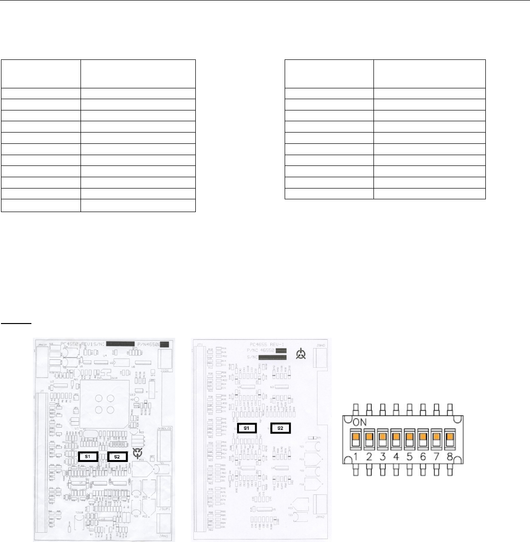
8. DIP SWITCHES SETTINGS FOR PT100/THERMISTOR INPUTS DESIGNATION
The following must be done in order to set the right sensors connected to the TPR-6:
1. Set the sensor type in the TEMPERATURE SETTINGS page. Refer to section 6.1 page 10.
2. Set the dipswitches as shown here after.
In order to change the position of the dip switches the main PCB (In all models) and the input PCB
(In TPR-6/14 only) should be dismantled.
Note: Take all safety precautions to prevent electrical shock or damage to the TPR-6 before
dismantling the TPR.
Main PCB (All models)
Input PCB (TPR-6/14 only)
Close look on dip switches
S1&S2
PT100/Thermistor inputs T1-T6 (All models) are designated via dip switches 1-6 on the main PCB.
PT100/Thermistor inputs T7-T14 (TPR-6/14 only) are designated via dip switches 1-8 on the input PCB.
Two sets of dip switches are on each PCB – marked S1 and S2. Each PT100/Thermistor input is designated
by the position of two dip switches – one in S1 and the second in S2. Both dip switches must be in the same
position.
When dip switches are in ON position, the input is designated as a Thermistor input (PTC type or NTC type
should be programmed via the key pad).
When dip switches are in Off position the input is designated as PT100.
For example, in order to designate PT100/Thermistor input T6 to Thermistor PTC put dip switch no. 6 in S1
and dip switch no. 6 in S2 on the main PCB to its ON position. After doing so program this input as a PTC
input via the key pad.
In order to designate PT100/Thermistor input T8 to PT100 put dip switch no. 2 in S1 and dip switch no. 2 in S2
on the input PCB to its OFF position. (Note that dip switches no. 1 in S1 & S2 are for PT100/Thermistor input
T7).
21 • Dip switches Settings for PT100/Thermistor Inputs Designation
________________________________________________________________________________________________
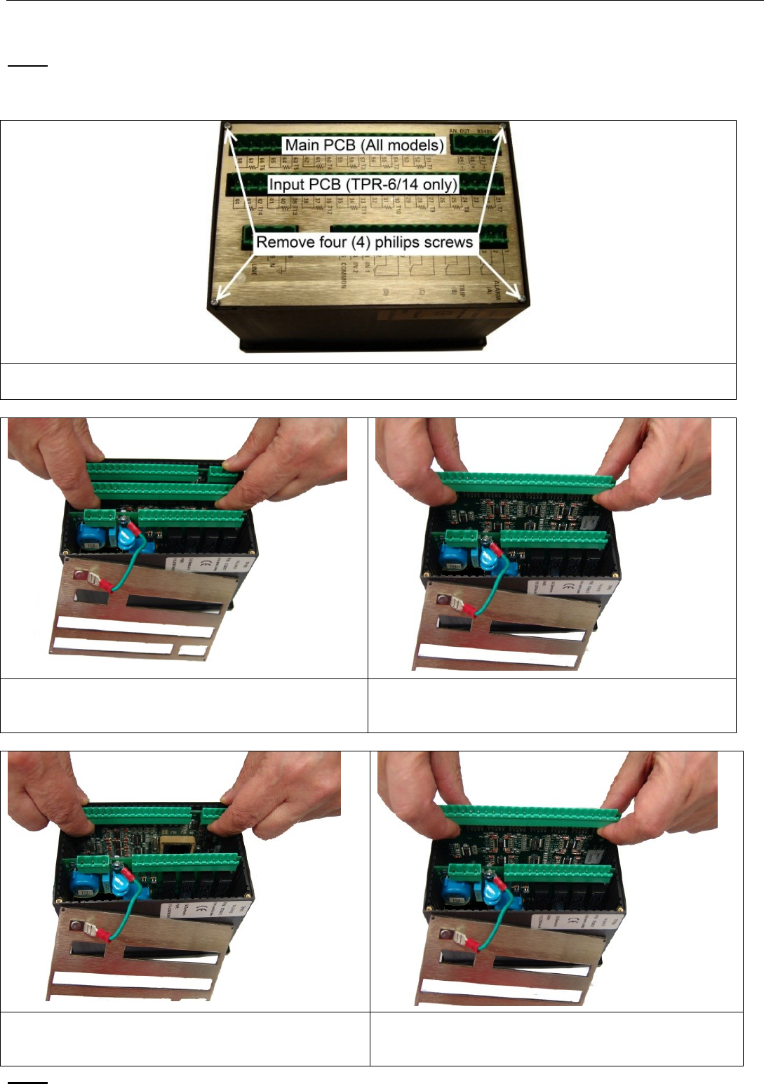
8.1 Dismantling the Main PCB and the Input PCB
Note:
This procedure must be done by a qualified personnel.
Verify that the TPR-6 is completely disconnected from any power source before this procedure is done.
1. Identify the Main PCB (in All models) and Input PCB (TPR-6/14 only).
2. Remove four screws holding the back cover of the TPR-6 and remove the cover.
3. Hold the Input PCB by the two sides of the
connector with four fingers as shown in the
picture.
4. Pull upwards to remove the Input PCB as
shown in the picture.
5. Hold the Main PCB by the two sides of the
connector with four fingers as shown in the
picture.
6. Pull upwards to remove the Main PCB as
shown in the picture.
Note:
Upon completion of dip switch settings re-install both PCBs gently and close the back cover.

22 • Tripping / Alarm Default Settings
________________________________________________________________________________________________
9. TRIPPING / ALARM DEFAULT SETTINGS
In this table, (+) stands for ENABLED, (-) for DISABLED.
Print this page for every installed unit, mark its serial number, installation number, drawing number and
General notes for future reference concerning this installation.
Mark the newly programmed values into the parenthesis ( ) of each item for future reference.
Installation Number : _________________, TPR-6 Serial Number : ________________________
Drawing Number : ______________________, Project Name/Number : _____________________
Protection
Trip
Alarm
Auto
Reset
Relay
C
Relay D
Active
During
ANSI
Code
1
T1 LEVEL 1
(-) ( )
(+) ( )
(-) ( )
(-) ( )
(-) ( )
Always
49R
2
T2 LEVEL 1
(-) ( )
(+) ( )
(-) ( )
(-) ( )
(-) ( )
Always
49R
3
T3 LEVEL 1
(-) ( )
(+) ( )
(-) ( )
(-) ( )
(-) ( )
Always
49R
4
T4 LEVEL 1
(-) ( )
(-) ( )
(-) ( )
(-) ( )
(-) ( )
Always
49R
5
T5 LEVEL 1
(-) ( )
(-) ( )
(-) ( )
(-) ( )
(-) ( )
Always
49R
6
T6 LEVEL 1
(-) ( )
(-) ( )
(-) ( )
(-) ( )
(-) ( )
Always
49R
7
T7 LEVEL 1
(-) ( )
(-) ( )
(-) ( )
(-) ( )
(-) ( )
Always
49R
8
T8 LEVEL 1
(-) ( )
(-) ( )
(-) ( )
(-) ( )
(-) ( )
Always
49R
9
T9 LEVEL 1
(-) ( )
(-) ( )
(-) ( )
(-) ( )
(-) ( )
Always
49R
10
T10 LEVEL 1
(-) ( )
(-) ( )
(-) ( )
(-) ( )
(-) ( )
Always
49R
11
T11 LEVEL 1
(-) ( )
(-) ( )
(-) ( )
(-) ( )
(-) ( )
Always
49R
12
T12 LEVEL 1
(-) ( )
(-) ( )
(-) ( )
(-) ( )
(-) ( )
Always
49R
13
T13 LEVEL 1
(-) ( )
(-) ( )
(-) ( )
(-) ( )
(-) ( )
Always
49R
14
T14 LEVEL 1
(-) ( )
(-) ( )
(-) ( )
(-) ( )
(-) ( )
Always
49R
15
T1 LEVEL 2
(+) ( )
(-) ( )
(-) ( )
(-) ( )
(-) ( )
Always
49R
16
T2 LEVEL 2
(+) ( )
(-) ( )
(-) ( )
(-) ( )
(-) ( )
Always
49R
17
T3 LEVEL 2
(+) ( )
(-) ( )
(-) ( )
(-) ( )
(-) ( )
Always
49R
18
T4 LEVEL 2
(-) ( )
(-) ( )
(-) ( )
(-) ( )
(-) ( )
Always
49R
19
T5 LEVEL 2
(-) ( )
(-) ( )
(-) ( )
(-) ( )
(-) ( )
Always
49R
20
T6 LEVEL 2
(-) ( )
(-) ( )
(-) ( )
(-) ( )
(-) ( )
Always
49R
21
T7 LEVEL 2
(-) ( )
(-) ( )
(-) ( )
(-) ( )
(-) ( )
Always
49R
22
T8 LEVEL 2
(-) ( )
(-) ( )
(-) ( )
(-) ( )
(-) ( )
Always
49R
23
T9 LEVEL 2
(-) ( )
(-) ( )
(-) ( )
(-) ( )
(-) ( )
Always
49R
24
T10 LEVEL 2
(-) ( )
(-) ( )
(-) ( )
(-) ( )
(-) ( )
Always
49R
25
T11 LEVEL 2
(-) ( )
(-) ( )
(-) ( )
(-) ( )
(-) ( )
Always
49R
26
T12 LEVEL 2
(-) ( )
(-) ( )
(-) ( )
(-) ( )
(-) ( )
Always
49R
27
T13 LEVEL 2
(-) ( )
(-) ( )
(-) ( )
(-) ( )
(-) ( )
Always
49R
28
T14 LEVEL 2
(-) ( )
(-) ( )
(-) ( )
(-) ( )
(-) ( )
Always
49R
29
EXTERNAL INPUT 1
(-) ( )
(-) ( )
(-) ( )
(-) ( )
(-) ( )
Always
86 / 94
30
EXTERNAL INPUT 2
(-) ( )
(-) ( )
(-) ( )
(-) ( )
(-) ( )
Always
86 / 94
31
COMM. PORT FAILED
(-) ( )
(-) ( )
(+) ( )
(-) ( )
(-) ( )
Always
3
32
INTERNAL FAULT
(-) ( )
(+) ( )
(-) ( )
(-) ( )
(-) ( )
Always
3
General Notes : ____________________________________________________________________

23 • Flash Messages
________________________________________________________________________________________________
10. FLASH MESSAGES
The message is displayed for a short while only. Display than returns to the previous message. Flash
messages are usually displayed as a response to an operator action.
It is used either to confirm activation of the requested operation, or to indicate reason for not doing so.
Flash messages are :
Display
Description
DATA SAVED OK
Displayed after pressing Store key. If an error is found during store
process, then next message is shown.
STORAGE ERROR
Displayed when an error is found in the store process.
WRONG PARAMETERS
Displayed after power-up, if the non-volatile parameter check sum is
found to be wrong.
UNAUTHORIZED ACCESS
When Authorized Key is open (locked), and a parameter change is
attempted. Also displayed after Unauthorized Store and Reset action.
SELF TEST PASSED
Displayed as a response to running the built in test procedure,
provided that all tests were "O.K.".
SELF TEST FAILED
ERROR CODE = 32
Displayed as a response to finding an error during the operation of
Test procedure.
Error code should be reported to Authorized Factory representative.
24 • TPR-6 Communication
________________________________________________________________________________________________
11. TPR-6 COMMUNICATION
The TPR-6 is equipped with a powerful data communication system, operating beyond a motor protection
controller into the realm of a complete motor management system.
This communication system is unmatched in its reliability, flexibility and ease of use providing the ideal basis
for the design of a modern motor management system.
The TPR-6 incorporates RS485 serial link and uses a MODBUS RTU protocol (The protocol is not included in
this document) to provides high speed data acquisition to supervisory computers.
Data formats have been carefully structured to provide fast notification of alarms and continuous updates of
performance parameters. Load control can be performed from host computers or by PLCs.
The following information and control can be accessed through the communication.
* All Actual data parameters
* All TPR-6 Settings (Read & Write)
* Reset
The TPR-6 system is user expandable. No special engineering skills or tools are required.
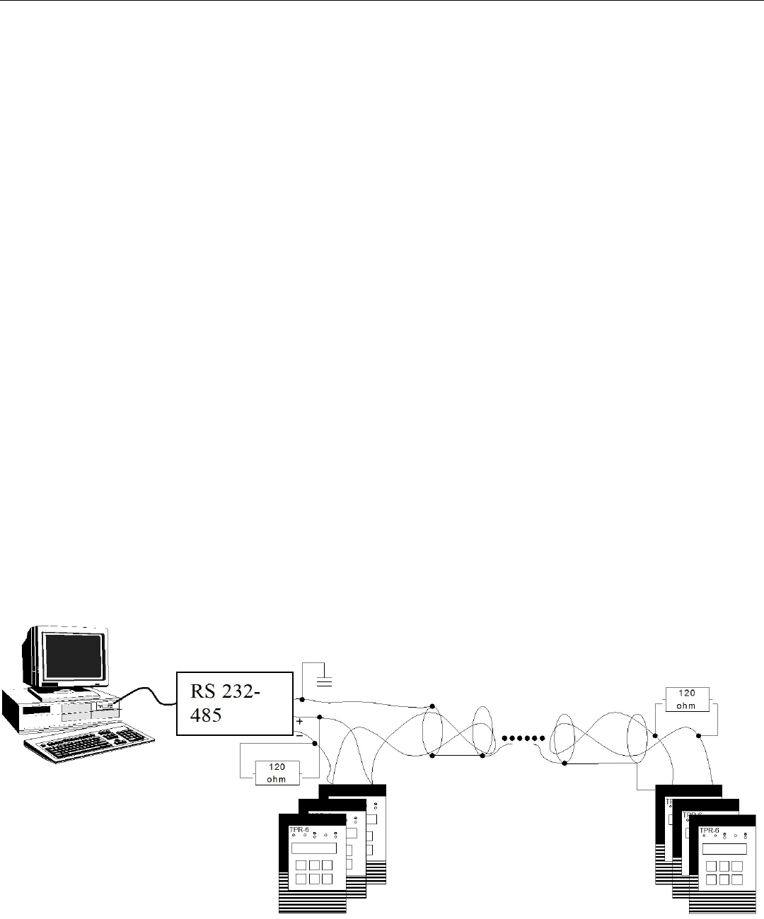
For small systems, the Host computer can communicate directly with the TPR-6 via a twisted shielded pair.
For larger systems a Data Highway enables multiple TPR-6 connection. Up to 32 TPR’s can be added on
each twisted pair of the Host serial link with full access to all TPR's.
The system also performs high speed data acquisition Users therefore have a simple and friendly means of
building a fully integrated monitoring and control systems.
System reliability is exceptionally high, meeting the highest standards of protected communication in the
industry. Included in each message is a 16 bit CRC.

25 • Technical Specifications
________________________________________________________________________________________________
12. TECHNICAL SPECIFICATIONS
Auxiliary Power Supply
(terminals 19-20)
Ac Power Supply: 110-240V 50/60Hz or DC (+10% / -15%)
Power consumption: 12 VA or 10W. Recommended fuse rating: 0.5A.
Temperature Inputs
Types: TPR-6/6 with 6 temp. inputs and TPR-6/14 with 14 temp. inputs
Temp. Inputs: Field adjustable (dip switches) as RTD (Pt100) or Thermistors (software
programmable as PTC or NTC).
Temp. Range: For RTD: 5-250 deg C. For Thermistors: 0.5 – 30 KΏ
Time delay: 2 Sec.
Accuracy: ± 3% of full scale resistance.
Max wire resistance: 25% of Sensor resistance at 10 deg C.
Fault Time Delays
Accuracy: ±0.5 Sec. or ±2% of time, which ever is greater, for all but the above
mentioned faults and the following exceptions:
Relays Contacts
(terminals 1-12)
Rated load: 8A/250 VAC (VDE, UL, cUL); 8A/24VDC (UL, cUL).
Maximum breaking capacity AC: 2000 VA
Max. DC Load Breaking Capacity: 8A at 30VDC.
Dielectric Strength
1500 VAC, for 1 minute, Between Ground (terminal 18) and:
* Auxiliary power supply inputs
* Control Terminal
Discrete Inputs
(terminals 13-15)
Two Discrete (digital) inputs. The inputs are optically Isolated.
Input voltage to 110 -240V 50/60Hz or DC (+10% / -15%).
Ambient and
Storage temperatures
Operation temperature: 50°C
Storage: 70°C
26 • Dimensions and Cut-Out Dimensions
________________________________________________________________________________________________
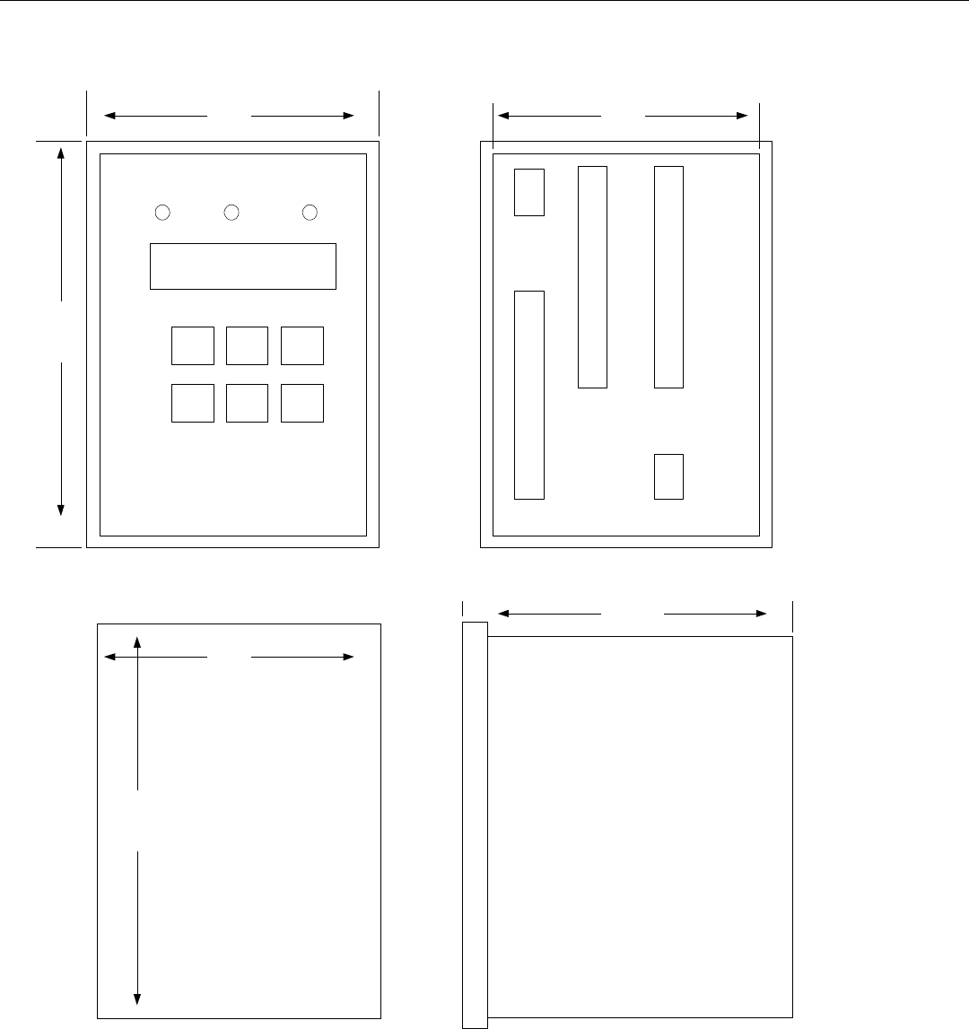
13. DIMENSIONS AND CUT-OUT DIMENSIONS
86.4
107
Cut-Out
92
138
144
96

27 • Ordering Information
________________________________________________________________________________________________
14. ORDERING INFORMATION
TPR-6
14-
2-
M-
0-
S
No. of
Temp.
Inputs
Supply
Voltage
Comm.
Required
Options
Front
Panel
No. Of Temp. Inputs
Specify
Description
6
6 Temperature Inputs
14
14 Temperature Inputs
Supply Voltage
Specify
Description
2
110-240V 50/60Hz or DC (+10% / -15%)
Communication
Specify
Description
M
RS485 with MODBUS protocol
Required Options
Specify
Description
0
No Option
8
Conformal coating
M
Marine approval (Consult factory)
Front Panel
Specify
Description
S
Standard