TSIP Reference Rev C, April 1999 Trimble Manual
User Manual: Pdf
Open the PDF directly: View PDF ![]() .
.
Page Count: 593 [warning: Documents this large are best viewed by clicking the View PDF Link!]
- TSIP Reference, Rev C
- Legal
- Contents
- List of Figures
- List of Tables
- Preface
- 1 Trimble Standard Interface Protocol
- 1.1 TSIP Interface Scope
- 1.2 TSIP Implementation Clarifications
- 1.3 TSIP Signal Characteristics
- 1.4 TSIP Packet Structure
- 1.5 Key GPS Setup Parameters
- 2 Command Packets
- 2.1 Command Packet Summary
- 2.2 Command Packet Descriptions
- Command Packet 0x1A
- Command Packet 0x1D
- Command Packet 0x1E
- Command Packet 0x1F
- Command Packet 0x20
- Command Packet 0x21
- Command Packet 0x22
- Command Packet 0x23
- Command Packet 0x24
- Command Packet 0x25
- Command Packet 0x26
- Command Packet 0x27
- Command Packet 0x28
- Command Packet 0x29
- Command Packet 0x2A
- Command Packet 0x2B
- Command Packet 0x2C
- Command Packet 0x2D
- Command Packet 0x2E
- Command Packet 0x2F
- Command Packet 0x31
- Command Packet 0x32
- Command Packet 0x33
- Command Packet 0x34
- Command Packet 0x35
- Command Packet 0x36
- Command Packet 0x37
- Command Packet 0x38
- Command Packet 0x39
- Command Packet 0x3A
- Command Packet 0x3B
- Command Packet 0x3C
- Command Packet 0x3D
- Command Packet 0x3E
- Command Packet 0x60
- Command Packet 0x61
- Command Packet 0x62
- Command Packet 0x65
- Command Packet 0x67
- Command Packet 0x68
- Command Packet 0x6A
- Command Packet 0x6B
- Command Packet 0x6D
- Command Packet 0x6E
- Command Packet 0x70
- Command Packet 0x75
- Command Packet 0x77
- Command Packet 0x7A
- Command Packet 0x7A 0x00
- Command Packet 0x7A 0x01
- Command Packet 0x7A 0x02
- Command Packet 0x7A 0x03
- Command Packet 0x7A 0x04
- Command Packet 0x7A 0x05
- Command Packet 0x7A 0x06
- Command Packet 0x7A 0x80
- Command Packet 0x7A 0x81
- Command Packet 0x7A 0x82
- Command Packet 0x7A 0x83
- Command Packet 0x7A 0x84
- Command Packet 0x7A 0x85
- Command Packet 0x7A 0x86
- Command Packet 0x7C
- Command Packet 0x8E
- Command Packet 0x8E 0x20
- Command Packet 0x8E 0x60
- Command Packet 0x8E 0x62
- Command Packet 0x8E 0x64
- Command Packet 0x8E 0x6B
- Command Packet 0x8E 0x6D
- Command Packet 0x8E 0x6F
- Command Packet 0x8E 0x70 (Obsolete)
- Command Packet 0x8E 0x71
- Command Packet 0x8E 0x73 (Obsolete)
- Command Packet 0x8E 0x74
- Command Packet 0x8E 0x75
- Command Packet 0x8E 0x76
- Command Packet 0x8E 0x78
- Command Packet 0x8E 0x79
- Command Packet 0x8E 0x7A
- Command Packet 0x8E 0x7B
- Command Packet 0x8E 0x7C
- Command Packet 0x8E 0x7E
- Command Packet 0x8E 0x7F
- Command Packet 0x8E 0x80
- Command Packet 0x8E 0x81
- Command Packet 0x8E 0x82
- Command Packet 0x8E 0x84
- Command Packet 0x8E 0x85
- Command Packet 0x8E 0x86
- Command Packet 0x8E 0x87
- Command Packet 0x8E 0x88
- Command Packet 0x8E 0x89
- Command Packet 0x8E 0x8A
- Command Packet 0x8E 0x8B
- Command Packet 0x8E 0x8E
- Command Packet 0x8E 0x8F
- Command Packet 0x8E 0x90
- Command Packet 0x8E 0x91
- Command Packet 0x8E 0x92
- Command Packet 0x8E 0x94
- Command Packet 0x8E 0x95
- Command Packet 0x8E 0x96
- Command Packet 0x8E 0x97
- Command Packet 0x8E 0x98
- Command Packet 0x8E 0x9A
- Command Packet 0xB0
- Command Packet 0xBB
- Command Packet 0xBC
- Command Packet 0xC2
- 3 Report Packets
- 3.1 Report Packet Summary
- 3.2 Report Packet Descriptions
- Report Packet 0x13
- Report Packet 0x1A
- Report Packet 0x3D
- Report Packet 0x40
- Report Packet 0x41
- Report Packet 0x42
- Report Packet 0x43
- Report Packet 0x44
- Report Packet 0x45
- Report Packet 0x46
- Report Packet 0x47
- Report Packet 0x48
- Report Packet 0x49
- Report Packet 0x4A
- Report Packet 0x4B
- Report Packet 0x4C
- Report Packet 0x4D
- Report Packet 0x4E
- Report Packet 0x4F
- Report Packet 0x53
- Report Packet 0x54
- Report Packet 0x55
- Report Packet 0x56
- Report Packet 0x57
- Report Packet 0x58
- Report Packet 0x59
- Report Packet 0x5A
- Report Packet 0x5B
- Report Packet 0x5C
- Report Packet 0x5E
- Report Packet 0x5F
- Report Packet 0x60
- Report Packet 0x61
- Report Packet 0x6A
- Report Packet 0x6D
- Report Packet 0x6E
- Report Packet 0x6F
- Report Packet 0x70
- Report Packet 0x76
- Report Packet 0x78
- Report Packet 0x7B
- Report Packet 0x7D
- Report Packet 0x82
- Report Packet 0x83
- Report Packet 0x84
- Report Packet 0x85
- Report Packet 0x87
- Report Packet 0x88
- Report Packet 0x8B
- Report Packet 0x8D
- Report Packet 0x8F
- Report Packet 0x8F 0x20
- Report Packet 0x8F 0x60
- Report Packet 0x8F 0x62
- Report Packet 0x8F 0x64
- Report Packet 0x8F 0x6B
- Report Packet 0x8F 0x6D
- Report Packet 0x8F 0x6F
- Report Packet 0x8F 0x70 (Obsolete)
- Report Packet 0x8F 0x71
- Report Packet 0x8F 0x73 (Obsolete)
- Report Packet 0x8F 0x74
- Report Packet 0x8F 0x75
- Report Packet 0x8F 0x76
- Report Packet 0x8F 0x77
- Report Packet 0x8F 0x78
- Report Packet 0x8F 0x79
- Report Packet 0x8F 0x7A
- Report Packet 0x8F 0x7B
- Report Packet 0x8F 0x7C
- Report Packet 0x8F 0x7E
- Report Packet 0x8F 0x7F
- Report Packet 0x8F 0x80
- Report Packet 0x8F 0x81
- Report Packet 0x8F 0x82
- Report Packet 0x8F 0x84
- Report Packet 0x8F 0x85
- Report Packet 0x8F 0x86
- Report Packet 0x8F 0x87
- Report Packet 0x8F 0x88
- Report Packet 0x8F 0x89
- Report Packet 0x8F 0x8A
- Report Packet 0x8F 0x8B
- Report Packet 0x8F 0x8E
- Report Packet 0x8F 0x8F
- Report Packet 0x8F 0x90
- Report Packet 0x8F 0x91
- Report Packet 0x8F 0x92
- Report Packet 0x8F 0x94
- Report Packet 0x8F 0x95
- Report Packet 0x8F 0x96
- Report Packet 0x8F 0x97
- Report Packet 0x8F 0x98
- Report Packet 0x8F 0x9A
- Report Packet 0xB0
- Report Packet 0xBB
- Report Packet 0xBC
- A Packet Usage Summary
- B Mapping Products
- C Marine Products
- C.1 Supported Marine Products
- C.2 Supported TSIP Packets
- C.3 Supported NMEA Messages
- C.4 Key GPS Configuration Parameters
- C.5 DSM and DSM Reference Station
- C.6 DSMPro
- C.7 DSM12
- C.8 DSM212H and DSM212L
- C.9 DSM12RS
- C.10 NT300D
- D Mobile Positioning and Communication Products
- E Machine Control Products
- E.1 Supported Machine Control Products
- E.2 Supported TSIP Packets
- E.3 Supported NMEA Messages
- E.4 Key GPS Parameter Settings
- E.5 AgGPS 120
- E.6 AgGPS 122
- E.7 AgGPS 124
- E.8 AgGPS 132
- E.9 DSM EuroCard
- E.10 BD112
- E.11 BD122
- E.12 BD132
- F NMEA-0183 Messages
- Alphabetical Packet Index
- Numerical Packet Index
- Index
- Reader Comment Form
TSIP Reference
Part Number: 34462-00
Revision: C
Date: April 1999
Trimble Navigation Limited
645 North Mary Avenue
Post Office Box 3642
Sunnyvale, CA 94088-3642
U.S.A.
+1-800-827-8000 in North America
+1-408-481-8000 International
FAX: +1-408-481-7744
www.trimble.com
Trimble Navigation Europe Limited
Trimble House, Meridian Office Park
Osborn Way, Hook
Hampshire RG27 9HX
ENGLAND
+44-1256-760-150
Fax: +44-1256-760-148
Voicemail: +44-1256-761-130
Trimble Navigation Singapore PTE Limited
79 Anson Road
# 05-02
Singapore 079906
SINGAPORE
+65-325-5668
Fax: +65-225-9989
Voicemail: +65-325-5668
Trimble Japan K.K.
Sumitomo Hamamatsu-cho, Building 10F
1-18-16 Hamamatsu-cho Minato-ku
Tokyo 105
JAPAN
+81-3-5472-0880
Fax: +81-3-5472-2326
Trimble Navigation New Zealand Limited
11 Birmingham Drive
P.O. Box 8729 Riccarton
Christchurch
NEW ZEALAND
+64-3-339-1400
Fax: +64-3-339-1417
Copyrights
© 1998 Trimble Navigation Limited. All rights reserved. No part of this manual may be
copied, photocopied, reproduced, translated, or reduced to any electronic medium or
machine-readable form without prior written consent from Trimble Navigation Limited.
Printed in the United States of America. Printed on recycled paper.
Revision Notice
This is the first release of the TSIP Reference, Part Number 34462-00, Revision C, April
1999.
Trademarks
AgGPS, AL9000, BD132, DSM, DSMPro, DSM EuroCard, DSM12, DSM12RS,
DSM212H, DSM212L, NT300D, Placer GPS 450, Placer GPS 455, Placer GPS 455DR,
Crosscheck AMPS Cellular, CrossCheck XR, CrossCheck XRDR, ProXR, ProXRS, TAIP,
TANS, and TSIP are trademarks of Trimble Navigation Limited. IBM is a registered
trademark of International Business Machines, Inc. MS-DOS and Windows is a trademark
of Microsoft Corporation. Intel is a trademark of Intel Corporation. All other brand names
are trademarks of their respective holders.
Disclaimer of Warranty
EXCEPT AS INDICATED IN “LIMITED WARRANTY” HEREIN, TRIMBLE HARDWARE, SOFTWARE, FIRMWARE AND
DOCUMENTATION IS PROVIDED “AS IS” AND WITHOUT EXPRESS OR LIMITED WARRANTY OF ANY KIND BY
EITHER TRIMBLE OR ANYONE WHO HAS BEEN INVOLVED IN ITS CREATION, PRODUCTION, OR DISTRIBUTION
INCLUDING BUT NOT LIMITED TO THE IMPLIED WARRANTIES OF MERCHANTABILITY AND FITNESS FOR A
PARTICULAR PURPOSE. THE ENTIRE RISK, AS TO THE QUALITY AND PERFORMANCE OF THE TRIMBLE
HARDWARE, SOFTWARE, FIRMWARE AND DOCUMENTATION, IS WITH YOU. SOME STATES DO NOT ALLOW THE
EXCLUSION OF IMPLIED WARRANTIES, SO THE ABOVE EXCLUSION MAY NOT APPLY TO YOU.
Limitation of Liability
IN NO EVENT WILL TRIMBLE OR ANY PERSON INVOLVED IN THE CREATION, PRODUCTION, OR DISTRIBUTION
OF THE TRIMBLE SOFTWARE BE LIABLE TO YOU ON ACCOUNT OF ANY CLAIM FOR ANY DAMAGES,
INCLUDING ANY LOST PROFITS, LOST SAVINGS, OR OTHER SPECIAL, INCIDENTAL, CONSEQUENTIAL, OR
EXEMPLARY DAMAGES, INCLUDING BUT NOT LIMITED TO ANY DAMAGES ASSESSED AGAINST OR PAID BY
YOU TO ANY THIRD PARTY, RISING OUT OF THE USE, LIABILITY TO USE, QUALITY OR PERFORMANCE OF SUCH
TRIMBLE SOFTWARE AND DOCUMENTATION, EVEN IF TRIMBLE OR ANY SUCH PERSON OR ENTITY HAS BEEN
ADVISED OF THE POSSIBILITY OF DAMAGES, OR FOR ANY CLAIM BY ANY OTHER PARTY. SOME STATES DO
NOT ALLOW THE LIMITATION OR EXCLUSION OF LIABILITY FOR INCIDENTAL OR CONSEQUENTIAL DAMAGES
SO, THE ABOVE LIMITATIONS MAY NOT APPLY TO YOU.
Software and Firmware Limited Warranty
Trimble warrants that Software and Firmware products will substantially conform to the
published specifications provided it is used with the Trimble products, computer products,
and operating system for which it was designed. For a period of ninety (90) days,
commencing thirty (30) days after shipment from Trimble, Trimble also warrants that the
magnetic media on which Software and Firmware are distributed and the documentation
are free from defects in materials and workmanship. During the ninety (90) day warranty
period, Trimble will replace defective media or documentation, or correct substantial
program errors at no charge. If Trimble is unable to replace defective media or
documentation, or correct program errors, Trimble will refund the price paid for The
Software. These are your sole remedies for any breach in warranty.

TSIP Reference v
Contents
Preface
Scope and Audience . . . . . . . . . . . . . . . . . . . . . . . . . . . . . . . . . . . xxxix
Organization . . . . . . . . . . . . . . . . . . . . . . . . . . . . . . . . . . . . . . . xxxix
Related Information . . . . . . . . . . . . . . . . . . . . . . . . . . . . . . . . . . . xl
Document Updates . . . . . . . . . . . . . . . . . . . . . . . . . . . . . . xl
World Wide Web (WWW) Site . . . . . . . . . . . . . . . . . . . . . . . . xl
File Transfer Protocol (FTP) Site . . . . . . . . . . . . . . . . . . . . . . . xli
Technical Assistance. . . . . . . . . . . . . . . . . . . . . . . . . . . . . . . . . . . xli
Reader Comment Form . . . . . . . . . . . . . . . . . . . . . . . . . . . . . . . . . xli
Document Conventions . . . . . . . . . . . . . . . . . . . . . . . . . . . . . . . . . xlii
Notes, Tips, Cautions, and Warnings . . . . . . . . . . . . . . . . . . . . . . . . . . xlii
1 Trimble Standard Interface Protocol
1.1 TSIP Interface Scope . . . . . . . . . . . . . . . . . . . . . . . . . . . . . . . . . . 1-2
1.2 TSIP Implementation Clarifications . . . . . . . . . . . . . . . . . . . . . . . . . . . 1-2
1.2.1 Machine Codes and Product ID Codes . . . . . . . . . . . . . . . . . . . . 1-2
1.2.2 Serial Port Naming Conventions . . . . . . . . . . . . . . . . . . . . . . . 1-2
1.2.3 TSIP Packets Supported by Individual Receivers . . . . . . . . . . . . . . . 1-3
1.3 TSIP Signal Characteristics . . . . . . . . . . . . . . . . . . . . . . . . . . . . . . . 1-3
1.4 TSIP Packet Structure . . . . . . . . . . . . . . . . . . . . . . . . . . . . . . . . . . 1-3
1.4.1 Packets. . . . . . . . . . . . . . . . . . . . . . . . . . . . . . . . . . . . . 1-3
1.4.2 Subpackets. . . . . . . . . . . . . . . . . . . . . . . . . . . . . . . . . . . 1-4
1.4.3 Checksums. . . . . . . . . . . . . . . . . . . . . . . . . . . . . . . . . . . 1-4
1.4.4 Data Types . . . . . . . . . . . . . . . . . . . . . . . . . . . . . . . . . . . 1-5
1.5 Key GPS Setup Parameters . . . . . . . . . . . . . . . . . . . . . . . . . . . . . . . 1-6
1.5.1 Key Mobile Receiver Setup Parameters . . . . . . . . . . . . . . . . . . . . 1-6
1.5.2 GPS Parameter Descriptions . . . . . . . . . . . . . . . . . . . . . . . . . 1-7
1.5.3 GPS Position Fix Mode . . . . . . . . . . . . . . . . . . . . . . . . . . . . 1-8
1.5.4 GPS Operating Parameters . . . . . . . . . . . . . . . . . . . . . . . . . . 1-8
Dynamics Code . . . . . . . . . . . . . . . . . . . . . . . . . . . . . . . . 1-9
Elevation Mask . . . . . . . . . . . . . . . . . . . . . . . . . . . . . . . . 1-9

vi TSIP Reference
Contents
SNR Mask . . . . . . . . . . . . . . . . . . . . . . . . . . . . . . . . . . . 1-10
PDOP Mask and Switch . . . . . . . . . . . . . . . . . . . . . . . . . . . . 1-10
1.5.5 I/O Options . . . . . . . . . . . . . . . . . . . . . . . . . . . . . . . . . . 1-10
Fix Computation Time . . . . . . . . . . . . . . . . . . . . . . . . . . . . 1-11
Minimum Projection Flag . . . . . . . . . . . . . . . . . . . . . . . . . . . 1-11
Simultaneous Measurements Flag. . . . . . . . . . . . . . . . . . . . . . . 1-11
1.5.6 DGPS Position Fix Mode . . . . . . . . . . . . . . . . . . . . . . . . . . . 1-12
1.5.7 Overdetermined Mode. . . . . . . . . . . . . . . . . . . . . . . . . . . . . 1-12
2 Command Packets
2.1 Command Packet Summary . . . . . . . . . . . . . . . . . . . . . . . . . . . . . . . 2-2
2.2 Command Packet Descriptions . . . . . . . . . . . . . . . . . . . . . . . . . . . . . 2-7
Command Packet 0x1A . . . . . . . . . . . . . . . . . . . . . . . . . . . . . . . . . 2-7
Command Packet 0x1A 0x00 . . . . . . . . . . . . . . . . . . . . . . . . . . . . . . 2-7
Command Packet 0x1D . . . . . . . . . . . . . . . . . . . . . . . . . . . . . . . . . 2-7
Command Packet 0x1E . . . . . . . . . . . . . . . . . . . . . . . . . . . . . . . . . 2-8
Command Packet 0x1F . . . . . . . . . . . . . . . . . . . . . . . . . . . . . . . . . 2-8
Command Packet 0x20 . . . . . . . . . . . . . . . . . . . . . . . . . . . . . . . . . 2-8
Command Packet 0x21 . . . . . . . . . . . . . . . . . . . . . . . . . . . . . . . . . 2-9
Command Packet 0x22 . . . . . . . . . . . . . . . . . . . . . . . . . . . . . . . . . 2-9
Command Packet 0x23 . . . . . . . . . . . . . . . . . . . . . . . . . . . . . . . . . 2-10
Command Packet 0x24 . . . . . . . . . . . . . . . . . . . . . . . . . . . . . . . . . 2-10
Command Packet 0x25 . . . . . . . . . . . . . . . . . . . . . . . . . . . . . . . . . 2-11
Command Packet 0x26 . . . . . . . . . . . . . . . . . . . . . . . . . . . . . . . . . 2-11
Command Packet 0x27 . . . . . . . . . . . . . . . . . . . . . . . . . . . . . . . . . 2-11
Command Packet 0x28 . . . . . . . . . . . . . . . . . . . . . . . . . . . . . . . . . 2-11
Command Packet 0x29 . . . . . . . . . . . . . . . . . . . . . . . . . . . . . . . . . 2-11
Command Packet 0x2A . . . . . . . . . . . . . . . . . . . . . . . . . . . . . . . . . 2-12
Command Packet 0x2B . . . . . . . . . . . . . . . . . . . . . . . . . . . . . . . . . 2-13
Command Packet 0x2C . . . . . . . . . . . . . . . . . . . . . . . . . . . . . . . . . 2-14
Command Packet 0x2D . . . . . . . . . . . . . . . . . . . . . . . . . . . . . . . . . 2-15
Command Packet 0x2E . . . . . . . . . . . . . . . . . . . . . . . . . . . . . . . . . 2-15
Command Packet 0x2F . . . . . . . . . . . . . . . . . . . . . . . . . . . . . . . . . 2-15
Command Packet 0x31 . . . . . . . . . . . . . . . . . . . . . . . . . . . . . . . . . 2-15
Command Packet 0x32 . . . . . . . . . . . . . . . . . . . . . . . . . . . . . . . . . 2-16
Command Packet 0x33 . . . . . . . . . . . . . . . . . . . . . . . . . . . . . . . . . 2-16
Command Packet 0x34 . . . . . . . . . . . . . . . . . . . . . . . . . . . . . . . . . 2-16
Command Packet 0x35 . . . . . . . . . . . . . . . . . . . . . . . . . . . . . . . . . 2-17
Command Packet 0x36 . . . . . . . . . . . . . . . . . . . . . . . . . . . . . . . . . 2-20

TSIP Reference vii
Contents
Command Packet 0x37 . . . . . . . . . . . . . . . . . . . . . . . . . . . . . . . . . 2-20
Command Packet 0x38 . . . . . . . . . . . . . . . . . . . . . . . . . . . . . . . . . 2-21
Command Packet 0x39 . . . . . . . . . . . . . . . . . . . . . . . . . . . . . . . . . 2-23
Command Packet 0x3A . . . . . . . . . . . . . . . . . . . . . . . . . . . . . . . . . 2-25
Command Packet 0x3B . . . . . . . . . . . . . . . . . . . . . . . . . . . . . . . . . 2-25
Command Packet 0x3C . . . . . . . . . . . . . . . . . . . . . . . . . . . . . . . . . 2-26
Command Packet 0x3D . . . . . . . . . . . . . . . . . . . . . . . . . . . . . . . . . 2-26
Command Packet 0x3E . . . . . . . . . . . . . . . . . . . . . . . . . . . . . . . . . 2-29
Command Packet 0x60 . . . . . . . . . . . . . . . . . . . . . . . . . . . . . . . . . 2-29
Command Packet 0x61 . . . . . . . . . . . . . . . . . . . . . . . . . . . . . . . . . 2-31
Command Packet 0x62 . . . . . . . . . . . . . . . . . . . . . . . . . . . . . . . . . 2-33
Command Packet 0x65 . . . . . . . . . . . . . . . . . . . . . . . . . . . . . . . . . 2-35
Command Packet 0x67 . . . . . . . . . . . . . . . . . . . . . . . . . . . . . . . . . 2-35
Command Packet 0x67 0x00 . . . . . . . . . . . . . . . . . . . . . . . . . . . . . . 2-36
Command Packet 0x67 0x01 . . . . . . . . . . . . . . . . . . . . . . . . . . . . . . 2-36
Command Packet 0x67 0x02 . . . . . . . . . . . . . . . . . . . . . . . . . . . . . . 2-39
Command Packet 0x67 0x03 . . . . . . . . . . . . . . . . . . . . . . . . . . . . . . 2-39
Command Packet 0x67 0x04 . . . . . . . . . . . . . . . . . . . . . . . . . . . . . . 2-41
Command Packet 0x67 0x05 . . . . . . . . . . . . . . . . . . . . . . . . . . . . . . 2-41
Command Packet 0x67 0x06 . . . . . . . . . . . . . . . . . . . . . . . . . . . . . . 2-42
Command Packet 0x67 0x09 . . . . . . . . . . . . . . . . . . . . . . . . . . . . . . 2-43
Command Packet 0x67 0x0A . . . . . . . . . . . . . . . . . . . . . . . . . . . . . . 2-43
Command Packet 0x68 . . . . . . . . . . . . . . . . . . . . . . . . . . . . . . . . . 2-45
Command Packet 0x68 0x00 . . . . . . . . . . . . . . . . . . . . . . . . . . . . . . 2-45
Command Packet 0x68 0x01 . . . . . . . . . . . . . . . . . . . . . . . . . . . . . . 2-45
Command Packet 0x68 0x02 . . . . . . . . . . . . . . . . . . . . . . . . . . . . . . 2-46
Command Packet 0x68 0x03 . . . . . . . . . . . . . . . . . . . . . . . . . . . . . . 2-47
Command Packet 0x68 0x04 . . . . . . . . . . . . . . . . . . . . . . . . . . . . . . 2-48
Command Packet 0x68 0x05 . . . . . . . . . . . . . . . . . . . . . . . . . . . . . . 2-49
Command Packet 0x6A . . . . . . . . . . . . . . . . . . . . . . . . . . . . . . . . . 2-50
Command Packet 0x6A 0x01 . . . . . . . . . . . . . . . . . . . . . . . . . . . . . . 2-50
Command Packet 0x6B . . . . . . . . . . . . . . . . . . . . . . . . . . . . . . . . . 2-51
Command Packet 0x6B 0x00 . . . . . . . . . . . . . . . . . . . . . . . . . . . . . . 2-51
Command Packet 0x6B 0x01 . . . . . . . . . . . . . . . . . . . . . . . . . . . . . . 2-51
Command Packet 0x6B 0x02 . . . . . . . . . . . . . . . . . . . . . . . . . . . . . . 2-52
Command Packet 0x6B 0x03 . . . . . . . . . . . . . . . . . . . . . . . . . . . . . . 2-52
Command Packet 0x6D . . . . . . . . . . . . . . . . . . . . . . . . . . . . . . . . . 2-53
Command Packet 0x6D 0x00 . . . . . . . . . . . . . . . . . . . . . . . . . . . . . . 2-53
Command Packet 0x6D 0x01 . . . . . . . . . . . . . . . . . . . . . . . . . . . . . . 2-54

viii TSIP Reference
Contents
Command Packet 0x6D 0x02 . . . . . . . . . . . . . . . . . . . . . . . . . . . . . . 2-55
Command Packet 0x6D 0x03 . . . . . . . . . . . . . . . . . . . . . . . . . . . . . . 2-58
Command Packet 0x6D 0x04 . . . . . . . . . . . . . . . . . . . . . . . . . . . . . . 2-58
Command Packet 0x6E . . . . . . . . . . . . . . . . . . . . . . . . . . . . . . . . . 2-59
Command Packet 0x6E 0x01 . . . . . . . . . . . . . . . . . . . . . . . . . . . . . . 2-59
Command Packet 0x70 . . . . . . . . . . . . . . . . . . . . . . . . . . . . . . . . . 2-60
Command Packet 0x75 . . . . . . . . . . . . . . . . . . . . . . . . . . . . . . . . . 2-61
Command Packet 0x77 . . . . . . . . . . . . . . . . . . . . . . . . . . . . . . . . . 2-61
Command Packet 0x7A . . . . . . . . . . . . . . . . . . . . . . . . . . . . . . . . . 2-62
Command Packet 0x7A 0x00 . . . . . . . . . . . . . . . . . . . . . . . . . . . . . . 2-63
Command Packet 0x7A 0x01 . . . . . . . . . . . . . . . . . . . . . . . . . . . . . . 2-64
Command Packet 0x7A 0x02 . . . . . . . . . . . . . . . . . . . . . . . . . . . . . . 2-64
Command Packet 0x7A 0x03 . . . . . . . . . . . . . . . . . . . . . . . . . . . . . . 2-65
Command Packet 0x7A 0x04 . . . . . . . . . . . . . . . . . . . . . . . . . . . . . . 2-65
Command Packet 0x7A 0x05 . . . . . . . . . . . . . . . . . . . . . . . . . . . . . . 2-65
Command Packet 0x7A 0x06 . . . . . . . . . . . . . . . . . . . . . . . . . . . . . . 2-67
Command Packet 0x7A 0x80 . . . . . . . . . . . . . . . . . . . . . . . . . . . . . . 2-70
Command Packet 0x7A 0x81 . . . . . . . . . . . . . . . . . . . . . . . . . . . . . . 2-71
Command Packet 0x7A 0x82 . . . . . . . . . . . . . . . . . . . . . . . . . . . . . . 2-71
Command Packet 0x7A 0x83 . . . . . . . . . . . . . . . . . . . . . . . . . . . . . . 2-72
Command Packet 0x7A 0x84 . . . . . . . . . . . . . . . . . . . . . . . . . . . . . . 2-72
Command Packet 0x7A 0x85 . . . . . . . . . . . . . . . . . . . . . . . . . . . . . . 2-72
Command Packet 0x7A 0x86 . . . . . . . . . . . . . . . . . . . . . . . . . . . . . . 2-73
Command Packet 0x7C . . . . . . . . . . . . . . . . . . . . . . . . . . . . . . . . . 2-77
Command Packet 0x7C 0x00 . . . . . . . . . . . . . . . . . . . . . . . . . . . . . . 2-77
Command Packet 0x7C 0x01 . . . . . . . . . . . . . . . . . . . . . . . . . . . . . . 2-78
Supporting position fixes greater then 2 Hz. . . . . . . . . . . . . . . . . . 2-79
Command Packet 0x7C 0x02 . . . . . . . . . . . . . . . . . . . . . . . . . . . . . . 2-80
Command Packet 0x7C 0x03 . . . . . . . . . . . . . . . . . . . . . . . . . . . . . . 2-81
Command Packet 0x7C 0x05 . . . . . . . . . . . . . . . . . . . . . . . . . . . . . . 2-81
Command Packet 0x7C 0x06 . . . . . . . . . . . . . . . . . . . . . . . . . . . . . . 2-82
Command Packet 0x7C 0x09 . . . . . . . . . . . . . . . . . . . . . . . . . . . . . . 2-83
Command Packet 0x8E . . . . . . . . . . . . . . . . . . . . . . . . . . . . . . . . . 2-85
Command Packet 0x8E 0x20 . . . . . . . . . . . . . . . . . . . . . . . . . . . . . . 2-85
Command Packet 0x8E 0x60 . . . . . . . . . . . . . . . . . . . . . . . . . . . . . . 2-85
Command Packet 0x8E 0x62 . . . . . . . . . . . . . . . . . . . . . . . . . . . . . . 2-86
Command Packet 0x8E 0x64 . . . . . . . . . . . . . . . . . . . . . . . . . . . . . . 2-87
Command Packet 0x8E 0x6B . . . . . . . . . . . . . . . . . . . . . . . . . . . . . . 2-87
Command Packet 0x8E 0x6D . . . . . . . . . . . . . . . . . . . . . . . . . . . . . . 2-88

TSIP Reference ix
Contents
Command Packet 0x8E 0x6F . . . . . . . . . . . . . . . . . . . . . . . . . . . . . . 2-89
Command Packet 0x8E 0x70 (Obsolete) . . . . . . . . . . . . . . . . . . . . . . . . 2-89
Command Packet 0x8E 0x71 . . . . . . . . . . . . . . . . . . . . . . . . . . . . . . 2-89
Command Packet 0x8E 0x73 (Obsolete) . . . . . . . . . . . . . . . . . . . . . . . . 2-90
Command Packet 0x8E 0x74 . . . . . . . . . . . . . . . . . . . . . . . . . . . . . . 2-93
Command Packet 0x8E 0x75 . . . . . . . . . . . . . . . . . . . . . . . . . . . . . . 2-93
Command Packet 0x8E 0x76 . . . . . . . . . . . . . . . . . . . . . . . . . . . . . . 2-94
Command Packet 0x8E 0x78 . . . . . . . . . . . . . . . . . . . . . . . . . . . . . . 2-94
Command Packet 0x8E 0x79 . . . . . . . . . . . . . . . . . . . . . . . . . . . . . . 2-95
Command Packet 0x8E 0x7A . . . . . . . . . . . . . . . . . . . . . . . . . . . . . . 2-95
Command Packet 0x8E 0x7B . . . . . . . . . . . . . . . . . . . . . . . . . . . . . . 2-96
Command Packet 0x8E 0x7C . . . . . . . . . . . . . . . . . . . . . . . . . . . . . . 2-96
Command Packet 0x8E 0x7E . . . . . . . . . . . . . . . . . . . . . . . . . . . . . . 2-101
Command Packet 0x8E 0x7F . . . . . . . . . . . . . . . . . . . . . . . . . . . . . . 2-102
Command Packet 0x8E 0x80 . . . . . . . . . . . . . . . . . . . . . . . . . . . . . . 2-102
Command Packet 0x8E 0x81 . . . . . . . . . . . . . . . . . . . . . . . . . . . . . . 2-102
Command Packet 0x8E 0x82 . . . . . . . . . . . . . . . . . . . . . . . . . . . . . . 2-104
Command Packet 0x8E 0x84 . . . . . . . . . . . . . . . . . . . . . . . . . . . . . . 2-104
Command Packet 0x8E 0x85 . . . . . . . . . . . . . . . . . . . . . . . . . . . . . . 2-105
Command Packet 0x8E 0x86 . . . . . . . . . . . . . . . . . . . . . . . . . . . . . . 2-105
Command Packet 0x8E 0x87 . . . . . . . . . . . . . . . . . . . . . . . . . . . . . . 2-106
Command Packet 0x8E 0x88 . . . . . . . . . . . . . . . . . . . . . . . . . . . . . . 2-106
Command Packet 0x8E 0x89 . . . . . . . . . . . . . . . . . . . . . . . . . . . . . . 2-108
Important Note About Auto-Differential Source Mode . . . . . . . . . . . . 2-108
Command Packet 0x8E 0x8A . . . . . . . . . . . . . . . . . . . . . . . . . . . . . . 2-110
Command Packet 0x8E 0x8B . . . . . . . . . . . . . . . . . . . . . . . . . . . . . . 2-111
Command Packet 0x8E 0x8E . . . . . . . . . . . . . . . . . . . . . . . . . . . . . . 2-112
Command Packet 0x8E 0x8F . . . . . . . . . . . . . . . . . . . . . . . . . . . . . . 2-113
Command Packet 0x8E 0x90 . . . . . . . . . . . . . . . . . . . . . . . . . . . . . . 2-113
Command Packet 0x8E 0x91 . . . . . . . . . . . . . . . . . . . . . . . . . . . . . . 2-113
Display Mode . . . . . . . . . . . . . . . . . . . . . . . . . . . . . . . . . 2-113
Boundary Mode . . . . . . . . . . . . . . . . . . . . . . . . . . . . . . . . 2-113
Swath Direction . . . . . . . . . . . . . . . . . . . . . . . . . . . . . . . . 2-114
Swath Width . . . . . . . . . . . . . . . . . . . . . . . . . . . . . . . . . . 2-115
Output Rate . . . . . . . . . . . . . . . . . . . . . . . . . . . . . . . . . . 2-115
Command Packet 0x8E 0x92 . . . . . . . . . . . . . . . . . . . . . . . . . . . . . . 2-121
Indicator LED Sensitivity . . . . . . . . . . . . . . . . . . . . . . . . . . . 2-121
Command Packet 0x8E 0x94 . . . . . . . . . . . . . . . . . . . . . . . . . . . . . . 2-124
Command Packet 0x8E 0x95 . . . . . . . . . . . . . . . . . . . . . . . . . . . . . . 2-125

xTSIP Reference
Contents
Command Packet 0x8E 0x96 . . . . . . . . . . . . . . . . . . . . . . . . . . . . . . 2-126
Command Packet 0x8E 0x97 . . . . . . . . . . . . . . . . . . . . . . . . . . . . . . 2-127
Command Packet 0x8E 0x98 . . . . . . . . . . . . . . . . . . . . . . . . . . . . . . 2-127
Command Packet 0x8E 0x9A . . . . . . . . . . . . . . . . . . . . . . . . . . . . . . 2-129
Command Packet 0xB0 . . . . . . . . . . . . . . . . . . . . . . . . . . . . . . . . . 2-130
Command Packet 0xB0 0x00 . . . . . . . . . . . . . . . . . . . . . . . . . . . . . . 2-130
Command Packet 0xB0 0x01 . . . . . . . . . . . . . . . . . . . . . . . . . . . . . . 2-132
Command Packet 0xB0 0x40 . . . . . . . . . . . . . . . . . . . . . . . . . . . . . . 2-132
Command Packet 0xB0 0x41 . . . . . . . . . . . . . . . . . . . . . . . . . . . . . . 2-133
Command Packet 0xB0 0x42 . . . . . . . . . . . . . . . . . . . . . . . . . . . . . . 2-134
Command Packet 0xB0 0x43 . . . . . . . . . . . . . . . . . . . . . . . . . . . . . . 2-135
Command Packet 0xB0 0x44 . . . . . . . . . . . . . . . . . . . . . . . . . . . . . . 2-135
Command Packet 0xBB . . . . . . . . . . . . . . . . . . . . . . . . . . . . . . . . . 2-136
Command Packet 0xBB 0x00 . . . . . . . . . . . . . . . . . . . . . . . . . . . . . . 2-136
Command Packet 0xBC . . . . . . . . . . . . . . . . . . . . . . . . . . . . . . . . . 2-138
Command Packet 0xC2 . . . . . . . . . . . . . . . . . . . . . . . . . . . . . . . . . 2-141
3 Report Packets
3.1 Report Packet Summary . . . . . . . . . . . . . . . . . . . . . . . . . . . . . . . . . 3-2
3.2 Report Packet Descriptions . . . . . . . . . . . . . . . . . . . . . . . . . . . . . . . 3-8
Report Packet 0x13 . . . . . . . . . . . . . . . . . . . . . . . . . . . . . . . . . . . 3-8
Report Packet 0x1A . . . . . . . . . . . . . . . . . . . . . . . . . . . . . . . . . . . 3-8
Report Packet 0x1A 0x00 . . . . . . . . . . . . . . . . . . . . . . . . . . . . . . . . 3-8
Report Packet 0x3D . . . . . . . . . . . . . . . . . . . . . . . . . . . . . . . . . . . 3-9
Report Packet 0x40 . . . . . . . . . . . . . . . . . . . . . . . . . . . . . . . . . . . 3-12
Report Packet 0x41 . . . . . . . . . . . . . . . . . . . . . . . . . . . . . . . . . . . 3-13
Report Packet 0x42 . . . . . . . . . . . . . . . . . . . . . . . . . . . . . . . . . . . 3-14
Report Packet 0x43 . . . . . . . . . . . . . . . . . . . . . . . . . . . . . . . . . . . 3-15
Report Packet 0x44 . . . . . . . . . . . . . . . . . . . . . . . . . . . . . . . . . . . 3-16
Report Packet 0x45 . . . . . . . . . . . . . . . . . . . . . . . . . . . . . . . . . . . 3-17
Report Packet 0x46 . . . . . . . . . . . . . . . . . . . . . . . . . . . . . . . . . . . 3-20
Report Packet 0x47 . . . . . . . . . . . . . . . . . . . . . . . . . . . . . . . . . . . 3-22
Report Packet 0x48 . . . . . . . . . . . . . . . . . . . . . . . . . . . . . . . . . . . 3-22
Report Packet 0x49 . . . . . . . . . . . . . . . . . . . . . . . . . . . . . . . . . . . 3-23
Report Packet 0x4A . . . . . . . . . . . . . . . . . . . . . . . . . . . . . . . . . . . 3-23
Report Packet 0x4B . . . . . . . . . . . . . . . . . . . . . . . . . . . . . . . . . . . 3-26
Report Packet 0x4C . . . . . . . . . . . . . . . . . . . . . . . . . . . . . . . . . . . 3-27
Report Packet 0x4D . . . . . . . . . . . . . . . . . . . . . . . . . . . . . . . . . . . 3-28
Report Packet 0x4E . . . . . . . . . . . . . . . . . . . . . . . . . . . . . . . . . . . 3-28

TSIP Reference xi
Contents
Report Packet 0x4F . . . . . . . . . . . . . . . . . . . . . . . . . . . . . . . . . . . 3-29
Report Packet 0x53 . . . . . . . . . . . . . . . . . . . . . . . . . . . . . . . . . . . 3-30
Report Packet 0x54 . . . . . . . . . . . . . . . . . . . . . . . . . . . . . . . . . . . 3-31
Report Packet 0x55 . . . . . . . . . . . . . . . . . . . . . . . . . . . . . . . . . . . 3-31
Report Packet 0x56 . . . . . . . . . . . . . . . . . . . . . . . . . . . . . . . . . . . 3-34
Report Packet 0x57 . . . . . . . . . . . . . . . . . . . . . . . . . . . . . . . . . . . 3-35
Report Packet 0x58 . . . . . . . . . . . . . . . . . . . . . . . . . . . . . . . . . . . 3-36
Report Packet 0x59 . . . . . . . . . . . . . . . . . . . . . . . . . . . . . . . . . . . 3-40
Report Packet 0x5A . . . . . . . . . . . . . . . . . . . . . . . . . . . . . . . . . . . 3-41
Sample Length. . . . . . . . . . . . . . . . . . . . . . . . . . . . . . . . . 3-41
Signal Level . . . . . . . . . . . . . . . . . . . . . . . . . . . . . . . . . . 3-42
Codephase . . . . . . . . . . . . . . . . . . . . . . . . . . . . . . . . . . . 3-42
Doppler . . . . . . . . . . . . . . . . . . . . . . . . . . . . . . . . . . . . 3-42
Measure Time . . . . . . . . . . . . . . . . . . . . . . . . . . . . . . . . . 3-43
Report Packet 0x5B . . . . . . . . . . . . . . . . . . . . . . . . . . . . . . . . . . . 3-44
Report Packet 0x5C . . . . . . . . . . . . . . . . . . . . . . . . . . . . . . . . . . . 3-45
Report Packet 0x5E . . . . . . . . . . . . . . . . . . . . . . . . . . . . . . . . . . . 3-47
Report Packet 0x5F . . . . . . . . . . . . . . . . . . . . . . . . . . . . . . . . . . . 3-47
Report Packet 0x60 . . . . . . . . . . . . . . . . . . . . . . . . . . . . . . . . . . . 3-48
Report Packet 0x61 . . . . . . . . . . . . . . . . . . . . . . . . . . . . . . . . . . . 3-49
Report Packet 0x6A . . . . . . . . . . . . . . . . . . . . . . . . . . . . . . . . . . . 3-50
Report Packet 0x6A 0x00 . . . . . . . . . . . . . . . . . . . . . . . . . . . . . . . . 3-50
Report Packet 0x6A 0x01 . . . . . . . . . . . . . . . . . . . . . . . . . . . . . . . . 3-50
Report Packet 0x6D . . . . . . . . . . . . . . . . . . . . . . . . . . . . . . . . . . . 3-51
Report Packet 0x6E . . . . . . . . . . . . . . . . . . . . . . . . . . . . . . . . . . . 3-52
Report Packet 0x6E 0x01 . . . . . . . . . . . . . . . . . . . . . . . . . . . . . . . . 3-52
Report Packet 0x6F . . . . . . . . . . . . . . . . . . . . . . . . . . . . . . . . . . . 3-52
Report Packet 0x6F 0x01 . . . . . . . . . . . . . . . . . . . . . . . . . . . . . . . . 3-52
Report Packet 0x70 . . . . . . . . . . . . . . . . . . . . . . . . . . . . . . . . . . . 3-55
Report Packet 0x76 . . . . . . . . . . . . . . . . . . . . . . . . . . . . . . . . . . . 3-55
Report Packet 0x78 . . . . . . . . . . . . . . . . . . . . . . . . . . . . . . . . . . . 3-56
Report Packet 0x7B . . . . . . . . . . . . . . . . . . . . . . . . . . . . . . . . . . . 3-56
Report Packet 0x7B 0x00 . . . . . . . . . . . . . . . . . . . . . . . . . . . . . . . . 3-56
Report Packet 0x7B 0x04 . . . . . . . . . . . . . . . . . . . . . . . . . . . . . . . . 3-57
Report Packet 0x7B 0x05 . . . . . . . . . . . . . . . . . . . . . . . . . . . . . . . . 3-57
Report Packet 0x7B 0x06 . . . . . . . . . . . . . . . . . . . . . . . . . . . . . . . . 3-58
Report Packet 0x7B 0x80 . . . . . . . . . . . . . . . . . . . . . . . . . . . . . . . . 3-60
Report Packet 0x7B 0x84 . . . . . . . . . . . . . . . . . . . . . . . . . . . . . . . . 3-61
Report Packet 0x7B 0x85 . . . . . . . . . . . . . . . . . . . . . . . . . . . . . . . . 3-61

xii TSIP Reference
Contents
Report Packet 0x7B 0x86 . . . . . . . . . . . . . . . . . . . . . . . . . . . . . . . . 3-62
Report Packet 0x7D . . . . . . . . . . . . . . . . . . . . . . . . . . . . . . . . . . . 3-65
Report Packet 0x7D 0x00 . . . . . . . . . . . . . . . . . . . . . . . . . . . . . . . . 3-65
Report Packet 0x7D 0x01 . . . . . . . . . . . . . . . . . . . . . . . . . . . . . . . . 3-65
Report Packet 0x7D 0x02 . . . . . . . . . . . . . . . . . . . . . . . . . . . . . . . . 3-66
Report Packet 0x7D 0x03 . . . . . . . . . . . . . . . . . . . . . . . . . . . . . . . . 3-67
Report Packet 0x7D 0x05 . . . . . . . . . . . . . . . . . . . . . . . . . . . . . . . . 3-67
Report Packet 0x7D 0x06 . . . . . . . . . . . . . . . . . . . . . . . . . . . . . . . . 3-67
Report Packet 0x7D 0x09 . . . . . . . . . . . . . . . . . . . . . . . . . . . . . . . . 3-68
Report Packet 0x7D 0x7F . . . . . . . . . . . . . . . . . . . . . . . . . . . . . . . . 3-68
Report Packet 0x82 . . . . . . . . . . . . . . . . . . . . . . . . . . . . . . . . . . . 3-69
Report Packet 0x83 . . . . . . . . . . . . . . . . . . . . . . . . . . . . . . . . . . . 3-71
Report Packet 0x84 . . . . . . . . . . . . . . . . . . . . . . . . . . . . . . . . . . . 3-72
Report Packet 0x85 . . . . . . . . . . . . . . . . . . . . . . . . . . . . . . . . . . . 3-73
Report Packet 0x87 . . . . . . . . . . . . . . . . . . . . . . . . . . . . . . . . . . . 3-75
Report Packet 0x87 0x00 . . . . . . . . . . . . . . . . . . . . . . . . . . . . . . . . 3-75
Report Packet 0x87 0x01 . . . . . . . . . . . . . . . . . . . . . . . . . . . . . . . . 3-75
Report Packet 0x87 0x02 . . . . . . . . . . . . . . . . . . . . . . . . . . . . . . . . 3-77
Report Packet 0x87 0x03 . . . . . . . . . . . . . . . . . . . . . . . . . . . . . . . . 3-77
Report Packet 0x87 0x04 . . . . . . . . . . . . . . . . . . . . . . . . . . . . . . . . 3-79
Report Packet 0x87 0x05 . . . . . . . . . . . . . . . . . . . . . . . . . . . . . . . . 3-79
Report Packet 0x87 0x06 . . . . . . . . . . . . . . . . . . . . . . . . . . . . . . . . 3-80
Report Packet 0x87 0x08 . . . . . . . . . . . . . . . . . . . . . . . . . . . . . . . . 3-81
Report Packet 0x87 0x09 . . . . . . . . . . . . . . . . . . . . . . . . . . . . . . . . 3-82
Report Packet 0x87 0x0A . . . . . . . . . . . . . . . . . . . . . . . . . . . . . . . . 3-83
Report Packet 0x87 0x7D . . . . . . . . . . . . . . . . . . . . . . . . . . . . . . . . 3-83
Report Packet 0x87 0x7E . . . . . . . . . . . . . . . . . . . . . . . . . . . . . . . . 3-84
Report Packet 0x87 0x7F . . . . . . . . . . . . . . . . . . . . . . . . . . . . . . . . 3-84
Report Packet 0x88 . . . . . . . . . . . . . . . . . . . . . . . . . . . . . . . . . . . 3-85
Report Packet 0x88 0x00 . . . . . . . . . . . . . . . . . . . . . . . . . . . . . . . . 3-85
Report Packet 0x88 0x01 . . . . . . . . . . . . . . . . . . . . . . . . . . . . . . . . 3-85
Report Packet 0x88 0x02 . . . . . . . . . . . . . . . . . . . . . . . . . . . . . . . . 3-86
Report Packet 0x88 0x03 . . . . . . . . . . . . . . . . . . . . . . . . . . . . . . . . 3-86
Report Packet 0x88 0x04 . . . . . . . . . . . . . . . . . . . . . . . . . . . . . . . . 3-88
Report Packet 0x88 0x05 . . . . . . . . . . . . . . . . . . . . . . . . . . . . . . . . 3-88
Report Packet 0x88 0x08 . . . . . . . . . . . . . . . . . . . . . . . . . . . . . . . . 3-89
Report Packet 0x88 0x7F . . . . . . . . . . . . . . . . . . . . . . . . . . . . . . . . 3-90
Report Packet 0x8B . . . . . . . . . . . . . . . . . . . . . . . . . . . . . . . . . . . 3-91
Report Packet 0x8B 0x00 . . . . . . . . . . . . . . . . . . . . . . . . . . . . . . . . 3-91

TSIP Reference xiii
Contents
Report Packet 0x8B 0x01 . . . . . . . . . . . . . . . . . . . . . . . . . . . . . . . . 3-91
Report Packet 0x8B 0x02 . . . . . . . . . . . . . . . . . . . . . . . . . . . . . . . . 3-92
Report Packet 0x8B 0x03 . . . . . . . . . . . . . . . . . . . . . . . . . . . . . . . . 3-93
Report Packet 0x8D . . . . . . . . . . . . . . . . . . . . . . . . . . . . . . . . . . . 3-94
Report Packet 0x8D 0x00 . . . . . . . . . . . . . . . . . . . . . . . . . . . . . . . . 3-94
Report Packet 0x8D 0x01 . . . . . . . . . . . . . . . . . . . . . . . . . . . . . . . . 3-95
Report Packet 0x8D 0x02 . . . . . . . . . . . . . . . . . . . . . . . . . . . . . . . . 3-97
Report Packet 0x8D 0x03 . . . . . . . . . . . . . . . . . . . . . . . . . . . . . . . . 3-99
Report Packet 0x8D 0x04 . . . . . . . . . . . . . . . . . . . . . . . . . . . . . . . . 3-100
Report Packet 0x8F . . . . . . . . . . . . . . . . . . . . . . . . . . . . . . . . . . . 3-101
Report Packet 0x8F 0x20 . . . . . . . . . . . . . . . . . . . . . . . . . . . . . . . . 3-101
Report Packet 0x8F 0x60 . . . . . . . . . . . . . . . . . . . . . . . . . . . . . . . . 3-103
Report Packet 0x8F 0x62 . . . . . . . . . . . . . . . . . . . . . . . . . . . . . . . . 3-104
Report Packet 0x8F 0x64 . . . . . . . . . . . . . . . . . . . . . . . . . . . . . . . . 3-106
Report Packet 0x8F 0x6B . . . . . . . . . . . . . . . . . . . . . . . . . . . . . . . . 3-110
Report Packet 0x8F 0x6D . . . . . . . . . . . . . . . . . . . . . . . . . . . . . . . . 3-111
Report Packet 0x8F 0x6F . . . . . . . . . . . . . . . . . . . . . . . . . . . . . . . . 3-112
Report Packet 0x8F 0x70 (Obsolete) . . . . . . . . . . . . . . . . . . . . . . . . . . 3-113
Report Packet 0x8F 0x71 . . . . . . . . . . . . . . . . . . . . . . . . . . . . . . . . 3-117
Report Packet 0x8F 0x73 (Obsolete) . . . . . . . . . . . . . . . . . . . . . . . . . . 3-118
Report Packet 0x8F 0x74 . . . . . . . . . . . . . . . . . . . . . . . . . . . . . . . . 3-119
Report Packet 0x8F 0x75 . . . . . . . . . . . . . . . . . . . . . . . . . . . . . . . . 3-119
Report Packet 0x8F 0x76 . . . . . . . . . . . . . . . . . . . . . . . . . . . . . . . . 3-119
Report Packet 0x8F 0x77 . . . . . . . . . . . . . . . . . . . . . . . . . . . . . . . . 3-120
Report Packet 0x8F 0x78 . . . . . . . . . . . . . . . . . . . . . . . . . . . . . . . . 3-123
Report Packet 0x8F 0x79 . . . . . . . . . . . . . . . . . . . . . . . . . . . . . . . . 3-123
Report Packet 0x8F 0x7A . . . . . . . . . . . . . . . . . . . . . . . . . . . . . . . . 3-124
Report Packet 0x8F 0x7B . . . . . . . . . . . . . . . . . . . . . . . . . . . . . . . . 3-125
Report Packet 0x8F 0x7C . . . . . . . . . . . . . . . . . . . . . . . . . . . . . . . . 3-130
Report Packet 0x8F 0x7E . . . . . . . . . . . . . . . . . . . . . . . . . . . . . . . . 3-131
Report Packet 0x8F 0x7F . . . . . . . . . . . . . . . . . . . . . . . . . . . . . . . . 3-133
Report Packet 0x8F 0x80 . . . . . . . . . . . . . . . . . . . . . . . . . . . . . . . . 3-139
Racal Service . . . . . . . . . . . . . . . . . . . . . . . . . . . . . . . . . 3-139
Omnistar Service . . . . . . . . . . . . . . . . . . . . . . . . . . . . . . . 3-139
Report Packet 0x8F 0x81 . . . . . . . . . . . . . . . . . . . . . . . . . . . . . . . . 3-142
Report Packet 0x8F 0x82 . . . . . . . . . . . . . . . . . . . . . . . . . . . . . . . . 3-143
Report Packet 0x8F 0x84 . . . . . . . . . . . . . . . . . . . . . . . . . . . . . . . . 3-143
Report Packet 0x8F 0x85 . . . . . . . . . . . . . . . . . . . . . . . . . . . . . . . . 3-144
Report Packet 0x8F 0x86 . . . . . . . . . . . . . . . . . . . . . . . . . . . . . . . . 3-148

xiv TSIP Reference
Contents
Report Packet 0x8F 0x87 . . . . . . . . . . . . . . . . . . . . . . . . . . . . . . . . 3-149
Report Packet 0x8F 0x88 . . . . . . . . . . . . . . . . . . . . . . . . . . . . . . . . 3-150
Report Packet 0x8F 0x89 . . . . . . . . . . . . . . . . . . . . . . . . . . . . . . . . 3-150
Report Packet 0x8F 0x8A . . . . . . . . . . . . . . . . . . . . . . . . . . . . . . . . 3-152
Report Packet 0x8F 0x8B . . . . . . . . . . . . . . . . . . . . . . . . . . . . . . . . 3-153
Report Packet 0x8F 0x8E . . . . . . . . . . . . . . . . . . . . . . . . . . . . . . . . 3-157
Report Packet 0x8F 0x8F . . . . . . . . . . . . . . . . . . . . . . . . . . . . . . . . 3-159
Report Packet 0x8F 0x90 . . . . . . . . . . . . . . . . . . . . . . . . . . . . . . . . 3-160
Report Packet 0x8F 0x91 . . . . . . . . . . . . . . . . . . . . . . . . . . . . . . . . 3-165
Report Packet 0x8F 0x92 . . . . . . . . . . . . . . . . . . . . . . . . . . . . . . . . 3-167
Report Packet 0x8F 0x94 . . . . . . . . . . . . . . . . . . . . . . . . . . . . . . . . 3-170
Report Packet 0x8F 0x95 . . . . . . . . . . . . . . . . . . . . . . . . . . . . . . . . 3-171
Report Packet 0x8F 0x96 . . . . . . . . . . . . . . . . . . . . . . . . . . . . . . . . 3-171
Report Packet 0x8F 0x97 . . . . . . . . . . . . . . . . . . . . . . . . . . . . . . . . 3-172
Report Packet 0x8F 0x98 . . . . . . . . . . . . . . . . . . . . . . . . . . . . . . . . 3-173
Report Packet 0x8F 0x9A . . . . . . . . . . . . . . . . . . . . . . . . . . . . . . . . 3-174
Report Packet 0xB0 . . . . . . . . . . . . . . . . . . . . . . . . . . . . . . . . . . . 3-175
Report Packet 0xB0 0x80 . . . . . . . . . . . . . . . . . . . . . . . . . . . . . . . . 3-175
Report Packet 0xB0 0x81 . . . . . . . . . . . . . . . . . . . . . . . . . . . . . . . . 3-177
Report Packet 0xB0 0x82 . . . . . . . . . . . . . . . . . . . . . . . . . . . . . . . . 3-178
Report Packet 0xB0 0xC0 . . . . . . . . . . . . . . . . . . . . . . . . . . . . . . . . 3-179
Report Packet 0xB0 0xC1 . . . . . . . . . . . . . . . . . . . . . . . . . . . . . . . . 3-179
Report Packet 0xB0 0xC2 . . . . . . . . . . . . . . . . . . . . . . . . . . . . . . . . 3-180
Report Packet 0xB0 0xC3 . . . . . . . . . . . . . . . . . . . . . . . . . . . . . . . . 3-182
Report Packet 0xB0 0xC4 . . . . . . . . . . . . . . . . . . . . . . . . . . . . . . . . 3-183
Report Packet 0xBB . . . . . . . . . . . . . . . . . . . . . . . . . . . . . . . . . . . 3-184
Report Packet 0xBB 0x00 . . . . . . . . . . . . . . . . . . . . . . . . . . . . . . . . 3-184
Report Packet 0xBC . . . . . . . . . . . . . . . . . . . . . . . . . . . . . . . . . . . 3-186
A Packet Usage Summary
B Mapping Products
B.1 Supported Mapping Products . . . . . . . . . . . . . . . . . . . . . . . . . . . . . . B-1
B.1.1 Identification. . . . . . . . . . . . . . . . . . . . . . . . . . . . . . . . . . B-1
B.2 Supported TSIP Packets . . . . . . . . . . . . . . . . . . . . . . . . . . . . . . . . . B-2
B.3 Supported NMEA Messages. . . . . . . . . . . . . . . . . . . . . . . . . . . . . . . B-14
B.4 Key Configuration Parameter Settings. . . . . . . . . . . . . . . . . . . . . . . . . . B-14
B.5 GPS Pathfinder Pro XR . . . . . . . . . . . . . . . . . . . . . . . . . . . . . . . . . B-15
B.5.1 GPS Pathfinder Pro XR TSIP Implementation Clarifications. . . . . . . . . B-15

TSIP Reference xv
Contents
GPS Pathfinder Pro XR Port Naming Conventions . . . . . . . . . . . . . . B-15
GPS Pathfinder Pro XR Default Port Configurations . . . . . . . . . . . . . B-15
Maximum Positioning Rate for GPS Pathfinder Pro XR . . . . . . . . . . . B-15
GPS Pathfinder Pro XR Key Configuration Parameter Settings . . . . . . . B-16
B.6 GPS Pathfinder Pro XRS . . . . . . . . . . . . . . . . . . . . . . . . . . . . . . . . B-18
B.6.1 GPS Pathfinder Pro XRS TSIP Implementation Clarifications . . . . . . . . B-18
GPS Pathfinder Pro XRS Port Naming Conventions . . . . . . . . . . . . . B-18
GPS Pathfinder Pro XRS Default Port Configurations . . . . . . . . . . . . B-18
Maximum Positioning Rate for GPS Pathfinder Pro XRS . . . . . . . . . . B-18
GPS Pathfinder Pro XRS Key Configuration Parameter Settings. . . . . . . B-19
C Marine Products
C.1 Supported Marine Products . . . . . . . . . . . . . . . . . . . . . . . . . . . . . . . C-1
C.1.1 Identification. . . . . . . . . . . . . . . . . . . . . . . . . . . . . . . . . . C-1
C.2 Supported TSIP Packets . . . . . . . . . . . . . . . . . . . . . . . . . . . . . . . . . C-2
C.3 Supported NMEA Messages. . . . . . . . . . . . . . . . . . . . . . . . . . . . . . . C-15
C.4 Key GPS Configuration Parameters . . . . . . . . . . . . . . . . . . . . . . . . . . . C-15
C.5 DSM and DSM Reference Station. . . . . . . . . . . . . . . . . . . . . . . . . . . . C-17
C.5.1 DSM and DSM Reference Station TSIP Implementation Clarifications . . . C-17
DSM and DSM Reference Station Port Naming Conventions . . . . . . . . C-17
DSM and DSM Reference Station Default Port Configurations . . . . . . . C-17
DSM and DSM Reference Station Key Configuration Parameter Settings . . C-17
C.5.2 Accuracy Versus Fix Density for DSM Receivers. . . . . . . . . . . . . . . C-20
C.5.3 Accuracy Versus Fix Density for DSM Reference Stations. . . . . . . . . . C-20
C.6 DSMPro . . . . . . . . . . . . . . . . . . . . . . . . . . . . . . . . . . . . . . . . . C-21
C.6.1 DSMPro TSIP Implementation Clarifications. . . . . . . . . . . . . . . . . C-21
DSMPro Port Naming Conventions . . . . . . . . . . . . . . . . . . . . . . C-21
DSMPro Default Port Configurations . . . . . . . . . . . . . . . . . . . . . C-21
DSMPro Key GPS Configuration Parameter Settings . . . . . . . . . . . . C-21
C.6.2 Accuracy Versus Fix Density DSMPro Receivers . . . . . . . . . . . . . . C-23
C.7 DSM12. . . . . . . . . . . . . . . . . . . . . . . . . . . . . . . . . . . . . . . . . . C-24
C.7.1 DSM12 TSIP Implementation Clarifications . . . . . . . . . . . . . . . . . C-24
DSM12 Port Naming Conventions . . . . . . . . . . . . . . . . . . . . . . C-24
DSM12 Default Port Configurations . . . . . . . . . . . . . . . . . . . . . C-24
Maximum Positioning Rate for DSM12. . . . . . . . . . . . . . . . . . . . C-24
DSM12 Key Configuration Parameter Settings . . . . . . . . . . . . . . . . C-25
C.8 DSM212H and DSM212L . . . . . . . . . . . . . . . . . . . . . . . . . . . . . . . . C-27
C.8.1 DSM212H and DSM212L TSIP Implementation Clarifications . . . . . . . C-27
DSM212H and DSM212L Port Naming Conventions . . . . . . . . . . . . C-27

xvi TSIP Reference
Contents
DSM212H and DSM212L Default Port Configurations . . . . . . . . . . . C-27
Maximum Positioning Rate for DSM212H and DSM212L Receivers . . . . C-27
DSM212H and DSM212L Key Configuration Parameter Settings . . . . . . C-27
C.9 DSM12RS . . . . . . . . . . . . . . . . . . . . . . . . . . . . . . . . . . . . . . . . C-30
C.9.1 DSM12RS TSIP Implementation Clarifications . . . . . . . . . . . . . . . C-30
DSM12RS Port Naming Conventions. . . . . . . . . . . . . . . . . . . . . C-30
DSM12RS Default Port Configurations. . . . . . . . . . . . . . . . . . . . C-30
Maximum Positioning Rate for DSM12RS Receiver . . . . . . . . . . . . . C-30
DSM12RS Key Configuration Parameter Settings . . . . . . . . . . . . . . C-31
C.10 NT300D . . . . . . . . . . . . . . . . . . . . . . . . . . . . . . . . . . . . . . . . . C-33
C.10.1 NT300D TSIP Implementation Clarifications. . . . . . . . . . . . . . . . . C-33
NT300D Port Naming Conventions. . . . . . . . . . . . . . . . . . . . . . C-33
NT300D Default Port Configurations . . . . . . . . . . . . . . . . . . . . . C-33
NT300D Default NMEA Sentences . . . . . . . . . . . . . . . . . . . . . . C-33
NT300D Key Configuration Parameter Settings . . . . . . . . . . . . . . . C-33
D Mobile Positioning and Communication Products
D.1 Supported Mobile Positioning and Communications Products . . . . . . . . . . . . . D-1
D.1.1 Identification. . . . . . . . . . . . . . . . . . . . . . . . . . . . . . . . . . D-1
D.2 TSIP Packet Summary . . . . . . . . . . . . . . . . . . . . . . . . . . . . . . . . . . D-2
D.3 Supported NMEA Messages. . . . . . . . . . . . . . . . . . . . . . . . . . . . . . . D-13
D.4 Key GPS Configuration Parameter Settings . . . . . . . . . . . . . . . . . . . . . . . D-14
D.5 CrossCheck AMPS Cellular . . . . . . . . . . . . . . . . . . . . . . . . . . . . . . . D-15
D.5.1 Crosscheck AMPS Cellular TSIP Implementation Clarifications. . . . . . . D-15
CrossCheck AMPS Cellular Port Naming Conventions . . . . . . . . . . . D-15
Crosscheck AMPS Cellular Key GPS Configuration Parameter Settings . . D-15
D.6 CrossCheck XR . . . . . . . . . . . . . . . . . . . . . . . . . . . . . . . . . . . . . D-18
D.6.1 CrossCheck XR TSIP Implementation Clarifications. . . . . . . . . . . . . D-18
CrossCheck XR Port Naming Conventions . . . . . . . . . . . . . . . . . . D-18
CrossCheck XR Key GPS Configuration Parameter Settings. . . . . . . . . D-18
D.7 Placer GPS 450 . . . . . . . . . . . . . . . . . . . . . . . . . . . . . . . . . . . . . D-21
D.7.1 Placer GPS 450 TSIP Implementation Clarifications . . . . . . . . . . . . . D-21
Placer GPS 450 Port Naming Conventions . . . . . . . . . . . . . . . . . . D-21
Placer GPS 450 Key GPS Configuration Parameter Settings . . . . . . . . . D-22
D.8 Placer GPS 455 and Placer GPS 455DR. . . . . . . . . . . . . . . . . . . . . . . . . D-24
D.8.1 Placer GPS 455/455DR TSIP Implementation Clarifications. . . . . . . . . D-24
Placer 455/455DR Port Naming Conventions. . . . . . . . . . . . . . . . . D-24
Placer GPS 455/455DR Key GPS Configuration Parameter Settings. . . . . D-25

TSIP Reference xvii
Contents
E Machine Control Products
E.1 Supported Machine Control Products . . . . . . . . . . . . . . . . . . . . . . . . . . E-1
E.1.1 Identification. . . . . . . . . . . . . . . . . . . . . . . . . . . . . . . . . . E-2
E.2 Supported TSIP Packets . . . . . . . . . . . . . . . . . . . . . . . . . . . . . . . . . E-3
E.3 Supported NMEA Messages. . . . . . . . . . . . . . . . . . . . . . . . . . . . . . . E-15
E.4 Key GPS Parameter Settings. . . . . . . . . . . . . . . . . . . . . . . . . . . . . . . E-16
E.5 AgGPS 120 . . . . . . . . . . . . . . . . . . . . . . . . . . . . . . . . . . . . . . . E-17
E.5.1 AgGPS 120 TSIP Implementation Clarifications . . . . . . . . . . . . . . . E-17
AgGPS 120 Port Naming Conventions . . . . . . . . . . . . . . . . . . . . E-17
AgGPS 120 Default Port Configurations . . . . . . . . . . . . . . . . . . . E-17
AgGPS 120 Key GPS Configuration Parameter Settings . . . . . . . . . . . E-17
E.5.2 Accuracy Versus Fix Density for AgGPS 120 Receivers . . . . . . . . . . . E-19
E.6 AgGPS 122 . . . . . . . . . . . . . . . . . . . . . . . . . . . . . . . . . . . . . . . E-20
E.6.1 AgGPS 122 TSIP Implementation Clarifications . . . . . . . . . . . . . . . E-20
AgGPS 122 Port Naming Conventions . . . . . . . . . . . . . . . . . . . . E-20
AgGPS 122 Default Port Configurations . . . . . . . . . . . . . . . . . . . E-20
Maximum Positioning Rate for AgGPS 122 Receivers . . . . . . . . . . . . E-20
AgGPS 122 Key Configuration Parameter Settings. . . . . . . . . . . . . . E-21
E.7 AgGPS 124 . . . . . . . . . . . . . . . . . . . . . . . . . . . . . . . . . . . . . . . E-23
E.7.1 AgGPS 124 TSIP Implementation Clarifications . . . . . . . . . . . . . . . E-23
AgGPS 124 Port Naming Conventions . . . . . . . . . . . . . . . . . . . . E-23
AgGPS 124 Default Port Configurations . . . . . . . . . . . . . . . . . . . E-23
Maximum Positioning Rate for AgGPS 124 Receivers . . . . . . . . . . . . E-23
AgGPS 124 Key Configuration Parameter Settings. . . . . . . . . . . . . . E-24
E.8 AgGPS 132 . . . . . . . . . . . . . . . . . . . . . . . . . . . . . . . . . . . . . . . E-26
E.8.1 AgGPS 132 TSIP Implementation Clarifications . . . . . . . . . . . . . . . E-26
AgGPS 132 Port Naming Conventions . . . . . . . . . . . . . . . . . . . . E-26
AgGPS 132 Default Port Configurations . . . . . . . . . . . . . . . . . . . E-26
Maximum Positioning Rate for AgGPS 132 Receivers . . . . . . . . . . . . E-26
AgGPS 132 Key Configuration Parameter Settings. . . . . . . . . . . . . . E-27
E.9 DSM EuroCard . . . . . . . . . . . . . . . . . . . . . . . . . . . . . . . . . . . . . E-29
E.9.1 DSM EuroCard TSIP Implementation Clarifications . . . . . . . . . . . . . E-29
DSM EuroCard Port Naming Conventions . . . . . . . . . . . . . . . . . . E-29
DSM EuroCard Default Port Configurations . . . . . . . . . . . . . . . . . E-29
DSM EuroCard Key Configuration Parameter Default Settings . . . . . . . E-29
E.9.2 Accuracy Versus Fix Density for DSM EuroCard. . . . . . . . . . . . . . . E-30
E.9.3 Accuracy Versus Fix Density for DSM EuroCard Reference Stations . . . . E-30
E.10 BD112 . . . . . . . . . . . . . . . . . . . . . . . . . . . . . . . . . . . . . . . . . . E-31

xviii TSIP Reference
Contents
E.10.1 BD112 TSIP Implementation Clarifications . . . . . . . . . . . . . . . . . E-31
BD112 Port Naming Conventions. . . . . . . . . . . . . . . . . . . . . . . E-31
BD112 Default Port Configurations. . . . . . . . . . . . . . . . . . . . . . E-31
Maximum Positioning Rate for BD112 . . . . . . . . . . . . . . . . . . . . E-31
BD112 Key Configuration Parameter Settings . . . . . . . . . . . . . . . . E-31
E.11 BD122 . . . . . . . . . . . . . . . . . . . . . . . . . . . . . . . . . . . . . . . . . . E-32
E.11.1 BD122 TSIP Implementation Clarifications . . . . . . . . . . . . . . . . . E-32
BD122 Port Naming Conventions. . . . . . . . . . . . . . . . . . . . . . . E-32
BD122 Default Port Configurations. . . . . . . . . . . . . . . . . . . . . . E-32
Maximum Positioning Rate for BD122 Receivers . . . . . . . . . . . . . . E-32
BD122 Key Configuration Parameter Settings . . . . . . . . . . . . . . . . E-32
E.12 BD132 . . . . . . . . . . . . . . . . . . . . . . . . . . . . . . . . . . . . . . . . . . E-33
E.12.1 BD132 TSIP Implementation Clarifications . . . . . . . . . . . . . . . . . E-33
BD132 Port Naming Conventions. . . . . . . . . . . . . . . . . . . . . . . E-33
BD132 Default Port Configurations. . . . . . . . . . . . . . . . . . . . . . E-33
Maximum Positioning Rate for BD132 Receivers . . . . . . . . . . . . . . E-33
BD132 Key Configuration Parameter Settings . . . . . . . . . . . . . . . . E-33
F NMEA-0183 Messages
F.1 NMEA-0183 Message Structure. . . . . . . . . . . . . . . . . . . . . . . . . . . . . F-1
F.1.1 Symbols and Delimiters . . . . . . . . . . . . . . . . . . . . . . . . . . . . F-2
F.1.2 Checksum Values . . . . . . . . . . . . . . . . . . . . . . . . . . . . . . . F-3
F.1.3 Field Formats . . . . . . . . . . . . . . . . . . . . . . . . . . . . . . . . . F-3
F.1.4 Null Fields . . . . . . . . . . . . . . . . . . . . . . . . . . . . . . . . . . . F-3
F.1.5 Talker ID Codes . . . . . . . . . . . . . . . . . . . . . . . . . . . . . . . . F-4
F.1.6 Latitude and Longitude Values . . . . . . . . . . . . . . . . . . . . . . . . F-4
F.1.7 Time Values . . . . . . . . . . . . . . . . . . . . . . . . . . . . . . . . . . F-4
F.1.8 Other Values . . . . . . . . . . . . . . . . . . . . . . . . . . . . . . . . . . F-4
F.2 NMEA Message Summary . . . . . . . . . . . . . . . . . . . . . . . . . . . . . . . F-5
ALM Message . . . . . . . . . . . . . . . . . . . . . . . . . . . . . . . . . . . . . . F-6
DTM Message . . . . . . . . . . . . . . . . . . . . . . . . . . . . . . . . . . . . . . F-7
GBS Message . . . . . . . . . . . . . . . . . . . . . . . . . . . . . . . . . . . . . . F-8
GGA Message . . . . . . . . . . . . . . . . . . . . . . . . . . . . . . . . . . . . . . F-9
GLL Message . . . . . . . . . . . . . . . . . . . . . . . . . . . . . . . . . . . . . . F-10
GRS Message . . . . . . . . . . . . . . . . . . . . . . . . . . . . . . . . . . . . . . F-11
GSA Message . . . . . . . . . . . . . . . . . . . . . . . . . . . . . . . . . . . . . . F-12
GST Message . . . . . . . . . . . . . . . . . . . . . . . . . . . . . . . . . . . . . . F-13
GSV Message . . . . . . . . . . . . . . . . . . . . . . . . . . . . . . . . . . . . . . F-14
MSS Message . . . . . . . . . . . . . . . . . . . . . . . . . . . . . . . . . . . . . . F-15

TSIP Reference xix
Contents
PTNLAG001 Message. . . . . . . . . . . . . . . . . . . . . . . . . . . . . . . . . . F-16
PTNLDG Message. . . . . . . . . . . . . . . . . . . . . . . . . . . . . . . . . . . . F-17
PTNL,GGK Message . . . . . . . . . . . . . . . . . . . . . . . . . . . . . . . . . . F-18
PTNLID Message . . . . . . . . . . . . . . . . . . . . . . . . . . . . . . . . . . . . F-19
PTNLSM Message. . . . . . . . . . . . . . . . . . . . . . . . . . . . . . . . . . . . F-20
RMC Message . . . . . . . . . . . . . . . . . . . . . . . . . . . . . . . . . . . . . . F-21
VTG Message . . . . . . . . . . . . . . . . . . . . . . . . . . . . . . . . . . . . . . F-22
XTE Message . . . . . . . . . . . . . . . . . . . . . . . . . . . . . . . . . . . . . . F-23
ZDA Message . . . . . . . . . . . . . . . . . . . . . . . . . . . . . . . . . . . . . . F-24
Alphabetical Packet Index
Numerical Packet Index
Subject Index
Reader Comment Form

xx TSIP Reference
Contents

TSIP Reference xxi
List of Figures
Figure 1-1 TSIP Packet Structure . . . . . . . . . . . . . . . . . . . . . . . . . . . . . . . . 1-3
Figure 1-2 TSIP Subpacket Structure . . . . . . . . . . . . . . . . . . . . . . . . . . . . . . 1-4
Figure 2-1 Snap to Swath . . . . . . . . . . . . . . . . . . . . . . . . . . . . . . . . . . . . 2-114
Figure 3-1 Proximity Indicator for A-B Endzone Headland . . . . . . . . . . . . . . . . . . . 3-163
Figure 3-2 Proximity Indicator for Curved Headland . . . . . . . . . . . . . . . . . . . . . . 3-164
Figure 3-3 Proximity Indicator for Closed Circuit Headland . . . . . . . . . . . . . . . . . . 3-164
Figure F-1 Sample ZDA Message Structure . . . . . . . . . . . . . . . . . . . . . . . . . . . F-1

xxii TSIP Reference
List of Figures

TSIP Reference xxiii
List of Tables
Table 1-1 Dynamic Codes. . . . . . . . . . . . . . . . . . . . . . . . . . . . . . . . . . . . 1-9
Table 1-2 Fix Computation Time Parameter Options. . . . . . . . . . . . . . . . . . . . . . 1-11
Table 1-3 Differential GPS Position Fix Solution Modes. . . . . . . . . . . . . . . . . . . . 1-12
Table 2-1 Command Packets . . . . . . . . . . . . . . . . . . . . . . . . . . . . . . . . . . 2-2
Table 2-2 Request Raw RTCM Data Packet . . . . . . . . . . . . . . . . . . . . . . . . . . 2-7
Table 2-3 Clear Oscillator Offset . . . . . . . . . . . . . . . . . . . . . . . . . . . . . . . . 2-7
Table 2-4 Set Oscillator Offset . . . . . . . . . . . . . . . . . . . . . . . . . . . . . . . . . 2-7
Table 2-5 Clear Battery-Backed Memory. . . . . . . . . . . . . . . . . . . . . . . . . . . . 2-8
Table 2-6 Request Extended Receiver Firmware Information . . . . . . . . . . . . . . . . . 2-8
Table 2-7 Set Position Fix Mode . . . . . . . . . . . . . . . . . . . . . . . . . . . . . . . . 2-9
Table 2-8 Set Initial Position (XYZ Cartesian ECEF) . . . . . . . . . . . . . . . . . . . . . 2-10
Table 2-9 Set Altitude Only . . . . . . . . . . . . . . . . . . . . . . . . . . . . . . . . . . . 2-12
Table 2-10 Set Altitude and Inverse Variance . . . . . . . . . . . . . . . . . . . . . . . . . . 2-12
Table 2-11 Set Altitude Flag . . . . . . . . . . . . . . . . . . . . . . . . . . . . . . . . . . . 2-12
Table 2-12 Set Initial Position (LLA) . . . . . . . . . . . . . . . . . . . . . . . . . . . . . . 2-13
Table 2-13 Request or Set Operating Parameters . . . . . . . . . . . . . . . . . . . . . . . . 2-14
Table 2-14 Byte 0, Dynamics Codes . . . . . . . . . . . . . . . . . . . . . . . . . . . . . . . 2-14
Table 2-15 Set GPS Time. . . . . . . . . . . . . . . . . . . . . . . . . . . . . . . . . . . . . 2-15
Table 2-16 Set Satellite Number for One-Satellite Mode . . . . . . . . . . . . . . . . . . . . 2-16
Table 2-17 Request or Set I/O Option Flags . . . . . . . . . . . . . . . . . . . . . . . . . . . 2-17
Table 2-18 Byte 0, Position Flags . . . . . . . . . . . . . . . . . . . . . . . . . . . . . . . . 2-18
Table 2-19 Byte 1, Velocity Flags . . . . . . . . . . . . . . . . . . . . . . . . . . . . . . . . 2-18
Table 2-20 Byte 2, Timing Flags . . . . . . . . . . . . . . . . . . . . . . . . . . . . . . . . . 2-19
Table 2-21 Byte 3, Auxiliary Flags. . . . . . . . . . . . . . . . . . . . . . . . . . . . . . . . 2-19
Table 2-22 Set Velocity Aiding of Acquisition. . . . . . . . . . . . . . . . . . . . . . . . . . 2-20
Table 2-23 Request or Load Satellite System Data. . . . . . . . . . . . . . . . . . . . . . . . 2-21
Table 2-24 Request or Set Satellite Disable or Ignore Health . . . . . . . . . . . . . . . . . . 2-23
Table 2-25 Request Last Raw Measurement . . . . . . . . . . . . . . . . . . . . . . . . . . . 2-25
Table 2-26 Request Satellite Ephemeris Status. . . . . . . . . . . . . . . . . . . . . . . . . . 2-25
Table 2-27 Request Satellite Tracking Status . . . . . . . . . . . . . . . . . . . . . . . . . . 2-26
Table 2-28 Port A Configuration Parameters. . . . . . . . . . . . . . . . . . . . . . . . . . . 2-27
Table 2-29 Set Differential GPS Pseudorange Corrections . . . . . . . . . . . . . . . . . . . 2-29

xxiv TSIP Reference
List of Tables
Table 2-30 Byte 3, Station Health Flags . . . . . . . . . . . . . . . . . . . . . . . . . . . . . 2-30
Table 2-31 Byte 4,9,... Scale/UDRE/SV Flags . . . . . . . . . . . . . . . . . . . . . . . . . . 2-30
Table 2-32 DGPS Delta Pseudorange Corrections . . . . . . . . . . . . . . . . . . . . . . . . 2-31
Table 2-33 Byte 2, Station Health Flag. . . . . . . . . . . . . . . . . . . . . . . . . . . . . . 2-31
Table 2-34 Byte 3,6,... Scale/UDRE/SV Flags . . . . . . . . . . . . . . . . . . . . . . . . . . 2-32
Table 2-35 Request or Set DGPS Position Fix Mode . . . . . . . . . . . . . . . . . . . . . . 2-33
Table 2-36 Request or Set DGPS Position Fix Mode and Parameters . . . . . . . . . . . . . . 2-34
Table 2-37 Request Differential Correction Status. . . . . . . . . . . . . . . . . . . . . . . . 2-35
Table 2-38 Request Reference Station Control. . . . . . . . . . . . . . . . . . . . . . . . . . 2-36
Table 2-39 Set or Reset Reference Station Control . . . . . . . . . . . . . . . . . . . . . . . 2-36
Table 2-40 Set Reference Station Options . . . . . . . . . . . . . . . . . . . . . . . . . . . . 2-36
Table 2-41 Byte 1, Option 1 Flags . . . . . . . . . . . . . . . . . . . . . . . . . . . . . . . . 2-37
Table 2-42 Byte 2, Option 2 Flags . . . . . . . . . . . . . . . . . . . . . . . . . . . . . . . . 2-38
Table 2-43 Request Reference Station Output Version. . . . . . . . . . . . . . . . . . . . . . 2-39
Table 2-44 Set Reference Station Output Version . . . . . . . . . . . . . . . . . . . . . . . . 2-39
Table 2-45 Request Reference Station Position . . . . . . . . . . . . . . . . . . . . . . . . . 2-39
Table 2-46 Set Reference Station Position, XYZ ECEF . . . . . . . . . . . . . . . . . . . . . 2-40
Table 2-47 Set Reference Station Position, LLA, WGS-84, HAE . . . . . . . . . . . . . . . . 2-40
Table 2-48 Set Reference Station Position, LLA, WGS-84, MSL . . . . . . . . . . . . . . . . 2-40
Table 2-49 Set Reference Station Position to the Current Position . . . . . . . . . . . . . . . 2-40
Table 2-50 Set Reference Station Position to the Average Position . . . . . . . . . . . . . . . 2-41
Table 2-51 Clear the Reference Station Position . . . . . . . . . . . . . . . . . . . . . . . . . 2-41
Table 2-52 Request Reference Station ID . . . . . . . . . . . . . . . . . . . . . . . . . . . . 2-41
Table 2-53 Set Reference Station ID . . . . . . . . . . . . . . . . . . . . . . . . . . . . . . . 2-41
Table 2-54 Request RTCM Type 16 Text. . . . . . . . . . . . . . . . . . . . . . . . . . . . . 2-41
Table 2-55 Set RTCM Type 16 Text . . . . . . . . . . . . . . . . . . . . . . . . . . . . . . . 2-41
Table 2-56 Request RTCM Type Specific Output Intervals . . . . . . . . . . . . . . . . . . . 2-42
Table 2-57 Set RTCM Type Specific Output Interval . . . . . . . . . . . . . . . . . . . . . . 2-42
Table 2-58 Request Average Position – Reference Station Position . . . . . . . . . . . . . . . 2-43
Table 2-59 Request Time Schedule Message Interval and Offset . . . . . . . . . . . . . . . . 2-43
Table 2-60 Set Time Schedule Message Interval and Offset . . . . . . . . . . . . . . . . . . . 2-44
Table 2-61 Request Differential Mode . . . . . . . . . . . . . . . . . . . . . . . . . . . . . . 2-45
Table 2-62 Set Differential Mode (duplicates Packet 62) . . . . . . . . . . . . . . . . . . . . 2-45
Table 2-63 Request Mobile Differential Options. . . . . . . . . . . . . . . . . . . . . . . . . 2-45
Table 2-64 Set Mobile Differential Options . . . . . . . . . . . . . . . . . . . . . . . . . . . 2-46
Table 2-65 Byte 1 Bit Position Encoding. . . . . . . . . . . . . . . . . . . . . . . . . . . . . 2-46
Table 2-66 Request Mobile Differential Input Version. . . . . . . . . . . . . . . . . . . . . . 2-46
Table 2-67 Set Mobile Differential Input Version . . . . . . . . . . . . . . . . . . . . . . . . 2-46
Table 2-68 Request Masking Reference Station Position . . . . . . . . . . . . . . . . . . . . 2-47

TSIP Reference xxv
List of Tables
Table 2-69 Set Masking Reference Station Position, XYZ ECEF . . . . . . . . . . . . . . . . 2-47
Table 2-70 Set Masking Reference Station Position, LLA, WGS-84, HAE . . . . . . . . . . . 2-47
Table 2-71 Set Masking Reference Station Position, LLA, WGS-84, MSL . . . . . . . . . . . 2-48
Table 2-72 Set Masking Reference Station Position to Current Position . . . . . . . . . . . . 2-48
Table 2-73 Disable the Masking Reference Station Position. . . . . . . . . . . . . . . . . . . 2-48
Table 2-74 Request Input Reference Station ID . . . . . . . . . . . . . . . . . . . . . . . . . 2-48
Table 2-75 Set Input Reference Station ID . . . . . . . . . . . . . . . . . . . . . . . . . . . . 2-49
Table 2-76 Request Last Received RTCM Type 16 . . . . . . . . . . . . . . . . . . . . . . . 2-49
Table 2-77 Fix Differential Corrections Output Control . . . . . . . . . . . . . . . . . . . . . 2-50
Table 2-78 Request Position Sigma Information Parameters . . . . . . . . . . . . . . . . . . 2-51
Table 2-79 Set Position Sigma Information Parameters . . . . . . . . . . . . . . . . . . . . . 2-51
Table 2-80 Request Position Sigma VCV Parameters . . . . . . . . . . . . . . . . . . . . . . 2-51
Table 2-81 Set Position VCV Parameters . . . . . . . . . . . . . . . . . . . . . . . . . . . . 2-52
Table 2-82 Request Position Sigma Information . . . . . . . . . . . . . . . . . . . . . . . . . 2-52
Table 2-83 Request Position VCV Information . . . . . . . . . . . . . . . . . . . . . . . . . 2-52
Table 2-84 Request Average Position Start/Stop Control . . . . . . . . . . . . . . . . . . . . 2-53
Table 2-85 Set Average Position Start/Stop Control . . . . . . . . . . . . . . . . . . . . . . . 2-53
Table 2-86 Request Average Position Options . . . . . . . . . . . . . . . . . . . . . . . . . . 2-54
Table 2-87 Set Average Position Options . . . . . . . . . . . . . . . . . . . . . . . . . . . . 2-54
Table 2-88 Byte 1, Option 1 Flags . . . . . . . . . . . . . . . . . . . . . . . . . . . . . . . . 2-54
Table 2-89 Byte 2, Option 2 Flags . . . . . . . . . . . . . . . . . . . . . . . . . . . . . . . . 2-55
Table 2-90 Request Auto Stop Parameters (Controls/Options) . . . . . . . . . . . . . . . . . 2-55
Table 2-91 Set Auto Stop Parameters (Controls/Options) . . . . . . . . . . . . . . . . . . . . 2-55
Table 2-92 Type 0 Byte 2 Bit Encoding . . . . . . . . . . . . . . . . . . . . . . . . . . . . . 2-55
Table 2-93 Request Auto Stop Parameters (maximum coordinate offset from initial). . . . . . 2-56
Table 2-94 Set Auto Stop Parameters (maximum coordinate offset from initial) . . . . . . . . 2-56
Table 2-95 Type 1, Byte 6 Bit Encoding . . . . . . . . . . . . . . . . . . . . . . . . . . . . . 2-56
Table 2-96 Request Auto Stop Parameters (number and duration). . . . . . . . . . . . . . . . 2-57
Table 2-97 Set Auto Stop Parameters (number and/or duration). . . . . . . . . . . . . . . . . 2-57
Table 2-98 Type 2 Byte 10 Bit Encoding . . . . . . . . . . . . . . . . . . . . . . . . . . . . 2-57
Table 2-99 Request Current Average Position . . . . . . . . . . . . . . . . . . . . . . . . . . 2-58
Table 2-100 Request Average Position Delta from Last, XYZ or ENU . . . . . . . . . . . . . . 2-58
Table 2-101 Request Synchronized Measurement Parameters . . . . . . . . . . . . . . . . . . 2-59
Table 2-102 Set Synchronized Measurement Parameters . . . . . . . . . . . . . . . . . . . . . 2-59
Table 2-103 Set Position/Velocity Filter Operation Packet . . . . . . . . . . . . . . . . . . . . 2-60
Table 2-104 Set Overdetermined Mode . . . . . . . . . . . . . . . . . . . . . . . . . . . . . . 2-61
Table 2-105 Set Maximum PRC Age . . . . . . . . . . . . . . . . . . . . . . . . . . . . . . . 2-61
Table 2-106 Bit Mask Values (Hexadecimal) . . . . . . . . . . . . . . . . . . . . . . . . . . . 2-62
Table 2-107 Request NMEA Interval and Message Mask. . . . . . . . . . . . . . . . . . . . . 2-63

xxvi TSIP Reference
List of Tables
Table 2-108 Set NMEA Interval . . . . . . . . . . . . . . . . . . . . . . . . . . . . . . . . . . 2-63
Table 2-109 Set NMEA Interval and Message Mask . . . . . . . . . . . . . . . . . . . . . . . 2-64
Table 2-110 Set NMEA Messages to Output, By Name List . . . . . . . . . . . . . . . . . . . 2-64
Table 2-111 Request NMEA Messages Now By Mask . . . . . . . . . . . . . . . . . . . . . . 2-64
Table 2-112 Request NMEA Messages Now, By Name List . . . . . . . . . . . . . . . . . . . 2-65
Table 2-113 Request Current NMEA Output Messages Mask and/or Name List. . . . . . . . . 2-65
Table 2-114 Request NMEA Local Time Offset. . . . . . . . . . . . . . . . . . . . . . . . . . 2-65
Table 2-115 Set NMEA Local Time Offsets. . . . . . . . . . . . . . . . . . . . . . . . . . . . 2-66
Table 2-116 Request NMEA Message Specific Options . . . . . . . . . . . . . . . . . . . . . 2-67
Table 2-117 Set NMEA GGA Options and Precision . . . . . . . . . . . . . . . . . . . . . . . 2-67
Table 2-118 Byte 2 NMEA GGA Options. . . . . . . . . . . . . . . . . . . . . . . . . . . . . 2-68
Table 2-119 Set NMEA GLL Options and Precision . . . . . . . . . . . . . . . . . . . . . . . 2-68
Table 2-120 Byte 2, NMEA GLL Options. . . . . . . . . . . . . . . . . . . . . . . . . . . . . 2-68
Table 2-121 Set NMEA VTG Options. . . . . . . . . . . . . . . . . . . . . . . . . . . . . . . 2-69
Table 2-122 Byte 2, NMEA VTG Options . . . . . . . . . . . . . . . . . . . . . . . . . . . . 2-69
Table 2-123 NMEA VTG Speed Precision . . . . . . . . . . . . . . . . . . . . . . . . . . . . 2-69
Table 2-124 NMEA RMC Options and Precision . . . . . . . . . . . . . . . . . . . . . . . . . 2-69
Table 2-125 Byte 2, NMEA RMC Option Flags . . . . . . . . . . . . . . . . . . . . . . . . . 2-70
Table 2-126 Request NMEA Interval and Message Mask. . . . . . . . . . . . . . . . . . . . . 2-70
Table 2-127 Set NMEA Interval . . . . . . . . . . . . . . . . . . . . . . . . . . . . . . . . . . 2-70
Table 2-128 Set NMEA Interval and Message Mask . . . . . . . . . . . . . . . . . . . . . . . 2-71
Table 2-129 Set NMEA Messages to Output, By Name List . . . . . . . . . . . . . . . . . . . 2-71
Table 2-130 Request NMEA Messages Now By Mask . . . . . . . . . . . . . . . . . . . . . . 2-71
Table 2-131 Request NMEA Messages Now, By Name List . . . . . . . . . . . . . . . . . . . 2-72
Table 2-132 Request Current NMEA Output Messages Mask and/or Name List. . . . . . . . . 2-72
Table 2-133 Request NMEA Local Time Offset. . . . . . . . . . . . . . . . . . . . . . . . . . 2-72
Table 2-134 Set NMEA Local Time Offsets. . . . . . . . . . . . . . . . . . . . . . . . . . . . 2-73
Table 2-135 Request NMEA Message Specific Options . . . . . . . . . . . . . . . . . . . . . 2-73
Table 2-136 Set NMEA GGA Options and Precision . . . . . . . . . . . . . . . . . . . . . . . 2-73
Table 2-137 Byte 2 NMEA GGA Options. . . . . . . . . . . . . . . . . . . . . . . . . . . . . 2-74
Table 2-138 Set NMEA GLL Options and Precision . . . . . . . . . . . . . . . . . . . . . . . 2-74
Table 2-139 Byte 2, NMEA GLL Options. . . . . . . . . . . . . . . . . . . . . . . . . . . . . 2-74
Table 2-140 Set NMEA VTG Options. . . . . . . . . . . . . . . . . . . . . . . . . . . . . . . 2-75
Table 2-141 Byte 2, NMEA VTG Options . . . . . . . . . . . . . . . . . . . . . . . . . . . . 2-75
Table 2-142 NMEA VTG Speed Precision . . . . . . . . . . . . . . . . . . . . . . . . . . . . 2-75
Table 2-143 NMEA RMC Options and Precision . . . . . . . . . . . . . . . . . . . . . . . . . 2-75
Table 2-144 Byte 2, NMEA RMC Option Flags . . . . . . . . . . . . . . . . . . . . . . . . . 2-76
Table 2-145 Request ASAP Fix Rate . . . . . . . . . . . . . . . . . . . . . . . . . . . . . . . 2-77
Table 2-146 Set ASAP Fix Rate . . . . . . . . . . . . . . . . . . . . . . . . . . . . . . . . . . 2-77

TSIP Reference xxvii
List of Tables
Table 2-147 Request Position Fix Rate Options. . . . . . . . . . . . . . . . . . . . . . . . . . 2-78
Table 2-148 Set Position Fix Rate Options . . . . . . . . . . . . . . . . . . . . . . . . . . . . 2-78
Table 2-149 Byte 1, Option 1 Flags . . . . . . . . . . . . . . . . . . . . . . . . . . . . . . . . 2-78
Table 2-150 Byte 2, Option 2 Flags . . . . . . . . . . . . . . . . . . . . . . . . . . . . . . . . 2-79
Table 2-151 Request Position Fix Output Interval and Offset. . . . . . . . . . . . . . . . . . . 2-80
Table 2-152 Set Position Fix Output Interval and Offset . . . . . . . . . . . . . . . . . . . . . 2-80
Table 2-153 Request Maximum Measurement Age . . . . . . . . . . . . . . . . . . . . . . . . 2-81
Table 2-154 Set Maximum Measurement Age . . . . . . . . . . . . . . . . . . . . . . . . . . 2-81
Table 2-155 Request CTS to Transmit Delay . . . . . . . . . . . . . . . . . . . . . . . . . . . 2-81
Table 2-156 Set CTS to Transmit Delay. . . . . . . . . . . . . . . . . . . . . . . . . . . . . . 2-81
Table 2-157 Request RTS Trailing Edge Delay . . . . . . . . . . . . . . . . . . . . . . . . . . 2-82
Table 2-158 Set RTS Trailing Edge Delay. . . . . . . . . . . . . . . . . . . . . . . . . . . . . 2-82
Table 2-159 Time-Based Message Interval Request. . . . . . . . . . . . . . . . . . . . . . . . 2-83
Table 2-160 Time-Based Message Interval Command . . . . . . . . . . . . . . . . . . . . . . 2-84
Table 2-161 Super Packet Output Request. . . . . . . . . . . . . . . . . . . . . . . . . . . . . 2-85
Table 2-162 Request DR Calibration . . . . . . . . . . . . . . . . . . . . . . . . . . . . . . . 2-85
Table 2-163 Set DR Calibration . . . . . . . . . . . . . . . . . . . . . . . . . . . . . . . . . . 2-86
Table 2-164 Request GPS/DR Position/Velocity . . . . . . . . . . . . . . . . . . . . . . . . . 2-86
Table 2-165 Firmware Version Name and Configuration Block Request . . . . . . . . . . . . . 2-87
Table 2-166 Request Gyroscope Calibration Values. . . . . . . . . . . . . . . . . . . . . . . . 2-87
Table 2-167 Set Gyroscope Calibration Values . . . . . . . . . . . . . . . . . . . . . . . . . . 2-87
Table 2-168 Request Odometer Calibration Values . . . . . . . . . . . . . . . . . . . . . . . . 2-88
Table 2-169 Set Odometer Calibration Values. . . . . . . . . . . . . . . . . . . . . . . . . . . 2-88
Table 2-170 Request Firmware Name Packet . . . . . . . . . . . . . . . . . . . . . . . . . . . 2-89
Table 2-171 Request Beacon Channel Status . . . . . . . . . . . . . . . . . . . . . . . . . . . 2-89
Table 2-172 Request Radiobeacon Database Report . . . . . . . . . . . . . . . . . . . . . . . 2-89
Table 2-173 Receiver Control Command . . . . . . . . . . . . . . . . . . . . . . . . . . . . . 2-90
Table 2-174 Byte 2, Acquisition Mode . . . . . . . . . . . . . . . . . . . . . . . . . . . . . . 2-91
Table 2-175 Byte 3-4, Frequency . . . . . . . . . . . . . . . . . . . . . . . . . . . . . . . . . 2-92
Table 2-176 Clear Beacon Database Command . . . . . . . . . . . . . . . . . . . . . . . . . . 2-93
Table 2-177 FFT Start Command . . . . . . . . . . . . . . . . . . . . . . . . . . . . . . . . . 2-93
Table 2-178 FFT Stop Command . . . . . . . . . . . . . . . . . . . . . . . . . . . . . . . . . 2-94
Table 2-179 Request RTCM Reports . . . . . . . . . . . . . . . . . . . . . . . . . . . . . . . 2-94
Table 2-180 Set Radiobeacon Station Attributes . . . . . . . . . . . . . . . . . . . . . . . . . 2-95
Table 2-181 Request Radiobeacon Station Attributes Report . . . . . . . . . . . . . . . . . . . 2-95
Table 2-182 Request Receiver Configuration Block and Software Version . . . . . . . . . . . . 2-96
Table 2-183 Set Receiver Configuration Block . . . . . . . . . . . . . . . . . . . . . . . . . . 2-96
Table 2-184 Request Satellite Line-of-Sight (LOS) Output . . . . . . . . . . . . . . . . . . . . 2-101
Table 2-185 Request Receiver ROM Configuration Block and Software Version . . . . . . . . 2-102

xxviii TSIP Reference
List of Tables
Table 2-186 Request DGPS Service Provider System Information . . . . . . . . . . . . . . . . 2-102
Table 2-187 Request Decoder Station Information . . . . . . . . . . . . . . . . . . . . . . . . 2-102
Table 2-188 Set Decoder Station Information . . . . . . . . . . . . . . . . . . . . . . . . . . . 2-103
Table 2-190 Request Decoder Diagnostic Info Packet . . . . . . . . . . . . . . . . . . . . . . 2-104
Table 2-191 Set Satellite FFT Control Packet . . . . . . . . . . . . . . . . . . . . . . . . . . . 2-104
Table 2-192 Request DGPS Source Status Packet. . . . . . . . . . . . . . . . . . . . . . . . . 2-105
Table 2-193 Satellite Database Control . . . . . . . . . . . . . . . . . . . . . . . . . . . . . . 2-105
Table 2-194 Request Network Statistics Packet . . . . . . . . . . . . . . . . . . . . . . . . . . 2-106
Table 2-195 Request Diagnostic Options Packet . . . . . . . . . . . . . . . . . . . . . . . . . 2-106
Table 2-196 Set Satellite Output Options Packet . . . . . . . . . . . . . . . . . . . . . . . . . 2-107
Table 2-197 Byte 2, I/O Option Flags . . . . . . . . . . . . . . . . . . . . . . . . . . . . . . . 2-107
Table 2-198 Request Satellite DGPS Source Control . . . . . . . . . . . . . . . . . . . . . . . 2-108
Table 2-199 Set DGPS Source Control . . . . . . . . . . . . . . . . . . . . . . . . . . . . . . 2-109
Table 2-200 Request Service Provider Information . . . . . . . . . . . . . . . . . . . . . . . . 2-110
Table 2-201 Add Service Provider Information . . . . . . . . . . . . . . . . . . . . . . . . . . 2-110
Table 2-202 Request Service Provider Activation Information Packet . . . . . . . . . . . . . . 2-111
Table 2-203 Enter Service Provider Activation Information . . . . . . . . . . . . . . . . . . . 2-111
Table 2-204 Upload Service Provider Data . . . . . . . . . . . . . . . . . . . . . . . . . . . . 2-112
Table 2-205 Request Service Provider Data . . . . . . . . . . . . . . . . . . . . . . . . . . . . 2-112
Table 2-206 Request Receiver Identity . . . . . . . . . . . . . . . . . . . . . . . . . . . . . . 2-113
Table 2-207 Boundary Mode/Headland Type Settings . . . . . . . . . . . . . . . . . . . . . . 2-114
Table 2-208 Guidance Configuration Request. . . . . . . . . . . . . . . . . . . . . . . . . . . 2-115
Table 2-209 Guidance Configuration Command . . . . . . . . . . . . . . . . . . . . . . . . . 2-116
Table 2-210 Pattern Mode Settings . . . . . . . . . . . . . . . . . . . . . . . . . . . . . . . . 2-117
Table 2-211 Lightbar Configuration Request . . . . . . . . . . . . . . . . . . . . . . . . . . . 2-121
Table 2-212 Lightbar Configuration Command . . . . . . . . . . . . . . . . . . . . . . . . . . 2-121
Table 2-213 Lightbar Event Options. . . . . . . . . . . . . . . . . . . . . . . . . . . . . . . . 2-123
Table 2-214 Guidance Operation Command . . . . . . . . . . . . . . . . . . . . . . . . . . . 2-124
Table 2-215 Button Box Configuration Type Request. . . . . . . . . . . . . . . . . . . . . . . 2-125
Table 2-216 Button Box Configuration Type Command . . . . . . . . . . . . . . . . . . . . . 2-126
Table 2-217 Point Manipulation Command . . . . . . . . . . . . . . . . . . . . . . . . . . . . 2-126
Table 2-218 Utility Information Request . . . . . . . . . . . . . . . . . . . . . . . . . . . . . 2-127
Table 2-219 Individual Button Box Configuration Request . . . . . . . . . . . . . . . . . . . . 2-127
Table 2-220 Individual Button Box Configuration Command. . . . . . . . . . . . . . . . . . . 2-128
Table 2-221 Button Box Operations . . . . . . . . . . . . . . . . . . . . . . . . . . . . . . . . 2-128
Table 2-222 Differential Correction Information Request. . . . . . . . . . . . . . . . . . . . . 2-129
Table 2-223 Request PPS Configuration Settings Report . . . . . . . . . . . . . . . . . . . . . 2-130
Table 2-224 Set PPS Configuration Command . . . . . . . . . . . . . . . . . . . . . . . . . . 2-130
Table 2-225 PPS Signal Enable/Disable Command . . . . . . . . . . . . . . . . . . . . . . . . 2-132

TSIP Reference xxix
List of Tables
Table 2-226 Request Event Timestamp Selection . . . . . . . . . . . . . . . . . . . . . . . . . 2-132
Table 2-227 Set Event Timestamp Selection . . . . . . . . . . . . . . . . . . . . . . . . . . . 2-133
Table 2-228 Request Event Packet Options . . . . . . . . . . . . . . . . . . . . . . . . . . . . 2-133
Table 2-229 Set Event Packet Options. . . . . . . . . . . . . . . . . . . . . . . . . . . . . . . 2-133
Table 2-230 Byte 2 Output options 1 . . . . . . . . . . . . . . . . . . . . . . . . . . . . . . . 2-134
Table 2-231 Byte 3 Output options 2 . . . . . . . . . . . . . . . . . . . . . . . . . . . . . . . 2-134
Table 2-232 Byte 4 Output options 3 . . . . . . . . . . . . . . . . . . . . . . . . . . . . . . . 2-134
Table 2-233 Request Event Plus Position Packet . . . . . . . . . . . . . . . . . . . . . . . . . 2-134
Table 2-234 Request Event Only Packet. . . . . . . . . . . . . . . . . . . . . . . . . . . . . . 2-135
Table 2-235 Event Marker Miscellaneous Command . . . . . . . . . . . . . . . . . . . . . . . 2-135
Table 2-236 Request Primary Receiver Configuration Block . . . . . . . . . . . . . . . . . . . 2-136
Table 2-237 Set Primary Receiver Configuration Block. . . . . . . . . . . . . . . . . . . . . . 2-136
Table 2-238 Request Serial Port Configuration Parameters . . . . . . . . . . . . . . . . . . . . 2-138
Table 2-239 Set Serial Port Configuration Parameters . . . . . . . . . . . . . . . . . . . . . . 2-138
Table 2-240 Byte 6 Flow Control . . . . . . . . . . . . . . . . . . . . . . . . . . . . . . . . . 2-139
Table 2-241 Protocols . . . . . . . . . . . . . . . . . . . . . . . . . . . . . . . . . . . . . . . 2-140
Table 2-242 Byte 9 Special Operation Modes . . . . . . . . . . . . . . . . . . . . . . . . . . . 2-140
Table 2-243 Output Arbitrary Data Stream on Port A. . . . . . . . . . . . . . . . . . . . . . . 2-141
Table 3-1 Report Packet Summary . . . . . . . . . . . . . . . . . . . . . . . . . . . . . . . 3-2
Table 3-2 TSIP Parsing Error Notification . . . . . . . . . . . . . . . . . . . . . . . . . . . 3-8
Table 3-3 TSIP RTCM Wrapper / Port A Echo . . . . . . . . . . . . . . . . . . . . . . . . . 3-8
Table 3-4 Port A Configuration Report . . . . . . . . . . . . . . . . . . . . . . . . . . . . . 3-9
Table 3-5 Almanac Data for Single Satellite . . . . . . . . . . . . . . . . . . . . . . . . . . 3-12
Table 3-6 GPS Time. . . . . . . . . . . . . . . . . . . . . . . . . . . . . . . . . . . . . . . 3-13
Table 3-7 Command Packet 0x41 and Packet 0x46 Relationship. . . . . . . . . . . . . . . . 3-13
Table 3-8 Single-Precision Position Fix (XYZ Cartesian ECEF). . . . . . . . . . . . . . . . 3-14
Table 3-9 Velocity Fix (XYZ Cartesian ECEF). . . . . . . . . . . . . . . . . . . . . . . . . 3-15
Table 3-10 Non-Overdetermined Satellite Selection . . . . . . . . . . . . . . . . . . . . . . . 3-16
Table 3-11 Receiver Firmware Information . . . . . . . . . . . . . . . . . . . . . . . . . . . 3-17
Table 3-12 Receiver Firmware Configuration . . . . . . . . . . . . . . . . . . . . . . . . . . 3-18
Table 3-13 Health of Receiver . . . . . . . . . . . . . . . . . . . . . . . . . . . . . . . . . . 3-20
Table 3-14 Byte 1 Bit Encoding, Error Code Flag Values . . . . . . . . . . . . . . . . . . . . 3-21
Table 3-15 Signal Levels for all Satellites . . . . . . . . . . . . . . . . . . . . . . . . . . . . 3-22
Table 3-16 Almanac Health Page. . . . . . . . . . . . . . . . . . . . . . . . . . . . . . . . . 3-23
Table 3-17 Single-Precision LLA Position Fix Report. . . . . . . . . . . . . . . . . . . . . . 3-24
Table 3-18 Manual 2D Reference Altitude Parameters Report . . . . . . . . . . . . . . . . . 3-25
Table 3-19 Machine / Code ID and Additional Status . . . . . . . . . . . . . . . . . . . . . . 3-26
Table 3-20 Byte 1 Bit Encoding, Status 1 Flag. . . . . . . . . . . . . . . . . . . . . . . . . . 3-26
Table 3-21 Byte 2 Bit Encoding, Status 2 Flag. . . . . . . . . . . . . . . . . . . . . . . . . . 3-26

xxx TSIP Reference
List of Tables
Table 3-22 Report Operating Parameters. . . . . . . . . . . . . . . . . . . . . . . . . . . . . 3-27
Table 3-23 Byte 0, Dynamics Range Settings . . . . . . . . . . . . . . . . . . . . . . . . . . 3-27
Table 3-24 Response to Set GPS Time . . . . . . . . . . . . . . . . . . . . . . . . . . . . . . 3-28
Table 3-25 UTC Parameters . . . . . . . . . . . . . . . . . . . . . . . . . . . . . . . . . . . 3-29
Table 3-26 Analog-to-Digital Readings . . . . . . . . . . . . . . . . . . . . . . . . . . . . . 3-30
Table 3-27 One Satellite Bias and Bias Rate Report . . . . . . . . . . . . . . . . . . . . . . . 3-31
Table 3-28 I/O Options . . . . . . . . . . . . . . . . . . . . . . . . . . . . . . . . . . . . . . 3-31
Table 3-29 Byte 0 Bit Encoding, Position Flags . . . . . . . . . . . . . . . . . . . . . . . . . 3-32
Table 3-30 Byte 1 Bit Encoding, Velocity Flags . . . . . . . . . . . . . . . . . . . . . . . . . 3-32
Table 3-31 Byte 2 Bit Encoding, Timing Flags . . . . . . . . . . . . . . . . . . . . . . . . . 3-33
Table 3-32 Byte 3 Bit Encoding, Auxiliary Flags . . . . . . . . . . . . . . . . . . . . . . . . 3-33
Table 3-33 Velocity Fix East-North-Up . . . . . . . . . . . . . . . . . . . . . . . . . . . . . 3-34
Table 3-34 Information About Last Computed Fix . . . . . . . . . . . . . . . . . . . . . . . 3-35
Table 3-35 Satellite System Data Report . . . . . . . . . . . . . . . . . . . . . . . . . . . . . 3-36
Table 3-36 Almanac Report Data Format . . . . . . . . . . . . . . . . . . . . . . . . . . . . 3-37
Table 3-37 Almanac Health Report Data Format . . . . . . . . . . . . . . . . . . . . . . . . 3-37
Table 3-38 Ionosphere Report Data Format . . . . . . . . . . . . . . . . . . . . . . . . . . . 3-38
Table 3-39 UTC Report Data Format . . . . . . . . . . . . . . . . . . . . . . . . . . . . . . 3-38
Table 3-40 Ephemeris Report Data Format . . . . . . . . . . . . . . . . . . . . . . . . . . . 3-38
Table 3-41 Status of Satellite Disable or Ignore Health . . . . . . . . . . . . . . . . . . . . . 3-40
Table 3-42 Byte 0, Operation. . . . . . . . . . . . . . . . . . . . . . . . . . . . . . . . . . . 3-40
Table 3-43 Raw Measurement Data . . . . . . . . . . . . . . . . . . . . . . . . . . . . . . . 3-41
Table 3-44 Satellite Ephemeris Status . . . . . . . . . . . . . . . . . . . . . . . . . . . . . . 3-44
Table 3-45 Satellite Tracking Status . . . . . . . . . . . . . . . . . . . . . . . . . . . . . . . 3-45
Table 3-46 Byte 1, Channel and Slot Code Values. . . . . . . . . . . . . . . . . . . . . . . . 3-46
Table 3-47 Additional Fix Status Report . . . . . . . . . . . . . . . . . . . . . . . . . . . . . 3-47
Table 3-48 Byte 0, # Measurements Used in Previous Fix. . . . . . . . . . . . . . . . . . . . 3-47
Table 3-49 Byte 1, Old Measurements . . . . . . . . . . . . . . . . . . . . . . . . . . . . . . 3-47
Table 3-50 Differential GPS Pseudorange Corrections . . . . . . . . . . . . . . . . . . . . . 3-48
Table 3-51 Byte 3, Version/Type/SVs . . . . . . . . . . . . . . . . . . . . . . . . . . . . . . 3-48
Table 3-52 Byte 4,9, Scale/UDRE/SV . . . . . . . . . . . . . . . . . . . . . . . . . . . . . . 3-48
Table 3-53 Differential GPS Delta Pseudorange Corrections . . . . . . . . . . . . . . . . . . 3-49
Table 3-54 Byte 2 Bit Position Encoding, Version/# SVs . . . . . . . . . . . . . . . . . . . . 3-49
Table 3-55 Byte 3,6,... Bit Position Encoding, Scale/UDRE/SV. . . . . . . . . . . . . . . . . 3-49
Table 3-56 Differential Corrections Used in Fix . . . . . . . . . . . . . . . . . . . . . . . . . 3-50
Table 3-57 Fix Differential Corrections Output Control . . . . . . . . . . . . . . . . . . . . . 3-50
Table 3-58 All-In-View Satellite Selection. . . . . . . . . . . . . . . . . . . . . . . . . . . . 3-51
Table 3-59 Byte 0, Fix Mode . . . . . . . . . . . . . . . . . . . . . . . . . . . . . . . . . . . 3-51
Table 3-60 Synchronized Measurement Output Parameters . . . . . . . . . . . . . . . . . . . 3-52

TSIP Reference xxxi
List of Tables
Table 3-61 Synchronized Measurements . . . . . . . . . . . . . . . . . . . . . . . . . . . . . 3-52
Table 3-62 FLAGS1 Bit Assignments . . . . . . . . . . . . . . . . . . . . . . . . . . . . . . 3-54
Table 3-63 Position/Velocity Filter Operation Packet . . . . . . . . . . . . . . . . . . . . . . 3-55
Table 3-64 Overdetermined Mode . . . . . . . . . . . . . . . . . . . . . . . . . . . . . . . . 3-55
Table 3-65 Maximum PRC Age . . . . . . . . . . . . . . . . . . . . . . . . . . . . . . . . . 3-56
Table 3-66 NMEA Interval and Message Mask . . . . . . . . . . . . . . . . . . . . . . . . . 3-56
Table 3-67 NMEA Name List Only . . . . . . . . . . . . . . . . . . . . . . . . . . . . . . . 3-57
Table 3-68 NMEA Message Mask Only . . . . . . . . . . . . . . . . . . . . . . . . . . . . . 3-57
Table 3-69 NMEA Message Mask and Name List . . . . . . . . . . . . . . . . . . . . . . . . 3-57
Table 3-70 NMEA Local Time Offsets. . . . . . . . . . . . . . . . . . . . . . . . . . . . . . 3-57
Table 3-71 NMEA GGA Options and Precision . . . . . . . . . . . . . . . . . . . . . . . . . 3-58
Table 3-72 Byte 2, Option Flags Bit Assignments . . . . . . . . . . . . . . . . . . . . . . . . 3-58
Table 3-73 Byte 2 NMEA GLL Options and Precision . . . . . . . . . . . . . . . . . . . . . 3-58
Table 3-74 Byte 2, Option Flags Bits. . . . . . . . . . . . . . . . . . . . . . . . . . . . . . . 3-59
Table 3-75 NMEA VTG Options. . . . . . . . . . . . . . . . . . . . . . . . . . . . . . . . . 3-59
Table 3-76 Byte 2, Options Flags Bit Assignments . . . . . . . . . . . . . . . . . . . . . . . 3-59
Table 3-77 NMEA VTG Speed Precision . . . . . . . . . . . . . . . . . . . . . . . . . . . . 3-59
Table 3-78 NMEA RMC Options . . . . . . . . . . . . . . . . . . . . . . . . . . . . . . . . 3-60
Table 3-79 Byte 2 Bit Encoding, Options Flags Bit Assignments . . . . . . . . . . . . . . . . 3-60
Table 3-80 NMEA Interval and Message Mask . . . . . . . . . . . . . . . . . . . . . . . . . 3-60
Table 3-81 NMEA Name List Only . . . . . . . . . . . . . . . . . . . . . . . . . . . . . . . 3-61
Table 3-82 NMEA Message Mask Only . . . . . . . . . . . . . . . . . . . . . . . . . . . . . 3-61
Table 3-83 NMEA Message Mask and Name List . . . . . . . . . . . . . . . . . . . . . . . . 3-61
Table 3-84 NMEA Local Time Offsets. . . . . . . . . . . . . . . . . . . . . . . . . . . . . . 3-61
Table 3-85 NMEA GGA Options and Precision . . . . . . . . . . . . . . . . . . . . . . . . . 3-62
Table 3-86 Byte 2, Option Flags Bit Assignments . . . . . . . . . . . . . . . . . . . . . . . . 3-62
Table 3-87 Byte 2 NMEA GLL Options and Precision . . . . . . . . . . . . . . . . . . . . . 3-62
Table 3-88 Byte 2, Option Flags Bits. . . . . . . . . . . . . . . . . . . . . . . . . . . . . . . 3-63
Table 3-89 NMEA VTG Options. . . . . . . . . . . . . . . . . . . . . . . . . . . . . . . . . 3-63
Table 3-90 Byte 2, Options Flags Bit Assignments . . . . . . . . . . . . . . . . . . . . . . . 3-63
Table 3-91 NMEA VTG Speed Precision . . . . . . . . . . . . . . . . . . . . . . . . . . . . 3-63
Table 3-92 NMEA RMC Options . . . . . . . . . . . . . . . . . . . . . . . . . . . . . . . . 3-64
Table 3-93 Byte 2 Bit Encoding, Options Flags Bit Assignments . . . . . . . . . . . . . . . . 3-64
Table 3-94 ASAP Fix Rate . . . . . . . . . . . . . . . . . . . . . . . . . . . . . . . . . . . . 3-65
Table 3-95 Position Fix Rate Options . . . . . . . . . . . . . . . . . . . . . . . . . . . . . . 3-65
Table 3-96 Byte 1 Bit Encoding, Option Flags 1 Bit Assignments . . . . . . . . . . . . . . . 3-65
Table 3-97 Byte 2, Option Flags 2 Bit Assignments . . . . . . . . . . . . . . . . . . . . . . . 3-66
Table 3-98 Position Fix Output Interval and Offset . . . . . . . . . . . . . . . . . . . . . . . 3-66
Table 3-99 Maximum Measurement Age Report . . . . . . . . . . . . . . . . . . . . . . . . 3-67

xxxii TSIP Reference
List of Tables
Table 3-100 CTS to Transmit Delay . . . . . . . . . . . . . . . . . . . . . . . . . . . . . . . . 3-67
Table 3-101 RTS Trailing Edge Delay. . . . . . . . . . . . . . . . . . . . . . . . . . . . . . . 3-67
Table 3-102 Time-Based Message Interval Report . . . . . . . . . . . . . . . . . . . . . . . . 3-68
Table 3-103 Fast Rate Option Not Installed . . . . . . . . . . . . . . . . . . . . . . . . . . . . 3-68
Table 3-104 Differential Position Fix Mode Byte . . . . . . . . . . . . . . . . . . . . . . . . . 3-69
Table 3-105 Differential Position Fix Mode, Additional Parameters . . . . . . . . . . . . . . . 3-70
Table 3-106 Double-Precision XYZ Position Fix & Clock Bias . . . . . . . . . . . . . . . . . 3-71
Table 3-107 Double-Precision LLA Position Fix & Clock Bias . . . . . . . . . . . . . . . . . 3-72
Table 3-108 Differential Correction Status . . . . . . . . . . . . . . . . . . . . . . . . . . . . 3-73
Table 3-109 Byte 1, Summary Status Code . . . . . . . . . . . . . . . . . . . . . . . . . . . . 3-74
Table 3-110 Reference Station Control . . . . . . . . . . . . . . . . . . . . . . . . . . . . . . 3-75
Table 3-111 Reference Station Options . . . . . . . . . . . . . . . . . . . . . . . . . . . . . . 3-75
Table 3-112 Byte 1, Options 1 Flags. . . . . . . . . . . . . . . . . . . . . . . . . . . . . . . . 3-76
Table 3-113 Byte 2 Bit Positioning . . . . . . . . . . . . . . . . . . . . . . . . . . . . . . . . 3-76
Table 3-114 Reference Station Output Version . . . . . . . . . . . . . . . . . . . . . . . . . . 3-77
Table 3-115 Byte 1, Version . . . . . . . . . . . . . . . . . . . . . . . . . . . . . . . . . . . . 3-77
Table 3-116 Reference Station Position, XYZ ECEF . . . . . . . . . . . . . . . . . . . . . . . 3-77
Table 3-117 Reference Station Position, LLA WGS-84 HAE . . . . . . . . . . . . . . . . . . 3-78
Table 3-118 Reference Station Position Set from the Current Position . . . . . . . . . . . . . . 3-78
Table 3-119 No Reference Station Position . . . . . . . . . . . . . . . . . . . . . . . . . . . . 3-78
Table 3-120 Reference Station Position, LLA, WGS-84 MSL . . . . . . . . . . . . . . . . . . 3-78
Table 3-121 Reference Station Position Set from Average Position. . . . . . . . . . . . . . . . 3-79
Table 3-122 Reference Station ID . . . . . . . . . . . . . . . . . . . . . . . . . . . . . . . . . 3-79
Table 3-123 RTCM Type 16 Text . . . . . . . . . . . . . . . . . . . . . . . . . . . . . . . . . 3-79
Table 3-124 RTCM Type Specific Output Intervals . . . . . . . . . . . . . . . . . . . . . . . . 3-80
Table 3-125 TSIP Notification of Sent Version 2 RTCM . . . . . . . . . . . . . . . . . . . . . 3-81
Table 3-126 Bytes 6-7, Delta time . . . . . . . . . . . . . . . . . . . . . . . . . . . . . . . . . 3-81
Table 3-127 Average Position – Reference Station Position (XYZ). . . . . . . . . . . . . . . . 3-82
Table 3-128 Average Position – Reference Station Position (ENU). . . . . . . . . . . . . . . . 3-82
Table 3-129 No Average Position . . . . . . . . . . . . . . . . . . . . . . . . . . . . . . . . . 3-82
Table 3-130 Time Schedule Message Interval and Offset . . . . . . . . . . . . . . . . . . . . . 3-83
Table 3-131 Byte 2, Interval . . . . . . . . . . . . . . . . . . . . . . . . . . . . . . . . . . . . 3-83
Table 3-132 Mobile Packet Ignored by Reference Station . . . . . . . . . . . . . . . . . . . . 3-83
Table 3-133 Reference Station Warnings . . . . . . . . . . . . . . . . . . . . . . . . . . . . . 3-84
Table 3-134 Reference Station Option Not Installed . . . . . . . . . . . . . . . . . . . . . . . 3-84
Table 3-135 Differential Mode Control (duplicates Packet 82) . . . . . . . . . . . . . . . . . . 3-85
Table 3-136 Mobile Differential Options . . . . . . . . . . . . . . . . . . . . . . . . . . . . . 3-85
Table 3-137 Byte 1 Bit Position Encoding. . . . . . . . . . . . . . . . . . . . . . . . . . . . . 3-85
Table 3-138 Mobile Differential Input Version . . . . . . . . . . . . . . . . . . . . . . . . . . 3-86

TSIP Reference xxxiii
List of Tables
Table 3-139 Masking Reference Station Position, XYZ ECEF . . . . . . . . . . . . . . . . . . 3-86
Table 3-140 Masking Reference Station Position, LLA, WGS-84 HAE . . . . . . . . . . . . . 3-86
Table 3-141 Masking Reference Station Position Set to Current Position . . . . . . . . . . . . 3-87
Table 3-142 No Masking Reference Station Position . . . . . . . . . . . . . . . . . . . . . . . 3-87
Table 3-143 Masking Reference Station Position, LLA, WGS-84 MSL . . . . . . . . . . . . . 3-87
Table 3-144 Input Reference Station ID . . . . . . . . . . . . . . . . . . . . . . . . . . . . . . 3-88
Table 3-145 Last Received RTCM Type 16 . . . . . . . . . . . . . . . . . . . . . . . . . . . . 3-88
Table 3-146 No Received RTCM Type 16. . . . . . . . . . . . . . . . . . . . . . . . . . . . . 3-88
Table 3-147 TSIP Notification of Received Version 2 RTCM Report. . . . . . . . . . . . . . . 3-89
Table 3-148 Bytes 6-7, Delta Time . . . . . . . . . . . . . . . . . . . . . . . . . . . . . . . . 3-89
Table 3-149 Mobile Differential Option Not Installed . . . . . . . . . . . . . . . . . . . . . . 3-90
Table 3-150 Position Sigma Information Parameters . . . . . . . . . . . . . . . . . . . . . . . 3-91
Table 3-151 Position VCV Parameters . . . . . . . . . . . . . . . . . . . . . . . . . . . . . . 3-91
Table 3-152 Position Sigma Information . . . . . . . . . . . . . . . . . . . . . . . . . . . . . 3-92
Table 3-153 Position VCV Information . . . . . . . . . . . . . . . . . . . . . . . . . . . . . . 3-93
Table 3-154 Average Position . . . . . . . . . . . . . . . . . . . . . . . . . . . . . . . . . . . 3-94
Table 3-155 Byte 2, Status Codes . . . . . . . . . . . . . . . . . . . . . . . . . . . . . . . . . 3-95
Table 3-156 Average Position Options. . . . . . . . . . . . . . . . . . . . . . . . . . . . . . . 3-95
Table 3-157 Byte 1 Bit Encoding, Option 1 Flags. . . . . . . . . . . . . . . . . . . . . . . . . 3-96
Table 3-158 Byte 2 Bit Encoding, Option 1 Flags. . . . . . . . . . . . . . . . . . . . . . . . . 3-96
Table 3-159 Auto Stop Parameters (Control / Options) . . . . . . . . . . . . . . . . . . . . . . 3-97
Table 3-160 Type 0 Byte 2, Options 1 Bit Encoding . . . . . . . . . . . . . . . . . . . . . . . 3-97
Table 3-161 Auto Stop Parameters (Maximum Coordinate Offset from Initial) . . . . . . . . . 3-97
Table 3-162 Type 1 Byte 6 Bit Encoding, Options . . . . . . . . . . . . . . . . . . . . . . . . 3-98
Table 3-163 Auto Stop Parameters (Number and/or Duration) . . . . . . . . . . . . . . . . . . 3-98
Table 3-164 Type 2 Byte 10, Options Bit Encoding. . . . . . . . . . . . . . . . . . . . . . . . 3-98
Table 3-165 Current Average Position XYZ ECEF . . . . . . . . . . . . . . . . . . . . . . . . 3-99
Table 3-166 Current Average Position LLA WGS-84 HAE. . . . . . . . . . . . . . . . . . . . 3-99
Table 3-167 Current Average Position LLA WGS-84 MSL. . . . . . . . . . . . . . . . . . . . 3-100
Table 3-168 Average Position Delta from Last XYZ or ENU. . . . . . . . . . . . . . . . . . . 3-100
Table 3-169 Super Packet Output Report . . . . . . . . . . . . . . . . . . . . . . . . . . . . . 3-101
Table 3-170 Byte 27 Bit Encoding, Position Fix Flags . . . . . . . . . . . . . . . . . . . . . . 3-102
Table 3-171 Bytes 32–47, SVs. . . . . . . . . . . . . . . . . . . . . . . . . . . . . . . . . . . 3-103
Table 3-172 DR Calibration and Status . . . . . . . . . . . . . . . . . . . . . . . . . . . . . . 3-103
Table 3-173 GPS/DR Position/Velocity . . . . . . . . . . . . . . . . . . . . . . . . . . . . . . 3-104
Table 3-174 Byte 42-43, Position Source . . . . . . . . . . . . . . . . . . . . . . . . . . . . . 3-105
Table 3-175 Board Configuration and Immediate Frequency Report . . . . . . . . . . . . . . . 3-106
Table 3-176 Firmware Version and Configuration Report. . . . . . . . . . . . . . . . . . . . . 3-106
Table 3-177 Input and Output Protocols. . . . . . . . . . . . . . . . . . . . . . . . . . . . . . 3-109

xxxiv TSIP Reference
List of Tables
Table 3-178 Gyroscope Values . . . . . . . . . . . . . . . . . . . . . . . . . . . . . . . . . . 3-110
Table 3-179 Odometer Readings Values. . . . . . . . . . . . . . . . . . . . . . . . . . . . . . 3-111
Table 3-180 Firmware Version Name Report Packet . . . . . . . . . . . . . . . . . . . . . . . 3-112
Table 3-181 Beacon Channel Status Report . . . . . . . . . . . . . . . . . . . . . . . . . . . . 3-113
Table 3-182 DGPS Station Database Reports (Modified) . . . . . . . . . . . . . . . . . . . . . 3-117
Table 3-183 Byte 1 Bit Encoding, Record Index . . . . . . . . . . . . . . . . . . . . . . . . . 3-118
Table 3-184 Receiver Control Acknowledgment . . . . . . . . . . . . . . . . . . . . . . . . . 3-118
Table 3-185 Clear Radiobeacon Database Acknowledgment . . . . . . . . . . . . . . . . . . . 3-119
Table 3-186 FFT Start Acknowledgment . . . . . . . . . . . . . . . . . . . . . . . . . . . . . 3-119
Table 3-187 FFT Stop Acknowledgment . . . . . . . . . . . . . . . . . . . . . . . . . . . . . 3-119
Table 3-188 Wideband and Narrowband FFT Parameters. . . . . . . . . . . . . . . . . . . . . 3-120
Table 3-189 FFT Report Packet, First Page . . . . . . . . . . . . . . . . . . . . . . . . . . . . 3-121
Table 3-190 FFT Report Packet, Intermediate Pages . . . . . . . . . . . . . . . . . . . . . . . 3-121
Table 3-191 FFT Report Packet, Last Page . . . . . . . . . . . . . . . . . . . . . . . . . . . . 3-122
Table 3-192 RTCM Reports Acknowledgment . . . . . . . . . . . . . . . . . . . . . . . . . . 3-123
Table 3-193 RTCM Report. . . . . . . . . . . . . . . . . . . . . . . . . . . . . . . . . . . . . 3-123
Table 3-194 Input Station Attributes Acknowledgment . . . . . . . . . . . . . . . . . . . . . . 3-123
Table 3-195 Output Station Attributes Report . . . . . . . . . . . . . . . . . . . . . . . . . . . 3-124
Table 3-196 DGPS Receiver Configuration Block Report . . . . . . . . . . . . . . . . . . . . 3-125
Table 3-197 Input Receiver Configuration Block Acknowledgment . . . . . . . . . . . . . . . 3-130
Table 3-198 Satellite Line-of-Sight (LOS) Message . . . . . . . . . . . . . . . . . . . . . . . 3-131
Table 3-199 Bytes 10 and 11, Channel Status Flags. . . . . . . . . . . . . . . . . . . . . . . . 3-132
Table 3-200 Bytes 72 and 73, Ephemeris URA Word. . . . . . . . . . . . . . . . . . . . . . . 3-132
Table 3-201 DGPS Receiver ROM Configuration Block . . . . . . . . . . . . . . . . . . . . . 3-133
Table 3-202 DGPS Service Provider System Information. . . . . . . . . . . . . . . . . . . . . 3-139
Table 3-203 Errors/Warnings Bit Descriptions (OmniSTAR Only). . . . . . . . . . . . . . . . 3-141
Table 3-204 Decoder Station Selection Acknowledgment Packet. . . . . . . . . . . . . . . . . 3-142
Table 3-205 Decoder Stations Info Packet. . . . . . . . . . . . . . . . . . . . . . . . . . . . . 3-142
Table 3-207 Bytes 4, 7, ... Station Options . . . . . . . . . . . . . . . . . . . . . . . . . . . . 3-142
Table 3-208 Decoder Diagnostic Information . . . . . . . . . . . . . . . . . . . . . . . . . . . 3-143
Table 3-209 Satellite FFT Control Acknowledgment Packet . . . . . . . . . . . . . . . . . . . 3-143
Table 3-210 DGPS Source Tracking Status Packet . . . . . . . . . . . . . . . . . . . . . . . . 3-144
Table 3-211 Clear Satellite Database Acknowledgment Packet . . . . . . . . . . . . . . . . . . 3-148
Table 3-212 Network Statistics Packet. . . . . . . . . . . . . . . . . . . . . . . . . . . . . . . 3-149
Table 3-213 Satellite Output Options Packet . . . . . . . . . . . . . . . . . . . . . . . . . . . 3-150
Table 3-214 DGPS Source Control Acknowledgment . . . . . . . . . . . . . . . . . . . . . . 3-150
Table 3-215 DGPS Source Control Report . . . . . . . . . . . . . . . . . . . . . . . . . . . . 3-151
Table 3-216 Service Provider Change Acknowledgment . . . . . . . . . . . . . . . . . . . . . 3-152
Table 3-217 Service Provider Information Report. . . . . . . . . . . . . . . . . . . . . . . . . 3-152

TSIP Reference xxxv
List of Tables
Table 3-218 Service Provider Activation Change Acknowledgment . . . . . . . . . . . . . . . 3-153
Table 3-219 Service Provider Activation Brief Information Report. . . . . . . . . . . . . . . . 3-154
Table 3-220 Service Provider Activation Extended Information Report . . . . . . . . . . . . . 3-155
Table 3-221 Subscription Options . . . . . . . . . . . . . . . . . . . . . . . . . . . . . . . . . 3-156
Table 3-222 Service Provider Data Download Report Packet . . . . . . . . . . . . . . . . . . . 3-157
Table 3-223 Service Provider Data Acknowledgment Packet . . . . . . . . . . . . . . . . . . . 3-158
Table 3-224 Receiver Identity Request . . . . . . . . . . . . . . . . . . . . . . . . . . . . . . 3-159
Table 3-225 Receiver Restart Codes (Bytes 3-6) . . . . . . . . . . . . . . . . . . . . . . . . . 3-159
Table 3-226 Guidance Status Information . . . . . . . . . . . . . . . . . . . . . . . . . . . . . 3-160
Table 3-227 GPS Error Status Flags . . . . . . . . . . . . . . . . . . . . . . . . . . . . . . . . 3-162
Table 3-228 Baseline Status Flags . . . . . . . . . . . . . . . . . . . . . . . . . . . . . . . . . 3-162
Table 3-229 Headland Types and Proximity Indicators (State of indicator LED
when guidance paused also indicated here) . . . . . . . . . . . . . . . . . . . . . 3-163
Table 3-230 Guidance Configuration Report . . . . . . . . . . . . . . . . . . . . . . . . . . . 3-165
Table 3-231 Lightbar Configuration Report . . . . . . . . . . . . . . . . . . . . . . . . . . . . 3-167
Table 3-232 Lightbar Event Options. . . . . . . . . . . . . . . . . . . . . . . . . . . . . . . . 3-169
Table 3-233 Guidance Operation Acknowledgment. . . . . . . . . . . . . . . . . . . . . . . . 3-170
Table 3-234 Button Box Configuration Type Report . . . . . . . . . . . . . . . . . . . . . . . 3-171
Table 3-235 Point Manipulation Acknowledgment . . . . . . . . . . . . . . . . . . . . . . . . 3-171
Table 3-236 Point Quantity Report . . . . . . . . . . . . . . . . . . . . . . . . . . . . . . . . 3-172
Table 3-237 Utility Information Report . . . . . . . . . . . . . . . . . . . . . . . . . . . . . . 3-172
Table 3-238 Individual Button Configuration Report . . . . . . . . . . . . . . . . . . . . . . . 3-173
Table 3-239 Differential Correction Information Report . . . . . . . . . . . . . . . . . . . . . 3-174
Table 3-240 PPS Signal Configuration Report . . . . . . . . . . . . . . . . . . . . . . . . . . 3-175
Table 3-241 PPS Signal Enable/Disable Acknowledgment . . . . . . . . . . . . . . . . . . . . 3-177
Table 3-242 PPS Signal Auto-Generated Report . . . . . . . . . . . . . . . . . . . . . . . . . 3-178
Table 3-243 Event Timestamp Selection Report. . . . . . . . . . . . . . . . . . . . . . . . . . 3-179
Table 3-244 Event Packet Options Report. . . . . . . . . . . . . . . . . . . . . . . . . . . . . 3-179
Table 3-245 Byte 2 Output options 1 . . . . . . . . . . . . . . . . . . . . . . . . . . . . . . . 3-180
Table 3-246 Byte 3 Output options 2 . . . . . . . . . . . . . . . . . . . . . . . . . . . . . . . 3-180
Table 3-247 Byte 4 Output options 3 . . . . . . . . . . . . . . . . . . . . . . . . . . . . . . . 3-180
Table 3-248 Event Timestamp Selection Report. . . . . . . . . . . . . . . . . . . . . . . . . . 3-180
Table 3-249 Byte 2 Time Type and Status Options . . . . . . . . . . . . . . . . . . . . . . . . 3-181
Table 3-250 Byte 3 Position Type and Status Options . . . . . . . . . . . . . . . . . . . . . . 3-181
Table 3-251 Event Timestamp Selection Report. . . . . . . . . . . . . . . . . . . . . . . . . . 3-182
Table 3-252 Byte 2 Time Type and Status Options . . . . . . . . . . . . . . . . . . . . . . . . 3-182
Table 3-253 Event Marker Miscellaneous Action Taken . . . . . . . . . . . . . . . . . . . . . 3-183
Table 3-254 Primary Receiver Configuration Block. . . . . . . . . . . . . . . . . . . . . . . . 3-184
Table 3-255 Set Serial Port Configuration Parameters . . . . . . . . . . . . . . . . . . . . . . 3-186

xxxvi TSIP Reference
List of Tables
Table 3-256 Byte 6 Flow Control . . . . . . . . . . . . . . . . . . . . . . . . . . . . . . . . . 3-187
Table 3-257 Protocols . . . . . . . . . . . . . . . . . . . . . . . . . . . . . . . . . . . . . . . 3-188
Table 3-258 Byte 9 Special Operation Modes . . . . . . . . . . . . . . . . . . . . . . . . . . . 3-188
Table A-1 TSIP Packet Usage Summary . . . . . . . . . . . . . . . . . . . . . . . . . . . . A-2
Table B-1 Mapping Product Identification . . . . . . . . . . . . . . . . . . . . . . . . . . . B-1
Table B-2 Mapping Products TSIP Packet Summary . . . . . . . . . . . . . . . . . . . . . . B-2
Table B-3 Mapping NMEA Message Summary. . . . . . . . . . . . . . . . . . . . . . . . . B-14
Table B-4 GPS Pathfinder Pro XR Key Configuration Parameter Settings . . . . . . . . . . . B-16
Table B-5 GPS Pathfinder Pro XRS Key Configuration Parameter Settings . . . . . . . . . . B-19
Table C-1 Marine Product Identification . . . . . . . . . . . . . . . . . . . . . . . . . . . . C-2
Table C-2 Marine Products TSIP Packet Usage Summary . . . . . . . . . . . . . . . . . . . C-2
Table C-3 Marine NMEA Message Summary. . . . . . . . . . . . . . . . . . . . . . . . . . C-15
Table C-4 DSM Serial Port Names . . . . . . . . . . . . . . . . . . . . . . . . . . . . . . . C-17
Table C-5 DSM Key Configuration Parameter Settings. . . . . . . . . . . . . . . . . . . . . C-18
Table C-6 Suggested Parameter Settings for DSM Receivers. . . . . . . . . . . . . . . . . . C-20
Table C-7 Suggested Parameter Settings for the DSM Reference Station . . . . . . . . . . . C-20
Table C-8 DSMPro Key Configuration Parameter Settings . . . . . . . . . . . . . . . . . . . C-21
Table C-9 Suggested Parameter Settings . . . . . . . . . . . . . . . . . . . . . . . . . . . . C-23
Table C-10 DSM12 Key Configuration Parameter Settings . . . . . . . . . . . . . . . . . . . C-25
Table C-11 DSM212H and DSM212L Key Configuration Parameter Settings . . . . . . . . . C-28
Table C-12 DSM12RS Key Configuration Parameter Settings. . . . . . . . . . . . . . . . . . C-31
Table C-13 NT300D Key Configuration Parameter Settings . . . . . . . . . . . . . . . . . . . C-33
Table D-1 Mobile Positioning and Communications Product Identification . . . . . . . . . . D-1
Table D-2 Mobile Positioing Products TSIP Packet Summary . . . . . . . . . . . . . . . . . D-2
Table 4-3 Mobile Positioning NMEA Message Summary . . . . . . . . . . . . . . . . . . . D-13
Table D-4 Crosscheck AMPS Cellular Key Configuration Parameter Settings . . . . . . . . . D-15
Table D-5 Crosscheck XR Key Configuration Parameter Settings . . . . . . . . . . . . . . . D-19
Table D-6 Placer GPS 450 Key Configuration Parameter Settings . . . . . . . . . . . . . . . D-22
Table D-7 Placer GPS 455/455DR Key Configuration Parameter Settings . . . . . . . . . . . D-25
Table E-1 Machine Control Product Identification . . . . . . . . . . . . . . . . . . . . . . . E-2
Table E-2 Machine Control Product TSIP Packet Summary . . . . . . . . . . . . . . . . . . E-3
Table E-3 Machine Control NMEA Message Summary . . . . . . . . . . . . . . . . . . . . E-15
Table E-4 AgGPS 120 Key Configuration Parameter Settings . . . . . . . . . . . . . . . . . E-17
Table E-5 AgGPS 120 Suggested Parameter Settings. . . . . . . . . . . . . . . . . . . . . . E-19
Table E-6 AgGPS 122 Key Configuration Parameter Settings . . . . . . . . . . . . . . . . . E-21
Table E-7 AgGPS 124 Key Configuration Parameter Settings . . . . . . . . . . . . . . . . . E-24
Table E-8 AgGPS 132 Key Configuration Parameter Settings . . . . . . . . . . . . . . . . . E-27
Table E-9 Suggested Parameter Settings for DSM EuroCard. . . . . . . . . . . . . . . . . . E-30
Table E-10 Suggested Parameter Settings for the DSM EuroCard Reference Station . . . . . . E-30

TSIP Reference xxxvii
List of Tables
Table F-1 Sample ZDA Message Structure . . . . . . . . . . . . . . . . . . . . . . . . . . . F-2
Table F-2 Supported Talker ID Codes . . . . . . . . . . . . . . . . . . . . . . . . . . . . . F-4
Table F-3 Supported NMEA-0183 Messages . . . . . . . . . . . . . . . . . . . . . . . . . . F-5
Table F-4 ALM Message Fields. . . . . . . . . . . . . . . . . . . . . . . . . . . . . . . . . F-6
Table F-5 DTM Message Fields. . . . . . . . . . . . . . . . . . . . . . . . . . . . . . . . . F-7
Table F-6 GBS Message Fields . . . . . . . . . . . . . . . . . . . . . . . . . . . . . . . . . F-8
Table F-7 GGA Message Fields. . . . . . . . . . . . . . . . . . . . . . . . . . . . . . . . . F-9
Table F-8 GLL Message Fields . . . . . . . . . . . . . . . . . . . . . . . . . . . . . . . . . F-10
Table F-9 GRS Message Fields . . . . . . . . . . . . . . . . . . . . . . . . . . . . . . . . . F-11
Table F-10 GSA Message Fields . . . . . . . . . . . . . . . . . . . . . . . . . . . . . . . . . F-12
Table F-11 GST Message Fields . . . . . . . . . . . . . . . . . . . . . . . . . . . . . . . . . F-13
Table F-12 GSV Message Fields . . . . . . . . . . . . . . . . . . . . . . . . . . . . . . . . . F-14
Table F-13 MSS Message Fields . . . . . . . . . . . . . . . . . . . . . . . . . . . . . . . . . F-15
Table F-14 PTNLAG001 Message Fields . . . . . . . . . . . . . . . . . . . . . . . . . . . . F-16
Table F-15 PTNLDG Message Fields . . . . . . . . . . . . . . . . . . . . . . . . . . . . . . F-17
Table 6-16 PTNL,GGK Message Fields . . . . . . . . . . . . . . . . . . . . . . . . . . . . . F-18
Table F-17 PTNLID Message Fields . . . . . . . . . . . . . . . . . . . . . . . . . . . . . . . F-19
Table 6-18 PTNLSM Message Fileds . . . . . . . . . . . . . . . . . . . . . . . . . . . . . . F-20
Table F-19 RMC Message Fields. . . . . . . . . . . . . . . . . . . . . . . . . . . . . . . . . F-21
Table F-20 VTG Message Fields . . . . . . . . . . . . . . . . . . . . . . . . . . . . . . . . . F-22
Table F-21 XTE Message Fields . . . . . . . . . . . . . . . . . . . . . . . . . . . . . . . . . F-23
Table F-22 ZDA Message Fields . . . . . . . . . . . . . . . . . . . . . . . . . . . . . . . . . F-24

xxxviii TSIP Reference
List of Tables

TSIP Reference xxvii
Preface
Welcome to the TSIP Reference. This publication provides reference information about
TSIP (Trimble Standard Interface Protocol). Included is technical information about TSIP
packet structures, data formats, and detailed information about TSIP command and report
packets. TSIP is a communications protocol for sending configuration commands to
Trimble receivers and receiving reports output by Trimble receivers. TSIP commands and
reports can be interchanged between a Trimble receiver and an external device using a
direct cable connection or wireless communications link.
Scope and Audience
The TSIP information in this publication is of a highly technical nature and is intended for
software developers and GPS system integrators.
The typical Trimble receiver user might find this reference information useful for gaining
a better understanding of the operation of the TSIP software included with the receiver.
To understand the information included in this manual, you need to have a good
understanding of GPS theory of operation, NMEA message types, RTCM SC-104
message types, and a strong understanding of the application for which you plan to
develop software or integrate GPS systems. Some information also may require a good
understanding of beacon and satellite differential theory of operation and/or the sensors
used in GPS/Dead Reckoning systems.
Organization
This manual contains the following chapters:
•Chapter 1, Trimble Standard Interface Protocol provides detailed information
about the Trimble Standard Interface Protocol (TSIP) packet structures.
•Chapter 2, Command Packets includes detailed descriptions of TSIP command
packets.
•Chapter 3, Report Packets includes detailed descriptions of TSIP report packets.
•Appendix A, Packet Usage Summary summarizes the TSIP command and report
packets and identifies the products supported by each packet.
•Appendix E, Machine Control Products provides TSIP implementation
clarifications, identifies the supported TSIP packets, and gives the default
parameters settings for Machine Control products.

xxviii TSIP Reference
Preface
•Appendix B, Mapping Products provides TSIP implementation clarifications,
identifies the supported TSIP packets, and gives the default parameters settings for
Mapping products.
•Appendix C, Marine Products provides TSIP implementation clarifications,
identifies the supported TSIP packets, and gives the default parameters settings for
Marine products.
•Appendix E, Machine Control Products provides TSIP implementation
clarifications, identifies the supported TSIP packets, and gives the default
parameters settings for Machine Control products.
•Appendix D, Mobile Positioning and Communication Products provides TSIP
implementation clarifications, identifies the supported TSIP packets, and gives the
default parameters settings for Mobile Positioning and Communications products.
•Appendix F, NMEA-0183 Messages, describes the NMEA-0183 sentences
supported by the TSIP implementation.
•The Bibliography lists additional reading material.
•The Alphabetical Packet Index lets you lookup packet information alphabetically
by packet name.
•The Numerical Packet Index lets you lookup packet information numerically by
packet ID.
•The Index lets you lookup words and terms and other topics.
Related Information
This manual contains TSIP reference information for Trimble receivers. The following
sections discuss other sources of information.
Document Updates
The TSIP Reference is continuously updated as new TSIP improvements are implemented
in firmware releases. Printed versions of the TSIP Reference are typically released semi-
annually. Interim releases of the TSIP Reference may be available for download from the
Trimble World Wide Web site or ftp (File Transfer Protocol) site. Contact your local
Trimble Dealer for more information.
World Wide Web (WWW) Site
For an interactive look at Trimble, visit our site on the World Wide Web (http://
www.trimble.com).

TSIP Reference xxix
Preface
File Transfer Protocol (FTP) Site
Use the Trimble FTP site to send files or to receive files such as software patches, utilities,
and FAQs. The address is ftp://ftp.trimble.com.
You can also access the FTP site from the Trimble World Wide Web site (http://
www.trimble.com/support/support.htm).
Technical Assistance
If you have a problem and cannot find the information you need in the product
documentation, contact your local dealer.
Reader Comment Form
Thank you for purchasing this product. We would appreciate feedback about the
documentation. Use the reader comment form at the back of this manual or, if this is not
available, send comments and suggestions to the address in the front. All comments and
suggestions become the property of Trimble Navigation Limited.

xxx TSIP Reference
Preface
Document Conventions
Italics are used for emphasis.
Bold is used to emphasize important topics.
Notes, Tips, Cautions, and Warnings
Notes, tips, cautions, and warnings are used to emphasize important information.
Note – Notes give additional significant information about the subject to increase your
knowledge, or guide your actions.
Tip – Indicates a shortcut or other time or labor-saving hint that can help you make better
use of TSIP.
Caution – Cautions alert you to situations that could cause hardware damage or software
error.
Warning – Warnings alert you to situations that could cause personal injury or
unrecoverable data loss.

TSIP Reference Volume 1 1-1
1 Trimble Standard Interface
Protocol
Trimble receivers can be configured and controlled using the Trimble Standard Interface
Protocol (TSIP). This chapter provides an overview of TSIP and gives general guidelines
for using TSIP to configure and control Trimble receivers.
The Trimble Standard Interface Protocol (TSIP) allows you to control the GPS receiver
and set GPS configuration parameters. For receivers with appropriate capabilities, TSIP
can be used to control beacon and satellite DGPS parameters and external sensor
configurations. Along with this flexibility, comes the responsibility of making intelligent
parameter selections consistent with each other and the overall system application.
Detailed descriptions of TSIP command packets and reports packets are included in
Chapter 2, Command Packets and Chapter 3, Report Packets.
The GPS receiver is set to factory default parameter settings for working with a great
number of applications. When a customized application is needed, some modification to
the standard settings must be applied. Application hints for several packets are described
in this chapter to help you use the powerful features of TSIP.
Note – The TSIP information in this publication is of a highly technical nature and is
intended for software developers and GPS system integrators. The typical Trimble receiver
user might find this reference information useful for gaining a better understanding of the
operation of the TSIP software included with a Trimble receiver.

1-2 TSIP Reference Volume 1
Trimble Standard Interface Protocol 1
1.1 TSIP Interface Scope
The Trimble Standard Interface Protocol is used in a large number of Trimble electronics
and navigation sensor designs. The protocol was originally defined for the Trimble
Advanced Navigation Sensor (TANS) and is may be referred to as the TANS protocol even
though it is applied to many other devices.
Typically one serial port on the receiver electronics is used to input and output TSIP
commands and reports, control the GPS and other electronics, and output data for
instrumentation such as:
•Integration with control systems
•Mobile vehicle tracking and management systems
•Navigation processors
•Navigation displays
TSIP is based on the transmission of information packets between your equipment and a
Trimble receiver.
1.2 TSIP Implementation Clarifications
The TSIP reference information in this publication is presented in a generic manner.
Information for clarifying the TSIP implementation for individual receivers is provided
separately in the appendices.
1.2.1 Machine Codes and Product ID Codes
In TSIP, most products are uniquely identified by a product ID and a machine ID, much
like people are named with a first and last name. The machine ID, like a last name,
associates the GPS receiver with a particular family of Trimble receivers. The product ID,
like a first name, uniquely specifies the product within its family. While all Trimble TSIP
receivers are assigned a machine ID, not all of them may have a product ID as well. The
machine ID is used in Report Packet 0x45, Report Packet 0x4B, and Report Packet 0x8F
0x8F. The product ID is used in Report Packet 0x45, Report Packet 0x8F 0x64, Report
Packet 0x8F 0x7B, and Report Packet 0x8F 0x8F. To identify the machine ID and product
ID used by a Trimble receiver, see the product specific appendices.
1.2.2 Serial Port Naming Conventions
This publication uses the terms Port A and Port B to refer to the first and second serial
ports of a Trimble receiver. These are internal names assigned to Trimble receiver
electronics. Many Trimble receivers use the same naming convention to label serial port
connectors on the back panel. Some receivers use alternate naming schemes to identify
serial ports. Serial port naming conventions for all receivers are described in the
appendices.

TSIP Reference Volume 1 1-3
1 Trimble Standard Interface Protocol
1.2.3 TSIP Packets Supported by Individual Receivers
Separate descriptions of each TSIP packet are described in Chapter 2, Command Packets
and Chapter 3, Report Packets. The product-specific appendices contain lists of the
packets supported by individual receivers.
Appendix A, Packet Usage Summary, contains a complete list of TSIP packets and
identifies the subset of packets supported by each receivers. You can use this information
to quickly identify the packets supported by a specific receiver. Software developers and
system integrators might find this information useful when developing applications for
multiple Trimble receiver products.
1.3 TSIP Signal Characteristics
The user interface signals are EIA RS-232 or RS-422 using a standard serial format, sent
least-significant-bit first, at 9600 baud, with 8 data bits, odd parity, and one stop-bit.
1.4 TSIP Packet Structure
The basic structure of a TSIP packet is the same for both command and report packets.
(see Figure 1-1).
Figure 1-1 TSIP Packet Structure
1.4.1 Packets
<DLE> is the byte 0x10, <ETX> is the byte 0x03, and <ID> is a packet ID byte, which can
have any value with the exception of <ETX> and <DLE>. The values of the data bytes
varies and are dependent on the function performed by the packet.
<DLE><ID><data bytes><DLE><ETX>
0x10 0x03 (end packet)
Data bytes
Packet ID (1-byte identifier)
0x10 (start packet)

1-4 TSIP Reference Volume 1
Trimble Standard Interface Protocol 1
To prevent confusion with the starting and ending frame sequences, <DLE> <ID> and
<DLE> <ETX> respectively, every <DLE> byte in the <data bytes> of a packet is preceded
by an extra <DLE> stuffing byte. These extra <DLE> bytes must be added (stuffed) before
sending a packet and removed (unstuffed) after receiving the packet. A simple <DLE>
<ETX> sequence does not necessarily signify the end of the packet, as these can be bytes
in the middle of a data string. The end of a packet is <ETX> preceded by an odd number of
<DLE> bytes.
1.4.2 Subpackets
Several packets support multiple functions which are processed using subpackets.
Subpackets are treated as and behave like separate packets (see Figure 1-2).
Figure 1-2 TSIP Subpacket Structure
To identify these subpackets, a 1-byte hexadecimal Subpacket ID (SID) is included as the
first byte of data. Hexadecimal notation is used to identify the subpackets associated with
a packet. For example, 0x8E 0x20 means Command Packet 0x8E Subpacket 0x20, and
0x8F 0x20 means Report Packet 0x8F Subpacket 0x20. The word Subpacket is dropped
from and actual descriptions. For example, Command Packet 0x8E Subpacket 0x20 is
referred to Command Packet 0x8E 0x20 or more simply as 0x8E 0x20.
1.4.3 Checksums
Some TSIP packets include a checksum at the end of the data bytes. Unless otherwise
noted, the checksum is computed over all of the data bytes, excluding the checksum itself,
and including a subpacket id, if applicable.
Note – The 1-byte hexadecimal Packet ID defines the meaning and format of the data in
the packet.
<DLE><ID><SID + data bytes><DLE><ETX>
0x10 0x03 (end)
data bytes = 1-byte Subpacket ID + data bytes
Packet ID
0x10 (start)

TSIP Reference Volume 1 1-5
1 Trimble Standard Interface Protocol
1.4.4 Data Types
Multiple-byte data types follow the ANSI / IEEE Standard and the 754 IEEE Standard for
binary Floating-Point Arithmetic. These values are sent most-significant byte first and
results in the switching the order of the bytes as they are normally stored. Only the
fractional part of the mantissa for real numbers, Single and Double, is reported because the
leading bit on the mantissa is always 1.
TSIP supports the following data types:
•BYTE – an 8-bit unsigned number
•INTEGER – a 16-bit number sent in two's complement format
•LONG Integer – A 32-bit number sent in two’s compliment form
•SINGLE – single-precision (4-byte) real numbers are sent as a series of four bytes
(a, b, c, d). They have a precision of 24 significant bits, roughly 6.5 digits with the
following value:
exponent = 2 (0x7F & a) + (0x80 & b) / 128 - 127
mantissa = 1 + ((0x7F & b) + (c + d / 256) / 256) / 128
sign = + if (0x80 & a) is 0, - otherwise.
•DOUBLE – double-precision (eight-byte) real numbers are sent as a series of
eight bytes (a, b, c, d, e, f, g, h). They have a precision of 52 significant bits, a little
better than 15 digits with the following value:
exponent = 16 (0x7F & a) + (0xF0 & b)/ 16 - 1023
mantissa = 1 + ((0x0F & b) + (c+ (d+ (e+ (f+ (g+h/ 256) /256) /256) / 256) / 256)
/ 256) / 16
sign = + if (0x80 & a) is 0, - otherwise.

1-6 TSIP Reference Volume 1
Trimble Standard Interface Protocol 1
1.5 Key GPS Setup Parameters
Correctly selecting the proper GPS operating parameters is important to get the best
performance from the GPS electronics. The key GPS command packets follow:
•Command Packet 0x22 (Position Fix Mode Command)
•Command Packet 0x2C (Operating Parameters Command)
•Command Packet 0x35 (I/O Option Flags Command)
•Command Packet 0x62 (DGPS Position Fix Mode Command)
•Command Packet 0xBB (Receiver Configuration Parameters Commands)
The default settings for these GPS parameters allow the receiver to operate under a wide
variety of demanding conditions. You can use command packets to change the default GPS
parameters if the receiver’s default settings are not adequate for a specific receiver
application or operating environment.
1.5.1 Key Mobile Receiver Setup Parameters
The default parameters produce good GPS performance in almost any environment. You
can optimize the receiver to a particular application if the vehicle dynamics and expected
signal blockage levels are known. If the receiver is removed from this environment, then a
specifically tuned receiver may not operate as well as a receiver with the default options.
Warning – When the receiver is operating under conditions different from those
established by the default GPS parameter settings, performance can be degraded.
Note – Always consult the receiver’s operation manual for the optimum parameter
settings for specific applications. The operation manual included with a receiver usually
specifies optimized GPS parameter settings for horizontal applications. For example, the
parameter settings for a Marine reciever product might be optimized for a sea-going
vessel, the settings for a Precision Agricultural receiver might be optimized for land-based
farm machinery, and the settings for an Intelligent Mobile Tracking receiver might be
optimized for use in vehicles operating in urban canyons. The default settings may also be
found in the product-specific appendix

TSIP Reference Volume 1 1-7
1 Trimble Standard Interface Protocol
1.5.2 GPS Parameter Descriptions
Before configuring the GPS parameters, you must consider the environment in which the
receiver is expected to operate. It is important to determine the priorities and make the
appropriate selections based on the trade-offs between how frequently a position solution
is available versus the absolute accuracy of the solution.
If you contrast the sensor performance required for an aircraft flying level, or a marine
vessel in a calm sea, with that of a truck or bus being driven in an area of partial or
complete blockage due to buildings and trees, then it is clear that different demands are
made on the GPS sensor. Accuracy of the position solution is optimized when the
Minimum Projection (Command Packet 0x35) option flag is ON causing the GPS to output
a position solution only when it has a continuous lock on three or more satellites
simultaneously. Four SVs are required when the receiver is set to 3D mode.
In a downtown urban canyon, it is difficult to maintain continuous lock on a specific
satellite constellation for any length of time. The GPS sensor may find it almost
impossible to pick up signals simultaneously from 3 or 4 satellites and is also subject to
continuous constellation shifts, since the satellites are frequently blocked from view by tall
buildings.
Switching the Minimum Projection Flag to OFF gives the receiver more freedom to select
and propagate old measurements to yield a position solution. Where signal blockage
occurs, new positions are computed for 2-3 seconds using the last satellite velocity vector
before the signal blockage occurred. The drawback is that there is less accuracy than when
a continuous lock is maintained.
You can check for the occurrence of this condition by setting the Additional Fix Status to
ON (Command Packet 0x35) causing automatic output Report Packet 0x5E to identify the
number of old measurements being used. This data is useful where the GPS sensor is used
as part of a Dead Reckoning (DR) system to check the independence of measurements.
This information can be used as a weighting parameter in computing the overall solution.
PDOP Masks set other limitations as do Elevation and SNR Masks. You must be satisfied
with a lower accuracy provided that solution density or frequency is at an acceptable level.
Avoid setting the Elevation and SNR Masks too low. GPS Satellite geometry is sometimes
improved considerably by selecting satellites positioned at a low elevation. Low elevation
satellites are subject to significant signal degradation due to greater ionospheric and
tropospheric attenuation and signal blockage by passing scenery when the GPS sensor is in
a moving vehicle.
GPS codephase data from low-elevation satellites is more difficult to decode and has more
noise. Set the Elevation Mask between 5° and 10° whenever possible.
The Dynamics Code should be set correctly to optimize the search algorithm for satellites
if there has been a complete loss of lock due to short periods of signal blockage.
Note – This becomes increasingly important when frequent satellite blockages are
expected for example, in downtown urban canyon environments and heavily foliated areas.

1-8 TSIP Reference Volume 1
Trimble Standard Interface Protocol 1
1.5.3 GPS Position Fix Mode
For the best accuracy, the preferable GPS position fix mode is Manual 3D (three
dimensional) where the following calculations are included:
•Altitude
•Latitude
•Longitude
•Time
Four satellites are required to obtain a position with a PDOP below the PDOP Mask set in
Command Packet 0x2C. This normally provides the most accurate solution. For example,
if only 3D solutions are desired, you should set the 3D Manual mode. This may be
restrictive depending on how the PDOP Mask is set; especially when the receiver is
subjected to frequent signal blockage or when the geometry is poor due to an incomplete
constellation.
Trimble does not recommended using manual 2D position solutions, however if a 2D (two
dimensional) solution is needed, set the 2D Manual mode. The sensor uses the last altitude
obtained in a 3D solution or the altitude you supplied. Any error in the altitude and altitude
error degrades the accuracy of the latitude and longitude solution.
When high accuracy is required for 2D solutions, you must supply an accurate altitude.
The limitation is that solutions are only as accurate as the altitude supplied. For example,
if a marine user enters sea-level as the altitude, small errors in the horizontal solution
occur when the sea state is rough or there are high tidal variations. These errors however,
may be smaller than the altitude errors induced by Selective Availability (SA). 2D may be
preferable for a marine user who does not want to observe unusual altitudes.
The default mode is Auto 2D/3D. The receiver first attempts to obtain a 3D solution with a
PDOP below both the PDOP Mask and PDOP Switch. If this is not possible, the receiver
attempts to obtain a 2D solution with a PDOP less than the PDOP Mask. This mode
supplies fairly continuous position solutions even when there is frequent signal blockage.
This mode is preferable for most land or air applications, where altitude changes are
occurring and there is occasional signal blockage.
1.5.4 GPS Operating Parameters
Operating parameters are used to define the:
•Maximum dynamics you expect to experience
•Set of usable satellites based on the GPS satellite geometry at your position

TSIP Reference Volume 1 1-9
1 Trimble Standard Interface Protocol
Dynamics Code
For many applications it is reasonable to set the dynamics mode to LAND mode—the
receiver assumes a medium dynamic environment, and the satellite search and
reacquisition routines are optimized for vehicle type environments. Table 1-1 describes the
Dynamic Codes.
For additional information, see Command Packet 0x2C on page 2-14 and Report Packet
0x4C on page 3-27.
Elevation Mask
The Elevation Mask establishes the minimum elevation angle for satellites to be used in a
solution output by the receiver. Satellites located near the horizon are more difficult to
track due to signal attenuation and are also less accurate due to the higher variability in the
ionospheric and tropospheric corruption of the signal.
When there are no obstructions, the receiver can track a satellite down to near the horizon.
If the Elevation Mask is set too low, the receiver can experience frequent constellation
switching due to low elevation satellites being obscured.
Table 1-1 Dynamic Codes
Code Description
LAND Satellite search and reacquisition routines are optimized for vehicle type
environments.
SEA Satellite search and reacquisition routines assume a low acceleration
environment.
AIR Satellite search and reacquisition routines are optimized for high
acceleration conditions
STATIC Satellite search and reacquisition routines are optimized for stationary
receivers such as reference stations

1-10 TSIP Reference Volume 1
Trimble Standard Interface Protocol 1
Frequent constellation switching is undesirable because position jumps may occur. The
size of these jumps is much more noticeable when S/A is present and DGPS is not
available. The benefit of a low Elevation Mask is that more satellites are available for use
in a solution and a better PDOP may result. An Elevation Mask of 10° provides a
reasonable trade-off of the benefits and drawbacks. High accuracy users may prefer a
higher mask angle—for example, and Elevation Mask of 15°—where the ionosphere and
troposphere begin to be more predictable. The default Elevation Mask value varies
depending on the receiver application. For application-specific information, see the
appendices. For additional information, see Command Packet 0x2C on page 2-14 and
Report Packet 0x4C on page 3-27.
SNR Mask
The SNR Mask defines the minimum signal strength for a satellite to be used in a solution.
There is an internal hysteresis on this threshold that allows excursions below the threshold
if lock is maintained and the signal was previously above the mask.
The SNR Mask should only be lowered cautiously since this mask is also used to minimize
the effects of jammers on the receiver. High accuracy users should use a mask set to 5.0 or
6.0 since weaker measurements can contain slightly more noise. The default value varies
depending on the application and are specified in the appendices. For additional
information, see Command Packet 0x2C on page 2-14 and Report Packet 0x4C on page
3-27.
PDOP Mask and Switch
The PDOP Mask sets the maximum Position Dilution of Precision (PDOP) for which any
2D or 3D solution is made. The PDOP Switch sets the level at which the receiver stops
attempting a 3D solution and attempts to generate a 2D solution in the automatic 2D/3D
mode.
The PDOP Switch level does not affect either manual mode. Raising the PDOP Mask
increases the position solution density during signal blockage, but position solutions with
the higher PDOP are less accurate, especially with S/A present. Lowering the mask
improves the average accuracy at the risk of lowering the position solution density.
The default PDOP Mask and PDOP Switch varies depending of the receiver application.
For application-specific information, see the appendices.
For additional information, see Command Packet 0x2C on page 2-14 and Report Packet
0x4C on page 3-27.
1.5.5 I/O Options
The I/O Option parameters include options for enabling and disabling the output of
automatic reports and options for setting time of fix parameters. The following sections
give guidelines for setting Time of Fix parameters to optimize the operation of the
receiver.

TSIP Reference Volume 1 1-11
1 Trimble Standard Interface Protocol
Fix Computation Time
Several options are available to specify the time of the GPS solution. Table 1-2 describes
the Time of Fix parameters.
Minimum Projection Flag
If the receiver loses the signal for one of the GPS satellites in a constellation, a position
solution is not computed until a new satellite is added to the constellation. For example, if
a four-satellite constellation is required for the current GPS position fix mode and lock on
one of the four satellites is lost, the receiver must lock on another satellite to complete the
constellation. Such constellation switching can also cause position jumps.
Normally when the Minimum Projection Flag is not set, slightly older measurements on
the order of 2-3 seconds are tolerated to provide solutions when obstructions make it
impossible to acquire the same constellation.
In applications that require high accuracy instead of high availability, the Minimum
Projection Flag should be set ON.
Simultaneous Measurements Flag
All measurements must be tagged with the same time when the Simultaneous
Measurements Flag (Command Packet 0x35) parameter is are set. In older receiver
architectures, measurements were not guaranteed to be taken simultaneously unless the
Simultaneous Measurements Flag was set. The measurements were then all propagated to
a common time to calculate a position fix. Most modern receivers automatically take
simultaneous measurements, and therefore they ignore this setting.
Table 1-2 Fix Computation Time Parameter Options
Parameter Description
At Integer
Second Receivers with older architectures use this parameter to ensure that the
fix is always calculated at the integer second, instead of at 250 msecs
and 750 msecs, etc.The most recent measurements are obtained at
each integer second and a solution is then computed for that integer
second. The benefit of this mode is the standard fix time. The drawback
is that some measurement projection may be performed. Most modern
receivers synchronize fixes to the integer second and therefore ignore
this setting.
ASAP In receivers with older architectures, measurements are not taken all at
the same time, and positions are calculated as soon as enough
measurements are available. Most modern receivers take all the
measurements at once and compute fixes at regular intervals (i.e. 1 Hz,
5 Hz, 10 Hz) and therefore ignore this setting.

1-12 TSIP Reference Volume 1
Trimble Standard Interface Protocol 1
1.5.6 DGPS Position Fix Mode
The receiver can be configured to operate in Manual GPS mode, Manual DGPS, or
Automatic mode using Command Packet 0x62. Command Packet 0x62 is acknowledged
with Report Packet 0x82. Table 1-3 describes the differential position fix modes.
1.5.7 Overdetermined Mode
The receiver can be configured to compute overdetermined solutions and weighted
overdetermined solutions.
Overdetermined Mode (non-weighted) directs the receiver to use all currently tracked
satellites satisfying the masks for computation of the position fix.
Weighted Overdetermined Mode is similar to overdetermined mode except that different
measurements are given different weights. The weights are determined based on the
estimated measurement errors for the satellites used in the position fix.
Table 1-3 Differential GPS Position Fix Solution Modes
Mode Description
Manual GPS Differential correction processing is disabled and position fix solutions
are determined without DGPS corrections.
Manual DGPS The receiver only computes solutions if corrections are available for
the selected satellites. Manual DGPS is the most accurate mode but, it
is also the most selective since the fix density is dependent on the
availability of corrections. Use the
Manual DGPS mode if accuracy is
critical.
Auto DGPS The receiver automatically switches between GPS and DGPS mode,
depending on the availability of differential correction data. Auto DGPS
mode avoids the fix density problem but opens the possibility of
moving in and out of DGPS mode resulting in position and velocity
jumps. Use the Auto DGPS mode if fix density is critical.

TSIP Reference Volume 1 2-1
2 Command Packets
Command packets are sent to the receiver when requesting data, making inquiries about
parameter settings or operating modes, or executing commands. Command packets are
usually acknowledged by the receiver by returning a response in the form of a report
packet to a computer program designed to read or display TSIP packets.
Some command packets contain no data bytes, as in the case where a request for data is
sent. Other command packets include data bytes to select options which command the
receiver to change a parameter setting or to perform an action.
In some cases, the receiver might acknowledge a command packet by sending one of
several report packets based on the data bytes contained in the command packet.

2-2 TSIP Reference Volume 1
Command Packets 2
2.1 Command Packet Summary
Table 2-1 lists the command packet ID numbers, provides a short description of each
command packet, and identifies all packets returned by the receiver in response to a
particular command packet.
Table 2-1 Command Packets
Command
Packet ID Packet Description Report
Packet ID
0x1A TSIP RTCM Wrapper Command 0x1A
0x1A 0x00 Raw RTCM Data Packet Request 0x1A 0x00
0x1D Oscillator Offset Command –
0x1E Clear Battery-Backed Memory Command –
0x1F Receiver Firmware Information Request 0x45
0x20 Almanac Request 0x40
0x21 Current Time Request 0x41
0x22 Position Fix Mode Command 0x44 or 0x6D
0x23 Initial Position (XYZ Cartesian ECEF) Command –
0x24 GPS Position Fix Mode Request 0x44 or 0x6D
0x25 Soft Reset / Self Test Command 0x45, 0x46, 0x4B,
0x42 or 0x83,
0x4A or 0x84
0x26 Health Request 0x46, 0x4B
0x27 Signal Levels Request 0x47
0x28 GPS System Message Request 0x48
0x29 Almanac Health Page Request 0x49
0x2A Altitude for 2D Mode Command –
0x2B Initial Position (Latitude, Longitude, Altitude) Command –
0x2C Operating Parameters Command 0x4C
0x2D Oscillator Offset Request 0x4D
0x2E GPS Time Command 0x4E
0x2F UTC Parameters Request 0x4F
0x31 Accurate Initial Position (XYZ Cartesian ECEF) Command –
0x32 Accurate Initial Position (Latitude, Longitude, Altitude) Command
0x33 Analog-to-Digital Readings Command 0x53
0x34 Satellite Number For One-Satellite Mode Command –
0x35 I/O Option Flags Command 0x55
0x36 Velocity Aiding of Acquisition Command 0x55

TSIP Reference Volume 1 2-3
2Command Packets
0x37 Last Position and Velocity Request 0x57,
0x42 or 0x83, or
0x4A or 0x84,
0x43 or 0x56
0x38 Download and Upload Satellite System Data 0x57
0x39 Satellite Attribute Database Command 0x59
0x3A Last Raw Measurement Request 0x5A
0x3B Satellite Ephemeris Status Request 0x5B
0x3C Satellite Tracking Status Request 0x5C
0x3D Serial Port A Communication Parameters Command 0x3D
0x3E Additional Fix Parameters Request 0x5E
0x60 DGPS Pseudorange Corrections Command –
0x61 DGPS Delta Pseudorange Corrections Command –
0x62 DGPS Position Fix Mode Command 0x82
0x65 Differential Correction Status Request 0x85
0x67 Reference Station Parameters Command 0x87
0x67 0x00 Reference Station Control Command 0x87 0x00
0x67 0x01 Reference Station Options Command 0x87 0x01
0x67 0x02 Reference Station Output Version Command 0x87 0x02
0x67 0x03 Reference Station Position Command 0x87 0x03
0x67 0x04 Reference Station ID Command 0x87 0x04
0x67 0x05 RTCM Type 16 Text Command 0x87 0x05
0x67 0x06 RTCM Type Specific Output Intervals Command 0x87 0x06
0x67 0x09 Average Position Reference Station Position Request 0x87 0x09
0x67 0x0A Time Schedule Message Interval and Offset Request 0x87 0x0A
0x68 Mobile Differential Parameters Command 0x88
0x68 0x00 Mobile Differential Mode Command 0x88 0x00
0x68 0x01 Mobile Differential Options Command 0x88 0x01
0x68 0x02 Mobile Differential Input Version Command 0x88 0x02
0x68 0x03 Masking Reference Station Position Command 0x88 0x03
0x68 0x04 Input Reference Station ID Command 0x88 0x04
0x68 0x05 Last Received RTCM Type 16 Request 0x88 0x05
0x6A Differential Corrections Used in the Fix Commands 0x6A
0x6A 0x01 Fix Differential Corrections Output Control Command 0x6A 0x01
0x6B QA/QC Commands 0x8B
0x6B 0x00 Position Sigma Information Parameters Command 0x8B 0x00
Table 2-1 Command Packets (Continued)
Command
Packet ID Packet Description Report
Packet ID

2-4 TSIP Reference Volume 1
Command Packets 2
0x6B 0x01 Position VCV Parameters Command 0x8B 0x01
0x6B 0x02 Position Sigma Information Request 0x8B 0x02
0x6B 0x03 Position VCV Information Request 0x8B 0x03
0x6D Average Position Commands 0x8D
0x6D 0x00 Average Position Start/Stop Control Command 0x8D 0x00
0x6D 0x01 Average Position Options Command 0x8D 0x01
0x6D 0x02 Auto Stop Parameter Options Command 0x8D 0x02
0x6D 0x03 Current Average Position Request 0x8D 0x03
0x6D 0x04 Average Position Delta from Last Position 0x8D 0x04
0x6E Synchronized Measurement Parameters Commands 0x6F
0x6E 0x01 Synchronized Measurement Parameters Command 0x6F 0x01
0x70 Position/Velocity Filter Command 0x70
0x75 Overdetermined Mode Command 0x76
0x77 Maximum PRC Age Command 0x78
0x7A NMEA Output Configuration Commands 0x7B
0x7A 0x00 NMEA Interval and Message Mask Command 0x7B 0x00
0x7A 0x01 NMEA Messages to Output By Name List Command –
0x7A 0x02 NMEA Messages Now By Mask Request –
0x7A 0x03 NMEA Messages Now By Name List Request –
0x7A 0x04 Current NMEA Output Messages Mask and/or Name List Request 0x7B 0x04
0x7A 0x05 NMEA Local Time Offset Command 0x7B 0x05
0x7A 0x06 NMEA Message Options Command 0x7B 0x06
0x7A 0x80 NMEA Interval and Message Mask Command 0x7B 0x80
0x7A 0x81 NMEA Messages to Output By Name List Command –
0x7A 0x82 NMEA Messages Now By Mask Request –
0x7A 0x83 NMEA Messages Now By Name List Request –
0x7A 0x84 Current NMEA Output Messages Mask and/or Name List Request 0x7B 0x84
0x7A 0x85 NMEA Local Time Offset Command 0x7B 0x85
0x7A 0x86 NMEA Message Options Command 0x7B 0x86
0x7C Position Fix or PRC Rate Configuration Commands 0x7D
0x7C 0x00 ASAP Fix Rate Command 0x7D 0x00
0x7C 0x01 Fast Rate I/O Options Command 0x7D 0x01
0x7C 0x02 Position Fix Output Interval and Offset Command 0x7D 0x02
0x7C 0x03 Maximum Measurement Age Command 0x7D 0x03
0x7C 0x05 CTS to Transmit Delay Command 0x7D 0x05
0x7C 0x06 RTS Trailing Edge Delay Command 0x7D 0x06
Table 2-1 Command Packets (Continued)
Command
Packet ID Packet Description Report
Packet ID

TSIP Reference Volume 1 2-5
2Command Packets
0x7C 0x09 Time-Based Message Interval Command 0x7D 0x09
0x8E Application Commands 0x8F
0x8E 0x20 Super Packet Output Request 0x8F 0x20
0x8E 0x60 DR Calibration Command 0x8F 0x60
0x8E 0x62 GPS/DR Position/Velocity Request 0x8F 0x62
0x8E 0x64 Firmware Name Request 0x8F 0x64
0x8E 0x6B Gyroscope Calibration Values Command 0x8F 0x6B
0x8E 0x6D Odometer Calibration Values Command 0x8F 0x6D
0x8E 0x6F Firmware Version Name and Configuration Block Request 0x8F 0x6F
0x8E 0x70 Beacon Channel Status Request (Obsolete) 0x8F 0x70
0x8E 0x71 Beacon DGPS Station Database Report Request 0x8F 0x71
0x8E 0x73 Beacon Channel Control Command (Obsolete) 0x8F 0x73
0x8E 0x74 Clear Beacon Database Command 0x8F 0x74
0x8E 0x75 FFT Start Command 0x8F 0x75
0x8E 0x76 FFT Stop Command 0x8F 0x76
0x8E 0x78 Beacon Station Attributes Report Request 0x8F 0x78
0x8E 0x79 Beacon Station Attributes Command 0x8F 0x79
0x8E 0x7B Receiver Configuration Block and Software Version Request 0x8F 0x7B
0x8E 0x7C Receiver Configuration Block Command 0x8F 0x7C
0x8E 0x7E Satellite Line-of-Sight (LOS) Request 0x8F 0x7E
0x8E 0x7F Receiver ROM Configuration Block and Software Version Request 0x8F 0x7F
0x8E 0x80 DGPS Service Provider System Information Request 0x8F 0x80
0x8E 0x81 Decoder Station Information Command 0x8F 0x81
0x8E 0x82 Decoder Diagnostic Information Request 0x8F 0x82
0x8E 0x84 Satellite FFT Control Command 0x8F 0x84
0x8E 0x85 DGPS Source Tracking Status Request 0x8F 0x85
0x8E 0x86 Satellite Database Control 0x8F 0x86
0x8E 0x87 Network Statistics Request 0x8F 0x87
0x8E 0x88 Diagnostic Output Options Command 0x8F 0x88
0x8E 0x89 DGPS Source Control Command 0x8F 0x89
0x8E 0x8A Service Provider Information Request 0x8F 0x8A
0x8E 0x8B Service Provider Activation Information Command 0x8F 0x8B
0x8E 0x8E Service Provider Data Load Command 0x8F 0x8E
0x8E 0x8F Receiver Identity Request 0x8F 0x8F
0x8E 0x90 Guidance Status Request 0x8F 0x90
0x8E 0x91 Guidance Configuration Command 0x8F 0x91
Table 2-1 Command Packets (Continued)
Command
Packet ID Packet Description Report
Packet ID

2-6 TSIP Reference Volume 1
Command Packets 2
0x8E 0x92 Lightbar Configuration Command 0x8F 0x92
0x8E 0x94 Guidance Operation Command 0x8F 0x94
0x8E 0x95 Button Box Configuration Type Command 0x8F 0x95
0x8E 0x96 Point Manipulation Command 0x8F 0x96
0x8E 0x97 Utility Information Request 0x8F 0x97
0x8E 0x98 Individual Button Configuration Command 0x8F 0x98
0x8E 0x9A Differential Correction Information Request 0x8F 0x9A
0xB0 PPS Signal and Event Commands 0x8F 0x8E
0xB0 0x00 PPS Signal Configuration Command 0xB0 0x80,
0xB0 0x82
0xB0 0x01 PPS Signal Enable/Disable Command 0xB0 0x81
0xB0 0x40 Event Timestamp Selection Command 0xB0 0xC0
0xB0 0x41 Event Packet Options Command 0xB0 0xC1
0xB0 0x42 Event Plus Position Request 0xB0 0xC2
0xB0 0x43 Event Only Request 0xB0 0xC3
0xB0 0x44 Event Marker Miscellaneous Command 0xB0 0xC4
0xBB Receiver Configuration Parameters Commands 0xBB
0xBB 0x00 Primary Receiver Configuration Parameters Request 0xBB 0x00
0xBC Serial Port Configuration Parameters Command 0xBC
0xC2 Port A Data Transmission Command –
Table 2-1 Command Packets (Continued)
Command
Packet ID Packet Description Report
Packet ID

2Command Packets
TSIP Reference Volume 1 2-7
2.2 Command Packet Descriptions
0x1A Command Packet 0x1A
TSIP RTCM Wrapper Command
Packet 0x1A allows the GPS receiver to accept RTCM data into the Control port.
0x1A 0x00 Command Packet 0x1A 0x00
Raw RTCM Data Packet Request
The raw RTCM data must be wrapped inside a TSIP header and trailer with the
appropriate 0x1A packet identifier with a subpacket ID of 0x00 (zero). The raw RTCM
data enclosed in Packet 0x1A begins with the header {<DLE>0x1A 0x00}and ends with
the trailer {<DLE><ETX>}. For detailed information about the structure of TSIP packets,
see section 1.4 on page 1-3. Table 2-2 shows the data format.
This packet can be generated in base station mode (see Command Packet 0x67 0x01).
If Command Packet 0x7C 0x01 is sent with the “echo RTCM Port A input in Command
Packet 0x1A 0x00” turned on, the data is sent out the opposite port.
0x1D Command Packet 0x1D
Oscillator Offset Command
Command Packet 0x1D sets or clears the GPS oscillator offset in battery-backed memory.
The GPS oscillator offset requires clearing only when servicing the receiver or performing
field diagnostics. To clear the oscillator offset in the receiver, the receiver is sent one data
byte, the ASCII letter C (C = 0x43) as shown in Table 2-3. Clear the oscillator only when
specifically told to do so by an authorized Trimble service center.
To set the oscillator offset, the receiver is sent four data bytes in Command Packet 0x1D as
shown in Table 2-4.
Table 2-2 Request Raw RTCM Data Packet
Byte # Item Type Value/Units Meaning
0 Subpacket ID BYTE 0x00 Raw RTCM Data Packet
1-end Data BYTE
data
Raw RTCM data
Table 2-3 Clear Oscillator Offset
Byte # Item Type Value/Units Meaning
0 Oscillator Offset Clear Flag BYTE 0x43 Clear the GPS Oscillator offset
Table 2-4 Set Oscillator Offset
Byte # Item Type Value/Units Meaning
0-3 Oscillator Offset SINGLE
Hz
GPS Oscillator Offset value, in Hz

2-8 TSIP Reference Volume 1
Command Packets 2
0x1E Command Packet 0x1E
Clear Battery-Backed Memory Command
Command Packet 0x1E clears all battery-backed data and performs a software reset to
initiate a cold start in the receiver. This packet contains one data byte equal to the ASCII
letter K = 0x4B as shown in Table 2-5.
0x1F Command Packet 0x1F
Receiver Firmware Information Request
Command Packet 0x1F can be sent with no data bytes to request the firmware version
numbers of a receiver or with two data bytes to request a specific type of firmware
information.
When information is requested about the firmware version numbers (Navigation and
Signal Processors), there are no data bytes contained in the command packet. In response,
the receiver sends Report Packet 0x45. For the second form, Command Packet 0x1F
contains data bytes as indicated in Table 2-6, and the receiver sends an extended form of
Report Packet 0x45.
0x20 Command Packet 0x20
Almanac Request
Command Packet 0x20 requests almanac data for one satellite from the receiver by
including one data byte specifying the satellite PRN number. The receiver acknowledges
by sending the PRN number in Report Packet 0x40.
Table 2-5 Clear Battery-Backed Memory
Byte # Item Type Value/Units Meaning
0 Battery Clear Flag BYTE 0x4B Clear all battery-backed data and reset
receiver
Caution – When using this packet, the receiver loses all almanac, ephemeris, current
position, and mode information. In normal use this packet should not be sent.
Table 2-6 Request Extended Receiver Firmware Information
Byte # Item Type Value/Units Meaning
0 Machine ID BYTE
ID
Receiver Machine ID. See product-specific appendix
for machine IDs.
1 Firmware
Information
Request
BYTE
flag
Requests the receiver configuration or sets the Reset
Acknowledgment bit in Report Packet 0x4B:
0 Request Receiver configuration
1 Set Reset Acknowledge bit in Report Packet
0x4B

2Command Packets
TSIP Reference Volume 1 2-9
0x21 Command Packet 0x21
Current Time Request
Command Packet 0x21 requests current GPS time, and the receiver responds by sending
the data in Report Packet 0x41. Command Packet 0x21 contains no data bytes.
0x22 Command Packet 0x22
Position Fix Mode Command
Command Packet 0x22 configures the receiver to operate in a specific position fix mode
and stores the new mode setting in battery-backed memory. One data byte is included in
the packet to select the position fix mode. Table 2-7 identifies the position fix modes
selectable with their corresponding data byte values.
Time only (0D) mode uses a single satellite to determine receiver clock error (time) and
error rate (frequency) when the position is precisely known. In this mode, the receiver
does not compute positions or velocities and responds by sending the clock bias and bias
rate in Report Packet 0x54. Similarly, overdetermined clock mode uses more than one
satellite to determine receiver clock error and error rate when the position is precisely
known. Time only and overdetermined clock modes are useful for timing applications,
allowing the receiver to maintain 1 PPS (Pulse Per Second) accuracy even when a full-
position fix is not possible.
Table 2-7 Set Position Fix Mode
Byte # Item Type Value/Units Meaning
1 Position
Fix
Mode
BYTE
flag
Position fix mode:
0 Automatic (2D/3D) (
default
)
1 Time only (0D)
3 Horizontal (2D)
4 Full position (3D)
10 Overdetermined clock mode†
† Not all receivers support this mode.

2-10 TSIP Reference Volume 1
Command Packets 2
0x23 Command Packet 0x23
Initial Position (XYZ Cartesian ECEF) Command
Command Packet 0x23 sends an approximate initial position, in Cartesian ECEF (Earth
Centered, Earth Fixed) WGS-84 coordinates, to the receiver. Packet 0x23 is useful when a
receiver is moved more than 1,000 miles (approximately) after calculating its last position
fix. When Packet 0x23 is received, the receiver immediately searches for visible SVs
starting at the approximate initial position and widens the search to all SVs if insufficient
SVs are available for calculating a position fix.
Command Packet 0x23 reduces the time required for initialization. A software reset is not
performed by issuing this command, and this command packet is ignored if the receiver is
already generating positions. Table 2-8 shows the format of the data bytes for setting
initial position in XYZ Cartesian ECEF.
The X-axis points toward the intersection of the equator and the Greenwich meridian, the
Y-axis points toward the intersection of the equator and the 90° meridian, and the Z-axis
points toward the North Pole.
0x24 Command Packet 0x24
GPS Position Fix Mode Request
Command Packet 0x24 requests the current position fix mode, DOPs, and selected
satellites of the receiver. The receiver responds to the request by sending the information
in Report Packet 0x44 or Report Packet 0x6D. Command Packet 0x24 contains no data
bytes.
Note – The receiver can automatically initialize without requesting additional information
from the user, but the initialization process takes longer.
Table 2-8 Set Initial Position (XYZ Cartesian ECEF)
Byte # Item Type Value/Units Meaning
0-3 X SINGLE
meters
X coordinate position along X-axis of Earth-Centered,
Earth-Fixed (ECEF) coordinate system
4-7 Y SINGLE
meters
Y coordinate position along Y-axis of ECEF coordinate
system
8-11 Z SINGLE
meters
Z coordinate position along Z-axis of ECEF coordinate
system

2Command Packets
TSIP Reference Volume 1 2-11
0x25 Command Packet 0x25
Soft Reset / Self Test Command
Command Packet 0x25 initiates a software reset for the receiver, causing the receiver to
perform the equivalent of powering off and then on. The receiver performs a self-test
during the reset routine. Command Packet 0x25 contains no data bytes. The receiver
acknowledges the request by returning Report Packets 0x41, 0x45, 0x46, 0x4B, (0x42 and
0x4A) or (0x83 and 0x84).
0x26 Command Packet 0x26
Health Request
Command Packet 0x26 requests health and status information from the receiver, and the
receiver responds by returning Report Packet 0x46 and Report Packet 0x4B. Command
Packet 0x26 contains no data bytes.
0x27 Command Packet 0x27
Signal Levels Request
Command Packet 0x27 requests signal levels for all satellites currently being tracked by
the receiver, and the receiver responds by sending the information in Report Packet 0x47.
Command Packet 0x27 contains no data bytes.
0x28 Command Packet 0x28
GPS System Message Request
Command Packet 0x28 requests the GPS system ASCII message sent with the navigation
data by each satellite, and the receiver responds by sending the data in Report Packet 0x48.
Command Packet 0x28 contains no data bytes.
0x29 Command Packet 0x29
Almanac Health Page Request
Command Packet 0x29 requests the health page from the almanac stored in the receiver,
and the receiver responds by sending the health page in Report Packet 0x49. Command
Packet 0x29 contains no data bytes.
Tip – The receiver sends Report Packet 0x45 only when powering up and resetting (or on
request). When Report Packet 0x45 is sent by the receiver without request, the receiver
has either powered up or has been reset.

2-12 TSIP Reference Volume 1
Command Packets 2
0x2A Command Packet 0x2A
Altitude for 2D Mode Command
Command Packet 0x2A sets or requests the altitude parameters used when the receiver is
operating in Manual 2D mode. The receiver responds to Packet 0x2A by setting the
altitude parameters defined by the data bytes in the packet. When Packet 0x2A contains no
data bytes, the receiver sends all current altitude values in Report Packet 0x4A. Table 2-9
through Table 2-11 show the data byte values for setting the 2D altitude parameters.
Table 2-9 Set Altitude Only
Byte # Item Type Value/Units Meaning
0-3† Reference
Altitude
SINGLE
altitude
Reference altitude for 2D
† Sets the Altitude Flag and sets the Inverse Variance to default.
Table 2-10 Set Altitude and Inverse Variance
Byte # Item Type Value/Units Meaning
0-3 Reference
Altitude
SINGLE
altitude
Reference Altitude is used for manual 2D positions
when the Altitude Flag is set. The altitude value is in
units of HAE WGS-84 or MSL depending on the
selected I/O options for the position
4-7 Inverse
Variance
SINGLE 10-100 Inverse Altitude Variance is the scale factor for
estimating reference altitude accuracy. This value
ranges from 10.0 (indicating an accuracy of 10 cm)
to 100.0 (indicating an accuracy of 1 cm, the default)
Table 2-11 Set Altitude Flag
Byte # Item Type Value/Units Meaning
0 Altitude
Flag
BYTE
flag
Determines whether or not the Reference Altitude and
Inverse Altitude Variance parameters are used when
the receiver operates in 2D mode. The parameters are
used when the Altitude Flag is set, and when the
Altitude Flag is cleared, the last 3D altitude (altitude
hold) is used.
0 Not used
1Used

2Command Packets
TSIP Reference Volume 1 2-13
0x2B Command Packet 0x2B
Initial Position
(Latitude, Longitude, Altitude) Command
Command Packet 0x2B is used to set an approximate initial WGS-84 position (latitude,
longitude, and altitude coordinates) for the receiver. Command Packet 0x2B is useful
when a receiver is moved more than 1,000 miles from the location of the last position fix.
Command Packet 0x2B causes an immediate search for the visible SVs starting at the
approximate initial position and widens the search to all SVs if the receiver cannot acquire
enough SVs to generate a position. The receiver can initialize without any data from you,
but it takes more time to generate a position.
Command Packet 0x2B does not perform a software reset and is ignored when the receiver
is already generating positions. Table 2-12 shows the data format.
Table 2-12 Set Initial Position (LLA)
Byte # Item Type Value/Units Meaning
0-3 Latitude SINGLE
radians, north
Latitude coordinate of approximate initial position.
4-7 Longitude SINGLE
radians, east
Longitude coordinate of approximate initial
position.
8-11 Altitude SINGLE
meters
Altitude at approximate initial position.

2-14 TSIP Reference Volume 1
Command Packets 2
0x2C Command Packet 0x2C
Operating Parameters Command
Command Packet 0x2C sets the operating parameter values of a receiver or requests the
current parameter values, and the receiver responds by sending the parameter values in
Report Packet 0x4C. The receiver stores the operating parameters in battery-backed
memory. Table 2-13 and Table 2-14 show the data formats.
When the Dynamics Code is set to static and the fix mode is automatic (set by Command
Packet 0x22), the receiver enters automatic 1-satellite mode when a position fix cannot be
performed but there is at least one usable satellite. In this mode, no positions or velocities
are computed. Instead, the receiver sends Report Packet 0x54 with the clock bias and bias
rate. As long as the receiver remains stationary, this mode can be used for time transfer
applications and to enable the receiver to maintain the accuracy of the 1 PPS (Pulse Per
Second) output even if a full position fix is not possible.
Table 2-13 Request or Set Operating Parameters
Byte # Item Type Value/Units Meaning
0Dynamics
Code
BYTE Table 2-14 Sets expected vehicle dynamics (velocity) used
when computing the initial solution
1-4 Elevation
Mask SINGLE†
radians
Sets lowest acceptable elevation angle for satellites
included in position solutions
5-8 Signal
Level
Mask
SINGLE†
AMUs
Sets minimum signal level for satellites included in
position solutions. For a description of AMUs, see
Report Packet 0x5A on page 3-41.
9-12 PDOP
Mask SINGLE†
PDOP
Sets maximum PDOP for satellites included in
position solutions
13-16 PDOP
Switch SINGLE†
PDOP
Sets transition between 2D and 3D mode when the
receiver is operating in Auto 2D/3D position fix
mode. A 3D position fix is computed when 4 or
more satellites are available and the resulting
PDOP is less than the PDOP Switch value
† A negative value in a Single field leaves the current setting unchanged.
Table 2-14 Byte 0, Dynamics Codes
Dec Hex Dynamics Code Meaning Approximate Acceleration
00x00
Current value left unchanged
10x01
Land mode < 2 g
20x02
Sea mode < 1 g
30x03
Air mode < 4 g
40x04
Static mode Stationary

2Command Packets
TSIP Reference Volume 1 2-15
0x2D Command Packet 0x2D
Oscillator Offset Request
Command Packet 0x2D requests the calculated offset of the receiver GPS oscillator, and
the receiver responds by returning Report Packet 0x4D. The permissible oscillator offset
varies with the particular receiver. This packet is used mainly for service. Command
Packet 0x2D contains no data bytes.
0x2E Command Packet 0x2E
GPS Time Command
Command Packet 0x2E sets the approximate GPS time of week and the week number in
receiver memory, and the receiver responds by sending Report Packet 0x4E. The GPS
week number reference is Week # 0 starting January 6, 1980. The seconds count begins at
midnight each Sunday morning. Table 2-15 shows the data format.
0x2F Command Packet 0x2F
UTC Parameters Request
Command Packet 0x2F requests the current UTC-to-GPS time offset (leap seconds), and
the receiver responds by sending Report Packet 0x4F. Command Packet 0x2F contains no
data bytes.
0x31 Command Packet 0x31
Accurate Initial Position
(XYZ Cartesian ECEF) Command
Command Packet 0x31 provides an accurate initial position to the receiver in XYZ
coordinates and is similar to the content in Command Packet 0x23. Command Packet 0x31
is used for satellite acquisition aiding in systems where another source of position is
available and/or in time-transfer (1-satellite mode) applications. For acquisition aiding, the
position provided to the receiver in this packet should be accurate to a few kilometers. To
achieve high-accuracy time transfer, the position should be accurate to within a few
meters.
Table 2-15 Set GPS Time
Byte # Item Type Value/Units Meaning
0-3 GPS time SINGLE
seconds
GPS time of week
4-5 GPS week INTEGER
weeks
GPS week number

2-16 TSIP Reference Volume 1
Command Packets 2
0x32 Command Packet 0x32
Accurate Initial Position
(Latitude, Longitude, Altitude) Command
Command Packet 0x32 provides the receiver with an accurate initial position in latitude,
longitude, and altitude coordinates, and is similar in content to Command Packet 0x2B.
Command Packet 0x32 is used for satellite acquisition aiding in systems where another
source of position is available and/or in time-transfer (1-satellite mode) applications.
For acquisition aiding, the position provided to the receiver in this packet should be
accurate to within a few kilometers. To achieve high-accuracy time transfer, the position
should be accurate to within a few meters.
0x33 Command Packet 0x33
Analog-to-Digital Readings Command
Command Packet 0x33 requests reports from the analog-to-digital channels. The
command packet contains no data bytes. The receiver returns the analog to-digital reports
in Report Packet 0x53.
Command Packet 0x33 and Report Packet 0x53 are primarily intended for Trimble
production testing and field diagnostics.
0x34 Command Packet 0x34
Satellite Number For One-Satellite Mode Command
Command Packet 0x34 lets the user assign the satellite used for the 1-satellite mode. The
receiver does not retain the satellite assignment in battery-backed memory. Packet 0x34
contains one data byte as shown in Table 2-16.
Table 2-16 Set Satellite Number for One-Satellite Mode
Byte # Item Type Value/Units Meaning
0 SV PRN BYTE
ID
Pseudorandom number of the satellite to track:
0 Use valid satellite with highest elevation above
horizon. This is the setting for the receiver if it
does not receive Command Packet 0x34.
1-32 PRN of satellite to use

2Command Packets
TSIP Reference Volume 1 2-17
0x35 Command Packet 0x35
I/O Option Flags Command
Command Packet 0x35 requests or sets the current I/O option flags, and the receiver
responds by sending Report Packet 0x55. Packet 0x35 is sent with no data bytes when
requesting the I/O option flags, or with 4 data bytes when setting the option flags. The
receiver records the I/O option flag settings in battery-backed memory. Table 2-17
describes the I/O option flag settings and the byte values for changing these I/O option
flags. For factory default values, consult product-specific appendix.
Table 2-17 Request or Set I/O Option Flags
Byte # Item Type Value/Units Meaning
0Position
Flags
BYTE
flags
Sets options for position and altitude-related data
1 Velocity
Flags
BYTE
flags
Sets options for velocity-related data
2 Timing
Flags
BYTE
flags
Sets options for time-related data
3 Auxiliary
Flags
BYTE
flags
Sets other miscellaneous options

2-18 TSIP Reference Volume 1
Command Packets 2
Table 2-18 Byte 0, Position Flags
Bit Meaning
0 Automatic output of XYZ ECEF position data in Report Packet 0x42 or Report
Packet 0x83:†
0: Off 1: On
1 Automatic output of LLA position data in Report Packet 0x4A or Report Packet
0x84:†
0: Off 1: On
2 Format of LLA altitude data output in Report Packet 0x4A or Report Packet
0x84:†
0: HAE WGS-84 1: MSL
3 Format of altitude data input in Command Packet 0x2A:
0: HAE WGS-84 1: MSL
4 Numeric precision of position data in automatic reports:
0: Send single-precision data in Report Packet 0x42 and/or Report Packet
0x4A
1: Send double-precision data in Report Packet 0x83 and/or Report Packet
0x84
5 Automatic output of Super Packet data in Report Packet 0x8F 0x20:
0: Off 1: On
6-7 Reserved (set to zero)
† Selection of single-precision or double-precision report packet is determined by bit
setting of Byte 4.
Table 2-19 Byte 1, Velocity Flags
Bit Meaning
0 Automatic output of XYZ ECEF data in Report Packet 0x43:
0: Off 1: On
1 Automatic output of ENU data in Report Packet 0x56:
0: Off 1: On
2-7 Reserved (set to zero)

2Command Packets
TSIP Reference Volume 1 2-19
Table 2-20 Byte 2, Timing Flags
Bit Meaning
0 Type of Time data:
0: GPS time 1: UTC
1 Fix computation time:
0: ASAP 1: At Integer Second
2 Time of position fix output in Command Packet 0x37:
0: When Computed
1: On request
3 Simultaneous Measurements Status:
0: Off 1: On
4 Minimum Projection:
0: Off 1: On
5-7 Reserved (set to zero)
Table 2-21 Byte 3, Auxiliary Flags
Bit Meaning
0 Automatic output of raw measurement data in Report Packet 0x5A:
0: Off 1: On
1 Raw or filtered codephase measurements:
0: Raw 1: Filtered
2 Automatic output of Additional Fix Status information in Report Packet 0x5E:
0: Off 1: On
3-7 Reserved (set to zero)

2-20 TSIP Reference Volume 1
Command Packets 2
0x36 Command Packet 0x36
Velocity Aiding of Acquisition Command
Command Packet 0x36 sends velocity information to the GPS receiver from an external
source to aid in satellite acquisition and reacquisition. Table 2-22 shows the data format.
0x37 Command Packet 0x37
Last Position and Velocity Request
Command Packet 0x37 requests information about source codes, time of last fix, GPS
week, and UTC offset. The receiver returns Report Packet 0x57 and the appropriate
position packet (Report Packet 0x42 or 0x4A, or Report Packet 0x83 or 0x84) and the
appropriate velocity packet (Report Packet 0x43 or 0x56), based on the I/O options in
effect. Packet 0x37 contains no data bytes.
Table 2-22 Set Velocity Aiding of Acquisition
Byte # Item Type Value/Units Meaning
0 Coordinate
Selection
BYTE
flag
Select ECEF or ENU coordinates:
0ECEF
1 ENU (East, North, Up)
1Velocity
Aiding Flag
BYTE
flag
Velocity Aiding flag status:
0Disable
1 Enable (see note below)
When the velocity aiding enable flag is set to 1,
the GPS receiver assumes that velocity data is
accurate to 25 meters per second or better and
can be used for aiding. The GPS receiver uses
the velocity data until another Packet 36 is sent
with the aiding enable flag set to 0. Once aiding
begins, Packet 36 must be sent again whenever
velocity changes greater than 25 meters per
second occur or until velocity aiding is disabled. A
flag value of 0 disables velocity aiding. The
velocity aiding data is ignored once acquisition
occurs, but the aiding data is used again if
acquisition is lost.
2-5 X or ESINGLE
meters/second
X or East velocity
6-9 Y or NSINGLE
meters/second
Y or North velocity
10-13 Z or USINGLE
meters/second
Z or Up velocity

2Command Packets
TSIP Reference Volume 1 2-21
0x38 Command Packet 0x38
Download and Upload Satellite System Data
Command Packet 0x38 downloads satellite data from one receiver, and uploads the data to
another receiver. The receiver acknowledges a download operation by sending the
requested data in Report Packet 0x58.
The process of downloading satellite data from one receiver and uploading it to another
decreases the amount of time required for the receiver to initialize from a cold start
(battery-backed memory cleared). Note that the receiver can initialize itself without
uploading data - it merely takes longer.
To download data from one receiver, use only bytes 0-2. To upload the data to another
receiver, use all bytes. Table 2-24 shows the data format.
Note – Data can be downloaded from most receivers, but all receivers do not accept
uploaded data.
Table 2-23 Request or Load Satellite System Data
Byte # Item Type Value/Units Meaning
0 Operation BYTE
flag
Determines whether data is uploaded to the
receiver or downloaded from the receiver:
1 Download satellite data from receiver
2 Uploads satellite data into receiver if the
receiver supports satellite data uploads
1 Type of Data BYTE
flag
Requested data type:
1 Not used
2 Almanac
3 Health page, T_oa, WN_oa
4 Ionosphere
5UTC
6 Ephemeris
2SV PRN BYTE
flag
Selects an individual satellite or all satellites (if
applicable):
0 Data is not satellite specific
1-32 Data is requested for a specific satellite
PRN (pseudorandom number)
3 Length BYTE
n
Number of data bytes to load
4 to
n
+3 Data
n
BYTEs Data to be loaded

2-22 TSIP Reference Volume 1
Command Packets 2
Caution – Use extreme caution when using this command packet. The structure of
satellite data is critical to receiver operation. The action of downloading of data from a
receiver to a PC cannot harm the reciever or PC. However, receiver damage could result if
the structure of the satellite data is not compatible with the receiver. It is safe to download
and upload data between receivers with the same Trimble model number. Contact Trimble
before attempting download and upload data between two different Trimble receiver
models.

2Command Packets
TSIP Reference Volume 1 2-23
0x39 Command Packet 0x39
Satellite Attribute Database Command
The receiver maintains a satellite attribute database containing 32 records. One record
exists for each one of the 32 GPS satellites. Normally, all of the satellites are enabled for
use in the computation of solutions, and the health data for the satellite is heeded when
computing solutions. This also assumes that the satellites meet the requirements set for the
mask parameters for elevation angle, signal level, and PDOP.
Command Packet 0x39 is used to reset the satellite attribute flag for individual satellite
records or all satellite records, allowing you to unconditionally disable the corresponding
satellite(s) or to ignore the health of the corresponding satellite(s), regardless of whether
the satellite(s) meet all other requirements.
This packet is also used to view the current Enable/Disable status and Heed/Ignore status
of satellites. The receiver returns Report Packet 0x59 for operation values of 3 and 6 only.
When viewing the list of disabled satellite records included in Report Packet 0x59, the
satellite records are not numbered, even though they are listed numerically.
Byte 1 is set to a value ranging from 1-32 to select a particular satellite record, or it is set
to 0 to select all 32 satellite records. The bit value of Byte 0 determines whether or not the
satellite record is enabled or disabled and whether or not the health of the satellite is
heeded. Byte 0 performs a variety of operations on the satellites depending on the value of
the operation byte. The receiver does not hold this information in battery-backed memory.
When powering on and after resetting the receiver, the database records are reset to their
default values (all satellites are available for selection when computing a solution, and the
health of all satellites is heeded when determining whether or not the satellites are suitable
for selection). Table 2-24 shows the data format.
Table 2-24 Request or Set Satellite Disable or Ignore Health
Byte # Item Type Value/Units Meaning
0Operation
BYTE
flag
Requested operation:
1 Enable satellite(s) for selection
2 Disable satellite(s) for selection
3 Request Enable/Disable attribute status of all
satellites
4 Heed health of satellite(s)
5 Ignore health of satellite(s)
6 Request Heed/Ignore attribute status on all
satellites
1SV PRN # BYTE
PRN #
Include data for one satellite or all satellites (where
applicable) in request:
0 All 32 satellites
1-32 Any one satellite PRN number

2-24 TSIP Reference Volume 1
Command Packets 2
Caution – Use extreme caution when ignoring satellite health. Ignoring health can cause
the receiver software to lock up, since an unhealthy satellite could contain defective data.
Also, disabling all satellites constrains the receiver, making it impossible to compute
positions.

2Command Packets
TSIP Reference Volume 1 2-25
0x3A Command Packet 0x3A
Last Raw Measurement Request
Command Packet 0x3A requests the most recent raw measurement data for a specified
satellite or for all satellites in the current tracking set. The receiver returns Report Packet
0x5A when data is available. Table 2-25 shows the data format.
0x3B Command Packet 0x3B
Satellite Ephemeris Status Request
Command Packet 0x3B requests the current status of satellite ephemeris data. The receiver
acknowledges with Report Packet 0x5B when data is available. Table 2-26 shows the data
format.
Tip – The I/O auxiliary option byte (byte 3 of Command Packet 0x35) bit 1 determines
whether the received codephase measurement is raw or carrier filtered.
Table 2-25 Request Last Raw Measurement
Byte # Item Type Value/Units Meaning
0 Satellite # BYTE 0x00 Satellite(s) data included in report:
0 All satellites in the current tracking set
1-32 Specific satellite PRN number
Table 2-26 Request Satellite Ephemeris Status
Byte # Item Type Value/Units Meaning
0 Satellite # BYTE 0x00 Satellite(s) data included in report:
0 All satellites for which ephemeris data is
available
1-32 Specific satellite PRN number

2-26 TSIP Reference Volume 1
Command Packets 2
0x3C Command Packet 0x3C
Satellite Tracking Status Request
Command Packet 0x3C requests the current satellite tracking status. The receiver
acknowledges with Report Packet 0x5C when data is available. Table 2-27 shows the data
format.
0x3D Command Packet 0x3D
Serial Port A Communication Parameters Command
Command Packet 0x3D sets or requests the communication parameter settings for serial
Port A, including the input and output baud rates, the number of data bits, parity, the
number of stop bits, the input and output protocols, and the flow control state. The
communication parameter settings for Port A are used to control the throughput and
format of data processed internally by the receiver.
When Command Packet 0x3D is used to request serial communication parameter settings,
the packet is sent with no data bytes. When Command Packet 0x3D is used to set serial
communication parameter settings, the packet includes the data bytes described in Table
2-28. The receiver retains these values in battery-backed memory.
When the language mode for the input port is set to RTCM, raw RTCM data is processed
on Port A. These corrections are used only if the DGPS mode parameter is enabled with
Command Packet 0x62.
Table 2-27 Request Satellite Tracking Status
Byte # Item Type Value/Units Meaning
0 Satellite # BYTE 0x00 Satellite(s) data included in report:
0 All satellites in the current tracking set
1-32 Specific satellite PRN number
Note – The terms Port A and Port B refer to the first and second serial ports on the
receiver electronics. Some receivers use alternate naming conventions to identify both the
serial port numbers and the serial port connector labels on the back panel of the receiver.
Refer to the applicable product-specific appendix for additional information.
Note – Some receivers allow either serial port to be configured independently. These
receivers may use this packet to configure the "other" serial port (i.e. if sending packet to
Port A which is running TSIP, the configuration changes apply to Port B, and vice versa).
Some receivers may use this packet to always configure the serial port explicitly labeled
Port A. Refer to the applicable product-specific appendix for additional information.

2Command Packets
TSIP Reference Volume 1 2-27
The following parameter settings are hardware flow control options:
•Heed CTS is used to send data when CTS input is asserted and stop sending data
when CTS is not asserted (negated). For additional information about the CTS to
transmit delay, see Report Packet 0x7D 0x05.
•Ignore CTS is used to send data regardless of the CTS input state.
•RTS Rx mode is an output signal used to notify an external data source that the
receiver input buffer is nearly full and data input must stop.
•RTS Tx mode is an output signal used to indicate that the receiver has data ready
for output. For additional information about the RTS trailing edge delay, see
Report Packet 0x7D 0x06.
•RTS always high is an output signal that is always asserted.
•RTS always low is an output signal that is always not asserted (negated).
Flow control parameter settings are ignored for receivers that do not support flow control
negotiation.
When Command Packet 0x3D is received with no data bytes, the receiver responds by
sending the current settings in Report Packet 0x3D.
Table 2-28 Port A Configuration Parameters
Byte # Item Type Value/Units Meaning
0 Output Baud Rate BYTE
flag
Baud rate of output data:
0 50 bps
1 110 bps
4 300 bps
5 600 bps
6 1200 bps
8 2400 bps
9 4800 bps
11 9600 bps
12 38400 bps
28 19200 bps
1 Input Baud Rate BYTE
flag
Baud rate of input data (see above)
2 Data Bits and Parity BYTE
flag
Data Bits and Parity:
2 7 bits, Even parity
3 8 bits, Even parity
6 7 bits, Odd parity
7 8 bits, Odd parity
18 7 bits, No parity
19 8 bits, No parity

2-28 TSIP Reference Volume 1
Command Packets 2
3 Stop Bits and Flow
Control
BYTE
flag
Stop Bits and Hardware Flow Control:
7 1 stop bit, heed CTS, normal RTS
15 2 stop bits, heed CTS, normal RTS
23 1 stop bit, ignore CTS, normal RTS
31 2 stop bits, ignore CTS, normal
RTS
39 1 stop bit, heed CTS, RTS always
47 2 stop bits, heed CTS, RTS always
55 1 stop bit, ignore CTS, RTS always
63 2 stop bits, ignore CTS, RTS
always
All receivers do not support flow control
negotiation. The stop bit setting is heeded,
and the flow control settings are ignored
when a receiver does not support flow
control.
4 Language Mode for
Transmission
BYTE
flag
Language Mode for Transmission:
0 TSIP Packets
1Off
5NMEA
6 RTCM SC-104
7 Report Packet 0x60 and 0x61
output
5 Language Mode for
Reception
BYTE
flag
Language Mode for Reception:
0 TSIP Packets
1 RTCM SC-104
6 Off (do not decode Port A input)
Note – The default port parameters vary depending on the receiver. Refer to the
applicable product-specific appendix for additional information.
Table 2-28 Port A Configuration Parameters (Continued)
Byte # Item Type Value/Units Meaning

2Command Packets
TSIP Reference Volume 1 2-29
0x3E Command Packet 0x3E
Additional Fix Parameters Request
Command Packet 0x3E requests the attributes of a position fix, i.e. the number of old
measurements used in the fix and whether the fix converged. The GPS receiver
acknowledges the request with Report Packet 0x5E. The I/O options can be set by the
fourth byte of Command Packet 0x35 to output Report Packet 0x5E continuously.
0x60 Command Packet 0x60
DGPS Pseudorange Corrections Command
Command Packet 0x60 provides the receiver with differential corrections from RTCM
SC-104 message types 1 and 9, in TSIP format. Normally, there is no response to this
packet, although the RTCM notify packet (Report Packet 0x88 0x08) can be enabled to
respond, by setting bit 5 of byte 1 in Command Packet 0x68 0x01. Note that the Station ID
will be 6060 in the notify packet if the corrections are from Command Packet 0x60.
The units of measure and scale factors are determined by RTCM SC-104, Version 2 format.
Note – RTCM SC-104 Version 1 formatted messages in TSIP format are not supported by
most receivers.
Table 2-29 Set Differential GPS Pseudorange Corrections
Byte # Item Type Value/Units Meaning
0-1 Z count INTEGER
seconds
Modified Z count in units of 0.6 seconds
2 Station Health
Flags
BYTE Health of reference station
3 Version/Type/#
SVs
BYTE Table 2-30 Sets RTCM message type, version, and
number of differential corrections
4,9,...†Scale/UDRE/
SV Flags
BYTE Table 2-31 Sets RTCM Version 2 scale factor and
UDRE, and pseudorandom numbers for
number of satellites used to compute
differential corrections
5-6
10-11,...†PRC INTEGER
meters
Pseudorange corrections for satellites
identified in RTCM packet
7,12,...†RRC BYTE
meters/sec
Range rate correction (value is signed) for
satellites
8,13,...†IODE BYTE
IODE #
Issue of Data Ephemeris used by reference
station
† Repeated for up to 12 SVs.

2-30 TSIP Reference Volume 1
Command Packets 2
Table 2-30 Byte 3, Station Health Flags
Bit Meaning
0-5 Number of differential corrections from satellites in this packet
6 RTCM SC-104 Message Type:
0: Type 1 1: Type 9
7 RTCM SC-104 Version:†
0: Version 1 1: Version 2
†Only RTCM SC-104 Version 2 format is supported.
Table 2-31 Byte 4,9,... Scale/UDRE/SV Flags
Bit Meaning
0-4 Pseudorandom numbers for satellite
5-6 RTCM SC-104 Version 2 UDRE
7 (MSB) RTCM SC-104 Version 2 scale factor

2Command Packets
TSIP Reference Volume 1 2-31
0x61 Command Packet 0x61
DGPS Delta Pseudorange Corrections Command
Command Packet 0x61 provides the receiver with delta differential corrections from
RTCM SC-104 message type 2, in TSIP format. There is no response to this packet.
The units of measure and scale factors are determined by RTCM SC-104, Version 2 format.
Note – RTCM SC-104 Version 1 formatted messages wrapped in TSIP packets are not
supported by the receiver.
Note – Many modern receivers do not need the delta pseudorange corrections and will
ignore this packet.
Table 2-32 DGPS Delta Pseudorange Corrections
Byte # Item Type Value/Units Meaning
0-1 Z count INTEGER
seconds
Modified Z count in 0.6 seconds units
2Health
Flags
BYTE Table 2-33 Sets RTCM version number and number of delta
differential corrections in this packet
3,6,...†Scale/
UDRE/SV
Flags
BYTE Table 2-34 Sets RTCM Version 2.0 scale factor and UDRE,
and pseudorandom numbers of satellite
4-5
7-8,...†DPRC INTEGER
data
Delta pseudorange corrections for satellite
† Repeated for up to 12 SVs.
Table 2-33 Byte 2, Station Health Flag
Bit Meaning
0-5 Number of delta differential corrections in packet
6 Reserved (set to zero)
7 (MSB) RTCM SC-104 Version:†
0: Version 1 1: Version 2 (
default
)
†Only RTCM SC-104 Version 2 format is supported.

2-32 TSIP Reference Volume 1
Command Packets 2
Table 2-34 Byte 3,6,... Scale/UDRE/SV Flags
Bit Meaning
0-4 Pseudorandom numbers of satellite
5-6 RTCM Version 2 UDRE†
7 (MSB)RTCM Version 2 scale factor
† Not used in Command Packet 0x61 by all TSIP receivers. The UDRE value is taken
from the most recent Report Packet 0x60. The UDRE of the Version 2 message is
encoded here to provide extra information.

2Command Packets
TSIP Reference Volume 1 2-33
0x62 Command Packet 0x62
DGPS Position Fix Mode Command
Command Packet 0x62 sets or requests the differential GPS position fix mode and other
RTCM parameters, and the receiver retains this information in battery-backed memory.
When DGPS parameters are requested, Command Packet 0x62 is sent with no data bytes.
The position fix modes include: Manual GPS, Manual DGPS, and Automatic.
The receiver acknowledges Command Packet 0x62 by sending the current mode setting in
Report Packet 0x82. Table 2-35 and Table 2-36 show two other versions of this packet.
Table 2-35 Request or Set DGPS Position Fix Mode
Byte # Item Type Value/Units Meaning
0 Mode BYTE
flag
GPS Position Fix Mode:
0 Manual GPS (Mode 0) differential off, directs
the receiver to perform position solutions
without differential corrections, even if the
differential corrections are available
1 Manual DGPS (Mode 1) directs the receiver to
perform position solutions only if valid
differential correction data is available
2 or 3 Automatic (Mode 2 or 3) directs the receiver to
automatically switch between Mode 2 and 3.
The receiver automatically operates in mode 2
(differential currently off) when not receiving
differential correction data for all satellites in a
constellation that meets all other mask
requirements. The receiver automatically
operates in mode 3 (differential currently on)
when receiving differential correction data for
all satellites in a constellation that meets all
other mask requirements

2-34 TSIP Reference Volume 1
Command Packets 2
Table 2-36 Request or Set DGPS Position Fix Mode and Parameters
Byte # Item Type Value/Units Meaning
0Mode
BYTE
flag
GPS Position Fix Mode:
0 Manual GPS (Mode 0) differential off,
directs the receiver to perform position
solutions without differential corrections,
even if the differential corrections are
available
1 Manual DGPS (Mode 1) directs the
receiver to perform position solutions only
if valid differential correction data is
available
2 or 3 Automatic (Mode 2 or 3) directs the
receiver to automatically switch between
Mode 2 and 3. The receiver automatically
operates in mode 2 (differential currently
off) when not receiving differential
correction data for all satellites in a
constellation that meets all other mask
requirements. The receiver automatically
operates in mode 3 (differential currently
on) when receiving differential correction
data for all satellites in a constellation that
meets all other mask requirements
1 Version BYTE
flag
RTCM Version:
0 Automatic (RTCM Version 1, 2, or PRC
Type 9)
1 Version 1 only
2 RTCM Version 2 or PRC Type 9
2-3 Reference
Station ID
INTEGER
flag
Identification code assigned to the reference
station which sends RTCM corrections to the
radiobeacon:
0xFFFFID is -1, allows any reference station to be
selected
other
: Accept only given reference station ID for
use

2Command Packets
TSIP Reference Volume 1 2-35
0x65 Command Packet 0x65
Differential Correction Status Request
Command Packet 0x65 requests the status of differential corrections for a specific satellite
or for all satellites for which data is available. The receiver responds by sending Report
Packet 0x85 for each satellite if data is available. The contents of Command Packet 0x65
are shown in Table 2-37.
0x67 Command Packet 0x67
Reference Station Parameters Command
Command Packet 0x67 has several forms differentiated by the Subpacket ID as the first
data byte. Each (0x67 subpackets) packet can be thought of as a different command
packet. The GPS receiver responds by sending the data in Report Packet 0x87. Table 2-38
through Table 2-60 shows the data format. All reference station parameters including the
position must be set before turning on the reference station output by setting the control.
The Port A Language Mode for Transmission (Command Packet 0x3D, byte 4) must be set
to 6 to enable RTCM output. For the best performance from a reference station, the GPS
receiver’s Dynamic Code (Command Packet 0x2C, byte 0) should be set to static. The
Pseudorange Correction (PRC, Type 1 or 9) message can be output slower than the
position fix rate using the Interval and Offset parameters (see Command Packet 0x7C
0x02).
Table 2-37 Request Differential Correction Status
Byte # Item Type Value/Units Meaning
0 Satellite # BYTE 0x00 Satellite(s) data included in report:
0 All satellites for which correction status data is
available
1-32 Specific satellite PRN number

2-36 TSIP Reference Volume 1
Command Packets 2
0x67 0x00 Command Packet 0x67 0x00
Reference Station Control Command
Command Packet 0x67 0x00 turns the reference station on or off, resets the reference
station, or requests the current status of the reference station. To request reference station
control information, use the packet shown in Table 2-38. To set reference station control,
use the packet shown in Table 2-39. The receiver responds by sending the data in Report
Packet 0x87 0x01.
0x67 0x01 Command Packet 0x67 0x01
Reference Station Options Command
Command Packet 0x67 0x01 requests or sets the reference station option flags. Send byte
0 only to request the options, and the receiver responds by sending the data in Report
Packet 0x87 0x01. Table 2-40 through Table 2-43 show the data format to set the reference
station options.
Table 2-38 Request Reference Station Control
Byte # Item Type Value/Units Meaning
0 Subpacket ID BYTE 0x00 Request Reference Station Control
Table 2-39 Set or Reset Reference Station Control
Byte # Item Type Value/Units Meaning
0 Subpacket ID BYTE 0x00 Set Reference Station Control
1 Control BYTE
flag
Reference Station Control:
0 Turn off Reference Station
1 Turn on Reference Station
2 Reset Reference Station
Table 2-40 Set Reference Station Options
Byte # Item Type Value/Units Meaning
0 Subpacket ID BYTE 0x01 Set Reference Station Options
1 Option 1 Flags BYTE Table 2-41 First bank of Reference Station option flags
2 Option 2 Flags BYTE Table 2-42 Second bank of Reference Station option flags

2Command Packets
TSIP Reference Volume 1 2-37
Table 2-41 Byte 1, Option 1 Flags
Bit # Option
0 (LSB) Output RTCM Type 16:
0: No (
default
)1:Yes
1 Output ASCII Carriage Return after RTCM messages:
0: No 1: Yes (
default
)
2 Output ASCII Line Feed after RTCM messages:
0: No (
default
)1:Yes
3 Output TSIP wrapper around RTCM messages using Report Packet 0x1A:
0: No (
default
)1:Yes
4 Output Type 2 messages in RTCM PRC Type 9 mode:
0: No (
default
)1:Yes
5 Output TSIP RTCM Output Notification using Report Packet 0x87 0x08:
0: No 1: Yes (
default
)
6 Output RTCM PRC (Type 1 or 9):
0: No 1: Yes (
default
)
7 Output Report Packet 0x60 and 0x61 on Port B:
0: No (
default
)1:Yes

2-38 TSIP Reference Volume 1
Command Packets 2
Table 2-42 Byte 2, Option 2 Flags
Bit # Option Associated
Packet
0 (LSB) Automatically transfers the average position to the reference position and
starts the reference station when the minimum number and/or duration is
satisfied:†
0: Off (
default
)1:On
0x67 0x03,
0x67 0x00
1 Outputs a warning if the reference station is enabled and generating
corrections, but the Port A language for transmissions is not set to RTCM or
Report Packet 0x60 and 0x61:
0: Output (
default
) 1: Do not output
0x87 0x7E,
0x3D
2 Auxiliary Message Scheduling:
0: PRC Based – interval PRC messages per auxiliary
message (Command Packet 0x67 0x06) (default)
1: Time Based – interval and offset within the hour
(Command Packet 0x67 0x0A)
3-7 Reserved (set to zero)
† When the time duration and/or the number of positions requirement is satisfied and this bit is set to
On, the equivalent of the following two commands are performed:
Command Packet 0x67 0x03, Type Value of 5: Copies current average position to reference position.
Command Packet 0x67 0x00, Control Value of 1: Turns the reference station on.

2Command Packets
TSIP Reference Volume 1 2-39
0x67 0x02 Command Packet 0x67 0x02
Reference Station Output Version Command
Command Packet 0x67 0x02 sets or requests the RTCM version output from the reference
station. Send the packet with byte 0 only to request the RTCM version. Send the entire
packet shown in Table 2-44 when setting the RTCM version. The receiver responds with
Report Packet 0x87 0x02.
0x67 0x03 Command Packet 0x67 0x03
Reference Station Position Command
Command Packet 0x67 0x03 requests or sets the Reference Station Position parameter
settings. The packet is also used to clear the current reference station position and set the
position to the current average position. The reference station position can be set or output
in one of several format depending on the byte settings included in the packet. Table 2-45
through Table 2-50 show the format of the data bytes.
Table 2-43 Request Reference Station Output Version
Byte # Item Type Value/Units Meaning
0 Subpacket ID BYTE 0x02 Requests the RTCM version output by the
reference station
Table 2-44 Set Reference Station Output Version
Byte # Item Type Value/Units Meaning
0 Subpacket ID BYTE 0x02 Sets the RTCM version output by the reference
station
1 Version BYTE
flag
Sets the RTCM version to use when outputting
RTCM messages from reference station:
2 Output RTCM Version 2
0xFF Output RTCM PRC Type 9
Table 2-45 Request Reference Station Position
Byte # Item Type Value/Units Meaning
0 Subpacket ID BYTE 0x03 Request Reference Station Position
1Type BYTE
flag
Request position in specified units or execute
following command:
0 Request position in XYZ ECEF
1 Request position in LLA, Alt in WGS-84
4 Request position in LLA, Alt in MSL

2-40 TSIP Reference Volume 1
Command Packets 2
Table 2-46 Set Reference Station Position, XYZ ECEF
Byte # Item Type Value/Units Meaning
0 Subpacket ID BYTE 0x03 Set Reference Station Position
1Type BYTE 0x00 Set XYZ ECEF
2-9 XDOUBLE
meters
X value in meters
10-17 YDOUBLE
meters
Y value in meters
18-25 ZDOUBLE
meters
Z value in meters
Table 2-47 Set Reference Station Position, LLA, WGS-84, HAE
Byte # Item Type Value/Units Meaning
0 Subpacket ID BYTE 0x03 Set Reference Station Position
1Type BYTE 0x01 Set LLA, WGS-84
2-9 Latitude DOUBLE
radians
Latitude in radians, north
10-17 Longitude DOUBLE
radians
Longitude in radians, east
18-25 Altitude DOUBLE
meters
Altitude in meters, WGS-84 HAE
Table 2-48 Set Reference Station Position, LLA, WGS-84, MSL
Byte # Item Type Value/Units Meaning
0 Subpacket ID BYTE 0x03 Set Reference Station Position
1Type BYTE 0x04 LLA, MSL
2-9 Latitude DOUBLE
radians
Latitude in radians, north
10-17 Longitude DOUBLE
radians
Longitude in radians, east
18-25 Altitude DOUBLE
meters
Altitude in meters, WGS-84, MSL
Table 2-49 Set Reference Station Position to the Current Position
Byte # Item Type Value/Units Meaning
0 Subpacket ID BYTE 0x03 Set Reference Station Position
1Type BYTE 0x02 Set to the current position

2Command Packets
TSIP Reference Volume 1 2-41
0x67 0x04 Command Packet 0x67 0x04
Reference Station ID Command
Command Packet 0x67 0x04 requests or sets the Reference Station ID parameter. Report
Packet 0x87 0x04 is sent in response.
0x67 0x05 Command Packet 0x67 0x05
RTCM Type 16 Text Command
Command Packet 0x67 0x05 requests or sets the text in RTCM Type 16 records. Report
Packet 0x87 0x05 is sent in response to a request for a report.
Table 2-50 Set Reference Station Position to the Average Position
Byte # Item Type Value/Units Meaning
0 Subpacket ID BYTE 0x03 Set Reference Station position
1Type BYTE 0x05 Set to current average position
Table 2-51 Clear the Reference Station Position
Byte # Item Type Value/Units Meaning
0 Subpacket ID BYTE 0x03 Set Reference Station Position
1Type BYTE 0x03 Clear the position
Table 2-52 Request Reference Station ID
Byte # Item Type Value/Units Meaning
0 Subpacket ID BYTE 0x04 Request Reference Station ID. The receiver
responds by returning the data in Report Packet
0x87 0x04
Table 2-53 Set Reference Station ID
Byte # Item Type Value/Units Meaning
0 Subpacket ID BYTE 0x04 Set Reference Station ID
1-2 ID INTEGER 0-1023 Reference Station ID
Table 2-54 Request RTCM Type 16 Text
Byte # Item Type Value/Units Meaning
0 Subpacket ID BYTE 0x05 Request RTCM Type 16 Text
Table 2-55 Set RTCM Type 16 Text
Byte # Item Type Value/Units Meaning
0 Subpacket ID BYTE 0x05 Set RTCM Type 16 Text
1-end Text BYTE
ASCII
Up to 90 characters of ASCII text

2-42 TSIP Reference Volume 1
Command Packets 2
0x67 0x06 Command Packet 0x67 0x06
RTCM Type Specific Output Intervals Command
Command Packet 0x67 0x06 requests or sets the RTCM Type Record-Specific Output
Intervals.
Send the packet using the structure shown in Table 2-56 to request the data in Report
Packet 0x87 0x06:
Send the packet using the structure shown in Table 2-57 to set the RTCM Type Specific
Output Interval:
Table 2-56 Request RTCM Type Specific Output Intervals
Byte # Item Type Value/Units Meaning
0 Subpacket ID BYTE 0x06 RTCM Type Specific Output Intervals
1Type BYTE
flag
Output interval type:
2 Type 2 interval (default 15)
3 Type 3 interval (default 30)
6 Type 6 interval (default 0)
16 Type 16 interval (default 30)
Table 2-57 Set RTCM Type Specific Output Interval
Byte # Item Type Value/Units Meaning
0 Subpacket ID BYTE 0x06 RTCM Type Specific Output Intervals
1Type BYTE
flag
Output interval type:
2 Type 2 interval (default 15)
3 Type 3 interval (default 30)
6 Type 6 interval (default 0)
16 Type 16 interval (default 30)
2Interval BYTE
flag
RTCM message output interval and RTCM record
type:
0 Disables message output
1-250 Outputs one message for every Interval PRC
(Type 1 or 9) messages
254 Outputs message now (Type 16 only)
255 Sets interval to default value

2Command Packets
TSIP Reference Volume 1 2-43
0x67 0x09 Command Packet 0x67 0x09
Average Position Reference Station Position Request
Command Packet 0x67 0x09 average position reference station position. The receiver
sends the data in Report Packet 0x87 0x09.
0x67 0x0A Command Packet 0x67 0x0A
Time Schedule Message Interval and Offset Request
Command Packet 0x67 0x0A requests or sets the time schedule message interval and
offset.
Table 2-58 Request Average Position – Reference Station Position
Byte # Item Type Value/Units Meaning
0 Subpacket ID BYTE 0x09 Average Position Reference Station Position
1Type BYTE
flag
Average position in XYZ delta or ENU delta:
0 XYZ delta units
1 ENU delta units
Table 2-59 Request Time Schedule Message Interval and Offset
Byte # Item Type Value/Units Meaning
0 Subpacket ID BYTE 0x0A Time Schedule Interval and Offset
1Type BYTE
flag
Requests Time Schedule Type:
2 Type 2 time interval and offset
3 Type 3 time interval and offset
6 Type 6 time interval and offset
16 Type 16 time interval and offset

2-44 TSIP Reference Volume 1
Command Packets 2
Table 2-60 Set Time Schedule Message Interval and Offset
Byte # Item Type Value/Units Meaning
0 Subpacket ID BYTE 0x0A Time Schedule Interval and Offset
1Type BYTE
flag
Time Schedule type:
2 Type 2 time interval and offset
3 Type 3 time interval and offset
6 Type 6 time interval and offset
16 Type 16 time interval and offset
2-3 Interval INTEGE
R
flag
Time, in seconds, between message outputs:
0 Message output is off
1-3600Time between message outputs in
seconds (1-3600 seconds)
0xFFFFSets interval to the default value
4-5 Offset INTEGE
R
flag
Offsets (delays) the second of message output:
0-3600Offsets (delays) the second of message
output
0xFFFFSets offset to the default value

2Command Packets
TSIP Reference Volume 1 2-45
0x68 Command Packet 0x68
Mobile Differential Parameters Command
Command Packet 0x68 has several forms differentiated by the subpacket ID as the first
data byte. Each 0x68 subpacket can be thought of as a different command packet. The GPS
receiver responds by returning the corresponding 0x88 report packet. Table 2-61 through
Table 2-76 show the data format.
0x68 0x00 Command Packet 0x68 0x00
Mobile Differential Mode Command
Send the packet using the structure shown in Table 2-61 to request the mobile differential
mode in Report Packet 0x88 0x00.
Send the command packet using the format shown in Table 2-62 when setting the mobile
differential mode.
0x68 0x01 Command Packet 0x68 0x01
Mobile Differential Options Command
Send the command packet using the format shown in Table 2-63 when requesting the
mobile differential options. Report Packet 0x88 0x01 is sent in response.
Table 2-61 Request Differential Mode
Byte # Item Type Value/Units Meaning
0 Subpacket ID BYTE 0x00 Mobile Differential Mode
Table 2-62 Set Differential Mode (duplicates Packet 62)
Byte # Item Type Value/Units Meaning
0 Subpacket ID BYTE 0x00 Mobile Differential Mode
1 Mode BYTE
flag
Sets the mobile differential mode:
0 Differential Off (Manual GPS)
1 Differential On Manual (Manual DGPS)
2 or 3 Differential Auto (DGPS if available,
otherwise, GPS)
Table 2-63 Request Mobile Differential Options
Byte # Item Type Value/Units Meaning
0 Subpacket ID BYTE 0x01 Mobile Differential Options

2-46 TSIP Reference Volume 1
Command Packets 2
Send the command packet using the format shown in Table 2-64 when settings the mobile
differential options
0x68 0x02 Command Packet 0x68 0x02
Mobile Differential Input Version Command
Send the command packet using the format shown in Table 2-66 when requesting the
mobile differential RTCM input version.
Send the command packet using the format shown in Table 2-67 when settings the mobile
differential RTCM input version.
Table 2-64 Set Mobile Differential Options
Byte # Item Type Value/Units Meaning
0 Subpacket ID BYTE 0x01 Mobile Differential Options
1 Options 1 BYTE Table 2-65 Various Mobile Differential Options
2 Options 2 BYTE 0x00 Reserved (set to zero)
Table 2-65 Byte 1 Bit Position Encoding
Bit # Option
0 (LSB) Output RTCM Type 16 in Report Packet 0x88 0x05:
0: No (
default
)1: Yes
1-4 Reserved (set to zero)
5 Output TSIP RTCM Reception Notification in Report Packet 0x88 0x08:
0: No (
default
)1: Yes
6-7 Reserved (set to zero)
Table 2-66 Request Mobile Differential Input Version
Byte # Item Type Value/Units Meaning
0 Subpacket ID BYTE 0x02 Mobile Differential Input Version. The receiver sends
the data in Report Packet 0x88 0x02
Table 2-67 Set Mobile Differential Input Version
Byte # Item Type Value/Units Meaning
0 Subpacket ID BYTE 0x02 Mobile Differential Output Version
1 Version BYTE
flag
RTCM Version:
0 Automatic (RTCM Version 1, 2, or PRC
Type 9)
1 Accept RTCM Version 1 only
2 Accept RTCM Version 2 or PRC Type 9 only

2Command Packets
TSIP Reference Volume 1 2-47
0x68 0x03 Command Packet 0x68 0x03
Masking Reference Station Position Command
A masking reference station position allows you to use a location other than the current
location to determine satellite elevations for satellite tracking determination, and for
Elevation Mask comparison. This is useful for long baseline postprocessed applications to
ensure that the mobile receiver sees the same set of satellites as the reference station. Table
2-68 through Table 2-71 shows the data format.
Send the command packet using the format shown in Table 2-68 when requesting the
masking reference station position.
Send the command packet using the format shown in Table 2-69 when setting the masking
reference station position using XYZ ECEF coordinates.
Send the command packet using the format shown in Table 2-70 when setting the masking
reference station position using LLA, WGS-84 HAE coordinates.
Table 2-68 Request Masking Reference Station Position
Byte # Item Type Value/Units Meaning
0 Subpacket ID BYTE 0x03 Masking Reference Station Position. The receiver
sends the data in Report Packet 0x88 0x03
1Type BYTE
flag
Select the coordinate system for reporting the
position:
0 XYZ ECEF
1 LLA, Alt in WGS-84 HAE
4 LLA, Alt in WGS-84 MSL
Table 2-69 Set Masking Reference Station Position, XYZ ECEF
Byte # Item Type Value/Units Meaning
0 Subpacket ID BYTE 0x03 Masking Reference Station Position
1Type BYTE 0x00 Set XYZ ECEF
2-9 XDOUBLE
meters
X value in meters
10-17 YDOUBLE
meters
Y value in meters
18–25 ZDOUBLE
meters
Z value in meters
Table 2-70 Set Masking Reference Station Position, LLA, WGS-84, HAE
Byte # Item Type Value/Units Meaning
0 Subpacket ID BYTE 0x03 Masking Reference Station Position
1Type BYTE 0x01 Set LLA, WGS-84
2-9 Latitude DOUBLE
radians
Latitude in radians, north
10-17 Longitude DOUBLE
radians
Longitude in radians, east
18-25 Altitude DOUBLE
radians
Altitude in meters WGS-84, HAE

2-48 TSIP Reference Volume 1
Command Packets 2
Send the command packet using the format shown in Table 2-71 when setting the masking
reference station position using LLA, WGS-84 MSL coordinates.
Send the command packet using the format shown in Table 2-72 when setting the masking
reference station position to your current coordinates.
Send the command packet using the format shown in Table 2-73 when disabling the
masking reference station position.
0x68 0x04 Command Packet 0x68 0x04
Input Reference Station ID Command
Command Packet 0x68 0x04 requests or sets the input reference station ID. Send the
packet using the structure shown in Table 2-74 to request the Input Reference Station ID in
Report Packet 0x88 0x04:
Table 2-71 Set Masking Reference Station Position, LLA, WGS-84, MSL
Byte # Item Type Value/Units Meaning
0 Subpacket ID BYTE 0x03 Masking Reference Station Position
1Type BYTE 0x04 LLA, WGS-84, MSL
2-9 Latitude DOUBLE
radians
Latitude in radians, north
10-17 Longitude DOUBLE
radians
Longitude in radians, east
18-25 Altitude DOUBLE
radians
Altitude in meters, MSL
Table 2-72 Set Masking Reference Station Position to Current Position
Byte # Item Type Value/Units Meaning
0 Subpacket ID BYTE 0x03 Masking Reference Station Position
1Type BYTE 0x02 Set to the current position
Table 2-73 Disable the Masking Reference Station Position
Byte # Item Type Value/Units Meaning
0 Subpacket ID BYTE 0x03 Masking Reference Station Position
1Type BYTE 0x03 Disable the position
Table 2-74 Request Input Reference Station ID
Byte # Item Type Value/Units Meaning
0 Subpacket ID BYTE 0x04 Input Reference Station ID

2Command Packets
TSIP Reference Volume 1 2-49
Send the packet using the structure shown in Table 2-75 to set the Input Reference Station
ID:
0x68 0x05 Command Packet 0x68 0x05
Last Received RTCM Type 16 Request
Command Packet 0x68 0x05 requests the last received RTCM Type 16 record. Report
Packet 0x88 0x05 is sent in response.
Table 2-75 Set Input Reference Station ID
Byte # Item Type Value/Units Meaning
0 Subpacket ID BYTE 0x04 Input Reference Station ID
1-2 ID INTEGER
flag
Selects Reference Station ID:
0xFFFFAccept any Reference Station ID
other
Accept only this Reference Station ID
Table 2-76 Request Last Received RTCM Type 16
Byte # Item Type Value/Units Meaning
0 Subpacket ID BYTE 0x05 Last Received RTCM Type 16 Request

2-50 TSIP Reference Volume 1
Command Packets 2
0x6A Command Packet 0x6A
Differential Corrections Used in the Fix Commands
Command Packet 0x6A has several forms differentiated by the subpacket ID as the first
data byte. Each 0x6A subpacket can be thought of as a different command packet. The
GPS receiver responds by returning the corresponding 0x6A report packet.
0x6A 0x01 Command Packet 0x6A 0x01
Fix Differential Corrections Output Control Command
Command Packet 0x6A 0x01 controls whether or not the receiver will output the fix
differential corrections in Report Packet 0x6A 0x00 when the receiver is calculating
differential position fixes. To query for the fix differential corrections output settings, send
Command Packet 0x6A 0x01 as data bytes.
Table 2-77 Fix Differential Corrections Output Control
Byte # Item Type Value/Units Meaning
0 Subpacket ID BYTE 0x01 Fix Differential Corrections Output Control
1 Output Enabled BYTE
flag
Fix differential corrections output:
0 Disable
1 Enable
2-3 Reserved BYTE 0x00 Reserved (set to zero)

2Command Packets
TSIP Reference Volume 1 2-51
0x6B Command Packet 0x6B
QA/QC Commands
Command Packet 0x6B has several forms that are differentiated by the subpacket ID as the
first data byte. Each (0x6B subpacket) packet can be thought of as a different command
packet. Table 2-78 through Table 2-83 show the data formats. The GPS receiver responds
by returning the corresponding 0x8B report packet.
0x6B 0x00 Command Packet 0x6B 0x00
Position Sigma Information Parameters Command
Send the command packet using the format shown in Table 2-78 when requesting the
position sigma information parameters. Report Packet 0x8B 0x00 is sent in response.
Send the command packet using the format shown in Table 2-79 when setting the position
sigma information parameters. Report Packet 0x8B 0x00 is sent in acknowledgment.
0x6B 0x01 Command Packet 0x6B 0x01
Position VCV Parameters Command
Send the command packet using the format shown in Table 2-80 when requesting the
position VCV parameters. Report Packet 0x8B 0x01 is sent in response.
Table 2-78 Request Position Sigma Information Parameters
Byte # Item Type Value/Units Meaning
0 Subpacket ID BYTE 0x00 Request Position Sigma Information Parameters
Table 2-79 Set Position Sigma Information Parameters
Byte # Item Type Value/Units Meaning
0 Subpacket ID BYTE 0x00 Position Sigma Information Parameters
1 Enable BYTE
flag
Automatic output of information:
0 Disable
1Enable
2-5 Reserved BYTE 0 Reserved (set to 0)
6-7 Checksum INTEGER Checksum
Table 2-80 Request Position Sigma VCV Parameters
Byte # Item Type Value/Units Meaning
0 Subpacket ID BYTE 0x01 Request Position Sigma VCV Parameters

2-52 TSIP Reference Volume 1
Command Packets 2
Send the command packet using the format shown in Table 2-81 when setting the position
VCV parameters. Report Packet 0x8B 0x01 is sent in acknowledgment.
0x6B 0x02 Command Packet 0x6B 0x02
Position Sigma Information Request
Send the command packet using the format shown in Table 2-82 when requesting the a
single position sigma information report. To enable automatic output of the position sigma
information, use Command Packet 0x6B 0x00. Report Packet 0x8B 0x02 is sent in
response.
0x6B 0x03 Command Packet 0x6B 0x03
Position VCV Information Request
Send the command packet using the format shown in Table 2-83 when requesting the a
single position VCV information report. To enable automatic output of the position VCV
information, use Command Packet 0x6B 0x01. Report Packet 0x8B 0x03 is sent in
response.
Table 2-81 Set Position VCV Parameters
Byte # Item Type Value/Units Meaning
0 Subpacket ID BYTE 0x01 Position VCV Parameters
1 Enable BYTE
flag
Automatic output of information:
0 Disable
1Enable
2-5 Reserved BYTE 0 Reserved (set to 0)
6-7 Checksum INTEGER Checksum
Table 2-82 Request Position Sigma Information
Byte # Item Type Value/Units Meaning
0 Subpacket ID BYTE 0x02 Request Position Sigma Information
Table 2-83 Request Position VCV Information
Byte # Item Type Value/Units Meaning
0 Subpacket ID BYTE 0x03 Request Position VCV Information

2Command Packets
TSIP Reference Volume 1 2-53
0x6D Command Packet 0x6D
Average Position Commands
Command Packet 0x6D allows the user to average position fixes computed by the receiver.
The averaging can be performed over a predetermined period of time, for a predetermined
number of positions, or until the averaging process is stopped by the user.
If the receiver also has reference station capability, the receiver can be configured to
automatically start the reference station using the average position, after the averaging
process has progressed for a user-defined duration of time and/or achieved a user-defined
number of positions in the average. For more information see Command Packet 0x67
0x01, Byte 2, Bit 0.
0x6D 0x00 Command Packet 0x6D 0x00
Average Position Start/Stop Control Command
Command Packet 0x6D 0x00 requests or sets the Average Position Stop/Stop Control as
shown in Table 2-84 and Table 2-85. The receiver responds by sending the data in Report
Packet 0x8D 0x00.
Table 2-84 Request Average Position Start/Stop Control
Byte # Item Type Value/Units Meaning
0 Subpacket ID BYTE 0x00 Request Average Position Start/Stop Control
Table 2-85 Set Average Position Start/Stop Control
Byte # Item Type Value/Units Meaning
0 Subpacket ID BYTE 0x00 Average Position Start/Stop Control
1Control BYTE
flag
Average position start/stop control:
0 Stop averaging positions
1 Restart averaging positions
2 Continue to average positions. Ignored if
averaging is on

2-54 TSIP Reference Volume 1
Command Packets 2
0x6D 0x01 Command Packet 0x6D 0x01
Average Position Options Command
Command Packet 0x6D 0x01 requests or sets the average position options as shown in
Table 2-86 and Table 2-87. The receiver responds by sending the data in Report Packet
0x8D 0x01.
Table 2-86 Request Average Position Options
Byte # Item Type Value/Units Meaning
0 Subpacket ID BYTE 0x01 Request Average Position Options
Table 2-87 Set Average Position Options
Byte # Item Type Value/Units Meaning
0 Subpacket ID BYTE 0x01 Average position options
1 Option Flags 1 BYTE Table 2-88 First bank of Option flags
2 Option Flags 2 BYTE Table 2-89 Second bank of Option flags
Table 2-88 Byte 1, Option 1 Flags
Bit # Option
0 (LSB) Generate Report Packet 0x8D 0x03 with the Average Position in XYZ ECEF
units:
0: No 1: Yes
1 Generate Report Packet 0x8D 0x03 with the Average Position in LLA, WGS-
84, HAE units:
0: No 1: Yes
2 Generate Report Packet 0x8D 0x03 with the Average Position in LLA, WGS-
84, MSL units:
0: No 1: Yes
3 Reserved (set to zero)
4 Generate Report Packet 0x8D 0x04 with the Delta Average Position in XYZ
units:
0: No 1: Yes
5 Generate Report Packet 0x8D 0x04 with the Delta Average Position in ENU
units:
0: No 1: Yes
6-7 Reserved (set to zero)
Note – When a particular output format is enabled, the packet for that data is output every
time a new position is included in the average.

2Command Packets
TSIP Reference Volume 1 2-55
0x6D 0x02 Command Packet 0x6D 0x02
Auto Stop Parameter Options Command
Command Packet 0x6D 0x02 requests or sets the options and controls for the Auto Stop
parameters. The structure of the packet varies depending on the selected parameter type
(byte 1).
Send the packet using the structure shown in Table 2-90 to request the Auto Stop
Parameter Options in Report Packet 0x8D 0x02:
Send the packet using the structure shown in Table 2-91 to set the Auto Stop Parameter
Options:
Table 2-89 Byte 2, Option 2 Flags
Bit # Option
0 (LSB) Average Position behavior upon Reset or power cycle:
0: Continue Average
1: Restart Average
1-7 Reserved (set to zero)
Table 2-90 Request Auto Stop Parameters (Controls/Options)
Byte # Item Type Value/Units Meaning
0 Subpacket ID BYTE 0x02 Auto Stop Parameter Options.
1Type BYTE 0x00 Auto stop control/options
Table 2-91 Set Auto Stop Parameters (Controls/Options)
Byte # Item Type Value/Units Meaning
0 Subpacket ID BYTE 0x02 Auto Stop Parameter Options. Receiver sends data
in Report Packet 0x8D 0x02
1Type BYTE 0x00 Auto stop control/options
2 Option Flags 1 BYTE Table 2-92 Various auto stop options
3 Option Flags 2 BYTE 0x00 Reserved (set to zero)
Table 2-92 Type 0 Byte 2 Bit Encoding
Bit # Option
0 (LSB) Stop or restart (see next note) averaging when the maximum coordinate
offset from the initial position is met:
0: Disable 1: Enable
1 Stop Averaging when the Minimum Number and/or Duration is met:
0: Disable 1: Enable
2-7 Reserved (set to zero)

2-56 TSIP Reference Volume 1
Command Packets 2
Send the packet using the structure in Table 2-93 to request the maximum coordinate
offset from initial position of the Auto Stop parameters in Report Packet 0x8D 0x02:
Send the packet using the structure shown in Table 2-94 to set the maximum coordinate
offset from initial position of the Auto Stop parameters:
Note – Stop or Restart is selected in byte 6 of Command Packet 0x6D 0x02 Type 1. Also,
changing the maximum offset enable/disable state clears the maximum offset status (Bit 2)
in the status byte.
Table 2-93 Request Auto Stop Parameters (maximum coordinate offset from initial)
Byte # Item Type Value/Units Meaning
0 Subpacket ID BYTE 0x02 Auto Stop Parameters
1Type BYTE 0x01 Maximum coordinate offset from initial
Table 2-94 Set Auto Stop Parameters (maximum coordinate offset from initial)
Byte # Item Type Value/Units Meaning
0 Subpacket ID BYTE 0x02 Auto Stop Parameters
1Type BYTE 0x01 Maximum coordinate offset from initial
2-5 Max Offset SINGLE Maximum offset from initial (Negative values are
ignored)
6 Options BYTE Table 2-95 Options for Maximum Offset
Note – Changing the maximum offset value or changing the options byte bit 0 value clears
the maximum offset status (bit 2) in the status byte.
Table 2-95 Type 1, Byte 6 Bit Encoding
Bit # Option
0 (LSB) Behavior when Maximum Offset is met:
0: Restart Averaging. In this case, the position offset occurrence bit (bit
2) in the status byte is set and remains set until the process in
manually restarted
1: Stop Averaging. In this case, the position offset occurrence bit (bit 2)
in the status byte is set. This bit gets cleared if the process is
restarted or continued
1-7 Reserved (set to zero)

2Command Packets
TSIP Reference Volume 1 2-57
Send the packet using the structure in Table 2-96 to request the number and/or duration
Auto Stop parameters in Report Packet 0x8D 0x02
Send the packet using the structure shown in Table 2-97 to set the number and/or duration
Auto Stop Parameters:
Table 2-96 Request Auto Stop Parameters (number and duration)
Byte # Item Type Value/Units Meaning
0 Subpacket ID BYTE 0x02 Auto stop parameters. The receiver sends the data
in Report Packet 0x8D 0x02
1Type BYTE 0x02 Number and Duration
Table 2-97 Set Auto Stop Parameters (number and/or duration)
Byte # Item Type Value/Units Meaning
0 Subpacket ID BYTE 0x02 Auto stop parameters
1Type BYTE 0x02 Number and Duration
2-5 Number LONG >0 Auto stop after
Number
positions are included in
average (
default
: 1)
6-9 Duration LONG ≥0 Auto stop after the averaging has been on for
Duration
seconds (
default
: 0)
10 Options BYTE Table 2-98 Number and Duration auto stop options
Note – Negative numbers entered for either
Number
or
Duration
are ignored.
Table 2-98 Type 2 Byte 10 Bit Encoding
Bit # Option
0 (LSB) Number and/or Duration:
0: Auto stop averaging process if both
Number
and
Duration
conditions
are satisfied (
default
)
1: Auto stop averaging process if either the
Number
or
Duration
conditions are satisfied, whichever comes first
1-7 Reserved (set to zero)

2-58 TSIP Reference Volume 1
Command Packets 2
0x6D 0x03 Command Packet 0x6D 0x03
Current Average Position Request
Command Packet 0x6D 0x03 requests the current average position in one of three
different formats. The receiver responds by sending the data in Report Packet 0x8D 0x03.
0x6D 0x04 Command Packet 0x6D 0x04
Average Position Delta from Last Position
Command Packet 0x6D 0x04 requests a report containing the delta position between the
last average position and the current averaged position in XYZ or ENU units. The receiver
responds by sending the data in Report Packet 0x8D 0x04.
Table 2-99 Request Current Average Position
Byte # Item Type Value/Units Meaning
0 Subpacket ID BYTE 0x03 Current Average Position Request
1Type BYTE
flag
Selects the format of the data included in Report
Packet 0x8D 0x03:
0XYZ ECEF
1LLA WGS-84 HAE
4LLA WGS-84 MSL
Table 2-100 Request Average Position Delta from Last, XYZ or ENU
Byte # Item Type Value/Units Meaning
0 Subpacket ID BYTE 0x04 Average Position Delta from Last Position
1Type BYTE
flag
Sets the units for reporting average position delta:
0XYZ
1ENU

2Command Packets
TSIP Reference Volume 1 2-59
0x6E Command Packet 0x6E
Synchronized Measurement Parameters Commands
Command Packet 0x6E sets or requests the Synchronized Measurement parameters. The
receiver responds by sending the synchronized measurements in Report Packet 0x6F.
There are two sychronized measurement parameters:
•Enable or Disable Synchronized Measurements
•Output Interval.
0x6E 0x01 Command Packet 0x6E 0x01
Synchronized Measurement Parameters Command
Command Packet 0x6E 0x01 sets or requests the Synchronized Measurement Parameter
settings using the data formats shown in Table 2-101 or Table 2-102.The receiver responds
by sending Report Packet 0x6E 0x01.
Note – After Command Packet 0x25 turns on or resets the receiver, a position fix must be
made before outputting synchronized measurements to verify the validity of the information
within the Synchronized Measurement Packet.
Note – Report Packet 0x6F 0x01 is not output at a rate greater than once per second.
Table 2-101 Request Synchronized Measurement Parameters
Byte # Item Type Value/Units Meaning
0 Subpacket ID BYTE 0x01 Synchronized Measurement Parameters
Table 2-102 Set Synchronized Measurement Parameters
Byte # Item Type Value/Units Meaning
0 Subpacket ID BYTE 0x01 Synchronized Measurement Parameters
1Enable BYTE
flag
Method used to output synchronized
measurements at the output interval:
0 Disable outputs
1 Enable using filtered pseudorange values
3 Enable using raw pseudorange values
2 Output
Interval
BYTE 0x01-0xFF Sets time elapsing (1-255 seconds) while
outputting synchronized measurements. The
interval is synchronized to the time of the week†
† For example, with an output interval of 5 seconds, synchronized measurement outputs (Report
Packet 0x6F) are sent at time of week seconds: 0, 5, 10, 15, and on.

2-60 TSIP Reference Volume 1
Command Packets 2
0x70 Command Packet 0x70
Position/Velocity Filter Command
The PV filter smooths position data when the antenna is moving and attempts to reduce
the effects of position disturbances which include reflected signals and small outages of
DGPS corrections.Command Packet 0x70 enables or disables the P/V Filter, Static Filter,
and/or Altitude Filter.The format is shown in Table 2-103.
To request the filter operation state, send Command Packet 0x70 with no data bytes.
Note – The dynamic filter must be turned
on
before the Static Filter can operate. If the
Dynamic Filter is turned
off
, enabling the Static Filter with this packet does not turn the
Static Filter
on
until the Dynamic Filter is
enabled
.
Table 2-103 Set Position/Velocity Filter Operation Packet
Byte # Item Type Value/Units Meaning
0 Dynamic
Filter Switch
BYTE
flag
Dynamic Filter Switch:
0 Disable
1 Enable
1Static Filter
Switch
BYTE
flag
Static Filter Switch:
0 Disable
1 Enable
2 Altitude Filter
Switch
BYTE
flag
Altitude Filter Switch:
0 Disable
1 Enable
3 Reserved BYTE 0x00 Reserved (set to zero)

2Command Packets
TSIP Reference Volume 1 2-61
0x75 Command Packet 0x75
Overdetermined Mode Command
Command Packet 0x75 requests or sets the solution mode (assigns the type of
constellation and weighting scheme) used when the receiver generates a position solution.
The receiver responds with Report Packet 0x76. There are two position fix constellation
modes.
•Overdetermined Mode (non-weighted)
•Weighted Overdetermined Mode
To request the Overdetermined Mode Report, Command Packet 0x75 is sent with no data
bytes. Table 2-104 lists the data byte values for setting the solution mode.
0x77 Command Packet 0x77
Maximum PRC Age Command
Command Packet 0x77 sets or requests the maximum time interval in seconds to
propagate RTCM pseudorange corrections (PRC) if no new corrections are received while
the receiver is operating in DGPS mode. The corrections are no longer used when the
timer elapses. The receiver acknowledges with Report Packet 0x78. To request the
maximum pseudorange correction age, the Command Packet 0x77 is sent with no data
bytes. To set the maximum pseudorange correction age, follow the format shown in Table
2-105.
Table 2-104 Set Overdetermined Mode
Byte # Item Type Value/Units Meaning
1Fix Type
BYTE flag Solution Mode:
1
Overdetermined solution.
Overdetermined
(non-weighted) directs the receiver to use all
currently tracked satellites satisfying the masks
for computation of the position fix. Uses all
available satellites
2
Weighted overdetermined solution
. Weighted
Overdetermined is similar to overdetermined
mode except that different measurements are
given different weights based on the estimated
measurement errors for the satellites used in
the position fix. Uses all available satellites
Table 2-105 Set Maximum PRC Age
Byte # Item Type Meaning
0-1 Maximum PRC Age INTEGER Maximum pseudorange correction age in seconds

2-62 TSIP Reference Volume 1
Command Packets 2
0x7A Command Packet 0x7A
NMEA Output Configuration Commands
Command Packet 0x7A has several forms differentiated by a Subpacket ID as the first data
byte. Each 0x7A subpacket pair can be thought of as a separate command packet. These
subpackets are divided into two groups: subcodes 0x00-0x7F correspond to NMEA output
control for the opposite port to that from which the command is issued; subcodes 0x80-
0xFF represent the same control offered in the 0x00-0x7F packets but the NMEA output
control applies to the current port. For example, if the TSIP communication is occuring on
Port A, subcodes 0x00-0x7F apply to the Port B NMEA configuration, but subcodes 0x80-
0xFF apply to the Port A NMEA configuration.
Message Mask is the NMEA message mask, a 32-bit vector for determining whether or
not a given NMEA message is output. If the bit for a message is set, the message is sent
every Interval seconds with two exceptions: ALM and GSV messages.
•On rare occasions, the GSV output is missed because the time of output coincides
with a receiver update computation, and becomes available again on the next
Interval second output.
•The receiver automatically sends ALM messages when a new almanac is decoded.
Upon decoding a new almanac, one almanac message is output each second
starting from SV 1, until all existing SV almanacs are sent. The current almanac
can be requested at any time, allowing the output of one almanac message per
second until all SV almanacs are output.
Bit Mask is the hexadecimal numbers are ORed together to produce the combined output
mask. Table 2-106 shows the hex bit mask values.
Table 2-106 Bit Mask Values (Hexadecimal)
Message Bit Mask
GGA 0x00000001
GLL 0x00000002
VTG 0x00000004
GSV 0x00000008
GSA 0x00000010
ZDA 0x00000020
ALM 0x00000040
RMC 0x00000080
GRS 0x00000100
GBS 0x00000200
GST 0x00000400
MSS 0x00001000
PTNLAG001 N/A
PTNLID 0x00002000

2Command Packets
TSIP Reference Volume 1 2-63
For example, GGA, VTG, GSA, and ZDA messages are enabled for output (the default
mask) when the mask value is 0x00000035, and all of the above messages are enabled for
output when the mask value is 0x0000007F.
The ZDA message is output only when an external input is received (see DataMerge
protocol in Command Packet 0x8E 0x7C), so there is no bit mask value to enable it.
Message List (the NMEA message name list) is an alternative to dealing with the mask
directly. A message name list is a sequence of ASCII characters representing the names of
the messages, separated by commas, and terminated with a zero.
Example list: GGA,VTG (= G,G,A,,,V,T,G, 0) or, in hex, 0x47, 0x47, 0x42, 0x2C, 0x56,
0x54, 0x47, 0x00). This list corresponds to a mask of 0x00000005.
0x7A 0x00 Command Packet 0x7A 0x00
NMEA Interval and Message Mask Command
Command Packet 0x7A 0x00 requests or sets the NMEA message transmission interval or
a combination of the NMEA message transmission interval and the message mask for the
opposite port. The receiver responds by sending Report Packet 0x7B 0x00.
PTNLDG 0x00004000
PTNLSM 0x00008000
PTNL,GGK 0x00010000
Note – Not all products support the same NMEA messages. Check the product-specific
appendices for availability.
Table 2-107 Request NMEA Interval and Message Mask
Byte # Item Type Value/Units Meaning
0 Subpacket ID BYTE 0x00 Request NMEA Interval and Message Mask. The
receiver responds with Report Packet 0x7B 0x00
Table 2-108 Set NMEA Interval
Byte # Item Type Value/Units Meaning
0 Subpacket ID BYTE 0x00 NMEA Interval
1 Interval BYTE
seconds
NMEA message output interval:
0 Output messages at position fix rate
others Time interval in seconds
Table 2-106 Bit Mask Values (Hexadecimal) (Continued)
Message Bit Mask

2-64 TSIP Reference Volume 1
Command Packets 2
0x7A 0x01 Command Packet 0x7A 0x01
NMEA Messages to Output By Name List Command
Command Packet 0x7A 0x01 sends a comma-delimited list of NMEA message names for
the opposite port to the receiver. The receiver responds by sending Report Packet 0x7B
0x00.
0x7A 0x02 Command Packet 0x7A 0x02
NMEA Messages Now By Mask Request
Command Packet 0x7A 0x02 requests that the selected NMEA messages indicated by the
message mask included in the packet be immediately output on the opposite port.
Table 2-109 Set NMEA Interval and Message Mask
Byte # Item Type Value/Units Meaning
0 Subpacket ID BYTE 0x00 NMEA Interval and Message Mask
1Interval BYTE
seconds
NMEA message output interval:
0 Output messages at position fix
rate
others Time interval in seconds
2-5 Output mask MESSAGE MASK
mask
NMEA bit-mask for outputting
messages
Note – The position fix interval and offset set by Command Packet 0x7C 0x02 does not
influence NMEA scheduling.
Table 2-110 Set NMEA Messages to Output, By Name List
Byte # Item Type Value/Units Meaning
0 Subpacket ID BYTE 0x01 NMEA Messages to Output By Name
List
1-end List MESSAGE LIST
list
Comma-delimited NMEA name list of
messages to automatically output
Table 2-111 Request NMEA Messages Now By Mask
Byte # Item Type Value/Units Meaning
0 Subpacket ID BYTE 0x02 Request NMEA Messages Now By
Mask
1 Reserved BYTE 0x00 Reserved (set to zero)
2-5 Request Mask MESSAGE MASK
mask
Message mask for desired messages

2Command Packets
TSIP Reference Volume 1 2-65
0x7A 0x03 Command Packet 0x7A 0x03
NMEA Messages Now By Name List Request
Command Packet 0x7A 0x03 requests that the NMEA messages identified in the comma-
delimited message name list included in the packet be immediately output on the opposite
port.
0x7A 0x04 Command Packet 0x7A 0x04
Current NMEA Output Messages
Mask and/or Name List Request
Command Packet 0x7A 0x04 requests the NMEA comma-delimited message name list,
the message mask or a combination of the two for the opposite port. The receiver sends the
data in Report Packet 0x7B 0x04.
0x7A 0x05 Command Packet 0x7A 0x05
NMEA Local Time Offset Command
Command Packet 0x7A 0x05 requests or sets the NMEA local time offsets for the
opposite port.
Send the packet using the structure shown in Table 2-114 to request the data in Report
Packet 0x7B 0x05.
Table 2-112 Request NMEA Messages Now, By Name List
Byte # Item Type Value/Units Meaning
0 Subpacket ID BYTE 0x03 Request NMEA messages now, by
name list
1-end List MESSAGE LIST
list
Comma-delimited NMEA name list to
request
Table 2-113 Request Current NMEA Output Messages Mask
and/or Name List
Byte # Item Type Value/Units Meaning
0 Subpacket ID BYTE 0x04 Request current NMEA mask and/or name list
1 Request BYTE
flag
Selects the NMEA data included in Report Packet
0x7B 0x04:
1 Request message name list
2 Request message mask
3 Request both message name list and mask
Table 2-114 Request NMEA Local Time Offset
Byte # Item Type Value/Units Meaning
0 Subpacket ID BYTE 0x05 NMEA Local Time Offset

2-66 TSIP Reference Volume 1
Command Packets 2
Send the packet using the structure shown in Table 2-115 to set the Local Time Offsets:
Table 2-115 Set NMEA Local Time Offsets
Byte # Item Type Value/Units Meaning
0 Subpacket ID BYTE 0x05 NMEA Local Time Offsets
1 Hour Offset BYTE
hours
GMT hours minus Local hours
2 Minute Offset BYTE
minutes
GMT minutes minus Local minutes
Note: Offsets may be either positive or negative numbers.
2Command Packets
TSIP Reference Volume 1 2-67
0x7A 0x06 Command Packet 0x7A 0x06
NMEA Message Options Command
Command Packet 0x7A 0x06 requests or sets the data reporting options for the NMEA
GGA, GLL, VTG, and RMC message sentences for the opposite port.
Send the packet using the structure shown in Table 2-116 to request the data in Report
Packet 0x7B 0x06.
Send the packet using the structure shown in Table 2-117 to set the GGA options and
precision for the opposite port.
Table 2-116 Request NMEA Message Specific Options
Byte # Item Type Value/Units Meaning
0 Subpacket ID BYTE 0x06 NMEA Message Options
1 Message Request BYTE
flag
Selects requested message options:
0 Request GGA Options and Precision
1 Request GLL Options and Precision
2 Request VTG Options
3 Request VTG Precision
4 Request RMC Options and Precision
Table 2-117 Set NMEA GGA Options and Precision
Byte # Item Type Value/Units Meaning
0 Subpacket ID BYTE 0x06 NMEA Message Options
1 Message BYTE 0x00 Set GGA Options and Precision
2OptionsBYTE Table 2-118 GGA Options
3 Precision BYTE 0x00-0x07 Set GGA Precision (0-7 decimal places)

2-68 TSIP Reference Volume 1
Command Packets 2
Send the packet using the structure shown in Table 2-119 to set the GLL options and
precision for the opposite port.
Table 2-118 Byte 2 NMEA GGA Options
Bit Option
0 (LSB) Reserved (set to zero)
1 Validity of GGA for old positions. In an old position the time in the GGA
message is not the current time:
0: Valid 1: Invalid
2 Validity of GGA for non-differential positions when in Auto DGPS mode:
0: Valid 1: Invalid
3 Representation of invalid GGA:
0: All null fields 1: ‘0’ in the status field
4 Precision of time in GGA (decimal places):
0: Two 1: None
5-7 Reserved (set to zero)
Table 2-119 Set NMEA GLL Options and Precision
Byte # Item Type Value/Units Meaning
0 Subpacket ID BYTE 0x06 NMEA Message Options
1 Message BYTE 0x01 Set GLL Options and Precision
2OptionsBYTE Table 2-120 GLL Options
3 Precision BYTE 0x00-0x07 Set GLL Precision (1-7 decimal places)
Table 2-120 Byte 2, NMEA GLL Options
Bit Option
0 (LSB) NMEA Version of GLL:
0: Version 2.01 1: Version 1.5
1 Validity of GLL for old positions. In an old position the time in the GLL
message is not the current time:
0: Valid 1: Invalid
2 Validity of GLL for non-differential positions when in Auto DGPS mode:
0: Valid 1: Invalid
3 Representation of invalid GLL:
0: All null fields 1: 'V' in status field
4 Precision of time in GLL (decimal places):
0: Two 1: None
5-7 Reserved (set to zero)

2Command Packets
TSIP Reference Volume 1 2-69
Send the packet using the structure shown in Table 2-121 to set the VTG options for the
opposite port.
Send the packet using the structure shown in Table 2-123 to set the VTG speed precision
for the opposite port:
Send the packet using the structure shown in Table 2-124 to set the RMC options and
precision for the opposite port:
Table 2-121 Set NMEA VTG Options
Byte # Item Type Value/Units Meaning
0 Subpacket ID BYTE 0x06 NMEA Message Options
1 Message BYTE 0x02 Set VTG Options
2Options
BYTE Table 2-123 VTG Options
Table 2-122 Byte 2, NMEA VTG Options
Bit Option
0 (LSB) NMEA Version of VTG:
0: Version 2.01 1: Version 1.5
1-4 Reserved (set to zero)
5 NMEA Speed to Output:
0: 2D SOG 1: 3D SOG
6-7 Reserved (set to zero)
Table 2-123 NMEA VTG Speed Precision
Byte # Item Type Value/Units Meaning
0 Subpacket ID BYTE 0x06 NMEA Message Options
1Message
BYTE 0x03 Set VTG Speed Precision
2Precision
BYTE 0x00-0x03 VTG Speed Precision (0-3 decimal places)
Table 2-124 NMEA RMC Options and Precision
Byte # Item Type Value/Units Meaning
0 Subpacket ID BYTE 0x06 NMEA Message Options
1 Message BYTE 0x04 Set RMC Options and Precision
2 Option Flags BYTE Table 2-125 Set RMC message options
3 Position Precision BYTE 0x00-0x07 Set RMC position precision (0-7 decimal
places)
4 Speed Precision BYTE 0x00-0x03 Set RMC speed precision (0-3 decimal
places)

2-70 TSIP Reference Volume 1
Command Packets 2
0x7A 0x80 Command Packet 0x7A 0x80
NMEA Interval and Message Mask Command
Command Packet 0x7A 0x80 requests or sets the NMEA message transmission interval or
a combination of the NMEA message transmission interval and the message mask for the
current port. The receiver responds by sending Report Packet 0x7B 0x80.
Table 2-125 Byte 2, NMEA RMC Option Flags
Bit Meaning
0 (LSB) Reserved (set to zero)
1 Validity of RMC for old positions. For an old position, the time in the RMC
message is not the current time.
0: Valid 1: Invalid
2 Validity of RMC for non-differential positions when in Auto DGPS mode:
0: Valid 1: Invalid
3 Reserved (set to zero)
4 Precision of time in RMC message (decimal places):
0: Two 1: None
5NMEA Speed to Output:
0: 2D SOG 1: 3D SOG
6-7 Reserved (set to zero)
Table 2-126 Request NMEA Interval and Message Mask
Byte # Item Type Value/Units Meaning
0 Subpacket ID BYTE 0x80 Request NMEA Interval and Message Mask. The
receiver responds with Report Packet 0x7B 0x80
Table 2-127 Set NMEA Interval
Byte # Item Type Value/Units Meaning
0 Subpacket ID BYTE 0x80 NMEA Interval
1 Interval BYTE
seconds
NMEA message output interval:
0 Output messages at position fix rate
others Time interval in seconds

2Command Packets
TSIP Reference Volume 1 2-71
0x7A 0x81 Command Packet 0x7A 0x81
NMEA Messages to Output By Name List Command
Command Packet 0x7A 0x81 sends a comma-delimited list of NMEA message names for
the current port to the receiver. The receiver responds by sending Report Packet 0x7B
0x80.
0x7A 0x82 Command Packet 0x7A 0x82
NMEA Messages Now By Mask Request
Command Packet 0x7A 0x82 requests that the selected NMEA messages indicated by the
message mask included in the packet be immediately output on the current port.
Table 2-128 Set NMEA Interval and Message Mask
Byte # Item Type Value/Units Meaning
0 Subpacket ID BYTE 0x80 NMEA Interval and Message Mask
1Interval BYTE
seconds
NMEA message output interval:
0 Output messages at position fix
rate
others Time interval in seconds
2-5 Output mask MESSAGE MASK
mask
NMEA bit-mask for outputting
messages
Note – The position fix interval and offset set by Command Packet 0x7C 0x02 does not
influence NMEA scheduling.
Table 2-129 Set NMEA Messages to Output, By Name List
Byte # Item Type Value/Units Meaning
0 Subpacket ID BYTE 0x81 NMEA Messages to Output By Name
List
1-end List MESSAGE LIST
list
Comma-delimited NMEA name list of
messages to automatically output
Table 2-130 Request NMEA Messages Now By Mask
Byte # Item Type Value/Units Meaning
0 Subpacket ID BYTE 0x82 Request NMEA Messages Now By
Mask
1 Reserved BYTE 0x00 Reserved (set to zero)
2-5 Request Mask MESSAGE MASK
mask
Message mask for desired messages

2-72 TSIP Reference Volume 1
Command Packets 2
0x7A 0x83 Command Packet 0x7A 0x83
NMEA Messages Now By Name List Request
Command Packet 0x7A 0x83 requests that the NMEA messages identified in the comma-
delimited message name list included in the packet be immediately output on the current
port.
0x7A 0x84 Command Packet 0x7A 0x84
Current NMEA Output Messages
Mask and/or Name List Request
Command Packet 0x7A 0x84 requests the NMEA comma-delimited message name list,
the message mask or a combination of the two for the current port. The receiver sends the
data in Report Packet 0x7B 0x84.
0x7A 0x85 Command Packet 0x7A 0x85
NMEA Local Time Offset Command
Command Packet 0x7A 0x85 requests or sets the NMEA local time offsets for the current
port.
Send the packet using the structure shown in Table 2-133 to request the data in Report
Packet 0x7B 0x85.
Table 2-131 Request NMEA Messages Now, By Name List
Byte # Item Type Value/Units Meaning
0 Subpacket ID BYTE 0x83 Request NMEA messages now, by
name list
1-end List MESSAGE LIST
list
Comma-delimited NMEA name list to
request
Table 2-132 Request Current NMEA Output Messages Mask
and/or Name List
Byte # Item Type Value/Units Meaning
0 Subpacket ID BYTE 0x84 Request current NMEA mask and/or name list
1 Request BYTE
flag
Selects the NMEA data included in Report Packet
0x7B 0x84:
1 Request message name list
2 Request message mask
3 Request both message name list and mask
Table 2-133 Request NMEA Local Time Offset
Byte # Item Type Value/Units Meaning
0 Subpacket ID BYTE 0x85 NMEA Local Time Offset

2Command Packets
TSIP Reference Volume 1 2-73
Send the packet using the structure shown in Table 2-134 to set the Local Time Offsets for
the current port:
0x7A 0x86 Command Packet 0x7A 0x86
NMEA Message Options Command
Command Packet 0x7A 0x86 requests or sets the data reporting options for the NMEA
GGA, GLL, VTG, and RMC message sentences for the current port.
Send the packet using the structure shown in Table 2-135 to request the data in Report
Packet 0x7B 0x86.
Send the packet using the structure shown in Table 2-136 to set the GGA options and
precision for the current port.
Table 2-134 Set NMEA Local Time Offsets
Byte # Item Type Value/Units Meaning
0 Subpacket ID BYTE 0x85 NMEA Local Time Offsets
1 Hour Offset BYTE
hours
GMT hours minus Local hours
2 Minute Offset BYTE
minutes
GMT minutes minus Local minutes
Note: Offsets may be either positive or negative numbers.
Table 2-135 Request NMEA Message Specific Options
Byte # Item Type Value/Units Meaning
0 Subpacket ID BYTE 0x86 NMEA Message Options
1 Message Request BYTE
flag
Selects requested message options:
0 Request GGA Options and Precision
1 Request GLL Options and Precision
2 Request VTG Options
3 Request VTG Precision
4 Request RMC Options and Precision
Table 2-136 Set NMEA GGA Options and Precision
Byte # Item Type Value/Units Meaning
0 Subpacket ID BYTE 0x86 NMEA Message Options
1 Message BYTE 0x00 Set GGA Options and Precision
2OptionsBYTE Table 2-137 GGA Options
3 Precision BYTE 0x00-0x07 Set GGA Precision (0-7 decimal places)

2-74 TSIP Reference Volume 1
Command Packets 2
Send the packet using the structure shown in Table 2-138 to set the GLL options and
precision for the current port.
Table 2-137 Byte 2 NMEA GGA Options
Bit Option
0 (LSB) Reserved (set to zero)
1 Validity of GGA for old positions. In an old position the time in the GGA
message is not the current time:
0: Valid 1: Invalid
2 Validity of GGA for non-differential positions when in Auto DGPS mode:
0: Valid 1: Invalid
3 Representation of invalid GGA:
0: All null fields 1: ‘0’ in the status field
4 Precision of time in GGA (decimal places):
0: Two 1: None
5-7 Reserved (set to zero)
Table 2-138 Set NMEA GLL Options and Precision
Byte # Item Type Value/Units Meaning
0 Subpacket ID BYTE 0x86 NMEA Message Options
1 Message BYTE 0x01 Set GLL Options and Precision
2OptionsBYTE Table 2-139 GLL Options
3 Precision BYTE 0x00-0x07 Set GLL Precision (1-7 decimal places)
Table 2-139 Byte 2, NMEA GLL Options
Bit Option
0 (LSB) NMEA Version of GLL:
0: Version 2.01 1: Version 1.5
1 Validity of GLL for old positions. In an old position the time in the GLL
message is not the current time:
0: Valid 1: Invalid
2 Validity of GLL for non-differential positions when in Auto DGPS mode:
0: Valid 1: Invalid
3 Representation of invalid GLL:
0: All null fields 1: 'V' in status field
4 Precision of time in GLL (decimal places):
0: Two 1: None
5-7 Reserved (set to zero)

2Command Packets
TSIP Reference Volume 1 2-75
Send the packet using the structure shown in Table 2-140 to set the VTG options for the
current port.
Send the packet using the structure shown in Table 2-142 to set the VTG speed precision
for the current port:
Send the packet using the structure shown in Table 2-143 to set the RMC options and
precision for the current port:
Table 2-140 Set NMEA VTG Options
Byte # Item Type Value/Units Meaning
0 Subpacket ID BYTE 0x86 NMEA Message Options
1 Message BYTE 0x02 Set VTG Options
2Options
BYTE Table 2-141 VTG Options
Table 2-141 Byte 2, NMEA VTG Options
Bit Option
0 (LSB) NMEA Version of VTG:
0: Version 2.01 1: Version 1.5
1-4 Reserved (set to zero)
5 NMEA Speed to Output:
0: 2D SOG 1: 3D SOG
6-7 Reserved (set to zero)
Table 2-142 NMEA VTG Speed Precision
Byte # Item Type Value/Units Meaning
0 Subpacket ID BYTE 0x86 NMEA Message Options
1Message
BYTE 0x03 Set VTG Speed Precision
2Precision
BYTE 0x00-0x03 VTG Speed Precision (0-3 decimal places)
Table 2-143 NMEA RMC Options and Precision
Byte # Item Type Value/Units Meaning
0 Subpacket ID BYTE 0x86 NMEA Message Options
1 Message BYTE 0x04 Set RMC Options and Precision
2 Option Flags BYTE Table 2-144 Set RMC message options
3 Position Precision BYTE 0x00-0x07 Set RMC position precision (0-7 decimal
places)
4 Speed Precision BYTE 0x00-0x03 Set RMC speed precision (0-3 decimal
places)

2-76 TSIP Reference Volume 1
Command Packets 2
Table 2-144 Byte 2, NMEA RMC Option Flags
Bit Meaning
0 (LSB) Reserved (set to zero)
1 Validity of RMC for old positions. For an old position, the time in the RMC
message is not the current time.
0: Valid 1: Invalid
2 Validity of RMC for non-differential positions when in Auto DGPS mode:
0: Valid 1: Invalid
3 Reserved (set to zero)
4 Precision of time in RMC message (decimal places):
0: Two 1: None
5NMEA Speed to Output:
0: 2D SOG 1: 3D SOG
6-7 Reserved (set to zero)

2Command Packets
TSIP Reference Volume 1 2-77
0x7C Command Packet 0x7C
Position Fix or PRC Rate Configuration Commands
Command Packet 0x7C has four forms that are differentiated by the subpacket ID as the
first data byte. Each (0x7C subpacket) pair can be thought of as a separate command
packet. The receiver acknowledges with corresponding Report Packet 0x7D subpacket.
0x7C 0x00 Command Packet 0x7C 0x00
ASAP Fix Rate Command
Command Packet 0x7C 0x00 sets or requests the rate for computing position fixes or for
computing pseudorange corrections when the Reference Station mode is enabled. The
selected rate takes effect on the next integer second. The ASAP Fix Rate applies only if the
Fix Computation Time is set to ASAP mode in the I/O Options Timing byte (Command
Packet 0x35, byte 2). If the Fix Computation Time is set to At Integer Second, position
fixes are computed only at integer seconds irrespective of the specified ASAP Fix Rate.
The receiver retains the GPS position fix rate in battery-backed memory. Table 2-145 and
Table 2-146 show the data format. Send the packet using the structure shown in Table
2-145 to request the ASAP Fix Rate in Report Packet 0x7D 0x00:
Send the packet using the structure shown in Table 2-146 to set the ASAP Fix Rate:
Table 2-145 Request ASAP Fix Rate
Byte # Item Type Value/Units Meaning
0 Subpacket ID BYTE 0x00 Request ASAP Fix Rate
Table 2-146 Set ASAP Fix Rate
Byte # Item Type Value/Units Meaning
0†Subpacket ID BYTE 0x00 ASAP Fix Rate
1†ASAP Rate BYTE 0x01-0x0A Number of position fixes per second (fix rate in Hz)
(
range
: 1-10)
† Report Packet 0x45, Byte 23 gives information on the receiver’s fastest ASAP rate which varies by
product. When selecting a position fix rate greater than 5 Hz in 12-channel receivers, the maximum
number of satellites tracked simultaneously may be reduced to 8. Also, pseudorange corrections can
be output at a maximum rate of 5 Hz.

2-78 TSIP Reference Volume 1
Command Packets 2
0x7C 0x01 Command Packet 0x7C 0x01
Fast Rate I/O Options Command
Command Packet 0x7C 0x01 sets or requests the position fix rate I/O option bytes. Table
2-148 through Table 2-150 show the position fix rate I/O options and the byte values for all
possible states. The receiver retains the option states in battery-backed memory.
Send the packet using the structure shown in Table 2-147 to request the data in Report
Packet 0x7D 0x01.
Send the packet using the structure shown in Table 2-148 to set the Position Fix Rate
options.
Table 2-147 Request Position Fix Rate Options
Byte # Item Type Value/Units Meaning
0 Subpacket ID BYTE 0x01 Request Position Fix Rate Options
Table 2-148 Set Position Fix Rate Options
Byte # Item Type Value/Units Meaning
0 Subpacket ID BYTE 0x01 Set Position Fix Rate Options.
1 Option Flags 1 BYTE Table 2-149 Various options
2 Option Flags 2 BYTE Table 2-150 Various options
Table 2-149 Byte 1, Option 1 Flags
Bit Option
0 (LSB) Set Precision of Time for report packets 0x42, 0x43, 0x4A, 0x54, 0x56, 0x57,
0x83, and 0x84:
0: Single (
default
)1:Double
1 Timestamp of Velocity:
0: Same as position timestamp (
default
)
1: True time of velocity
2-7 Reserved (set to zero)

2Command Packets
TSIP Reference Volume 1 2-79
Supporting position fixes greater then 2 Hz
To support position fix rates greater than 2 Hz, a double precision time of fix output can be
selected which affects the following position, velocity, and time report packets:
•Report Packet 0x42 – Single-Precision Position Fix (XYZ Cartesian ECEF)
Report
•Report Packet 0x43 – Velocity Fix (XYZ Cartesian ECEF) Report
•Report Packet 0x4A – Single-Precision LLA Position Fix Report or Manual 2D
Reference Altitude Parameters Report
•Report Packet 0x54 – One Satellite Bias and Bias Rate Report
•Report Packet 0x56 – Velocity Fix East-North-Up (ENU) Report
•Report Packet 0x57 – Last Computed Fix Report
•Report Packet 0x83 – Double-Precision XYZ Position Fix & Clock Bias Report
•Report Packet 0x84 – Double-Precision LLA Position Fix & Clock Bias Report
When double precision is selected, the time of fix output is of type Double instead of
Single in each of these packets. The packet lengths increase by 4 bytes and otherwise
remain unchanged. Some receivers may automatically switch to double precision time
representation in these packets if the position fix rate is faster than 2 Hz.
Table 2-150 Byte 2, Option 2 Flags
Bit Option
0 (LSB) Port A automatic message control for all automatic packets that cannot be
controlled in another way:
0: Output (
default
) 1: No output
1 Port B automatic message control for all automatic packets that cannot be
controlled in another way:
0: Output (
default
) 1: No output
2 Time only (0D) output in Report Packet 0x54:
0: On (
default
)1:Off
3 Output full Satellite Data for ephemeris and UTC when received in Report
Packet 0x58:
0: Off (
default
)1:On
4 Echo RTCM Port A input in Report Packet 0x1A 0x00:
0: Off (
default
)1:Off
5-7 Reserved (set to zero)

2-80 TSIP Reference Volume 1
Command Packets 2
0x7C 0x02 Command Packet 0x7C 0x02
Position Fix Output Interval and Offset Command
The Interval and Offset parameters allow outputting positions at a slower rate than the
current position fix rate setting. For example, if the Integer Second mode is in effect and
the Interval is 5 and Offset is 0, then the position output occurs at the GPS time of the
week seconds: 0, 5, 10, 15, and so on. If the Offset value is changed from 0 to 1 in this
example, then the position output occurs at the GPS time of the week seconds: 1, 6, 11, 16,
and so on.
In another example, with a 5 Hz position fix rate, if the Interval is 3 and Offset is 0, the
position output occurs at the GPS time of the week seconds: 0, 0.6, 1.2, 1.8, 2.4, 3.0, and
so on. The Interval and Offset parameters also affect the RTCM Pseudorange Corrections
(PRC Type 1 or 9) messages. These parameters do not affect the NMEA output. Send the
packet using the structure shown in Table 2-151 to request the data in Report Packet 0x7D
0x02.
Send the packet using the structure shown in Table 2-152 to set the Position Fix Output
Interval and Offset.
Table 2-151 Request Position Fix Output Interval and Offset
Byte # Item Type Value/Units Meaning
0 Subpacket ID BYTE 0x02 Position Fix Output Interval and Offset
Table 2-152 Set Position Fix Output Interval and Offset
Byte # Item Type Value/Units Meaning
0 Subpacket ID BYTE 0x02 Position Fix Output Interval and Offset
1-2 Interval INTEGER
interval
Output one every
interval
position fixes. A
value of 0 restores the receiver defaults.
3-4 Offset INTEGER
offset
Determines which position is output within an
interval

2Command Packets
TSIP Reference Volume 1 2-81
0x7C 0x03 Command Packet 0x7C 0x03
Maximum Measurement Age Command
Command Packet 0x7C 0x03 requests or sets the maximum age before measurements are
no longer considered when computing position fixes.
Send the packet using the structure shown in Table 2-153 to request the data in Report
Packet 0x7D 0x03.
Send the packet using the structure shown in Table 2-154 to set Maximum Measurement
Age.
0x7C 0x05 Command Packet 0x7C 0x05
CTS to Transmit Delay Command
The CTS to Transmit Delay Time parameter allows the user to set up a delay before the
transmission of data. This is typically used with radio transmitter setups to allow the
transmitter to power up completely before any data is sent.
Send the packet using the structure shown in Table 2-155 to request the data in Report
Packet 0x7D 0x05.
Send the packet using the structure shown in Table 2-156 to set the CTS to Transmit
Delay.
Table 2-153 Request Maximum Measurement Age
Byte # Item Type Value/Units Meaning
0 Subpacket ID BYTE 0x03 Maximum Measurement Age
Table 2-154 Set Maximum Measurement Age
Byte # Item Type Value/Units Meaning
0 Subpacket ID BYTE 0x03 Maximum Measurement Age
1-2 Max Age INTEGER 0x00-0x1388 Sets the maximum time, in milliseconds (0-
5000), after which the measurement is no longer
used to compute a position fix.
Table 2-155 Request CTS to Transmit Delay
Byte # Item Type Value/Units Meaning
0 Subpacket ID BYTE 0x05 Requests the CTS to Tx Delay Time
Table 2-156 Set CTS to Transmit Delay
Byte # Item Type Value/Units Meaning
0 Subpacket ID BYTE 0x05 Set CTS to Tx Delay
1-2 CTS to Tx Delay INTEGER 0x00-0x7D00 Delay time in milliseconds (0-32000)
2-82 TSIP Reference Volume 1
Command Packets 2
If the Heed CTS mode is selected in Command Packet 0x3D, the delay time begins when a
signal is received on the CTS input.
If the Ignore CTS mode is selected in Command Packet 0x3D, the programmed delay is
still used. The delay time begins when the receiver has data ready to send.
0x7C 0x06 Command Packet 0x7C 0x06
RTS Trailing Edge Delay Command
The RTS Trailing Edge Delay Time parameter allows the user to set a delay time for the
deactivation of the RTS signal after the last bit of data is sent. This feature could be used in
radio data transmission systems where RTS is used for the Push-to-Talk signal.
Send the packet using the structure shown in Table 2-157 to request the data in Report
Packet 0x7D 0x06.
Send the packet using the structure shown in Table 2-158 to set the RTS Trailing Edge
Delay.
Table 2-157 Request RTS Trailing Edge Delay
Byte # Item Type Value/Units Meaning
0 Subpacket ID BYTE 0x06 RTS Trailing Edge Delay Time
Table 2-158 Set RTS Trailing Edge Delay
Byte # Item Type Value/Units Meaning
0 Subpacket ID BYTE 0x06 RTS Trailing Edge Delay
1-2 RTS Delay INTEGER 0x00-0x7D00 Delay time in milliseconds (0-32000)

2Command Packets
TSIP Reference Volume 1 2-83
0x7C 0x09 Command Packet 0x7C 0x09
Time-Based Message Interval Command
In order to set the message output rate for a protocol that is tied to a fixed time interval and
not relative to the position rate (as in packet 0x7C 0x02), the Time-Based Message
Interval Command may be used.
Selecting a specific output interval does not affect the current fix rate of the receiver or the
protocol currently in use on the specified port. For example, if a TSIP interval of 100
milliseconds is selected for Port 0, but Port 0 is currently outputting TSIP data and the
receiver is currently calculating fixes at a 5 Hz rate (every 200 msecs), the TSIP data will
not be output any faster than the fix rate so the receiver will report data every 200 msecs.
If the fix rate is subsequently increased to 10 Hz (every 100 msecs), the the TSIP data will
be output at the originally configured rate of 100 msecs. Similarly, if the port is currently
configured for NMEA output, sending a command to configure the TSIP output interval
on that port will not change the output protocol, so NMEA data will continue to be output
at whatever interval it was previously configured. If the output protocol is later changed to
TSIP, the configuration sent previously will be in effect.
Command Packet 0x7C 0x09 can be sent in an abbreviated form to request output of
Report Packet 0x7D 0x09 as shown in Table 2-159.
Table 2-159 Time-Based Message Interval Request
Byte # Item Type Value/
Units Meaning
0 Subpacket ID BYTE 0x09 Time-based message interval request
1Port BYTE Interval data is requested for settings on a
specific port:
0Port 0
1Port 1
0xFF All ports (multiple report packets will be
generated)
2 Message
Protocol
BYTE Protocol to which the interval applies
0TSIP
1NMEA
3-6 Reserved BYTE 0 Reserved
7-8 Checksum INTEGER
checksum
Checksum

2-84 TSIP Reference Volume 1
Command Packets 2
To configure the message interval on a given port, use the packet form shown in Table
2-160.
Table 2-160 Time-Based Message Interval Command
Byte # Item Type Value/
Units Meaning
0 Subpacket ID BYTE 0x09 Time-based message interval command
1Port BYTE Interval data command applies to a specific port:
0Port 0
1Port 1
0xFF All ports
2 Message
Protocol
BYTE Protocol to which the interval applies
0TSIP
1NMEA
3 Message
Interval BYTE Output interval for messages of protocol specified
in byte 2
1 5 seconds
2 1 second
3 200 milliseconds1
4 100 milliseconds1
5 50 milliseconds1
4-11 Reserved BYTE 0 Reserved
12-13 Checksum INTEGER
checksum
Checksum
1If Fast rate option is purchased and fix update rate is supported by receiver.

2Command Packets
TSIP Reference Volume 1 2-85
0x8E Command Packet 0x8E
Application Commands
Several packets have been added to the core TSIP protocol to provide additional
application-specific output. In the 0x8E packets, the first data byte is a Subpacket ID
which indicates the subpacket type. Therefore, the ID code for these packets is 2 bytes
long followed by the data. Each (0x8E subpacket) pair can be thought of as a separate
command packet. The receiver acknowledges with corresponding Report Packet 0x8F
subpackets.
0x8E 0x20 Command Packet 0x8E 0x20
Super Packet Output Request
Command Packet 0x8E 0x20 can be sent to request Report Packet 0x8F 0x20. The
command packet requests the transmission of detailed information about the last position
and velocity solutions, including the information required to perform inverted differential
GPS post processing. Automatic output of Super Packet data can be enabled with
Command Packet 0x35. See also Report Packet 0x8F 0x20.
0x8E 0x60 Command Packet 0x8E 0x60
DR Calibration Command
Command Packet 0x8E 0x60 requests or sets the DR (dead reckoning) sensor calibration
values which include the results of the odometer and gyroscope calibrations. The receiver
responds by sending Report Packet 0x8F 0x60.
Note – The GPS receiver may not support Super Packet Output unless the Super Packet
Option is installed. Check the product-specific appendices for more information.
Table 2-161 Super Packet Output Request
Byte # Item Type Value/Units Meaning
0 Subpacket ID BYTE 0x20 Super Packet Output Request
Table 2-162 Request DR Calibration
Byte # Item Type Value/Units Meaning
0 Subpacket BYTE 0x60 Request DR Sensor Calibration Values
1-2 Checksum INTEGER
checksum
Checksum of byte 0

2-86 TSIP Reference Volume 1
Command Packets 2
0x8E 0x62 Command Packet 0x8E 0x62
GPS/DR Position/Velocity Request
Command Packet 0x8E 0x62 requests Report Packet 0x8F 0x62, the GPS/DR Position/
Velocity Report. Table 2-164 shows the data structure.
Table 2-163 Set DR Calibration
Byte # Item Type Value/Units Meaning
0 Subpacket BYTE 0x60 Set DR Sensor Calibration Values
1 Reserved BYTE 0x00 Reserved (set to zero)
2 Digital/Analog
Odometer Switch
BYTE
flag
Type of vehicle odometer:
1 Digital
2 Analog
3 Odometer Status BYTE
flag
Health status of odometer:
0 Good health (no errors)
other
Bad health (errors)
4-11 Odometer Scale
Factor
DOUBLE
pulses/mile
Number of pulses output by odometer
after traveling one mile, measured
during the odometer calibration
12 Reserved BYTE 0x00 Reserved (set to zero)
13 Gyro Status BYTE
flag
Health status of gyroscope:
0 Good health (no errors)
other
Bad health (errors)
14-21 Gyro Rate Bias DOUBLE
degrees/
second
Bias rate of gyroscope recorded during
calibration. Bias rate is not used in the
actual calibration but should be within -
10 to +10 degrees per second if the
gyroscope is operating correctly.
22-29 Gyro Scale Factor 1 DOUBLE
unitless
Ratio of actual gyro scale factor to
nominal gyro scale factor. This value is
measured during the gyro calibration
procedure.
30-37 Gyro Scale Factor 2 DOUBLE
unitless
Ratio of actual gyro scale factor to
nominal gyro scale factor. This value is
measured during the gyro calibration
procedure.
38-39 Checksum INTEGER
checksum
Checksum of bytes 0-37
Table 2-164 Request GPS/DR Position/Velocity
Byte # Item Type Value/Units Meaning
0 Subpacket BYTE 0x62 GPS/DR Position/Velocity Request
1-2 Checksum INTEGER
checksum
Checksum of byte 0

2Command Packets
TSIP Reference Volume 1 2-87
0x8E 0x64 Command Packet 0x8E 0x64
Firmware Version Name and Configuration Block Request
Command Packet 0x8E 0x64 requests two types of information from the receiver. Report
Packet 0x8F 0x64 is sent in response in one of two forms, depending on the setting of
Byte 1. The data structure is shown in Table 2-165.
0x8E 0x6B Command Packet 0x8E 0x6B
Gyroscope Calibration Values Command
Command Packet 0x8E 0x6B requests or sets the gyroscope calibration values. The
receiver responds to by sending Report Packet 0x8E 0x6B.
Table 2-165 Firmware Version Name and Configuration Block Request
Byte # Item Type Value/Units Meaning
0 Subpacket BYTE 0x64 Firmware Version Name Request
1 Report Type BYTE
flag
Determines the type of port requested:
0 Reports the board configuration and
intermediate frequency
1 Reports the firmware version name,
version number, and configuration
2-3 Checksum INTEGER
checksum
Checksum of byte 0-1
Table 2-166 Request Gyroscope Calibration Values
Byte # Item Type Value/Units Meaning
0 Subpacket BYTE 0x6B Request Gyroscope Calibration Values
1-2 Checksum INTEGER
checksum
Checksum of byte 0
Table 2-167 Set Gyroscope Calibration Values
Byte # Item Type Value/Units Meaning
0 Subpacket BYTE 0x6B Set Gyroscope Calibration Values
1-4 Gyro Scale
Factor 1
FLOAT
unitless
Ratio of actual gyro scale factor to nominal gyro
scale factor. This value is measured during the
gyro calibration procedure.
5-8 Gyro Scale
Factor 2
FLOAT
unitless
Ratio of actual gyro scale factor to nominal gyro
scale factor. This value is measured during the
gyro calibration procedure.
9-10 Checksum INTEGER
checksum
Checksum of bytes 0-8

2-88 TSIP Reference Volume 1
Command Packets 2
0x8E 0x6D Command Packet 0x8E 0x6D
Odometer Calibration Values Command
Command Packet 0x8E 0x6D requests or sets the vehicle’s odometer calibration values
and the receiver responds with Report Packet 0x8E 0x6D.
Table 2-168 Request Odometer Calibration Values
Byte # Item Type Value/Units Meaning
0 Subpacket BYTE 0x6D Request Odometer Values
1-2 Checksum INTEGER
checksum
Checksum of byte 0
Table 2-169 Set Odometer Calibration Values
Byte # Item Type Value/Units Meaning
0 Subpacket BYTE 0x6D Set Odometer Values
1-4 Odometer
Scale Factor
FLOAT
pulses/mile
Number of pulses output by odometer after
traveling one mile, measured during the
odometer calibration
5Health BYTE
flag
Sets the health status of odometer:
00 System healthy
01 No pulses since power is on
02 Odometer scale factor invalid
04 Backup light active
08 Invalid time
10 Odometer speed is invalid
6 Analog/Digital
Switch
BYTE
flag
Sets the Analog or Digital Odometer
potentiometer setting type:
0 Custom (load potentiometer values
from packet)
1 Digital (set potentiometer values to their
digital default levels, 0xB000 in version
2.30)
2 Analog (set potentiometer values to
their digital default levels, 0x1000 in
version 2.30)
7 Potentiometer
Value
BYTE 0x1000 to
0xB000 Sets the sensitivity of the odometer input
circuit. The valid range is 0x1000 for the most
sensitive setting (Analog) to 0xB000 for the
lease sensitive setting (Digital)
8-9 Checksum INTEGER
checksum
Checksum of bytes 0-7

2Command Packets
TSIP Reference Volume 1 2-89
0x8E 0x6F Command Packet 0x8E 0x6F
Firmware Name Request
Command Packet 0x8F 0x6F is sent when requesting the receiver’s firmware name.
Report Packet 0x8F 0x6F is sent in response. Table 2-170 shows the data structure.
0x8E 0x70 Command Packet 0x8E 0x70 (Obsolete)
Beacon Channel Status Request (Obsolete)
Command Packet 0x8E 0x70 requests a report containing the status of the two Beacon
channels. The requested data is returned in Report Packet 0x8F 0x70 (Obsolete).
0x8E 0x71 Command Packet 0x8E 0x71
Beacon DGPS Station Database Report Request
Command Packet 0x8E 0x71 requests a report containing the data in the ten Beacon DGPS
Station Database records. The requested data is returned in Report Packet 0x8F 0x71.
Table 2-170 Request Firmware Name Packet
Byte # Item Type Value/Units Meaning
0 Subpacket ID BYTE 0x6F Request Firmware Name
1-2 Checksum INTEGER
checksum
Checksum of bytes 0
Note – Command Packet 0x8E 0x70 and Report Packet 0x8F 0x70 continue to be
supported in firmware releases after version 1.04. However, the preferred packets to use
are Command Packet 0x8E 0x85 and Report Packet 0x8F 0x85.
Table 2-171 Request Beacon Channel Status
Byte # Item Type Value/Units Meaning
0 Subpacket ID BYTE 0x70 Beacon Channel Status Request
1-2 Checksum INTEGER
checksum
Checksum
Table 2-172 Request Radiobeacon Database Report
Byte # Item Type Value/Units Meaning
0 Subpacket ID BYTE 0x71 Radiobeacon Database Report Request
1-2 Checksum INTEGER
checksum
Checksum

2-90 TSIP Reference Volume 1
Command Packets 2
0x8E 0x73 Command Packet 0x8E 0x73 (Obsolete)
Beacon Channel Control Command (Obsolete)
Command Packet 0x8E 0x73 sets the configuration parameters for one of the two Beacon
channels. To operate the Beacon channels in any automatic acquisition mode, the
command packet must be sent twice to change both channels to the same automatic
acquisition mode. For example, to operate the receiver in Auto Range acquisition mode,
send Command Packet 0x8E 0x73 with Byte 2 set to 1 once to set Beacon Channel 0 and a
second time to set Beacon Channel 1. Report Packet 0x8F 0x73 (Obsolete) is returned to
acknowledge completion of the parameter configuration.
Note – Command Packet 0x8E 0x73 and Report Packet 0x8F 0x73 continue to be
supported in firmware releases after version 1.04. However, the preferred packets to use
are Command Packet 0x8E 0x89 and Report Packet 0x8F 0x89.
Table 2-173 Receiver Control Command
Byte # Item Type Value/Units Meaning
0 Subpacket ID BYTE 0x73 Beacon Channel Control Command
1 Channel Number BYTE
flag
Beacon channel number:
0 Beacon Channel 0
1 Beacon Channel 1
2 Acquisition Mode BYTE Table 2-174 Beacon channel acquisition mode
3-4 Frequency INTEGER Table 2-175 Radiobeacon station frequency for Manual
acquisition mode, ranging from 283.5-325
kHz, in 0.5 kHz increments.
5-6 Checksum INTEGER
checksum
Checksum

2Command Packets
TSIP Reference Volume 1 2-91
Table 2-174 Byte 2, Acquisition Mode
Dec Hex Meaning
0 0x00 Manual acquisition mode. The receiver disregards the acquisition mode
selected for the other Beacon channel when one channel is placed in
Manual mode.
1 0x01 Auto Range Acquisition Mode. The channel uses one of the two closest
radiobeacon stations. The command packet must be sent twice to place
both channels in Auto Range acquisition mode.
2 0x02 Auto Power Acquisition Mode. The channel uses one of the two most
powerful radiobeacon stations. The command packet must be sent
twice to place both channels in Auto Power acquisition mode.
3 0x03 Reserved
4 0x04 Disables the Beacon channel. To completely disable the radiobeacon
signal acquisition, the command packet must be sent twice, once for
each channel, to disable both channels. Disabling beacon acquisition is
useful when operating the unit as a GPS receiver or when accepting
differential corrections through a port from another source of differential
GPS corrections.

2-92 TSIP Reference Volume 1
Command Packets 2
Table 2-175 Byte 3-4, Frequency
Dec Hex kHz Dec Hex kHz Dec Hex kHz
2835 0xB13 283.5 2975 0xB9F 297.5 3115 0xC2B 311.5
2840 0xB18 284.0 2980 0xBA4 298.0 3120 0xC30 312.0
2845 0xB1D 284.5 2985 0xBA9 298.5 3125 0xC35 312.5
2850 0xB22 285.0 2990 0xBAE 299.0 3130 0xC3A 313.0
2855 0xB27 285.5 2995 0xBB3 299.5 3135 0xC3F 313.5
2860 0xB2C 286.0 3000 0xBB8 300.0 3140 0xC44 314.0
2865 0xB31 286.5 3005 0xBBD 300.5 3145 0xC49 314.5
2870 0xB36 287.0 3010 0xBC2 301.0 3150 0xC4E 315.0
2875 0xB3B 287.5 3015 0xBC7 301.5 3155 0xC53 315.5
2880 0xB40 288.0 3020 0xBCC 302.0 3160 0xC58 316.0
2885 0xB45 288.5 3025 0xBD1 302.5 3165 0xC5D 316.5
2890 0xB4A 289.0 3030 0xBD6 303.0 3170 0xC62 317.0
2895 0xB4F 289.5 3035 0xBDB 303.5 3175 0xC67 317.5
2900 0xB54 290.0 3040 0xBE0 304.0 3180 0xC6C 318.0
2905 0xB59 290.5 3045 0xBE5 304.5 3185 0xC71 318.5
2910 0xB5E 291.0 3050 0xBEA 305.0 3190 0xC76 319.0
2915 0xB63 291.5 3055 0xBEF 305.5 3195 0xC7B 319.5
2920 0xB68 292.0 3060 0xBF4 306.0 3200 0xC80 320.0
2925 0xB6D 292.5 3065 0xBF9 306.5 3205 0xC85 320.5
2930 0xB72 293.0 3070 0xBFE 307.0 3210 0xC8A 321.0
2935 0xB77 293.5 3075 0xC03 307.5 3215 0xC8F 321.5
2940 0xB7C 294.0 3080 0xC08 308.0 3220 0xC94 322.0
2945 0xB81 294.5 3085 0xC0D 308.5 3225 0xC99 322.5
2950 0xB86 295.0 3090 0xC12 309.0 3230 0xC9E 323.0
2955 0xB8B 295.5 3095 0xC17 309.5 3235 0xCA3 323.5
2960 0xB90 296.0 3100 0xC1C 310.0 3240 0xCA8 324.0
2965 0xB95 296.5 3105 0xC21 310.5 3245 0xCAD 324.5
2970 0xB9A 297.0 3110 0xC26 311.0 3250 0xCB2 325.0

2Command Packets
TSIP Reference Volume 1 2-93
0x8E 0x74 Command Packet 0x8E 0x74
Clear Beacon Database Command
Command Packet 0x8E 0x74 clears the records in the radiobeacon database. Report
Packet 0x8F 0x74 is sent in response.
0x8E 0x75 Command Packet 0x8E 0x75
FFT Start Command
Command Packet 0x8E 0x75 configures the receiver to perform Fast Fourier Transforms
(FFT), allowing the receiver to generate either narrowband (with or without signal input
squaring) or wideband FFT spectral plots. The packet is acknowledged with Report Packet
0x8F 0x75, and the actual reports containing the FFT data are returned with Report Packet
0x8F 0x77.
Table 2-176 Clear Beacon Database Command
Byte # Item Type Value/Units Meaning
0 Subpacket ID BYTE 0x74 Clear Beacon Database Command
1-2 Checksum INTEGER
checksum
Checksum
Table 2-177 FFT Start Command
Byte # Item Type Value/Units Meaning
0 Subpacket ID BYTE 0x75 FFT Start Command
1 Narrowband
Flag
BYTE
flag
FFT spectral plot type:
0 Wideband FFT spectral plot
1 Narrowband FFT spectral plot
2 Input Squared
Flag
BYTE
flag
Squares the input prior to generating
narrowband FFT spectral plot.
0 Not squared
1 Squared
3-4 Center
Frequency
INTEGER Table 2-175 Center frequency, in 100 Hz units, ranging from
283.5 to 325.0 kHz2
5 Number of
Integrations
BYTE
flag
Number of post FFT power sums:
5 Narrowband (recommended)
33 Wideband (recommended)
6 Channel
Number
BYTE
flag
Beacon Channel Number:1
0 Channel 0
1 Channel 1
7-8 Checksum INTEGER
checksum
Checksum
1 The wideband FFT program uses a single channel.
2 MF (medium frequency) ranges from 283.5-325.0 kHz, in 100 Hz units.

2-94 TSIP Reference Volume 1
Command Packets 2
0x8E 0x76 Command Packet 0x8E 0x76
FFT Stop Command
Command Packet 0x8E 0x76 stops the generation of FFT spectral plots. Report Packet
0x8F 0x76 is sent is response.
0x8E 0x78 Command Packet 0x8E 0x78
RTCM Reports Request
Command Packet 0x8E 0x78 requests the generation and transmission of RTCM reports.
The request is acknowledged with Report Packet 0x8F 0x78, followed by the actual report
containing the RTCM data.
Table 2-178 FFT Stop Command
Byte # Item Type Value/Units Meaning
0 Subpacket ID BYTE 0x76 FFT Stop Command
1-2 Checksum INTEGER
checksum
Checksum
Table 2-179 Request RTCM Reports
Byte # Item Type Value/Units Meaning
0 Subpacket ID BYTE 0x78 RTCM Reports Request
1RTCM Report
Flag
BYTE
flag
Determines if RTCM reports are output by
receiver:
0 Disabled
1 Enabled
2-3 Checksum INTEGER
checksum
Checksum

2Command Packets
TSIP Reference Volume 1 2-95
0x8E 0x79 Command Packet 0x8E 0x79
Beacon Station Attributes Command
Command Packet 0x8E 0x79 changes the attribute of one or more of the 84 radiobeacon
stations, ranging from 283.5 KHz to 325.0 KHz, in 0.5 KHz increments. See also Report
Packet 0x8F 0x79.
The station attributes are used only in the Auto Power and Auto Range signal acquisition
modes. When a station is disabled (Byte = 2), it is not included in the search list. If the
station attribute is set to ignore health (Byte = 1), the station is included in the search list
regardless of its health status. When the station is not monitored and is defined as
unmonitored (Byte = 3), the station is treated as a healthy station in the selection process
for Auto Range acquisition mode only.
0x8E 0x7A Command Packet 0x8E 0x7A
Beacon Station Attributes Report Request
Command Packet 0x8E,0x7A requests a report containing the attribute assigned to the 84
radiobeacon station definitions. The request is acknowledged with Report Packet 0x8F
0x7A.
Table 2-180 Set Radiobeacon Station Attributes
Byte # Item Type Value/Units Meaning
0 Subpacket ID BYTE 0x79 Radiobeacon Station Attributes Command
1 1st station BYTE
flag
Station attributes for first through eighty-fourth
station (from 283.5 KHz to 325.0 KHz) in 0.5
KHz increments:
0 Station Enabled/Health heeded
1 Station Enabled/Health Ignored
2 Disabled - Station disabled
3 Unmonitored
When station health is unmonitored, it is treated
as a healthy station in the Auto Range mode
selection process
. . . . . .
84 84th station
85-86 Checksum INTEGER
checksum
Checksum
Table 2-181 Request Radiobeacon Station Attributes Report
Byte # Item Type Value/Units Meaning
0 Subpacket ID BYTE 0x7A Radiobeacon Station Attributes Request
1-2 Checksum INTEGER
checksum
Checksum

2-96 TSIP Reference Volume 1
Command Packets 2
0x8E 0x7B Command Packet 0x8E 0x7B
Receiver Configuration Block and Software Version Request
Command Packet 0x8E 0x7B requests a report containing the current receiver
configuration parameter settings and software version number. Report Packet 0x8F 0x7B
is sent in response.
0x8E 0x7C Command Packet 0x8E 0x7C
Receiver Configuration Block Command
Command Packet 0x8E 0x7C is used to set the receiver configuration parameters stored in
battery-backed RAM (Random Access Memory). Report Packet 0x8F 0x7C is sent in
response.
Table 2-182 Request Receiver Configuration Block and Software Version
Byte # Item Type Value/Units Meaning
0 Subpacket ID BYTE 0x7B Output Receiver Configuration Block and
Software Version Request
1-2 Checksum INTEGER
checksum
Checksum
Table 2-183 Set Receiver Configuration Block
Byte # Item Type Value/Units Meaning
0 Subpacket ID BYTE 0x7C Receiver Configuration Block
1Head BYTE 0x55h Beginning of Configuration Block
2Version BYTE 0x00-0x01 Version Number of Configuration Block (1-2)
3-34 Serial Number STRING
ASCII
Serial Number of Receiver
35 Day BYTE 0x01-0x1F Day of Manufacture (1-31)
36 Month BYTE 0x01-0x0C Month of Manufacture (1-12)
37-38 Year INTEGER
year
Year of Manufacture
39-40 Superpacket
Option Flag
INTEGER
flag
DGPS postprocessing option with Report
Packet 0x8F 0x20:
0Off
1On
41 Input Protocol BYTE
flag
Port B Input Protocol:
0 None
1TSIP
4RTCM
11 ASCII IN then OUTPUT PORT A
(DataMerge)
12 ASCII IN then OUTPUT PORT B
(DataMerge)
14 LBAR (from Lightbar)

2Command Packets
TSIP Reference Volume 1 2-97
42 Output Protocol BYTE
flag
Port B Output Protocol:
0 None
2TSIP
3NMEA
5 Internally-generated RTCM (i.e. base
station)
10 Externally-generated RTCM (i.e. flow-
thru RTCM)
15 LBAR (to Lightbar)
43 Input Baud
Rate
BYTE
flag
Port B Input Baud Rate:
0 None
1 110 bps
2 300 bps
3 600 bps
4 1200 bps
5 2400 bps
6 4800 bps
7 9600 bps
8 19200 bps
9 38400 bps
44 Output Baud
Rate
BYTE
flag
Port B Output Baud Rate (see above)
45 Parity BYTE
flag
Port B Parity:
0 None
1Odd
2Even
46 Data Bits BYTE
flag
Port B Data Bits:
0 5 data bits
1 6 data bits
2 7 data bits
3 8 data bits
47 Stop Bits BYTE
flag
Port B Stop Bits:
0 1 stop bit
1 2 stop bits
48 Reserved BYTE 0x00 Reserved (set to zero)
Table 2-183 Set Receiver Configuration Block (Continued)
Byte # Item Type Value/Units Meaning

2-98 TSIP Reference Volume 1
Command Packets 2
49 Input Protocol BYTE
flag
Port A Input Protocol:
0 None
1TSIP
4RTCM
11 ASCII IN then OUTPUT PORT A
(DataMerge)
12 ASCII IN then OUTPUT PORT B
(DataMerge)
14 LBAR (from Lightbar)
50 Output Protocol BYTE
flag
Port A Output Protocol:
0 None
2TSIP
3NMEA
5 Internally-generated RTCM (i.e. base
station)
10 Externally-generated RTCM (i.e. flow-
thru RTCM)
15 LBAR (to Light bar)
51 Input Baud
Rate
BYTE
flag
Port A Input Baud Rate:
0 None
1 110 bps
2 300 bps
3 600 bps
4 1200 bps
5 2400 bps
6 4800 bps
7 9600 bps
8 19200 bps
9 38400 bps
52 Output Baud
Rate
BYTE
flag
Port A Output Baud Rate (see above)
53 Parity BYTE
flag
Port A Parity:
0 None
1Odd
2Even
54 Data Bits BYTE
flag
Port A Data Bits:
0 5 data bits
1 6 data bits
2 7 data bits
3 8 data bits
Table 2-183 Set Receiver Configuration Block (Continued)
Byte # Item Type Value/Units Meaning

2Command Packets
TSIP Reference Volume 1 2-99
55 Stop Bits BYTE
flag
Port A Stop Bits:
0 1 stop bit
1 2 stop bits
56 Reserved BYTE 0x00 Reserved (set to zero)
57 Product ID BYTE Product Identification Code. See product-
specific appendix for values.
58 P/V Filter Flag BYTE
flag
Position/Velocity Filter:
0 Disabled
1 Static/dynamic filters on
2 Dynamic filter only on
3 Static/dynamic/altitude filters on
4 Dynamic/altitude filters on
5 Altitude filter only on
The PV filter smooths position data when the
antenna is moving and attempts to reduce
the effects of position disturbances which
include reflected signals and small outages
of DGPS corrections.
59 Carrier Phase
Flag
BYTE
flag
Carrier Phase Processing:
0 Disable
1Enable
60 1 PPS Flag BYTE
flag
1 PPS Output:
0 Disable
1Enable
61-64 Antenna Gain REAL
dB value
Antenna gain, in decibels
65 Event Flag BYTE
flag
Event Marker Input:
0 Disable
1 Enable
The flag setting is ignored if the receiver
does not support Event Marker input.
66 Beacon
Enabled/
Disabled Flag
BYTE
flag
Beacon receiver:
0 Disable
1Enable
67 Maximum
Position Rate
BYTE
flag
Maximum allowable position rate:
01 Hz
15 Hz
210 Hz
Table 2-183 Set Receiver Configuration Block (Continued)
Byte # Item Type Value/Units Meaning

2-100 TSIP Reference Volume 1
Command Packets 2
68 Beacon
Attribute
BYTE
flag
Default beacon attribute used by receiver:
0 Heed health
1 Ignore health
2 Disable beacon
3 Beacon is not monitored
69 RTCM
Time-out
BYTE
seconds
Time-out period on external RTCM input, in
seconds
70 Scorpio
Decoding
BYTE
flag
Availability of Scorpio decoding:
0Off
1On
71 Base Station BYTE
flag
Reference station option:
0 Not available
1 RTCM Type 1 corrections available
2 RTCM Type 1 and 9 corrections
available
72 Everest BYTE
flag
Everest Multipath Reduction option:
0 Not available
1Available
73 Modem Control BYTE
flag
Availability of modem control:
0 Not available
1Available
74 Reserved BYTE 0x00 Reserved (set to zero)
75-76 D&E
Subscription
INTEGER
week
D&E subscription week number
77 Guidance BYTE
flag
Guidance option availability:
0 Not installed
1 Installed and currently disabled
2 Installed and currently enabled
78 Satellite
Differential
Service
Provider
BYTE
flag
Satellite differential service provider used to
acquire differential GPS corrections:
0All
1 Racal only
2 Omnistar only
79 Language BYTE
flag
Language used on display:
0English
1 Spanish
2French
3 German
4 Portugese
Table 2-183 Set Receiver Configuration Block (Continued)
Byte # Item Type Value/Units Meaning

2Command Packets
TSIP Reference Volume 1 2-101
0x8E 0x7E Command Packet 0x8E 0x7E
Satellite Line-of-Sight (LOS) Request
Command Packet 0x8E 0x7E enables or disables the automatic output of Report Packet
0x8F 0x7E.
80 Hardware
name
BYTE Hardware type:
0 Unknown
1Beast
2Spot
3 Bascom
4Taz
5 EuroBeast
81-82 TNL
Subscription
INTEGER
week
TNL subscription week number
83 Display units
BYTE Display units:
0Metric
1 U.S.
84 Disabled
streams
BYTE 0x00 Set to zero
85-124 Reserved BYTEs 0x00 Reserved (set to zero)
125-126 End INTEGER 0xAA55h Tail of Configuration Block
127-128 Checksum INTEGER
checksum
Checksum of configuration block computed
as ( 0 - sum of bytes 1 through 126)
129-130 Checksum INTEGER
checksum
Checksum of Bytes 0-128 (normal TSIP
checksum)
Table 2-184 Request Satellite Line-of-Sight (LOS) Output
Byte # Item Type Value/Units Meaning
0 Subpacket ID BYTE 0x7E Satellite Line-of-Sight (LOS)
1 LOS Enable Flag BYTE
flag
0 Disable Report Packet 0x8F 0x7E
1 Enable Report Packet 0x8F 0x7E
2-3 Reserved BYTE 0x00 Reserved (set to zero)
4-5 Checksum INTEGER
checksum
Checksum
Table 2-183 Set Receiver Configuration Block (Continued)
Byte # Item Type Value/Units Meaning

2-102 TSIP Reference Volume 1
Command Packets 2
0x8E 0x7F Command Packet 0x8E 0x7F
Receiver ROM Configuration Block and Software Version Request
Command Packet 0x8E 0x7F requests a report containing the ROM receiver configuration
parameter settings and software version number. Report Packet 0x8F 0x7F is sent in
response.
0x8E 0x80 Command Packet 0x8E 0x80
DGPS Service Provider System Information Request
Command Packet 0x8E 0x80 requests system information about the status of the satellite
DGPS service specified. Report Packet 0x8F 0x80 is sent in response.
0x8E 0x81 Command Packet 0x8E 0x81
Decoder Station Information Command
The Racal satellite DGPS service provides RTCM from multiple stations on the same link.
To query for information about these stations, send the packet shown in Table 2-187.
Table 2-185 Request Receiver ROM Configuration Block and Software Version
Byte # Item Type Value/Units Meaning
0 Subpacket ID BYTE 0x7F Output Receiver ROM Configuration Block and
Software Version
1-2 Checksum INTEGER
checksum
Checksum
Table 2-186 Request DGPS Service Provider System Information
Byte # Item Type Value/Units Meaning
0 Subpacket ID BYTE 0x80 DGPS Service Provider System Information
1 Provider BYTE
flag
Selects the DGPS service provider:
3 Racal
4Omnistar
0xFF Current provider in use
2-3 Reserved BYTE 0x00 Reserved (set to zero)
4-5 Checksum INTEGER
checksum
Checksum
Table 2-187 Request Decoder Station Information
Byte # Item Type Value/Units Meaning
0 Subpacket ID BYTE 0x81 Decoder Station Information
1-2 Checksum INTEGER
checksum
Checksum

2Command Packets
TSIP Reference Volume 1 2-103
To change the decoder station information, use the packet shown in Table 2-188. Report
Packet 0x8F 0x81 (a null packet) is sent in response. By default, the receiver enables
output from all of the stations in the downlink list and then picks the best station to use.
The user can change how the receiver chooses the "best" station by modifying the station
selection preference setting in byte 7. In most areas, the network solution should provide
better DGPS performance. In some areas near the edge of the network coverage, you may
receive better DGPS coverage by setting the selection preference to prefer the closest
station instead of the network station.
Note – Do not attempt to configure the station information before a valid station list exists.
Table 2-188 Set Decoder Station Information
Byte # Item Type Value/Units Meaning
0 Subpacket ID BYTE 0x81 Decoder station information
1 Selection Flag BYTE
flag
Selects the decoder station:
0 Select station provided
1 Select all available stations
2-3 Station ID INTEGER
identifier
Station identifier
4RTCM Enable Flag BYTE
flag
Enables RTCM output from the selected
station:
0 Disable RTCM output from this
station
1 Enable RTCM output from this
station
5-6 Reserved INTEGER 0x00 Reserved (set to zero)
7 Selection
preference
BYTE
preference
Station selection preference:
0 Prefer network station
1 Prefer closest station
8-10 Reserved BYTE 0x00 Reserved (set to zero)
11-12 Checksum INTEGER
checksum
Checksum

2-104 TSIP Reference Volume 1
Command Packets 2
0x8E 0x82 Command Packet 0x8E 0x82
Decoder Diagnostic Information Request
Command Packet 0x8E 0x82 requests data decoder diagnostic information for the satellite
DGPS service specified. Report Packet 0x8F 0x82 is sent in response.
0x8E 0x84 Command Packet 0x8E 0x84
Satellite FFT Control Command
Command Packet 0x8E 0x84 starts or stops the satellite FFT (Fast Fourier Transform)
diagnostics and sets the FFT diagnostic options. The packet is acknowledged with Report
Packet 0x8F 0x84 (a null packet).
Table 2-190 Request Decoder Diagnostic Info Packet
Byte # Item Type Value/Units Meaning
0 Subpacket ID BYTE 0x82 Decoder Diagnostic Information
1Provider
BYTE
flag
Selects the service provider:
3Racal
4Omnistar
0xFF Current provider in use
2-3 Reserved BYTE 0x00 Reserved
4-5 Checksum INTEGER
checksum
Checksum
Table 2-191 Set Satellite FFT Control Packet
Byte # Item Type Value/Units Meaning
0 Subpacket
ID
BYTE 0x84 Satellite FFT Control Command
1Mode BYTE
flag
Starts or stops FFT diagnostics:
0 Stop FFT (all other data fields ignored)
1 Start FFT
2 Oscillator
Offset
BYTE
flag
Include or exclude oscillator offset in narrowband
FFT:
0 Exclude oscillator offset
1 Include oscillator offset
3FFT Plot
Type Flag
BYTE
flag
Selects narrowband or wideband FFT plot:
0 Wideband FFT spectral plot
1 Narrowband FFT spectral plot
4 Input
Squared
Flag
BYTE
flag
Determines if a narrowband FFT plot is squared:
0 Input is not squared
1 Input is squared before generating
narrowband FFT plot
5-12 Center
Frequency
DOUBLE
hertz
FFT center frequency (Hz)

2Command Packets
TSIP Reference Volume 1 2-105
0x8E 0x85 Command Packet 0x8E 0x85
DGPS Source Tracking Status Request
Command Packet 0x8E 0x85 requests the tracking status for the source of DGPS
corrections (either beacon or satellite). Report Packet 0x8F 0x85 is sent in response.
0x8E 0x86 Command Packet 0x8E 0x86
Satellite Database Control
Command Packet 0x8E 0x86 requests the contents of the satellite DGPS station database
or clears the database. Report Packet 0x8F 0x71 is sent when requesting the database
contents, and Report Packet 0x8F 0x86 (a null packet) is sent when clearing the database.
13 Number of
Integrations
BYTE
sums
Number of post-FFT power sums
5 Narrowband (recommended)
33 Wideband (recommended)
14-16 Reserved BYTE 0x00 Reserved (set to zero)
17-18 Checksum INTEGER
checksum
Checksum
Note – With the release of Firmware Release 1.04, this is the preferred packet to use in
lieu of Command Packet 0x8E 0x70 (Obsolete) which was previously used to query for
beacon status.
Table 2-192 Request DGPS Source Status Packet
Byte # Item Type Value/Units Meaning
0 Subpacket ID BYTE 0x85 DGPS Tracking Status
1-2 Checksum INTEGER
checksum
Checksum
Table 2-193 Satellite Database Control
Byte # Item Type Value/Units Meaning
0 Subpacket ID BYTE 0x86 Satellite Database Control
1 Operation BYTE
flag
Database operation:
0 Request database of Racal stations
1 Clear database of Racal stations
2-3 Reserved BYTE 0 Reserved (set to zero)
4-5 Checksum INTEGER
checksum
Packet checksum
Table 2-191 Set Satellite FFT Control Packet (Continued)
Byte # Item Type Value/Units Meaning

2-106 TSIP Reference Volume 1
Command Packets 2
0x8E 0x87 Command Packet 0x8E 0x87
Network Statistics Request
Command Packet 0x8E 0x87 requests a report containing the network statistics for the
VRS solution. Report Packet 0x8F 0x87 is sent in response.
0x8E 0x88 Command Packet 0x8E 0x88
Diagnostic Output Options Command
Command Packet 0x8E 0x88 requests or sets the Diagnostic Output options.
To request the current output options, send the packet shown in Table 2-195. Report
Packet 0x8F 0x88 is sent in response.
Note – The Record Index (byte 1) of Report Packet 0x8F 0x71 is modified and contains
additional flags in the uppermost bits: If this is a satellite database, bit 4 indicates whether
the database contains Racal LandStar station information or Omnistar station information.
Bit 5 indicates if the station is the RTCM source, Bit 6 indicates if the station is a network
station, and Bit 7 indicates if this is a Beacon or Satellite database (bit set = Satellite).
Table 2-194 Request Network Statistics Packet
Byte # Item Type Value/Units Meaning
0 Subpacket ID BYTE 0x87 Network Statistics Request
1 Channel BYTE
flag
Satellite DGPS or External RTCM:
0 Satellite DGPS (Racal only)
1 External RTCM
2 Satellite ID BYTE 0x00-0x20 SV ID (1-32) or 0 to receive network statistics
for all SVs
3 Reserved BYTE 0x00 Reserved (set to zero)
4-5 Checksum INTEGER
checksum
Checksum
Table 2-195 Request Diagnostic Options Packet
Byte # Item Type Value/Units Meaning
0 Subpacket ID BYTE 0x88 Diagnostic Output options
1 Port Number BYTE 0x00-0x01 Serial port number
2-3 Checksum INTEGER
checksum
Packet checksum

TSIP Reference Volume 1 2-107
2Command Packets
To change the output options, send the packet shown in Table 2-196. Report Packet 0x8F
0x88 is sent in response.
Table 2-196 Set Satellite Output Options Packet
Byte # Item Type Value/Units Meaning
0 Subpacket ID BYTE 0x88 Satellite Output options
1 Port Number BYTE 0x00-0x01 Serial port
0Port B
1Port A
2 I/O Options BYTE Table 2-197 Racal or Omnistar decoder diagnostics
3-6 Reserved BYTE 0x00 Reserved (set to zero)
7-8 Checksum INTEGER
checksum
Checksum
Table 2-197 Byte 2, I/O Option Flags
Bit # Meaning
0
(LSB) Racal decoder diagnostics:
0: Disable 1: Enable
1 Omnistar decoder diagnostics:
0: Disable 1: Enable
2 Reserved (set to zero)
3-7 Reserved (set to zero)

2-108 TSIP Reference Volume 1
Command Packets 2
0x8E 0x89 Command Packet 0x8E 0x89
DGPS Source Control Command
The Satellite DGPS source control packet is used to control whether the desired source of
differential corrections is a Beacon or a Satellite Station and to set the appropriate
parameters depending on the source chosen.
The packet is used in three different ways for Beacon and Satellite receivers:
•To configure the beacon modes and frequencies when operating in Beacon
Differential Only source mode. For Beacon receivers, this is the only mode
available.
•To configure the satellite differential bit rate and frequency when operating in
Satellite Differential Only source mode.
•To configure the satellite and beacon frequencies and RTCM time-outs when
operating in Auto Differential source mode.
Important Note About Auto-Differential Source Mode
Due to the complexity of automatic source switching, Trimble does not recommend using
Auto-Differential Source mode. Users will be more satisfied with performance and
operation using either Beacon Only or Satellite Only source mode.
In order to successfully enter Auto-Differential mode, the following requirements must be
met:
•Valid Beacon frequencies for both beacon channels must be specified. If only one
beacon is available in a region, both channels must be set to the same beacon
frequency.
•The Beacon acquisition mode must be set to Manual mode.
•A valid satellite frequency must be specified.
•A valid satellite bit rate must be specified.
This packet replaces Command Packet 0x8E 0x73 (Obsolete) which was formerly used to
control the beacon channels. A single acquisition mode is used for both beacon channels.
To request the current DGPS source parameters, send the packet shown in Table 2-198.
Report Packet 0x8F 0x89 is sent in response.
Table 2-198 Request Satellite DGPS Source Control
Byte # Item Type Value/Units Meaning
0 Subpacket ID BYTE 0x89 Satellite DGPS Source Control
1-2 Checksum INTEGER
checksum
Checksum

TSIP Reference Volume 1 2-109
2Command Packets
To change the DGPS source parameters, send the packet shown in Table 2-199. Response
packet is null Report Packet 0x8F 0x89.
Table 2-199 Set DGPS Source Control
Byte # Item Type Value/Units Meaning
0 Subpacket ID BYTE 0x89 Satellite DGPS Source Control
1DGPS Source
Mode
BYTE
flag
DGPS Source mode:
0 Beacon differential only
1 Satellite differential only
2 Automatic switching between beacon
and satellite DGPS sources (see
note above)
2 Beacon
Acquisition Mode
BYTE
flag
Beacon mode used to acquire DGPS
signals:
0 Manual mode
1 Auto Distance mode
2 Auto Power mode
3 Reserved
4 Channel disabled
3-4 Beacon
Frequency 0
INTEGER 2835-3250 Channel 0 manual beacon frequency for
manual beacon mode and DGPS source
auto-switching mode (units of 0.1 kHz).
Value 0 = unchanged
5-6 Beacon
Frequency 1
INTEGER 2835-3250 Channel 1 manual beacon frequency for
manual beacon mode and DGPS source
auto-switching mode (units of 0.1 kHz).
Value 0 = unchanged
7-8 Beacon RTCM
Time-out
INTEGER
seconds
Time to wait for RTCM corrections before
switching to Satellite in DGPS source auto-
switching mode (seconds). (
default
: 30 sec.)
Value 0 = unchanged
9-16 Satellite
Frequency
DOUBLE
Hz
Satellite frequency for manual Satellite
mode and DGPS source auto-switching
mode. Value 0 = unchanged
17-20 Satellite Bit Rate SINGLE
baud
Satellite bit rate (600, 1200, 2400)
21-22 Satellite RTCM
Time-out
INTEGER
seconds
Time to wait for RTCM corrections before
switching to Beacon in DGPS source auto-
switching mode (seconds). (
default
: 60 sec.)
Value 0 = unchanged
23-26 Reserved BYTE 0x00 Reserved (set to zero)
27-28 Checksum INTEGER
checksum
Checksum

2-110 TSIP Reference Volume 1
Command Packets 2
0x8E 0x8A Command Packet 0x8E 0x8A
Service Provider Information Request
Information about the service providers supported by the receiver is available through this
packet. To query for service provider information, send the packet shown in Table 2-200.
All of the database entries or just the first n entries can be requested.
If Racal or Omnistar add another service with a separate service identifier and scrambling
information, this service may need to be added to the receiver’s default database in order
to be able to access this service. To add a service provider to the existing database, use the
packet shown in Table 2-201. To delete a service provider, send in the service identifier of
the entry to be deleted and set the service provider to ‘Unknown’. Otherwise this
information persists in receiver memory until battery-backed RAM is cleared.
Table 2-200 Request Service Provider Information
Byte # Item Type Value/Units Meaning
0 Subpacket ID BYTE 0x8A Service provider information
1 Number of
Entries
BYTE Number of requested provider entries (0
requests all entries)
2-3 Reserved BYTE 0x00 Reserved (set to zero)
4-5 Checksum INTEGER
checksum
Packet checksum
Table 2-201 Add Service Provider Information
Byte # Item Type Value/Units Meaning
0 Subpacket ID BYTE 0x8A Service provider information
1 Service Provider BYTE
flag
Service provider:
3 Racal only
4 Omnistar only
0xFF Unknown service provider
2-3 Service Identifier INTEGER Service identifier for particular link
0x8E20Racal LandStar service
0xC685OmniStar service
0x2873OmniStar service
0xFFFFUnknown service
4-5 Scrambler 1 Generator INTEGER Generator polynomial for first
scrambler
6-7 Scrambler 1 Initial State INTEGER Initial state of first scrambler
8-9 Scrambler 2 Generator INTEGER Generator polynomial for second
scrambler
10-11 Scrambler 2 Initial State INTEGER Initial state of second scrambler
12-13 Reserved BYTE 0x00 Reserved (set to zero)
14-15 Checksum INTEGER
checksum
Checksum

TSIP Reference Volume 1 2-111
2Command Packets
0x8E 0x8B Command Packet 0x8E 0x8B
Service Provider Activation Information Command
Information about the user activation for service providers requiring external activation is
available through this packet. Send the packet using the structure shown in Table 2-202 to
query for service provider activation informatio. Two different activation information
packets are available. See Report Packet 0x8F 0x8B for more information.
Send the packet using the structure shown in Table 2-203 to set the activation information:
The subscription information persists in receiver memory even if battery-backed RAM is
cleared, however if battery-backed RAM is cleared, the activation code entered for this
subscription will be cleared.
Table 2-202 Request Service Provider Activation Information Packet
Byte # Item Type Value/Units Meaning
0 Subpacket ID BYTE 0x8B Service Provider Activation Information
1 Service Provider BYTE Service provider:
4OmniStar
2 Information Type BYTE Type of activation information:
0 Brief description
1 Extended description
3 Reserved BYTE 0x00 Reserved (set to zero)
4-5 Checksum INTEGER
checksum
Checksum
Table 2-203 Enter Service Provider Activation Information
Byte # Item Type Value/Units Meaning
0 Subpacket ID BYTE 0x8B Service Provider Activation Information
1 Service Provider BYTE Service provider:
4 OmniStar activation
2-25 ASCII Activation
Code
BYTE
code
ASCII numeric user activation code provided
by OmniStar upon subscription
26-33 Reserved BYTE 0x00 Reserved (set to zero)
34-35 Checksum INTEGER
checksum
Packet checksum

2-112 TSIP Reference Volume 1
Command Packets 2
0x8E 0x8E Command Packet 0x8E 0x8E
Service Provider Data Load Command
Command Packet 0x8E 0x8E requests the service provider to download data (almanac,
reference station lists, etc.) or to request the service provider to accept data uploaded to the
receiver. Since the amount of downloaded or uploaded data exceeds 114 bytes the data is
divided among several packets called pages. Even when all of the data bytes are DLEs
(which transmits 2 TSIP bytes for each data bytes), the packet structure does not overflow
the 255 byte TSIP buffer length.
The data structure of the packets is described in Table 2-204 and Table 2-205. Each page
contains a maximum of 114 bytes, so multiple pages are generated until all of the data
bytes are transmitted. All of the pages (packets) must be merged together to form one data
block.
Table 2-204 Upload Service Provider Data
Byte # Item Type Value/Units Meaning
0 Subpacket ID BYTE 0x8E Service Provider Data Load
Command
1 Data Type BYTE 0x01 Upload data
2 Service
Provider Type
BYTE 0x04 Service provider:
4Omnistar
3-6 Version SINGLE Service provider version
7 Page Number BYTE
number
Page number (number of 114 byte
packet)
8 Transfer
Complete
BYTE
flag
Flag setting determines if this is last
page (packet) of data, signifying the
end of transmission:
0 More pages left to transmit
1 Last page transmitted
9 Byte Count BYTE 1-114 Number of data bytes in packet,
n
10-(10 +
n
)Data BYTE 0-255 Service provider upload data
(11 +
n
)-(12 +
n
)Checksum INTEGER
checksum
Checksum of bytes 0-10+n
Table 2-205 Request Service Provider Data
Byte # Item Type Value/Units Meaning
0 Subpacket ID BYTE 0x8E Service Provider Data Load Command
1 Data Type BYTE 0x00 Data request
2 Service
Provider Type
BYTE 0x04 Service provider:
4Omnistar
3-4 Reserved INTEGER 0x00 Reserved
5-6 Checksum INTEGER
checksum
Checksum

TSIP Reference Volume 1 2-113
2Command Packets
0x8E 0x8F Command Packet 0x8E 0x8F
Receiver Identity Request
Command Packet 0x8E 0x8F queries the receiver for the Machine ID and Product ID used
to uniquely identify the receiver architecture. Report Packet 0x8F 0x8F is sent in response.
Table 2-206 shows the packet data structure.
0x8E 0x90 Command Packet 0x8E 0x90
Guidance Status Request
Command Packet 0x8E 0x90 can be sent with no data bytes to request output of Report
Packet 0x8F 0x90. Automatic output of the guidance status packet is configured using
Command Packet 0x8E 0x91.
0x8E 0x91 Command Packet 0x8E 0x91
Guidance Configuration Command
The items inside the guidance configuration packet are configurable items that most users
will only change once, if they change them at all. Each of these items controls some aspect
of the guidance functionality provided by the PSO. Some additional definitions of packet
entries are described below.
Display Mode
The display mode determines in which direction the lightbar LEDs light and arrow
indicators point to indicate error. If Show Correction is selected, the LEDs will indicate
the direction to steer. If Show Error is selected, the LEDs will reflect the error with respect
to the current swath. Select Show Correction to follow the LEDs, and Show Error to
"pull" the LEDs.
Boundary Mode
Boundary mode determines what kind of boundary will be specified by the headland
points. Headland points are used to describe the field boundary so that the receiver can
provide an indicator of where the vehicle is relative to the field boundary.
Table 2-206 Request Receiver Identity
Byte # Item Type Value/Units Meaning
0 Subpacket ID BYTE 0x8F Receiver Identity Request
1-2 Checksum INTEGER
checksum
Checksum
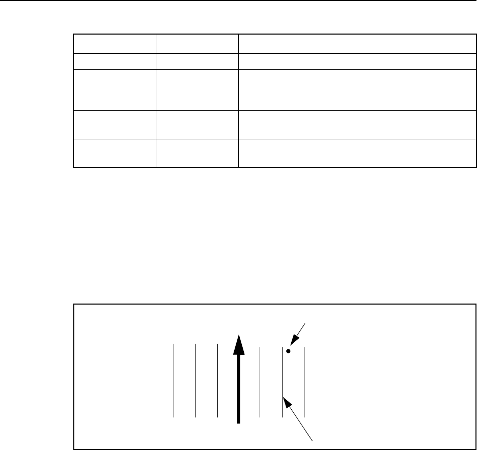
2-114 TSIP Reference Volume 1
Command Packets 2
Swath Direction
The swath direction setting establishes the direction for swath increment, left or right of
the A-B line. Auto Turn Detect changes swath number when the equipment turns around
approximately 110° with respect to the current swath. Snap to Swath is a second automatic
swath changing option which is not heading dependent. In Snap to Swath, the swathing
system determines which swath is nearest the current position and sets the swath number
accordingly and provides guidance relative to that swath as shown in Figure 2-1.
Figure 2-1 Snap to Swath
Both Auto Turn Detect and Snap to Swath are temporarily disabled when a user manually
changes the swath either by incrementing or decrementing or setting to a specific swath
number. The automatic options reactivate when the operator brings the equipment onto the
selected swath. The reactivation thresholds are ±3 meters and ±5 degrees with respect to
the manually selected swath number. For example, if the user is on swath #5 in Auto Turn
Detect mode and increments 5 times to make the current swath #10, the Auto Turn Detect
mode will not reactivate until the user drives within ±3meters and ±5 degrees of swath
#10. The user may drive either direction on swath #10.
Table 2-207 Boundary Mode/Headland Type Settings
Setting Value Description
None 0 No headland wanted.
A-B End zones 1 Establishes a headland area at opposite ends of
the field where the field ends are defined by the A
and B baseline points.
Closed Circuit 2 Field perimeter defined by user-supplied (via ADD
headland) points.
Curved
Headland 3Last automatically logged curved pass before ’End
Headland’ retained as field boundary.
A
B
123123
Position
Swath chosen

TSIP Reference Volume 1 2-115
2Command Packets
Swath Width
The swath width parameter is set according to the width of the applicator or spray boom,
where the total width is measured from one end of the boom to the other.
When calculating coverage area, half the swath width is added. The resulting adjusted
field area represents the enclosed area plus a strip of land 1/2 swath width wide around the
edge (see AgGPS Parallel Swathing Option Manual for more information).
Output Rate
The output rate controls how often the guidance status packet is sent. The output rate is
selectable in 200 msec increments including integer seconds (1000 msecs). A value of 0
turns automatic output off.
Command Packet 0x8E 0x91 can be sent with no data bytes to request output of Report
Packet 0x8F 0x91 as shown in Table 2-208.
Table 2-208 Guidance Configuration Request
Byte # Item Type Value/Units Meaning
0 Subpacket ID BYTE 0x91 Guidance configuration command
1-2 Checksum INTEGER
checksum
Checksum

2-116 TSIP Reference Volume 1
Command Packets 2
To change the guidance configuration, send the packet using the structure shown in Table
2-209.
Table 2-209 Guidance Configuration Command
Byte # Item Type Value/Units Meaning
0 Subpacket ID BYTE 0x91 Guidance configuration command
1Units BYTE
flag
Specifies what units will be used for the lightbar
text display and lightbar LEDs
0Metric
1English
2 Display Mode BYTE
flag
Determines in which direction the lightbar
LEDs illuminate and arrow indicators point to
indicate error
0 Show Correction
1 Show Error
3 Boundary
Mode BYTE Table 2-207 Specifies desired field boundary/headlands
type (see notes above)
4 Pattern Mode BYTE Table 2-210 Guidance pattern to use
5-6 Look Ahead INTEGER
seconds
Allows the system to predict future error. This
accounts for system delays, including operator
response time. The recommended setting is 2
seconds.
7Swath
Direction BYTE
flag
Direction to generate swaths relative to A-B
line (see notes above)
0 Left
1Right
2 Automatic turn detection
3 Snap to closest swath
8-11 Swath Width SINGLE
meters
Width of applicator or spray boom (see notes
above)
12-15 Antenna
Offset SINGLE
meters
Antenna position offset fore or aft of the
applicator boom
> 0 The antenna is ahead of the boom
< 0 The antenna is behind the boom
16-19 Guidance
Output Rate LONG
msecs
Rate of guidance status packet transmission in
increments of 200 msecs:
0 No automatic output
200,1000 Output every 200 or 1000 msecs,
etc.
20-21 Number of
swaths to skip INTEGER
number
Number of swaths to skip when using Skip ’N’
pattern. Unused when pattern is not Skip N.
0 to 999 is valid range.
22-34 Reserved BYTE 0 Reserved
35-36 Checksum INTEGER
checksum
Checksum
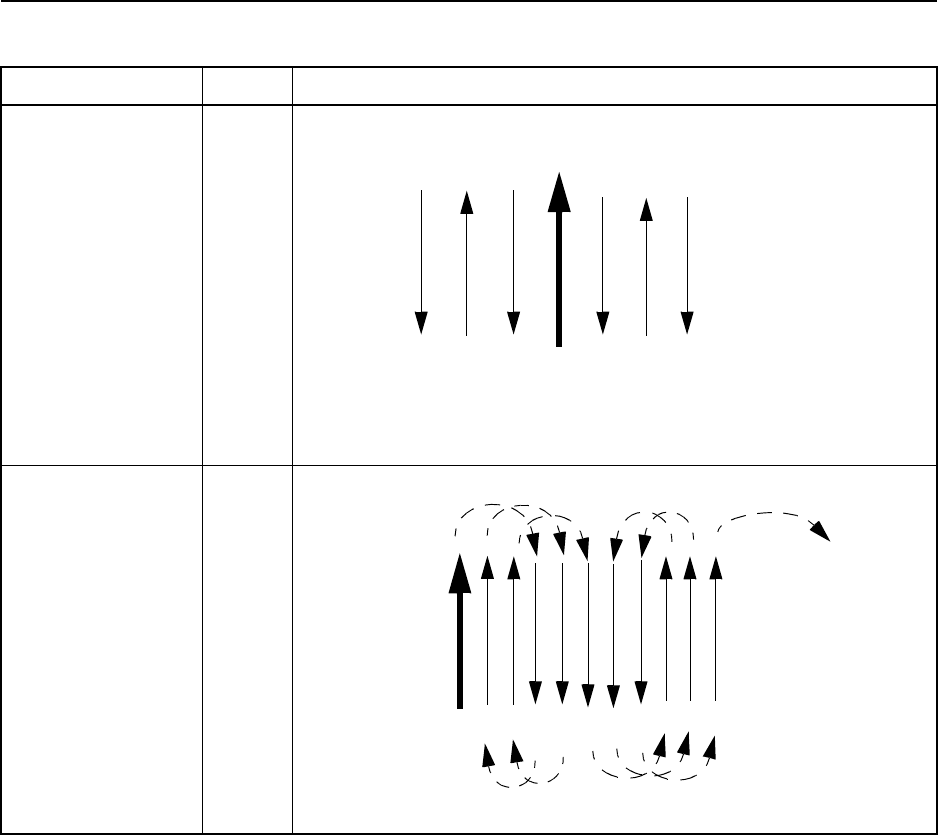
TSIP Reference Volume 1 2-117
2Command Packets
Table 2-210 Pattern Mode Settings
Setting Value Description
None 0 No pattern wanted. Basic A-B guidance
Increment action bumps swath by 1 to the right or left, depending on
the side of the current swath.
Skip ’N’ 1 Swath increment involves skipping over ’N’ swaths at a time. Skip 2 is
shown here. Set the number to skip in guidance configuration packet.
A
B
RightLeft
123
123
A
B
13
2
45678
910
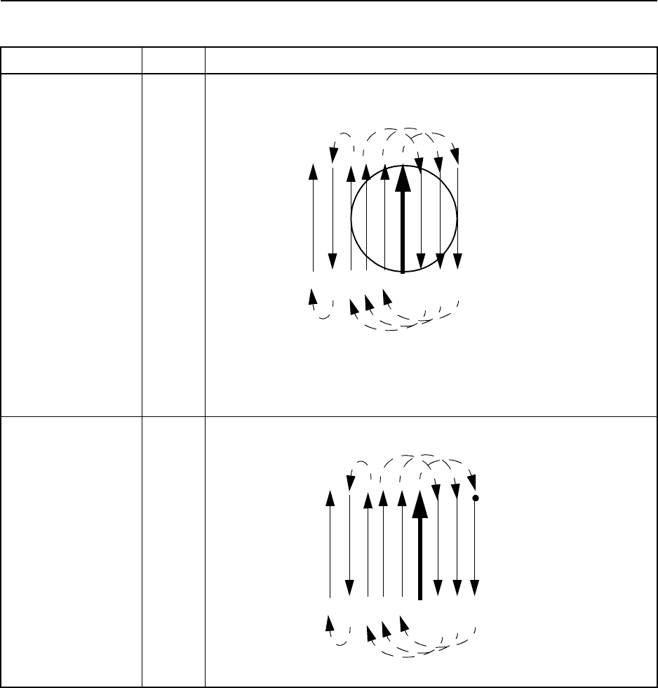
2-118 TSIP Reference Volume 1
Command Packets 2
Circle Racetrack 2 A-B distance defines circle diameter. A detected or user-specified turn
direction sets the first increment to the swath nearest one radius left or
right. Subsequent swath increments index swath as shown.
When the incrementing is high enough to take you back to the A-B line
(i.e. after swath 6 below), the incrementing switches to move up the
field (to swaths 7 and 8, etc.).
This pattern is only available in the
Ag
GPS FlightBar product.
Half-field Racetrack 3 Similar to circle racetrack, except distance between subsequent
swaths is determined by a ’C’ point (corner point).
This pattern is only available in the
Ag
GPS FlightBar product.
Table 2-210 Pattern Mode Settings (Continued)
Setting Value Description
A
B
13
2
45678
A
B
13
2
45678
C
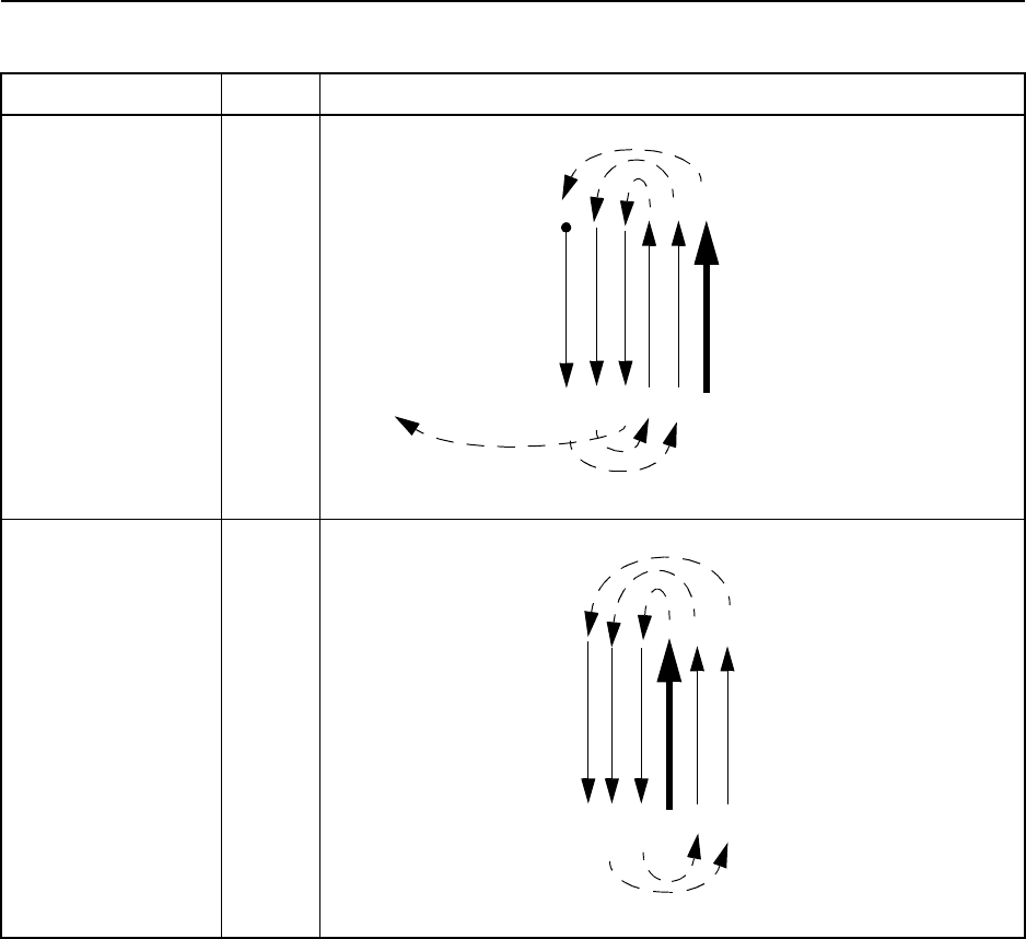
TSIP Reference Volume 1 2-119
2Command Packets
Squeeze 4 Spiral in, using point ’C’ point to define outer spiral.
This pattern is only available in the
Ag
GPS FlightBar product.
Inverse Squeeze 5 Spiral out
This pattern is only available in the
Ag
GPS FlightBar product.
Table 2-210 Pattern Mode Settings (Continued)
Setting Value Description
A
B
1
3
2
4
5
C
A
B
13
2
45
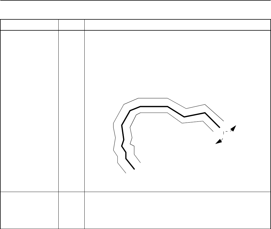
2-120 TSIP Reference Volume 1
Command Packets 2
Follow Last Curve 6 Guidance is parallel to last path. System logs points along arbitrary
path and computes parallel offset of the ’curved’ path. Path logged is
shown as wide line below. Parallel offset is right or left at end of this
pass, depending on vehicle turn at end (curved arrows). Offset occurs
when vehicle exceeds snap-to-swath threshold while executing the
turn.
Follow Last Curve
Spiral 7 Curve following, but offset is immediate to the right or to the left when a
user ends a swath with ’Increment’ or ’Decrement’ respectively.
System need not wait for vehicle to exceed snap-to-swath threshold
before computing the offset. External switch (Trimble Keypad)
Increment and Decrment switches provide interface to this feature.
Table 2-210 Pattern Mode Settings (Continued)
Setting Value Description
Start of pass
End

TSIP Reference Volume 1 2-121
2Command Packets
0x8E 0x92 Command Packet 0x8E 0x92
Lightbar Configuration Command
The lightbar configuration packet contains configurable items that most users will only
change once, if they change them at all. Each of these items controls some aspect of the
lightbar operation.
Indicator LED Sensitivity
The indicator LED sensitivity defines the sensitivity of the lightbar’s large center LED
when approaching the pause/resume point while guidance is paused. The indicator LED
will glow red, Orange, then green as a vehicle passes over the resume point. Sensitivity is
the radius of the GREEN zone, and the width of the ORANGE zone.
The indicator LED is also used to indicate field boundaries when particular headland
modes are selected. However, the LED is toggled between GREEN and RED at field
boundaries, so the indicator LED sensitivity does not apply.
Send the packet described in Table 2-211 to request the current lightbar configuration.
To change the lightbar configuration, send the packet described in Table 2-212.
Note – The faster the ground speed, the larger the LED sensitivity should be. As a frame of
reference, a speed of 8 m.p.h. (13 k.p.h.) must have a sensitivity of 36 ft. (11 m) to yield a
3-second warning.
Table 2-211 Lightbar Configuration Request
Byte # Item Type Value/Units Meaning
0 Subpacket ID BYTE 0x92 Lightbar configuration request
1-2 Checksum INTEGER
checksum
Checksum
Table 2-212 Lightbar Configuration Command
Byte # Item Type Value/Units Meaning
0 Subpacket ID BYTE 0x92 Lightbar configuration command
1 Lightbar
Mounting
BYTE
flag
Specifies how lightbar is mounted
0 Dash mounted (upright mounting)
1 Ceiling mounted (inverts lightbar text)
2 Lightbar
Intensity BYTE 1-5 Determines the LED brightness and text base
on a scale of 1 to 5.

2-122 TSIP Reference Volume 1
Command Packets 2
3 Lightbar Text
Type BYTE
flag
Specifies what kind of information will be
provided on the small text display below the
LEDs on the lightbar
0No text
1 Swath # and predicted cross-track error
2 GPS status information
3 Current swath number
4 Distance from start of current swath
5 Distance to end of current swath
6 GPS-derived true heading
7 Predicted cross-track error
8 Directional error between current
heading and direction of A-B line, or the
desired heading of a curved swath.
9 Ground speed
10 Current swath number and ground
speed
11 Lightbar demo text
12 Curve Arrows: turn signal indicator
active under curved guidance.
13 Number of points logged on a curved
swath.
Note – Setting the text type to Demo Text will
put the lightbar into a demo mode where the
lightbar continually cycles through its
initialization lightshow. This is primarily
intended as an eye-catcher for trade shows.
4 LED Spacing
Mode BYTE
flag
This setting configures the lightbar for linear or
scaled display
0 Linear display - allows an LED interval
to be specified, and spaces each of the
17 LEDs to either side of center by this
distance.
1 Scaled display - allows specification of
an LED interval and a distance which
the end LED represents.
5-8 Lightbar LED
Interval SINGLE
meters
If linear spacing is selected, the interval is used
as the interval represented by each LED. If
scaled spacing is selected, the interval
represents the LED spacing at the center of the
lightbar.
9-12 Lightbar LED
End Interval SINGLE
meters
If scaled spacing is selected, the end interval
represents the LED spacing at the far ends of
the lightbar.
Table 2-212 Lightbar Configuration Command (Continued)
Byte # Item Type Value/Units Meaning

TSIP Reference Volume 1 2-123
2Command Packets
13-16 Proximity
Indicator
Sensitivity
SINGLE
meters
The indicator LED sensitivity defines the
sensitivity of the lightbar’s large, center LED.
This setting determines how near a PAUSE
point a vehicle must be before turning
ORANGE and GREEN.
17 Event Option BYTE Table 2-213 Lightbar event output designed to sound alarm.
18-21 Cross-track-
error alarm
tolerance
SINGLE
meters
Applies when event option 0x08 is active.
Lightbar event outpu continuously active when
cross-track-error exceeds this value.
22-29 Reserved BYTE 0 Reserved
30-31 Checksum INTEGER
checksum
Checksum
Table 2-213 Lightbar Event Options
Bit # Meaning
0
(LSB) When swath number changes:
0: No event 1: Short beep
1 When crossing field boundary (boundaries defined by RED zone for indicator
LED. See Figure 3-1, Figure 3-2, Figure 3-3):
0: No event 1: Long beep
2 When inside field (GREEN and ORANGE zones):
0: No event 1: Continuous output
3 When cross-track error exceeds cross-track-error alarm tolerance:
0: No event 1: Continuous output
4 When switch pressed:
0: No event 1: Beep
5-7 Reserved (set to zero)
Note – The center LED spacing and the end LED distance are used to describe the
distance represented by the first LED from the center and the distance represented by all
of the LEDs on one side of the lightbar, respectively. For example, if the center LED
spacing is set to 0.5 meters, the LED slides one unit to the left or right for every 0.5 meters
off-line. A smaller sensitivity setting provides more precise guidance. A larger setting
increases the distance off-line before the LEDs indicate error. If the LED display is
Scaled
,
the first 10 LEDs left and right of center are spaced equally by the spacing value. The
outside LEDs become less sensitive to represent the end value settings. The seven
outside LEDs are scaled to the configured LED end distance.
Table 2-212 Lightbar Configuration Command (Continued)
Byte # Item Type Value/Units Meaning

2-124 TSIP Reference Volume 1
Command Packets 2
0x8E 0x94 Command Packet 0x8E 0x94
Guidance Operation Command
This command is used to set up the receiver for guidance operation in a particular field.
The command format is described in Table 2-214. The receiver acknowledges the actions
by sending Report Packet 0x8F 0x94.
Note – You cannot set an end distance in
Linear
mode since the total distance
represented by the lightbar LEDs is controlled completely by the linear spacing value.
Table 2-214 Guidance Operation Command
Byte # Item Type Value/Units Meaning
0 Subpacket ID BYTE 0x94 Guidance operation command
1 Operation BYTE
flag
Type of operation
0 Set Point A
1 Set Point B
2 Set Point C
3 Increment swath number
4 Decrement swath number
5 Pause guidance
6 Resume guidance
7 Jump to a specific swath number (see
note)
8 Reset guidance
For types 0-2, the user may set the point from
the current position (default) or from a provided
position by setting the lat/lon/alt values below
and the user-provided position flag.
2-3 Set swath
number SIGNED
INTEGER
flag
Swath number to jump to if ’Jump to specific
swath number’ is chosen
0 A-B Line
< 0 Swaths right of A-B line
> 0 Swaths left of A-B line
OR...
Move Curved
swath when in
curved
guidance
mode.
Position of path being guided to, with respect to
vehicle position at end of the previous swath.
0 Offset Curved path to the LEFT.
1 Offset Curved path to the RIGHT.
2 No offset. Guidance will be back down
the previous curved swath.
4 User provided
position BYTE
flag
Source of point position
0 Use current receiver position
1 Use provided position
5-12 Latitude DOUBLE
radians
Latitude of provided position
13-20 Longitude DOUBLE
radians
Longitude of provided position

TSIP Reference Volume 1 2-125
2Command Packets
0x8E 0x95 Command Packet 0x8E 0x95
Button Box Configuration Type Command
The button box configuration type packet is used to select a set of factory-defined actions
for the buttons on the button box. The user may clear all of the factory-defined actions by
selecting Clear All Buttons. The user may also define a custom configuration by selecting
Custom Button Configuration below and then using Command Packet 0x8E 0x98 to define
each button separately. To request the current button box configuration, use packet format
described in Table 2-215.
To assign a type of button boxconfiguration, use the packet described in Table 2-216. If a
custom configuration is desired, use Command Packet 0x8E 0x98 to configure individual
buttons. If you have previously defined a custom configuration but then switched to a
default configuration, you may return to the custom button definitions by selecting Custom
Button Configuration.
21-28 Altitude DOUBLE
meters
WGS-84 altitude of provided position
29-36 Reserved BYTE 0 Reserved
37-38 Checksum INTEGER
checksum
Checksum
Note – The "jump to a specific swath" setting is only necessary when you want to change
swath rows to the opposite side of the A-B line or fix an accidental increment while
maintaining the existing A-B line. See additional notes about changing swath number while
in
Auto Turn Detect
or
Snap to Swath
modes in Command Packet 0x8E 0x91
documentation.
Note – Curved guidance operation does not permit jumps to any swath in a field because
the system stores data only from the previous path driven. ’Change Swath’ when curve
following involves moving the path being guided to by the lightbar between three possible
positions: Left, Right, and Center with respect to the path driven on the previous swath
(during which time the system was logging points for guiding on the next swath).
Table 2-215 Button Box Configuration Type Request
Byte # Item Type Value/Units Meaning
0 Subpacket ID BYTE 0x95 Button box configuration type request
1-2 Checksum INTEGER
checksum
Checksum
Table 2-214 Guidance Operation Command (Continued)
Byte # Item Type Value/Units Meaning

2-126 TSIP Reference Volume 1
Command Packets 2
0x8E 0x96 Command Packet 0x8E 0x96
Point Manipulation Command
This packet is used to capture, delete last, and clear all headland points and area points.
Report Packet 0x8F 0x96 is sent in response. The format of Command Packet 0x8E 0x96
is shown in Table 2-217.
Table 2-216 Button Box Configuration Type Command
Byte # Item Type Value/Units Meaning
0 Subpacket ID BYTE 0x95 Button box configuration type command
1 Button
Configuration
Type
BYTE
flag
Configure buttons according to
0 Default button box definitions
1 Default external switch definitions
2 Custom button configuration (individual
buttons are defined using Command
Packet 0x8E 0x98)
3 Clear all button definitions
2-6 Reserved BYTE 0 Reserved
7-8 Checksum INTEGER
checksum
Checksum
Table 2-217 Point Manipulation Command
Byte # Item Type Value/Units Meaning
0 Subpacket ID BYTE 0x96 Point capture command
1 Operation BYTE
flag
Point operation:
0 Capture current position
1 Delete last point captured of type
specified
2 Delete all points of type specified
3 Capture using provided position (bytes
7-30)
4 Request number of points of type "Type
of Point"
2 Type of point BYTE
flag
Type of point to capture
0 Headlands point
1Area point
3-6 Reserved BYTE 0 Reserved
7-14 Latitude DOUBLE
radians
Latitude of provided position
15-22 Longitude DOUBLE
radians
Longitude of provided position
23-30 Altitude DOUBLE
meters
WGS84 Altitude of provided position
31-34 Reserved BYTE 0 Reserved
35-36 Checksum INTEGER
checksum
Checksum

TSIP Reference Volume 1 2-127
2Command Packets
0x8E 0x97 Command Packet 0x8E 0x97
Utility Information Request
This packet requests various utility information including the current area and the
coverage area determined from the area points. The packet is described in Table 2-218.
0x8E 0x98 Command Packet 0x8E 0x98
Individual Button Configuration Command
The individual button configuration packet is used to configure an action for each button
on the button box if the user wants to customize them. Several default configurations can
be easily set using Command Packet 0x8E 0x95. Report Packet 0x8F 0x98 is sent in
response.
To request the current button configurations, use packet format described in Table 2-219.
Table 2-218 Utility Information Request
Byte # Item Type Value/Units Meaning
0 Subpacket ID BYTE 0x97 Utility information request
1 Request type BYTE
flag
Information requested
0 Area within points
1 Adjusted area (includes area flaps for
boom width).
2 Sum of length of line segments
connecting successive area points.
3 Same as 2 above, with addition of
segment between last and first area
point to provide a perimeter measure.
4 Length of last segment: distance
between last two points in area-point
vector
2-5 Reserved BYTE 0 Reserved
6-7 Checksum INTEGER
checksum
Checksum
Table 2-219 Individual Button Box Configuration Request
Byte # Item Type Value/Units Meaning
0 Subpacket ID BYTE 0x98 Individual button configuration request
1-2 Checksum INTEGER
checksum
Checksum

2-128 TSIP Reference Volume 1
Command Packets 2
To assign new operations to a button or buttons, use the packet described in Table 2-220.
This is a variable length packet depending on how many buttons are configured.
Table 2-220 Individual Button Box Configuration Command
Byte # Item Type Value/Units Meaning
0 Subpacket ID BYTE 0x98 Individual button configuration command
1 Number of
buttons BYTE
buttons
Number of buttons configured in this packet
2-6 Reserved BYTE 0 Reserved
For each button, n, specified in byte 1
7, 10,
13,
etc.
Button SIGNED
BYTE -6 thru 6,
excluding 0 Button number according to Trimble cable pin
out. Negative numbers indicate the shift key is
pressed before this button, i.e -5 indicates the
button combination Shift 5.
8, 11,
14,
etc.
Operation BYTE Table 2-221 When button is pressed, this operation occurs.
9, 12,
15,
etc.
Reserved BYTE 0 Reserved
(7 +
3*n) -
(8+
3*n)
Checksum INTEGER
checksum
Checksum
Table 2-221 Button Box Operations
Value Meaning Intended Use
0 Clear button definition
Ag
132 PSO and
Ag
GPS FlightBar
1Set Point A
Ag
132 PSO
2Set Point B/C
Ag
132 PSO
3 Pause/Resume
Ag
132 PSO
4Set A → Set B → Pause → Resume → Pause ...
Ag
GPS FlightBar
5 Increment swath
Ag
132 PSO and
Ag
GPS FlightBar
6 Decrement swath
Ag
132 PSO and
Ag
GPS FlightBar
7 Reset guidance
Ag
132 PSO and
Ag
GPS FlightBar
8 Add headland point†
Ag
132 PSO
9 Delete last headland point†
Ag
132 PSO
10 Clear all headland points†
Ag
132 PSO
11 Add area point†
Ag
132 PSO
12 Delete last area point†
Ag
132 PSO
†If a boundary point operation is selected for a button, any buttons configured for headland or area
operations will be cleared. Likewise, if a headland or area operation is selected for a button, any but-
tons configured for boundary operations will be cleared.

TSIP Reference Volume 1 2-129
2Command Packets
0x8E 0x9A Command Packet 0x8E 0x9A
Differential Correction Information Request
Command Packet 0x8E 0x9A can be sent with no data bytes to request output of Report
Packet 0x8F 0x9A as shown in Table 2-222.
13 Clear all area points†
Ag
132 PSO
14 Add boundary point (headland and area point)†
Ag
GPS FlightBar
15 Delete last boundary point†
Ag
GPS FlightBar
16 Clear all boundary points†
Ag
132 PSO and
Ag
GPS FlightBar
17 Shift button
Ag
132 PSO and
Ag
GPS FlightBar
18 Toggle pattern mode
Ag
132 PSO and
Ag
GPS FlightBar
Note – Duplicate operation assignments are not permitted. If an operation is selected for a
button and was previously assigned to another button, the previous assignment will be
cleared.
Note – The button defined as a Shift key cannot have a Shift-n assignment.
Table 2-222 Differential Correction Information Request
Byte # Item Type Value/Units Meaning
0 Subpacket ID BYTE 0x9A Differential correction information request
1-2 Checksum INTEGER
checksum
Checksum
Table 2-221 Button Box Operations (Continued)
Value Meaning Intended Use
†If a boundary point operation is selected for a button, any buttons configured for headland or area
operations will be cleared. Likewise, if a headland or area operation is selected for a button, any but-
tons configured for boundary operations will be cleared.

2-130 TSIP Reference Volume 1
Command Packets 2
0xB0 Command Packet 0xB0
PPS Signal and Event Commands
The Command Packet 0xB0 subpackets are used to request and configure the PPS signal
and event input settings. In the 0xB0 packets, the first data byte is a Subpacket ID which
indicates the subpacket type. Therefore, the ID code for these packets is 2 bytes long
followed by the data. Each (0xB0 subpacket) pair can be thought of as a separate
command packet.
0xB0 0x00 Command Packet 0xB0 0x00
PPS Signal Configuration Command
Command Packet 0xB0 0x00 can be used to configure PPS output options or request a
report containing the current configuration options.
Table 2-223 shows the structure of Command Packet 0xB0 0x00 when requesting a report
of PPS configuration settings. The receiver responds by sending the data in Report Packet
0xB0 0x80.
Table 2-224 shows the structure of Command Packet 0xB0 0x00 when commands are sent
to configure PPS settings. The receiver resets the configuration settings and acknowledges
the command by sending Report Packet 0xB0 0x80.
Table 2-223 Request PPS Configuration Settings Report
Byte # Item Type Value/Units Meaning
0 Subpacket ID BYTE 0x00 PPS Configuration Settings Report Request
1 PPS Number BYTE 0x01 Currently supports the output of one PPS signal.
2-3 Checksum INTEGER
—
Checksum of bytes 0-1
Table 2-224 Set PPS Configuration Command
Byte # Item Type Value/Units Meaning
0 Subpacket ID BYTE 0x00 PPS Configuration Settings Command
1 PPS Number BYTE 0x01 Currently supports the output of one PPS signal
(PPS Number = 1).
2 Enable Flag BYTE
flag
Enables or disables the specified PPS signal
(PPS Number):
0Disabled
1 Enabled
3PPS
Timebase
BYTE
flag
Sets the PPS timebase to use the GPS or UTC
time of the week, or the receiver’s internal clock
(user-defined):
0GPS time
1 UTC (Universal Time Coordinated)
2 Receiver’s internal clock (user-defined)

TSIP Reference Volume 1 2-131
2Command Packets
4 PPS Polarity BYTE
flag
Sets the polarity of the specified PPS signal
(PPS Number):
0 Negative polarity
1 Positive polarity
5Auto
Generated
Reports
BYTE
flag
Enables or disables the automatic output of
Report Packet 0xB0 0x82 for the specified PPS
Number:
0Disable
1Enable
6-9 Reserved BYTE 0x00 Reserved (set to zero)
10-17 Period DOUBLE 1.0 Hz Currently supports a 1 Hz PPS (pulse per
second) output signal rate.
18-25 Offset DOUBLE
seconds
PPS output signal offset in seconds for the
specified PPS Number. The Polarity of the PPS
signal is offset by the specified number of
seconds. Negative polarity causes the signal to
output sooner, and positive polarity causes the
PPS signal to output later
26-29 Max UNC
Threshold
SINGLE
seconds
Maximum allowable clock uncertainty threshold,
in seconds, for the specified PPS Number.
If the Maximum UNC Threshold is set to a large
value (e.g. 1 second), the GPS receiver
continues to produce a PPS signal even when a
position fix is not available (satellites are not
tracked). If the Maximum UNC Threshold is set
to a small value (e.g. 1 msec), the PPS signal is
disabled a few seconds after a position is no
longer available (satellites are no longer
tracked). The PPS signal drifts when a position
fix is not available and snaps back to the correct
position once a position fix becomes available
again
30-31 Checksum INTEGER
checksum
Checksum
Table 2-224 Set PPS Configuration Command (Continued)
Byte # Item Type Value/Units Meaning

2-132 TSIP Reference Volume 1
Command Packets 2
0xB0 0x01 Command Packet 0xB0 0x01
PPS Signal Enable/Disable Command
Command Packet 0xB0 0x01 enables or disables a specified PPS signal (PPS Number).
The receiver enables or disables the specified PPS signal and acknowledges the operation
with Report Packet 0xB0 0x81.
0xB0 0x40 Command Packet 0xB0 0x40
Event Timestamp Selection Command
Command Packet 0xB0 0x40 can be used to configure event timestamp selection options
or request a report containing the current configuration options.
Table 2-226 shows the structure of Command Packet 0xB0 0x40 when requesting a report
of event timestamp selection settings. The receiver responds by sending the data in Report
Packet 0xB0 0xC0.
Table 2-225 PPS Signal Enable/Disable Command
Byte # Item Type Value/Units Meaning
0 Subpacket ID BYTE 0x01 PPS Signal Enable/Disable Command
1 PPS Number BYTE 0x01 Currently supports the output of one PPS
signal (PPS Number = 1).
2 Enable Flag BYTE
flag
Enables or disables the specified PPS signal
(PPS Number):
0 Disable
1Enable
3-4 Checksum INTEGER
checksum
Checksum
Table 2-226 Request Event Timestamp Selection
Byte # Item Type Value/Units Meaning
0 Subpacket ID BYTE 0x40 Request Event Timestamp Selection
1 Select BYTE
1-n
Event selection, depends on number of events
supported by receiver.

TSIP Reference Volume 1 2-133
2Command Packets
Table 2-227 shows the structure of Command Packet 0xB0 0x40 when commands are sent
to configure event timestamp settings. The receiver resets the configuration settings and
acknowledges the command by sending Report Packet 0xB0 0xC0.
0xB0 0x41 Command Packet 0xB0 0x41
Event Packet Options Command
Command Packet 0xB0 0x41 can be used to configure event timestamp options or request
a report containing the current options.
Table 2-228 shows the structure of Command Packet 0xB0 0x41 when requesting a report
of event timestamp options settings. The receiver responds by sending the data in Report
Packet 0xB0 0xC1.
Table 2-229 shows the structure of Command Packet 0xB0 0x41 when commands are sent
to configure event timestamp options. The receiver resets the configuration settings and
acknowledges the command by sending Report Packet 0xB0 0xC1.
Table 2-227 Set Event Timestamp Selection
Byte # Item Type Value/Units Meaning
0 Subpacket ID BYTE 0x40 Event Timestamp Selection
1 Select BYTE
1-n
Event selection, depends on number of events
supported by receiver.
2Slope BYTE Event input configuration:
0 Disable
1 Enable and timestamp positive edge
2 Enable and timestamp negative edge
Table 2-228 Request Event Packet Options
Byte # Item Type Value/Units Meaning
0 Subpacket ID BYTE 0x41 Request Event Timestamp Options
1Event
Selected
BYTE
1-n
Event selection, depends on number of events
supported by receiver.
Table 2-229 Set Event Packet Options
Byte # Item Type Value/Units Meaning
0 Subpacket ID BYTE 0x41 Set Event Timestamp Options
1Event
Selected
BYTE
1-n
Event selection, depends on number of events
supported by receiver.
2Options 1
BYTE Table 2-230 Output options 1
3Options 2
BYTE Table 2-231 Output options 2
4Options 3
BYTE Table 2-232 Output options 3

2-134 TSIP Reference Volume 1
Command Packets 2
0xB0 0x42 Command Packet 0xB0 0x42
Event Plus Position Request
Command Packet 0xB0 0x42 is used to request a single output of the event plus position
packet, Report Packet 0xB0 0xC2. To enable automatic output of Report Packet 0xB0
0xC2, use Command Packet 0xB0 0x40.
Table 2-233 shows the structure of Command Packet 0xB0 0x42 when requesting a report
of event plus position. The receiver responds by sending the data in Report Packet 0xB0
0xC2.
Table 2-230 Byte 2 Output options 1
Bit # Meaning
0 (LSB) Automatic output of event plus position Report Packet 0xB0 0xC2 upon
event reception:
0: Disable 1: Enable
1 Automatic output of event only Report Packet 0xB0 0xC3 upon event
reception:
0: Disable 1: Enable
2-7 Reserved (set to zero)
Table 2-231 Byte 3 Output options 2
Bit # Meaning
0-7 Reserved (set to zero)
Table 2-232 Byte 4 Output options 3
Bit # Meaning
0-7 Reserved (set to zero)
Table 2-233 Request Event Plus Position Packet
Byte # Item Type Value/Units Meaning
0 Subpacket ID BYTE 0x42 Event Plus Position Report
1 Select BYTE
1-n
Event selection, depends on number of events
supported by receiver.

TSIP Reference Volume 1 2-135
2Command Packets
0xB0 0x43 Command Packet 0xB0 0x43
Event Only Request
Command Packet 0xB0 0x43 is used to request a single output of the event only packet,
Report Packet 0xB0 0xC3. To enable automatic output of Report Packet 0xB0 0xC3, use
Command Packet 0xB0 0x41.
Table 2-234 shows the structure of Command Packet 0xB0 0x43 when requesting a report
of the event only packet. The receiver responds by sending the data in Report Packet 0xB0
0xC3.
0xB0 0x44 Command Packet 0xB0 0x44
Event Marker Miscellaneous Command
Command Packet 0xB0 0x44 is used to either force an event or reset the event
counter.Table 2-235 shows the structure of Command Packet 0xB0 0x44. The receiver
responds by sending the data in Report Packet 0xB0 0xC4.
Table 2-234 Request Event Only Packet
Byte # Item Type Value/Units Meaning
0 Subpacket
ID
BYTE 0x43 Request Event Only Report
1 Select BYTE
1-n
Event selection, depends on number of events
supported by receiver.
Table 2-235 Event Marker Miscellaneous Command
Byte # Item Type Value/Units Meaning
0 Subpacket
ID
BYTE 0x44 Event Marker Action Command
1 Select BYTE
1-n
Event selection, depends on number of events
supported by receiver.
2 Command BYTE
flag
Action to be taken:
0: Force event now
1: Reset event count to zero

2-136 TSIP Reference Volume 1
Command Packets 2
0xBB Command Packet 0xBB
Receiver Configuration Parameters Commands
Command Packet 0xBB sets or displays the receiver configuration parameters.
0xBB 0x00 Command Packet 0xBB 0x00
Primary Receiver Configuration Parameters Request
Command Packet 0xBB 0x00 contains the primary receiver configuration parameters that
a user usually needs to modify. To leave any parameter unchanged, enter *0xFF or -1 as
the value. To query for the primary receiver configuration, send packet BB with subcode 0
as the only data byte as shown in Table 2-236.
Table 2-236 Request Primary Receiver Configuration Block
Byte # Item Type Value/Units Meaning
0 Subcode BYTE 0x00 Request Primary Receiver Configuration Block
Table 2-237 Set Primary Receiver Configuration Block
Byte # Item Type Value/Units Meaning
0 Subcode BYTE 0x00 Set Primary Receiver Configuration Block
1 Operating
Dimension
BYTE
flag
Operating dimension:
0 Automatic
1 Time Only (1 SV)
3 Horizontal (2D)
4 Full Position (3D)
6 2D Clock Hold
7 Overdetermined Clock
2 DGPS Mode BYTE
flag
Differential GPS mode:
0DGPS off
1DGPS only
3DGPS auto
3 Dynamics Code BYTE
flag
Vehicle dynamics code:
1Land
2Sea
3Air
4 Stationary
4 Solution Mode BYTE
flag
Overdetermined mode used to compute
position solution:
1 Overdetermined fix
2 Weighted overdetermined fix
5-8 Elevation Mask SINGLE 0-PI/2 Lowest satellite elevation for fixes (radians)
9-12 AMU Mask SINGLE
AMUs
Minimum signal level for fixes
13-16 PDOP Mask SINGLE
PDOP
Maximum PDOP for fixes
17-20 PDOP Switch SINGLE
PDOP
Selects 2D/3D transition mode when the
reciever is operating in auto 2D/3D mode

TSIP Reference Volume 1 2-137
2Command Packets
21 DGPS Age Limit BYTE
seconds
Maximum time to use a DGPS correction,
in seconds
22 Foliage Mode BYTE
flag
Foliage mode usage:
0Never
1 Sometimes
2Always
23 Low Power Mode BYTE
flag
Low Power mode:
0 Disable
(recommended)
1Auto
24 Clock Hold Mode BYTE
flag
Clock Hold mode:
0 Disable
1 Enable
25 Measurement Rate BYTE
flag
Measurement rate:
01 Hz
15 Hz
210 Hz
26 Position Fix Rate BYTE
flag
Position Fix Rate:
01 Hz
15 Hz
210 Hz
3 Position at measurement rate
27-39 Reserved BYTEs -1 Reserved for future use
Table 2-237 Set Primary Receiver Configuration Block (Continued)
Byte # Item Type Value/Units Meaning

2-138 TSIP Reference Volume 1
Command Packets 2
0xBC Command Packet 0xBC
Serial Port Configuration Parameters Command
Command Packet 0xBC sets or displays the port configuration parameters. The data
format for requesting Report Packet 0xBC is shown in Table 2-238. The data format for
configuring serial port parameters is shown in Table 2-239.
The operation type is used to specify special protocol operation such as reference station
output. For example, if the receiver protocol is set to reference station mode and TSIP is
active on a port, then only DGPS corrections packets 0x60 and 0x61 will be output on that
port.
Table 2-238 Request Serial Port Configuration Parameters
Byte # Item Type Value/Units Meaning
0Port # BYTE
port number
Request Serial Port Configuration Parameters
Table 2-239 Set Serial Port Configuration Parameters
Byte # Item Type Value/Units Meaning
0Port # BYTE
flag
Set Serial Port Configuration Parameters for
specified reciever port:
0Port 0
1Port 1
2Port 2
3Port 3
0xFF Current port
1 Input Baud Rate BYTE
flag
Input baud rate:
0 None
1 110 bps
2 300 bps
3 600 bps
4 1200 bps
5 2400 bps
6 4800 bps
7 9600 bps
8 19200 bps
9 38400 bps
2 Output Baud
Rate
BYTE
flag
Output baud rate (see above)
3 # Data Bits BYTE
flag
Number of data bits:
0 5 data bits
1 6 data bits
2 7 data bits
3 8 data bits

TSIP Reference Volume 1 2-139
2Command Packets
4Parity BYTE
flag
Parity of transmitted data:
0 None
1Odd
2Even
5 # Stop Bits BYTE
flag
Number of stop bits in transmitted data:
0 1 bit for 6-8 data bits or 1.5 bits for 5 data
bits
1 2 bits
6 Flow Control BYTE Table 2-240 Method of flow control negotiation
7 Input Protocols BYTE Table 2-241 Input protocol used by serial port
8 Output
Protocols
BYTE Table 2-241 Output protocol used by serial port
9Protocol
Operation Mode
BYTE Table 2-242 Special operation mode of protocols
Table 2-240 Byte 6 Flow Control
Bit # Meaning
0 (LSB) RTS CTS:
0: Disabled 1: Enabled
1 Transmit XON/XOFF:
0: Disabled 1: Enabled
2 Transmit XANY:
0: Disabled 1: Enabled
3 Receive XON/XOFF:
0: Disabled 1: Enabled
4-7 Reserved (set to zero)
Table 2-239 Set Serial Port Configuration Parameters (Continued)
Byte # Item Type Value/Units Meaning

2-140 TSIP Reference Volume 1
Command Packets 2
Table 2-241 Protocols
Bit # Meaning
0 (LSB) TAIP:
0: Disabled 1: Enabled
1 TSIP:
0: Disabled 1: Enabled
2 NMEA:
0: Disabled 1: Enabled
3RTCM:
0: Disabled 1: Enabled
4 DCOL:
0: Disabled 1: Enabled
5-7 Reserved (set to zero)
Table 2-242 Byte 9 Special Operation Modes
Bit # Meaning
0 (LSB) Reference station mode:
0: Disabled 1: Enabled
1-7 Reserved (set to zero)

TSIP Reference Volume 1 2-141
2Command Packets
0xC2 Command Packet 0xC2
Port A Data Transmission Command
Command Packet 0xC2 is used to send an arbitrary stream of data bytes out of Port A.
Table 2-243 Output Arbitrary Data Stream on Port A
Byte # Item Type Value/Units Meaning
0-end Data BYTEs
data
The data sent out of receiver Port A.
Note – Command Packet C2 must be sent to Port B, and the Port A Output Language
(Command Packet 0x3D, Byte 4) must not be set to
TSIP
or
Off
to send the data out
through Port A.

2-142 TSIP Reference Volume 1
Command Packets 2

TSIP Reference Volume 1 3-1
3 Report Packets
The Trimble GPS receiver sends report packets in response to command packets. Report
packets are also sent when the receiver is powered up and automatically at periodic
intervals or when information is available to report.
Some report packets contain no data and are used to acknowledge the performance of the
action associated with a command packet.
Report packets are assigned a hexadecimal identification code to distinguish one report
from another. For example, the report packet ID for the differential GPS receiver
application reports is 0x8F.
Some report packets have several subpackets which are assigned hexadecimal subpacket
ID codes. For example, the hexadecimal number 0x8F 0x7C is the hexadecimal code for
Report Packet 0x8F, Subpacket 0x7C. The subpackets are treated as discrete report
packets because they usually perform a function associated with the report packet ID code.
For example, some of the 0x8F subpackets report on or acknowledge a variety of unique
beacon or satellite differential functions.
Most report packets are contained within a single report packet. A few report packets
exceed the 123 byte data limit for TSIP packets and are divided into multiple packets
called pages. For more information, see TSIP Packet Structure on page 1-3.

3-2 TSIP Reference Volume 1
Report Packets 3
3.1 Report Packet Summary
Table 3-1 lists the report packet ID numbers, provides a short description of each packet,
and indicates when the packet is sent.
Table 3-1 Report Packet Summary
Report
Packet ID Packet Description
Power Up
Auto
Request
Command
Packet ID
0x13 TSIP Parsing Error Notification –
0x1A TSIP RTCM Wrapper / Port A Echo Report ✔–
0x1A 0x00 Raw RTCM Wrapper / Port A Echo Report –
0x3D Serial Port A Configuration Report ✔0x3D
0x40 Almanac Data for Single Satellite Report ✔✔ 0x20
0x41 GPS Time Report ✔✔✔ 0x21
0x42 Single-Precision Position Fix (XYZ Cartesian ECEF) Report ✔✔✔ 0x25,
0x37
0x43 Velocity Fix (XYZ Cartesian ECEF) Report ✔✔ 0x37
0x44 Non-Overdetermined Satellite Selection Report ✔0x22,
0x24
0x45 Receiver Firmware Information Report ✔✔0x1F,
0x25
0x46 Health of Receiver Report ✔✔✔ 0x25,
0x26
0x47 Signal Levels for All Satellites Report ✔0x27
0x48 GPS System Message Report ✔✔ 0x28
0x49 Almanac Health Page Report ✔✔ 0x29
0x4A Single-Precision LLA Position Fix Report or Manual 2D Reference Altitude Parameters
Report
Single-Precision LLA Position Fix Report ✔✔✔ 0x25,
0x37
Manual 2D Reference Altitude Parameters Report ✔0x2A
0x4B Machine / Code ID and Additional Status Report ✔✔✔ 0x25,
0x26
0x4C Operating Parameters Report ✔0x2C
0x4D Oscillator Offset Report ✔0x2D
0x4E GPS Time Command Verification ✔0x2E
0x4F UTC Parameters Report ✔0x2F
0x53 Analog-to-Digital Readings Report ✔0x33
0x54 One Satellite Bias and Bias Rate Report ✔✔ 0x34
0x55 I/O Options Report ✔0x35

TSIP Reference Volume 1 3-3
3Report Packets
0x56 Velocity Fix East-North-Up (ENU) Report ✔✔ 0x37
0x57 Last Computed Fix Report ✔0x37
0x58 Satellite System Data Reports ✔✔ 0x38
0x59 Satellite Attribute Database Status Report ✔0x39
0x5A Raw Measurement Data Report ✔0x3A
0x5B Satellite Ephemeris Status Report ✔✔ 0x3B
0x5C Satellite Tracking Status Report ✔0x3C
0x60 Differential GPS Pseudorange Corrections Report ✔0x3D
0x61 Differential GPS Delta Pseudorange Corrections Report ✔0x3D
0x6A Differential Corrections Used in the Fix Reports ✔0x6A
0x6A 0x00 Differential Corrections Used in Fix Report ✔0x6A 0x01
0x6A 0x01 Fix Differential Corrections Output Control Report ✔0x6A 0x01
0x6D All-In-View Satellite Selection Report ✔✔ 0x24
0x6E Synchronized Measurement Parameters Reports ✔0x6E
0x6E 0x01 Synchronized Measurement Output Parameters Report ✔0x6E 0x01
0x6F Synchronized Measurements Reports ✔0x6E
0x6F 0x01 Synchronized Measurements Report ✔✔ 0x6E 0x01
0x70 Position/Velocity Filter Operation Report ✔0x70
0x76 Overdetermined Mode Report ✔0x75
0x78 Maximum PRC Age Report ✔0x77
0x7B NMEA Output Control Reports ✔0x7A
0x7B 0x00 NMEA Interval and Message Mask Report ✔0x7A 0x00
0x7B 0x04 NMEA Name List / Message Mask Report ✔0x7A 0x04
0x7B 0x05 NMEA Local Time Offsets Report ✔0x7A 0x05
0x7B 0x06 NMEA Message Options and Precision Report ✔0x7A 0x06
0x7B 0x80 NMEA Interval and Message Mask Report ✔0x7A 0x80
0x7B 0x84 NMEA Name List / Message Mask Report ✔0x7A 0x84
0x7B 0x85 NMEA Local Time Offsets Report ✔0x7A 0x85
0x7B 0x86 NMEA Message Options and Precision Report ✔0x7A 0x86
0x7D Position Fix Rate Configuration Reports ✔0x7C
0x7D 0x00 ASAP Fix Rate Report ✔0x7C 0x00
0x7D 0x01 Position Fix Rate Options Report ✔0x7C 0x01
0x7D 0x02 Position Fix Output Interval and Offset Report ✔0x7C 0x02
0x7D 0x03 Maximum Measurement Age Report ✔0x7C 0x03
Table 3-1 Report Packet Summary (Continued)
Report
Packet ID Packet Description
Power Up
Auto
Request
Command
Packet ID

3-4 TSIP Reference Volume 1
Report Packets 3
0x7D 0x05 CTS to Transmit Delay Report ✔0x7C 0x05
0x7D 0x06 RTS Trailing Edge Delay Report ✔0x7C 0x06
0x7D 0x09 Time-Based Message Interval Report ✔0x7C 0x09
0x7D 0x7F Fast Rate Option Not Installed Notification ✔–
0x82 Differential Position Fix Mode Report ✔✔✔ 0x62
0x83 Double-Precision XYZ Position Fix & Clock Bias Report ✔✔✔ 0x25,
0x37
0x84 Double-Precision LLA Position Fix & Clock Bias Report ✔✔✔ 0x25,
0x37
0x85 Differential Correction Status Report ✔0x65
0x87 Reference Station Parameters Report ✔0x67
0x87 0x00 Reference Station Control Report ✔0x67 0x00
0x87 0x01 Reference Station Options Report ✔0x67 0x01
0x87 0x02 Reference Station Output Version Report ✔0x67 0x02
0x87 0x03 Reference Station Position Report ✔0x67 0x03
0x87 0x04 Reference Station ID Report ✔0x67 0x04
0x87 0x05 RTCM Type 16 Text Report ✔0x67 0x05
0x87 0x06 RTCM Type Specific Output Intervals Report ✔0x67 0x06
0x87 0x08 TSIP Notification of Sent Version 2 RTCM Report ✔–
0x87 0x09 Average Position – Reference Station Position Report ✔0x67 0x09
0x87 0x0A Time Schedule Message Interval and Offset Report ✔0x67 0x0A
0x87 0x7D Mobile Packet Ignored by Reference Station Notification ✔–
0x87 0x7E Reference Station Warnings Notification ✔–
0x87 0x7F Reference Station Option Not Installed Notification ✔–
0x88 Mobile Differential Parameters Report ✔0x68
0x88 0x00 Mobile Differential Mode Control Report ✔0x68 0x00
0x88 0x01 Mobile Differential Options Report ✔0x68 0x01
0x88 0x02 Mobile Differential Input Version Report ✔0x68 0x02
0x88 0x03 Masking Reference Station Position ✔0x68 0x03
0x88 0x04 Input Reference Station ID Report ✔0x68 0x04
0x88 0x05 Last Received RTCM Type 16 Report ✔0x68 0x05
0x88 0x08 TSIP Notification of Received Version 2 RTCM Report ✔–
0x88 0x7F Mobile Differential Option Not Installed Notification ✔–
0x8B QA/QC Reports ✔0x6B
Table 3-1 Report Packet Summary (Continued)
Report
Packet ID Packet Description
Power Up
Auto
Request
Command
Packet ID

TSIP Reference Volume 1 3-5
3Report Packets
0x8B 0x00 Position Sigma Information Parameters Report ✔0x6B 0x00
0x8B 0x01 Position VCV Parameters Report ✔0x6B 0x01
0x8B 0x02 Position Sigma Information Report ✔✔ 0x6B 0x02
0x8B 0x03 Position VCV Information Report ✔✔ 0x6B 0x03
0x8D Average Position Reports ✔0x6D
0x8D 0x00 Average Position Start/Stop Control Report ✔0x6D 0x00
0x8D 0x01 Average Position Options Report ✔0x6D 0x01
0x8D 0x02 Auto Stop Parameters (Control / Options) Report ✔0x6D 0x02
0x8D 0x03 Current Average Position XYZ ECEF Report ✔0x6D 0x03
0x8D 0x04 Average Position Delta from Last XYZ or ENU Report ✔0x6D 0x04
0x8F Application Reports ✔0x8E
0x8F 0x20 Super Packet Output Report ✔0x8E 0x20
0x8F 0x60 DR Calibration and Status Report ✔0x8E 0x60
0x8F 0x62 GPS/DR Position/Velocity Report ✔✔ 0x8E 0x62
0x8E 0x6B
0x8F 0x64 Firmware Version Name Report ✔0x8E 0x64
0x8F 0x6B Last Gyroscope Readings Report ✔✔ 0x8E 0x6B
0x8E 0x6B
0x8F 0x6D Last Odometer Readings Report ✔✔ 0x8E 0x6D
0x8E 0x6B
0x8F 0x6F Firmware Version and Configuration Report ✔0x8E 0x6F
0x8F 0x70 Beacon Channel Status Report (Obsolete) ✔0x8E 0x70
0x8F 0x71 DGPS Station Database Reports ✔0x8E 0x71
0x8F 0x73 Beacon Channel Control Acknowledgment (Obsolete) ✔0x8E 0x73
0x8F 0x74 Clear Beacon Database Acknowledgment ✔0x8E 0x74
0x8F 0x75 FFT Start Acknowledgment ✔0x8E 0x75
0x8F 0x76 FFT Stop Acknowledgment ✔0x8E 0x76
0x8F 0x77 FFT Reports ✔0x8F 0x75
0x8F 0x78 RTCM Reports ✔0x8E 0x78
0x8F 0x79 Beacon Station Attributes Acknowledgment ✔0x8E 0x79
0x8F 0x7A Beacon Station Attributes Report ✔0x8E 0x78
0x8F 0x7B DGPS Receiver RAM Configuration Block Report ✔0x8E 0x7B
0x8F 0x7C DGPS Receiver Configuration Block Acknowledgment ✔0x8E 0x7C
0x8F 0x7E Satellite Line-of-Sight (LOS) Message ✔0x8E 0x7E
0x8F 0x7F DGPS Receiver ROM Configuration Block Report ✔0x8E 0x7F
Table 3-1 Report Packet Summary (Continued)
Report
Packet ID Packet Description
Power Up
Auto
Request
Command
Packet ID

3-6 TSIP Reference Volume 1
Report Packets 3
0x8F 0x80 DGPS Service Provider System Information Report ✔0x8E 0x80
0x8F 0x81 Decoder Station Information Report and Selection
Acknowledgment
✔0x8E 0x81
0x8F 0x82 Decoder Diagnostic Information Report ✔0x8E 0x82
0x8F 0x84 Satellite FFT Control Acknowledgment ✔0x8E 0x84
0x8F 0x85 DGPS Source Tracking Status Report ✔0x8E 0x85
0x8F 0x86 Clear Satellite Database Acknowledgment ✔0x8E 0x86
0x8F 0x87 Network Statistics Report ✔0x8E 0x87
0x8F 0x88 Diagnostic Output Options Report ✔0x8E 0x88
0x8F 0x89 DGPS Source Control Report /Acknowledgment ✔0x8E 0x89
0x8F 0x8A Service Provider Information Report and Acknowledgment ✔0x8E 0x8A
0x8F 0x8B Service Provider Activation Information Report and
Acknowledgment
✔0x8E 0x8B
0x8F 0x8E Service Provider Data Load Report ✔0x8E 0x8E
0x8F 0x8F Receiver Identity Report ✔✔0x8E 0x8F
0x8F 0x90 Guidance Status Report ✔0x8E 0x90
0x8F 0x91 Guidance Configuration Report ✔0x8E 0x91
0x8F 0x92 Lightbar Configuration Report ✔0x8E 0x92
0x8F 0x94 Guidance Operation Acknowledgment ✔0x8E 0x94
0x8F 0x95 Button Box Configuration Type Report ✔0x8E 0x95
0x8F 0x96 Point Manipulation Report ✔0x8E 0x96
0x8F 0x97 Utility Information Report ✔0x8E 0x97
0x8F 0x98 Individual Button Configuration Report ✔0x8E 0x98
0x8F 0x9A Differential Correction Information Report ✔0x8E 0x9A
0xB0 PPS and Event Report Packets ✔0xB0
0xB0 0x80 PPS Signal Configuration Report ✔0xB0 0x00
0xB0 0x81 PPS Signal Enable/Disable Acknowledgment ✔0xB0 0x01
0xB0 0x82 PPS Signal Auto-Generated Report ✔0xB0 0x01
0xB0 0xC0 Event Timestamp Selection Report ✔0xB0 0x40
0xB0 0xC1 Event Packet Options Report ✔0xB0 0x41
0xB0 0xC2 Event Plus Position Report ✔✔ 0xB0 0x42
0xB0 0xC3 Event Only Report ✔✔ 0xB0 0x43
0xB0 0xC4 Event Marker Miscellaneous Action Taken ✔0xB0 0x44
Table 3-1 Report Packet Summary (Continued)
Report
Packet ID Packet Description
Power Up
Auto
Request
Command
Packet ID

TSIP Reference Volume 1 3-7
3Report Packets
0xBB Receiver Configuration Parameters Reports ✔0xBB
0xBB 0x00 Primary Receiver Configuration Parameters Report ✔0xB0 0x00
0xBC Serial Port Configuration Parameters Report ✔0xBC
Table 3-1 Report Packet Summary (Continued)
Report
Packet ID Packet Description
Power Up
Auto
Request
Command
Packet ID

3-8 TSIP Reference Volume 1
Report Packets 3
3.2 Report Packet Descriptions
0x13 Report Packet 0x13
TSIP Parsing Error Notification
Packet 0x13 is sent to notify the calling software when the receiver cannot parse the data
sent in a command packet. The contents of the problem packet are included in the report.
0x1A Report Packet 0x1A
TSIP RTCM Wrapper / Port A Echo Report
Only one subpacket 0x00 is valid at this time.
0x1A 0x00 Report Packet 0x1A 0x00
Raw RTCM Wrapper / Port A Echo Report
Report Packet 0x1A 0x00 can be generated by one of the following two methods:
Method 1: Reference Station receivers can generate Report Packet 0x1A 0x00 on Port A
when in RTCM Output mode by setting the TSIP RTCM wrapper bit (Command Packet
0x67 0x01), Bit 3, Options Byte 1). This places (DLE, 0x1A, 0x00) before and (DLE,
ETX) after normal RTCM bytes. Note that RTCM Version 2 does not contain any internal
DLE bytes, so DLE stuffing does not apply.
Method 2: Report Packet 0x1A 0x00 can be generated by setting the Port A RTCM Echo
bit (Command Packet 0x7C 0x01), Bit 4, Options Byte 2). In this case, Report Packet
0x1A 0x00 is generated on Port B and contains all data received on Port A, provided that
Port A is not in TSIP mode (see Command Packet 0x3D, Byte 5). Note that this allows
RTCM data to be monitored on Port B at the same time it is being decoded by the receiver.
A new Port A Reception Language (see Command Packet 0x3D, Byte 5) value of Off has
been introduced to bypass the RTCM decoding of the RTCM (or other) data which is being
received on Port A, but still allows the echo function. When the Echo mode is enabled, the
data from Port A is accumulated into a 32-byte buffer and is sent whenever the buffer is
full or every half second when data is in the buffer.
Table 3-2 TSIP Parsing Error Notification
Byte # Item Type Value/Units Meaning
0 Packet ID BYTE
packet ID
Packet ID of non-parsable packet
1-
n
Contents of Packet BYTE
data
Data content of non-parsable packet with
length
n
Table 3-3 TSIP RTCM Wrapper / Port A Echo
Byte # Item Type Value/Units Meaning
0 Subpacket ID BYTE 0x00 RTCM data
1-end Data BYTE
data
The raw data

TSIP Reference Volume 1 3-9
3Report Packets
0x3D Report Packet 0x3D
Serial Port A Configuration Report
Report Packet 0x3D reports the logical communication parameter settings for the serial
Port A on the receiver. The Port A communication parameters must match those of the
external port being configured (typically the port which does not support TSIP input and
output). The Port A communication parameters are used to digitally control the throughput
and format of data processed internally within the receiver.
The configuration parameters support options for setting the baud rate of the input and
output serial ports, number of bits, parity, and number of stop bits, hardware flow control,
and the input and output protocols. The receiver sends this 6-byte packet in response to
Command Packet 0x3D. Table 3-4 shows the data format.
Warning – The terms Port A and Port B refer to the first and second serial ports on the
receiver electronics. Some receivers use alternate naming conventions to identify both the
serial port numbers and the serial port connector labels on the back panel of the receiver.
Refer to the applicable product-specific appendix for additional information.
Some receivers allow either serial port to be configured independently. These receivers
may use this packet to configure the "other" serial port (i.e. if sending packet to Port A
which is running TSIP, the configuration changes apply to Port B, and vice versa). Some
receivers may use this packet to always configure the serial port explicitly labeled Port A.
Refer to the applicable product-specific appendix for additional information.
Table 3-4 Port A Configuration Report
Byte # Item Type Value/Units Meaning
0 Output Baud
Rate
BYTE
flag
Baud rate of data output through Port A:
0 50 bps
1110 bps
4300 bps
5600 bps
6 1200 bps
8 2400 bps
9 4800 bps
11 9600 bps
12 38400 bps
28 19200 bps
1 Input Baud
Rate
BYTE
flag
Baud rate of data input through Port A (see Byte 0)

3-10 TSIP Reference Volume 1
Report Packets 3
For transmission, the language mode specifies whether packets, RTCM messages, or
NMEA messages are output on Port A. For reception, the language mode specifies
whether packets or RTCM data are received on Port A.
The baud rate and protocol of the logical Port A input and output serial ports can be set
independently. However, the number of data bits, parity, and the stop bits are the same for
both the transmitter and the receiver.
When the input serial port is configured to support RTCM SC-104, raw binary RTCM SC-
104 data is input through Port A. These corrections are used only if the DGPS mode
parameter is set to Manual On or Automatic using Command Packet 0x62.
2 Parity and #
bits/character
code
BYTE
flag
Number of data bits and parity of data input and
output through Port A:
2 7 bits, Even Parity
3 8 bits, Even Parity
6 7 bits, Odd Parity
7 8 bits, Odd Parity
18 7 bits, No Parity
19 8 bits, No Parity
3 Stop bits
code and
hardware flow
control
BYTE
flag
Number of stop bits and flow control of data input
and output through Port A:
7 1 stop bit, heed CTS, normal RTS
15 2 stop bits, heed CTS, normal RTS
23 1 stop bit, ignore CTS, normal RTS
31 2 stop bits, ignore CTS, normal RTS
39 1 stop bit, heed CTS, RTS always
47 2 stop bits, heed CTS, RTS always
55 1 stop bit, ignore CTS, RTS always
Only the Stop Bits parameter is valid for receivers
that do not support flow control negotiation. The flow
control settings are ignored for receivers that do not
support flow control negotiation.
4 Output
Protocol
BYTE
flag
Type of data output through CHAN-A:
0TSIP Packets
1Off
5NMEA
6RTCM SC-104
7 Packets 0x60 and 0x61
5 Input Protocol BYTE
flag
Type of data input through Port A:
0TSIP Packets
1RTCM SC-104
6 Off (do not decode Port A input)
Table 3-4 Port A Configuration Report (Continued)
Byte # Item Type Value/Units Meaning

3Report Packets
TSIP Reference Volume 1 3-11
The receiver holds this information in battery-backed memory. After loss of battery-
backed memory, the receiver reverts to default values.
The following parameter settings are hardware flow control options:
•Heed CTS is used to send data when CTS input is asserted and stop sending data
when CTS is not asserted (negated). For additional information about the CTS to
transmit delay, see Report Packet 0x7D 0x05.
•Ignore CTS is used to send data regardless of the CTS input state.
•RTS Rx mode is an output signal used to notify an external data source that the
receiver input buffer is nearly full and data input must stop.
•RTS Tx mode is an output signal used to indicate that the receiver has data ready
for output. For additional information about the RTS trailing edge delay, see
Report Packet 0x7D 0x06.
•RTS always high is an output signal that is always asserted.
•RTS always low is an output signal that is always not asserted (negated).
Note – The default port parameters vary depending on the receiver. Refer to the
applicable product-specific appendix for additional information.

3-12 TSIP Reference Volume 1
Report Packets 3
0x40 Report Packet 0x40
Almanac Data for Single Satellite Report
Report Packet 0x40 reports the almanac data for a single satellite. The receiver sends this
packet on request (Command Packet 0x20) and when data is received from a satellite.
Table 3-5 shows the data format.
The ICD-GPS-200 defines these symbols. T_zc is normally positive. If no almanac data is
available for this satellite, then T_zc is negative. T_zc and the week number in this packet
refer to the Z count time and week number at the time the almanac was received. The
ICD-GPS-200 also describes the remaining items.
Table 3-5 Almanac Data for Single Satellite
Byte # Item Type Value/Units Meaning
0 Satellite BYTE 0x01-0x20 SV pseudorandom number (PRN), 1-32
1T_zc SINGLE
seconds
Refer to ICD-GPS-200 specification
5 Week number INTEGER
weeks
Refer to ICD-GPS-200 specification
7 Eccentricity SINGLE
dimensionless
Refer to ICD-GPS-200 specification
11 T_oa SINGLE
seconds
Refer to ICD-GPS-200 specification
15 i_o SINGLE
radians
Refer to ICD-GPS-200 specification
19 OMEGA_dot SINGLE
radians/sec
Refer to ICD-GPS-200 specification
23 Square root A SINGLE
(meters)
1/2 Refer to ICD-GPS-200 specification
27 OMEGA o SINGLE
radians
Refer to ICD-GPS-200 specification
31 Omega SINGLE
radians
Refer to ICD-GPS-200 specification
35 M o SINGLE
radians
Refer to ICD-GPS-200 specification
3Report Packets
TSIP Reference Volume 1 3-13
0x41 Report Packet 0x41
GPS Time Report
Report Packet 0x41 reports the current GPS time of week and the week number. The
receiver sends this packet in response to Command Packet 0x21 and during an update
cycle. Update cycles occur every 15 seconds when not performing fixes and occur every
150 seconds when performing fixes. Table 3-6 shows the data format.
GPS time differs from UTC by a variable integral number of seconds. UTC = (GPS time) –
(GPS/UTC offset). The GPS week number reference is Week # 0 beginning on January 6,
1980. The seconds count begins with 0 each Sunday morning at midnight GPS time. A
negative value for time of week indicates that the time is not yet known. In this case, the
receiver only sends the packet on request. Table 3-7 shows the relationship between the
information in Report Packet 0x41, and the Report Packet 0x46 status code.
Table 3-6 GPS Time
Byte # Item Type Value/Units Meaning
0-3 Time SINGLE
seconds
GPS time of week
4-5 Week INTEGER
weeks
GPS week number
6-9 Offset SINGLE
seconds
UTC/GPS time offset
Table 3-7 Command Packet 0x41 and Packet 0x46 Relationship
Approximate Time
Accuracy Packet 0x46 Time Source Sign
(TOW) Packet 0x46
Status Code
None No time at all - 0x01
Unknown Approximate time from real-time clock or Packet
0x2E +0x01
20-50 msec + clock drift Time from satellite + Not 0x01
Full accuracy Time from GPS solution + 0x00
Note – For the most accurate GPS time, before using the GPS time from Report Packet
0x41, verify that the Report Packet 0x46 status code is 00h (Doing position fixes).

3-14 TSIP Reference Volume 1
Report Packets 3
0x42 Report Packet 0x42
Single-Precision Position Fix
(XYZ Cartesian ECEF) Report
Report Packet 0x42 reports the current GPS position fix in XYZ ECEF (Earth-Centered,
Earth-Fixed) coordinates. If the I/O position option (Command Packet 0x35) is set to XYZ
ECEF and the I/O precision of position output is set to single-precision, then the receiver
sends this packet each time a fix is computed if selected by the I/O timing option. Table
3-8 shows the data format.
The time of fix is in GPS time or UTC as selected by the I/O timing option. At start-up, the
receiver sends this packet and/or Report Packet 0x83 with a negative time of fix to report
the last computed position. Report Packet 0x83 provides a double-precision version of this
information.
Table 3-8 Single-Precision Position Fix (XYZ Cartesian ECEF)
Byte # Item Type Units Meaning
0-3 X SINGLE
meters
Position along x-axis of XYZ Cartesian ECEF coordinate
system
4-7 Y SINGLE
meters
Position along y-axis of XYZ Cartesian ECEF coordinate
system
8-11 Z SINGLE
meters
Position along z-axis of XYZ Cartesian ECEF coordinate
system
12-15†Time of Fix SINGLE†
seconds
Time of position solution in GPS seconds
† The time of fix precision can be selected as either Single or Double in bit #0 of Command Packet
0x7C 0x01, Option 1 byte. If Double precision is selected, the packet length increases by 4 bytes and
the time of fix is obtained from bytes 12-19. Also note that at fix rates of 5 Hz and above, the time
field automatically becomes a Double to ensure sufficient precision throughout the GPS week.

3Report Packets
TSIP Reference Volume 1 3-15
0x43 Report Packet 0x43
Velocity Fix (XYZ Cartesian ECEF) Report
Report Packet 0x43 reports the current GPS velocity fix in XYZ ECEF coordinates. If the
I/O position option (Command Packet 0x35) is set to XYZ ECEF, the receiver sends this
packet each time a fix is computed if selected by the I/O timing option. Table 3-9 shows
the data format.
The time of fix is in GPS time or UTC as selected by the I/O timing option.
Table 3-9 Velocity Fix (XYZ Cartesian ECEF)
Byte # Item Type Units Meaning
0-3 X Velocity SINGLE
meters/sec
Velocity of vehicle along x-axis of XYZ Cartesian
ECEF coordinate system
4-7 Y Velocity SINGLE
meters/sec
Velocity of vehicle along y-axis of XYZ Cartesian
ECEF coordinate system
8-11 Z Velocity SINGLE
meters/sec
Velocity of vehicle along z-axis of XYZ Cartesian
ECEF coordinate system
12-15 Bias Rate SINGLE
meters/sec
Bias rate in meters per second
16-19†Time of Fix SINGLE
seconds
Time of position fix, in GPS seconds
† The time of fix precision can be selected as either Single or Double in bit #0 of Command Packet
0x7C 0x01, Option 1 byte. If Double precision is selected, the packet length increases by 4 bytes and
the time of fix is obtained from bytes 16-23. Also note that at fix rates of 5 Hz and above, the time
field automatically becomes a Double to ensure sufficient precision throughout the GPS week.

3-16 TSIP Reference Volume 1
Report Packets 3
0x44 Report Packet 0x44
Non-Overdetermined Satellite Selection Report
Report Packet 0x44 provides a list of satellites used for position fixes by the GPS receiver.
The packet also provides the PDOP, HDOP, VDOP, and TDOP of that set and provides the
current mode (automatic or manual, 3D or 2D). The GPS receiver sends this packet in
response to Command Packet 0x24 and whenever a new satellite selection is attempted. If
more than four satellites are used to generate the position, the GPS receiver sends
overdetermined-mode Report Packet 0x6D instead of this packet. Therefore, you must
listen for both packets if in overdetermined mode. In non-overdetermined mode, the GPS
receiver only generates Report Packet 0x44. The GPS receiver attempts a new selection
every 15 seconds and whenever satellite availability and tracking status changes. Table
3-10 shows the data format.
A PDOP value of zero indicates that the GPS receiver is not doing fixes, usually because
there are not enough healthy usable satellites for position fixes. In this case, the satellite
number list contains up to four of the satellites that are usable.
Empty satellite number bytes contain zero. Negative PDOP values indicate that the PDOP
is greater than the PDOP mask value and therefore the GPS receiver is not performing
fixes.
Table 3-10 Non-Overdetermined Satellite Selection
Byte # Item Type Value/Units Meaning
0 Mode BYTE
flag
Non-overdetermined mode:
1 Auto, 1-satellite, 0D
3 Auto, 3-satellite, 2D
4 Auto, 4-satellite, 3D
11 Manual, 1-satellite, 0D
13 Manual, 3-satellite, 2D
14 Manual, 4-satellite, 3D
1-4 4 SV #sBYTE 4 satellite numbers
5-8 PDOP SINGLE
PDOP
Precision Dilution of Precision
9-12 HDOP SINGLE
HDOP
Horizontal Dilution of Precision
13-16 VDOP SINGLE
VDOP
Vertical Dilution of Precision
17-20 TDOP SINGLE
TDOP
Time Dilution of Precision
Note – Some receivers only output Report Packet 0x6D, regardless of solution mode
setting. Refer to the applicable product-specific appendix for additional information.

3Report Packets
TSIP Reference Volume 1 3-17
0x45 Report Packet 0x45
Receiver Firmware Information Report
Report Packet 0x45 provides information about the version of firmware in the Navigation
and Signal Processors, and can provide information about the receiver configuration. The
receiver sends this packet containing the software versions only after a power-on or reset
and in response to Command Packet 0x1F. Table 3-11 shows the data format.
Table 3-11 Receiver Firmware Information
Byte # Item Type Value/Units Meaning
0NAV Proc Major
Number
BYTE
release
number
Major portion of NAV Processor firmware
release number. Number to left of
decimal point
1NAV Proc Minor
Number
BYTE
release
number
Minor portion of NAV Processor firmware
release number. Number to right of
decimal point
2NAV Proc Month BYTE 0x01-0x0C Month of year (1-12) when NAV
Processor firmware released
3NAV Proc Day BYTE 0x01-0x1F Day of month (1-31) when NAV
Processor firmware released
4NAV Proc Year BYTE
year minus
1900
Year when NAV Processor firmware
released, minus 1900
5SIG Proc Major Number BYTE
release
number
Major portion of SIG Processor firmware
release number. Number to left of
decimal point
6SIG Proc Minor Number BYTE
release
number
Minor portion of SIG Processor firmware
release number. Number to right of
decimal point
7SIG Proc Month BYTE 0x01-0x0C Month of year (1-12) when SIG
Processor firmware released
8SIG Proc Day BYTE 0x01-0x1F Day of month (1-31) when SIG Processor
firmware released
9SIG Proc Year BYTE
year minus
1900
Year when SIG Processor firmware
released, minus 1900

3-18 TSIP Reference Volume 1
Report Packets 3
If the receiver configuration is also requested in response to Packet 0x1F with Command
0, the packet continues with the information shown in Table 3-12.
Table 3-12 Receiver Firmware Configuration
Byte # Item Type Value/Units Meaning
10-14 BCD Serial Number BYTE
serial
number
Serial number of BCD
15 Checksum BYTE
checksum
Checksum of serial number. Least
significant byte of sum of bytes 10 to 15
= 0xFF
16-17 Revision INTEGER 0x00 Configuration revision number.
18 Machine ID BYTE Receiver Machine ID. Values are listed in
the product-specific appendices
19 Configuration Length BYTE 74 Length of data in configuration block
20 Number of Channels BYTE 8-12 Number of satellite tracking channels
21 RTCM Input BYTE
flag
RTCM input status:
0 Not Installed
1 Installed (available)
2 Default at Clear RAM
22 RTCM Output BYTE
flag
RTCM output status:
0 Not Installed
1 Version 2 Installed (available)
2 Version 2 and PRC Type 9
Installed (available)
23 Fix Rate BYTE
flag
Maximum fix rate.
01 Hz
12 Hz
45 Hz
9 10 Hz
24 Synchronized
Measurements
BYTE
flag
Synchronized measurements status:
0 Not installed
1 Installed (available)
3 Carrier Phase installed
(available)
25 Miscellaneous BYTE 3 Default value
26 NMEA Output BYTE
flag
NMEA output status:
0 Not installed
1 Installed (available)
2 Default at clear RAM
27 1 PPS Output BYTE
flag
1 PPS Output Status:
0 Not installed
1 Installed

3Report Packets
TSIP Reference Volume 1 3-19
Installed means that the hardware and firmware exist in this particular receiver and can be
used to perform the specified function. In some cases, the functionality is installed in a
particular unit, but it must be enabled prior to use.
For example, consider byte #26 values for NMEA output: receivers that have a value of 2
for byte #26, output NMEA messages as the default without requiring the receiver to be
configured to perform this function. Receivers without firmware for enabling NMEA
output have a 0 value for this byte. Finally, some receivers have a value of 1 for this byte,
meaning NMEA output is available, but not the default. In this configuration a TSIP
command must be used to enable the function before NMEA is output. This is why the
byte #26 value 1 meaning in Table 3-12 is annotated as available.
28 Product ID BYTE Receiver Product ID. Values are listed in
the product-specific appendices.
29 Reserved BYTE 0x01 Reserved (set to 1)
30-93 Reserved BYTE 0x00 Reserved (set to zero)
94-95 Checksum INTEGER
checksum
Checksum of bytes 20-93
Table 3-12 Receiver Firmware Configuration (Continued)
Byte # Item Type Value/Units Meaning

3-20 TSIP Reference Volume 1
Report Packets 3
0x46 Report Packet 0x46
Health of Receiver Report
Report Packet 0x46 provides information about the satellite tracking status and the
operational health of the receiver. The receiver sends this packet after power-on or
software-initiated resets, in response to Command Packet 0x26, during an update cycle,
when a new satellite selection is attempted, and when the receiver detects a change in its
health. Report Packet 0x4B is always sent with this packet.
Table 3-13 Health of Receiver
Byte # Item Type Value/Units Meaning
0 Status
Code
BYTE
flag
Current status of receiver:
0 Doing position fixes
1 Do not have GPS time yet
2 Reserved (set to zero)
3PDOP is too high
8 No usable satellites
9 Only 1 usable satellite
10 Only 2 usable satellites
11 Only 3 usable satellites
12 The chosen satellite is unusable. This
message is included when the one-satellite
mode is in effect and a specific satellite is
chosen with Command Packet 0x34, the
selected satellite is not usable
1 Error Code
Flags
BYTE Table 3-14 Bits of byte are flags for displaying error codes

3Report Packets
TSIP Reference Volume 1 3-21
Table 3-14 Byte 1 Bit Encoding, Error Code Flag Values
Bit # Meaning if bit value = 1
0 (LSB) Battery-backed Memory Battery Condition:1
0: Good condition 1: Battery failed.
1 Reserved (set to zero)
2 Reserved (set to zero)
3 Reserved (set to zero)
4 Antenna Feed Line Status2
0: No fault 1: Fault
5 Reference Frequency Error Condition:3
0: No errors or acceptable rate of errors
1: Excessive error rate
6 Reserved (set to zero)
7 (MSB) Reserved (set to zero)
1 After error is detected, bit remains set until the receiver is reset. "Battery failed" indi-
cator is also set if battery-backed memory was intentionally cleared.
2 This bit follows the current status of the antenna feed line fault-detection circuitry. If
this bit is set, this may be an indication that there is a fault in the antenna or the
antenna connection.
3 Bit is 1 if the last computed reference frequency error indicated that the reference
oscillator is out of tolerance. Command Packet 0x2D requests the oscillator offset
and Report Packet 0x4D returns the oscillator offset. Not all receivers report this
condition.

3-22 TSIP Reference Volume 1
Report Packets 3
0x47 Report Packet 0x47
Signal Levels for All Satellites Report
Report Packet 0x47 provides received signal levels for all satellites currently being tracked
or on which tracking is being attempted. The receiver sends this packet only in response to
Command Packet 0x27. Table 3-15 shows the data format.
Up to 12 satellite number/signal level pairs may be sent, indicated by the count field. The
signal level is normally positive. If it is zero then that satellite is not acquired. If it is
negative then that satellite had acquired lock in the past and is not currently in lock. The
absolute value of the signal level field is the last known signal level of that satellite. The
signal level provided in this packet is a linear measure of the signal strength after
correlation or de-spreading.
0x48 Report Packet 0x48
GPS System Message Report
Report Packet 0x48 provides the 22-byte ASCII message carried in the GPS satellite
navigation message. The receiver sends this packet in response to Command Packet 0x28
and when this data is received from a satellite. The message effectively is a bulletin board
from the GPS Control Segment to users. The format is free-form ASCII. The message may
be blank.
Table 3-15 Signal Levels for all Satellites
Byte # Item Type Meaning
0 Count BYTE Number of satellite records in packet
1 Satellite Number 1 BYTE PRN number of first satellite
2-5 Signal Level 1 SINGLE Signal level of first satellite
6 Satellite Number 2 BYTE PRN number of second satellite
7-10 Signal Level 2 SINGLE Signal level of second satellite
. . . . . . . . . PRN numbers and signal levels of other satellites within view

3Report Packets
TSIP Reference Volume 1 3-23
0x49 Report Packet 0x49
Almanac Health Page Report
Report Packet 0x49 provides health information on 32 satellites. Packet data consists of 32
bytes each containing the 6-bit health from almanac page 25. Byte #0 is for satellite #1,
and so on, see Table 3-16. The receiver sends this packet in response to Command Packet
0x29 and when this data is received from a satellite.
0x4A Report Packet 0x4A
Single-Precision LLA Position Fix Report or
Manual 2D Reference Altitude Parameters Report
Report Packet 0x4A has two forms. It provides current GPS position fix in LLA (latitude,
longitude, and altitude) coordinates or reference altitude parameters. The length of the
received packet can be used to determine which version is received. If the received packet
length is 20 bytes (or 24 bytes, see the footnotes in Table 3-17), the receiver sends the
Single Precision LLA Position Fix Report. If the received packet length is 9 bytes, the
receiver sends the Manual 2D Reference Altitude Parameters Report.
If the I/O position option is set to LLA and the I/O precision of position output is set to
single-precision, the receiver sends this packet each time a fix is computed if selected by
the I/O timing option. Table 3-17 shows the data format for the single-precision LLA
Position Fix.
Table 3-16 Almanac Health Page
Byte # Item Type Value/Units Meaning
0 Health of Satellite # 1 BYTE
flag
Health status of satellite 1:
0 Healthy satellite
> 0 Unhealthy satellite
1 Health of Satellite # 2 BYTE
flag
Health status of satellite 2 (see Byte 0)
.. BYTE
flag
Health status of satellites 3-31 (see Byte 0)
.. BYTE
flag
.. BYTE
flag
31 Health of Satellite # 32 BYTE
flag
Health status of satellite 32 (see Byte 0)

3-24 TSIP Reference Volume 1
Report Packets 3
Depending on which I/O LLA altitude option is selected, altitude refers to either WGS-84
HAE or WGS-84 MSL.
Depending on which I/O timing option is selected, the time of fix represents either GPS or
UTC.
The receiver also sends Report Packet 0x4A at start-up with a negative time of fix to report
the last computed position.
Report Packet 0x84 provides a double-precision version of this information.
Table 3-17 Single-Precision LLA Position Fix Report
Byte # Item Type Value/Units Meaning
0-3 Latitude SINGLE
radians
Latitude used on position solution computation. + for
North, – for South
4-7 Longitude SINGLE
radians
Longitude used in position solution computation. +
for East, – for West
8-11 Altitude SINGLE
meters
Altitude used in position solution computation
12-15 Clock Bias SINGLE
meters
Clock bias
16-19†Time of fix SINGLE†
seconds
Time when position solution is computed
† The time of fix precision can be selected as either Single or Double in bit #0 of Command Packet
0x7C 0x01, Option 1 byte. If Double precision is selected, the packet length increases by 4 bytes and
the time of fix is obtained from bytes 16-23. Also note that at fix rates of 5 Hz and above, the time
field automatically becomes a Double to ensure sufficient precision throughout the GPS week.
Caution – When converting from radians to degrees, significant errors are introduced by
using an imprecise approximation for pi(π). The value of π as specified in ICD-GPS-200 is
3.1415926535898.

3Report Packets
TSIP Reference Volume 1 3-25
The receiver also sends Report Packet 0x4A in response to the setting of or requesting of
the Reference Altitude Parameters using Command Packet 0x2A. The parameters used in
the Manual 2D mode are described in Table 3-18.
Table 3-18 Manual 2D Reference Altitude Parameters Report
Byte # Item Type Value/Units Meaning
0-3 Reference
Altitude
SINGLE
meters
Used for manual 2D positions if the altitude
flag is set. Altitude is in units of WGS-84
HAE or MSL depending on the selected I/O
options for the position.
4-7 Inverse Altitude
Variance
SINGLE 10.0-100.0 Scale factor for estimating the accuracy of
the reference altitude. Ranges from 10.0
(indicating an accuracy of 10 cm) to 100.0
(indicating an accuracy of 1 cm) (
default
:
100.0).
8 Altitude Flag BYTE
flag
Determines whether or not the Reference
Altitude and Inverse Altitude Variance are
enabled.
0 Disabled
1 Enabled
The two parameters are used when the flag
is enabled, and altitude hold (last 3D
altitude) is used when the flag is cleared.

3-26 TSIP Reference Volume 1
Report Packets 3
0x4B Report Packet 0x4B
Machine / Code ID and Additional Status Report
The receiver transmits Report Packet 4B in response to Command Packet 0x25 and
Command Packet 0x26 and following a change in state. In conjunction with Report Packet
0x46, health of receiver, this packet identifies the receiver and may present error messages.
The machine ID can be used by equipment communicating with the receiver to determine
the type of receiver to which the equipment is connected. The interpretation and use of
packets can then be adjusted accordingly. Table 3-19 and Table 3-20 show the data format.
Table 3-19 Machine / Code ID and Additional Status
Byte # Item Type Value/Units Meaning
0 Machine ID BYTE
varies
Machine ID for receiver. Values are listed in the
product-specific appendices.
1 Status Flags 1 BYTE Table 3-20 Status information
2 Status Flags 2 BYTE Table 3-21 Status information
Table 3-20 Byte 1 Bit Encoding, Status 1 Flag
Bit # Meaning
0 (LSB) Reserved (set to zero).
1 Battery Powered Time Clock Fault Status:
0: No fault 1: Fault
2 A-to-D Converter Fault Status:
0: No fault 1: Fault
3 Status of Almanac Stored in Receiver Memory:
0: Complete & current1:Not complete or current.
4 Receiver Reset Status acknowledged with Command Packet 0x1F:
0: Not acknowledged1: Acknowledged
5-7 Reserved (set to zero).
Table 3-21 Byte 2 Bit Encoding, Status 2 Flag
Bit # Meaning
0 (LSB) Output of TSIP Superpackets (Report Packet 0x8F 0x20):
0: Not supported 1: Supported
1-7 Reserved (set to zero).

3Report Packets
TSIP Reference Volume 1 3-27
0x4C Report Packet 0x4C
Operating Parameters Report
Report Packet 0x4C reports several GPS operating parameter values. The receiver sends
this packet after receiving Command Packet 0x2C (which either requests a report of
current GPS parameter values or sets the operating GPS parameter values of a receiver).
The receiver retains this information in battery-backed memory. Table 3-22 and Table 3-23
show the data format.
Table 3-22 Report Operating Parameters
Byte # Item Type Value/Units Meaning
0 Dynamics Code BYTE Table 3-23 Reports the expected vehicle dynamics and
is used to assist the initial solution (
default
:
1 = Land)
1-4 Elevation Mask SINGLE
radians
Reports the lowest angle at which the
receiver can use a satellite in a position fix
5-8 Signal Level Mask SINGLE
AMUs
† Reports the minimum signal level for a
satellite to be used for position fixes
9-12 PDOP Mask SINGLE
PDOP
Reports the maximum PDOP for calculating
position fixes
13-16 PDOP Switch SINGLE
PDOP
Influences whether the receiver will
calculate a 2D or 3D fix depending on the
PDOP. If 4 or more satellites are available
and the resulting PDOP is less than the
PDOP Switch value, then 3D fixes are
calculated. The PDOP Switch is used only in
automatic 2D/3D mode.
† See Report Packet 0x5A for AMU definition.
Table 3-23 Byte 0, Dynamics Range Settings
Dec Hex Meaning Assumed Acceleration
0 0x00 Current value is left unchanged.
1 0x01 Land < 2 g
20x02Sea < 1 g
30x03Air < 4 g
4 0x04 Static Stationary

3-28 TSIP Reference Volume 1
Report Packets 3
0x4D Report Packet 0x4D
Oscillator Offset Report
Packet 0x4D reports the current value of the GPS oscillator offset in Hertz at the L1
carrier. This packet contains one Single number. The receiver sends this packet in response
to Command Packet 0x2D. The permissible offset varies with the receiver.
0x4E Report Packet 0x4E
GPS Time Command Verification
Report Packet 0x4E reports whether or not the receiver accepted the time given in a Set
GPS Time Packet (Command Packet 0x2E). This packet contains one data byte. Table
3-24 shows the data format.
Table 3-24 Response to Set GPS Time
Dec Hex Meaning
89
(’Y’) 0x59 The receiver accepted the time in Command Packet 0x2E, but the
receiver has not yet received the time from a satellite
78
(’N’) 0x4E The receiver did not accept the time in Command Packet 0x2E, but the
receiver did receive the time from a satellite and is using that time. The
receiver ignores the time setting in Command Packet 0x2E
3Report Packets
TSIP Reference Volume 1 3-29
0x4F Report Packet 0x4F
UTC Parameters Report
Report Packet 0x4F is sent in response to Command Packet 0x2F to report the UTC
information broadcast by the GPS system. For details on the meanings of the following
parameters, consult ICD-GPS-200, Sections 20.3.3.5.2.4, 20.3.3.5.1.8, and Table 20-IX.
The remaining bytes in this packet indicate when the next leap second is scheduled to
occur. Table 3-25 shows the data format.
Tip – On the simplest level, you can calculate UTC time from GPS time by subtracting
∆TLS seconds.
Table 3-25 UTC Parameters
Byte # Item Type Value/Units Meaning
0-7 A0 DOUBLE Refer to ICD-GPS-200 specification
8-11 A1 SINGLE Refer to ICD-GPS-200 specification
12-13 ∆TLS INTEGER Refer to ICD-GPS-200 specification
14-17 TOT SINGLE Refer to ICD-GPS-200 specification
18-19 WNTINTEGER Refer to ICD-GPS-200 specification
20-21 WNLSF INTEGER Refer to ICD-GPS-200 specification
22-23 DN INTEGER Refer to ICD-GPS-200 specification
24-25 ∆TLSF INTEGER Refer to ICD-GPS-200 specification

3-30 TSIP Reference Volume 1
Report Packets 3
0x53 Report Packet 0x53
Analog-to-Digital Readings Report
The receiver sends Report Packet 0x53 when reporting the converted output of eight
monitored analog signals on request (Command Packet 0x33). Table 3-26 shows the data
format. Not all receivers support all of the fields in this packet.
The temperature is obtained as follows from the SINGLE value received: Temp ( C) = 25
+ (value - 2.98) x 100. For example, if the SINGLE value received for temperature is 3.06,
the temperature inside the receiver is: 25 + (3.06 - 2.98) x 100 = 33 ( C).
Table 3-26 Analog-to-Digital Readings
Byte # Item Type Value/Units
0-3 Temperature inside receiver SINGLE 0x00
4-7 Reserved (set to zero) SINGLE 0x00
8-11 Reserved (set to zero) SINGLE 0x00
12-15 Voltage of antenna DC power supply/automatic gain control SINGLE
volts
16-19 Voltage of battery or source supplying receiver with DC power†SINGLE
volts
20-23 Antenna current in Amps multiplied by 10.34 SINGLE 0x00
24-27 Voltage of +2.5V (nominal) power SINGLE 0x00
28-31 Voltage of +5.0V (nominal) power SINGLE 0x00
† The reported voltage is 1/10th of the actual voltage. For example, a voltage of 10.5 Volts is reports as
1.05 Volts.
Caution – Report Packet 0x53 is provided primarily for Trimble production test and field
diagnostics. Users should never need to use this packet.
°
°

3Report Packets
TSIP Reference Volume 1 3-31
0x54 Report Packet 0x54
One Satellite Bias and Bias Rate Report
Report Packet 0x54 reports the computed clock-only solution when the receiver is in
manual or automatic one-satellite mode. Table 3-28 shows the data format.
The bias is the offset of the receiver internal time clock from GPS time. Bias is expressed
as meters of apparent range from the satellites. It is used to correct the 1 PPS output. Bias
rate is the frequency error of the receiver’s internal oscillator. It is expressed as apparent
range rate.
0x55 Report Packet 0x55
I/O Options Report
Report Packet 0x55 provides current I/O options in effect in response to Command Packet
0x35. Table 3-28 shows the data format, which is the same as for Command Packet 0x35.
For default values, consult product-specific appendix.
Table 3-27 One Satellite Bias and Bias Rate Report
Byte # Item Type Value/Units Meaning
0-3 Bias SINGLE
meters
One satellite bias, in meters
4-7 Bias Rate SINGLE
meters/sec
Clock bias rate, in meters per second
8-11†Time of Fix SINGLE
seconds
Time of position fix, in GPS seconds
† The time of fix precision can be selected as either Single or Double in bit #0 of Command Packet
0x7C 0x01, Option 1 byte. If Double precision is selected, the packet length increases by 4 bytes and
the time of fix is obtained from bytes 16-23. Also note that at fix rates of 5 Hz and above, the time
field automatically becomes a Double to ensure sufficient precision throughout the GPS week.
Caution – For accurate interpretation of the propagation delay, the precise constant for the
speed of light must be used. The WGS-84 value for the speed of light is 299,792,458
meters per second.
Table 3-28 I/O Options
Byte # Item Type Value/Units Meaning
0 Position Flags BYTE Table 3-29 Position flags (bits) show current status of automatic
position reporting options, position precision, etc.
1 Velocity Flags BYTE Table 3-30 Velocity flags (bits) show current status of automatic
velocity reports
2 Timing Flags BYTE Table 3-31 Timing flags (bits) show current status of time and
position fix timing parameters
3 Auxiliary Flags BYTE Table 3-32 Auxiliary flags (bits) show current status of raw
measurement output parameter, codephase output
parameter, and automatic output of additional fix
reports

3-32 TSIP Reference Volume 1
Report Packets 3
Table 3-29 Byte 0 Bit Encoding, Position Flags
Bit # Meaning
0 (LSB) Automatic Output of XYZ ECEF Position Report (Report Packet 0x42 or 0x83
enabled depending on current setting for bit 4):
0: Off 1: On
1 Automatic Output of LLA Position Report (Report Packet 0x4A or 0x84
enabled depending on current setting for bit 4):
0: Off 1: On
2Units of LLA Altitude Output (Report Packet 0x84 or 0x4A enabled depending
on current setting for bit 4):
0: WGS-84 HAE 1: WGS-84 MSL
3 Units of Altitude Input (Command Packet 0x2A):
0: WGS-84 HAE 1: WGS-84 MSL
4 Precision of Position Data in Automatic Reports:
0: Single-Precision 1: Double-Precision
5 Automatic output of Super Packet data in Report Packet 0x8F 0x20:
0: Off 1: On
6-7 Reserved (set to zero)
Table 3-30 Byte 1 Bit Encoding, Velocity Flags
Bit # Meaning
0 (LSB) Automatic Output of XYZ ECEF Velocity Report (Report Packet 0x43):
0: Off 1: On
1 Automatic Output of ENU Velocity Report (Report Packet 0x56):
0: Off 1: On
2-7 Reserved (set to zero)

3Report Packets
TSIP Reference Volume 1 3-33
Table 3-31 Byte 2 Bit Encoding, Timing Flags
Bit # Meaning
0 (LSB) Time Type:
0: GPS time 1: UTC
1 Fix Computation Time:
0: ASAP 1: At Integer Second
2 Automatic Output of Fix Time (Command Packet 0x37):
0: When computed 1: On request
3 Simultaneous Measurements:
0: Off 1: On
4 Minimum Projection:
0: Off 1: On
5-7 Reserved (set to zero)
Table 3-32 Byte 3 Bit Encoding, Auxiliary Flags
Bit # Meaning
0 (LSB) Measurement output:
0: Off 1: On
1 Codephase Measurement Data Source:
0: Raw 1: Filtered
2 Automatic Output of Additional Fix Status Report (Report Packet 0x5E):
0: Off 1: On
3 Units for Signal Level Output:
0: AMUs 1: dBHz
4-7 Reserved (set to zero)

3-34 TSIP Reference Volume 1
Report Packets 3
0x56 Report Packet 0x56
Velocity Fix East-North-Up (ENU) Report
If East-North-Up (ENU) coordinates are selected for the I/O position option, the receiver
sends this packet each time that a fix is computed if selected by the I/O timing option or in
response to Command Packet 0x37 (last known fix). Table 3-33 shows the data format.
The time of fix is in GPS or UTC time as selected by the I/O timing option.
Table 3-33 Velocity Fix East-North-Up
Byte # Item Type Value/Units Meaning
0-3 East Velocity SINGLE
meters/sec
East velocity, + for east, – for west
4-7 North Velocity SINGLE
meters/sec
North velocity, + for north, – for south
8-11 Up Velocity SINGLE
meters/sec
Up velocity, + for up, – for down
12-15 Clock Bias Rate SINGLE
meters/sec
Clock bias rate
16-19†Time of Fix SINGLE†
seconds
Time when position solution is computed
† The time of fix precision can be selected as either Single or Double in bit #0 of Command Packet
0x7C 0x01, Option 1 byte. If Double precision is selected, the packet length increases by 4 bytes and
the time of fix is obtained from bytes #16-23. Also note that at fix rates of 5 Hz and above, the time
field automatically becomes a Double to ensure sufficient precision throughout the GPS week.

3Report Packets
TSIP Reference Volume 1 3-35
0x57 Report Packet 0x57
Last Computed Fix Report
Report Packet 0x57 provides information concerning the time and origin of the previous
position fix. The receiver sends this packet, among others, in response to Command
Packet 0x37. Table 3-34 show the data format.
Table 3-34 Information About Last Computed Fix
Byte # Item Type Value/Units Meaning
0 Info Source BYTE
flag
Source of Information:
0None
1 Regular fix
2 Initialization diagnostic
4 Initialization diagnostic
5 Entered by Command Packet 0x23 or
0x2B
6 Entered by Command Packet 0x31 or
0x32
8 Default position after RAM battery fail
1 Diagnostic Code BYTE — Manufacturing diagnostic code
2-5†Fix Time SINGLE†
seconds
Time of last position fix, in GPS seconds
6-7†Fix Week INTEGER
GPS week
Week of last position fix, in GPS weeks
† The time of fix precision can be selected as either Single or Double in bit #0 of Command Packet
0x7C 0x01, Option 1 byte. If Double precision is selected, the packet length increases by 4 bytes.
The time of last fix is obtained from bytes # 2-9 and the week of last fix is obtained from bytes #10-
11. Also note that at fix rates of 5 Hz and above, the time field automatically becomes a Double to
ensure sufficient precision throughout the GPS week.

3-36 TSIP Reference Volume 1
Report Packets 3
0x58 Report Packet 0x58
Satellite System Data Reports
Report Packet 0x58 provides GPS data (almanac, ephemeris, etc.). The receiver sends this
packet on request or in response to Command Packet 0x38 (acknowledging the loading of
data). Table 3-35 shows the data format. The binary almanac, health page, and UTC data
streams are similar to Report Packet 0x40, 0x49, and 0x4F respectively, and those reports
are preferred. To get ionosphere or ephemeris, this report packet must be used. See Table
3-36 through Table 3-40.
Table 3-35 Satellite System Data Report
Byte # Item Type Value/Units Meaning
0 Operation BYTE
flag
Type of satellite information operation:
0 Request acknowledged/Cannot grant
request
1 Request acknowledged
2 Requested data included in this report
3 Requested data not available for SV
1 Data Type BYTE
flag
Type of satellite information included in this
report:
1 Reserved value
2 Almanac (see Table 3-36)
3 Health page, T_oa, WN_oa (see Table
3-37)
4 Ionosphere (see Table 3-38)
5UTC (see Table 3-39)
6 Ephemeris (see Table 3-40)
2SV PRN # BYTE
flag
Satellite information in the report is for all
satellites or a specific satellite:
0 Data that is not satellite ID specific
1-32 Satellite PRN number
3 Length (n) BYTE — Number of bytes of data to be loaded
Begin Output of Requested Satellite Information
4 to n + 3 Data n BYTEs Actual satellite information begins at byte 4 and
continues for a specified number of bytes,
depending on the Type of Data (Byte 1)

3Report Packets
TSIP Reference Volume 1 3-37
Table 3-36 Almanac Report Data Format
Byte # Item Type Meaning
4 t_oa_raw BYTE Refer to ICD-GPS-200, Section 20.3.3.5.1.2
5SV_HEALTH BYTE Refer to ICD-GPS-200, Section 20.3.3.5.1.2
6-9 e SINGLE Refer to ICD-GPS-200, Section 20.3.3.5.1.2
10-13 t_oa SINGLE Refer to ICD-GPS-200, Section 20.3.3.5.1.2
14-17 i_o SINGLE Refer to ICD-GPS-200, Section 20.3.3.5.1.2
18-21 OMEGADOT SINGLE Refer to ICD-GPS-200, Section 20.3.3.5.1.2
22-25 sqrt_A SINGLE Refer to ICD-GPS-200, Section 20.3.3.5.1.2
26-29 OMEGA_0 SINGLE Refer to ICD-GPS-200, Section 20.3.3.5.1.2
30-33 omega SINGLE Refer to ICD-GPS-200, Section 20.3.3.5.1.2
34-37 M_0 SINGLE Refer to ICD-GPS-200, Section 20.3.3.5.1.2
38-41 a_f0 SINGLE Refer to ICD-GPS-200, Section 20.3.3.5.1.2
42-45 a_f1 SINGLE Refer to ICD-GPS-200, Section 20.3.3.5.1.2
46-49 Axis SINGLE Refer to ICD-GPS-200, Section 20.3.3.5.1.2
50-53 n SINGLE Refer to ICD-GPS-200, Section 20.3.3.5.1.2
54-57 OMEGA_n SINGLE Refer to ICD-GPS-200, Section 20.3.3.5.1.2
58-61 ODOT_n SINGLE Refer to ICD-GPS-200, Section 20.3.3.5.1.2
62-65 t_zc SINGLE Refer to ICD-GPS-200, Section 20.3.3.5.1.2
66-67 Weeknum INTEGER Refer to ICD-GPS-200, Section 20.3.3.5.1.2
68-69 wn_oa INTEGER Refer to ICD-GPS-200, Section 20.3.3.5.1.2
Table 3-37 Almanac Health Report Data Format
Byte # Item Type Meaning
4 Week # for health BYTE Refer to ICD-GPS-200, Sec 20.3.3.5.1.3
5-36 SV_health 32 BYTES Refer to ICD-GPS-200, Sec 20.3.3.5.1.
37 t_oa for health BYTE Refer to ICD-GPS-200, Sec 20.3.3.5.1.
38 Current t_oa BYTE Units = seconds/4096
39-40 Current week # INTEGER

3-38 TSIP Reference Volume 1
Report Packets 3
Table 3-38 Ionosphere Report Data Format
Byte # Item Type Meaning
4-11 — — Compact storage of the following information
12-15 Alpha_0 SINGLE Refer to ICD-GPS-200, Sec 20.3.3.5.1.9
16-19 Alpha_1 SINGLE Refer to ICD-GPS-200, Sec 20.3.3.5.1.9
20-23 Alpha_2 SINGLE Refer to ICD-GPS-200, Sec 20.3.3.5.1.9
24-27 Alpha_3 SINGLE Refer to ICD-GPS-200, Sec 20.3.3.5.1.9
28-31 Beta_0 SINGLE Refer to ICD-GPS-200, Sec 20.3.3.5.1.9
32-35 Beta_1 SINGLE Refer to ICD-GPS-200, Sec 20.3.3.5.1.9
36-39 Beta_2 SINGLE Refer to ICD-GPS-200, Sec 20.3.3.5.1.9
40-43 Beta_3 SINGLE Refer to ICD-GPS-200, Sec 20.3.3.5.1.9
Table 3-39 UTC Report Data Format
Byte # Item Type Meaning
4-16 --- --- Compact storage of the following information
17-24 A_0 DOUBLE Refer to ICD-GPS-200, Sec 20.3.3.5.1.8
25-28 A_1 SINGLE Refer to ICD-GPS-200, Sec 20.3.3.5.1.8
29-30 Delta_t_LS INTEGER Refer to ICD-GPS-200, Sec 20.3.3.5.1.8
31-34 t_ot SINGLE Refer to ICD-GPS-200, Sec 20.3.3.5.1.8
35-36 WN t INTEGER Refer to ICD-GPS-200, Sec 20.3.3.5.1.8
37-38 WN_LSF INTEGER Refer to ICD-GPS-200, Sec 20.3.3.5.1.8
39-40 DN INTEGER Refer to ICD-GPS-200, Sec 20.3.3.5.1.8
41-42 Delta_t_LSF INTEGER Refer to ICD-GPS-200, Sec 20.3.3.5.1.8
Table 3-40 Ephemeris Report Data Format
Byte # Item Type Meaning
4SV_number BYTE SV PRN number
5-8 t_ephem SINGLE Time of collection
9-10 weeknum INTEGER Refer to ICD-GPS-200, Sec 20.3.3.3, Table 20-I.
11 CodeL2 BYTE Refer to ICD-GPS-200, Sec 20.3.3.3, Table 20-I.
12 L2Pdata BYTE Refer to ICD-GPS-200, Sec 20.3.3.3, Table 20-I.
13 SVacc_raw BYTE Refer to ICD-GPS-200, Sec 20.3.3.3, Table 20-I.
14 SV_health BYTE Refer to ICD-GPS-200, Sec 20.3.3.3, Table 20-I.
15-16 IODC INTEGER Refer to ICD-GPS-200, Sec 20.3.3.3, Table 20-I.
17-20 T_GD SINGLE Refer to ICD-GPS-200, Sec 20.3.3.3, Table 20-I.
21-24 t_oc SINGLE Refer to ICD-GPS-200, Sec 20.3.3.3, Table 20-I.
25-28 a_f2 SINGLE Refer to ICD-GPS-200, Sec 20.3.3.3, Table 20-I.

3Report Packets
TSIP Reference Volume 1 3-39
29-32 a_f1 SINGLE Refer to ICD-GPS-200, Sec 20.3.3.3, Table 20-I.
33-36 a_f0 SINGLE Refer to ICD-GPS-200, Sec 20.3.3.3, Table 20-I.
37-40 SVacc SINGLE Refer to ICD-GPS-200, Sec 20.3.3.3, Table 20-I.
41 IODE BYTE Refer to ICD-GPS-200, Sec 20.3.3.4
42 fit_interval BYTE Refer to ICD-GPS-200, Sec 20.3.3.4
43-46 C_rs SINGLE Refer to ICD-GPS-200, Sec 20.3.3.4
47-50 Delta_n SINGLE Refer to ICD-GPS-200, Sec 20.3.3.4
51-58 M_0 DOUBLE Refer to ICD-GPS-200, Sec 20.3.3.4
59-62 C_uc SINGLE Refer to ICD-GPS-200, Sec 20.3.3.4
63-70 e DOUBLE Refer to ICD-GPS-200, Sec 20.3.3.4
71-74 C_us SINGLE Refer to ICD-GPS-200, Sec 20.3.3.4
75-82 sqrt_A DOUBLE Refer to ICD-GPS-200, Sec 20.3.3.4
83-86 t_oe SINGLE Refer to ICD-GPS-200, Sec 20.3.3.4
87-90 C_ic SINGLE Refer to ICD-GPS-200, Sec 20.3.3.4
91-98 OMEGA_0 DOUBLE Refer to ICD-GPS-200, Sec 20.3.3.4
99-102 C_is SINGLE Refer to ICD-GPS-200, Sec 20.3.3.4
103-110 i_0 DOUBLE Refer to ICD-GPS-200, Sec 20.3.3.4
111-114 C_rc SINGLE Refer to ICD-GPS-200, Sec 20.3.3.4
115-122 Omega DOUBLE Refer to ICD-GPS-200, Sec 20.3.3.4
123-126 OMEGADOT SINGLE Refer to ICD-GPS-200, Sec 20.3.3.4
127-130 IDOT SINGLE Refer to ICD-GPS-200, Sec 20.3.3.4
131-138 Axis DOUBLE = (sqrt_A)2
139-146 n DOUBLE Derived from delta_n
147-154 r1me2 DOUBLE = sqrt(1.0-e2)
155-162 OMEGA_n DOUBLE Derived from OMEGA_0, OMEGADOT
163-170 ODOT_n DOUBLE Derived from OMEGADOT
Table 3-40 Ephemeris Report Data Format (Continued)
Byte # Item Type Meaning

3-40 TSIP Reference Volume 1
Report Packets 3
0x59 Report Packet 0x59
Satellite Attribute Database Status Report
Displays current Enable/Disable or Heed/Ignore Health attribute settings for the 32
satellite records in the satellite attribute database. Normally the attribute is set to select
satellites for use in a GPS solution depending on whether or not the candidate satellites are
in good health and whether or not they satisfy the mask values for elevation angle, signal
level, and PDOP. The receiver sends this packet in response to Command Packet 0x39.
The report is useful for determining whether or not the attribute bit in the satellite records
changed since the receiver was powered on or since battery-backed memory was cleared.
Table 3-41 shows the data format.
Table 3-41 Status of Satellite Disable or Ignore Health
Byte # Item Type Value/Units Meaning
0 Operation BYTE Table 3-42 Determines whether the data in bytes 1-32 show
the Enable/Disable attribute status or Heed/Ignore
Health attribute status for the 32 satellites
1-32 SV Flags 32 BYTEs
(1 byte per
satellite)
flags
State of 32 single byte flags used to identify the
Enable/Disable attribute status or the Heed/Ignore
Health attribute status for the 32 satellites:
0 Enable satellite/Heed health
1 Disable satellite/Ignore health
Table 3-42 Byte 0, Operation
Dec Hex Meaning
3 0x03 The 32 single-byte flags (byte 1-32) identify the Enable/Disable attribute
status for the 32 satellites. Disabled satellites are not used, even when
the satellite is in good health. The flags identify any satellites which are
manually disabled by user. The factory default setting is to enable all
satellites for inclusion in position solution computations if they are in
good health and conform with the mask values for elevation angle,
signal level, PDOP, and PDOP Switch
6 0x06 The 32 single-byte flags (byte 1-32) identify the Heed/Ignore Health
attribute status for the 32 satellites. Flags with the Ignore attribute set
indicate that the satellite can be used in the position solution, regardless
of whether the satellite is in good or bad health. The factory default
setting is to heed satellite health when choosing the satellites included
in a position solution computation
3Report Packets
TSIP Reference Volume 1 3-41
0x5A Report Packet 0x5A
Raw Measurement Data Report
Report Packet 0x5A provides raw GPS measurement data. If the appropriate I/O auxiliary
option is selected, the receiver sends this data automatically as measurements are taken.
The receiver also sends this packet in response to Command Packet 0x3A. Table 3-43
shows the data format and the information provided immediately afterwards provides a
more detailed description of each parameter.
Sample Length
The Sample Length parameter (Bytes 1-4) is the number of milliseconds over which the
measurement is averaged. Thus, if the sample length is 428, then the receiver tracked the
satellite and collected the measurement over a 428 millisecond period. The receiver uses a
500 millisecond dwell time per satellite. Therefore, Raw Measurement Data for each
satellite currently being tracked is available every 1/2 second.
Table 3-43 Raw Measurement Data
Byte # Item Type Value/Units Meaning
0SV PRN BYTE 0x01-0x20 Satellite pseudorandom number (1-32)
1-4 Sample
Length
SINGLE
msec
Time elapsing while a measurement is averaged.
See Sample Length on page 3-41
5-8 Signal
Level
SINGLE
AMUs
Approximation of C/N0, stated in antenna amplitude
measurement units (AMU’s). See Signal Level on
page 3-42
9-12 Code
phase
SINGLE
chips/16
Average C/A (Coarse/Acquisition) code delay over
the sample interval is measured with respect to the
receiver’s millisecond timing reference (bytes 1-4).
See Codephase on page 3-42
13-16 Doppler SINGLE
hertz
Apparent carrier frequency offset averaged over the
sample interval. The Doppler is measured with
respect to the nominal GPS L1 frequency of 1575.42
MHz, referenced to the receiver’s internal oscillator.
See Doppler on page 3-42
17-24 Measure
Time
DOUBLE
seconds
Center of the sample interval adjusted by adding the
averaged codephase value (modulo 1ms). See
Measure Time on page 3-43
Note – Packet 0x5A identifies the raw satellite signal measurement data used in position
solution computations.

3-42 TSIP Reference Volume 1
Report Packets 3
Signal Level
The Signal Level parameter (Byte 5-8) (an approximation of C/N0) is stated in antenna
amplitude measurement units (AMU’s), a Trimble devised unit. An approximate
correlation of AMU levels to C/N0 follows:
5 AMUs ≅ 41 dB Hz
16 AMUs ≅ 51 dB Hz
26 AMUs ≅ 55 dB Hz
Formula: C/N0(dBHz) ≅ 20 log(AMU) + 27
Four basic parameters affect C/N0:
•Signal strength from the GPS satellite
•Receiver/antenna gain
•Pre-amplifier noise figure
•Receiver noise bandwidth
The approximation is accurate from 3 to 25 AMU’s.
Codephase
The Codephase parameter (Byte 9-12) value is the average C/A code delay over the
sample interval and is measured with respect to the receiver’s millisecond timing
reference. Thus, it includes all receiver, satellite, and propagation biases and errors. It is
expressed in 1/16th of a C/A code chip, that corresponds to:
1/16 * C/A code chip ≅ 977.517ns/16 ≅ 61.0948 ns
≅ 61.0948 * speed of light, m/s
≅ 18.3158 meter
The I/O option auxiliary byte bit 2 determines whether raw or carrier filtered codephase
data is received.
Doppler
The Doppler parameter (Byte 13-16) value is apparent carrier frequency offset averaged
over the sample interval. It is measured with respect to the nominal GPS L1 frequency of
1575.42 MHz, referenced to the receiver’s internal oscillator. Thus, it includes all receiver
and satellite clock frequency errors. It is expressed in Hertz at the L1 carrier.

3Report Packets
TSIP Reference Volume 1 3-43
Measure Time
The Measure Time parameter (time of measurement, Byte 17-24) is the center of the
sample interval adjusted by adding the averaged codephase value (modulo 1ms).
The codephase provides only a modulo 1ms measure of the pseudorange between the user
and the satellite. The integer millisecond portion of the pseudorange must be derived by
utilizing the approximate user and satellite positions. Rough user position (within a few
hundred kilometers) must be known; the satellite position can be found from its almanac
or ephemeris data.
Each ms integer corresponds to:
C/A code epoch * speed of light= 1 ms * speed of light, m/s
≅ 300 km (approximately)
≅ 299.792458 km (precise)
The satellite time of transmission for a measurement can be reconstructed using the code
phase, the time of measurement, and the user-determined integer number of milliseconds.
The receiver occasionally adjusts its clock to maintain time accuracy within ±0.5
milliseconds, at which time the integer millisecond values for all satellites are adjusted
upward or downward by one millisecond.

3-44 TSIP Reference Volume 1
Report Packets 3
0x5B Report Packet 0x5B
Satellite Ephemeris Status Report
The receiver sends Report Packet 0x5B in response to Command Packet 0x3B and when a
new ephemeris (identified by the IODE) is received. It contains information on the status
of the ephemeris stored in receiver memory for a specified satellite. Table 3-44 shows the
data format.
Table 3-44 Satellite Ephemeris Status
Byte # Item Type Value/Units Meaning
0SV PRN # BYTE 1-32 Pseudorandom number of satellite
1-4 Collection Time SINGLE
seconds
GPS time when Ephemeris data is collected
from the satellite
5Health BYTE ICD-GPS-200 The 6-bit ephemeris health
6IODE BYTE ICD-GPS-200 Issue of Data Ephemeris. See the U.S.
Government document ICD-GPS-200
7-10 toe SINGLE
seconds
See the U.S. Government document ICD-
GPS-200
11 Fit Interval Flag BYTE ICD-GPS-200 See the U.S. Government document ICD-
GPS-200
12-15 URA SINGLE
meters
User Range Accuracy of satellite, converted
to meters from the 4-bit code described in
ICD-GPS-200

3Report Packets
TSIP Reference Volume 1 3-45
0x5C Report Packet 0x5C
Satellite Tracking Status Report
Report Packet 0x5C provides tracking status data for a specified satellite. Some of the
information is very implementation-dependent and is provided mainly for diagnostic
purposes. The receiver sends this packet in response to Command Packet 0x3C. Table
3-45 shows the data format.
Table 3-45 Satellite Tracking Status
Byte # Item Type Value/Units Meaning
0SV PRN # BYTE 1-32 Pseudorandom number of satellite.
1 Channel and
Slot Code
BYTE Table 3-46 Internal code assigned to the hardware channel
and slot used to track the specified satellite. For
parallel tracking receivers (which includes most
modern receivers), no sequencing of satellites is
done and only one satellite is assigned to a
hardware channel. Slot encoding is not used
and bit positions 2-0 (LSB) within Byte 1 are
always 0 0 0 (slot 1). Channel encoding for Byte
1 is in bit positions 7 (MSB) to 3
2 Acquisition Flag BYTE
flag
Signal acquisition (lock) state of the satellite:
0 Never acquired
1Acquired
2 Re-opened search
3 Ephemeris Flag BYTE
flag
Status of Ephemeris received from specified
satellite:
0 Ephemeris is not received from satellite
other
Good ephemeris received from satellite
(< 4 hours old, good health). Note that
some receivers use a value of 33 to
indicate that the received ephemeris was
not healthy.
4-7 Signal Level SINGLE Same as in Report Packet 0x5A
8-11 GPS Time SINGLE
flag
GPS Time of Last Measurement:
< 0 No measurements taken
≥ 0 Center of last measurement dwell taken
from this satellite
12-15 Elevation SINGLE
radians
Approximate elevation of satellite above the
horizon. Used for searching and computing
measurement correction factors
16-19 Azimuth SINGLE
radians
Approximate azimuth from true north to satellite.
Used for computing measurement correction
factors
1 Not all GPS receivers actively report this status information. The value may always be set to zero

3-46 TSIP Reference Volume 1
Report Packets 3
20 Old
Measurement
Flag1
BYTE
flag
0 Flag not set, measurement is new
other
Measurement too old to be considered
for position solutions
21 Integer msec
Flag1BYTE
flag
Status of the integer millisecond range to the
specified satellite:
0 Unknown
1 Acquired from sub-frame data collection
2 Verified by a bit crossing time
3 Verified by a successful position fix
4 Suspected msec error
22 Bad Data Flag1BYTE
flag
Current health status of the data:
0 Data presumed good
1 Bad parity
2 Bad ephemeris health
23 Data Collect
Flag
BYTE
flag
Receiver is collecting data from satellite:
0 Not collecting data
other
Collecting data
Table 3-46 Byte 1, Channel and Slot Code Values
Hex Binary Meaning
0x00 00000000 Channel 1
0x08 00001000 Channel 2
0x10 00010000 Channel 3
0x18 00011000 Channel 4
0x20 00100000 Channel 5
0x28 00101000 Channel 6
0x30 00110000 Channel 7
0x38 00111000 Channel 8
0x40 01000000 Channel 9
0x48 01001000 Channel 10
0x50 01010000 Channel 11
0x58 01011000 Channel 12
Table 3-45 Satellite Tracking Status (Continued)
Byte # Item Type Value/Units Meaning
1 Not all GPS receivers actively report this status information. The value may always be set to zero

3Report Packets
TSIP Reference Volume 1 3-47
0x5E Report Packet 0x5E
Additional Fix Status Report
Report Packet 0x5E describes attributes of a position fix. The information is requested by
Command Packet 0x3E or sent after each fix if bit 2 of AUX Byte in Command Packet
0x35 is set. Table 3-47 shows the data format.
0x5F Report Packet 0x5F
Severe Failure Notification
The GPS receiver sends Report Packet 0x5F when a failure prevents it from operating
correctly. The packet data bytes consists of a 0x02 followed by an ASCII text message
describing the failure.
Table 3-47 Additional Fix Status Report
Byte # Item Type Value/Units Meaning
0 Measurements Used
in Previous Fix
BYTE Table 3-48 Number of measurements in current fix used
in the previous fix and status
1 Old Measurements BYTE Table 3-49 Number of old measurements in current fix (2-
3 s)
Table 3-48 Byte 0, # Measurements Used in Previous Fix
Bit # Meaning
0-3 Number of measurements in current fix used in the previous fix
4 Position fix computation status:
1: Fix still converging
0: Doing Fixes
5-7 Reserved (set to zero)
Table 3-49 Byte 1, Old Measurements
Bit # Meaning
0-3 Number of old measurements in current fix (2-3 s)
4-7 Reserved (set to zero)

3-48 TSIP Reference Volume 1
Report Packets 3
0x60 Report Packet 0x60
Differential GPS Pseudorange Corrections Report
Report Packet 0x60 is only available in Reference Station mode for receivers with
reference station capabilities and provides the differential correction information of RTCM
SC-104 Version 2 message types 1 and 9 in TSIP format. This packet can be output instead
of RTCM on Port A by selecting Port A Language for Transmission (Command Packet
0x3D, Byte 4) value of 7. This packet also can be output on Port B when Port A is
outputting RTCM or Packet 0x60 by setting Bit 7 of Byte 1 in Command Packet 0x67
0x01.
Table 3-50 Differential GPS Pseudorange Corrections
Byte # Item Type Value/Units Meaning
0-1 Zcount INTEGER Modified Z-count in units of 0.6
seconds
2 Station Health BYTE Health of the reference station
3 Version/Type/SVs BYTE Table 3-51 Bit flags identify RTCM version
number and record type
4,9,...†Scale/UDRE/SV BYTE†Table 3-52 Bit flags identify RTCM scale factor,
Version 2 UDRE, and satellite PRN
5-6, 10-11,...†PRC INTEGER†Pseudorange correction
7,12,...†RRC BYTE†Range rate correction, note signed
8,13,...†IODE BYTE†The IODE used by the reference
station
† These bytes are repeated for up to 12 SVs.
Table 3-51 Byte 3, Version/Type/SVs
Bit # Item Meaning
7 (MSB) Version RTCM SC-104 Version Number:†
0: Version 1 1: Version 2
6Type
RTCM SC-104 Message Type:
0: Type 1 1: Type 9
5-0 # SVs Number of SV corrections in this packet
† Only version 2 is supported.
Table 3-52 Byte 4,9, Scale/UDRE/SV
Bit # Item Meaning
7 (MSB)Scale RTCM SC-104 Version 2 Scale Factor
6-5 UDRE RTCM SC-104 Version 2 UDRE
0-4 SV SV PRN

3Report Packets
TSIP Reference Volume 1 3-49
0x61 Report Packet 0x61
Differential GPS Delta
Pseudorange Corrections Report
Report Packet 0x61 is only available in Reference Station mode for Reference Station
receivers and provides the differential correction information of RTCM SC-104 Version 2
message type 2 in TSIP format. This packet can be output instead of RTCM on Port A by
selecting a Port A Language for Transmission (Command Packet 0x3D, Byte 4) value of
7. This packet also can be output on Port B when Port A is outputting RTCM or Report
Packet 0x60 by setting Bit 7 of Byte 1 in Command Packet 0x67 0x01.
Table 3-53 Differential GPS Delta Pseudorange Corrections
Byte # Item Type Value/Units Meaning
0-1 Zcount INTEGER Modified Z count in units of 0.6 seconds
2Version/
# SVsBYTE Table 3-54 RTCM version and number of satellites
included in report
3,6,...†Scale/UDRE/SV BYTE†Table 3-55 Scale/UDRE/SV # of each satellite included
in report
4-5,
7-8,...†DPRC INTEGER†RTCM SC-104 delta pseudorange
corrections for satellites
† These bytes are repeated for up to 12 SVs.
Table 3-54 Byte 2 Bit Position Encoding, Version/# SVs
Bit # Meaning
7 (MSB) RTCM SC-104 Version Number:†
0: Version 1 1: Version 2
6 Reserved (set to zero)
5-0 Number of SV delta corrections in this packet
† Only version 2 is supported.
Table 3-55 Byte 3,6,... Bit Position Encoding,
Scale/UDRE/SV
Bit # Meaning
7 (MSB) RTCM SC-104 Version 2 Scale Factor
6-5 RTCM SC-104 Version 2 UDRE†
0-4 SV PRN
† Not used in Command Packet 0x61 by other TSIP receivers. The UDRE
value is taken from Report Packet 0x60. The UDRE of the Version 2 mes-
sage is encoded here to provide extra information.

3-50 TSIP Reference Volume 1
Report Packets 3
0x6A Report Packet 0x6A
Differential Corrections Used in the Fix Reports
Report Packet 6A is used to report the differential corrections used in the fix.
0x6A 0x00 Report Packet 0x6A 0x00
Differential Corrections Used in Fix Report
Report Packet 0x6A 0x00 provides information about the differential corrections that were
used in a position fix. If output of this packet is enabled via Command Packet 0x6D 0x01,
this information is output when differential fixes are calculated.
0x6A 0x01 Report Packet 0x6A 0x01
Fix Differential Corrections Output Control Report
Report Packet 0x6A 0x01 indicates whether or not the receiver outputs the fix differential
corrections packet 0x6A 0x00 when the receiver is calculating differential position fixes.
Table 3-56 Differential Corrections Used in Fix
Byte # Item Type Value/Units Meaning
0 Subpacket ID BYTE 0x00 Differential Corrections Used in Fix
Report
1-4 Fix Time Tag LONG 0 .. 604799999 Milliseconds into week of fix
5 # of Satellites BYTE Number of satellites used in the fix
The following three items are repeated “number of satellites” times 9 bytes per satellite
6, 15, .. Satellite ID BYTE 0x01-0x20 Satellite PRN (1-32)
7-10,
16-19, ... RC SINGLE
meters
Range correction
11-14,
20-23, ... RRC SINGLE
meters/sec
Range rate correction (RRC)
6 + Nsvs*9 Checksum INTEGER 0x0000 -
0xFFFF Checksum across bytes 0 to End
Table 3-57 Fix Differential Corrections Output Control
Byte # Item Type Value/Units Meaning
0 Subpacket ID BYTE 0x01 Fix Differential Corrections Output Control
1 Output
Enabled
BYTE
flag
Toggles differential corrections output for position
fix:
0 Disabled
1 Enabled
2 Reserved BYTE 0x00 Reserved (set to zero)
3 Reserved BYTE 0x00 Reserved (set to zero)

3Report Packets
TSIP Reference Volume 1 3-51
0x6D Report Packet 0x6D
All-In-View Satellite Selection Report
Report Packet 0x6D provides a list of satellites used for position fixes by the receiver. The
packet also provides the PDOP, HDOP, TDOP, and VDOP of that set and provides the
current mode (automatic or manual, 3D or 2D). This packet has variable length equal to 16
+ Nsvs, where Nsvs is the number of satellites used in the solution.
The receiver sends this packet in response to Command Packet 0x24 and whenever a new
satellite selection is attempted. Table 3-58 and Table 3-66 show the data format.
Table 3-58 All-In-View Satellite Selection
Byte # Item Type Value/Units Meaning
0 Fix Mode BYTE Table 3-59 GPS position fix mode
1-4 PDOP SINGLE
PDOP
Precision Dilution of Precision
5-8 HDOP SINGLE
HDOP
Horizontal Dilution of Precision
9-12 VDOP SINGLE
VDOP
Vertical Dilution of Precision
13-16 TDOP SINGLE
TDOP
Time Dilution of Precision
17 SV PRN†BYTE 0x01-0x20 Pseudorandom number (0-32) of first satellite in
view
...
(16 +
Nsvs
)SV PRN†BYTE 0x01-0x20 Pseudorandom numbers (1-32) of remaining
satellites in view
† In overdetermined clock mode, the SV PRN may be "negative" if any TRAIM algorithms excluded the
satellite from the fix.
Note – Negative PDOP values indicate that the PDOP is greater than the PDOP mask
value and therefore the receiver is not performing fixes.
Table 3-59 Byte 0, Fix Mode
Bit # Meaning
0-2 2D or 3D Mode:
0: Unknown
1: 0D
2: 2D Clock Hold
3: 2D
4: 3D
5: Overdetermined Clock
6: DGPS Reference Station
3 Auto or Manual Mode:
0: Auto 1: Manual
4-7 Number of satellites

3-52 TSIP Reference Volume 1
Report Packets 3
0x6E Report Packet 0x6E
Synchronized Measurement Parameters Reports
Report Packet 0x6E reports sychronized measurement output configuration as well as the
synchronized measurement data. See Command Packet 0x6E for more information.
0x6E 0x01 Report Packet 0x6E 0x01
Synchronized Measurement Output Parameters Report
Report Packet 0x6E 0x01 shows the current setting of the synchronized measurements
output parameters. Table 3-60 shows the values.
0x6F Report Packet 0x6F
Synchronized Measurements Reports
Report Packet 0x6F contains the values shown in Table 3-61 and Table 3-62.
0x6F 0x01 Report Packet 0x6F 0x01
Synchronized Measurements Report
Table 3-60 Synchronized Measurement Output Parameters
Byte # Item Type Value/Units Meaning
0 Subpacket ID BYTE 0x01 Synchronized Measurement output parameters
1 Enable Flag BYTE
flag
Current status of synchronized measurements:
0 Outputs disabled
1 Outputs enabled, filtered pseudorange
3 Outputs enabled, raw pseudorange
2 Output Interval BYTE 0x01-0xFF Output interval in seconds (ranges from 1-255),
synchronized to GPS time of week
Table 3-61 Synchronized Measurements
Byte # Item Type Value/Units Meaning
0 Subpacket ID BYTE 0x01 Synchronized Measurements
Begin Preamble
1 Preamble BYTE 0x02 Begin preamble
2-3 Length INTEGER Number of bytes: preamble to postamble
inclusive
4-11 Receive Time DOUBLE
msecs
Time of GPS week
12-19 Clock Offset DOUBLE
msecs
Receiver clock offset
20 # of SVsBYTE Number of satellites in the packet
Begin Packet Data (bytes = number of SVs times 27 bytes per SV)
† The number can be negative (signed 2’s complement form).

3Report Packets
TSIP Reference Volume 1 3-53
21,48,... SV PRN BYTE 0x01-0x20 Pseudorandom number of satellite (1-32)
22, 49,... FLAGS1 BYTE Table 3-62 Flag values show synchronized measurement
status of satellite
23, 50,... FLAGS2 BYTE 0x00 Reserved (set to zero)
24, 51,... Elevation
Angle†BYTE
degrees
Satellite elevation angle
25-26,
52-53,... Azimuth INTEGER
degrees
Satellite azimuth
27, 54,... SNR times 4 BYTE
4*AMUs
Number of AMUs times four
28-35,
55-62,... Pseudorange DOUBLE
meters
Full L1 C/A Pseudorange
36-43,
63-70,... Carrier Phase DOUBLE
cycles
L1 band Continuous Phase
44-47,
71-74,... Doppler SINGLE
hertz
L1 band Doppler
End of the packet data
21+27n
22+27n Checksum INTEGER — Sum of bytes before checksum starting with
preamble
23+27n Postamble BYTE 0x03
Note – The sign convention is such that when the pseudorange increases, the carrier-
phase decreases, and the doppler is negative.
Note – The pseudorange measurement obtained is carrier filtered or raw based on the
ENABLE (byte 1 Command Packet 0x6E) byte.
Note – Not all receivers support output of accurate carrier phase information. Some
receivers support this packet as it is a more fully-featured packet than Report Packet 0x5A,
but do not provide carrier phase information.
Table 3-61 Synchronized Measurements (Continued)
Byte # Item Type Value/Units Meaning
† The number can be negative (signed 2’s complement form).

3-54 TSIP Reference Volume 1
Report Packets 3
Table 3-62 FLAGS1 Bit Assignments
Bit # Meaning
0 (LSB) Reserved (set to zero)
1 L1 Carrier-phase Cycle Slip:
0: No 1: Yes
2 Reserved (set to zero)
3 Reserved (set to zero)
4 Valid L1 Carrier-phase:
0: No 1: Yes
5 Reserved (set to zero)
6 Reserved (set to zero)
7 (MSB) New Position Calculated:
0: No 1: Yes

3Report Packets
TSIP Reference Volume 1 3-55
0x70 Report Packet 0x70
Position/Velocity Filter Operation Report
Report Packet 0x70 indicates the operational state of the P/V filter, static filter, and/or
altitude filter. The data format is shown in Table 3-63. Command Packet 0x70 is used to
modify the state of these filters.
0x76 Report Packet 0x76
Overdetermined Mode Report
Report Packet 0x76 shows whether the receiver is in the overdetermined (non-weighted)
or weighted overdetermined mode. It returns one byte with the values shown in Table
3-64. For additional information, see Command Packet 0x75.
Table 3-63 Position/Velocity Filter Operation Packet
Byte # Item Type Value/Units Meaning
0 Dynamic Filter Switch BYTE
flag
Toggles Dynamic Filter:
0 Disabled
1 Enabled
1 Static Filter Switch BYTE
flag
Toggles Static Filter:
0 Disabled
1 Enabled
2 Altitude Filter Switch BYTE
flag
Toggles Altitude Filter:
0 Disabled
1 Enabled
3 Reserved BYTE 0x00 Reserved (set to zero)
Note – The dynamic filter must be on for the static filter to operate. If the dynamic filter is
off, enabling the static filter will this packet will NOT turn the static filter on UNTIL the
dynamic filter is enabled.
Table 3-64 Overdetermined Mode
Byte # Item Type Value/Units Meaning
0 Fix type BYTE
flag
Overdetermined position fix mode:
1 Overdetermined
2 Weighted Overdetermined

3-56 TSIP Reference Volume 1
Report Packets 3
0x78 Report Packet 0x78
Maximum PRC Age Report
Report Packet 0x78 reports the amount of time in seconds that RTCM pseudorange
corrections can be propagated in DGPS mode before they are no longer used. It returns 2
bytes, as described in Table 3-108.
For additional information, see Command Packet 0x77.
0x7B Report Packet 0x7B
NMEA Output Control Reports
Packet 0x7B has several forms that are differentiated by a Subpacket ID as the first data
byte. Each 0x7B subpacket can be thought of as a separate report packet. These
subpackets are divided into two groups: subcodes 0x00-0x7F correspond to NMEA output
control for the opposite port to that from which the command is issued; subcodes 0x80-
0xFF represent the same control offered in the 0x00-0x7F packets but the NMEA output
control applies to the current port. For example, if the TSIP communication is occuring on
Port A, subcodes 0x00-0x7F apply to the Port B NMEA configuration, but subcodes 0x80-
0xFF apply to the Port A NMEA configuration. For more information about the data
formats and message masks, see Command Packet 0x7A. Table 3-66 through Table 3-76
shows the various forms of Packet 0x7B.
0x7B 0x00 Report Packet 0x7B 0x00
NMEA Interval and Message Mask Report
Report Packet 0x7B 0x00 reports the NMEA message output interval and the current
Message Mask for the opposite port.
Table 3-65 Maximum PRC Age
Byte # Item Type Value/Units Meaning
0-1 Max PRC Age INTEGER
seconds
Maximum pseudorange correction age
Table 3-66 NMEA Interval and Message Mask
Byte # Item Type Value/Units Meaning
0 Subpacket ID BYTE 0x00 NMEA interval and message mask
1 Interval BYTE
seconds
Time between NMEA messages
(position fix rate if 0)
2-5 Message Bit Mask MESSAGE MASK
mask
NMEA bit-mask for outputting
messages

3Report Packets
TSIP Reference Volume 1 3-57
0x7B 0x04 Report Packet 0x7B 0x04
NMEA Name List / Message Mask Report
Report Packet 0x7B 0x04 reports the comma-delimited Message List and/or Message
Mask depending on the Contents byte for the opposite port.
0x7B 0x05 Report Packet 0x7B 0x05
NMEA Local Time Offsets Report
Report Packet 0x7B 0x05 reports the NMEA local time offset from Greenwich time for the
opposite port.
Table 3-67 NMEA Name List Only
Byte # Item Type Value/Units Meaning
0 Subpacket ID BYTE 0x04 NMEA Name List / Message Mask
1 Contents BYTE 0x01 Message name list only
2-end Message List MESSAGE LIST
list
Comma-delimited NMEA name list
Table 3-68 NMEA Message Mask Only
Byte # Item Type Value/Units Meaning
0 Subpacket ID BYTE 0x04 NMEA message mask and/or name
list
1 Contents BYTE 0x02 Message mask only
2-5 Message Mask MESSAGE MASK
mask
NMEA bit-mask for outputting
messages
Table 3-69 NMEA Message Mask and Name List
Byte # Item Type Value/Units Meaning
0 Subpacket ID BYTE 0x04 NMEA message mask and/or name
list
1 Contents BYTE 0x03 Both message mask and name list
2-5 Message Mask MESSAGE MASK
mask
NMEA bit-mask for outputting
messages
6-end Message List MESSAGE LIST
list
Comma-delimited NMEA name list
Table 3-70 NMEA Local Time Offsets
Byte # Item Type Value/Units Meaning
0 Subpacket ID BYTE 0x05 NMEA local time offsets
1 Hour offset BYTE
hours
GMT hours - Local hours
2 Minute offset BYTE
minutes
GMT minutes - Local minutes

3-58 TSIP Reference Volume 1
Report Packets 3
0x7B 0x06 Report Packet 0x7B 0x06
NMEA Message Options and Precision Report
Report Packet 0x7B 0x06 reports the NMEA option flag settings for the GGA, GLL, VTG,
and RMC message sentences for the opposite port.
Note – Check the product-specific appendices for default NMEA options settings.
Table 3-71 NMEA GGA Options and Precision
Byte # Item Type Value/Units Meaning
0 Subpacket ID BYTE 0x06 Message Specific Options
1 Message BYTE 0x00 GGA Options and Precision
2 Option Flags BYTE Table 3-72 GGA Option values
3Precision
BYTE 0x00-0x07 GGA Precision (0-7 decimals)
Table 3-72 Byte 2, Option Flags Bit Assignments
Bit Meaning
0 (LSB) Reserved (set to zero)
1 Validity of GGA for old positions. In an old position the time in the GGA
message is not the current time:
0: Valid 1: Invalid
2 Validity of GGA for non-differential positions when in auto DGPS mode:
0: Valid 1: Invalid
3 Representation of invalid GGA:
0: All null fields 1: ’0’ in status field
4 Precision of time in GGA (decimal places):
0: Two 1: None
5-7 Reserved (set to zero)
Table 3-73 Byte 2 NMEA GLL Options and Precision
Byte # Item Type Value/Units Meaning
0 Subpacket ID BYTE 0x06 Message Specific Options
1 Message BYTE 0x01 GLL Options and Precision
2 Option Flags BYTE Table 3-74 Selected GLL options
3Precision
BYTE 0x00-0x07 GLL Precision (0-7 decimals)

3Report Packets
TSIP Reference Volume 1 3-59
Table 3-74 Byte 2, Option Flags Bits
Bit Meaning
0 (LSB)NMEA Version of GLL:
0: Version 2.01 1: Version 1.5
1 Validity of GLL for old positions. In an old position the time in the GLL
message is not the current time:
0: Valid 1: Invalid
2 Validity of GLL for non-differential positions when in auto DGPS mode:
0: Valid 1: Invalid
3 Representation of invalid GLL message:
0: All null fields 1: ’V’ in status field
4 Precision of time in GLL (number of decimal places):
0: Two 1: None
5-7 Reserved (set to zero)
Table 3-75 NMEA VTG Options
Byte # Item Type Value/Units Meaning
0 Subpacket ID BYTE 0x06 Message Specific Options
1 Message BYTE 0x02 VTG options
2 Option Flags BYTE Table 3-76 Selected VTG message VTG
Table 3-76 Byte 2, Options Flags Bit Assignments
Bit Meaning
0 (LSB) NMEA Version of VTG:
0: Version 2.01 1: Version 1.5
1-4 Reserved (set to zero)
5NMEA Speed to Output:
0: 2D SOG 1: 3D SOG
6-7 Reserved (set to zero)
Table 3-77 NMEA VTG Speed Precision
Byte # Item Type Value/Units Meaning
0 Subpacket ID BYTE 0x06 Message-Specific Options
1 Message BYTE 0x03 VTG Speed Precision
2 Precision BYTE 0x00-0x03 VTG Speed Precision (0-3 decimals)

3-60 TSIP Reference Volume 1
Report Packets 3
0x7B 0x80 Report Packet 0x7B 0x80
NMEA Interval and Message Mask Report
Report Packet 0x7B 0x80 reports the NMEA message output interval and the current
Message Mask for the current port.
Table 3-78 NMEA RMC Options
Byte # Item Type Value/Units Meaning
0 Subpacket ID BYTE 0x06 Message Specific Options
1 Message BYTE 0x04 RMC Options
2 Option Flags BYTE Table 3-76 Selected RMC message options
3 Position Precision BYTE 0x00-0x07 RMC Position Precision (0-7 decimals)
4 Velocity Precision BYTE 0x00-0x03 RMC Speed Precision (0-3 decimals)
Table 3-79 Byte 2 Bit Encoding, Options Flags Bit Assignments
Bit # Meaning
0 (LSB) Reserved (set to zero)
1 Validity of RMC for old positions. In an old position the time in the RMC
message is not the current time:
0: Valid 1: Invalid
2 Validity of RMC for non-differential positions when in auto DGPS mode:
0: Valid 1: Invalid
4 Precision of time in RMC (decimal places):
0: Two 1: None
5NMEA Speed to Output:
0: 2D SOG 1: 3D SOG
6-7 Reserved (set to zero)
Table 3-80 NMEA Interval and Message Mask
Byte # Item Type Value/Units Meaning
0 Subpacket ID BYTE 0x00 NMEA interval and message mask
1 Interval BYTE
seconds
Time between NMEA messages
(position fix rate if 0)
2-5 Message Bit Mask MESSAGE MASK
mask
NMEA bit-mask for outputting
messages

3Report Packets
TSIP Reference Volume 1 3-61
0x7B 0x84 Report Packet 0x7B 0x84
NMEA Name List / Message Mask Report
Report Packet 0x7B 0x84 reports the comma-delimited Message List and/or Message
Mask depending on the Contents byte for the current port.
0x7B 0x85 Report Packet 0x7B 0x85
NMEA Local Time Offsets Report
Report Packet 0x7B 0x85 reports the NMEA local time offset from Greenwich time for the
current port.
Table 3-81 NMEA Name List Only
Byte # Item Type Value/Units Meaning
0 Subpacket ID BYTE 0x04 NMEA Name List / Message Mask
1 Contents BYTE 0x01 Message name list only
2-end Message List MESSAGE LIST
list
Comma-delimited NMEA name list
Table 3-82 NMEA Message Mask Only
Byte # Item Type Value/Units Meaning
0 Subpacket ID BYTE 0x04 NMEA message mask and/or name
list
1 Contents BYTE 0x02 Message mask only
2-5 Message Mask MESSAGE MASK
mask
NMEA bit-mask for outputting
messages
Table 3-83 NMEA Message Mask and Name List
Byte # Item Type Value/Units Meaning
0 Subpacket ID BYTE 0x04 NMEA message mask and/or name
list
1 Contents BYTE 0x03 Both message mask and name list
2-5 Message Mask MESSAGE MASK
mask
NMEA bit-mask for outputting
messages
6-end Message List MESSAGE LIST
list
Comma-delimited NMEA name list
Table 3-84 NMEA Local Time Offsets
Byte # Item Type Value/Units Meaning
0 Subpacket ID BYTE 0x05 NMEA local time offsets
1 Hour offset BYTE
hours
GMT hours - Local hours
2 Minute offset BYTE
minutes
GMT minutes - Local minutes

3-62 TSIP Reference Volume 1
Report Packets 3
0x7B 0x86 Report Packet 0x7B 0x86
NMEA Message Options and Precision Report
Report Packet 0x7B 0x86 reports the NMEA option flag settings for the GGA, GLL, VTG,
and RMC message sentences for the current port.
Note – Check the product-specific appendices for default NMEA options settings.
Table 3-85 NMEA GGA Options and Precision
Byte # Item Type Value/Units Meaning
0 Subpacket ID BYTE 0x06 Message Specific Options
1 Message BYTE 0x00 GGA Options and Precision
2 Option Flags BYTE Table 3-86 GGA Option values
3Precision
BYTE 0x00-0x07 GGA Precision (0-7 decimals)
Table 3-86 Byte 2, Option Flags Bit Assignments
Bit Meaning
0 (LSB) Reserved (set to zero)
1 Validity of GGA for old positions. In an old position the time in the GGA
message is not the current time:
0: Valid 1: Invalid
2 Validity of GGA for non-differential positions when in auto DGPS mode:
0: Valid 1: Invalid
3 Representation of invalid GGA:
0: All null fields 1: ’0’ in status field
4 Precision of time in GGA (decimal places):
0: Two 1: None
5-7 Reserved (set to zero)
Table 3-87 Byte 2 NMEA GLL Options and Precision
Byte # Item Type Value/Units Meaning
0 Subpacket ID BYTE 0x06 Message Specific Options
1 Message BYTE 0x01 GLL Options and Precision
2 Option Flags BYTE Table 3-88 Selected GLL options
3Precision
BYTE 0x00-0x07 GLL Precision (0-7 decimals)

3Report Packets
TSIP Reference Volume 1 3-63
Table 3-88 Byte 2, Option Flags Bits
Bit Meaning
0 (LSB)NMEA Version of GLL:
0: Version 2.01 1: Version 1.5
1 Validity of GLL for old positions. In an old position the time in the GLL
message is not the current time:
0: Valid 1: Invalid
2 Validity of GLL for non-differential positions when in auto DGPS mode:
0: Valid 1: Invalid
3 Representation of invalid GLL message:
0: All null fields 1: ’V’ in status field
4 Precision of time in GLL (number of decimal places):
0: Two 1: None
5-7 Reserved (set to zero)
Table 3-89 NMEA VTG Options
Byte # Item Type Value/Units Meaning
0 Subpacket ID BYTE 0x06 Message Specific Options
1 Message BYTE 0x02 VTG options
2 Option Flags BYTE Table 3-90 Selected VTG message VTG
Table 3-90 Byte 2, Options Flags Bit Assignments
Bit Meaning
0 (LSB) NMEA Version of VTG:
0: Version 2.01 1: Version 1.5
1-4 Reserved (set to zero)
5NMEA Speed to Output:
0: 2D SOG 1: 3D SOG
6-7 Reserved (set to zero)
Table 3-91 NMEA VTG Speed Precision
Byte # Item Type Value/Units Meaning
0 Subpacket ID BYTE 0x06 Message-Specific Options
1 Message BYTE 0x03 VTG Speed Precision
2 Precision BYTE 0x00-0x03 VTG Speed Precision (0-3 decimals)

3-64 TSIP Reference Volume 1
Report Packets 3
Table 3-92 NMEA RMC Options
Byte # Item Type Value/Units Meaning
0 Subpacket ID BYTE 0x06 Message Specific Options
1 Message BYTE 0x04 RMC Options
2 Option Flags BYTE Table 3-93 Selected RMC message options
3 Position Precision BYTE 0x00-0x07 RMC Position Precision (0-7 decimals)
4 Velocity Precision BYTE 0x00-0x03 RMC Speed Precision (0-3 decimals)
Table 3-93 Byte 2 Bit Encoding, Options Flags Bit Assignments
Bit # Meaning
0 (LSB) Reserved (set to zero)
1 Validity of RMC for old positions. In an old position the time in the RMC
message is not the current time:
0: Valid 1: Invalid
2 Validity of RMC for non-differential positions when in auto DGPS mode:
0: Valid 1: Invalid
4 Precision of time in RMC (decimal places):
0: Two 1: None
5NMEA Speed to Output:
0: 2D SOG 1: 3D SOG
6-7 Reserved (set to zero)

3Report Packets
TSIP Reference Volume 1 3-65
0x7D Report Packet 0x7D
Position Fix Rate Configuration Reports
The 0x7D subpackets are sent in response to corresponding Command Packet 0x7C
subpackets. Each subpacket contains the requested position fix rate configuration
information requested by the corresponding Command Packet 0x7C subpacket.
0x7D 0x00 Report Packet 0x7D 0x00
ASAP Fix Rate Report
Report Packet 0x7D 0x00 reports the number of position fixes per second.
0x7D 0x01 Report Packet 0x7D 0x01
Position Fix Rate Options Report
Report Packet 0x7D 0x01 reports the Position Fix Rate Option Flag settings.
Table 3-94 ASAP Fix Rate
Byte # Item Type Value/Units Meaning
0 Subpacket ID BYTE 0x00 ASAP Position Fix Rate
1ASAP Rate†BYTE 0x01-0x0A Position fixes per second (1-10)
† The ASAP Fix Rate applies only if the Fix Computation Time is set to ASAP mode in the I/O Options
Timing byte (Command Packet 0x35, Byte 2). If the Fix Computation Time is at to At Integer Second,
then position fixes are computed only at integer seconds irrespective of the ASAP Fix Rate entered.
Table 3-95 Position Fix Rate Options
Byte # Item Type Value/Units Meaning
0 Subpacket ID BYTE 0x01 Position Fix Rate Options
1 Option 1 Flags BYTE Table 3-96 Various Options
2 Option 2 Flags BYTE Table 3-97 Various Options
Table 3-96 Byte 1 Bit Encoding, Option Flags 1 Bit Assignments
Bit # Option
0 (LSB) Precision of Time for Report Packet 0x42, 0x43, 0x4A, 0x54, 0x56, 0x57,
0x83, and 0x84:
0: Single (
default
)1:Double
1 Timestamp of Velocity:†
0: Same as timestamp of position (default):
1: True time of velocity
2-7 Reserved (set to zero)
† The true time of velocity is different from the time of position only for fix rates greater
than 5 Hz (DSM receivers).

3-66 TSIP Reference Volume 1
Report Packets 3
0x7D 0x02 Report Packet 0x7D 0x02
Position Fix Output Interval and Offset Report
The Interval and Offset parameters allow for outputting positions at a slower rate than the
current position fix rate setting. For example, if the At Integer Second mode is in effect and
the Interval is 5 and Offset is 0, then the position output occurs at the 0, 5, 10, 15,... GPS
time of week seconds. If the Offset value is changed from 0 to 1, then the position output
occurs at the 1, 6, 11, 16,... GPS time of the week seconds. In another example, if the
position fix rate is 5 Hz, the Interval is 3, and the Offset is 0, then the position output
occurs at 0, 0.6, 1.2, 1.8, 2.4, 3.0,... GPS time of the week seconds.
Table 3-97 Byte 2, Option Flags 2 Bit Assignments
Bit # Option
0 (LSB) Port A automatic control for all automatic packets that cannot be controlled in
another way:
0: Output automatic report packets on Port A (
default
)
1: Do not output automatic report packets on Port A
1 Port B automatic control for a all automatic packets that cannot be controlled
in another way:
0: Output automatic report packets on Port B (
default
)
1: Do not output automatic report packets on Port B
2 Time only (0D) packet output (Report Packet 0x54):
0: On (
default
)1:Off
3 Output full satellite data for ephemeris and UTC report when data is received
(Report Packet 0x58):
0: Off (
default
)1:On
4 Echo RTCM Port A input (Report Packet 0x1A 0x00):
0: Off (
default
)1:On
5-7 Reserved (set to zero)
Table 3-98 Position Fix Output Interval and Offset
Byte # Item Type Value/Units Meaning
0 Subpacket ID BYTE 0x02 Position Fix Output Interval and Offset
1-2 Interval INTEGER
interval
Output one of every
interval
position fixes
3-4 Offset INTEGER
offset
Change which position is output within an
interval

3Report Packets
TSIP Reference Volume 1 3-67
0x7D 0x03 Report Packet 0x7D 0x03
Maximum Measurement Age Report
Report Packet 0x7D 0x03 reports the maximum age of measurements included in a
position fix solution.
0x7D 0x05 Report Packet 0x7D 0x05
CTS to Transmit Delay Report
The CTS to Transmit Delay Time parameter reports the delay time before the transmission
of data. This is typically used with radio transmitter setups to allow the transmitter to
obtain maximum power before any data is sent.
If the Heed CTS mode parameter is selected in Report Packet 0x3D, the delay time begins
when a signal is received on the CTS input. If the Ignore CTS mode parameter is selected
in Report Packet 0x3D, the programmed delay is still used. The delay time begins when
the reciever is ready to send data.
0x7D 0x06 Report Packet 0x7D 0x06
RTS Trailing Edge Delay Report
The RTS Trailing Edge Delay Time parameter allows the user to set a delay time for the
deactivation of the RTS signal after the last bit of data is sent. This feature could be used in
radio data transmission systems where RTS is used for the Push-to-Talk signal.
Table 3-99 Maximum Measurement Age Report
Byte # Item Type Value/Units Meaning
0 Subpacket ID BYTE 0x03 Maximum Measurement Age
1-2 Max Age INTEGER 0-5000
millisececonds
Allow measurements used in position fix to
be at most this old
Table 3-100 CTS to Transmit Delay
Byte # Item Type Value/Units Meaning
0 Subpacket ID BYTE 0x05 CTS to Tx Delay
1-2 CTS to Tx Delay INTEGER 0x00-0x7D00 Delay time in milliseconds (0-32000)
Table 3-101 RTS Trailing Edge Delay
Byte # Item Type Value/Units Meaning
0 Subpacket ID BYTE 0x06 Set RTS Trailing Edge Delay
1-2 RTS Delay INTEGER 0x00-0x7D00 Delay time in milliseconds (0–32000)

3-68 TSIP Reference Volume 1
Report Packets 3
0x7D 0x09 Report Packet 0x7D 0x09
Time-Based Message Interval Report
Report Packet 0x7D 0x09 is used to report the current message interval relative to a fixed
time base (instead of relative to the fix rate as in packet 0x7D 0x02). See Command Packet
0x7C 0x09 for more information. The format of this report is shown in Table 3-102.
0x7D 0x7F Report Packet 0x7D 0x7F
Fast Rate Option Not Installed Notification
Notification sent to calling software when Fast Rate Option is not installed on receiver.
Table 3-102 Time-Based Message Interval Report
Byte # Item Type Value/
Units Meaning
0 Subpacket ID BYTE 0x09 Time-based message interval report
1Port BYTE Interval data reported applies to a specific port:
0Port 0
1Port 1
2 Message
Protocol
BYTE Protocol to which the interval applies
0TSIP
1NMEA
3 Message
Interval BYTE Output interval for messages of protocol specified
in byte 2
0Custom
1 5 seconds
2 1 second
3 200 milliseconds1
4 100 milliseconds1
5 50 milliseconds1
4-11 Reserved BYTE 0 Reserved
12-13 Checksum INTEGER
checksum
Checksum
1If Fast rate option is purchased and fix update rate is supported by receiver.
Table 3-103 Fast Rate Option Not Installed
Byte # Item Type Value/Units Meaning
0 Subpacket ID BYTE 0x7F Fast Rate Option Not Installed

3Report Packets
TSIP Reference Volume 1 3-69
0x82 Report Packet 0x82
Differential Position Fix Mode Report
Report Packet 0x82 reports the differential position fix mode and other RTCM receiver
parameters. Two versions of Report Packet 0x82 are available—one version reports the
Mode only as a single data byte and the second version reports the Mode and additional
parameters.
The receiver sends Report Packet 0x82 in response to Command Packet 0x62 and
whenever a satellite selection is made while the receiver is operating in one of the Auto
DGPS modes (mode 2 and 3). The packet is sent before position and velocity fix packets
whenever a GPS/DGPS mode change occurs. The packet indicates the current GPS/DGPS
mode in effect.
The receiver switches automatically between modes 2 and 3 based on the availability of
differential corrections for a constellation of satellites meeting all mask requirements. If
the required number of satellites is not available to form the constellation, then the
receiver stays in its current automatic mode (2 or 3) and does not compute position
solutions. Table 3-104 lists the valid modes. If the packet contains the additional
parameters, it contains three additional bytes in the format shown in Table 3-105.
Table 3-104 Differential Position Fix Mode Byte
Mode Meaning
0 Manual GPS (Differential off) – receiver computes position solutions without
differential corrections, even when corrections are available
1 Manual DGPS (Differential on) – receiver only computes position solutions
when valid RTCM corrections are available
2 Auto GPS (Differential currently off) – receiver does not receive differential
correction data for all satellites in constellation meeting all mask requirements,
and is not computing differential position solutions
3 Auto DGPS (Differential currently on) – receiver receives differential correction
data for all satellites in constellation meeting masks requirements, and is
computing differential position solutions

3-70 TSIP Reference Volume 1
Report Packets 3
Table 3-105 Differential Position Fix Mode, Additional Parameters
Byte # Item Type Value/Units Meaning
0 Mode BYTE
flag
Manual GPS (Differential Off)
0 Manual GPS (Differential Off)
1 Manual DGPS (Differential On)
2 Auto GPS (Differential Currently Off)
3 Auto DGPS (Differential Currently On)
1RTCM
version
BYTE
flag
RTCM version used to compute positions:
0 Auto (Version 1, 2, or PRC Type 9)
1 Version 1 only
2 Version 2 or PRC Type 9 only
2-3 Reference
Station ID
INTEGER Station number assigned to the selected reference
station for receivers supporting input from reference
stations
0xFFFF (-1)Accept any reference station for use
other Accept only given reference station ID

3Report Packets
TSIP Reference Volume 1 3-71
0x83 Report Packet 0x83
Double-Precision XYZ
Position Fix & Clock Bias Report
Report Packet 0x83 provides current GPS position fix in XYZ ECEF coordinates. If the I/O
position option is set to XYZ ECEF and the I/O double-precision of position option is
selected, the receiver sends this packet each time a fix is computed if selected by the I/O
timing option. Table 3-106 shows the data format.
The time of fix is in GPS time or UTC, as selected by the I/O timing option. At start-up, if
the I/O double-precision of position option is selected, the receiver also sends this packet
with a negative time of fix to report the last computed position. Report Packet 0x42
provides a single-precision version of this information.
Table 3-106 Double-Precision XYZ Position Fix & Clock Bias
Byte # Item Type Value/Units Meaning
0-7 XDOUBLE
meters
X coordinate along the x-axis of Earth-Centered,
Earth-Fixed (ECEF) coordinate system
8-15 YDOUBLE
meters
Y coordinate along the y-axis of ECEF coordinate
system
16-23 ZDOUBLE
meters
Z coordinate along the z-axis of ECEF coordinate
system
24-31 Clock Bias DOUBLE
meters
Clock bias
32-35†Time of Fix SINGLE†
seconds
GPS time or UTC, as selected by the
I/O timing option
† The time of fix precision can be selected as either Single or Double in bit #0 of Command Packet
0x7C 0x01, Option 1 byte. If Double precision is selected, the packet length increases by 4 bytes and
the time of fix is obtained from bytes 32-39. Also note that at fix rates of 5 Hz and above, the time
field automatically becomes a Double to ensure sufficient precision throughout the GPS week.

3-72 TSIP Reference Volume 1
Report Packets 3
0x84 Report Packet 0x84
Double-Precision LLA
Position Fix & Clock Bias Report
Report Packet 0x84 provides current GPS position fix in LLA coordinates. If the I/O
position option is set to LLA and the double-precision of position option is selected, the
receiver sends this packet each time a fix is computed if selected by the I/O timing option.
Altitude is in WGS-84 HAE or WGS-84 MSL, as selected by the I/O position option. The
time of fix is in GPS time or UTC, as selected by the I/O timing option. At start-up, the
receiver sends this packet with a negative time of fix to report the last computed position.
Report Packet 0x4A provides a single-precision version of this information.
Table 3-107 Double-Precision LLA Position Fix & Clock Bias
Byte # Item Type Value/Units Meaning
0-7 Latitude DOUBLE
radians
Latitude of position. + for north, - for south
8-15 Longitude DOUBLE
radians
Longitude of position. + for east, - for west
16-23 Altitude DOUBLE
meters
WGS-84 HAE or MSL altitude as selected by the
I/O position option
24-31 Clock Bias DOUBLE
meters
Clock bias
32-35 Time of Fix†SINGLE
seconds
GPS time or UTC, as selected by the
I/O timing option
† The time of fix precision can be selected as either Single or Double in bit #0 of Command Packet
0x7C 0x01, Option 1 byte. If Double precision is selected, the packet length increases by 4 bytes and
the time of fix is obtained from bytes 32-39. Also note that at fix rates of 5 Hz and above, the time
field automatically becomes a Double to ensure sufficient precision throughout the GPS week.
Caution – When converting from radians to degrees, significant errors are introduced by
using an approximation for pi (π). The value of π as specified in ICD-GPS-200 is
3.1415926535898.

3Report Packets
TSIP Reference Volume 1 3-73
0x85 Report Packet 0x85
Differential Correction Status Report
Report Packet 0x85 provides the status of differential corrections for a specific satellite. It
is sent in response to Command Packet 0x65. Table 3-108 and Table 3-109 show the data
format.
Table 3-108 Differential Correction Status
Byte # Item Type Value/Units Meaning
0SV PRN #BYTE 0x01-0x20 Pseudorandom number of satellite
(1-32)
1 Status Code Flag BYTE Table 3-109 Flag values summarize current status
of differential corrections
2 Station Health BYTE Health of reference station used by
receiver
3 SV Health
(UDRE)
BYTE See ICD-GPS-200 See the U.S. Government document,
ICD-GPS-200
4IODE 1 BYTE See ICD-GPS-200 Issue of Data Ephemeris for
pseudorange correction
5IODE 2 BYTE See ICD-GPS-200 Delta Issue of Data Ephemeris that
may be used during an ephemeris
change
6-9 Z count SINGLE
seconds
Z count as Time of week
10-13 PRC SINGLE
meters
Pseudorange Correction (PRC)
14-17 RRC SINGLE
m/sec
Range-Rate Correction
18-21 Delta PRC SINGLE
meters
Delta pseudorange correction

3-74 TSIP Reference Volume 1
Report Packets 3
Table 3-109 Byte 1, Summary Status Code
Bit # Meaning
0 (LSB) Good correction data:
0: No 1: Yes
1 Good delta correction data:
0: No 1: Yes
2 Station health bad (5 or 7):
0: No 1: Yes
3 Data too old:
0: No 1: Yes
4 UDRE too high (>4):
0: No 1: Yes
5 IODE mismatch with Ephemeris and no delta correction data available:
0: No 1: Yes
6 Reserved (set to zero)
7 Receiver is not attempting to track satellite:
0: No 1: Yes
Note – For DSM Reference Station receivers, this packet reports received corrections
when the unit is not in Reference Station mode. This packet reports the generated
corrections when it is in Reference Station Mode.

3Report Packets
TSIP Reference Volume 1 3-75
0x87 Report Packet 0x87
Reference Station Parameters Report
Report Packet 0x87 has several forms that are differentiated by the Subpacket ID as the
first data byte. Each 0x87 subpackets can be thought of as a different report packet. Table
3-110 through Table 3-134 show the data format. This report packet is sent in response to
the corresponding Command Packet 0x67 subpackets.
0x87 0x00 Report Packet 0x87 0x00
Reference Station Control Report
Report Packet 0x87 0x00 reports the current operating state (on or off) of the reference
station in response to Command Packet 0x67 0x00.
0x87 0x01 Report Packet 0x87 0x01
Reference Station Options Report
Report Packet 0x87 0x01 reports the reference station option flag settings in response to
Command Packet 0x67 0x01.
Note – Report Packet 0x87 subpackets are only available for receivers with reference
station capabilities.
Table 3-110 Reference Station Control
Byte # Item Type Value/Units Meaning
0 Subpacket ID BYTE 0x00 Reference Station control
1 Control BYTE
flag
Reports if reference station is turned on of off:
0Off
1On
Table 3-111 Reference Station Options
Byte # Item Type Value/Units Meaning
0 Subpacket ID BYTE 0x01 Reference Station Options
1 Options 1 BYTE Table 3-112 Reference Station Options 1
2 Options 2 BYTE Table 3-113 Reference Station Options 2

3-76 TSIP Reference Volume 1
Report Packets 3
Table 3-112 Byte 1, Options 1 Flags
Bit # Option
0 (LSB) Output RTCM Type 16 Record:
0: No 1: Yes
1 Output ASCII Carriage Return after RTCM messages:
0: No 1: Yes
2 Output ASCII Line Feed after RTCM messages:
0: No 1: Yes
3 Output
TSIP wrapper (Report Packet 0x1A 0x00) around RTCM messages:
0: No 1: Yes
4 Output RTCM Type 2 in PRC Type 9 mode:
0: No 1: Yes
5 Output TSIP RTCM Output Notification (Report Packet 0x87 0x08):
0: No 1: Yes
6 Output RTCM PRC (Type 1 or 9):
0: No 1: Yes
7 Output Report Packet 0x60 and Report Packet 0x61 on Port B:
0: No 1: Yes
Table 3-113 Byte 2 Bit Positioning
Bit # Option Associated
Packets
0 (LSB) Automatically transfer the average position to the reference position and
start the reference station when the minimum
Number
and/or
Duration
is
satisfied. See the next note for additional information.
0: Off 1: On
0x67 0x03,
0x67 0x00
1 Outputs a warning if the reference station is enabled and generating
corrections, but the Port A language for transmission is not set to RTCM or
Command Packet 0x60 and Command Packet 0x61:
0: Send warning 1: Do not send warning
0x87 0x7E,
0x3D
2 Auxiliary Message Scheduling:
0: PRC Based – interval PRC messages per auxiliary message,
Command Packet 0x67 0x06
1: Time Based – interval and offset within
the hour, Command Packet 0x67 0x0A)
3-7 Reserved (set to zero)

3Report Packets
TSIP Reference Volume 1 3-77
0x87 0x02 Report Packet 0x87 0x02
Reference Station Output Version Report
Report Packet 0x87 0x02 reports the RTCM version output from the reference station in
response to Command Packet 0x67 0x02.
0x87 0x03 Report Packet 0x87 0x03
Reference Station Position Report
Report Packet 0x87 0x03 reports the reference station position in one of several formats
depending on the request issued with Command Packet 0x67 0x03.
Table 3-116 shows the packet structure when reporting the position in XYZ ECEF
coordinates.
Note – When the time duration and/or the number of positions requirement is satisfied and
Bit 0 of Byte 2 in Command Packet 0x67 0x01 is set, the equivalent of the following two
commands are performed:
Command Packet 0x67 0x03, Type Value of 5 – Copy current average position to reference
position.
Command Packet 0x67 0x00, Control Value of 1 – Turn the reference station on.
Table 3-114 Reference Station Output Version
Byte # Item Type Value/Units Meaning
0 Subpacket ID BYTE 0x02 Reference Station Output Version
1Version BYTE Table 3-115 Reports the RTCM version.
Table 3-115 Byte 1, Version
Dec Hex Meaning
2 0x02 RTCM Version 2
255 0xFF RTCM PRC Type 9
Table 3-116 Reference Station Position, XYZ ECEF
Byte # Item Type Value/Units Meaning
0 Subpacket ID BYTE 0x03 Reference Station Position
1Type BYTE 0x00 XYZ ECEF
2-9 XDOUBLE
meters
X coordinate
10-17 YDOUBLE
meters
Y coordinate
18-25 ZDOUBLE
meters
Z coordinate

3-78 TSIP Reference Volume 1
Report Packets 3
Table 3-117 shows the packet structure when reporting the position in LLA WGS-84 HAE
coordinates.
Table 3-118 shows the packet structure used to confirm whether or not the current position
could be set to the reference station position.
Table 3-119 shows the packet structure when no reference station position is available to
report.
Table 3-120 shows the packet structure when reporting the position in LLA WGS-84 MSL
coordinates.
Table 3-117 Reference Station Position, LLA WGS-84 HAE
Byte # Item Type Value/Units Meaning
0 Subpacket ID BYTE 0x03 Reference Station Position
1Type BYTE 0x01 LLA, WGS-84 HAE
2-9 Latitude DOUBLE
radians
Latitude in radians, north
10-17 Longitude DOUBLE
radians
Longitude in radians, east
18-25 Altitude DOUBLE
radians
Altitude in meters, WGS-84 HAE
Table 3-118 Reference Station Position Set from the Current Position
Byte # Item Type Value/Units Meaning
0 Subpacket ID BYTE 0x03 Reference Station Position
1Type BYTE 0x02 Copied from current position
2Confirmation
BYTE
flag
Position not copied:
0 Not copied
1 Copied
Table 3-119 No Reference Station Position
Byte # Item Type Value/Units Meaning
0 Subpacket ID BYTE 0x03 Reference Station Position
1Type BYTE 0x03 No Reference Station Position
Table 3-120 Reference Station Position, LLA, WGS-84 MSL
Byte # Item Type Value/Units Meaning
0 Subpacket ID BYTE 0x03 Reference Station Position
1Type BYTE 0x04 LLA, WGS-84 MSL
2-9 Latitude DOUBLE
radians
Latitude in radians, north
10-17 Longitude DOUBLE
radians
Longitude in radians, east
18-25 Altitude DOUBLE
radians
Altitude in meters, WGS-84 MSL

3Report Packets
TSIP Reference Volume 1 3-79
Table 3-121 shows the packet structure used to confirm whether or not the average
position could be copied to the reference station position.
0x87 0x04 Report Packet 0x87 0x04
Reference Station ID Report
Report Packet 0x87 0x84 reports the reference station ID in response to Command Packet
0x67 0x04.
0x87 0x05 Report Packet 0x87 0x05
RTCM Type 16 Text Report
Report Packet 0x87 0x05 sends the text included in an RTCM Type 16 message in
response to Command Packet 0x67 0x05.
Table 3-121 Reference Station Position Set from Average Position
Byte # Item Type Value/Units Meaning
0 Subpacket ID BYTE 0x03 Reference Station Position
1Type BYTE 0x05 Copied from current average position
2Confirmation
BYTE
flag
Copy average position to the reference station
position:
0 Not copied. Average position not available
1Copied
Table 3-122 Reference Station ID
Byte # Item Type Value/Units Meaning
0 Subpacket ID BYTE 0x04 Reference Station ID
1-2 ID INTEGER 0x00-0x3FF Reference Station ID value (0-1023)
Table 3-123 RTCM Type 16 Text
Byte # Item Type Value/Units Meaning
0 Subpacket ID BYTE 0x05 RTCM Type 16 Text
1 Length BYTE
bytes
Number of bytes in Type 16 text
2-end Text BYTE
text
Up to 90 characters of ASCII text which is zero
padded to the next multiple of three and truncated
at 90 characters to represent the actual data to be
sent in a type 16

3-80 TSIP Reference Volume 1
Report Packets 3
0x87 0x06 Report Packet 0x87 0x06
RTCM Type Specific Output Intervals Report
The reference station can be configured to output some RTCM messages every n
corrections. Report Packet 0x87 0x06 reports the PRC-based scheduling for other RTCM
messages in response to Command Packet 0x67 0x06.
Table 3-124 RTCM Type Specific Output Intervals
Byte # Item Type Value/Units Meaning
0 Subpacket ID BYTE 0x06 RTCM Type Specific Output Intervals
1Type BYTE
flag
Report the type of RTCM output interval:
2 Type 2 Interval
3 Type 3 Interval
6 Type 6 Interval
16 Type 16 Interval
2Interval BYTE 0x00-0xFF Report the RTCM output interval:
0 Message output is off
1-250 One message is output for every
interval
pseudorange correction (PRC, Type 1 or 9)
254 Send now acknowledge
255 Invalid message type

3Report Packets
TSIP Reference Volume 1 3-81
0x87 0x08 Report Packet 0x87 0x08
TSIP Notification of Sent Version 2 RTCM Report
Report Packet 0x87 0x08 is used to notify the user or application that the reference station
has sent out a new RTCM report.
Table 3-125 TSIP Notification of Sent Version 2 RTCM
Byte # Item Type Value/Units Meaning
0 Subpacket ID BYTE 0x08 TSIP Notification of Sent Version 2 RTCM
Report
1Type BYTE RTCM Message Type sent
2-3 Station ID INTEGER
ID
RTCM Station ID sent
4-5 Z Count INTEGER
Zcount
RTCM Z Count sent
6-7 Delta Time INTEGER Table 3-126 GPS time at transmission minus message
Z count time
8 Sequence Number BYTE
number
RTCM Sequence Number sent
9 Length BYTE
length
RTCM Length sent
10 Health BYTE
health
RTCM Station Health sent
11 SV count BYTE
flag
Number of satellites sent in this message:
0None
1-255 Number of satellites
12-end SV PRN BYTE 0x01-0x20 PRN of satellites sent (1-32)
Table 3-126 Bytes 6-7, Delta time
Dec Hex Meaning
-32767 to -32736 -0x7FFF to -0x7FE0 Reserved
-32735 -0x7FDF < -5.5 seconds
nn
-5.5 through 60 seconds:
n
+ 27234 = Delta Time in milliseconds
32767 0x7FFF > 60 seconds

3-82 TSIP Reference Volume 1
Report Packets 3
0x87 0x09 Report Packet 0x87 0x09
Average Position – Reference Station Position Report
Report 0x87 0x09 reports the position difference between the average position and the
reference station position in one of several formats as requested by Command Packet 0x67
0x09.
Table 3-127 shows the packet structure when reporting the average position delta in XYZ
coordinates.
Table 3-128 shows the packet structure when reporting the position difference in ENU
(East, North, Up) coordinates.
Table 3-129 shows the packet structure when no average position is available.
Table 3-127 Average Position – Reference Station Position (XYZ)
Byte # Item Type Value/Units Meaning
0 Subpacket ID BYTE 0x09 Average Position - Reference Station
1Type BYTE 0x00 XYZ delta
2-5 X SINGLE Delta in X coordinate
6-9 Y SINGLE Delta in Y coordinate
10-13 Z SINGLE Delta in Z coordinate
Table 3-128 Average Position – Reference Station Position (ENU)
Byte # Item Type Value/Units Meaning
0 Subpacket ID BYTE 0x09 Average Position - Reference Station
1Type BYTE 0x01 ENU delta
2-5 E SINGLE Delta in East direction
6-9 N SINGLE Delta in North direction
10-13 U SINGLE Delta in Up direction
Table 3-129 No Average Position
Byte # Item Type Value/Units Meaning
0 Subpacket ID BYTE 0x09 Average Position - Reference Station
1Type BYTE 0x02 No Average Position

3Report Packets
TSIP Reference Volume 1 3-83
0x87 0x0A Report Packet 0x87 0x0A
Time Schedule Message Interval and Offset Report
The RTCM messages can be scheduled for output at a given time interval and offset. The
time-based scheduling information is reported in Report Packet 0x87 0x0A.
0x87 0x7D Report Packet 0x87 0x7D
Mobile Packet Ignored by Reference Station Notification
Notifies the calling software when a mobile packet is ignored by the reference station.
Table 3-130 Time Schedule Message Interval and Offset
Byte # Item Type Value/Units Meaning
0 Subpacket ID BYTE 0x0A Time Schedule Interval and Offset
1Type BYTE
flag
Reports the RTCM record type:
2 Type 2 interval and offset
3 Type 3 interval and offset
6 Type 6 interval and offset
16 Type 16 interval and offset
2-3 Interval INTEGER Table 3-131 Reports the time in seconds between RTCM
message output.
4-5 Offset INTEGER
seconds
Reports the delay (offset) of RTCM message
output
Table 3-131 Byte 2, Interval
Dec Hex Meaning
0 0x00 Message output is off
1-3600 0x01-0xE10 The time in seconds between message transmissions
65535 0xFFFF Invalid message type
Table 3-132 Mobile Packet Ignored by Reference Station
Byte # Item Type Value/Units Meaning
0 Subpacket ID BYTE 0x7D Mobile Packet Ignored: a packet was received in
Reference Station mode which is a mobile control
packet, and it has been ignored
1ID BYTE
ID
The packet ID of the ignored packet
2 Length BYTE
bytes
The length of the ignored packet
3 First Byte BYTE The first byte of the ignored packet, or 255 if there
is none

3-84 TSIP Reference Volume 1
Report Packets 3
0x87 0x7E Report Packet 0x87 0x7E
Reference Station Warnings Notification
Notifies the calling software when a reference station warning occurs.
0x87 0x7F Report Packet 0x87 0x7F
Reference Station Option Not Installed Notification
Notifies the calling software with the reference station option is not installed on the
receiver.
Table 3-133 Reference Station Warnings
Byte # Item Type Value/Units Meaning
0 Subpacket ID BYTE 0x7E Reference Station Warning
1 Warning BYTE 0x00 Port A Output Language is not RTCM or not
Packet 0x60 or 0x61
Table 3-134 Reference Station Option Not Installed
Byte # Item Type Value/Units Meaning
0 Subpacket ID BYTE 0x7F Requested option is not installed

3Report Packets
TSIP Reference Volume 1 3-85
0x88 Report Packet 0x88
Mobile Differential Parameters Report
Report Packet 0x88 has several forms that are differentiated by the subpacket ID as the
first data byte. Each 0x88 subpacket can be thought of as a different report packet.
0x88 0x00 Report Packet 0x88 0x00
Mobile Differential Mode Control Report
Report Packet 0x88 0x00 reports the Mobile Differential Control mode in response to a
request from Command Packet 0x68 0x00
0x88 0x01 Report Packet 0x88 0x01
Mobile Differential Options Report
Report Packet 0x88 0x01 reports the Mobile Differential Option flag settings in response
to a request from Command Packet 0x68 0x01.
Table 3-135 Differential Mode Control (duplicates Packet 82)
Byte # Item Type Value/Units Meaning
0 Subpacket ID BYTE 0x00 Mobile Differential Mode
1 Mode BYTE
flag
Differential GPS mode:
0 Differential Off (Manual GPS)
1 Differential On Manual (Manual DGPS)
2 Auto differential currently off (GPS)
3 Auto differential currently on (DGPS)
Table 3-136 Mobile Differential Options
Byte # Item Type Value/Units Meaning
0 Subpacket ID BYTE 0x01 Mobile Differential Options
1Options 1
BYTE Table 3-137 Various Mobile Differential Options
2Options 2
BYTE 0x00 Reserved (set to zero)
Table 3-137 Byte 1 Bit Position Encoding
Bit # Option
0 (LSB) Output last received RTCM Type 16 record in Report Packet 0x88 0x05:
0: No (
default
)1:Yes
1-4 Reserved (set to zero)
5 Output TSIP RTCM Version 2 Reception Notification in Report Packet 0x88
0x08:
0: No (
default
)1:Yes
6-7 Reserved (set to zero)

3-86 TSIP Reference Volume 1
Report Packets 3
0x88 0x02 Report Packet 0x88 0x02
Mobile Differential Input Version Report
Report Packet 0x88 0x02 reports the Mobile Differential RTCM Input Version setting in
response to a request from Command Packet 0x68 0x02.
0x88 0x03 Report Packet 0x88 0x03
Masking Reference Station Position
Report Packet 0x88 0x03 reports the Masking Reference Station Position in one of several
formats depending on the byte settings in Command Packet 0x68 0x03.
The report is output in the format shown in Table 3-139 when the position is requested in
XYZ ECEF coordinates.
The report is output in the format shown in Table 3-140 when the position is requested in
LLA, WGS-84 HAE coordinates.
Table 3-138 Mobile Differential Input Version
Byte # Item Type Value/Units Meaning
0 Subpacket ID BYTE 0x02 Mobile Differential Input Version
1Version BYTE
flag
Reports the RTCM version number:
0 Automatic (RTCM Version 1, 2, or PRC
Type 9)
1 Accept RTCM Version 1 only
2 Accept RTCM Version 2 or PRC Type 9 only
Table 3-139 Masking Reference Station Position, XYZ ECEF
Byte # Item Type Value/Units Meaning
0 Subpacket ID BYTE 0x03 Masking Reference Station Position
1Type BYTE 0x00 XYZ Earth-Centered, Earth-Fixed (ECEF)
Coordinates
2-9 XDOUBLE
meters
X value in meters
10-17 YDOUBLE
meters
Y value in meters
18-25 ZDOUBLE
meters
Z value in meters
Table 3-140 Masking Reference Station Position, LLA, WGS-84 HAE
Byte # Item Type Value/Units Meaning
0 Subpacket ID BYTE 0x03 Masking Reference Station Position
1Type BYTE 0x01 LLA, WGS-84
2-9 Latitude DOUBLE
radians
Latitude in radians, north
10-17 Longitude DOUBLE
radians
Longitude in radians, east
18-25 Altitude DOUBLE
radians
Altitude in meters WGS-84 HAE

3Report Packets
TSIP Reference Volume 1 3-87
The report is output in the format shown in Table 3-141 after Command Packet 0x68 0x03
is used copy the current position coordinates to the Masking Reference Station Position
parameter.
The report is output in the format shown in Table 3-142 after Command Packet 0x68 0x03
is used to disable the Masking Reference Station position.
The report is output in the format shown in Table 3-143 when reporting the Masking
Reference Station position in LLA WGS-84 MSL coordinates.
Table 3-141 Masking Reference Station Position Set to Current Position
Byte # Item Type Value/Units Meaning
0 Subpacket ID BYTE 0x03 Masking Reference Station Position
1Type BYTE 0x02 Set to the current position.
2Confirmation
BYTE
flags
Status of position copy:
0 Position not copied
1 Position copied
Table 3-142 No Masking Reference Station Position
Byte # Item Type Value/Units Meaning
0 Subpacket ID BYTE 0x03 Masking Reference Station Position
1Type BYTE 0x03 Masking Reference Station Position Disabled
Table 3-143 Masking Reference Station Position, LLA, WGS-84 MSL
Byte # Item Type Value/Units Meaning
0 Subpacket ID BYTE 0x03 Masking Reference Station Position
1Type BYTE 0x04 LLA WGS-84 MSL
2-9 Latitude DOUBLE
radians
Latitude in radians, north
10-17 Longitude DOUBLE
radians
Longitude in radians, east
18-25 Altitude DOUBLE
radians
Altitude in meters, WGS-84 MSL

3-88 TSIP Reference Volume 1
Report Packets 3
0x88 0x04 Report Packet 0x88 0x04
Input Reference Station ID Report
Report Packet 0x88 0x04 reports the method used to select the reference station ID in
response to Command Packet 0x68 0x04.
0x88 0x05 Report Packet 0x88 0x05
Last Received RTCM Type 16 Report
Report Packet 0x88 0x05 is output in the format shown in Table 3-145 when Command
Packet 0x68 0x05 requests the last RTCM Type 16 record received from the reference
station.
Report Packet 0x88 0x05 is output in the format shown in Table 3-146 when Command
Packet 0x68 0x05 requests the last RTCM Type 16 record received from the reference
station and a Type 16 record is not available.
Table 3-144 Input Reference Station ID
Byte # Item Type Value/Units Meaning
0 Subpacket ID BYTE 0x04 Input Reference Station ID
1-2 ID INTEGER Sets the reference station ID:
-1 Accept any Reference Station ID
(0xFFFF)
other
Accept only this Reference Station ID
Table 3-145 Last Received RTCM Type 16
Byte # Item Type Value/Units Meaning
0 Subpacket ID BYTE 0x05 Last received RTCM Type 16
1 Length BYTE 0x00-0x5A Number of characters received (0-90)
2-3 ID INTEGER
ID
ID of the reference station that sent the Type 16
record
4-7 Time LONG
msecs
Z count of RTCM Type 16 record converted to
GPS time of week in milliseconds
8-end Text BYTE
text
Received text, including zero padding, if any
Table 3-146 No Received RTCM Type 16
Byte # Item Type Value/Units Meaning
0 Subpacket ID BYTE 0x05 Last received RTCM Type 16
1 Length BYTE 0xFF No Type 16 received

3Report Packets
TSIP Reference Volume 1 3-89
0x88 0x08 Report Packet 0x88 0x08
TSIP Notification of Received Version 2 RTCM Report
Report Packet 0x88 0x08 is output in the format shown in Table 3-147 when a RTCM
Version 2, Type 16 record is received if the receiver is configured to automatically output
this report (see byte 1, bit 5 of Report Packet 0x88 0x01).
Table 3-147 TSIP Notification of Received Version 2 RTCM Report
Byte # Item Type Value/Units Meaning
0 Subpacket ID BYTE 0x08 TSIP notification of received Version 2
RTCM
1Type BYTE
record type
RTCM Message Type Received
2-3 Station ID INTEGER
identifier
RTCM Station ID
4-5 Z Count INTEGER
Z count
RTCM Z count received
6-7 Delta Time () INTEGER Table 3-148 GPS time at reception, minus message Z
count time
8 Sequence Number BYTE
number
RTCM Sequence Number received
9 Length BYTE
length
Length of RTCM record
10 Health BYTE
health
RTCM Station Health
11 SV Count BYTE
flag
Satellite count included in RTCM record:
0 No satellites received in this
message
1-254 Number of satellites received in
this message
255 RTCM message received from the
wrong Reference Station
12-end SV PRN BYTE 0x01-0xFF Satellite PRNs received (1-32)
Table 3-148 Bytes 6-7, Delta Time
Dec Hex Meaning
-32768 -0x8000 GPS Time not known
-32767 to -32736 -0x7FFF to -0x7FE0 Reserved
-32735 -0x7FDF < -5.5 seconds
nn
-5.5 through 60 seconds:
n
+ 27234 = Delta Time in milliseconds
32767 0x7FFF > 60 seconds

3-90 TSIP Reference Volume 1
Report Packets 3
0x88 0x7F Report Packet 0x88 0x7F
Mobile Differential Option Not Installed Notification
Report Packet 0x88 0x7F is sent when the Mobile Differential Option is not installed on
the receiver.
Table 3-149 Mobile Differential Option Not Installed
Byte # Item Type Value/Units Meaning
0 Subpacket ID BYTE 0x7F Requested option is not installed

3Report Packets
TSIP Reference Volume 1 3-91
0x8B Report Packet 0x8B
QA/QC Reports
Report Packet 0x8B has several forms that are differentiated by the subpacket ID as the
first data byte. Each (0x8B subpacket) packet can be thought of as a different report
packet. Table 3-150 through Table 3-153 show the data formats. This report packet is sent
in response to Command Packet 0x6B subpackets.
0x8B 0x00 Report Packet 0x8B 0x00
Position Sigma Information Parameters Report
Reports the position sigma information parameters in response to Command Packet 0x6B
0x00.
0x8B 0x01 Report Packet 0x8B 0x01
Position VCV Parameters Report
Reports the position VCV parameters in response to Command Packet 0x6B 0x01.
Table 3-150 Position Sigma Information Parameters
Byte # Item Type Value/Units Meaning
0 Subpacket ID BYTE 0x00 Position Sigma Information Parameters Report
1 Enabled BYTE
flag
Automatic output of information:
0 Disabled
1 Enabled
2-5 Reserved BYTE 0 Reserved (set to 0)
6-7 Checksum INTEGER
checksum
Checksum
Table 3-151 Position VCV Parameters
Byte # Item Type Value/Units Meaning
0 Subpacket ID BYTE 0x01 Position VCV Parameters Report
1 Enabled BYTE
flag
Automatic output of information:
0 Disabled
1 Enabled
2-5 Reserved BYTE 0 Reserved (set to 0)
6-7 Checksum INTEGER
checksum
Checksum

3-92 TSIP Reference Volume 1
Report Packets 3
0x8B 0x02 Report Packet 0x8B 0x02
Position Sigma Information Report
Reports the position sigma information for a position. This packet is sent in response to
Command Packet 0x6B 0x02 or when the sigma information outputs are enabled via
Command Packet 0x6B 0x00. If enabled for automatic output, this packet will be sent out
before the corresponding position packet.The sigma values are scaled by unit variance. If
byte 1 is set to zero, the data is unavailable from the receiver and the remainder of the
packet should be ignored. If byte 22 is set to 0, the semi-major axis, semi-minor axis and
orientation values are not valid and must be derived from the sigmas and covariance.
Table 3-152 Position Sigma Information
Byte # Item Type Value/Units Meaning
0 Subpacket ID BYTE 0x02 Position Sigma Parameters Report
1-4 Time of Fix LONG
msecs
Time of position to which the data pertains in
milliseconds since start of GPS week
5Data Valid
BYTE
flag
Data validity:
0 Unavailable or invalid. The remainder of
the packet should be ignored.
1Valid
6-9 RMS SINGLE Position residual root mean square (RMS)
10-13 Sigma East SINGLE
meters
Sigma east in meters
14-17 Sigma North SINGLE
meters
Sigma north in meters
18-21 Cov. E-N SINGLE East-north covariance
22-25 Sigma Up SINGLE
meters
Sigma up in meters
26 Axes Valid BYTE
flag
Validity of axes values:
0 Invalid. The semi-major axis, semi-
minor axis and orientation values are
not valid and must be derived from the
sigmas and covariance.
1Valid
27-30 Semi-major SINGLE
meters
Semi-major axis in meters
31-34 Semi-minor SINGLE
meters
Semi-minor axis in meters
35-38 Orientation SINGLE
radians
Orientation of semi-major axis from true north
39-42 Unit Variance SINGLE Unit variance
43-44 # of epochs INTEGER Used only for RTK
45-46 D.O.F. INTEGER Degrees of freedom
47-48 Flags INTEGER 0 Reserved (set to 0)
49-52 Reserved BYTE 0 Reserved (set to 0)
53-54 Checksum INTEGER
checksum
Checksum

3Report Packets
TSIP Reference Volume 1 3-93
0x8B 0x03 Report Packet 0x8B 0x03
Position VCV Information Report
Reports the position VCV information for a position. The VCV matrix elements refer to
the ECEF coordinates. This packet is sent in response to Command Packet 0x6B 0x03 or
when the VCV information outputs are enabled via Command Packet 0x6B 0x01. If
enabled for automatic output, this packet will be sent out before the corresponding
position packet. The VCV matrix elements are scaled by unit variance. If byte 1 is set to
zero, the data is unavailable from the receiver and the remainder of the packet should be
ignored.
Table 3-153 Position VCV Information
Byte # Item Type Value/Units Meaning
0 Subpacket ID BYTE 0x03 Position VCV Parameters Report
1-4 Time of Fix LONG msecs Time of position to which the data pertains in
milliseconds since start of GPS week
5Data Valid
BYTE
flag
Data validity:
0 Unavailable or invalid. The remainder
of the packet should be ignored.
1Valid
6-9 RMS SINGLE Position residual root mean square (RMS)
10-13 VCV XX SINGLE VCV matrix element XX
14-17 VCV XY SINGLE VCV matrix element XY
18-21 VCV XZ SINGLE VCV matrix element XZ
22-25 VCV YY SINGLE VCV matrix element YY
26-29 VCV YZ SINGLE VCV matrix element YZ
30-33 VCV ZZ SINGLE VCV matrix element ZZ
34-37 Unit Variance SINGLE Unit variance
38-39 # of epochs INTEGER Used only for RTK
40-41 D.O.F. INTEGER Degrees of freedom
42-43 Flags INTEGER 0 Reserved (set to 0)
44-47 Reserved BYTE 0 Reserved (set to 0)
48-49 Checksum INTEGER Checksum

3-94 TSIP Reference Volume 1
Report Packets 3
0x8D Report Packet 0x8D
Average Position Reports
Report Packet 0x8D has several forms that are differentiated by the subpacket ID as the
first data byte. Each (0x8D subpacket) packet can be thought of as a different report
packet. Table 3-154 through Table 3-168 show the data formats. This report packet is sent
in response to Command Packet 0x6D subpackets.
0x8D 0x00 Report Packet 0x8D 0x00
Average Position Start/Stop Control Report
Reports the reason why position averaging has stopped and the current state of position
averaging in response to Command Packet 0x6D 0x00.
Table 3-154 Average Position
Byte # Item Type Value/Units Meaning
0 Subpacket ID BYTE 0x00 Average Position Start/Stop Control Report
1 Stop Code BYTE
flag
Shows if position averaging is turned on or reason
why position averaging stopped:
0 Averaging is currently on
1 Averaging has never been started
2 Averaging stopped by manual stop
command
3 Averaging stopped by a position offset
beyond the maximum limit
4 Averaging stopped due to number and/or
duration minimums being met. Note that the
value of 7 below overrides this value
5 Averaging stopped by manually entering
Reference Station mode
6 Averaging stopped due to upper limit of time
or number of positions occurrence (upper
limit is about two billion seconds or
positions). When this happens, the process
must be restarted and cannot be continued
7 Averaging stopped due to automatic transfer
of Reference Station mode
2 Status BYTE Table 3-155 Average position status byte

3Report Packets
TSIP Reference Volume 1 3-95
0x8D 0x01 Report Packet 0x8D 0x01
Average Position Options Report
Reports the current averaging options in response to a request received in Command
Packet 0x6D 0x01.
Table 3-155 Byte 2, Status Codes
Bit # Meaning if Bit Value = 1
0 (LSB) Number of averages requirement has been satisfied†
1 Time duration of average requirement has been satisfied†
2 A Position Offset beyond maximum limit caused a restart since the last
manual start or continue
3-7 Reserved
† If autostop on number and/or time is disabled, then Bits 0 and 1 are kept at a value of
0.
Table 3-156 Average Position Options
Byte # Item Type Value/Units Meaning
0 Subpacket ID BYTE 0x01 Average Position Options
1 Option 1 Flags BYTE Table 3-157 First set of option flags
2 Option 2 Flags BYTE Table 3-158 Second set of option flags

3-96 TSIP Reference Volume 1
Report Packets 3
Table 3-157 Byte 1 Bit Encoding, Option 1 Flags
Bit # Option
0 (LSB) Output Report Packet 0x87 0x03 with Average Position options reported in
XYZ ECEF:†
0: No (
default
)1:Yes
1 Output Report Packet 0x87 0x03 with Average Position options reported in
LLA, WGS-84 HAE:†
0: No (
default
)1:Yes
2 Output Report Packet 0x87 0x03 with Average Position options reported in
LLA, WGS-84 MSL:†
0: No (
default
)1:Yes
3 Reserved, set to zero to ensure future compatibility
4 Output Report Packet 0x87 0x04 with Delta Average Position options
reported in XYZ:†
0: No (
default
)1:Yes
5 Output Report Packet 0x87 0x04 with Delta Average Position options
reported in ENU:†
0: No (
default
)1:Yes
6-7 Reserved (set to zero)
† When a particular output format is enabled, the packet for that data is output every
time a new position is included in the average.
Table 3-158 Byte 2 Bit Encoding, Option 1 Flags
Bit # Option
0 (LSB) Average Position behavior upon reset or power cycle
0: Continue Averaging (
default
)
1: Restart Averaging
1-7 Reserved (set to zero)

3Report Packets
TSIP Reference Volume 1 3-97
0x8D 0x02 Report Packet 0x8D 0x02
Auto Stop Parameters (Control / Options) Report
The report is output in one of several formats depending on the byte settings in Command
Packet 0x6D 0x02.
The format shown in Table 3-159 reports the Auto-Stop configuration options.
The format shown in Table 3-161 reports the configuration of position averaging auto-stop
based on maximum coordinate offset from the initial position and the maximum offset
from the initial position.
Table 3-159 Auto Stop Parameters (Control / Options)
Byte # Item Type Value/Units Meaning
0 Subpacket ID BYTE 0x02 Auto stop parameters
1Type BYTE 0x00 Auto stop control/options
2Options 1
BYTE Table 3-160 Various Auto Stop Options
3Options 2
BYTE 0x00 Reserved (set to zero)
Table 3-160 Type 0 Byte 2, Options 1 Bit Encoding
Bit # Option
0 (LSB) Stop or Restart† Averaging when the Maximum Coordinate Offset from the
initial position is met:
0: Disable (
default
) 1: Enable
1 Stop Averaging when the Minimum Number and/or Duration is met:
0: Disable (
default
) 1: Enable
2-7 Reserved (set to zero)
† Stop or Restart is selected in Byte 6 of Command Packet 0x6D 0x02 Type 1. Also,
changing the maximum offset enable/disable state clears the maximum offset status
(Bit 2) in the status byte.
Table 3-161 Auto Stop Parameters
(Maximum Coordinate Offset from Initial)
Byte # Item Type Value/Units Meaning
0 Subpacket ID BYTE 0x02 Auto stop parameters
1Type BYTE 0x01 Maximum coordinate offset from initial position
2-5 Max Offset SINGLE Maximum offset from initial position
6 Options BYTE Table 3-162 Options for Maximum Offset

3-98 TSIP Reference Volume 1
Report Packets 3
The format shown in Table 3-163 reports the configuration of position averaging auto-stop
based on the number of positions included in the average position or the time duration.
Table 3-162 Type 1 Byte 6 Bit Encoding, Options
Bit # Option
0 (LSB) Behavior when Maximum Offset is met:
0: Restart Averaging. In this case, the position offset occurrence bit (Bit
2) in the status byte is set and remains set until the process is
manually restarted (
default
)
1: Stop Averaging. In this case, the position offset occurrence bit (Bit 2)
in the status byte is set. This bit gets cleared if the process is
restarted or continued
1-7 Reserved (set to zero)
Table 3-163 Auto Stop Parameters (Number and/or Duration)
Byte # Item Type Value/Units Meaning
0 Subpacket ID BYTE 0x02 Auto Stop Parameters
1Type BYTE 0x02 Number and Duration
2-5 Number†LONG
position
count
Auto stop after
Number
positions are included in
the average (
default
= 1)
6-9 Duration LONG
seconds
Auto stop after the averaging is on for
Duration
seconds (
default
= 0)
10 Options BYTE Table 3-164 Number and Duration auto stop options
† Negative numbers entered for
number
or
duration
are ignored.
Table 3-164 Type 2 Byte 10, Options Bit Encoding
Bit # Option
0 (LSB) Number and/or Duration
0: Auto stop averaging process if both
Number
and
Duration
conditions
are satisfied (
default
)
1: Auto stop averaging process if either the
Number
or
Duration
conditions are satisfied, whichever comes first
1-7 Reserved (set to zero)

3Report Packets
TSIP Reference Volume 1 3-99
0x8D 0x03 Report Packet 0x8D 0x03
Current Average Position XYZ ECEF Report
Reports the current average position in XYZ ECEF or LLA WGS-84 HAE units depending
on the request sent in Command Packet 0x6D 0x03. Table 3-165 shows the format for
reporting the current average position in XYZ ECEF units.
Table 3-165 shows the format for reporting the current average position in LLA WGS-84
HAE units.
Table 3-165 Current Average Position XYZ ECEF
Byte # Item Type Value/Units Meaning
0 Subpacket ID BYTE 0x03 Current average position
1Type BYTE 0x00 XYZ ECEF
2-5 Number LONG Number of positions in the average
6-9 Duration LONG
seconds
Average duration in seconds
10-17†XDOUBLE If no positions (zero) are included in the average,
the average position coordinates and the time
are not output at all. The number and duration
fields do accurately reflect the state of the
averaging process, however.
18-25†YDOUBLE
26-33†ZDOUBLE
34-37†Time LONG
seconds
Average time is seconds. If MSB = 1, process is
stopped and lower bits indicate total averaging
time
† These bytes only exist if
Number
is greater than zero.
Table 3-166 Current Average Position LLA WGS-84 HAE
Byte # Item Type Value/Units Meaning
0 Subpacket ID BYTE 0x03 Current average position
1Type BYTE 0x00 LLA WGS-84 HAE
2-5 Number LONG Number of positions in the average
6-9 Duration LONG
seconds
Average duration in seconds
10-17†Latitude DOUBLE If no positions (zero) are included in the average,
the average position coordinates and the time
are not output at all. The number and duration
fields do accurately reflect the state of the
averaging process, however.
18-25†Longitude DOUBLE
26-33†Altitude DOUBLE WGS-84 HAE
34-37†Time LONG
seconds
Average time is seconds. If MSB = 1, process is
stopped and lower bits indicate total averaging
time
† These bytes only exist if
Number
is greater than zero (0).

3-100 TSIP Reference Volume 1
Report Packets 3
0x8D 0x04 Report Packet 0x8D 0x04
Average Position Delta from Last XYZ or ENU Report
Reports the change in average position from the last XYZ or ENU average position in
response to Command Packet 0x6D 0x04.
Table 3-167 Current Average Position LLA WGS-84 MSL
Byte # Item Type Value/Units Meaning
0 Subpacket ID BYTE 0x03 Current average position
1Type BYTE 0x04 LLA WGS-84 MSL
2-5 Number LONG Number of positions in the average
6-9 Duration LONG
seconds
Average duration in seconds
10-17†Latitude DOUBLE If no positions (zero) are included in the average,
the average position coordinates and the time are
not output at all. The number and duration fields
do accurately reflect the state of the averaging
process, however.
18-25†Longitude DOUBLE
26-33†Altitude DOUBLE WGS-84 MSL
34-37†Time LONG
seconds
Average time in seconds. If MSB = 1, process is
stopped and lower bits indicate total averaging
time
† These bytes only exist if
Number
is greater than zero (0).
Table 3-168 Average Position Delta from Last XYZ or ENU
Byte # Item Type Value/Units Meaning
0 Subpacket ID BYTE 0x04 Average position delta from last
1Type BYTE
flag
Geographic coordinates:
0XYZ
1ENU
2-5 Number LONG Number of positions in the average
6-9 Duration LONG
seconds
Averaging duration in seconds
10-13†X or ESINGLE If the position average currently consists of 0 or 1
positions, a delta computation cannot be
performed. The Last Average Delta Position
values and the time are not output at all. The
number and duration fields do accurately reflect
the state of the averaging process, however.
14-17†Y or NSINGLE
18-21†Z or USINGLE
22-25†Time LONG
seconds
Average time in seconds. If MSB = 1, process is
stopped and lower bits indicate total averaging
time
† These bytes only exist if
Number
is greater than one (1).

3Report Packets
TSIP Reference Volume 1 3-101
0x8F Report Packet 0x8F
Application Reports
Report Packet 0x8F subpackets are responses to the Command Packet 0x8E subpackets.
For a detailed description of subpacket structures, see TSIP Packet Structure on page 1-3.
0x8F 0x20 Report Packet 0x8F 0x20
Super Packet Output Report
Report Packet 0x8F 0x20 is sent in response to Command Packet 0x8E 0x20. The Super
Packet data includes detailed information about the last position and velocity solutions,
including the information required to perform inverted differential GPS postprocessing.
For more information, see Command Packet 0x8E 0x20.
Note – The GPS receiver may not support Super Packet Output unless the Super Packet
Option is installed. Check the product-specific appendices for more information.
Table 3-169 Super Packet Output Report
Byte # Item Type Value/Units Meaning
0 Subpacket ID BYTE 0x20 Super Packet Output Report
1 Key Byte BYTE
key
Interpreted only by Trimble postprocessing
software
2-3 East Velocity INTEGER
meters/sec
East velocity in 0.005 meter per second
increments
4-5 North Velocity INTEGER
meters/sec
North velocity in 0.005 meter per second
increments
6-7 Up Velocity INTEGER
meters/sec
Up velocity in 0.005 meter per second
increments
8-11 Time of Week LONG
msec
GPS time of the week, in milliseconds
12-15 Latitude LONG -230 to 230 Latitude indicated on WGS-84 datum.
Units = 2-31 semicircle
Range = -230 to 230
16-19 Longitude LONG 0 to 230 Longitude east of the meridian indicated on
WGS-84 datum
Units = 2-31 semicircle
Range = 0 to 230
20-23 Altitude LONG
millimeters
Altitude for position above the WGS-84
ellipsoid.
24-26 Reserved BYTE 0x00 Reserved (set to zero)
27 Position Fix
Flags
BYTE Table 3-170 Bits of byte used as flags for identifying the
characteristics of the position fix

3-102 TSIP Reference Volume 1
Report Packets 3
28 Number of
SVs
BYTE 0x01-0x08 Number of SVs (1-8) contributing data used
to compute position solution
29 UTC Offset BYTE
seconds
Number of leap seconds between UTC and
GPS time
30-31 Week INTEGER
week
GPS time of position solution, in weeks
32-47 SV PRNX and
IODE
BYTE Table 3-171 Repeated in groups of two bytes, one group
of two bytes for each of the eight satellites
tracked on the eight L1 band channels. The
two bytes are set to zero if the group is not
applicable
48-56 Ionospheric
Data
BYTE ICD-GPS-200 Ionospheric data considered when computing
position solution. See the ICD-GPS-200
specification for details
Table 3-170 Byte 27 Bit Encoding, Position Fix Flags
Bit # Meaning
0 (LSB) Position Fix Availability:
0: Position fix is available
1: No Position Fix available; last position fix used to compute solution
1 DGPS Corrections Used in Position Solution:
0: GPS position fix
1: RTCM corrections used to compute position solution
2 Type of GPS Position Fix used for position solution:
0: 3D Position Fix
1: 2D Position Fix
3 Altitude used for 2D Position Fix:
0: Altitude from last computed 3D position fix is used
1: User-defined altitude is used
4 Position or Altitude Filter:
0: Off
1: On (
default
)
5-7 Reserved (set to zero)
Table 3-169 Super Packet Output Report (Continued)
Byte # Item Type Value/Units Meaning

3Report Packets
TSIP Reference Volume 1 3-103
0x8F 0x60 Report Packet 0x8F 0x60
DR Calibration and Status Report
Report Packet 0x8F 0x60 reports the dead reckoning sensor calibration values in response
to a request sent in Command Packet 0x8E 0x60.
Table 3-171 Bytes 32–47, SVs
Dec Hex Meaning
0 0x00 Even numbered bytes contain the PRNX value (Satellite PRN and IODC
- IODE value). PRN = lower six bits of PRNX. IODC = (PRNX/64) x 256 +
IODE
1 0x01 Odd numbered bytes identify the IODE (Issue of Data Ephemeris)
Table 3-172 DR Calibration and Status
Byte # Item Type Value/Units Meaning
1 Subpacket BYTE 0x60 DR Calibration and Status Report
2-5 Odometer
Scale Factor
FLOAT
pulses/mile
Calibrated number of pulses per mile output by
odometer
5-9 Gyro Left
Scale Factor
FLOAT
unitless
Ratio of actual gyro scale factor to nominal gyro
scale factor. This value is measured during the
gyro calibration procedure.
10-13 Gyro Right
Scale Factor
FLOAT
unitless
Ratio of actual gyro scale factor to nominal gyro
scale factor. This value is measured during the
gyro calibration procedure.
14 Digital/Analog
Odometer
Switch
BYTE
flag
Type of odometer:
1 Digital
2 Analog

3-104 TSIP Reference Volume 1
Report Packets 3
0x8F 0x62 Report Packet 0x8F 0x62
GPS/DR Position/Velocity Report
Report Packet 0x8F 0x62 is sent in response to a request for the current GPS/DR position
and velocity solution received in Command Packet 0x8E 0x62. Command Packet 0x8E
0x65 can be used to enable automatic transmission of this report once per second.
Table 3-173 GPS/DR Position/Velocity
Byte # Item Type Value/Units Meaning
1 Subpacket BYTE 0x62 GPS/DR Position/Velocity Report
2-9 Time Tag DOUBLE
hh:mm:ss
Time when position/velocity solution
computed
10-17 Latitude DOUBLE
meters
Latitude of vehicle in the WGS-84
datum
18-25 Longitude DOUBLE
meters
Longitude of vehicle in the WGS-84
datum
26-33 Altitude DOUBLE
meters
Altitude of vehicle above mean sea
level
34-41 Clock Bias DOUBLE
seconds
Clock bias of position solution
42-43 Position Source INTEGER Table 3-174 Position fix method used to compute
position solution
44-51 East Velocity DOUBLE
meters/second
Easterly speed of vehicle, in meters
per second
52-59 North Velocity DOUBLE
meters/second
Northerly speed of vehicle, in meters
per second
60-67 Up Velocity DOUBLE
meters/second
Vertical speed of vehicle in meters per
second.
68-75 Clock Bias Velocity DOUBLE
meters/second
Clock bias of velocity solution
76 Velocity Source BYTE
flag
Method used to compute velocity
solution:
0 Velocity Fix, East-North-Up
(ENU)
1 Velocity Fix, XYZ Cartesian
ECEF
77 S/H Status BYTE flag Speed/Heading Status:
1 Heading filter successfully run
2 S/A-compensated heading
available
3 Odometer scale factor updated

3Report Packets
TSIP Reference Volume 1 3-105
78 # SVs in Solution BYTE 1-8 Number of satellites used in position
solution computation
The next byte is repeated for the number of SVs included in position solution
varies
SV PRN BYTE 1-32 Pseudorandom number of satellite
included in position and velocity
solution
Table 3-174 Byte 42-43, Position Source
Bit Meaning
0-3 Underlying GPS Source Information:
0: 2D GPS
1: 3D GPS
15: No GPS
4 Differential Corrections Used:
0: False 1: True
5 Integrated GPS + DR Solution:1
0: False 1: True
6 Solution is more than 10 seconds old:
0: False 1: True
7 Solution is valid:
0: False: 1: True
8 DR is used in solution:
0: False 1: True
9 DR solution is degraded:2
0: False 1: True
10-15 Reserved (set to zero)
1 Combined bits 5 and 8 indicate: 0 0 = GPS only, 0 1 = DR without GPS, 1 1 = Inte-
grated GPS and DR solution.
2 Estimated horizontal position error is greater than 300 meters.
Table 3-173 GPS/DR Position/Velocity
Byte # Item Type Value/Units Meaning

3-106 TSIP Reference Volume 1
Report Packets 3
0x8F 0x64 Report Packet 0x8F 0x64
Firmware Version and Configuration Report
Report Packet 0x8F 0x64 is sent in response to a request received in Command Packet
0x8E 0x64. Two types of reports can be sent, depending on the setting of Byte 1 in
Command Packet 0x8E 0x64. The data structures for the two reports is shown in Table
3-175 and Table 3-176.
The Board Configuration and Immediate Frequency form of the report is sent when Byte 1
of Command Packet 0x8E 0x64 is set to 0x00. The Board Configuration and IF
Configuration strings describe the hardware architecture of the receiver. New strings are
added as new receiver architectures are introduced.
The Firmware Version and Configuration form of the report are sent when Byte 1 of
Command Packet 0x8E 0x6F is set to 0x01. The report identifies the firmware version
name, version number, and receiver configuration information.
Table 3-175 Board Configuration and Immediate Frequency Report
Byte # Item Type Value/Units Meaning
0 Subpacket BYTE 0x64 Firmware Version and Configuration Report
1 Report Type BYTE 0x00 Reports the board configuration and
intermediate frequency
varies
Board
Configuration
BYTE
string
Board Configuration string
varies
IF Configuration BYTE
string
Intermediate Frequency (IF) string
Checksum INTEGER
checksum
Checksum of packet data bytes
Table 3-176 Firmware Version and Configuration Report
Byte # Item Type Value/Units Meaning
0 Subpacket BYTE 0x64 Firmware Version and Configuration Report
1 Report Type BYTE 0x01 Reports the firmware version name, version
number, and configuration
2 Port Number BYTE flag Receiver port number:
0Port B
1Port A
Port A and Port B are internal circuit
designations for the first and second serial
port. See the receiver manual to learn the port
label name imprinted on the receiver’s
connector panel.
3-22 Firmware
Name
BYTE
string
Firmware version name
23 Major Version BYTE 0x01-0xFF Major part of firmware release number (X if
format is X.Y) (1-255)

3Report Packets
TSIP Reference Volume 1 3-107
24 Minor Version BYTE 0x01-0xFF Minor part of firmware release number (Y if
format is X.Y) (1-255)
25 FW Month BYTE 0x01-0x0C Firmware version release month (1-12)
26 FW Day BYTE 0x01-0x1F Firmware version release day (1-31)
27 FW Year BYTE 96-
nn
Firmware version release year
Begin configuration block
28 Configuration
Block Header
BYTE 0x55 Marks the beginning of the configuration block
29 Configuration
Version
BYTE 0x00-0x01 Version number of firmware configuration block
30-61 Serial Number BYTE Receiver serial number
62 Manufacturing
Day
BYTE 0x01-0x0C Day of month of receiver manufacture (1-31)
63 Manufacturing
Month
BYTE 0x01-0x1F Month of year of receiver manufacture (1-12)
64 Manufacturing
Year
BYTE 96-
nn
Year of receiver manufacture
65 Product ID BYTE
flag
Product identification code:
0Placer GPS 450
1Placer GPS 455
66 Network Type BYTE
flag
Type of network supported:
0 None
1MAP27
2 CDPD
3 RDI
4AXION
5 TAIP (Direct Connection)
67 Input Protocol BYTE Table 3-177 Input protocols used by Port #. Multiple
protocols may be enabled by setting bits, with
the exception of RTCM SC-104 (bit 8). When
bit 8 is set to True to enable RTCM, all other
protocol bit settings are ignored.
68 Output
Protocol
BYTE Table 3-177 Output protocols used by Port #. Multiple
protocols may be enabled by setting bits. All
protocol settings remain in effect even when
the RTCM SC-104 bit (bit 8) is set to True.
Table 3-176 Firmware Version and Configuration Report
Byte # Item Type Value/Units Meaning

3-108 TSIP Reference Volume 1
Report Packets 3
69 Input Baud
Rate
BYTE
flag
Throughput of data input on port (see Port #,
above), in bits per second:
0 None
1 110 bps
2 300 bps
3 600 bps
4 1200 bps
5 2400 bps
6 4800 bps
7 9600 bps
8 19200 bps
9 38400 bps
70 Output Baud
Rate
BYTE
flag
Throughput of data output on port (see Port #,
above), in bits per second:
0 None
1 110 bps
2 300 bps
3 600 bps
4 1200 bps
5 2400 bps
6 4800 bps
7 9600 bps
8 19200 bps
9 38400 bps
71 Parity BYTE
flag
Parity of data:
0 None
1Odd
2Even
72 Data Bits BYTE
flag
Number of data bits:
0 5 data bits
1 6 data bits
2 7 data bits
3 8 data bits
73 Stop Bits BYTE
flag
Number of stop bits:
0 1 stop bit
1 2 stop bits
74 Flow Control BYTE
flag
Flow control negotiation:
0 Disabled
1Enabled
Table 3-176 Firmware Version and Configuration Report
Byte # Item Type Value/Units Meaning

3Report Packets
TSIP Reference Volume 1 3-109
75 P/V Filter BYTE
flag
Position/Velocity Filter:
0 Disabled
1Enabled
76 1 PPS Output BYTE
flag
Enables or disables 1 PPS (pulse per second)
output for time synchronization with external
instruments:
0 Disabled
1Enabled
77 Event Marker
Input
BYTE
flag
Event Marker Input:
0 Disabled
1Enabled
78-142 Reserved BYTE 0x00 Reserved (set to zero)
143-150 Configuration
Block Tail
BYTE 0xAA55 Marks the end of the configuration block
End Configuration block
151-152 Checksum INTEGER
checksum
Checksum of configuration block
153-154 Checksum INTEGER
checksum
Checksum of bytes 0-152
Table 3-177 Input and Output Protocols
Bit # Meaning
0 (LSB) None (disable all input or output protocols):
0: False 1: True
1TAIP:
0: False 1: True
2TSIP:
0: False 1: True
3 Reserved (set to zero)
4 NMEA-0183:
0: False 1: True
5-7 Reserved (set to zero)
8 RTCM SC-104:
0: False 1: True
Note – For Byte 67, Input Protocol, all other protocol bit settings are
ignored, regardless of their current bit setting. For Byte 68, Output
Protocol, there is no restriction. All protocol bit settings are applied.
9-15 Reserved (set to zero)
Table 3-176 Firmware Version and Configuration Report
Byte # Item Type Value/Units Meaning

3-110 TSIP Reference Volume 1
Report Packets 3
0x8F 0x6B Report Packet 0x8F 0x6B
Last Gyroscope Readings Report
Report Packet 0x8F 0x6B is sent in response to Command Packet 0x8E 0x6B when
requesting the last gyroscope reading values. Command Packet 0x8E 0x65 can be used to
enable automatic transmission of this report once per second.
Table 3-178 Gyroscope Values
Byte # Item Type Value/Units Meaning
1 Subpacket BYTE 0x6B Last Gyroscope Reading Report
2-9 Gyro Heading DOUBLE
radians
Current heading of vehicle
10-17 Gyro Heading Rate DOUBLE
radians/second
Compensated turn rate based on gyro
measurement
18-25 Gyro Heading Rate
Bias
DOUBLE
degrees/second
Bias rate of gyroscope recorded
during calibration. Bias rate is not used
in the actual calibration but should be
within -10 to +10 degrees per second if
the gyroscope is operating correctly.
26-33 Time Tag DOUBLE
hh:mm:ss
Time when gyroscope reading is
computed
34-41 Gyro Duty Cycle DOUBLE — Fraction of 1, representing the heading
sensor output (no units)
42 Health Status BYTE
flag
Health status of gyroscope:
0 No errors
other
Errors
43-50 Gyro Scale Factor 1 DOUBLE
unitless
Ratio of actual gyro scale factor to
nominal gyro scale factor. This value is
measured during the gyro calibration
procedure.
51-58 Gyro Scale Factor 2 DOUBLE
unitless
Ratio of actual gyro scale factor to
nominal gyro scale factor. This value is
measured during the gyro calibration
procedure.
59-62 Gyro Variance FLOAT
radians
2Variance of heading indicates
uncertainty
63-66 Heading Correction FLOAT
radians
Size of heading correction made this
second

3Report Packets
TSIP Reference Volume 1 3-111
0x8F 0x6D Report Packet 0x8F 0x6D
Last Odometer Readings Report
Report Packet 0x8F 0x6D is sent in response to Command Packet 0x8E 0x6D when
requesting the vehicle’s last odometer readings. Command Packet 0x8E 0x65 can be used
to enable automatic transmission of this report once per second.
Table 3-179 Odometer Readings Values
Byte # Item Type Value/Units Meaning
1 Subpacket BYTE 0x6D Last Odometer Readings Report
2-3 Last Second
Count
BYTE
pulses/second
Pulses counted during last second of
reading
4-11 Odometer Speed DOUBLE
miles/hour
Reports computed speed of vehicle
12-19 Odometer Sample
Time
DOUBLE
seconds
Reports the time, in seconds, elapsing
while number of odometer pulses are
recorded
20-27 Time Tag DOUBLE
hh:mm:ss
Reports the time recorded when
odometer speed reading is computed
28-31 Odometer Scale
Factor
FLOAT
pulses/mile
Reports the calibrated number of pulses
per mile output by odometer
32-35 Odometer
Variance
FLOAT
pulses/mile
Reports the difference, in pulses per mile,
between calibrated odometer scale factor
and most recent scale factor computation
36 Health Status BYTE
flag
Reports the health status of odometer:
00 System healthy
01 No pulses since power is on
02 Odometer scale factor invalid
04 Backup light active
08 Invalid time
10 Odometer speed is invalid
37 A/D Switch BYTE
flag
Reports the Analog or Digital Odometer
potentiometer setting type:
0 Custom (load potentiometer
values from packet)
1 Digital (potentiometer values set
to their digital default levels,
0xB000 in version 2.30)
2 Analog (potentiometer values set
to their digital default levels,
0x1000 in version 2.30)

3-112 TSIP Reference Volume 1
Report Packets 3
0x8F 0x6F Report Packet 0x8F 0x6F
Firmware Version Name Report
Report Packet 0x8F 0x6F is sent in response to Command Packet 0x8E 0x6F when
requesting the receiver’s firmware name.
38 Potentiometer
Value
BYTE 0x1000 to
0xB000 Reports the sensitivity of the odometer
input circuit. The valid range is 0x1000 for
the most sensitive setting (Analog) to
0xB000 for the lease sensitive setting
(Digital)
39 Odometer Status BYTE Health of odometer:
0 Bad health: speed is either invalid
or system does not have valid time
1Healthy
40-41 Checksum INTEGER checksum Checksum of bytes 0-39
Table 3-180 Firmware Version Name Report Packet
Byte # Item Type Value/Units Meaning
0 Subpacket ID BYTE 0x6F Firmware Version Name
1-20 Firmware Version
Name
BYTE
string
Name assigned to the receiver’s firmware
21-22 Checksum INTEGER
checksum
Checksum of bytes 0-20
Table 3-179 Odometer Readings Values
Byte # Item Type Value/Units Meaning

3Report Packets
TSIP Reference Volume 1 3-113
0x8F 0x70 Report Packet 0x8F 0x70 (Obsolete)
Beacon Channel Status Report (Obsolete)
Report Packet 0x8F 0x70 is sent in response to Command Packet 0x8E 0x70 (Obsolete).
The report contains the current status of the two Beacon channels.
Note – Command Packet 0x8E 0x70 and Report Packet 0x8F 0x70 continue to be
supported in firmware releases after version 1.04. However, the preferred packets to use
are Command Packet 0x8E 0x85 and Report Packet 0x8F 0x85.
Table 3-181 Beacon Channel Status Report
Byte # Item Type Value/Units Meaning
0 Subpacket ID BYTE 0x70 Beacon Channel Status
1 Channels BYTE 0x02 Number of Beacon channels (2)
Begin Channel 1 Data
Block
2-3 Frequency INTEGER 2835-3250 Beacon Channel 0 frequency when searching
for or tracking radiobeacon1
4 Mode BYTE
flag
Beacon Channel 0 acquisition mode:
0 Manual - Channel tracks user-defined
radiobeacon frequency
1 Auto Range - Channel tracks one of
the two closest radiobeacon
frequencies
2 Auto Power - Channel tracks one of
the two most powerful radiobeacon
frequencies
3 Reserved (set to zero)
4Disabled – Beacon channel is
powered off
1 MF (medium frequency) band ranges from 283.5-325.0 kHz, in 100 Hz increments.
2 Quality of Beacon signal lock is the ratio of samples collected at peak and trough. The lock indicator
is scaled by 16 to improve resolution at low SNR values. Values ranges from 0 to 255 divided by 16.
3 Electromagnetic field intensity values (256 levels) range from 0 to 127.5 DBUV/M, in 0.5 DBUV/M
units (decibels above one microvolt per meter)
4 Signal to noise levels range from 0-25.5 Db, in 0.1 Db units.
5 Values range from -12.8 to 12.7 Hz, in 0.1 Hz units.

3-114 TSIP Reference Volume 1
Report Packets 3
5Status BYTE
flag
Beacon Channel 0 status:
0 Channel is idle
1 Wideband FFT being performed
2 Channel searching for radiobeacon
signal
3 Channel acquired a radiobeacon
signal
4 Good RTCM collected from
radiobeacon
5 Channel is disabled
6RTCM Used Flag BYTE
flag
RTCM Used Flag status for Beacon Channel
0:
0 Not source of differential corrections
1 Source of differential corrections
7SNR BYTE 0x00-0xFF Beacon Channel 0 Signal to Noise level4 (0-
255)
8 Input Level BYTE 0x00-0xFF Beacon Channel 0 Electromagnetic field
intensity level3 (0-255)
9 Rate Index BYTE
flag
Beacon Channel 0 data modulation rate
index:
0 25 bps
1 50 bps
2 100 bps
3 200 bps
10 Lock Indicator BYTE 0x00-0xFF Beacon Channel 0 signal lock quality2 (0-255)
11 Carrier Offset BYTE 0x00-0xFF Beacon Channel 0 frequency difference
between transmitter and receiver oscillators5
(0-255)
12 Bit Rate Offset BYTE 0x00-0xFF Beacon Channel 0 difference (0-255) between
calculated bit rate and theoretical bit rate5
13 Word Error Rate BYTE 0x00-0xFF Number of RTCM word errors (0-255) in last
255 words on Beacon Channel 0
14 Beacon Health BYTE
Not defined
Beacon Channel 0 radiobeacon health status
Table 3-181 Beacon Channel Status Report (Continued)
Byte # Item Type Value/Units Meaning
1 MF (medium frequency) band ranges from 283.5-325.0 kHz, in 100 Hz increments.
2 Quality of Beacon signal lock is the ratio of samples collected at peak and trough. The lock indicator
is scaled by 16 to improve resolution at low SNR values. Values ranges from 0 to 255 divided by 16.
3 Electromagnetic field intensity values (256 levels) range from 0 to 127.5 DBUV/M, in 0.5 DBUV/M
units (decibels above one microvolt per meter)
4 Signal to noise levels range from 0-25.5 Db, in 0.1 Db units.
5 Values range from -12.8 to 12.7 Hz, in 0.1 Hz units.

3Report Packets
TSIP Reference Volume 1 3-115
Begin Channel 2 Data
Block
15-16 Frequency INTEGER 2835-3250 Beacon Channel 1 Frequency when
searching for or tracking radiobeacon1
17 Mode BYTE
flag
Beacon Channel 1 Beacon Acquisition Mode:
0 Manual - Channel tracks user-defined
radiobeacon frequency
1 Auto Range - Channel tracks one of
the two closest radiobeacon
frequencies
2 Auto Power - Channel tracks one of
the two most powerful radiobeacon
frequencies
3 Reserved (set to zero)
4Disabled – Beacon channel is
powered off
18 Status BYTE
flag
Beacon Channel 1 status:
0 Channel is idle
1 Wideband FFT being performed
2 Channel searching for radiobeacon
signal
3 Channel acquired a radiobeacon
signal
4 Good RTCM collected from
radiobeacon
5 Channel is disabled
19 RTCM Used Flag BYTE
flag
RTCM Used Flag status of Beacon Channel 1:
0 Not source of differential corrections
1 Source of differential corrections
20 SNR BYTE 0x00-0xFF Beacon Channel 1 Signal to Noise level4 (0-
255)
21 Input Level BYTE 0x00-0xFF Beacon Channel 1 Electromagnetic field
intensity level3 (0-255)
Table 3-181 Beacon Channel Status Report (Continued)
Byte # Item Type Value/Units Meaning
1 MF (medium frequency) band ranges from 283.5-325.0 kHz, in 100 Hz increments.
2 Quality of Beacon signal lock is the ratio of samples collected at peak and trough. The lock indicator
is scaled by 16 to improve resolution at low SNR values. Values ranges from 0 to 255 divided by 16.
3 Electromagnetic field intensity values (256 levels) range from 0 to 127.5 DBUV/M, in 0.5 DBUV/M
units (decibels above one microvolt per meter)
4 Signal to noise levels range from 0-25.5 Db, in 0.1 Db units.
5 Values range from -12.8 to 12.7 Hz, in 0.1 Hz units.

3-116 TSIP Reference Volume 1
Report Packets 3
22 Rate Index BYTE
flag
Beacon Channel 1 data modulation rate
index:
0 25 bps
1 50 bps
2 100 bps
3 200 bps
23 Lock Indicator BYTE 0x00-0xFF Beacon Channel 1 signal lock quality2 (0-255)
24 Carrier Offset BYTE 0x00-0xFF Beacon Channel 1 frequency difference
between transmitter and receiver oscillators5
(0-255)
25 Bit Rate Offset BYTE 0x00-0xFF Beacon Channel 1 difference between
calculated bit rate and theoretical bit rate5 (0-
255)
26 Word Error Rate BYTE 0x00-0xFF Number of RTCM word errors in last 255
words on Beacon Channel 1 (0-255)
27 Beacon Health BYTE Not defined Beacon Channel 1 radiobeacon health status
28-29 Checksum INTEGER
checksum
Checksum of bytes 0-27
Table 3-181 Beacon Channel Status Report (Continued)
Byte # Item Type Value/Units Meaning
1 MF (medium frequency) band ranges from 283.5-325.0 kHz, in 100 Hz increments.
2 Quality of Beacon signal lock is the ratio of samples collected at peak and trough. The lock indicator
is scaled by 16 to improve resolution at low SNR values. Values ranges from 0 to 255 divided by 16.
3 Electromagnetic field intensity values (256 levels) range from 0 to 127.5 DBUV/M, in 0.5 DBUV/M
units (decibels above one microvolt per meter)
4 Signal to noise levels range from 0-25.5 Db, in 0.1 Db units.
5 Values range from -12.8 to 12.7 Hz, in 0.1 Hz units.

3Report Packets
TSIP Reference Volume 1 3-117
0x8F 0x71 Report Packet 0x8F 0x71
DGPS Station Database Reports
Report Packet 0x8F 0x71 is sent is response to Command Packet 0x8E 0x71. The receiver
generates one report packet for each of the ten records in the DGPS station database.
Either the beacon station database or satellite station database may be requested via
Command Packet 0x8E 0x71 and 0x8E 0x86, respectively. Data in beacon records is
derived from the Radiobeacon almanac.
Table 3-182 DGPS Station Database Reports (Modified)
Byte # Item Type Value Meaning
0 Subpacket ID BYTE 0x71 Database reports
1 Record Index
and Flags
BYTE Table 3-183 Index Number of database record (0-9) and
source of differential corrections
2-3 Station ID INTEGER -1 or
0-1023 Station identification number
4-5 Frequency INTEGER 0 or 2835-3250 Beacon frequency1 or 0 if satellite database
is used
6 Modulation
Rate
BYTE
flag
Modulation rate:
0 25 bps
1 50 bps
2 100 bps
3 200 bps
4 600 bps
5 1200 bps
6 2400 bps
7 4800 bps
7Health BYTE
flag
Health of station:
0 Normal Health
1 Not monitored
2 No information available
3 Do not use
0x80 Data invalid
8-11 Latitude SINGLE
radians
Latitude of reference station, in radians
12-15 Longitude SINGLE
radians
Longitude of reference station, in radians
16-19 Distance SINGLE
meters
Computed distance to reference station, in
meters
20-23 Range SINGLE
meters
Reported range of transmission, in meters
(Beacon only)
24-27 Seconds LONG
seconds
Number of seconds since database record
was updated

3-118 TSIP Reference Volume 1
Report Packets 3
0x8F 0x73 Report Packet 0x8F 0x73 (Obsolete)
Beacon Channel Control Acknowledgment (Obsolete)
Report Packet 0x8F 0x73 is sent to acknowledge Command Packet 0x8F 0x73.
28 USCG Index BYTE 1-10 or 1282Index of the beacon frequency used in Auto
Range mode2 (Beacon only). for more
information, see the USCG COMDTINST
M16577.1 specification
29-30 Checksum INTEGER
checksum
Packet checksum
1 Beacon MF (medium frequency) band ranges from 283.5-325.0 kHz, in 100 Hz increments.
2 The radiobeacon database contains a maximum of 10 radiobeacons. Any radiobeacon not included
in the Auto Range list is assigned an index number of 128.
Table 3-183 Byte 1 Bit Encoding, Record Index
Bit # Meaning
0-3 Index number of database record (0-9)
4 If satellite DGPS database:
0: database of Racal LandStar stations
1: database of Omnistar stations (not currently available)
5 Station used as RTCM source, if set
6 Station providing network corrections, if set
7 Database type:
0: Beacon DGPS Database
1: Satellite DGPS Database
Note – Command Packet 0x8E 0x73 and Report Packet 0x8F 0x73 continue to be
supported in firmware releases after version 1.04. However, the preferred packets to use
are Command Packet 0x8E 0x89 and Report Packet 0x8F 0x89.
Table 3-184 Receiver Control Acknowledgment
Byte # Item Type Value/Units Meaning
0 Subpacket ID BYTE 0x73 Beacon Channel Control Acknowledgment
1-2 Checksum INTEGER
—
Checksum of Byte 0
Table 3-182 DGPS Station Database Reports (Modified) (Continued)
Byte # Item Type Value Meaning
3Report Packets
TSIP Reference Volume 1 3-119
0x8F 0x74 Report Packet 0x8F 0x74
Clear Beacon Database Acknowledgment
Report Packet 0x8F 0x74 is sent to acknowledge Command Packet 0x8E 0x74. For more
information, see Command Packet 0x8E 0x74 on page 2-93.
0x8F 0x75 Report Packet 0x8F 0x75
FFT Start Acknowledgment
Report Packet 0x8F 0x75 is sent to acknowledge Command Packet 0x8E 0x75. For more
information, see Command Packet 0x8E 0x75 on page 2-93.
0x8F 0x76 Report Packet 0x8F 0x76
FFT Stop Acknowledgment
Report Packet 0x8F 0x76 is sent to acknowledge Command Packet 0x8E 0x76. For more
information, see Command Packet 0x8E 0x76 on page 2-94.
Table 3-185 Clear Radiobeacon Database Acknowledgment
Byte # Item Type Value/Units Meaning
0 Subpacket ID BYTE 0x74 Clear Beacon Database Acknowledgment
1-2 Checksum INTEGER
—
Checksum of Byte 0
Table 3-186 FFT Start Acknowledgment
Byte # Item Type Value/Units Meaning
0 Subpacket ID BYTE 0x75 FFT Start Acknowledgment
1-2 Checksum INTEGER
checksum
Checksum of Byte 0
Table 3-187 FFT Stop Acknowledgment
Byte # Item Type Value/Units Meaning
0 Subpacket ID BYTE 0x76 FFT Stop Acknowledgment
1-2 Checksum INTEGER
checksum
Checksum of Byte 0

3-120 TSIP Reference Volume 1
Report Packets 3
0x8F 0x77 Report Packet 0x8F 0x77
FFT Reports
Report Packet 0x8F 0x77 is generated after Command Packet 0x8E 0x75 is acknowledged
with Report Packet 0x8F 0x75. The receiver performs a 1024-point Fast Fourier
Transform (FFT) by the number of times specified by the Number of Integrations
parameter in Command Packet 0x8E 0x75. Once the FFT report is completed, the receiver
begins the next FFT. The FFT reports are generated and sent continuously until the FFT
Stop Command (Command Packet 0x8E 0x76) is issued.
Because the amount of data contained in the FFT report exceeds 123 bytes, the report is
divided into multiple packets (pages).
Even if all data bytes are DLEs (which would transmit 2 TSIP bytes for each data byte), the
message structure does not overflow the 255 byte TSIP buffer length.
The contents of the message packet pages are described in Table 3-189 through Table
3-191. Each page contains a maximum of 123 data bytes, so multiple pages are generated
until all of the data bytes in the report are transmitted. A total of nine pages are generated
for narrowband FFT reports, five pages are generated for wideband FFT reports. All of the
message packets must be concatenated together to form one data block.
Table 3-188 describes the different parameters used in the wideband and narrowband
FFTs.
Table 3-188 Wideband and Narrowband FFT Parameters
Wideband FFT Narrowband FFT
Sample frequency
FFT bin size
Number of frequency bins in report 512 bins 1024 bins
Center frequency Specified by bytes 2-9 below
Fs25x106
916×
------------------= Hz 173.6 kHz≅
F
sNB
Fs
128
--------- Hz 1356.3 Hz≅=
Fs
1024
------------169.54 Hz≅Fs
128 1024×
---------------------------1.32 Hz≅
1.75 Fs
×296.7fkHz≅)

3Report Packets
TSIP Reference Volume 1 3-121
The block of wideband FFT data lies in the range of (260.416 to 346.883 kHz).
Table 3-189 FFT Report Packet, First Page
Byte # Item Type Value/Units Meaning
0 Subpacket ID BYTE 0x77 FFT Report
1 Page Number BYTE 0x00 First page number
2-9 Frequency DOUBLE
frequency
Center frequency of narrowband/wideband
spectral plot in Hz.
10-17 Bin Size DOUBLE 1.32 or
169.54 FFT bin size in Hz.
18 Input Squared
Flag
BYTE
flag
FFT input squaring option is only used in
narrowband mode:
0 No input squaring
1 Input squaring on
19 Number of
Integrations
BYTE
flag
Number of post FFT power sums:
5 Recommended for narrowband FFT
33 Recommended for wideband FFT
20-21 Number
of Bins
INTEGER
flag
Number of FFT bins:
512 Wideband Report
1024 Narrowband Report
22-25 Maximum
Level
SINGLE 0-127.5
dBuV Maximum power level
26 Averaged
Power
Sample†
BYTE 0x00-0xFF Averaged power sample of first bin of first
report page (0-255)†
124 Averaged
Power
Sample†
BYTE 0x00-0xFF Averaged power sample of last bin of first
report page (0-255)†
125-126 Checksum INTEGER
checksum
Checksum of Bytes 0-124
† Measured in units of 0.5 dB, ranging from 0-127.5 dB.
Table 3-190 FFT Report Packet, Intermediate Pages
Byte # Item Type Value/Units Meaning
0 Subpacket ID BYTE 0x77 FFT Report
1 Page Number BYTE 0x01 Second page of report
2 Averaged Power Sample BYTE 0x00-0xFF The averaged power sample of first
bin of second report page (0-255)
to last bin of second report page†
. . . Averaged Power Sample BYTE 0x00-0xFF
124 Averaged Power Sample BYTE 0x00-0xFF
125-126 Checksum INTEGER
checksum
Checksum (bytes 0-124)
† Measured in units of 0.5 dB, ranging from 0-127.5 dB.
3Fs
2
-------- to 2Fs

3-122 TSIP Reference Volume 1
Report Packets 3
Table 3-191 FFT Report Packet, Last Page
Byte # Item Type Value/Units Meaning
0 Subpacket ID BYTE 0x77 FFT Report
1 Page Number BYTE
flag
Last page of report:
4 Narrowband
8 Wideband
2 Averaged
Power Sample
BYTE 0x00-0xFF1Averaged power sample of first bin in the
last page of the report to the average power
sample of last bin (512th bin for wideband or
1024th bin for narrowband) in report (0-
255)1
. . . Averaged
Power Sample
BYTE 0x00-0xFF1
x
Average
Power
Sample2
BYTE 0x00-0xFF1
x
+1 -
x
+2 Checksum2INTEGER
checksum
Checksum2 of Bytes 0-
x
1Measured in units of 0.5 dB, ranging from 0–127.5 dB.
2Where
x
is 65 for narrowband FFT and 46 for wideband FFT.

3Report Packets
TSIP Reference Volume 1 3-123
0x8F 0x78 Report Packet 0x8F 0x78
RTCM Reports
Report Packet 0x8F 0x78 (see Table 3-192) is sent to acknowledge to Command Packet
0x8E 0x78. Once the command packet is acknowledged, the first RTCM report (see Table
3-193), containing raw demodulated RTCM bytes, is generated and the report is
transmitted as Report Packet 0x8F 0x78. RTCM reports are continuously generated and
transmitted until report generation is stopped.
0x8F 0x79 Report Packet 0x8F 0x79
Beacon Station Attributes Acknowledgment
Report Packet 0x8F 0x79 is sent to acknowledge Command Packet 0x8E 0x79. For more
information, see Command Packet 0x8E 0x79 on page 2-95.
Table 3-192 RTCM Reports Acknowledgment
Byte # Item Type Value/Units Meaning
0 Subpacket ID BYTE 0x78 RTCM Reports
1-2 Checksum INTEGER
—
Checksum of Byte 0
Table 3-193 RTCM Report
Byte # Item Type Value/Units Meaning
0 Subpacket ID BYTE 0x78 RTCM Report
1 Channel
Number
BYTE 0x00 or 0x01 RTCM Channel Number:
0 Channel 0
1 Channel 1
2-5 Time LONG 0-2147483648 Transmit time, in milliseconds, since the
start of the week. Used to compute RTCM
latency
6-
x
RTCM bytes†BYTE 0x00-0xFF Total number of bytes (0-255) contained in
the report
(x
+ 1) to
(x + 2) Checksum INTEGER
checksum
Checksum of Byte 0-
x
† A variable length buffer is sent out. To reduce any buffering latency, a report is generated whenever a
good RTCM message is decoded by the receiver or a maximum of 64 bytes are collected.
Table 3-194 Input Station Attributes Acknowledgment
Byte # Item Type Value/Units Meaning
0 Subpacket ID BYTE 0x79 Beacon Station Attributes Acknowledgment
1-2 Checksum INTEGER
—
Checksum of Byte 0

3-124 TSIP Reference Volume 1
Report Packets 3
0x8F 0x7A Report Packet 0x8F 0x7A
Beacon Station Attributes Report
Report Packet 0x8F 0x7A is sent in response to Command Packet 0x8E 0x7A. The report
contains a list of the attribute settings for the 84 radiobeacon station frequencies supported
by the receiver. The actual station attributes are set using Command Packet 0x8E 0x79.
For more information, see Command Packet 0x8E 0x7A on page 2-95 and Command
Packet 0x8E 0x79 on page 2-95.
Table 3-195 Output Station Attributes Report
Byte # Item Type Value/Units Meaning
0 Subpacket ID BYTE 0x7A Output Station Attributes Report
1 Attribute BYTE
flag
Attributes for the 283.5 KHz station through the
325.0 KHz station (in 0.5 KHz increments)
0 Beacon enabled/Health heeded
1 Beacon enabled/Health ignored
2 Beacon disabled
3 Beacon is not monitored
When station health is unmonitored, it is treated
as a healthy station in the Auto Range mode
selection process
. . . Attribute BYTE
flag
84 Attribute BYTE
flag
85-86 Checksum INTEGER
checksum
Checksum of Bytes 0-84

3Report Packets
TSIP Reference Volume 1 3-125
0x8F 0x7B Report Packet 0x8F 0x7B
DGPS Receiver RAM Configuration Block Report
Report Packet 0x8F 0x7B is sent in response to Command Packet 0x8E 0x7B. The report
contains current receiver configuration parameter settings and a software version report.
The actual receiver configuration parameters are set using Command Packet 0x8E 0x7C.
For more information, see Command Packet 0x8E 0x7B on page 2-96 and Command
Packet 0x8E 0x7C on page 2-96.
Table 3-196 DGPS Receiver Configuration Block Report
Byte # Item Type Value/Units Meaning
0 Subpacket ID BYTE 0x7B Receiver Configuration Block Report
1 Port Number BYTE 0x00-0x01 Receiver port number.
0Port B
1Port A
See the product-specific appendices for more
information about port designators.
2-21 Name STRING Software Name
22 Major Version BYTE 0x01-0xFF Major part of software release number (X if
format is X.Y) (1-255)
23 Minor Version BYTE 0x01-0xFF Minor part of software release number (Y if
format is X.Y) (1-255)
24 Month BYTE 0x01-0x0C Software version release month (1-12)
25 Day BYTE 0x01-0x1F Software version release day (1-31)
26 Year BYTE
year minus
1900
Software version release year minus 1900
Begin configuration block
27 Head BYTE 0x55h Beginning of receiver configuration block
28 Version BYTE 0x00-0x01 Version number of software configuration block
29-60 Serial
Number
STRING
ASCII
Serial number of receiver as an ASCII NULL
terminated string
61 Day BYTE 0x01-0x1F Day of receiver manufacture (1-31)
62 Month BYTE 0x01-0x0C Month of receiver manufacture (1-12)
63-64 Year INTEGER
year
Year of receiver manufacture
65-66 Superpacket
Option Flag
INTEGER
flag
Superpacket option flag – DGPS
postprocessing with Report Packet 0x8F 0x20:
0 Unavailable
1Available

3-126 TSIP Reference Volume 1
Report Packets 3
67 Input Protocol BYTE
flag
Port B Input Protocol:
0None
1TSIP
4RTCM
11 ASCII IN then OUTPUT PORT A
(DataMerge)
12 ASCII IN then OUTPUT PORT B
(DataMerge)
14 LBAR (from Lightbar)
68 Output
Protocol
BYTE
flag
Port B Output Protocol:
0None
2TSIP
3NMEA
5 Internally-generated RTCM (i.e. Base
Station)
10 Externally-generated RTCM (i.e. Flow-
thru RTCM)
15 LBAR (to Lightbar)
69 Input Baud
Rate
BYTE
flag
Port B Input Baud Rate:
0None
1110 bps
2300 bps
3600 bps
4 1200 bps
5 2400 bps
6 4800 bps
7 9600 bps
8 19200 bps
9 38400 bps
If Output Baud Rate is set to None and Input
Baud Rate is set to a specified value, Output
Baud Rate is set to the same value as Input
Baud Rate.
70 Output Baud
Rate
BYTE
flag
Port B Output Baud Rate flag settings are
identical to Port B Input Baud Rate
71 Parity BYTE
flag
Port B Parity setting:
0None
1Odd
2Even
Table 3-196 DGPS Receiver Configuration Block Report (Continued)
Byte # Item Type Value/Units Meaning

3Report Packets
TSIP Reference Volume 1 3-127
72 Data Bits BYTE
flag
Port B Data Bits setting:
05
16
27
38
73 Stop Bits BYTE
flag
Port B Stop Bits:
01
12
74 Reserved BYTE 0x00 Reserved (set to zero)
75 Input Protocol BYTE
flag
Port A Input Protocol:
0None
1TSIP
4RTCM
11 ASCII IN then OUTPUT PORT A
(DataMerge)
12 ASCII IN then OUTPUT PORT B
(DataMerge)
14 LBAR (from Lightbar)
76 Output
Protocol
BYTE
flag
Port A Output Protocol:
0None
2TSIP
3NMEA
5 Internally-generated RTCM (i.e. Base
Station)
10 Externally-generated RTCM (i.e. Flow-
thru RTCM)
15 LBAR (to Lightbar)
77 Input Baud
Rate
BYTE
flag
Port A Input Baud Rate:
0None
1110 bps
2300 bps
3600 bps
4 1200 bps
5 2400 bps
6 4800 bps
7 9600 bps
8 19200 bps
9 38400 bps
If Output Baud Rate is set to None and Input
Baud Rate is set to a specified value, Output
Baud Rate is set to the same value as Input
Baud Rate.
Table 3-196 DGPS Receiver Configuration Block Report (Continued)
Byte # Item Type Value/Units Meaning

3-128 TSIP Reference Volume 1
Report Packets 3
78 Output Baud
Rate
BYTE
flag
Port A Output Baud Rate flag settings are
identical to Port A Input Baud Rate
79 Parity BYTE
flag
Port A Parity setting:
0None
1Odd
2Even
80 Data Bits BYTE
flag
Port A Data Bits setting:
05
16
27
38
81 Stop Bits BYTE
flag
Port A Stop Bits:
01
12
82 Reserved BYTE 0x00 Reserved (set to zero)
83 Product ID BYTE Receiver Product ID. Values are listed in the
product-specific appendices.
84 P/V Filter Flag BYTE
flag
Position/Velocity filter state:
0 Disabled
1 Enabled
85 Carrier Phase
Flag
BYTE
flag
Carrier phase processing state:
0 Disabled
1 Enabled
86 1 PPS Flag BYTE
flag
Enables or disables 1 PPS (pulse per second)
output for time synchronization with external
instruments:
0 Disabled
1 Enabled
87-90 Antenna Gain REAL
decibels
Antenna Gain factor, in dB
91 Event Flag BYTE
flag
Event Marker Input enabled:
0 Disabled
1 Enabled
The Event Marker parameter setting is ignored
if the receiver does not support Event Marker
input.
92 Beacon
Enabled Flag
BYTE
flag
Beacon is enabled:
0 Disabled
1 Enabled
Table 3-196 DGPS Receiver Configuration Block Report (Continued)
Byte # Item Type Value/Units Meaning

3Report Packets
TSIP Reference Volume 1 3-129
93 Maximum
Position Rate
BYTE
flag
Maximum position rate allowed:
01 Hz
15 Hz
210 Hz
94 Beacon
Attribute
BYTE
flag
Default beacon attribute used by the receiver:
0 Beacon enabled/Health heeded
1 Beacon enabled/Health ignored
2 Beacon disabled
3 Beacon is not monitored
95 RTCM
Time-out
BYTE
seconds
Time-out for external RTCM input, in seconds
96 Scorpio
Decoding
BYTE
flag
Scorpio decoding availability:
0 Not available
1Available
97 Base Station BYTE
flag
Reference station support availability:
0 Not available
1 RTCM Type 1 corrections available
2 RTCM Type 1 and 9 corrections
available
98 Everest BYTE
flag
Everest Multipath Reduction availability:
0 Not available
1Available
99 Modem
Control
BYTE
flag
Modem control available:
0 Not available
1Available
100 Reserved BYTE 0x00 Reserved (set to zero)
101-102 D&E
Subscription
INTEGER week
number D&E subscription week number
103 Guidance BYTE
flag
Guidance option is installed and enabled:
0Not installed
1 Installed and currently disabled
2 Installed and currently enabled
104 Satellite
Differential
Satellite
Provider
BYTE
flag
Satellite differential service providers available:
0All
1 Racal only
2 Omnistar only
Table 3-196 DGPS Receiver Configuration Block Report (Continued)
Byte # Item Type Value/Units Meaning

3-130 TSIP Reference Volume 1
Report Packets 3
0x8F 0x7C Report Packet 0x8F 0x7C
DGPS Receiver Configuration Block Acknowledgment
Report Packet 0x8F 0x7C is sent to acknowledge Command Packet 0x8E 0x7C. For more
information, see Command Packet 0x8E 0x7C on page 2-96.
105 Language BYTE
flag
Language used on display:
0 English
1 Spanish
2 French
3 German
4 Portugese
106 Hardware
name
BYTE Hardware type:
0 Unknown
1 Beast
2 Spot
3Bascom
4Taz
5 EuroBeast
107-108 TNL
Subscription
INTEGER
week
TNL subscription week number
109 Display units
BYTE Display units:
0Metric
1 U.S.
110 Disabled
streams
BYTE 0x00 Set to zero
111-150 Reserved BYTE 0x00 Reserved (set to zero)
151-152 End INTEGER 0xAA55h End of configuration block
End configuration block
153-154 Checksum INTEGER
checksum
Checksum of configuration block computed as
( 0 - sum of bytes 27 through 152)
155-156 Checksum INTEGER
checksum
Checksum of bytes 0-154
Table 3-197 Input Receiver Configuration Block Acknowledgment
Byte # Item Type Value/Units Meaning
0 Subpacket ID BYTE 0x7C Input Receiver Configuration Block
Acknowledgment
1-2 Checksum INTEGER
checksum
Checksum of Byte 0
Table 3-196 DGPS Receiver Configuration Block Report (Continued)
Byte # Item Type Value/Units Meaning

3Report Packets
TSIP Reference Volume 1 3-131
0x8F 0x7E Report Packet 0x8F 0x7E
Satellite Line-of-Sight (LOS) Message
Automatic output of Report Packet 0x8F 0x7E is enabled by sending Command Packet
0x8E 0x7E.
Table 3-198 Satellite Line-of-Sight (LOS) Message
Byte # Item Type Value/Units Meaning
0 Subpacket ID BYTE 0x7E Satellite Line-of-Sight (LOS) Message
1Byte Count
BYTE 80 Total number of bytes in packet
2-9 User Time of
Data
DOUBLE
seconds
User Time of Data,
t
, in seconds of the week.
This differs from GPS time by +/- 0,5 msecs
and by several seconds from UTC time.
10-11 Channel Status
Flags
BYTEs Table 3-199 Status of satellite tracking channel
12-19 Pseudorange DOUBLE
meters
Pseudorange value
20-23 Delta
Pseudorange
SINGLE
meters
Delta Pseudorange value
24-27 Pseudorange
Variance
SINGLE
meters
Pseudorange Variance
28-31 Delta
Pseudorange
Variance
SINGLE
meters
Delta Pseudorange Variance
32-39 SV X Position
(t) ECEF
DOUBLE
meters
X Position (
t
) of satellite in ECEF (Earth
Centered, Earth Fixed) coordinates
40-47 SV Y Position
(t) ECEF
DOUBLE
meters
Y Position (
t
) of satellite in ECEF coordinates
48-55 SV Z Position (t)
ECEF
DOUBLE
meters
Z Position (
t
) of satellite in ECEF coordinates
56-59 SV X Delta
Position ECEF
SINGLE
meters
X Delta Position of satellite in ECEF
coordinates
60-63 SV Y Delta
Position ECEF
SINGLE
meters
Y Delta position of satellite in ECEF
coordinates
64-67 SV Z Delta
Position ECEF
SINGLE
meters
Z Delta Position of satellite in ECEF
coordinates
68-71 Ionospheric
Correction
SINGLE
meters
Ionospheric Correction
72-73 Ephemeris URA
Word
INTEGER Table 3-200 Ephemeris URA Word
74-77 Delta
Pseudorange
Interval
SINGLE
seconds
Delta Pseudorange Interval
78-79 Checksum INTEGER
checksum
Checksum

3-132 TSIP Reference Volume 1
Report Packets 3
Table 3-199 Bytes 10 and 11, Channel Status Flags
Bit Meaning
0-4 Satellite ID, a value ranging from 0-31 (0=32)
5 ICD 225 Corrected:
0: S/A corrected 1: S/A not corrected
6-7 Reserved (set to zero)
8 Y-code:
0: Disabled 1: Enabled
9-11 Satellite Tracking State:
0: No data
1: State 1 – C/A search
2: State 2 – P-code/Y-code search
3: State 3 – Code lock
4: State 4 – AFC lock
5: State 5 – Costas
6: State 6 – Sequential synchronization
7: State 7 – Signal reacquisition
12 Code Type:
0: P-code or Y-code 1: C/A code
13 Ionospheric Correction:
0: Modeled 1: L1/L2 Bands
14 Antenna Used (set to zero)
15 Channel Byte Status (1 = Failed)
Table 3-200 Bytes 72 and 73, Ephemeris URA Word
Bit # Meaning
0-3 URA† (as per ICD-CPS-200) (setting = 0-3)
4 Availability:
0: No ephemeris 1: Valid ephemeris
5NAV Data Validity:
0: Data valid 1: Data invalid
6 Differential Corrected:
0: Not corrected 1: Corrected
7 Reserved (set to zero)
8-15 Differential GPS UDRE Byte, in meters
† The Ephemeris URA is the SPS (broadcast) URA if bit 6 of the channel status word
(bytes 8 and 9) in this block are set to TRUE. Otherwise it is the PPS URA.

3Report Packets
TSIP Reference Volume 1 3-133
0x8F 0x7F Report Packet 0x8F 0x7F
DGPS Receiver ROM Configuration Block Report
Report Packet 0x8F 0x7F is sent in response to Command Packet 0x8E 0x7F. The report
contains receiver configuration parameter settings and a software version report that are
stored in ROM. For more information, see Command Packet 0x8E 0x7F on page 2-102.
Table 3-201 DGPS Receiver ROM Configuration Block
Byte # Item Type Value/Units Meaning
0 Subpacket ID BYTE 0x7B Receiver Configuration Block Report
1 Port Number BYTE 0x00 or 0x01 Receiver port number. Port B = 0. Port A =1
2-21 Name STRING
string
Software Name
22 Major Version BYTE 0x01-0xFF Major part of software release number (X if
format is X.Y) (1-255)
23 Minor Version BYTE 0x01-0xFF Minor part of software release number (Y if
format is X.Y) (1-255)
24 Month BYTE 0x01-0x0C Software version release month (1-12)
25 Day BYTE 0x01-0x1F Software version release day (1-31)
26 Year BYTE
year minus
1900
Software version release year minus 1900
27 Head BYTE 0x55h Beginning of receiver configuration block
28 Version BYTE 0x00-0x01 Version number of software configuration
block
29-60 Serial
Number
STRING ASCII Serial number of receiver as an ASCII NULL
terminated string
61 Day BYTE 0x01-0x1F Day of receiver manufacture (1-31)
62 Month BYTE 0x01-0x0C Month of receiver manufacture (1-12)
63-64 Year INTEGER
year
Year of receiver manufacture
65-66 Superpacket
Option Flag
INTEGER
flag
Superpacket option flag – DGPS
postprocessing with Report Packet
0x8F 0x20:
0 Unavailable
1 Available
67 Input
Protocol
BYTE
flag
Port B Input Protocol:
0None
1TSIP
4RTCM
11 ASCII IN then OUTPUT PORT A
(DataMerge)
12 ASCII IN then OUTPUT PORT B
(DataMerge)
14 LBAR (from Lightbar)

3-134 TSIP Reference Volume 1
Report Packets 3
68 Output
Protocol
BYTE
flag
Port B Output Protocol:
0None
2TSIP
3NMEA
5 Internally-generated RTCM (i.e. Base
Station)
10 Externally-generated RTCM (i.e. Flow-
thru RTCM)
15 LBAR (to Lightbar)
69 Input Baud
Rate
BYTE
flag
Port B Input Baud Rate:
0None
1 110 bps
2 300 bps
3 600 bps
4 1200 bps
5 2400 bps
6 4800 bps
7 9600 bps
8 19200 bps
9 38400 bps
If Output Baud Rate is set to None and Input
Baud Rate is set to a specified value, Output
Baud Rate is set to the same value as Input
Baud Rate.
70 Output Baud
Rate
BYTE
flag
Port B Output Baud Rates are identical to Port
B Input Baud Rate (see above)
71 Parity BYTE
flag
Port B Parity setting:
0None
1Odd
2Even
72 Data Bits BYTE
flag
Number of Port B data bits:
05
16
27
38
73 Stop Bits BYTE
flag
Number of Port B stop bits:
01
12
74 Reserved BYTE 0x00 Reserved (set to zero)
Table 3-201 DGPS Receiver ROM Configuration Block (Continued)
Byte # Item Type Value/Units Meaning

3Report Packets
TSIP Reference Volume 1 3-135
75 Input
Protocol
BYTE
flag
Port A Input Protocol:
0None
1TSIP
4RTCM
11 ASCII IN then OUTPUT PORT A
(DataMerge)
12 ASCII IN then OUTPUT PORT B
(DataMerge)
14 LBAR (from Lightbar)
76 Output
Protocol
BYTE
flag
Port A Output Protocol:
0None
2TSIP
3NMEA
5 Internally-generated RTCM (i.e. Base
Station)
10 Externally-generated RTCM (i.e. Flow-
thru RTCM)
15 LBAR (to Lightbar)
77 Input Baud
Rate
BYTE
flag
Port A Input Baud Rate:
0None
1 110 bps
2 300 bps
3 600 bps
4 1200 bps
5 2400 bps
6 4800 bps
7 9600 bps
8 19200 bps
9 38400 bps
If Output Baud Rate is set to None and Input
Baud Rate is set to a specified value, Output
Baud Rate is set to the same value as Input
Baud Rate.
78 Output Baud
Rate
BYTE
flag
Port A Output Baud Rate are identical to Input
Baud Rate (see above).
79 Parity BYTE
flag
Port A Parity setting:
0None
1Odd
2Even
Table 3-201 DGPS Receiver ROM Configuration Block (Continued)
Byte # Item Type Value/Units Meaning

3-136 TSIP Reference Volume 1
Report Packets 3
80 Data Bits BYTE
flag
Number of Port A data bits:
05
16
27
38
81 Stop Bits BYTE
flag
Number of Port A stop bits:
01
12
82 Reserved BYTE 0x00 Reserved (set to zero)
83 Product ID BYTE Receiver Product ID. Values are listed in the
product-specific appendices.
84 P/V Filter BYTE
flag
Toggles Position/Velocity filter:
0Disabled
1Enabled
85 Carrier
Phase Flag
BYTE
flag
Carrier phase processing:
0Disabled
1Enabled
86 1 PPS Flag BYTE
flag
Toggles 1 PPS (pulse per second) output for
time synchronization with external
instruments:
0Disabled
1Enabled
87-90 Antenna Gain REAL
decibels
Antenna Gain factor, in db
91 Event Flag BYTE
flag
Event Marker Input:
0Disabled
1Enabled
The Event Flag setting is ignored if the
receiver does not support Event Marker input.
92 Beacon
Enabled Flag
BYTE
flag
Flag value indicates whether or not beacon is
enabled:
0Disabled
1Enabled
93 Maximum
Position Rate
BYTE
flag
Maximum position rate allowed:
01 Hz
15 Hz
2 10 Hz
Table 3-201 DGPS Receiver ROM Configuration Block (Continued)
Byte # Item Type Value/Units Meaning

TSIP Reference Volume 1 3-137
3Report Packets
94 Beacon
Attribute
BYTE
flag
Default beacon attributes used by the
receiver:
0 Beacon enabled/Health heeded
1 Beacon enabled/Health ignored
2 Beacon disabled
3 Beacon is not monitored
95 RTCM Time-
out
BYTE
seconds
Time-out for external RTCM input, in seconds.
96 Scorpio
decoding
BYTE
flag
Scorpio decoding availability:
0 Not available
1 Available
97 Base station BYTE
flag
Reference station availability:
0 Base station not available
1 Base station RTCM Type 1 corrections
available
2 Base station RTCM Type 1 and 9
corrections available
98 Everest BYTE
flag
Everest Multipath Reduction availability:
0 Not available
1 Available
99 Modem
control
BYTE
flag
Availability of RTS/CTS modem control:
0Not available
1Available
100 Reserved BYTE 0x00 Reserved (set to zero)
101-102 D&E
Subscription
INTEGER
week
number
D&E subscription week number
103 Guidance BYTE
flag
Guidance option is installed and enabled:
0 Not installed
1 Installed and disabled by default
2 Installed and enabled by default
104 Satellite
Differential
Satellite
Provider
BYTE
flag
Satellite differential service provider
availability:
0All
1 Racal only
2 Omnistar only
105 Language BYTE
flag
Language used on display:
0English
1 Spanish
2 French
3 German
4 Portugese
Table 3-201 DGPS Receiver ROM Configuration Block (Continued)
Byte # Item Type Value/Units Meaning

3-138 TSIP Reference Volume 1
Report Packets 3
106 Hardware
name
BYTE Hardware type:
0 Unknown
1Beast
2Spot
3 Bascom
4Taz
5 EuroBeast
107-108 TNL
Subscription
INTEGER
week
TNL subscription week number
109 Display units
BYTE Display units:
0 Metric
1 U.S.
110 Disabled
streams
BYTE 0x00 Set to zero
111-150 Reserved BYTE 0x00 Reserved (set to zero)
151-152 End INTEGER 0xAA55h End of configuration block
153-154 Checksum INTEGER
checksum
Checksum of configuration block computed as
( 0 - sum of bytes 27 through 152)
155-156 Checksum INTEGER
checksum
Checksum of Byte 0-154
Table 3-201 DGPS Receiver ROM Configuration Block (Continued)
Byte # Item Type Value/Units Meaning

TSIP Reference Volume 1 3-139
3Report Packets
0x8F 0x80 Report Packet 0x8F 0x80
DGPS Service Provider System Information Report
Report Packet 0x8F 0x80 reports information about the current status of the DGPS service
provider in response to Command Packet 0x8E 0x80. Due to operational differences
among service providers, the decoder state and access information is interpreted slightly
differently for each service provider.
Racal Service
At all times, the user access information accurately reflects the current access state, where
“Access information available” indicates that no access information has been received yet.
The initial confirmation of user access typically occurs after decoder initialization is
complete.
Omnistar Service
Once the initialization sequence is complete, the user access information is valid. Before
initialization is completed, the access may not accurately reflect the final access state. To
help determine whether the user access will become enabled when initialization is
complete, the user may wish to look at the activation stop date provided by Report Packet
0x8F 0x8B. If the activation stop date is a future date, user access will become enabled
when initialization is completed.
Table 3-202 DGPS Service Provider System Information
Byte # Item Type Value/Units Meaning
0 Subpacket ID BYTE 0x80 Service Provider System Information
Report
1 User Access BYTE
flag
Reports current state of User Access
information:
0 Access information unavailable
1 User disabled
2 User enabled
2-5 User ID Code LONG
ID
Decoder user ID
6-9 Firmware Version SINGLE Decoder firmware version

3-140 TSIP Reference Volume 1
Report Packets 3
10 Decoder State BYTE
flag
Reports the current state of the decoder:
0-4 Initialization in progress
5 Initialization complete
6 User access confirmed
7 RTCM data received
8 Decoder reset detected
9 Decoder unavailable
10 No new RTCM data
11 Need data update from master
station
12 No offshore operation permitted
13 Invalid region of operation
14 Invalid satellite link
Note that the decoder state can only
report one error/warning at a time. To get
complete error information for Omnistar
operation, use Errors/Warnings entry.
11 Service Provider BYTE
flag
Identifies the satellite station DGPS
corrections service provider:
3 Racal
4 Omnistar
255 Unknown
12-13 Errors/Warnings INTEGER Table 3-203 All current error or initialization conditions
(Omnistar only)
14 Reserved BYTE 0x00 Reserved (set to zero)
15-16 Checksum INTEGER
checksum
Packet checksum
Table 3-202 DGPS Service Provider System Information (Continued)
Byte # Item Type Value/Units Meaning

TSIP Reference Volume 1 3-141
3Report Packets
Table 3-203 Errors/Warnings Bit Descriptions (OmniSTAR Only)
Bit # Meaning
0 (LSB) Expiration Date Restrictions:
0: Valid 1: Expiration is Invalid
1 Region Restriction:
0: Valid 1: Current position outside of valid regions
2 Offshore Restriction:
0: Valid 1: Current position is restricted
3 Satellite Link Restriction:
0: Valid 1: Current satellite link is restricted
4 Site Information:
0: Valid 1: None available yet (still initializing)
5 Almanac Information:
0: Valid 1: None available yet (still initializing)
6 Position Information:
0: Valid 1: None available yet (still initializing)
7 Timing Information:
0: Valid 1: None available yet (still initializing)
8-14 Reserved (set to zero)
15 Operational warning which may cause no DGPS corrections:
0: All data valid 1: Need data update from central hub

3-142 TSIP Reference Volume 1
Report Packets 3
0x8F 0x81 Report Packet 0x8F 0x81
Decoder Station Information Report
and Selection Acknowledgment
The Racal DGPS service provides RTCM from multiple stations on the same link. Report
Packet 0x8F 0x81 is used to both acknowledge a change in decoder station selection
information and to output the requested station information.
Table 3-204 Decoder Station Selection Acknowledgment Packet
Byte # Item Type Value/Units Meaning
0 Subpacket ID BYTE 0x81 Decoder Station Selection Modification
Received
1-2 Checksum INTEGER
checksum
Checksum
Table 3-205 Decoder Stations Info Packet
Byte # Item Type Value/Units Meaning
0 Subpacket ID BYTE 0x81 Decoder stations information
1 # of Stations BYTE Number of stations available on satellite link
For each of n stations, the following three bytes are sent
2-3,
5-6, ... Station ID INTEGER
identifier
Reference station identifier
4, 7 ... Flags BYTE Table 3-207 Station access flags
2+3*n Reserved INTEGER 0x00 Reserved (set to zero)
4+3*n Selection
preference
BYTE preference Station selection preference:
0 Prefer network station
1 Prefer closest station
5+3*n Reserved BYTE 0x00 Reserved (set to zero)
6+3*n Reserved BYTE 0x00 Reserved (set to zero)
7+3*n Reserved BYTE 0x00 Reserved (set to zero)
8+3*n Checksum INTEGER
checksum
Checksum
Table 3-207 Bytes 4, 7, ... Station Options
Bit # Meaning
0 (LSB) User access to station:
0: No access 1: Access granted
1 User selected to receive RTCM from this station:
0: Not selected 1: Selected
2-7 Reserved (set to zero)

TSIP Reference Volume 1 3-143
3Report Packets
0x8F 0x82 Report Packet 0x8F 0x82
Decoder Diagnostic Information Report
Report Packet 0x8F 0x82 includes diagnostic information for evaluating the quality of the
decoded data received from the service provider. This is a good indicator of whether there
is currently data on the signal and whether the receiver is able to decode the signal well.
The statistics are collected over a set data block size which can take 3-5 minutes to collect
the data provided the receiver is configured to track the signal.
0x8F 0x84 Report Packet 0x8F 0x84
Satellite FFT Control Acknowledgment
Report Packet 0x8F 0x84 acknowledges the start and stop of satellite FFT diagnostics.
Table 3-208 Decoder Diagnostic Information
Byte # Item Type Value/Units Meaning
0 Subpacket ID BYTE 0x82 Decoder diagnostic information
1-4 Quality Figure SINGLE 0-100% Percentage of error-free data received in last
data block
For Racal, the maximum quality figure is
about 97.7% due to way it is calculated. For
Omnistar, the maximum quality figure is
100%.
Low quality figures indicate that the data link
is poor either due to low signal level or a
noisy environment.
5-6 Tracking Errors INTEGER
ratio
Number of times the decoder has lost
synchronization with the incoming control
blocks per 1000 block interval
7-8 Decoding Errors INTEGER
ratio
Number of incorrectly decoded data blocks
per 1000 block interval.
9-12 Age of Data LONG
seconds
Age of diagnostic data. An age greater than
0 and less than 5 minutes indicates fresh,
valid data.
13 Provider BYTE
flag
Service provider name:
3 Racal
4 Omnistar
255 Unknown
14-16 Reserved BYTE 0x00 Reserved (set to zero)
17-18 Checksum INTEGER
checksum
Checksum
Table 3-209 Satellite FFT Control Acknowledgment Packet
Byte # Item Type Value/Units Meaning
0 Subpacket ID BYTE 0x84 Satellite FFT control
1-2 Checksum INTEGER
checksum
Checksum

3-144 TSIP Reference Volume 1
Report Packets 3
0x8F 0x85 Report Packet 0x8F 0x85
DGPS Source Tracking Status Report
Report Packet 0x8F 0x85 is intended to replace Report Packet 0x8F 0x70. This packet is
used to convey the DGPS tracking status for either beacon or satellite differential signals.
Some fields have duplicate meanings depending on the mode (beacon or satellite). In
satellite mode, the second channel of data (channel 1) is meaningless. Report Packet
0x8F 0x70 is still supported, but this is the preferred packet to use.
Table 3-210 DGPS Source Tracking Status Packet
Byte # Item Type Value/Units Meaning
0 Subpacket ID BYTE 0x85 DGPS Tracking Status
1-2 Reserved BYTE 0x00 Reserved (set to zero)
Begin Beacon Channel 0 or Satellite Channel Data Block
3-10 Frequency DOUBLE Hz Channel 0 frequency
11 Acquisition Mode BYTE
flag
Channel 0 signal acquisition mode:
0 Manual mode
1 Auto Distance mode
2 Auto Power mode
4 Disabled
5 Satellite mode
12 Status BYTE
flag
Channel 0 status:
0 Idle - channel is powered down
1 Wideband FFT search
2 Searching for signal
3 Channel acquired signal
4 Channel is locked on signal
5 Channel is disabled
13 RTCM Used Flag BYTE
flag
Channel 0 RTCM Flag settings:
0 Channel 0 is not the source of
RTCM differential corrections
1 Channel 0 is the source of RTCM
differential corrections
14 SNR BYTE 0x00-0xFF Channel 0 signal to noise ratio ranging from
0-25.5 dB, in 0.1 dB units
15 Input Level BYTE 0x00-0xFF Beacon: Channel 0 electromagnetic field
intensity level
Satellite: ADC input voltage level
Ranges from 0-127.5 dBuV/m in 0.5 dBuV/
m units (decibels above one microvolt/
meter) (0-255)

TSIP Reference Volume 1 3-145
3Report Packets
16 Rate Index BYTE
flag
Channel 0 data transfer rate:
0 25 bps
1 50 bps
2 100 bps
3 200 bps
4 600 bps
5 1200 bps
6 2400 bps
7 4800 bps
17 Lock Indicator BYTE 0x00-0xFF Channel 0 signal lock quality. Ratio of the
samples collected at peak and trough. This
lock indicator is scaled by 16 to improve
resolution at low SNR values. Values range
from 0-255 divided by 16
18-21 Carrier Offset LONG units of 0.1
Hz Channel 0 frequency difference between
transmitter and receiver oscillators. Values
in 0.1 Hz units.
22 Time Since Last
Synchronization
BYTE 0x00-0xFF Channel 0 time since last synchronization
in units of 0.1 seconds (0-255). A sync time
less than 3 seconds is a good indicator that
the receiver is correctly tracking a satellite
differential signal. If the sync time is greater
than 4 seconds, check for correct receiver
configuration and verify good signal levels.
(Satellite mode only)
23 Word Error Rate/
Time Since Last
RTCM
BYTE 0x00-0xFF Beacon: Number of RTCM word errors in
last 255 words received on Channel 0
Satellite: time since last RTCM received in
units of 0.1 seconds (0-255)
24 Health Status BYTE
bit pattern
Bit pattern of Channel 0 health status (bits
0-2):
111 Reference station not working
110 Reference station transmission not
monitored
101 Specified by service provider
100 Specified by service provider
011 Specified by service provider
010 Specified by service provider
001 Specified by service provider
000 Specified by service provider
25 DGPS Source
Auto Switching
BYTE
flag
Channel 0 DGPS source auto-switching
state:
0 Disabled
1Enabled
Table 3-210 DGPS Source Tracking Status Packet
Byte # Item Type Value/Units Meaning

3-146 TSIP Reference Volume 1
Report Packets 3
26 Satellite Unique
Word Polarity
BYTE
flag
Channel 0 Satellite unique word polarity:
0 Positive
1 Negative
27-28 Satellite Service
Identifier
INTEGER identifier Satellite DGPS service identifier
0x8E20Racal LandStar
0xC685OmniStar
0x2873OmniStar
0xFFFFUnknown
29-32 Reserved BYTE 0x00 Reserved (set to zero)
Begin Beacon Channel 1 Data Block (invalid data for Satellite)
33-40 Frequency DOUBLE Channel 1 frequency
41 Acquisition Mode BYTE
flag
Channel 1 signal acquisition mode:
0 Manual mode
1 Auto Distance mode
2 Auto Power mode
4 Disabled
5 Satellite mode
42 Status BYTE
flag
Channel 1 status:
0 Idle - channel is powered down
1 Wideband FFT search
2 Searching for signal
3 Channel acquired signal
4 Channel is locked on signal
5 Channel is disabled
43 RTCM Used Flag BYTE
flag
Channel 1 RTCM Flag settings:
0 Channel 0 is not the source of
RTCM differential corrections
1 Channel 0 is the source of RTCM
differential corrections
44 SNR BYTE 0x00-0xFF Channel 1 signal to noise ratio ranging from
0-25.5 dB, in 0.1 dB units (0-255)
45 Input Level BYTE 0x00-0xFF Beacon: Channel 1 electromagnetic field
intensity level (0-255)
Satellite: ADC input voltage level (0-255)
Ranges from 0-127.5 dBuV/m in 0.5 dBuV/
m units (decibels above one microvolt/
meter)
Table 3-210 DGPS Source Tracking Status Packet
Byte # Item Type Value/Units Meaning

TSIP Reference Volume 1 3-147
3Report Packets
46 Rate Index BYTE
flag
Channel 1 data transfer rate:
0 25 bps
1 50 bps
2 100 bps
3 200 bps
4 600 bps
5 1200 bps
6 2400 bps
7 4800 bps
47 Lock Indicator BYTE 0x00-0xFF Channel 1 signal lock quality. Ratio of the
samples collected at peak and trough. This
lock indicator is scaled by 16 to improve
resolution at low SNR values. Values range
from 0-255 divided by 16
48-51 Carrier Offset LONG units of 0.1
Hz Channel 1 frequency difference between
transmitter and receiver oscillators. Values
in 0.1 Hz units.
52 Time Since Last
Synchronization
BYTE 0x00-0xFF Channel 1 time since last synchronization
in units of 0.1 seconds (0-255). A sync time
less than 3 seconds is a good indicator that
the receiver is correctly tracking a satellite
differential signal. If the sync time is greater
than 4 seconds, check for correct receiver
configuration and verify good signal levels.
(Satellite mode only)
53 Word Error Rate/
Time Since Last
RTCM
BYTE 0x00-0xFF Beacon: Number of RTCM word errors in
last 255 words received on Channel 1
Satellite: time since last RTCM received in
units of 0.1 seconds
54 Health Status BYTE
bit pattern
Bit pattern of Channel 1 Health status (bits
0-2):
111 Reference station not working
110 Reference station transmission not
monitored
101 Specified by service provider
100 Specified by service provider
011 Specified by service provider
010 Specified by service provider
001 Specified by service provider
000 Specified by service provider
55 DGPS Source
Auto Switching
BYTE
flag
Channel 1 DGPS source auto-switching
state:
0 Disabled
1Enabled
Table 3-210 DGPS Source Tracking Status Packet
Byte # Item Type Value/Units Meaning

3-148 TSIP Reference Volume 1
Report Packets 3
0x8F 0x86 Report Packet 0x8F 0x86
Clear Satellite Database Acknowledgment
Report Packet 0x8F 0x86 acknowledges receipt of Command Packet 0x8E 0x86 after
clearing the Satellite Database.
56 Satellite Unique
Word Polarity
BYTE
flag
Channel 1 Satellite unique word polarity:
0 Positive
1 Negative
57-58 Satellite Service
Identifier
INTEGER 0x8E20 Satellite DGPS service identifier
0x8E20Racal LandStar
0xC685OmniStar
0x2873OmniStar
0xFFFFUnknown
59-62 Reserved BYTE 0x00 Reserved (set to zero)
63-64 Checksum INTEGER
checksum
Checksum
Table 3-211 Clear Satellite Database Acknowledgment Packet
Byte # Item Type Value/Units Meaning
0 Subpacket ID BYTE 0x86 Clear Satellite Database
17-18 Checksum INTEGER
checksum
Checksum
Table 3-210 DGPS Source Tracking Status Packet
Byte # Item Type Value/Units Meaning

TSIP Reference Volume 1 3-149
3Report Packets
0x8F 0x87 Report Packet 0x8F 0x87
Network Statistics Report
Report Packet 0x8F 0x87 reports the VRS network statistics in response to Command
Packet 0x8E 0x87.
Table 3-212 Network Statistics Packet
Byte # Item Type Value/Units Meaning
0 Subpacket ID BYTE 0x87 Network Statistics
1 Channel BYTE
flag
Network channel used to acquire
corrections:
0 Satellite
1 External RTCM
2-3 Station ID INTEGER
ID
Reference station identifier
4-7 Ionospheric Model
Age
LONG
age
Age of Ionospheric model parameters
8Satellite
ID BYTE 0x01-0x20 Satellite PRN (1-32)
9IODE BYTE
IODE
IODE
10 Ionospheric State BYTE
flag
Ionospheric data validity (state):
0 Invalid Ionospheric data
2 Valid Ionospheric data
11-14 Network Model Age LONG
age
Age of network model parameters
15-18 Network Correction
Age
LONG
age
Age of network corrections
19-22 Reserved BYTE 0x00 Reserved (set to zero)
23-24 Checksum INTEGER
checksum
Checksum

3-150 TSIP Reference Volume 1
Report Packets 3
0x8F 0x88 Report Packet 0x8F 0x88
Diagnostic Output Options Report
Report Packet 0x8F 0x88 reports the Satellite Output options in response to Command
Packet 0x8E 0x88.
0x8F 0x89 Report Packet 0x8F 0x89
DGPS Source Control Report /Acknowledgment
Report Packet 0x8F 0x89 is used to both acknowledge that the DGPS source parameters
have been changed and to report source parameters in response to a query.
Table 3-213 Satellite Output Options Packet
Byte # Item Type Value/Units Meaning
0 Subpacket ID BYTE 0x88 Diagnostic Output Options
1 Port Number BYTE 0x00-0x01 Serial port number (0-1)
2I/O Options BYTE
flag
Enable automatic output of Racal decoder
diagnostics:
bit 0 Enable automatic output of Racal
LandStar decoder diagnostics
bit 1 Enable automatic output of OmniStar
decoder diagnostics
3-6 Reserved BYTE 0x00 Reserved (set to zero)
7-8 Checksum INTEGER
checksum
Checksum
Table 3-214 DGPS Source Control Acknowledgment
Byte # Item Type Value/Units Meaning
0 Subpacket ID BYTE 0x89 DGPS Source Control Acknowledge
1-2 Checksum INTEGER
checksum
Packet checksum

TSIP Reference Volume 1 3-151
3Report Packets
Table 3-215 DGPS Source Control Report
Byte # Item Type Value/Units Meaning
0 Subpacket ID BYTE 0x89 DGPS Source Control Report
1DGPS Source
Mode
BYTE
flag
Source mode for DGPS corrections:
0 Beacon differential only
1 Satellite differential only
2 Automatic switching between beacon
and satellite DGPS sources (not
recommended)
2 Beacon
Acquisition
Mode
BYTE
flag
Beacon signal acquisition mode:
0 Beacon Manual mode
1 Beacon Auto Distance mode
2 Beacon Auto Power mode
3 Beacon Auto-combination mode
3-4 Beacon
Frequency 0
INTEGER 0.1 kHz Channel 0 manual beacon frequency for
manual beacon mode and DGPS source
auto-switching mode (units of 0.1 kHz). Value
0 = unchanged
5-6 Beacon
Frequency 1
INTEGER 0.1 kHz Channel 1 manual beacon frequency for
manual beacon mode and DGPS source
auto-switching mode (units of 0.1 kHz). Value
0 = unchanged
7-8 Beacon RTCM
Time-out
INTEGER
seconds
Time to wait for RTCM corrections before
switching to Satellite in DGPS source auto-
switching mode (seconds). Default is 30
seconds (value 0 = unchanged)
9-16 Satellite
Frequency
DOUBLE
hertz
Satellite frequency for manual Satellite mode
and DGPS source auto-switching mode
(value 0 = unchanged)
17-20 Satellite Bit Rate SINGLE
baud
Satellite bit rate (600, 1200, 2400 baud)
21-22 Satellite RTCM
Time-out
INTEGER
seconds
Time to wait for RTCM corrections before
switching to Beacon in DGPS source auto-
switching mode (seconds). Default is 60
seconds (value 0 = unchanged)
23-26 Reserved BYTE 0x00 Reserved (set to zero)
27-28 Checksum INTEGER
checksum
Packet checksum

3-152 TSIP Reference Volume 1
Report Packets 3
0x8F 0x8A Report Packet 0x8F 0x8A
Service Provider Information Report
and Acknowledgment
Report Packet 0x8F 0x8A is used to both acknowledge that a service provider has been
added and to report service provider information upon query with Command Packet 0x8E
0x8A.
Table 3-216 Service Provider Change Acknowledgment
Byte # Item Type Value/Units Meaning
0 Subpacket ID BYTE 0x8A Service provider information
1-2 Checksum INTEGER
checksum
Packet checksum
Table 3-217 Service Provider Information Report
Byte # Item Type Value/Units Meaning
0 Subpacket ID BYTE 0x8A Service provider information
1 Number of entries BYTE Number of service provider entries in
packet
2 Total entries BYTE Total number of entries available
3-4 Reserved BYTE 0x00 Reserved (set to zero)
For each service provider entry:
5, 18,
31, ... Service Provider BYTE
flag
Service Provider Name:
3 Racal
4Omnistar
255 Unknown Service (empty entry)
6-7, ... Service Identifier INTEGER Service identifier for particular link
0x8E20 Racal LandStar service
0xC685 OmniStar service
0x2873 OmniStar service
0xFFFF Unknown service
8-9, ... Scrambler 1
generator
INTEGER Generator polynomial for first scrambler
10-11,
... Scrambler 1 initial
state
INTEGER Initial state of first scrambler
12-13,
... Scrambler 2
generator
INTEGER Generator polynomial for second
scrambler
14-15,
... Scrambler 2 initial
state
INTEGER Initial state of second scrambler
16-17,
... Reserved INTEGER 0x00 Reserved (set to zero)
last 2
bytes Checksum INTEGER
checksum
Packet checksum

TSIP Reference Volume 1 3-153
3Report Packets
0x8F 0x8B Report Packet 0x8F 0x8B
Service Provider Activation Information Report and Acknowledgment
Report Packet 0x8F 0x8B is used to both acknowledge that the service provider activation
has been modified and to report service provider activation information upon query with
Command Packet 0x8E 0x8B. Both brief and extended information reports are available,
and either can be queried with Command Packet 0x8E 0x8B.
Table 3-218 Service Provider Activation Change Acknowledgment
Byte # Item Type Value/Units Meaning
0 Subpacket ID BYTE 0x8B Service provider activation
1 Provider BYTE 0x04 Omnistar
2 Activation
confirmation
BYTE
flag
Activation confirmation:
0 Activation failed
1 Activation succeeded
2 Duplicate activation sent. An activation
code may only be entered once.
3 Reserved BYTE 0x00 Reserved (set to zero)
4-5 Checksum INTEGER
checksum
Packet checksum

3-154 TSIP Reference Volume 1
Report Packets 3
Table 3-219 Service Provider Activation Brief Information Report
Byte # Item Type Value/Units Meaning
0 Subpacket ID BYTE 0x8B Service provider activation information
1 Service Provider BYTE 0x04 OmniStar
2-25 ASCII Activation
Code
BYTE
code
User activation code provided by OmniStar
upon subscription
26 Activation Month BYTE 0x01-0x0C Month that current activation period began
(1-12)
27 Activation Day BYTE 0x01-0x1F Day that current activation period began (1-
31)
28 Activation Year BYTE
year minus
1900
Year - 1900 that current activation period
began
29 Deactivation
Month
BYTE 0x01-0x0C Month that current activation period ends
(1-12)
30 Deactivation
Day
BYTE 0x01-0x1F Day that current activation period ends (1-
31)
31 Deactivation Year BYTE
year minus
1900
Year - 1900 that current activation period
ends
32 Information Type BYTE 0 Type of activation information:
0 Brief description (this packet)
1 Extended description
33-36 Elapsed Time
Activation
SIGNED
LONG
INTEGER
Type of activation information:
0 No elapsed timer subscription. Use
start/stop date subscription
information.
> 0 Elapsed time, in seconds, left on
subscription before it expires.
37-39 Reserved BYTE 0x00 Reserved (set to zero)
40-41 Checksum INTEGER
checksum
Checksum

TSIP Reference Volume 1 3-155
3Report Packets
Table 3-220 Service Provider Activation Extended Information Report
Byte # Item Type Value/Units Meaning
0 Subpacket ID BYTE 0x8B Service provider activation information
1 Service Provider BYTE 0x04 OmniStar
2-25 ASCII Activation
Code
BYTE
code
User activation code provided by OmniStar
upon subscription
26 Activation Month BYTE 0x01-0x0C Month that current activation period began
(1-12)
27 Activation Day BYTE 0x01-0x1F Day that current activation period began (1-
31)
28 Activation Year BYTE
year minus
1900
Year - 1900 that current activation period
began
29 Deactivation
Month
BYTE 0x01-0x0C Month that current activation period ends
(1-12)
30 Deactivation
Day
BYTE 0x01-0x1F Day that current activation period ends (1-
31)
31 Deactivation Year BYTE
year minus
1900
Year - 1900 that current activation period
ends
32 Information Type BYTE 1 Type of activation information:
0 Brief description
1 Extended description (this packet)
33-36 Elapsed Time
Activation
SIGNED
LONG
INTEGER
Type of activation information:
0 No elapsed timer subscription. Use
start/stop date subscription
information.
> 0 Elapsed time, in seconds, left on
subscription before it expires.
37 Service Type BYTE Type of correction service provided:
0 Virtual Base Station (VBS)
1 Virtual Reference Cell (VRC)
2 Single Station
38-39 Subscription
Options
INTEGER Table 3-221 Subscription Options
40-41 Single Station ID INTEGER If the service type is Single Station, the
subscription is valid only for the single
station described by this station ID (range
0-1023).
42-43 Accuracy Level INTEGER 0-7 Level of DGPS correction accuracy
provided by subscription (0 = high
accuracy)
44-47 Satellite Links LONG
INTEGER Bit array indicating which satellite links are
authorized for this subscription
48-61 Reserved BYTE 0x00 Reserved (set to zero)

3-156 TSIP Reference Volume 1
Report Packets 3
62 Number of
subscription
regions
BYTE Number of subscription regions described
below
For each circular subscription region, n, in byte 61:
63-66,
77-80,
etc.
Latitude SINGLE radians Latitude of center of region
67-70,
81-84,
etc.
Longitude SINGLE radians Longitude of center of region
71-74,
85-88,
etc.
Radius SINGLE meters Radius of region. For VRC regions, the
radius value has no meaning.
75, 89,
etc. Type of region BYTE Type of region:
1 Subscription includes area defined
within region
2 Subscription excludes region
3 Region defines virtual reference cell
area applicable if service type is
VRC service.
76, 90,
etc. Reserved BYTE 0 Reserved (set to zero)
63+
(14*n)
thru 64
+(14*n)
Checksum INTEGER
checksum
Checksum
Table 3-221 Subscription Options
Bit # Meaning
0 (LSB) Offshore operation:
0: No access 1: Access granted
1-7 Reserved (set to zero)
Note – This packet is only supported for OmniStar activation, and the activation date
information is not available for OmniStar service. Only the deactivation date or elapsed
timer activation should be used. If the elapsed timer value is zero, the activation is
controlled by the deactivation date; if no valid deactivation date information is available, the
deactivation year is set to 1980. Non-zero elapsed timer values indicate the subscription is
controlled by the elapsed timer.
Table 3-220 Service Provider Activation Extended Information Report (Continued)
Byte # Item Type Value/Units Meaning

TSIP Reference Volume 1 3-157
3Report Packets
0x8F 0x8E Report Packet 0x8F 0x8E
Service Provider Data Load Report
Report Packet 0x8E 0x8E reports the downloaded service provider data (almanac and
reference station lists) as requested by Command Packet 0x8E 0x8E. Since the amount of
downloaded or uploaded data exceeds 114 bytes, the data is divided among several packets
called pages. Even when all of the data bytes are DLEs (which transmits 2 TSIP bytes for
each data bytes), the packet structure does not overflow the 255 byte TSIP buffer length.
The data structure of the packets is described in Table 3-222 and Table 3-223. Each page
contains a maximum of 114 bytes, so multiple pages are generated until all of the data
bytes are transmitted. All of the pages (packets) must be merged together to form one data
block.
Table 3-222 Service Provider Data Download Report Packet
Byte # Item Type Value/Units Meaning
0 Subpacket ID BYTE 0x8E Service Provider Data Load Command
1 Data Type BYTE 0x02 Download data
2 Service
Provider Type
BYTE Service provider:
4Omnistar
3-6 Version SINGLE Service provider version
7 Page Number BYTE
number
Page number (number of 114 byte
packet)
8 Transfer
Complete
BYTE
flag
Flag setting determines if this is last
page (packet) of data, signifying the
end of transmission:
0 More pages left to transmit
1Transfer complete
9 Byte Count BYTE 1-114 Number of data bytes in packet,
n
10-(10 +
n
)Data BYTE 0-255 Service provider upload data
(11 +
n
)-(12 +
n
)Checksum INTEGER
checksum
Checksum of bytes 0-124

3-158 TSIP Reference Volume 1
Report Packets 3
Table 3-223 Service Provider Data Acknowledgment Packet
Byte # Item Type Value/Units Meaning
0 Subpacket ID BYTE 0x8E Service Provider Data Load Command
1 Data Type BYTE 0x00 Data request
2 Service
Provider Type
BYTE 0x04 Service provider:
4Omnistar
3 Page Number BYTE Page number of data acknowledged
4 Load Result BYTE Result of data loading:
0 Load of this page failed
1 Load of this page succeeded
5 Reserved BYTE 0x00 Reserved
6-7 Checksum INTEGER
checksum
Checksum of bytes 0-5

TSIP Reference Volume 1 3-159
3Report Packets
0x8F 0x8F Report Packet 0x8F 0x8F
Receiver Identity Report
Report Packet 0x8F 0x8F is sent when the receiver is powered on and can be sent in
response to Command Packet 0x8E 0x8F. The packet indicates the type of receiver and
why the receiver restarted if an error caused the receiver to reset. If this packet is requested
using Command Packet 0x8E 0x8F, the restart code may have been previously cleared (set
to zero) after the receiver powered on, so only the Machine ID and Product ID are valid
and the Restart Code is set to 0. Table 3-224 shows the data structure.
Table 3-224 Receiver Identity Request
Byte # Item Type Value/Units Meaning
0 Subpacket ID BYTE 0x8F Receiver Identity Request
1 Machine ID BYTE
Machine ID
Receiver Machine ID. See product-specific
appendices for values.
2 Product ID BYTE
Product ID
Receiver Product ID. See product-specific
appendices for values.
3-6 Restart Code BYTE Table 3-225 Reasons for receiver reset
7-13 Reserved BYTE 0x00 Reserved (set to zero)
14-15 Checksum INTEGER
checksum
Checksum of byte 0-13
Table 3-225 Receiver Restart Codes (Bytes 3-6)
Value Meaning
0 Normal power cycle occurred
0x20000001 Receiver reset after Omnistar activation code confirmation
0x20000002 Error in configuration block occurred and has been corrected
0x20000003 Receiver reset after Omnistar data upload
0x20000004 Receiver reset after CSI subscription updated
All others
An error occurred

3-160 TSIP Reference Volume 1
Report Packets 3
0x8F 0x90 Report Packet 0x8F 0x90
Guidance Status Report
Report Packet 0x8F 0x90 may be sent in response to a query packet Command Packet
0x8E 0x90 or it may be automatically output if configured for auto-output with Command
Packet 0x8E 0x91. This packet contains the current state of guidance operation.
Table 3-226 Guidance Status Information
Byte # Item Type Value/Units Meaning
0 Subpacket ID BYTE 0x90 Guidance status report
1Enabled BYTE
flag
Guidance operation
0Off
1On
2-9 Time tag DOUBLE
seconds
Time of validity of guidance data. Zero if no
guidance available.
10-11 GPS status BYTE Table 3-227 GPS error status indicators that would
preclude guidance operation
12 Baseline
status BYTE Table 3-228 Baseline validity information required for
guidance operation
13-14 Current swath SIGNED
INTEGER
flag
Current swath used to compute cross-track
error.
0 A-B Line
< 0 Swaths right of A-B line
> 0 Swaths left of A-B line
Curved guidance swaths are all positive (no
baseline defines left and right)
15 Turn direction BYTE
flag
Turn direction relative to AB line
0 Left
1Right
2 Auto detect

TSIP Reference Volume 1 3-161
3Report Packets
16 Proximity BYTE Indicator LED state. See Figure 3-1 for
illustration of indicator LED when using
headlands, And PAUSE discussion in manual
for description of indicator LED coloring when
guidance is paused.
The indicator LED will glow red when GPS
conditions are invalid, and when user data are
needed (e.g., point A or B). These states are
not reflected by the proximity byte.
0Off
1 Far (Red)
2 Near (Orange)
3 On (Green)
Note – See Table 3-229 for information about
these proximity states relative to different
headland types.
17-20 Ground speed SINGLE
meters/
second
GPS-derived ground speed
21-24 True heading SINGLE
radians
GPS-derived true heading
25-28 Cross-track
error SINGLE
meters
Perpendicular distance between current
position and current swath
< 0 Current position is right of current swath
> 0 Current position is left of current swath
29-32 Predicted
cross-track
error
SINGLE
meters
Perpendicular distance between the current
swath and the predicted position after time
specified by look-ahead value
< 0 Predicted position is right of current
swath
> 0 Predicted position is left of current
swath
33-36 Heading error SINGLE
radians, -pi/
2 to pi/2
Directional error between current heading and
direction of current swath
37-40 SOL Distance SINGLE
meters
Distance from start of current swath to current
position
41-44 EOL Distance SINGLE
meters
Distance to end of current swath from current
position
Curve Turn
Signal Angle
radians
When Curve follow or Spiral pattern is set, this
is the heading error used to drive turn signal
LEDs and text arrows.
Note – EOL distance does not apply to curved
guidance, so the EOL bytes are used.
Table 3-226 Guidance Status Information (Continued)
Byte # Item Type Value/Units Meaning

3-162 TSIP Reference Volume 1
Report Packets 3
45-48 Pause
Distance SINGLE
meters
Distance to pause point from current position.
49-52 Local plane
heading SINGLE
radians, -pi
to pi
Vehicle heading relative to the guidance plane
defined by the A-B line
53-58 Reserved BYTE 0 Reserved
59-60 Checksum INTEGER
checksum
Checksum
Table 3-227 GPS Error Status Flags
Bit # Meaning
0 (LSB) GPS Position Fix Available:
0: Fix available 1: No fix available
1 Searching for satellites (prior to computing a fix):
0: Satellites avail. 1: Currently searching for satellites
2 Age of fix:
0: Fix is recent 1: Fix is old
3 Differential GPS Position Fix Available:
0: Differential fix 1: Fix is autonomous
4 3D GPS Position Fix Available:
0: 3D fix available 1: 2D fix available
5-14 Reserved (set to zero)
15 Guidance Option Availability:
0: Available 1: Not Installed
Table 3-228 Baseline Status Flags
Bit # Meaning
0
(LSB) Point A Validity:
0: No valid point 1: Have valid point A
1 Point B Validity:
0: No valid point 1: Have valid point B
2 Point C Validity:
0: No valid point 1: Have valid point C
3 Pause Guidance:
0: Guidance active 1: Guidance is paused
4-7 Reserved (set to zero)
Table 3-226 Guidance Status Information (Continued)
Byte # Item Type Value/Units Meaning

TSIP Reference Volume 1 3-163
3Report Packets
Figure 3-1 Proximity Indicator for A-B Endzone Headland
Table 3-229 Headland Types and Proximity Indicators (State of indicator LED when
guidance paused also indicated here)
Indicator
Type None Curved Headland
(see Figure 3-2) Closed Circuit
(see Figure 3-3) A-B End zones
(see Figure 3-1)
Red
Not
Applicable Less than 1/2 swath
width from headland
boundary.
Outside field defined
by closed headland
boundary
Outside field defined
by extending the A-B
line sideways
Orange Not
Applicable Between 1/2 and 1
swath width from
headland boundary.
Not Applicable Not Applicable
Green Not
Applicable Further than 1 swath
width from headland
boundary.
Inside field defined by
closed headland. Between lines
perpendicular to A-B
line, extending from A
and B less
proximity
distance.
GREEN
RED
RED
B
A
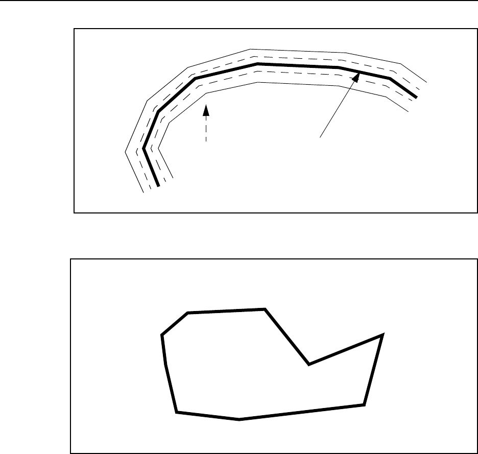
3-164 TSIP Reference Volume 1
Report Packets 3
Figure 3-2 Proximity Indicator for Curved Headland
Figure 3-3 Proximity Indicator for Closed Circuit Headland
Orange
Orange
RED RED
Green
Green
Healand: vehicle
centerline on last
headland pass.
Operator will
see indicator LED
change colors near
headland boundary.
GREEN
RED
RED
RED
RED

TSIP Reference Volume 1 3-165
3Report Packets
0x8F 0x91 Report Packet 0x8F 0x91
Guidance Configuration Report
Report Packet 0x8F 0x91 reports information about the current guidance configuration in
response to Command Packet 0x8E 0x91. Table 3-230 describes the format of this packet.
For more information, see Command Packet 0x8E 0x91 on page 2-113.
Table 3-230 Guidance Configuration Report
Byte # Item Type Value/Units Meaning
0 Subpacket ID BYTE 0x91 Guidance configuration report
1Units BYTE
flag
Specifies what units will be used for the lightbar
text display and lightbar LEDs
0Metric
1English
2 Display Mode BYTE
flag
Determines in which direction the lightbar
LEDs light and arrow indicators point to
indicate error.
0 Show Correction - configures the LEDs
to light in the direction to steer. Set this
to follow the LEDs.
1 Show Error - configures the LEDs to
reflect the error with respect to the
current swath. Set this to "pull" the
LEDs.
3 Boundary
Mode BYTE Table 2-207 Boundary mode determines what kind of
boundary will be specified with the headland
points. Headland points are used to describe
the field edges so that the receiver can provide
an indicator of where the vehicle is relative to
the field edges.
4 Pattern Mode BYTE Table 2-210 Guidance pattern to use
5-6 Look Ahead INTEGER
seconds
Allows the system to predict future error. This
accounts for system delays, including operator
response time. The recommended setting is 2
seconds.

3-166 TSIP Reference Volume 1
Report Packets 3
7Swath
Direction BYTE
flag
The swath direction setting determines
whether the swaths are generated to the left or
right of the A-B line. A setting of
Auto Detect
establishes swaths in the direction turned after
the first swath. When
Automatic Turn Detection
is configured, swaths automatically increment
when the equipment turns approximately 110°
with respect to the active swath. Note:
manually incrementing or otherwise changing
the current swath number temporarily overrides
Automatic Turn Detection
and
Snap to Swath
.
See Command Packet 0x8E 0x91 for more
information
0 Left
1Right
2 Automatic turn detection
3 Snap to closest swath
8-11 Swath Width SINGLE
meters
The swath width parameter is set according to
the width of the applicator or spray boom,
where the total width is measured from one
end of the boom to the other. Note: When
calculating coverage area, half the configured
width is added.
12-15 Antenna
Offset SINGLE
meters
Antenna position offset fore or aft of the
applicator boom
> 0 The antenna is ahead of the boom
< 0 The antenna is behind the boom
16-19 Guidance
Output Rate LONG
msecs
The output rate controls how often the
guidance status packet is sent. The output rate
is selectable in 200 msec increments up to
integer seconds (1000 msecs). A value of 0
turns automatic output off.
20-22 Number of
Swaths to
Skip
INTEGER
swaths
Number of swaths to skip when using Skip ’N’
pattern. Unused when pattern is not Skip N.
0 to 999 is valid range.
22-34 Reserved BYTE 0 Reserved
35-36 Checksum INTEGER
checksum
Checksum
Table 3-230 Guidance Configuration Report (Continued)
Byte # Item Type Value/Units Meaning

TSIP Reference Volume 1 3-167
3Report Packets
0x8F 0x92 Report Packet 0x8F 0x92
Lightbar Configuration Report
This packet reports the current lightbar configuration and is sent in response to Command
Packet 0x8E 0x92. For more information about the contents of this packet, see Command
Packet 0x8E 0x92.
Table 3-231 Lightbar Configuration Report
Byte # Item Type Value/Units Meaning
0 Subpacket ID BYTE 0x92 Lightbar configuration report
1 Lightbar
Mounting
BYTE
flag
Specifies how lightbar is mounted
0 Dash mounted (upright mounting)
1 Ceiling mounted (inverts lightbar text)
2 Lightbar
Intensity BYTE 1-5 Determines the LED brightness and text base
on a scale of 1 to 5.
3 Lightbar Text
Type BYTE
flag
Specifies what kind of information will be
provided on the small text display below the
LEDs on the lightbar.
0No text
1 Swath # and predicted cross-track error
2 GPS status information
3 Current swath number
4 Distance from start of current swath
5 Distance to end of current swath
6 GPS-derived true heading
7 Predicted cross-track error
8 Directional error between current
heading and direction of A-B line
9 Ground speed
10 Current swath number and ground
speed
11 Lightbar demo text
12 Turn signal arrows for curved guidance
13 Number of points logged on a curved
swath.
Note – Setting the text type to Demo Text will
put the lightbar into a demo mode where the
lightbar continually cycles through its
initialization lightshow. This is primarily
intended as an eye-catcher for trade shows.

3-168 TSIP Reference Volume 1
Report Packets 3
4 LED Spacing
Mode BYTE
flag
This setting configures the lightbar for linear or
scaled display
0 Linear display - allows an LED interval
to be specified, and spaces each of the
17 LEDs to either side of center by this
distance.
1 Scaled display - allows specification of
an LED interval and a distance which
the end LED represents.
5-8 Lightbar LED
Interval SINGLE
meters
If linear spacing is selected, the interval is used
as the interval represented by each LED. If
scaled spacing is selected, the interval
represents the LED spacing at the center of the
lightbar.
9-12 Lightbar LED
End Interval If scaled spacing is selected, the end interval
represents the LED spacing at the far ends of
the lightbar.
13-16 Proximity
Indicator
Sensitivity
SINGLE
meters
The indicator LED sensitivity defines the
sensitivity of the lightbar’s large, center LED.
This setting determines how near a PAUSE
point a vehicle must be before turning
ORANGE and GREEN.
17 Event Option BYTE
bitmask, see
Table 3-232
Lightbar event output designed to sound alarm.
18-21 Cross-Track-
Error Alarm
Tolerance
SINGLE
meters
Applies when event option 0x08 is active.
Lightbar event outpu continuously active when
cross-track-error exceeds this value.
22-29 Reserved BYTE 0 Reserved
30-31 Checksum INTEGER
checksum
Checksum
Table 3-231 Lightbar Configuration Report (Continued)
Byte # Item Type Value/Units Meaning

TSIP Reference Volume 1 3-169
3Report Packets
Table 3-232 Lightbar Event Options
Bit # Meaning
0
(LSB) When swath number changes:
0: No event 1: Short beep
1 When crossing field boundary (boundaries defined by RED zone for indicator
LED. See Figure 3-1, Figure 3-2, Figure 3-3):
0: No event 1: Long beep
2 When inside field (GREEN and ORANGE zones):
0: No event 1: Continuous output
3 When cross-track error exceeds cross-track-error alarm tolerance:
0: No event 1: Continuous output
4 When switch pressed:
0: No event 1: Beep
5-7 Reserved (set to zero)

3-170 TSIP Reference Volume 1
Report Packets 3
0x8F 0x94 Report Packet 0x8F 0x94
Guidance Operation Acknowledgment
This packet acknowledges guidance actions taken via Command Packet 0x8E 0x94.
Table 3-233 Guidance Operation Acknowledgment
Byte # Item Type Value/Units Meaning
0 Subpacket ID BYTE 0x94 Acknowledge guidance operation
1 Operation BYTE
flag
Type of operation
0Set point A
1Set point B
2Set point C
3 Increment swath number
4 Decrement swath number
5 Pause guidance
6 Resume guidance
7 Jump to a specific swath number
8 Reset guidance
2 Operation
Status BYTE
flag
Operation status:
0 Operation failed; check guidance and
GPS status
1 Operation successful
3 Guidance
Status BYTE
flag
Guidance validity information required for
operation
0Status valid
1Status unknown
2 Guidance off
3 Need point A
4 Need point B
5 Need point C
6 Guidance paused
7 Cannot resume without pause first
255 Guidance option not installed
4-5 GPS status BYTE Table 3-227 GPS error status indicators that would
preclude guidance operation (0=valid)
6-9 Reserved BYTE 0 Reserved
10-11 Checksum INTEGER
checksum
Checksum

TSIP Reference Volume 1 3-171
3Report Packets
0x8F 0x95 Report Packet 0x8F 0x95
Button Box Configuration Type Report
This packet reports the type of button box configuration currently in use in response to
Command Packet 0x8E 0x95. See Command Packet 0x8E 0x95 for more information.
0x8F 0x96 Report Packet 0x8F 0x96
Point Manipulation Report
To acknowledge the capture, deletion or clearing of headland points and area points via
Command Packet 0x8E 0x96, the packet described in Table 3-235 is sent.
Table 3-234 Button Box Configuration Type Report
Byte # Item Type Value/Units Meaning
0 Subpacket ID BYTE 0x95 Button box configuration type report
1 Button
Configuration
Type
BYTE
flag
Buttons configured according to:
0 Default button box definitions
1 Default external switch definitions
2 Custom button configuration
3 Button configuration cleared
2-6 Reserved BYTE 0 Reserved
7-8 Checksum INTEGER
checksum
Checksum
Table 3-235 Point Manipulation Acknowledgment
Byte # Item Type Value/Units Meaning
0 Subpacket ID BYTE 0x96 Point manipulation report
1 Operation BYTE
flag
Point operation:
0 Capture of current position
1 Delete last point of type specified
2 Delete all points of type specified
3 Capture of provided position
2 Point Type BYTE
flag
Type of point
0 Headlands point
1Area point
3 Operation
Status BYTE
flag
Operation status:
0 Operation failed; check GPS status
1 Operation succeeded
4-5 GPS Status BYTE Table 3-227 GPS error status indicators that would
preclude point operation
6-9 Reserved BYTE 0 Reserved
10-11 Checksum INTEGER
checksum
Checksum

3-172 TSIP Reference Volume 1
Report Packets 3
To report how many points of a particular type have been stored, the packet format
described in Table 3-236 is sent.
0x8F 0x97 Report Packet 0x8F 0x97
Utility Information Report
This packet reports various utility information including the current area and the coverage
area determined from the area points in response to Command Packet 0x8E 0x97.
Table 3-236 Point Quantity Report
Byte # Item Type Value/Units Meaning
0 Subpacket ID BYTE 0x96 Point manipulation report
1 Operation BYTE
flag
Point operation:
4 Report number of points.
2 Point Type BYTE
flag
Type of point
0 Headlands point
1Area point
3-4 Number of
Points INTEGER
points
Number of points of type "Point Type"
5-8 Reserved BYTE 0 Reserved
9-10 Checksum INTEGER
checksum
Checksum
Table 3-237 Utility Information Report
Byte # Item Type Value/Units Meaning
0 Subpacket ID BYTE 0x97 Utility information report
1 Data Type BYTE
flag
Information type in bytes 2-9:
0 Area within points
1 Adjusted area (includes area flaps for
boom width).
2 Path length (connect area points)
3 Perimeter (path length closed back to
first area point).
4 Length of last segment: distance
between last two points in area-point
vector
2-3 Number of
Points INTEGER
points
Number of points used in area, path length,
and perimeter calculations
4-11 Information DOUBLE
meters
2 or
meters
See above data types.
12-19 Reserved BYTE 0 Reserved
20-21 Checksum INTEGER
checksum
Checksum

TSIP Reference Volume 1 3-173
3Report Packets
0x8F 0x98 Report Packet 0x8F 0x98
Individual Button Configuration Report
The individual button configuration packet is used to report the configuration for each
button on the button box as shown in Table 3-238. These button configurations may
represent a preset factory configuration or a user-defined configuration. Report Packet
0x8F 0x95 may be requested to determine if a factory set or user-defined set is being used.
Table 3-238 Individual Button Configuration Report
Byte # Item Type Value/Units Meaning
0 Subpacket ID BYTE 0x98 Individual button configuration
report
1 Number of
buttons BYTE
buttons
Number of buttons described in this
report
2-6 Reserved BYTE 0 Reserved
For each button, n, specified in byte 1
7, 10, 13, etc. Button SIGNED
BYTE -6 thru 6,
excluding 0 Button number according to Trimble
cable pin out. Negative numbers
indicate the shift key is pressed
before this button, i.e -5 indicates
the button combination Shift 5.
8, 11, 14, etc. Operation BYTE Table 2-221 When button is pressed, this
operation occurs.
9, 12, 15, etc. Reserved BYTE 0 Reserved
(7 + 3*n) - (8+ 3*n) Checksum INTEGER
checksum
Checksum

3-174 TSIP Reference Volume 1
Report Packets 3
0x8F 0x9A Report Packet 0x8F 0x9A
Differential Correction Information Report
Report Packet 0x8F 0x9A is sent in response to a query packet Command Packet 0x8E
0x9A. This packet contains information about the last differential correction set that was
received and used by the receiver..
Table 3-239 Differential Correction Information Report
Byte # Item Type Value/Units Meaning
0 Subpacket ID BYTE 0x9A Differential Correction Information Report
1-2 Data Source INTEGER
flag
Source of corrections:
0 Beacon Channel 0
1 Beacon Channel 1
2 External RTCM
3 Racal LandStar satellite service
4 OmniSTAR satellite service
3-4 Station ID SIGNED
INTEGER
0–1023
Reference station identifier from RTCM
message header
5-12 Age DOUBLE
seconds
Age of last corrections received and used
13 Partial Flag BYTE
flag
Partial Flag:
0Not partial correction set (i.e. Type 1’s)
1 Partial correction set (i.e. Type 9’s)
14-22 Reserved BYTE 0 Reserved
23-24 Checksum INTEGER
checksum
Checksum

TSIP Reference Volume 1 3-175
3Report Packets
0xB0 Report Packet 0xB0
PPS and Event Report Packets
Report Packet 0xB0 subpackets are sent in response to Command Packet 0xB0
subpackets.
0xB0 0x80 Report Packet 0xB0 0x80
PPS Signal Configuration Report
Report Packet 0xB0 0x80 contains the configuration parameter settings for a specified PPS
Number (PPS signal). The report packet is sent in response to Command Packet 0xB0
0x00. The remote device can send an abbreviated form of Command Packet 0xB0 0x00 to
request the report, and the report packet is automatically sent when the remote device uses
Command Packet 0xB0 0x00 to configure parameter settings for a specified PPS Number.
Table 3-240 PPS Signal Configuration Report
Byte # Item Type Value/Units Meaning
0 Subpacket
ID
BYTE 0x80 PPS Signal Configuration Report
1PPS
Number
BYTE 0x01 Currently supports the output of one PPS signal
(PPS Number = 1).
2 Enable Flag BYTE
flag
Identifies the current state of the specified PPS
signal (PPS Number):
0Disabled
1Enabled
3PPS
Timebase
BYTE
flag
Identifies the timebase used for outputting the
specified PPS signal (PPS Number):
0 GPS time
1 UTC (Universal Time Coordinated)
2Receiver’s internal clock (user-defined)
4PPS Polarity BYTE
flag
Identifies the polarity of the specified PPS signal
(PPS Number)
The PPS polarity only refers to a negative or
positive PPS pulse. There is no interrupt
associated with the signal—the leading edge of
the PPS pulse is not affected by the polarity
setting:
0 Negative
1Positive
5Auto
Generate
Reports
BYTE
flag
Identifies whether or not Report Packet 0xB0
0x82 is automatically generated for the PPS
signal (PPS Number) and sent to the remote
device:
0Disabled
1Enabled

3-176 TSIP Reference Volume 1
Report Packets 3
6-9 Reserved BYTE 0x00 Reserved (set to zero)
10-17 Period DOUBLE 1.0 Hz Identifies the PPS signal output frequency rate for
the specified PPS Number. The receiver currently
supports a 1 Hz PPS (pulse per second) output
signal rate.
18-25 Offset DOUBLE
seconds
Identifies the PPS output signal offset in seconds
for the specified PPS Number.
For example, a you can offset the PPS output
signal to account for a 100 nsec delay attributed
to a GPS antenna cable run. A positive value
causes the signal to occur later and a negative
value causes the signal to occur sooner
26-29 Max UNC
Threshold
SINGLE
seconds
Maximum allowable clock uncertainty threshold,
in seconds, for the specified PPS Number.
If the Maximum UNC Threshold is set to a large
value (e.g. 1 second), the GPS receiver continues
to produce a PPS signal even when a position fix
is not available (satellites are not tracked). If the
Maximum UNC Threshold is set to a small value
(e.g. 1 msec, the PPS signal is disabled a few
seconds after a position is no longer available
(satellites are no longer tracked). The PPS signal
drifts when a position fix is not available and
snaps back to the correct position once a position
fix becomes available again.
30-31 Checksum INTEGER
checksum
Checksum
Table 3-240 PPS Signal Configuration Report (Continued)
Byte # Item Type Value/Units Meaning

TSIP Reference Volume 1 3-177
3Report Packets
0xB0 0x81 Report Packet 0xB0 0x81
PPS Signal Enable/Disable Acknowledgment
Report Packet 0xB0 0x81 is returned to acknowledge completion of the request to enable
or disable a specified PPS signal (PPS Number) sent in Command Packet 0xB0 0x01. For
more information, see Command Packet 0xB0 0x01 on page 2-132.
Table 3-241 PPS Signal Enable/Disable Acknowledgment
Byte # Item Type Value/Units Meaning
0 Subpacket ID BYTE 0x81 PPS Signal Enable/Disable Acknowledgment
1PPS Number BYTE 0x01 Identifies the number assigned to the PPS
signal. The receiver currently supports the
output of one PPS signal (PPS Number 1).
2 Enable Flag BYTE
flag
Identifies the current enable/disable state of
the specified PPS signal (PPS Number):
0 Disabled
1 Enabled
3-4 Checksum INTEGER
checksum
Checksum of bytes 0-2

3-178 TSIP Reference Volume 1
Report Packets 3
0xB0 0x82 Report Packet 0xB0 0x82
PPS Signal Auto-Generated Report
Report Packet 0xB0 0x82 is automatically generated for a specific PPS Number (PPS
signal) if the Auto Generated Reports parameter (byte 5 of Command Packet 0xB0 0x00)
is set to 1. Each report packet contains information about the preceding PPS signal output
for the specified PPS Number.
If the serial port is unloaded, the report packet is typically generated and sent to the remote
device 10 milliseconds after the PPS signal is sent.
The Time value of the specified PPS signal (PPS Number) is based on the selected PPS
Timebase, PPS Polarity and PPS Offset parameter values.
Table 3-242 PPS Signal Auto-Generated Report
Byte # Item Type Value/Units Meaning
0 Subpacket ID BYTE 0x82 PPS Signal Auto-Generated Report
1PPS Number BYTE 0x01 Identifies the number assigned to the PPS
signal. The receiver currently supports the
output of one PPS signal (PPS Number 1).
2PPS Timebase BYTE
flag
Identifies the timebase used for outputting the
specified PPS signal (PPS Number):
0GPS time
1 UTC (Universal Time Coordinated)
2 User-defined timebase
3 Reserved BYTE 0x00 Reserved (set to zero)
4-11 Time DOUBLE
seconds
GPS or UTC time of the week when the PPS
event took place
12-15 Max UNC SINGLE
seconds
Clock uncertainty at pulse time, in seconds, for
the specified PPS Number
16-17 Checksum INTEGER
checksum
Checksum

TSIP Reference Volume 1 3-179
3Report Packets
0xB0 0xC0 Report Packet 0xB0 0xC0
Event Timestamp Selection Report
Report Packet 0xB0 0xC0 contains the timestamp configuration settings for timestamping
of event inputs. The report packet is sent in response to Command Packet 0xB0 0x40. The
remote device can send an abbreviated form of Command Packet 0xB0 0x40 to request the
report, and the report packet is automatically sent when the remote device uses Command
Packet 0xB0 0x40 to configure parameter settings for a specified event.
0xB0 0xC1 Report Packet 0xB0 0xC1
Event Packet Options Report
Report Packet 0xB0 0xC1 contains the output packet configuration settings for event
inputs. The report packet is sent in response to Command Packet 0xB0 0x41. The remote
device can send an abbreviated form of Command Packet 0xB0 0x41 to request the report,
and the report packet is automatically sent when the remote device uses Command Packet
0xB0 0x41 to configure output options for a specified event.
Table 3-243 Event Timestamp Selection Report
Byte # Item Type Value/Units Meaning
0 Subpacket
ID
BYTE 0xC0 Event Timestamp Selection Report
1 Select BYTE
1-n
Event selection, depends on number of events
supported by receiver.
2Slope BYTE Event input configuration:
0 Disabled
1 Enabled. Timestamp positive edge
2 Enabled. Timestamp negative edge
Table 3-244 Event Packet Options Report
Byte # Item Type Value/Units Meaning
0 Subpacket
ID
BYTE 0xC1 Event Timestamp Options Report
1Event
selected
BYTE
1-n
Event selection, depends on number of events
supported by receiver.
2Options 1 BYTE Table 3-245 Output options 1
3 Options 2 BYTE Table 3-246 Output options 2
4 Options 3 BYTE Table 3-247 Output options 3

3-180 TSIP Reference Volume 1
Report Packets 3
0xB0 0xC2 Report Packet 0xB0 0xC2
Event Plus Position Report
Report Packet 0xB0 0xC2 contains the timestamp and position information output when
an event is received. The report packet is automatically output if Byte 2, bit 0 is set in
Command Packet 0xB0 0x41, or it may be output in response to Command Packet 0xB0
0x42.
Table 3-245 Byte 2 Output options 1
Bit # Meaning
0 (LSB) Automatic output of event plus position packet XX-XX upon event
reception
0: Disabled 1: Enabled
1 Automatic output of event only packet XX-XX upon event reception
0: Disabled 1: Enabled
2-7 Reserved (set to zero)
Table 3-246 Byte 3 Output options 2
Bit # Meaning
0-7 Reserved (set to zero)
Table 3-247 Byte 4 Output options 3
Bit # Meaning
0-7 Reserved (set to zero)
Table 3-248 Event Timestamp Selection Report
Byte # Item Type Value/Units Meaning
0 Subpacket
ID
BYTE 0xC2 Event Plus Position Report
1 Select BYTE
1-n
Event selection, depends on number of events
supported by receiver.
2Flag 1 BYTE Table 3-249 Time type and status
3 Flag 2 BYTE Table 3-250 Position type and status
4-5 Count INTEGER Event count since reset
6-13 Time DOUBLE
seconds
Event time (seconds from beginning of week)
14-21 X or Lat DOUBLE
radians
Latitude in radians, ECEF X in meters
22-29 Y or Lon DOUBLE
radians
Longitude in radians, ECEF Y in meters
30-37 Z or Alt DOUBLE
meters
Altitude in meters, ECEF Z in meters
38-39 Checksum INTEGER
checksum
Checksum

TSIP Reference Volume 1 3-181
3Report Packets
Table 3-249 Byte 2 Time Type and Status Options
Bit # Meaning
0 (LSB) Time tag:
0: GPS 1: UTC
1 Accurate GPS time:
0: Available 1: Not available
2 UTC offset information:
0: Valid
1: Not current or don’t yet have time from a satellite to verify. Use
Command Packet 0x2F to request present UTC parameters for
applicability
3-7 Reserved (set to zero)
Table 3-250 Byte 3 Position Type and Status Options
Bit # Meaning
0-1 Position reference frame:
0: ECEF XYZ
1: LLA HAE
2: LLA MSL
3: Not used
2 Position quality:
0: Good 1: Sub-optimal
3 Position availability:
0: Available 1: Not available
4-7 Reserved (set to zero)

3-182 TSIP Reference Volume 1
Report Packets 3
0xB0 0xC3 Report Packet 0xB0 0xC3
Event Only Report
Report Packet 0xB0 0xC3 contains the timestamp information output when an event is
received. The report packet is automatically output if Byte 2, bit 1 is set in Command
Packet 0xB0 0x41, or it may be output in response to Command Packet 0xB0 0x43.
Table 3-251 Event Timestamp Selection Report
Byte # Item Type Value/Units Meaning
0 Subpacket
ID
BYTE 0xC3 Event Only Report
1 Select BYTE
1-n
Event selection, depends on number of events
supported by receiver.
2Flag 1 BYTE Table 3-252 Time type and status
3-4 Count INTEGER
counter
Event count since reset
5-12 Time DOUBLE
seconds
Event time (seconds from beginning of week)
13-14 Checksum INTEGER
checksum
Checksum
Table 3-252 Byte 2 Time Type and Status Options
Bit # Meaning
0 (LSB) Time tag:
0: GPS 1: UTC
1 Accurate GPS time:
0: Available 1: Not available
2 UTC offset information:
0: Valid
1: Not current or don’t yet have time from a satellite to verify. Use
Command Packet 0x2F to request present UTC parameters for
applicability
3-7 Reserved (set to zero)

TSIP Reference Volume 1 3-183
3Report Packets
0xB0 0xC4 Report Packet 0xB0 0xC4
Event Marker Miscellaneous Action Taken
Report Packet 0xB0 0xC4 is used to acknowledge that an event marker action was taken as
commanded in Report Packet 0xB0 0xC4.Table 3-253 shows the structure of Report
Packet 0xB0 0xC4.
Table 3-253 Event Marker Miscellaneous Action Taken
Byte # Item Type Value/Units Meaning
0 Subpacket
ID
BYTE 0xC4 Event marker action taken
1 Select BYTE
1-n
Event selection, depends on number of events
supported by receiver.
2Action
complete BYTE
flag
Action taken:
0: Event forced
1: Event count reset to zero

3-184 TSIP Reference Volume 1
Report Packets 3
0xBB Report Packet 0xBB
Receiver Configuration Parameters Reports
Command Packet 0xBB sets or displays the receiver configuration parameters.
0xBB 0x00 Report Packet 0xBB 0x00
Primary Receiver Configuration Parameters Report
Report Packet 0xBB 0x00 contains the primary receiver configuration parameters that a
user usually needs to modify, sent in response to Command Packet 0xBB 0x00.
Table 3-254 Primary Receiver Configuration Block
Byte # Item Type Value/Units Meaning
0 Subcode BYTE 0x00 Primary Receiver Configuration Block
1 Operating
Dimension
BYTE
flag
Operation dimension:
0 Automatic
1Time Only (1 SV)
3 Horizontal (2)
4 Full Position (3D)
5DGPS Reference
6 2D Clock Hold
7 Overdetermined Clock
2 DGPS Mode BYTE
flag
Differential GPS mode:
0 DGPS Off
1 DGPS Only
3DGPS Auto
3 Dynamics Code BYTE
flag
Vehicle dynamics code:
1Land
2Sea
3Air
4 Stationary
4 Solution Mode BYTE
flag
Overdetermined mode used to compute
position solution:
1 Overdetermined fix
2 Weighted overdetermined fix
5-8 Elevation Mask SINGLE 0-PI/2 Lowest satellite elevation for fixes
(radians)
9-12 AMU Mask SINGLE
AMUs
Minimum signal level for fixes
13-16 PDOP Mask SINGLE
PDOP
Reports the maximum PDOP for
calculating position fixes
17-20 PDOP Switch SINGLE
PDOP
Influences whether the receiver will
calculate a 2D or 3D fix depending on
the PDOP. If 4 or more satellites are
available and the resulting PDOP is less
than the PDOP Switch value, then 3D
fixes are calculated. The PDOP Switch
is used only in automatic 2D/3D mode.

TSIP Reference Volume 1 3-185
3Report Packets
21 DGPS Age Limit BYTE
seconds
Maximum time to use a DGPS
correction, in seconds
22 Foliage Mode BYTE
flag
Foliage mode:
0Never
1 Sometimes
2Always
23 Low Power Mode BYTE
flag
Low power mode:
0 Disabled
1Auto
24 Clock Hold Mode BYTE
flag
Clock Hold mode:
0Off
1On
25 Measurement Rate BYTE
flag
Measurement rate:
01 Hz
15 Hz
210 Hz
26 Position Fix Rate BYTE
flag
Position Fix rate:
01 Hz
15 Hz
210 Hz
3 Position at measurement rate
27-39 Reserved BYTE -1 Reserved for future use
Table 3-254 Primary Receiver Configuration Block (Continued)
Byte # Item Type Value/Units Meaning

3-186 TSIP Reference Volume 1
Report Packets 3
0xBC Report Packet 0xBC
Serial Port Configuration Parameters Report
Report Packet 0xBC reports the serial port configuration parameters, in response to a
request sent in Command Packet 0xBC. The data format is shown in Table 3-255.
The operation type is used to specify special protocol operation such as reference station
output. For example, if the receiver protocol is set to reference station mode and TSIP is
active on a port, then only DGPS corrections packets 0x60 and 0x61 will be output on that
port.
Table 3-255 Set Serial Port Configuration Parameters
Byte # Item Type Value/Units Meaning
0Port # BYTE
flag
Number of receiver’s serial port:
0Port 0
1Port 1
2Port 2
3Port 3
255 Current port
Note – See product-specific appendices for
more information on port naming conventions.
1 Input Baud Rate BYTE
flag
Throughput of data input through serial port, in
bits per second:
0None
1 110 baud
2 300 baud
3 600 baud
4 1200 baud
5 2400 baud
6 4800 baud
7 9600 baud
8 19200 baud
9 38400 baud
2 Output Baud Rate BYTE
flag
Throughput of data output through serial port,
in bits per second. Same options as Input
Baud Rate.
3 # Data Bits BYTE
flag
Number of data bits transmitted:
0 5 bits
1 6 bits
2 7 bits
3 8 bits
4Parity BYTE
flag
Parity of transmitted data:
0None
1Odd
2Even

TSIP Reference Volume 1 3-187
3Report Packets
5 # Stop Bits BYTE
flag
Number of stop bits in transmitted data:
0 1 bit for 6-8 data bits/1.5 bits for 5 data
bits
1 2 bits
6 Flow Control BYTE Table 3-256 Method of flow control negotiation
7 Input Protocols BYTE Table 3-257 Input protocol used by serial port
8 Output Protocols BYTE Table 3-257 Output protocol used by serial port
9Protocol
Operation Mode
BYTE Table 3-258 Special operation mode of protocols
Table 3-256 Byte 6 Flow Control
Bit # Meaning
0 (LSB) RTS CTS:
0: Disabled 1: Enabled
1 Transmit XON/XOFF:
0: Disabled 1: Enabled
2 Transmit XANY:
0: Disabled 1: Enabled
3 Receive XON/XOFF:
0: Disabled 1: Enabled
4-7 Reserved (set to zero)
Table 3-255 Set Serial Port Configuration Parameters (Continued)
Byte # Item Type Value/Units Meaning

3-188 TSIP Reference Volume 1
Report Packets 3
Table 3-257 Protocols
Bit # Meaning
0 (LSB) TAIP:
0: Disabled 1: Enabled
1 TSIP:
0: Disabled 1: Enabled
2 NMEA:
0: Disabled 1: Enabled
3RTCM:
0: Disabled 1: Enabled
4 DCOL:
0: Disabled 1: Enabled
5-7 Reserved (set to zero)
Table 3-258 Byte 9 Special Operation Modes
Bit # Meaning
0 (LSB) Reference station mode:
0: Disabled 1: Enabled
1-7 Reserved (set to zero)


A-2 TSIP Reference Volume 2
Packet Usage Summary A
Table A-1 TSIP Packet Usage Summary
ID Name
AgGPS 120
AgGPS 122
AgGPS 124
AgGPS 132
AL9000
DSM EuroCard
BD-112
BD-122
BD-132
DSM
DSMPro
DSM12
DSM212H and DSM121L
DSM12RS
NT300D
Placer GPS 450
Placer GPS 455/455DR
GPS Pathfinder ProXR
GPS Pathfinder ProXRS
CrossCheck AMPS
CrossCheck XR
0x13 TSIP Parsing
Error Notification
✔✔✔✔✔✔✔✔ ✔✔✔✔✔✔✔✔✔✔
0x1A TSIP RTCM
Wrapper
Command
✔
0x1A 0x00 Raw RTCM Data
Packet Request
✔
0x1A TSIP RTCM
Wrapper / Port A
Echo Report
✔✔
✔
0x1A 0x00 Raw RTCM
Wrapper / Port A
Echo Report
✔✔✔
0x1D Oscillator Offset
Command
✔ ✔✔✔✔✔✔✔✔✔✔✔✔✔✔✔✔✔✔✔✔
0x1E Clear Battery-
Backed Memory
Command
✔ ✔✔✔✔✔✔✔✔✔✔✔✔✔✔✔✔✔✔✔✔
0x1F Receiver
Firmware
Information
Request
✔ ✔✔✔✔✔✔✔✔✔✔✔✔✔✔✔✔✔✔✔✔
0x20 Almanac Request ✔ ✔✔✔✔✔✔✔✔✔✔✔✔✔✔✔✔✔✔✔✔
0x21 Current Time
Request
✔ ✔✔✔✔✔✔✔✔✔✔✔✔✔✔✔✔✔✔✔✔
0x22 Position Fix Mode
Command
✔ ✔✔✔✔✔✔✔✔✔✔✔✔✔✔✔✔✔✔✔✔
0x23 Initial Position
(XYZ Cartesian
ECEF) Command
✔ ✔✔✔✔✔✔✔✔✔✔✔✔✔✔✔✔✔✔✔✔
1Requires Reference Station option.
2Not all receivers support carrier phase information.
3May require Post-Processing option.
4Requires Guidance option.

TSIP Reference Volume 2 A-3
APacket Usage Summary
0x24 GPS Position Fix
Mode Request
✔ ✔✔✔✔✔✔✔✔✔✔✔✔✔✔✔✔✔✔✔✔
0x25 Soft Reset / Self
Test Command
✔ ✔✔✔✔✔✔✔✔✔✔✔✔✔✔✔✔✔✔✔✔
0x26 Health Request ✔ ✔✔✔✔✔✔✔✔✔✔✔✔✔✔✔✔✔✔✔✔
0x27 Signal Levels
Request
✔ ✔✔✔✔✔✔✔✔✔✔✔✔✔✔✔✔✔✔✔✔
0x28 GPS System
Message
Request
✔ ✔✔✔✔✔✔✔✔✔✔✔✔✔✔✔✔✔✔✔✔
0x29 Almanac Health
Page Request
✔ ✔✔✔✔✔✔✔✔✔✔✔✔✔✔✔✔✔✔✔✔
0x2A Altitude for 2D
Mode Command
✔ ✔✔✔✔✔✔✔✔✔✔✔✔✔✔✔✔✔✔✔✔
0x2B Initial Position
(Latitude,
Longitude,
Altitude)
Command
✔ ✔✔✔✔✔✔✔✔✔✔✔✔✔✔✔✔✔✔✔✔
0x2C Operating
Parameters
Command
✔ ✔✔✔✔✔✔✔✔✔✔✔✔✔✔✔✔✔✔✔✔
0x2D Oscillator Offset
Request
✔ ✔✔✔✔✔✔✔✔✔✔✔✔✔✔✔✔✔✔✔✔
0x2E GPS Time
Command
✔ ✔✔✔✔✔✔✔✔✔✔✔✔✔✔✔✔✔✔✔✔
0x2F UTC Parameters
Request
✔ ✔✔✔✔✔✔✔✔✔✔✔✔✔✔✔✔✔✔✔✔
Table A-1 TSIP Packet Usage Summary
ID Name
AgGPS 120
AgGPS 122
AgGPS 124
AgGPS 132
AL9000
DSM EuroCard
BD-112
BD-122
BD-132
DSM
DSMPro
DSM12
DSM212H and DSM121L
DSM12RS
NT300D
Placer GPS 450
Placer GPS 455/455DR
GPS Pathfinder ProXR
GPS Pathfinder ProXRS
CrossCheck AMPS
CrossCheck XR
1Requires Reference Station option.
2Not all receivers support carrier phase information.
3May require Post-Processing option.
4Requires Guidance option.

A-4 TSIP Reference Volume 2
Packet Usage Summary A
0x31 Accurate Initial
Position (XYZ
Cartesian ECEF)
Command
✔ ✔✔✔✔✔✔✔✔✔✔✔✔✔✔✔✔✔✔✔✔
0x32 Accurate Initial
Position (Latitude,
Longitude,
Altitude)
Command
✔ ✔✔✔✔✔✔✔✔✔✔✔✔✔✔✔✔✔✔✔✔
0x33 Analog-to-Digital
Readings
Command
✔✔✔✔✔✔✔✔✔ ✔✔✔✔ ✔✔
0x34 Satellite Number
For One-Satellite
Mode Command
✔ ✔✔✔✔✔✔✔✔✔✔✔✔✔✔✔✔✔✔✔✔
0x35 I/O Option Flags
Command
✔ ✔✔✔✔✔✔✔✔✔✔✔✔✔✔✔✔✔✔✔✔
0x36 Velocity Aiding of
Acquisition
Command
✔✔✔✔
0x37 Last Position and
Velocity Request
✔ ✔✔✔✔✔✔✔✔✔✔✔✔✔✔✔✔✔✔✔✔
0x38 Download and
Upload Satellite
System Data
✔ ✔✔✔✔✔✔✔✔✔✔✔✔✔✔✔✔✔✔✔✔
0x39 Satellite Attribute
Database
Command
✔ ✔✔✔✔✔✔✔✔✔✔✔✔✔✔✔✔✔✔✔✔
0x3A Last Raw
Measurement
Request
✔ ✔✔✔✔✔✔✔✔✔✔✔✔✔✔✔✔✔✔✔✔
Table A-1 TSIP Packet Usage Summary
ID Name
AgGPS 120
AgGPS 122
AgGPS 124
AgGPS 132
AL9000
DSM EuroCard
BD-112
BD-122
BD-132
DSM
DSMPro
DSM12
DSM212H and DSM121L
DSM12RS
NT300D
Placer GPS 450
Placer GPS 455/455DR
GPS Pathfinder ProXR
GPS Pathfinder ProXRS
CrossCheck AMPS
CrossCheck XR
1Requires Reference Station option.
2Not all receivers support carrier phase information.
3May require Post-Processing option.
4Requires Guidance option.

TSIP Reference Volume 2 A-5
APacket Usage Summary
0x3B Satellite
Ephemeris Status
Request
✔ ✔✔✔✔✔✔✔✔✔✔✔✔✔✔✔✔✔✔✔✔
0x3C Satellite Tracking
Status Request
✔ ✔✔✔✔✔✔✔✔✔✔✔✔✔✔✔✔✔✔✔✔
0x3D Serial Port A
Communication
Parameters
Command
✔ ✔✔✔✔✔✔✔✔✔✔✔✔✔✔✔✔✔✔✔✔
0x3D Serial Port A
Configuration
Report
✔ ✔✔✔✔✔✔✔✔✔✔✔✔✔✔✔✔✔✔✔✔
0x3E Additional Fix
Parameters
Request
✔✔✔✔
0x40 Almanac Data for
Single Satellite
Report
✔ ✔✔✔✔✔✔✔✔✔✔✔✔✔✔✔✔✔✔✔✔
0x41 GPS Time Report ✔ ✔✔✔✔✔✔✔✔✔✔✔✔✔✔✔✔✔✔✔✔
0x42 Single-Precision
Position Fix (XYZ
Cartesian ECEF)
Report
✔ ✔✔✔✔✔✔✔✔✔✔✔✔✔✔✔✔✔✔✔✔
0x43 Velocity Fix (XYZ
Cartesian ECEF)
Report
✔ ✔✔✔✔✔✔✔✔✔✔✔✔✔✔✔✔✔✔✔✔
0x44 Non-
Overdetermined
Satellite Selection
Report
✔✔✔✔
Table A-1 TSIP Packet Usage Summary
ID Name
AgGPS 120
AgGPS 122
AgGPS 124
AgGPS 132
AL9000
DSM EuroCard
BD-112
BD-122
BD-132
DSM
DSMPro
DSM12
DSM212H and DSM121L
DSM12RS
NT300D
Placer GPS 450
Placer GPS 455/455DR
GPS Pathfinder ProXR
GPS Pathfinder ProXRS
CrossCheck AMPS
CrossCheck XR
1Requires Reference Station option.
2Not all receivers support carrier phase information.
3May require Post-Processing option.
4Requires Guidance option.

A-6 TSIP Reference Volume 2
Packet Usage Summary A
0x45 Receiver
Firmware
Information
Report
✔ ✔✔✔✔✔✔✔✔✔✔✔✔✔✔✔✔✔✔✔✔
0x46 Health of
Receiver Report
✔ ✔✔✔✔✔✔✔✔✔✔✔✔✔✔✔✔✔✔✔✔
0x47 Signal Levels for
All Satellites
Report
✔ ✔✔✔✔✔✔✔✔✔✔✔✔✔✔✔✔✔✔✔✔
0x48 GPS System
Message Report
✔ ✔✔✔✔✔✔✔✔✔✔✔✔✔✔✔✔✔✔✔✔
0x49 Almanac Health
Page Report
✔ ✔✔✔✔✔✔✔✔✔✔✔✔✔✔✔✔✔✔✔✔
0x4A Single-Precision
LLA Position Fix
Report or Manual
2D Reference
Altitude
Parameters
Report
✔ ✔✔✔✔✔✔✔✔✔✔✔✔✔✔✔✔✔✔✔✔
0x4B Machine / Code
ID and Additional
Status Report
✔ ✔✔✔✔✔✔✔✔✔✔✔✔✔✔✔✔✔✔✔✔
0x4C Operating
Parameters
Report
✔ ✔✔✔✔✔✔✔✔✔✔✔✔✔✔✔✔✔✔✔✔
0x4D Oscillator Offset
Report
✔ ✔✔✔✔✔✔✔✔✔✔✔✔✔✔✔✔✔✔✔✔
0x4E GPS Time
Command
Verification
✔ ✔✔✔✔✔✔✔✔✔✔✔✔✔✔✔✔✔✔✔✔
Table A-1 TSIP Packet Usage Summary
ID Name
AgGPS 120
AgGPS 122
AgGPS 124
AgGPS 132
AL9000
DSM EuroCard
BD-112
BD-122
BD-132
DSM
DSMPro
DSM12
DSM212H and DSM121L
DSM12RS
NT300D
Placer GPS 450
Placer GPS 455/455DR
GPS Pathfinder ProXR
GPS Pathfinder ProXRS
CrossCheck AMPS
CrossCheck XR
1Requires Reference Station option.
2Not all receivers support carrier phase information.
3May require Post-Processing option.
4Requires Guidance option.

TSIP Reference Volume 2 A-7
APacket Usage Summary
0x4F UTC Parameters
Report
✔ ✔✔✔✔✔✔✔✔✔✔✔✔✔✔✔✔✔✔✔✔
0x53 Analog-to-Digital
Readings Report
✔ ✔✔✔✔✔✔✔✔✔✔✔✔✔✔ ✔✔
0x54 One Satellite Bias
and Bias Rate
Report
✔ ✔✔✔✔✔✔✔✔✔✔✔✔✔✔✔✔✔✔✔✔
0x55 I/O Options
Report
✔ ✔✔✔✔✔✔✔✔✔✔✔✔✔✔✔✔✔✔✔✔
0x56 Velocity Fix East-
North-Up (ENU)
Report
✔ ✔✔✔✔✔✔✔✔✔✔✔✔✔✔✔✔✔✔✔✔
0x57 Last Computed
Fix Report
✔ ✔✔✔✔✔✔✔✔✔✔✔✔✔✔✔✔✔✔✔✔
0x58 Satellite System
Data Reports
✔ ✔✔✔✔✔✔✔✔✔✔✔✔✔✔✔✔✔✔✔✔
0x59 Satellite Attribute
Database Status
Report
✔ ✔✔✔✔✔✔✔✔✔✔✔✔✔✔✔✔✔✔✔✔
0x5A Raw
Measurement
Data Report
✔ ✔✔✔✔✔✔✔✔✔✔✔✔✔✔✔✔✔✔✔✔
0x5B Satellite
Ephemeris Status
Report
✔ ✔✔✔✔✔✔✔✔✔✔✔✔✔✔✔✔✔✔✔✔
0x5C Satellite Tracking
Status Report
✔ ✔✔✔✔✔✔✔✔✔✔✔✔✔✔✔✔✔✔✔✔
0x5E Additional Fix
Status Report
✔✔✔✔✔
Table A-1 TSIP Packet Usage Summary
ID Name
AgGPS 120
AgGPS 122
AgGPS 124
AgGPS 132
AL9000
DSM EuroCard
BD-112
BD-122
BD-132
DSM
DSMPro
DSM12
DSM212H and DSM121L
DSM12RS
NT300D
Placer GPS 450
Placer GPS 455/455DR
GPS Pathfinder ProXR
GPS Pathfinder ProXRS
CrossCheck AMPS
CrossCheck XR
1Requires Reference Station option.
2Not all receivers support carrier phase information.
3May require Post-Processing option.
4Requires Guidance option.

A-8 TSIP Reference Volume 2
Packet Usage Summary A
0x5F Severe Failure
Notification
✔✔✔✔✔
0x60 DGPS
Pseudorange
Corrections
Command
✔ ✔✔✔✔✔✔✔✔✔✔✔✔✔✔✔✔✔✔✔✔
0x60 Differential GPS
Pseudorange
Corrections
Report1
✔ ✔✔✔✔✔✔✔✔✔✔ ✔ ✔✔
0x61 DGPS Delta
Pseudorange
Corrections
Command
✔ ✔✔✔✔✔✔✔✔✔✔✔✔✔✔✔✔✔✔✔✔
0x61 Differential GPS
Delta
Pseudorange
Corrections
Report1
✔✔✔✔✔✔✔✔✔✔✔ ✔✔✔
0x62 DGPS Position
Fix Mode
Command
✔✔✔✔✔✔✔✔✔ ✔✔✔✔✔✔✔✔✔✔
0x65 Differential
Correction Status
Request
✔ ✔✔✔✔✔✔✔✔✔✔✔✔✔✔✔✔✔✔✔✔
0x67 Reference Station
Parameters
Command1
✔ ✔✔✔✔✔✔✔✔✔✔ ✔ ✔✔
0x67 0x00 Reference Station
Control
Command1
✔ ✔✔✔✔✔✔✔✔✔✔ ✔ ✔✔
Table A-1 TSIP Packet Usage Summary
ID Name
AgGPS 120
AgGPS 122
AgGPS 124
AgGPS 132
AL9000
DSM EuroCard
BD-112
BD-122
BD-132
DSM
DSMPro
DSM12
DSM212H and DSM121L
DSM12RS
NT300D
Placer GPS 450
Placer GPS 455/455DR
GPS Pathfinder ProXR
GPS Pathfinder ProXRS
CrossCheck AMPS
CrossCheck XR
1Requires Reference Station option.
2Not all receivers support carrier phase information.
3May require Post-Processing option.
4Requires Guidance option.

TSIP Reference Volume 2 A-9
APacket Usage Summary
0x67 0x01 Reference Station
Options
Command1
✔ ✔✔✔✔✔✔✔✔✔✔ ✔ ✔✔
0x67 0x02 Reference Station
Output Version
Command1
✔ ✔✔✔✔✔✔✔✔✔✔ ✔ ✔✔
0x67 0x03 Reference Station
Position
Command1
✔ ✔✔✔✔✔✔✔✔✔✔ ✔ ✔✔
0x67 0x04 Reference Station
ID Command1
✔ ✔✔✔✔✔✔✔✔✔✔ ✔ ✔✔
0x67 0x05 RTCM Type 16
Text Command1
✔ ✔✔✔✔✔✔✔✔✔✔ ✔ ✔✔
0x67 0x06 RTCM Type
Specific Output
Intervals
Command1
✔ ✔✔✔✔✔✔✔✔✔✔ ✔ ✔✔
0x67 0x09 Average Position
Reference Station
Position Request1
✔ ✔✔✔✔✔✔✔✔✔✔ ✔ ✔✔
0x67 0x0A Time Schedule
Message Interval
and Offset
Request1
✔ ✔✔✔✔✔✔✔✔✔✔ ✔ ✔✔
0x68 Mobile Differential
Parameters
Command
✔✔✔✔
0x68 0x00 Mobile Differential
Mode Command
✔✔✔✔
Table A-1 TSIP Packet Usage Summary
ID Name
AgGPS 120
AgGPS 122
AgGPS 124
AgGPS 132
AL9000
DSM EuroCard
BD-112
BD-122
BD-132
DSM
DSMPro
DSM12
DSM212H and DSM121L
DSM12RS
NT300D
Placer GPS 450
Placer GPS 455/455DR
GPS Pathfinder ProXR
GPS Pathfinder ProXRS
CrossCheck AMPS
CrossCheck XR
1Requires Reference Station option.
2Not all receivers support carrier phase information.
3May require Post-Processing option.
4Requires Guidance option.

A-10 TSIP Reference Volume 2
Packet Usage Summary A
0x68 0x01 Mobile Differential
Options
Command
✔✔✔✔
0x68 0x02 Mobile Differential
Input Version
Command
✔✔✔✔
0x68 0x03 Masking
Reference Station
Pos i tio n
Command
✔✔✔✔
0x68 0x04 Input Reference
Station ID
Command
✔✔✔✔
0x68 0x05 Last Received
RTCM Type 16
Request
✔✔✔✔
0x6A Differential
Corrections Used
in the Fix
Commands
✔✔✔✔ ✔✔✔ ✔✔✔✔✔✔✔✔ ✔
0x6A 0x01 Fix Differential
Corrections
Output Control
Command
✔✔✔✔ ✔✔✔ ✔✔✔✔✔✔✔✔ ✔
0x6A Differential
Corrections Used
in the Fix Reports
✔✔✔✔ ✔✔✔ ✔✔✔✔✔✔✔✔ ✔
0x6A 0x00 Differential
Corrections Used
in Fix Report
✔✔✔✔ ✔✔✔ ✔✔✔✔✔✔✔✔ ✔
Table A-1 TSIP Packet Usage Summary
ID Name
AgGPS 120
AgGPS 122
AgGPS 124
AgGPS 132
AL9000
DSM EuroCard
BD-112
BD-122
BD-132
DSM
DSMPro
DSM12
DSM212H and DSM121L
DSM12RS
NT300D
Placer GPS 450
Placer GPS 455/455DR
GPS Pathfinder ProXR
GPS Pathfinder ProXRS
CrossCheck AMPS
CrossCheck XR
1Requires Reference Station option.
2Not all receivers support carrier phase information.
3May require Post-Processing option.
4Requires Guidance option.

TSIP Reference Volume 2 A-11
APacket Usage Summary
0x6A 0x01 Fix Differential
Corrections
Output Control
Report
✔✔✔✔ ✔✔✔ ✔✔✔✔✔✔✔✔ ✔
0x6B QA/QC
Commands
0x6B 0x00 Position Sigma
Information
Parameters
Command
0x6B 0x01 Position VCV
Parameters
Command
0x6B 0x02 Position Sigma
Information
Request
0x6B 0x03 Position VCV
Information
Request
0x6D Average Position
Commands
✔ ✔✔✔✔✔✔✔✔✔✔✔✔✔ ✔✔
0x6D All-In-View
Satellite Selection
Report
✔ ✔✔✔✔✔✔✔✔✔✔✔✔✔✔✔✔✔✔✔✔
0x6D 0x00 Average Position
Start/Stop Control
Command
✔ ✔✔✔✔✔✔✔✔✔✔✔✔✔ ✔✔
0x6D 0x01 Average Position
Options
Command
✔ ✔✔✔✔✔✔✔✔✔✔✔✔✔ ✔✔
Table A-1 TSIP Packet Usage Summary
ID Name
AgGPS 120
AgGPS 122
AgGPS 124
AgGPS 132
AL9000
DSM EuroCard
BD-112
BD-122
BD-132
DSM
DSMPro
DSM12
DSM212H and DSM121L
DSM12RS
NT300D
Placer GPS 450
Placer GPS 455/455DR
GPS Pathfinder ProXR
GPS Pathfinder ProXRS
CrossCheck AMPS
CrossCheck XR
1Requires Reference Station option.
2Not all receivers support carrier phase information.
3May require Post-Processing option.
4Requires Guidance option.

A-12 TSIP Reference Volume 2
Packet Usage Summary A
0x6D 0x02 Auto Stop
Parameter
Options
Command
✔ ✔✔✔✔✔✔✔✔✔✔✔✔✔ ✔✔
0x6D 0x03 Current Average
Position Request
✔ ✔✔✔✔✔✔✔✔✔✔✔✔✔ ✔✔
0x6D 0x04 Average Position
Delta from Last
Position
✔ ✔✔✔✔✔✔✔✔✔✔✔✔✔ ✔✔
0x6E Synchronized
Measurement
Parameters
Commands
✔ ✔✔✔✔✔✔✔✔✔✔✔✔✔✔✔✔✔✔✔✔
0x6E 0x01 Synchronized
Measurement
Parameters
Command
✔ ✔✔✔✔✔✔✔✔✔✔✔✔✔✔✔✔✔✔✔✔
0x6E Synchronized
Measurement
Parameters
Reports
✔ ✔✔✔✔✔✔✔✔✔✔✔✔✔✔✔✔✔✔✔✔
0x6E 0x01 Synchronized
Measurement
Output
Parameters
Report
✔ ✔✔✔✔✔✔✔✔✔✔✔✔✔✔✔✔✔✔✔✔
0x6F Synchronized
Measurements
Reports2
✔ ✔✔✔✔✔✔✔✔✔✔✔✔✔✔✔✔✔✔✔✔
Table A-1 TSIP Packet Usage Summary
ID Name
AgGPS 120
AgGPS 122
AgGPS 124
AgGPS 132
AL9000
DSM EuroCard
BD-112
BD-122
BD-132
DSM
DSMPro
DSM12
DSM212H and DSM121L
DSM12RS
NT300D
Placer GPS 450
Placer GPS 455/455DR
GPS Pathfinder ProXR
GPS Pathfinder ProXRS
CrossCheck AMPS
CrossCheck XR
1Requires Reference Station option.
2Not all receivers support carrier phase information.
3May require Post-Processing option.
4Requires Guidance option.

TSIP Reference Volume 2 A-13
APacket Usage Summary
0x6F 0x01 Synchronized
Measurements
Report2
✔ ✔✔✔✔✔✔✔✔✔✔✔✔✔✔✔✔✔✔✔✔
0x70 Position/Velocity
Filter Command
✔✔✔✔ ✔✔✔ ✔✔✔✔✔✔✔✔✔✔
0x70 Position/Velocity
Filter Operation
Report
✔✔✔✔ ✔✔✔ ✔✔✔✔✔✔✔✔✔✔
0x75 Overdetermined
Mode Command
✔ ✔✔✔✔✔✔✔✔✔✔✔✔✔✔✔✔✔✔✔✔
0x76 Overdetermined
Mode Report
✔ ✔✔✔✔✔✔✔✔✔✔✔✔✔✔✔✔✔✔✔✔
0x77 Maximum PRC
Age Command
✔ ✔✔✔✔✔✔✔✔✔✔✔✔✔✔✔✔✔✔✔✔
0x78 Maximum PRC
Age Report
✔ ✔✔✔✔✔✔✔✔✔✔✔✔✔✔✔✔✔✔✔✔
0x7A NMEA Output
Configuration
Commands
✔ ✔✔✔✔✔✔✔✔✔✔✔✔✔✔ ✔✔
0x7A 0x00 NMEA Interval
and Message
Mask Command
✔ ✔✔✔✔✔✔✔✔✔✔✔✔✔✔ ✔✔
0x7A 0x01 NMEA Messages
to Output By
Name List
Command
✔ ✔✔✔✔✔✔✔✔✔✔✔✔✔✔ ✔✔
0x7A 0x02 NMEA Messages
Now By Mask
Request
✔ ✔✔✔✔✔✔✔✔✔✔✔✔✔✔ ✔✔
Table A-1 TSIP Packet Usage Summary
ID Name
AgGPS 120
AgGPS 122
AgGPS 124
AgGPS 132
AL9000
DSM EuroCard
BD-112
BD-122
BD-132
DSM
DSMPro
DSM12
DSM212H and DSM121L
DSM12RS
NT300D
Placer GPS 450
Placer GPS 455/455DR
GPS Pathfinder ProXR
GPS Pathfinder ProXRS
CrossCheck AMPS
CrossCheck XR
1Requires Reference Station option.
2Not all receivers support carrier phase information.
3May require Post-Processing option.
4Requires Guidance option.

A-14 TSIP Reference Volume 2
Packet Usage Summary A
0x7A 0x03 NMEA Messages
Now By Name
List Request
✔ ✔✔✔✔✔✔✔✔✔✔✔✔✔✔ ✔✔
0x7A 0x04 Current NMEA
Output Messages
Mask and/or
Name List
Request
✔ ✔✔✔✔✔✔✔✔✔✔✔✔✔✔ ✔✔
0x7A 0x05 NMEA Local
Time Offset
Command
✔ ✔✔✔✔✔✔✔✔✔✔✔✔✔✔ ✔✔
0x7A 0x06 NMEA Message
Options
Command
✔ ✔✔✔✔✔✔✔✔✔✔✔✔✔✔ ✔✔
0x7A 0x80 NMEA Interval
and Message
Mask Command
✔✔✔✔ ✔✔✔ ✔✔✔ ✔✔
0x7A 0x81 NMEA Messages
to Output By
Name List
Command
✔✔✔✔ ✔✔✔ ✔✔✔ ✔✔
0x7A 0x82 NMEA Messages
Now By Mask
Request
0x7A 0x83 NMEA Messages
Now By Name
List Request
Table A-1 TSIP Packet Usage Summary
ID Name
AgGPS 120
AgGPS 122
AgGPS 124
AgGPS 132
AL9000
DSM EuroCard
BD-112
BD-122
BD-132
DSM
DSMPro
DSM12
DSM212H and DSM121L
DSM12RS
NT300D
Placer GPS 450
Placer GPS 455/455DR
GPS Pathfinder ProXR
GPS Pathfinder ProXRS
CrossCheck AMPS
CrossCheck XR
1Requires Reference Station option.
2Not all receivers support carrier phase information.
3May require Post-Processing option.
4Requires Guidance option.

TSIP Reference Volume 2 A-15
APacket Usage Summary
0x7A 0x84 Current NMEA
Output Messages
Mask and/or
Name List
Request
✔✔✔✔ ✔✔✔ ✔✔✔ ✔✔
0x7A 0x85 NMEA Local
Time Offset
Command
✔✔✔✔ ✔✔✔ ✔✔✔ ✔✔
0x7A 0x86 NMEA Message
Options
Command
✔✔✔✔ ✔✔✔ ✔✔✔ ✔✔
0x7B NMEA Output
Control Reports
✔ ✔✔✔✔✔✔✔✔✔✔✔✔✔✔ ✔✔
0x7B 0x00 NMEA Interval
and Message
Mask Report
✔ ✔✔✔✔✔✔✔✔✔✔✔✔✔✔ ✔✔
0x7B 0x04 NMEA Name List
/ Message Mask
Report
✔ ✔✔✔✔✔✔✔✔✔✔✔✔✔✔ ✔✔
0x7B 0x05 NMEA Local
Time Offsets
Report
✔ ✔✔✔✔✔✔✔✔✔✔✔✔✔✔ ✔✔
0x7B 0x06 NMEA Message
Options and
Precision Report
✔ ✔✔✔✔✔✔✔✔✔✔✔✔✔✔ ✔✔
0x7B 0x80 NMEA Interval
and Message
Mask Report
✔✔✔✔ ✔✔✔ ✔✔✔ ✔✔
0x7B 0x84 NMEA Name List
/ Message Mask
Report
✔✔✔✔ ✔✔✔ ✔✔✔ ✔✔
Table A-1 TSIP Packet Usage Summary
ID Name
AgGPS 120
AgGPS 122
AgGPS 124
AgGPS 132
AL9000
DSM EuroCard
BD-112
BD-122
BD-132
DSM
DSMPro
DSM12
DSM212H and DSM121L
DSM12RS
NT300D
Placer GPS 450
Placer GPS 455/455DR
GPS Pathfinder ProXR
GPS Pathfinder ProXRS
CrossCheck AMPS
CrossCheck XR
1Requires Reference Station option.
2Not all receivers support carrier phase information.
3May require Post-Processing option.
4Requires Guidance option.

A-16 TSIP Reference Volume 2
Packet Usage Summary A
0x7B 0x85 NMEA Local
Time Offsets
Report
✔✔✔✔ ✔✔✔ ✔✔✔ ✔✔
0x7B 0x86 NMEA Message
Options and
Precision Report
✔✔✔✔ ✔✔✔ ✔✔✔ ✔✔
0x7C Position Fix or
PRC Rate
Configuration
Commands
✔ ✔✔✔✔✔✔✔✔✔✔✔✔✔✔ ✔✔
0x7C 0x00 ASAP Fix Rate
Command
✔ ✔✔✔✔✔✔✔✔✔✔✔✔✔✔ ✔✔
0x7C 0x01 Fast Rate I/O
Options
Command
✔✔✔✔
0x7C 0x02 Position Fix
Output Interval
and Offset
Command
✔ ✔✔✔✔✔✔✔✔✔✔✔✔✔✔ ✔✔
0x7C 0x03 Maximum
Measurement
Age Command
✔ ✔✔✔✔✔✔✔✔✔✔✔✔✔✔ ✔✔
0x7C 0x05 CTS to Transmit
Delay Command1
✔✔✔✔
0x7C 0x06 RTS Trailing Edge
Delay Command1
✔✔✔✔
0x7C 0x09 Time-Based
Message Interval
Command1
✔✔✔✔ ✔✔✔ ✔✔✔ ✔✔
Table A-1 TSIP Packet Usage Summary
ID Name
AgGPS 120
AgGPS 122
AgGPS 124
AgGPS 132
AL9000
DSM EuroCard
BD-112
BD-122
BD-132
DSM
DSMPro
DSM12
DSM212H and DSM121L
DSM12RS
NT300D
Placer GPS 450
Placer GPS 455/455DR
GPS Pathfinder ProXR
GPS Pathfinder ProXRS
CrossCheck AMPS
CrossCheck XR
1Requires Reference Station option.
2Not all receivers support carrier phase information.
3May require Post-Processing option.
4Requires Guidance option.

TSIP Reference Volume 2 A-17
APacket Usage Summary
0x7D Position Fix Rate
Configuration
Reports
✔ ✔✔✔✔✔✔✔✔✔✔✔✔✔✔ ✔✔
0x7D 0x00 ASAP Fix Rate
Report
✔ ✔✔✔✔✔✔✔✔✔✔✔✔✔✔ ✔✔
0x7D 0x01 Position Fix Rate
Options Report
✔✔✔✔
0x7D 0x02 Position Fix
Output Interval
and Offset Report
✔ ✔✔✔✔✔✔✔✔✔✔✔✔✔✔ ✔✔
0x7D 0x03 Maximum
Measurement
Age Report
✔ ✔✔✔✔✔✔✔✔✔✔✔✔✔✔ ✔✔
0x7D 0x05 CTS to Transmit
Delay Report1
✔✔ ✔✔
0x7D 0x06 RTS Trailing Edge
Delay Report1
✔✔ ✔✔
0x7D 0x09 Time-Based
Message Interval
Report1
✔✔✔✔ ✔✔✔ ✔✔✔ ✔✔
0x7D 0x7F Fast Rate Option
Not Installed
Notification
✔ ✔✔✔✔✔✔✔✔✔✔
0x82 Differential
Position Fix Mode
Report
✔ ✔✔✔✔✔✔✔✔✔✔✔✔✔✔✔✔✔✔✔✔
0x83 Double-Precision
XYZ Position Fix
& Clock Bias
Report
✔ ✔✔✔✔✔✔✔✔✔✔✔✔✔✔✔✔✔✔✔✔
Table A-1 TSIP Packet Usage Summary
ID Name
AgGPS 120
AgGPS 122
AgGPS 124
AgGPS 132
AL9000
DSM EuroCard
BD-112
BD-122
BD-132
DSM
DSMPro
DSM12
DSM212H and DSM121L
DSM12RS
NT300D
Placer GPS 450
Placer GPS 455/455DR
GPS Pathfinder ProXR
GPS Pathfinder ProXRS
CrossCheck AMPS
CrossCheck XR
1Requires Reference Station option.
2Not all receivers support carrier phase information.
3May require Post-Processing option.
4Requires Guidance option.

A-18 TSIP Reference Volume 2
Packet Usage Summary A
0x84 Double-Precision
LLA Position Fix
& Clock Bias
Report
✔ ✔✔✔✔✔✔✔✔✔✔✔✔✔✔✔✔✔✔✔✔
0x85 Differential
Correction Status
Report
✔ ✔✔✔✔✔✔✔✔✔✔✔✔✔✔✔✔✔✔✔✔
0x87 Reference Station
Parameters
Report1
✔ ✔✔✔✔✔✔✔✔✔✔ ✔ ✔✔
0x87 0x00 Reference Station
Control Report1
✔ ✔✔✔✔✔✔✔✔✔✔ ✔ ✔✔
0x87 0x01 Reference Station
Options Report1
✔ ✔✔✔✔✔✔✔✔✔✔ ✔ ✔✔
0x87 0x02 Reference Station
Output Version
Report1
✔ ✔✔✔✔✔✔✔✔✔✔ ✔ ✔✔
0x87 0x03 Reference Station
Position Report1
✔ ✔✔✔✔✔✔✔✔✔✔ ✔ ✔✔
0x87 0x04 Reference Station
ID Report1
✔ ✔✔✔✔✔✔✔✔✔✔ ✔ ✔✔
0x87 0x05 RTCM Type 16
Text Report1
✔ ✔✔✔✔✔✔✔✔✔✔ ✔ ✔✔
0x87 0x06 RTCM Type
Specific Output
Intervals Report1
✔ ✔✔✔✔✔✔✔✔✔✔ ✔ ✔✔
0x87 0x08 TSIP Notification
of Sent Version 2
RTCM Report1
✔ ✔✔✔✔✔✔✔✔✔✔ ✔ ✔✔
Table A-1 TSIP Packet Usage Summary
ID Name
AgGPS 120
AgGPS 122
AgGPS 124
AgGPS 132
AL9000
DSM EuroCard
BD-112
BD-122
BD-132
DSM
DSMPro
DSM12
DSM212H and DSM121L
DSM12RS
NT300D
Placer GPS 450
Placer GPS 455/455DR
GPS Pathfinder ProXR
GPS Pathfinder ProXRS
CrossCheck AMPS
CrossCheck XR
1Requires Reference Station option.
2Not all receivers support carrier phase information.
3May require Post-Processing option.
4Requires Guidance option.

TSIP Reference Volume 2 A-19
APacket Usage Summary
0x87 0x09 Average Position
– Reference
Station Position
Report1
✔ ✔✔✔✔✔✔✔✔✔✔ ✔ ✔✔
0x87 0x0A Time Schedule
Message Interval
and Offset
Report1
✔ ✔✔✔✔✔✔✔✔✔✔ ✔ ✔✔
0x87 0x7D Mobile Packet
Ignored by
Reference Station
Notification1
✔ ✔✔✔✔✔✔✔✔✔✔ ✔ ✔✔
0x87 0x7E Reference Station
Warnings
Notification1
✔ ✔✔✔✔✔✔✔✔✔✔ ✔ ✔✔
0x87 0x7F Reference Station
Option Not
Installed
Notification1
✔ ✔✔✔✔✔✔✔✔✔✔ ✔ ✔✔
0x88 Mobile Differential
Parameters
Report
✔✔✔✔
0x88 0x00 Mobile Differential
Mode Control
Report
✔✔✔✔
0x88 0x01 Mobile Differential
Options Report
✔✔✔✔
0x88 0x02 Mobile Differential
Input Version
Report
✔✔✔✔
Table A-1 TSIP Packet Usage Summary
ID Name
AgGPS 120
AgGPS 122
AgGPS 124
AgGPS 132
AL9000
DSM EuroCard
BD-112
BD-122
BD-132
DSM
DSMPro
DSM12
DSM212H and DSM121L
DSM12RS
NT300D
Placer GPS 450
Placer GPS 455/455DR
GPS Pathfinder ProXR
GPS Pathfinder ProXRS
CrossCheck AMPS
CrossCheck XR
1Requires Reference Station option.
2Not all receivers support carrier phase information.
3May require Post-Processing option.
4Requires Guidance option.

A-20 TSIP Reference Volume 2
Packet Usage Summary A
0x88 0x03 Masking
Reference Station
Position
✔✔✔✔
0x88 0x04 Input Reference
Station ID Report
✔✔✔✔
0x88 0x05 Last Received
RTCM Type 16
Report
✔✔✔✔
0x88 0x08 TSIP Notification
of Received
Version 2 RTCM
Report
✔✔✔✔
0x88 0x7F Mobile Differential
Option Not
Installed
Notification
✔✔✔✔
0x8B QA/QC Reports
0x8B 0x00 Position Sigma
Information
Parameters
Report
0x8B 0x01 Position VCV
Parameters
Report
0x8B 0x02 Position Sigma
Information
Report
0x8B 0x03 Position VCV
Information
Report
Table A-1 TSIP Packet Usage Summary
ID Name
AgGPS 120
AgGPS 122
AgGPS 124
AgGPS 132
AL9000
DSM EuroCard
BD-112
BD-122
BD-132
DSM
DSMPro
DSM12
DSM212H and DSM121L
DSM12RS
NT300D
Placer GPS 450
Placer GPS 455/455DR
GPS Pathfinder ProXR
GPS Pathfinder ProXRS
CrossCheck AMPS
CrossCheck XR
1Requires Reference Station option.
2Not all receivers support carrier phase information.
3May require Post-Processing option.
4Requires Guidance option.

TSIP Reference Volume 2 A-21
APacket Usage Summary
0x8D Average Position
Reports
✔ ✔✔✔✔✔✔✔✔✔✔✔✔✔ ✔✔
0x8D 0x00 Average Position
Start/Stop Control
Report
✔ ✔✔✔✔✔✔✔✔✔✔✔✔✔ ✔✔
0x8D 0x01 Average Position
Options Report
✔ ✔✔✔✔✔✔✔✔✔✔✔✔✔ ✔✔
0x8D 0x02 Auto Stop
Parameters
(Control /
Options) Report
✔ ✔✔✔✔✔✔✔✔✔✔✔✔✔ ✔✔
0x8D 0x03 Current Average
Position XYZ
ECEF Report
✔ ✔✔✔✔✔✔✔✔✔✔✔✔✔ ✔✔
0x8D 0x04 Average Position
Delta from Last
XYZ or ENU
Report
✔ ✔✔✔✔✔✔✔✔✔✔✔✔✔ ✔✔
0x8E Application
Commands
✔✔✔✔ ✔✔✔ ✔✔✔✔✔✔✔✔✔✔
0x8E 0x20 Super Packet
Output Request3
✔✔
0x8E 0x60 DR Calibration
Command
✔
0x8E 0x62 GPS/DR Position/
Velocity Request
✔
0x8E 0x64 Firmware Name
Request
✔✔ ✔✔
Table A-1 TSIP Packet Usage Summary
ID Name
AgGPS 120
AgGPS 122
AgGPS 124
AgGPS 132
AL9000
DSM EuroCard
BD-112
BD-122
BD-132
DSM
DSMPro
DSM12
DSM212H and DSM121L
DSM12RS
NT300D
Placer GPS 450
Placer GPS 455/455DR
GPS Pathfinder ProXR
GPS Pathfinder ProXRS
CrossCheck AMPS
CrossCheck XR
1Requires Reference Station option.
2Not all receivers support carrier phase information.
3May require Post-Processing option.
4Requires Guidance option.

A-22 TSIP Reference Volume 2
Packet Usage Summary A
0x8E 0x6B Gyroscope
Calibration
Values Command
✔
0x8E 0x6D Odometer
Calibration
Values Command
✔
0x8E 0x6F Firmware Version
Name and
Configuration
Block Request
✔✔ ✔✔
0x8E 0x70 Beacon Channel
Status Request
(Obsolete)
✔✔✔✔ ✔✔ ✔✔✔✔ ✔✔
0x8E 0x71 Beacon DGPS
Station Database
Report Request
✔✔✔✔ ✔✔ ✔✔✔✔ ✔✔
0x8E 0x73 Beacon Channel
Control
Command
(Obsolete)
✔✔✔✔ ✔✔ ✔✔✔✔ ✔✔
0x8E 0x74 Clear Beacon
Database
Command
✔✔✔✔ ✔✔ ✔✔✔✔ ✔✔
0x8E 0x75 FFT Start
Command
✔✔✔✔ ✔✔ ✔✔✔✔ ✔✔
0x8E 0x76 FFT Stop
Command
✔✔✔✔ ✔✔ ✔✔✔✔ ✔✔
0x8E 0x78 RTCM Reports
Request
✔✔✔✔ ✔✔ ✔✔✔✔ ✔✔
Table A-1 TSIP Packet Usage Summary
ID Name
AgGPS 120
AgGPS 122
AgGPS 124
AgGPS 132
AL9000
DSM EuroCard
BD-112
BD-122
BD-132
DSM
DSMPro
DSM12
DSM212H and DSM121L
DSM12RS
NT300D
Placer GPS 450
Placer GPS 455/455DR
GPS Pathfinder ProXR
GPS Pathfinder ProXRS
CrossCheck AMPS
CrossCheck XR
1Requires Reference Station option.
2Not all receivers support carrier phase information.
3May require Post-Processing option.
4Requires Guidance option.

TSIP Reference Volume 2 A-23
APacket Usage Summary
0x8E 0x79 Beacon Station
Attributes
Command
✔✔✔✔ ✔✔ ✔✔✔✔ ✔✔
0x8E 0x7A Beacon Station
Attributes Report
Request
✔✔✔✔ ✔✔ ✔✔✔✔ ✔✔
0x8E 0x7B Receiver
Configuration
Block and
Software Version
Request
✔✔✔✔ ✔✔✔ ✔✔✔✔ ✔✔
0x8E 0x7C Receiver
Configuration
Block Command
✔✔✔✔ ✔✔✔ ✔✔✔✔ ✔✔
0x8E 0x7E Satellite Line-of-
Sight (LOS)
Request
✔✔✔✔ ✔✔✔ ✔✔✔✔ ✔✔
0x8E 0x7F Receiver ROM
Configuration
Block and
Software Version
Request
✔✔✔✔ ✔✔✔ ✔✔✔✔ ✔✔
0x8E 0x80 DGPS Service
Provider System
Information
Request
✔✔ ✔
0x8E 0x81 Decoder Station
Information
Command
✔✔ ✔
Table A-1 TSIP Packet Usage Summary
ID Name
AgGPS 120
AgGPS 122
AgGPS 124
AgGPS 132
AL9000
DSM EuroCard
BD-112
BD-122
BD-132
DSM
DSMPro
DSM12
DSM212H and DSM121L
DSM12RS
NT300D
Placer GPS 450
Placer GPS 455/455DR
GPS Pathfinder ProXR
GPS Pathfinder ProXRS
CrossCheck AMPS
CrossCheck XR
1Requires Reference Station option.
2Not all receivers support carrier phase information.
3May require Post-Processing option.
4Requires Guidance option.

A-24 TSIP Reference Volume 2
Packet Usage Summary A
0x8E 0x82 Decoder
Diagnostic
Information
Request
✔✔ ✔
0x8E 0x84 Satellite FFT
Control
Command
✔✔ ✔
0x8E 0x85 DGPS Source
Tracking Status
Request
✔✔✔✔ ✔✔ ✔✔✔ ✔✔
0x8E 0x86 Satellite
Database Control
✔✔ ✔
0x8E 0x87 Network Statistics
Request
✔✔✔✔ ✔✔✔ ✔✔✔ ✔✔
0x8E 0x88 Diagnostic Output
Options
Command
✔✔ ✔
0x8E 0x89 DGPS Source
Control
Command
✔✔✔✔ ✔✔ ✔✔✔ ✔✔
0x8E 0x8A Service Provider
Information
Request
✔✔ ✔
0x8E 0x8B Service Provider
Activation
Information
Command
✔✔ ✔
0x8E 0x8E Service Provider
Data Load
Command
✔✔ ✔
Table A-1 TSIP Packet Usage Summary
ID Name
AgGPS 120
AgGPS 122
AgGPS 124
AgGPS 132
AL9000
DSM EuroCard
BD-112
BD-122
BD-132
DSM
DSMPro
DSM12
DSM212H and DSM121L
DSM12RS
NT300D
Placer GPS 450
Placer GPS 455/455DR
GPS Pathfinder ProXR
GPS Pathfinder ProXRS
CrossCheck AMPS
CrossCheck XR
1Requires Reference Station option.
2Not all receivers support carrier phase information.
3May require Post-Processing option.
4Requires Guidance option.

TSIP Reference Volume 2 A-25
APacket Usage Summary
0x8E 0x8F Receiver Identity
Request
✔✔✔✔ ✔✔✔ ✔✔✔ ✔✔
0x8E 0x90 Guidance Status
Request4
✔✔✔✔ ✔✔✔ ✔✔✔ ✔✔
0x8E 0x91 Guidance
Configuration
Command4
✔✔✔✔ ✔✔✔ ✔✔✔ ✔✔
0x8E 0x92 Lightbar
Configuration
Command4
✔✔✔✔ ✔✔✔ ✔✔✔ ✔✔
0x8E 0x94 Guidance
Operation
Command4
✔✔✔✔ ✔✔✔ ✔✔✔ ✔✔
0x8E 0x95 Button Box
Configuration
Type Command4
✔✔✔✔ ✔✔✔ ✔✔✔ ✔✔
0x8E 0x96 Point
Manipulation
Command4
✔✔✔✔ ✔✔✔ ✔✔✔ ✔✔
0x8E 0x97 Utility Information
Request4
✔✔✔✔ ✔✔✔ ✔✔✔ ✔✔
0x8E 0x98 Individual Button
Configuration
Command4
✔✔✔✔ ✔✔✔ ✔✔✔ ✔✔
0x8E 0x9A Differential
Correction
Information
Request
✔✔✔✔ ✔✔✔ ✔✔✔ ✔✔
0x8F Application
Reports
✔✔✔✔ ✔✔✔ ✔✔✔✔✔✔✔✔✔✔
Table A-1 TSIP Packet Usage Summary
ID Name
AgGPS 120
AgGPS 122
AgGPS 124
AgGPS 132
AL9000
DSM EuroCard
BD-112
BD-122
BD-132
DSM
DSMPro
DSM12
DSM212H and DSM121L
DSM12RS
NT300D
Placer GPS 450
Placer GPS 455/455DR
GPS Pathfinder ProXR
GPS Pathfinder ProXRS
CrossCheck AMPS
CrossCheck XR
1Requires Reference Station option.
2Not all receivers support carrier phase information.
3May require Post-Processing option.
4Requires Guidance option.

A-26 TSIP Reference Volume 2
Packet Usage Summary A
0x8F 0x203Super Packet
Output Report
✔✔
0x8F 0x60 DR Calibration
and Status
Report
✔
0x8F 0x62 GPS/DR Position/
Velocity Report
✔
0x8F 0x64 Firmware Version
Name Report
✔✔ ✔✔
0x8F 0x6B Last Gyroscope
Readings Report
✔
0x8F 0x6D Last Odometer
Readings Report
✔
0x8F 0x6F Firmware Version
and Configuration
Report
✔✔ ✔✔
0x8F 0x70 Beacon Channel
Status Report
(Obsolete)
✔✔✔✔ ✔✔ ✔✔✔✔ ✔✔
0x8F 0x71 DGPS Station
Database
Reports
✔✔✔✔ ✔✔ ✔✔✔✔ ✔✔
0x8F 0x73 Beacon Channel
Control
Acknowledgment
(Obsolete)
✔✔✔✔ ✔✔ ✔✔✔✔ ✔✔
0x8F 0x74 Clear Beacon
Database
Acknowledgment
✔✔✔✔ ✔✔ ✔✔✔✔ ✔✔
Table A-1 TSIP Packet Usage Summary
ID Name
AgGPS 120
AgGPS 122
AgGPS 124
AgGPS 132
AL9000
DSM EuroCard
BD-112
BD-122
BD-132
DSM
DSMPro
DSM12
DSM212H and DSM121L
DSM12RS
NT300D
Placer GPS 450
Placer GPS 455/455DR
GPS Pathfinder ProXR
GPS Pathfinder ProXRS
CrossCheck AMPS
CrossCheck XR
1Requires Reference Station option.
2Not all receivers support carrier phase information.
3May require Post-Processing option.
4Requires Guidance option.

TSIP Reference Volume 2 A-27
APacket Usage Summary
0x8F 0x75 FFT Start
Acknowledgment
✔✔✔✔ ✔✔ ✔✔✔✔ ✔✔
0x8F 0x76 FFT Stop
Acknowledgment
✔✔✔✔ ✔✔ ✔✔✔✔ ✔✔
0x8F 0x77 FFT Reports ✔✔✔✔ ✔✔ ✔✔✔✔ ✔✔
0x8F 0x78 RTCM Reports ✔✔✔✔ ✔✔ ✔✔✔✔ ✔✔
0x8F 0x79 Beacon Station
Attributes
Acknowledgment
✔✔✔✔ ✔✔ ✔✔✔✔ ✔✔
0x8F 0x7A Beacon Station
Attributes Report
✔✔✔✔ ✔✔ ✔✔✔✔ ✔✔
0x8F 0x7B DGPS Receiver
RAM
Configuration
Block Report
✔✔✔✔ ✔✔✔ ✔✔✔✔ ✔✔
0x8F 0x7C DGPS Receiver
Configuration
Block
Acknowledgment
✔✔✔✔ ✔✔✔ ✔✔✔✔ ✔✔
0x8F 0x7E Satellite Line-of-
Sight (LOS)
Message
✔✔✔✔ ✔✔✔ ✔✔✔✔ ✔✔
0x8F 0x7F DGPS Receiver
ROM
Configuration
Block Report
✔✔✔✔ ✔✔✔ ✔✔✔✔ ✔✔
0x8F 0x80 DGPS Service
Provider System
Information
Report
✔✔ ✔
Table A-1 TSIP Packet Usage Summary
ID Name
AgGPS 120
AgGPS 122
AgGPS 124
AgGPS 132
AL9000
DSM EuroCard
BD-112
BD-122
BD-132
DSM
DSMPro
DSM12
DSM212H and DSM121L
DSM12RS
NT300D
Placer GPS 450
Placer GPS 455/455DR
GPS Pathfinder ProXR
GPS Pathfinder ProXRS
CrossCheck AMPS
CrossCheck XR
1Requires Reference Station option.
2Not all receivers support carrier phase information.
3May require Post-Processing option.
4Requires Guidance option.

A-28 TSIP Reference Volume 2
Packet Usage Summary A
0x8F 0x81 Decoder Station
Information
Report and
Selection
Acknowledgment
✔✔ ✔
0x8F 0x82 Decoder
Diagnostic
Information
Report
✔✔ ✔
0x8F 0x84 Satellite FFT
Control
Acknowledgment
✔✔ ✔
0x8F 0x85 DGPS Source
Tracking Status
Report
✔✔✔✔ ✔✔ ✔✔✔ ✔✔
0x8F 0x86 Clear Satellite
Database
Acknowledgment
✔✔ ✔
0x8F 0x87 Network Statistics
Report
✔✔✔✔ ✔✔✔ ✔✔✔ ✔✔
0x8F 0x88 Diagnostic Output
Options Report
✔✔ ✔
0x8F 0x89 DGPS Source
Control Report /
Acknowledgment
✔✔✔✔ ✔✔ ✔✔✔ ✔✔
0x8F 0x8A Service Provider
Information
Report and
Acknowledgment
✔✔ ✔
Table A-1 TSIP Packet Usage Summary
ID Name
AgGPS 120
AgGPS 122
AgGPS 124
AgGPS 132
AL9000
DSM EuroCard
BD-112
BD-122
BD-132
DSM
DSMPro
DSM12
DSM212H and DSM121L
DSM12RS
NT300D
Placer GPS 450
Placer GPS 455/455DR
GPS Pathfinder ProXR
GPS Pathfinder ProXRS
CrossCheck AMPS
CrossCheck XR
1Requires Reference Station option.
2Not all receivers support carrier phase information.
3May require Post-Processing option.
4Requires Guidance option.

TSIP Reference Volume 2 A-29
APacket Usage Summary
0x8F 0x8B Service Provider
Activation
Information
Report and
Acknowledgment
✔✔ ✔
0x8F 0x8E Service Provider
Data Load Report
✔✔ ✔
0x8F 0x8F Receiver Identity
Report
✔✔✔✔ ✔✔✔ ✔✔✔ ✔✔
0x8F 0x90 Guidance Status
Report4
✔✔✔✔ ✔✔✔ ✔✔✔ ✔✔
0x8F 0x91 Guidance
Configuration
Report4
✔✔✔✔ ✔✔✔ ✔✔✔ ✔✔
0x8F 0x92 Lightbar
Configuration
Report4
✔✔✔✔ ✔✔✔ ✔✔✔ ✔✔
0x8F 0x94 Guidance
Operation
Acknowledgment
4
✔✔✔✔ ✔✔✔ ✔✔✔ ✔✔
0x8F 0x95 Button Box
Configuration
Type Report4
✔✔✔✔ ✔✔✔ ✔✔✔ ✔✔
0x8F 0x96 Point
Manipulation
Report4
✔✔✔✔ ✔✔✔ ✔✔✔ ✔✔
0x8F 0x97 Utility Information
Report4
✔✔✔✔ ✔✔✔ ✔✔✔ ✔✔
Table A-1 TSIP Packet Usage Summary
ID Name
AgGPS 120
AgGPS 122
AgGPS 124
AgGPS 132
AL9000
DSM EuroCard
BD-112
BD-122
BD-132
DSM
DSMPro
DSM12
DSM212H and DSM121L
DSM12RS
NT300D
Placer GPS 450
Placer GPS 455/455DR
GPS Pathfinder ProXR
GPS Pathfinder ProXRS
CrossCheck AMPS
CrossCheck XR
1Requires Reference Station option.
2Not all receivers support carrier phase information.
3May require Post-Processing option.
4Requires Guidance option.

A-30 TSIP Reference Volume 2
Packet Usage Summary A
0x8F 0x98 Individual Button
Configuration
Report4
✔✔✔✔ ✔✔✔ ✔✔✔ ✔✔
0x8F 0x9A Differential
Correction
Information
Report
✔✔✔✔ ✔✔✔ ✔✔✔ ✔✔
0xB0 PPS Signal and
Event Commands
✔✔✔✔ ✔✔✔ ✔✔✔✔ ✔✔
0xB0 0x00 PPS Signal
Configuration
Command
✔✔✔✔ ✔✔✔ ✔✔✔✔ ✔✔
0xB0 0x01 PPS Signal
Enable/Disable
Command
✔✔✔✔ ✔✔✔ ✔✔✔✔ ✔✔
0xB0 0x40 Event Timestamp
Selection
Command
✔✔✔✔✔✔✔✔ ✔✔✔ ✔✔
0xB0 0x41 Event Packet
Options
Command
✔✔✔✔✔✔✔✔ ✔✔✔ ✔✔
0xB0 0x42 Event Plus
Position Request
✔✔✔✔✔✔✔✔ ✔✔✔ ✔✔
0xB0 0x43 Event Only
Request
✔✔✔✔✔✔✔✔ ✔✔✔ ✔✔
0xB0 0x44 Event Marker
Miscellaneous
Command
✔
0xB0 PPS and Event
Report Packets
✔✔✔✔ ✔✔✔ ✔✔✔✔ ✔✔
Table A-1 TSIP Packet Usage Summary
ID Name
AgGPS 120
AgGPS 122
AgGPS 124
AgGPS 132
AL9000
DSM EuroCard
BD-112
BD-122
BD-132
DSM
DSMPro
DSM12
DSM212H and DSM121L
DSM12RS
NT300D
Placer GPS 450
Placer GPS 455/455DR
GPS Pathfinder ProXR
GPS Pathfinder ProXRS
CrossCheck AMPS
CrossCheck XR
1Requires Reference Station option.
2Not all receivers support carrier phase information.
3May require Post-Processing option.
4Requires Guidance option.

TSIP Reference Volume 2 A-31
APacket Usage Summary
0xB0 0x80 PPS Signal
Configuration
Report
✔✔✔✔ ✔✔✔ ✔✔✔✔ ✔✔
0xB0 0x81 PPS Signal
Enable/Disable
Acknowledgment
✔✔✔✔ ✔✔✔ ✔✔✔✔ ✔✔
0xB0 0x82 PPS Signal Auto-
Generated
Report
✔✔✔✔ ✔✔✔ ✔✔✔✔ ✔✔
0xB0 0xC0 Event Timestamp
Selection Report
✔✔✔✔✔✔✔✔ ✔✔✔ ✔✔
0xB0 0xC1 Event Packet
Options Report
✔✔✔✔✔✔✔✔ ✔✔✔ ✔✔
0xB0 0xC2 Event Plus
Position Report
✔✔✔✔✔✔✔✔ ✔✔✔ ✔✔
0xB0 0xC3 Event Only
Report
✔✔✔✔✔✔✔✔ ✔✔✔ ✔✔
0xB0 0xC4 Event Marker
Miscellaneous
Action Taken
✔
0xBB Receiver
Configuration
Parameters
Commands
✔✔ ✔✔
0xBB 0x00 Primary Receiver
Configuration
Parameters
Request
✔✔ ✔✔
Table A-1 TSIP Packet Usage Summary
ID Name
AgGPS 120
AgGPS 122
AgGPS 124
AgGPS 132
AL9000
DSM EuroCard
BD-112
BD-122
BD-132
DSM
DSMPro
DSM12
DSM212H and DSM121L
DSM12RS
NT300D
Placer GPS 450
Placer GPS 455/455DR
GPS Pathfinder ProXR
GPS Pathfinder ProXRS
CrossCheck AMPS
CrossCheck XR
1Requires Reference Station option.
2Not all receivers support carrier phase information.
3May require Post-Processing option.
4Requires Guidance option.

A-32 TSIP Reference Volume 2
Packet Usage Summary A
0xBB Receiver
Configuration
Parameters
Reports
✔✔ ✔✔
0xBB 0x00 Primary Receiver
Configuration
Parameters
Report
✔✔ ✔✔
0xBC Serial Port
Configuration
Parameters
Command
✔✔ ✔✔
0xBC Serial Port
Configuration
Parameters
Report
✔✔ ✔✔
0xC2 Port A Data
Transmission
Command
✔✔
Table A-1 TSIP Packet Usage Summary
ID Name
AgGPS 120
AgGPS 122
AgGPS 124
AgGPS 132
AL9000
DSM EuroCard
BD-112
BD-122
BD-132
DSM
DSMPro
DSM12
DSM212H and DSM121L
DSM12RS
NT300D
Placer GPS 450
Placer GPS 455/455DR
GPS Pathfinder ProXR
GPS Pathfinder ProXRS
CrossCheck AMPS
CrossCheck XR
1Requires Reference Station option.
2Not all receivers support carrier phase information.
3May require Post-Processing option.
4Requires Guidance option.

TSIP Reference Volume 2 B-1
B Mapping Products
TSIP (Trimble Standard Interface Protocol) support for Mapping products are summarized
in this chapter. The Mapping products are identified and the TSIP command and report
packets supported by each product are summarized. Application notes are provided for
each Mapping product to clarify the TSIP implementation and identify the default settings
for key GPS parameters and receiver configuration options.
B.1 Supported Mapping Products
TSIP information is provided for these Mapping receivers:
•GPS Pathfinder Pro XR (section B.5 on page B-15)
•GPS Pathfinder Pro XRS (section B.6 on page B-18)
B.1.1 Identification
In TSIP, each product is uniquely identified by a product ID and a machine ID, much like
people are named with a first and last name. The machine ID, like a last name, associates
the GPS receiver with a particular family of Trimble receivers. The product ID, like a first
name, uniquely specifies the product within its family. The machine ID is used in Report
Packet 0x45, Report Packet 0x4B, and Report Packet 0x8F 0x8F. The product ID is used
in Report Packet 0x45, Report Packet 0x8F 0x64, Report Packet 0x8F 0x7B, and Report
Packet 0x8F 0x8F. The machine and product IDs for the supported products listed above
are defined in Table B-1.
Table B-1 Mapping Product Identification
Name
Machine ID Product ID
Decimal Hex Decimal Hex
GPS Pathfinder Pro XR (P/N 29654-11) 97 0x61 20x02
GPS Pathfinder Pro XR (P/N 38073-80) 104 0x68 23 0x17
GPS Pathfinder Pro XRS (P/N 33302-50) 65 0x41 60x06
GPS Pathfinder Pro XRS (P/N 33302-51) 69 0x45 22 0x16

B-2 TSIP Reference Volume 2
Mapping Products B
B.2 Supported TSIP Packets
Table B-2 includes a numerical listing of TSIP command and report packets and identifies
the products supported by each packet.
Table B-2 Mapping Products TSIP Packet Summary
ID Name
GPS Pathfinder Pro XR
GPS Pathfinder Pro XRS
0x13 TSIP Parsing Error Notification ✔✔
0x1A TSIP RTCM Wrapper Command
0x1A 0x00 Raw RTCM Data Packet Request
0x1A TSIP RTCM Wrapper / Port A Echo Report
0x1A 0x00 Raw RTCM Wrapper / Port A Echo Report
0x1D Oscillator Offset Command ✔✔
0x1E Clear Battery-Backed Memory Command ✔✔
0x1F Receiver Firmware Information Request ✔✔
0x20 Almanac Request ✔✔
0x21 Current Time Request ✔✔
0x22 Position Fix Mode Command ✔✔
0x23 Initial Position (XYZ Cartesian ECEF) Command ✔✔
0x24 GPS Position Fix Mode Request ✔✔
0x25 Soft Reset / Self Test Command ✔✔
0x26 Health Request ✔✔
0x27 Signal Levels Request ✔✔
0x28 GPS System Message Request ✔✔
0x29 Almanac Health Page Request ✔✔
0x2A Altitude for 2D Mode Command ✔✔
0x2B Initial Position (Latitude, Longitude, Altitude) Command ✔✔
0x2C Operating Parameters Command ✔✔
0x2D Oscillator Offset Request ✔✔
0x2E GPS Time Command ✔✔
0x2F UTC Parameters Request ✔✔
1Requires Guidance option. Not available in GPS Pathfinder Pro XR (P/N 29654-11, machine ID = 97)
2Requires Event In option.

TSIP Reference Volume 2 B-3
BMapping Products
0x31 Accurate Initial Position (XYZ Cartesian ECEF) Command ✔✔
0x32 Accurate Initial Position (Latitude, Longitude, Altitude) Command ✔✔
0x33 Analog-to-Digital Readings Command ✔✔
0x34 Satellite Number For One-Satellite Mode Command ✔✔
0x35 I/O Option Flags Command ✔✔
0x36 Velocity Aiding of Acquisition Command
0x37 Last Position and Velocity Request ✔✔
0x38 Download and Upload Satellite System Data ✔✔
0x39 Satellite Attribute Database Command ✔✔
0x3A Last Raw Measurement Request ✔✔
0x3B Satellite Ephemeris Status Request ✔✔
0x3C Satellite Tracking Status Request ✔✔
0x3D Serial Port A Communication Parameters Command ✔✔
0x3D Serial Port A Configuration Report ✔✔
0x3E Additional Fix Parameters Request
0x40 Almanac Data for Single Satellite Report ✔✔
0x41 GPS Time Report ✔✔
0x42 Single-Precision Position Fix (XYZ Cartesian ECEF) Report ✔✔
0x43 Velocity Fix (XYZ Cartesian ECEF) Report ✔✔
0x44 Non-Overdetermined Satellite Selection Report
0x45 Receiver Firmware Information Report ✔✔
0x46 Health of Receiver Report ✔✔
0x47 Signal Levels for All Satellites Report ✔✔
0x48 GPS System Message Report ✔✔
0x49 Almanac Health Page Report ✔✔
0x4A Single-Precision LLA Position Fix Report or Manual 2D Reference Altitude
Parameters Report
✔✔
0x4B Machine / Code ID and Additional Status Report ✔✔
Table B-2 Mapping Products TSIP Packet Summary (Continued)
ID Name
GPS Pathfinder Pro XR
GPS Pathfinder Pro XRS
1Requires Guidance option. Not available in GPS Pathfinder Pro XR (P/N 29654-11, machine ID = 97)
2Requires Event In option.

B-4 TSIP Reference Volume 2
Mapping Products B
0x4C Operating Parameters Report ✔✔
0x4D Oscillator Offset Report ✔✔
0x4E GPS Time Command Verification ✔✔
0x4F UTC Parameters Report ✔✔
0x53 Analog-to-Digital Readings Report ✔✔
0x54 One Satellite Bias and Bias Rate Report ✔✔
0x55 I/O Options Report ✔✔
0x56 Velocity Fix East-North-Up (ENU) Report ✔✔
0x57 Last Computed Fix Report ✔✔
0x58 Satellite System Data Reports ✔✔
0x59 Satellite Attribute Database Status Report ✔✔
0x5A Raw Measurement Data Report ✔✔
0x5B Satellite Ephemeris Status Report ✔✔
0x5C Satellite Tracking Status Report ✔✔
0x5E Additional Fix Status Report
0x5F Severe Failure Notification
0x60 DGPS Pseudorange Corrections Command ✔✔
0x60 Differential GPS Pseudorange Corrections Report ✔✔
0x61 DGPS Delta Pseudorange Corrections Command ✔✔
0x61 Differential GPS Delta Pseudorange Corrections Report ✔✔
0x62 DGPS Position Fix Mode Command ✔✔
0x65 Differential Correction Status Request ✔✔
0x67 Reference Station Parameters Command ✔✔
0x67 0x00 Reference Station Control Command ✔✔
0x67 0x01 Reference Station Options Command ✔✔
0x67 0x02 Reference Station Output Version Command ✔✔
0x67 0x03 Reference Station Position Command ✔✔
0x67 0x04 Reference Station ID Command ✔✔
Table B-2 Mapping Products TSIP Packet Summary (Continued)
ID Name
GPS Pathfinder Pro XR
GPS Pathfinder Pro XRS
1Requires Guidance option. Not available in GPS Pathfinder Pro XR (P/N 29654-11, machine ID = 97)
2Requires Event In option.

TSIP Reference Volume 2 B-5
BMapping Products
0x67 0x05 RTCM Type 16 Text Command ✔✔
0x67 0x06 RTCM Type Specific Output Intervals Command ✔✔
0x67 0x09 Average Position Reference Station Position Request ✔✔
0x67 0x0A Time Schedule Message Interval and Offset Request ✔✔
0x68 Mobile Differential Parameters Command
0x68 0x00 Mobile Differential Mode Command
0x68 0x01 Mobile Differential Options Command
0x68 0x02 Mobile Differential Input Version Command
0x68 0x03 Masking Reference Station Position Command
0x68 0x04 Input Reference Station ID Command
0x68 0x05 Last Received RTCM Type 16 Request
0x6A Differential Corrections Used in the Fix Commands ✔✔
0x6A 0x01 Fix Differential Corrections Output Control Command ✔✔
0x6A Differential Corrections Used in the Fix Reports ✔✔
0x6A 0x00 Differential Corrections Used in Fix Report ✔✔
0x6A 0x01 Fix Differential Corrections Output Control Report ✔✔
0x6B QA/QC Commands
0x6B 0x00 Position Sigma Information Parameters Command
0x6B 0x01 Position VCV Parameters Command
0x6B 0x02 Position Sigma Information Request
0x6B 0x03 Position VCV Information Request
0x6D Average Position Commands ✔✔
0x6D All-In-View Satellite Selection Report ✔✔
0x6D 0x00 Average Position Start/Stop Control Command ✔✔
0x6D 0x01 Average Position Options Command ✔✔
0x6D 0x02 Auto Stop Parameter Options Command ✔✔
0x6D 0x03 Current Average Position Request ✔✔
0x6D 0x04 Average Position Delta from Last Position ✔✔
Table B-2 Mapping Products TSIP Packet Summary (Continued)
ID Name
GPS Pathfinder Pro XR
GPS Pathfinder Pro XRS
1Requires Guidance option. Not available in GPS Pathfinder Pro XR (P/N 29654-11, machine ID = 97)
2Requires Event In option.

B-6 TSIP Reference Volume 2
Mapping Products B
0x6E Synchronized Measurement Parameters Commands ✔✔
0x6E 0x01 Synchronized Measurement Parameters Command ✔✔
0x6E Synchronized Measurement Parameters Reports ✔✔
0x6E 0x01 Synchronized Measurement Output Parameters Report ✔✔
0x6F Synchronized Measurements Reports ✔✔
0x6F 0x01 Synchronized Measurements Report ✔✔
0x70 Position/Velocity Filter Command ✔✔
0x70 Position/Velocity Filter Operation Report ✔✔
0x75 Overdetermined Mode Command ✔✔
0x76 Overdetermined Mode Report ✔✔
0x77 Maximum PRC Age Command ✔✔
0x78 Maximum PRC Age Report ✔✔
0x7A NMEA Output Configuration Commands ✔✔
0x7A 0x00 NMEA Interval and Message Mask Command ✔✔
0x7A 0x01 NMEA Messages to Output By Name List Command ✔✔
0x7A 0x02 NMEA Messages Now By Mask Request ✔✔
0x7A 0x03 NMEA Messages Now By Name List Request ✔✔
0x7A 0x04 Current NMEA Output Messages Mask and/or Name List Request ✔✔
0x7A 0x05 NMEA Local Time Offset Command ✔✔
0x7A 0x06 NMEA Message Options Command ✔✔
0x7A 0x80 NMEA Interval and Message Mask Command ✔✔
0x7A 0x81 NMEA Messages to Output By Name List Command ✔✔
0x7A 0x82 NMEA Messages Now By Mask Request
0x7A 0x83 NMEA Messages Now By Name List Request
0x7A 0x84 Current NMEA Output Messages Mask and/or Name List Request ✔✔
0x7A 0x85 NMEA Local Time Offset Command ✔✔
0x7A 0x86 NMEA Message Options Command ✔✔
0x7B NMEA Output Control Reports ✔✔
Table B-2 Mapping Products TSIP Packet Summary (Continued)
ID Name
GPS Pathfinder Pro XR
GPS Pathfinder Pro XRS
1Requires Guidance option. Not available in GPS Pathfinder Pro XR (P/N 29654-11, machine ID = 97)
2Requires Event In option.

TSIP Reference Volume 2 B-7
BMapping Products
0x7B 0x00 NMEA Interval and Message Mask Report ✔✔
0x7B 0x04 NMEA Name List / Message Mask Report ✔✔
0x7B 0x05 NMEA Local Time Offsets Report ✔✔
0x7B 0x06 NMEA Message Options and Precision Report ✔✔
0x7B 0x80 NMEA Interval and Message Mask Report ✔✔
0x7B 0x84 NMEA Name List / Message Mask Report ✔✔
0x7B 0x85 NMEA Local Time Offsets Report ✔✔
0x7B 0x86 NMEA Message Options and Precision Report ✔✔
0x7C Position Fix or PRC Rate Configuration Commands ✔✔
0x7C 0x00 ASAP Fix Rate Command ✔✔
0x7C 0x01 Fast Rate I/O Options Command ✔✔
0x7C 0x02 Position Fix Output Interval and Offset Command ✔✔
0x7C 0x03 Maximum Measurement Age Command ✔✔
0x7C 0x05 CTS to Transmit Delay Command
0x7C 0x06 RTS Trailing Edge Delay Command
0x7C 0x09 Time-Based Message Interval Command ✔✔
0x7D Position Fix Rate Configuration Reports ✔✔
0x7D 0x00 ASAP Fix Rate Report ✔✔
0x7D 0x01 Position Fix Rate Options Report
0x7D 0x02 Position Fix Output Interval and Offset Report ✔✔
0x7D 0x03 Maximum Measurement Age Report ✔✔
0x7D 0x05 CTS to Transmit Delay Report
0x7D 0x06 RTS Trailing Edge Delay Report
0x7D 0x09 Time-Based Message Interval Report
0x7D 0x7F Fast Rate Option Not Installed Notification
0x82 Differential Position Fix Mode Report ✔✔
0x83 Double-Precision XYZ Position Fix & Clock Bias Report ✔✔
0x84 Double-Precision LLA Position Fix & Clock Bias Report ✔✔
Table B-2 Mapping Products TSIP Packet Summary (Continued)
ID Name
GPS Pathfinder Pro XR
GPS Pathfinder Pro XRS
1Requires Guidance option. Not available in GPS Pathfinder Pro XR (P/N 29654-11, machine ID = 97)
2Requires Event In option.

B-8 TSIP Reference Volume 2
Mapping Products B
0x85 Differential Correction Status Report ✔✔
0x87 Reference Station Parameters Report ✔✔
0x87 0x00 Reference Station Control Report ✔✔
0x87 0x01 Reference Station Options Report ✔✔
0x87 0x02 Reference Station Output Version Report ✔✔
0x87 0x03 Reference Station Position Report ✔✔
0x87 0x04 Reference Station ID Report ✔✔
0x87 0x05 RTCM Type 16 Text Report ✔✔
0x87 0x06 RTCM Type Specific Output Intervals Report ✔✔
0x87 0x08 TSIP Notification of Sent Version 2 RTCM Report ✔✔
0x87 0x09 Average Position – Reference Station Position Report ✔✔
0x87 0x0A Time Schedule Message Interval and Offset Report ✔✔
0x87 0x7D Mobile Packet Ignored by Reference Station Notification ✔✔
0x87 0x7E Reference Station Warnings Notification ✔✔
0x87 0x7F Reference Station Option Not Installed Notification ✔✔
0x88 Mobile Differential Parameters Report
0x88 0x00 Mobile Differential Mode Control Report
0x88 0x01 Mobile Differential Options Report
0x88 0x02 Mobile Differential Input Version Report
0x88 0x03 Masking Reference Station Position
0x88 0x04 Input Reference Station ID Report
0x88 0x05 Last Received RTCM Type 16 Report
0x88 0x08 TSIP Notification of Received Version 2 RTCM Report
0x88 0x7F Mobile Differential Option Not Installed Notification
0x8B QA/QC Reports
0x8B 0x00 Position Sigma Information Parameters Report
0x8B 0x01 Position VCV Parameters Report
0x8B 0x02 Position Sigma Information Report
Table B-2 Mapping Products TSIP Packet Summary (Continued)
ID Name
GPS Pathfinder Pro XR
GPS Pathfinder Pro XRS
1Requires Guidance option. Not available in GPS Pathfinder Pro XR (P/N 29654-11, machine ID = 97)
2Requires Event In option.

TSIP Reference Volume 2 B-9
BMapping Products
0x8B 0x03 Position VCV Information Report
0x8D Average Position Reports ✔✔
0x8D 0x00 Average Position Start/Stop Control Report ✔✔
0x8D 0x01 Average Position Options Report ✔✔
0x8D 0x02 Auto Stop Parameters (Control / Options) Report ✔✔
0x8D 0x03 Current Average Position XYZ ECEF Report ✔✔
0x8D 0x04 Average Position Delta from Last XYZ or ENU Report ✔✔
0x8E Application Commands ✔✔
0x8E 0x20 Super Packet Output Request ✔✔
0x8E 0x60 DR Calibration Command
0x8E 0x62 GPS/DR Position/Velocity Request
0x8E 0x64 Firmware Name Request
0x8E 0x6B Gyroscope Calibration Values Command
0x8E 0x6D Odometer Calibration Values Command
0x8E 0x6F Firmware Version Name and Configuration Block Request
0x8E 0x70 Beacon Channel Status Request (Obsolete) ✔✔
0x8E 0x71 Beacon DGPS Station Database Report Request ✔✔
0x8E 0x73 Beacon Channel Control Command (Obsolete) ✔✔
0x8E 0x74 Clear Beacon Database Command ✔✔
0x8E 0x75 FFT Start Command ✔✔
0x8E 0x76 FFT Stop Command ✔✔
0x8E 0x78 RTCM Reports Request ✔✔
0x8E 0x79 Beacon Station Attributes Command ✔✔
0x8E 0x7A Beacon Station Attributes Report Request ✔✔
0x8E 0x7B Receiver Configuration Block and Software Version Request ✔✔
0x8E 0x7C Receiver Configuration Block Command ✔✔
0x8E 0x7E Satellite Line-of-Sight (LOS) Request ✔✔
0x8E 0x7F Receiver ROM Configuration Block and Software Version Request ✔✔
Table B-2 Mapping Products TSIP Packet Summary (Continued)
ID Name
GPS Pathfinder Pro XR
GPS Pathfinder Pro XRS
1Requires Guidance option. Not available in GPS Pathfinder Pro XR (P/N 29654-11, machine ID = 97)
2Requires Event In option.

B-10 TSIP Reference Volume 2
Mapping Products B
0x8E 0x80 DGPS Service Provider System Information Request ✔
0x8E 0x81 Decoder Station Information Command ✔
0x8E 0x82 Decoder Diagnostic Information Request ✔
0x8E 0x84 Satellite FFT Control Command ✔
0x8E 0x85 DGPS Source Tracking Status Request ✔✔
0x8E 0x86 Satellite Database Control ✔
0x8E 0x87 Network Statistics Request ✔✔
0x8E 0x88 Diagnostic Output Options Command ✔
0x8E 0x89 DGPS Source Control Command ✔✔
0x8E 0x8A Service Provider Information Request ✔
0x8E 0x8B Service Provider Activation Information Command ✔
0x8E 0x8E Service Provider Data Load Command ✔
0x8E 0x8F Receiver Identity Request ✔✔
0x8E 0x90 Guidance Status Request1✔✔
0x8E 0x91 Guidance Configuration Command1✔✔
0x8E 0x92 Lightbar Configuration Command1✔✔
0x8E 0x94 Guidance Operation Command1✔✔
0x8E 0x95 Button Box Configuration Type Command1✔✔
0x8E 0x96 Point Manipulation Command1✔✔
0x8E 0x97 Utility Information Request1✔✔
0x8E 0x98 Individual Button Configuration Command1✔✔
0x8E 0x9A Differential Correction Information Request ✔✔
0x8F Application Reports ✔✔
0x8F 0x20 Super Packet Output Report ✔✔
0x8F 0x60 DR Calibration and Status Report
0x8F 0x62 GPS/DR Position/Velocity Report
0x8F 0x64 Firmware Version Name Report
0x8F 0x6B Last Gyroscope Readings Report
Table B-2 Mapping Products TSIP Packet Summary (Continued)
ID Name
GPS Pathfinder Pro XR
GPS Pathfinder Pro XRS
1Requires Guidance option. Not available in GPS Pathfinder Pro XR (P/N 29654-11, machine ID = 97)
2Requires Event In option.

TSIP Reference Volume 2 B-11
BMapping Products
0x8F 0x6D Last Odometer Readings Report
0x8F 0x6F Firmware Version and Configuration Report
0x8F 0x70 Beacon Channel Status Report (Obsolete) ✔✔
0x8F 0x71 DGPS Station Database Reports ✔✔
0x8F 0x73 Beacon Channel Control Acknowledgment (Obsolete) ✔✔
0x8F 0x74 Clear Beacon Database Acknowledgment ✔✔
0x8F 0x75 FFT Start Acknowledgment ✔✔
0x8F 0x76 FFT Stop Acknowledgment ✔✔
0x8F 0x77 FFT Reports ✔✔
0x8F 0x78 RTCM Reports ✔✔
0x8F 0x79 Beacon Station Attributes Acknowledgment ✔✔
0x8F 0x7A Beacon Station Attributes Report ✔✔
0x8F 0x7B DGPS Receiver RAM Configuration Block Report ✔✔
0x8F 0x7C DGPS Receiver Configuration Block Acknowledgment ✔✔
0x8F 0x7E Satellite Line-of-Sight (LOS) Message ✔✔
0x8F 0x7F DGPS Receiver ROM Configuration Block Report ✔✔
0x8F 0x80 DGPS Service Provider System Information Report ✔
0x8F 0x81 Decoder Station Information Report and Selection Acknowledgment ✔
0x8F 0x82 Decoder Diagnostic Information Report ✔
0x8F 0x84 Satellite FFT Control Acknowledgment ✔
0x8F 0x85 DGPS Source Tracking Status Report ✔✔
0x8F 0x86 Clear Satellite Database Acknowledgment ✔
0x8F 0x87 Network Statistics Report ✔✔
0x8F 0x88 Diagnostic Output Options Report ✔
0x8F 0x89 DGPS Source Control Report /Acknowledgment ✔✔
0x8F 0x8A Service Provider Information Report and Acknowledgment ✔
0x8F 0x8B Service Provider Activation Information Report and Acknowledgment ✔
0x8F 0x8E Service Provider Data Load Report ✔
Table B-2 Mapping Products TSIP Packet Summary (Continued)
ID Name
GPS Pathfinder Pro XR
GPS Pathfinder Pro XRS
1Requires Guidance option. Not available in GPS Pathfinder Pro XR (P/N 29654-11, machine ID = 97)
2Requires Event In option.

B-12 TSIP Reference Volume 2
Mapping Products B
0x8F 0x8F Receiver Identity Report ✔✔
0x8F 0x90 Guidance Status Report1✔✔
0x8F 0x91 Guidance Configuration Report1✔✔
0x8F 0x92 Lightbar Configuration Report1✔✔
0x8F 0x94 Guidance Operation Acknowledgment1✔✔
0x8F 0x95 Button Box Configuration Type Report1✔✔
0x8F 0x96 Point Manipulation Report1✔✔
0x8F 0x97 Utility Information Report1✔✔
0x8F 0x98 Individual Button Configuration Report1✔✔
0x8F 0x9A Differential Correction Information Report ✔✔
0xB0 PPS Signal and Event Commands ✔✔
0xB0 0x00 PPS Signal Configuration Command ✔✔
0xB0 0x01 PPS Signal Enable/Disable Command ✔✔
0xB0 0x40 Event Timestamp Selection Command 2 ✔✔
0xB0 0x41 Event Packet Options Command 2 ✔✔
0xB0 0x42 Event Plus Position Request 2 ✔✔
0xB0 0x43 Event Only Request 2 ✔✔
0xB0 0x44 Event Marker Miscellaneous Command
0xB0 PPS and Event Report Packets ✔✔
0xB0 0x80 PPS Signal Configuration Report ✔✔
0xB0 0x81 PPS Signal Enable/Disable Acknowledgment ✔✔
0xB0 0x82 PPS Signal Auto-Generated Report ✔✔
0xB0 0xC0 Event Timestamp Selection Report 2 ✔✔
0xB0 0xC1 Event Packet Options Report 2 ✔✔
0xB0 0xC2 Event Plus Position Report 2 ✔✔
0xB0 0xC3 Event Only Report 2 ✔✔
0xB0 0xC4 Event Marker Miscellaneous Action Taken
0xBB Receiver Configuration Parameters Commands
Table B-2 Mapping Products TSIP Packet Summary (Continued)
ID Name
GPS Pathfinder Pro XR
GPS Pathfinder Pro XRS
1Requires Guidance option. Not available in GPS Pathfinder Pro XR (P/N 29654-11, machine ID = 97)
2Requires Event In option.

TSIP Reference Volume 2 B-13
BMapping Products
0xBB 0x00 Primary Receiver Configuration Parameters Request
0xBB Receiver Configuration Parameters Reports
0xBB 0x00 Primary Receiver Configuration Parameters Report
0xBC Serial Port Configuration Parameters Command
0xBC Serial Port Configuration Parameters Report
0xC2 Port A Data Transmission Command
Table B-2 Mapping Products TSIP Packet Summary (Continued)
ID Name
GPS Pathfinder Pro XR
GPS Pathfinder Pro XRS
1Requires Guidance option. Not available in GPS Pathfinder Pro XR (P/N 29654-11, machine ID = 97)
2Requires Event In option.

B-14 TSIP Reference Volume 2
Mapping Products B
B.3 Supported NMEA Messages
Table B-3 shows which NMEA messages are supported by each product. For more
information on these messages, see TSIP Command Packet 0x7A.
B.4 Key Configuration Parameter Settings
Correctly selecting the proper GPS operating parameters is important to get the best
performance from the GPS sensor. Command Packets are available for changing the
receiver setup for the specific conditions of a particular user, including packets:
•0x22 (Position Fix Mode Command)
•0x2C (Operating Parameters Command)
•0x35 (I/O Option Flags Command)
•0x62 (DGPS Position Fix Mode Command)
The default values for the parameters in these packets allow the receiver to operate under a
wide variety of demanding conditions. You can choose to change the default parameters if
the receiver is required to perform only in a specific or limited environment.
Table B-3 Mapping NMEA Message Summary
Message Pro XR Pro XRS
ALM ✔✔
GBS
GGA ✔✔
GLL ✔✔
GRS ✔✔
GSA ✔✔
GST ✔✔
GSV ✔✔
MSS ✔✔
PTNLAG001 ✔✔
PTNLDG ✔✔
PTNL,GGK ✔✔
PTNLID ✔✔
PTNLSM ✔✔
RMC ✔✔
VTG ✔✔
ZDA ✔✔
Warning – When the receiver is exposed to operating conditions different from those
described in the setup, performance can be degraded.

TSIP Reference Volume 2 B-15
BMapping Products
B.5 GPS Pathfinder Pro XR
TSIP implementation clarifications, default GPS parameter and configuration settings, and
application-specific information for the GPS Pathfinder Pro XR receiver are covered in
this section.
B.5.1 GPS Pathfinder Pro XR TSIP Implementation Clarifications
The following sections clarify the TSIP implementation for GPS Pathfinder Pro XR
receiver.
GPS Pathfinder Pro XR Port Naming Conventions
The TSIP packets for configuring serial ports refer to the first serial port on the receiver
electronics board as Port A and the second serial port as Port B. The GPS Pathfinder Pro
XR serial port connectors are labeled Port A and Port B. These port connector names are
equivalent to the Port A and Port B names used in this publication. Where ports are
referenced by number, Port A corresponds to port number 1 and Port B corresponds to port
number 0. This publication assumes that Port B is used for TSIP transmissions even
though the user can reverse the communications role of the two ports. Note that when
using TSIP packet 0x3D to configure port parameters, the configuration data applies to the
opposite port from the one the command is issued from.
GPS Pathfinder Pro XR Default Port Configurations
The Port A default input protocol is RTCM at 9600 baud with 8 data bits, no parity, and 1
stop bit. The default output protocol is NMEA at 9600 baud with 8 data bits, no parity, and
1 stop bit. The default NMEA messages are GGA and VTG.
Port B defaults to TSIP input and output at 9600 baud with 8 data bits, odd parity, and 1
stop bit.
Maximum Positioning Rate for GPS Pathfinder Pro XR
The standard GPS Pathfinder Pro XR is manufactured to support a 1 Hz positioning rate.
GPS Pathfinder Pro XR receivers with the factory-installed 10 Hz option can support
positioning rates of 5 or 10 Hz. The Maximum Positioning Rate can be set using
Command Packet 0x8E 0x7C, Byte 67. You can learn the current Positioning Rate by
requesting Report Packet 0x8F 0x7C.
Note – The 5 Hz and 10 Hz positioning rates are available only if the 10 Hz Option is
installed on the receiver.

B-16 TSIP Reference Volume 2
Mapping Products B
GPS Pathfinder Pro XR Key Configuration Parameter Settings
Table B-4 identifies key configuration parameters, their associated command packets, and
default settings. If the receiver fails to operate correctly after changing parameter values,
reset the configuration settings to their default values.
Table B-4 GPS Pathfinder Pro XR Key Configuration Parameter Settings
Parameter Packet Default
GPS Position Fix Mode 0x22 Auto 2D/3D
Operating Parameters
• Dynamics Code 0x2C Land
• Elevation Mask 0x2C 15°
• Signal Level Mask (SNR) 0x2C 2.0 AMUs
• PDOP Mask 0x2C 12.0
• PDOP Switch 0x2C 8.0
Key Receiver Configuration Block Settings
Positioning Rate 0x8E 0x7C 1 Hz
I/O Option Flags
I/O Options Position Flags
• Automatic XYZ ECEF Position Data Report Output Flag 0x35 On
• Automatic LLA Position Data Report Output Flag 0x35 Off
• Format of LLA Altitude Data Output in Report Packet 0x42 or
0x83 Flag 0x35 HAE WGS-84
• Format of Altitude Data Input in Command Packet 0x2A Flag 0x35 HAE WGS-84
• Numeric Precision of Data in Automatic Reports Flag 0x35 Single
I/O Options Velocity Flags
• Automatic output of XYZ ECEF data in Report Packet 0x43 Flag 0x35 On
• Automatic output of ENU data in Report Packet 0x55 Flag 0x35 Off
I/O Options Timing Flags
• Type of Time Data Flag 0x35 GPS
• Fix Computation Time Flag 0x35 ASAP
• Time of Position Fix Output in Command Packet 0x37 Flag 0x35 When computed
• Simultaneous Measurements Status Flag 0x35 Off
• Minimum Projection Flag 0x35 On

TSIP Reference Volume 2 B-17
BMapping Products
I/O Options Auxiliary Flags
• Automatic Output of Raw Measurement Data in Report Packet
0x5A Flag 0x35 Off
• Raw or Filtered Codephase Measurements Flag 0x35 Filtered
• Automatic Output of Additional Fix Status Information in Report
Packet 0x5E Flag 0x35 Off
• Units for signal-to-noise output data 0x35 AMUs
DGPS Mode Parameters
• Mode 0x62 Auto
• Max PRC Age 0x77 30
• Reference Station ID 0x62 Any Station
NMEA Message Parameters
GGA Message
• Validity of GGA for old positions 0x7A Invalid
• Validity of GGA for non-differential positions 0x7A Valid
• Representation of invalid GGA 0x7A ’0’ in status field
• Precision of time in GGA (decimal places) 0x7A 2
GLL Message
•GLL NMEA Version 0x7A 2.01
• Validity of GLL for old positions 0x7A Valid
• Validity of GLL for non-differential positions 0x7A Valid
• Representation of invalid GLL message 0x7A ’V’ in status field
• Precision of time in GLL (number of decimal places) 0x7A 2
VTG Message
•VTG NMEA Version 0x7A 2.01
•NMEA Speed to Output 0x7A 2D SOG
RMC Message
• Validity of RMC for old positions 0x7A Invalid
• Validity of RMC for non-differential positions 0x7A Valid
• Precision of time in RMC (decimal places) 0x7A 2
•NMEA Speed to Output 0x7A 2D SOG
Table B-4 GPS Pathfinder Pro XR Key Configuration Parameter Settings (Continued)
Parameter Packet Default

B-18 TSIP Reference Volume 2
Mapping Products B
B.6 GPS Pathfinder Pro XRS
TSIP implementation clarifications, default GPS parameter and configuration settings, and
application-specific information for the GPS Pathfinder Pro XRS receiver are covered in
this section.
B.6.1 GPS Pathfinder Pro XRS TSIP Implementation Clarifications
The following sections clarify the TSIP implementation for the GPS Pathfinder Pro XRS
receiver.
GPS Pathfinder Pro XRS Port Naming Conventions
The TSIP packets for configuring serial ports refer to the first serial port on the receiver
electronics board as Port A and the second serial port as Port B. The GPS Pathfinder Pro
XRS serial port connectors are labeled Port A and Port B. These port connector names are
equivalent to the Port A and Port B names used in this publication. Where ports are
referenced by number, Port A corresponds to port number 1 and Port B corresponds to port
number 0. This publication assumes that Port B is used for TSIP transmissions even
though the user can reverse the communications role of the two ports. Note that when
using TSIP packet 0x3D to configure port parameters, the configuration data applies to the
opposite port from the one the command is issued from.
GPS Pathfinder Pro XRS Default Port Configurations
The Port A default input protocol is RTCM at 9600 baud with 8 data bits, no parity, and 1
stop bit. The default output protocol is NMEA at 9600 baud with 8 data bits, no parity, and
1 stop bit. The default NMEA messages are GGA and VTG.
Port B defaults to TSIP input and output at 9600 baud with 8 data bits, odd parity, and 1
stop bit.
Maximum Positioning Rate for GPS Pathfinder Pro XRS
The standard GPS Pathfinder Pro XRS is manufactured to support a 1 Hz positioning rate.
Pro XRS receivers with the factory-installed 10 Hz option can support positioning rates of
5 or 10 Hz.The Maximum Positioning Rate can be set using Command Packet 0x8E 0x7C,
Byte 67. You can learn the current Positioning Rate by requesting Report Packet 0x8F
0x7C.
Note – The 5 Hz and 10 Hz positioning rates are available only if the 10 Hz Option is
installed on the receiver.

TSIP Reference Volume 2 B-19
BMapping Products
GPS Pathfinder Pro XRS Key Configuration Parameter Settings
Table B-4 identifies key configuration parameters, their associated command packets, and
default settings. If the receiver fails to operate correctly after changing parameter values,
reset the configuration settings to their default values.
Table B-5 GPS Pathfinder Pro XRS Key Configuration Parameter Settings
Parameter Packet Default
GPS Position Fix Mode 0x22 Auto 2D/3D
Operating Parameters
• Dynamics Code 0x2C Land
• Elevation Mask 0x2C 15°
• Signal Level Mask (SNR) 0x2C 2.0 AMUs
• PDOP Mask 0x2C 12.0
• PDOP Switch 0x2C 8.0
Key Receiver Configuration Block Settings
Positioning Rate 0x8E 0x7C 1 Hz
I/O Option Flags
I/O Options Position Flags
• Automatic XYZ ECEF Position Data Report Output Flag 0x35 On
• Automatic LLA Position Data Report Output Flag 0x35 Off
• Format of LLA Altitude Data Output in Report Packet 0x42 or
0x83 Flag 0x35 HAE WGS-84
• Format of Altitude Data Input in Command Packet 0x2A Flag 0x35 HAE WGS-84
• Numeric Precision of Data in Automatic Reports Flag 0x35 Single precision
I/O Options Velocity Flags
• Automatic output of XYZ ECEF data in Report Packet 0x43
Flag 0x35 On
• Automatic output of ENU data in Report Packet 0x55 Flag 0x35 Off
I/O Options Timing Flags
• Type of Time Data Flag 0x35 GPS
• Fix Computation Time Flag 0x35 ASAP
• Time of Position Fix Output in Command Packet 0x37 Flag 0x35 When computed
• Simultaneous Measurements Status Flag 0x35 Off
• Minimum Projection Flag 0x35 On

B-20 TSIP Reference Volume 2
Mapping Products B
I/O Options Auxiliary Flags
• Automatic Output of Raw Measurement Data in Report Packet
0x5A Flag 0x35 Off
• Raw or Filtered Codephase Measurements Flag 0x35 Filtered
• Automatic Output of Additional Fix Status Information in Report
Packet 0x5E Flag 0x35 Off
• Units for signal-to-noise output data 0x35 AMUs
DGPS Mode Parameters
• Mode 0x62 Auto
• Max PRC Age 0x77 30
• Reference Station ID 0x62 Any Station
NMEA Message Parameters
GGA Message
• Validity of GGA for old positions 0x7A Invalid
• Validity of GGA for non-differential positions 0x7A Valid
• Representation of invalid GGA 0x7A ’0’ in status field
• Precision of time in GGA (decimal places) 0x7A 2
GLL Message
•GLL NMEA Version 0x7A 2.01
• Validity of GLL for old positions 0x7A Valid
• Validity of GLL for non-differential positions 0x7A Valid
• Representation of invalid GLL message 0x7A ’V’ in status field
• Precision of time in GLL (number of decimal places) 0x7A 2
VTG Message
•VTG NMEA Version 0x7A 2.01
•NMEA Speed to Output 0x7A 2D SOG
RMC Message
• Validity of RMC for old positions 0x7A Invalid
• Validity of RMC for non-differential positions 0x7A Valid
• Precision of time in RMC (decimal places) 0x7A 2
•NMEA Speed to Output 0x7A 2D SOG
Table B-5 GPS Pathfinder Pro XRS Key Configuration Parameter Settings (Continued)
Parameter Packet Default

TSIP Reference Volume 2 C-1
C Marine Products
TSIP (Trimble Standard Interface Protocol) support for Marine products are summarized
in this chapter. The Marine products are identified and the TSIP command and report
packets supported by each product are summarized. Application notes are provided for
each Marine product to clarify the TSIP implementation and identify the default settings
for key GPS parameters and receiver configuration options.
C.1 Supported Marine Products
TSIP information is provided for the these Marine products:
•DSM and DSM Reference Station (section C.5 on page C-17)
•DSMPro (section C.6 on page C-21)
•DSM12 (section C.7 on page C-24)
•DSM212H and DSM212L (section C.8 on page C-27)
•DSM12RS (section C.9 on page C-30)
•NT300D (section C.10 on page C-33)
C.1.1 Identification
In TSIP, each product is uniquely identified by a product ID and a machine ID, much like
people are named with a first and last name. The machine ID, like a last name, associates
the GPS receiver with a particular family of Trimble receivers. The product ID, like a first
name, uniquely specifies the product within its family. The machine ID is used in Report
Packet 0x45, Report Packet 0x4B, and Report Packet 0x8F 0x8F. The product ID is used
in Report Packet 0x45, Report Packet 0x8F 0x64, Report Packet 0x8F 0x7B, and Report
Packet 0x8F 0x8F. The machine and product IDs for the supported products listed above
are defined in Table C-1.

C-2 TSIP Reference Volume 2
Marine Products C
C.2 Supported TSIP Packets
Table C-2 includes a numerical listing of TSIP command and report packets and identifies
the Marine products supported by each packet.
Table C-1 Marine Product Identification
Name
Machine ID
Decimal Hex
Product ID
Decimal Hex
DSM and DSM Reference Station 37 0x25 20x02
DSMPro 37 0x25 60x06
DSM12 (P/N 29654-20) 97 0x61 10x01
DSM12 (P/N 38073-20) 104 0x68 24 0x18
DSM12RS (P/N 29654-25) 97 0x61 10x01
DSM12RS (P/N 38073-25) 104 0x68 24 0x18
DSM212H and DSM212L (P/N 29654-30,
29654-35) 97 0x61 10x01
DSM212H and DSM212L (P/N 38073-30,
38073-35) 104 0x68 24 0x18
NT300D 101 0x65 0 0x00
Table C-2 Marine Products TSIP Packet Usage Summary
ID Name
DSM
DSMPro
DSM12
DSM212H and DSM121L
DSM12RS
NT300D
0x13 TSIP Parsing Error Notification ✔✔✔✔
0x1A TSIP RTCM Wrapper Command ✔
0x1A 0x00 Raw RTCM Data Packet Request ✔
0x1A TSIP RTCM Wrapper / Port A Echo Report ✔✔
0x1A 0x00 Raw RTCM Wrapper / Port A Echo Report ✔✔
0x1D Oscillator Offset Command ✔✔✔✔✔✔
0x1E Clear Battery-Backed Memory Command ✔✔✔✔✔✔
1Requires Reference Station option.
2Requires Guidance option. Not available in products with machine ids = 37, 97, and 101
3Requires Event In option.

TSIP Reference Volume 2 C-3
CMarine Products
0x1F Receiver Firmware Information Request ✔✔✔✔✔✔
0x20 Almanac Request ✔✔✔✔✔✔
0x21 Current Time Request ✔✔✔✔✔✔
0x22 Position Fix Mode Command ✔✔✔✔✔✔
0x23 Initial Position (XYZ Cartesian ECEF) Command ✔✔✔✔✔✔
0x24 GPS Position Fix Mode Request ✔✔✔✔✔✔
0x25 Soft Reset / Self Test Command ✔✔✔✔✔✔
0x26 Health Request ✔✔✔✔✔✔
0x27 Signal Levels Request ✔✔✔✔✔✔
0x28 GPS System Message Request ✔✔✔✔✔✔
0x29 Almanac Health Page Request ✔✔✔✔✔✔
0x2A Altitude for 2D Mode Command ✔✔✔✔✔✔
0x2B Initial Position (Latitude, Longitude, Altitude) Command ✔✔✔✔✔✔
0x2C Operating Parameters Command ✔✔✔✔✔✔
0x2D Oscillator Offset Request ✔✔✔✔✔✔
0x2E GPS Time Command ✔✔✔✔✔✔
0x2F UTC Parameters Request ✔✔✔✔✔✔
0x31 Accurate Initial Position (XYZ Cartesian ECEF) Command ✔✔✔✔✔✔
0x32 Accurate Initial Position (Latitude, Longitude, Altitude) Command ✔✔✔✔✔✔
0x33 Analog-to-Digital Readings Command ✔✔✔✔✔
0x34 Satellite Number For One-Satellite Mode Command ✔✔✔✔✔✔
0x35 I/O Option Flags Command ✔✔✔✔✔✔
0x36 Velocity Aiding of Acquisition Command ✔✔
0x37 Last Position and Velocity Request ✔✔✔✔✔✔
0x38 Download and Upload Satellite System Data ✔✔✔✔✔✔
0x39 Satellite Attribute Database Command ✔✔✔✔✔✔
0x3A Last Raw Measurement Request ✔✔✔✔✔✔
Table C-2 Marine Products TSIP Packet Usage Summary
ID Name
DSM
DSMPro
DSM12
DSM212H and DSM121L
DSM12RS
NT300D
1Requires Reference Station option.
2Requires Guidance option. Not available in products with machine ids = 37, 97, and 101
3Requires Event In option.

C-4 TSIP Reference Volume 2
Marine Products C
0x3B Satellite Ephemeris Status Request ✔✔✔✔✔✔
0x3C Satellite Tracking Status Request ✔✔✔✔✔✔
0x3D Serial Port A Communication Parameters Command ✔✔✔✔✔✔
0x3D Serial Port A Configuration Report ✔✔✔✔✔✔
0x3E Additional Fix Parameters Request ✔✔
0x40 Almanac Data for Single Satellite Report ✔✔✔✔✔✔
0x41 GPS Time Report ✔✔✔✔✔✔
0x42 Single-Precision Position Fix (XYZ Cartesian ECEF) Report ✔✔✔✔✔✔
0x43 Velocity Fix (XYZ Cartesian ECEF) Report ✔✔✔✔✔✔
0x44 Non-Overdetermined Satellite Selection Report ✔✔
0x45 Receiver Firmware Information Report ✔✔✔✔✔✔
0x46 Health of Receiver Report ✔✔✔✔✔✔
0x47 Signal Levels for All Satellites Report ✔✔✔✔✔✔
0x48 GPS System Message Report ✔✔✔✔✔✔
0x49 Almanac Health Page Report ✔✔✔✔✔✔
0x4A Single-Precision LLA Position Fix Report or Manual 2D Reference
Altitude Parameters Report
✔✔✔✔✔✔
0x4B Machine / Code ID and Additional Status Report ✔✔✔✔✔✔
0x4C Operating Parameters Report ✔✔✔✔✔✔
0x4D Oscillator Offset Report ✔✔✔✔✔✔
0x4E GPS Time Command Verification ✔✔✔✔✔✔
0x4F UTC Parameters Report ✔✔✔✔✔✔
0x53 Analog-to-Digital Readings Report ✔✔✔✔✔✔
0x54 One Satellite Bias and Bias Rate Report ✔✔✔✔✔✔
0x55 I/O Options Report ✔✔✔✔✔✔
0x56 Velocity Fix East-North-Up (ENU) Report ✔✔✔✔✔✔
0x57 Last Computed Fix Report ✔✔✔✔✔✔
Table C-2 Marine Products TSIP Packet Usage Summary
ID Name
DSM
DSMPro
DSM12
DSM212H and DSM121L
DSM12RS
NT300D
1Requires Reference Station option.
2Requires Guidance option. Not available in products with machine ids = 37, 97, and 101
3Requires Event In option.

TSIP Reference Volume 2 C-5
CMarine Products
0x58 Satellite System Data Reports ✔✔✔✔✔✔
0x59 Satellite Attribute Database Status Report ✔✔✔✔✔✔
0x5A Raw Measurement Data Report ✔✔✔✔✔✔
0x5B Satellite Ephemeris Status Report ✔✔✔✔✔✔
0x5C Satellite Tracking Status Report ✔✔✔✔✔✔
0x5E Additional Fix Status Report ✔✔
0x5F Severe Failure Notification ✔✔
0x60 DGPS Pseudorange Corrections Command ✔✔✔✔✔✔
0x60 Differential GPS Pseudorange Corrections Report1✔✔ ✔
0x61 DGPS Delta Pseudorange Corrections Command ✔✔✔✔✔✔
0x61 Differential GPS Delta Pseudorange Corrections Report1✔✔ ✔
0x62 DGPS Position Fix Mode Command ✔✔✔✔✔
0x65 Differential Correction Status Request ✔✔✔✔✔✔
0x67 Reference Station Parameters Command1✔✔ ✔
0x67 0x00 Reference Station Control Command1✔✔ ✔
0x67 0x01 Reference Station Options Command1✔✔ ✔
0x67 0x02 Reference Station Output Version Command1✔✔ ✔
0x67 0x03 Reference Station Position Command1✔✔ ✔
0x67 0x04 Reference Station ID Command1✔✔ ✔
0x67 0x05 RTCM Type 16 Text Command1✔✔ ✔
0x67 0x06 RTCM Type Specific Output Intervals Command1✔✔ ✔
0x67 0x09 Average Position Reference Station Position Request1✔✔ ✔
0x67 0x0A Time Schedule Message Interval and Offset Request1✔✔ ✔
0x68 Mobile Differential Parameters Command ✔✔
0x68 0x00 Mobile Differential Mode Command ✔✔
0x68 0x01 Mobile Differential Options Command ✔✔
Table C-2 Marine Products TSIP Packet Usage Summary
ID Name
DSM
DSMPro
DSM12
DSM212H and DSM121L
DSM12RS
NT300D
1Requires Reference Station option.
2Requires Guidance option. Not available in products with machine ids = 37, 97, and 101
3Requires Event In option.

C-6 TSIP Reference Volume 2
Marine Products C
0x68 0x02 Mobile Differential Input Version Command ✔✔
0x68 0x03 Masking Reference Station Position Command ✔✔
0x68 0x04 Input Reference Station ID Command ✔✔
0x68 0x05 Last Received RTCM Type 16 Request ✔✔
0x6A Differential Corrections Used in the Fix Commands ✔✔✔✔
0x6A 0x01 Fix Differential Corrections Output Control Command ✔✔✔✔
0x6A Differential Corrections Used in the Fix Reports ✔✔✔✔
0x6A 0x00 Differential Corrections Used in Fix Report ✔✔✔✔
0x6A 0x01 Fix Differential Corrections Output Control Report ✔✔✔✔
0x6B QA/QC Commands
0x6B 0x00 Position Sigma Information Parameters Command
0x6B 0x01 Position VCV Parameters Command
0x6B 0x02 Position Sigma Information Request
0x6B 0x03 Position VCV Information Request
0x6D Average Position Commands ✔✔✔✔✔
0x6D All-In-View Satellite Selection Report ✔✔✔✔✔✔
0x6D 0x00 Average Position Start/Stop Control Command ✔✔✔✔✔
0x6D 0x01 Average Position Options Command ✔✔✔✔✔
0x6D 0x02 Auto Stop Parameter Options Command ✔✔✔✔✔
0x6D 0x03 Current Average Position Request ✔✔✔✔✔
0x6D 0x04 Average Position Delta from Last Position ✔✔✔✔✔
0x6E Synchronized Measurement Parameters Commands ✔✔✔✔✔✔
0x6E 0x01 Synchronized Measurement Parameters Command ✔✔✔✔✔✔
0x6E Synchronized Measurement Parameters Reports ✔✔✔✔✔✔
0x6E 0x01 Synchronized Measurement Output Parameters Report ✔✔✔✔✔✔
0x6F Synchronized Measurements Reports ✔✔✔✔✔✔
0x6F 0x01 Synchronized Measurements Report ✔✔✔✔✔✔
Table C-2 Marine Products TSIP Packet Usage Summary
ID Name
DSM
DSMPro
DSM12
DSM212H and DSM121L
DSM12RS
NT300D
1Requires Reference Station option.
2Requires Guidance option. Not available in products with machine ids = 37, 97, and 101
3Requires Event In option.

TSIP Reference Volume 2 C-7
CMarine Products
0x70 Position/Velocity Filter Command ✔✔✔✔
0x70 Position/Velocity Filter Operation Report ✔✔✔✔
0x75 Overdetermined Mode Command ✔✔✔✔✔✔
0x76 Overdetermined Mode Report ✔✔✔✔✔✔
0x77 Maximum PRC Age Command ✔✔✔✔✔✔
0x78 Maximum PRC Age Report ✔✔✔✔✔✔
0x7A NMEA Output Configuration Commands ✔✔✔✔✔✔
0x7A 0x00 NMEA Interval and Message Mask Command ✔✔✔✔✔✔
0x7A 0x01 NMEA Messages to Output By Name List Command ✔✔✔✔✔✔
0x7A 0x02 NMEA Messages Now By Mask Request ✔✔✔✔✔✔
0x7A 0x03 NMEA Messages Now By Name List Request ✔✔✔✔✔✔
0x7A 0x04 Current NMEA Output Messages Mask and/or Name List Request ✔✔✔✔✔✔
0x7A 0x05 NMEA Local Time Offset Command ✔✔✔✔✔✔
0x7A 0x06 NMEA Message Options Command ✔✔✔✔✔✔
0x7A 0x80 NMEA Interval and Message Mask Command ✔✔✔
0x7A 0x81 NMEA Messages to Output By Name List Command ✔✔✔
0x7A 0x82 NMEA Messages Now By Mask Request
0x7A 0x83 NMEA Messages Now By Name List Request
0x7A 0x84 Current NMEA Output Messages Mask and/or Name List Request ✔✔✔
0x7A 0x85 NMEA Local Time Offset Command ✔✔✔
0x7A 0x86 NMEA Message Options Command ✔✔✔
0x7B NMEA Output Control Reports ✔✔✔✔✔✔
0x7B 0x00 NMEA Interval and Message Mask Report ✔✔✔✔✔✔
0x7B 0x04 NMEA Name List / Message Mask Report ✔✔✔✔✔✔
0x7B 0x05 NMEA Local Time Offsets Report ✔✔✔✔✔✔
0x7B 0x06 NMEA Message Options and Precision Report ✔✔✔✔✔✔
0x7B 0x80 NMEA Interval and Message Mask Report ✔✔✔
Table C-2 Marine Products TSIP Packet Usage Summary
ID Name
DSM
DSMPro
DSM12
DSM212H and DSM121L
DSM12RS
NT300D
1Requires Reference Station option.
2Requires Guidance option. Not available in products with machine ids = 37, 97, and 101
3Requires Event In option.

C-8 TSIP Reference Volume 2
Marine Products C
0x7B 0x84 NMEA Name List / Message Mask Report ✔✔✔
0x7B 0x85 NMEA Local Time Offsets Report ✔✔✔
0x7B 0x86 NMEA Message Options and Precision Report ✔✔✔
0x7C Position Fix or PRC Rate Configuration Commands ✔✔✔✔✔✔
0x7C 0x00 ASAP Fix Rate Command ✔✔✔✔✔✔
0x7C 0x01 Fast Rate I/O Options Command ✔✔
0x7C 0x02 Position Fix Output Interval and Offset Command ✔✔✔✔✔✔
0x7C 0x03 Maximum Measurement Age Command ✔✔✔✔✔✔
0x7C 0x05 CTS to Transmit Delay Command1✔✔
0x7C 0x06 RTS Trailing Edge Delay Command1✔✔
0x7C 0x09 Time-Based Message Interval Command1✔✔✔
0x7D Position Fix Rate Configuration Reports ✔✔✔✔✔✔
0x7D 0x00 ASAP Fix Rate Report ✔✔✔✔✔✔
0x7D 0x01 Position Fix Rate Options Report ✔✔
0x7D 0x02 Position Fix Output Interval and Offset Report ✔✔✔✔✔✔
0x7D 0x03 Maximum Measurement Age Report ✔✔✔✔✔✔
0x7D 0x05 CTS to Transmit Delay Report1✔
0x7D 0x06 RTS Trailing Edge Delay Report1✔
0x7D 0x09 Time-Based Message Interval Report1✔✔✔
0x7D 0x7F Fast Rate Option Not Installed Notification ✔✔
0x82 Differential Position Fix Mode Report ✔✔✔✔✔✔
0x83 Double-Precision XYZ Position Fix & Clock Bias Report ✔✔✔✔✔✔
0x84 Double-Precision LLA Position Fix & Clock Bias Report ✔✔✔✔✔✔
0x85 Differential Correction Status Report ✔✔✔✔✔✔
0x87 Reference Station Parameters Report1✔✔ ✔
0x87 0x00 Reference Station Control Report1✔✔ ✔
0x87 0x01 Reference Station Options Report1✔✔ ✔
Table C-2 Marine Products TSIP Packet Usage Summary
ID Name
DSM
DSMPro
DSM12
DSM212H and DSM121L
DSM12RS
NT300D
1Requires Reference Station option.
2Requires Guidance option. Not available in products with machine ids = 37, 97, and 101
3Requires Event In option.

TSIP Reference Volume 2 C-9
CMarine Products
0x87 0x02 Reference Station Output Version Report1✔✔ ✔
0x87 0x03 Reference Station Position Report1✔✔ ✔
0x87 0x04 Reference Station ID Report1✔✔ ✔
0x87 0x05 RTCM Type 16 Text Report1✔✔ ✔
0x87 0x06 RTCM Type Specific Output Intervals Report1✔✔ ✔
0x87 0x08 TSIP Notification of Sent Version 2 RTCM Report1✔✔ ✔
0x87 0x09 Average Position – Reference Station Position Report1✔✔ ✔
0x87 0x0A Time Schedule Message Interval and Offset Report1✔✔ ✔
0x87 0x7D Mobile Packet Ignored by Reference Station Notification1✔✔ ✔
0x87 0x7E Reference Station Warnings Notification1✔✔ ✔
0x87 0x7F Reference Station Option Not Installed Notification1✔✔ ✔
0x88 Mobile Differential Parameters Report ✔✔
0x88 0x00 Mobile Differential Mode Control Report ✔✔
0x88 0x01 Mobile Differential Options Report ✔✔
0x88 0x02 Mobile Differential Input Version Report ✔✔
0x88 0x03 Masking Reference Station Position ✔✔
0x88 0x04 Input Reference Station ID Report ✔✔
0x88 0x05 Last Received RTCM Type 16 Report ✔✔
0x88 0x08 TSIP Notification of Received Version 2 RTCM Report ✔✔
0x88 0x7F Mobile Differential Option Not Installed Notification ✔✔
0x8B QA/QC Reports
0x8B 0x00 Position Sigma Information Parameters Report
0x8B 0x01 Position VCV Parameters Report
0x8B 0x02 Position Sigma Information Report
0x8B 0x03 Position VCV Information Report
0x8D Average Position Reports ✔✔✔✔✔
0x8D 0x00 Average Position Start/Stop Control Report ✔✔✔✔✔
Table C-2 Marine Products TSIP Packet Usage Summary
ID Name
DSM
DSMPro
DSM12
DSM212H and DSM121L
DSM12RS
NT300D
1Requires Reference Station option.
2Requires Guidance option. Not available in products with machine ids = 37, 97, and 101
3Requires Event In option.

C-10 TSIP Reference Volume 2
Marine Products C
0x8D 0x01 Average Position Options Report ✔✔✔✔✔
0x8D 0x02 Auto Stop Parameters (Control / Options) Report ✔✔✔✔✔
0x8D 0x03 Current Average Position XYZ ECEF Report ✔✔✔✔✔
0x8D 0x04 Average Position Delta from Last XYZ or ENU Report ✔✔✔✔✔
0x8E Application Commands ✔✔✔✔
0x8E 0x20 Super Packet Output Request
0x8E 0x60 DR Calibration Command
0x8E 0x62 GPS/DR Position/Velocity Request
0x8E 0x64 Firmware Name Request
0x8E 0x6B Gyroscope Calibration Values Command
0x8E 0x6D Odometer Calibration Values Command
0x8E 0x6F Firmware Version Name and Configuration Block Request
0x8E 0x70 Beacon Channel Status Request (Obsolete) ✔✔✔✔
0x8E 0x71 Beacon DGPS Station Database Report Request ✔✔✔✔
0x8E 0x73 Beacon Channel Control Command (Obsolete) ✔✔✔✔
0x8E 0x74 Clear Beacon Database Command ✔✔✔✔
0x8E 0x75 FFT Start Command ✔✔✔✔
0x8E 0x76 FFT Stop Command ✔✔✔✔
0x8E 0x78 RTCM Reports Request ✔✔✔✔
0x8E 0x79 Beacon Station Attributes Command ✔✔✔✔
0x8E 0x7A Beacon Station Attributes Report Request ✔✔✔✔
0x8E 0x7B Receiver Configuration Block and Software Version Request ✔✔✔✔
0x8E 0x7C Receiver Configuration Block Command ✔✔✔✔
0x8E 0x7E Satellite Line-of-Sight (LOS) Request ✔✔✔✔
0x8E 0x7F Receiver ROM Configuration Block and Software Version Request ✔✔✔✔
0x8E 0x80 DGPS Service Provider System Information Request
0x8E 0x81 Decoder Station Information Command
Table C-2 Marine Products TSIP Packet Usage Summary
ID Name
DSM
DSMPro
DSM12
DSM212H and DSM121L
DSM12RS
NT300D
1Requires Reference Station option.
2Requires Guidance option. Not available in products with machine ids = 37, 97, and 101
3Requires Event In option.

TSIP Reference Volume 2 C-11
CMarine Products
0x8E 0x82 Decoder Diagnostic Information Request
0x8E 0x84 Satellite FFT Control Command
0x8E 0x85 DGPS Source Tracking Status Request ✔✔✔
0x8E 0x86 Satellite Database Control
0x8E 0x87 Network Statistics Request ✔✔✔
0x8E 0x88 Diagnostic Output Options Command
0x8E 0x89 DGPS Source Control Command ✔✔✔
0x8E 0x8A Service Provider Information Request
0x8E 0x8B Service Provider Activation Information Command
0x8E 0x8E Service Provider Data Load Command
0x8E 0x8F Receiver Identity Request ✔✔✔
0x8E 0x90 Guidance Status Request2✔✔✔
0x8E 0x91 Guidance Configuration Command2✔✔✔
0x8E 0x92 Lightbar Configuration Command2✔✔✔
0x8E 0x94 Guidance Operation Command2✔✔✔
0x8E 0x95 Button Box Configuration Type Command2✔✔✔
0x8E 0x96 Point Manipulation Command2✔✔✔
0x8E 0x97 Utility Information Request2✔✔✔
0x8E 0x98 Individual Button Configuration Command2✔✔✔
0x8E 0x9A Differential Correction Information Request ✔✔✔
0x8F Application Reports ✔✔✔✔
0x8F 0x20 Super Packet Output Report
0x8F 0x60 DR Calibration and Status Report
0x8F 0x62 GPS/DR Position/Velocity Report
0x8F 0x64 Firmware Version Name Report
0x8F 0x6B Last Gyroscope Readings Report
0x8F 0x6D Last Odometer Readings Report
Table C-2 Marine Products TSIP Packet Usage Summary
ID Name
DSM
DSMPro
DSM12
DSM212H and DSM121L
DSM12RS
NT300D
1Requires Reference Station option.
2Requires Guidance option. Not available in products with machine ids = 37, 97, and 101
3Requires Event In option.

C-12 TSIP Reference Volume 2
Marine Products C
0x8F 0x6F Firmware Version and Configuration Report
0x8F 0x70 Beacon Channel Status Report (Obsolete) ✔✔✔✔
0x8F 0x71 DGPS Station Database Reports ✔✔✔✔
0x8F 0x73 Beacon Channel Control Acknowledgment (Obsolete) ✔✔✔✔
0x8F 0x74 Clear Beacon Database Acknowledgment ✔✔✔✔
0x8F 0x75 FFT Start Acknowledgment ✔✔✔✔
0x8F 0x76 FFT Stop Acknowledgment ✔✔✔✔
0x8F 0x77 FFT Reports ✔✔✔✔
0x8F 0x78 RTCM Reports ✔✔✔✔
0x8F 0x79 Beacon Station Attributes Acknowledgment ✔✔✔✔
0x8F 0x7A Beacon Station Attributes Report ✔✔✔✔
0x8F 0x7B DGPS Receiver RAM Configuration Block Report ✔✔✔✔
0x8F 0x7C DGPS Receiver Configuration Block Acknowledgment ✔✔✔✔
0x8F 0x7E Satellite Line-of-Sight (LOS) Message ✔✔✔✔
0x8F 0x7F DGPS Receiver ROM Configuration Block Report ✔✔✔✔
0x8F 0x80 DGPS Service Provider System Information Report
0x8F 0x81 Decoder Station Information Report and Selection
Acknowledgment
0x8F 0x82 Decoder Diagnostic Information Report
0x8F 0x84 Satellite FFT Control Acknowledgment
0x8F 0x85 DGPS Source Tracking Status Report ✔✔✔
0x8F 0x86 Clear Satellite Database Acknowledgment
0x8F 0x87 Network Statistics Report ✔✔✔
0x8F 0x88 Diagnostic Output Options Report
0x8F 0x89 DGPS Source Control Report /Acknowledgment ✔✔✔
0x8F 0x8A Service Provider Information Report and Acknowledgment
Table C-2 Marine Products TSIP Packet Usage Summary
ID Name
DSM
DSMPro
DSM12
DSM212H and DSM121L
DSM12RS
NT300D
1Requires Reference Station option.
2Requires Guidance option. Not available in products with machine ids = 37, 97, and 101
3Requires Event In option.

TSIP Reference Volume 2 C-13
CMarine Products
0x8F 0x8B Service Provider Activation Information Report and
Acknowledgment
0x8F 0x8E Service Provider Data Load Report
0x8F 0x8F Receiver Identity Report ✔✔✔
0x8F 0x90 Guidance Status Report2✔✔✔
0x8F 0x91 Guidance Configuration Report2✔✔✔
0x8F 0x92 Lightbar Configuration Report2✔✔✔
0x8F 0x94 Guidance Operation Acknowledgment2✔✔✔
0x8F 0x95 Button Box Configuration Type Report2✔✔✔
0x8F 0x96 Point Manipulation Report2✔✔✔
0x8F 0x97 Utility Information Report2✔✔✔
0x8F 0x98 Individual Button Configuration Report2✔✔✔
0x8F 0x9A Differential Correction Information Report ✔✔✔
0xB0 PPS Signal and Event Commands ✔✔✔✔
0xB0 0x00 PPS Signal Configuration Command ✔✔✔✔
0xB0 0x01 PPS Signal Enable/Disable Command ✔✔✔✔
0xB0 0x40 Event Timestamp Selection Command ✔✔✔✔
0xB0 0x41 Event Packet Options Command ✔✔✔✔
0xB0 0x42 Event Plus Position Request ✔✔✔✔
0xB0 0x43 Event Only Request ✔✔✔✔
0xB0 0x44 Event Marker Miscellaneous Command
0xB0 PPS and Event Report Packets ✔✔✔✔
0xB0 0x80 PPS Signal Configuration Report ✔✔✔✔
0xB0 0x81 PPS Signal Enable/Disable Acknowledgment ✔✔✔✔
0xB0 0x82 PPS Signal Auto-Generated Report ✔✔✔✔
0xB0 0xC0 Event Timestamp Selection Report ✔✔✔
0xB0 0xC1 Event Packet Options Report ✔✔✔
Table C-2 Marine Products TSIP Packet Usage Summary
ID Name
DSM
DSMPro
DSM12
DSM212H and DSM121L
DSM12RS
NT300D
1Requires Reference Station option.
2Requires Guidance option. Not available in products with machine ids = 37, 97, and 101
3Requires Event In option.

C-14 TSIP Reference Volume 2
Marine Products C
0xB0 0xC2 Event Plus Position Report ✔✔✔
0xB0 0xC3 Event Only Report ✔✔✔
0xB0 0xC4 Event Marker Miscellaneous Action Taken
0xBB Receiver Configuration Parameters Commands
0xBB 0x00 Primary Receiver Configuration Parameters Request
0xBB Receiver Configuration Parameters Reports
0xBB 0x00 Primary Receiver Configuration Parameters Report
0xBC Serial Port Configuration Parameters Command
0xBC Serial Port Configuration Parameters Report
0xC2 Port A Data Transmission Command ✔
Table C-2 Marine Products TSIP Packet Usage Summary
ID Name
DSM
DSMPro
DSM12
DSM212H and DSM121L
DSM12RS
NT300D
1Requires Reference Station option.
2Requires Guidance option. Not available in products with machine ids = 37, 97, and 101
3Requires Event In option.

TSIP Reference Volume 2 C-15
CMarine Products
C.3 Supported NMEA Messages
Table C-3 shows which NMEA messages are supported by each product. For more
information on these messages, see TSIP Command Packet 0x7A.
C.4 Key GPS Configuration Parameters
Correctly selecting the proper GPS operating parameters is important to get the best
performance from the GPS sensor. Command Packets are available for changing the
receiver setup for the specific conditions of a particular user, including packets:
•0x22 (Position Fix Mode Command)
•0x2C (Operating Parameters Command)
•0x35 (I/O Option Flags Command)
•0x62 (DGPS Position Fix Mode Command)
Table C-3 Marine NMEA Message Summary
Message DSM DSMPro DSM12 DSM12RS DSM212H DSM212L NT300D
ALM ✔✔✔ ✔ ✔ ✔ ✔
GBS
GGA ✔✔ ✔ ✔ ✔ ✔ ✔
GLL ✔✔✔ ✔ ✔ ✔ ✔
GRS ✔✔ ✔ ✔✔
GSA ✔✔✔ ✔ ✔ ✔ ✔
GST ✔✔ ✔ ✔✔
GSV ✔✔✔ ✔ ✔ ✔ ✔
MSS ✔✔ ✔ ✔✔
PTNLAG001 ✔✔ ✔ ✔
PTNLDG ✔✔ ✔ ✔
PTNL,GGK ✔✔ ✔ ✔
PTNLID ✔✔ ✔ ✔
PTNLSM ✔✔ ✔ ✔
RMC ✔✔ ✔ ✔✔
VTG ✔✔✔ ✔ ✔ ✔ ✔
ZDA ✔✔✔ ✔ ✔ ✔ ✔
C-16 TSIP Reference Volume 2
Marine Products C
The default values for the parameters in these packets allow the receiver to operate under a
wide variety of demanding conditions. You can choose to change the default parameters if
the receiver is required to perform only in a specific or limited environment.
Warning – When the receiver is exposed to operating conditions different from those
described in the setup, performance can be degraded.

TSIP Reference Volume 2 C-17
CMarine Products
C.5 DSM and DSM Reference Station
TSIP implementation clarifications, default GPS parameter and configuration settings, and
application-specific information for the DSM and DSM Reference Station are covered in
this section. A DSM Reference Station is a DSM receiver with the factory-installed
Reference Station Option.
C.5.1 DSM and DSM Reference Station TSIP Implementation Clarifications
The following sections clarify the TSIP implementation for the DSM and DSM Reference
Station.
DSM and DSM Reference Station Port Naming Conventions
The DSM and DSM Reference Station feature a multi-port cable. The TSIP Reference uses
the terms Port A and Port B to refer to the receivers first and second serial ports. Table C-4
matches the TSIP Reference names for serial ports to the connector names on the multi-
port cable.
DSM and DSM Reference Station Default Port Configurations
The Port A default input protocol is RTCM at 9600 baud with 8 data bits, no parity, and 1
stop bit. The default output protocol is NMEA at 4800 baud with 8 data bits, no parity, and
1 stop bit. The default NMEA messages are GGA, GSA, VTG, and ZDA.
Port B defaults to TSIP input and output at 9600 baud with 8 data bits, odd parity, and 1
stop bit.
DSM and DSM Reference Station Key Configuration Parameter Settings
Table C-5 identifies key configuration parameters, their associated command and report
packets, default settings and recommended settings. If the receiver fails to operate
correctly after changing parameter values, reset the configuration settings to their default
values.
Table C-4 DSM Serial Port Names
Multiport Cable TSIP Serial Port Designation
NMEA/RTCM out Port A
RTCM in Port A
Control Port B

C-18 TSIP Reference Volume 2
Marine Products C
Table C-5 DSM Key Configuration Parameter Settings
Parameter Packet Default
GPS Position Fix Mode 0x22 Auto 2D/3D
Operating Parameters
• Dynamics Code 0x2C 1 = Land
• Elevation Mask 0x2C 0.1309 radians
(7.5°)
• Signal Level Mask (SNR) 0x2C 6.0 AMUs
• PDOP Mask 0x2C 8.0
• PDOP Switch 0x2C 6.0
I/O Option Flags
I/O Options Position Flags
• Automatic XYZ ECEF Position Data Report Output Flag 0x35 0= Off
• Automatic LLA Position Data Report Output Flag 0x35 1 = On
• Format of LLA Altitude Data Output in Report Packet 0x42 or 0x83
Flag 0x35 0 = HAE
WGS-84
• Format of Altitude Data Input in Command Packet 0x2A Flag 0x35 0 = HAE
WGS-84
• Numeric Precision of Data in Automatic Reports Flag 0x35 Double
I/O Options Velocity Flags
• Automatic output of XYZ ECEF data in Report Packet 0x43 Flag 0x35 0 = Off
• Automatic output of ENU data in Report Packet 0x55 Flag 0x35 1 = On
I/O Options Timing Flags
• Type of Time Data Flag 0x35 1 = UTC
• Fix Computation Time Flag 0x35 0 = ASAP
• Time of Position Fix Output in Command Packet 0x37 Flag 0x35 0 = When
computed
• Simultaneous Measurements Status Flag 0x35 0 = Off
• Minimum Projection Flag 0x35 0 = Off
I/O Options Auxiliary Flags
• Automatic Output of Raw Measurement Data in Report Packet
0x5A Flag 0x35 0 = Off
• Raw or Filtered Codephase Measurements Flag 0x35 0 = Raw
• Automatic Output of Additional Fix Status Information in Report
Packet 0x5E Flag 0x35 0 = Off
DGPS Mode Parameters
• Mode 0x62 Auto
• Max PRC Age 0x77 30
• Reference Station ID 0x62 0 = Any Station

TSIP Reference Volume 2 C-19
CMarine Products
NMEA Message Parameters
GGA Message
• Validity of GGA for old positions 0x7A Invalid
• Validity of GGA for non-differential positions 0x7A Valid
• Representation of invalid GGA 0x7A ’0’ in status field
• Precision of time in GGA (decimal places) 0x7A 2
GLL Message
•GLL NMEA Version 0x7A 2.01
• Validity of GLL for old positions 0x7A Valid
• Validity of GLL for non-differential positions 0x7A Valid
• Representation of invalid GLL message 0x7A ’V’ in status field
• Precision of time in GLL (number of decimal places) 0x7A 0
VTG Message
•VTG NMEA Version 0x7A 2.01
•NMEA Speed to Output 0x7A 2D SOG
RMC Message
• Validity of RMC for old positions 0x7A N/A
• Validity of RMC for non-differential positions 0x7A N/A
• Precision of time in RMC (decimal places) 0x7A N/A
•NMEA Speed to Output 0x7A N/A
Table C-5 DSM Key Configuration Parameter Settings (Continued)
Parameter Packet Default

C-20 TSIP Reference Volume 2
Marine Products C
C.5.2 Accuracy Versus Fix Density for DSM Receivers
Table C-6 shows suggested parameter selections for the DSM receiver as a function of
signal blockage and whether accuracy or fix density is important.
C.5.3 Accuracy Versus Fix Density for DSM Reference Stations
Table C-7 shows suggested parameter selections for the DSM Reference Station as a
function of signal blockage and whether accuracy or fix density is important.
Table C-6 Suggested Parameter Settings for DSM Receivers
High Signal Blockage Clear Sky
Parameter Accuracy Fix Density Accuracy Fix Density
Fix Mode Manual 3-D Auto Manual 3-D Auto
Elevation Mask 10 5 10 5
SNR Mask 6.0 4.0 6.0 4.0
PDOP Mask 6.0 12.0 6.0 12.0
PDOP Switch N/A 8.0 N/A 8.0
Minimum
Projection OFF OFF ON OFF
Simultaneous
Measurement OFF OFF ON ON
DGPS Mode Manual ON AUTO or OFF Manual ON AUTO or OFF
Table C-7 Suggested Parameter Settings for the DSM Reference Station
Parameter
High Signal Blockage Clear Sky
Accuracy Fix Density Accuracy Fix Density
Elevation Mask 7.5 5 7.5 5
SNR Mask 6.0 4.0 6.0 4.0
Minimum Projection OFF OFF ON OFF
Simultaneous Measurement OFF OFF ON ON
Dynamics Code Static Static Static Static

TSIP Reference Volume 2 C-21
CMarine Products
C.6 DSM
Pro
TSIP implementation clarifications, default GPS parameter and configuration settings, and
application-specific information for the DSMPro receiver are covered in this section.
C.6.1 DSM
Pro
TSIP Implementation Clarifications
The following sections clarify the TSIP implementation for the DSMPro receiver.
DSM
Pro
Port Naming Conventions
The DSMPro receiver includes one RS-232 serial port and two RS-422 serial ports. One
RS-422 port (Port 3) is reserved for sending and receiving TSIP packets. The DSMPro Port
3 is referred to as Port B in this publication. The DSMPro Port 1 is referred to as Port A in
this publication.
DSM
Pro
Default Port Configurations
The Port A default input protocol is RTCM at 9600 baud with 8 data bits, no parity, and 1
stop bit. The default output protocol is NMEA at4800 baud with 8 data bits, no parity, and 1
stop bit. The default NMEA messages are GGA, GSA, VTG, and Table F-20 identifies the
VTG message fields..
Port B defaults to TSIP input and output at 9600 baud with 8 data bits, odd parity, and 1
stop bit.
DSM
Pro
Key GPS Configuration Parameter Settings
Table C-8 identifies key configuration parameters, their associated command packets, and
default settings. If the receiver fails to operate correctly after changing parameter values,
reset the configuration settings to their default values.
Table C-8 DSM
Pro
Key Configuration Parameter Settings
Parameter Packet Default
GPS Position Fix Mode 0x22 Auto 2D/3D
Operating Parameters
• Dynamics Code 0x2C Land
• Elevation Mask 0x2C 7.5°
• Signal Level Mask (SNR) 0x2C 6.0
• PDOP Mask 0x2C 8.0
• PDOP Switch 0x2C 6.0

C-22 TSIP Reference Volume 2
Marine Products C
I/O Option Flags
I/O Options Position Flags
• Automatic XYZ ECEF Position Data Report Output Flag 0x35 Off
• Automatic LLA Position Data Report Output Flag 0x35 On
• Format of LLA Altitude Data Output in Report Packet 0x42 or
0x83 Flag 0x35 HAE WGS-84
• Format of Altitude Data Input in Command Packet 0x2A Flag 0x35 HAE WGS-84
• Numeric Precision of Data in Automatic Reports Flag 0x35
I/O Options Velocity Flags
• Automatic output of XYZ ECEF data in Report Packet 0x43 Flag 0x35 Off
• Automatic output of ENU data in Report Packet 0x55 Flag 0x35 On
I/O Options Timing Flags
• Type of Time Data Flag 0x35 UTC
• Fix Computation Time Flag 0x35 ASAP
• Time of Position Fix Output in Command Packet 0x37 Flag 0x35 When computed
• Simultaneous Measurements Status Flag 0x35 Off
• Minimum Projection Flag 0x35 Off
I/O Options Auxiliary Flags
• Automatic Output of Raw Measurement Data in Report Packet
0x5A Flag 0x35 Off
• Raw or Filtered Codephase Measurements Flag 0x35 Raw
• Automatic Output of Additional Fix Status Information in Report
Packet 0x5E Flag 0x35 Off
DGPS Mode Parameters
• Mode 0x62 Auto
• Max PRC Age 0x77 30
• Reference Station ID 0x62 Any Station
NMEA Message Parameters
GGA Message
• Validity of GGA for old positions 0x7A Invalid
• Validity of GGA for non-differential positions 0x7A Valid
• Representation of invalid GGA 0x7A ’0’ in status field
• Precision of time in GGA (decimal places) 0x7A 2
Table C-8 DSM
Pro
Key Configuration Parameter Settings (Continued)
Parameter Packet Default

TSIP Reference Volume 2 C-23
CMarine Products
C.6.2 Accuracy Versus Fix Density DSM
Pro
Receivers
Table C-6 shows suggested parameter selections as a function of signal blockage and
whether accuracy or fix density is important.
GLL Message
•GLL NMEA Version 0x7A 2.01
• Validity of GLL for old positions 0x7A Valid
• Validity of GLL for non-differential positions 0x7A Valid
• Representation of invalid GLL message 0x7A ’V’ in status field
• Precision of time in GLL (number of decimal places) 0x7A 0
VTG Message
•VTG NMEA Version 0x7A 2.01
•NMEA Speed to Output 0x7A 2D SOG
RMC Message
• Validity of RMC for old positions 0x7A N/A
• Validity of RMC for non-differential positions 0x7A N/A
• Precision of time in RMC (decimal places) 0x7A N/A
•NMEA Speed to Output 0x7A N/A
Table C-9 Suggested Parameter Settings
High Signal Blockage Clear Sky
Parameter Accuracy Fix Density Accuracy Fix Density
Fix Mode Manual 3-D Auto Manual 3-D Auto
Elevation Mask 10 5 10 5
SNR Mask 6.0 4.0 6.0 4.0
PDOP Mask 6.0 12.0 6.0 12.0
PDOP Switch N/A 8.0 N/A 8.0
Minimum
Projection OFF OFF ON OFF
Simultaneous
Measurement OFF OFF ON ON
DGPS Mode Manual ON AUTO or OFF Manual ON AUTO or OFF
Table C-8 DSM
Pro
Key Configuration Parameter Settings (Continued)
Parameter Packet Default

C-24 TSIP Reference Volume 2
Marine Products C
C.7 DSM12
Product support information, TSIP implementation clarifications, and product-specific
TSIP requirements for the DSM12 are covered in this section.
C.7.1 DSM12 TSIP Implementation Clarifications
The following sections clarify the TSIP implementation for the DSM12 receiver by
providing product-specific information.
DSM12 Port Naming Conventions
The DSM12 serial port connectors are labeled Port A and Port B. These port connector
names are equivalent Port A and Port B names used in this publication. Where ports are
referenced by number, Port A corresponds to port number 1 and Port B corresponds to port
number 0. This publication assumes that Port B is used for TSIP transmissions even
though the user can reverse the communications role of the two ports. Note that when
using TSIP packet 0x3D to configure port parameters, the configuration data applies to the
opposite port from the one the command is issued from.
DSM12 Default Port Configurations
The Port A default input protocol is RTCM at 9600 baud with 8 data bits, no parity, and 1
stop bit. The default output protocol is NMEA at 9600 baud with 8 data bits, no parity, and
1 stop bit. The default NMEA messages are GGA and VTG.
Port B defaults to TSIP input and output at 9600 baud with 8 data bits, odd parity, and 1
stop bit.
Maximum Positioning Rate for DSM12
The DSM12 receiver is manufactured to support a 5 Hz positioning rate.

TSIP Reference Volume 2 C-25
CMarine Products
DSM12 Key Configuration Parameter Settings
Table C-10 identifies key configuration parameters, their associated command packets, and
default settings. If the receiver fails to operate correctly after changing parameter values,
reset the configuration settings to their default values.
Table C-10 DSM12 Key Configuration Parameter Settings
Parameter Command Default
GPS Position Fix Mode 0x22 Auto 2D/3D
Operating Parameters
• Dynamics Code 0x2C Land
• Elevation Mask 0x2C 7.5°
• Signal Level Mask (SNR) 0x2C 2.0 AMUs
• PDOP Mask 0x2C 8.0
• PDOP Switch 0x2C 6.0
Key Receiver Configuration Block Settings
Positioning Rate 0x8E 0x7C 5 Hz
I/O Option Flags
I/O Options Position Flags
• Automatic XYZ ECEF Position Data Report Output Flag 0x35 Off
• Automatic LLA Position Data Report Output Flag 0x35 On
• Format of LLA Altitude Data Output in Report Packet 0x42 or
0x83 Flag 0x35 HAE WGS-84
• Format of Altitude Data Input in Command Packet 0x2A Flag 0x35 HAE WGS-84
• Numeric Precision of Data in Automatic Reports Flag 0x35 Double precision
I/O Options Velocity Flags
• Automatic output of XYZ ECEF data in Report Packet 0x43
Flag 0x35 Off
• Automatic output of ENU data in Report Packet 0x55 Flag 0x35 On
I/O Options Timing Flags
• Type of Time Data Flag 0x35 UTC
• Fix Computation Time Flag 0x35 ASAP
• Time of Position Fix Output in Command Packet 0x37 Flag 0x35 When computed
• Simultaneous Measurements Status Flag 0x35 Off
• Minimum Projection Flag 0x35 Off

C-26 TSIP Reference Volume 2
Marine Products C
I/O Options Auxiliary Flags
• Automatic Output of Raw Measurement Data in Report Packet
0x5A Flag 0x35 Off
• Raw or Filtered Codephase Measurements Flag 0x35 Raw
• Automatic Output of Additional Fix Status Information in Report
Packet 0x5E Flag 0x35 Off
DGPS Mode Parameters
• Mode 0x62 Auto
• Max PRC Age 0x77 30
• Reference Station ID 0x62 Any Station
NMEA Message Parameters
GGA Message
• Validity of GGA for old positions 0x7A Invalid
• Validity of GGA for non-differential positions 0x7A Valid
• Representation of invalid GGA 0x7A ’0’ in status field
• Precision of time in GGA (decimal places) 0x7A 2
GLL Message
•GLL NMEA Version 0x7A 2.01
• Validity of GLL for old positions 0x7A Valid
• Validity of GLL for non-differential positions 0x7A Valid
• Representation of invalid GLL message 0x7A ’V’ in status field
• Precision of time in GLL (number of decimal places) 0x7A 2
VTG Message
•VTG NMEA Version 0x7A 2.01
•NMEA Speed to Output 0x7A 2D SOG
RMC Message
• Validity of RMC for old positions 0x7A Invalid
• Validity of RMC for non-differential positions 0x7A Valid
• Precision of time in RMC (decimal places) 0x7A 2
•NMEA Speed to Output 0x7A 2D SOG
Table C-10 DSM12 Key Configuration Parameter Settings (Continued)
Parameter Command Default

TSIP Reference Volume 2 C-27
CMarine Products
C.8 DSM212H and DSM212L
Product support information, TSIP implementation clarifications, and product-specific
TSIP requirements for the DSM212H and DSM212L receivers are covered in this section.
C.8.1 DSM212H and DSM212L TSIP Implementation Clarifications
The following sections clarify the TSIP implementation for the DSM212H and DSM212L
receivers by providing product-specific information.
DSM212H and DSM212L Port Naming Conventions
The DSM212H and DSM212L serial port connectors are labeled Port A and Port B. These
port connector names are equivalent Port A and Port B names used in this publication.
Where ports are referenced by number, Port A corresponds to port number 1 and Port B
corresponds to port number 0. This publication assumes that Port B is used for TSIP
transmissions even though the user can reverse the communications role of the two ports.
Note that when using TSIP packet 0x3D to configure port parameters, the configuration
data applies to the opposite port from the one the command is issued from.
DSM212H and DSM212L Default Port Configurations
The Port A default input protocol is RTCM at 9600 baud with 8 data bits, no parity, and 1
stop bit. The default output protocol is NMEA at 9600 baud with 8 data bits, no parity, and
1 stop bit. The default NMEA messages are GGA and VTG.
Port B defaults to TSIP input and output at 9600 baud with 8 data bits, odd parity, and 1
stop bit.
Maximum Positioning Rate for DSM212H and DSM212L Receivers
The DSM212L receiver is manufactured to support a 1 Hz positioning rate, and the
DSM212H receiver includes the 10 Hz positioning rate option, supporting positioning
rates of 5 or 10 Hz. The Maximum Positioning Rate for the DSM212H can be set using
Command Packet 0x8E 0x7C, Byte 67. You can learn the current Positioning Rate by
requesting Report Packet 0x8F 0x7C.
DSM212H and DSM212L Key Configuration Parameter Settings
Table C-10 identifies key configuration parameters, their associated command packets, and
default settings. If the receiver fails to operate correctly after changing parameter values,
reset the configuration settings to their default values.

C-28 TSIP Reference Volume 2
Marine Products C
Table C-11 DSM212H and DSM212L Key Configuration Parameter Settings
Parameter Command Default
GPS Position Fix Mode 0x22 Auto 2D/3D
Operating Parameters
• Dynamics Code 0x2C Land
• Elevation Mask 0x2C 7.5°
• Signal Level Mask (SNR) 0x2C 2.0 AMUs
• PDOP Mask 0x2C 8.0
• PDOP Switch 0x2C 6.0
Key Receiver Configuration Block Settings
Positioning Rate 0x8E 0x7C 1 Hz (DSM212L)
5 Hz (DSM212H)
I/O Option Flags
I/O Options Position Flags
• Automatic XYZ ECEF Position Data Report Output Flag 0x35 Off
• Automatic LLA Position Data Report Output Flag 0x35 On
• Format of LLA Altitude Data Output in Report Packet 0x42 or
0x83 Flag 0x35 HAE WGS-84
• Format of Altitude Data Input in Command Packet 0x2A Flag 0x35 HAE WGS-84
• Numeric Precision of Data in Automatic Reports Flag 0x35 Double precision
I/O Options Velocity Flags
• Automatic output of XYZ ECEF data in Report Packet 0x43
Flag 0x35 Off
• Automatic output of ENU data in Report Packet 0x55 Flag 0x35 On
I/O Options Timing Flags
• Type of Time Data Flag 0x35 UTC
• Fix Computation Time Flag 0x35 ASAP
• Time of Position Fix Output in Command Packet 0x37 Flag 0x35 When computed
• Simultaneous Measurements Status Flag 0x35 Off
• Minimum Projection Flag 0x35 Off
I/O Options Auxiliary Flags
• Automatic Output of Raw Measurement Data in Report Packet
0x5A Flag 0x35 Off
• Raw or Filtered Codephase Measurements Flag 0x35 Raw
• Automatic Output of Additional Fix Status Information in Report
Packet 0x5E Flag 0x35 Off

TSIP Reference Volume 2 C-29
CMarine Products
DGPS Mode Parameters
• Mode 0x62 Auto
• Max PRC Age 0x77 30
• Reference Station ID 0x62 Any Station
NMEA Message Parameters
GGA Message
• Validity of GGA for old positions 0x7A Invalid
• Validity of GGA for non-differential positions 0x7A Valid
• Representation of invalid GGA 0x7A ’0’ in status field
• Precision of time in GGA (decimal places) 0x7A 2
GLL Message
•GLL NMEA Version 0x7A 2.01
• Validity of GLL for old positions 0x7A Valid
• Validity of GLL for non-differential positions 0x7A Valid
• Representation of invalid GLL message 0x7A ’V’ in status field
• Precision of time in GLL (number of decimal places) 0x7A 2
VTG Message
•VTG NMEA Version 0x7A 2.01
•NMEA Speed to Output 0x7A 2D SOG
RMC Message
• Validity of RMC for old positions 0x7A Invalid
• Validity of RMC for non-differential positions 0x7A Valid
• Precision of time in RMC (decimal places) 0x7A 2
•NMEA Speed to Output 0x7A 2D SOG
Table C-11 DSM212H and DSM212L Key Configuration Parameter Settings (Continued)
Parameter Command Default

C-30 TSIP Reference Volume 2
Marine Products C
C.9 DSM12RS
Product support information, TSIP implementation clarifications, and product-specific
TSIP requirements for the DSM12RS receiver are covered in this section.
C.9.1 DSM12RS TSIP Implementation Clarifications
The following sections clarify the TSIP implementation for the DSM12RS receiver by
providing product-specific information.
DSM12RS Port Naming Conventions
The DSM12RS serial port connectors are labeled Port A and Port B. These port connector
names are equivalent Port A and Port B names used in this publication. Where ports are
referenced by number, Port A corresponds to port number 1 and Port B corresponds to port
number 0. This publication assumes that Port B is used for TSIP transmissions even
though the user can reverse the communications role of the two ports. Note that when
using TSIP packet 0x3D to configure port parameters, the configuration data applies to the
opposite port from the one the command is issued from.
DSM12RS Default Port Configurations
The Port A default input protocol is RTCM at 9600 baud with 8 data bits, no parity, and 1
stop bit. The default output protocol is NMEA at 9600 baud with 8 data bits, no parity, and
1 stop bit. The default NMEA messages are GGA and VTG.
Port B defaults to TSIP input and output at 9600 baud with 8 data bits, odd parity, and 1
stop bit.
Maximum Positioning Rate for DSM12RS Receiver
The DSM12RS receiver is manufactured to support a 1 Hz positioning rate. The
Maximum Positioning Rate is set using Command Packet 0x8E 0x7C, Byte 67. You can
learn the current Positioning Rate by requesting Report Packet 0x8F 0x7C.
Note – The 5 Hz and 10 Hz positioning rates are available only if the 10 Hz Option is
installed on the receiver.

TSIP Reference Volume 2 C-31
CMarine Products
DSM12RS Key Configuration Parameter Settings
Table C-10 identifies key configuration parameters, their associated command packets, and
default settings. If the receiver fails to operate correctly after changing parameter values,
reset the configuration settings to their default values.
Table C-12 DSM12RS Key Configuration Parameter Settings
Parameter Command Default
GPS Position Fix Mode 0x22 Auto 2D/3D
Operating Parameters
• Dynamics Code 0x2C Land
• Elevation Mask 0x2C 7.5°
• Signal Level Mask (SNR) 0x2C 2.0 AMUs
• PDOP Mask 0x2C 8.0
• PDOP Switch 0x2C 6.0
Key Receiver Configuration Block Settings
Positioning Rate 0x8E 0x7C 1 Hz
I/O Option Flags
I/O Options Position Flags
• Automatic XYZ ECEF Position Data Report Output Flag 0x35 Off
• Automatic LLA Position Data Report Output Flag 0x35 On
• Format of LLA Altitude Data Output in Report Packet 0x42 or
0x83 Flag 0x35 HAE WGS-84
• Format of Altitude Data Input in Command Packet 0x2A Flag 0x35 HAE WGS-84
• Numeric Precision of Data in Automatic Reports Flag 0x35 Double precision
I/O Options Velocity Flags
• Automatic output of XYZ ECEF data in Report Packet 0x43
Flag 0x35 Off
• Automatic output of ENU data in Report Packet 0x55 Flag 0x35 On
I/O Options Timing Flags
• Type of Time Data Flag 0x35 UTC
• Fix Computation Time Flag 0x35 ASAP
• Time of Position Fix Output in Command Packet 0x37 Flag 0x35 When computed
• Simultaneous Measurements Status Flag 0x35 Off
• Minimum Projection Flag 0x35 Off

C-32 TSIP Reference Volume 2
Marine Products C
I/O Options Auxiliary Flags
• Automatic Output of Raw Measurement Data in Report Packet
0x5A Flag 0x35 Off
• Raw or Filtered Codephase Measurements Flag 0x35 Raw
• Automatic Output of Additional Fix Status Information in Report
Packet 0x5E Flag 0x35 Off
DGPS Mode Parameters
• Mode 0x62 Auto
• Max PRC Age 0x77 30
• Reference Station ID 0x62 Any Station
NMEA Message Parameters
GGA Message
• Validity of GGA for old positions 0x7A Invalid
• Validity of GGA for non-differential positions 0x7A Valid
• Representation of invalid GGA 0x7A ’0’ in status field
• Precision of time in GGA (decimal places) 0x7A 2
GLL Message
•GLL NMEA Version 0x7A 2.01
• Validity of GLL for old positions 0x7A Valid
• Validity of GLL for non-differential positions 0x7A Valid
• Representation of invalid GLL message 0x7A ’V’ in status field
• Precision of time in GLL (number of decimal places) 0x7A 2
VTG Message
•VTG NMEA Version 0x7A 2.01
•NMEA Speed to Output 0x7A 2D SOG
RMC Message
• Validity of RMC for old positions 0x7A Invalid
• Validity of RMC for non-differential positions 0x7A Valid
• Precision of time in RMC (decimal places) 0x7A 2
•NMEA Speed to Output 0x7A 2D SOG
Table C-12 DSM12RS Key Configuration Parameter Settings (Continued)
Parameter Command Default

TSIP Reference Volume 2 C-33
CMarine Products
C.10 NT300D
TSIP implementation clarifications, default GPS parameter and configuration settings, and
application-specific information for the NT300D receiver are covered in this section.
C.10.1 NT300D TSIP Implementation Clarifications
The following sections clarify the TSIP implementation for NT300D receiver.
NT300D Port Naming Conventions
The NT300D features two serial ports called Serial Port 1 and Serial Port 2. Either port can
be configured for TSIP input and output. The port currently used to input and output TSIP
packets is referred to as Port B in this publication. The port used to output RTCM data is
referred to as Port A in this publication. Note that when using TSIP packet 0x3D to
configure port parameters, the configuration data applies to the opposite port from the one
the command is issued from.
NT300D Default Port Configurations
The default input and output protocols for both Port A and Port B are set to Off (no
protocols are selected by default). The default baud rate is 4800 baud for both ports. For all
input and output protocols on both ports, the NT300D is hard-wired to support 8
characters, no parity, and 1 stop bit.
NT300D Default NMEA Sentences
The default NMEA messages are DTM, GGA, VTG, XTE, and ZDA.
NT300D Key Configuration Parameter Settings
Table C-13 identifies key configuration parameters, their associated command packets, and
default settings. If the receiver fails to operate correctly after changing parameter values,
reset the configuration settings to their default values.
Table C-13 NT300D Key Configuration Parameter Settings
Parameter Packet Default
GPS Position Fix Mode 0x22 Manual 3D
Operating Parameters
• Dynamics Code 0x2C Sea
• Elevation Mask 0x2C 10°
• Signal Level Mask (SNR) 0x2C 6.0 (M)
• PDOP Mask 0x2C 8.0
• PDOP Switch 0x2C 6.0

C-34 TSIP Reference Volume 2
Marine Products C
I/O Option Flags
I/O Options Position Flags
• Automatic XYZ ECEF Position Data Report Output Flag 0x35 Off
• Automatic LLA Position Data Report Output Flag 0x35 On
• Format of LLA Altitude Data Output in Report Packet 0x42 or
0x83 Flag 0x35 HAE WGS-84
• Format of Altitude Data Input in Command Packet 0x2A Flag 0x35 HAE WGS-84
• Numeric Precision of Data in Automatic Reports Flag 0x35 Double precision
I/O Options Velocity Flags
• Automatic output of XYZ ECEF data in Report Packet 0x43
Flag 0x35 Off
• Automatic output of ENU data in Report Packet 0x55 Flag 0x35 On
I/O Options Timing Flags
• Type of Time Data Flag 0x35 UTC
• Fix Computation Time Flag 0x35 ASAP
• Time of Position Fix Output in Command Packet 0x37 Flag 0x35 When computed
• Simultaneous Measurements Status Flag 0x35 Off
• Minimum Projection Flag 0x35 Off
I/O Options Auxiliary Flags
• Automatic Output of Raw Measurement Data in Report Packet
0x5A Flag 0x35 Off
• Raw or Filtered Codephase Measurements Flag 0x35 Raw
• Automatic Output of Additional Fix Status Information in
Report Packet 0x5E Flag 0x35 Off
DGPS Mode Parameters
• Mode 0x62 Auto
• Max PRC Age 0x77 30
• Reference Station ID 0x62 Any Station
NMEA Message Parameters
GGA Message
• Validity of GGA for old positions 0x7A Invalid
• Validity of GGA for non-differential positions 0x7A Valid
• Representation of invalid GGA 0x7A ’0’ in status field
• Precision of time in GGA (decimal places) 0x7A 2
Table C-13 NT300D Key Configuration Parameter Settings (Continued)
Parameter Packet Default

TSIP Reference Volume 2 C-35
CMarine Products
GLL Message
•GLL NMEA Version 0x7A 2.01
• Validity of GLL for old positions 0x7A Valid
• Validity of GLL for non-differential positions 0x7A Valid
• Representation of invalid GLL message 0x7A ’V’ in status field
• Precision of time in GLL (number of decimal places) 0x7A 2
VTG Message
•VTG NMEA Version 0x7A 2.01
•NMEA Speed to Output 0x7A SOG
RMC Message
• Validity of RMC for old positions 0x7A Invalid
• Validity of RMC for non-differential positions 0x7A Valid
• Precision of time in RMC (decimal places) 0x7A 2
•NMEA Speed to Output 0x7A SOG
Table C-13 NT300D Key Configuration Parameter Settings (Continued)
Parameter Packet Default

C-36 TSIP Reference Volume 2
Marine Products C

TSIP Reference Volume 2 D-1
D Mobile Positioning and
Communication Products
TSIP (Trimble Standard Interface Protocol) support for Mobile Positioning and
Communications products are summarized in this chapter. The Mobile Positioning and
Communications products are identified and the TSIP command and report packets
supported by each product are summarized. Application notes are provided for each
Mobile Positioning and Communications product to clarify the TSIP implementation and
identify the default settings for key GPS parameters and receiver configuration options.
D.1 Supported Mobile Positioning and Communications Products
TSIP information is provided for these receivers:
•CrossCheck AMPS Cellular (section D.5 on page D-15)
•CrossCheck XR (section D.6 on page D-18)
•Placer GPS 450 (section D.7 on page D-21)
•Placer GPS 455 and Placer GPS 455DR (section D.8 on page D-24)
D.1.1 Identification
In TSIP, each product is uniquely identified by a product ID and a machine ID, much like
people are named with a first and last name. The machine ID, like a last name, associates
the GPS receiver with a particular family of Trimble receivers. The product ID, like a first
name, uniquely specifies the product within its family. The machine ID is used in Report
Packet 0x45, Report Packet 0x4B, and Report Packet 0x8F 0x8F. The product ID is used
in Report Packet 0x45, Report Packet 0x8F 0x64, Report Packet 0x8F 0x7B, and Report
Packet 0x8F 0x8F. The machine and product IDs for the supported products listed above
are defined in Table D-1.
Table D-1 Mobile Positioning and Communications Product Identification
Name
Machine ID
Decimal Hex
Product ID
Decimal Hex
CrossCheck AMPS Cellular 100 0x64 00x00
CrossCheck XR 00x00
Placer GPS 450 84 0x54 0 0x00
Placer GPS 455 and Placer GPS 455DR 85 0x55 0 0x00

D-2 TSIP Reference Volume 2
Mobile Positioning and Communication Products D
D.2 TSIP Packet Summary
Table D-2 includes a numerical listing of TSIP command and report packets and identifies
the products supported by each packet.
Table D-2 Mobile Positioing Products TSIP Packet Summary
ID Name
Placer GPS 450
Placer GPS 455
Placer GPS 455DR
CrossCheck AMPS
CrossCheck XR
0x13 TSIP Parsing Error Notification ✔✔✔✔✔
0x1A TSIP RTCM Wrapper Command
0x1A 0x00 Raw RTCM Data Packet Request
0x1A TSIP RTCM Wrapper / Port A Echo Report
0x1A 0x00 Raw RTCM Wrapper / Port A Echo Report
0x1D Oscillator Offset Command ✔✔✔✔✔
0x1E Clear Battery-Backed Memory Command ✔✔✔✔✔
0x1F Receiver Firmware Information Request ✔✔✔✔✔
0x20 Almanac Request ✔✔✔✔✔
0x21 Current Time Request ✔✔✔✔✔
0x22 Position Fix Mode Command ✔✔✔✔✔
0x23 Initial Position (XYZ Cartesian ECEF) Command ✔✔✔✔✔
0x24 GPS Position Fix Mode Request ✔✔✔✔✔
0x25 Soft Reset / Self Test Command ✔✔✔✔✔
0x26 Health Request ✔✔✔✔✔
0x27 Signal Levels Request ✔✔✔✔✔
0x28 GPS System Message Request ✔✔✔✔✔
0x29 Almanac Health Page Request ✔✔✔✔✔
0x2A Altitude for 2D Mode Command ✔✔✔✔✔
0x2B Initial Position (Latitude, Longitude, Altitude) Command ✔✔✔✔✔
0x2C Operating Parameters Command ✔✔✔✔✔
0x2D Oscillator Offset Request ✔✔✔✔✔
0x2E GPS Time Command ✔✔✔✔✔
0x2F UTC Parameters Request ✔✔✔✔✔
0x31 Accurate Initial Position (XYZ Cartesian ECEF) Command ✔✔✔✔✔
0x32 Accurate Initial Position (Latitude, Longitude, Altitude) Command ✔✔✔✔✔
1Requires Reference Station option.
2No carrier phase information supported.

TSIP Reference Volume 2 D-3
D Mobile Positioning and Communication Products
0x33 Analog-to-Digital Readings Command
0x34 Satellite Number For One-Satellite Mode Command ✔✔✔✔✔
0x35 I/O Option Flags Command ✔✔✔✔✔
0x36 Velocity Aiding of Acquisition Command
0x37 Last Position and Velocity Request ✔✔✔✔✔
0x38 Download and Upload Satellite System Data ✔✔✔✔✔
0x39 Satellite Attribute Database Command ✔✔✔✔✔
0x3A Last Raw Measurement Request ✔✔✔✔✔
0x3B Satellite Ephemeris Status Request ✔✔✔✔✔
0x3C Satellite Tracking Status Request ✔✔✔✔✔
0x3D Serial Port A Communication Parameters Command ✔✔✔✔✔
0x3D Serial Port A Configuration Report ✔✔✔✔✔
0x3E Additional Fix Parameters Request
0x40 Almanac Data for Single Satellite Report ✔✔✔✔✔
0x41 GPS Time Report ✔✔✔✔✔
0x42 Single-Precision Position Fix (XYZ Cartesian ECEF) Report ✔✔✔✔✔
0x43 Velocity Fix (XYZ Cartesian ECEF) Report ✔✔✔✔✔
0x44 Non-Overdetermined Satellite Selection Report
0x45 Receiver Firmware Information Report ✔✔✔✔✔
0x46 Health of Receiver Report ✔✔✔✔✔
0x47 Signal Levels for All Satellites Report ✔✔✔✔✔
0x48 GPS System Message Report ✔✔✔✔✔
0x49 Almanac Health Page Report ✔✔✔✔✔
0x4A Single-Precision LLA Position Fix Report or Manual 2D Reference
Altitude Parameters Report
✔✔✔✔✔
0x4B Machine / Code ID and Additional Status Report ✔✔✔✔✔
0x4C Operating Parameters Report ✔✔✔✔✔
0x4D Oscillator Offset Report ✔✔✔✔✔
0x4E GPS Time Command Verification ✔✔✔✔✔
Table D-2 Mobile Positioing Products TSIP Packet Summary
ID Name
Placer GPS 450
Placer GPS 455
Placer GPS 455DR
CrossCheck AMPS
CrossCheck XR
1Requires Reference Station option.
2No carrier phase information supported.

D-4 TSIP Reference Volume 2
Mobile Positioning and Communication Products D
0x4F UTC Parameters Report ✔✔✔✔✔
0x53 Analog-to-Digital Readings Report
0x54 One Satellite Bias and Bias Rate Report ✔✔✔✔✔
0x55 I/O Options Report ✔✔✔✔✔
0x56 Velocity Fix East-North-Up (ENU) Report ✔✔✔✔✔
0x57 Last Computed Fix Report ✔✔✔✔✔
0x58 Satellite System Data Reports ✔✔✔✔✔
0x59 Satellite Attribute Database Status Report ✔✔✔✔✔
0x5A Raw Measurement Data Report ✔✔✔✔✔
0x5B Satellite Ephemeris Status Report ✔✔✔✔✔
0x5C Satellite Tracking Status Report ✔✔✔✔✔
0x5E Additional Fix Status Report
0x5F Severe Failure Notification
0x60 DGPS Pseudorange Corrections Command ✔✔✔✔✔
0x60 Differential GPS Pseudorange Corrections Report1
0x61 DGPS Delta Pseudorange Corrections Command ✔✔✔✔✔
0x61 Differential GPS Delta Pseudorange Corrections Report1
0x62 DGPS Position Fix Mode Command ✔✔✔✔✔
0x65 Differential Correction Status Request ✔✔✔✔✔
0x67 Reference Station Parameters Command1
0x67 0x00 Reference Station Control Command1
0x67 0x01 Reference Station Options Command1
0x67 0x02 Reference Station Output Version Command1
0x67 0x03 Reference Station Position Command1
0x67 0x04 Reference Station ID Command1
0x67 0x05 RTCM Type 16 Text Command1
0x67 0x06 RTCM Type Specific Output Intervals Command1
0x67 0x09 Average Position Reference Station Position Request1
0x67 0x0A Time Schedule Message Interval and Offset Request1
Table D-2 Mobile Positioing Products TSIP Packet Summary
ID Name
Placer GPS 450
Placer GPS 455
Placer GPS 455DR
CrossCheck AMPS
CrossCheck XR
1Requires Reference Station option.
2No carrier phase information supported.

TSIP Reference Volume 2 D-5
D Mobile Positioning and Communication Products
0x68 Mobile Differential Parameters Command
0x68 0x00 Mobile Differential Mode Command
0x68 0x01 Mobile Differential Options Command
0x68 0x02 Mobile Differential Input Version Command
0x68 0x03 Masking Reference Station Position Command
0x68 0x04 Input Reference Station ID Command
0x68 0x05 Last Received RTCM Type 16 Request
0x6A Differential Corrections Used in the Fix Commands ✔✔✔ ✔
0x6A 0x01 Fix Differential Corrections Output Control Command ✔✔✔ ✔
0x6A Differential Corrections Used in the Fix Reports ✔✔✔ ✔
0x6A 0x00 Differential Corrections Used in Fix Report ✔✔✔ ✔
0x6A 0x01 Fix Differential Corrections Output Control Report ✔✔✔ ✔
0x6B QA/QC Commands
0x6B 0x00 Position Sigma Information Parameters Command
0x6B 0x01 Position VCV Parameters Command
0x6B 0x02 Position Sigma Information Request
0x6B 0x03 Position VCV Information Request
0x6D Average Position Commands
0x6D All-In-View Satellite Selection Report ✔✔✔✔✔
0x6D 0x00 Average Position Start/Stop Control Command
0x6D 0x01 Average Position Options Command
0x6D 0x02 Auto Stop Parameter Options Command
0x6D 0x03 Current Average Position Request
0x6D 0x04 Average Position Delta from Last Position
0x6E Synchronized Measurement Parameters Commands ✔✔✔✔✔
0x6E 0x01 Synchronized Measurement Parameters Command ✔✔✔✔✔
0x6E Synchronized Measurement Parameters Reports ✔✔✔✔✔
0x6E 0x01 Synchronized Measurement Output Parameters Report ✔✔✔✔✔
0x6F Synchronized Measurements Reports2✔✔✔✔✔
Table D-2 Mobile Positioing Products TSIP Packet Summary
ID Name
Placer GPS 450
Placer GPS 455
Placer GPS 455DR
CrossCheck AMPS
CrossCheck XR
1Requires Reference Station option.
2No carrier phase information supported.

D-6 TSIP Reference Volume 2
Mobile Positioning and Communication Products D
0x6F 0x01 Synchronized Measurements Report2✔✔✔✔✔
0x70 Position/Velocity Filter Command ✔✔✔✔✔
0x70 Position/Velocity Filter Operation Report ✔✔✔✔✔
0x75 Overdetermined Mode Command ✔✔✔✔✔
0x76 Overdetermined Mode Report ✔✔✔✔✔
0x77 Maximum PRC Age Command ✔✔✔✔✔
0x78 Maximum PRC Age Report ✔✔✔✔✔
0x7A NMEA Output Configuration Commands
0x7A 0x00 NMEA Interval and Message Mask Command
0x7A 0x01 NMEA Messages to Output By Name List Command
0x7A 0x02 NMEA Messages Now By Mask Request
0x7A 0x03 NMEA Messages Now By Name List Request
0x7A 0x04 Current NMEA Output Messages Mask and/or Name List Request
0x7A 0x05 NMEA Local Time Offset Command
0x7A 0x06 NMEA Message Options Command
0x7A 0x80 NMEA Interval and Message Mask Command
0x7A 0x81 NMEA Messages to Output By Name List Command
0x7A 0x82 NMEA Messages Now By Mask Request
0x7A 0x83 NMEA Messages Now By Name List Request
0x7A 0x84 Current NMEA Output Messages Mask and/or Name List Request
0x7A 0x85 NMEA Local Time Offset Command
0x7A 0x86 NMEA Message Options Command
0x7B NMEA Output Control Reports
0x7B 0x00 NMEA Interval and Message Mask Report
0x7B 0x04 NMEA Name List / Message Mask Report
0x7B 0x05 NMEA Local Time Offsets Report
0x7B 0x06 NMEA Message Options and Precision Report
0x7B 0x80 NMEA Interval and Message Mask Report
0x7B 0x84 NMEA Name List / Message Mask Report
Table D-2 Mobile Positioing Products TSIP Packet Summary
ID Name
Placer GPS 450
Placer GPS 455
Placer GPS 455DR
CrossCheck AMPS
CrossCheck XR
1Requires Reference Station option.
2No carrier phase information supported.

TSIP Reference Volume 2 D-7
D Mobile Positioning and Communication Products
0x7B 0x85 NMEA Local Time Offsets Report
0x7B 0x86 NMEA Message Options and Precision Report
0x7C Position Fix or PRC Rate Configuration Commands
0x7C 0x00 ASAP Fix Rate Command
0x7C 0x01 Fast Rate I/O Options Command
0x7C 0x02 Position Fix Output Interval and Offset Command
0x7C 0x03 Maximum Measurement Age Command
0x7C 0x05 CTS to Transmit Delay Command1
0x7C 0x06 RTS Trailing Edge Delay Command1
0x7C 0x09 Time-Based Message Interval Command1
0x7D Position Fix Rate Configuration Reports
0x7D 0x00 ASAP Fix Rate Report
0x7D 0x01 Position Fix Rate Options Report
0x7D 0x02 Position Fix Output Interval and Offset Report
0x7D 0x03 Maximum Measurement Age Report
0x7D 0x05 CTS to Transmit Delay Report1
0x7D 0x06 RTS Trailing Edge Delay Report1
0x7D 0x09 Time-Based Message Interval Report
0x7D 0x7F Fast Rate Option Not Installed Notification
0x82 Differential Position Fix Mode Report ✔✔✔✔✔
0x83 Double-Precision XYZ Position Fix & Clock Bias Report ✔✔✔✔✔
0x84 Double-Precision LLA Position Fix & Clock Bias Report ✔✔✔✔✔
0x85 Differential Correction Status Report ✔✔✔✔✔
0x87 Reference Station Parameters Report1
0x87 0x00 Reference Station Control Report1
0x87 0x01 Reference Station Options Report1
0x87 0x02 Reference Station Output Version Report1
0x87 0x03 Reference Station Position Report1
0x87 0x04 Reference Station ID Report1
Table D-2 Mobile Positioing Products TSIP Packet Summary
ID Name
Placer GPS 450
Placer GPS 455
Placer GPS 455DR
CrossCheck AMPS
CrossCheck XR
1Requires Reference Station option.
2No carrier phase information supported.

D-8 TSIP Reference Volume 2
Mobile Positioning and Communication Products D
0x87 0x05 RTCM Type 16 Text Report1
0x87 0x06 RTCM Type Specific Output Intervals Report1
0x87 0x08 TSIP Notification of Sent Version 2 RTCM Report1
0x87 0x09 Average Position – Reference Station Position Report1
0x87 0x0A Time Schedule Message Interval and Offset Report1
0x87 0x7D Mobile Packet Ignored by Reference Station Notification1
0x87 0x7E Reference Station Warnings Notification1
0x87 0x7F Reference Station Option Not Installed Notification1
0x88 Mobile Differential Parameters Report
0x88 0x00 Mobile Differential Mode Control Report
0x88 0x01 Mobile Differential Options Report
0x88 0x02 Mobile Differential Input Version Report
0x88 0x03 Masking Reference Station Position
0x88 0x04 Input Reference Station ID Report
0x88 0x05 Last Received RTCM Type 16 Report
0x88 0x08 TSIP Notification of Received Version 2 RTCM Report
0x88 0x7F Mobile Differential Option Not Installed Notification
0x8B QA/QC Reports
0x8B 0x00 Position Sigma Information Parameters Report
0x8B 0x01 Position VCV Parameters Report
0x8B 0x02 Position Sigma Information Report
0x8B 0x03 Position VCV Information Report
0x8D Average Position Reports
0x8D 0x00 Average Position Start/Stop Control Report
0x8D 0x01 Average Position Options Report
0x8D 0x02 Auto Stop Parameters (Control / Options) Report
0x8D 0x03 Current Average Position XYZ ECEF Report
0x8D 0x04 Average Position Delta from Last XYZ or ENU Report
0x8E Application Commands ✔✔✔✔✔
Table D-2 Mobile Positioing Products TSIP Packet Summary
ID Name
Placer GPS 450
Placer GPS 455
Placer GPS 455DR
CrossCheck AMPS
CrossCheck XR
1Requires Reference Station option.
2No carrier phase information supported.

TSIP Reference Volume 2 D-9
D Mobile Positioning and Communication Products
0x8E 0x20 Super Packet Output Request
0x8E 0x60 DR Calibration Command ✔
0x8E 0x62 GPS/DR Position/Velocity Request ✔
0x8E 0x64 Firmware Name Request ✔✔✔✔✔
0x8E 0x6B Gyroscope Calibration Values Command ✔
0x8E 0x6D Odometer Calibration Values Command ✔
0x8E 0x6F Firmware Version Name and Configuration Block Request ✔✔✔✔✔
0x8E 0x70 Beacon Channel Status Request (Obsolete)
0x8E 0x71 Beacon DGPS Station Database Report Request
0x8E 0x73 Beacon Channel Control Command (Obsolete)
0x8E 0x74 Clear Beacon Database Command
0x8E 0x75 FFT Start Command
0x8E 0x76 FFT Stop Command
0x8E 0x78 RTCM Reports Request
0x8E 0x79 Beacon Station Attributes Command
0x8E 0x7A Beacon Station Attributes Report Request
0x8E 0x7B Receiver Configuration Block and Software Version Request
0x8E 0x7C Receiver Configuration Block Command
0x8E 0x7E Satellite Line-of-Sight (LOS) Request
0x8E 0x7F Receiver ROM Configuration Block and Software Version Request
0x8E 0x80 DGPS Service Provider System Information Request
0x8E 0x81 Decoder Station Information Command
0x8E 0x82 Decoder Diagnostic Information Request
0x8E 0x84 Satellite FFT Control Command
0x8E 0x85 DGPS Source Tracking Status Request
0x8E 0x86 Satellite Database Control
0x8E 0x87 Network Statistics Request
0x8E 0x88 Diagnostic Output Options Command
0x8E 0x89 DGPS Source Control Command
Table D-2 Mobile Positioing Products TSIP Packet Summary
ID Name
Placer GPS 450
Placer GPS 455
Placer GPS 455DR
CrossCheck AMPS
CrossCheck XR
1Requires Reference Station option.
2No carrier phase information supported.

D-10 TSIP Reference Volume 2
Mobile Positioning and Communication Products D
0x8E 0x8A Service Provider Information Request
0x8E 0x8B Service Provider Activation Information Command
0x8E 0x8E Service Provider Data Load Command
0x8E 0x8F Receiver Identity Request
0x8E 0x90 Guidance Status Request
0x8E 0x91 Guidance Configuration Command
0x8E 0x92 Lightbar Configuration Command
0x8E 0x94 Guidance Operation Command
0x8E 0x95 Button Box Configuration Type Command
0x8E 0x96 Point Manipulation Command
0x8E 0x97 Utility Information Request
0x8E 0x98 Individual Button Configuration Command
0x8E 0x9A Differential Correction Information Request
0x8F Application Reports ✔✔✔✔✔
0x8F 0x20 Super Packet Output Report
0x8F 0x60 DR Calibration and Status Report ✔
0x8F 0x62 GPS/DR Position/Velocity Report ✔
0x8F 0x64 Firmware Version Name Report ✔✔✔✔✔
0x8F 0x6B Last Gyroscope Readings Report ✔
0x8F 0x6D Last Odometer Readings Report ✔
0x8F 0x6F Firmware Version and Configuration Report ✔✔✔✔✔
0x8F 0x70 Beacon Channel Status Report (Obsolete)
0x8F 0x71 DGPS Station Database Reports
0x8F 0x73 Beacon Channel Control Acknowledgment (Obsolete)
0x8F 0x74 Clear Beacon Database Acknowledgment
0x8F 0x75 FFT Start Acknowledgment
0x8F 0x76 FFT Stop Acknowledgment
0x8F 0x77 FFT Reports
0x8F 0x78 RTCM Reports
Table D-2 Mobile Positioing Products TSIP Packet Summary
ID Name
Placer GPS 450
Placer GPS 455
Placer GPS 455DR
CrossCheck AMPS
CrossCheck XR
1Requires Reference Station option.
2No carrier phase information supported.

TSIP Reference Volume 2 D-11
D Mobile Positioning and Communication Products
0x8F 0x79 Beacon Station Attributes Acknowledgment
0x8F 0x7A Beacon Station Attributes Report
0x8F 0x7B DGPS Receiver RAM Configuration Block Report
0x8F 0x7C DGPS Receiver Configuration Block Acknowledgment
0x8F 0x7E Satellite Line-of-Sight (LOS) Message
0x8F 0x7F DGPS Receiver ROM Configuration Block Report
0x8F 0x80 DGPS Service Provider System Information Report
0x8F 0x81 Decoder Station Information Report and Selection Acknowledgment
0x8F 0x82 Decoder Diagnostic Information Report
0x8F 0x84 Satellite FFT Control Acknowledgment
0x8F 0x85 DGPS Source Tracking Status Report
0x8F 0x86 Clear Satellite Database Acknowledgment
0x8F 0x87 Network Statistics Report
0x8F 0x88 Diagnostic Output Options Report
0x8F 0x89 DGPS Source Control Report /Acknowledgment
0x8F 0x8A Service Provider Information Report and Acknowledgment
0x8F 0x8B Service Provider Activation Information Report and Acknowledgment
0x8F 0x8E Service Provider Data Load Report
0x8F 0x8F Receiver Identity Report
0x8F 0x90 Guidance Status Report
0x8F 0x91 Guidance Configuration Report
0x8F 0x92 Lightbar Configuration Report
0x8F 0x94 Guidance Operation Acknowledgment
0x8F 0x95 Button Box Configuration Type Report
0x8F 0x96 Point Manipulation Report
0x8F 0x97 Utility Information Report
0x8F 0x98 Individual Button Configuration Report
0x8F 0x9A Differential Correction Information Report
0xB0 PPS Signal and Event Commands
Table D-2 Mobile Positioing Products TSIP Packet Summary
ID Name
Placer GPS 450
Placer GPS 455
Placer GPS 455DR
CrossCheck AMPS
CrossCheck XR
1Requires Reference Station option.
2No carrier phase information supported.

D-12 TSIP Reference Volume 2
Mobile Positioning and Communication Products D
0xB0 0x00 PPS Signal Configuration Command
0xB0 0x01 PPS Signal Enable/Disable Command
0xB0 0x40 Event Timestamp Selection Command
0xB0 0x41 Event Packet Options Command
0xB0 0x42 Event Plus Position Request
0xB0 0x43 Event Only Request
0xB0 0x44 Event Marker Miscellaneous Command
0xB0 PPS and Event Report Packets
0xB0 0x80 PPS Signal Configuration Report
0xB0 0x81 PPS Signal Enable/Disable Acknowledgment
0xB0 0x82 PPS Signal Auto-Generated Report
0xB0 0xC0 Event Timestamp Selection Report
0xB0 0xC1 Event Packet Options Report
0xB0 0xC2 Event Plus Position Report
0xB0 0xC3 Event Only Report
0xB0 0xC4 Event Marker Miscellaneous Action Taken
0xBB Receiver Configuration Parameters Commands ✔✔✔✔✔
0xBB 0x00 Primary Receiver Configuration Parameters Request ✔✔✔✔✔
0xBB Receiver Configuration Parameters Reports ✔✔✔✔✔
0xBB 0x00 Primary Receiver Configuration Parameters Report ✔✔✔✔✔
0xBC Serial Port Configuration Parameters Command ✔✔✔✔✔
0xBC Serial Port Configuration Parameters Report ✔✔✔✔✔
0xC2 Port A Data Transmission Command
Table D-2 Mobile Positioing Products TSIP Packet Summary
ID Name
Placer GPS 450
Placer GPS 455
Placer GPS 455DR
CrossCheck AMPS
CrossCheck XR
1Requires Reference Station option.
2No carrier phase information supported.

TSIP Reference Volume 2 D-13
D Mobile Positioning and Communication Products
D.3 Supported NMEA Messages
Table 4-3 shows which NMEA messages are supported by each product. Mobile
Positioning products do not support the NMEA configuration available in TSIP Command
Packet 0x7A.
Table 4-3 Mobile Positioning NMEA Message Summary
Message
Placer GPS Crosscheck
450 455 455DR AMPS XR
ALM
GBS
GGA ✔✔ ✔ ✔ ✔
GLL ✔✔ ✔ ✔ ✔
GRS
GSA ✔✔ ✔ ✔ ✔
GST
GSV
MSS
PTNLAG001
PTNLDG
PTNL,GGK
PTNLID
PTNLSM
VTG ✔✔ ✔ ✔ ✔
RMC ✔✔ ✔ ✔ ✔
ZDA ✔✔ ✔ ✔ ✔

D-14 TSIP Reference Volume 2
Mobile Positioning and Communication Products D
D.4 Key GPS Configuration Parameter Settings
Correctly selecting the proper GPS operating parameters is important to get the best
performance from the GPS sensor. Command Packets are available for changing the
receiver setup for the specific conditions of a particular user, including packets:
•0x22 (Position Fix Mode Command)
•0x2C (Operating Parameters Command)
•0x35 (I/O Option Flags Command)
•0x62 (DGPS Position Fix Mode Command)
The default values for the parameters in these packets allow the receiver to operate under a
wide variety of demanding mobile positioning and tracking applications. You can choose
to change the default parameters if the receiver is required to perform only in a specific or
limited environment.
Warning – When the receiver is exposed to operating conditions different from those
described in the setup, performance can be degraded.

TSIP Reference Volume 2 D-15
D Mobile Positioning and Communication Products
D.5 CrossCheck AMPS Cellular
TSIP implementation clarifications, default GPS parameter and configuration settings, and
application-specific information for the Crosscheck AMPS Cellular unit are covered in
this appendix.
D.5.1 Crosscheck AMPS Cellular TSIP Implementation Clarifications
The following sections clarify the TSIP implementation for Crosscheck AMPS Cellular
unit.
CrossCheck AMPS Cellular Port Naming Conventions
The TSIP packets for configuring serial ports refer to the first serial port on the unit’s
electronics board as Port A and the second serial port as Port B. The Crosscheck AMPS
Cellular unit uses a descriptive name to label the single serial port connector on the back
panel of the receiver processing unit. The connector label name, AUX (MDT) reflects the
default function assigned to the port. The AUX (MDT) port can be used to transmit TSIP
data and is referred to as Port B in this publication.
Crosscheck AMPS Cellular Key GPS Configuration Parameter Settings
Table D-4 identifies key configuration parameters, their associated command packets, and
default settings. If the unit fails to operate correctly after changing parameter values, reset
the configuration settings to their default values.
Note – The Crosscheck AMPS Cellular unit is factory configured to use TAIP (Trimble
ASCII Interface Protocol) rather than TSIP. To use TSIP instead of TAIP, use the TAIP PR
(Protocol) message to select TSIP as both the input and output protocols for controlling the
selected port.
Table D-4 Crosscheck AMPS Cellular Key Configuration Parameter Settings
Parameter Packet Default
GPS Position Fix Mode 0x22 Auto 2D/3D
Operating Parameters
• Dynamics Code 0x2C Land
• Elevation Mask 0x2C 10.0°
• Signal Level Mask (SNR) 0x2C 6.0
• PDOP Mask 0x2C 8.0
• PDOP Switch 0x2C 6.0

D-16 TSIP Reference Volume 2
Mobile Positioning and Communication Products D
I/O Option Flags
I/O Options Position Flags
• Automatic XYZ ECEF Position Data Report Output Flag 0x35 On
• Automatic LLA Position Data Report Output Flag 0x35 Off
• Format of LLA Altitude Data Output in Report Packet 0x42 or
0x83 Flag 0x35 HAE WGS-84
• Format of Altitude Data Input in Command Packet 0x2A Flag 0x35 HAE WGS-84
• Numeric Precision of Data in Automatic Reports Flag 0x35 Single
I/O Options Velocity Flags
• Automatic output of XYZ ECEF data in Report Packet 0x43
Flag 0x35 Off
• Automatic output of ENU data in Report Packet 0x55 Flag 0x35 On
I/O Options Timing Flags
• Type of Time Data Flag 0x35 UTC
• Fix Computation Time Flag 0x35 ASAP
• Time of Position Fix Output in Command Packet 0x37 Flag 0x35 When computed
• Simultaneous Measurements Status Flag 0x35 Off
• Minimum Projection Flag 0x35 Off
I/O Options Auxiliary Flags
• Automatic Output of Raw Measurement Data in Report Packet
0x5A Flag 0x35 Off
• Raw or Filtered Codephase Measurements Flag 0x35 Raw
• Automatic Output of Additional Fix Status Information in Report
Packet 0x5E Flag 0x35 Off
DGPS Mode Parameters
• Mode 0x62 Auto
• Max PRC Age 0x77 30
• Reference Station ID 0x62 Any Station
NMEA Message Parameters
GGA Message
• Validity of GGA for old positions 0x7A N/A
• Validity of GGA for non-differential positions 0x7A N/A
• Representation of invalid GGA 0x7A N/A
• Precision of time in GGA (decimal places) 0x7A N/A
Table D-4 Crosscheck AMPS Cellular Key Configuration Parameter Settings
Parameter Packet Default

TSIP Reference Volume 2 D-17
D Mobile Positioning and Communication Products
GLL Message
•GLL NMEA Version 0x7A N/A
• Validity of GLL for old positions 0x7A N/A
• Validity of GLL for non-differential positions 0x7A N/A
• Representation of invalid GLL message 0x7A N/A
• Precision of time in GLL (number of decimal places) 0x7A N/A
VTG Message
•VTG NMEA Version 0x7A N/A
•NMEA Speed to Output 0x7A N/A
RMC Message
• Validity of RMC for old positions 0x7A N/A
• Validity of RMC for non-differential positions 0x7A N/A
• Precision of time in RMC (decimal places) 0x7A N/A
•NMEA Speed to Output 0x7A N/A
Table D-4 Crosscheck AMPS Cellular Key Configuration Parameter Settings
Parameter Packet Default

D-18 TSIP Reference Volume 2
Mobile Positioning and Communication Products D
D.6 CrossCheck XR
TSIP implementation clarifications, default GPS parameter and configuration settings, and
application-specific information for the CrossCheck XR units are covered in this
appendix.
D.6.1 CrossCheck XR TSIP Implementation Clarifications
The following sections clarify the TSIP implementation for CrossCheck XR units.
CrossCheck XR Port Naming Conventions
The TSIP packets for configuring serial ports refer to the first serial port on the unit’s
electronics board as Port A and the second serial port as Port B. The CrossCheck XR unit
uses descriptive names to label the port connectors on the back panel of the processing
unit. The connector label names reflect the default function assigned to each port.
CrossCheck XR units can transmit TSIP data from any serial port, but only one port is
used to transmit TSIP data at any given time. The CrossCheck XR port currently used to
transmit TSIP data is referred to as Port B in this publication. The CrossCheck XR RTCM
Port is referred to as Port A in this publication.
CrossCheck XR Key GPS Configuration Parameter Settings
Table D-4 identifies key configuration parameters, their associated command packets, and
default settings. If the unit fails to operate correctly after changing parameter values, reset
the configuration settings to their default values.
Note – CrossCheck XR operating parameters are configured locally with TSIP packets or
TAIP messages using the MDT port. When the CrossCheck XR operates in mobile tracking
applications, TSIP or TAIP messages are transmitted over a wireless communications link
to the Radio port. TSIP or TAIP input and output is disabled on the MDT port when the
Radio port is used and vice versa.
Note – CrossCheck XR units are factory configured to use TAIP (Trimble ASCII Interface
Protocol) rather than TSIP. To use TSIP instead of TAIP, use the TAIP PR (Protocol)
message to select TSIP as both the input and output protocols for controlling the selected
port.

TSIP Reference Volume 2 D-19
D Mobile Positioning and Communication Products
Table D-5 Crosscheck XR Key Configuration Parameter Settings
Parameter Packet Default
GPS Position Fix Mode 0x22 Auto 2D/3D
Operating Parameters
• Dynamics Code 0x2C Land
• Elevation Mask 0x2C 10.0°
• Signal Level Mask (SNR) 0x2C 6.0
• PDOP Mask 0x2C 8.0
• PDOP Switch 0x2C 6.0
I/O Option Flags
I/O Options Position Flags
• Automatic XYZ ECEF Position Data Report Output Flag 0x35 On
• Automatic LLA Position Data Report Output Flag 0x35 Off
• Format of LLA Altitude Data Output in Report Packet 0x42 or
0x83 Flag 0x35 HAE WGS-84
• Format of Altitude Data Input in Command Packet 0x2A Flag 0x35 HAE WGS-84
• Numeric Precision of Data in Automatic Reports Flag 0x35 Single
I/O Options Velocity Flags
• Automatic output of XYZ ECEF data in Report Packet 0x43
Flag 0x35 Off
• Automatic output of ENU data in Report Packet 0x55 Flag 0x35 On
I/O Options Timing Flags
• Type of Time Data Flag 0x35 UTC
• Fix Computation Time Flag 0x35 ASAP
• Time of Position Fix Output in Command Packet 0x37 Flag 0x35 When computed
• Simultaneous Measurements Status Flag 0x35 Off
• Minimum Projection Flag 0x35 Off
I/O Options Auxiliary Flags
• Automatic Output of Raw Measurement Data in Report Packet
0x5A Flag 0x35 Off
• Raw or Filtered Codephase Measurements Flag 0x35 Raw
• Automatic Output of Additional Fix Status Information in Report
Packet 0x5E Flag 0x35 Off
DGPS Mode Parameters
• Mode 0x62 Auto
• Max PRC Age 0x77 30
• Reference Station ID 0x62 Any Station

D-20 TSIP Reference Volume 2
Mobile Positioning and Communication Products D
NMEA Message Parameters
GGA Message
• Validity of GGA for old positions 0x7A N/A
• Validity of GGA for non-differential positions 0x7A N/A
• Representation of invalid GGA 0x7A N/A
• Precision of time in GGA (decimal places) 0x7A N/A
GLL Message
•GLL NMEA Version 0x7A N/A
• Validity of GLL for old positions 0x7A N/A
• Validity of GLL for non-differential positions 0x7A N/A
• Representation of invalid GLL message 0x7A N/A
• Precision of time in GLL (number of decimal places) 0x7A N/A
VTG Message
•VTG NMEA Version 0x7A N/A
•NMEA Speed to Output 0x7A N/A
RMC Message
• Validity of RMC for old positions 0x7A N/A
• Validity of RMC for non-differential positions 0x7A N/A
• Precision of time in RMC (decimal places) 0x7A N/A
•NMEA Speed to Output 0x7A N/A
Table D-5 Crosscheck XR Key Configuration Parameter Settings (Continued)
Parameter Packet Default

TSIP Reference Volume 2 D-21
D Mobile Positioning and Communication Products
D.7 Placer GPS 450
TSIP implementation clarifications, default GPS parameter and configuration settings, and
application-specific information for the Placer GPS 450 unit are covered in this section.
D.7.1 Placer GPS 450 TSIP Implementation Clarifications
The following sections clarify the TSIP implementation for Placer GPS 450 unit.
Placer GPS 450 Port Naming Conventions
The TSIP packets for configuring serial ports refer to the first serial port on the unit’s
electronics board as Port A and the second serial port as Port B. The Placer GPS 450 unit
uses descriptive names to label the port connectors on the back panel of the processing
unit. The connector label names reflect the default function assigned to each port.
Placer GPS 450 units can transmit TSIP data from any serial port, but only one port is used
to transmit TSIP data at any given time. The Placer GPS 450 port currently used to
transmit TSIP data is referred to as Port B in this publication. The use of the term Port A
does not apply to the Placer GPS 450 unit.
Note – Placer GPS operating parameters are configured locally with TSIP packets or TAIP
messages using the MDT port. When the Placer GPS operates in mobile tracking
applications, TSIP packets or TAIP messages are transmitted over a wireless
communications link to the Radio port.
Note – Placer GPS units are factory configured to use TAIP (Trimble ASCII Interface
Protocol) rather than TSIP. To use TSIP instead of TAIP, use the TAIP PR (Protocol)
message to select TSIP as both the input and output protocols for controlling the selected
port.

D-22 TSIP Reference Volume 2
Mobile Positioning and Communication Products D
Placer GPS 450 Key GPS Configuration Parameter Settings
Table D-4 identifies key configuration parameters, their associated command packets, and
default settings. If the unit fails to operate correctly after changing parameter values, reset
the configuration settings to their default values.
Table D-6 Placer GPS 450 Key Configuration Parameter Settings
Parameter Packet Default
GPS Position Fix Mode 0x22 Auto 2D/3D
Operating Parameters
• Dynamics Code 0x2C Land
• Elevation Mask 0x2C 10.0°
• Signal Level Mask (SNR) 0x2C 6.0
• PDOP Mask 0x2C 8.0
• PDOP Switch 0x2C 6.0
I/O Option Flags
I/O Options Position Flags
• Automatic XYZ ECEF Position Data Report Output Flag 0x35 On
• Automatic LLA Position Data Report Output Flag 0x35 Off
• Format of LLA Altitude Data Output in Report Packet 0x42 or
0x83 Flag 0x35 HAE WGS-84
• Format of Altitude Data Input in Command Packet 0x2A Flag 0x35 HAE WGS-84
• Numeric Precision of Data in Automatic Reports Flag 0x35 Single
I/O Options Velocity Flags
• Automatic output of XYZ ECEF data in Report Packet 0x43
Flag 0x35 Off
• Automatic output of ENU data in Report Packet 0x55 Flag 0x35 On
I/O Options Timing Flags
• Type of Time Data Flag 0x35 UTC
• Fix Computation Time Flag 0x35 ASAP
• Time of Position Fix Output in Command Packet 0x37 Flag 0x35 When computed
• Simultaneous Measurements Status Flag 0x35 Off
• Minimum Projection Flag 0x35 Off
I/O Options Auxiliary Flags
• Automatic Output of Raw Measurement Data in Report Packet
0x5A Flag 0x35 Off
• Raw or Filtered Codephase Measurements Flag 0x35 Raw
• Automatic Output of Additional Fix Status Information in Report
Packet 0x5E Flag 0x35 Off

TSIP Reference Volume 2 D-23
D Mobile Positioning and Communication Products
DGPS Mode Parameters
• Mode 0x62 Auto
• Max PRC Age 0x77 30
• Reference Station ID 0x62 Any Station
NMEA Message Parameters
GGA Message
• Validity of GGA for old positions 0x7A N/A
• Validity of GGA for non-differential positions 0x7A N/A
• Representation of invalid GGA 0x7A N/A
• Precision of time in GGA (decimal places) 0x7A N/A
GLL Message
•GLL NMEA Version 0x7A N/A
• Validity of GLL for old positions 0x7A N/A
• Validity of GLL for non-differential positions 0x7A N/A
• Representation of invalid GLL message 0x7A N/A
• Precision of time in GLL (number of decimal places) 0x7A N/A
VTG Message
•VTG NMEA Version 0x7A N/A
•NMEA Speed to Output 0x7A N/A
RMC Message
• Validity of RMC for old positions 0x7A N/A
• Validity of RMC for non-differential positions 0x7A N/A
• Precision of time in RMC (decimal places) 0x7A N/A
•NMEA Speed to Output 0x7A N/A
Table D-6 Placer GPS 450 Key Configuration Parameter Settings (Continued)
Parameter Packet Default

D-24 TSIP Reference Volume 2
Mobile Positioning and Communication Products D
D.8 Placer GPS 455 and Placer GPS 455DR
Product support information, TSIP implementation clarifications, and product-specific
TSIP requirements for Placer GPS 455 and Placer GPS 455DR units are covered in this
section. The Placer GPS 455DR is a Placer GPS 455 with the Heading Sensor Option.
D.8.1 Placer GPS 455/455DR TSIP Implementation Clarifications
The following sections clarify the TSIP implementation for the Placer GPS 455 and Placer
GPS 455DR units by providing product-specific information.
Placer 455/455DR Port Naming Conventions
The TSIP packets for configuring serial ports refer to the first serial port on the unit’s
electronics board as Port A and the second serial port as Port B. The Placer GPS 455 and
Placer GPS 455DR units use descriptive names to label the port connectors on the back
panel of the processing unit. The connector label names reflect the default function
assigned to each port.
Placer GPS units can transmit TSIP data from any serial port, but only one port is used to
transmit TSIP data at any given time. The Placer GPS port currently used to transmit TSIP
data is referred to as Port B in this publication. The Placer GPS RTCM Port is referred to as
Port A in this publication.
Note – Placer GPS operating parameters are configured locally with TSIP packets or TAIP
messages using the MDT port. When the Placer GPS operates in mobile tracking
applications, TSIP packets or TAIP messages are transmitted over a wireless
communications link to the Radio port. TSIP or TAIP input and output is disabled on the
MDT port when the Radio port is used and vice versa.
Note – Placer GPS units are factory configured to use TAIP (Trimble ASCII Interface
Protocol) rather than TSIP. To use TSIP instead of TAIP, use the TAIP PR (Protocol)
message to select TSIP as both the input and output protocols for controlling the selected
port.

TSIP Reference Volume 2 D-25
D Mobile Positioning and Communication Products
Placer GPS 455/455DR Key GPS Configuration Parameter Settings
Table D-4 identifies key configuration parameters, their associated command packets, and
default settings. If the unit fails to operate correctly after changing parameter values, reset
the configuration settings to their default values.
Table D-7 Placer GPS 455/455DR Key Configuration Parameter Settings
Parameter Packet Default
GPS Position Fix Mode 0x22 Auto 2D/3D
Operating Parameters
• Dynamics Code 0x2C Land
• Elevation Mask 0x2C 0.0° (Urban mode)
• Signal Level Mask (SNR) 0x2C 6.0
• PDOP Mask 0x2C 8.0
• PDOP Switch 0x2C 6.0
I/O Option Flags
I/O Options Position Flags
• Automatic XYZ ECEF Position Data Report Output Flag 0x35 On
• Automatic LLA Position Data Report Output Flag 0x35 Off
• Format of LLA Altitude Data Output in Report Packet 0x42 or
0x83 Flag 0x35 HAE WGS-84
• Format of Altitude Data Input in Command Packet 0x2A Flag 0x35 HAE WGS-84
• Numeric Precision of Data in Automatic Reports Flag 0x35 Single
I/O Options Velocity Flags
• Automatic output of XYZ ECEF data in Report Packet 0x43
Flag 0x35 Off
• Automatic output of ENU data in Report Packet 0x55 Flag 0x35 On
I/O Options Timing Flags
• Type of Time Data Flag 0x35 UTC
• Fix Computation Time Flag 0x35 ASAP
• Time of Position Fix Output in Command Packet 0x37 Flag 0x35 When computed
• Simultaneous Measurements Status Flag 0x35 Off
• Minimum Projection Flag 0x35 Off
I/O Options Auxiliary Flags
• Automatic Output of Raw Measurement Data in Report Packet
0x5A Flag 0x35 Off
• Raw or Filtered Codephase Measurements Flag 0x35 Raw
• Automatic Output of Additional Fix Status Information in
Report Packet 0x5E Flag 0x35 Off

D-26 TSIP Reference Volume 2
Mobile Positioning and Communication Products D
DGPS Mode Parameters
• Mode 0x62 Auto
• Max PRC Age 0x77 30
• Reference Station ID 0x62 Any Station
NMEA Message Parameters
GGA Message
• Validity of GGA for old positions 0x7A N/A
• Validity of GGA for non-differential positions 0x7A N/A
• Representation of invalid GGA 0x7A N/A
• Precision of time in GGA (decimal places) 0x7A N/A
GLL Message
•GLL NMEA Version 0x7A N/A
• Validity of GLL for old positions 0x7A N/A
• Validity of GLL for non-differential positions 0x7A N/A
• Representation of invalid GLL message 0x7A N/A
• Precision of time in GLL (number of decimal places) 0x7A N/A
VTG Message
•VTG NMEA Version 0x7A N/A
•NMEA Speed to Output 0x7A N/A
RMC Message
• Validity of RMC for old positions 0x7A N/A
• Validity of RMC for non-differential positions 0x7A N/A
• Precision of time in RMC (decimal places) 0x7A N/A
•NMEA Speed to Output 0x7A N/A
Table D-7 Placer GPS 455/455DR Key Configuration Parameter Settings (Continued)
Parameter Packet Default

TSIP Reference Volume 2 E-1
E Machine Control Products
TSIP (Trimble Standard Interface Protocol) support for Machine Control products are
summarized in this chapter. The Machine Control products are identified and the TSIP
command and report packets supported by each product are summarized. Machine Control
products are available for these applications:
•Agriculture
•Construction
•Mining
•Precise Positioning board sets
Application notes are provided for each Machine Control product to clarify the TSIP
implementation and identify the default settings for key GPS parameters and receiver
configuration options.
E.1 Supported Machine Control Products
TSIP information is provided for these Machine Control products:
•AgGPS 120 (section E.5 on page E-17)
•AgGPS 122 (section E.6 on page E-20)
•AgGPS 124 (section E.7 on page E-23)
•AgGPS 132 (section E.8 on page E-26)
•DSM EuroCard (section E.9 on page E-29)
•BD112 (section E.10 on page E-31)
•BD122 (section E.11 on page E-32)
•BD132 (section E.12 on page E-33)

E-2 TSIP Reference Volume 2
Machine Control Products E
E.1.1 Identification
In TSIP, each product is uniquely identified by a product ID and a machine ID, much like
people are named with a first and last name. The machine ID, like a last name, associates
the GPS receiver with a particular family of Trimble receivers. The product ID, like a first
name, uniquely specifies the product within its family. The machine ID is used in Report
Packet 0x45, Report Packet 0x4B, and Report Packet 0x8F 0x8F. The product ID is used
in Report Packet 0x45, Report Packet 0x8F 0x64, Report Packet 0x8F 0x7B, and Report
Packet 0x8F 0x8F. The machine and product IDs for the supported products listed above
are defined in Table E-1. Due to hardware feature additions, some of the products listed in
this table have two different sets of hardware associated with them. These products have
two sets of IDs to uniquely identify the hardware used. The product part number (or for
board sets, the part number printed on the PCB) is provided here to help developers
identify which system they may be using.
Table E-1 Machine Control Product Identification
Name
Machine ID
Decimal Hex
Product ID
Decimal Hex
AgGPS 120 37 0x25 70x07
AgGPS 122 97 0x61 0 0x00
AgGPS 122A (P/N 29654-53) 97 0x61 40x04
AgGPS 122 (P/N 38073-00) 104 0x68 27 0x1B
AgGPS 124 104 0x68 11 0x0B
AgGPS 132 (P/N 33302-00) 65 0x41 5 0x05
AgGPS 132 (P/N 33302-01) 69 0x45 10 0x0A
AgGPS 132 Air (P/N 33302-10) 65 0x41 9 0x09
AgGPS 132 Air (P/N 33302-11) 69 0x45 21 0x15
DSM EuroCard 37 0x25 20x02
BD112 105 0x69 19 0x13
BD122 (PCB P/N 26901) 97 0x61 16 0x10
BD122 (PCB P/N 37785) 104 0x68 17 0x11
BD132 (PCB P/N 31640) 65 0x41 80x08
BD132 (PCB P/N 36219) 69 0x45 18 0x12
CASE SB2400 (P/N 33302-20) 65 0x41 70x07
CASE SB2400 (P/N 33302-21) 69 0x45 20 0x14
AL9000 97 0x61 30x03
AL9001 104 0x68 14 0x0E
AL9100 65 0x41 13 0x0D
AL9101 69 0x45 15 0x0F

TSIP Reference Volume 2 E-3
EMachine Control Products
E.2 Supported TSIP Packets
Table E-2 includes a numerical listing of TSIP command and report packets and identifies
the Machine Control products supported by each packet.
Table E-2 Machine Control Product TSIP Packet Summary
ID Name
AgGPS 120
AgGPS 122
AgGPS 124
AgGPS 132
DSM EuroCard
AL9000
BD112
BD122
BD132
0x13 TSIP Parsing Error Notification ✔✔✔✔✔✔✔✔
0x1A TSIP RTCM Wrapper Command ✔
0x1A 0x00 Raw RTCM Data Packet Request ✔
0x1A TSIP RTCM Wrapper / Port A Echo Report ✔✔
0x1A 0x00 Raw RTCM Wrapper / Port A Echo Report ✔✔
0x1D Oscillator Offset Command ✔ ✔✔✔✔✔✔✔✔
0x1E Clear Battery-Backed Memory Command ✔ ✔✔✔✔✔✔✔✔
0x1F Receiver Firmware Information Request ✔ ✔✔✔✔✔✔✔✔
0x20 Almanac Request ✔ ✔✔✔✔✔✔✔✔
0x21 Current Time Request ✔ ✔✔✔✔✔✔✔✔
0x22 Position Fix Mode Command ✔ ✔✔✔✔✔✔✔✔
0x23 Initial Position (XYZ Cartesian ECEF) Command ✔ ✔✔✔✔✔✔✔✔
0x24 GPS Position Fix Mode Request ✔ ✔✔✔✔✔✔✔✔
0x25 Soft Reset / Self Test Command ✔ ✔✔✔✔✔✔✔✔
0x26 Health Request ✔ ✔✔✔✔✔✔✔✔
0x27 Signal Levels Request ✔ ✔✔✔✔✔✔✔✔
0x28 GPS System Message Request ✔ ✔✔✔✔✔✔✔✔
0x29 Almanac Health Page Request ✔ ✔✔✔✔✔✔✔✔
0x2A Altitude for 2D Mode Command ✔ ✔✔✔✔✔✔✔✔
0x2B Initial Position (Latitude, Longitude, Altitude)
Command
✔ ✔✔✔✔✔✔✔✔
0x2C Operating Parameters Command ✔ ✔✔✔✔✔✔✔✔
0x2D Oscillator Offset Request ✔ ✔✔✔✔✔✔✔✔
0x2E GPS Time Command ✔ ✔✔✔✔✔✔✔✔
0x2F UTC Parameters Request ✔ ✔✔✔✔✔✔✔✔
1Requires Reference Station option.
2No carrier phase information supported.
3 Requires Guidance option. Not available in products with machine id 37 or 97.
4Requires Event In option.

E-4 TSIP Reference Volume 2
Machine Control Products E
0x31 Accurate Initial Position (XYZ Cartesian ECEF)
Command
✔ ✔✔✔✔✔✔✔✔
0x32 Accurate Initial Position (Latitude, Longitude,
Altitude) Command
✔ ✔✔✔✔✔✔✔✔
0x33 Analog-to-Digital Readings Command ✔✔✔✔✔✔✔✔
0x34 Satellite Number For One-Satellite Mode
Command
✔ ✔✔✔✔✔✔✔✔
0x35 I/O Option Flags Command ✔ ✔✔✔✔✔✔✔✔
0x36 Velocity Aiding of Acquisition Command ✔✔
0x37 Last Position and Velocity Request ✔ ✔✔✔✔✔✔✔✔
0x38 Download and Upload Satellite System Data ✔ ✔✔✔✔✔✔✔✔
0x39 Satellite Attribute Database Command ✔ ✔✔✔✔✔✔✔✔
0x3A Last Raw Measurement Request ✔ ✔✔✔✔✔✔✔✔
0x3B Satellite Ephemeris Status Request ✔ ✔✔✔✔✔✔✔✔
0x3C Satellite Tracking Status Request ✔ ✔✔✔✔✔✔✔✔
0x3D Serial Port A Communication Parameters
Command
✔ ✔✔✔✔✔✔✔✔
0x3D Serial Port A Configuration Report ✔ ✔✔✔✔✔✔✔✔
0x3E Additional Fix Parameters Request ✔✔
0x40 Almanac Data for Single Satellite Report ✔ ✔✔✔✔✔✔✔✔
0x41 GPS Time Report ✔ ✔✔✔✔✔✔✔✔
0x42 Single-Precision Position Fix (XYZ Cartesian
ECEF) Report
✔ ✔✔✔✔✔✔✔✔
0x43 Velocity Fix (XYZ Cartesian ECEF) Report ✔ ✔✔✔✔✔✔✔✔
0x44 Non-Overdetermined Satellite Selection Report ✔✔
0x45 Receiver Firmware Information Report ✔ ✔✔✔✔✔✔✔✔
0x46 Health of Receiver Report ✔ ✔✔✔✔✔✔✔✔
0x47 Signal Levels for All Satellites Report ✔ ✔✔✔✔✔✔✔✔
0x48 GPS System Message Report ✔ ✔✔✔✔✔✔✔✔
0x49 Almanac Health Page Report ✔ ✔✔✔✔✔✔✔✔
Table E-2 Machine Control Product TSIP Packet Summary
ID Name
AgGPS 120
AgGPS 122
AgGPS 124
AgGPS 132
DSM EuroCard
AL9000
BD112
BD122
BD132
1Requires Reference Station option.
2No carrier phase information supported.
3 Requires Guidance option. Not available in products with machine id 37 or 97.
4Requires Event In option.

TSIP Reference Volume 2 E-5
EMachine Control Products
0x4A Single-Precision LLA Position Fix Report or
Manual 2D Reference Altitude Parameters Report
✔ ✔✔✔✔✔✔✔✔
0x4B Machine / Code ID and Additional Status Report ✔ ✔✔✔✔✔✔✔✔
0x4C Operating Parameters Report ✔ ✔✔✔✔✔✔✔✔
0x4D Oscillator Offset Report ✔ ✔✔✔✔✔✔✔✔
0x4E GPS Time Command Verification ✔ ✔✔✔✔✔✔✔✔
0x4F UTC Parameters Report ✔ ✔✔✔✔✔✔✔✔
0x53 Analog-to-Digital Readings Report ✔ ✔✔✔✔✔✔✔✔
0x54 One Satellite Bias and Bias Rate Report ✔ ✔✔✔✔✔✔✔✔
0x55 I/O Options Report ✔ ✔✔✔✔✔✔✔✔
0x56 Velocity Fix East-North-Up (ENU) Report ✔ ✔✔✔✔✔✔✔✔
0x57 Last Computed Fix Report ✔ ✔✔✔✔✔✔✔✔
0x58 Satellite System Data Reports ✔ ✔✔✔✔✔✔✔✔
0x59 Satellite Attribute Database Status Report ✔ ✔✔✔✔✔✔✔✔
0x5A Raw Measurement Data Report ✔ ✔✔✔✔✔✔✔✔
0x5B Satellite Ephemeris Status Report ✔ ✔✔✔✔✔✔✔✔
0x5C Satellite Tracking Status Report ✔ ✔✔✔✔✔✔✔✔
0x5E Additional Fix Status Report ✔✔
✔
0x5F Severe Failure Notification ✔✔
✔
0x60 DGPS Pseudorange Corrections Command ✔ ✔✔✔✔✔✔✔✔
0x60 Differential GPS Pseudorange Corrections
Report1
✔ ✔✔✔✔✔✔✔✔
0x61 DGPS Delta Pseudorange Corrections Command ✔ ✔✔✔✔✔✔✔✔
0x61 Differential GPS Delta Pseudorange Corrections
Report1✔✔✔✔✔✔✔✔✔
0x62 DGPS Position Fix Mode Command ✔✔✔✔✔✔✔✔
0x65 Differential Correction Status Request ✔ ✔✔✔✔✔✔✔✔
0x67 Reference Station Parameters Command1✔ ✔✔✔✔✔✔✔✔
0x67 0x00 Reference Station Control Command1✔ ✔✔✔✔✔✔✔✔
Table E-2 Machine Control Product TSIP Packet Summary
ID Name
AgGPS 120
AgGPS 122
AgGPS 124
AgGPS 132
DSM EuroCard
AL9000
BD112
BD122
BD132
1Requires Reference Station option.
2No carrier phase information supported.
3 Requires Guidance option. Not available in products with machine id 37 or 97.
4Requires Event In option.

E-6 TSIP Reference Volume 2
Machine Control Products E
0x67 0x01 Reference Station Options Command1✔ ✔✔✔✔✔✔✔✔
0x67 0x02 Reference Station Output Version Command1✔ ✔✔✔✔✔✔✔✔
0x67 0x03 Reference Station Position Command1✔ ✔✔✔✔✔✔✔✔
0x67 0x04 Reference Station ID Command1✔ ✔✔✔✔✔✔✔✔
0x67 0x05 RTCM Type 16 Text Command1✔ ✔✔✔✔✔✔✔✔
0x67 0x06 RTCM Type Specific Output Intervals Command1✔ ✔✔✔✔✔✔✔✔
0x67 0x09 Average Position Reference Station Position
Request1
✔ ✔✔✔✔✔✔✔✔
0x67 0x0A Time Schedule Message Interval and Offset
Request1
✔ ✔✔✔✔✔✔✔✔
0x68 Mobile Differential Parameters Command ✔✔
0x68 0x00 Mobile Differential Mode Command ✔✔
0x68 0x01 Mobile Differential Options Command ✔✔
0x68 0x02 Mobile Differential Input Version Command ✔✔
0x68 0x03 Masking Reference Station Position Command ✔✔
0x68 0x04 Input Reference Station ID Command ✔✔
0x68 0x05 Last Received RTCM Type 16 Request ✔✔
0x6A Differential Corrections Used in the Fix Commands ✔✔✔ ✔✔✔✔
0x6A 0x01 Fix Differential Corrections Output Control
Command
✔✔✔ ✔✔✔✔
0x6A Differential Corrections Used in the Fix Reports ✔✔✔ ✔✔✔✔
0x6A 0x00 Differential Corrections Used in Fix Report ✔✔✔ ✔✔✔✔
0x6A 0x01 Fix Differential Corrections Output Control Report ✔✔✔ ✔✔✔✔
0x6B QA/QC Commands
0x6B 0x00 Position Sigma Information Parameters Command
0x6B 0x01 Position VCV Parameters Command
0x6B 0x02 Position Sigma Information Request
0x6B 0x03 Position VCV Information Request
0x6D Average Position Commands ✔ ✔✔✔✔✔✔✔✔
Table E-2 Machine Control Product TSIP Packet Summary
ID Name
AgGPS 120
AgGPS 122
AgGPS 124
AgGPS 132
DSM EuroCard
AL9000
BD112
BD122
BD132
1Requires Reference Station option.
2No carrier phase information supported.
3 Requires Guidance option. Not available in products with machine id 37 or 97.
4Requires Event In option.

TSIP Reference Volume 2 E-7
EMachine Control Products
0x6D All-In-View Satellite Selection Report ✔ ✔✔✔✔✔✔✔✔
0x6D 0x00 Average Position Start/Stop Control Command ✔ ✔✔✔✔✔✔✔✔
0x6D 0x01 Average Position Options Command ✔ ✔✔✔✔✔✔✔✔
0x6D 0x02 Auto Stop Parameter Options Command ✔ ✔✔✔✔✔✔✔✔
0x6D 0x03 Current Average Position Request ✔ ✔✔✔✔✔✔✔✔
0x6D 0x04 Average Position Delta from Last Position ✔ ✔✔✔✔✔✔✔✔
0x6E Synchronized Measurement Parameters
Commands
✔ ✔✔✔✔✔✔✔✔
0x6E 0x01 Synchronized Measurement Parameters
Command
✔ ✔✔✔✔✔✔✔✔
0x6E Synchronized Measurement Parameters Reports ✔ ✔✔✔✔✔✔✔✔
0x6E 0x01 Synchronized Measurement Output Parameters
Report
✔ ✔✔✔✔✔✔✔✔
0x6F Synchronized Measurements Reports2✔ ✔✔✔✔✔✔✔✔
0x6F 0x01 Synchronized Measurements Report2✔ ✔✔✔✔✔✔✔✔
0x70 Position/Velocity Filter Command ✔✔✔ ✔✔✔✔
0x70 Position/Velocity Filter Operation Report ✔✔✔ ✔✔✔✔
0x75 Overdetermined Mode Command ✔ ✔✔✔✔✔✔✔✔
0x76 Overdetermined Mode Report ✔ ✔✔✔✔✔✔✔✔
0x77 Maximum PRC Age Command ✔ ✔✔✔✔✔✔✔✔
0x78 Maximum PRC Age Report ✔ ✔✔✔✔✔✔✔✔
0x7A NMEA Output Configuration Commands ✔ ✔✔✔✔✔✔✔✔
0x7A 0x00 NMEA Interval and Message Mask Command ✔ ✔✔✔✔✔✔✔✔
0x7A 0x01 NMEA Messages to Output By Name List
Command
✔ ✔✔✔✔✔✔✔✔
0x7A 0x02 NMEA Messages Now By Mask Request ✔ ✔✔✔✔✔✔✔✔
0x7A 0x03 NMEA Messages Now By Name List Request ✔ ✔✔✔✔✔✔✔✔
0x7A 0x04 Current NMEA Output Messages Mask and/or
Name List Request
✔ ✔✔✔✔✔✔✔✔
0x7A 0x05 NMEA Local Time Offset Command ✔ ✔✔✔✔✔✔✔✔
Table E-2 Machine Control Product TSIP Packet Summary
ID Name
AgGPS 120
AgGPS 122
AgGPS 124
AgGPS 132
DSM EuroCard
AL9000
BD112
BD122
BD132
1Requires Reference Station option.
2No carrier phase information supported.
3 Requires Guidance option. Not available in products with machine id 37 or 97.
4Requires Event In option.

E-8 TSIP Reference Volume 2
Machine Control Products E
0x7A 0x06 NMEA Message Options Command ✔ ✔✔✔✔✔✔✔✔
0x7A 0x80 NMEA Interval and Message Mask Command ✔✔✔ ✔✔✔✔
0x7A 0x81 NMEA Messages to Output By Name List
Command
✔✔✔ ✔✔✔✔
0x7A 0x82 NMEA Messages Now By Mask Request
0x7A 0x83 NMEA Messages Now By Name List Request
0x7A 0x84 Current NMEA Output Messages Mask and/or
Name List Request
✔✔✔ ✔✔✔✔
0x7A 0x85 NMEA Local Time Offset Command ✔✔✔ ✔✔✔✔
0x7A 0x86 NMEA Message Options Command ✔✔✔ ✔✔✔✔
0x7B NMEA Output Control Reports ✔ ✔✔✔✔✔✔✔✔
0x7B 0x00 NMEA Interval and Message Mask Report ✔ ✔✔✔✔✔✔✔✔
0x7B 0x04 NMEA Name List / Message Mask Report ✔ ✔✔✔✔✔✔✔✔
0x7B 0x05 NMEA Local Time Offsets Report ✔ ✔✔✔✔✔✔✔✔
0x7B 0x06 NMEA Message Options and Precision Report ✔ ✔✔✔✔✔✔✔✔
0x7B 0x80 NMEA Interval and Message Mask Report ✔✔✔ ✔✔✔✔
0x7B 0x84 NMEA Name List / Message Mask Report ✔✔✔ ✔✔✔✔
0x7B 0x85 NMEA Local Time Offsets Report ✔✔✔ ✔✔✔✔
0x7B 0x86 NMEA Message Options and Precision Report ✔✔✔ ✔✔✔✔
0x7C Position Fix or PRC Rate Configuration
Commands
✔ ✔✔✔✔✔✔✔✔
0x7C 0x00 ASAP Fix Rate Command ✔ ✔✔✔✔✔✔✔✔
0x7C 0x01 Fast Rate I/O Options Command ✔✔
0x7C 0x02 Position Fix Output Interval and Offset Command ✔ ✔✔✔✔✔✔✔✔
0x7C 0x03 Maximum Measurement Age Command ✔ ✔✔✔✔✔✔✔✔
0x7C 0x05 CTS to Transmit Delay Command1✔✔
0x7C 0x06 RTS Trailing Edge Delay Command1✔✔
0x7C 0x09 Time-Based Message Interval Command1✔✔✔ ✔✔✔✔
0x7D Position Fix Rate Configuration Reports ✔ ✔✔✔✔✔✔✔✔
Table E-2 Machine Control Product TSIP Packet Summary
ID Name
AgGPS 120
AgGPS 122
AgGPS 124
AgGPS 132
DSM EuroCard
AL9000
BD112
BD122
BD132
1Requires Reference Station option.
2No carrier phase information supported.
3 Requires Guidance option. Not available in products with machine id 37 or 97.
4Requires Event In option.

TSIP Reference Volume 2 E-9
EMachine Control Products
0x7D 0x00 ASAP Fix Rate Report ✔ ✔✔✔✔✔✔✔✔
0x7D 0x01 Position Fix Rate Options Report ✔✔
0x7D 0x02 Position Fix Output Interval and Offset Report ✔ ✔✔✔✔✔✔✔✔
0x7D 0x03 Maximum Measurement Age Report ✔ ✔✔✔✔✔✔✔✔
0x7D 0x05 CTS to Transmit Delay Report1✔
0x7D 0x06 RTS Trailing Edge Delay Report1✔
0x7D 0x09 Time-Based Message Interval Report1✔✔✔ ✔✔✔✔
0x7D 0x7F Fast Rate Option Not Installed Notification ✔ ✔✔✔✔✔✔✔✔
0x82 Differential Position Fix Mode Report ✔ ✔✔✔✔✔✔✔✔
0x83 Double-Precision XYZ Position Fix & Clock Bias
Report
✔ ✔✔✔✔✔✔✔✔
0x84 Double-Precision LLA Position Fix & Clock Bias
Report
✔ ✔✔✔✔✔✔✔✔
0x85 Differential Correction Status Report ✔ ✔✔✔✔✔✔✔✔
0x87 Reference Station Parameters Report1✔ ✔✔✔✔✔✔✔✔
0x87 0x00 Reference Station Control Report1✔ ✔✔✔✔✔✔✔✔
0x87 0x01 Reference Station Options Report1✔ ✔✔✔✔✔✔✔✔
0x87 0x02 Reference Station Output Version Report1✔ ✔✔✔✔✔✔✔✔
0x87 0x03 Reference Station Position Report1✔ ✔✔✔✔✔✔✔✔
0x87 0x04 Reference Station ID Report1✔ ✔✔✔✔✔✔✔✔
0x87 0x05 RTCM Type 16 Text Report1✔ ✔✔✔✔✔✔✔✔
0x87 0x06 RTCM Type Specific Output Intervals Report1✔ ✔✔✔✔✔✔✔✔
0x87 0x08 TSIP Notification of Sent Version 2 RTCM Report1✔ ✔✔✔✔✔✔✔✔
0x87 0x09 Average Position – Reference Station Position
Report1
✔ ✔✔✔✔✔✔✔✔
0x87 0x0A Time Schedule Message Interval and Offset
Report1
✔ ✔✔✔✔✔✔✔✔
0x87 0x7D Mobile Packet Ignored by Reference Station
Notification1
✔ ✔✔✔✔✔✔✔✔
0x87 0x7E Reference Station Warnings Notification1✔ ✔✔✔✔✔✔✔✔
Table E-2 Machine Control Product TSIP Packet Summary
ID Name
AgGPS 120
AgGPS 122
AgGPS 124
AgGPS 132
DSM EuroCard
AL9000
BD112
BD122
BD132
1Requires Reference Station option.
2No carrier phase information supported.
3 Requires Guidance option. Not available in products with machine id 37 or 97.
4Requires Event In option.

E-10 TSIP Reference Volume 2
Machine Control Products E
0x87 0x7F Reference Station Option Not Installed
Notification1
✔ ✔✔✔✔✔✔✔✔
0x88 Mobile Differential Parameters Report ✔✔
0x88 0x00 Mobile Differential Mode Control Report ✔✔
0x88 0x01 Mobile Differential Options Report ✔✔
0x88 0x02 Mobile Differential Input Version Report ✔✔
0x88 0x03 Masking Reference Station Position ✔✔
0x88 0x04 Input Reference Station ID Report ✔✔
0x88 0x05 Last Received RTCM Type 16 Report ✔✔
0x88 0x08 TSIP Notification of Received Version 2 RTCM
Report
✔✔
0x88 0x7F Mobile Differential Option Not Installed Notification ✔✔
0x8B QA/QC Reports
0x8B 0x00 Position Sigma Information Parameters Report
0x8B 0x01 Position VCV Parameters Report
0x8B 0x02 Position Sigma Information Report
0x8B 0x03 Position VCV Information Report
0x8D Average Position Reports ✔ ✔✔✔✔✔✔✔✔
0x8D 0x00 Average Position Start/Stop Control Report ✔ ✔✔✔✔✔✔✔✔
0x8D 0x01 Average Position Options Report ✔ ✔✔✔✔✔✔✔✔
0x8D 0x02 Auto Stop Parameters (Control / Options) Report ✔ ✔✔✔✔✔✔✔✔
0x8D 0x03 Current Average Position XYZ ECEF Report ✔ ✔✔✔✔✔✔✔✔
0x8D 0x04 Average Position Delta from Last XYZ or ENU
Report
✔ ✔✔✔✔✔✔✔✔
0x8E Application Commands ✔✔✔ ✔✔✔✔
0x8E 0x20 Super Packet Output Request
0x8E 0x60 DR Calibration Command
0x8E 0x62 GPS/DR Position/Velocity Request
0x8E 0x64 Firmware Name Request
Table E-2 Machine Control Product TSIP Packet Summary
ID Name
AgGPS 120
AgGPS 122
AgGPS 124
AgGPS 132
DSM EuroCard
AL9000
BD112
BD122
BD132
1Requires Reference Station option.
2No carrier phase information supported.
3 Requires Guidance option. Not available in products with machine id 37 or 97.
4Requires Event In option.

TSIP Reference Volume 2 E-11
EMachine Control Products
0x8E 0x6B Gyroscope Calibration Values Command
0x8E 0x6D Odometer Calibration Values Command
0x8E 0x6F Firmware Version Name and Configuration Block
Request
0x8E 0x70 Beacon Channel Status Request (Obsolete) ✔✔✔ ✔ ✔✔
0x8E 0x71 Beacon DGPS Station Database Report Request ✔✔✔ ✔ ✔✔
0x8E 0x73 Beacon Channel Control Command (Obsolete) ✔✔✔ ✔ ✔✔
0x8E 0x74 Clear Beacon Database Command ✔✔✔ ✔ ✔✔
0x8E 0x75 FFT Start Command ✔✔✔ ✔ ✔✔
0x8E 0x76 FFT Stop Command ✔✔✔ ✔ ✔✔
0x8E 0x78 RTCM Reports Request ✔✔✔ ✔ ✔✔
0x8E 0x79 Beacon Station Attributes Command ✔✔✔ ✔ ✔✔
0x8E 0x7A Beacon Station Attributes Report Request ✔✔✔ ✔ ✔✔
0x8E 0x7B Receiver Configuration Block and Software
Version Request
✔✔✔ ✔✔✔✔
0x8E 0x7C Receiver Configuration Block Command ✔✔✔ ✔✔✔✔
0x8E 0x7E Satellite Line-of-Sight (LOS) Request ✔✔✔ ✔✔✔✔
0x8E 0x7F Receiver ROM Configuration Block and Software
Version Request
✔✔✔ ✔✔✔✔
0x8E 0x80 DGPS Service Provider System Information
Request
✔✔
0x8E 0x81 Decoder Station Information Command ✔✔
0x8E 0x82 Decoder Diagnostic Information Request ✔✔
0x8E 0x84 Satellite FFT Control Command ✔✔
0x8E 0x85 DGPS Source Tracking Status Request ✔✔✔ ✔ ✔✔
0x8E 0x86 Satellite Database Control ✔✔
0x8E 0x87 Network Statistics Request ✔✔✔ ✔✔✔✔
0x8E 0x88 Diagnostic Output Options Command ✔✔
0x8E 0x89 DGPS Source Control Command ✔✔✔ ✔ ✔✔
0x8E 0x8A Service Provider Information Request ✔✔
Table E-2 Machine Control Product TSIP Packet Summary
ID Name
AgGPS 120
AgGPS 122
AgGPS 124
AgGPS 132
DSM EuroCard
AL9000
BD112
BD122
BD132
1Requires Reference Station option.
2No carrier phase information supported.
3 Requires Guidance option. Not available in products with machine id 37 or 97.
4Requires Event In option.

E-12 TSIP Reference Volume 2
Machine Control Products E
0x8E 0x8B Service Provider Activation Information Command ✔✔
0x8E 0x8E Service Provider Data Load Command ✔✔
0x8E 0x8F Receiver Identity Request ✔✔✔ ✔✔✔✔
0x8E 0x90 Guidance Status Request3✔✔✔ ✔✔✔✔
0x8E 0x91 Guidance Configuration Command3✔✔✔ ✔✔✔✔
0x8E 0x92 Lightbar Configuration Command3✔✔✔ ✔✔✔✔
0x8E 0x94 Guidance Operation Command3✔✔✔ ✔✔✔✔
0x8E 0x95 Button Box Configuration Type Command3✔✔✔ ✔✔✔✔
0x8E 0x96 Point Manipulation Command3✔✔✔ ✔✔✔✔
0x8E 0x97 Utility Information Request3✔✔✔ ✔✔✔✔
0x8E 0x98 Individual Button Configuration Command3✔✔✔ ✔✔✔✔
0x8E 0x9A Differential Correction Information Request3✔✔✔ ✔✔✔✔
0x8F Application Reports ✔✔✔ ✔✔✔✔
0x8F 0x20 Super Packet Output Report
0x8F 0x60 DR Calibration and Status Report
0x8F 0x62 GPS/DR Position/Velocity Report
0x8F 0x64 Firmware Version Name Report
0x8F 0x6B Last Gyroscope Readings Report
0x8F 0x6D Last Odometer Readings Report
0x8F 0x6F Firmware Version and Configuration Report
0x8F 0x70 Beacon Channel Status Report (Obsolete) ✔✔✔ ✔ ✔✔
0x8F 0x71 DGPS Station Database Reports ✔✔✔ ✔ ✔✔
0x8F 0x73 Beacon Channel Control Acknowledgment
(Obsolete)
✔✔✔ ✔ ✔✔
0x8F 0x74 Clear Beacon Database Acknowledgment ✔✔✔ ✔ ✔✔
0x8F 0x75 FFT Start Acknowledgment ✔✔✔ ✔ ✔✔
0x8F 0x76 FFT Stop Acknowledgment ✔✔✔ ✔ ✔✔
0x8F 0x77 FFT Reports ✔✔✔ ✔ ✔✔
0x8F 0x78 RTCM Reports ✔✔✔ ✔ ✔✔
Table E-2 Machine Control Product TSIP Packet Summary
ID Name
AgGPS 120
AgGPS 122
AgGPS 124
AgGPS 132
DSM EuroCard
AL9000
BD112
BD122
BD132
1Requires Reference Station option.
2No carrier phase information supported.
3 Requires Guidance option. Not available in products with machine id 37 or 97.
4Requires Event In option.

TSIP Reference Volume 2 E-13
EMachine Control Products
0x8F 0x79 Beacon Station Attributes Acknowledgment ✔✔✔ ✔ ✔✔
0x8F 0x7A Beacon Station Attributes Report ✔✔✔ ✔ ✔✔
0x8F 0x7B DGPS Receiver RAM Configuration Block Report ✔✔✔ ✔✔✔✔
0x8F 0x7C DGPS Receiver Configuration Block
Acknowledgment
✔✔✔ ✔✔✔✔
0x8F 0x7E Satellite Line-of-Sight (LOS) Message ✔✔✔ ✔✔✔✔
0x8F 0x7F DGPS Receiver ROM Configuration Block Report ✔✔✔ ✔✔✔✔
0x8F 0x80 DGPS Service Provider System Information
Report
✔✔
0x8F 0x81 Decoder Station Information Report and Selection
Acknowledgment
✔✔
0x8F 0x82 Decoder Diagnostic Information Report ✔✔
0x8F 0x84 Satellite FFT Control Acknowledgment ✔✔
0x8F 0x85 DGPS Source Tracking Status Report ✔✔✔ ✔ ✔✔
0x8F 0x86 Clear Satellite Database Acknowledgment ✔✔
0x8F 0x87 Network Statistics Report ✔✔✔ ✔✔✔✔
0x8F 0x88 Diagnostic Output Options Report ✔✔
0x8F 0x89 DGPS Source Control Report /Acknowledgment ✔✔✔ ✔ ✔✔
0x8F 0x8A Service Provider Information Report and
Acknowledgment
✔✔
0x8F 0x8B Service Provider Activation Information Report and
Acknowledgment
✔✔
0x8F 0x8E Service Provider Data Load Report ✔✔
0x8F 0x8F Receiver Identity Report ✔✔✔ ✔✔✔✔
0x8F 0x90 Guidance Status Report3✔✔✔ ✔✔✔✔
0x8F 0x91 Guidance Configuration Report3✔✔✔ ✔✔✔✔
0x8F 0x92 Lightbar Configuration Report3✔✔✔ ✔✔✔✔
0x8F 0x94 Guidance Operation Acknowledgment3✔✔✔ ✔✔✔✔
0x8F 0x95 Button Box Configuration Type Report3✔✔✔ ✔✔✔✔
0x8F 0x96 Point Manipulation Report3✔✔✔ ✔✔✔✔
Table E-2 Machine Control Product TSIP Packet Summary
ID Name
AgGPS 120
AgGPS 122
AgGPS 124
AgGPS 132
DSM EuroCard
AL9000
BD112
BD122
BD132
1Requires Reference Station option.
2No carrier phase information supported.
3 Requires Guidance option. Not available in products with machine id 37 or 97.
4Requires Event In option.

E-14 TSIP Reference Volume 2
Machine Control Products E
0x8F 0x97 Utility Information Report3✔✔✔ ✔✔✔✔
0x8F 0x98 Individual Button Configuration Report3✔✔✔ ✔✔✔✔
0x8F 0x9A Differential Correction Information Report3✔✔✔ ✔✔✔✔
0xB0 PPS Signal and Event Commands ✔✔✔✔✔✔✔✔
0xB0 0x00 PPS Signal Configuration Command ✔✔✔ ✔✔✔✔
0xB0 0x01 PPS Signal Enable/Disable Command ✔✔✔ ✔✔✔✔
0xB0 0x40 Event Timestamp Selection Command 4✔✔✔✔✔✔✔✔
0xB0 0x41 Event Packet Options Command 4✔✔✔✔✔✔✔✔
0xB0 0x42 Event Plus Position Request 4✔✔✔✔✔✔✔✔
0xB0 0x43 Event Only Request 4✔✔✔✔✔✔✔✔
0xB0 0x44 Event Marker Miscellaneous Command 4
0xB0 PPS and Event Report Packets ✔✔✔✔✔✔✔✔
0xB0 0x80 PPS Signal Configuration Report ✔✔✔ ✔✔✔✔
0xB0 0x81 PPS Signal Enable/Disable Acknowledgment ✔✔✔ ✔✔✔✔
0xB0 0x82 PPS Signal Auto-Generated Report ✔✔✔ ✔✔✔✔
0xB0 0xC0 Event Timestamp Selection Report 4✔✔✔✔✔✔✔✔
0xB0 0xC1 Event Packet Options Report 4✔✔✔✔✔✔✔✔
0xB0 0xC2 Event Plus Position Report 4✔✔✔✔✔✔✔✔
0xB0 0xC3 Event Only Report 4✔✔✔✔✔✔✔✔
0xB0 0xC4 Event Marker Miscellaneous Action Taken 4✔
0xBB Receiver Configuration Parameters Commands
0xBB 0x00 Primary Receiver Configuration Parameters
Request
0xBB Receiver Configuration Parameters Reports
0xBB 0x00 Primary Receiver Configuration Parameters
Report
0xBC Serial Port Configuration Parameters Command
0xBC Serial Port Configuration Parameters Report
0xC2 Port A Data Transmission Command ✔
Table E-2 Machine Control Product TSIP Packet Summary
ID Name
AgGPS 120
AgGPS 122
AgGPS 124
AgGPS 132
DSM EuroCard
AL9000
BD112
BD122
BD132
1Requires Reference Station option.
2No carrier phase information supported.
3 Requires Guidance option. Not available in products with machine id 37 or 97.
4Requires Event In option.

TSIP Reference Volume 2 E-15
EMachine Control Products
E.3 Supported NMEA Messages
Table E-3 shows which NMEA messages are supported by each product. For more
information on these messages, see TSIP Command Packet 0x7A.
Table E-3 Machine Control NMEA Message Summary
Message
AgGPS 120
AgGPS 122
Ag•GPS 124
AgGPS 132
DSM EuroCard
AL9000
BD112
BD122
BD132
ALM ✔✔✔✔✔✔✔✔✔
GBS
GGA ✔✔✔✔✔✔✔✔✔
GLL ✔✔✔✔✔✔✔✔✔
GRS ✔✔✔ ✔✔✔✔
GSA ✔✔✔✔✔✔✔✔✔
GST ✔✔✔ ✔✔✔✔
GSV ✔✔✔✔✔✔✔✔✔
MSS ✔✔✔✔✔✔
PTNLAG001 ✔✔✔ ✔✔✔✔
PTNLDG ✔✔✔✔✔✔
PTNL,GGK ✔✔✔ ✔✔✔✔
PTNLID ✔✔✔ ✔✔✔✔
PTNLSM ✔✔✔ ✔✔✔✔
RMC ✔✔✔ ✔✔✔✔
VTG ✔✔✔✔✔✔✔✔✔
ZDA ✔✔✔✔✔✔✔✔✔

E-16 TSIP Reference Volume 2
Machine Control Products E
E.4 Key GPS Parameter Settings
Correctly selecting the proper GPS operating parameters is important to get the best
performance from the GPS sensor. Command Packets are available for changing the
receiver setup for the specific conditions of a particular user, including packets:
•0x22 (Position Fix Mode Command)
•0x2C (Operating Parameters Command)
•0x35 (I/O Option Flags Command)
•0x62 (DGPS Position Fix Mode Command)
The default values for the parameters in these packets allow the Precision Agricultural
receivers to operate under a wide variety of demanding conditions. You can choose to
change the default parameters if the receiver is required to perform only in a specific or
limited environment.
Warning – When the receiver is exposed to operating conditions different from those
described in the setup, performance can be degraded.

TSIP Reference Volume 2 E-17
EMachine Control Products
E.5
Ag
GPS 120
TSIP implementation clarifications, default GPS parameter and configuration settings, and
application-specific information for the AgGPS 120 receiver are covered in this appendix.
E.5.1
Ag
GPS 120 TSIP Implementation Clarifications
The following sections clarify the TSIP implementation for the AgGPS 120 receiver.
Ag
GPS 120 Port Naming Conventions
The AgGPS 120 receiver features one RS-232 serial port and two RS-422 serial ports. One
RS-422 port (Port 3) is reserved for sending and receiving TSIP packets. The Port 3 is
referred to as Port B in this publication. The Port 1 is referred to as Port A in this
publication.
Ag
GPS 120 Default Port Configurations
The Port A default input protocol is RTCM at 9600 baud with 8 data bits, no parity, and 1
stop bit. The default output protocol is NMEA at 4800 baud with 8 data bits, no parity, and
1 stop bit. The default NMEA messages are GGA, GSA, VTG, and ZDA.
Port B defaults to TSIP input and output at 9600 baud with 8 data bits, odd parity, and 1
stop bit.
Ag
GPS 120 Key GPS Configuration Parameter Settings
Table E-4 identifies key configuration parameters, their associated command packet, and
default settings. If the receiver fails to operate correctly after changing parameter values,
reset the configuration settings to their default values.
Table E-4
Ag
GPS 120 Key Configuration Parameter Settings
Parameter Packet Default
GPS Position Fix Mode 0x22 Auto 2D/3D
Operating Parameters
• Dynamics Code 0x2C Land
• Elevation Mask 0x2C 7.5°
• Signal Level Mask 0x2C 6.0 AMUs
• PDOP Mask 0x2C 8.0
• PDOP Switch 0x2C 6.0

E-18 TSIP Reference Volume 2
Machine Control Products E
I/O Option Flags
I/O Options Position Flags
• Automatic XYZ ECEF Position Data Report Output Flag 0x35 Off
• Automatic LLA Position Data Report Output Flag 0x35 On
• Format of LLA Altitude Data Output in Report Packet 0x42 or
0x83 Flag 0x35 HAE WGS-84
• Format of Altitude Data Input in Command Packet 0x2A Flag 0x35 HAE WGS-84
• Numeric Precision of Data in Automatic Reports Flag 0x35 Single precision
I/O Options Velocity Flags
• Automatic output of XYZ ECEF data in Report Packet 0x43
Flag 0x35 Off
• Automatic output of ENU data in Report Packet 0x55 Flag 0x35 On
I/O Options Timing Flags
• Type of Time Data Flag 0x35 UTC
• Fix Computation Time Flag 0x35 ASAP
• Time of Position Fix Output in Command Packet 0x37 Flag 0x35 When computed
• Simultaneous Measurements Status Flag 0x35 Off
• Minimum Projection Flag 0x35 Off
I/O Options Auxiliary Flags
• Automatic Output of Raw Measurement Data in Report Packet
0x5A Flag 0x35 Off
• Raw or Filtered Codephase Measurements Flag 0x35 Raw
• Automatic Output of Additional Fix Status Information in Report
Packet 0x5E Flag 0x35 Off
• Units for signal-to-noise output data 0x35 AMUs
DGPS Mode Parameters
• Mode 0x62 Auto
• Max PRC Age 0x77 30
• Reference Station ID 0x62 Any Station
NMEA Message Parameters
GGA Message
• Validity of GGA for old positions 0x7A Valid
• Validity of GGA for non-differential positions 0x7A Valid
• Representation of invalid GGA 0x7A ’0’ in status field
• Precision of time in GGA (decimal places) 0x7A 2
Table E-4
Ag
GPS 120 Key Configuration Parameter Settings (Continued)
Parameter Packet Default

TSIP Reference Volume 2 E-19
EMachine Control Products
E.5.2 Accuracy Versus Fix Density for
Ag
GPS 120 Receivers
Table E-5 shows suggested parameter selections as a function of signal blockage and
whether accuracy or fix density is important.
GLL Message
•GLL NMEA Version 0x7A 2.01
• Validity of GLL for old positions 0x7A Valid
• Validity of GLL for non-differential positions 0x7A Valid
• Representation of invalid GLL message 0x7A ‘V’ in status field
• Precision of time in GLL (number of decimal places) 0x7A 2
VTG Message
•VTG NMEA Version 0x7A 2.01
•NMEA Speed to Output 0x7A 3D
RMC Message
• Validity of RMC for old positions 0x7A N/A
• Validity of RMC for non-differential positions 0x7A N/A
• Precision of time in RMC (decimal places) 0x7A N/A
•NMEA Speed to Output 0x7A N/A
Table E-5
Ag
GPS 120 Suggested Parameter Settings
High Signal Blockage Clear Sky
Parameter High
Accuracy High Fix
Density High
Accuracy High Fix
Density
Fix Mode Manual 3-D Auto 2D/3D Manual 3-D Auto 2D/3D
Elevation Mask 10 5 10 5
SNR Mask 6.0 4.0 6.0 4.0
PDOP Mask 6.0 12.0 4.0 12.0
PDOP Switch N/A 8.0 N/A 8.0
Minimum
Projection OFF OFF ON OFF
Simultaneous
Measurement OFF OFF ON OFF
DGPS Mode Manual ON AUTO Manual ON AUTO
Table E-4
Ag
GPS 120 Key Configuration Parameter Settings (Continued)
Parameter Packet Default

E-20 TSIP Reference Volume 2
Machine Control Products E
E.6
Ag
GPS 122
TSIP implementation clarifications, default GPS parameter and configuration settings, and
application-specific information for the AgGPS 122 and AgGPS 122A receivers are
covered in this section.
E.6.1
Ag
GPS 122 TSIP Implementation Clarifications
The following sections clarify the TSIP implementation for the AgGPS 122 receiver.
Ag
GPS 122 Port Naming Conventions
The AgGPS 122 serial port connectors are labeled Port A and Port B. These port connector
names are equivalent Port A and Port B names used in this publication. Where ports are
referenced by number, Port A corresponds to port number 1 and Port B corresponds to port
number 0. This publication assumes that Port B is used for TSIP transmissions even
though the user can reverse the communications role of the two ports. Note that when
using TSIP packet 0x3D to configure port parameters, the configuration data applies to the
opposite port from the one the command is issued from.
Ag
GPS 122 Default Port Configurations
The Port A default input protocol is RTCM at 9600 baud with 8 data bits, no parity, and 1
stop bit. The default output protocol is NMEA at 4800 baud with 8 data bits, no parity, and
1 stop bit. The default NMEA messages are GGA, GSA, VTG, and RMC.
Port B defaults to TSIP input and output at 9600 baud with 8 data bits, odd parity, and 1
stop bit.
Maximum Positioning Rate for
Ag
GPS 122 Receivers
The standard AgGPS 122 receiver is manufactured to support a 1 Hz positioning rate.
AgGPS 122 receiver models with the factory-installed 10 Hz option can support
positioning rates of 5 or 10 Hz. The Maximum Positioning Rate can be set using
Command Packet 0x8E 0x7C, Byte 67. You can learn the current positioning rate by
requesting Report Packet 0x8F 0x7C.
Note – The 5 Hz and 10 Hz positioning rates are available only if the 10 Hz Option is
installed on the receiver.

TSIP Reference Volume 2 E-21
EMachine Control Products
Ag
GPS 122 Key Configuration Parameter Settings
Table E-4 identifies key configuration parameters, their associated command packets, and
default settings. If the receiver fails to operate correctly after changing parameter values,
reset the configuration settings to their default values.
Table E-6
Ag
GPS 122 Key Configuration Parameter Settings
Parameter Packet Default
GPS Position Fix Mode 0x22 Auto 2D/3D
Operating Parameters
• Dynamics Code 0x2C Land
• Elevation Mask 0x2C 7.5°
• Signal Level Mask (SNR) 0x2C 6.0 AMUs
• PDOP Mask 0x2C 12.0
• PDOP Switch 0x2C 8.0
Key Receiver Configuration Block Settings
Positioning Rate 0x8E 0x7C 1 Hz
I/O Option Flags
I/O Options Position Flags
• Automatic XYZ ECEF Position Data Report Output Flag 0x35 On
• Automatic LLA Position Data Report Output Flag 0x35 Off
• Format of LLA Altitude Data Output in Report Packet 0x42 or
0x83 Flag 0x35 HAE WGS-84
• Format of Altitude Data Input in Command Packet 0x2A Flag 0x35 HAE WGS-84
• Numeric Precision of Data in Automatic Reports Flag 0x35 Single precision
I/O Options Velocity Flags
• Automatic output of XYZ ECEF data in Report Packet 0x43
Flag 0x35 On
• Automatic output of ENU data in Report Packet 0x55 Flag 0x35 Off
I/O Options Timing Flags
• Type of Time Data Flag 0x35 GPS
• Fix Computation Time Flag 0x35 ASAP
• Time of Position Fix Output in Command Packet 0x37 Flag 0x35 When computed
• Simultaneous Measurements Status Flag 0x35 Off
• Minimum Projection Flag 0x35 On

E-22 TSIP Reference Volume 2
Machine Control Products E
I/O Options Auxiliary Flags
• Automatic Output of Raw Measurement Data in Report Packet
0x5A Flag 0x35 Off
• Raw or Filtered Codephase Measurements Flag 0x35 Filtered
• Automatic Output of Additional Fix Status Information in Report
Packet 0x5E Flag 0x35 Off
• Units for signal-to-noise output data 0x35 AMUs
DGPS Mode Parameters
• Mode 0x62 Auto
• Max PRC Age 0x77 30
• Reference Station ID 0x62 Any Station
NMEA Message Parameters
GGA Message
• Validity of GGA for old positions 0x7A Invalid
• Validity of GGA for non-differential positions 0x7A Valid
• Representation of invalid GGA 0x7A ’0’ in status field
• Precision of time in GGA (decimal places) 0x7A 2
GLL Message
•GLL NMEA Version 0x7A 2.01
• Validity of GLL for old positions 0x7A Valid
• Validity of GLL for non-differential positions 0x7A Valid
• Representation of invalid GLL message 0x7A ’V’ in status field
• Precision of time in GLL (number of decimal places) 0x7A 2
VTG Message
•VTG NMEA Version 0x7A 2.01
•NMEA Speed to Output 0x7A 3D SOG
RMC Message
• Validity of RMC for old positions 0x7A Invalid
• Validity of RMC for non-differential positions 0x7A Invalid
• Precision of time in RMC (decimal places) 0x7A 0
•NMEA Speed to Output 0x7A 3D SOG
Table E-6
Ag
GPS 122 Key Configuration Parameter Settings (Continued)
Parameter Packet Default

TSIP Reference Volume 2 E-23
EMachine Control Products
E.7
Ag
GPS 124
TSIP implementation clarifications, default GPS parameter and configuration settings, and
application-specific information for the AgGPS 124 receiver is covered in this section.
E.7.1
Ag
GPS 124 TSIP Implementation Clarifications
The following sections clarify the TSIP implementation for the AgGPS 124 receiver.
Ag
GPS 124 Port Naming Conventions
The AgGPS 124 serial port connectors are labeled Port A and Port B. These port connector
names are equivalent Port A and Port B names used in this publication. Where ports are
referenced by number, Port A corresponds to port number 1 and Port B corresponds to port
number 0. This publication assumes that Port B is used for TSIP transmissions even
though the user can reverse the communications role of the two ports. Note that when
using TSIP packet 0x3D to configure port parameters, the configuration data applies to the
opposite port from the one the command is issued from.
Ag
GPS 124 Default Port Configurations
The Port A default input protocol is RTCM at 9600 baud with 8 data bits, no parity, and 1
stop bit. The default output protocol is NMEA at 4800 baud with 8 data bits, no parity, and
1 stop bit. The default NMEA messages are GGA, GSA, VTG, and RMC.
Port B defaults to TSIP input and output at 9600 baud with 8 data bits, odd parity, and 1
stop bit.
Maximum Positioning Rate for
Ag
GPS 124 Receivers
The standard AgGPS 124 receiver is manufactured to support a 1 Hz positioning rate.
AgGPS 124 receiver models with the factory-installed 10 Hz option can support
positioning rates of 5 or 10 Hz. The Maximum Positioning Rate can be set using
Command Packet 0x8E 0x7C, Byte 67. You can learn the current positioning rate by
requesting Report Packet 0x8F 0x7C.

E-24 TSIP Reference Volume 2
Machine Control Products E
Ag
GPS 124 Key Configuration Parameter Settings
Table E-4 identifies key configuration parameters, their associated command packets, and
default settings. If the receiver fails to operate correctly after changing parameter values,
reset the configuration settings to their default values.
Table E-7
Ag
GPS 124 Key Configuration Parameter Settings
Parameter Packet Default
GPS Position Fix Mode 0x22 Auto 2D/3D
Operating Parameters
• Dynamics Code 0x2C Land
• Elevation Mask 0x2C 7.5°
• Signal Level Mask (SNR) 0x2C 6.0 AMUs
• PDOP Mask 0x2C 12.0
• PDOP Switch 0x2C 8.0
Key Receiver Configuration Block Settings
Positioning Rate 0x8E 0x7C 1 Hz
I/O Option Flags
I/O Options Position Flags
• Automatic XYZ ECEF Position Data Report Output Flag 0x35 On
• Automatic LLA Position Data Report Output Flag 0x35 Off
• Format of LLA Altitude Data Output in Report Packet 0x42 or
0x83 Flag 0x35 HAE WGS-84
• Format of Altitude Data Input in Command Packet 0x2A Flag 0x35 HAE WGS-84
• Numeric Precision of Data in Automatic Reports Flag 0x35 Single precision
I/O Options Velocity Flags
• Automatic output of XYZ ECEF data in Report Packet 0x43
Flag 0x35 On
• Automatic output of ENU data in Report Packet 0x55 Flag 0x35 Off
I/O Options Timing Flags
• Type of Time Data Flag 0x35 GPS
• Fix Computation Time Flag 0x35 ASAP
• Time of Position Fix Output in Command Packet 0x37 Flag 0x35 When computed
• Simultaneous Measurements Status Flag 0x35 Off
• Minimum Projection Flag 0x35 On

TSIP Reference Volume 2 E-25
EMachine Control Products
I/O Options Auxiliary Flags
• Automatic Output of Raw Measurement Data in Report Packet
0x5A Flag 0x35 Off
• Raw or Filtered Codephase Measurements Flag 0x35 Filtered
• Automatic Output of Additional Fix Status Information in Report
Packet 0x5E Flag 0x35 Off
• Units for signal-to-noise output data 0x35 AMUs
DGPS Mode Parameters
• Mode 0x62 Auto
• Max PRC Age 0x77 30
• Reference Station ID 0x62 Any Station
NMEA Message Parameters
GGA Message
• Validity of GGA for old positions 0x7A Invalid
• Validity of GGA for non-differential positions 0x7A Valid
• Representation of invalid GGA 0x7A ’0’ in status field
• Precision of time in GGA (decimal places) 0x7A 2
GLL Message
•GLL NMEA Version 0x7A 2.01
• Validity of GLL for old positions 0x7A Valid
• Validity of GLL for non-differential positions 0x7A Valid
• Representation of invalid GLL message 0x7A ’V’ in status field
• Precision of time in GLL (number of decimal places) 0x7A 2
VTG Message
•VTG NMEA Version 0x7A 2.01
•NMEA Speed to Output 0x7A 3D SOG
RMC Message
• Validity of RMC for old positions 0x7A Invalid
• Validity of RMC for non-differential positions 0x7A Invalid
• Precision of time in RMC (decimal places) 0x7A 0
•NMEA Speed to Output 0x7A 3D SOG
Table E-7
Ag
GPS 124 Key Configuration Parameter Settings (Continued)
Parameter Packet Default

E-26 TSIP Reference Volume 2
Machine Control Products E
E.8
Ag
GPS 132
TSIP implementation clarifications, default GPS parameter and configuration settings, and
application-specific information for the AgGPS 132 receiver are covered in this section.
E.8.1
Ag
GPS 132 TSIP Implementation Clarifications
The following sections clarify the TSIP implementation for the AgGPS 132 receiver.
Ag
GPS 132 Port Naming Conventions
The AgGPS 132 and BD-132 serial port connectors are labeled Port A and Port B. These
port connector names are equivalent Port A and Port B names used in this publication.
Where ports are referenced by number, Port A corresponds to port number 1 and Port B
corresponds to port number 0. This publication assumes that Port B is used for TSIP
transmissions even though the user can reverse the communications role of the two ports.
Note that when using TSIP packet 0x3D to configure port parameters, the configuration
data applies to the opposite port from the one the command is issued from.
Ag
GPS 132 Default Port Configurations
The Port A default input protocol is RTCM at 9600 baud with 8 data bits, no parity, and 1
stop bit. The default output protocol is NMEA at 4800 baud with 8 data bits, no parity, and
1 stop bit. The default NMEA messages are GGA, GSA, VTG, and RMC.
Port B defaults to TSIP input and output at 9600 baud with 8 data bits, odd parity, and 1
stop bit.
Maximum Positioning Rate for
Ag
GPS 132 Receivers
The standard AgGPS 132 receiver is manufactured to support a 1 Hz positioning rate.
AgGPS 132 receiver model with the factory-installed 10 Hz option can support positioning
rates of 5 or 10 Hz. The Maximum Positioning Rate can be set using Command Packet
0x8E 0x7C, Byte 67. You can learn the current Positioning Rate by requesting Report
Packet 0x8F 0x7C.
Note – The 5 Hz and 10 Hz positioning rates are available only if the 10 Hz Option is
installed on the receiver.

TSIP Reference Volume 2 E-27
EMachine Control Products
Ag
GPS 132 Key Configuration Parameter Settings
Table E-4 identifies key configuration parameters, their associated command packet, and
default settings. If the receiver fails to operate correctly after changing parameter values,
reset the configuration settings to their default values.
Table E-8
Ag
GPS 132 Key Configuration Parameter Settings
Parameter Command Default
GPS Position Fix Mode 0x22 Auto 2D/3D
Operating Parameters
• Dynamics Code 0x2C Land
• Elevation Mask 0x2C 7.5°
• Signal Level Mask (SNR) 0x2C 6.0 AMUs
• PDOP Mask 0x2C 12.0
• PDOP Switch 0x2C 8.0
Key Receiver Configuration Block Settings
Positioning Rate 0x8E 0x7C 1 Hz
I/O Option Flags
I/O Options Position Flags
• Automatic XYZ ECEF Position Data Report Output Flag 0x35 On
• Automatic LLA Position Data Report Output Flag 0x35 Off
• Format of LLA Altitude Data Output in Report Packet 0x42 or
0x83 Flag 0x35 HAE WGS-84
• Format of Altitude Data Input in Command Packet 0x2A Flag 0x35 HAE WGS-84
• Numeric Precision of Data in Automatic Reports Flag 0x35 Single precision
I/O Options Velocity Flags
• Automatic output of XYZ ECEF data in Report Packet 0x43 Flag 0x35 On
• Automatic output of ENU data in Report Packet 0x55 Flag 0x35 Off
I/O Options Timing Flags
• Type of Time Data Flag 0x35 GPS
• Fix Computation Time Flag 0x35 ASAP
• Time of Position Fix Output in Command Packet 0x37 Flag 0x35 When computed
• Simultaneous Measurements Status Flag 0x35 Off
• Minimum Projection Flag 0x35 On

E-28 TSIP Reference Volume 2
Machine Control Products E
I/O Options Auxiliary Flags
• Automatic Output of Raw Measurement Data in Report Packet
0x5A Flag 0x35 Off
• Raw or Filtered Codephase Measurements Flag 0x35 Filtered
• Automatic Output of Additional Fix Status Information in Report
Packet 0x5E Flag 0x35 Off
• Units for signal-to-noise output data 0x35 AMUs
DGPS Mode Parameters
• Mode 0x62 Auto
• Max PRC Age 0x77 30
• Reference Station ID 0x62 Any Station
NMEA Message Parameters
GGA Message
• Validity of GGA for old positions 0x7A Invalid
• Validity of GGA for non-differential positions 0x7A Valid
• Representation of invalid GGA 0x7A ’0’ in status field
• Precision of time in GGA (decimal places) 0x7A 2
GLL Message
•GLL NMEA Version 0x7A 2.01
• Validity of GLL for old positions 0x7A Valid
• Validity of GLL for non-differential positions 0x7A Valid
• Representation of invalid GLL message 0x7A ’V’ in status field
• Precision of time in GLL (number of decimal places) 0x7A 2
VTG Message
•VTG NMEA Version 0x7A 2.01
•NMEA Speed to Output 0x7A 3D SOG
RMC Message
• Validity of RMC for old positions 0x7A Invalid
• Validity of RMC for non-differential positions 0x7A Invalid
• Precision of time in RMC (decimal places) 0x7A 0
•NMEA Speed to Output 0x7A 3D SOG
Table E-8
Ag
GPS 132 Key Configuration Parameter Settings (Continued)
Parameter Command Default

TSIP Reference Volume 2 E-29
EMachine Control Products
E.9 DSM EuroCard
TSIP implementation clarifications for the DSM EuroCard and DSM EuroCard Reference
Station are covered in this section. A DSM EuroCard Reference Station is a DSM
EuroCard with the factory-installed Reference Station Option.
E.9.1 DSM EuroCard TSIP Implementation Clarifications
The following sections clarify the TSIP implementation for the DSM EuroCard and DSM
EuroCard Reference Station.
DSM EuroCard Port Naming Conventions
On the DSM EuroCard and DSM EuroCard Reference Station I/O connector pin-out, pins
3 and 5 correspond to the transmit and receive lines for Port A. Pins 13 and 15 correspond
to the transmit and receive lines for Port B. These port names are equivalent Port A and
Port B names used in this publication. This publication assumes that Port B is used for
TSIP transmissions even though the user can reverse the communications role of the two
ports. Note that when using TSIP packet 0x3D to configure port parameters, the
configuration data applies to the opposite port from the one the command is issued from.
DSM EuroCard Default Port Configurations
The Port A default input protocol is RTCM at 9600 baud with 8 data bits, no parity, and 1
stop bit. The default output protocol is NMEA at 9600 baud with 8 data bits, no parity, and
1 stop bit. The default NMEA messages are GGA and VTG.
Port B defaults to TSIP input and output at 9600 baud with 8 data bits, odd parity, and 1
stop bit.
DSM EuroCard Key Configuration Parameter Default Settings
The default settings for key configuration parameters are identical to the DSM and DSM
Reference Station settings. For more information, see DSM and DSM Reference Station
on page C-17.

E-30 TSIP Reference Volume 2
Machine Control Products E
E.9.2 Accuracy Versus Fix Density for DSM EuroCard
Table E-5 shows suggested parameter selections for the DSM EuroCard as a function of
signal blockage and whether accuracy or fix density is important.
E.9.3 Accuracy Versus Fix Density for DSM EuroCard Reference Stations
Table E-10 shows suggested parameter selections for the DSM EuroCard Reference
Station with the Reference Station Option as a function of signal blockage and whether
accuracy or fix density is important.
Table E-9 Suggested Parameter Settings for DSM EuroCard
High Signal Blockage Clear Sky
Parameter Accuracy Fix Density Accuracy Fix Density
Fix Mode Manual 3-D Auto Manual 3-D Auto
Elevation Mask 10 5 10 5
SNR Mask 6.0 4.0 6.0 4.0
PDOP Mask 6.0 12.0 6.0 12.0
PDOP Switch N/A 8.0 N/A 8.0
Minimum
Projection OFF OFF ON OFF
Simultaneous
Measurement OFF OFF ON ON
DGPS Mode Manual ON AUTO or OFF Manual ON AUTO or OFF
Table E-10 Suggested Parameter Settings for the DSM EuroCard Reference
Station
Parameter
High Signal Blockage Clear Sky
Accuracy Fix Density Accuracy Fix Density
Elevation Mask 7.5 5 7.5 5
SNR Mask 6.0 4.0 6.0 4.0
Minimum Projection OFF OFF ON OFF
Simultaneous Measurement OFF OFF ON ON
Dynamics Code Static Static Static Static

TSIP Reference Volume 2 E-31
EMachine Control Products
E.10 BD112
TSIP implementation clarifications, default GPS parameter and configuration settings, and
application-specific information for the BD112 are covered in this section.
E.10.1 BD112 TSIP Implementation Clarifications
The following sections clarify the TSIP implementation for the BD-112.
BD112 Port Naming Conventions
On the BD112 I/O connector pin-out, pins 3 and 5 correspond to the transmit and receive
lines for Port A. Pins 13 and 15 correspond to the transmit and receive lines for Port B.
These port names are equivalent Port A and Port B names used in this publication. Where
ports are referenced by number, Port A corresponds to port number 0 and Port B
corresponds to port number 1. This publication assumes that Port B is used for TSIP
transmissions even though the user can reverse the communications role of the two ports.
Note that when using TSIP packet 0x3D to configure port parameters, the configuration
data applies to the opposite port from the one the command is issued from.
BD112 Default Port Configurations
The Port A default input protocol is RTCM at 9600 baud with 8 data bits, no parity, and 1
stop bit. The default output protocol is NMEA at 9600 baud with 8 data bits, no parity, and
1 stop bit. The default NMEA messages are GGA and VTG.
Port B defaults to TSIP input and output at 9600 baud with 8 data bits, odd parity, and 1
stop bit.
Maximum Positioning Rate for BD112
The standard BD112 is manufactured to support a 1 Hz positioning rate. BD112 models
with the factory-installed 10 Hz option can support positioning rates of 5 or 10 Hz. The
Maximum Positioning Rate can be set using Command Packet 0x8E 0x7C, Byte 67. You
can learn the current Positioning Rate by requesting Report Packet 0x8F 0x7C.
BD112 Key Configuration Parameter Settings
The default settings for key configuration parameters are identical to the AgGPS 122
settings. For more information, see AgGPS 122 TSIP Implementation Clarifications on
page E-20.
Note – The 5 Hz and 10 Hz positioning rates are available only if the 10 Hz Option is
installed on the receiver.

E-32 TSIP Reference Volume 2
Machine Control Products E
E.11 BD122
TSIP implementation clarifications, default GPS parameter and configuration settings, and
application-specific information for the BD132 receivers are covered in this section.
E.11.1 BD122 TSIP Implementation Clarifications
The following sections clarify the TSIP implementation for the BD122 receiver.
BD122 Port Naming Conventions
On the BD122 I/O connector pin-outfor both PCB P/N 26901 and PCB P/N 37785, pins 8
and 9 correspond to the receive and transmit lines for Port A. Pins 10 and 11 correspond
to the receive and transmit lines for Port B. These port names are equivalent Port A and
Port B names used in this publication. Where ports are referenced by number, Port A
corresponds to port number 1 and Port B corresponds to port number 0. This publication
assumes that Port B is used for TSIP transmissions even though the user can reverse the
communications role of the two ports. Note that when using TSIP packet 0x3D to
configure port parameters, the configuration data applies to the opposite port from the one
the command is issued from.
BD122 Default Port Configurations
The Port A default input protocol is RTCM at 9600 baud with 8 data bits, no parity, and 1
stop bit. The default output protocol is NMEA at 4800 baud with 8 data bits, no parity, and
1 stop bit. The default NMEA messages are GGA, GSA, VTG, and RMC.
Port B defaults to TSIP input and output at 9600 baud with 8 data bits, odd parity, and 1
stop bit.
Maximum Positioning Rate for BD122 Receivers
The standard BD122 receiver is manufactured to support a 1 Hz positioning rate. BD122
receiver models with the factory-installed 10 Hz option can support positioning rates of 5
or 10 Hz. The Maximum Positioning Rate can be set using Command Packet 0x8E 0x7C,
Byte 67. You can learn the current positioning rate by requesting Report Packet 0x8F
0x7C.
BD122 Key Configuration Parameter Settings
The default settings for key configuration parameters are identical to the AgGPS 122
settings. For more information, see AgGPS 122 TSIP Implementation Clarifications on
page E-20.
Note – The 5 Hz and 10 Hz positioning rates are available only if the 10 Hz Option is
installed on the receiver.

TSIP Reference Volume 2 E-33
EMachine Control Products
E.12 BD132
TSIP implementation clarifications, default GPS parameter and configuration settings, and
application-specific information for the BD132 receiver are covered in this section.
E.12.1 BD132 TSIP Implementation Clarifications
The following sections clarify the TSIP implementation for the BD132 receiver.
BD132 Port Naming Conventions
On the BD132 I/O connector pin-outfor both PCB P/N 31640 and PCB P/N 36219, pins 8
and 9 correspond to the receive and transmit lines for Port A. Pins 10 and 11 correspond
to the receive and transmit lines for Port B. These port names are equivalent Port A and
Port B names used in this publication. Where ports are referenced by number, Port A
corresponds to port number 1 and Port B corresponds to port number 0. This publication
assumes that Port B is used for TSIP transmissions even though the user can reverse the
communications role of the two ports. Note that when using TSIP packet 0x3D to
configure port parameters, the configuration data applies to the opposite port from the one
the command is issued from.
BD132 Default Port Configurations
The Port A default input protocol is RTCM at 9600 baud with 8 data bits, no parity, and 1
stop bit. The default output protocol is NMEA at 4800 baud with 8 data bits, no parity, and
1 stop bit. The default NMEA messages are GGA, GSA, VTG, and RMC.
Port B defaults to TSIP input and output at 9600 baud with 8 data bits, odd parity, and 1
stop bit.
Maximum Positioning Rate for BD132 Receivers
The standard BD132 receiver is manufactured to support a 1 Hz positioning rate. BD132
receiver model with the factory-installed 10 Hz option can support positioning rates of 5 or
10 Hz. The Maximum Positioning Rate can be set using Command Packet 0x8E 0x7C,
Byte 67. You can learn the current Positioning Rate by requesting Report Packet 0x8F
0x7C.
BD132 Key Configuration Parameter Settings
The default settings for key configuration parameters are identical to the AgGPS 132
settings. For more information, see AgGPS 132 TSIP Implementation Clarifications on
page E-26.
Note – The 5 Hz and 10 Hz positioning rates are available only if the 10 Hz Option is
installed on the receiver.

E-34 TSIP Reference Volume 2
Machine Control Products E

TSIP Reference Volume 2 F-1
F NMEA-0183 Messages
Trimble receivers can output a selection of NMEA-0183 messages. NMEA-0183
messages are normally generated and output to Port A, allowing the receiver to interface
with external instruments. Only the NMEA-0183 standard and Trimble proprietary
messages configured using TSIP command packets are described here. Some Trimble
products support additional NMEA-0183 standard messages and Trimble proprietary
messages which cannot be configured using TSIP command packets. These are described
separately in the receiver’s operation manual.
F.1 NMEA-0183 Message Structure
NMEA-0183 messages are strings of comma-delimited text. Figure F-1 shows the structure
of an NMEA-0183 message.
Figure F-1 Sample ZDA Message Structure
$GPZDA,220320.0,26,06,1997,00,00*52
Checksum
Sentence ID
Field 1
Field 2
Field 3
Field 4
Field 5
Comma Delimiter
Field 6
Asterisk Delimiter

F-2 TSIP Reference Volume 2
NMEA-0183 Messages F
Each NMEA message includes a message ID to distinguish the message from other NMEA
messages in the data stream. The actual data included in NMEA-0183 messages is placed
in fields. An NMEA message contains several fields, and each field is preceded by a
comma character. The sample message in Figure F-1 contains six fields. The NMEA
messages include a checksum value which is useful for checking the integrity of the data
included in the message.
The message structure of the sample ZDA message, shown below and the message fields
are described in Table F-1.
$GPZDA,220320.0,26,06,1997,00,00*52
The NMEA-0183 message examples in this chapter are presented in the format shown in
Table F-1. The structure of each sample message is shown in the paragraphs preceding the
message structure table.
The numbers in the Field column represent the message fields in left-to-right order. Field 1
is the first field following the first comma delimiter. In the sample message, field 1
contains the UTC Time value (220320.0). The last field in the message is preceded by the
last comma in the message (00 in the sample message).
F.1.1 Symbols and Delimiters
All messages conform to the NMEA-0183 Version 2.1 format. Symbols and delimiters are
used to identify or separate the various kinds of data included in the message.
NMEA-0183 messages always begin with a dollar sign character ($) followed by a talker
ID code and a message ID code. For the sample ZDA message, GP is the talker ID, and
ZDA is the message ID.
The string of comma delimited text immediately following the message ID code is
composed of fields containing data. Each field is followed by a comma character ( , ). For
the sample message, the data fields are shown below:
220320.0,26,06,1997,00,00
The first field contains the UTC time value (220320.0), the second field contains the Day
value (26), and so on.
Table F-1 Sample ZDA Message Structure
Field Description
1 Time, in UTC. (220320.0 in the sample message)
2 Day, 01 to 31. (26 in the sample message)
3 Month, 01 to 12. (06 in the sample message)
4 Year. (1997 in the sample message)
5 Local time zone offset from GMT, 00 to ±13 hours. (00 in the sample
message)
6 Local time zone offset from GMT, minutes. Fields 5 and 6, together, yield the
total offset. For example, if field 5 is ’-5’ and field 6 is ‘15’, local time is
5 hours and 15 minutes earlier than GMT. (00 in the sample message)

TSIP Reference Volume 2 F-3
FNMEA-0183 Messages
NMEA-0183 messages include a checksum value which is preceded by an asterisk
character (*). For more information about checksum values, see section F.1.2 on page F-3.
NMEA-0183 messages are always terminated with a carriage return and line feed. The
carriage return and line feed pair marks the end of the message.
F.1.2 Checksum Values
Newer Trimble receivers conform to NMEA-0183 Version 2.1 which states that checksums
are mandatory for all messages. Checksum values are always included in output messages,
but are optional for input messages.
Checksum values are used to verify the integrity of the data included in the message. The
sample message, shown in Table F-1, includes a checksum value. An asterisk character (*)
is used to delimit the last data field from the checksum value (52 in the sample message).
The checksum is the 8-bit exclusive OR of all characters in the message, between but not
including the ‘$’ and ‘*’ delimiters. Commas are also included. The hexadecimal result is
converted to two ASCII characters (0-9, A-F). The most significant character appears first.
F.1.3 Field Formats
The data values included in fields meet the format specifications established for the
NMEA-0183, Version 2.1 standard.
F.1.4 Null Fields
Null fields are included in some NMEA messages when no data is available for a particular
field. Null fields are empty and are usually reserved for transmitting data on a periodic or
irregular basis. The comma delimiter for the Null field is immediately followed by the
comma delimiter for the next field in the message string.
The inclusion of Null fields in a message is important because many NMEA messages
contain a fixed number of fields. NMEA message interpreters (software for processing
NMEA messages) expect to find a fixed number of fields in these messages, and specific
kinds of data in each field. The message processing software assumes that no data is
available for a particular field when a Null field is encountered while interpreting a
message.
F-4 TSIP Reference Volume 2
NMEA-0183 Messages F
F.1.5 Talker ID Codes
The Talker ID code identifies the source of the data (GPS, Loran C, Sounder, etc.). The
NMEA-0183 standard defines 35 Talker ID codes. The Talker ID codes available for
NMEA-0183 output from the most Trimble receivers are described in Table F-2.
F.1.6 Latitude and Longitude Values
The latitude and longitude values included in NMEA messages are presented in degrees,
minutes, and decimal minutes. Latitude is presented as ddmm.mmmm in a single field,
and longitude is presented as dddmm.mmmm in a single field. Within the field, degree
values are in dd or ddd format, and minutes and fractions of minutes are in mm.mmmm
format.
Latitude and longitude direction values (north, south, east, or west) are placed in a separate
field. Direction is a single character: ‘N’, ‘S’, ‘E’, or ‘W’ for North, South, East, or West.
F.1.7 Time Values
Time values are in UTC (Universal Time Coordinated), and are inserted in message strings
in hhmmss.ss format, where hh is hours (from 00–23), mm is minutes, and ss.ss is seconds
and fractions of seconds.
F.1.8 Other Values
The NMEA-0183 standard established the format of the data included in message fields.
Table F-2 Supported Talker ID Codes
Code Description
GP GPS
LG Loran C/ GPS
LC Loran C
II Integrated Instrumentation
Note – Older marine electronic equipment, designed prior to the introduction of GPS may
only accept the LC Ta lker ID. The Trimble receivers are designed to support the LC Talker
ID to remain compatible with older equipment interfaces.

TSIP Reference Volume 2 F-5
FNMEA-0183 Messages
F.2 NMEA Message Summary
Table F-3 describes the NMEA-0183 message set supported by various receivers and
identifies the page number where you can find detailed information about each message.
Some messages are only supported when specific Trimble options are installed on the
receiver. Messages beginning with PTNL are Trimble proprietary messages.
Table F-3 Supported NMEA-0183 Messages
Message Message Contents
ALM GPS week number, SV health, and complete almanac data for one
SV. One message per SV, up to a maximum of 32
DTM Local geodetic datum
GBS GNSS Satellite Fault Detection
GGA Time, position, and fix related data
GLL Position fix, time of position fix, and status
GRS GPS Range Residuals
GSA GPS position fix mode, SVs used for navigation and DOP values
GST GPS Pseudorange Noise Statistics
GSV Number of SVs visible, PRN numbers, elevation, azimuth and SNR
values
MSS Signal strength, signal-to-noise ratio, beacon frequency, and beacon
bit rate
PTNLAG001 66 character message available when TEXTA or TEXTB are selected
as the port input protocol.
PTNLDG Beacon channel strength, channel SNR, channel frequency, channel
bit rate, channel number, channel tracking status, RTCM source, and
channel performance indicator.
PTNL,GGK Time, Position, Position Type and DOP Values
PTNLID Receiver machine ID, product ID, major and minor release numbers,
and firmware release date.
PTNLSM Reference Station Number ID and the contents of the Special
Message included in valid RTCM Type 16 records.
RMC UTC time, status, latitude, longitude, speed over ground (SOG), date,
and magnetic variation of the position fix
VTG Actual track made good and speed over ground
XTE Cross-track error
ZDA UTC time, day, month, and year, local zone number and local zone
minutes.

F-6 TSIP Reference Volume 2
NMEA-0183 Messages F
ALM
ALM Message
GPS Almanac Data
The ALM message identifies the GPS week, SV health, and contains the almanac for one
satellite. The message structure is shown below:
$GPALM,1,1,03,698,00,6ae6,1d,779f,fdef,a10d68,6469a6,7c1f62,5f5839,*43
Table F-4 identifies the ALM message fields.
Table F-4 ALM Message Fields
Field Description
1 Total number of ALM messages for this cycle
2 Message sequence number
3 SV PRN number, 01 to 32
4 GPS week number
5 SV health status
6 Eccentricity
7 Almanac reference time
8 Inclination angle
9 Rate of right ascension
10 Root of semi-major axis
11 Argument of perigee
12 Longitude of ascension node
13 Mean anomaly
14 A f0, clock parameter
15 A f1, clock parameter

TSIP Reference Volume 2 F-7
FNMEA-0183 Messages
DTM
DTM Message
Datum Reference
The DTM message identifies the local geodetic datum. Latitude, longitude, and altitude
offsets from the reference datum and the selection of the reference datum, if not WGS-84,
are also included in the message. The message is used to identify the datum of the position
reported by the GGA and GLL messages.
The message structure is shown below, and Table F-5 identifies the DTM message fields.
$GPDTM,W84,,0.0,N,0.0,E,0.0,W84*6F
Table F-5 DTM Message Fields
Field Description
1 Local datum
2 Local datum subdivision code
3 Latitude offset in minutes North or South
4 Longitude offset in minutes East or West
5 Altitude offset in meters
6 Reference datum

F-8 TSIP Reference Volume 2
NMEA-0183 Messages F
GBS
GBS Message
GNSS Satellite Fault Detection
The GBS message is used to support Receiver Autonomous Integrity Monitoring (RAIM).
The data structure is shown below:
$GBS,183059.30,0.0,0.0,0.0,0.0,0.0,0.0*6F
The message fields are described in Table F-6.
Table F-6 GBS Message Fields
Field Description
1 UTC time of the GGA or GNS fix associated with this message.
2 Expected error in latitude.†
3 Expected error in longitude.†
4 Expected error in altitude.†
5 ID number of most likely failed satellite.
6 Probability of missed detection for most likely failed satellite.
7 Estimate of bias, in meters, on most likely failed satellite.
8 Standard deviation of bias estimate.
† Expected error in meters due to bias with noise equals 0.

TSIP Reference Volume 2 F-9
FNMEA-0183 Messages
GGA
GGA Message
GPS Fix Data
The GGA message contains the time, position, and fix related data. The message structure
is shown below:
$GPGGA,151924,3723.454444,N,12202.269777,W,2,09,1.9,–17.49,M,–
25.67,M,1,0000*57
Table F-7 identifies the GGA message fields.
Table F-7 GGA Message Fields
Field Description
1 UTC of position fix
2 Latitude in DD MM,MMMM format (0-6 decimal places)
3 Direction of latitude:
N: North
S: South
4 Longitude in DDD MM,MMMM format (0-6 decimal places)
5 Direction of longitude:
E: East
W: West
6 GPS Quality indicator:
0: fix not valid
1: GPS fix
2: DGPS fix
7 Number of SVs in use, 00-12
8 HDOP
9 Antenna height, MSL reference
10 ‘M’ indicates that the altitude is in meters.
11 Geoidal separation
12 ‘M’ indicates that the geoidal separation is in meters
13 Age of differential GPS data record, Type 1. Null when DGPS not used
14 Base station ID, 0000-1023

F-10 TSIP Reference Volume 2
NMEA-0183 Messages F
GLL
GLL Message
Position Data
The GLL message specifies the position fix, time of position fix, and status. The message
structure is shown below:
$GPGLL,3723.4543,N,12202.2696,W,151933,A*3E
Table F-8 identifies the GLL message fields.
Table F-8 GLL Message Fields
Field Description
1 Latitude in DD MM,MMMM format (0-7 decimal places)
2 Direction of latitude:
N: North
S: South
3 Longitude in DDD MM,MMMM format (0-7 decimal places)
4 Direction of longitude:
E: East
W: West
5 UTC of position
6Fixed text ‘A’ shows that data is valid

TSIP Reference Volume 2 F-11
FNMEA-0183 Messages
GRS
GRS Message
GPS Range Residuals
The GRS message is used to support the Receiver Autonomous Integrity Monitoring
(RAIM). The message structure is shown below, and Table F-9 describes the message
fields.
$GPGRS,220320.0,0,-0.8,-0.2,-0.1,-0.2,0.8,0.6,,,,,,,*55
Table F-9 GRS Message Fields
Field Description
1UTC time of GGA position fix
2 Residuals:
0: Residuals used to calculate position given in the matching GGA line
1: Residuals recomputed after the GGA position was computed
3-14 Range residuals for satellites used in the navigation solution, in meters

F-12 TSIP Reference Volume 2
NMEA-0183 Messages F
GSA
GSA Message
GPS DOP and Active Satellites
The GPS message identifies the GPS position fix mode, the SVs used for navigation, and
the DOP values. The message structure is shown below:
$GPGSA,A,3,19,28,14,18,27,22,31,29,,,,,1.7,1.0,1.3*35
Table F-10 identifies the GSA message fields.
Table F-10 GSA Message Fields
Field Description
1 GPS Mode:
M: Manual, forced to operate in 2D or 3D
A: Automatic, 3D/2D
2 Mode Status:
1: Fix not available
2: 2D
3: 3D
3-14 ID’s of SVs used in position fix (null for unused fields)
15 PDOP
16 HDOP
17 VDOP

TSIP Reference Volume 2 F-13
FNMEA-0183 Messages
GST
GST Message
GPS Pseudorange Noise Statistics
The GST message is used to support Receiver Autonomous Integrity Monitoring (RAIM).
The message structure is shown below, and Table F-11 describes the message fields.
$GPGST,220320.0,1.3,0.8,0.5,166.1,0.8,0.5,1.6,*4F
Table F-11 GST Message Fields
Field Description
1UTC time of GGA fix
2RMS value of the standard deviation of the range inputs to the navigation
process (range inputs include pseudoranges and DGPS corrections)
3 Standard deviation of semi-major axis of error ellipse, in meters
4 Standard deviation of semi-minor axis of error ellipse, in meters
5 Orientation of semi-major axis of error ellipse, in degrees from true north
6 Standard deviation of latitude error, in meters
7 Standard deviation of longitude error, in meters
8 Standard deviation of altitude error, in meters

F-14 TSIP Reference Volume 2
NMEA-0183 Messages F
GSV
GSV Message
GPS Satellites in View
The GSV message identifies the number of SVs in view, the PRN numbers, elevation,
azimuth and SNR values. The message structure is shown below:
$GPGSV,4,1,13,02,02,213,,03,-3,000,,11,00,121,,14,13,172,05*67
Table F-12 identifies the GSV message fields.
Table F-12 GSV Message Fields
Field Description
1 Total number of messages of this type in this cycle
2 Message number
3 Total number of SVs visible
4 SV PRN number
5Elevation in degrees, 90½ maximum
6 Azimuth, degrees from true north, 000½ to 359½
7 SNR, 00-99 dB (null when not tracking)
8-11 Information about second SV, same format as
fields 4-7
12-15 Information about third SV, same format as
fields 4-7
16-19 Information about fourth SV, same format as fields 4-7

TSIP Reference Volume 2 F-15
FNMEA-0183 Messages
MSS
MSS Message
Beacon Receiver Signal Status
The MSS message identifies the status of the beacon signal, including the beacon signal
strength, beacon signal-to-noise ratio (SNR), beacon frequency, and beacon bit rate.
$GPMSS,52.5,23.7,287.0,100*4C
Table F-13 MSS Message Fields
Field Description
1 Signal Strength (SS), dB ref: 1 υV/m
2 Signal-to-Noise Ratio (SNR), dB
3 Beacon Frequency, 283.5 to 325.0 kHz
4 Beacon Bit Rate (25, 50, 100, 200) bits per second

F-16 TSIP Reference Volume 2
NMEA-0183 Messages F
PTNLAG001
PTNLAG001 Message
Text Message
The PTNLAG001 message is a proprietary Trimble NMEA message which sets the 66
character message string output when TEXTA or TEXTB are selected as port input
options. The message structure is shown below:
$PTNLAG001,XXXXXXXXXXXXXXXXXXXXXXXXXXXXXXXXXXXXX
XXXXXXXXXXXXXXXXXXXXXXXXXXXXX*XX
Table F-14 identifies the PTNLAG001 message fields.
Table F-14 PTNLAG001 Message Fields
Field Description
1 66 character text string received when TEXTA or TEXTB is enabled as a
port input option

TSIP Reference Volume 2 F-17
FNMEA-0183 Messages
PTNLDG
PTNLDG Message
Trimble Beacon Receiver Status
The PTNLDG message is a Trimble proprietary message for identifying the Beacon
receivers channel strength, channel SNR, channel frequency, channel bit rate, channel
number, channel tracking status, RTCM source, and channel performance indicator. The
message structure is shown below:
$PTNLDG,XXX,XXX,XXXX,25,3,1,3*XX
The PTNLDG message fields are defined in free format with the maximum number of
characters in the field indicated in above (i.e. 25 bps displayed as xxx,25,xxx instead of
xxx,00025,xxx). Additionally, if a channel is disabled, the channel fields may be null
fields (commas only). If more than one channel is available, the message should be
repeated for each channel. Table F-15 identifies the message structure.
Table F-15 PTNLDG Message Fields
Field Description
1 Beacon channel signal strength, in 1 dBuV/m. This is the electromagnetic
field intensity level.
2 Beacon channel signal to noise (SNR) level, in dB.
3 Beacon channel frequency, in kHz (ranges from 283.5 kHz to 325 kHz)
4 Beacon channel bit rate, in bits per second (bps)
5 Beacon channel number, 0-99
6 Beacon channel tracking status:
0: Channel idle
1: Wideband FFT search
2: Searching for signal
3: Channel has acquired signal
4: Channel has locked on signal
5: Channel disabled
7 Specified channel is used as RTCM source:
0: Not used
1: Used
8 Channel tracking performance indicator is the number of errors in the last
255 words received in RTCM records.

F-18 TSIP Reference Volume 2
NMEA-0183 Messages F
PTNL,GGK
PTNL,GGK Message
Time, Position, Position Type and DOP Values
The PTNL,GGK message string is shown below, and Table 6-16 describes the message
fields.
$PTNL,GGK,172814.00,071296,3723.46587704,N,12202.269578
64,W,3,06,1.7,EHT-6.777,M*48
Table 6-16 PTNL,GGK Message Fields
Field Meaning
1 UTC of position fix, in hhmmss.ss format
2 UTC Date of position, in mmddyy format
3 Latitude, in degrees and decimal minutes (e.g. dddmm.mmmmmmm)
4 Direction of latitude:
N: North
S: South
5 Longitude, in degrees and decimal minutes (e.g. dddmm.mmmmmmm)
6 Direction of Longitude:
E: East
W: West
7 GPS Quality indicator:
0: Fix not available or invalid
1: Autonomous GPS fix
4: Differential, code phase only solution (DGPS)
8 Number of satellites used in GPS solution
9 DOP of fix
10 Ellipsoidal height of fix (antenna height above ellipsoid)
11 M: Ellipsoidal height is measured in meters

TSIP Reference Volume 2 F-19
FNMEA-0183 Messages
PTNLID
PTNLID Message
Trimble Receiver Identity
The PTNLID message is a Trimble proprietary message for identifying the receiver’s
machine ID, product ID, major and minor release numbers, and firmware release date. The
message structure is shown below:
$PTNLID,097,01,XXX,XXX,DDMMYY*XX
Table F-17 identifies the PTNLID message fields.
The PTNLID message is enabled using TSIP.
Table F-17 PTNLID Message Fields
Field Description
1 Machine ID
2 Product ID
3 Major firmware release number
4 Minor firmware release number
5 Firmware release date, in DD/MM/YY format

F-20 TSIP Reference Volume 2
NMEA-0183 Messages F
PTNLSM
PTNLSM Message
RTCM Special Message
The PTNLSM message is a Trimble proprietary message for identifying the Reference
Station ID and the ASCII Text message included in a RTCM Type 16 Special Message.
The PTNLSM message is generated anytime a RTCM stream receives a valid Type 16
Special Message. The message structure is shown below:
$PTNLSM,0022,This is a message,*.XX
Table 6-18 PTNLSM Message Fileds
Field Description
1 Reference Station ID number, ranging from 0 to 1023. Leading zeros must
be added to fill 4-digit field.
2 ASCII text message sentnence contained within the Type 16 RTCM
message.

TSIP Reference Volume 2 F-21
FNMEA-0183 Messages
RMC
RMC Message
Recommended Minimum Specific GPS Data
The RMC message identifies the UTC time, status, latitude, longitude, speed over ground
(SOG), date, and magnetic variation of the position fix.
$GPRMC,184804.00,A,3723.476543,N,12202.239745,W,000.0,0.0,051196,15.6,E
*7C
Table F-19 RMC Message Fields
Field Description
1 Time: UTC time of the position fix in hhmmss.ss format.
2Status:
A: Valid
V: Navigation Receiver Warning (V is output whenever the receiver suspects
something is wrong)
3Latitude coordinate (the number of decimal places, 0–7, is programmable
and determined by the numeric precision selected in TSIP Talker for a RMC
message).
4 Latitude direction:
N: North
S: South
5 Longitude coordinate (the number of decimal places, 0–7, is programmable
and determined by the numeric precision selected in TSIP Talker for a RMC
message)
6 Longitude direction:
W: West
E: East
7 Speed Over Ground (SOG) in knots
8 Track Made Good, True, in degrees
9 Date in dd/mm/yy format
10 Magnetic Variation in degrees
11 Direction of magnetic variation:
E: Easterly variation from True course (subtracts from True course),
W: Westerly variation from True course (adds to True course)

F-22 TSIP Reference Volume 2
NMEA-0183 Messages F
VTG
VTG Message
Course Over Ground and Ground Speed
The VTG message identifies the actual track made good and speed over ground. The
message structure is shown below:
$GPVTG,0,T,,,0.00,N,0.00,K*33
Table F-20 identifies the VTG message fields.
Table F-20 VTG Message Fields
Field Description
1 Track made good
2Fixed text ‘T’ shows that track made good is relative to true north
3 Not used
4 Not used
5 Speed over ground in knots
6 Fixed text ‘N’ shows that speed over ground is in knots
7 Speed over ground in kilometers/hour
8 Fixed text ‘K’ shows that speed over ground is in kilometers/hour

TSIP Reference Volume 2 F-23
FNMEA-0183 Messages
XTE
XTE Message
Cross-Track Error
The XTE message reports the vessel’s cross-track error. The message structure is shown
below and Table F-21 describes the message fields.
$GPXTE,A,A,0.050,L,N*5E
Table F-21 XTE Message Fields
Field Description
1 A:Valid (fixed)
2 A:Valid (fixed)
3 Cross-track Error, in nautical miles
4 Direction to Steer:
L: Left
R: Right
5 N:Nautical mile units
Note – For the NT300D, steering direction in XTE is opposite of the direction shown on the
display. The display shows which side on the track you are on.

F-24 TSIP Reference Volume 2
NMEA-0183 Messages F
ZDA
ZDA Message
Time and Date
The ZDA message identifies UTC time, day, month, and year, local zone number and local
zone minutes. The message structure is shown below:
$GPZDA,184830.15,05,11,1996,00,00*66
Table F-22 identifies the ZDA message fields.
Table F-22 ZDA Message Fields
Field Description
1 UTC time
2Day
3Month
4 Year
5Local Zone Number (– for East Longitude)
6 Local Zone Minutes

TSIP Reference Volume 2 Alphabetical Packet Index-1
Alphabetical Packet Index
Command Packets and Report Packets are listed alphabetical order by packet name. Column 1identifies the
packet name, column 2 indicates whether the packet is a command or report packet, column 3 lists the
packet identifier code (hexadecimal), and column 4 lists the page number where detailed information about
the packet is found.
Name Type ID Page
Accurate Initial Position (Latitude, Longitude, Altitude) Command Command 0x32 2-16
Accurate Initial Position (XYZ Cartesian ECEF) Command Command 0x31 2-15
Additional Fix Parameters Request Command 0x3E 2-29
Additional Fix Status Report Report 0x5E 3-47
All-In-View Satellite Selection Report Report 0x6D 3-51
Almanac Data for Single Satellite Report Report 0x40 3-12
Almanac Health Page Report Report 0x49 3-23
Almanac Health Page Request Command 0x29 2-11
Almanac Request Command 0x20 2-8
Altitude for 2D Mode Command Command 0x2A 2-12
Analog-to-Digital Readings Command Command 0x33 2-16
Analog-to-Digital Readings Report Report 0x53 3-30
Application Commands Command 0x8E 2-85
Application Reports Report 0x8F 3-101
ASAP Fix Rate Command Command 0x7C 0x00 2-77
ASAP Fix Rate Report Report 0x7D 0x00 3-65
Auto Stop Parameter Options Command Command 0x6D 0x02 2-55
Auto Stop Parameters (Control / Options) Report Report 0x8D 0x02 3-97
Average Position Commands Command 0x6D 2-53
Average Position Reports Report 0x8D 3-94
Average Position Delta from Last Position Command 0x6D 0x04 2-58
Average Position Delta from Last XYZ or ENU Report Report 0x8D 0x04 3-100
Average Position Options Command Command 0x6D 0x01 2-54
Average Position Options Report Report 0x8D 0x01 3-95
Average Position – Reference Station Position Report Report 0x87 0x09 3-82
Average Position Reference Station Position Request Command 0x67 0x09 2-43
Average Position Start/Stop Control Command Command 0x6D 0x00 2-53
Average Position Start/Stop Control Report Report 0x8D 0x00 3-94
Beacon Channel Control Acknowledgment (Obsolete) Report 0x8F 0x73 3-118
Beacon Channel Control Command (Obsolete) Command 0x8E 0x73 2-90
Beacon Channel Status Report (Obsolete) Report 0x8F 0x70 3-113

Alphabetical Packet Index-2 TSIP Reference Volume 2
Alphabetical Packet Index
Beacon Channel Status Request (Obsolete) Command 0x8E 0x70 2-89
Beacon DGPS Station Database Report Request Command 0x8E 0x71 2-89
Beacon Station Attributes Acknowledgment Report 0x8F 0x79 3-123
Beacon Station Attributes Command Command 0x8E 0x79 2-95
Beacon Station Attributes Report Report 0x8F 0x7A 3-124
Beacon Station Attributes Report Request Command 0x8E 0x78 2-94
Button Box Configuration Type Command Command 0x8E 0x95 2-125
Button Box Configuration Type Report Report 0x8F 0x95 3-171
Serial Port A Communication Parameters Command Command 0x3D 2-26
Serial Port A Configuration Report Report 0x3D 3-9
Clear Battery-Backed Memory Command Command 0x1E 2-8
Clear Beacon Database Acknowledgment Report 0x8F 0x74 3-119
Clear Beacon Database Command Command 0x8E 0x74 2-93
Clear Satellite Database Acknowledgment Report 0x8F 0x86 3-148
CTS to Transmit Delay Command Command 0x7C 0x05 2-81
CTS to Transmit Delay Report Report 0x7D 0x05 3-67
Current Average Position Request Command 0x6D 0x03 2-58
Current Average Position XYZ ECEF Report Report 0x8D 0x03 3-99
Current NMEA Output Messages Mask and/or Name List Request Command 0x7A 0x04 2-65
Current NMEA Output Messages Mask and/or Name List Request Command 0x7A 0x84 2-72
Current Time Request Command 0x21 2-9
Decoder Diagnostic Information Report Report 0x8F 0x82 3-143
Decoder Diagnostic Information Request Command 0x8E 0x82 2-104
Decoder Station Information Command Command 0x8E 0x81 2-102
Decoder Station Information Report and Selection Acknowledgment Report 0x8F 0x81 3-142
DGPS Position Fix Mode Command Command 0x62 2-33
DGPS Receiver RAM Configuration Block Report Report 0x8F 0x7B 3-125
DGPS Receiver ROM Configuration Block Report Report 0x8F 0x7F 3-133
DGPS Service Provider System Information Report Report 0x8F 0x80 3-139
DGPS Service Provider System Information Request Command 0x8E 0x80 2-102
DGPS Source Control Report /Acknowledgment Report 0x8F 0x89 3-150
DGPS Source Tracking Status Request Command 0x8E 0x85 2-105
DGPS Source Tracking Status Report Report 0x8F 0x85 3-144
DGPS Station Database Reports Report 0x8F 0x71 3-117
DGPS Source Control Command Command 0x8E 0x89 2-108
Diagnostic Output Options Command Command 0x8E 0x88 2-106
Diagnostic Output Options Report Report 0x8F 0x88 3-150
Differential Correction Status Report Report 0x85 3-73
Differential Correction Status Request Command 0x65 2-35
Differential Corrections Used in the Fix Commands Command 0x6A 2-50
Differential Corrections Used in Fix Report Report 0x6A 0x00 3-50
Differential Corrections Used in the Fix Reports Report 0x6A 3-50
DGPS Delta Pseudorange Corrections Command Command 0x61 2-31
Name Type ID Page

TSIP Reference Volume 2 Alphabetical Packet Index-3
Alphabetical Packet Index
Differential GPS Delta Pseudorange Corrections Report Report 0x61 3-49
DGPS Pseudorange Corrections Command Command 0x60 2-29
Differential Correction Information Report Report 0x8F 0x9A 3-174
Differential Correction Information Request Command 0x8E 0x9A 2-129
Differential GPS Pseudorange Corrections Report Report 0x60 3-48
Differential Position Fix Mode Report Report 0x82 3-69
Double-Precision LLA Position Fix & Clock Bias Report Report 0x84 3-72
Double-Precision XYZ Position Fix & Clock Bias Report Report 0x83 3-71
Download and Upload Satellite System Data Command 0x38 2-21
DR Calibration and Status Report Report 0x8F 0x60 3-103
DR Calibration Command Command 0x8E 0x60 2-85
Event Marker Miscellaneous Action Taken Report 0xB0 0xC4 3-183
Event Marker Miscellaneous Command Command 0xB0 0x44 2-135
Event Only Report Report 0xB0 0xC3 3-182
Event Only Request Command 0xB0 0x43 2-135
Event Packet Options Command Command 0xB0 0x41 2-133
Event Packet Options Report Report 0xB0 0xC1 3-179
Event Plus Position Report Report 0xB0 0xC2 3-180
Event Plus Position Request Command 0xB0 0x42 2-134
Event Timestamp Selection Command Command 0xB0 0x40 2-132
Event Timestamp Selection Report Report 0xB0 0xC0 3-179
Fast Rate I/O Options Command Command 0x7C 0x01 2-78
Fast Rate Option Not Installed Notification Report 0x7D 0x7F 3-68
FFT Reports Report 0x8F 0x77 3-120
FFT Start Acknowledgment Report 0x8F 0x75 3-119
FFT Start Command Command 0x8E 0x75 2-93
FFT Stop Acknowledgment Report 0x8F 0x76 3-119
FFT Stop Command Command 0x8E 0x76 2-94
Fix Differential Corrections Output Control Command Command 0x6A 0x01 2-50
Fix Differential Corrections Output Control Report Report 0x6A 0x01 3-50
Firmware Version Name Report Report 0x8F 0x6F 3-112
Firmware Name Request Command 0x8E 0x6F 2-89
Firmware Version Name and Configuration Block Request Command 0x8E 0x64 2-87
Firmware Version and Configuration Report Report 0x8F 0x64 3-106
GPS/DR Position/Velocity Report Report 0x8F 0x62 3-104
GPS/DR Position/Velocity Request Command 0x8E 0x62 2-86
GPS Position Fix Mode Request Command 0x24 2-10
GPS System Message Report Report 0x48 3-22
GPS System Message Request Command 0x28 2-11
GPS Time Command Command 0x2E 2-15
GPS Time Command Verification Report 0x4E 3-28
GPS Time Report Report 0x41 3-13
Guidance Configuration Command Command 0x8E 0x91 2-113
Name Type ID Page

Alphabetical Packet Index-4 TSIP Reference Volume 2
Alphabetical Packet Index
Guidance Configuration Report Report 0x8F 0x91 3-165
Guidance Operation Acknowledgment Report 0x8F 0x94 3-170
Guidance Operation Command Command 0x8E 0x94 2-124
Guidance Status Report Report 0x8F 0x90 3-160
Guidance Status Request Command 0x8E 0x90 2-113
Gyroscope Calibration Values Command Command 0x8E 0x6B 2-87
Health of Receiver Report Report 0x46 3-20
Health Request Command 0x26 2-11
Individual Button Configuration Command Command 0x8E 0x98 2-127
Individual Button Configuration Report Report 0x8F 0x98 3-173
Initial Position (Latitude, Longitude, Altitude) Command Command 0x2B 2-13
Initial Position (XYZ Cartesian ECEF) Command Command 0x23 2-10
I/O Option Flags Command Command 0x35 2-17
I/O Options Report Report 0x55 3-31
Input Reference Station ID Command Command 0x68 0x04 2-48
Input Reference Station ID Report Report 0x88 0x04 3-88
Last Computed Fix Report Report 0x57 3-35
Last Gyroscope Readings Report Report 0x8F 0x6B 3-110
Last Odometer Readings Report Report 0x8F 0x6D 3-111
Last Position and Velocity Request Command 0x37 2-20
Last Raw Measurement Request Command 0x3A 2-25
Last Received RTCM Type 16 Report Report 0x88 0x05 3-88
Last Received RTCM Type 16 Request Command 0x68 0x05 2-49
Lightbar Configuration Command Command 0x8E 0x92 2-121
Lightbar Configuration Report Report 0x8F 0x92 3-167
Machine / Code ID and Additional Status Report Report 0x4B 3-26
Masking Reference Station Position Command Command 0x68 0x03 2-47
Masking Reference Station Position Report 0x88 0x03 3-86
Maximum Measurement Age Command Command 0x7C 0x03 2-81
Maximum Measurement Age Report Report 0x7D 0x03 3-67
Maximum PRC Age Command Command 0x77 2-61
Maximum PRC Age Report Report 0x78 3-56
Mobile Packet Ignored by Reference Station Notification Report 0x87 0x7D 3-83
Mobile Differential Input Version Command Command 0x68 0x02 2-46
Mobile Differential Input Version Report Report 0x88 0x02 3-86
Mobile Differential Mode Command Command 0x68 0x00 2-45
Mobile Differential Mode Control Report Report 0x88 0x00 3-85
Mobile Differential Options Command Command 0x68 0x01 2-45
Mobile Differential Options Report Report 0x88 0x01 3-85
Mobile Differential Parameters Command Command 0x68 2-45
Mobile Differential Parameters Report Report 0x88 3-85
Network Statistics Report Report 0x8F 0x87 3-149
Network Statistics Request Command 0x8E 0x87 2-106
Name Type ID Page

TSIP Reference Volume 2 Alphabetical Packet Index-5
Alphabetical Packet Index
NMEA Message Options and Precision Report Report 0x7B 0x06 3-58
NMEA Message Options and Precision Report Report 0x7B 0x86 3-62
NMEA Interval and Message Mask Command Command 0x7A 0x00 2-63
NMEA Interval and Message Mask Command Command 0x7A 0x80 2-70
NMEA Interval and Message Mask Report Report 0x7B 0x00 3-56
NMEA Interval and Message Mask Report Report 0x7B 0x80 3-60
NMEA Local Time Offset Command Command 0x7A 0x05 2-65
NMEA Local Time Offset Command Command 0x7A 0x85 2-72
NMEA Local Time Offsets Report Report 0x7B 0x05 3-57
NMEA Local Time Offsets Report Report 0x7B 0x85 3-61
NMEA Message Options Command Command 0x7A 0x06 2-67
NMEA Message Options Command Command 0x7A 0x86 2-73
NMEA Output Configuration Commands Command 0x7A 2-62
NMEA Output Control Reports Report 0x7B 3-56
NMEA Messages Now By Mask Request Command 0x7A 0x02 2-64
NMEA Messages Now By Mask Request Command 0x7A 0x82 2-71
NMEA Messages Now By Name List Request Command 0x7A 0x03 2-65
NMEA Messages Now By Name List Request Command 0x7A 0x83 2-72
NMEA Messages to Output By Name List Command Command 0x7A 0x01 2-64
NMEA Messages to Output By Name List Command Command 0x7A 0x81 2-71
NMEA Name List / Message Mask Report Report 0x7B 0x04 3-57
NMEA Name List / Message Mask Report Report 0x7B 0x84 3-61
Non-Overdetermined Satellite Selection Report Report 0x44 3-16
One Satellite Bias and Bias Rate Report Report 0x54 3-31
Odometer Calibration Values Command Command 0x8E 0x6D 2-88
Operating Parameters Command Command 0x2C 2-14
Operating Parameters Report Report 0x4C 3-27
Oscillator Offset Command Command 0x1D 2-7
Oscillator Offset Report Report 0x4D 3-28
Oscillator Offset Request Command 0x2D 2-15
Overdetermined Mode Command Command 0x75 2-61
Overdetermined Mode Report Report 0x76 3-55
Point Manipulation Command Command 0x8E 0x96 2-126
Point Manipulation Report Report 0x8F 0x96 3-171
Port A Data Transmission Command Command 0xC2 2-141
Position Fix Mode Command Command 0x22 2-9
Position Fix or PRC Rate Configuration Commands Command 0x7C 2-77
Position Fix Output Interval and Offset Command Command 0x7C 0x02 2-80
Position Fix Output Interval and Offset Report Report 0x7D 0x02 3-66
Position Fix Rate Configuration Reports Report 0x7D 3-65
Position Fix Rate Options Report Report 0x7D 0x01 3-65
Position Sigma Information Parameters Command Command 0x6B 0x00 2-51
Position Sigma Information Parameters Report Report 0x8B 0x00 3-91
Name Type ID Page

Alphabetical Packet Index-6 TSIP Reference Volume 2
Alphabetical Packet Index
Position Sigma Information Report Report 0x8B 0x02 3-92
Position Sigma Information Request Command 0x6B 0x02 2-52
Position VCV Information Report Report 0x8B 0x03 3-93
Position VCV Information Request Command 0x6B 0x03 2-52
Position VCV Parameters Command Command 0x6B 0x01 2-51
Position VCV Parameters Report Report 0x8B 0x01 3-91
Position/Velocity Filter Command Command 0x70 2-60
Position/Velocity Filter Operation Report Report 0x70 3-55
PPS Signal Auto-Generated Report Report 0xB0 0x82 3-178
PPS Signal and Event Commands Command 0xB0 2-130
PPS Signal Configuration Command Command 0xB0 0x00 2-130
PPS Signal Enable/Disable Acknowledgment Report 0xB0 0x81 3-177
PPS Signal Enable/Disable Command Command 0xB0 0x01 2-132
PPS Signal Configuration Report Report 0xB0 0x80 3-175
PPS and Event Report Packets Report 0xB0 3-175
Primary Receiver Configuration Parameters Report Report 0xBB 0x00 3-184
Primary Receiver Configuration Parameters Request Command 0xBB 0x00 2-136
QA/QC Commands Command 0x6B 2-51
QA/QC Reports Report 0x8B 3-91
Raw RTCM Data Packet Request Command 0x1A 0x00 2-7
Raw Measurement Data Report Report 0x5A 3-41
Raw RTCM Wrapper / Port A Echo Report Report 0x1A 0x00 3-8
Receiver Configuration Block and Software Version Request Command 0x8E 0x7B 2-96
Receiver Configuration Block Command Command 0x8E 0x7C 2-96
Receiver Configuration Parameters Commands Command 0xBB 2-136
Receiver Configuration Parameters Reports Report 0xBB 3-184
Receiver Firmware Information Report Report 0x45 3-17
Receiver Firmware Information Request Command 0x1F 2-8
Receiver Identity Report Report 0x8F 0x8F 3-159
Receiver Identity Request Command 0x8E 0x8F 2-113
Receiver ROM Configuration Block and Software Version Request Command 0x8E 0x7F 2-102
Reference Station Control Command Command 0x67 0x00 2-36
Reference Station Control Report Report 0x87 0x00 3-75
Reference Station ID Command Command 0x67 0x04 2-41
Reference Station ID Report Report 0x87 0x04 3-79
Reference Station Option Not Installed Notification Report 0x88 0x7F 3-90
Reference Station Option Not Installed Notification Report 0x87 0x7F 3-84
Reference Station Options Command Command 0x67 0x01 2-36
Reference Station Options Report Report 0x87 0x01 3-75
Reference Station Output Version Command Command 0x67 0x02 2-39
Reference Station Output Version Report Report 0x87 0x02 3-77
Reference Station Parameters Command Command 0x67 2-35
Reference Station Parameters Report Report 0x87 3-75
Name Type ID Page

TSIP Reference Volume 2 Alphabetical Packet Index-7
Alphabetical Packet Index
Reference Station Position Report Report 0x87 0x03 3-77
Reference Station Position Command Command 0x67 0x03 2-39
Reference Station Warnings Notification Report 0x87 0x7E 3-84
RTCM Reports Report 0x8F 0x78 3-123
RTCM Reports Request Command 0x8E 0x78 2-94
RTCM Type 16 Text Command Command 0x67 0x05 2-41
RTCM Type 16 Text Report Report 0x87 0x05 3-79
RTCM Type Specific Output Intervals Command Command 0x67 0x06 2-42
RTCM Type Specific Output Intervals Report Report 0x87 0x06 3-80
RTS Trailing Edge Delay Command Command 0x7C 0x06 2-82
RTS Trailing Edge Delay Report Report 0x7D 0x06 3-67
Satellite Attribute Database Command Command 0x39 2-23
Satellite Attribute Database Status Report Report 0x59 3-40
Satellite Database Control Command 0x8E 0x86 2-105
Satellite Ephemeris Status Report Report 0x5B 3-44
Satellite Ephemeris Status Request Command 0x3B 2-25
Satellite FFT Control Acknowledgment Report 0x8F 0x84 3-143
Satellite FFT Control Command Command 0x8E 0x84 2-104
Satellite Line-of-Sight (LOS) Message Report 0x8F 0x7E 3-131
Satellite Line-of-Sight (LOS) Request Command 0x8E 0x7E 2-101
Satellite Number For One-Satellite Mode Command Command 0x34 2-16
Satellite System Data Reports Report 0x57 3-35
Satellite Tracking Status Report Report 0x5C 3-45
Satellite Tracking Status Request Command 0x3C 2-26
Serial Port Configuration Parameters Command Command 0xBC 2-138
Serial Port Configuration Parameters Report Report 0xBC 3-186
Service Provider Activation Information Command Command 0x8E 0x8B 2-111
Service Provider Activation Information Report and Acknowledgment Report 0x8F 0x8B 3-153
Service Provider Data Load Command Command 0x8E 0x8E 2-112
Service Provider Data Load Report Report 0x8F 0x8E 3-157
Service Provider Information Report and Acknowledgment Report 0x8F 0x8A 3-152
Service Provider Information Request Command 0x8E 0x8A 2-110
Severe Failure Notification Report 0x5F 3-47
Signal Levels for All Satellites Report Report 0x47 3-22
Signal Levels Request Command 0x27 2-11
Single-Precision LLA Position Fix Report or Manual 2D Reference Altitude
Parameters Report Report 0x4A 3-23
Single-Precision Position Fix (XYZ Cartesian ECEF) Report Report 0x42 3-14
Soft Reset / Self Test Command Command 0x25 2-11
Super Packet Output Report Report 0x8F 0x20 3-101
Super Packet Output Request Command 0x8E 0x20 2-85
Synchronized Measurement Parameters Command Command 0x6E 0x01 2-59
Synchronized Measurement Parameters Commands Command 0x6E 2-59
Name Type ID Page

Alphabetical Packet Index-8 TSIP Reference Volume 2
Alphabetical Packet Index
Synchronized Measurement Output Parameters Report Report 0x6E 0x01 3-52
Synchronized Measurement Parameters Reports Report 0x6E 3-52
Synchronized Measurements Reports Report 0x6F 3-52
Synchronized Measurements Report Report 0x6F 0x01 3-52
Time Schedule Message Interval and Offset Report Report 0x87 0x0A 3-83
Time Schedule Message Interval and Offset Request Command 0x67 0x0A 2-43
TSIP Notification of Received Version 2 RTCM Report Report 0x88 0x08 3-89
TSIP Notification of Sent Version 2 RTCM Report Report 0x87 0x08 3-81
TSIP Parsing Error Notification Report 0x13 3-8
TSIP RTCM Wrapper Command Command 0x1A 2-7
TSIP RTCM Wrapper / Port A Echo Report Report 0x1A 3-8
UTC Parameters Report Report 0x4F 3-29
UTC Parameters Request Command 0x2F 2-15
Utility Information Report Report 0x8F 0x97 3-172
Utility Information Request Command 0x8E 0x97 2-127
Velocity Aiding of Acquisition Command Command 0x36 2-20
Velocity Fix East-North-Up (ENU) Report Report 0x56 3-34
Velocity Fix (XYZ Cartesian ECEF) Report Report 0x43 3-15
Name Type ID Page

TSIP Reference Volume 2 Numeric Packet Index-1
Numerical Packet Index
Command Packets and Report Packets are listed below in hexadecimal numerical order. Column 1 lists the
packet identifier code (hexadecimal), column 2 indicates whether the packet is a report or command
packet, column 3 identifies the packet name, and column 4 shows the page number where detailed
information about the packet is found.
ID Type Name Page
0x13 Report TSIP Parsing Error Notification 3-8
0x1A Command TSIP RTCM Wrapper Command 2-7
0x1A 0x00 Command Raw RTCM Data Packet Request 2-7
0x1A Report TSIP RTCM Wrapper / Port A Echo Report 3-8
0x1A 0x00 Report Raw RTCM Wrapper / Port A Echo Report 3-8
0x1D Command Oscillator Offset Command 2-7
0x1E Command Clear Battery-Backed Memory Command 2-8
0x1F Command Receiver Firmware Information Request 2-8
0x20 Command Almanac Request 2-8
0x21 Command Current Time Request 2-9
0x22 Command Position Fix Mode Command 2-9
0x23 Command Initial Position (XYZ Cartesian ECEF) Command 2-10
0x24 Command GPS Position Fix Mode Request 2-10
0x25 Command Soft Reset / Self Test Command 2-11
0x26 Command Health Request 2-11
0x27 Command Signal Levels Request 2-11
0x28 Command GPS System Message Request 2-11
0x29 Command Almanac Health Page Request 2-11
0x2A Command Altitude for 2D Mode Command 2-12
0x2B Command Initial Position (Latitude, Longitude, Altitude) Command 2-13
0x2C Command Operating Parameters Command 2-14
0x2D Command Oscillator Offset Request 2-15
0x2E Command GPS Time Command 2-15
0x2F Command UTC Parameters Request 2-15
0x31 Command Accurate Initial Position (XYZ Cartesian ECEF) Command 2-15
0x32 Command Accurate Initial Position (Latitude, Longitude, Altitude) Command 2-16
0x33 Command Analog-to-Digital Readings Command 2-16
0x34 Command Satellite Number For One-Satellite Mode Command 2-16
0x35 Command I/O Option Flags Command 2-17
0x36 Command Velocity Aiding of Acquisition Command 2-20

Numeric Packet Index-2 TSIP Reference Volume 2
Numerical Packet Index
0x37 Command Last Position and Velocity Request 2-20
0x38 Command Download and Upload Satellite System Data 2-21
0x39 Command Satellite Attribute Database Command 2-23
0x3A Command Last Raw Measurement Request 2-25
0x3B Command Satellite Ephemeris Status Request 2-25
0x3C Command Satellite Tracking Status Request 2-26
0x3D Command Serial Port A Communication Parameters Command 2-26
0x3D Report Serial Port A Configuration Report 3-9
0x3E Command Additional Fix Parameters Request 2-29
0x40 Report Almanac Data for Single Satellite Report 3-12
0x41 Report GPS Time Report 3-13
0x42 Report Single-Precision Position Fix (XYZ Cartesian ECEF) Report 3-14
0x43 Report Velocity Fix (XYZ Cartesian ECEF) Report 3-15
0x44 Report Non-Overdetermined Satellite Selection Report 3-16
0x45 Report Receiver Firmware Information Report 3-17
0x46 Report Health of Receiver Report 3-20
0x47 Report Signal Levels for All Satellites Report 3-22
0x48 Report GPS System Message Report 3-22
0x49 Report Almanac Health Page Report 3-23
0x4A Report Single-Precision LLA Position Fix Report or Manual 2D Reference Altitude
Parameters Report 3-23
0x4B Report Machine / Code ID and Additional Status Report 3-26
0x4C Report Operating Parameters Report 3-27
0x4D Report Oscillator Offset Report 3-28
0x4E Report GPS Time Command Verification 3-28
0x4F Report UTC Parameters Report 3-29
0x53 Report Analog-to-Digital Readings Report 3-30
0x54 Report One Satellite Bias and Bias Rate Report 3-31
0x55 Report I/O Options Report 3-31
0x56 Report Velocity Fix East-North-Up (ENU) Report 3-34
0x57 Report Last Computed Fix Report 3-35
0x58 Report Satellite System Data Reports 3-35
0x59 Report Satellite Attribute Database Status Report 3-40
0x5A Report Raw Measurement Data Report 3-41
0x5B Report Satellite Ephemeris Status Report 3-44
0x5C Report Satellite Tracking Status Report 3-45
0x5E Report Additional Fix Status Report 3-47
0x5F Report Severe Failure Notification 3-47
0x60 Command DGPS Pseudorange Corrections Command 2-29
0x60 Report Differential GPS Pseudorange Corrections Report 3-48
0x61 Command DGPS Delta Pseudorange Corrections Command 2-31
0x61 Report Differential GPS Delta Pseudorange Corrections Report 3-49
0x62 Command DGPS Position Fix Mode Command 2-33
ID Type Name Page

TSIP Reference Volume 2 Numeric Packet Index-3
Numerical Packet Index
0x65 Command Differential Correction Status Request 2-35
0x67 Command Reference Station Parameters Command 2-35
0x67 0x00 Command Reference Station Control Command 2-36
0x67 0x01 Command Reference Station Options Command 2-36
0x67 0x02 Command Reference Station Output Version Command 2-39
0x67 0x03 Command Reference Station Position Command 2-39
0x67 0x04 Command Reference Station ID Command 2-41
0x67 0x05 Command RTCM Type 16 Text Command 2-41
0x67 0x06 Command RTCM Type Specific Output Intervals Command 2-42
0x67 0x09 Command Average Position Reference Station Position Request 2-43
0x67 0x0A Command Time Schedule Message Interval and Offset Request 2-43
0x68 Command Mobile Differential Parameters Command 2-45
0x68 0x00 Command Mobile Differential Mode Command 2-45
0x68 0x01 Command Mobile Differential Options Command 2-45
0x68 0x02 Command Mobile Differential Input Version Command 2-46
0x68 0x03 Command Masking Reference Station Position Command 2-47
0x68 0x04 Command Input Reference Station ID Command 2-48
0x68 0x05 Command Last Received RTCM Type 16 Request 2-49
0x6A Command Differential Corrections Used in the Fix Commands 2-50
0x6A 0x01 Command Fix Differential Corrections Output Control Command 2-50
0x6A Report Differential Corrections Used in the Fix Reports 3-50
0x6A 0x00 Report Differential Corrections Used in Fix Report 3-50
0x6A 0x01 Report Fix Differential Corrections Output Control Report 3-50
0x6B Command QA/QC Commands 2-51
0x6B 0x00 Command Position Sigma Information Parameters Command 2-51
0x6B 0x01 Command Position VCV Parameters Command 2-51
0x6B 0x02 Command Position Sigma Information Request 2-52
0x6B 0x03 Command Position VCV Information Request 2-52
0x6D Report All-In-View Satellite Selection Report 3-51
0x6D Command Average Position Commands 2-53
0x6D 0x00 Command Average Position Start/Stop Control Command 2-53
0x6D 0x01 Command Average Position Options Command 2-54
0x6D 0x02 Command Auto Stop Parameter Options Command 2-55
0x6D 0x03 Command Current Average Position Request 2-58
0x6D 0x04 Command Average Position Delta from Last Position 2-58
0x6E Command Synchronized Measurement Parameters Commands 2-59
0x6E 0x01 Command Synchronized Measurement Parameters Command 2-59
0x6E Report Synchronized Measurement Parameters Reports 3-52
0x6E 0x01 Report Synchronized Measurement Output Parameters Report 3-52
0x6F Report Synchronized Measurements Reports 3-52
0x6F 0x01 Report Synchronized Measurements Report 3-52
0x70 Command Position/Velocity Filter Command 2-60
0x70 Report Position/Velocity Filter Operation Report 3-55
ID Type Name Page

Numeric Packet Index-4 TSIP Reference Volume 2
Numerical Packet Index
0x75 Command Overdetermined Mode Command 2-61
0x76 Report Overdetermined Mode Report 3-55
0x77 Command Maximum PRC Age Command 2-61
0x78 Report Maximum PRC Age Report 3-56
0x7A Command NMEA Output Configuration Commands 2-62
0x7A 0x00 Command NMEA Interval and Message Mask Command 2-63
0x7A 0x01 Command NMEA Messages to Output By Name List Command 2-64
0x7A 0x02 Command NMEA Messages Now By Mask Request 2-64
0x7A 0x03 Command NMEA Messages Now By Name List Request 2-65
0x7A 0x04 Command Current NMEA Output Messages Mask and/or Name List Request 2-65
0x7A 0x05 Command NMEA Local Time Offset Command 2-65
0x7A 0x06 Command NMEA Message Options Command 2-67
0x7A 0x80 Command NMEA Interval and Message Mask Command 2-70
0x7A 0x81 Command NMEA Messages to Output By Name List Command 2-71
0x7A 0x82 Command NMEA Messages Now By Mask Request 2-71
0x7A 0x83 Command NMEA Messages Now By Name List Request 2-72
0x7A 0x84 Command Current NMEA Output Messages Mask and/or Name List Request 2-72
0x7A 0x85 Command NMEA Local Time Offset Command 2-72
0x7A 0x86 Command NMEA Message Options Command 2-73
0x7B Report NMEA Output Control Reports 3-56
0x7B 0x00 Report NMEA Interval and Message Mask Report 3-56
0x7B 0x04 Report NMEA Name List / Message Mask Report 3-57
0x7B 0x05 Report NMEA Local Time Offsets Report 3-57
0x7B 0x06 Report NMEA Message Options and Precision Report 3-58
0x7B 0x80 Report NMEA Interval and Message Mask Report 3-60
0x7B 0x84 Report NMEA Name List / Message Mask Report 3-61
0x7B 0x85 Report NMEA Local Time Offsets Report 3-61
0x7B 0x86 Report NMEA Message Options and Precision Report 3-62
0x7C Command Position Fix or PRC Rate Configuration Commands 2-77
0x7C 0x00 Command ASAP Fix Rate Command 2-77
0x7C 0x01 Command Fast Rate I/O Options Command 2-78
0x7C 0x02 Command Position Fix Output Interval and Offset Command 2-80
0x7C 0x03 Command Maximum Measurement Age Command 2-81
0x7C 0x05 Command CTS to Transmit Delay Command 2-81
0x7C 0x06 Command RTS Trailing Edge Delay Command 2-82
0x7D Report Position Fix Rate Configuration Reports 3-65
0x7D 0x00 Report ASAP Fix Rate Report 3-65
0x7D 0x01 Report Position Fix Rate Options Report 3-65
0x7D 0x02 Report Position Fix Output Interval and Offset Report 3-66
0x7D 0x03 Report Maximum Measurement Age Report 3-67
0x7D 0x05 Report CTS to Transmit Delay Report 3-67
0x7D 0x06 Report RTS Trailing Edge Delay Report 3-67
0x7D 0x7F Report Fast Rate Option Not Installed Notification 3-68
ID Type Name Page

TSIP Reference Volume 2 Numeric Packet Index-5
Numerical Packet Index
0x82 Report Differential Position Fix Mode Report 3-69
0x83 Report Double-Precision XYZ Position Fix & Clock Bias Report 3-71
0x84 Report Double-Precision LLA Position Fix & Clock Bias Report 3-72
0x85 Report Differential Correction Status Report 3-73
0x87 Report Reference Station Parameters Report 3-75
0x87 0x00 Report Reference Station Control Report 3-75
0x87 0x01 Report Reference Station Options Report 3-75
0x87 0x02 Report Reference Station Output Version Report 3-77
0x87 0x03 Report Reference Station Position Report 3-77
0x87 0x04 Report Reference Station ID Report 3-79
0x87 0x05 Report RTCM Type 16 Text Report 3-79
0x87 0x06 Report RTCM Type Specific Output Intervals Report 3-80
0x87 0x08 Report TSIP Notification of Sent Version 2 RTCM Report 3-81
0x87 0x09 Report Average Position – Reference Station Position Report 3-82
0x87 0x0A Report Time Schedule Message Interval and Offset Report 3-83
0x87 0x7D Report Mobile Packet Ignored by Reference Station Notification 3-83
0x87 0x7E Report Reference Station Warnings Notification 3-84
0x87 0x7F Report Reference Station Option Not Installed Notification 3-84
0x88 Report Mobile Differential Parameters Report 3-85
0x88 0x00 Report Mobile Differential Mode Control Report 3-85
0x88 0x01 Report Mobile Differential Options Report 3-85
0x88 0x02 Report Mobile Differential Input Version Report 3-86
0x88 0x03 Report Masking Reference Station Position 3-86
0x88 0x04 Report Input Reference Station ID Report 3-88
0x88 0x05 Report Last Received RTCM Type 16 Report 3-88
0x88 0x08 Report TSIP Notification of Received Version 2 RTCM Report 3-89
0x88 0x7F Report Reference Station Option Not Installed Notification 3-90
0x8B Report QA/QC Reports 3-91
0x8B 0x00 Report Position Sigma Information Parameters Report 3-91
0x8B 0x01 Report Position VCV Parameters Report 3-91
0x8B 0x02 Report Position Sigma Information Report 3-92
0x8B 0x03 Report Position VCV Information Report 3-93
0x8D Report Average Position Reports 3-94
0x8D 0x00 Report Average Position Start/Stop Control Report 3-94
0x8D 0x01 Report Average Position Options Report 3-95
0x8D 0x02 Report Auto Stop Parameters (Control / Options) Report 3-97
0x8D 0x03 Report Current Average Position XYZ ECEF Report 3-99
0x8D 0x04 Report Average Position Delta from Last XYZ or ENU Report 3-100
0x8E Command Application Commands 2-85
0x8E 0x20 Command Super Packet Output Request 2-85
0x8E 0x60 Command DR Calibration Command 2-85
0x8E 0x62 Command GPS/DR Position/Velocity Request 2-86
0x8E 0x64 Command Firmware Version Name and Configuration Block Request 2-87
ID Type Name Page

Numeric Packet Index-6 TSIP Reference Volume 2
Numerical Packet Index
0x8E 0x6B Command Gyroscope Calibration Values Command 2-87
0x8E 0x6D Command Odometer Calibration Values Command 2-88
0x8E 0x6F Command Firmware Name Request 2-89
0x8E 0x70 Command Beacon Channel Status Request (Obsolete) 2-89
0x8E 0x71 Command Beacon DGPS Station Database Report Request 2-89
0x8E 0x73 Command Beacon Channel Control Command (Obsolete) 2-90
0x8E 0x74 Command Clear Beacon Database Command 2-93
0x8E 0x75 Command FFT Start Command 2-93
0x8E 0x76 Command FFT Stop Command 2-94
0x8E 0x77 Command RTCM Reports Request 2-94
0x8E 0x78 Command Beacon Station Attributes Report Request 2-94
0x8E 0x79 Command Beacon Station Attributes Command 2-95
0x8E 0x7B Command Receiver Configuration Block and Software Version Request 2-96
0x8E 0x7C Command Receiver Configuration Block Command 2-96
0x8E 0x7E Command Satellite Line-of-Sight (LOS) Request 2-101
0x8E 0x7F Command Receiver ROM Configuration Block and Software Version Request 2-102
0x8E 0x80 Command DGPS Service Provider System Information Request 2-102
0x8E 0x81 Command Decoder Station Information Command 2-102
0x8E 0x82 Command Decoder Diagnostic Information Request 2-104
0x8E 0x84 Command Satellite FFT Control Command 2-104
0x8E 0x85 Command DGPS Source Tracking Status Request 2-105
0x8E 0x86 Command Satellite Database Control 2-105
0x8E 0x87 Command Network Statistics Request 2-106
0x8E 0x88 Command Diagnostic Output Options Command 2-106
0x8E 0x89 Command DGPS Source Control Command 2-108
0x8E 0x8A Command Service Provider Information Request 2-110
0x8E 0x8B Command Service Provider Activation Information Command 2-111
0x8E 0x8E Command Service Provider Data Load Command 2-112
0x8E 0x8F Command Receiver Identity Request 2-113
0x8E 0x90 Command Guidance Status Request 2-113
0x8E 0x91 Command Guidance Configuration Command 2-113
0x8E 0x92 Command Lightbar Configuration Command 2-121
0x8E 0x94 Command Guidance Operation Command 2-124
0x8E 0x95 Command Button Box Configuration Type Command 2-125
0x8E 0x96 Command Point Manipulation Command 2-126
0x8E 0x97 Command Utility Information Request 2-127
0x8E 0x98 Command Individual Button Configuration Command 2-127
0x8E 0x9A Command Differential Correction Information Request 2-129
0x8F Report Application Reports 3-101
0x8F 0x20 Report Super Packet Output Report 3-101
0x8F 0x60 Report DR Calibration and Status Report 3-103
0x8F 0x62 Report GPS/DR Position/Velocity Report 3-104
0x8F 0x64 Report Firmware Version Name Report 3-106
ID Type Name Page

TSIP Reference Volume 2 Numeric Packet Index-7
Numerical Packet Index
0x8F 0x6B Report Last Gyroscope Readings Report 3-110
0x8F 0x6D Report Last Odometer Readings Report 3-111
0x8F 0x6F Report Firmware Version and Configuration Report 3-112
0x8F 0x70 Report Beacon Channel Status Report (Obsolete) 3-113
0x8F 0x71 Report DGPS Station Database Reports 3-117
0x8F 0x73 Report Beacon Channel Control Acknowledgment (Obsolete) 3-118
0x8F 0x74 Report Clear Beacon Database Acknowledgment 3-119
0x8F 0x75 Report FFT Start Acknowledgment 3-119
0x8F 0x76 Report FFT Stop Acknowledgment 3-119
0x8F 0x77 Report FFT Reports 3-120
0x8F 0x78 Report RTCM Reports 3-123
0x8F 0x79 Report Beacon Station Attributes Acknowledgment 3-123
0x8F 0x7A Report Beacon Station Attributes Report 3-124
0x8F 0x7B Report DGPS Receiver RAM Configuration Block Report 3-125
0x8F 0x7E Report Satellite Line-of-Sight (LOS) Message 3-131
0x8F 0x7F Report DGPS Receiver ROM Configuration Block Report 3-133
0x8F 0x80 Report DGPS Service Provider System Information Report 3-139
0x8F 0x81 Report Decoder Station Information Report and Selection Acknowledgment 3-142
0x8F 0x82 Report Decoder Diagnostic Information Report 3-143
0x8F 0x84 Report Satellite FFT Control Acknowledgment 3-143
0x8F 0x85 Report DGPS Source Tracking Status Report 3-144
0x8F 0x86 Report Clear Satellite Database Acknowledgment 3-148
0x8F 0x87 Report Network Statistics Report 3-149
0x8F 0x88 Report Diagnostic Output Options Report 3-150
0x8F 0x89 Report DGPS Source Control Report /Acknowledgment 3-150
0x8F 0x8A Report Service Provider Information Report and Acknowledgment 3-152
0x8F 0x8B Report Service Provider Activation Information Report and Acknowledgment 3-153
0x8F 0x8E Report Service Provider Data Load Report 3-157
0x8F 0x8F Report Receiver Identity Report 3-159
0x8F 0x90 Report Guidance Status Report 3-160
0x8F 0x91 Report Guidance Configuration Report 3-165
0x8F 0x92 Report Lightbar Configuration Report 3-167
0x8F 0x94 Report Guidance Operation Acknowledgment 3-170
0x8F 0x95 Report Button Box Configuration Type Report 3-171
0x8F 0x96 Report Point Manipulation Report 3-171
0x8F 0x97 Report Utility Information Report 3-172
0x8F 0x98 Report Individual Button Configuration Report 3-173
0x8F 0x9A Report Differential Correction Information Report 3-174
0xB0 Command PPS Signal and Event Commands 2-130
0xB0 0x00 Command PPS Signal Configuration Command 2-130
0xB0 0x01 Command PPS Signal Enable/Disable Command 2-132
0xB0 0x40 Command Event Timestamp Selection Command 2-132
0xB0 0x41 Command Event Packet Options Command 2-133
ID Type Name Page

Numeric Packet Index-8 TSIP Reference Volume 2
Numerical Packet Index
0xB0 0x42 Command Event Plus Position Request 2-134
0xB0 0x43 Command Event Only Request 2-135
0xB0 0x44 Command Event Marker Miscellaneous Command 2-135
0xB0 Report PPS and Event Report Packets 3-175
0xB0 0x80 Report PPS Signal Configuration Report 3-175
0xB0 0x81 Report PPS Signal Enable/Disable Acknowledgment 3-177
0xB0 0x82 Report PPS Signal Auto-Generated Report 3-178
0xB0 0xC0 Report Event Timestamp Selection Report 3-179
0xB0 0xC1 Report Event Packet Options Report 3-179
0xB0 0xC2 Report Event Plus Position Report 3-180
0xB0 0xC3 Report Event Only Report 3-182
0xB0 0xC4 Report Event Marker Miscellaneous Action Taken 3-183
0xBB Command Receiver Configuration Parameters Commands 2-136
0xBB 0x00 Command Primary Receiver Configuration Parameters Request 2-136
0xBB Report Receiver Configuration Parameters Reports 3-184
0xBB 0x00 Report Primary Receiver Configuration Parameters Report 3-184
0xBC Command Serial Port Configuration Parameters Command 2-138
0xBC Report Serial Port Configuration Parameters Report 3-186
0xC2 Command Port A Data Transmission Command 2-141
ID Type Name Page

TSIP Reference Index-1
Index
Numerics
0x13 3-8
0x1A 3-8
0x1A 0x00 2-7, 3-8
0x1D 2-7
0x1E 2-8
0x1F 2-8
0x20 2-8
0x21 2-9
0x22 2-9
0x23 2-10
0x24 2-10
0x25 2-11
0x26 2-11
0x27 2-11
0x28 2-11
0x29 2-11
0x2A 2-12
0x2B 2-13
0x2C 2-14
0x2D 2-15
0x2E 2-15
0x2F 2-15
0x32 2-16
0x33 2-16
0x34 2-16
0x35 2-17
0x36 2-20
0x37 2-20
0x38 2-21
0x39 2-23
0x3A 2-25
0x3B 2-25
0x3D 2-26, 3-9
0x3E 2-29
0x40 3-12
0x41 3-13
0x42 3-14
0x43 3-15
0x44 3-16
0x45 3-17
0x46 3-20
0x48 3-22
0x49 3-23
0x4A 3-23
0x4B 3-26
0x4C 3-27
0x4D 3-28
0x4E 3-28
0x4F 3-29
0x53 3-30
0x54 3-31
0x55 3-31
0x56 3-34
0x57 3-35
0x58 3-35
0x59 3-40
0x5A 3-41
0x5B 3-44
0x5C 3-45
0x5E 3-47
0x5F 3-47
0x60 2-29
0x61 2-31, 3-49
0x62 2-33
0x65 2-35
0x67 0x00 2-36
0x67 0x01 2-36
0x67 0x02 2-39
0x67 0x03 2-39
0x67 0x04 2-41
0x67 0x05 2-41
0x67 0x06 2-42
0x67 0x09 2-43
0x67 0x10 2-43
0x68 2-45
0x68 0x00 2-45
0x68 0x01 2-45

Index-2 TSIP Reference
Index
0x68 0x02 2-46
0x68 0x03 2-47
0x68 0x04 2-48
0x68 0x05 2-49
0x6A 2-50, 3-50
0x6A 0x00 3-50
0x6A 0x01 3-50
0x6B 2-51
0x6B 0x00 2-51
0x6B 0x01 2-51
0x6B 0x02 2-52
0x6B 0x03 2-52
0x6D 3-51
0x6D 0x00 2-53
0x6D 0x01 2-54
0x6D 0x02 2-55
0x6D 0x03 2-58
0x6E 2-59, 3-51
0x6E 0x01 2-59, 3-52
0x6F 3-52
0x6F 0x01 3-52
0x70 3-55
0x75 2-61
0x76 3-55
0x77 2-61
0x78 3-56
0x7A 2-62
0x7A 0x00 2-63
0x7A 0x01 2-64
0x7A 0x02 2-64
0x7A 0x03 2-65
0x7A 0x04 2-65
0x7A 0x05 2-65
0x7A 0x06 2-67
0x7A 0x80 2-70
0x7A 0x82 2-71
0x7A 0x84 2-72
0x7A 0x85 2-72
0x7A 0x86 2-73
0x7B 3-56
0x7B 0x00 3-56
0x7B 0x04 3-57
0x7B 0x05 3-57
0x7B 0x06 3-58
0x7B 0x80 3-60
0x7B 0x84 3-61
0x7B 0x85 3-61
0x7B 0x86 3-62
0x7C 2-77
0x7C 0x00 2-77
0x7C 0x01 2-78
0x7C 0x02 2-80
0x7C 0x03 2-81
0x7C 0x05 2-81
0x7C 0x06 2-82
0x7D 3-62
0x7D 0x00 3-65
0x7D 0x01 3-65
0x7D 0x02 3-66
0x7D 0x03 3-67
0x7D 0x05 3-67
0x7D 0x06 3-67
0x7D 0x127 3-68
0x82 3-62, 3-69
0x83 3-71
0x84 3-72
0x85 3-73
0x87 0x00 3-75
0x87 0x01 3-75, 3-76
0x87 0x02 3-77
0x87 0x03 3-77
0x87 0x04 3-79
0x87 0x05 3-79
0x87 0x06 3-80
0x87 0x08 3-81
0x87 0x09 3-82
0x87 0x10 3-83
0x87 0x125 3-83
0x87 0x126 3-84
0x87 0x127 3-84
0x88 3-85
0x88 0x00 3-85
0x88 0x01 3-85
0x88 0x02 3-86
0x88 0x03 3-86
0x88 0x04 3-88
0x88 0x05 3-88
0x88 0x127 3-90
0x8B 3-91
0x8B 0x00 3-91
0x8B 0x02 3-92
0x8B 0x03 3-93
0x8D 2-51, 3-91, 3-94
0x8D 0x00 2-51, 3-91, 3-94
0x8D 0x01 3-95, 3-96
0x8D 0x02 3-97

TSIP Reference Index-3
Index
0x8D 0x03 3-99
0x8D 0x04 3-100
0x8E 2-85
0x8E 0x20 2-85
0x8E 0x60 2-85
0x8E 0x62 2-86
0x8E 0x64 2-87
0x8E 0x6B 2-87
0x8E 0x6D 2-88
0x8E 0x6F 2-89
0x8E 0x70 2-89
0x8E 0x71 2-89
0x8E 0x73 (Obsolete) 2-90
0x8E 0x74 2-93
0x8E 0x75 2-93
0x8E 0x76 2-94
0x8E 0x78 2-94
0x8E 0x79 2-95
0x8E 0x7A 2-95
0x8E 0x7B 2-96
0x8E 0x7C 2-96
0x8E 0x7D 2-101
0x8E 0x7E 2-101
0x8E 0x80 2-102
0x8E 0x81 2-102
0x8E 0x82 2-104
0x8E 0x84 2-104
0x8E 0x85 2-105
0x8E 0x86 2-105
0x8E 0x87 2-106
0x8E 0x88 2-106
0x8E 0x89 2-108
0x8E 0x8A 2-110
0x8E 0x8B 2-111
0x8E 0x8F 2-113
0x8E 0x90 2-113
0x8E 0x91 2-113
0x8E 0x92 2-121
0x8E 0x94 2-124
0x8E 0x95 2-125
0x8E 0x96 2-126
0x8E 0x97 2-127
0x8E 0x98 2-127
0x8E 0x9A 2-129
0x8F 3-101
0x8F 0x20 3-101
0x8F 0x60 3-103
0x8F 0x62 3-104
0x8F 0x64 3-106
0x8F 0x6B 3-110
0x8F 0x6D 3-111
0x8F 0x6F 3-112
0x8F 0x70 3-113
0x8F 0x71 (Modified) 3-117
0x8F 0x73 3-118
0x8F 0x74 3-119
0x8F 0x75 3-119
0x8F 0x76 3-119
0x8F 0x77 3-120
0x8F 0x78 3-123
0x8F 0x79 3-123
0x8F 0x7A 3-124
0x8F 0x7B 3-125
0x8F 0x7C 3-130
0x8F 0x7E 3-131
0x8F 0x7F 3-133
0x8F 0x80 3-139
0x8F 0x81 3-142
0x8F 0x82 3-143
0x8F 0x84 3-143
0x8F 0x85 3-144
0x8F 0x86 3-148
0x8F 0x87 3-149
0x8F 0x88 3-150
0x8F 0x89 3-150
0x8F 0x8A 3-152
0x8F 0x8B 3-153
0x8F 0x8F 3-159
0x8F 0x90 3-160
0x8F 0x91 3-165
0x8F 0x92 3-167
0x8F 0x94 3-170
0x8F 0x95 3-171
0x8F 0x96 3-171
0x8F 0x97 3-172
0x8F 0x98 3-173
0x8F 0x9A 3-174
0xB0 2-130, 3-157
0xB0 0x00 2-130
0xB0 0x01 2-132, 3-91
0xB0 0x40 2-132
0xB0 0x41 2-133
0xB0 0x42 2-134
0xB0 0x43 2-135
0xB0 0x44 2-135
0xB0 0x80 3-175

Index-4 TSIP Reference
Index
0xB0 0x81 3-177
0xB0 0x82 3-178
0xB0 0xC0 3-179
0xB0 0xC1 3-179
0xB0 0xC2 3-180
0xB0 0xC3 3-182
0xB0 0xC4 3-183
0xBB 2-136, 3-184
0xBB 0x00 2-136
0xBC 2-138, 3-186
0xC2 2-141
1 PPS 2-9
3-D solution 1-8
A
accurate initial position
setting
latitude, longitude, altitude 2-16
XYZ Cartesian ECEF 2-15
Accurate Initial Position (Latitude, Longitude,
Altitude) Command 2-16
Accurate Initial Position (XYZ Cartesian ECEF)
Command 2-15
Additional Fix Parameters Request 2-29
Additional Fix Status 2-19
Command Packet 0x5E 1-7
Report Packet 0x5E 1-7
Additional Fix Status Report 3-47
Age 3-174
AgGPS 120
accuracy versus fix density E-19
key GPS configuration settings E-17
overview E-17
performance E-16
port naming conventions E-17
TSIP clarifications E-17
AgGPS 122
10 Hz option E-20, E-32
key configuration parameters E-21
maximum positioning rate E-20, E-32
overview E-20
port naming conventions E-20
versus AgGPS 122A E-20, E-32
AgGPS 122A E-20, E-32
AgGPS 124
key configuration parameters E-24
maximum positioning rate E-23
overview E-23
port naming conventions E-23
AgGPS 132
10 Hz Option E-26, E-33
key configuration parameters E-27
maximum positioning rate E-26, E-33
port naming conventions E-26
agricultural
AgGPS 120 E-17
products
AgGPS 122 E-20
AgGPS 124 E-23
AgGPS 132 E-26
AIR mode 1-9
All-In-View Satellite Selection Report 3-51
ALM message F-6
almanac F-6
health page
requesting 2-11
requesting 2-8
Almanac Data for Single Satellite Report 3-12
Almanac Health Page Report 3-23
Almanac Health Page Request 2-11
Almanac Request 2-8
ALT Input 2-18
altitude
2-D mode
requesting 2-12
setting 2-12
GPS fix mode 1-8
setting 2-12
Altitude for 2-D Mode Command 2-12
Analog-to-Digital Readings Command 2-16
Analog-to-Digital Readings Report 3-30
ANSI/IEEE Standard
754 IEEE Standard 1-5
Antenna Offset 3-166
Application Commands 2-85
Application Reports 3-101
applications
time-transfer 2-16
ASAP Fix Rate Command 2-77
ASAP Fix Rate Report 3-65, 3-67
audience xxxix
Auto Stop Parameters (Control / Options)
Report 3-97

TSIP Reference Index-5
Index
Auto Stop Parameters Options Command 2-55
automatic
position fix mode 2-9
Average Position - Reference Station Position
Report 3-82
Average Position Commands 2-53
Average Position Options Command 2-54
Average Position Options Report 3-95
Average Position Reference Station Position
Request 2-43
Average Position Report 2-51, 3-91, 3-94
Average Position Start / Stop Control
Command 2-53
Average Position Start/Stop Control Report 2-51,
2-52, 3-91, 3-92, 3-93, 3-94
B
battery-backed memory
clearing 2-8
Beacon Channel Control Acknowledgment 3-118
Beacon Channel Control Command 2-90
Beacon Channel Status Request 2-89
Beacon DGPS Station Database Report
Request 2-89
Beacon Station Attributes Command 2-95
Beacon Station Attributes Report Request 2-95
bit mask 2-62
Boundary Mode 3-165
Button 3-173
Button Box Configuration Type Command 2-125
Button Box Configuration Type Report 3-171
Button Configuration Type 3-171
C
cautions xlii
CHAN-A 2-27
CHAN-A Configuration Report 3-9
characteristics
TSIP 1-3
Clear Battery-Backed Memory Command 2-8
Clear Beacon Database Acknowledgment 3-119
Clear Beacon Database Command 2-93
Clear Satellite Database Acknowledgment 3-148
Clock Bias Rate 3-34
Codephase Measurements 2-19
Filtered 2-19
Raw 2-19
cold start 2-8
Command Packet
0x 8E 0x87, Network Statistics
Request 2-106, 3-174
0x1A 0x00, Raw RTCM Data Packet
Request 2-7
0x1A, TSIP RTCM Wrapper Command 2-7
0x1D, Oscillator Offset Command 2-7
0x1E, Clear Battery-Backed Memory
Command 2-8
0x1F, Receiver Firmware Information
Request 2-8
0x20, Almanac Request 2-8
0x21, Current Time Request 2-9
0x22, Position Fix Mode Command 2-9
0x23, Initial Position (XYZ Cartesian ECEF)
Command 2-10
0x24, GPS Receiver Position Fix Mode
Request 2-10
0x25, Soft Reset / Self Test Command 2-11
0x26, Health Request 2-11
0x27, Signal Levels Request 2-11
0x28, GPS System Message Request 2-11
0x29, Almanac Health Page Request 2-11
0x2A, Altitude for 2-D Mode
Command 2-12
0x2B, Initial Position (Latitude, Longitude,
Altitude) Command 2-13
0x2C, Operating Parameters Command 2-14
0x2D, Oscillator Offset Request 2-15
0x2E, GPS Time Command 2-15
0x2F, UTC Parameters Request 2-15
0x31, Accurate Initial Position (XYZ Carte-
sian ECEF) Command 2-15
0x32, Accurate Initial Position (Latitude,
Longitude, Altitude) Command 2-16
0x33, Analog-to-Digital Readings
Command 2-16
0x34, Satellite Number For One-Satellite
Mode Command 2-16
0x35, I/O Option Flags Command 2-17
0x35, I/O Options Command 1-7
0x36, Velocity Aiding of Acquisition
Command 2-20
0x37, Last Position and Velocity
Request 2-20

Index-6 TSIP Reference
Index
0x38, Download and Upload Satellite System
Data 2-21
0x39, Satellite Attribute Database
Command 2-23
0x3A, Last Raw Measurement Request 2-25
0x3B, Satellite Ephemeris Status
Request 2-25
0x3C, Satellite Tracking Status Request 2-26
0x3D, CHAN-A Communication Parameters
Command 2-26
0x3E, Additional Fix Parameters
Request 2-29
0x60, Differential GPS Pseudorange Correc-
tions Command 2-29
0x61, Differential GPS Delta Pseudorange
Corrections Command 2-31
0x62, DGPS Position Fix Mode
Command 2-33
0x65, Differential Correction Status
Request 2-35
0x67 0x00, Reference Station Control
Command 2-36
0x67 0x01, Reference Station Options
Command 2-36
0x67 0x02, Reference Station Output Version
Command 2-39
0x67 0x03, Reference Station Position
Command 2-39
0x67 0x04, Reference Station ID
Command 2-41
0x67 0x05, RTCM Type 16 Text
Command 2-41
0x67 0x06, RTCM Type Specific Output
Intervals Command 2-42
0x67 0x09, Average Position Reference Sta-
tion Position Request 2-43
0x67 0x10, Time Schedule Message Interval
and Offset Request 2-43
0x67, Reference Station Parameters
Command 2-35
0x68 0x00, Mobile Differential Mode
Command 2-45
0x68 0x01, Mobile Differential Options
Command 2-45
0x68 0x02, Mobile Differential Input Version
Command 2-46
0x68 0x03, Masking Reference Station Posi-
tion Command 2-47
0x68 0x04, Input Reference Station ID
Command 2-48
0x68 0x05, Last Received RTCM Type 16
Request 2-49
0x68, Mobile Differential Parameters
Command 2-45
0x6A 0x01, Fix Differential Corrections Out-
put Control Command 2-50
0x6A, Differential Corrections Used in the
Fix Commands 2-50
0x6B 0x00, Position Sigma Information
Parameters Command 2-51
0x6B 0x01, Position VCV Parameters
Command 2-51
0x6B 0x02, Position Sigma Information
Request 2-52
0x6B 0x03, Position VCV Information
Request 2-52
0x6B, QA/QC Commands 2-51
0x6D 0x00, Average Position Start / Stop
Control Command 2-53
0x6D 0x01, Average Position Options
Command 2-54
0x6D 0x02, Auto Stop Parameters Options
Command 2-55
0x6D 0x03, Current Average Position
Request 2-58
0x6D, Average Position Commands 2-53
0x6E 0x01, Synchronized Measurement
Parameters Command 2-59
0x6E, Synchronized Measurement Parame-
ters Command 2-59
0x75, Overdetermined Mode Command 2-61
0x77, Maximum PRC Age Command 2-61
0x7A 0x00, NMEA Interval and Message
Mask Command 2-63
0x7A 0x01, NMEA Messages to Output, By
Name List Command 2-64
0x7A 0x02, NMEA Messages Now By Mask
Request 2-64
0x7A 0x03, NMEA Messages Now By Name
List Request 2-65
0x7A 0x04, Current NMEA Output Messages
Mask and/or Name List Request 2-65
0x7A 0x05, NMEA Local Time Offsets
Command 2-65
0x7A 0x06, NMEA Message Options
Command 2-67

TSIP Reference Index-7
Index
0x7A 0x80, NMEA Interval and Message
Mask Command 2-70
0x7A 0x81, NMEA Messages to Output, By
Name List Command 2-71
0x7A 0x82, NMEA Messages Now By Mask
Request 2-71
0x7A 0x83, NMEA Messages Now By Name
List Request 2-72
0x7A 0x84, Current NMEA Output Messages
Mask and/or Name List Request 2-72
0x7A 0x85, NMEA Local Time Offsets
Command 2-72
0x7A 0x86, NMEA Message Options
Command 2-73
0x7A, NMEA Output Configuration
Commands 2-62
0x7C 0x00, ASAP Fix Rate Command 2-77
0x7C 0x01, Fast Rate I/O Options
Command 2-78
0x7C 0x02, Position Fix Output Interval and
Offset Command 2-80
0x7C 0x03, Maximum Measurement Age
Command 2-81
0x7C 0x05, CTS to Transmit Delay
Command 2-81
0x7C 0x06, RTS Trailing Edge Delay
Command 2-82
0x7C, Position Fix or PRC Configuration
Commands 2-77
0x8E 0x20, Super Packet Output
Request 2-85
0x8E 0x60, DR Calibration Command 2-85
0x8E 0x62, GPS/DR Position/Velocity
Request 2-86
0x8E 0x64, Firmware Version Name
Request 2-87
0x8E 0x6B, Gyroscope Calibration Values
Command 2-87
0x8E 0x6D, Odometer Calibration Values
Command 2-88
0x8E 0x6F, Firmware Version Name and
Configuration Block Request 2-89
0x8E 0x70 (Obsolete), Beacon Channel Sta-
tus Request 2-89
0x8E 0x71, Radiobeacon Database Report
Request 2-89
0x8E 0x73 (Obsolete), Beacon Channel Con-
trol Command 2-90
0x8E 0x74, Clear Beacon Database
Command 2-93
0x8E 0x75, FFT Start Command 2-93
0x8E 0x76, FFT Stop Command 2-94
0x8E 0x78, RTCM Reports Request 2-94
0x8E 0x79, Beacon Station Attributes
Command 2-95
0x8E 0x7A, Beacon Station Attributes Report
Request 2-95
0x8E 0x7B, Receiver Configuration Block
and Software Version Request 2-96
0x8E 0x7C, Receiver Configuration Block
Command 2-96
0x8E 0x7E, Satellite Line-of-Site (LOS)
Request 2-101
0x8E 0x7F, Receiver ROM Configuration
Block and Software Version Request 2-102
0x8E 0x80, DGPS Service Provider System
Information Request 2-102
0x8E 0x81, Decoder Station Information
Command 2-102
0x8E 0x82, Decoder Diagnostic Information
Request 2-104
0x8E 0x84, Satellite FFT Control
Command 2-104
0x8E 0x85, DGPS Source Status
Request 2-105
0x8E 0x86, Satellite Database Control 2-105
0x8E 0x87, Network Statistics
Request 2-106, 3-174
0x8E 0x88, Satellite Output Options
Command 2-106
0x8E 0x89, Satellite DGPS Source Control
Command 2-108
0x8E 0x8A, Service Provider
Information 2-110
0x8E 0x8B, Service Provider Activation
Information Command 2-111
0x8E 0x8F, Receiver Identity Request 2-113
0x8E 0x90, Guidance Status Request 2-113
0x8E 0x91, Guidance Configuration
Command 2-113
0x8E 0x92, Lightbar Configuration
Command 2-121
0x8E 0x94, Guidance Operation
Command 2-124
0x8E 0x95, Button Box Configuration Type
Command 2-125

Index-8 TSIP Reference
Index
0x8E 0x96, Point Manipulation
Command 2-126
0x8E 0x97, Utility Information
Request 2-127
0x8E 0x98, Individual Button Configuration
Command 2-127
0x8E 0x9A, Differential Correction Informa-
tion Request 2-129
0x8E, Application Commands 2-85
0x8F 0x90, Guidance Status Report 3-160
0xB0 0x00, PPS Signal Configuration
Command 2-130
0xB0 0x01, PPS Signal Enable/Disable
Command 2-132
0xB0 0x40, Event Timestamp Selection
Command 2-132
0xB0 0x41, Event Packet Options
Command 2-133
0xB0 0x42, Event Plus Position
Request 2-134
0xB0 0x43, Event Only Request 2-135
0xB0 0x44, Event Marker Miscellaneous
Command 2-135
0xB0, PPS Signals Commands 2-130
0xBB 0x00, Primary Receiver Configuration
Parameters Command 2-136
0xBB, Receiver Configuration Parameters
Commands 2-136
0xBC, Serial Port Configuration Parameters
Command 2-138
0xC2, Port A Data Transmission
Command 2-141
descriptions 2-7
listing 2-7
overview 2-1
product usage A-1
copyrights 2
Cross-Track Error Alarm Tolerance 3-168
CTS to Transmit Delay 3-67
CTS to Transmit Delay Command 2-81
Current Average Position Request 2-58
Current Average Position XYZ ECEF Report 3-99
Current NMEA Output Messages Mask and/or
Name List Request 2-65, 2-72
Current Time Request 2-9
D
Data Source 3-174
Data Type 3-172
dead reckoning (DR) 1-7
Decoder Diagnostic Information Report 3-143
Decoder Diagnostic Information Request 2-104
Decoder Station Information and Selection
Acknowledgment 3-142
Decoder Station Information Command 2-102
DGPS
mode 1-12
description 1-12
manual 1-12
setting 2-34
DGPS Position Fix Mode Command 2-33
DGPS Receiver Configuration Block
Acknowledgment 3-130
DGPS receiver module
performance 1-6
DGPS Receiver RAM Configuration Block
Report 3-125
DGPS Receiver ROM Configuration Block
Report 3-133
DGPS Service Provider System Information
Report 3-139
DGPS Service Provider System Information
Request 2-102
DGPS Source Control Report /
Acknowledgment 3-150
DGPS Source Status Request 2-105
DGPS Source Tracking Status Report 3-144
Differential Correction Information Report 3-174
Differential Correction Information
Request 2-129
Differential Correction Status Report 3-73
Differential Correction Status Request 2-35
Differential Corrections Used in Fix Report 3-50
Differential Corrections Used in the Fix
Commands 2-50
Differential Corrections Used in the Fix
Reports 3-50
Differential GPS Delta Pseudorange Corrections
Command 2-31
Differential GPS Delta Pseudorange Corrections
Report 3-49
Differential GPS Pseudorange Corrections
Command 2-29

TSIP Reference Index-9
Index
Differential GPS Pseudorange Corrections
Report 3-48
Differential Mode Control Report 3-85
Differential Position Fix Mode Report 3-69
disclaimer of warranty 3
Display Mode 3-165
DLE byte 1-3
document conventions xlii
document updates xl
Double-Precision LLA Position Fix & Clock Bias
Report 3-72
Double-Precision XYZ Position Fix & Clock Bias
Report 3-71
Download and Upload Satellite System Data 2-21
DPRC 2-31
DR (dead reckoning) 1-7
DR Calibration and Status Report 3-103
DR Calibration Command 2-85
DSM receiver
performance C-16, D-14
DTM message F-7
Dynamics Code 1-7
AIR mode 1-9
description 1-9
LAND mode 1-9
SEA mode 1-9
STATIC mode 1-9
E
East Velocity 3-34
EIA RS-422 1-3
Elevation Mask 1-7
description 1-9
setting 1-7
Enable or Disable Synchronized
Measurements 2-59
ENU Output 2-18
ETX byte 1-3
Event Marker Miscellaneous Action Taken 3-183
Event Marker Miscellaneous Command 2-135
Event Only Report 3-182
Event Only Request 2-135
Event Option (previously alarm mode) 3-168
Event Packet Options Command 2-133
Event Packet Options Report 3-179
Event Plus Position Report 3-180
Event Plus Position Request 2-134
Event Timestamp Selection Command 2-132
Event Timestamp Selection Report 3-179
F
Fast Rate I/O Options Command 2-78
Fast Rate Option Not Installed Report 3-68
FFT Reports 3-120
FFT Start Acknowledgment 3-119
FFT Start Command 2-93
FFT Stop Acknowledgment 3-119
FFT Stop Command 2-94
File Transfer Protocol (FTP) site xli
firmware
requesting version number 2-8
Command Packet 0x1F 2-8
Report Packet 0x45 2-8
Firmware Version and Configuration
Report 3-106
Firmware Version Name and Configuration Block
Request 2-87
Firmware Version Name Report 3-112
fix mode 1-8
2-D manual 1-8
auto 2-D/3-D 1-8
full position 2-9
Fix Computation Time
ASAP 2-19
At Integer Second 2-19
Fix Differential Corrections Output Control
Command 2-50
Fix Differential Corrections Output Control
Report 3-50
Fix Output Time
On Request 2-19
When Computed 2-19
frame sequence
packet 1-4
ftp.trimble.com xli
G
GGA message F-9
GLL message F-10

Index-10 TSIP Reference
Index
glossary Alphabetical Packet Index-1, Numerical
Packet Index-1
GP Talker ID F-4
GPScodephase data 1-7
fix mode
3-D manual 1-8
key setup parameters 1-6
operating parameters 1-8
parameters 1-8
system message
requesting 2-11
time 3-13
requesting 2-9
setting 2-15
time of week 2-15
week number 2-15
GPS Position Fix Mode Request 2-10
GPS receiver
operating environment 1-7
GPS Status 3-170, 3-171
GPS System Message Report 3-22
GPS System Message Request 2-11
GPS/DR Position/Velocity Report 3-104
GPS/DR Position/Velocity Request 2-86
GRS message F-11
GSA message F-12
GST message F-13
GSV message F-14
Guidance Configuration Command 2-113
Guidance Configuration Report 3-165
Guidance Operation Acknowledgment 3-170
Guidance Operation Command 2-124
Guidance Output Rate 3-166
Guidance Status 3-170
Guidance Status Report 3-160
Guidance Status Request 2-113
Gyroscope Calibration Values Command 2-87
H
HAE WGS-84 2-18
Headland Type
settings 2-114, 2-117, 3-163
Health of Receiver Report 3-20
Health Request 2-11
health request 2-11
I
I/O options
requesting 2-17
setting 2-17
options Report 3-31
I/O Option Flags Command 2-17
I/O Options Report 3-31
ICD-GPS-200 3-12
II Talker ID F-4
Indicator LED Sensitivity screen 2-121
Individual Button Configuration Command 2-127
Individual Button Configuration Report 3-173
Information 3-172
initial position
setting
latitude, longitude, altitude 2-13
XYZ Cartesian ECEF 2-10
Initial Position (XYZ Cartesian ECEF)
Command 2-10
Input Reference Station ID Command 2-48
Input Reference Station ID Report 3-88
intelligent mobile tracking
products D-21, D-24
interface
TSIP 1-2
Inverse Altitude Variance 2-12
inverse variance 2-12
IODE 2-29
L
Last Gyroscope Readings Report 3-110
Last Odometer Readings Report 3-111
Last Position and Velocity Request 2-20
Last Raw Measurement Request 2-25
Last Received RTCM Type 16 Report 3-88
Last Received RTCM Type 16 Request 2-49
latitude
GPS fix mode 1-8
LC Talker ID F-4
LED Spacing Mode 3-168
LG Talker ID F-4
Lightbar Configuration Command 2-121
Lightbar Configuration Report 3-167
Lightbar Intensity 3-167
Lightbar LED End Interval 3-168

TSIP Reference Index-11
Index
Lightbar LED Interval 3-168
Lightbar Mounting 3-167
Lightbar Text Type 3-167
limitation of liability 3
limited warranty
firmware 3
software 3
LLA ALT Input 2-18
LLA Output 2-18
longitude
GPS fix mode 1-8
Look Ahead 3-165
M
Machine / Code ID and Additional Status
Report 3-26
marine
products C-17, C-21, C-27, C-30, C-33
Masking Reference Station Position
Command 2-47
Masking Reference Station Position, XYZ ECEF
Report 3-86
Maximum Measurement Age Command 2-81
Maximum Measurement Age Report 3-67
Maximum PRC Age Command 2-61
Maximum PRC Age Report 3-56
MESSAGE-LIST 3-57, 3-61
Minimum Projection 2-19
Mobile Differential Input Version Command 2-46
Mobile Differential Mode Command 2-45
Mobile Differential Options Command 2-45
Mobile Differential Parameters Command 2-45
MSL Geoid 2-18
N
Network Statistics Report 3-149
Network Statistics Request 2-106
NMEA GGA Options and Precision Report 3-58,
3-62
NMEA Interval and Message Mask
Command 2-63, 2-70
NMEA Interval and Message Mask Report 3-56,
3-60
NMEA Local Time Offsets Command 2-65, 2-72
NMEA Local Time Offsets Report 3-57, 3-61
NMEA Message Options Command 2-67, 2-73
NMEA Messages Now By Mask Request 2-64,
2-71
NMEA Messages Now By Name List
Request 2-65, 2-72
NMEA Messages to Output, By Name List
Command 2-64, 2-71
NMEA Name List / Message Mask Report 3-57,
3-61
NMEA Output Configuration Commands 2-62
NMEA Output Control Report 3-56
NMEA-0183
latitude and longitude values F-4
message
ALM F-6
checksum values F-3
description F-1
field formats F-3
fields F-3
GGA F-9
GLL F-10
GSA F-12
GSV F-14
name list 2-63
null fields F-3
PTNL,GGK F-18
PTNLAG001 F-22
PTNLDG F-17
PTNLID F-19
RMC F-21
sample structure F-2
structure F-1
summary F-5
summary of supported messages F-5
symbols and delimiters F-2
VTG F-22
ZDA F-1, F-2, F-22
other values F-4
Talker ID Codes
GP F-4
II F-4
LC F-4
LG F-4
time values F-4
Non-Overdetermined Satellite Selection
Report 3-16
North Velocity 3-34
notes xlii

Index-12 TSIP Reference
Index
Number of Buttons 3-173
Number of Points 3-172
Number of Swaths to Skip 3-166
O
Odometer Calibration Values Command 2-88
One-Satellite Mode
setting Satellite Number 2-16
Operating Parameters Command 2-14
Operating Parameters Report 3-27
Operation 3-170, 3-171, 3-172, 3-173
operation 2-14
parameters
Dynamic Code 2-14
PDOP mask 2-14
PDOP Switch 2-14
requesting 2-14
setting 2-14
Signal Level Mask 2-14
Operation Status 3-170, 3-171
organization xxxix
oscillator offset 3-28
clearing 2-7
requesting 2-15
setting 2-7
Oscillator Offset Command 2-7
Oscillator Offset Report 3-28
Oscillator Offset Request 2-15
osition Sigma Information Parameters
Report 3-91
Output Interval 2-59
Overdetermined Mode 1-12
Overdetermined Mode Command 2-61
Overdetermined Mode Report 3-55
overview
agricultural products
AgGPS 122 E-20
AgGPS 124 E-23
intelligent mobile tracking products D-21,
D-24
marine products C-17, C-21, C-27, C-30,
C-33
packet usage summary A-1
Precision Agricultural Products E-1
AgGPS 120 E-17
AgGPS 132 E-26
Precision Agricultural products
AgGPS 122 E-20
AgGPS 124 E-23
survey and mapping products B-15, B-18
TSIP 1-1, B-1, C-1, D-1
P
packet
structure 1-3
TSIP 1-3
packet usage summary A-1
parameters
Dynamics Code 2-14
Elevation Mask 2-14
GPSDGPS mode 1-12
dynamics code 1-9
Elevation Mask 1-9
PDOP mask 1-10
PDOP switch 1-10
SNR Mask 1-10
summary 1-6
GPS setup 1-6, B-14, B-16, B-19, C-17,
C-21, C-25, C-27, C-31, C-33, D-14, D-15,
D-18, D-22, D-25, E-29, E-31, E-32, E-33
AgGPS 120 E-17
AgGPS 122 E-21
AgGPS 124 E-24
AgGPS 132 E-27
operating
requesting 2-14
setting 2-14
PDOP
mask 2-14
switch 2-14
Signal Level Mask 2-14
TSIP 1-7
UTC 2-15
Partial Flag 3-174
Pattern Mode 3-165
PDOP
Elevation Mask 1-10
mask 1-7, 1-8, 1-10
GPS fix mode 1-8
switch 1-8, 1-10
Point Manipulation Command 2-126

TSIP Reference Index-13
Index
Point Manipulation Report 3-171
Point Type 3-171, 3-172
port 3
controlling 1-2
Port A Data Transmission Command 2-141
position
fix mode
selecting 2-9
position fix
requesting parameters 2-29
Position Fix Output Interval and Offset
Command 2-80
Position Fix Output Interval and Offset
Report 3-66
Position Fix Rate Configuration Reports 3-65
Position Fix Rate Options Report 3-65
Position Sigma Information Parameters
Command 2-51
Position Sigma Information Report 3-92
Position Sigma Information Request 2-52
Position VCV Information Report 3-93
Position VCV Information Request 2-52
Position VCV Parameters Command 2-51
Position VCV Parameters Report 3-91
Position/Velocity Filter Operation Report 3-55
PPS Signal Auto-Generated Report 3-178
PPS Signal Configuration Command 2-130
PPS Signal Enable/Disable
Acknowledgment 3-177
PPS Signal Enable/Disable Command 2-132
PPS Signals Commands 2-130
PRC 2-29
Precision Agricultural Products
overview E-1
supported packets E-3
supported products E-1
preface xxxix
Primary Receiver Configuration Parameters
Command 2-136
Primary Receiver Configuration Parameters
Report 3-184
products
intelligent mogile tracking D-21, D-24
marine C-17, C-21, C-27, C-30, C-33
survey and mapping B-15, B-18
Proximity Indicator for A-B Endzone
Headland 3-163
Proximity indicator for Closed Circuit
headland 3-164
Proximity Indicator Sensitivity 3-168
PTNL,GGK message F-18
PTNLAG001 message F-16, F-22
PTNLDG message F-17
PTNLID message F-19
PTNLSM message F-20
Q
QA/QC Commands 2-51
QA/QC Reports 3-91
R
RAIM
GRS message F-11
GST message F-13
Raw Measurement Data Report 3-41
Raw Measurements 2-19
Raw RTCM Data Packet Request 2-7
reader comment form xli
real number
DOUBLE 1-5
SINGLE 1-5
Receiver Configuration Block and Software Ver-
sion Request 2-96
Receiver Configuration Block Command 2-96
Receiver Configuration Parameters
Commands 2-136
Receiver Firmware Information Report 3-17
Receiver Firmware Information Request 2-8
Receiver Identity Report 3-159
Receiver Identity Request 2-113
Receiver ROM Configuration Block and Software
Version Request 2-102
Reference Altitude 2-12
reference station
ID 2-34
Reference Station Control Command 2-36
Reference Station Control Report 3-75
Reference Station ID Command 2-41
Reference Station ID Report 3-79
Reference Station Option Not Installed
Report 3-84
Reference Station Options Command 2-36
Reference Station Options Report 3-75

Index-14 TSIP Reference
Index
Reference Station Output Version Command 2-39
Reference Station Output Version Report 3-77
Reference Station Parameters Command 2-35
Reference Station Parameters Report 3-75
Reference Station Position Command 2-39
Reference Station Position Report 3-77
Reference Station Warnings Report 3-84
related information xl
Report Packet
0x13, TSIP Parsing Error Notification 3-8
0x1A 0x00, TSIP RTCM Wrapper / Port A
Echo Report 3-8
0x1A, TSIP RTCM Wrapper / Port A Echo
Report 3-8
0x3D, CHAN-A Configuration Report 3-9
0x40, Almanac Data for Single Satellite
Report 3-12
0x41, GPS Time Command 2-9
0x41, GPS Time Report 3-13
0x42, Single-Precision Position Fix (XYZ
Cartesian ECEF) Report 3-14
0x43, Velocity Fix (XYZ Cartesian ECEF)
Report 3-15
0x44, Non-Overdetermined Satellite Selec-
tion Report 3-16
0x45, Receiver Firmware Information
Report 3-17
0x46, Health of Receiver Report 3-20
0x47, Signal Levels for All Satellites
Report 3-22
0x48, GPS System Message Report 3-22
0x49, Almanac Health Page Report 3-23
0x4A, Single-Precision LLA Position Fix /
Reference Altitude Report 3-23
0x4B, Machine / Code ID and Additional Sta-
tus Report 3-26
0x4C, Operating Parameters Report 3-27
0x4D, Oscillator Offset Report 3-28
0x4E, Response to Set GPS Time
Report 3-28
0x4F, UTC Parameters Report 3-29
0x53, Analog-to-Digital Readings
Report 3-30
0x54, One Satellite Bias and Bias Rate
Report 3-31
0x55, I/O Options Report 3-31
0x56, Velocity Fix East-North-Up (ENU)
Report 3-34
0x57, Information About Last Computed Fix
Report 3-35
0x58, Satellite System Data / Acknowledge
Report 3-36
0x59, Status of Satellite Disable or Ignore
Health Report 3-40
0x5A, Raw Measurement Data Report 3-41
0x5B, Satellite Ephemeris Status Report 3-44
0x5C, Satellite Tracking Status Report 3-45
0x5C, Satellite Tracking Status Request 2-26
0x5E, Additional Fix Status 1-7
0x5E, Additional Fix Status Report 3-47
0x5F, Severe Failure Report 3-47
0x60, Differential GPS Pseudorange Correc-
tions Report 3-48
0x61, Differential GPS Delta Pseudorange
Corrections Report 3-49
0x6A 0x00, Differential Corrections Used in
Fix Report 3-50
0x6A 0x01, Fix Differential Corrections Out-
put Control Report 3-50
0x6A, Differential Corrections Used in the
Fix Reports 3-50
0x6D, All-In-View Satellite Selection 3-51
0x6E 0x01, Synchronized Measurement
Parameters Report 3-52
0x6E, Synchronized Measurement Parame-
ters Report 3-52
0x6F 0x01, Synchronized Measurements
Report 3-52
0x6F, Synchronized Measurements
Report 3-52
0x70, Position/Velocity Filter Operation
Report 3-55
0x76, Overdetermined Mode Report 3-55
0x78, Maximum PRC Age Report 3-56
0x7B 0x00, NMEA Interval and Message
Mask Report 3-56
0x7B 0x04, NMEA Name List / Message
Mask Report 3-57
0x7B 0x05, NMEA Local Time Offsets
Report 3-57
0x7B 0x06, NMEA GGA Options and Preci-
sion Report 3-58
0x7B 0x80, NMEA Interval and Message
Mask Report 3-60
0x7B 0x84, NMEA Name List / Message
Mask Report 3-61

TSIP Reference Index-15
Index
0x7B 0x85, NMEA Local Time Offsets
Report 3-61
0x7B 0x86, NMEA GGA Options and Preci-
sion Report 3-62
0x7B, NMEA Output Control Report 3-56
0x7D 0x00, ASAP Fix Rate Report 3-65,
3-67
0x7D 0x01, Position Fix Rate Options
Report 3-65
0x7D 0x02, Position Fix Output Interval and
Offset Report 3-66
0x7D 0x03, Maximum Measurement Age
Report 3-67
0x7D 0x05, CTS to Transmit Delay
Report 3-67
0x7D 0x06, RTS Trailing Edge Delay
Report 3-67
0x7D 0x127, Fast Rate Option Not Installed
Report 3-68
0x7D, Position Fix Rate Configuration
Reports 3-65
0x82, Differential Position Fix Mode
Report 3-65, 3-69
0x83, Double-Precision XYZ Position Fix &
Clock Bias Report 3-71
0x84, Double-Precision LLA Position Fix &
Clock Bias Report 3-72
0x85, Differential Correction Status
Report 3-73
0x87 0x00, Reference Station Control
Report 3-75
0x87 0x01, Reference Station Options
Report 3-75
0x87 0x02, Reference Station Output Version
Report 3-77
0x87 0x03, Reference Station Position
Report 3-77
0x87 0x04, Reference Station ID Report 3-79
0x87 0x05, RTCM Type 16 Text Report 3-79
0x87 0x06, RTCM Type Specific Output
Intervals Reports 3-80
0x87 0x08, TSIP Notification of Sent Version
2 RTCM Report 3-81
0x87 0x09, Average Position - Reference Sta-
tion Position Report 3-82
0x87 0x10, Time Schedule Message Interval
and Offset Report 3-83
0x87 0x125, Mobile Packet Ignored by Refer-
ence Station Report 3-83
0x87 0x126, Reference Station Warnings
Report 3-84
0x87 0x127, Reference Station Option Not
Installed Report 3-84
0x87, Reference Station Parameters
Report 3-75
0x88 0x00, Differential Mode Control
Report 3-85
0x88 0x01, Mobile Differential Options
Report 3-85
0x88 0x02, Mobile Differential Input Version
Report 3-86
0x88 0x03, Masking Reference Station Posi-
tion, XYZ ECEF Report 3-86
0x88 0x04, Input Reference Station ID
Report 3-88
0x88 0x05, Last Received RTCM Type 16
Report 3-88
0x88 0x127, Mobile Differential Option Not
Installed Report 3-90
0x88, Mobile Differential Parameters
Report 3-85
0x8B 0x00, Position Sigma Information
Parameters Report 3-91
0x8B 0x01, Position VCV Parameters
Report 3-91
0x8B 0x02, Position Sigma Information
Report 3-92
0x8B 0x03, Position VCV Information
Report 3-93
0x8B, QA/QC Reports 3-91
0x8D 0x00, Average Position Start/Stop Con-
trol Report 2-51, 2-52, 3-91, 3-92, 3-93, 3-94
0x8D 0x01, Average Position Options
Report 3-95
0x8D 0x02, Auto Stop Parameters (Control /
Options) Report 3-97
0x8D 0x03, Current Average Position XYZ
ECEF Report 3-99
0x8D, Average Position Report 2-51, 3-91,
3-94
0x8F 0x20, Super Packet Output
Report 3-101
0x8F 0x60, DR Calibration and Status
Report 3-103
0x8F 0x62, GPS/DR Position/Velocity
Report 3-104

Index-16 TSIP Reference
Index
0x8F 0x64, Firmware Version Name
Report 3-106
0x8F 0x6B, Last Gyroscope Readings
Report 3-110
0x8F 0x6D, Last Odometer Readings
Report 3-111
0x8F 0x6F, Firmware Version and Configura-
tion Report 3-112
0x8F 0x70 (Obsolete), Beacon Channel Sta-
tus Report 3-113
0x8F 0x71 (Modified), Satellite Station Data-
base Reports (Modified) 3-117
0x8F 0x73, Beacon Channel Control
Acknowledgment 3-118
0x8F 0x74, Clear Beacon Database
Acknowledgment 3-119
0x8F 0x75, FFT Start
Acknowledgment 3-119
0x8F 0x76, FFT Stop
Acknowledgment 3-119
0x8F 0x77, FFT Reports 3-120
0x8F 0x78, RTCM Reports 3-123
0x8F 0x79, Beacon Station Attributes
Acknowledgment 3-123
0x8F 0x7A, Beacon Station Attributes
Report 3-124
0x8F 0x7B, DGPS Receiver RAM Configura-
tion Block Report 3-125
0x8F 0x7C, DGPS Receiver Configuration
Block Acknowledgment 3-130
0x8F 0x7E, Satellite Line-of-Sight (LOS)
Message 3-131
0x8F 0x7F, DGPS Receiver ROM Configura-
tion Block Report 3-133
0x8F 0x80, DGPS Service Provider System
Information Report 3-139
0x8F 0x81, Decoder Station Information and
Selection Acknowledgment 3-142
0x8F 0x82, Decoder Diagnostic
Report 3-143
0x8F 0x84, Satellite FFT Control
Acknowledgment 3-143
0x8F 0x85, DGPS Source Tracking Status
Report 3-144
0x8F 0x86, Clear Satellite Database
Acknowledgment 3-148
0x8F 0x87, Network Statistics Report 3-149
0x8F 0x88, Satellite Output Options
Report 3-150
0x8F 0x89, DGPS Source Control Report /
Acknowledgment 3-150
0x8F 0x8A, Service Provider Information
Report
and Acknowledgment 3-152
0x8F 0x8B, Service Provider Activation
Information Report and
Acknowledgment 3-153
0x8F 0x8F, Receiver Identity Report 3-159
0x8F 0x91, Guidance Configuration
Report 3-165
0x8F 0x92, Lightbar Configuration
Report 3-167
0x8F 0x94, Guidance Operation
Acknowledgment 3-170
0x8F 0x95, Button Box Configuration Type
Report 3-171
0x8F 0x96, Point Manipulation Report 3-171
0x8F 0x97, Utility Information Report 3-172
0x8F 0x98, Individual Button Configuration
Report 3-173
0x8F 0x9A, Differential Correction Informa-
tion Report 3-174
0x8F, Application Reports 3-101
0xB0 0x80, PPS Signal Configuration
Report 3-175, 3-179, 3-180, 3-182
0xB0 0x81, PPS Signal Enable/Disable
Acknowledgment 3-177
0xB0 0x82, PPS Signal Auto-Generated
Report 3-178
0xB0 0xC0, Event Timestamp Selection
Report 3-179
0xB0 0xC1, Event Packet Options
Report 3-179
0xB0 0xC2, Event Plus Position
Report 3-180
0xB0 0xC3, Event Only Report 3-182
0xB0 0xC4, Event Marker Miscellaneous
Action Taken 3-183
0xB0, PPS Report Packets 3-175
0xBB 0x00, Primary Receiver Configuration
Parameters Report 3-184
0xBC, Serial Port Configuration Parameters
Report 3-186
description 3-8
overview 3-1
product usage A-1

TSIP Reference Index-17
Index
reset receiver 2-11
Response to Set GPS Time Report 3-28
revision notice 3
RMC message F-21
RRC 2-29
RTCM Reports 3-123
RTCM Reports Request 2-94
RTCM Type 16 Text Command 2-41
RTCM Type 16 Text Report 3-79
RTCM Type Specific Output Intervals
Command 2-42
RTCM Type Specific Output Intervals
Reports 3-80
RTS Trailing Edge Delay Command 2-82
RTS Trailing Edge Delay Report 3-67
S
S/A GPS fix mode 1-8
PDOP Mask 1-10
satellite
bias report 3-31
blockages 1-7
ephemeris status 2-25
loading system data 2-21
number 2-16
system data
requesting 2-21
tracking status 2-26
Satellite Bias and Bias Rate Report 3-31
Satellite Database Control 2-105
Satellite DGPS Source Control Command 2-108
Satellite Ephemeris Status Report 3-44
Satellite Ephemeris Status Request 2-25
Satellite FFT Control Acknowledgment 3-143
Satellite FFT Control Command 2-104
Satellite Line-of-Sight (LOS) Message 3-131
Satellite Line-of-Site (LOS) Request 2-101
Satellite Number For One-Satellite Mode
Command 2-16
Satellite Output Options Command 2-106
Satellite Output Options Report 3-150
Satellite System Data / Acknowledge Report 3-36
Satellite Tracking Status Report 3-45
Satellite Tracking Status Request 2-26
scope xxxix
SEA mode 1-9
self test
initiating 2-11
Serial Port Configuration Parameters
Command 2-138
Serial Port Configuration Parameters
Report 3-186
Service Provider Activation Information
Command 2-111
Service Provider Activation Information Report
and Acknowledgment 3-153
Service Provider Information 2-110
Service Provider Information Report
and Acknowledgment 3-152
settings
headland type 2-114, 2-117, 3-163
setup
GPS parameters 1-6, B-16, B-19, C-17,
C-21, C-25, C-27, C-31, C-33, D-15, D-18,
D-22, D-25, E-27, E-29, E-31, E-32, E-33
AgGPS 122 E-21
AgGPS 124 E-24
fix mode 1-8
operating 1-8
Severe Failure Report 3-47
signal 1-3
signal levels 2-11
Signal Levels for All Satellites Report 3-22
Signal Levels Request 2-11
simultaneous GPS measurements 1-7, 2-19
Single-Precision LLA Position Fix / Reference
Altitude Report 3-23
Single-Precision Position Fix (XYZ Cartesian
ECEF) Report 3-14
SNR (Signal-to-Noise Ratio)
mask 1-7, 1-10
Soft Reset / Self Test Command 2-11
STATIC mode 1-9
Station ID 3-174
Super Packet Output Report 3-101
Super Packet Output Request 2-85
survey and mapping
products B-15, B-18
Swath Direction 3-166
Swath Width 3-166
Synchronized Measurement Parameters
Command 2-59

Index-18 TSIP Reference
Index
Synchronized Measurement Parameters
Report 3-52
Synchronized Measurements Report 3-52
T
Talker ID F-4
TANS (Trimble Advanced Navigation Sensor) 1-2
technical assistance xli
time GPS fix mode 1-8
Time for Fix 3-34
Time Only (0-D) 2-9
Time Schedule Message Interval and Offset 2-43
Time Schedule Message Interval and Offset
Report 3-83
Time Type
GPS 2-17, 2-19
UTC 2-17, 2-19
time-of-fix parameters
integer second 1-11
minimum projection 1-11
tips xlii
trademarks 3
Trimble Advanced Navigation Sensor (TANS) 1-2
Trimble Standard Interface Protocol (TSIP)
See TSIP
TSIPclarifications
AgGPS 120 E-17
Crosscheck AMPS Cellular D-15, D-18
DSM C-17
DSMPro C-21
NT300D C-33
Placer GPS 450 D-21
Placer GPS 455 D-21
Placer GPS 455DR D-21
ProXR B-15
ProXRS B-18
GPS setup parameters 1-6, B-14, B-16, B-19,
C-17, C-21, C-25, C-27, C-31, C-33, D-14,
D-15, D-18, D-22, D-25, E-27, E-29, E-31,
E-32, E-33
AgGPS 120 E-17
AgGPS 122 E-21
AgGPS 124 E-24
implementation clarifications
AgGPS 132 E-26
implementations
Precision Agricultural Products E-1
implmentation clarifications
AgGPS 122 E-20
AgGPS 124 E-23
interface 1-2
overview 1-1, B-1, C-1, D-1
packet support
Precision Agricultural Products E-3
parameter descriptions 1-7
RTCM wrapper 2-7, 3-8
signal characteristics 1-3
packet structure 1-3
TSIP Notification of Sent Version 2 RTCM
Report 3-81
TSIP Parsing Error Notification 3-8
TSIP RTCM Wrapper 2-7, 3-8
TSIP RTCM Wrapper / Port A Echo Report 3-8
TSIP RTCM Wrapper Command 2-7
U
Units 3-165
Up Velocity 3-34
UTCGRS message F-11
GST message F-13
parameters 3-29
requesting 2-15
parameters Report 3-29
UTC Parameters Request 2-15
Utility Information Report 3-172
V
Velocity Aiding Enable Flag 2-20
Velocity Aiding of Acquisition Command 2-20
setting 2-20
Velocity Fix (XYZ Cartesian ECEF) Report 3-15
Velocity Fix East-North-Up (ENU) Report 3-34
VTG message F-22
W
warnings xlii
WGS-84 2-10, 2-12, 2-13, 2-18, 3-24, 3-25, 3-32,

TSIP Reference Index-19
Index
3-72setting initial position 2-13
World Wide Web (WWW) site xl
www.trimble.com xl
www.trimble.com/support/support.htm xli
X
X for East Velocity 2-20
XTE message F-23
XYZ ECEF Output 2-18
Y
Y for North Velocity 2-20
Z
Z count 2-29, 2-31
Z for Up Velocity 2-20
ZDA message F-1, F-2, F-22, F-24

Index-20 TSIP Reference
Index

Reader Comment Form
TSIP Reference April 1999
P/N: 34462-00 Revision: C
We appreciate your comments and suggestions for improving this publication. Contributors of
particularly helpful evaluations will receive a thank-you gift.
I use the following Trimble product_________ ___________________________________________________ ,
for_________________________________________________________________________________________
Please circle a response for each of the statements below:
1 = Strongly Agree 2 = Agree 3 = Neutral 4 = Disagree 5 = Strongly Disagree
The manual is well organized 12345
I can find the information I want. 12345
The information in the manual is accurate. 12345
I can easily understand the instructions. 12345
The manual contains enough examples. 12345
The examples are appropriate and helpful. 12345
The layout and format are attractive and useful. 12345
The illustrations are clear and helpful. 12345
The manual is: too long just right too short
Please answer the following questions:
Which sections do you use the most? _____________________________________________________________
What do you like best about the manual? __________________________________________________________
___________________________________________________________________________________________
What do you like least about the manual? __________________________________________________________
___________________________________________________________________________________________
Optional
Name ______________________________________________________________________________________
Company ___________________________________________________________________________________
Address_____________________________________________________________________________________
___________________________________________________________________________________________
Telephone_____________________________Fax___________________________________________________
Please mail to the local office listed on the back cover or, to Trimble Navigation Limited, 645 North
Mary Avenue, Post Office Box 3642, Sunnyvale, CA 94088-3642. All comments and suggestions
become the property of Trimble Navigation Limited.
