C94 M8P Ublox App Board User Guide (UBX 15031066)
User Manual: Pdf
Open the PDF directly: View PDF ![]() .
.
Page Count: 29
UBX-15031066 - R06 Advance Information Page 2 of 29
Document Information
Title
C94-M8P
Subtitle
u-blox RTK Application Board Package
Document type
User Guide
Document number
UBX-15031066
Revision and date
R06
01-Feb-2017
Document status
Advance Information
Document status explanation
Objective Specification
Document contains target values. Revised and supplementary data will be published later.
Advance Information
Document contains data based on early testing. Revised and supplementary data will be published later.
Early Production Information
Document contains data from product verification. Revised and supplementary data may be published later.
Production Information
Document contains the final product specification.
This document applies to the following products:
Product name
Type number
Firmware/FLASH version
PCN reference
C94-M8P
C94-M8P-1-10
FLASH FW3.01 HPG1.30
N/A
C94-M8P
C94-M8P-2-10
FLASH FW3.01 HPG1.30
N/A
C94-M8P
C94-M8P-3-10
FLASH FW3.01 HPG1.30
N/A
C94-M8P
C94-M8P-4-10
FLASH FW3.01 HPG1.30
N/A
u-blox reserves all rights to this document and the information contained herein. Products, names, logos and designs described herein
may in whole or in part be subject to intellectual property rights. Reproduction, use, modification or disclosure to third parties of this
document or any part thereof without the express permission of u-blox is strictly prohibited.
The information contained herein is provided “as is” and u-blox assumes no liability for the use of the information. No warranty, either
express or implied, is given, including but not limited, with respect to the accuracy, correctness, reliability and fitness for a particular
purpose of the information. This document may be revised by u-blox at any time. For most recent documents, please visit
www.u-blox.com.
Copyright © 2017, u-blox AG

C94-M8P - User Guide
UBX-15031066 - R06 Advance Information Preface
Page 3 of 29
Preface
Using this guide
This guide assumes, the user has basic computer skills and is familiar with the Windows Graphical User Interface
(GUI) and GNSS receiver environments.
The following symbols are used in the document to highlight information:
A warning symbol indicates actions that could negatively impact or damage the device.
An index finger points out key information pertaining to device operation and performance.
Warnings and certifications
CAUTION! IN THE UNLIKELY EVENT OF A FAILURE IN THE INTERNAL PROTECTION
CIRCUITRY THERE IS A RISK OF AN EXPLOSION WHEN CHARGING FULLY OR
PARTIALLY DISCHARGED BATTERIES. REPLACE THE BATTERY IF IT NO LONGER
HAS SUFFICIENT CHARGE FOR UNIT OPERATION. CONTROL THE BATTERY BEFORE
USING IF THE DEVICE HAS NOT BEEN OPERATED FOR AN EXTENDED PERIOD OF
TIME.
Products marked with this lead-free symbol on the product label comply with the
“Directive 2002/95/EC and Directive 2011/65/EU of the European Parliament and the
Council on the Restriction of Use of certain Hazardous Substances in Electrical and
Electronic Equipment” (RoHS).
C94-M8P application board is RoHS compliant.

C94-M8P - User Guide
UBX-15031066 - R06 Advance Information Contents
Page 4 of 29
Contents
Preface ................................................................................................................................ 3
Using this guide ............................................................................................................................................... 3
Warnings and certifications ............................................................................................................................. 3
Contents .............................................................................................................................. 4
1 Introduction .................................................................................................................. 6
1.1 Overview .............................................................................................................................................. 6
1.2 C94-M8P package includes .................................................................................................................. 6
1.3 Software requirements ......................................................................................................................... 6
1.4 System requirements ............................................................................................................................ 6
2 Specification ................................................................................................................. 7
3 Getting started ............................................................................................................. 8
3.1 Software installation ............................................................................................................................. 8
3.2 Hardware installation ............................................................................................................................ 8
3.2.1 GNSS antenna considerations ........................................................................................................ 8
3.3 Updating firmware on C94-M8P ........................................................................................................... 9
3.4 Configuration ....................................................................................................................................... 9
3.4.1 GNSS module configuration .......................................................................................................... 9
3.4.2 Base Station configuration ........................................................................................................... 10
3.4.3 Rover configuration ..................................................................................................................... 13
4 Operation .................................................................................................................... 14
4.1 Base in operation ................................................................................................................................ 14
4.2 Rover in operation .............................................................................................................................. 14
4.2.1 Monitoring the quality of the RTCM stream ................................................................................ 15
5 Evaluation interfaces ................................................................................................. 16
5.1 RS232/UART Interface ........................................................................................................................ 16
5.2 USB interface ...................................................................................................................................... 16
5.3 J8 connector ....................................................................................................................................... 16
5.4 Battery connector ............................................................................................................................... 17
5.5 LED ..................................................................................................................................................... 17
5.6 Antenna connectors ........................................................................................................................... 17
5.6.1 Radio antenna connector ............................................................................................................ 17
5.6.2 GNSS antenna connector ............................................................................................................ 18
6 Block diagram ............................................................................................................. 19
7 Board layout ............................................................................................................... 20

C94-M8P - User Guide
UBX-15031066 - R06 Advance Information Contents
Page 5 of 29
8 Schematic .................................................................................................................... 21
Appendix .......................................................................................................................... 22
A Glossary ...................................................................................................................... 22
B Radio communication link configuration ................................................................. 22
B.1 Serial console terminal installation ...................................................................................................... 25
C Notes on FW3.01 HPG1.30 ......................................................................................... 26
D Notes on hardware .................................................................................................... 26
D.1 Variants -00 ........................................................................................................................................ 26
D.1.1 Overview ..................................................................................................................................... 26
D.1.2 Connectors.................................................................................................................................. 26
D.1.3 Dimensions.................................................................................................................................. 27
Related documents........................................................................................................... 28
Revision history ................................................................................................................ 28
Contact .............................................................................................................................. 29

C94-M8P - User Guide
UBX-15031066 - R06 Advance Information Introduction
Page 6 of 29
1 Introduction
1.1 Overview
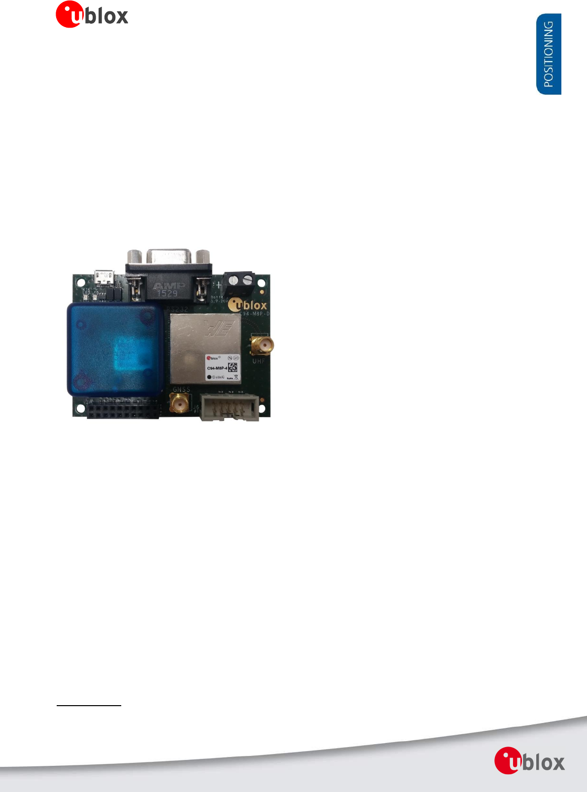
The C94-M8P application board package provides the means for efficient integration and evaluation of
NEO-M8P, u-blox’s M8 high precision GNSS modules.
The NEO-M8P module series introduces the concept of a “Rover” and a “Base Station”. By using a data stream
from the Base Station, the Rover can output its relative position with stunning cm-level accuracy in good
environments.
The C94-M8P board integrates the NEO-M8P-2 module with both Base Station and Rover functionality. The
C94-M8P includes a UHF radio link, allowing for easy setup and fast prototyping. The board also provides
connector pins for u-blox C027 and other application boards, enabling communication alternatives using u-blox
cellular and short-range technologies.
The C94-M8P application board package comes in four variants, each with an individually configured radio link
to meet different radio frequency requirements in different regions:
C94-M8P-1-10 for China (433 MHz)
C94-M8P-2-10 for USA and Canada (915 MHz)
C94-M8P-3-10 or C94-M8P-3-10 for Europe (433 MHz)
C94-M8P-4-10 for Japan (920 Mhz)
A label showing the application variant (ordering code) is located at the top-right corner of the board. For
information about variants with the old board version (C94-M8P-1-00, C94-M8P-2-00 and C94-M8P-3-00) refer
to Appendix D.1.
1.2 C94-M8P package includes
The C94-M8P package includes:
2 application boards (both with a NEO-M8P-2 module)
2 external UHF antennas
2 external active GNSS antennas
2 antenna ground planes
2 USB cables
A RF-shield is attached on the top of the radio module.
A plastic enclosure is attached on the top of the GNSS module. The purpose of the enclosure is to prevent
airflow affecting TCXO performance.
1.3 Software requirements
For the instructions and examples in this document, we require the following software:
The latest version of u-center for Windows (currently version 8.24). You can download it from
https://www.u-blox.com/en/product/c94-m8p
Serial console terminal, for example Putty
1.4 System requirements
For the instructions and examples in this document, we have the following system requirements:
PC with USB interface
Operating system: Windows Vista onwards (x86 and x64 versions)
GNSS USB drivers are automatically installed when installing u-center.
C94-M8P - User Guide
UBX-15031066 - R06 Advance Information Specification
Page 7 of 29
2 Specification
Parameter
Specification
Interfaces
1 USB port for GNSS data and power supply
1 RS232, for radio link configuration
Connection pins for UART communication (e.g. C027), 3.3 V
SMA connector
External GNSS antenna and UHF antenna
Dimensions
75 mm x 55 mm
Weight
35 g
Power Supply
5 V via USB or externally powered by battery (5.05 mm pitch 2-pin, 3.7 V – 20 V) powered
1 battery connector
Normal Operating temperature
-40°C to +65°C
Table 1: C94-M8P application board specification
C94-M8P - User Guide
UBX-15031066 - R06 Advance Information Getting started
Page 8 of 29
3 Getting started
3.1 Software installation
The latest version of u-center (currently version 8.24) is needed for the examples and instructions described in
this document. Internet access is also required during the software installation to ensure that the most up-to-
date components are installed on your system. After installation, the u-center application can be found in the
”u-blox” folder in the Start->Program menu.
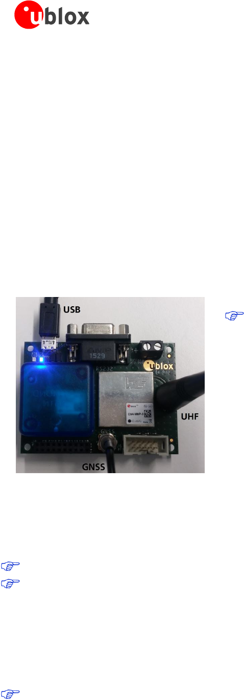
3.2 Hardware installation
To test and evaluate the benefits of u-blox’s Real Time Kinematic (RTK) technology, two C94-M8P application
boards – the “Base” and the “Rover” – need to be set up as described below.
Connect the UHF antenna to the SMA connector marked with “UHF”
Connect the GNSS antenna to the SMA connector marked with ”GNSS”
Connect the micro USB cable to the micro USB port on the board (for power and configuration)
Depending on the evaluation purposes, the test connectors may be used differently
The two boards are identical. Select one of the boards to
act as a “Base” and one as a “Rover”.
3.2.1 GNSS antenna considerations
In order to optimize the benefit of u-blox’s Real Time Kinematic (RTK) technology and achieve high accuracy
performance, the placements of the antennas are extremely important. The recommendations for the GNSS
antenna used with the system are:
The antenna needs to be placed in an open sky environment with unobstrucked visibility to the sky.
Care should be taken to minimize multipath. This can be achieved by using a ground plane, which is
supplied with the application board package for the GNSS antenna, and placing it above nearby buildings or
other obstructions.
If the installation does not provide a natural ground plane, such as a car roof, using a ground plane is
strongly recommended. The ground plane should have a minimum diameter of 10 cm. If better
performance is required due to multipath, then a larger ground plane will improve the performance.
Moving to a lower multipath environment might be required.
For more information, refer to Achieving Centimeter Level Performance with Low Cost Antennas [6].
Correct operation requires a static Base Station.
C94-M8P - User Guide
UBX-15031066 - R06 Advance Information Getting started
Page 9 of 29
3.3 Updating firmware on C94-M8P
Before starting evaluation, please check that the application boards are using the latest firmware. Information on
the latest firmware is published on the u-blox web site. For updating the firmware, follow the steps described in
chapter 7.1 Firmware Update u-blox 5-8 in u-center User Guide [4].
All the changes in configuration are lost when application boards are updated. Base and Rover must be re-
configured after updating
Do not have more than one application board connected to your computer while updating
3.4 Configuration
The C94-M8P package includes two identical boards featuring u-blox NEO-M8P-2 modules. You will configure
one of the boards to act as a Base Station, and the other will operate as a Rover.
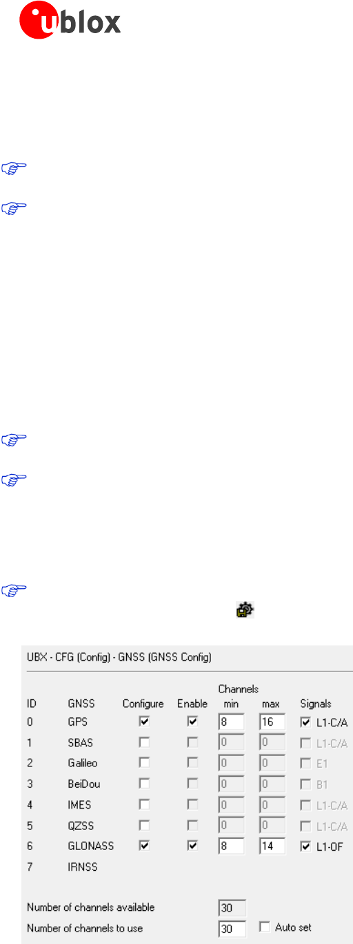
3.4.1 GNSS module configuration
The NEO-M8P-2 positioning module on the C94-M8P application board is a concurrent GNSS receiver and can
receive and track multiple GNSS systems. The NEO-M8P module is configured by default for concurrent GPS and
GLONASS reception, where both constellations will be used in an RTK solution. Other available configurations
are GPS-only and GPS+BeiDou reception. A GPS-only setup can be used if higher RTK update rate is of interest.
The default GNSS constellation is GPS+GLONASS. For most users this is the optimal configuration and no
further configuration is needed.
If the configuration is changed – the changes need to be made for both boards as Base and Rover should
use the same GNSS systems.
For GNSS module configuration, use the micro-A USB port to connect with a PC running u-center. Once it is
connected, configure the module on u-center (View -> Message View -> UBX-CFG-GNSS) as shown in Figure 1.
For more information, refer to the u-center User Guide [4], the u-blox 8 / u-blox M8 Receiver Description
including Protocol Specification [1], and Protocol Specification Addendum for HPG1.30 [5].
Always remember to store configuration changes by sending the UBX-CFG-CFG message in u-center, which
can be done with the shortcut, .
Figure 1: Configuration of the NEO-M8P-2 GNSS module on C94-M8P application board
C94-M8P - User Guide
UBX-15031066 - R06 Advance Information Getting started
Page 10 of 29
3.4.2 Base Station configuration
The board that is selected to operate as Base needs to be configured as described below.
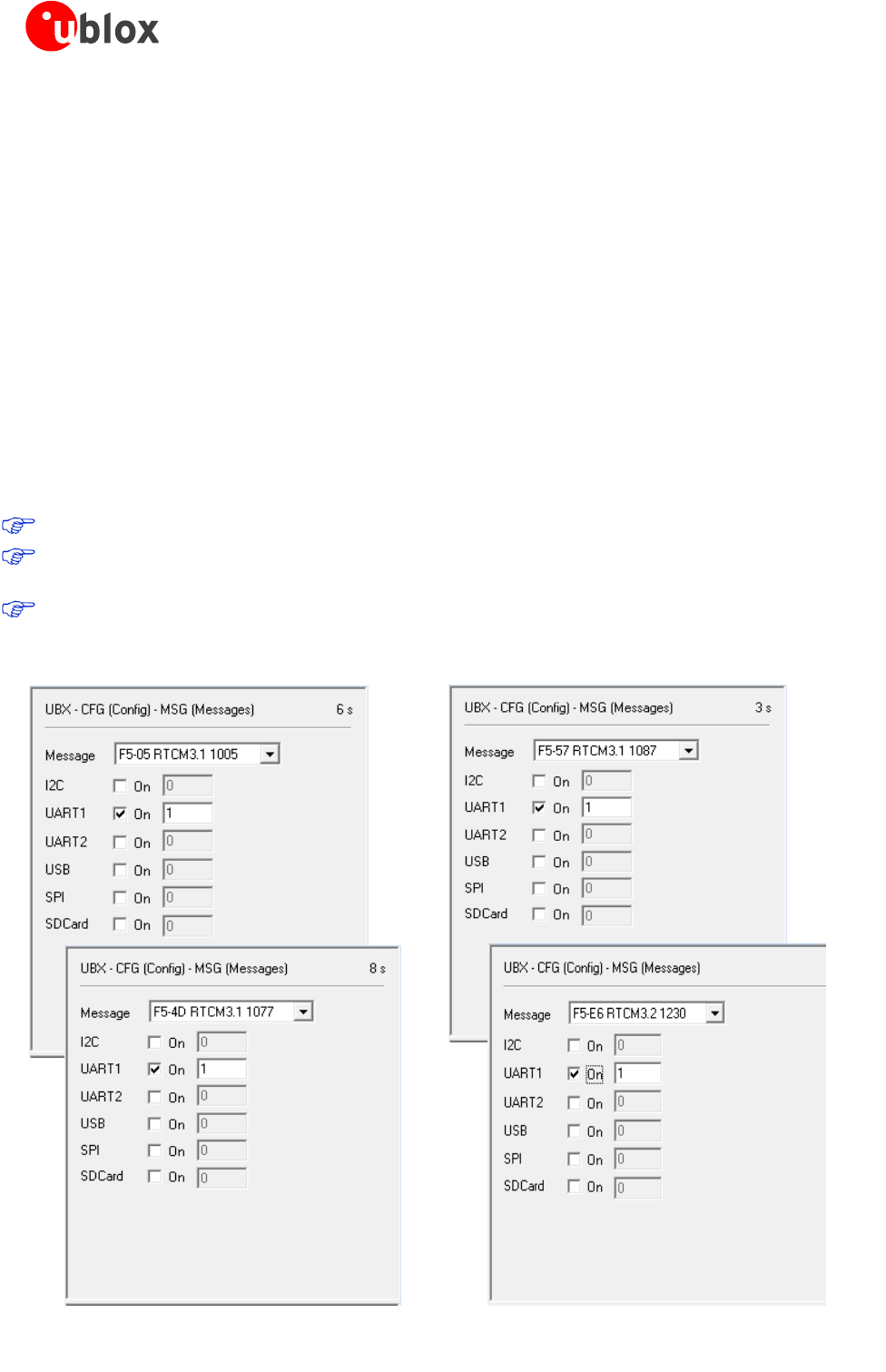
Setting up RTCM messages
A Base device needs to allow RTCM messages 1005 (Station coordinates), 1077 (GPS observations), 1087
(GLONASS observations) and 1230 (GLONASS code-phase biases) to go through the UART1 port on the receiver
module. UART1 refers to the connection between the NEO-M8P-2 GNSS module and the UHF radio module on
the application board. To do this, use the UBX-CFG-MSG messages as shown in Error! Reference source not
found..
RTCM messages should be configured to be output at 1 Hz. The output rate must be the same as the
Navigation Rate of Base station, which is 1 Hz by default.
RTCM messages do not need to be configured differently even if the Navigation Rate of the Rover is
configured differently, e.g. to have a higher output rate than the default 1 Hz.
Individual RTCM messages should be configured at the same rate.
The throughput of the RTCM communications link must be considered with respect to the amount of
bytes required for the enabled RTCM messages and message rates.
RTCM 1230 is required to make GLONASS ambiguity fixing possible.
If BeiDou is used, RTCM message 1127 needs to be used instead of 1087 (GLONASS), and RTCM 1230 can
be omitted.
MSM4 observation messages (i.e. 1074 for GPS, 1084 for GLONASS, and 1124 for BeiDou) can be used
instead of MSM7 to reduce the communication bandwidth requirements.
Figure 2: For a GPS+GLONASS setup, enable the RTCM messages 1005, 1077, 1087 and 1230 on UART1 port
C94-M8P - User Guide
UBX-15031066 - R06 Advance Information Getting started
Page 11 of 29
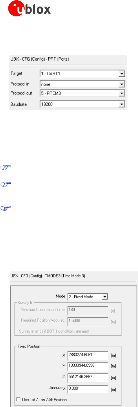
Base radio link
The radio link needs to be configured on the Base. Use the UBX-CFG-PRT message to set “Protocol in” to
“none”, as shown in Figure 3.
Figure 3: Configuring Base radio link
Base station operation
When the NEO-M8P functions as a Base Station, the receiver uses measurements from all available satellites to
broadcast corrections. By sending the UBX-CFG-TMODE3 message, the Base Station can be configured to
operate in a Fixed position mode or to self Survey-in its position, depending on the user’s knowledge of the Base
Station’s antenna reference position.
The Base Station must be configured with a Fixed position or have completed a Survey-in operation before it
will be able to output the RTCM reference station position message needed by the Rover.
The current firmware requires five ambiguities to attempt fixing. The RTK fixed status can therefore be
reached when either of the following requirements is fulfilled: 1) six satellites from a single constellation are
available, or 2) eight satellites from two different constellations are available.
Disable NMEA (disable child messages) in u-center to see TIME mode displayed in u-center.
Fixed position mode
In Fixed position mode, specify the Base Station’s antenna reference point with ECEF or Lat/Lon/Alt coordinates.
The corresponding fields are available via u-center, as shown in Figure 4. The coordinates can be specified with
0.1 mm resolution. For more information, see the Protocol Specification Addendum for HPG1.30 [5].
The accuracy of the specified coordinates will reflect directly in the absolute accuracy of the Rover’s position.
Figure 4: Configure to Fixed Position Mode for a Base Station
C94-M8P - User Guide
UBX-15031066 - R06 Advance Information Getting started
Page 12 of 29
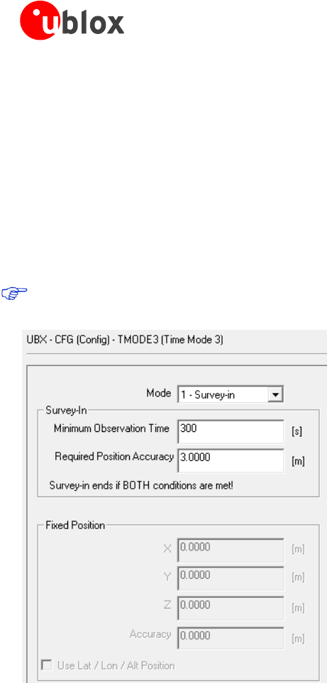
Survey-in mode
If the coordinates of the Base Station antenna are not known with very good accuracy, the Base Station should
be configured to operate in Survey-in mode. When working in Survey-in mode the Base Station will determine its
own position by building a weighted mean of all valid 3D position solutions.
The UBX-CFG-TMODE3 message has two fields to fill in for survey-in mode, as shown in Figure 5. The first field,
“Minimum Observation Time”, defines a minimum amount of observation time regardless of the actual number
of valid fixes that were used for position calculation. Reasonable values range from one day for applications that
require high absolute accuracy, to a few minutes for applications that only require high relative accuracy.
The second field, “Required Position Accuracy”, forces the calculated Base station position to be of at least the
given 3D position accuracy.
Navigation Rate (UBX-CFB-RATE) should be 1 Hz during Survey-in.
Figure 5: Configure to Survey-in Mode for a Base Station
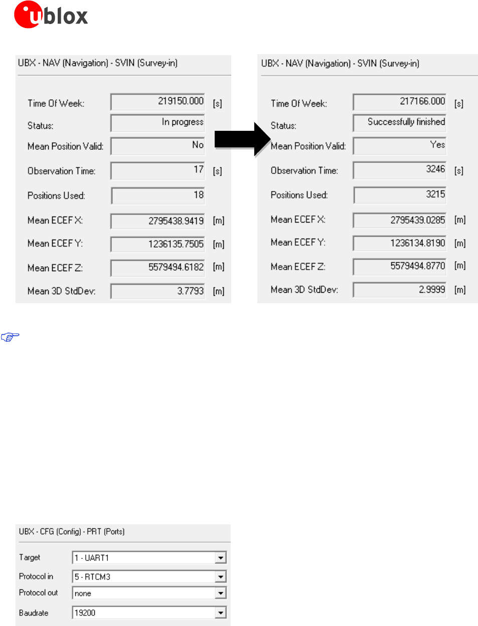
In operation, after both requirements are fulfilled, the Base station finishes the Survey-in mode and enters Fixed
mode automatically. Through the UBX-NAV-SVIN message, the Base operation status from Survey-in to Fixed can
be monitored, as shown in Figure 6.
C94-M8P - User Guide
UBX-15031066 - R06 Advance Information Getting started
Page 13 of 29
Figure 6: Base Station moving from Survey-in Mode to Fixed Mode
As the Base Station position error is inherited by the Rover absolute position error, users should carefully
evaluate the Rover absolute accuracy requirement and setup and choose the Base station mode accordingly.
3.4.3 Rover configuration
In its default mode, the Rover will automatically apply the RTCM corrections it receives. In effect, it will
immediately enter RTK float mode and, assuming circumstances allow for it, eventually reach RTK fixed mode.
In order to mitigate position jumps when switching between fixed and float modes, you can use RTK float-only
mode. Select it using the u-center message UBX-CFG-DGNSS. In this mode, the Rover will estimate the
ambiguities as float but will not attempt to fix them.
Rover radio link
Radio link needs to be configured on the Rover. Use UBX-CFG-PRT message to set Protocol out to “none”, as
shown in Figure 7.
Figure 7: Configuring Rover radio link
C94-M8P - User Guide
UBX-15031066 - R06 Advance Information Operation
Page 14 of 29
4 Operation
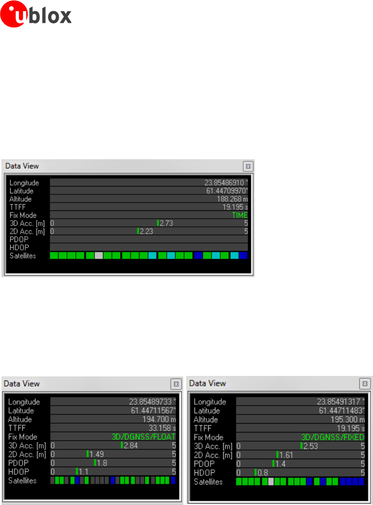
4.1 Base in operation
When the Base device is in normal operation, by enabling message UBX-NAV-STATUS, the Data View in u-center
shows “TIME” fix mode.
Figure 8: Data View shows “TIME” when Base is in FIXED mode
4.2 Rover in operation
When the Rover device is in normal operation, the Data View in u-center shows “FLOAT” or “FIXED” to indicate
the current operation mode.
Figure 9: Data View shows “FLOAT” or “FIXED” on Rover
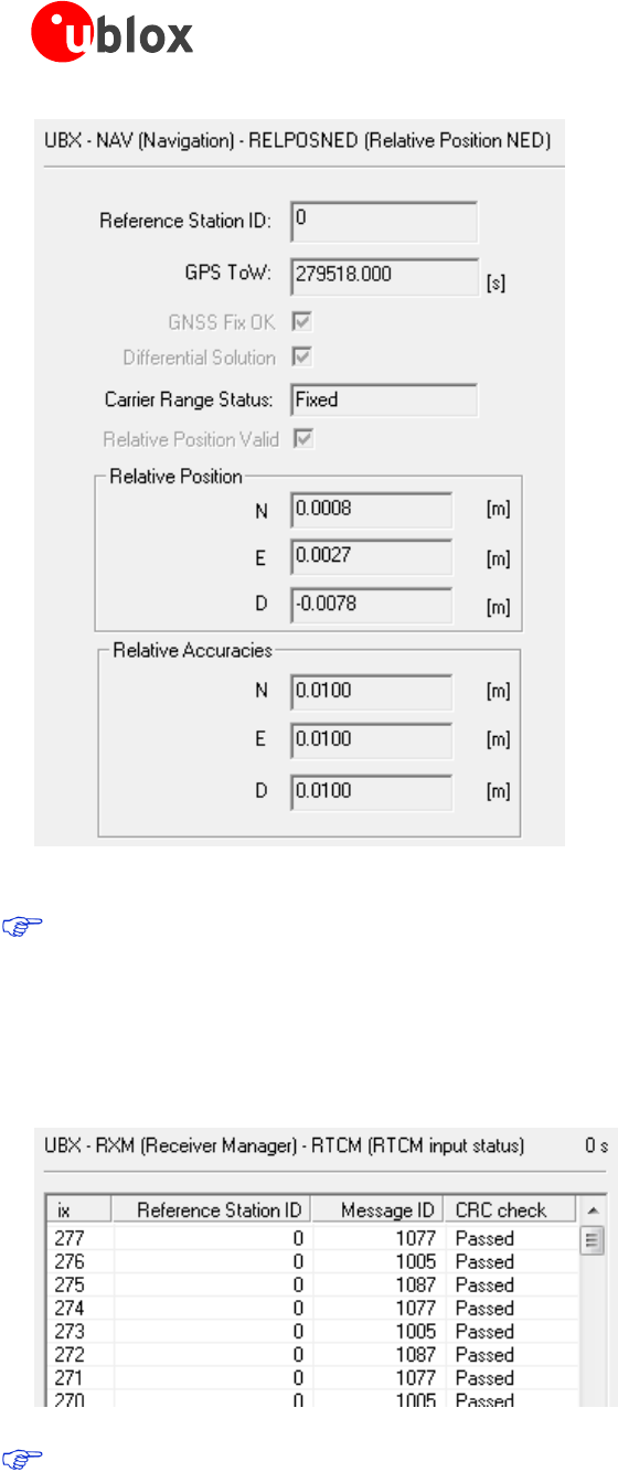
Additionally, the message “UBX-NAV-RELPOSNED” in u-center shows more details about relative positions and
accuracies. For more information, refer to the u-center User Guide [4], the u-blox 8 / u-blox M8 Receiver
Description including Protocol Specification [1], and Protocol Specification Addendum for HPG1.30 [5].
C94-M8P - User Guide
UBX-15031066 - R06 Advance Information Operation
Page 15 of 29
Figure 10: UBX-NAV-RELPOSNED in u-center for Rover
To achieve the expected accuracy of positioning with u-blox RTK technology, continued carrier phase
tracking is important.
4.2.1 Monitoring the quality of the RTCM stream
You can monitor the quality of the RTCM stream that the Rover receives. Use UBX-RXM-RTCM message to see
station ID, message type and CRC status.
Low latency (< 5 s) of the RTCM3 stream is critical for achieving a RTK FLOAT/FIXED solution at the Rover.
Any communication issues will prevent RTK FLOAT/FIXED being achieved.
C94-M8P - User Guide
UBX-15031066 - R06 Advance Information Evaluation interfaces
Page 16 of 29
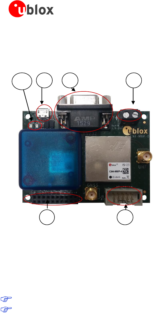
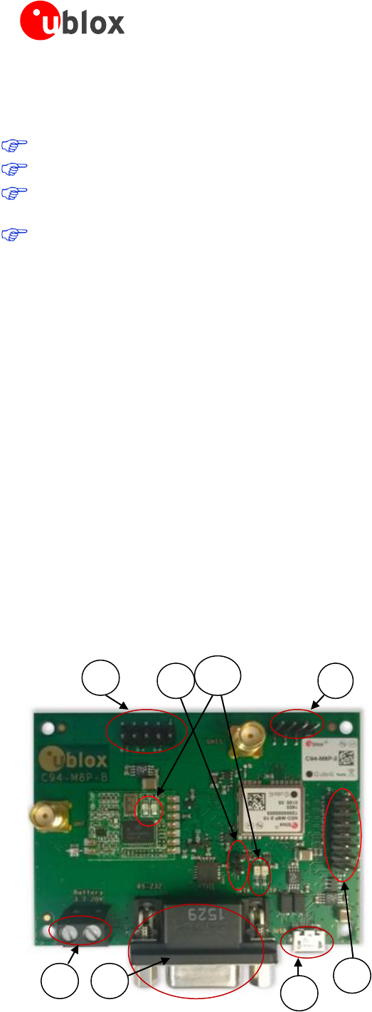
5 Evaluation interfaces
The C94-M8P application board provides the specified interfaces as mentioned in section 2, for configuration,
logging, and measurement.
J1: RS232 – UART M8P/Radio
J2: USB – M8P
J3: External battery / DC connector
J6: Debugger interface for radio module
J8: Test & Production interface
J8: UART & GNSS features
o Geofence and RTK status
o Interface to e.g. u-blox C027
J10: Indicator LEDs
Figure 11: C94-M8P Application Board
5.1 RS232/UART Interface
There are two purposes for the UART interface on the board:
For configuring the radio module with AT commands
On the Rover board, to log the data stream (RTCM messages) sent from the radio module to the GNSS
module
Before configuring the radio module, the UART output of the GNSS module needs to be disabled.
See section Appendix B for radio communication link configuration.
5.2 USB interface
The C94-M8P board provides one micro-A USB interface, which is used for:
Configuring the GNSS NEO-M8P-2 module
Logging data sent out from the GNSS module, including UBX, NMEA messages.
5.3 J8 connector
The J8 connector is the combined interface for monitoring the Geofence status output and the RTK status
output, and is also a connector for the UART.
Geofence status corresponds to pin 15 and the RTK status corresponds to pin 16 on the NEO-M8P-2
module.
Pin 13, pin 14, pin 20 and any of the GND pins are for connecting to u-blox C027 and other application
boards. It enables communication alternatives using u-blox cellular and short-range technologies.
J8
J2
J1
J3
J6
J10
C94-M8P - User Guide
UBX-15031066 - R06 Advance Information Evaluation interfaces
Page 17 of 29
The pin assignments of the 20-pin J8 connector are shown in Error! Reference source not found.. For more
information, see the NEO-M8P Data Sheet [2].
Pin Nr.
Assignment
1
V_BAT
2
GND
3
GND
4
RTK_STAT, monitor RTK status
5
GEOFENCE_STAT, monitor Geofence status
6
TIMEPULSE
7
GND
8
GND
9
RXD_GNSS
10
TXD_GNSS
11
GND
12
GND
13
RXD_EXT
14
TXD_EXT
15
GND
16
GND
17
SAFEBOOT_N
18
EXTINT
19
RESET_N
20
RADIO_OFF, apply 3.3 V to turn off the radio module for external UART communication.
Table 2: Pin assignments of J8 connector
5.4 Battery connector
There is a 2-pin battery connector available on the C94-M8P for connecting the board to an external battery or
DC supply. This uses a standard 5.05 mm pitch 2-pin connector for supplying a 3.7-20 VDC source or external
battery. The pin assignments of this 2-pin connector are shown in Error! Reference source not found..
Pin Nr.
Assignment
1
V_BAT, battery “+”
2
GND, battery “-”
Table 3: Pin assignments of battery connector
5.5 LED
The Blue LED (DS2), mounted on the C94-M8P application board, shows the time pulse output signal from the
NEO-M8P-2 module. The LED starts flashing one pulse per second during a GNSS fix. If there is no GNSS fix, the
LED will light up without flashing.
The Green LED (DS1) indicates the RTK status. The LED flashes in float mode and stays on in fix mode. The LED is
off when there is no RTK fix.
5.6 Antenna connectors
5.6.1 Radio antenna connector
The radio antenna SMA connector on each board is used for connecting a UHF antenna. This connector is
marked with the text “UHF” on the board.

C94-M8P - User Guide
UBX-15031066 - R06 Advance Information Evaluation interfaces
Page 18 of 29
5.6.2 GNSS antenna connector
The GNSS module SMA connector on each board is used to connect the external active GNSS antenna. This
connector is marked with the text “GNSS” on the board.
C94-M8P - User Guide
UBX-15031066 - R06 Advance Information Block diagram
Page 19 of 29
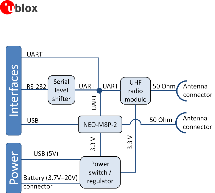
6 Block diagram
Figure 12: Block diagram of the C94-M8P application board
C94-M8P - User Guide
UBX-15031066 - R06 Advance Information Board layout
Page 20 of 29
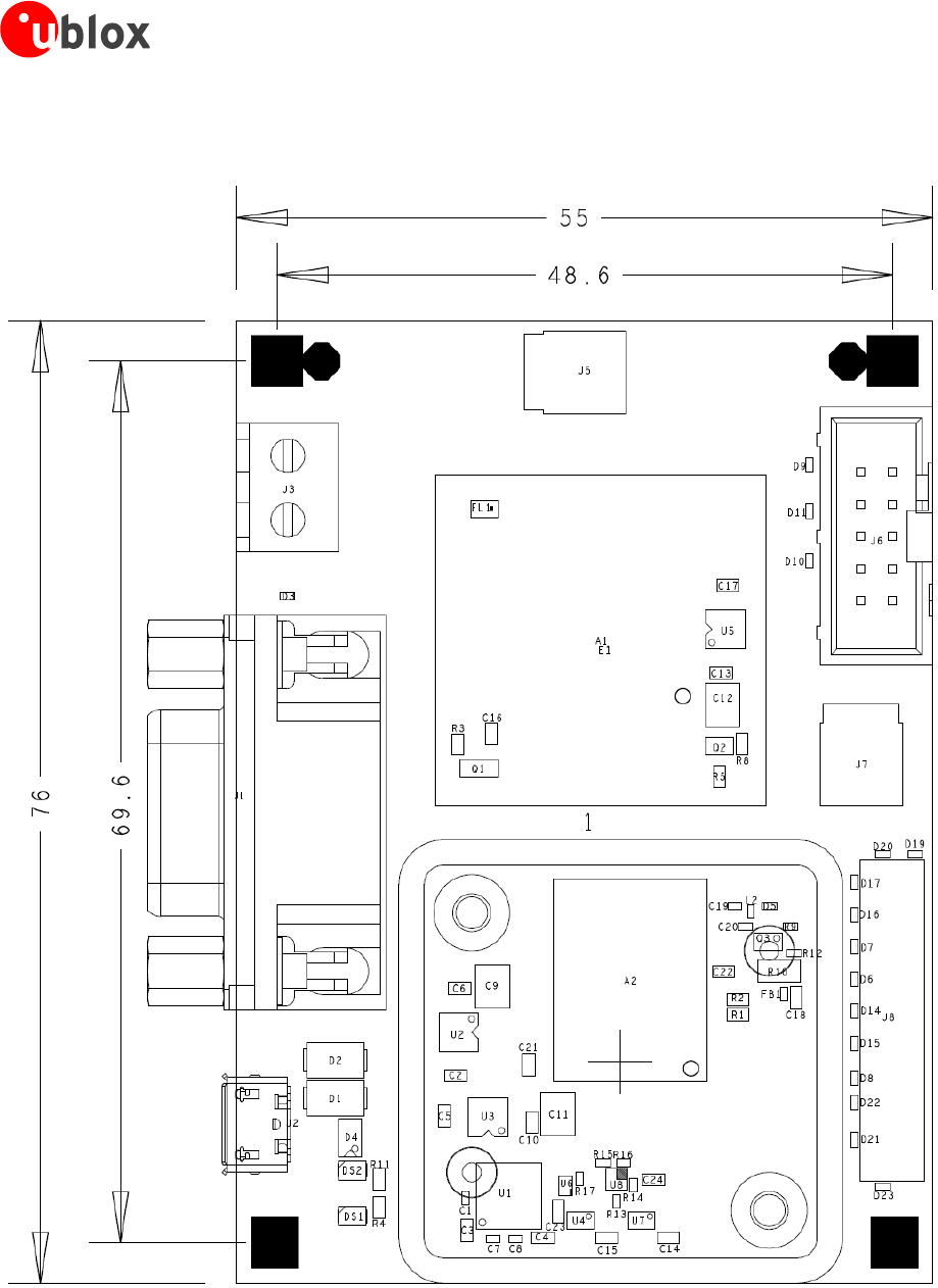
7 Board layout
Figure 13: Board Layout of C94-M8P Application Board
C94-M8P - User Guide
UBX-15031066 - R06 Advance Information Schematic
Page 21 of 29
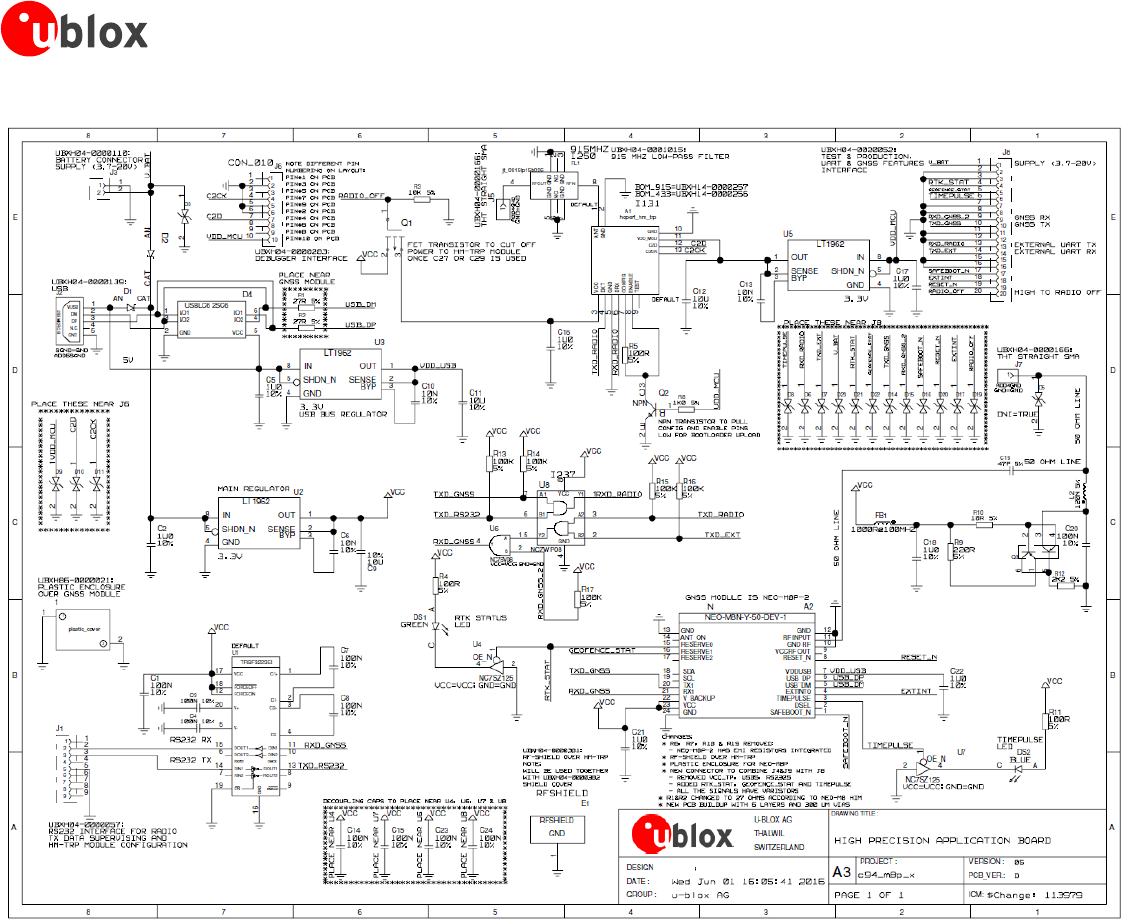
8 Schematic
Figure 14: Schematics of C94-M8P application board
C94-M8P - User Guide
UBX-15031066 - R06 Advance Information Appendix
Page 22 of 29
Appendix
A Glossary
Abbreviation
Definition
BeiDou
Chinese satellite system
ECEF
Earth Center Earth Fixed format
GLONASS
Russian satellite system
GND
Ground
GNSS
Global Navigation Satellite System
GPS
Global Positioning System
PCB
Printed circuit board
PLL
Phase Locked Loop
PPS
Pulse Per Second
QZSS
Quasi-Zenith Satellite System
RAIM
Receiver Autonomous Integrity Monitoring
RF
Radio Frequency
RTCM
Radio Technical Commission for Maritime Services
RTK
Real Time Kinematic
TTFF
Time To First Fix
UART
Universal Asynchronous Receiver/Transmitter
Table 5: Explanation of abbreviations used
B Radio communication link configuration
By default, users do not need to do any configuration for the Radio communication link. The u-blox default
configurations are tested and verified.
Users need to take all responsibility for any changes against the default configuration.
By default, u-blox has configured the radio link module to meet local radio frequency requirements. The
C94-M8P application boards are labeled according to different radio module variants as follows:
C94-M8P-1 for China
C94-M8P-2 for USA and Canada
C94-M8P-3 for Europe
C94-M8P-4 for Japan
The default radio-link configurations in shipped C94-M8P boards are listed here:
C94-M8P - User Guide
UBX-15031066 - R06 Advance Information Appendix
Page 23 of 29
Parameters
C94-M8P-1 for China
C94-M8P-2 for USA/Canada
C94-M8P-3 for Europe
C94-M8P-4 for Japan
Minimum Frequency
433.180 MHz
902.5 MHz
433.230 MHz
922.8 MHz
Maximum Frequency
434.730 MHz
928.0 MHz
434.730 MHz
923.2 MHz
Air Speed
32 kbps
32 kbps
48 kbps
48 kbps
Serial baud rate
19.2 kbps
19.2 kbps
19.2kbps
19.2 kbps
TX Power
11 dBm
20 dBm
11 dBm
8 dBm
LBT_RSSI
0
0
71
78
Number of Channels
10
50
7
3
ECC
0 (off)
0 (off)
0 (off)
0 (off)
OpResend
0 (off)
0 (off)
0 (off)
0 (off)
Duty Cycle
100 %
100 %
20 %
100 %
Window width
66
66
66
66
MAVLink
0
0
0
0
Table 4: Default configuration for regional variants of the radio module on C94-M8P application boards
The u-blox default configurations of the radio module regional variants are tested and verified. Users need to
take all responsibility for any changes to the default configuration.
The C94-M8P application board uses a HM-TRP radio module with SiK open source firmware, which supports a
subset variant of the Hayes “AT” modem commands for advance configuration.
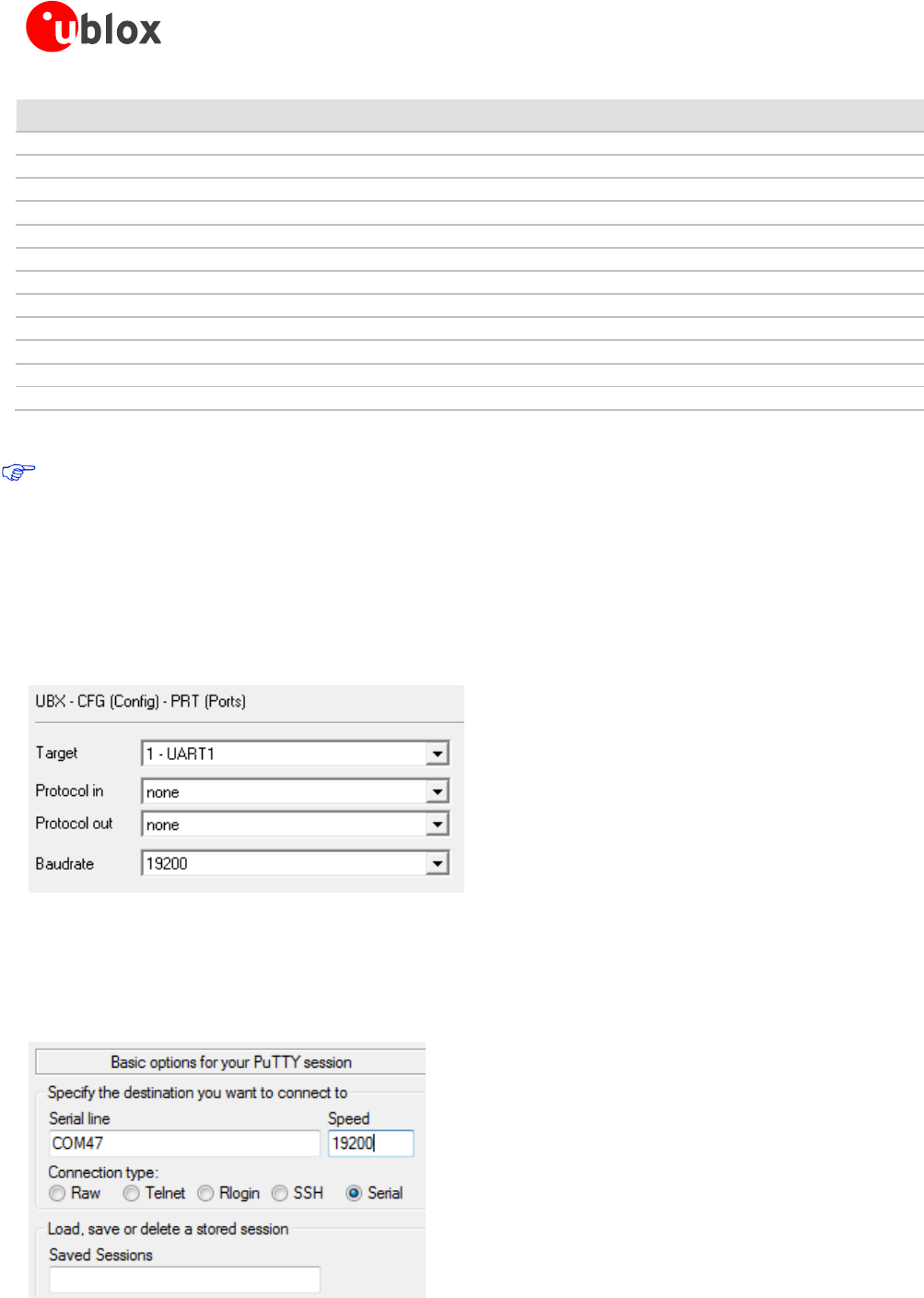
Before configuring the radio module, the GNSS module UART output needs to be disabled via u-center (View ->
Message View -> UBX-CFG-PRT), as shown in Figure 15. For more information, see the u-center User Guide [4],
and the u-blox 8 / u-blox M8 Receiver Description including Protocol Specification [1].
Figure 15: Disable UART output of NEO-M8P-2 GNSS module on C94-M8P application board
Use the serial-console application, Putty, on the PC to connect to the RS232/UART interface. Configure the serial
connection with baud rate 19200 Bd and COM port number assigned by Windows OS, as shown in Figure 16.
For more information about installing serial-console application, please see chapter B.1.
Figure 16: Configuration of serial connection for Radio Module on C94-M8P Application Board
C94-M8P - User Guide
UBX-15031066 - R06 Advance Information Appendix
Page 24 of 29
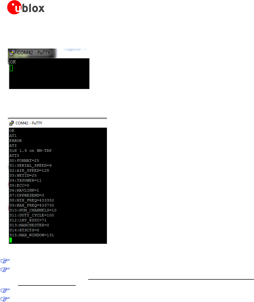
Enable the AT command mode by sending sequence “+++” (quickly type “+++” and wait for 1 second) via the
serial link. The radio module sends “OK” to indicate entering the AT command mode.
Figure 17: Radio module sends “OK” prompt through serial link when AT Command Mode is Enabled
In AT command mode, the radio module accepts AT commands and gives response correspondingly. In case of
wrong AT commands, the radio module returns ERROR as the response.
Figure 18: Send AT commands to Radio Module
Table 5 shows the AT command set that is supported by the C94-M8P application board.
Table 6 shows all radio parameters that are configurable. For more information about configuring the radio
module used by C94-M8P, see http://copter.ardupilot.com/wiki/common-3dr-radio-advanced-configuration-
and-technical-information/.
UHF operation needs to be on licensed bands according to regions.
Remember to enable GNSS module UART output on Base when finished with radio communication link
configuration.
C94-M8P - User Guide
UBX-15031066 - R06 Advance Information Appendix
Page 25 of 29
Commands
Description
ATI
Shows radio version
ATI2
Shows board type
ATI3
Shows board frequency
ATI4
Shows board version
ATI5
Shows radio parameters and the current settings.
ATI6
Displays timing report of TDM
ATI7
Displays signal report of RSSI
ATO
Exits from AT command mode
ATS<n>?
Displays radio parameter indicated by index number “<n>“. “<n>“ needs to specify by a user, which is listed in output of
command ATI5.
ATS<n>=<X>
Set radio parameter indexed by <n> to “<X>“. “<n>“ and “<X>“ need to specify by a user. “<n>“ is listed in output of
command ATI5.
ATZ
Reboots the radio module
AT&W
Writes the current parameters to EEPROM
AT&F
Resets all parameters to default factory settings
AT&T=RSSI
Enables debug reporting of RSSI
AT&T=TDM
Enables debug reporting of TDM
AT&T
Disables all debug reporting
Table 5: AT Command Set for Radio Module on C94-M8P application board
Index<n>
Parameter Name
Description
1
SERIAL_SPEED
Serial speed in “one byte form”, e.g. 19 corresponds to 19200 Bd configured for the C94-M8P
board.
2
AIR_SPEED
Air data rate in “one byte form”. Must be same for a pair of radios.
3
NETID
Network ID. Must be same for the pair of C94-M8P boards. Must be same for a pair of radios.
4
TXPOWER
Transmit power in dBm, maximum value is 20 dBm.
5
ECC
Enables / disables the golay error correcting code. Must be same for a pair of radios.
6
MAVLINK
Configure MAVLink framing and reporting,
0: no mavlink (default)
1: frame mavlink
2: low latency mavlink
8
MIN_FREQ
Minimum frequency in kHz. Must be same for a pair of radios.
9
MAX_FREQ
Maximum frequency in kHz. Must be same for a pair of radios.
10
NUM_CHANNELS
Number of frequency hopping channels. Must be same for a pair of radios.
11
DUTY_CYCLE
Percentage of time to allow transmit
12
LBT_RSSI
Threshold of Listen Before Talk. Must be same for a pair of radios.
15
MAX_WINDOW
Maximum transmitting window in milli seconds,
default: 66
for low latency: 33
Must be same for a pair of radios.
Table 6: Configurable radio parameters
B.1 Serial console terminal installation
Many serial console terminal programs are available, either as commercial software or from open source
communities. In this user guide, the examples show the Putty terminal emulator running on Windows 7. Putty is
an open source stand-alone application that runs on multiple operating systems. Download and uncompress the
software package from http://www.putty.org, and then run the executable file.
For more information about Putty, see http://www.putty.org.
C94-M8P - User Guide
UBX-15031066 - R06 Advance Information Appendix
Page 26 of 29
C Notes on FW3.01 HPG1.30
Multiple Base stations sharing the same network ID is not supported.
The Base station needs to be static.
High multipath and poor or no groundplanes on the Base or Rover will prevent the Rover entering FIXED
mode.
Do not enable both MSM7 and MSM4
D Notes on hardware
Users should be aware that the radio link latency of the C94 application board can extend up to 550 ms for a
message content of 2 k bits. E.g. with MSM7 messages, this payload size would represent about 12 satellites, for
instance 6 GPS and 6 GLO, which is a fairly typical scenario. Hence, update rates beyond 1 Hz should be
contemplated carefully owing to the radio modem latency. In any event, the modem interface rate of
192009600 baud will present a hard limit depending on the number of satellites, e.g. approximately 4 Hz with
12 satellites.
D.1 Variants -00
Variants using the old board version (C94-M8P-1-00, C94-M8P-2-00 and C94-M8P-3-00) have a different board
layout than the C94P-M8P-X-10 versions. This chapter describes the C94P-M8P-X-10 versions and how they
differ from the older versions.
D.1.1 Overview
There is no RF-shield attached on the top of the radio module and no plastic enclosure is attached on the top of
the GNSS module.
D.1.2 Connectors
J1: RS232 – UART M8P/Radio
J2: USB – M8P
J3: External battery / DC connector
J4: Interface to u-blox C027
J6: Debugger interface for radio module
J8: Test & Production interface
J9: Geofence and RTK status
J10: Indicator LEDs
J4
J2
J1
J3
J6
J10
J9
J8
C94-M8P - User Guide
UBX-15031066 - R06 Advance Information Appendix
Page 27 of 29
Figure 19: C94-M8P Application Board
J9 connector
The J9 connector is the monitor interface for the Geofence status and the RTK status, which correspond to pin
15 and pin 16 on the NEO-M8P-2 module. The pin assignments of this 2-pin connector are shown in Error!
Reference source not found.. For more information, refer to the NEO-M8P Data Sheet [2].
Pin Nr.
Assignment
1
GEOFENCE_STAT, monitor Geofence status
2
RTK_STA, monitor RTK status
Table 7: Pin assignments of J9
J4 connector
The J4 connector is the interface for connecting to u-blox C027 and other application boards. It enables
communication alternatives using u-blox cellular and short-range technologies. The pin assignments of this 4-pin
connector are shown in Error! Reference source not found.. For more details about C027, see https://www.u-
blox.com/product/c027.
Table 8: Pin assignments of J4
LED
There are four indicator LEDs mounted on the C94-M8P application board:
The Blue LED shows the time pulse output signal from the NEO-M8P-2 module. The LED starts flashing
one pulse per second during a GNSS fix. If there is no GNSS fix, the LED will light up without flashing.
The Yellow LED indicates geofence status
The Red LED flashes when the radio module is transmitting
The Green LED blinks when radio module is ready to receive
D.1.3 Dimensions
Dimensions between screw holes on the old board are 69.6 and 48.2 mm.
Pin Nr.
Assignment
1
GND
2
TXD
3
RXD
4
3.3 v
C94-M8P - User Guide
UBX-15031066 - R06 Advance Information Appendix
Page 28 of 29
Related documents
[1] u-blox 8 / u-blox M8 Receiver Description Including Protocol Specification (Public version), Docu. No. UBX-
13003221
[2] NEO-M8P Data Sheet, Docu. No. UBX-15016656
[3] NEO-M8P Hardware Integration Manual, Docu. No. UBX-15028081
[4] u-center User Guide, Docu. No. UBX-13005250
[5] Protocol Specification Addendum for HPG1.30, Docu. No. UBX-16004304
[6] Achieving Centimeter Level Performance with Low Cost Antennas, Docu. No. UBX-16010559
For regular updates to u-blox documentation and to receive product change notifications, register on our
homepage (http://www.u-blox.com)
Revision history
Revision
Date
Name
Status / Comments
R01
19-Feb-2016
yzha
Advance Information
R02
30-May-2016
jhak
Restructuring chapters, more details on Base/Rover configuration, FW3.01 HPG1.11
related information
R03
19-Aug-2016
jhak
Updated package contents, more details on GNSS antenna considerations and setting up
RTCM messages
R04
14-Oct-2016
jhak
HPG1.20 update. Added chapter D Notes on Hardware
R05
08-Dec-2016
jhak
HPG1.30 update. Merged all variants into one user guide
R06
01-Feb-2017
jhak
Updated board layout picture and radio settings

C94-M8P - User Guide
UBX-15031066 - R06 Advance Information Contact
Page 29 of 29
Contact
For complete contact information, visit us at www.u-blox.com
u-blox Offices
North, Central and South America
u-blox America, Inc.
Phone: +1 703 483 3180
E-mail: info_us@u-blox.com
Regional Office West Coast:
Phone: +1 408 573 3640
E-mail: info_us@u-blox.com
Technical Support:
Phone: +1 703 483 3185
E-mail: support_us@u-blox.com
Headquarters
Europe, Middle East, Africa
u-blox AG
Phone: +41 44 722 74 44
E-mail: info@u-blox.com
Support: support@u-blox.com
Asia, Australia, Pacific
u-blox Singapore Pte. Ltd.
Phone: +65 6734 3811
E-mail: info_ap@u-blox.com
Support: support_ap@u-blox.com
Regional Office Australia:
Phone: +61 2 8448 2016
E-mail: info_anz@u-blox.com
Support: support_ap@u-blox.com
Regional Office China (Beijing):
Phone: +86 10 68 133 545
E-mail: info_cn@u-blox.com
Support: support_cn@u-blox.com
Regional Office China (Chongqing):
Phone: +86 23 6815 1588
E-mail: info_cn@u-blox.com
Support: support_cn@u-blox.com
Regional Office China (Shanghai):
Phone: +86 21 6090 4832
E-mail: info_cn@u-blox.com
Support: support_cn@u-blox.com
Regional Office China (Shenzhen):
Phone: +86 755 8627 1083
E-mail: info_cn@u-blox.com
Support: support_cn@u-blox.com
Regional Office India:
Phone: +91 80 4050 9200
E-mail: info_in@u-blox.com
Support: support_in@u-blox.com
Regional Office Japan (Osaka):
Phone: +81 6 6941 3660
E-mail: info_jp@u-blox.com
Support: support_jp@u-blox.com
Regional Office Japan (Tokyo):
Phone: +81 3 5775 3850
E-mail: info_jp@u-blox.com
Support: support_jp@u-blox.com
Regional Office Korea:
Phone: +82 2 542 0861
E-mail: info_kr@u-blox.com
Support: support_kr@u-blox.com
Regional Office Taiwan:
Phone: +886 2 2657 1090
E-mail: info_tw@u-blox.com
Support: support_tw@u-blox.com
