012 4001 000 UltraRAE PGM 7200 F Ultra RAE_PGM 7200_F RAE
User Manual: Pdf UltraRAE_PGM-7200_F
Open the PDF directly: View PDF ![]() .
.
Page Count: 116 [warning: Documents this large are best viewed by clicking the View PDF Link!]

UltraRAE
COMPOUND SPECIFIC
PID MONITOR
PGM-7200
OPERATION AND MAINTENANCE
MANUAL
(Document No.: 012-4001)
Rev. F
RAE SYSTEMS INC.
1339 Moffett Park Drive
Sunnyvale, CA 94089
November 2001
For Sales & Service Contact
2650 E. 40th Ave. • Denver, CO 80205
Phone 303-320-4764 • Fax 303-322-7242
1-800-833-7958
www.geotechenv.com

§ Gas Detection Tubes & Pumps
§ SampleRAE Electronic Sampling Pump
§ MultiRAE PLUS Multi-gas Monitors
§ MultiRAE IR Multi-gas Monitors w/CO2
§ MultiRAE Confined Space Monitor
§ QRAE PLUS Multi-gas Monitors
§ QRAE Confined Space Monitor
§ VRAE Five-Gas Monitors
§ DRAE Two-Gas Monitors
§ MiniRAE 2000 Portable VOC Monitor (PID)
§ ppbRAE Portable ppb-Level VOC Monitor (PID)
§ UltraRAE Specific Compound Monitor
§ CDRAE Corona Discharge VOC Monitor
§ ToxiRAE PLUS PID Monitor
§ ToxiRAE PLUS Single Gas Monitors
§ ToxiRAE PLUS Oxygen Monitor
§ ToxiRAE PLUS Combustible Gas Monitor
§ MiniRAE PLUS Classic PID
§ ModuRAE Fixed System PID
§ AreaRAE Wireless Multi-point, Multi-gas Systems
How can I be informed and updated?
Be sure to mail in your warranty card via email, post or fax to get on
RAE’s private database (information is never supplied to others).
You will be updated on new products, technical advisory notices, new
accessories and much more. Thank you for your purchase!
RAE Systems Product Line
ii
Table of Contents
1. GENERAL INFORMATION 1-1
1.1 General Specifications.......................................... 1-3
2. OPERATION OF ULTRARAE 2-1
2.1 Physical Description............................................. 2-2
2.2 Keys and Display.................................................. 2-3
2.3 Power On/Off ....................................................... 2-4
2.4 Operation.............................................................. 2-5
2.4.1 Idle Operation.............................................. 2-5
2.4.2 Measurement Overview............................... 2-9
2.5 Alarm Signals..................................................... 2-12
2.6 Preset Alarm Limits and Calibration.................. 2-14
2.7 Integrated Sampling Pump ................................. 2-15
2.8 Backlight ............................................................ 2-16
2.9 Datalogging ........................................................ 2-17
3. OPERATION OF ACCESSORIES 3-1
3.1 Battery Charging Operation ................................. 3-1
3.2 Alkaline Battery Adapter...................................... 3-3
3.3 Dilution Fitting..................................................... 3-4
4. PROGRAMMING OF ULTRARAE 4-1
4.1 Programming Mode.............................................. 4-2
4.2 Keys for Programming Mode............................... 4-3
4.3 Entering into Programming Mode........................ 4-4
4.4 Calibration of the UltraRAE Monitor .................. 4-5
4.4.1 Fresh Air Calibration................................... 4-7
4.4.2 Span Calibration .......................................... 4-8
4.4.3 Modify Span Value...................................... 4-9
4.5 Change Alarm Limits......................................... 4-10
4.5.1 Change High Alarm Limit......................... 4-10
4.5.2 Change Low Alarm Limit ......................... 4-12
4.6 View or Change Datalog.................................... 4-13
4.6.1 View Data.................................................. 4-13
iii
4.6.2 Clear All Data............................................ 4-15
4.6.3 Change Data Log....................................... 4-16
4.7 Change Monitor Setup........................................ 4-17
4.7.1 Change Site ID .......................................... 4-18
4.7.2 Change User ID ......................................... 4-19
4.7.3 Change User Mode.................................... 4-20
4.7.4 Change Date .............................................. 4-21
4.7.5 Change Time ............................................. 4-22
4.7.6 Change Backlight ...................................... 4-23
4.7.6 Change DAC/Alarm Output...................... 4-24
4.7.8 Change DAC Range .................................. 4-25
4.7.9 Change Bar Code Reader .......................... 4-26
4.8 Change Sensor Configuration........................... 4-28
4.8.1 Change Measure Wait Time ........................... 4-28
4.8.2 Change PID Lamp........................................... 4-29
4.8.3 Change Dilution Ratio .................................... 4-30
4.9 Exit Programming Mode .................................. 4-31
5. UltraRAE COMPUTER INTERFACE 5-1
5.1 Install ProRAE-Suite Software ............................ 5-2
5.2 Connecting the UltraRAE to a PC........................ 5-4
5.3 Start ProRAE-Suite Software............................... 5-5
5.4 Setup Communication Port .................................. 5-7
5.5 Configure UltraRAE from PC.............................. 5-8
5.6 Send Configuration to UltraRAE ....................... 5-12
5.7 UltraRAE Data ................................................... 5-13
5.8 Password of UltraRAE Configuration................ 5-14
6. THEORY OF OPERATION 6-1
7. MAINTENANCE 7-1
7.1 Battery Replacement ............................................ 7-1
7.2 PID Sensor Cleaning / Replacement.................... 7-4
7.3 Sampling Pump .................................................... 7-7
7.4 Tube Tip Reservoir............................................... 7-9
7.5 Inlet Connector and Filter................................... 7-10
iv
8. TROUBLESHOOTING 8-1
8.1 Special Diagnostic Mode................................... ...8-2
8.2 Troubleshooting Table ......................................... 8-8
APPENDIX A. QUICK REFERENCE GUIDE A-1
APPENDIX B. TUBE DATA SHEETS B-1
APPENDIX C. TECHNICAL NOTES C-1
APPENDIX D. APPLICATION NOTES D-1
APPENDIX E. LITERATURE REQUEST E-1
APPPENDIX F. REQUEST RMA FORM F-1
Main Contact Numbers Outer Back Cover

v
! WARNING !
- Do NOT proceed before reading -
This manual must be carefully read by all
individuals who have or will have the responsibility
for using, maintaining, or servicing this product.
The product will perform as designed only if it is used,
maintained, and serviced in accordance with the manufacturer's
instructions.
CAUTION!!
To reduce the risk of electric shock, turn off power
before removing the monitor cover. Disconnect the
battery before removing sensor module for service.
Never operate the monitor while the cover is
removed. Remove monitor cover and sensor
module only in an area known to be non-hazardous.
CAUTION!!
The model PGM-7200 equipment is classified as to
intrinsic safety for use in class I, division 1, groups
A, B, C, D, or non-hazardous locations only.

vi
Special Notes
-1-
When the UltraRAE Monitor is taken out from the
transport case and turned on for the first time, there may be
some residual organic or inorganic vapor trapped inside the
detector chamber. The initial PID sensor reading may
indicate a few ppm. Enter an area known to be free of any
organic vapor and turn on the monitor. After running for
several minutes, the residual vapor in the detector chamber
will be cleared and the reading should return to zero.
-2-
The battery of the UltraRAE monitor will discharge slowly
even if it is turned off. If the monitor has not been charged
for 5-7 days, the battery voltage will be low. Therefore, it is
a good practice to always charge the monitor before using it.
It is also recommended to fully charge the monitor FOR AT
LEAST 10 HOURS before first use. See Section 7 for more
information on battery charging and replacement.
-3-
The instrument default condition for the tube barcode
reader is to be “OFF”. In this condition, once a tube is
selected, the instrument assumes that the same type of tube
will be used until a different tube type is programmed.
CAUTION
If the incorrect tube type is programmed or the Measure
Wait Time is otherwise set too short, it is possible to
underestimate the VOC concentration and thereby cause
overexposure. The automatic barcode reader can be enabled
in the program mode (see Section 4).

vii
WARNING:
Use only RAE Systems battery packs, part nos. 012-
3050, 012-3051 or 012-3052. This instrument has not
been tested in an explosive gas/air atmosphere having
an oxygen concentration greater than 21%.
Substitution of components may impair intrinsic safety.
Recharge batteries only in non-hazardous locations.
AVERTISSEMENT:
Utiliser seulement l'ensemble de batterie RAE Systems,
la reference 012-3050, 012-3051 au 012-3052. Cet
instrument n’a pas été essayé dans une atmosphère de
gaz/air explosive ayant une concentration d’oxygène
plus élevée que 21%. La substitution de composants
peut compromettre la sécurité intrinsique. Ne charger
les batteries que dans emplacements désignés non
dangereuse.
STATIC HAZARD:
Clean only with damp cloth
DANGER RISQUE D'ORIGINE
ELECTROSTATIQUE:
Nettoyer uniquement avec un chiffon humide.
CAUTION:
For safety reasons this equipment must be operated and
serviced by qualified personnel only. Read and
understand instruction manual completely before
operating or servicing.

viii
ATTENTION:
Pour des raisons de sécurité, cet équipment doit être
utilisé, entretenu et réparé uniquement par un
personnel qualifié. Étudier le manuel d’instructions en
entier avant d’utiliser, d’entretenir ou de réparer
l’équipement.
WARNING:
The calibration of all newly purchased RAE Systems
instruments should be tested by exposing the sensor(s)
to known concentration calibration gas before the
instrument is used or put into service.
For maximum safety, the accuracy of the UltraRAE
should be checked by exposing the sensor(s) to known
concentration calibration gas before each day’s use.
AVERTISSEMENT:
La calibration de toute instruments de RAE Systems
doivent être testé en exposant l’instrument a une
concentration de gaz connue par une procédure
diétalonnage avant de mettre en service l’instrument
pour la première fois.
Pour une securite maximale, la sensibilité du UltraRAE
doit être verifier en exposant l’instrument a une
concentration de gaz connue par une procédure
diétalonnage avant chaque utilisation journalière.
GENERAL INFORMATION
1 - 1
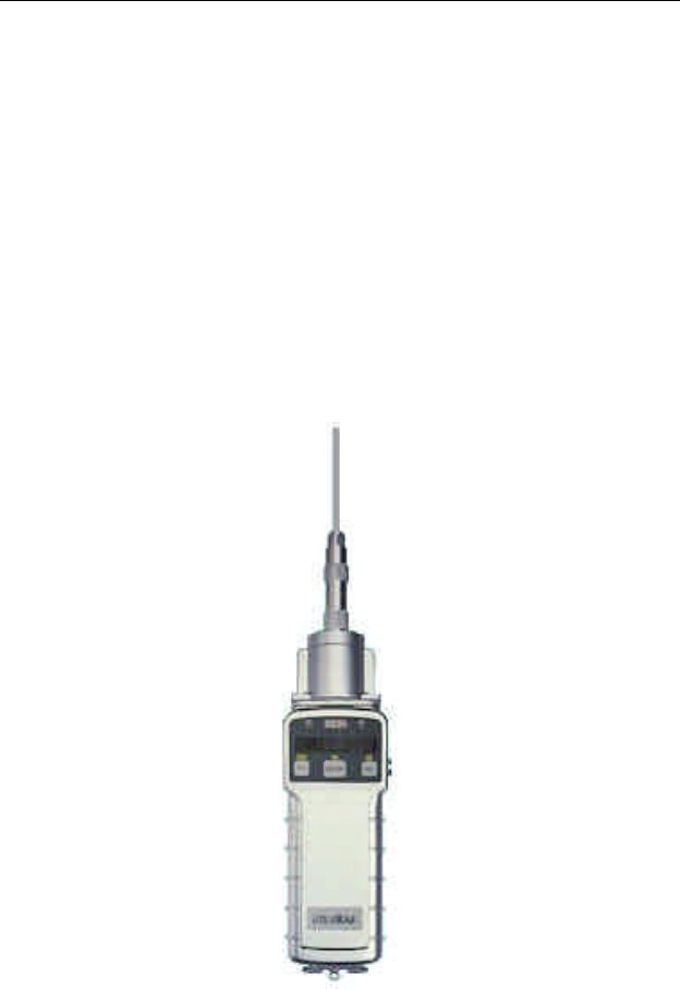
1. GENERAL INFORMATION
The UltraRAE is a hand-held, programmable Compound
Specific PID monitor designed to provide instantaneous
exposure monitoring of a specific organic gas for workers in
hazardous environments. It monitors a specific gas by utilizing
a gas separation tube and the Photo-Ionization Detector (PID)
with a 9.8 eV, 10.6 eV, or 11.7 eV gas discharge lamp. It also
can be used to measure total Volatile Organic Compound
(VOC) by utilizing a straight through tube and the PID as a
broad band monitor.
Figure 1-1 UltraRAE

GENERAL INFORMATION
1 - 2
Features are:
• Lightweight and Compact
- 20 oz (567 g), Cellular phone size
• Dependable and Accurate
- 10 hours monitoring with micro controller
• User Friendly
- menu driven, intuitive end-use operation
• Programmable Alarm Thresholds
- audio buzzer & flashing display alarm
UltraRAE (PGM-7200) consists of: a Compound Specific
PID monitor, gas separation tubes, a battery charger,
leather case, alkaline battery adapter, water and dust filter
plus calibration accessories.

GENERAL INFORMATION
1 - 3
1.1 General Specifications
Table 1.1
Compound Specific PID monitor Specification
Size: 9.25"L x 3.0"W x 2.0"H
Weight: 21 oz (567 g) with battery pack
Detector: photo-ionization sensor with 9.8 eV UV
lamp, optional 10.6 or 11.7 eV UV lamps
Battery: rechargeable NiMH, NiCd, or Alkaline
battery pack (snap in, field replaceable)
Battery charging: 10 hours charge through built-in charger
or an external battery charger
Operating Hours: 10 hours continuous
Display: 1 line by 8 characters, 5x7 dot matrix
LCD (0.4” character height)
LED Backlight: automatic activation in dim light or alarm
condition
Total VOC Range, Resolution & Response time (t90):
Calibrated to 100 ppm isobutylene:
0-99 ppm 0.1 ppm 5 sec
100-2000 ppm 1.0 ppm 5 sec
Specific Range, Resolution & Measurement time :
Measurement Gas
Benzene 0.1-200 ppm 0.1 ppm 60 sec
1,3-Butadiene 0.1-200 ppm 0.1 ppm 75 sec
Methylene Chloride 0.2-200 ppm 0.2 ppm 30 sec
PID Detector: easy access to lamp and sensor for
cleaning and replacement
Filter: porous metal, for dust and particle
filtering, field replaceable
Inlet probe: Teflon tube with ferrule fitting.
Keypad: 1 operation key and 2 program keys
Analog output: 0 to 2.5 volt linear output

GENERAL INFORMATION
1 - 4
Intrinsic Safety: UL & cUL Class 1, Division I, Group
A, B, C, D (US & Canada), EEx ia IIC T4
(Europe)
EM Interference: no effect when exposed to 0.43 mW/cm2
RFI (5 watt transmitter at 12 inches)
Alarm Setting: preset alarm limits for two action levels
Audible Alarm: 90 dB buzzer @ 10 cm
Visual Alarm: flashing red LED
External Alarm: optional plug in pen size vibration alarm
or remote alarm
Real-time Clock: automatic date and time stamps data
logged information
Data logging: 4000 data points, includes serial number,
user ID and site ID, date and time
Communication: down load data to PC and upload
instrument setup from PC through RS-232
link to serial port on PC
Calibration: two-point field calibration of zero and
standard reference gas for compound
specific vapor
Sampling Pump: internal integrated flow rate, 400 cc per
minute minimum (VOC tube), low flow
alarm
Temperature: -20o to 45oC (-4o to 113oF)
Humidity: 0 % to 95 % relative humidity
(Non-condensing)
Housing: ABS + PC, conductive coating, splash and
dust proof, will withstand 10’ drop test
Attachment: wrist strap
OPERATION
2 - 1
2. OPERATION OF ULTRARAE
The UltraRAE PID Monitor gives the real time measurements
and activates alarm signals whenever the exposure exceeds
preset limits. Prior to factory shipment the UltraRAE is preset
with default alarm limits and the sensors are pre-calibrated with
standard calibration gas. However, the user should calibrate the
instrument before the first use. After the monitor is fully
charged and calibrated, it is ready for immediate operation.
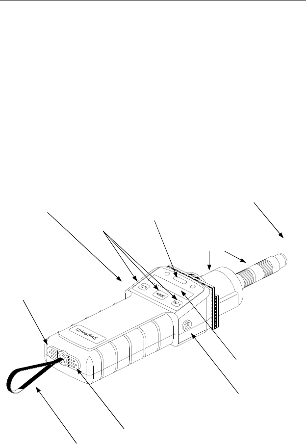
2.1 Figure 2-1 UltraRAE Features
Three keys
Buzzer
LCD display
Gas exit port
Red LEDs
Gas entry
Wrist strap
Charger connector
Communication port
Tube holder and reader

OPERATION
2 - 2
2.1 Physical Description
The main components of the UltraRAE Compound Specific
PID monitor include:
• Three keys for user to interact with the monitor: 1 operation
key and 2 programming keys for normal operation or
programming of the monitor
• LCD display for direct readout and calculated
measurements. The display is a one-line, eight-digit,
alphanumeric, 5x7 dot matrix type and has a back light for
readings under low light conditions
• Buzzer and red LED for alarm signal whenever the
exposures exceed preset limits
• Wrist strap
• Charge contact for plugging directly to the charging station
• Gas entry and exit ports with 5-in. Teflon inlet probe
• RAE-SEP tube holder and electronic tube type reader
• Serial communication port for PC interface
OPERATION
2 - 3
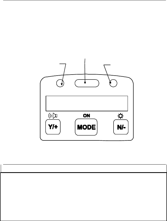
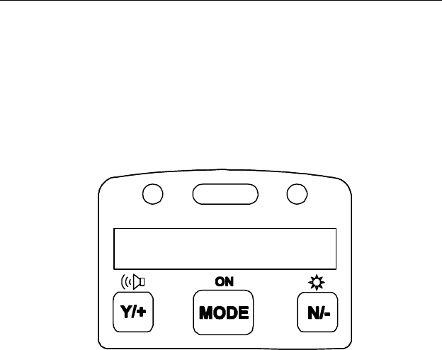
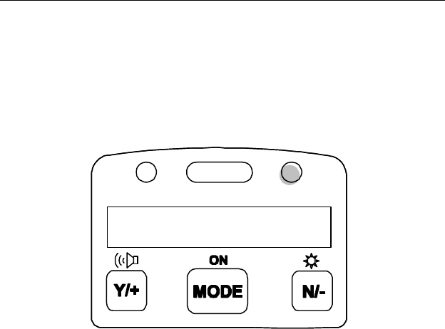
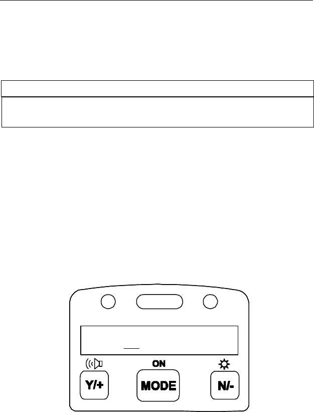
2.2 Keys and Display
Figure 2-2 shows the LCD display and the keypad on the front
panel of the monitor. The function of the 3 keys during normal
operation are summarized below:
Figure 2-2. UltraRAE Key Pad & Display
Key Function in Normal Operation
[MODE] -Turn on/off the power* and step through menu
[N/-] -Toggle on/off the back light, negative
acknowledgement /decrement value
[Y/+] -Start measurement, positive acknowledgement
/increment value
• * Pressing and holding the [MODE] key for 5 seconds turns
off the power to the monitor. Press the [MODE] key
momentarily to step through menu items. To save time,
press any key during message scrolling to skip to the end of
the message.
0.0
ppm
Light sensor
Alarm LED’s
Charge LED

OPERATION
2 - 4
2.3 Power On/Off
To turn on the UltraRAE Compound Specific PID monitor,
press [MODE] key for one second and release. The audio
buzzer will beep once and the display will show “ON!..” and
then “Ver #.##” to indicate the unit’s current firmware version
number. The model number, current date and time, unit internal
temperature, last calibration date and time, battery voltage, and
shut off voltage are displayed.
To turn off the UltraRAE Compound Specific PID monitor,
press and hold the [MODE] key for 5 seconds. The monitor
will beep once per second during the power-down sequence
with a count down timer showing the number of remaining
seconds. The message “Off!..” flashes on the LCD display and
the display will go blank indicating that the monitor is turned
off.
Data protection during power off
When the monitor is turned off, all the current real time data
including last measured value are erased. However, the datalog
data is preserved in non-volatile memory. Even if the battery is
disconnected, the datalog data will not be lost. During power
off period, the real time clock will continue to operate until the
battery is completely drained (usually in 5-7 days without any
charging). If the battery is completely drained or is
disconnected from the monitor for more than 30 minutes, the
real time clock will be lost. In this case, the user needs to enter
the real time clock information again, as described in Section 4,
or send the PC clock during configuration.
OPERATION
2 - 5
2.4 Operation
After the monitor is turned on and cycles through the start up
menu, the message “Ready..” will be displayed even if no tube
is presently inserted.
At this point, the user has two options: 1) step through the idle
operation menu, or 2) take a measurement.
2.4.1 Idle Operation
Press the [MODE] key to cycle through the idle operation
menu. The PID sensor and pump are turned off during this idle
operation. Idle operation menu displays include:
• Ready…
• Last tube name and reading
• Tube type selection (when barcode reader is turned off)
• Battery voltage
• Date, time and temperature
• PC communication
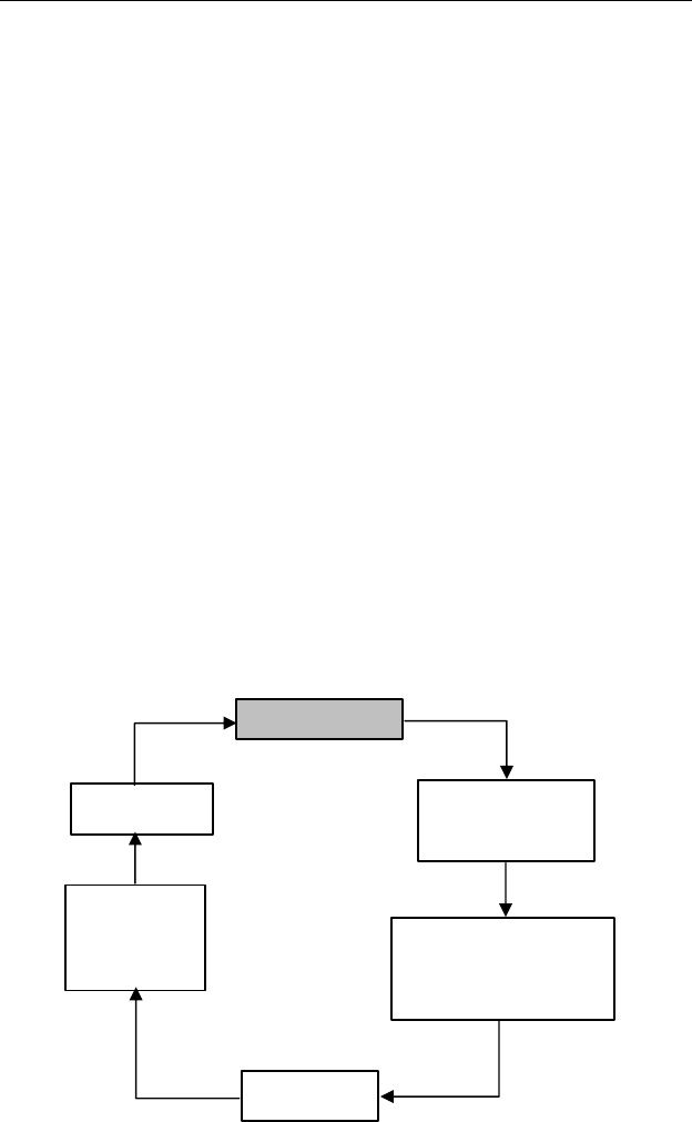
The displays are arranged in a “round robin” order:
Bat=4.8V
10/01/97
08:20
T=25°C
Last=Benzene
0.0 ppm
PC comm?
Change current
tube type
(barcode disabled)
Ready…
OPERATION
2 - 6
To choose a specific display, press the [MODE] key one or
more times until the desired display appears.
Note: To get back to “Ready” mode from any of the above
display, press the [MODE] key repeatedly until the
“Ready” message appears.
Figure 2-3 The UltraRAE is Ready
READY: The monitor is ready for a measurement to be taken.
Press the [MODE] key to advance to the next menu. If a tube is
inserted at this point, the “Tube in!” message is displayed,
followed by the alternate display of the gas name and “Start?”
The [Y/+] key can be pressed to start a measurement if the
monitor does not detect the presence of the tube. In either case,
the monitor will go to the second phase of the measurement
cycle (see Section 2.4.2).
LAST TUBE MEASUREMENT: This menu displays
“Last=”, followed by the name of the last tube and the
measurement value in ppm. For example: Last = Benzene 0.0
ppm. Press the [MODE] key to advance to the next menu.
Ready…

OPERATION
2 - 7
CHANGE CURRENT TUBE TYPE [Only in the default
condition where the barcode reader is turned “Off”]: The
present tube type is displayed e.g., “Benzene?” and can be
altered by pressing [N/-] until the desired tube type is displayed.
Press [Y/+] to accept the displayed tube. With the barcode
reader “Off,” the instrument assumes that the same type of tube
will be used until a different tube type is programmed. It is
important to select the tube type correctly because this
determines the lamp required and the measure wait time.
!! CAUTION !!
If the incorrect tube type is programmed or the Measure
Wait Time is otherwise set too short, it is possible to
underestimate the VOC concentration and thereby cause
overexposure.
This menu item is not displayed when the barcode reader is
enabled (to enable see Section 4.7.9).
BATTERY: The menu displays the present battery voltage.
Note: A fully charged battery pack should show 4.8 volts or
higher. When the battery voltage falls below 4.4 volts, a
flashing “Bat” will appear as a warning message. When the
battery voltage falls below 4.2 volts, there are about 20-30
minutes of run time left before the monitor turns off
automatically.
DATE, TIME, TEMP: This menu displays the current date
(month/day/year), time (24-hour format), and internal unit
temperature in degrees Celsius. For example:
7/16/97 … 9:00 (24 hr format) … 25°C ... 77°F

OPERATION
2 - 8
PC COMMUNICATION: Allows user to up load data from
the UltraRAE to a Personal Computer (PC) or send/receive
configuration information between a PC and the UltraRAE.
Connect the monitor to the serial port of a PC, and start the
UltraRAE application software. Press the [Y/+] key and the
LCD displays the “Comm ready...” The monitor is now ready
to receive commands from the PC.
Press the [MODE] or [N/-] key to exit the communication
standby mode and move to the next.
OPERATION
2 - 9
2.4.2 Measurement Overview
To start a measurement, the monitor must first be in the
“Ready…” mode. The monitor normally powers up into this
mode.
Measurement phases:
• Ready
• Tube Preparation
• Insert and identify tube
• Start measurement
• Display and log measurement
• Remove tube
Ready
Unit is ready to start a sample.
Tube Preparation
Break both ends of a new RAE-Sep tube using the tip cutter on
the tube reader of the UltraRAE, Figure 2-4. Use a new tube for
each measurement. The tube contents may be hygroscope and
should be used within a short time of opening.
Figure 2-4 Tube Tip Break-off
Tip Breaking Hole
Push to side
OPERATION
2 - 10
***CAUTION: Wear hand and eye protection when breaking tube
tips. Use caution in handling tubes with broken ends. Keep
away from children. RAE-Sep tubes should be disposed of
according to local regulations. See footnotes of data sheets for
disposal information.***
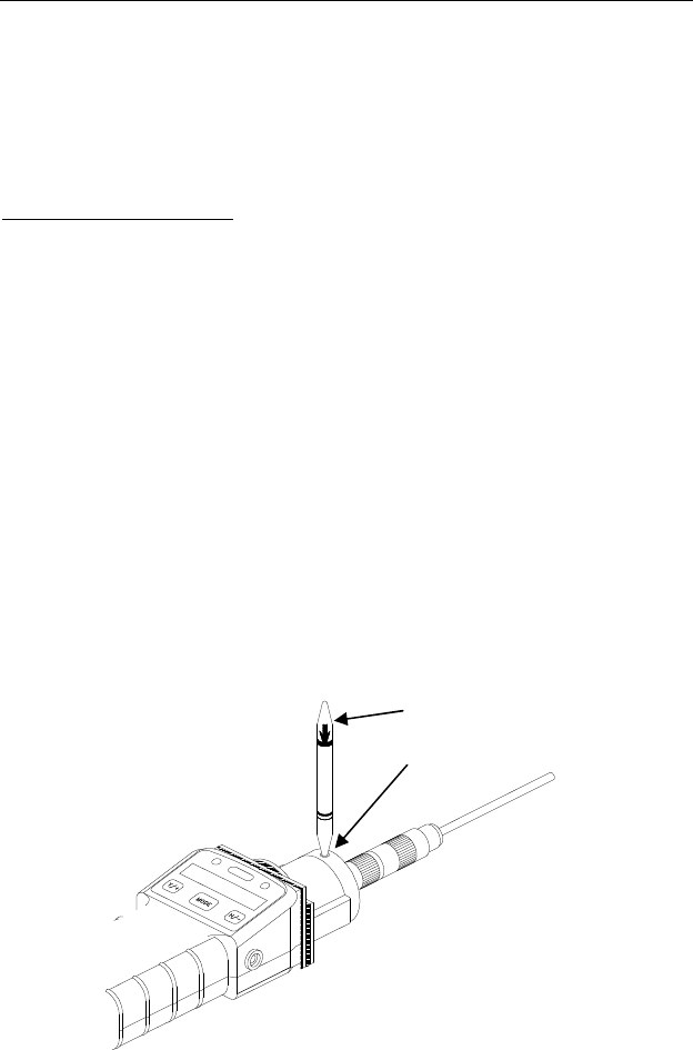
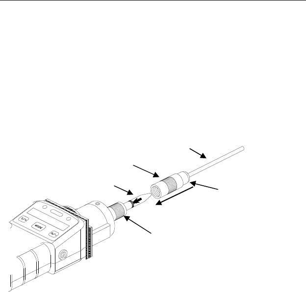
Tube insertion
Unscrew the top half of the tube holder on the inlet and insert
the tube securely into the UltraRAE with the tube arrow
pointing into the unit and face front.
Figure 2-5 Tube Insertion & Cap
Screw the tube holder back on. Give a twist (about 90-180°)
and push (about 5-15 lb.) action on the tube cap nut to ensure a
good seal on both sides of the tube. The tube code is read once
per second, and the tube type is displayed if the unit recognizes
the tube:
Benzene / Start? / Benzene / Start? ……
An error message is displayed if a valid tube is not detected:
“No Tube” or “Unknown Tube.” An “Unknown Tube” error
message must be cleared before a measurement can begin (see
Troubleshooting, Section 8.2). The “No Tube…” message is
followed by “…Manual Select?” The barcode reader can be
Tube
Tube Holder Cap
Teflon Tubing
Tube Holder Base
Tube Cap Nut

OPERATION
2 - 11
circumvented by pressing [Y/+] and selecting the appropriate
tube at the subsequent prompts using the [N/-] and [Y/+] keys.
Start Measurement
Press the [Y/+] key to start the measurement cycle. The pump
will start and the remaining wait time will be displayed. If a
VOC tube is inserted, the real-time ppm measurement will be
display. The total pump time is the sum of the pre-programmed
optimum time and the user programmable “measure wait time”.
At the end of the waiting period, the measurement value will be
logged, if enabled. At this point the monitor will alternately
display the measurement value and “Done!”
If no tube is inserted or detected, the [Y/+] key can be pressed.
The “Manual select?” message will be displayed. Press the
[Y/+] key again to confirm a manual tube selection. The first
tube name, of the currently configured tubes, will be displayed.
Press the [Y/+] key to accept this tube name or press the [N/-]
key to display the next tube in the list.
Measurement Display and Data Log
The sampled reading is the actual gas concentration in parts per
million (ppm) for that gas. The reading is held and displayed
until the user presses a key to move on to the next display.
Tube Removal
Press the [Y/+] key to advance to the next phase. The monitor
will next display the prompt “Remove tube!” (if a tube is
present). Remove the tube to return to the “Ready…” prompt.
Abort Measurement
During waiting period, any key pressed will abort the
measurement.
OPERATION
2 - 12
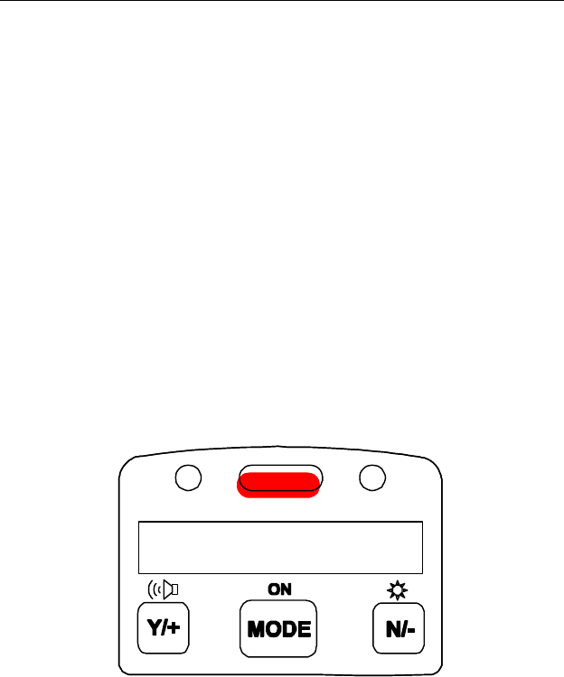
2.5 Alarm Signals
At the end of each measurement period, the gas concentration is
compared with the programmed alarm limits (two gas
concentration alarm limit settings: Low & High). A separate
set of limits can be programmed for each tube. If the
concentration exceeds either of the preset limits, the loud buzzer
and red flashing LED are activated immediately to warn user of
the alarm condition.
In addition, the UltraRAE will alarm if one of the following
conditions occurs: battery voltage falls below a pre-set voltage
level (4.4 V), failure of UV lamp, pump stall, or when the
datalog memory is full. When the low battery alarm occurs,
there will be approximately 20-30 minutes of operating time
remaining. When the battery voltage falls below 4.2 V, the
monitor will be turned off automatically.
Figure 2-6 Alarm Signals
10.2
ppm

OPERATION
2 - 13
Alarm Signal Summary:
Condition Alarm Signal
Gas exceeds “High
Alarm” limit 3 beeps/flashes per second plus sensor
name on LCD
Gas exceeds “Low
Alarm” limit 2 beeps/flashes per second plus sensor
name on LCD
Pump failure 3 beeps/flash per second plus “Pump”
message on LCD
PID lamp failure 3 beeps/flash per second plus
“Lamp” message on LCD
Low battery 1 flash per second, 1 beep per minute
plus “Bat” message on LCD
Memory full 1 flash per second plus “Mem”
message on LCD
Alarm Signal Testing:
Under normal non-alarm condition, it is possible to test the
UltraRAE LED, and buzzer in special diagnostic mode
(see Section 8.1).
OPERATION
2 - 14
2.6 Preset Alarm Limits and Calibration
The UltraRAE Compound Specific PID monitor is factory
calibrated with standard calibration gas, and is programmed
with default alarm limits as listed below. Refer to Section 4 for
programming procedures if new calibration or alarm limits are
required.
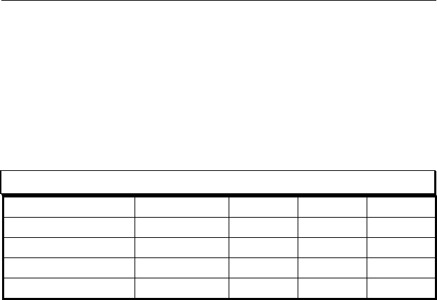
Factory Calibration and Preset Alarm Limits
Cal Gas Cal Span Units Low High
Benzene 5.0 ppm 5.0 10.0
Butadiene 5.0 ppm 5.0 10.0
Halocarbon 10.0 ppm 10.0 25.0
VOC 100.0 ppm 50.0 100.0

OPERATION
2 - 15
2.7 Integrated Sampling Pump
The UltraRAE Compound Specific PID monitor includes an
integrated sampling pump. This is a diaphragm type pump that
provides 400-500 cc per minute flow rate (with no tube in
place). Connecting a 1/4 inch Tygon tubing with 1/8 inch
inside diameter to the gas inlet port of the UltraRAE, this pump
can pull in air sample from 200 feet away horizontally, or 90
feet vertically, at 3 feet per second flow speed.
The pump is turned on when a measurement is manually started
by the operator and turns off automatically at the completion of
the sample.
If liquid or other objects are pulled into the inlet port filter,
causing the pump to stall, the monitor will detect the
obstruction and shut down the pump immediately. The alarm
will be activated and a flashing error message “Pump” will be
also displayed on the LCD display.
The user needs to acknowledge the pump shut off condition by
clearing the obstruction and pressing the [Y/+] key to re-start
the pump.

OPERATION
2 - 16
2.8 Backlight
The LCD display is equipped with an LED backlight to assist in
reading the display under poor lighting conditions. In manual
mode, the backlight can be turned on by pressing and holding
the [N/-] key for one second in normal operation. The backlight
can be turned off by pressing [N/-] a second time. If the [N/-]
key is not pressed, the backlight will be turned off automatically
after a pre-programmed time-out period to save power.
In automatic mode, the ambient light is sensed and the backlight
will be turned on automatically if the ambient light is below a
threshold level. The backlight will be turned off automatically
when the ambient light exceeds the threshold level.
(See Section 8.1 for instructions on how to set the threshold
level.)
Note: The LED backlight consumes about 20-30% of the total
average current, when the instrument is idle or not taking a
measurement.

OPERATION
2 - 17
2.9 Datalogging
The UltraRAE Compound Specific PID monitor stores the time
stamp, sample number, tube name and measured gas
concentration at the end of every sample period (when data
logging is enabled). In addition, the following information is
stored: user ID, site ID, serial number, last calibration date, and
alarm limits. All data is retained (even after the unit is turned
off) in non-volatile memory so that it can be down loaded later
to a PC.
Datalogging event
Each time the monitor is turned on, or a configuration parameter
is changed, a new datalog event is created. Information, such as
start time, user ID, site ID, serial number, last calibration date,
and alarm limits will be recorded.
Datalogging sample
After an event is recorded, the unit records a shorter form of the
data. This data contains the sample number, time
(hour/minute), tube name, and gas concentration.
If more than 900 measurements sample are recorded in one
event, a new event will be created automatically (by the
application software).
WARNING:
To reduce the risk of ignition of hazardous
atmospheres, recharge battery only in area known to
be non hazardous. Remove and replace battery only
in area known to be non-hazardous.
Ne charger les batteries que dans emplacements
désignés non-dangereuse.

OPERATION OF ACCESSORIES
3 - 1
3. OPERATION OF ACCESSORIES
The accessories for the UltraRAE include:
• Battery charger
• Alkaline battery adapter
• Dilution fitting
• Calibration adapter
3.1 Battery Charging Operation
The charging circuit of the UltraRAE is built into the monitor.
It only needs a regular AC to 12 V DC adapter (wall mount
transformer) to charge the monitor. Charging should be done
with the unit turned off.
1. Connect the AC adapter (or the optional automotive
charging adapter) to the DC jack on the UltraRAE monitor.
If the unit was off, it will automatically turn on.
2. The first message displayed will be “Deep discharge?” This
message will remain on the display for three seconds. If the
user wants to discharge the battery pack, affirm this query
with the [Y/+] key, otherwise the unit will abandon this
function and move on to the charge mode.
3. While charging, the display message will alternate between
“Charging” and “Bat=x.xV” (x.x is the present battery
voltage). The LED should be red in color when charging.
4. When the battery is fully charged, the LED will change
from red to green and the message “Fully charged” will
appear on the display. The red color indicates that the
battery is being charged. The green color indicates that the
battery is fully charged. After the battery is fully charged,
the unit will enter the “trickle charge” mode. In this mode,
OPERATION OF ACCESSORIES
3 - 2
the red LED will turn on for two or three seconds, every
minute, to maintain the full charge.
A completely discharged UltraRAE monitor will be charged to
full capacity within 10 hours.
Figure 3-1 Charging the Battery
The battery will be drained slowly even if the monitor is turned
off. If the monitor has not been charged for 5-7 days, the
battery voltage will be low.
The factory supplied battery is designed to last for 12 hours of
normal operation (no alarm, no back light condition), for a new
battery under the best condition. As the battery becomes older
or is subject to adverse conditions (such as cold ambient
temperature), the battery capacity will be reduced significantly.
Charging
Ready…

OPERATION OF ACCESSORIES
3 - 3
3.2 Alkaline Battery Adapter
An alkaline battery adapter is supplied with each UltraRAE kit.
It accepts four AA size alkaline batteries and can be used in
place of the Ni-MH or Ni-Cd battery pack to provide
approximately 12-14 hours of operation. The adapter is
intended for emergencies when there is no time to charge the
Ni-Cd or Ni-MH battery pack.
To install the adapter, remove the cover of the monitor.
Remove the Ni-Cd or Ni-MH battery pack from the battery
compartment and replace with the alkaline battery adapter.
Replace the battery compartment cover.
The internal charging circuit is designed to prevent damage to
alkaline batteries and the charging circuit when alkaline
batteries are installed inside the monitor.
Note: The AA Alkaline battery adapter supplied by
RAE Systems Inc. is intrinsically safe!

OPERATION OF ACCESSORIES
3 - 4
3.3 Dilution Fitting
The user may wish to install a dilution fitting in front of the
RAE-SEP tube to dilute the gas samples. One application for a
dilution fitting is to measure organic gas when the concentration
exceeds the upper limit of the sensor range.
Make sure to set the dilution ratio in the programming mode
(see Section 4.3) so that the correct gas reading will be
displayed when the dilution fitting is used.
WARNING: To use a dilution fitting, the user
must have the monitor located in a clean
atmosphere outside the confined space and use a
remote access probe or inert tubing to measure
the gas concentration inside the confined space.

PROGRAMMING
4 - 1
4. PROGRAMMING OF ULTRARAE
The UltraRAE Monitor is built with a microcomputer to
provide programming flexibility for the user. Authorized users
can re-calibrate the monitor, change the alarm limits, change
site ID, user ID, lamp type, real time clock, etc.
Programming is menu-driven to provide intuitive end-user
operation. The display shows the menu options, and the keypad
used for menu selection and data entry.

PROGRAMMING
4 - 2
4.1 Programming Mode
The programming mode allows users to change the setup in
the monitor, calibrate the monitor, modify the sensor
configuration and enter user information, etc. The
programming functions are organized in a three tier menu
structure. Each menu item includes several sub-menus to
perform additional programming functions. Appendix A shows
a more detailed menu tree structure.
Programming Menu
Calibrate monitor?
Change alarm limits?
View or change datalog?
Change monitor setup?
Change sensor configuration?
Once inside the programming mode, the LCD will display the
first menu. Each subsequent menu item can be viewed by
pressing the [N/-] repeatedly until the desired menu is
displayed. To enter the sub-menu of a particular menu, press
[Y/+] key, the sub-menu will be displayed.
Return to “Ready” menu: To exit the programming mode and
return to the idle operation, press the [MODE] key once at any
of the programming menu display.

PROGRAMMING
4 - 3
4.2 Keys for Programming Mode
The three keys perform a different set of functions during the
programming mode as summarized below.
Key Function in Programming Mode
[MODE] Exit menu when press momentarily or exit
data entry mode when pressed and held for
1 second
[Y/+] Increase numerical value for data entry or
confirm (yes) for a question
[N/-] Decrease numerical value for data entry or
deny (no) for a question
PROGRAMMING
4 - 4
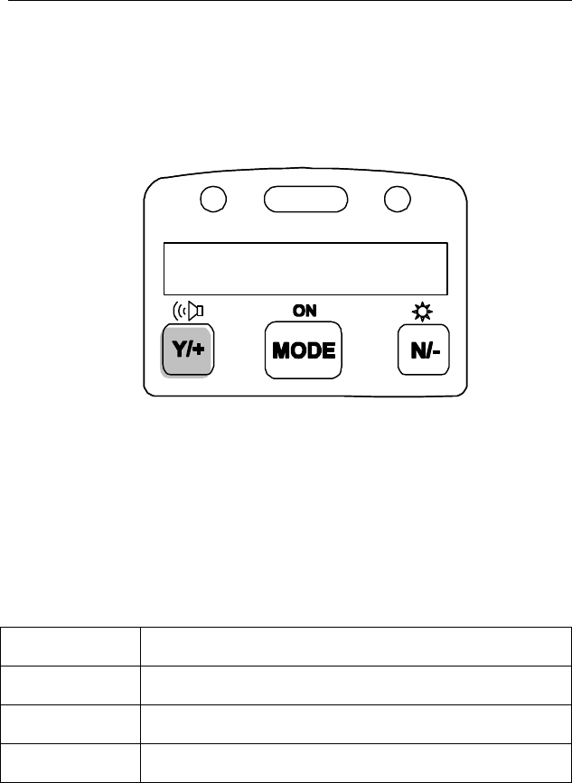
4.3 Entering into Programming Mode
1. Turn on the UltraRAE monitor, wait for the “Ready..”
message to be displayed.
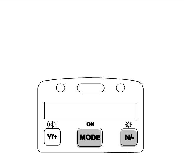
2. Press and hold down both [MODE] and [N/-] keys for three
seconds to enter programming mode. Note: This is to
prevent user from entering programming mode by accident.
Figure 4-1 Entering Programming Mode
3. Holding down these two keys for 3 seconds, the monitor
should enter the programming mode and the first menu item
“Calibrate Monitor?” will be displayed.
Ready…

PROGRAMMING
4 - 5
4.4 Calibration of the UltraRAE Monitor
CALIBRATION WARNINGS:
The Calibration of all newly purchased RAE Systems
instruments should be tested by exposing the sensor(s) to
known concentration calibration gas before the instrument
put into service for the first time.
For maximum safety, the accuracy of the UltraRAE should
be checked by exposing the sensor(s) to known
concentration calibration gas before each day’s use.
In the programming mode, the user may re-calibrate the
UltraRAE monitor. This is a two-point calibration process
using “fresh air“ and a standard reference gas. First a “fresh
air” calibration, which contains no detectable VOC (0.0 ppm), is
used to set the zero point for the sensor. Then a standard
reference gas, which contains a known concentration of a given
gas, is used to set the second point of reference (also known as
span gas). Separate calibration must be performed for each type
of tube being used.
Note: The span value must be set prior to calibrating for fresh
air or span.
Calibration Sub-Menu
Fresh air calib?
Span calib?
Modify span value?
Calibration Frequency
To achieve the highest level of measurement accuracy, it is
recommended that the monitor be calibrated once a day before

PROGRAMMING
4 - 6
it is used. If this is not possible, then the monitor should be
calibrated at least once a week.
Correction Factors Not Possible
It is necessary to calibrate for each type of RAE-Sep tube
directly with the gas to be measured and with the corresponding
RAE-Sep tube in place. It is NOT possible to calibrate with a
surrogate gas (such as isobutylene) and then apply a correction
factor. This is because the surrogate gas is often absorbed on
the RAE-Sep tube, or elutes at a different rate than the desired
gas.

PROGRAMMING
4 - 7
4.4.1 Fresh Air Calibration
This procedure determines the zero point of the sensor
calibration curve. To perform fresh air calibration, the
calibration adapter, a bottle of “fresh” air, and a Tedlar bag
(optional), or a charcoal filter are required. The “fresh” air is
clean dry air without any organic impurities. If such an air
bottle is not available, any clean ambient air without detectable
contaminant or a charcoal filter can be used.
The calibration adapter links the inlet port of the UltraRAE
monitor to the Tedlar bag or the charcoal filter. First fill the
Tedlar bag with “fresh” air from the bottle before starting.
1. The first sub-menu shows: “Fresh air calib?”
2. Insert a new, unused, RAE-SEP tube into the monitor and
secure the cap. If a “fresh” air bottle is available, fill the
Tedlar bag with the “fresh” air. Next, snap the calibration
adapter over the inlet port of the UltraRAE monitor and
connect the other end of the tube to the Tedlar bag. If a
charcoal filter is used, connect the filter to the inlet port of
the UltraRAE monitor. If the “fresh” air bottle or charcoal
filter is not available, make sure the monitor is in an area
free of any detectable vapor.
3. Press the [Y/+] key. The monitor will identify the inserted
tube and display the tube name. If the tube cannot be
identified, the tube can be manually selected by responding
with [N/-] until the correct tube name is displayed.
4. Press the [Y/+] key when the correct tube name is displayed
to start “fresh air calibration” of the monitor. The display
shows “zero in progress” followed by “wait..” and a
countdown timer.
5. When the sampling is complete, the display will show the
message “zeroed… reading = 0.0 … done!” The next sub-
menu will be displayed (“Span calib?”).
Note: The charcoal filter has a check box so that user can mark
off a box each time the filter has been used. The charcoal filter
should be replaced after four calibrations.

PROGRAMMING
4 - 8
4.4.2 Span Calibration
This procedure is the second type of sensor calibration. A
bottle of standard reference gas (span gas) and a Tedlar bag are
needed to perform this procedure. First, fill the Tedlar bag with
the span gas. Connect the calibration adapter to the inlet port of
the UltraRAE Monitor, and connect the tube to the Tedlar bag.
Before executing a span calibration, make sure the span value
has been set correctly (see next sub-menu).
1. Advance to the next calibration phase (Span calib), the
display should show “Span calib?
2. Insert a new RAE-SEP tube into the monitor. (Note: For
VOC calibration, there is no need to use a new VOC tube).
First fill the Tedlar bag (Do not overfill with span gas).
Then connect the bag to the inlet port.
3. Press the [Y/+] key. The monitor will identify the inserted
tube and display the tube name. If the tube cannot be
identified, the tube can be manually selected by responding
with [N/-] until the correct tube name is displayed.
4. Press the [Y/+] key when the correct gas name is shown.
The display shows “Span gas = xx ppm?” If incorrect, press
the [N/-] key and correct the span gas value. When the span
gas value is correct, open the valve to the Tedlar bag and
press the [Y/+] key to start the calibration. The display
reminds the user to “Apply gas now!” and begins a
countdown timer showing the number of remaining seconds.
When the count down timer reaches zero, the display shows
the calibrated value. Turn off the gas and press [MODE]
key to exit calibration
5. This completes the calibration procedure for a gas. The
display shows the next calibration sub-menu.
6. Disconnect the calibration adapter and Tedlar bag.
7. Press the [N/-] or [MODE] key to abort more calibration
and move directly to the next sub-menu item. The current
calibration data will be saved automatically.
PROGRAMMING
4 - 9
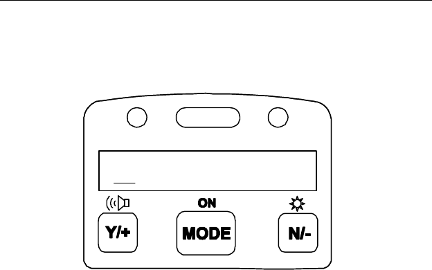
4.4.3 Modify Span Value
This function allows the user to change the span value of the
standard calibration gas.
Figure 4-2 Modify Span Value
The cursor blinks at the first digit of the span value. Use the
[Y/+] or [N/-] key to modify the digit at the cursor position.
Press the [MODE] key momentarily to advance the cursor to
the next digit.
When the number is adjusted to the desired value, press and
hold the [MODE] key for one second. The user will next be
asked to confirm the change (save?).
0005.0
PROGRAMMING
4 - 10
4.5 Change Alarm Limits
In this menu, the user can change the high and low alarm limits
for each RAE-SEP tube.
Alarm Limit Sub-Menu
High limit?
Low limit?
4.5.1 Change High Alarm Limit
1. The first sub-menu item allows the user to change the High
Alarm limit. Press the [Y/+] key. The monitor will identify
the inserted tube and display the tube name. If the tube
cannot be identified, the tube can be manually selected by
responding with [N/-] until the correct tube name is
displayed. Next press the [Y/+] key and the display will
show a flashing cursor on the left-most digit of the
previously stored High alarm limit.
Figure 4-3 Change Alarm Limits
2. To modify this limit, starting from the left-most digit, use
the [Y/+] or [N/-] key to change the digit value and press the
[MODE] key momentarily to advance to the next digit. The
0010.0

PROGRAMMING
4 - 11
flashing digit will move on to the next digit to its right.
Press and hold the [MODE] key for 1 second to exit data
entry mode. If there is any change to the existing value, the
display shows “Save?” Press the [Y/+] key to accept the
new value and move to the next sub-menu. Press the [N/-]
key to discard the changes.
3. To preserve the previously stored High Alarm limit, press
and hold the [MODE] key for 1 second and the monitor will
exit data entry mode and move to the next sub-menu.

PROGRAMMING
4 - 12
4.5.2 Change Low Alarm Limit
1. The second sub-menu item allows the user to change the
Low Alarm limit. Press [Y/+] key. The monitor will
identify the inserted tube and display the tube name. If the
tube cannot be identified, the tube can be manually selected
by responding with [N/-] until the correct tube name is
displayed. Next press the [Y/+] key and the display will
show a flashing cursor on the left-most digit of the
previously stored Low alarm limit.
2. To modify this limit, starting from the left-most digit, use
[Y/+] or [N/-] key to change the digit value and press
[MODE] key momentarily to advance to the next digit. The
flashing digit will move on to the next digit to its right.
Press and hold [MODE] key for 1 second to exit data entry
mode. If there is any change to the existing value, the
display shows “Save?” Press [Y/+] key to accept the new
value and move to next sub-menu. Press [N/-] key to
discard the changes.
3. To preserve the previously stored Low Alarm limit, press
and hold [MODE] key for 1 second and the monitor will
exit data entry mode and move to the next sub-menu.

PROGRAMMING
4 - 13
4.6 View or Change Datalog
The UltraRAE monitor calculates and stores the concentration
and ID of each sample taken. The user can review this stored
data, clear the datalog memory, and enable or disable the data
logging function.
Datalog Sub-Menu
View data?
Clear data?
Change data log?
4.6.1 View Data
This function allows the user to review all the data that is stored
in the non-volatile data memory.
Data is stored in groups, or “events”. An event is created and
stored when the unit is turned on, or when any configuration
parameter is changed (in program mode). When an event is
created, all vital configuration parameters are stored. Each
event can contain many “data” points. A data point consists of;
the sample number, time (hour : minute), tube ID, and
measurement value.
Data storage structure
Event #1
Data #1 (10/01/97, 14:20, Benzene, 0.2 ppm)
Data #2 (14:35, Benzene, 0.3 ppm)
Data #3 (14:55, Benzene, 0.1 ppm)
Data #4 (15:07, Benzene, 0.4 ppm)
Event #2
Data #1 (10/02/97, 09:06, Benzene, 0.4 ppm)
Data #2 (9:15, Benzene, 0.3 ppm)
PROGRAMMING
4 - 14
1. At the “View data?” menu display, press the [Y/+] key. The
LCD display will next show the first event number and start
date and time of the event. Press the [N/-] key to view the
next event.
Figure 4-4 Viewing Data
2. Press [Y/+] key to review data of the first event. The LCD
display shows the stored data including; the time stamp in
hours and minutes, the tube name, and measurement value.
Press the [N/-] key to see the next event. If there are no
more events, the message “no more event!” will appear.
The monitor will next jump back to the first event.
Action Display
# 1?
[Y/+] 10/01/97, 14:20, Benzene, 0.2 ppm
[Y/+] 14:35, Benzene, 0.3 ppm
3. Press the [Y/+] or [N/-] key to move forward or backward
to view other data from this event. When the end or the
beginning of the event is reached, the message “1st data” or
“End data” will appear. Press the [MODE] key to exit the
current event.
# 1?

PROGRAMMING
4 - 15
4.6.2 Clear All Data
This function will erase all data stored in the non-volatile data
memory.
1. “Clear All Data?” is the first sub-menu.
2. Press the [Y/+] key to clear the data memory. Display
shows: “Are you sure?”
3. Pressing the [Y/+] key again confirms erasure of all the data
memory.
4. Press the [N/-] or [MODE] key to exit without clearing the
data memory and move to next datalog sub-menu.

PROGRAMMING
4 - 16
4.6.3 Change Data Log
This function allows the user to enable or disable the data
logging. At the beginning of each measurement sample, the
current status of this feature is displayed (Log On/Log Off).
1. “Change data log?” is the first sub-menu.
2. Press the [Y/+] key to change the data logging function
(enable/disable). The display will show the current status of
this feature (Log On/Log Off) followed by a question mark.
3. Press the [N/-] key to change the present state of the logging
function. The message “Are you sure?” will be displayed if
the status has change. Confirm the change by pressing the
[Y/+] key. The [N/-] key is used to alternate the current
state.
4. Press the [MODE] key to exit and move to the next datalog
sub-menu.

PROGRAMMING
4 - 17
4.7 Change Monitor Setup
Several monitor unit specific variables can be changed. The
following is a list of configuration data that can be modified by
the user.
Monitor Setup Sub-Menu
Change Site ID?
Change User ID?
Change User Mode?
Change Date?
Change Time?
Change backlight?
Change DAC/Alarm output?
Change DAC range?

PROGRAMMING
4 - 18
4.7.1 Change Site ID
The user can enter an 8 digit alphanumeric Site ID in the
programming mode. This Site ID will be included in the data
log report.
1. “Change Site ID?” is the first sub-menu item.
2. Press the [Y/+] key and the display shows the current site
ID: “Site ID = xxxxxxxx” with the left most digit flashing.
3. Press the [Y/+] or [N/-] key to cycle through all 26
alphabets and 10 numerals. Press [MODE] key
momentarily to advance to the next digit. The flashing digit
will move to the next digit to the right. Repeat this process
until all 8 digits of the new site ID are entered.
4. Press and hold the [MODE] key for 1 second to exit the
data entry mode and move to the next monitor setup sub-
menu.
5. If there is any change to the existing Site ID, the display
shows “Save?” Press the [Y/+] key to accept the new Site
ID and exit the monitor setup sub-menu. Press the [N/-] key
to discard the changes and move to the next sub-menu.

PROGRAMMING
4 - 19
4.7.2 Change User ID
The user can enter an eight digit alphanumeric user ID in the
programming mode. This user ID will be included in the
datalog report.
1. “Change User ID?” is the second sub-menu item in Table
4.5.
2. Press the [Y/+] key and the display shows the current user
ID: “User ID = xxxxxxxx” with the left most digit flashing.
3. Press the [Y/+] or [N/-] key to cycle through all 26 letters
and 10 numerals. Press [MODE] key momentarily to
advance to the next digit. The flashing digit will move to
the next digit to the right. Repeat this process until all 8
digits of the new user ID are entered.
4. Press and hold the [MODE] key for 1 second to exit the
data entry mode and move to the next monitor setup sub-
menu.
5. If there is any change to the existing user ID, the display
shows “Save?” Press the [Y/+] key to accept the new user
ID and exit the monitor setup sub-menu. Press the [N/-] key
to discard the changes and move to the next sub-menu.

PROGRAMMING
4 - 20
4.7.3 Change User Mode
There are two different user modes: display and program
that can be selected from the programming menu.
1. “Change User Mode?” is displayed.
2. Press the [Y/+] key, the display shows the current user
mode selection: “User Mode = Program?”
3. Press the [Y/+] key to accept the currently displayed user
mode. Press [N/-] key to scroll to the alternate user modes.
Press [MODE] key to exit this sub-menu and move to the
next monitor setup sub-menu.
4. If there is any change to the existing selection, the display
shows “Save?” Press the [Y/+] key to accept the new
selection and exit the monitor setup sub-menu. Press the
[N/-] key to discard the changes and move to the next sub-
menu.
NOTE: If the user mode is changed to display mode, the user
can no longer enter the programming menu. Therefore, the user
cannot change the user mode back to program mode in normal
mode.
To restore the user mode back to program mode, turn the unit
off and back on in Diagnostic Mode. Next enter program mode
by holding the [MODE] and [N/-] keys for three seconds. Enter
the password at the prompt (the default is 000). Once program
mode is entered, go to the “Change Monitor Setup” / “Change
User Mode” and change the mode back to program.

PROGRAMMING
4 - 21
4.7.4 Change Date
The UltraRAE monitor is equipped with a real time clock
(RTC) into which the user can enter the correct date and time.
1. “Change Date?”
2. Press [Y/+] key, the display shows both the current date and
time: “Date = mm / dd” with the left most digit of the date
flashing.
3. To modify this value, use the [Y/+] or [N/-] key to change
the digit value and press the [MODE] key momentarily to
advance to the next digit. The flashing digit will move on to
next digit to its right. Repeat this process until the new date
and time values are entered. Press and hold the [MODE]
key for 1 second to exit data entry mode.
4. If there is any change to the existing value, the display
shows “Save?” Press the [Y/+] key to accept the new value
and move to next sub-menu. Press the [N/-] key to discard
the changes and move to next sub-menu.

PROGRAMMING
4 - 22
4.7.5 Change Time
1. “Change Time?”
2. Press [Y/+] key, the display shows both the current date and
time: “Time = hh : mm” with the left most digit of the time
flashing.
3. To modify this value, use the [Y/+] or [N/-] key to change
the digit value and press the [MODE] key momentarily to
advance to the next digit. The flashing digit will move on to
next digit to its right. Repeat this process until the new date
and time values are entered. Press and hold the [MODE]
key for 1 second to exit data entry mode.
4. If there is any change to the existing value, the display
shows “Save?” Press the [Y/+] key to accept the new value
and move to next sub-menu. Press the [N/-] key to discard
the changes and move to next sub-menu.

PROGRAMMING
4 - 23
4.7.6 Change Backlight
The UltraRAE monitor allows the user to turn the LCD back
light on and off. This can be done automatically when ambient
light falls below or above a certain level, or manually by
pressing the [N/-] key.
1. “Change backlight?”
2. Press [Y/+] key, the display shows the current backlight
mode: “Backlight Mode = auto turn on?”
3. Press the [Y/+] key to accept the currently displayed back
light mode. Press [N/-] key to change to the other back light
mode: “Backlight Mode = manual turn on?” Press
[MODE] key to exit this sub-menu and move to the first
monitor setup sub-menu.
4. If there is any change to the existing selection, the display
shows “Save?” Press the [Y/+] key to accept the new
selection and exit sub-menu. Press the [N/-] key to discard
the changes and return to the first monitor setup sub-menu.

PROGRAMMING
4 - 24
4.7.7 Change DAC / Alarm Output
The UltraRAE monitor allows the user to specify if the
communication / alarm connector is used for DAC output or
alarm output (see Figure 8-1 for connections). The default
setting is DAC signal output. DAC output is normally used to
connect to a chart recorder for plotting a gas concentration
represented by 0-2.5 volts DC. It provides a real-time signal
proportional to concentration. The alarm output is used for an
external alarm.
1. “Change DAC/Alarm output?”
2. Press the [Y/+] key, the display shows the current external
output mode: “External output = DAC?”
3. Press the [Y/+] key to accept the currently displayed DAC
output mode. Press [N/-] to change to alarm output mode:
“External output = Alarm?” Press [MODE] key to exit this
sub-menu and move to the next monitor setup sub-menu.
4. If there is any change to the existing selection with [Y/+]
key pressed, the display shows “Save?” Press the [Y/+] key
to accept the new selection and exit this sub-menu. Press
the [N/-] key to discard the changes and return to the next
monitor setup sub-menu.

PROGRAMMING
4 - 25
4.7.8 Change DAC Range
The DAC output function allows the user to set the gas
concentration span to be represented by the maximum 2.5V DC
output. This prevents the signal from going off scale during
measurements.
1. “Change DAC range?”
2. Press the [Y/+] key, the display shows the gas name:
“VOC?” Press [N/-] to have different gas names displayed:
“Benzene?”, “Halocarbon?”, or “Butadiene?”
3. If the [Y/+] key is press for the “VOC?”, it will show the
default DAC range “DAC range = 200 ppm?” Press [N/-]
key to change the range for 2000 ppm, 20 ppm or 200 ppm.
Press [MODE] key to exit this sub-menu and move to the
first monitor setup sub-menu.
4. If there is any change to the existing selection with [Y/+]
key pressed, the display shows “Save?” Press the [Y/+] key
to accept the new selection and exit this sub-menu. Press
the [N/-] key to discard the changes and return to the other
range selection.

PROGRAMMING
4 - 26
4.7.9 Change Bar Code Reader
The UltraRAE monitor allows the user to turn the tube bar code
reader on and off. The default condition is off.
1. “Change Bar Code Reader?”
2. Press the [Y/+] key, the display shows the reader status:
Bar Code Reader = Off?”
3. Press the [Y/+] key to accept the currently displayed status.
Press [N/-] to toggle between “On?” and “Off?” Press
[MODE] to exit this sub-menu and move to the next
monitor setup sub-menu.
4. Save any changes with the [Y/+] key after the “Save?”
prompt. Use the [N/-] key to discard the changes and move
to the next monitor setup sub-menu.
When the barcode reader is “On”, the UltraRAE reads the barcode
when a tube is inserted. The unit automatically identifies the tube
type and applies the calibration and measurement time for the
tube identified. This condition is most convenient for users who
switch frequently between tube types. When the barcode reader is
“On” it may occasionally need adjustment to identify the tubes
properly (see Section 8.1 Paragraph 8 on CCD Reader).
When the barcode reader is “Off”, the user must be sure to
identify the tube type properly before starting measurements.
Thereafter, the monitor will assume the same tube type even if
no tube is in place. It is important to select the tube type
correctly because this determines the lamp required and the
measure wait time.
!! CAUTION !!
If the incorrect tube type is programmed or the Measure Wait
Time is otherwise set too short, it is possible to underestimate
the VOC concentration and thereby cause overexposure.

PROGRAMMING
4 - 27
In the “On” mode, the barcode reader can be circumvented by
pressing “Start?…” [Y/+] with no tube in place, and then
selecting the tube manually after the prompt.

PROGRAMMING
4 - 28
4.8 Change Sensor Configuration
Configurations that can be changed in this menu include
measurement wait time, PID lamp type, and dilution ratio.
Sensor Configuration Sub-Menu
Change measure wait time?
Change lamp?
Change dilution ratio?
4.8.1 Change Measure Wait Time
The “measure wait time” is the time, in seconds, between the
start of a sample and the time the unit completes and datalogs a
measurement. The unit is preprogrammed to wait the optimum
amount of time, based on the type of tube being used. Each
tube type can be programmed separately. The user may want to
adjust this time in special situations. For example, when using
longer tubing to collect a remote sample (see Technical Note
140), longer times at low temperatures and shorter times at high
temperatures (see tube Data Sheets). Care must be taken when
setting this parameter because the final measurement value
depends on it. The minimum time is 10 seconds (time for UV
lamp to stabilize), and the maximum time is 255 seconds (4.25
minutes). For VOC tube measurements, this time is used only
during calibration; during normal VOC measurements the
readings run continuously until the user manually ends the
measurement.

PROGRAMMING
4 - 29
4.8.2 Change PID Lamp
There are three different energy UV lamps available for the PID
sensor: 9.8 eV, 10.6 eV and 11.7 eV. The user must select
the correct lamp from the programming menu.
1. “Change lamp?” is the second sub-menu item.
2. Press the [Y/+] key, the display shows the current PID lamp
selection: “Lamp = 10.6 eV?”
3. Press the [Y/+] key to accept the currently displayed PID
lamp. Press [N/-] key to change to the other lamp. Press
[MODE] key to exit this sub-menu and return to the first
sub-menu.
4. If there is any change to the existing selection, the display
shows “Save?” Press the [Y/+] key to accept the new
selection and exit the sub-menu. Press the [N/-] key to
discard the changes and return to the first sub-menu.

PROGRAMMING
4 - 30
4.8.3 Change Dilution Ratio
The user can insert an optional dilution fitting on the UltraRAE
gas inlet port to dilute the gas sample. In this case the user must
enter a dilution ratio (from 1 to 20) from the programming
menu so that the reading can be compensated to show the actual
concentration of the gas sample with the dilution fitting.
Note: The ratio number equals 1 means that there is no
dilution. The ratio number equals 2 means that the sample gas
is diluted by a ratio of 2 to 1, i.e. one part of sample gas with
one part of clean air.
1. “Change Dilution Ratio?” is the first sub-menu item.
2. Press the [Y/+] key, the display shows the current dilution
ratio: “Dilution Ratio = xx” with the left most digit flashing.
3. Press the [Y/+] or [N/-] key to increase or decrease the value
of the digit. Press [MODE] key momentarily to advance to
the next digit. The flashing digit will move to the next digit
to the right. Repeat this process until both digits of the new
dilution ratio are entered.
4. Press and hold the [MODE] key for 1 second to exit the data
entry mode and move to the next sub-menu.
5. If there is any change to the existing dilution ratio, the
display shows “Save?” Press the [Y/+] key to accept the new
ratio and exit the sub-menu. Press the [N/-] key to discard the
changes and move to the next sub-menu.

PROGRAMMING
4 - 31
4.9 Exit Programming Mode
1. To exit programming mode from the first tier menu level,
press the [MODE] key once. The “Ready” message will be
displayed.
2. To exit programming mode from 2nd tier sub-menu, press
the [MODE] key twice. The “Ready” message will be
displayed.
3. To return to programming mode, press and hold down both
the [MODE] and [N/-] keys for 3 seconds.


COMPUTER INTERFACE
5 - 1
5. UltraRAE COMPUTER INTERFACE
Each UltraRAE is shipped with an integral software package,
called the ProRAE Suite, and a serial computer interface cable.
This software package runs on any IBM compatible Personal
Computer (PC) under Windows 3.1 or Windows 95, 98 or
NT and later environments. It allows the user to configure the
UltraRAE monitor by means of a user-friendly, dialog box and
download configuration information from the PC to the
monitor. Collected data can also be uploaded from the
UltraRAE to a PC in order to perform data analysis, report
generation or record keeping. Installation and operation of this
software package is described in the following sections.
COMPUTER INTERFACE
5 - 2
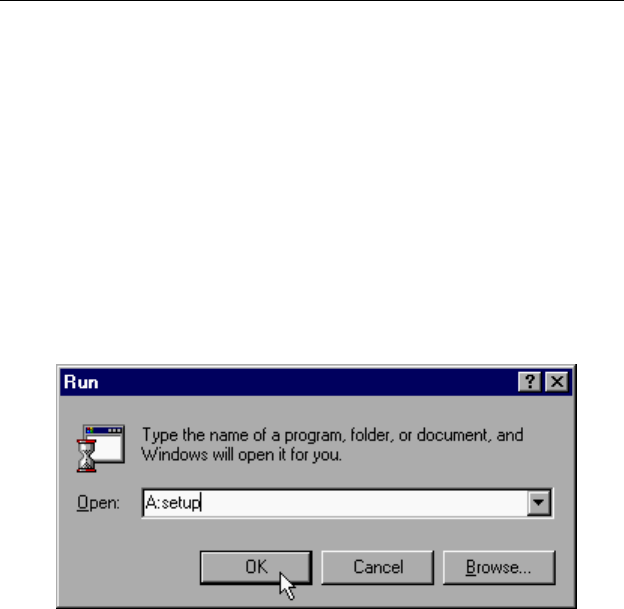
5.1 Install ProRAE-Suite Software
A ProRAE-Suite software package is supplied with the
UltraRAE monitor. This software package comes on three 3.5”
setup diskettes. To install the ProRAE-Suite software, insert
the first setup diskette into the “A” (floppy disk) drive. Click
the Start button on the taskbar to display the start menu, then
click the Run from the start menu to display the Run dialog
box. Once the setup diskette is in drive A, type A:\Setup.exe in
the Open field, as shown in Figure 5-1.
Figure 5-1 Run Dialog Box
Press the Enter key on the keyboard or click the OK button on
the menu to start the setup process. If the user choose the
default settings in every steps of the process, the ProRAE-Suite
software package will be installed under the default directory:
C:\Program Files\RAE Systems Inc\ProRAE-Suite. After
the software is installed successfully, a new menu item
ProRAE-Suite is added to the Programs menu. To start the
ProRAE-Suite software, click the Start button on the taskbar to
display the Start menu, click the Programs menu item to
display the Programs submenu, then click the ProRAE-Suite
menu item to display the ProRAE-Suite submenu. There are
two submenu items under the ProRAE-Suite submenu:
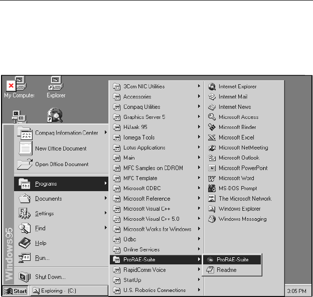
COMPUTER INTERFACE
5 - 3
ProRAE-Suite and Readme, as shown in Figure 5-2. Click the
ProRAE-Suite submenu item to start the ProRAE-Suite
software.
Figure 5-2 Start Menu

COMPUTER INTERFACE
5 - 4
5.2 Connecting the UltraRAE to a PC
The UltraRAE monitor includes a serial interface cable.
Connect the DB-9 connector side of the cable to the serial port
of the PC, and connect another side of the cable to the
MultiRAE PLUS monitor.
Turn on the power to the UltraRAE monitor. Press the
[MODE] key several times until the LCD shows “PC comm?”
Press the [Y/+] key and the display shows “Monitor will Pause,
OK?” Press [Y/+] key to confirm and the display shows
“Ready...” to indicate that the UltraRAE monitor is ready for
communication with PC. During the communication session,
the PC will directly control the UltraRAE monitor through the
serial link. There is no need for users to press any key on the
MultiRAE PLUS monitor during the communication session.
If no data transfer has occurred within one minute, the
UltraRAE monitor will return to instantaneous reading display.
Note: Do not connect to the parallel port of the PC by mistake.
The parallel port is usually a 25 pin female D connector on the
back of the PC, the serial port is usually a 25 or 9 pin male D
connector. If the serial port on the PC is a 25 pin connector,
the user needs to use a 25 pin to 9 pin adapter in order to accept
the serial cable.
COMPUTER INTERFACE
5 - 5
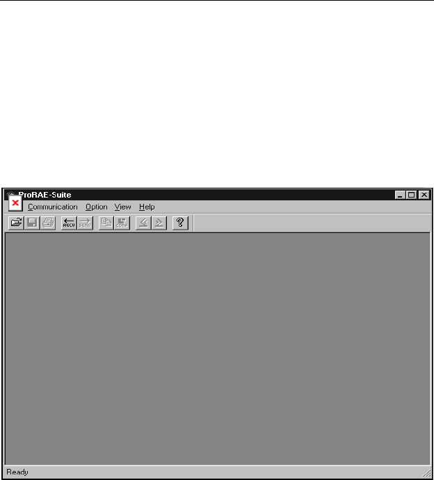
5.3 Start ProRAE-Suite Software
To start the ProRAE-Suite software, click the Start button on
the taskbar to display the Start menu, click Programs ->
ProRAE-Suite -> ProRAE-Suite submenu item to start the
ProRAE-Suite software. Figure 5-3 shows the main window of
the ProRAE-Suite software.
Figure 5-3 ProRAE-Suite Main Window
The functions of ProRAE-Suite software can be divided into
three categories:
1) Configuration data category. This category includes
editing the configuration data file, sending the
configuration data to the UltraRAE monitor and
receiving the configuration data from monitor, etc..
2) Logged data category. This category includes receiving the
logged data from the UltraRAE monitor, displaying the

COMPUTER INTERFACE
5 - 6
logged data in different format, exporting the logged data to
a tab delimited text file so that it can be read by the
Microsoft Excel software, etc..
3) The Upgrade category allows the UltraRAE firmware to be
upgraded to the latest version.
There is a tool bar beneath the menu bar. The frequently used
functions are represented in this tool bar in the form of a small
icon. For example, the Receive data function in the
Communication sub-menu is represented as a small arrow with
the letters “RECV”. When the mouse cursor (a small arrow) is
positioned near each icon in the tool bar, a short text will also
appear at the bottom of the Window to describe the function of
this icon.
This tool bar allows users to invoke a function conveniently by
clicking on the icon without going through the sub-menus.
COMPUTER INTERFACE
5 - 7
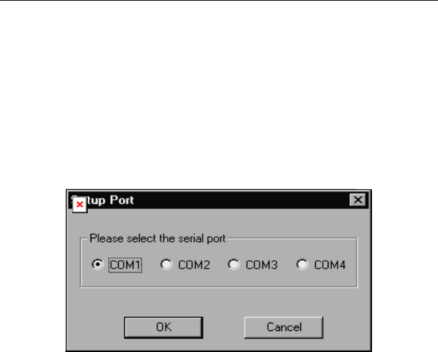
5.4 Setup Communication Port
It is necessary to setup the communication port on the ProRAE-
Suite software so that the UltraRAE monitor can communicate
with the PC correctly. Figure 5-4 shows the Setup Port dialog
box. Choose the appropriate port according to the PC’s serial
port setup.
Figure 5-4 Setup Port Dialog
Note: In most PC's, there are two serial ports. Make sure that
the serial port selected in the Setup Port dialog box matches the
actual serial port connected to the UltraRAE monitor. The
default serial port for ProRAE-Suite is COM1. If the incorrect
serial port is selected, an error message of “error occur during
serial port initialization” will appear when a user tries to
communicate between the PC and the UltraRAE monitor.
COMPUTER INTERFACE
5 - 8
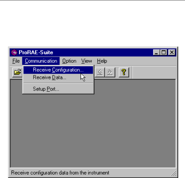
5.5 Configure UltraRAE from PC
Open a configuration file from an UltraRAE by choosing
Receive Configuration in the Communication menu.
Figure 5-5 Load Configuration from an UltraRAE
A user can also open a default configuration file shipped with
the ProRAE Suite software. The configuration file is a
document with extension “.cfg”. From the File menu, choose
Open…, then open the UltraRAE configuration file which
indicates the correct firmware version.
COMPUTER INTERFACE
5 - 9
Figure 5-6 Opening a Configuration File
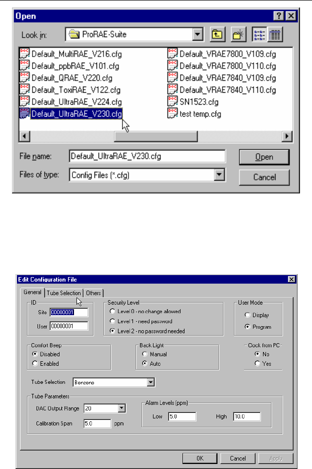
If modification to the default monitor configuration from the
generic .CFG file is not necessary, skip the following steps, and
go to Section 5.5 directly.
Figure 5-7 Edit Configuration

COMPUTER INTERFACE
5 - 10
Site/User ID:
This section sets the identification that is used throughout the
datalog information. The Site ID is an eight digit alphanumeric
field. The User ID is an eight digit alphanumeric field.
Security Level:
There are three levels of security to provide protection against
unauthorized changes to monitor settings. They can be changed
using the programming menu of the UltraRAE when the
instrument is in the programming mode.
Level 0 - allows the user to enter the programming menu
without password checking, but does not allow changes to
alarm limits, real time clock, correction factor, or user and
site information, etc. The user can still perform calibrations.
Level 1 - a four digit password is required to enter the
programming menu.
Level 2 - the programming menu may be entered without
restriction. Any changes made in the programming menu
can be saved.
Password:
The four-digit password must be entered if level 1 is selected as
the security level or the instrument is in text mode. Entry to the
programming menu requires that this password be entered.
User Mode:
This option allows user to set the instrument to “Display” mode
or “Program” mode.
In “Display” mode, the user can view several readings in the
normal operation, but cannot enter the programming menu. In
“Program” mode, user can enter the programming mode to
calibrate the monitor or change various setup in the monitor.
Password:
The four digit password must be entered if level 1 is selected as
the security level or the instrument is in text mode. Entry to the
programming menu requires that this password be entered.

COMPUTER INTERFACE
5 - 11
Comfort Beep:
This option allows the user to specify a time interval that the
buzzer will beep once to remind the user that the monitor is on.
If zero is entered for the time interval, then the security beep
feature is disabled.
Backlight:
This option allows the user to choose to turn on and off the
LCD backlight manually or automatically based on the ambient
light sensor input. If manual mode is selected, user can also
enter a time out period so that the back light will be turned off
automatically after the time out period.
Clock from PC:
This option allows the PC clock to be downloaded to the
UltraRAE monitor so the user does not need to manually set the
clock in UltraRAE.
Tube Selection:
This combo box lists all the available tube names for the current
configuration of this instrument. Select any tube name in this
combo box will display its related parameter values in the tube
parameter fields, such as DAC Output Range, Calibration Span,
Alarm Low Limit and Alarm High Limit.
DAC Range Output:
This combo box sets and displays the DAC range output for the
tube specified in the Tube Selection field.
Calibration span:
Enter the span value for the calibration gas selected.
Alarm Limits; Low, High:
Enter the alarm levels for each gas in these fields. The values
displayed here correspond to the gas presently indicated in the
Tube Selection field. Each tube can be set, in turn, by selecting
first the tube type.

COMPUTER INTERFACE
5 - 12
5.6 Send Configuration to UltraRAE
After the configuration has been loaded to the ProRAE Suite,
click on the “conf” icon, the configuration is ready for
modification.
To send a modified configuration to the UltraRAE, select the
Send Configuration… function from the Communication
menu or click the Send icon (right arrow with “Send” letters)
from the tool bar.
In order to save the configuration information for future use,
select Save As… from the File menu type in a desired file
name with “.cfg” as the configuration file name extension.
The “configure all” option is mainly used to restore the
UltraRAE’s default operational settings when the configuration
of the unit is non-recoverable and the unit is malfunctioning.
Because the default parameters are not normally fit a specific
unit, a user will need to re-calibration, re-setup lamp, pump, and
LCD contrast threshold, etc, because all those data in the
configuration has been overwritten.

COMPUTER INTERFACE
5 - 13
5.7 UltraRAE Data
To read the logged data from the UltraRAE, select the Receive
data… from the Communication menu or click the Receive
icon.
User can select Save As… from the File menu to save the data
as a file. Type in a desired file name with “..dat” as the data file
name extension.

COMPUTER INTERFACE
5 - 14
5.8 Password of UltraRAE Configuration
Each UltraRAE configuration is protected by a 4-digit
password. The user needs to enter the correct password before
a new configuration file can be sent to the UltraRAE monitor.
Default Password
The initial default password is “0000”.
Create Password
First, open the default configuration file by clicking on the
“CONF” button or by opening the “default.cfg” file. Select
“level 1” security. The “grayed” password field becomes
visible. Enter a 4 digit password in this field. Click [OK]
button to exit the dialog box. Save the configuration file use
“Save As” function from the File menu. The newly saved
configuration file will now be protected by the 4-digit
password.
Modify Password
To modify the password of an existing configuration file, open
the configuration file from the File menu. The password field
should be invisible. Click “SEND” button or select Send
Configuration function from the Communication menu. A
dialog box will appear and ask for the password. Enter the
previously selected password and click [OK] button. If the
password entered is correct, the software will try to send the
configuration file to the UltraRAE monitor. Since there is no
monitor connected to the PC, the software will time out after
about 30 seconds. Now, select Edit Configuration function
from the Action menu. The password field will become visible
in the dialog box. Modify the password as needed and save the
modified configuration file with the new password.
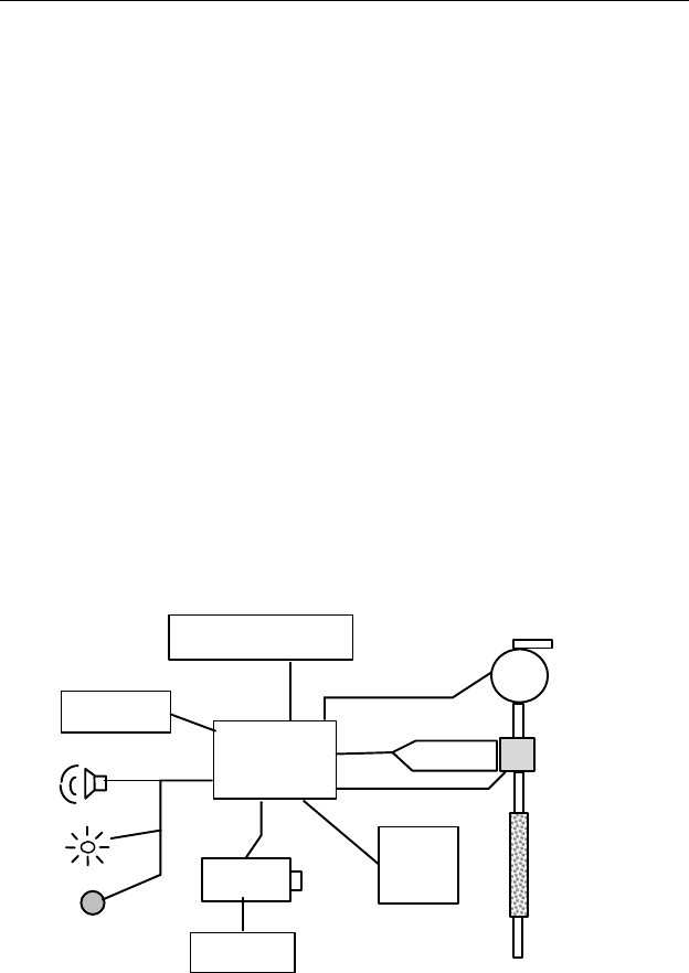
THEORY OF OPERATION
6 - 1
6. THEORY OF OPERATION
The UltraRAE monitor uses a newly developed electrodeless
discharge UV lamp as the high-energy photon source for the
PID. As organic vapors pass by the lamp, they are photo-
ionized and the ejected electrons are detected as a current. The
PID sensor will detect a broad range of organic vapors. A lamp
with high photon energy (e.g. 11.7 eV) will measure the most
kinds of compounds, whereas low photon energies (e.g. 9.8 eV)
are selective for easily ionizable compounds such as aromatics.
The gas separation tube filters out unwanted gases and allows
the target gas to be measured.
The RAE-SEP benzene tube uses a combination of adsorption
and oxidation to remove most common organic compounds
other than benzene. Methane, ethane, propane, and some
butane passes through the tube but is not detected by the PID.
Figure 6-1 UltraRAE Block Diagram
Micro-
processor
LCD Display
Keypad
Serial
Port
Battery
PID Sensor
UV lamp
Pump
Light
Sensor
LED
Buzzer
Charger
Gas Separation
(RAE-Sep)
Tube
Gas Inlet
Gas Outlet

THEORY OF OPERATION
6 - 2
The PID sensor for this UltraRAE monitor is constructed as a
small cavity in front of the UV lamp. A diaphragm pump is
installed inside the monitor enclosure to draw air sample into
the sensor through the gas separation tube and then exits
through the gas outlet port on the side of the enclosure.
A single chip microcomputer is used to control the operation of
the alarm buzzer, LED, pump and light sensor. It measures the
sensor readings and calculates the gas concentrations based on
calibration to known standard gases. The data is stored in non-
volatile memory so that it can be sent to a PC for record
keeping. RS-232 transceivers provide a serial interface between
the monitor and the serial port of a PC. An LCD display
consisting of a single row of eight alpha/numeric characters is
used to display the readings. The user interacts with the
monitor through three keys on the front panel keypad.
The monitor is powered by a rechargeable NiMH, NiCd battery,
or an alkaline pack.
NOTE: The printed circuit board of the monitor is
connected to the battery pack even if the power is
turned off. Therefore, it is very important to
disconnect the battery pack before servicing or
replacing any components inside the monitor.
Severe damage to the printed circuit board may
occur if the battery pack is not disconnected before
servicing the unit.

MAINTENANCE
7 - 1
7. MAINTENANCE
The major maintenance items of the UltraRAE are:
• Battery pack
• Sensor modules
• PID lamp
• Sampling pump
• Tube tip reservoir
• Inlet connectors and filter
7.1 Battery Replacement
When the display shows a flashing message “Bat”, the battery
requires recharging. The battery may be replaced in the field
(in area known to be non-hazardous) if required. It is
recommended to recharge the UltraRAE monitor upon returning
from fieldwork. A fully charged battery powers an UltraRAE
monitor for 12 hours continuous operation. The charging time
is less than 10 hours for a fully discharged battery. The built-in
charging circuit is controlled by two-step constant
voltage/constant current charging to prevent over-charging.
WARNING:
To reduce the risk of ignition of hazardous
atmospheres, recharge battery only in area
known to be non- hazardous. Remove and
replace battery only in area known to be non-
hazardous.
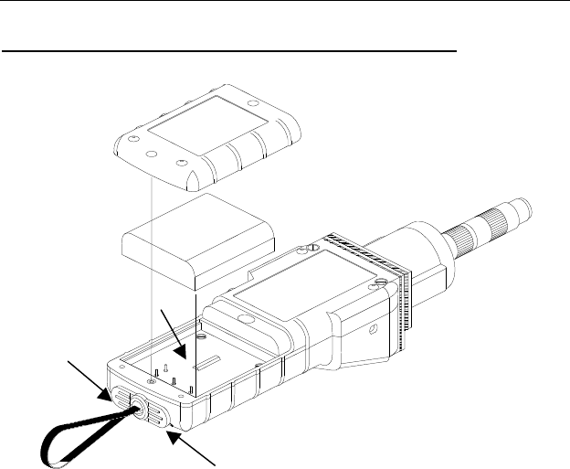
MAINTENANCE
7 - 2
Replacing and Recharging the Battery Pack
Figure 7-1 Battery Replacement
1. Turn off power of the UltraRAE.
2. Unscrew the two battery compartment screws, located on
the bottom of the monitor, and remove the cover.
3. Remove the battery from the battery compartment.
4. Connect the battery pack to an external charging station
(optional) for charging.
5. Replace a fully charged spare battery pack inside the battery
compartment. Make sure the battery pack is oriented
properly inside the compartment
Battery Cover
Battery Pack
Battery
Compartment
Communication
Connector
Charger
Connector

MAINTENANCE
7 - 3
6. Ensure the battery plug is securely connected to the
UltraRAE.
7. Close the battery cover and tighten the two screws.
Replacing the Alkaline Battery Adapter
1. Insert four fresh AA size alkaline batteries into the alkaline
battery adapter. Make sure that the polarity of the batteries
is correct.
2. Follow the same procedure as described above to replace the
battery adapter.
Note: The internal charging circuit is designed to prevent
damage to alkaline batteries and the charging circuit when
alkaline batteries are installed inside the monitor.
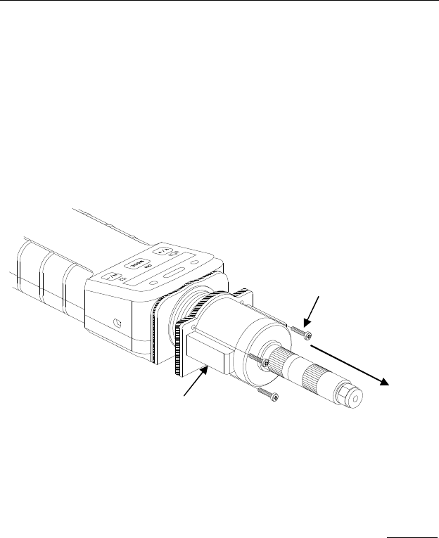
MAINTENANCE
7 - 4
7.2 PID Sensor Cleaning / Replacement
During normal operation, a film of dust or gas condensate may
build up inside the PID sensor module and the UV lamp. The
rate at which this film develops depends on the type and
concentration of vapors being sampled. As a guide, it is
recommended to clean the PID sensor module, the sensor
compartment and the lamp if the unit malfunctioning.
Figure 7-2 Tube Reader Removal
To access the sensor components and lamp, remove the four
screws holding the tube reader housing shown in Figure 7-2.
Next, remove the tube reader housing by gently pulling straight
back.
Tube Reader Cover
Screw, 4 places
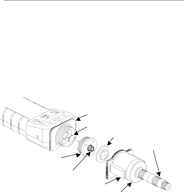
MAINTENANCE
7 - 5
If the lamp does not turn on, the monitor will display an error
message (Lamp) to indicate replacement of the lamp may be
required. Periodic cleaning of the lamp window will remove
film deposits and restore lamp sensitivity. Care must be
exercised when cleaning the window surface so that it
is not damaged.
The sensor module is made of several components and is
attached to the lamp-housing unit as shown in Figure 7-3.
Figure 7-3 Sensor Components
Lamp Housing
UV Lamp
Sensor Adapter
Bar Code Reader Cap
Sensor Module
Rubber tube connector
with filter
Tube tip reservoir
Tube holder cap

MAINTENANCE
7 - 6
1. Turn off UltraRAE power.
2. Open the bar code (tube) reader cover by unscrewing the
four case screws from the front of the monitor case.
3. Remove the sensor module from the lamp housing by gently
pulling on the module.
Note the sensor is made of Teflon and stainless steel material.
4. Dip the entire PID sensor module into GC grade methanol.
It is highly recommended that an ultrasound bath to be used
to clean the sensor for at least 15 minutes. Then dry the
sensor thoroughly.
5. If the lamp is operational, use a cotton swab to clean the flat
window surface with GC grade methanol. If the lamp does
not turn on, remove the UV lamp from the lamp housing.
6. Replace a new lamp, avoiding contact with the flat window
surface.
7. Reinstall the PID sensor module.
8. Replace the bar code (tube) reader and tighten the four
screws, which holds down the cap.
Lamp Window Cleaning Procedure:
Clean the lamp window surface by wiping it with anhydrous
methanol using a cotton swab. Rub in a circular motion at
moderate pressure. After cleaning, hold the lamp up to the light
at an angle to detect any remaining film. Repeat the process
until the lamp window is clean.
Never touch the window surface with fingers or
anything that may leave a film. Never use acetone
on 11.7 eV lamps.
CAUTION: Water will degrade window surfaces,
especially the 11.7 eV lamp window.
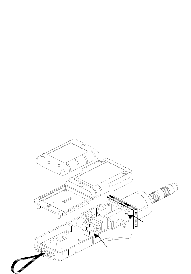
MAINTENANCE
7 - 7
7.3 Sampling Pump
The sampling pump is positive displacement piston pump.
When approaching the end of the specified lifetime of the
pump, it will consume higher amount of energy and reduce its
sample draw capability significantly. When this occurs, it is
necessary to replace or rebuild the pump.
To check the pump flow, remove the tube holder and insert a
piece of 3/16” (4 mm) glass or metal tubing into the rubber tube
connector in the sensor module (see Figure 7-4). The flow
should be above 350 cc/min. The flow with a RAE-SEP
benzene tube in the normal configuration should be greater than
200 cc/min.
Figure 7-4 Sampling Pump
Battery Cover
Bottom Cover
Top Cover
Lamp Housing
Pump

MAINTENANCE
7 - 8
Pump Replacement
1. Turn off UltraRAE power.
2. Open the battery cover, remove the battery pack, carefully
unscrew the six screws to open the bottom cover.
3. Unplug the pump from the PCB. Unscrew the two screws
that hold the pump assembly to the PCB. Disconnect the
Tygon tubing that connects the pump to the gas inlet port and
gas outlet port.
4. Replace a new pump assembly. Connect the Tygon tubing to
the gas inlet port. Plug the pump connector back into the
PCB and screw down the pump assembly to the board.
5. Replace the bottom cover and tighten the six. Re-connect the
battery pack. Replace the battery pack and its cover.
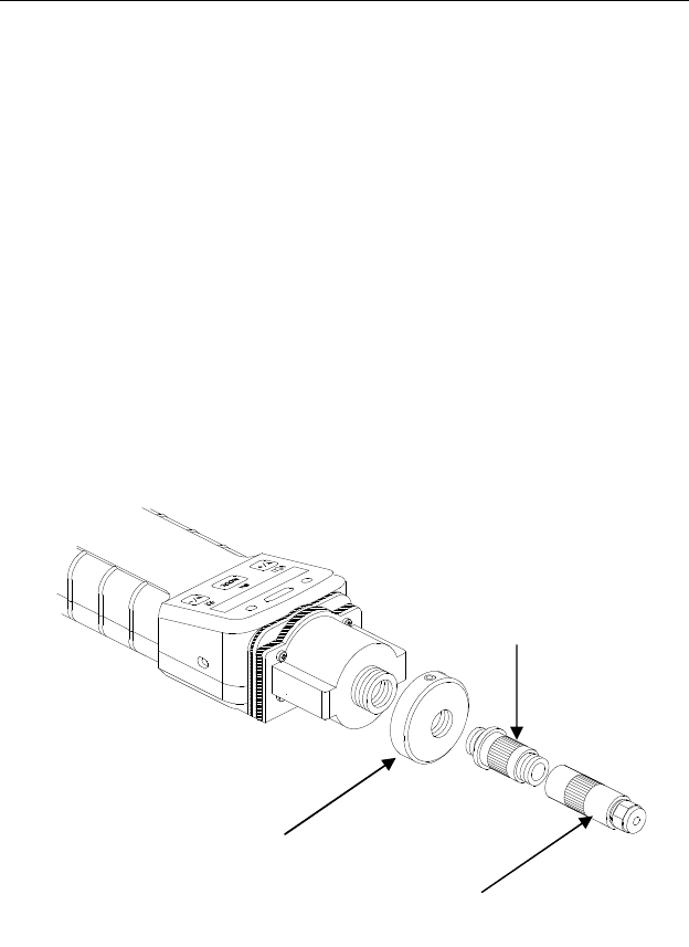
MAINTENANCE
7 - 9
7.4 Tube Tip Reservoir
After a RAE-SEP tube end is broken off, the tube tip will be
collected in the tube tip reservoir, as shown in Figure 7-5.
When the tube tip reservoir is full, it is necessary to empty the
reservoir. To do so, first unscrew the tube holder cap. Then
remove the matching metal tube attached to the tube tip
reservoir by turning it counter-clockwise. Then, unscrew the
tube tip reservoir slowly. Care must be exercised when
turning the tube tip reservoir so that user’s finger will not
be cut accidentally by the glass debris inside the reservoir.
Empty the reservoir. Replace the reservoir, metal tube and tube
holder cap in the reverse order.
Figure 7-5 Tube Tip Reservoir
Tube tip
reservoir
Tube holder
base
Tube
holder cap
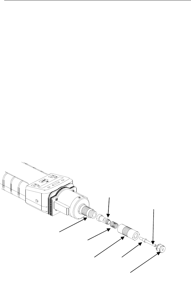
MAINTENANCE
7 - 10
7.5 Inlet Connector and Filter
When a RAE-SEP tube is inserted into the monitor, both ends
of the tube are sealed with rubber fittings to make an airtight
connection for the gas inlet.
When a RAE-SEP tube is inserted into the Bar Code Reader
Cap, the tube end is pushed against the rubber tube connector
inside the sensor module, as shown in Figure 7-3. A porous
metal filter is inserted into the other end of the rubber tube
connector to prevent glass debris and dirt entering the sensor.
To ensure that the metal filter is not clogged by glass debris or
dirt, it is recommended that the metal filter should be replaced
with a new one at regular interval (4-6 weeks). After repeated
insertion, the rubber tube connector may be worn out. Replace
the rubber tube connector with a new one to ensure airtight seal
for the RAE-SEP tube.
Figure 7-6 Gas Inlet Assembly
Tube
holder cap
Tube cap nut
Metal tube
connector with
rubber adapter
Teflon tube
Spring
Ferrule
Tube holder
base

MAINTENANCE
7 - 11
Figure 7-6 shows the assembly drawing of the gas inlet tube and
tube cap holder. The gas inlet tube is made of a piece of Teflon
tube. A metal ferrule is crimped onto the Teflon tube and the
V-grove on the metal tube adapter provides an air tight seal
when the tube cap is tightened. A spring maintains the
necessary tension for the metal tube adapter so that it pushes the
RAE-SEP tube against the sensor module. A piece of rubber
tube is glued on to the metal tube adapter and provides airtight
seal to the other end of the RAE-SEP tube. After repeated
insertion, the rubber tube may also be worn out. Replace the
entire metal tube adapter with a new one if necessary to ensure
airtight seal for the RAE-SEP tube.
To replace the metal tube adapter, remove the tube holder cap
from the bar code reader cap. Grab and pull the tube cap nut
away from the tube-holder cap body. Use a hex wrench to hold
the metal tube adapter by the flat section, unscrew the tube cap
nut counter-clockwise to disassemble the tube holder cap and
gas inlet tube assembly. Replace a new metal tube adapter.


TROUBLESHOOTING
8 - 1
8. TROUBLESHOOTING
To aid the user in diagnosing the monitor, the monitor has a
special diagnostic mode that can display critical, low level
parameters. Section 8.1 describes the operation of the
diagnostic mode. Section 8.2 summarizes the frequently
encountered problems and suggested solutions. Turning on the
UltraRAE monitor in diagnostic mode and using the
troubleshooting table in Section 8.2, the user can usually narrow
the problem down to one or two areas and correct the problem
without having to return the monitor for repair.
WARNING: The diagnostic mode allows the user to set
several low-level parameters that are very critical to the
operation of the monitor. Extra care should be taken when
setting these low-level parameters. If the user is not familiar
with these parameters and sets them incorrectly, it may
cause the monitor to shut down or malfunction.

TROUBLESHOOTING
8 - 2
8.1 Special Diagnostic Mode
To place the monitor into the special diagnostic mode, first turn
the monitor off. Next push and hold the [Y/+] key, while still
holding the [Y/+] key, also push and hold the [MODE] key for
at least two seconds. After the required delay, release both
keys, the monitor will now go through the normal start-up
display sequence and display a “Diagnostic mode” message. At
the end of the special mode start-up, the display will show the
raw counts of sensor channel 1A. These numbers are raw
sensor readings without calibration.
Other critical parameters of the monitor are available as shown
below. They can be reached by pressing the [MODE] key
repeatedly until the desired parameters are displayed.

TROUBLESHOOTING
8 - 3
Key Action Display
Raw readings, 1A (+ = 10X)
[MODE] Raw readings, 10A (+ = 10X)
[MODE] Raw readings, 1B (+ = 10X)
[MODE] Raw readings, 10B (+ = 10X)
[MODE] Lamp current
[MODE] Lamp fail level (+/-)
[MODE] Lamp drive (+/-)*
[MODE] Battery (Alkaline/NiCd)
[MODE] LCD contrast (+/-)
[MODE] Pump current
[MODE] Stall (pump) level (+/-)
[MODE] Motor (pump) drive (+/-)*
[MODE] DAC output count (+/-)
[MODE] Alarm test (on/off)
[MODE] Ambient light
[MODE] Backlight trip level (+/-)
[MODE] CCD tube reader (+/-)
[MODE] Deep discharge (battery)
Table 8-1 Diagnostic Mode Menu
* Normally these settings should not be changed. When
using an 11.7 eV lamp the LDRV can be increased up to 225
to extend the life of the lamp, and in this case the Lamp
current drops and the Lamp Fail Level may need to be
adjusted.

TROUBLESHOOTING
8 - 4
The following is a brief description of a few diagnostic
displays:
1) Raw Sensor Readings
The raw sensor readings provide a quick diagnosis on the
response and the sensitivity of the sensor. When zero gas (fresh
clean air) is applied to the monitor, the raw sensor readings
typically should be between 100 and 300. If the raw reading is
outside this range when zero gas is applied, the sensor or the
electronics may be defective. Channel A is the PID sensor.
Channel B is an auxillary channel that is not used.
When a specific gas is applied to the monitor, the raw reading
should increase. If the reading does not change when the
specific gas is applied, then the sensor or lamp may be
defective.
2) Adjust Lamp Failure Threshold
This display can be used to calibrate the PID lamp failure
threshold. If the lamp appears to be good but in normal
operation, a lamp failure message (i.e. “Lamp”) is displayed, the
lamp failure level may be set too high. This level can be
adjusted by using the following steps:
1. Turn the monitor off. Remove the UV lamp from the PID
sensor (see Section 7.2)
2. Turn the monitor on in the special diagnostic mode ([Y/+] +
[MODE]).
3. Press the [MODE] key until “Lamp xxx” is displayed, write
done this number. The reading “xxx” is the lamp current
reading.
4. Press the [MODE] key one more time. Fail yyy ” is now
displayed. The value “yyy” is the threshold level that
determines a lamp failure. Anything below this level is
considered a failure.

TROUBLESHOOTING
8 - 5
5. Push the [Y/+] or [N/-] key to increase or decrease the
threshold value “yyy” until it is about 10 - 15 counts above
the “xxx” value. This will optimally set the lamp failure
threshold. Press [MODE] key to exit this display. If the
threshold value has changed, a message “Save?” will
appear. Press [Y/+] to confirm the change, [N/-] or
[MODE] key to abandon the changes.
6. Turn the monitor off and replace the lamp.
7. To verify the above adjustment, turn the monitor back on in
diagnostic mode and press the [MODE] key until “Lamp
xxx, press the [MODE] key once more, Fail yyy +/-” is
display. The lamp current reading “xxx” should be higher
than the threshold value “yyy” by at least 10-15 counts. If
not, the lamp may be defective or very weak.
In most cases, lamp failure threshold adjustment is not required,
in which case the user should press [MODE] key to exit this
display.
3) Battery Type
The UltraRAE monitor can be powered by either a rechargeable
NiMH / Ni-Cd battery pack or an alkaline battery adapter. This
display shows the type of battery that is currently installed in
the monitor. The charger cable must be unplugged for a correct
battery type display.
4) Adjust LCD Contrast
This display allows the user to adjust the LCD contrast. Press
[Y/+] to increase the contrast and [N/-] key to decrease the
contrast. The bar graph shows the current LCD contrast setting.
If the display appears blank or very faint, press the [Y/+] key
several times to increase the contrast or darken the display.

TROUBLESHOOTING
8 - 6
5) DAC Output Counts
The menu allows the user to adjust the value of the analog
output DAC use the [Y/+] and [N/-] keys. The remote alarm
output signal on the serial interface cable is deselected and the
analog output signal is selected in its place. This signal has a
range of 0 to 2.5V in 4096 steps. The initial default output is
2048, or half-scale. See Figure 8-1 for signal pin-out. The
DAC output is linearly proportional to concentration.
6) Alarm Test
This menu is used to test the monitor’s alarm generators,
including four bright LED’s, the loud buzzer, and the vibrator
output signal (remote alarm). The message “Alarm” is first
displayed, followed by “On?” If the [Y/+] key is pressed at this
point, the alarms will turn on and the message “Off?” will
appear. To turn the alarms off, press the [Y/+] key again.
Check external alarm signal at connector.
Figure 8-1 Communication/Alarm Connector
7) Adjust Backlight Threshold
This display can be used to calibrate the LCD backlight turn on
and off threshold. Use the following steps to adjust the
backlight threshold.
1. The “Lite = xxx” message displays the present ambient light
level incident on the face of the monitor. In a brightly lit
room, the light reading should be above 130.
(front view of connector on monitor)
Pos 1,
Ground
(female, hole) Black
Pos 2, Alarm/DAC
(female, hole)
White
Pos 3, Receive
(male, pin) Red
Pos 4,
Transmit
(male, pin) Green

TROUBLESHOOTING
8 - 7
2. The user can shade the light sensor, which is located at the
upper left corner of the monitor, with their hand and watch
the light sensor reading. The light reading should drop to
less than 100. Determine the ambient light level when the
back light should be turned on and record the light sensor
reading. Press the [MODE] key one more time, the display
should show the message “Trip= yyy”.
3. Use [Y/+] or [N/-] key to increase or decrease the trip value
until it is about the same as the previously recorded light
sensor reading. Press [MODE] key to exit this display. If
the threshold value is changed, a message “Save?” will
appear. Press [Y/+] to confirm the change, [N/-] or [MODE]
key to abandon the changes.
8) CCD Tube Reader
This function displays the total number of light sensing
elements that are exposed to light (IR). The maximum value is
64 with no tube inserted. If this number is less than 64 when no
tube is present, increase the light collecting ability of the CCD
by pressing the [Y/+] key until this number just reaches 64.
Then press the [Y/+] key two more times.
With a Benzene RAE-SEP tube inserted, this number should be
46 to 52. For the VOC tube, this number should be 59 to 61.
Use the [Y/+] or [N/-] key to increase or decrease this count
until it is within range.
9) Battery Deep Discharge
This function allows the user to fully discharge the NiCd /
NiMH rechargeable batteries. If the monitor is repeatedly used
for only a few hours and then charged, or if the monitor’s
useable run time has decreased significantly, a deep discharge
cycle may restore some of the battery’s capacity. Before
starting this function, the AC adapter should be plugged in.
Press the [Y/+] key to confirm the start of this function.

TROUBLESHOOTING
8 - 8
8.2 Troubleshooting Table
Table 8-2
Problem Possible Reasons & Solutions
Cannot turn
on power after
charging the
battery
Reasons: Discharged battery. Defective
battery Microcomputer hang-
up
Solutions: Charge or replace battery.
Disconnect, then connect
battery to reset computer
No LED or
LCD back
light
Reasons: Trigger level too low, in
manual, defective LED or
LCD back light
Solutions: Adjust trigger level. Call
authorized service center
Lost password
Solutions: Use default configuration to
reset password from computer
Buzzer
inoperative Reasons: Bad buzzer
Solutions: Call authorized service center

TROUBLESHOOTING
8 - 9
Problem
Possible Reasons & Solutions
Reading
abnormally
high
Reasons: Dirty sensor module
Dirty water trap filter
Excessive moisture and water
condensation
Solutions: Clean & dry sensor module
Replace water trap filter
Re-calibrate
“Lamp”
message
during
operation
Reasons: Weak or defective PID lamp,
defective lamp drive circuit
Solutions: Check Lamp Threshold in
diagnostic mode, Section 8.1
.
Replace PID lamp
Reading
abnormally
low
Reasons: Incorrect calibration
Low sensitivity to the
specific gas
Solutions: Calibrate the monitor
Replace sensor
Tube ID error,
incorrect ID, or
not detected
Reasons: CCD value set incorrectly.
Tube barcode bad or dirty.
Barcode reader “Off”.
Solutions: Set CCD value in diagnostic
mode; see Section 8.1.
Use new or clean tube; make
sure arrow points to monitor
Turn on reader (Sect. 4.7.9)
Start with no tube to
manually select (Sect. 2.4.1)
Turn off reader to manually
select (Sect. 4.7.9)

TROUBLESHOOTING
8 - 10
Problem
Possible Reasons & Solutions
Read a small
background
value
Reasons: There is actually a small
background gas level Sensor
zero drift
Solutions: Do fresh air calibration (see
Section 4.4.1)
Reading
jumping
around
randomly
Reasons: Incorrect calibration gas
value.
Low sensitivity to cal gas
Solutions: Calibrate the monitor.
Use different cal gas.
Can not turn
off monitor or
corrupted
characters in
LCD display
Reasons: Microprocessor hang-up
Solutions: Disconnect and re-connect
battery to reset computer.
Call authorized service
center.
Calibration
error message Reasons: No standard gas input, weak
PID lamp, unit zeroed with
gas present
Solutions: Make sure standard gas flows
into monitor. Zero sensor &
recalibrate, replace lamp.

TROUBLESHOOTING
8 - 11
Problem
Possible Reasons & Solutions
“Bat” message
in operation Reasons: Discharged battery
Solutions: Recharge battery
Full scale
measurement
in humid
environment
Reasons: Dirty or wet sensor
Solutions: Clean and dry sensor
Replace water trap filter
Gas
measurement
saturates at
certain level
Reasons: PID lamp is strong
Solutions: Place a UV block Teflon disk
on lamp.
Replace lamp
Excessive
pump noise or
no inlet air
suction
Reasons: Blocked inlet path
Defective pump
Solutions: Check inlet connection
Replace a new lamp
Inlet flow too
low Reasons: Pump diaphragm damaged or
has debris. Flow path leaks.
Solutions: Check flow path for leaks;
sensor module, tube
connectors, Teflon tube
compression fitting.
Replace pump.

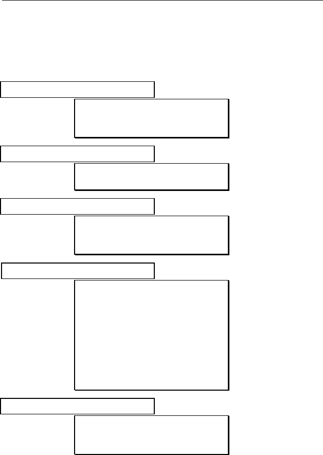
APPENDIX A
A - 1
QUICK REFERENCE GUIDE
PROGRAMMING MODE
Calibrate monitor?
Fresh air calib?
Span calib?
Modify span value?
Change alarm limits?
High limit?
Low limit?
View or change datalog?
View data?
Clear data?
Change data log?
Change monitor setup?
Change Site ID?
Change User ID?
Change User Mode?
Change Date?
Change Time?
Change backlight?
Change DAC/Alarm output?
Change DAC range?
Change Bar code reader?
Change sensor config?
Change measure wait time?
Change lamp?
Change dilution ration?
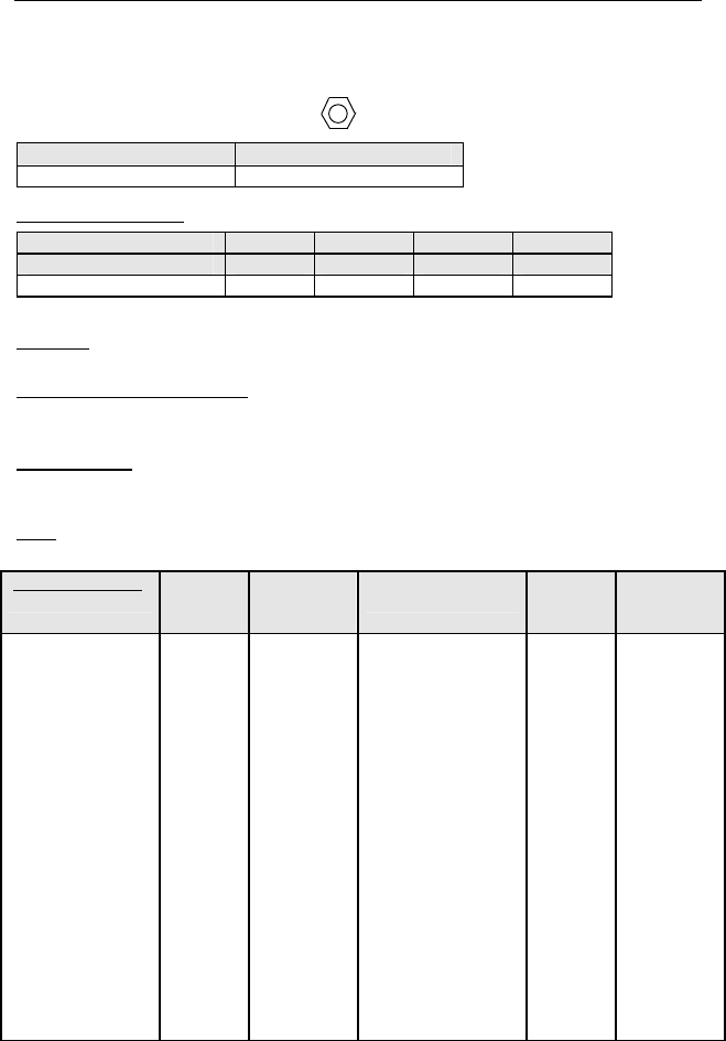
APPENDIX B
B - 1
TUBE DATA SHEETS
Benzene C6H6 Part No.: 012-3022-005
Standard Lamp Typical Range (ppmv)
9.8 eV 0.1 – 1000
Temperature Range: 2 - 40°C (36 - 104°F)
Temp (°C) 2-10 10-15 15-30 30-40
Temp (°F) 36-50 50-60 60-86 86-104
Measure Time (sec) 150 90 60 40
Calibration should be performed at the same temperature as the measurement.
Humidity: No effect on reading 0 - 95% RH. Humid, clean air drawn through the
tube before measurement will reduce VOC capacity.
Storage Life and Conditions: Unopened tubes can be stored for 1 year in
darkness at 5 - 25°C (40 - 77°F). Refrigeration is preferred. Open tubes should
be used within one hour to avoid loss of capacity.
Color Change: Yellow → Brown → Green
The benzene reading may be high if the green color extends to more than 3/4 of
the length. The tube may still have some capacity if there is no green color.
Note: It is preferable to recalibrate when changing batches. For more details on
tube operation see Technical Note 136.
Cross-sensitivity:
Substance Test
Conc.
(ppmv)*
Apparent
Benzene
Response
Substance Test
Conc.
(ppmv)*
Apparent
Benzene
Response
Toluene 400 0.1 n-Hexane 100# 0.0
o-Xylene 200 0.0 Cyclohexane 10# 0.4
Ethylbenzene 200 0.0 n-Octane 300 0.1
Styrene 100 0.0 β-Pinene 50 0.0
Nitrobenzene 100 0.0 Ethanol 50 0.0
Phenol 100 0.0 Isopropanol 100 0.0
Chlorobenzene 20 2.5 Acetone 100 0.0
Dichlorobenzene 50 1.0 Cyclohexanone 200 0.0
Hydrogen Sulfide 150 0.0 Tetrahydrofuran 100 0.0
Methane 25000** 0.0 Ethyl acetate 100 0.0
Propane 1000 0.0 Acrylonitrile 100 0.0
Isobutane 100 0.0 Epichlorohydrin 100 0.0
Isobutylene 500 0.0 Trichloroethylene 100 66
1,3-Butadiene 300 0.0 Perchloroethylene 50 38
n-Pentane 1500 0.0
*Not necessarily the maximum allowable concentration. ** Methane has no effect
on tube capacity. Propane and higher hydrocarbons do affect capacity.
# Higher concentrations may cause a reduced benzene response.
Note: Each tube contains about 3 mg of chromium compounds.
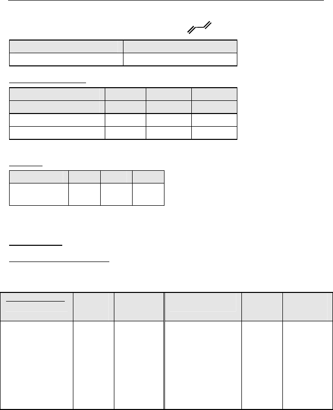
APPENDIX B
B - 2
Butadiene (Polymer) C4H6 Part No.: 012-3024-005
Standard Lamp Typical Range (ppmv)
9.8 eV 0.1 - 200
Temperature Range: 5 - 40°C (41 - 104°F)
Temp (°C) 5-18 18-30 30-40
Temp (°F) 41-64 64-86 86-104
Measure Time (sec) 180 75 50
Sample Vol. (mL) 1500 600 400
Calibration should be performed at the same temperature as the measurement.
Humidity: 0 - 95% RH.
RH <5% 50% 80%
Correction
Factor (CF) 1.0 1.5 1.6
When calibrated from a dry gas cylinder, multiply the reading by the CF to obtain
the true value.
Color Change: None
Storage Life and Conditions: Unopened tubes can be stored for 2 years in darkness at 0 -
40°C (32 - 104°F). Open tubes may be stored for up to 8 hours in clean air without
significant loss of capacity.
Cross-sensitivity:
Substance Test
Conc.
(ppmv)*
Apparent
Butadiene
Response
Substance Test
Conc.
(ppmv)*
Apparent
Butadiene
Response
Acrylonitrile 100 0.0 Methane 25000** 0.0
Styrene 100 0.0 Methyl Bromide# 5 3#
Ethylbenzene 200 0.0 Propane 1000 0.0
Toluene 100 0.2 Isobutane 100 0.0
Toluene 200 2 Isobutylene 50 40
Benzene 10 0.3 n-Hexane 200 0.0
Benzene 100 7 Cyclohexane 50 0.5
*Not necessarily the maximum allowable concentration.
** Methane above 1% by volume reduces the PID response, but has no effect on tube
capacity. Butane and higher hydrocarbons reduce tube capacity.
# Methyl bromide can be measured using a 10.6 eV lamp and a 60 sec. sampling time at
room temperature. Adjust time at other temperatures proportionately.
Note: Unused tubes contain no hazardous components but may adsorb toxic compounds
from the environment.
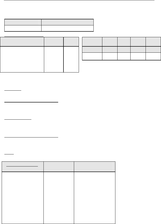
APPENDIX B
B - 3
Halocarbon (CH2Cl2) Part No.: 012-3023-005
Standard Lamp Typical Range (ppmv)
11.7 eV 0.1 - 200
Temperature Range: 2-40°C (41-104°F)
Substance Meas.
Time (sec)
Vol.
(mL)
Temp (°C)
2-10 10-15
15-30 30-40
Methyl Chloride 30 180
Temp (°F)
36-50 50-60
60-86 86-104
Methylene Chloride (MC)
30 180
Time (sec)
3x 2x 1x 0.67x
Chloroform 45 260
Carbon Tetrachloride 60 350
Calibration should be performed at the same temperature as the
measurement.
Humidity: No effect on reading 0 - 95% RH. Humid, clean air drawn through
the tube before measurement will reduce VOC capacity.
Storage Life and Conditions: Unopened tubes can be stored for 1 year in
darkness at 5 - 25°C (40 - 77°F). Open tubes may be stored for up to 8
hours in clean air at 50% RH without significant loss of capacity.
Color Change: Orange → Brown
The reading may be high if the tube is discolored to more than ¾
of its length.
Storage Life and Conditions: Unopened tubes can be stored for 2 year
in darkness at 0 - 40°C (32 - 104°F). Open tubes may be stored for up
to 8 hours in clean air without significant loss of capacity.
Note: For more details on tube operation see Technical Note 133.
Cross-sensitivity:
Substance Test Conc.
(ppmv)* Apparent MC
Response
Acetone 300 0.0
Ethanol 300 0.0
Ethyl acetate 300 0.0
Toluene 300 0.0
Methane 25000** 0.0
Isobutylene 500 0.1
n-Octane 200 0.0
Tetrahydrofuran 50 0.5
*Not necessarily the maximum allowable concentration.
** Methane above 1% by volume reduces the PID response, but has no effect on tube
capacity. Butane and higher hydrocarbons reduce tube capacity.
Note: Each tube contains about 3 mg of chromium compounds.

APPENDIX C
C - 1
RAE SYSTEMS TECHNICAL NOTES
p TN-102 Facts About PID Measurement
p TN-103 External Datalogger Interface to MiniRAE PID
p TN-104 Partial List of Ionization Potentials
p TN-105 MiniRAE PID Battery Characteristics
p TN-106 Correction Factors, Ionization Potentials, and
Calibration Characteristics
p TN-108 MiniRAE PLUS PGM-76 and 76IS ProRAE 76
Software Upgrade for PGM-75
p TN-109 MiniRAE Professional PID Zero Drift
p TN-112 MiniRAE PLUS Datalogger Data Conversion to
Microsoft Excel version 5.0
p TN-113 Calibration Procedures for ModuRAE PDM-10A
p TN-114 ToxiRAE Sensor Specifications
p TN-115 ToxiRAE Toxic Gas Monitor (PGM-35) at a Glance
p TN-116 ToxiRAE Oxygen Monitor (PGM-36) at a Glance
p TN-117 ToxiRAE Combustible Gas Monitor (PGM-37) at a
Glance
p TN-118 Use of RAE PIDs for Soil Headspace Measurements
p TN-119 Calculation of STEL, TWA, Min., Max., and Average
Values for ToxiRAE PID.
p TN-120 Measuring Correction Factors for Volatile Compounds
with MiniRAE 7 and ToxiRAE PIDs
p TN-121 CO Sensor Cross-Sensitivity and Removal with
Charcoal Filter
p TN-122 MiniRAE Compliance with EPA Method 21
p TN-123 Diagnostic Modes for RAE Instruments
p TN 124 PID Lamp Characteristics
p TN 125 Creating Custom Correction Factors and Gas Names
for the ToxiRAE PID
p TN-126 Interchangeability of Sensors in PGM-35 and PGM-50
p TN-127 Benzene-Specific Measurements in Petroleum
Hydrocarbons using the UltraRAE
p TN-128 ToxiRAE PID Communications Problems
p TN-130 Setting Alarm Limits for Mixtures
p TN-131 Verifying and Fixing Gas Alarm Limits
p TN-132 Upgrading RAE Instruments Firmware

APPENDIX C
C - 2
p TN-133 Methylene Chloride-Specific Measurements using the
UltraRAE
p TN-134 UltraRAE Bar Code Reader Patterns an Adjustments
p TN-135 UltraRAE Firmware & Tube Data Upgrade
Procedures
p TN-136 UltraRAE Operations Tips
p TN-137 Exiting Diagnostic Mode for ToxiRAE LEL
p TN-138 RAE System Year 2000 Compliance
p TN-139 UltraRAE Communication with NT
p TN-140 Extension Tubing Volume and Delay Time
p TN-141 MultiRAE Remote Control Functions
p TN-142 MiniRAE 2000 Preprogrammed Compound Library
p TN-143 Accuracy Comparisons of Gas Detection Tubes
p TN-144 Handling LEL Sensor Poisoning
p TN-145 Proper Care of Nickel Cadmium Battery Packs
p TN-146 Turning On UV Lamps in a PID Monitor
p TN-147 UltraRAE: Butadiene Specific Monitor
p TN-148 Measurement of Phosphine (PH3) by PID In the Food
Storage industry
p TN-149 PGM-30 UV Lamp Care
p TN-150 Understanding the ppbRAE
p TN-151 Electrochemical Sensor Replacement and Maintenance
p TN-152 Effects of Operating Conditions on Oxygen Sensors
p TN-153 TC Sensor Applications and Correction Factors
p TN-154 SampleRAE Correction Factors
p TN-155 2-Year Oxygen Sensor Installation and Calibration
p TN-156 Correction Factors for Combustible Gas (LEL) Sensors
p TN-157 Moisture Exchange Tubes for Humidity Control of Test
Gases
p TN-158 Conversion of PID Readings to Methane Equivalent
Response
p TN-159 Nerve Agent Measurements by PID
p TN-160 Upgrading MultiRAE/QRAE Ni-Cd Battery Pack
Technical Notes are available at www.raesystems.com.
See Appendix E to order hard copies of Technical Notes.

APPENDIX D
D - 1
RAE SYSTEMS APPLICATIONNOTES
p AP-200 PIDs and Aircraft Wing-tank Entry
p AP-201 Measuring Ammonia (NH3) with PIDs
p AP-202 ABCs of Gases in Industry
p AP-203 PID as a Hazmat Response Tool
p AP-204 Pulp & Paper: Measuring Turpentine & ClO2
p AP-205 Measuring Heat Transfer Fluids with a PID
p AP-206 Guide to Atmospheric Testing in a Confined Space
p AP-207 PIDs as an Arson Investigation Tool
p AP-208 HAZMAT User List
p AP-209 UltraRAE User List
p AP-210 North American RAE User List
p AP-211 PIDs for Continuous Monitoring of VOCs
p AP-212 PIDs for Indoor Air Quality
p AP-213 ModuRAE PID Configuration and Applications
p AP-214 Environmental Applications for PIDs
p AP-215 Gas Detection in the Marine Industry
p AP-216 Weapons of Mass Destruction
p AP-217 Confined Spaces in the Construction Industry
p AP-
218 Lengthening the Interval Between Calibration Checks
p AP-219 Using PIDs for 10% of LEL Decisions
p AP-220 Using PIDs in Clan Lab Investigations
p AP-221 PIDs for Exposure Risk in Unknown Environments
p AP-222 CO & Natural Gas Detection for Fire Department
Engine Companies
p AP-223 ppbRAE User List
p AP-224 Understanding the CDRAE and its Applications
Application Notes are available at www.raesystems.com
See Appendix E to order hard copies of Application Notes.

APPENDIX E
E - 1
LITERATURE REQUEST
Application and Technical Notes are available at
www.raesystems.com in PDF format for printing.
For hard copies, Photocopy this page and fax to:
Attn: Literature Department
1.408.752.0724 FAX
Please send me the following information:
Name:
Company:
Mailing Address:
City, State, Zip:
Country:
Telephone:
Fax:
Technical Notes:
(just list TN #)
Application Notes:
(just list AP #)
Comments:
Thank you, RAE Systems Sales & Marketing Department

APPENDIX F
F - 1
REQUEST FOR RMA FORM
Need to send your monitor in for repair,
calibration, service or upgrading?
For proper tracking of your equipment please obtain an RMA
Number before returning the monitor.
Photocopy this page and fax to Attn: Service Department:
1.408.585.3544
We will return fax the RMA Number and instructions on how to ship.
We must obtain the following information in full:
Name:
Company:
Shipping
Address:
City, State, Zip:
Telephone:
Fax:
Serial number:
Model:
Reason for
return:
Note: When returning an instrument for repair, please send only the monitor that needs
to be worked on without any additional accessories. Only send accessories with the
instrument when they are also in need of repair. This will help us get your equipment
back to you in an efficient manner.
Thank you, RAE Systems Service Department

RAE Systems Inc.
1339 Moffett Park Drive
Sunnyvale, California 94089
Main Contact Numbers
TEL: 408.752.0723
FAX: 408.752.0724
Toll Free Numbers
Instrument Sales: 877.RAE.CUSTomer (723.2878)
Technical Service: 888.RAE.4800 (723.4800)
Tube Sales: 888.RAE.TUBE (723.8823)
E-mail:
Instrument Sales: raesales@raesystems.com
Technical Service: tech@raesystems.com
World Wide Web site:
www.raesystems.com
