User Guide
User Manual: Pdf
Open the PDF directly: View PDF ![]() .
.
Page Count: 150 [warning: Documents this large are best viewed by clicking the View PDF Link!]

Dire Wolf
User Guide
Decoded
Information from
Radio
Emissions for
Windows
Or
Linux
Fans
Version 1.4 -- April 2017
Canis Dirus (Dire Wolf)
Harvard Museum of Natural History
Contents
1 Introduction .......................................................................................................................................... 1
2 Features ................................................................................................................................................ 2
3 Connection to Radio.............................................................................................................................. 3
3.1 Don’t have a serial port? ............................................................................................................... 3
3.2 For Best Results ............................................................................................................................. 4
4 Installation & Operation – Microsoft Windows XP or later .................................................................. 6
4.1 Run Dire Wolf ................................................................................................................................ 7
4.2 Select better font .......................................................................................................................... 8
4.3 AGW TCPIP socket interface ......................................................................................................... 9
4.3.1 APRSISCE/32 .......................................................................................................................... 9
4.3.2 Ui-View ................................................................................................................................ 10
4.3.3 YAAC (Yet Another APRS Client).......................................................................................... 10
4.3.4 SARTrack ............................................................................................................................. 10
4.4 Kiss TNC emulation – serial port ................................................................................................. 11
4.4.1 APRSISCE/32 ........................................................................................................................ 11
4.4.2 UI-View32 ............................................................................................................................ 12
4.4.3 YAAC (Yet Another APRS Client).......................................................................................... 12
4.5 Kiss TNC emulation – network .................................................................................................... 12
4.5.1 APRSISCE/32 ........................................................................................................................ 12
5 Installation & Operation – Linux ......................................................................................................... 13
5.1 Download source code ............................................................................................................... 13
5.1.1 Download with web browser .............................................................................................. 13
5.1.2 Using git clone ..................................................................................................................... 13
5.2 Build & Install .............................................................................................................................. 14
5.3 Select UTF-8 character set .......................................................................................................... 17
5.4 Run Dire Wolf .............................................................................................................................. 18
5.5 AGW TCPIP socket interface ....................................................................................................... 18
5.5.1 Xastir ................................................................................................................................... 18
5.6 Kiss TNC emulation – serial port ................................................................................................. 18
5.6.1 Xastir ................................................................................................................................... 19
5.6.2 Linux AX25 ........................................................................................................................... 19
5.6.2.1 Troubleshooting – kissattach failure .............................................................................. 21
5.6.2.2 First Work-around ........................................................................................................... 21
5.6.2.3 Second Work-around ...................................................................................................... 22
5.6.2.4 Unexpected transmissions .............................................................................................. 22
5.7 Automatic Start Up After Reboot ................................................................................................ 22
6 Macintosh OS X ................................................................................................................................... 24
6.1 Install Xcode/Command line tools. ............................................................................................. 24
6.2 Install Macports .......................................................................................................................... 24
6.3 Install Support tools and PortAudio Library. ............................................................................... 25
6.4 Compiling Direwolf...................................................................................................................... 25
6.5 Read the instructions to configure direwolf.conf file. ................................................................ 25
6.6 Running direwolf. ........................................................................................................................ 26
6.7 Read the rest of the User Guide. ................................................................................................ 27
6.8 In case of difficulties ................................................................................................................... 27
7 Basic Operation ................................................................................................................................... 28
7.1 Start up configuration information ............................................................................................. 28
7.2 Information for receiving and transmitting ................................................................................ 29
7.3 Periodic audio device statistics ................................................................................................... 34
8 Data Rates ........................................................................................................................................... 36
8.1 Bits per Second (bps) vs. Baud .................................................................................................... 36
8.2 1200 bps ...................................................................................................................................... 36
8.3 300 bps ........................................................................................................................................ 36
8.4 9600 bps ...................................................................................................................................... 37
8.5 2400 bps ...................................................................................................................................... 38
8.6 4800 bps ...................................................................................................................................... 39
9 Configuration File & command line options ....................................................................................... 41
9.1 Audio Device ............................................................................................................................... 41
9.1.1 Audio Device Selection – All Platforms ............................................................................... 43
9.1.2 Audio Device selection - Windows ...................................................................................... 43
9.1.3 Audio Device selection – Linux ALSA .................................................................................. 44
9.1.4 Audio Device selection – Mac OS X ..................................................................................... 46
9.1.5 Audio Device properties ...................................................................................................... 47
9.1.6 Use with Software Defined Radios...................................................................................... 47
9.1.6.1 gqrx ................................................................................................................................. 47
9.1.6.2 rtl_fm .............................................................................................................................. 48
9.1.6.3 SDR# ................................................................................................................................ 49
9.1.6.4 SDR Troubleshooting ....................................................................................................... 52
9.2 Radio channel configuration ....................................................................................................... 52
9.2.1 Radio channel – MYCALL ..................................................................................................... 53
9.2.2 Radio channel - Modem configuration , general form ....................................................... 53
9.2.3 Radio channel - Modem configuration for 1200 baud ....................................................... 54
9.2.4 Radio channel - Modem configuration for 300 baud HF ................................................... 54
9.2.5 Radio channel - Modem configuration for 9600 baud ....................................................... 56
9.2.6 Radio Channel - Allow frames with bad CRC ....................................................................... 56
9.2.7 Radio channel – DTMF Decoder .......................................................................................... 57
9.2.8 Radio Channel – Push to Talk (PTT)..................................................................................... 58
9.2.8.1 PTT with serial port RTS or DTR ...................................................................................... 58
9.2.8.2 PTT with General Purpose I/O (GPIO) ............................................................................. 59
9.2.8.3 PTT with Parallel Printer Port .......................................................................................... 59
9.2.8.4 PTT using hamlib ............................................................................................................. 59
9.2.8.4.1 Hamlib PTT Example 1: Use RTS line of serial port. ................................................. 60
9.2.8.4.2 Hamlib PTT Example 2: Use GPIO of USB audio adapter. (e.g. DMK URI) ............. 61
9.2.9 Radio Channel – Data Carrier Detect (DCD) ....................................................................... 63
9.2.10 Radio Channel – Connected Packet Indicator (CON) ......................................................... 63
9.2.11 Radio Channel – Transmit Inhibit Input .............................................................................. 64
9.2.12 Radio Channel – Transmit timing ........................................................................................ 64
9.2.12.1 Should I use wired PTT or VOX? .................................................................................. 65
9.2.12.2 Frame Priority and KISS Protocol ................................................................................ 66
9.3 Logging of received packets ........................................................................................................ 67
9.4 Client application interface ......................................................................................................... 67
9.4.1 AGWPE network protocol ................................................................................................... 67
9.4.2 Network KISS ....................................................................................................................... 68
9.4.3 Serial port KISS - Windows ................................................................................................ 68
9.4.4 Serial port KISS - Linux ....................................................................................................... 68
9.5 APRS Digipeater operation.......................................................................................................... 70
9.5.1 What Gets Repeated? ......................................................................................................... 70
9.5.2 Aliases ................................................................................................................................. 71
9.5.3 The New n-N Paradigm ....................................................................................................... 72
9.5.4 Duplicate Suppression......................................................................................................... 73
9.5.5 Digipeater - Configuration Details ...................................................................................... 73
9.5.6 Digipeater - Typical configuration ....................................................................................... 75
9.5.7 Digipeater – example 2 – routing between two states. ...................................................... 75
9.5.8 Digipeater algorithm ........................................................................................................... 76
9.5.9 APRS Digipeater - Compared to other implementations .................................................... 76
9.5.10 Preemptive Digipeating....................................................................................................... 78
9.5.11 The Ultimate APRS Digipeater ............................................................................................ 79
9.6 Packet Filtering for APRS ............................................................................................................. 80
9.6.1 Logical Operators ................................................................................................................ 80
9.6.2 Filter Specifications ............................................................................................................. 80
9.6.2.1 Wildcarding ..................................................................................................................... 81
9.6.2.2 Range Filter ..................................................................................................................... 81
9.6.2.3 Budlist Filter .................................................................................................................... 82
9.6.2.4 Object Filter ..................................................................................................................... 82
9.6.2.5 Type Filter ....................................................................................................................... 82
9.6.2.6 Symbol Filter ................................................................................................................... 82
9.6.2.7 Digipeater Filter .............................................................................................................. 83
9.6.2.8 Via digipeater unused Filter ............................................................................................ 83
9.6.2.9 Group Message Filter ...................................................................................................... 83
9.6.2.10 Unproto Filter .............................................................................................................. 83
9.6.3 SATgate example ................................................................................................................. 84
9.6.4 Troubleshooting .................................................................................................................. 85
9.7 GPS Interface ............................................................................................................................... 86
9.7.1 Direct connect to GPS receiver ........................................................................................... 86
9.7.2 GPSD Server ........................................................................................................................ 86
9.7.3 Waypoint Sentence Generation .......................................................................................... 86
9.8 Beaconing .................................................................................................................................... 87
9.8.1 Position & Object Beacons .................................................................................................. 87
9.8.2 Custom Beacon ................................................................................................................... 91
9.8.3 IGate StatusBeacon ............................................................................................................. 92
9.8.4 Tracker Beacon .................................................................................................................... 93
9.8.5 SmartBeaconingTM ............................................................................................................... 94
9.9 Internet Gateway (IGate) ............................................................................................................ 95
9.9.1 IGate - Select server and log in ........................................................................................... 95
9.9.2 IGate – Configure transmit .................................................................................................. 96
9.9.3 IGate – Sending directly to server ....................................................................................... 96
9.9.4 IGate – Client-side filtering ................................................................................................. 97
9.9.5 SATgate mode ..................................................................................................................... 97
9.9.6 IGate Debugging Options .................................................................................................... 98
9.10 APRStt Gateway ........................................................................................................................ 100
9.11 Transmitting Speech ................................................................................................................. 101
9.11.1 Install Text-to-Speech Software ........................................................................................ 101
9.11.2 Configuration .................................................................................................................... 101
9.11.3 Sample Application: ttcalc................................................................................................. 102
9.12 Transmitting Morse Code ......................................................................................................... 103
9.13 Transmitting DTMF Tones ......................................................................................................... 103
9.14 Logging ...................................................................................................................................... 104
9.14.1 Conversion to GPX format ................................................................................................ 105
9.15 Command Line Options ............................................................................................................. 106
10 AX.25 Connected Mode – New in version 1.4 .............................................................................. 108
10.1 AX.25 Protocol Versions. ........................................................................................................... 108
10.1.1 Compatibility with Older Version ...................................................................................... 108
10.1.2 AX.25 v2.0 Connection Sequence ..................................................................................... 109
10.1.3 AX.25 v2.2 Connection Sequence ..................................................................................... 109
10.1.4 AX.25 v2.2 to v2.0 Connection Sequence ......................................................................... 109
10.1.5 UI Frames and the “-q d” command line option ............................................................... 110
10.2 Connected Packet Operation .................................................................................................... 111
10.3 Configuration file items for connected mode packet ............................................................... 111
10.3.1 Enable Connected Mode Digipeater ................................................................................. 112
10.4 Digipeater Packet Filtering for Connected Packet .................................................................... 113
10.4.1 Logical Operators .............................................................................................................. 113
10.4.2 Filter Specifications ........................................................................................................... 113
10.4.2.1 Wildcarding ............................................................................................................... 114
10.4.2.2 Budlist Filter (source address) .................................................................................. 114
10.4.2.3 Digipeater Filter ........................................................................................................ 114
10.4.2.4 Via digipeater unused Filter ...................................................................................... 114
10.4.2.5 Unproto Filter (destination address) ........................................................................ 114
11 Advanced Topics - Windows ......................................................................................................... 115
11.1 Install com0com (optional) ....................................................................................................... 115
11.2 Build Dire Wolf from source on Windows (optional)................................................................ 118
12 Receive Performance .................................................................................................................... 119
12.1 WA8LMF TNC Test CD ............................................................................................................... 119
12.2 Evolution ................................................................................................................................... 119
12.3 1200 Baud hardware TNC comparison ..................................................................................... 121
12.3.1 Prepare KPC-3 Plus ............................................................................................................ 121
12.3.2 Prepare D710A .................................................................................................................. 122
12.3.3 Prepare Dire Wolf ............................................................................................................. 122
12.3.4 Compare them. ................................................................................................................. 123
12.3.5 Summary ........................................................................................................................... 124
12.4 9600 Baud TNC comparison ...................................................................................................... 125
Prepare D710A .................................................................................................................................. 125
12.4.1 Prepare Dire Wolf, first instance ....................................................................................... 126
12.4.2 Prepare Dire Wolf, second instance.................................................................................. 126
12.4.3 Compare them. ................................................................................................................. 127
12.4.4 Results ............................................................................................................................... 130
12.5 One Bad Apple Don’t Spoil the Whole Bunch… (“FIX_BITS” option) ....................................... 131
13 UTF-8 characters ........................................................................................................................... 136
13.1 Background ............................................................................................................................... 136
13.2 Microsoft Windows ................................................................................................................... 136
13.3 Linux .......................................................................................................................................... 138
13.4 Debugging ................................................................................................................................. 139
13.5 Configuration File ...................................................................................................................... 140
14 Other Included Applications ......................................................................................................... 141
14.1 aclients – Test program for side-by-side TNC performance comparison ................................ 141
14.2 atest - Decode AX.25 frames from an audio file ....................................................................... 141
14.3 decode_aprs - Convert APRS raw data to human readable form ............................................. 141
14.4 gen_packets - Generate audio file for AX.25 frames ................................................................ 142
14.5 ll2utm, utm2ll – Convert between Latitude/Longitude & UTM Coordinates ........................... 142
14.6 log2gpx - Convert Dire Wolf log files to GPX format ................................................................ 142
14.7 text2tt, tt2text – Convert between text and APRStt tone sequences ...................................... 143
15 Questions & Feedback .................................................................................................................. 143

Page 1
1 Introduction
In the early days of Amateur Packet Radio, it was necessary to use a “Terminal Node Controller” (TNC)
with specialized hardware. Those days are gone. You can now get better results at lower cost by
connecting your radio to the “soundcard” interface of a computer and using software to decode the
signals.
Dire Wolf is a software "soundcard" modem/TNC and APRS encoder/decoder. It can be used stand-alone
to observe APRS traffic, as a digital repeater (“digipeater”), APRStt gateway, or Internet Gateway (IGate).
It can also be used as a virtual TNC for other applications such as APRSIS32, UI-View32, Xastir, APRS-
TW,YAAC, UISS, Linux AX25, SARTrack, RMS Express, and many others. Both KISS and AGWPE network
protocols are supported for use by applications.
Starting with version 1.4, AX.25 version 2.2 connected mode is also supported for use with applications
such as Outpost PM.
Software and documentation can be found here:
Main page -- Scroll down to README section - https://github.com/wb2osz/direwolf/
Releases -- https://github.com/wb2osz/direwolf/releases
Documentation for most recent stable release --
https://github.com/wb2osz/direwolf/tree/master/doc
Documentation for most recent (unstable) development version --
https://github.com/wb2osz/direwolf/tree/dev/doc
Wiki -- https://github.com/wb2osz/direwolf/wiki

Page 2
2 Features
Software replacement for hardware based Packet TNC. Ideal for APRS or traditional
“connected” mode with AX.25 v2.2.
300, 1200, 2400, 4800, 9600, and higher bits per second data rates.
Over 1000 error-free frames decoded from WA8LMF TNC Test CD.
Compatible with Software defined radios such as gqrx, rtl_fm, and SDR#.
Operation with up to 3 soundcards and 6 radios.
APRStt gateway using latitude/longitude or UTM/MGRS/USNG coordinates.
Tool Kit for developing Touch Tone to Speech applications.
Internet Gateway (IGate) with IPv6 support.
Multiple decoders per channel to tolerate HF SSB mistuning.
Interface with many popular applications by
o AGW network protocol
o KISS serial port.
o KISS network protocol
Decoding of received information for troubleshooting.
Logging of received packets and conversation to GPX format for mapping.
Beaconing of fixed positions or GPS location. (GPS currently on Linux only.)
Very flexible Digipeating including selective routing between channels.
Packet filtering for digipeater or Internet Gateway.
Separate raw packet decoder: decode_aprs
Support for UTF-8 character set.
Runs in three different environments:
o Microsoft Windows XP or later. Pentium 3 or equivalent or later.
o Linux, regular PC or single board computers such as Raspberry Pi.
o Macintosh OS X.
New in version 1.4:
Traditional “connected” mode packet. See Chapter 10.
New filter and default behavior for IGate messaging. See new document Successful-APRS-
IGate-Operation.pdf with IGate background, configuration, and troubleshooting tips.
IBEACON for sending IGate statistics.
The top speed of 9600 bps has been increased to 38400. See Going-beyond-9600-baud.pdf for
more details.
Translation of position reports and objects into waypoint sentences: $GPWPL, $PGRMW,
$PMGNWPL, $PKWDWPL.
See the CHANGES.md file for revision history.
* APRS is a registered trademark of APRS Software and Bob Bruninga, WB4APR.
SmartBeaconingTM is a trademark of HamHUD.net.

Page 3
3 Connection to Radio
Receive Audio In:
For receiving all you need to do is connect your receiver speaker to the “Line In” or microphone
jack on your computer.
If you are using a laptop, with a built-in microphone, you could probably just set it near your
radio’s speaker in a quiet setting.
Transmit Audio Out:
If you want to transmit, you will need to get audio from the computer to the microphone input
of your transceiver.
PTT signal to activate transmitter:
If you have a serial port (either built-in or a USB to RS232 adapter cable), the RTS or DTR line can
be used to activate the transmitter. (Don’t connect it directly!!! You need a transistor switch or
opto-isolator.) GPIO pins can be used on suitable Linux systems. Otherwise you will need a VOX
circuit with a very short turn off delay.
I highly recommend using some sort of hardware timer to limit transmission time. Without this,
you might end up with your transmitter stuck on for a very long time. Alternatively some radios
have a configurable transmit timeout setting to limit transmission time.
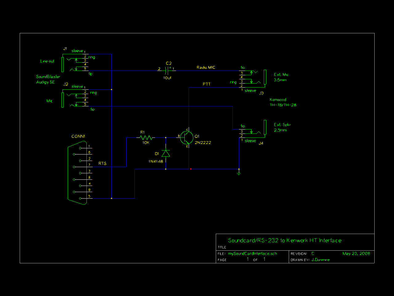
Others have documented this type of interface extensively so I won’t duplicate the effort. Many
homebrew plans and commercial products are available. A few random examples:
http://wa8lmf.net/ham/tonekeyer.htm#NEW
http://www.ebay.com/itm/EASY-DIGI-USB-Sound-Card-Interface-NO-MORE-USB-RS232-
ADAPTERS-/221668996763
https://sites.google.com/site/kh6tyinterface/
http://www.qsl.net/wm2u/interface.html
http://zs1i.blogspot.com/2010/02/zs1i-soundcard-interface-ii-project.html
http://www.kb3kai.com/tnc/soft-tnc.pdf
http://www.dunmire.org/projects/DigitalCommCenter/soundmodem/mySoundCardInterface.png
Google for something like ham radio sound card interface or ham radio digital mode interface to find
others.
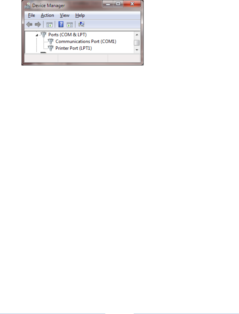
3.1 Don’t have a serial port?
Maybe you do but don’t know about it.
Page 4
My new computer didn’t have a serial port on the back. This was a disappointment because I still have
some useful gadgets that use a good old fashioned RS-232 port. I was surprised to see a serial port and
parallel printer port displayed in the Device Manager:
The connectors exist on the motherboard. It was only necessary to add appropriate cables to bring
them out to the rear panel. You can also buy PCI cards with serial ports or use an adapter cable with
USB on one end and RS-232 on the other end.
3.2 For Best Results
For receiving:
Leave squelch open.
Squelch delay will cut off the start of transmissions. You won’t hear the weak ones at all.
Turn off any battery saver feature.
This feature powers the receiver on and off rapidly to extend battery life. You will miss the
beginning of transmissions that come during the power down part of the cycle.
Turn off any “dual watch” feature.
This is actually one receiver scanning between two frequencies, not two independent receivers.
For transmitting:
Set proper transmit audio level.
Too low, you won’t be heard. Too high will cause distortion and make decoding less likely.
Most of us don’t have the test equipment to set the deviation level around 3 or 3.5 KHz so we
need to listen to other signals and set ours around the average of what others are sending.
Avoid use of VOX built into your transceiver.

Page 5
This is designed for voice operation and will keep the transmitter on about a half second after
the transmit audio has ended. This is much too long. Others will probably start transmitting
before you stop.
For an explanation, see the section called, “Radio Channel – Transmit Timing.”
If using the Signalink USB, turn the delay down to the minimum (fully counterclockwise).
According to the documentation, this should turn off the transmitter around 15 or 30
milliseconds after the transmit audio has ended.
Mobile Rigs:
Transceivers designed for mobile use often have a 6 pin mini-DIN “data” connector designed
specifically for connection to an external modem. If available, use this instead of the speaker and
microphone connections. This connection has flatter audio response.
The next 3 sections contain information specific to different operating systems. Proceed to the
corresponding one for your situation.
(4) Windows XP or later
(5) Linux
(6) Macintosh OS X
After installing on your particular operating system, continue with section 7, Basic Operation.
Page 6
4 Installation & Operation – Microsoft Windows XP or later
If using Linux, skip section 4 and proceed to section 5.
If using OS X, skip section 4 and proceed to section 6.
Download the desired direwolf-*-win.zip file from https://github.com/wb2osz/direwolf/releases
The “win” in the file name means it is the Windows version.
A Pentium 3 processor or equivalent or later is required for the prebuilt version. If you want to use a
computer from the previous century, see instructions in Makefile.win.
Put the Dire Wolf distribution file, direwolf-1.4-win.zip (or similar name depending on version), in some
convenient location such as your user directory. In this example, we will use C:\Users\John
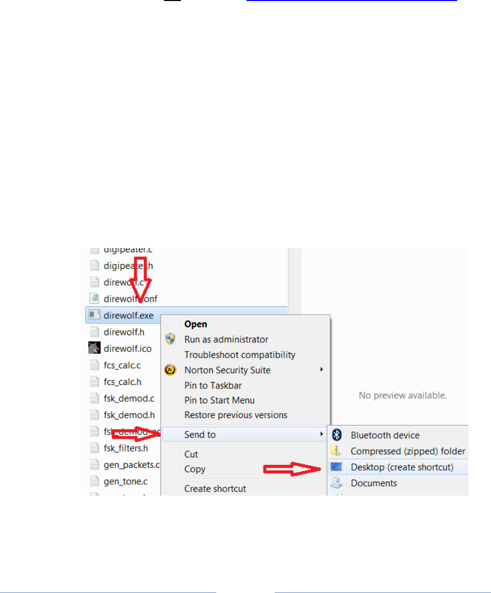
In Windows Explorer, right click on this file and pick “Extract All…” Click on the Extract button.
You should end up with a new folder containing:
direwolf.exe -- The application.
User-Guide.pdf -- This document.
and many others …
In Windows Explorer, right click on direwolf.exe and pick Send To > Desktop (create shortcut).
Look for the new direwolf.exe icon on your desktop.
Page 7
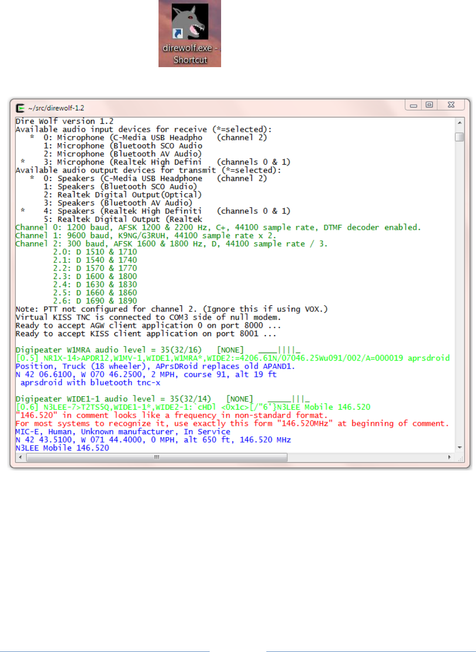
4.1 Run Dire Wolf
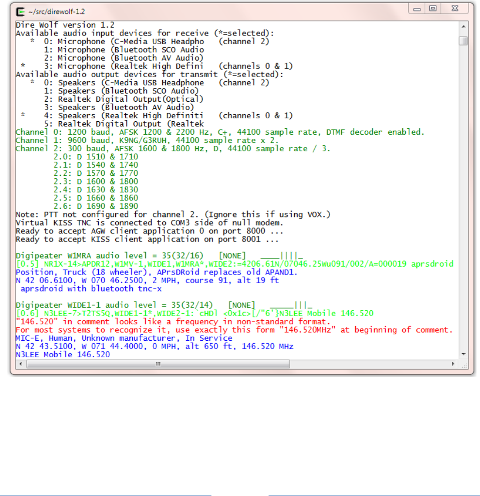
Double click on the desktop icon: and you should get a new window similar to this:
It starts with some informational messages in black.
- Audio devices being used and their mapping to radio channels. The current version allows up to
three audio devices. This allows up to six radio channels when all are operating in stereo.
Next we have some troubleshooting information about the radio channel configuration. Dire Wolf
supports the most popular 1200, 9600, and 300 baud standards. For 300 baud HF SSB operation,
multiple decoders can be configured to compensate for signals off frequency.

Page 8
A group of several lines is displayed for each packet received.
- The first line of each group, in dark green, contains the audio level of the station heard and
some other useful troubleshooting information. The numbers, in parentheses, after the audio
level are explained in A-Better-Packet-Demodulator-Part-1-1200-baud.pdf &
A-Closer-Look-at-the WA8LMF-TNC-Test-CD.pdf.
-
- The raw data is displayed in green and deciphered information is in blue.
- Sometimes you will see error messages in red when invalid data is received or other problems
are noticed.
We will learn more about these in later chapters.
The rest of section 4 describes how to use Dire Wolf with other packet radio applications such as
APRSISCE/32 and UI-View. If you are not interested using them this time, skip ahead to section 7, Basic
Operation.
When using the network interfaces, Dire Wolf and the client application can be running on different
computers. You could have a Linux computer in the “shack” running Dire Wolf as a digipeater. You
could connect to it from a Windows Laptop, running APRSIS 32, in another part of the house. In this
case you would specify the name or address of the first computer instead of using “localhost.”
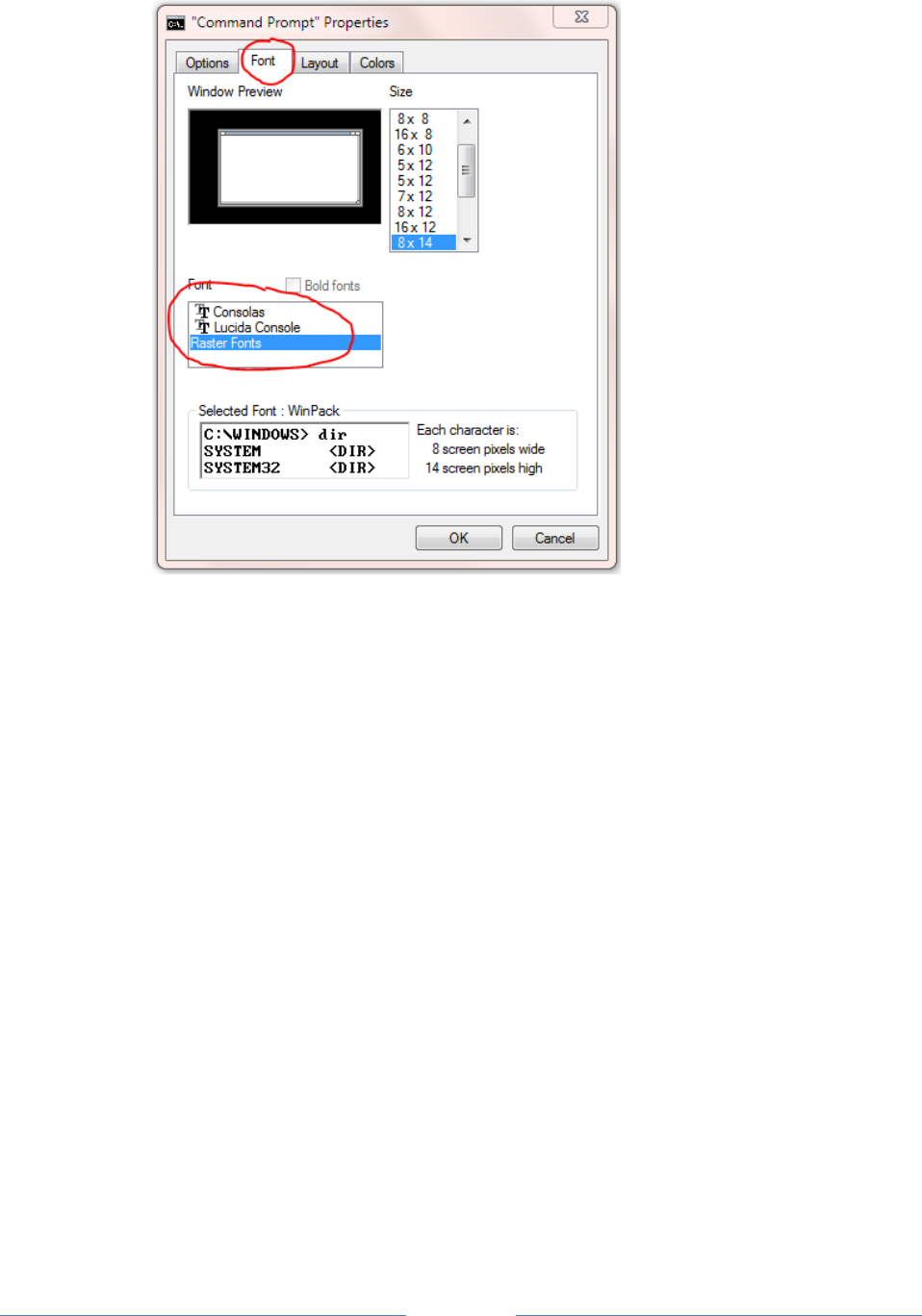
4.2 Select better font
You might need to change the font for best results. Right-click on the title bar and pick Properties from
the pop-up menu. Select the Font tab. Notice the list of fonts available. The one called “Raster
Fonts” has a very limited set of characters. Choose one of the others. For more details, see section
called UTF-8 Characters.
Page 9
4.3 AGW TCPIP socket interface
Dire Wolf provides a server function with the “AGW TCPIP Socket Interface” on default port 8000. Up to
3 different client applications can connect at the same time.
4.3.1 APRSISCE/32
1. First, start up Dire Wolf.
2. Run APRSISCE/32.
3. From the “Configure” menu, pick “ports” then “new port…”
4. Select type “AGW” from the list. Enter “Dire Wolf” as the name. Click “Create” button.
5. When it asks, “Configure as TCP/IP Port?” answer Yes.
6. Enter “localhost” for the address and port 8000.
7. Finally click on “Accept.”.
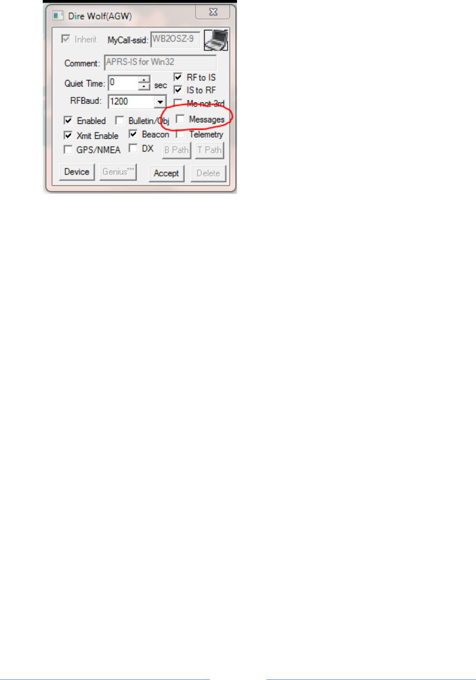
A common complaint is that “messages” are not being sent. It is necessary to enable the messages
option in the TNC port configuration.
Page 10
By default it is off. An attempt to send an APRS “message” does nothing and doesn’t produce any sort
of warning.
4.3.2 Ui-View
1. First, start up Dire Wolf.
2. Run UI-View32
3. From the Setup menu, pick Comms Setup.
4. Select Host mode: AGWPE from the list and click the “Setup” button.
5. Take defaults of localhost and 8000. Click on OK.
6. Click on OK for Comms Setup.
4.3.3 YAAC (Yet Another APRS Client)
1. First, start up Dire Wolf.
2. Run YAAC
3. From the Setup menu, pick Configure by Expert Mode.
4. Select the “Ports” tab.
5. Click the “Add” button.
6. From the Port type list, choose AGWPE.
7. For Server Host name specify where Dire Wolf is running. Use “localhost” if both are running on
the same computer.
8. For the port name list, you should see one or two items depending how Dire Wolf was
configured.
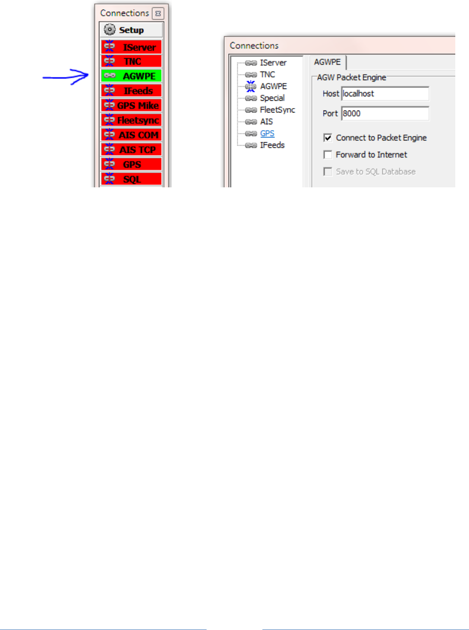
4.3.4 SARTrack
1. First, start up Dire Wolf.
2. Run SARTrack.
3. Select AGWPE under Connections.
Page 11
4. If SARTrack and Dire Wolf are running on different computers, enter the address of the host
where Dire Wolf is running.
4.4 Kiss TNC emulation – serial port
Dire Wolf can act like a packet radio TNC using the KISS protocol by serial port.
You can use a serial port to emulate a hardware TNC. A cable can be attached to different computer
running an application expecting a KISS TNC. More often, you will run both on the same computer and
want to connect them together without two physical serial ports and a cable between them.
To use this feature, you must install com0com as explained later in the Advanced Topics section. If you
followed the instructions, other applications will think they are talking with a TNC on the COM4 serial
port.
Here are detailed configuration steps for a couple popular applications.
4.4.1 APRSISCE/32
1. First start up Dire Wolf.
2. Run APRSISCE/32.
3. From the “Configure” menu, pick “ports” then “new port…”
4. Select type “KISS” from the list. Enter “Dire Wolf” as the name. Click “Create” button.
5. When it asks, “Configure as TCP/IP Port?” answer No.
6. For port configuration, pick “COM4” from the list. If you don’t see COM4, com0com has not
been installed properly. Go back and fix it.
7. The baud rate shouldn’t matter because there is not a physical serial port. Leaving it black
seems to be fine. Keep defaults of Party:None, Data:8, and Stop:1
8. Finally click on “Accept.”.

Page 12
4.4.2 UI-View32
1. First, start up Dire Wolf.
2. Run UI-View32
3. From the Setup menu, pick Comms Setup.
4. Select Host mode: KISS from the list, then COM port 4, and click the “Setup” button.
5. Clear all of the “Into KISS” and “Exit KISS” fields then click the OK button.
6. Click on OK for Comms Setup.
4.4.3 YAAC (Yet Another APRS Client)
1. First, start up Dire Wolf.
2. Run YAAC
3. From the Setup menu, pick Configure by Expert Mode.
4. Select the “Ports” tab.
5. Click the “Add” button.
6. From the Port type list, choose Serial_TNC
7. For device name pick COM4.
8. Baud Rate doesn’t apply in this case because there is no physical serial port.
9. For Command to enter KISS mode, pick KISS-only.
4.5 Kiss TNC emulation – network
Dire Wolf can also use the KISS protocol over a network connection with default port 8001.
Here are detailed configuration steps for a popular application.
4.5.1 APRSISCE/32
1. First start up Dire Wolf.
2. Run APRSISCE/32.
3. From the “Configure” menu, pick “ports” then “new port…”
4. Select type “KISS” from the list. Enter “Dire Wolf” as the name. Click “Create” button.
5. When it asks, “Configure as TCP/IP Port?” answer Yes.
6. Enter “localhost” for the address and port 8001.
7. Finally click on “Accept.”.
Skip sections 5 (Linux) and 6 (OS X) and proceed to section 7 for Basic Operation.

Page 13
5 Installation & Operation – Linux
This is distributed as open source so you can see how it works and make your own modifications. You
will need the usual development tools such as gcc and make.
The ALSA sound system is used for Linux. If you have some other Unix-like operating system that does
not have ALSA, you can try using the OSS code. This hasn’t been tested for a long time so no
guarantees. Look inside Makefile.linux and make the minor change described in the comments.
Special considerations for the Raspberry Pi are covered in a separate document. If you are using the
Raspberry Pi, or other similar single board computer, see separate “Raspberry Pi APRS” document.
5.1 Download source code
Chose either of these methods, depending on your preference. If this is new to you and you are not
familiar with “git,” the first method might be less confusing.
5.1.1 Download with web browser
Go to the releases page, https://github.com/wb2osz/direwolf/releases , with your web browser. Chose
the desired release, and download the source as either zip or a compressed tar file. They are equivalent.
It doesn’t matter which one you pick except in the next step here.
If you picked the zip format, unpack it with a command like this:
unzip direwolf-1.4.zip
If you use the compressed tar format, unpack it like this:
tar xfz direwolf-1.4.tar.gz
The exact file name will depend on the release version. Adjust your actual command accordingly. In
either case, change your current working directory to the source directory. e.g.
cd direwolf-1.4
Skip section 5.1.2.
5.1.2 Using git clone
Follow these steps to clone the git repository and checkout the desired version.
cd ~
git clone https://www.github.com/wb2osz/direwolf
cd direwolf

Page 14
At this pint you should have the most recent stable version. There are times when you might want to
get a specific older version. To get a list of them, type:
git tag
You should see a list of releases something like this:
1.0
1.1
1.2
1.3-dev-F
1.3-dev-I
1.3-dev-K
To select a specific version, specify the tag like this:
git checkout 1.2
In some cases, you might want the latest (sometimes unstable) development version to test a bug fix or
get a preview of a new (possibly incomplete) feature that will be in the next release. In that case, type:
git checkout dev
5.2 Build & Install
It might be necessary to install an additional package with this command:
sudo apt-get install libasound2-dev
Failure to install the libasound2-dev package will result in the compile error, “audio.c…: fatal error:
alsa/asoundlib.h: No such file or directory.”
Optional Step: update tocalls file
The APRS packet destination field is often used to identify the manufacturer/model of the sender.
These are not hardcoded into Dire Wolf. Instead they are read from a file called tocalls.txt at
application start up time.
The original standard symbols (house, car, etc.) are built in but the "new" symbols, using
overlays, are often updated. These are also read from files so you can use the latest versions
without updating the rest of the application.
If you want to use the latest versions of these files, instead of the versions bundled in with the
software release, type this:
make tocalls-symbols
The risk is that new additions to the file could be in some incompatible format and won’t be
processed correctly.

Page 15
Optional Step: gpsd support
Dire Wolf can send beacons based on the current location taken from a GPS receiver. When
using Linux, the preferred method is to use “gpsd” which allows multiple applications to share a
GPS receiver. Install it:
sudo apt-get install gpsd
sudo apt-get install libgps-dev
The “make” step should realize whether the necessary files are available and you should see a
message looking something like one of these indicating whether gpsd support was built in.
This includes support for gpsd.
This does NOT include support for gpsd.
Optional Step: hamlib support
Dire Wolf can use “hamlib” for more flexible PTT control. You can install it from a package or
build from source as described here:
http://hamlib.sourceforge.net/manuals/1.2.15/_rdmedevel.html
Boiled down version if you don’t want to read the instructions:
cd ~
sudo apt-get install automake libtool texinfo
git clone git://hamlib.git.sourceforge.net/gitroot/hamlib/hamlib
cd hamlib
sh autogen.sh
make
make check
sudo make install
cd ~/direwolf
Edit Makefile.linux and look for this section:
# Uncomment following lines to enable hamlib support.
#CFLAGS += -DUSE_HAMLIB
#LDFLAGS += -lhamlib
Remove the # from the beginning of the last two lines.
Compile and install the application.
cd ~/direwolf
make

Page 16
sudo make install
You should now have files in these locations, under /usr/local, owned by root.
/usr/local/bin/direwolf
The main application.
/usr/local/bin/decode_aprs
Utility to interpret “raw” data you might find on
http://aprs.fi or http://findu.com
/usr/local/bin/tt2text
text2tt
ll2utm
utm2ll
log2gpx
gen_packets
aclients
ttcalc
dwspeak.ch
Utilities related to APRStt gateway, UTM
coordinates, log file to GPX conversion, test frame
generation, TNC comparison, and a Touch Tone to
Speech sample application.
/usr/local/bin/telem-balloon.pl
telem-bits.pl
telem-data91.pl
telem-data.pl
telem-eqns.pl
telem-parm.pl
telem-unit.pl
telem-volts.py
/usr/local/share/doc/direwolf/
APRS-Telemetry-Toolkit.pdf
telem-balloon.conf
telem-m0xer-3.txt
telem-volts.conf
APRS Telemetry Toolkit.
/usr/share/applications/direwolf.desktop
Application definition with icon, command to
execute, etc.
/usr/share/direwolf/tocalls.txt
Mapping from destination address to system type.
Search order for tocalls.txt is first the current
working directory and then /usr/share/direwolf.
/usr/share/direwolf/symbolsX.txt
symbols-new.txt
Descriptions and codes for APRS symbols.
/usr/share/direwolf/dw-icon.png
Icon for the desktop.
/usr/local/share/doc/direwolf/
A-Better-APRS-Packet-Demodulator-Part-
1-1200-baud.pdf
A-Better-APRS-Packet-Demodulator-Part-
2-9600-baud.pdf
APRStt-Implementation-Notes.pdf
APRStt-interface-for-SARTrack.pdf
CHANGES.md
LICENSE-dire-wolf.txt
LICENSE-other.txt
Various documentation, mostly in PDF form.
README.md is an overview.

Page 17
Raspberry-Pi-APRS.pdf
Raspberry-Pi-APRS-Tracker.pdf
Raspberry-Pi-SDR-IGate.pdf
README.md
User-Guide.pdf
/usr/local/share/doc/direwolf/examples/
direwolf.conf
dw-start.sh
sdr.conf
telem-m0xer-3.txt
telem-balloon.conf
telem-volts.conf
Sample configuration files and other examples.
/usr/local/man/man1/*
“man” pages with concise on-line help.
Some of these files might not apply to your system depending on the type of desktop environment.
If this is the first time you are installing Dire Wolf perform this step:
make install-conf
When upgrading from an earlier version, you will probably want to skip this step because it will wipe out
your earlier configuration file.
This step should have copied the initial configuration file into your home directory.
~/direwolf.conf
Configuration file.
Search order is current working directory then the
user’s home directory.
If you are installing from a DEB or RPM package, /usr/bin will probably be used instead of
/usr/local/bin. You should find the sample “direwolf.conf” file along with the documentation. Copy it
to your home directory or other desired location.
5.3 Select UTF-8 character set
For best results, you will want to be using the UTF-8 character set. Verify this by examining the LANG
environment variable.
$ echo $LANG
Make sure that it ends with “.utf8” like these examples:
af_ZA.utf8
en_GB.utf8
fr_CH.utf8

Page 18
See section called UTF-8 Characters for more details.
5.4 Run Dire Wolf
Run “direwolf” from the command line.
The rest of this section describes how to use Dire Wolf with other Linux packet radio applications such as
Xastir. If you are not interested in using it with some other application at this time, skip ahead to
section 7, Basic Operation.
5.5 AGW TCPIP socket interface
Dire Wolf provides a server function with the “AGW TCPIP Socket Interface” on default port 8000. Up to
3 different client applications can attach at the same time. You can increase the number by modifying
this line in source file server.c: #define MAX_NET_CLIENTS 3
5.5.1 Xastir
1. Run “direwolf” from a bash shell window.
2. Run Xastir from another window.
3. From the “Interface” menu, pick “Interface Control.”
4. Click the “Add” button.
5. From the “Choose Interface Type” list, pick “Networked AGWPE” and click “Add” button.
6. Take all the default values and click on “OK” button.
7. You should now be back to the “Interface Control” dialog box. Select the device mentioning
“Networked AGWPE” and click the “Start” button. The device status should now be “UP.”
8. Click the “Close” button.
9. Watch all the stations appear on the map.
You might notice that the “Configure AGWPE” option for “Digipeat?” is grayed out. This is because the
protocol does not have the ability to set the “has been repeated” bits in the “via” fields of the AX.25
protocol. You can overcome this restriction by using the KISS TNC interface.
5.6 Kiss TNC emulation – serial port
Dire Wolf can act like a packet radio TNC speaking the KISS protocol over a pseudo terminal.
What is a pseudo terminal? Dire Wolf acts like a traditional TNC speaking the KISS protocol over a serial
port. Some packet applications want to talk to a TNC over a serial port. One possible approach would
be to have Dire Wolf talk to one serial port and the application would talk to another serial port. The

Page 19
two serial port connectors would be attached to each other with a “null modem” (cross over) cable so
that data going out of one would go into the other.
A pseudo terminal is like a pair of real serial ports connected to each other with a cable. Except there
are no serial ports and no cable. Instead there is just a pair of virtual devices. Applications can use them
exactly like they would use a serial port.
In this case, Dire Wolf creates a pseudo terminal and talks to one end. The other is available for use by
an application such as Xastir or kissattach. The visible end will have a device name like /dev/pts/99.
The annoying thing is that you can’t specify the name you want. One time you might get /dev/pts/1 and
other time it might be /dev/pts/5, depending on what happens to be available. This is inconvenient if
you need to store the serial port name (pseudo terminal in this case) in the application configuration.
It’s also annoying if you want a single script to start up Dire Wolf and associated applications that use
the serial KISS interface.
Dire Wolf creates a symlink, /tmp/kisstnc, when the pseudo terminal is created. Xastir will correctly
handle a symbolic link to the actual device name so you can put /tmp/kisstnc in the configuration.
Avoid using the “-p” pseudo terminal option if possible. Each time it might use a different
device number making it difficult for automatic connection by other applications. It has been
problematic in other ways. Use the AGW or KISS network interface if your application supports
it.
5.6.1 Xastir
1. Run “direwolf -p” from a bash shell window.
2. Run Xastir from another window.
3. From the “Interface” menu, pick “Interface Control.”
4. Click the “Add” button.
5. From the “Choose Interface Type” list, pick “Serial KISS TNC” and click “Add” button.
6. For TNC Port, enter “/tmp/kisstnc”. Take all the other default values and click on “OK” button.
7. You should now be back to the “Interface Control” dialog box. Select the device mentioning
“Serial KISS TNC” and click the “Start” button. The device status should now be “UP.”
8. Click the “Close” button.
9. Watch stations appear on the map.
5.6.2 Linux AX25
Dire Wolf can be used with Linux AX25 instead of a physical TNC. First install ax25-tools. On Debian /
Ubuntu / Raspbian, it might be as simple as:
sudo apt-get update
sudo apt-get install ax25-tools
For Red Hat / Fedora / CentOS,

Page 20
(need command)
Add a port description to /etc/ax25/axports, as described in the AS25 HOWTO documentation. For
example,
radio WB2OSZ-15 1200 255 2 comment
This is important and not obvious. Remove any blank lines from the file.
Start up Dire Wolf with the “-p” option to make the KISS pseudo terminal interface available.
direwolf –p
You should see a message something like this:
Virtual KISS TNC is available on /dev/pts/5
WARNING - Dire Wolf will hang eventually if nothing is reading from it.
Created symlink /tmp/kisstnc -> /dev/pts/5
Take heed of that warning! The pseudo terminal has a finite amount of buffer space available. If
direwolf is filling it up on one end and nothing is reading from the other end, the received frame
processing thread will stop and eventually you will get a message like this:
Received frame queue is out of control. Length=….
Reader thread is probably frozen.
This can be caused by using a pseudo terminal (direwolf -p) where another.
application is not reading the frames from the other side.
After a while this will trigger another error message about a memory leak. If you encounter this, try to
use the network KISS interface instead of the pseudo terminal interface.
Leave that command window alone and open a new one. These are some sample commands for a quick
test. Your situation will vary. kissattach command needs to be run as root:
sudo /usr/sbin/kissattach /dev/pts/5 radio 44.56.4.118
kissattach doesn’t like to see a symbolic link instead of a device. (See
http://www.spinics.net/lists/linux-hams/msg03487.html)
You could use something like this instead if you want to start up multiple applications from one script.
sudo /usr/sbin/kissattach `ls -l /tmp/kisstnc | awk '{ print $11 }'` radio 44.56.4.118
See troubleshooting section, below, if you run into an issue with this.
After a successful kissattach, continue appropriately for your situation. Simple example for testing:
sudo route add -net 44.0.0.0/8 ax0
ping 44.56.4.120

Page 21
You should see it transmitting something.
If difficulties are encountered, try using the “-d k” option to display the KISS protocol messages. You
might see something like this for a ping command to one of the 44.x.x.x addresses:
<<< Data frame from KISS client application, port 0, total length = 47
000: 00 a2 a6 a8 40 40 40 60 ae 84 64 9e a6 b4 7f 03 ....@@@`..d.....
010: cd 00 03 00 cc 07 04 00 01 ae 84 64 9e a6 b4 1e ...........d....
020: 2c 38 04 76 00 00 00 00 00 00 00 2c 38 04 78 ,8.v.......,8.x
5.6.2.1 Troubleshooting – kissattach failure
Sometimes kissattach has an issue with the Dire Wolf pseudo terminal. This shows up most often on
Raspbian but sometimes occurs with other versions of Linux.
kissattach: Error setting line discipline: TIOCSETD: Device or resource busy
Are you sure you have enabled MKISS support in the kernel
or, if you made it a module, that the module is loaded?
The root cause and a proper solution have not been found yet. For now, two different work-arounds are
available.
5.6.2.2 First Work-around
IZ1YPS came up with this interesting work-around.
(1) Start up direwolf with -p option as you normally would.
(2) Rather than putting the pseudo terminal slave name (/dev/pts/…) in the kissattach, use
/dev/ptmx instead. Example:
sudo /usr/sbin/kissattach /dev/ptmx radio 44.56.4.118
It should respond with something like this:
AX.25 port radio bound to device ax0
Awaiting client connects on
/dev/pts/5
Remember that last line because it will be used in the final step.
(3) Connect them with mkiss.
sudo mkiss /tmp/kisstnc /dev/pts/5
The last command line argument is the result from step 2. If you wanted to script those last two
steps, you could do it like this:
x=`sudo /usr/sbin/kissattach /dev/ptmx radio 44.56.4.118 | tail -1`

Page 22
sudo mkiss /tmp/kisstnc $x
5.6.2.3 Second Work-around
Rather than using the pseudo terminal feature of Dire Wolf, use the TCP network KISS port instead.
AB4MW pointed out that “socat” can be used to create a pseudo terminal for use by other applications.
First install “socat.” On Debian / Ubuntu / Raspbian systems, the command is:
sudo apt-get install socat
Run “direwolf” without the “-p” option. Among the start up messages you should see:
Ready to accept KISS client application on port 8001 ...
Now create a two way connection between port 8001 and a new pseudo terminal in a different
command window.
socat PTY:raw,echo=0,link=/tmp/kisstnc TCP4:127.0.0.1:8001
Use the result with kissattach.
5.6.2.4 Unexpected transmissions
Why might you transmitting apparent trash when no beacons were configured? The issue is that if you
enable a TCP/IP address on your Linux ax? interface, broadcasting programs like Samba, Avahi (Bonjour),
etc. will send their traffic out over RF! The solution here is to either reconfigure those applications to
only bind to specific interfaces (not all interfaces) or setup iptables packet filters to intercept that
broadcast traffic before it hits the ax? interface.
You can find a lot of good information on Linux AX.25 here:
http://www.trinityos.com/HAM/CentosDigitalModes/hampacketizing-centos.html
5.7 Automatic Start Up After Reboot
You might want your TNC / application server / digipeater to start up automatically after a reboot. This
often causes confusion as there are many ways to do this. You will find some discussions in the forums
but here is one solution which should be usable for many use cases.
The important thing to remember is that direwolf writes a lot of information to “stdout.” This
information is valuable and really needs to go somewhere. If you simply try starting direwolf from
/etc/rc.local or via a script in /etc/rc2.d, you will probably be disappointed. I also think it is better to run
direwolf as an ordinary user, rather than root, so there is less chance of damaging your system if
something goes wrong.

Page 23
(a) If you are running a graphical desktop, the recommended way to start direwolf is to create a
terminal window and run direwolf inside of that window. Examples:
/usr/bin/xterm -bg white -fg black -e "direwolf" &
or
/usr/bin/lxterminal -t "Dire Wolf" -e "direwolf" &
(b) If you are running a “lite” version of Linux without the graphical desktop, popping up a GUI
window is not an option and will give Xsession errors. Even if a graphical desktop is available,
you still might want to use alternative solutions like the “screen” tool in detached mode so you
can re-connect to Direwolf and see what happened with only a text terminal (locally, via an SSH
connection, etc).
screen -d -m -S direwolf "direwolf"
If the “screen” utility is not already installed, add it with “sudo apt-get install screen” on Debian-
based distributions.
Later you can use “screen -list” to get a list of sessions and attach to an existing session with
“screen -D -r direwolf”
You can again "detach" from the Direwolf screen session with control-a then “d” at any time and
direwolf will continue to run.
A script is provided to handle the most common cases. If you followed the installation steps above, you
should have a file named dw-start.sh in your home directory. Ensure that it is executable:
chmod +x dw-start.sh
My suggestion is to run this script from cron so if direwolf stops running for any reason, it will be
automatically restarted. Use the “crontab –e” command and add a line like this, substituting you own
user name instead of john:
* * * * * /home/john/dw-start.sh >/dev/null 2>&1
The line above will run the /home/john/dw-start.sh script once per minute. Dire Wolf will be started
automatically if not running already. If a previous instance of Dire wolf crashes, or is terminated for any
other reason, it will be restarted within a minute. A log of restarts can be found in /tmp/dw-start.log.
dw-start.sh will try to determine if you have a graphical desktop and select either GUI or CLI mode. You
can override this by looking for “RUNMODE=AUTO” near the top of the dw-start.sh file and modifying as
described in the script's comments.
Skip over section 6 (Macintosh OS X), and continue with section 7, Basic Operation.

Page 24
6 Macintosh OS X
A port to the Macintosh was provided by Robert, KK5VD. This is new for version 1.3 and has not been
well tested yet.
Requirements for compiling/installing Direwolf on Mac OS X.
Built/Tested using Mac OS X 10.10 and XCode 6.3 Development/Command line tools.
Installation of Macports package manager is required as the dependencies within the
makefile.macosx are structured for it.
6.1 Install Xcode/Command line tools.
Xcode can be found on Apple’s Developer website. You will need an ID and password to gain access.
https://developer.apple.com/downloads/index.action will lead you to a login window from your
browser.
Obtain a login ID or enter your current one. Once logged in, uncheck all checked boxes on the left with
the exception of Development tools.
Locate Xcode and command line tools for your operating system version. Do not select anything that's a
beta release.
Download both and install Xcode first followed by the command line tools.
Execute the terminal program located here: /Applications/Utilities/Terminal.app
This program is used to enter command line commands.
After installing, run the following command from the command line to activate the command line tools
(MacOSX 10.10 and possibly other versions).
sudo xcode-select -s /Library/Developer/CommandLineTools
At the prompt enter your password. (You must have admin rights).
6.2 Install Macports
Install macports package manager from this URL: https://www.macports.org/install.php
Select and install the one that is relevant to your operating system version.

Page 25
6.3 Install Support tools and PortAudio Library.
From the command line, enter the following:
sudo port install coreutils portaudio +universal
coreutilis Includes the program ginstall, as Apple's version doesn't work correctly with
the makefile provided by Direwolf.
portaudio Portable Audio Interface library for accessing Apple's CoreAudio sound system.
+universal This flag will cause the build system to create both 32bit and 64bit versions
of the library.
6.4 Compiling Direwolf.
Obtain the source code by one of the methods described in the Linux section, above.
From the command line.
cd <DireWolf Source Code Location>
make -k
Why “-k?” That means keep going even if errors.
If there are no reported errors.
sudo make install
Perform next step only if this is the first time DireWolf is being installed. It will cause an existing
customized version of direwolf.conf file to be overwritten.
make install-conf
6.5 Read the instructions to configure direwolf.conf file.
The configuration file is located in either the current directory path or the HOME directory.
After editing the configuration file SAVE A COPY TO ANOTHER LOCATION! Move the edited file to ~/
(home) directory.
The one significant difference from the other operating systems is that the audio device names can
contain spaces. If they do, they must be quoted like the example below.
Configuration file format:

Page 26
ADEVICE <Device Input Name>:<Device Input Number> <Device Output Name>:<Device Output Number>
Example:
ADEVICE "USB Audio Codec:6" "USB Audio Codec:5"
You are probably wondering: How do I know what devices are available? A listing of audio devices
is presented on start up of Dire Wolf. The remaining configuration options are described in
the relevant sections of this User Guide. Where there are Windows / Linux differences use the Linux
version.
Example Device listing:
Dire Wolf version ...
Reading config file /Users/<Home_Dir>/direwolf.conf
Audio input device for receive: USB Audio CODEC:6 (channel 0)
Audio out device for transmit: USB Audio CODEC:5 (channel 0)
Number of devices = 7
--------------------------------------- device #0
Name = "Built-in Line In"
Host API = Core Audio
Max inputs = 2
Max outputs = 0
--------------------------------------- device #1
Name = "Built-in Digital"
Host API = Core Audio
Max inputs = 2
Max outputs = 0
...
--------------------------------------- device #5
Name = "USB Audio CODEC"
Host API = Core Audio
Max inputs = 0
Max outputs = 2
--------------------------------------- device #6
Name = "USB Audio CODEC"
Host API = Core Audio
Max inputs = 2
Max outputs = 0
6.6 Running direwolf.
From the command line enter.
cd ~/
/usr/local/bin/direwolf
Direwolf reads the configure file that is located in the same directory where the program was executed.
i.e. ~/direwolf.conf

Page 27
There are a number of command line parameter available to the user. These are listed later in this User
Guide.
6.7 Read the rest of the User Guide.
This should answer most of your questions.
If something is missing or unclear post a question on one of the discussion groups or contact the author.
6.8 In case of difficulties
If you are not a programmer and/or not familiar with using command line build tools, you have a lot to
learn.
The author of Dire Wolf (WB2OSZ) does not have a Mac and can’t provide help with any issues
specifically related to this platform. If you are having Mac-specific issues, post your question to one of
the discussion groups:
https://groups.yahoo.com/neo/groups/direwolf_packet/info
https://groups.yahoo.com/neo/groups/linuxham/info
Or e-mail the person providing the port to this platform:
Robert, k k 5 v d ( a t ) y a h o o ( d o t ) c o m
Page 28
7 Basic Operation
Dire Wolf is not an interactive application. It has no graphical user interface. It is meant to be a
replacement for a physical TNC used by other applications. It has a dumb terminal output so you can
watch what is going on for troubleshooting.
The exact appearance will vary depending on the version you are using. Some of these illustrations
might be from an earlier version and look slightly different than the current version.
7.1 Start up configuration information
You should see something like this for the Windows version:
It starts off listing the available audio devices. In this case, we have a cheap USB Audio adapter and the
others are part of the motherboard. A device, other than the default, can be specified in the
configuration file. Details are in a later section.
Page 29
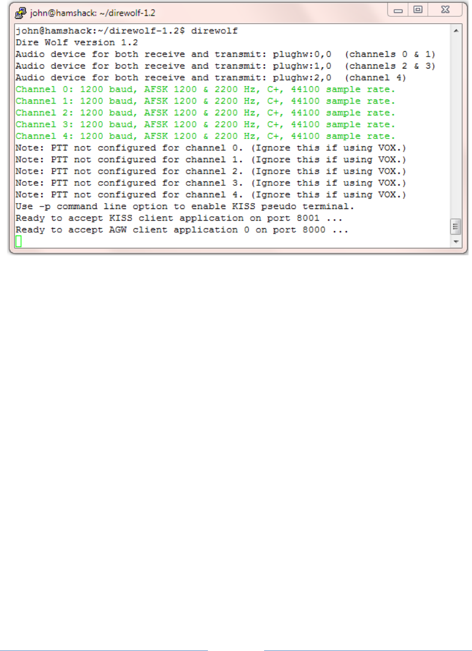
You should see something like this for the Linux version:
It starts with:
The version number.
Audio device(s) being used.
Modem configuration.
A reminder that serial port KISS is off by default.
Port numbers for use by client applications.
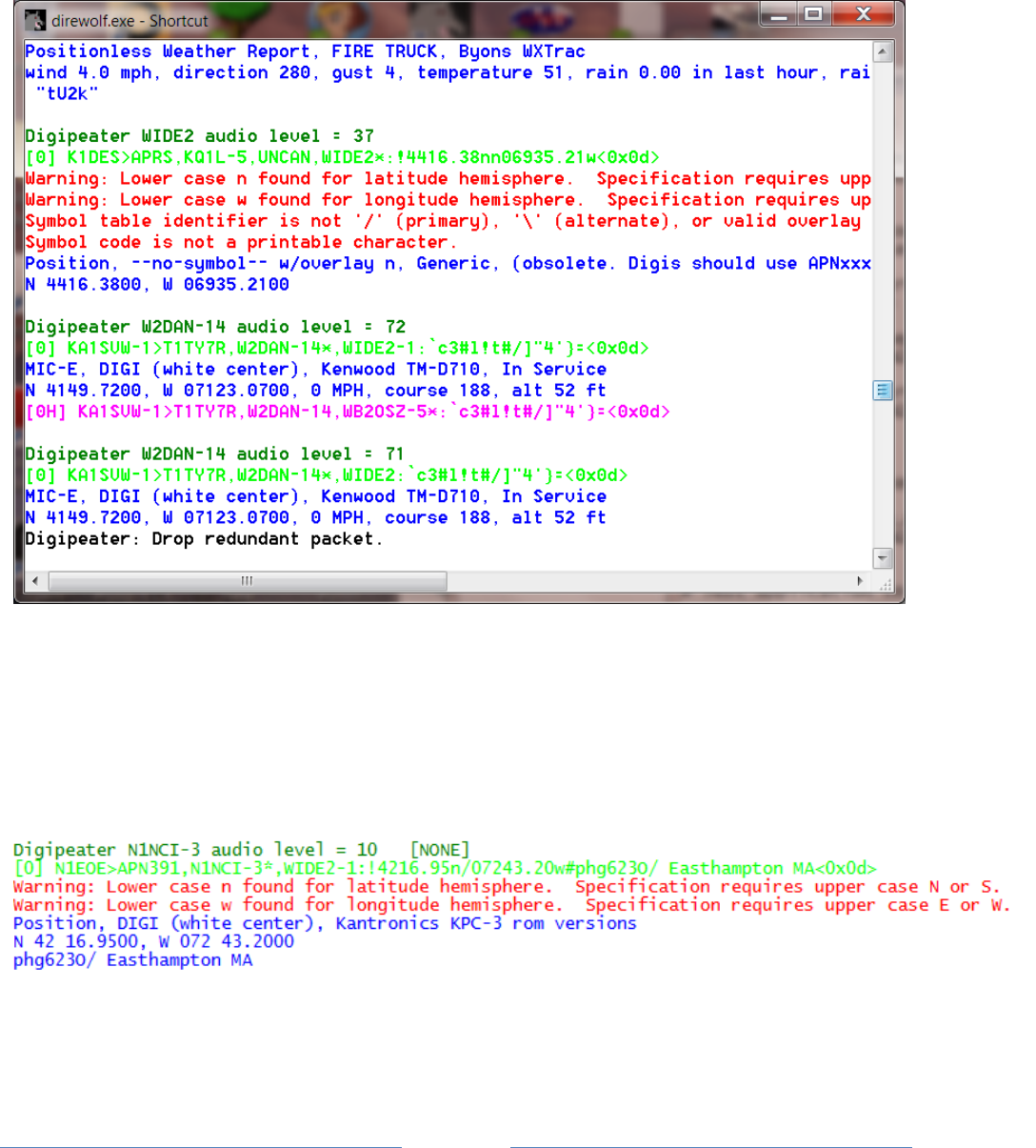
7.2 Information for receiving and transmitting
Different types of information are color coded:
Black for information.
Dark Green for the audio level. More about this below.
Green for received data.
Blue for a decoded version of the raw data.
o The first line contains:
the message type (e.g. MIC-E, Position, or Weather)
symbol to be displayed (e.g. Truck, House)
equipment model or software application
MIC-E status (In Service, En Route, Off Duty, …)
transmitter power, antenna height, gain, and direction.
o The second line contains:
Latitude & longitude, speed, course (direction in degrees), altitude
o The optional third line contains a comment or weather information.
Page 30
Magenta for transmitted data. In this case, each line is preceded by the radio channel and
priority. 0 for the first channel, 1 for the second if used. “H” means high priority for digipeated
packets. “L” is for lower priority packets originating at this station.
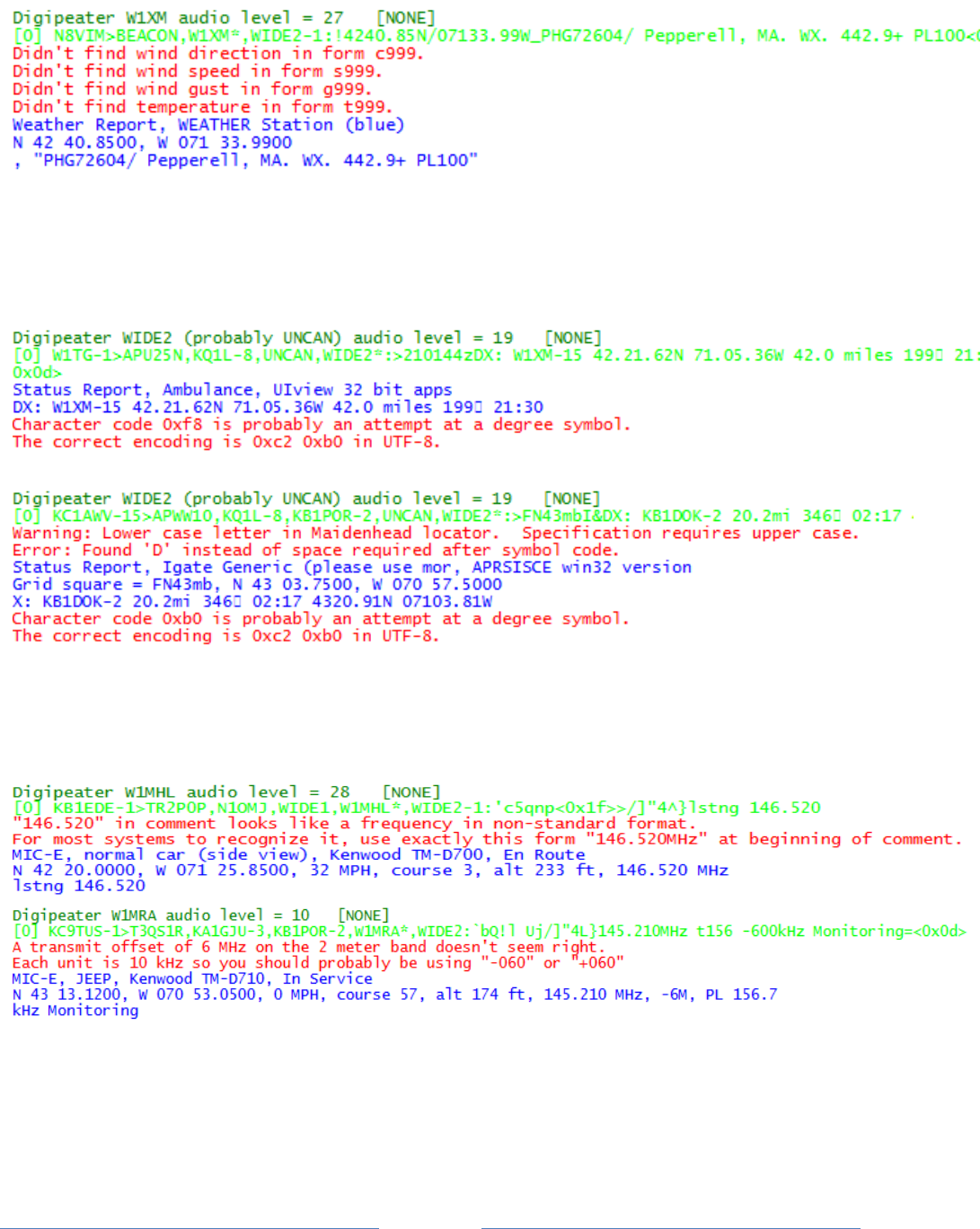
Red for errors. If a newcomer is wondering why his transmissions are not showing up in other
applications, these error messages might provide a clue about the problem.
Other common errors are pointed out to help troubleshoot why signals are not interpreted as the
sender probably expected.
The APRS specification requires upper case letters for the hemisphere. Many systems will also
recognize lower case, but don’t bet on it.
A “Positionless Weather Report” with the data type indicator of “_” requires a minimum of wind and
temperature information in a specific format.
Page 31
Here are some failed attempts to put a degree symbol in the comment. Trying to use characters from
Microsoft code page 437 or ISO 8859-1 (Latin 1) are valiant attempts but wrong because APRS uses
UTF-8 for non-ASCII characters.
Some APRS-capable transceivers will recognize a frequency in a standard format. Press the TUNE button
and the voice channel will be switched to that frequency. In the example below, it won’t happen
because the frequency is not in the proper format.
Here is a situation where a repeater is being advertised. If the “88.5” in the comment had been in the
proper format, suitably equipped radios would be able to set the PL tone automatically.
Page 32
That’s it. You can’t interact with it directly. Use one of the many APRS / packet radio applications
designed to interface with a physical TNC.
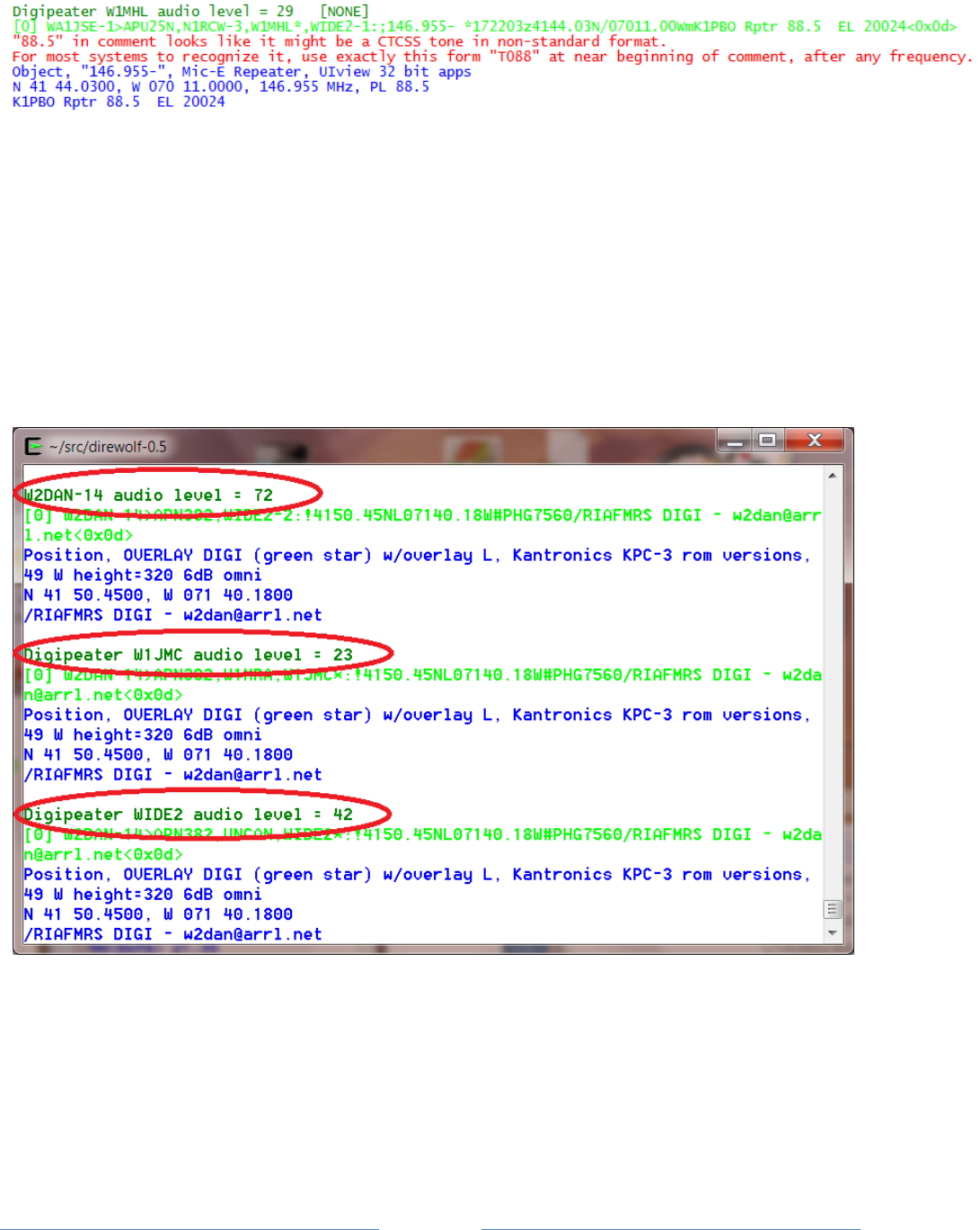
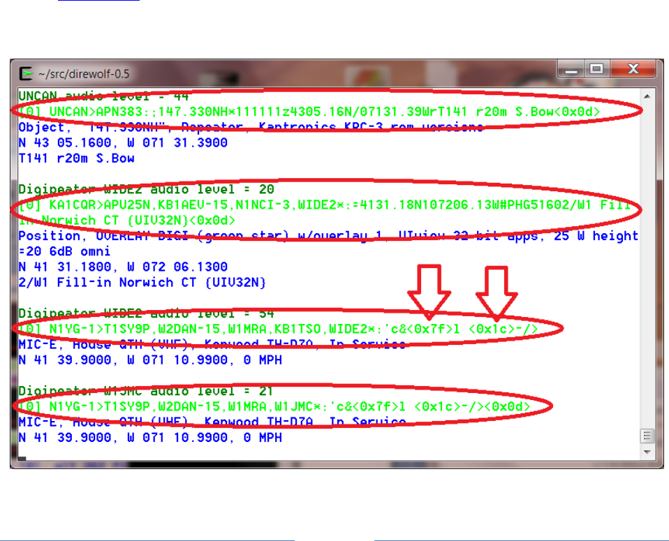
There is quite a bit of information packed in there.
The first line of each group contains the audio level of the station heard. This number depends on the
volume level of your receiver and the gain setting of the computer audio input. The absolute numbers
have no meaning but the relative values are revealing.
Consider the items circled above.
In the first case, we are hearing the original transmission directly.
In the other two cases, we are hearing the same thing from two different digipeaters.
Notice that the audio levels vary quite a bit. If the level is too high, clipping will occur resulting in signal
distortion and a much lower chance of being demodulated properly.
Page 33
Dire Wolf has an automatic gain control and can handle a very wide range of audio signal levels. Other
systems are not as forgiving.
A station using Dire Wolf can monitor the audio levels and advice those which are significantly different
than most others.
- (Image above needs to be updated for newer version) The numbers, in parentheses, after the
audio level are explained in A-Better-Packet-Demodulator-Part-1-1200-baud.pdf &
A-Closer-Look-at-the WA8LMF-TNC-Test-CD.pdf.
The second line of each group has the raw received data. It has the following parts:
“[0]” indicates it was received on the first (or only) radio channel.
The source station.
The “destination” which is a misleading name. For the MIC-E encoding it is part of the location.
In most other cases, it identifies the type of device or software application.
Digipeaters. “*” indicates it is the station we are actually receiving.
Finally the information part of the packet. notice that unprintable characters are represented
by their hexadecimal representation such as “<0x1c>”. This is the same convention used by
http://aprs.fi

Page 34
Finally we have decoded information in blue.
The first line contains the message type, symbol, and other station attributes such as
equipment/application type.
The second line is the location and optional speed and direction of travel.
The final line has any comment or weather information.
7.3 Periodic audio device statistics
This can be a useful troubleshooting tool if packets are not being decoded as expected. Is received
audio getting to the decoder? Is the audio interface producing the proper sample rate?
On the command line, use “-a” followed by the number of seconds between reports. 10 is a good
number for trouble shooting. If the interval is too short there will be significant variation in the sample
rate due to the way the counts are collected. Example:
ADEVICE0: Sample rate approx. 44.1 k, 0 errors, receive audio levels CH0 90, CH1 0
Digipeater WIDE2 (probably N3LEE-4) audio level = 40(19/11) [NONE] _||||||||
[0.4] W1CNH-5>APN391,N3LEE-10,N3LEE-4,WIDE2*:!4345.33ND07127.48W#PHG3630/W1, Moultonboro
W1CNH-5<0x0d>
Position, OVERLAY DIGI (green star) w/overlay D, Kantronics KPC-3 rom versions, 9 W
height=640 3dBi omni
N 43 45.3300, W 071 27.4800
/W1, Moultonboro W1CNH-5
ADEVICE0: Sample rate approx. 44.1 k, 0 errors, receive audio levels CH0 112, CH1 0
The parts of the message:
ADEVICE0 means it is the first audio device (sound card). ADEVICE1 for the second, etc.
44.1 k is the approximate average sample rate during the interval. If this is off
significantly, there is something wrong with the audio input system. For
example, one time use of a USB hub for an audio adapter caused this to
be 42.8 k. Many samples were getting lost.
CH0 90 shows a audio input is working for channel 0. If no frames are being decoded,
leave the squelch open and set audio input gain so this is somewhere in the
30 to 150 range.
CH1 0 shows that channel 1 has no audio input. In this case we are running in
the audio device in stereo with the right channel disconnected.
You may have noticed that the received packet has an audio level of 40 but the reports in between are
roughly 2 or 3 times greater. This is because the noise, with squelch open, is louder than the received
packets.
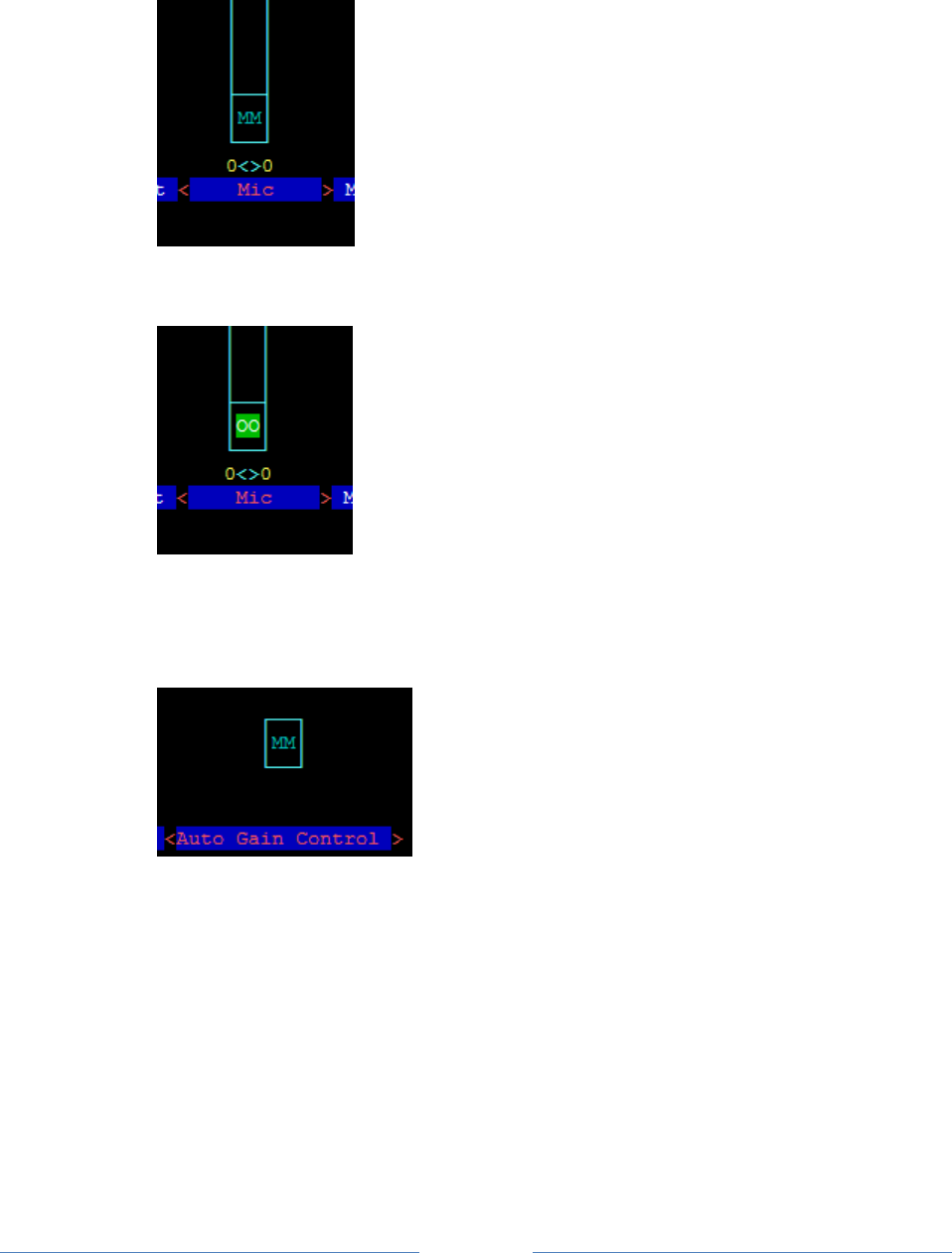
Page 35
If you are getting insufficient audio, check the cabling and the audio input gain.
If using Linux, run “alsamixer” and look for the microphone, or line input. “MM” indicates it is muted.
Select it by using the and keys. Press the ‘m” key to unmute it. The “MM” should change to
“00.”
Then use the ↑ key to increase the gain.
You want any auto gain control to be off.
“MM” indicates that it is off. If you see “00” instead, use the and keys to select it and press
“M” to toggle it.
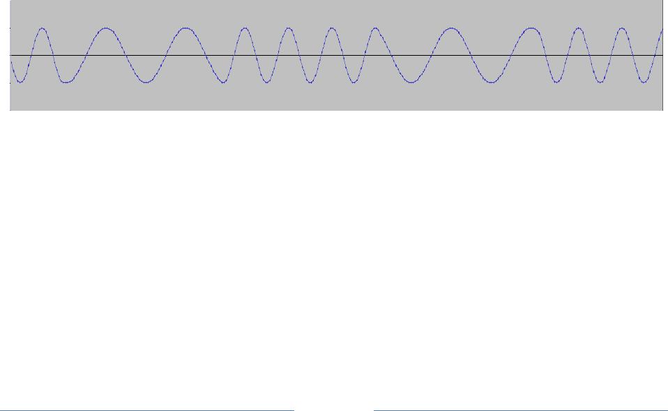
Page 36
8 Data Rates
Packet radio can be sent over many different speeds and modulation methods. Here is a brief overview
that might help clear up some of the confusion.
The AX.25 and APRS specifications say nothing about the type of modem. In practice, 1200 baud AFSK is
the most common for VHF / UHF FM. 9600 baud is also standardized, widely available, and gaining in
popularity.
8.1 Bits per Second (bps) vs. Baud
The terms “Bits per Second” (bps) and Baud are often used interchangeably because they are often the
same number.
Baud refers to the maximum number of “symbols” (signal states) per second. With two tone frequency
shift keying a “symbol” represents a single bit so the numbers are the same. With more advanced
modulation techniques we can send multiple bits at the same time. In this case, bits per second will be
some multiple of the Baud.
8.2 1200 bps
This is the original method from when packet radio got started about 30 years ago and still the most
popular. It is based on the Bell 202 standard which switches between 1200 and 2200 Hz tones to
represent the two signal states. This is called Audio Frequency Shift Keying (AFSK). It is simple, easy to
implement, and should work with any transceiver designed for voice. It isn’t very fussy about the audio
amplifier passband characteristics so you can simply use the microphone and speaker connections.
8.3 300 bps
Below 28 MHz, we are legally limited to 300 baud data (here, maybe different in other countries). HF
operation typically uses AFSK with a difference of 200 Hz between the two tones. When AFSK is sent
with an SSB transmitter it becomes FSK of the RF signal.
A slight mistuning of the receiver frequency will result in a corresponding difference in the audio tones.
Dire Wolf can tolerate this mistuning by using multiple demodulators tuned to different audio frequency
pairs.
A few references:

Page 37
Packet Radio on HF http://wiki.complete.org/PacketRadioOnHF
Others… ?
Google for “hf aprs” for many discussions on this topic.
8.4 9600 bps
Rather than converting the digital data to audio, it is also possible to use the digital signal for direct FSK
on the RF carrier. Here are some early designs from the previous century.
K9NG - need to find link…
G3RUH - http://www.amsat.org/amsat/articles/g3ruh/109.html
http://www.tapr.org/pdf/CNC1988-9600BaudModem-G3RUH.pdf
KD2BD -http://www.amsat.org/amsat/articles/kd2bd/9k6modem/
The audio amplifiers – in both the transmitter and receiver – are designed for voice operation and don’t
have the necessary bandwidth for digital signals. Trying to use the microphone and speaker connections
will only result in disappointment.
The newer major brand mobile transceivers have 6 pin mini-DIN “data” connectors that bypass the
audio stages. (I think that name is confusing. They should be labeled “external modem” – but they
didn’t ask me.) The big 3 manufacturers did something right and standardized the connector. In some
cases, configuration settings might impact the signals coming out of this connector so be sure to check
your radio manual.
1
Transmit audio. Typ. 1 to 2 Vp-p, 600 Ω
2
Ground
3
PTT – pull to ground to transmit
4
Receive audio for 9600 bps. Typ. 500 to 600 mVp-p, 10 kΩ
5
Receive audio for 1200 bps. Typ. 200 to 500 mVp-p, 600 Ω
6
Squelch – typ. 5V for carrier present, 0 for no carrier.
Watch out. The pin numbering is in a non-obvious order.
More details: http://wa8lmf.net/6-Pin-MiniDin-Data-Connector/
Commercial VHF/UHF radios usually have an accessory connector, either inside or on the back, with the
necessary connections. Other equipment will need to be modified. The received signal needs to be
taken from the discriminator before amplification stages have the chance to corrupt it. For transmitting,
a direct connection needs to be made into the modulator. Here are some useful tips for 9600 baud
operation:
http://www.wb4hfn.com/Resources/9600MAN.TXT
ftp://ftp.tapr.org/general/9600baud/
https://groups.yahoo.com/neo/groups/direwolf_packet/conversations/topics/768
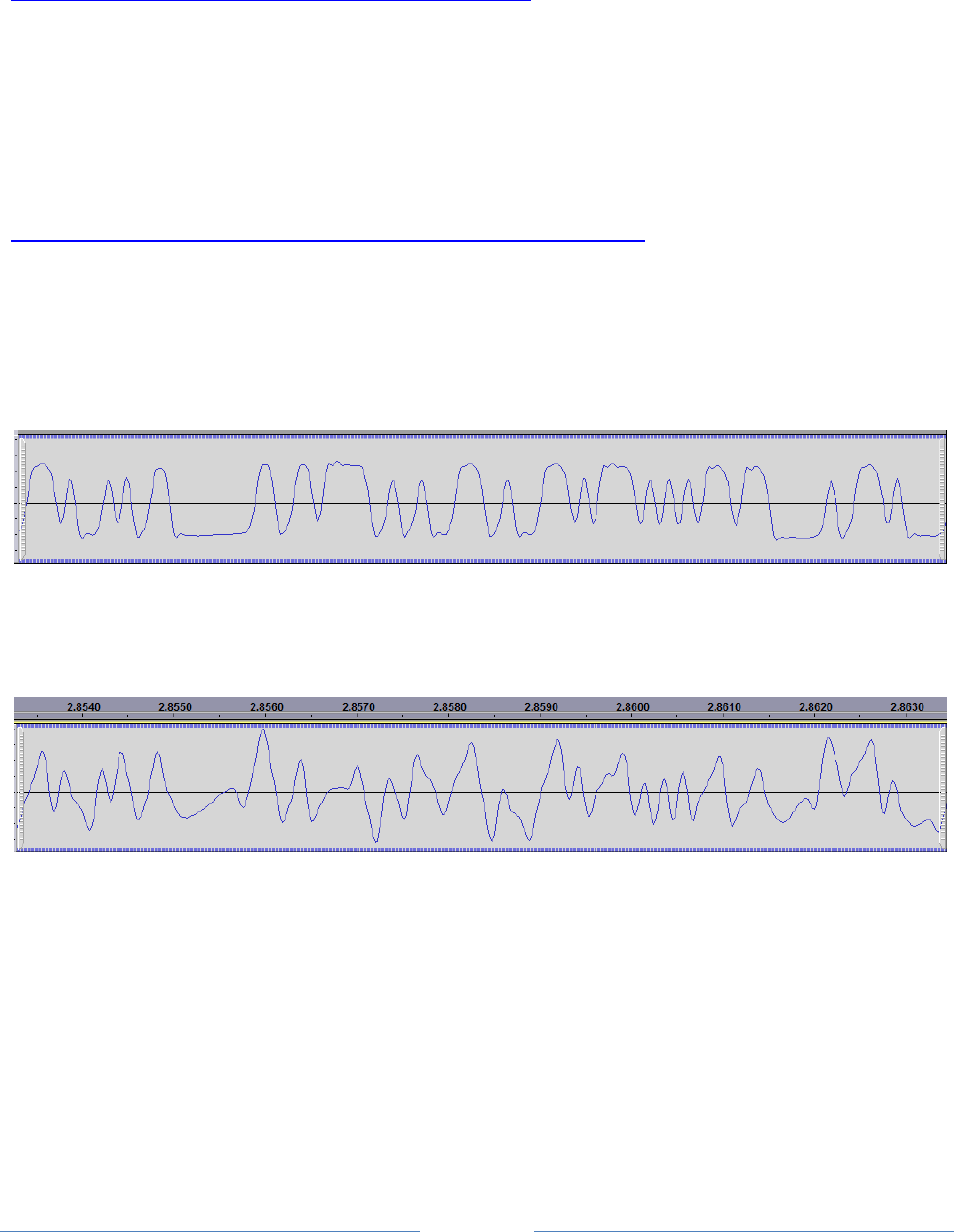
Page 38
Your “soundcard” must also have wide bandwidth. A 9600 baud signal could contain a 4800 Hz square
wave if the right combination of bits is present.
Take a look at the response of a popular chip used in cheap USB Audio adapters:
http://www.hardwaresecrets.com/datasheets/CM108.pdf Look in section 9.3.2 of the data sheet and
notice that the frequency response is flat, within 1 dB, from roughly 50 Hz to 15 kHz. This is what we
want. Wide and flat to minimize distortion.
Can you get better results with an expensive higher quality (whatever that means) audio interface? I
don’t know. I’ve seen some unsubstantiated claims to that effect but no scientific proof from side-by-
side comparisons.
Compare the CM108 frequency response with the SignaLink USB:
http://www.frenning.dk/OZ1PIF_HOMEPAGE/SignaLinkUSB-mods.html Response is bumpy and falls off
a cliff above 2.5 KHz. Good for 1200 baud but there is no possible way this could ever work for 9600
baud.
We also need low frequency response. VHF/UHF FM receivers usually have a high pass filter, with a cut
off of around 300 Hz so the CTCSS tones don’t get to the speaker. This is a disaster for 9600 baud data.
The signal below is from the “data” connector PR9 pin of Kenwood mobile rig:
Notice how we have a nice horizontal line where several bits in a row have the same value.
The next graph was captured at the same time from an RS-UV3 where the high pass filter was not
disabled.
Instead of a nice horizontal line, it droops back to the center because the lower frequencies are lost.
You can go faster if your radio and soundcard have enough bandwidth. For more discussion, see
related document Going-beyond-9600-baud.pdf.
8.5 2400 bps
There are different – and incompatible – ways to get 2400 bits per second through a voice radio.

Page 39
AFSK could also be used but you’d probably need to get the two tones a little further apart for good
results. I’ve seen references to ham radio 2400 baud AFSK with 1200/2400 and 1775/3250 tone pairs.
That last one would have some trouble getting through the audio stages of most transceivers.
Back in the 1990’s there were at least three commercial TNCs that allowed 2400 bits per second.
MFJ-2400 which is an optional board for the MFJ-1270 or MFJ-1274.
AEA PK232-2400.
Kantronics KPC-2400.
Were they compatible with each other? I don’t know. If not, that might help explain why 2400 bps
never gained much popularity.
The first two listed above used the EXAR XR-2123 PSK modem chip which implements the V.26 / Bell 201
standard.
Rather than using multiple tones, this uses a single 1800 Hz tone but the phase is shifted to convey
data. This is called Phase Shift Keying (PSK). In this case, the phase is shifted in multiples of 90 to send
two bits at the same time. The phase changes at a maximum rate of 1200 “symbols” per second. The
signal state changes at 1200 baud and two bits are sent at once so we end up with 2400 bits per second.
For more information, see the accompanying document, 2400-4800-PSK-for-APRS-Packet-Radio.pdf.
8.6 4800 bps
There are even more ways to get 4800 bits/second.
I’ve heard of people using AFSK with 2400 and 4800 tones but it would be necessary to modify radios for
greater audio bandwidth. If you have that bandwidth, you can do better than AFSK.
The Hamilton Area Packet Network “HAPN-T” board pushes the digital signal through the radio in the
same way we would for 9600 baud operation. The literature doesn’t mention anything about data
scrambling so it would probably not be compatible with the K9NG/G3RUH scheme.
If we can distinguish between 4 different phases, why not go for 8? With a few minor modifications, a
V.27 style demodulator was also implemented. This uses the same 1800 Hz audio carrier. It can change
phase 1600 times per second so it is 1600 baud. The 8 phases can represent 3 bits at a time so we have
1600 x 3 = 4800 bits per second.

Page 40
For more information, see the accompanying document, 2400-4800-PSK-for-APRS-Packet-Radio.pdf.

Page 41
9 Configuration File & command line options
The default configuration provides standard 1200 baud AFSK reception and will be adequate for many
people. Those desiring more features and flexibility can change the operation by editing the
configuration file and restarting Dire Wolf. Some of the options available include:
Selecting alternate audio devices.
Dual channel (stereo) operation for use with two transceivers.
Audio sampling rate to balance between performance and CPU power required.
Transmission rates other than 1200 baud. e.g. 300 for HF use.
AFSK tones other than 1200 & 2200 Hz
Digipeating.
APRStt Gateway
Internet Gateway (IGate).
Beaconing.
Normally the configuration file is read from the current working directory. On Linux the user’s home
directory is also searched. The “-c” command line option can be used to read a file from a different
location.
Other command line options are described at the end of this section.
Configuration commands are generally a keyword followed by parameters.
Command keywords are case insensitive. i.e. upper and lower case are equivalent.
Command parameters are case sensitive. i.e. upper and lower case are different.
Any parameter values containing spaces must be enclosed by quotes.
Example: The next two are equivalent
PTT /dev/ttyS0 RTS
ptt /dev/ttyS0 RTS
But this not equivalent because device names are case sensitive.
PTT /dev/TTYs0 RTS
9.1 Audio Device
Often the system’s primary, maybe only, audio device is used.
If you have multiple soundcards, you might want to use a different dedicated interface rather than the
same one that goes to your speakers.

Page 42
Starting with version 1.2, up to three audio devices can be used at the same time. This allows operation
with up to six radio channels. If you need two channels, there are some advantages to using a separate
soundcard for each instead of running one in stereo.
Better utilization of multicore systems. Each soundcard can use a different CPU for the digital
signal processing. Two channels, on the same soundcard, must use the same CPU.
Simultaneous transmitting on multiple channels. Dire Wolf is not clever enough to transmit
both channels on the same sound card at the same time. One will have to wait until the other is
finished.
Inexpensive USB audio adapters only have mono microphone inputs.
Text-to-Speech applications can’t use a single channel of a soundcard in stereo mode.
Audio Device
Configuration
Command
Channels,
mono
Channels, stereo
Left
Right
0 = first or only
ADEVICE
or ADEVICE0
0
0
1
1 = second optional
ADEVICE1
2
2
3
2 = third optional
ADEVICE2
4
4
5
Note that valid radio channels might not be contiguous. For example if the first device is operating in
mono and the second device is operating in stereo, you will have radio channels 0, 2, and 3.
Applications use a single KISS or AGW network connection for all channels. The protocols have a way to
convey the channel (port) number.
Channel 0 (left or mono)
Channel 1 (right if stereo)
Channel 2 (left or mono)
Channel 3 (right if stereo)
Channel 4 (left or mono)
Channel 5 (right if stereo)
ADEVICE0
ADEVICE1
ADEVICE2
Multiport
TNC
Applications
KISS or
AGW
network
protocol

Page 43
9.1.1 Audio Device Selection – All Platforms
A radio channel (or pair of channels when using stereo) normally uses the same physical interface for
both input (receive) and output (transmit). In this case, it can be listed once, in the ADEVICE
configuration, as in these examples:
ADEVICE0 USB
ADEVICE1 plughw:1,0
ADEVICE2 "USB Audio Codec:5"
You could also list the same interface twice, once for input and once for output. These are equivalent
to the previous example where the interface was listed once.
ADEVICE0 USB USB
ADEVICE1 plughw:1,0 plughw:1,0
ADEVICE2 "USB Audio Codec:5" "USB Audio Codec:5"
It is also possible to use different audio interfaces for receive and transmit. Examples:
ADEVICE USB Bluetooth
ADEVICE1 plughw:1,0 plughw:2,0
ADEVICE2 "Built-in Line In" "USB Audio Codec:5"
The output interface must be something recognized by the sound system for your particular Operating
System, often referred to as a platform. Windows, Linux, and Mac OSX differences are covered in the
next few sections.
The sections after that cover additional forms that can be used for the input only. These are typically
used with Software Defined Radios (SDR).
The single “-“ character (usual Linux convention) or the keyword “stdin” means read from
standard input.
UDP:nnn means read from the specified UDP port.
In both cases, the audio streams must be 16 bit signed little endian. You must make sure that the
number of samples per second agree for the digital audio source and in the Dire Wolf configuration.
9.1.2 Audio Device selection - Windows
When Dire Wolf starts up, it displays the available audio devices.
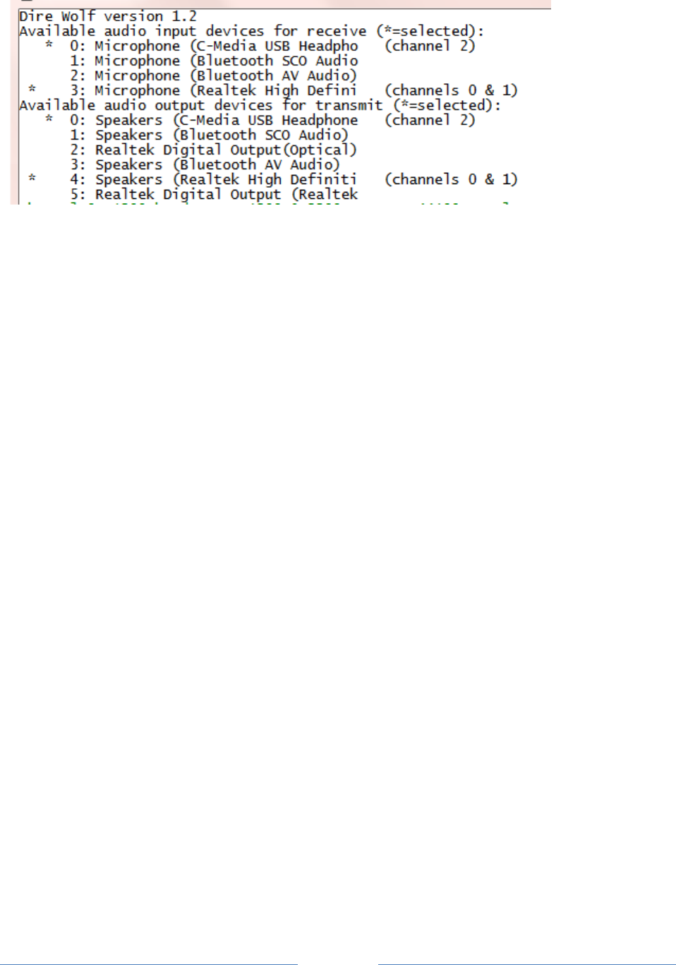
Page 44
Input devices and output devices are listed with a number assigned by the operating system. In the
configuration you can select them with either the number or a substring of the description. One
number (or string) can be used for both or the receive/transmit sides can be listed separately.
For this example, these two different forms would be equivalent:
ADEVICE0 3 4
ACHANNELS 2
ADEVICE1 0
or
ADEVICE0 High
ACHANNELS 2
ADEVICE1 USB
The numbers can change as USB devices are added and removed so picking some unique substring of
the description is more predictable.
Many people will simply use the default device and won’t have to worry about this option.
“ACHANNELS 2” means operate the preceding device in stereo mode for two radio channels.
“ACHANNELS 1” means operate the preceding device in mono for one radio channels.
Mono operation (one channel per device) is assumed if not specified.
9.1.3 Audio Device selection – Linux ALSA
Linux ALSA audio devices are much more flexible and therefore more complicated and confusing. Here
is the simplified version that will be appropriate in most cases.
Get a list of audio input cards by typing “arecord -l” (the option is lower case L)
john@linux64:~/direwolf$ arecord -l
**** List of CAPTURE Hardware Devices ****

Page 45
card 0: Intel [HDA Intel], device 0: AD1984 Analog [AD1984 Analog]
Subdevices: 0/1
Subdevice #0: subdevice #0
card 0: Intel [HDA Intel], device 2: AD1984 Alt Analog [AD1984 Alt Analog]
Subdevices: 1/1
Subdevice #0: subdevice #0
card 1: Device [C-Media USB Audio Device], device 0: USB Audio [USB Audio]
Subdevices: 1/1
Subdevice #0: subdevice #0
Get a list of audio output cards by typing “aplay -l” (the option is lower case L)
john@linux64:~/direwolf$ aplay -l
**** List of PLAYBACK Hardware Devices ****
card 0: Intel [HDA Intel], device 0: AD1984 Analog [AD1984 Analog]
Subdevices: 0/1
Subdevice #0: subdevice #0
card 0: Intel [HDA Intel], device 2: AD1984 Alt Analog [AD1984 Alt Analog]
Subdevices: 1/1
Subdevice #0: subdevice #0
card 1: Device [C-Media USB Audio Device], device 0: USB Audio [USB Audio]
Subdevices: 1/1
Subdevice #0: subdevice #0
In this case we find two “cards” to use the ALSA terminology. The first (card 0) is on the system board.
The second (card 1) is a cheap USB audio adapter. Remember these numbers so we can reference the
desired one later.
Troubleshooting tip:
What if “aplay –l” complains, “no soundcards found…”?
I had a situation where user “root” could see the devices but an ordinary user could not.
The solution was to add the user name to the “audio” group like this.
sudo addgroup john audio
This will not take effect immediately. Log out and log in again.
In this example, I want to pick the USB device. Recall that the card number was 1 so we want to put
“plughw:1,0” in the configuration file like this:
ADEVICE plughw:1,0
If you had a third audio “card,” its name would be plughw:2,0
Use pavucontrol, alsamixer, or similar application to set the audio signal levels.
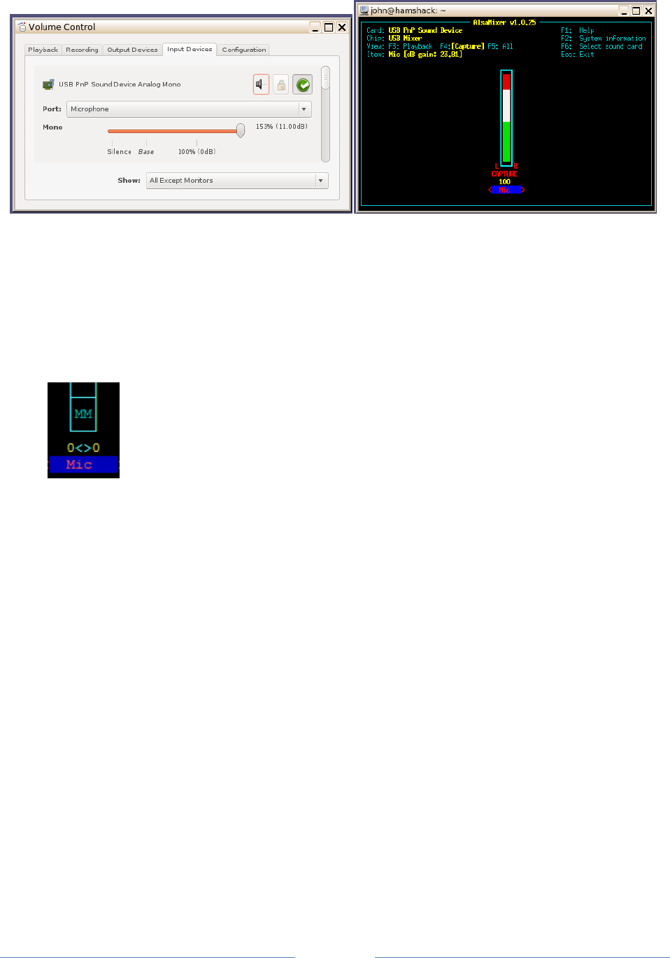
Page 46
If the user has PulseAudio installed, the installing of pavucontrol is mandatory to make sure the right
audio routing is done. In many respects, pavucontrol can do everything that alsamixer can do but not
the other way around. Unfortunately, there are reports that pavucontrol can create blocking issues and
programs will crash if it's running or they will stop running when pavucontrol is loaded.
Troubleshooting tip:
On a new system you might find the audio input device initially muted. If you see
“MM” in alsamixer, select the input device using and keys then press “m” to
unmute it. Use ↑ key to set near maximum gain.
Once you have the proper levels set, save them with:
sudo alsactl store
Otherwise, you might find them reset to some other default the next time you reboot.
You might need to use "sudo alsactl restore" to make sure proper sound levels are always restored.
9.1.4 Audio Device selection – Mac OS X
The Macintosh version uses Port Audio. The audio device names may contain spaces. If they do, the
parts with spaces must be quoted so we now which spaces are part of the names and which spaces
separate them.
ADEVICE "USB Audio Codec:6" "USB Audio Codec:5"
When Dire Wolf starts up, you should see a list of the audio devices available.

Page 47
9.1.5 Audio Device properties
Two options are available. They apply to the most recent ADEVICEn command.
ARATE sample-rate
Where,
sample-rate is number of audio samples per second.
The default is 44100. Other standard values are 22050 and 11025.
When using a normal audio interface (built in to motherboard or USB adapter),
it’s generally best to take the default.
This would be necessary when using a software defined radio which tend to use
rates like 48000 or 24000. This can also be specified on the command line for
the first device only.
ACHANNELS num-channels
Where,
num-channels is 1 for mono (default) or 2 for stereo,
allowing use of two radio channels on one soundcard.
People find “ACHANNELS” confusing because it is too similar to “CHANNEL.” Would it be better to use
something more distinct such as “STEREO?”
9.1.6 Use with Software Defined Radios
When using software defined radios (SDR), the audio will be coming from another application rather
than a “soundcard.”
9.1.6.1 gqrx
Gqrx (2.3 and later) has the ability to send streaming audio through a UDP socket to another application
for further processing. As explained in http://gqrx.dk/doc/streaming-audio-over-udp, select the
Network tab of the audio settings window. Enter the host name or address where Dire Wolf will be
running. Use “localhost” if both are on the same computer. Pick some unused UDP port. Here we use
the same number as in the gqrx documentation.
Use the following Dire Wolf configuration file options:
ADEVICE udp:7355 default
ARATE 48000
ACHANNELS 1

Page 48
This means that Dire Wolf will obtain audio from a UDP stream for receiving. If you transmit on that
channel, audio will go to the ALSA device named “default.”
Alternatively, you can override the configuration file settings with command line options like this:
direwolf -n 1 -r 48000 -b 16 udp:7355
“-n 1” sets number of audio channels to 1.
“-r 48000” means audio sample rate of 48000 per second.
“-b 16” means 16 bits per sample, signed, little endian.
Note that these command line options apply only to the first audio device (ADEVICE0) and the first
channel (CHANNEL 0).
9.1.6.2 rtl_fm
Other SDR applications might produce audio on stdout so it is convenient to pipe into the next
application. In this example, the final “-“ means read from stdin.
rtl_fm -f 144.39M -o 4 - | direwolf -n 1 -r 24000 -b 16 -
Instead of command line options, you could do the same thing in the configuration file like this:
ADEVICE0 stdin default
ARATE 24000
See http://kmkeen.com/rtl-demod-guide/index.html for rtl_fm documentation.
Here is another possible variation you might want to try. In one window, start up Dire Wolf listening to
a UDP port. Note that rtl_fm has a default sample rate of 24000.
direwolf -n 1 -r 24000 -b 16 udp:7355
In a different window, run rtl_fm and use the netcat utility to send the audio by UDP.
rtl_fm -f 144.39M -o 4 - | nc -u localhost 7355
Note that the SDR and Dire Wolf can be running on different computers, even different operating
systems. You could use the command above on Linux but change localhost to the address of a Windows
machine where Dire Wolf is running.
If you see some warning about audio input level being too high, don't worry about in this case.
It's only a potential problem when using the analog input of a sound card. If the analog audio input is
too large, it can exceed the range of the A/D converter, resulting in clipping, distortion of the signal, and
less reliable demodulation. The warning level is overly cautious. The input level can go much higher
before it reaches the A/D range limit.
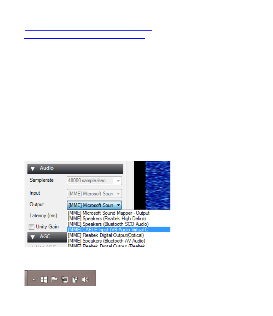
Page 49
In this case, where 16 bit digital audio is going from one application to another, there is no danger of
overflowing the signal range.
9.1.6.3 SDR#
The SDR# website doesn’t seem to have any documentation on how to use the software. They just
point to a Google search:
http://www.google.com/search?q=sdrsharp+tutorial
Here are some other good locations to help you get started.
http://www.atouk.com/SDRSharpQuickStart.html
http://www.qsl.net/yo4tnv/docs/SDRSharp.pdf
https://learn.adafruit.com/getting-started-with-rtl-sdr-and-sdr-sharp/sdr-number-fm-radio
First verify that you can hear the desired signal through the speaker. Check the frequency calibration
against a signal of known frequency. My cheap RTL-SDR dongle was off by 64 ppm which is more than 9
kHz on the 2 meter band.
How can we send the received audio to another application instead of the speaker? You could install a
second sound card and connect the” line out” from the first to the “line in” of the second. There is
another way. Install a “virtual audio cable” which is a pair of imaginary audio devices connected to each
other without any hardware in the middle.
Install VB-CABLE Driver from http://vb-audio.pagesperso-orange.fr/Cable/ and reboot.
Nothing shows up under the Programs menu so don’t worry when you don’t see anything new there.
Run SDR# and notice the audio settings. It probably has 48000 samples per second. Instead of using the
default output, select the new “CABLE Input (VB-Audio Virtual C” instead.
Let’s test what we have so far. In the Task Bar notification area (usually bottom right corner) right click
on the speaker icon and pick Recording Devices from the pop up menu.
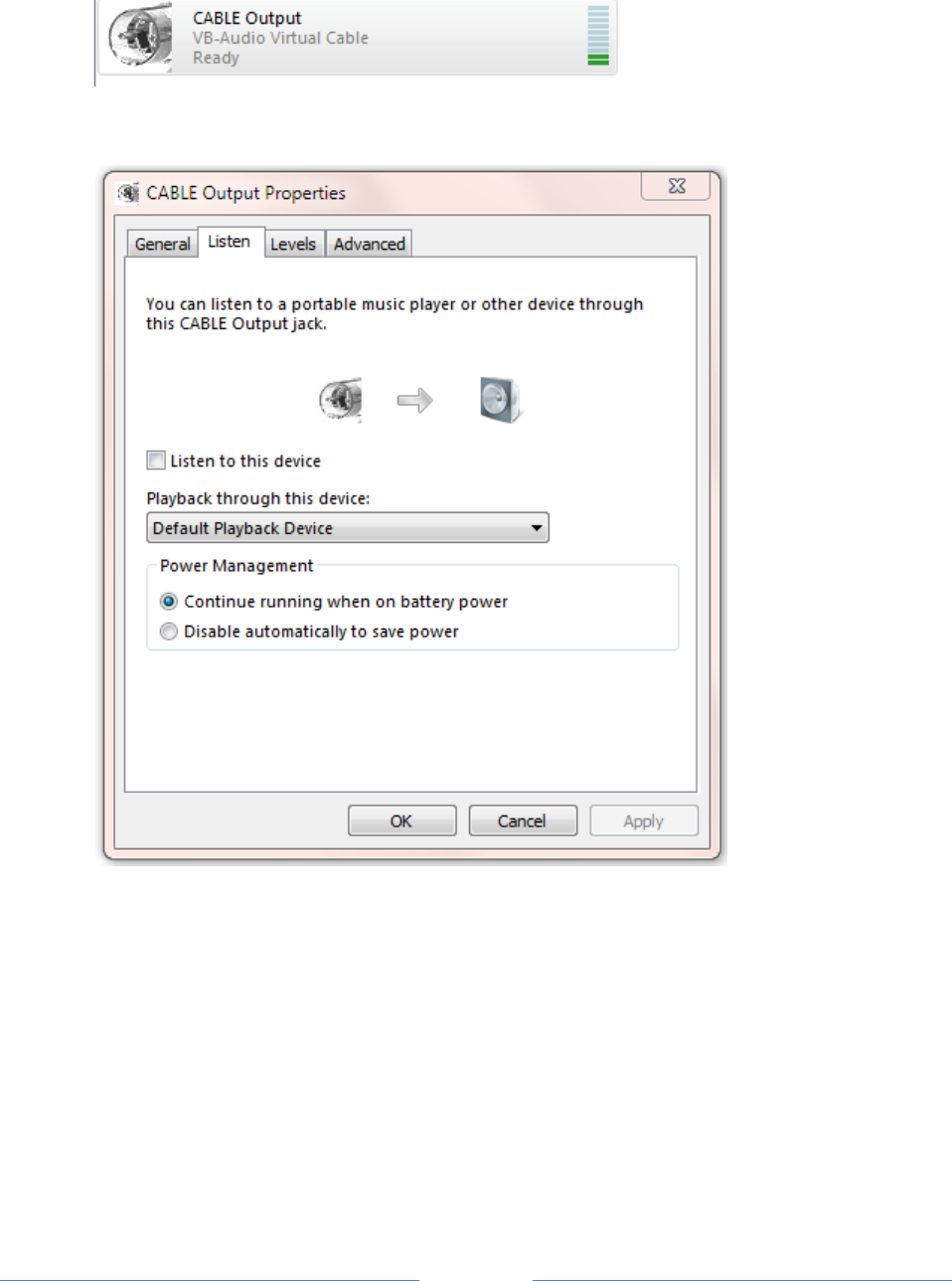
Page 50
You should see CABLE Output and the level indicator on the right should show some activity. Select it
and click the Properties button.
Pick the Listen tab.
Check the “Listen to this device” box and Apply. You should hear audio from SDR# through the
speaker. Leave it on for now during the testing. You might want to turn it off again after it is all
working.
If you look at the CABLE device Advanced properties,
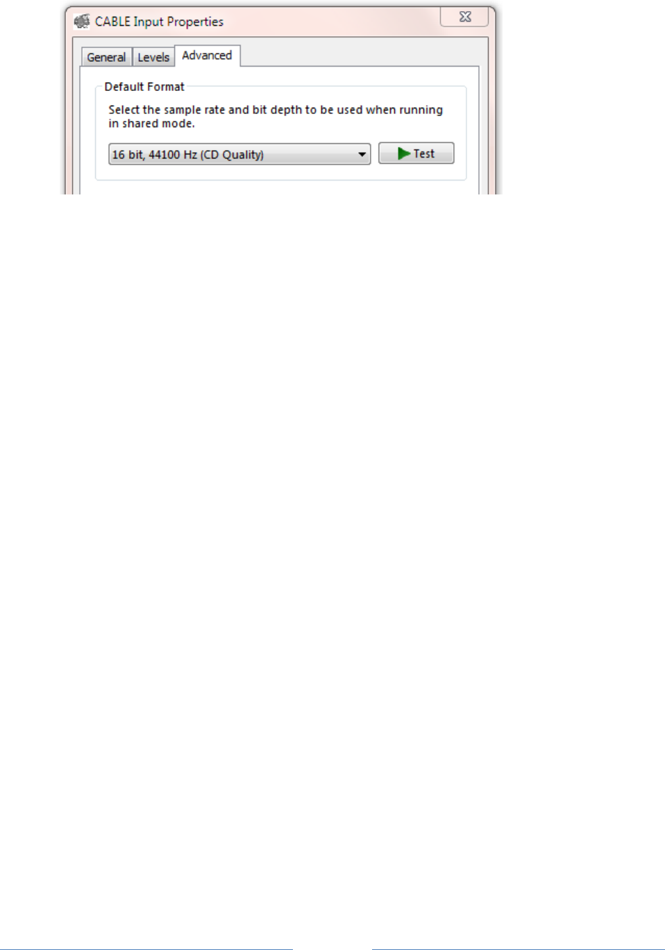
Page 51
you will find that it says 44100 Hz sample rate. We are using 48000 but this doesn’t seem to cause a
problem. I don’t know if it is performing rate conversions or just pushing the bytes through and not
caring.
I found the mismatch to be disturbing and changed it to different values for sample rate, bits per
sample, and number of channels. It didn’t seem to make any difference. Based on the evidence, this
setting seems to be ignored and the bytes just get pushed through.
It is important that the applications producing and consuming the audio stream agree. The delivery
service doesn’t seem to care.
Put this in your direwolf.conf file:
ADEVICE CABLE 0
ARATE 48000
When you start up Dire Wolf, you should see something like this:
Reading config file direwolf.conf
Available audio input devices for receive (*=selected):
0: Microphone (Realtek High Defini
1: Microphone (Bluetooth SCO Audio
2: Microphone (Bluetooth AV Audio)
* 3: CABLE Output (VB-Audio Virtual (channel 0)
Available audio output devices for transmit (*=selected):
* 0: Speakers (Realtek High Definiti (channel 0)
1: Speakers (Bluetooth SCO Audio)
2: CABLE Input (VB-Audio Virtual C
3: Realtek Digital Output(Optical)
4: Speakers (Bluetooth AV Audio)
5: Realtek Digital Output (Realtek
Channel 0: 1200 baud, AFSK 1200 & 2200 Hz, E+, 48000 sample rate.
Note: PTT not configured for channel 0. (Ignore this if using VOX.)
The lines of interest have been highlighted in red.
The audio input is from the CABLE output device.
The sample rate matches the value seen in SDR#.
You should now be able to decode the packets you hear.

Page 52
9.1.6.4 SDR Troubleshooting
If you can hear packets but they are not being decoded, try adding “-a 10” to the command line. This
will print out the audio sample rate and level each 10 seconds. In this example, we see that audio is
being received. However, I “accidentally” forgot to set the audio sample rate in the Dire Wolf
configuration file so it defaults to 44100. The decoder is expecting 44.1k samples per second, but the
actual rate is 48k so the decoding will fail.
Reading config file sdrsharp.conf
Available audio input devices for receive (*=selected):
0: Microphone (Realtek High Defini
1: Microphone (Bluetooth SCO Audio
2: Microphone (Bluetooth AV Audio)
* 3: CABLE Output (VB-Audio Virtual (channel 0)
Available audio output devices for transmit (*=selected):
* 0: Speakers (Realtek High Definiti (channel 0)
1: Speakers (Bluetooth SCO Audio)
2: CABLE Input (VB-Audio Virtual C
3: Realtek Digital Output(Optical)
4: Speakers (Bluetooth AV Audio)
5: Realtek Digital Output (Realtek
Channel 0: 1200 baud, AFSK 1200 & 2200 Hz, E+, 44100 sample rate.
Note: PTT not configured for channel 0. (Ignore this if using VOX.)
Ready to accept AGW client application 0 on port 8000 ...
Ready to accept KISS client application on port 8001 ...
ADEVICE0: Sample rate approx. 48.0 k, 0 errors, receive audio level CH0 61
ADEVICE0: Sample rate approx. 47.9 k, 0 errors, receive audio level CH0 63
ADEVICE0: Sample rate approx. 48.0 k, 0 errors, receive audio level CH0 62
ADEVICE0: Sample rate approx. 48.1 k, 0 errors, receive audio level CH0 52
ADEVICE0: Sample rate approx. 47.9 k, 0 errors, receive audio level CH0 55
The reported sample rate will vary a little, especially for short collection intervals. This is because the
audio samples are transferred in large blocks for efficiency rather than a steady stream of one at a time.
9.2 Radio channel configuration
As mentioned above you can have up to six radio channels. Specify options for each channel like this:
CHANNEL 0
(options for first (left) or only channel of first device: MYCALL, MODEM, PTT, etc.)
CHANNEL 1
(options for second channel if first device is operating in stereo.)
Each of the following MYCALL, MODEM, PTT, and so on, applies to the most recent CHANNEL command.

Page 53
9.2.1 Radio channel – MYCALL
Multiple radio channels can use the same or different station identifiers. This is required for beaconing
or digipeating. Example:
MYCALL WB2OSZ-5
The AX.25 specification requires that the call is a maximum of 6 upper case letters and digits. The
substation id (SSID), if specified, must be in the range of 1 to 15.
9.2.2 Radio channel - Modem configuration , general form
The format has changed in version 1.2 to be simpler and more intuitive. The old format will still be
accepted but you will see a message with a suggestion to upgrade to the new format.
Each radio channel can be configured separately for different speeds and modem properties. The
general form of the configuration option is:
MODEM speed [ option ]…
In most cases, you can just specify the speed. For special situations you can override the defaults with
these options:
Form
Purpose
Applicable to
Example, Comments
mark:space
Specify non-default tone
pair for AFSK modes.
Use 0:0 to for K9NG/G3RUH
style baseband.
All.
2130:2230 for AEA/timewave PK-
232 HF tones.
num@offset
Configure ‘num’ different
demodulators with center
frequencies shifted by
‘offset’ Hz.
Mostly 300 baud
on HF SSB.
5@30 could be used to
compensate for other transmitters
off frequency.
/n
Divide audio sampling
frequency to reduce CPU
speed requirement.
The multiple
demodulator
case, very old
computer, or
micrcocomputer.
/2 means use half the normal
audio sample rate.
Do not use for 9600 baud.
ABCDEF+-
Pick demodulator version
and optional multiple
slicers.
A, B, C, E, and F
are for 1200
baud. D is
optimized for
300 baud.
“+” is applicable
to 1200 and
9600.
More details in the receive
performance section. Short
answer: A, B , C, F are obsolete.
D is the default for 300 baud.
E is the default for 1200.
E+ will provide better
compensation for imbalance of
mark/space tone amplitudes.

Page 54
The letters are only for AFSK
modes and do NOT apply to 9600
baud.
Note: The @ and + options are mutually exclusive. Both can’t be used at the same time on the same
channel.
9.2.3 Radio channel - Modem configuration for 1200 baud
The default configuration is 1200 baud, AFSK with 1200 & 2200 Hz tones for VHF FM use. If you omit
the configuration, the default is the same as using either one of these:
MODEM 1200
MODEM 1200 1200:2200 E+
The “+” demodulator option compensates for the variety of FM transceiver pre-emphasis / de-emphasis
mismatch. The accompanying document “A-Better-APRS-Packet-Demodulator.pdf” covers this in great
detail. This is on by default but you can deactivate it with “-“.
Demodulator style E is the default. There is probably no reason to use anything else for 1200 baud.
Both send and receive must use the same speed and modulation type. In special situations, such as a
satellite, you might want to receive 9600 baud and transmit 1200 baud. In this case you would need to
use two different channels, one for transmit, and one for receive.
9.2.4 Radio channel - Modem configuration for 300 baud HF
The following are equivalent suitable configurations for 300 baud HF SSB operation using the popular
1600 / 1800 Hz tone pair.
MODEM 300
MODEM 300 1600:1800
MODEM 300 1600:1800 D
When using HF SSB, any mistuning or poor calibration can cause the audio frequencies to shift. These
are less likely to be decoded properly. For this situation, we can configure multiple decoders per
channel, each tuned to a different pair of audio frequencies. With this example, we have 7 different
modems, spaced at 30 Hz apart.
MODEM 300 7@30
When the application starts up, the modem configuration is confirmed along with the audio frequencies
for each. This should be able to tolerate mistuning of 100 Hz in each direction.
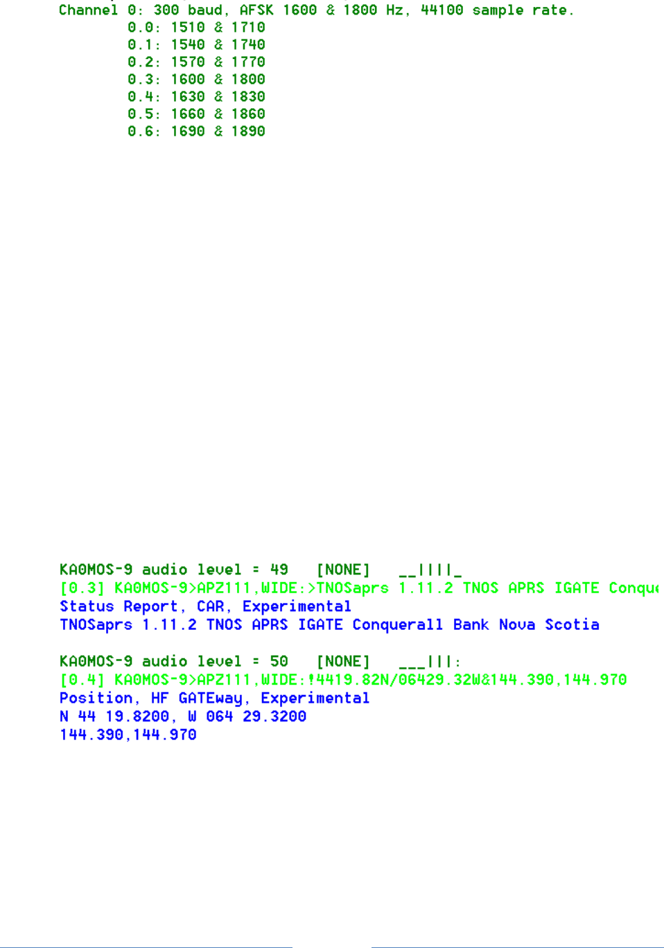
Page 55
When multiple modems are configured per channel, a simple spectrum display reveals which decoders
picked up the signal properly.
| means a frame was received with no error.
: means a frame was received with a single bit error. (FIX_BITS 1 or higher configured.)
. means a frame was received with multiple errors. (FIX_BITS 2 or higher configured.)
_ means nothing was received on this decoder.
Here are some samples and what they mean.
___|___ Only the center decoder (e.g. 1600/1800 Hz) was successful.
_|||___ 3 different lower frequency modems received it properly.
Assuming USB operation, the transmitting station is probably a
little low in frequency.
___|||: 3 different higher frequency modems received it with no error.
The highest one received it with a single bit error.
Here are some typical signals heard on 10.1476 MHz USB.
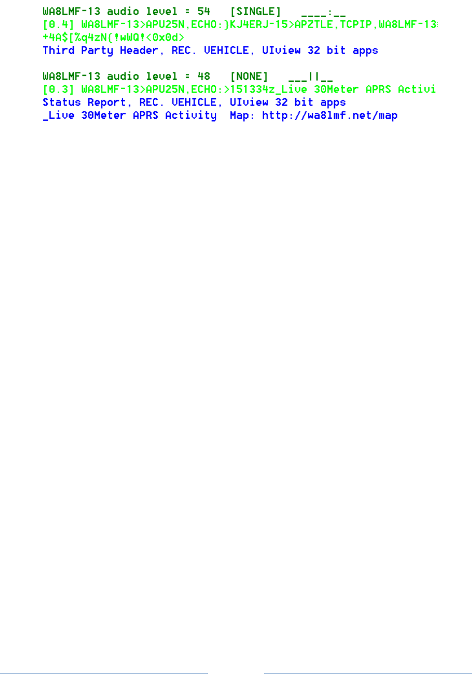
Page 56
The beginning of the monitor line shows the radio channel and which modem was used.
The “+” option would not be useful for 300 baud HF SSB because we don’t have the FM pre-emphasis /
de-emphasis that causes the two tone amplitudes to be way out of balance.
Running several demodulators in parallel can consume a lot of CPU time. You will probably want to use
the “/n” option in this case to reduce the audio sample rate and CPU load.
9.2.5 Radio channel - Modem configuration for 9600 baud
K9NG / G3RUH style baseband with scrambling is used with there are no AFSK tones specified:
MODEM 9600
MODEM 9600 0:0
Using the “/n” option would be a very bad idea in this case. We need the high sample rate to capture
the high baud rate.
The demodulator types (A, B, C, …) are only for the AFSK modes. They are not applicable to 9600 baud.
The “+” option can also be useful in this case but for a different reason. There are no tones but a DC
offset can be introduced with using a software defined radio (SDR). This will be explained in a later
update to “A-Better-APRS-Packet-Demodulator.”
As mentioned in an earlier section, this won’t work with the microphone and speaker connection on
your transceiver. The audio amplifiers, designed for voice, do not have enough bandwidth and distort
the signal so it is not usable.
9.2.6 Radio Channel - Allow frames with bad CRC
Normally we want to reject any received frame if the CRC is not perfect. Dire Wolf can optionally try to
fix a small number of corrupted bits. “Fix” is probably too strong of a word. It’s really guessing and
there is no guarantee that it is right.
See section called “One Bad Apple Don’t Spoil the Whole Bunch” for more discussion.

Page 57
Previously it was a global setting that applied to all channels. In Version 1.2, it applies to the most
recent CHANNEL so different radio channels can have different settings .
The general format is:
FIX_BITS effort_level [ sanity_check ] [PASSALL ]
Where,
effort_level indicates the amount of effort to modify the frame to get a valid CRC.
0 means no attempt.
1 means try changing single bits. (default)
2 means try changing two adjacent bits.
larger not recommended because there is a high probability of getting bad data.
sanity_check adds a heuristic to guess whether the fix up attempt was successful.
APRS tests whether it looks like a valid APRS packet. (default)
AX25 only checks the address part. Suitable for non-APRS packet.
NONE bypasses the sanity check.
PASSALL means allow the frame through after exhausting all fix up attempts.
Occasionally you might see something resembling a valid packet but most of the
Time it will just be random noise. Examples:
audio level = 45(32/16) [PASSALL]
[0] <0xc0>k<0xe3>)<0x15><0xe5><0xe7>y<0xd6>r<0xeb>Um<0x8a>#
audio level = 28(23/19) [PASSALL]
[0] <0xa4><0xa6>"<0xa7>f<0xa2><0xa0><0x96>b<0x9a><0x92><0x88>@<0xe4><0x96><0x84>
b<0xa0><0x9e><0xa4><0xe4><0xae>b<0x9a><0xa4><0x82>@<0xe0><0xae><0x92><0x84>
<0x8a>d@c<0x03><0xf0>'cFwmH'>/=KEN<0x10>FROM COMTOOCOOK,N.H.<0x0d>
Only error-free frames are digipeated or passed along to an APRTS-IS server. Propagating possibly
corrupt data would not be acting responsibly. Note that these frames are passed along to attached
applications. If they pass along data to someone else, it could be corrupt.
9.2.7 Radio channel – DTMF Decoder
A DTMF (“Touch Tone”) decoder can be enabled, for the current channel, with this command:
DTMF
You can confirm that the option is selected from the message at application start up time:
Channel 0: 1200 baud, AFSK 1200 & 2200 Hz, C+, 44100 sample rate, DTMF decoder enabled.

Page 58
9.2.8 Radio Channel – Push to Talk (PTT)
There are up to five different methods available for activating your transmitter.
Serial port control lines.
General Purpose I/O pins (Linux only).
Parallel Printer Port (Linux only).
“hamlib” (optional, Linux only).
VOX (voice operated transmit) – External hardware activates the transmitter when transmit
audio is present.
When PTT has not been configured, you will see a message like this at start up time:
Note: PTT not configured for channel 0. (Ignore this if using VOX.)
You don’t need to configure an output control line when using VOX so just ignore the informational
note.
9.2.8.1 PTT with serial port RTS or DTR
To use a serial port (either built-in or a USB to RS232 adapter cable), use an option of this form:
PTT device-name [-]rts-or-dtr [ [-]rts-or-dtr ]
For Windows the device name would be COM1, COM2, etc.
For Linux, the device name would probably be something like /dev/ttyS0 or /dev/ttyUSB0. You can also
use the Windows format. COM1 is converted to /dev/ttyS0, COM1 is converted to /dev/ttyS1, and so
on.
Normally the higher voltage is used for transmit. Prefix the control line name with “-” to get the
opposite polarity. Some interfaces want RTS and DTR to be driven with opposite polarity to minimize
chances of transmitting at the wrong time. Starting with version 1.2, you can now specify two control
lines with the same or opposite polarity. Example:
PTT COM1 RTS DTR
PTT COM1 RTS -DTR
Alternatively, the RTS and DTR signals from one serial port could control two transmitters. E.g.
CHANNEL 0
PTT COM1 RTS
CHANNEL 1
PTT COM1 DTR
Examples:

Page 59
PTT COM1 RTS
PTT COM1 -DTR
PTT /dev/ttyUSB0 RTS
9.2.8.2 PTT with General Purpose I/O (GPIO)
On Linux you can use General Purpose I/O (GPIO) pins if available. This is mostly applicable to a
microprocessor board, such as a Raspberry Pi or BeagleBone, not a general purpose PC. Precede the pin
number with “-“ to invert the signal.
PTT GPIO [-]pin-number
Example:
PTT GPIO 25
There are more details in the separate Raspberry Pi APRS document.
9.2.8.3 PTT with Parallel Printer Port
The old fashioned parallel printer port can also be used on Linux. In this case, use LPT, followed by an
optional “-“ to mean inverted, and the data bit number. This works only with the primary parallel
printer port on the motherboard or possibly a PCI card configured to use I/O address 0x378. It will not
work with a USB to parallel printer port adapter.
Examples:
PTT LPT 0
PTT LPT -2
9.2.8.4 PTT using hamlib
If the Linux version was built to use hamlib, you can also use this form for greater flexibility:
PTT RIG model port
Where,
model identifies the type of radio.
Get a list of values by running “rigctl --list”.
2 is used to communicate with “rigctld.”
“AUTO” will try to guess what is connected.
Port is name of serial port connected to radio.
In the case where model is 2, this would be a host name/address
and optional port number. Default port is 4532

Page 60
Examples:
Yeasu FT-817 on /dev/ttyUSB0: PTT RIG 120 /dev/ttyUSB0
rigctld on localhost: PTT RIG 2 localhost:4532
Try to guess what is on /dev/ttyS0: PTT RIG AUTO /dev/ttyS0
For more details, see http://sourceforge.net/p/hamlib/wiki/Hamlib/
FAQ: http://sourceforge.net/p/hamlib/wiki/FAQ/
This would be a good place to go with questions: http://sourceforge.net/p/hamlib/discussion/
9.2.8.4.1 Hamlib PTT Example 1: Use RTS line of serial port.
Of course, it would be a lot easier to use the built-in functionality for this simple case. This is just an
exercise on our journey to being able to use the flexibility for more interesting cases.
First let’s try it manually. In one terminal window, start up a daemon with the desired configuration.
rigctld -m 1 -p /dev/ttyS0 -P RTS -t 4532
“/dev/ttyS0” is the serial port on the mother board.
“-m 1” is for the “dummy” backend, not some particular type of radio.
“-t 4532” is not really necessary because that is the default port.
In another window,
echo "\set_ptt 1" | nc localhost 4532
echo "\set_ptt 0" | nc localhost 4532
echo "\set_ptt 1" | nc localhost 4532
echo "\set_ptt 0" | nc localhost 4532
We observe that the RTS control line changed. Next…
rigctl -m 2 -r localhost:4532
T 1
T 0
T 1
T 0
q
“-m 2” means talk to “rigctld.”
“-r localhost:4532” indicates where rigctld is running. You can leave off the “:4532” because that
is the default port. You might also see examples with 127.0.0.1 which is equivalent but obscure and
confusing to those without any networking background. Actually, it seems you can omit the “-r” option
entirely because localhost is the default for rig “model” 2.

Page 61
Again, we should observe the RTS line of serial port /dev/ttyS0 changing. To use this for PTT, put this in
your Dire Wolf configuration file:
PTT RIG 2 localhost:4532
The “2” is very important. It means communicate with the instance of “rigctld” that we already started
up. In this case it is running on the same host but it could be running on a different computer.
9.2.8.4.2 Hamlib PTT Example 2: Use GPIO of USB audio adapter. (e.g. DMK URI)
A few people have asked about support for the DMK URI. This uses a C-Media CM108/CM119 with one
interesting addition: a GPIO pin is used to drive PTT. Here is some related information.
DMK URI:
http://www.dmkeng.com/URI_Order_Page.htm
http://dmkeng.com/images/URI%20Schematic.pdf
http://www.repeater-builder.com/voip/pdf/cm119-datasheet.pdf
Homebrew versions of the same idea:
http://images.ohnosec.org/usbfob.pdf
http://www.qsl.net/kb9mwr/projects/voip/usbfob-119.pdf
http://rtpdir.weebly.com/uploads/1/6/8/7/1687703/usbfob.pdf
http://www.repeater-builder.com/projects/fob/USB-Fob-Construction.pdf
We will need to use one of the “/dev/hidraw” devices. But which one?
Create a shell script, with the following content:
#!/bin/bash
# List the names for the HID raw devices.
# WB2OSZ, Feb. 2016
h=/sys/class/hidraw
for x in `ls $h`
do
n=`grep HID_NAME $h/$x/device/uevent | gawk -F= '{ print $2 }'`
echo /dev/$x $n
done
When we run it, we see that we want /dev/hidraw3 in this case:
/dev/hidraw0 Microsoft Microsoft 3-Button Mouse with IntelliEye(TM)
/dev/hidraw1 Dell Dell USB Keyboard
/dev/hidraw2 Dell Dell USB Keyboard
/dev/hidraw3 C-Media USB Audio Device

Page 62
The default permissions allow use only by root, so we need to change this:
sudo chmod 666 /dev/hidraw3
Now we can start up rigctld:
rigctld -p /dev/hidraw3 -P CM108 -vvvv -C ptt_bitnum=2
Test it from another window:
rigctl -m 2
T 1
T 0
T 1
T 0
q
With the “-vvvv” debugging option for rigctld, you should see something like this:
cm108:cm108_ptt_set called
cm108:cm108_ptt_set bit number 2 to state 1
cm108:cm108_ptt_set called
cm108:cm108_ptt_set bit number 2 to state 0
cm108:cm108_ptt_set called
cm108:cm108_ptt_set bit number 2 to state 1
cm108:cm108_ptt_set called
cm108:cm108_ptt_set bit number 2 to state 0
Finally, put this in your direwolf configuration file in the appropriate channel section:
PTT RIG 2 localhost
Doing this every time you reboot would be annoying. How can we automate the process? We can
enhance our earlier script to include the necessary start up steps:
#!/bin/bash
# Look for C-Media device and start up rigctld
# with option to use bit 2 for PTT.
# WB2OSZ, Feb. 2016
echo "Look for suitable device for PTT."
h=/sys/class/hidraw
d=""
for x in `ls $h`
do
n=`grep HID_NAME $h/$x/device/uevent | gawk -F= '{ print $2 }'`
echo " /dev/$x $n"
if [[ "$n" =~ "C-Media" ]]
then
echo "Found suitable device /dev/$x"
if [ ! -z "$d" ]
then

Page 63
echo "WARNING! More than one found."
fi
d=/dev/$x
fi
done
if [ -z "$d" ]
then
echo "No suiable devices found for PTT."
exit
fi
echo "Starting up rigctld with PTT on $d"
if [ `whoami` != root ]
then
sudo chmod 666 $d
fi
# After it is working properly, you might want to take out –vvvv.
rigctld -p $d -P CM108 -vvvv -C ptt_bitnum=2
If you want it to run automatically after each reboot, add this to /etc/rc.local, using your script location.
/home/john/cm108.sh > /tmp/cm108.log 2>&1 &
Watch the debug output with a command like this:
tail -f /tmp/cm108.log
9.2.9 Radio Channel – Data Carrier Detect (DCD)
The carrier detect signal can be sent to any of the output locations available for PTT. The same serial
port can be used for both PTT and DCD. For example:
PTT COM1 RTS
DCD COM1 DTR
In this case, you could connect an LED to the serial port like this:
Pin 5 (GND) ---- (cathode) LED (anode) ---- 680 ohm resistor ---- Pin 4 (DTR)
9.2.10 Radio Channel – Connected Packet Indicator (CON)
A third indicator is active when connected to another station. Again, the same serial port can be used
for two different functions. For example:
PTT COM1 RTS
CON COM1 DTR
Or you could use GPIO pins like this:
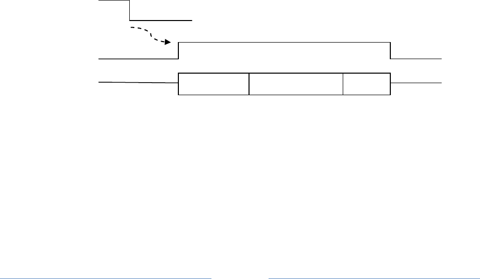
Page 64
PTT GPIO 25
DCD GPIO 24
CON GPIO 23
9.2.11 Radio Channel – Transmit Inhibit Input
For the Linux version only, it is possible to have a GPIO control input to prevent transmitting. This might
be used with a squelch signal from the receiver. A site with multiple radios could use this to give priority
to the other radio service when it is active.
TXINH GPIO 17
TXINH GPIO -17
As with PTT, minus in front of the GPIO number means invert the signal.
9.2.12 Radio Channel – Transmit timing
Transmit timing is determined by 5 parameters which can be different for each channel. The defaults
are:
DWAIT 0 x 10 mSec per unit = 0 mSec.
SLOTTIME 10 x 10 mSec per unit = 100 mSec.
PERSIST 63 probability for transmitting after each slottime.
TXDELAY 30 x 10 mSec per unit = 300 mSec.
TXTAIL 10 x 10 mSec per unit = 100 mSec.
Carrier Detect
Delay
PTT
Transmit Audio
When a frame is ready for transmission, we first have to wait until the channel is clear. The technical
term for this is Carrier Sense Multiple Access (CSMA). In plain English, if you want to say something,
wait until no one else is speaking.
First we wait for the DWAIT time. Normally this is zero. This is used only for specific situations
where the radio can’t turn around from receive to transmit fast enough.
For digipeated frames the transmission can begin immediately after the channel is clear.
TXDELAY
TXTAIL
AX.25 Frame(s)

Page 65
For other frames, SLOTTIME and PERSIST are used to generate a random delay. This is to
minimize the chances of two different stations starting to transmit at the same time. The
process is:
(a) Wait for SLOTTIME.
(b) If a random number, in the range of 0 to 255, is less than or equal to PERSIST, start to
transmit. Otherwise go back to step (a).
For the default values, we have delays with the following probabilities:
Delay, mSec Probability
100 .25 = 25%
200 .75 * .25 = 19%
300 .75 * .75 * .25 = 14%
400 .75 * .75 * .75 * .25 = 11%
500 .75 * .75 * .75 * .75 * .25 = 8%
600 .75 * .75 * .75 * .75 * .75 * .25 = 6%
700 .75 * .75 * .75 * .75 * .75 * .75 * .25 = 4%
etc. ...
If a signal is detected during any of the steps above, we go back to the top and start over.
The Push to Talk (PTT) control line is asserted.
The data can’t be sent immediately because the transmitter takes a little while to stabilize after being
activated. The HDLC “flag” pattern (01111110) is sent for a time period of TXDELAY. For historical
reasons, going back more than 30 years, the times are in 10 mS units so 30 actually means 300
milliseconds.
When sending audio out through a “soundcard” there is latency between sending an audio waveform to
the output device and when the sound comes out. We can’t be sure precisely when the queued up
sound has been completed so we need to keep the PTT on a little longer. The HDLC “frame” pattern is
also sent during this time to keep the channel busy. A TXTAIL of 10 (x10 mSec = 100 mSec) is probably a
little on the generous side but better safe than sorry.
9.2.12.1 Should I use wired PTT or VOX?
It might be tempting to use the VOX built into your transceiver and avoid the extra circuitry for the PTT
signal. Is this a good idea?
First let’s consider the case where we have a wired connection to activate the transmitter. The
transmitter is turned on, we send our digital data as an audio signal, and then turn off the transmitter

Page 66
when the audio is finished. Another station hears an empty channel, waits a little while, and starts
transmitting.
Wired PTT
My Transmit Audio
Another station
VOX stands for Voice Operated Transmit. It is designed for voice which contains small gaps between
words. It responds quickly when speech begins so it doesn’t chop off the beginning of the first word.
We don’t want the transmitter going on and off for each word so there is a built in delay before turning
the transmitter off again. This is usually referred to as the “VOX delay.” On one popular HT, the default
is 500 milliseconds and the minimum setting is 250. Another popular HT doesn’t have a configuration
setting for the amount of time time. Googling didn’t reveal any clues on how long this time might be. It
would not be unreasonable to assume they picked something around the default time for another
brand.
Keeping the transmitter on a half second after the sound ends is fine for voice. But what about digital
data? We saw in the previous section that another station waiting for a clear channel, will usually
transmit within a half second after no longer hears another digital signal.
My Transmit Audio
VOX delay
PTT from VOX
Another station
In this case, you will probably miss the beginning of another station transmitting because you haven’t
switched back to receive yet. You are also interfering with others by sending a quiet carrier.
My recommendation is to avoid VOX unless you can be sure the transmitter will turn off very soon (e.g.
less than 50 mSec.) after the audio signal is no longer present. If you insist on using VOX, be sure the
“VOX delay” setting is at the absolute shortest setting.
9.2.12.2 Frame Priority and KISS Protocol
Digital Data as Audio
Digital Data as Audio
Digital Data as Audio
Digital Data as Audio

Page 67
The AX.25 protocol spec defines two priorities for transmission of frames.
“Priority” queue for expedited frames.
These are sent as soon as the channel is not busy. On your screen you will see magenta lines
starting with “[nH],” where n is the channel, meaning High priority. APRS uses this for
digipeated frames.
“Normal” queue.
After the channel is clear, we wait for a random time to reduce chances of a collision. On your
screen you will see magenta lines starting with “[nL],” where n is the channel, meaning Low
priority.
Unfortunately the KISS protocol does not have a way to convey this distinction. If it looks like the client
application is sending an APRS frame, we apply a heuristic to decide. When a digipeater field has the
“has been used” bit set, the frame goes into the high priority queue. Otherwise it goes in the normal
low priority queue.
It’s not clear if something similar should be attempted for non-APRS AX.25 frames. It might be possible
to apply some heuristic for control vs. information frames but we might make the situation worse by
sending them out of the original order.
9.3 Logging of received packets
Specify the directory where log files should be written. Use “.” to use the current working directory.
Examples:
LOGDIR .
LOGDIR log-files
LOGDDIR /home/pi/aprslogs
A new log file is started each day. The log file has the name yyyy-mm-dd.log, where yyyy-mm-dd is the
current date. The file format is described later in this section.
9.4 Client application interface
Three different interfaces are provided for client applications such as APRSISCE/32, UI-View32, Xastir,
APRS-TW, YAAC, SARTrack, AX.25 for Linux, RMS Express, and many others.
9.4.1 AGWPE network protocol
In most case, Dire Wolf can be used as a drop in replacement for AGWPE. By default, it listens on
network port 8000. This can be changed with a command resembling:

Page 68
AGWPORT 8000
The raw mode (similar to KISS) interface has been available for a long time. This is fine for all APRS
applications and some others such as RMS Express.
Some other packet applications, such as Outpost PM, require the AX.25 connected mode. This has been
added in version 1.4. Earlier versions will display an error like this:
Can't process command from AGW client app.
Connected packet mode is not implemented.
The ttcalc sample application uses the AGW network protocol and can be used as a starting point for
writing your own applications.
In a system exposed to the Internet, you might want to disable the port for security reasons. Do this by
specifying 0 for the port number:
AGWPORT 0
9.4.2 Network KISS
The KISS protocol can also be used with a network port so Dire Wolf and the client application can be
running on different computers. The default is:
KISSPORT 8001
This can also be disabled by specifying 0:
KISSPORT 0
9.4.3 Serial port KISS - Windows
A configuration option like this:
NULLMODEM COM3
will provide a dumb KISS TNC on COM3. You need to provide either a “null modem” cable to another
serial port, used by the application, or configure a virtual null modem cable.
See later section, with “com0com” in the title, for an in depth discussion of how this works.
9.4.4 Serial port KISS - Linux
This feature does not use the configuration file. Instead it is activated by using the –p option on the
command line.

Page 69
A “pseudo terminal” is created, providing a virtual KISS TNC. The Linux chapter, “KISS TNC emulation –
serial port” section, provides some examples of how to use this with some popular applications.

Page 70
9.5 APRS Digipeater operation
This section describes digipeating for APRS operation. Traditional connected mode digipeating is
described in another section.
Digipeaters (short for digital repeaters) retransmit signals from other stations to increase their range.
Analog voice repeaters listen on one frequency and simultaneously retransmit the same signal on a
different frequency.
Digital repeaters use a “store and forward” approach. A packet is received, examined, then possibly
modified and retransmitted. Usually it is retransmitted on the same radio channel but it is also possible
for a multi-port digipeater to link multiple radio channels. Packets received on one channel can be
retransmitted on different channels. Each to/from channel combination can have its own filtering rules
to determine what is allowed.
9.5.1 What Gets Repeated?
Clearly a digipeater should not retransmit everything it hears. If it did that, anything that was heard on
the channel would keep bouncing back and forth between all of the available digipeaters. We will get
into the exact rules later but first we need to understand what the standard display format is telling us.
The standard display format has an address part composed of:
Source address - Originating station. Normally a ham radio callsign.
An extra number, called the SSID, allows up to 16 stations to
be operated under the same callsign.
Destination address - In traditional connected mode packet, this would be a specific
station. In APRS this is used in several different ways. We can
ignore it for this discussion.
Via path - Up to 8 items for path that the packet has taken already and
where it might go.
Suppose the original packet looked like this, with 2 digipeaters listed. Notice that there is no “*” so we
are hearing the original (source) station:
WB2OSZ>APRS,N2GH,W2UB:something
If DIGI1 retransmits it, the packet would look like this in the standard monitor format:
WB2OSZ>APRS,N2GH*,W2UB:something

Page 71
The “*” means that the “has been used” flag (the “H” bit), associated with the first digipeater field was
set to true. This has been used up and is no longer used in making further decisions. If DIGI2
retransmits the same packet, the result looks like this:
WB2OSZ>APRS,N2GH,W2UB*:something
The “*” after the second position indicates that the “has been used” flag (“H” bit) is set for the first and
second digipeater positions.
You should never see more than one “*” in the via path. It should appear only for the last one which has
has been used. The last digipeater field is marked with “*” so this is no longer eligible for being
processed by another digipeater.
This is what you know if everyone is well behaved:
The packet originally came from WB2OSZ
It was retransmitted by N2GH. (Therefore N2GH can hear WB2OSZ.)
It was retransmitted by W2UB. (Therefore W2UB can hear N2GH.)
As we will see later, some implementations are not well behaved so we really don’t know where the
packet travelled.
9.5.2 Aliases
Using specific station names is usually not very satisfactory. Who is available? Who can hear me?
“Aliases” can allow digipeaters to respond to additional names. Multiple stations can respond to the
same alias. For example, the local Emergency Operations Center (EOC) might respond to the alias EOC
so you don’t have to remember the exact callsign used. It is common for digipeaters to respond to the
alias “TEST.”
The 20th Century hardware TNCs did not allow much flexibility, allowing at most 4 aliases. For example,
UIDIGI ON EOC,TEST
If I was to transmit something like this,
WB2OSZ>APRS,EOC:something
It might be retransmitted as:
WB2OSZ>APRS,KB1MKZ*:something
The alias is always replaced by the callsign of the digipeater. It should never be retransmitted like this:
WB2OSZ>APRS,EOC*:something
Aliases are always replaced by the MYCALL of the digipeater.

Page 72
Two different TNC manuals mentioned nothing about duplicate suppression for UIDIGI so they might
clutter up the radio channel with unnecessary duplicates of the same thing.
9.5.3 The New n-N Paradigm
In the early days of APRS, digipeater aliases of RELAY and WIDE were used. This is obsolete, since
around 2004, and all uses of them should have been removed long ago.
Fixing the 144.39 APRS Network
The New n-N Paradigm
http://www.aprs.org/fix14439.html
The accepted method is now to use the form XXXn-N. This is an enhanced form is composed of 3 parts:
XXX The prefix. Usually this is “WIDE” but otherw are allowed for geogprahical
regions or other uses. For example, “MA” might be used for Massachusetts.
n Usually 1 for a local “fill-in” short range digipeater. 2 for a good location with
long range. Theoretically numbers up to 7 can be used.
N The remaining hop count. Initially in the range of 1 thru 7 This is decremented
each time while not 0.
Suppose I transmitted something like this:
WB2OSZ>APRS,WIDE2-2:something
Again, the 20th Century TNC doesn’t allow much flexibility here.
UITRACE WIDE,30
This means it will respond to an address composed of
The characters “WIDE”.
A digit in the range of 1 through 7.
An SSID in range of 1 through 7.
This is not very selective. It will match 49 different combinations such WIDE1-1, WIDE1-7, WIDE2-2,
WIDE7-5, etc.
The “30” at the end means that duplicates, within 30 seconds will not be transmitted.
There doesn’t seem to be a way to specify more than a single prefix.

Page 73
9.5.4 Duplicate Suppression
If we are not careful, digipeaters could get completely out of control. An original packet might get heard
by a dozen digipeaters and retransmitted by each of them. A larger growing ring of digipeaters hears
multiple others and retransmits what it heard from each. The original digipeaters could hear those and
transmit again forming a loop.
There are two things we can do to bring the situation under control.
Usually, when we are preparing to transmit, we wait for a clear channel, and then wait a random
amount of time to minimize the chances of transmitting at the same time as someone else. In the case
of digipeating, we start transmitting immediately when the channel becomes clear. Digipeaters
immediately transmitting at the same time on top of each other. The AX.25 protocol specification refers
to these as “expediated” frames. Due to the FM capture effect, the strongest signal should win. Old
TNCs often have a parameter, called UIDWAIT, which needs to be off for this to work properly.
The second part of the solution is to avoid sending duplicates within a certain amount of time, usually 30
seconds. A digipeater must remember everything it transmits and not transmit the same thing within 30
seconds. The comparison involves only the source, destination, and information part. In other words,
the varying via path is ignored when checking to see if two packets are the same.
9.5.5 Digipeater - Configuration Details
Dire Wolf avoids these limitations and allows very flexible configuration options to handle a wide variety
of situations. APRS digipeater configuration is achieved with commands of the form:
DIGIPEAT from-chan to-chan aliases wide [ preemptive ]
where,
from-chan is the channel where the packet is received.
to-chan is the channel where the packet is to be re-transmitted.
aliases is an alias pattern for digipeating ONCE. Anything matching
this pattern is effectively treated like WIDE1-1.
'MYCALL' for the receiving channel is an implied
member of this list.
wide is the pattern for normal WIDEn-N digipeating
where the ssid is decremented.
preemptive is one of the preemptive digipeating modes: OFF, DROP, MARK, or

Page 74
TRACE. Default is off.
Pattern matching uses "extended regular expressions." Rather than listing all the different possibilities
(such as "WIDE3-3,WIDE4-4,WIDE5-5,WIDE6-6,WIDE7-7"), a pattern can be specified such as
"^WIDE[34567]-[1-7]$". This means:
^ beginning of call. Without this, leading characters
don't need to match and ZWIDE3-3 would end up matching.
WIDE is an exact literal match of upper case letters W I D E.
[34567] means ANY ONE of the characters listed.
- is an exact literal match of the "-" character (when not
found inside of []).
[1-7] is an alternative form where we have a range of characters
rather than listing them all individually.
$ means end of call. Without this, trailing characters don't
need to match. As an example, we would end up matching
WIDE3-15 besides WIDE3-1.
Google "Extended Regular Expressions" for more information.
As a typical example, you might have a dual port digipeater between the national standard APRS
frequency and a local frequency for a special event. You could use the “t/m” filter (described in a later
section) to allow only “Message” packets to be forwarded to the special event frequency.
Duplicates are not transmitted if the same thing was transmitted within the DEDUPE number of
seconds. The default is
DEDUPE 30
Duplicate checking is performed by comparing the source, destination, and information part. In other
words, the via path is ignored.
Packet filtering can be used to limit what gets retransmitted for each combination of from/to radio
channel. For example you might want to transmit only position reports from W2UB when digipeating
from channel 0 to 1.
FILTER 0 1 t/p & b/W2UB
Complete details are in the Packet Filtering section.

Page 75
9.5.6 Digipeater - Typical configuration
Enable digipeating by editing the configuration file (direwolf.conf) and modifying the two lines that look
similar to this:
MYCALL NOCALL
Obviously, you would want to change this to your own call.
For example: MYCALL WB2OSZ-5
#DIGIPEAT 0 0 ^WIDE[3-7]-[1-7]$ ^WIDE[12]-[12]$
Remove the “#” character at the beginning of the line. Lines beginning with “#” are
comments and they are ignored.
Restart Dire Wolf so it will read the modified configuration file.
What does this all mean?
The first 0 means the rule applies to packets received on radio channel 0.
The second 0 means anything matching the rule is transmitted on channel 0.
Next we aliases that need to match exactly. This gets replaced by MYCALL when digipeateed. It
does not apply the rule of decrementing the last digit of WIDEn-n. We use ^WIDE[3-7]-[1-7]$ to
“trap” larger values of N as discussed in
Fixing the 144.39 APRS Network
The New n-N Paradigm
http://www.aprs.org/fix14439.html
If you wanted to process WIDE3-n normally, instead of “trapping” it, you could use this instead:
DIGIPEAT 0 0 ^WIDE[4-7]-[1-7]$ ^WIDE[123]-[123]$
The final parameter specifies patterns to be processed with the new n-N paradigm if not caught
by the aliases. If the last digit is greater than zero it is decremented by 1 when retransmitted.
9.5.7 Digipeater – example 2 – routing between two states.
In this hypothetical example, we are on top of a tall hill between Massachusetts and New Hampshire.
Radio channel 0: Directional antenna towards MA
Radio channel 1: Directional antenna towards NH
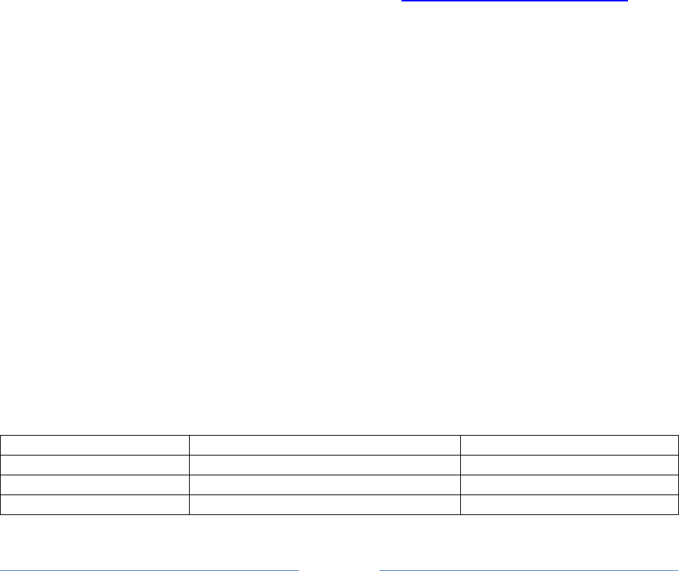
Page 76
Each channel does its normal digipeating out to the same channel. Anything with MAn-n in the path
should be sent to channel 0 regardless of where it came from.
DIGIPEAT 0 0 ^WIDE[3-7]-[1-7]$ ^WIDE[12]-[12]$|^MA[1-7]-[1-7]$
DIGIPEAT 1 0 ^WIDE[3-7]-[1-7]$ ^WIDE[12]-[12]$|^MA[1-7]-[1-7]$
Similarly we want anything for NH to be digipeated only to radio channel 1.
DIGIPEAT 0 1 ^WIDE[3-7]-[1-7]$ ^WIDE[12]-[12]$|^NH[1-7]-[1-7]$
DIGIPEAT 1 1 ^WIDE[3-7]-[1-7]$ ^WIDE[12]-[12]$|^NH[1-7]-[1-7]$
9.5.8 Digipeater algorithm
If the first unused digipeater field, in the received packet, matches the first pattern, the original
digipeater field is replaced by MYCALL of the destination channel.
Example: W9XYZ>APRS,WIDE7-7
Becomes: W9XYZ >APRS,WB2OSZ*
In this example, we trap large values of N as recommended in http://www.aprs.org/fix14439.html
If not caught by the first pattern, see if it matches the second pattern. Matches will be processed with
the usual WIDEn-N rules.
If N >= 2, the N value is decremented and MYCALL (of the destination channel) is inserted if enough
room.
Example: W9XYZ >APRS,WIDE2-2
Becomes: W9XYZ >APRS,WB2OSZ*,WIDE2-1
If N = 1, we don't want to keep WIDEn-0 in the digipeater list so the station is replaced by MYCALL.
Example: W9XYZ >APRS,WIDE2-1
Becomes: W9XYZ >APRS,WB2OSZ*
If N = 0, the hop count has been used up and the packet is not digipeated.
9.5.9 APRS Digipeater - Compared to other implementations
Based on observations, a couple other popular implementations always insert their call rather than
replacing when the hop count is all used up. Example:
Unconditional insert
Adaptive insert / replace
Original digipeater path
WIDE1-1,WIDE2-2
WIDE1-1,WIDE2-2
After 1 hop
W1ABC,WIDE1*,WIDE2-2
W1ABC*,WIDE2-2
After 2 hops
W1ABC,WIDE1,W2DEF*,WIDE2-1
W1ABC,W2DEF*,WIDE2-1
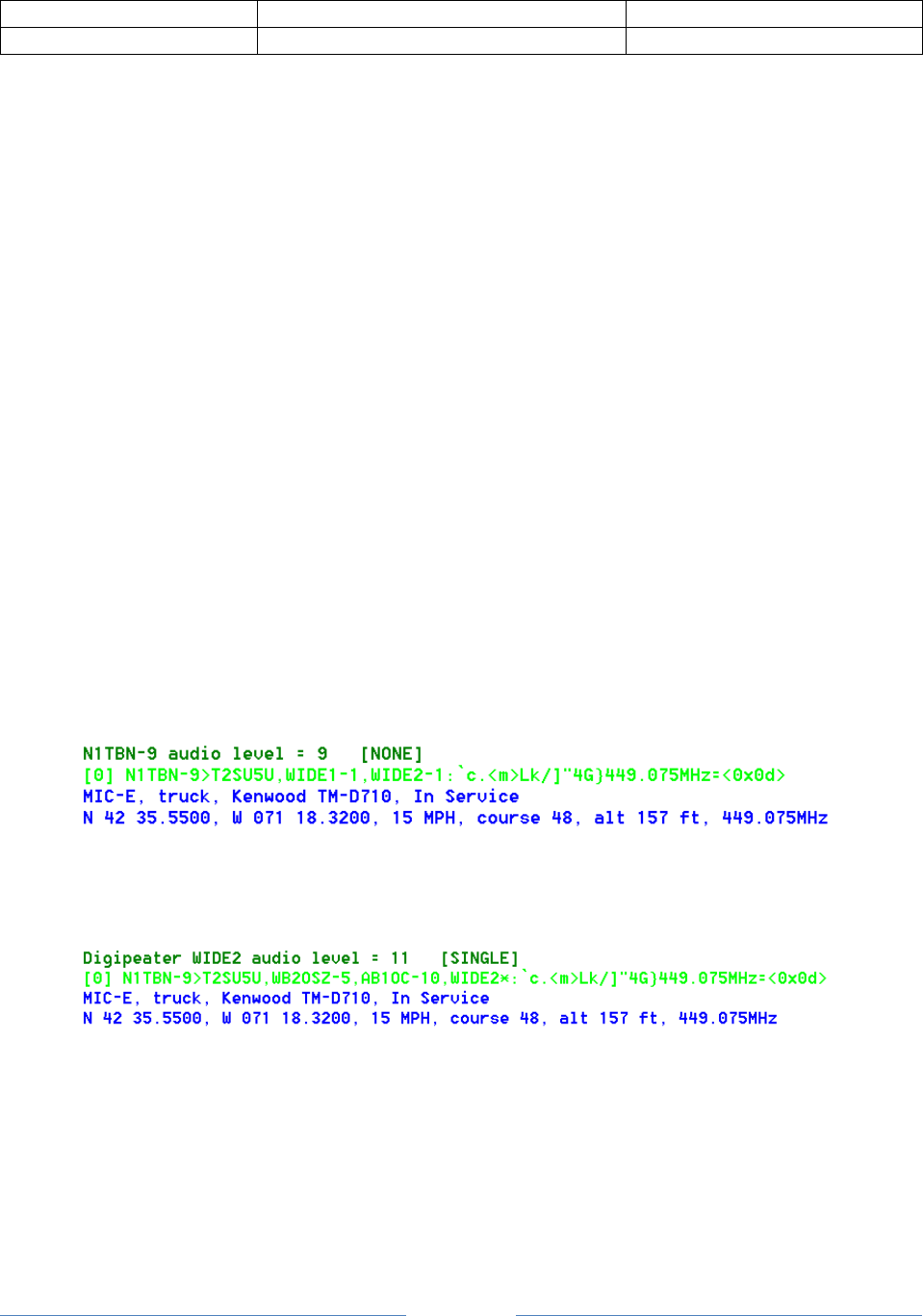
Page 77
After 2 hops
W1ABC,WIDE1,W2DEF,W3GHI,WIDE2*
W1ABC,W2DEF,W3GHI*
Implemented by
KPC-3+, TM-D710A
Dire Wolf
The unconditional insert approach has a rather unfortunate consequence. The final packet looks like it
was relayed by five different digipeaters.
W1ABC
Unknown station not implementing tracing.
W2DEF
W3GHI
Unknown station not implementing tracing.
The packet is longer than it needs to be and wastes radio channel capacity.
This also creates an ambiguous situation where we are not sure about the path taken.
I would argue that it violates the AX.25 protocol specification section 3.12.5:
The destination station can determine the route the frame took to reach it
by examining the address field…
The via path part of the address field, up through the address marked with “*” should contain the path
that the packet has traveled.
Here is a real example that demonstrates the different cases and something new and unexpected.
We start off with the original packet. There is no “*” in the header, so we are hearing the originating
station.
Next we see the same packet (below) after it was digipeated by WB2OSZ-5 and AB1OC-10. Notice how
the original WIDE1-1 was replaced by WB2OSZ-5 because the remaining hop count was all used up.
The “*” appears after WIDE2 so that is what the radio is hearing. If we didn’t know the earlier history,
we wouldn’t know whether WIDE2-0 (the -0 is not displayed) was left there by AB1OC-5 or a different
later station that did not identify itself.
Here is something totally unexpected. Below we see the packet was digipeated twice and we are
hearing W1HML, as indicated by the “*” after it.
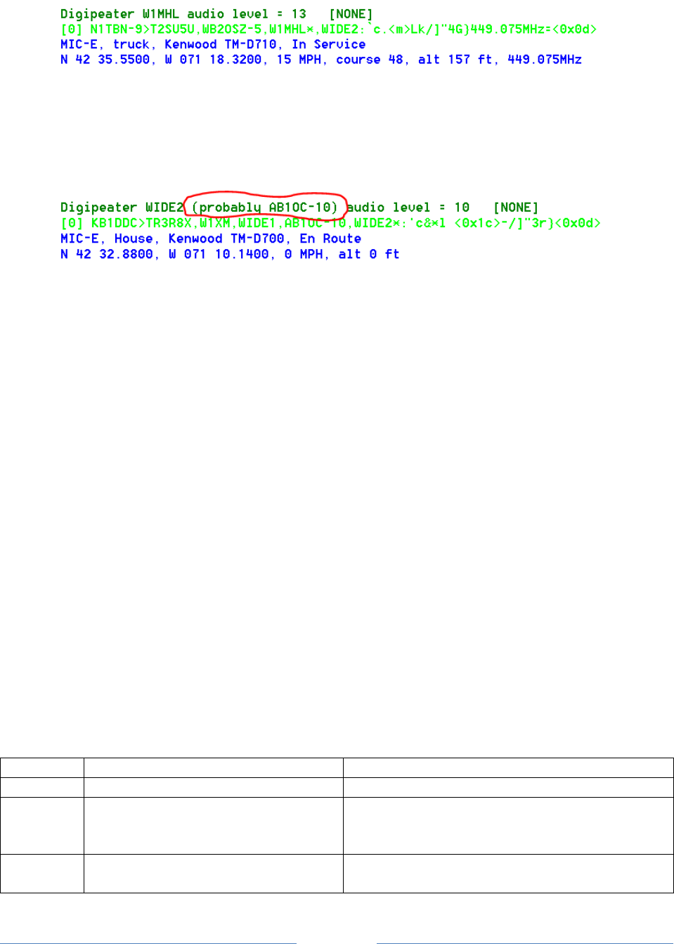
Page 78
The really strange part is a WIDE2-0, at the end, which is not marked as being used. When the
remaining count is reduced to zero, the digipeater should be marked as being used.
In version 1.0, we start to list the possible actual station heard when “*” is after something of the form
WIDEn-0. Example:
9.5.10 Preemptive Digipeating
Normally the digipeater function looks only at the first unused item in the digipeater list. The
preemptive option allows processing of any unused field, not just the first one, if my call or an alias
matches. Note that the option does not apply to the “generic XXXXn-N” specification.
Example: The received packet contains these digipeaters:
CITYA*, CITYB, CITYC, CITYD, CITYE
The first one has already been used. My alias list includes CITYD.
Normally, this would not be retransmitted because CITYB is not in the alias list. When the preemptive
option is selected, “CITYD” is matched even though it is not the first unused. As you would expect,
CITYD is replaced by my call before retransmission. What happens to CITYB and CITYC? That depends
on the option specified:
DROP – All prior path data is lost. (misleading, bad)
MARK – Prior path data is marked as being used. (misleading, bad)
TRACE – Prior path data will reflect the actual path taken. (good)
Results, for this example, are summarized below.
Option
Path after digipeating
Comment
OFF
(none)
No match. Not digipeated.
DROP
WB2OSZ*, CITYE
Erases history before getting here.
Gives incorrect impression that original station
was heard directly rather than via CITYA. (BAD)
MARK
CITYA, CITYB, CITYC, WB2OSZ*, CITYE
Gives incorrect impression that packet traveled
through CITYB and CITYC. (BAD)

Page 79
TRACE
CITYA, WB2OSZ*, CITYE
Accurate tracing of path used to get here.
(GOOD)
9.5.11 The Ultimate APRS Digipeater
http://www.aprs.org/digi-ultimate.html describes the “Ultimate APRS Digipeater” with 3 radios and
different rules for forwarding packets from one channel to another. It’s no longer necessary to lament
that, “such a digipeater does not yet exist.” It’s available now. Using the digipeating rules described
above, and packet filtering in the next section, you can do all of this and more.

Page 80
9.6 Packet Filtering for APRS
Sometimes it is desirable for a digipeater or Internet Gateway to pass along some types of packets and
block others.
A filter can be defined for each combination of where the packet came from (radio channel or IGate
server) and where it is being sent to. The format of the configuration command is:
FILTER from-channel to-channel filter-expression
FILTER IG to-channel filter-expression
FILTER from-channel IG filter-expression
The filter expression is loosely based on http://www.aprs-is.net/javaprsfilter.aspx “Server-side Filter
Commands” with the addition of logical operators to combine the filter results. For example, you could
decide to digipeat only telemetry originating from WB2OSZ or object reports not within a certain
distance of a given location.
FILTER 0 0 ( t/t & b/WB2OSZ ) | ( t/o & ! r/42.6/-71.3/50 )
It’s not necessary to put quotes around the filter expression even though it contains spaces.
9.6.1 Logical Operators
The individual filter specifications return a true or false value depending whether the current packet
satisfies the condition. These results can be combined into larger expressions to for very flexible
configuration. The operators are:
| Logical OR. Result is true if either argument is true.
& Logical AND. Result is true if both arguments are true.
! Logical NOT. This inverts the value of the following part.
( ) Parentheses are used for grouping.
& has higher precedence than the | operator so the two following forms are equivalent:
w & x | y & z
( w & x ) | ( y & z )
This is the same as the rule for multiplying and adding. When evaluating the arithmetic expression, a * b
+ c *d, you would first multiply a * b, then multiply c *d, and finally add the two products together.
When in doubt, use parentheses to make the order more explicit.
9.6.2 Filter Specifications

Page 81
The filter specifications are composed of a lower case letter, the punctuation character to be used as a
field separator, and parameters. These two are equivalent:
b/W2UB/N2GH
b#W2UB#N2GH
Other implementations allow only the “/” separator character. This extra flexibility comes in handy
when you want to use the “/” character in a parameter value.
Everything is case sensitive. This means that upper and lower case are not equivalent.
All Filter Specifications must be followed by a space. This is so we can distinguish between special
characters that are part of the filter or a logical operator.
9.6.2.1 Wildcarding
Most of the filters allow the “*” character at the end of a string to mean match anything here. This
operates on character strings without any knowledge of the callsign-SSID syntax. If you wanted to
match “W2UB” regardless of any SSID, your first reaction might be to use
b/W2UB*
This would not be correct because it would also match W2UBA, W2UBZ, and many others. The correct
form would be:
b/W2UB/W2UB-*
This will match only that callsign (implied SSID of zero) or that callsign followed by any SSID.
9.6.2.2 Range Filter
r/lat/lon/dist
This allows position and object reports with a location within the specified distance of given location.
Latitude and longitude are in decimal degrees. (negative for south or west.)
Distance is in kilometers.
Note that this applies only to packets containing a location. It will return a false result for other types
such as messages and telemetry. If you wanted to digipeat stations only within 50 km you might use
something like this:
FILTER 0 0 r/42.6/-71.3/50
This would reject other types of packets such as messages and telemetry. To allow them, use the “or”
operator to also allow all types other than position and object:

Page 82
FILTER 0 0 r/42.6/-71.3/50 | ( ! t/po )
9.6.2.3 Budlist Filter
b/call1/call2…
Allow all packets from the specified calls. These must be exact matches including the SSID. Wildcarding
is allowed.
When combined with the “!” (not) operator, it can be used to reject packets from specified calls.
9.6.2.4 Object Filter
o/obj1/obj2…
Allow objects and items whose name matches one of them listed. Wildcarding is allowed.
9.6.2.5 Type Filter
t/poimqstunw
List one or more of the following letters for types of packets to be allowed.
p - Position Packets
o - Object
i - Item
m - Message
q - Query
s - Status
t - Telemetry
u - User-defined
n - NWS format
w - Weather
9.6.2.6 Symbol Filter
s/pri/alt/over
“pri” is zero or more symbols from the primary symbol set.
“alt” is one or more symbols from the alternate symbol set.
“over” is overlay characters. Overlays apply only to the alternate symbol set.

Page 83
Examples:
s/-> Allow house and car from primary symbol table.
s//# Allow alternate table digipeater, with or without overlay.
s//#/\ Allow alternate table digipeater, only if no overlay.
s//#/SL1 Allow alternate table digipeater, with overlay S, L, or 1
9.6.2.7 Digipeater Filter
d/digi1/digi2…
Allow packets that have been repeated by any of the listed digipeaters. Wildcarding is allowed.
If you wanted to run a “fill in” digi, which would repeat packets only if heard directly, use this:
FILTER 0 0 ! d/*
That means, when digipeating from channel 0 to channel 0 allow packets only if they have not been
digipeated through some other station.
9.6.2.8 Via digipeater unused Filter
v/digi1/digi2…
Allow packets that have any listed digipeaters that don’t have the “has-been-used” flag set. Wildcarding
is allowed.
9.6.2.9 Group Message Filter
g/call1/call2…
Allow “message” packets with any of the listed addressees. Wildcarding is allowed.
9.6.2.10 Unproto Filter
u/unproto1/unproto2…
Allow packets with any of the specified strings in the AX.25 destination field. APRS uses this field in a
variety of ways. Most often it is the system type from the tocalls.txt file. For example, to select packets
from the Kantronics KPC-3+, version 9.1, use:
u/APN391

Page 84
This does not apply to the MIC-E packet types because they use the destination field for part of the
position.
Wildcarding is allowed so you could use “u/APDW*” to mean any version of Dire Wolf.
9.6.3 SATgate example
Suppose you wanted to run a SATgate to forward anything either from some station called "RS0ISS" or
anything digipeated by it. That's easy. The filter could look like:
FILTER 0 ig b/RS0ISS | d/RS0ISS
That means when forwarding from RF channel 0, through the IGate function, accept packets that are
from RS0ISS or have been digipeated by RS0ISS. The "b" filter matches the source address. The "d"
filter only considers digipeater addresses that have already been used.
Consider the case where you want to run a normal terrestrial IGate and a SATgate at the same time.
Suppose that some nearby earth station sent a packet via RS0ISS-4. A nearby observer might see
something like this:
W2UB>CQ,RS0ISS-4:something
W2UB>CQ,RS0ISS-4*:something
The first one was heard directly from the source. The second one is the retransmission by the digipeater
named RS0ISS-4. In this context, the "*" means that the digipeater address has been used. i.e. We are
hearing the digipeater, not the source station directly. If we send both of these to an APRS Internet
Server, the second one will be dropped as a duplicate. How could we filter out the first one and let the
second through?
One suggestion, from a discussion group, was to ignore all packets heard directly from the source and
process only those which have been digipeated. In this case the filter would be:
FILTER 0 ig d/*
Here "*" is a wildcard meaning match anything. Dropping anything heard directly would interfere with
the normal IGate behavior. The "v" filter is useful in this case.
FILTER 0 ig ! v/RS0ISS*/ARISS
"v" also looks at the digipeater addresses but considers only those which have NOT been used. In this
example, "v/RS0ISS*/ARISS" produces a match if any unused digipeater address matches RS0ISS (with
any SSID, due to wildcard), or exactly ARISS. The "!" inverts the following value.

Page 85
We end up dropping the first example packet because it is addressed to travel via certain digipeaters but
hasn't yet. The second example packet, and other normal terrestrial packets - whether heard directly or
via digipeater - are allowed to continue to the APRS Internet Server.
A later section describes the “SATGATE” option which uses a different technique.
9.6.4 Troubleshooting
Packet filtering operation can be examined by using “-df” on the command line. Each time a filter
expression is evaluated, the result is displayed like this:
Packet filter for APRS digipeater from radio channel 0 to 0 returns TRUE
Packet filter from IGate to radio channel 0 returns FALSE
To get more detail, use double the ”f” in the command line option. i.e. “-dff” will explain what each of
the individual filter specifications is doing.
t/p returns FALSE for T data type indicator
t/p returns TRUE for ! data type indicator
In this example, we have a filter that will pass only position reports. This is based primarily on the first
character of the information part of the packet. “T” indicates telemetry data so the result is false. “!” is
one of the characters used to indicate a position report so we get a true result.
Command line option “-dfff” will also show results of the logical operators: ! & |

Page 86
9.7 GPS Interface
Your location, from a GPS receiver, can be used in a tracker beacon described in the following Beaconing
section. There are two types of interface available:
Direct connect to serial or USB port. Available on all platforms.
GPSD server. Available only on Linux. This allows multiple applications to share one receiver.
9.7.1 Direct connect to GPS receiver
Use the GPSNMEA configuration option with the device name. This might be a serial port or a USB
device that looks like a serial port. The standard baud rate of 4800 is used. Examples:
GPSNMEA COM22
GPSNMEA /dev/ttyACM0
Dire Wolf reads NMEA sentences ( $GPRMC and $GPGGA ) from the receiver and parses them to extract
position information.
Advantages: Simple configuration. Available on all platforms.
Disadvantage: GPS receiver can’t be shared by multiple applications.
9.7.2 GPSD Server
An alternative method is available on Linux. “gpsd” (http://www.catb.org/gpsd/ ) allows multiple
applications to share the GPS receiver at the same time. You must install “gpsd” and have it running.
Add the GPSD item to the configuration file. If the GPSD server process is running on a different
computer, you can specify the host name or address. Examples:
GPSD
GPSD localhost -- equivalent to first example.
GPSD 192.168.1.147 -- use server running on different computer.
The accompanying document, Raspberry-Pi-APRS-Tracker.pdf, goes into more detail. The same
general principles apply to other types of Linux systems.
9.7.3 Waypoint Sentence Generation
APRS Position and Object Reports can be converted to NMEA Sentences for display on the AvMap G5 /
G6 or other mapping devices or applications. The configuration file item has the following format:
WAYPOINT serial-port [ formats ]
Where,
serial-port can be the same as, or different than, the one used for GPSNMEA.

Page 87
formats is one or more letters representing the formats. If none specified, the default
is generic and Kenwood.
N for $GPWPL - NMEA generic with only location and name.
G for $PGRMW - Garmin, adds altitude, symbol, and comment to
previously named waypoint.
M for $PMGNWPL - Magellan, more complete for stationary objects.
K for $PKWDWPL - Kenwood with APRS style symbol but missing comment.
For debugging purposes, you can put “-dw” on the command line to display the sentences. Here is an
example with the original packet, an explanation, and the resulting waypoints.
[0.4] WQ2H-4>4R3V7W,WIDE1-1,WIDE2-1:`c/ l#C>/`"47}WQ2H Mobile FT2DX 5W
with a rubber duck!_(<0x0d>
MIC-E, normal car (side view), Yaesu FT2D, Special
N 42 36.7700, W 071 19.0400, 0 MPH, course 339, alt 105 ft
WQ2H Mobile FT2DX 5W with a rubber duck!
$GPWPL,4236.7700,N,07119.0400,W,WQ2H-4*35
$PGRMW,WQ2H-4,32.0,00AA,WQ2H Mobile FT2DX 5W with a rubber duck!*4C
$PMGNWPL,4236.7700,N,07119.0400,W,32.0,M,WQ2H-4,WQ2H Mobile FT2DX 5W
with a rubber duck!,a*6C
$PKWDWPL,131356,V,4236.7700,N,07119.0400,W,0.0,339.0,160616,32.0,WQ2H-
4,/>*52
Look at the comments in the source file waypoint.c for an explanation of the sentences.
9.8 Beaconing
Dire Wolf has several configuration commands for setting up periodic transmissions.
PBEACON - Position
OBEACON - Object
CBEACON - Handcraft your own Custom beacon
IBEACON - IGate status
TBEACON - Tracker beacon with GPS location
9.8.1 Position & Object Beacons
Two configuration commands are available for periodic beacons to announce yourself or other things in
your region with fixed positions.
PBEACON - for a “position report.” This is generally used for your own location.
OBEACON - for an “object report.” This is generally used for other entities.
The big difference is that the “object report” contains an object name,

Page 88
usually different than your radio call.
These have many options so it would be very cumbersome and error prone to have everything in fixed
positions. Instead we use keyword=value pairs. The available keywords are:
Keyword
Description
Example values
Comment
DELAY
Time, in minutes or minutes:seconds, to
delay before sending first time.
Default is 1 minute.
1
0:30
One minute.
Half minute.
EVERY
Time, in minutes or minutes:seconds,
between transmissions.
Default is 10 minutes.
Use an extremely long interval (like
1000000 for around two years) here to get
a one time transmission.
10
9:45
Ten minutes.
9 ¾ minutes
SENDTO
Radio channel for transmission or “IG” to
send to Internet Gateway.
Default is the first, or only, radio channel
0.
“R” followed by a number simulates signal
received on that channel.
1
IG
R0
Second radio
channel.
Internet Gateway.
Simulated channel
0 reception.
DEST
Explicit destination field for AX.25 packet.
Normally you will want the default which
identifies the software version.
CQ
“SPEECH”,
“MORSE”, and
“DTMF” are special
cases explained
later.
VIA
Digipeater path.
Default none.
WIDE1-1
WIDE1-1,WIDE2-1
Upper case only.
No spaces.
MESSAGING
Set the APRS Messaging attribute for a
position report. i.e. Data Type Indicator
will be “=” instead of “!”
0
1
Default value.
Set attribute.
OBJNAME
Name for object, up to 9 characters.
Applies only to OBEACON.
EOC
Hamfest
Any printable
characters
including
embedded spaces.
LAT
Latitude in signed decimal degrees
(negative for south) or degrees ^ minutes
hemisphere.
42.619
42^37.14N
Both examples are
equivalent.
LONG
Longitude in signed decimal degrees
(negative for west) or degrees ^ minutes
hemisphere.
-71.34717
71^20.83W
Both examples are
equivalent.
ZONE
Zone with latitude band for UTM
coordinates.
19T
EASTING
UTM coordinate.
307504

Page 89
NORTHING
UTM coordinate.
4721177
ALTITUDE
or ALT
Altitude in meters.
90
SYMBOL
Two different styles are available:
(a) Exactly two characters specifying
symbol table / overlay and the
symbol code.
(b) A substring of the description.
S#
“Jet ski”
More details
below.
OVERLAY
A single upper case letter or digit overlay
character.
S
POWER
Transmitter power in watts.
50
HEIGHT
Antenna height in feet.
20
GAIN
Antenna gain in dBi.
6
DIR
One of 8 directions, N, NE, E, SE, S, SW, W,
or NW, for a directional antenna. Default
is omni-directional.
NE
FREQ
Where to contact you by voice or radio
frequency for some other entity. MHz.
146.955
TONE
CTCSS tone required for specified radio
frequency. Hz.
74.4
OFFSET
Transmit offset in MHz.
-0.60
MHz.
COMMENT
Name, location, announcements, etc.
COMMENTCMD
Run specified command and insert result
after the fixed part of comment.
|rxR_'J>+!(|
Original intention
was to insert base
91 compressed
telemetry.
COMPRESS
Use 1 for compressed format.
Note that power/height/gain gets
converted to single radio range value in
the compressed format.
0
1
Human readable.
Compressed.
Note: Entire configuration item must be on a single line. Some of the examples, below, are on multiple
lines due to page width limitation.
Any values containing spaces must be surrounded by quotation marks.
Example: Typical home station. The ASCII character set does not contain the degree symbol so we use ^
instead to separate degrees and minutes. If no symbol is given, it defaults to house. All three of these
are different ways to represent the same location.
PBEACON LAT=42^37.14N LONG=71^20.83W
PBEACON LAT=42.619 LONG=-71.34717
PBEACON zone=19T easting=307504 northing=4721177
The included coordinate conversion utilities can be use to convert one form to the other. In the
following examples, the first line is the command you type. The second line is the response.

Page 90
$ ll2utm 42.619 -71.34717
UTM zone = 19, hemisphere = N, easting = 307504, northing = 4721177
MGRS = 19TCH12 19TCH0721 19TCH075212 19TCH07502118 19TCH0750421177
USNG = 19TCH02 19TCH0621 19TCH075211 19TCH07502117 19TCH0750321177
$ utm2ll 19T 307504 4721177
from UTM, latitude = 42.618996, longitude = -71.347166
You might want to identify your station once every ten minutes with different ranges. This would use
the WIDE2-2 path twice an hour and no digipeating the other four times per hour.
PBEACON DELAY=1 EVERY=30 VIA=WIDE2-2 LAT=42^37.14N LONG=71^20.83W
PBEACON DELAY=11 EVERY=30 LAT=42^37.14N LONG=71^20.83W
PBEACON DELAY=21 EVERY=30 LAT=42^37.14N LONG=71^20.83W
The easy way to specify a symbol is with a substring of the description. Examples:
PBEACON LAT=42^37.14N LONG=71^20.83W SYMBOL=”Jet Ski”
PBEACON LAT=42^37.14N LONG=71^20.83W SYMBOL=”digi” OVERLAY=S
A list of all symbols available can be printed by running direwolf with the “-S” (upper case S) command
line option.
For more precise control, you can specify exactly two characters with a particular pattern. The first
character indicates:
/ = primary symbol table
\ = alternate symbol table
A-Z 0-9 = alternate symbol table with specified overlay.
These two are equivalent:
PBEACON LAT=42^37.14N LONG=71^20.83W SYMBOL=\# OVERLAY=S
PBEACON LAT=42^37.14N LONG=71^20.83W SYMBOL=S#
To advertize a voice repeater in your neighborhood:
OBEACON OBJNAME=146.955ma LAT=42^34.61N LONG=71^26.47W SYMBOL=/r
OFFSET=-0.600 TONE=74.4 COMMENT=”www.wb1gof.org”
Remember it must be a single line in the configuration file even though it is two lines on this page.
Note how “/r” was used to get the repeater symbol. If you used “SYMBOL=repeater”, it would end up
matching the “Mic-E Repeater” description and the symbol code would come out as “/m.”
$ direwolf -S | grep -i repeater
/m LM 77 AB177 Mic-E Repeater
/r LR 82 AB182 Repeater
I0 A0I AB0164C IRLP repeater (I0)

Page 91
In this case, FREQ= would be redundant because the frequency is part of the object name. See
http://aprs.org/localinfo.html for recommendations. The offset often causes confusion. When it
appears in the packet, it is in units of 10 kHz. “500” means 5 MHz. A complete description can be
found here: http://www.aprs.org/info/freqspec.txt
Here is one possible way to send messages through the International Space Station. It is similar to
“UNPROTO CQ VIA ARISS” on some other TNCs.
PBEACON delay=00:01 every=00:30 symbol="/`" lat=32^39.30N long=097^23.06W
comment="Hello from Texas, sutton.matthew@gmail.com" via=ARISS
dest=CQ messaging=1
The symbols-new.txt file is still evolving. You can download the latest from
http://www.aprs.org/symbols/symbols-new.txt
9.8.2 Custom Beacon
For unusual situations, or if you enjoy composing obscure APRS packets by hand, the custom beacon
type is available.
The timing, transmission channel, and digipeater via path are the same as for the position and object
beacons. The difference is that you can put anything you want in the information part. The first
character of the information part is the data type indicator.
Keyword
Description
Example values
Comment
DELAY
Time, in minutes or minutes:seconds, to
delay before sending first time.
Default is 1 minute.
1
0:30
One minute.
Half minute.
EVERY
Time, in minutes or minutes:seconds,
between transmissions.
Default is 10 minutes.
10
9:45
Ten minutes.
9 ¾ minutes
SENDTO
Radio channel for transmission or “IG” to
send to Internet Gateway.
Default is the first, or only, radio channel 0.
“R” followed by a number simulates signal
received on that channel.
1
IG
R0
Second radio
channel.
Internet Gateway.
Simulated channel
0 reception.
DEST
Explicit destination field for AX.25 packet.
Normally you will want the default which
identifies the software version.
CQ
“SPEECH”,
“MORSE”, and
“DTMF” are special
cases explained
later.
VIA
Digipeater path.
Default none.
WIDE1-1
WIDE1-1,WIDE2-1
Upper case only.
No spaces.

Page 92
INFO
Handcrafted “information” part for packet.
This is a constant value.
INFOCMD
Command to generate “information” part
for packet. This allows each to be different
as determined by a user-supplied script.
A couple examples:
CBEACON dest=SPEECH info="Club meeting tonight at 7 pm."
CBEACON info="!4237.14NS07120.83W#PHG7140Raspberry Pi digipeater"
See “APRS Telemetry Toolkit” documentation for more examples for COMMENTCMD and INFOCMD.
9.8.3 IGate StatusBeacon
IGate stations will often send occasional status reports with statistics. It doesn’t make sense to use this
if the IGate feature has not been configured.
The timing, transmission channel, and digipeater via path are the same as for the other types of beacons
already described. Any other options, not listed below, will be ignored.
Keyword
Description
Example values
Comment
DELAY
Time, in minutes or minutes:seconds, to
delay before sending first time.
Default is 1 minute.
1
0:30
One minute.
Half minute.
EVERY
Time, in minutes or minutes:seconds,
between transmissions.
Default is 10 minutes.
10
9:45
Ten minutes.
9 ¾ minutes
SENDTO
Radio channel for transmission or “IG” to
send to Internet Gateway.
Default is the first, or only, radio channel 0.
“R” followed by a number simulates signal
received on that channel.
1
IG
R0
Second radio
channel.
Internet Gateway.
Simulated channel
0 reception.
DEST
Explicit destination field for AX.25 packet.
Normally you will want the default which
identifies the software version.
CQ
“SPEECH”,
“MORSE”, and
“DTMF” are special
cases explained
later.
VIA
Digipeater path.
Default none.
WIDE1-1
WIDE1-1,WIDE2-1
Upper case only.
No spaces.
A couple examples:
IBEACON
IBEACON DELAY=30 EVERY=30 VIA=WIDE1-1

Page 93
The information part of the packet will look something like this:
<IGATE,MSG_CNT=2,PKT_CNT=0,DIR_CNT=10,LOC_CNT=35,RF_CNT=45,UPL_CNT=122,DNL_CNT=456
It contains several identifier / value pairs.
MSG_CNT Number of APRS “messages” from the Internet Server which have been
transmitted over the radio.
PKT_CNT Number of other (non-message) packets from the Internet Server which have
been transmitted. When this number is 0 and MSG_CNT is not, it might be
because there was a filter like “t/m” to allow only the “message” type.
DIR_CNT Number of stations heard directly (without going through any digipeaters)
during the past 30 minutes.
LOC_CNT Number of “local” stations which IS-to-RF packets are expected to reach. This is
based on the via path specified for IGate transmission. For example, if the path
was WIDE2-2, packets could travel up to 2 digipeater hops. LOC_CNT is the
number of stations heard with this number of used digipeater addresses or
fewer.
RF_CNT Number of stations heard in the past 30 minutes regardless of the number of
digipeater hops along the way.
UPL_CNT Number of packets which have been uploaded to the Internet Server. Most of
them probably came from the radio but it is also possible to generate beacons
and send them to the Server rather than transmitting them. (i.e. “SENDTO=IG”
option)
DNL_CNT Number of packets which have been downloaded from the Internet Server. The
number actually transmitted (sum of MSG_CNT + PKT_CNT) can be lower due to
filtering and transmit rate limiting.
MSG_CNT and LOC_CNT are from the original APRS specification.
PKT_CNT, DIR_CNT, and RF_CNT followed precedent set by APRSISCE32.
UPL_CNT and DNL_CNT are unique to this software.
9.8.4 Tracker Beacon
Information from a GPS receiver can be used to report the location of a moving entity.
First you must use either the GPSNMEA (all platforms) or GPSD (Linux only) configuration items to
establish communication with the GPS receiver.

Page 94
The TBEACON command has the same options as PBEACON, above, except latitude, longitude, course,
and speed are obtained from the GPS receiver. If you specify ALTITUDE greater than 0, the actual
altitude will be taken from the GPS location.
Example: Driving around in a car.
TBEACON DELAY=0:30 EVERY=2:00 VIA=WIDE1-1 SYMBOL=car
This will wait 30 seconds then transmit once every 2 minutes after that.
In this case, the FREQ options can be used to indicate that you are listening to a certain voice channel.
TBEACON SYMBOL=car FREQ=146.955 OFFSET=-0.600 TONE=74.4
9.8.5 SmartBeaconingTM
A fixed transmission schedule might not be ideal. If you are moving quickly, you might want to send
position updates more quickly. If sitting still, there is no reason to transmit very often. Sending
redundant information over and over just clutters up the radio channel. A display application which
tries to calculate the current position from the last know location and “dead reckoning” is thrown way
off when there is a change of direction.
SmartBeaconingTM adjusts the timing based on speed and changes in direction. It’s the same technique
used by Kenwood, Yaesu/Standard, and in many other applications. These 3 examples are all
equivalent. In the first example, reasonable defaults are supplied for use in a land vehicle. In other
two, all parameters are specified.
SMARTBEACONING
SMARTBEACONING 60 1:30 5 30 0:10 30 255
SMARTBEACONING 60 0:90 5 0:1800 0:10 30 255
Remember that a beacon time of just a number is interpreted as minutes. So if you want 1800 seconds,
be sure to write it as “0:1800”.
What do the numbers mean?
Fast Speed & Fast Rate -- For speeds above 60 MPH, a beacon will be sent every 1 ½ minutes.
Slow Speed & Slow Rate -- For speeds below 5 MPH, a beacon will be sent every 30 minutes.
For speeds in between, a rate proportionally in between will be used.
Additional beacons will be sent more frequently when direction changes significantly.
Send no more frequently than 10 seconds apart.
Send if direction has changed more than 30 degrees since last report at high speed.
Requires sharper turns at lower speeds.

Page 95
SmartBeaconing applies only to Tracker Beacons. The “EVERY” timing parameter is ignored and
replaced by a variable time depending on motion.
More details can be found in these references or just Google for APRS SmartBeaconingTM to find
discussions and recommendations.
http://www.hamhud.net/hh2/smartbeacon.html
http://info.aprs.net/index.php?title=SmartBeaconing
9.9 Internet Gateway (IGate)
Dire Wolf can serve as a gateway between the radio network and servers on the Internet. This allows
information to be retrieved from locations such as http://aprs.fi or http://findu.com. Information can
optionally be relayed from the servers, through your station, and on to the radio.
More detailed information can be found in the separate document called Successful-APRS-IGate-
Operation.pdf
9.9.1 IGate - Select server and log in
First you need to specify the name of a Tier 2 server. The current preferred way is to use one of these
regional rotate addresses:
noam.aprs2.net - for North America
soam.aprs2.net - for South America
euro.aprs2.net - for Europe and Africa
asia.aprs2.net - for Asia
aunz.aprs2.net - for Oceania
Each name has multiple addresses corresponding to the various servers available in your region. Why
not just specify the name of one specific server? This approach offers several advantages:
Simplicity – You don’t need to change your configuration as new servers become available or
disappear.
Resilience – If your current server becomes unavailable, another one will be found
automatically.
Load balancing – Picking one at random helps to spread out the load.
Visit http://aprs2.net/ for the most recent information. You also need to specify your login name and
passcode. For example:
IGSERVER noam.aprs2.net
IGLOGIN WB2OSZ-5 123456

Page 96
9.9.2 IGate – Configure transmit
If you want to transmit information from the servers, you need to specify two additional pieces of
information: the radio channel and the via path for the packet header. Examples:
IGTXVIA 0 WIDE1-1,WIDE2-1
IGTXVIA 1 WZ9ZZZ
IGTXVIA 0
In the first case packets will be transmitted on the first radio channel with a path of WIDE1-1,WIDE2-1.
In the second case, packets are transmitted on the second radio channel and directed to a known
nearby digipeater with wide coverage. In the third case, there will be no digipeating.
The maximum digipeater path length also influences the local station count (LOC_CNT) in the IGATE
status beacon. In the first case, LOC_CNT would include stations heard with a maximum of two used
digipeater hops. In the second case, LOC_CNT would include only those heard directly or via one
digipeater. In the third case, LOC_CNT will be the same as DIR_CNT, only stations heard directly.
You will probably want to apply a filter for what packets will be obtained from the server. Read about
Server Side filters here: http://www.aprs-is.net/javaprsfilter.aspx This example means that I only
want to get “messages” within 50 km of my station.
IGFILTER t/m/WB2OSZ-5/50
The Internet Servers will often send more than what you are expecting, so you might want to apply an
additional an additional client side filter as described in a later section.
Important!
Do not confuse this “IGFILTER” (server side) with the “FILTER” (client side) command
which is processed by Dire Wolf. Here we are simply passing along the filter
specification and not processing or checking it in any way.
Finally, we don’t want to flood the radio channel. The IGate function will limit the number of packets
transmitted during 1 minute and 5 minute intervals. If a limit would be exceeded, the packet is dropped
and warning is displayed in red.
IGTXLIMIT 6 10
9.9.3 IGate – Sending directly to server
If you want your station to appear at http://findu.com or http://aprs.fi , you need to send a beacon
advertising your position. If you send it over the radio, another IGate client station needs to hear you
and pass the information along to a server.
To put your own station on the map, without relying on someone else to hear you, send a beacon to the
IGate server by specifying “SENDTO=IG” in the beacon configuration. Use overlay R for receive only, T
for two way.

Page 97
PBEACON sendto=IG delay=0:30 every=60:00 symbol="igate"
overlay=R lat=42^37.14N long=071^20.83W
PBEACON sendto=IG delay=0:30 every=60:00 symbol="igate"
overlay=T lat=42^37.14N long=071^20.83W
9.9.4 IGate – Client-side filtering
After setting an appropriate “server-side” filter with “IGFILTER,” the server might send more than you
want, creating excessive clutter on the radio channel. It is possible to apply another stage of filtering in
Dire Wolf, the “client-side.” If you wanted to allow only APRS “messages” and weather to be
transmitted on radio channel 0, you could use a filter like this:
FILTER IG 0 t/mwn
This can also be applied in the opposite direction to restrict what is passed from the radio channel(s) to
the server. Examples:
FILTER 0 IG t/m Only “messages” from channel 0.
FILTER 1 IG t/wn Only weather from channel 1.
FILTER 2 IG Nothing from channel 2.
The differences between the two types of filtering are summarized below.
Server-side filtering
Client-side filtering
Configuration file
IGFILTER
FILTER
Where defined
http://www.aprs-
is.net/javaprsfilter.aspx
“Packet Filtering” section of this
document.
Where processed
Internet Server
Inside of Dire Wolf application.
Expressions with & | ! ( )
No
Yes
Precise control over what is
passed through
No
Yes
Can be different for each radio
channel
No
Yes
9.9.5 SATgate mode
If we hear a packet directly and the same one digipeated, we only send the first to the APRS IS due to
duplicate removal. It may be desirable to favor the digipeated packet over the original. For example,
you might be more interested in packets that have been forwarded by satellites rather than heard
directly. For this situation, we have an option which delays a packet if we hear it directly and the via
path is not empty.
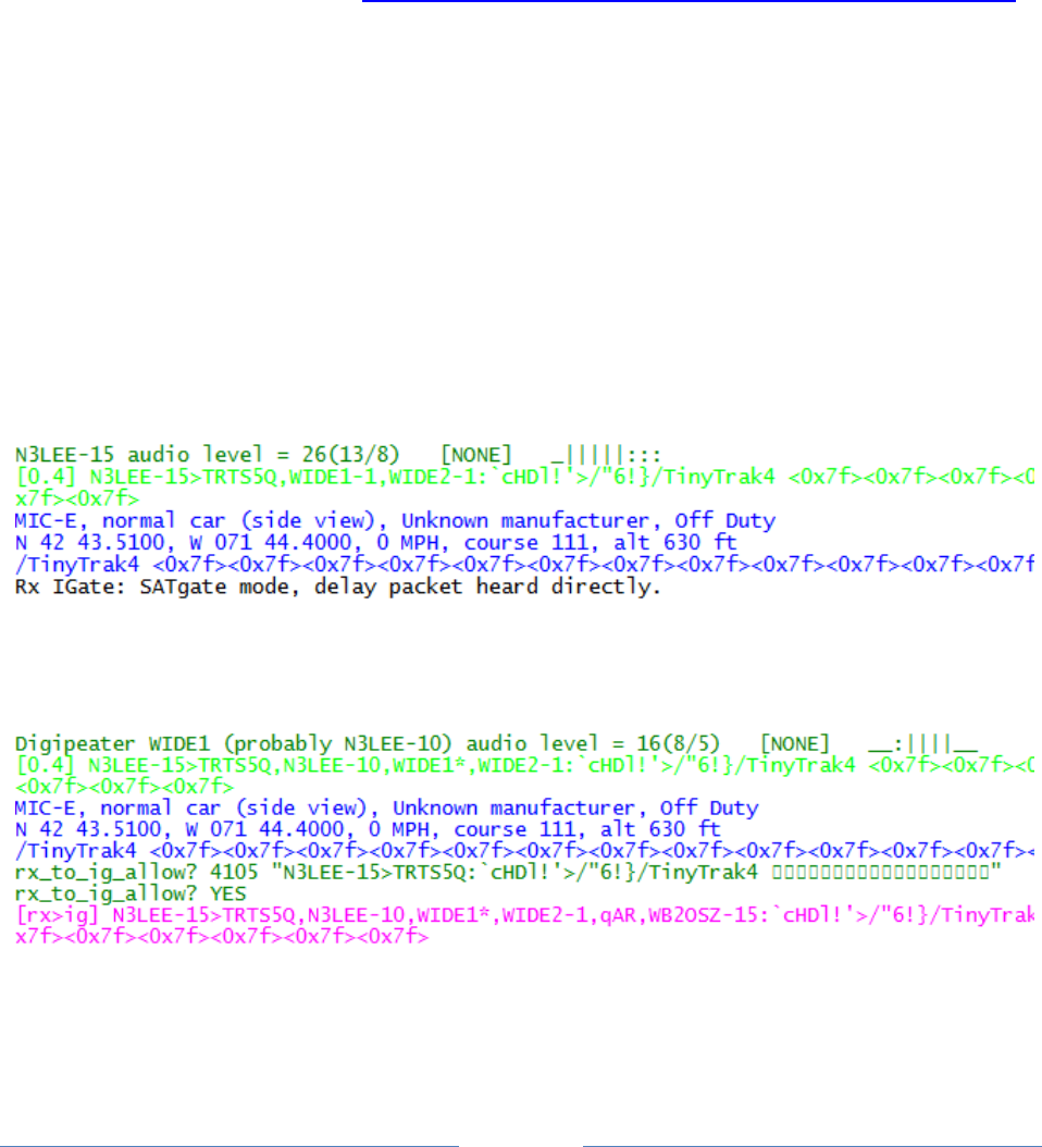
Page 98
When using this option, the digipeated packets will go to the server immediately. The original, heard
directly, is sent after a delay, typically 10 seconds. Duplicate removal will drop the original if there is a
corresponding digipeated version.
The configuration option for this feature is:
SATGATE
You can optionally add a delay time in seconds. The default is 10.
You can find more discussion here: http://www.tapr.org/pipermail/aprssig/2016-January/045283.html
9.9.6 IGate Debugging Options
To see more of what is going on behind the scenes, use one of these debugging options on the
command line:
-di Show packets being sent to Server.
-dii Show information about duplicate removal.
Here is an example of SATgate mode. We hear a station directly. The packet gets put into a waiting
area instead of being sent to the server immediately.
We hear it via some digipeater. It’s not a duplicate so it is sent to the server.
Note that [rx>ig] means transfer from receiver to IGate. Magenta indicates outgoing direction.
We hear it from another digipeater. It is dropped as a duplicate.
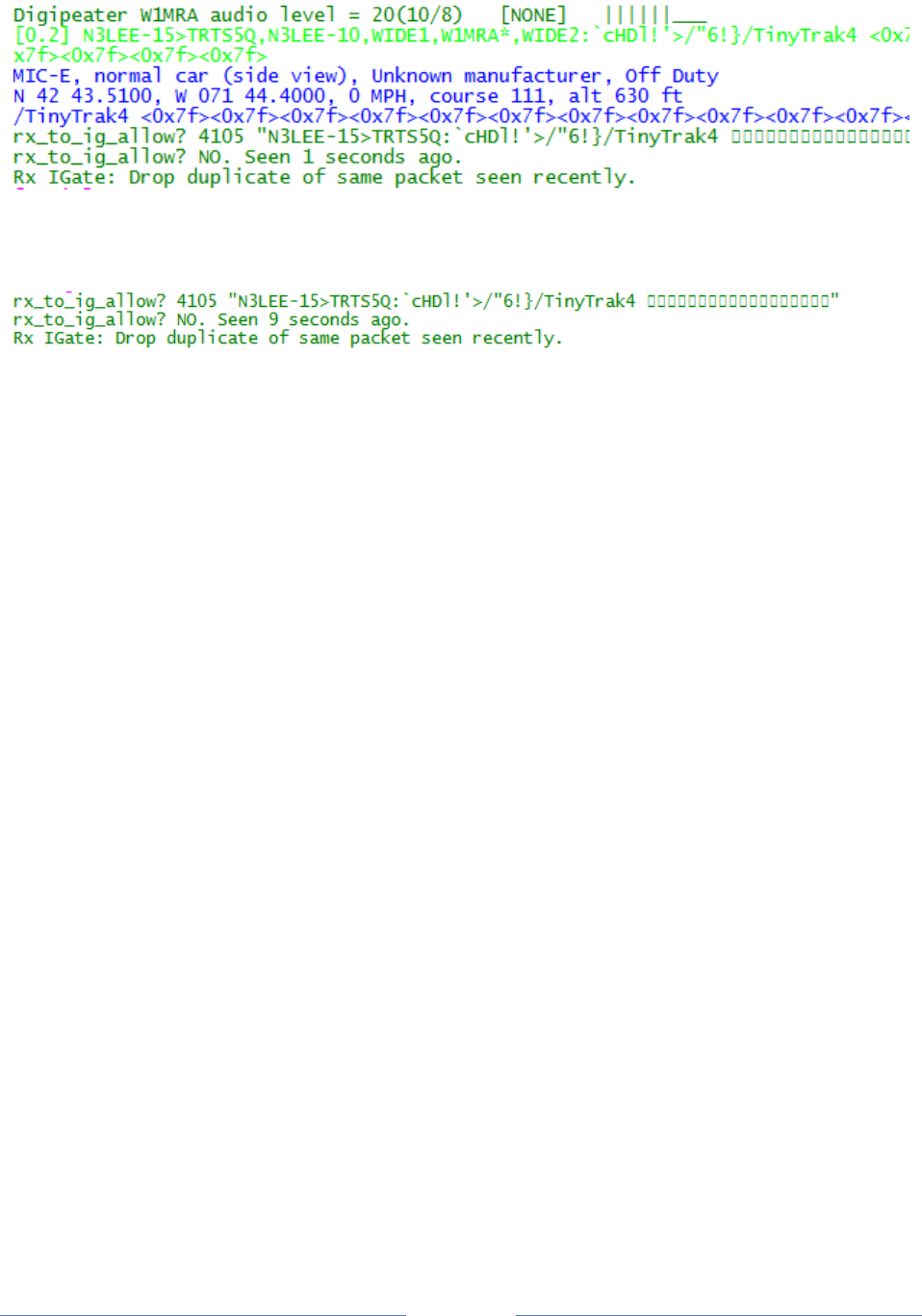
Page 99
About 10 seconds after it was heard, the original packet is released from the waiting area. It is a
duplicate so it is dropped.

Page 100
9.10 APRStt Gateway
The APRStt Gateway function allows a user, equipped with only a DTMF (“touch tone”) pad, to enter
information into the global APRS network. Various configuration options determine how the touch tone
sequences get translated to APRS “object” packets. They are easily recognized because they all begin
with TT.
TTPOINT
TTVECTOR
TTGRID
TTUTM
TTCORRAL
TTMACRO
TTOBJ
etc.
See separate document, APRStt Implementation Notes, for all the details.

Page 101
9.11 Transmitting Speech
There are many software applications that will convert text to speech. Dire Wolf can utilize these to
transmit information with a synthesized voice. At the end of this section we have a simple application
that listens for DTMF (“Touch Tone”) sequences and responds with voice. The possibilities are endless!
9.11.1 Install Text-to-Speech Software
First we need to install some software to convert text to speech. Googling around reveals some good
lists of alternatives available.
http://download.cnet.com/windows/text-to-speech-software/3150-33660_4-0.html
http://elinux.org/RPi_Text_to_Speech_%28Speech_Synthesis%29
These examples use eSpeak but most of the others should also be fine with minor changes to the
scripts. First we need to install the software.
Windows:
Download setup_espeak-xxx.exe from http://espeak.sourceforge.net/download.html
and run it.
Raspbian Linux:
Instructions here: RPi Text to Speech (Speech Synthesis)
http://elinux.org/RPi_Text_to_Speech_%28Speech_Synthesis%29
(Not yet tested at the time this is being written.)
Other Debian / Ubuntu Linux:
sudo apt-get install espeak
Red Hat / Fedora / CentOS Linux:
T.B.D. ?
9.11.2 Configuration
Next we need a little script to run the text-to-speech application with the desired options. Dire Wolf
will invoke this script with two command line arguments:
The radio channel number. In most cases you can ignore this. In more complex multi-channel
situations you can use this to send the speech to the desired audio device.
The text to be spoken.

Page 102
Two simple examples are provided:
dwespeak.bat for use with Windows
set chan=%1
set msg=%2
sleep 1
"C:\Program Files (x86)\eSpeak\command_line\espeak.exe" -v en %msg%
dwespeak.sh for use with Linux:
#!/bin/bash
chan=$1
msg=$2
sleep 1
espeak -v en-sc "$msg"
Let’s test what we have so far. Open a command window and run one of the following depending on
your operating system. The quotation marks are very important. Do not omit them.
dwespeak.bat 0 "The rain in Spain stays mainly in the plain."
dwespeak.sh 0 "The rain in Spain stays mainly in the plain."
If you don’t hear the words spoken, go back and solve the problem before continuing with the next step.
Next, edit the configuration file, direwolf.conf, and add one of these options, again using the
appropriate script name for your operating system.
SPEECH dwespeak.bat
SPEECH dwespeak.sh
Whenever transmitting a packet, the destination address will be examined. If it is “SPEECH” the text-to-
speech application will be invoked, with the “info” part, rather than sending an AX.25 frame. Here is
one possible way you could use this to announce an event:
CBEACON dest=SPEECH info=”Club meeting tonight at 7 pm.”
9.11.3 Sample Application: ttcalc
Here is a simple application that can be used as a starting point for developing you own applications.
This listens for DTMF (“Touch Tone”) sequences and responds with voice.
(1) Perform steps above and verify that the dwespeak.bat or dwespeak.sh script produces
speech output.
(2) Edit the Dire Wolf configuration file and make sure it has the SPEECH option specified properly.
It wouldn’t hurt to try the CBEACON example above to make sure it is all working properly. Use
“delay=0:15 every=0:30” so you don’t have to wait so long.
(3) Enable the DTMF decoder on the desired channel in the configuration file. Example:

Page 103
CHANNEL 0
DTMF
(4) Run “direwolf” and verify that the DTMF decoder is enabled. You should see something like this
with the startup status messages.
Channel 0: 1200 baud, AFSK 1200 & 2200 Hz, E+, 44100 sample rate, DTMF decoder enabled.
(5) Run “ttcalc” in another window. Dire Wolf should display a message that a client application
has connected.
Connected to AGW client application 0...
(6) Transmit touch tones (from a different radio obviously) such as:
4 * 6 #
(7) The spoken words, “twenty four,” will be transmitted in response.
This is not a very useful application. It is provided as a simple example to be used as a starting point for
your innovation applications.
9.12 Transmitting Morse Code
When the destination field is set to “MORSE” the information part is sent in Morse Code. Under some
circumstances you might want to use this to meet station identification requirements. If an SSID is
specified, it is multiplied by 2 to get the speed in words per minute (WPM). E.g. SSID of -10 will be 20
WPM.
CBEACON dest=MORSE info=”de WB2OSZ/R.”
CBEACON dest=MORSE-10 info=”de WB2OSZ/R.”
9.13 Transmitting DTMF Tones
When the destination field is set to “DTMF” the information part is sent as DTMF tones, commonly
called touch tones. If an SSID is specified, it is the number of tones per second. Minimum 1, maximum
10, default 5. Only characters 0 – 9, A – D, *, and # generate tones. Other characters result in silence
for one normal tone period.
CBEACON dest=DTMF info=”1234567890”
CBEACON dest=DTMF-10 info=”ABCD * #”

Page 104
9.14 Logging
Simple, yet versatile, logging is available by specifying –l (lower case L) on the command line or using the
LOGDIR option in the configuration file. In either case, specify the directory (folder) where log files
should be written. Use period (“.”) for the current working directory.
Rather than saving often unreadable raw data, the digested parts are saved in Comma Separated Value
(CSV) format. The first line has the names of the fields.
chan, utime, isotime, source, heard, level, error, dti, name, symbol, latitude, longitude,
speed, course, altitude, frequency, offset, tone ,system, status, comment
Name
Example
Description
chan
0
Radio channel where packet was received.
utime
1403134556
UTC in seconds since January 1, 1970 in decimal.
isotime
2014-06-18T09:56:21Z
Time in ISO 8601 format.
source
Sending station of packet.
heard
Station heard on radio. Actually our best guess because we can’t
always be sure due to different interpretations of tracing. See
Digipeater section for my discussion about this.
level
23
Audio level of station heard.
error
0
0 = packet received with correct CRC.
1 = able to get correct CRC by changing one bit.
>2 = found good CRC by changing more than 1 bit. Result
probably shouldn’t be trusted.
See section about “one bad apple.”
dti
!
Data Type Indentifier – first byte of information part. For
examples: “;” for Object Report or “=” for position with APRS
messaging.
name
EOC
Name from Object or Item report. Otherwise the sending
station.
symbol
/-
Two characters: symbol table (or overlay) and symbol code.
latitude
12.345678
In degrees. Negative south.
longitude
-123.456789
In degrees. Negative is west.
speed
55
Speed in knots.
course
123
Direction of travel, degrees.
altitude
90
Meters above average sea level.
frequency
146.955
Voice frequency in MHz.
offset
-600
Voice transmit offset in kHz.
tone
74.4
D123
CTCSS tone or DCS code preceded by “D.”
system
Kenwood TH-D72
Name of hardware or software. Usually derived from the
destination address, such as APN383 for Kantronics KPC-3. For
MIC-E packets, it’s a lot more obscure.
status
En Route
Status from MIC-E packets.
telemetry
Seq=3307, Vbat=4.383
V, Vsolar=0.436 V,
Telemetry data.

Page 105
Temp=-34.6 C, Sat=12
comment
Comment.
Fields are quoted if the data value contains a comma or quotation character. A new log file is started
each day. The log file has the name yyyy-mm-dd.log, where yyyy-mm-dd is the current date.
Data, in this convenient form, can be imported into a spreadsheet or fed into other conversion
applications to obtain the desired subset and format.
9.14.1 Conversion to GPX format
A sample application is included for converting a log file to GPX format. The source code can be used as
the starting point for other custom converters.
Specify one or more log file names on the command line. Redirect the output if you want to save the
GPX information to a file. Example:
log2gpx 2014-06-21.log 2014-06-22.log > localaprs.gpx
The GPX file can be uploaded to many popular mapping applications such as Google maps or
OpenStreetMap. Here is on that is very easy to use: http://www.gpsvisualizer.com/ You don’t need to
have an account or log in. Simply upload your GPX file and the waypoints and tracks are displayed on a
map. Click on a waypoint to see any additional information.
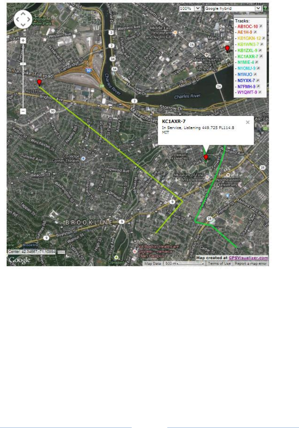
Page 106
9.15 Command Line Options
Command line options can be used to specify the configuration file location or override some of the
settings in the configuration file. Case is significant. Pay careful attention to upper and lower case.
-c fname Configuration file name.
-r n Audio sample rate for first audio device. e.g. 44100
-n n Number of audio channels for first audio device. 1 or 2.
-b n Bits per audio channel for first audio device.
8 bit unsigned or 16 bit signed little endian.

Page 107
-B n Data rate in bits/sec for channel 0. Standard values are 300, 1200, 9600.
If < 600, AFSK tones are set to 1600 & 1800.
If > 2400, K9NG/G3RUH style encoding is used.
Otherwise, AFSK tones are set to 1200 & 2200.
-D n Divide audio sample rate by n for channel 0.
-l logdir Name of directory for storing log files.
Use period “.” to specify current working directory.
-d x Debug options
a = AGWPE network protocol client
k = KISS serial port client
n = KISS network client
u = Redisplay non-ASCII characters in hexadecimal
p = Packet hex dump
g = GPS interface
t = Tracker beacon
o = Output controls such as PTT and DCD
i = IGate
h = Hamlib verbose level. Repeat for more.
m = monitor heard station list.
f = packet filtering. Use ff for details of individual filter specifications.
-q x Quiet (suppress output) options
h = Omit the “heard” line with audio level.
d = Omit decoding of APRS packets.
-t n Text colors.
1 = normal, 0 = disable text colors.
-x Send transmit level calibration tones.
-U Print UTF-8 test string and exit.
-S Print symbol tables and exit.
-a n Print audio device statistics each n seconds. See section called “Periodic
audio device statistics” for more details.
After any options, there can be a single command line argument for the source of received audio. This
can overrides the audio input specified in the configuration file. Choices are:
“-“ or “stdin” for reading from stdin.
“UDP:” followed by an optional port number to read from a UDP socket.
The Software Defined Radio section contains some examples.

Page 108
10 AX.25 Connected Mode – New in version 1.4
APRS uses only a small part of the AX.25 protocol dealing with Unnumbered Information (UI) frames.
The sender does not know if anyone actually received the information. Another type of Amateur Packet
Radio uses the “connected” mode. Many TNCs enter this mode with the “CONNECT” command. Rather
than broadcasting to everyone, the intention is to have a conversation with a specific station which
could be a person or an automated system such as a Bulletin Board System (BBS). Behind the scenes,
the Information frames are assigned sequence numbers. The recipient sends acknowledgement that
frames have been received. When the sender does not get acknowledgment within a few seconds, the
data is sent again.
If you are familiar with the computer networking terms, UDP and TCP, it is a similar idea.
With the former, you just send something and don’t know if it got there. In the latter case, all the
information should get there in the right order. Any pieces missing, due to an imperfect radio link, are
automatically resent and assembled into the correct order.
10.1 AX.25 Protocol Versions.
The AX.25 version 2.0 protocol specification was published in 1984.
Version 2.2 was published in 1998. https://www.tapr.org/pub_ax25.html
Version 2.2 has several improvements that make bulk information transfer more efficient.
Information fields can be larger and two stations can negotiate a mutually acceptable size.
Sequence numbers have larger fields so more frames can be sent before waiting for an
acknowledgement. This means we can put more Information frames into a single transmission
and have less overhead sending back so many acknowledgements.
Individual missing frames can be resent, rather than backing up and starting over from the last
checkpoint.
Let’s take an example. Suppose that Information frames 0, 1, 2, 3, 4, 5, 6 were sent. Frame 1 gets lost
due to interference. With version 2.0, the receiving station would reply: Frame 0 was received; start
sending again with 1. The sending station would have to send 1, 2, 3, 4, 5, 6 again.
With version 2.2, the receiving station would ask for a resend of only 1. The term for this is “Selective
Reject” (SREJ).
10.1.1 Compatibility with Older Version
Dire Wolf implements version 2.2. There are a lot of 20 year old TNCs still in use and we need to
maintain compatibility with version 2.0.

Page 109
When trying to make a connection to another station, we first try to establish a version 2.2 connection.
If that fails, we fall back to version 2.0. The two versions are sometimes referred to as Basic and
Extended modes.
It is useful to understand the role of the following frames when troubleshooting connection problems.
SABM Set Asynchronous Balanced Mode command
SABME Set Asynchronous Balanced Mode Extended command (new for v2.2)
UA Unnumbered Acknowledge response
DM Disconnected Mode response
FRMR Frame Reject response (never sent by v2.2)
10.1.2 AX.25 v2.0 Connection Sequence
Originating station
Destination Station
Request a connection, basic
mode.
SABM
UA
Accept the connection.
Or
DM
Refuse the connection.
10.1.3 AX.25 v2.2 Connection Sequence
In this case, we use SABME rather than SABM to request Extended mode.
Originating station
Destination Station
Request a connection,
extended mode.
SABME
UA
Accept the connection.
Or
DM
Refuse the connection.
10.1.4 AX.25 v2.2 to v2.0 Connection Sequence
Now we consider the case where the originating station requests Extended mode but the destination
station is running an older version.
Originating station, v2.2
Destination Station, v2.0
Request a connection,
SABME

Page 110
extended mode.
FRMR
I don’t recognize that
command.
SABME was not defined for
v2.0 protocol specification.
FRMR should be sent back in
this case.
So, you don’t understand v2.2.
That’s OK. Let’s try again with
v2.0, basic mode.
SABM
UA
Accept the connection.
Or
DM
Refuse the connection.
This is the way it is supposed to work. The v2.0 protocol spec clearly states that FRMR should be sent in
response to any unrecognized command. In reality, we have some defective implementations out
there which thwart this scheme.
The Kantronics KPC-3+ sends DM, rather than FRMR, in response to SABME.
Dire Wolf works around this bug. When DM is received, in response to SABME, it reacts as if
FRMR had been received and falls back to v2.0.
The Kenwood TM-D710A doesn’t respond at all to SABME.
This is a problem. It looks like the station is not there at all when we try to connect to it. An
unpleasant hack was added to work around this defect. The MAXV22 option can be used to
specify the maximum number of times that an unanswered v2.2 connection attempt will be
made before falling back to v2.0.
The default is half of the RETRY value. If you take all the defaults, up to 5 SABME and 5 SABM
connection requests will be sent before giving up.
If you set the MAXV22 value to 0, it won’t try SAMBE at all immediately start with SABM. In this
case you are giving up all of the v2.2 benefits if the destination station is capable of the newer
version from the year 1998.
If you set MAXV22 ≥ RETRY, only SABME will be used, up to RETRY times. This is how it is
supposed to work.
10.1.5 UI Frames and the “-q d” command line option
APRS uses only “UI” (unnumbered information) frames. Traditional packet also uses them for general
broadcasts, not directed to a particular station. There is really no way to tell them apart because they
both use the same protocol ID. (IMHO, it was an unfortunate choice that APRS did not use a special
protocol ID.)

Page 111
These beacons, containing arbitrary text, will be interpreted as APRS. For example, if the beacon text
started with the letter “T”, it would be interpreted as telemetry data, most likely resulting in an error
message because it doesn’t have the required format. This doesn’t hurt anything but it is extra
distracting clutter.
The decoding of UI frame contents can be disabled by using the “-q d” or “-qd” command line option. It
is equivalent with or without the space in the middle.
10.2 Connected Packet Operation
Dire Wolf is not an interactive application. You can’t type into it as you would with a traditional
hardware TNC. The connected packet functionality is available only thru the AGW network protocol
which is widely supported by many applications such as Outlook PM.
Most of the applications listed here should be compatible but only a few have been tested so far.
http://www.soundcardpacket.org/6compat.aspx
I’d like to hear about your experiences so we can make a list of compatible applications and fix any
issues with the others.
Dire Wolf has a built-in digipeater capability described later.
10.3 Configuration file items for connected mode packet
Several configuration options are available for fine tuning operation. In most cases, the defaults should
be fine. Most of these have the same names and meanings as in many other popular TNCs.
FRACK n Number of seconds to wait for acknowledgement to transmission.
Default 3.
RETRY n Number of times to retry before giving up.
Default 10.
PACLEN n Maximum size for information part of a frame.
Default 256. Maximum 2048.
MAXFRAME n Max frames to send before waiting for acknowledgement.
“Basic” mode (v2.0). Default 4. Maximum 7.
EMAXFRAME n Max frames to send before waiting for acknowledgement.
“Extended” mode (v2.2). Default 32. Maximum 63.
MAXV22 n Maximum number of times to attempt v2.2 connection before
giving up and trying v2.0 instead. This is for working around

Page 112
defective AX.25 v2.0 implementations.
Defaults to half of the RETRY value.
Ideally it would be the same as the RETRY value.
0 means that it won’t attempt a v2.2 connection and immediately
uses v2.0
Just as you can use a serial port or General Purpose I/O (GPIO) pins for transmit control (PTT) and carrier
detect (DCD), you can also get an indication of when connected to another station. For example:
PTT GPIO 25
DCD GPIO 24
CON GPIO 23
10.3.1 Enable Connected Mode Digipeater
Digipeater configuration is achieved with commands of the form:
CDIGIPEAT from-chan to-chan [ aliases ]
where,
from-chan is the channel where the packet is received.
to-chan is the channel where the packet is to be re-transmitted.
aliases is an optional alias pattern.
'MYCALL' for the receiving channel is an implied
member of this list.
Pattern matching uses "extended regular expressions." A few highlights:
^ beginning of call.
$ means end of call. Without this, trailing characters don't
need to match.
| means “or” i.e. match either string.
[12] means either character so we would 1 or 2.
Examples:
W Match W anywhere.
^W Match W in first character position.
W$ Match W in the last character position.
^W$ Match exactly W.
^CHELMS$|^EMA$ Match either of the two aliases exactly.
Google "Extended Regular Expressions" for more information.
For the most common case of single channel operation, simply use:
CDIGIPEAT 0 0
Notice the leading C on this option to distinguish it from the APRS digipeater.

Page 113
Restart Dire Wolf so it will read the modified configuration file.
10.4 Digipeater Packet Filtering for Connected Packet
You might want to configure a digipeater to retransmit or ignore frames depending on the addresses
involved.
A filter can be defined for each combination of the radio channel where the frame is heard and where it
is being sent to. The format of the configuration command is:
CFILTER from-channel to-channel filter-expression
Notice the leading C on this option to distinguish it from the APRS digipeater filtering.
The filter expression is a subset of what is allowed for APRS. In this case we only look at the addresses
involved and not the information being sent. For example, we could use this to allow frames only from a
station beginning with WB which have not been digipeated by W2UB or N2GH.
CFILTER 0 0 b/WB* & ( ! d/W2UB/N2GH )
It’s not necessary to put quotes around the filter expression even though it contains spaces.
10.4.1 Logical Operators
The individual filter specifications return a true or false value depending whether the current frame
satisfies the condition. These results can be combined into larger expressions to for very flexible
configuration. The operators are:
| Logical OR. Result is true if either argument is true.
& Logical AND. Result is true if both arguments are true.
! Logical NOT. This inverts the value of the following part.
( ) Parentheses are used for grouping.
10.4.2 Filter Specifications
The filter specifications are composed of a lower case letter, the punctuation character to be used as a
field separator, and parameters. These two are equivalent:
b/W2UB/N2GH
b#W2UB#N2GH
Other implementations allow only the “/” separator character. This extra flexibility comes in handy
when you want to use the “/” character in a parameter value.
Everything is case sensitive. This means that upper and lower case are not equivalent.

Page 114
All Filter Specifications must be followed by a space. This is so we can distinguish between special
characters that are part of the filter or a logical operator.
10.4.2.1 Wildcarding
All of the filters in this section allow the “*” character at the end of a string to mean match anything
here. This operates on character strings without any knowledge of the callsign-SSID syntax. If you
wanted to match “W2UB” regardless of any SSID, your first reaction might be to use
b/W2UB*
This would not be correct because it would also match W2UBA, W2UBZ, and many others. The correct
form would be:
b/W2UB/W2UB-*
This will match only that callsign (implied SSID of zero) or that callsign followed by any SSID.
10.4.2.2 Budlist Filter (source address)
b/call1/call2…
Allow all packets from the specified calls. These must be exact matches including the SSID.
When combined with the “!” (not) operator, it can be used to reject packets from specified calls.
10.4.2.3 Digipeater Filter
d/digi1/digi2…
Allow packets that have been repeated by any of the listed digipeaters.
10.4.2.4 Via digipeater unused Filter
v/digi1/digi2…
Allow packets that have any listed digipeaters that don’t have the “has-been-used” flag set.
10.4.2.5 Unproto Filter (destination address)
u/call1/call2…
Allow packets with any of the specified calls in the AX.25 destination field.
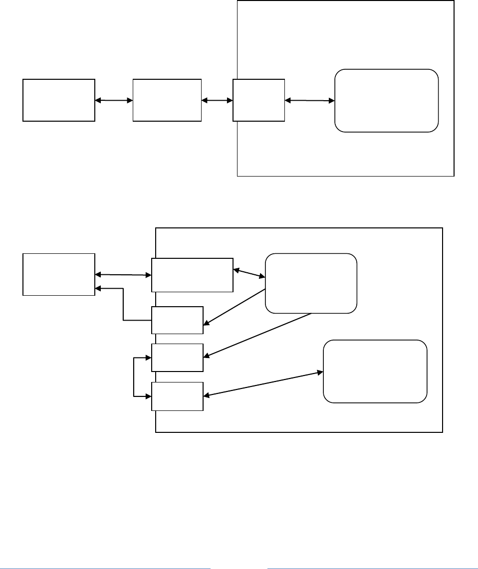
Page 115
11 Advanced Topics - Windows
11.1 Install com0com (optional)
Many Windows packet radio applications can communicate with a physical TNC connected to a serial
port, as illustrated below.
Dire Wolf is a software replacement for a separate TNC. One way of using it is illustrated below.
The packet radio application expects to find a TNC on COM4. COM3, connected to Dire Wolf, behaves
like a KISS TNC. The two serial ports are connected to each other with a “null modem” cable. Anything
coming out of the COM3 port goes into COM4 and vice versa.
Rather than having two physical serial ports, connected by an external cable, we can use a pair of virtual
ports.
Computer
Radio
COM4
Application
“Sound card”
COM1
COM3
Dire Wolf
PTT
Audio
“null
modem”
cable
Radio
TNC
Computer
COM
port
Application
Audio & PTT
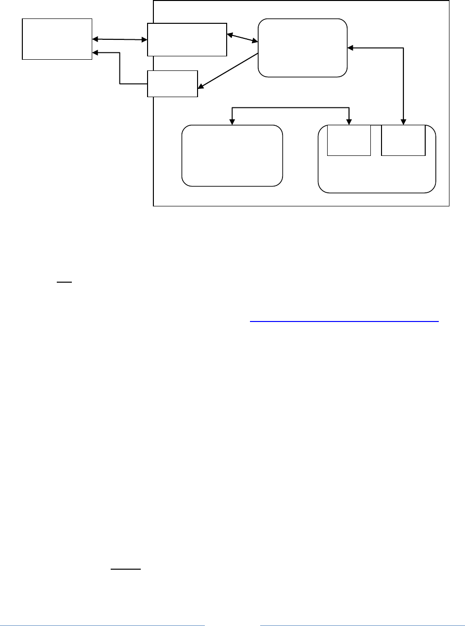
Page 116
Special software tricks both Dire Wolf and the packet radio application into thinking they are using a pair
of physical serial ports connected to each other.
This step is not necessary if you only want to use the “AGW TCPIP socket interface” or KISS over a
network connection.
Down load and install the “Null-modem emulator” from http://sourceforge.net/projects/com0com/
Click on the “View all files” button then pick “com0com” and the most recent version, currently 2.2.2.0
at the time this is being written.
If you have the 64 bit version of Windows 7, download the file with “x64-fre” in the name. Otherwise,
get the file with “i386-fre” in the name.
Follow the instructions for installation.
This creates two virtual serial ports named CNCA0 and CNCB0. In this example we will rename them to
COM3 and COM4. If you already have a COM3 or COM4, use other numbers and make the appropriate
substitutions in all of the configuration steps.
There is an opportunity to run the Setup Command Prompt at the end of the installation. You can also
run it at a later time with:
Start All Programs com0com Setup Command Prompt
Enter these commands, exactly as shown:
Computer
Radio
Application
“Sound card”
COM1
Dire Wolf
PTT
Audio
com0com null
modem emulator
virtual
COM4
virtual
COM3
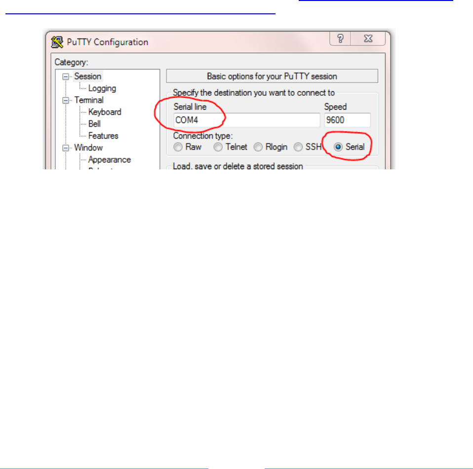
Page 117
change CNCA0 PortName=COM3,EmuBR=yes
change CNCB0 PortName=COM4,EmuOverrun=yes
quit
It is very important that you apply the options as shown. Without them, Dire Wolf might hang trying to
write to COM3 if nothing is connected to COM4.
On Windows XP, you can verify correct operation by starting up two different instances of
HyperTerminal.
Start All Programs Accessories Communications HyperTerminal
Connect one to COM3 and the other to COM4 (or other pair used in earlier setup). Anything typed into
one should show up in the other.
Unfortunately, HyperTerminal is not available on Windows 7. See http://windows.microsoft.com/en-
us/windows/what-happened-hyperterminal#1TC=windows-7 PuTTY is a good alternative.
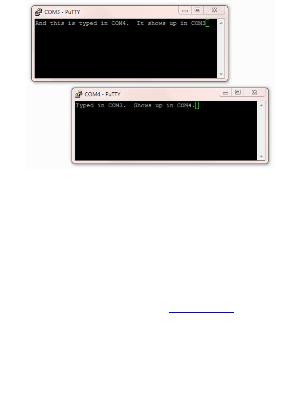
Page 118
Edit the configuration file, “direwolf.conf.” Look for the line that looks like this:
# NULLMODEM COM3
and remove the “#” character from the beginning of the line.
If you followed the instructions here, Dire Wolf will make the virtual COM3 behave like a KISS TNC.
Configure your application to use COM4 and it will think it is attached to an external TNC.
11.2 Build Dire Wolf from source on Windows (optional)
The Windows version contains prebuilt executable files so you don’t need to build it from source. Some
people might want to. Here is how.
The Windows version is built with the MinGW compiler from http://www.mingw.org/. “cd” into the
source directory and run “make” with the Windows-specific Makefile.
cd direwolf-1.3-src
make -f Makefile.win
The result should be several new executable files including “direwolf.exe” and “decode_aprs.exe.”

Page 119
12 Receive Performance
12.1 WA8LMF TNC Test CD
See separate document, with similar name.
12.2 Evolution
Over the years, I’ve experimented with various combinations of demodulator parameters. The original
one, from earlier versions, is called “A.” The additional decoders, called “B” and “C,” offer slightly better
performance at the cost of greater CPU requirements.
Another, called “F” (for fast) is really “A” but it handles only the default case of 1200 baud data and
44,100 sample rate. It is optimized for low end processors that don’t have vector math instructions. It
offers a considerable CPU time reduction for ARM processors (Raspberry Pi – model 1, Beaglebone, etc.)
but doesn’t make much difference Intel x86 type processors.
Decoder
Packets decoded
from WA8LMF test
CD, track 2
Relative amount of
CPU time required.
Comment
A
963
44
Same as earlier versions.
B
964
50
New for version 0.9
C
970
53
D
923
33
“D” was fine tuned for best
300 baud results.
It is not intended for use
with 1200 baud.
E
988
67
New in version 1.2.
F
963
42
Mostly benefits
microprocessor systems
without vector processing.
Not much benefit for x86
PC.
Only for 1200 baud, 44100
sample rate.
A+
975
49
New in version 1.2
B+
982
56
C+
984
60
E+
1008
70
F+
975
49
Starting in version 1.2, we have the new “+” option which is more forgiving of imbalances in the levels of
the two AFSK tones. The accompanying document, “A Better APRS Packet Demodulator,” explains the
problem and a couple solutions.

Page 120
“E+” is now the default for 1200 baud operation on a Windows or Linux PC with an Intel type CPU. If
you are using a really old slow PC, that can’t keep up, you could try the new ”/n“ option which uses less
CPU power by reducing the sampling rate. The configuration command would be like this:
MODEM 1200 /3
This is now the default when running on the Raspberry Pi.
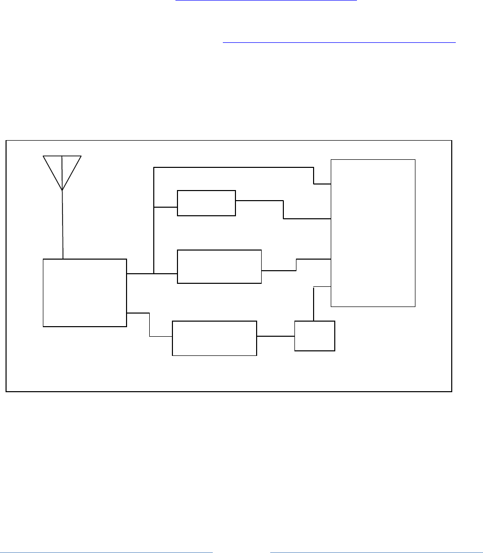
Page 121
12.3 1200 Baud hardware TNC comparison
Here we compare 1200 baud decoder performance against two popular hardware based solutions. This
test was run using version 1.2 before the improved “E+” demodulator was implemented.
For this experiment we need:
Antenna, outside on the roof.
A cheap USB Audio Adapter ( http://www.adafruit.com/product/1475 )
Kantronics KPC-3 Plus
Kenwood TM-D710A
Serial communication cable for D710A ( http://www.amazon.com/gp/product/B000068OER is a
lower cost alternative to the official Kenwood PG-5G) – connect to COM port on control panel.
Audio Y cables, RS232-cables.
PC running Ubuntu Linux.
Connect up everything as shown below. While this transceiver has a “data” connector for external
modems, I used the speaker output because that is probably the more typical usage.
12.3.1 Prepare KPC-3 Plus
Using some sort of terminal emulator application, such as minicom, connect to /dev/ttyS0. Disable any
digipeater settings or beaconing (DIGIPEAT, UITRACE, UIDIGI, UIFLOOD, BEACON, BLT) so it is not
distracted by trying to transmit. Beacons also show up like monitored transmissions. Enable
monitoring:
Mic In
USB
USB Audio Adapter
COM1
USB
Computer
SPKR
SPKR
KPC-3 Plus
COM
USB to RS-232 adapter
Control Panel
TM-D710A
SPKR

Page 122
MONITOR ON
You should see received packets being displayed. Exit from the terminal application.
12.3.2 Prepare D710A
Use the TNC button on the control panel to select “PACKET12” (not APRS) mode. Enable the COM port
with menu 604.
Using some sort of terminal emulator application, connect to /dev/ttyUSB0. Disable any digipeater
settings or beaconing so it is not distracted by trying to transmit. Enable monitoring:
MONITOR ON
You should see received packets being displayed. Exit from the terminal application.
12.3.3 Prepare Dire Wolf
In this test we are using Linux so that device name syntax is shown.
Two different configuration files were prepared. The first (direwolf.conf0) will use the default audio
input on the motherboard.
CHANNEL 0
MODEM 1200 1200 2200 C+
FIX_BITS 0
Note that attempted bad bit fix-up is disabled so we count only error-free frames. This provides a fair
apples-to-apples comparison against the other systems without this feature.
Prepare a second configuration file (direwolf.conf1) like this.
ADEVICE plughw:2,0
CHANNEL 0
MODEM 1200 1200 2200 C+
AGWPORT 8010
KISSPORT 8011
FIX_BITS 1
This provides the more typical usage with the default FIX_BITS value. A $5 external USB Audio Adapter
is being used to dispel the rumor that you need an expensive sound card for good results.
Start up two different Dire Wolf instances, with different configuration files, in different windows.
direwolf -c direwolf.conf0
direwolf -c direwolf.conf1

Page 123
12.3.4 Compare them.
Run the “aclients” test fixture with command line arguments like this
aclients /dev/ttyS0=KPC3+ /dev/ttyUSB0=D710A 8000=DireWolf-0 8010=DireWolf-1
Each command line argument is a serial port name or a TCP port number. Notice how we use two
different port numbers for the two instances of Dire Wolf. The part after “=” is just a comment to label
the results.
Packets are collected from 4 different sources and printed side-by-side in columns for each TNC. A gap
means that TNC did not decode the frame that others did.
It starts off looking like this with the first couple packets being received by everybody.
john@hamshack:~$ aclients /dev/ttyS0=KPC3+ /dev/ttyUSB0=D710A 8000=DireWolf-0 8010=DireWolf-1
Client 3 now connected to DireWolf-1 on localhost (127.0.0.1), port 8010
Client 2 now connected to DireWolf-0 on localhost (127.0.0.1), port 8000
Client 0 now connected to KPC3+ on /dev/ttyS0
Client 1 now connected to D710A on /dev/ttyUSB0
W1OEM-4>ID,EKONCT,W1MRA*,WI W1OEM-4>ID,EKONCT,W1MRA*,WI W1OEM-4>ID,EKONCT,W1MRA*,WI W1OEM-4>ID,EKONCT,W1MRA*,WI
K1SEM>APWW10,KB1JDX-15,W1MR K1SEM>APWW10,KB1JDX-15,W1MR K1SEM>APWW10,KB1JDX-15,W1MR K1SEM>APWW10,KB1JDX-15,W1MR
N1NCI-3>APN383:!4302.00NN07 N1NCI-3>APN383:!4302.00NN07
AB1OC-10>DX,RFONLY: <<UI>>: AB1OC-10>DX,RFONLY:DX de A AB1OC-10>DX,RFONLY:DX de A
N3LEE-7>T2TS4Y,WIDE1-1*,WID N3LEE-7>T2TS4Y,WIDE1-1*,WID N3LEE-7>T2TS4Y,WIDE1-1*,WID N3LEE-7>T2TS4Y,WIDE1-1*,WID
N3LEE-7>T2TS4Y,WIDE1-1,AB1O N3LEE-7>T2TS4Y,WIDE1-1,AB1O N3LEE-7>T2TS4Y,WIDE1-1,AB1O N3LEE-7>T2TS4Y,WIDE1-1,AB1O
KE5KTU-9>TR2P3Y,W1CLA-1,WID KE5KTU-9>TR2P3Y,W1CLA-1,WID KE5KTU-9>TR2P3Y,W1CLA-1,WID
KE5KTU-9>TR2P3Y,W1MHL,W1MRA KE5KTU-9>TR2P3Y,W1MHL,W1MRA KE5KTU-9>TR2P3Y,W1MHL,W1MRA
KE5KTU-9>TR2P3Y,W1MHL,W1MRA
N1LMA-8>APNX01,EKONCT,W1MRA N1LMA-8>APNX01,EKONCT,W1MRA N1LMA-8>APNX01,EKONCT,W1MRA N1LMA-8>APNX01,EKONCT,W1MRA
N1YG-1>T1SY9P,W2DAN-15,W1MR N1YG-1>T1SY9P,W2DAN-15,W1MR N1YG-1>T1SY9P,W2DAN-15,W1MR
WM1X>APU25N,WIDE2-1: <<UI>> WM1X>APU25N,WIDE2-1 <UI C>: WM1X>APU25N,WIDE2-1:@310423 WM1X>APU25N,WIDE2-1:@310423
WM1X>APU25N,AB1OC-10,WIDE2* WM1X>APU25N,AB1OC-10,WIDE2*
… The totals for each are displayed once every 30 minutes. …
K1SEM>APWW10,N1NCI-3,WIDE1, K1SEM>APWW10,N1NCI-3,WIDE1, K1SEM>APWW10,N1NCI-3,WIDE1,
N1OMJ>APWW10,W1MRA*,WIDE2-1 N1OMJ>APWW10,W1MRA*,WIDE2-1 N1OMJ>APWW10,W1MRA*,WIDE2-1 N1OMJ>APWW10,W1MRA*,WIDE2-1
N1OMJ>APWW10,W1MRA,N8VIM,WI N1OMJ>APWW10,W1MRA,N8VIM,WI N1OMJ>APWW10,W1MRA,N8VIM,WI N1OMJ>APWW10,W1MRA,N8VIM,WI
N1OMJ>APWW10,W1MRA,W1JMC* < N1OMJ>APWW10,W1MRA,W1JMC*:@ N1OMJ>APWW10,W1MRA,W1JMC*:@
N1OMJ>APWW10,W1MRA,AB1OC-10 N1OMJ>APWW10,W1MRA,AB1OC-10 N1OMJ>APWW10,W1MRA,AB1OC-10
N1ESA>TQRX9P,EKONCT,W1MRA*, N1ESA>TQRX9P,EKONCT,W1MRA*, N1ESA>TQRX9P,EKONCT,W1MRA*, N1ESA>TQRX9P,EKONCT,W1MRA*,
Totals after 30 minutes, KPC3+ 208, D710A 197, DireWolf-0 297, DireWolf-1 318
MCU-4>T1RS0S,EKONCT,W1MRA,W MCU-4>T1RS0S,EKONCT,W1MRA,W MCU-4>T1RS0S,EKONCT,W1MRA,W
N3LEE-7>T2TS5Q,AB1OC-10,WID N3LEE-7>T2TS5Q,AB1OC-10,WID
N3LEE-7>T2TS5Q,AB1OC-10,WID N3LEE-7>T2TS5Q,AB1OC-10,WID N3LEE-7>T2TS5Q,AB1OC-10,WID N3LEE-7>T2TS5Q,AB1OC-10,WID
K1SEM>APWW10,KB1JDX-15,W1MR K1SEM>APWW10,KB1JDX-15,W1MR K1SEM>APWW10,KB1JDX-15,W1MR K1SEM>APWW10,KB1JDX-15,W1MR
W1AST>TRPR4S,KB1AEV-15,N1NC W1AST>TRPR4S,KB1AEV-15,N1NC
AB1OC-10>DX,RFONLY: <<UI>>: AB1OC-10>DX,RFONLY <UI R>:D AB1OC-10>DX,RFONLY:DX de A AB1OC-10>DX,RFONLY:DX de A
W1MV-1>BEACON,W1MRA*,MA2-1: W1MV-1>BEACON,W1MRA*,MA2-1 W1MV-1>BEACON,W1MRA*,MA2-1: W1MV-1>BEACON,W1MRA*,MA2-1:
… After running several hours and we find these totals: …
AB1OC-10>APWW10,N8VIM,WIDE1 AB1OC-10>APWW10,N8VIM,WIDE1 AB1OC-10>APWW10,N8VIM,WIDE1 AB1OC-10>APWW10,N8VIM,WIDE1
W1BRI>APW261,W1MRA*,WIDE2-1 W1BRI>APW261,W1MRA*,WIDE2-1 W1BRI>APW261,W1MRA*,WIDE2-1 W1BRI>APW261,W1MRA*,WIDE2-1
N1LMA>APU25N,EKONCT,W1MRA*, N1LMA>APU25N,EKONCT,W1MRA*, N1LMA>APU25N,EKONCT,W1MRA*,
N1LCY>APU25N,W1MRA*,WIDE2-1 N1LCY>APU25N,W1MRA*,WIDE2-1 N1LCY>APU25N,W1MRA*,WIDE2-1 N1LCY>APU25N,W1MRA*,WIDE2-1
N1ESA>TQRX9Q,EKONCT,W1MRA*, N1ESA>TQRX9Q,EKONCT,W1MRA*, N1ESA>TQRX9Q,EKONCT,W1MRA*, N1ESA>TQRX9Q,EKONCT,W1MRA*,
AB1OC-10>APWW10,WIDE1-1*,WI AB1OC-10>APWW10,WIDE1-1*,WI AB1OC-10>APWW10,WIDE1-1*,WI AB1OC-10>APWW10,WIDE1-1*,WI
AB1OC-10>APWW10,WIDE1-1,N8V AB1OC-10>APWW10,WIDE1-1,N8V AB1OC-10>APWW10,WIDE1-1,N8V AB1OC-10>APWW10,WIDE1-1,N8V
AB1OC-10>APWW10,WIDE1-1,AB1
N1OMJ>APWW10,W1MRA*,WIDE2-1 N1OMJ>APWW10,W1MRA*,WIDE2-1 N1OMJ>APWW10,W1MRA*,WIDE2-1 N1OMJ>APWW10,W1MRA*,WIDE2-1
N1OMJ>APWW10,WA1PLE-15,WIDE N1OMJ>APWW10,WA1PLE-15,WIDE N1OMJ>APWW10,WA1PLE-15,WIDE N1OMJ>APWW10,WA1PLE-15,WIDE
N1ZZN>APAGW,W1MRA*,WIDE2: < N1ZZN>APAGW,W1MRA*,WIDE2 <U N1ZZN>APAGW,W1MRA*,WIDE2:@3 N1ZZN>APAGW,W1MRA*,WIDE2:@3
K1SEM>APWW10,N1NCI-3,WIDE1, K1SEM>APWW10,N1NCI-3,WIDE1, K1SEM>APWW10,N1NCI-3,WIDE1, K1SEM>APWW10,N1NCI-3,WIDE1,
K1SEM>APWW10,N1NCI-3,WIDE1, K1SEM>APWW10,N1NCI-3,WIDE1, K1SEM>APWW10,N1NCI-3,WIDE1, K1SEM>APWW10,N1NCI-3,WIDE1,
N3LEE-2>GPS: <UI>:!4243.50N N3LEE-2>GPS <UI>:!4243.50NS N3LEE-2>GPS:!4243.50NS07144 N3LEE-2>GPS:!4243.50NS07144
Totals after 540 minutes, KPC3+ 4255, D710A 4076, DireWolf-0 5667, DireWolf-1 6088

Page 124
12.3.5 Summary
If we give the highest number a score of 100% and scale the others proportionally, the scores are:
100% Dire Wolf, single bit fix up
93% Dire Wolf, error-free frames only
70% Kantronics KPC-3 Plus
67% Kenwood TM-D710A
The exact proportions will vary depending on what stations you happen to hear.
As mentioned before, this was done with an older version of the software. Improvements made since
then should produce even better results.
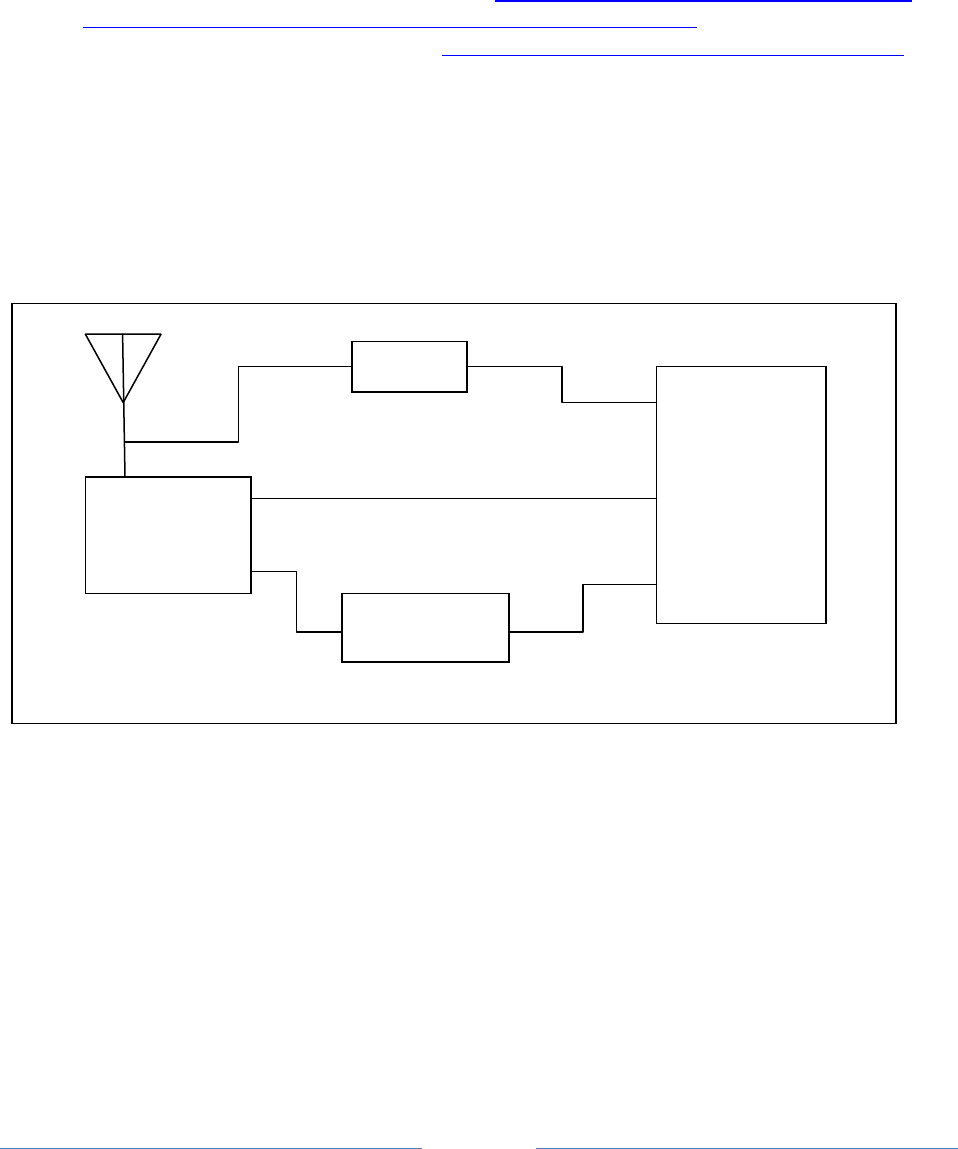
Page 125
12.4 9600 Baud TNC comparison
Here we compare 9600 baud decoder performance. For this experiment we need:
Kenwood TM-D710A.
Software Defined Radio USB dongle. ( such as http://www.amazon.com/Receiver-RTL2832U-
Compatible-Packages-Guaranteed/dp/B009U7WZCA/ref=pd_cp_e_0 )
Serial communication cable for D710A ( http://www.amazon.com/gp/product/B000068OER is a
lower cost alternative to the official Kenwood PG-5G) – connect to COM port on control panel.
Radio data cable with 6 pin mini-DIN connector – same type of connector used for PS/2
keyboard and mouse. The data communications cable from the Kenwood PG-5H package does
not appear to be suitable. It uses the PR1 pin. We need the PR9 pin.
Tee adapter to connect single antenna to two receivers.
Wire up everything as shown below. In this case, we use an indoor antenna so we can get weak signals
with the transmitter only a few blocks away.
Connect the PR9 pin from the DATA connector on the transceiver to the audio input on the computer.
This has wider bandwidth than the PR1 signal or the speaker output.
After many days of listening, no indigenous 9600 baud activity was heard so I had to generate my own
by walking around the neighborhood with a Kenwood TH-D72A transmitting beacons at the maximum
rate (every 0.2 minute) at EL power.
Prepare D710A
Tune to 144.99 MHz. Use the TNC button on the control panel to select “PACKET” (not APRS) mode.
Enable the COM port with menu 604.
USB
Computer
COM1
TM-D710A
Control Panel
PR9 &
GND
COM
SDR USB dongle
Audio In

Page 126
Using some sort of serial port terminal emulator application, such as minicom, connect to /dev/ttyS0.
Disable any sort of digipeater settings or beaconing so it is not distracted by trying to transmit. We also
don’t want to fry the SDR USB dongle! If the control panel shows PACKET12, change the speed by typing
this command:
HBAUD 9600
Enable monitoring:
MONITOR ON
Exit from the terminal application.
12.4.1 Prepare Dire Wolf, first instance
Be sure to use Dire Wolf version 1.2 or later. In this test we are using Linux and the system board
“soundcard” which is the default audio device. Create a configuration file, direwolf.conf-96 with the
following:
CHANNEL 0
MODEM 9600
FIX_BITS 0
When a data speed and no tones are specified, it uses N9GH/G3RUH style encoding.
The default of “FIX_BITS 1” is turned off so we get a fair apples-to-apples comparison.
Start up one instance of Dire Wolf like this.
direwolf -c direwolf.conf-96
12.4.2 Prepare Dire Wolf, second instance
This one will be using an SDR dongle rather than a sound card. Prepare another configuration file,
direwolf.conf-sdr, with the following:
CHANNEL 0
FIX_BITS 0
AGWPORT 8002
KISSPORT 8003
It is not necessary to set the modem characteristics because this will be done on the command line.
Start up the SDR and Dire Wolf in a single command line like this:
rtl_fm -f 144.982M -o 4 -s 48000 | direwolf -c direwolf.conf-sdr -r 48000 -B 9600 –
Note how we use the command line to specify the audio input device (- at the end) and data rate (-B
9600). Both applications must use 1 audio channel and the same sample rate (48000).

Page 127
The astute reader might notice the strange frequency 144.982 when we are using 144.99. It seems the
SDR frequency is off a little. This was necessary to get similar + and – swings around the center
frequency. Your results might be different.
The numbers, in parentheses, after the audio level are explained in A-Better-Packet-Demodulator-Part-
2-9600-baud.pdf.
WB2OSZ audio level = 142(+130/-131) [NONE] |||||||||
When 144.99 was used, we see an imbalance like this:
WB2OSZ audio level = 144(+98/-163) [NONE] ||||_____
When tuned too far the other way, at 144.977, we see:
WB2OSZ audio level = 140(+149/-109) [NONE] ____|||||
IMPORTANT POINT:
The position of the vertical bars and underscores have much different meanings for 300, 1200, and 9600
baud operation.
300 Baud HF SSB, multiple tone pairs. (config file: MODEM 300 5@40)
Here we have 5 completely separate demodulators with different tone pairs. Each of
the decoded signal positions corresponds to a different tone pair. Mistuning of an SSB
signal will shift the audio frequencies up or down. The position in the middle indicates
proper tuning. Positions toward the left mean the audio tones are too low.
1200 Baud AFSK, multiple gains for “space” tone. (config file: MODEM 1200 E+)
The character positions correspond to different gain ratios between the mark and space
filters. Toward the right means more gain for the space tone.
9600 Baud K9NG/G3RUH, multiple slicing levels. (config file: MODEM 9600 +)
In this case, it becomes a tuning indicator. I think this is due to a DC bias from the SDR
being off frequency or an artifact of discriminator non linearity on the edges but need to
study this in more detail.
12.4.3 Compare them.
Start up a recording so we can go back and try more experiments with this data at a later time.
arecord -f S16_LE -r 44100 walkabout9600c.wav
Run the “aclients” application with command line arguments like this

Page 128
aclients /dev/ttyS0=D710 8000=DireWolf-soundcard 8002=DireWolf-SDR
john@hamshack:~$ aclients /dev/ttyS0=D710 8000=DireWolf-soundcard 8002=DireWolf-SDR
Client 0 now connected to D710 on /dev/ttyS0
Client 1 now connected to DireWolf-soundcard on localhost (127.0.0.1), port 8000
Client 2 now connected to DireWolf-SDR on localhost (127.0.0.1), port 8002
WB2OSZ>TRSW1S <UI R>:'c0ol#'[/>"4j}= WB2OSZ>TRSW1S:'c0ol#'[/>"4j}= WB2OSZ>TRSW1S:'c0ol#'[/>"4j}=
WB2OSZ>TRSW1S <UI R>:'c0ol#'[/>"4j}= WB2OSZ>TRSW1S:'c0ol#'[/>"4j}= WB2OSZ>TRSW1S:'c0ol#'[/>"4j}=
WB2OSZ>TRSW1S <UI R>:'c0ol#'[/>"4j}= WB2OSZ>TRSW1S:'c0ol#'[/>"4j}= WB2OSZ>TRSW1S:'c0ol#'[/>"4j}=
WB2OSZ>TRSW1S <UI R>:'c0ol#'[/>"4j}= WB2OSZ>TRSW1S:'c0ol#'[/>"4j}= WB2OSZ>TRSW1S:'c0ol#'[/>"4j}=
WB2OSZ>TRSW1S <UI R>:'c0ol#'[/>"4j}= WB2OSZ>TRSW1S:'c0ol#'[/>"4j}= WB2OSZ>TRSW1S:'c0ol#'[/>"4j}=
WB2OSZ>TRSW1S <UI R>:'c0ol#'[/>"4j}= WB2OSZ>TRSW1S:'c0ol#'[/>"4j}= WB2OSZ>TRSW1S:'c0ol#'[/>"4j}=
WB2OSZ>TRSW1S <UI R>:'c0ol#'[/>"4j}= WB2OSZ>TRSW1S:'c0ol#'[/>"4j}= WB2OSZ>TRSW1S:'c0ol#'[/>"4j}=
WB2OSZ>TRSW1S <UI R>:'c0ol#'[/>"4j}= WB2OSZ>TRSW1S:'c0ol#'[/>"4j}= WB2OSZ>TRSW1S:'c0ol#'[/>"4j}=
WB2OSZ>TRSW1S <UI R>:'c0ol#'[/>"4j}= WB2OSZ>TRSW1S:'c0ol#'[/>"4j}= WB2OSZ>TRSW1S:'c0ol#'[/>"4j}=
Totals after 2 minutes, D710 9, DireWolf-soundcard 9, DireWolf-SDR 9
It starts off with all receiving the same thing while the transmitter is near.
WB2OSZ>TRSW1S <UI R>:'c0ol#'[/>"4j}= WB2OSZ>TRSW1S:'c0ol#'[/>"4j}= WB2OSZ>TRSW1S:'c0ol#'[/>"4j}=
WB2OSZ>TRSW1S <UI R>:'c0ol#'[/>"4j}= WB2OSZ>TRSW1S:'c0ol#'[/>"4j}= WB2OSZ>TRSW1S:'c0ol#'[/>"4j}=
WB2OSZ>TRSW1S <UI R>:'c0ol#'[/>"4j}= WB2OSZ>TRSW1S:'c0ol#'[/>"4j}= WB2OSZ>TRSW1S:'c0ol#'[/>"4j}=
WB2OSZ>TRSW1S <UI R>:'c0ol#'[/>"4j}= WB2OSZ>TRSW1S:'c0ol#'[/>"4j}= WB2OSZ>TRSW1S:'c0ol#'[/>"4j}=
WB2OSZ>TRSW1S <UI R>:'c0ol#'[/>"4j}= WB2OSZ>TRSW1S:'c0ol#'[/>"4j}=
WB2OSZ>TRSW1S:'c0ol#'[/>"4j}=
WB2OSZ>TRSW1S <UI R>:'c0ol#'[/>"4j}= WB2OSZ>TRSW1S:'c0ol#'[/>"4j}= WB2OSZ>TRSW1S:'c0ol#'[/>"4j}=
WB2OSZ>TRSW1S <UI R>:'c0ol#'[/>"4j}= WB2OSZ>TRSW1S:'c0ol#'[/>"4j}=
Totals after 4 minutes, D710 16, DireWolf-soundcard 17, DireWolf-SDR 14
As the signal gets weaker, the left and right columns are missing some that are in the
middle column.
WB2OSZ>TRSW1S:'c0ol#'[/>"4j}= WB2OSZ>TRSW1S:'c0ol#'[/>"4j}=
WB2OSZ>TRSW1S:'c0ol#'[/>"4j}=
[ b Ps> E P QR A . o H
Totals after 6 minutes, D710 16, DireWolf-soundcard 20, DireWolf-SDR 15
lrm + . c5 $
WB2OSZ>TRSW1S:'c0ol#'[/>"4j}=
What happened there? It looks like garbage. When listening to 9600 baud we
occasionally see random noise that just happens to have a valid CRC. Remember that
there are only 65536 possible values for the CRC and sometimes random noise will just
happen to match. Below is what it looked like in the first receiving window. At the end
we will subtract these from the totals.
audio level = 104(+142/-151) ___|_____
[0.3]
<0x84>[<0x14>b<0x14><0xb9>Ps><0xbd><0x98><0xaa><0xb1>E<0xe6><0xc5>P<0xa0>QR<0x93><0xf
b>A<0xd7>.<0xfe>o<0xe3>H<0xb5>
audio level = 105(+142/-158) ________|
[0.8]
lrm<0xb3>+<0xab>.<0x82><0x07><0xd3><0xf2><0x9e>c5<0x80>$<0x93><0xe3><0x11><0x86>
Totals after 8 minutes, D710 16, DireWolf-soundcard 22, DireWolf-SDR 15
Totals after 10 minutes, D710 16, DireWolf-soundcard 22, DireWolf-SDR 15
Totals after 12 minutes, D710 16, DireWolf-soundcard 22, DireWolf-SDR 15
WB2OSZ>TRSW1S:'c0ol#'[/>"4j}=

Page 129
The transmitter was out of range for a few minutes. When it starts to come back in
range, the middle is the first to start receiving it properly.
Totals after 14 minutes, D710 16, DireWolf-soundcard 23, DireWolf-SDR 15
WB2OSZ>TRSW1S <UI R>:'c0ol#'[/>"4j}= WB2OSZ>TRSW1S:'c0ol#'[/>"4j}=
WB2OSZ>TRSW1S <UI R>:'c0ol#'[/>"4j}= WB2OSZ>TRSW1S:'c0ol#'[/>"4j}=
Totals after 16 minutes, D710 18, DireWolf-soundcard 25, DireWolf-SDR 15
WB2OSZ>TRSW1S <UI R>:'c0ol#'[/>"4j}= WB2OSZ>TRSW1S:'c0ol#'[/>"4j}=
WB2OSZ>TRSW1S <UI R>:'c0ol#'[/>"4j}= WB2OSZ>TRSW1S:'c0ol#'[/>"4j}=
WB2OSZ>TRSW1S <UI R>:'c0ol#'[/>"4j}= WB2OSZ>TRSW1S:'c0ol#'[/>"4j}=
Totals after 18 minutes, D710 21, DireWolf-soundcard 28, DireWolf-SDR 15
WB2OSZ>TRSW1S <UI R>:'c0ol#'[/>"4j}= WB2OSZ>TRSW1S:'c0ol#'[/>"4j}=
YD p bP && NU 8y ^k 2 I
QmW
Once again, random noise just happened to have a valid CRC. We will subtract this from
the final totals. This is what it looked like in the receiving window:
audio level = 180(+204/-196) ________|
[0.8]
YD<0x97><0x87>p<0xd3>bP<0xb2><0xa0><0x96><0xda>&&<0xb0><0xdc>NU<0x1e>8y<0xbc>^k<0x89>
<0x0c><0xd6><0xe2>2<0x16>I<0x01><0xda><0x82>QmW<0xf0><0xd8>gE<0xf4><0xae><0xfc>.<0xbf
><0xd9><0xb3><0xe5><0xe8><0x9e><0xe6>0<0xe1><0xc0><0x0b><0x15>"<0xe5>A
Totals after 20 minutes, D710 22, DireWolf-soundcard 29, DireWolf-SDR 16
WB2OSZ>TRSW1S <UI R>:'c0ol#'[/>"4j}= WB2OSZ>TRSW1S:'c0ol#'[/>"4j}=
WB2OSZ>TRSW1S <UI R>:'c0ol#'[/>"4j}= WB2OSZ>TRSW1S:'c0ol#'[/>"4j}=
WB2OSZ>TRSW1S <UI R>:'c0ol#'[/>"4j}= WB2OSZ>TRSW1S:'c0ol#'[/>"4j}=
WB2OSZ>TRSW1S <UI R>:'c0ol#'[/>"4j}= WB2OSZ>TRSW1S:'c0ol#'[/>"4j}=
WB2OSZ>TRSW1S:'c0ol#'[/>"4j}=
WB2OSZ>TRSW1S <UI R>:'c0ol#'[/>"4j}= WB2OSZ>TRSW1S:'c0ol#'[/>"4j}= WB2OSZ>TRSW1S:'c0ol#'[/>"4j}=
WB2OSZ>TRSW1S <UI R>:'c0ol#'[/>"4j}= WB2OSZ>TRSW1S:'c0ol#'[/>"4j}= WB2OSZ>TRSW1S:'c0ol#'[/>"4j}=
Totals after 22 minutes, D710 28, DireWolf-soundcard 36, DireWolf-SDR 18
WB2OSZ>TRSW1S <UI R>:'c0ol#'[/>"4j}= WB2OSZ>TRSW1S:'c0ol#'[/>"4j}= WB2OSZ>TRSW1S:'c0ol#'[/>"4j}=
WB2OSZ>TRSW1S <UI R>:'c0ol#'[/>"4j}= WB2OSZ>TRSW1S:'c0ol#'[/>"4j}= WB2OSZ>TRSW1S:'c0ol#'[/>"4j}=
WB2OSZ>TRSW1S <UI R>:'c0ol#'[/>"4j}= WB2OSZ>TRSW1S:'c0ol#'[/>"4j}= WB2OSZ>TRSW1S:'c0ol#'[/>"4j}=
WB2OSZ>TRSW1S <UI R>:'c0ol#'[/>"4j}= WB2OSZ>TRSW1S:'c0ol#'[/>"4j}= WB2OSZ>TRSW1S:'c0ol#'[/>"4j}=
WB2OSZ>TRSW1S <UI R>:'c0ol#'[/>"4j}= WB2OSZ>TRSW1S:'c0ol#'[/>"4j}= WB2OSZ>TRSW1S:'c0ol#'[/>"4j}=
WB2OSZ>TRSW1S <UI R>:'c0ol#'[/>"4j}= WB2OSZ>TRSW1S:'c0ol#'[/>"4j}= WB2OSZ>TRSW1S:'c0ol#'[/>"4j}=
WB2OSZ>TRSW1S <UI R>:'c0ol#'[/>"4j}= WB2OSZ>TRSW1S:'c0ol#'[/>"4j}= WB2OSZ>TRSW1S:'c0ol#'[/>"4j}=
WB2OSZ>TRSW1S <UI R>:'c0ol#'[/>"4j}= WB2OSZ>TRSW1S:'c0ol#'[/>"4j}= WB2OSZ>TRSW1S:'c0ol#'[/>"4j}=
WB2OSZ>TRSW1S <UI R>:'c0ol#'[/>"4j}= WB2OSZ>TRSW1S:'c0ol#'[/>"4j}= WB2OSZ>TRSW1S:'c0ol#'[/>"4j}=
Totals after 24 minutes, D710 37, DireWolf-soundcard 45, DireWolf-SDR 27
WB2OSZ>TRSW1S <UI R>:'c0ol#'[/>"4j}= WB2OSZ>TRSW1S:'c0ol#'[/>"4j}= WB2OSZ>TRSW1S:'c0ol#'[/>"4j}=
WB2OSZ>TRSW1S <UI R>:'c0ol#'[/>"4j}= WB2OSZ>TRSW1S:'c0ol#'[/>"4j}= WB2OSZ>TRSW1S:'c0ol#'[/>"4j}=
WB2OSZ>TRSW1S <UI R>:'c0ol#'[/>"4j}= WB2OSZ>TRSW1S:'c0ol#'[/>"4j}= WB2OSZ>TRSW1S:'c0ol#'[/>"4j}=
WB2OSZ>TRSW1S <UI R>:'c0ol#'[/>"4j}= WB2OSZ>TRSW1S:'c0ol#'[/>"4j}= WB2OSZ>TRSW1S:'c0ol#'[/>"4j}=
WB2OSZ>TRSW1S <UI R>:'c0ol#'[/>"4j}= WB2OSZ>TRSW1S:'c0ol#'[/>"4j}= WB2OSZ>TRSW1S:'c0ol#'[/>"4j}=
WB2OSZ>TRSW1S <UI R>:'c0ol#'[/>"4j}= WB2OSZ>TRSW1S:'c0ol#'[/>"4j}= WB2OSZ>TRSW1S:'c0ol#'[/>"4j}=
As the transmitter returns home, all three can hear it properly.
Total scores, subtracting frames that look like garbage:
37 + 6 = 43 45 -2 + 6 = 49 27 – 1 + 6 = 32
This is not the most realistic test scenario – only one transmitter is involved - but it does provide useful
data for comparison.

Page 130
12.4.4 Results
If we give the highest number a score of 100% and scale the others proportionally, the scores are:
100% Dire Wolf, audio input on system board.
88% Kenwood TM-D710A
65% Dire Wolf, software defined radio (SDR) adapter.
The exact percentage should not be taken too seriously because they can be manipulated by the
amount of time spent in the zone where Dire Wolf could receive the signal but the TNC inside the TM-
D710A could not.
The software defined radio did pretty well when you consider that it costs only about $22.
There is potential for possible improvement by:
Finding better configuration options.
Using higher quality hardware such as the FUNcube Pro dongle.
Using other SDR software such as gqrx.
This experiment applies only to 9600 baud operation. Results with 1200 baud could be much different.
There is one remaining mystery. Why doesn’t the data change? When walking around, the GPS location
should change and the beacon content should change. What is going on here? I don’t know. After
getting an initial GPS fix, the HT was inside for quite a while where it would lose the GPS signal. Did the
radio decide to shut off the GPS and use the last known location even when out walking around?
Later improvement: Version 1.4 decodes slightly more packets from the same recording.
Command
Version 1.2
Version 1.4
atest -B 9600 walkabout9600c.wav
43
46
atest -B 9600 -P + walkabout9600c.wav
47
49

Page 131
12.5 One Bad Apple Don’t Spoil the Whole Bunch… (“FIX_BITS” option)
There is an old proverb, “One bad apple spoils the barrel,” which applies to AX.25 frames used for APRS
and traditional packet radio. Each frame contains a 16 bit frame check sequence (FCS) used for error
detection. If any one bit is corrupted along the way, the FCS is wrong and the entire frame is discarded.
The Osmond Brothers offered the advice, “Give it one more try before you give up…” That can also
apply to AX.25 frames. From my observations, single bit errors are fairly common. Why not give it one
more try before giving up?
My original attempt at receiving APRS signals performed the HDLC decoding real time on the bits as
soon as they came out of the AFSK demodulator. If the FCS was wrong, the frame was discarded. The
original bit stream was gone. No second chances.
In version 0.6, the HDLC decoder was rearranged to operate in two different phases. The first phase
only looked for the special 01111110 “flag” patterns surrounding the frames. The raw received data was
stored in an array of bits without undoing the “bit stuffing” at this time. This stream of bits was then
processed in the second phase. This provides an opportunity to give it another try if it didn’t go well the
first time.
For single bit errors, we can try to invert each of the bits – one at a time! – and recalculate the FCS. My
experimentation found this recovered a lot of packets that would normally be discarded. Experimental
results are summarized in a table later.
What about two or three adjacent bits getting clobbered along the way? If something is good, then
more must be better. Right? The next experiment was to try modifying groups of two or three adjacent
bits.
Why stop at modifying only adjacent bits? What about two non-adjacent (or “separated”) single bit
errors? This also allowed a fair number of additional frames to be decoded but at a much larger cost.
The processing time is proportional to the square of the number of bits so it climbs rapidly with larger
packets. For larger frames this could be seconds rather than milliseconds.
There is one little problem with flipping various bits trying to find a valid FCS. We get a lot of false
positives on the FCS check and end up with bogus data. Callsigns contain punctuation characters. The
information part has unprintable characters.
The 16 bit FCS has 65,536 different possible values. Even if totally random data goes into the checking
process, you will end up with a valid FCS one out of every 65,536 times. When you try hundreds or even
thousands of bit flipping combinations and process lots of packets, a fair number will just happen to get
past the FCS check and produce bad data.
My further refinement was to run the results through an additional sanity check. A good AX.25 frame
will have:
An address part that is a multiple of 7 bytes.
Between 2 and 10 addresses.

Page 132
Only upper case letters, digits, and space in the addresses.
Certain values in the frame control and protocol octets.
For APRS, the information part has only printable ASCII characters or these:
o 0x0a line feed
o 0x0d carriage return
o 0x1c used by MIC-E
o 0x1d used by MIC-E
o 0x1e used by MIC-E
o 0x1f used by MIC-E
o 0x7f used by MIC-E
o 0x80 seen in "{UIV32N}<0x0d><0x9f><0x80>"
o 0x9f seen in "{UIV32N}<0x0d><0x9f><0x80>"
o 0xb0 degree symbol, ISO Latin1
(Note: UTF-8 uses two byte sequence 0xc2 0xb0.)
o 0xbe invalid MIC-E encoding.
o 0xf8 degree symbol, Microsoft code page 437
After applying this extra step of sanity checking, no bad data was visually observed for the single bit
fixing case. In very large sample sizes, there were a few cases of bad data getting thru when flipping
more than one adjacent bit. Obvious errors are fairly common when flipping two non-adjacent bits.
What about non-APRS frames? There is a configuration setting to perform a less stringent sanity check
for general AX.25. The control and protocol bytes, of the frame, are not tested. The information part is
not checked so “binary” data can be used. A less strict sanity check makes it more likely for corrupted
data to get through.
In this example, the first decoder was able to achieve a valid FCS and plausible contents by flipping two
non-adjacent bits. The third decoder received it with a correct CRC. Results were different so the
duplicate detection did not combine them.
Digipeater WB6JAR-10 audio level = 23 [TWO_SEP] .__
[0] N6VNI-14>APRS,WB6JAR-10*,WIDE,QIDE-6:!3356.05N/11758.61Wk Geo & Kris LaHabra,CA
Digipeater WB6JAR-10 audio level = 23 [NONE] _:|
[0] N6VNI-14>APRS,WB6JAR-10*,WIDE,WIDE:!3356.05N/11758.01Wk Geo & Kris LaHabra,CA
In this example, the first and third decoders both found combinations of two bit changes that resulted in
a valid FCS and plausible data. The second one does not look right with “/V” in the GPS sentence. The
first one might or might not be correct. Checking the GPS checksum is left as an exercise for the reader.
N6QFD-9 audio level = 14 [TWO_SEP] .__
[0] N6QFD-9>GPSTJ,WIDE2-
2:$GPRMC,020114,A,3409.7103,U,11804.0209,W,14.6,89.2,231105,13.5,E,A*30<0x0d><0x0a>
N6IFD-9 audio level = 14 [TWO_SEP] __.
[0] N6IFD-9>GPSLJ,WIDE2-
2:$GPRMC,020114,A,3409.7103/V,11804.0209,W,14.6,89.2,231109,13.5,E,A*30<0x0d><0x0a>

Page 133
Most of my earlier testing was done with Track 2 of the WA8LMF TNC Test CD
(http://wa8lmf.net/TNCtest/index.htm). With the test CD, I got the following results for Dire Wolf
version 0.6. Versions 0.7 and 0.8 had no changes in this area. In version 0.9, we use all 3 decoders
running in parallel.
Version 0.6
Version 0.9
Version 1.2
Bits changed
Number
of
packets
received
(+ means
change
from
previous
line)
Percentage
increase
(in addition
to preceding
line)
Number
of
packets
received
Percentage
increase
Number
of
packets
received
Percentage
increase
None
965
- - -
976
- - -
988
Single
+ 12
1.2
+ 21
2.1
+ 15
1.5
Two adjacent
+ 2
0.2
+ 1
0.1
+ 3
0.3
Three adjacent
+ 0
0
+ 0
0.0
+2
0.2
Two separated
+ 12
1.2
+ 24
2.4
+9
0.9
Results were more impressive when listening to local stations live. About 23% additional packets were
successfully decoded after flipping some bits and giving them another chance.
Version 0.6
Bits changed
Number of
packets
received
Percentage
increase
None
6998
- - -
Single
+ 962
13.7
Two adjacent
+ 57
0.8
Three adjacent
+ 7
0.1
Two separated (not adjacent)
+ 572
8.2
Why such large disparities in the % increase? What is so much different about the local stations heard
vs. the sample on the Test CD? I looked for a pattern in the packets that would normally be rejected but
were recovered by flipping a single bit.
It doesn’t seem to be correlated with a small number of stations. I tabulated where the signals came
from (digipeater heard, not original source station) and they are from all over, not just a few stations.
It doesn’t seem to be correlated with audio deviation of the transmitted signal. Audio levels varied over
a 9 to 1 ratio. A lot of people still don’t get the concept of setting a proper transmit audio level.
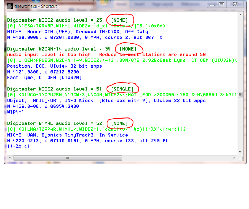
Page 134
Is it correlated to the type of system transmitting? Again, there doesn’t seem to be a pattern. A wide
variety of system types are represented.
By default, only single bit fix up is enabled. You can experiment with the others with a configuration file
setting. In the configuration file, specify the maximum level of correction to be attempted:
0 [NONE] - Don't try to repair.
1 [SINGLE] - Attempt to fix single bit error. (default)
2 [DOUBLE] - Also attempt to fix two adjacent bits.
3 [TRIPLE] - Also attempt to fix three adjacent bits.
4 [TWO_SEP] - Also attempt to fix two non-adjacent (separated) bits.
Example: Limit attempt to fixing a single bit:
FIX_BITS 1
The audio level line contains the number of bits that were changed to get a valid FCS on the frame. In
most cases this will be NONE. Here is an example, where a frame that would normally be rejected, was
recovered by changing a SINGLE bit.

Page 135
It is important to remember that we are not repairing errors, we are only changing bits until we get a
valid CRC. We could be adding additional corruption instead of repairing corruption.
The “sanity” check is not a validity check. We catch things that obviously look crazy but corrupted data
could get through. One person compared this to playing a game of Russian Roulette. Most of the time
you get lucky but sometimes, it doesn’t work out so well.
This feature is being provided for those who want to experiment with it. Don’t use if handling important
information such as emergency communications. When using a “FIX_BITS” value greater than 1 you
will get occasional bad data.
The Digipeater and IGate functions will process only packets received with
a correct CRC to avoid relaying possibly corrupted data. Forwarding
possibly corrupted data would be a disservice to the community.
Note that the possibly corrupted frames are passed along to any attached applications. If you are using
some other application to perform the digipeater or IGate functions, you could be passing along
corrupted data.

Page 136
13 UTF-8 characters
13.1 Background
AX.25, like most other computer communication, uses the ASCII character set. ASCII was developed in
the 1960’s and has a total of 94 printable characters. This didn’t keep people happy for very long. As
computer usage grew, different vendors starting to add more characters in many different inconsistent
ways. Numerous incompatible standards were only partial solutions.
For example, the degree symbol was represented by
11111000 in Microsoft code page 437
10110000 in ISO Latin1 (8859-1)
Skipping over several decades of history and countless incompatible standards, UTF-8 is now the
preferred way to handle communication for all the additional characters. ASCII is a subset of UTF-8 so
they can be used at the same time. Character codes with 0 in the most significant bit are the traditional
ASCII characters:
0xxxxxxx Latin letters, digits, common symbols,
and control functions such as new line.
Vast numbers of additional characters are represented by sequences of two or more bytes. The first
byte has 11 in the two most significant bits. One or more additional bytes have 10 in the most
significant bytes.
11xxxxxx 10xxxxxx …
For example, the degree symbol is now:
11000010 10110000
When Dire Wolf is used as a TNC for other client applications, UTF-8 is fully supported. Characters from
the radio get sent to the application. Characters from the application get sent to the radio.
The only issue arises when trying to display the characters so a person can see them. Dire Wolf does not
have a graphical user interface (GUI). It is just a text-based application that depends on some sort of
terminal emulator to change internal character codes into viewable images. Some very old terminal
emulators don’t understand UTF-8. Others might have the capability but need special configuration
settings.
13.2 Microsoft Windows
The Microsoft Windows “Command Prompt” has a default of “Raster Fonts.” This has a very limited set
of characters available. Select one of the other two.
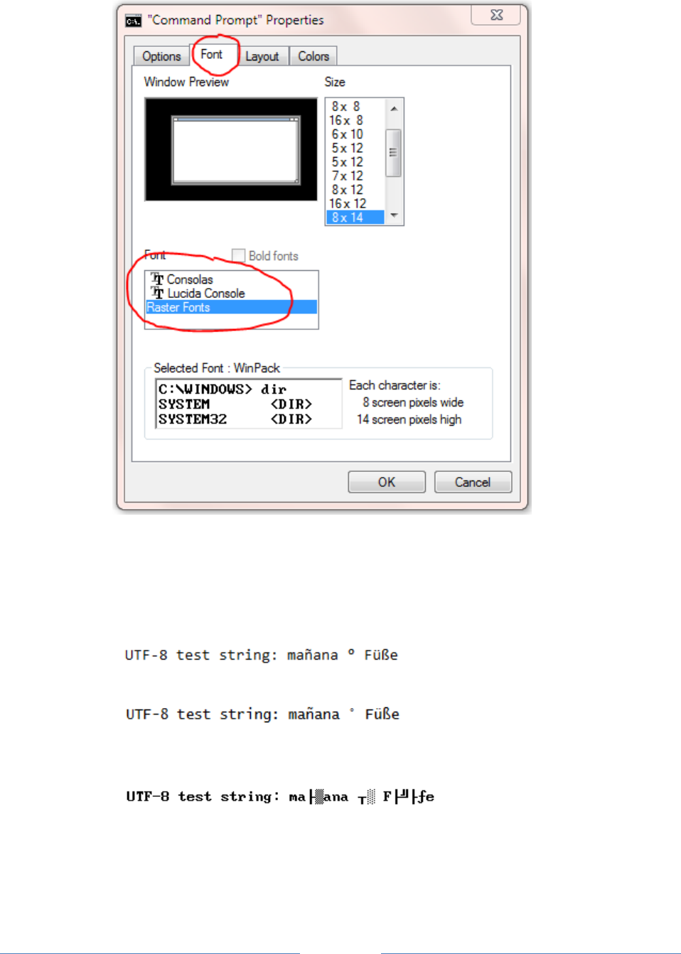
Page 137
Run direwolf with the upper case -U option to display a test string.
Here are results for the 3 different fonts:
Consolas
Lucida Console
Raster Fonts
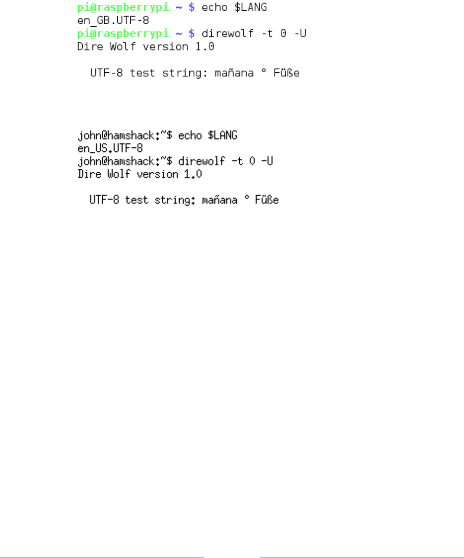
Page 138
13.3 Linux
UTF-8 is usually the default on newer systems but there might be cases where you need to set the LANG
environment variable.
The default on Raspian is correct. This is using LXTerminal.
The defaults on Ubuntu are also correct. There are reports that a certain command line option is
required to make xterm process UTF-8 but that doesn’t seem to be true anymore.
If using PuTTY to access a remote Linux system, be sure to change the character set to UTF-8.
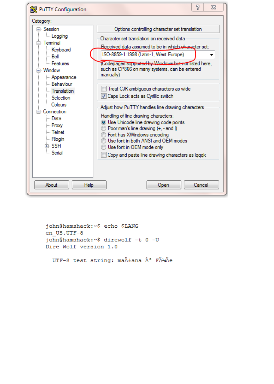
Page 139
If PuTTY is using ISO Latin-1, it will look like this:
Linux has many flavors and an overabundance of terminal emulators so we can’t cover all the
possibilities here. Google for something like linux terminal utf-8 for more help.
13.4 Debugging
The “-d u” command line option turns on debugging for messages containing non-ASCII characters.
After the normal monitor format, just the information part of the packet is repeated. Any non-ASCII
characters are displayed in hexadecimal so you can take a closer look at the bytes in the packet.
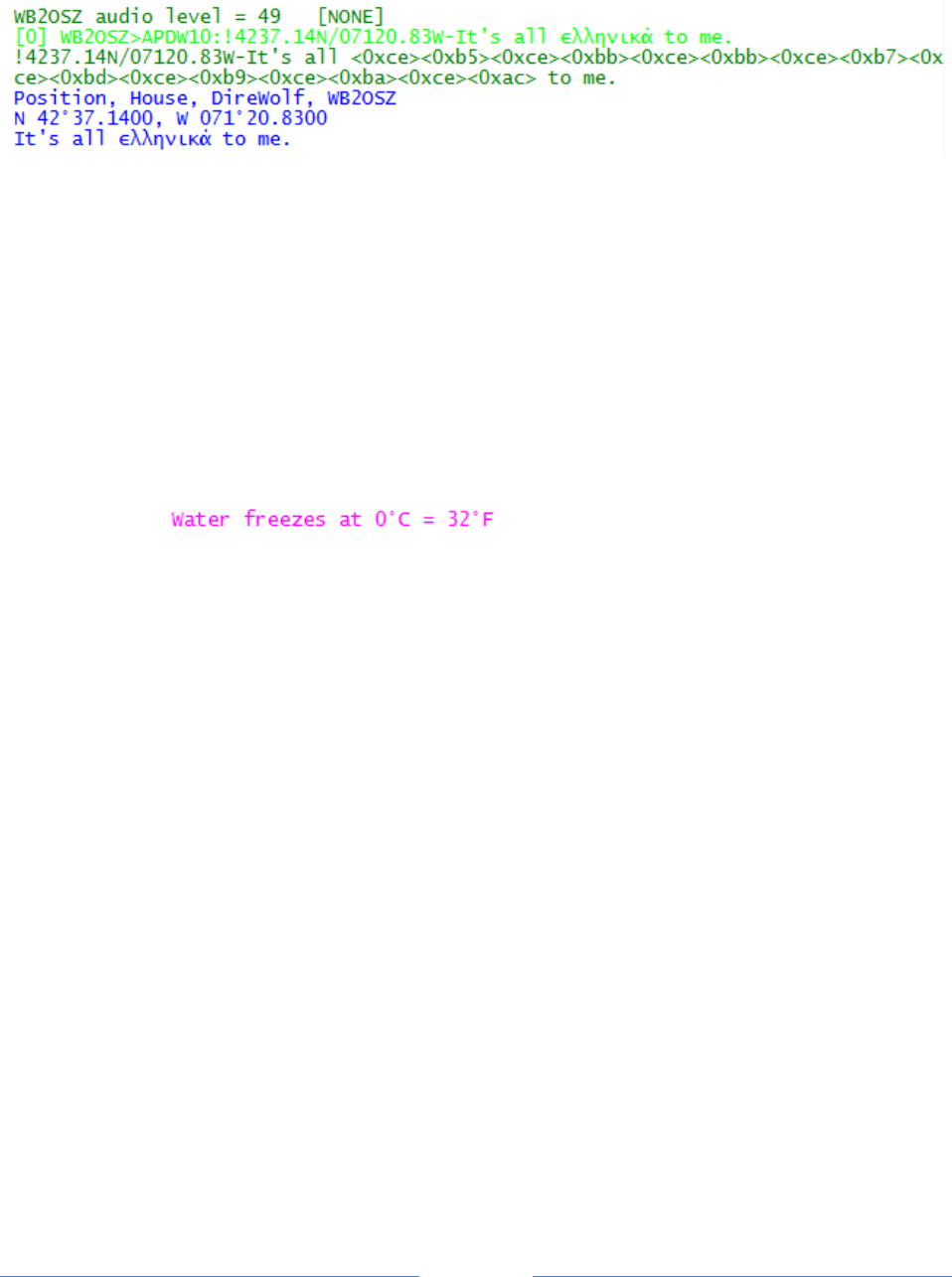
Page 140
Here we see where the character string “ελληνικά” has been replaced by the numerical values of the
bytes: ce b5 ce bb ce bb ce b7 ce bd ce b9 ce ba ce ac.
This extra line appears only when non-ASCII characters are present.
13.5 Configuration File
To transmit non-ASCII characters in a beacon, use the same hexadecimal notation used to display
received packets. For example,
PBEACON … comment="Water freezes at 0<0xc2><0xb0>C = 32<0xc2><0xb0>F"
Would send a comment that looks like this:

Page 141
14 Other Included Applications
The “direwolf” software TNC package includes several other related applications. “man” pages are
available in the Linux version.
14.1 aclients – Test program for side-by-side TNC performance comparison
aclients is used to compare how well different TNCs decode AX.25 frames at the same time. The
Receive Performance section contains a couple examples.
14.2 atest - Decode AX.25 frames from an audio file
atest is a test application which decodes AX.25 frames from an audio recording. This provides an
easy way to test Dire Wolf decoding performance much quicker than normal real-time.
14.3 decode_aprs - Convert APRS raw data to human readable form
decode_aprs is useful for understanding sometimes obscure APRS packets and finding errors.
Suppose you find something like this in the raw data section of http://aprs.fi or http://findu.com .
WB4APR-7>3X5Y1S,N3UJJ-6,WIDE1*,WIDE2-1,qAS,WA5VHU-1:`h9<0x1e>l4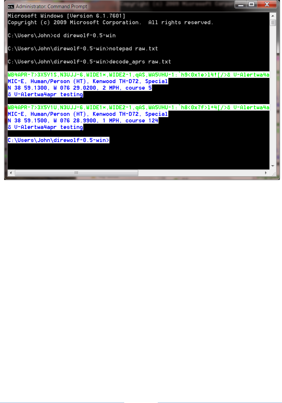
Page 142
One interesting thing to note here is that some message types use non-printable characters. In this
case, we use the form <0x**> where ** is the hexadecimal representation. In the example above, we
find two unprintable characters <0x1e> <0x7f>.
14.4 gen_packets - Generate audio file for AX.25 frames
gen_packets is a test application which converts text to AX.25 audio for testing packet decoders.
It is very flexible allowing a wide range of audio sample rates, data speeds, and AFSK tones. It will even
generate the scrambled signals commonly used for 9600 baud operation.
14.5 ll2utm, utm2ll – Convert between Latitude/Longitude & UTM Coordinates
These are explained in the separate APRStt Implementation Notes.
14.6 log2gpx - Convert Dire Wolf log files to GPX format

Page 143
14.7 text2tt, tt2text – Convert between text and APRStt tone sequences
These are explained in the separate APRStt Implementation Notes.
15 Questions & Feedback
https://groups.yahoo.com/neo/groups/direwolf_packet/info is a good place to ask questions and share
information with other users. You might find your questions have already been answered here.
You can contact the author directly at wb2osz *at* Comcast *dot* net. Be sure to mention the version
number and whether you are using Windows or Linux.
