User Guide Centerline
User Manual: Pdf
Open the PDF directly: View PDF ![]() .
.
Page Count: 10
Roux C. (CNRS UMR5600 - Plateforme ISIG & SedAlp, Sediment Management in Alpine basins)
Extraction of the centerline
Toolset name : SPATIAL COMPONENT
Tool’s name : Centerline
User guide for FluvialCorridor toolbox
How to cite : Roux, C., Alber, A., Piégay, H., 2013. Centerline guideline for the
FluvialCorridor toolbox, a new ArcGIS tool
box package for exploring
multiscale riverscape at a network scale
. Sedalp (Sediment Management in
Alpin Basins) and CNRS (UMR5600).

Roux C. (CNRS UMR5600 - Plateforme ISIG & SedAlp, Sediment Management in Alpine basins)
FluvialCorridor package for ArcGIS
Version V01 - 2014
CNRS - UMR5600 Environnement Ville Société
Alpine Space Program - Sedalp
For each use of the FluvialCorridor GIS package leading to a publication, a report, a
talk presentation or any other document, please refer to the following paper :
Roux, C., Alber, A., Bertrand, M., Vaudor, L., Piégay, H., submitted. "FluvialCorridor" : A
new ArcGIS package for multiscale riverscape exploration. Geomorphology.
Roux C. (CNRS UMR5600 - Plateforme ISIG & SedAlp, Sediment Management in Alpine basins)
1
I. Concept and methods
A crucial step for the fluvial corridors characterization is the assessment of metrics over linear
(e.g. hydrographic stream network) or polygon (e.g. valley bottom, active channel) features.
To ensure a geomorphologic analysis to be possible and to make it easier to proceed, these
metrics must be available within a single entity. Centerline of the valley bottom, of the active
channel or of a single fluvial reach can so be viewed as a linear reference axis over which all
assessed metrics can be reported. This unit is of course not a real and physical unit but it is a
key unit for metric analysis and metrics assessment.
Initially developed to extract the centerline of a valley bottom polygon over an entire
watershed, this tool can also be used to extract the centerline of only one polygon (fluvial
reach or any slender polygon).
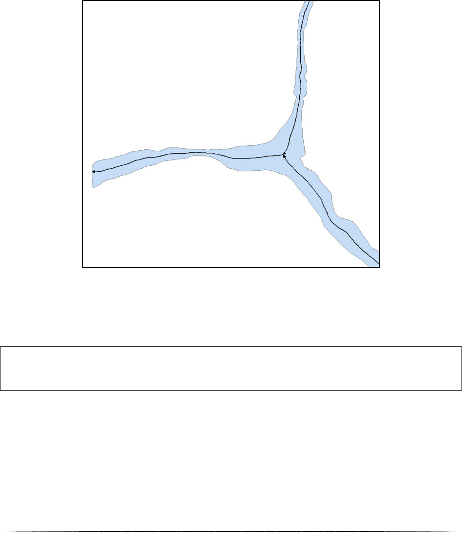
Figure 1 Centerline extracted with the Centerline tool of the FluvialCorridor toolbox (Le Guil river, French southern Alps).
Framework used in this tool has been inspired of the one developed by Alber and Piégay
(2011) and it is based on a Thiessen polygonization of the input polygon.
Implementation of this extraction method has been done with a GIS software (ArcGIS 10.0)
thanks to two vector layers. The first one representing the valley bottom and the second is the
related hydrographic stream network.
Roux C. (CNRS UMR5600 - Plateforme ISIG & SedAlp, Sediment Management in Alpine basins)
2
General algorithmic framework
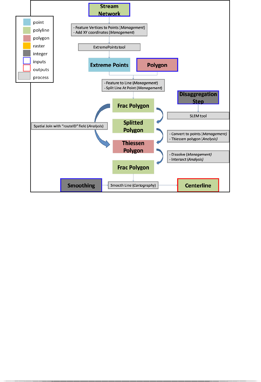
The algorithmic scheme developed for the Centerline tool is presented in the Fig. 2.
Figure 2 General algorithmic framework of the Centerline tool
Creation of the centerlines is based on a geomatic framework :
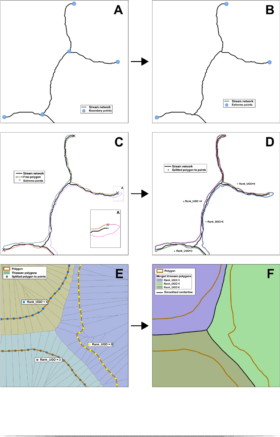
1. In a first hand, each extremities of the input polygon are stored into a set of points,
extracted from the stream network. In this way, start and end points of each streams
are extracted thanks to the Feature To Points ArcGIS tool and they are attributed with
their (,) coordinates (Fig. 3A). Resulting shapefile is then run into the
ExtremePoints tool (included into the FluvialCorridor package) to delete duplicates
and only keep extremities (i.e. upstream sources of each tributaries and the extreme
downstream point of the entire network) (Fig. 3B).
2. The second step consists in creating a set of points over the input polygon boundaries.
These points will be used for the Thiessen polygonization. Firstly, boundaries are
splitted at extremities with the extreme points (Fig. 3C). Resulting lines are then
identified with a unique id “Rank_UGO” and are splitted in elementary segments with
a constant user defined step (in meters) thanks to the SLEM tool (included into the
FluvialCorridor package) (Fig. 3D). Each segments is converted into midpoint,
transferring the origin line id “Rank_UGO”.
3. Thiessen polygonization is finally applied over this set of points (Fig. 3E). Resulting
set of polygons is dissolved according to the “Rank_UGO” field and then, converted
into lines which are intersect with the input polygon in order to only retain the
centerline (Fig. 3F).
Roux C. (CNRS UMR5600 - Plateforme ISIG & SedAlp, Sediment Management in Alpine basins)
3
Figure 3 Geomatic process involves wihtin Centerline tool
Roux C. (CNRS UMR5600 - Plateforme ISIG & SedAlp, Sediment Management in Alpine basins)
4
II. Screen user interface
II.1. Startup screen
Into the screen user, several fields have to be filled (Fig. 4). Be careful that a green mark in
front of a field is not a guaranty that this field is not optional. Into Centerline, if a field is
available, that means that it must be filled.
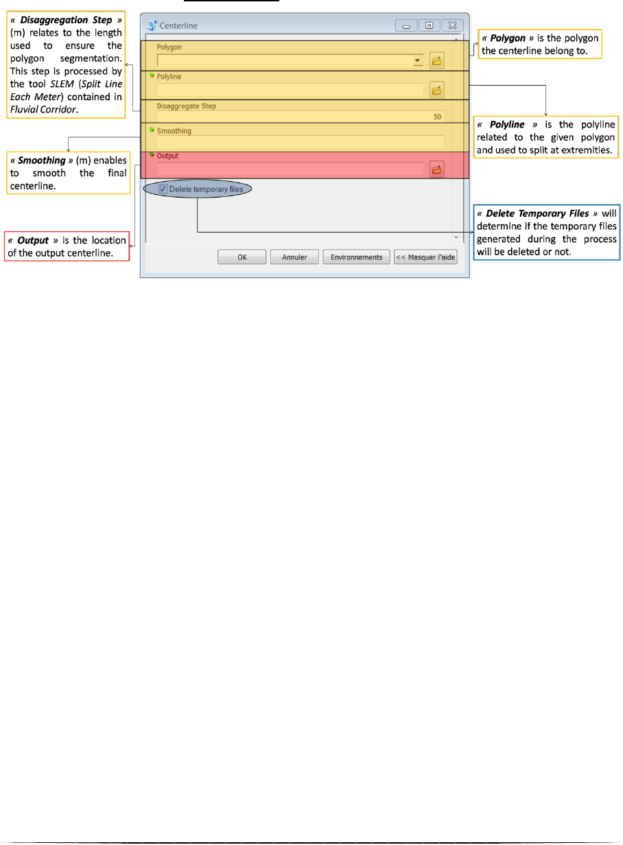
Figure 4 Screen user interface of the Centerline tool
Centerline tool does not involve a lot of parameters. In a first hand, user must provides the
tow features required for a run : the polygon user wants to extract the centerline and the
related polyline used to split the input polygon at extremities. The constant user defined step
used to split the polygon boundaries is then asked. This parameter directly affects the output
centerline accuracy and the computation time. A smoothing parameter has to be filled in the
“Smoothing” field.
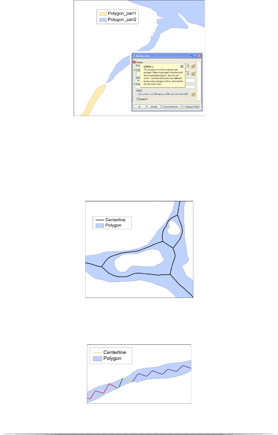
Note : Multi-part input polygon
The input polygon must contains only one subpart. Thus, when user fills the field “Polygon”,
a short process begins in which the polygon is converted into “Multi Part To Single Part”
(ArcGIS function) to detect possible subparts. Number of entities is then counted and if there
is only one part, user can fill next fields. If several subparts are counted, a warning message
appears (Fig. 6). This checking process freezes the screen user interface during a few seconds
during which one it is recommended to not fill other fields.
Note : Batch execution
In order to use the Centerline tool over a set of polygon (e.g. a set of fluvial reaches), it is
possible to use it in “Batch” mode.
II.2. Management of temporary files
Temporary files created during the compilation are managed thanks to the ArcGIS default
geodatabase (%ScratchWorkspace%). If the user does not modify this geodatabase in the
general environment proprieties, its path must looks like C:\Documents and
Settings\<user>\My Documents\ArcGIS\Default.gdb. With the box “Delete Temporary
Files”, the user has the choice to keep or erase temporary files.
Roux C. (CNRS UMR5600 - Plateforme ISIG & SedAlp, Sediment Management in Alpine basins)
5
III. Caution for use and limitations
III.1. Results
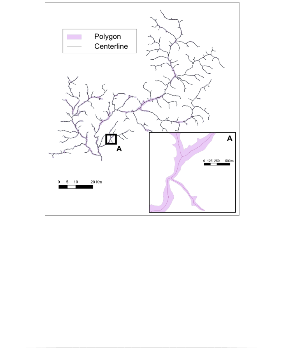
Presented results have been obtained thanks to the Centerline tool. Study area is the Durance
watershed upstream to the Sisteron dam, in French southern Alps. This catchment extends
over 6314², with a hydrographic network of ~616. Used valley bottom has been
extracted with the Valley Bottom tool of the FluvialCorridor package. Parameters used for the
valley bottom extraction have been set empirically in order to obtain a single part valley
bottom polygon.
With a constant user defined step of 20m, computation time for such a study area is 5min
30sec.
Figure 5 Results of the Centerline tool on the Durance catchment upstream the Sisteron Dam.
III.2. Non exhaustive list of cautions and limitations
A few biases can occur during the Centerline tool. They can be due to :
‐ the polygon and polyline input layers
‐ the values of the different asked parameters
a. Incorrect polygon
Framework used in Centerline requires the input polygon to be :
‐ a single part. If not, a warning message will appear and the process will be stopped
(Fig. 6).
Roux C. (CNRS UMR5600 - Plateforme ISIG & SedAlp, Sediment Management in Alpine basins)
6
‐ homogeneous (i.e. input polygon must not contain wholes. In that way, parameters of
the Valley Bottom tool must be set precisely. User can also use the Eliminate Polygon
Part ArcGIS tool.
For a non homogeneous polygon, the tool will consider the polygon as a multi-channel
unit (Fig. 7). Such a result could involve some problems if user wants to apply the
next steps of the FluvialCorridor toolbox (e.g. Sequencing).
Figure 7 Inhomogeneous polygons are considered as multi-channel but can make FluvialCorridor workflow impossible.
b. Too coarse disaggregation step
A too to coarse step of segmentation will result in a wrongly defined centerline. In extreme
cases, the output centerline could be discontinuous (Fig. 8).
Figure 8 A too coarse disaggregation step leads to a discontinuous centerline.
Figure 6 Discontinuous polygon leads to a
warning message and stops the process.
Roux C. (CNRS UMR5600 - Plateforme ISIG & SedAlp, Sediment Management in Alpine basins)
7
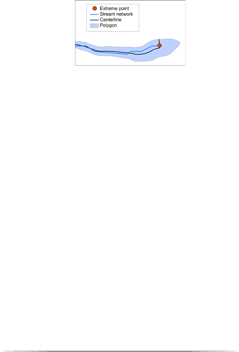
c. Extremities lags
Accuracy of the input polyline used to extract extreme points also affects the output centerline
quality (Fig. 9)
Figure 9 Lags between ends of polylines and real extremities of the polygon

Roux C. (CNRS UMR5600 - Plateforme ISIG & SedAlp, Sediment Management in Alpine basins)
1
ANNEX 1
List of temporary files created during the Centerline tool
Name
Description
ExtremePoints
Set of points with the extreme points of the
input linear network.
PolyToLine
Conversion of the input polygon into lines.
NearTable
Table with the minimal distance between
ExtremePoints and PolyToLine.
FracTEMP
Raw split PolyToLine.
FracTEMPToPoints
Conversion of FracTEMP into points.
FracVB_TEMP
A temp feature of the splitted VBToLine.
FracPoly
PolyToLine split with the ExtremePoints
shapefile.
PolySplitTEMP
Temp split FracPoly (SLEM tool).
PolySplit
PolySplitTEMP sorted with the
“Rank_UGO” and “Distance”fields.
PolySplitToPoint
PolySplit converted into a set of midpoints.
ThiessenPoly
Thiessen polygonization with the points of
VBToPoints.
JoinTEMP
Spatial join between Thiessen polygons and
VBToPoint.
Join
JoinTEMP sorted with the “Rank_UGO” and
“Distance”fields.
Dissolve1
Dissolved Join with the “Rank_UGO” field.
DissolveToLine
Dissolve1 converted into lines.
RawCenterline
Intersection of DissolveToLine and the input
polygon.
Centerline_TEMP
Smoothed RawCenterline.
Centerline
Final centerline.
