V11_User_Manual User Manual
User Manual: Pdf User Manual
Open the PDF directly: View PDF ![]() .
.
Page Count: 826 [warning: Documents this large are best viewed by clicking the View PDF Link!]
- Contents
- Introduction
- MassCore
- Projects
- Media Management & Libraries
- Housekeeping
- Drag and Drop
- Database Views
- Search
- Media Management
- Media Management and Library Tab Windows
- Media Management Tab Window
- Media Management Tab Context Menu
- Media Manager File Format Conversions
- Libraries and other View Windows
- Library Tab Windows
- Library Tab Context Menu
- Offline / Reference Libraries
- Mounting Rules
- Tracks and Track Groups
- Transport and Navigation
- Recording and Acquisition
- Editing
- Editing in the Timeline
- Clips and Compositions
- Clip and Selection Editing
- Clip Properties
- Selection Tab Window
- Selections and Region Selections
- Working with Selections and Regions
- Dragging Clips into a Composition
- Copy and Paste
- Auto-Crossfade By Default
- Clip Fade Commands
- Editing Modes
- Editing Context Menu
- Jog-Wheel Editing
- Edit Command highlights:
- Auto Silence Removal
- EDL Tab Window
- The Placement Tool
- Source - Destination Editing
- Fade Editor
- Mixer
- Overview
- Mixer Pages
- Mixer Components
- Global Indicators / Buttons
- Buses
- Bus Master Strips
- Panning Control Group Buses
- Internal Return Buses
- Groups / VCA
- Horus/Hapi Preamp Remote Controls
- Highlighting
- Mixer Configuration from the Mix! page
- Configure Page
- Route Page
- Organize Page
- 3D Panning Control Bus Window
- Mixer Delay Compensation
- Creating and Configuring Mixers
- Configuring a Blank or Existing Mixer
- Dithering Options
- Mixer Presets
- Peak Logger
- Audio Bridge
- Mixer Sharing
- Legacy Mixer
- Legacy Mixer Surround Components
- Monitor
- Meter Bridge
- Effects and Plug-Ins
- Effects and Plug-ins
- Adding and Managing Effects
- Parametric EQ
- 10 Bands EQ
- Three Band Tone Control
- Dynamics Processing
- Delay
- Flanger
- MS Encoder
- AnguDion
- AnguDion II
- Mastering Peak/VU Meters
- Phase-Oscillo
- Surround Meter
- DC Meter
- Modulometer
- Function Generator
- Wordlength Meter
- Effects and Plug-in Automation
- Optional Plug-ins
- Merging Technologies
- EQ-X
- PanNoir Panner
- VoiCode
- Flux
- VST Support
- External Effects
- FX rendering Tab Window
- Automation
- Scope
- Master Automation Transport Controls
- Dynamic Automation Levels
- Automation Modes
- Projects With Existing Automation
- Display and Editing of Automation Data
- Editing and Automation
- Filter Automation Tracks to Snapshot Dialog
- Automation Editing
- Automation Settings
- Automation in Editing and Libraries
- Mixer and Plug-in Snapshots
- Strip and Bus Tools
- Project Processes
- Final Check Metering
- File and Project Interchange
- Customizing Pyramix
- Applications
- Project Templates
- Virtual Multi-track
- Pyramix With VCube
- LTC sync
- Dubbing Mode
- Discontinuous TimeCode
- Reconforming to Original Media from Avid &/or OMF
- Digitizing a Tape with Discontinuous TimeCode
- Loop Recording With Simultaneous Playlist Creation
- TimeCode Midnight
- Editing Multitrack Recordings
- Film 24 to NTSC Sync
- Checking AC3 encoded files in Pyramix
- Working with External Machines
- Versioning
- Object Based Audio Workflow
- Video
- Conforming and Reconforming
- Machine Control
- Remote Control
- GPI / GPO Control
- CD/SACD Mastering and Album Publishing
- Mastering a Composition to CD-R
- IMPORTANT! - First Steps
- CD Markers
- SACD Notes
- CD/SACD Tab Window
- CD/SACD Tab Window Menus
- Default Settings
- Show CD Player
- Ghost Track
- Multiple CDs or versions in one Project
- Red-Book Validation
- DDP Import
- CD Image File / SACD Edited Master Import
- SACD Functions
- Exporting Projects to CD Image Files
- Album Publishing
- Standalone Album Publishing Application
- DiscWrite
- Productivity
- Menus
- Settings
- Troubleshooting
- Appendices
- Index

XUser Man-
ual
User Manual

No part of this documentation may be reproduced in any form whatsoever or be stored in any
data retrieval system without prior written permission of the copyright owners.
This documentation is supplied on an as-is basis. Information contained within this documenta-
tion is subject to change at any time without notice and must not be relied upon.
All company and product names are ™ or Registered Trademarks ® of their respective owners.
Windows 7 and Windows 10 are trademarks of Microsoft Corporation.
Merging Technologies makes no warranties express or implied regarding this software, its qual-
ity, performance, merchantability or fitness for a particular purpose. The software is supplied “as
is” you, the purchaser, are assuming the entire risk of the results of using this Merging Technolo-
gies software.
In no circumstances will Merging Technologies, its owners, directors, officers, employees or
agents be liable to you for any consequential, incidental or indirect loss or damages including
loss of time, loss of business, loss of profits, loss of data or similar resulting from the use of or
inability to use the Merging Technologies hardware and or software or for any defect in the
hardware software or documentation.
© Copyright Merging Technologies Inc. 2018. All rights reserved
Merging Technologies
Le Verney 4 CH-1070 Puidoux Switzerland
Tel: +41 21 946 04 44
www.merging.com

Contents iii
Contents
Document Version: V11.1 User Manual-rev 2
Date: 23rd - July - 2018

Contents iv
Contents iii
1 Introduction 21
Thank you! 22
Contacting Merging 22
International Office: 22
UK: 22
USA: 22
Installation 23
About This Manual 23
Scope 23
Windows 10 23
Commands Reference 23
MassCore™ 24
Important Note 24
Pyramix Guides 24
Other Pyramix Guides 24
Assumptions 25
Conventions 25
Aneman 26
User Interface 27
Program Window 27
Project Window 28
Status Bar 28
Project Editing Panel 29
Project Management Panel 29
Tab Windows 30
Toolbars 31
Dual Monitors 32
TimeCode Entry 32
Automatic Fades and Crossfades 33
Summary 33
Sample Rate Conversion 33
2 MassCore 34
Overview 35
Windows Boot Choice 35
Memory 35
Core Load Indicators 36
3 Projects 39

Contents v
Overview 40
Backward Compatibility 40
Project Files 40
Editing Project 40
User Templates 43
4 Media Management & Libraries 44
Housekeeping 45
Databases 45
Performance Tips! 46
Media Folders 46
Media Target Settings 46
Audition Play 46
Drag and Drop 46
Database Views 47
Search 48
Quick Search 48
Search Media Dialog 49
Search Filters 55
Media Management 56
The Media Menu 56
Media Management and Library Tab Windows 57
Media Management and Library Tab Columns 57
The Trimmer 59
Media Management Tab Window 60
Media Browser 61
Media Management Tab Menus 61
Media Management Tab Context Menu 79
Media Manager File Format Conversions 81
Libraries and other View Windows 82
Other View Windows 83
Library Maintenance 83
Using Global Libraries 83
Useful Library Commands 85
Library Tab Windows 86
Library Menus 86
Library Tab Context Menu 92
Offline / Reference Libraries 93
Creating Offline/Reference Libraries 93
Using Offline/Reference Libraries 93
Media / Timeline Linkage 93
Mounting Rules 94

Contents vi
5 Tracks and Track Groups 96
Tracks 97
Track Numbering 97
Adding Tracks 97
Creating Tracks via Paste 97
Create New Tracks 98
Track Types 99
Audio Tracks 99
Tracks Grouping 100
Synchronized Creation/Deletion of Tracks/Strips 101
Deleting Tracks 101
Routing Tracks to / from the Mixer 101
Track Display Height 102
Track Header Panel 102
Track Header Components 104
Track Record Modes 108
Automation Tracks 108
Automation Sub-Tracks 108
Bus and VCA Group Automation Tracks 110
Tracks Tab Window 111
Track Tab Column Fields 112
Track Envelope and Static Gain 114
Static Gain 114
Envelope 115
Track Groups 118
Track Group Column Fields 118
6 Transport and Navigation 120
Transport Control 121
Navigation 121
Timeline Structure 121
Time Scale Rulers 121
Playhead Cursor Options 128
Cursor & Timescale Ruler Toolbars 129
Cursor Toolbar 129
Other Timescale Ruler Toolbars 131
Bars & Beats Ruler Toolbar 131
Markers 133
Project Markers 133
Track Group Markers 134
Media Markers 135

Contents vii
Markers Tab Window 140
Jog / Shuttle 141
Jog Wheel Settings 141
Mouse Scrubbing Settings 141
Vari Speed Audio Quality 142
Transport Controls 142
Transport Control Panel 144
Zooming and Panning 145
Time Scale Zoom and Pan 145
Track Height Zoom 145
Scroll Wheel 145
The Overview 146
Virtual Transport 2 146
7 Recording and Acquisition 147
Getting Audio into Pyramix Virtual Studio 148
Check Sync 148
File Format and Disk Limitations 148
Pyramix audio file format 148
Recording Audio into a Pyramix Virtual Studio Project 148
Record Source Before or After Effects 149
Track Record Modes 149
After Recording 149
AutoPunch Mode 150
SafetyRecord Mode 150
Background Recorders 150
Set-up and Operation 151
Edit while Recording 155
Recording Status 156
Take Logger 158
Importing Audio Files into Pyramix Virtual Studio 163
Mounting Media Folders 163
Sample Rate Conversion 163
Digitizing Sessions 166
Manual Digitizing 167
Autoconforming 168
8 Editing 169
Editing in the Timeline 170
Clips and Compositions 170
Clips in a Composition 170
Sample Rate Mismatch 170

Contents viii
Anatomy of a Clip 171
Locking Clips 172
Grouping Clips 172
Clip and Selection Editing 173
Clip Properties 173
Renaming Clips 174
Selection Tab Window 175
Selections and Region Selections 177
Working with Selections and Regions 178
Dragging Clips into a Composition 179
Copy and Paste 179
Auto-Crossfade By Default 180
Clip Fade Commands 181
Editing Modes 181
Splitting Clips and Regions 183
Editing Context Menu 184
Editing Context Sub-menus 185
Jog-Wheel Editing 187
Edit Command highlights: 188
Auto Silence Removal 192
EDL Tab Window 193
The Placement Tool 195
Source - Destination Editing 196
Concept 196
Setting up a Source - Destination Environment 196
2,3 and 4 Point Edits 198
9 Fade Editor 199
Fade Editor Tab Window 200
Toolbar 200
Undo Note: 202
The Graphical Display 202
The Faders & Control Section 203
Parameters & Options Section 203
Save X Fade 205
Save Fade 206
10 Mixer 207
Overview 208
Mixer Pages 210
Mix ! 210

Contents ix
Basic Mixer 211
Mixer Rows 213
Mixer Components 220
Input Strips 220
Basic Strip 221
Stereo Strips 222
Multi Channel Strips 224
Channel Direct Outputs 224
Direct Monitoring Input Strips 224
Input Strips Fed From Internal Return Buses 224
Global Indicators / Buttons 225
Buses 226
General Mix Buses 226
Bus Sends 228
Bus Master Strips 232
Panning Control Group Buses 233
Internal Return Buses 235
Groups / VCA 236
Horus/Hapi Preamp Remote Controls 237
Effects and Plug-ins 240
Highlighting 244
Multiple Strip Selection and Operations 247
Mixer Configuration from the Mix! page 248
Adding Strips 248
Rearranging Strips 250
Effect Management 250
Configure Page 251
Settings 251
Strip and Bus operations 253
Effect Management 255
External Effects Inserts 257
Route Page 258
I/O Bus Capacity 259
Internal Return Buses 259
Organize Page 260
3D Panning Control Bus Window 262
The 3D Room Editor 264
GP Bus Channel Configuration or ‘3D Room’ types 265
Mixer Delay Compensation 269
Summary 269
Delay Compensation Switching 269
Delay Compensation 269

Contents x
Creating and Configuring Mixers 273
Mixer Configuration Wizard 273
Configuring a Blank or Existing Mixer 277
Adding Strips 277
Mixer I/O Assignments 277
Further Mixer Configuration Options 278
Dithering Options 279
Mixer Presets 281
Peak Logger 282
Audio Bridge 284
ASIO Device Mode 285
Secondary Audio Device Host Mode 286
Rewire 289
Mixer Sharing 290
Activating Mixer Sharing 290
Rewire 292
Legacy Mixer 293
Legacy Mixing/Monitoring/Aux Send and SubGroup Buses 293
Strip & Bus Channel Types 296
Basic Strip 302
Legacy Mixer Surround Components 306
Legacy Surround Control window 307
11 Monitor 310
Monitor ! Window 311
Scope 311
Monitor ! page 312
Speaker Sets 314
Configure page 315
Commands 317
Media Manager and Library Monitoring 319
External Metering 320
External Inputs 320
Adding an External Machine 321
Talkback 322
Setting Up 323
Foldback 329
12 Meter Bridge 331
Meter Bridge 332
Scope 332
Meter Bridge Switch 332

Contents xi
Meter Bridge Window 333
Configuring the Meter Bridge 334
Automation Fader Mode and Group Indicators 338
13 Effects and Plug-Ins 339
Effects and Plug-ins 340
Adding and Managing Effects 340
VS3 Plug-In Support 340
VS3 Plug-ins Maximum Sampling Rate 341
Viewing Plug-in Information 343
Common Components 343
Effects Automation 346
Parametric EQ 346
10 Bands EQ 347
Three Band Tone Control 347
Dynamics Processing 348
Delay 350
Flanger 351
MS Encoder 352
AnguDion 352
AnguDion II 353
Mastering Peak/VU Meters 354
Peak-Meter 355
Global Settings and Presets 356
Phase-Oscillo 362
Surround Meter 365
DC Meter 366
Modulometer 366
Function Generator 368
Wordlength Meter 368
Effects and Plug-in Automation 369
Effects Snapshots 369
Optional Plug-ins 370
Merging Technologies 370
EQ-X 370
PanNoir Panner 372
User Interface 373
VoiCode 376
User Interface 376
Flux 381
Algorithmix 383

Contents xii
Vincent Burel 383
Cedar Audio Restoration Suite for Pyramix 383
Prosoniq 384
Zynaptiq 386
ZTX Pro 386
VST Support 388
VST Plug-ins 388
VST Plug-in Automation 393
Direct X Plug-ins 394
External Effects 395
FX rendering Tab Window 396
14 Automation 399
Scope 400
Master Automation Transport Controls 400
Global Dynamic Automation Modes 400
Snapshot Automation 400
Dynamic Automation Levels 401
Automation Modes 402
Dynamic Automation Transport Modes 403
Selecting Automation Modes 404
Preview Automation Mode 408
Projects With Existing Automation 409
Display and Editing of Automation Data 409
Automation Curve Colors 409
Track Automation Menu 410
Automation Tracks Versions 413
View Several Parameters 414
Undo/Redo 414
Editing and Automation 414
Editing Automation and Envelope Data 415
Filter Automation Tracks to Snapshot Dialog 418
Filter Automation Tracks to Snapshot Dialog Options 419
Automation Editing 420
VCA Group Automation Editing 420
Automation Settings 421
Automation in Editing and Libraries 422
Mixer and Plug-in Snapshots 423
15 Strip and Bus Tools 424
Strip and Bus Tools 425
Eq, Comp/Limiter/Expander 425

Contents xiii
Sections 426
Common Features 426
Bus Tools 432
Delay Compensation 436
Delay Compensation / Pre-Anticipation 438
16 Project Processes 439
Dither 440
Archiving Metadata 441
Mixing Down Projects 445
Non Real-Time Mixdown 448
Archiving Projects 448
Consolidating Projects 449
Converting Projects 450
Changing Project Length / Pitch 450
Reconforming a Project 450
Surround Post-Processing Projects 450
Rendering Projects 451
Process Plug-ins 452
Glitch Detector 452
ZTX Pro 453
Effects Rack 454
Pencil 456
Prosoniq MPEX 4 457
ReNOVAtor 457
Cleaning Up Project media 457
Project Notes 457
17 Final Check Metering 458
Final Check Metering 459
Final Check Window 459
Metering Tab 460
Meters 461
History Graphs 465
Setup 467
Loudness Metering Notes 471
Loudness and Peak Metering 472
18 File and Project Interchange 473
File Interchange - Formats 474
File Size Limitations 474

Contents xiv
Hard Drive Limitations 475
PMF 475
WAV and BWF 475
Broadcast WAV file Tips. 476
Quicktime 476
MTFF 477
DSD 477
Compressed Audio File Formats 478
Codecs 478
MXF 479
Dolby 479
Simple File Conversion 479
File & Project Interchange with Apple Macintosh 479
Project Interchange 480
Import / Export 482
Import 482
Export 484
AAF 485
AES-31 493
CD Import 493
CMX EDL 497
Cue Sheets Printer 498
DDP Import 498
Final Cut Pro XML 499
OMF 499
Open TL 501
Report Printer 501
SACD Edited Master Import 502
Sonic Solutions 502
Video Clips 503
XML 504
Cue Sheet Printer 505
19 Customizing Pyramix 507
Customizing the User Interface 508
Toolbars and Menus 508
Customizing Keyboard Shortcuts 509
User Macros 511
20 Applications 512
Project Templates 513
Virtual Multi-track 513

Contents xv
Multitrack Editing 515
Pyramix With VCube 515
Sony 9-pin (P2) Protocol Support Over IP 515
LTC sync 516
Dubbing Mode 516
Discontinuous TimeCode 516
Reconforming to Original Media from Avid &/or OMF 517
Digitizing a Tape with Discontinuous TimeCode 518
Loop Recording With Simultaneous Playlist Creation 518
TimeCode Midnight 518
Editing Multitrack Recordings 519
Film 24 to NTSC Sync 519
Checking AC3 encoded files in Pyramix 520
Working with External Machines 520
Use Auto-chase 520
Using Freeze Mode 520
Versioning 521
Object Based Audio Workflow 521
MPEG-H Authoring Tool projects 523
21 Video 524
Video Tracks 526
Video Output 528
Wrap in Video 531
22 Conforming and Reconforming 539
Conforming 540
CMX EDLs 540
Importing a CMX EDL 540
CMX EDL Format 542
CMX Autoconform 543
Reconform 544
Introduction 544
Reconforming with an Existing Change EDL 544
Reconforming Using Pyramix for Picture Change Detection 548
Reconforming Using VCube for Picture Change Detection 556
Relink to New Media 565
23 Machine Control 567
Pyramix and VCube 568
Virtual Transport 2 568

Contents xvi
PyraCube 568
VCube on External PC 568
Control of External Device 569
External Machines 569
9-pin (Sony P2 protocol) 569
Setting up an external machine 569
Sony P2 Protocol Over IP 569
Linking Functions of External and Internal Machines 573
Synchronizer 573
Chase Synchronizer 573
9-Pin Controller/Synchronizer Explained 573
Transport Control Panel 574
Internal / External Machine panels - Features 575
Internal Machine panel - Features 577
External Machine panel - Features 578
TimeCode Registers 580
Controllers Section 581
Examples: 582
24 Remote Control 583
Generic Control 584
Hardware Control Surfaces 584
ISIS 584
Supported Controllers Table 584
Controllers Table 585
Control by External Device 585
Control by Another Pyramix 585
EMC 589
OASIS Protocol 590
EUCON Control Surfaces 592
25 GPI / GPO Control 595
GPI / GPO Support 596
26 CD/SACD Mastering and Album Publishing 599
Mastering a Composition to CD-R 600
IMPORTANT! - First Steps 600
CD Markers 600
Convert Text Markers to CD 601
SACD Notes 601
CD/SACD Tab Window 602

Contents xvii
Album Section: 602
Tree Info/Track Inspector Section 602
PQ Markers Section 604
Tracks List Section 605
CD/SACD Tab Window Menus 606
Default Settings 608
Show CD Player 609
Ghost Track 610
Multiple CDs or versions in one Project 610
Red-Book Validation 610
DDP Import 611
CD Image File / SACD Edited Master Import 611
SACD Functions 611
Exporting Projects to CD Image Files 612
Album Publishing 616
Digital Release 616
Album Publishing Settings 617
Encoding Process 626
Cover Artwork 628
Standalone Album Publishing Application 629
Cue Sheets 630
Generating Album(s) 632
DiscWrite 634
Optical Drives - Important Note: 640
CD Text 640
Burning a CD-R 640
27 Productivity 641
Locating Clips 642
Playlists 643
Playlists Tab Window 643
Bars & Beats 645
Bars & Beats Settings 646
Bars & Beats Ruler Toolbar 648
Tempo Map 651
Tab Windows 653
Tab Arrangement 653
Workspaces 661
Workspaces Tab Window 661
Optimizing Pyramix 663
PC/OS Setup 663

Contents xviii
Housekeeping 663
Use Templates 663
Pyramix File Format .PMF 663
One File Per Track option 664
Reducing Unnecessary Disk Access 664
Core Power Saving 665
MassCore & VST Core Allocation 665
Use Workspaces 668
Creating Tracks via paste 668
Disable Skin 668
28 Menus 669
Pyramix Default Menus 670
Project 670
Edit 673
View Menu 679
Clips 684
Tracks 688
Cursor & Marks 690
Markers 693
Selection 696
Fade Editor 697
Media 701
Automation 702
Video 704
Workspaces 704
ADR 705
Machines 705
Monitor 711
Macros 711
Settings 712
Window 712
Help 712
29 Settings 713
Configuration - The Settings Dialog Window 714
Settings Buttons 714
Hardware 716
Formats and Sync 716
Secondary Audio Device Bridging 718
MassCore 719

Contents xix
Routing 719
Mic/Pre Remote 720
MIDI Sync 721
TimeCode Setup 723
TimeCode over Physical MIDI (MTC) Horus/Hapi 725
Mixer 726
Level Meter 726
Core Power Saving 729
Mixer Settings 730
VST Plug-Ins Settings 731
Project 734
General 734
Record 736
Controller Mapping 742
Application 743
General 743
Editing 746
Playback/Record 748
Jog/Chase 751
CD/SACD 754
Desktop Layout 755
TimeLine layout 757
Location 760
Automation 762
Background Recorders 764
Time Stretch 766
ZTX Pro Settings 766
Prosoniq MPEX4 Settings 767
Remote Control 768
Machine 768
Controller 773
Virtual Transport 2 778
Video 779
30 Troubleshooting 781
Keeping Up To Date 782
Pyramix Busy Warning 782
Error Messages 782
Multi-channel Audio Files 783
Clip Display Problems 783
Relaunch After Improper Exit 784
Debug Menu 784

Contents xx
General Troubleshooting 787
31 Appendices 789
Appendix I - Mouse Modifier Keys 790
Main Editor 790
Overview 792
Notes 792
Media Folder 792
Appendix II VS3 Control Panel 793
Audio Bridge 795
Saving Settings 795
Appendix III Optional Features 796
Pyramix DSD / DXD / SACD 796
Appendix IV 9-Pin connection 803
PC RS-232 Serial Port to External Sony P2 RS-422 Controller 803
Connecting an RS422 device using a direct cable 803
Appendix V - Network Connections 805
Ethernet Connection & Settings 805
Synchronization with Virtual Transport 2 807
Appendix VI - Pyramix iXML Implementation 808
32 Index 809

1 - 21
www.merging.com/Pyramix
USER MANUAL
1Introduction

Introduction : Thank you! 1 - 22
Thank you!
Congratulations on your purchase of Pyramix Virtual Studio. More than just a product, this is a gateway to the
future of sound recording, editing, mixing and mastering. You have joined a worldwide community of users who
have already discovered the Pyramix advantage.
Note: IMPORTANT! - The first thing you need to do is register your software to acquire your Pyra-
mix key(s) and to be included in our user support list.
Please also subscribe to the User Forum at:
http://forum.merging.com/
Contacting Merging
International Office:
Merging Technologies S.A.
Le Verney 4
CH-1070 Puidoux
Switzerland
Phone: +41 21 946 0444
UK:
Merging UK (Emerging Ltd)
23 Campbell Court
Campbell Road
Bramley
Hampshire
RG26 5EG
UK
Phone: +44 (0) 118 402 5090
Fax: +44 (0) 870 1231747
Email: sales@merginguk.com
USA:
Merging USA (Independent Audio)
43 Deerfield Road
Portland,
ME 04101-1805
United States of America
Phone: +1 (207) 773 2424
Fax: +1 (207) 773 2422
For all documentation inquiries or suggestions for improvement:
http://www.merging.com

Introduction : Installation 1 - 23
Installation
Please see the Pyramix Installation Guide and the Installation Guides for any hardware you have purchased.
About This Manual
Automatically installed with Pyramix and available under the Help menu or [F1], this manual is intended to be a
comprehensive reference source for all the standard features and functions in Pyramix 7.x.
Navigation
In electronic form, all the Contents and Index entries and Cross-references are hyperlinks. I.e. clicking on them
will jump to the relevant item.
PLEASE DO NOT PRINT THIS DOCUMENT UNLESS ABSOLUTELY NECESSARY
SAVE TREES AND INK BY USING THE HYPERLINKS
VERY IMPORTANT!
We strongly recommend you consult the other Pyramix guides for a more complete understanding of all the fea-
tures and functions of Pyramix.
Scope
This manual is principally concerned with Pyramix software installed on workstations with used together with
Horus audio interfaces via RAVENNA. Although many of the features and functions described also apply to Pyra-
mix Native there are differences. Native differences are detailed in the Pyramix Native documentation.
Pyramix 11 Compatibility
Pyramix 11.x is compatible with Windows 7 Professional (64 bit) and Windows 10 Professional (64 bit) MassCore
RAVENNA, Native/RAVENNA and Native.
Windows 10
The Windows 10 Creator Update, is supported by Pyramix v11 MassCore. (based on the RTX64 -3.2 version). The
Windows 10 Anniversary (1607) is also supported.
If you wish to use Windows 10 Creator Update please refer to the Pyramix 11 Installation Guide for details.
Defer Updates
Merging recommends that you set Windows updates to defer for 180 days, in this way you retain control of what is
installed on your Windows 10 system.
Details about the recommended Windows 10 Defer Update setting can be found here:
https://confluence.merging.com/display/PUBLICDOC/Windows+10+Defer+Updates
Users performing an update from Windows 7 to Windows 10 should proceed in this way:
https://confluence.merging.com/display/PUBLICDOC/Updating+Windows+7+to+Windows+10+Anniversary+1607
Note: Merging will communicate more details on this Windows 10 Creator update issue
in the near future.
Windows 10 Configuration
Merging Technologies recommended Windows 10 configuration details can be found here:
http://download.merging.com/beta/SupportTools/Docs/Windows10ConfigurationBeta.pdf%3C
Commands Reference
Automatically installed with Pyramix and available under the Help menu, this document lists all the commands
available in Pyramix together with the default Keyboard Shortcuts.

Introduction : MassCore™ 1 - 24
MassCore™
MassCore is an extremely powerful Pyramix option. A truly deterministic real-time engine that does not rely on
the Windows operating system. This avoids the inherent restrictions and latencies introduced by the operating
system and allows the channel/track-count to be increased to an unprecedented level. MassCore is scalable from
16 to 384 Live I/O (768 simultaneous) channels with a massive 512 channel bus structure (At 1FS).
MassCore enables a number of new features:
• Larger Mixer configurations
• Extra 2.66ms and Ultra 1.33ms latency options
• Full Delay Compensation (VS3 and VST)
• VST inserts on Buses and Auxes
• VST Multi-channel support
• External Inserts (physical effects)
• External Monitor Inputs and Talkback
• Virtual ASIO I/O
Where features are MassCore specific you will see the MassCore logo:
Important Note
Pyramix is not only a very powerful workstation, it is also a highly configurable one, the user interface especially
so. Screenshots in this manual are shown mainly with the default interface on a Windows System with the graph-
ite scheme.
If you cannot find something in a Pyramix menu or toolbar that is discussed or shown in the manual, or something
appears differently, please go to:
Settings > All Settings > Desktop Layout and examine the relevant tab window.
Pyramix Guides
Quickstart Guide
Automatically installed with Pyramix and available under the Help menu, this document is intended to enable
new users to achieve good results quickly.
Other Pyramix Guides
The other guides listed here are installed along with the Pyramix software and / or may be freely downloaded
from the Merging Technologies website.
http://www.merging.com

Introduction : Pyramix Guides 1 - 25
Installation Guide
Full details to enable a successful installation.
MassCore RAVENNA Network Guide
Detailed information about setting up Pyramix with RAVENNA and Horus.
Pyramix Applications Guides
These guides aim to be a useful resource for Pyramix users. They will contain set-up examples and practical hints
and tips for using Pyramix for specific applications such as;
Music Recording, Editing and Mastering (in development)
SACD Production Guide (in development)
Post Production (in development)
Radio Production (in development)
Guides for Pyramix Optional Features
Documentation for optional features is provided in PDF format. Some are automatically installed with the Pyramix
software. Others may be downloaded freely from:
http://www.merging.com
Assumptions
This User Manual and the other Pyramix guides assume you are thoroughly familiar with PCs and Windows terms
and concepts. If the PC is new, please ensure the machine is working correctly before attempting to install Pyramix
Virtual Studio.
Conventions
Conventions used in this manual:
Names found on Pyramix screens and menus are shown in bold. E.g. Information & Settings
Menu and sub-menu selections are shown like this:
View > Tracks > Show all Tracks
Which means:
Go to the View pull-down menu, mouse down to the Tracks sub-menu and choose Show all Tracks.
All Pyramix settings have been gathered together in a hierarchical structure. Selecting Settings > All Settings
opens the Pyramix Settings window with a folder and file tree in the left hand pane.
Where a dialog box has several Pages, Tabs are used to ‘turn’ the pages. Tab page selection is shown thus:
Settings > Keyboard Shortcut Editor : Clips
Which means:
Go to the Settings pull down menu, choose Keyboard Shortcut Editor then click on the Clips Tab.
Keyboard Shortcuts are shown thus: [Shift + Alt + R] means hold down the Shift and Alt keys then press R
Important Information
Important information is shown thus:
Note: When producing a CD image the mixer output MUST be stereo, not two monos.
Pyramix Virtual Studio Overview
Pyramix Virtual Studio is a powerful and flexible Digital Audio Workstation (DAW) integrating hard disk record-
ing and editing, digital audio mixing, effects processing, machine control, video, and CD-R mastering.
Introduction : Aneman 1 - 26
Pyramix runs on the PC hardware platform.
MassCore is scalable from 16 to 384 Live I/O (768 simultaneous) with a massive bus structure.
The Pyramix workstation is capable of up to 384 channels of 24-bit digital audio I/O. External access to these
inputs and outputs is determined by your choice of Horus / Hapi options.
Pyramix v11 with MassCore 256 + Key:
384 @1FS / 192 @2FS / 96 @4FS / 64* @8FS & DSD
(*Please refer to system requirements in the Pyramix Installation Guide)
Pyramix v11 with MassCore 128 Key:
128 @1FS / 64 @2FS / 32 @4FS / 16 @8FS & DSD
Note: For example the MassCore 128 key allows you to connect 16 I/Os @ 8FS/DXD/DSD (How-
ever a larger Mixer of 64 Strip/buses can be created but only 16 I/Os may be connected). 64 I/Os
for 8FS/DXD/DSD are only available when the MassCore 256 + Key is present.
Aneman
If you have a Merging Technologies Network Audio Interface, e.g. a Horus or Hapi these devices use RAVENNA
audio over IP to connect to the Pyramix workstation.
ANEMAN is an application developed by Merging Technologies and will enable you to connect, monitor, and
manage your networked audio devices. It can be launched from its desktop shortcut:
Or from its toolbar icon in the Pyramix Program Window:
Please visit:
www.aneman.net
for more details and to download the application.
Aneman Icon in Pyramix Program Window Toolbar
Introduction : User Interface 1 - 27
User Interface
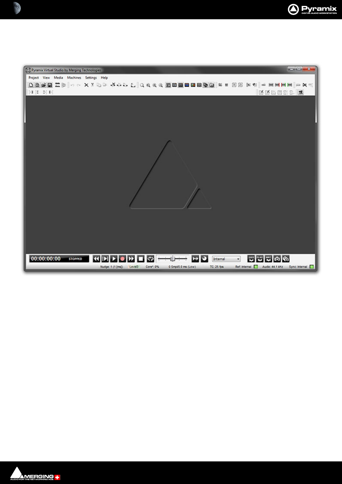
Program Window
The main Pyramix Virtual Studio by Merging Technologies program window appears when the program is
launched. It has dockable Toolbars across the top with a Transport bar and status information at the bottom. This
main window can be resized, moved, minimized or maximized with the conventional Windows control boxes.
Pyramix Program Window
Introduction : User Interface 1 - 28
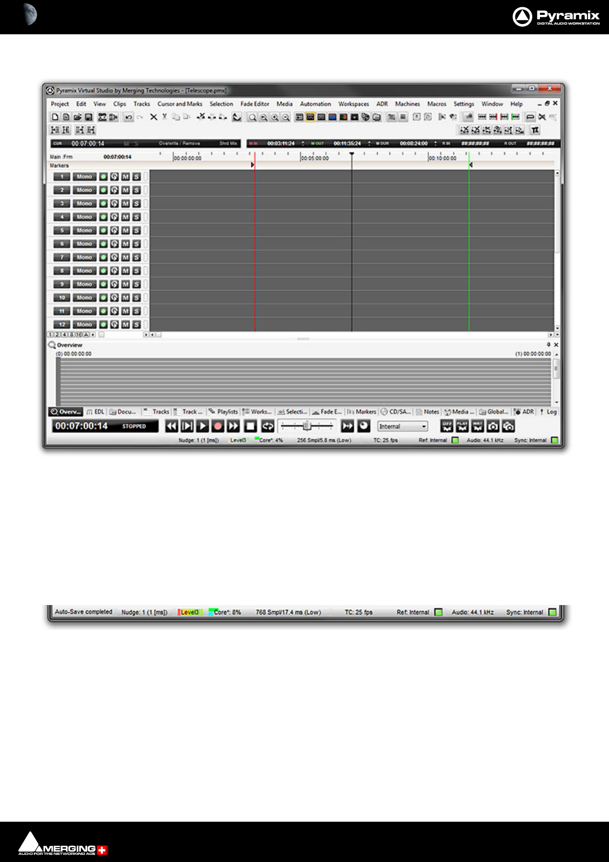
Project Window
The Pyramix Project window is always completely enclosed by the main window. A Project window only exists if
a Project is open, and appears automatically when a new Project is started. A Project window can be resized,
moved, minimized or maximized within the main window. If the Project window is made large enough, two sepa-
rate panels are visible: the Project Editing Panel at the top, contains the Timeline which shows a graphic repre-
sentation of the Composition. The lower section of the screen is the Project Management Panel. The dividing
line between these panels may be grabbed with the mouse and moved up or down, thereby varying the space
allocated to each panel. The Project Editing Panel can be maximized to fill the Project window by clicking on the
arrow at bottom right where the scroll bars meet. A second click restores the previous window arrangement.
Status Bar
At the very bottom of the Pyramix Window the Status bar shows:
Message Area
Messages from Pyramix are shown here.
Nudge
Currently selected nudge setting
Playback Buffer Meter
Graphic representation of the current state of the Playback buffers together with the buffer Level selected cur-
rently. When the transport is not running or there are no audio Clips under the playhead cursor this will have no
Pyramix Project Window
Status Bar

Introduction : User Interface 1 - 29
segments lit. In normal playback all the segments are lit. If the number of Tracks approaches the disk bandwidth or
buffer capabilities less segments will be lit.
Core (MassCore Systems)
CPU Load
Latency
Input to Output Latency in Samples and Milliseconds
TimeCode
Current Frame Rate and Reference Source.
• If the selected Reference Source is available the LED lights in Green
• If the selected Reference Source is not available then the LED flashes in Red.
• If a Pull-Up, Pull-Down or Varispeed setting produces an invalid Frame Rate, it’s then displayed in Red
Audio
Current Sample Rate and Sync Source.
• If the selected Sync Source is available and locked on the LED lights in Green
• If the selected Sync Source is not available and the system defaulted to Internal then the LED lights in Red
• If the selected Sync Source is available but with a different Sample Rate then the LED flashes in Red.
Pyramix Busy Warning
When Pyramix is engaged on a very demanding task, such as a opening a huge project or a long and complex ren-
der the user interface may appear to freeze with the window changed to white and the interface not responding.
A status window opens at the bottom right of the main Pyramix window to inform the user that Pyramix is still
operational. One of the following messages may be displayed:
• Pyramix Virtual Studio busy (during tasks like: opening project, mount, renders, libraries,…)
• AAF Parser busy (during AAF import task)
• Merging Technologies VS3 busy (during Mixer tasks)
• Merging Technologies Convert busy (during Convert task)
Note: The small progress bar within the Pyramix status window (white) will progress at different
speeds. Please be aware that the progress bar does not necessarily indicate the remaining busy
time.
Project Editing Panel
By default the Project Editing Panel has a number of dockable toolbars at the top, a row or rows of Time Scale
Ruler tool bars and below this the Timescale Ruler(s), Markers Tray and the main Timeline Tracks display. This is
where much of the audio editing is accomplished. Audio Tracks may be created, added or deleted, and audio
Clips can be edited, moved, copied or pasted. Note that the Project Editing Panel automatically starts with the
same number of audio Tracks as the number of Input Channels configured in the Mixer of a new Project.
Project Management Panel
The Project Management Panel has a number of tools for managing, navigating and modifying a Project. A sin-
gle click on one of the tool Tabs at the bottom of this Panel, opens its window in the Panel. Double- clicking a Tab
opens it as a floating window. Double-clicking the Tab of a floating window or its Caption Bar returns the window
to the panel.
Note: By default, clicking the red X close box of a floating Tab Window removes it from the
screen. It can be reinstated as a Tab from View > Editor Tabs

Introduction : User Interface 1 - 30
Tab Windows
Many Tab window functions can also be accessed from pull-down menus.
Any or all of the Tab windows can be shown or hidden for a Project, and moved independently and outside of the
main Program window. Double-clicking a Tab opens it as a floating Window. Double-clicking the header of a float-
ing Tab Docks it back where it came from.
Tab Window List
Overview
Please see: The Overview on page 146
EDL
Please see: EDL Tab Window on page 193
Document Libraries
Please see: Project Libraries on page 82
Tracks
Please see: Tracks Tab Window on page 111
Track Groups
Please see: Track Groups Tab Window on page 118
Playlists
Please see: Playlists on page 643
Workspaces
Please see: Workspaces on page 661
Selection
Please see: Selection Tab Window on page 175
Fade Editor
Please see: Fade Editor Tab Window on page 200
Markers
Please see: Markers Tab Window on page 140
CD
Please see: CD/SACD Tab Window on page 602
Metadata
Please see: Archiving Metadata on page 441
Video
Please see: Video Tab on page 530
Introduction : User Interface 1 - 31
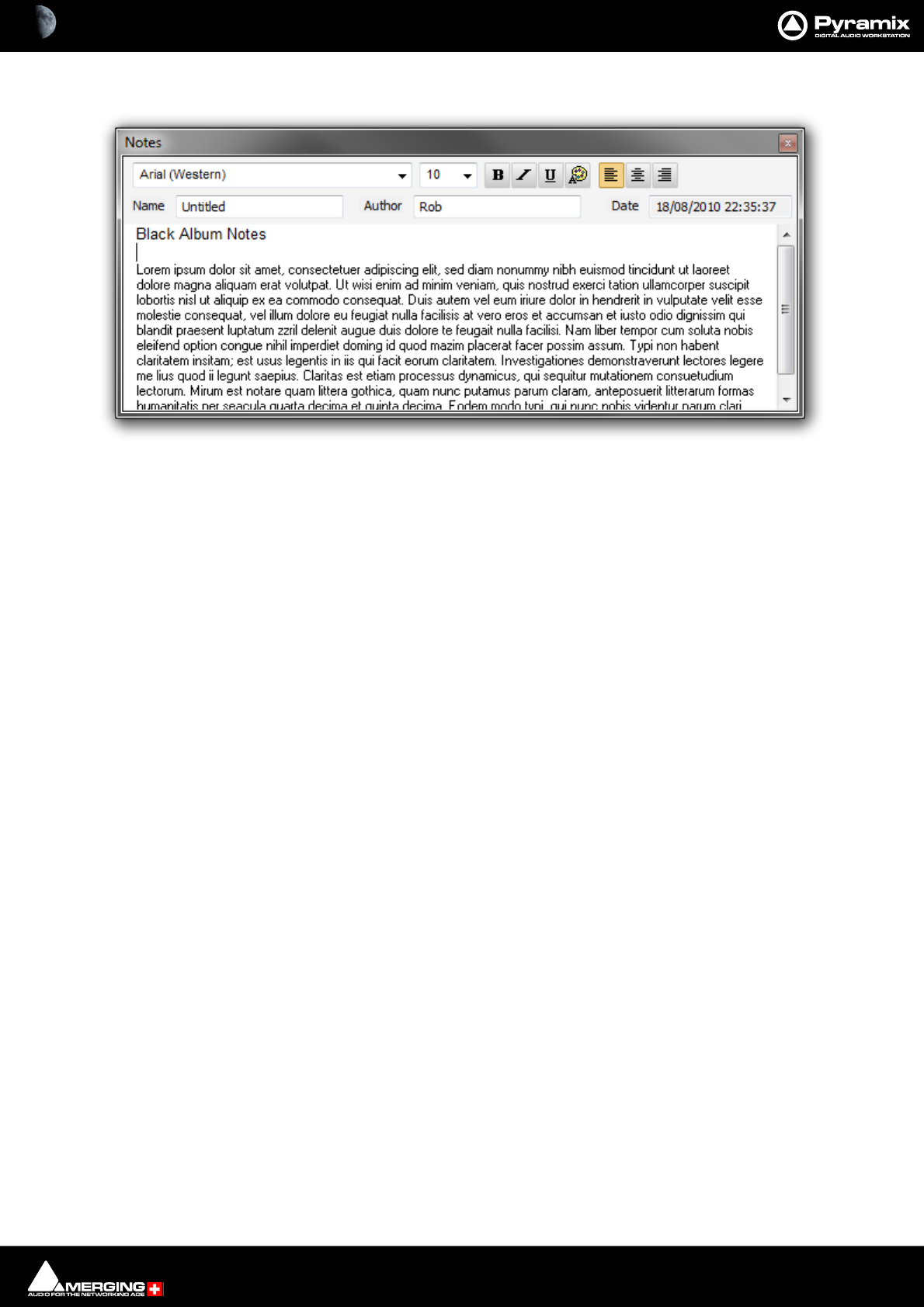
Notes
The Notes Tab provides a simple word processor for adding notes to the Project. Anything written here will be
kept with the Project when it is saved.
Media Management
Please see: Media Management Tab Window on page 60
Global Libraries
Please see: Document and Global Libraries on page 86
ADR
Only available with the ADR option. Please see the ADR User Guide for more information.
Log
Check this Tab Window if you are experiencing problems.
Most of the Tab Windows are fully described in the sections of this document they relate to as in the cross-refer-
ences above.
Metadata
Please see: Metadata Tab Window on page 441
Video
Please see:
FX Rendering
Please see:
Tab Windows Productivity Tips
For more detail on Tab Window functionality, Please see Tab Windows on page 653
Toolbars
The Pyramix main window has a number of Toolbars ranged across the top. All the Toolbars can be torn away and
rearranged. Hovering over a a Toolbar button pops up a tool-tip with its function.
Toolbars can be Shown/Hidden using the View > Scales / Toolbars > menu.
Individual Toolbars can be configured in Settings > All Settings > Desktop Layout (Please see: Desktop Layout
on page 755
Introduction : Dual Monitors 1 - 32
Dual Monitors
By default the screen is horizontally divided with the Tab Windows below the Timeline. When using Dual Monitor
setups, you may wish to divide the main project window vertically. With the Timeline displayed on the left screen
and the Tab Windows on the right, more Tracks can be viewed simultaneously. This can be achieved by checking
the Display Timeline on the Left of Tab Windows radio button in the Settings > All Settings > Application >
Timeline Layout page. This change will take effect the next time a Project is opened.
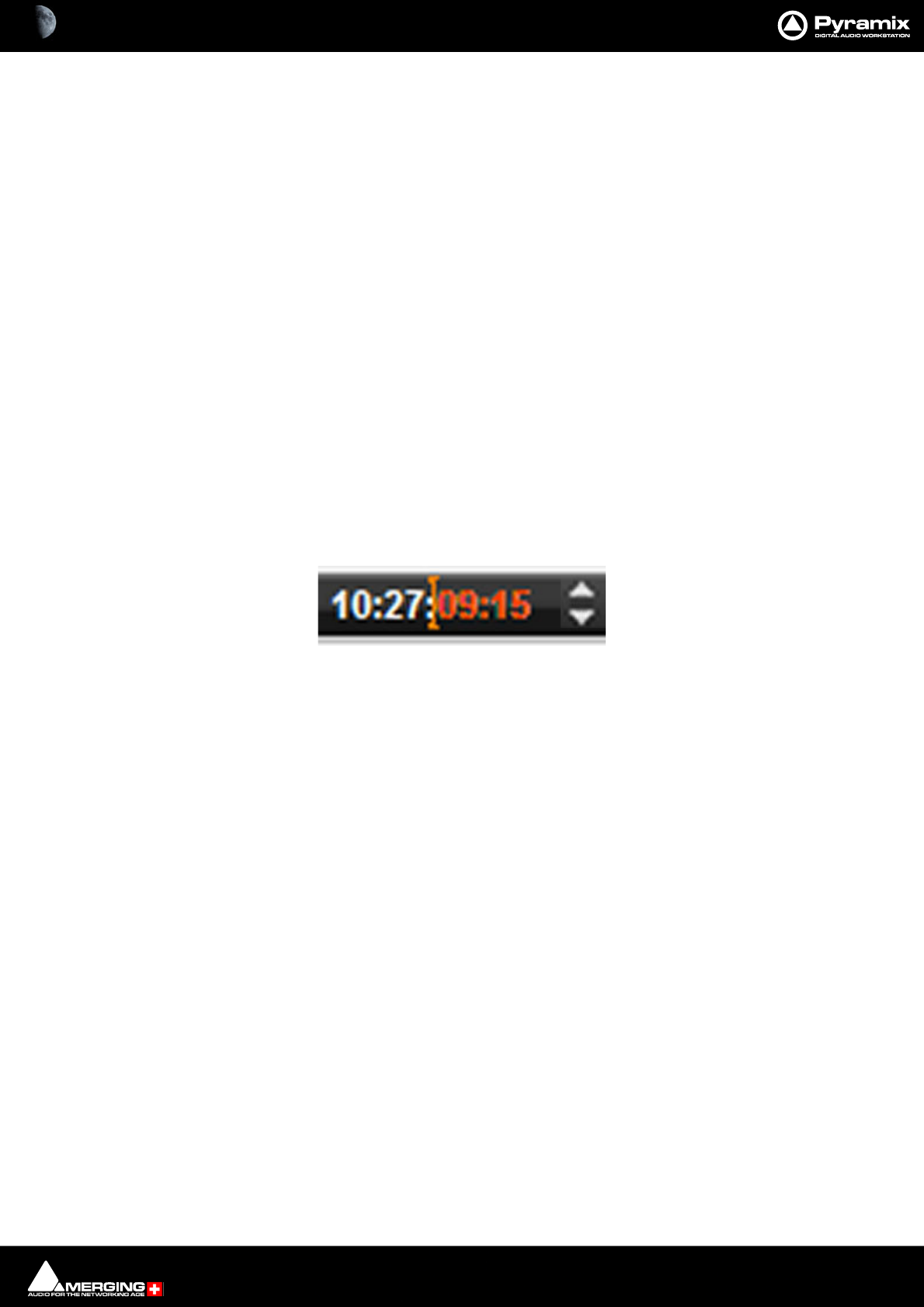
TimeCode Entry
TimeCode values in Pyramix can be changed by using the up arrow, Increment or down arrow, Decrement but-
tons, by using the on screen numeric keys or by direct entry from the numeric keypad. an OK button or the ENTER
key finalizes the entry. In Pyramix numbers are entered in time code fields from right to left, a block at a time, pro-
gressively overwriting existing numbers.
This makes the most common TimeCode changes easy, I.e frames or seconds, without having to re-enter the min-
utes or hours.
Clicking in a register inserts a red I-beam cursor. Entries must be made in Hours : Minutes : Seconds : Frames order.
So, to enter 10 Hours and 9 seconds and 15 frames, key: 1 0 0 0 0 9 1 5. BUT if you want to change the seconds
then you only have to enter the seconds and frames E.g. to enter 9 seconds and 15 frames, key: 9 1 5 followed by
ENTER. However, to change 10:27:10:15 frames to 10:27:09:15 you would need to key, 0 9 1 5 followed by ENTER.
In practice most operators always enter the leading zero even when it is not required, to avoid errors.
Arithmetic TimeCode Entry
An existing TimeCode value can have time added to or subtracted from it. I.e. a relative entry. Type the number to
be added or subtracted then, instead of pressing the Numeric Key Pad Enter, press - (Minus) or + (Plus) on the
main keyboard or Ctrl + Minus or Ctrl + Plus on the Numeric Key Pad.
Increment / Decrement UP & DOWN Arrow Buttons
The + (plus) and - (minus) buttons to the right of the TimeCode registers increment or decrement by one unit per
click of the smallest unit in the current register. E.g. Frames, Samples etc.
Modifiers
Click Frames
Alt + Click Subframes
Ctrl + Click Seconds
Shift + Click Minutes
Ctrl + Shift + Click Hours
Ctrl + Alt Current Nudge Value
TimeCode Register

Introduction : Automatic Fades and Crossfades 1 - 33
Automatic Fades and Crossfades
Summary
Auto Deglitching:
When enabled (Ramp length is user definable), Auto Deglitching allows on-the-fly Deglitching in playback when
no fades or crossfades have been created.
This is set globally in Settings > All Settings > Application > Playback/Record
To set Auto Deglitching for individual Clips use: Clips > Properties. Clicking in the Auto Deglitching field opens a
drop-down list with the option to Follow General Settings or to set a value for the Clip between 1.0 [ms] to 5
[ms] in 0.5 [ms] steps.
(The Auto Deglitch action is not visible on Clips, since it only occurs in the playback engine)
Auto Crossfade:
Recording
Set in Settings > All Settings > Project > Record : Post Processing: Auto Cross-Fade.
When enabled (Fade Type and duration is user definable, creates a Fade/Crossfade on Clips being recorded.
Playback
Set in Settings > All Settings > Application > Editing : Drag & Drop: Auto-Crossfade by default - Control key
for Drag & Drop.
Off by default. When checked, a fade will be created on Clips that overlap when they are dragged on top of each
other during editing.
The default X-fade can be modified in the Fade Editor. Simply edit a Crossfade to taste, then “overwrite” the
default X fade. (Click on X Presets : Save Preset and choose Default.
Sample Rate Conversion
Pyramix can convert Clips to the current Project sampling rate, automatically and on-the-fly. It can also convert in
non real-time using the very high quality Merging Technologies HeptaCon Sample Rate Converter.
Please see: Real-time Sampling Rate Conversion on page 750,
Convert - Quick Convert sub-menu on page 70
and Sample Rate Conversion on page 163

2 - 34
www.merging.com/Pyramix
USER MANUAL
1MassCore

MassCore : Overview 2 - 35
Overview
MassCore™ is an extremely powerful Pyramix option. A truly deterministic real-time engine that does not rely on
the Windows operating system. This avoids the inherent restrictions and latencies introduced by the operating
system and allows the channel/track-count to be increased to an unprecedented level. MassCore is scalable from
16 to 384 Live I/O (768 simultaneous) with a massive bus structure. (For now this is limited in code to a total of 512
at 1FS (256@2FS, 128@4FS, 64@8FS).
MassCore enables a number of new features:
• Larger Mixer configurations
• Extra 2.66ms and Ultra 1.33ms latency options
• Full Delay Compensation (VS3 and VST)
• VST inserts on Mix Buses, Aux Send and SubGroup Buses
• VST Multi-channel support
• External Inserts (physical effects)
• External Monitor Inputs and Talkback
•Virtual ASIO support
Windows Boot Choice
You will see a new screen after the P. O. S . T (Power On Self Test) screen before Windows starts to boot. This screen
offers the choice between:
Windows 10 (7)
and
Windows 10 (7) MassCore
Please choose Merging Technologies MassCore. Boot will then proceed as normal.
If you do not make a choice then the machine will boot into Masscore mode after 30 seconds automatically.
Please ignore all other options on this screen unless asked to use them by Merging Technologies technical sup-
port staff.
Memory
MassCore memory allocation is 256MB for all Operating Systems.
The total amount of memory available in a MassCore machine affects the number of VST channels which will be
available.
With 8GB or more of system memory, 384 VST channels are available.
MassCore : Core Load Indicators 2 - 36
Core Load Indicators
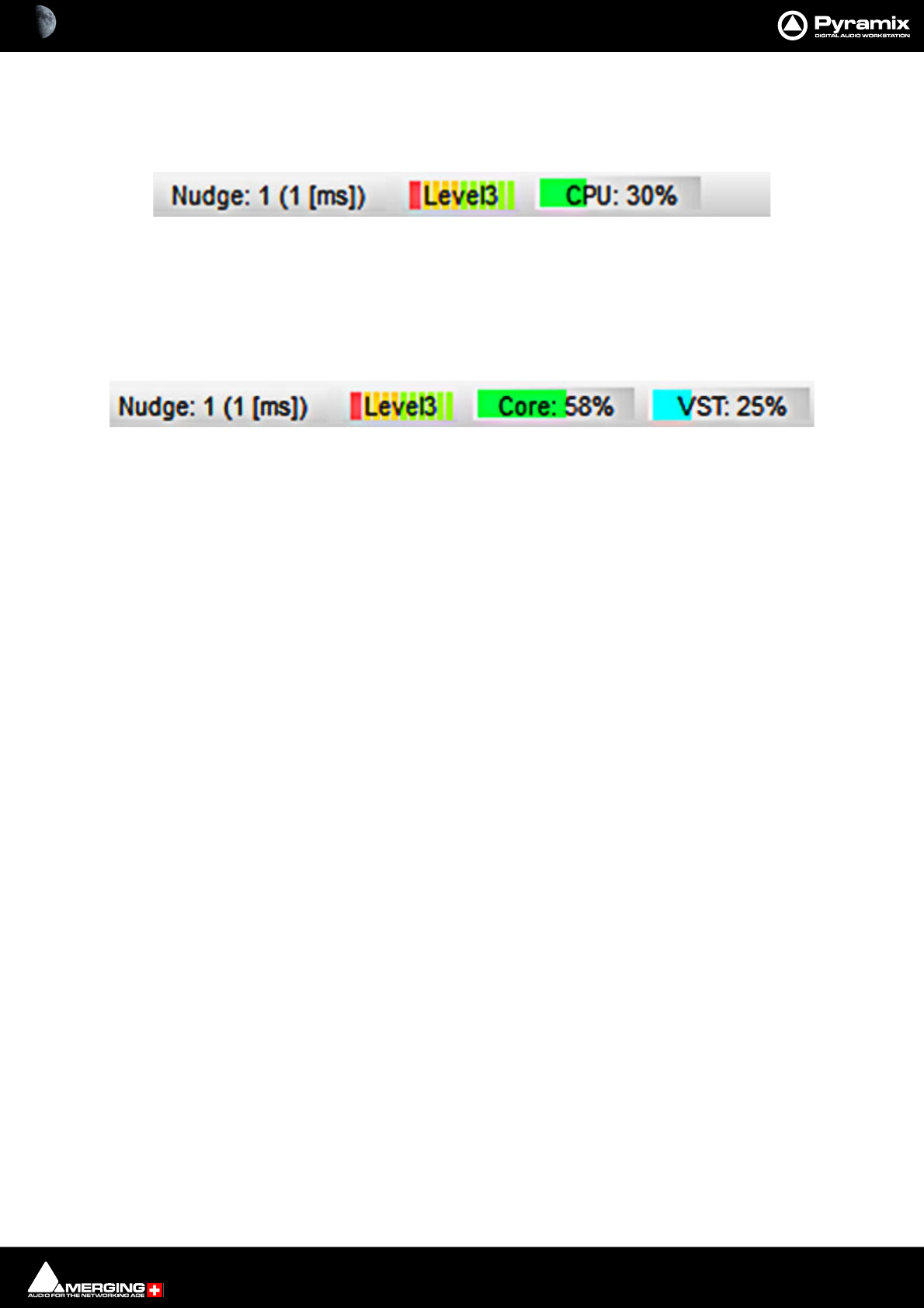
In Native systems a single CPU: load indicator is present in the Title Bar:
The CPU load displayed in the Pyramix bottom bar is not the CPU usage as computed in Windows task manager
. CPU load in Native is computed in this way: (time to process audio frame) / (duration of one frame) * 100.
Thus, it is the percentage of time used to process in one audio frame duration; this indicator is more useful than
CPU Usage because it takes in account CPU stall during processing time.
In MassCore based systems the CPU: load indicator is supplemented by a VST: core load indicator in the Title Bar:
MassCore Load
(Green bar, orange when heavily loaded, red when overloaded): Indicates the MassCore Load.
VST Core load
(Blue bar, orange when heavily loaded, red when overloaded): Indicates VST core load for VST processing.
In both screenshots the left-hand bargraph display shows disk buffering.
MassCore & CPU load indicator range
• Green from 0% to 74% = Safe mode*
• Orange from 75% to 84% = Moderate Risk*
• Red from 85%->100% = High Risk
*MassCore users: Will have enhanced Core stability when using recommended dedicated Graphic Cards.
*Native users: Owners of recent laptops owners often experience performance problems when the CPU load
reaches somewhere around the middle point of load, then random CPU jumps causing sudden glitches are possi-
ble. This has also been seen when benchmarking with Non-Merging Applications on recent laptops.
Core Load Indicator - Native in Title bar
Core Load Indicators - MassCore in Title
MassCore : Core Load Indicators 2 - 37
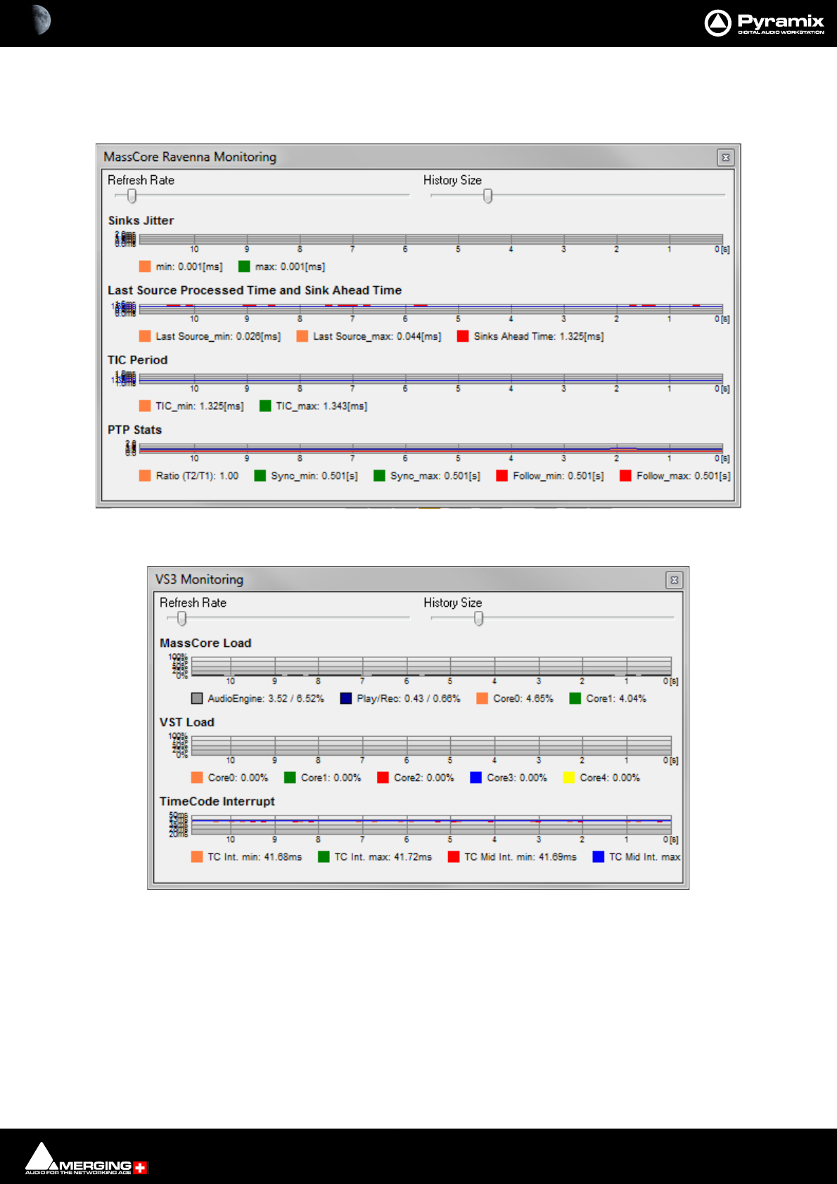
MassCore and VS3 Monitoring Debug Windows
To see more detailed information about both Core Load Indicators, [Shift + Click] on them to open the two Mon-
itoring debug Windows:
In order to support some VST plug-ins which need a big buffer to be efficient (e.g. Algorithmix EQ Orange/Red,...)
we recommend that you increase the VST Plug-ins engine Latency size up to 8192 smpl (samples) using the
VST Plug-ins Engine Latencies slider in the All Settings > Hardware > MassCore page.
Note: this value can only be adjusted when no project is open.
Important! If a Drop (glitch) occurs, the Core indicator will blink. Click on it to reset it.
Note: This indication may be useful if, for example, you do a Realtime Mixdown or Recording
and leave the Studio for a minute to get a coffee. If, on your return, you see the Core blinking this
MassCore Ravenna Monitoring Window
VS3 Monitoring Window

MassCore : Core Load Indicators 2 - 38
would mean that you have experienced a drop, so that you probably have a glitch in you final
mix or recording.
Overload Diagnosis and Cures
First determine whether the CORE indicator or the VST indicator is turning red during a glitch.
If the MassCore (CORE) indicator becomes red during playback or recording you have exceeded the capacity of the
workstation. You should reduce the size of your project mixer and/or the amount of active plug-ins you are using,
or try increasing the Max Mixer Delay Compensation slider value in the Mixer Settings page (Settings > All Set-
tings > Project > Mixer > Mixer Settings). You may also try changing the buffered read and write settings of your
.pmf files from within the Project > Record page under Format/(PMF)/Settings for projects with large numbers
of audio tracks (approaching machine capacity for current sample rate).
VST
If the VST indicator becomes red you might want to increase the MassCore VST Plug-ins Engine : Buffer Size
slider value in the All Settings > Settings > MassCore page. The VST buffer size can be increased in order to sup-
port VST plug-ins that need larger buffers in order for them to work efficiently. So, if you are experiencing VST Core
Loads or Peaks (100%) we recommend that you set the VST Plug-ins Engine : Buffer Size value higher, it can go
up to 4096 samples to help support certain VST plug-ins. Note that you can also monitor the VST Core load by
Shift Clicking on the CORE % indicator, this will open the VST core load debug window. (See above) If you see
spikes (red) during playback or an idle indicator then it may be advisable to increase the VST Plug-ins engine
Latency (Settings > All Settings > MassCore : VST Plug-ins Engine Buffer Size), this value can only be adjusted
if all projects are closed within Pyramix.
DMA
If a DMA Bus (Direct Memory Access) load (peak) occurs, the Text will blink with red DMA text. For the user this
means that something inappropriate occurred during, for example, the Recording and that the recorded file could
contain abnormalities. We recommend that users verify their System configuration/calibration if such indications
occur regularly.
Note: These bars should be ignored when loading a project, making changes in the graphical
layout of Pyramix when stopped (opening pages, moving the mixer, etc.), or doing offline pro-
cesses (renders, non real-time mix-downs, etc.). If the indicators become red during these phases
of your work, simply click on the indicator bar to reset it.
Pyramix Latency Modes for MassCore
Low, Extra and Ultra modes are supported.

3 - 39
www.merging.com/Pyramix
USER MANUAL
Projects

Projects : Overview 3 - 40
Overview
Projects are the top level of Pyramix organization. There are four types of Project. For most applications the one
most commonly used is the Editing Project. The second type is Digitizing Session. As the name implies this a
special type of project optimized for media acquisition.
Two further Project types, DXD Mixing Project and DSD Project are solely concerned with high-definition audio
and the production of SACD masters.
There is also the option to Load a Template. Templates are the quickest way to configure Pyramix for a specific
purpose. A wide variety of Templates are supplied with Pyramix and can also provide a basis for refining your own
‘User Templates’.
You can find more information about Digitizing Sessions here: Digitizing Sessions on page 166
Backward Compatibility
Even the latest version of Pyramix is capable of saving in project formats back to V4.3. Some current features are
obviously not supported in previous versions but the Project > Save Special option offers the ability to save in all
relevant previous versions back to V4.3.
Important! The v11 Aux Bus structure, if used, does not allow for Save Special. Only v11 Projects with
Legacy Aux Buses can use Save Special.
Project Files
Saving a Project saves a number of files in a single compressed file. Including .pmx, .pml, .Playlist.pml, .Default-
Library.pml and .Composition.pml.
On opening a Project these files are decompressed.
These files will only be all visible in Windows Explorer when the project is open in Pyramix.
When the Project is saved these files are re-zipped into a single.pmx file and, when the Project is closed the
decompressed temporary files are deleted.
Editing Project
New Project
1. Launch Pyramix Virtual Studio
2. Choose Project > New.
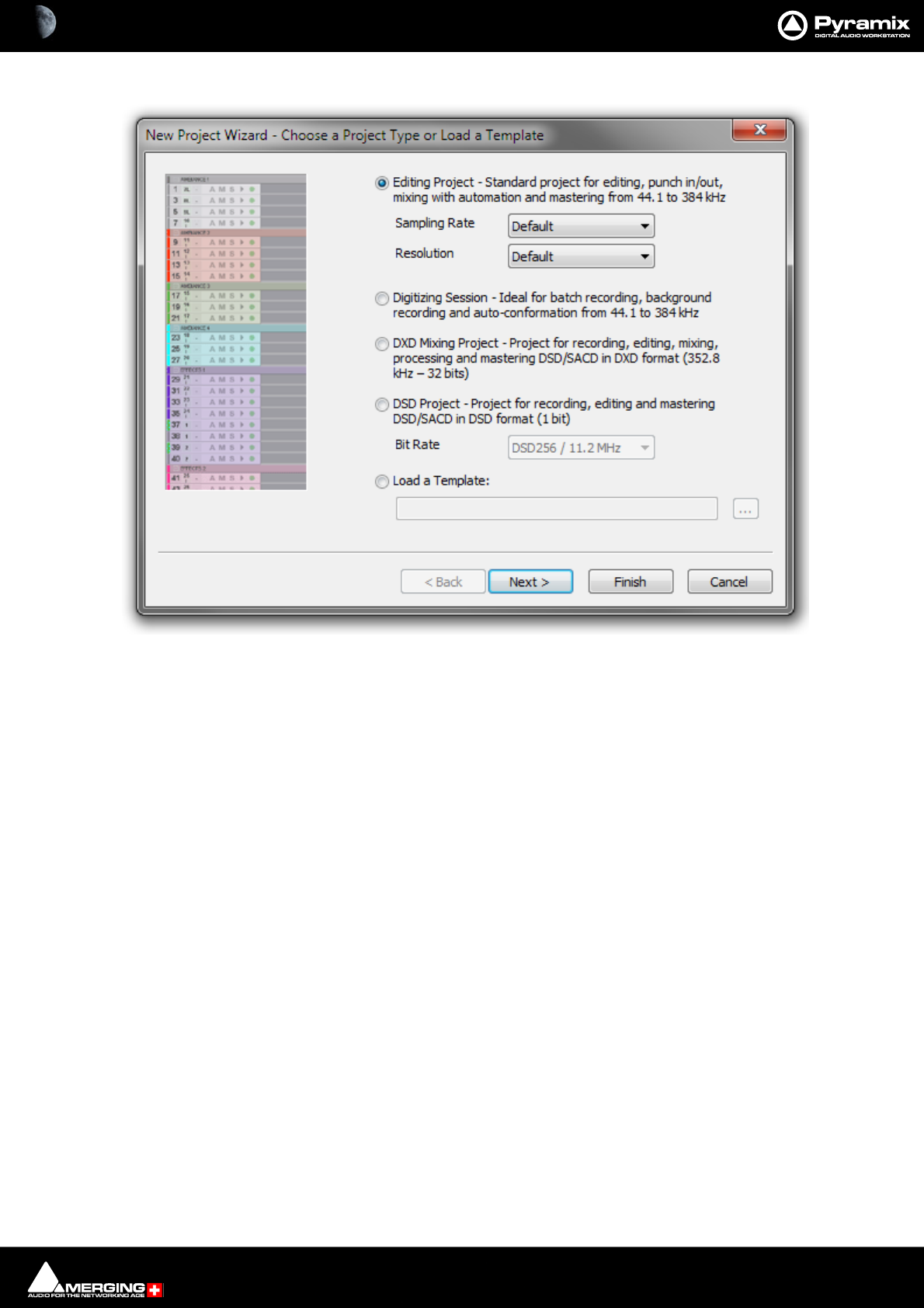
Projects : Overview 3 - 41
3. The New Project Wizard - Choose a Project Type window will open.
4. The default is Editing Project which is the type we will use.
5. Choose a suitable sampling rate from the Sampling Rate drop-down list. (Use 44.1kHz if in doubt and using
an analogue input)
6. Choose a suitable bit-depth from the Resolution drop-down list. (Use 24 bit if in doubt)
New Project Wizard - Choose a Project Type dialog
Projects : Overview 3 - 42
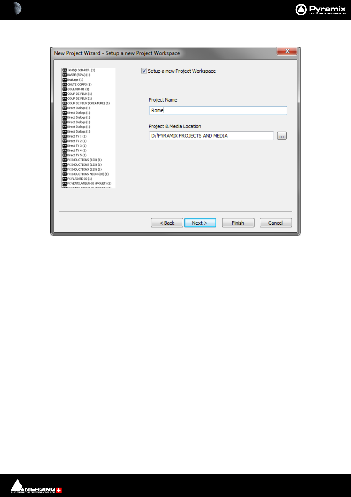
7. Click Next. The New Project WIzard - Setup a New Project Workspace dialog will open.
8. Click in the Setup a new Project Workspace box to tick it.
9. Type a name for the Project and either type a suitable path to the Project and Media Location or use the ...
button to open a Browse for Folder window. This works like a Windows Explorer window and enables you to
navigate to a suitable folder.
New Project Wizard - Setup a new Project Workspace dialog
Projects : User Templates 3 - 43
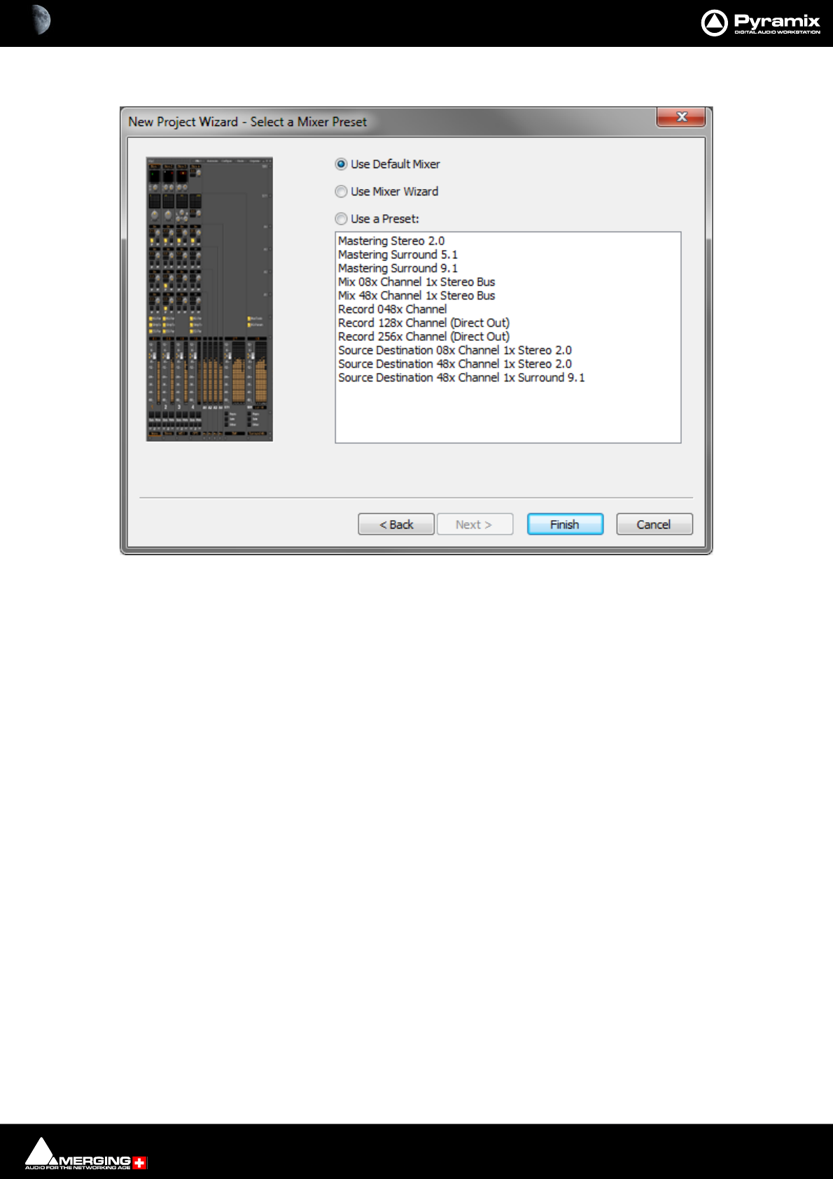
10. Click Next. The New Project Wizard - Select a Mixer Preset dialog will open.
11. If this is the first time you’ve used Pyramix, choose the Mix 08x Channel 1x Stereo Bus preset in the drop-
down list by clicking on the name. Note that the Use a Preset radio button is checked automatically if a Preset
is selected.
12. Click Finish to activate your new Project. It will open with a Project Window and Mixer Window. There will
be 8 empty Tracks in the Project Editing Panel corresponding with the 8 Mixer Input channels.
Mixer Wizard
Please see: Mixer Configuration Wizard on page 273
Presets
A considerable number of pre-configured presets are supplied for common tasks. You can add your own custom
Mixer Presets to the list. Please see: Mixer Presets on page 281
User Templates
When you have a Project with a configuration which may be useful for future Projects you can save it as a Tem-
plate. I.e. the current Project minus all the Cues. Simply select:
Project > Save Template
A Browser window opens with the default Templates Folder open. Choose an existing Template folder, if appropri-
ate, or create a new one. Name the Template and click on Save
New Project Wizard - Select a Mixer Preset dialog

4 - 44
www.merging.com/Pyramix
USER MANUAL
Media Management & Libraries

Media Management & Libraries : Housekeeping 4 - 45
Housekeeping
The Windows hierarchical filing system can become confusing and cluttered very quickly when dealing with a
multitude of Media Files. Complex audio projects generate thousands of more or less enigmatically named files.
Keeping track of all the files used in a Project in the Windows filing system can become a nightmare even if the
user is meticulous.
Pyramix uses the concepts of Media Drives/Folders, Databases and Libraries to reduce the clutter. The Media
Management Tab, the EDL Tab, Library Tabs and Views such as; Search Results, Used Media, Media Present in
Project Default Folder and Media NOT Present in Project Default Folder, are all ways of viewing and manipu-
lating the contents of the Databases. These Media Management tools help users to work in a structured and sim-
ple manner whilst keeping track of all the Project components.
Databases
All Media listings i.e. Libraries are held in databases. A default path to all the database files can be set in Settings
> All Settings > Application > Location : Default Database Location. Otherwise the Database path will be
C:\Documents and Settings\<user name>\Application Data\Merging Technologies\Pyramix.
Important! Enough free space (several GB) must be preserved on disk for these files to grow under nor-
mal usage. If necessary, the files can be relocated to a bigger or faster drive.
Searching
Database files can be searched using a simple SQLite based search tool which is available in Library, Media Man-
ager, and View Toolbars. Search works with combinations of logical operators *, AND, OR.
Relocate Libraries
To relocate the Library Databases:
Settings > All Settings > Location : Default Database Location
• Type a new location for the database files or Browse to one.
• Check also that the Fade Library Location is valid:
Settings > All Settings > Application > Editing : Fade Library Location
• If it isn’t valid or in the location you wish it to be, proceed as for the Database Location above.
•Click on OK
•Restart Pyramix.
• Database Library paths will then be updated.
Conversion of Previous Version Libraries (v6.x or older)
The Version 7 library format is not backwards compatible, so conversion is required for libraries created in previous
Pyramix versions:
• Pyramix does the conversion automatically the first time it opens any version 6 (or older) library.
• Conversion will take some time, especially with large libraries, but is only required once.
• A backup (.pml.6xx) is made of the original library so that it can be renamed and restored in version 6 or
previous.
• The .pml file is replaced with a converted version 7 library
• Note that subsequent changes made to the new version 7 .pml library will NOT be forwarded to the
backup .pml.6xx library.

Media Management & Libraries : Drag and Drop 4 - 46
Performance Tips!
Database Location
For optimum housekeeping perfomance Merging recommend strongly that the Default Database Location
should be set to point to the fastest drive on your system. SSDs are recommended and, where possible, not the
C:\OS defaultdrive (since a drive with less activity and higher speed should perform better).
Saving
Project Save times will be faster if Saves are made to a high-performance Disk (e.g. an SSD). Saving to older Disks
(e.g. 5400 rpm etc.) or saving to the Disk where the OS is located (this disk is often very busy with other tasks)
could slow down Saves times.
Media Folders
Media Folders are Windows folders or drives which contain Media Files. Pyramix needs to mount these Media
Folders specifically, in order to access the Media Files contained therein. Once mounted, suitable files are dis-
played as Master Clips. I.e. pointers to the underlying Media audio files. Mono and interleaved Stereo and Multi-
channel Media files are all displayed and manipulated as single Master Clips
These can be dragged and dropped or copied and pasted directly into the Timeline or into a User library from
the Media Management Window regardless of format, sampling rate or bit depth.
Media Folder Syncronization
Pyramix synchronizes the contents of mounted Media Folders with the underlying Windows folders automatically.
When media is added to these folders by Merging Technologies or third-party applications the changes are
reflected automatically. In the event of a consistency problem the Media Manager Media Folder > Refresh Media
Folder function will remount the selected folder and rebuild indexes.
Media Target Settings
When a Project is created, either with Project > New or Project > New From Template and a Media Folder is cre-
ated or selected, the Project General : Project Media Folder Media Folder, the Record : Target settings Media
Folder, the Project > Render : Target Settings Media Folder and the Project > Mix Down : Target Settings
Media Folder all point to the same folder. These target settings can be changed later and each can point to a differ-
ent folder.
Audition Play
Master Clips in the Media Management window and all audio objects in the Library windows can be auditioned
through the Monitor as a MONO downmix as determined by the Monitor settings Please see: Media Manager
and Library Monitoring on page 319. The toolbar Play (Space) and Stop (Esc) buttons starts and stop playback
of a selected object. Double-clicking an object begins playback at the start.
Drag and Drop
Audio Media files compatible with Pyramix may be dragged and dropped into Pyramix Libraries and the Timeline.
Single or multiple files can be dragged and dropped in the conventional Windows manner from browser windows
and from applications that support such operations, e.g. iTunes. As a rule of thumb, if you can drag and drop a file
from a location to the Desktop, you can drag and drop to the Pyramix Timeline or libraries.
Example:
Start Pyramix, open a Project and a library view. From a Windows Browser window select one or several audio files
and drag them over the library. If the selection contains compatible audio files the library will highlight. Drop the
files over the library. Any compatible files will be added to the library and can be then used just like any other
library file in Pyramix.
Note: The converse, dragging and dropping from a Pyramix library to the Desktop or to a
browser or other application is NOT supported.

Media Management & Libraries : Database Views 4 - 47
Drag and Drop and Copy to Project Default Folder
If you hold down the Ctrl key whilst dragging and dropping into the Timeline then the Media File(s) will also be
copied to the Project Default Folder. Otherwise they are mounted from their source location directly.
Drag and Drop TO Libraries
A Timeline selection, single or multiple Clips on one or many Tracks can be copied to a Library by holding down
Alt + Shift, dragging over the right-hand pane of a Library and dropping.
Database Views
The Media Management Tab, all Libraries, the Used Media view, Project Default Media view, Non Project
Default Media view and the all important Search Results window are all ways of looking at the database files for
particular purposes.
Each of these windows is a way of viewing and manipulating the contents of the underlying databases. In data-
base terminology, a report. The Media Management Tab window is also the main bridge between the Windows
filing system and the Pyramix Media database.
Look and feel, controls and menus are almost identical in all Libraries and Views except for Media Management.
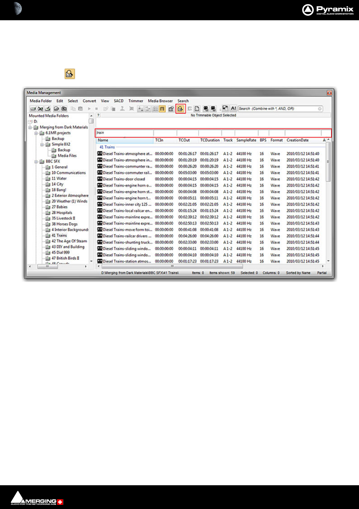
Media Management & Libraries : Search 4 - 48
Search
Overview
Thanks to the database engine Pyramix has comprehensive search tools. All Library views and the Media Manager
have a powerful Filter Search which refines the current view.
A simple search field is available in all Libraries and the Media Manager. A more comprehensive search dialog is
accessed via Media > Search Media or via a toolbar icon. For power users the dialog can be associated with a key-
board shortcut. Search Results are added to the Global Library in a folder labelled with the date and time of the
search and the search term(s). Results may be further refined using Filters.
Quick Search
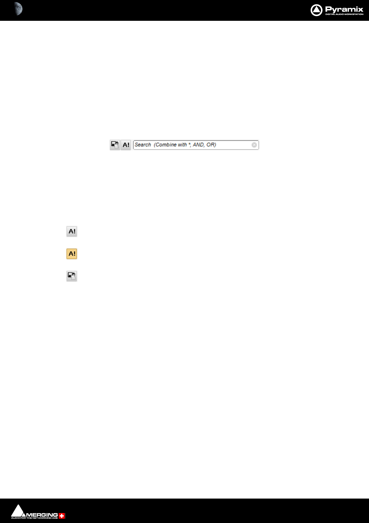
In any Library Tab or the Media Management Tab Click in the Search box to type a query.
When you click in the Search box a list of previous search terms (if any) drops down with the option to Clear
Search History at the end. This option clears the previous search terms visible at the top of this drop-down list but
leaves the current term in the search box intact. The [X] deletes the current search term from the box.
Note: When Exact Word Match is checked in the Search Media dialog (See below) then only
exact words in the database are searched.
The Search Exact button toggles Exact Word Match on and off. Default is Off
Search Exact button active.
Clicking on the Add to Search Results button creates a new folder in the Global Library,
named with date and the search request term(s). This folder can be renamed.
Search Box and Buttons
Media Management & Libraries : Search 4 - 49
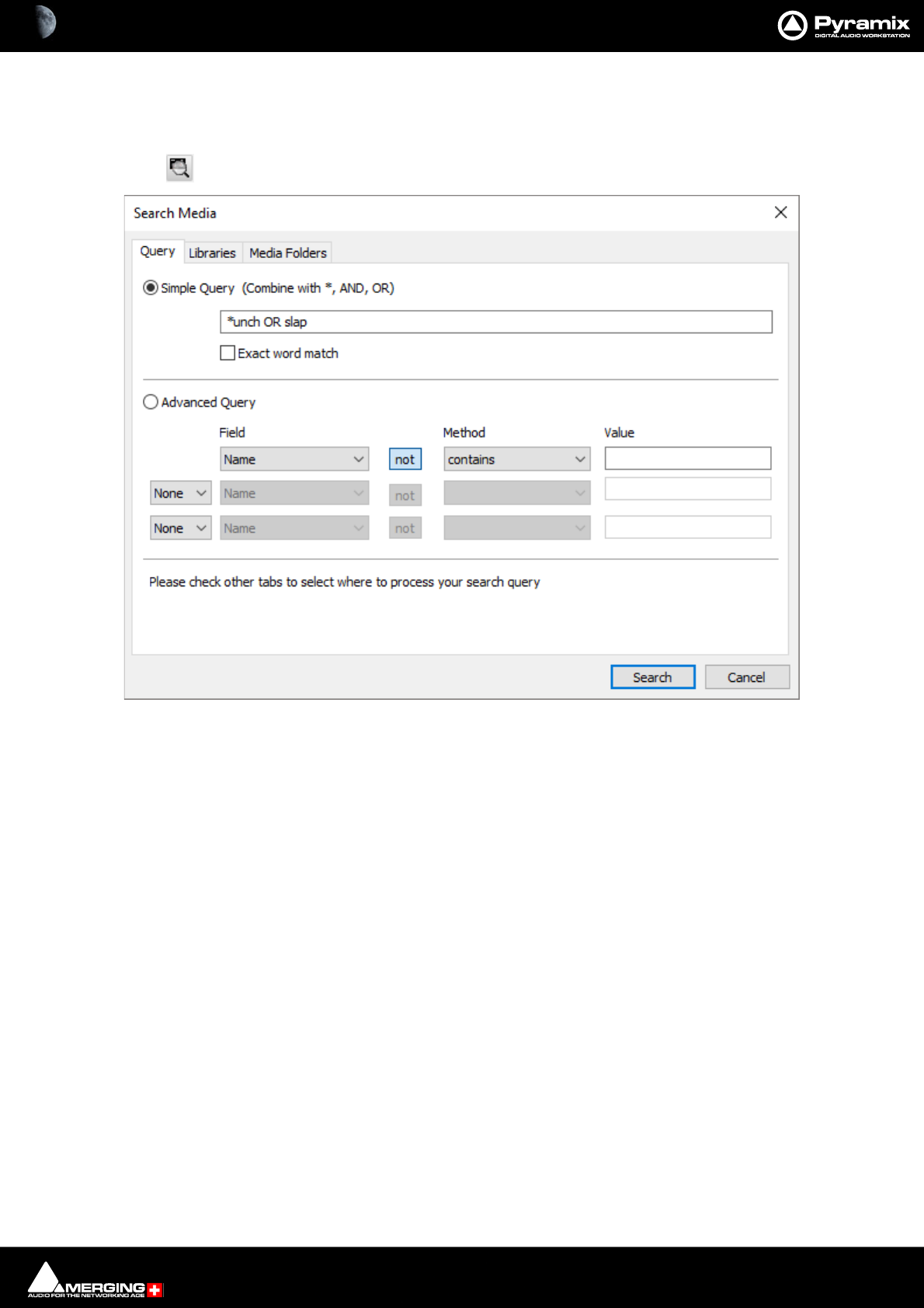
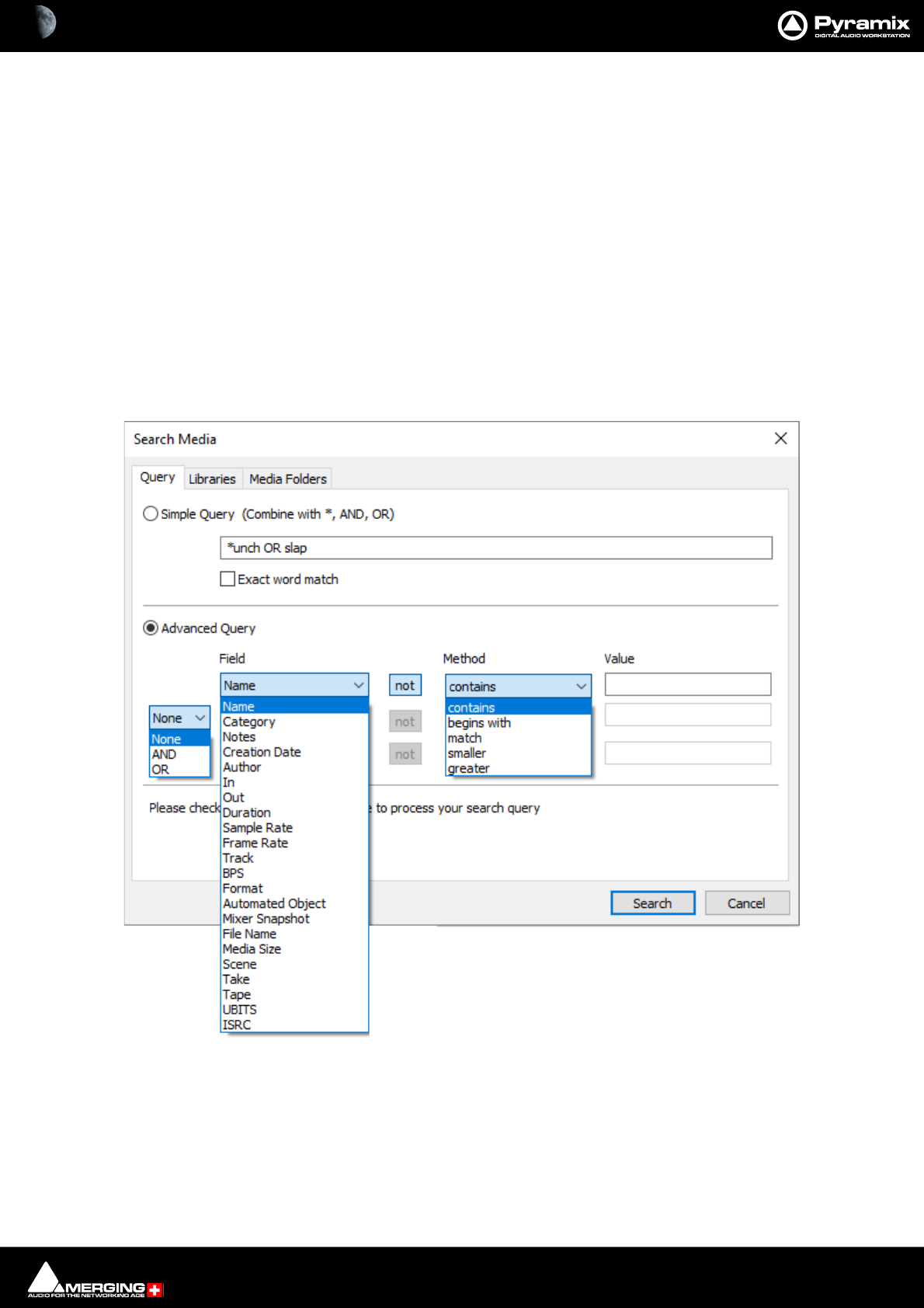
Search Media Dialog
The Search Media dialog is accessed via Media > Search Media or:
Clicking on the Search Media Toolbar icon:
Search Media Dialog Tabs
The Search Media dialog has three Tabs:
Query Is where search terms are set
Libraries Is where Libraries to be searched are set
Media Folders Is where Media Folders to be searched are set
Query Tab
The Search Media dialog opens with the Query Tab. This Tab sets up the search terms.
The top section is for Simple Queries. For more advanced searches the bottom section offers further possibilities.
Simple Query
Simple Query This radio button toggles with Advanced Query.
When Simple Query is selected the search is restricted to the Name of the
object(s) to be found. Search term(s) are typed in the text entry box. AND and OR
can be used in between two search terms to increase the scope. Similarly, * can be
used as a wildcard at the beginning or end of a search term.
Exact Word Match When checked the search will only identify exact words in the database.
The wild card * is still valid.
When unchecked the words are searched partially. E.g. car will return items
such as car door opening but also caravan passing or even scary scream.
Search Media dialog - Query Tab - Simple Query
Media Management & Libraries : Search 4 - 50
Note: When Exact Word Match is checked it also applies to the quick search at top right of
Library Tabs.
Simple Query Syntax
The wildcard * can also be used as a prefix or suffix so that:
*unch will return items including:
“munch”
“punch”
and
auto* will return items including:
“automobile”
“automat”
Advanced Query
Advanced Query This radio button toggles with Simple Query.
When selected the following options are available:
Field Name drop-down list offers the choice of all file types and information
fields on which a search can be conducted:
Name
Category
Notes
Search Media dialog - Query Tab - Advanced Query

Media Management & Libraries : Search 4 - 51
Creation Date
Author
In
Out
Duration
Sample Rate
Frame Rate
Track
BPS
Format
Automated Object
Mixer Snapshot
File Name
Media Size
Scene
Take
Tape
UBITS
ISRC
Not When lit (blue) inverts the search to exclude any files containing the search
term in the chosen field.
Method The drop-down offers the choice of:
Contains
begins with
match
smaller
greater
Value Type the search term here
The next two rows are used to add further terms to the search and have the same controls as the first except for
the first drop-down which offers the choice of:
None
AND
OR
Media Management & Libraries : Search 4 - 52
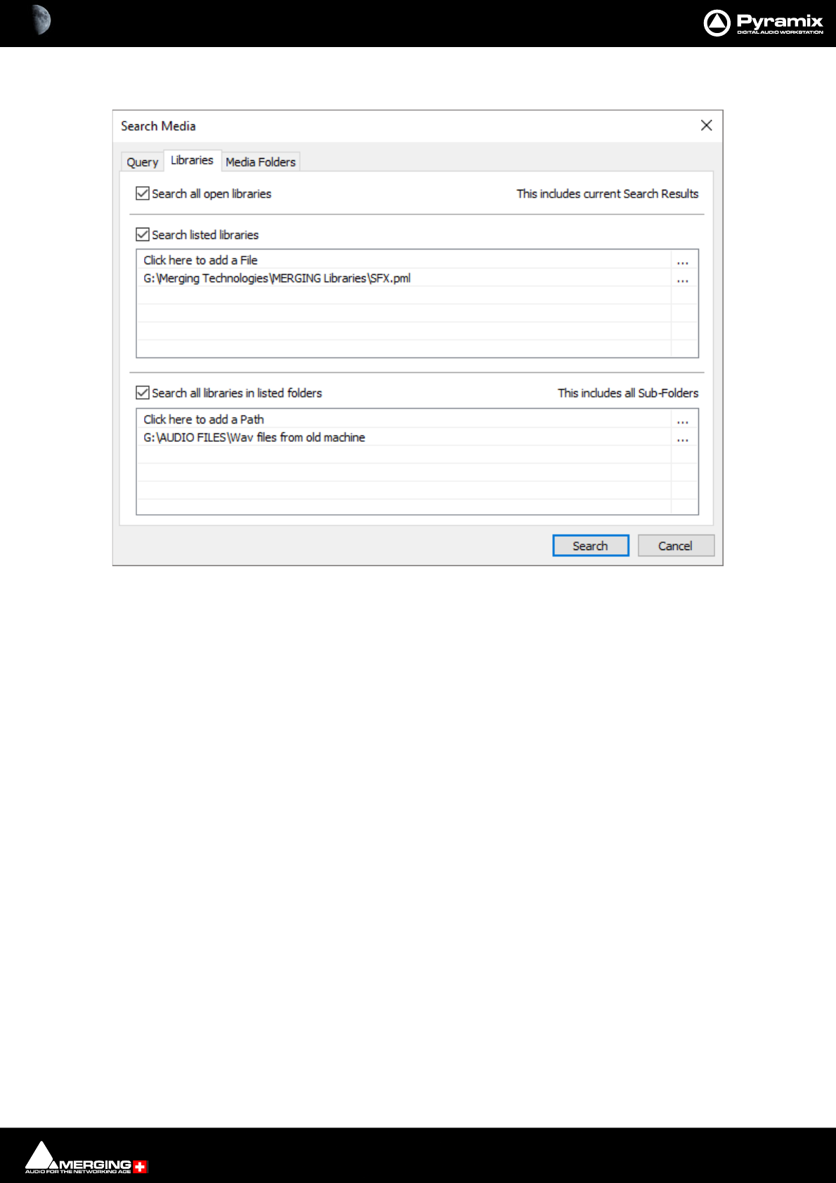
Libraries Tab
The Libraries Tab determines which Libraries will be searched according to the search terms set in the Query Tab.
Search all open libraries When ticked all open libraries will be included in the search (including the current
search results)
Search listed libraries When ticked any libraries included in the list will be searched whether open or not.
Clicking on the ... button opens a browser to locate Library files to add to the list.
Search all libraries in listed folders When ticked any libraries in the folders included in the list will be searched
whether open or not. (Including sub-folders.
Clicking on the ... button opens a browser to locate Folders to add to the list.
Search Media dialog - Libraries Tab
Media Management & Libraries : Search 4 - 53
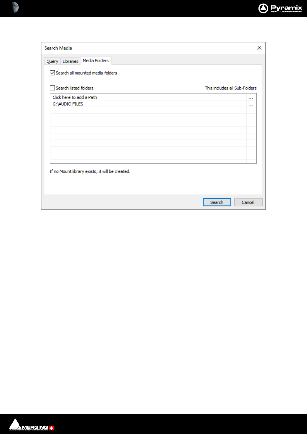
Media Folders Tab
Search all mounted media folders When ticked all mounted media folders will be included in the search.
Search listed folders When ticked any folders included in the list will be searched whether mounted or
not. (This includes all Sub-Folders.
Clicking on the ... button opens a browser to locate folders to add to the list.
If a folder is added which does not have a Quickmount library one will be created
when the search is run.
Search Media dialog - Media Folders Tab
Media Management & Libraries : Search 4 - 54
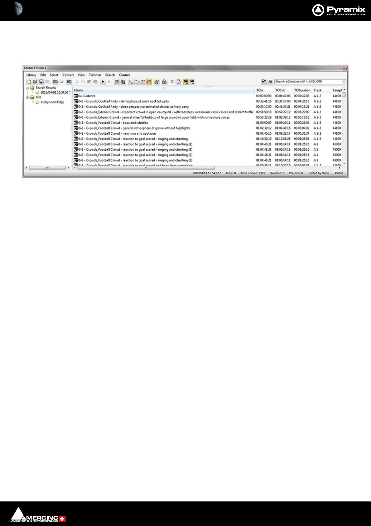
Search Results
Search Results are added to the Global Library in a folder labelled with the date and time of the search and the
search term(s). The focus is set to the latest search result.
Any operation which can be performed on a library entry can be performed on a search result. E.g. Drag and
Drop. Any item or items in a results folder can be dragged and dropped to another Library or to the Timeline.
Deleting Search Results
If the Search Results library is open the individual results are displayed in the right-hand pane and can be deleted.
To delete the entire search click on the Search Results in the left-hand pane. All current search results libraries will
appear in the right-hand pane and may be deleted.
Global Libraries Tab - Search Results
Media Management & Libraries : Search 4 - 55
Search Filters
All Library views and the Media Manager view have a Filters option. Filters are accessed via View > Filters in the
Library or Media Manager View menu or by clicking on the:
Filters toolbar icon
In the screenshot above the Filter text entry boxes and Filters icon are highlighted in red.
• The specific Columns available for filtering are set in Options. Please see: Media Management and
Library Tab Columns on page 57
• Filters are not case-sensitive.
• Filters always behave as if there is a wild card at either end of the filter term. I.e. *text*.
• Multiple filters are allowed. So, for example, you could search on trains in the Name column and A 1-6 in
the Track column. This would filter the view to show only results containing *train* with six audio tracks.
• Filters are NOT recursive I.e. don’t filter sub-folders.
Media Management Tab with Filters
Media Management & Libraries : Media Management 4 - 56
Media Management
The Media Menu
This menu gathers together significant Media related commands for the current Project.
Search Media Opens the Search Media dialog
Mount Referenced Media Mounts all media not already mounted and used in the current Project
Auto-Mount Media When selected, whenever a reference from an Offline library is placed in the current Proj-
ect, the Media will automatically be mounted.
Select Online Clips Selects all Clips in the Timeline whose Media files are currently mounted
Select Offline Clips Selects all Clips in the Timeline whose Media files are not currently mounted
Select Used Media Opens a floating Library View window listing all Media files used by the current Project.
Select Media present on Project Default Folder Opens a floating Library View window with all Media present in the Project
Default folder selected (highlighted)
Select Media NOT present on Project Default Folder Opens a floating Library View window with all Media NOT present in the
Project Default folder selected (highlighted)
Collect Media to current Project Default Folder Copies all media files used in the current project (as shown when the previous
Select Media not present ... is invoked to the current Project Default Folder. This func-
tion is especially useful if moving a machine or disk to another studio or where network
resources may not be available.
Clean-Up Media Opens the Choose a Media Folder to Clean-Up window. Choose the Media Folder you
wish to clean-up and click OK. All media not referenced by the current Project will be per-
manently removed from the selected folder.
Media Management & Libraries : Media Management and Library Tab Windows 4 - 57
Media Management and Library Tab Windows
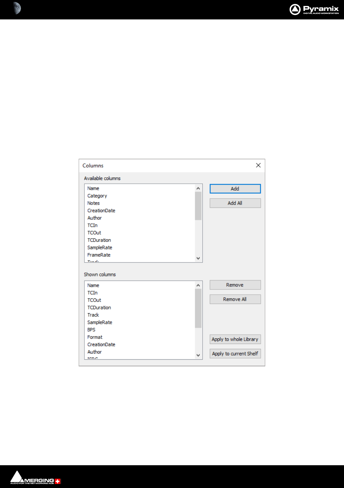
Media Management and Library Tab Columns
The Columns displayed in Libraries and the Media management window are determined by the Columns dialog
accessed from View > Options
Rearranging Columns
Columns present in Library, Media Management and Search Results frames can be rearranged by simply clicking
and dragging the column headers.
Reordering Columns
Clicking on a column header does two things on Columns where this is appropriate. It orders all Library entries
according to the numerical or alphabetical order of that Column and it toggles that order between Ascending and
Descending.
Options Opens the Columns dialog box:
The dialog box shows two lists, Available Columns and Shown Columns.
Available Columns buttons:
Add Adds the column(s) selected to the Shown columns list
Add All Adds All the available columns to the Shown Columns list
Shown Columns buttons:
Remove Removes the column(s) selected from the Shown columns list
Remove All Removes all column from the Shown columns list
Libraries View Menu Options - Columns pane

Media Management & Libraries : Media Management and Library Tab Windows 4 - 58
Apply to whole Library Applies the changes made in this dialog to all Folders in the current Library
Apply to current Shelf Applies the changes made in this dialog to all Folders in the current Shelf
Columns
Name Clip or Media File name
Category E.g. Master Clip, Media Folder etc.
Notes Where specified
CreationDate Date Media File (Clip) created
Author Where specified
TCIn Clip or Media File In TimeCode
TCOut Clip or media File Out TimeCode
TCDuration TimeCode Length of Clip or Media File
SampleRate Sample rate of Clip or Media File
FrameRate (Media Only) Where specified
Track Shows the Tracks the Media File or Clip occupies
BPS Beats Per Second
Format File format e.g. PMF, WAV etc.
AutomatedObject
MixerSnapshot
FileName (Media Only) Media File Name
MediaSize (Media Only) In bytes
Scene Where specified
Take Where specified
Tape Where specified
UBITS
ISRC
Media Management & Libraries : Media Management and Library Tab Windows 4 - 59
The Trimmer
All Library and Media Management Windows have a Composition/Media Trimmer:
The Trimmer can be shown/hidden with the menu item Trimmer > Show. An object highlighted (selected) in the
list view is automatically opened in the trimmer. Multi-channel objects may be auditioned and trimmed. A small
square to the left of each Track displayed allows Tracks to be de-selected/selected for playback in the Trimmer. The
Trimmer output is stereo for 2 channel media. For Media with more than two channels the routing is assumed to
be stereo. If the Media contains Channel Type metadata (PMF, BWF, Wave, MP3...NOT AIFF) the monitoring will
automatically route the mapping to the associated monitoring patch. Clicking on the ? at top-left opens the
Media Trimmer Commands list:
Media, Clips or Compositions can be trimmed in the following ways:
•Double-click: Plays the object through the Monitoring Section from the point where you double-click.
Note: Trimmer sound output is via the Monitor Panel. If no sound is heard through the current L
& R Monitor Outputs you may need to assign values to the None entry in the Main Grid and
Downmixes section of the Monitor Please see: Media Manager and Library Monitoring on
page 319
•Click & Drag: Drag the object to the timeline or to an other library properly trimmed (from the In point to
the Out point. Dragging it from the list view takes it untrimmed).
Library Trimmer
Trim In Trim Out
Sync Point
Playhead
Mute Buttons
Help

Media Management & Libraries : Media Management Tab Window 4 - 60
•Shift + Click: Sets the Trim In point. The point can be modified later by simply clicking on it.
•Control + Click: Sets the Trim Out point. The point can be modified later by simply clicking on it.
•Control + Shift + Click: Sets a Sync Point. The point can be modified later by simply clicking on it.
•Shift + Alt + Click: Sets the Trim In point and plays from it.
•Control + Alt + Click: Sets the Trim Out point and plays from it.
•Control + Shift + Alt + Click: Sets the Sync Point and plays from it.
•Control + Double-Click: Resets the Trim In and Trim Out and Sync Points.
Trim In, Trim Out and Sync Points
The Trim In, Trim Out and Sync Points are permanently preserved for Compositions and MasterClips stored in a
Library (Project or Global), but only until the next Mount or Refresh for mounted Media in the Media Management
Window.
Compatibility
Because the Media Trimmer allows Trim In, Trim Out and Sync Points to be set and saved in current libraries, menu
options: Library > Save Library as 5.x 6.0 and Library > Save Library As 4.x allow Libraries to be saved in a for-
mat compatible with previous versions for maximum compatibility.
Media Management Tab Window
The Media Management Tab Window is very similar in appearance and operation to the Document and Global
Library Tab Windows. However, the Menus and Toolbars differ a little, reflecting their different capabilities.
Media Manager History
By default the Media Manager database and its history is retained when Pyramix is shut down and relaunched.
(Settings > All Settings > Application > General : Keep Media Manager History
If this option is unchecked, it forces a history reset. (The Media_Library_.pml file is recreated from scratch on the
next Pyramix launch.)
This option is useful when several people are working on different projects with the same database (same login).
This can make the history database grow VERY fast.
Note: If disabled the Media_Library_.pml file will remain small but the mounting time will most
probably be slower.

Media Management & Libraries : Media Management Tab Window 4 - 61
Media Browser
The Media Management window can operate on Mounted Media Folders and act as a Media Browser for any
local or network storage locations.
Below all Mounted Media Folders an “Explorer like” Media Browser Tree allows Media Folders to be browsed
without Mounting them formally.
When displayed in the Media Browser all recognized Media are mounted temporarily and can be auditioned and
placed in the Timeline.
Media Management Tab Menus
Media Folder Menu
Mount Media Folder Opens the Choose a media folder to mount dialog:
Mounting a folder makes it visible to the Pyramix media filing system.
Field with drop-down list Clicking the down arrow reveals a list of folders mounted recently. You can select a
folder from the list and click on Mount to mount it.
Permanent Mount Any folder Mounted with this box ticked will be mounted when Pyramix is
launched subsequently.
Recursive When the box is ticked all sub-folders under the folder selected will also be
mounted.
Media Management Tab floating Window
Choose a media folder to mount dialog
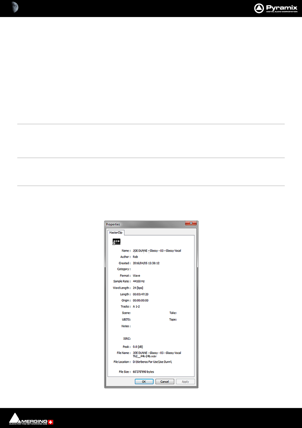
Media Management & Libraries : Media Management Tab Window 4 - 62
Reset Recent Mounted Folders List Clicking the button resets the list of folders mounted recently. I.e. the list
accessed from the drop-down. This only takes effect when the dialog is closed.
Browse... Opens a browser window to locate a folder to mount.
Create New Folder Opens a Save As browser window. Navigate to the location where you wish to cre-
ate a new folder, type a suitable name and click on Save to create the new folder
which then appears in the field in the Choose a media folder to mount dialog.
Mount Mounts the folder shown in the field and closes the dialog.
Cancel Closes the dialog without mounting a folder.
Unmount Media Folder Unmounts the selected Media folder (an Are you sure dialog protects from inadvertent
unmounting.) Makes the selected folder invisible to the Pyramix filing system.
Refresh Media Folder Invoking Refresh Media Folder initiates a complete ground up re-mount of the selected
folder. This may solve inconsistency issues. F5 will also refresh the selected folder.
Clear Media Manager History Choose this option to reduce Database size and improver performance.
Create Offline/Reference Library Please see: Using Offline/Reference Libraries on page 93
Create Quick Mount Libraries Use this option to create __QuickMount.pml libraries recursively for a whole disk or
folder, (typically overnight on a big new media disk) so that rapid browsing will be avail-
able the next time the disk is browsed.
Open Folder Opens the Media Management Library for the selected drive and directory. Double click-
ing on the name of the Media directory has the same effect
Up One Level Moves up one level in the file hierarchy
Mounting Rules Opens the Mounting Rules dialog only when a file or files are selected. This allows the
user to apply special rules when attempting to mount files that contain the same ‘unique’
identifier. Please see: Mounting Rules on page 94
Properties Opens the Properties window for the selected Media Folder or MasterClip:
Properties window
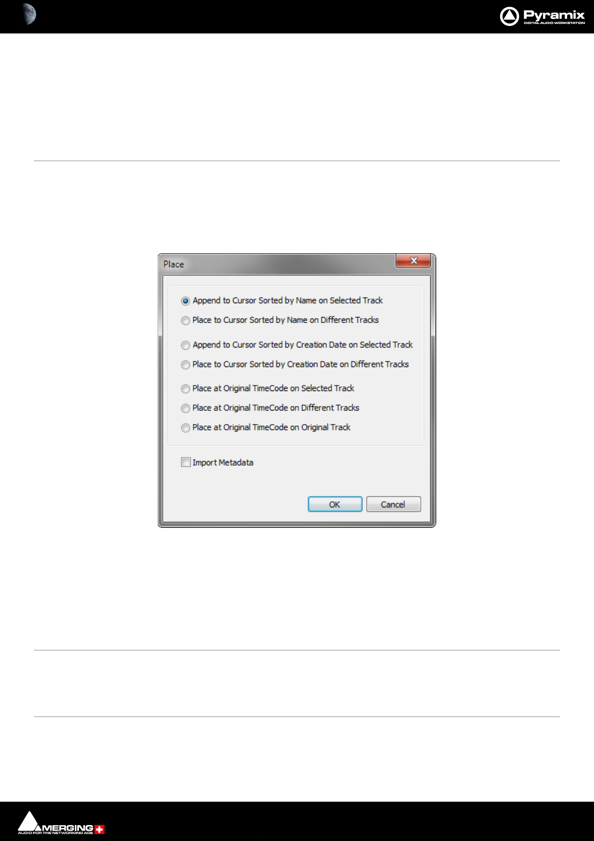
Media Management & Libraries : Media Management Tab Window 4 - 63
Edit Menu
Copy Copy object.
Paste with Media Pastes object complete with associated Media files to wherever the target object is
stored.
Rename Rename object
Lock Rename When ticked Locks all objects for Renaming. Do you really want your Sound Effects
Library entries to be renamed by anyone who can access it?
Open/Audition Opens highlighted (selected) Clip or Composition in the Trimmer and begins audition
play. Opens highlighted (selected) Shelf
Audition Opens highlighted (selected) master Clip in the trimmer and begins audition play.
Stop Audition Stop audition Play and return Cursor to beginning
Place (Ctrl + P) Opens the Place dialog:
The selected object(s) will be placed in the Timeline according to the rule chosen here.
The selected object will be placed in the timeline on the selected Track and Playhead Cursor position at its Sync
Point or, if no Sync Point has been set, at its In Point.
Import Metadata when checked, Metadata in a BWF file will be imported into the Metadata Tab window when
you click on OK as well as the chosen Place action.
Placement Tool Opens the Placement Tool for placing the object. Please see: The Placement Tool on
page 195
Locate Selects the first instance of the current object in the Timeline and positions the Playhead
Cursor at the start of it.
Show Usage Selects all instances of the current object in the Timeline and zooms to make them all vis-
ible.
Media Management Edit menu Place dialog
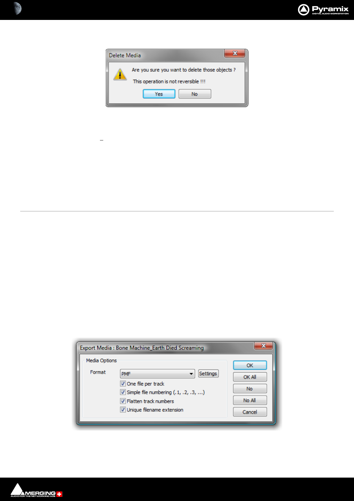
Media Management & Libraries : Media Management Tab Window 4 - 64
Delete Media Deletes the selected MasterClip(s). A confirmation dialog pops-up when this option is
chosen:
Clicking on Yes DEL ET ES the Media File(s), No cancels.Deletes the selected Master Clip
and Associated Media Files
Important! Delete Media does what it says. This command:
PERMANENTLY REMOVES AUDIO (and its associated Waveform file(s) from the drive.
Collect Selected Media to current Project Media Folder
Select Menu
Select All Selects all objects in the right-hand pane (Ctrl + Click toggles selection of individual
objects)
Invert Selection Selected objects are de-selected, unselected objects are selected
Select Media Present on current Project Media Folder Selects any Media file(s) shown in the right-hand pane that are pres-
ent on the current Project Media Folder.
Select Media NOT present on current Project Media Folder Selects any Media file(s) shown in the right-hand pane that are
not present on the current Project Media Folder.
Convert Menu
Quick Import Enables sound files in any supported format to be imported into a Pyramix Media Drive or
Folder in either their original format or converted to the Pyramix native PMF format.
Note: Files in supported formats do not need to be converted to be used in Pyramix, a big time-
saver.
Quick Export Enables Pyramix Master Clips to be exported in any of the supported file formats with a
number of options. When Quick Export is chosen a File Browser window opens to enable
the target folder to be chosen. When you click OK in the Browser the Export Media dia-
log opens with options: .
One file per track When checked, multi-channel Master Clips are exported with a single file for each
channel in the Clip.
Delete Media confirmation dialog
Quick Export - Export Media: Dialog

Media Management & Libraries : Media Management Tab Window 4 - 65
Simple file numbering (.1, .2, .3, ...) When checked resultant files are numbered (.1, .2, .3, … instead of
_##001##_, _##002##_, …)
Flatten track numbers When checked, Tracks are numbered 1, 2, 3, 4 instead of, for example 1, 2, 7, 8
Unique filename extension When checked, adds a unique filename extension.
Export Masterclips This is similar to Quick Export (above) but is also available in Libraries. It enables selected
Shelves and Media Folders to be exported. Their complete/recursive folder structure is
exported. Only Masterclips/Media are exported. Compositions or any other objects in
Libraries are not exported.
Quick Convert > Enables one or more Media files to be converted in a variety of ways. (Please see: Convert
- Quick Convert sub-menu on page 70)
Sample Rate Conversion Please see: Samplerate Conversion on page 76
Reverse Reverses the selection so it plays backwards
Export XML Description Exports Media Descriptions as an XML file Select a range of media and select Convert >
Export XML Description.
Export to MTInterchange XML
Publish to Open External Database Please see: Archiving Metadata on page 441
View Menu
The View menu determines how information is displayed.
Status Bar Turns the Status bar on and off
Large Show large Icons
Small Show small Icons
List Show as list
Detail Show as list with details
Filters Adds Filter term entry boxes above each column in the view
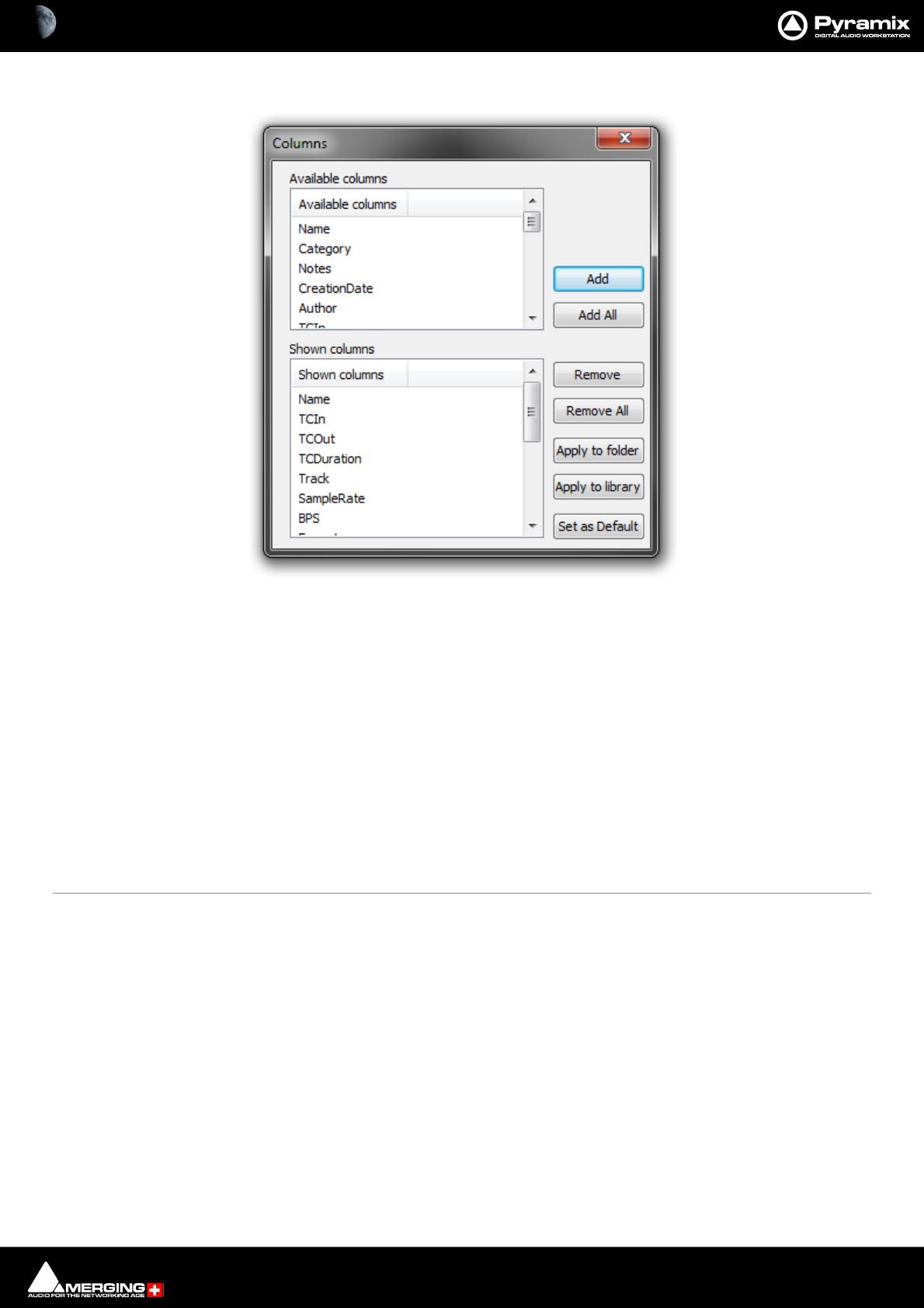
Media Management & Libraries : Media Management Tab Window 4 - 66
Options Opens the Columns dialog box:
The dialog box shows two lists, Available Columns and Shown Columns.
Available Columns buttons:
Add Adds the column(s) selected to the Shown columns list
Add All Adds All the available columns to the Shown Columns list
Shown Columns buttons:
Remove Removes the column(s) selected from the Shown columns list
Remove All Removes all column from the Shown columns list
Apply to Folder Applies the changes made in this dialog to the current Folder
Apply to library Applies the changes made in this dialog to all Folders in the current Library
Set as Default Sets the changes made in this dialog as the default column content for all Folders
in all Libraries.
New Window Opens another instance of the Media Management Tab Window
Refresh Forces a refresh
Libraries View Menu Options - Columns pane
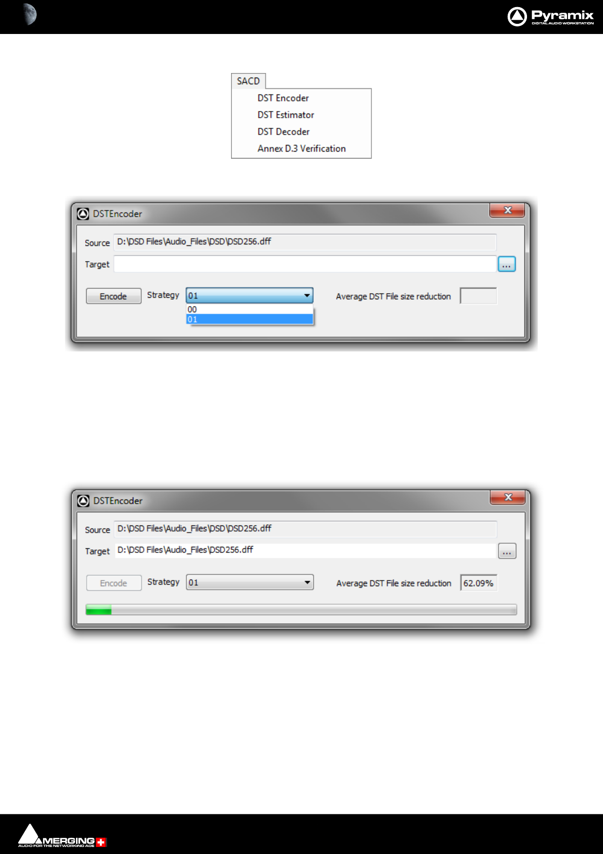
Media Management & Libraries : Media Management Tab Window 4 - 67
SACD Menu
DST Encoder Encode an Edited Master in DST
Source Shows the full path of the selected file.
Target The ... button opens a browser window to set the destination file path and enter a
name for the file.
Strategy The drop-down offers the choice of 00 or 01.
Average DST File size reduction Shows the average percentage reduction in file size dynamically as the encode
progresses and the average when it is complete.
Encode Initiates the encoding.
Media Management SACD menu
DST Encoder dialog
DST Encoder in operation
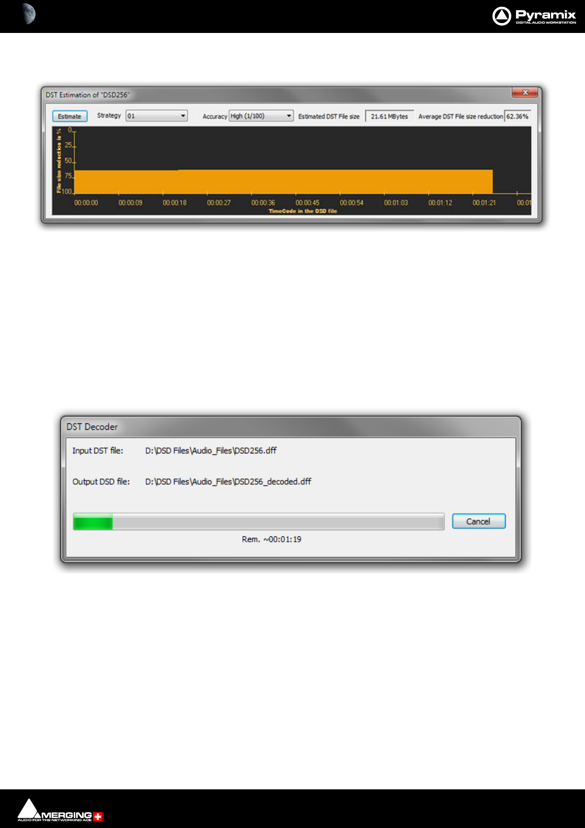
Media Management & Libraries : Media Management Tab Window 4 - 68
DST Estimator Estimate the DST encoding of an Edited Master with a graph to show the file reduction
rate as a function of the audio material.
Estimate Initiates the estimation process on the selected file.
Strategy The drop-down offers the choice of 00 or 01.
Accuracy The drop-down offers the choice of High (1/5) or Very High (1/100).
Estimated DST File Size Shows the estimated file size dynamically as the estimation progresses and the
total when it is complete.
Average DST File size reduction Shows the average percentage reduction in file size dynamically as the encode
progresses and the average when it is complete.
DST Decoder Decodes a DSDIFF file. Selecting this option opens a browser window to select the file to
be decoded. Clicking on Open. initiates the decode. When the decode is completed the
dialog closes
Clicking on Cancel aborts the decode.
DST Estimator
DST Decoder in operation
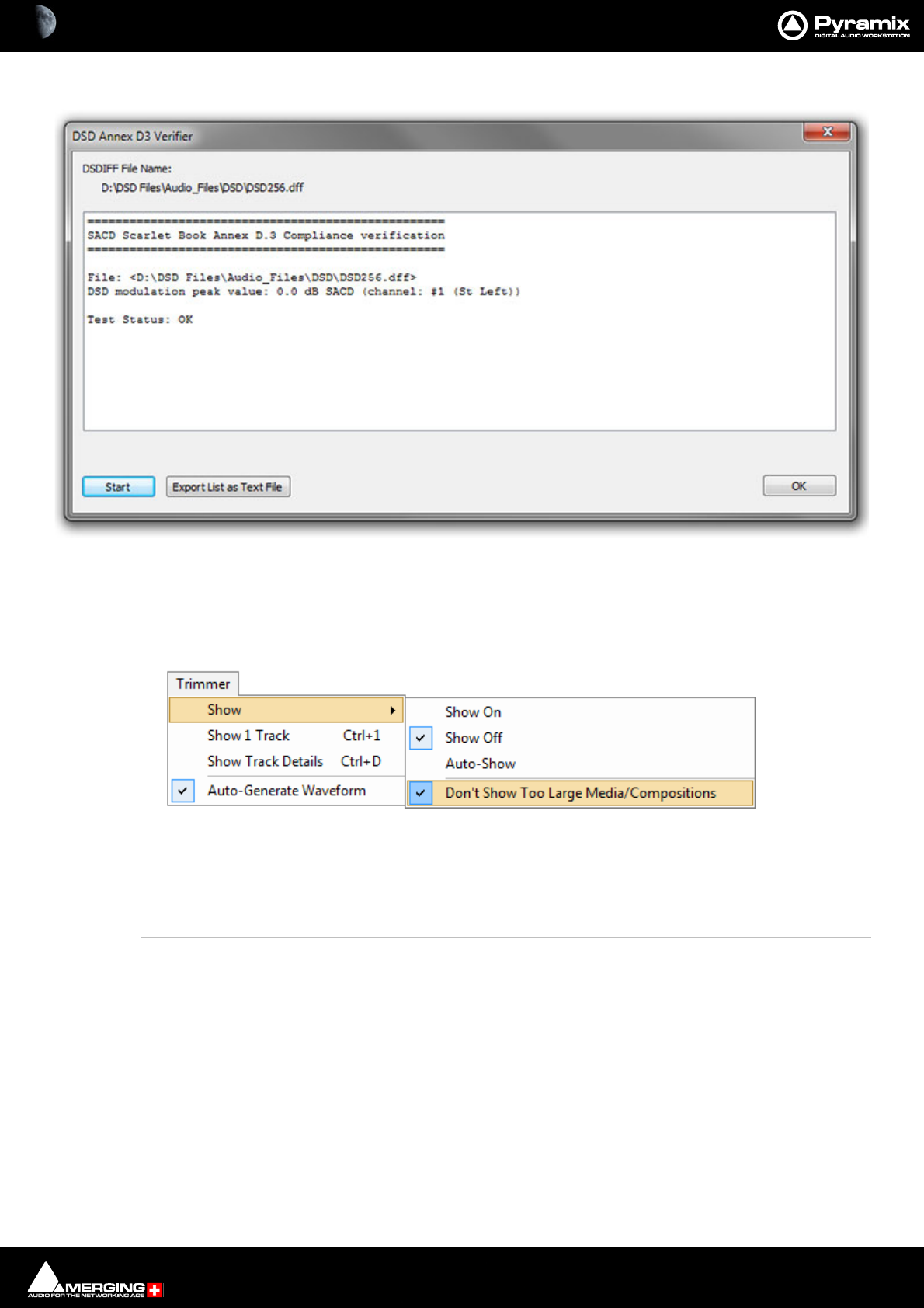
Media Management & Libraries : Media Management Tab Window 4 - 69
Annex D.3 Verification Verify the selected file.
Start Initiates the verification process.
Export List as Text File Opens a browser window where the file path is set and the file named.
OK Closes the verifier window.
Trimmer Menu
Show
Show On When ticked the Trimmer is visible
Show Off When ticked the Trimmer is hidden
Auto-Show When ticked the Trimmer is only shown when a Media file is selected
Don’t Show too Large Media/Compositions When ticked Large Media files and Compositions will not be
opened in the Trimmer.
Note: When this option is selected Media or Compositions with more than 16 Tracks or more
than 100 Clips will not be shown in the Trimmer. Selecting this option avoids the loading time
associated with Compositions containing a large number of Clips.
Show 1 Track Show only the first Track of the object displayed in the Trimmer. When this option is
selected Up and down arrows appear at the left of the Trimmer Track display which
enable any Track to be displayed.
Show Track Details The following information is displayed for each Track of the selected Media file:
•Track Name
• Track Number
Media Manager Trimmer Menu
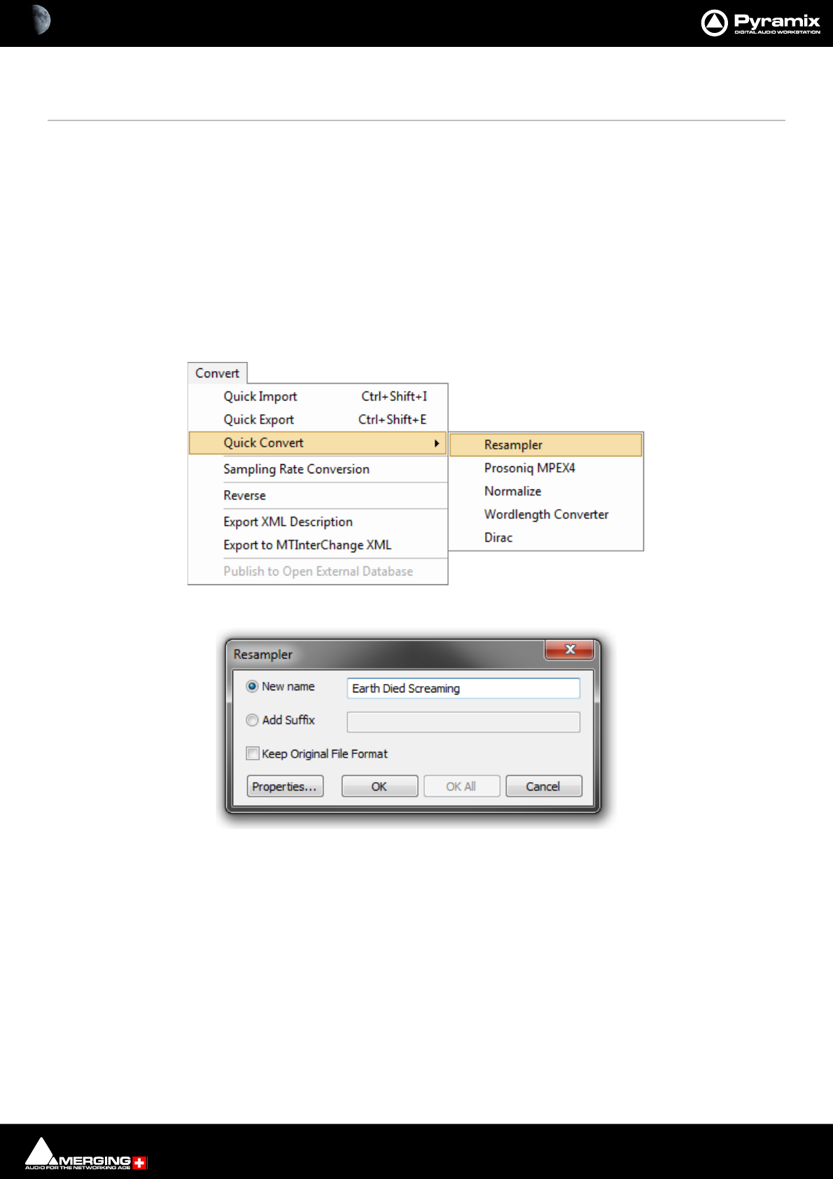
Media Management & Libraries : Media Management Tab Window 4 - 70
• Track Type (left, Right, Center etc.)
• Track File Name (If the Media is recorded in One File Per Track mode)
Auto-Generate Waveform Waveforms are automatically created for objects without them.
Media Browser Menu
Mount Currently Displayed Media Folder allows easy mounting of the Media Folder currently displayed in the Media Browser.
(Typically when the correct folder is located).
Search Menu
Search All Mounted Media Folders Toggles between Global and Local search. When Active, all Mounted Folders are
searched. When Inactive only the current Folder is searched.
Add to Search Results Creates a new Search Results folder named by date and time and the search term(s).
Convert - Quick Convert sub-menu
Output Dialog
All these options produce new media files on disk. Whichever conversion option is chosen, this dialog box will
pop-up with a title reflecting the selected process. Either a new name may be chosen or the existing one kept with
a new suffix. If you wish to process multiple files in one operation the Add Suffix button must be selected. When
multiple files are selected and when this option is chosen the OK All button is available. The Keep Original File
Format check box does what it says. The Properties... button opens a dialog box specific to each conversion type.
(See below)
Media Management Convert - Quick Convert sub- menu
Resampler Converter dialog
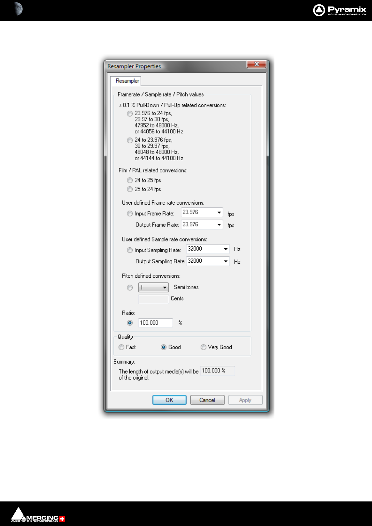
Media Management & Libraries : Media Management Tab Window 4 - 71
Quick Convert - Process Properties Dialogs
Resampler Properties
This module is initially aimed at performing ±0.1 % pull-up / pull- down audio conversions, but there are several
possible ways of defining the ratio between the destination length and the final length (frame rates, sample rates,
pitch and ratio in percent).
The process differs from a Time Stretch operation since the pitch is modified. The Input and Output files have the
same sampling rate but the length of the output files will be: (initial length) x (displayed ratio).
Another setting, Quality, has an effect on the resolution of the oversampling process of the treatment.
Resampler Properties dialog
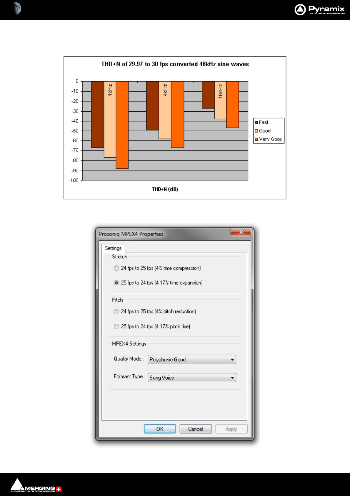
Media Management & Libraries : Media Management Tab Window 4 - 72
This module is available, like MPEX, in the 'Quick convert' list of the Media Manager, the Project menu (to process
all the media in a project), and as a 'Surround Encoder' (Project > Surround Processing).
The following graph gives an indication of the effect of the three Quality settings on THD & Noise.
Prosoniq MPEX4 Properties
Resampler quality setting effect on THD & Noise
Prosoniq MPEX4 Properties dialog
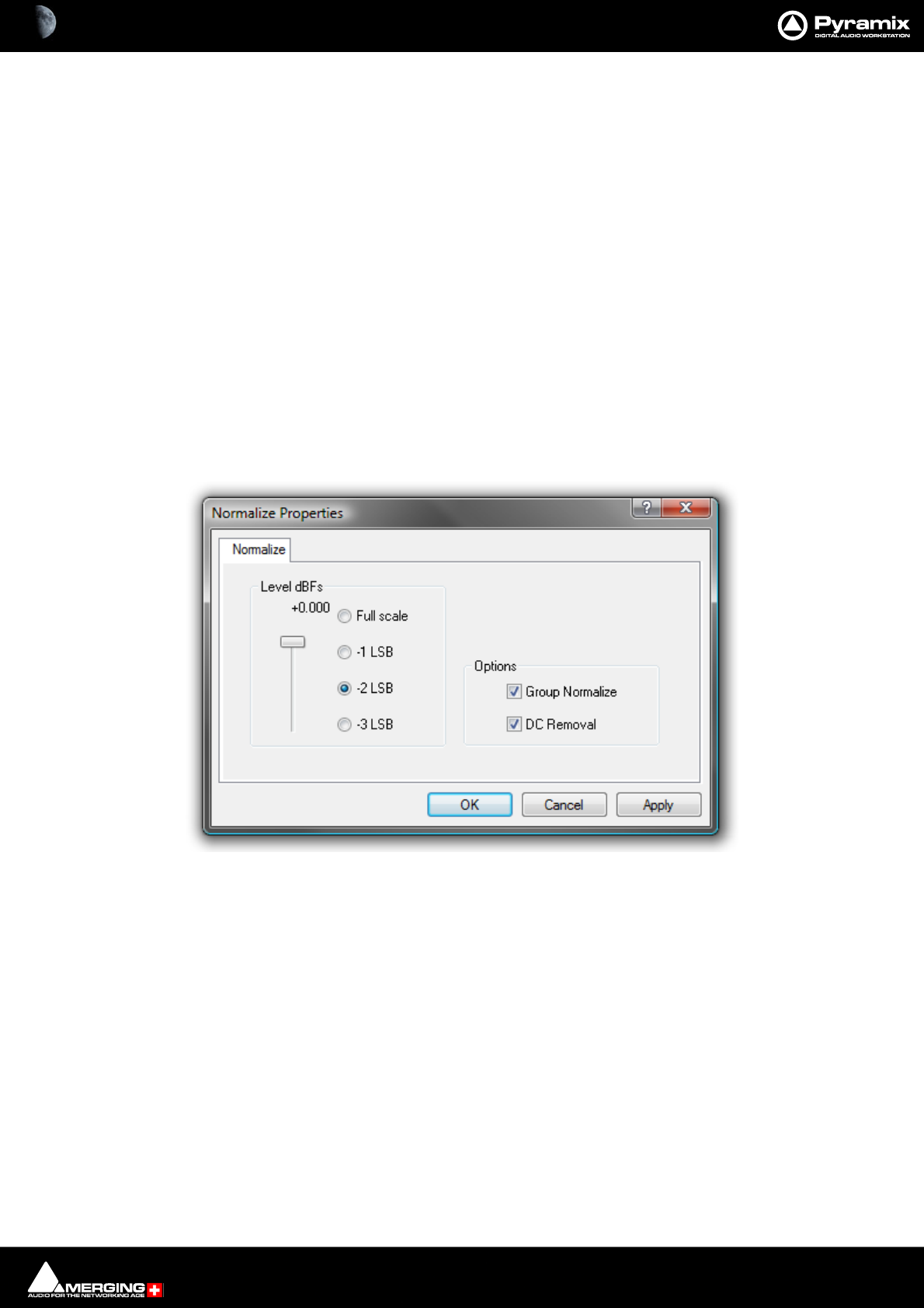
Media Management & Libraries : Media Management Tab Window 4 - 73
Select the required conversion factor from the four Stretch and Pitch options.
Optimize MPEX4 Settings by making appropriate choices from the Quality Mode and Formant Type combo
boxes.
Quality Mode Single Instrument Fast
Single Instrument Best
Polyphonic Fast
Polyphonic Good
Polyphonic Best
Formant Type Sung Voice
Spoken Voice
Normalize Properties
Level dBfs
Here you can select from four preset values, or use the slider to specify the maximum level for the new file.
Group Normalize
When checked, the level of the highest peak in any group of Clips is raised to maximum and level of the other Clips
is increase proportionally.
DC Removal
When checked, D.C. offsets will be removed.
Normalize Properties dialog
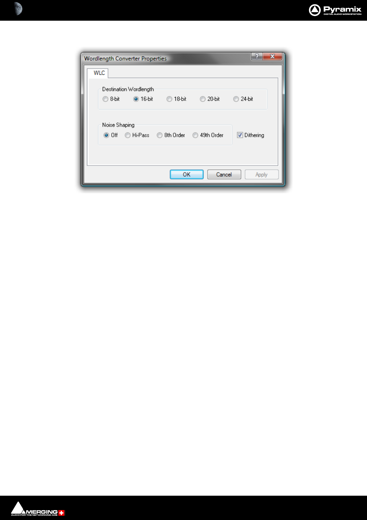
Media Management & Libraries : Media Management Tab Window 4 - 74
Wordlength Converter Properties
Destination Wordlength
Select the desired wordlength using the radio buttons.
Noise Shaping
Select the required quality of Noise Shaping.
Hi-Pass is single order shaping with
8th Order and
49th Order offering improved quality.
A higher quality setting will produce better results, but the processing time will also increase.
Dithering When checked, If dithering is required, dithering will be applied.
Wordlength Converter Properties dialog
Media Management & Libraries : Media Management Tab Window 4 - 75
ZTX Pro
Optional high quality pitch-shift and time-stretch renderer from Zynaptiq.
Note: Merging Technologies ZTX Pro key is required.
ZTX Pro Dialog
New Name Toggles with Add Suffix. The field is populated with the existing name of the file
selected in Media Manager. The name may be changed by typing in the field.
Add Suffix Type in the field to add a suffix.
Output Fomat Three options - Keep Original File Format, BWF or PMF.
Properties... Opens the ZTX Pro Properties dialog.
ZTX Pro dialog
ZTX Pro Properties dialog
Media Management & Libraries : Media Management Tab Window 4 - 76
Settings
Time Stretch
Four options are available:
% (percentage) Type in the field to enter a percentage value between 50 and 200.
24 to 25fps As it says.
25 to 24fps As it says.
Transcribe mode (2x Stretch) As it says.
Quality & Localization
Three quality modes are available in the drop-down list: Good, Better, Best.
Time/Frequency localization:
The slider can be set to one of five positions from far left to far right:
1. Far left. Selects full time localization. Good setting for single instruments and voice.
2. Time/frequency localization with emphasis on time localization. If setting 1. produces echoes this give better
results.
3. Middle. This sets the time/frequency localization halfway between time and frequency domains. It is the best
setting for all general purpose signals and should be set as default for non-preview processing.
4. Higher frequency localization and less time localization. May be a better choice for classical music than the
lower Time/Freq localization settings.
5. far right. Highest frequency localization. This may not be an ideal choice if you're dealing with signals with
very fast attack transients.
Pitch
The sliders enable values of -12 to +12 semitones and -50 to +50 cents to be set.
Formants
Choice of Preserve, which results in the most natural pitch shifting or manual with values of 0.5 - 2.0 available.
Samplerate Conversion
Where the sampling rate of a Media File is different to the current Project, Pyramix offers a simple means of con-
verting the Media File’s sample rate at very high quality. Using the Merging Technologies HeptaCon Sample Rate
Converter:
Radio buttons offer the choice of two text entry fields, New name for the file or Add Suffix to the existing file-
name. A check box selects Keep Original File Format otherwise the file will be converted to PMF format as well
as sample rate converted.
MT Hepta SRC module dialog
Media Management & Libraries : Media Management Tab Window 4 - 77
Properties...
Selecting Properties... opens the HeptaCon SRC module Properties dialog:
Data Format
The radio buttons offer the choice of PCM or DSD 64. (The latter is only available for DSD to DXD conversion.)
Sampling Rate Conversion
Output SR Select the Output Sampling Rate from the drop down list.
Filter Type Offers the choice of Lin. Phase, Min Phase or Apodising.
•Linear Phase features constant group delay, thanks to the linear phase, and has a symmetric impulse
response, but also longer rings. This offers the best preservation of stereo image. There will be a minimum
of phase distortion from the anti-aliasing filter.
MT Hepta SRC module Properties dialog
Media Management & Libraries : Media Management Tab Window 4 - 78
•Minimum Phase features an asymmetric impulse response with minimum phase response. This gives the
lowest amount of phase variation along the frequency spectrum and allows slightly better results for tran-
sient sounds.
•Apodizing offers the steepest response around the Nyquist point and linear phase. It offers the best of
both worlds for the about the same computational effort as the 2 other designs. There is a steep transition
band in the LPF filter using an almost linear phase. Arguably this is the best compromise between linear
and minimum phase types.
Quality Conversion Quality defaults to Very High.
Gain (dB) Use the increment/decrement buttons or type a value for any required Gain offset.
(E.g. when converting from DSD where the DSD recording has taken advantage of
the 3.1dB SACD maximum level allowed by SACD Audio signal properties Annex
D3 you should reduce the gain by typing a minus value (e.g. -3.10dB) to avoid clip-
ping in the PCM output product.)
Note: In a DSD to PCM conversion the gain is applied on the filter’s pre-computed lookup table
(64 bit floating point domain) so avoiding any clipping if dealing with levels above 0dB (SACD).
In PCM to PCM conversions gain adjustment is applied after the SRC stage and before the dither-
ing stage.
Dithering
Enable When ticked Dithering is enabled.
Requantization The drop-down list offers a wide choice of output bit-depths.
Noise Type Default is TPDF
Noise Shaping Choice of High Pass (POW-r2) or Equal Loudness (POW-r 3)
OK
Accepts the settings and closes the dialog.
Cancel
Cancels any changes made and closes the dialog.
Apply
For future developments
Choose OK in the MT HeptaCon SRC module dialog box to begin the conversion. When converting multiple files,
choose OK to convert the files one at a time with the possibility of changing parameters on each file or, if Add Suf-
fix was chosen in step 2, you can choose OK All to convert all the selected files in one operation.
Convert Media Files Sampling Rate... dialog

Media Management & Libraries : Media Management Tab Context Menu 4 - 79
Media Management Tab Context Menu
Right-clicking on an Audio File entry (or a blank area) in the file list in the Media Management Tab opens a context
menu with the following entries:
Show All Drives
Copy
Paste with Media
Audition
Stop Audition
Place
Locate
Show Usage
Delete Media
Quick Import
Quick Export
Quick Convert >
Sampling Rate Conversion
DST Encoder
DST Estimator
Annex D.3 Verification
Publish to VCube Timeline
These functions are the same as those which can be found in the Media Management Tab Menus. Please
see: Media Management Tab Menus on page 61
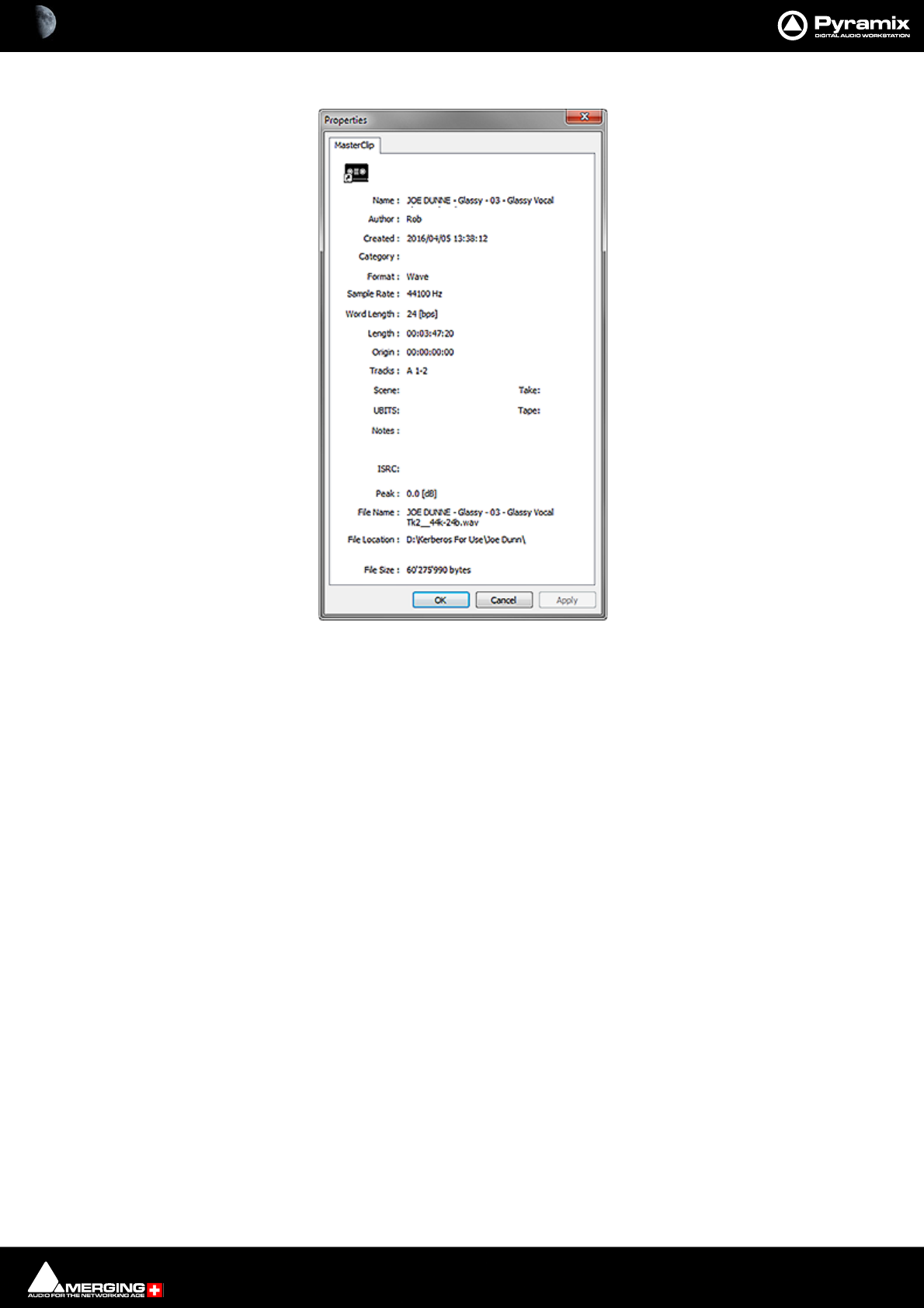
Media Management & Libraries : Media Management Tab Context Menu 4 - 80
Properties Opens the Properties window for the selected Master Clip:
Properties window
Media Management & Libraries : Media Manager File Format Conversions 4 - 81
Media Manager File Format Conversions
Input Formats
Generic lossless or
lossy PCM format
(BWF, PM F, M P3,
M TFF-PCM ...)
DSDIFF
2.8 MHz
(DSD64)
DSDIFF
5.6 M Hz
(DSD128)
DSDIFF
11.2 M Hz
(DSD256)
M TFF-
DSD
2.8 MHz
(DSD64)
MTFF-
DSD
5.6 M Hz
(DSD128)
M TFF-
DSD
11.2 M Hz
(DSD256)
WSD
2.8 MHz
(DSD64)
WSD
5.6 M Hz
(DSD128)
WSD
11.2 M Hz
(DSD256)
DSF
2.4 MHz
(DSD64)
DSF
5.6 M Hz
(DSD128)
DSF
11.2 M Hz
(DSD267)
Generic lo ssless
or lossy PCM format
(BWF, PM F, M P3,
MTFF-PCM….)
Yes Yes (1)NoNoNoNoNoNoNoNoNoNoNo
DSDIFF
2.8 MHz
(DSD64)
Yes (2) Yes (3 ) No No Yes (3) No No Y es (3) No No Y es (3) No No
DSDIFF
5,6 M Hz
(DSD128)
Yes (2) No Yes (3) No No Y es (3) No No Yes (3 ) No No Yes (3) No
DSDIFF
11.2 M Hz
(DSD256)
Yes (2) No No Yes (3 ) No No Yes (3) No No Yes (3) No No Y es (3)
MTFF-DSD
2.8 MHz
(DSD64)
Yes (2) Yes (3 ) No No Yes (3) No No Y es (3) No No Y es (3) No No
MTFF-DSD
5.6 M Hz
(DSD128)
Yes (2) No Yes (3) No No Y es (3) No No Yes (3 ) No No Yes (3) No
MTFF-DSD
11.2 M Hz
(DSD256)
Yes (2) No No Yes (3 ) No No Yes (3) No No Yes (3) No No Y es (3)
WSD
2.8 MHz
(DSD64)
Yes (2) Yes (3 ) No No Yes (3) No No Y es (3) No No Y es (3) No No
WSD
5.6 M Hz
(DSD128)
Yes (2) No Yes (3) No No Y es (3) No No Yes (3 ) No No Yes (3) No
WSD
11.2 M Hz
(DSD256)
Yes (2) No No Yes (3 ) No No Yes (3) No No Yes (3) No No Y es (3)
DSF
2.8 MHz
(DSD64)
Yes (2) Yes (3 ) No No Yes (3) No No Y es (3) No No Y es (3) No No
DSF
5.6 M Hz
(DSD128)
Yes (2) No Yes (3) No No Y es (3) No No Yes (3 ) No No Yes (3) No
DSF
11.2 M Hz
(DSD256) Y es No No Yes (3 ) No No Yes (3 ) No No Yes (3) No No Y es (3)
(1) Pyramix Media manager's Quick export requires the input media's sampling rate to be 352.8 kHz
(2)
(3)
Pyramix Media manager's Quick export requires the output format to support 352.8 kHz sample rate
No processing filter will be applied, only audio data copy
Output Formats
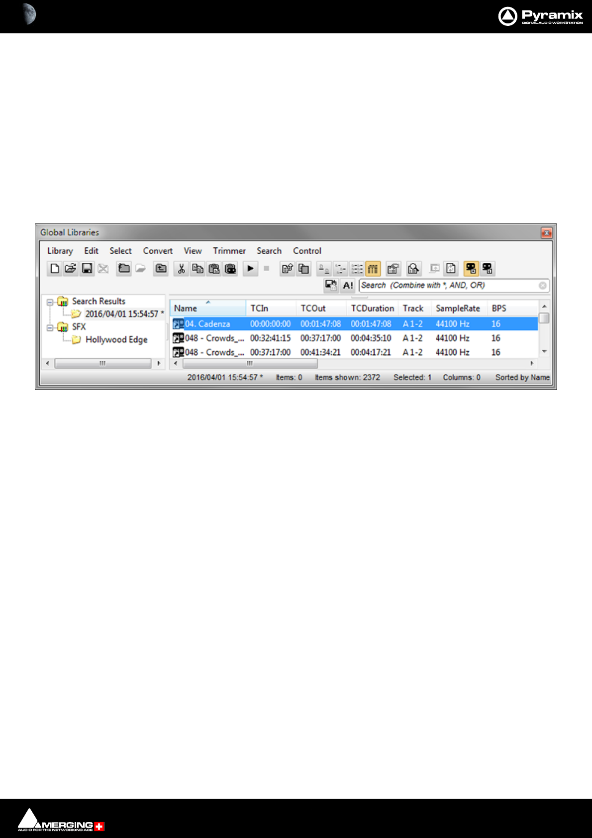
Media Management & Libraries : Libraries and other View Windows 4 - 82
Libraries and other View Windows
Pyramix uses Libraries to help keep Project organization tidy. Libraries are used to organize project material into
logical groupings. However, Libraries are not the same as Windows directories or folders. They are only meaning-
ful within the Pyramix environment. A Library is a database, containing a collection of pointers to different types
of media objects with tools designed to enable you to work quickly and intuitively.
Other View windows such as Search Results, Used Media, Project Default Media and Non-Project Default
Media operate in the same way as Library windows.
Shelves
A library Shelf is a sub-folder. You can create many Shelves in a Library and Shelves can also contain further
Shelves.
Project Libraries
Composition Library
Since Pyramix 7, the Composition Library is no longer present. This has been done to preserve editing interactiv-
ity.
We recommend two work flows to achieve the same results as using the Composition Library:
• Toggle the Select Used Media view to list the Media by location, based on Timeline selection. You can
search and drag & drop from this window back into the Timeline. You can also save the Select Used
Media content to a User Library which can be re-opened as a Library.
• Use the EDL view since this has been improved and is fully functional and reliable.
Default Library
Each new Project creates an empty User Library named Default Library (‘project name.pmx’). This is provided
to aid housekeeping and is kept with the project.
User Project Libraries
Further Project Libraries can be created at will. From the Document Libraries Tab choose Library > New Library.
Global Libraries
Project Libraries are kept with the Project, Global Libraries are available to all projects and users of the system.
Otherwise they are identical functionally. Global Libraries are useful for sound effects or where several users need
access to the same source material to produce different end products.
User Libraries
Master Clips can simply be dragged from Media Folders to User Libraries for purposes of Clip organization,
grouping, etc. just as they are dragged into Compositions
Clips or Selections can be copied and pasted into User and Global libraries. Library items can be dragged and
dropped onto other Libraries, Shelves or the Timeline or you can use the familiar Cut, Copy and Paste commands.
Libraries - Shelves

Media Management & Libraries : Libraries and other View Windows 4 - 83
Other View Windows
Search Results
Project Default Media
Non-Project Default Media
Used Media
All these views have the same controls and behave like Libraries.
Adding Regions and Compositions to Libraries
User Libraries are not restricted to storing individual Clips. Whole Compositions or selected Regions of Compo-
sitions, including all the Clips in a Composition in relation to each other on multiple Tracks may be placed in a
library. To do this, select one or more Clips in a Composition, hold down the Shift-Alt keys and drag the selection
from the Timeline to the Library, or hold down the Shift-Alt keys and drag the whole Composition from the
Overview panel to the User Library.Media Folders
User Libraries can contain Master Clips, Compositions, Mixer Snapshots, Plug-in Snapshots, Fade Settings,
etc…. Each Project can have an unlimited number of User Libraries open, each with an unlimited number and
mixture of contents.
N.B. In Pyramix User Libraries, there is no practical distinction between a Clip, a section of a Composition
(Region) and a complete Composition. Either can be added to a User Library or to an existing Composition. This
is an extremely powerful feature. Any item copied to a User Library from the Timeline appears there as a Compo-
sition automatically labelled Part of ‘composition name’.
Automation in Libraries
If the menu item Edit > Automation Editing > Enable Automation Editing is enabled then any Edit operation
(Cut/Copy/Paste etc…) brings automation data with it according to the mode set in the same sub-menu. E.g. Cut/
Copy/Delete Displayed Automation. When active Edit operations will only include Automation Curves visible in
the Timeline. When Cut/Copy/Delete Whole Strip Automation is active (Enabled By Default) ALL Automation,
even the curves not visible currently in Timeline Track(s) will be affected when editing.
Note: Only parameters of controls present in both the source and destination Mixer strips will be
copied successfully.
Library Maintenance
If media is moved or the path to it is changed (E.g. by copy, backup or moving folders etc.) Libraries referencing
the ‘orphaned media can have their paths updated by simply mounting all the media folders involved and select-
ing Drive > Update Media Paths in the Global Libraries tab window.
Libraries (apart from the Default Library which is embedded in the Project) can be closed from the Library menu,
but not deleted. Click on the library you wish to close to highlight it and select Library > Close Library. This will
remove the library from the Project Library list but it can still be opened, if required, by selecting Library > Open
Library and navigating to the library you wish to open, clicking on it to highlight it, and clicking on Open.
A Shelf can be re-named by clicking on it to highlight it in the right-hand pane and selecting Rename from either
the Library Edit menu or the right-click context menu.
A Shelf can be deleted by clicking on it to highlight it in the right-hand pane and pressing Delete.
Using Global Libraries
Overview
The Pyramix Global Libraries feature is one of the most unique productivity tools imaginable in any DAW and is
thus one of the least understood. This section describes the Libraries (Global and Document) and their use. Exam-
ples describe workflows which rely on them to speed up an operator's working day in many different ways.

Media Management & Libraries : Libraries and other View Windows 4 - 84
Global V Document Libraries
The main difference between Global and Document Libraries is this: Global Libraries are independent files, able to
be opened and used without having a reference to a single Pyramix Project while Document Libraries are saved
embedded within the Pyramix Project itself and are thus more commonly used with the saving of items associated
with a single Timeline.
Note: Documents Libraries from other Projects can be accessed by simply opening the PMX Proj-
ect containing the required Document Library in the Global Libraries Tab.
Global Libraries as Sound Libraries
One of the most time consuming tasks for any integrated Media Management tool in a DAW is to parse thousands
of audio files and search for the exact sound needed. Using the Global Libraries, users are able to do a scan of any
media location (even an entire server!) and present this database to Pyramix users to allow for the following:
• Offline reference to an entire set of media files. (Media does not need to be present to be able to search.)
• Ultra-fast searching of terrabytes of media using File Name, or any other metadata.
• Search using Boolean (And/Or) search tools.
Global Libraries as Sound Design Libraries
Most effects editors and dubbing mixers are familiar with the concept that a single sound effect is rarely used on
it’s own to match against a picture element. More often than not, a single sound effect is constructed from a vari-
ety of individual elements which, when played together form a composite which aids in the suspension of disbe-
lief.
Once an editor makes such a composite on a Timeline, in order to be able to use it again, they would need to
either save the Project, remembering where it exists, or bounce it to a single file for use in other Projects in the
future.
The problem with the first solution is that the user would always need to remember which Project and where in
the Timeline the effect exists. The problem with the second approach is that, if in the future the editor needs only
part of the composite for the subsequent usage, he or she would have to build it again from scratch.
Global Libraries solves this dilemma with the ability to save selections of Clips from the Timeline with the follow-
ing information, which are then usable in any Project, so long as the media still exists at the same location. These
composites can be stored in the same databases as the originating Sound Library, in sub-folders of that Library, or
as completely separate Library files.
Saving edits into a Global Library saves:
• Edit information: Trim/Fade/Crossfades/Fade Curves.
• Clip Gain and Clip Envelope.
• Track location (if the sound design was done on a specific set of tracks that are normally reserved for cer-
tain types of sounds (ie using a template where Atmos tracks are 25-32) then this can be recalled when
bringing a saved composite back to the Timeline.
• Track-based automation.
• Clip color, naming etc.
This is perfect for use in the following work flows:
• Building a bigger and bigger sound library over time by adding in composites as they are built to be
able to enhance future productions with a greater fx toolbox
• Show or production based composites (such as stings for TV programs) where parts of designed
sounds need to be used a varying parts of an episode.
Use of Global Libraries for Tracklay Versioning
Understanding that Libraries can hold composite edits from the Timeline as single elements in an easy to search
database also means that it is very simply to create versions of a section of the Timeline without having to create
Mute Tracks or otherwise disfigure an otherwise pristine Timeline.

Media Management & Libraries : Libraries and other View Windows 4 - 85
If you have a section of a tracklay that you could edit in a number of different ways and want to give the dubbing
mixer and/or director options during the mix you can:
• Highlight the initial edit version.
• Color it with a pre-agreed color for "alternate versions available" to be recognized.
• Save it into a Global Library.
• Delete it from the Timeline and complete another fresh edit, coloring it in the same manner once com-
pleted.
• Repeat the process as many times as needed.
When it comes to the mix the dubbing mixer can see that there is an alternative version and use the Place func-
tion in the Library to put into place any of the other versions. The dubbing mixer can even use the Trimmer in the
Global Libraries tab to audition the edit on its own before placing it on the Timeline.
Creating a Folder Structure Independent of Sound Library Structure
Depending on the editor’s personal preferences and the working practices in facilities, sound effects may exist in
numerous physical libraries and be in an order that does not make a lot of sense in an everyday workflow. Global
Libraries allow for complete reordering and restructuring, with the ability to create a folder structure manually.
This allows for a sound editor to create and refine their tools as time goes by, creating more and more streamlined
methods of organizing (and thus finding!) files for use in editing.
Libraries as Sharing Tools for Multiple Pyramix's Working Together
Global Libraries are multi-read files since they do not actually require saving in order to update them on the disk.
Thus, it is possible for a user on one Pyramix computer to place information and edits in a Global Library, and if
that same Library is open on another, network connected Pyramix, then that editor can simply grab the Library
item and place it on their Timeline.
Uses of this Feature:
• A Dialogue editor can send updates to the FX editor(s) without having to save Projects and ask them
to open/copy/paste.
• FX editors can make available any additional sounds they are working on for other editors to use as a
reference.
• A common library folder can be used a repository for any series based sounds that anyone might
need access to.
Saving Mixer Information Away from a Timeline
By using the same method as one would for saving a part of the Timeline to a library, users can also save an entire
Mixer's worth of parameters, or that of any individual VS3 plug-in in the Mixer.
Some reasons for saving parameters to a library
• EQ settings for standard use. (Source music from a radio effect for example.)
• Mixer Snapshot for a scene that will be occurring again in the Timeline.
• Aux sends for reverbs.
• Basic levels of individual Tracks.
• Mic Pre amp settings for Horus Mic-Pres.
Useful Library Commands
SHIFT+ALT Click and Drag to drag Mixers and composite edits into a Library.
Right-click on a composite edit in a Library and choose Place and then select: Original Timecode, Original
Track to return a composite edit to its original placing in the Timeline
New Shelf in the Library menu in the Global Libraries tab makes new sub folders.
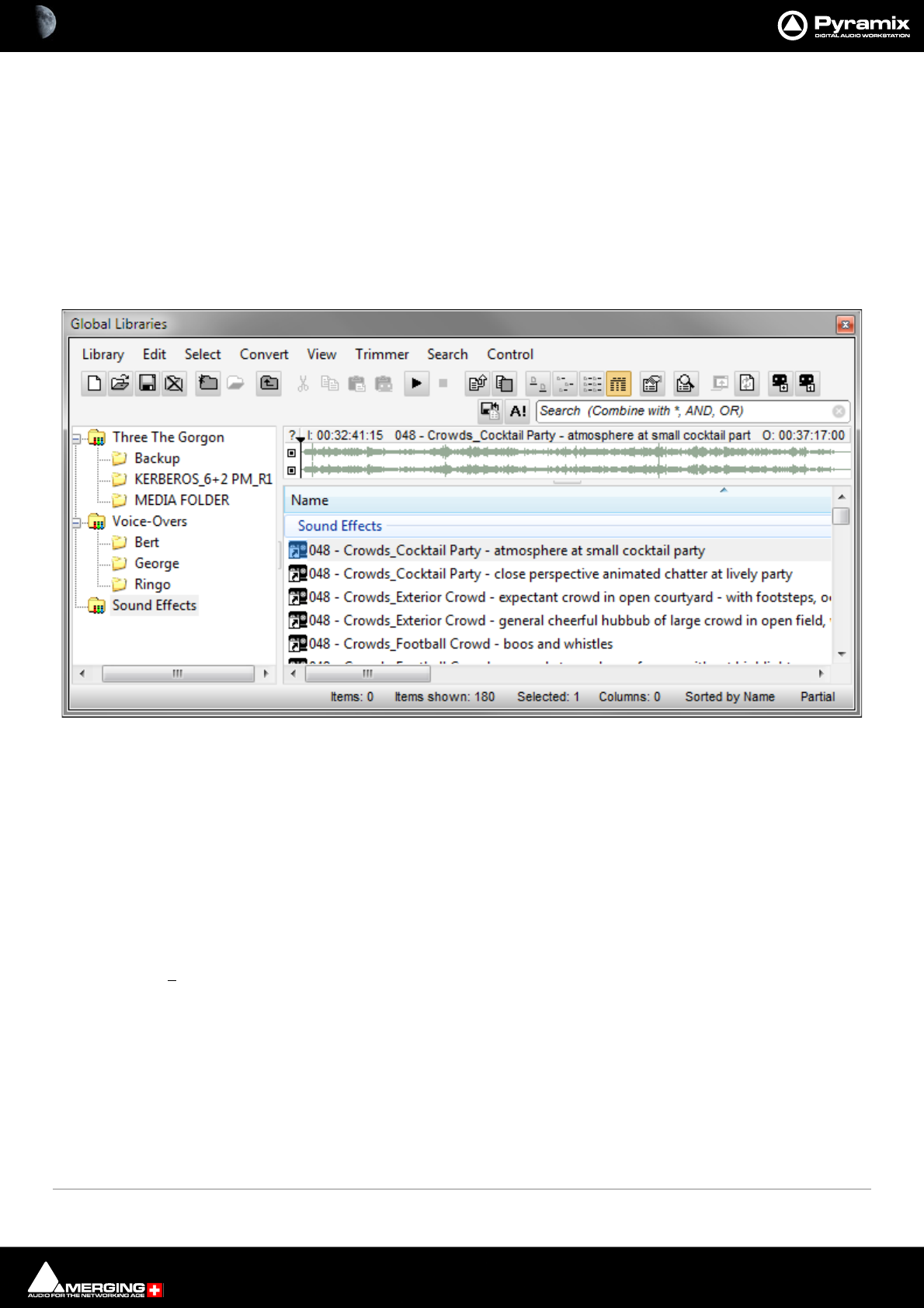
Media Management & Libraries : Library Tab Windows 4 - 86
Library Tab Windows
Document and Global Libraries
There is no real difference between Document libraries and Global Libraries. The distinction is an organizational
one, made to help keep complex Projects manageable and to provide security features for larger facilities. Librar-
ies designated as Global are available to all projects but can be opened and manipulated from the Document
Library window. Equally, Libraries created in the Document Libraries window can be opened in the Global
Libraries window.
The default Project Library created with every Project is stored with the Project. It can still be opened in the Global
Libraries window by locating the .PMX project file in the Project’s Media Files sub-folder.
The left hand pane shows Libraries and Shelves associated with the project. The contents of the selected Library
or Shelf is shown in the right-hand pane with information about the objects in columns. Shelves are displayed at
the top with individual library items below. Clicking on the + or - signs in the left-hand pane expands or collapses
Libraries and Shelves.
Libraries allow Drag & Drop operations from the Library content (right side window) to the Library/Shelf tree hier-
archy (left side window).
Library Menus
Library Menu
The Library menu allows new Libraries and Shelves to be created and existing ones to be opened and saved.
When a library is opened the media used by MasterClips/Compositions may not be mounted, (E.g. on a remov-
able drive). Mount Referenced Media automatically mounts the most recent location where these media were
found
New Library Create new user library in a mounted folder
Open Library Open existing user library
Save Library As Save a copy of the current library with a new name or in a new location
Save Library As 7.x Save a copy of the current library in Pyramix 7.x format for maximum compatibility
Close Library Close current library Shift + Click closes all open Libraries
Global Libraries Tab floating Window
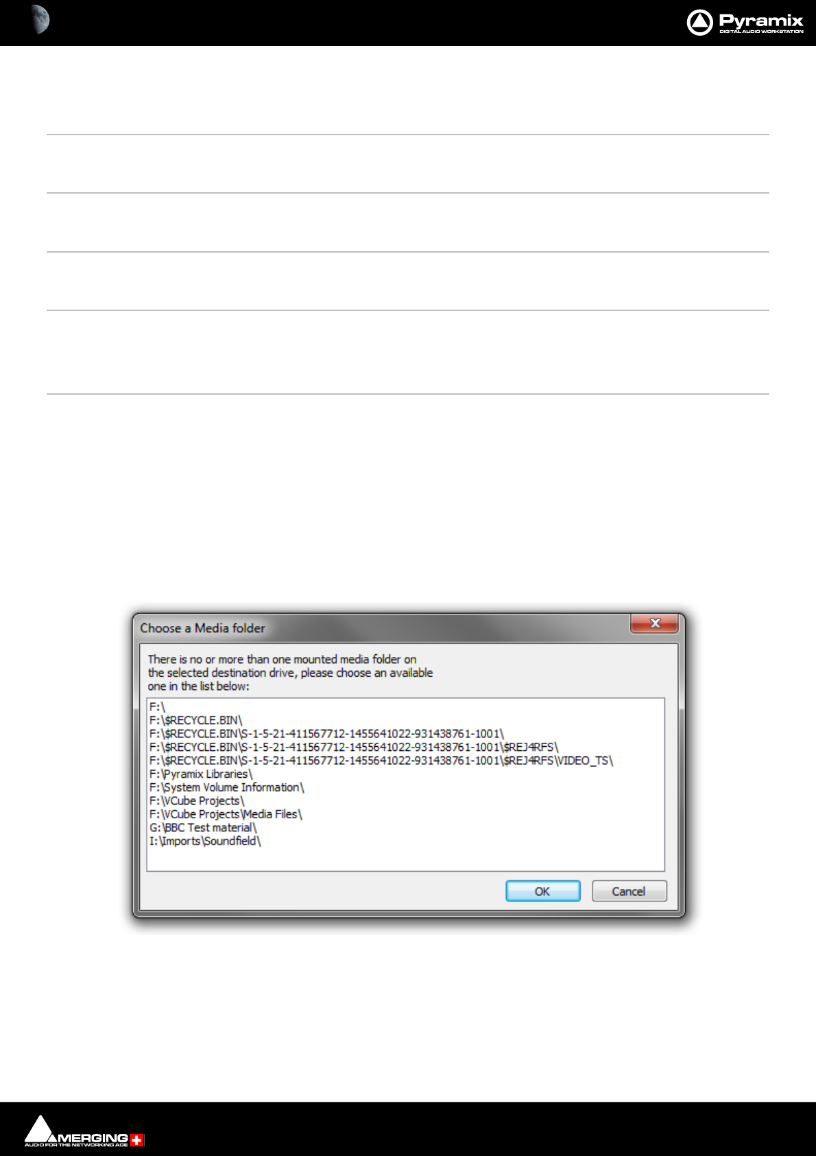
Media Management & Libraries : Library Tab Windows 4 - 87
Mount Referenced Media Automatically mounts the most recent location where media in the current project were
found
Update Referenced Media Paths To update a library, mount all the media folders involved then select this menu item
Import MTInterchange XML Opens the Import MTInterchange XML Browser Window
Export to MTIntercange XML Opens the Export MTInterchange XML Browser Window
Import MTInterChange XML Opens a File Browser to locate the XML file you wish to import
Export to MTInterChange XML Opens a File Browser to select a folder for exporting an MTInterchange XML
Import OMF Library (Avid Bin) Opens a File Browser to locate the OMF Library you wish to import
Export to Akai DD-Series No longer available
New Shelf Adds a new Shelf (folder) in the current Library or Shelf
Open Shelf Opens selected/highlighted Shelf
Up One Level Moves right-hand pane display up one level in the hierarchy
Properties Pops up a window showing the Properties of the currently selected object
Edit Menu
Cut Cuts Object from pane. Object will be deleted unless pasted elsewhere.
Copy Copy object
Copy Trimmer Selection As it says
Paste Paste object (Media is preserved at its current location)
Paste with Media When more than one Media folder or no Media Folders are mounted this opens the
Choose a Media Folder dialog.
Select a suitable folder and click on OK to complete pasting the object complete with a
copy of the associated Media files to the target directory path chosen in the pop-up.
Click on OK to complete the Paste with Media Files
Library Edit menu Paste with Media - Choose a Media Folder dialog
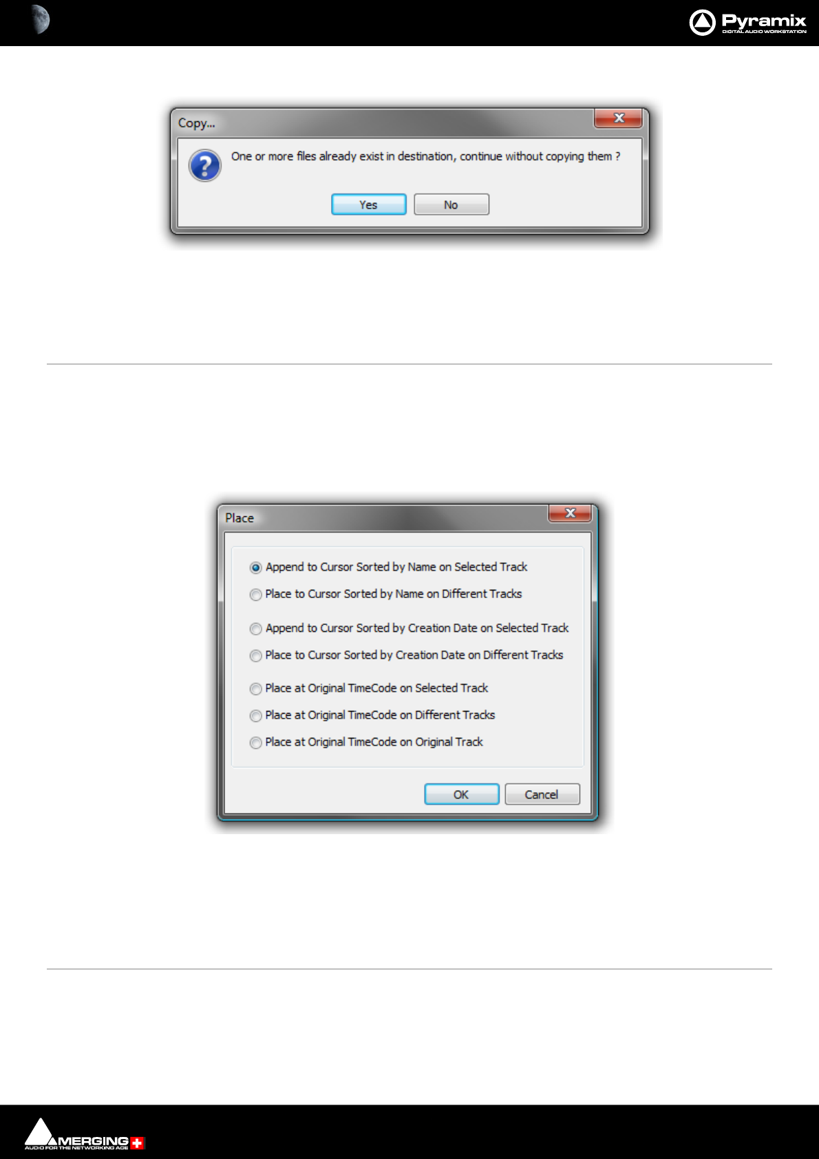
Media Management & Libraries : Library Tab Windows 4 - 88
If one or more of the Media Files already exist in the chosen destination a dialog pops-up :
Click on Yes to complete the Paste Click on No to abort the operation.
Rename Rename object
Lock Rename When ticked Locks all objects in the library for Renaming. Do you really want your Sound
Effects Library entries to be renamed by anyone who can access it?
Open/Audition/View Opens highlighted (selected) Clip or Composition in the Trimmer and begins audition
play. Opens highlighted (selected) Shelf
Audition Opens highlighted (selected) master Clip in the trimmer and begins audition play.
Stop Audition Stop audition Play and return Cursor to beginning
Place Opens the Place dialog:
The selected object(s) will be placed in the Timeline according to the rule chosen here.
The selected object will be placed in the timeline on the selected Track and Playhead Cursor position at its Sync
Point or, if no Sync Point has been set, at its In Point
Placement Tool Opens the Placement Tool for placing the object. Please see: The Placement Tool on
page 195
Library Edit menu Paste with Media - Choose a Media Folder - Copy... dialog
Library Edit menu Place dialog
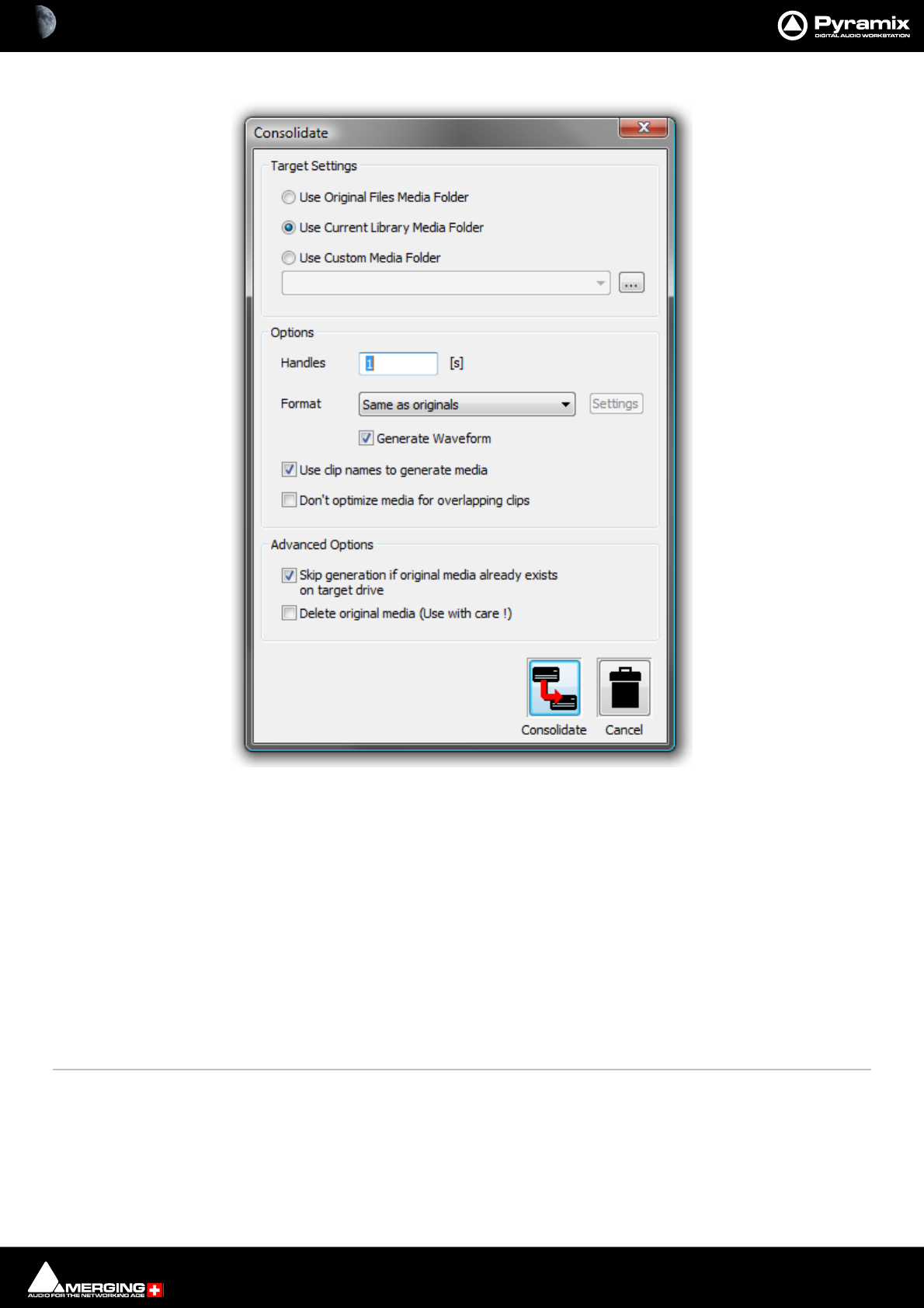
Media Management & Libraries : Library Tab Windows 4 - 89
Consolidate (Libraries only) Opens the Consolidate dialog.
The Consolidate function makes a selective backup of the media segments in the selected object. I.e. instead of
backing up the whole of every media file referenced by the Clips in a composition, Consolidate backs up only
those parts of the media files that are referenced by the Clip segments in the Composition. Extra media, beyond
the Clip boundaries can be added using the Handles option. This allows further manipulation of the Composition
within the limits of the handle length.
Please see also: Consolidating Projects on page 449
Collect Selected Media to current Project Media Folder Copies all selected media to the current Project Media Folder.
Select Menu
Select All Selects all objects in the right-hand pane (Ctrl Click toggles selection of individual
objects)
Invert Selection Selected objects are de-selected, unselected objects are selected
Select Media Present on current Project Media Folder Selects any Media file(s) shown in the right-hand pane that are pres-
ent on the current Project Media Folder.
Select Media NOT present on current Project Media Folder Selects any Media file(s) shown in the right-hand pane that are
not present on the current Project Media Folder.
Libraries Edit menu Consolidate dialog
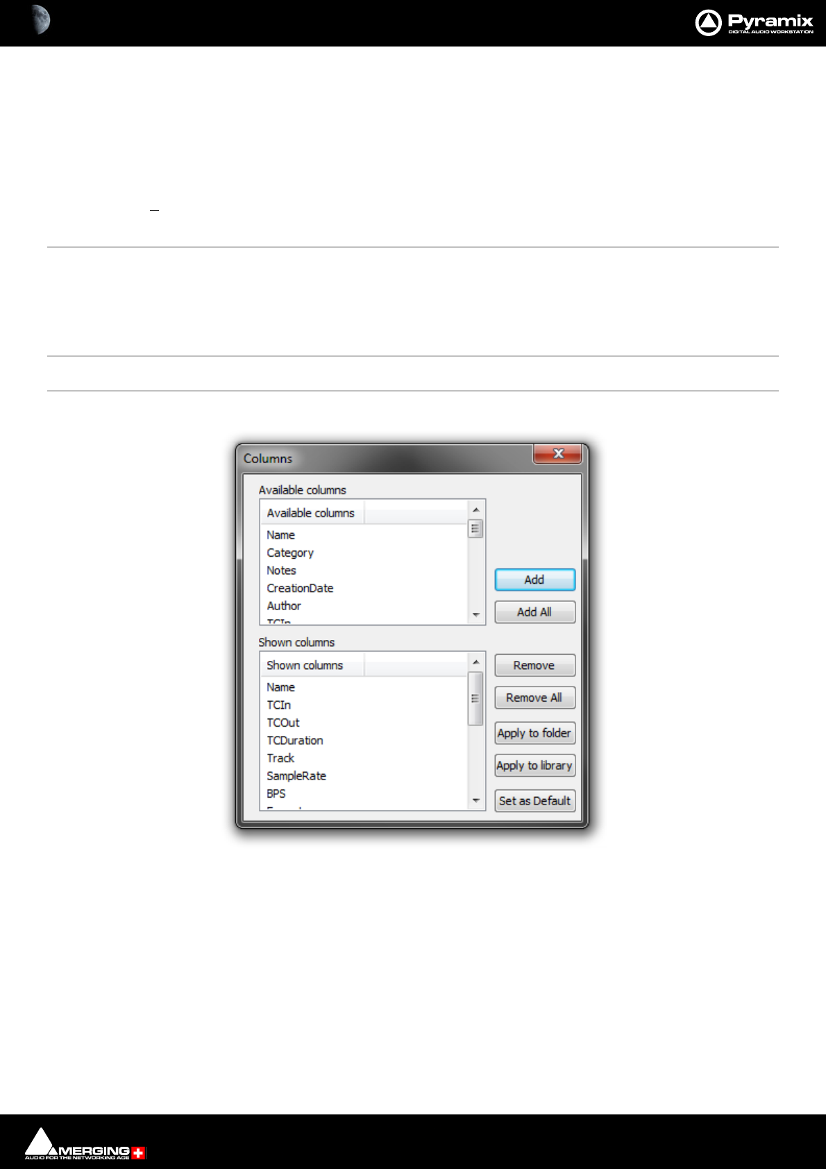
Media Management & Libraries : Library Tab Windows 4 - 90
Convert Menu
Export Masterclips This is similar to Quick Export in the Media Manager but is also available in Libraries. It
enables selected Shelves and Media Folders to be exported. Their complete/recursive
folder structure is exported. Only Masterclips/Media are exported. Compositions or any
other objects in Libraries are not exported.
View Menu
The View menu determines how information is displayed.
Status Bar Turns the Status bar on and off
Large Show large Icons
Small Show small Icons
List Show as list
Detail Show as list with details
Filters Adds Filter term entry boxes above each column in the view
Options Opens the Columns dialog box:
The dialog box shows two lists, Available Columns and Shown Columns.
Available Columns buttons:
Add Adds the column(s) selected to the Shown columns list
Add All Adds All the available columns to the Shown Columns list
Shown Columns buttons:
Remove Removes the column(s) selected from the Shown columns list
Remove All Removes all column from the Shown columns list
Apply to Folder Applies the changes made in this dialog to the current Folder
Apply to library Applies the changes made in this dialog to all Folders in the current Library
Libraries View Menu Options - Columns pane
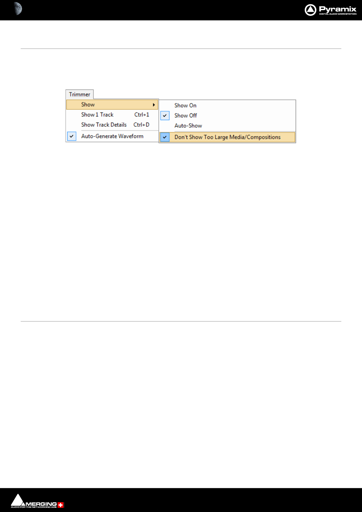
Media Management & Libraries : Library Tab Windows 4 - 91
Set as Default Sets the changes made in this dialog as the default column content for all Folders
in all Libraries.
New Window Opens a new Library Window empty
Refresh Forces a refresh
Trimmer Menu
Show
Show On When ticked the Trimmer is visible
Show Off When ticked the Trimmer is hidden
Auto-Show When ticked the Trimmer is only shown when a Media file is selected
Don’t Show too Large Media/Compositions When ticked Large Media files and Compositions will not be
opened in the Trimmer.
Note: When this option is selected Media or Compositions with more than 16 Tracks or more
than 100 Clips will not be shown in the Trimmer. Selecting this option avoids the loading time
associated with Compositions containing a large number of Clips.
Show 1 Track Show only the first Track of the object displayed in the Trimmer. When this option is
selected Up and down arrows appear at the left of the Trimmer Track display which
enable any Track to be displayed.
Show Track Details The following information is displayed for each Track of the selected Media file:
•Track Name
• Track Number
• Track Type (left, Right, Center etc.)
• Track File Name (If the Media is recorded in One File Per Track mode)
Auto-Generate Waveform Waveforms are automatically created for objects without them.
Search Menu
Add to Search Results Creates a new Search Results folder named by date and time and the search term(s).
Exact Word Match When ticked result will only show exact matches.
Media Manager Trimmer Menu

Media Management & Libraries : Library Tab Context Menu 4 - 92
Control Menu
Provided mostly for use with hardware controllers.
Folders >
Up Moves the focus up one step in the tree.
Down Moves the focus down one step in the tree
Collapse Collapses the current branch
Expand/Focus on List Expands current selection/Shifts focus to list
List >
Up Moves the focus up one step in the list
Down Moves the focus down one step in the list
Focus on Folders Shifts the focus to the Folders level
Focus on Trimmer Shifts the focus to the Trimmer
Trimmer >
Focus on List Shifts the focus to the list
Play from In Play from In marker in Trimmer
Play from Start Play from In marker in Trimmer
Stop Play from In marker in Trimmer
Set In Play from In marker in Trimmer
Set Out Play from In marker in Trimmer
Set Sync Set Sync Point on Clip in from In marker in Trimmer
Library Tab Context Menu
Right-clicking on an object (or a blank area) in the file list in a Library Tab opens a context menu with the following
entries:
New Shelf
Open Shelf
Cut
Copy
Paste
Paste with Media
Rename
Open/Audition/View
Place
Consolidate
Properties
These functions are the same as those which can be found in the Library Tab Menus. Please see: Library Menus
on page 86

Media Management & Libraries : Offline / Reference Libraries 4 - 93
Offline / Reference Libraries
As the name implies Offline/Reference Libraries are useful for keeping track of very large projects and material
on media that may not be permanently on-line.
Creating Offline/Reference Libraries
Offline libraries are created in the Media Management Tab Window by selecting
Media Folder > Create Offline/Reference Library.
This will open a standard Windows browser.
Navigate to the location you wish to save the library in.
Type a name for the new Offline Library and Click on Save.
Note: The Folder(s) currently mounted in the Media Management frame, the Media Files it con-
tains, its sub-folders their Media File contents will be added to the new Offline Library.
Using Offline/Reference Libraries
When used in the following manner Offline Libraries provide an extremely powerful organizational tool for man-
aging very large project libraries and, for example, sound effects libraries.
Mount The Media
In the Media Management Tab Window, Mount all folders or disks containing your audio files (as ripped with
LibraryLoader, mTools or any other source). We strongly suggest these files be in either PMF or BWF (Broadcast
Wave Format) as they both have a long description field, a unique identifier and a timestamp.
Note: There may well be Copyright implications when working with ripped files. Please ensure
you comply with any restrictions on copying other people’s material.
Create An Initial Library
Open a Media Folder you wish to include in the new Library and follow the above procedure to create the new
Offline Library
The library can now be re-organized, Folders and Shelves created, items duplicated etc. etc.
You can make searches (queries) or apply filters to your Offline / Reference libraries) and, if Media > Auto-mount
Media is on, each time an item is dragged onto the Timeline the appropriate audio file will automatically mount.
Or this can be done this manually by calling Media > Mount Referenced Media.
Updating Libraries - Orphaned Entries
If the original audio files are moved or reorganized, just mount all the folders once again, load all your libraries and
call the Library menu command Update Referenced Media Paths.
Media / Timeline Linkage
It is important to note that the link between the Timeline and the media is made using unique ID’s in the files. This
means that if multiple files with the same name, with no unique ID (WAV for example) are available in various loca-
tions, then Pyramix will not be able to distinguish between them when all the folders are mounted. The Timeline
will attempt to reference any and all of the instances of the file, meaning that the media shown in the Timeline
may well not be the desired instance. I
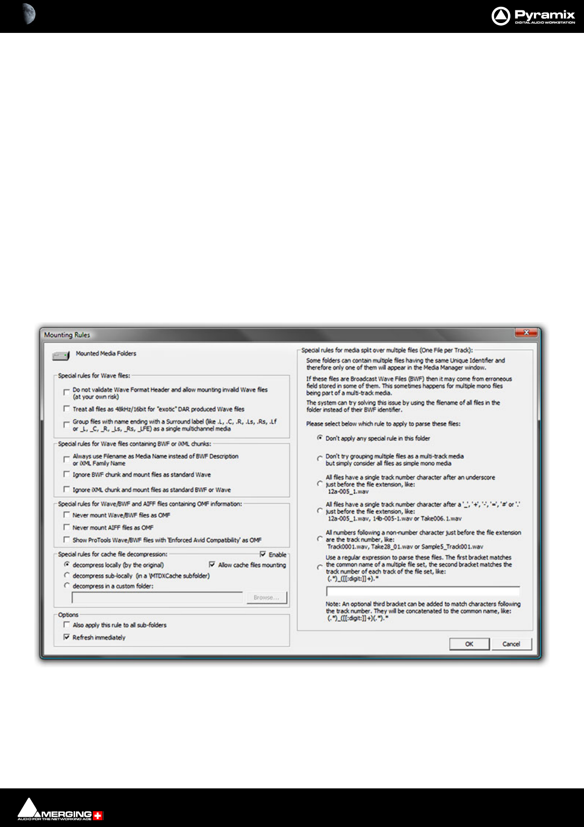
Media Management & Libraries : Mounting Rules 4 - 94
Mounting Rules
This dialog allows various rules to be applied when parsing BWF or Wave files in a given folder. Pyramix always
tries to group multiple mono files that are part of a single multi-track media when viewed in the Media Manager
so the multiple mono files appear as a single item with multiple tracks numbered in the form A 1-2 or A 1-8, or A 1-
2, 7-8, etc. Otherwise, you would see a separate entry for each mono file whether or not it is part of a multi-track
'set'. In order to achieve this in the case of BWF files Pyramix looks at the BWF header and uses the Originator Ref-
erence field as a Unique Identifier with some rules as defined by the EBU organization and some conventions
adopted between various manufacturers.
It may happen that some files do not follow these rules and therefore sometimes the Pyramix Media Manager fails
to properly mount these files. Sometimes some files are missing, or some tracks within a multi-track media are
missing. The Pyramix Media Manager detects these conflicts at the time the folder is mounted and informs the
user of such a problem, prompting him to go to the Media Manager > Drive > Mounting Rules menu item. The
Mounting Rules dialog allows a variety of different rules to be applied for this or these Media Folders so all files
are properly mounted.
Folders where a conflict has been detected appear in Red.
Folders where a special Mounting Rule has been applied appear in Dark Green.
The Mounting Rules dialog can be found in the Media Management Tab window in the Media Folder menu :
Media Folder > Mounting Rules
Most of the dialog is self-explanatory. The description of the Rules that can be applied appears in the Mounting
Rules dialog as above but for convenience, we have also listed the options on the left of the dialog below.
Special rules for Wave files
Do not validate Wave format Header and allow mounting invalid Wave files (at your own risk)
This can enable files to be mounted that do not follow the Wave specification strictly.
Mounting Rules dialog

Media Management & Libraries : Mounting Rules 4 - 95
Treat all files as 48kHz/16bit for ‘exotic’ DAR originated Wave files
As it says. Please see DAR WAV file Import on page 95
Group files with name ending with a surround label (like .L,. C, .R, .Ls, .Rs, .Lf or _L, _C, _R, _Ls, _Rs,
_LFE) as a single multichannel media
As it says. Useful when working with files generated by certain other DAWs.
Special rules for Wave files containing BWF or iXML chunks:
Always use Filename as Media Name instead of BWF Description or iXML Family Name
This will allow files recorded in Steinberg’s Nuendo to be mounted and can also help with (re)conforming files
from Aaton Cantar or other location recorders where the filename matches information in the EDL.
Ignore BWF chunk and mount files as standard Wave
This effectively treats Broadcast Wave files as ordinary Wave files and can help with (re)conforming as above.
Ignore iXML chunk and mount files as standard BWF or Wave
This treats iXML files as pure Wave or BWF with the same aims as above.
Special rules for Wave/BWF and AIFF files containing OMF information:
Never mount Wave/BWF files as OMF
Never mount AIFF files as OMF
Show ProTools Wave/BWF files with ‘Enforced Avid Compatibility’ as OMF
Special rules for cache file decompression
When compressed audio files are mounted Pyramix creates an uncompressed WAV version of the file(s) in a cache.
The location of these cache files is determined by this dialog.
Locally (by the original) File(s) will be created in the same location as the original file.
Sub-locally (by the original, in a \MTDXCache sub folder). File(s) will be created in a sub folder created by Pyra-
mix in the same location as the original file.
Custom (files are generated to the specified location). File(s) will be created in a user specified location. When
this option is selected the Browse... button is available to open a file browser window to set the user defined path.
Enable enables the rule.
Allow cache files mounting when ticked, cache files can be mounted directly, otherwise they remain invisible, i.e.
filtered out of Media Manager views.
Options
Also apply this rule to all sub-folders
Refresh immediately
DAR WAV file Import
It seems that DAR systems were strange in that they always played audio at 48khz. Even if 44.1khz audio
was imported into a DAR, it would be converted to 48khz. The sample rate and bit-depth information in
the WAV files was ignored as everything was assumed to be 16-bit/48khz. We've seen WAV files from
DAR systems where the WAV files were identified as containing 128-bit audio or having a 10hz sample
rate. So it would seem there must have been a bug in the DAR software that caused incorrect data to be
stored in the WAV header. There is already code in the Pyramix WAV handler to try to catch these com-
pletely invalid parameters but, unfortunately, the WAV files from DAR don't include any manufacturer
identifier so it isn't simply a case of identifying that they are from a DAR and automatically forcing them
to 48khz in Pyramix.

5 - 96
www.merging.com/Pyramix
USER MANUAL
Tracks and Track Groups
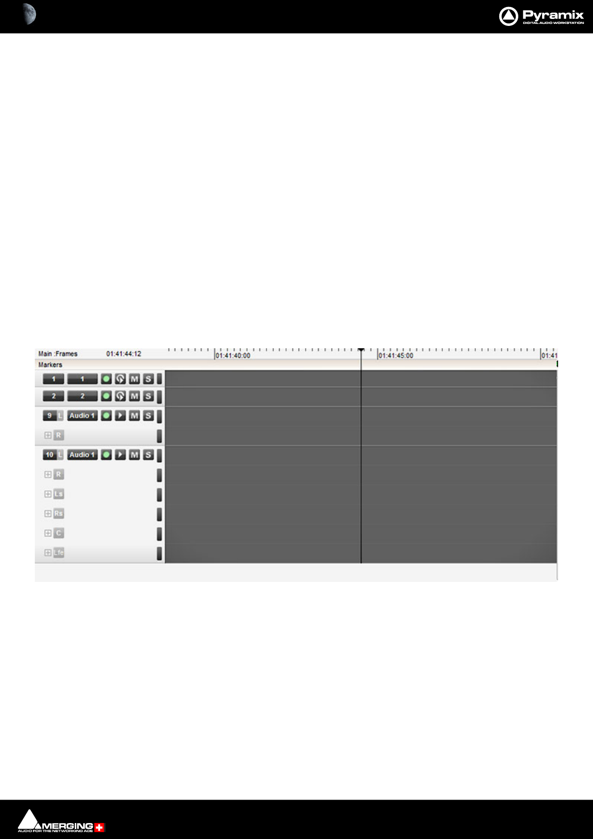
Tracks and Track Groups : Tracks 5 - 97
Tracks
Each Project has a user defined number of audio Tracks on which audio Clips can be placed, or audio inputs can
be recorded. Blocks representing placed or recorded Clips will appear on the Track as soon as a Clip has been
placed or recorded onto it. The Track itself extends horizontally beneath the Time Scale bar, and multiple Tracks
are stacked vertically.
Where appropriate a Video Track or Tracks can also be added. Please see: Video Tracks on page 526.
On the left side of each Track is a Header panel with various controls and information displays. Please see: Track
Header Panel on page 102
Some operations only apply to a selected Track. A Track can be selected by left-clicking anywhere on the Header
which will then appear in a darker shade of gray. You can also select a Track by clicking on a blank Track area. How-
ever, when selecting a Track, be careful NOT to inadvertently click on any of the Track buttons, thereby changing a
Track function: the Track Name or a blank area are good places to click in order to select.
Track Numbering
Tracks are numbered according to the Mixer Strip they are connected to. So, in a project using Mono Mixer Strips
exclusively, if there are 10 Tracks they will be numbered 1-10.
Where there are Stereo Mixer Strips or Multi-channel Mixer Strips then, whilst each channel is on a separate Track,
both Tracks of a stereo pair are numbered the same, together with a suffix to indicate each channel type. The same
applies to multi-channel. As shown here:
Adding Tracks
By default, a new Project opens with the same number of Tracks as there are Input Channels defined in the
Mixer for the Project. However, Tracks can easily be added or deleted.
Creating Tracks via Paste
If a Clip or Composition is dragged and dropped or copied and pasted from Media Management or a Library onto
a blank area of the TimeLine where no Tracks exist, sufficient Tracks will be created below the last existing Track to
accommodate the number of Channels in the Clip or Composition.
Track numbering - mono - stereo - multi-channel
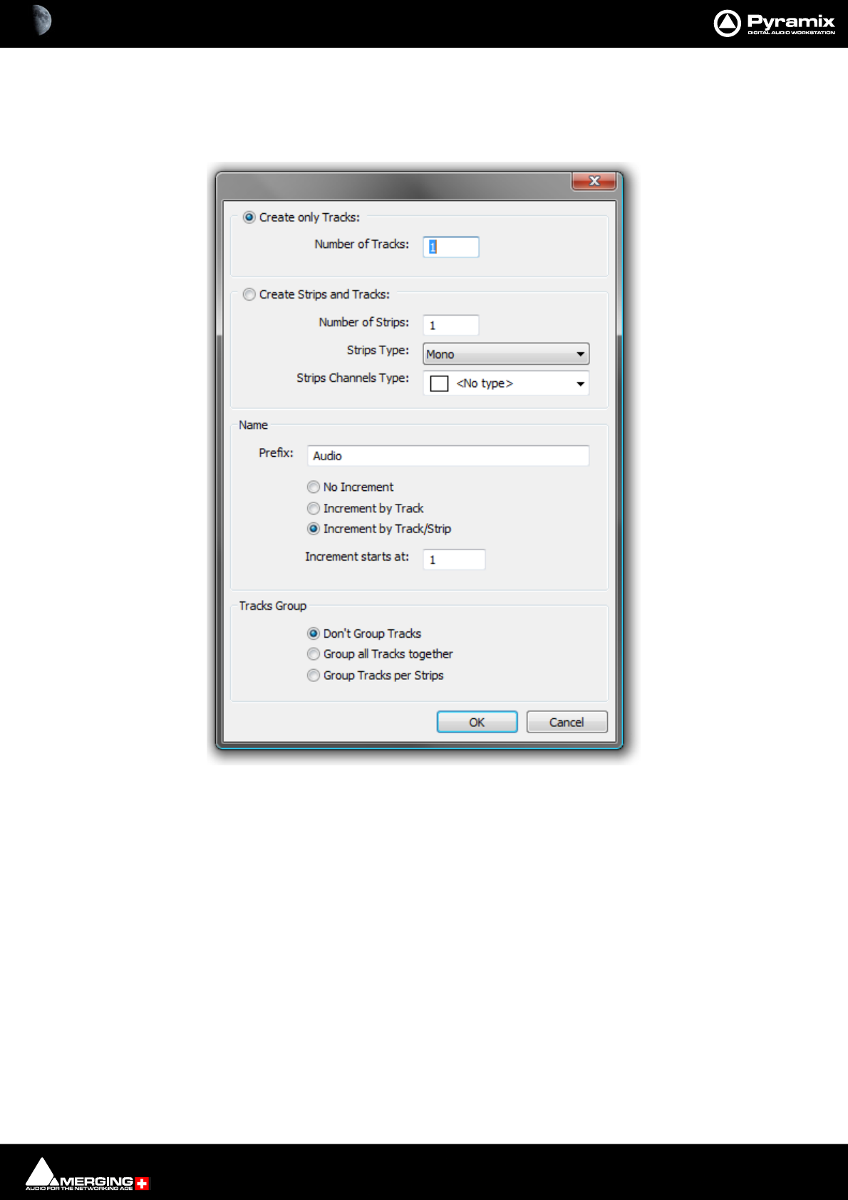
Tracks and Track Groups : Tracks 5 - 98
Create New Tracks
New Tracks are inserted below the currently selected Track or, if no Track is selected, at the bottom after the last
existing Track. To add Tracks to the Timeline, select Tracks > New Audio Track (or right-click in a blank area of
the Track header and choose New Audio Track from the context menu).
Create only Tracks: / Create Strips and Tracks:
To simply create Mono Tracks only, check the Create only Tracks radio button, enter the number of Tracks
required into the Number of Tracks data entry box and click OK. The Track(s) will be created with the default
name Audio numbered in ascending order from 1.
If you wish to create Mixer strips at the same time, check the Create Strips and Tracks radio button. Enter the
number of Strips required into the Number of Strips data entry box. Pyramix currently supports four categories of
Strip. The default is Mono.
Create New Tracks dialog
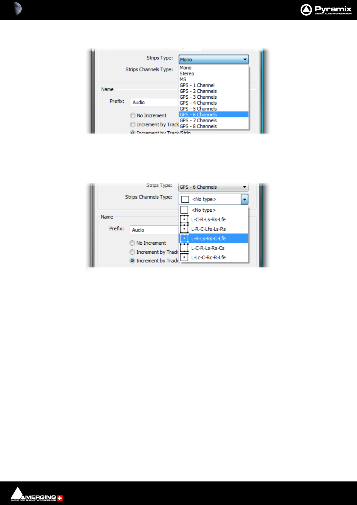
Tracks and Track Groups : Track Types 5 - 99
Other types of strip can be selected from the Strips Type drop-down list.
If you choose anything other than Mono the appropriate number of Tracks will be created to suit the chosen strip
type. The strip inputs and outputs will be ‘tagged’ with a letter or letters indicating channel assignments depend-
ing on the choice made in the Strips Channels Type drop-down list.
The formats on offer vary according to the Strip Type chosen. A six channel example is shown above. As a further
example, if you choose MS. <No Type> is the only available choice and the strip I/O is tagged C and W for Centre
and Width since this is the logical format.
Track Types
Overview
In Pyramix there are two basic types of Track. Audio Tracks which can be single or multi-channel and Automation
Sub-Tracks which are a vehicle for displaying extra automation data relating to Audio Tracks. A third possibility
exists, which is to use an Audio Track to display Bus Automation.
Audio Tracks
When Multi-channel Tracks are created with a Strip Channels Type format, certain functions are automatically
linked, namely: Automation, Solo, Mute, Monitor mode, Record mode, Waveform display.
By default and to reduce on-screen clutter Stereo or Multichannel Tracks only display the full complement of but-
tons on the first channel. For example, the right-hand Track of a stereo pair will only show a pale gray + button
Create New Tracks dialog - Strips Type
Create New Tracks dialog - Strips Channels Type
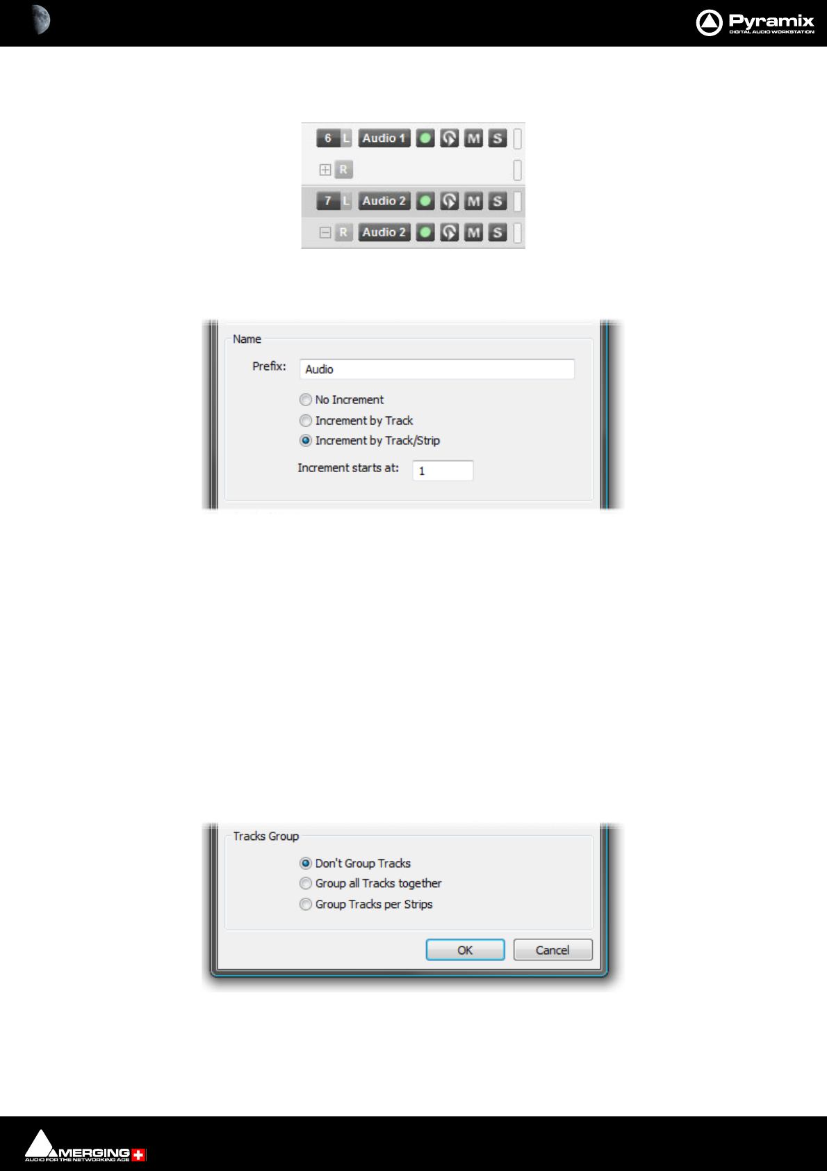
Tracks and Track Groups : Track Types 5 - 100
next to the R button. Clicking on the + button reveals the rest of the buttons in the header. The + button then
turns into a - button. Clicking the - button hides the buttons again:
Naming and Numbering
However many Tracks and Strips you decide to create, they can be automatically named and incrementally num-
bered.
If the No Increment option is chosen all Tracks created will have the same name. I.e. whatever is entered in the
Prefix: text entry box and no number.
If the Increment by Track option is chosen, each Track will be named using the text entered in the Prefix: text
entry box and numbered incrementally. E.g. If you enter say, Atom and add two 5.1 GP strips in L-C-R-Ls-Rs-Lfe for-
mat, six Tracks are added. If the Increment starts at: number is set to, say 33 then all the Track names will all be
Atom 33 as will the Strip name.
If the Increment by Track/Strip option is chosen in the above example then the Tracks will be named Atom 33,
Atom 34 to Atom 38 and the Strip will be named Atom.
Tracks Grouping
There are three options:
Don’t Group Tracks leaves the new Tracks ungrouped.
Group all Tracks together groups all the new Tracks in a single group.
Track Headers - Stereo
Create New Tracks dialog - Name
Create New Tracks dialog - Grouping

Tracks and Track Groups : Synchronized Creation/Deletion of Tracks/Strips 5 - 101
Group Tracks per Strips groups the Tracks as they are assigned to strips. E.g. 12 Tracks assigned to two 5.1 strips
would be grouped as two six-Tracks.
Synchronized Creation/Deletion of Tracks/Strips
Note: When Creating, Deleting or Moving Strips in the Mixer Configuration page (or with the
right mouse button context menus) the connected Tracks are also Created/Destroyed or moved
accordingly.
• This behavior will apply when the Tracks > Synchronize Tracks & Strips is checked.
• When Strips are Created or Moved the Tracks are Created or Moved seamlessly.
• On Deleting a Strip or Strips, only empty Tracks are destroyed. Tracks containing Clips are preserved, dis-
connected and set to minimum size.
Deleting Tracks
Single Track
To delete a Track, first select the Track to delete. Then choose Tracks > Delete from the Project window pull-
down menu. The Track and all Clips placed on it will be deleted. Note that only the Clip or pointer will be deleted,
not the original Media File.
Multiple Tracks
You can also delete all Tracks from the selected Track to the last (highest number) by selecting Delete to Last
instead of Delete.
You can also right-click in the Track Header to add or delete Tracks.
Routing Tracks to / from the Mixer
When you create a Mixer, Pyramix will automatically create the same number of Tracks as Mixer Input Strips
(channels).
If Connect automatically as many inputs and outputs as possible is checked, Pyramix will attempt to automat-
ically route the output of each Track Channel to a corresponding Mixer input Channel, so that with mono Tracks
Track 1 outputs route to Mixer Strip 1 input, Track 2 to Mixer Strip 2, etc.
Similarly, Pyramix will attempt to automatically route each Mixer Strip Channel output to a corresponding Track
input, so that Mixer channel 1 output routes to Track 1 input, Mixer channel 2 to Track 2, etc.
With Stereo Tracks Track 1L and Track 1R Channels will be routed to Mixer Strip 1 by default, Mixer Strip 1’s out-
puts will be routed to Track 1L and Track 1R and so on.
So a 5.1 Multi-channel Track connected to a 5.1 Mixer Strip will be connected to the six channels according to the
Strips Channels Type scheme selected in the Mixer creation wizard or in the Add Tracks dialog.
These default Track I/O assignments can easily be changed by the user by right-clicking on the Main Mixer Strip
Number in a Mono Track or the L and R buttons in a stereo Track or the LCRLsRsLfe buttons in a 5.1 Multi-Channel
Track. Please see also: Adding Strips on page 277
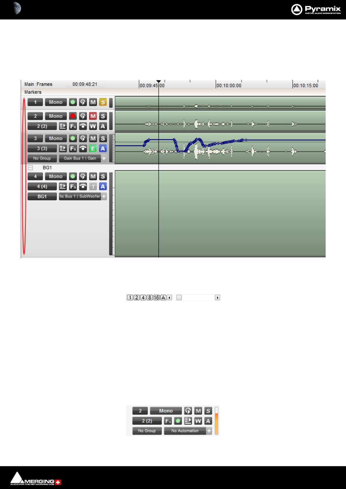
Tracks and Track Groups : Track Display Height 5 - 102
Track Display Height
Individual Presets
Double-Clicking in the blank area of the Track header to the left of the Strip number (highlighted in red below)
cycles through four preset Track heights. Mini, Medium, Large and Extra large :
Global Track Display Height
1, 2, 4, 8, 16, and A buttons at the bottom left of the Project Editing Panel automatically scale the vertical Track
size so that 1, 2, 4, 8, 16 or All (as many as possible given the vertical space) Tracks fit in the vertical space allocated
to the Project Editing Panel.
The horizontal Scrollbar adjacent to these buttons enables continuous adjustment of the Track height.
Shift + Mouse Scroll Wheel also adjusts Track height.
Track Header Panel
The Track Header Panel contains a number of buttons and information fields.
Preset Track Heights
Track Height Controls
Track Header Panel
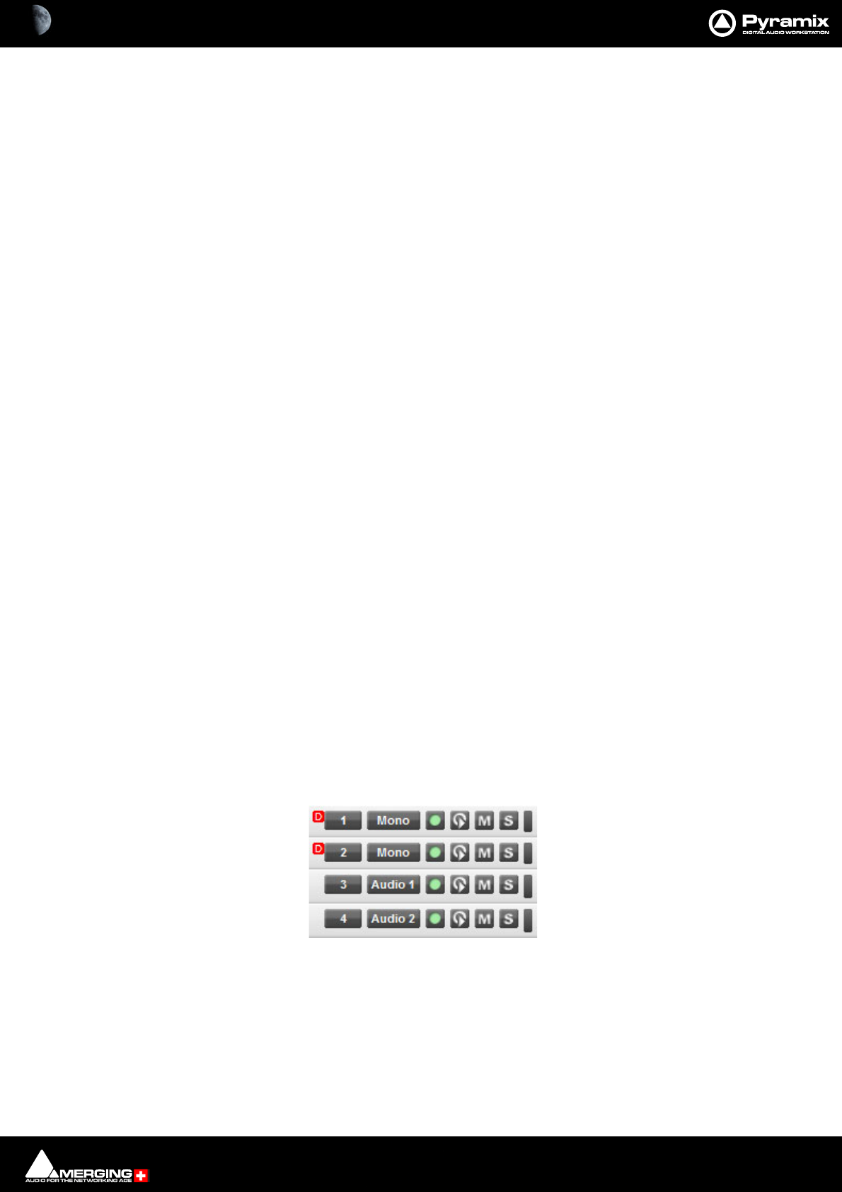
Tracks and Track Groups : Track Header Panel 5 - 103
In the top row of a Mono Track Header or, by default, in the first Track of a multi-channel Track object, the first
button at top left indicates the mixer strip the Track is connected to. Clicking on this pops up a list of all the Chan-
nels of all the Strips in the current Mixer plus None. Clicking on any Mixer Strip Channel in the list connects the
Track’s output to it.
The next button is the Track Name. Click on it to type in a new name.
The box with the red number in the second row shows the input currently connected. Click on this to pop up a list
of all possible inputs. Click on an input in the list to connect it.
To change a Track Input or Output assignment, just click on the corresponding Track input or output box, then
select the appropriate Mixer channel or Input number from the corresponding pop-up list. If the Input assign-
ment is changed in the Track Header, this change is reflected in the strip and vice-versa.
When Track inputs and outputs are not assigned, the corresponding boxes for that Track will show no input and
Off instead of numbers.
Multiple Tracks can be assigned to the same Mixer channel. They are therefore sub-mixed (summed) before enter-
ing the Mixer. This allows more Tracks to be played than the number of Mixer channels.
Many Tracks can be fed from the same physical input.
Track Control Grouping
Where the Mixer Strip is multi-channel, Tracks are grouped into Multi-Channel Track groups. By default, only the
first Track in such an object shows the full complement of Track Header controls. The other Tracks just show the
channel assignment, e.g. R, C, Ls, Lfe etc. and a small [+] button. Clicking this button shows the full complement of
Track Header controls.
Button Grouping
Buttons in Multi Channel Track are linked by default. First by Track Group then by Mixer Strip. This behavior can be
modified as follows:
No Modifier Auto linked by Track Group then by Mixer Strip.
Ctrl Bypasses all linking
Shift Affects all Tracks
Ctrl + Shift Bypasses Track Groups but still follows the Strip. (Useful when Multi-Channel
Strips/Tracks are grouped.)
Scroll Wheel Affects Track height.
Tracks Feeding Direct Monitoring Input Strips
Track returns to these strips do not have automatic delay compensation applied and are intended for monitoring
only. When mixing down the Track outputs should be connected to ‘normal’ strips. To indicate this clearly, Tracks
feeding Direct Monitoring Input Strips show a small red box with ‘D’ in the header:
Track Header Direct Monitoring Indicator
Tracks and Track Groups : Track Header Panel 5 - 104
Track Header Components
Overview
The Track Header consists of a number of buttons and information displays spread over from one to three rows.
Buttons used most frequently are arranged in the top row so that, when only one row high, they remain visible.
If the Track is a member of a Track Group then a toggling - / + button is shown, together with the Track Group
name, in the Track Group separator area above the header.
Expand Track Group
Collapse Track Group - Alternate state of Expand Track Group.
Components
First Row
The number on the top-left button shows the number of the Mixer Strip Channel its output is
assigned to. Clicking this icon pops up a list to select from all available Mixer Strip Channels.
If the button shows a Off, no Mixer Strip Channel is selected and recording and or replay is
not possible.
Where the mixer strip is anything other than mono a channel identifier is also shown. All
Tracks are numbered in this way in ascending mixer Strip order.
Note: If the small red D symbol is visible to the left of the Strip number then the Track is feeding
a Direct Monitoring Input Strip - Therefore automatic delay compensation will not be applied.
Patch Track to a ‘normal’ Input Strip for mix down etc. The symbol is also displayed when the Track
is feeding an Input Strip with an Internal Bus Return Input. A Strip fed from an Internal Return
Bus will NOT be fully Delay Compensated when in Auto-Monitoring mode and when in Repro
mode the red ‘D’ will be appear to indicate that automatic delay compensation will not be
applied. On the other hand, recorded material will be Compensated correctly and in sync with
the current timeline events.
The name button defaults to the Track type. Click on the button to type a new name in the
field.
The Record icon has three possible states.
Record Safe and Record Ready are toggled by left-clicking the icon. AutoPunch Ready is enabled / disabled
by holding down the ALT key while left-clicking the icon.
Record Safe - no recording possible.
Record Ready - Recording commences when the transport Master Record button is pressed
and finishes either when the Stop button is pressed, or when the Play button is pressed.
Track Header Components
Tracks and Track Groups : Track Header Panel 5 - 105
Autopunch Ready - Recording commences when the previously set Record In point is
reached and finishes when the previously set Record Out point is reached.
The Monitor icon has three possible states.
These are toggled by left clicking the icon.
Auto - monitoring switches the associated Mixer channel input automatically between input
and repro. Behavior depends on the Auto-monitoring section setting in the Settings > All
Settings > Application > Playback/Record page. European Monitoring (All Tracks turn to
INPUT on stop) OR US Monitoring (Only Record Ready Tracks turn to INPUT on stop)
Repro - The associated Mixer channel is always fed from the Track replay.
Input - The associated Mixer channel is always fed from the Track’s selected Input source.
The Mute icon toggles the Track Output between Un-Muted, as shown here;
and Track Output Muted, as shown here.
The Solo icon toggles the Track Output between Solo off, as shown here and;
Solo active as shown here.
Peak Meter - If the Peak Meter is visible on the far right of the Track Header, clicking on it
hides it. If not visible, clicking in the space where it should be unhides it.
The meter scales with the Track height.
Meter parameters follow the settings made in Settings > All Settings > Mixer > Level Meter.
Automation Scale - If Automation display is switched on, a scale appropriate to the control is
shown to the right of the meter.
Second Row
Input source - the first number shows the absolute number of the selected record input.
The second number in brackets shows the input number within the physical or logical input
block. When this area shows a No Input no record input is selected. This can be also set
directly in the Mixer Console window.
Playlist opens this menu:
Please see: Playlists on page 643
Playlist popup menu
Tracks and Track Groups : Track Header Panel 5 - 106
Effects - Clicking this button pops up a menu:
The list shows all effects in the Mixer Strip the Track is connected to. Selecting an effect in the list opens
the control window for the plug-in.
The Always Visible icon toggles between always visible when a member of a Track Group.
(As shown here.) and:
Hidden when Auto Hide is active.
The Waveform icon has three possible states.
Display Waveform - by default shows Clips as orange blocks with white waveform superim-
posed.
Display Text - by default shows Clips as orange blocks with Text Labels without waveform.
Display Envelope - by default shows Clips as orange blocks with white waveform and adds
a black line which allows the gain to be adjusted using the mouse by simply clicking and drag-
ging.
Note: Waveform display can be conventional symmetric or Half Waveform relative to the bot-
tom of the Clip. View > Waveform Display > Show Half Waveform / Origin
Toggles automation curve display for the Track. Inactive as shown here, or
Automation curve display for the Track Active, as shown here.
Right-clicking the button pops up the automation display menu for the Track. Please
see: Track Automation Menu on page 410
Third Row
Track Group indicator and selector. Click on the button to pop-up the list of Track Groups
available. Click on an entry to select.
Track Group indicator and selector indicating that the Track is a member of the Track
Group Dial.
Automation Curve indicator and selector. Clicking on the button pops-up a list of
automatable parameters for the Track. The selected parameter curve is superimposed on the
Track and the label changes to reflect this:
Automation Curve indicator and selector. Here Fader has been selected.
Add Automation Sub-track this button is just to the right of the Automation Curve button
above. Clicking on the button pops-up a list of automatable parameters for the Track. The
Automation popup menu
Tracks and Track Groups : Track Header Panel 5 - 107
selected parameter curve is displayed in a new Automation Sub-track below the current nor-
mal Track.
The main button in the Automation Sub-track Header pops up the list of automatable parameters for the Track.
Selecting More... opens the Select Displayed Automation Track dialog with access to every automatable
parameter in the Project. (Please see: Automation Sub-Tracks on page 108)
The smaller [+] and [-] buttons on the right of the main button create a new Automation Sub-track and delete
the current one, respectively. The icon to the right indicates the number of audio channels controlled by the auto-
mation in the Sub-track.
When one or more Automation Sub-tracks exist a small blue [A] button is shown adjacent to the Strip number.
Clicking this button toggles all Automation Sub-Tracks associated with this Audio Track visible/hidden.
Automation Sub-track Header
Automation Sub-track Indicator/toggle
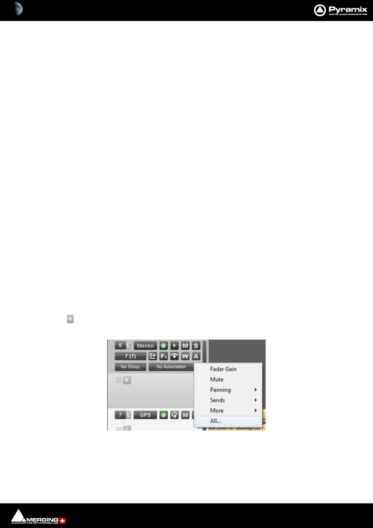
Tracks and Track Groups : Track Record Modes 5 - 108
Track Record Modes
Each Track has a tri-state Record Ready toggle button, located to the left of the Track itself in the Track Header.
Tip: Right-clicking on a Track arming button opens the Settings > All Settings window immediately on the Proj-
ect > Record page.
Play
The Green Dot in the Track Header indicates Record Safe mode, the default when Tracks are newly created.
When in this state, the Track cannot be recorded to.
Record Ready (Manual)
Click on the Green Dot once to toggle to Record Ready mode. This is indicated by the dot turning into the Red
Dot. The Track will now go into Record mode immediately when the Master Record button is pressed in the
Transport Strip or Transport window.
Record Punch In (Auto)
Alt-Click on the Red Dot to toggle to Record Punch In mode. This is indicated by a Red Dot flanked by 2 white
vertical lines. In this mode, when the Master Record button is pressed in the Transport Strip or Transport win-
dow, the Track will stay in Play mode until the current Mark In point is reached, then the Track will go into
Record mode. It will stay in Record mode until the current Mark Out point is reached.
Automation Tracks
Overview
Automation curves can be overlaid on Audio Tracks. However, there is often a need to display more than one auto-
mation parameter at the same time. (Commonly Gain, Mute and Pan). In order to accommodate this Pyramix has
Automation Sub Tracks. Similarly, there are times when it would be highly desirable to be able to display Bus
automation curves in the Timeline. Pyramix uses ordinary Audio Tracks for this purpose, Please see: Bus and VCA
Group Automation Tracks on page 110.
Automation Sub-Tracks
Add Automation Sub-track this button is located just to the right of the Automation Curve
button in the third row of Audio Track headers. Clicking on the button pops-up a list of auto-
matable parameters for the Track.

Tracks and Track Groups : Automation Tracks 5 - 109
All automatable functions can be displayed. Fader Gain and Mute can be selected directly while other functions
are grouped logically into sub-menus. Clicking on All... at the bottom of the list opens the Select Displayed
Automation Track dialog:
All automatable parameters for the entire Project are shown in a tree.
Hide Empty Tracks When ticked only Tracks with existing Automation Date will be present in the tree.
Only connected strip / bus When ticked only Strips and Buses connected are shown.
Display the selection in an extra automation sub-track When ticked a new Automation Sub-Track is created
to contain the automation curve for the selected parameter when the OK button is
clicked.
OK Confirms selection and closes the dialog
Cancel Cancels the selection and closes the dialog.
The selected parameter curve is displayed in a new Automation Sub-track below the current normal
Track.
The main button in the Automation Sub-track Header pops up the list of automatable parameters for the Track.
Selecting More... opens the Select Displayed Automation Track dialog with access to every automatable
parameter in the Project. The smaller [+] and [-] buttons on the right of the main button create a new Automation
Sub-track and delete the current one, respectively. The icon to the right indicates the number of audio channels
controlled by the automation in the Sub-track.
Select Displayed Automation Track dialog
Automation Sub-track Header
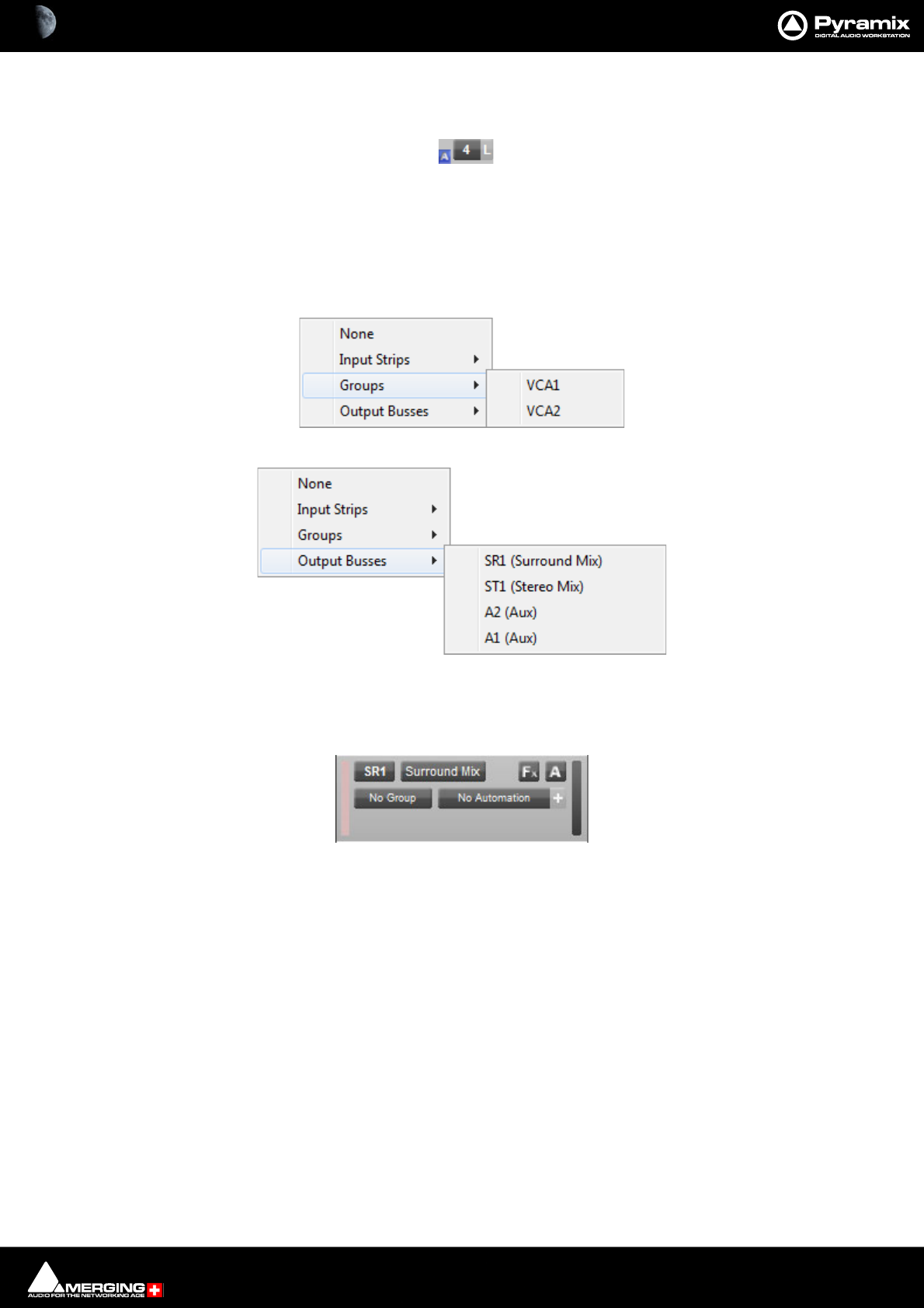
Tracks and Track Groups : Automation Tracks 5 - 110
When one or more Automation Sub-tracks exist a small blue [A] button is shown adjacent to the Strip number.
Clicking this button toggles all Automation Sub-Tracks associated with this Audio Track visible/hidden.
Bus and VCA Group Automation Tracks
Normal Audio Tracks are used to display and manipulate Bus and VCA Group Automation.
Clicking on the top-left button, used for assigning Tracks to Mixer Strips Now also has the option of connecting to
VCA Group Strips and Bus Strips :
A Bus is connected without consideration of the number of Channels in the strip.
The Bus ID is displayed in the connection Box (SR1, ST2, A3, etc…)
The Bus Name is displayed in the Name Box, but is not editable currently.
The Fx button remains available.
The Automation button [A] is available.
The Automation Name and [+] are available.
Automation Sub-Tracks [+]) are available.
Notes:
When connected to a Bus the Track does not play back any audio. It can, however carry Clips.
When right clicking on the [A] button or left clicking on the Automation Name or [+] all menus enabling Automa-
tion Tracks to be selected filter available Tracks following the Bus controls as is the case for Input Strips.
Automation Sub-track Indicator
Select VCA Group Strip
Select Output Bus
Bus Automation Track header

Tracks and Track Groups : Tracks Tab Window 5 - 111
Tracks Tab Window
The Track Tab Window shows a table where each row contains information about a single Track and each column
contains information and function selection fields. New Tracks can be created or existing ones deleted and the
order of Tracks changed. All Track parameters are accessible and modifiable.
New Tracks can be added by clicking on the first line of the Tab Window and typing a suitable name then pressing
Enter.
Tracks can be deleted by selecting them and pressing the Delete key.
The order of the Tracks can be changed by selecting and dragging Tracks. Click on the symbol at the far left of the
Name field and drag to the desired row.
Tracks Tab pop-up
Right-clicking on a selection of Tracks or on all Tracks (no selection) displays this context menu:
Increment Tracks Name : Adds an incremental number after each selected Tracks name, taking into account
an already existing number
Repeat & Increment Tracks Name : Copies the first selected Tracks name to the rest of the selection and adds an
incremental number
Copy Tracks Name : Copy the selected Tracks name or all if no selection
Paste Tracks Name : Paste the previously selected Tracks name to the currently selected Tracks
Import Tracks Name : Rename the selected Tracks or all Tracks if no selection with names coming from a
text file
Export Tracks Name : Saving the selected Tracks or all if no selection to a text file
Tracks Tab floating Window

Tracks and Track Groups : Tracks Tab Window 5 - 112
Making Settings Changes to Multiple Tracks
Changes to Tracks settings can be made on a multiple selection of Tracks. Press Ctrl and Click on a Track to add or
subtract it or press Shift to select a contiguous range of Tracks.
Changing Repro or Input connections
Clicking in the column field to drops down a list of available connections. Highlight the required connection to
select it.
With a range of Tracks selected, choosing a connection from the list assigns all selected Tracks to the same con-
nection. If Alt is held down while choosing the selected Tracks are connected in ascending order.
Track Tab Column Fields
Name
The name of the Track. Up to 29 characters are visible in this field but longer names are accepted. Click in the field
or use F2 to enter a new name.
Repro Connection
Shows which Mixer Input Strip (and Channel if applicable) the Track is connected to. Clicking in this column field
drops down a list box with all available Mixer Input strips (and Channels). Strip number on the left followed by
Channel Tag with the Strip Name in brackets.
Input Connection
Shows which Input is feeding the Track. Clicking in this column field drops down a list box with all available physi-
cal inputs and Internal Return buses.
Group
Shows which Track Group (if any) the Track belongs to. (see below) Clicking in this column field drops down a list
box with all available Track Groups.
Solo
If YES Track is soloed.Clicking in this column field toggles between YES and blank.
Mute
If YES Track is muted.Clicking in this column field toggles between YES and blank.
Record Ready
Shows the current record ready state. Clicking in this column field drops down a list box with the three possible
states, Safe, Record Ready and Auto-Punch.
Monitoring
Shows the current monitor mode. Clicking in this column field drops down a list box with the three possible
modes, Auto, Input and Repro.
Hidden
If YES the Track is not visible in the Timeline but continues to operate normally. Clicking in this column field tog-
gles between YES and blank.
Always Visible
If YES the Track will always appear on screen (if there is sufficient room) even when scrolling other Tracks.
Collapsed
If YES the Track is a member of a Track Group currently collapsed. (see below)
Display Mode
Shows the current Clip Display Mode mode. Clicking in this column field drops down a list box with the three pos-
sible modes, Block, Waveform or Envelope

Tracks and Track Groups : Tracks Tab Window 5 - 113
Show Automation
If YES the automation envelope is displayed. Clicking in this column field toggles between YES and blank.
Show Peak-Meter
If YES a Peak Meter is displayed in the Track Header. Clicking in this column field toggles between YES and blank.
Size
Shows the current Track display Height. (in pixels) Clicking in this field allows a numeric value between 24 and 511
to be entered.
Background Color
Shows Clip background color. If blank, color is set to the default. Clicking in this column field pops-up a color
picker. Choosing Standard restores to default.
Waveform Color
Shows Clip Waveform color. If blank color, color is set to the default. Clicking in this column field pops-up a color
picker. Choosing Standard restores to default.
Recording Media Folder
Shows the Media Folder where new recordings will be stored. Clicking in this column field pops-up a list of all
mounted Media Folders.
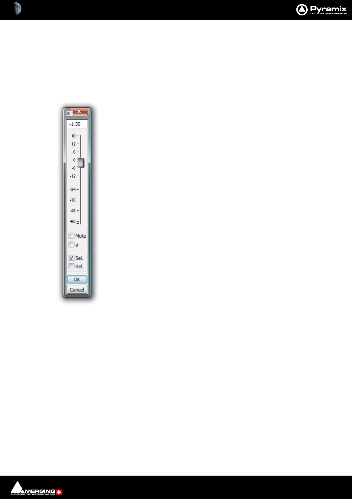
Tracks and Track Groups : Track Envelope and Static Gain 5 - 114
Track Envelope and Static Gain
Pyramix offers two Track based methods of varying Clip gain. Static Gain and Envelope.
Note: Static Gain and Envelope operate independently of the dynamic automation.
Static Gain
Gain Window
The Gain window allows the gain to be set for the current selection. The gain value can be
typed into the box at the top of the strip or set by clicking and dragging the fader.
Keyboard up and down arrows adjust gain by 0.1dB per press, with Shift 0.5dB per press
and with Ctrl + Shift 1.0dB per press.
Mute when checked, mutes the selection but retains the gain value
Sel. box (Selection). When checked, the gain change will be applied to the whole selec-
tion (default is checked.)
Rel. box (Relative) When checked and a series of Clips are grouped, the gain change is
relative to pre-existing level.s
When neither box is checked any gain change is only applied to the Clip which was last
right-clicked (even if others are selected)
OK button executes any changes selected in the Gain window and closes it
Cancel button cancels any changes selected in the Gain window and closes it
Note: The upper end of the scale is not fixed. You can continue to raise gain until
the mouse pointer hits the edge of the screen.
Keyboard Shortcuts
• Up Arrow = Increase gain by 0.1dB/step
• Down Arrow = Decrease gain by 0.1dB/step
• Shift + Up Arrow = Increase gain by 0.5dB/step
• Shift + Down Arrow = Decrease gain by 0.5dB/step
• Ctrl + Shift + Up Arrow = Increase gain by 1.0dB/ step
• Ctrl + Shift + Down Arrow = Decrease gain by 1.0dB/step
Gain Window
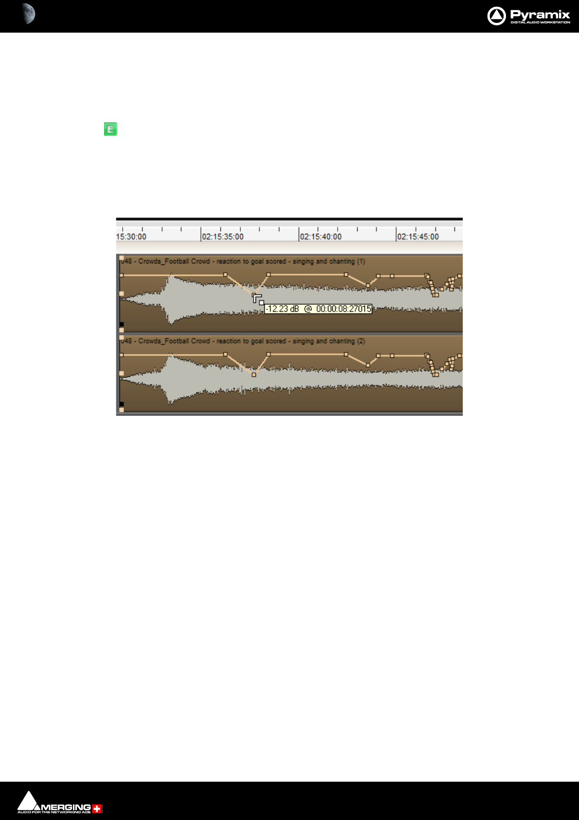
Tracks and Track Groups : Track Envelope and Static Gain 5 - 115
Envelope
Enveloping is active continuously for all Clips. However, in order to change the envelope from the default 0db
unity gain Display Envelope must first be switched on in the Track Header by toggling the Waveform button until
it displays:
Display Envelope - by default shows Clips as orange blocks (brown when selected) with
white waveform and adds a thin black line (thicker and orange when the Cue is selected)
which allows the gain to be adjusted using the mouse by simply clicking and dragging. Press-
ing the Alt key enables the drawing tool for envelopes. This is also applicable to Automation
curves.
Note: Adjustment nodes on Envelopes are square and nodes on automation Tracks are circular.
As can be seen above the mouse cursor changes to a new symbol when over the Envelope line. Different cursor
symbols mean that clicking (and, where appropriate, dragging) will do different things. For example, Left-clicking
adds a node which can then be dragged to the desired level as shown in the box beside the cursor. Note that the
TimeCode value pop-up is elapsed time from the beginning of the Clip.
Note: Double-clicking a node restores its value to 0dB.
Actions and Modifiers
Left Click Anywhere on the Envelope line to make a new node.
Ctrl + Click On an existing node to adjust all nodes in the Region selected currently. New
points are inserted automatically at the Region borders if necessary.
Alt + Click Anywhere on the Envelope line to draw nodes freehand.
Shift + Click Fine tune of a point (0.1 dB steps for dB values).
V + Click Constrains changes to a point to Vertical.
H + Click Constrains changes to a point to Horizontal
Click - hold - Alt Create new point with same value as next point. (if one exists).
Click -hold- Ctrl Create new point with the same value as previous point (if one exists).
Ctrl + Alt + Click On an existing node to erase it.
Envelope Cursors
Adjusting Envelope
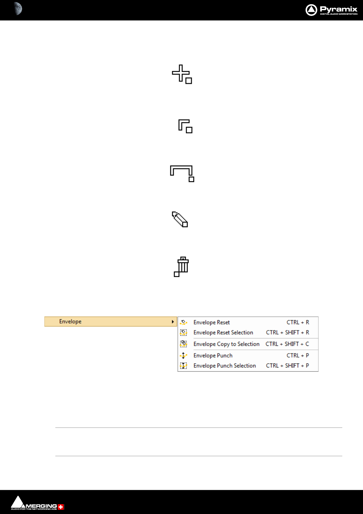
Tracks and Track Groups : Track Envelope and Static Gain 5 - 116
Note: Adjustment nodes on Automation Tracks are circular and nodes on Envelopes are square
Left Click anywhere on the Envelope line to make a new node:
Left Click on an existing node to adjust it:
Ctrl + Click on an existing node to adjust all nodes in the Region selected currently:
Alt + Click anywhere on the Envelope line to draw nodes freehand:
Ctrl + Alt + Click on an existing node to erase it:
Clip Envelope Menu Functions
Clips > Envelope offers a number of powerful Envelope related functions :
Envelope Reset Reset the gain envelope for the whole selection by deleting all envelope nodes
within the selection only on the Track under the mouse cursor when Reset is cho-
sen.
Envelope Reset Selection Reset the gain envelope for the whole selection by deleting all envelope nodes
within the selection.
Envelope Copy to Selection Copies the values of all envelope nodes within the selection from the Track
under the mouse cursor when Copy to Selection is chosen to all other Tracks in the
selection
Clip > Envelope Sub-menu
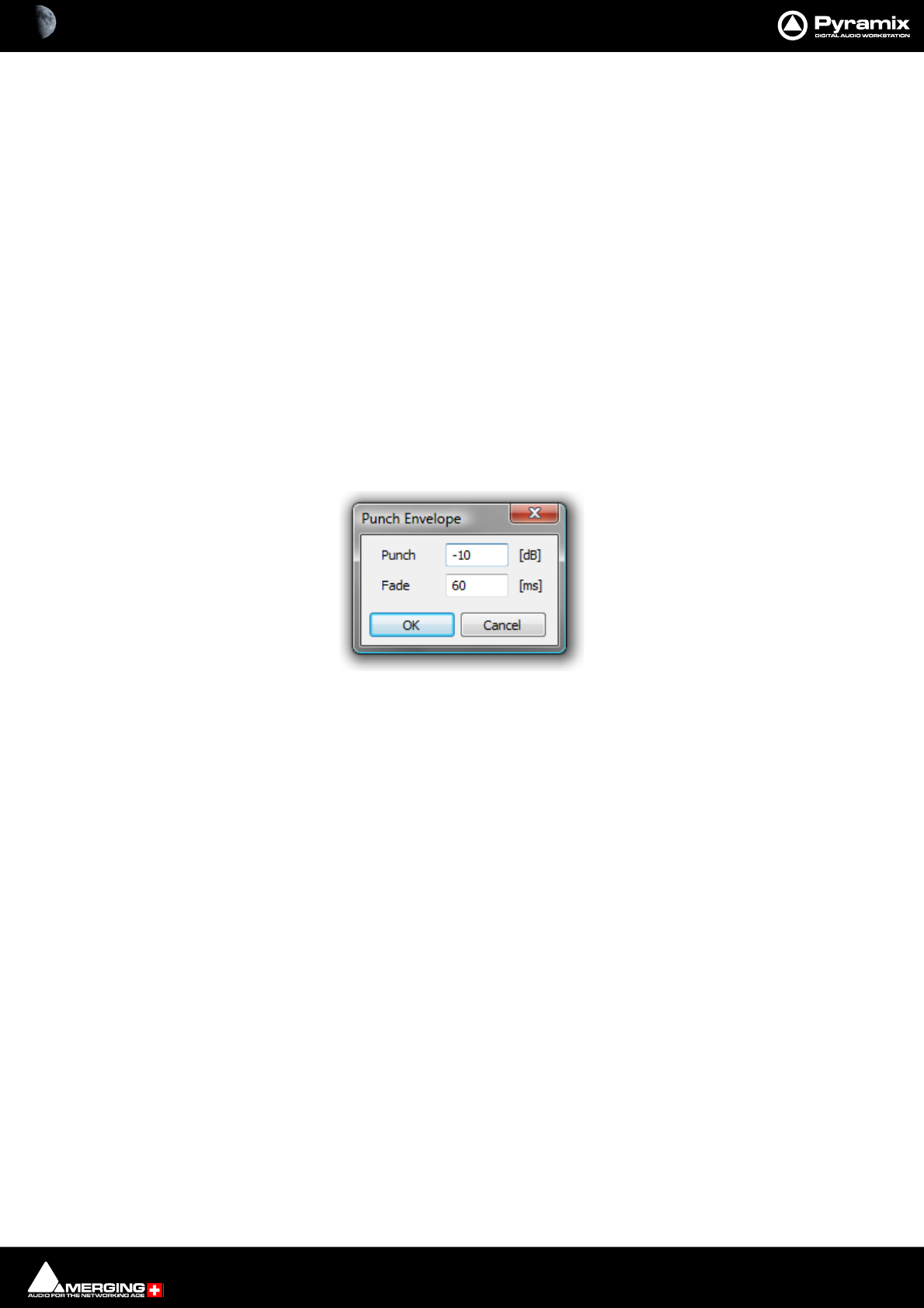
Tracks and Track Groups : Track Envelope and Static Gain 5 - 117
Envelope Punch Places four new envelope nodes at the bounds of the selection on the Track under
the mouse cursor when Punch is chosen and opens the Punch Envelope dialog
box
Envelope Punch Selection Carries out the same operation as Punch but to all Tracks in the current Selection.
Envelope Shortcuts
If Envelope features in your workflow it is well worthwhile learning some keyboard shortcuts:
Envelope Reset Ctrl + R
Envelope Reset Selection Ctrl + SHIFT + R
Envelope Copy to Selection Ctrl + SHIFT + C
Envelope Punch Ctrl + P
Envelope Punch Selection Ctrl + SHIFT + P
Punch Envelope
Punch Envelope is a powerful method of adjusting gain within a Clip in many circumstances, especially when edit-
ing dialog.
When invoked from the Clips > Envelopes menu or by Ctrl + P or Ctrl + SHIFT + P the Punch Envelope dialog
appears :
Type the gain change required in the Punch field. (Type a - minus to attenuate)
To add a fade at each end of the Punch, type the required duration in ms in the Fade field.
Click on OK to execute the change or Cancel to reject it.
Punch Envelope dialog
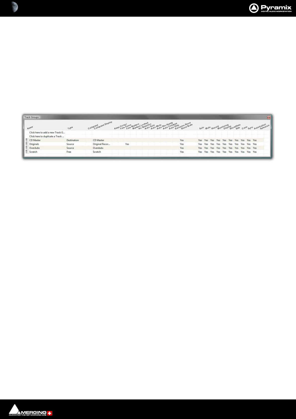
Tracks and Track Groups : Track Groups 5 - 118
Track Groups
Track Groups, as the name implies, enable a number of logical function linkages between Tracks and several
other useful methods of improving efficiency. Track groups can be created and manipulated by the user. Track
Groups are also created by default when Recording or Rendering operations occur on more than one Track at the
same time.
Note: To add Tracks to a Track Group us e the drop-down list menu in the Group field in the
Tracks Tab pane.
Track Groups Tab Window
Opens a table where each row contains information about a single Track group and each column contains Infor-
mation and function selection fields.
The first two rows enable new Track Groups to be created and existing ones to be duplicated by clicking on the
Name field.
To create a new Track Group, click on Click here to add a new Track Group. A text entry box replaces the Name.
Enter a suitable name and press Enter. A new Track group will appear at the bottom of the list.
To duplicate an existing Track Group, click on the Track Group you wish to duplicate then click on Click here to
duplicate a Track Group. A text entry box replaces the Click here to duplicate a Track Group. Type a suitable
name and press Enter. The duplicate Track Group appears in the row below the Track Group you have just cop-
ied. Subsequent rows are moved down the table. The Track Group entries can be re-ordered by clicking on the
symbol at the far left of the Name field and dragging to the desired row.
When Tracks are assigned to a Track Group a small Group Track is shown in the Timeline immediately above the
first assigned Track.
Track Groups can be collapsed/expanded by clicking the little [-] or [+] on the Track Group Track header.
Track Group Column Fields
Name
The name of the Track Group. Up to 29 characters are visible in this field but longer names are accepted. Click in
the field or F2 to edit the name.
Type
Clicking in this column field drops down a list box with current choices of Free, Source, or Destination.
Free is used to create General purpose Track Groups
Source is used for grouping Tracks to be Sources in the Source/Destination model.
Destination is used for grouping Tracks to be Destinations in the Source/Destination model.
Collapsed
Track Groups can be collapsed, so only one of the Tracks of the group is displayed. When set to Ye s, only the Track
chosen and shown in the Collapsed Display field is displayed in the Timeline. This field has the same function as
the little [-] or [+] on the Track Group header.
If the single visible Track is selected the group is expanded.
Collapsed Display
Tracks Groups Tab floating Window

Tracks and Track Groups : Track Groups 5 - 119
Clicking in this column field drops down a list box which contains the names of all the Tracks in the group. The
selected name determines which Track will be displayed when the display is collapsed.
The rest of the fields
All the other column fields toggle when clicked, either displaying Yes or a blank. The functions described below
apply when the fields are set to Yes.
Keep Cursor
The Group ‘remembers’ the position of the cursor and restores it each time one of its Tracks is selected.
Free Zoom
The group has its own zooming factor, independent of the general zoom factor.
Free Markers
Track Groups can have their own list of markers that are displayed on the Track Group Scale or on the main Time-
Code Scale if the Track Group Scale is hidden (see below).
Markers Locked
Locks the Markers. For the particular Group. Free Markers must be ON
No Selection
Clicking on Clips placed on Tracks of the Group does not select anything, the cursor is simply placed at the posi-
tion where the mouse is clicked. Clicking with the Q key held down allows Clips to be selected on these Tracks.
Auto Solo
If any Track of this Group is selected, the whole group is automatically Soloed.
Auto Mute
The whole Group is automatically muted unless one of its Tracks is selected.
Auto Record Ready
When a Track of this Group is selected, the whole Group goes into Record Ready mode.
Auto Collapse
When none of the Tracks of this Group is selected, the Group is automatically collapsed to display a single Track.
When this Track is selected, the whole Group is expanded.
Auto Hide
When none of the Tracks of this Group is selected, all Tracks of the group are automatically hidden. When any
Track of the Group is selected, the whole Group is shown.
Exclusive Show
When any Track of this Group is selected, all Tracks that are not part of this Group are hidden. This is the equivalent
of a Solo for the Display.
Show Scale
Toggles show/hide an independent scale for TimeCode if the Track Group is on Free Zoom and Markers if it is in
Free Markers mode. If OFF then the Scale and Markers are displayed in the main Scale of the Timeline when any
of the Tracks of this Group is selected.
Selection
When set to Yes this option ensures that any selection made within a Track Group is extended to all Tracks in the
group. Selection is disabled by default for backwards compatibility.
All other columns of the Tab Window (Solo, Mute, Record, Monitoring, Display, Show/Hide, Size, Color, Sync,
Automation Display) define which of the parameters set in the Track Header or in the Tracks Tab window are
affected by the group, I.e. which of these parameters are changed in the whole group when a change is made to
an individual Track of the Group.

6 - 120
www.merging.com/Pyramix
USER MANUAL
Transport and Navigation
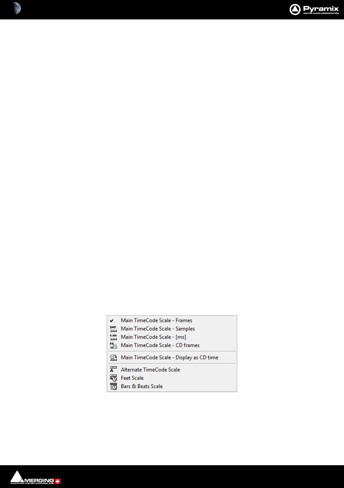
Transport and Navigation : Transport Control 6 - 121
Transport Control
Pyramix features a wide range of Transport Control commands including, unlike many other workstations,
Reverse Play and Play at fractions and multiples of sync play speed both forwards and backwards. These possibil-
ities can be attached to short-cut keys in the Keyboard Shortcut editor. Please see: Customizing Keyboard
Shortcuts on page 509
Of course, these commands are also available via remote controllers that support them.
Navigation
Pyramix Virtual Studio offers a number of ways of navigating around a Project.
Timeline Structure
Important! The Pyramix Timeline starts at 00:00:00:00 on Day 0. It is perfectly possible to go backwards
before 00:00:00:00 say to 23:50:50:00. In this case the cursor is in Day -1. If you go forwards beyond
TimeCode Midnight the cursor will be in Day +1. When the Timeline is outside Day 0 it is shaded in red.
The TimeCode display in the bottom Transport Toolbar and Main Transport Window will show a red indi-
cation when the Playhead Cursor is outside Day 1. E.g. -1 in the day before Day 0, +1 in the day after Day 0
and so on.
Time Scale Rulers
Pyramix is equipped with many Time Scale options. Each Time Scale has an associated Time Scale Ruler and Tool
Bar which appears above the Time Scale Ruler(s).
Main TimeCode Ruler
Near the top of the Project Editing Panel is a horizontal gray area with time code numbers. This is the Main Time-
Code Ruler. On the left, above the Track Headers, the Time Range, i.e. the length of the visible Timeline window is
indicated.
The simplest way to move the Playhead Cursor within the Project Editing Panel is to position the mouse any-
where along the Time Scale Ruler and left-click. The Playhead will immediately move to the new position. You
can also left-click the Playhead Cursor and drag it along the Ruler.
Context Menu
Clicking in the left hand, Header, area of a Time Scale Ruler pops up a context menu.
The first six entries offer a choice of display modes for the Main TimeCode Scale a tick appears next to the option
selected currently:
• Main TimeCode Scale - Frames
• Main TimeCode Scale - Samples
• Main TimeCode Scale - [ms]
Main TimeCode Scale Ruler context menu
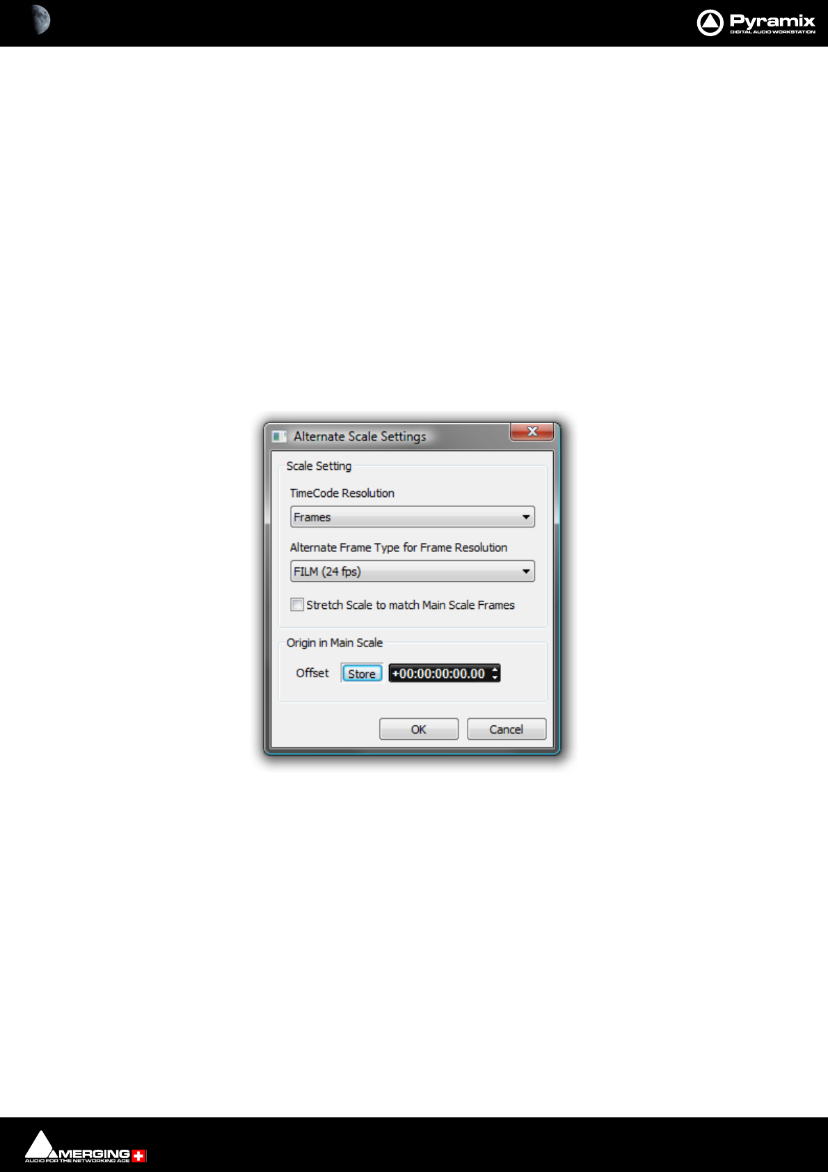
Transport and Navigation : Navigation 6 - 122
• Main TimeCode Scale - CD frames
• Main TimeCode Scale - Display as CD Time
The remaining three entries add new Time Scale Rulers beneath the Main TimeCode Scale Ruler
•Alternate TimeCode Scale
•Feet Scale
• Bars & Beats Scale
Alternate Time Scale Ruler
To add an alternative Time Scale Ruler below the Main Ruler right-click in the Main Ruler header area and select
Alternate TimeCode Scale
You can set up the Alternate Time Scale Ruler either by right-clicking in the its Header to open the context menu
or by selecting Alternate TimeCode Scale Settings or View > Scales / Toolbars > Alternate TimeCode Scale
Settings:
• Alternate TimeCode Scale Settings
Choosing this pops up the Alternate Scales dialog:
Alternate Scale Settings dialog
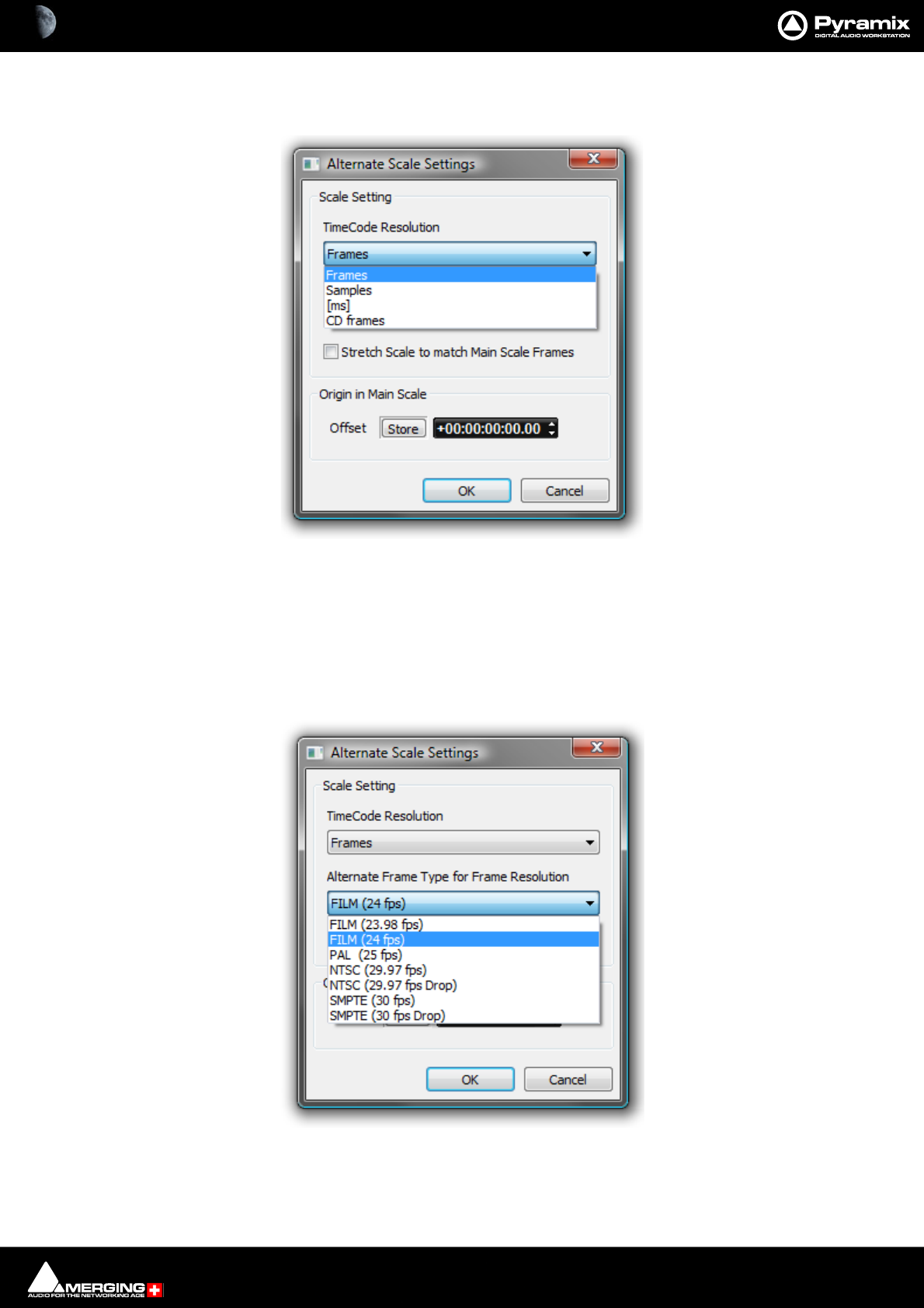
Transport and Navigation : Navigation 6 - 123
Scale Setting
The Scale Setting combo box offers a choice of TimeCode resolution to display:
Stretch Scale to match Main Scale Frames (see below)
Origin in Main Scale
An Offset can set and stored. For example when versioning. I.e. making several sound versions for the same pic-
ture.
The Alternate Frame Type for Frame Resolution combo box offers a choice of frame types appropriate to the
chosen resolution. E.g.
View > Scales / Toolbars > Alternate TimeCode Scale Settings also enables selection of The TimeCode Resolu-
tion for the Alternate Scale from a choice of:
Alternate Scale Settings TimeCode Resolution drop-down menu
Alternate Frame Type for Frame Resolution combo box
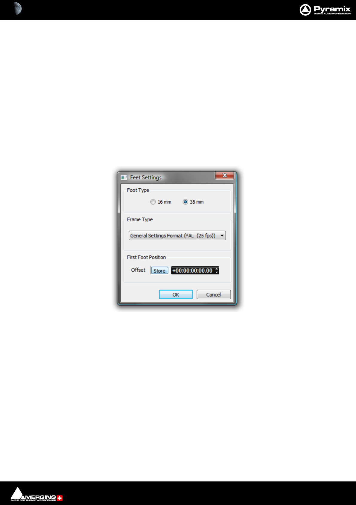
Transport and Navigation : Navigation 6 - 124
•Frames
•Samples
•[ms]
•CD Frames
When the Resolution is set to Frames, an Alternate Frame Rate can be chosen.
When Alternate Frame Rate is chosen, the check box Stretch Scale to match Main Scale Frames allows the
Alternate Scale to no longer display the same time flow as the Main Scale (1 Second = 1 Second). Instead it
matches the length of individual Frames (1 Frame = 1 Frame). In this case the time is not the same in both scales
and this allows making comparisons between, for example, 24 frames events and 25 frames events.
The Origin in Main Scale option allows an offset to be set between the Main Scale and the Alternate Scale.
Film Feet Scale Ruler
As with the other Scale Rulers, clicking in the header area pops up a context menu with the extra option Feet Set-
tings selecting this pops up the Feet Settings dialog:
Foot Type
The radio buttons offer a choice of 16mm feet (units of 40 frames) and 35mm feet (units of 16 frames).
Feet Settings dialog
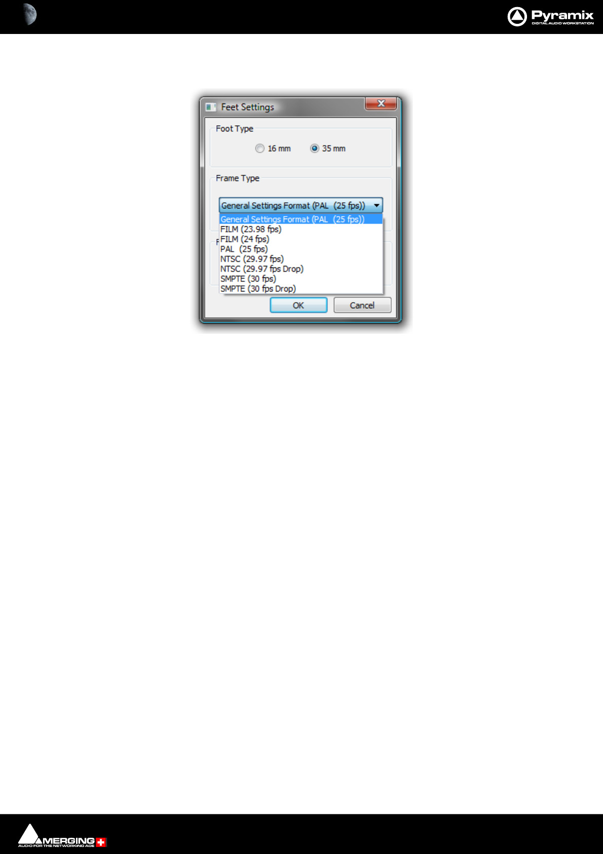
Transport and Navigation : Navigation 6 - 125
Frame Type
The combo box offers a choice of frame rates:
Default is the format selected in All Settings > Formats & Sync > Frequencies. You may need one of the others in
the context of non-linear editing workflows.
Frame Type combo box
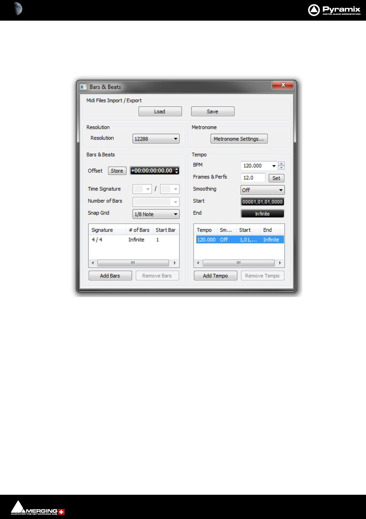
Transport and Navigation : Navigation 6 - 126
Bars & Beats Scale Ruler
As with the other Scale Rulers clicking in the header area pops up a context menu with show/hide for the Alter-
nate, Feet and Bars & Beats Scale bars plus two extra options, Bars & Beats Settings and Tempo Map. The Temp o
Map option shows the current Tempo Map below the Bars & Beats Scale Bar.
Midi Files Import / Export
Load
Save
Both buttons open a Browser Window to enable navigation to a file to load or a location to save to.
Note: Currently, when MIDI files of type 2 are imported, only the Track 1 Tempo Map and Time
Signature is imported.
Resolution
Sets the clock resolution in Pulses Per Quarter Note, PPQ. The combo box offers a choice of values between 192
and 49152
Bars & Beats
Offset Offsets the Bars & Beats scale start from the main Time Scale. Value can be typed
in the TimeCode register and or nudged up or down with the increment, decre-
ment buttons.
Store Offsets the Bars & Beats scale start to the current Playhead Cursor position.
Note: Offsets can be negative or positive.
Bars & Beats Settings dialog
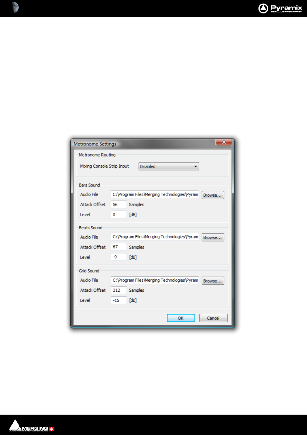
Transport and Navigation : Navigation 6 - 127
Time Signature and Bars
The bottom left panel displays a list of blocks of bars in the order they appear in the ‘song’. The following settings
apply to the currently selected entry in the list.
Time Signature Use the combo boxes to set the Time Signature
Number of Bars Type a value or choose Infinite from the combo box dropdown list.
Snap Grid Combo box offers a choice of Off or values between Note and 1/64 Note .
Add Bars
Click to add a new block of bars to the list above.
Remove Bars
Deletes the selected entry from the list above.
Metronome
Metronome Settings...
Tempo
The bottom right panel displays a list of currently defined Tempos in the order they appear in the ‘song’. The fol-
lowing BPM, Frames & Perfs, Smoothing, Start and End fields reflect the values for the highlighted (selected)
Tempo.
BPM Allows you to pick a tempo from the common values in the drop-down list, to
increment or decrement in 1BPM steps with the up and down buttons or to
directly type a value in the box.
Metronome Settings dialog
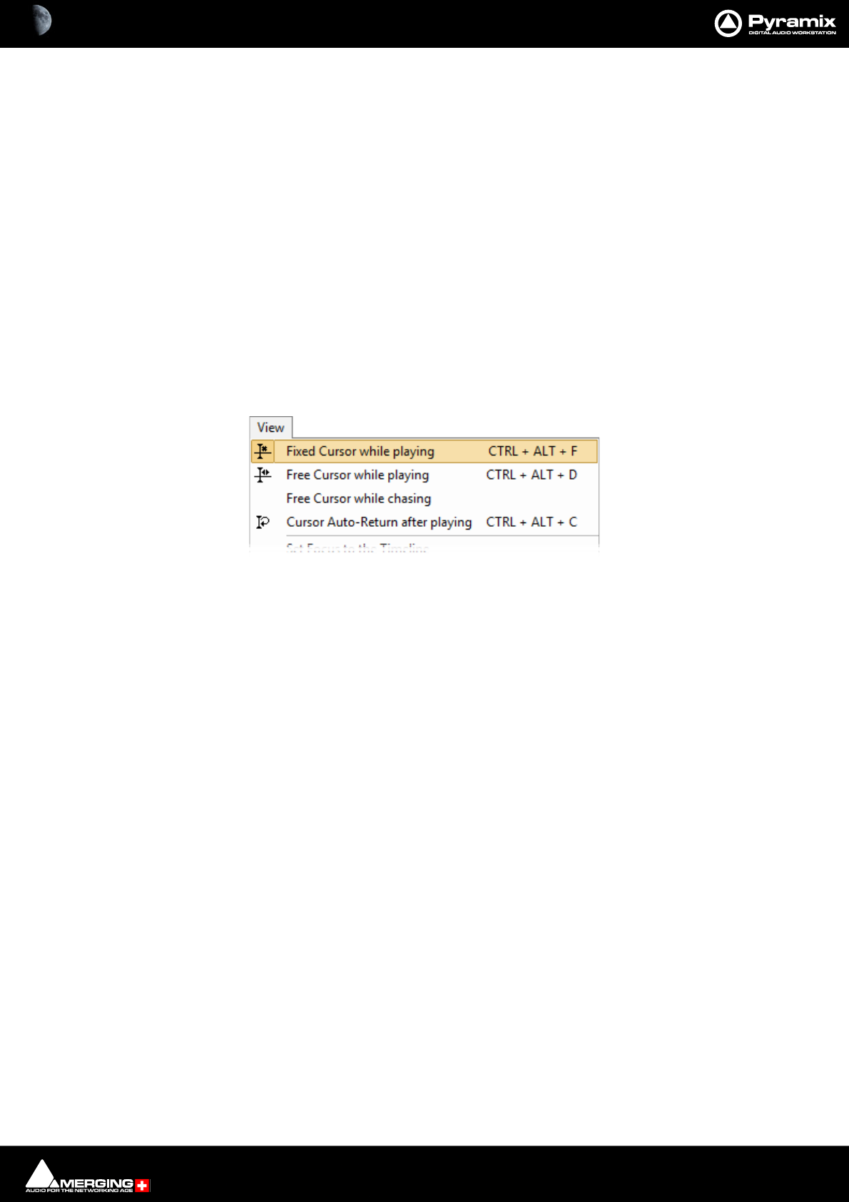
Transport and Navigation : Navigation 6 - 128
Frames & Perfs An alternative method of defining a Tempo used by film composers. It is based on
24 frames per second, each frame subdivided into 8 perfs, or perforations. Thus a
value of 24.0 results in a Tempo of 60BPM. Perfs are entered as decimals. E.g. 12.7.
Illegal entries are rounded.
Smoothing Enables values between Note and 1/64 . to be chosen. (or OFF)
Start The starting point for the Tempo can be entered by typing.
End The end point for the Tempo can be entered by typing.
The Information pane shows all currently defined Tempos.
Add Tempo
Adds a new Tempo
Remove Tempo
Removes the highlighted (selected Tempo) from the list.
Playhead Cursor Options
Four Playhead Cursor options will be found at the top of the View menu:
Local Options
Fixed or Moving Playhead Cursor
The Playhead Cursor can be static with the Timeline moving (choose: View > Fixed Cursor while playing) or the
Playhead Cursor can move while the Timeline remains static, ‘Paging’ when the Playhead Cursor hits the screen
edge. (Choose: View > Free Cursor while playing).
Note: In Fixed Cursor While Playing mode, if Play Selection is invoked then Cursor switches to
Free Cursor mode until Stop is pressed.
Chase Options
When Free Cursor while chasing is selected in conjunction with either of the local options the Playhead Cursor
and Timeline position can be freely manipulated from the workstation whenever the TimeCode Master machine is
in Stop, Rew, FF, Play, Locate, etc. as well as while chasing, but as soon as Pyramix has locked to incoming Time-
Code, the cursor will "jump" to current TC. This mode is useful for Cinema mixing since it allows the Sound Editor
to make good use of idle moments to perform quick edits and adjustments, anywhere in the Timeline and regard-
less of current TC position. This used to be the default behavior.
When Free Cursor while chasing is NOT selected, the Cursor will always be locked to TimeCode when Pyramix is
set to chase, whether in Stop, Rew, FF, Play, Locate, etc. as well as while chasing.This mode is desirable for TV Post,
where the Pyramix Playhead cursor and Timeline display should always reflect the current TC position.
Auto Return
Cursor Auto-Return after playing. When this is selected with either of the local options, the Playhead Cursor
will return to the point at which Play began when Stop is selected.
Playhead Position
When View > Fixed Cursor while playing is selected, the Playhead position can be set in Settings > All Settings
> Application > Playback/Record in the Fixed Cursor Settings section. The Place of Cursor in Screen combo
box offers a range of choices between 1/10th and 1/2 of Screen.
View menu (part)
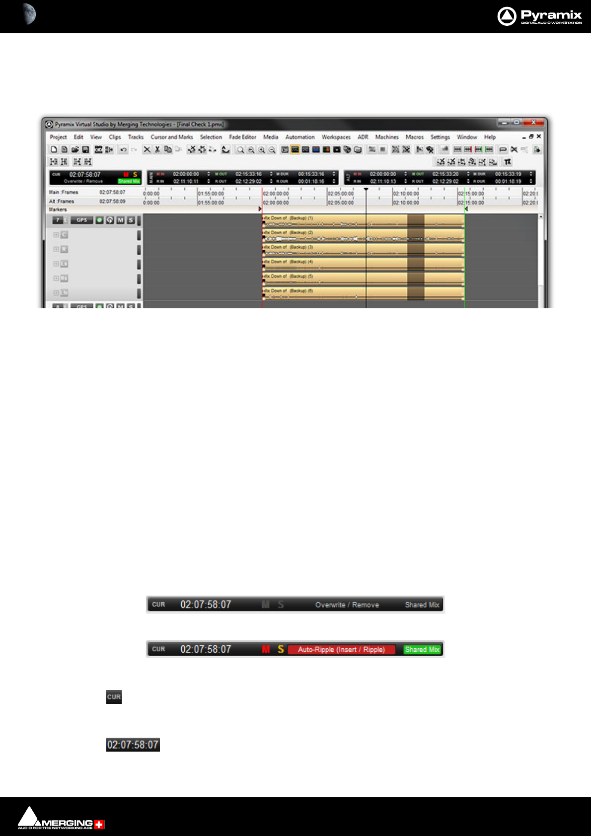
Transport and Navigation : Navigation 6 - 129
Cursor & Timescale Ruler Toolbars
Above the Timescale Ruler(s) and below the Project Editing Panel Toolbar(s) are the Timescale Toolbars and
Cursor Toolbar. When several Timescale Ruler Toolbars are displayed together each Toolbar will wrap into two
rows as shown here:
Each Toolbar contains a number of Icons and TimeCode register boxes with increment / decrement up and down
arrow buttons. The Cursor and Main Marker/Region Timescale Toolbars are associated with the main Timescale
Ruler and Marker Tray. Other Timescale Toolbars appear by default when the Alternate Timescale, Footage or Bars
& Beats rulers are visible. Any or all of these Toolbars can be Hidden/Shown using View > Scales / Toolbars and
toggling individual Toolbars or Hide All Toolbars.
Increment / Decrement UP & DOWN Arrow Buttons
The + (plus) and - (minus) buttons to the right of the TimeCode registers increment or decrement by one unit per
click of the smallest unit in the current register. E.g. Frames, Samples etc.
Modifiers
Click Frames
Alt + Click Subframes
Ctrl + Click Seconds
Shift + Click Minutes
Ctrl + Shift + Click Hours
Ctrl + Alt Current Nudge Value
Cursor Toolbar
Click here to locate to the current Playhead Cursor position with the Playhead Cursor cen-
tered in the Timeline.
Current Cursor position register. Click to edit.
Timescale Ruler Toolbars
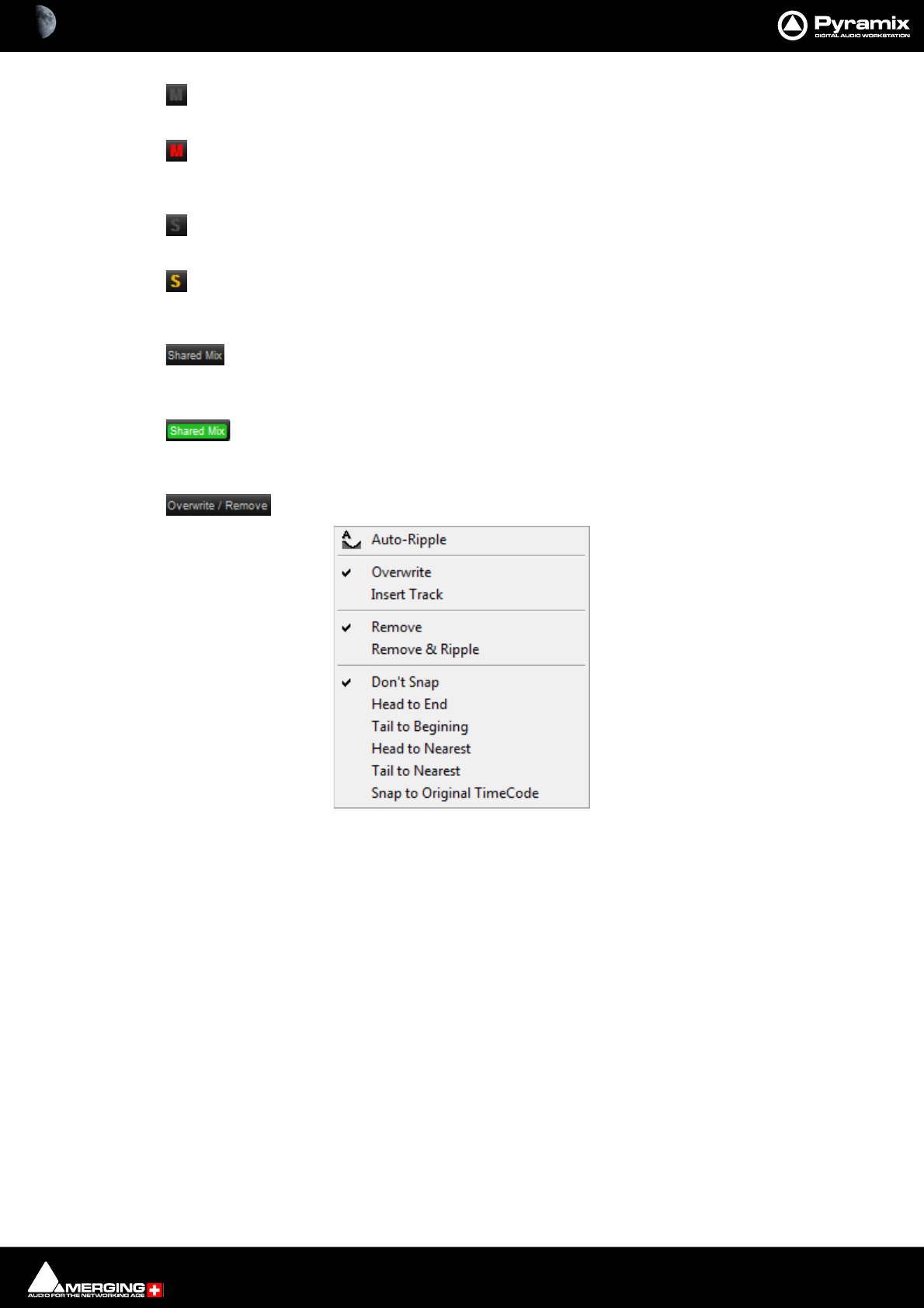
Transport and Navigation : Navigation 6 - 130
Global Mute indicator. When unlit no Tracks are muted.
Global Mute indicator. When lit one or more Tracks are muted. Click on the lit indicator to can-
cel all active Mutes.
Global Solo indicator. When unlit no Tracks are Soloed.
Global Solo indicator. When lit one or more Tracks is Soloed. Click on the lit indicator to can-
cel all active Solos.
When inactive, as here, the current Project’s mixer is not shared with subsequently opened
Projects.
When active, the current Project Mixer will be shared with Projects opened or created subse-
quently. Please see: Mixer Sharing on page 290
This area indicates the current Edit Mode. Clicking on it pops-up a menu:
This shows the options selected currently with ticks. Click on menu entries to change the options.
Auto-Ripple Toggles Auto-Ripple On or Off
Overwrite When active Pasting a Cue(s) will overwrite any Cue(s) present on the target
Track(s) for the duration of the pasted Cue(s).
Insert Track When active Pasting a Cue(s) will split an existing Cue or Cues present at the Insert
point to accommodate the Pasted Cue(s).
Remove When active deleting a Cue or Selected Region leaves blank space. No subsequent
Cues are moved.
Remove & Ripple When active, deleting a Cue or Selected Region results in all subsequent Cues on
the same Track(s) being moved forward by the same time as the time deleted.
Don’t Snap When active, moving a Selected Cue or Range simply moves it at will.
Head to End When active, moving a Selected Cue or Range results in its beginning snapping to
the end of the last Cue on the Track(s)
Tail to Beginning When active, moving a Selected Cue or Range results in its end snapping to the
beginning of the first Cue on the Track(s)
Timescale Ruler Toolbars
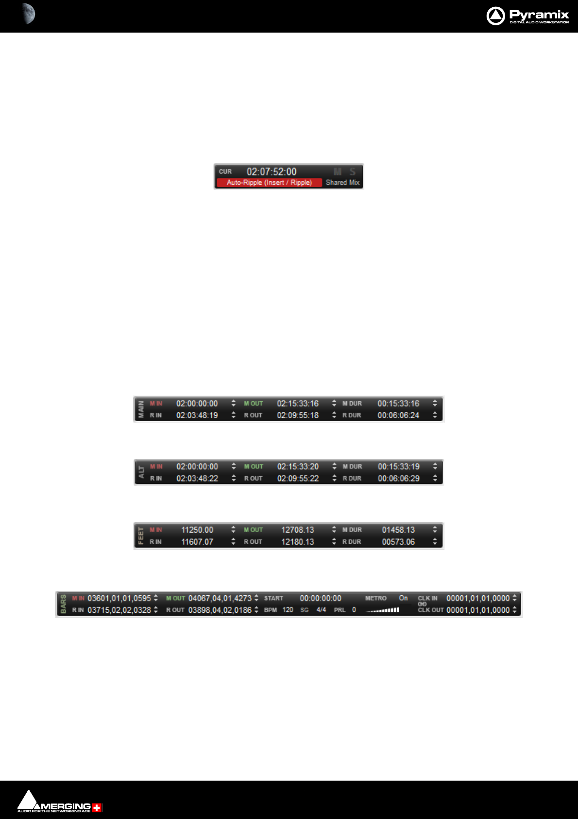
Transport and Navigation : Navigation 6 - 131
Head to Nearest When active, moving a Selected Cue or Range results in its beginning snapping to
the nearest Cue on the Track(s) or the Playhead Cursor or In/Out Marker.
Tail to Nearest When active, moving a Selected Cue or Range results in its end snapping to the
nearest Cue on the Track(s) or the Playhead Cursor or In/Out Marker.
Snap to Original TimeCode When active, moving a Selected Cue results in it snapping to the Original Time-
Code as stamped in the file.
Note: Whenever a mode is selected which can affect other Cues, e.g. Ripple then the label dis-
played in the Toolbar turns red.
Other Timescale Ruler Toolbars
In all of the following Toolbars:
M IN Centers the Timeline on the In Marker.
M Out Centers the Timeline on the Out marker.
M Dur Zooms the Timeline to show the entire area between the In and Out Markers
R In Centers the Timeline on the beginning of the current Selection or Range.
R Out Centers the Timeline on the end of the current Selection or Range.
R Dur Zooms the Timeline to show the entire area between the beginning and end of the
current Range or Selection.
When values are typed into the M Dur or R Dur registers, the In value remains fixed while the Out is adjusted.
Main (Markers and Selected Range) Toolbar
Alternate TimeCode Ruler Toolbar
Film Feet Ruler Toolbar
Bars & Beats Ruler Toolbar
M IN Centers the Timeline on the In Marker.
M Out Centers the Timeline on the Out marker.
M Dur Zooms the Timeline to show the entire area between the In and Out Markers
R In Centers the Timeline on the beginning of the current Selection or Range.
R Out Centers the Timeline on the end of the current Selection or Range.
R Dur Zooms the Timeline to show the entire area between the beginning and end of the
current Range or Selection.
When values are typed into the M Dur or R Dur registers, the In value remains fixed while the Out is adjusted.
Start The Start register enables an Offset to be entered for the first Bar

Transport and Navigation : Navigation 6 - 132
Metro Clicking on Metro opens the Metronome Settings dialog. Clicking on the label to
the right toggles through On, Pre-Roll only and Off.
Volume Below Metro the volume slider sets the metronome click level.
BPM Clicking BPM enables an alternative value to be entered.The BPM counter displays
and allows modification of the tempo map section where the Cursor is currently.
SG Toggles Time Signature
4/4 Click on the Time Signature displayed currently to enter and alternative.
PRL Click on the number adjacent to PRL to enter a Pre-Roll value.
CLK IN When Click In is set (to something other than 1, 1, 1) the Pre-Roll pre-counts to
Click In Bar/Beat, otherwise pre-counts to the first Bar.
Lock (chain) Symbol Toggles between blank (off ), MRK (In Marker) and RGN (Region) Click In/Out are
then linked to the Markers or selected Region automatically.
CLK OUT When Click Out is set (to something other than 1, 1, 1) the PostRoll counts ???
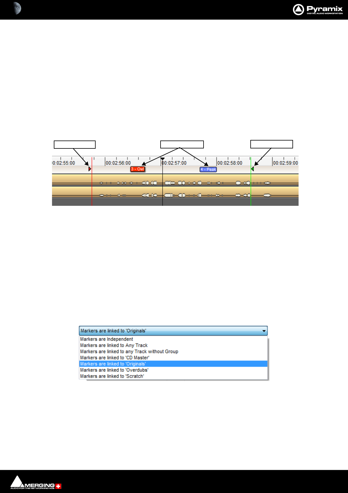
Transport and Navigation : Markers 6 - 133
Markers
Pyramix has several types of Marker. For information about Track Group Markers please see: Track Group
Markers on page 134. For Media Markers, please see: Media Markers on page 135 and for CD and SACD Mark-
ers please see: CD Markers on page 600 and the SACD Production Guide.
The Cursor & Markers and Markers menus, Toolbar and keyboard shortcuts all offer methods of placing Markers
and using them for locating etc. The menu entries should be self explanatory. Please see also : Cursor & Marks
on page 690 and Markers on page 693
Up to 48 Markers can be attached to shortcut keys and/or mapped to a hardware controller.
Project Markers
Project Markers are shown in a Markers Tray just above the TimeLine Tracks display.
Placing Project Markers
Markers are placed at the current Playhead Cursor position in the Timeline by either [NUM9], Markers > Add
marker to Cursor or in the Markers Tab window.
Renaming or Deleting Markers in the Tray
Right-click a Marker in the Tray to pop a context menu with choice of Rename Marker or Delete Marker.
GoTo Marker
Right or Left-click in the Marker Tray above the Track Header to pop up a list of all Markers in the current Project.
Click on a Marker in the list to locate the Playback Head cursor to it.
Markers Linking
The Markers Linking drop-down list menu is at the top of the Markers Tab Window.
The selection made here determines the behavior of markers when Tracks are edited.
Markers Independent (markers are locked to the scale)
Linked to Any Track (markers follow any Track operation)
Linked to Tracks without Group (markers follow any Track that is not a member of a group)
Linked to ‘Effects’, ‘Music’, ‘Foley’ etc. (Markers follow any Track which is a member of theTrack G roup selected
here.)
Markers
Mark OUT
Mark IN Markers
Markers Linking drop-down list menu
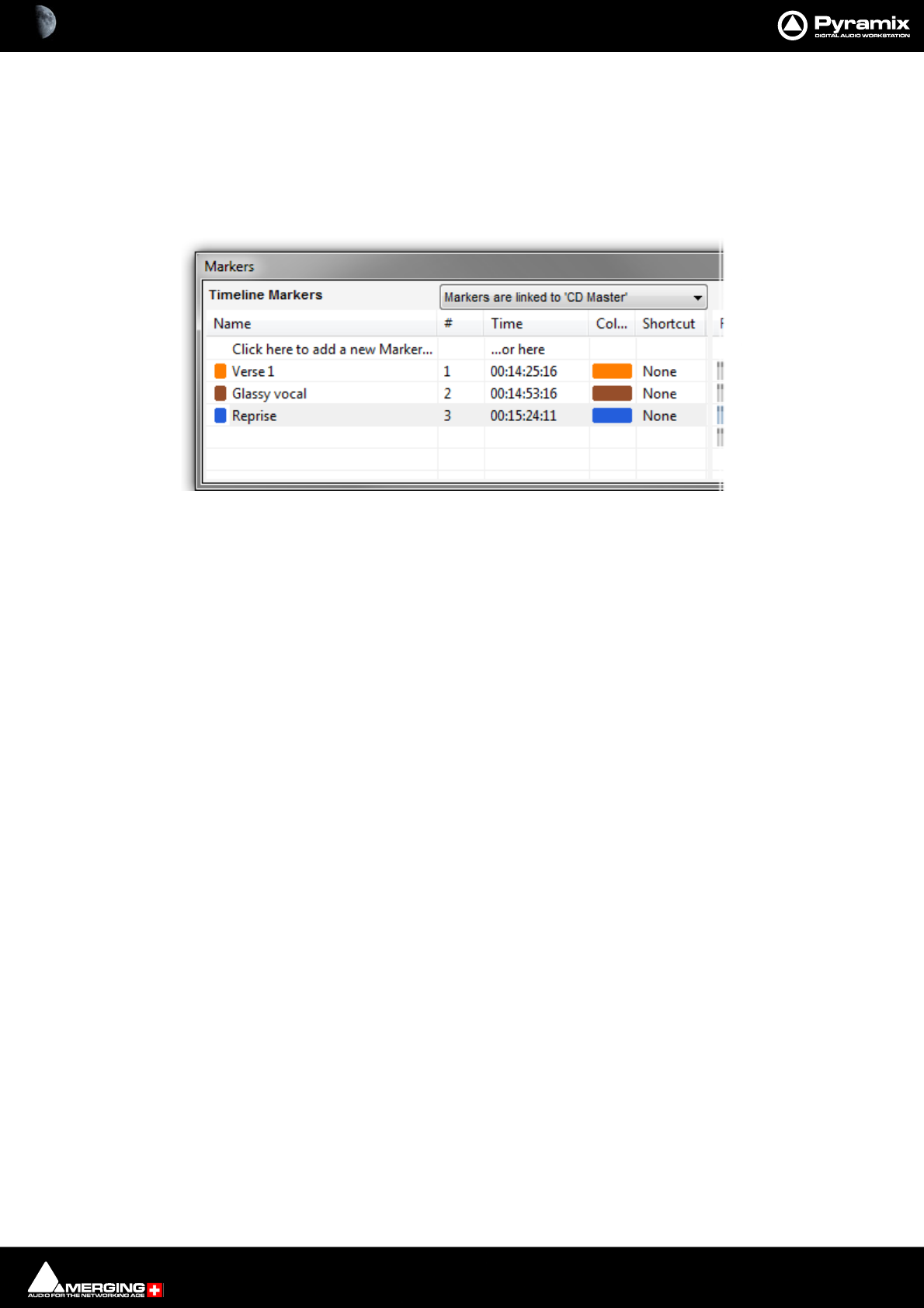
Transport and Navigation : Markers 6 - 134
Editing Project Markers
Project Markers can be edited the following ways:
• Click and drag to move Markers directly in the timeline Marker Tray..
• With the mouse over the Marker in the tray right-click pops up a context menu with Rename Marker and
Delete Marker options.
•In the Timeline Markers section of the Markers Tab window.
See: Markers Tab Window on page 140
Track Group Markers
Filter By Track Groups
Separate lists of Markers can be created for the Project as a whole and for individual Track Groups.
The Filter By Track Groups column shows Project Markers and all the Track Groups added to the Project. Time-
line Markers can be created in a specific Track Group.
For example:
1. Create a Project with Tracks.
2. Create two or more Track Groups in the Track Groups Tab window.
3. Add Tracks to each of the Track Groups.
4. Turn Free Markers on (Ye s ) for each Track Group.
5. Add Markers with Group 1 selected in the Timeline (Either by selecting one of the Tracks belonging to the
Track Group in the Timeline or by clicking on the Track Group where it is listed under Filter By Track Groups
in the Markers Tab window.)
Timeline Markers section of Markers tab
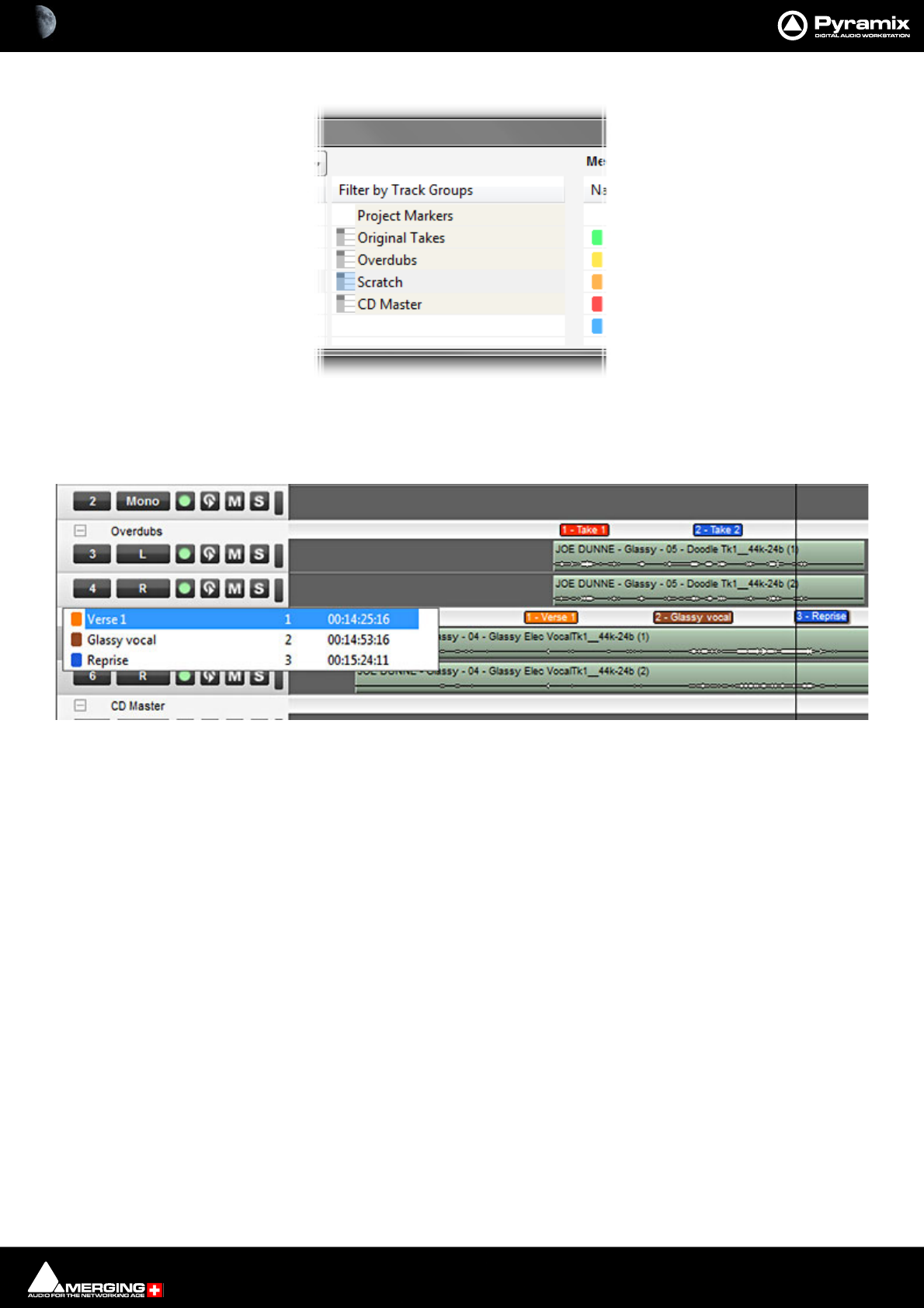
Transport and Navigation : Markers 6 - 135
6. Repeat step 5 for the other Track Groups.
Now you can use the Filter By Track Group entries to filter the Markers displayed in the Markers Tab window. Click-
ing on Project Markers shows the list of Markers belonging to the Project without any of the Markers belonging to
Track Groups. Clicking on any of the Track Groups shows only the Markers belonging to that Track Group.
Markers created in Track Groups are shown in the Group separator tray above the Track Group in the Timeline.
Clicking on the Track Group Name in the Timeline pops up a list of all markers created in the Track group. These
function as locators.
Media Markers
Overview
Media Files and Libraries Master Clips can store Markers. These are called Media Markers to differentiate them
from the Timeline Project and Track Group Markers. Media Markers are useful for many purposes, e.g. marking
good, bad or indifferent takes within a long continuous recording or marking the peak point of a car or plane pass
etc.. They are attached to the Master Clip or to the Media itself.
Characteristics
• Media Markers can be added to any Media File, regardless of format.
• Media Markers are stored in the Media Object or Master Clip in the Media Manager, Libraries and in Proj-
ects referencing the Media.
• Multiple Clips referencing the same Media share the same Markers within the same Project or Library.
Note: When recording into the Active Project Media Markers will not be added if any Clip or Clips
is/are selected in the Timeline.
Filter by Track Groups section of Markers tab
Track Group Markers in the Timeline
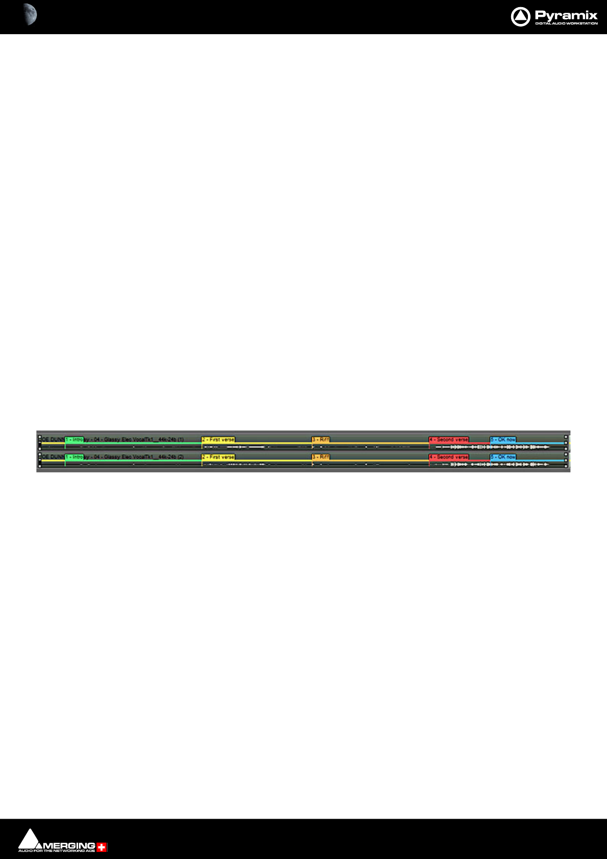
Transport and Navigation : Markers 6 - 136
Where Media Markers Are Saved
Media Markers are stored in the Media Object or Master Clip in the Media Manager, Libraries and in Projects refer-
encing the Media. When saving a Project with two different versions (with Project > Save As for example), the
Media Markers within both versions can evolve differently as they are saved in the Projects and/or in different
Libraries, but: Media Markers can be saved along with the physical Media File by using the menu item Markers >
Update Media Markers to Files. A file with the same name as the physical Media File with an .mmd extension is
saved in the same location as the Media Files which contains all the Markers for this Media.
When adding Markers to a Media being recorded the .mmd file is automatically saved automatically when the
recording is stopped.
When mounting a Media file with no reference to any Projects or Libraries, its associated Markers are only available
in its associated .mmd file.
Clips in a Project or Master Clips in a Library carry a copy of the Markers and can be edited separately. The original
version of the Markers created during recording can be retrieved from the .mmd file. This .mmd file can be
updated after modification of the Markers with the menu Markers > Update Media Markers to Files, as
explained above.
Contents
Media Markers contain:
• A Number (not editable) The first Media Marker in each recording starts numbering at 1.
• A TimeCode (the offset from the beginning of the Media).
• A Name.
• A Comment.
• A Rating (a choice of: Excellent, Good, OK, Bad, Ridiculous or Custom).
Display
Media Markers are displayed:
• In the Media Manager or Library Trimmer (not editable here)
• In the Timeline in Clips referencing a Media containing Markers (editable in this case) but only when the
Clip(s) is(are) selected and the menu item Markers > Display Media Markers is active.
The Media Markers have a color based on their Rating:
• Excellent = Green
•Good = Blue
•OK = Yellow
•Bad = Orange
• Ridiculous = Red
•Bad Take = Gray
• Custom = Use definable color and name
• Markers outside Clip boundaries (trimmed Clips) are displayed only if the menu item View > Show Media
is enabled.
Media Markers in the Timeline

Transport and Navigation : Markers 6 - 137
A Rating Line is displayed on Clips containing Media Markers, even if the Clips are not selected.
• This enables sections of a recording with a good or bad rating to be identified easily.
• The Rating Line can be shown/hidden using the menu item Markers > Display Media Markers Rating
Line
Note: When the Rating Line and Media Markers are hidden then Nudge Cursor to Next/Previ-
ous Edit and Nudge Clip to Next/Previous Edit ignore Media Markers.
Tip! Adding Media Markers in conjunction with the Rating Line
A nice feature is the possibility of mapping, for example, the Add Media Marker with Rating Excellent function
to a Key of your choice, and then mapping the Add Media Marker with Rating OK to the same Key but on Key
Up. Do the same with Add Media Marker with Rating Good, Add Media Marker with Rating Bad and Add
Media Marker with Rating Ridiculous to three other Keys.
Pressing any of these keys will actually “color” your recording e.g. green (Excellent) as long as the key is pressed
and resume “normal” yellow (OK) when released. This allows for marking regions of the recording that will be rec-
ognised easily during editing when the Rating Line is displayed.
Rate Selected Region
This allows a rating to be applied to a selected region using the menu item Markers > Rate Region.
When the command is activated a Media Marker with the chosen rating is placed at the beginning of the region
selected. A second Media Marker is placed at the end of the selected region with the rating OK or whatever the
former rating at that location was. E.g. an area is selected in a Clip rated Good. Under Markers > Rate Region
Excellent is selected. A Media Marker for Excellent is placed at the beginning of the selected region and a Meida
Marker for Good is placed at the end.
Note: Any pre-existing Media Markers within the selected region are deleted.
Rate Playback / Record Zone
This enables a Region / Zone in a selected Clip to be rated while it is being recorded or played back.
Note: This only works with short-cut keys while recoring or playing back. The corresponding rat-
ing will be applied while the shortcut key is depressed and will cease to be applied when it is
released. Ratings are bound to Keys in the Keyboard Shortcut Editor. Please see: Customizing
Keyboard Shortcuts on page 509
Editing Media Markers
Media Markers can be edited the following ways:
• Grab and move Media Markers directly on Clips.
• Add Markers to the selected Clip with the menu item Markers > Add Media Marker to Cursor
• Add a Rating based Media Marker with the menu Markers > Add Media Markers Special > Add Media
Marker with Rating XXX
• Delete a Media Marker with the menu item Markers > Delete Selected Media Marker
Media Markers - Rating Line
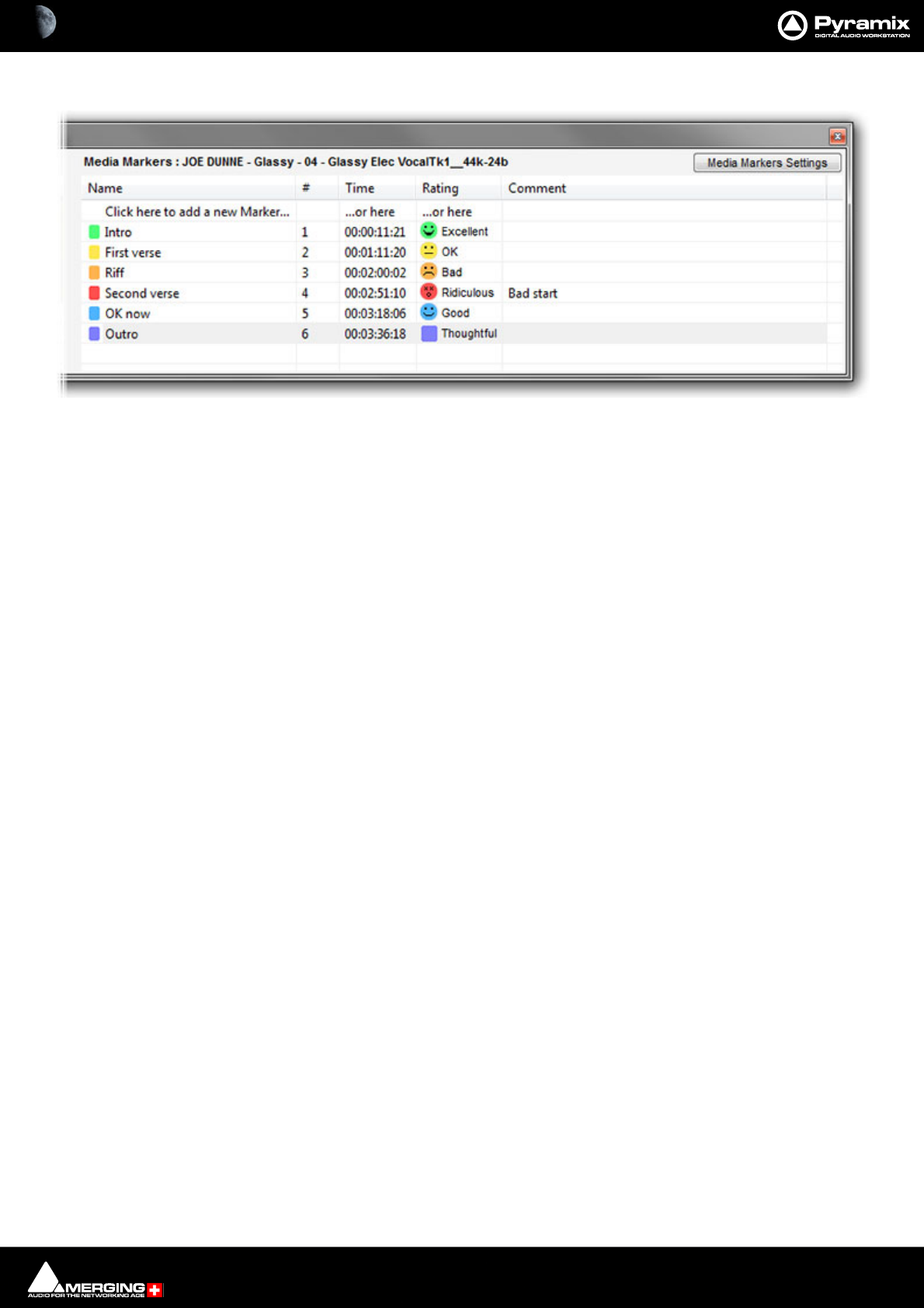
Transport and Navigation : Markers 6 - 138
In the Marker Tab:
• The selected Clip name is shown at the top.
• The Media Marker section displays the list of Media Markers in the Clip selected currently.
• Media Markers can be added, deleted and modified here like standard Markers.
•To change a Rating click the marker you wish to change in the Rating column. A list drops-down with the
standard ratings and the ten custom ratings. (See immediately below.)
Media Markers section of Markers tab
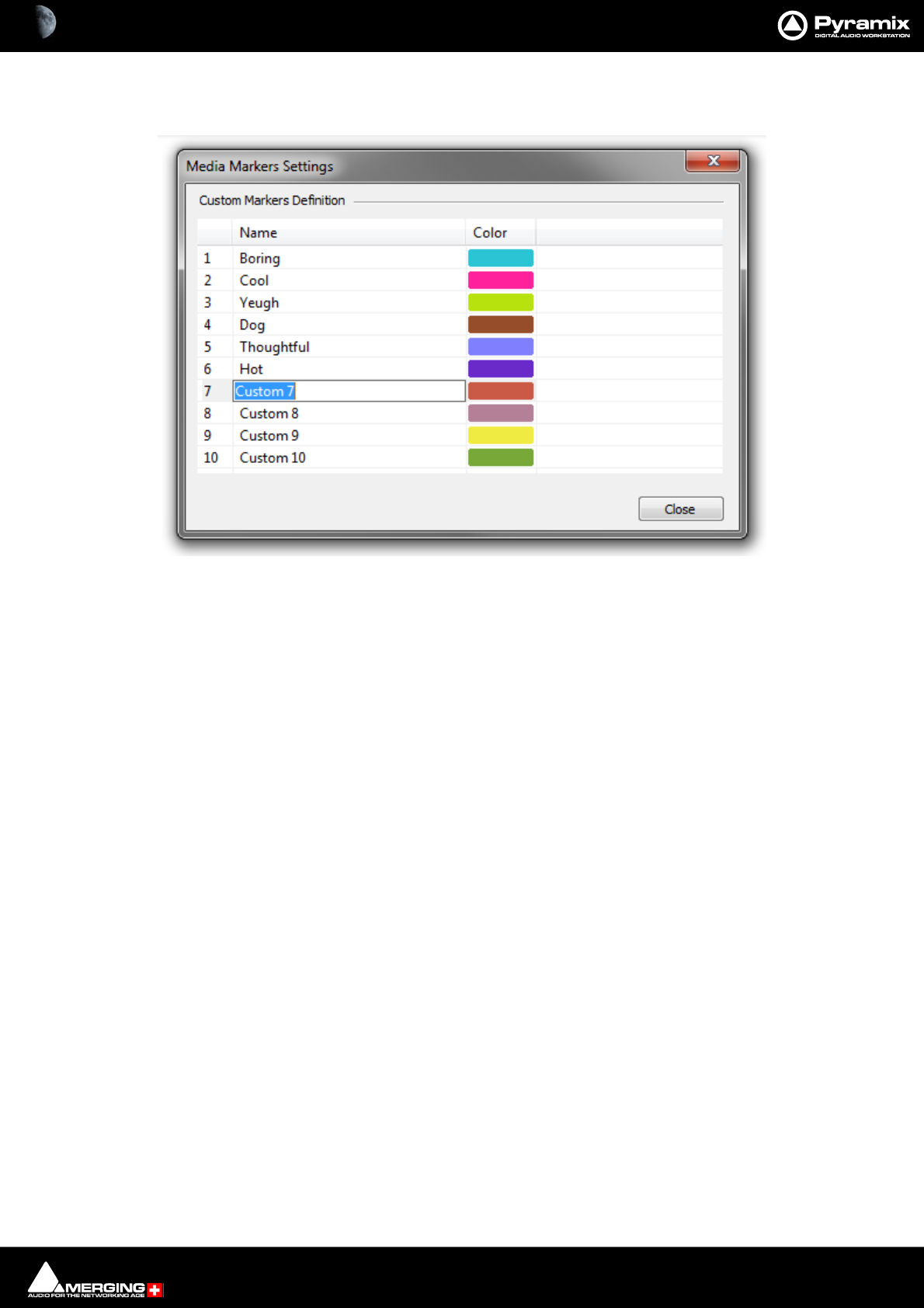
Transport and Navigation : Markers 6 - 139
Media Markers Settings - Custom Markers
Clicking on the Media Markers Settings button opens the Media Markers Settings dialog:
By default the 10 Custom Markers are labelled Custom 1 to Custom 10. Click in the field and type to rename the
Marker. Clicking on the Color pops-up a color picker where any color desired can be selected.
Note: Custom Media Markers have no effect on the Rating Line when inserted between standard
Media Markers.
Media Markers - Undo
Undo /Redo operates as normal when Adding, Deleting and Modifying Media Markers of an existing Clip/Media
File.
When Adding, Deleting and Modifying Media Markers while recording a Media File:
• In the Timeline: Undo / Redo works as normal while the recording continues. When the recording is
stopped nothing that has been done during recording can be undone.
• With Background Recorders whose recordings are being edited in the Timeline in the active Project: Undo
/ Redo works both during recording and after the recording is stopped.
• With Background Recorders whose recordings are NOT being edited in the Timeline of the Active Project
(I.e. when using the Take Logger.) There is NO undo for Media markers.
Editing Media Markers During a Recording in the Timeline:
If there is a Recording happening in the Project Timeline (and there are no selected Clips),the Marker Tab displays
the Markers for the current Recording.
Media Markers for the current Recording can be added, deleted and modified exactly like for the selected Clips.
Media Markers created during a Recording are saved automatically in an .mmd file in the same location as the
recorded file.
Note: This is not available in Dubbing Mode.
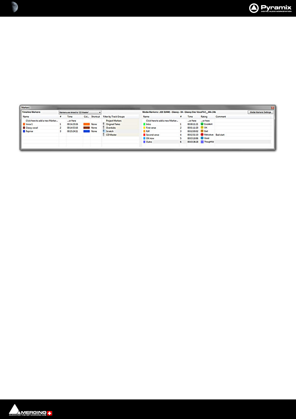
Transport and Navigation : Markers 6 - 140
Editing Media Markers during a Background Recording:
Media being recorded with a Background Recorder can be added Media Markers by using the Edit while Record-
ing option.
The growing Media in the timeline being recorded by a Background Recorder can have Media Markers added in
exactly the same way as any other Media placed in the Timeline.
Media Markers created during a Background Recording are saved automatically in an .mmd file in the same loca-
tion as the recorded file.
Markers Tab Window
Markers can also be added and managed from within the Markers Tab Window.
Different lists of Markers can be edited by selecting the desired Track Group or the main Project Markers list in
the Markers Tab Window. Markers are numbered in ascending order by their position in time. If a Marker is moved
before or after another Marker, the affected markers are automatically re-numbered.
Clicking on the first entry in the Name or Time Fields ‘Click here to add a new Marker... or here’ Adds a new
Marker at 00:00:00:00 This value can be edited in the usual way.
Marker colors are user selectable. Clicking in the Color field drops down a list box with all the available colors.
Double-clicking on a Marker’s Name Field jumps the Playhead Cursor to the Marker.
Double-click with CTRL pressed plays from the marker TimeCode
Double-click with SHIFT pressed plays from the marker TimeCode with the first Preroll. This also applies to CD
markers
Right-click to open a menu that enables Markers to be Cut / Copy / Pasted between Groups or Projects.
Markers Tab Window

Transport and Navigation : Jog / Shuttle 6 - 141
Jog / Shuttle
Shuttle
The transport can be shuttled with audio output at up to 8 times speed.
Jog Wheel Settings
Jog Wheel Mode
Jog Wheel Mode is selected in Machines > Controllers.
Jog Wheel Settings
Jog / Scrub parameters are set in Settings > All Settings > Application > Jog / Chase.
Auto Jog on move
When checked moving the jog-wheel enters Jog mode. When Auto-Jog is enabled, all Jog Commands are pro-
cessed a slightly different way. Pyramix temporarily stops chasing and starts Jogging while sending Goto com-
mands to the External Machine. The audio is therefore perfectly scrubbed and the external machine follows the
audio as well as it possibly can. When the user stops Jogging, Pyramix automatically returns to chase mode.
Geared Jogging
When checked the jog wheel “gearing” I.e. the amount you have to turn the wheel for a given amount of cursor
movement is related to the current Zoom level.
Jog Speed ceiling
Sets the maximum jog speed from a choice of 1X, 2X, 4X or 8X play speed
Jog Sensitivity
The value typed in the box (in seconds) determines the number of seconds the transport will move per revolution
of an attached physical jog wheel.
Flywheel responsiveness and inertia
Responsive follows the actual movements as sent by the jog wheel. Smooth passes the actual movement
through a smoothing filter. So, when the slider is set to Responsive the Smoothing Filter parameters have no
effect. For sound to picture work where tight sync to picture is required use a setting biased to Responsive. For a
more pronounced flywheel effect choose a Smoother setting. The Middle position is a good starting point.
Jog - sensitivity [0.33] second(s) per revolution
Sets the time moved in one revolution of the jog wheel. Type the required value in the box.
Shuttle - sensitivity [2] revolution(s) for nominal speed
Sets the fraction of a revolution or number of revolutions required to maintain nominal speed. E.g. an entry of 0.25
will require a quarter of a turn clockwise to achieve nominal speed.
Navigate - sensitivity [3] revolution(s) to traverse the timeline
Navigate is silent jog mode. Sets the number of revolutions of the jog wheel required to traverse the visible time-
line. I.e. the actual speed varies with the zoom setting.
Geared Jog mute when timeline view range is > 00:00:10:00
Audio will be muted when the TimeLine view range exceeds the value in the register.
Fine Jog sensitivity factor [ ]
Sets the fraction of the regular Jog Sensitivity Setting that will be invoked when Fine Jog is selected in the
Machines > Controllers menu.
Mouse Scrubbing Settings
There are two scrub modes, Analog Tape Mode and Repeat Loop Mode. Check the appropriate box for the
required mode. The length of the loop in Repeat Loop Mode is related to the base sampling frequency so the
loop will be 116mS long at 44.1, 88.2 and 176.4 kHz or 106ms at 48, 96 and 192 kHz.
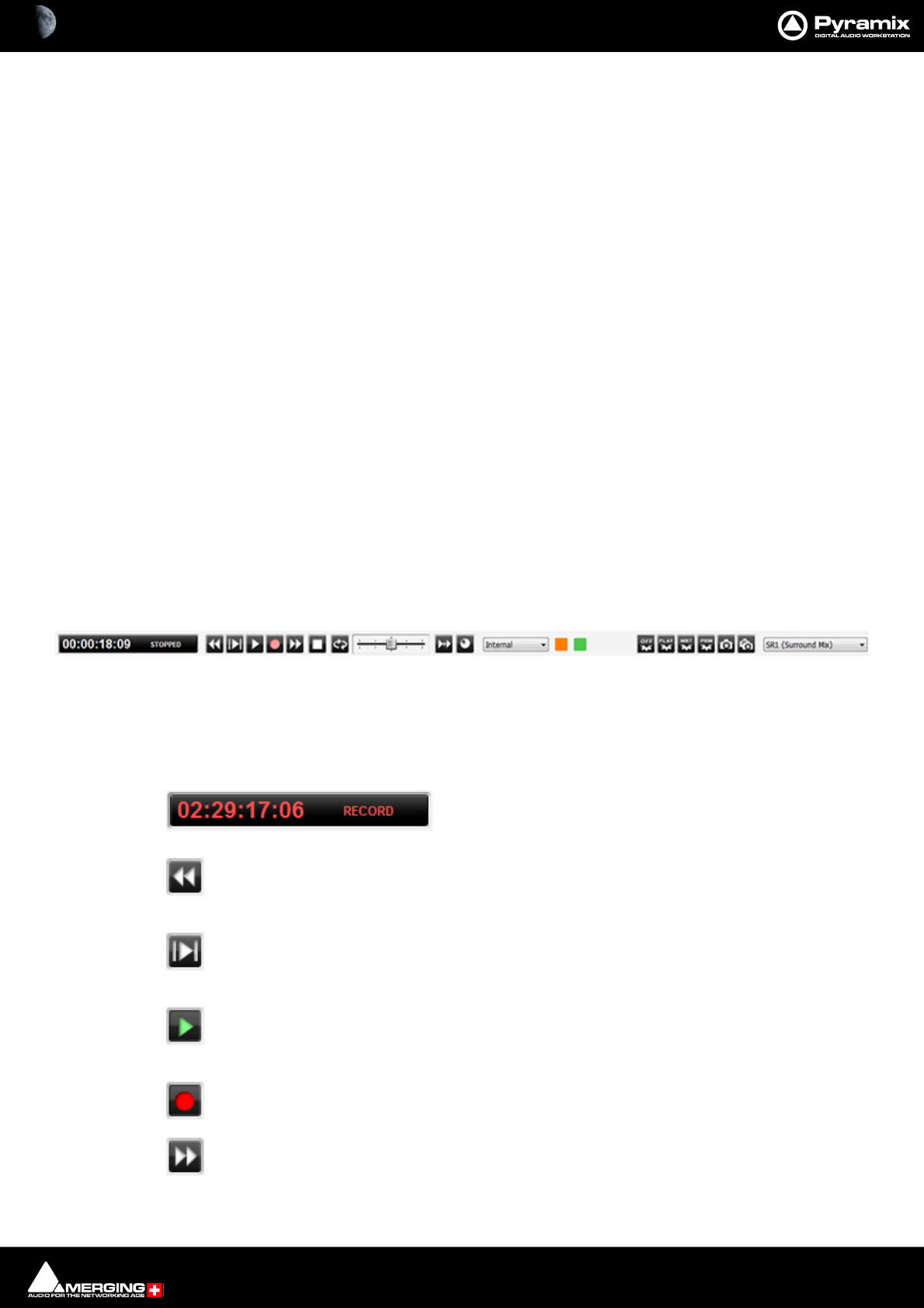
Transport and Navigation : Transport Controls 6 - 142
Analog Tape Mode gives a similar response to ‘reel-rocking’ on an analogue tape machine.
Jog anyway
When lit, Jog Mode is used regardless of how much audio is visi-
ble in the Timeline
Shuttle when more than 10 [s] is shown in the Timeline
When lit, if there is more than 10 seconds of audio visible in the
Timeline scrub will be in Shuttle Mode
Repeat Loop Mode continuously repeats a short loop starting at the cursor position.
Vari Speed Audio Quality
High when playing less than of equal to [6] track(s)
Best when playing less than or equal to [2] track(s)
MassCore : the varispeed quality is set automatically according to the current core load.
Native : the playback quality is defined by the playback streams numbers set above.
Fast Speed Settings
F.FWD and REW nominal speed ratio [20]
Type in the box to set the nominal F.FWD and REW speed. (I.e. a value of 20 means 20 times sync play speed)
Transport Controls
The Transport Bar brings together the most commonly used Transport Controls, Chase and Capture Offset but-
tons, and a Counter / transport status display.
From left to right, the controls are as follows:
The counter shows the current Active Machine position and transport mode.
Counter in Record mode.
The Rewind button moves the Active Machine at an accelerated speed backwards. A sec-
ond press doubles the speed.
The Play Selection button plays the current highlighted selection area when the Active
Machine is the Internal Machine (Pyramix).
The Play button plays the Active Machine at normal speed forward. A subsequent press
Pauses playback and another Restarts.
The Record button puts the Active Machine into Record mode.
The Fast Forward button moves the Active Machine at an accelerated speed forwards. A
second press doubles the speed.
Transport Bar

Transport and Navigation : Transport Controls 6 - 143
The Stop button stops playback.
The Loop Play toggle button puts the Active Machine into a Loop Play Mode, which continu-
ously plays between the current In and Out points.
In the default, Shuttle, mode the Shuttle Control slider shuttles the Play Head for-
ward (right) or backward (left) at up to 8 X play speed. (Depending on the Jog Speed Ceiling
Setting in Settings > Jog Chase. When Machines > Controllers > Jog Wheel Mode - Pitch
is selected the slide varies playback speed plus or minus 25% when the transport is in Play.
When the transport is not in Play the slider operates in normal, Shuttle, mode.
When the Chase toggle button is active, the Active Machine will only play back when valid
time code is detected on the chosen TimeCode input port.
The Controllers Online / Offline button. (Grey = Online Red = Offline) Toggles external hard-
ware controllers On and Off line.
The drop-down list selects which machine is currently controlled. Select Internal
from the list to ensure you are directly controlling the Pyramix Composition Play Head and
not some external device (I.e.RS-422 Sony 9-pin P2 controlled machine)
The colored buttons indicate the presence of a Background Recorder or recorders. One
button will be shown per Background recorder. Clicking on a button switches the Transport
Bar controls to the associated Background Recorder. Please see also: Background
Recorders on page 150
To the right of this is an area where any of the Floating Tool Palettes can be ‘Docked’. By default this will have the
Automation Toolbar docked. Please see: Global Dynamic Automation Modes on page 400
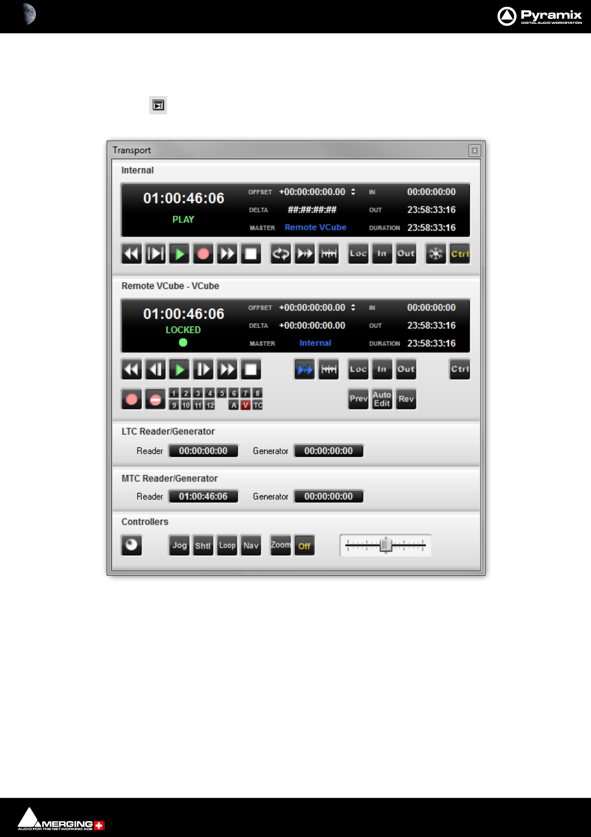
Transport and Navigation : Transport Controls 6 - 144
Transport Control Panel
Pressing the Transport Control Panel button or [Alt T], or selecting View > Windows /
Tools > Transport opens a floating Transport Window displaying all available
machines with individual sets of buttons and status indicators.
Note: This Window contains a set of transport controls for each machine installed and enabled
with the Internal Transport (Pyramix) at the top. Below the machines are displays for LTC and
VT2 (and MIDI when applicable) TimeCode Sources and at the bottom of the panel there are con-
trols which indicate and control hardware Remote Controllers Online/Offline (red = Offline), Jog-
Wheel Mode, and Shuttle.
Clicking on the black name bar toggles the individual area between collapsed and full.
Important! For details of machine installation and settings Please see: Machine on page 768
and for details of these Transport Controls Please see: Internal / External Machine panels - Features
on page 575
Transport Control Panel floating Window
Transport and Navigation : Zooming and Panning 6 - 145
Zooming and Panning
The Project Editing Panel allows two kinds of zoom: horizontal or Time Scale zooming; and vertical or Track
Height zooming.
Time Scale Zoom and Pan
Icons on the View Toolbar zoom in or out at the current Play Head location.
The Fit in window [Alt 1]icon on the Toolbar automatically adjusts the horizontal scale to fit
the selected area inside the Project Editing Panel with a small margin.
The Previous zoom [Alt 2] icon restores the horizontal scale to the previous size.
Zoom In [Alt 3]and
Zoom Out [Alt 4]
Holding down the Alt key, then selecting an area of the Composition by clicking and dragging the mouse to the
left or right zooms in horizontally on the selected area.
Similarly, an area of the Composition can be selected by clicking and dragging.
The Scrollbar beneath the Tracks Pans the view of the Timeline horizontally left or right.
Track Height Zoom
1, 2, 4, 8, 16, and A buttons at the bottom left of the Project Editing Panel automatically scale the vertical Track
size so that 1, 2, 4, 8, 16 or All (as many as possible given the vertical space) Tracks fit in the vertical space allocated
to the Project Editing Panel.
The horizontal Scrollbar adjacent to these buttons enables continuous adjustment of the Track height.
Scroll Wheel
It is well worth while using a three button mouse with a scroll wheel.
Scroll Scrolls vertically through the Tracks shown in the Project Editing Panel
Scroll + Ctrl Scrolls the Timeline
Scroll + Alt Zooms the Timeline timescale
Scroll + Shift Changes the Track height
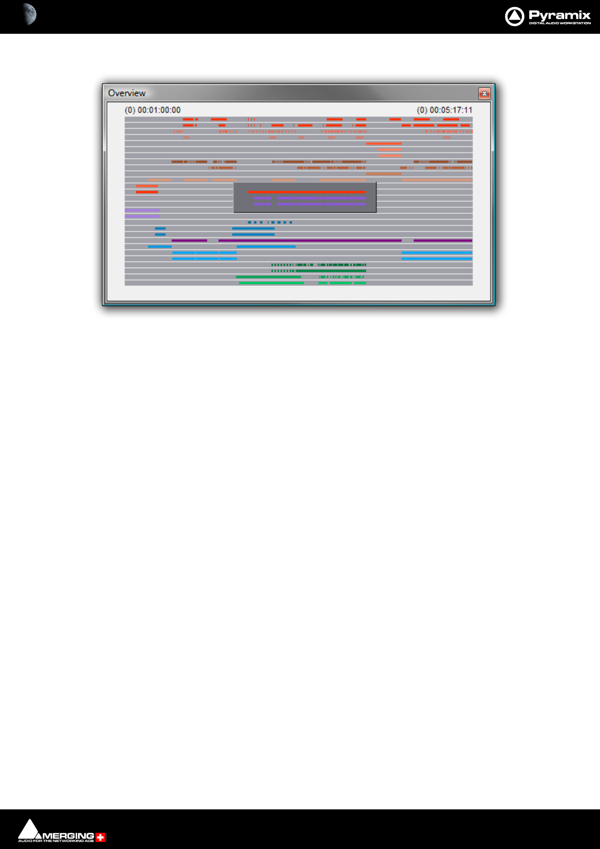
Transport and Navigation : The Overview 6 - 146
The Overview
The Project Management Panel Overview Tab offers a powerful and simple means of navigating around the Proj-
ect Editing Panel.
Overview displays a graphic representation of the entire current Composition, showing the location of all Clips.
A shaded gray box indicates the location and zoom range of the part of the Composition which is currently dis-
played in the Project Editing Panel. Clips are shown as rectangles in the same color as their background on the
Timeline.
Click anywhere in the Overview to center the Project Editing Panel display on that point. Click and drag on the
shaded gray box to move the section of the Composition shown in the Project Editing Panel without changing the
current horizontal zoom. The zoom range of the Project Editing Panel can be adjusted by dragging the edges of
the shaded gray box in the Overview. An alternative method for adjusting horizontal zoom is to press the Alt key
while clicking and dragging across the desired range for the zoom, just as you can do directly in the Project Editing
Panel itself.
Virtual Transport 2
VT 2 is a built in synchronizer. It synchronizes VCube with Pyramix running on the same machine or on a remote
machine connected over the network. Please see: Virtual Transport 2 on page 778
VT 2 also provides MIDI Sync capabilities. Please see: MIDI Sync on page 721
Overview Tab Window

7 - 147
www.merging.com/Pyramix
USER MANUAL
Recording and Acquisition

Recording and Acquisition : Getting Audio into Pyramix Virtual Studio 7 - 148
Getting Audio into Pyramix Virtual Studio
There are four primary methods of getting audio into Pyramix: You can record audio directly into the Timeline of a
Pyramix Editing Project, record audio using a Digitizing Session, use Background Recorders or you can import
audio files existing previously.
Please see also: Digitizing Sessions on page 166, Background Recorders on page 150 and Importing
Audio Files into Pyramix Virtual Studio on page 163.
Check Sync
Before attempting to record any audio please check Pyramix and the audio source(s) are synchronized as you
intend.
MassCore
Verify PTP sync (green) under RAVENNA.
Native
Project sampling rate should match ASIO interface sampling rate.
File Format and Disk Limitations
File Size Limitations
By design legacy SD2, WAV or BWF files are limited to a maximum of 2GB due to their 32bit signed addressing
(thus 31 available bits) formats, while 32bits unsigned addressing AIF files are limited to 4GB. Please keep this in
mind when recording and/or exporting to any of these formats, the 2GB/4GB limit might in fact be quite close,
particularly when working with high sample rate multitrack files.
As a comparison, Pyramix, thanks to its own PMF 64bit addressing file format, can generate PMF files of virtually
limitless size. This makes it the file type of choice for creating single file, large multitrack projects at high sampling
rates.
The WAV file format can now accommodate RIFF64 removing the 2GB limitation. Please see: WAV and BWF on
page 475
Hard Drive Limitations
A very similar 2GB/4GB* limit can also be encountered the hard way when attempting to write large files, even in
PMF format, onto storage units (hard drives, memory cards etc.) formatted using an old 32bit file system such as
FAT32 or HFS.
Yet another, higher, limitation also exists with IDE ATA/ATAPI drives. This will show up at around 137GB. This may
be caused by part of a system (drivers, controllers and/or old Windows version) only recognizing the 28bit
addressing of the original ATA specifications, and not the enhanced 48bits available on newer equipment. This is
usually solved by installing fresh and or updated Bios/Drivers/OS.
*The official limit is 4GB, but serious trouble can start at around 2GB.
Pyramix audio file format
Unless there is a good reason for using another file format for recordings we strongly recommend using the
default .PMF file format. This will give the best performance in a number of key areas. For further information
please see: Optimizing Pyramix on page 663
Recording Audio into a Pyramix Virtual Studio Project
Start a new Project, or open an existing one. Make certain the Mixer sample rate and sync source is set as desired.
You will need to configure at least the same number of Mixer channels as Tracks you wish to record.
Before beginning audio capture, check or select appropriate record settings. Open the Settings > All Settings >
Project > Record page (alternatively use the keyboard short-cut Ctrl - f and click the Record Tab) There are many
settings in this dialog page, but for now you need only be concerned with; Destination Drive (Media File folder),
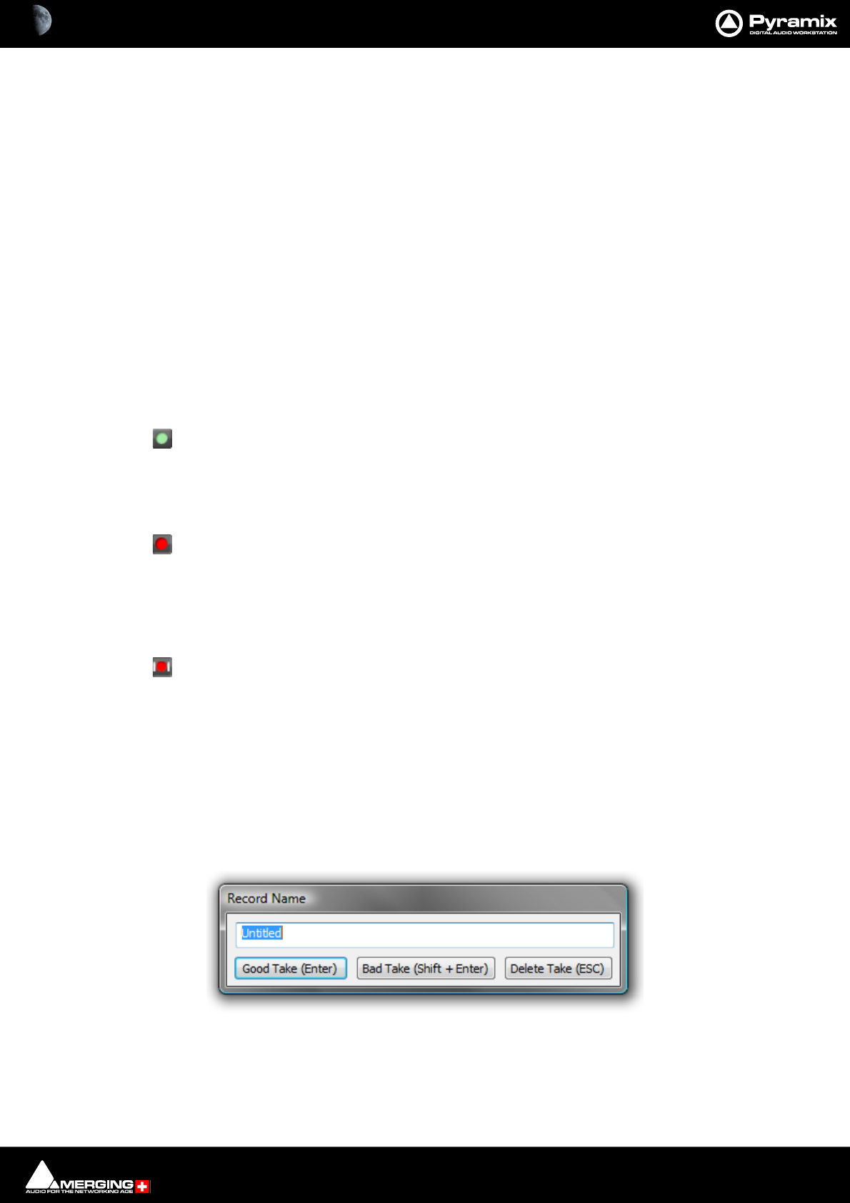
Recording and Acquisition : Getting Audio into Pyramix Virtual Studio 7 - 149
Resolution (bit depth or word length) and Format (file type). As previously mentioned, unless you have a specific
reason for using a different format we recommend using the default PMF format.
Note: These settings are completely independent of the settings for Mix-down and Render.
Record Source Before or After Effects
The record source can be before or after any effects in the Mixer Strip. This can be set globally from the Gain +-
pop-up menu or individually from the right-click context menu when hovering the mouse pointer over the rele-
vant strip.
Track Record Modes
Each Track has a tri-state Record Ready toggle button, located to the left of the Track itself in the Track Informa-
tion and Setup Area.
Tip: Right clicking on a Track arming button opens the Settings > Project page immediately on the Record page.
Play
The Green Dot in the Track Header indicates Record Safe mode, the default when Tracks
are newly created. When in this state, the Track cannot be recorded to.
Record Ready (Manual)
Click on the Green Dot once to toggle to Record Ready mode. This is indicated by the dot
turning into the Red Dot. The Track will now go into Record mode immediately when the
Master Record button is pressed in the Transport Strip or Transport window.
Record Punch In (Auto)
Alt-Click on the Red Dot to toggle to Record Punch In mode. This is indicated by a Red Dot
flanked by 2 red vertical lines. In this mode, when the Master Record button is pressed in
the Transport Strip or Transport window, the Track will stay in Play mode until the current
Mark In point is reached, then the Track will go into Record mode. It will stay in Record
mode until the current Mark Out point is reached.
After Recording
New recordings will be processed according to the settings made in the Settings > All Settings > Project >
Record page. Please see: Record on page 736
If the Prompt for name after recording box is checked the Record Name dialog appears when the recording is
finished and the transport stopped.
Type a name for the recording (or leave the default) then select one of the button options.
Record Name dialog

Recording and Acquisition : Background Recorders 7 - 150
AutoPunch Mode
AutoPunch when Chasing TimeCode
If Tracks are set to Auto-Punch mode (Alt+Click on Rec Ready button) then the system will start recording (after
locking to TC) when it reaches the Mark In point and punch out when it reaches the Mark Out point.
If the Mark In is located before the current location (and the Mark Out far after) then the system will immediately
record once locked and stop recording when unlocking.
Recording from a tape with Discontinuous TimeCode
Pyramix AutoPunch Mode makes this a simple operation.
• Place the Mark In at 00:00:00:00 and Mark Out at 23:59:59:24 (default values for a new project)
• Connect LTC Out from the tape machine into Pyramix
•Set Chase mode to HARD CHASE
• Rewind the tape
• Press Play on the tape machine
Each time a valid TC is encountered Pyramix will lock and start recording a new Clip, then stop when the timecode
stops or jumps. A separate media will be created for each continuous section of timecode on the tape.
SafetyRecord Mode
Pyramix is equipped with a Safe Record mode for the Internal Machine.
Safety Record is turned off by default. It can be activated by selecting Machines > Internal Machine >Safety
Record. When this mode is active an S is superimposed on the Transport Controls Record button.
Once a recording has begun the only way to stop it is to go to the Menu and de-activate Safety Record mode.
Apart from this no key presses, mouse clicks or external control inputs will stop the recording.
Note: Whilst it is possible to assign a Keyboard Shortcut to the Safety Record toggle, for maxi-
mum security, it might be wiser not to.
Background Recorders
Pyramix is equipped with a very powerful Background Recorder. Up to four Background Recorders may be set up
with one or two sets of record locations and parameters per recorder. (Format, Media File Count, Waveform Media
destination and edit while recording settings.) Each Recorder has its own Mixer. This is configurable in exactly the
same way as the ‘normal’ Pyramix Mixer. The default mixer has 8 strips for 8 track recording. To record greater track
counts reconfigure the mixer with the number and type of strips required.
Typically, Background Recorders will be used in the following ways:
• When recording a concert a backup or backups can be recorded simultaneously.
• In live broadcasting. While recording the recorded file is accessible and can be output for transmission
with a few minutes delay for safety reasons.
• Archiving - record multiple sources and manage the process from a single interface without the need to
switch between digitizing sessions.
• Multitrack recording without the distractions of the Timeline.
• Pre-buffering enables up to a minute of audio to be recorded before the record button is pressed.
Editing While Recording
Clips can be edited while they are still recording. This will be useful in the situations above and also for any appli-
cation where a lot of voice is recorded. E.g. in radio, when recording talking books and anywhere fast turnaround
is a priority.
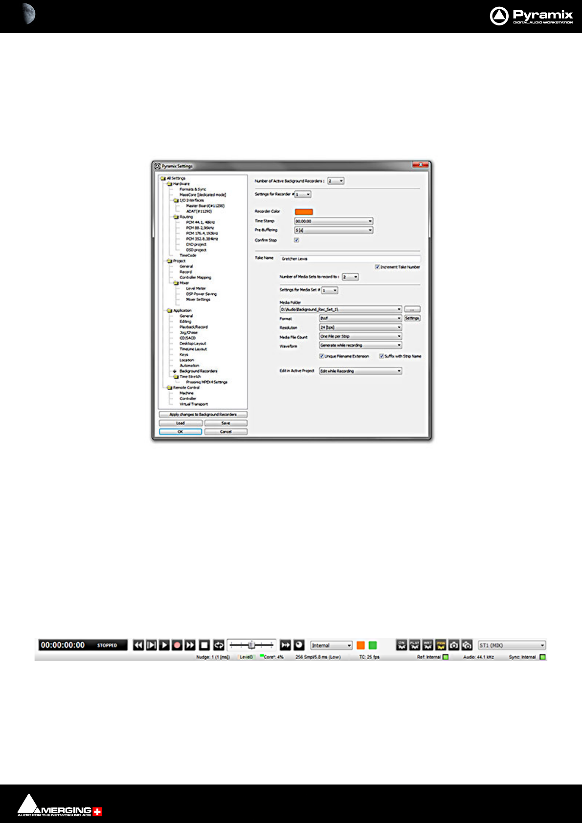
Recording and Acquisition : Background Recorders 7 - 151
• Record two or more wild voice-overs and edit while still recording.
• Transfer from a linear master tape and begin clean-up and eq while the transfer continues.
Set-up and Operation
Set-up
Background Recorders are set up in the Settings > All Settings > Application > Background Recorders page.
Please click here to see: Background Recorders on page 764.
Mixer
Each Background Recorder has its own Mixer. This is fully configurable in exactly the same way as the main Pyra-
mix mixer. Please see: Mixer on page 207
Note: The default Mixer is configured with 8 mono strips. For multi-track recording up to the
capabilities of the system reconfigure the Mixer accordingly.
Operation
Once one or more Background Recorders have been set up they are operated from the Transport window or the
Main Pyramix Window Transport Controls or the Take Logger.
Main Pyramix Window Transport Control Bar
Settings > All Settings > Application > Background Recorders
Main Window Transport Control Bar

Recording and Acquisition : Background Recorders 7 - 152
The orange and green buttons show the presence of two Background Recorders. The button color will reflect the
color selected in the Background Recorders Settings page.
Clicking on the buttons focuses the Transport Controls on the Background Recorder clicked on. This is exactly the
same as selecting the Recorder in the adjacent drop-down list.
Background Recorder Indicator buttons
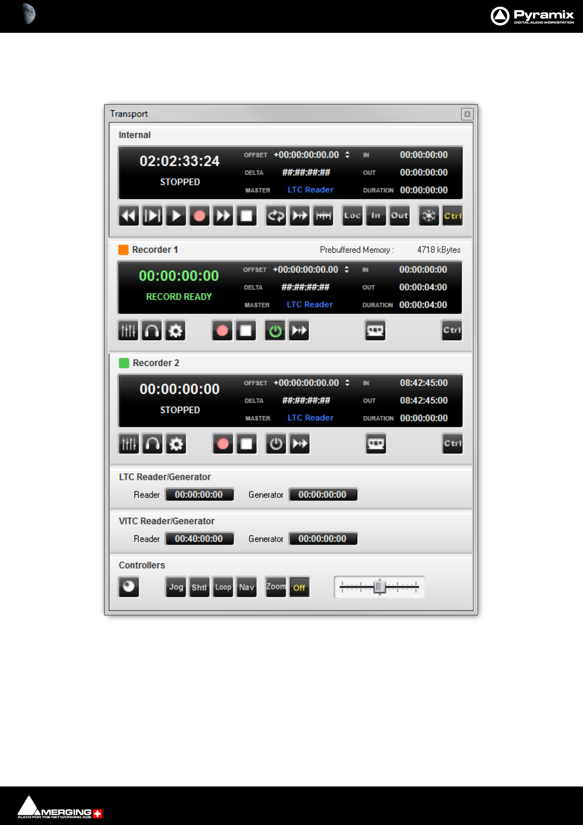
Recording and Acquisition : Background Recorders 7 - 153
Transport Window
(Click on the icon to open or View > Windows / Tools > Transport.
Transport Window

Recording and Acquisition : Background Recorders 7 - 154
Background Recorder Transport Control Panel
Clicking on the title bar toggles the panel between collapsed and full. When pre-buffering is active the amount of
memory used is shown in the title bar.
Upper Section of Panel
For detailed information on the upper section of the panel please see: Internal / External Machine panels -
Features on page 575
Controls
Toggles the Mixer window associated with the Background Recorder open/closed.
Toggles the Monitor source between the Pyramix Timeline Mixer and the Background
Recorder Mixer. Lights yellow when Monitor source is the Background Recorder.
Opens Pyramix Settings on the Background Recorders page.
Starts Recording.
Stop - One press Stops the recording but leaves the Recorder Enabled.
Enables the Recorder.
Enables/disables Chase. Lights blue when Chase is enabled.
Opens a floating Media Management Window showing the recordings.
Ctrl Control, lights orange when active. Pressing Ctrl or selecting it in the Transport Toolbar
combo box routes keyboard shortcuts, Sony 9-Pin commands or controllers to the Back-
ground Recorder.
Notes
• Each recorder acts as an independent machine like the Internal or any External Machine.
• Background Recorders are started and stopped manually from the Transport Window.
• When set to Chase Background Recorders follow the current Master.
Background Recorder Transport Control Panel

Recording and Acquisition : Background Recorders 7 - 155
• The Mixer has all the same features as the main Pyramix Mixer and is configured and operated in the same
manner.
• The Mixer is saved on quitting the application and when the settings are confirmed by clicking OK.
• Tracks can be armed from the Mixer with a button next to the strip number at the bottom of the fader. The
button turns red when the associated Track(s) are Rec armed.
• All Mixer inputs are pre-buffered but only the Armed Strips are recorded when Recording commences.
• The Background Recorder Mixer can be monitored in the Monitoring Section by clicking on the monitor-
ing button in the transport control panel.
• Background Recorders can also be controlled from the Transport Control Toolbar in the main Pyramix win-
dow by selecting them from the drop-down list.
Enable Record
• When the Enable button is active or Play is active in the Transport Toolbar, the Recorder starts to pre-buf-
fer data. (When pre-buffering is active.)
• The amount of pre-buffered data is visible in the Duration counter in the machine display.
• The amount of memory consumed by the pre-buffer is shown in the title bar of the recorder control panel.
•The In and Out counters show the Timestamps for the recording that WILL be performed when Record is
initiated.
• Entering Chase mode enables the recorder and starts to pre-buffer data once the machine is locked to the
selected incoming Timecode. The In and Out registers then refer to the incoming chased timecode.
Recording
• When record is initiated the all pre-buffered data is sent to the media file(s).
• When the recording is Stopped the file(s) of both Media Sets are closed and data is once again pre-buff-
ered immediately. I.e. One click on Stop leaves the Recorder in Enabled mode. A second click on Stop or
clicking on the Enable button or disabling Chase ends the buffering.
• The amount of memory used to pre-buffer data and cache the recording is displayed in the header of the
Background Recorder machine on the right of its name. An ever increasing amount here shows that the
system may stall rapidly.
Edit while Recording
• When recording a new file or files with the Background Recorders, the file(s) being recorded can be edited
in a Timeline while the recording continues.
• This is also possible for recordings in the Timeline but only in non-dubbing mode and only when using
the MTFF file formats for the recording. (lossless only available as an output format)
• When a recording starts the new media being recorded appears in the media manager immediately, col-
ored the same as the recorder color for easy identification.
• The media can be dragged to the Timeline and edited while it grows in size.
• The clips in the Timeline are also colored with the Recorder color and the end of the edited clips continues
to extend automatically as the recording progresses. This only applies when the clips are the last clip on
the Track to avoid undesired collisions.
• Multiple recordings coming from different machines can be edited at the same time.
• The media being recorded can be sent for editing automatically when the recording begins. Please
see: Background Recorders on page 764.
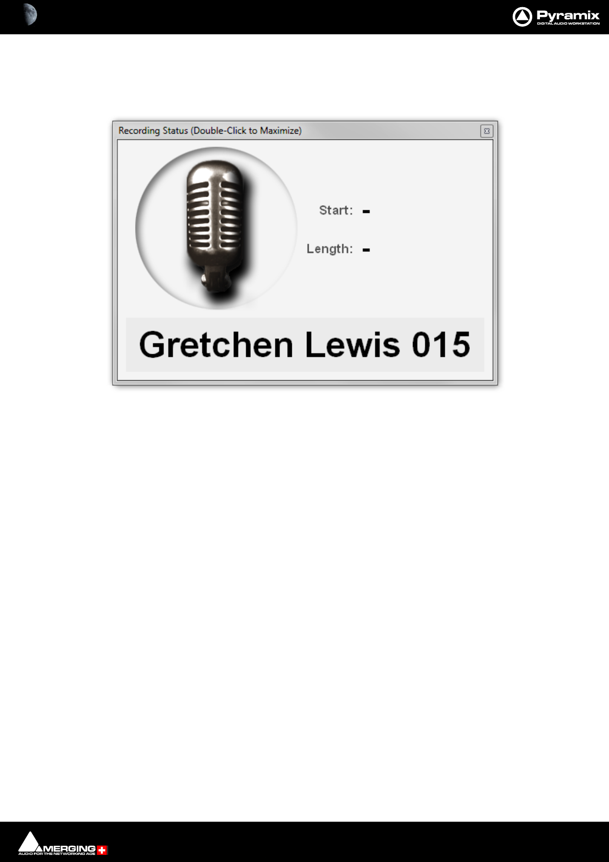
Recording and Acquisition : Recording Status 7 - 156
Recording Status
The Recording Status window is opened from View > Windows / Tools > Recording Status or [Alt + R].
The window can be maximised to full screen by double-clicking anywhere on the window. A subsequent double-
click restores to the original size. The Window can also be resized in the normal Windows manner.
The Start and Stop fields are blank until recording is initiated.
When specified in the Record Settings page, in the Background Recorders Settings page or in the Take Logger
the Take Name is shown at the bottom. When no Take Name is specified it will show Untitled. The Take name is
updated in real time when modified in the Take Logger.
Recording Status Window - Stopped
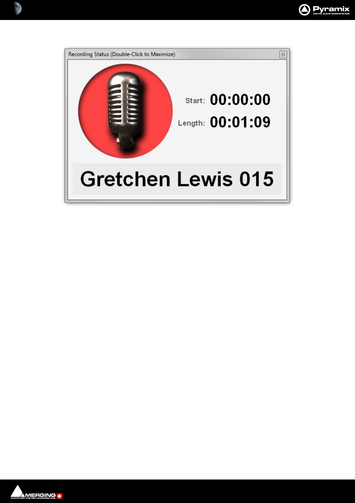
Recording and Acquisition : Recording Status 7 - 157
When in Record the window changes. The “mic” turns red and the Start and Length fields are populated:
Note: If the current recorder is the Active Project and this Project is displaying the Bars & Beats
ruler then the Start: time is displayed as a Bars - Beats counter.
Recording Status window - Recording
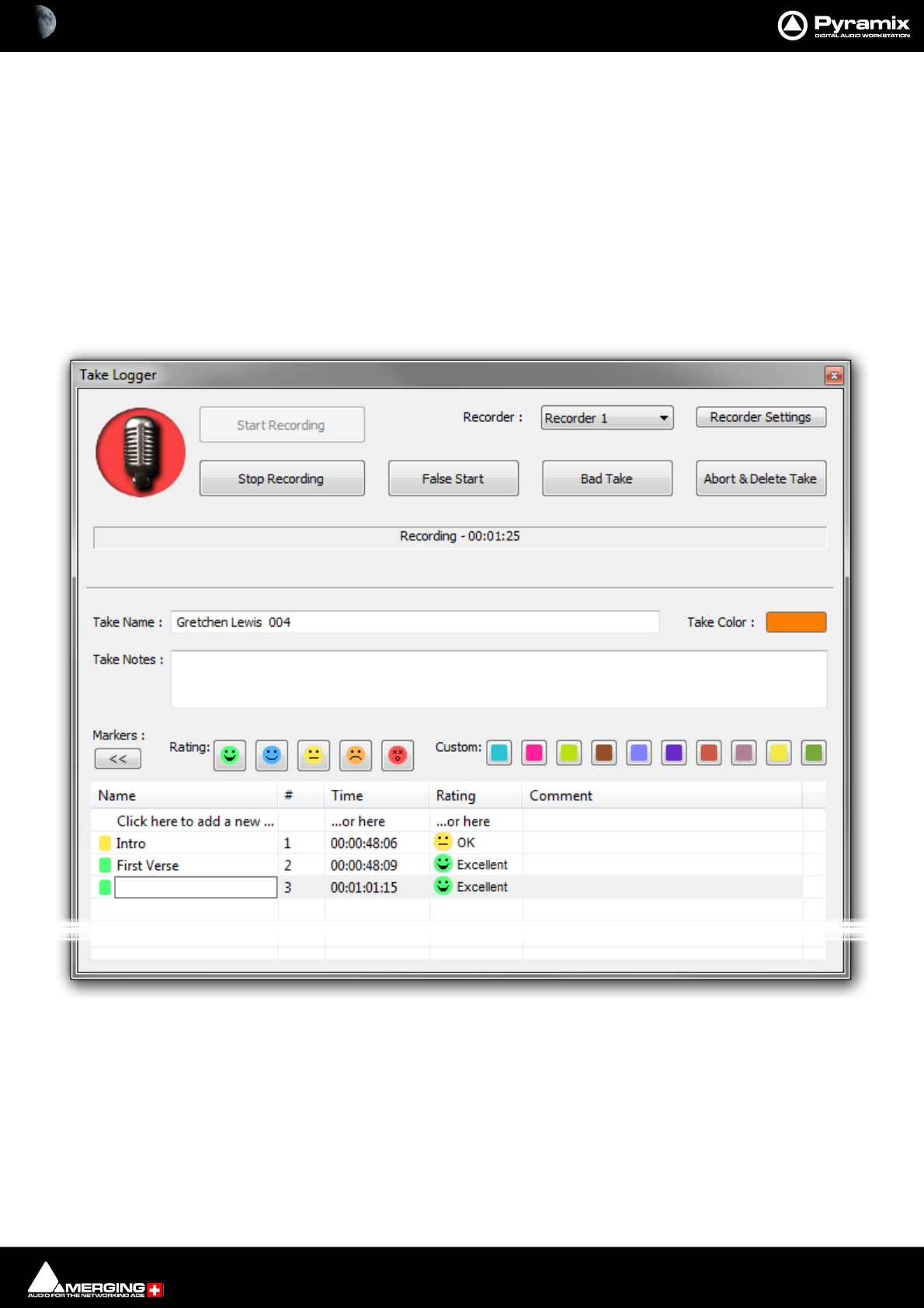
Recording and Acquisition : Take Logger 7 - 158
Take Logger
Scope
The Take Logger can control any available recorder, the Active Project or any Background Recorder. The Active
Project cannot be in Dubbing Mode.
Operation
Note: When the Take Logger has the focus ALL regular keyboard shortcuts are disabled. key-
board shortcuts specific to the Take Logger become active. These shortcuts are assigned in the
Keyboard Shortcuts Editor. Please see: Customizing Keyboard Shortcuts on page 509.
The Take Logger window is opened from View > Windows / Tools > Take Logger:
Start Recording
Clicking on the button Starts the recording on the selected recorder.
Stop Recording
Clicking on the button Stops the recording on the selected recorder. If this is a Background Recorder it is left in
Enabled mode. I.e. continuously pre-buffering for the length of time specified in Background Recorder Settings.
Use Stop Recording to end a successful recording. The Take number is incremented automatically.
False Start
Take Logger window
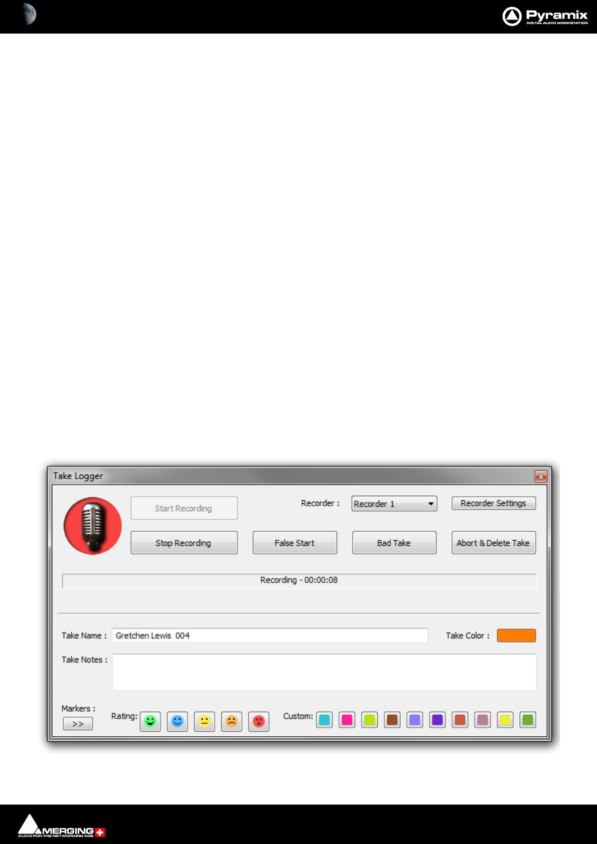
Recording and Acquisition : Take Logger 7 - 159
Clicking on the button adds a Media marker with the rating False Start (colored dark gray). All preceding Media
Markers are also changed to dark gray to indicate that this portion of the recording is bad.
Bad Take
Clicking on the button Stops the recording on the selected recorder. A Bad (xxx) suffix is added to the file name(s)
and to the Take Name. The resultant Clips will be colored in the Bad Take color specified in Settings > All Set-
tings > Application > Timeline Layout : Clips & Waveforms.
Abort & Delete Take
Clicking on the button Stops the recording on the selected recorder. The recorded file(s) are deleted and the Take
number is not incremented.
Note: If the Take Logger is being used to control a Background Recorder, the Media and Clips in
the Timeline are NOT deleted.
Recorder :
The field shows the recorder selected currently. Clicking on the field drops down a list of available recorders. This
will include the Active Project and any Background Recorders which have been set up.
Recorder Settings
Clicking on the button opens the Settings page for the selected recorder.
Status Field
The Status Field shows information about the current state of the recorder being controlled by the Take Logger.
This will be one of the following:
Stopped
Ready The selected Recorder is Enabled and ready to record.
Ready - Prebuffering The selected Recorder is in Enabled mode and is buffering audio to the duration
set in Background Recorder Settings.
Recording - 00:12:23 The selected Recorder is recording. The counter shows recording duration.
When recording the background of the mic symbol flashes red:
Take Logger window recording

Recording and Acquisition : Take Logger 7 - 160
Take Name :
The Take Name will be displayed automatically if specified for the selected Recorder. If no Take Name is specified
the field will show Untitled. Clicking in the field produces a cursor. Typing a Take Name here is the equivalent of
typing it in the Recorder’s Settings. A Take Number suffix is appended automatically where this is specified in the
Recorder’s Settings.
The Take Name is applied to the recorded file name(s), to the recorded file(s) metadata and to the recorded clips
shown in the Timeline.
Take Color :
Clicking on the box pops-up a choice of colors and More Color... which opens a color picker. The color chosen is
used to color the resultant clips in the Timeline.
Note: Take Name, Take Notes and Take Color can all be changed during recording. The infor-
mation is only stored when the recording is stopped.
Take Notes :
This is a free form text field. Information entered here is shown in the resultant Clips in the Timeline. Take Notes are
also saved in the MMD (Media MetaData) file in the same location as the recorded Media file(s).
Markers
Media Markers can be added in the Take Logger during recording by clicking on one of the Rating buttons. The
Media Marker is created at the elapsed time when the button is pressed.

Recording and Acquisition : Take Logger 7 - 161
Lower Section
>> Clicking on the [>>] button expands the Take Logger window to show Media Markers added to the recording
in progress. The button changes to [<<] clicking it contracts the window again.
Clicking on the first entry in the Name, Time, or Rating columns also creates a new Media Marker. In this case it is
given the rating Good by default.
Name A free text field
#Media Marker Number. This field is filled in automatically.
Time Shows the position of the Marker.
Rating Shows the Rating selected. To change a Rating click in the field to drop-down a list
with the five options and select.
Comment A free text field.
Note: Media Markers shown in the list remain editable whilst the recording continues. When the
recording is Stopped the list is removed.
Note: Media Markers are saved in the MMD (Media MetaData) file in the same location as the
recorded Media file(s).
Take Logger window recording

Recording and Acquisition : Take Logger 7 - 162
Managing Takes
When using the Take Logger the Take Name and Take Notes are also saved in the MMD file in the same location as
the recorded Media file(s). This data will populate the Media Manager fields. Take Name in the Name field and Take
notes in the Notes field.
You can sort by columns in the Media Manager in the usual way and use the right-click context menu > Locate to
select any Clips using that take in the Timeline.
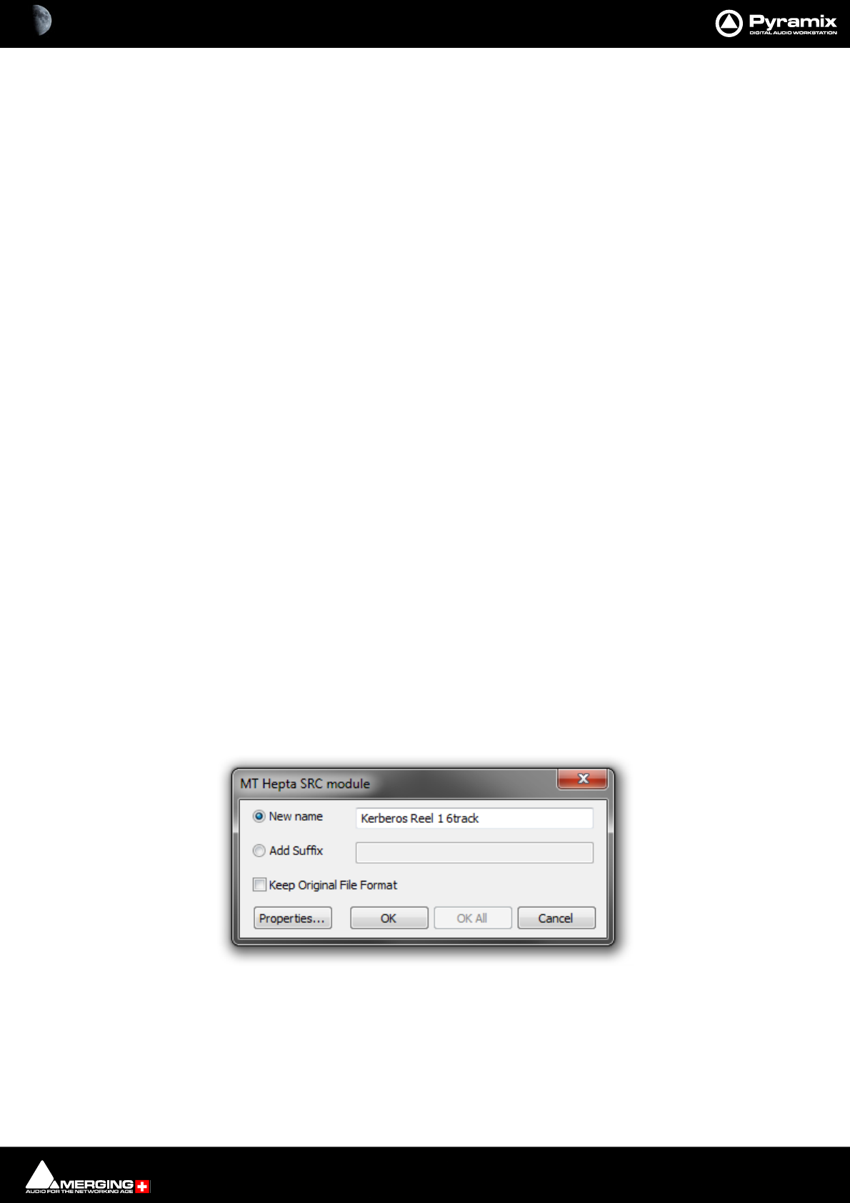
Recording and Acquisition : Importing Audio Files into Pyramix Virtual Studio 7 - 163
Importing Audio Files into Pyramix Virtual Studio
Different file types with different bit depths (word lengths) can be freely combined in a Composition. Simply
Mount the Media Drive or Media Folder and drag-and-drop the required material into the Timeline.
Files with different sample rates can also be freely combined.
Note: If a Clip has a different sample rate to the current project the Clip will play at the ‘wrong’
speed! E.g. in a 48kHz project a 96kHz Clip will play at half speed. With most material this will be
glaringly obvious, however with sound effects, smaller differences in rate (E.g. 44.1kHz - 48kHz)
may well go unnoticed.
Mounting Media Folders
If many audio files already exist in a single Windows directory or folder, it is easy to mount that Windows folder as
a Pyramix Media Folder. Once mounted, the supported files become available for use in a Project.
1. Start a New Project or Open an existing one.
2. Click the Media Management Tab in the Project Management Panel to open the Media window, or double-
click to open it as a floating window.
3. Select Media Folder > Mount Media Folder. This opens the Choose a media folder to mount dialog box.
4. Click the Browse... button, then navigate to the Windows directory containing the audio files you wish to
import.
5. Click the OK button to mount that Windows directory as a Media Folder. All supported audio file types will be
seen by Pyramix, and be available for use in the Project. A check in the Recursive box means Pyramix will look
in sub-directories of the chosen folder as well as the root. A check in the Permanent mount box means Pyra-
mix will attempt to mount the folder whenever the application is launched. I.e. make it available to all Proj-
ects.
Sample Rate Conversion
Where the sampling rate of a Media File is different to the current Project, Pyramix offers a simple means of con-
verting the Media File’s sample rate at very high quality. Using the Merging Technologies HeptaCon Sample Rate
Converter.
1. Select a Master Clip file or files in the main Media Management window.
2. Choose Convert > Sampling Rate Conversion. The MT Hepta SRC module dialog box appears:
Radio buttons offer the choice of two text entry fields, New name for the file or Add Suffix to the existing file-
name. A check box selects Keep Original File Format otherwise the file will be converted to PMF format as
well as sample rate converted.
MT Hepta SRC module dialog
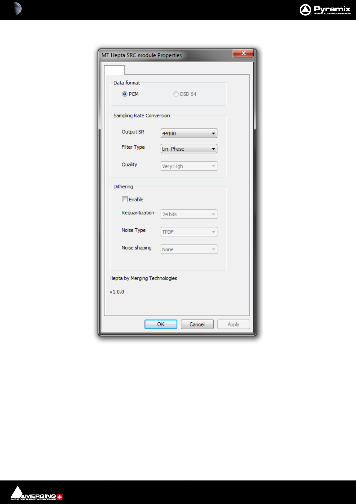
Recording and Acquisition : Importing Audio Files into Pyramix Virtual Studio 7 - 164
3. Selecting Properties opens the MT Hepta SRC module Properties dialog:
4. Choose the required target sample rate by clicking on the Output SR down arrow to drop-down the list of all
available Sample Rates.
5. Filter Type offers the choice of Lin. Phase, Min Phase or Apodising.
•Linear Phase features constant group delay, thanks to the linear phase, and has a symmetric impulse
response, but also longer rings. This offers the best preservation of stereo image. There will be a minimum
of phase distortion from the anti-aliasing filter.
•Minimum Phase features an asymmetric impulse response with minimum phase response. This gives the
lowest amount of phase variation along the frequency spectrum and allows slightly better results for tran-
sient sounds.
•Apodizing offers the steepest response around the Nyquist point and linear phase. It offers the best of
both worlds for the about the same computational effort as the 2 other designs. There is a steep transition
band in the LPF filter using an almost linear phase. Arguably this is the best compromise between linear
and minimum phase types
MT Hepta SRC module Properties dialog
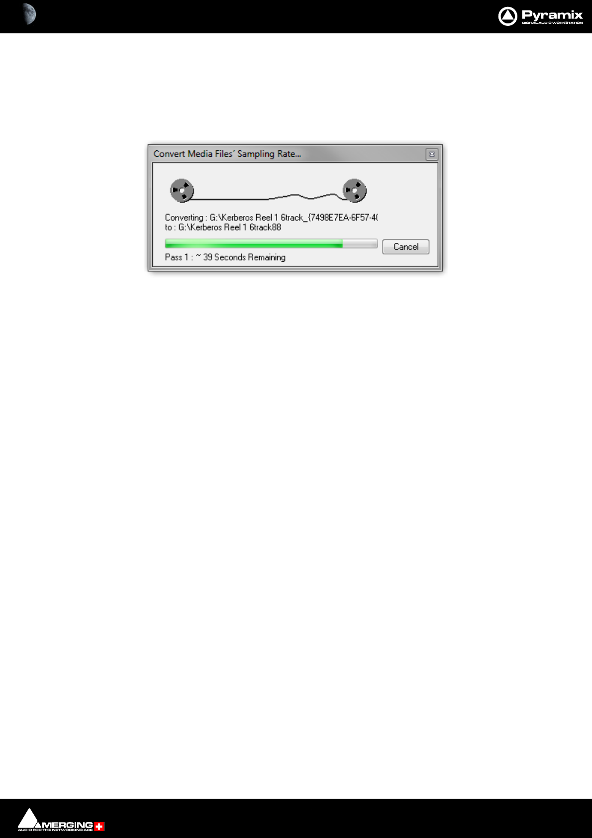
Recording and Acquisition : Importing Audio Files into Pyramix Virtual Studio 7 - 165
6. Conversion Quality defaults to Very High. In the Dithering section there is a check box to enable dithering,
a Requantization drop-down to select the desired bit depth and a further drop-down to select the desired
Noise Shaping. Finally click on OK to close the dialog
7. Choose OK in the MT Hepta SRC module dialog box to begin the conversion. When converting multiple files,
choose OK to convert the files one at a time with the possibility of changing parameters on each file or, if Add
Suffix was chosen in step 2, you can choose OK All to convert all the selected files in one operation.
Convert Media Files Sampling Rate... dialog
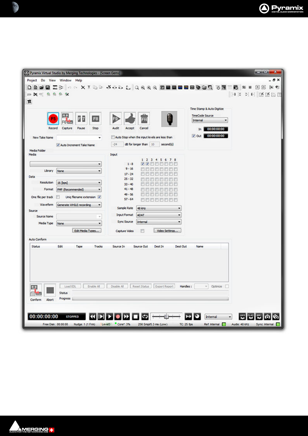
Recording and Acquisition : Digitizing Sessions 7 - 166
Digitizing Sessions
A Digitizing Session is a special type of Pyramix Project which is intended for efficiently loading audio material
into Pyramix. One advantage to using a Digitizing Session for capture is that Master Clips referencing the audio
Media Files can be generated and saved directly into a specified Library for later placement.
Digitizing Session Project Window

Recording and Acquisition : Digitizing Sessions 7 - 167
Manual Digitizing
1. In the Media section, choose an appropriate Media Folder to which to your captured files will be saved. If you
wish to simultaneously save Master Clip references to these Media Files into a previously created Library,
select that Library from the Library drop-down list.
2. In the Data section, choose the appropriate Resolution (bit depth or word length) and Format (file type) for
the saved audio files. Check One File per track ON to generate a separate file for each Track recorded. I.e. two
files for a stereo source, six for a discrete 5.1 source and so on.
3. In the Input radio button matrix, check ON for each Input you wish to record from. Also set the Sample Rate,
Input Format and Sync Source as appropriate.
4. Type in a New Take Name to name the captured files. If the Auto Increment Take Name box is checked all
subsequent takes will use the name typed in the New Take Name field as a ‘seed’ with a numerical suffix to
denote the individual takes. E.g. Enter ‘Vocal’ as the New Take Name, check the Auto Increment Take Name
box and record a few seconds, stop then record another few seconds. The first take will be called ‘Vocal’ and
the second ‘Vocal 2’
5. You can monitor incoming audio through the Mixer. Click on the Show/Hide Mixer icon to display the Mixer,
and set levels as appropriate.
6. Any external machine can be used as the source. However, it is much more convenient to use a machine
which can be controlled by Pyramix. A machine can be selected from the Machine drop-down list. It’s control
panel appears below the list.
7. Locate the required material on the source tape.
8. Click on the red Record button to begin recording. The system will remain in record until the Stop, Pause or
Cancel button is pressed.
9. Press the Stop button to stop recording.
10. You can press the Audit button to audition the recording just made.
11. Press the Accept button to save the recording to the destination Media Folder, or press the Cancel button to
delete the recording without saving it.
12. To Auto Stop on silence, e.g. at the end of a tape, use the Auto Stop when the input levels are less than
check box to stop recording when the input level is lower than the value in: -XX dB for longer than XX sec-
ond(s)

Recording and Acquisition : Digitizing Sessions 7 - 168
Autoconforming
1. Pyramix can record audio selectively according to an EDL (Edit Decision List) in the CMX format.
2. Follow the set-up suggestions above and ensure the source machine is working correctly under 9-pin control.
3. Click the Load EDL button, navigate to the directory containing the EDL you wish to load the audio for.
4. If the list is not already in Reel order, click the Optimize button. This will sort the list so that audio is digitized
with the minimum of reel changing and spooling. All overlapping edits will be merged.
5. Load the first reel in the list, click the Capture button and Pyramix will automatically control the source
machine. All the required audio in the reel will be digitized.
6. Change the reel when prompted until all the required audio has been digitized.
If you know the audio is not available for certain edits in the list, or you wish to digitize only certain edits, uncheck
the box(es) in the Status field for the relevant entries before clicking Capture. The Status filed will show when
Clips have been captured which match the edits.
Enable All
Checks all the boxes in the Status Field for capture.
Disable All
Un-checks all the boxes in the Status Field. I.e. no edits are selected for capture.
Reset Status
Restores the Status Field check boxes to their previous state.
Export Report
Exports an .rtf file detailing the edits which were captured and those which were not.
Handles
Sets an extra amount of audio to be captured at each end of the edits. This allows greater freedom in editing but
may cause problems in some circumstances. The drop-down list gives a choice of from 0 to 10 frames.

8 - 169
www.merging.com/Pyramix
USER MANUAL
Editing
Editing : Editing in the Timeline 8 - 170
Editing in the Timeline
The Timeline is the place in Pyramix where audio Clips can be edited, faded up and down and otherwise
arranged into a mono, stereo or multi-channel digital audio Composition.
A Project Editing Panel containing the Timeline will be visible as soon as you open a Project.
The Fade Editor provides elegant alternative methods of viewing and adjusting the parameters of edits in the
Timeline.
Clips and Compositions
Clips in a Composition
As with Clips in a Media Drive or Library, Clips in a Composition are just pointers to the original audio Media
File. Any actions performed on a Clip in a Composition will affect neither the original audio Media File, nor the
Master Clip in the Media Folder or Library it came from. In the Project Editing Panel, a Clip can be edited,
shortened, split into 2 Clips, moved, level controlled, deleted, etc., and all actions will ONLY affect the Composi-
tion.
Once placed in the Composition, each Clip by default displays a Waveform of the Media file to which it points. This
Waveform display can be enabled, disabled or scaled by the user.
Sample Rate Mismatch
Pyramix allows Clips of any supported sample rate to be placed in the Timeline. By default Clips that do not match
the Project sample rate are converted ‘on-the-fly’ to the project sampling rate. (Please see also: Real-time Sam-
pling Rate Conversion on page 750)
To help avoid inadvertent placement of Clips that do not match the project sample rate, if RealTime Sampling
Rate Conversion is active a discreet blue SR icon is added in such Clips or a red SR icon if not :
If desired, this can be made more obvious by changing the Waveform color of Clips deviating from the Project
sampling rate in Settings > All Settings > Application > Timeline Layout : Clips & Waveforms.
Note: Each Clip’s assumed sample rate is determined by information contained in the file header.
If this information is incorrect (as with certain DAR files) the Clips will not play back at the correct
speed or pitch.
Please see also: DAR WAV file Import on page 95
Sample Rate Mismatch
Editing : Clips and Compositions 8 - 171
Anatomy of a Clip
Many Edit Commands refer to parts of a Clip rather than the entire Clip.
Once a Clip is selected, Trim Handles appear at each end which are used to manipulate the Clip. Each Trim Han-
dle consists of 3 Control Points. The Control Points on the left side of the Clip allows adjustment of the begin-
ning of the Clip, and the Control Points on the right side allows adjustment of the end. Click and drag on the
middle Control Point to move the head or tail of the Clip as desired to shorten or lengthen the Clip. These can be
moved out to the full extent of the original audio Media File to which the Clip is pointing. Select View > Show
Media to view the unused audio (if any) as a grayed out waveform.
Head
The beginning of a Clip on a Track is referred to as the Head. The Head may or may not represent the actual begin-
ning of the Media File for the Clip, since the Clip is just a set of pointers to an area of the whole media file.
Tail
The end of a Clip on a Track is referred to as the Tail. The Tail may or may not represent the actual end of the media
file for the Clip, since the Clip is just a set of pointers to an area of the whole Media File.
Sync Point
The Sync Point is an internal reference point inside the Clip. This defaults to the start of a Clip until moved.The Sync
Point may be moved by dragging its handle within the Clip. If the Play cursor is positioned over some part of the
Clip, the Sync Point may be snapped within the Clip to the position of the Play Cursor by choosing Clips > Set
Sync Point to Cursor.
Trim Handle
The Trim Handle is the middle handle available at either end of the Clip when the Clip is selected. This handle is
used to shorten or lengthen the Clip (trim the Clip in or out) up to the limit of the available media. To trim the Clip,
drag the handle.
Fade Handles
The Fade Handles are the top and bottom handles available at either end of the Clip when the Clip is selected. The
handles are used to create a fade in at the beginning of the Clip, or a fade out at the end of the Clip. To create or
adjust a fade, drag one of the trim handles to create the desired fade in or fade out. The top handle adjusts the
fade within the Clip and the bottom handle trims the Clip in or out as you adjust the fade. If the Top Handle is used
with the CTRL key modifier, a symmetrical crossfade is created with any adjacent Clips, centered at the original
end point of the selected Clip. If no adjacent Clip exists, then it extends or shrinks the duration of the fade while
maintaining the duration of the selected Clip.
Waveform Display
Clips can appear either as a block with the Clip name inside, or can show the audio waveform of the media refer-
enced by the Clip.
Trim Handle
Sync Point
Fade Handles
Tail
Waveform Display
Head
Clip Gain
Features of a Clip in the Timeline
Clip Name
Unused Media

Editing : Clips and Compositions 8 - 172
Clip Name
The name of the Clip is shown unless suppressed. View > Waveform Display > Hide Clip Name when Waveform
Shown.
Clip Gain
The overall Gain applied to the Clip is shown. This value is displayed in decibels.
Gain can be adjusted by selecting Clips > Clip Gain. The Gain window appears. Please see: Gain Window on
page 114 If a Region is selected the Gain will be changed on all Clips in the selection.
Locking Clips
Clips can be protected from being displaced during editing by selecting Clips > Lock. A locked Clip cannot be
moved in time or to another Track until it is unlocked. Clips > Unlock. If you simply wish to prevent loss of sync
select Clips > Lock Horizontal Drag.
Grouping Clips
To Group multiple Clips, whether they are on the same or different Tracks, select the Clips you wish to Group
together. Now choose Clips > Group. When any Clip in a Group is selected, copied, deleted or moved, all Clips in
its Group will be similarly selected, copied, deleted or moved.
To ungroup previously Grouped Clips in order to treat them separately, select the Group and choose Clips >
Ungroup.
Groups can be nested. I.e. one Group may be inside another Group. For example a stereo or multi-channel Clip is
simply a group of mono Clips. Stereo or Multi-channel Clips may be ungrouped into individual mono ones in the
same way as any other group.
Editing : Clip and Selection Editing 8 - 173
Clip and Selection Editing
Master Clips appear in the Timeline as blocks which can be edited on a Track (or Tracks, depending on how many
channels the Master Clip contains) The Clip can be trimmed, split, crossfaded, and have many other operations
performed on it without ever affecting the underlying media file. Each instance of a Clip references the entire
media file, and can always be "opened up" by using the Trim Handles to reveal more of the Clip until the complete
underlying Media File is visible. Clips can be dragged in the Timeline while the transport is playing.
Clip Properties
Clips > Properties opens the Properties window for the selected Clip. If multiple Clips are selected, opens the
Properties window for the first Clip selected.
Selection Window
Editing : Clip Properties 8 - 174
Renaming Clips
Although Clips can be renamed in the Clips > Properties Selection Window, Pyramix offers a more convenient
method of renaming Clips in a logical and orderly manner.
Clips Rename open the Rename Clips dialog:
The Clip Name can be composed out of user text, automatically generated data or a combination of both. The dia-
log box is largely self explanatory. Auto numbering is relevant where a number of Clips are selected when the
Rename Clips dialog is opened.
Rename Clips Dialog
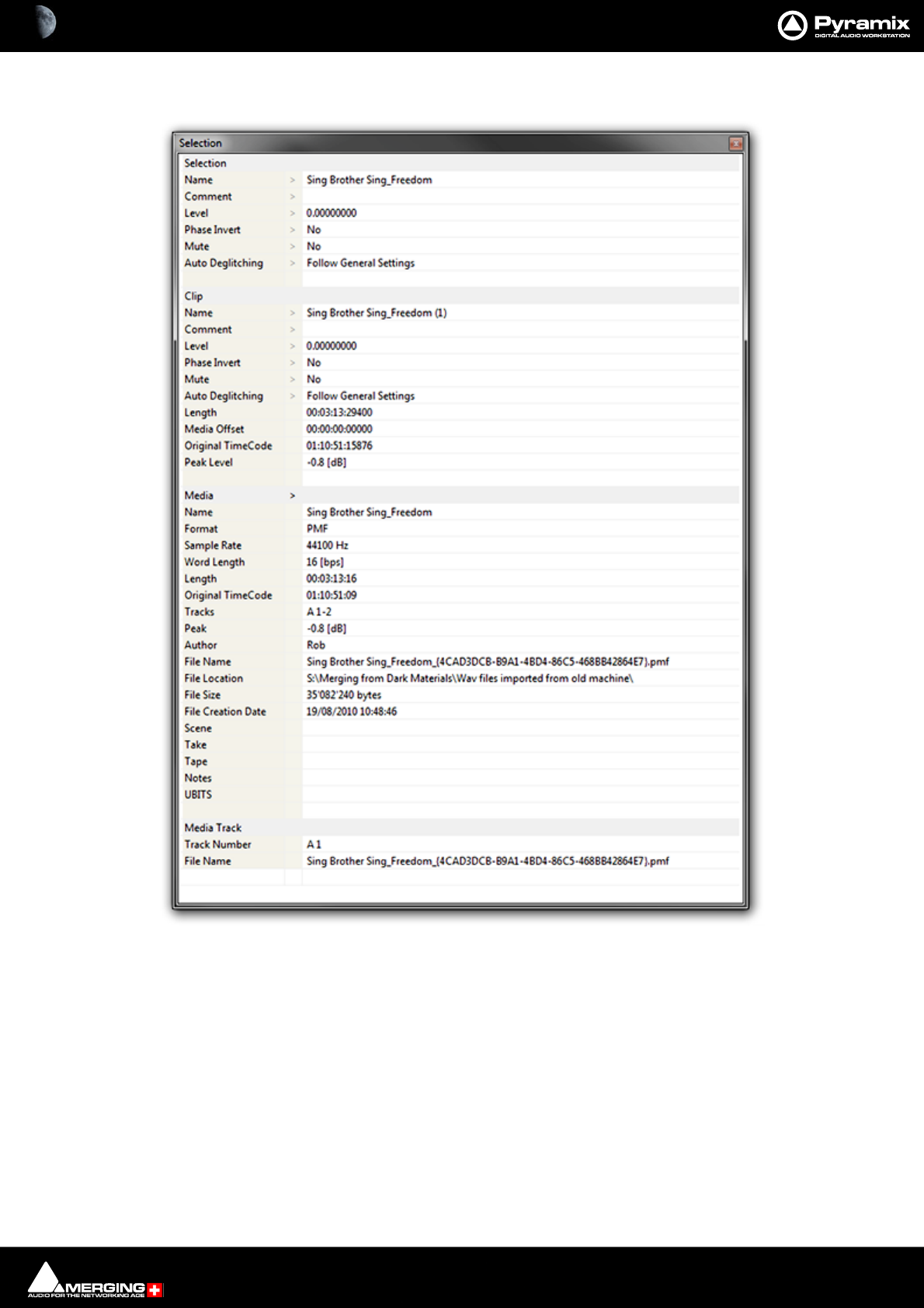
Editing : Selection Tab Window 8 - 175
Selection Tab Window
The Selection Tab Window groups together Selection, Clip and Media Properties fields in a table.
When choosing Selection Properties or a Properties Menu item, this Tab Window is displayed. If the Tab Win-
dows section is hidden, then the Selection Tab Window is undocked to ensure it is visible. Parameters that can be
modified are marked with a ‘>’ sign. Click on the ‘>’ sign or on the parameter itself to change/edit it.
Selection and Clip Modifiable Fields
Name
This field shows the name of Clip as it appears in the composition. This name will also be displayed in
the Clip block when the Clip is set to Show Text.
Selection Tab Window - floating

Editing : Selection Tab Window 8 - 176
Comment
This field shows a user comment concerning the Clip. The information displayed here will also be shown in the
Comment field in the EDL Tab window
Level
Available in both
Pops up a window with a fader and numerical entry box for level, and two check boxes, Sel.ection and Rel.ative.
When neither box is checked any gain change is only applied to the Clip on which you last right clicked (even if
others are selected). If Sel. is checked, the gain will be applied to the whole selection (selected by default). If Rel. is
checked and you have a grouped series of Clips the gain change is relative to pre-existing levels.
If you click on the > in the “selection” part gain is applied to the whole selection, and if you click in the “Clip” part,
the gain is applied only to the Clip which was under the mouse when you clicked.
E.g: Three Clips are selected, the first at -1 dB, the second at -2 dB and the third at -3 dB. You wish to increase the
gain of all the selected Clips by 1dB. Check the Rel. box and add 1 dB either with the fader or in the numeric box.
This will result in the first Track at 0 dB, second at -1, third at -2.
Phase Invert
Toggles between No and Yes (Phase inverted)
Mute
Toggles between No and Yes (Muted)
Auto Deglitching
Drops down a list box with choice of None, Follow General Settings or fade settings between 1.0 [mS] and 5.0
[mS] in 0.5[mS] increments. This feature avoids the necessity to manually make short fades when quickly making
cut edits. On any Clips that do not already have a fade a small ramp is automatically applied to avoid clicks at the
beginning and end. Any Clips with fades previously applied bypass the Auto-Deglitching feature.
Note: the global Automatic -Deglitching value is set in the Settings > All Settings > Applica-
tion > Playback/Record page in the Automatic Deglitching section.
Clip Information Only Fields
Apart from the modifiable fields listed above, Clip also shows the following information fields:
Length
This shows the total length of the selected Clip segment.
Media Offset
This field shows the amount by which the start of the selected Clip segment is offset from the beginning of the
entire Master Clip.
Original TimeCode
This field shows the original TimeCode stamp at the head of the Clip.
Peak Level
This field shows the highest level (in Decibels Full Scale) reached by any sample within a Clip. This is only shown for
Clips which have had a Waveform display generated.
Media Information Only Fields
Name
Shows the original short name of the audio media.
Format
Shows the media format as PMF, Wave etc.
Sample Rate

Editing : Selections and Region Selections 8 - 177
Word Length
Length
Shows the total length of the media file referenced by the Clip.
Original TimeCode
Tracks
Shows the Tracks the media was originally recorded to.
Peak
This field shows the highest level (in Decibels Full Scale) reached by any sample within a media file.
Author
Shows the user who was logged in when the file was created.
File Name
Shows the full media filename including the unique identifier and extension.
File Location
Shows the full Windows path to the media file
File Size
Shows file size in bytes.
File Creation Date
Scene
Take
Tape
Notes
UBITS
Media Track Information Only Fields
Track Number
Shows the Track number within the media file. I.e. a stereo file will have A1 and A2 for the two Tracks.
File Name
Shows the full media filename including the unique identifier and extension.
Note: The values shown in the Clip, Media and Media Track sections reflect the Track clicked on
in the Timeline. Where a selection contains several, possibly multi-channel, Clips, clicking on the
individual items in the Timeline updates the information to reflect the last item clicked.
The Selection Tab Window is automatically updated when the selection changes and can therefore remain float-
ing.
Selections and Region Selections
Selection Operations
Many Pyramix editing operations can only be carried out if a Clip or Region is selected.
There are two ways of selecting material in the Timeline. Whole Clips and Regions.
Clip Selection

Editing : Working with Selections and Regions 8 - 178
Clicking in a Clip selects it (the color becomes darker and Handles appear). The whole Clip is ready for editing.
Clicking on other Clips while holding down the Shift key adds them to the selection. If the Clip is grouped with
other Clips, this will select the entire group. To select a single Clip in a group, first ungroup the Clips, then select
the desired Clip.
Region Selection
A Region Selection is a selected area of the Composition. A Region can include many Clips on many Tracks or
only a portion of a single Clip. It is indicated as a darker gray rectangular area over one or more Tracks. When
selecting a Clip within a group, the Region is automatically extended to the whole group. To avoid auto-selecting
the entire Clip Group and to select a range within the Clip Group Left-click the mouse while the cursor is over the
clip group at the start of the area to be selected, then while continuing to hold down the Left mouse button, press
and hold SHIFT, then drag across the clip group to make the selection. A Region can be made by clicking and
dragging the mouse across one or more Tracks.
Of course, keyboard shortcuts exist for making Regions, and this is one of the most useful ways to mark a Region.
The Pyramix default method of marking a Region in point is to press [ on the keyboard: this selects everything to
the right of the current Play Head Cursor location on the currently selected Track. ] marks a Region out point: this
selects everything to the left of the current Play Head Cursor location, up to a previously marked in point. Once a
Region has been defined in this manner it can be extended or ‘grown’ across more Tracks by using Ctrl +Shift
+Cursor UP or DOWN arrows. Ctrl +Alt +Shift +Cursor UP or DOWN shrinks. (Assuming the standard Pyramix
keyboard shortcut assignments are in use.)
Using the keyboard short-cuts, Regions can be easily made on-the-fly while playing or scrubbing the Timeline.
This is particularly efficient when used in conjunction with the Numeric Keypad transport control short-cuts.
Working with Selections and Regions
Any selection of Clips or selected Region can be manipulated as a single object. This object will include all Clips,
fades, envelopes and automation. It can be Copied and Pasted elsewhere in the Timeline or “Snapshot” copied to
a library for future use. The object can be given a suitable name and is treated in the same way as any other library
object for searching etc. This function can be used, for example, to keep complex composite effects for future use
in the current or future Projects.
With the ability to open the same Library from multiple Pyramix on a network, editors can share parts of composi-
tions in real-time between systems (when dropping something in a library from one system it will pop in the other
within seconds) and not only within the same Pyramix system.
Snapshot a Selection or Region
To Snaphot a Selection or Region:
• Make a Selection or select a Region
• Hold down Alt + Shift
• Cursor changes to:
• Click anywhere in the Selection or Region and drag to a library.
• The resulting object will appear in the library labelled, Region of {Project Name}.
Snapshot Timeline
To Snapshot the entire Timeline:
• Open the Overview Tab
• Hold down Alt + Shift
• Cursor changes to:
• Click anywhere in the Overview and drag to a library.

Editing : Dragging Clips into a Composition 8 - 179
• The resulting object will appear in the library labelled, Region of {Project Name}.
Dragging Clips into a Composition
The simplest way to place an audio Clip into your Composition is by dragging it from a Media Folder or Library.
To drag from a Media Folder:
1. Click on the Media Management Tab to open the Media Management tab window.
2. Double-click on a mounted Media Folder or subfolder to open it. The Master Clips will all be listed on the
right side of that window.
3. Select a Master Clip by left-clicking and holding. Drag the Master Clip into a Track. You can place it into any
Track, at any point on the Track.
The procedure for dragging an object from a Library is virtually identical to that outlined above for Media Drives.
However, access the required Library using the Global Libraries or Document Libraries Tabs in the Project
Management Panel.
Copy and Paste
Another way to get objects into a Composition is by copying and pasting them.
1. Select an object in a Media Folder or Library.
2. Right-click on the Master Clip, and choose Copy from the pop-up.
3. Place the Play Head Cursor where you want to paste the beginning of the Master Clip.
4. Right-click on the Track to which you wish to place the Clip, and choose Paste to Cursor from the pop-up.
The beginning of the object will be placed at the Play Head in the Track on which you right-clicked. Alterna-
tively, simply click the mouse on the Track and at the time you want the Clip to start, right -click and choose
Paste to Mouse to insert the Clip where you placed the mouse cursor.
Selecting a Clip
Click on any Clip in the Composition to select it. It will change color to indicate selection. Shift-click to select multi-
ple Clips at the same time.
Simple Copy and Paste
1. Left-click a Clip to select it.
2. Right-click and choose Copy from the pop-up. (or use menu Edit > Copy or use Ctrl + C)
3. Place the Play Head Cursor where you want to paste the beginning of the Master Clip.
4. Right-click on the Track to which you wish to place the Clip, and choose Paste to Cursor from the pop-up. (or
use menu Edit > Paste to Cursor or use Ctrl + V). The beginning of the Clip will be placed at the Play Head in
the Track on which you right-clicked. Alternatively, simply place the mouse cursor on the Track and at the
time you want the Clip to start, right-click and choose Paste to Mouse to insert the Clip where you placed
the mouse cursor.
Selecting a Region
To select a Region, click the mouse at one end of the Region you wish to select, and drag the cursor to the other
end of the Region you wish to select.
A Region can include more than one Clip, and may extend across multiple Tracks. The selected Region may also
include the area(s) on a Track where no Clip is present.
Adding Tracks to a Selected Region
With a Region selected, Shift + Click on other Tracks to add them to the selection. The Tracks do not have to be
continuous.
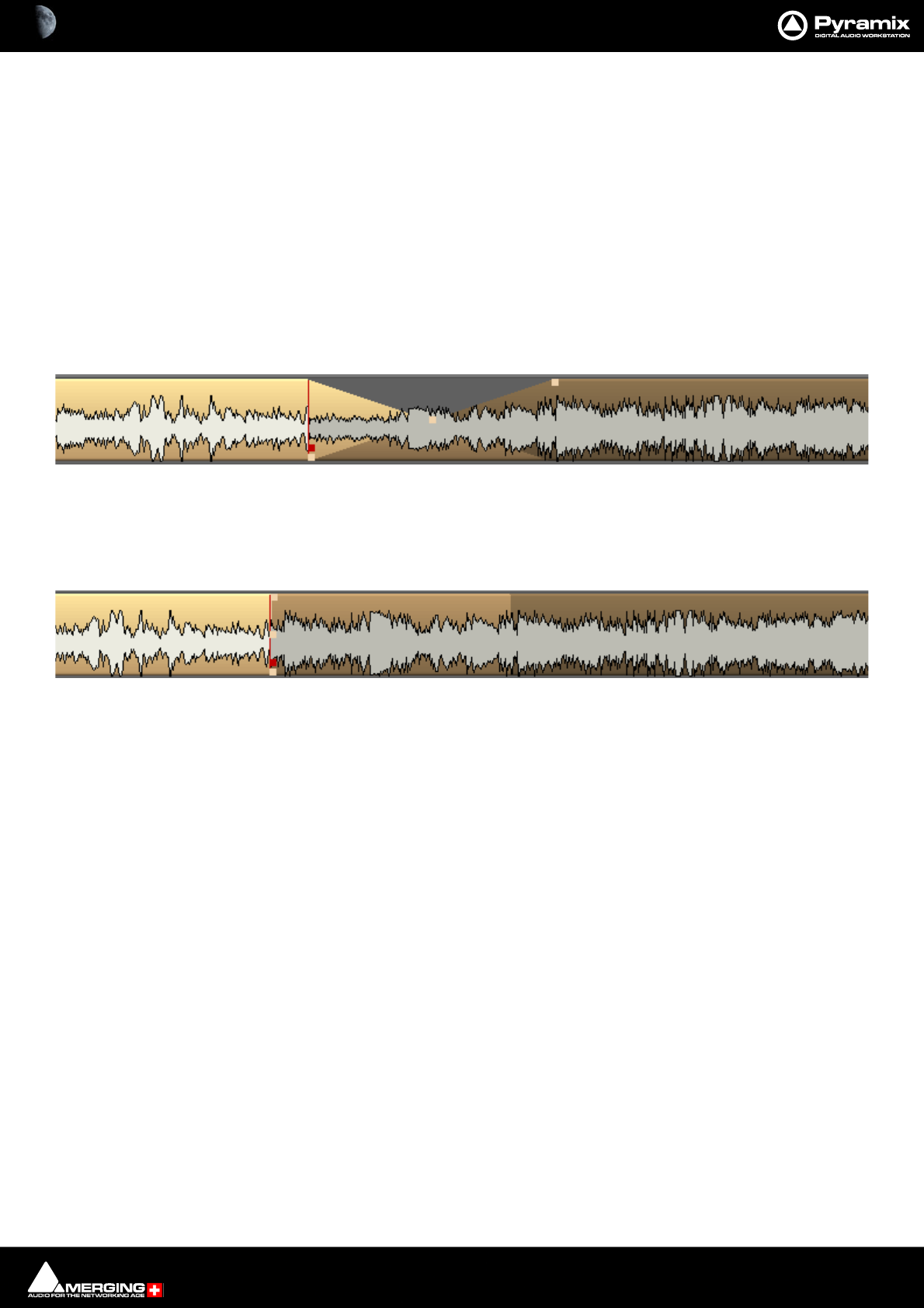
Editing : Auto-Crossfade By Default 8 - 180
Note: Discontinuous Regions cannot be selected horizontally.
Clip Selection Behavior
The following lists the various behaviors for a selected Clip depending on different modifier keys.
When a Clip is selected:
No Modifier Key
With no key modifier, the Clip can be manipulated in standard Edit Mode.
Ctrl Key Modifier (Auto Crossfade Mode)
While a Clip is selected, pressing and holding the Ctrl key before clicking and dragging automatically creates a
cross-fade when the Clip is moved to overlap any adjacent Clip. The mouse cursor changes to a hand with an X
over it to indicate Auto Crossfade Mode is engaged. While in Auto-Crossfade Mode selected Clips can only be
moved in time, not to other Tracks.
Ctrl Key Modifier Option (Layering Mode)
When in the Ctrl Crossfade mode, if the Ctrl Key is released (while still holding the left mouse button) Layering
Mode is entered. This mode allows Clips to be overlapped. (Technically, the result is a crossfade with zero length
fades.)
Ctrl SHIFT Key Modifier (Slip Media Mode)
While a Clip is selected, pressing the CTRL and SHIFT keys will allow the audio contents of the Clip to be slipped in
time. The Media can be slipped to the extent of its availability.
Ctrl Alt Key Modifier (Slip Clip Mode)
While a Clip is selected, pressing the CTRL and ALT keys will allow the In and Out point of the Clip to be slipped
together in time while the Media remains where it is in time. Think of this as moving a "window" within the media.
Alt ShiftKey Modifier
While a Clip is selected, pressing the ALT and SHIFT keys will allow the Clip to be dropped into a Library as a new
Composition.
Note: When a Clip is moved over another in either within the TimeLine in Layering or Auto-
Crossfade Modes or from a Library or Media Management, the Clip color temporarily changes to
red. This is particularly helpful where there are hidden Clips on the right side of the screen that
may be erased by the new Clip or move.
Auto-Crossfade By Default
Auto Crossfade / Layering can be set as the default editing mode. This reverses the functionality described
above. When this mode is engaged, pressing the Ctrl key enables the Edit mode.
Auto Crossfade Mode
Layering Mode
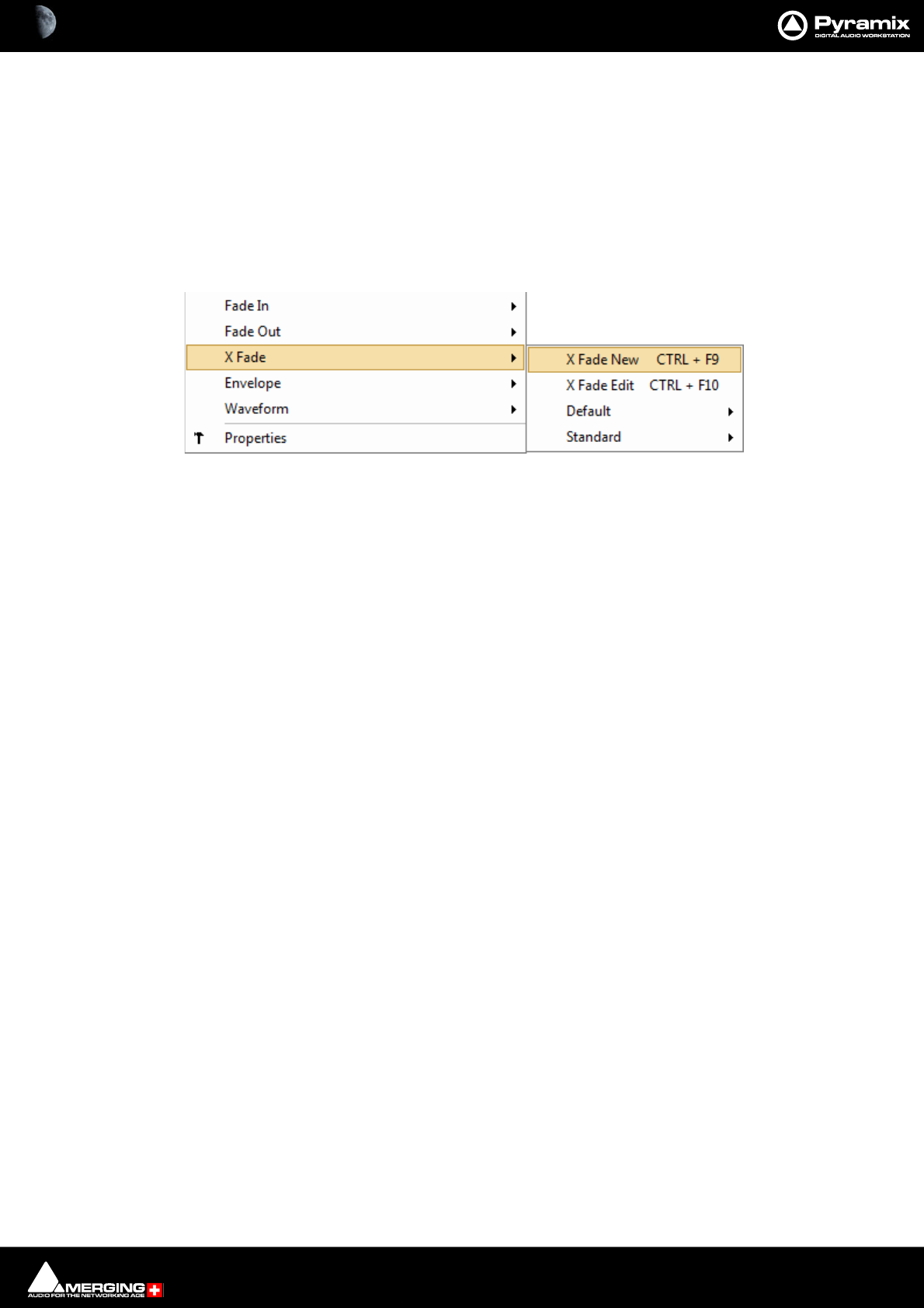
Editing : Clip Fade Commands 8 - 181
This mode can be engaged by selecting Edit > Auto-Crossfade or by checking the Auto-Crossfade by Default -
Control key for Drag & Drop box in Settings > All Settings > Editing.
Clip Fade Commands
Fade In
Fade Out
X Fade Each of these three entries on the Clips menu lead to sub-menus which all look like this:
New Creates a fade when a Region is defined at the beginning (Fade In) the end (Fade
Out) or across overlapping Clips (X Fade)
Edit When chosen from either the Fade In or Fade Out sub-menus, opens the Fade Edi-
tor with the current fade. From the Cross Fade sub-menu opens the Fade Editor
only when a Region is defined across an existing cross fade. (Please see: Fade Edi-
tor Tab Window on page 200)
Default When a Clip is selected or a Region is defined which includes the Clip start or end,
Fade In or Out > Default > Complete recalls the length and shape of the Default
Fade In or Out and applies it to the selection.Default > Curve Only recalls only
the curve shape.
When a Region is defined on a Clip or Clips which are cross-faded X Fade >
Default Complete or Curve Only recalls and applies the Default Crossfade length
and shape or shape only respectively.
Standard Sub-menu offers a choice of fade types
Power Linear
Tension Linear
dB Linear
Cosine
Root Cosine
Editing Modes
The current Editing Modes are shown in the Cursor Toolbar. If either Remove, Insert or Snap modes will result in
rippling of other Clips. I.e. loss of sync, the Editing Modes are shown in Red Some of the editing commands which
delete Clips from, or paste Clips into the Timeline behave differently depending on the current settings of the
Insert mode and the Remove mode.
Crossfade sub-menu
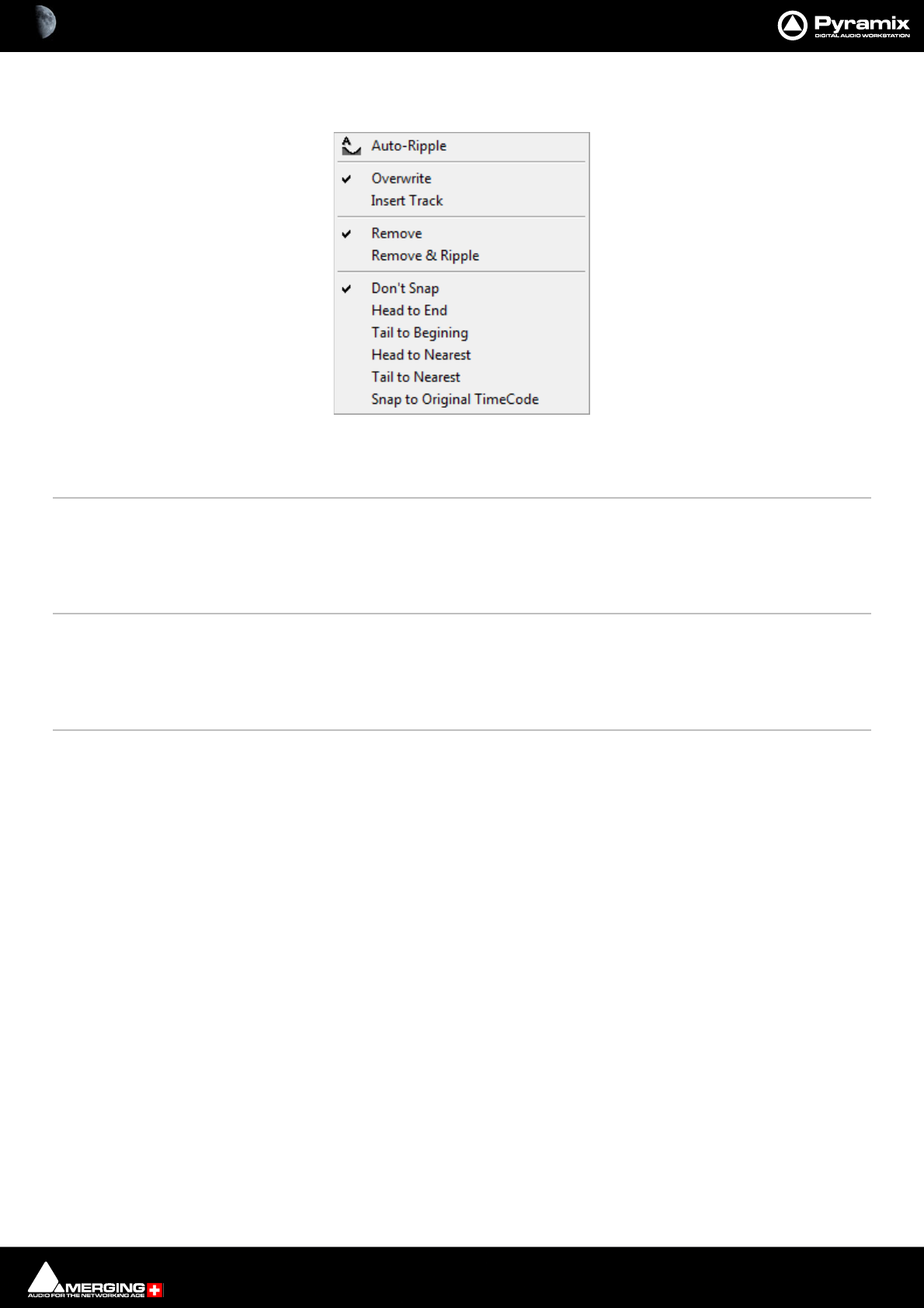
Editing : Editing Modes 8 - 182
Edit Modes Context Menu
Clicking on the current Edit Mode indication in the CURsor Toolbar header pops up the Edit Modes menu:
Auto-Ripple When this option is checked (enabled) all Insert or Remove operations ripple the
rest of the Track
Overwrite When checked, any Clip placed so that it overlaps an existing Clip will overwrite the
part of that Clip where the two overlap.
Insert Track When checked, any Clip placed on a Track will be inserted into the Track and will rip-
ple all other material on the Track later in time (to the right) by the length of the Clip
being inserted.
Remove When checked any selected material will simply be removed from the Timeline.
Everything else will be left intact and in the same place.
Remove and Ripple When checked any selected material will be removed from the Timeline. Everything
else to the right (after) the removed material will be Rippled (moved) to the left (ear-
lier) to take up the space left by the removed material.
Don’t Snap No snap mode set. This mode doesn't affect the behavior of objects placed on a
Track. Behavior follows the existing Insert and Remove modes.
Head to End This mode will cause the beginning of any Clip placed on a Track to snap to the end
of the last Clip on the Track, abutting the head of the new Clip to the end (tail) of the
last Clip.
Tail to Beginning This mode will cause any Clip placed on a Track to snap to the beginning of the first
Clip on the Track, abutting the tail of the new Clip to the head of the first Clip.
Head to Nearest This mode will cause any Clip placed on a Track to snap the head of the Clip to the
nearest edit point or mark on the Track. This includes the head or tail of existing Clips
on the Track, as well as the Play Head Cursor, Mark In, Mark Out, Named Markers, or
CD Marks. The Clip will interact with existing Clips according to the Insert Mode set-
ting.
Tail to Nearest This mode will cause any Clip placed on a Track to snap the tail of the Clip to the
nearest edit point or mark on the Track. This include the head or tail of existing Clips
on the Track, as well as the Play Head Cursor, Mark In, Mark Out, Named Markers, or
CD Marks. The Clip will interact with existing Clips according to the Insert Mode set-
ting.
Snap to Original TimeCode This mode will cause any Clip placed on a Track to snap the head of the Clip
to the time location represented by the Clips original TimeCode. The Clip will inter-
act with existing Clips according to the Insert Mode setting.
Edit Modes Menu

Editing : Editing Modes 8 - 183
Splitting Clips and Regions
Splitting a Selection
Splitting Clips
Edit > Split (or Ctrl + T) makes an edit on the selected Clip(s) at the cursor position splitting it (them). If a Region is
defined within a Clip or Clips then this Region is Split (edited) by using this command. Each split portion of the
original Clip(s) now becomes a new, independent Clip in its own right.
Splitting Regions
If the Play Cursor is positioned over a selected Region rather than a whole Clip or Clips, then choosing the Edit >
Split command will split the selected Region from the surrounding material at the edges of the selection area, not
under the Playhead Cursor.
Once a Region is marked on a Clip, simply clicking on the Region makes an edit. (same effect as the Edit > Split
menu command.) This will split the Clip or Clips at the Region boundaries. If a Region is across several Tracks,
Edits will be made on all Tracks within the Region.
Cutter
Holding down the C key changes the mouse pointer to a cutter. Edits (cuts) are made wherever the user clicks. To
make an edit with the cutter on a range of Clips at the same position, just select them before cutting.
Duplicate Selection
Holding down the D key while clicking on the selection then dragging to a new location duplicates the selected
material and moves the copy.
Holding down the F key while clicking on the selection then dragging to another Track (or Tracks if the selection
covers more than one Track) duplicates the selected material and moves the copy locked in time.
Moving a Selection
Simply drag a selected Clip move or reposition it to another location on the same Track or a different Track. If a
Region is selected, clicking on it will split it from the surrounding material. The resulting separate Clip can then be
dragged to a different location or Track. To constrain a Clip in time when moving it to another Track, hold down
the Alt, Shift and Ctrl keys at the same time while dragging the Clip to the new Track.
Adjusting a Region Selection
Simply position the Arrow Cursor at the edge (beginning or ending) of the Region. The cursor will change shape to
indicate the Region can now be adjusted by clicking and dragging. You may drag the edge beyond the other end
of the Region. Doing so ensures that the new selection Region begins (or ends) exactly where the original Region
ended (or began). This also applies to the top and bottom edges of the Region. For example, you can extend the
selected Region on one Track up or down to include additional Tracks.
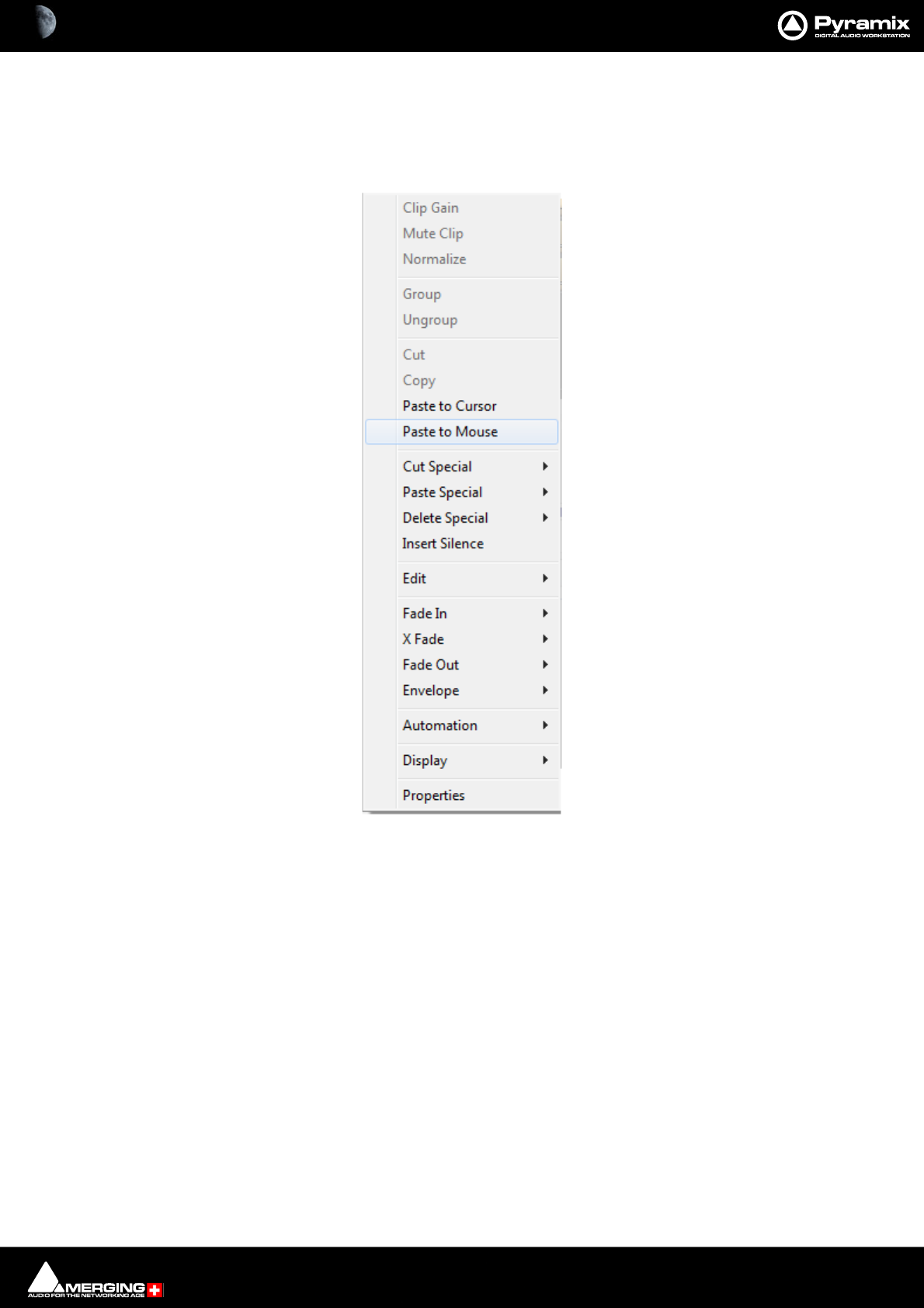
Editing : Editing Context Menu 8 - 184
Editing Context Menu
Right-clicking in the Timeline opens a context menu with extensive editing options. Some options will be grayed
out when they are inapplicable. E.g. unless a Clip is selected, or if there is nothing on the Clipboard to Paste.
All the commands in the context menu and sub-menus can be found elsewhere, principally in the Edit and Clip
menus. However, here they are grouped in a convenient way for quick access.
For power users, keyboards shortcuts are the way to go.
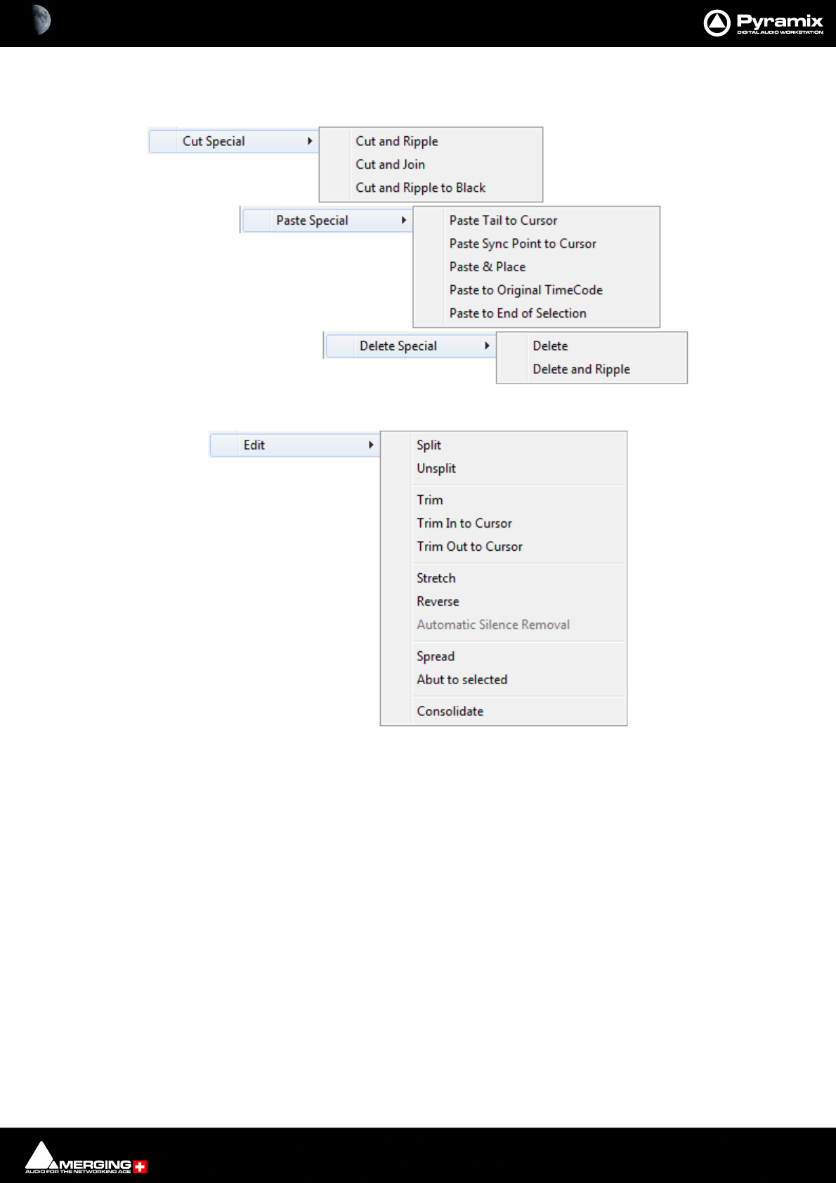
Editing : Editing Context Menu 8 - 185
Editing Context Sub-menus

Editing : Editing Context Menu 8 - 186
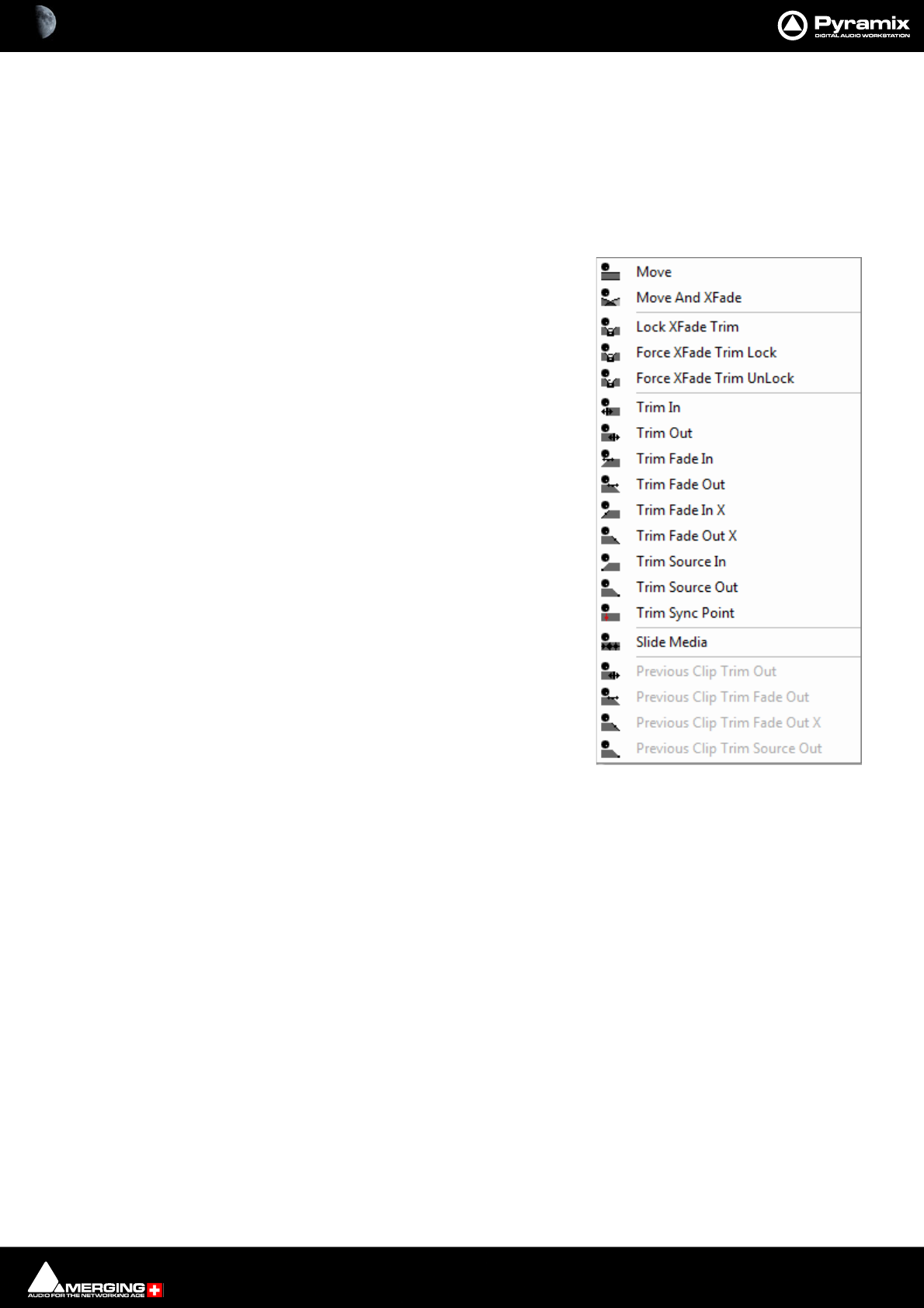
Editing : Jog-Wheel Editing 8 - 187
Jog-Wheel Editing
A number of editing actions may be undertaken on a selected Clip or group of Clips using a jog-wheel on an exter-
nal hardware controller.
First select the Clip or group of Clips, then select the desired Jog-
Wheel Editing Mode from:
Edit > Jog-Wheel Editing >
Move
Move And XFade
Lock XFade Trim
Force XFade Trim Lock
Force XFade Trim Unlock
Trim In
Trim Out
Trim Fade In
Tim Fade Out
Trim Fade In X
Trim Fade Out X
Trim Source In
Trim Source Out
Trim Sync Point
Slide Media
Previous Clip Trim Out
Previous Clip Trim Fade Out
Previous Clip Trim Fade Out X
Previous Clip Trim Source Out
Now simply move the jog wheel to Move, Trim, Slip or Slide the Clip(s)
The last four options are included for mapping to physical buttons on the controller.
Pressing the Spacebar or Enter confirms the change(s), Esc cancels.

Editing : Edit Command highlights: 8 - 188
Edit Command highlights:
Further Editing commands are to be found on the main Edit menu. Please see: Edit on page 673
Undo Pyramix keeps Track of all edit decisions and operations so they can be undone if neces-
sary. This menu item shows the name of the last operation. To undo this operation, simply
click on the Undo (operation) menu item and the listed operation will be undone. When-
ever an item is undone, it immediately shows up as the most recent item in the Redo list.
Undo History Pyramix keeps Track of the most recent edit decisions and operations and shows them
here in a sub-menu. These are listed from the most recent at the top, to the oldest at the
bottom of the list. To undo a whole block of operations, click on the name of the oldest
operation and everything since that time (from that point in the list to the top of the list)
will be undone. The name of the next operation in the list will be shown as the next Undo
item, and all the items that have been undone are immediately added to the Redo His-
tory list. The size of the undo history is set to 32 steps by default, but it can be adjusted in
the All Settings > Settings > Application > General page.
Redo If an operation has been undone using the Undo commands in this menu, the most
recently undone operation will be shown here. To Redo the operation, simply click on
Edit > Redo and the operation will be Redone. Whenever an item is Redone, it immedi-
ately shows up as the most recent item in the Undo list in this menu. The next edit opera-
tion carried out in Pyramix will then purge this item since the operation could cause a
conflict with previous operations and therefore renders the Redo invalid.
Redo History Pyramix keeps Track of the most recent operations that have been undone, and shows
them here in the Redo History sub-menu. To Redo a whole block of operations, click on
the name of the oldest operation and everything since that time (from that point in the
list to the top of the list) will be Redone. The name of the next operation in the list will be
shown as the next Redo menu item, and all the items that have been Redone are immedi-
ately added to the Undo History list. The next edit operation carried out in Pyramix will
then purge this list since the operation could cause a conflict with previous operations
and therefore renders the Redo list invalid.
Delete This command deletes the selected Clip or Region. When a selection is deleted, other
material on the Track behaves according to the current Remove mode setting.
Cut Cuts the current selection from the project and places it on the Clipboard. When a Selec-
tion is Cut, other material on the Track behaves according to the current Remove mode
setting.
Copy Copies the current selection from the project and places it on the Clipboard
Paste>
Paste to Cursor Inserts the contents of the Clipboard starting at the current Playhead Cursor posi-
tion. When the contents of the Clipboard is Pasted, other material on the Track(s)
behaves according to the current Insert mode setting.
Paste to Mouse Inserts the contents of the Clipboard starting at the current Mouse Cursor position.
When the contents of the Clipboard is Pasted, other material on the Track(s)
behaves according to the current Insert mode setting.
Paste Tail to Cursor Inserts the contents of the Clipboard ending at I.e. immediately before, the current
Playhead Cursor position. When the contents of the Clipboard is Pasted, other
material on the Track(s) behaves according to the current Insert mode setting.
Paste Sync Point to Cursor Inserts the contents of the Clipboard with the first sync point in the Clipboard con-
tents at the current Playhead Cursor position. Depending on where the first sync
point is, the material pasted may start, end or straddle the current Playhead Cursor
Position. When the contents of the Clipboard is Pasted, other material on the
Track(s) behaves according to the current Insert mode setting.
Paste & Place Opens the Placement Tool with extensive placement options. Please see: The
Placement Tool on page 195

Editing : Edit Command highlights: 8 - 189
Paste to Original TimeCode If the Clipboard contains a single Clip, insert this at its original TimeCode *
Works differently with Clips and Range Selections. If the Clipboard contains a sin-
gle Clip this will be pasted to its original TimeCode. If the Clipboard contains more
than one Clip or a selection of a Clip or Clips this will be pasted to the TimeCode at
the beginning of where the selection was made on the next Track(s) where there
are no Clips which would be overwritten.
Paste to End of Selection Inserts beginning of contents of Clipboard to end of current selection.
Fill Selection This command will substitute the Clipboard contents for the selected Clip or Region for
the duration of the Clipboard contents. No Ripple of following Clips will occur.
Replace Selection This command will substitute the Clipboard contents for the selected Clip or Region and
will ripple all subsequent Clips if the duration of the clipboard contents is greater or
shorter than the selected Clip or Region.
Loop Selection This command will substitute a loop of the Clipboard contents within the selected Clip or
Region boundaries, creating a 10ms cross-fade between the inserted iterations of the
Clipboard contents. No ripple will occur.
Note: all Clips within a region’s boundaries will be replaced.
Fit Selection This command allows a Clip on the Clipboard to be fitted into a user defined Region on
the Timeline by stretching or squeezing it. (to maxima of 50% and 200%) This requires
one of the optional Time compression/Expansion plug-ins to be present.
Delete and Ripple Deletes the current Selection forcing a Ripple to occur on all affected Tracks.
Cut and Ripple Cuts the current Selection and places it on the Clipboard forcing a Ripple to occur on all
affected Tracks.
Paste and Ripple Inserts the contents of the Clipboard to the current Playhead Cursor position forcing a
Ripple on all affected Tracks.
Insert Silence Inserts silence (blank space) into the current selection, forcing a ripple on all selected
Tracks.
Delete and Join Deletes the currently selected Clip/Selection and ripples the end of the Clip.
Cut and Join Cuts and saves to the Clipboard the currently selected Clip/Selection and ripples the end
of the Clip.
Delete and Ripple to Black Deletes the currently selected Clip/selection and ripples all following butted or cross-
faded Clips.
Cut and Ripple to Black Cuts and saves to the Clipboard the currently selected Clip/Selection and ripples all fol-
lowing butted or crossfaded Clips.
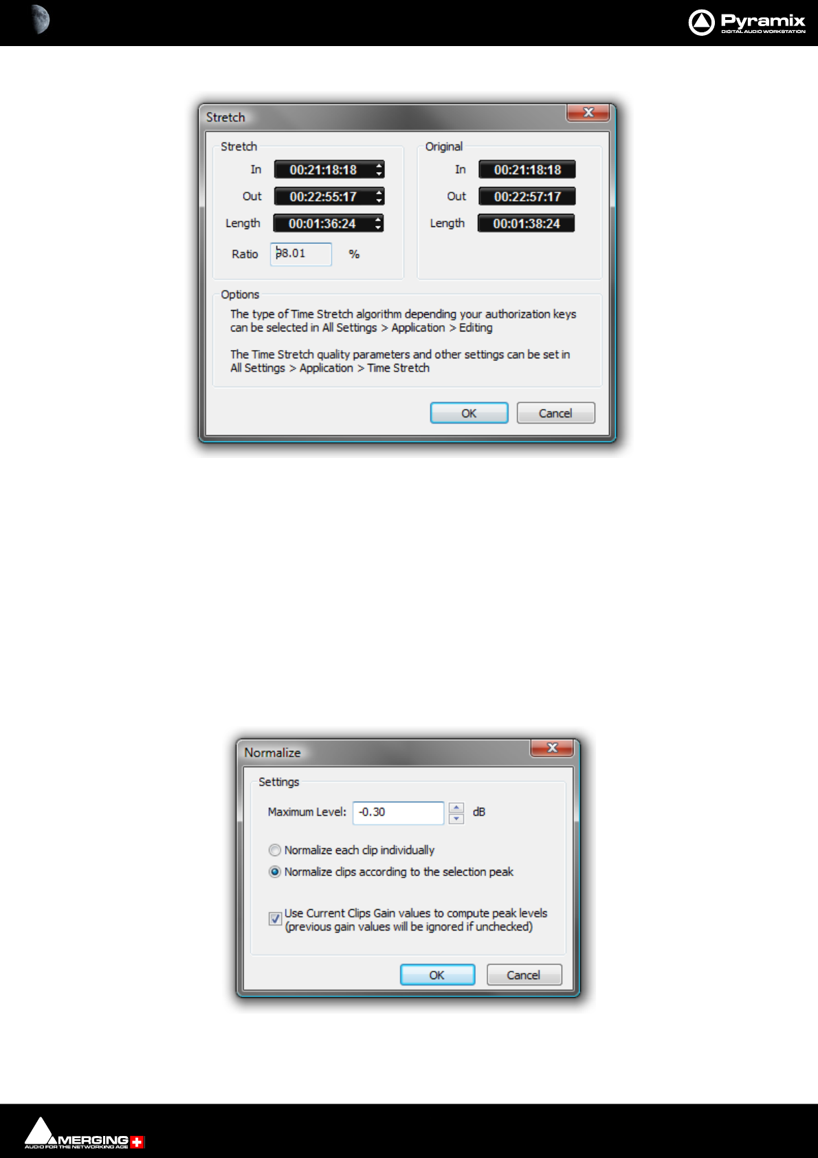
Editing : Edit Command highlights: 8 - 190
Stretch Opens the Stretch plug-in dialog.
The Increment and Decrement buttons allow the In point, Out point or Length of the selection to be adjusted. The
Ratio of stretch or squeeze is shown as a percentage. Clicking the OK button starts the process. Cancel aborts.
Depending on the available authorization keys, the Time Stretch algorithm can be selected in:
All Settings > Application > Editing : Time Stretch Tool : Selected combo box
Settings for the chosen algorithm can be made in:
All Settings > Application > Time Stretch > ‘Plug-in name’ Settings
Note: The percentage of Stretch and Shrink is limited to 200% and 50% respectively.
Reverse Reverses the Clip in the Timeline so it plays backwards.
Normalize Opens the Normalize dialog.
The Maximum Level can be set by typing or using the increment / decrement buttons.
The process can be applied to:
Stretch dialog
Normalize dialog
Editing : Edit Command highlights: 8 - 191
•Normalize each clip individually
•Normalize clips according to the selection peak
Clicking on OK starts the process. The selected Clip or Clips are examined to locate the highest peak, then the
overall gain of the Clip(s) is increased so that this reaches the maximum level specified. All other selected Clips are
either treated individually or raised in level by the same amount.
When in Normalize clips according to the selection peak mode, if the following box is checked:
• Use Current Clips Gain values to compute peak levels (previous gain values will be ignored if
unchecked)
Then:
MaxPeak of the selection will be computed using the level of Clips:
MaxPeak = Max(peak + Level)
DeltaGainToApply = DesiredMaximumLevel - MaxPeak
And then for each Clip, of the selection:
Level = Level + DeltaGainToApply
Note: this check-box is grayed out when Normalize each clip individually is selected.
Normalize Example:
In this case with Maximum Level = -0.3 dB and “Use Current Clips Gain values to compute peak levels (previ-
ous gain values will be ignored if unchecked)” selected:
Consolidate Opens the Consolidate Project dialog box. Please see: Consolidating Projects on
page 449.
Spread Opens the Enter gap time dialog which enables a space (silence) to be inserted between
selected Clips.
Abut to selected This command abuts all Clips between the Mark In and Mark Out on a Track to a selected
Clip between the Marks on the same Track.
Peak Level Original Gain Value New Gain Value
Clip 1 -18.0 4.0 3.8
Clip 2 -16.0 4.5 4.3
Clip 3 -12.0 -1.0 -1.2
Clip 4 -9.0 -2.6 -2.8
Clip 5 -3.0 1.0 0.8
Clip 6 0.0 -0.1 -0.3
Clip 7 -40.0 2.0 1.8
Clip 8 -20.0 4.2 4.0
Editing : Auto Silence Removal 8 - 192
Auto Silence Removal
Edit > Automatic Silence Removal Automatic Silence Removal operates by scanning the Selection and then automatically
editing it into smaller Clips by removing Regions which fall below the threshold level and
meet the ‘Minimal Sound’ and ‘Silence’ criteria set in the Automatic Silence Removal
dialog.
Note: This function is non-destructive of the Media file - it edits the Clip by breaking it up into
smaller Clips, not by deleting any actual audio from the hard drive.
Threshold [dB]
This field determines the threshold level in dB below which material in the Clip will be removed.
Minimal Silence [ms] / Minimal Sound [ms]
Sets the shortest periods of silence and sound which can be created by removing material that drops below the
threshold. Some audio material (E.g. speech) contains very short gaps. If all of these were removed, the audio
would become too "chopped up". On speech the object of the exercise is usually to break it into areas where
speech is present not remove small gaps between words or sentences. Some audio material may have very short
transient peaks in the midst of a segment that falls below the threshold. If all of these short transients were created
as Clips the end result might well sound worse than the original.
The minimum setting is 10 ms and the maximum is 5000ms (5 seconds).
Fade Out [ms] / Fade In [ms]
Sets the length of the automatic Fade Out and Fade In that will be applied to all new Clips created by the Auto-
matic Silence Removal operation. The range for this setting is between 5 ms and 500ms (1/2 second).
Once the parameters have been set, click OK.
This process takes into account the current Remove Mode to determine whether to leave gaps between the
newly created Clips, or to join or ripple the Clips on the Track together.
Automatic Silence Removal cannot be executed on cross-faded Clips.
Automatic Silence Removal dialog
Editing : EDL Tab Window 8 - 193
EDL Tab Window
The EDL (Edit Decision List) Window, is a textual and numeric representation of the same information shown
graphically in the Timeline and Fade Editor.
Changes made here are reflected in the Timeline and vice-versa The list shows information concerning the Clips in
the form of a list of text and TimeCode fields, most of which can be edited. This provides an alternate way of view-
ing and editing the composition. To edit a field, click in it to produce a cursor, or drag across the text in the field to
select it, then type the desired information using normal text entry procedures.
Fields can be adjusted in width in the usual Windows way. Clicking in a Field label will sort all entries in the list in
ascending order, sorted on that field. A second click sorts in descending order.
Fields available in the Edit Decision List Panel are:
Field Description Editable
Name Clip Name Yes
Type Type of Clip(e.g. audio, video, midi etc.) No
Dest In Clip’s In time in the Timeline Yes
Dest Out Clip’s Out time in the Timeline Yes
Fade In Clip’s Fade In length Yes
Fade Out Clip’s Fade Out length Yes
Length Length of Clip in the Timeline Yes
Source In Media TimeCode value at Master Clip’s Head Yes
Source Out Media TimeCode value at Master Clip’s Tail Yes
Sync Source Media TimeCode value at the Clip’s sync point Yes
Sync Dest Clip’s sync point time in the Timeline Yes
Track Name of Track Clip is assigned to No
Comment Comments about the Clip from the properties page Yes

Editing : EDL Tab Window 8 - 194
Absolute Sources in EDL View
When View Sources in EDL View is checked in the Settings > All Settings > Application > TimeLine Layout
page, the original Source In, Source Out and Sync Point times are shown in Absolute Time in the EDL View.
Absolute time is the incoming TimeCode recorded at the audio capture. When this mode is disabled, the default
start time of TimeCode for the captured Clip is 00:00:00:00.
Editing : The Placement Tool 8 - 195
The Placement Tool
Although the Placement Tool remains an extremely flexible paste option, most important operations are
directly available as single commands in the Edit menu. All these commands can be mapped to a keyboard
key or included in a macro. In most cases, this is a far more efficient way to work.
Several different placement options for a Paste action can be chosen from the Edit menu or from the pop-up
menu which appears if there is something to be pasted and the cursor is over a Track when you right-click E.g.
Paste to Cursor.
Open the Placement Tool window by selecting Paste & Place... from the right-click Paste options above, or
choose Edit > Paste > Paste & Place from the Edit menu.
The Placement Tool window allows the user to customize the placement of a Clip in extremely powerful and
flexible ways.
The button layout corresponds to the numeric pad on a standard keyboard.
.Select a Paste Place action by choosing amongst the sequence of lit buttons in the window.
For example, you could choose to Send the Sync Point of a Clip to a typed Time Code location on a Destina-
tion Track chosen from a pop-up list; or you could Send the Tail of a Clip to the Play Cursor. Nearly every per-
mutation of placement is possible. Whatever action you choose, the results of your choices will be displayed as
text in the lower-right corner of the window before you choose to Do It!
Remember to choose an Insert Mode to determine how the surrounding Clips will be adjusted when the new
Clip is placed in the Track.
Placement tool floating Window
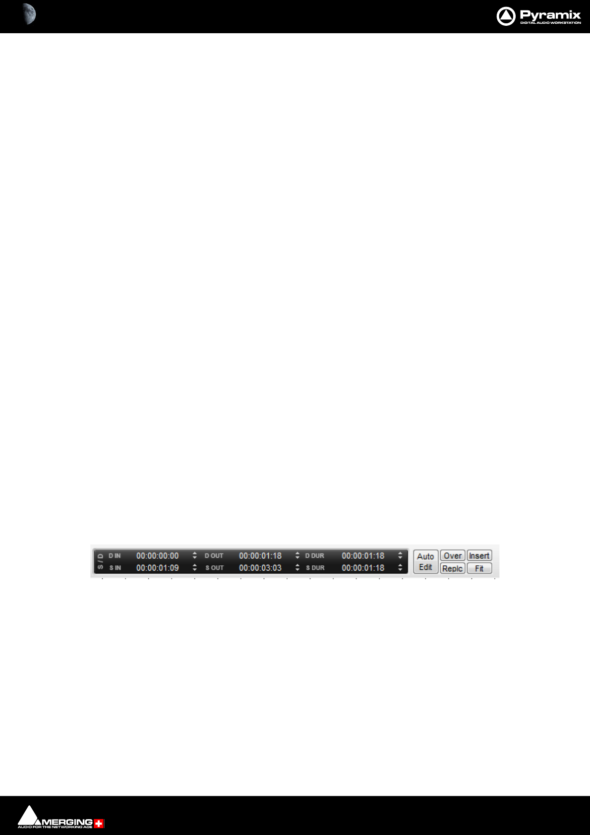
Editing : Source - Destination Editing 8 - 196
Source - Destination Editing
Concept
Source - Destination Editing is a powerful method of viewing and editing material especially applicable to edit-
ing multiple, multi-track, takes into one, ‘ideal’ take. Special Source and Destination Track Groups allow multiple
Timelines to be visible simultaneously. Each Source and destination Timeline has its own zoom level and Playhead
cursor. By taking advantage of the ‘Collapse’ feature, editing 48 track source material becomes almost as simple as
editing mono or stereo.
Source - Destination editing can also be extremely useful in broadcast and tracklaying applications. Pyramix can
have as many Clip editors as you wish. Just create some Tracks, group them, set the group as a Source. Set the Clip
Editor Track or Tracks as ‘always visible’ (in the Tracks Tab Window, so each Clip Editor always stays on top of the
composition and that’s it.
If there is no Destination group in your composition then the section between the Gates in the Source Group/Clip
Editor is sent to the positions delineated by the Mark In/Mark Out on the selected Track(s) in the composition.
Setting up a Source - Destination Environment
Templates
The quickest and easiest way to get started with Source - Destination editing is to use one of the supplied Tem-
plates. Choose the one which most closely matches your requirements, modify to taste and save as a Template
for future use.
Starting from Scratch
In the Track Groups window, Create as many Source groups as there are alternate versions of the material you are
editing and select their type as Source.
Tip: Create a Group, select its type as Source then choose Tracks > Duplicate Selected Track Group repeatedly
until you have the required number of Source groups.
Create as many Destination groups you want to edit to (generally only one) and select its (their) type as Destina-
tion.
Create as many Tracks for each source take as you need for your editing and associate a Group to each of them.
Set these groups as Keep Cursor, Free Zoom, Auto-Solo and No Selection.
Select the option Tracks > Auto Select Tracks.
Show the Source - Destination Toolbar, View > Scales > Toolbars > Source - Destination.
You are now ready to proceed with Source - Destination Editing the following manner:
Source and Destination Groups have special markers called Gate In and Gate Out which can be Set, Nudged and
Auditioned:
Set the selected Track Group Gate In/Out of the selected Track Group to Cursor with the menu Cursor & Marks >
Gate In/Out to Cursor
To remove a Gate set it again in the same position.
Gates can be dragged with the mouse by clicking on them and moving.
Gate colors:
By default, Gates are displayed in Grey.
The Source Gates currently selected for the next edit operation are displayed in White.
Source-Destination Timescale Ruler Toolbar

Editing : Source - Destination Editing 8 - 197
The Destination Gates currently selected for the next edit operation are displayed in Black.
The current Source and Destination Gates for the next edit operation are the selected group Gates or if no groups
are selected the last group where Gates have been set/removed/modified.
In 3 point editing, the “virtual” missing gate of the group that has only one gate set is displayed in Grey.
Set the Cursor to the selected Track Group Gate In/Out
Cursor & Marks > Cursor to Gate In/Out
Zoom to the selected Track Group Gate In/Out.
Cursor & Marks > Show Gate In/Out
Nudge the selected Track Group Gate In/Out with the menu selection
Cursor & Marks > Nudge Gates > Nudge Gate In/Out to Left/Right.
Each nudge operation can be auditioned automatically by setting 'Audition
after Nudge' in the Settings > All Settings > Application > Editing page
Audition the selected Track Group Gate In/Out Pre/Through/Post with the
menu selection: Machines > Internal Machine > Audition > Audition Gate In/Out
Pre/Audition/Post.
The space between Gate In and Gate Out can be selected with the menu
Selection > Select between Gates.
Positions of Gate In and Gate Out for each selected groups can be displayed and manually modified with the
Source-Destination Toolbar (If not already visible show with View > Scales > Toolbars > Source-Destination)
Once Gates In and Out have been set, Source - Destination operations can be applied FROM either the selected
Source Track Group or the last Source Track Group whose Gates have been set TO either the selected Destination
Track Group or the last Destination Track Group whose Gates have been set.
Both Source and Destination Gate In and Gate Out can be set or removed
(by setting them twice at the same position) to perform any combination of Source - Destination editing opera-
tion described in the table below.
When Gates are set the following Source-Destination operations available in the Edit menu (Edit > Source-Desti-
nation > [edit command from list below] can be applied:
• Auto-Edit Source to Destination
• Overwrite Source to Destination
• Insert Source to Destination
• Replace Source to Destination
• Fit Source to Destination
When the Source has only 1 Gate then the Region to edit can be automatically adjusted to the end (or beginning
in case of a single Gate Out) of the Clip under the Gate when the edit operation is performed. This is available by
choosing the menu item:
Edit > Source – Destination Settings > Limit 1 Gate Sources to End/Beginning of Clip.
When the Source has 2 Gates set and the Destination has 1 Gate set, then the behavior of the Auto-Edit Source to
Destination operation can be chosen between Overwrite or Insert by choosing the menu item:
Edit > Source- Destination Settings > 3 Gates Auto-Edit does Overwrite
or:
Edit > Source- Destination Settings > 3 Gates Auto-Edit does Insert
Editing : Source - Destination Editing 8 - 198
The menu item:
Edit > Source - Destination Settings > Auto Set Destination Gate In after Edit
allows the Destination Gate In to be set to the previous Destination Out point after any Source-Destination opera-
tion. This automatically prepares the Destination for the next operation. The Destination is also automatically cen-
tered around the new Gate In.
The menu item Edit > Source - Destination Settings > Auto Set Destination Gate In after Edit allows the Desti-
nation Track Group to be automatically selected after any Source-Destination operation.
All these operations works independently of the Auto-Ripple mode (they have their own overwrite/ripple modes
described in the table on the next page) but follow the Auto-Crossfade settings accessible in the menu Edit >
Auto-Crossfade.
Keyboard Shortcuts
Most Source - Destination operations are available as Keyboard Shortcuts.
2,3 and 4 Point Edits
Source-Destination
operations
Source
Gate In OR Gate Out Only
Source
Gate In & Gate Out
Destination
Gate In OR Gate Out Only
Auto-Edit: Performs 2 points edit-
ing by doing the following Over-
write operation.
Overwrite: Copies material FROM
Source Gate In to the end of the
Track or from start of Track to Gate
Out
TO Destination Gate In or Destina-
tion Gate Out by overwriting Desti-
nation material
Auto-Edit: Performs 3 point editing by doing
the following Overwrite or Insert operation
depending which one is selected in the menu
Edit > Source-Destination Settings.
Overwrite: Copies material between Source
Gate In and Source Gate Out to Destination
Gate In or Destination Gate Out by overwrit-
ing Destination material
Insert: Copies material between Source Gate
In and Source Gate Out to Destination Gate In
or Destination Gate Out by rippling Destina-
tion material
Destination
Gate In & Gate Out
Auto-Edit: Performs 3 points edit-
ing by doing the following Over-
write operation.
Overwrite: Copies material from
Source Gate In or Source Gate Out
to Destination Gate In and Gate
Out by overwriting Destination
material
Auto-Edit: Performs 4 point editing by doing
the following Replace operation.
Overwrite: Copies material between Source
Gate In and Source Gate Out to Destination
Gate In by overwriting Destination material.
Insert: Copies material between Source Gate
In and Source Gate Out to Destination gate In
by rippling Destination material
Replace: Replaces material between Destina-
tion Gate In and Gate Out by material
between Source Gate In and Source Gate Out
by rippling the Destination material
Fit: Replaces material between Destination
Gate In and Gate Out by material between
Source Gate In and Source Gate Out by
stretching or squeezing the Source material

9 - 199
www.merging.com/Pyramix
USER MANUAL
Fade Editor
Fade Editor : Fade Editor Tab Window 9 - 200
Fade Editor Tab Window
The Pyramix Fade Editor offers several methods for creating fades and cross-fades. Fades can be made graphically
by simply clicking and dragging appropriate points on the display or by using a specialized set of faders and but-
tons or by directly entering numeric data. A comprehensive set of auditioning options is provided together with
libraries for user defined fade shapes and fades.
The Fade Editor always displays the fades for the current selection in the main Editor. The nearest fade to the click
point is automatically selected.
Toolbar
Contains these buttons. If your Fade Editor has a different selection you can change that in Settings > All Settings
> Application > Desktop Layout : Fade Editor :
Accept & Close Editor (Close the Fade Editor and keep the changes, in effect an ‘OK’ button)
Restore & Close Editor (Restore the fade to its state prior to opening the Fade Editor or
selecting a new fade, effectively a Cancel button)
Fade Editor Tab floating Window
Fade Editor : Toolbar 9 - 201
Undo last fade change
Select/Edit Previous Fade
Select/Edit Next Fade
Zoom around the current Fade (Reset Zoom)
Zoom In
Zoom Out
Crossfade (Makes an asymetric fade symmetrical by using the fade length and curve from the side
of the crossfade that is not selected and applying it to the selected side. E.g. to create the mirror
image of a fade out select the incoming clip and choose Crossfade)
Show/Hide Faders & Control Section
Show/Hide Parameters & Options Section
Audition Crossfade
Audition Crossfade around the Reference Point
Audition Out with Curve
Audition Out without Curve
Audition Out after Fade
Audition Out up to the Reference Point with Curve
Audition Out up to the Reference Point without Curve
Audition Out from the Reference Point without Curve
Audition Out Original Material
Audition In with Curve
Audition In without Curve

Fade Editor : The Graphical Display 9 - 202
Audition In after Fade
Audition In from the Reference Point with Curve
Audition In from the Reference Point without Curve
Audition In to the Reference Point
Audition In Original Material
Undo Note:
By default Undo in the fade editor is restricted to the last action only in order to conserve memory. In a complex
mix the sheer number of actions to be remembered for undo can lead to excessive memory consumption. This
behavior can be changed in Settings > All Settings > Application > Editing : Fade Editor. Simply check the box
for Enable Undo for every Fade Editor change.
The Graphical Display
Consists of the following elements:
• The TimeCode scale displaying the Zoom range on its left.
• A Reference Point which is set by default at the edit point or in the middle of the (X) Fade. This marker can
be moved by clicking in the TimeCode Scale and is just a Reference Point for Auditioning (see above) or for
Auto-Center (see below)
• All Tracks or a selection can be displayed (see Parameters & Options below)
• At the left of each Track display The Track name of each Clip is shown, with a toggling Edit On/Off selec-
tor. This allows one or more Clip’s/Fades to be excluded from further modification.
• A Vertical Scrollbar navigates through hidden Tracks if any
• An Horizontal Scrollbar navigates before and after the Fade position
• The outgoing and incoming Clip fades are displayed with curves
• The Fade Position can be moved by clicking and dragging within the Fade area (Cursor changes to
hand)
• The Fade Length can be changed by clicking and dragging on the left or right side of the Fade area.
(cursor changes to <|>)
• The Media of the Clips can be moved by clicking and dragging outside the Fade area. (Cursor
changes to hand with tape reel)
• The Fade Curves can be modified by clicking and dragging on the Bezier Control Point Handles in
the Fade black box
Waveform Color Change
The waveform color can be used to indicate where the main Playhead Cursor is in relation to the Reference Point.
When the Update waveform color with cursor position check box is ticked in Settings > All Settings > Appli-
cation > Editing : Fade Editor the waveform(s) color will change to the color chosen in Settings > All Settings >
Application > TimeLine Layout : Clips & Waveforms - FadeEditor Waveform Position Color according to the
location of the main Playhead Cursor and the Reference Point (default is centre of crossfade)

Fade Editor : The Faders & Control Section 9 - 203
Context Menu
Right-clicking in the graphical display pops-up a context menu:
The Fade In, Fade Out and X Fade sub-menus offer choices of Default (complete or Curve Only), Standard, (any
of the standard fade curves) and Load (from the list of previously saved presets)
The Faders & Control Section
Has the following controls and displays:
•The Fade Safe check box in the Fader section ensures (when checked) that all following fades to the right
of the one being edited are left intact while editing the current fade. This enables Auto-Ripple to be used
without Auto-Ripple while keeping Fade synchronization clean.
• When the Force Safe box is checked the Fade Editor forces Fade Safe to enabled after each edit change.
• Six Memory Set and six Memory Recall buttons store and recall all the settings in the Fade Editor. The
recall buttons are only numbered when there are stored parameters to recall.
•Gain Faders, Nudge buttons (in 0.5dB steps) and Manual Entry Value Box for both Fade Out & Fade In
•Intercept and Asymmetry Faders, Nudge buttons and Manual Entry Value Box (in dB)
•Length Faders, Nudge buttons and Manual Entry Value Box (in milliseconds. Type an s after any numeric
entry to obtain a value in seconds) for both Fade Out & In
• Length of Fade Out & In can be linked by clicking the Link button
• Length of Fade Out and In can be changed symmetrically (centered) by clicking the Mirror button.
•Position Faders, Nudge buttons and Manual Entry Value Box (in milliseconds, type an s after any number
entry for a value in seconds) for both Fade Out & In
• Position of Fade Out & In can be linked by clicking the Link button
•Media Position Faders, Nudge buttons and Manual Entry
•Value Box (in millisecond, type an s after any number entry for a value in seconds) for Fade In
Parameters & Options Section
In this table parameters and options may be modified by clicking on >.
There are these sections and fields:
Control
•Link Length (see above)
•Mirror Length (see above)
•Link Position (see above)
•Fade Safe (see above)
•Treat Gap as Fade. When set to Yes enables two Clips which are not overlapping but with overlapping
Media to be edited in the Fade Editor as a fade. Default is No.
Display
•Shown Tracks offers these choices:
• All tracks

Fade Editor : Parameters & Options Section 9 - 204
• Follow TimeLine Display
•Choice of tracks. The number of Tracks selected in the TimeLine controls the available choices. So, if
4 Tracks are selected, there will be the option of 1, 2, 3, or 4 Tracks
•Auto-Center, enables automatic re-centering of the display around the Fade or Reference Point after cer-
tain operations
•None
•Fade
• Reference Point
•Zoom, can be one of the following:
•Free, follows only Zoom Reset, In and Out
•Auto-Zoom, automatically Zooms around the current Fade after some operations
•Auto-Zoom / Free, automatically Zooms around the current Fade but only when it enters the Fade
Editor, thereafter, the Zoom is Free
•Timeline, follows the Timeline Zoom factor
• Choice of User defined Zoom Presets (see menu View > Zoom)
• Waveform Display Can be any of the following:
• Follow Project Settings
•X1
•X2
•X4
•X8
•X16
•X32
•X64
• Auto-Scale Visible
Audition
•Pre-Roll from the choices defined in the Settings > All Settings Application Playback/Record Page
•Post-Roll from the choices defined in the Settings > All Settings Application Playback/Record Page
•Solo, when On only the edited Tracks are auditioned, when Off all Tracks of the composition are audi-
tioned as well
•Loop, any audition operation is repeated until Stop is pressed
•Speed, allows choice between 100%, 50% and 25% of normal play speed for auditioning
•Audition after Nudge, to automatically audition the Fade after nudging any parameter
Memory
•Set, allows saving up to 6 temporary Fades for comparison
•Recall, allows recall of one of the 6 temporary saved Fades
X Presets / Out Presets / In Presets
•Load Curve, allows loading the Curve SHAPE only from a choice of:
• Default
•Power
• Linear
•dB
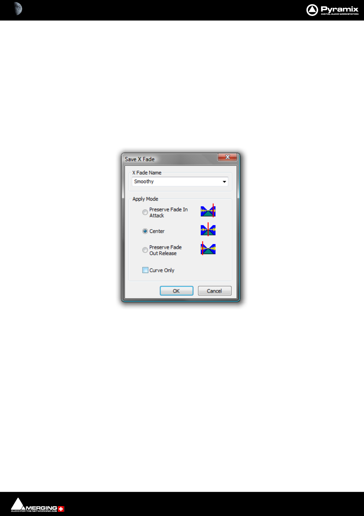
Fade Editor : Parameters & Options Section 9 - 205
•Cosine
•Root-Cosine
•Any User-defined curves
•Load Preset, allows loading a Fade from a choice of:
•Default Fade
• Any user defined Fades
•Save Preset,
•Default Fade
• New opens the Save X Fade or Save Fade pop-up dialog box (See below)
Save X Fade
The dialog box opens with the cursor in the X Fade Name box. Simply type a name for the new preset or choose
an existing one to over-write using the dropdown list. Choose appropriate options and click OK or hit the Enter
key to save the preset.
Apply Mode Options
A number of options are provided which affect the way the Fade will be applied when recalled.
Curve Only
When this box is checked only the curve shape will be recalled and applied to the overlapping Tracks for the dura-
tion of the existing cross-fade. If left unchecked, the original duration and positions of the start, end and reference
point will also be applied to the existing cross-fade.
Preserve Fade In Attack
Fade will be aligned to the left, relative to the edge of the Clip, when recalled.
Center
Fade will be centered, relative to the edge of the Clip, when recalled
Preserve Fade Out Release
Fade will be aligned to the right, relative to the edge of the Clip, when recalled.
Save X Fade dialog
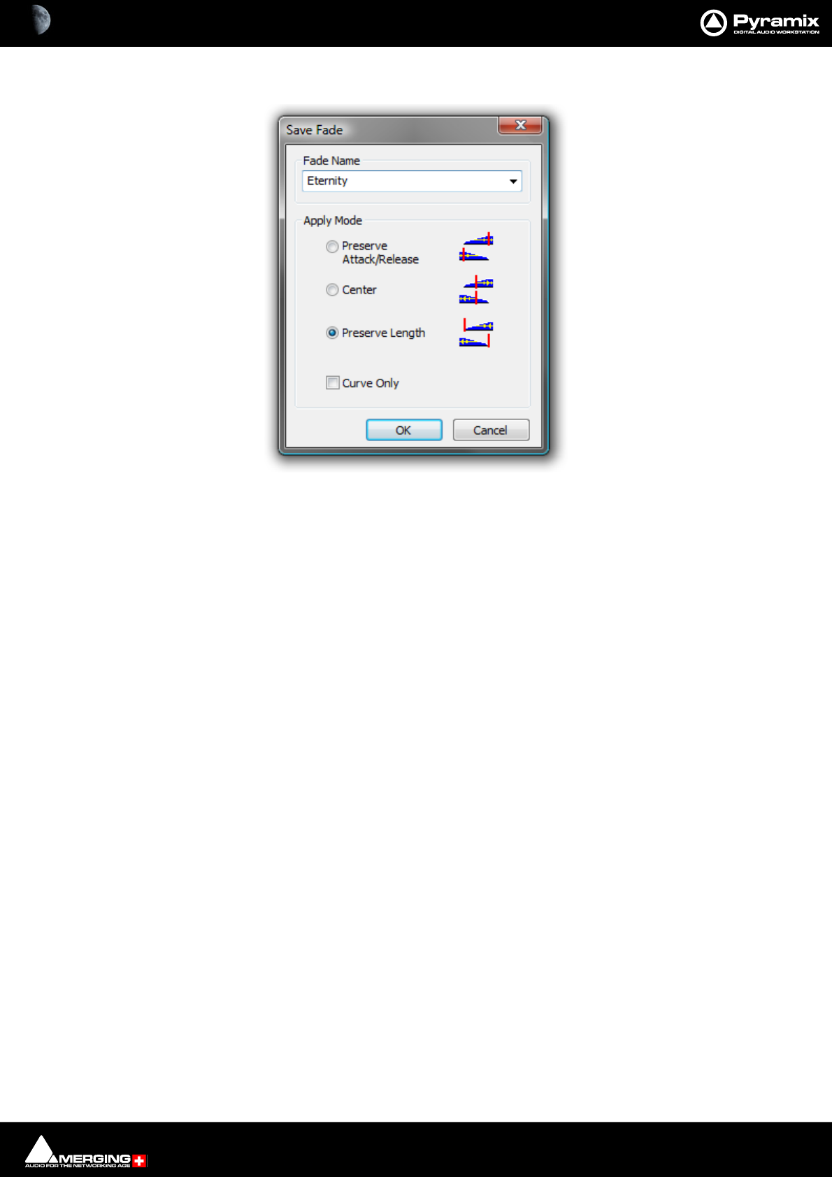
Fade Editor : Parameters & Options Section 9 - 206
Save Fade
The dialog box opens with the cursor in the Fade Name box. Simply type a name for the new preset or choose an
existing one to over-write using the dropdown list. Choose appropriate options and click OK or hit the Enter key
to save the preset.
Apply Mode Options
A number of options are provided which affect the way the Fade will be applied when recalled.
Preserve Attack or Release
Center
Preserve Length
Save Fade dialog

10 - 207
www.merging.com/Pyramix
USER MANUAL
Mixer

Mixer : Overview 10 - 208
Overview
The Pyramix Mixer has evolved into an extremely powerful tool kit. The extensive range of components and the
routing and automation possibilities can be a potential source of confusion. However, the basic principles are sim-
ple and logical. Signals enter mixer strips at the bottom, go through various controls and processing to the top of
the strip where they are routed to a bus or buses. The buses run horizontally and the sum of the bus signals enters
the bus master strip at the top and moves down through a master fader and other controls to the output(s).
Native VS3, VST and External Insert plug-in effects can be inserted in Input Strips, Aux Send Bus masters, Mix-
Groups and Mix Buses.
Note: For low latency foldback when recording an artist the Direct Monitoring Strip type should
be used.
The mixer can also take the output from an ASIO enabled application and merge it into the MassCore engine and
I/O and send audio to the ASIO enabled application.
To facilitate copy and paste between projects and importation of AAF/OMF/EDL etc. projects the Mixer has a
shared mode where the same mixer is used for more than one open Project.
If you are new to Pyramix, please use one of the simpler mixer templates to become familiar with the basic fea-
tures. E.g. Mix 08 X 02 (Stereo)
Bus Architecture and Panning
For Pyramix Version10 and subsequent versions the mixer has been modified and enhanced extensively.
Important! When deciding on which types of buses to use, Legacy or the new General Mixing Buses, it
is crucial to understand the limitations that are inherent in a system with two ways of employing busing.
Please ensure that if you are going to use the new busing and panning that you convert ALL of your
buses to the new type. Or, if you are building a new Project, please choose the new buses only.
• - Legacy subgroups will not feed into new buses.
• - A mix of legacy and new buses may confuse some control surfaces.
Bus Architecture
A new type of Mix/Aux bus has been added - the General Mixing Bus. This comes in five varieties:
•Mix Bus
•Mix Group
•Aux Bus
•Aux Group
•Object Bus
The Object Bus is provided for sending any Input Strip’s output(s) to a specialized Object Bus for new 3D, immer-
sive formats such as Dolby Atmos.
The bus type is selected from a dialog when the bus is added.
Aux v Mix Groups
In Pyramix Aux buses are intended solely for foldback purposes. They are not intended to be used as a means of
applying effects, internal or external, to a collection of sources, with the bus output re-routed back to an input
strip. Effects can however be inserted into Aux buses in order to enhance the artists experience.
Mix-group buses are intended to be used as conventional Sub-groups and, of course, can have internal VS3 and
VST effects inserted and or external inserts.
Using Mix Group buses for mix effects ensures that the full automatic (and manual) delay compensation features
will function correctly.

Mixer : Overview 10 - 209
General Mixing Bus Channel Configuration
All General Mixing Buses channel configuration can be changed at any time in the 3D Room Editor. Please
see: The 3D Room Editor on page 264
Room Models
Two types of room model are available:
Virtual Rooms use a Stereo panning based algorithm using either a Square Root or Sin/Cos panning law
extended to all three dimensions. In this mode speaker positions are fixed. This mode is designed for Film, Post
Production or Music where no real world room definition is needed or known in advance and precision is needed
to focus on each individual speaker.
Sized Rooms use a sound in air propagation/attenuation based algorithm. In this mode speaker positions are
editable. The panning algorithm uses real distances to compute levels. In this mode all speakers will output some
level even if it is very low, wherever the Panner is positioned.
The room type can be switched at any time in the Room Editor.
Panning Control Buses
Panning is achieved using Panning Control Buses. These are purely control buses, they don’t process any audio
and have no channels, no associated Output Strip and no I/O. Instead of having a separate panner on each Input
Strip Bus Send there is one or more Panning Control Buses. Input Strip Bus Sends are assigned to Panning Control
Buses or routed direct using a Channel Router matrix. One Panner can control several Bus sends in different for-
mats. E.g. when Mono, Stereo, Surround and Auro3D Buses are present. Equally, if it is desired to pan differently to
different Buses, this can be achieved by adding more Panning Control Buses.
The Panning Control Bus user interface in each Input Strip can be switched to one of three different panner types
or a direct Channel Router Matrix. Left-click on the Bus Send Pan 1 etc. label to open the Routing context menu
with the choice of:
Channel Router
Panner 1
Panner 2
etc.
Panner Types
Panner Type is selected by right-clicking on a Panner in the Strip to open the context menu and choosing: Set
Panner Type The sub-menu offers the choice of:
•None useful if you wish to hide the panner in a Strip using a Router
•3D Panner, which gives access to the standard 2D surround control plus the Height/Z axis, divergence
and LFE gain.
•2D Panner, which gives access to the standard 2D surround control plus divergence and LFE gain.
•Pan/Balance (1D Panner), which gives access to three types of panning (below) plus divergence and LFE
gain.
• On a Mono strip the control is always pan.
• On a Stereo strip the following choices are offered as Dual Source Mode
(Right-click on the Panner in the Strip to open the context menu and choose: Dual Source Mode
• None (Hides the Panner in the Strip. Useful if you don’t want to see the Panner in a Strip
where the Router is in use.
•Single Pan
•Dual Pan
•Balance
Note: Width control is the Source Size parameter when in Single Pan mode.

Mixer : Mixer Pages 10 - 210
Mixer Pages
The Mixer user interface is arranged in four pages grouping functions in a logical manner. Most time will be spent
working in the main Mix ! page. The other pages, Configure, Route and Organize, toggle with the Mix ! screen
and are accessed from buttons at top right of the screen...
Mix !
Overview
This is the operational Mixer user interface page. It is necessarily complex when used to the fullest extent since
Pyramix’ capabilities are prodigious. However, it can also be kept very simple. The Mixer surface is divided into a
number of areas both vertically in strips and horizontally in rows. A number of features help to keep track of what
is going on in large and complex mixers. Strips and buses can be colored and there is a powerful bi-directional sig-
nal flow display. I.e. when signal FLow is active, clicking on an input strip highlights all the buses it is feeding. Sim-
ilarly, clicking on a Bus highlights all the Input Strips feeding it.
Controls
Rotary Controls, sliders and Faders are adjusted by grabbing them with the mouse and dragging. Rotary controls
and horizontal sliders are adjusted by dragging left or right and faders by dragging up or down. Double-clicking a
Fader, slider or Rotary knob returns the value to the default. E.g. unity gain on a Channel Strip Fader. Holding down
the Ctrl key increases resolution to 0.1dB. Keyboard up and down arrows adjust gain by 0.1dB per press, with
Shift 0.5dB per press and with Ctrl + Shift 1.0dB per press. Bargraph shows peak level.
Mixer Window Tabs and control buttons
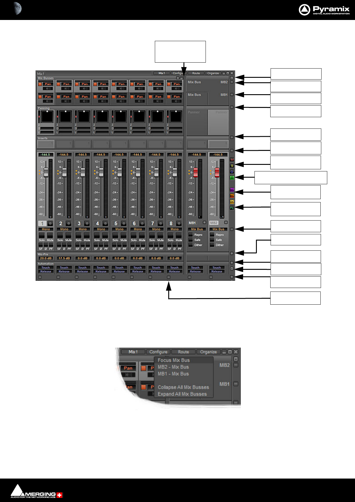
Mixer : Mixer Pages 10 - 211
Basic Mixer
+ Clicking on this pops-up a menu which enables individual Buses to have the focus
and or All Mix Buses to be collapsed or expanded.
Clicking on a single bus in the list collapses the others.
-Clicking on this toggles the Buses between collapsed into a single row and
expanded to full height in separate rows.
Mic Pre
pop-up menu
Effects/Inserts
pop-up menu
Panning
pop-up menu
MB1: Mix Bus
pop-up menu
Strip/Bus/Group
color buttons
Mute
pop-up menu
Mixer
pop-up menu
Simple 8 X 2 X 1 mixer
Automatic Delay Compensation
Button/Indicator
Mixer Global
Buttons/Indicators
Gain
pop-up menu
Auto/I/O&VCA
pop-up menu
Signal Flow
button
+pops-up Bus Focus
menu
- Toggles Bus rows
collapsed/full
Strip
pop-up menus
MB2: Mix Bus
pop-up menu
Show/Hide Mix Buses
/Groups pop-up menu
Show/Hide Masters
pop-up menu
Focus Mix Bus pop-up
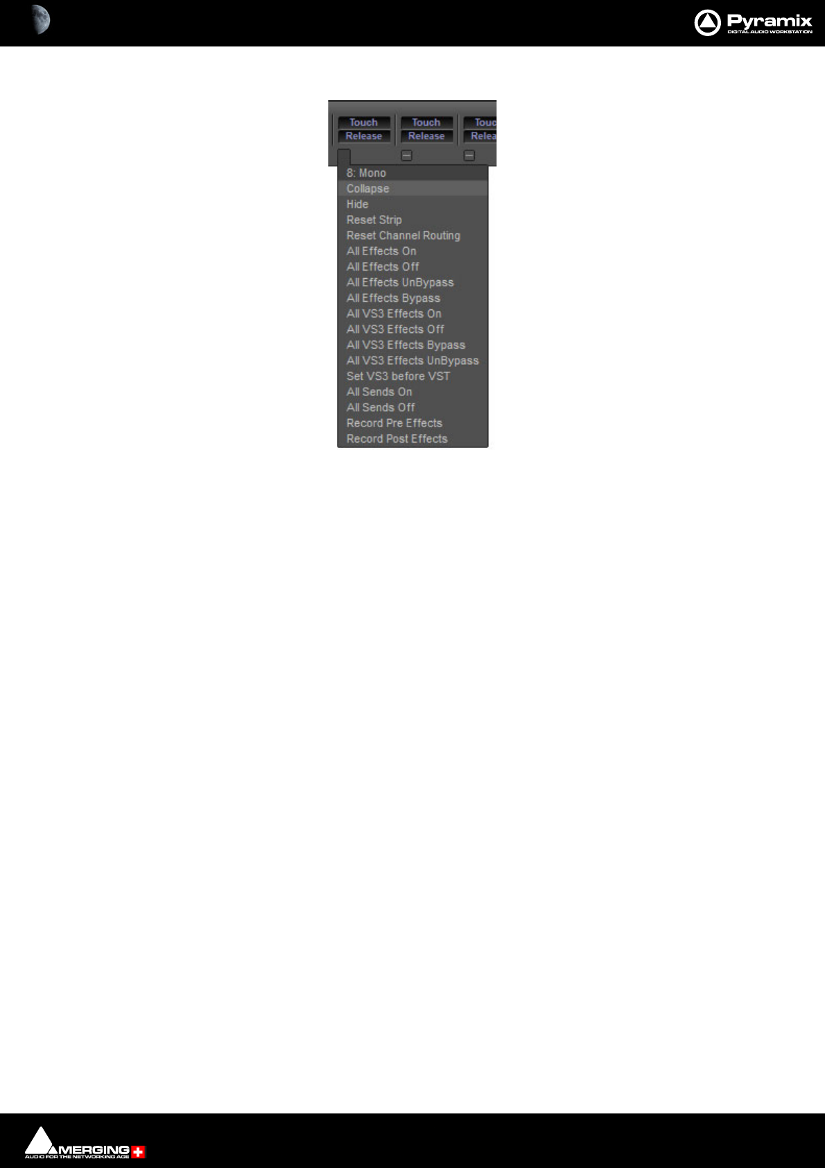
Mixer : Mixer Pages 10 - 212
Strip Pop-up Menus
The precise contents of the Strip pop-up menu will vary according to the Strip type. The following is a selection of
important functions:
Collapse Collapses the Strip to a narrower Strip. If the Strip is collapsed the - changes to +.
Clicking on + restores the Strip to full width.
Hide Removes the Strip from the Console UI. To restore hidden Strips hover over the
Mixer +button and select Show All in the Input Strips or Masters section as
appropriate.
Reset Strip Resets all Strip controls to their defaults.
Reset Channel Routing Creates a diagonal unity routing when both the Strips and the Buses channel types
are set to none.
The other entries are self explanatory.
Strip pop-up
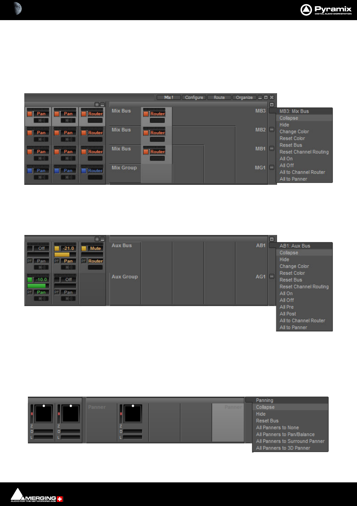
Mixer : Mixer Pages 10 - 213
Mixer Rows
Starting at the top a mixer can contain rows as follows:
Mix & Mix Group Buses Every mixer contains one or more summing Mix Buses. Mono, Stereo and Multi-
channel are all available. The Mix Bus rows also contain the On/Off switch and the
output meter to the target Bus(es).
Note: Mix & Mix Group Bus sends are switched OFF by default.
Aux & Aux-Group Buses If Aux and or Aux-group Buses are present in the mixer their send controls appear
here.
Note: Aux & Aux-Group Bus sends are switched OFF by default.
Effects The Effects row has one or more slots per strip for Plug-ins. In Pyramix all processes
are considered to be effects. Plug-ins can be either native VS3 or VST. The effects
row expands to accommodate the number of plug-ins instantiated in the strips.
Panning The panning row has a surround panner section in Input Strips, Mix Group and Aux
Group Strips.
Mixer & Mix Group Buses rows & Mix Bus drop-down
Aux & Aux Group Buses rows & Aux Bus drop-down
Aux & Aux Group Buses rows & Aux Bus drop-down
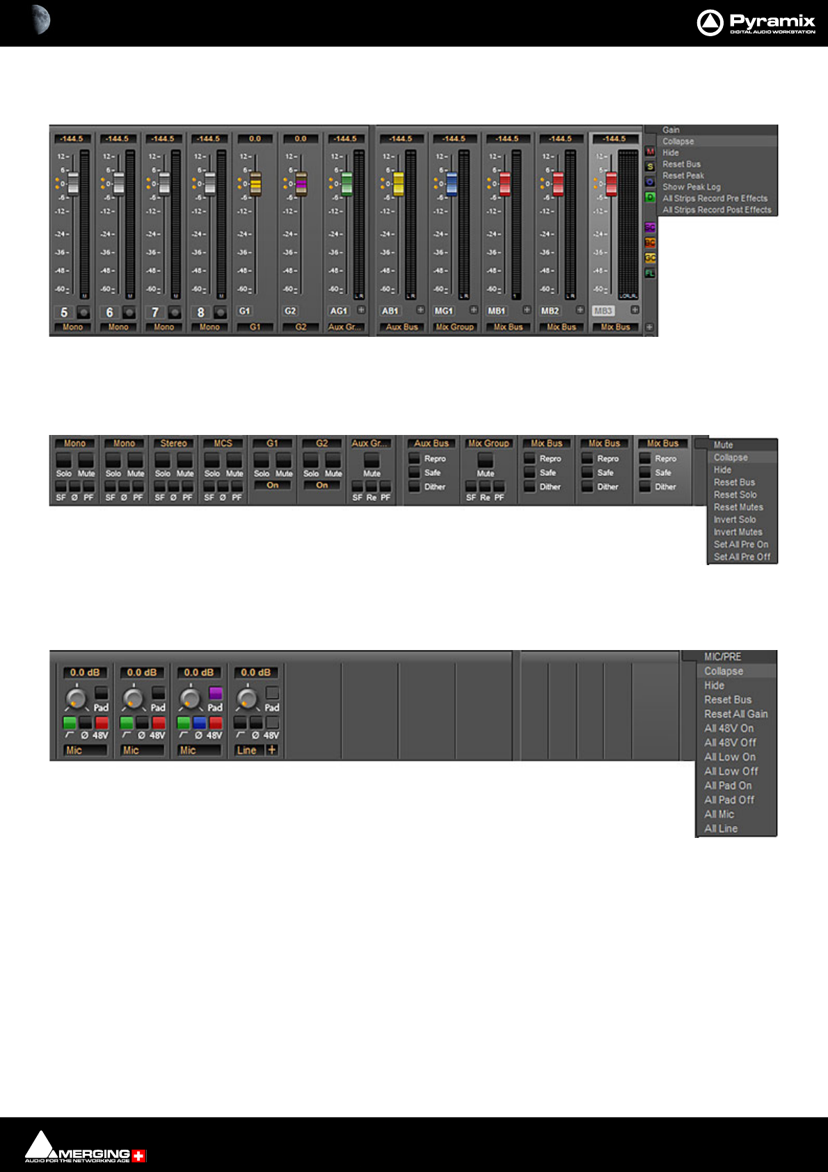
Mixer : Mixer Pages 10 - 214
Gain The Gain section includes the Fader, Meter(s) and Record Arm button/indicator (on
applicable strips).
Mute The Mute row includes the Mute and Solo buttons along with Solo Safe, Phase
reverse and Pre-fade on Input Strips, Repro, Safe and Dither on Aux and Mix Buses,
Mute, Safe Re-Pan and Pre-Fade on Aux and Mix Group Strips.
Mic Pre Only present in a system including a HORUS or Hapi with an A to D card installed.
Includes all the controls necessary to set source type, gain, phantom powering etc.
Aux & Aux Group Buses rows & Aux Bus drop-down
Mute & Solo row & Mute drop-down
Mute & Solo row & Mute drop-down
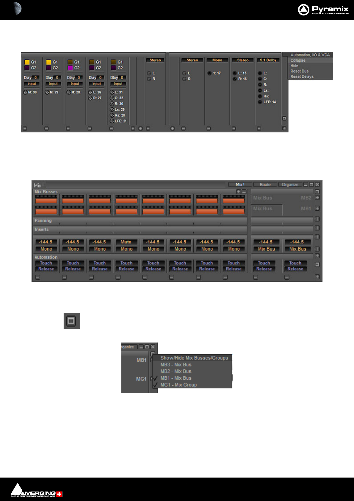
Mixer : Mixer Pages 10 - 215
Automation, I/O & VCA This row is modal. When collapsed it shows two Automation buttons per strip.
When expanded it shows the I/O and VCA Group assignments.
Expand / Collapse Vertical
Expand / Collapse and Hide can reduce clutter by concealing unused controls. This is a simple mixer with all areas
Collapsed vertically:
The small, grey + - boxes on the right of the mixer surface toggle horizontal areas of the mixers surface shown full
size or collapsed. They also pop-up context menus when the cursor is above them. (see below)
This button near the top of the mixer on the right-hand edge pops up a Show/Hide Mix
Buses/Groupsmenu:
Ticked Bus rows are shown full height. If all Buses are hidden a single row is displayed to represent all the Buses
present in the mixer.
The individual Bus rows expand/collapse when clicked on the meter area in an Input Strip and collapse all other
bus rows.
Input, Delay & VCA Group row & Automation, I/O & VCA drop-down
Simple 8 X 2 X 1 mixer Window with all areas hidden
Show/Hide Mix Buses/Groups menu
mixer + - pop-up menus
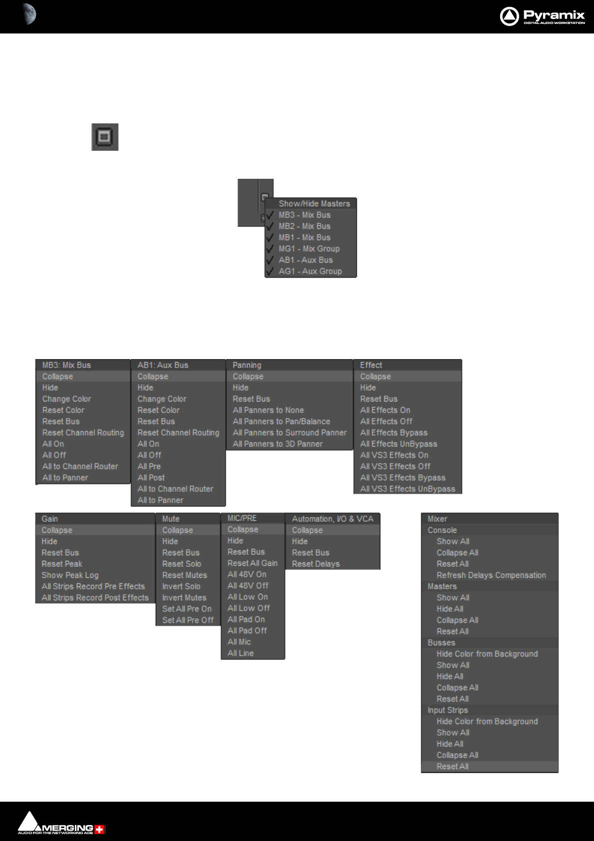
Mixer : Mixer Pages 10 - 216
Expand / Collapse Horizontal
The - buttons at the bottom of each Strip collapse the strip to a narrow gray band and also pop-up a menu. The
button changes to + when the Strip is collapsed. Clicking again restores the strip to full with. Bus strips also have a
+ button to the right of the Bus label. It toggles the meters between narrow and wide. In the case of a Bus with
many channels the strip width is increased to accommodate the meters when expanded.
This button near the bottom of the mixer on the right-hand edge pops up a Show/Hide Masters
menu:
Ticked Bus Master Strips are shown. Unticked Strips are hidden.
+- Row Menus
Each + - box also pops-up a menu relevant to the row of the mixer it deals with when the cursor is above it. E.g. :
Show/Hide Masters menu

Mixer : Mixer Pages 10 - 217
Collapse Versus Hide
Choosing Collapse leaves a small artefact of the mixer area visible, a gray horizontal bar with a + box at the right-
hand side which restores. Hide completely removes the area from view. Choosing Show All in the Mixer + - pop-
up will restore.
Resets
These context menus also provide a convenient way to restore all controls of specific types or, in the relevant sec-
tions, the entire Strip or Mixer to the default condition.
Bus + - Pop-up Menus
Collapse Collapses the Bus Send row.
Hide Hides the Bus Send row.
Change Color Opens the Color Picker window.
Reset Color Resets Color to the default.
Reset Bus Turns Bus Off.. In an Aux Bus reduces the send level to -144.5dB and turns Bus Off.
Note: Aux Buses set to Pre-fader are NOT affected.
Reset Channel Routing As it says.
All On Turns On the Strip sends to the bus for every Input Strip.
All Off Turns Off the Strip sends to the bus for every Input Strip.
All Pre Aux only All sends are switched to Pre Fader.
All Post Aux only All sends are switched to Post Fader.
All to Channel Router All sends are set to Channel Router Matrix.
All to Panner All sends are set to the Panning Bus (One entry will be present per Panning Bus in
the mixer.)
Panning Pop-up Menu
Collapse Collapses the Panner row.
Hide Hides the Panner row.
Reset Bus Resets the bus to the default condition.
All Panners to None Removes the Panner from all Input Strips and leaves a thin placeholder row.
All Panners to Pan/Balance Sets every Input Strip Panner to Pan for Mono Strips, Balance for Stereo Strips and
Pan for multi-channel Strips.
All Panners to Surround Panner Sets every Input Strip Panner to Surround mode.
All Panners to 3D Panner Sets every Input Strip Panner to 3D mode.
Effect Pop-up Menu
Collapse Collapses the Effects row.
Hide Hides the Effects row.
Reset Bus Nothing.
All Effects On Turns all Effects in the Mixer On.
All Effects Off Turns all Effects in the Mixer Off.
All Effects Bypass Switches all Effects in the Mixer to Bypass.
All Effects Unbypass Switches all Effects in the Mixer to in circuit.
All VS3 Effects On Turns all VS3 Effects in the Mixer On.
All VS3 Effects Off Turns all VS3 Effects in the Mixer Off.
All VS3 Effects Bypass Switches all VS3 Effects in the Mixer to Bypass.
All VS3 Effects Unbypass Switches all VS3 Effects in the Mixer to in circuit.
All VST Effects On Turns all VS3 Effects in the Mixer On.
All VST Effects Off Turns all VS3 Effects in the Mixer Off.

Mixer : Mixer Pages 10 - 218
All VST Effects Bypass Switches all VS3 Effects in the Mixer to Bypass.
All VST Effects Unbypass Switches all VS3 Effects in the Mixer to in circuit.
Gain Pop-up Menu
Collapse Collapses the Effects row.
Hide Hides the Faders row.
Reset Bus Resets all faders to 0dB.
Reset Peak Resets all latched Peak indicators to Off.
Show Peak Log Opens a window with a list of all Peaks since the last Reset.
All Strips Record Pre Effects Record source for all Input Strips is taken before any Effects present in the Strip.
All Strips Record Post effects Record source for all Input Strips is taken after any Effects present in the Strip.
Mute Pop-up Menu
Collapse Collapses the Effects row.
Hide Hides the Mutes and Solos row.
Reset Bus Cancels any active Solos and Mutes.
Reset Solo Cancels any active Solos.
Reset Mutes Cancels any active Mutes.
Invert Solo Any Strips in Solo will be un Soloed and vice-versa.
Invert Mutes Any Strips Muted will be Unmuted and vice-versa.
Set All Pre On Sets all Input Strips to Prefade On.
Set All Pre Off Sets all Input Strips to Prefade Off.
Mic/Pre Pop-up Menu
Collapse Collapses the Effects row.
Hide Hides the Mic/Pre row.
Reset Bus Resets the Mic Pres to the default condition.
Reset All Gain Resets all Preamp gains to the default value.
All 48V On Turns 48V Phantom Power On on all Preamps set to Mic.
All 48V Off Turns 48V Phantom Power Off on all Preamps set to Mic.
All Low On Turns the High Pass Filter On on all preamps.
All Low Off Turns the High Pass Filter Off on all Preamps.
All Pad On Turns the Pad On all preamps set to Mic.
All Pad Off Turns the Pad Off all preamps set to Mic.
All Mic Switches all Preamps to Mic mode.
All Line Switches all Preamps to Line mode.
Automation, I/O & VCA Pop-up Menu
Collapse Collapses the Effects row.
Hide Hides the Effects row.
Reset Bus Nothing.
Reset Delays Resets all Delays to zero.
Mixer Pop-up Menu
Console
Show All Shows every section of the Console Unhidden and Uncollapsed. Use this to see
sections of the Mixer which have been hidden from View.
Collapse All Collapses every section of the Console to its minimum height and width.
Reset All Resets every Console setting to the default value.
Refresh Delays Compensation Recalculates and applies the required delays to time align the Mixer.

Mixer : Mixer Pages 10 - 219
Masters
Show All Shows every section of the Console Unhidden and Uncollapsed. Use this to see
sections of the Mixer which have been hidden from View.
Hide All Hides all Master Strips from view.
Collapse All Collapses all Master Strips to narrow bars.
Reset All Resets every Master Strip setting to the default value.
Buses
Hide Color From Background Where Bus Colors are active, hides the Colors
Show All Shows all Bus Send rows, the Panner & Effects rows uncollapsed.
Hide All Collapses all Bus Send rows to a single row, collapses all Aux Send rows to a single
row, collapses the Panner row(s), Collapses the Effects row.
Collapse All Collapses all Bus Send rows to minimum height.
Reset All Resets all Buses.
Input Strips
Hide Color From Background Where Input Strip Colors are active, hides the Colors.
Show All Shows all Input Strips at normal width including those hidden or collapsed previ-
ously.
Hide All Hides all the input Strips from view in the Mixer window.
Collapse All Collapses all Input Strips to narrow bars.
Reset All Resets all Input Strips.

Mixer : Mixer Components 10 - 220
Mixer Components
Input Strips
Mixer Input Strips associated with Tracks (the main number top-left in the Track Header) are fed by and control the
monitor output of the Tracks. The Mixer Strip Channel Live (physical) or Internal Return Bus Input goes direct to
the associated Track. When a strip has no associated Track it is fed by and controls the Live (physical) or Internal
Return Bus input assigned to it.
When the strip has an associated Track, the Track output is automatically switched between input and playback
output depending on transport mode, the monitoring setting in the Track header and the setting of the Settings
> All Settings > Application > Playback/Record : Auto-monitoring option, European Monitoring (all tracks
turn to INPUT on stop) or US Monitoring (only Record Ready tracks turn to INPUT on stop).
Note: When strip channels have an associated Track NONE of the strip controls, fader, mute,
affect the signal fed to the Track input. The Record feed can be Pre or Post Effects, selected from
the Strip pop-up menu.
Mixer Input Strips have the same functions as the input strips of any standard mixing console providing level con-
trol, pan, mute, etc.
The following types of input strips are available:
Mono
Mono - Direct Monitoring
Stereo
Stereo - Direct Monitoring
MS
MS - Direct Monitoring
Multi-Channel Strip)
Mixer : Mixer Components 10 - 221
Basic Strip
Controls and Faders
Rotary Controls, sliders and Faders may be adjusted by grabbing them with the mouse and dragging. Rotary con-
trols and horizontal sliders are adjusted by dragging left or right and faders by dragging up or down. Double-click-
ing a Fader, slider or Rotary knob returns the value to the default. E.g. unity gain on a Channel Strip Fader. Holding
down the Ctrl key increaes the resolution to 0.1dB Keyboard up and down arrows adjust gain by 0.1dB per press,
with Shift 0.5dB per press and with Ctrl + Shift 1.0dB per press.
Buttons
Buttons on the main mixer surface are black when inactive. When active they ‘light up’.
A basic mono channel strip contains:
Mix Bus Send
Output Meter
On /Off toggle switch, Pan / Router Click in the box to select.
Bus Trim. click on the button to open the Bus Trim pop-up.
Panning
Pan Slider Panner type can be 3D, 2D or Pan/Balance as shown here.
Divergence and LFE Sliders. LFE only relevant if present in Bus
Inserts
Slots for VS3 and VST Plug-ins and External Inserts.
Numeric display of fader output level value, if cursor is over a fader knob shows fader
gain. If a pan-slider is being moved, shows current pan position. May be clicked to
enter a fader gain value directly.
Fader and Post-Fader (default) Input bargraph Peak Meter(s)
Bargraph shows peak level.
Rec enable(d) Enables/disables recording for the associated track. Lights red when
enabled. (Purple when source is after effects.)
Solo solos the strip, Mute mutes the strip. Ctrl + Solo cancels all other Solos.
SaFe prevents the strip being muted by solo operations elsewhere. Ø reverses the
channel phase. PF changes the metering position to Pre-Fader.
I/O &VCA - If a VCA Group or Groups is present the select buttons also appear here.
Delay A delay value (in samples) can be set in this box.
Input Clicking on Input pops-up a box with the choice of the strip taking its input from
a physical connection or any output bus.
Input and Direct Output Assignment
Right-click on the XLR icons to pop-up a drop down list of valid assignments.
Note: Direct Outputs must first be enabled in the Mixer : Route page.
Please see: Channel Direct Outputs on page 224
Basic Strip

Mixer : Mixer Components 10 - 222
Stereo Strips
In a Stereo Strip the single bargraph meter is replaced by a pair and the Panner can be set to Dual-Source Mode
with a choice of Balance control, Single Panner or Dual Panner (accessible from the right-click context menu.)
Stereo Strips can reverse the Phase of both the Left and Right channels. The single button has four possible states:
Black: No phase inversion
White: Left channel inverted
Red: Right channel inverted
Blue: Both channels inverted

Mixer : Mixer Components 10 - 223
M&S Stereo Strips
What is M&S?
M&S stands for Middle and Side. M&S is a microphone technique which outputs Sum and Difference signals
instead of Left and Right (also known as LR, AB or XY). These Sum and Difference signals are often known as M&S
although this nomenclature is often a source of confusion...
Sum and Difference signals can be created from a conventional Left, Right source. For example, by using the
Pyramix MS Encoder plug-in.(Please see: MS Encoder on page 352).
Decoding M&S
A Sum and Difference or M&S decoder reconstitutes Left and Right by adding the Difference (S) signal to the
Sum (M) signal to produce Left and adding the phase-reversed Difference (S) signal to the Sum (M) signal to
produce Right. This is often represented as:
L = M + S and R = M - S
Benefit of M&S
In mixing as opposed to recording, the main practical benefit of manipulating a signal in the Sum and Difference
domain is true control over the width of the image. Pyramix can handle these signals directly thanks to the provi-
sion of M&S Stereo strips.
The new General Mixing Bus decodes MS directly and without any additional user interface. Users can feed An
MS strip can be fed with Middle and Side information as before and the Panner will decode the Left and Right
information and feed it directly to the connected Buses.
If you wish to route the raw M & S signals, switch the Bus connection to use the Channel Router instead of the
Panner.
Width Control
The Middle and Side Mixing controls which existed in the old-style busing connection are absent temporarily. So,
when using the new General Mixing Buses, users will need to change the balance between the Middle and Side
levels by using Clip Gains & Clip Envelopes.
The direct M&S mixing functionality will return in a subsequent release of the Pyramix software.
Phase Button in an M&S Strip
The Phase of both the Sum and Difference channels can be reversed. The single Ø button has four possible states:
Black: No phase inversion
White: Sum (M) channel inverted
Red: Difference (S) channel inverted
Blue: Both channels inverted
Inverting either Sum or Difference results in the image being reversed left to right.
Note: If the Input meters consistently show S higher than M then either the image is very wide
and unlikely to be compatible for a mono listener or the M and S inputs have become reversed at
some point. Regrettably, this is extremely common when dealing with location recordings in film
and TV.
Mixer : Mixer Components 10 - 224
Multi Channel Strips
In a Multi Channel Strip there are as many bargraph meters as there are channels. The Panner type can be None,
(which hides the Panner if you are using the Router) 3D, 2D or Pan/Balance.
Channel Direct Outputs
All Input Strip Channels can have Direct Outputs. The Direct Out connection is disabled by default. It can be
enabled in the Mixer Route Tab using the Strips Direct Out Page by clicking on (Click to Enable) in the Strip
Header in the routing matrix. When active (Click to Enable) disappears. Clicking again in the Strip Header disables
the Direct Out and(Click to Enable) reappears.
The Direct Out can be routed per Channel to any output by clicking on a crosspoint in the matrix. The Direct Out
can be sent Pre or Post Fader. Click on the DO: Post box in the Mixer I/O section to toggle. The Direct Out is cur-
rently always Post Effects. Direct Outs are not shown in the I/O section of the mixer unless they are activated in
the Route page.
Direct Monitoring Input Strips
Direct Monitoring Input Strips are a special version of the basic Input Strip designed specifically for recording. The
principal feature of these strips is minimum monitoring latency for the artist. This is achieved by applying auto-
matic delay compensation only to the signal fed to the main output bus. For this reason, Aux Sends and Effects
cannot be installed in Direct Monitoring Input Strips and they cannot be routed to SubGroups. Three types are
available:
Mono - Direct Monitoring
Stereo - Direct Monitoring
MS - Direct Monitoring
Note: Track returns to these strips do not have automatic delay compensation applied and are
intended for monitoring only. When mixing down the Track outputs should be connected to
‘normal’ strips. To indicate this clearly, Tracks feeding Direct Monitoring Input Strips show a small
red box with ‘D’ in the header:
Adding Direct Monitoring Input Strips
To add a Direct Monitoring Strip right-click on a blank area of an existing strip to the right of where you wish to
add it. Select Strip > Add > Mono -Direct Monitoring, Stereo - Direct Monitoring or MS - Direct Monitoring
from the context menu as appropriate.
Note: If Auto-Delay Compensation is turned on for the Mixer then the recording from a Direct
Monitoring Input Strip will be in sync with the existing Tracks while maintaining minimum
latency for foldback to the artist.
Input Strips Fed From Internal Return Buses
Note: A Strip fed from an Internal Return Bus will NOT be fully Delay Compensated when in
Auto-Monitoring mode and when in Repro mode the red ‘D’ will be highlighted due to non-
compensation. On the other hand the recorded material will be Compensated correctly and in
sync with the current timeline events.
Track Header Direct monitoring Indicators
Mixer : Global Indicators / Buttons 10 - 225
Global Indicators / Buttons
The small indicators/buttons on the right-hand side of the mixer window, adjacent to and Shown / Hidden with
the Fader row, have the following functions::
Color and Signal Flow Buttons
These small buttons on the right-hand side of the mixer window, adjacent to the Fader row, have the following
functions:
Signal Flow [FL]
When the Signal Flow button is active (lit):
When an Input Strip is selected it is colored light green and the complete signal path where the signal is sent from
that strip is colored a darker green. Loops are taken into account in the signal flow coloring.
Signal Flow coloring applies whether signals are actually present or not.
If an output Bus Strip is selected it is colored blue and the complete signal path of all sources feeding the Bus is
also colored blue. Loops are not taken into account.
If a VCA Group is selected, the signal flow of all members of the group is colored green.
If multiple strips are selected (hold down the Ctrl key and click on Strip numbers) then the signal flow for all strips
selected is colored green.
If the Ctrl key is pressed when clicking on the [FL] button, the Mixing console UI contracts to show to only compo-
nents participating to the signal flow. Ctrl clicking the [FL] button again restores the mixer UI to its original state.
MUTE - Lit when a Mute or mutes are active. Clicking on the lit button cancels all active Mutes.
SOLO - Lit when a Solo or Solos are active. Clicking on the lit button cancels all active Solos.
Overload - Lit when an Overload indicator is latched. Clicking on the lit button cancels all active Overload
LEDs.
Automatic Delay Compensation Status
Please see : Delay Compensation on page 269
Strip Color - When lit shows the Tracks Clip background colors in the Input Strips background.
Bus Color - When lit the bus colors are shown.
Group Color - When lit the VCA-group fader knob(s) and Strip fader knob(s) of Strips assigned to VCA
groups is(are) colored according to the VCA group.. Color is fixed.
Signal Flow - When lit Bus and Strip colors are switched off (if active) and the signal flow for the strip
selected currently is shown. If an Input Strip is selected then the Strip and all Buses it feeds are colored
green. If a Bus strip is selected then the Bus and all Strips feeding it are colored green.

Mixer : Buses 10 - 226
Buses
In a MassCore system the only limitation on the number of audio I/O buses is the available power. For now the
maximum number of buses is artificially limited in code to 512 (at 1FS, 256@2FS, 128@4FS, 64@8FS).
The Pyramix Mixer uses a number of different types of Bus:
General Mixing Buses Sum audio and are available in several types. (see below)
Control Buses Do not carry audio. There are two types; the Panning Control Group and the so-
called VCA Group.
Object Buses These are a special type of General Mixing audio bus provided for new 3D immer-
sive formats including Dolby Atmos.
Internal Return Buses These are a special type of Bus used to return the output of General Mixing Buses
back to Input Strips.
General Mix Buses
General Mix Bus Types
Mix Bus Master Output Buses. May be routed to physical outputs.
Mix Group Used as a Sub-Group principally for Effects, e.g. reverb. Can only be rerouted into
another General Mixing Bus.
Aux Bus Used principally for artist foldback. May be routed to physical outputs.
Aux Group Used as a Sub-Group. Can only be rerouted into another General Mixing Bus.
Note: Please be aware that a Mix Group Bus or Aux Group Bus will auto-take Internal Bus con-
nection resources, starting from the last one. E.g. IB384-IB385 for the first two Group Channels
added to a Mixer. This means that you will no longer see IB384 and IB385 in the IB list.
General Mix Bus Features
General Mixing Buses can have a virtually unlimited number of channels. (Only limited by the maximum sup-
ported by the Pyramix engine.
Each channel can be assigned a type, including 3D specific types, from the extensive list of Channel Types. Please
see: Channel/Speaker Types on page 265
When creating a new General Mixing Bus, (Right-click context menu Bus > Add > New General Mixing Bus) the
choice is given for one of the five types, the number of channels and a choice of predefined Channel Types (AKA
Speaker Arrangements e.g. Mono, Stereo, 5.1 Dolby, 9.1 Auro etc.) or Custom. (Please see next page)
General Mixing Busses can also be given an optional Room Size. In this case the panning algorithm changes to a
distance based algorithm. Please see: Room Models on page 209.
An existing General Mixing Bus topology can be modified after its creation by using the Room Editor. Please see:
The 3D Room Editor on page 264.
Mixer : Buses 10 - 227
General Mix Bus Formats
All of the General Mix Bus types apart from Object Bus can be created in any of the formats listed here plus
Custom:
Custom
When Custom is selected as the General Mix Bus Channel Mapping the Bus is created with the number of chan-
nels specified but not set to any Type. Clicking on the Custom box in the Bus Master I/O section will open the 3D
Room Editor where custom channel assignments may be made. Please see: The 3D Room Editor on page 264
Mono 9.0 Surround
Stereo 9.1 Surround
3.0 Front 11.0 Surround
3.1 Front 11.1 Surround
3.0 Surround 5.0 Dolby
3.1 Surround 5.1 Dolby
4.0 Quadro 7.0 Dolby
4.1 Quadro 7.1 Dolby
4.0 Surround 9.0 Dolby
4.1 Surround 9.1 Dolby (Atmos)
5.0 Side (THX) 7.0 DTS (Neo:X)
5.1 Side (THX) 7.1 DTS (Neo:X)
5.0 Surround (SACD) 9.0 DTS (Neo:X)
5.1 Surround (SACD) 9.1 DTS (Neo:X)
6.0 Side 11.0 DTS (Neo:X)
6.1 Side 11.1 DTS (Neo:X)
6.0 Surround 10.2 TMH
6.1 Surround 12.2 TMH
7.0 Side 8.0 Auro
7.1 Side 9.1 Auro
7.0 Surround (SDDS) 10.1 Auro
7.1 Surround (SDDS) 11.1 (7+4) Auro
7.0 Surround (THX) 11.1 Auro
7.1 Surround (THX) 13.1 Auro
8.0 Surround 22.2 Hamasaki/NHK
8.1 Surround 30.2 La Totale
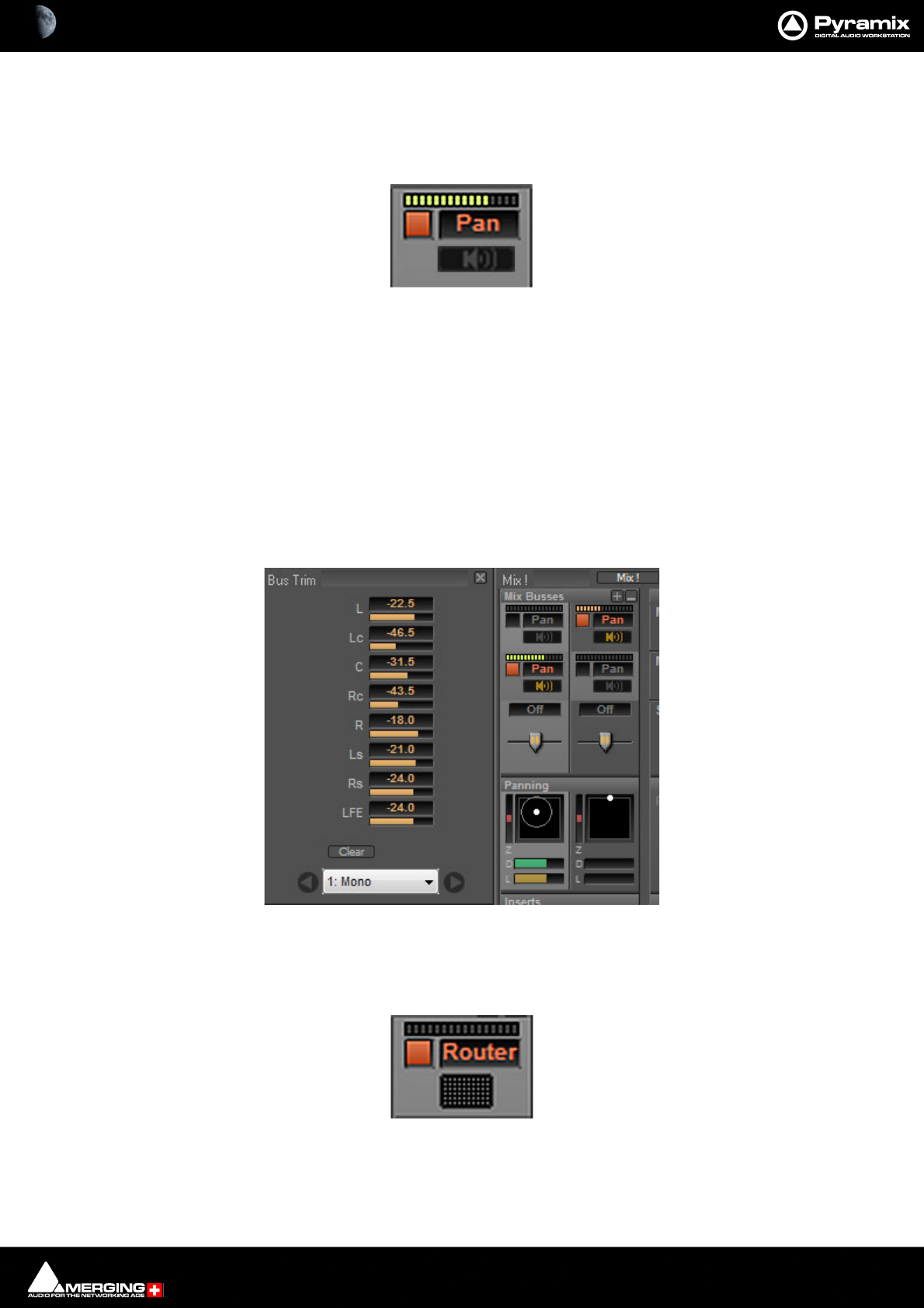
Mixer : Buses 10 - 228
Bus Sends
General Mixing Bus sends have similar controls in the Mixer user interface
Mix Bus & Mix Group Send:
Send peak meter Clicking on the meter collapses/expands the bus send.
An On/Off button When lit the Bus send is active.
Panning/Routing option box
Clicking in the box pops up the Routing context menu. This lists all Panning Control Buses present in the mixer
and Channel Router.
When Panner is selected (or Panner 1, Panner 2, etc.) the Bus send follows the selected Panning Control Bus
parameters to pan/mix the signal in its channels. Please see: Panning Control Group Buses on page 233.
Bus Trim
Bus Trim Only present when Bus Send is set to Pan. Clicking on the button opens the Bus
Trim pop-up:
The sliders are used to trim the send level to each speaker present in the Bus. Values may also be entered directly
by clicking in the numeric field and typing a value (e.g. -22.5)
When Channel Router is selected, a small grid icon appears below the box.
Clicking on this opens a Channel Routing grid window
Mix Bus Send Pan
Bus Trim pop-up
Mix Bus Send Router

Mixer : Buses 10 - 229
Channel Routing Grid:
Click in a crosspoint field and type a level value (or mute) to route individual Strip Outputs to the bus. Strip Out-
puts run vertically.
Clear Clears all routing assignments.
Auto Routes the Strip Outputs automatically. Where the destination bus is not
the same configuration as the Strip only Channels with matching designa-
tions are routed.
9: MCS The box shows the Bus being routed to. the down arrow drops-down a list
of all Buses available in the Mixer.
<> The left and right arrows step along the buses according to their positions
in the Mixer.
Aux Bus & Aux Group Send:
Send peak meter Clicking on the meter collapses/expands the bus send.
An On/Off button When lit the Bus send is active.
Send Level box Shows the current Send Level. Click in the field to enter a precise value manually.
An horizontal Send Level display and control Click and drag the bar to set the Send gain.
PF button When lit (as here) the Bus Send is Pre-fader.
Panning/Routing option box
Clicking in the box pops up the Routing context menu. This lists all Panning Control Buses present in the mixer
and Channel Router .
When Panner is selected (or Panner 1, Panner 2, etc.) the Bus send follows the selected Panning Control Bus
parameters to pan/mix the signal in its channels. Please see: Panning Control Group Buses on page 233.
Bus Trim Only present when Bus Send is set to Pan. Clicking on the button opens the Bus
Trim pop-up. Please see: Bus Trim on page 228
Channel Routing Grid
Aux Bus Send

Mixer : Buses 10 - 230
When Channel Router is selected, a small grid icon appears below the box.
Clicking on this opens a Channel Routing Grid window. Please see previous page.
Mix Bus Send Router
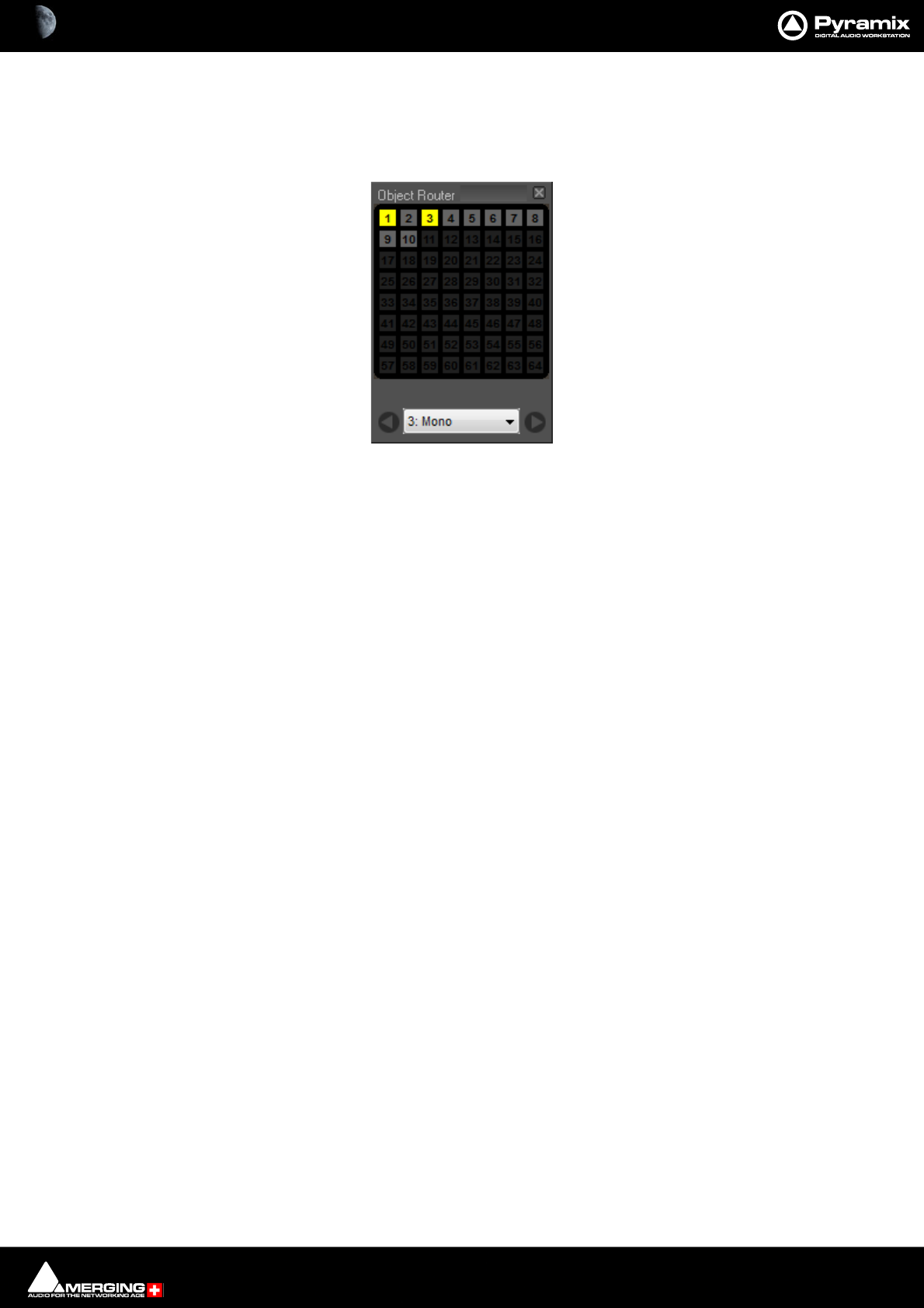
Mixer : Buses 10 - 231
Object Bus Send
The Object Bus is a specialised type of General Mix Bus intended for use with formats such as Dolby Atmos which
use conventional “Bed” tracks along with Audio “Objects”.
An Object Bus Strip Send has an Object Router:
The Objects Router shows each Object Channel as a button. All Input Channels of the Strip shown in the box are
sent to the Object Channel(s) selected. (button(s) lit)
Note: When an Input Strip is routed to an Object bus, all other Buses for that strip input are
muted, as for a Solo.
• Objects Bus Routing is automated. Input sound can be sent for a limited time to any Objects Channel.
• Objects Buses can be Enabled and Disabled via the right-hand side [+] popup menu. This enables any
Object sending in the Object Bus to be disabled temporarily keeping all input audio in its Bed for editing
and monitoring.
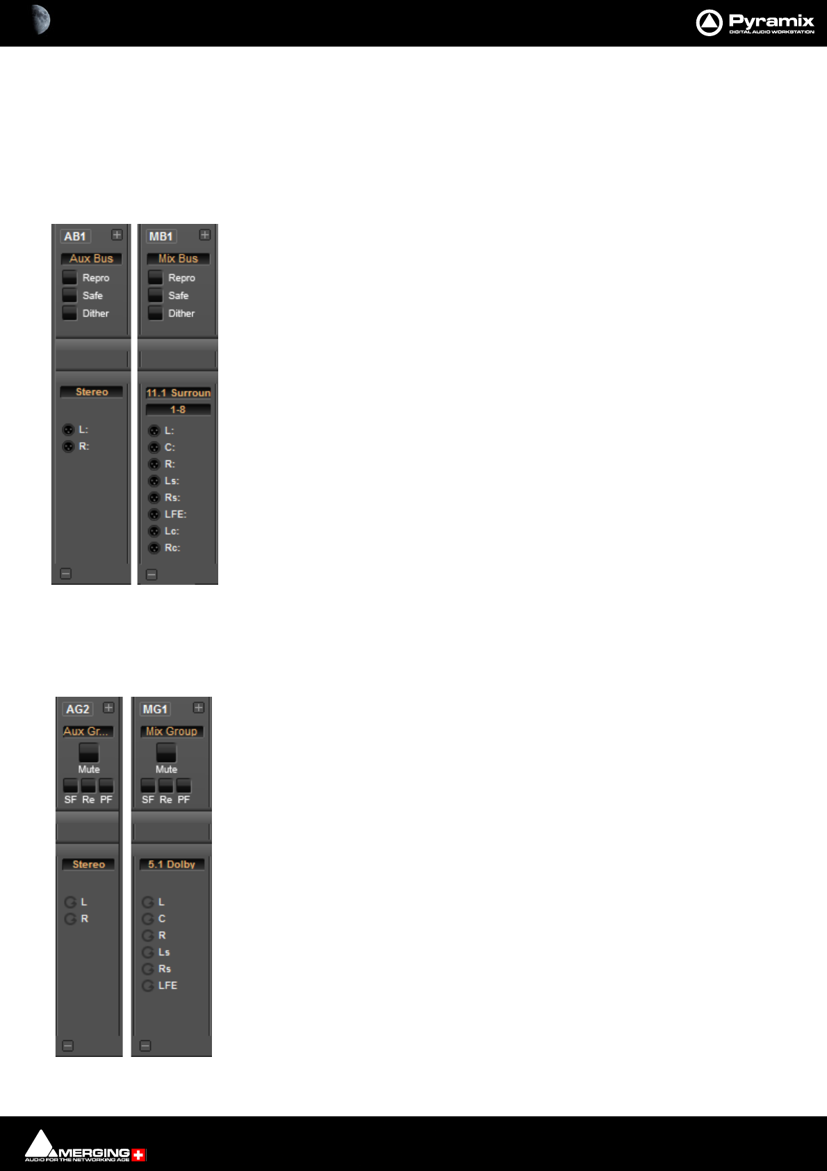
Mixer : Bus Master Strips 10 - 232
Bus Master Strips
There are as many Output bargraphs as there are Channels in the Bus. The + button to the right of the Bus label
increases the strip width to make the meters easier to see and makes the Channel labels visible.
Mix Bus & Aux Buses
I/O Section:
Mute Section
Repro/Re Mutes the Bus when in Stop to prevent howl round from auto input switching.
Safe/SaFe Prevents the strip being Muted by Solo operations elsewhere.
Dither The button turns Dither on and off. Lit yellow when on. Clicking on the Dither
label opens the ReDithering dialog. Please see: Dithering Options on
page 279
Bus Format Label Stereo, 5.1 Dolby, 30.2 La Totale etc. Clicking on the label opens the
Room Editor window.
1-8 For Buses with more than 8 outputs this box appears. Clicking on the box steps
through the Bus outputs in banks of 8.
XLR icons Route Bus Channels to physical outputs or Internal Buses or MT ASIO Bridge.
(Where these are present.) Right-click to pop-up a list of available destinations.
Mix Group & Aux Group Buses
These Group Buses have the same Mix Bus Send and Panning Options as Input Strips. Aux Groups have Aux Sends,
Mix Groups do not.
Mute Section
Mute Mutes the strip
SF/ SaFe prevents the strip being muted by Solo operations elsewhere.
Re Mutes the Bus when in Stop to prevent howl round from auto input switching.
PF Switches the Bargraph meters to Pre-Fader.
I/O Section
Bus Format LabelStereo, 5.1 Dolby, 30.2 La Totale etc. Clicking on the Bus format label opens
the Room Editor window.
1-8 For Buses with more than 8 outputs this box appears. Clicking on the box steps
through the Bus outputs in banks of 8.
Remix icons A label next to each icon indicates the Channel Type or Number if no Type is
assigned.
Mixer : Panning Control Group Buses 10 - 233
Panning Control Group Buses
This Bus allows for controlling panning information in 1D (Left/Right), 2D (Surround) or 3D (Full
Space).
The Panning Control Bus does not process audio and has no Channels, no associated Output Strip and no I/O. Any
General Mix Bus / Mix Group / Aux Bus / Aux Group uses the information generated by a Panning Control Bus to
pan sound sent to their respective channels.
The same Panning Control Bus can pan sound for any channel mapping of any General Mix Bus. I.e. the panning
parameters of an input strip can control for example, the sends to a 9.1 Mixing Bus, a 5.1Mix Group and a Stereo
Aux Group simultaneously.
Generally, only one Panning Control Bus is required for all Mixing Buses, however multiple Panning Control Buses
can be created if different panning information is required for an Strip to different Mixing Buses. (Right-click con-
text menu: Bus > Add > Panning Control Bus)
The in-strip User Interface for the Panning Control Bus is switchable between three different Types of Panner.
(Right-click over the Panner in the Strip to open the context menu: Set Panner Type):
None
2D Panner Pans in 2D space. I.e. Left/Right and Front/Back and provides control of Diver-
gence and LFE gain.
3D Panner Pans in 3D space. I.e. Left/Right and Front/Back, Up/Down and provides control of
Divergence and LFE gain.
Pan/Balance Pans in 1D space. I.e. Left/Right and provides control of Divergence and LFE gain.
When the Strip is Mono the control is always Pan.
When the Strip is Stereo there are three different types of Pan/Balance available as
Dual Source Mode. Right-click over the Panner in a Stereo Input Strip to open the
context menu and select Dual Source Mode and one of the following options:
Mixer : Panning Control Group Buses 10 - 234
Single Pan Pans the Stereo Channels as a point source.
Dual Pan Pans each Channel independently.
Balance Changes the balance between Left and Right.
Divergence
Divergence has a type which can be changed per Strip. The type may be changed in the Panning Control Bus
window or by right-clicking over the Panner in an Input Strip and selecting the Divergence type from the list:
1D (Left/Right) The divergence only spreads over the front Left and Right channels.
2D (L/R - F/R) The divergence spreads over the surround space.
3D (L/R - F/R - T/B) The divergence spreads over the whole 3D space.
The Divergence Type selected is displayed in the Panning Control Bus window.
The Automation for the panning information is associated with the Panning Control Bus and is the same for any
General Mixing Bus sharing the Panning Control Bus. Automation for the Send On/Off, Send Gain, Pre/Post
Fader is associated with each General Mixing Bus, independently.

Mixer : Internal Return Buses 10 - 235
Internal Return Buses
Some of the time slots within MassCore can be reserved to convey Aux Send or Master Output Buses back to
input strips. In effect, these are internal send/return paths. To change the number of available Internal Return
Buses, close all open Projects (if any) and go to:
Settings > All Settings > Mixer > Mixer Settings.
The number of Internal Return Buses can be set using the Internal Buses combo box. Click on the OK button to
memorize the setting and exit.
The number of Internal Return Buses you assign here will be available as possible channel strip sources in the
mixer.
Note: Please be aware that a Mix Group Bus or Aux Group Bus will auto-take Internal Bus connec-
tion resources, starting from the last one. E.g. IB384-IB385 for the first two SubGroup Channels
added to a Mixer. This means that you will no longer see IB384 and IB385 in the IB list.
Note: A Strip fed from an Internal Return Bus will NOT be fully Delay Compensated when in
Auto-Monitoring mode and when in Repro mode the red ‘D’ will be appear to indicate that auto-
matic delay compensation will not be applied. On the other hand, recorded material will be
Compensated correctly and in sync with the current timeline events.
Mixer : Groups / VCA 10 - 236
Groups / VCA
•Master Group Strips - allow the grouping of faders of several mixer strips. Analo-
gous to VCA grouping. When a group or groups are added (from the mixer con-
textual menu Strip > Add Strip > VCA/Group) A group button for each group
created will appear above the I/O section on each input strip. When selected, the
associated Group strip will control the grouped input strips if the On button is lit
on the Group strip.
Pressing and holding the Ctrl key when moving a VCA master fader disables the
delta between the faders in the group.
Note: If an input Strip with Horus/Hapi Preamp controls is added to a VCA Group
then Preamp Controls will appear under the VCA Master Fader section.
Each VCA group is assigned a color automatically. When the GC button is lit (on the right-hand edge of the con-
sole) the VCA Group fader knobs and the knobs of faders in strips belong to the groups are colored accordingly.
VCA Master
VCA Groups Knob colors
Mixer : Horus/Hapi Preamp Remote Controls 10 - 237
Horus/Hapi Preamp Remote Controls
If you are using the Merging Technologies Horus/Hapi I/O with analog inputs, remote control of the analog pre-
amps is available in the Pyramix Mixer. The controls appear automatically in the mixer when a strip’s input is
patched to a Horus/Hapi analog preamp.
Note: Please ensure that AD inputs have first been connected in the RAVENNA Easy Connect
application. Once connected they will be available in the Pyramix Mixer.
If the Horus/Hapi Preamp Remote section is not visible click on the + Expand button on the right-hand side of the
mixer.
The controls enable analog gain to be set, the Pad and High-pass Filter to be activated, 48V Phantom Power to be
switched, Phase to be reversed and the Preamp to be switched between Mic and Line. If Channels patched to
Horus analog preamps are ‘VCA’ grouped then the Preamp Remote Controls in the VCA Group strip will affect all
members of the Group.
Note: GPS Channels do not support the Horus/Hapi Preamp Remote controls when connected
to Horus/Hapi analog inputs.
Mixer showing Horus Preamp Remote Controls
Mixer : Horus/Hapi Preamp Remote Controls 10 - 238
Horus/Hapi Preamp Remote Controls - Detail
The field at the top shows the Preamp Gain set with the knob. Adjustable between 0dB and 60dB when the pre-
amp is switched to Mic or Line. May also be clicked to enter a fader gain value directly.
Pad Lights purple when the Pad is active.
HPF Lights green when the 80Hz Filter is active.
Phase Lights Blue when Phase is reversed.
48V Phantom Lights red when the 48V Phantom Power is switched on.
Mic/Line Displays the current preamp mode. Clicking on the box pops-up a list with the
choice of Mic or Line.
Notes
When the last mouse click was somewhere in the Preamp Control section of the mixer strip the gain can be
adjusted from the keyboard up and down arrows in 0.5dB increments.
Control of Individual Channels in Stereo Strips
Clicking the + button next to the Mic or Line indicator in a stereo channel opens the Preamp Channels Control
panel.
This panel enables the same parameters found in a mono Strip to be set per channel. If a gain offset is applied this
is indicated on the single knob in the strip by a second orange dot. The left and right arrows either side of the
channel numbers step left and right across the mixer. Alternatively channels may be selected from the drop down
list.
VCA Group Strip
When changes are made in a VCA Group Strip all controls of all group members will update to match. However, if
the Gains of each strip are different the gain will not go below 0dB for the lowest strip’s PreAmp Gain value when
using the VCAGroup control. This 0dB barrier can be broken by using Ctrl while changing the gain. Of course this
means that any strips affected will lose their gain relationship with the other strips in the group.
HORUS Preamp Remote Controls
Preamp Channels Control panel
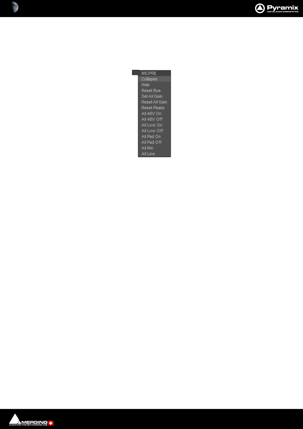
Mixer : Horus/Hapi Preamp Remote Controls 10 - 239
Note: Where a button is half lit this indicates there are mixed settings “behind” the button. E.g.
buttons on a VCA Group Strip. When a buttin in this condition is pressed the parameter is
switched On in all channels affected.
HORUS Preamp Remote Controls Context Menu
Hovering over the expand/collapse + or - button for the section pops-up a context menu:
Collapse Hides the controls but leaves the gain value visible.
Hide Removes the Preamp control section from the Mixer display. It can be restored by
hovering the mouse over the bottom + button and selecting Console > Show All.
Reset Bus Resets all the Preamp Gain settings to 0dB.
Set All Gain Sets all the Preamp Gain settings to 30dB.
Reset All Gain Resets all the Preamp Gain settings to 0dB.
All 48V On As it says.
All 48V Off As it says.
All Low On Switches all the HPFs On.
All Low Off Switches all the HPFs Off.
All Pad On As it says.
All Pad Off As it says.
All Mic Switches all the Preamps to Mic mode.
All Line Switches all the preamps to Line mode.
Mic Preamp Recall Options
When opening an existing project, opening or switching between multiple projects and when creating a new
project from scratch or from a template the Mic Preamp settings behavior is customizable in All Settings > Hard-
ware > Mic/Pre Remote. Please see: Mic/Pre Remote on page 720

Mixer : Horus/Hapi Preamp Remote Controls 10 - 240
Effects and Plug-ins
Please see also: Effects and Plug-Ins on page 339
Mixer Strip Controls
When Native VS3 Effects, VST Plug-ins and External Inserts are instantiated in mixer strips each instance has a
block of one or two buttons. The full Effect name, Plug-in name or External Insert pops-up along with the
required delay compensation when you hover the mouse pointer over each block:
Buttons
Each block has one or two buttons. The left-hand, yellow button is lit when the effect or insert is switched on.
Switching an effect or insert off removes it from the signal chain and this may well be audible.The right-hand, red
button indicates that the effect is Bypassed when lit. Bypassing an effect retains the same delay as when the
effect is active. Further, well behaved effects will continue to calculate internal parameters when bypassed making
seamless switching possible.
When Full Delay Compensation is selected, Effects and Plug-ins that correctly report their latency will have their
delay compensated. This delay is maintained when the Effect or Plug-In is in bypass mode.
Please see also Mixer Delay Compensation on page 269
Mixer Strip Plug-in Controls with Name and Delay pop-up
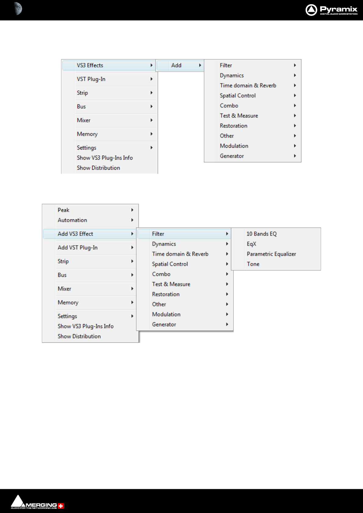
Mixer : Horus/Hapi Preamp Remote Controls 10 - 241
Native VS3 Plug-ins
These include the eq and dynamics found on a conventional hardware mixer’s channel strip. To add a native plug-
in when in Mix ! mode, right-click with the mouse cursor over the strip where the plug-in is to be added.
If you right-clicked in the effects area of the strip select VS3 Effects > Add.
If you clicked somewhere else, select Add VS3 Effect. Select an effect from the sub-menu. It will appear in the
strip.
VST Plug-Ins
To add a VST plug-in the procedure is the same except select VST Plug-In > Add or Add VST Plug-In.
Note: Although VS3 and VST Plug-ins can be added at any time, even during playback, without
rebuilding the mixer, if the plug-in reports a Delay Compensation Value, the mixer must be
rebuilt before this is compensated for.
Mixer Strip Context Menu
Mixer Strip Context Menu
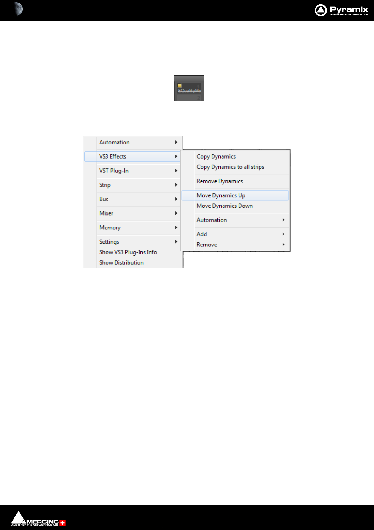
Mixer : Horus/Hapi Preamp Remote Controls 10 - 242
Ghost Effects and Plug-ins
Essentially, Ghost Effects or Plug-ins mean that if you load a project containing an effect or plug-in which is
unavailable on your machine, this plug-in will appear in the mixer strip as a Ghost plug-in. Subsequently saving
the project will not trash the missing Plug-in’s state information. When a plug-in is a Ghost its name appears
crossed out in the mixer :
Removing, Copying or Moving VS3 Effects and VST Plug-Ins
VS3
Right-click on an Effect in a Strip to open the context menu and hover the cursor over VS3 Effects. Here you can
make a number of changes to the Effects
Copy “Effect Name” Copies the effect for pasting into another Strip (Copy the Effect then right-click in
the target Strip and select Paste).
Copy “Effect Name” to all strips Copies the Effect you right-clicked on to all Input Strips, but not to any Buses,
regardless of whether the original effect is instantiated in an Input Strip or Bus.
Remove “Effect Name” Removes the Effect you right-clicked on.
Remove Accesses a list of all effects currently instantiated in the strip. You can select any of
them for removal.
Move “Effect Name” Up Moves the effect you right-clicked on Up the list.
Move “Effect Name” Down Moves the effect you right-clicked on Down the list.
Note: The Up and Down options are only shown when a move is possible.
Automation Enables the Automation mode to be set for the entire Effect.
Remove “Effect Name” Removes the Effect you right-clicked on.
Add Accesses the Effects list to add a further Effect to the Strip.
Remove Accesses a list of all effects currently instantiated in the strip. You can select any of
them for removal.
Ghost Plug-in
VS3 Effects Context Menu
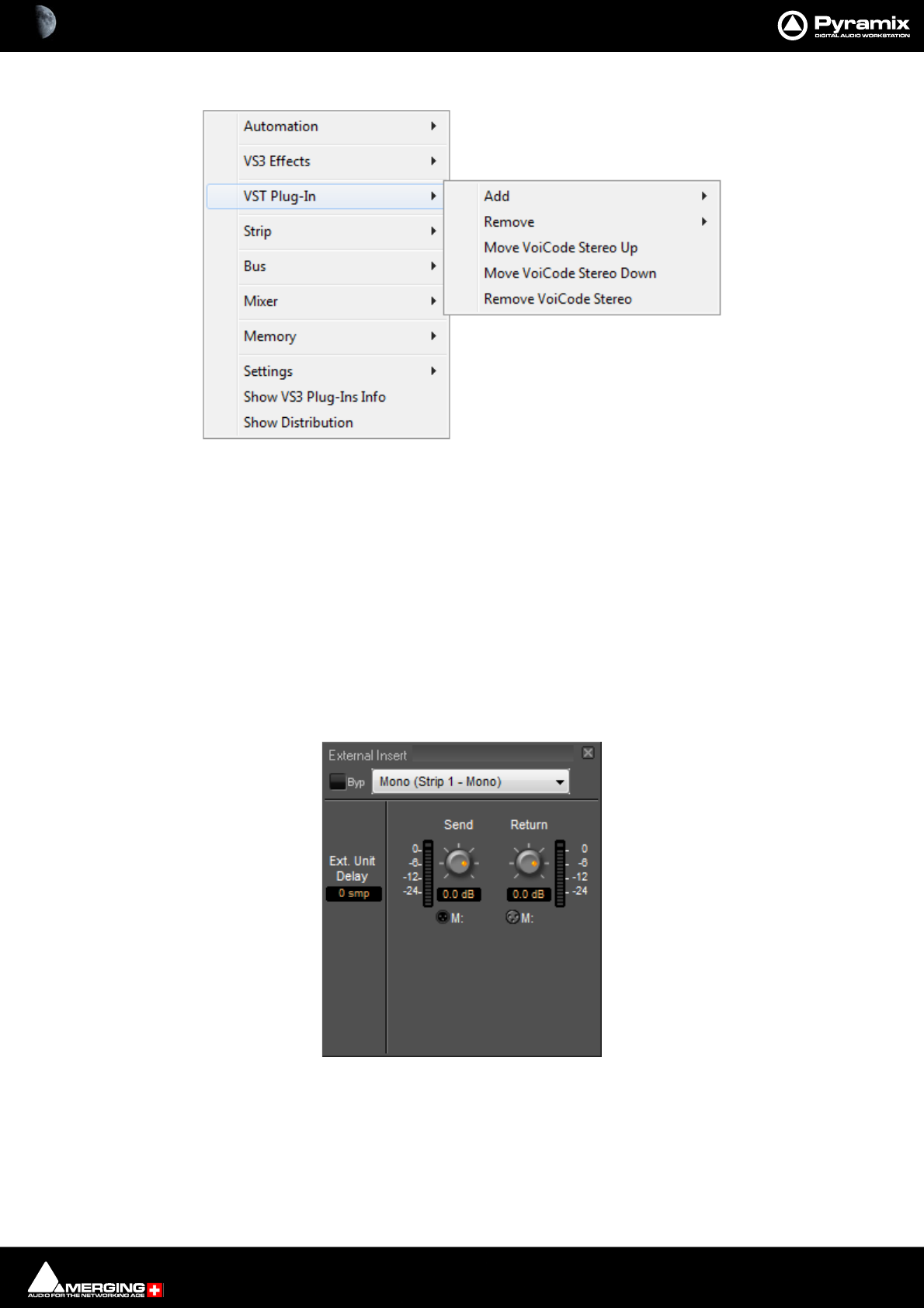
Mixer : Horus/Hapi Preamp Remote Controls 10 - 243
VST
As the image above shows, the options are similar for VST Plug-Ins
Add Accesses the Plug-Ins list to add a further Plug-In to the Strip
Remove Accesses a list of all Plug-Ins currently instantiated in the strip. You can select any
of them for removal.
Move “Effect Name” Up Moves the effect you right-clicked on Up the list.
Move “Effect Name” Down Moves the effect you right-clicked on Down the list.
Remove “Effect Name” Removes the Plug-In you right-clicked on.
External Insert
To add an External Insert simply right-click over the strip where the plug-in is to be added and choose: VS3 Effects
> Add > Other > External Insert
Clicking on the External Input name in the strip opens the External Insert Control Window.
Send and Return Connections can be made by clicking on the XLR icons and levels set with the knobs. When you
have determined the delay introduced by the I/O loop including the external effect the value in samples should be
entered in the Ext. Unit Delay field.
VST Effects Context Menu
Mixer Strip External Insert Plug-in Control Window

Mixer : Highlighting 10 - 244
Highlighting
To aid in comprehension Strips and Buses are highlighted when selected. Highlighting a bus strip also highlights
all its bus sends in all the strips feeding it.
In this screenshot Strip 8 is selected. The Stereo Bus MB2 is also selected. Strip highlights follow the Tracks
selected in the Timeline. Multiple selections are possible.
Mixer with Strip 8 selected
Mixer : Highlighting 10 - 245
Colors
Color can be added to Input Strips, Buses, Auxes, Sub-Groups and VCA Groups to improve comprehension.
Bus, Aux and Sub-group colors are set via the +- pop-up menus. Input Strips follow the color set in the Track
Header or in the Tracks Tab window.
Mixer with Strip Bus and Group colors active
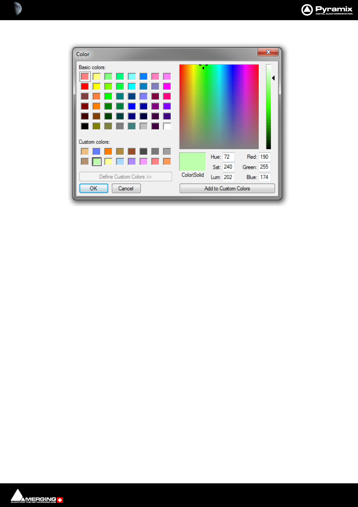
Mixer : Highlighting 10 - 246
Change Color Opens a Color picker:
Hide or Show Colors hides or restores the colored lines. Change color allows the color of an individual bus to be
altered. Reset color restores the color to its previous state.
Color Picker window

Mixer : Highlighting 10 - 247
Multiple Strip Selection and Operations
Multiple Console Strips can be selected together.
Select Multiple Strips
Click on a Strip then press and hold the Ctrl key and click on the Strip number (below the fader) to add or remove
other strips to or from the selection.
Click on a Strip then press and hold Shift and click on another Strip number (below the fader) to select all Strips
between the first selected and the last.
To cancel the multiple selection click on a Strip number (below the fader) on any of the selected strips.
Linked Actions on Multiple Selected Strips
Press and hold [Ctrl] + [Shift] to perform any of the following on all selected (highlighted) strips:
• Double-click on any of the Faders, Gain Knobs or Pans in the selected strips to reset all of them to the
default value.
• Move Faders or Gain Knobs in any of the selected Strips moves all of the faders or knobs in the selected
strips while preserving their delta.
• Click on any button, e.g. On/Off, Mute, Solo, IP, Phase, Record Ready, etc… to set the same state on all the
selected strips.
• Add or subtract all selected Strips to or from a VCA group. (When subtracting the Leaving VCA Group
dialog appears for each Strip which is assigned to the VCA Group.)
• Adding Effects (Support for VS3 effects)
• Copying Effects (Support for VS3 effects)
•Stem change
Note: If [Shift] only is pressed and held the above actions are performed on ALL Strips regard-
less of any selections.
On a MultiBus Matrix router if [Control] + [Alt] are pressed and held then the patching is performed on
the selected Strips by incrementing the patched slot for each Strip.
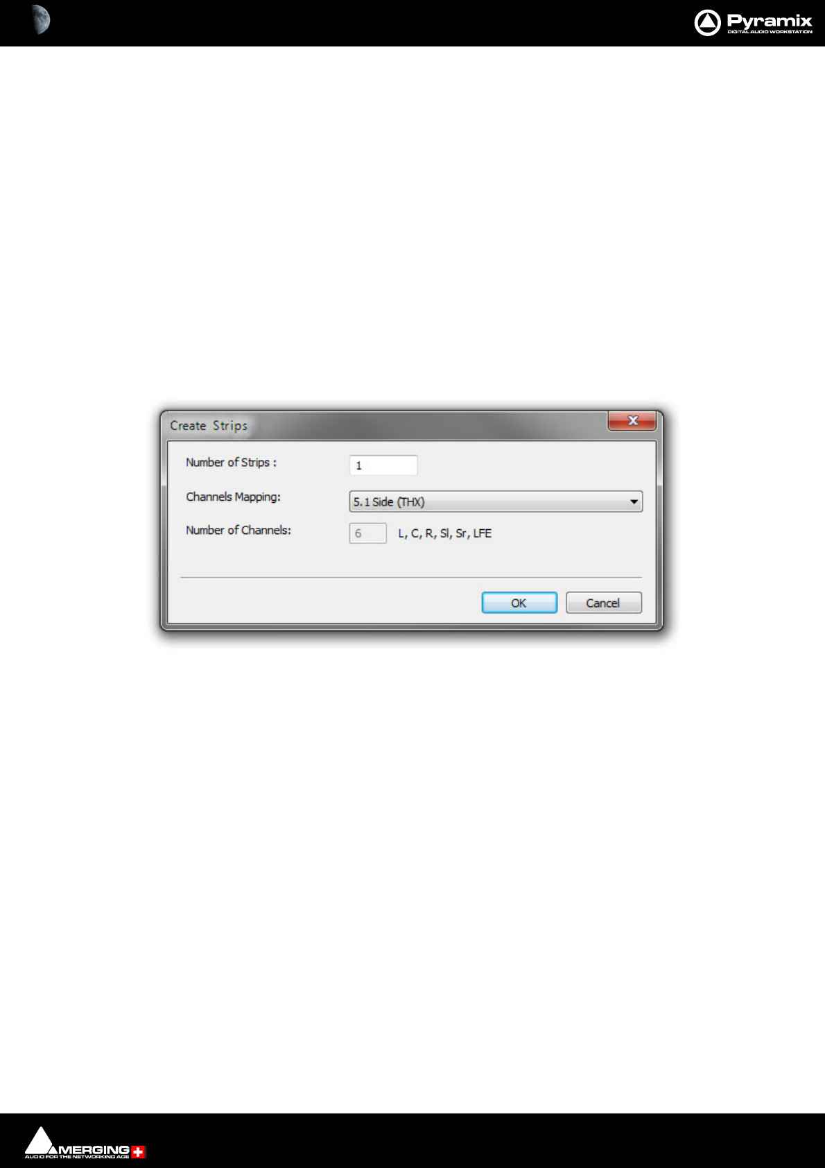
Mixer : Mixer Configuration from the Mix! page 10 - 248
Mixer Configuration from the Mix! page
Adding Strips
Adding Input Strips
Access the right-click context menu with the mouse cursor over a blank area in an existing strip.
Choose Strip > Add:
Mono Adds a single Strip.
Mono - Direct Monitoring Adds a single Strip.
Stereo Adds a single Strip.
Stereo - Direct Monitoring Adds a single Strip.
MS Adds a single Strip.
MS - Direct Monitoring Adds a single Strip.
Multi - Channel Strip Opens the Create Strips dialog:
Number of Strips : Type the number of strips required in the field.
Channels Mapping: Select a Mapping from the drop-down list (52 available) plus Custom.
Number of Channels Shows the number of Channels and their designations. The number field is
grayed and can only be typed in when Custom is chosen as the Mapping.
Note: If you wish to add multiple Mono or Stereo Strips it is much quicker to use the Multi-
Channel Strip option and choose Mono or Stereo as the Mapping.
Create Strips dialog
Mixer : Mixer Configuration from the Mix! page 10 - 249
Adding Audio Buses
Select Bus > Add > General Mixing Bus. The Create > General Purpose Mixing Bus dialog opens
Number of Buses: Type the number of Buses to be created in the field. (Default is 1)
Bus Type: The radio buttons determine which type of General Mixing Bus will be created:
•Mix Bus
•Aux Bus
•Object Bus
•Mix Group
•Aux group
Channels Mapping: The drop-down lists all the pre-defined Room / Channel mappings and Custom.
In most cases there will be a suitable mapping in the list. If you choose Custom
then set the number of Audio Channels:
Number of Channels: Only available when Custom is chosen in Channel Mapping:
Room Type The radio buttons give the choice of Virtual Or Sized. If sized is selected enter a
value in meters in the field.
Create Creates the Bus or Buses with the parameters selected and exits the dialog.
Cancel Exits the dialog without creating any Buses.
Create General Purpose Mixing Bus dialog

Mixer : Mixer Configuration from the Mix! page 10 - 250
Panning Control Buses
Access the right-click context menu with the mouse cursor over a blank area in an existing strip. Select Bus > Add
> Panning Control Bus. A new panning control Bus is created in the Mixer.
Input Strips
Select Strip > Add and choose the type of Input Strip to Add from the list below, or choose VCA Group.
•Mono
• Mono - Direct Monitoring
•Stereo
• Stereo - Direct Monitoring
•MS
• MS - Direct Monitoring
• Multi Channel Strip
•VCA Group
Rearranging Strips
Input strips, VCA group strips and Sub-group strips are moved directly in the console UI.
Only Input Strips, Groups and SubGroups can be moved. The Bus Masters Strips cannot.
Using Context Menu:
• Select one or more Strips
• In the right-click context menu choose Strip > Copy Selected Strips
• Select a destination Strip <x>
• In the right-click context menu choose Strip > Move Copied Strips Before <x> or Move Copied Strips
After <x>
Using Drag & Drop:
• Select one or more Strips
• Press Ctrl + Shift + Alt
• Drag the selected Strips onto any other Strips
Note: If a Sub-group or VCA group is not moved, i.e. located at the far right of all the input strips,
it is locked in place when scrolling the input strips. When a Sub-group or VCA group is moved in
between other input strips it is then scrolled with them.
Effect Management
Add Effects on all Strips Selected
Select the Strips you wish to add the effect to.
Press and hold Ctrl + Shift keys.
From the right-click context menu select the required effect VS3 Effects > Add > xxx or VST Plug-In > Add > xxx
Remove Effects on all Strips selected
Select the Strips you wish to remove effects from.
Hover the Cursor over the Effects Slot you wish to clear.
Right-Click to open the context menu.VS3 Effects > Remove > xxx
Press and Hold the Ctrl + Shift keys.
Clicking on the Effect removes it from the Slot on all Strips selected.
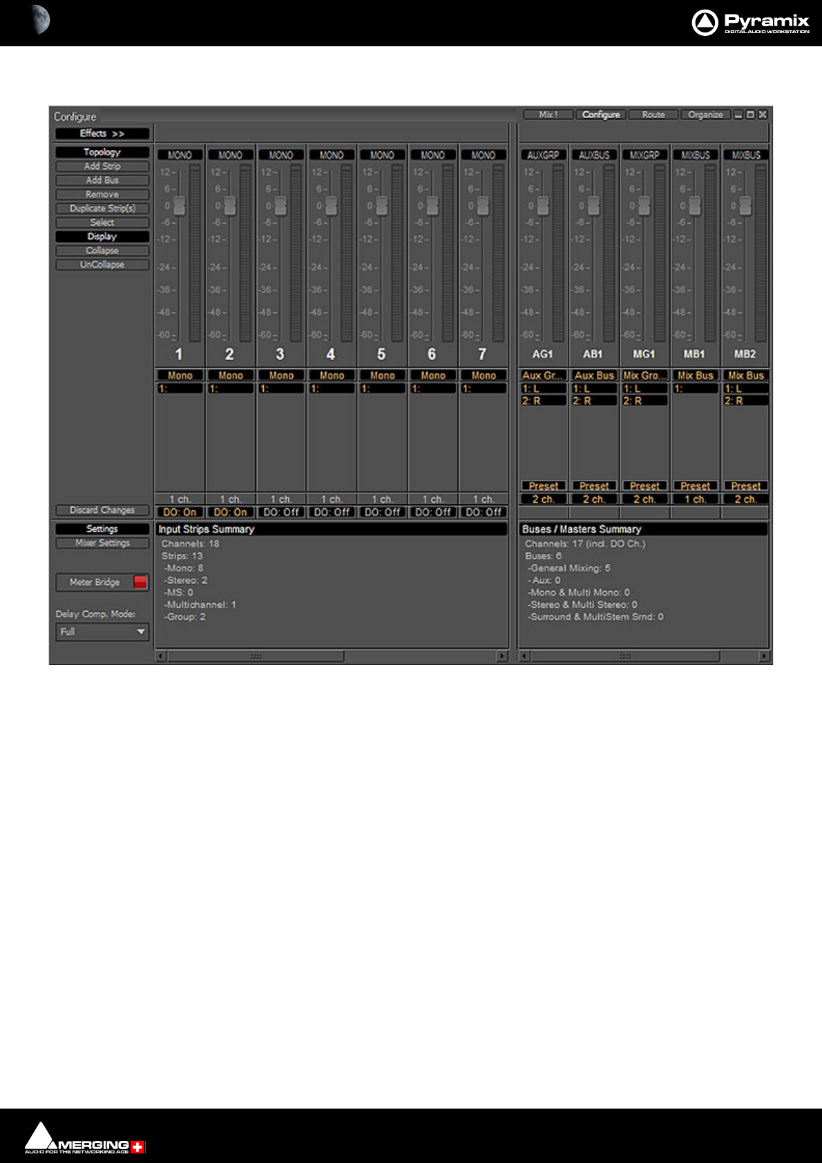
Mixer : Configure Page 10 - 251
Configure Page
In the Configure page multiple changes may be made to the mixer without it rebuilding after each change. The
rebuild only occurs when you exit the page.
Synchronized Creation/Deletion of Tracks/Strips
Note: When Creating, Deleting or Moving Strips in the Mixer Configuration page (or with the
right mouse button context menus) the connected Tracks are also Created/Destroyed or moved
accordingly.
• This behavior will apply when Tracks > Synchronize Tracks & Strips is checked.
• When Strips are Created or Moved the Tracks are Created or Moved seamlessly.
On Deleting a Strip or Strips, only empty Tracks are destroyed. Tracks containing Clips are preserved, disconnected
and set to minimum size.
Settings
Mixer Settings
Opens the Mixer Settings window at the All Settings > Misc > Mixer Settings page.
Meter Bridge
When turned on (lit) the Meter Bridge Window is available to be opened from View > Windows / Tools > Meter
Bridge or the Toolbar icon. Please see: Meter Bridge on page 332
Mixer Configure Page
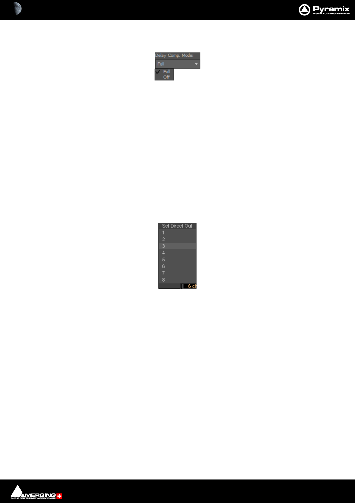
Mixer : Configure Page 10 - 252
Delay Comp Mode
Drop down list menu:
Offers the choice of Full and Off.
Please see: Mixer Delay Compensation on page 269
Mixer Configuration Summaries
The two panels at bottom right summarize the current mixer configuration. Input Strip Summary lists the total
number of Channels and Input Strips and the quantity of each type. Buses / Masters Summary lists the total
number of bus channels and buses strips with the quantity of each type.
Note: Rebuilding a large mixer with many effects can take some time.
Direct Outputs
The Direct Out connection is disabled by default. It can be enabled in the Configuration Page by selecting the
strip and clicking on the DO: Off box or disabled if the box shows DO: On. Alternatively Direct Out can be set in
the Route Page by clicking on the Strip Header.
The Direct Out can be routed by Channel to any physical output. The Direct Out can be sent Pre or Post Fader.
Click on the DO: Post box in the Mixer I/O section to toggle. The Direct Out is currently always Post Effects. For
multi-channel strips clicking in the box above the DO: box pops-up a Set Direct Out list:
Highlight the required channel. This will be fed to the logical output assigned in the Mixer Route page or by click-
ing on the DO XLR icon in the Mix page.
Selecting Strips
Strips can be selected by clicking on the label at the top of the strip which turns orange to show it is selected.
Selection uses the conventional modifier logic: Clicking a second strip while holding SHIFT selects all strips in
between and strips can be individually added or subtracted from a selection by clicking with the Ctrl key held
down. Ctrl + A selects all strips. Strips can be selected by type using the Select context menu.
Strip Display
Click and drag the separator bar between Strips and Buses to show more or less Buses. The scroll bars give access
to Strips and buses currently off screen.
Double-clicking the label at the top of a strip minimizes the strip. Double-clicking the label button on a minimized
Strip restores it to full width.
Set Direct Out
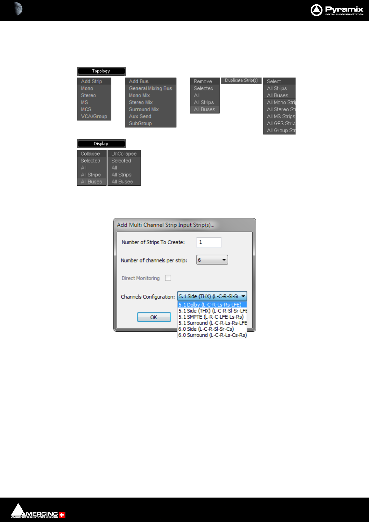
Mixer : Configure Page 10 - 253
Strip and Bus operations
Once selected, strips can be dragged and dropped to reorganize. Other strip operations make use of the Topol-
ogy and Display menu buttons. Each button pops up a list of options:
Add Strip - Mono, Stereo, MS, MCS and VCA/Group pops up a dialog with appropriate options:
Note: Notice the Direct Monitoring check box. (Grayed out in this case because it is only appli-
cable to Mono, Stereo and MS Strips). When checked, the strip added will be a Direct Monitoring
Strip. Please see Direct Monitoring Input Strips on page 224
Topology and Display menus
Add Multi Channel Strip Input Strip(s)... dialog
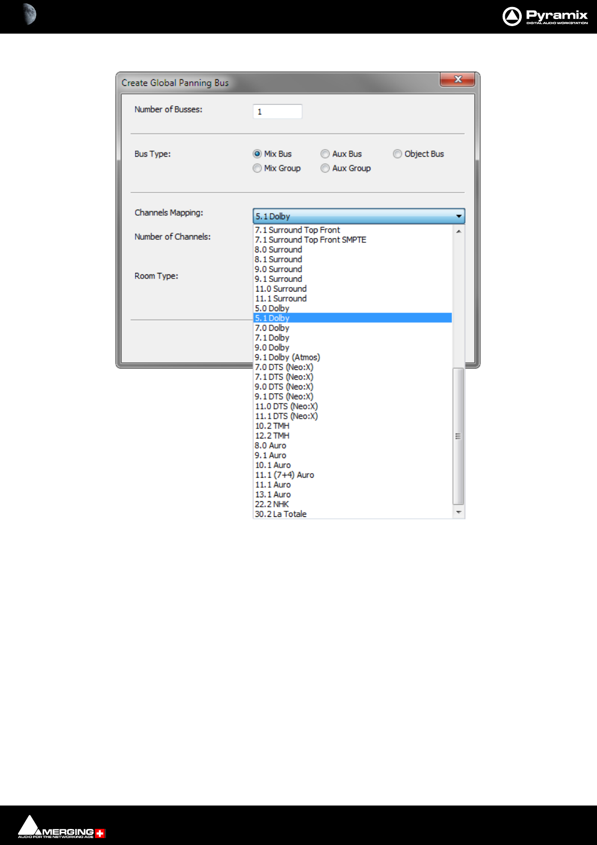
Mixer : Configure Page 10 - 254
Add Bus opens the Create General Purpose Bus dialog:
Choose the Number of Buses, The Bus Type, The Channels Mapping: from the drop-down list. Number of
Channels: is for information only. Also select the Room Type.
Duplicate Strip(s) adds a copy of the selected strip(s) to the right of the selected strip(s) including settings (pan,
gain etc.) and effects.
Select Offers selection choices to speed up configuration.
All Strips
All Buses
All Mono Strips
All Stereo Strips
All GPS Strips
All Group Strips
Productivity Shortcuts
Ctrl + A selects All Strips, DELete, deletes all selected strips.
Create Multi Purpose Bus Strip(s)... dialog
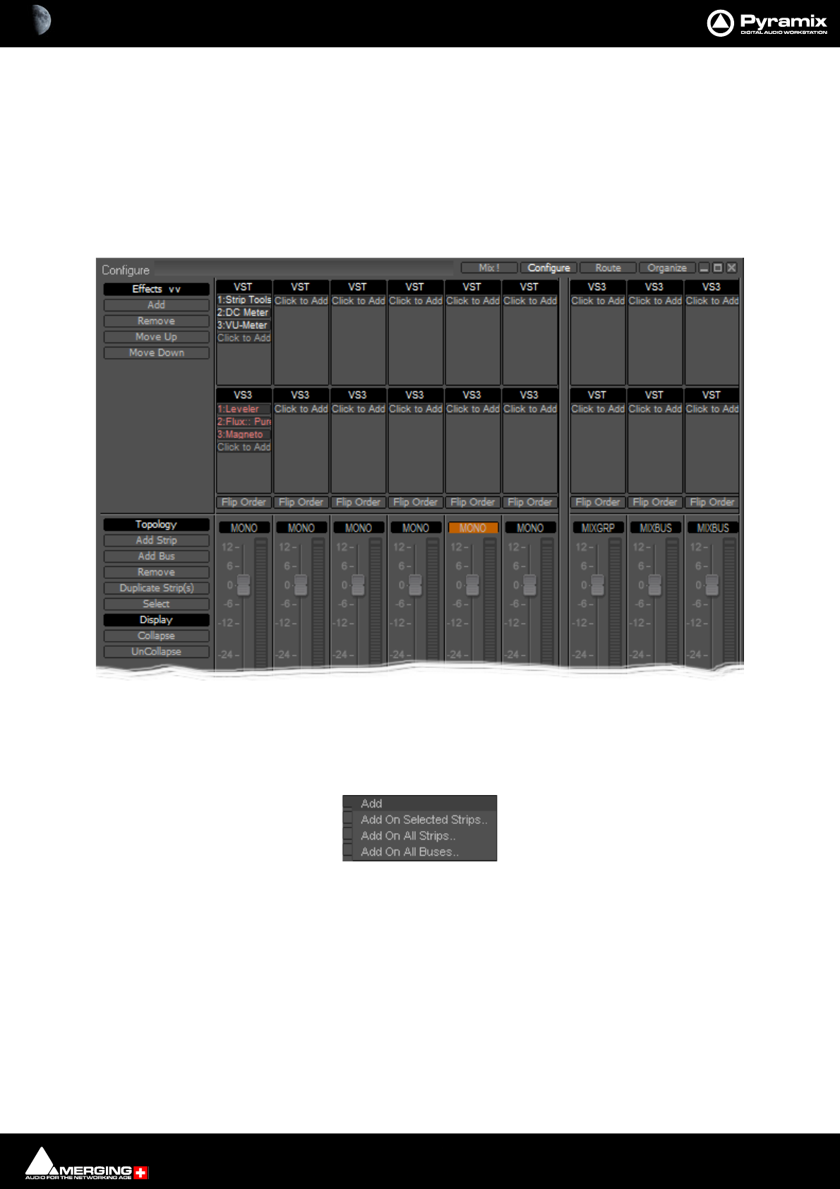
Mixer : Configure Page 10 - 255
Selected Strips can be dragged to a new location in the mixer. The screen scrolls horizontally when you hit the
edges of the Strip panel.
Double-clicking a Strip toggles it’s collapsed/uncollapsed states.
Strip names can be edited by clicking in the name box and typing. Tab moves to the name box of the next strip to
the right, SHIFT + Tab moves to the name box of the next Strip on the left.
Effect Management
Clicking on Effects >> expands the Effects section.
This offers several methods of managing effects on strips and buses.
Configure: Effects Buttons
Add Pops up a sub-menu with options
Add On Selected Strips..
Add On All Strips..
Add On All Buses..
Configure Page - Effects section
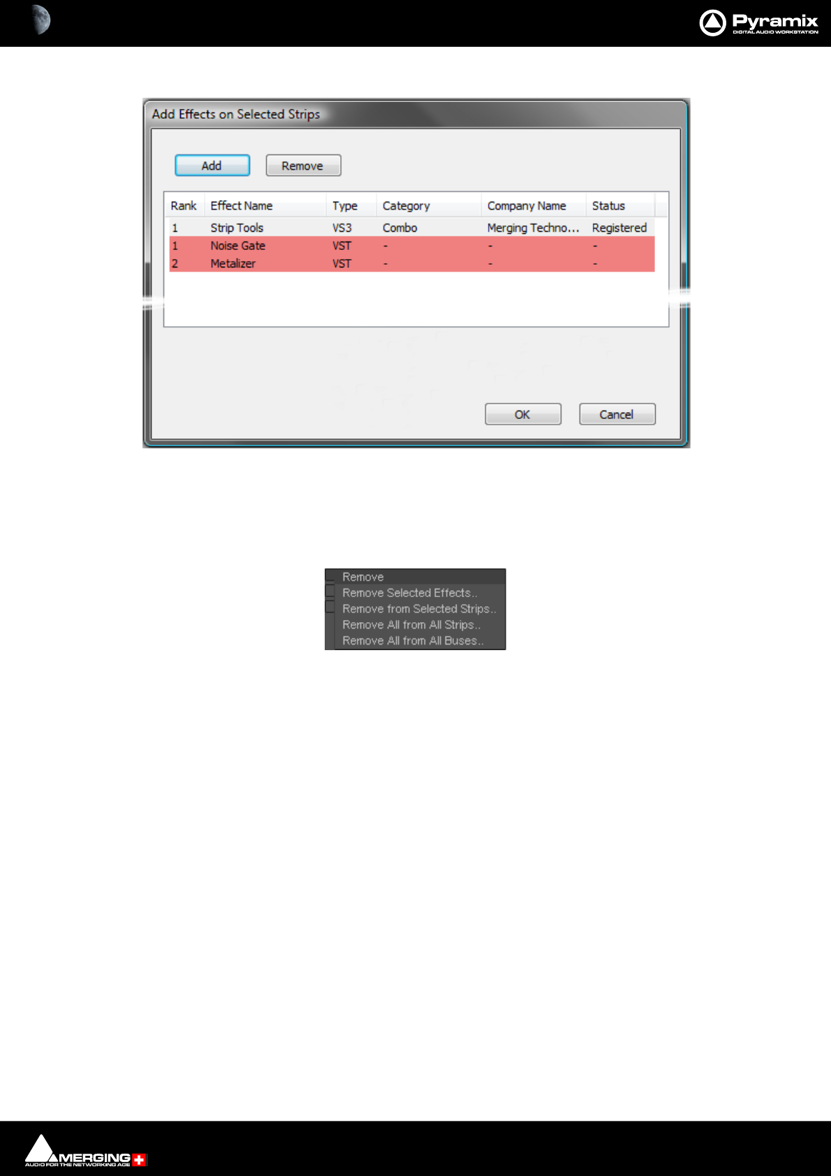
Mixer : Configure Page 10 - 256
Each of these three options opens an Add Effect On XXX dialog, identical apart from the title
Note: That the different types of effect are shown by color. Pale Gray for VS3 and Red for VST.
These colors are also used when effects are shown in containers in the Strips display.
Remove Pops up a sub-menu with options:
Remove Selected Effects..
Remove From Selected Strips..
Remove All From All Strips..
Remove All From All Buses..
Move Up Moves the selected effect(s) up in the list.
Move Down Moves the selected effect(s) down in the list.
Effects Section Containers
The Effects section of each strip is divided into two container areas by plug-in type, VST at the top and VS3 below.
Clicking on the Click to Add buttons in each container pops-up a list of available plug-ins in the relevant format
sub-grouped by type. E.g. Dynamics, Restoration etc. Simply select from the list by clicking on an entry to install
the plug-in, in the Strip. When a Strip or Bus has many effects, the container expands to accommodate them.
Shift Order
You can change the order of the VS3 and VST containers by clicking on the Shift Order buttons below the contain-
ers.
Selecting, Copying and Moving Effects
You can select an installed effect with a left-Click then drag and drop to move or Ctrl + drag and drop to copy
effects of the same type to a Strip or Bus of the same dimensions or change the order of effects within the effect
type container of the strip. SHIFT + Clicking a second effect with an effect already selected, selects all effects
between the first and last selected. Ctrl + Click adds to selection.
Add Effects On Selected Strips dialog
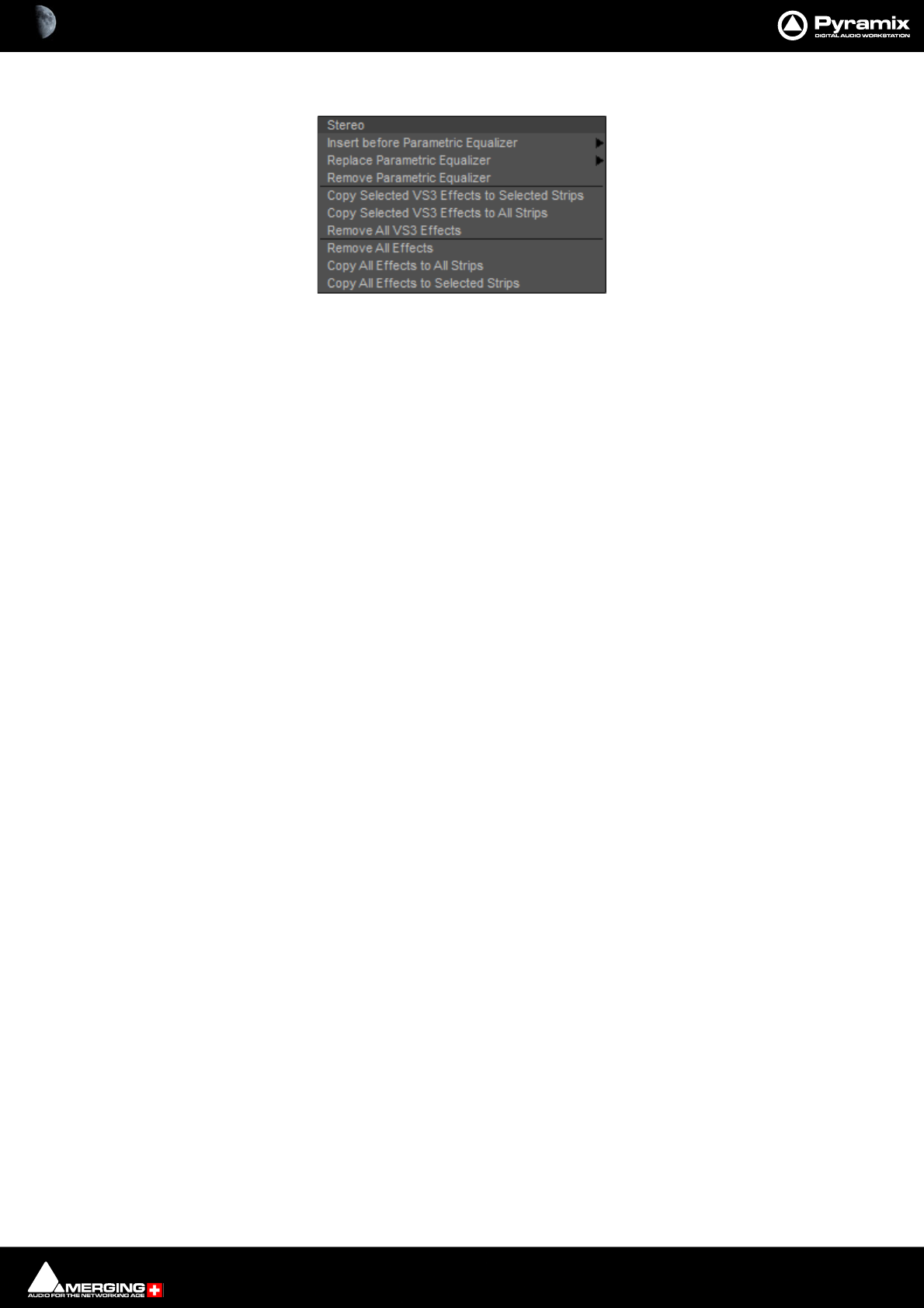
Mixer : Configure Page 10 - 257
Right-clicking on an installed plug-in pops-up a context menu, for example:
Insert before (effect clicked on) > drops down a list of effects of the same type that can be inserted before current the
effect.
Replace (effect clicked on) > drops down a list of effects of the same type that can replace the current effect. Dou-
ble-Clicking an installed effect does the same thing.
Remove (effect clicked on) Uninstalls the current effect from the Strip or Bus
Copy Selected (Effect type) Effects to selected strips As it says. Target strips can be selected before or after selecting the
effect(s)
Copy Selected (Effect type) to All Strips As it says.
Remove All (Effect type) Effects Removes all effect of the current type clicked on from the Strip.
Remove All Effects Removes all effects of all types from the current Strip.
Copy All Effects to All Strips Copies all the effects installed in the current Strip to all other Strips.
Copy All Effects to Selected Strips Copies all the effects installed in the current Strip to all selected Strips.
External Effects Inserts
External Inserts are added in the same way as VS3 Effects. Click on Click to Add and choose Other > External
Insert
Effect context popup
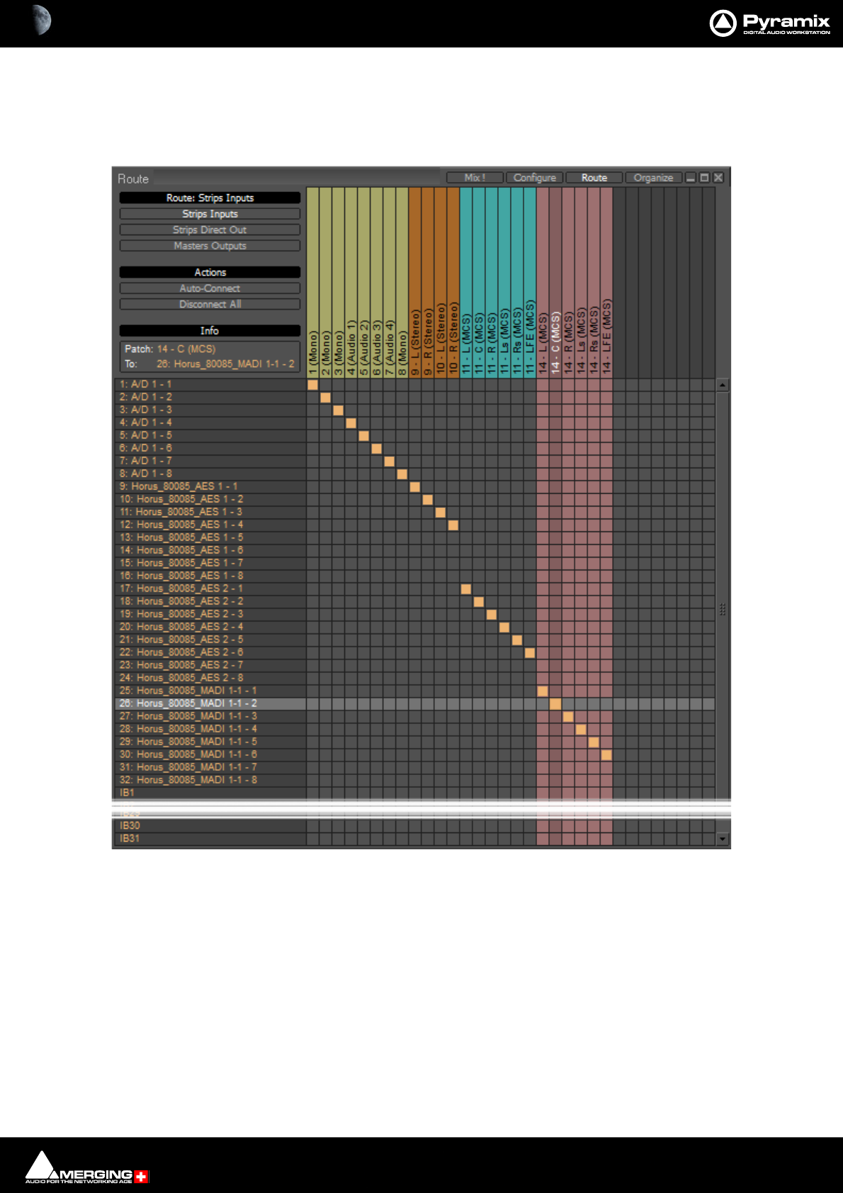
Mixer : Route Page 10 - 258
Route Page
Route brings together all routing to and from physical I/O in an intuitive matrix routing grid environment. It opens
in the Strips Input page:
Strips Direct Out and Masters Outputs are similar.
Making Connections
When the cursor is hovering over a destination crosspoint the column and row are highlighted for ease of viewing.
Bus colors are carried across from the Mixer. If the cursor is over a crosspoint which is part of a multichannel strip
or bus the other channels in the group are also highlighted dimly. In Strips Inputs clicking on a crosspoint routes
the source in the left hand column to the destination in the top row. In Strips Direct Out and Masters Outputs
sources are horizontal and destinations vertical. Clicking and dragging allow multiple assignments to be made
rapidly.
Mixer Route Page

Mixer : Route Page 10 - 259
Right-clicking a crosspoint pops-up a context menu with options appropriate to the destination.:
Auto-Connect
Connects all the Strip Input Channels to physical inputs in ascending order.
Disconnect All
Removes all crosspoint assignments.
Info
The Info box shows detail about the currently highlighted crosspoint.
I/O Bus Capacity
In a MassCore system the only limitation on the number of I/O buses is the available power. For now the maximum
number of buses is artificially limited in code to 512 (at 1FS, 256@2FS, 128@4FS, 64@8FS).
Internal Return Buses
Some of the time slots within MassCore can be reserved to convey Aux Send or Master Output Buses back to
input strips. In effect, these are internal send/return paths. To change the number of available Internal Return
Buses, close all open Projects (if any) and go to:
Settings > All Settings > Mixer > Mixer Settings.
The number of Internal Return Buses can be set using the Internal Buses combo box. Click on the OK button to
memorize the setting and exit.
The number of Internal Return Buses you assign here will be available as possible channel strip sources in the
mixer.
Note: Please be aware that a Mix Group Bus or Aux Group Bus will auto-take Internal Bus connec-
tion resources, starting from the last one. E.g. IB384-IB385 for the first two SubGroup Channels
added to a Mixer. This means that you will no longer see IB384 and IB385 in the IB list.
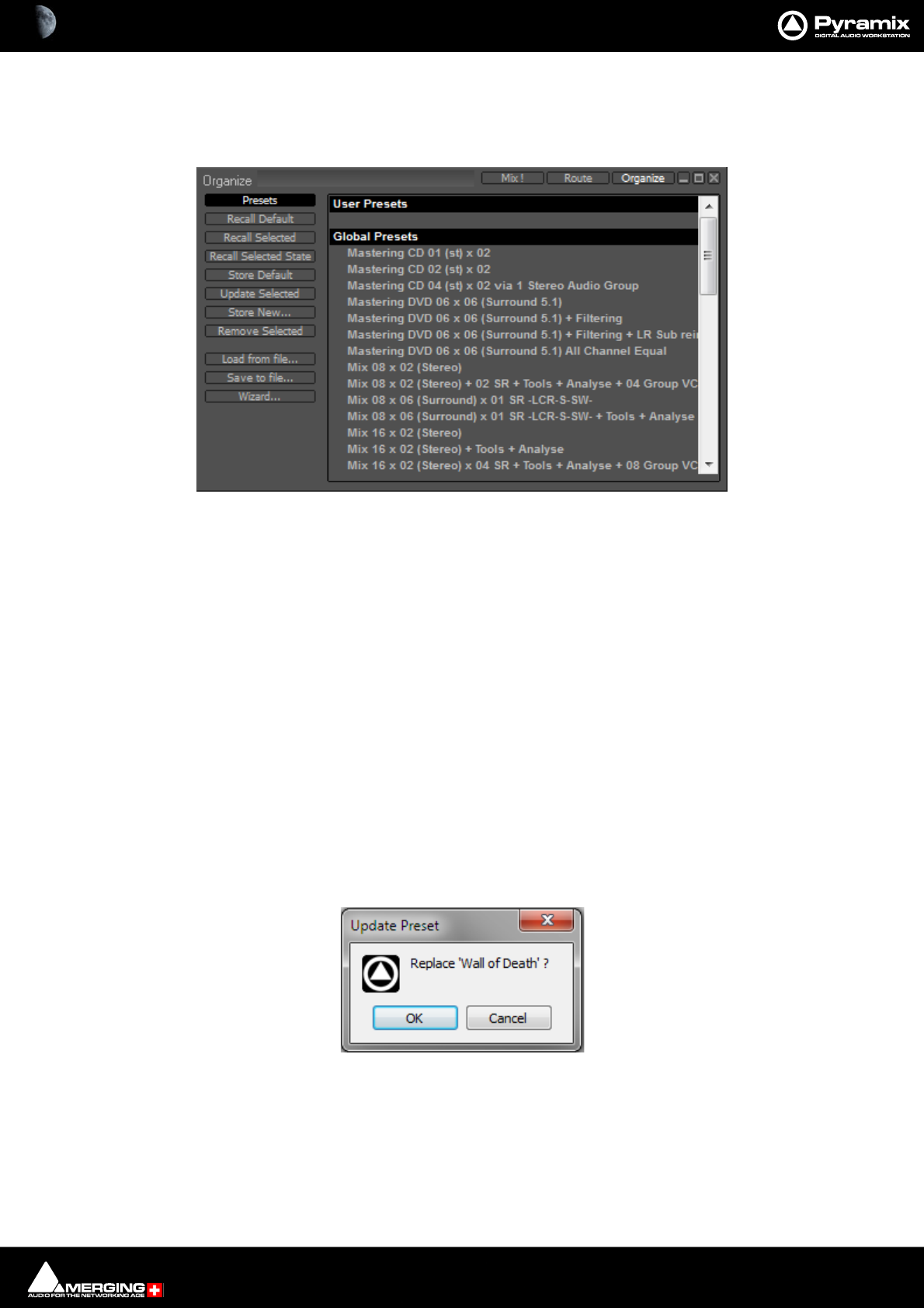
Mixer : Organize Page 10 - 260
Organize Page
Here, Mixer Presets and Settings can be managed:
Presets
Global & User Presets
All the Factory Global and User Presets appear in the list in the right-hand pane. Global Preset are available to any
user logged on the current machine, User Presets are available only for the User that created the Preset.
Recall Default Recalls the Default Mixer - see below.
Recall Selected Recalls the selected Preset.
Recall Selected State Recalls parameters, panning, levels etc. from a saved Mixer Preset and applies
these to the current Mixer.
Note: This only applies to strips and effects common to both configurations. If the current mixer
does not have the same plug-ins etc. non-coincident items will be ignored. Similarly if you recall
the state of a 100 strip mixer to a 10 strip mixer the last (right-hand end)90 strips are ignored.
Store Default Makes the current Mixer the default. E.g. when called from the New Project Wiz-
ard.
Update Selected Opens the Update Preset dialog:
Replaces the Preset selected currently to match the current Mixer. Click on OK to save it and close the dialog. Can-
cel closes the dialog without saving, leaving the selected Preset unchanged.
Mixer Organize Page
Update Preset dialog
Mixer : Organize Page 10 - 261
Store New... Opens the New preset name dialog:
Type a suitable name for the Mixer. If the Global box is ticked the Mixer Preset will be available in all Projects in the
Global section of the Presets list. If unchecked it will appear in the User Presets section. Click on OK to save it and
close the dialog. Cancel closes the dialog without saving.
Remove Selected Opens the Remove preset dialog:
OK deletes the selected Preset and closes the dialog. Cancel leaves the Preset intact and closes the dialog.
Load from file... Opens a Windows File Browser window to enable a Preset to be loaded from a Win-
dows Folder.
Save to file... Opens a Windows File Browser to enable the current Preset to be Saved to a Win-
dows Folder.
Wizard... Opens the Mixer Configuration Wizard. Please see: Mixer Configuration
Wizard on page 273.
New preset name dialog
Remove Preset dialog
Mixer : 3D Panning Control Bus Window 10 - 262
3D Panning Control Bus Window
The Panning Control Bus window offers far more information and a greater degree of control over all the 3D pan-
ning parameters than could be shown on an individual Input strip. It is opened from View > Windows / Tools >
Surround Panner or the icon in the View Toolbar.
Views
The left hand pane is the view looking down on the virtual room from above.
The right hand pane is the view looking into the virtual room from the back.
Here is the Panning Control Bus window displaying controlling a Mono strip feeding a 32 Speaker Room/Bus:
Layers
Speakers are grouped in three layers plus LFEs.
Speakers in he “normal” layer are colored red, the top layer green and the bottom layer blue, LFEs are yellow.
Controls
The controls present at the bottom of the window vary depending on the source type.
Mono Source
Left/Right Pans all source channels between left and right.
Front/Rear Pans all source channels between front and rear.
Bottom/Top Pans all source channels between bottom and top.
Divergence Sets the amount of divergence.
Panning Control Bus window - Mono Source

Mixer : 3D Panning Control Bus Window 10 - 263
LFE Sets the LFE level.
LFE2 Sets the LFE level to the second Sub-woofer. (Only shown when present in the
Room Configuration.)
Divergence Type Clicking in the field cycles through 1D, 2D and 3D
1D Divergence is applied Left and Right.
2D Divergence is applied Left, Right, Front and Rear.
3D Divergence is applied Left, Right, Front, Rear, Top and Bottom.
Virtual Pan Law Clicking in the field switches between Sin/Cos and Square Root.
Sized Pan Attenuation Only applicable to Sized room models. Enables the effect of distance on the atten-
uation to be exaggerated or reduced by a factor of 5 times. Central position means
default attenuation is 1/d, moving the parameter to the right exaggerates the
effect of distance, moving the parameter to the left reduces the effect of distance.
Stereo Source
All of the above PLUS:
Rotation LR Rotates the image in the horizontal plane. No Change in height.
Rotation FR Tilts / Rotates the image in the vertical plane Left and Right. Center is fixed.
Rotation BT Tilts / Rotates the image in the vertical plane from Front to Back
Source Size
Dual Source Mode Clicking on the field cycles through:
Balance
Single Pan Pans the stereo source as a mono source.
Dual Pan Rotation and Source Size controls are hidden and replaced
by:
2nd Left/Right
2nd Front/Rear
2nd Bottom Top
2nd Divergence
Thus in Dual Pan mode the two source channels are dealt with independently.
Note: The 3DConnexion Space Navigator and SpaceMouse Pro mice are supported for pan-
ning. Please follow the configuration guide which may be found here:
https://confluence.merging.com/display/PUBLICDOC/3DConnexion+Mouse+-+Configuration+Guide
Mixer : 3D Panning Control Bus Window 10 - 264
The 3D Room Editor
All General Mixing Buses are configurable in the 3D Room Editor window. This is opened by clicking on the Bus
label in the Automation, I/0 and VCA section of the Bus Strip.
3D Room Editor - Virtual mode
Mixer : 3D Panning Control Bus Window 10 - 265
GP Bus Channel Configuration or ‘3D Room’ types
Virtual Room Model
The Virtual Room model uses a Stereo Panning based algorithm using either a Square Root or Sin/Cos panning
law, extended to all 3 dimensions.
The only User parameter is the Square Root - Sin/Cos choice available either in All Settings > Mixer > Mixer Set-
tings : Virtual Room / Stereo Pan Law or Virtual Pan Law in the 3D Panner Window.
Channel/Speaker Types
In Virtual Room mode the Channels or Speakers can only be of the 32 types listed below:
Note: Speakers belonging to the three Height Layers and LFE(s) are color coded as in the above
table in the 3D Room Editor window and the Advanced Panning Control Bus window. The
speaker selected currently is colored orange.
• The Channel Type directly defines the position of the Speaker in the Room
• The Room has no real size, the panning algorithm only uses amplitude for computing levels based on the
position of each Speakers/Channels, that is defined by its Channel Type.
• The algorithm ensures that the levels are sharply focused near the closest speaker to the Panner’s coordi-
nates.
• This mode is designed for Film, Post-production or Music where no real-world room definition is needed
or known in advance and precision is needed to focus on a given Speaker.
• The Channel Type directly defines the position of the Speaker in the Room
• The Room has no real-world size, the panning algorithm only uses amplitude for computing levels based
on the position of each Speakers/Channels, that is defined by its Channel Type.
• The algorithm ensures that the levels are sharply focused near the closest speaker to the Panner’s coordi-
nates.
• This mode is designed for Film, Post-production or Music where no real-world room definition is needed
or known in advance and precision is needed to focus on a given Speaker.
1LLeft 17Tr Top Right
2CCenter 18Trl Top Surround Left
3RRight 19Trc Top Surround Center
4Ls Surround Left 20 Trr Top Surround Right
5Rs Surround Right 21 Tsl Top Side Left
6LFE Low Frequency Effects 22 Tsr Top Side Right
7Lc Center Left 23 Bl Bottom left
8Rc Center Right 24 Bc Bottom Center
9Cs Surround Center 25 Br Bottom Right
10 Sl Side Left 26 Brl Bottom Surround Left
11 Sr Side Right 27 Brc Bottom Surround Center
12 Lcs Center Surround Left 28 Brr Bottom Surround Right
13 Rcs Center Surround Right 29 Bsl Bottom Side Left
14 VoG Voice of God 30 Bsr Bottom Side Right
15 Tl Top left 31 VoD Voice of Devil
16 Tc Top Center 32 LFE2 Low Frequency Effects E2
Mixer : 3D Panning Control Bus Window 10 - 266
Sized Room Model
• Sized Rooms use a Sound in Air propagation/attenuation based algorithm.
• In this mode the panning algorithm uses real distances to compute levels.
• All Speakers output some level, even if very low, wherever the Panner is positioned.
• The position of each Speakers is editable in the Room Editor. The selected Speaker is highlighted in
Orange and its coordinates can be changed using the editor.
• By default the sound attenuation depends on the distance from the panning source to each speakers by
1/d. (One divided by the distance.)
• A parameter called Sized Pan Attenuation in the 3D Panner Window enables the effect of distance on the
attenuation to be exaggerated or reduced by a factor of 5 times.
• Central position means default attenuation is 1/d, moving the parameter to the right exaggerates the
effect of distance, moving the parameter to the left reduces the effect of distance.
• In this mode the Room has a size and the Speakers have a editable position, independently of their Type,
that is only useful in this model.
• The Room Size definition is the Radius of the cubic Room, i.e. half its boundary size. E.g. if 3m is entered
the room is 6m x 6m x 6m.
3D Room Editor - Sized mode
Mixer : 3D Panning Control Bus Window 10 - 267
Left Hand Pane
#The number of the Channel (Not editable).
Type Clicking in the field pops-up the list of Pre-defined Channel Types, as above, plus
<Custom>. Choosing one of the predefined Types sets the X, Y and Z co-ordinates
accordingly. However, they are editable.
Custom Name Type in this field to add a Custom Name. This is applicable to pre-defined channel
Types and Custom Channels.
XClick and type in the field to set the Left - Right co-ordinate for the speaker.
YClick and type in the field to set the Front - Rear co-ordinate for the speaker.
ZClick and type in the field to set the Top - Bottom co-ordinate for the speaker.
Gain Click in the field and type a value to trim the Speaker output level.
Routing Click in the field to pop-up a list of all destinations available.
Room Settings
Name Click in the field and type to name the Speaker Arrangement.
Remap Room/Bus The drop-down lists all the Pre-defined Room Types available. Choosing one in the
list opens the Remap Room and reconfigure Bus dialog:
Note: As the dialog indicates, Changing the Room Mapping will reset all custom speaker
names and coordinates you may have set and reconfigure the associated Bus.
Options are OK to reconfigure or Cancel to retain the current configuration.
Type: The radio buttons toggle between Virtual and Sized. If Sized is selected the Set
Room Size dialog appears:
Click in the Please enter the initial room size: field and enter a value (in Meters)
Click on OK to change mode and set the initial room size or Cancel to retain the current mode.
Editing Tools
Remap Room and reconfigure Bus dialog
Set Room Size dialog
Mixer : 3D Panning Control Bus Window 10 - 268
Speaker Coords Origin : Determines the base point in space for the XYZ coordinate settings. The drop-
down offers the choice of: <Room center> or any of the speakers present in the
room (by number). Speaker position is either relative to the center of the room, or
to the selected reference Speaker.
Display Coords: When checked the coordinates fro the selected speaker are shown numerically
and by a dotted orange line from the point of origin.Predefined Speaker
Arrangements/Channel Assignments
52 Predefined Room types listed below:
Mono 9.0 Surround
Stereo 9.1 Surround
3.0 Front 11.0 Surround
3.1 Front 11.1 Surround
3.0 Surround 5.0 Dolby
3.1 Surround 5.1 Dolby
4.0 Quadro 7.0 Dolby
4.1 Quadro 7.1 Dolby
4.0 Surround 9.0 Dolby
4.1 Surround 9.1 Dolby (Atmos)
5.0 Side (THX) 7.0 DTS (Neo:X)
5.1 Side (THX) 7.1 DTS (Neo:X)
5.0 Surround (SACD) 9.0 DTS (Neo:X)
5.1 Surround (SACD) 9.1 DTS (Neo:X)
6.0 Side 11.0 DTS (Neo:X)
6.1 Side 11.1 DTS (Neo:X)
6.0 Surround 10.2 TMH
6.1 Surround 12.2 TMH
7.0 Side 8.0 Auro
7.1 Side 9.1 Auro
7.0 Surround (SDDS) 10.1 Auro
7.1 Surround (SDDS) 11.1 (7+4) Auro
7.0 Surround (THX) 11.1 Auro
7.1 Surround (THX) 13.1 Auro
8.0 Surround 22.2 Hamasaki/NHK
8.1 Surround 30.2 La Totale

Mixer : Mixer Delay Compensation 10 - 269
Mixer Delay Compensation
Summary
Mixer Delay Compensation offers a choice between:
Full
Off
This choice is made in the All Settings > Project > Mixer > Mixer Settings page along with a switch to turn Auto-
matic Compensation on or off and a slider to set the Maximum Mixer Delay Compensation.
Delay Compensation Switching
As detailed above, Compensation can be selected in the All Settings menu. It can also be toggled On/Off in the
Mixer context menu. Right click and select Settings then click on Enable Delay Compensation to toggle On or
Off.
1. Input strip set as a (normal) Input: no compensation. If a Delay is applied manually the output signal of this
strip will be delayed by the applied value.
2. Input strip used as a Bus return, i.e. patched to an Internal Bus and set as a bus return (see Input Strip Mode
on page 271): all other Output Strips are automatically delayed by the amount equal to the Bus internal pro-
cessing delay.
3. Input strip used as a Bus return, i.e. where the bus signal is sent outside the workstation and returned to a
physical Input: All other Strips are automatically delayed by the amount equal to the Bus internal processing
delay providing the Input is set as a Bus (see Input Strip Mode on page 271). If a Delay is applied manually,
for example to compensate for the delay in an external processor, the signal of all other output strips will be
further delayed, according to the value entered.
When Full is selected, Plug-in effects that correctly report their latency will also have their delay compensated.
Further, this delay will be maintained when the plug-in is in bypass mode.
Please see also Mixer Settings on page 730
Delay Compensation
Delay Compensation Indicator
A small button labeled D on the right-hand side of the mixer adjacent to the Fader line indicates the current state
of delay compensation in the mixer:
A stable green indicates that delays are compensated.
Stable red indicates that delays are not compensated.
Blinking red indicates that you need to adjust the maximum length of delay that can be compensated in order to
achieve proper compensation.
Mixer : Mixer Delay Compensation 10 - 270
Maximum Delay Compensation
Pyramix sets a default value for the maximum number of samples of delay that can be compensated automati-
cally. As effects are added the required total delay value is calculated. If an Effect is instantiated that will exceed
this limit the Mixer error: Delay compensation dialog appears:
To deal with the problem either remove an effect or effects or go to Settings > All Settings > Project > Mixer >
Mixer Settings and increase the Max Mixer delay Compensation - Delay setting to a value slightly in excess of
that proposed in the dialog.
Note: Increasing the Delay value too much steals valuable memory from MassCore.
Outboard Latency
Typical latency in ms of outboard gear ranges from 2 to 5 ms. The following chart may help you to compute the
proper delay compensation values for outboard equipment:
Delay Chart
Time Alignment of Recorded Clips
All recordings from Input Strips designated as Input are automatically time-aligned. E.g. recordings from live
inputs.
Ms samples@4
4.1kHz
samples@4
8kHz
samples@8
8.2kHz
samples@9
6kHz
samples@1
76.4kHz
samples@1
92kHz
samples@3
52.8kHz
144 48 88 96 176 192 352
3132 144 265 288 529 576 1058
5221 240 441 480 882 960 1764
7309 336 617 672 1235 1344 2470
9397 432 794 864 1588 1728 3175
10 441 480 880 960 1764 1920 3528
12 529 576 1058 1152 2117 2304 4234
Max Delay
(Auto PLUS
Manual)
1216 1216 2432 2432 4864 4864 9728
Mixer : Mixer Delay Compensation 10 - 271
Recording Bus Returns
When recording the output of an input strip taking an Aux or Bus return, for example to “freeze” a reverb Track, the
recorded media will be placed too early in the Timeline. In this situation it may therefore be desirable to designate
this Aux or Bus return as a normal Input in order to ensure correct time-alignment of the recorded Clip.
Note: For Power Users the SABR debug windows show the delay values applied to each bus /
aux node and may prove useful. (Accessible by right-clicking on the Info Bar and selecting from
the Debug sub-menu.)
Delay Compensation Detail
All digital processing takes a finite amount of time. When Internal Return Buses are used to route Master output
buses back into channel inputs (by selecting an Internal Return Bus input from the routing pop-up for the Bus
output, and selecting an Internal Return Bus output as the return channel input) all other buses not so routed
must be delayed if the Mixer is to be ‘time-aligned’ I.e. If a signal is fed to two inputs, the first feeding the Main
Output direct and the second routed back to an input via (say) a Stereo Send bus with the return input strip
routed to the Main Output, then the second will be delayed with respect to the first. Selecting Settings > Enable
Delay Compensation from the mixer context pop-up menu will automatically ensure both signals remain in sync
by delaying the signals directly routed to the Main Output by an amount equivalent to the delay introduced by
the extra processing in the second path.
Note: For obvious reasons a strip fed by an Internal Bus or buses cannot be routed back to the
same internal buses.
Input Strip Mode
In order for Pyramix to correctly calculate the required delay you have to tell it which bus is the source for the
Internal Return Bus. Clicking on Input at the bottom of the strip, above the XLR icon, pops-up a list of all the out-
put buses and Input. Input is the default and means the strip is fed from a physical live input and no delay com-
pensation is required. If any Internal or External Return Bus is ticked and Automatic Delay Compensation is
turned on, Pyramix calculates the required delay and applies it to all Output buses not feeding a Return Bus.
Delay vs. Delay Compensation
When the Input Strip Mode is set to Input the delay setting affects the only the delay on the strip’s signal. When
{any Bus name} Return is selected as the Input Strip Mode the delay setting affects the delay on all other output
bus signals to ensure correct time-alignment.
Input Type pop-up
Mixer : Mixer Delay Compensation 10 - 272
Delay Compensation of External Inputs
Where an Output Bus is used to feed an external processor via a physical output and the external processor output
is fed back into Pyramix via an external live input, then the necessary delay compensation must be computed and
applied by the operator since Pyramix has no means of determining the delay of the external device. However, the
Input Strip Mode (Click on Input to pop-up the menu) should be set to the bus feeding the external processor (as
above) so that the input channel delay setting affects delay compensation rather than simply delaying the signal
through the input strip.
In the illustration, Group Bus Ext Rev feeds an external device via physical outputs 17 & 18. The outputs of the
external device are connected to physical inputs 1 & 2. The channels’ Mode has been set to Ext Rev Return and
delay compensation of 256 samples applied.
In contrast Int FX SubGroup bus has VS3 and VST plug-ins inserted in the strip and feeds the output buses
directly. There is, of course, no reason why an external insert cannot be used in a Group Bus instead of using an
Output bus for this purpose.
External Insert Plug-ins
Internal VS3 Engine latency is automatically compensated except for the audio interface I/O latency. Thus you
have to manually set the delay of the external unit plus the I/O latency. It is not possible to change the delay or
change the bypass status during playback or recording.
Determining Delay Compensation for External Effects Loops
One strategy for achieving this is to route a signal directly to an Output Bus and, via a physical output from a sec-
ond Output Bus, to the external processor’s input. The processor’s output is connected to a physical Pyramix input
and routed to an input strip. The strip mode must be set to the Bus used as the source. Then you can use impulse
sounds, clicks, rimshots etc. to aid manual adjustment of the delay compensation by comparing the direct sound
with the sound returning from the external processor.
Determining Delay Compensation for External Insert Plug-ins
A similar strategy can be employed here. Route the signal you wish to treat with an External Insert Plug-in to two
input strips. Add the External Insert in one strip only, complete with the external processor in circuit. Delay the
untreated strip until the audio is in sync with the treated audio and note the delay value. Then apply this value in
the Ext. Unit Delay field in the External Insert window.
Effects Delay Indication
When the mouse cursor is hovered over a plug-in, in a strip, the required delay value is displayed:
Here you can see that Dynamics currently requires a 448 sample delay to be applied to the other output buses.
This is applied automatically when Full Delay Compensation is switched on.
Input Type pop-up
Plug-in Name and Delay pop-up
Mixer : Creating and Configuring Mixers 10 - 273
Creating and Configuring Mixers
If one of the numerous mixer presets does not quite suit your application it is simple to modify an existing mixer,
create one using the Mixer Wizard or design one from scratch. The Wizard can be started from the New Project
Wizard (Please See: New Project on page 40) or from an existing mixer by right-clicking anywhere on the mixer
surface and selecting Settings > Wizard...
Mixer Configuration Wizard
The Mixer Configuration Wizard can be started from within the New Project Wizard or from the right-click con-
text menu in an existing mixer, Settings > Wizard...
Each dialog has <Back, Next> and Cancel buttons at the bottom.
Note: If the <Back button is used to return to a previous page, settings already made in subse-
quent pages are retained when they are returned to using Next>
Back Grayed out since this is the first page.
Next> Moves to the next Wizard page.
Cancel Keeps the current Mixer and closes the Wizard.
Click on Next to move to the next page:
Configuration Wizard Welcome dialog
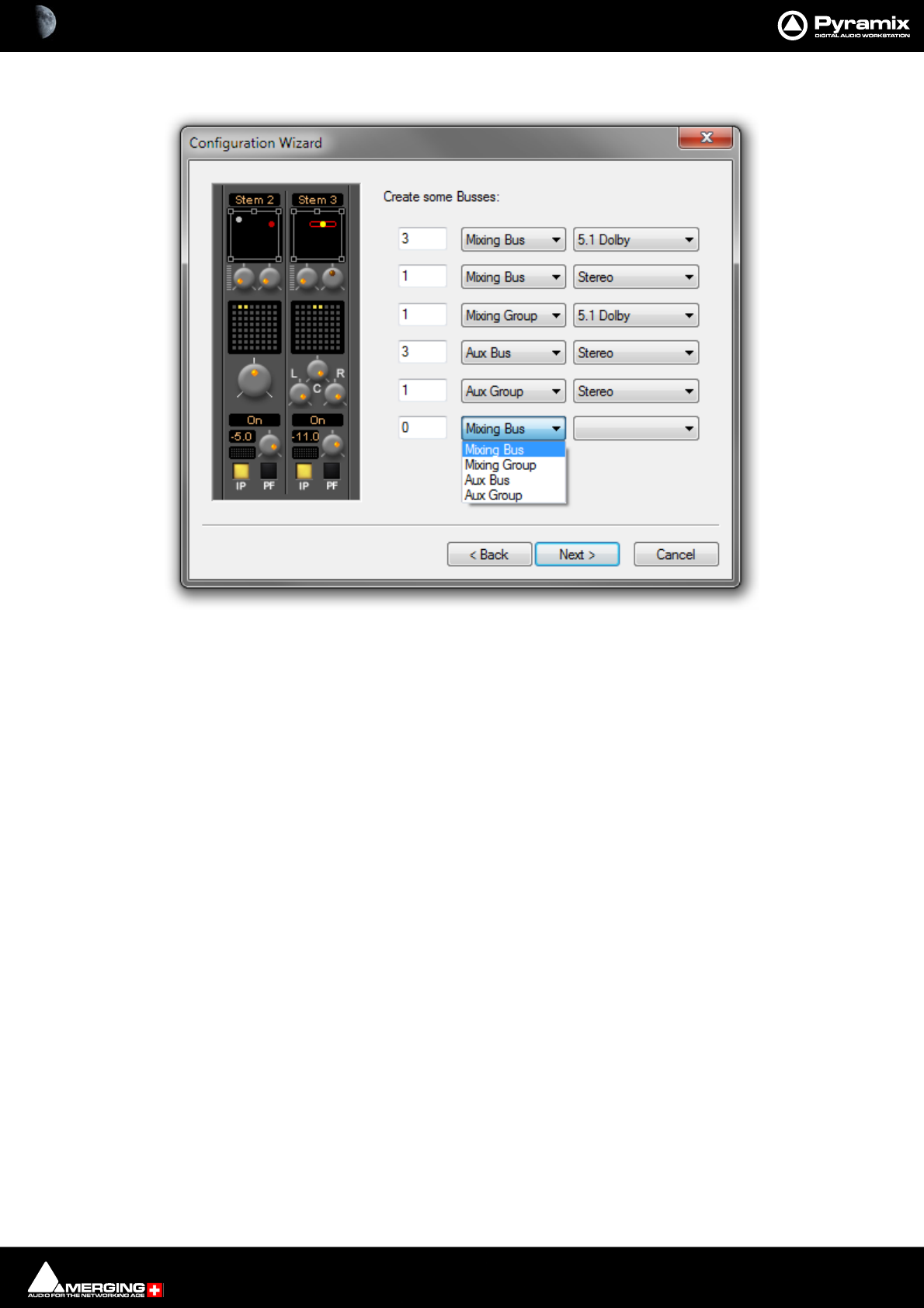
Mixer : Creating and Configuring Mixers 10 - 274
Create some Buses:
Column 1 Field for the number of Buses to be created.
Column 2 Drop-down list with the four General Purpose Mixing Bus Types:
Mixing Bus
Mixing Group
Aux Bus
Aux Group
Column 3 Drop-down list with the 32 Bus Formats available.
Back Moves to the previous page page.
Next> Moves to the next Wizard page.
Cancel Keeps the current Mixer and closes the Wizard.
Type the number of buses required in the left-hand field and select the Type needed from the mid-
dle drop down list. choose the Bus Format from the right-hand drop-down list. The six rows are used
to create different Bus Types and formats simultaneously. Click the Next button to move on to the
next page:
Configuration Wizard Buses dialog
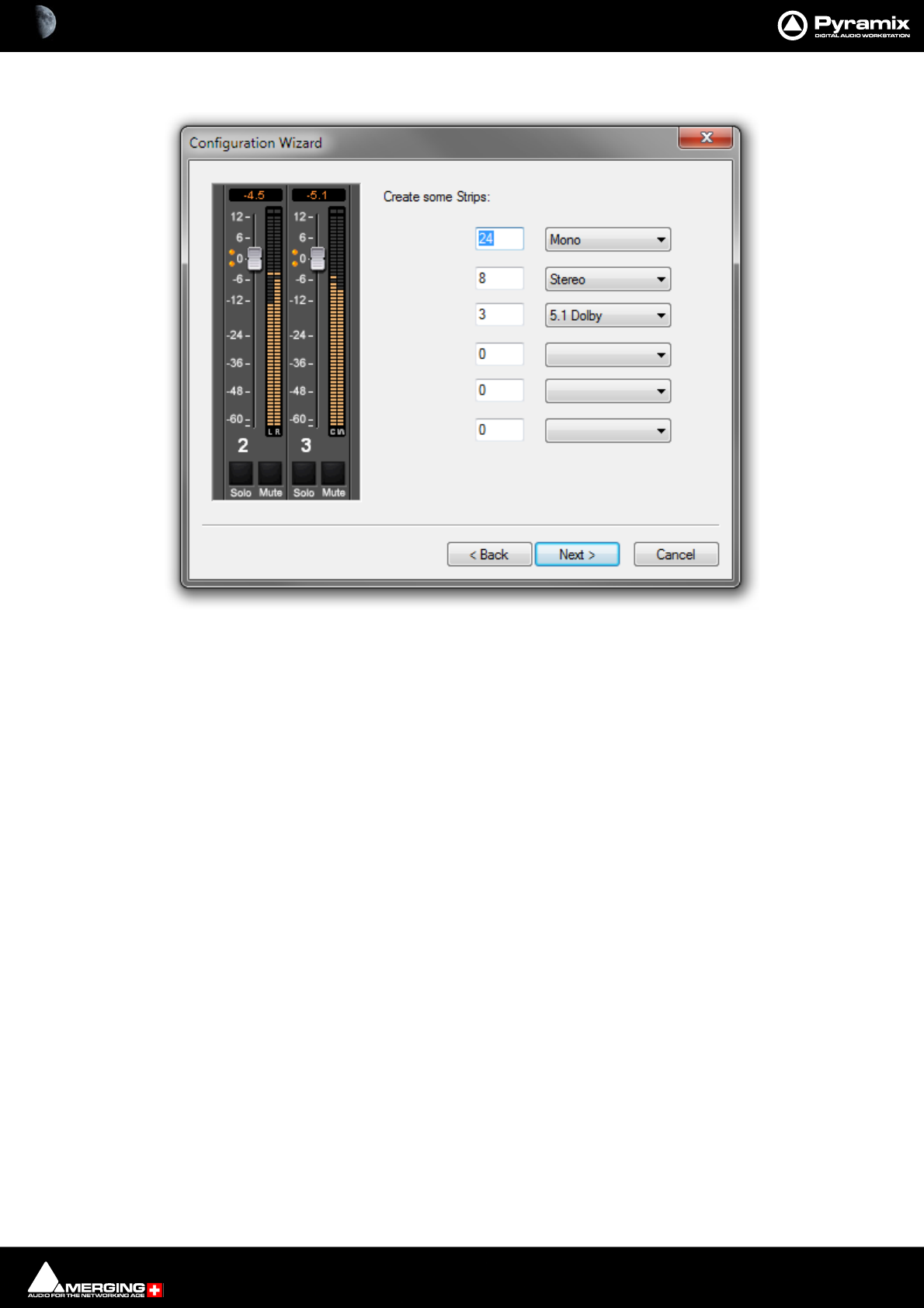
Mixer : Creating and Configuring Mixers 10 - 275
Create Some Strips
Column 1 Field for the number of Buses to be created.
Column 2 Drop-down list with the 32 Strip Formats available.
Back Moves to the previous page page.
Next> Moves to the next Wizard page.
Cancel Keeps the current Mixer and closes the Wizard.
Type the number of Strips required in the left-hand field and choose the Strip Format from the right-
hand drop-down list. The six rows are used to create different Strip Types and formats simultane-
ously. Click the Next button to move on to the next page:
Configuration Wizard strips dialog
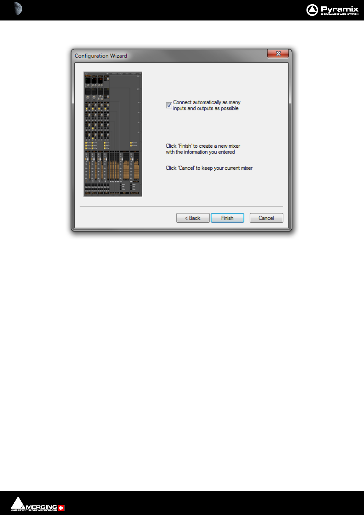
Mixer : Creating and Configuring Mixers 10 - 276
Connect & Finish
Connect automatically as many inputs and outputs as possible Check the box to auto connect.
Back Moves to the previous page page.
Next> Moves to the next Wizard page.
Cancel Keeps the current Mixer and closes the Wizard.
Checking the Connect automatically as many inputs and outputs as possible check-box will cre-
ate the same number and types of Tracks as there are Input Strips and connect as many as possible
to the available physical inputs in ascending order and connect output Buses to the physical I/O and
Track outputs to Mixer Input Strips, although you can easily reconfigure this later. If the box is not
ticked, the Tracks will be created in the same way with Track outputs connected to Mixer strips but
no physical Inputs or Outputs will be connected.
Note: When the Wizard is run from New Project Wizard clicking Cancel opens the new Project
with a Blank Mixer Window (to configure see below).
Configuration Wizard auto Connect & Finish dialog
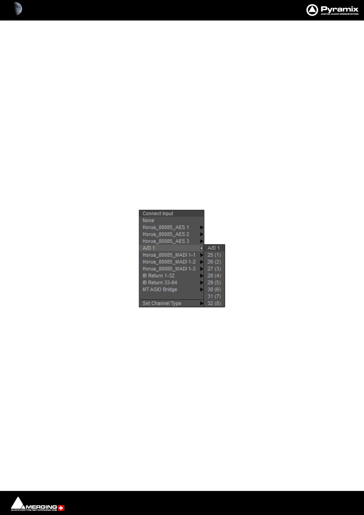
Mixer : Configuring a Blank or Existing Mixer 10 - 277
Configuring a Blank or Existing Mixer
Configuration of the mixer control surface is accomplished via contextual menus. The precise options available
will depend on where you click on the mixer. If you wish to affect the entire mixer, right-click on the top bar of the
Mixer window. To change options for a Bus, right-click on a blank area of the Bus strip. Similarly, for a channel input
strip, right click on a blank area of the Strip. Right-clicking within a function block adds menu entries to the top of
the list, relevant to the specific block.
Adding Strips
Right-click anywhere on the Faders, choose Strip > Add and select the appropriate type of strip to add or right-
click anywhere on the Faders, choose Bus > Add and select the appropriate type of bus to add.
Removing Strips
To remove a given input strip, bus or group, right-click directly on it and choose Strip > Remove (Strip, Bus or
Group) as appropriate.
Mixer I/O Assignments
To or from physical I/O
To change I/O assignments to or from physical I/O or the Internal Return Buses, click on the appropriate XLR
icon. Choose Connect Input or Connect Output from the pop-up menu and choose the desired connection.
When connecting a multichannel strip clicking on the header A/D1 in the above illustration) will connect all chan-
nels consecutively.
From Tracks
Note that several Tracks may be routed to the same mixer input strip. Tracks are assigned to mixer input strips
either automatically or manually from the Track Header. See: Track Header Panel on page 102
I/O assignment pop-up
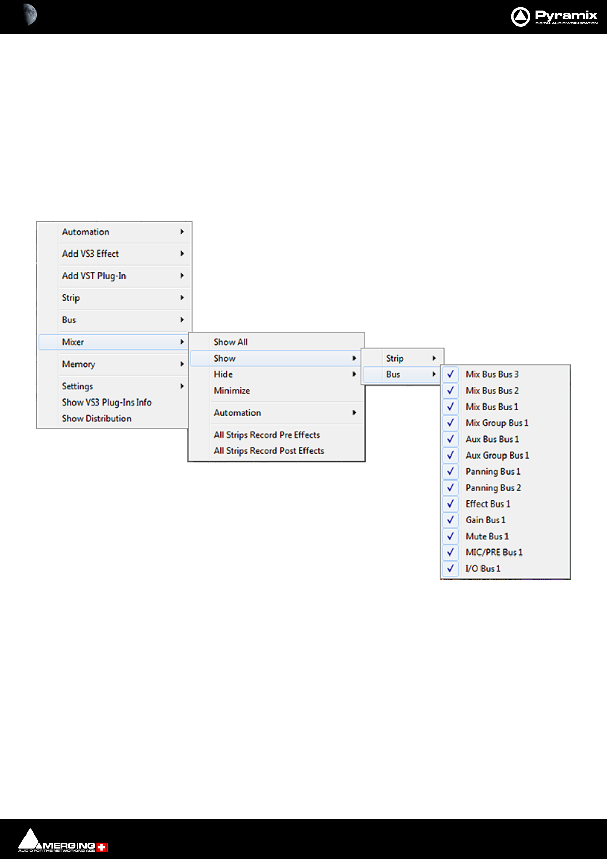
Mixer : Configuring a Blank or Existing Mixer 10 - 278
Further Mixer Configuration Options
Mixer Context Pop-up menu
The entries on this menu vary according to where you right-click on the mixer surface. At the top of the menu the
entries concern the specific mixer component under the mouse cursor when you right click. The next section of
the menu has entries which affect the Strip. Entries from Mixer to the end of the menu affect the entire mixer and
are available wherever the mouse is right-clicked.
Mixer > Show
Show All Makes all input strips and buses visible
Show / Hide > Selects Strips and Buses to be shown or hidden. When checked, the Buses or
strips are visible on the console surface. Both Show and Hide access the same lists.
Minimize When checked, Mixer window is minimized
Automation > These menu choices toggle the Automation mode for the entire mixer.
Follow Strip Mode
Isolate
Play Please see: Dynamic Automation Transport Modes on page 403
Record
Memory > The choices here enable mixer presets to be saved loaded and managed.
Please see: Mixer Presets on page 281
Settings >
General... Opens the Mixer Settings window at the All Settings > Hardware > Hardware > For-
mats & Sync page. Please see: Formats and Sync on page 716
Mixer Show / Hide context menu
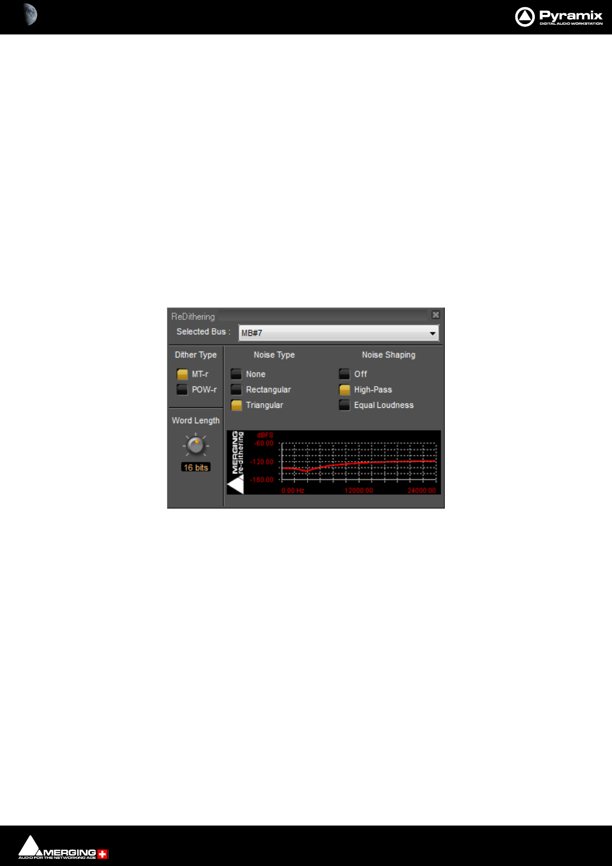
Mixer : Dithering Options 10 - 279
Dithering... Opens the Dithering window. Please see: below and Dither on page 440 for an
explanation of the need for dither.
Enable Delay Compensation Enables Delay Compensation for the mixer.
Add Strip
Add Bus
Remove Select All Strips, All Buses or All to remove groups of mixer components or every com-
ponent.
Auto-connect Automatically connects the Mixer inputs and outputs using the available inputs and
outputs of the installed daughter card (s) and the Mixers Preferred Monitoring Outputs
Wizard... Launches the Configuration Wizard. Please see: Mixer Configuration Wizard on
page 273
Show VS3 Plug-Ins Info Pops up the VS3 Plug-Ins Information window. Please see: VS3 Plug-Ins Information
on page 343
Show Distribution Redundant
Dithering Options
To open the ReDithering window, right-click anywhere on the mixer surface and select Settings > Dithering...
The Dithering window opens.
Selected Bus :
The combo box allows the choice of any of the Mixer’s buses.
Dither Type
The Pyramix Mixer offers a choice of dither algorithms. MT-r and POW-r click the box to choose. The bottom-right
hand panel changes to reflect the options available with the selected dither process.
Word Length
The output word length of the digital audio data can be varied from 8 bits to 24 bits. Click on the rotary knob and
drag left and right to adjust the value.
MT-r Options
PDF (Probability Density Function)
Refers to Dither Noise Type. In basic terms, the addition of a dither signal (noise) into the digital audio streams
improves linearity in the reproduction of low-level signals. In other words, as signal level drops (such as in a fade
out) dithering helps to maintain a smooth decay. There are three options:
Dithering MT-r floating Window
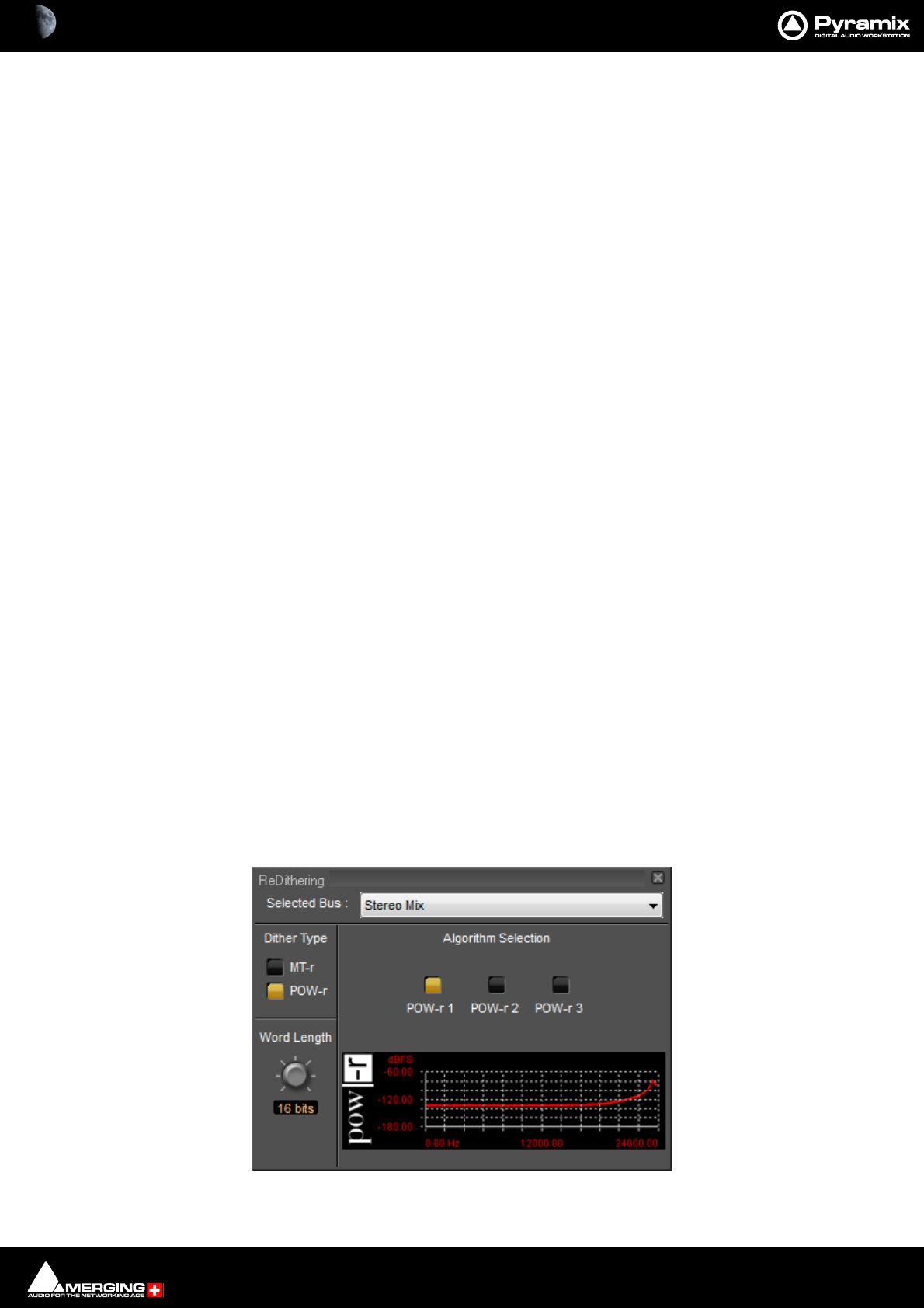
Mixer : Dithering Options 10 - 280
None
No dither signal will be added to the data.
Rectangular
A rectangle shape dither signal will be added to the data. Rectangular distribution is a family of symmetric proba-
bility distributions such that for each member of the family, all intervals of the same length on the distribution's
support are equally probable.
Triangular
A triangle shape dither signal will be added to the data. Triangular distribution is a continuous probability distri-
bution with lower limit a, upper limit b and mode c, where a < b and a = c = b.
Noise Shaping
Noise shaping is a technique that is used to push quantization noise energy, which in linear digital systems is nor-
mally spread over the whole audio spectrum (0 Hz up to half the sampling frequency), into higher frequencies
where the human ear is less sensitive to its effects. There are three noise shaping options and the graph shows the
curve applied:
Off
No noise shaping added.
Hi Pass
This provides a first-order high-pass filter for the noise transfer function. This type of noise shaping takes little
computational power to produce, but at the expense of not Tracking the characteristics of the human ear very
accurately when compared with:
Equal Loudness
Psycho acoustically noise shaped dither inserts an FIR-filter in the feedback path. This shapes the noise as closely
as possible to the characteristics of the human ear. More taps in this type of filter allow a closer approximation to
the response curve of the ear, but each tap, of course, increases the computational instructions required. The filter
implemented here is a 9-tap FIR-filter, which closely approximates the curve of the human ear.
Note: As usual there is no “free lunch”. So Acoustic noise-shaping uses more resources than Hi
Pass.
POW-r
Note: POW-r is a set of licensed noise shaping which requires the Pow- R Redithering Key
POW-r offers the choice of three settings, POW-r 1, POW-r 2 and POW-r 3. The graph indicates the effect of the
noise-shaping.
Dithering POW-r floating Window

Mixer : Mixer Presets 10 - 281
•POW-r: Is essentially a combination of dither technologies and settings
•POW-r 2: Similar to MT-r Triangular with high pass noise shaping
•POW-r 3: Similar to MT-r Triangular with equal loudness noise shaping
Mixer Presets
Mixer Presets can be saved in a user folder or added to the main Mixer Preset list either for the current user or all
users.
Default Mixer
To Save the current Mixer setup as the default Mixer, right click on the Mixing Console and select Memory > Pre-
sets > Store > Default.
Storing New Mixer Presets
To add a preset to the main list of available Mixer presets I.e. the list which appears when starting a new project,
right click on the Mixing Console, select Memory > Presets > Store > New… and enter a name for your Mixer Pre-
set. If the Global check box is checked then the preset will be available for any user logged on the current
machine, if not the preset will be available only for the user that created the new preset.
Removing Mixer Presets
To remove a preset from the main list, right-click on the Mixing Console, select Memory > Presets > Remove >
(preset you wish to remove). The Remove Preset dialog box appears with OK and Cancel options.
Saving / Loading Mixer Presets
Mixer Presets can also be stored in Windows folders. Right-click on the Mixing Console, select Memory > Save. A
Windows Explorer window opens enabling the current Mixer Preset to be named and saved to any Windows
folder. Similarly, selecting Memory > Load enables a Mixer Preset to be loaded from any Windows folder.
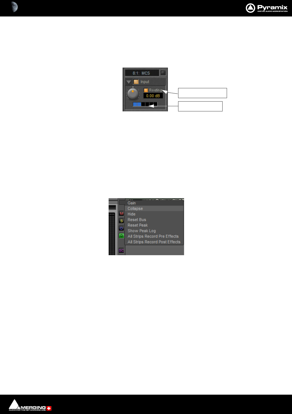
Mixer : Peak Logger 10 - 282
Strip and Bus Tools
In a multi-channel strip the clicking the show/hide Routing button displays the channel routing buttons. There
are as many routing buttons as there are channels in the strip. (Up to 24) Where there are more than 8 channels, up
to three rows of 8 routing buttons will be present. Strip and Bus Tools affect all channels whose routing buttons
are lit blue. In Mono and Stereo strips the routing buttons are on by default. In MCS strips only channels 1 & 2 have
their routing buttons on by default.
If more than one instance of Strip or Bus Tools is used in the strip the routing buttons allow, for example, different
settings to be applied to Front L-R and Rear L-R etc.
Note: The maximum number of channels a single instance of Strip & Bus Tools can operate on is
8. If you need to affect more channels a second instance will be required.
Peak Logger
The Pyramix Mixer is equipped with a Peak Logger. This has obvious applications in Mastering.
Click on the Gain Pop-up to access the Gain options:
Show/Hide Routing
Routing Buttons

Mixer : Peak Logger 10 - 283
Mixer Peak Log Window
Click on Show Peak Log to open the Mixer Peak Log Window:
Enable Logging
Tick the box to enable Peak Logging
Threshold
Type a value here to determine the level above which peaks will be logged. Hit Enter on the keyboard to validate
the change.
Strips Peaks
Tick the box to record Strips Peaks
Buses Peaks
Tick the box to record Bus Peaks
Note: Both Strip and Bus Peaks can be recorded simultaneously.
Clear
Clicking on the Clear button erases all the recorded values since the last time it was pressed. (Or since Logging
was enabled.)
Mixer Peak Log Window

Mixer : Audio Bridge 10 - 284
Audio Bridge
Overview
•The Audio Bridge enables Pyramix to connect to a non Merging Technologies Audio Device in the sys-
tem. This can be an internal Sound Card or an external ASIO device.
• This is used typically for monitoring the signals coming from a primary MassCore or ASIO based Horus
unit, deployed as a stage box, locally on a secondary Audio Device.
• Since this Secondary Audio Device mode is bi-directional it also provides talkback support for the Pyramix
operator to talk to an operator near the Horus deployed remotely.
• Recordings should only be made using signals from the primary unit. The secondary unit should NOT be
used as a record source since it employs a sample rate converter to maintain perfect sync with the main
unit. This obviates the need for an external hardware sync connection.
• The Audio Bridge also enables an ASIO or Rewire enabled application’s output to be merged into the
MassCore engine and I/O and to send audio to an ASIO or Rewire application.
•The Audio Bridge provides 8 to 96 I/O channels (depending on the ASIO or Rewire application or Second-
ary Audio Device’s capabilities.)
The appropriate Audio Bridge option must first be enabled in the VS3 Control Panel (to a maximum of 96 chan-
nels with the extended Native Version) Pyramix must first be closed (if open) before the VS3 Control Panel is
launched.

Mixer : Audio Bridge 10 - 285
ASIO Device Mode
Once the Audio Bridge ASIO option is enabled in the VS3 Control Panel new sources and destinations will show up
in the Input and Output drop-down lists in the Pyramix Mixer/Monitor etc. just like any other source and destina-
tion. E.g. Audio Bridge 1,2,3 etc.
Banks are prefixed by the driver name, for example:
• Audio Bridge Bank 1
• ASIO4ALL Bank 1
Audio Bridge ASIO - VS3 Control Panel
Mixer : Audio Bridge 10 - 286
Secondary Audio Device Host Mode
The Secondary Audio Device is either the built-in sound card or an external ASIO-type device. It is used as a Sec-
ondary Audio Device for Pyramix, in addition to the standard primary MassCore device.
Application
This is used typically as a solution for monitoring the signal coming from a primary MassCore or ASIO based Horus
unit locally. Typically when the primary Horus unit deployed remotely as a stage box through RAVENNA.
Since this Secondary Audio Device Hosting Mode is bi-directional it also provides talkback support for communi-
cation with a person located near the remote primary unit.
Note: The Secondary Audio Device should NOT be used to record from since it uses an always on
SRC (Sample Rate Converter) to maintain perfect sync with the main unit without any external
hardware based sync being required. Recording should only be performed from signal coming
from the primary unit. The secondary unit should only be used for monitoring and talkback.
Configuration
1. Launch the VS3 Control Panel and enable the Secondary Audio Device Host Mode ( bottom)
2. Choose between 8 to 96 I/O channels (depending on the secondary Host capabilities).
Audio Bridge Secondary Audio Device Host Mode - VS3 Control Panel
Mixer : Audio Bridge 10 - 287
3. Launch Pyramix and go to the: Settings > All Settings > Hardware > Secondary Audio Device Bridging
page.
Audio Devices
Type: The drop-down list offers the choice of Windows Audio, DirectSound or ASIO.
Note: ASIO only supports Outputs.
Output: The drop-down list offers the choice of all audio devices with drivers of the Type
selected.
Input: The drop-down list offers the choice of all audio devices with drivers of the Type
selected. (Windows Audio or DirectSound only.
4. Select one device from the Audio Devices list and click on OK to use it as a monitoring target/talkback
source.
5. Open the Monitoring Panel and go to the Configure tab. The Talkback Monitor tab can be configured for
talkback purposes.
6. Patch the Mixer or the Monitor accordingly.
Note: The Audio Bridge I/O entries will be labeled as AB1 to ABn.
All Settings > Hardware > Secondary Audio Device Bridging
Mixer : Audio Bridge 10 - 288
Secondary Audio Devices in Practice
RAVENNA Network
Background
Recorders
Secondary Audio Device
(Onboard Audio Card or USB external ASIO device)
Inputs:
Microphones
and other
recording
Sources
Outputs:
Cue sends to
artists on
stage/live
room
Monitoring Section Project Mixer Busses
Buses
Buses
T
alkback Mic
(
s
)
Externals Inputs Stage Monitors Mic Inputs
Inputs:
Talkback Mic(s)
Outputs:
Control Room
Monitors
Pyramix Engine
MassCore
Cue Sends to Artists
Control Room Monitors
Secondary Audio Device Bridging schematic
Mixer : Audio Bridge 10 - 289
Rewire
Propellorhead “ReWire Mixer Application” support.
Once the Audio Bridge ReWire option is enabled in the VS3 Control Panel new sources and destinations will show
up in the Input and Output drop-down lists just like any other source and destination. E.g. Rewire 1,2,3 etc.
Banks are prefixed by the driver name, for example:
• Rewire Bank 1
Audio Bridge Rewire - VS3 Control Panel

Mixer : Mixer Sharing 10 - 290
Mixer Sharing
Overview
Mixer Sharing enables a single mixer belonging to a project to be used by other projects, which results in rapid
switching between Projects. This facilitates copy and paste operations without requiring a mixer re-build each
time you switch between Projects. It is also extremely useful when importing AAF, OMF, EDLs etc. and a rapid
means of comparing or reviewing.
Activating Mixer Sharing
Project > Share Mixer Console toggles the feature on and off for the mixer in the current Project. Alternatively,
click on the Share Mix button in the Cursor toolbar to the right of the Edit Mode display.
Selecting Create a new Project that shares the current Project Mixer in the Interchange - Import dialog will
force Mixer Sharing to active when the import takes place using the mixer from the Project where the import was
initiated.
When Mixer Sharing is active the Cursor Toolbar Icon turns to Green, meaning that we’re in Shared Mixer Mode
and that this is the master Project sharing its Mixing Console.
Shared Mixer - active
Mixer : Mixer Sharing 10 - 291
Mixer Sharing in Action
When switching to an open Project, loading a pre-existing Project or creating a new Project, its own Mixing Con-
sole will be hidden and the Shared Mixing Console is used instead.
Switching is quasi instantaneous. To reflect this state the Toolbar Icon turns Red, meaning that we’re in Shared
Mixer Mode but that the currently active Project is a ‘slave’ and does NOT the own the Mixing Console.
Shared Mixing Console Mode can only be terminated when ‘Master Project is active. Exit the mode by selecting
Project > Share Mixing Console or by Clicking the green icon.
Note: It is not possible to exit Pyramix while a Shared Mixer is active. If you attempt to do so, this
warning appears:
Simply click on OK, close (and save as required) any Projects using the Shared Mixer then exit Pyramix.
Slave Project Capabilities
When the active Project is NOT the owner of the Mixing Console the following apply:
• The Sampling Rate cannot be changed
• The Mixer cannot be configured (Configure button on the Mixer toolbar is disabled)
•All pages in All Settings relating to the Mixer and VS3 are hidden. (Hardware, Mixer, Sampling Rate etc...)
• All actions which use a non-real-time mixer are disabled. (Mix-down, Generate CD Image, Convert, Sur-
round Encode)
• Recording is possible but changing the dubbing Mode is not.
• Automation is disabled in the Project(s) using the slave mixer.
Share Mixer icons - active Slave
Mixer : Mixer Sharing 10 - 292
• When the Project is saved the Mixer saved will be the shared one. If there is a pre-existing Mixer this dialog
appears:
If you wish to replace the Mixer saved currently Click on OK to accept and close the dialog.
If you do not wish to replace the Mixer saved currently Click on Cancel
Note: If you have made editing changes in the Slave Project and wish to Save these without Sav-
ing the Shared Console to the Slave Project file do this:
1. Switch to the ‘Master’ Project
2. De-activate Mixer Sharing
3. Switch back to the ‘Slave’ Project
4. It’s original Mixer will be present but minimized.
5. Maximize the Mixer
Note: None of the above apply to the Project sharing its Console (Active Green icon) Everything
works as normal when in this Project.
Multiple Projects
It is perfectly possible to have several Projects open sharing a single mixer. This can be useful when compiling.
It is also possible to create a new Project from a ‘Slave’ Project. However, the mixer you specify or create will only
be saved with the Project if you follow the procedure above. Otherwise, the Shared mixer will be saved with the
Project.
If an existing Project is opened from a ‘Slave’ Project the Shared Mixer will be used. Again, if you don’t want to lose
the existing mixer when saving the pre-existing Project, follow the procedure above.
Rewire
Propeller Head “Rewire Mixer Application” is supported with Pyramix.
• ReWire supports Sampling Rates from, 1FS to 8FS.
• ReWire support must first be enabled in the VS3 Control Panel under the Audio Bridge section.
• The number of Rewire channels available corresponds with the value set in the VS3 Control Panel.
• The Rewire connectivity will appear in the Mixer input selection lists, as Live Inputs.
• Transport, Bars & Beats will be linked between the ReWire client and Pyramix.
Note: At present Rewire cannot be used in combination with ASIO Bridge. Only one mode at a
time can be selected in the VS3 Control Panel. Concurrent support will follow shortly.
Shared Mixer - Save Warning

Mixer : Legacy Mixer 10 - 293
Legacy Mixer
WARNING! Legacy Buses should be converted for compatibility.
Converting Legacy Buses
Existing legacy Buses can be converted to the new General Mixing Buses. Right-click on the legacy Bus and select
Bus > Convert ‘Bus XXX’ to the General Mixing Bus model.
A new General Mixing Bus will be created for legacy Surround Buses, Stereo Buses. Mono Buses are converted to
General Aux Buses since General Mixing Buses do not have Gain Control.
A new General Aux Bus will be created for legacy Aux Buses and also for Mono Mix Buses.
A new General Aux Group will be created for legacy SubGroup Buses.
In each case a new Panning Bus is created and associated with the new General Mixing Bus and all automation
related to the legacy Bus is transferred to the new Panning Bus.
Surround Buses:
For Multi-Stem Surround groups, multiple General Mixing Buses will be created, one per stem. This is the new par-
adigm for Multi-Stem. Each new Bus/Stem can be modified later with the Room Editor to reduce (or extend) the
number of Channels independently for a more optimized use of Buses, Channels and I/Os.
The new Panning Control Bus Panner Type is set to Surround Panner for all Input Strips but can be changed later
to 3D Panner or Pan/Balance per Strip.
The new Panning Control Bus is set to Dual Source Mode, Dual Panner for each Stereo Input Strip.
The Channel Router option is selected for any GPS Input Strips and the grid set as per the legacy Bus. However it
is recommended to switch to the Panning Bus mode in order to benefit from full re-panning.
Stereo Buses:
The Panning Control Bus Panner Type is set to Pan/Balance for all input strips, but can be changed later to 3D
Panner or Pan/Balance per Strip.
The legacy panning mode is converted to the Panning Bus modes Balance, Single Pan, Dual Pan.
Legacy Mixing/Monitoring/Aux Send and SubGroup Buses
These are the summing buses where mixer strip signals are routed to. Each bus type (Mix, Aux Send or SubGroup)
has a Repro button in the Master section to allow this bus to output signal only when the system is playing back.
No signal will be output in Stop or Record modes, for example to avoid audio feedback (howl round) in the Studio
main speakers when Tracks auto switch to Input monitor when Recording or Stopped.
Mix Bus
A mix bus is the destination for the final product of your mix. The outputs of a mix bus are usually routed to a mas-
ter machine to record the final mix. They can also be routed via Internal Return Buses. Apart from their other
uses, these enable the final mix to be recorded in Pyramix. Main Mixing, Aux Send and SubGroup Buses also
appear in the Monitor.
Mix Buses are available in several formats:
Mono Mix
Provides a single mono output. Any input strip can be routed to it.
Multiple Mono Mix
Provides several mono outputs. Any input strip can be routed to any or all of them
Stereo Mix
Provides a single stereo output. Any input strip can be routed to it
Multiple Stereo Mix

Mixer : Legacy Mixer 10 - 294
Provides several stereo outputs and allows any input strip to be routed to any or all of them
Surround Mix - 5.1 format
Multiple Surround Mix - provides several surround outputs and allows to route any mixer strip onto any of them.
Note: Unlike mono and stereo multiple buses, input strips can only be routed to ONE 5.1 destina-
tion stem of a multiple surround bus. This reflects their normal use. E.g. a common set-up will
have three surround bus stems for Dialogue, Effects and Music. Each Input strip is routed to the
appropriate surround bus by clicking on the Stem ‘X’ button.
All surround bus stems can be summed for monitoring in the Monitor.
Mixer : Legacy Mixer 10 - 295
Multiple Mix Buses (Stems)
Mono / Stereo
When a mono or stereo multiple mix bus is added to the mixer a routing matrix box appears in the input strips
with a send level control (mono) or pan control (stereo).
The 8 by 8 matrix gives access to up to 64 output buses. Routing is shown by lit crosspoints.
Double-clicking the matrix in the strip opens the routing matrix window.
Valid choices are shown in gray. Once the window is open, other input channels can be route by either selecting
them from the drop-down list or using the < and > arrows to step across the mixer surface.
Surround
Up to 16 surround buses each with from six to nine channels may be added as a single Multiple Surround Mix
output strip. The principle use of these is for stem mixing where, for example, dialog, background effects, spot
effects, Foley and music are recorded as separate recordings but monitored as a complete mix. Each surround bus
is identified by number. In this illustration, a Multiple Surround Mix strip has been added to the mixer with three
surround buses.
Clicking on the label above the Surround Panner pops up a list of the available stems. Simultaneously selecting
more than one on a strip is not possible.
Stereo Mix bus matrix
Mono Mix bus matrix
Mix bus routing matrix
Mixer : Legacy Mixer 10 - 296
The associated Surround Mix output strip routing is shown below:
The top (SR1) box shows what the meters are displaying. Clicking on it cycles through each Stem and Lvl: All
which meters the sum of all the Stems The bottom box shows and selects which Stem the XLR icons refer to. Rout-
ing to physical outputs or Internal Return Buses is accomplished in the same way as other buses. I.e. right-click the
relevant XLR icon and select Connect > etc. from the menu.
Strip & Bus Channel Types
All Strips and Buses Channels have a custom type that can be manually set manually to:
•Left (L)
•Center (C)
•Right (R)
• Surround Left (Ls)
• Surround Right (Rs)
•LFE (Lfe)
•Left Center (Lc)
•Right Center (Rc)
• Surround Center (Cs)
• No particular type
Mono Strips are tagged by default to no particular type
Stereo Strips are tagged by default to L-R
MS strips are tagged by default to C-W
GPS Strip (General Purpose Strip):
GPS Strips can have from 1 to 8 channels
They can be used as Aux returns or for any kind of direct Input usage e.g. premixes or multi-channel record-
ings.(LCR, LCRS, etc…) By default a 2 channel GPS Strip is initialized to L-R and a 6 channel GPS Strip is initialized to
LCRLsRsLfe 5.1. This can be changed/customized in the Configuration Page.
Multiple Surround Mix Output Routing
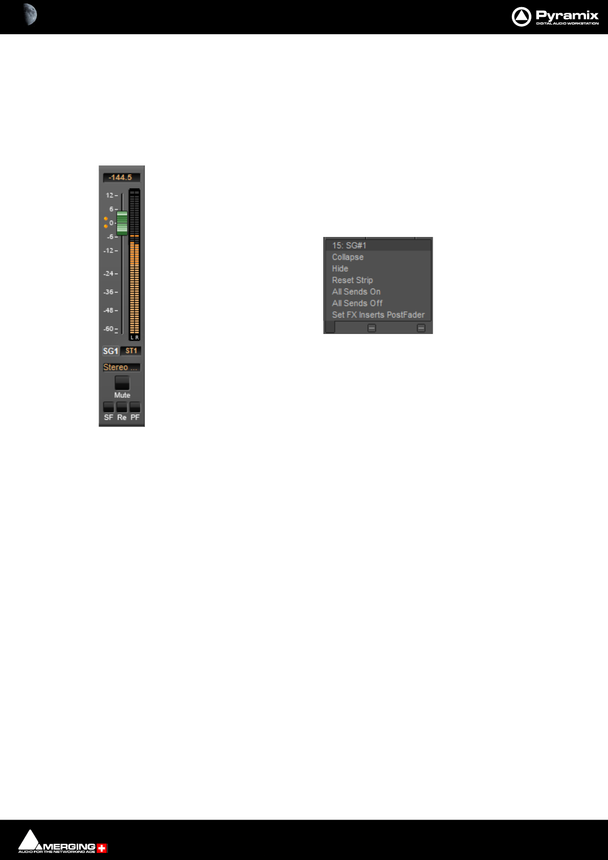
Mixer : Legacy Mixer 10 - 297
GPS Strips feeding any buses (Aux or Mix) are routed by default by Channel Type (like any other strip) but this rout-
ing can be manually changed by clicking on the Channel Routing grid (like any other strip).
Aux Send Buses:
Aux Send buses provide a way to create ‘auxiliary’ mixes which are used to provide headphone or cue mixes for
musicians etc.
SubGroup Buses
SubGroups are a special type of Aux bus which are routed to buses automatically, in exactly
the same way as normal input strips, instead of having output connections. SubGroup buses
offer a quick and efficient means of managing effects channels (e.g. for Reverb plug-ins or
any VST/VS3 plug-in used as Send FX). When using SubGroups there is no longer any neces-
sity to have additional corresponding return strips. In addition, this also enables the use of
post-fader effects. Hover over the strip pop-up and select from the list:
SubGroups have Mute, Solo Safe and PF, Pre-Fader metering, buttons like input strips and
Repro buttons and In Place options like Aux Send buses.
Note: Please be aware that a SubGroup Bus will auto-take Internal Bus connec-
tion resources, starting from the last one. E.g. IB384-IB385 for the first two Sub-
Group Channels added to a Mixer. This means that you will no longer see IB384
and IB385 in the IB list.
Aux Send Bus Channels
Aux Send Buses are intended purely for folding back a mix to musicians etc. and can have from 1 to 8 channels.
Channels have a custom type that can be set manually in the Configuration Page to:
•Left (L)
•Center (C)
•Right (R)
• Surround Left (Ls)
• Surround Right (Rs)
•LFE (Lfe)
•Left Center (Lc)
•Right Center (Rc)
• Surround Center (Cs)
By Default a 2 channel Aux Send Bus is initialized to L-R and a 6 channel Aux Send Bus is initialized to 5.1. This
can be changed/customized in the Configuration Page.
Note: When an Aux Send bus is added it is important to ensure that the Type for each channel of
the Aux Send bus is set correctly.
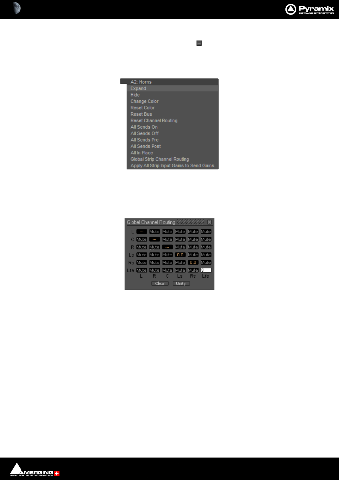
Mixer : Legacy Mixer 10 - 298
Aux Send Bus Context Menu
As with other buses, Clicking on an Aux Send bus’s small gray box on the right-hand edge of the mixer window
Expands / Collapses the send display. When the cursor is above the box the Aux Send Bus pop-up context menu
opens:
Most of the entries are the same as other buses, but the last two entries are specific to Aux Send buses.
Global Strip Channel Routing
Opens the Global Channel Routing window for the Aux Send bus
This routing grid groups together the Channel Types of all the input Strips present in the current mixer, shown
horizontally (L, R, C, ...). The vertical channels are the Channel Types of this Aux Send bus. When a node’s value is
edited, the static aux send gain of all strips having this channel type is updated with the new value for this Aux
Send Bus. When some strips are already set to different values for a specific node “---” is displayed.
Clear Sets the entire grid to Mute
Unity Sets the entire grid to Mute
Note: Invoking either Clear or Unity will affect all Strips Aux Sends to this Aux Send Bus.
Apply All Strip Input Gains to Send Gain
The current input gain value of every strip in the mixer will be applied to all the Aux sends feeding this Aux Send
Bus.
Aux Send bus pop-up context menu
Global Channel Routing window
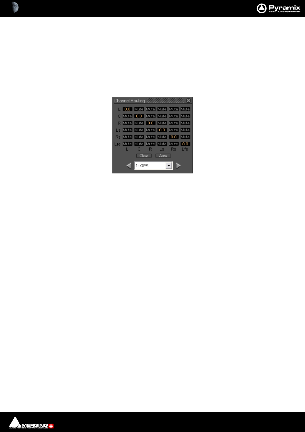
Mixer : Legacy Mixer 10 - 299
Aux Send Routing
When a Strip feeding an Aux Send Bus is of the same type as the Aux Send bus E.g. Stereo strip feeding stereo Aux
Send bus 5.1, Strip feeding a 5.1 Bus the sending Strip’s Channels are automatically routed to the corresponding
Aux Send bus Channel Type. (Left to Left, Right to Right, etc…).
Where the sending Strip differs in Type to the Aux Send Bus E.g. a Stereo Strip feeding a 5.1 Aux Send Bus, the rout-
ing must be made manually. The same method is used if you wish to alter auto-routed values.
Static Channel Routing
Aux Send Channel Routing is set by clicking on the little grid icon adjacent to the knob on the Aux Bus send in the
channel strip. This opens a Channel Routing window:
Shown here with a 5.1 channel feeding a 5.1 Aux Send Bus. Gain values can be entered for each node of the Strip/
Bus crossing. Just click on any node and enter a dB value. Enter nothing (no character) or -144.5 to reset the node
to Mute.
Clear Clears all nodes to Mute
Auto Sets a 1 : 1 flat routing as shown above
Channel Routing window

Mixer : Legacy Mixer 10 - 300
Aux Send Buses In-Place Panning
In-Place panning for each Aux Send bus is turned on with the IP button in Aux Send section(s) of each Input Strip.
In-Place Aux Sends take the output(s) of the appropriate panner at the same level(s) the panner is feeding its out-
put bus.
Note: Only corresponding Bus Types are fed in this way. Thus if you feed a Mono Aux Send Bus
typed Center from a 5.1 panner and there is no signal on the centre channel no signal will be fed
to the Aux Send Bus even if the signal on the left and right outputs is identical creating a ‘phan-
tom center’.
In-Place Panning Source
When an IP button is lit (yellow) on an Input Strip, the way in which the aux send channels are routed to an Aux
Send bus is determined in the Aux return strip. For example, in a mixer configuration with an Aux Send bus, a Sur-
round bus and a Stereo bus. Clicking on the highlighted box below the Aux master fader pops up a list of options:
These determine whether the Aux send will follow one of the output bus panners or the Static Channel Assign-
ment set in the Input Strip. E.g. for Aux Send bus 1:
Off (Use Channel Routing Grid) Aux pan follows Static Channel Routing assignment
SR1 (Surround Mix) Aux pan follows Surround Mix bus panners
ST1 (Stereo Mix) Aux pan follows Stereo Mix bus panners
To make all the Aux 1 sends follow the Mixer Strip Surround Panners, click on the box below the fader and select
SR1 (Surround Mix)
Note: When IP:Off is displayed in the Aux Send master strip I.e. no In-Place source is selected,
then the IP buttons in the input strips will be grayed out. Similarly, when an In-Place source IS
In-Place Panning Indicator/Selector
In-Place Panning Source pop-up

Mixer : Legacy Mixer 10 - 301
selected and the yellow IP button in the input strip is lit then the static routing grid is grayed out
and unavailable as in this illustration.
The three strips shown are 10, 11, and 12. Since the IP button is selected (Yellow) on strips 10 and 11 the static
routing grid is grayed out and thus unavailable. On strip 12 the IP button is deselected (dark) and the Static Chan-
nel Routing grid can be opened by clicking on the grid button next to the knob.
Note: The IP button defaults to On when the aux send is first turned on. If the send is subse-
quently turned Off (muted) then the current setting of the IP button is remembered when it is
unmuted.
Strip Aux sends and Channel Routing dialog
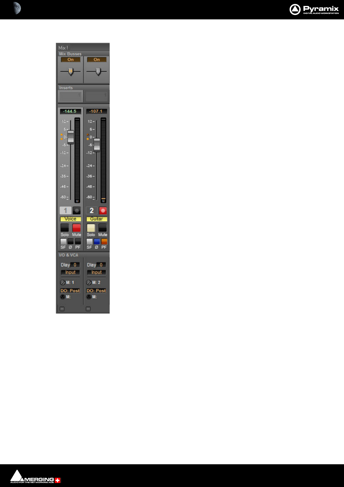
Mixer : Legacy Mixer 10 - 302
Basic Strip
A basic mono channel strip contains:
On /Off toggle switch
Pan slider to Main output bus. In this case there is just a single stereo mix bus.
Inserts area. Expands to suit the number of plug-ins applied.
Numeric display of fader output level value, if cursor is over a fader knob shows fader
gain. If cursor is over pan-slider, shows current pan position. May be clicked to enter a
fader gain value directly.
Level Bargraph Rotary Controls and Faders
Rotary Controls, sliders and Faders may be adjusted by grabbing them with the mouse
and dragging. Rotary controls and horizontal sliders are adjusted by dragging left or
right and faders by dragging up or down. Double-clicking a Fader, slider or Rotary knob
returns the value to the default. E.g. unity gain on a Channel Strip Fader. Holding down
the Ctrl key increaes the resolution to 0.1dB Keyboard up and down arrows adjust
gain by 0.1dB per press, with Shift 0.5dB per press and with Ctrl + Shift 1.0dB per
press. Bargraph shows peak level.
Buttons
Buttons on the main mixer surface are black when inactive. When active they ‘light up’.
Rec enable(d) Enables/disables recording for the associated track. Lights red when
enabled. (Purple when source is after effects.)
Solo solos the strip, Mute mutes the strip Ctrl + Solo cancels all other Solos.
SaFe prevents the strip being muted by solo operations elsewhere. Ø reverses the
channel phase. PF changes the metering position to Pre-Fader.
Delay A delay value (in samples) can be set in this box.
Input Clicking on Input pops-up a box with the choice of the strip taking its input from
a physical connection or any output bus.
Logical Input and Direct Output Assignment
Right-click on the XLR icons to pop-up a drop down list of valid assignments.
Note: Direct Outputs must first be enabled in the Route page. Please see: Channel Direct
Outputs on page 224
Stereo Strips
In a Stereo Strip feeding a stereo bus the single bargraph meter is replaced by a pair and the simple pan pot is
replaced by a choice of Balance control, Dual Panner, Pan/Width or 5.x Legacy Stereo Panner accessible from
the right-click context menu. (See below)
Stereo Strips can reverse the Phase of both the Left and Right channels. The single button has four possible states:
Black: No phase inversion
White: Left channel inverted
Red: Right channel inverted
Blue: Both channels inverted
Basic Strip
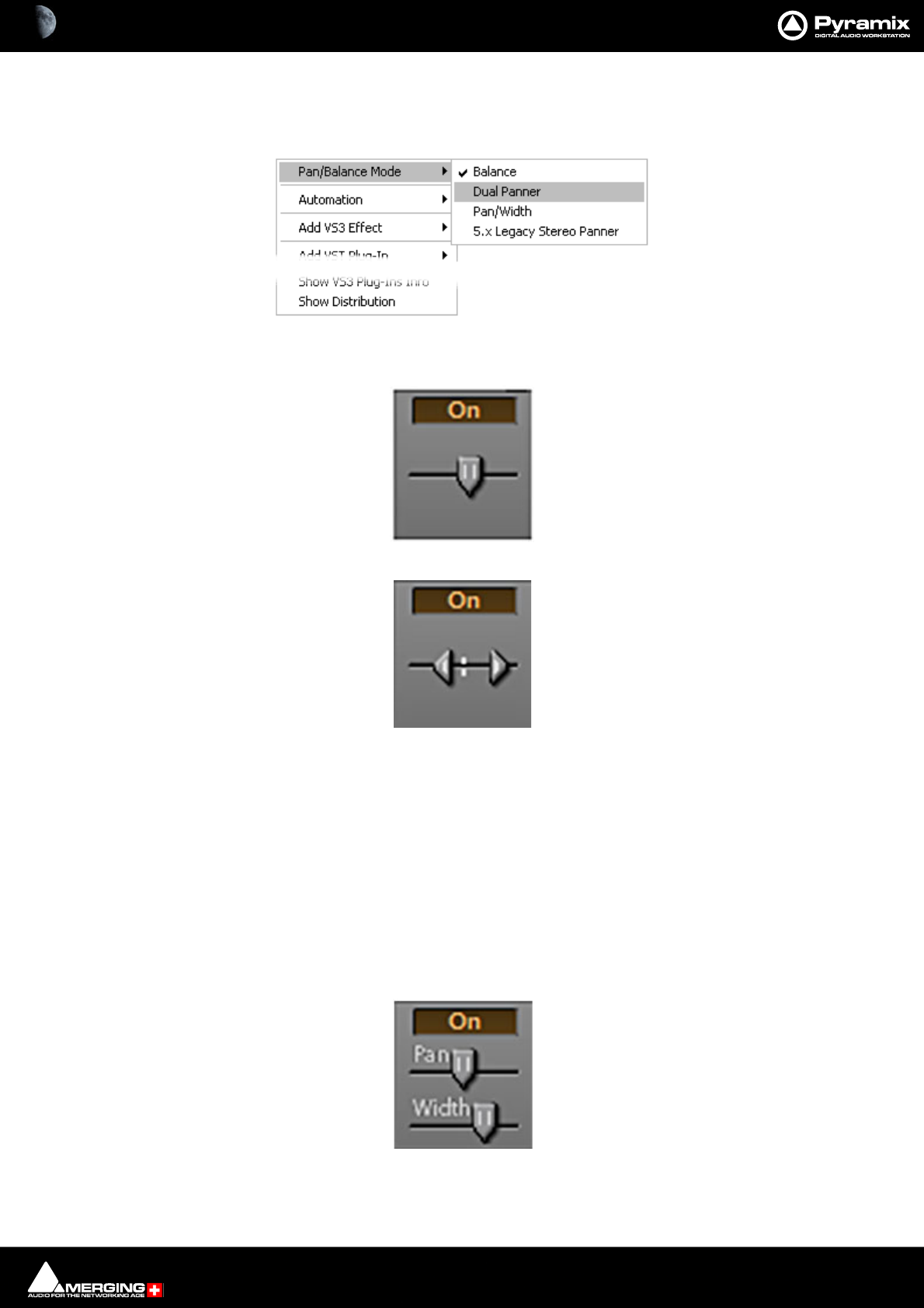
Mixer : Legacy Mixer 10 - 303
Stereo Panners
Pyramix offers a comprehensive choice of stereo panners which can be selected by right-clicking over the panner
to open the context menu:
•Mode 1: Balance
•Mode 2: Dual Panner
To adjust the pan (direction), left click and drag to right or left. To adjust the Width, Ctrl + Left-Click and
drag - The distance between the cursors represents the Width value.
Note: The Width value can be negative (-100% to +100% range), and the 2 channels are then
reversed. I.e. Right becomes Left and vice-versa.
Note: Since the Width range of values and Pan range of values are linked, adjusting the Pan can
cause the Width parameter to be updated, but the initial Width value is restored linearly when
moving the pan back to its former position, just like fader grouping on some mixer desks. To
avoid this (i.e. validate the current Width value), Ctrl + Left-Click on the panner to reset the
cached Width value.
•Mode 3: Pan/Width
Pan slider acts like a normal balance control. Width alters the stereo image width from mono to 100%. If
the SHIFT key is held down while moving the Width slider the range is extended to 125%. I.e. Super wide.
This can be helpful with overly narrow images but should be used with caution.
Stereo Panner context menu

Mixer : Legacy Mixer 10 - 304
•Mode 4: 5.x Legacy Stereo Panner Rotary
V5.x and V4.x legacy panner (for compatibility with older projects)
Default Position Indicators
Like other Pyramix mixer controls the panner knobs/pointers have an orange dot when at the default position.
Gearing
For finer adjustment hold down the Shift key whilst clicking and dragging.
Reset
To reset any of the panners to the default value simply double-click the knob/pointer.
Strip Meters
Characteristics
Meter ballistics and other parameters may be adjusted. Please see Level Meter on page 726
Peak Reset
To Reset Peak Hold and Overload for the entire mixer hold down P when the Mixer is activated.
To Reset the Peak Hold and Overload for a specific Strip or bus Click on the lit Overload LED.
To Reset the Peak hold and Overload of every Strip and Bus Ctrl + Click any Overload LED.
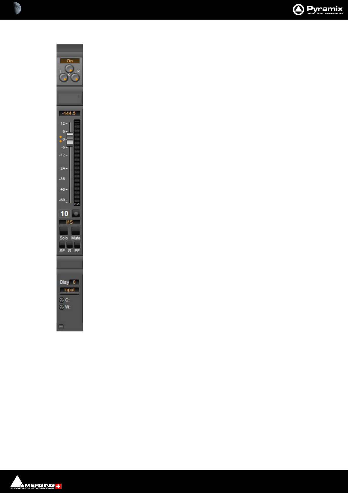
Mixer : Legacy Mixer 10 - 305
M&S Stereo Strips
What is M&S?
M&S stands for Middle and Side. M&S is a microphone technique which outputs Sum and Differ-
ence signals instead of Left and Right (also known as LR, AB or XY). These Sum and Difference sig-
nals are often known as M&S although this nomenclature is often a source of confusion...
Sum and Difference signals can be created from a conventional Left, Right source. For example, by
using the Pyramix MS Encoder plug-in.(Please see: MS Encoder on page 352).
Decoding M&S
A Sum and Difference or M&S decoder reconstitutes Left and Right by adding the Difference (S)
signal to the Sum (M) signal to produce Left and adding the phase-reversed Difference (S) signal
to the Sum (M) signal to produce Right. This is often represented as:
L = M + S and R = M - S
Benefit of M&S
In mixing as opposed to recording, the main practical benefit of manipulating a signal in the Sum
and Difference domain is true control over the width of the image. Pyramix can handle these sig-
nals directly thanks to the provision of M&S Stereo strips.
M&S Strip controls
An M&S strip stereo bus send has three controls. The center knob determines the Sum (M) contri-
bution to the Left and Right outputs. The L knob determines the in-phase Difference (S) contribu-
tion to the Left output and the R knob determines the out-of-phase Difference (S) contribution to
the Right output. The L&R knobs are ganged by default. To move them independently click and
drag with the Ctrl key held down.
The Phase of both the Sum and Difference channels can be reversed. The single Ø button has four
possible states:
Black: No phase inversion
White: Sum (M) channel inverted
Red: Difference (S) channel inverted
Blue: Both channels inverted
Inverting either Sum or Difference results in the image being reversed left to right.
If the Input meters consistently show S higher than M then either the image is very wide and unlikely to be com-
patible for a mono listener or the M and S inputs have become reversed at some point. Regrettably, this is
extremely common when dealing with location recordings in film and TV.
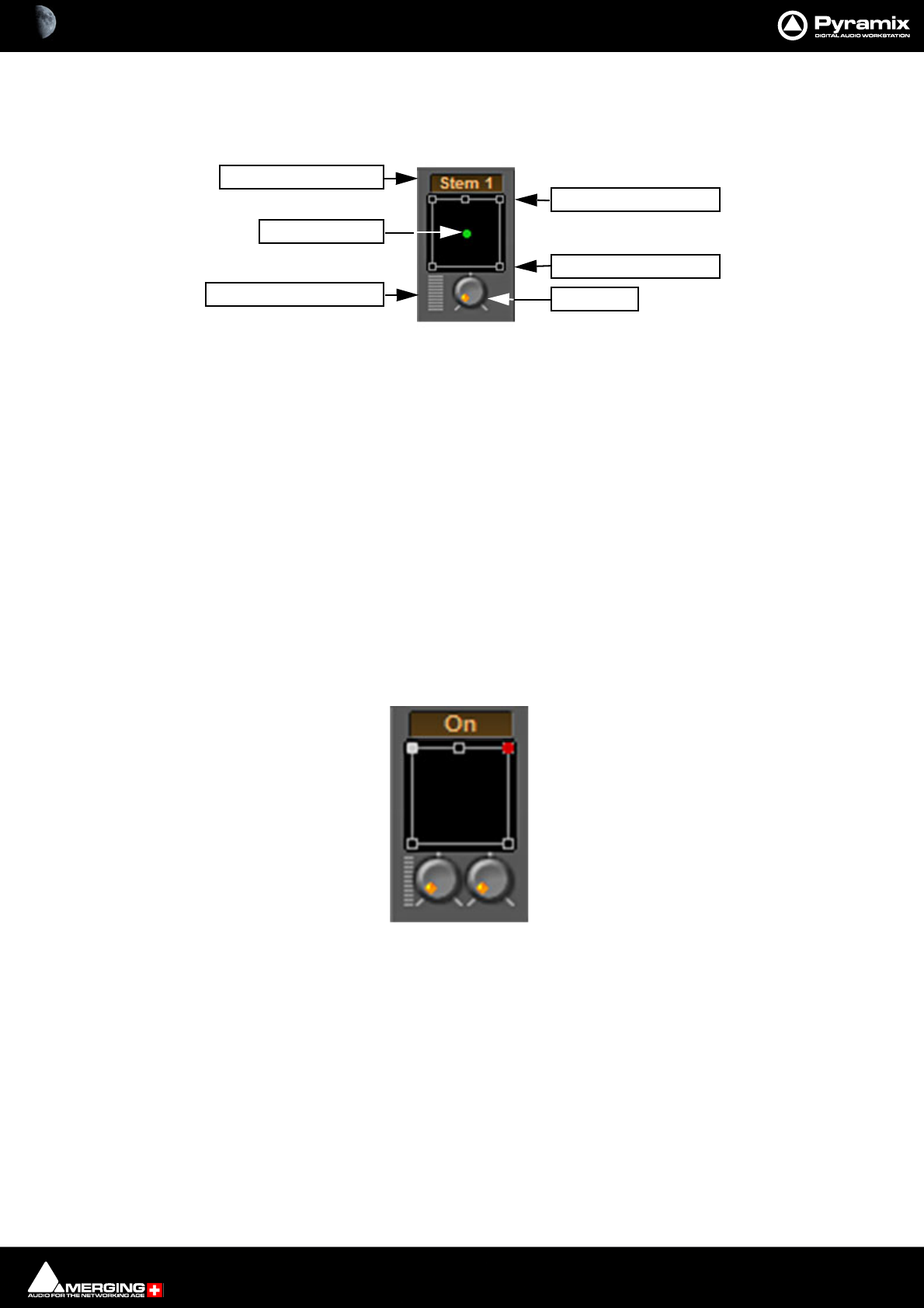
Mixer : Legacy Mixer Surround Components 10 - 306
Legacy Mixer Surround Components
When a Surround Bus is added to the mixer an surround panner appears at the top on the Input Strips
Speaker Controls
Double-clicking on any of the Speaker Controls toggles the mute on/off of the selected surround channel (also
muting any audio routed to that surround channel output). When a channel control is muted, it is no longer dis-
played on the Mixer Input Strip.
Joystick Panner
Determines the position of the source within the surround sound space. To position it, simply left-click on the con-
trol and move it to the desired location. Double-clicking on this control will automatically center it.
LFE Level
Determines the level sent to the LFE (.1) output.
Surround Stem select
If a Multiple Surround Bus has been added to the mixer Stem ‘X’ appears at the top of the strip. Click on the box to
select the stem you wish to route the strip to.
Stereo Input Strips.
The Surround Sound Panner Position control behaves slightly differently in a Stereo Input Strip. Notice there are
now two independent position controls and two independent LFE sends. One for each input channel.
Open Surround Control
The Surround Control window offers far more information and a greater degree of control over all the surround
panning parameters than could be shown on an individual Input strip. It can be opened and closed by Ctrl +
Clicking on the appropriate area on the strip.
LFE Level
Joystick Panner
Surround Stem Select
Open Surround Control
Front Speaker controls
Rear Speaker controls
Strip Surround controls
Stereo strip surround controls
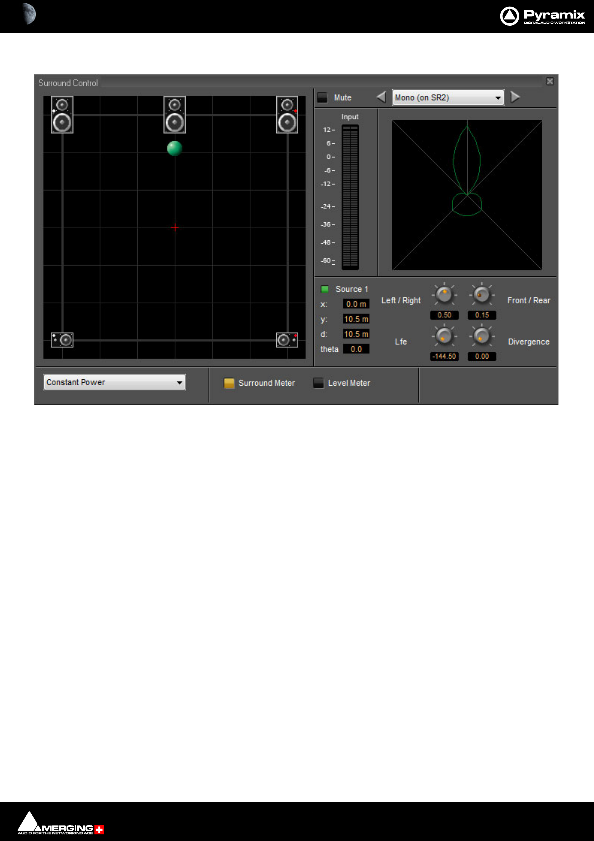
Mixer : Legacy Mixer Surround Components 10 - 307
Legacy Surround Control window
Options available will depend on whether the Mixer Channel is single source (mono) or 2 sources (stereo)
Position/Speaker Control
When a single source is used, the Position Control is displayed as a green dot on a grid with 5 speaker icons. Each
speaker icon represents a Surround Speaker Position (L, C, R, SL, SR). The position of the Green Dot determines the
position of the source within the surround sound space. To position it, simply left-click anywhere within the sur-
round sound space. To position it, simply left-click on the control and move it to the desired location or use the
knobs. Double-clicking on the Green Dot automatically centers it.
Surround Panning Algorithm
The drop down list gives a choice of panning algorithms.
Constant Gain
Allows the surround panning to preserve a constant gain sum on all speakers wherever the Position Control is
placed.
Constant Power
Allows the surround panning to preserve a constant power sum on all speakers wherever the Position Control is
placed.
Surround Control floating Win-
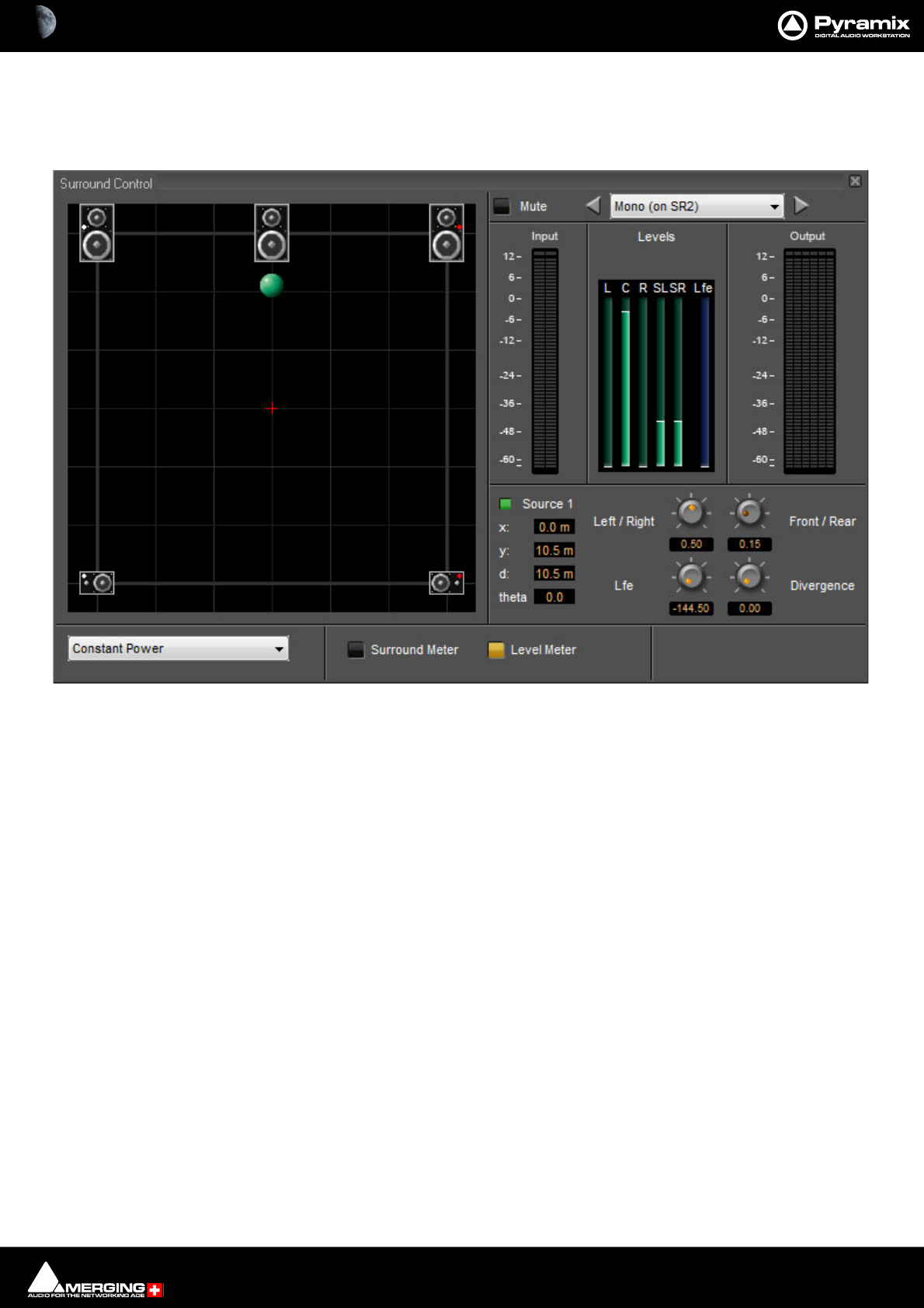
Mixer : Legacy Mixer Surround Components 10 - 308
Level Meter
Toggles the main display between the Surround Meter and Level Meter. This shows the send Levels to each sur-
round channel in the middle of the right-hand section and Output meters on the right:
Surround Control floating Win-

Mixer : Legacy Mixer Surround Components 10 - 309
Stereo Surround Control
Surround Meter
The Display can show static Left, Right and Summed Lobes in white, red and yellow, respectively when the buttons
are lit with the actual signal in bright red.
Link
Click and drag on the red and white balls is independent and the controls are switched between Source 1 and
Source 2 by clicking on the buttons. If a Link option is chosen from the combo box click and drag and the controls
will affect both sources depending on the chosen linking.
Surround Control floating Win-
Surround Control Link combo box

11 - 310
www.merging.com/Pyramix
USER MANUAL
Monitor
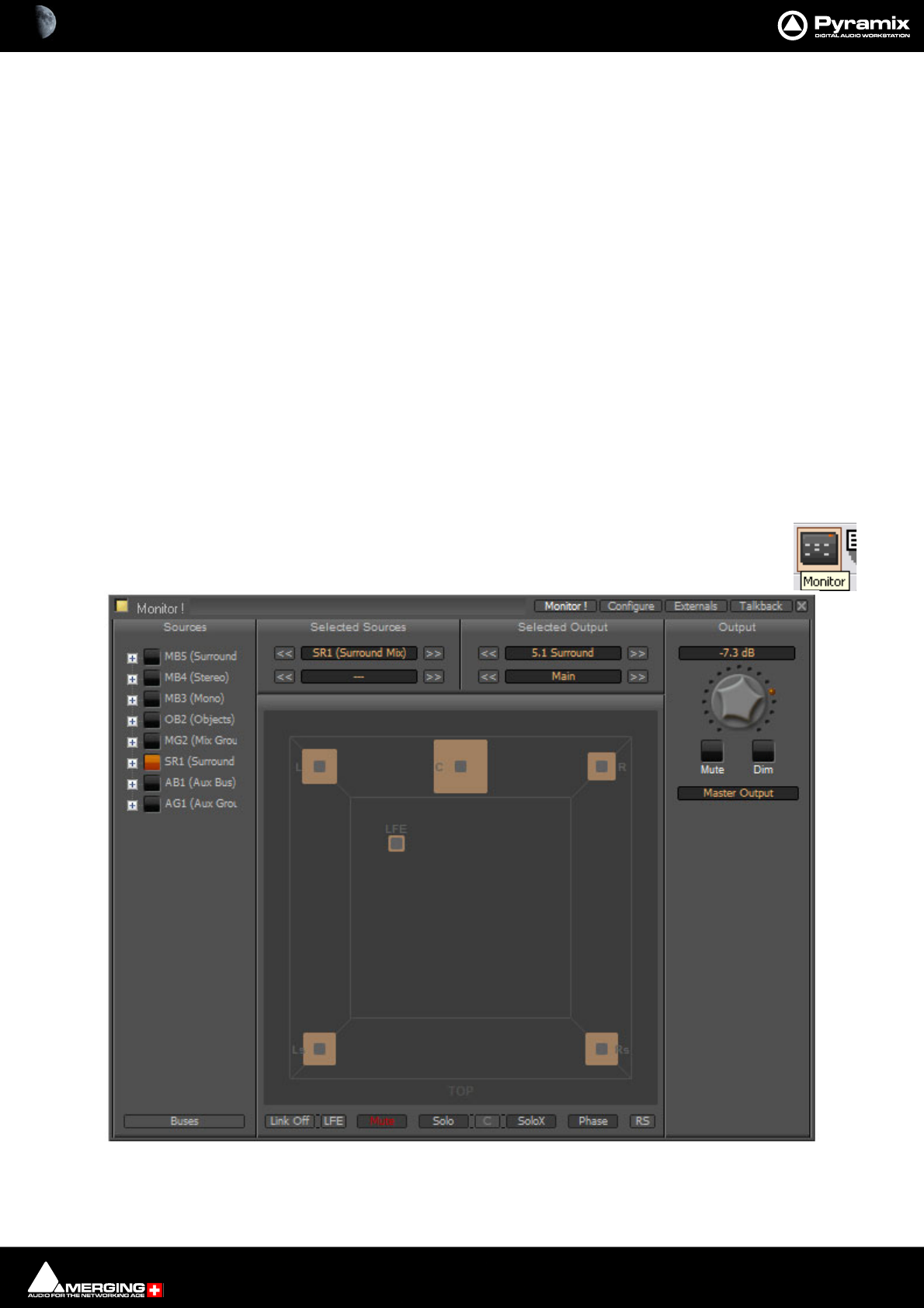
Monitor : Monitor ! Window 11 - 311
Monitor ! Window
Scope
Pyramix has a dedicated Monitor section. This extremely powerful tool offers comprehensive monitoring facilities
including summing and downmixing for all supported formats. External Machine Inputs, comprehensive Talkback,
Foldback and External Metering are also supported depending on your system specification.
The Monitor presents monitor outputs of all buses present in the current Mixer as sources. It is also possible to
configure external sources both for recorder returns and for talkback. Sources can be summed for monitoring
without affecting the Mixer bus outputs. This is useful, for example, when you need to listen to a guide track while
recording.
You do not have to use the Monitor and disabling it will save DSP power but, with complex Mixers and routing,
the Monitor helps to keep things logical.
The monitor is also used to output the audio signal from the audition function of the Media Manager and Libraries
as an unformatted input. (I.e. Routed to LRC in a Surround 5.1 Speaker Set and to LR in a Stereo one)
Monitor Hardware Control
Many functions of the Monitor can be mapped to a hardware controller or to the keyboard. To facilitate this, the
commands are available in the Monitor menu. Please see the documentation for your hardware controller,
Remote Control on page 583 and Customizing Keyboard Shortcuts on page 509.
By default the Monitor window is shown. It can be opened with View > Monitor or toggled with the
icon in the View Toolbar.
The Monitor has four pages: a Main Monitor ! page in normal operation, a Configure page for setting up and two
further pages for configuring Externals (machines) and Talkback.
Monitor Main Monitor ! Window
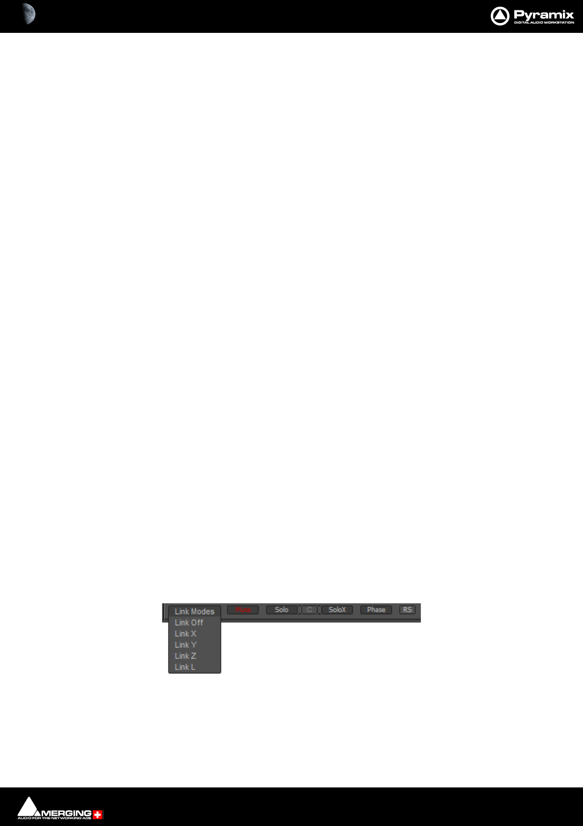
Monitor : Monitor ! page 11 - 312
Monitor ! page
The Monitor ! window is divided vertically into three sections.
Sources, left-hand section:
The button top-left of the title bar enables/disables the Monitor and lights yellow when enabled. This allows DSP
power to be saved when comprehensive monitoring control is not required. Below the Enable Monitoring but-
ton is a tree view of all buses used in the mixer. Clicking on the + and - boxes shows and hides branches in the
usual way. Click on any complete bus or any available stem or any bus/stem channel to select it for monitoring.
Selection is exclusive unless the Ctrl key held is down. Then selection is cumulative and clicking adds or subtracts
Sources according to their current state.
Buses / Externals button
Note: At bottom left in the screenshot above the button labelled Buses indicates which sources
are available for activation. Clicking on this button toggles through Buses, Externals and Buses
/ Externals.
Note: Multiple selections are made by holding the Ctrl key and clicking.
Main, centre section:
Selected Sources
<< SR1 >>: Select previous/next Pyramix source. Only sources visible in the Sources section are available. I.e.
If the component channels of a bus or stem are collapsed this bus or stem is switched as a unit when the compo-
nent channels are visible in the Sources section then clicking on the << or >> buttons steps through each avail-
able channel in turn.
<< -- -- >>: Select previous/next External Source. Only External Sources visible in the Sources section are avail-
able.
Note: Clicking on any of the << or >> buttons cancels the selection made previously in the
Sources section.
Selected Output
<< Surround 5.1 >>: Select previous/next Speaker Set.
<< Main >>: Select the previous/next Downmix defined in the Configure page.
Main area
Speakers are only shown when connected in the Configure page.
Halo Meters
The speakers have “halo” meters as seen above. The bigger the colored area, the louder the speaker.
The buttons at the bottom determine the linking and function of the active Speaker buttons.
Link Clicking on this button pops up a list of possible Link Modes.
Link Off No Link is applied to parameters selected (Mute, Solo, Solo X, Phase...)
Link X Links Left and Right (and everything along the X axis).
Link Y Links the Front with the Back (and everything along the Y axis).
Monitor Buttons

Monitor : Monitor ! page 11 - 313
Link Z Links the associated speaker in all the height layers Tl +L + Bl etc.
Link L Links the associated speakers that are on the same Z layer.
LFE Includes the LFE Speaker(s) in the Link Group.
Mute Clicking on a speaker mutes it. Selections are cumulative.
Solo Clicking on a speaker solos it. Selections are cumulative.
C Works in conjunction with Solo and SoloX. Toggles between In Place and Center.
Center routes the soloed channel(s) to the Center speaker or equally to the L/R
speakers if no center speaker is present. In Place mode is the normal Solo, SoloX
mode.
SoloX Solo eXclusive on the clicked speaker. Selections toggle.
Phase Toggles the phase of the selected speaker(s). Useful for quick image checks.
RS Reset. Deselect all speakers.
Output, right-hand area
Monitor Level box Displays the current output level. Output level can be entered numerically in the box after
clicking on it.
Volume Knob: sets all the output gains in a range from -144.5dB to +24dB. Double-click to set it to 0dB.
Note: Maximum permissible volume can be set in the Configure page.
Mute: button mute the outputs.
Dim: button reduces the output level by an amount set in the Configure page. Default value is -20dB.
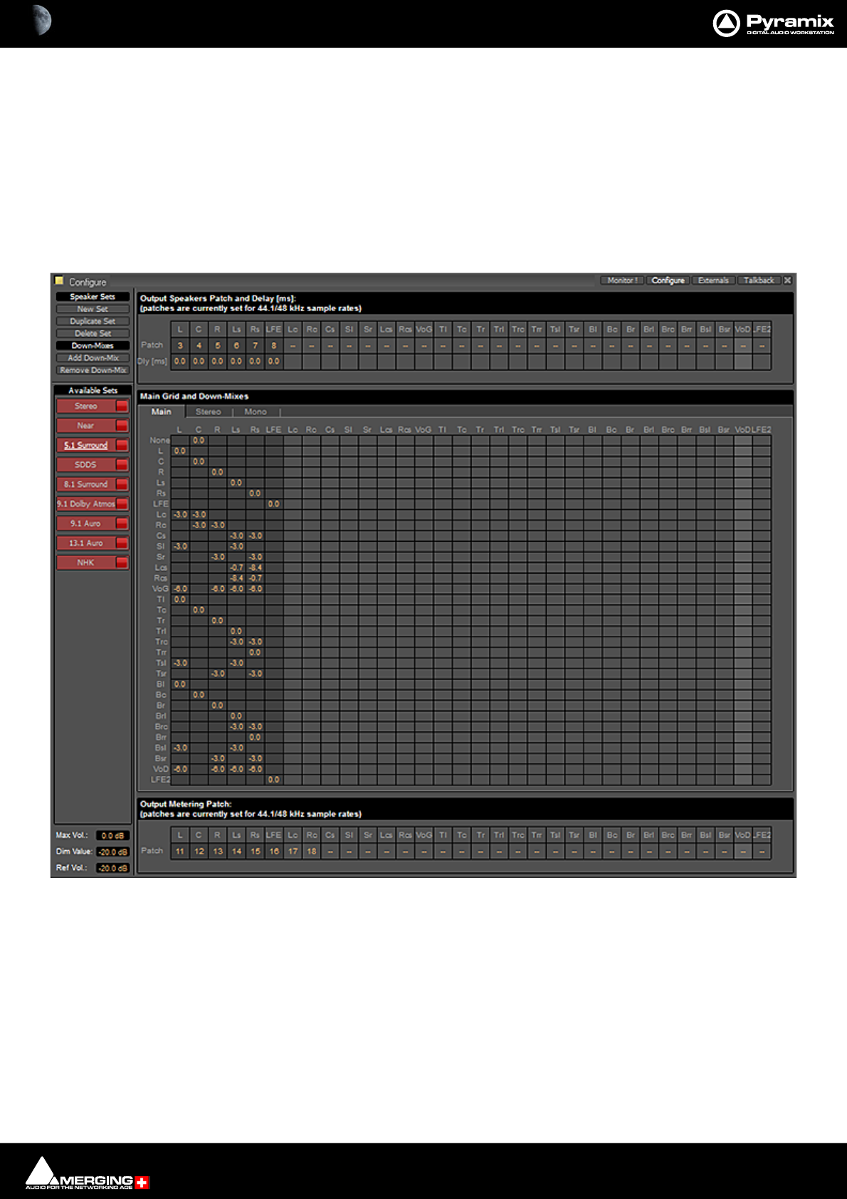
Monitor : Monitor ! page 11 - 314
Speaker Sets
Speaker Sets are set-up in the Configure page.
A speaker set consists of:
A Patch: This connects signals to the physical outputs of the output device(s). The number of connection will
depend on the number of speakers you want to connect. Since the number of available live outputs depends on
the selected sampling rate, the patch will differ for 1Fs, 2 Fs, 4Fs and 8 Fs sampling rates.
A Main grid: this matrix defines the relation between the Mixer’s buses output channel types and the monitor’s
output channel types (thus the monitor’s physical outputs).
A set of Downmixes (max: 4) : A downmix is a an alternative grid which uses the same patch as the main grid. In
this page you can patch the outputs of you monitor, add/remove downmixes, and defines the corresponding grids
in dB (only the channel types which are patched).
Monitor Configure Window

Monitor : Configure page 11 - 315
Configure page
The Configure page enables multiple Speaker Sets, each with multiple down-mixes, to be created and edited.
Nine factory Speaker Sets (On the left of the page, labelled on a red background at the top of the Speaker Sets
list) are installed with Pyramix. Their Main channel to speaker Main Grid and Down-Mix assignments cannot be
changed, but their output Patches from speakers in the Monitor to physical outputs can.
Speaker Types
The following Channel/Speaker Types are available:
None (Channel Type only. Used for Buses and Media with no Type assigned.)
LLeft
CCenter
RRight
Ls Left Surround
Rs Right Surround
LFE Low Frequency Effects
Lc Left Center
Rc Right Center
Cs Centre Surround
Sl Side Left
Sr Side Right
Lcs Left Surround Center
Rcs Right Surround center
VoG Voice of God
Tl Top Left
Tc Top Center
Tr Top Right
Trl Top Surround Left
Trc Top Surround Center
Trr Top Surround Right
Tsl Top Side Left
Tsr Top Side Right
Bl Bottom Left
Bc Bottom Centre
Br Bottom Right
Brl Bottom Surround Left
Brc Bottom Surround Center
Brr Bottom Surround Right
Bsl Bottom Side Left
Bsr Bottom Side Right
VOD Voice of Devil
LFE2 Low Frequency Effects 2
Factory Speaker Sets
Stereo
Near
5.1 Surround
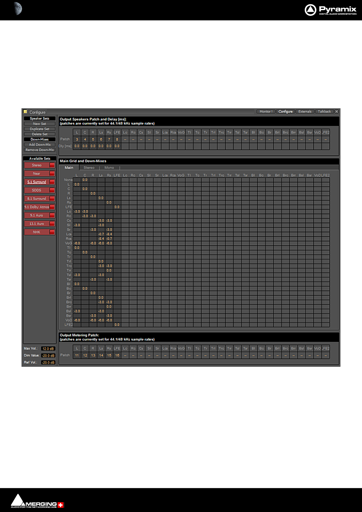
Monitor : Configure page 11 - 316
SDDS
8.1 Surround
9.1 Dolby Atmos
9.1 Auro
13.1 Auro
NHK
They and each of their down-mixes can be enabled/disabled in order to determine which ones are visible in the
main Monitor page.
The Configure page is divided into four main areas; Speaker Sets and Down-Mixes, Available Sets, Output
Speakers Patch and Delay[ms], Main Grid and Down-Mixes and Output Metering Patch.
Available Sets
To select an existing Speaker Set in order to view or alter its settings, click on its title in the Available Sets list. The
label will become underlined and the Set’s parameters will appear in the grid. If the Set has Down-Mixes already
defined there will be one or more tabs next to the Main Tab in the Main Grid and Down-Mixes area.
Nine sets, Stereo and Surround 5.1 are factory defined and cannot be altered. New Sets and Down-Mixes can be
Created, Duplicated and Deleted using the Command buttons.
Max Vol:
Monitor Configure Window
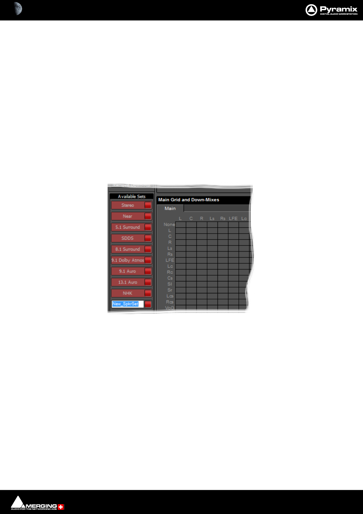
Monitor : Configure page 11 - 317
To set the Maximum Volume attainable click on the value box to highlight it and type the desired value in the
range 0.0dB to 36db then hit Enter or click elsewhere on the window to save the change.
Dim Value:
To change the Dim Value Level, click on the value box to highlight it and type the desired attenuation value then
hit Enter or click elsewhere on the window to save the change.
Note: Only negative values are accepted. Positive values revert to 0dB. I.e. Type -15 etc.
Ref Vol:
To set the Reference Volume level click on the value box to highlight it and type the desired value in the range -
20dB to 0dB then hit Enter or click elsewhere on the window to save the change.
Commands
Speaker Sets
New Set
Clicking on New Set creates a new Speaker Set with a blank matrix Grid and adds a new entry to the Available
Sets list with the label highlighted ready for text entry:
Type a suitable name and click on a blank area or hit ENTER to accept the name.
Duplicate Set
Creates a new Speaker Set with a the same matrix Grid settings and Down-Mixes and settings as the set currently
selected (underlined) and displayed in the grid. The new label is highlighted ready for text entry.
Delete Set
Deletes the currently selected (underlined) Speaker Set.
Down-Mixes
Add Down-Mix
Creates a new Down-Mix associated with the currently selected Speaker Set with a new tab in the Main Grid and
Down-Mixes section.
Remove Down-Mix
Deletes the current Down-Mix
Monitor Configure New Speaker Set
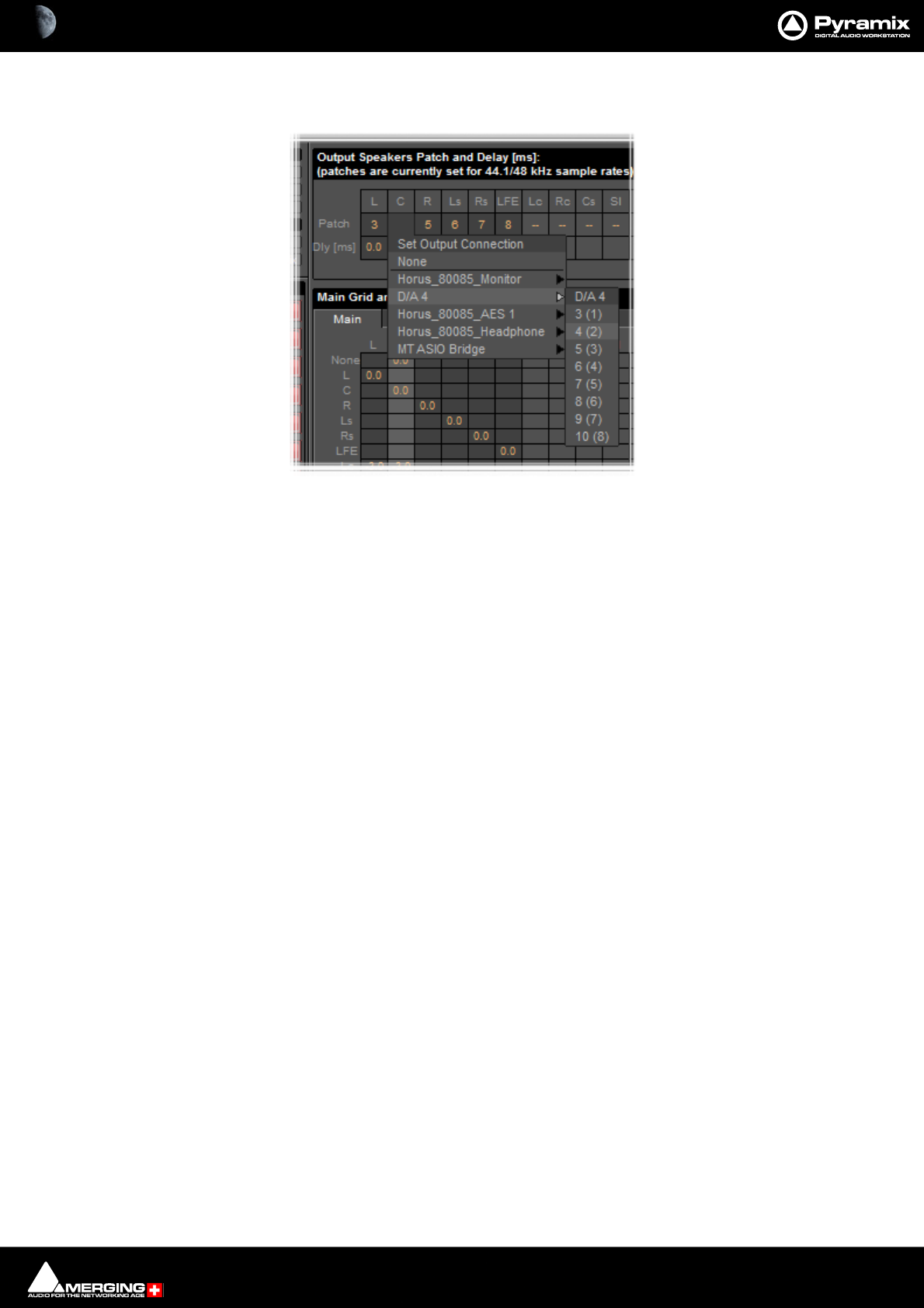
Monitor : Configure page 11 - 318
Output Patch:
This is where the Monitor’s Speaker Set outputs are patched to physical outputs.
Clicking on a cell pops up the Set Output Connection menu with all available physical outputs grouped by their
connectors. The sub-menus list the group and the individual channels. Select an individual channel to connect it
or select the group, e.g. D/A 4 to connect the whole group in ascending order from the cell clicked on.
Note: Each Speaker Set has its own Output Patch associated with it. This is useful where differ-
ent speakers are used for different formats. If there is only one set of speakers patch all Speaker
Sets to the same physical outputs.
Double Assignment
When an output of the Mixer and an output of the Monitor are connected to the same physical output then these
are summed and the Mixer displays the connection in orange as a warning.
Speaker Delays
Delay can be set per Speaker by clicking in the box below the Output Connection and typing in a value. Speaker
delays are typically used to compensate for the physical positioning of the loudspeakers for example where the
Left Centre and Right speakers are placed in a straight line, the Centre speaker will be nearer to the listening posi-
tion and should be delayed accordingly.
Saving Speaker Sets
Mixer to Monitor connection status is saved in the project.
The Speaker Set settings are saved when you leave the page to go back to the Monitor ! page; otherwise, modifi-
cations are not saved.
Monitor Configure Output Patch
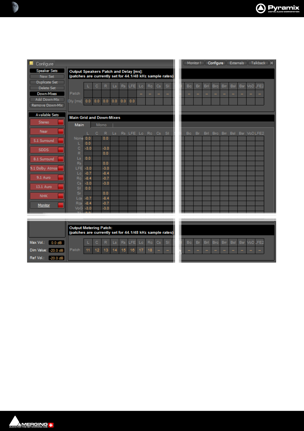
Monitor : Media Manager and Library Monitoring 11 - 319
Media Manager and Library Monitoring
The Pyramix Monitor Panel is used to audition Cues in the Media Manager and Libraries.
Note: The None channel type is used to monitor media which do not have a channel type set in
metadata. In order to be able to audition such media in the Media Manager and Libraries the L
and R None entries in the Main Grid matrix must be set to a value, e.g. 0.0.If you plan to audition
Surround material also set the C entry to a value e.g. -3.0.
Monitor Configure Media Manager
Monitor : External Metering 11 - 320
External Metering
If you wish to use your favorite external hardware meters with Pyramix this can be achieved easily and conve-
niently.
Under the Main Grid of the Monitor Configure page an extra set of 32 patches is provided to configure external
outputs specifically for metering.
Patches are made in exactly the same way as the Speaker Output Patches. Please see: Output Patch: on
page 318
External Inputs
External devices may be added in the Monitor panel. This is useful for connecting monitoring returns from the Stu-
dio’s fixed external audio devices such as recorders.
Monitor Configure Output Metering Patch
Monitor : External Inputs 11 - 321
Adding an External Machine
Up to 8 new externals can be added.
Note: External machines will only be visible and available as monitor sources in the Monitor !
page when the Buses /Externals button is set appropriately. Please see: Buses / Externals
button on page 312
Each external has a dedicated input Patch. Patches are set up by clicking in the boxes below the speaker letters
and choosing inputs from those available.
Monitor Externals page
Monitor : Talkback 11 - 322
Talkback
Talkback facilities are provided in the Monitor section for studios without a separate talkback system.
These facilities are intended to be used with GPI/O external connections for physical talkback switches.
Please see: GPI / GPO Support on page 596 for information about setting up GPI/Os.
When Talkback is set up and active the Talkback section appears at the bottom of the main Monitor ! page:
Monitor ! page with Talkback Section
Monitor : Talkback 11 - 323
Setting Up
Talkback Page
You can add up 8 Studios (Destinations) and 3 Talkbacks (Sources) in the Talkback page:
Destination
Add Adds a Destination
Delete Deletes the selected Destination or the remaining one when there is only one shown.
Source
Add Adds a Source
Delete Deletes the selected Source or the remaining one when there is only one shown.
Record reset latch
When lit red all active conversations are muted when the transport is in Record.
Play reset latch
When lit green all active conversations are muted when the transport is in Play
Stop enable talk to all
When lit yellow the Talk To All function is activated when the transport is in Stop.
Example
This is how you would set up talkback for a simple facility with a Mix Room, Studio and Machine Room.
•The Mixer will be able to speak to the Vocal Booth or the Machine Room independently.
•The Assistant will only be able to speak to the Mix Room.
•The Vocal Booth will only be able to speak to the Mix Room.
Monitor Talkback page
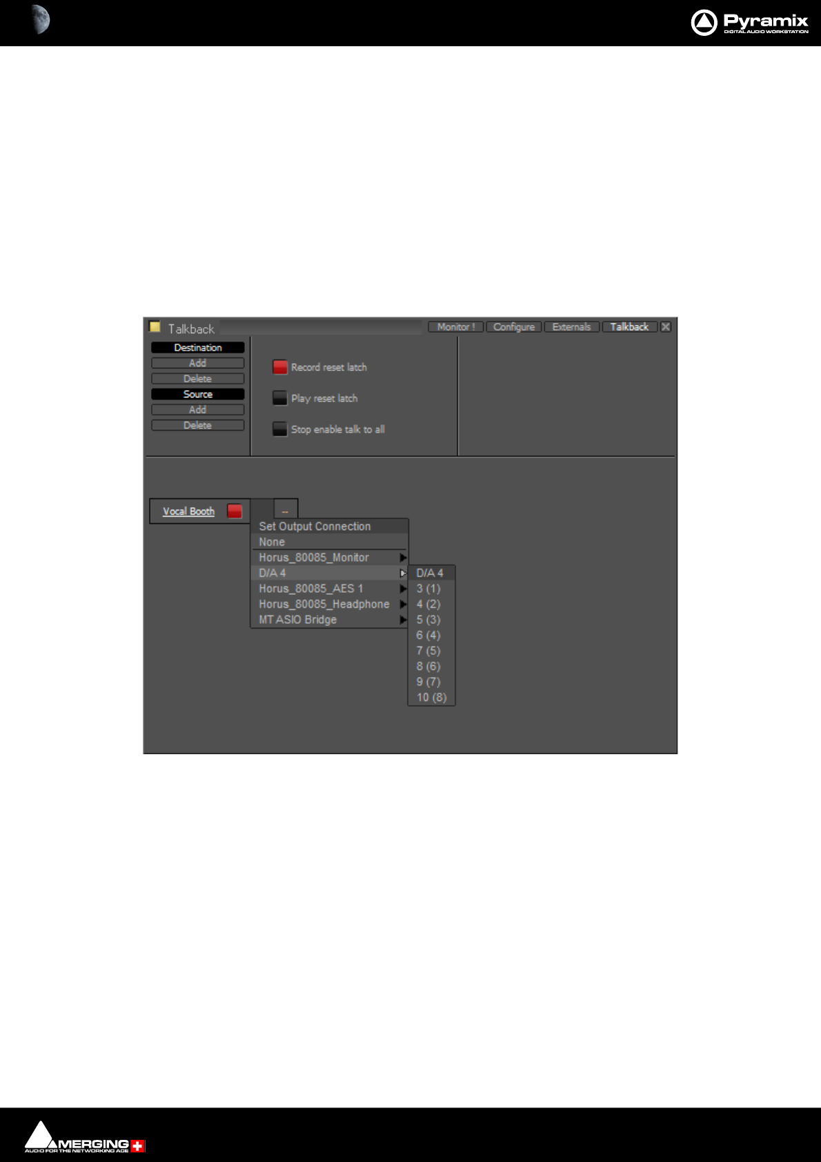
Monitor : Talkback 11 - 324
Note: If a separate ‘Producer’ Talkback unit is required this can be achieved with a simple parallel
physical connection of buttons that both activate the Mixer to Vocal Booth GPI.
Setting Up
1. Click on Studio Add
A New Monitor Studio box appears. Type a suitable name for the Studio, in this case, Vocal Booth and press
the keyboard Enter key to confirm.
The red button indicates that the destination is active.
Note: The Talkback section will be shown at the bottom of the Monitor ! page if any destina-
tions are active in the Talkback page.
2. Notice the two boxes to the right of the name with orange dashes. Click on the left box to drop down the Set
Output Connection menu:
3. choose a suitable physical output to feed the Talkback amplifier/loudspeaker.
Note: If you only have digital outputs then you will need a converter.
4. If you wish to have stereo talkback/foldback repeat steps 2&3 for the right-hand box. Here only the Vocal
Booth is to be fed with Foldback so that is the only stereo destination.
5. Repeat steps 1 to 3 twice to add two more destinations.
6. Label these to suit, in this case, Mix Room and Machine Room.
Monitor Talkback page Destination Output Connection

Monitor : Talkback 11 - 325
You should now have something like this on screen:
Note: Only the Vocal Booth has been set up as a stereo destination. If you want separate speaker
and headphone feeds to the studio just add another destination and label it appropriately. E.g
Vocal Booth HP for maximum control.
7. Now set up the sources by clicking on Source Add
8. A column appears with New Talker highlighted in a box. Type a suitable name for the source. In this case
Mixer.
Monitor Talkback page with destinations
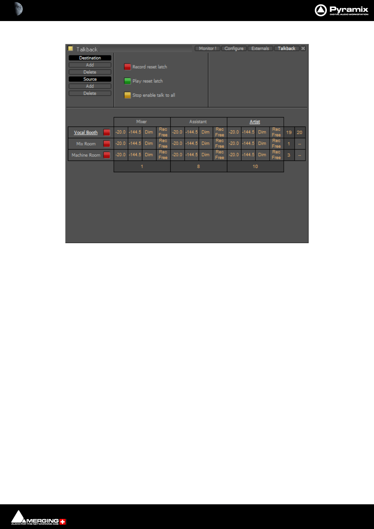
Monitor : Talkback 11 - 326
9. Add two more sources and label them Assistant and Artist
10. Click on the boxes with the orange dashes at the bottom of each source column to open the Set Input Con-
nection menu and choose a suitable input connection for each of the talkback microphones.
Note: If you only have line level analogue inputs you will need external mic pres and if you only
have digital inputs then you will need converters as well.
11. Now the levels, Dim and Mute switching must be set.
• The boxes in the first column of each Source set the attenuation that will be applied to the Destina-
tion output when Talkback is activated from each source.
• The second column sets the send level per Destination. You can type mute or a numeric value in
the box.
Note: If mute or -144.5 is entered this Destination will be grayed out and unavailable in the
Talkback section of the Monitor page. For example, it is illogical for the Mixer Source to talk to
the Mix Room Destination and so on.
• The third column offers the choice of Dim or None. Selecting Dim means that when this crosspoint
(Source to Destination) is activated by pressing the relevant Talk button, the Main Monitor Out-
put will be dimmed.
Note: This is essential when, for example, the Mix Room talks to the Vocal Booth with the pro-
gramme mic channel open to avoid howl-round and possible damage to loudspeakers and hear-
ing.
• The fourth and final column offers a choice between Rec Free and Rec Loc.
Rec Free means that talkback on this crosspoint can be initiated when the Transport is in Record and
the Record Reset Latch is set.
Rec Loc disables the crosspoint when the Transport is in Record and the Record Reset Latch is set.
Monitor Talkback page with Sources and Destinations
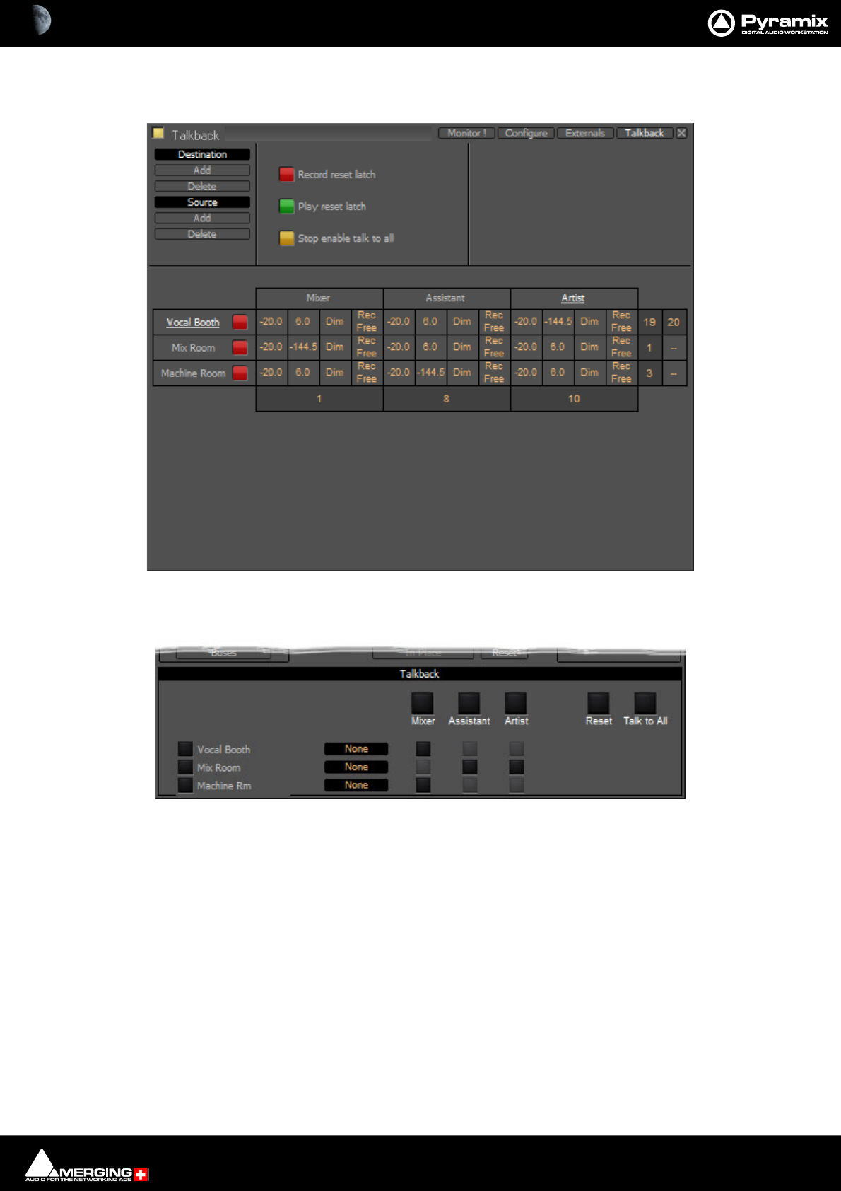
Monitor : Talkback 11 - 327
So, bearing in mind who is going to be allowed to talk to whom and given that it is illogical to use talkback to talk
to yourself, the levels should now look approximately like this:
Returning to the Monitor ! page you will see this in the Talkback section:
(If the buttons on the left are lit blue ignore them for now) The big buttons with the labels Mixer, Assistant and
Artist are Talk to All destinations (In this case only relevant to Mixer)
Monitor Talkback page with Sources and Destinations and levels set
Monitor ! page Talkback Section
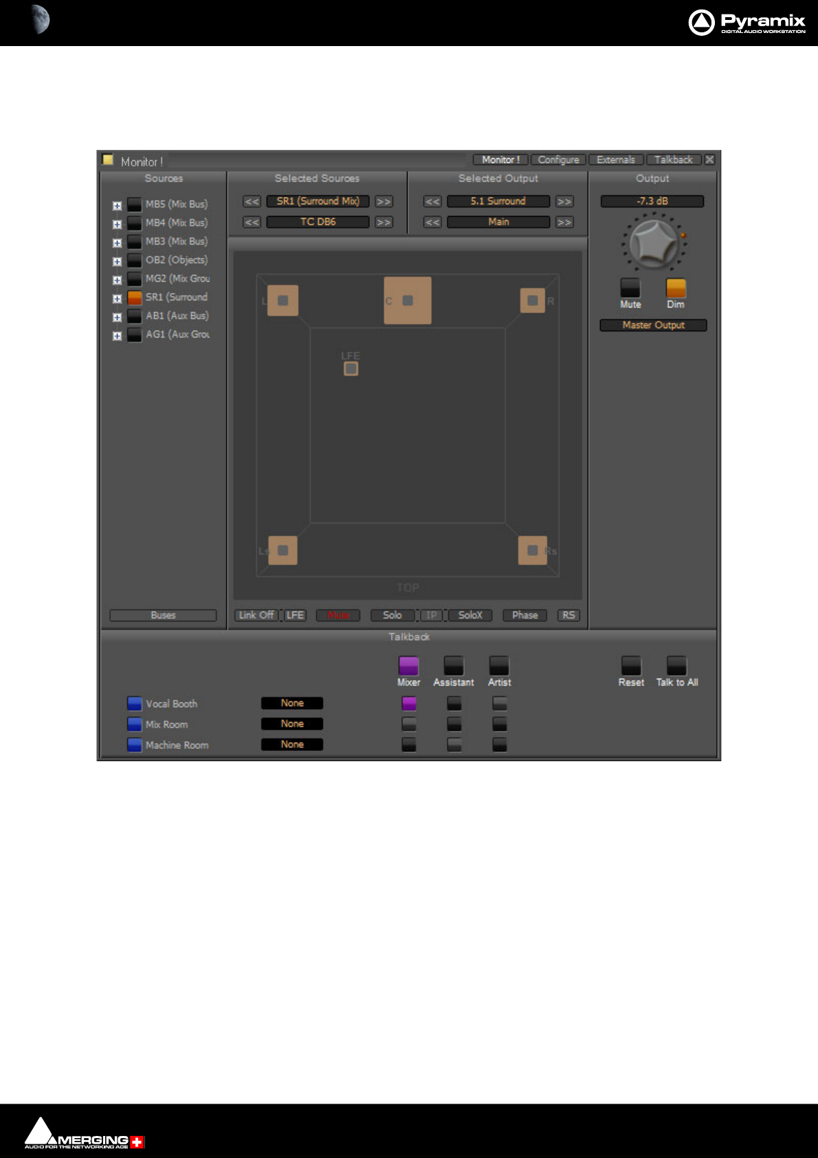
Monitor : Talkback 11 - 328
Operation
The smaller buttons vertically below the bigger, labelled Source buttons initiate talkback from the horizontal
sources to the vertical destinations. These are the buttons you are most likely to want to map to GPIs. For example
in the following screenshot the Mixer is talking to the Vocal Booth:
Note: Notice that, due to the settings made earlier, Mixer talking to Vocal Booth also Dims the
Main Monitor Output.
Talkback Button Operation
All the Talkback buttons are dual mode. A press of less than one second latches the Talkback open. A second press
cancels. A press of more than one second initiates Talkback on press and cancels when the button is released.
Reset cancels all latched talkbacks.
Talk to All initiates open Talkback between all enabled Sources and Destinations
Monitor Talkback page : Mixer talking to Vocal Booth
Monitor : Talkback 11 - 329
Foldback
Continuing the foregoing Talkback example it is also possible to add foldback to the Talkback outputs. To add
Foldback to the Vocal Booth Talkback outputs click on the black box to the right of the Vocal Booth label to drop-
down a list of available Foldback sources:
Select the required Foldback Studio Monitor Source.
Note: You can add a bus in the mixer specifically to produce a mix for Foldback.
Monitor Talkback page : Select Foldback Source
Monitor : Talkback 11 - 330
The buttons on the left of the Vocal Booth label etc. toggles the foldback on and off per destination:
Here, the Vocal Booth is fed with MB3 (Mix Bus) output. The vocals are recorded clean on MB1 (Mono Mix) and,
as can be seen above, the Mixer Room monitors are being fed with the sum of these buses.
Monitor Talkback page : Foldback to Vocal Booth Active

12 - 331
www.merging.com/Pyramix
USER MANUAL
Meter Bridge

Meter Bridge : Meter Bridge 12 - 332
Meter Bridge
Scope
Pyramix has a dedicated Meter Bridge window.
The Meter Bridge can present a meter display for every Input strip and Bus present in the current Mixer and exter-
nal Machine configured in the Monitor : Externals page.
The Meter Bridge also indicates the currently selected mixer strip with a yellow outline, any strips in Record Ready
condition with a red outline, whether any strips are Muted or Soloed and optionally shows Ramses Groups and
Fader Automation mode per strip.
Meter ballistics and alignment are adjustable either manually or via presets.
You do not have to use the Meter Bridge but, especially when used with Ramses MSC, it offers flexible metering
in one place. With complex Mixers and routing, the Meter Bridge can help to keep things logical.
General Purpose Buses
The new General Buses are supported for Mix and Aux Buses, Groups are not supported currently.
Note: The Meter Bridge is displayed “Always On Top” of other windows.
Meter Bridge Switch
The Meter Bridge Window is enabled/disabled via View > Windows / Tools > Meter Bridge or from the Toolbar
Icon or by mapping the function to a short-cut key.
Meter Bridge Switch
Meter Bridge : Meter Bridge 12 - 333
Meter Bridge Window
By default the Meter Bridge window is hidden. It can be opened with View > Meter Bridge or the icon in the
View Toolbar.
Meter Bridge Window - Triple Row Mode
Meter Bridge : Meter Bridge 12 - 334
Resize
The Meter Bridge Window can be resized by clicking and dragging the edges. (Mouse cursor changes to double
arrow) Vertical resizing is limited to sensible display options. Scroll bars will appear when there is more informa-
tion to display than the window can accomodate.There is a separate auto-hide scroll bar for the Input Strips so you
can keep all the Buses and Externals visible together with a contiguous section of the Input Strips of a very large
mixer. (This will appear when the mouse cursor is over the right-hand edge of the top two rows.)
Auto Size
Double-clicking the caption bar positions and resizes the meter window automatically to a third of the available
screen height for a single row display, half screen height for a two row display and the full screen height for the
three row display mode.
Global Mute and Solo Indicators
If any mixer strip is Muted or Soloed the global indicators in the left margin illuminate.
Note: Active Track Mutes and Solos are not shown in the Meter Bridge.
Selected Strip and Record Ready Status
When Auto-select Active Strip is switched on in the configuration section the currently selected strip is shown
with a yellow outline.
Any strips currently in Record Ready mode are shown outlined in red.
Configuring the Meter Bridge
When first opened the Mixer Bridge appears as above. clicking on the double arrow >> below the Yellow Activate
button opens the Display panel (a subsequent click on the << arrows closes):
Layout
The three buttons determine whether the meters are displayed as a single, double or triple row (default).
Meter Bridge Configuration : Display Section
Meter Bridge : Meter Bridge 12 - 335
Single Row
Single row is useful if you only wish to display buses and or Externals (returns).
Strips
The red button shows/hides the Input Strip Meters (default is Show)
Note: Show/Hide for Input Strips is only available in ‘single row’ display mode. Useful in applica-
tions where the Bus and External Machines are of more interest than the Inputs.
Pre-Fader
When lit, the Input Meters source is taken pre-fader. (default is post-fader)
Automation
When lit, four Fader Automation Mode indicators are shown in each Input Strip. (default is hidden)
Auto-select Active Strip
When lit, the active strip is highlighted in yellow
Buses
The red button shows/hides the Bus Strip Meters (default is Show)
Pre-Fader
When lit, the Buses Meters source is taken pre-fader. (default is post-fader)
Externals
The red button shows/hides the External Machines Meters.
Note: Externals, External machine Returns, are set up in the Monitor : Externals page.
Please see: External Inputs on page 320
Meters Zoom
The slider adjusts the meter scaling. Range is from 0dB to -144.5dB maximum to 0dB to -10dB minimum. Double-
clicking on the slider ‘knob’ resets to default scaling.
Meter Bridge - Single Row Mode
Meter Bridge : Meter Bridge 12 - 336
Meters Type
The drop-down offers a choice between displaying Peak (default), VU or Peak + VU as seen here along with the
Automation Indicators:
Meter Bridge - Triple Row Mode
Meter Bridge : Meter Bridge 12 - 337
Meter Settings
Clicking on the Meter Settings button opens the MeterBridge Settings window. This is divided into two tabs
Timing and Align.ment.
Presets
A number of presets are provided in each tab. To apply a preset click on the desired preset in the list. A * will
appear in the top left-hand corner of the selected preset. Click on the Apply button to apply the preset and close
the window. Alternatively click on Cancel to retain the existing settings and close the window.
Timing Tab
The Timing tab offers a number of Presets on the left of the window and individual parameter control sliders on
the right.
Peak Integration = 20 ms 1ms to 100 ms
RMS Integration = 60 ms 20 ms to 300 ms
Peak Release = 16 dB/s 1 dB to 50 dB
RMS Release = 6 dB/s 1 dB to 50 dB
Max Level Hold Time = 2.0 s 0.1 s to 10 s
Align. Tab
RMS Ref = -18dBFs -32 dBFs to 0 dBFs
Peak Color A Alignment = -18 dB -48 dB to -10 dB
Peak Color B Alignment = -9 dB -17 dB to -48 dB
RMS Color A Alignment = 0 dB -48 dB to 8 dB
RMS Color B Alignment = 9 dB 1 dB to 48 dB
Note: The Peak Integration setting determines the range of settings available to the RMS Inte-
gration slider. This is because the RMS integration time is a simple multiple of the peak integra-
tion time. Hence, a 1ms integration time for peak offers the best resolution for RMS integration.
The A and B color change alignment sliders’ ranges are interactive. The A setting determines the
level at which the first color change occurs and the B setting determines the level at which the
second color change occurs.
MeterBridge Settings - Timing and Align. Tabs
Meter Bridge : Meter Bridge 12 - 338
Automation Fader Mode and Group Indicators
Ramses Group
This indicator shows that the associated strip is a member of a Ramses MSC control Group. When in inverse video
(filled in) it also indicates that the associated strip is a member of the currently selected strip’s Group.
Note: These Ramses MSC Control Groups are currently completely independent of the Pyramix
grouping arrangements.
Automation Fader Mode
In the default, Auto-Write, mode only the Write and Read indicators are lit together.
As soon as a fader is touched with the transport in play the Read indicator extinguishes leaving only the red Write
indicator lit.
If an Automation Trim mode is selected the yellow Trim indicator will also be lit.
Similarly, if a Hold mode is selected the purple Hold indicator will be lit.
Thus, in the Meter Bridge screenshot above, the automation is in Auto-Write plus Trim & Hold modes.
Member of Group
Member of selected
Strip’s Group
Write
Read
Trim
Hold

13 - 339
www.merging.com/Pyramix
USER MANUAL
Effects and Plug-Ins

Effects and Plug-Ins : Effects and Plug-ins 13 - 340
Effects and Plug-ins
This chapter describes individual effects and their components as they are applied in the Pyramix Mixer. There is
also a section on the FX rendering Tab Window.
For rendered effects please see : Effects Rack on page 454, ReNOVAtor on page 383 and Prosoniq MPEX 4
on page 457
Adding and Managing Effects
Please see: Effect Management on page 250 and Native VS3 Effects and VST Plug-Ins on page 241
Note: If a Plug-in is unregistered then (unregistered) will be appended to the name in the list.
For more detailed information about registration status open the VS3 Plug-ins Information
window.
VS3 Plug-In Support
VS3 Plug-ins are Pyramix native. A wide selection is available both from Merging Technologies and from third-
party authors. VS3 Plug-ins operate over a maximum of 8 channels per iteration. If you wish to affect more than 8
channels, e.g. in a multichannel bus with n channels then it is necessary to use more than one iteration of the
plug-in and route each accordingly.
Effects and Plug-Ins : Adding and Managing Effects 13 - 341
VS3 Plug-ins Maximum Sampling Rate
Most VS3 Plug-ins work in DXD Projects without conversion. The following table shows which plug-ins work directly and which
convert:
10 Band EQ 96kHz
Al
g
orithmix Plu
g
-in
s
DXD/384kHz
An
g
udion I & II DXD/384kHz
Aphro DXD/384kHz
Bus Tools & Strip Tool
s
DXD/384kHz
Cedar VS3 Renderer* DXD/384kHz
DC Mete
r
DXD/384kHz
Dela
y
DXD/384kHz
D
y
namic
s
DXD/384kHz
EqX DXD/384kHz
Flan
g
e
r
DXD/384kHz
Flux Plu
g
-in
s
DXD/384kHz
Generato
r
DXD/384kHz
Modulomete
r
DXD/384kHz
MS Encode
r
DXD/384kHz
Parametric Equalize
r
DXD/384kHz
Phase-Oscillo DXD/384kHz
Surround Mete
r
DXD/384kHz
Tone 48kHz
V
B Plu
g
-in
s
See table below
V
U Mete
r
DXD/384kHz
Wordlen
g
th Mete
r
DXD/384kHz
VS3 Plu
g
-ins Maximum Sam
p
lin
g
Rate
Max Sampling RateVS3 Plug-ins
High Track count above 4FS can cause performance issues.
Effects and Plug-Ins : Adding and Managing Effects 13 - 342
VB VS3 Plug-ins Maximum Sampling Rates
V
B EQ Notch/Pro
(EQ-Pro Pack ) DXD/384kHz
V
B Tone-4 96kHz
V
B Tone Parametric/Shelf DXD/384kHz
V
B Tone Param/Shelf FS2 192kHz
V
B Compressor
(
Blue/Red
)
(Compressors Pack) DXD/384kHz
V
B Strip Tools
(
1-2-3
)
(Striptool Series Pack) DXD/384kHz
V
B Frequenc
y
Anal
y
ze
r
(Measure Pack) DXD/384kHz
V
B VU Mete
r
(Measure Pack) DXD/384kHz
V
B Multi Tap dela
y
(Special Fx Pack) DXD/384kHz
V
B Choru
s
(Special Fx Pack) DXD/384kHz
V
B Stereoman
(Stereo Management Pack) DXD/384kHz
V
B MonoSwitche
r
(Stereo Management Pack) DXD/384kHz
V
B C10 DXD/384 Khz
(C10-Multiband Compressor
pack) DXD/384kHz
V
B C10/D10
(C10-Multiband Compressor
pack) 96kHz
VB - VS3 Plug-ins Max Sampling Rate
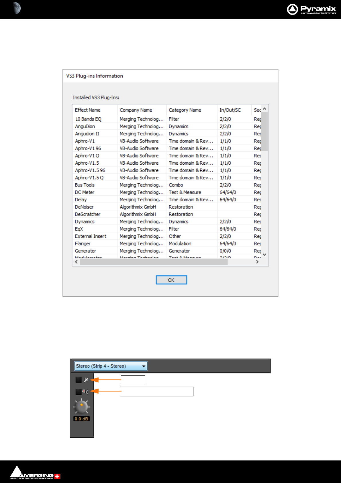
Effects and Plug-Ins : Adding and Managing Effects 13 - 343
Viewing Plug-in Information
VS3 Plug-Ins Information
The Mixer right-click context menu has an option to pop-up the VS3 Plug-Ins Information WindowT
This window shows all effects currently present on the machine. Fields show the Effect Name, the manufacturer/
developer Company Name, the Category Name and Security Status. I.e. if the plug-in is currently authorized.
Common Components
Several of the following Pyramix Effects share common components.
VS3 - Plug-Ins Information Window
Intelligent Gain Make-up
Bypass
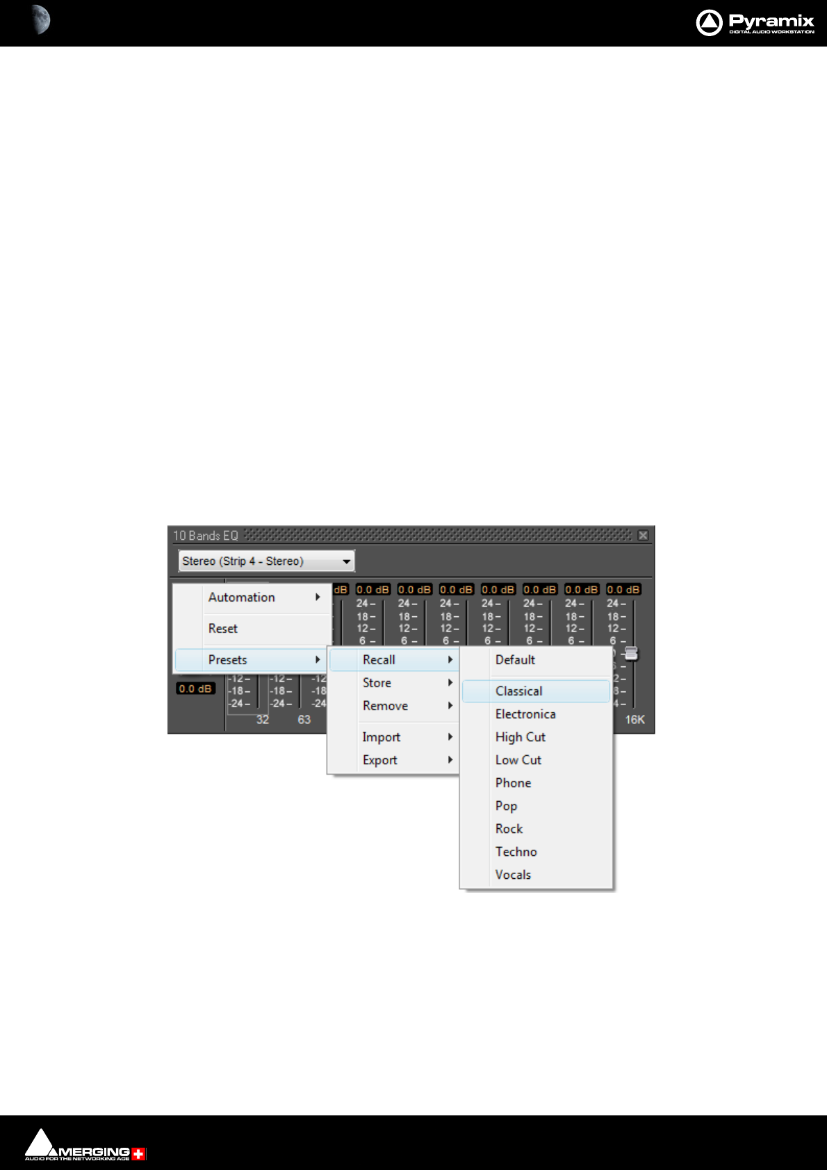
Effects and Plug-Ins : Adding and Managing Effects 13 - 344
Channel Combo Box
Shows which channel has the plug-in that the window is currently controlling. Clicking the arrow drops down a list
of all channels that have this plug-in assigned to them. Click on a name to selected a channel from the list. The
control values will change to reflect the current state of the plug-in on the selected channel. This feature enables
all instances of a particular plug-in to be controlled from the same interface window without opening duplicate
windows for each channel.
Bypass Switch
The On/Off (bypass) switch when lit red the effect is bypassed but remains “in circuit”. Well behaved effects will
maintain their internal parameters in this state so that they can be switched back in without artefacts.
Bypass all Effects
Clicking on a bypass button with Shift bypasses all effects in the strip.
Auto Gain Compensation
(Only where relevant) When this switch is lit Auto Gain Compensation is in circuit. The function is intended to
keep the output level of the plug-in approximately equal to the input level. The computed value varies as the
plug-in controls are adjusted and can be further adjusted using the knob.
Output Gain
Manually adjusts the gain applied at the output of the plug-in. The value is shown in dB.
Effects Presets
Right-clicking in the Plug-in window pops-up a contextual menu which enables the plug-in to be Reset to its
default values. Presets can be Recalled, Stored or Removed and Imported or Exported to and from libraries.
Choosing Presets
Click on the desired preset from the list. The plug-in's parameters will be set to the values stored in the preset.
Effects Presets context menu and recall sub-menu
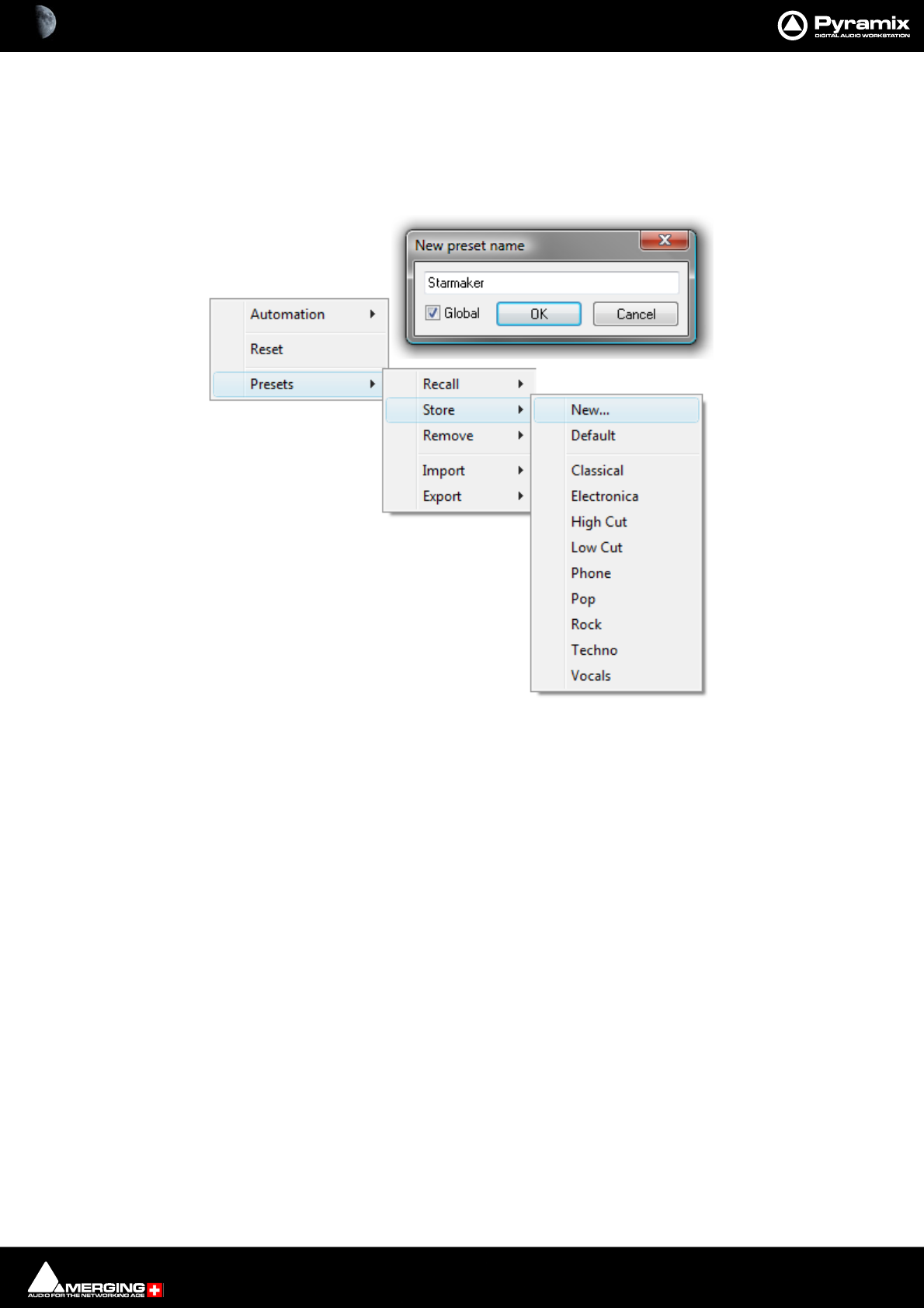
Effects and Plug-Ins : Adding and Managing Effects 13 - 345
Storing Presets
Creating a new preset stores a snapshot of the current values. Store > New opens the New Preset Name dialog
box.
If the Global box is checked, the Preset will be available in all future Projects.
Default
Choosing Presets > Store > Default makes the current parameters the default. These can be from new values or a
previously recalled Preset
Modifying an Existing Plug-in Preset
To modify or update an existing preset, set the effect's parameters to the desired new settings. Right-click and
select Presets > Store then choose the Preset name in the list to update or modify. A Store preset dialogue box
will appear asking if you wish to replace the chosen Preset. Click OK to accept or Cancel to reject. The new settings
will overwrite the previous preset parameter settings.
Deleting Presets
To delete the current preset, right click in the effects window. Then choose Presets > Remove then choose the
preset you wish to remove.
Effects Presets context
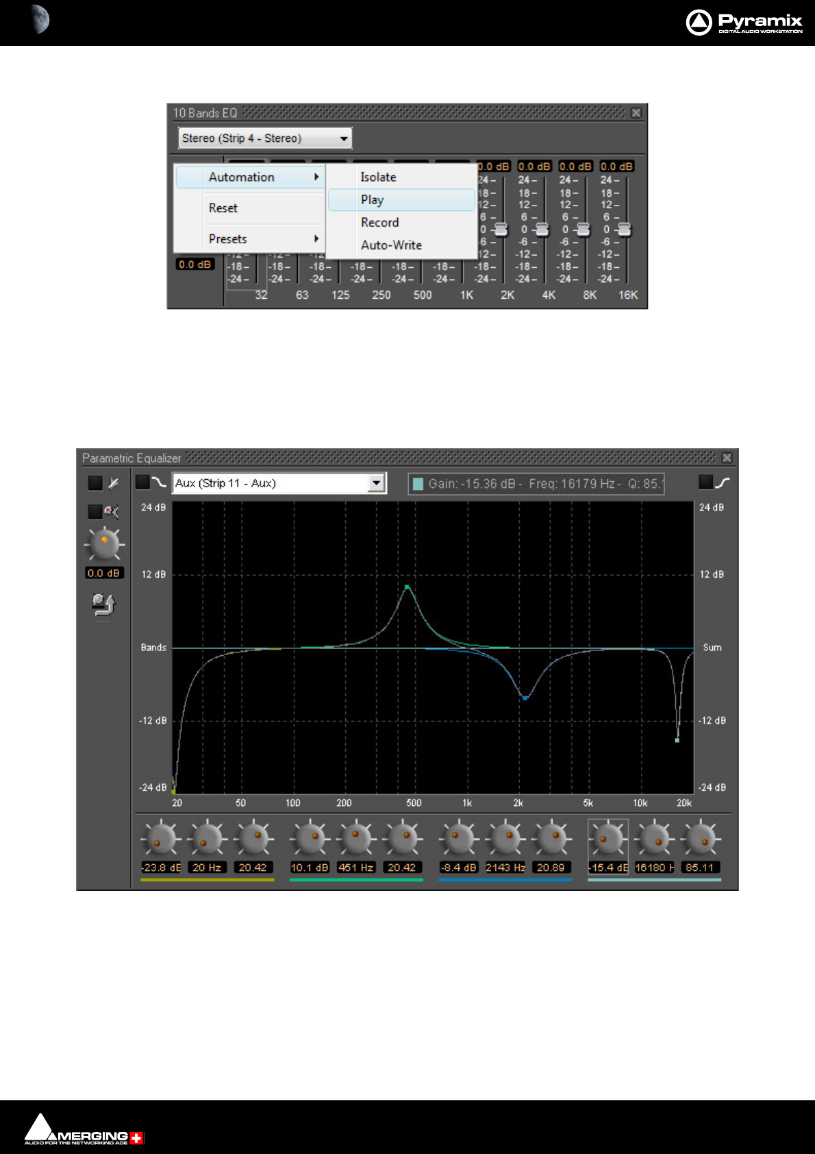
Effects and Plug-Ins : Parametric EQ 13 - 346
Effects Automation
Right-clicking over the effect controls gives access to Automation mode selection for the plug-in. VS3 Plug-in
automation works in the same way as the Mixer automation.
Please see Automation on page 399
Parametric EQ
The Parametric Equalizer is a four band fully parametric EQ with independent control of boost and cut, frequency,
and bandwidth (Q factor) for each band. The common controls at the top of the window behaves as outlined ear-
lier. The equalizer can be operated using the rotary controls at the bottom (shown or hidden by the knob and
arrow icon on the left), by directly entering numerical parameters in the boxes below the knobs or by clicking and
dragging on one of the four colored nodes. Left-clicking enables level and frequency to be adjusted, right-clicking
then dragging left or right allows adjustment of Q.
Parametric EQ floating Window
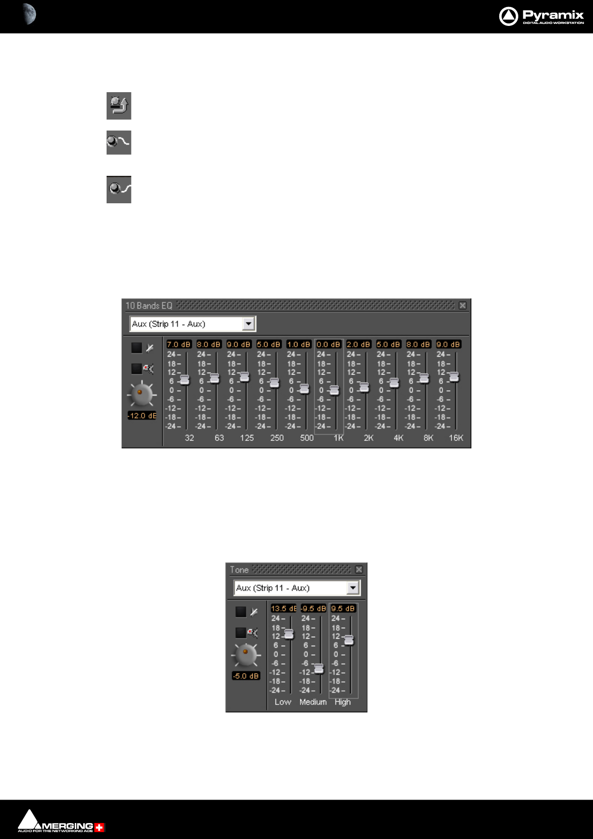
Effects and Plug-Ins : 10 Bands EQ 13 - 347
All bands are full range. Boost and cut of up to 24dB is available. Q can be set anywhere from 0.2 (wide) to 20 (nar-
row).
This button shows or hides the rotary controls.
Peaking / Shelving When lit, the lowest (red) band is switched to shelving response. In this
mode the Q control for the band is unavailable.
Peaking Shelving When lit, is switched to shelving response. In this mode the Q control is for
the band unavailable.
10 Bands EQ
This ten band graphic equalizer offers +/-24dB of boost or cut in any or all of ten bands, one band per octave, rang-
ing from 32Hz to 16kHz. Double-clicking on a slider knob restores it to zero.
Note: 10 Bands EQ is limited to a maximum of 2FS I.e. 96kHz.
Three Band Tone Control
A simple three band equalizer which offers a boost or cut of +/- 24dB in any or all of three bands.
The Low LPF is a shelving EQ with a slope of 6dB/Octave and a turnover frequency of 100 Hz, the Medium BPF has
a Q (bandwidth) of 0.8 with a center frequency of 2 kHz, and the High HPF is a shelving EQ with a slope of 6dB/
Octave and a turnover frequency of 8 kHz.
10 Bands EQ floating Window
Tone Control floating Window
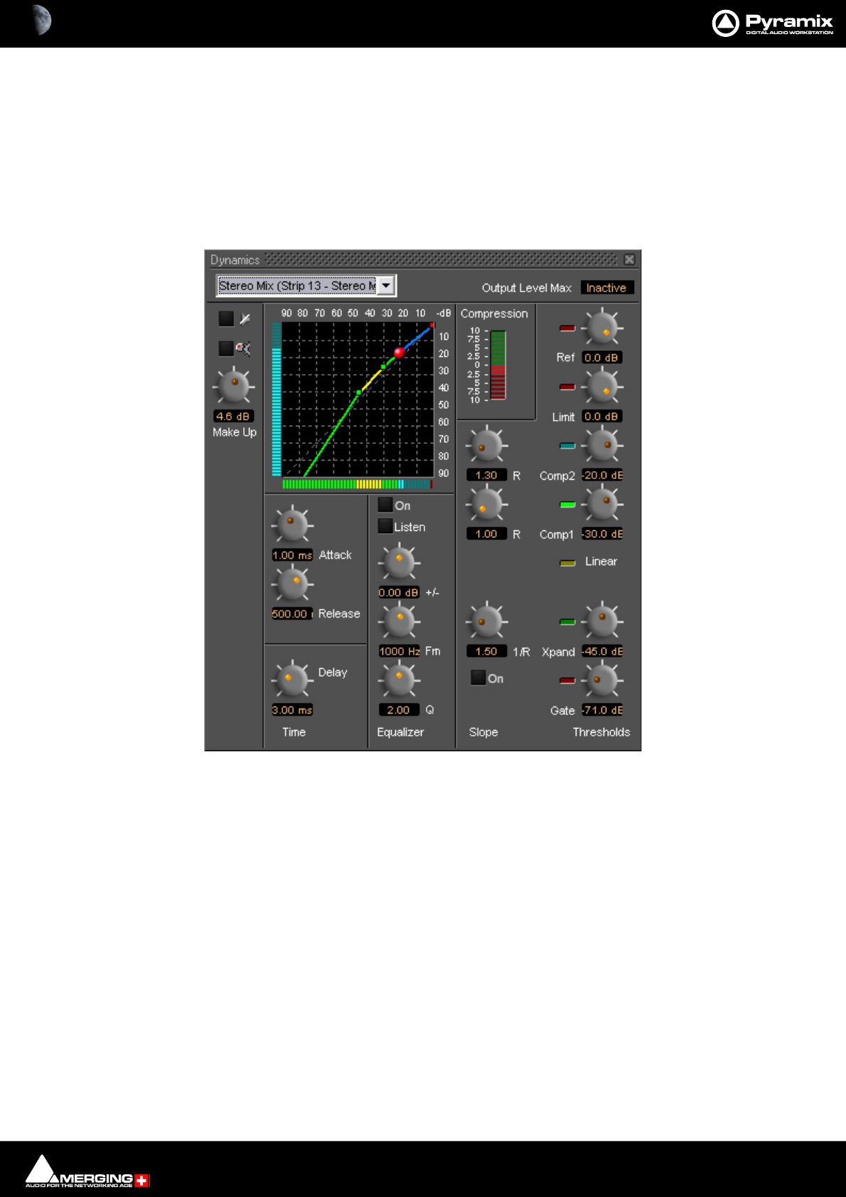
Effects and Plug-Ins : Dynamics Processing 13 - 348
Note: Three Band Tone Control is limited to a maximum of 1FS I.e. 48kHz.
Dynamics Processing
A comprehensive dynamics processing module. Functions available include one gate, one expander, two com-
pressors, one limiter, and a de-esser. The operation of each of these effects is interrelated in this comprehensive
dynamics processor, and the user interface shows the operative dynamic range where each process takes effect.
Output Level Max
This box shows Inactive when auto-gain compensation is on.
Thresholds
Threshold controls set the level above or below which the plug-in will affect the dynamics of the input signal. All
the threshold settings are on the right of the window. From the bottom up, Gate, Expander, Compressor 1, Com-
pressor 2, Limiter, and Input Reference Level.
Reference Level
Sets the input level reference. E.g, setting the reference level to -20 would mean an input level of -20dB is consid-
ered to be the equivalent of unity gain for purpose of calculating the input threshold levels for all dynamics pro-
cesses except limiting. The reference level value is variable between 0dB (unity gain) to -30dB.
Limit
Sets the limit threshold (and ceiling).
Dynamics floating Window

Effects and Plug-Ins : Dynamics Processing 13 - 349
Ratios / Slope
Limit and Gate have fixed ratios, tending to infinity. Ratio settings for the Expander and Compressors are to the left
of their respective Threshold controls.
Compression Bar Graph Meter
The Compression bar graph indicator, above the ratio controls, shows the amount of overall gain reduction or
increase applied to the input signal. No change is in the middle of the scale. Green ‘leds’ above the middle indicate
gain increase, red ‘leds’ below indicate gain reduction. The display range of the indicator can be toggled between
+/-10dB, +/- 20dB, and +/-40dB by clicking on it.
Time
The speed at which the dynamics processor responds when signals go above or below any of the threshold set-
tings are in this section. Careful setting of these parameters make dynamics processing more subtle and less
obtrusive.
Delay
Allows the main program signal to be delayed by 0.01ms to 10ms. Allows ‘brick-wall’ limiting since the processor
has time to respond to fast transients.
Attack
Attack Time sets the response speed of the processor when a threshold level is reached within the range of .01 mil-
liseconds to 600 milliseconds.
Release
Release Time sets the rate at which applied gain change returns to unity after the threshold is no longer exceeded.
Range is 5 milliseconds to 5 seconds.
Equalizer
The equalizer is in the side-chain. I.e. it affects the key signal which triggers the effect of the dynamics processor,
but does not alter the tonal balance of the main signal. This enables the response of the processor to be made
more sensitive to certain frequencies than others. This is typically used to produce a de-essing effect, used to con-
trol excessive sibilance. E.g. boosting frequencies 3kHz to 8kHz range so that a compressor acts when the signal
has components in this range thus reducing signal level and making the sibilance less obtrusive.
Q
Sets the bandwidth of the eq.
Frequency
Sets the equalizer center frequency in the range 20Hz to 20kHz. 24dB of Boost/Cut are available. The Test button
toggles the output of the EQ between side and program chains. When On, the output of the EQ is heard. This can
be useful when identifying sibilance etc. On/Off toggles the equalizer on and off in the side chain. When Off, the
program material triggers the processor. When On, the signal is in effect, split. The portion sent via the equalizer is
used to trigger or ‘key’ the operation of the dynamics processor on the normal program material.
X/Y Dynamics Response Display
This shows the threshold and ratio settings for the gate, expander, compressor 1, compressor 2, and limiter pro-
cesses, and the Dynamics Processor's reference level. These are shown as a series of colored lines with control han-
dles on a grid representing input level in dB below unity gain (0dB) on the horizontal axis, and output gain in dB
below unity gain (0dB) on the vertical axis.
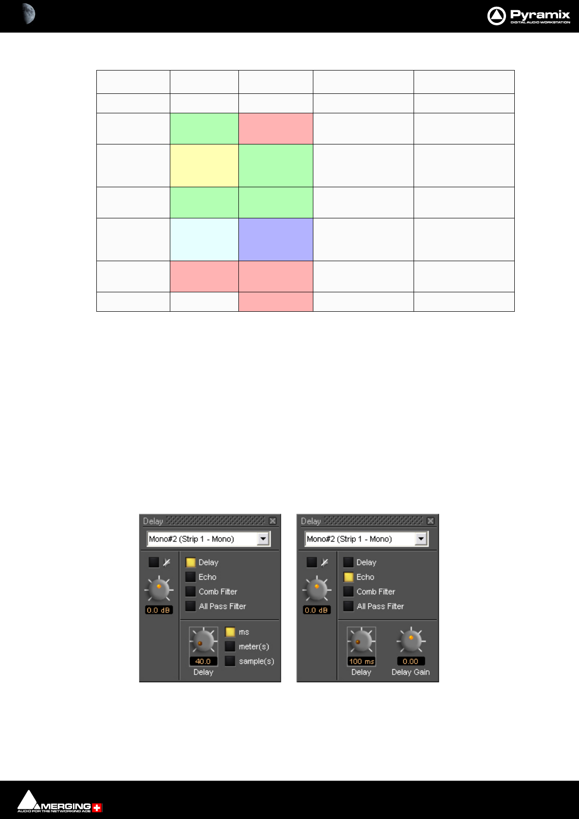
Effects and Plug-Ins : Delay 13 - 350
The legend for this display is as follows:
Adjusting Dynamics Parameters
Parameters can be altered by clicking and dragging on the control knobs or by clicking and dragging the control
handles in the graphic display. Handle controls are affected by other parameter settings. In some instances drag-
ging a handle will change more than one parameter.
Dancing Star Real-time Response Indicator
A red "dancing star" inside the graphic display gives a useful indication of how the processor is affecting program
material. It shows the output level in real-time when signal is present at the inputs.
Delay
The delay Plug-in provides four delay-based effects. ‘Plain-vanilla’ Delay, Echo, Comb Filter and All Pass Filter.
The interface is slightly different when Delay is selected.
uses a straight-through signal path at unity gain with no direct (un-delayed) signal present at the output. The
length of delay can be set in milliseconds, meters or samples. The range of delay available is 0 to 800 ms. Delay
time can be set with the knob, or by typing in the desired delay amount in the text box.
Process Line Color Handle Color Line Slope Function Handle Function
Gate Red *** Gate on/off ***
Expander Green Red Expander Ratio Gate Threshold,
Expander Ratio
Linear Yellow Green Linear response
between Expander
and Compress 1
Expander Threshold
Compressor 1 Green Green Compressor 1 Ratio Compressor 1 Thresh-
old
Compressor 2 Blue-Gray Blue Compressor 2 Ratio Compressor 2 Thresh-
old, Compressor 1
ratio
Limiter Red Red Shows Limit Limiter Threshold,
Compressor 2 Ratio
Reference Red *** Limiter Threshold
Delay floating Windows
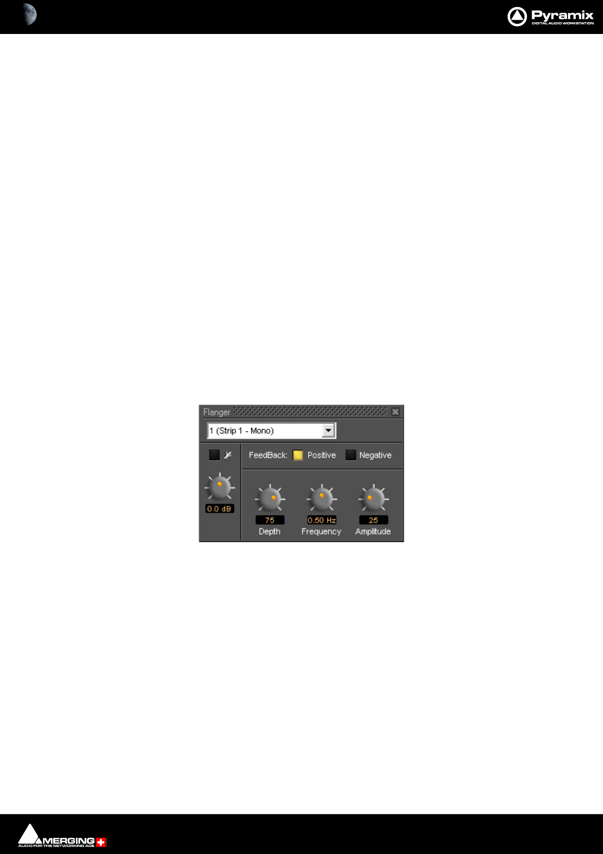
Effects and Plug-Ins : Flanger 13 - 351
Echo
Echo adds a set amount of delay to the signal passing through it and then mixes this delayed signal with the direct
audio source signal. The delayed signal is always at unity gain. The level of the direct signal relative to the delayed
signal is set by the Delay Gain control as a factor between 0 (full attenuation of the direct signal), 1 (unity gain of
the direct signal), and -1 (unity gain of the direct signal phase reversed).
Comb Filter
Delays the signal then feeds part of the delayed signal back to the input of the delay. Comb Filter has the same
control parameters as Echo, but the audible effect is quite different because it uses a feed backward rather than a
feed forward signal path. The name Comb Filter comes from the fact that signals with a wavelength which is an
odd multiple of half the delay time are canceled by the process. This result gives a frequency response chart which
looks like a comb, with some frequencies (depending on the delay time) missing, like the gaps between the teeth
of a comb.
All Pass Filter
Combines the processes used in the Echo and Comb Filter effects. The result is a multiple echoed signal with a flat
frequency response. The control parameters are again the same as in the Echo and Comb Filter effects. Delay Gain
has a quite different effect. It doesn’t affect the overall level of the output signal. It primarily affects the phase of
the signals at different frequencies. If set to 1, it inverts the phase of the input signal and there will be no echo.
With a gain of -1, the input signal there is no phase shift. A gain of 0 means that there is no direct signal compo-
nent and the delayed signals are phase shifted by an amount dependent on their respective frequencies.
Flanger
The flanger produces the characteristic sound which was first produced by playing two copies of something, in
sync but varying the speed of one copy by holding the flanges of the tape spool.
Pyramix Flanger plug-in simulates this effect by time modulating the signal and feeding it back to the input either
in phase (positive) or phase reversed (negative). Feedback type toggles between Positive and Negative. Depth of
modulation can be varied between 0 and 100%, Frequency between 0.05Hz and 5Hz and the Amplitude of the
modulation between 0 and 100%.
Flanger floating Window
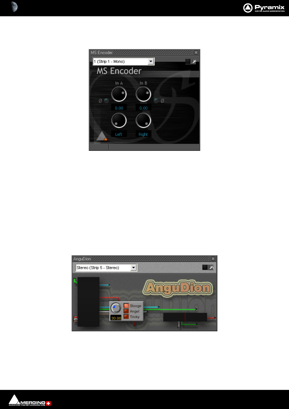
Effects and Plug-Ins : MS Encoder 13 - 352
MS Encoder
As it says on the tin.
Either input can be phase reversed, the input levels are adjustable and the both channels can be individually
panned anywhere between hard left and hard right.
Encode Levels
With the controls hard Left and Right and Unity gain applied signals are encoded in this way:
M = A + B - 3dB
S = A - B - 3dB
AnguDion
Interesting! Three buttons labeled Stooge, Angel, and Tricky, one knob calibrated from 0 - 100
You work out what it does!
MS Encoder floating Window
Angudion floating Window
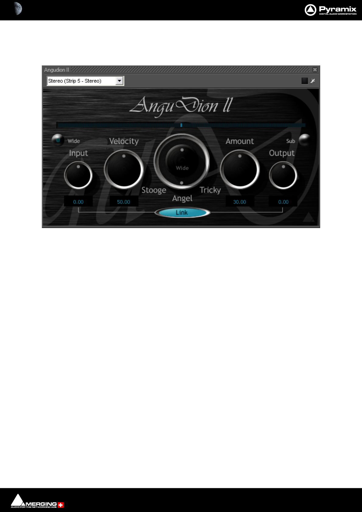
Effects and Plug-Ins : AnguDion II 13 - 353
AnguDion II
Even more interesting!
This time with Wide and Sub buttons and linkable Input and Output gain rotaries. Velocity and Amount rotaries
flank a rotary switch with Stooge, Angel and Tricky options. The concentric Wide pot becomes active when
AnguDion II is inserted in a stereo channel and the wide button is pressed. The Sub button can be selected when
AnguDion II is inserted in a surround strip.
If you have had a play and still want to know more, please see the separate Angudion PDF file.
Angudion II floating Window
Effects and Plug-Ins : Mastering Peak/VU Meters 13 - 354
Mastering Peak/VU Meters
A precise measuring instrument. The VU meter displays the audio level on every strip where it is activated in a
common window. It can serve as a master level display replacing expensive external hardware metering units.
Clicking on a VU meter plug-in opens the meter window. The plug-in offers three different level displays, each with
the option of Dynamic range display.
Peak VU Both Both+Dynamic
Meter floating Windows
Effects and Plug-Ins : Mastering Peak/VU Meters 13 - 355
Peak-Meter
This measures the peak value of the audio signal. Peak meter-
ing is very useful to check the absolute digital level of the
audio signal. The Peak meter bars are blue and it has a default
release time of 16 dB/second.
VU-Meter
The VU (Volume Unit) meter displays an average amplitude
level. The VU meter is displayed in orange/yellow color, has a
default integration time of 60 ms and a release time of 10 dB/
second.
Dynamic-Meter
This display measures the instantaneous dynamic range of the
audio signal. Basically this is the difference between the Peak
and the VU display. If a pure sine tone is measured, the
dynamics would be zero. The Dynamics meter is displayed in
yellow and has a default release time of 12 dB/second.
Activating the VU-Meter
The VU-Meter can be added like any other plug-in on any strip
by choosing Add Effect > VU-Meter from the context menu
within the mixer strip. The only difference compared to other
plug-ins is that when multiple instances of the VU-Meter are
activated they are always displayed within a single window
frame.
Display options
The Peak and the VU meter can be displayed individually with
a middle mouse click anywhere within the window area of the
VU meter. Each click with the middle mouse switches between
the options Peak and VU, only Peak and only VU.
The Dynamics display can be activated by clicking on the
switches at the top of the meter bargraphs. On multi-channel
meters (stereo strips, surround mixes, etc.), the dynamics are
summed together into one bargraph, allowing for example to
display the dynamics of the L, R and C channels of a surround
mix without the rear channels.
Peak Meter floating Window
Effects and Plug-Ins : Mastering Peak/VU Meters 13 - 356
VU-Meter controls
Most of the display parameters of the VU-meter can be adjusted individually. Click with the right mouse button
anywhere on the VU-meter to display a dialog allowing to control most parameters of the VU-meter.
The left side of the control window contains global settings and several predefined presets, while the right side
has four Tabs and a panel of controls specific to the selected tab.
Global Settings and Presets
Eight presets are defined which allow you to quickly select a set of parameters which fit best to your application.
Switch Display
Clicking on this large button cycles through VU, PEAK and BOTH.
Double VU
When this button is lit, the peak meter switches to VU characteristics, thus enabling you to run 2 VU-meters with
different settings at the same time.
Level Mark
Preset Name Description
Def. (ref -16) Default preset with a VU reference level of -16 dBFS
Def. (ref -18) Default preset with a VU reference level of -18 dBFS
Fast (ref -16) Preset with fast response times and a VU reference level of -16 dBFS
Fast (ref -18) Preset with fast response times and a VU reference level of -18 dBFS
Slow (ref -16) Preset with slow response times and a VU reference level of -16 dBFS
Slow (ref -18) Preset with slow response times and a VU reference level of -18 dBFS
BBC VU (ref -16) Preset with BBC standard settings (slower VU release time settings) and a
VU reference level of -16 dBFS
BBC VU (ref -18) Preset with BBC standard settings (slower VU release time settings) and a
VU reference level of -18 dBFS
Vu-Meter Controls Timing Tab
Effects and Plug-Ins : Mastering Peak/VU Meters 13 - 357
When this button is lit, a mark at your desired “nominal” level (set in the Scale Tab), will be displayed as a gray bar.
When the input signal exceeds the mark level, the bar will become light green.
Timing Tab Settings
These parameters are accessed by clicking onto the Timing Tab at the right side of the settings pane (see also pic-
ture above).
Peak integration
This parameter adjusts the integration time of the peak meter for rising levels measured in milliseconds.
VU integration
This is the integration time of the VU meter for rising levels measured in milliseconds.
Peak Release
This is the speed at which the peak meter falls, when the level is decreasing, expressed in dB’s per second.
VU Release
This is the speed at which the VU meter falls, when the level is decreasing, expressed in dB’s per second.
Dyn Release
This is the fall time of the dynamics display. It is expressed in dB’s per second.
Max Level Hold Time
The highest segment reached will remain lit for a specified time after the level decreases, making it easy to see
what the maximum level was. This parameter adjusts the length of time the segment remains illuminated.
Alignment Tab Settings
The alignment parameters affect the scale of the peak and VU meter. They are accessed by clicking the Align Tab.
Vu-Meter Controls Align Tab
Effects and Plug-Ins : Mastering Peak/VU Meters 13 - 358
VU Ref
This parameter sets the level of the 0 VU point in relation to 0 dBFS (0 dBFS is the value at which the maximum
value of a sample word is reached. Anything above this level means that the signal is clipped).
If, for example, the VU Reference level is set to -16 dBFS, the VU meter would display 0 dB when the signal is at -16
dBFS.
Peak Color A/B alignment
The peak meter uses three colors depending on the magnitude of the displayed level. Below the A point, the color
is blue. Between the A and B point, the color is a lighter blue, and above the B point, the color is red.
These two parameters adjust the level of the A and B points.
VU Color A/B alignment
The VU meter uses three colors depending on the magnitude of the displayed level. Below the A point, the color is
dark orange. Between the A and B point, the color is a lighter orange, and above the B point, the color is red.
These two parameters adjust the level of the A and B points.
Scale Tab Settings
These alignment parameters affect the rulers of the peak and the VU meter and also the dB range of the display.
They are accessed by clicking the Scale Tab.
Rulers Max
This sets the maximum level of the range displayed by the peak meter. Usually you would set this to 0 dBFs, such
that a digital full scale level would reach exactly the top of the scale. But since Pyramix uses Floating Point arithme-
tic, you might theoretically have signal levels above 0 dBFs, so it may be useful to be able to display them (of
course, at the output of the mixer, such a signal has to be converted back to an integer number, and would cause
digital clipping, so care should be taken with signals at these levels).
Rulers Min
This sets the minimum level of the range displayed by the peak meter, and thus influences the accuracy and the
resolution of the peak and VU meter. Signals lower than the minimum are not visible on the meter.
Mark Level
Sets the position of the Level Mark. This is normally set to your desired “nominal” level.
Vu-Meter Controls Scale Tab
Effects and Plug-Ins : Mastering Peak/VU Meters 13 - 359
Height
This modifies the height (in pixels) of the VU meter plug-in window as it is displayed on the screen.
Priority Settings Tab
The priority settings are accessed by clicking the Priority Tab.
The buttons select how much CPU time of the host PC can be consumed by the plug-in, and therefore influences
the redraw speed and accuracy of the VU-meter. The higher the priority, the more CPU time is assigned to the
plug-in and the better the meter performs.
DSD Settings Tab
For DSD sessions special meter settings are accessed via the DSD Tab.
Vu-Meter Controls Priority Tab
Vu-Meter Controls DSD Tab

Effects and Plug-Ins : Mastering Peak/VU Meters 13 - 360
DSD Filtering options
In the specific case of a DSD session the VU meter offers three filtering options which allow you to make sure that
your DSD signal is compatible to Annex D.4 of the SACD Scarlet Book concerning the high frequency dither noise
content. These radio buttons let you choose one of three possible filters which will be applied to the DSD signal
before it is measured by the level meter.
The 20k option applies a 20 kHz low pass filter to the signal, thus only the audible audio content is measured.
The 20k-50k option applies a band pass filter with a frequency range of 20 kHz to 40 kHz to the signal. According
to Annex D.4 of the SACD Scarlet Book the signal level in this frequency range should not exceed -28 dB.
The 40k-100k option applies a band pass filter with a frequency range of 50 kHz to 100kHz to the signal. Accord-
ing to Annex D.4 of the SACD Scarlet Book the signal level in this frequency range should not exceed -20 dB.
Measurement Accuracy
Where maximum accuracy is required select High. However, this setting does require extra processing.
Note: In order to avoid such HF noise residuals whenever it is intended to release material in
PCM, Merging Technologies usually recommends users to work in DXD, for preference. Please
see the FFT plots on the next page.
For more information on how to cope with the High Frequency noise content of the DSD a good starting point is
to read the Wikipedia entry on DSD at:
http://en.wikipedia.org/wiki/Direct_Stream_Digital
Refer in particular to the DSD Technique chapter.
Effects and Plug-Ins : Mastering Peak/VU Meters 13 - 361
FFT Plots
Effects and Plug-Ins : Phase-Oscillo 13 - 362
Phase-Oscillo
This plug-in combines a phase meter and a X/Y oscilloscope.
Note: Phase-Oscillo cannot be used in a mono strip. Attempting to do so will result in an error
message.
The phase meter displays the phase of a stereo signal within the range of -1 to +1. a value of +1 means that the left
and right channel are completely in phase. A value of -1 means that the left and right channel are completely out
of phase causing complete cancellation when they would be summed into a mono signal. A good stereo mix
should be somewhere in between 0 and +1.
The basic oscilloscope gives you some information about the stereophony and the phasing of a stereo signal. A
signal which is completely mono appears as a vertical line. If only the right channel carries a signal, it is displayed
as a straight line at a 45° angle from the bottom left to the top right. If only the left channel carries a signal, it is dis-
played as a straight line at a 45° angle from the bottom right to the top left. If the left and right channel are out of
phase, this would result in a horizontal line.
A decent stereo mix would appear as a vertically shaped cloud as shown in the example below:
Phase-Oscillo Controls
Simple controls are available immediately with more comprehensive setup available in the expanded window
when Setup... is clicked.
Bypass
When lit red, the Phase Oscillo is bypassed.
Assignment
Where several instances of Phase Oscillo exist in the Mixer the drop-down list provides access to each instance.
Phase-Oscillo floating Window
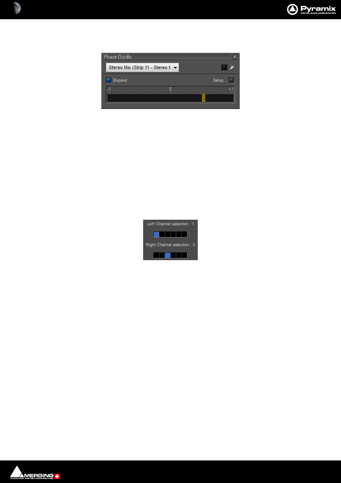
Effects and Plug-Ins : Phase-Oscillo 13 - 363
Expand
Toggles the oscilloscope display on and off. When off, only the phase meter is displayed.
Interpolation
When this switch is on, the samples of the signals displayed on the oscilloscope are interconnected, resulting in
increased readability in many circumstances.
Setup...
This button opens the set-up pane with further options
Working Priority
Choose one of these switches to select the amount of CPU time of the host PC which will be consumed by the
plug-in. This influences the redraw speed and accuracy of the oscilloscope. The higher the priority, the more CPU
time is assigned to the plug-in
Left and Right Channel selection
If the plug-in is inserted on a bus with more than two channels (e.g. a surround bus or a multiple stereo bus), these
two selectors allow you to select the appropriate channels for the left and right input of the plug-in. On a surround
bus, you might for example select the left front and right front channels to be displayed.
Phase-Oscillo Phase only
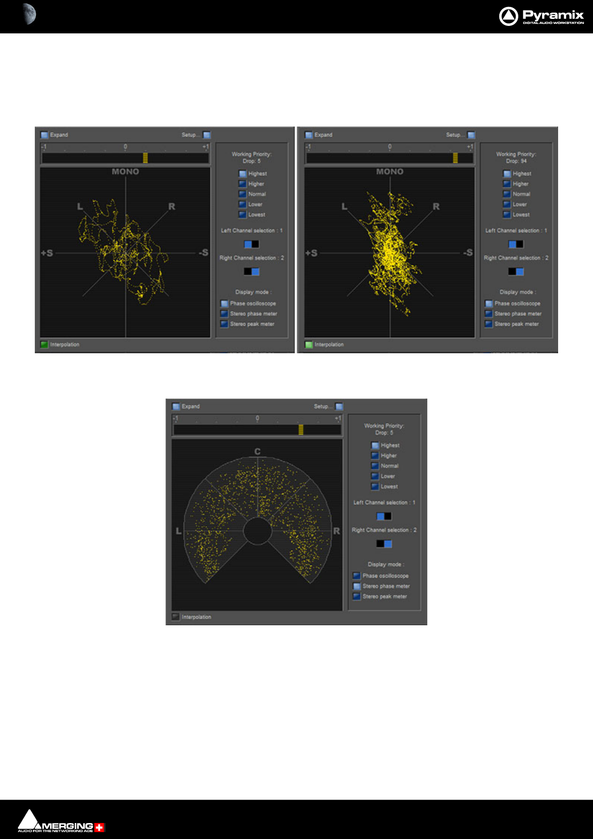
Effects and Plug-Ins : Phase-Oscillo 13 - 364
Display Mode
Three Display Modes are available for the Oscilloscope.
Interpolation adds two further variants for Phase Oscilloscope and Stereo peak meter.
• Phase oscilloscope
•Stereo phase meter
Phase oscilloscope without and with Interpolation
Stereo Phase Meter

Effects and Plug-Ins : Surround Meter 13 - 365
• Stereo peak meter
Surround Meter
Gives a very useful indication of energy distribution in a surround sound field.
The Surround Meter incorporates automatic gain ranging which maintains a meaningful display for a wide range
of material. There are no settings to adjust!
Stereo peak meter without and with Interpolation
Surround Meter floating Window
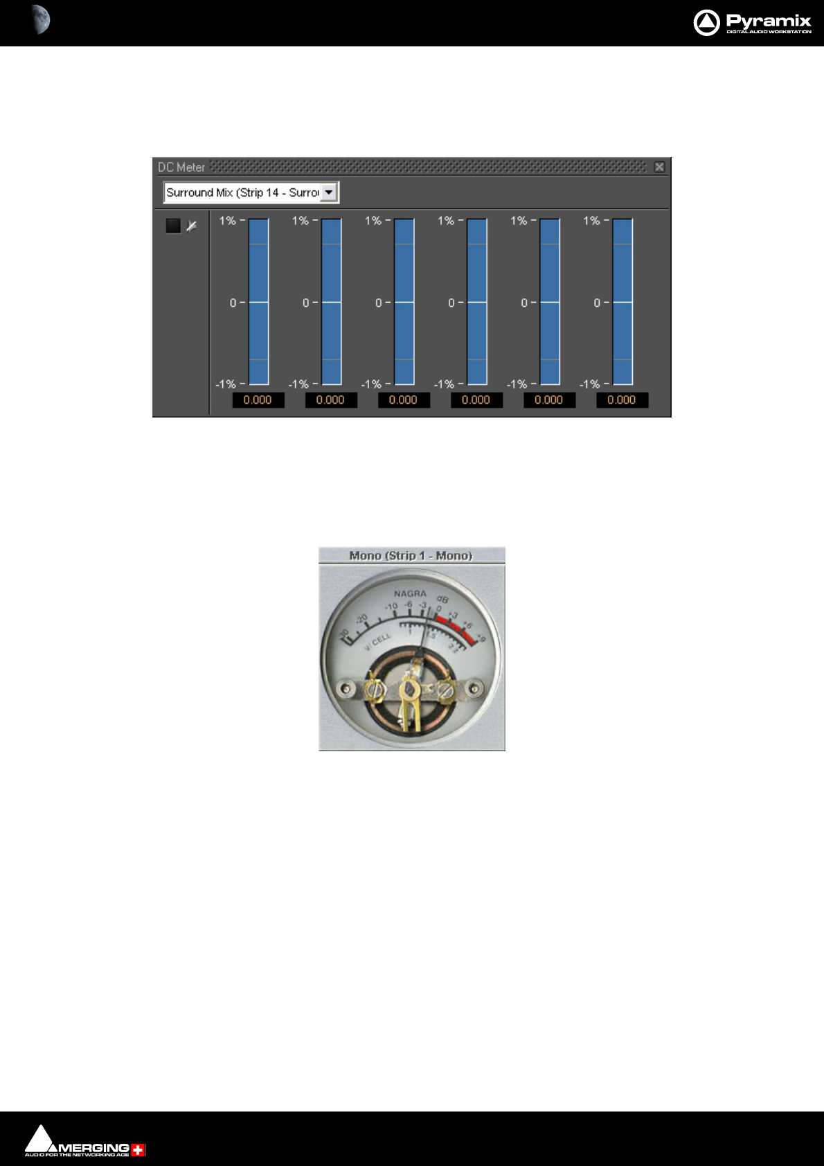
Effects and Plug-Ins : DC Meter 13 - 366
DC Meter
Measures the DC content in the signal.
Modulometer
The Modulometer is a faithful reproduction of the classic meter fitted to Nagra portable Tape recorders.
Common operational practice to is set levels so the meter reads (average) - 8 when recording speech. This is partly
due to the Modulometer's characteristics as a quasi peak meter (quasi because it has the ballistics of a mechanical
meter) and it also reflects the caution required in location dialogue recording where a lost take can represent
many thousands of dollars. Although not by any means desirable, a low level signal is better than one with distor-
tion from peak clipping.
DC Meter floating Window
Modulometer floating Window

Effects and Plug-Ins : Modulometer 13 - 367
Right-clicking anywhere on the window pops up a context menu. This has several options which control the
behavior of the Modulometer.
Reset
Restores the default settings
Presets
Offers the standard Preset options
Display (Frame / Sec)
Sets the display refresh rate
Release (dB / Sec)
Sets the Release time
Acceleration (dB / Sec)
Sets Acceleration rate
Reference (dBFS)
Sets the Reference level in DeciBels Full Scale
Integration (ms)
Sets the Integration time in milliseconds
Hide
Hides the Modulometer
Modulometer menu
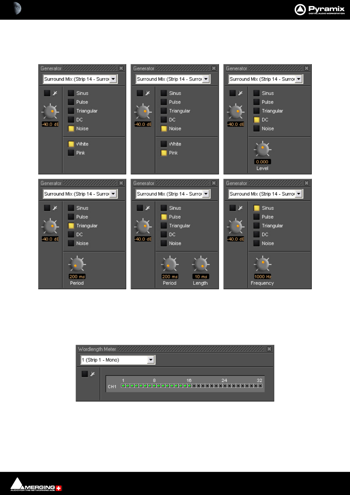
Effects and Plug-Ins : Function Generator 13 - 368
Function Generator
This oscillator can produce a Sine wave, a Pulse wave, a Triangular (Sawtooth) wave, DC and White or Pink Noise.
Wordlength Meter
The Wordlength Meter (or Bit Meter) allows you to view the effective wordlength of a signal.
Bear in mind that, once you apply any gain adjustment (e.g. a fader set anywhere other than 0dB) the signal will
become 32 bit float data.
Function Generator floating Windows
Wordlength Meter floating Window

Effects and Plug-Ins : Effects and Plug-in Automation 13 - 369
Effects and Plug-in Automation
All signal processing parameters in Pyramix VS3 Effects Plug-ins can be fully automated dynamically in the same
manner as the Mixer controls. Please see Dynamic Automation Transport Modes on page 403.
Note: For information about differences when automating VST Plug-ins Please see: VST Plug-in
Automation on page 393
Effects Snapshots
Effect Settings can be easily stored and recalled by dragging them to/from libraries.
Creating Effects Snapshots
Hold Alt + Shift, then click and drag from the horizontal bar next to the Channel combo box in a Plug-in window
to the library where you want to store the settings, then release. A new item, of the type Mixer Snapshot, is stored
in the library. The snapshot is given the name of the plug-in by default. The new item is automatically highlighted
so, if you wish to change the default name, simply type the new name and hit Enter to confirm. The name of the
snapshot can be subsequently changed by clicking on the name in the library, then entering the new name.
Note: In some plug-ins Alt + Shift click and drag will work on any of the horizontal section title
bars and in others from anywhere on the plug-in window where the cursor changes to .
Using Effects Snapshots
Simply click and drag a snapshot from a user library to a plug-in of the same type as the original and release any-
where on the surface where the cursor changes to
Anywhere the snapshot cannot be dropped, or if the snapshot plug-in type does not match the target plug-in, the
cursor changes to
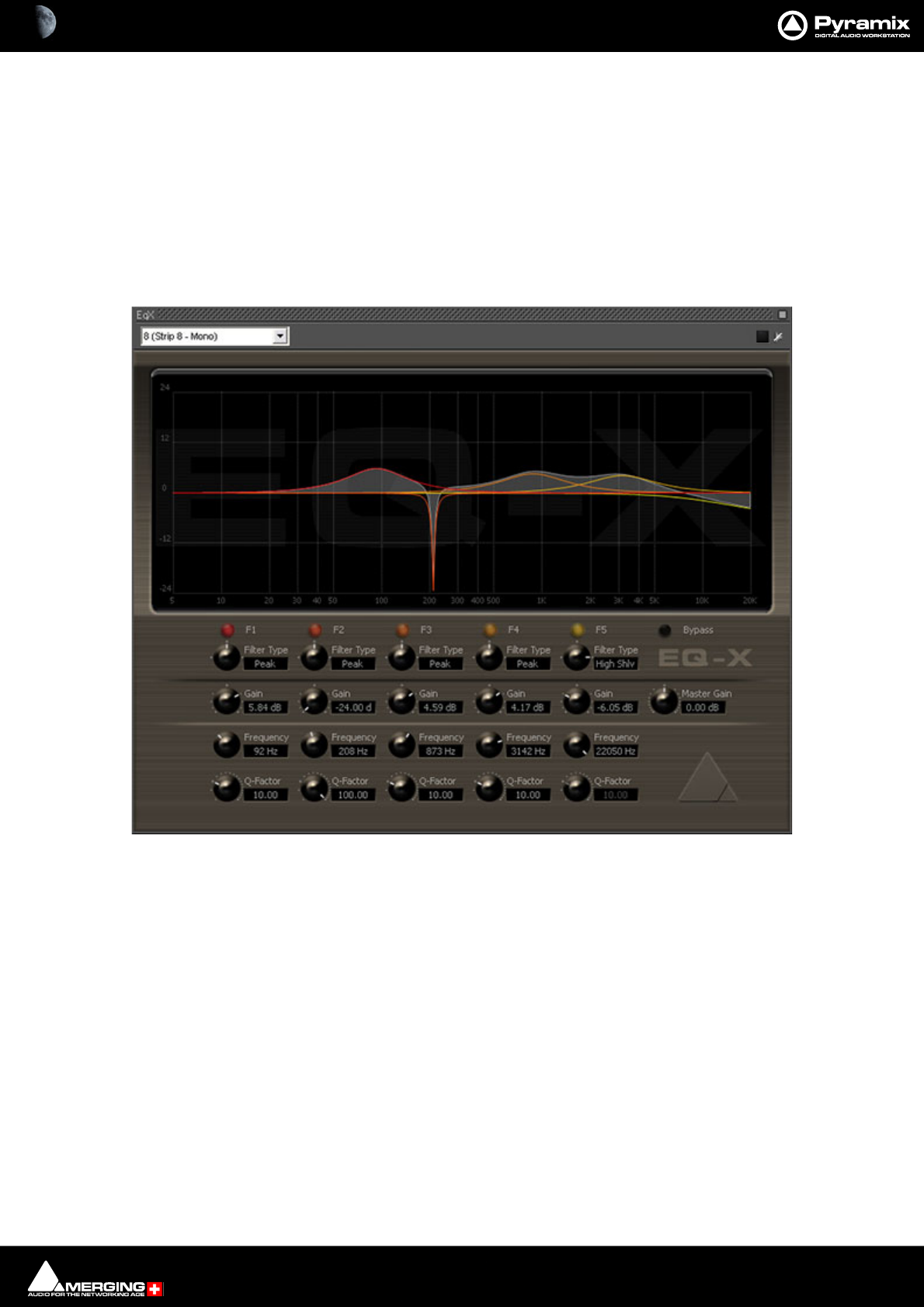
Effects and Plug-Ins : Optional Plug-ins 13 - 370
Optional Plug-ins
Optional Pyramix plug-ins. For operating instructions please see each plug-in’s guide.
Merging Technologies
EQ-X
EQ-X builds on the existing and universally acclaimed quality of Pyramix EQ. It is backwards compatible. EQ-X
offers Extreme definition filtering at sampling frequencies up to DXD with notch, low pass, hi-pass, peak and shelv-
ing filter types available.
The state space filter design of this Extreme Definition Equalizer has been specifically optimized to deal with the
highest audio resolutions while still permitting very low noise & distortion, typically offering a THD+N of better
than -110dB, throughout the entire audible (and even non-audible) range. Of course, this new digital filter's
topography, while designed with high sample rate in mind, also offers the extra benefits and low noise to 1FS
equalization. However, since there is no such thing as a free lunch, EQ-X does "eat" about double the processing
DSP power of an equivalent "traditional" digital EQ instance in Pyramix.
EQ-X is a five band fully parametric EQ with independent control of Filter Type, Gain boost and cut, Frequency,
and Q factor (bandwidth) for each band. The equalizer can be operated using the rotary controls, by directly enter-
ing numerical parameters in the boxes beside the knobs or by clicking and dragging on one of the five colored
box nodes which appear when the mouse cursor is over the response graph. Left-clicking enables level and fre-
quency to be adjusted, right-clicking then dragging left or right allows adjustment of Q.
EQ-X floating Window
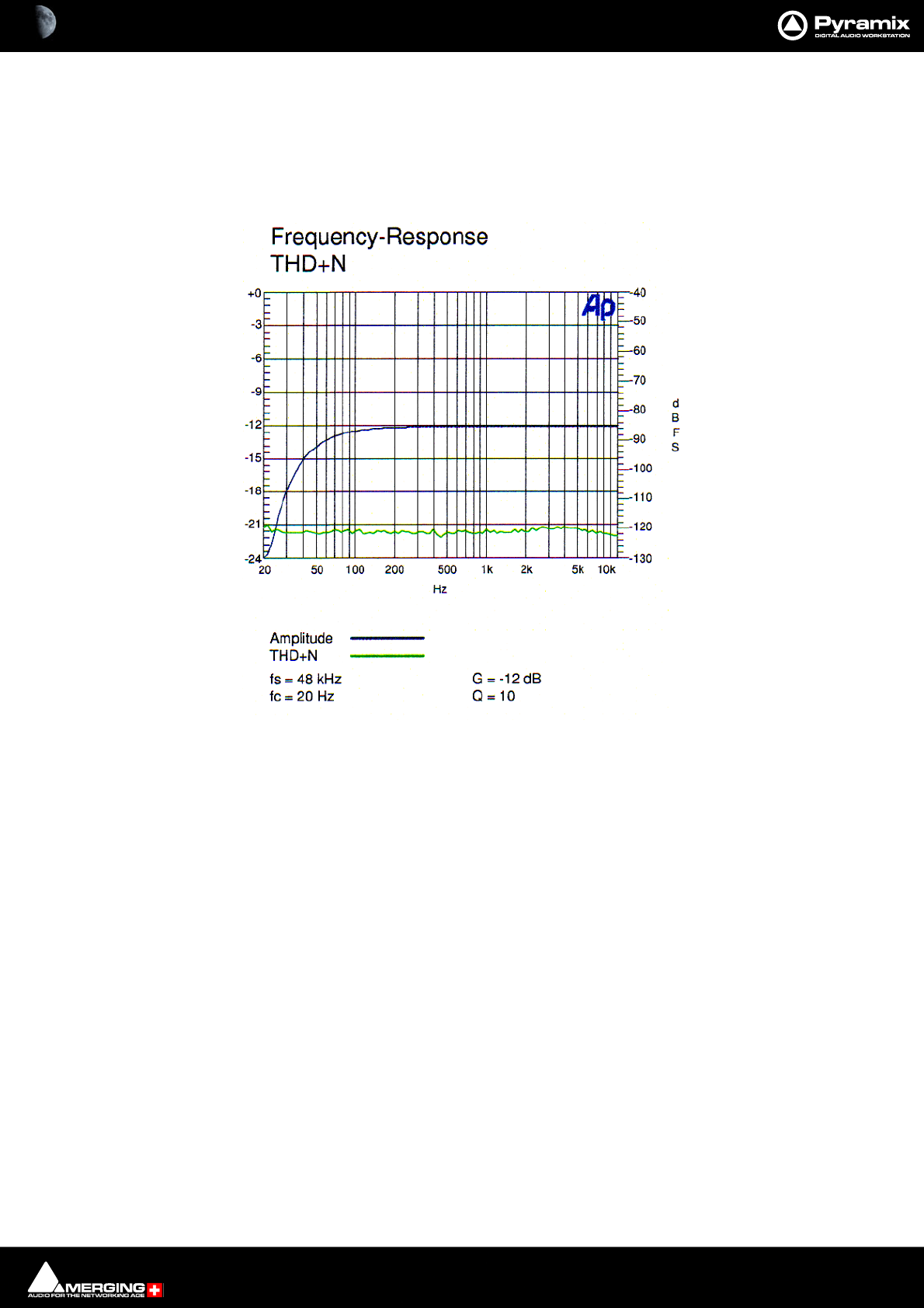
Effects and Plug-Ins : EQ-X 13 - 371
All bands are full range. Boost and cut of up to 24dB is available. Q can be set anywhere from 1.0 (wide) to 100 (nar-
row). Master Gain enables the overall level to be adjusted to suit the applied eq.
EQ-X Frequency Response THD+Noise
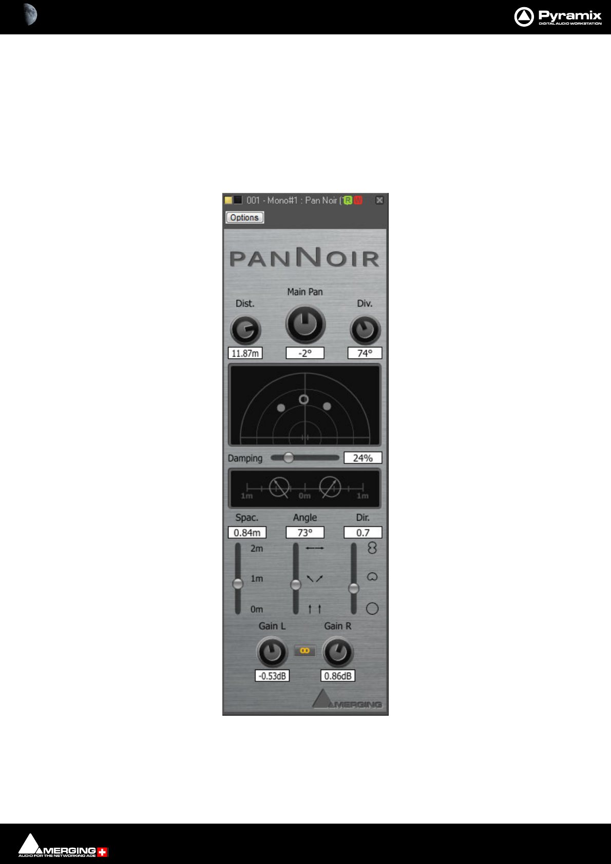
Effects and Plug-Ins : PanNoir Panner 13 - 372
PanNoir Panner
Overview
This VST plug-in is essentially a panner employing phase and amplitude to achieve superior results in comparison
with simple amplitude panning. When the position of the different sources,is entered as well as information about
the main mic pair, The PanNoir Panner computes and applies the delays and gain appropriate to the distances
from each source to each mic of the main mic pair. This enables extremely realistic left-right placement of spot mic
sources in relation to the main mic pair.
Note: PanNoir will only work with Pyramix as the host.
Noir Advanced Panner floating Window
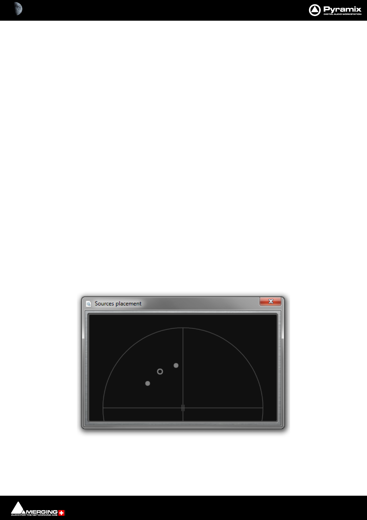
Effects and Plug-Ins : PanNoir Panner 13 - 373
Installation
The PanNoir Panner is installed with Pyramix but can only be used if the relevant security key is present. Please
contact your Merging Technologies Sales Partner to obtain the relevant security key.
Note: Since the PanNoir Panner is a VST plug-in it is necessary to run the VST Scanner application
(located in: All Programs > Merging Technologies > VS3Runtime > VST Scanner) to Re-Scan
the folder in which the PanNoir.dll has been installed (in C:\Program Files\Steinberg\VSTPl-
ugins\Merging Technologies\). Please see also: VST Plug-ins Scanner on page 388
Mono vs. Stereo
The PanNoir Panner is a stereo-in/stereo-out VST plug-in. To pan a mono input to a stereo output it MUST be
inserted into a stereo channel. To pan a mono input just use one of the input channels. Please read about the Div.,
parameter and the notes after that. Please see: Div. on the next page.
User Interface
The upper section of the plug-in user interface is about the placement of sources, the lower section, deals with
settings concerning the main mic pair.
Sources placement (upper section of the GUI)
The parameters Main Pan, Dist, and Div set the positions of the two sources. Source number 1 is simply the left
channel of the input signal, while source number 2 is the right channel. If the input is a mono signal, source num-
ber 2 can simply be ignored: it will only contain silence.
Note: The left-most source is always source number one, and vice versa. This plug-in will never
swap the inputs.
The easiest way to place the sources is by clicking and dragging the grey circles on the upper screen. Active
regions will turn pale yellow when the cursor is over them and bright yellow when clicked and dragged. Keyboard
shortcuts are described below.
Note: For greater precision, double-clicking on the upper screen opens a copy of this screen in a
separate window. This new window can be resized and hence permits very precise control to be
achieved via simple mouse drags.
Alternatively, you can use the three upper knobs directly:
Noir Sources Placement pop-up Window

Effects and Plug-Ins : PanNoir Panner 13 - 374
Main Pan Source Angle - The angle from the center of the main mic couple to the center of the
sources. Value in degrees, from -90° to +90°. Negative values indicate a source on the
left hand side, positive values indicate a source on the right hand side.
Note: To limit dragging to Pan Angle only hold down the crtl key to lock Distance while drag-
ging the circles on the screen.
Dist. Source Distance - The distance from the center of the main mic pair to the sources.
Value in meters, from 0.1m to 20m.
Note: To limit dragging to Distance only hold down the Crtl + Shift keys to lock Angle while
dragging the circles on the screen.
Div. Source Divergence Angle - The angle between the two sources, as seen from the center
of the main mic pair. Value in degrees, from 0° to 180°.
Note: To limit dragging to Divergence Angle only hold down the Shift key to lock Pan Angle and
Distance while dragging the circles on the screen.
Note: A divergence of 0° means the sources are superimposed, so the two channels of the input
signal will be summed, and then treated as a mono input. If you are indeed working with a mono
input signal, this is exactly what is needed, and you should never need to change the div. If how-
ever the input signal is a stereo pair, you will probably prefer to uses a non-zero div.
Note: This allows sources to be placed behind the main mic pair. This represents a 180° phase
shift in the audio signal (multiplication by -1) and is, in principle, not illegal. However, the simula-
tion is very likely to sound less realistic, since the real-world microphones used for recording
were probably neither designed nor placed to record what was behind them. Try it by all means,
you may like the effect!
Damping
The value determines the degree of source attenuation with increasing distance from the main mic pair. If no
attenuation is required the value is set to 0%.
Main Mic Pair Settings (lower section of the GUI)
The parameters Spac, Angle, and Dir set up the main mic pair. This setup should match the actual settings that
were used for the recording. If these settings are not known, the default parameters are probably a good approxi-
mation. However, feel free to try other settings to see if they improve the result.
In a similar manner to Sources placement, the microphones on the lower screen can be clicked and dragged.
Active regions will turn pale yellow when the cursor is over them and bright yellow when clicked and dragged.
Keyboard shortcuts are described below.
Alternatively, you can use the three lower sliders directly:
Spac. Mic Pair Spacing - The distance between the two mics of the main mic pair. Value in
meters, from 0 m (mics on top of each other) to 2 m (2m away from each other, so in
other words, 1m away from the center point). Simply drag one mic from left to right on
the screen to change this parameter.
Angle Mic Angle - The angle between the two mics of the main mic pair. Value in degrees, from
0° (facing forward, parallel to each other) to 180° (facing left and right, opposite each
other). Hold down the Shift key and drag one mic on the screen, rotating it, to change
this parameter.
Dir. Mic Directivity [0 , 2] - The directivity of the mics of the main mic couple. Value without
units. 0 = omni, 1 = cardioid, 2 = fig. 8. Hold down the ctrl key and drag one mic verti-
cally on screen to change this parameter.
Gain L and Gain R Click and drag the knobs to set the Left and Right Gains. Clicking on the button
between the knobs links the Gain knobs. (Lit yellow.)

Effects and Plug-Ins : PanNoir Panner 13 - 375
Additional Information
• Knobs and the horizontal slider are controlled by horizontal mouse click and drag. Vertical sliders are con-
trolled by vertical mouse click and drag.
• When the mouse cursor is over a parameter name, the VST-parameter name pops up. This is the name that
is needed when mapping the plug-in to an external device, such as a control surface.
• When clicking on the white text boxes of the parameters, a popup window lets you edit their values with
the keyboard directly. Note that you don't need to type the unit in.
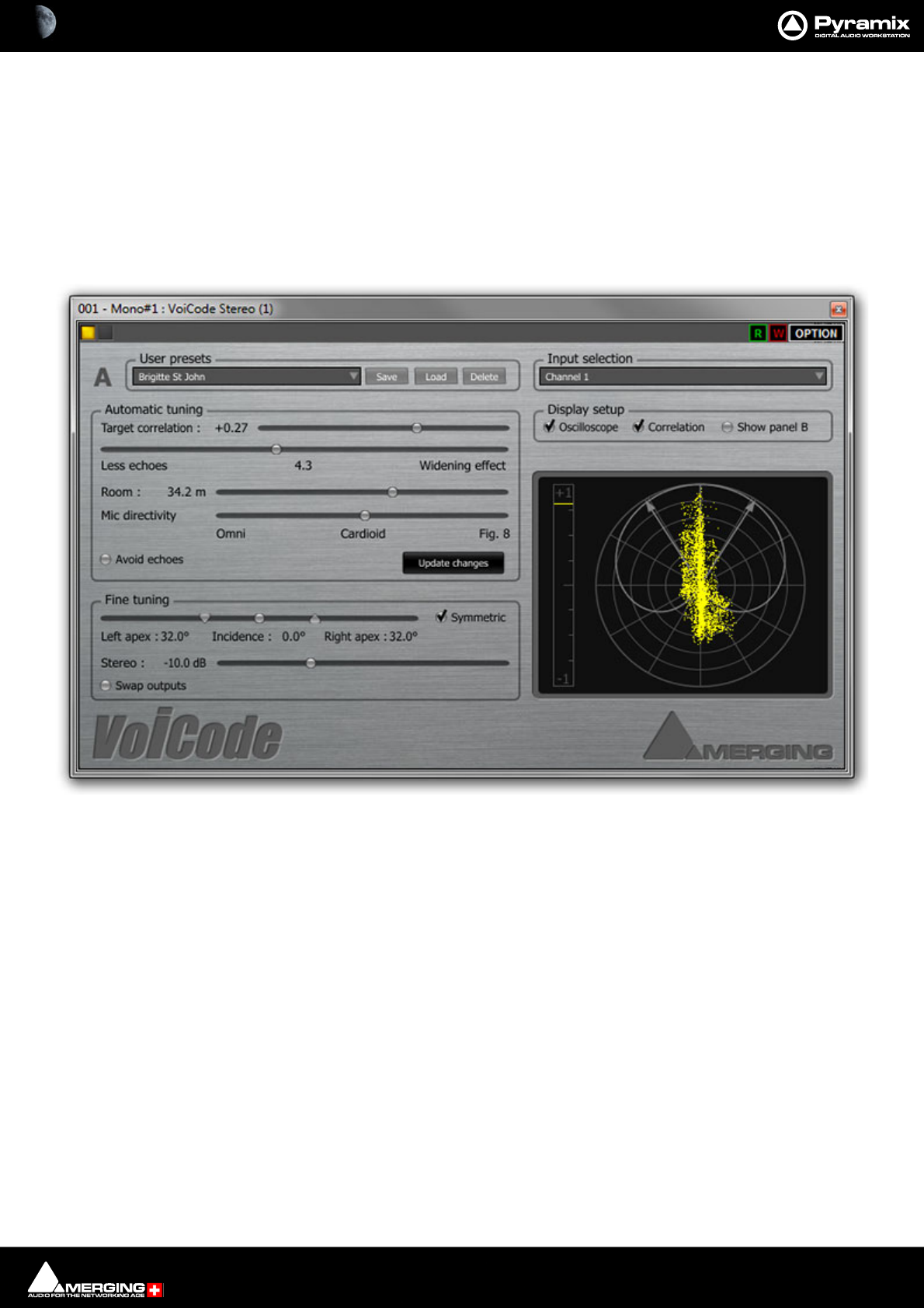
Effects and Plug-Ins : VoiCode 13 - 376
VoiCode
Overview
This VST plug-in produces highly convincing stereo from mono sources. It requires some experimentation to
achieve the best possible results. When adjusted optimally, the effect is uncanny.
The system represents the interpolation of an MS stereo recording technique where the S-signal is being calcu-
lated from specific delays and amplitude corrections which depend on the chosen directivity, the angle of inci-
dence, the left apex angle, the right apex angle, and room size. If the left and right VoiCode output signals are
summed the original mono signal is restored.
Install
VoiCode is installed with Pyramix or Ovation but can only be used if the relevant security key is present. Please
contact your Merging Technologies Sales Partner to obtain a security key.
Note: Since VoiCode is a VST plug-in it is necessary to run the VST Scanner application (located
in: All Programs > Merging Technologies > VS3Runtime > VST Scanner) to Re-Scan the folder
in which the VoiCode_Stereo.dll has been installed (in C:\Program Files\Steinberg\VSTPl-
ugins\Merging Technologies\) .
Please see: VST Plug-ins Scanner on page 388
Mono vs. Stereo
Voicode is a stereo-in/stereo-out VST plug-in. To produce a stereo output it MUST be inserted into a stereo chan-
nel.
User Interface
The user interface defaults to Control Panel A on the left of the window with a polar co-ordinate display, which
doubles as an oscilloscope, the Display Setup section and Input selection on the right. When Show Panel B is
VoiCode User Interface

Effects and Plug-Ins : VoiCode 13 - 377
active a second control panel appears on the right. This enables two sets of settings/presets to be compared and a
slider allows for fading between the two.
Top Row
On the left, the first button activates/de-activates and lights yellow when the plug-in is active. The second button
toggles bypass and lights red when the plug-in is bypassed. On the right, the Green R and Red W buttons control
the local dynamic automation mode. Green lit = Read, Red lit = Write, Green and Red lit = auto-write and both off
= automation off. The global automation mode takes precedence. The Option button gives access to Info... about
VoiCode. The other options are standard VST entries and irrelevant in the case of VoiCode.
Input Selection and Graphics/Meters section
Input Selection
This VST plug-in can use 2 inputs and obviously has 2 outputs. The plug-in is however intended to process a mono
input. The drop-down list offers the options of using:
Channel 1
Channel 2
Sum Channels 1 & 2
Sum Channels 1 & 2 (-3dB) (Classic derivation for M of a Sum and Difference (M&S) recording)
Display Setup
VoiCode has the option of an Oscilloscope display, a Correlation (phase) meter and Show Panel B. (Double con-
trol panels.)
Oscilloscope When ticked the Oscilloscope display is active, superimposed on the polar coordi-
nate display.
Correlation When ticked the vertical Correlation meter is shown to the left of the polar coordi-
nate display.
Show Panel B When ticked all the controls in the A Control panel on left of the window are dupli-
cated on the right of the window in the B Control panel and an A - B slider control
appears below Display setup.
A B Slider Show Panel B enables two different sets of parameters to be set up and viewed
simultaneously. The slider is used to fade between parameter sets. Two sets of
parameters can be compared and, if desired, blended in any proportion. I.e. with
the slider hard left only the left-hand A panel parameters are used. Similarly, with
the slider hard right only the parameters in the right-hand B panel are used. At any
setting in between a proportion of left A and right B panel parameters is blended.
Note: If Show panel B is deselected when the slider is anywhere other than fully at A then the
slider is returned to the A side.
Correlation Meter The vertical bar is a Correlation (phase) meter looking at the VoiCode stereo out-
put. When the ‘needle’ is at the top of the scale (+1) the left and right outputs are
100% correlated, i.e. double mono. At the other end of the scale (-1) the left and
right outputs are decorrelated I.e. substantially out of phase. This is highly undesir-
able.
Polar Coordinate Display/Oscilloscope
The graphic shows a representation of the Mic directivity chosen and the Left
apex, Incidence and Right apex angle settings. When Oscilloscope is active a
goniometer is superimposed on the graphic.
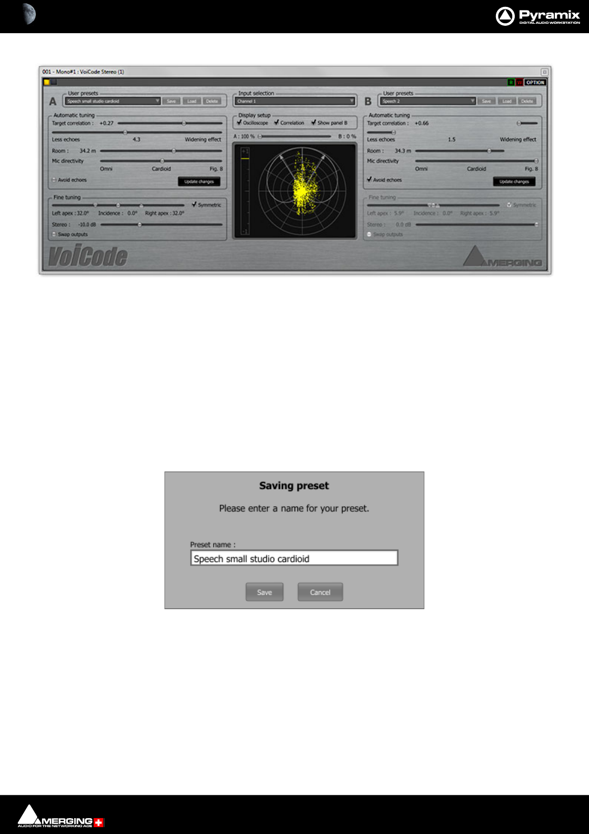
Effects and Plug-Ins : VoiCode 13 - 378
Control Panels
A (or B)
Identifier for the two control panels.
User Presets
User presets can be saved, loaded and deleted. A drop down list and three buttons, Save, Load and Delete man-
age the presets.
New Preset... The drop-down list shows all existing presets with New Preset... at the bottom of the list. Click on
an existing Preset to select it followed by the Load button to update the parameters.
To create a new preset click on New Preset... adjust parameters until you are happy with the results then click on
Save to open the Saving Preset dialog :
Type a suitable name for your preset and click on the Save button to save it and close the dialog. Alternatively
click on the Cancel button to close the dialog without saving the preset.
To delete an existing preset click on the preset to select it then click on the Delete button. A safety Are you sure ?
dialog opens. Click on Yes to delete the selected preset and close the dialog or No to close the dialog without
deleting. Deleted presets are sent to the Recycle bin and can be recovered from there if deleted inadvertently.
Adjusting VoiCode
The two sections detailed below control the output signal. Tune the plug-in from top to bottom in the first
instance. I.e. adjust the Automatic tuning parameters first, then press the Update Changes button, then adjust
the parameters in the Fine tuning section. It should not be necessary to make large adjustments in the Fine tun-
ing section since the Update Changes function computes a good approximation of the values required.
VoiCode User Interface with both Control panels visible
VoiCode Saving preset dialog

Effects and Plug-Ins : VoiCode 13 - 379
Automatic Tuning
Target correlation : This control slider has no direct effect on the output signal. It only takes effect
when Update Changes is clicked. When this happens, the parameters will be
tuned so that the correlation of the stereo output signal will match the chosen Tar-
get correlation value selected by this control.
Less echoes - Widening effect This control slider has no direct effect on the output signal. It only takes effect
when Update Changes is clicked. The range is from 0 - 10. Choosing a large (wide)
value informs the algorithm that the signal comes from a wide stereo scene (typi-
cally an orchestra) and that when searching for optimal parameters, it should
favour the ones with a widening effect. The downside of choosing a very wide
setting is that small delays may become apparent. Choosing a lower value,
towards the Less echoes end of the scale, will minimize such artefacts. However,
the widening effect will be diminished. As a general rule, the more spooky, jumpy
and rhythmic the input signal, e.g. speech, the smaller the value required.
Room : The slider sets the area of the room the signal was recorded in. (Or your best esti-
mate.) Between 10.0 m and 50.0 m.
If the room size is not known then choose a value of 34 -35 m as a starting point.
Mic directivity The slider selects the pick-up pattern of the mic used to record the original signal.
The adjustment is continuous from Omni through Cardioid to Fig. 8. The pattern
is shown graphically in the Oscilloscope display.
If the mic pick-up pattern is not known, use Omni as a starting point. If the mic was
a shotgun use Fig. 8.
Avoid Echoes When ticked the Less Echoes - Widening Effect slider range is reduced to 0 - 1.5,
the Target Correlation slider range is reduced to 0.66 - 1 and the Room : slider
range is reduced to 10.0m - 39.0m.
Update Changes This is the most important component of the Automatic tuning-section. If any of
the Automatic Tuning controls have been moved the button flashes red to remind
you to click it in order to re-compute the parameters.
When clicked, the plug-in will attempt to tune the parameters in the Fine tuning
section, to achieve optimal values. In order to do this successfully, the plug-in
needs two pre-conditions :
• Sensible values for the parameters of the Automatic tuning section. (As described in detail above.)
• A 1 second long sample of the mono signal to be processed. When Update Changes is activated the plug-
in uses the last 1 second of input sound to calculate the parameters. Therefore it makes no sense to click
Update Changes when no audio (silence) is being played. Similarly, clicking Update Changes during a
trumpet solo or when the whole string orchestra is playing may produce slightly different tuning, even if
both passages are on the same recording, with the same automatic tuning-parameters.
• When Update Changes is clicked on very slow systems the plug-in may stop reacting for a short while.
The computation can be interrupted by pressing the Esc key.
Note: If you attempt to invoke the Update Changes function when there is no audio passing
through VoiCode a warning dialog appears :
VoiCode Auto tuner cannot work dialog

Effects and Plug-Ins : VoiCode 13 - 380
Fine tuning
Left apex, Incidence and Right apex
Incidence The slider operates in the range 0 to 90 degrees within the boundaries of the Left
and Right Apex sliders. (See below.) Incidence is the angle of incidence enclosed
by the major (on) axis of the mic and the bearing line of the sound source. I.e. how
far off-axis the source is. This value is usually zero since, in an ideal world the
source will be on-axis. In some circumstances, e.g. a telephone conversation, the
angle would be around 12 degrees. Or a piano recording with a boundary mic
directly on the lid (value should be approximately the same as the angle of the
lid…).
Left and Right Apex The sliders operate in the range from 5 to 90 degrees. These values represent the
fictitious left and right angles in relation to the direction the mic is pointing in. You
might want to think of them as the major axis angles from the centre line of two
mic capsules used for a classic co-incident pair recording.
Symmetric When ticked, forces Left and Right Apex angles to keep the same values regard-
less of which is adjusted and locks the angle of Incidence to 0 degrees.
Stereo The slider takes direct control of the generated stereo signal. I.e. it is a width con-
trol. Values close to 0dB will reduce correlation of the output and negative values
will increase correlation to +1 at infinity. (I.e. mono.)
Swap Outputs When ticked the Left and Right outputs are swapped. Since the VoiCode algorithm
generates and artificial S (side) signal it is not possible to determine its sign which
means that the plug-in chooses arbitrarily which signal is Left and which is Right. If
the generated stereo image appears to be reversed then ticking (or unticking)
Swap outputs will reverse the image.
Other Considerations
The Room size slider also affects the spatial parameters directly. Smaller values will make the signal "dry", and big-
ger values will make the signal "wet". The default choice is an ideal value between "dry" and "wet".
Narrow Apex angles correspond to a less spatial impression than wide Apex angles since the spatial impression is
based on smaller delays.
By choosing the appropriate Target Correlation or by moving the Stereo slider the sound stage is opened or
closed. These controls also have a major effect on annoying artefacts in the upper frequency range which can be
eliminated by choosing a value towards the Less echoes end of the scale.
The effects of changing the Mic directivity setting (which may be unknown) can be heard immediately by the
user. However, please remember to click on Compute after changing the Mic directivity setting in order to adapt
the other parameters to suit.
Note: A professional stereo signal should have a target correlation between 0.2 and 0.7. It
should not be lowered to an average which is less than 0. If a slight stereo is introduced with leg-
acy mono recordings or speech then, in order to avoid nasty pseudo stereophonic effects out-
side the sweet spot and to improve the overall sound quality, the target correlation of may of
course exceed 0.7.
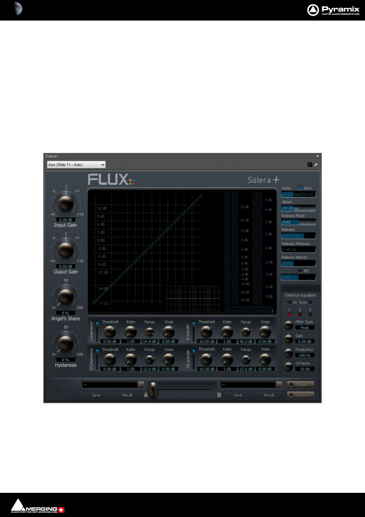
Effects and Plug-Ins : Flux 13 - 381
Flux
Note: The Flux VS3 plugins come as a separate installer. 64bit installers are available as down-
loads. First, download and install the Flux Center 64bit.
https://www.fluxhome.com/download
For further information about installing and using Flux Center 64bit please see here:
https://confluence.merging.com/display/PUBLICDOC/Flux+Download+Center
Once Flux Center is launched go into Settings and select the VS3 option and the Pyramix v10 installation pack.
You will then be able to install the Flux VS3 plugins of your choice.
Solera +
Solera + is the flag ship of the range of Angel Class Dynamic Processors. It is primarily designed for mastering
and re-mastering applications. However, it can also be used as a regular dynamic processor for superior sonic
quality and distortion free operation.
Developed for Merging Technologies by Flux, every Angel Class Dynamic Processor plug-in uses some exclusive
algorithms that endows them with an incredibly clear and natural sound.
The Pure series uses the same technologies for specific dynamic processes.
Solera floating Window

Effects and Plug-Ins : Flux 13 - 382
Here are some of the key features that make our plug-in the best available for dynamic processing in the digital
domain:
1. Analog like metering. RMS values are more useful than dBfs when setting up a dynamic processor.
2. The Angel's Share parameter takes account of the signal for intelligent relaxation of the compressor action.
3. The Hysteresis parameter allows compressing and de-compressing independently of the sound level and
can be mixed with the standard compression scheme.
4. The Auto Release features an unique algorithm that avoids typical pumping effect.
5. A delay line can inserted in the signal path to produce a null attack time.
6. The A/B compare and Morphing section enables ultra-fast and precise operation.
The Angel Class Dynamic Processor family supports up to simultaneous 8 channels and DXD operations.
Note: Solera is a wine making technique: A Solera is method of fractional blending for wine, closely
paralleling the making of Sherry or Madeira. A solera consists of several rows of stacked oak barrels
with the oldest wine in the bottom row and the most recently made at the top. At bottling, about one-
third of the wine in the bottom row is removed and wine from the row just above replaces it and soon,
until reaching the top row, which is replenished with new wine. The concept behind a Solera is to
make a wine that remains consistent from year to year.
Angel's Share is a term used for Armagnac, Cognac, Whisky; that part of the spirit that evaporates
during the process of aging.
Full operating details can be found in the Angel Class Processors User Guide.
Syrah v3 Creative adaptive dynamics processor.
Syrah v3 is a new generation dynamics processor utilizing real time dynamic detection and level dependent pro-
cessing, providing adaptive dynamic capabilities, which mean that Syrah is always trying to adapt to the music
and to the beat of the material. Using parts of Flux’ exquisite 'BitterSweet' technology, new adaptive-dynamics
technology, and well-recognized level independent dynamics processing, Syrah will be well suited as a creative
versatile processor for recording and mixing, as well as for delicate and demanding mastering tasks.
Pure Series
The Pure Series plug-ins are essentially the individual building blocks of Solera presented as individual plug-ins.
The advanced release mode is only available in Solera.
Pure Compressor
Pure Compressor is the compressor section of the Solera
Pure Expander
Pure Compressor is the expander section of the Solera
Pure DCompressor
Pure Compressor is the de-compressor section of the Solera
Pure DExpander
Pure Compressor is the de-expander section of the Solera

Effects and Plug-Ins : Flux 13 - 383
Algorithmix
DeNoiser
DeScratcher
DeNoiser + DeScratcher, Restoration Suite
ReNOVAtor
Overview
The ReNOVAtor™ plug-in for the Pyramix rendering interface is an impressive weapon in the battle for cleaner
recordings. Coughs, chair scrapes even mobile phone tones are all in its sights.
The ReNOVAtor™ Plug-In enables audio data in the frequency domain to be modified simply and quickly. These
modifications include interpolation of selected areas over the time- and/or frequency line as well as gain modifica-
tions. The interpolation can also be restricted to certain gain ranges within the selected area, which is very useful if
only a certain part of the data needs treatment (e.g. one specific harmonic etc.) which cannot otherwise be
selected. The ReNOVAtor™ window is fully resizable for optimum compatibility with all screen resolutions.
Vincent Burel
The VB plug-ins are bundled in the Pyramix 64-bit installer and require valid keys to operate. In the absence of the
relevant keys they operate in demo mode. (Plug-ins are bypassed every 30 seconds.)
Aphro V1 Reverb / Aphro V1.5 Reverb
Aphro-V1.0/Aphro V1.5 are real time Digital Effects Processors. Elements of a high quality effects processor series
called Aphro-Vx, Aphro-V1 and V1.5 are specially created to simulate sonorous atmosphere and room effects, in a
realistic way.The handling philosophy is made simple and practical thanks to a wide range of presets, which
requires the user to select a preset matching the best desired effect, and then to use the different interfaces in
order to adjust it, according to his requirements. Grouping parameters by theme, gave us the idea of creating a
modular and ergonomic user interface.
VB Packs
• VB C10-Multiband Compressor (C10-D10 - Limiter / C10-DXD)
• VB Compressor (Red-Blue Compressor and Decompressor / MultiChannel Compressor)
• VB EQ-Pro Pack (EQPro - G3/G4 EQnotch - G3/G4
• VB Limiter (C-Limiter)
• VB Measure Pack (VU-Meter / Oscilloscope / Spectrum Analyzer)
• VB Special Fx (Chorus / MultiTap)
• VB Stereo Management (Stereoman / MonoSwitcher)
• VB Striptool V1* / V2 / V3)
• VB Tone-X Pack (Tone-Param / Tone-Shelf / Tone-4)
* VB Striptools V1 plug-in is free of charge for all users. (32-bit or 64-bit)
Note: Having the VB plug-ins installed can result in a 10 second (approximately) delay when
launching Pyramix. If you do not wish to install the VB plug-ins along with Pyramix 9.1 or higher
then select Custom when launching the Pyramix installer and under the VBAudio plugin entry
select: This Feature will Not be Available.
Cedar Audio Restoration Suite for Pyramix
Cedar’s range of restoration tools need no introduction here. The following processes are available for Pyramix:
• Cedar dehiss for Pyramix
• Cedar declick for Pyramix
• Cedar manual declick for Pyramix
• Cedar decrackle for Pyramix

Effects and Plug-Ins : Flux 13 - 384
• Cedar dethump for Pyramix
•Cedar Retouch for Pyramix
For full details please contact your Merging sales partner.
Prosoniq
MPEX4 Timestretch and pitch change
Overview
The MPEX4 algorithm for Pyramix has been developed with the German based company Prosoniq, well known for
their high quality digital audio algorithms.
MPEX stands for Minimum Perceived Loss Time Compression/EXpansion. Incorporating this technology into Pyra-
mix Virtual Studio enables users to adjust timing and pitch of existing material with outstanding results and ease
of use.
Algorithm
Time Scaling (also known as 'Time Stretching', 'Time Compression/Expansion' and 'Time Correction') is the process
of changing the length of a sound or sounds without changing its pitch. When a sound is transposed by playing it
back at a different speed, e.g. when slowing down the playback speed of a tape recorder, it will play back at a dif-
ferent tempo but also at a different pitch. While this may be fine when tuning drum loops to match the speed of a
recording it will make pitched sounds - like vocals - sound totally out of tune. Therefore it is desirable to provide a
process that enables the duration and pitch of a recording to be changed independently from each other.
Time Stretch and Pitch Change for Film Applications
There are three main categories of Cinema time stretching and pitch changing requirements:
1) Conversion of audio rushes from 24 to 25 or 25 to 24 when their associated video or film has to be sped up or
slowed down. The main reasons are:
a. The shooting has been done with film AND video, so one part of the rushes or the other have to be sped up
or slowed down.
b. The telecine process to bring the film rushes to video for editing didn't preserve the original speed, intention-
ally or by mistake.
c. The shooting has been done on video at 25fps (intentionally or by mistake) and has to go to film.
Pyramix provides various solutions to this problem:
Batch conversion
of a whole media folder. Just select all media to stretch/squeeze / pitch change and select the menu Quick Con-
vert > Prosoniq MPEX4 module. All media will be processed in one shot. Media will have to be re-synchronized in
time with their video equivalent by using the reference "Clap".
In the case where all the media are already synchronized in time with their video equivalent (either manually or
because they've been properly stamped while recording), then simply send all these media to their original Time-
Code (time stamp) in a Pyramix project and select the menu item Project > Stretch / Pitch. All media will be prop-
erly stretched/squeezed and their position will be also correctly updated. The new original TimeCode (time stamp)
can then be written back to the media by selecting the menu item Clips > Operations > Update Media Original
TC, so these new media can now be used exactly as if they've been recorded and stamped at that new speed,
allowing also auto-conformation or other TimeCode based processes. All information stored in the Clips referenc-
ing these media in the Timeline (like fades, sync points, gain curve, ...) are also stretched/squeezed properly.
Optionally the media can be consolidated to convert only the required part
The two processes described above are necessary when a mix of different source material speed have to be "nor-
malized". In the case where it is known from the beginning that the whole editing and mix will have to be
stretched back to the other (original rushes) speed, Merging provides a very convenient solution in term of hard-
disk space, conversion time and finally sound quality. The Virtual Transport Video Player allows playing the video
editing at a different speed than the audio material allowing matching (for instance and in the majority of cases) a
video running at 24 frames per second with an audio editing stamped at 25 frames per seconds. This avoids com-

Effects and Plug-Ins : Flux 13 - 385
pressing the audio so it matches the video being played too fast (25fps instead of 24) but preferably run the video
at the correct speed (24fps) and therefore the audio also.
Surround Post-processing
Conversion of a final mix from 24 to 25 for DVD/Video distribution of a film or 25 to 24 for film distribution of a
video shot and edited movie.
Pyramix allows stretching/squeezing a whole surround mix by selecting the menu Project > Surround Post-pro-
cessing and choosing the Prosoniq MPEX4 24/25 Time Stretcher module. This function stretches/squeezes a
whole 5.1 mix without inter-channels phase artifacts thanks to the new Prosoniq MPEX4 algorithm. This function
allows processing multiple stem surround mixes stem by stem. Due to artefacts introduced by most time stretch-
ing algorithms available until now, the normal procedure was to separate the dialogue stem and the music/
effects/ambiance stems, time-stretch them separately and remix them afterward. Although the Surround Post-
processing function allows this methodology, this is no longer required due to the very high quality of the MPEX4
module. Therefore a complete mix can be stretched in one pass retaining maximum sound quality.
Time fit
Compression or expansion of a portion of audio to fit in a given time, generally dialogue, ADR, translation or Foley.
Pyramix provides three ways to stretch/squeeze a Region of audio:
• Just select the Region or Clip to process and place the cursor at the position where the nearest Region
boundary should be extended to and select Edit > Stretch. A dialog will then allow the boundaries to be
precisely adjusted with the help of TimeCode entries, or simply click OK or press the Enter key to confirm
the operation.
• Select the Region or Clip you want to process and copy it (Edit > Copy, or Ctrl C etc.). Select the Region
you want the copied Region to fit into then simply use the command Edit > Fit Selection.
• Select the Region or Clip to process, select the menu Project > Render and choose the Prosoniq MPEX4
module.
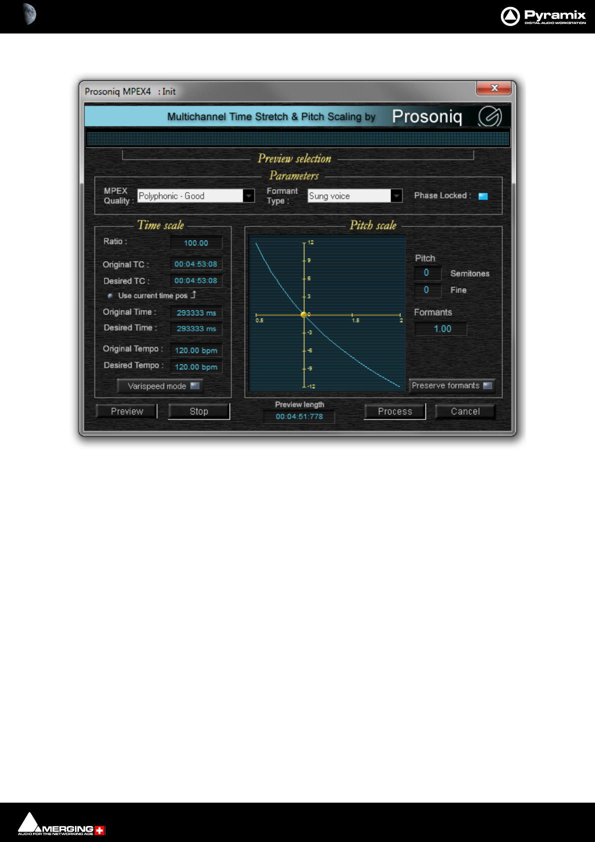
Effects and Plug-Ins : Flux 13 - 386
A comprehensive interface then enables the time-stretch parameters to be precisely adjusted. In addition to time-
stretching this interface also allows Pitch and Formant adjustments.
Quick Convert
The Prosoniq MPEX4 process can also be accessed by the Quick Convert function (Media Management Tab Win-
dow, Menu Convert > Quick Convert > Prosoniq MPEX4.
Zynaptiq
ZTX Pro
Optional high quality pitch-shift and time-stretch renderer from The Zynaptiq.
Note: Merging Technologies ZTX Pro key is required.
Accessing ZTX Pro
When a valid key is present ZTX Pro replaces Timezone as the Default Time-stretch tool in Editing.
It can also be defined under Settings > Application > Editing > Time Stretch Tool
TimeZone is no longer supported and no longer available.
Configuration
ZTX Pro is configured is in Pyramix Settings under Settings > Application > Time Stretch > ZTX Pro Settings.
Three quality modes are available: Good, Better, Best.
Prosoniq MPEX4 dialog

Effects and Plug-Ins : Flux 13 - 387
Time/Frequency localization setting
1. Selects full time localization. Good setting for single instruments and voice.
2. Time/frequency localization with emphasis on time localization. If setting 1. produces echoes this give better
results.
3. This sets the time/frequency localization halfway between time and frequency domains. It is the best setting
for all general purpose signals and should be set as default for non-preview processing.
4. Higher frequency localization and less time localization. May be a better choice for classical music than the
lower Time/Freq localization settings.
5. Highest frequency localization. This may not be an ideal choice if you're dealing with signals with very fast
attack transients.

Effects and Plug-Ins : VST Support 13 - 388
VST Support
VST Plug-ins
All well-behaved VST2 plug-ins can be used with Pyramix.
As of v11.1 VST3 plug-ins are supported in the mixer and in Effects Rendering but not currently in the Effect Rack.
32 bit or 64-bit OS
From Pyramix V10 onwards only 64-bit VST plug-ins are supported.
Under 32-bit OS only 32-bit VST plug-ins are supported. (Only if running Pyramix v9.1 and prior 32-bit versions.)
Note: Please ensure you use 64 bit plug-ins on 64 bit OS systems and 32 bit VST plug-ins on 32
bit OS systems. It is possible to use a workaround to run 32 bit VST plug-ins on a 64 bit OS system
by using the jBridge application. For further details please follow this link:
http://jstuff.wordpress.com/jbridge
VST Plug-ins Scanner
In order to use VST Plug-ins, when launched, Pyramix must first scan the directories where the plug-ins are
located. By default \Program Files\VSTPlugins and or \Program Files\Steinberg\VSTPlugins directories are
scanned if they exist.
VST3 plug-ins are also, by default, scanned at Pyramix launch of and do not require a folder to be mounted in All
Settings > Mixer > VST-Plugins.
VST3 plugins are specified to be added into the c:\Program Files\Common Files\VST3 folder, this
folder is scanned at Pyramix launch or on demand from Pyramix Settings.
VST3 plugins are known for their technological advancements and creative basis. Users can now benefit from:
Improved performance, Resizable edit windows (when the plug-in supports them) and Multiple dynamic I/O’s
since VST3 plug-ins are not limited to a fixed number of inputs and outputs.
Further directories may be added to the scan list in Pyramix Settings. Please see: VST Plug-Ins Settings on
page 731.
Also in VST Plug-ins Settings there are two options for how installed plug-ins will be ordered in the list menu:
By Company Name and I/O Configuration or by I/O configuration.
Note: The VST Plug-ins are initialized during Pyramix launch and this can take some considerable
time. E.g. around four minutes for a Waves bundle. Please be patient if the Pyramix splash screen
is displayed for a long time.
Note: VST plug-ins are processed by the host CPU. Therefore, if you are intending to use VST
plug-ins intensively, fast host processors are recommended.
Multi-channel VST Plug-ins
Multi-channel VST plug-ins are supported on MassCore Systems only.
Note: The input scheme for multi-channel VST plug-ins is SMPTE L-R-C-Lfe-Ls-Rs. The output is
routed correctly for the Pyramix bus layout Film L-C-R-Ls-Rs-Lfe.
Routing
On all Pyramix platforms VST plug-ins are automatically routed according the Strip or Bus Channel types e.g. C, LR
etc. and the matching VST Speaker arrangement (typically, 5.1 Surround VST speaker arrangement uses the SMPTE
L-R-C-Lfe-Ls-Rs mapping). If no VST Speaker arrangement can be found, the routing is straight.
Effects and Plug-Ins : VST Support 13 - 389
For example, if for some strange reason you stamp a Stereo Aux as R-L, the left channel of a VST plug-in inserted
into it will be fed by the 2nd channel of the Aux, and the Right channel by the 1st one; and at the VST insert out-
put, the R-L routing is restored.
Note: If the VST Core meter shows peaks we recommend increasing the VST Plug-ins Latency
value. Please see: VST on page 38
On/Off and Bypass
Like VS3 plug-ins VST plug-ins have yellow On/Off and red bypass buttons on the mixer providing standard bypass
control.
The left-hand yellow button is lit when the effect is switched on. Switching an effect off removes it from the signal
chain and this may well be audible.The right-hand red button indicates that the effect is bypassed when lit.
Bypassing an effect retains the same delay as when the effect is active. Further, well behaved effects will continue
to calculate internal parameters when bypassed making seamless switching possible.
Note: Certain VST plug-ins such as UltraPitch do not have the standard VST internal “soft” bypass
function. In this case, Bypass simply acts as an ON/OFF button. One effect of this is a change in
Delay compensation scheme resulting in latency changes as the plug-in is switched ON or OFF.
Changing the delay compensation on the fly during Playback or Record is not safe since it will
cause a glitch or playback stall, and therefore Pyramix postpones the delay compensation
recomputation until the transport switches back to stop. When you change the bypass status of
such a plug-in on the fly the DelayComp status LED turns red and, on the next Stop, Delay com-
pensation is recomputed and the status LED returns to green.
Most VST plug-ins provide a private 'bypass', (inside the plug-in's own user interface), which
enables clean, click-free and state-safe bypassing, without latency change (i.e. the plug-in main-
tains the same latency whether it is bypassed or not). Unfortunately, there is no simple and effec-
tive bypass solution for plug-ins that do not have an internal bypass.
VST Effect Wrapper Header
On the VST user interface windows themselves, the On/Off and bypass buttons are on the left of the caption bar
and function in the same way as the buttons on the mixer.
Caption Bar
The Caption bar text of these windows shows the ID of the related Strip or Bus and its name, before the plug-in
name.
Automation
Automation mode is set using the R and W buttons. (Unlike VS3 plug-ins individual controls cannot have indepen-
dent Automation modes).
Interface Switch
The drop-down underneath the On/Off and bypass buttons enables switching between the plug-in Editor inter-
face and the Routing view.
Programs
The Program List combo box and previous/next buttons below the automation buttons are only present if the
plug-in has more than one program.
VST - Plug-In On/Off and Bypass
VST - Plug-In Wrapper header
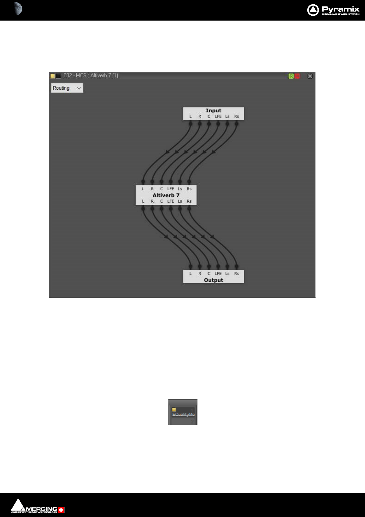
Effects and Plug-Ins : VST Support 13 - 390
VST Routing
Enables the automatic channel routing to be changed, by simply selecting the connection arrow and moving it to
another IO
The Input/Output sections' channel mapping, follows the channel order of the Strip/Bus.
VST Plug-ins Without a User Interface
A generic UI has been added for VST and VST3 plug-ins which are provided without a user interface.
Ghost Plug-ins
As with VS3 plug-ins, the Ghost plug-in feature is implemented for VST plug-ins: essentially, this means that if you
load a project containing a VST plug-in which is unavailable on your machine, this plug-in will appear in the mixer
as a Ghost plug-in. This also applies to VST3 plug-ins when a Project is saved as a version lower than v11.1.
Saving the project will not trash a missing plug-in’s state information.
When a plug-in is a Ghost its name appears crossed out in the mixer :
VST - Plug-In Routing view
VST - Plug-In Ghost
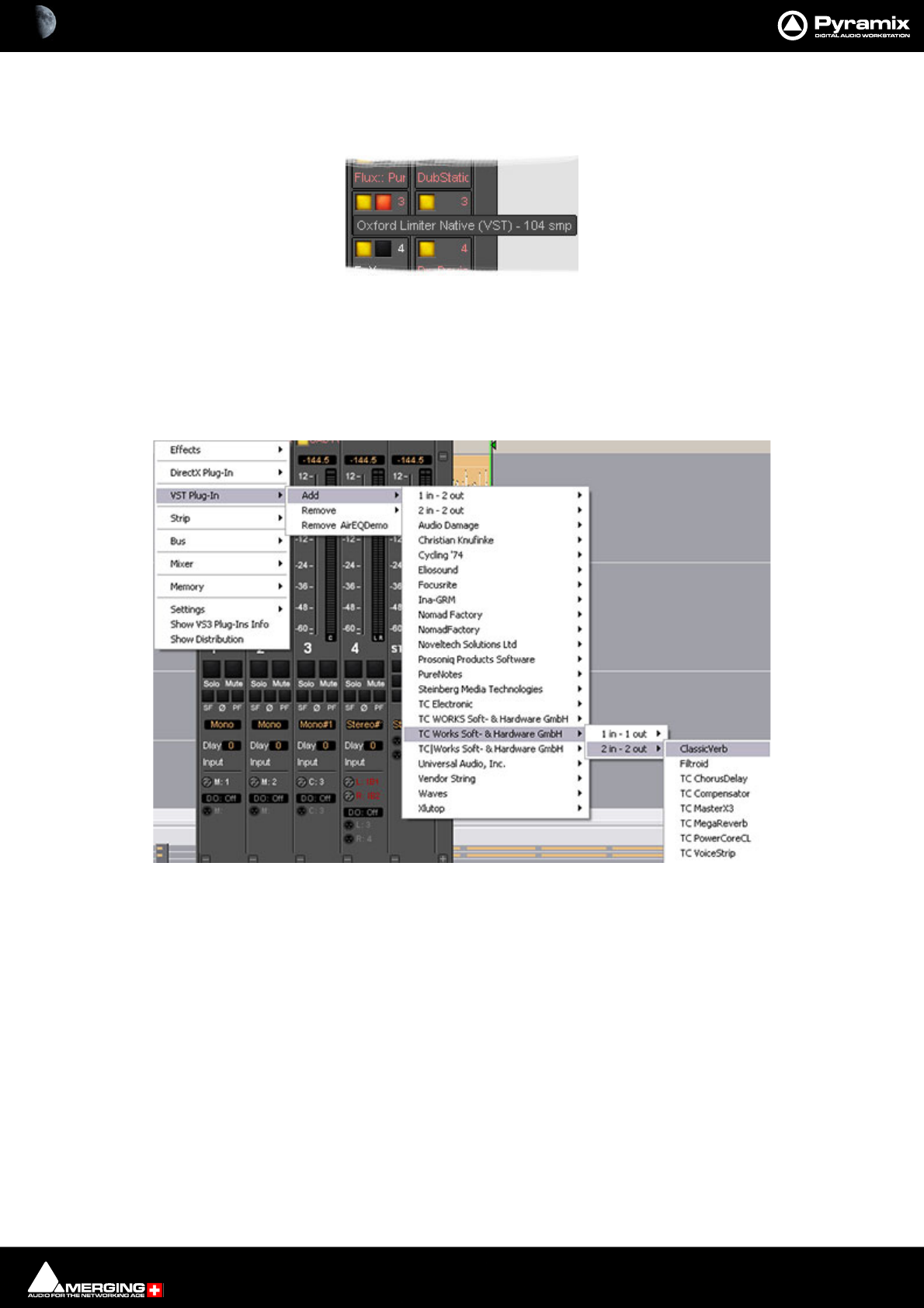
Effects and Plug-Ins : VST Support 13 - 391
Processing Delay Display
At any time, you can view a VST plug-in’s processing delay in the VST plug-in name tooltip on the mixer (if non-
zero, the processing delay will be appended in smp (samples) after the plug-in name):
VST Plug-ins Display Order
The list of VST Plug-ins that appears when adding a new instance of a plug-in can be ordered in two ways.
If Company Name and I/O Configuration is chosen the list will be ordered by Company Name and the plug-in’s
grouped according to their I/O configuration. I.e. 1 in - 1 out, 1 in - 2 out, 2 in - 2 out and so on as shown here:
VST - Plug-In Tooltip with delay value
VST - Plug-Ins List by Manufacturer
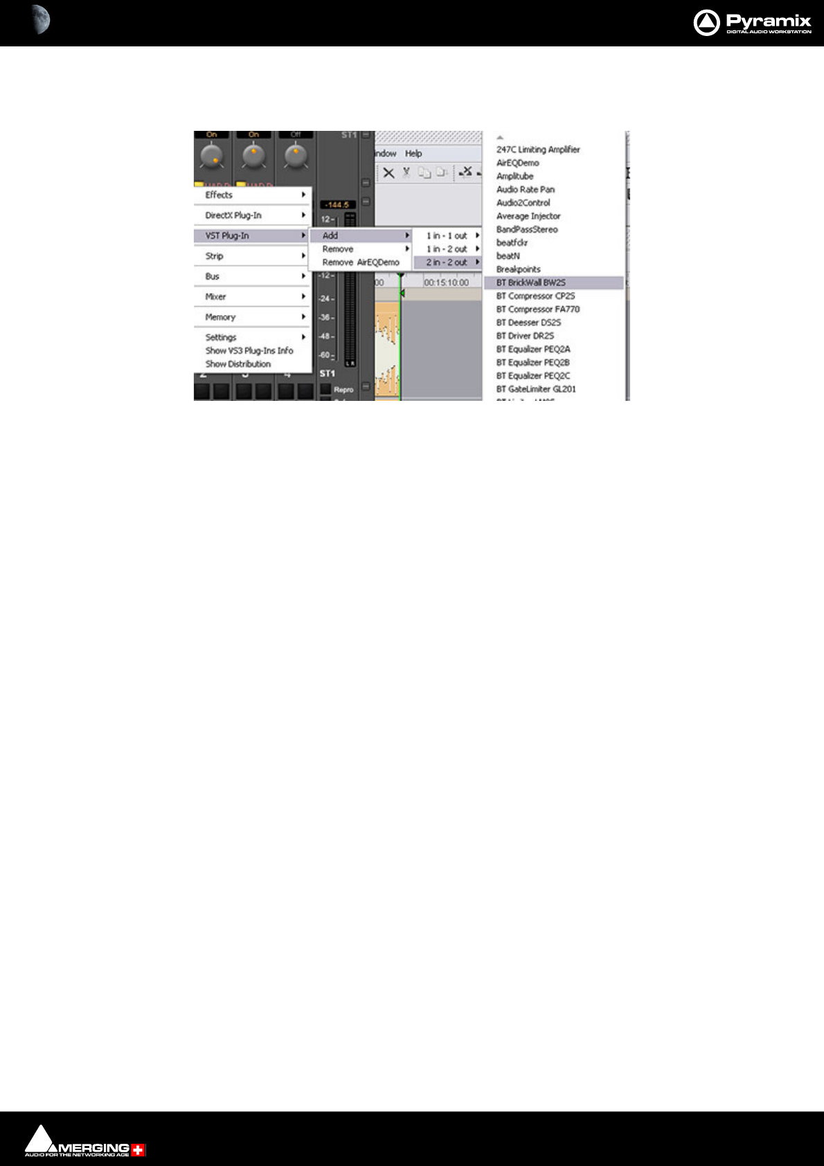
Effects and Plug-Ins : VST Support 13 - 392
Alternatively, choosing I/O Configuration groups the Plug-ins by I/O Configuration and within each group lists
them alphabetically by name as shown here:
The alternative displays are chosen in the Settings > All Settings : Project > Mixer > VST Plug-ins Settings page.
Please see also: VST Plug-Ins Settings on page 731
VST - Plug-Ins list by I/O configuration
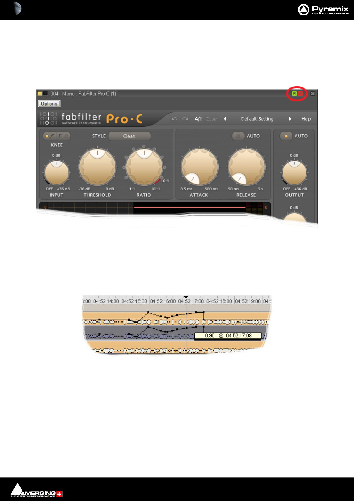
Effects and Plug-Ins : VST Support 13 - 393
VST Plug-in Automation
VST plug-in automation works in much the same way as VS3 plug-in and Pyramix Mixer automation. However,
there are a few differences:
Automation Mode
Read/Write, Auto-Write or Isolate status can only be set for an entire plug-in.
Automation mode is set using the R and W buttons to be found at top right of a VST Effect window. (Unlike VS3
plug-ins individual controls cannot have independent Automation modes).
Automated Control Values
Control values are always expressed as zero to one. I.e. in the range 0.0 to 1.0 when editing automation points in
the Timeline. The exception is when the VST plug-in reports a control as a toggle switch.
VST - Plug-In Automation Read Write buttons
VST - Plug-In Automation node control value display

Effects and Plug-Ins : VST Support 13 - 394
Direct X Plug-ins
in Pyramix V6.1 and later, DirectSound / DirectX plug-ins can only be used inside a suitable “VST Wrapper”. There
are several freely available, for example from Vincent Burel.
Important! Projects and templates created with previous versions of Pyramix may well contain
Direct X plug-ins. If a Project or Template is loaded which contains Direct X plug-ins then these
will be visible in the mixer but cannot be activated.
However, if such a Project is “Saved As” V5.1 then these plug-ins will be active if the Project is sub-
sequently opened in a system running V5.1.
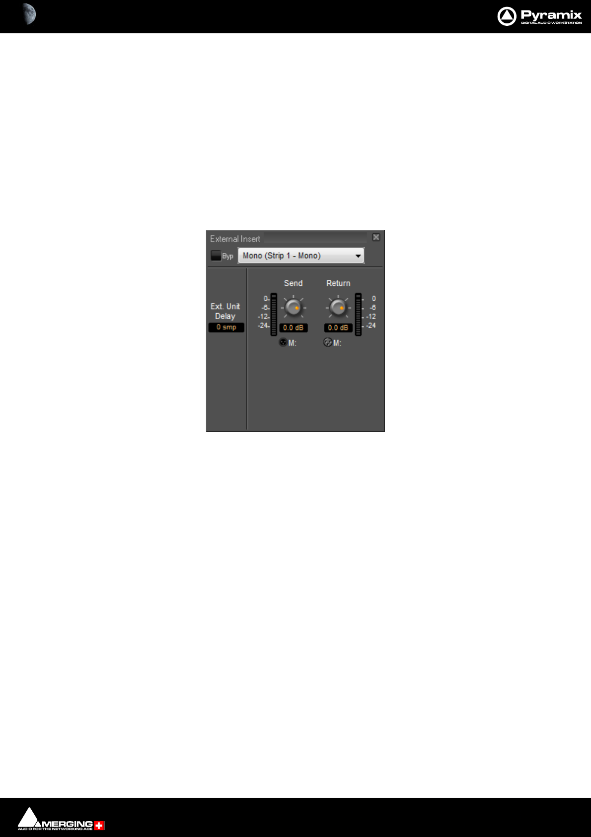
Effects and Plug-Ins : External Effects 13 - 395
External Effects
Pyramix General Purpose Mix Bus Types, Mix Bus and Aux Bus, can be routed to any physical output. Thus, an
Aux can be routed via a physical output to an external effect. The output of the external effect is simply brought
back into Pyramix via one of the physical inputs. However, a delay will be introduced by the external processor and
the converters. If the return needs to be time-aligned with other signals please see: Mixer Delay Compensation
on page 269
External Insert
To add an External Insert simply right-click over the strip where the plug-in is to be added and choose: VS3 Effects
> Add > Other > External Insert
Clicking on the External Input name in the strip opens the External Insert Control Window.
Send and Return Connections can be made by clicking on the XLR icons and levels set with the knobs. When you
have determined the delay introduced by the I/O loop including the external effect the value in samples should be
entered in the Ext. Unit Delay field.
Mixer Strip External Insert Plug-in Control Window
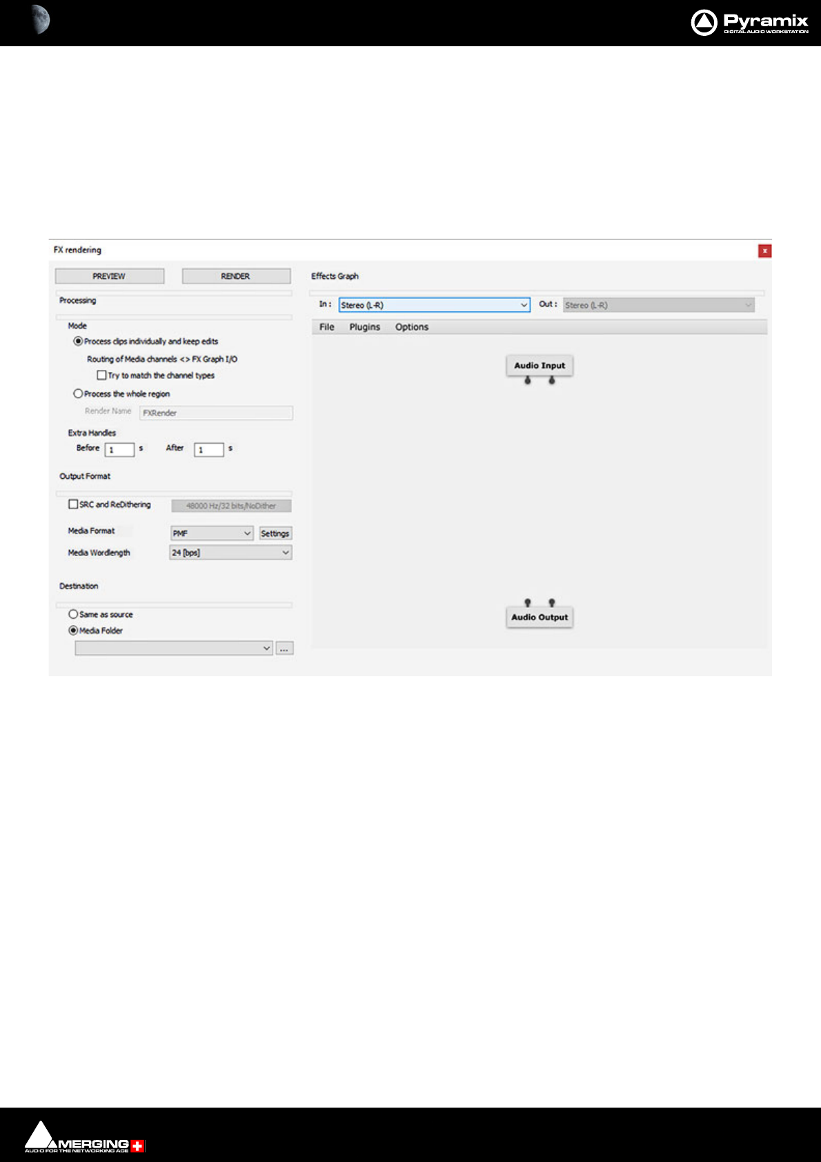
Effects and Plug-Ins : FX rendering Tab Window 13 - 396
FX rendering Tab Window
The FX rendering Tab Window offers a quick convenient way of rendering a Clip or Region with Plug-in process-
ing applied. If the FX rendering Tab is not present in the lower part of the main Pyramix Window it can be opened
with View > Editor Tabs > FX Rendering
A Clip, Clips or Region must be selected before an Effect or Effects can be Previewed or Rendered.
The FX rendering Window with nothing selected looks like this:
The left-hand side, Processing, of the Window has the set-up options and the PREVIEW and RENDER buttons
which initiate Preview or Render. The right-hand side, Effects Graph, is where Plug-ins are instantiated, FX render
presets are saved and recalled and a graphic representation of the Input, Output and Effect or Effects.
Processing
Mode
Process clips individually and keep edits Each Clip selected will be processed individually in its edited form in
the Timeline. The resultant file(s) will be named according to the original(s). Toggles
with Process the whole region.
Routing of Media channels <> FX Graph I/O
Try to match the channel types When the box is checked FX Rendering will attempt to match the
Input and Output channel types.
Process the whole region Processes the whole of a selected region. Toggles with Process clips indi-
vidually and keep edits
Render Name Type a name for the resultant render file(s). (Default is FXRender) This
option is grayed out when Process clips individually and keep edits is
selected.
Extra Handles
Before Type in the box to add a Handle at the start of the rendered file.
FX rendering Tab Window

Effects and Plug-Ins : FX rendering Tab Window 13 - 397
After Type in the box to add a Handle at the start of the rendered file. (Useful for plugins
which generate audio beyond the duration of the Clip or Region, e.g. reverb.
Default is 1S before and after.
Output Format
SRC and ReDithering When the box is checked Sample Rate conversion and Redithering will be applied to the
rendered file according to the settings chosen from the drop-down list.
Media Format Select the desired Output format from the drop-down list. Default is PMF.
Settings Opens a dialog box with settings options relevant to the format selected.
Media Wordlength Select the desired Output Wordlength from the drop-down list.
Destination
Same as source The rendered output file(s) will be placed in the same location as the original(s).
Media Folder The down arrow drops down a list of all Media Folders Mounted currently. The ... button
opens the Choose a media folder to mount dialog.
Effects Graph
In : The field shows the channel format of the Audio Input block. The down arrow drops
down a list of available formats.
OUT : The field shows the channel format of the Audio Output block. The down arrow drops
down a list of available formats.
Note: When Process clips individually and keep edits is selected the OUT : field is grayed out
since the Output format is fixed as the same as the input format. When Process the whole
region is selected the Output format can be different to the Input format. E.g. if you wish to pro-
cess LR from a 5.1source region.
Menus:
File
Open... Opens the Load a filter graph browser with the path set to the MERGING Libraries
folder. Select the desired Filter graph and click on Open to load it into the FX render-
ing Tab window and close the browser. Or click Cancel to close the browser witout load-
ing a Filter graph.
Save Saves the Filter Graph under the current file name or opens the Save a filter graph
browser if the Filter Graph has not been saved previously.
Save As... Opens the Save a filter graph browser
Plugins
Create plugin
Create plugin > VS3 Shows a list of all available VS3 plugins.
Create plugin > VST Shows a list of all available VST plugins.
The selected plugin will appear as a block in the middle of the Effects Graph.
Delete all plugins Deletes all plugins present in the Effects Graph.
Options
Edit the list of available plugins... Opens the Available Plugins window. This has an Options... button which
plugins to be added to or removed from the list.
Plugin menu type
List plugins by category
List plugins by manufacturer
List plugins based on the directory structure
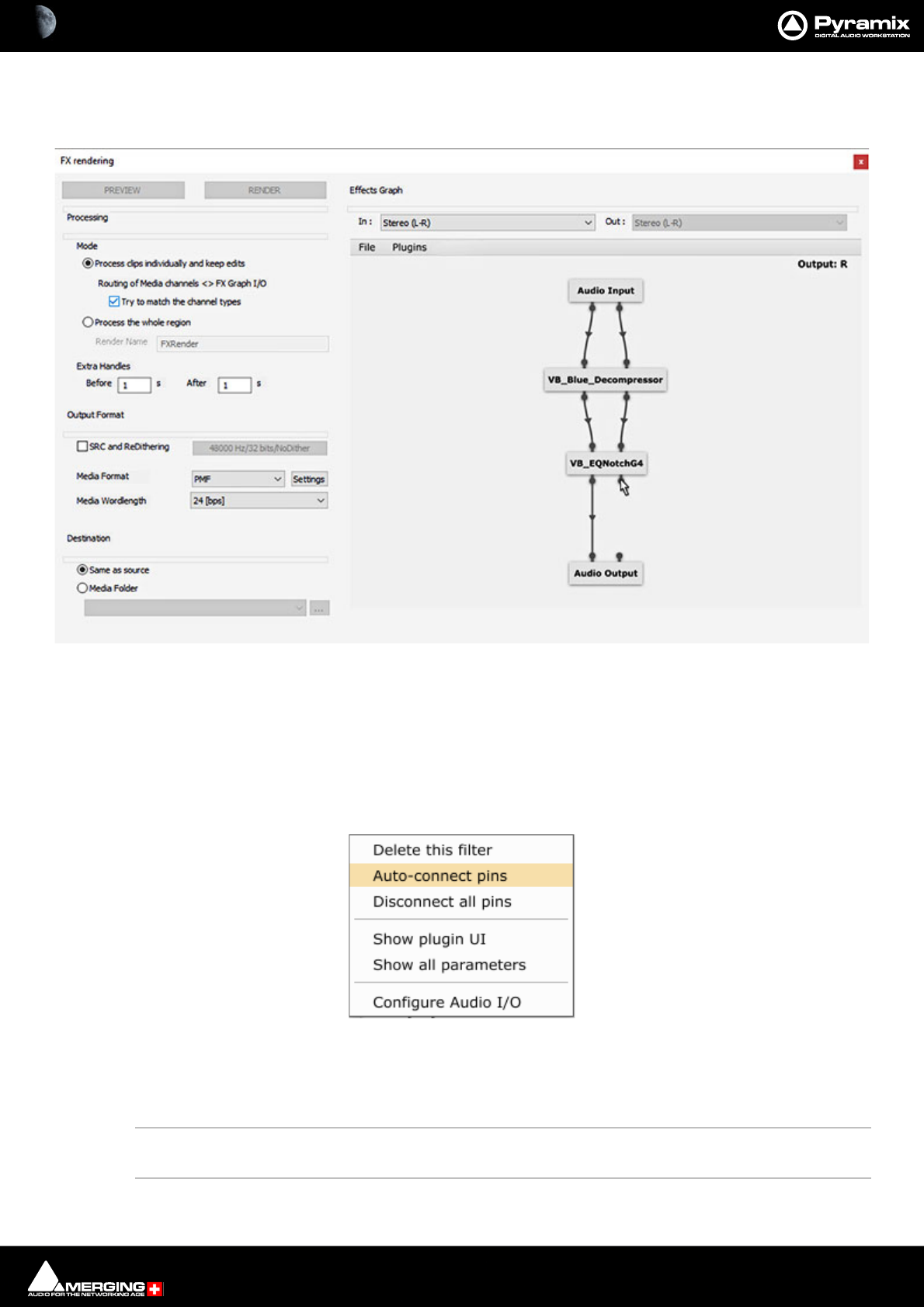
Effects and Plug-Ins : FX rendering Tab Window 13 - 398
Filter Graph
The filter graph shows a graphic representation of the Audio Input, Plugin(s) Audio Output and the connections
between them.
Plugins may be added from the Plugins menu or from the right-click context menu when the mouse cursor is over
a blank area.
Connections are made by clicking on an input or output pin node and dragging to another node. While the mouse
cursor is over a pin node the type of connection is shown at top right.
Individual connections are removed by clicking on the small arrow in the middle of the ‘cable’.
Right-clicking with the mouse cursor over a Plugin accesses a context menu:
Delete this filter Deletes the plugin under the mouse cursor.
Auto-connect pins Auto-connection is based on the channel types. (If there is no match, a one to one con-
nection will be applied.)
Disconnect all pins Removes all connections to pin nodes on the plugin under the mouse cursor.
Show plugin UI Opens the plugin UI in a separate window.
Show all parameters Opens an editable list of all parameters available for the plugin.
Configure Audio I/O Select a plugin and Right-Clicking enables the Input and Output Configuration to be
selected.
FX rendering Tab Window
FX rendering Effects Graph context menu

14 - 399
www.merging.com/Pyramix
USER MANUAL
Automation
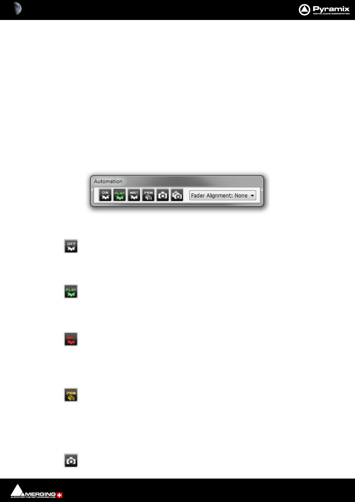
Automation : Scope 14 - 400
Scope
Pyramix Virtual Studio is equipped with an extremely powerful automation system, including both dynamic and
snapshot automation of levels, pans, effects, etc. This chapter covers internal control of automation. If you are
using a Ramses MSC or ISIS Controller, please see the relevant User Guides for further information.
Master Automation Transport Controls
Global Dynamic Automation Modes
Set using the On/Off, Read and Write buttons in the Automation toolbar (or the Automation menu items) these
set the dynamic automation mode for the entire console. Individual controls will behave according to their own
current mode.
The Global Automation Controls are in a dockable Tool Palette, by default located at the bottom right side of the
main Pyramix window. There are Off, Play(Read) Write and Preview buttons plus two buttons with camera icons
which deal with Snapshot automation: .
Off button can only be used to turn dynamic automation Off. When it is Off, no existing auto-
mation data is played back and no new data is recorded when controls are moved.
When dynamic automation is on, (Play or Write buttons lit), existing automation data is played back. New auto-
mation data can only be recorded when Write is lit and the controls to be automated are in an appropriate mode.
When the Play (read) button is pressed it ‘lights’ green.
Controls set to Read, or Auto-Write, Read existing automation data, otherwise they maintain their default values.
Controls set to Isolate or Record maintain their current values and no new data is recorded.
When the Write button is pressed it ‘lights’ red. Controls set to Write write their current val-
ues. Controls set to Touch only record when they are moved. Controls set to Read, Read
existing automation data (if any). Controls set to Isolate maintain their current values.
Snapshot Automation
When the Preview button is pressed it ‘lights’ yellow. In preview mode Automation Read is
active until a control is moved. When the Transport is stopped the Filter Automation Tracks
to Snapshot Range dialog appears. (If this has been selected in All Settings > Application
> Automation.) Please see: Preview Automation Mode on page 408. Please see
also: Filter Automation Tracks to Snapshot Dialog on page 418
The Off button cancels either Read, Write or Preview modes and switches dynamic automation off.
The Snapshot button opens the Filter Automation Tracks to Snapshot dialog. When OK is
pressed inserts an automation event (key frame) is inserted which records the state of all
Master Automation Controls dockable toolbar
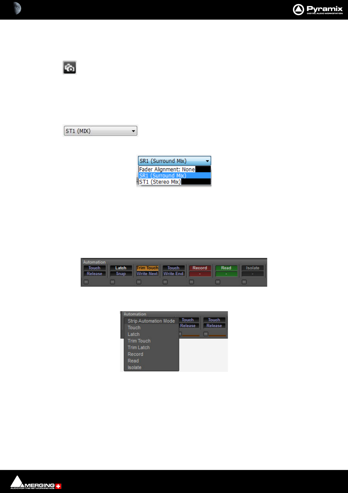
Automation : Dynamic Automation Levels 14 - 401
enabled controls at the current cursor position if their state has changed since the previous
Snapshot.
The Snapshot Range button opens the Filter Automation Tracks to Snapshot Range dia-
log. When OK is pressed automation snapshot key frames of all enabled controls are inserted
at the Mark In and Mark Out cursor positions. In effect, this sets all enabled controls to the
current state throughout the range defined by the marks.
Please see also: Filter Automation Tracks to Snapshot Dialog on page 418
Designated Bus Selector for Fader Alignment
The box shows which bus the automation is aligned with when auto-
matic delay compensation is active. The drop-down list shows all available buses plus the
option of none.
Dynamic Automation Levels
There are two “levels” of automation in the mixing console.
Level 1
The modes as defined per Strip in the section atthe bottom of the mixer:
Clicking on the upper button pops-up the list of available Strip Automation Modes:
•Touch
•Latch
•Trim Touch
•Trim Latch
•Record
•Read
•Isolate
Control strips Automation buttons
Control Strip Automation Mode pop-up
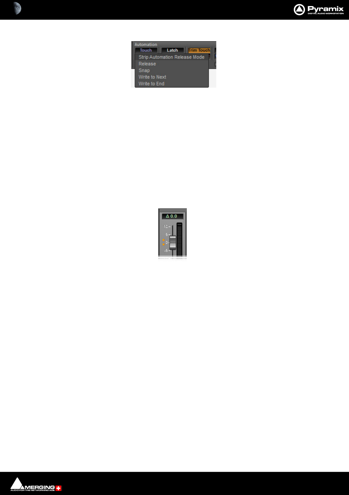
Automation : Automation Modes 14 - 402
Clicking on the lower button pops-up the list of available Release Modes:
•Release
•Snap
• Write to Next
• Write to End
These modes are also available through the contextual right-click mouse button under
Strip > Automation and have the same effect as selections made with the buttons at the bottom of the strips.
These modes do not color the mixer strips, only the buttons on the bottom of strips
To set these modes for the entire mixer the Automation menu has entries for Console Strips Mode - XXX and
Console Strips Release Mode - XXX.
Note: When a Trim mode is selected a delta symbol appears in the numeric display:
Level 2
Level 2 is the modes available via the right-click context menus under Automation (per component), Bus > Auto-
mation (for the whole bus), Mixer > Automation for the entire mixer The modes are:
• Follow Strip
•Record
•Read
•Isolate
These modes override the Strips level 1 mode.
When in Follow Strip Mode, the level 1 Strip mode for the whole strip applies to the component, when in Record,
Read or Isolate the component ignores the Strips mode.
These modes color the background of the mixer components and override any strip or bus color.
Automation Modes
Behavior when a control is touched or released depends on the global settings in the Automation menu, strip set-
tings or individual control settings.
Control Strip Automation Release Mode pop-up
Trim Touch or Latch Mode Delta indicator
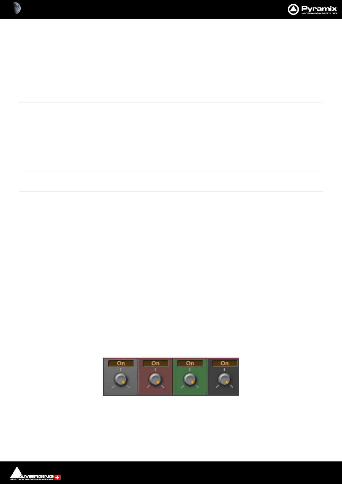
Automation : Automation Modes 14 - 403
Automation Menu - Touch and Release Modes
Console Strips Mode - Touch The automation starts writing a new pass when the control is touched and stops writing
when the control is released. Behavior on release depends on the release mode.
Console Strips Mode - Latch The automation starts writing a new pass when the control is touched. The value when
the control is released will continue to be written until the transport stops.
Console Strips Mode - Trim Touch The automation starts updating the current pass when the control is touched and stops
updating when the control is released.
Console Strips Mode - Trim Latch The automation starts updating when the control is touched but continues when the
control is released and stops only when the transport stops.
Console Strips Release Mode - Snap A straight jump is made from the current control value to the value written in the previ-
ous pass.
Console Strips Release Mode - Auto-Release An interpolation is created from the current value to the value written in the
previous pass. I.e. a fade. The length of this is defined in Automation Settings > Auto-
Release Time.
Console Strips Release Mode - Write to Next The same value is kept after the last written point until the next point is found in
the previous pass.
Console Strips Release Mode - Write to End Writes the current value to the end, ignoring previously written points. (If any)
Release Auto-Writing Immediately releases all controls currently recording automation. This option is provided
for controllers without touch sensitive faders etc.
Note: Ctrl + Alt + Esc releases Auto-Write
Trim Mode Notes
•Automation Trim modes shows a visual indicator when active (delta/small triangle in the numeric dis-
play).
• When in a Trim mode the fader will be set to 0dB and the offset applied will be reflected on the Fader
scale.
• An offset is applied to the absolute value, and the fader is fixed on the new value.
•Automation Trim can be applied to linked Strip Faders.
•Warning: When strips in Trim mode are linked to a VCA Group, they will not be controlled by the VCA
Master. This is intentional.
Note: Without Automation enabled, the Trim behavior can still be used despite the fact that no
values will be written, in such a case the Fader will remain at the last position it is moved to.
Dynamic Automation Transport Modes
Every control in the mixer can be set to one of four dynamic automation transport modes. The automation mode
can be set for individual controls, for channel strips, for buses, for groups of controls or for the whole mixer. The
current mode is shown by the background color.
Auto-Write Write Read Isolate
Dynamic Automation Transport Mode colors
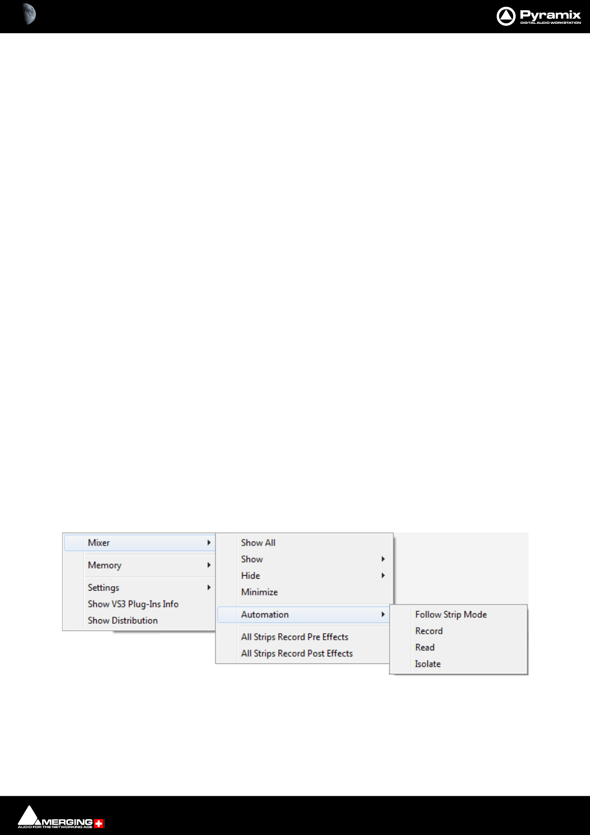
Automation : Automation Modes 14 - 404
Auto-Write
Default background color.
With the transport in Play, and the Master Automation Controls in Read or Write modes, the control(s) Read
(play back) previously recorded automation data.
In Write mode When a control is moved new automation data is written until the control is released. Behavior
when the control is released, or the transport stopped, is governed by the choices made in the Automation menu
and in Automation > Automation Settings.
Write
Dull red background.
With the transport in Play, and the Master Automation Controls in Write mode, the current state of all controls in
Record mode is recorded as automation data.
Read
Dull green background.
The control(s) follow the last automation data recorded for them or maintain their default position where no previ-
ously recorded automation data exists.
Isolate
Charcoal gray background.
The control(s) are isolated from any automation moves already recorded. Controls can be moved without affecting
existing automation data.
Default Mode
The default mode is Auto-Write. When the Automation Transport mode is Write if a control is moved automation
data is written automatically. Press a button and the same applies.
Selecting Automation Modes
Automation modes are set globally for the entire mixer, per strip or per component.
Entire Mixer
The entire mixer can be set to the same mode from the Automation menu or by right-clicking in a blank area of
mixer panel (E.g. under the bus strips) and selecting the desired mode from the popup menu. Mixer > Automa-
tion > xxxxx
Mixer context menu Mixer Automation sub-menu
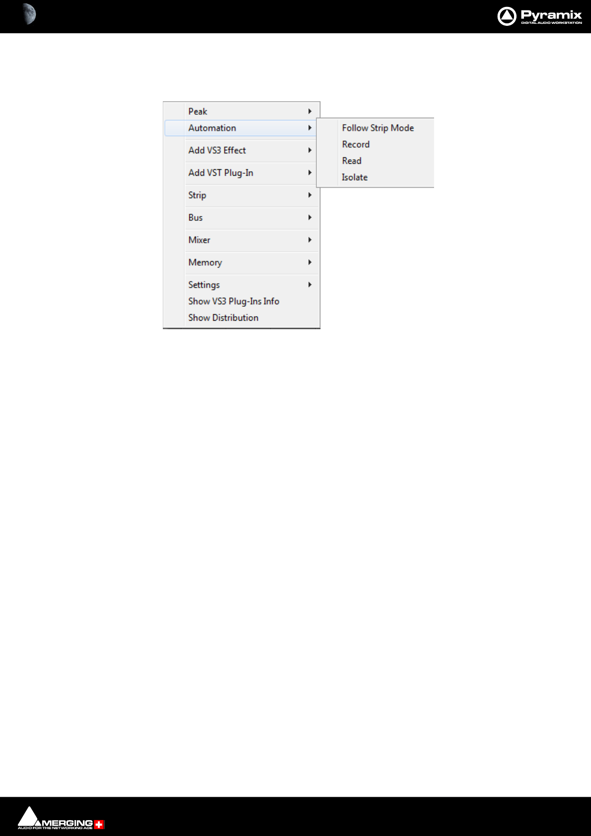
Automation : Automation Modes 14 - 405
Block, Strip, Bus or Entire Mixer
Right-clicking in a mixer channel strip function-block, e.g. as shown here in the fader area, pops up a contextual
menu. Selecting Automation opens a sub-menu offering a choice of four automation modes:
Automation sub-menu
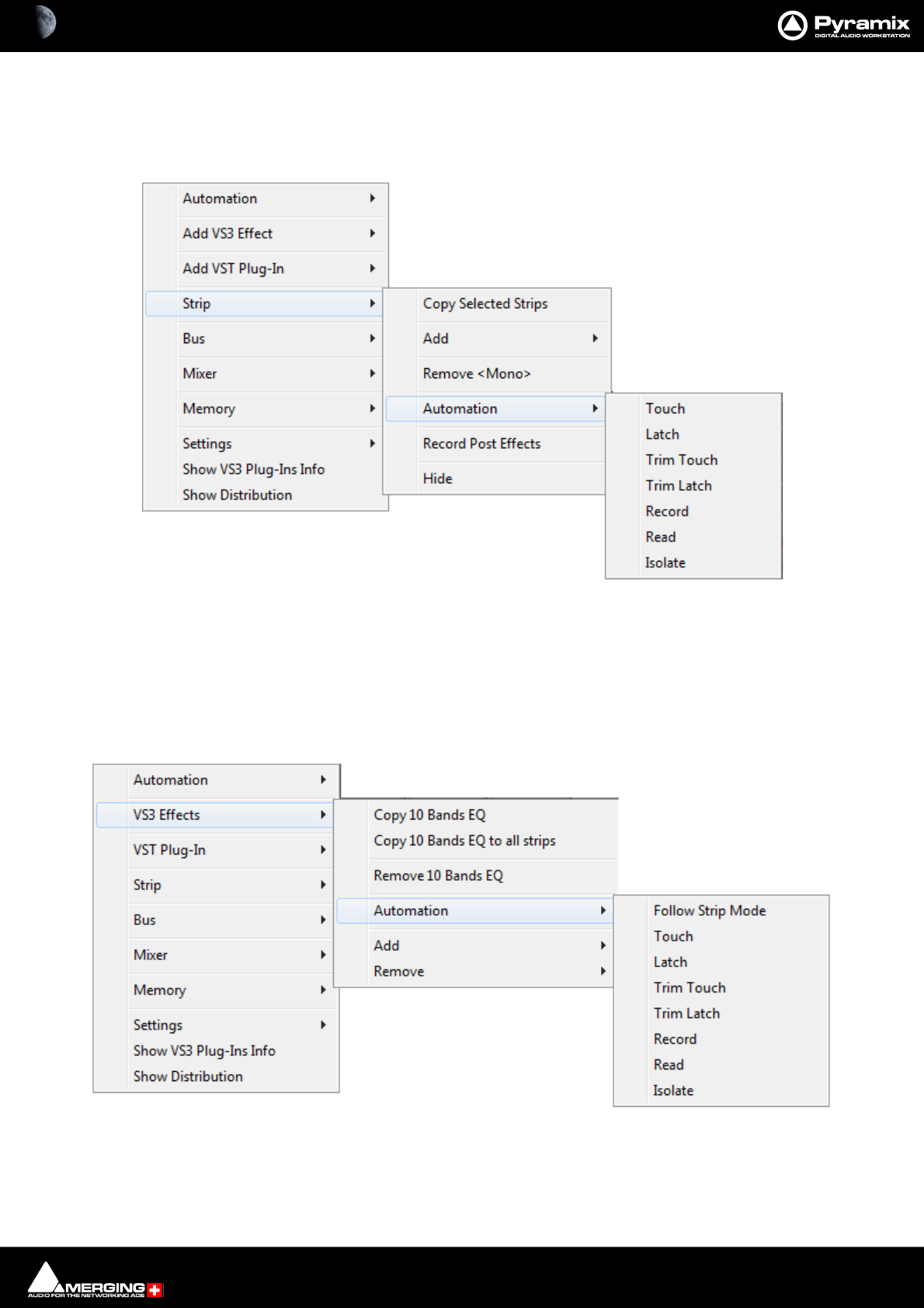
Automation : Automation Modes 14 - 406
This contextual menu also enables the automation mode for the whole strip, one or more buses or the entire
mixer to be set by choosing Strip, Bus or Mixer.
Selecting one of these opens a sub-menu. Selecting Automation opens a further sub-menu offering the choice of
automation modes:
WARNING: We advise that users do not automate Buses or Aux Send ON/OFF as this could cause
Delay Compensation issues. As an alternative simply automate Bus or Aux Send Gain.
VS3 Effects
Right-clicking over a VS3 Effect in a Strip, pops up a contextual menu. Selecting VS3 > Automation opens a sub-
menu offering a choice of seven automation modes:
Strip > Automation sub-menu
VS3 Effects > Automation sub-menu

Automation : Automation Modes 14 - 407
Follow Strip mode No mode identification letters shown in effect block. Effect Automation follows the mode
set for the entire Strip
Touch T shown in the effect block.The automation starts writing a new pass when the control is
touched and stops writing when the control is released. Behavior on release depends on
the release mode for the Strip.
Latch L shown in the effect block. The automation starts writing a new pass when the control is
touched. The value when the control is released will continue to be written until the
transport stops.
Trim Touch TT shown in the effect block. The automation starts updating the current pass when the
control is touched and stops updating when the control is released.
Trim Latch TL shown in the effect block.The automation starts updating when the control is touched
but continues when the control is released and stops only when the transport stops.
Record Effect block shaded red. With the transport in Play, and the Master Automation Controls
in Write mode, the current state of all controls is recorded as automation data.
Read Effect block shaded green.The control(s) follow the last automation data recorded for
them or maintain their default position where no previously recorded automation data
exists.
Isolate No mode identification letters shown in effect block. The control(s) are isolated from any
automation moves already recorded. Controls can be moved without affecting existing
automation data.
VS3 Effects Automation modes
Automation : Automation Modes 14 - 408
Preview Automation Mode
This mode allows Automation moves and snapshots to be tried out. If the result is as desired it can be saved. Oth-
erwise any changes made are discarded, preserving the pre-existing automation.
Preview Mode Options are set in the Settings > All Settings > Application > Automation page.
Preview Mode Options
Auto write on Stop Applies the Automation on all parameters changed during the pass without con-
firmation.
Confirm on Stop The Filter Automation Tracks to Snapshot Range dialog will open automatically
when the Transport is stopped. (Equivalent of pressing the Snapshot Range but-
ton.)
Manual Write The Preview button will blink when the Transport is stopped if any parameter
changes have occurred but the Filter Automation Tracks to Snapshot Range
action dialog will not open automatically . Clicking on the Preview button will
opens the dialog.
The Automation states in which parameters will be affected by changes in Preview Mode are set by checking the
desired boxes in:
Affect Parameters in :
Isolate
Read
Touch / Latch
Write / Record
When Automation Preview mode is active there are a number of different scenarios depend-
ing on the controls automation mode.
Isolate No automation data will be Read or Written. (Same behavior as Play or Write
modes.)
Read Read the current automation data. (Same behavior as Play or Write modes.)
Write When the automation Snapshot Range button is pressed the window shows
every control in Write Mode which has been moved since the previous Snapshot.
Until a control is adjusted it follows the pre-existing automation curve. The last
value set is retained until the Snapshot Range window appears. This window
opens automatically on Stop when Preview mode: Popup Snapshot window on
Stop is active. In the Snapshot Range window the changes can be cancelled or
accepted per control.
Auto-Write Same behavior as Write mode.
Preview Mode Options in the Automation Settings page
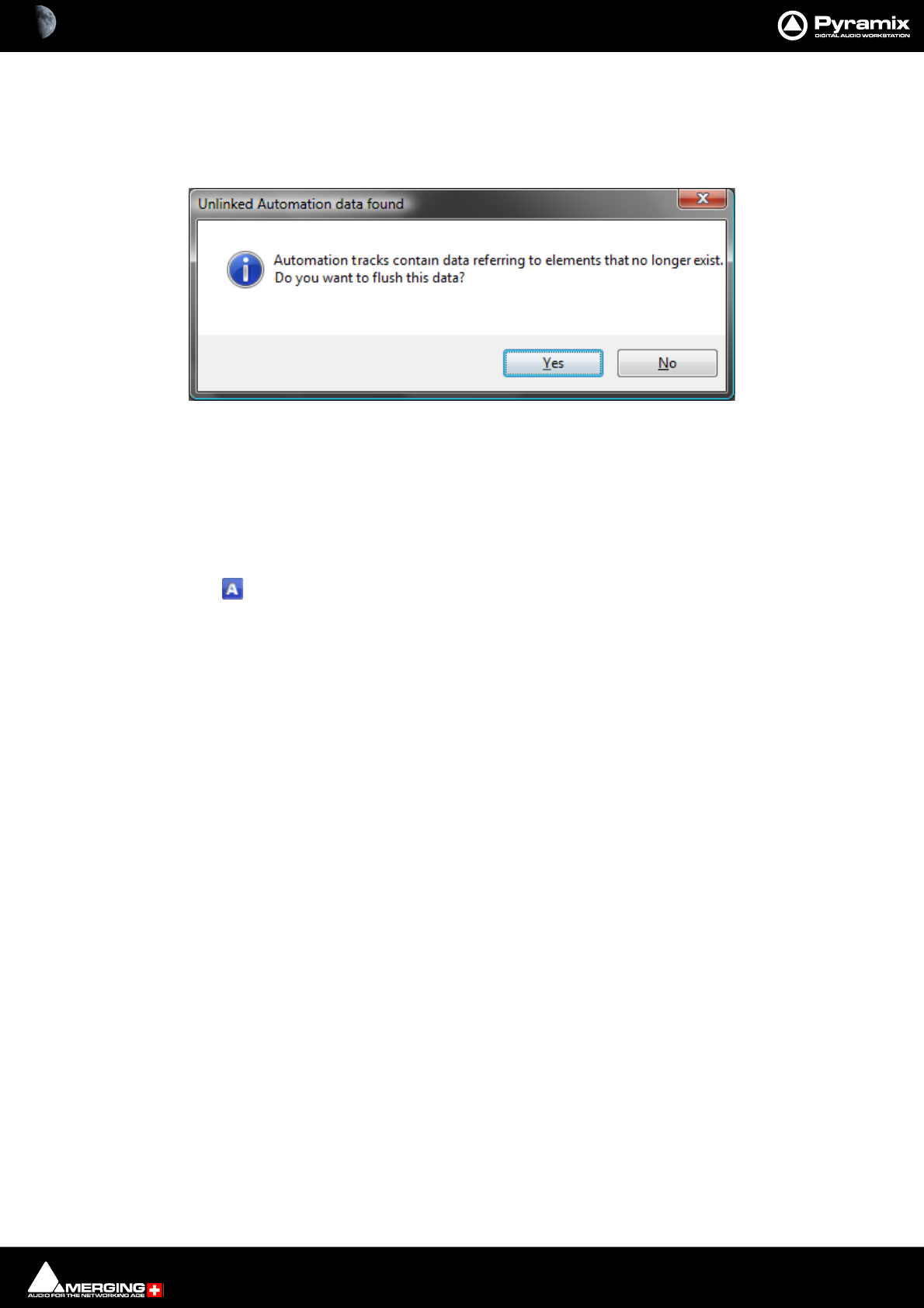
Automation : Projects With Existing Automation 14 - 409
Projects With Existing Automation
When opening a Project that has existing dynamic automation and where a mixer element is no longer present or
when rebuilding a mixer where a previously automated element has been removed the following dialog appears:
Clicking on Ye s removes the redundant data. Clicking on No retains it giving the opportunity to re-instate the
missing element(s).
Display and Editing of Automation Data
The automation data recorded for any control on any strip can be viewed and edited on any Track in the Timeline.
Clicking the Show/Hide Automation button in the Track Header displays or hides automation curves.
The Automation curve is colored depending on the parameter type displayed:
Automation Curve Colors
Fader Blue
Pan/Balance/Surround Green
Send & On/Off Cyan
Mute Red
Everything else Black
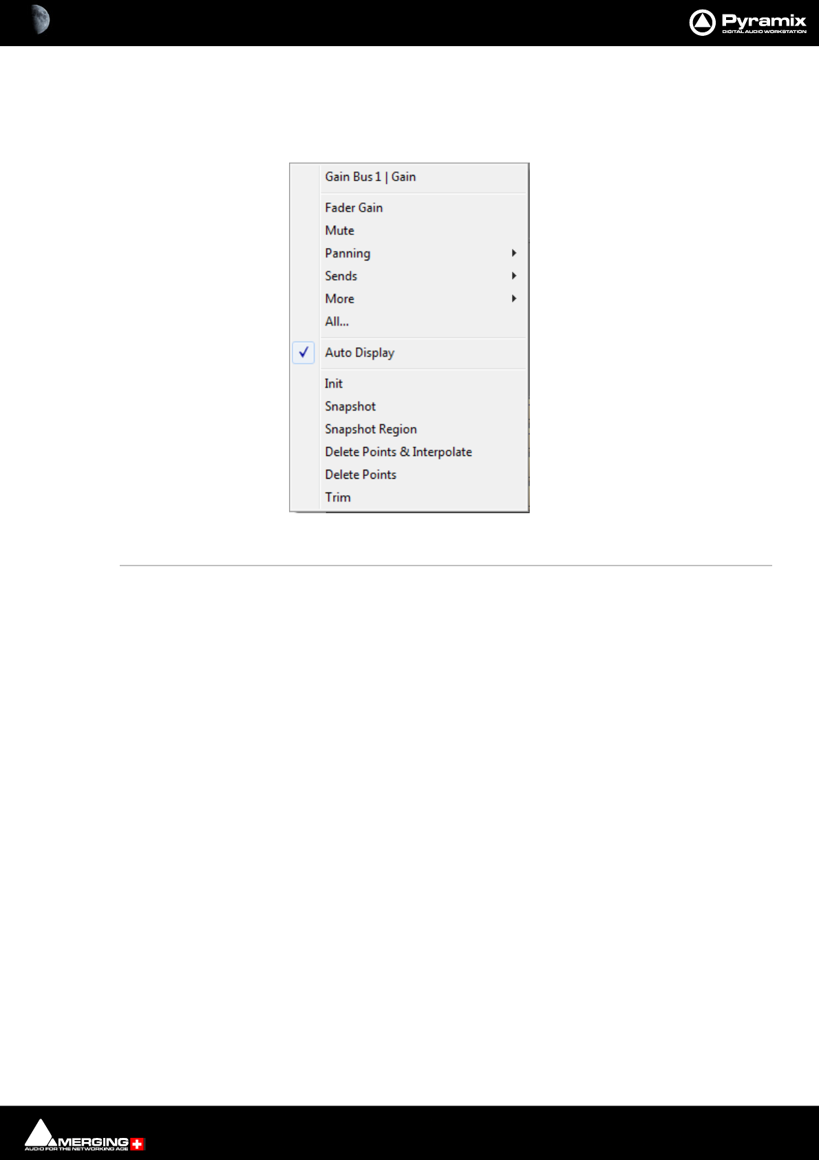
Automation : Display and Editing of Automation Data 14 - 410
Track Automation Menu
Right-clicking the Show/Hide Automation button pops up the automation menu for the Track. This menu is
modal,i.e. the content varies according to the current mixer architecture and depending on pre-existing automa-
tion data.
Gain Bus 1 | Gain This line shows the current automation parameter selected for display as a curve.
Fader Gain Sets the automation curve display to Fader Gain.
Mute Sets the automation curve display to Mute.
Panning Sets the automation curve display to the Pan or Balance parameter chosen from
the sub-menu. The options available will depend on the type of Mixer Strip and
the Buses present in the Mixer. Any of the following may be present:
Pan, Balance, Left/Right Pan {bus} Front Rear Pan {bus}.
Sends Sets the automation curve display to the Send chosen from the sub-menu.
More Sets the automation curve display to any other automatable parameter in the cur-
rent mixer which has automation data written, chosen from the sub-menu.
Note: All of the above choices will be overridden the next time a different control parameter is
written, if Auto Display (see below) is turned On.
Track Automation Initial context menu
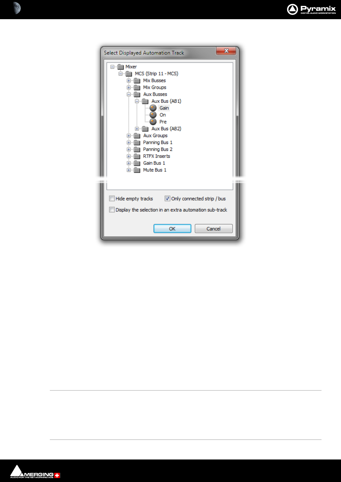
Automation : Display and Editing of Automation Data 14 - 411
All... Opens the Select Displayed Automation Track dialog:
Every automatable parameter of every Strip and Bus is available. However, default is to have the Only connected
strip / bus box ticked so only parameters from the Mixer Strip connected to the Track are shown.
Clicking on the plus sign next to a folder will show the all automatable parameters associated with it. Simply
choose the parameter you wish to have displayed.
Hide Empty Tracks When ticked (default), Tracks with no automation data written are
not shown in the tree.
Display the selection in an extra automation sub-track When ticked, a new Automation Sub-Track is cre-
ated to contain the automation curve for the selected parameter
when the OK button is clicked.
Only connected strip / bus When ticked (default) only the parameters from the current Strip
or Bus are shown. When un-ticked every parameter in the Mixer is
available.
OK Confirms selection and closes the dialog
Cancel Cancels the selection and closes the dialog.
Note: If you choose a Strip AND a specific parameter to display in this dialog then Auto Display
should be turned OFF.
Auto Display When Auto Display is selected, the automation curve displayed will be from the
last control on the Mixer Strip associated with the Track that has been adjusted or
switched. (Defaults is ON)
Note: Auto Display should normally be Off when any control NOT on the Mixer Strip is dis-
played, or if you wish to lock the view to automation data from a specific control.
Select Displayed Automation Parameter
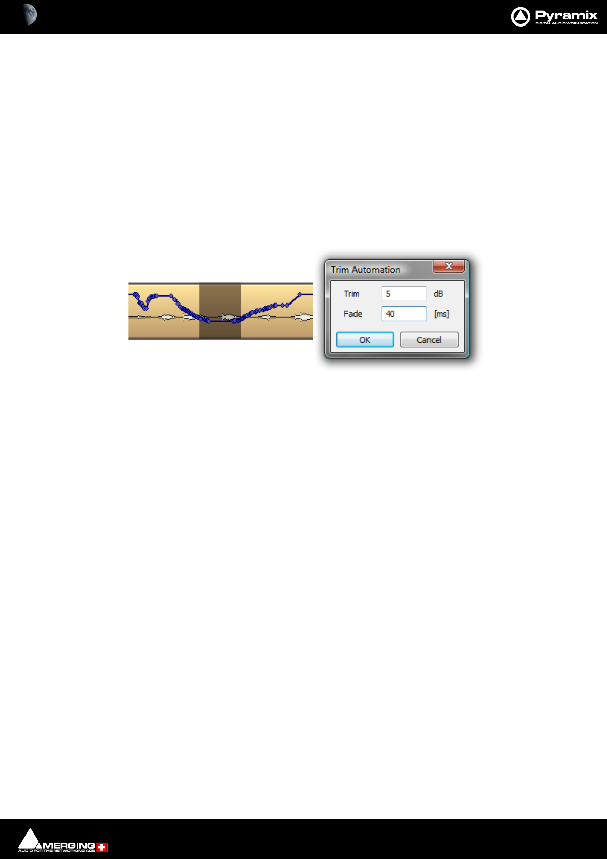
Automation : Display and Editing of Automation Data 14 - 412
Init Creates an initial “write” of automation parameters for mouse editing. The initial
version is created with the current state of the mixing console control.
Snapshot Creates a snapshot of the automation curve displayed currently.
Snapshot Region Creates a snapshot of the automation curve in the current Region.
Delete Points & Interpolate Deletes all automation points from the control curve in the current Region and
interpolates between the last existing point before the selection and the first point
after the selection.
Delete Points Deletes all points from the automation curve in the current Region.
Trim See below
Trim
When automation Trim is invoked a dialogue box opens which enables the automation points values in the range
selected currently to be trimmed:
Values can be increase by simply typing the number of dB required or decreased by typing - (minus) before the
number in the Trim box. The Fade box allows a value in ms to be entered. This defines the length of fade which is
automatically applied at the beginning and end of the selected range from and to the original values.
Note: dB applies to level changes. If the automation curve is displaying frequency, values will be in Hz and so on.
Track Trim Automation dialog
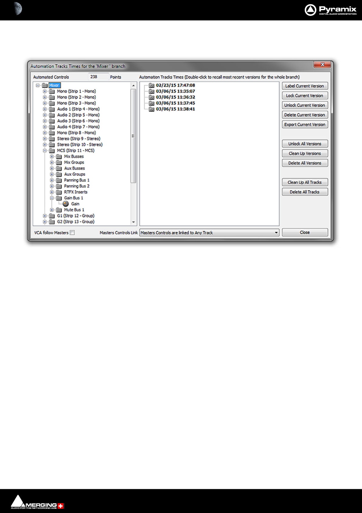
Automation : Display and Editing of Automation Data 14 - 413
Automation Tracks Versions
Automation > Automation Tracks opens the Automation Tracks Times window:
Automated Controls
The Automated Controls pane displays all the automatable controls in a tree structure. Double-clicking an entry
in the tree brings the automation passes for the entry into the Automation Tracks Versions pane. This shows all
the automation passes for the selected Control, Strip or the entire mixer. Double-clicking a version makes it cur-
rent.
Label Current Version creates a copy of the current version for the selected control or branch of controls,
gives it a name that will be displayed in the version Tree and locks it/them. This
makes it easy to recall a given and easily identifiable version of the automation for
the whole mixing console. A warning dialogue is shown if the item selected is any-
thing other than Mixer.
Lock Current Version Locks the current version
Unlock Current Version Unlocks the current version
Delete Current Version Deletes the current version. Subsequent passes are re-numbered as necessary.
Export Current Version Exports the current Track or Branch as an XML file.
Unlock All Versions Unlocks all versions in the tree.
Clean Up Versions Deletes all versions except the most recent.
Delete All Versions Deletes all the automation passes for the selected control.
Clean Up All Tracks Deletes all versions except the current one for all Tracks.
Delete All Tracks Deletes all automation information for all Tracks.
Locked Versions
Locked versions will be preserved when:
Automation Tracks Times Window
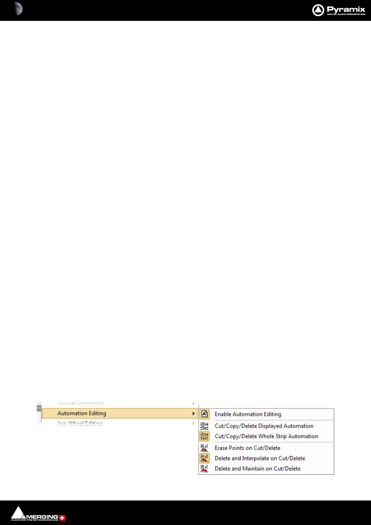
Automation : Editing and Automation 14 - 414
• Clicking on the Clean Up Versions button
• Clicking on the Clean Up All Tracks button
• Saving with the “Keep only current and locked versions while saving” option in the Automation Settings
• The “Limit versions to the number of Undo/Redo” option is enabled in the Automation Settings
Locked versions will NOT be preserved when:
• Clicking on the Delete Current Version button
• Clicking on the Delete All Versions button
• Clicking on the Delete All Tracks button
VCA Follow Masters
When ticked (default) Moving Clips in the Timeline will result in both Masters and VCAs following the automation.
Masters Controls Link
The drop-down list enables you to select which Track(s) or Track Groups will, when edited, affect the position of
automation applied to Master controls, buses etc.
Like Markers or CD/SACD Markers, all Masters controls can be either:
• Independent (No action on any Track will affect the Masters)
• Linked to Any Track (Any editing action requiring synchronization will affect the Masters controls)
• Linked to Any Track without a Group
• Link to Track Group A, B, C, etc…
Close
Closes the dialog.
View Several Parameters
To view more than one automation parameter in the Timeline for a Track, create Automation Sub-tracks for each
parameter you wish to view. Please see also Automation Sub-Tracks on page 108
Undo/Redo
The menu item Edit > Undo/Redo also reacts to Automation actions providing a shortcut to the Automation
Tracks Window.
Editing and Automation
Overview
Editing data exists independently of the Clips on Tracks. When Clips are edited in the timeline any automation
data applying to Clips affected by the editing process is treated according to choices made in the Edit > Automa-
tion Editing sub-menu :

Automation : Editing and Automation 14 - 415
Automation Editing
Enable Automation Editing Enabled By Default. Enables Timeline Automation Editing
Cut/Copy/Delete Displayed Automation Will only affect Automation Curves visible in the Timeline when Edit-
ing.
Cut/Copy/Delete Whole Strip Automation Enabled By Default. Will affect ALL Automation, even the curves not
visible currently in timeline Track(s) when editing.
Erase Points on Cut/Delete Erases all points contained within the selection. Does not add Automation points
to the selection boundaries.
Delete and Interpolate on Cut/Delete Enabled By Default. Interpolates a curve from the start of the selection to
end of the selection.
Delete and Maintain on Cut/Delete Does not interpolate the curve from start to end of the selection. Therefore
maintains a flat curve on Cut or Delete.
Editing Automation and Envelope Data
Automation Curve Colors
Blue Fader
Green Pan/Balance/Surround
Cyan Send & On/Off
Red Mute
Black All others
Actions and Modifiers Automation and Envelope
Left Click Anywhere on the Automation line to make a new node
Ctrl + Click On an existing node to adjust all nodes in the Region selected currently. New
points are inserted automatically at the Region borders if necessary
Ctrl + Shift + Click Anywhere on the Envelope line to draw nodes freehand
Shift + Click Fine tune a node (0.1 dB steps for dB values)
V + Click Constrains changes to a node to Vertical
H + Click Constrains changes to a node to Horizontal
Click & hold + Alt Create new node with same value as next point (if one exists) when the mouse is
moved.
Click & hold + Ctrl Create new node with the same value as previous point (if one exists) when the
mouse is moved.
Ctrl + Alt + Click & hold Deletes any existing node the mouse moves over.
Ctrl + Alt + Click On an existing node to erase it
Automation Cursors
Note: Adjustment nodes on Automation Tracks are circular and nodes on Envelopes are square.
Left Click anywhere on the Automation or Envelope curve line to make a new node:
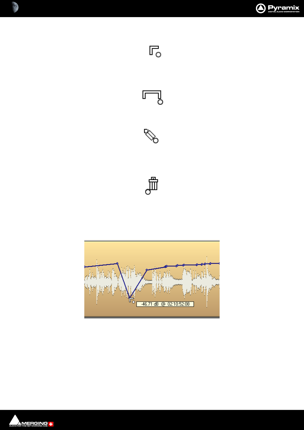
Automation : Editing and Automation 14 - 416
Left Click on an existing node to adjust it:
Ctrl + Click on an existing node to adjust all nodes in the Region selected currently. New nodes are inserted auto-
matically at the Region borders if necessary:
Ctrl + Shift + Click anywhere on the Automation or Envelope curve line to draw nodes freehand:
Ctrl + Alt + Click on an existing node to erase it
Ctrl + Alt + Click & hold Deletes any existing node the mouse moves over.:
Edit
Automation data can be edited directly with the mouse. When the mouse is over the of automation curve, the cur-
sor changes into an add node symbol. When the mouse is over a node of the automation curve, the value and
timestamp of the point is displayed.
The value can be adjusted by clicking on the node and dragging. If you click anywhere on the automation curve, a
new node will be inserted.
Dragging an automation node
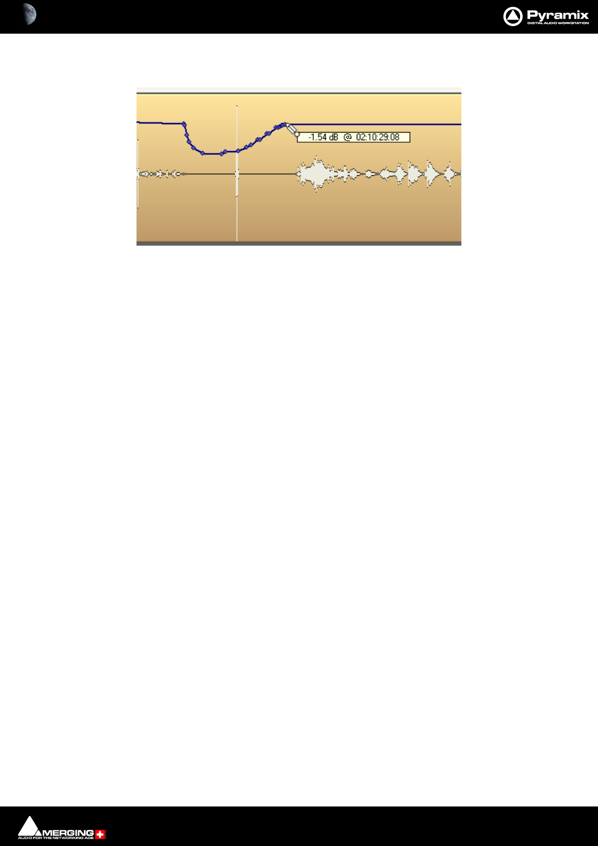
Automation : Editing and Automation 14 - 417
If you hold the Ctrl + Shift keys while dragging on the automation curve, the mouse pointer will turn into a pencil.
The curve can then be drawn freehand.
Automation Menu Editing options
Delete Selected Points Deletes all automation points contained in the selected Region
Cut Selected Points Cuts all automation points contained in the selected Region
Copy Selected Points Copies all automation points contained in the selected Region
Paste Points to Cursor Pastes all copied or cut automation points at the cursor on the selected Track
Paste Points to Original TC Pastes all copied or cut automation points at the Original TimeCode on the selected Track
Note: Each of these options opens the Filter Automation Tracks to Snapshot dialog:
Drawing an automation curve
Automation : Filter Automation Tracks to Snapshot Dialog 14 - 418
Filter Automation Tracks to Snapshot Dialog
This dialog shows all automation Tracks available and enables you to choose which Tracks will be modified by an
Cut, Copy, Delete or Snapshot action. The Tracks shown are limited to the current Timeline selection (A selected
Clip or Clips, or a Region) if one is present.
The following actions will pop-up the dialog:
Automation > Automation Snapshot Cursor
Automation > Automation Snapshot Range
Automation > Delete Selected Points & Interpolate
Automation > Delete Selected Points
Automation > Cut Selected Points
Automation > Copy Selected Points
Stopping the Transport after a control has been moved when in Preview mode
Note: The Dialog title changes to reflect the action.
I.e. Filter Automation Tracks to Snapshot - Cursor/Range/Delete/Cut/Copy
Filter Automation Tracks to Snapshot Cursor Dialog

Automation : Filter Automation Tracks to Snapshot Dialog 14 - 419
Filter Automation Tracks to Snapshot Dialog Options
The top Tabs switch between displaying Controls by Strips or by Types of Control..
The bottom Tabs change the automatic selections :
All Every Control in the Mixer is selected
Nothing No Controls are selected
Displayed Only the Controls displayed on Tracks / Automation Sub-tracks are selected
Last The Control(s) selected previously are selected
Switches
Note: The following switches are only available when appropriate. E.g. Automation Snapshop
Cursor etc. not Delete Selected Points
Maintain to next point When ticked the parameter values at the cursor position will be maintained until
the next automation point per parameter.
To End When ticked the parameter values at the cursor position will be maintained until
the end of time(line).
Note: If both Maintain to next point and To End are ticked, then To End takes precedence.
Automation : Automation Editing 14 - 420
Automation Editing
VCA Group Automation Editing
VCA Group Automation is displayed in the Timeline as an extra curve showing the summed effect of the original
Strip Automation and the VCA Group automation (Gain or Mute only).
The VCA Group Automation can not be edited when it is displayed in a Strip Track part of that Group, but all edit-
ing of the Strip Automation will Link and calculate the summation in real time.
The VCA Group Automation can only be edited if displayed in its own Track Header. (Right-click on the A button in
a Track Header and select the VCA Group you wish to edit the automation for from the list.)
VCA Coalesce
If a Strip is associated with one or more VCA Groups then, when you exit the group, the Leaving VCA Group box
appears:
Two choices are available:
Yes (default) Merges the Strip Automation with the VCA Group Automation into a single sum curve.
No Excludes the effect of the VCA Group Automation and leaves the Strip Automation curve as it was. The
Coalesce option is the only one in the Mixer which supports Undo/Redo.
Conventional Strip and VCA Automation Curves
Leaving VCA Group message box
Strip and VCA Automation Coalesced
Automation : Automation Settings 14 - 421
Automation Settings
Select All Settings > Application > Automation. (Automation > Automation Settings also takes you to the
Automation page):
Optimizations
Offers a choice of options to enhance system performance when using automation.
Keep only current version while saving when checked, the system only saves the current version of all automa-
tion Tracks. This looses the saved automation versions history, but dramatically shortens the save time for projects
with automation.
Limit versions to the number of Undo/Redo when checked the system only keeps a limited number of versions
in memory (the same as the number of Undo/Redos as defined in the Settings > All Settings > General Page).
This reduces the number of automation versions kept in the history but enhances performance.
Auto-Release Options
If Auto Release is enabled any control will, when released or when the transport is stopped, return to its value or
state in the previous automation pass or the default where no previous pass exists. This occurs either immediately
Automation Settings page

Automation : Automation in Editing and Libraries 14 - 422
if the control only has two states (e.g. a button) or over a period of time if the control is a fader or knob. The time
period is determined by the value entered in the Release Time box in ms.
Preview Mode Options
The selections here affect actions in Automation Preview Mode.
Auto write on Stop Automation goes into Auto write mode when a Preview pass is stopped.
Confirm on Stop A confirmation dialog pops-up when a Preview pass is stopped.
Manual write Clicking on the Preview button writes the Preview pass.
Affect Parameters in :
Isolate When checked, parameters are affected in Isolate mode.
Read When checked, parameters are affected in Read mode.
Touch / Latch When checked, parameters are affected in Touch /Latch mode.
Write / Record When checked, parameters are affected in Write / Record mode.
Options
Check Source/Destination settings
When enabled (default) verifies the project when it is opened and ensures that the Automation > Automation
Tracks : Master Controls Link setting is set to Master Controls are linked to any Track.
Preview mode: Popup Snapshot window on Stop
When enabled pops-up the Filter Automation Tracks to Snapshot ... dialog.
Automation in Editing and Libraries
You can use the Automation menu Cut/Copy/Paste functions to copy data (even between projects). Just select a
Region and select Automation > Copy Selected Points, then choose which list(s) to copy, then go into another
project (or the same) and select Automation > Paste Points to Cursor or Paste Points to Original TC.
If you enable the menu item Edit > Enable Automation then any editing operation on Clips also applies to all
associated automation data (Cut/Copy/Paste, Auto-Ripple, etc…)
If you edit a Clip or Clips in the Timeline or drag a Clip or Clips to a library, all automation applied to the Clip(s) is
also copied/pasted according to the mode set in the same sub-menu.
E.g. Cut/Copy/Delete Displayed Automation.
When active Edit operations will only include Automation Curves visible in the Timeline.
Cut/Copy/Delete Whole Strip Automation when active (Enabled By Default) ALL Automation, even the curves
not visible currently in Timeline Track(s) will be affected when editing.
Note: Only parameters of controls present in both the source and destination Mixer strips will be
copied successfully.

Automation : Mixer and Plug-in Snapshots 14 - 423
Mixer and Plug-in Snapshots
Note: Mixer Snapshots as described here use the dynamic automation mechanism.
Mixer Snapshots
Snapshots of the entire state of the mixer surface may be easily and quickly saved and recalled.
Saving Mixer Snapshots
To save a Mixer snapshot hold down Alt and Shift then Click anywhere on the Mixer surface and drag to a user
library. A new item of the type Mixer Snapshot will appear in the library. The snapshot is named Mixer Snapshot
by default. To accept this name just hit Enter. Otherwise, type a suitable name then hit Return.
Recalling Mixer Snapshots
To recall a mixer snapshot simply click on it in the library, drag it over the mixer surface and release. All parameters
will be reset to the values stored in the snapshot.
Note: A Mixer Snapshot includes all Plug-in Parameters.
Effects Snapshots
Effect Settings can be easily stored and recalled by dragging them to/from libraries.
Creating Effects Snapshots
Hold Alt + Shift, then click and drag from a Plug-in window to the library where you want to store the settings,
then release. A new item, of the type Mixer Snapshot, is stored in the library. The snapshot is given the name of
the plug-in by default. The new item is automatically highlighted so, if you wish to change the default name, sim-
ply type the new name and hit Enter to confirm. The name of the snapshot can be subsequently changed by click-
ing on the name in the library, then entering the new name.

15 - 424
www.merging.com/Pyramix
USER MANUAL
Strip and Bus Tools
Strip and Bus Tools : Strip and Bus Tools 15 - 425
Strip and Bus Tools
Eq, Comp/Limiter/Expander
Strip and Bus Tools are a quick and efficient way of adding the Equalization and Dynamics (compression and
expansion) functions commonly found on hardware consoles to channels and buses. Strip and Bus Tools are par-
ticularly economical with DSP processing power. Each processing block may be switched into circuit’ individually.
Blocks which are not ‘in circuit’ do not use DSP resources.
Difference between Strip Tools and Bus Tools
There is only one major difference between Strip and Bus Tools. Bus Tools have a sophisticated Limiter with Look-
ahead and Delay Compensation where Strip Tools has a Compressor.
Both may be freely used in Strips or Buses if the need should arise for a limiter in an Input Strip or a Compressor in
a Bus.
Modules
The Strip and Bus Tools plug-ins consist of several Sections or modules. Each Section has a title bar at the top con-
taining an On/Off switch for the section and a control triangle which toggles between showing or hiding the sec-
tion.
Display Options
Multiple instances of the Bus Tools plug-in are displayed in one large window. Right-click onto the window title
bar of the plug-in to open a menu offering some general display options for the Strip Tools plug-ins:
This menu allows you to either directly select the number of strips displayed in the plug-in window, or to incre-
ment/decrement this number by one. The maximum number will vary depending on how many Strip Tools are
assigned.
Strip Tools - General Display Options
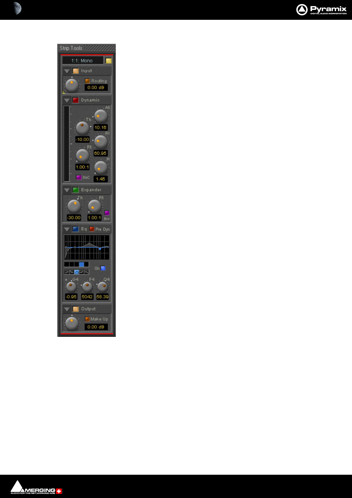
Strip and Bus Tools : Strip and Bus Tools 15 - 426
Sections
From top to bottom, Strip Tools contains the following Sections:
Input Level
This section contains the input level control and shows the name of the mixer strip
this instance of the plug-in is assigned to.
Dynamics
This section contains a compressor. It can be switched, as shown here, to act as a
decompressor.
Expander
This is a downwards expander. It can also be switched to act as an upwards expander.
Equalizer
This is a five band fully parametric equalizer. Each band can be switched to high or
low pass, shelving or peaking characteristics.
Output
This section controls the output level of the strip tool and also offers automatic gain
make up for the compressor.
Common Features
Each Section or module of Strip and Bus Tools has a number of controls in common.
Title Bar
A text description of Section’s function, e.g. Input, Dynamic etc. Also contains:
Show/Hide triangle
At top left of every Section a grey triangle toggles between showing or hiding the section. Clicking a triangle with
Shift held down opens the Section (If hidden) and hides all other Sections. Clicking a Section with Ctrl. held down
opens all Sections.
Note: Sections remain active when hidden.
Section On/Off Button
Between the Show/Hide triangle and the Section Title is the On/Off button for the Section.
Knobs
The position indicator dot lights orange when the control is at the default value. A white star appears top-left of
the scale of the last control ‘touched’.
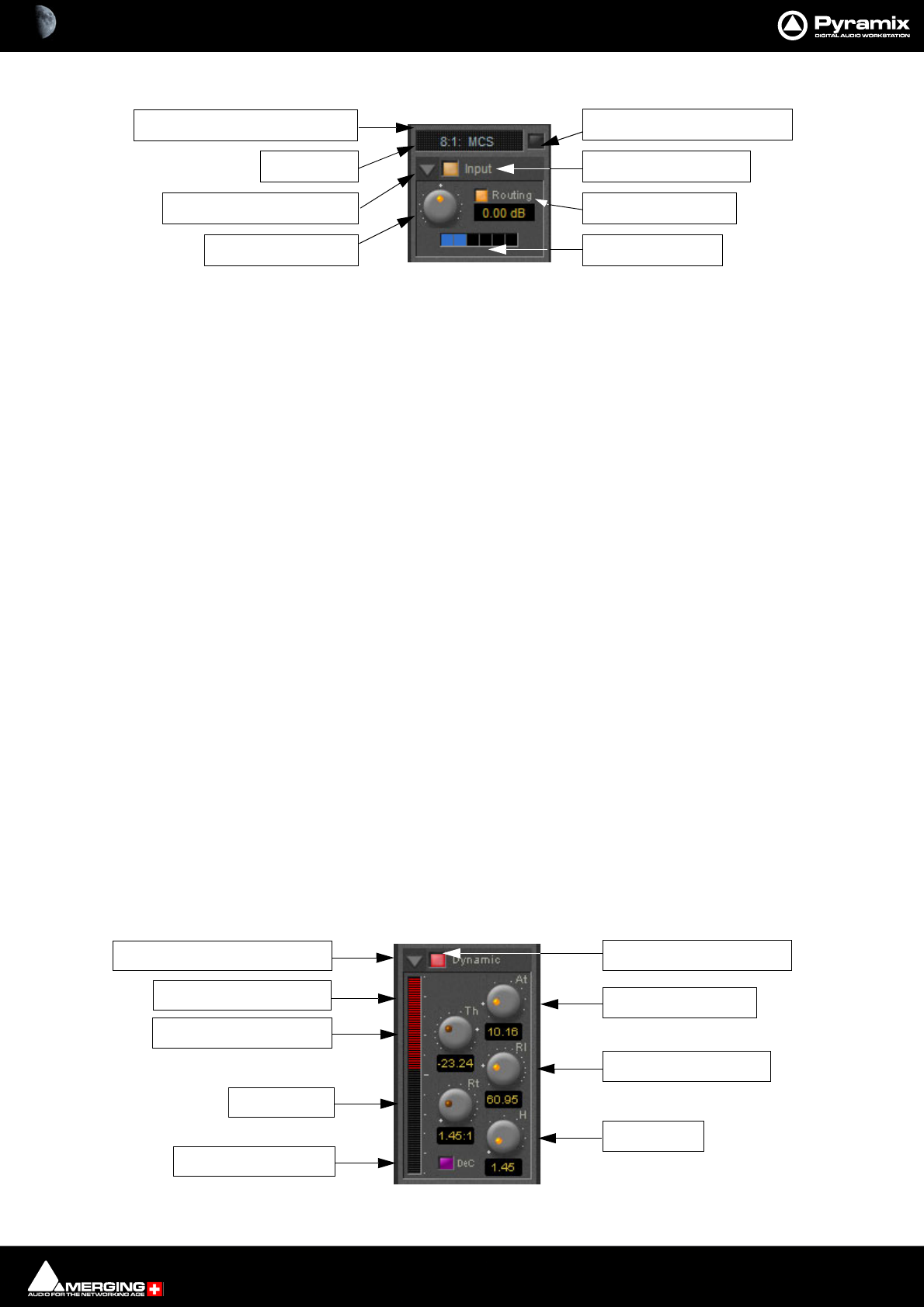
Strip and Bus Tools : Strip and Bus Tools 15 - 427
Input Section
Color Bar
Indicates strip is selected.
Strip Name
Displays the name of the strip the plug-in is assigned to. The name for the plug-in can be changed by double-click-
ing on the strip name, then typing in a name and hitting the Return key to confirm. If a plug-in name is changed in
this way, subsequent changes to the parent mixer-strip name do not affect the plug-in strip name. To recover the
name of the parent strip, simply remove the strip name.
The strip name is saved with presets and within Pyramix projects.
Activate/deactivate plug-in
This button switches the entire Strip plug-in on or off. Note that when the plug-in is switched off, it doesn’t con-
sume any DSP power.
Show/Hide input section
Input section on/off
Input level control
Adjusts the input level over a range of -48 dB to +48 dB.
Show/hide Routing
By default Routing buttons are hidden. This button toggles between Showing and Hiding the Routing Buttons.
Routing remains active when hidden.
Routing Buttons
Determine which audio streams running through the strip will be processed by the plug-in. The number of but-
tons depends on the number of steams controlled by the strip. This means one for a mono input channel or two
for a stereo input channel and so on up to 8 for a 7.1 input channel. Streams which are not selected will be left
untouched.
Dynamics Section
Strip Name
Show/Hide Input Section
Input Level Control
Activate/De-activate Plug-in
Input Section On/Off
Show/Hide Routing
Routing Buttons
Color bar indicates Selected
Show/Hide Dynamics Section
Gain Reduction Display
Threshold Level Control
Ratio Control
De-Compress Switch
Dynamics Section On/Off
Attack Time Control
Release Time Control
Hold Control

Strip and Bus Tools : Strip and Bus Tools 15 - 428
Show/Hide Dynamics section
Dynamics Section On/Off
Gain reduction display
The bar graph shows the gain reduction/increase generated by the Dynamics Section or by the Expander. The
range of the display can be switched between +-10 or 20 dB by clicking on the bar graph. Scale markings in 1dB
increments on the right-hand side of the bar graph make it easy to see if the range is 10 or 20 dB.
Colors are used to denote a gain reduction or increase generated by either the compressor or the expander:
• Gain reduction by the Compressor is displayed in Red from top to bottom.
• Gain increase by the De-Compressor is displayed in Pink from bottom to top.
• Gain reduction by the Expander (normal or inverse) is displayed in Green from bottom to top. With the
compressor in inverse mode, the gain reduction of the expander is displayed in Green from top to bottom
Threshold Level Control
Sets the level at which the compressor begins to act. If the input signal level exceeds the Threshold Level, the
gain is reduced (or increased in De-Compressor mode) in proportion to the setting of the ratio control.
Ratio Control
Determines the proportion of gain reduction (or increase) for signals above the threshold level. If, for example, the
ratio is set to 2.00:1, in Compressor mode, if the input level rises by 2dBs above the threshold level, the output
level will only rise by 1 dB.
Attack Time Control
Controls the time the compressor takes to react when the input level exceeds the Threshold Level. The lower the
attack time, the faster the reaction.
Release and Hold Time controls
These two parameters work together and control the amount of time the compressor takes to react when the
input level is above the threshold level and starts fall. During the hold time the gain of the compressor remains
constant. After the hold time the gain of the compressor is changed at the rate set by the release time. The lower
the release time, the faster the reaction.
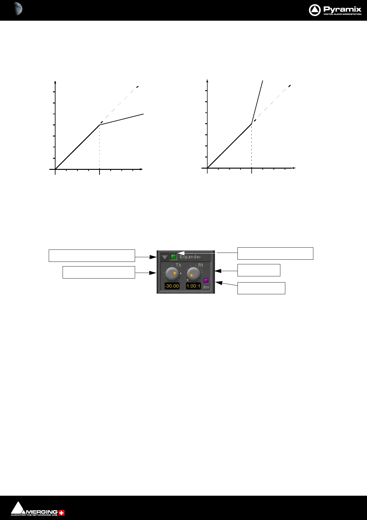
Strip and Bus Tools : Strip and Bus Tools 15 - 429
De-Compress Switch
Switches the compressor between the compress and the de-compress modes.
In compressor mode, when the input level exceeds the threshold level, the gain is reduced according to the set-
ting of the ratio control. In de-compressor mode, when the input level exceeds the threshold level, the gain is
increased according to the setting of the ratio control.
Expander Section
Show/hide Expander section
Dynamics section on/off
Threshold Level Control
If the input signal level falls below the threshold level, the gain of the expander is reduced (or increased in inverse
mode) according to the setting of the ratio control.
Ratio control
Determines the proportion of gain reduction (or increase) for signals below the threshold level. If, for example, the
ratio is set to 2.00:1, in normal mode the output level will be decreased by 2 dB if the input level is decreased by 1
dB below the threshold level.
Compressor and De-Compressor action
Threshold
Input level
Output level
Threshold
Input level
Output level
Compressor mode De-compressor mode
Show/Hide Expander Section
Threshold Level Control
Expander Section On/Off
Ratio Control
Inverse Switch
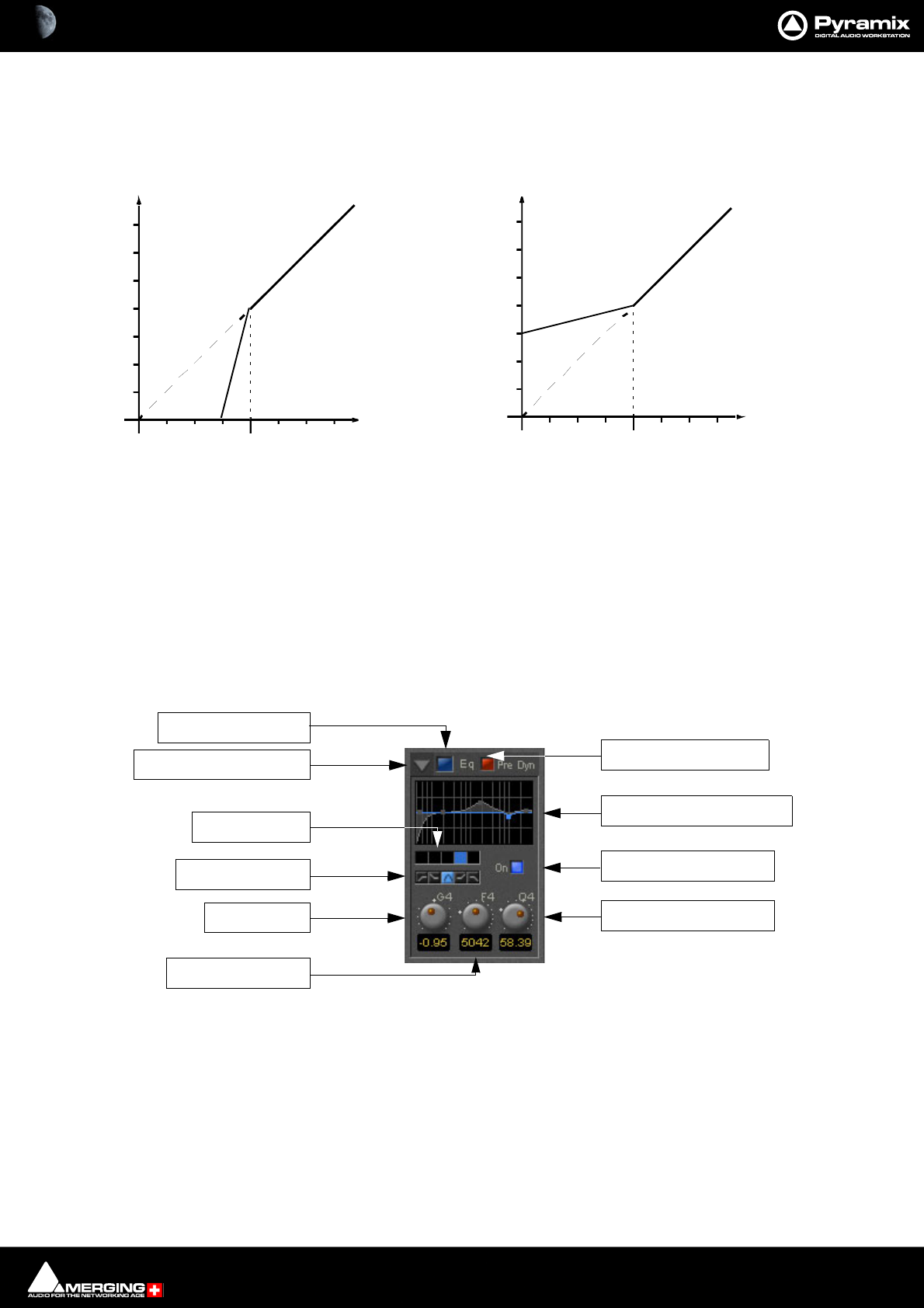
Strip and Bus Tools : Strip and Bus Tools 15 - 430
Inverse switch
Switches the between normal and inverse expander modes.
Attack/Release/Hold controls
The Expander Section uses the settings of the Attack/Release/Hold controls in the Dynamics Section to control
it’s timing.
Equalizer section
A fully parametric five band equalizer. Each band covers the entire frequency range from 20 Hz to 20 kHz (or
higher, depending on the sampling rate of the project) and can be switched between peaking, high or low shelv-
ing and low-pass or high-pass characteristics. Each of the five bands can be switched off. De-activated bands do
not consume DSP power.
Show/ Hide EQ Section
EQ section on/off
Pre Dynamics Switch
This switch offers the option to the switch the EQ before the dynamics section. By default the EQ is after the
dynamics section.
Threshold
Input level
Output level
Threshold
Input level
Output level
Expander normal mode Inverse mode
Expander normal and Inverse mode action
EQ Section On/Off
Band Filter Type
Band Selector
Gain Control
Frequency Control
Show/Hide EQ Section Pre-Dynamics Switch
Graphic Display Window
Selected Band On/Off
Q (Bandwidth) Control
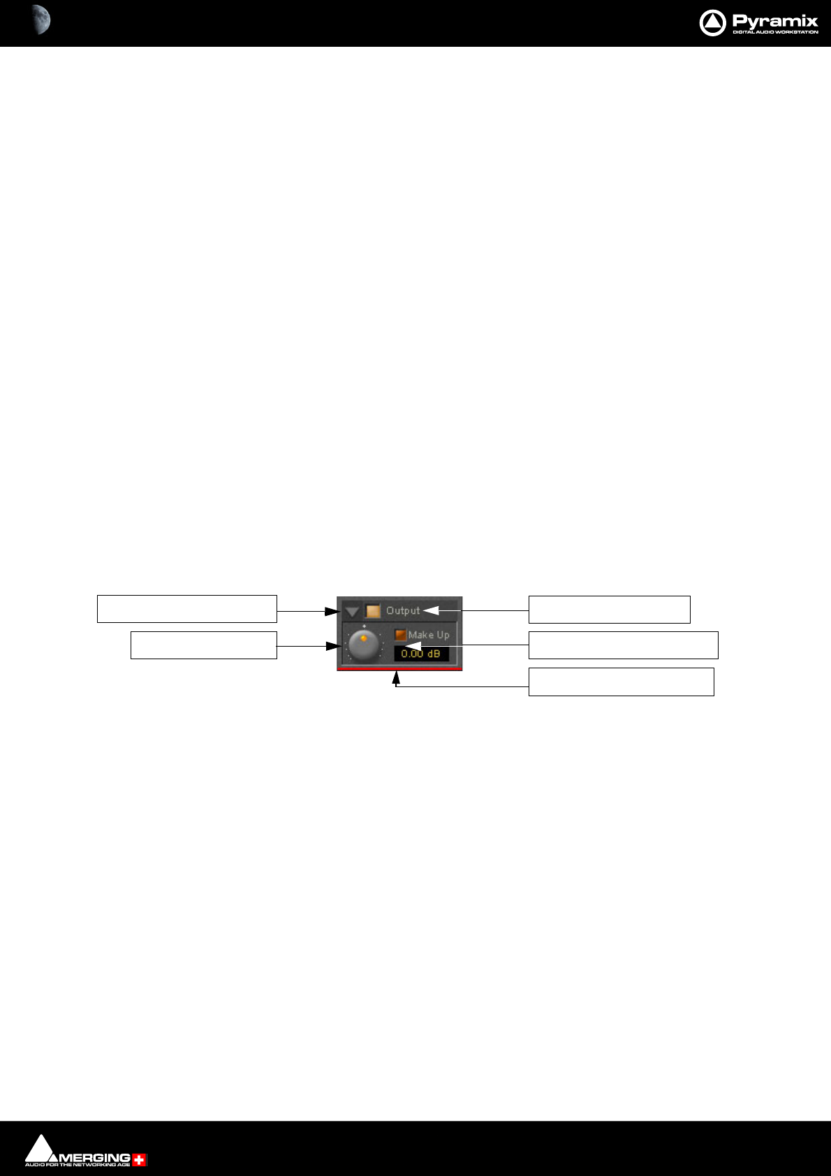
Strip and Bus Tools : Strip and Bus Tools 15 - 431
Graphic Display Window
This small window displays the settings of the currently selected EQ band in blue color and the resulting curve of
the whole EQ section in gray color. You can click and drag directly onto the handles (the small blue or gray points)
of the EQ bands to change the settings within the graph window.
Double-click anywhere in the window to open a bigger version. Please see The Big Graph Window on page 431.
Band Selector
Click onto one of these five buttons to select the band to be manipulated by the Gain, Frequency and Q control
underneath. A band gets also selected if it is manipulated in the small or big graph window.
Selected band characteristics
These five buttons determine the characteristics of the selected EQ band. The choices from left to right are High-
Pass Filter, Low Shelving, Peak, High Shelving and Low-Pass Filter.
Selected Band On/Off
Switches the selected EQ band on or off. By default the five bands are switched off in order to economize DSP
power, so don’t forget to switch an EQ band on before you can hear what it is doing.
Gain Control
-24 dB to +24 dB, boost and cut.
Frequency Control
The frequency range for each band is 20 Hz to 20 kHz regardless of the project sampling rate .
Q (bandwidth) Control
The range for the Q parameter is 0.2 up to 100. A Q of 0.2 results in a very wide bandwidth, a Q of 100 will give an
extremely narrow notch.
Output Section
Show/ Hide Output section
Output section on/off
Output Level control
Adjusts the output level over a range of -48 dB to +48 dB.
Automatic Gain Make Up switch
When lit, Output gain is automatically adapted according to the settings in the Dynamics Section. In this case the
Output Level Control will be grayed out and inaccessible.
The Big Graph Window
The big graph window opens when you double-click the small graph window inside the EQ Section. The current
settings of the selected EQ band are displayed as a blue line and the resulting overall EQ curve is displayed as a
gray shaded area. Frequency and Gain parameters of each of the five bands can be altered by clicking on a band’s
handle and dragging with the mouse.
Output Level Control
Show/Hide Output Section Output Section On/Off
Auto Gain Make-Up Switch
Color bar indicates Selected
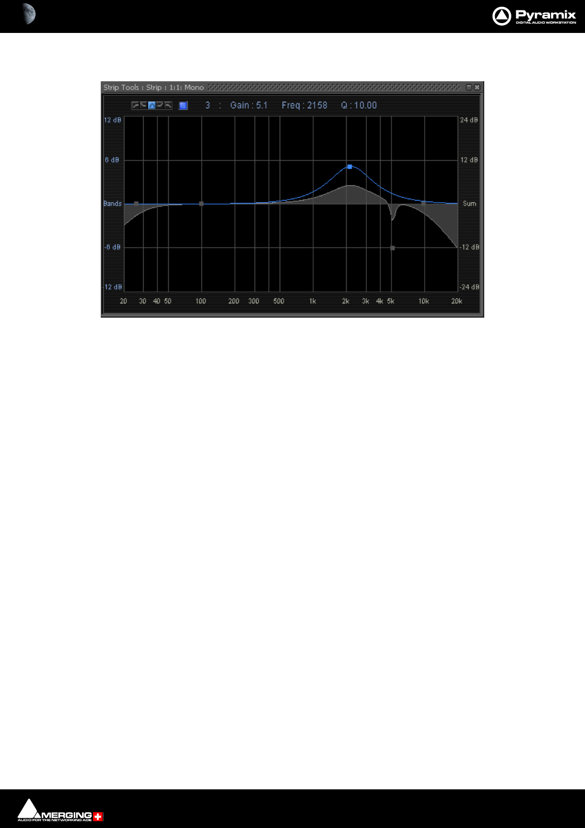
Strip and Bus Tools : Bus Tools 15 - 432
Handles of bands which are not selected are displayed as small gray squares. Grabbing and drag a handle selects
the band.
The frequency response display uses two separate gain scales. The left hand, blue scale shows the scale used for
individual bands. The right hand, gray scale shows the scale for the overall EQ curve. Both scales automatically
adapt their range according to the settings of the curves they apply to. The range of the left and the right scale my
be different. The ranges for the individual bands can be either +/- 6 dB, +/- 12 dB or +/- 24 dB, but the scale for the
overall curve may go up to +/- 72 dB.
The upper area of the Big Graph Window provides an On/Off switch and buttons to select and indicate the char-
acteristic (High-Pass, Low Shelf, Peak, High Shelf or Low-Pass) for the selected EQ band together with numeric dis-
plays of Gain, Frequency and Bandwidth.
Frequency and Bandwidth setting.
Shortcuts
• Double click on a handle to reset the gain of this band to unity.
•The Tab key switches between EQ bands.
• Clicking and dragging a handle with the right mouse button alters the Q (bandwidth) of this band.
•Hold the Ctrl key while dragging with the left mouse button to lock the gain parameter and only change
the frequency.
•Hold the Shift key while dragging with the left mouse button to lock the frequency parameter and only
change the gain.
Bus Tools
Bus Tools are very similar to Strip Tools but are specifically designed to be inserted into buses rather than chan-
nels. Bus Tools combine the most frequently used ‘mastering’ processing blocks you find on the output buses of a
mixing console in a single plug-in, including an advanced limiter. Like Strip Tools multiple instances of the Bus
Tools plug-in are displayed in one large window. The number of instances displayed is user selectable.
IMPORTANT! Pre-Anticipation (PA) and Delay Compensation (DC)
Delay compensation adds a delay determined by the Pre-Anticipation delay setting to all channels passing
through a Bus Tools plug-in NOT selected for processing.
If two or more Bus Tools are inserted in a Bus with PA & DC switched on, the delay times of each Bus Tools will add
together for all channels:
Big Graph floating Window
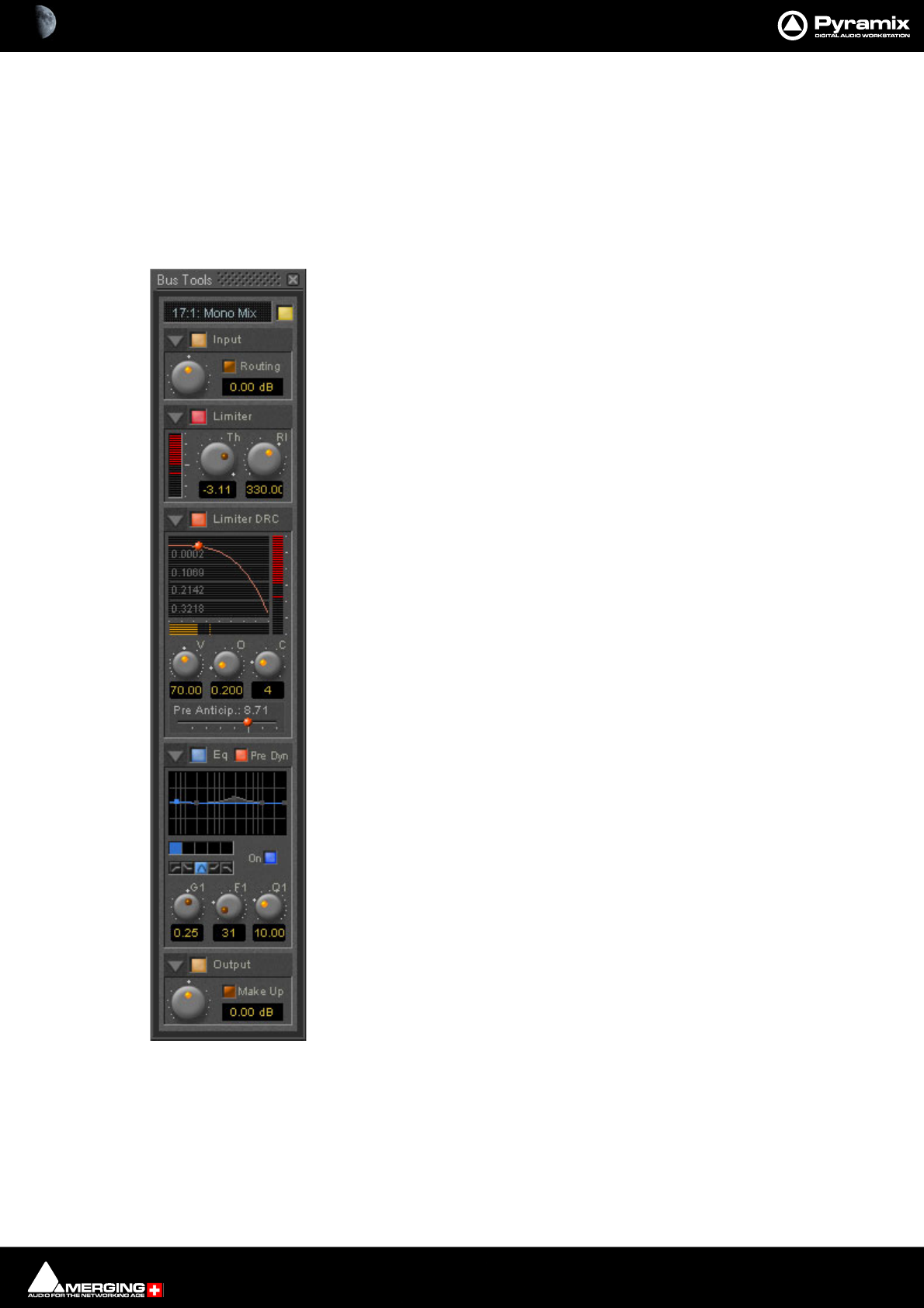
Strip and Bus Tools : Bus Tools 15 - 433
Sections
The Input, EQ, and Output sections are almost identical to the ones found in Strip Tools. Please see the relevant
paragraphs in the Strip Tools section for a full description. Where there are differences, these will be dealt with
here. Shortcuts and Automation functions are the same as Strip Tools, but the Linking feature is only available
with the Bus Tools.
From top to bottom, the Bus Tools plug-in contains the following sections:
Input Level
This section contains the input level control and shows the name of the mixer strip
this instance of the plug-in is assigned to.
Limiter
This section contains the limiter, which either acts as a standard limiter, but it can also
work in conjunction with Limiter DRC section below.
Limiter DRC
This section adds a Dynamic Release Compensation (DRC) to the Limiter section. This
enables very musical control of the release time of the limiter.
Equalizer
This is a five band fully parametric equalizer. Each band can be switched to high or
low pass, shelving or peaking characteristics.
Output
This section controls the output level of the Bus Tool and also offers automatic gain
make up for the Limiter.
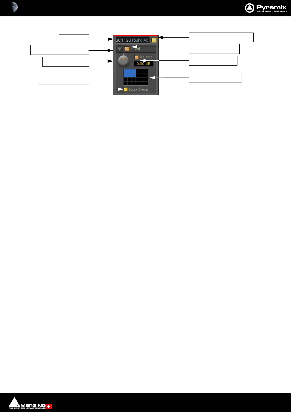
Strip and Bus Tools : Bus Tools 15 - 434
Main and Input Level Section
Strip Name
Displays the name of the strip the plug-in is assigned to. The name for the plug-in can be changed by double-click-
ing on the strip name, then typing in a name and hitting the Return key to confirm. If a plug-in name is changed in
this way, subsequent changes to the parent mixer-strip name do not affect the plug-in strip name. To recover the
name of the parent strip, simply remove the strip name.
Activate/Deactivate Plug-in
This button switches the entire Strip plug-in on or off. Note that when the plug-in is switched off, it doesn’t con-
sume any DSP power.
Show/Hide input Section
Input Section On/Off
Input level control
Adjusts the input level over a range of -48 dB to +48 dB.
Show/hide Routing
By default Routing buttons are hidden. This button toggles between Showing and Hiding the Routing Buttons.
Routing remains active when hidden.
Routing Button Matrix
The buttons determine which audio channels running through the Bus will be processed by the plug-in. The num-
ber of buttons shown depends on the number of channels controlled by the Bus. In the case of a multiple sur-
round Bus this may be up to 64. A single instance of Bus Tools can process up to 8 channels selected from this
matrix.
A 5.1 surround bus will have six buttons. The order of the channels selected by the buttons is (from left to right):
Left, Center, Right, Left Surround, Right Surround, Subwoofer.
This enables, for example, the Left, Center and Right channels of a surround Bus to be independently processed
from the surround channels by adding two Bus Tools plug-ins to the Bus and selecting L, C, R in the first and LS and
RS in the second.
Using Bus Tools on multiple surround buses
Although a single instance of Bus Tools can process 8 channels it is simple to use multiple instances to process
many more with linked parameters. E.g. with four surround Buses you could use 3 instances. Assign the L & R chan-
nels of each Bus to Bus Tools A, the Centers of each bus to Bus Tools B and the Surround Ls and Rs of each Bus to
Bus Tools C. The 3 Bus Tools can then be linked as you wish by right-clicking and creating control groups in the yel-
low matrix. If Delay Compensation (see below) is activated all channels will remain time-aligned, even when using
Pre-Anticipation.
Linking Bus -Tools controls
Any choice of Bus Tools controls can be linked together. When you move any of the controls which is a member of
a link group, all the other members of the group also move. There are 48 link groups for linear/rotary controls and
48 link groups for switches.
Strip Name
Show/Hide Input Section
Delay Compensation
Input Level Control
Activate/De-activate Plug-in
Input Section On/Off
Show/Hide Routing
Routing Button Matrix
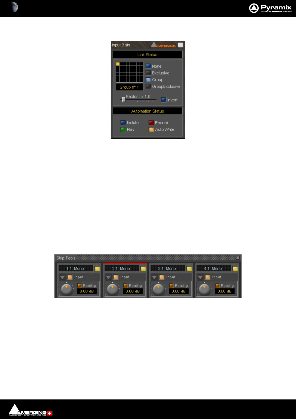
Strip and Bus Tools : Bus Tools 15 - 435
To add a control to a link group, right-click on the knob or button to display its Link Status and Automation Sta-
tus pop-up window. E.g. this is the pop-up for an input gain control.:
Group assignment mode buttons
These four buttons define the link mode of the control. Four choices are available:
None The control is not a member of any group.
Group The control is a member of the selected group. When you move (or switch) this con-
trol or any other control which is a member of this group, all the members of the
group will move (or switch) along with it.
Exclusive This mode is only available for switches. With this mode selected, when this switch is
on, all the other members of the group will be switched off.
Group Exclusive This is a mode which has a superior effect on all groups which are set to Group
Exclusive. When any of the groups which are set to Group Exclusive is switched on,
all the other groups set to Group Exclusive will be switched off.
Grouped controls are indicated by a yellow L in the corner of the control ‘block’.
Factor X Slider Works only on continuous (rotary or linear) controls. It determines the gearing of
this control in relation to other members of the group and vice versa. E.g, assume
the input gain of strip tools #1 and the input gain of strip tools #2 are both assigned
to group one. The scale factor of the gain of strip tools #2 is set to 2. Now when you
change the gain of strip tools #1 by 1 dB, the gain of strip tools #2 will change by 2
dB’s.
Invert Also works only on continuous controls. It inverts the effect of the movement for
this control caused by another group member or vice versa. E.g, assume the input
gain of strip tools #1 and the input gain of strip tools #2 are both assigned to group
one. The invert button of the gain of strip tools #2 is on. Now when you increase the
gain of strip tools #1 by 1 dB, the gain of strip tools #2 will diminished by 1 dB.
Strip Tools - Link and Automation Status
Strip Tools - Grouped Controls
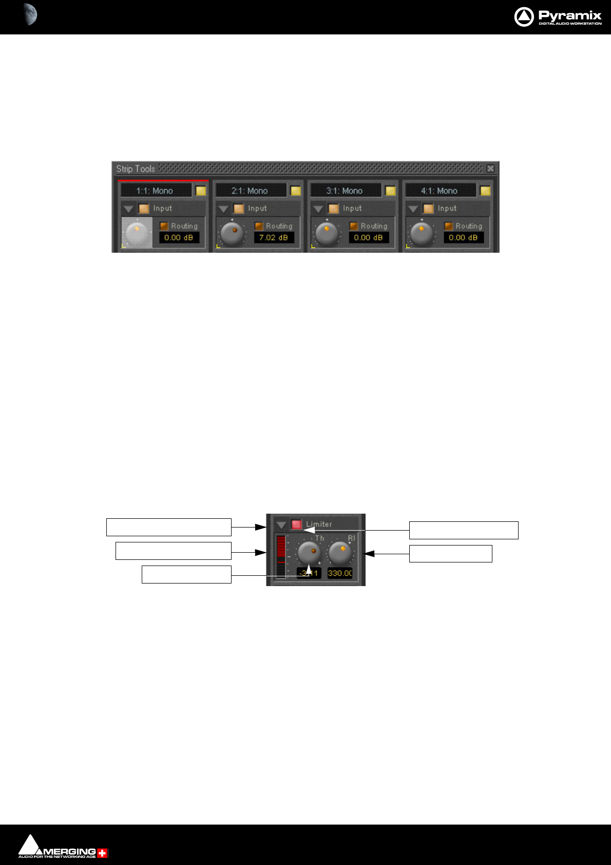
Strip and Bus Tools : Bus Tools 15 - 436
Automation mode switches
Please see: Dynamic Automation Transport Modes on page 403 for a description of the automation mode
switches.
When a grouped control is clicked, all other members of the group have a yellow L at the bottom left-hand corner.
Offset
If controls are offset when grouping is turned on, they retain the offset as shown here.
The red bar at the top of the strip indicates it is selected. The grayed out knob is the one which was right-clicked.
Delay Compensation
Delay Compensation
When the DRC section is active, the plug-in introduces a small delay to the audio signal. Since some signals of a
bus may not be selected for processing using the routing buttons, these signals would not be delayed, and there
would be a time misalignment at the output of the bus. When Delay Compensation is on, the same delay is
applied to all signals whether selected for processing or not. This results in correct time alignment for all the sig-
nals of a bus.
Limiter section
This is a straightforward ‘brick-wall’ limiter with simple Threshold and Release parameters. However, the DRC
(Dynamic Release Compensation) feature described in the next section can be activated to allow very musical
control of the release time.
A brickwall limiter is a limiter which guarantees that the output level will never exceed the threshold level. On a
normal limiter, a high level signal with very fast attack might cause an output higher than the threshold level, with
a brickwall limiter this will not happen.
Show/Hide Limiter section
Limiter section on/off
Gain reduction display
The bar graph shows the gain reduction generated by the Limiter Section. The range of the display can be
switched between 6 or 12 dB by clicking on the bar graph. Scale markings in 1dB increments on the right-hand
side of the bar graph make it easy to see if the range is 6 or 12 dB.
Threshold control
If the input signal level rises above the threshold level, the gain of the limiter is reduced. This limiter guarantees
that at no time will the level of the output signal exceed the threshold.
Release control
This parameter controls the amount of time the limiter takes to release. I.e remove the gain reduction) when the
input level was above the threshold level and starts fall. During the hold time the gain of the compressor remains
constant. The lower the release time, the faster the reaction.
Strip Tools - Grouped Knobs
Show/Hide Limiter Section
Gain Reduction Display
Threshold Control
Limiter Section On/Off
Release Control
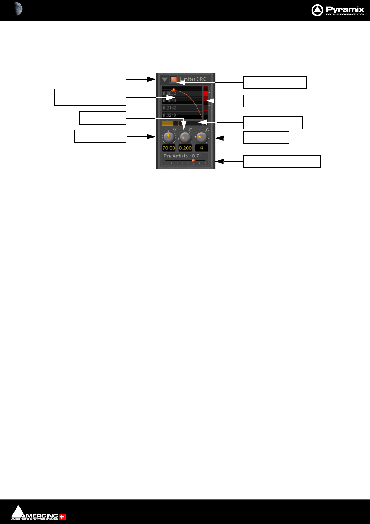
Strip and Bus Tools : Bus Tools 15 - 437
Limiter DRC Section
DRC stands for Dynamic Release Compensation. In short, this means the release time of the limiter is altered
depending on the dynamic nature of the signal routed through the processor.
Show/hide DRC section
DRC section on/off
Release Acceleration or Modification Display
Shows a curve which illustrates the relationship between the change in dynamics of the input signal and the vari-
ation of the release time. The curve can be adapted between linear and power function characteristics (see also
the description of the Curve Control parameter). During playback the display will also show a small red ball mov-
ing along the curve. This shows the range the algorithm is working in.
Gain reduction bargraph
Displays the gain reduction of the limiter while the DRC circuit is active. The scale is fixed at 6 dB.
Dynamics bargraph
Displays the dynamics of the input signal, which is the basis for the DRC algorithm.
Velocity control
Determines the speed of the DRC algorithm. The lower the value, the faster the algorithm reacts to changes of the
dynamics of the signal and the more it reacts to dynamics the more the release time will remain constant.
Offset control
This parameter basically sets the minimum release time. In this sense the release control of the limiter defines the
maximum release time, so the release time determined by the DRC algorithm will vary between these two times.
Curve control
This parameter controls the characteristics of the relationship between the dynamics of the signal and the result-
ing release time
Show/Hide DRC Section
Release Acceleration or
Modification Display
Velocity Control
DRC Section On/Off
Gain Reduction Bargraph
Dynamics Bargraph
Curve Control
Lookahead Delay Control
Offset Control

Strip and Bus Tools : Delay Compensation / Pre-Anticipation 15 - 438
Pre-Anticipation (Lookahead delay) control
This parameter changes the integration time for RMS detection and thus changes the effect of the DRC circuit.
The delay setting here also determines the delay that will be applied to signals passing through the plug-in NOT
not be selected for processing when Delay Compensation is switched ON
Note: Please note that this parameter delays the all signals running through the Bus Tools plug-
in, so phase or other timing errors may occur when the plug-in is used in places other than the
mix bus.
EQ and Output Sections
These are identical to the Strip Tools versions.
It is worth noting that, since the Limiter is in this case a brickwall design, the Automatic Gain Make-up function
compensates for the same amount as the value set by the Threshold Control of the Limiter. The resulting signal
will be close to, but never exceed 0dBfs. If Gain Make-up is Off the Output Level Control will act as a ‘ceiling’ con-
trol, setting the absolute level of the resulting output signal.
Delay Compensation / Pre-Anticipation
Example
In this table Bus Tools Instance 1 is IN circuit for the Left and Right channels of the mix and Bus Tools Instance 2 is
IN circuit for the Left Surround and Right Surround channels. For the Center and Sub-Woofer Channels both Bus
Tools are OUT of circuit. BUT Pre-Anticipation and Delay Compensation is switched ON for the channels selected
for processing. To ensure proper time alignment all channels are automatically delayed by the same total amount.
(the 8.71 and 5.8 figures are arbitrary)
If all channels are selected for processing (in circuit) with linked Pre-Anticipation then there is no need to activate
Delay Compensation.
5.1 Surround Mix Bus using two Bus Tools
Channel BUS 1 BUS 2 BUS 3 BUS 4 BUS 5 BUS 6
Routing L C R SL SR SW
Instance 1 IN OUT IN OUT OUT OUT
Delay 8,71 (PA) 8.71 (DC) 8,71 (PA) 8.71 (DC) 8.71 (DC) 8.71 (DC)
Instance 2 OUT OUT OUT IN IN OUT
Delay 5.8 (DC) 5.8 (DC) 5.8 (DC) 5.8 (PA) 5.8 (PA) 5.8 (DC)
Total Delay 14.51 ms 14.51 ms 14.51 ms 14.51 ms 14.51 ms 14.51 ms

16 - 439
www.merging.com/Pyramix
USER MANUAL
Project Processes

Project Processes : Dither 16 - 440
Dither
Whenever changes are made to digital audio signals such as mixing, altering gain, eq or reverb, the result is usually
an increase in the number of bits. These extra bits have to be removed to suit the requirements of delivery and
interconnect standards. If the bit depth is reduced by simply ignoring the extra bits (truncation) or even rounding
the least significant bit up or down, the resulting error can give rise to audible distortion of low signal levels. Obvi-
ously, there is also a permanent loss of resolution. These effects are cumulative. I.e. If the signal is repeatedly pro-
cessed and bit reduced to shorter word lengths, there will be a significant and audible loss of accuracy in subtle,
low level sounds. Human hearing makes use of this low level information in imaging and unless something is
done to avoid the problem, space and clarity will be adversely affected.
In Pyramix all processing takes place in 32 bit floating point so, if signals are kept within this environment, there is
no need for bit depth reduction until the final stage before output. Truncation or rounding are undesirable but a
single ‘dithering’ stage can reduce bit depth whilst maintaining low level linearity. This is achieved by adding a
controlled amount of low level noise to the signal. Since there is no such thing as a free lunch, the trade off is a
slightly increased level of noise. However, the noise can be ‘shaped’ to reduce its perceived audibility.
See also: Dithering Options on page 279
It is important dithering is only applied once.
Project Processes : Archiving Metadata 16 - 441
Archiving Metadata
Overview
Custom Metadata may be user defined and associated with rendered files. Metadata may be added during:
•Render
•Mixdown
•Directly during Recording (Normal Recording and Dubbing modes)
Single Media, One File per Track and One File per Bus are supported. The same Metadata Set is embedded in all
files in the latter two cases.
Riff and RF64 (>4GB) Files are supported.
Note: If a file is almost at the 4GB boundary and updating its Metadata would take it over this
limit then the update will be refused.
Any Media Markers set in any files in the Timeline are also exported in the Metadata XML.
Defining Metadata
The Metadata is defined in the Metadata Tab Window
Metadata Tab Window
Load Metadata Set and
Save Metadata Set Load and Save, respectively, the Metadata definition including the BWF map-
ping and Values. Metadata definition templates can be created that can be
loaded in other projects.
Import Metadata Set from BWF Opens a File Browser window to locate the target BWF file. When the target
file is selected, clicking on Open loads the Metadata set present in the BEXT and
LISTINFO chunks.
Import Metadata Set from Selection Imports the Metadata set from the (BWF) Clip currently selected in the
Timeline.
MetaData Tab Window
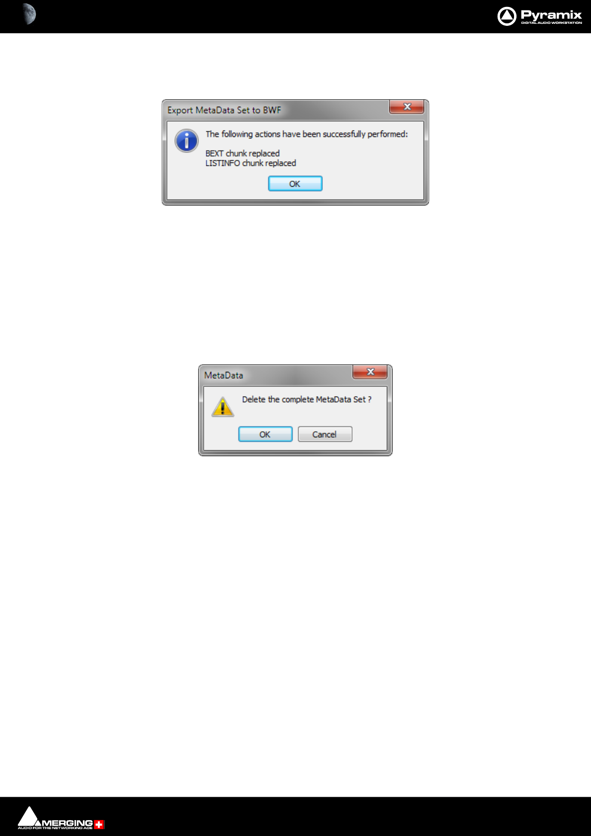
Project Processes : Archiving Metadata 16 - 442
Export Metadata Set to BWF Opens a File Browser window to locate the target file. When the target file is
selected, clicking on Open updates the Metadata in the target file. A message box
pops-up to confirm that the action has been carried out:
Click on OK to close the box.
Enable Metadata Set definition Editing gives control over Metadata editing:
When checked, the Name, Mapping, Database Mapping and Value fields are
editable and new Metadata entries can be added. This is for editing the Metadata
Set definitions.
When unchecked, only the Value field is accessible for modification. No new Meta-
data entries can be added. This is for normal operation of editing Metadata con-
tent.
Clear Metadata Set This button deletes the entire Metadata Set currently present in the Metadata Tab
Window. A confirmation dialog pops-up for safety:
Click on OK to confirm the deletion or Cancel to cancel.
Export MetaData Set to BWF message box
Delete MetaData confirmation dialog
Project Processes : Archiving Metadata 16 - 443
Metadata Fields
Four columns are accessible for defining, editing and exporting Metadata:
Name: The key name of the metadata, identifies this metadata, consists of a freely defin-
able string of characters.
BWF Mapping: A list of fields available in the BEXT header or in the LIST-INFO chunk. Any Meta-
data Value can be mapped/written to when a file is rendered in BWF format. These
fields are:
Database Mapping This field is for Database Mapping information that is exported in the XML so that a
database parsing the XML can map this Metadata with specific Database fields.
These values are free text.
A set of predefined values can be set in the registry in:
HKEY_CURRENT_USER\Software\Merging Technologies\Pyramix\Archiving-
MetaData\DatabaseMapping
as String entries where the names of the strings are the preset values for database
mapping values.
Value: The actual Value, or useful content of the metadata, consists of a freely definable
string of characters.
• Below the Metadata list columns, the Advanced Value Editing text field enables multiple lines of text to
be edited for the selected Metadata.
Note: The Update Value button must be clicked to save the edited data.
• The Metadata Set currently defined in the MetaData Tab is simply saved in the current project.
Render with Archiving
In the Render dialog window (accessible through the menu Project > Render) a new Archiving Metadata sec-
tion has been added, offering two options:
Insert Archiving Metadata if target is BWF
This will insert all Metadata entries defined in the current Metadata Tab that have a BWF Mapping field set cor-
rectly into the corresponding field of the generated BWF file.
Only the Metadata Value field content is inserted in the file fields/chunks. The Metadata Name information is not
inserted in the target file, this is only present for information in the application during editing and rendering.
BEXT / Description BEXT / Originator
BEXT / OriginatorReference BEXT / OriginationDate
BEXT / OriginationTime BEXT / TimeReference
BEXT / CodingHistory BEXT / UMID
INFO / IARL INFO / IART
INFO / ICMS INFO / ICMT
INFO / ICOP INFO / ICRD
INFO / IENG INFO / IGNR
INFO / IKEY INFO / IMED
INFO / INAM INFO / IPRD
INFO / ISBJ INFO / ISFT
INFO / ISRC INFO / ISRF
INFO / ITCH
Project Processes : Archiving Metadata 16 - 444
Generate Archiving Metadata XML along with rendered files
This will generate an XML file along with any rendered files (of any format, even if not BWF) containing all Meta-
data defined in the Metadata Tab.
If the target rendered file is named x:\yyy\zzz\file.typ the generated XML will be named x:\yyy\zzz\file.typ.xml
Sample MetaData Set
MetaData Sample Set

Project Processes : Mixing Down Projects 16 - 445
Mixing Down Projects
Exporting a Composition to a File
Once you have finished editing your Composition, the complete Composition or any selected area can be
exported to an audio file (or files). This is really the same as mixing down the Composition to a file instead of to an
audio output.
1. Choose Project > Mix Down to open the Mix Down dialog box.
2. In the Target Settings section, type in an appropriate file name under Mix Down Name or use the default
which will be Mix Down of “Project Name”; choose the folder to which the file will be saved from the Media
Folder drop-down list (only previously mounted folders will be available as options) or use the ... open a
browser to navigate to and mount an alternative.
3. The Suffix with Bus Name option will create files named like:
Terminator_Final-M&E-Stem1-L.wav
Terminator_Final-M&E-Stem1-C.wav
Terminator_Final-M&E-Stem1-R.wav
Mix Down dialog

Project Processes : Mixing Down Projects 16 - 446
Unique filename extension when checked, produces files with a unique identifier.
4. The Single Media drop-down list offers the choice of Singe Media to make a single multi-track audio file, or
One file per Track to generate separate audio files for each Track or One file per Bus/Stem and choose the
appropriate export file type from the Media Format pop-up list, choose the bit depth/word length from the
Media Wordlength combo box.
Note: These settings are completely independent of the settings for Recording and Render.
5. In the Record section, choose to export the Whole composition, or the area between the In and Out Markers
with Between Marks, or a Selection made previously, by clicking the appropriate radio button.
6. Processing choose Real time for a real-time mixdown otherwise, leave unchecked for a faster mixdown at
the same quality.
7. If the mixdown is required at a sampling rate other than the Project sampling rate check the SRC and ReDith-
ering box. Clicking the 48ooo Hz/32bits/NoDither button opens the SRC Output Settings dialog.
8. Mix Sources - Choose the appropriate output bus(es) as the source for the exported file. All output buses con-
figured in your Mixer will be available in the Bus Name list. Click the check boxes to add buses to the mix-
down. If the bus is a GP bus clicking in the Channel Mapping column will pop-up a list of mapping choices.
Clicking in the Destination Track column drops-down a list of all existing tracks in the Project plus the
options, Create New Tracks and None.
Note: The names displayed will correspond to the labels in the mixer strips.
9. Mix Down begins the process.
Stop pops-up a Stop Record? confirm dialog. If you click Yes the recording stops at the point where you
clicked and is retained up to that point. The Mix Down dialog is closed.
Abort pop-ups an Abort Record? confirm dialog. If you click Yes the recording is stopped at that point and
discarded. The Mix Down dialog is closed.
Options
Processing
Real Time When checked the Mix Down will take place in Real Time
SRC and ReDithering When checked the settings shown in the button below come into play.
Clicking the button opens the SRC Output Settings Properties dialog. Please
see: Properties... on page 77.
Note: Please be aware that the SRC option in the Mixdown is shared with the Media Manager
Sampling Rate Conversion tool. This means that if, following a Mixdown that has SRC applied, if
you subsequently use the Media Manager Sampling Rate Conversion tool and change the SRC
parameters, then those values will also be changed in the Mixdown Dialog Box SRC section.
Loudness and True peak Limiting
When checked Loudness control and True Peak Limiting will be applied to the mix-
down.
Note: The Final Check key is required to use these options.
Note: One file per Bus/Stem mode must be enabled.
Loudness Column in Mix Sources
The Loudness column in the Mix Sources section allows independent selection, among the Sources selected as
to which one will perform the Loudness Analysis and True Peak Limiting, following the global Loudness Analysis
and True Peak Limiting settings available in the Processing section. Click on an entry in the Loudness column to
choose between Enabled and Disabled.
• This feature is only useful when in One File per Bus/Stem mode. This enables the Loudness Analysis and
Correction to be performed on selected Buses and not on others. This allows for a single pass mix-down
with multiple selections.

Project Processes : Mixing Down Projects 16 - 447
•In Single Media mode all Busses will automatically have the same settings, only global Loudness Analy-
sis/Correction is possible in this mode.
•In One File per Track mode this feature is not available (N/A), no Loudness Analysis/Correction is possible
in this mode
Settings Click on Settingsto open the Loudness and True peak limiting settings dialog:
True Peak Limiting Normalization Check the box to enable.
Target Loudness The drop-down list offers a choice of target loudness levels.
Max. True Peak The drop-down list offers a choice of maximum peak levels.
Max. Gain change The drop-down list offers a choice of maximum allowable gain change to be applied
by the processing.
A measurement report will be displayed after the Mixdown process.
The measurement report is available in a Log file in the same location as the Mixdown media file(s).
Post-Processing
Keep in default library When checked the resultant mixed down file(s) will be placed in the Default Library
Place in VCube When checked the resultant mixed down file(s) will be placed in new Tracks in the
VCube Timeline automatically. All pre-existing audio Tracks are removed. See also
note below.
Wrap in Video When checked, once the Mixdown is complete, the resultant file will be “wrapped”
into a destination Video file. The Settings button opens a Settings dialog for this.
Please see: Wrap in Video on page 531
Controllers
Offline Controllers When checked Hardware Controllers will be switched Offline automatically for the
duration of the Mix Down. If the box is left unchecked it is possible to use the Hard-
ware Controller for changing Monitor volume etc. or to fade out.
Archiving Metadata
Insert Archiving Metadata if target is BWF When checked Archiving Metadata is inserted in the resultant
file(s).
Generate Archiving Metadata XML along mixdown files When checked an XML Metadata file is generated
in the same location as the output audio file(s).
Please see: Archiving Metadata on page 441
Notes on ‘Place in VCube’
The following notes apply when VCube is running on a different machine running on the same local network.
Important! If using the Post-Processing Place in VCube function with separate standalone machines.
I.e. a Pyramix and a VCube the Mix Down Destination Folder must be mounted as a network path, e.g.
\\server\sharedisk\folder\file.pmf. The files must be accessible from both machines using the same net-
Loudness and True peak limiting settings dialog
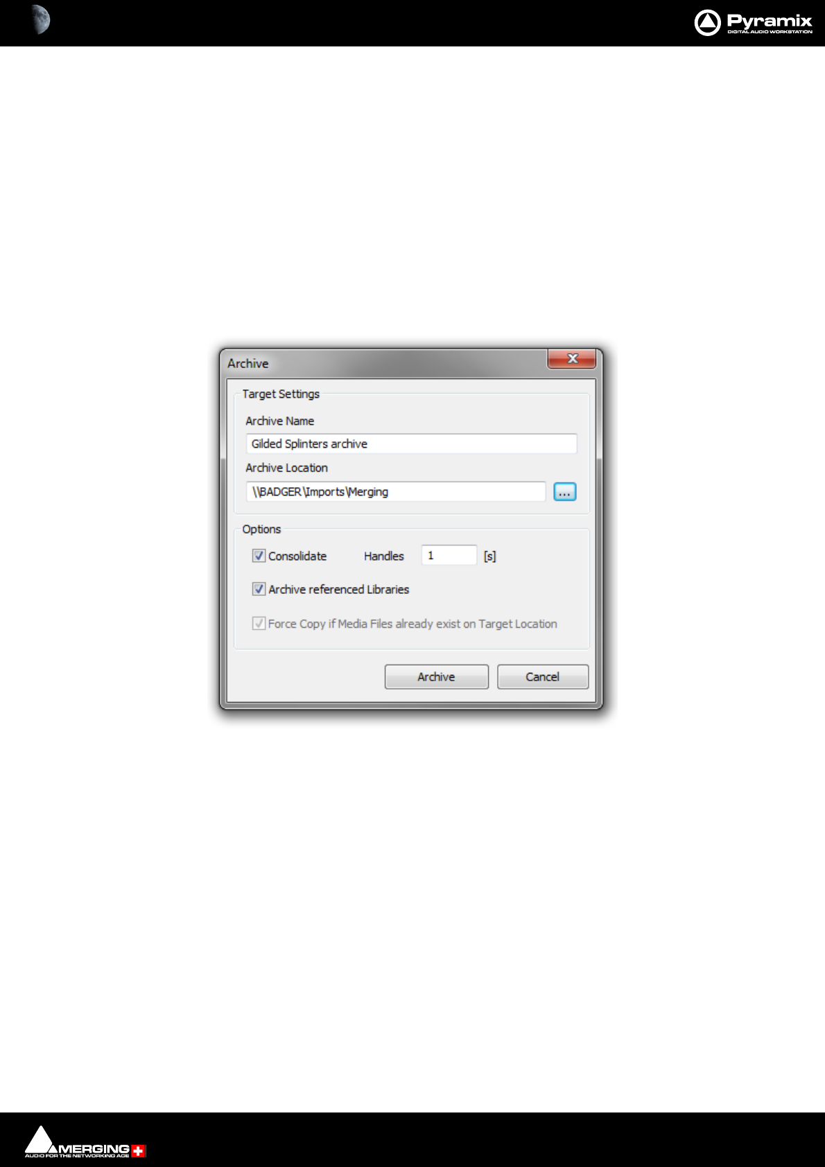
Project Processes : Archiving Projects 16 - 448
work name.
Typically the share name of a disk can be seen differently from both machines if not set correctly, e.g. one
can see e:\media\file and the other see \\machine\shared\media\file in such case Pyramix cannot trans-
late the name for the VCube.
Non Real-Time Mixdown
Note: In Pyramix, non real-time mixdowns introduce no degradation whatsoever and are a con-
siderable aid to productivity since they are usually (much) faster than real-time.
Archiving Projects
Project > Archive opens the Archive dialog :
This function copies the Project and media utilized to a single location.
If Consolidate is checked then new audio Media Files be created containing only the audio used in the Project not
the entire original Media. Handles may be added by typing a handle length in the box.
Project Libraries referenced in the Project are also Consolidated but not Global Libraries.
Force Copy if Media Files already exist on Target Location is grayed out when Consolidate is active.
When checked Files will be copied regardless of whether they already exist at the target location.
Archive dialog
Project Processes : Consolidating Projects 16 - 449
Consolidating Projects
Consolidating a Composition is a method of reducing the storage space used by Media files and of bringing all ele-
ments of the Composition together to move it to another machine or storage medium. The Consolidate function
makes a selective backup of the media used in the Composition. Instead of backing up the whole of every media
file referenced by the Clips in a composition, Consolidate backs up only those parts of the media files that are ref-
erenced by the Clip segments.
Target Settings
The Radio Buttons offer a choice of locations for the consolidated Composition.
Use Original Files Media Folder
The Consolidated Composition will be saved in the same location as the original files
Use Current Project Media Folder
The Consolidated Composition will be saved in the same location as the current Project Media
Use Custom Media Folder
The Consolidated Composition will be saved in a user selected location.
Consolidate dialog

Project Processes : Converting Projects 16 - 450
Options
Handles
To allow for limited further editing of the Consolidated Composition, changing fade durations etc. extra material
(if it exists), can be retained at each end of every Clip, beyond that which is defined by the Composition EDL. Enter
a value in seconds.
Format
This drop down list enables the Consolidated Composition to be saved in the same format as the original or to be
converted to any supported format.
Generate Waveform
When checked, waveform files will be generated and saved with the Consolidated Composition
Use clip names to generate media
When checked, the original Clip names are used for the newly generated media
Don’t optimize media for overlapping clips
Advanced Options
Skip generation if original media already exists on target drive
When checked new media will not be written where a version already exists on the target drive.
Delete original media (Use with care!)
When checked the original media files referenced by the consolidation are deleted after the consolidation is com-
plete. N.B. Destructive!
Converting Projects
Changing Project Length / Pitch
Processes whole Projects. Offers Time Compression or Pitch Reduction of 4% (24fps to 25fps) or Time Expansion or
Pitch Rise of 4.17% (25fps to 24fps)
Given an Origin Reference and a Ratio, all Clips of the project are stretched/squeezed and moved accordingly to
the stretch ratio and origin reference. Optionally all media can be consolidated to process only the part of audio
required by the Clips. This function is available through the menu Project / Stretch and requires the Prosoniq
MPEX4 authorization key to be entered.
Reconforming a Project
Processes entire project. To be used where the existing project was created by Autoconforming material to a CMX
EDL.
Surround Post-Processing Projects
The Surround Source Stem can be selected from a list of available stems from all Surround buses.
Available processing plug-ins are:
• Multiple File Export
• Minnetonka AC3 (Dolby Digital) Encoder (to be purchased separately)
• MPEX4 Cinema 24fps to 25fps or 25fps to 24fps Multi-channel Time Stretcher by Prosoniq (optional)
Project Processes : Rendering Projects 16 - 451
Rendering Projects
The Render function available in menu Project > Render offers a choice of Rendering plug-Ins. Please see also:
Render with Archiving on page 443
Rendering Process Lists the Rendering Processes and is where you select the one required.
Extra Handles The before and after boxes allow a time value to be entered for extra material
(where available) to be included in the material used for analysis by the process
(where applicable).
Note: Handles added in the Render menu are not meant to be processed. They're only used to
give some extra material to processes that need analyzing before or after the given portion of
data.
Handles will NEVER be processed by any Render plug-ins.
Target Settings Affect the Output File.
Render Name A text entry box where any legal filename may be entered.
Media Folder The drop-down list allows mounted Drives/folders to be selected as the destina-
tion for the output file. The adjacent ... button opens a browser window if more
options or a new folder are required.
Resolution A drop down list with all valid choices of bit-depth for the output file(s)
One file per track When checked, multi-track sources will be rendered as separate files.
Unique filename extension When checked, ensures the output files have unique extensions.
Render dialog
Project Processes : Process Plug-ins 16 - 452
Format The drop-down list allows a choice of output formats.
Settings If options are available for the chosen format, this button accesses them. If no
options are available the button is grayed out.
Waveform The drop-down list offers Waveform generation options. None, Generate AFTER
recording or Generate WHILE recording.
Note: These settings are completely independent of the settings for Recording and Mix-down.
Source Offers a mutually exclusive choice of sources between Whole composition, Between
Marks, Selection or Selection (Split by Groups)
Selection (Split by Groups) splits the rendering process into multiple renders for each selected Clip Group in the
timeline. In this case the Render Name text edit box is ignored and all renders take the name of the first Clip in
time of each group.
Only render solo tracks (one file per track medias and mono processing only)
When checked, only soloed Tracks will be rendered. Only media files with ‘one-file-per-track’ will be processed and
processing will be mono only.
Render Initiates the Render Process.
Cancel Cancels all changes made in the dialog and closes it without rendering.
Process Plug-ins
Glitch Detector
Finds Glitches and Pops. Select Digital Glitch Detector in the Rendering Process list in the Render dialog, make
other settings as required then click on Render to open the Digital Glitch Detector dialog:
Type the number of consecutive samples to detect on in the When finding _____ consecutive samples box.
(Default is 10)
Choose detection method:
lower than -144.5dB
or
Digital Glitch Detector dialog

Project Processes : Process Plug-ins 16 - 453
of the same value
Now select what you wish Pyramix to do when it detects the type of potential glitch chosen above:
add a marker
slice the region
copy the region to another track
ZTX Pro
Optional high quality pitch-shift and time-stretch renderer from The Zynaptiq.
Note: Merging Technologies ZTX Pro key is required.
Accessing ZTX Pro
When a valid key is present ZTX Pro replaces Timezone as the Default Time-stretch tool in Editing.
It can also be defined under Settings > Application > Editing > Time Stretch Tool
TimeZone is no longer supported and no longer available.
Configuration
Dirac is configured is in Pyramix Settings under Settings > Application > Time Stretch > ZTX Pro Settings
Three quality modes are available: Good, Better, Best.
Time/Frequency localization setting
1. Selects full time localization. Good setting for single instruments and voice.
2. Time/frequency localization with emphasis on time localization. If setting 1. produces echoes this give better
results.
3. This sets the time/frequency localization halfway between time and frequency domains. It is the best setting
for all general purpose signals and should be set as default for non-preview processing.
4. Higher frequency localization and less time localization. May be a better choice for classical music than the
lower Time/Freq localization settings.
5. Highest frequency localization. This may not be an ideal choice if you're dealing with signals with very fast
attack transients.
Project Processes : Process Plug-ins 16 - 454
Effects Rack
Enables chains of up to eight VS3, VST and or Direct X plug-ins to be used as rendered processes. Select Effects
Rack in the Rendering Process list in the Render dialog, make other settings as required then click on Render to
open the Effects Rack Window
Note: The Effects Rack processes up to six channels. Automatic Delay compensation is available.
VSt3 plug-ins are not currently supported.
Each of the eight slots can be loaded with one plug-in effect.
Most of the buttons are self explanatory.
Load FX
Opens a pop-up with lists of installed VS3 and VST plug-ins. Selecting None removes the currently loaded effect.
Show
Toggles the control Window for the currently loaded effect visible or hidden.
M
Mutes the effect in this slot
S
Solos the effect in this slot
Bypass
Bypasses all effects in the rack when lit
Audition
Effects Rack Window

Project Processes : Process Plug-ins 16 - 455
Plays the Timeline to audition the effects
Stop
Stops the Audition
Process
Closes the Effects Rack Window and initiates the Rendering Process
Cancel
Closes the Effects Rack Window and cancels the Render
Load Preset
Pops up a menu with Recall... >, Remove... > and Load From File options.
Hovering the mouse pointer over Recall... > reveals a list of all Presets present. Selecting one loads all its effects
and parameters into the Effects Rack.
Hovering the mouse pointer over Remove... > reveals a list of all Presets present. Selecting one erases it from the
Presets list.
Selecting Load From File opens a Browser Window to enable a previously written Preset File to be located and
loaded.
Save Preset
Opens a pop-up with two options: User > and Save To File.
Hovering the mouse pointer over User > reveals the option to Create New... and a list of all existing Presets.
Selecting an existing preset will overwrite the current contents of the selected Preset.
Selecting Save To File opens a Browser Window where you can name the Preset and navigate to a suitable loca-
tion for the file.
Mutes Reset
Resets all slots Mutes
Solos Reset
Resets all slots Solos
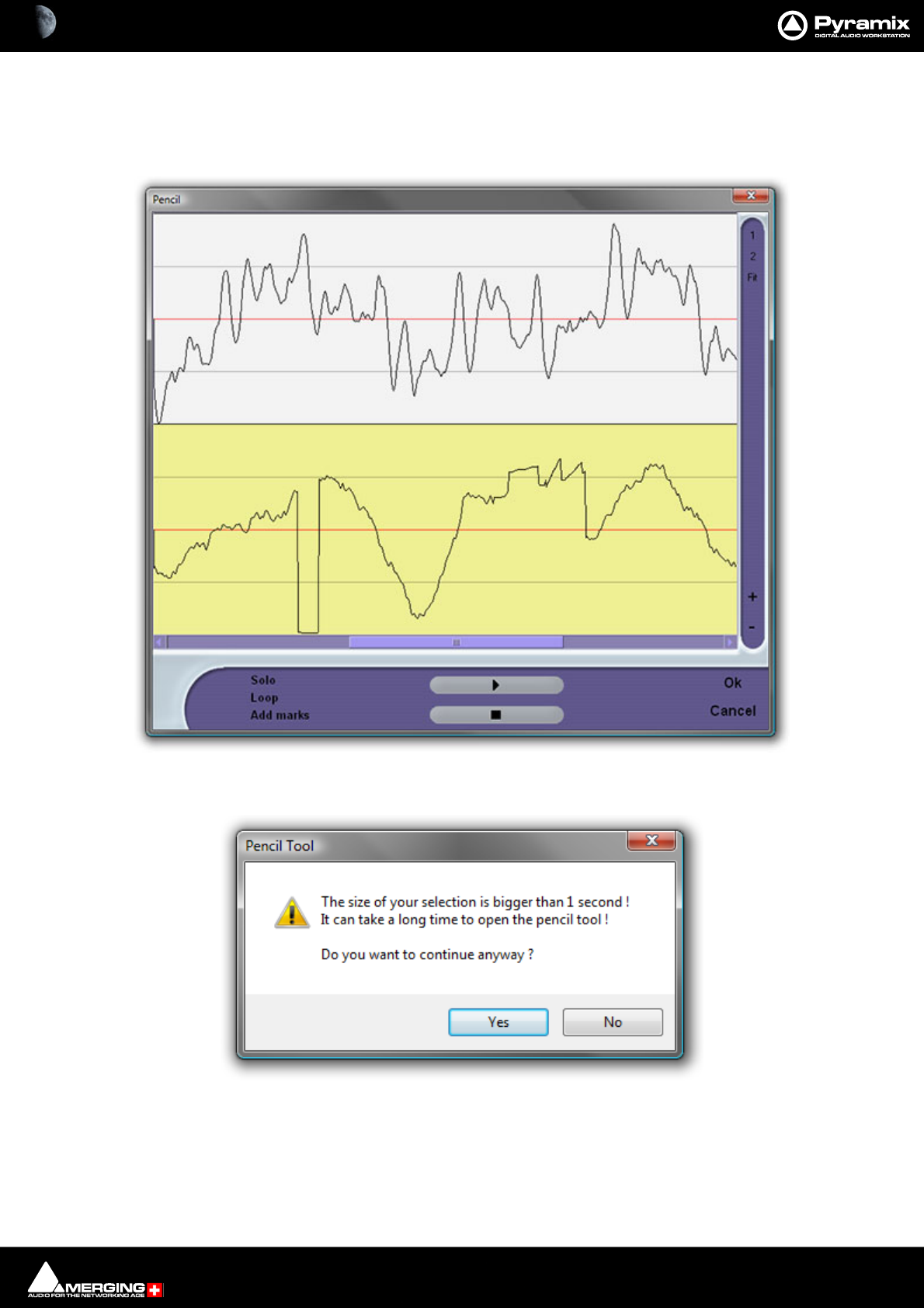
Project Processes : Process Plug-ins 16 - 456
Pencil
For retouching waveforms. To use the Pencil tool first select the section of audio containing the waveform you
wish to modify. Now select Pencil in the Rendering Process list in the Render dialog, make other settings as
required, then click on Render to open the Pencil window:
Note: If you select a section of audio longer than 1 second this Pencil Tool dialog will appear:
The yellow Track is the one currently selected for treatment.
The 1 and 2 buttons on the right determine whether one or both Tracks of a two Track selection are shown. Fit
shows all selected Tracks.
The + and - buttons zoom in and out in time.
Pencil Window
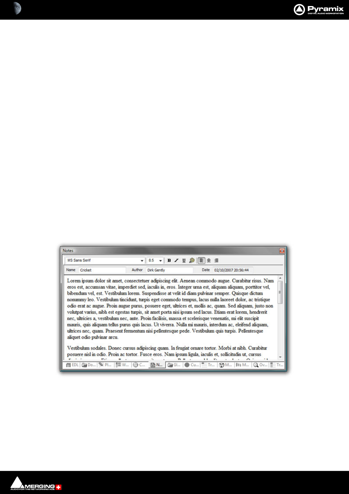
Project Processes : Cleaning Up Project media 16 - 457
Solo When ticked solos the selected Track
Loop When ticked preview playback will loop
Add Marks When ticked adds a Marker to the Timeline where the Pencil Render has taken
place
The > button initiates preview playback and the square stop button stops preview playback.
Prosoniq MPEX 4
An optional Multi-channel Time Stretch / Pitch Scaling with Formant plug-in. Please see: MPEX4 Timestretch
and pitch change on page 384
ReNOVAtor
An optional renovation suite plug-in by Algorithmix.
Cleaning Up Project media
Deletes all Media files in the selected folder which is not used in, or referenced by the current Project.
N.B. This operation is NOT reversible. There is no UNDO!
Project Notes
Click on the Notes tab to add text notes to a project. Type or cut and paste text into the editor. Drop down list
boxes give a choice of font and size. Text can be emboldened, italicized, underlined and colored. Justification can
be left, centre or right.
Notes entered here are saved with the project. The notes can be reviewed, edited and copied into other applica-
tions by highlighting the text and copying with Ctrl + C.
Notes Tab Editor

17 - 458
www.merging.com/Pyramix
USER MANUAL
Final Check Metering

Final Check Metering : Final Check Metering 17 - 459
Final Check Metering
Scope
Pyramix has an optional plug-in dedicated to precision metering. As the name implies this window brings
together all the tools necessary to ensure that masters conform to the relevant standards.
Final Check enables you to monitor and check a wide variety of mix characteristics objectively. Final Check pres-
ents this information via a simple and easy to read user interface making it easier to be confident that your mix will
conform to the specifications required by your clients.
Note: FINAL CHECK supports GENERAL MIX BUSES in Stereo and L C R LS Rs Lfe formats ONLY.
Final Check Window
Open the Final Check window either by clicking on the icon or View > Windows / Tools FinalCheck Meter-
ing.
The Final Check Window is presented with two tabbed pages, Metering and Setup.
In the Upper left-hand corner, the yellow square toggles the plug-in between active and inactive states.
The Window can be resized by clicking and dragging. Double-clicking on the upper boundary maximizes the Final
Check Metering window automatically and sets the window to full screen.
If you are using more than one monitor, it will be maximized on the screen where most of the window was located
previously. Double-clicking again restores to the previous size.
In the upper-right corner the [X] box closes the Final Check window.
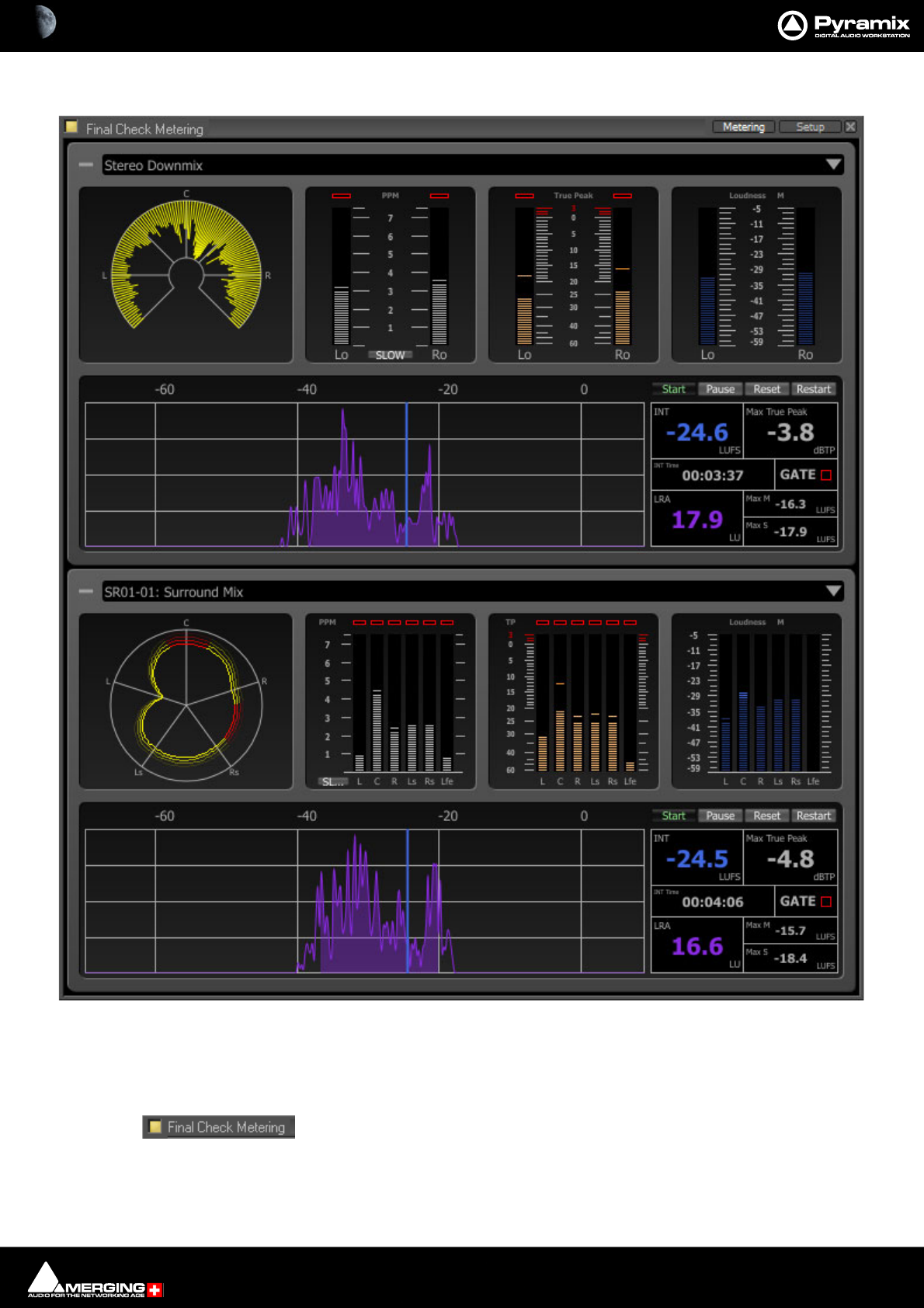
Final Check Metering : Final Check Window 17 - 460
Metering Tab
The Metering page is divided between the upper Stereo-panel and the lower Surround-panel. If one panel is not
required for the current application, it can be minimized by simply clicking on the (-) icon at the top-left of the
panel. To restore, click the (+) icon. The window is resizable using the usual edge handles and double-headed
arrows.
At top-left the button must show yellow before the meters will operate. Clicking the but-
ton toggles between on and off.
At top right of each panel, the down arrow accesses a list of all buses in the current Pyramix mixer. Click on an
entry to select which bus will be monitored. If a bus contains more than one stem, an additional menu allows you
Final Check Metering Page
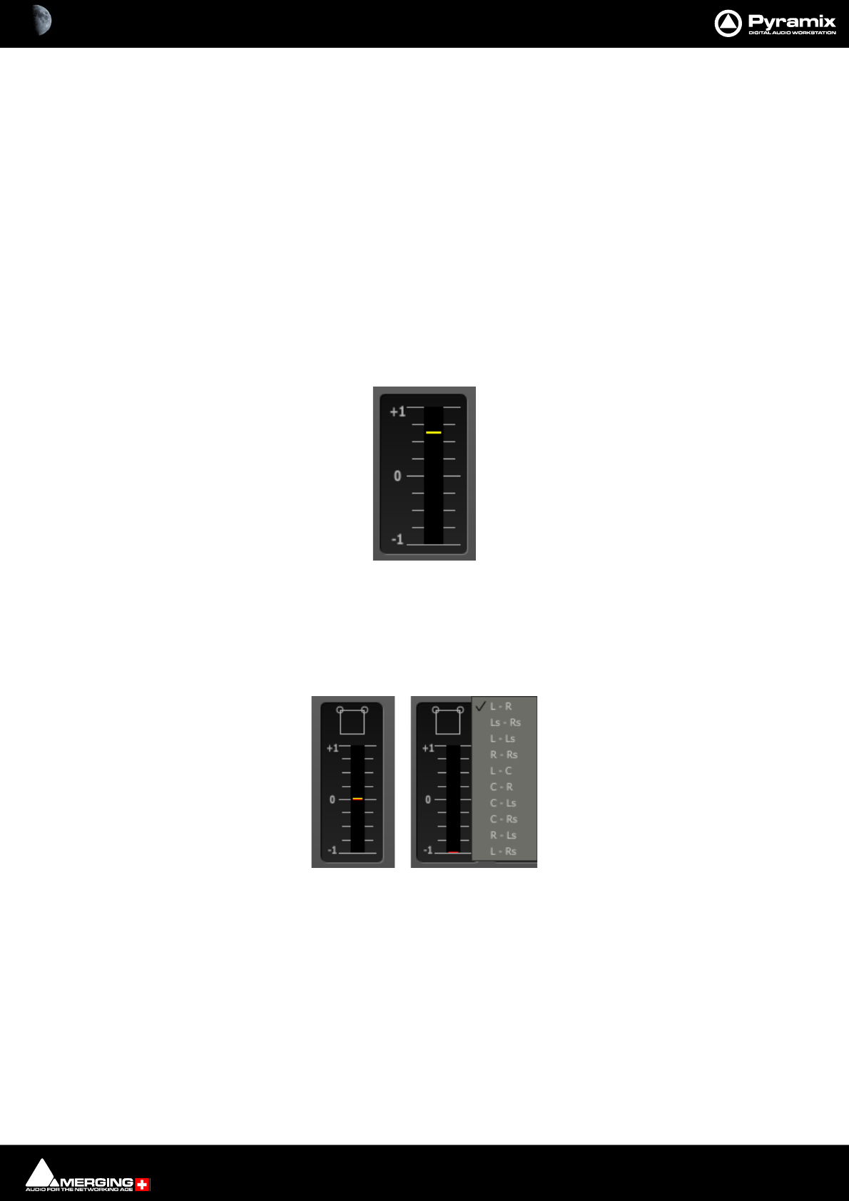
Final Check Metering : Final Check Window 17 - 461
to select which stem to monitor. It is not possible to monitor a combination of bus and/or stem. To achieve this
simply create an additional bus in the mixer and route the multiple stems as required. The bus and stems being
monitored currently, appear ticked. Final Check will even perform useful tricks such as managing a fold-down of
the selected Surround Bus to be monitored by the Stereo Panel, thus enabling you to see what the levels would be
after mixdown. Select Use Stereo Mixdown from the Stereo section bus list to access this option.
Keyboard Shortcuts
In the Metering page [P] clears ALL peak indicators. (Same shortcut as Pyramix Mixer.)
In the Metering page [R] resets all the History graphs and LIaR. Same as Right-click on a History Graph and select-
ing Reset all or [Shift] + click on Reset on LIaR.
Meters
Once the Bus(es) is (are) selected, any or all of the following meters will be active depending on the choices made
in the Setup page:
Phase Meter Stereo
This displays the value of the phase correlation within the mix. A clear colour code allows you to easily spot nega-
tive correlations.
Yellow = In phase, Red = Out of phase.
Phase Meter Surround
For a surround mix, a simple right-click allows you to select which two channels you want to monitor. An Icon at
the top of the phase meter shows the user which two channels are selected. Alternatively, this can be selected via
the Setup page. Please see: Setup on page 467
Stereo Phase Meter
Surround Phase Meter and Channel Assign
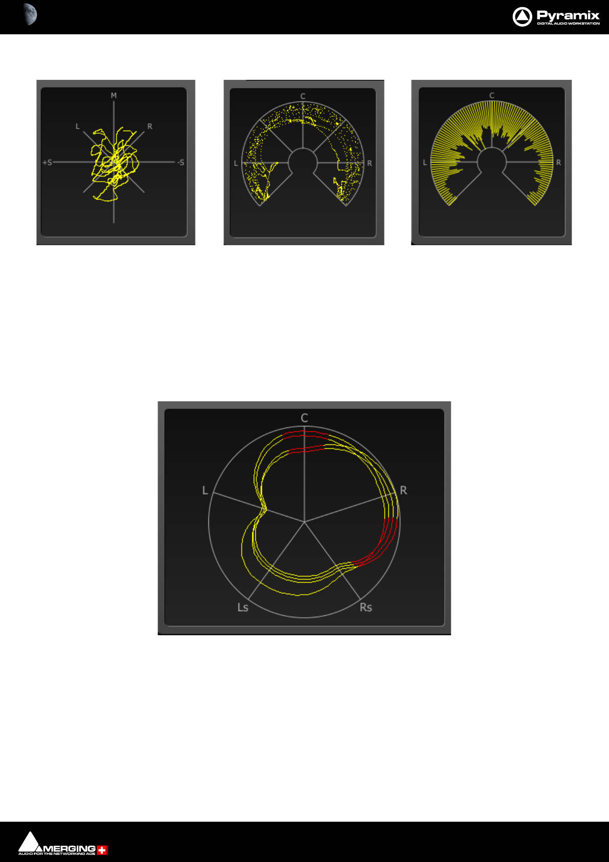
Final Check Metering : Final Check Window 17 - 462
Phase Oscilloscope (stereo mix only)
A classical phase oscilloscope, which also includes two new display modes :
Stereo Phase stereo-meter : A polar co-ordinates plot of the points displayed by the classical phase oscilloscope
Stereo Phase VU Meter : A circular graph showing directional RMS of the points of the phase stereo-meter as
described above.
Note: Any points or lines below the L - R line represent out of phase samples.
Surround Monitor (surround mix only)
This meter shows a true 360° display of your surround-mix. With the added feature of a simple colour code allow-
ing the user to quickly detect phase issues by highlighting them in red.
Principle
A negative phase between two neighboring channels (L-Ls, Ls-Rs, Rs-R, R-C and C-L) is displayed by a “symmetric”
red segment centred halfway between the two channels in question. For example, a phase just below zero
between Ls and Rs will result in a red dot at the “back” i.e. lowest part of the surround monitor display. If, on the
other hand, Ls-Rs were totally out of phase, (phase = -1) the whole 72° (one fifth of 360°) between Ls and Rs lines
would be red. The rule is : a phase of -x will turn red a region of x*72° (linearity is also to angle, not to segment
length).
Stereo Phase VU MeterStereo Phase Oscillo MeterStereo Phase Oscillo Interpolate on
Surround Monitor
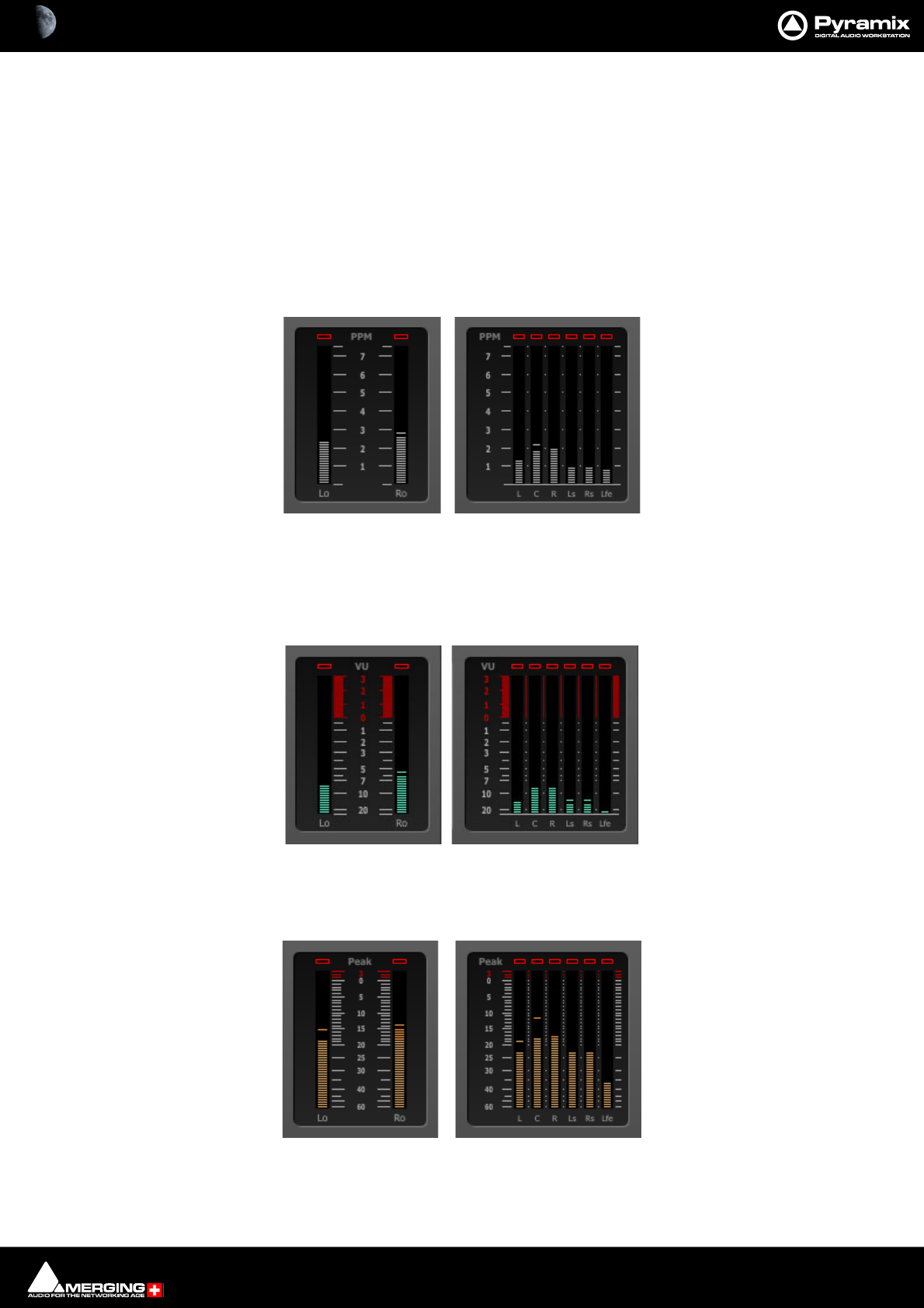
Final Check Metering : Final Check Window 17 - 463
Additionally, the LR phase is displayed (although L and R are not neighboring channels) centered midway
between L and R, that is on C… Consequently, it is possible for the red regions to overlap if LR and LC/RC phase
correlations are all negative.
To gain familiarity, we suggest you experiment using the Phase Correlation meters and the Surround Monitor
together, in a Project that just uses sine wave at the same frequency, e.g. 1kHz, and see what happens when the
various elements are phase reversed.
Note: In simple terms, any red segment means there is a phase issue which should be investi-
gated since it may have an adverse effect on your mix.
Peak Programme Meter (PPM) :
This digital replication of the old analogue PPM includes separate overload indicators and a Slow option enabled
in the Setup page. Clicking on the Slow button activates the mode and the button turns red. A selection of differ-
ent, presets for scale and dynamics (DIN, Nordic, BBC or EBU) are available in the Setup page.
VU Meter :
A classical Volume Unit (VU) indicator which also comes with a separate overload indicator.
True Peak Meter :
This is also known as an "inter-sample peak meter". In accordance with EBU R128, it allows you to spot areas sus-
ceptible to producing analog overflows, after D/A conversion, with high accuracy even beyond +0dBFS.
PPMs (Peak Programme Meters)
VU Meters
True Peak Meters
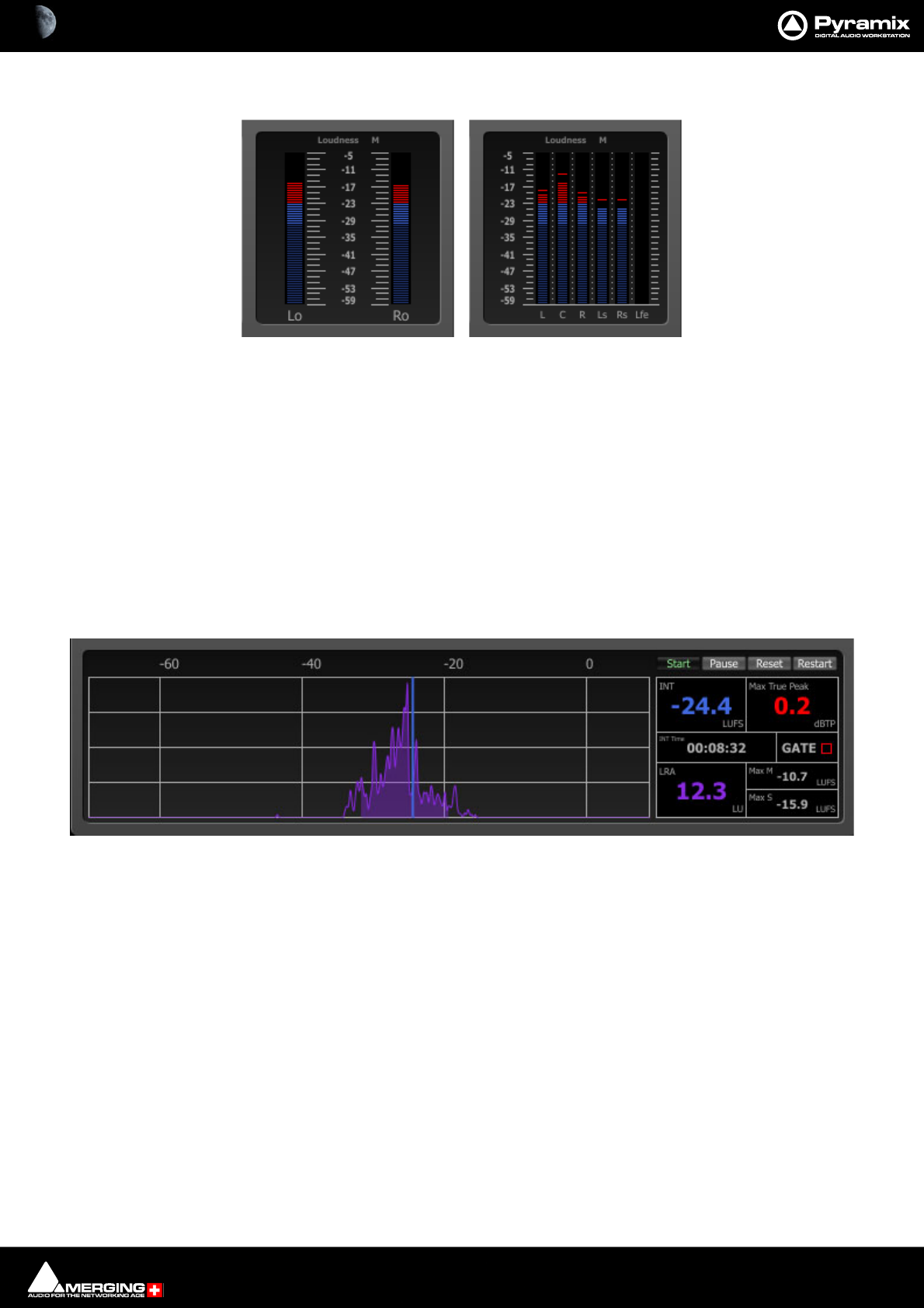
Final Check Metering : Final Check Window 17 - 464
Loudness Meter :
As recommended by EBU R128. Three different loudness bargraphs can be displayed, differentiated by their inte-
gration time.
Loudness M (EBU mode Momentary : 400 ms) integration time.
Loudness S (EBU mode Short-term : 3 s) integration time.
Loudness Custom (Custom integration time) An additional loudness meter with any integration
time you wish. (Defined via the setup page.) Note the different names on the
meters themselves.
Loudness metering is rapidly becoming the standard for transmission-ready mixes for TV and in most territories
conformity to a LUFS level is now a delivery requirement. It is also fully compatible with ATSC (Advanced Television
Systems Committee) A/85.
LIaR (Loudness Integration and Range) :
Values Panel
The right-hand panel shows several values and indicators and also contains the Start, Pause, Reset and Restart
buttons.
Values
INT The integrated LUFS total for the period when the instantaneous loudness is
above the gate threshold.
Max True Peak Shows the Maximum True Peak value in dBTP since the last reset.
INT Time Shows the elapsed time since the Start button was pressed. (Only increments
when the transport is running.)
GATE LED flashes when gating is active. The red LED will turn on when the signal
streamed through Final Check is below the gating threshold, and hence isn't taken
in account for the measurement. If the gate is set to -70LUFS in the Setup page it
remains active at this threshold.
LRA Loudness Range value. Shows the value in LU between the quasi lowest and quasi
highest LU results recorded since the start of recording values.
Loudness Meters
LRA Curve Values Panel
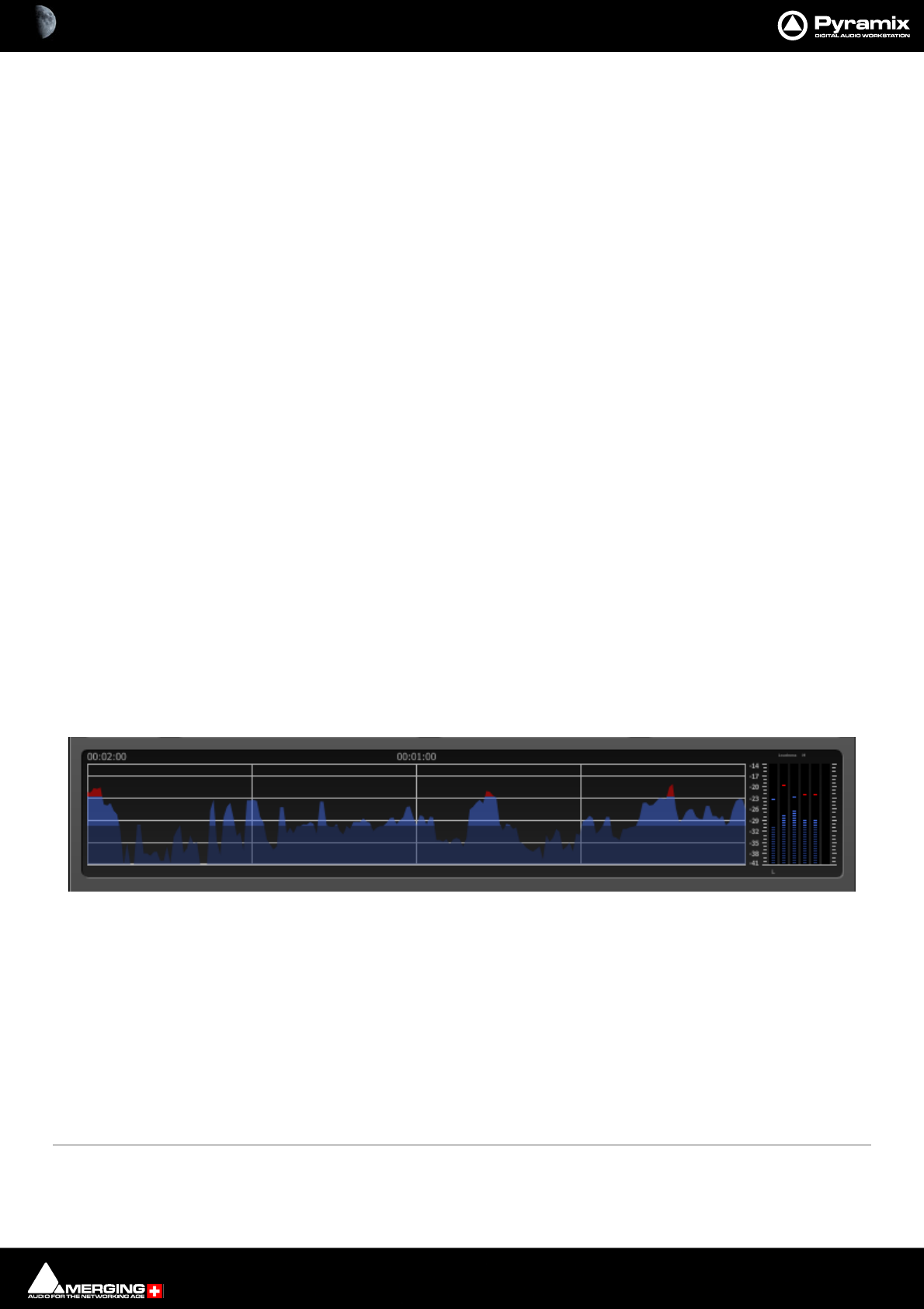
Final Check Metering : Final Check Window 17 - 465
Max M Shows the Maximum M value (EBU mode Momentary : 400ms) recorded since
the last Reset.
Max S Shows the Maximum S value (EBU mode Short : 3s) recorded since the last Reset.
Controls
Start Begins the analysis process.
Pause Stops new data being written and freezes the display. A second click resumes.
LUFS values continue to be calculated while in Pause and the first new value after
pause resumes will reflect this.
Reset Clears the values whether running or paused.
Restart Clears the values and restarts whether in pause or running.
Note: If used with the Shift modifier the LIaR controls also affect ALL the History graphs.
LRA Curve
The purple LRA curve (and the other measurements) is refreshed every second, and plots the amount of time the
output is at a given Loudness (vertically) against the Loudness, in LUFS (horizontally) The width of the filled space
below the curve represents the LRA.
Context Menu
LIaR has a right-click context menu with these entries:
Copy Data To Clipboard Copies the LIaR data to the Windows Clipboard (to ease export to MS Excel, etc.)
Copy All Data To Clipboard Copies all FinalCheck Meter data to Windows Clipboard.
History Graphs
All the meters except Phase and Spatialization have the option of a History Graph. This shows the values over
time. The data recorded can be copied to the Clipboard and used in other applications such as Microsoft Excel to
produce graphical or numerical reports. Currently, the History Graphs are most useful where a Project or Song is
played continuously from beginning to end.
Loudness History Graph
Arguably the most useful of the History Graphs, the Loudness History has three color bands, dark-blue, light-blue
and red. The transition thresholds are determined in the Setup page.
Context Menu
Start When ticked, the History Graph updates constantly with new values. Mutually exclusive
with Pause.
Pause When ticked, the History Graph stops scrolling. New values will not be logged until Start
is clicked again.
Reset Clears the contents of the History Graph.
Restart Clears the contents of the History Graph and starts recording.
Start all Applies to all History Graphs and the LIaR graph. Mutually exclusive with Pause all.
Loudness History Graph with Meters

Final Check Metering : Final Check Window 17 - 466
Pause all When ticked all History Graph and the LIaR graph stop scrolling. New values will not be
logged until Start all is clicked again. (Or one of the individual Start context menu
entries.)
Reset Clears the contents of the History Graphs and the LIaR graph.
Restart Clears the contents of the History Graphs and the LIaR graph and starts recording.
Copy Data To Clipboard Copies the History Graph’s data to the Windows Clipboard (to ease export to MS Excel,
etc.)
Copy All Data To Clipboard Copies all FinalCheck Meter data to Windows Clipboard.
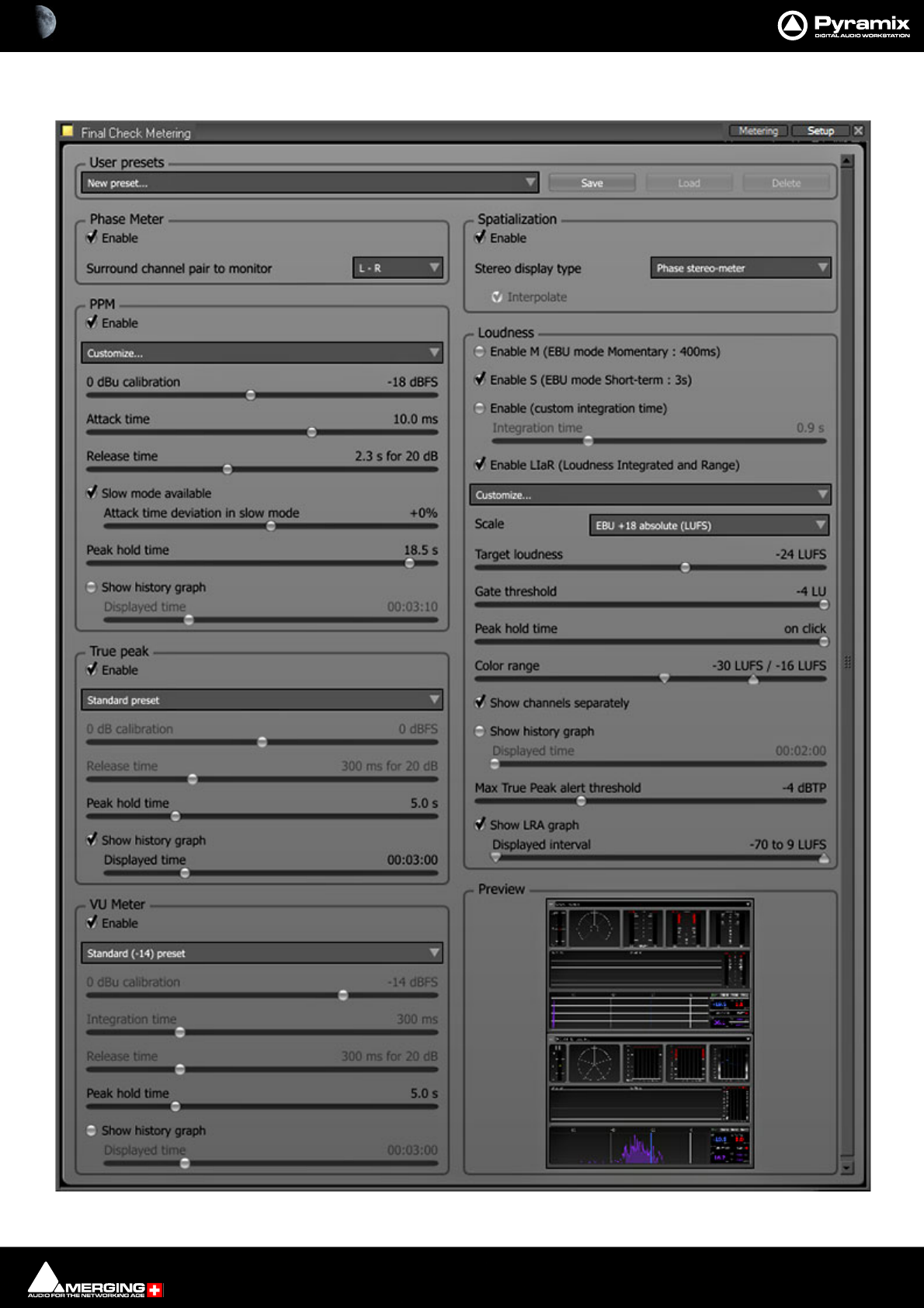
Final Check Metering : Final Check Window 17 - 467
Setup
Final Check Metering Setup Tab
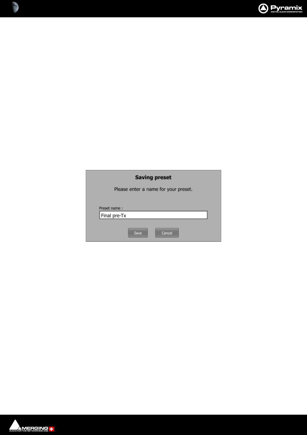
Final Check Metering : Final Check Window 17 - 468
Click on the Setup tab at top right of the Final Check window, adjacent to the X (close) box to open the Setup
page.
Click on the Metering tab to return to the main Final Check Metering page.
The Setup tab has a User presets management area at the top. The rest of the window is divided into sections for
each meter type, in two columns, and a Preview section to show how the Metering tab layout will appear.
Phase Meter Spatialization
PPM Loudness
True Peak
VU Meter Preview
User Presets
User presets can be saved, loaded and deleted. A drop down list and three buttons, Save, Load and Delete man-
age the presets. Deleted presets go to the Recycle bin. If a preset is deleted inadvertently it can be restored. How-
ever, restored or copied presets from another location will not be visible in Final Check until Pyramix is restarted.
New Preset... The drop-down list shows all existing presets with New Preset... at the bottom of the list. Click on
an existing Preset to select it followed by the Load button to update the parameters.
To create a new preset click on New Preset... adjust parameters until you are happy with the results then click on
Save to open the Saving Preset dialog :
Common Controls
The Enable buttons in each section allow you to show or hide a given meter. Meter settings are accessible only
when the meter is enabled.
Note that Spatialization refers to the Oscilloscope and Surround Monitor.
For Bargraph-meters (PPM, TruePeak, VU and Loudness), the Show history graph button enables the display of
a history graph beside the bargraph. It also enables the time range that the history graph should cover to be set
using the Displayed time slider." Also, when a meter is showing more than one channel, the history graph will log
only the maximum of all channels. Therefore, be careful with loudness.
For Bargraph-meters (PPM, TruePeak, VU and Loudness) Peak hold time sets the time during which overload
LEDs and peaks (small horizontal lines above the filled column) remain displayed.
Left boundary (0.0s) will reset the peaks and OL LEDs immediately.
Right boundary (on click) will never reset the peaks and OL leds automatically. You can reset them by clicking on
the meters. Tip : hitting P on the keyboard will reset all peaks and OL LEDs in Final Check.)
Bargraph-meters (PPM, VU, TruePeak and Loudness) have a preset drop-down menu that allows you to select
from a variety of presets, or the option Customize… Most settings cannot be changed unless Customize… is
selected.)
If you use Shift when operating the LIar Start, Pause, Reset and Restart buttons ALL the history graphs will fol-
low suit.
Final Check Saving preset dialog

Final Check Metering : Final Check Window 17 - 469
Individual Meters Setup
Phase Meter
Enable When ticked the Phase Meters are active and shown in the Metering page.
Surround channel pair to monitorThe drop-down list offers the choice of any channel pair in a 6 track surround
bus to monitor for stereo phase. (This only affects the Surround Phase Meter.) This
setting can also be altered in the Metering page, by simply right-clicking on the
Surround Phase-Meter.
PPM
Enable When ticked the PPMs are active and shown in the Metering page.
Type Label (Type II A (BBC)) Clicking on the label drops down a list of alternative PPM standards. Type I (DIN),
Type I (Nordic), Type II A (BBC) and Type II B (EBU) or Customize...
When Customize is active the following five controls will be available:
0dBu calibration The slider enables adjustment between -24dBFS and 0dBFS.
Attack time The slider enables adjustment between 1ms and 15ms.
Release time The slider enables adjustment between 0.5s and 5.0s for a 20dB fall.
Slow mode available When ticked a Slow button will be shown on the PPM scales in the Metering win-
dow. Active when red. Clicking the button toggles on/off. When the button on the
PPM scale is off, nothing happens. When active, the attack time of the PPM is raised
significantly.
Attack time deviation in slow mode The slider sets the attack time when Slow is active from -50% to +50% of
the PPM slow-mode standard.
Peak hold time The slider sets the amount of time the peak value is held from 0.0s to 19.5s or on
click, which requires a click on the meter to reset.
Show history graph When ticked the history graph is shown in the Metering page.
Displayed time The slider enables adjustment of the time window that the History Graph displays
from 00:02:00s to 02:00:00s
True Peak
Enable When ticked the TPMs are active and shown in the Metering page.
Type Label (Standard Preset) Clicking on the label drops down a list of alternative standards or Customize...
0dB calibration The slider enables offset adjustment between -12dBFS and +12dBFS
Release time The slider enables adjustment between 1ms and 1000ms.
Peak hold time The slider sets the amount of time the peak value is held from 0.0s to 19.5s or on
click, which requires a click on the meter to reset.
Show history graph When ticked the history graph is shown in the Metering page.
Displayed time The slider enables adjustment of the time window that the History Graph displays
from 00:02:00s to 02:00:00s
VU Meter
Enable When ticked the PPMs are active and shown in the Metering page.
Standard (-14) preset The down arrow drops down a list of alternative presets. Standard (-14) preset,
North America / Australia (-18) preset and France (-20) preset.
0dB calibration The slider enables offset adjustment of the 0dB point between -24dBFS and 0dBFS.
Integration time The slider varies the integration time from 1ms to 1000ms.
Release time The slider varies the release time from 1ms to 1000ms. (for 20dB decay)
Peak hold time The slider sets the amount of time the peak value is held from 0.0s to 19.5s or on
click, which requires a click on the meter to reset.
Show history graph When ticked the history graph is shown in the Metering page.

Final Check Metering : Final Check Window 17 - 470
Displayed time The slider enables adjustment of the time window that the History Graph displays
from 00:02:00s to 02:00:00s
Spatialization
Enable When ticked the spatial displays are active and shown in the Metering page.
Stereo display type The drop-down list offers the choice of: Phase Oscillo, Phase Stereo-meter and
VU stereo-meter.
Interpolate When ticked, the dots of the Phase Oscillo display will be interpolated. It is irrele-
vant to other meter displays
Loudness
Enable M (EBU mode Momentary : 400ms) enables the display of a loudness bargraph with integration time of
400ms, which corresponds to the momentary mode according to EBU R128.
Enable S (EBU mode Short : 3s) enables the display of a loudness bargraph with integration time of 3 seconds,
which corresponds to the short-term mode according to EBU R128.
Enable (custom integration time) enables the display of a loudness bargraph with user-selectable integration
time. The integration time is set with the Integration time slider.
Enable LIaR (Loudness Integration and Range) enables the display of the loudness INT and LRA meter and
graph.
Standard ITU preset The drop-down list offers the choice of:
EBU Mode (R128) preset
ATSC A/85 & ITU 1864 preset
Customize... When this option is selected the Target loudness and Gate threshold slid-
ers are active.
Scale The drop-down menu allows you to select one of the following scales for the loud-
ness bargraphs.
EBU +9 absolute (LUFS) This scale covers a range from -41 LUFS to -14 LUFS and is appropriate for
programs with small dynamic range.
EBU +18 absolute (LUFS)This scale covers a range from -59 LUFS to -5 LUFS and is appropriate for
programs with large dynamic range.
EBU +9 relative (LU) This scale covers the same range as EBU +9 absolute (LUFS), but is labeled
in LU, relative to -23 LUFS, hence from -18 LU to +9 LU. This scale is only
available with EBU Mode (R128) preset.
EBU +18 relative (LU) This scale covers the same range as EBU +18 absolute (LUFS), but is
labeled in LU, relative to -23 LUFS, hence from -36 LU to +18 LU. This scale is
only available with EBU Mode (R128) preset.
Target Loudness When Customize... is the selected preset the slider enables adjustment between
-30 LUFS and -20 LUFS.
Gate threshold When Customize... is the selected preset the slider enables values between -70LU
and -4 LU relative to be set. This threshold is relative to the selected Target loud-
ness. When the instantaneous loudness is below this threshold, the integrated
loudness calculation does not take the values into account until the instantaneous
loudness rises above the threshold again.
Peak hold time The slider varies the peak hold time between 0 and 19.5 seconds in half second
increments plus on click. (Peak is held until the display is clicked.)
Color Range The two markers set the transition points between the color bands in the Loud-
ness graph displays. Defaults are -30LUFS and -16LUFS.
Show channels separately When ticked each channel will have its own LUFS bargraph display. Note: the his-
tory graph will NOT display the sum of all channels, when this button is ticked.
Instead, it shows the maximum channels loudness.
Show history graph When ticked the history graph is shown in the Metering page.
Displayed time The slider enables adjustment of the time window that the History Graph displays
from 00:02:00s to 02:00:00s

Final Check Metering : Final Check Window 17 - 471
Max True Peak alert threshold Sets the threshold value (in dBTP) at which the Max True Peak numerical display
turns red. (In order to make it obvious there is an overload problem.)
Show LRA graph Toggles the LRA-repartition curve shown/hidden alongside the Loudness INT
and LRA display. (where some meters would display a History Graph instead.)
The LRA curve (the purple one) and other LIar displays are refreshed every sec-
ond. The LRA curve plots the amount of time a given Loudness occurred (verti-
cally) against the Loudness, in LUFS (horizontally) The width of the filled space
below the curve represents the LRA. The left boundary of the filled space is the
LRA Inf (the ignored quietest 10%), and the right one, the LRA Sup (the ignored
loudest 5%)
Displayed interval The markers set the boundaries of the displayed LRA curve, in LUFS, to enable
zooming into the range where the program is located.
Preview
Shows a thumbnail of the layout of the Metering page.
Loudness Metering Notes
Loudness Graph Color Range
The boundaries for the dark-blue and red zones can be selected in the Setup page. (Color range marker sliders)
You can of course choose the maximum LUFS value for the transition to the red band, e.g. -23LUFS, however
momentary excursions beyond -23LUFS are not necessarily a problem since it is the average value we are con-
cerned with.
Keeping In the Spirit
Advertisers will always look for ways to make their messages stand out from the crowd. One way of achieving this
in the new world of R128 loudness delivery requirements is to have the majority of the advert quiet with one
excessively noisy section.
Broadcasters can foil attempts at such subterfuge by specifying a required value for max M or max S, although this
is not in the R128 recommendations.
If this is done then it makes sense to set the Color Range transition to red at the same value. (For -23LUFS target
loudness -16LUFS is a good starting point.)
Report Files
A Final Check report file will look something like this when opened in Notepad or a text editor:
<?xml version="1.0" encoding="UTF-8"?> XML information
<FinalCheck_Metering> Title and start of results
<Stereo> First, showing results for the selected stereo pair
<Loudness_INT>-70</Loudness_INT> Loudness integrated (=averaged) on the whole file in LUFS
<Loudness_Range_LRA>0</Loudness_Range_LRA> Loudness range AKA lra in LUs
<Max_TruePeak>-144.5</Max_TruePeak> Maximum True Peak value in dBFS
<MML>-70</MML> Maximum momentary loudness AKA Max M
<MSL>-70</MSL> Maximum long-term loudness AKA Max S
</Stereo> End of results for the stereo pair
<Surround_5.1> Start of results for surround
<Loudness_INT>1.50099659</Loudness_INT> Loudness integrated (=averaged) on the whole file in LUFS
<Loudness_Range_LRA>4.75279236</Loudness_Range_LRA> Loudness range AKA lra in LUs
<Max_TruePeak>6.76408482</Max_TruePeak> Maximum True Peak value in dBFS
<MML>1.63770938</MML> Maximum momentary loudness AKA Max M
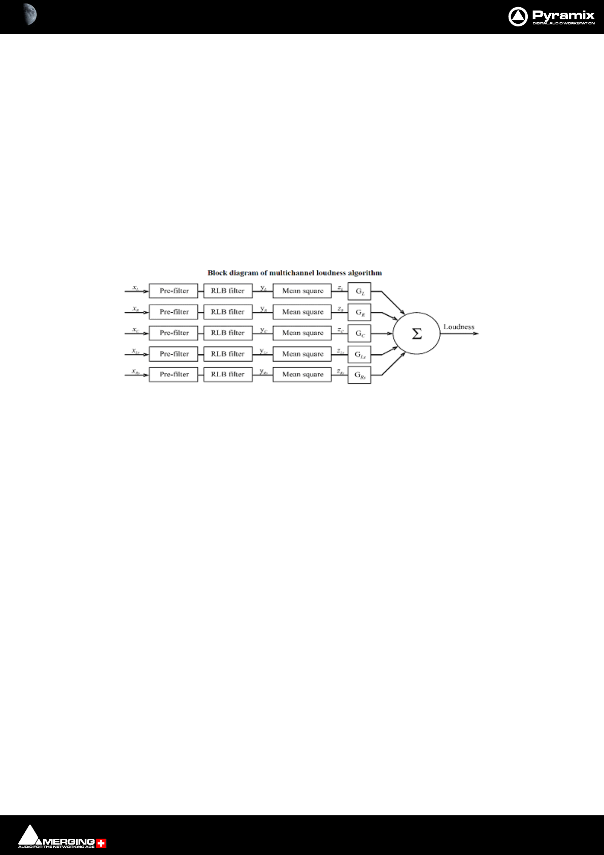
Final Check Metering : Loudness and Peak Metering 17 - 472
<MSL>1.53237224</MSL> Maximum long-term loudness AKA Max S
</Surround_5.1> End of results for the surround tracks
</FinalCheck_Metering> End of file
Loudness and Peak Metering
ITU-R 1770-1
This is the new recommendation of the ITU (International Telecommunication Union) about Peak and Loudness
measurement. It specifies the requirements for the audio meters employed to measure programme loudness,
and/or to indicate true-peak level to assist in the avoidance of overload of digital audio signals.
Loudness Algorithm
The goal of the loudness measurement is to give a numerical expression of the overall loudness that the listener
feels. It is expressed in LUFS. The block diagram below shows inputs for five main channels.
The pre-filtering accounts for the acoustic effects of the head. The RLB-filter is a LEQ (Loudness equivalent) fre-
quency-weighting curve that delivers much more precise results than previous LEQ-curves. The G-factors account
for different weighting of different channels.
LUFS
Loudness Unit Full Scale is the unit used for Loudness measurement. To match the ITU recommendation, a mix
shall have an overall Loudness of -23 LUFS. This unit is dB-like, in the sense that a variation of 1 dB in a mix will pro-
duce a variation of 1LUFS in its loudness as well.
For calibration: a full scale sine wave on one non-surround channel shall read -3.01 LUFS.
LKFS
LKFS (Loudness K-Weighting Full Scale) is the old name for the Loudness unit, which is now called LUFS instead, as
recommended by the ITU. These two units are strictly the same, though.
Dolby Dialnorm™
LUFS are the same unit as the Dolby Dialnorm™ unit, and you will therefore get the same results as long as Dolby's
automatic speech detection is disabled.
LEQ(A) ?
LEQ(A) is not supported. With the new Loudness algorithm described above, old-fashioned LEQ-curves are now
widely obsolete, and are therefore not included in this plug-in.
True Peak Detector
Unlike traditional digital peak detectors that merely check if the input samples are close to digital full scale, a True
Peak Detector first performs an oversampling operation. This means that it is able to detect peaks that would
occur between samples, possibly with an amplitude larger than 0dBFS (which traditional digital peak detectors
cannot detect). With heavily compressed audio material it is not uncommon for a True Peak Detector to show val-
ues up to +3 dBFS (or even worse) while a standard digital peak detector would only show + 0 dBFS.

18 - 473
www.merging.com/Pyramix
USER MANUAL
File and Project Interchange
File and Project Interchange : File Interchange - Formats 18 - 474
File Interchange - Formats
http://forum.merging.com/viewtopic.php?f=23&t=1414
File Size Limitations
By design SD2 and legacy WAV or BWF files are limited to a maximum of 2GB, sometimes 4GB due to their 32bit
signed addressing (thus 31 available bits) formats, while 32bits unsigned addressing AIF files are limited to 4GB.
File
Formats File
Extension Play Rec Export Audio
Data
Format
Max # of
Channels
in a single
file
Interleave
Max Bit
depth
Max
Sample
Rate
Max
File
Size
Unique
Identifier
(UID)
Data Chunk
(metadata)
format
PMF pmf yy y PMF
Virtually
Unlimited
(note1)
block 32bit float 384 kHz virtually
unlimited
in Name
& PMF
PMF
(Proprietary)
PMF (DXD) pmf y y y PMF Currently
up to 48
block 32bit float 352.8 kHz virtually
unlimited
in Name
& PMF
PMF
(Proprietary)
WAV wav yy y WAV
Virtually
Unlimited
(note1)
y 32bit float 384 kHz 4GB in iXML iXML
BWF wav yy y WAV
Virtually
Unlimited
(note1)
y 32bit float 384 kHz 4Gb in BWF BWF & iXML
WAV wav yy y RIFF64
Virtually
Unlimited
(note1)
y 32bit float 384 kHz virtually
unlimited in iXML iXML
BWF wav yy y RIFF64
Virtually
Unlimited
(note1)
y 32bit float 384 kHz virtually
unlimited in BWF BWF & iXML
AIF aif yy y AIF
Virtually
Unlimited
(note1)
y 32bit float 384 kHz 4GB n n
SD2
(note 3) sd2 yy y SD2
Virtually
Unlimited
(note1)
y 24bit 48kHz 2GB n n
PMI pmi yyWAV
Virtually
Unlimited
(note1)
y 32bit float 384 kHz virtually
unlimited CD TOC
OMF omf yy y WAV
or AIF y 32bit float 384 kHz 2GB n n
MXF mxf yy y AES3
or WAV y 32bit float 384 kHz
AVI avi y WAV y 32bit float 384 kHz
QuickTime
(note 2) mov y PCM 32bit float 192 kHz
DSDIFF dff yy y DSD64
Currently
up to 16 y 1bit 2822 kHz virtually
unlimited nPMF
(Proprietary)
DSDIFF Em dff y y DSD64 Typically
2, 5 or 6 y 1bit 2822 kHz virtually
unlimited nPMF
(Proprietary)
n=not supported
y=supported
Pyramix Supported Audio Files
note 1: While both block interleaved and sample interleaved formats may theoretically accept an unlimited number of
channels, disk performance of multichannel sample interleaved files w ill degrade severely over 24 to 32 tracks
note 3: Bew are of the fragile data fork / resource tw in file structure of (MacOS) SD2 file format, requiring special care to
be handled properly in a PC. More on this topic at the follow ing URL:
note 2: QuickTime Pro is required for the QuickTime handler to w ork correctly.

File and Project Interchange : File Interchange - Formats 18 - 475
Please keep this in mind when recording and/or exporting to any of these formats, the 2GB/4GB limit might in fact
be quite close, particularly when working with high sample rate multitrack files.
Pyramix's WAV/BWF Media handler now accommodates RIFF64 removing the 2/4GB limitation. It does this in the
following way: Up to 4GB Pyramix creates a regular (legacy) WAV/BWF, but when a recorded media exceeds 4GB,
for example during a recording/render or mixdown, Pyramix will automatically and transparently start creating a
RIFF64 instead of a regular WAV/BWF.
When performing file interchange please be aware that the destination workstation/software must be compatible
with RIFF64 WAV/BWF to be able to read RIFF64 WAV/BWF files.
Similarly, some "old" applications may only recognize WAV/BWF as proper files if their file size remains below the
2GB limit.
Hard Drive Limitations
A very similar 2GB/4GB* limit can also be encountered the hard way when attempting to write large files, even in
PMF format, onto storage units (hard drives, memory cards etc.) formatted using an old 32bit file system such as
FAT32 or HFS.
Yet another, higher, limitation also exists with IDE ATA/ATAPI drives. This will show up at around 137GB. This may
be caused by part of a system (drivers, controllers and/or old Windows version) only recognizing the 28bit
addressing of the original ATA specifications, and not the enhanced 48bits available on newer equipment. This is
usually solved by installing fresh and or updated BIOS/Drivers/OS.
*The official limit is 4GB, but serious trouble can start at around 2GB.
PMF
PMF or Pyramix Media File is Merging Technologies native format. It carries a number of advantages when com-
pared with others, especially where multi-channel recordings are concerned.
• PMF has a 64bit addressing structure, so there is no 2GB limit.
• PMF can contain comprehensive proprietary metadata
Note: Please see: Appendix VI - Pyramix iXML Implementation on page 808 for further
information.
The advantages of using interleaved PMF for multi-channel files (One file per track not selected) are:
• Contiguous blocks on disk so, when reading the same block (same time position) for all the Tracks at once,
the disk head does not have to do long and time-consuming seeks.
• It is not necessary to read samples for all Tracks when only one Track is required for replay. E.g. when using
a guide mix to edit a multitrack recording.
• Simpler Media Management, one file instead of say, 48 for a 48 track recording.
• Waveforms are embedded in the file."
The only time to consider using a different file format is when material must be exported to an application that
does not support PMF.
WAV and BWF
Wave and Broadcast Wave (BWF) files are supported by Pyramix. In Pyramix WAV/BWF is now RIFF64 compatible,
so the 2/4 GB file size limitation no longer applies.
The disadvantage of using WAV and BWF for interleaved multi-track recordings is that the audio is interleaved
sample by sample for all channels, which may adversely impact the overall throughput of hard drives or any other
storage media, particularly when only a subset of all channels present in such a file is being used on subsequent
playback.
Example: if, in a given Pyramix project, only channels 1 and 2 out of a 48 track BWF file are being played, the hard
drive's head will still have to spend the time scanning the entire data corresponding to all 48 tracks to just retrieve
the useful samples corresponding to those two channels. Alternatively, PMF with its much larger channel inter-

File and Project Interchange : File Interchange - Formats 18 - 476
leaving in blocks of typically 64 kB can instruct the hard drive's head to only seek to the corresponding blocks con-
taining the required data of channels 1 and 2.
Broadcast WAV file Tips.
File Types
There are two types of BWF file:
BWF P means polyphonic -> multitracks
BWF M means monophonic -> one file per track
The Cantar location recorder produces only BWF-M files, and some Avid people want BWF-P. To convert BWF M
BWF P mount the file in the Media Manager and select Convert > Quick Export, then do NOT check the One file
per Track option. (Uncheck it if necessary). All Scene and Takes information present in the original BWF file will be
also exported in the resulting BWF-P file.
Metadata
BWF files have a special chunk in the file that contains metadata; this is called the BEXT chunk or Broadcast Wave
File metadata.
The first field of this chunk is the Description. This is the field we display in the Name column for BWF files instead
of the file name. We do the same for PMF and OMF. We only display the real filename for Wave, AIFF and SDII that
have no metadata.
In v4.2.6 or higher you can add the FileName column to also display the real filename of all files. (Media Manager
window View > Options : Columns tab)
Once renamed in the Media Manager both the Description field and the filename of your BWF files should be
updated.
iXML
WAV files generated by Pyramix can also contain iXML information and as such carry similar information to data
chunk of a BWF.
The iXML metadata of a WAV file is available to any compatible application, if the application is not iXML aware,
the file will be seen as a regular WAV.
Quicktime
In order to enable the Quicktime handler you will need to purchase and install Quicktime Pro from Apple.
http://www.apple.com/quicktime/pro/

File and Project Interchange : File Interchange - Formats 18 - 477
MTFF
Merging Technologies File Format
• Format Support
•PCM
• DXD (linear PCM requiring extra HF filtering
• DSD - DSD 256
• Lossless Compression (Only available for output formats)
•Metadata
•Unique ID
• Album Art (under development)
•Settings Options
• LRC - Lossless Compression
• Channel mapping presets
DSD
DSD
DXD
DSF
1 bit file format designed by Sony
• playback only
• supports DSD64 and DSD128
WSD
1 bit file format designed by Korg-Audio
• playback only
•DSD64 only

File and Project Interchange : File Interchange - Formats 18 - 478
Compressed Audio File Formats
Pyramix supports many compressed file formats, including MP3, Ogg Vorbis, FLAC and AAC, directly. Other com-
pressed formats WMA, RA (RealAudio) AVI and more are supported via Windows DirectShow technology.
Codecs
MP3 and AAC
Pyramix supports MP3 and AAC directly. (Requires the optional Advanced Audio Codec Support key.) No sepa-
rate codec installation is required and no decompressed file is generated.
MP3
Requires the optional Audio Advanced Codec Support key.
• MP3 file format support (Encode/Decode)
• No decompressed file is generated for these formats (doesn’t use DirectShow)
• Word length: Record 16/24/32 bits, playback 32 bits
• Sampling Rates: 44kHz & 48kHz
• Mono or stereo tracks
• Encoding: MPEG 1 Layer 3 ABR (VBR) mono or Joint Stereo
• Decoding: MPEG-1 Layer 1/2/3 (MPEG-2 and 2.5 are supported but the sample rates required are not sup-
ported by Pyramix)
MP4/M4A (AAC)
Requires the optional Audio Advanced Codec Support key.
• No decompressed file is generated for these formats (doesn’t use DirectShow)
• Wordlength: 16/24/32 bits
• Sampling Rates: Record and playback 44kHz, 48kHz, 88.2kHz, 96kHz
• Record - max 6 tracks, Playback - max 48 tracks
• Encoding: LC-AAC MPEG4
• Decoding: HE/LC/Main/SSR-AAC (MPEG2 or MPEG4), DRM not supported
FLAC
FLAC encoding and decoding is supported directly. No separate codec installation or key is required and no
decompressed file is generated.
Note: Additional codec installation is not required
• No decompressed file is generated for this formats (doesn’t use DirectShow)
• Wordlength: 16/24/32 bits
• Sampling Rates: 44kHz, 48kHz, 88.2kHz, 96kHz, 176.4kHz, 192kHz, 352.8kHz, 384khz
• Record - max 6 tracks, Playback - max 8 tracks
Ogg-Vorbis
Ogg-Vorbis encoding and decoding is supported natively. No separate codec installation or key is required.
• No decompressed file is generated for this formats (doesn’t use DirectShow)
• Wordlengths: 16/24/32 bits
• Sampling rates: 44.1kHz, 48kHz, 88.2kHz, 96kHz, 176.4kHz, 192kHz
• Format: Number of tracks: Record - max 6 tracks, Playback - max 255 tracks

File and Project Interchange : Dolby 18 - 479
MXF
The Pyramix MXF implementation can read and decode MXF files following specifications AS WELL as files coming
from Avid / Digidesign workstations.
Pyramix MXF can generate valid MXF files complying with MXF specifications and have passed the validations
tests provided by Snell&Wilcox.
As of today, supported MXF formats are OP1A and OPAtom, as well as potentially OP1B, OP1C, OP2A.
MXF Essences supported today are AES3 & Broadcast Wave audio files (conforming to SMPTE 382M).
For the latest MXF interchange information please see:
http://forum.merging.com/viewtopic.php?f=23&t=2094
Dolby
Dolby AC3 encoding and Dolby E encoding and decoding can be accomodated via optional Minnetonka Sur-
Code plug-ins. These require the relevant iLok authorizations from Minnetonka. Please contact your Merging
Technologies sales partner for more information.
Note: The Dolby plug-ins require a separate installer.
Simple File Conversion
To convert to or from PMF audio files use the Project > Render ><None> function.
Place the file you wish to convert on a Track or Tracks in the Timeline and select the resultant Clip by clicking on it.
Make appropriate settings in the Render dialog, click on the Render button and voila!
File & Project Interchange with Apple Macintosh
Currently, the recommended Interchange Format when working with Pro Tools 7 is AAF / OMF, with BWF media
files. Please see: AAF on page 485 and OMF on page 499 for further information and also refer to the Pyramix
Interchange Forum in the Support Section (for registered users) for regularly updated information, as well as Inter-
change tips & tricks :
http://forum.merging.com/viewforum.php?f=23
History
SD2 & Pro Tools 5 Sessions and Legacy Apple File Formats
Old Macintosh files such as SD2 and PT4.x and PT5.x projects files have a Mac-binary, or double-fork structure that
the PC cannot handle directly. As opposed to interchange files, PC files or new Mac files (that do carry a simple sin-
gle file structure), SD2 and PT5 projects files are based on a Data fork (the one you see in every computer file) and
a Resource fork (a hidden, second file storing all the file info). While this binary structure was actually quite a clever
and convenient move, the fact that half of the file is hidden by design makes it a very fragile cross-platform media.
A sure sign that the resource fork has been lost is when the file appears with a generic icon and is present but
unreadable. A broken binary file cannot be rebuilt.
Note: SD2 is only supported on 32-bit systems.
Note: For more info about the specific handling of "old" Apple files, please read the following
entry in the Forum's Support Section (for registered users):
http://forum.merging.com/viewtopic.php?f=23&t=1414
File and Project Interchange : Project Interchange 18 - 480
Project Interchange
Interchange
Format Software
Key File Format(s) Import Export Max.
Sample Rate Max. EDL
Duration
AAF PSO-AAF BWF y y
AES31 PSO-AES31 BWF y y
192khz /
DSD
CD Import PSO-CDR
PMF, AIF,
WAV, etc. y
CMX-EDL - - y y
DDP import See Packs - y
Final Cut Pro
XML (v7)
PSO-FCP
See packs - y n 13h30
OMF V1 & V2 PSO-OMF
OMF, AIF,
BWF/WAV y n 13h30
OPEN TL PSO-OTL BWF/WAV y y
SACD Edited
Master Import PSO-SAA
DSDIFF
Edited Master y 2822 kHz
Sonic
Solutions PSO-SONIC AIF y
Video Clips -
See
Supported
Video Medias y
XML EDL - - y y unlimited
n = Not supported
y = Supported
Pyramix Project Interchange Options
File and Project Interchange : Project Interchange 18 - 481
Import and Export are handled by InterChange. In the Project menu the Import and Export options each open a
window where a list of available InterChange plug-ins is presented.
Note: On export, the Volume Automation can be set to represent the Clip Gain, the Clip Enve-
lope or a combination of both.
Interchange
Format Clip Name Clip
Gain Clip
Envelope Clip
Fades X-fade
Curves Markers CD/SACD
Markers
AAF yyyyynn
AES31 y y
y
(note 1) y y n n
CD Import y y
CMX-EDL
DDP Import y y
Final Cut Pro
XML (v7) y
OMF V1
unembedded y n n y
no
(all to Power) n n
OMF V2
unembedded y y n y
no
(all to Power) n n
OMF V2
embedded y y
y
(note 2) y
no
(all to Power) n n
OPEN TL y y n y basic n n
SACD Edited
Master Import
em
namennnn y
Sonic
Solutions
Video Clip
XML EDLyyyyyyy
n = Not supported
y = Supported
Note 1: clip envelopes w ill be supported soon w hen specif ication is published by AES
Note 2: Export from Pyramix is feasible but not yet import. Currently import is only supported by PT
Pyramix Project Interchange Options Clip and Marker Support
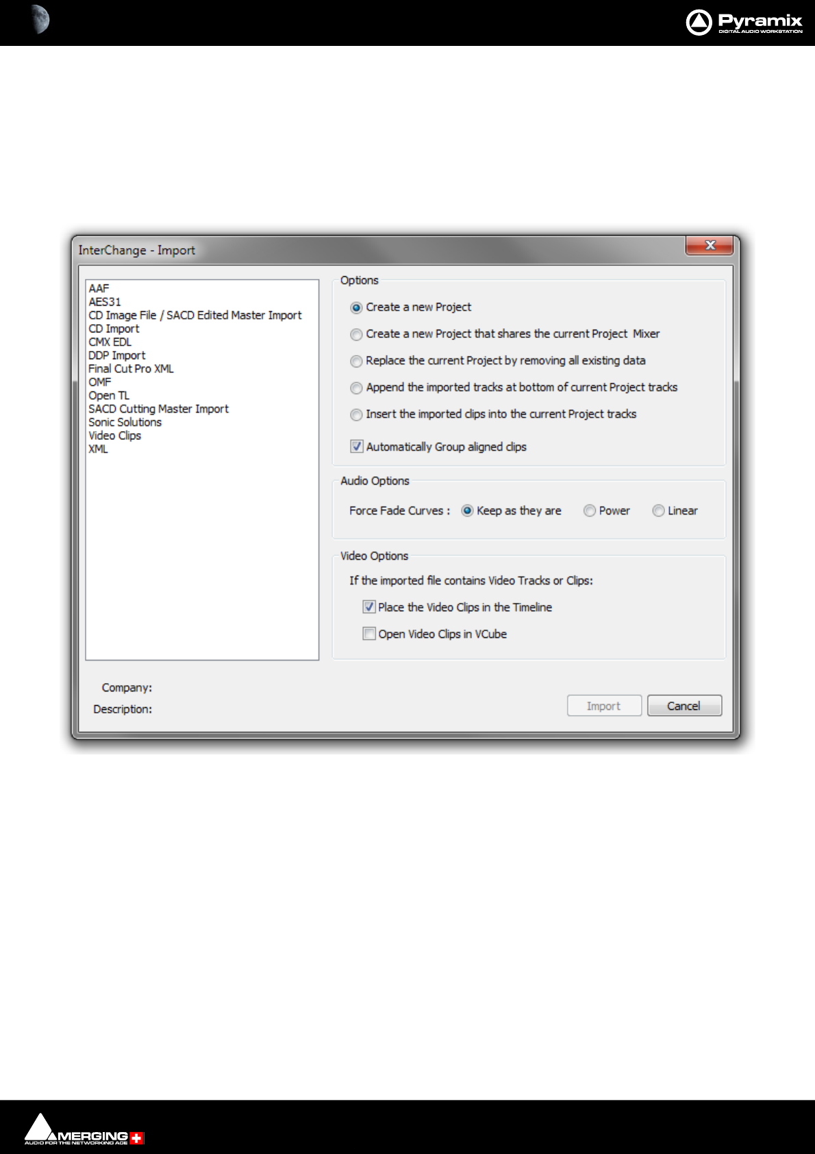
File and Project Interchange : Import / Export 18 - 482
Import / Export
Import
Note: It is not necessary to have a Project open in order to use the Import function since a Proj-
ect can be created on Import.
Project > Import opens this window:
The Options radio buttons determine how the imported material will affect the current project.
Options
•Create a new Project - creates a new Project from scratch using the Default Mixer
•Create a new Project that shares the current Project Mixer. (Mixer Sharing is turned on automatically in
the current project when this option is selected and Import is clicked.)
•Replace the current Project by removing all existing data - Replaces the current project Tracks, Track
Groups and Markers then creates new Tracks, Track Groups and Markers from the imported Composition
• Append the imported tracks at bottom of current Project tracks
• Insert the imported clips into the current Project tracks
•Automatically Group aligned clips - When this option is chosen with one of the above, stereo and other
multi-channel Clips will be grouped automatically.
Project Interchange - Import dialog

File and Project Interchange : Import / Export 18 - 483
Audio Options
Force Fade Curves: the choice made here may be overridden in the subsequent Import dialog depending on the
type of Import. e.g. AAF
• Keep as they are - existing fades rendered or otherwise are retained
• Power - forces fades to Pyramix Power curve, usually used where individual fades predominate
• Linear - forces fades to Pyramix Linear curve, usually used where crossfades predominate
Video Options
If the imported file contains Video Tracks or Clips:
• Place the Video Clips in the Timeline.
If this option is checked then any Video Clips present in the imported file will be placed in the Timeline as black
Video Clips. These Clips are usable only for reference and are not played back as such by Pyramix (see below for
playing them back). Audio in a Video Clip container is also imported and placed in the Timeline according to the
method chosen in the Options section of the dialog.
Open Video Clips in VCube:
• Open Video Clips in VCube.
Single or multiple Video Clips are opened in VCube.
Imported Video Clips are saved in the project, so, when the project is opened, the Video Clips will again be present
on the timeline. The referenced Video Media will be opened automatically in VCube depending on the same
options as above, but for general project opening that can be found in:
Settings > All Settings > Application > General : Project Opening Section
• Open Video Clips in VCube
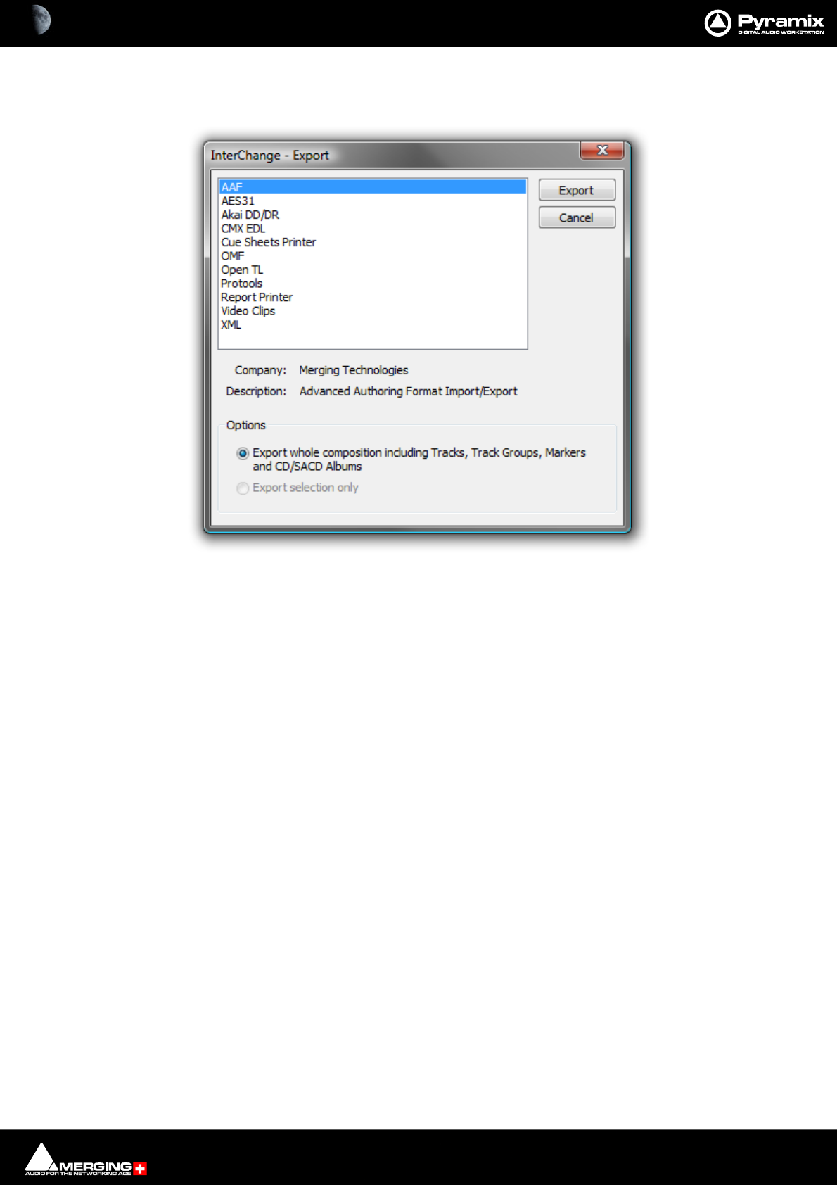
File and Project Interchange : Import / Export 18 - 484
Export
Project > Export opens this window:
Options
• Export whole composition including Tracks, Track groups, Discs and Markers
• Export selection only
Note: The Export selection only choice will be grayed out if there is no selection in the Project
Timeline.
Project Interchange - Export dialog

File and Project Interchange : Import / Export 18 - 485
AAF
Pyramix can import and export projects in AAF (Advanced Authoring Format)
Note: Pyramix can also use MXF audio files and export MXF audio files. Please see: MXF on
page 479
About AAF
AAF is a set of specifications for project interchange (.aaf ) files. Media files can be embedded or referenced by link.
When embedded, audio can be in a WAV or AIFF wrapper or be in simple PCM format. When imported from an
AAF file PCM audio must be ‘wrapped’ for playback. E.g. as BWAV, Wave or PMF files.
AAF files can have envelope information, static level information or both.
Note: AAF files can specify sample and frame rate per track.
Alternates
The AAF specification accommodates Alternate Clips. I.e. Alternative media for a given Clip. Unfortunately not all
applications deal with the alternates in the same way when exporting and importing. Therefore we have
attempted to accommodate the common variations.
Sample Accurate Edits
Certain NLE applications require audio edits to occur only on frame boundaries. It is often desirable to have audio
Clips start or finish somewhere other than a frame boundary. Therefore some applications allow this to be accom-
plished but add small padding Clips of silence to maintain frame boundary compliance. In a large project large
numbers of these tiny Clips can make editing in a DAW difficult or impossible. Therefore we have included an
option to remove them on import and also an option to add them on export for applications down the line which
require them.
Recommendations
• Use embedded audio in AAF files where possible.
• In a controlled network workflow with proven file compatibility AAF files with linked Media files may be
more appropriate to avoid needless duplication.
• Where the AAF file contains embedded PCM audio (E.g. AAF export from Pro Tools) Normalize Envelope to
Envelope + Gain. This option offers greater clarity and flexibility.
• Remove ‘Sample Accurate Edits’. If these are not removed, editing complex projects becomes difficult or
impossible due to all the tiny ‘padding’ Clips. Sync is not affected in any way by selecting this option.
• Use mono WAV files for stereo and multi-channel Media files for maximum compatibility with other appli-
cations.
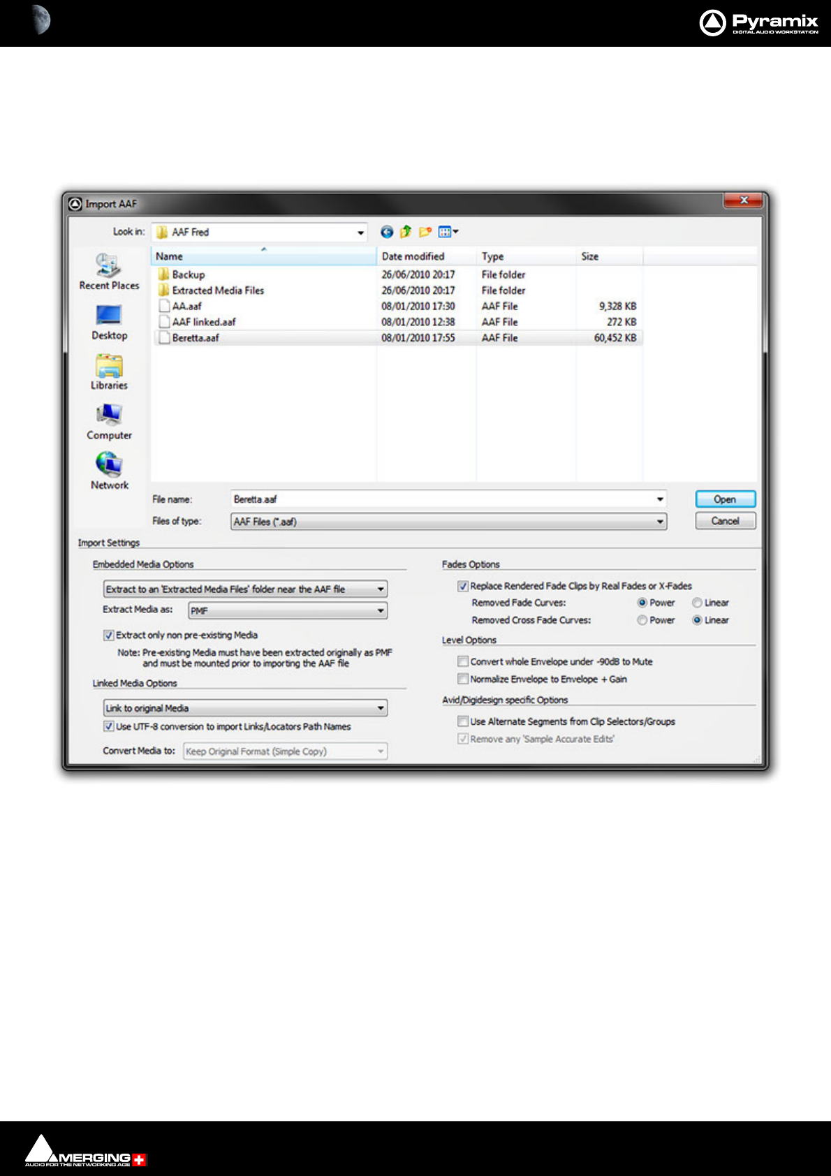
File and Project Interchange : Import / Export 18 - 486
Import
Select AAF in the Interchange Import dialog. Choose the appropriate import options leaving Audio Options
Force Fade Curves: set to Keep as they are and click on Import.
(Please see also: Options on page 482)
The Import AAF File window opens:
The lower section of the dialog contains Import Settings, the upper section is a File Browser. The Open button
initiates the Import once a suitable AAF file has been selected and the Import Settings have been made.
Import Settings
Embedded Media Options
The drop-down list has the following options:
• Extract to an ‘Extracted Media Files’ folder near the AAF file
• Extract to the Project Default Media Folder
• Extract to a new Sub-folder in the Project Default Media Folder
(Sub-folder will be named automatically after the AAF source file)
• Prompt for a Folder to Extract Media to
• Do not Extract any Media
Interchange - Import AAF dialog

File and Project Interchange : Import / Export 18 - 487
Note: You will see:
• (N/A) Extract to the Project Default Media Folder
and
• (N/A) Extract to a new Sub-folder in the Project Default Media Folder
If either a new Project is to be created or no Project Media Default Folder has been set in the Settings > All Set-
tings > Project > General page. (Please see also: Project Media Folder on page 735)
Extract Media as :
The drop-down list has the following options:
•PMF
•BWF/Wave
Extract only non pre-existing Media
Note: Pre-existing Media must have been extracted originally as PMF and must be mounted prior to importing the
AAF file.
When ticked if Media used by the imported AAF file already exists as PMF files and is mounted then it will not be
extracted again. This is big time saver when working with AAF imports subject to frequent updating.
Linked Media Options
The main drop-down list has the following options:
• Link to original Media
• Copy/Convert to the Project Default Media Folder
• Copy convert to a new sub-folder in the Project Default Media Folder
(Sub-folder will be named automatically after the AAF source file)
• Prompt for a Folder to Copy/ Convert Media
Note: You will see:
• (N/A) Copy/Convert to the Project Default Media Folder
and
• (N/A) Copy/Convert to a new Sub-folder in the Project Default Media Folder
If either a new Project is to be created or no Project Media Default Folder has been set in the Settings > All Set-
tings > Project > General page. (Please see also: Project Media Folder on page 735)
Convert Media to:
Only available when Prompt for a floder to Copy/Convert Media to is chosen in the main Linked Media drop-
down. The drop-down offers the choice of:
• Keep Original Format (Simple Copy
•PMF
•BWF/Wave
Use UTF-8 conversion to import Links/Locators Path Names
Default is ticked I.e. On. This allows the referenced path names (called Locators in AAF/OMF) to be converted using
UTF-8 coding. If you experience problems with the conversion untick the box.
Fades Options
Replace Rendered Fade Clips with Real Fades or X-Fades
When the box is ticked there is a radio button choice of Power curve or Linear curve for both:
• Removed Fade Curves:
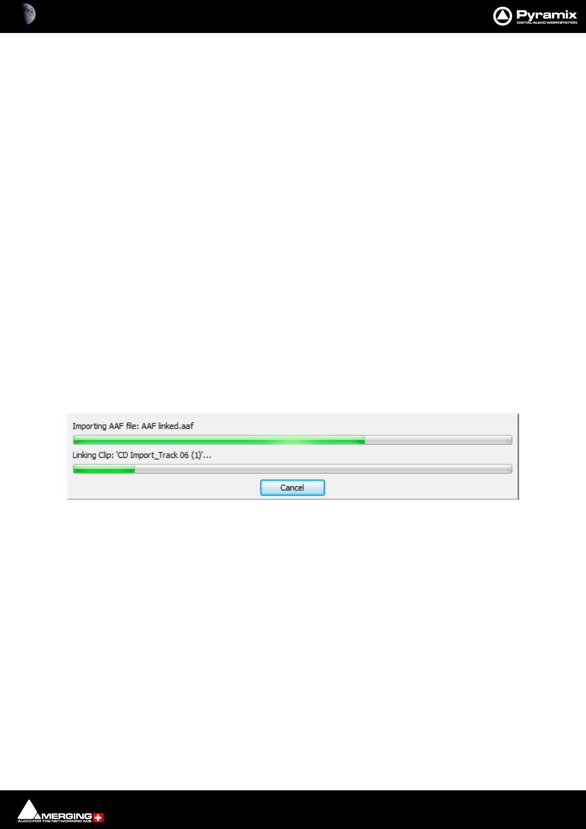
File and Project Interchange : Import / Export 18 - 488
• Removed Cross Fade Curves:
The default settings are Power for Fade Curves and Linear for Cross Fade curves.
Level Options
Convert whole Envelope under-90dB to Mute
When ticked does as it says.
Normalize Envelope to Envelope + Gain
When ticked the highest envelope point in the Clip is normalized to 0dB and a corresponding inverse static gain
adjustment is applied. For example, if the highest envelope point is -10dB all envelope points will be increased in
value by 10 dB and the static gain will be reduced by 10dB.
Note: This function is selected automatically and grayed out when Replace Rendered Fade
Clips with Real Fades or X-Fades is ticked.
Avid/Digidesign specific Options
Use Alternate Segments from Clip Selectors/Groups
The AAF specification allows for alternative media to be specified for Clips. Unfortunately, not all applications
apply this in the same way. If you experience problems with missing media checking the box may help.
Remove any ‘Sample Accurate Edits’
Only available when Replace Rendered Fade Clips By Real Fades or X-Fades is not ticked.(see Fades Options
above) When selected all the tiny, mute ‘padding’ media files used to ensure edits are always on frame boundaries
will be removed. The Media Clips with wanted material will be in precisely the correct positions.
Execute Import
Navigate to the required AAF file or type its name in the File name box and click Open to begin the Import pro-
cess. A progress box opens to inform the user:
Import Progress Window
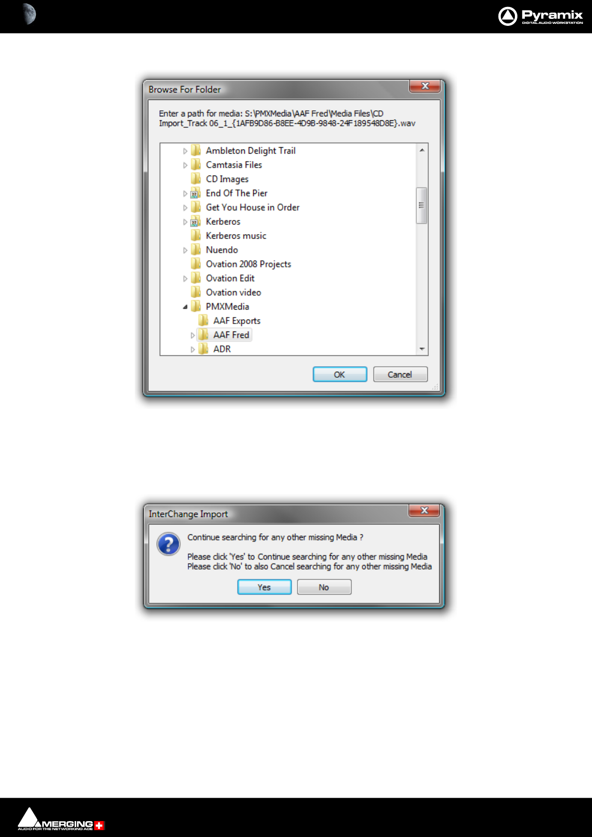
File and Project Interchange : Import / Export 18 - 489
If a linked Media File or Files cannot be located, a browser window opens:
The browser enables the user to navigate to the missing file. If the file cannot be found or is known to be absent,
click on the Cancel button to ignore the file.
A further dialog box opens with the option to ignore just the one file or the current file and all subsequent missing
files :
Click on Ye s to skip the current missing Media file and Continue searching for any other missing Media
Click on No to skip the current missing file and Cancel searching for any other missing Media.
If a subsequent missing file is identified the Browser opens again. with the same options as above.
Browse For Folder Window
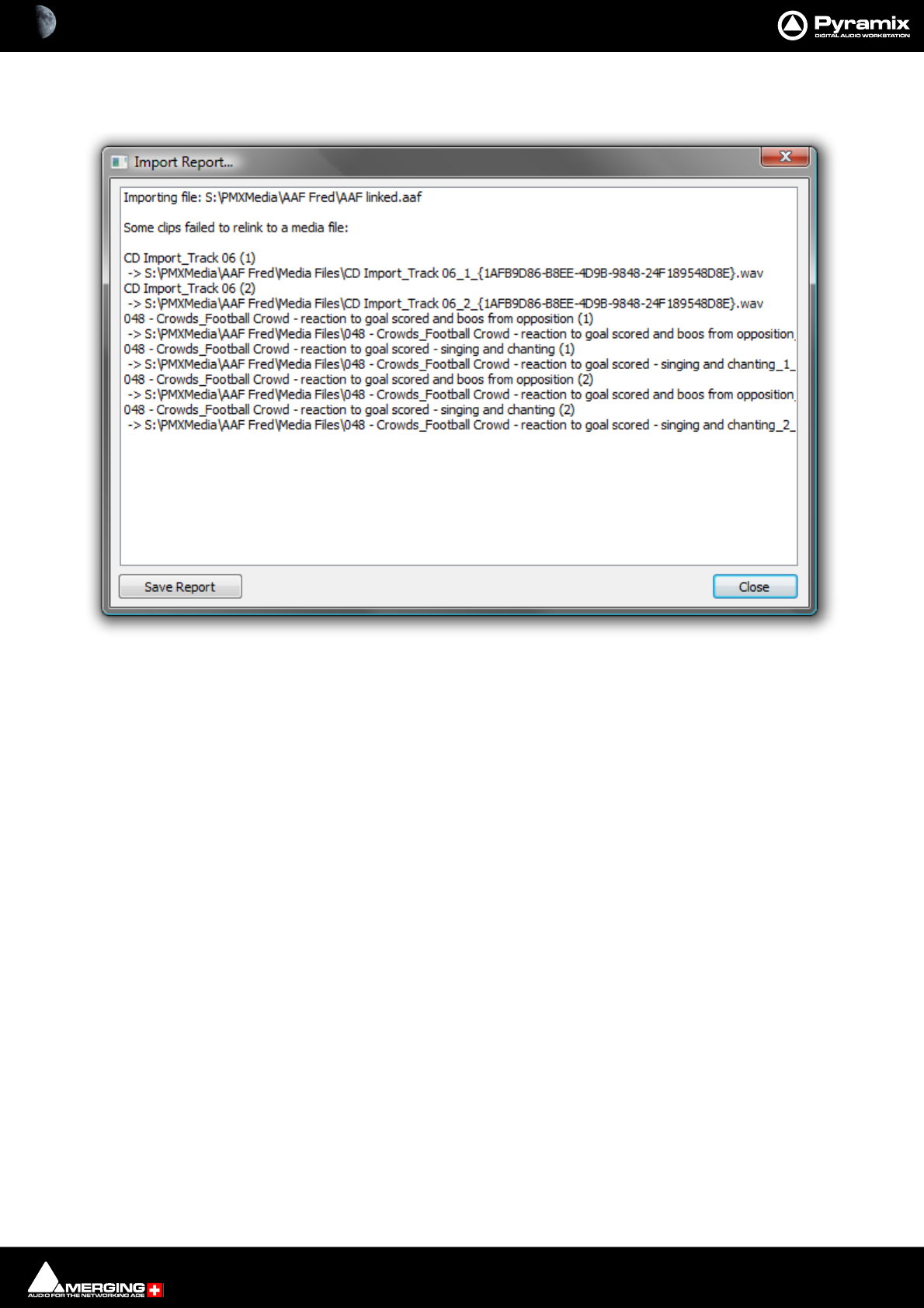
File and Project Interchange : Import / Export 18 - 490
Import Report
If files are skipped during the Import process, the Import Report window appears :
All skipped files are listed along with the locations searched.
Clicking on the Save Report button opens a Save As dialog. Here you can save the Import Report as a Text File.
Close simply closes the Import Report without saving.
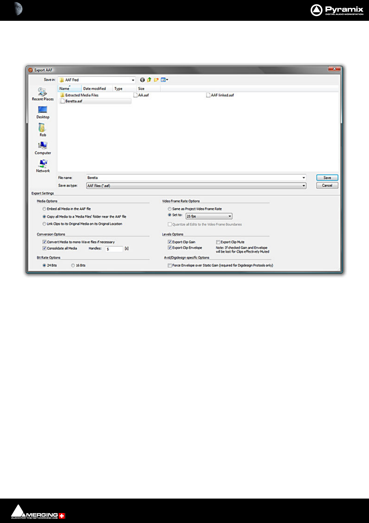
File and Project Interchange : Import / Export 18 - 491
Export
Select AAF in the Interchange Export dialog. Choose the appropriate export option and click on Export. The
Export AAF File dialog opens:
The lower section of the dialog contains Export Settings, the upper section is a File Browser. The Save button ini-
tiates the Export once a file name has been typed and the Export Settings have been made.
Export Settings
Media Options
The radio buttons offer the following options:
• Embed all Media in the AAF file. - All Media will be embedded in the AAF file in PCM format.
• Copy all Media to a ‘Media Files’ folder near the AAF file.
• Link Clips to original Media in its Original Location
Conversion Options
Convert Media to mono Wave files if necessary
When ticked (default) all Media not already in the form of mono Wave files will be converted to mono Wave files.
Note: This option is unavailable when Embed all Media in the AAF file is selected.
Consolidate all Media
When ticked only Media used in the project (plus handles - see below) will be embedded or copied. (This function
will be grayed out and unavailable if Link Clips to original Media in its Original Location is selected above)
Handles:
Interchange - Export AAF dialog

File and Project Interchange : Import / Export 18 - 492
Handles at the beginning and end may be added to Consolidated Media files to facilitate future editing. Type the
required handle length in the box. (Handles will not be added when a Clip begins at the beginning or ends at the
end of the Media file)
Bit Rate Options
The radio buttons offer the following options:
•24 Bits (default)
•16 Bits
Use 24 bits unless you have a good reason not to.
Video Frame Rate Options
The radio buttons offer the following options:
• Same as Project Video frame Rate - I.e. same as the Pyramix source project
• Set to: - The drop down list offers the choice of all conventional frame rates.
Quantize all Edits to the Video Frame Boundaries
When ticked ‘padding’ files will be added to ensure that all edits occur on Video Frame Boundaries. This option is
not available when Link Clips to original Media in Original Location is selected.
Level Options
The radio buttons offer the following options:
• Export Clip Gain
• Export Clip Envelope
• Export Clip Mute
Note: If checked Gain and Envelope will be lost for Clips effectively muted.
Avid/Digidesign specific Options
Force Envelope over Static Gain (required for Avid Pro Tools only)
If the Pyramix Project contains Static Gain variations and or Envelope information the two are combined into
Envelope information.
Execute Export
In the Browser section navigate to the required destination drive/folder, type in a suitable name for the AAF file in
the File name box and click Save to begin the Export process. A progress box opens to inform the user:
When the export is concluded this info box appears:
Note: EMBEDDED MEDIA When exporting to AAF with embedded Media the Clip names may
change when the file is opened in Pro Tools. In order to avoid problems getting AAF files into Pro
Tools there are some limitations to the structure of the AAF file and where the Clip name can be
stored. For AAF files referencing external media, these restrictions don't cause any noticeable dif-
ferences. When exporting embedded AAF files, the Clip name basically needs to be associated
AAF Interchange Export Succeeded info box

File and Project Interchange : Import / Export 18 - 493
AES-31
Straightforward Import and Export in AES-31 format.
Genex Cuepoint files are supported. If a .CPT file exists near the .ADL file, cue points will be converted to Pyramix
markers.
CD Import
Pyramix has comprehensive CD import functions. Project > Import opens the Interchange Import dialog box.
choose the appropriate destination option and choose CD Import
CD Import dialog

File and Project Interchange : Import / Export 18 - 494
Device Settings
The combo box drop-down list shows all suitable drives on the machine.
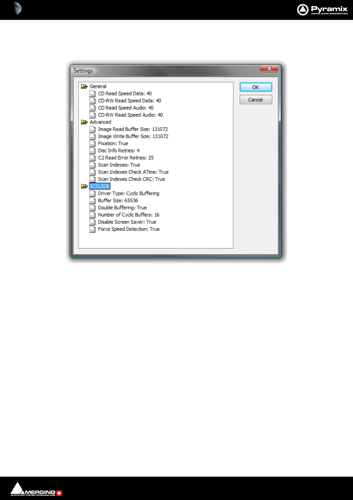
File and Project Interchange : Import / Export 18 - 495
Settings
The Settings button opens a dialog box with specific drive settings. These settings may be altered if required by
clicking on an entry and typing a new value in the box.
Status
The field to the right of the Settings button shows pertinent information about the CD import process.
Disc Content
Read TOC...
Click the Read TOC button to read the Table Of Contents on the CD. The tracks are listed in the pane below.
Read ISRC, UPCEAN & CDtext When checked this information will also be read, if present.
Read pause and index markers When checked the Pause and Index markers will be read.
(Scanning can take several minutes) This can take several minutes longer than a simple read.
CD Import Settings dialog
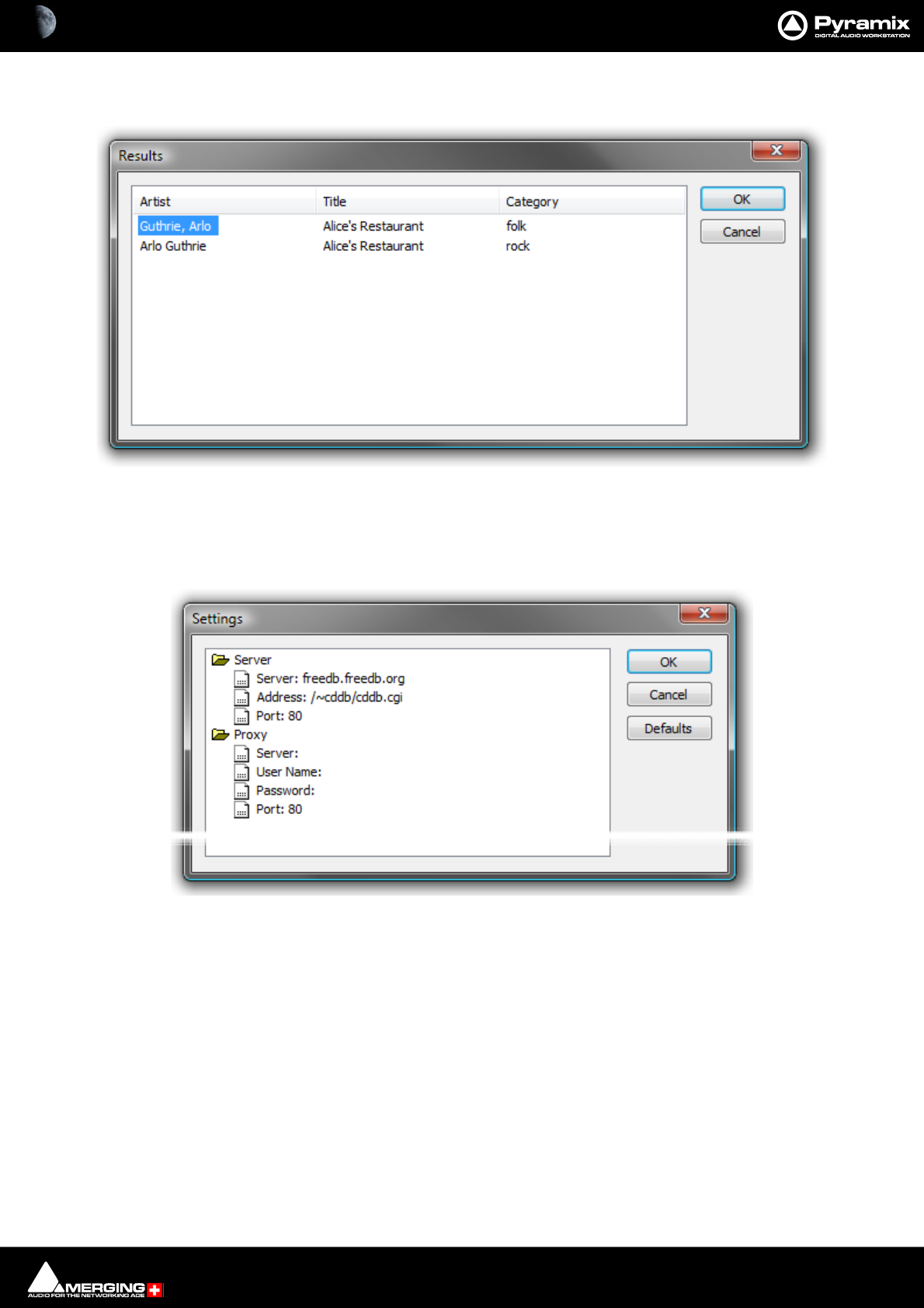
File and Project Interchange : Import / Export 18 - 496
Query Database Click to use an online database to obtain track names and other data about com-
mercial CDs. Results are shown in a dialog :
If multiple disc titles are shown, click on the appropriate one to select it then click on OK to import the data. The
disc name is automatically entered in the Clip Prefix: field.
Database Settings Click to access a dialog where the database address and other settings can be
changed:
Default settings are shown above. To change a setting, click on the entry and type. Click OK to save the edited set-
tings. Defaults restores the default settings and Cancel closes the dialog without making changes..
Import All Tracks When active all tracks on the CD will be imported regardless of individual selec-
tions in the track list check boxes.
Import Selected Track(s) When active only the tracks selected (ticked in the track list) will be imported.
Select All Click the button to select all tracks in the list.
Deselect All Click the button to deselect all tracks in the list.
Target File
Destination Drive: The combo box drop-down lists all mounted folders.
Format: Shows the format selected and offers the choice of :
PMF, SD2, AIFF, FLAC, Ogg Vorbis, MP3/MPEG-1/2 Audio, MP4/AAC, DSDIFF, DSDIFF Edited Master, Virtual
Tape, Wave, BWF, CD Image, MTFF, Digital Release, OMF.
CD Import Query Database results dialog
CD Import Database Settings dialog
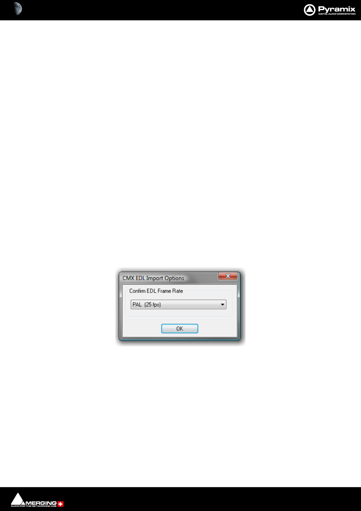
File and Project Interchange : Import / Export 18 - 497
Waveform: Offers the choice of Generate WHILE recording, Generate AFTER recording or
None.
Sampling Rate Offers an extensive choice of sampling rates for the imported tracks. CD tracks are
saple rate converted automatically on import if anything other than 44.1kHz is
selected.
Prefix When checked a prefix will be added to each imported track. This defaults to the
CD title but any desired prefix may be typed in the field when the box is checked.
Place in timeline When checked imported tracks will be placed in the Timeline.
Add track group When checked a Track Group will be added for the imported tracks.
Add Disc & CD markers When checked Disc and CD markers will be added.
Track Bar illustrates progress bar for each imported track
Disc Bar illustrates import progress of all selected tracks or the entire disc.
Import Tracks Click to initiate the import process.
Cancel Click to abort an import in progress or to close the dialog without importing.
Keep window open after Import When checked the CD Import window remains open, e.g. for further imports,
after the import is completed. The Place in timeline, Add Track Group and Add Disc
& CD markers options and the Prefix label field will be grayed out when this
option is selected.
Keep open keeps the CD Import window open after the import is completed and grays out the Place in timeline,
Add Track Group and Add Disc & CD markers options. (Since these only take effect when the window is closed.)
CMX EDL
Importing a CMX EDL
Select Project > Import and choose CMX EDL in the InterChange-Import dialog then click on the Import but-
ton. Select the desired edl file in the Open file-browser window. The CMX EDL Import Options dialog opens:
CMX EDL Import Options dialog
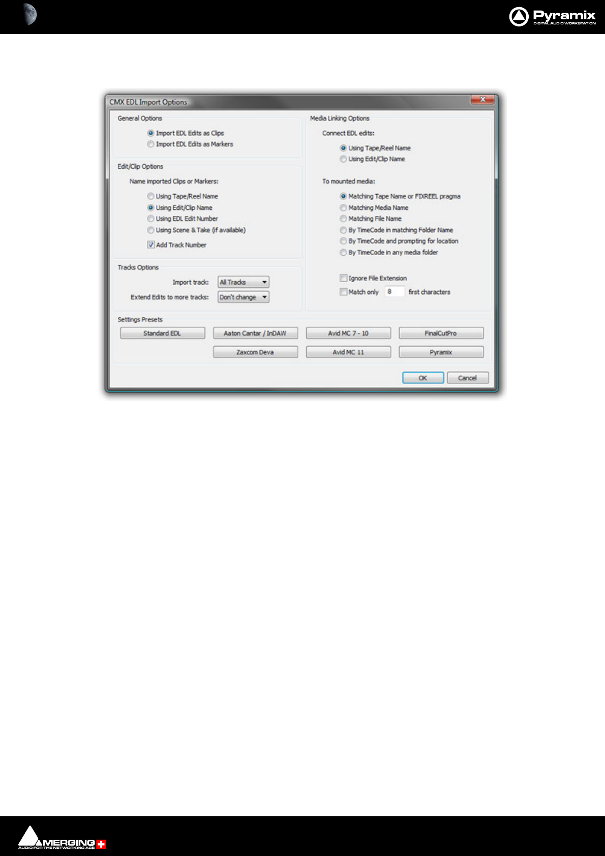
File and Project Interchange : Import / Export 18 - 498
If the EDL Frame Rate is correct, simply click the OK button. Otherwise, select the correct rate from the drop down
list and click the OK button. The CMX EDL Import Options main dialog opens.
The Settings Presets buttons at the bottom of the box set the options for a variety of common CMX variants. If
the edl you wish to import matches one of these, simply click the appropriate Preset button. The settings are
reflected in the rest of the dialog. Click the OK button to begin the Import.
If the edl is not one of the common variants or the intention is to perform a partial or re-conform, make the appro-
priate choices in the dialog before clicking on the OK button to begin the Import.
Exporting a CMX EDL
To export a CMX EDL choose Project > Export... and select CMX EDL in the Interchange - Export dialog. Click
on the Export button to open a file browser where you can select or create a suitable destination for the file.
Click on the Save button to start the export.
Note: Any Compositions or Cues which cross “TimeCode Midnight” into a different day will be
split and wrapped back to the start. E.g. I have a Cue which starts at 23:59: 51:00 in Day0 and fin-
ishes at 00:01:10:00 in Day +1. In the EDL this Cue will be split into two Cues. The first will run
from 23:59:51:00 to 24:00:00:00 and the second from 00:00:00:00 to 00:01:10:00 both in Day
0.
Cue Sheets Printer
The Cue Sheets Printer is a mini application for printing Cue Sheets from a Project. Full instructions can be found
at the end of this chapter. Please see: Cue Sheet Printer on page 505
Note:
DDP Import
Import DDP file.
CMX EDL Import Options dialog

File and Project Interchange : Import / Export 18 - 499
Final Cut Pro XML
Note: FCP X is NOT supported.
Supports import and export of MasterClips, Bins, Sequences or Projects to and from Pyramix.
To export a FCP XML file from Final Cut Pro, either select a single Sequence or a full Project in Final Cut Pro and
select File > Export > XML. This will export either a single Sequence (with the choice of all referenced MasterClips
along with it) or a full Project including all Sequences and MasterClips contained in it.
To import a FCP XML file into Pyramix, create an empty project and select Project > Import and choose the Final
Cut Pro XML format.
Note: When importing in Pyramix a FCP XML file containing more than one Sequence or Master-
Clip, Pyramix will prompt you to choose which of the available Sequences you would like to
import into the Timeline and will allow you to import all others into the Default Library of the
current project.
Scope
The following items are imported by Pyramix:
• Video and Audio Bins, Sequences and MasterClips
• Video and Audio Tracks Names
• Video and Audio Clips
•Audio Clips Fades
• Audio Clips Gain
• Audio Clips Envelopes (Key Frames)
•Clips Sync Points
• Clips Comments and Metadata (Master Comments, Clip Comments, Labels and Scene & Take)
• Links and Groups
• Clips colors
Known limitations
• FCP XML Export from Pyramix is not yet implemented
•Video Clips from HD compositions have length and positions truncated to an even number
OMF
OMF Import supports both OMF1 and OMF 2 format. Supports 10.5.3 / 11 sub-compositions.
When exporting OMF from another application, there is a choice of either embedding the audio files into the OMF
file, or keeping them external as a link. Pyramix supports both approaches.
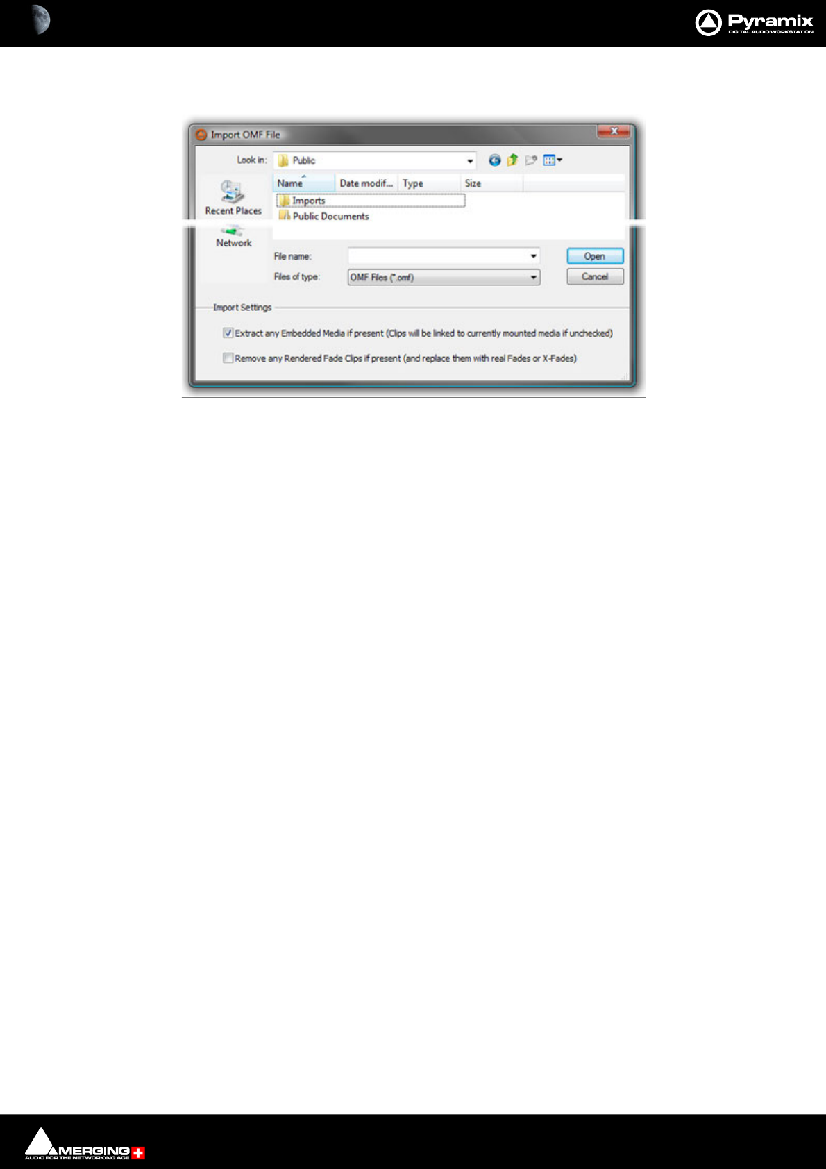
File and Project Interchange : Import / Export 18 - 500
Selecting Project > Import followed by OMF in the Interchange Import dialog opens the Import OMF File
browser window.
Import Settings
At the bottom of the browser window two import settings check boxes offer the options to:
Extract any Embedded Media if present (Clips will be linked to currently mounted media if unchecked)
(default is ticked) and
Remove any Rendered Fade Clips if present (and replace them with real fades or X-Fades)
Default is un-ticked
When importing an OMF file with embedded audio for the first time, leave the Extract option ticked to extract the
media files. Please un-tick the Extract any Embedded Media if present box on subsequent imports of the same
OMF file (because the media will already be present).
If the same file is imported a second time, there's no need to extract the audio twice, simply mount the folder
where it's been extracted to, prior to importing the OMF file. The OMF Media Handler generates an external Wave-
form (.pk) file when the file is first imported.
When importing an OMF file that references (links) to external audio files, the folder(s) that contain these files
must be Mounted in Pyramix before importing the OMF file. (This also applies to Sonic Solutions import).
Ticking the Remove any Rendered Fade Clips if present box converts any rendered fades or X-fades present in
the OMF file into normal Pyramix real-time fades. These can subsequently be manipulated in the usual Pyramix
manner.
OMF Mounting Rules
(Media Management Tab window, Media Folder > Mounting Rules)
AIFF files generated by Avid systems and BWF files generated by Pro Tools with the option Enforce Avid Compat-
ibility have a built-in OMF chunk and have always been recognized by Pyramix as an OMF Media. The Mounting
Import OMF File browser window
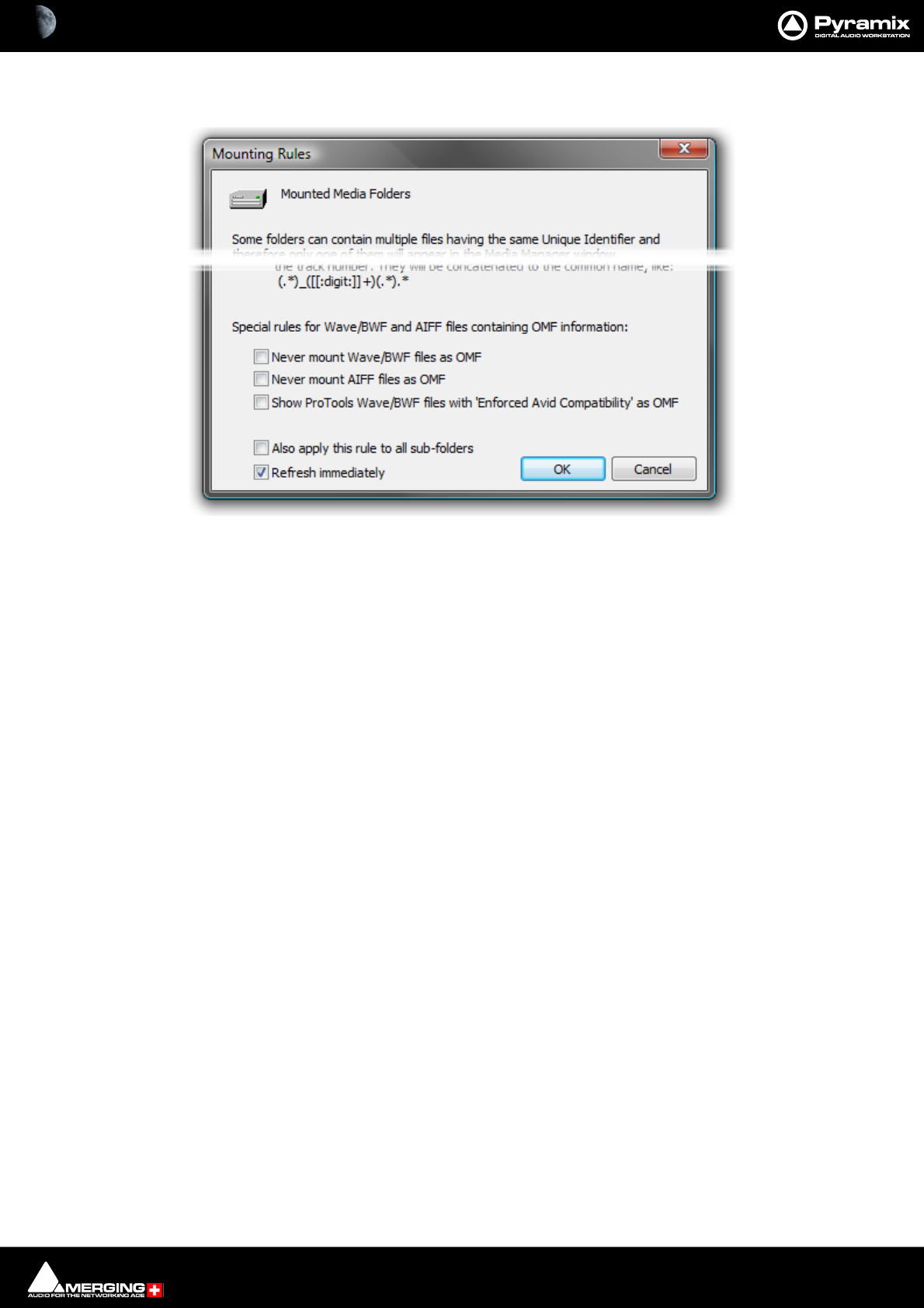
File and Project Interchange : Import / Export 18 - 501
Rules dialog has some special Mounting Rules options for folders containing Wave/BWF and AIFF files that have
an OMF chunk These enable the default behavior to be altered:
• Never mount Wave/BWF files as OMF (for files coming from Avid)
• Never mount AIFF files as OMF (for files coming from Avid)
• Show Pro Tools Wave/BWF files with Enforced Avid Compatibility as OMF (the new default behavior is to
always show BWF files generated by Pro Tools as BWF even if they have the OMF/Avid compatibility chunk.
This option allows forcing these files to be mounted "a la Avid" as in previous Pyramix versions)
Importing Avid and AudioVision bins
Avid and AudioVision bins may be imported as a library. In a library tab window select:
Library > Import OMF library (Avid bin)
Open TL
Straightforward Import and Export in Tascam Open TL format.
Report Printer
(includes EDL, Markers, CD TOC report sheet)
This program really needs a printer. Here is a way to add a printer when no physical printer exists:
1. Start the add new printer wizard. Start > Settings > Printers > add Printer
2. In the wizard choose local printer and deactivate automatically detect
3. Under "Use the following port” choose File
4. Select the printer that you will eventually use to print the file
5. The rest of the installation is the same as a standard printer installation
If you print a page test, a dialog will open and ask you the name of the file. Enter the path where you want to write
the file.
Mounting Rules dialog

File and Project Interchange : Import / Export 18 - 502
SACD Edited Master Import
Import Edited Master file.
Sonic Solutions
Straightforward Import in Sonic Solutions format. When importing an Sonic Solutions file that references (links) to
external audio files, the folder(s) that contain theses files must be Mounted in Pyramix before importing the file.
Note: Sonic Solutions HD format is not currently supported.
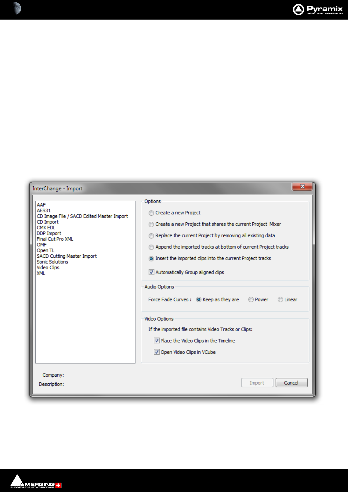
File and Project Interchange : Import / Export 18 - 503
Video Clips
Pyramix
Please see: Importing Video Clips on page 527
VCube
Note: If using the ASIO bridge for VCube audio I/O then prior to importing video clips launch
Pyramix followed by VCube when Pyramix has finished starting. Check that the VCube is shown
and connected in Settings > All Settings > Remote Control > Virtual Transport 2.
(If using a separate ASIO device or no VS3/ASIO audio then the boot order is unimportant.)
Import
Note: Prior to using Project > Import : Video Clips VCube should be running and connected via
VT2. To ensure that imported Clips open in VCube when the Project is reopened subsequently
make sure that Save the VCube composition in the Pyramix project is active in the Settings >
All Settings > Remote Control > Virtual Transport 2 page.
Selecting Project > Import... opens the Interchange - Import dialog.
1. Select Video Clips in the left-hand list.
2. Choose the appropriate Import Options.
3. Click on Import.
4. The Import Video File browser window opens.
Interchange - Import dialog

File and Project Interchange : Import / Export 18 - 504
5. Select the file you wish to import.
6. Click on Open to import the video file.
Note: Audio Tracks are also imported and placed in the Timeline. The method of placement fol-
lows the Replace/Append/Insert rules as per other (composition based) formats. Please see:
Options on page 482
Export : Video Clips
Under Construction
XML
Straightforward Import and Export in Pyramix XML format.
Note: This will NOT work with Final Cut Pro (X or earlier versions).
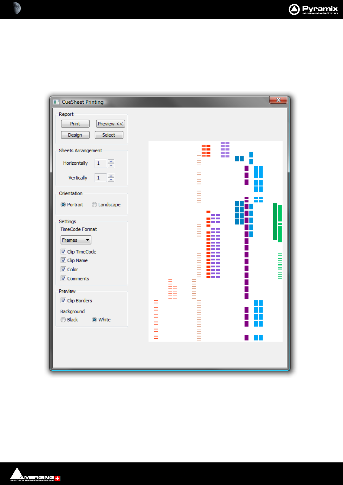
File and Project Interchange : Import / Export 18 - 505
Cue Sheet Printer
The Cue Sheet Printer offers comprehensive options for printing out a graphic representation of the Timeline.
Cuesheets are frequently a contracted delivery requirement which takes much time and effort to produce.
Select Project > Export. This opens the Project Export dialog box. Select Cue Sheets printer and click on the
Export button. (or simply double-click the Cue sheets printer entry)
The CueSheet Printing window opens. (Shown with the Preview option selected.):
Report
Print
Click this button to print the cue sheet(s) with the selected options. This opens the Print Options dialog box
unless the Orientation selected is different from the printer’s default. If it is the Paper Orientation conflict dialog
CueSheet Printing Window

File and Project Interchange : Import / Export 18 - 506
box pops-up with buttons which offer a choice of Select other report, Change Orientation, Force or Cancel.
Force should make the printer change orientation for this print. Some printers will not accept this. If this is the
case, see below.
Print Options dialog box
Offers the choice of which pages to print and the number of copies. Allows any installed printer to be selected and
configured. If Force does not result in correct page orientation the printer page orientation can be changed by
clicking Change then Select in the next screen which should give access to the Printer’s set up dialog with
options dependant on the selected printer.
Preview
Adds a graphic preview of the Cue-Sheet(s) to the right-hand side of the window.
Design
Opens the design software used to create the Cue-sheets. Please see the Design Report List and Label Designer
documentation, which is installed with Pyramix and can be found here:
C:\Program Files\Common Files\Merging Technologies\LL\Docs\ListAndLabelDesigner.pdf
Select
Opens a file browser. Saved Cue-sheets can be loaded for printing.
Sheets Arrangement
Horizontally and Vertically set the number of pages with the increment / decrement buttons. This also controls
the time scaling.
Orientation
Portrait / Landscape
Toggle between vertical and horizontal page orientation.
Settings
TimeCode Format
Shows the TimeCode format which will be used on the cue-sheets from the choice in the drop-down list. Frames,
Samples, [ms] or CD Frames
Clip TimeCode
When checked, Clip TimeCodes will be printed
Clip Name
When checked, Clip Names will be printed
Color
When checked, the cue-sheets will be printed in the colors used in the original project. (With a color printer)
Comments
When checked, Comments will be printed
Preview
Clip Borders
When checked, Clip borders are shown in the preview display.
Background
Black / White
Toggle the preview background color.

19 - 507
www.merging.com/Pyramix
USER MANUAL
Customizing Pyramix
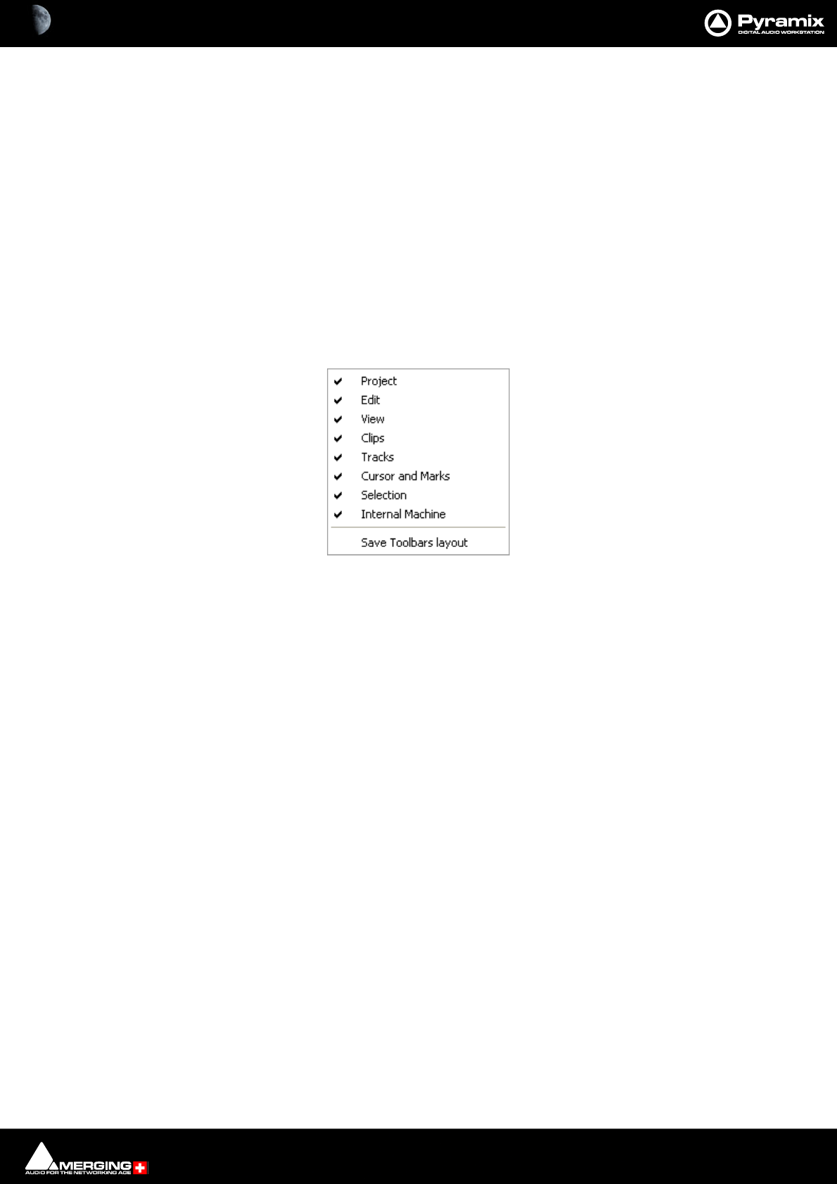
Customizing Pyramix : Customizing the User Interface 19 - 508
Customizing the User Interface
Pyramix Virtual Studio allows considerable customization of the user interface. Apart from the usual Windows
interface possibilities Pyramix has Interface Editors, user defined Workspaces, customizable Keyboard Short-
cuts and user defined Macros.
Desktop Layout, TimeLine Layout and Track Headers Layout are designed in Settings > All Settings > Appli-
cation
Toolbars and Menus
The Pyramix Toolbars and Menus are almost entirely customizable. Please see: Desktop Layout on page 755
Complete Toolbars can be managed by right-clicking anywhere in the blank space in the Toolbar dock to pop up
this menu:
Click on the Toolbar names to toggle Toolbars shown (ticked) or hidden.
Save Toolbars Layout Clicking on this entry saves the current Toolbar arrangement.
Toolbar context menu
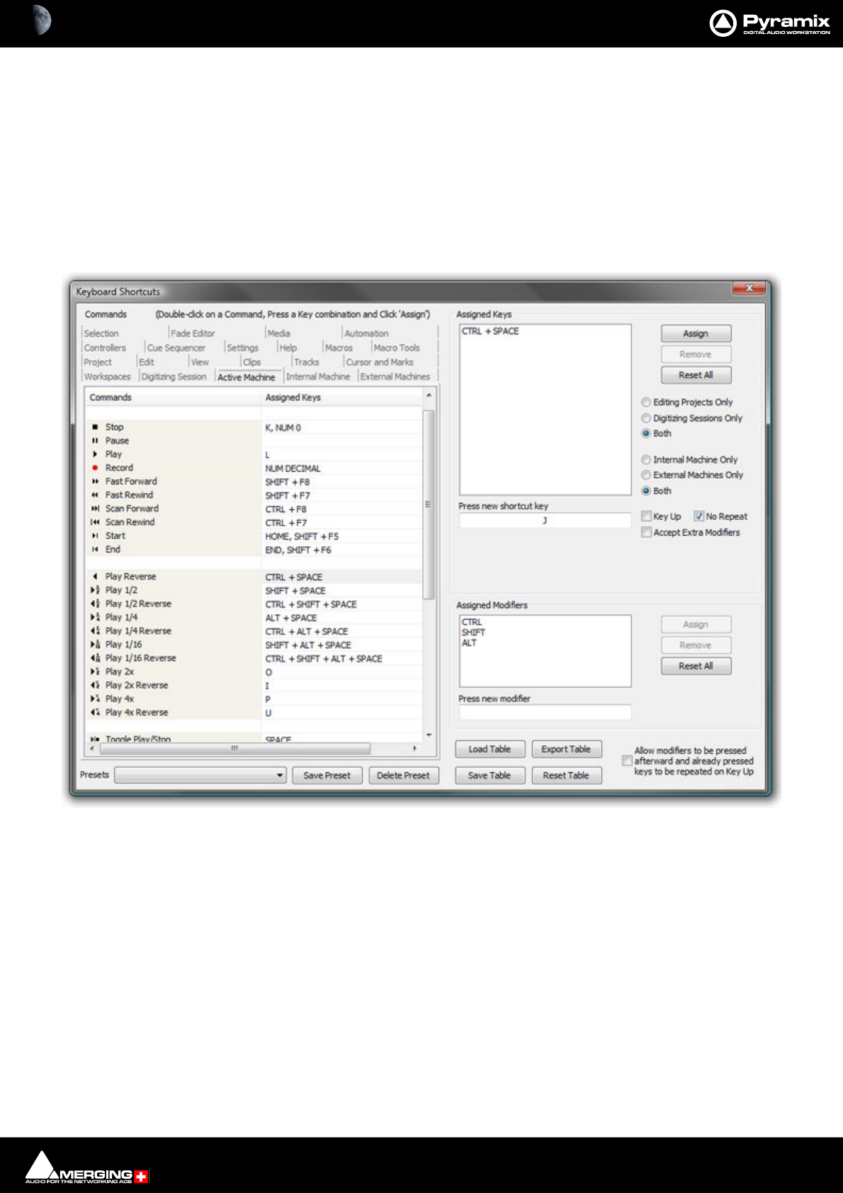
Customizing Pyramix : Customizing Keyboard Shortcuts 19 - 509
Customizing Keyboard Shortcuts
We strongly encourage you to learn the default Pyramix keyboard shortcuts. These have been used by audio pro-
fessionals for over a decade, and are powerful, quick and efficient for audio editing and device control. However, if
you are already familiar with another style of audio or video editing, you may wish to create your own Keyboard
Shortcuts for various Pyramix transport and editing functions.
To define your own Keyboard Shortcuts:
1. Choose View > Customize > Keyboard Shortcuts from the Toolbar. This opens the Keyboard Shortcuts
window:
2. All menu Commands are grouped together into Tabs within this window. Select the Tab with whichever
group of Command Functions you wish to add or change key assignments for.
3. Click on the appropriate Command so that it is highlighted.
4. Click in the Press new shortcut key box. The cursor will become a blinking bar.
5. Now press the desired Key or combination of Key and modifier (e.g. the Ctrl, Shift, Alt, etc.). These will appear
in the Press new shortcut key box. Note that Pyramix will warn you if the chosen Key or combination is
already assigned to another function.
6. Click the Assign button.
7. Continue assigning Keys to Commands until you are satisfied.
8. Any set of user defined Keyboard Shortcuts can be saved as a Preset. To do so, click the Save Preset button,
then name the Preset. Similarly, to recall a previously saved Preset, click in the Presets box and select it from
the pop-up list. Note that several common Presets are shipped with Pyramix Virtual Studio.The Table will be
saved in the system for the user currently logged in and will not affect any other user.
Keyboard Shortcuts Window

Customizing Pyramix : Customizing Keyboard Shortcuts 19 - 510
9. A table can be Saved or Loaded to a file so it can be taken to an other system. Just Click on the Save Table or
Load Table button.
10. A table can be exported as a Text File along with some comments about commands. This is very useful since it
enables you to print it as a command reference guide with your own keyboard shortcuts.
Example:
Many users with a video editing background will be familiar with the J, K and L keys assigned to Reverse Play, Stop
and Play respectively. To make these assignments:
1. Choose Settings > Keyboard Shortcut Editor or View > Customize > Keyboard Shortcut Editor
2. Select the Active Machine Tab
3. Click on the Play Reverse Command to select it.
4. Click in the Press new shortcut key box.
5. Type J (Notice J is not currently assigned to any function)
6. Click Assign
7. Click on the Stop Command to select it.
8. Double click the J in the Press new shortcut key box to highlight it.
9. Type K
10. Click Assign.
11. Repeat steps 7 to 10 substituting Play and L
12. Save the Preset. It is immediately active.
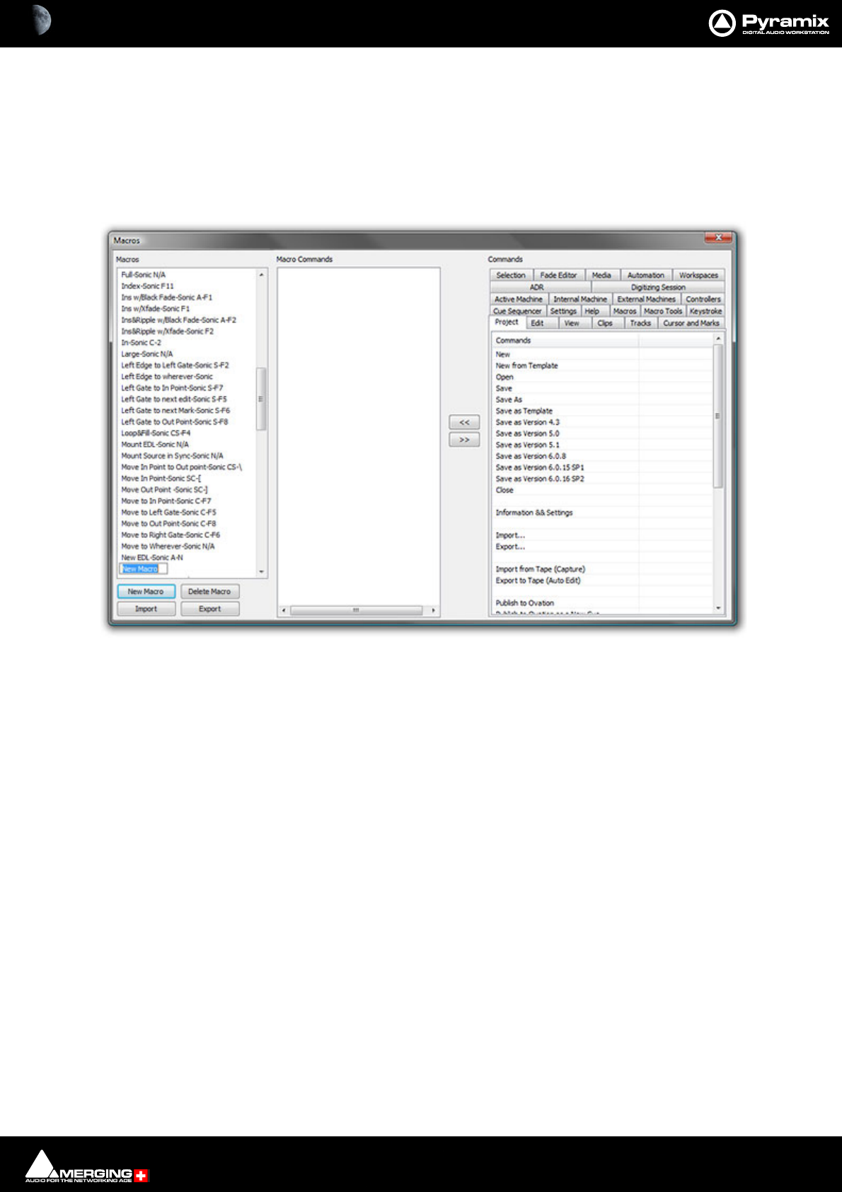
Customizing Pyramix : User Macros 19 - 511
User Macros
Macros are sequences of commands which can be invoked by a single keypress or combination. Macros can be a
very powerful aid to productivity.
To define a new Macro:
1. Choose Settings > Macro Editor or View > Customize > Macro Editor. This opens the Macros window:
1. Click the New Macro button, then name the Macro.
2. Various menu Command functions are grouped together into Tabs. Select the Tab with whichever group of
Command Functions you wish to add to the Macro.
3. Click on the appropriate Command so that it is highlighted.
4. Press the << button to add this command to the Macro.
5. Repeat steps 3 to 5 to assign further Commands to the Macro until it is complete.
A Keyboard Shortcut can now call the new Macro. Follow the instructions in the previous section for assigning
Keyboard Shortcuts. In this case, choose the Macro Tab within the Keyboard Shortcut window. Your new
Macro will appear as an option inside this window.
Note: macros can also contain keystrokes including: Enter, Shift, Tab, the Arrows (up, down,
left, right), Space Bar and ESC
Macros Window

20 - 512
www.merging.com/Pyramix
USER MANUAL
Applications
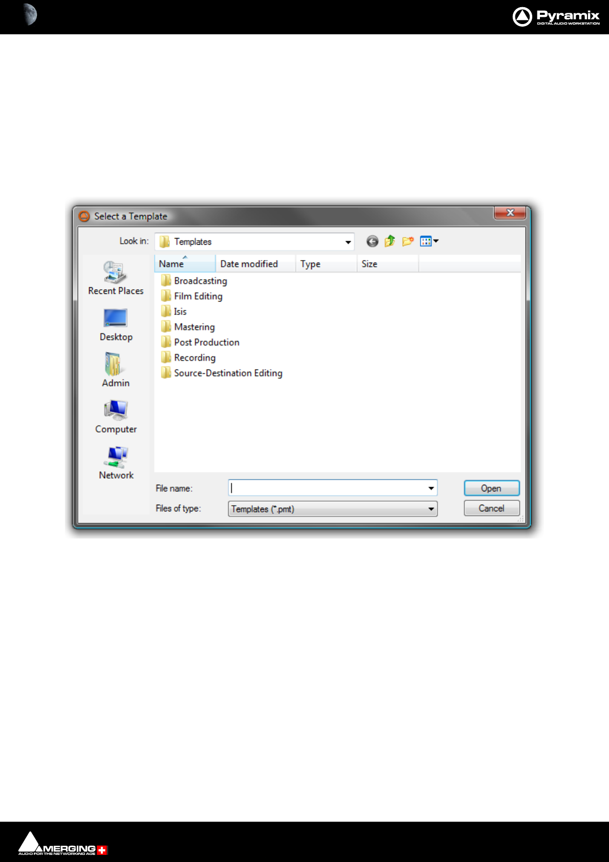
Applications : Project Templates 20 - 513
Project Templates
Pyramix provides the user with a number of Templates for various applications. A Template is a complete Pyramix
Project, without any associated audio, specially configured to suit a particular type of activity. Apart from configur-
ing the appearance of Pyramix, the Track layout and Mixer design, templates also include important optimizations
to suit the activity.
Please see: Optimizing Pyramix on page 663
These templates also offer a good starting point for creating your own customized templates. To begin a new proj-
ect using a template choose Project > New from Template which opens the Select a Template file browser.
When a template is opened a dialog box appears requesting the user to choose a Media Folder for the new proj-
ect. Unless the project is saved using the Save As option, the first time it is saved the Save As dialog will appear.
Further Templates will be added as they are developed.
To save a new Template choose File > Save as Template, name and save.
Virtual Multi-track
A number of Templates suitable for multi-track recording are provided with Pyramix. These Templates have all
the required settings already in place. If none of the supplied Templates is exactly suitable for your task it will save
time if you modify the one closest to your needs and save it as a Template for future use.
Settings for Multi-track recording
Multi-track recording can be demanding on disk performance, DSP and the host CPU. In order to optimize Pyramix
for the purpose if not using one of the supplied Templates the following settings should be made in the Record
Page:
Select a Template dialog

Applications : Virtual Multi-track 20 - 514
•Flatten Track Numbers: OFF
• Quiet if creation failed: ON
• Prompt for name after recording: OFF
• Keep in default library: OFF (Should always be OFF)
Suggested Settings
• Group Recorded Clips: ON
• Increment Take Number: ON
•Prefix with Track Name: ON
To Record audio directly into the Tracks of a Project, using Pyramix Virtual Studio as if it were a
tape machine:
1. Set the Destination Drive, Resolution and Format.
2. Arm each Track on which you wish to record. In this case, set each Track to Record Ready mode (simple Red
Dot).
3. Check your input levels using the Mixer, and adjust as appropriate.
4. Position the Play Head Cursor in the Composition where you wish the recording to start.
5. Click the red Master Record button in the Transport Strip or Transport Window. The recording will begin,
and display a red bar in those Tracks you have armed for recording.
6. Press the Stop button in the Transport Strip or Transport Window to stop the recording. A Record Name
dialog box will appear.
If you are satisfied with the recording, type an appropriate name into the Record Name box and click the Good
Take button. This will save an audio Media File of the selected type onto the selected Media Drive, with the
name you just chose and place a Clip in the Timeline, also with the same name. If you are not satisfied with the
recording, click the Delete Take button and the recording will not be saved. The third option is Bad Take. A Bad
Take is saved and a Clip placed in the Timeline just like a Good Take, but the Clip’s color is set to a specific color
(definable in the Settings > All Settings > Application > TimeLine Layout page) and are numbered the follow-
ing way: Take 1, Take 2, Take 3 (Bad 1), Take 3 (Bad 2), Take 3 (Bad 3), Take 3, Take 4, Take 5 (Bad1), Take 5, and so
on… This helps manage takes where there are mistake(s) but the user wishes to keep them anyway.
To Punch In audio directly into the Tracks of a Project, using Pyramix Virtual Studio as if it were a
tape machine with punch in capabilities:
1. Set the Destination Drive, Resolution and Format as above.
2. Arm each Track on which you wish to punch in. In this case, set each Track to Record Punch In mode (Red
Dot with 2 vertical bars). (alt-click on the round rec/play button in the Track Header.
3. Check the input levels using the Mixer, and adjust as appropriate.
4. Mark a punch in record In and Out point. This can be done either by marking a selection area on a Track, or by
setting a Mark In and Mark Out on the Time Scale bar. The simplest way to mark a selection area on a Track
is to click and drag in the Track: a darker gray rectangle indicates the selected area. The simplest way to set a
Mark In is to Shift-click on the Time Scale bar: a movable red triangle and vertical line indicates the Mark In.
The simplest way to set a Mark Out is to Ctrl-click on the Time Scale bar: a movable green triangle and verti-
cal line indicates the Mark Out. A selection takes precedence over Mark In and Out for punch in.
5. Position the Play Head Cursor before the marked In point or Selection area.
6. Press the red master Record button in the Transport Strip or Transport Window. The Play Head will begin
moving through the Composition, and Tracks will begin playback. Recording will begin on the armed Tracks
as soon as the selection area or Mark In point is reached during playback. A red bar will be displayed in those
Tracks which are recording.
7. The recording will stop automatically when the selection out or Mark Out point is reached. The Play Head
Cursor will continue playing through the Composition.
8. Press the Stop button in the Transport Strip or Transport Window to stop playback. A Record Name dialog
box will appear with the same options as a normal recording.

Applications : Pyramix With VCube 20 - 515
Multitrack Editing
Pyramix is ideally suited for editing multitrack recordings. Grouping Clips across all Tracks used for the recording
allows edit decisions to be made while listening to a single Track or several with the resulting edit changes
reflected in all the Clips in the group. Track Grouping functions enable you to work in a way that suits you. The
Source - Destination editing model is just one possibility.
Please see the following sections:
Grouping Clips on page 172
Track Groups on page 118
Source - Destination Editing on page 196
Editing with Limited Hardware
Multi-track recordings with many Tracks (E.g. 48 Track 96kHz 24 bit music recordings) can be edited on hardware
which cannot support this number of Tracks. (E.g. a laptop) Simply mute Tracks that do not need to be heard using
the button in the Track Header. Tracks muted here, rather than in the mixer, no longer access the disk. Pro-
viding the Multitrack recording’s Clips are grouped across all Tracks, then any editing changes made on the Tracks
used for the editing guide sound will also be reflected in the muted Tracks.
Pyramix With VCube
The highly sophisticated VCube video recorder/player has a symbiotic relationship with Pyramix. Whether the
VCube is running on a separate remote PC or locally on the same machine (PyraCube) there is tight integration
between the two. In a Pyracube this extends to synchronized editing and automatic VCube launch when a Pyra-
mix project containing video is opened.
Sony 9-pin (P2) Protocol Support Over IP
Hitherto there have been two principle options for synchronizing a VCube with Pyramix, Virtual Transport either
locally or over IP and Sony 9-pin (P2) protocol over an RS422 serial connection.
In Pyramix V7.x and later with VCube V3.x and later there is the further, elegant option of using the Sony protocol
over IP ethernet. This offers enhanced reliability and simplified configuration. Please see: Sony P2 Protocol Over
IP on page 569

Applications : LTC sync 20 - 516
LTC sync
EXAMPLE - where a cinema projector must be the master
• Cinema projector follows mains (or is crystal controlled) and sends biphase signal to a Biphase -to
LTC converter. (E.g. the Rosendahl BIF)
• Converter’s LTC output is directly fed to Networked Audio Interface LTC input
• Pyramix is set to "LTC sync" mode and will adapt it's own internal clock to sync to LTC whenever the
Pyramix is set to lock and the external LTC is recognized to be playing at about 1x forward speed.
• Pyramix feeds it's own clock to the DA-88 (or similar machine used as an A/D converter) via Word-
clock.
• The DA-88 (or equivalent) is set to sync to external Wordclock
All LTC sync ballistics in the Pyramix software have been carefully designed to both allow a large locking range (-7
to +5%) while still exhibiting extremely low instantaneous jitter and more importantly a controlled maximum
speed change slope - not more than about 25 PPM per ms (25 Parts Per Million/millisecond) - in order to make sure
that any other digital audio equipment connected to it's Wordclock output is provided with a smoothly changing
clock speed (free of any abrupt speed changes). Driving the pyramix with the LTC output of the DA-88 is maybe
possible in some situations but will demonstrate several limitations which should not occur if you follow precisely
the recommended setup as described above.
Dubbing Mode
This mode is provided principally for film re-recording. It allows Tracks to be Armed or Disarmed for recording
while recording is taking place.
Dubbing Mode is selected via All Settings > Settings > Project > Record
Enable Dubbing
When checked, Dubbing Mode is engaged.
Confirm Track Arming
Only available when Dubbing Mode is selected in the adjacent check box. A check in this box means that any
changes to Track arming made whilst recording must be confirmed by a new Record command before they will
take effect.
Example
When recording a final mix in stems (E.g. Dialogue, Effects and Music) you may well wish to retain a previous take
for, say Effects, until a certain point. This can be achieved by arming the Dialogue and Music Track Groups, playing
the transport and punching into record at the desired point. Once in record, the Effects Track Group can be
dropped straight into record at the appropriate moment by simply arming it, or if the Confirm Track Arming box
is checked, by arming it and, applying a second record command when you wish to begin recording. (either on
screen or via MMC, 9-pin etc.)
Discontinuous TimeCode
Auto-Punch mode allows a whole tape with discontinuous TimeCode to automatically be recorded.
• Set all desired Tracks is auto-punch mode
• Place Mark In at 00:00:00:00 and Mark Out at 23:59:59:24 (default values for a new project)
• Plug LTC Out from the tape machine into Pyramix
• Set Chase mode to HARD CHASE
• Rewind the tape

Applications : Reconforming to Original Media from Avid &/or OMF 20 - 517
• Press Play on the tape machine
Each time a valid TC is encountered Pyramix will lock and start recording a new Clip, then stop when the timecode
jumps. A separate media file will be created for each continuous timecode on the tape.
Reconforming to Original Media from Avid &/or OMF
There are no specific rules for the detailed settings of the procedure described below. It may change from user to
user, project to project, etc… It really is up to the user to define a specific workflow including naming of the origi-
nal recording, importing the stereo/original version into the Avid and making sure that the Video Editor properly
keeps track of the proper naming, metadata, etc… Once the method is properly defined and working, the rules
should then be communicated to all people involved in a given project, once and for all.
Philosophical Point
Reconforming to New Media always involves some delicate & dirty experimentations in the Relink to New Media
dialog. This usually requires comparisons of Clip information in Clip Properties and Media information in Pyramix
Media Manager. Once some kind of correspondence in the naming structure can be found, then all of a sudden
the whole process becomes incredibly simple, the entire TimeLine becomes populated by happy green Clips and
an amazing feeling of personal achievement is yours forever.
The following example could and should be interpreted at will to match your specific needs and requirements
Procedure
• Import the OMF from the Avid (even without Avid media, it is not required)
• Mount the original Multitrack session media
• Select Project > Reconform > Relink to New Media
• Now the hard part: try to find, in the Clips imported from the OMF, any matching information (in Clip
Properties) that can also be found in the original media properties
• For instance, you may find that the Clip Names match the Original Media File Names, but you may very
well find that the Clip Names are in fact Scene & Takes and should rather match the Original Media Scene
& Take, etc…
(OMF is at this better than CMX since it can include information such as Clip Names, Metadata, TimeCodes, etc…)
It finally all depends on how the original media has been documented while recording (BWF metadata) and how
the Video Editor and Media “Ingester” have documented the Media and Clips in the Avid.
Again, as already stated above, there are no rules and it may change from user to user, project to project.
Suggested Procedure for Managing a Workflow
• Record the Original Media in BWF with TimeCode and name them Take1, Take2, Take3, etc… or any other
name that can easily be understood and searched.
• Create a BWF 16 bits Stereo Render of your Multitrack recording files WITH THE SAME NAME as the origi-
nal.
• Import these files into the Avid and make sure all Clips created out of these Media keep the Media Name
or File Name.
• Export an OMF out of the video edit and import it back in Pyramix (Even without media).
• You should then be able to match the OMF Clip Name to the Original Media File Name, or at least, if the
Video Editor messed up with the Clip Names, the OMF Media Names with the Original Media Name or File
Name.
•- Once the Relink procedure has been successfully achieved, you should have all your Clips referencing
the Original Media’s first track(s).
•- Then go to Tracks > Extend, select all Tracks you want to extend and choose Auto-Detect. This should
extend all your Clips according to the number of Tracks of your original multitrack recording.

Applications : Digitizing a Tape with Discontinuous TimeCode 20 - 518
Summary
If something goes wrong with Reconform (apart from SD2 files not recognized, Please see: File & Project Inter-
change with Apple Macintosh on page 479) please look for some sort of timing or wording mismatch between
Clips and Media and feel free to try several different settings in the Relink to New Media Dialog, till you find THE
ONE that matches your topology.
Digitizing a Tape with Discontinuous TimeCode
Pyramix can automatically record a whole tape where the TimeCode is not continuous:
• Set all desired Tracks in Auto-Punch mode
•Place Mark In at 00:00:00:00 and Mark Out at 23:59:59:24 (These are the default values for a new project)
• Plug LTC Out from the tape machine into Pyramix
•Set Chase mode to HARD CHASE (Settings > All Settings > Jog/Chase : Chase Settings -Chase Mode)
• Rewind the tape
• Press Play on the tape machine
• Each time a valid TC is encountered Pyramix will lock and start recording a new Clip, then stop when the
TimeCode jumps. A separate media will thus be created for each continuous TimeCode on the tape.
Loop Recording With Simultaneous Playlist Creation
•Check the Create an Empty Playlist for each Recording option in the Settings > All Settings Project >
Record Page.
• Put the required Tracks in Auto Punch mode (Alt + click the Track arming, the Track arming button will dis-
play )
•Place Mark In and Mark Out around the Region to be recorded.
• Put Pyramix in Chase Mode (preferably Hard Chase) and chase an LTC input.
• Have the TimeCode that feeds Pyramix looping around two boundaries that start a little before the Mark
In and stop a little after the Mark out. (To make a Preroll Postroll. These should be big enough to let Pyra-
mix sync properly and lock to the incoming TimeCode).
• Pyramix will then, for each loop, sync and lock, enter in record at Mark In, stop recording at Mark Out and
create a new PlayList for each loop iteration.
N.B. This requires that an external TimeCode source/generator be used to generate the reference TC loop.
TimeCode Midnight
For those users with a requirement to sync/chase TimeCode with projects near or crossing the day barrier (be it
Zero or 24 hours) Pyramix has an Allow chasing across midnight option in the Settings > All Settings > Appli-
cation > Jog/Chase page.
If this setting remains unchecked (default) then the Pyramix cursor will always follow the exact given TimeCode
and therefore will remain strictly within "day zero" of the Pyramix timeline. For additional security and comfort, if
Pyramix is in locked state while crossing the midnight barrier, then even with this setting unchecked, there will
not be an immediate jump from midnight back to zero while playing or recording in sync. The playback or record-
ing will remain seamless, uninterrupted and cross the day barrier until an out-of-lock status is recognized. Only
then is re-chase triggered to whatever the incoming TimeCode currently is.

Applications : Editing Multitrack Recordings 20 - 519
Editing Multitrack Recordings
To edit Multitrack recordings without listening to all of them just Mute the Tracks and Hide them. All edits per-
formed on the remaining visible one will still occur on all others and only the audio from the visible one will be
played back for monitoring. (E.g. a stereo guide mix)
Film 24 to NTSC Sync
Here are some settings for the most common Scenarios for Film 24 to NTSC Sync. Presets for all of these can be
found in Settings > All Settings > Hardware > Formats & Sync.
Mix/Editing for TV shot in NTSC and 48 kHz and edited in sync with NTSC equipment:
• Set the Frame Rate to NTSC Drop
•Set the Video Format to NTSC
• Set the Sampling Rate to 48 kHz
• Set the Varispeed to Nominal
Result: FR = 29.97 SR = 48000 Video Input = 29.97 (Standard for TV, Audio at 48kHz in sync with 29.97 while Shoot-
ing, Post and Diffusion)
Mix/Editing for Film shot at 24 fps and 48kHz but edited in sync with NTSC equipment:
• Set the Frame Rate to Film (24 fps)
•Set the Video Format to NTSC
• Set the Sampling Rate to 48 kHz
• Set the Varispeed to Pull-Down
Result: FR = 23.98 SR = 47952 Video Input = 29.97 (Standard for Film, Audio at 48kHz in sync with Film 24fps for
Shooting and Diffusion, but at 47952 in sync with 29.97 for the Post with Film 24 running at 23.98)
Mix/Editing for Film shot at 24 but converted 3:2 to 30 frames and edited in sync with NTSC
equipment:
• Set the Frame Rate to SMPTE Non-Drop
•Set the Video Format to NTSC
• Set the Sampling Rate to 48 kHz
• Set the Varispeed to Pull-Down
Result: FR = 29.97 SR = 47952 Video Input = 29.97 (Standard for Film, Audio at 48kHz in sync with Film 24fps for
Shooting and Diffusion, but at 47952 in sync with 29.97 for the Post with Film converted to 30 running at 29.97)
Special case:
Mix/Editing for Film shot in High Def at 23.98 fps and 48kHz and edited in sync with HD NTSC
equipment like D5 or other:
• Set the Frame Rate to 23.98
• Set the Video Format to Trilevel 24/1.001
• Set the Sampling Rate to 48 kHz
• Set the Varispeed to Nominal
Result: FR = 23.98 SR = 48000 Video Input = 23.98 (For Film shot in HD 23.98, Audio at 48 kHz sync with Film 23.98
while Shooting and Post. Caution: The Audio needs a Pull-Up to run in sync with the Film if printed a real Roll)

Applications : Checking AC3 encoded files in Pyramix 20 - 520
Checking AC3 encoded files in Pyramix
Two types of AC3 encoded files can be played back in Pyramix:
If the file was generated as an .ac3 file, then Pyramix will automatically decode it on the fly and playback 6 chan-
nels of audio.
If the file was generated as a .wav file, then Pyramix will consider the file as Wave and simply play two channels of
digital encoded AC3 to its (digital) outputs to feed an external decoder.
Most AC3 encoders allow embedding of encoded AC3 signal into a Wave file while encoding, for easy playback.
For example, Minnetonka SurCode offers this feature.
Working with External Machines
Use Auto-chase
Auto-Chase is a convenient, one button press solution for situations where control must be frequently switched
between the Internal Machine I.e. Pyramix and an External Machine or machines.
If all enabled machines are set to Auto-Chase, when Ctrl is switched between machines the Active Machine is
automatically taken out of Chase mode and the previously Active Machine automatically enters Chase mode. To
activate Auto-Chase for all external machines, enable the menu setting:
Machines > External Machine > Auto-Chase
And, to activate Auto-Chase for the internal machine, enable the menu setting:
Machines > Internal machine > Auto-Chase
Using Freeze Mode
• If you are using Pyramix for sound-for-picture work, the Freeze Mode is a very powerful tool. For example,
to position an out of sync car-door slam do the following:
• Use the Transport controls with all machines on-line to position the picture on the point where the door
slams.
• Press the Freeze button to freeze the external machine(s).
• Select the Clip that has the sound of the door slam.
• Position the Clip Sync Point at the beginning of the impact. (Click and drag the red Clip Sync Point or
position the Playhead Cursor and select Clips > Set Sync Point to Cursor (Ctrl + M)
• Press Freeze and the Playhead Cursor will jump to the point at which Freeze was activated.
•Now, select Clips > Send Sync Point to Cursor (Ctrl + Alt + M) and the Clip will move so that its Sync
Point is at the Playhead Cursor position and the sound of the slam is synchronized with the picture.

Applications : Versioning 20 - 521
Versioning
When making “promos” and commercials for radio, TV and film there is often a requirement to produce several dif-
ferent versions with, for example, different dates or times or different languages. The effects and music are often
the same for each version. Pyramix offers several ways of achieving this.
Probably the simplest method is to select all the Clips you wish to move or copy to a new location in the Timeline
then select Cursor and Marks > Goto TimeCode, (NUM 6) type in the new TC location and then Cut and Paste or
Copy and Paste. If you have a lot of this work to do, you may want to build a couple of simple macros to do this
with the these commands: Cut / Paste to Cursor and Copy / Paste to Cursor.
As an alternative to typing in the new cursor TimeCode location, you could use the Nudge Cursor functions to off-
set it from where it is currently parked. Nudge to the left/right uses one of the 5 predetermined nudge settings.
Another method uses User Libraries. Copy the selected Clips and paste to a library or (Shift + Alt Drag) then
place the Composition using any tool you wish. This method has the advantage that you can save the library and
open it in another project.
Object Based Audio Workflow
Pyramix 11.1 supports an immersive audio tool kit for broadcasters by developing the Audio Definition Module
(ADM ITU-R BS.2076) and MPEGH (by Fraunhofer IIS) export.
Pyramix 11.1 is the first DAW with a complete workflow to generate master files with Object-Based Audio (OBA)
metadata according to the Audio Definition Model (ADM) or MPEG-H 3D audio.
Pyramix 11.1 now consolidates the former OBA workflow, primarily designed for Dolby Atmos mixing for Film or
Immersive Live performance, into a comprehensive workflow for TV production with the addition of multi-lan-
guage support and ADM format export. OBA is the future of sound for broadcasters, to address multiple platforms
with the highest quality experience. To achieve OBA Master files, the Audio Definition Model metadata inserted
within Broadcast Wave Files constitutes a flexible and free solution to address the next generation of encoders.
As a result of the cooperative development with the Fraunhofer team, a comprehensive MPEG-H workflow is avail-
able by exporting Pyramix 11 OBA projects directly to the Fraunhofer MPEG-H Authoring Tool.
This tool is a stand-alone application developed by Fraunhofer IIS for authoring and monitoring of MPEG-H Audio
content. It provides monitoring and rendering of channels, objects and higher-order ambisonics content includ-
ing the import and export of MPEG-H metadata. The MPEG-H Authoring Tool is already in use within the South
Korean terrestrial 4K TV broadcast service.
Applications : Object Based Audio Workflow 20 - 522
Settings
• ADM metadata are exported during a Mixdown process and related options are available in the Mixdown
dialog.
• ADM metadata can only be inserted into BWF files using the Single Media option.
• In ADM terminology one ADM Object corresponds to one Pyramix Mixer bus. It must be either a Gen-
eral Mixing bus or an Objects bus. Exported ADM Objects then correspond to the selected Mix Sources
in the Mixdown dialog.
• ADM Programs and Contents are automatically generated based on the selected Mix Sources (buses) and
embed and refer to ADM Objects.
To generate ADM metadata, just tick the Insert ADM Metadata if target is BWF check box, ensure BWF and Sin-
gle Media are also selected and proceed to Mixdown.
ADM Metadata Settings
Additional metadata to define the content of each of the Mix Sources can be edited in the ADM Metadata dialo-
accessed from the Settings button adjacent to the Insert ADM Metadata if target is BWF checkbox.
• Each Mix Sources/ Object can be given a Language
• Each Mix Source / Object can set as a Dialogue object
• Each Mix Source / Object can set as an Audio Description object
Mixdown dialog and ADM Metadata dialog

Applications : Object Based Audio Workflow 20 - 523
The above metadata in addition to the selected Mix Sources are sufficient for the ADM export process to properly
create logical and comprehensive ADM Programmes and Contents
Additional Settings options
Always include an additional Programme without any Dialogue, allows for adding one additional Programme
with only the Bed and dynamic Objects without any Dialogue. This Programme can be useful for dubbing
houses for preparing additional languages tracks
Generate DirectSpeakers as Objects allows the EBU standard speaker sets to be bypassed and generates all
Objects and Beds as pure ADM Objects. This can be required by some ADM renderers.
MPEG-H Authoring Tool projects
• MPEG-HAT project uses the same metadata used for generating ADM metadata
• The process and settings are the same as for generating ADM (see above), the only difference is:
•MPEG-HAT requires BWF using One File Per Track
•The Generate MPEG-H Authoring Tool project check box must be ticked.

21 - 524
www.merging.com/Pyramix
USER MANUAL
Video
Video : 21 - 525
Scope
Video Playback Support with up to two independent outputs. (Four may be available optionally at a later date.)
These outputs can be displayed on any screen connected to the PC’s graphics device. Certain Blackmagic inter-
faces are also supported. AJA interfaces are not supported.
It’s now possible to playback video directly within Pyramix. This video can be imported via the Interchange Import
(Video Clips, AAF, XML) or via the Media Manager.
Audio files can be “wrapped” in a Video file using an option in the Mixdown dialog.
VCube
For more complex video requirements VCube offers a great deal more: Recording/Capture, Rendering, Wrapping,
4k support, ADR support with wipes and clocks, SDI Audio support, Crosslock (TimeCode different to frame rate)
and higher performance on a dedicated system/engine.
Hardware
Black Magic support
Pyramix supports Blackmagic design Video Cards via the DeckLink SDK. This covers DeckLink, UltraStudio and
Intensity product lines. Only Decklink Studio 4K has been validated as of now. The DeckLink Studio Monitor is
known to be working but has no Video reference to ensure genlock.
Video Card Outputs:
The Video card can be enabled under All Settings > Video > Settings : Video Cards:
In order for this feature to work the correct Merging Key Pack and a Blackmagic Design Video Card are required.
The Video Output(s) are mirrored to this hardware when a supported Blackmagic DeckLink device is installed on
the computer.
Formats
Merging Technologies have tested and validated for use the following file types and codecs in Pyramix’s video-in-
timeline feature. Other codecs and file types may work, but we only support the ones listed below currently.
Mov: DNxHD (8bit) **
ProRes 422 HQ
ProRes 422 LT
ProRes 422 Proxy
DV25
DV50
H264**
MXF: DNxHD (8bit) **
XDCAM HD**
AVCi**, IMX**
Note: 10bit DNxHD is not supported.
** DNxHD, AVCi, IMX, XDCAM HD and H264 (Encode only for VCube encoding via render, H264 Playback is
included as standard) are all optional codecs and come at an additional cost to the Pyramix pack. Please contact
your local Merging Sales Partner if you wish to purchase one or more of these options. **
Settings >Video > Settings : Video Cards
Video : Video Tracks 21 - 526
Delay Compensation
The video will often be delayed with respect to the audio whether displayed via the graphics card or a dedicated
video card. Pyramix is able to compensate for this.
Separate delay compensation settings are available for the graphics card and optional video card. These may be
found in the Settings > All Settings > Video > Settings page.
Graphics delay Compensates for the graphic card(s) output delay.(computer screen) Type a value
(in frames) or use the increment / decrement buttons.
Video delay Compensates for the video card(s) output(s) (Blackmagic Design). Type a value (in
frames) or use the increment / decrement buttons.
Recommendations:
• To avoid excessive memory consumption and consequent impact on audio performance, work with intra-
frame proxy files whenever possible.
• H264 is not recommended for editing.
• If using Video in the Timeline of a a DXD or DSD Project we recommend using ONE video output for opti-
mum performance.
Pro Res or DNxHD are recommended for editing and performance purposes.
Video Tracks
Video Tracks are quite similar to Audio Tracks and many operations are the same, move, lock, split, cut, copy and
paste, dissolve etc.. The Mute and Solo buttons in the Track Header work in the same way as Audio Mute and Solo.
Clicking on the Video Track number (V1 in this case) pops up a menu to select the Video Output for the Track:
Adding a Video Track
A new empty Video Track may be added from Video > New Video Track or from the right-click context menu
accessed when the mouse cursor is over the Track Headers Add Video Track or from the Add Video Track button
in the Video Toolbar:
Video Track
Video Track Output pop-up
Video Toolbar Add Video Track
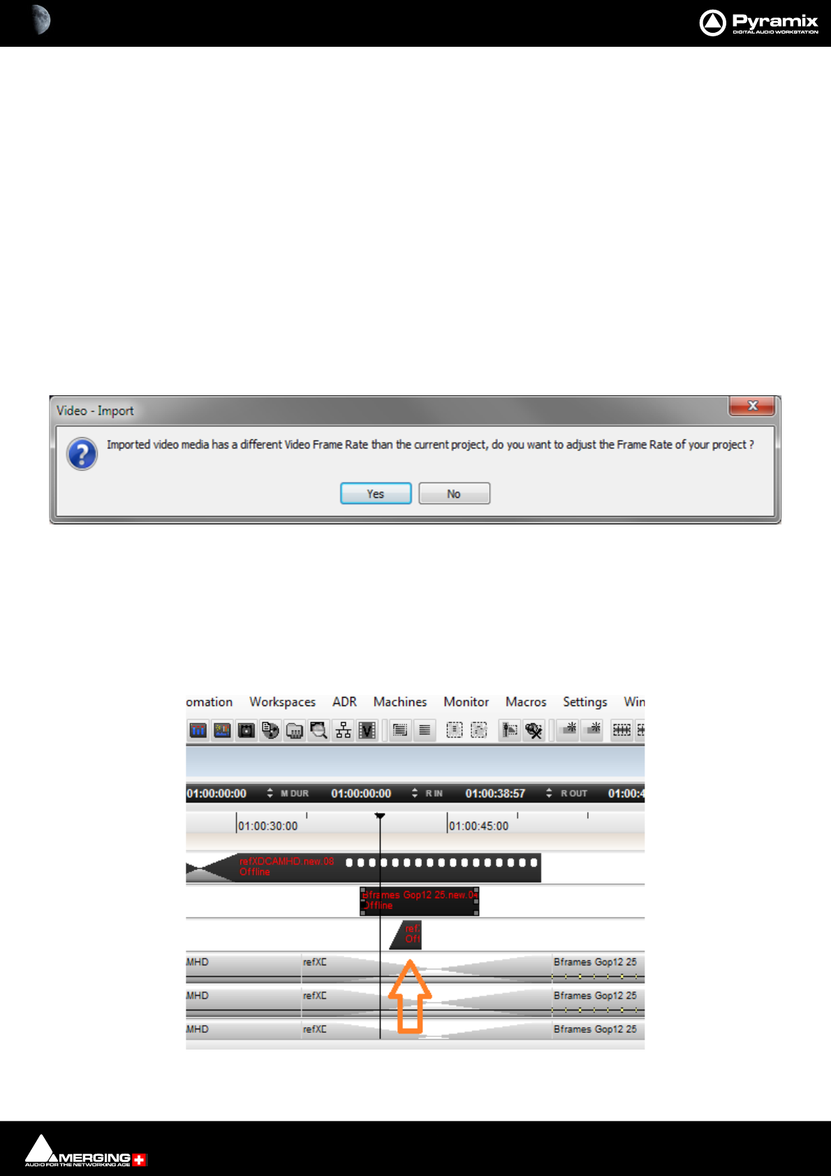
Video : Video Tracks 21 - 527
The new Video Track will be added above the Track selected currently or above the first track if no Track is selected
currently.
Video Tracks are added automatically when importing.
Where Video Tracks already exist the Media Manager may be used to place Video Clips in the same way as Audio
Clips.
Supported Video Formats
Pro Res or DNxHD files are recommended for editing and performance purposes.
Importing Video Compositions
AAF and XML are supported via Project > Import: AAF or XML. Please see: Import on page 482
Importing Video Clips
Video Clips are imported via Projects > Import: Video Clips. Please see: Import on page 482
If a Video Clip is imported which has a different Frame Rate to the current Project a dialog will appear asking if the
Project Frame Rate should be adjusted to match the imported video media. Choose Ye s to change automatically :
Video in Media Manager
Video Clips can be placed from the Media Manager in the same way as Audio Clips.
Multi Layer Compositions
When a multi-layer composition is imported, Pyramix displays the layers under the main video track (layers are
inverted compared to most video editors). The compositing is done bottom-up. In this example the smallest video
clip will overlay the 2 other clips:
Video - Import dialog
Video layers Compositing
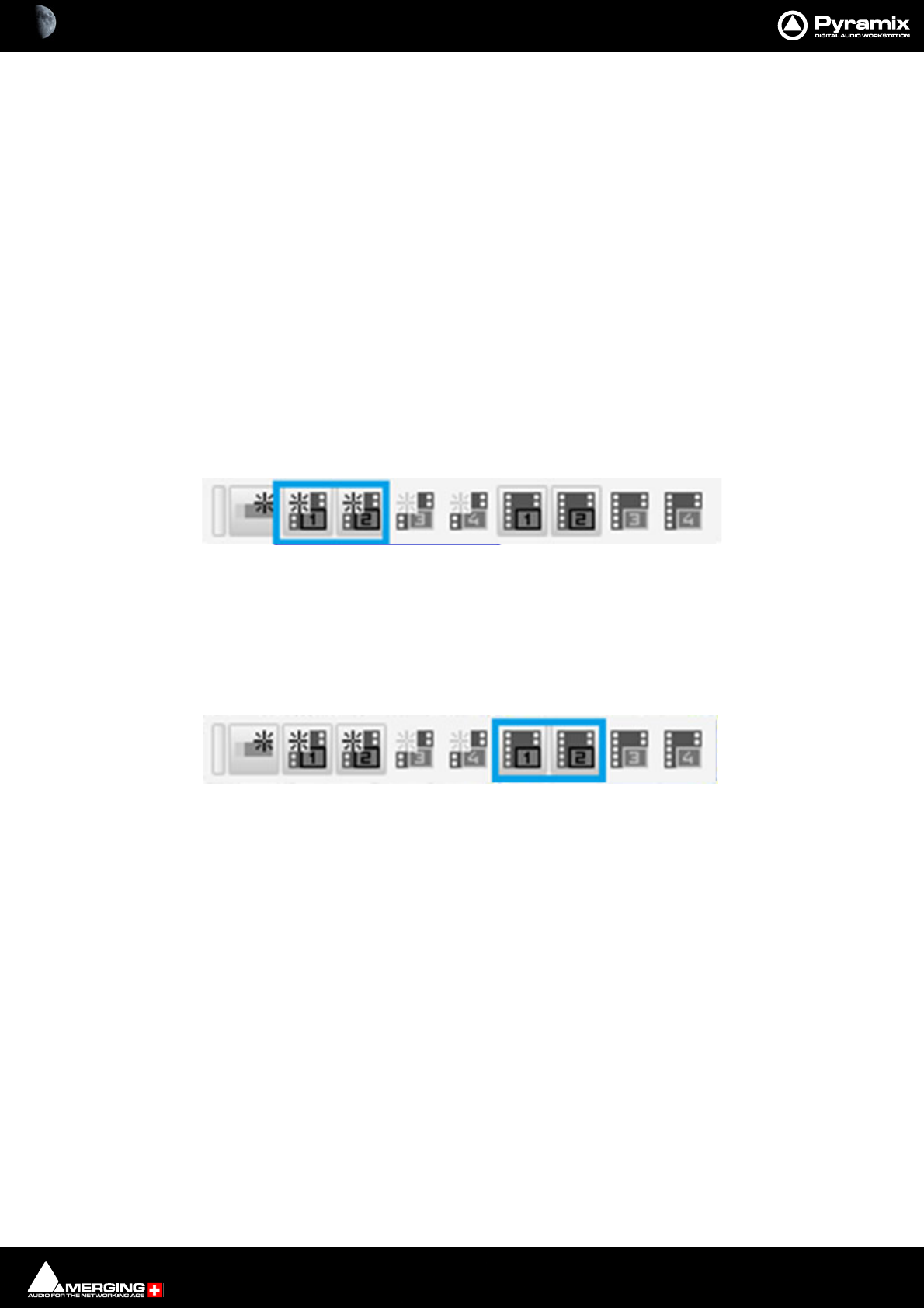
Video : Video Output 21 - 528
When several Tracks are patched to the same Video Output, they are composited in the bottom-up order. Two
Tracks patched to different Outputs are displayed independently (see Video Tab window and Video Output Win-
dows). This can be useful for comparing Video Clips or in a multi-camera workflow.
Note: By default, all imported layers are patched and composited into Video Output 1.
Thumbnails
Video Thumbnail images may be added to the Video Track in the Timeline. Thumbnails generation is initiated
manually by right-clicking on the relevant Video Track and selecting Display > Image. Thumbnail Generation may
be cancelled by Right-Clicking and selecting Cancel Image Generation on the generation message at the bottom
left-hand corner of the Pyramix GUI.
Video Output
Output Windows
Output Windows are added from Video > New Video Window... > New Video Window Output 1,2,3 or 4 or from
the Video Toolbar.
The left-hand four buttons add Video Output Windows for each of the outputs:
Click on the buttons to create Video Output Windows. Multiple Windows for each output are supported.
Note: Two Output Windows are available currently. Four may be made available as an option at a
later date. The extra buttons are greyed out and inoperative for now.
The right-hand four buttons toggle all Output Windows open and closed per Output:
A shortcut key may be assigned to display or hide all the video frames routed to the respective Video Output (1 or
2). This can be bypassed using the Always Visible context menu option (see below).
Video Toolbar Create Output Windows
Video Toolbar Toggle Output Windows

Video : Video Output 21 - 529
Output Window
Right-clicking anywhere in the window pops-up a context menu.
Video Output 1 Information only. Shows which of the video outputs is feeding the Window.
No aspect ratio Output Window may be resized to any shape by clicking and dragging the edges/
corners.
16:9 aspect ratio The Video Output Window is fixed at 16:9 aspect ratio when resized.
4:3 aspect ratio The Video Output Window is fixed at 4:3 aspect ratio when resized.
Stretch Image is resized to fit the Video Output Window. This may result in a distorted
image.
Double Size Sets the Video Output Window size to Double. normal size.
Normal Size Sets the Video Output Window size to Normal normal size.
Half Size Sets the Video Output Window size to Half normal size.
Quarter Size Sets the Video Output Window size to Quarter normal size.
Hide Windows Frame Hides the Windows border around the video. In this mode the Video Output win-
dow can be moved by clicking and dragging and can be resized from the Right-
Click context menu to Double, Normal, Half or Quarter sizes.
Always Visible Overrides the Toggle Video Output Window function and keeps the Video Output
Window visible.
Always on Top The Video Output Window is always displayed on top of any other Windows or dia-
logs on screen.
Full Screen Displays the Video Output full screen. (On the monitor the window is on in a multi-
screen system.)
Show Overlays Toggles Overlays shown/hidden.
Video Output Window with context menu
Video : Video Output 21 - 530
Overlays
Each of the Video Outputs supports independent Overlays of TimeCode, Name and Text. Overlays are set-up in
the Settings > All Settings > Video > Overlays page. Please see: Overlays on page 779
Video Tab
If the Video Tab is not already present it can be added by selecting View > Editor Tabs > Video.
Patched Video Outputs are displayed in condensed form. There are no controls or menus in the Video Tab.
Notes
• Video Editing: We recommend using Pro Res or DNxHD files for editing and performance purposes.
• There is no control over the video output(s) assignment (yet). Video Output 1 will be output to the first
detected Video hardware, Video Output 2 to the second, and so on. Multiple output cards are supported.
Video Tab Window

Video : Wrap in Video 21 - 531
Wrap in Video
Wrap in Video is a Post Processing option within the Mixdown dialog which enables audio Tracks to be
“wrapped” into a Video File. It can also be invoked from the Timeline via: Video > Wrap Selection.
Note: Audio can only be wrapped in a single Video Clip file.
Wrap Support
• AVI & MPEG: Not supported in Pyramix.
• MXF: Audio: Only 16/24 AES3 samples.
• MP4: Audio: 2-6, 8 channels, 16bits only. Start Timecode not supported.
Wrapping Between File Formats
Constraints if changing extensions in the “Custom Name field” when wrapping are as follows:
• Codec is DNXHD: MXF <-> MOV
• Codec is DV: MXF <-> MOV
• Codec is IMX:\D10: MXF <-> MOV
• Codec is AVCINTRA: MXF <-> MOV
• Codec is Apple PRORES: Valid for mov only
• Codec is MJPEG: Valid for mov only
• MP4 to MOV: Any content. Audio converted to 16 bit pcm
• MOV to MP4: Only H264, MPEG content. Audio converted to AAC
• Codec is XDCAMHD: not recommended, not supported
Note: Any format not listed is unsupported and could produce a corrupted file.
Wrapping Timeline Tracks Files into Video Files using Mixdown
1. Open the Mixdown dialog and make audio settings appropriate for the job in hand.
2. Check the Wrap in Video box.
§ Video track Wrap Behavior:
If an option was valid for a Wrap and then a Mixdown is done. Afterwards if the timeline change (deselect the
video track), on the following Mixdown the Wrap dialog settings will open up allowing you to adjust the source
video option.
Video : Wrap in Video 21 - 532
3. Click on the adjacent Settings button to open the Wrap Video Settings dialog:
Source Video
Use the Top Most Video present in the Timeline This will include the top timeline video track in the Wrapped file.
Use the selected Video Clip in the Timeline This will include the Video Clip selected in the Timeline in the wrapped file.
Use Custom File This will include the file whose path is shown in the field in the wrapped file. The ... but-
ton opens a File Browser enabling a file suitable file to be selected.
Note: The Source Video options are disabled if not applicable.
If there is no video selected the option Use the selected video Clip in the Timeline is disabled.
If there is no video present in the Timeline, then only the option Use Custom File is enabled.
Note: If an option was valid for a Wrap and then a Mixdown is executed, afterwards if the Time-
line is changed (deselect the Video Track), on a subsequent Mixdown the Wrap Video Settings
dialog will open to enable a source video option to be chosen.
Wrapped Video
Use Audio Mixdown Name The resulting file name will have the Mixdown name selected in the Mixdown Dialog.
Use Source Video Name The resulting file name will have same name as the Video Source File.
Use Custom Name Type the name you require name in the field.
Note: If this Use Custom Name option is checked but the field left empty the wrapped video file
will be assigned the same name as the Audio Mixdown output file. If a file wwith the same name
already exists, the new file will be given a Date/Time suffix.
Wrap Video Settings dialog
Video : Wrap in Video 21 - 533
Target Folder Field shows the path to the Target Folder where the wrapped video file will be created.
The ... button opens a File Browser enabling a folder to be selected or created.
Ensure RDD09 Compliance When checked the wrapped file will be checked for RDD09 compliance.
Options
Use Source Video Timecode to generate Target Video Timecode When checked, Timecode in the wrapped file will match
the original Video File
Use Timeline Timecode to generate Target Video Timecode When checked, the TimeCode in the wrapped file will
match the Timeline Timecode. (Not available for all formats.)
Wrapping the File
Initiate the process by clicking on the Mix Down button in the Mix Down dialog.
The Audio Mix Down proceeds first. When this is complete the Wrap process begins and the MTVideoWrap win-
dow opens:
The green bar indicates progress.
Clicking on the X button while the Wrap is in progress opens the MTWrapUtility dialog:
Click on Ye s to Cancel the Wrap process, or No to continue the Wrap.
MTVideoWrap window
MTVideoWrap window
Video : Wrap in Video 21 - 534
Successful Wrap
When the Wrap is complete the bar indicates the status of the completed Wrap.
Green Bar Means that the Wrap was successful.
Red Bar Means that the Wrap failed. (See below)
Clicking on the > arrow shows details about the Wrap:
Clicking on the > arrows in front of each entry will open further details where available.
The Tick button, when clicked, opens the resultant file in a player.
MTVideoWrap window
MTVideoWrap window
Video : Wrap in Video 21 - 535
The Bin button, when clicked, Opens a confirmation dialog:
Click on Yes to delete the file or No to cancel.
Clear Completed Click the button to remove the completed entries from the list. This does NOT delete the
output file(s).
Failed Wrap
If the Wrap fails the bar is red:
Clicking on the > arrow shows details about the Wrap:
MTWrapUtility dialog
MTVideoWrap window
MTVideoWrap window
Video : Wrap in Video 21 - 536
Clicking on the ! button opens the MTWrapUtility dialog:
The dialog shows the reason for the failure. Clicking on Retry may allow the Wrap to be completed. However, if as
in this case the Audio file does not exist, nothing will happen. Clicking Ignore leaves the entry in the MTVideoW-
rap list. Clicking Abort removes the entry from the list.
Channel Mapping Warning
When the Mix Down button is pressed if the Output Bus Channel Format does not match a permissible target
Video File Channel Mapping a warning dialog appears:
Click on Yes to continue the Wrap or No to abort.
MTWrapUtility dialog
MTVideoWrap window
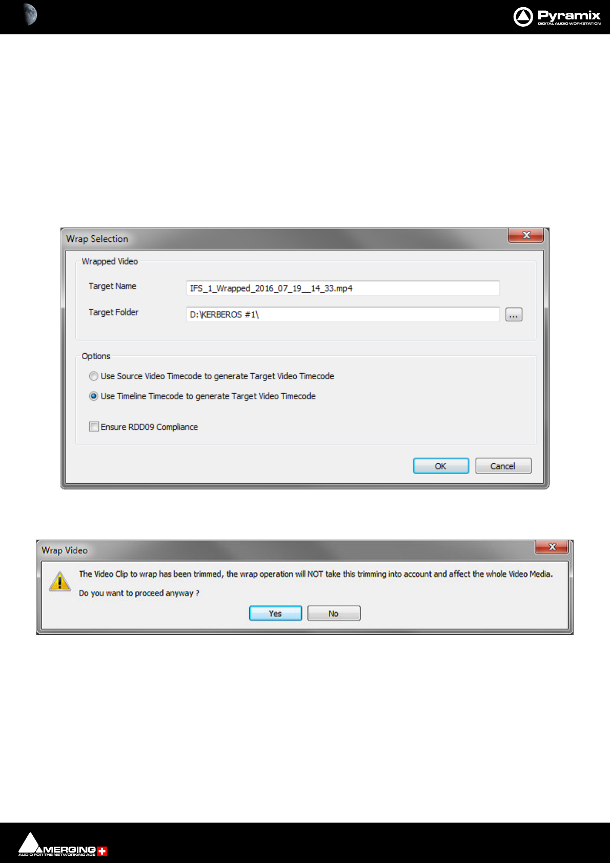
Video : Wrap in Video 21 - 537
Wrapping Timeline Audio in a Video File using Video > Wrap Selection
This feature enables new audio to be wrapped quickly and easily into a video file directly in the Pyramix Timeline.
It is also available from the right-click context menu when the mouse cursor is on a Video clip. Video > Wrap
Selection.
Note: This method is suitable for direct wrapping from the Timeline without effects processing,
automation, mixing etc. If you wish to include any processing such as this, then please use: Proj-
ect > Mix Down with the Wrap options described earlier in this chapter instead.
Video > Wrap Selection
1. Select the Video Clip you wish to wrap the Audio into and one or more Audio Clips in the Timeline.
2. Choose Video > Wrap Selection. The Wrap Selection dialog window opens:
Note: If the Video Clip has been trimmed the following warning is displayed:
Wrapped Video
Target Name Shows the Target Name generated automatically. Click in the field and type if you require
an alternative file name.
Target Folder Defaults to the Project Folder. Click on the ... button to open a File Browser to choose a
different Folder.
Options
Use Source Video Timecode to generate Target Video Timecode As it says when checked. Toggles with:
Use Timeline Timecode to generate Target Video Timecode.
Wrap Selection dialog
Wrap Video warning dialog

Video : Wrap in Video 21 - 538
Ensure RDD09 Compliance When checked the wrapped file will be checked for RDD09 compliance.
3. Click on OK to initiate the Wrap process or Cancel to abort.
4. If the Audio clips either reference a single multi-track audio file, or a set of aligned in time audio files, without
any editing and/or fades within the Video range, the Audio is wrapped within the Video directly from the
audio files. If the Audio clips come from various audio files, are edited within the Video range, have fades,
crossfades, etc… then the Audio is automatically rendered first and then wrapped with the Video using
MTVideoWrap. Please see: Wrapping the File on page 533
This Wrap Selection option is available from the Right-click context menu.

22 - 539
www.merging.com/Pyramix
USER MANUAL
Conforming and Reconforming
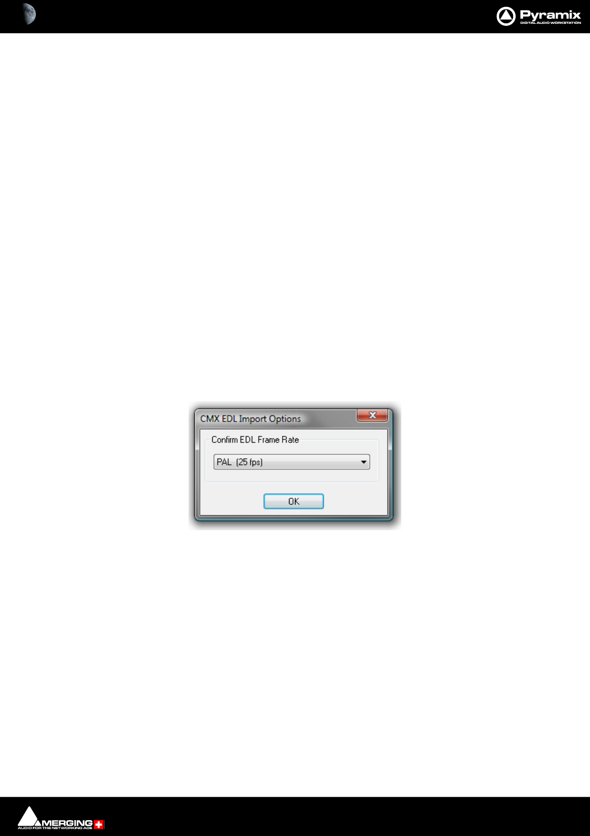
Conforming and Reconforming : Conforming 22 - 540
Conforming
Conform
Conforming is the process of making and positioning audio Cues in the Timeline from Audio media files already
present in a folder available to the Pyramix PC in conformity with an imported EDL (Edit Decision List.) or video
project, for example, AAF, Final Cut Pro or OMF.
Autoconform
Where the Audio media files associated with an EDL are not available to the Pyramix PC, Pyramix can control a
tape deck or other device to import the required audio.
Reconform
Pyramix can conform audio to match a several flavours of EDL and also reconform an existing project to match a
CMX change EDL.
Pyramix can also reconform an audio project by importing two versions of a video project, original and new.
CMX EDLs
CMX is one of the earliest types of EDL. The name comes from the company that developed it in the early 1970s
CBS Memorex eXperimental. Over the intervening decades other companies have extended the original format to
encompass, for example, more audio tracks. Although there are now several far more sophisticated alternatives,
CMX remains the lingua franca of EDLs.
Importing a CMX EDL
Select Project > Import choose CMX EDL in the InterChange-Import dialog then click on the Import button.
Select the desired edl file in the Open file-browser window. The CMX EDL Import Options dialog opens:
If the EDL Frame Rate is correct, simply click the OK button. Otherwise, select the correct rate from the drop down
list and click the OK button.
CMX EDL Import Options dialog
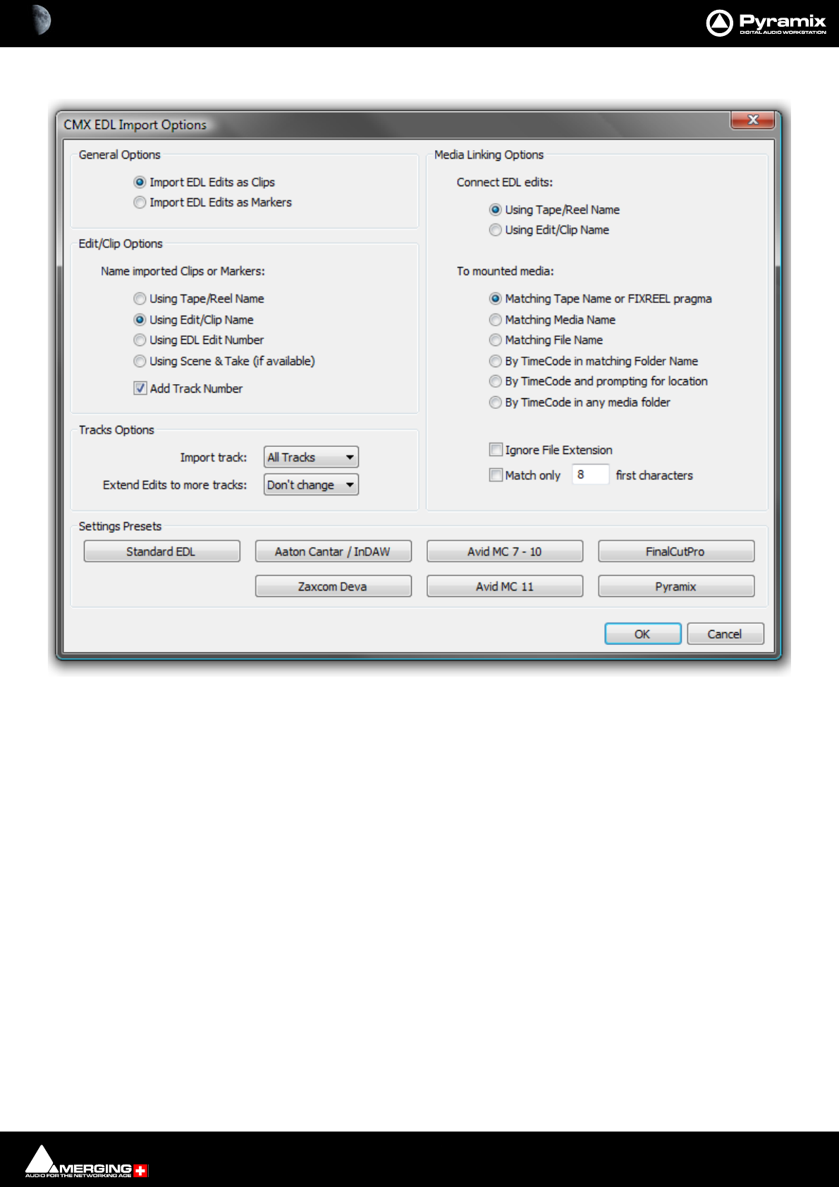
Conforming and Reconforming : Conforming 22 - 541
The CMX EDL Import Options main dialog opens:
Common CMX Variants
The Settings Presets buttons at the bottom of the box set the options for a variety of common CMX variants. If
the edl you wish to import matches one of these, simply click the appropriate Preset button. The settings are
reflected in the rest of the dialog. Click the OK button to begin the Import.
If the EDL is not one of the common variants or the intention is to perform a partial or re-conform, make the
appropriate choices in the dialog before clicking on the OK button to begin the Import.
CMX EDL import Options
General Options
Import EDL Edits as Clips
Import EDL Edits as Markers
Edit/Clip Options Choose to name created Clips from either:
Using Tape/Reel Name
Using Edit/Clip Name
Using EDL Edit Number
Using Scene & Take (if available) of linked media file. (E.g. BWF PMF etc. files with information in the Scene &
Take fields)
Tracks Options
CMX EDL Import Options dialog

Conforming and Reconforming : Conforming 22 - 542
Import Track Drop-down list offering a choice of importing All Tracks (default) or any individual
track. Importing only the edits made on the first audio track. This can be useful
with projects edited on a MediaComposer where the TimeCode of all audio tracks
but the first one has been lost from files imported from a Deva recorder.
Extend Edits to more tracks Offers the choice of extending the edits to more tracks than the original list by
selecting the desired number of target tracks from the drop down list.
Media Linking Options
Connect EDL edits: Choose the way to relink the audio media to edits by either:
Using Tape/Reel Name
Using Edit/Clip Name
from the EDL...
To Mounted Media: … and match it to either
Matching Tape Name or FIXREEL pragma (the media original)
Matching Media Name (the media original)
Matching File Name (the media original)
By TimeCode in matching Folder name (the media Timestamp in a folder whose name matches the
Reel or Edit name)
By TimeCode and prompting for location (the media Timestamp in a given folder)
By TimeCode in any media folder (the media Timestamp in any mounted media folder)
Ignore File Extension When checked any file extension is ignored while comparing file names
Match only X first characters When checked only the given number of first characters in the file-
name are compared. (useful for matching files coming from Aaton Cantar
or InDAW recorders)
CMX EDL Format
CMX Edls are a set of statement lines which typically look like this:
TITLE: An example of CMX EDL
001 TEST AA C 00:00:24:24 00:00:25:00 00:59:58:00 00:59:58:01
AUD 3 4
* Sine on all tracks
002 DAT12 AA C 20:18:18:07 20:18:21:13 01:02:40:02 01:02:43:08
* Introduction
003 TAPE1 AA C 01:15:07:07 01:15:11:13 01:02:43:13 01:02:47:19
004 TAPE1 NONE C 01:15:14:02 01:15:16:04 01:02:47:19 01:02:49:21
AUD 3 4
005 TAPE1 NONE C 1000Hz 01:15:14:02 01:15:16:04 01:02:47:19 01:02:49:21
006 TAPE1 NONE C “A sound” 01:15:14:02 01:15:16:04 01:02:47:19 01:02:49:21
Pyramix will extract all the information regarding audio from these EDLs and then paste a set of Clips into the cur-
rent composition’s Timeline.
There are many CMX formats which differ in details, Pyramix should be tolerant enough to accept most of them as
long as edit lines fields are well separated by spaces or TABs.

Conforming and Reconforming : Conforming 22 - 543
Any errors encountered while parsing an EDL file are stored and reported after loading as much of the file as pos-
sible. Any non valid lines, missing media or media sampling rate mismatches are reported.
Media Reconnection
The major problem encountered while importing an EDL is reconnecting to referenced media. Pyramix needs all
referenced media to be present (mounted) when the import occurs. After the import, the newly created composi-
tion MUST be saved as a Pyramix project to keep the connection between Clips and media.
Media are searched while importing the EDL by Media Source name (or Reel name following the EDL terminol-
ogy), and Source In and Source Out TimeCodes. So, to be reconnected, a Clip needs to find in any media folder a
media file with a Media Source name matching field #2 in the EDL, in the preceding example TEST, DAT12 or
TAPE1, and where the original TimeCode and length match the Source In and Source Out field.
Source Names - FIXREEL
It often happens that the media is generated with a different Source (Tape, Reel) name than the EDL referencing it.
For this purpose we have added a special keyword to the CMX language which allows Pyramix to replace one Reel
name with another while parsing the EDL.
FIXREEL: DAT12 DAT012 This preamble added at beginning of the file will replace all occurrences of the reel name
DAT12 by DAT012. The preamble can be preceded by the comment asterisk (and a space or TAB) so the EDL
remains compatible for import by other systems:
* FIXREEL: DAT12 DAT012
It is also possible to add the keyword MEDIANAME, FILENAME or FOLDERNAME at the end of this line to tell Pyra-
mix, instead of the Source (Tape, Reel) name, to search for the Media name or the Media Filename:
* FIXREEL: DAT12 Ambiance43b MEDIANAME
* FIXREEL: DAT12 d:\pmxmedia\dat12\ambiance43b.wav FILENAME
or to search by TimeCode in the given mounted media folder (this is kind of a conformation to existing digitized
material):
* FIXREEL: DAT12 d:\pmxmedia\dat12 FOLDERNAME
The keyword OFFSET followed by a TimeCode can be added at the end of the line to allow media without origin
(original TimeCode, source TimeCode, time stamp) to be referenced, for example WAVE files.
* FIXREEL: DAT12 Ambiance43b MEDIANAME OFFSET 08:45:32:00
* FIXREEL: DAT12 d:\pmxmedia\ambiance43b.wav FILENAME OFFSET 08:45:32:00
This covers most cases of media reconnection and should help solve special cases of EDLs exported by exotic sys-
tems.
Media Reconnection Failure
An imported Clip whose media has not been retrieved or whose media is not at the same sampling rate as the cur-
rent project will be associated a ‘fake’ media.
It WILL NOT be possible to retrieve its media file after the import, but it will be possible to associate a new media
file in the standard way (Control key pressed while dragging a media file from a media folder).
CMX Autoconform
When a CMX EDL is not accompanied by audio files on disk an Autoconform can be performed. A Digitizing Ses-
sion is used to grab the audio referenced by the CMX EDL from an external machine (This may be operated under
9-pin control or simple time-code chase). The CMX EDL can then be imported into an Editing Project (as
described above) to link to the digitized media.
Please see also: Digitizing Sessions on page 166
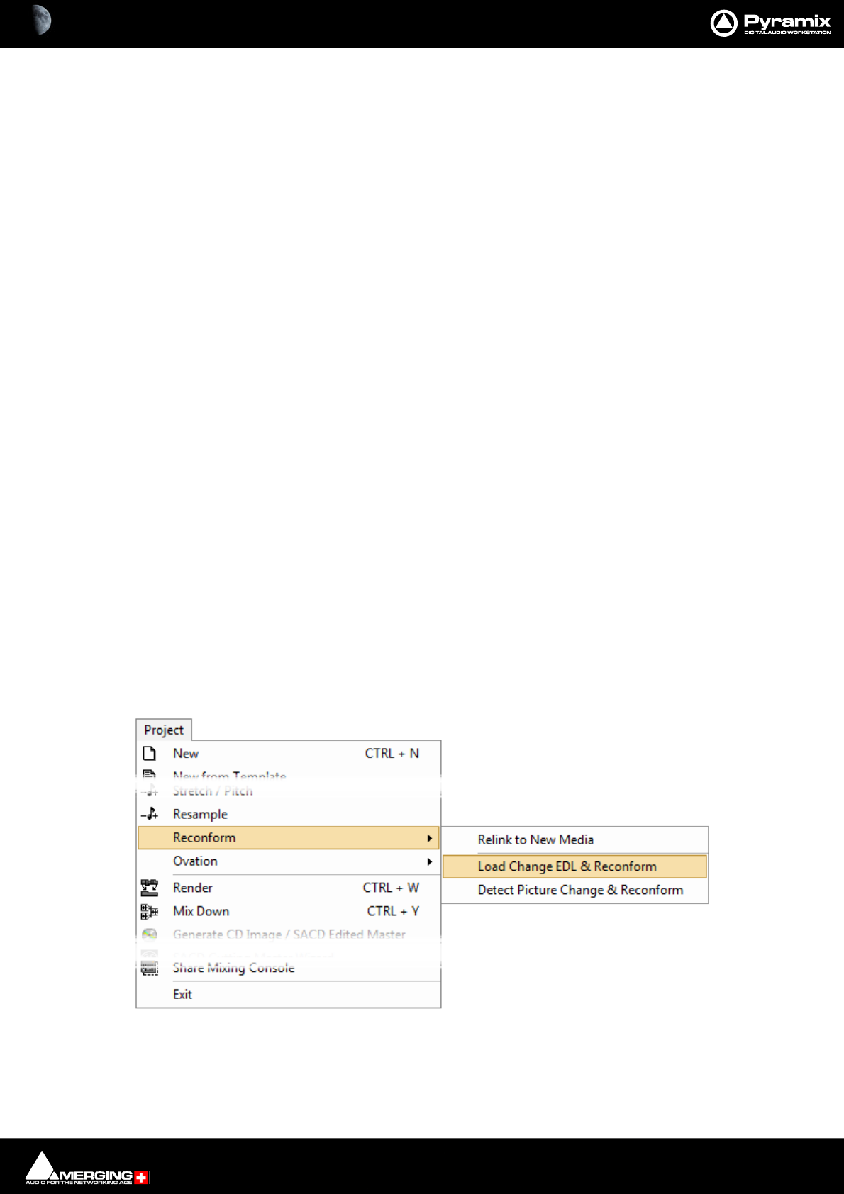
Conforming and Reconforming : Reconform 22 - 544
Reconform
Introduction
Reconform enables Tracks in an existing project to be conformed to take account of changes in the picture edit.
Reconform > Relink to new Media can be used to link to new Media files when new Cues without previously
associated Media files are produced by the Reconform.
In Pyramix there are three routes to Reconforming. The first two make use of a so-called Change EDL. This EDL is a
standard CMX EDL generated from a “State 1 EDL” and a “State 2 EDL”.
In the first case, CMX Reconform, the change EDL is generated by a third party application. This may be the video
editing software, or a specialized EDL manager.
Please see: Reconform Using Pyramix with an Existing Change EDL below.
Where there is no existing Change EDL there are two possibilities:
For users with Pyramix and access to both the original and modified video EDLs Pyramix can load the original pic-
ture (Version1 if not already part of the project) plus the new picture (Version2) and generate the necessary
changes from these.
Please see: Reconforming Using Pyramix for Picture Change Detection on page 548
For users running VCube as well as Pyramix, VCube can be used to generate a Change EDL from the original
(Version1) and revised (Version2) EDLs.
Please see Reconforming Using VCube for Picture Change Detection on page 556
Reconforming with an Existing Change EDL
The Reconform function allows picture edit changes to be applied to a project by loading a so-called “Change
EDL”. T h e Reconform function rearranges Cues within the current project where necessary to reflect the change
from State 1 to State 2 by creating edits on all Tracks of the project using the original material as sources and plac-
ing them to the new destination TimeCodes.
Step 1
With the Pyramix project you wish to conform open in Pyramix select:
Project > Reconform > Load Change EDL & Reconform
Project Menu - Reconform Sub-menu
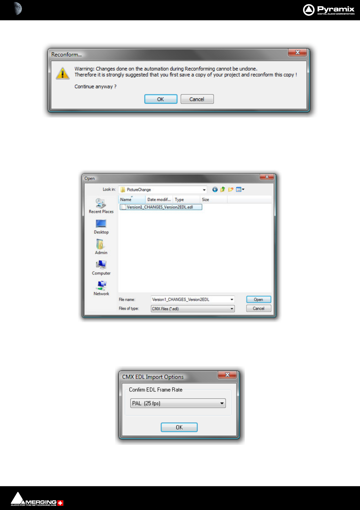
Conforming and Reconforming : Reconform 22 - 545
Opens the Reconform... dialog:
This Warning: gives good advice. It is good operational practice to retain the old Project (Version 1 in this case)
and to reconform a copy, saving this copy with a suitable filename matching the new Video composition version.
Assuming you have already done this, click on OK to close the dialog.
A file Open Browser Window opens:
Now, if necessary, navigate to the folder containing the Change EDL. In this case the required file is
Version1_CHANGES_Version2.EDL. Select this and Click on Open.
The CMX EDL Import Options, Confirm EDL Frame Rate dialog opens:
Check that the EDL Frame Rate matches the Pyramix Project Frame Rate. If the Frame Rate is incorrect, choose the
correct one from the drop-down list. Click on OK.
Reconform... dialog
Pyramix Open Browser Window
Pyramix CMX EDL Import Options dialog

Conforming and Reconforming : Reconform 22 - 546
The Reconform from Change EDL dialog opens:
Select all Tracks that will have to be reconformed (generally all Tracks in the project).
Tick the Create Changes Tracking Tracks box if these are required.
Click on OK to perform the Reconform.
Reconform from Change EDL dialog
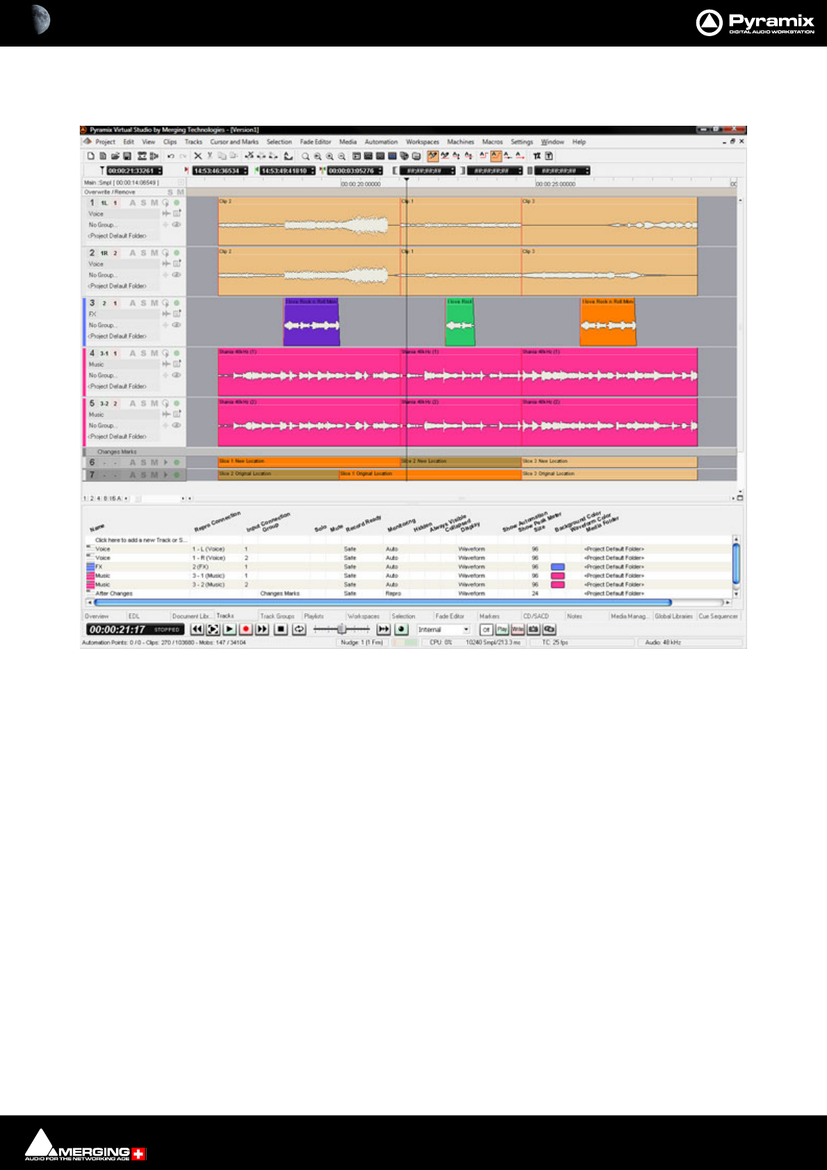
Conforming and Reconforming : Reconform 22 - 547
Step 2
Pyramix automatically conforms Version1 to Version2 on all Tracks:
As can be seen in the above screenshot two new ‘fake’ Tracks have been created and added at the bottom of the
Timeline to display the Change Tracking. These show in colour which sections of the Version1 Timeline have
been moved, sliced, diced and or squeezed etc. to become Version2
Step 3
Selecting Edit > Undo (Ctrl+Z) once will remove the Change Tracking Tracks.
Note: Once the Change Tracking Tracks have been removed they are NOT retrievable.
Pyramix Version 1 Project Reconformed with Change Tracks
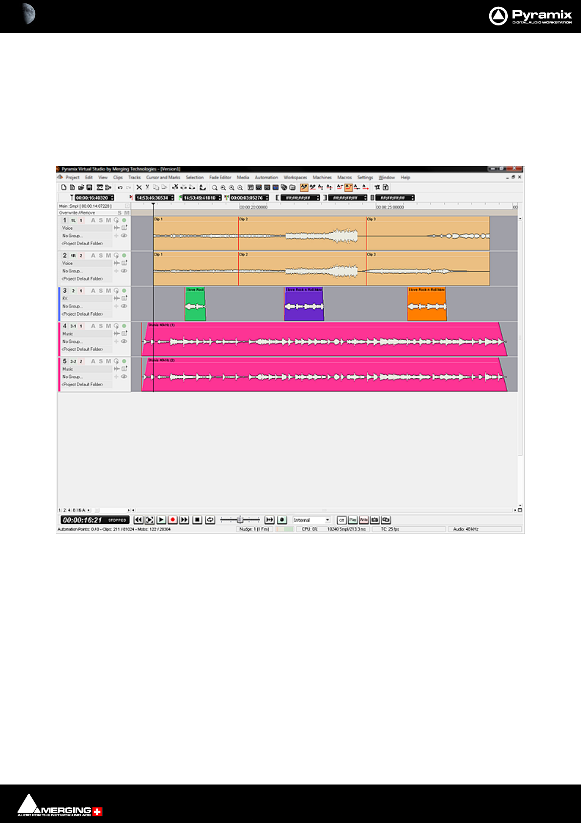
Conforming and Reconforming : Reconform 22 - 548
Reconforming Using Pyramix for Picture Change Detection
You can use Pyramix to perform a Reconform from two Video Projects.
Note: The precise details of subsequent Dialog boxes may vary from those shown below
depending on the specific format selected:
Step 1
Open the Pyramix Project you wish to reconform.
Pyramix Project Version1 requiring Reconform
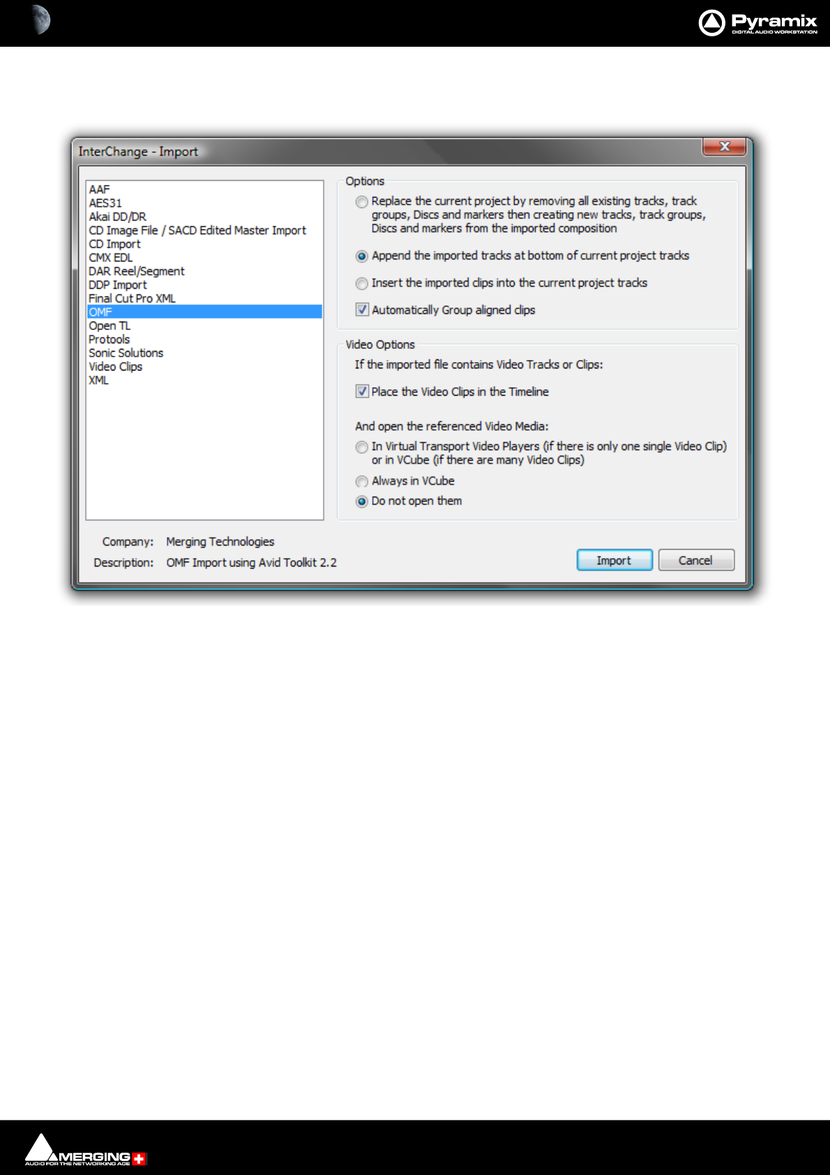
Conforming and Reconforming : Reconform 22 - 549
Step 2
Select Project > Import and choose the appropriate format. (in this case OMF)
Select the following options:
• Append the imported Tracks at bottom of current project Tracks
• Place the Video Clips in the Timeline
• Do not open them
Click on the Import button to open the Open File Browser Window:
Interchange Import dialog
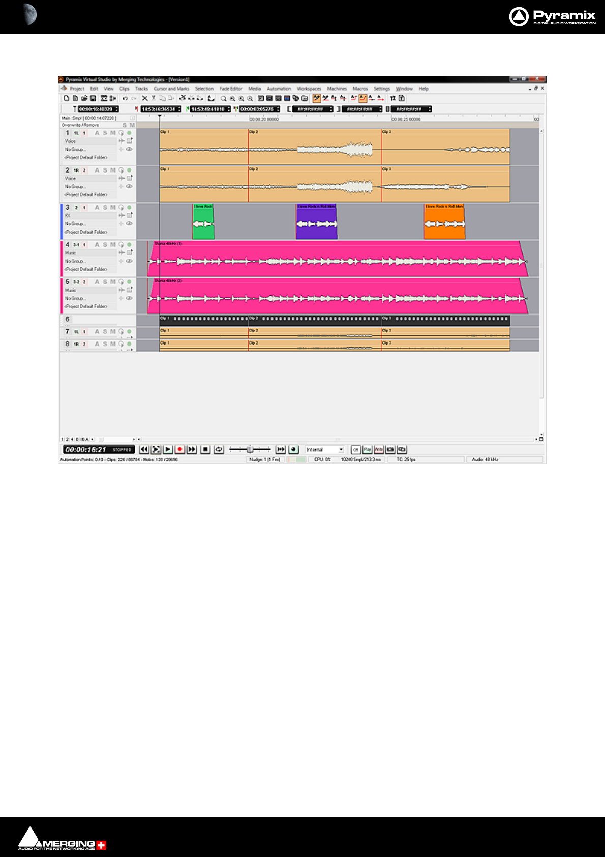
Conforming and Reconforming : Reconform 22 - 550
If necessary, navigate to the folder containing the Version1 Video Project file. Select the file and click on Open.
Notice that the Version1 Video and Audio Tracks have been added at the bottom of the Timeline.
Pyramix Project Version1 with Version1 Video imported
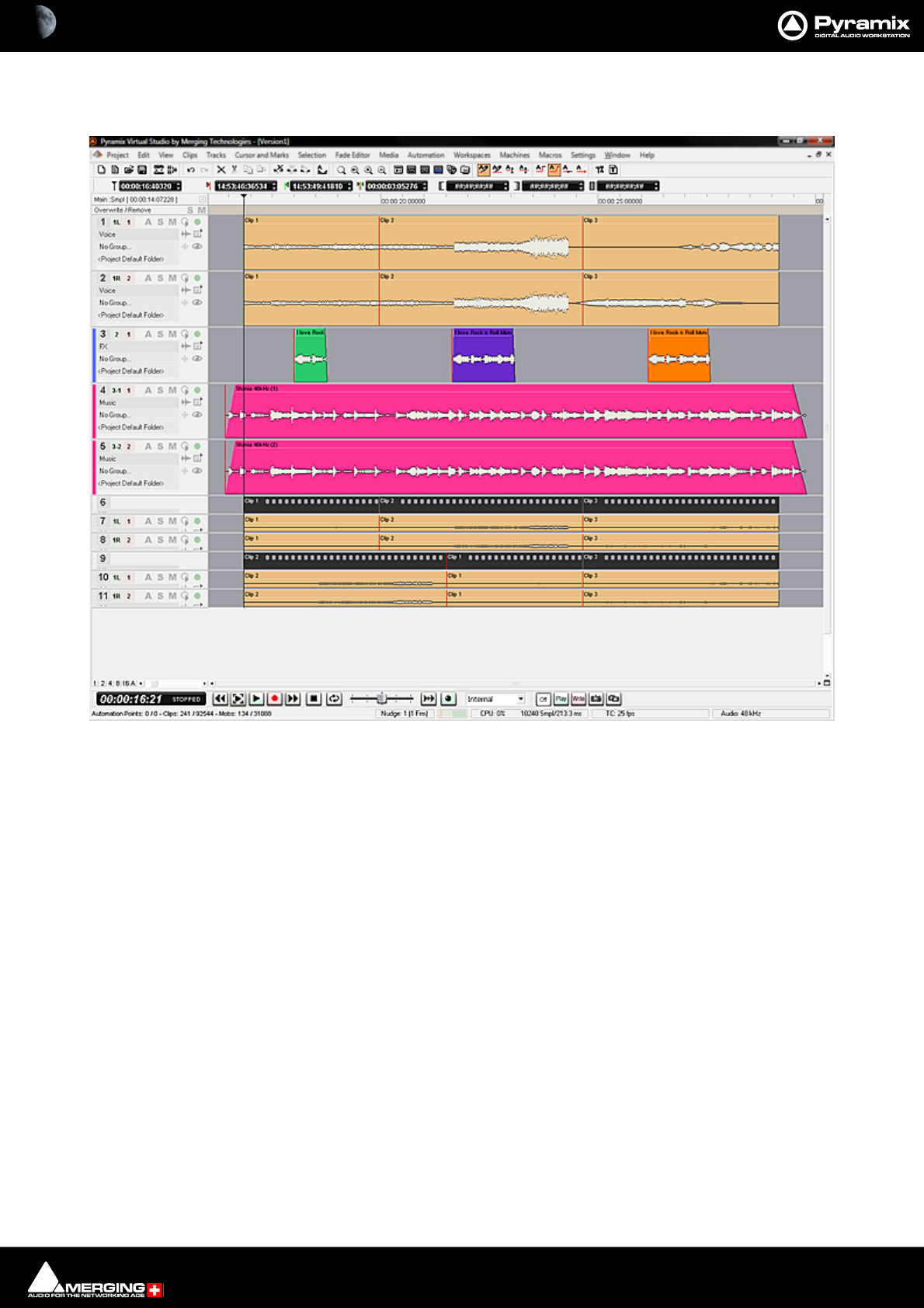
Conforming and Reconforming : Reconform 22 - 551
Step 3
Repeat Step2 with the same options, substituting Version2 when selecting the Video Project file.
Notice that the Version2 Video and Audio Tracks have been added below the Version1 Video and Audio Tracks at
the bottom of the Timeline.
Pyramix Project Version1 with Version1and Version2 Video imported
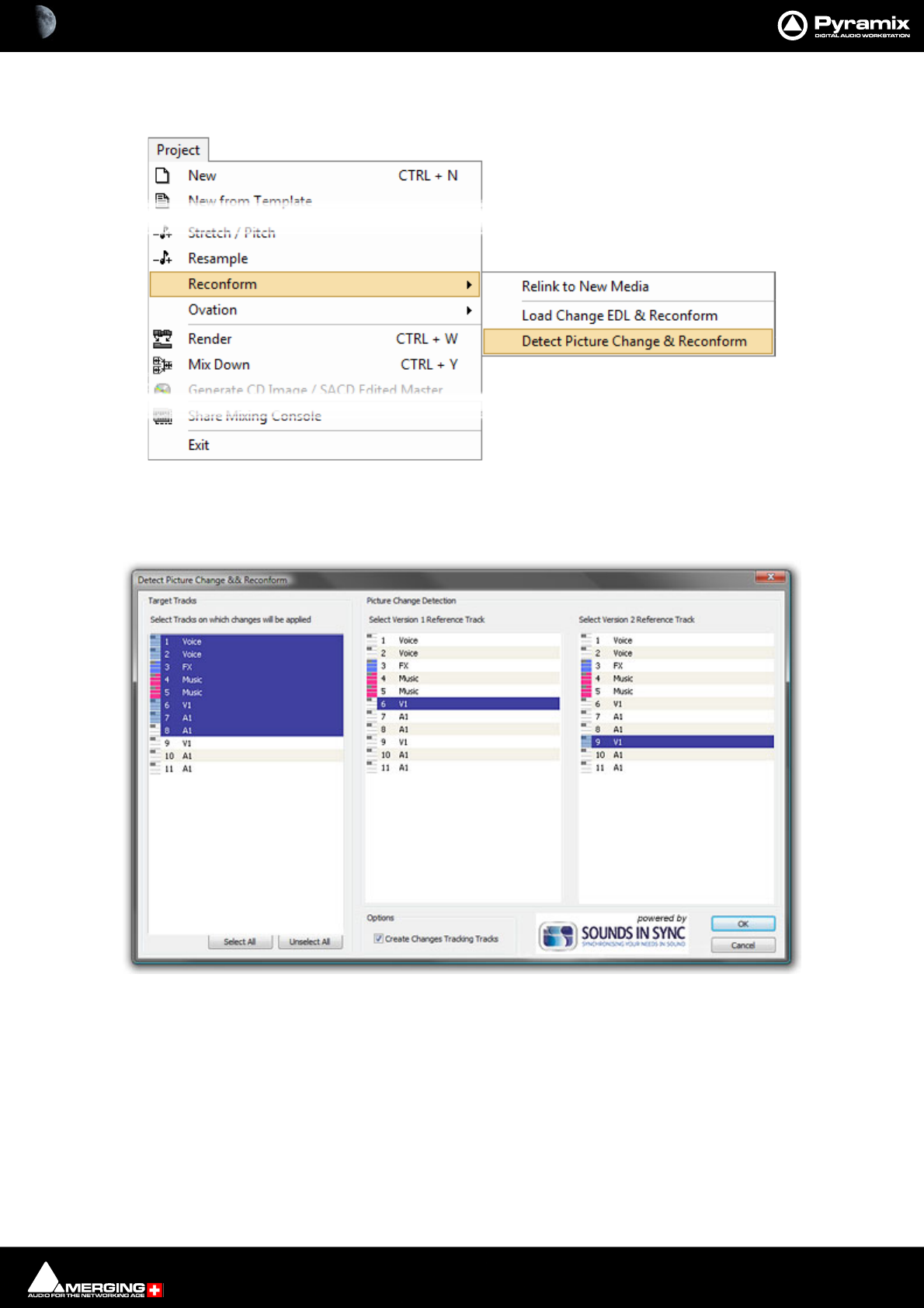
Conforming and Reconforming : Reconform 22 - 552
Step 4
Select, Project > Reconform > Detect Picture Changes & Reconform (Ctrl+R):
The Detect Picture Change & Reconform dialog opens.
Step 5
Select all Tracks that will have to be reconformed (generally all Tracks in the project except those belonging to the
Version2 Video project, but including Version1 Video and Audio Tracks). Select the Track that will be the Version1
Reference Track for the picture change detection (generally the V1 Track of the Version1 Video Project), then
Select the Track that will be the Version2 Reference Track for the picture change detection (generally the V1 Track
of the Version2 Video Project).
Tick the Create Changes Tracking Tracks box if these are required.
When all the selections have been made click on OK to perform the Reconform:
Pyramix Project > Detect Picture Change & Reconform
Detect Picture Change & Reconform dialog
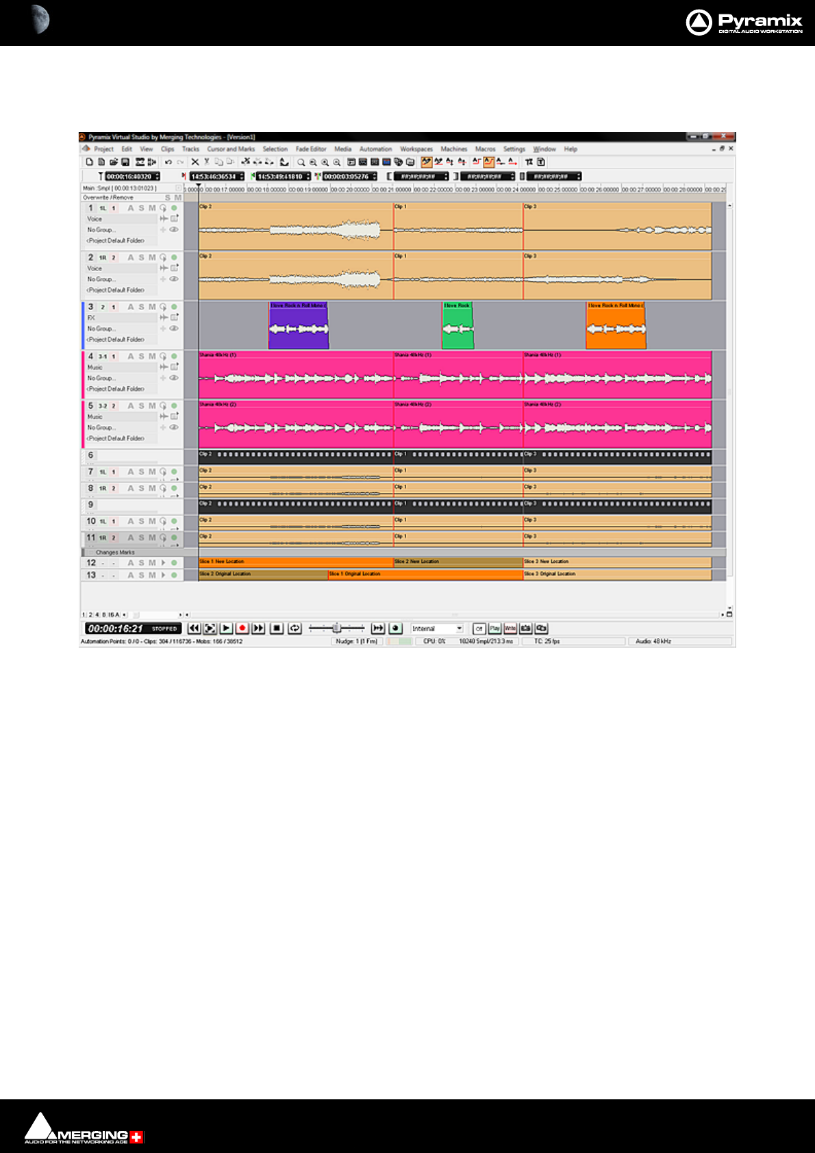
Conforming and Reconforming : Reconform 22 - 553
Step 6
The Pyramix Project has now been Reconformed:
Verifications can be made with the Change Tracking Tracks, as well as comparing the Version1 Video Tracks that
should now match the Version2 Video Tracks.
Pyramix Project Version1 and imported Video Project Version1 Conformed to match Version2 Video Project with Change Tracks
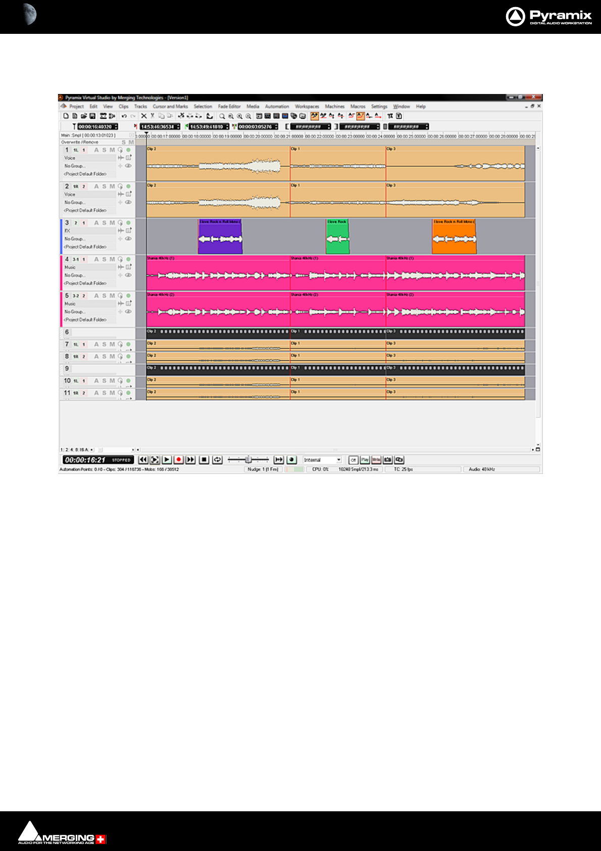
Conforming and Reconforming : Reconform 22 - 554
Step 7
Selecting Edit > Undo (Ctrl+Z) once will remove the Change Tracking Tracks.
Note: Once the Change Tracking Tracks have been removed they are NOT retrievable.
Pyramix Project Version1 Reconformed to Version2 with Change Tracking Tracks removed
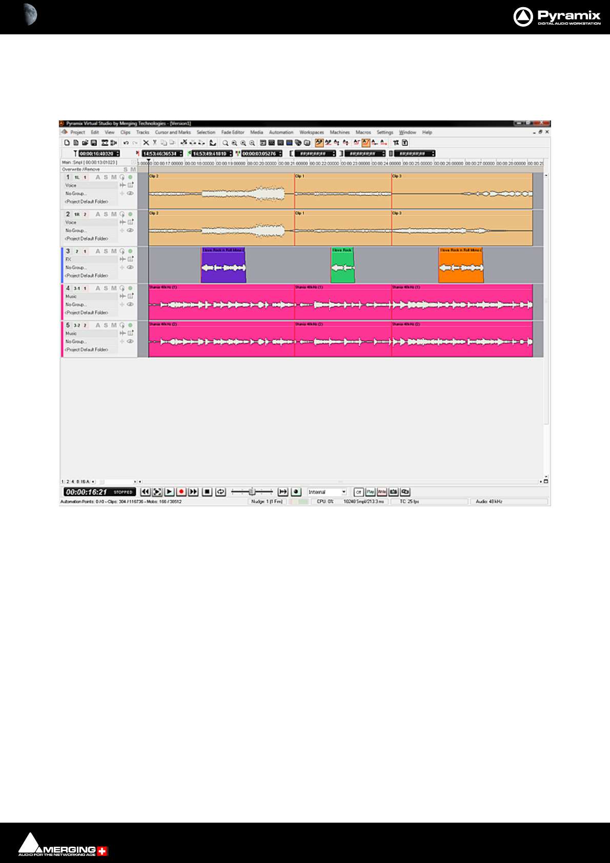
Conforming and Reconforming : Reconform 22 - 555
Step 8
The Video Reference Tracks (with their associated Audio Tracks) can be removed by right-clicking on the first Video
Track Header and selecting Delete To Last Track. The original Pyramix Project is now reconformed and ready for
you to continue working on Version2.
Note: Where the Version2 project contains new material, it may well be appropriate to move the
relevant audio from the Version2 Audio Tracks up to the main Pyramix Project Tracks before
deleting. A future Pyramix version may contain an option to carry out this step automatically.
Pyramix Project Version1 Reconformed to Version2 with Imported Tracks removed.

Conforming and Reconforming : Reconform 22 - 556
Reconforming Using VCube for Picture Change Detection
For users with VCube a Pyramix Project can be reconformed to match a new version of a Video Project quickly and
simply.
Step 1
Open the original version of the video in VCube and the Project with the matching audio in Pyramix:
VCube Original Version 1 Composition
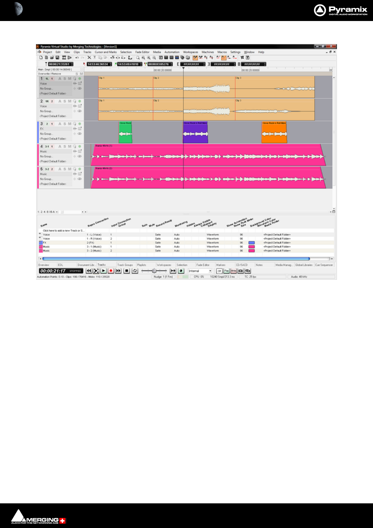
Conforming and Reconforming : Reconform 22 - 557
Pyramix Version 1 Project with Audio matching Original VCube Version 1 Composition
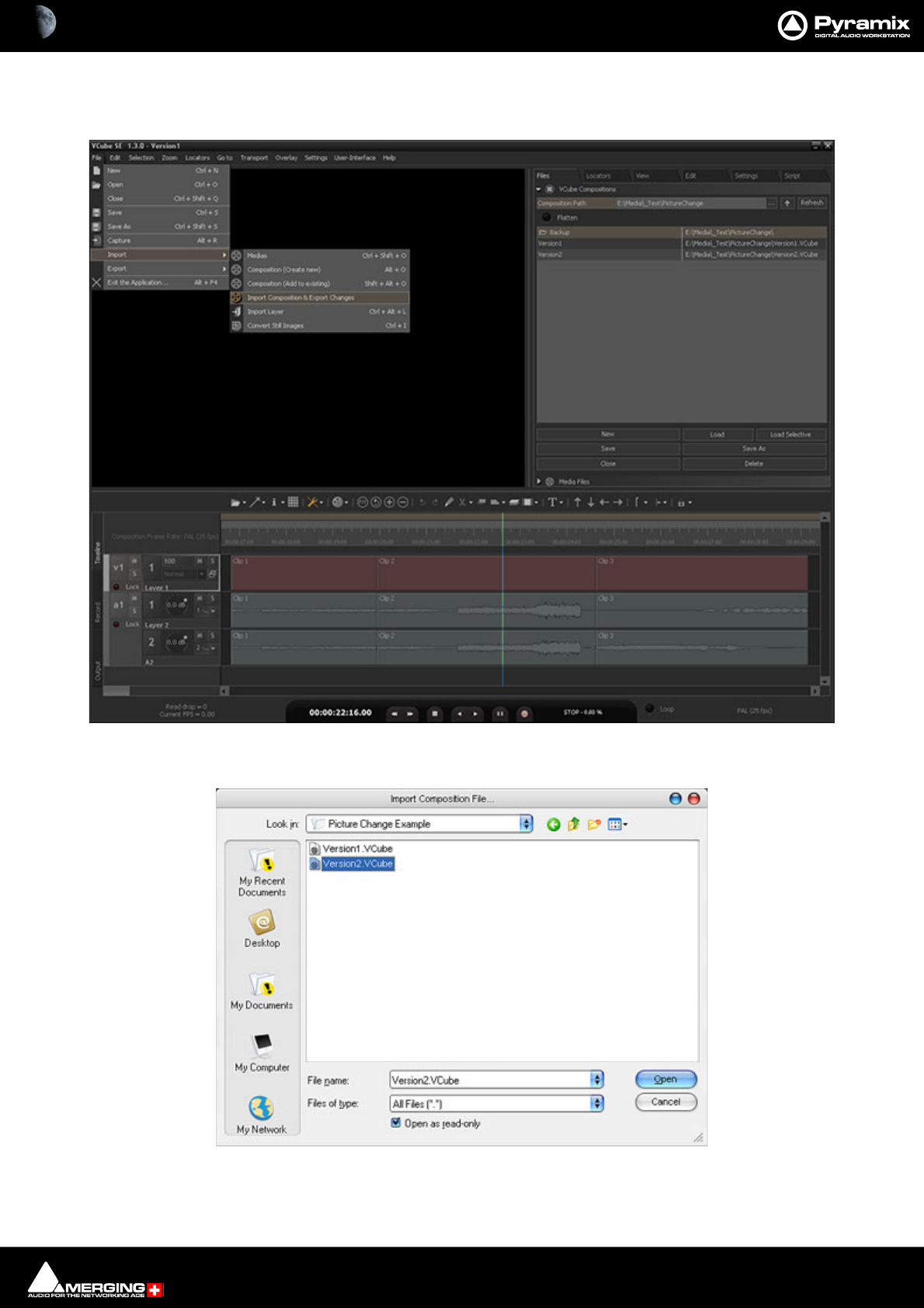
Conforming and Reconforming : Reconform 22 - 558
Step 2
In VCube select: File > Import > Import Composition and Export Changes:
This opens a Browser Window.
If necessary, navigate to the folder containing the changed version of the Video Composition. Select this and Click
on Open.
VCube New Version 2 Composition
VCube Import Composition File Browser Window
Conforming and Reconforming : Reconform 22 - 559
Step 3
The new video file, Version 2 is now displayed in the VCube Timeline:
The changes between the two versions will have been exported to a Change EDL file which will be found in the
same source folder.
VCube New Version 2 Composition
Conforming and Reconforming : Reconform 22 - 560
Step 4
Return to Pyramix, which is still displaying the original Version 1 audio Project:
Select Project > Reconform > Load Change EDL.
The Reconform... dialog opens:
This Warning: gives good advice. It is good operational practice to retain the old Project (Version 1 in this case)
and to reconform a copy, saving this copy with a suitable filename matching the new Video composition version.
Assuming you have already done this, click on OK to close the dialog.
Pyramix Menu - Project > Reconform > Load Change EDL & Reconform
Pyramix Reconform dialog
Conforming and Reconforming : Reconform 22 - 561
A file Open Browser Window opens:
Now, if necessary, navigate to the folder containing the Change EDL.
Note: This automatically generated file will be named in the form:
Original Composition name_CHANGES_New Composition name.EDL.
In this case the required file is Version1_CHANGES_Version2.EDL. Select this and Click on Open.
The CMX EDL Import Options, Confirm EDL Frame Rate dialog opens:
Check that the EDL Frame Rate matches the Pyramix Project Frame Rate. If the Frame Rate is incorrect, choose the
correct one from the drop-down list. Click on OK to confirm
Pyramix Open Browser Window
Pyramix CMX EDL Import Options dialog
Conforming and Reconforming : Reconform 22 - 562
The Reconform Project dialog opens proposing the creation of two new Change Tracking Tracks:
Select all Tracks that will have to be reconformed (generally all Tracks in the project).
Tick the Create Changes Tracking Tracks box if these are required.
Click on OK to perform the Reconform.
Pyramix Reconform from Change EDL dialog

Conforming and Reconforming : Reconform 22 - 563
Step 5
Pyramix automatically conforms Version1 to Version2 on all Tracks:
As can be seen in the above screenshot two new ‘fake’ Tracks have been created and added at the bottom of the
Timeline to display the Change Tracking. These show in colour which sections of the Version1 Timeline have
been moved, sliced, diced and or squeezed etc. to become Version2
Pyramix Version 1 Project Reconformed with Change Tracks
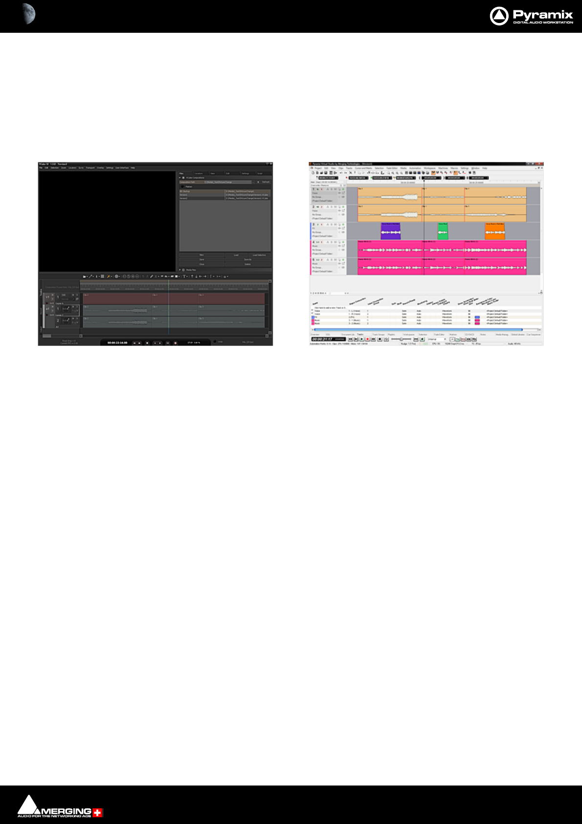
Conforming and Reconforming : Reconform 22 - 564
Step 6
Selecting Edit > Undo (Ctrl+Z) once will remove the Change Tracking Tracks.
Note: Once the Change Tracking Tracks have been removed they are NOT retrievable.
Now you will have both Pyramix and VCube Version2 displayed in the respective applications:
VCube displays the ‘real’ Version2 from the editing department and Pyramix displays Version2 Reconformed
automatically from Version1.
Note: The above example used two VCube Projects for the Video. The procedure is identical
when importing two AAF, OMF or Final Cut Pro Video Editing Projects.
VCube showing Version2 Project with Pyramix showing Version1 Reconfomed to match
Conforming and Reconforming : Reconform 22 - 565
Relink to New Media
Opens a dialog offering various options similar to the Import CMX EDL function.
This allows relinking all or a selection of Clips to new media. Typically. this is used for replacement of 16 bit ver-
sions of audio files with 24 bit versions based on the Clip name, media name, Scene & Take information or original
TimeCode.
Relink Clips Media Gives options to extract a string from the original Clip:
Using current Media Tape Name
Using current Media Name
Using current Media File Name
Using current Media Scene & Take
Using Clip Name
With various options applicable to the above:
Ignore characters after finding… ignores the rest of the string after a given substring is found
Ignore File Extension ignores any characters after the last dot
Match only … first characters ignores all characters after a given number
Reconform Relink to New Media Options dialog

Conforming and Reconforming : Reconform 22 - 566
Scene & Take Separators gives a choice of characters to be used to separate a Scene name
and a Take name from the string.
Note: Note: this is relevant only for Tape, Media and Clip Name, as Scene & Take are already prop-
erly separated in a Media Scene & Take tag.
To any other Media gives options to find which information to use from the Media that will be searched:
Matching Media Tape Name
Matching Media Name
Matching Media File Name
Matching Media Scene & Take
By TimeCode in matching Folder name Any Media with overlapping TimeCode in a folder with a
matching name
By TimeCode and prompting for location Any Media with overlapping TimeCode with prompting for
the folder name/ location
By TimeCode in any media folder Any Media with overlapping TimeCode
With various options:
Ignore characters after finding… ignores the rest of the string after a given substring is found
Ignore File Extension ignores any characters after the last dot
Match only … first characters ignores all characters after a given number of them
Search In allows the choice of which Media Folder to search in
Search sub-folders When checked sub-folders are searched
Match Options Offers options for the matching algorithm:
Match exactly both strings must be identical
Match only minimum common available characters
Take0001.new.01 will match with Take0001
Original contains new Media Take0001 will match with 0001
New Media contains Original 0001 will match with Take0001
Case insensitive TAKE0001 will match with Take0001
Ignore characters… if, for instance, /_+- are specified then 12-A/0001 will match with
12/A_0001
Ignore TimeCodes no checks are made on Original TimeCodes (timestamps). This
allows media with erroneous/lost timestamps to be replaced with
the correct ones or vice-versa.
Other Options
Extend Edits to more tracks When conforming a Clip referencing multiple Tracks to a Clip ref-
erencing a mono media file adds a new Clip (with the same fades,
etc…) for all of these Tracks as well.
Note: In the case of multiple passes for the conform operation, this function can be performed
afterwards with the menu item Tracks > Extend This automatically extends the number of Tracks to
accommodate all the Media channels of each of the Clips of one or more timeline Track(s)
Color Clips that successfully relinked in Green
Re-colors successfully linked Clips in Green
Color Clips that failed relinking in Red
Re-colors Clips that failed to re-link in Red

23 - 567
www.merging.com/Pyramix
USER MANUAL
Machine Control

Machine Control : Pyramix and VCube 23 - 568
Pyramix can control and be controlled by a wide variety of external hardware. This chapter, Machine Control
deals with situations where Pyramix is controlling an external machine or machines. It also deals with Pyramix and
VCube running either on the same machine or on separate machines.
Pyramix and VCube
Virtual Transport 2
Virtual Transport 2 provides a simple and robust method of controlling a VCube from Pyramix whether the VCube
is running on the same machine as Pyramix or a machine on the same network.
PyraCube
Pyramix and VCube running on the same machine.
VCube Prerequisites
The VCube audio I/O must be set in the VS3 control panel. Options are:
•Use the ASIO bridge so that VCube I/O is available to the Pyramix Mixer.
•Native - ASIO with an ASIO sound device.
Note: In a non MassCore, Native mode PyraCube the ASIO sound device buffer must be set to
256 samples for correct synchronization between Pyramix and VCube. If this is not possible, for
example if the device does not permit it, then you must use the No VS3/ASIO Audio setting.
•No VS3/ASIO Audio
Apart from this no settings are required to be made in VCube.
Note: If using the ASIO Bridge for VCube audio Pyramix must be launched first and complete
start up before launching VCube.
Set-up in Pyramix
The VCube will appear in the list in the Settings > All Settings > Remote Control > Virtual Transport 2page. If
not already connected, click on the VCube and click on Connect.
Note that it’s status is shown as Connected.
If you are intending to use Import Video Clips in Pyramix set the Save VCube composition in the Pyramix proj-
ect option to on. (Checked). When the Pyramix Project is opened subsequently, the Video Clip(s) will be opened in
VCube.
VCube on External PC
Set-up in Pyramix
The VCube will appear in the list in the Settings > All Settings > Remote Control > Virtual Transport 2page.
Click on the VCube and click on Connect.
Note that it’s status is now shown as Connected.
If you are intending to use Import Video Clips in Pyramix set the Save VCube composition in the Pyramix proj-
ect option to on. (Checked). When the Pyramix Project is opened subsequently, the Video Clip(s) will be opened in
the remote VCube.
No settings are required on the remote VCube

Machine Control : Control of External Device 23 - 569
Control of External Device
If Pyramix is controlling another machine, (with the exception of GPO control) this device must be set up as an
External Machine.
External Machines
9-pin (Sony P2 protocol)
9-pin Control of External Machine
If you wish to control a 9-pin slave machine from Pyramix the target machine must be set up as an external
machine. If you wish to control Pyramix as a slave from an external 9-pin controller / synchronizer then the exter-
nal controller must be set up as a Remote Controller in Pyramix. Please see: Control by External Device on
page 585
Connection for the Sony 9-Pin protocol
Please see: Appendix IV 9-Pin connection on page 803 for a description of the physical connection between the
PC's COM port and the RS-422 connector of the external machine.
Setting up an external machine
• Select the Settings > All Settings > Remote Control > Machine page.
• Click the Add button.
• Enter a suitable name for the external machine in the Name field, such as “Betacam”.
• Choose the Driver for the machine from the drop-down list. Sony 9-pin
•Check the Enable field.
• Adjust the Driver Properties, the Port Properties and the Settings according to your needs. Please
see: Sony 9-Pin Protocol Configuration (Machine) on page 770.
•Click OK to confirm all the entries and to add the new machine to the list.
Note: Since Merging Technologies products are based on hard disk and computer technology
they do not need to take account of the color framing sequence. (Used to produce ‘legal’ picture
edits). Therefore Sony P2 devices must have their Color Framing mode disabled (2F), in order to
synchronize correctly. Please see the device manufacturer’s documentation for the correct pro-
cedure to do this.
Sony P2 Protocol Over IP
A Pyramix can control one or more Pyramix workstations on the same network using Sony P2 protocol over IP
Note: Both Machine Control and Remote Control authorization keys are required to use P2
over IP.
Configure 9-pin over IP in Pyramix
•On the Slave Pyramix machine select the Settings > All Settings > Remote Control > Controller
page.
•Click the Add button. The Controller Properties dialog opens.
• Enter a suitable name for the slave in the Name field.
• Choose the Driver for from the drop-down list. I.e. Sony 9-pin
Machine Control : External Machines 23 - 570
• Click on the Properties button to open the Sony 9-Pin Configuration dialog.
•In the Port section click on the IP (Ethernet) radio button.
• Click on OK to close the dialog.
• Make any other changes you need in the Sony 9-Pin Configuration dialog. (Please see: Sony 9-Pin
Protocol Configuration (Machine) on page 770 for a detailed description of the options.)
•Click OK to confirm all the entries and to add the new machine to the list.
Sony 9-Pin Configuration dialog
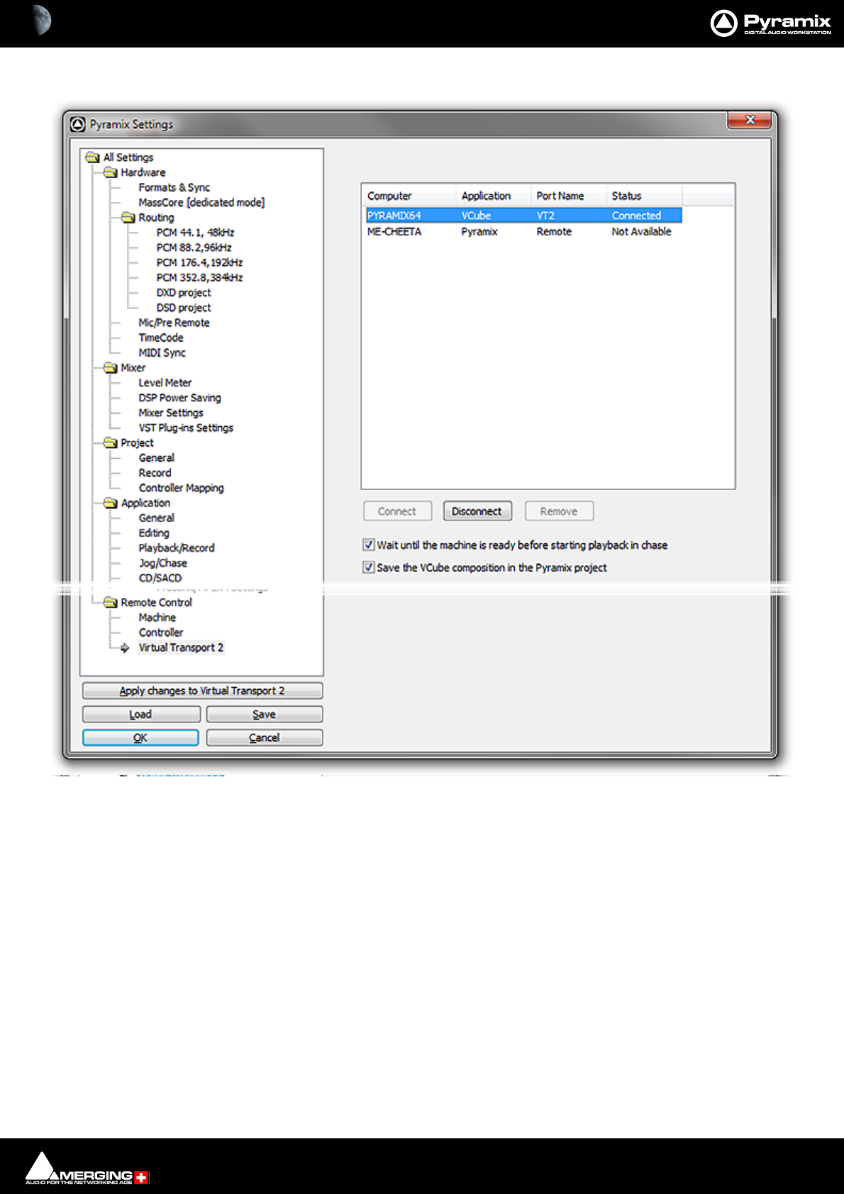
Machine Control : External Machines 23 - 571
1. On the Master Pyramix machine open Settings > Remote Control > Virtual Transport 2.
• The slave machine will appear in the list. Click on it to select it and click on Connect.
• The status will change to Connected. The machine will appear in the Pyramix Transport Control
Panel (Alt + T) window and is now ready for use.
Note: For solid and stable synchronization ensure that all machines use the same video refer-
ence.

Machine Control : External Machines 23 - 572
Transport Control Panel
Port In Use
If you attempt to connect to a port which is already in use an error message appears in the relevant section of the
Transport Control Panel. In the example above the remote Pyramix on machine ME-CHEETA is already connected
via 9-pin over IP therefore the remote VCube on machine ME-CHEETA cannot be connected.
Transport Control Panel

Machine Control : Chase Synchronizer 23 - 573
Linking Functions of External and Internal Machines
The following functions can be linked in the Settings > All Settings > Remote Control : Machines page by sim-
ply ticking the boxes:
• Play and Record
• Play-Record Toggle
• In / Out Points
•Offset
Please see also: Machine on page 768
Synchronizer
Pyramix will chase an external TimeCode source as a slave, however, a far more satisfactory method is to work with
Pyramix as the master.
External machines, capable of chasing TimeCode can, of course, follow Pyramix as slaves.
Chase Synchronizer
Pyramix can synchronize external 9-pin (Sony P2 protocol) machines including those that cannot chase TimeCode.
No TimeCode connection TO the machine from Pyramix is required. The Chase Synchronizer compares the Time-
Code coming FROM the external machine with the required position (including offset, if any) and sends transport
commands in order to synchronize the machine.
9-Pin Controller/Synchronizer Explained
The Host Pyramix system (the first machine shown in the Transport Control Panel) is the synchronizer. It may or
may not be the Master.
Therefore, when an External Machine is the Master, the Host Pyramix MUST chase it if a second External Machine is
to be synchronized. For Example, in a set-up with two External Machines Ext1 and Ext2.
If the Host is the master then either or both Ext 1 and Ext 2 can Chase.
If Ext 1 is the Master then Host and Ext 2 can Chase
If Ext 1 is the Master and the Host is offline then Ext 2 cannot chase.
I.e. whenever an External Machine is in Chase it follows the Host Pyramix.
TimeCode Source
When the Host Pyramix is in Chase it follows either LTC or External TimeCode as determined by the settings on the
All Settings > Hardware > TimeCode page.
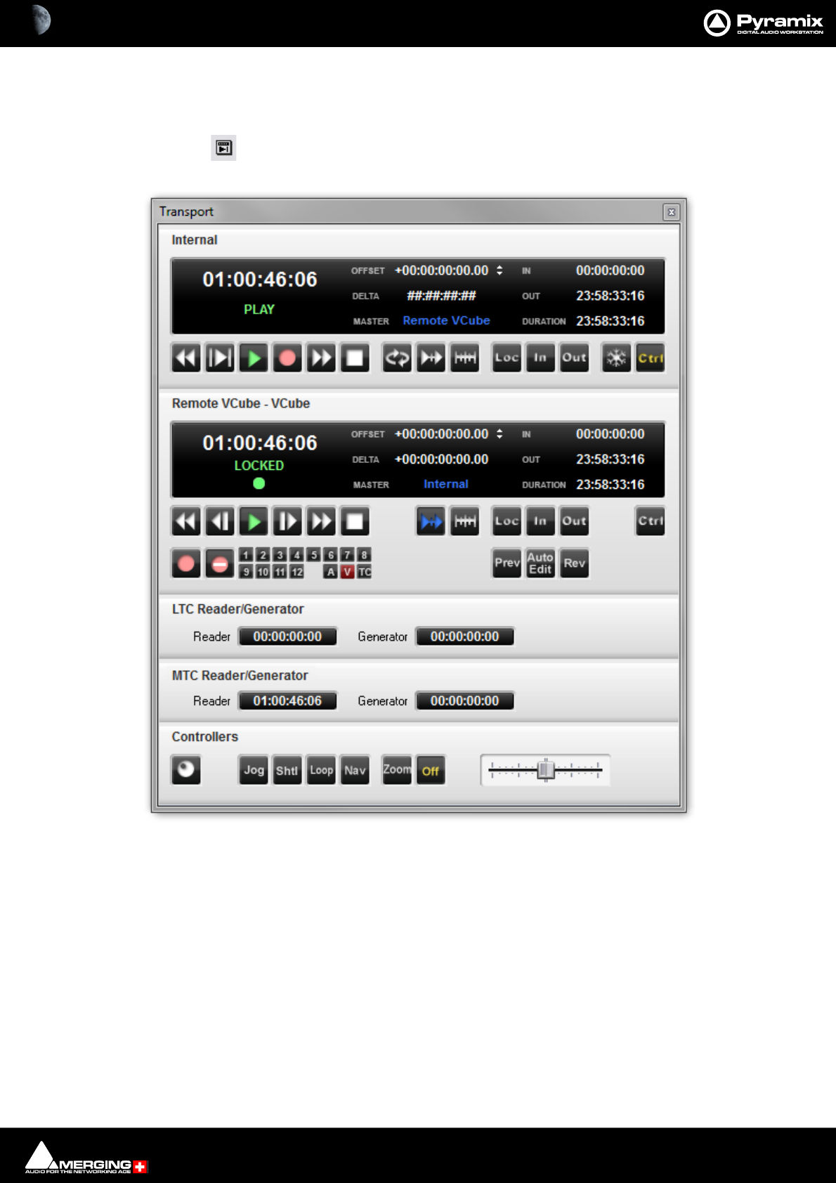
Machine Control : Transport Control Panel 23 - 574
Transport Control Panel
Pressing the Transport Control Panel button or [Alt T], or selecting View > Windows /
Tools > Transport opens a floating Transport Window displaying all available
machines with individual sets of buttons and status indicators.
Note: This Window contains a set of transport controls for each machine installed and enabled
with the Internal Transport (Pyramix) at the top. Below the machines are displays for LTC and
VT2 (and MTC when applicable) TimeCode Sources and at the bottom of the panel there are con-
trols which affect hardware Remote Controllers.
Clicking on the black bar with the machine name toggles the individual area between collapsed
and full. For example, dvcam is collapsed in the above illustration.
Important! For details of machine installation and settings. Please see: Machine on page 768
Transport Control Panel floating Window
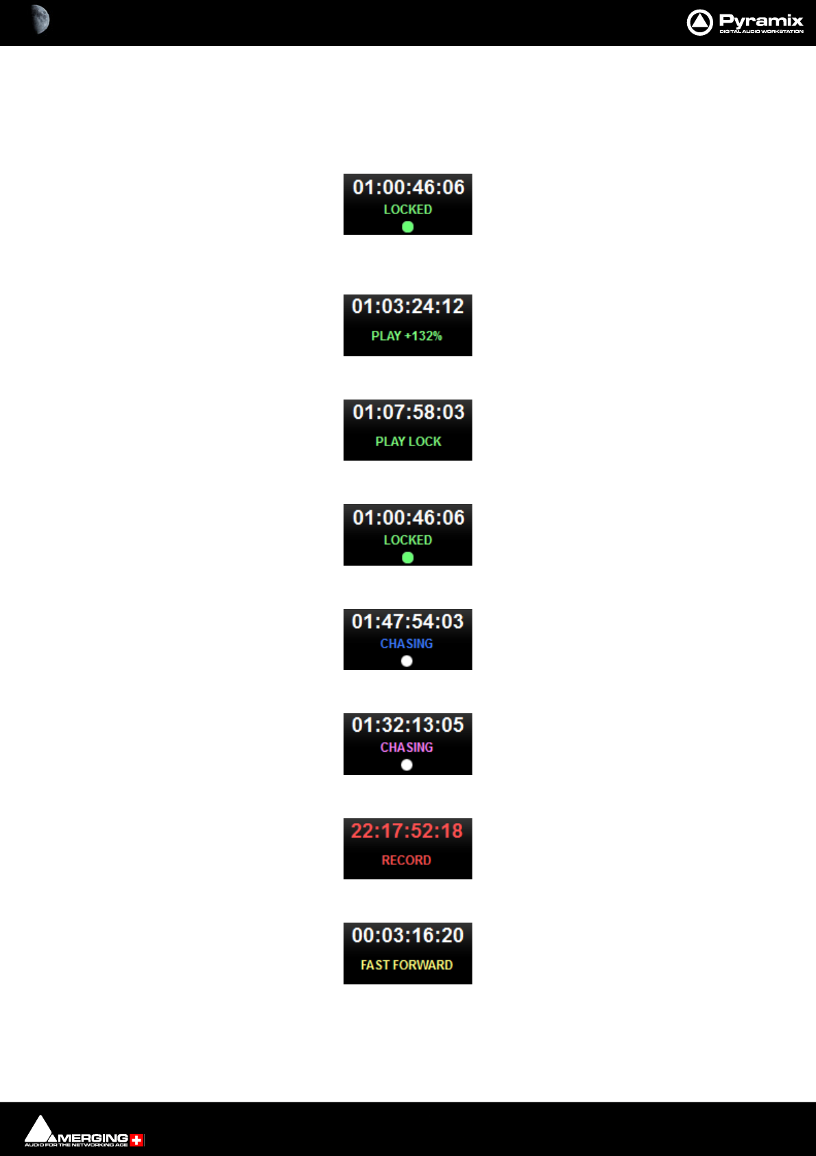
Machine Control : Transport Control Panel 23 - 575
Internal / External Machine panels - Features
Main Counter
In each machine panel the main counter shows the machine’s current position and status of Transport and Record.
The Master machine shows Play in green when running at sync speed:
The Master machine in jog or shuttle shows Play and the + or - percentage off sync speed or Play Still when sta-
tionary. If the speed exceeds 200% then Rewind or Fast Forward is shown in yellow :
An External Machine shows Play Lock in green when it is master and at sync speed:
An External Machine shows Locked in green when it is locked at sync speed:
A machine chasing shows Chase in blue:
If an offset is applied the status display and TimeCode registers are purple:
A machine in record shows Record in red and the main counter also turns red:
A machine in Fast Forward or Rewind shows this in yellow:
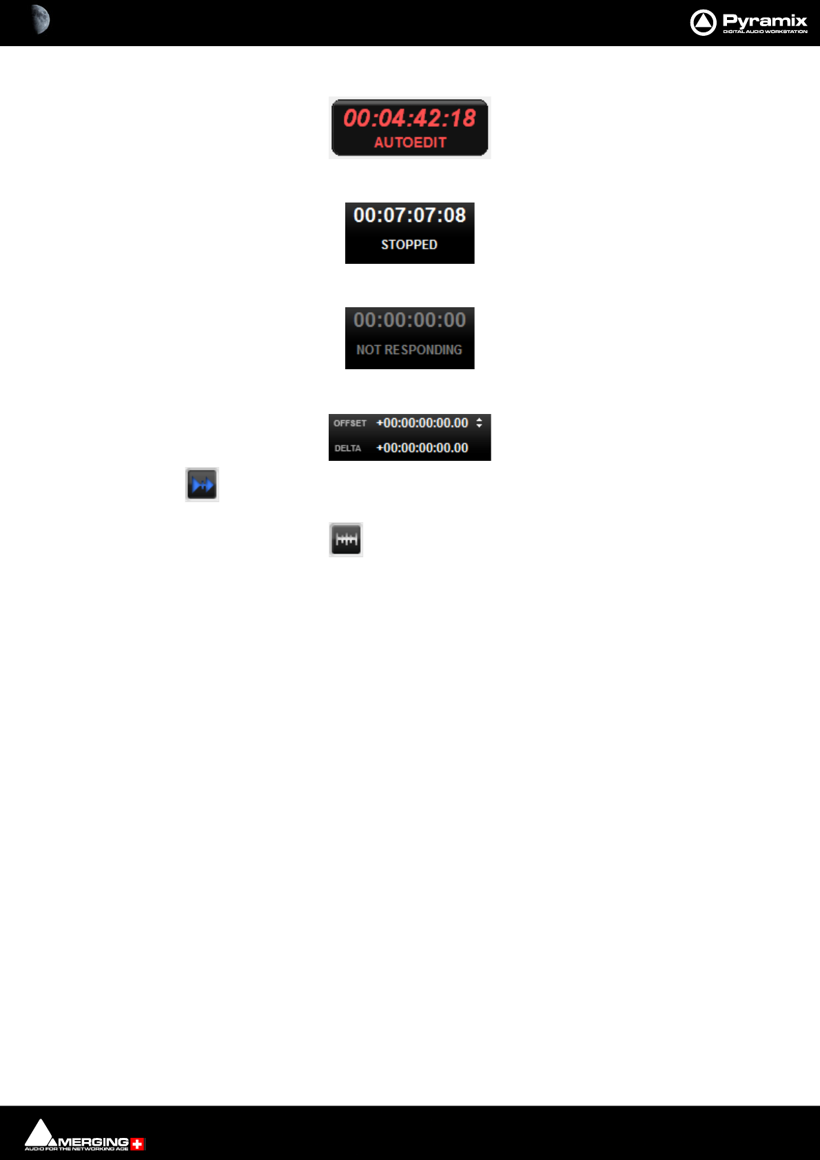
Machine Control : Transport Control Panel 23 - 576
A machine carrying out an Auto-Edit shows this in red:
A Stopped machine shows this in white:
If a machine is disconnected or there is a problem this is shown in gray:
Chase, Offset register, Capture Offset and Delta
When the button is lit the machine is in Chase Mode (see below)
The Offset Register shows the current Offset value.
An Offset can be captured with the Offset Capture button. The button lights when an Offset is set.
Offset values can also be typed directly into the register and trimmed with the increment/decrement buttons.
Note: A positive Offset Value makes the machine with the Offset later and a negative Offset
value makes it earlier. E.g. If you are sourcing picture from an external VCR and the picture is
arriving 3 seconds before the sound, enter a 3 second positive offset in the video machine’s
External Transport control panel.
Delta shows the current difference (error) value between where the machine should be and where it actually is.
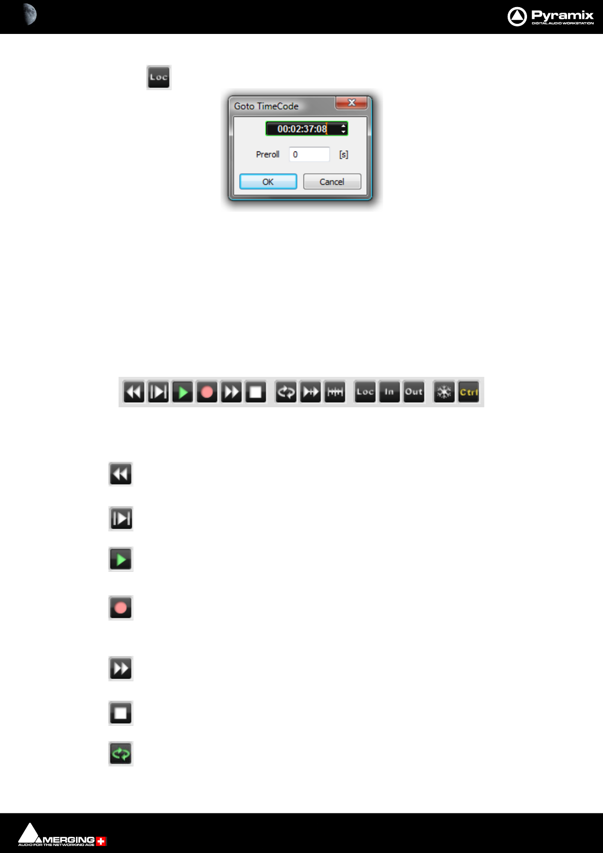
Machine Control : Transport Control Panel 23 - 577
Locate
Pressing the Locate button pops up the Goto Timecode dialog:
The register shows the machine’s current TimeCode position value and is highlighted, ready for typed input. The
value can also be adjusted with the increment/decrement buttons. Clicking the OK button sends the machine to
the TimeCode value in the register and closes the dialog.
A Preroll value can also be set. This value is retained and will be present when the dialog is next opened from any
Machine control panel.
Note: Goto TimeCode has no effect if it is invoked from a machine in Chase Mode.
Internal Machine panel - Features
Transport Controls
The Internal Machine panel has the same transport controls as the Transport Control Bar with some extras:
The Rewind button moves the Play Head at an accelerated speed backward through the
Composition. A second press doubles the speed.
The Play Selection button plays the current highlighted selection area.
The Play button plays the Composition at normal speed forward from the current position of
the Play Head. A subsequent press Pauses playback and another Restarts.
The Record button puts Pyramix into Record mode, and creates a new recording to the disk
on the Tracks previously armed for recording. The Play Head moves forward at normal Play
speed during the recording.
The Fast Forward button moves the Play Head at an accelerated speed forward through the
Composition while it is being pressed. A second press doubles the speed.
The Stop button stops playback.
The Loop Play toggle button puts Pyramix into a loop play mode, which continuously plays
through from beginning to end of the current selection.
Goto TimeCode dialog
Transport Controls
Machine Control : Transport Control Panel 23 - 578
Pops up the Goto Timecode dialog. See above in Internal / External Machine panels -
Common Features
Chase Please see: Chase Mode on page 579
Offset capture button. Captures the current offset which is shown in the OFFSET register.
Locate. Opens the Goto TimeCode dialog.
In Locates Playhead Cursor to the value in the IN register. Ctrl + In Captures the current Play-
head Cursor position to the IN register.
Out Locates the Playhead Cursor to the value in the OUT register. Ctrl + Out Captures the
current Playhead Cursor position to the OUT register.
Note: The In and Out points set for the Internal Machine are the main, red In and green Out,
marker positions in the Pyramix TimeLine.
The Freeze button stops all External Machines where they are. See Freeze Mode below.
Sets the Internal Machine (Pyramix) as the Active Machine. See Active Machine below.
External Machine panel - Features
Transport Controls
The Rewind button moves the External Machine at an accelerated speed backwards.
The - 1 Frame button nudges the External Machine backwards one frame per press.
The Play button starts the External Machine in Play mode.
The + 1 Frame button nudges the External Machine forwards one frame per press.
The Fast Forward button moves the External Machine at an accelerated speed forwards.
The Stop button sends a Stop command to the External Machine.
Chase Please see: Chase Mode on page 579
Transport Controls
Machine Control : Transport Control Panel 23 - 579
Offset capture button. Captures the current offset which is shown in the OFFSET register.
Pops up the Goto Timecode dialog. See above in Internal / External Machine panels -
Common Features.
In Locates Playhead Cursor to the value in the IN register. Ctrl + In Captures the current Play-
head Cursor position to the IN register.
Out Locates the Playhead Cursor to the value in the OUT register. Ctrl + Out Captures the
current Playhead Cursor position to the OUT register.
Sets the External Machine as the Active Machine. See Active Machine below.
Record and Edit controls
The fifteen small buttons are for arming audio tracks 1-12 and arming the Video and TimeCode. The [A] is Assem-
ble mode for machines that support it.
The Record button initiates and indicates recording on the External Machine
Inhibits recording on the External Machine
Preview Edit Initiates a preview of an edit. The External Machine (and any chasing
machines) go into play from the In point minus preroll and the output on all tracks armed for
record switches from replay to direct at the In point and back to replay at the Out point. The
machine Stops at the Out point plus post roll.
Auto Edit Initiates an edit. The External Machine (and any chasing machines) go into play
from the In point plus preroll and all tracks armed for record are punched into record at the In
point and back to replay at the Out point with the machine monitor outputs following. The
machine Stops at the Out point plus post roll.
Review Edit Initiates a review of the Auto Edit just performed. The External Machine (and
any chasing machines) go into play from the In point minus preroll and plays to the Out point
plus post roll.
Note: Pre and Post roll for the machine in question are set up in the dialog. This can be found in
the Settings > All Settings > Remote Control > Machine page by selecting the machine and
clicking on Properties. Further settings are to be found in the Sony 9-Pin Protocol Configura-
tion (Machine) dialog, accessed by clicking on the Properties button in the Machine proper-
ties dialog.
Please see also: Machine Properties on page 769
Chase Mode
Each Machine has a Chase button. The choice of Hard, Soft and Vari Chase is available in the Settings >
All Settings > Application > Jog/Chase page. When Chase Mode is engaged the Internal Machine can chase LTC,
the selected External Machine or Virtual Transport inputs selected in the Settings > All Settings > Hardware >
TimeCode page in the TimeCode Source and Ext. TC Source combo boxes.
Record and Edit Control
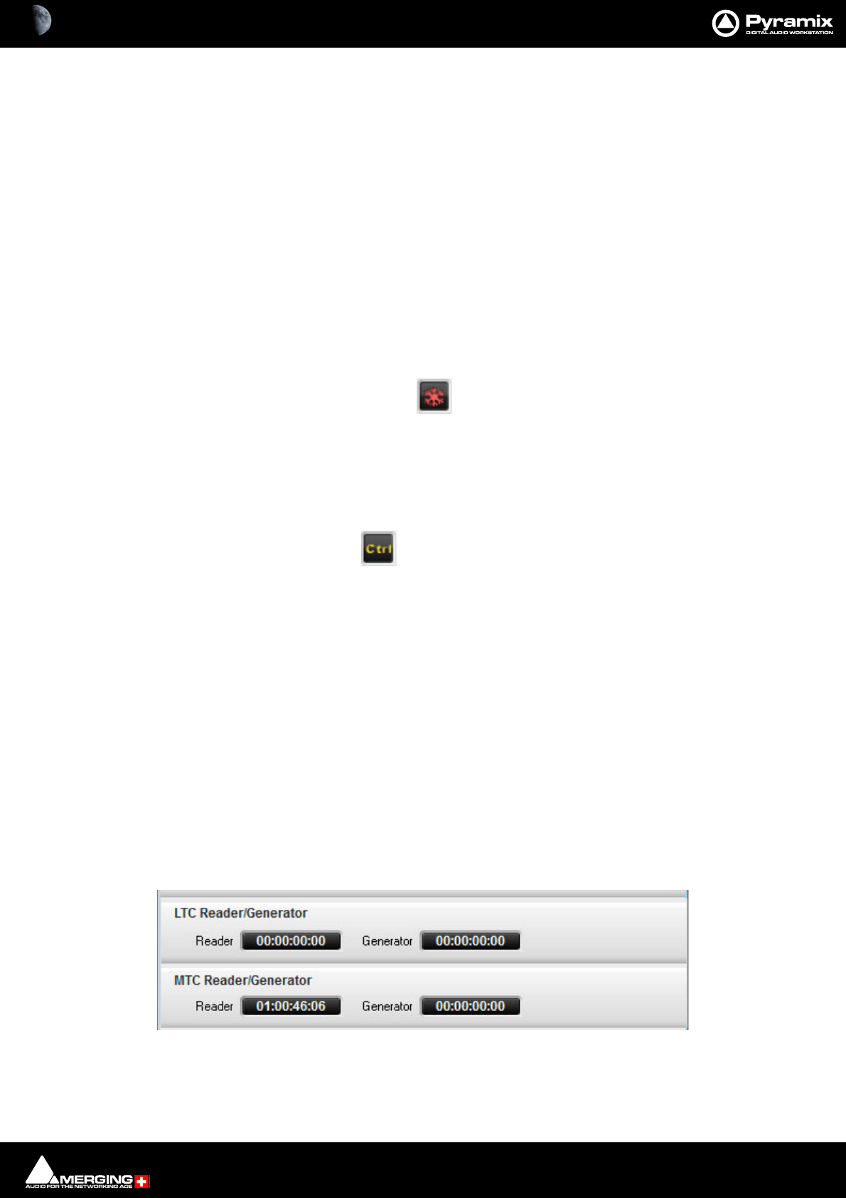
Machine Control : Transport Control Panel 23 - 580
Hard When Hard Chase is active, Pyramix will only playback when valid TimeCode is
detected on the chosen TimeCode input port. If there is a jump in the incoming
TimeCode, Pyramix will adjust to the new TimeCode, re-synchronize and begin
playback from the new TimeCode position. Pyramix will run on its own internal
TimeCode for up to 1 frame if there is a drop out in the time code. If no valid Time-
Code is detected after that time, playback will stop.
Soft When Soft Chase is active, Pyramix will only playback when valid TimeCode is
detected on the chosen TimeCode input port. If there is a jump in the incoming
TimeCode, Pyramix will not adjust to the new TimeCode, but will continue play-
back with an offset from the incoming TimeCode position. Pyramix will continue to
run on its own internal TimeCode for up to 1 frame if there is a drop out in the
TimeCode. If no valid TimeCode is detected after that time, playback will stop.
Vari When the Vari Chase is active, Pyramix will Varispeed, I.e. alter its sampling rate to
follow fluctuations in an external TimeCode. (going back and forth, slowing down,
accelerating, playing normally or backwards, up to 8x nominal speed) while in
playback (not in record)
Freeze Mode
The Internal Machine also has a Freeze button. When active, as shown here, all External Machines remain
where they are and the point in time at which Freeze was activated is kept in memory. Pyramix can be freely used
and moved while Freeze is active. When the Freeze button is cancelled, the Pyramix Playhead Cursor jumps to
the point where Freeze was activated and full control is restored.
This function has many uses. For example, it can be used to position an out of sync effect, say a car-door slam. For
detailed instructions please see: Using Freeze Mode on page 520
Active Machine
Each Machine’s Panel has a Ctrl button which sets it as the Active Machine. The Active Machine receives
the full input of the Active Machine mapped keyboard shortcuts, the Transport Control Bar and input from all
available Remote Controllers.
The Machine combo-box in the Transport Control Bar shows the active machine and can be used to switch
between the installed and enabled machines. Alternatively you can toggle through the currently enabled
machines. Machines > Active Machine > Toggle machines
Auto-chase
If all enabled machines are set to Auto-Chase, when Ctrl is switched between machines the Active Machine is
automatically taken out of Chase mode and the previously Active Machine automatically enters Chase mode. To
activate Auto-Chase for all external machines, enable the menu setting:
Machines > External Machine > Auto-Chase
And, to activate Auto-Chase for the internal machine, enable the menu setting:
Machines > Internal machine > Auto-Chase
TimeCode Registers
Each TimeCode reference source has two registers:
Reader register shows show the current TimeCode incoming on the LTC, MTC physical or logical inputs.
TimeCode Registers
Machine Control : Transport Control Panel 23 - 581
Generator register shows the current TimeCode outgoing on the LTC or MTC physical or logical outputs
In the case of VT, Virtual Transport, the Reader Timecode is the VT TimeCode and the Generator is the TimeCode
reported by Pyramix on the corresponding Pyramix VT client.
Controllers Section
Controllers Online/Offline
When the Controllers button is lit red all connected Controllers are set Offline
Press the button again to toggle to Online.
Offline ensures no External Commands can be sent to Pyramix while a maintenance or housekeeping operation
is in progress.
When performing a Mix-down, Generating a CD image, or during any Surround encoding operation, Pyramix
automatically sets all controllers offline to ensure the operation is not inadvertently interrupted and to prevent
exaggerated motor fader movements during non real-time processes.
Jog Wheel Mode
Jog
Shuttle
Loop
Navigate
Zoom
Off
The buttons select the hardware Jog Wheel Mode from a choice of Jog, Shtl, Loop, Nav, Zoom or Off. Many con-
trollers will have buttons either corresponding directly to these functions or mappable to them.
Note: Further Jog Wheel Modes are available in Machines > Controllers.
The selected function is lit in yellow. (Off in the images above.)
The Shuttle slider is provided for convenience when using the Transport Control Panel.
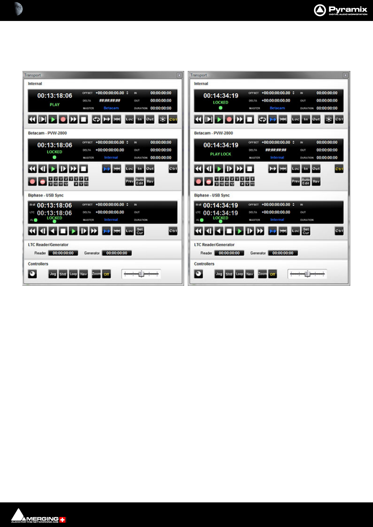
Machine Control : Transport Control Panel 23 - 582
Examples:
In the following examples there are three machines. At the top of each window is the host Pyramix Internal
Machine. Below this is a BETACAM - PVW-2800 and the third machine is a BiPhase transport or transports. (Via the
MTUsbSync Board) Both External Machines are controlled via the Sony 9-pin P2 protocol.
In the left-hand example the Host Pyramix is Master and both External Machines are in Chase and Locked.
In the right-hand example the Betacam is now the Master and both the Internal Pyramix and External BiPhase
Machines are in Chase and Locked.
Note: Machines NOT in chase can be used independently of the Master while the Master is in use
by using their individual controls. So you can locate on a machine whilst continuing to mix using
the Master and slaves.
Transport Control Examples

24 - 583
www.merging.com/Pyramix
USER MANUAL
Remote Control

Remote Control : Generic Control 24 - 584
Scope
Pyramix can control and be controlled by a wide variety of external hardware. This chapter, Remote Control deals
with situations where Pyramix is controlled by an external device such as a control surface or machine controller.
Generic Control
The Pyramix transport can be controlled by devices capable of issuing standard Sony 9-Pin (P2 Protocol) com-
mands and by MMC (MIDI MACHINE CONTROL) commands.
The Pyramix Mixer can be controlled by devices capable of issuing suitable MIDI data. The Mixer can be “taught”
which commands relate to which function.
Hardware Control Surfaces
Hardware remote control is accomplished via the Merging Technologies Oasis protocol, Proprietary protocols,
Merging Technologies EMC (Enhanced MIDI Control) MIDI or the 9-pin (Sony P2 protocol). Templates are supplied
for some popular controllers or you can map your own MIDI control surface to Pyramix.
ISIS
The Merging Technologies ISIS and ISIS Expander are purpose designed for Pyramix and offer comprehensive
control for many applications. Notably, in conjunction with the Pyramix Fade Editor, editing is extremely quick.
For full details please contact your Merging Technologies Sales Partner.
Supported Controllers Table
Pyramix Virtual Studio supports controllers from many different manufacturers, as seen in the table below, in sev-
eral control modes. While JL Cooper products work with a proprietary protocol, Yamaha, Radikal Technologies,
and Mackie units need to be set to HUI mode to communicate with Pyramix. Finally the Sony DMX-R100 com-
municates via standard MIDI control and Sony 9-pin P-2 protocol commands.
Auto-mapping
Wherever auto-mapping is supported, our controller driver will automatically link active Pyramix parameters to all
available control surface items. With manual mapping, a drag & drop or menu dialog, depending on the driver, will
allow for any specific Pyramix parameter to be linked to any available control surface item.
Strip Cloning
Strip cloning will duplicate all parameter assignment for a dedicated strip to adjacent channel(s). Finally, MIDI
mapping will create links between Pyramix parameters and control surface items with a select and learn method.

Remote Control : Control by External Device 24 - 585
Controllers Table
For the latest version of the Supported Controllers table, please follow this link:
https://confluence.merging.com/pages/viewpage.action?pageId=17203276
For the EMC User Guide and other downloadable User Guide documents about supported controllers/consoles
please go to:
www.merging.com
Choose the document(s) you wish to download.
Control by External Device
If Pyramix is to be controlled by another device or devices, these are installed via Settings > All Settings Remote
Control > Controller (See: Controller on page 773 ) and, where applicable, Pyramix functions are mapped to the
controller via the Settings > All Settings > Project > Controller Mapping page. (See: Controller Mapping on
page 742)
9-pin Configuration (Pyramix controlled by external device)
Please see: Sony 9 - Pin Protocol Configuration (Pyramix controlled by external device) on page 775
Control by Another Pyramix
This can be achieved either by using Virtual Transport 2 and Sony P2 over IP, or by conventional 9-pin RS422 serial.
The former is a convenient, cost effective and robust solution.
Configuring Pyramix for Control by another Pyramix using P2 over IP / VT2
• In Pyramix select the Settings > All Settings > Remote Control > Controller page.
• Click the Add button. The Controller Properties dialog opens.
• Enter a suitable name for the Pyramix in the Name field.
• Choose the Driver for the machine from the drop-down list. I.e. Sony 9-pin
•Click on the Properties button to open the Sony 9-Pin Configuration dialog.
•In the Port section click on the IP (Ethernet) radio button
• Make any other changes you need in the Sony 9-Pin Protocol Configuration (Please see: Sony 9-Pin
Protocol Configuration (Machine) on page 770 for a detailed description of the options.)
•Click on OK to close the Sony 9-Pin Configuration dialog.
•Check that Enable is ticked in the Controller Properties dialog.
•Click on OK to close the Controller Properties dialog.
Note: The slave machine will show up on other Pyramix machines in the Settings > All Settings
> Remote Control > Virtual Transport 2 page. (This may take a while until the network map is
refreshed) Once showing as Available simply click on the name in the list to highlight it and click
on Connect.
Configuring Pyramix for Control by another Pyramix using Sony P2 protocol over RS422
• In Pyramix select the Settings > All Settings > Remote Control > Controller page.
• Click the Add button. The Controller Properties dialog opens.
• Enter a suitable name for the Pyramix in the Name field.
• Choose the Driver for the machine from the drop-down list. I.e. Sony 9-pin
•Click on the Properties button to open the Sony 9-Pin Configuration dialog.
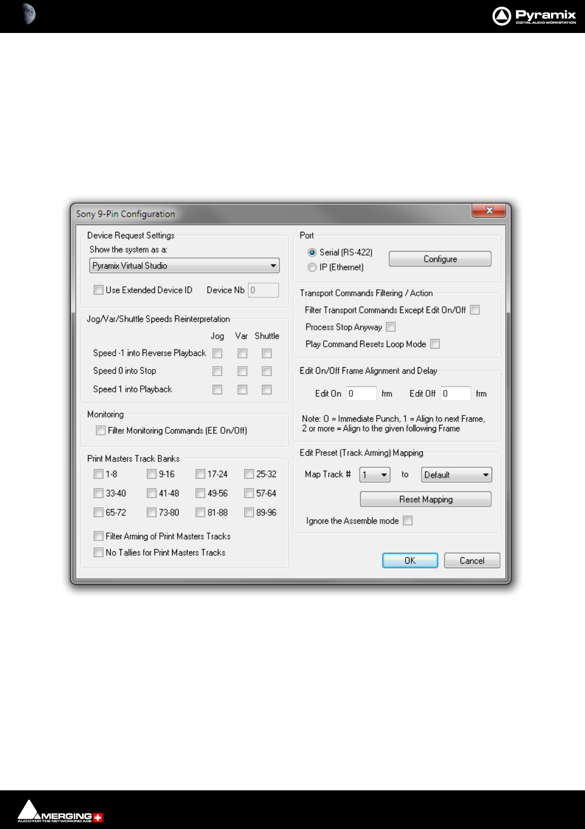
Remote Control : Control by External Device 24 - 586
•In the Port section click on the Serial (RS-422) radio button
•Click on Configure to open the
• Make any other changes you need in the Sony 9-Pin Configuration. Please see subsequent pages for a
detailed description of the options.)
•Click on OK to close the Sony 9-Pin Configuration dialog.
•Check that Enable is ticked in the Controller Properties dialog.
•Click on OK to close the Controller Properties dialog.
Sony 9 - Pin Protocol Configuration (Pyramix controlled by external device)
Device Request Settings
The Sony 9-pin P2 protocol transmits a code to identify the machine. Some machine controllers will do nothing or
exhibit aberrant behavior if they do not recognize the identifier code. Therefore, Pyramix can masquerade as
another device. The device identifier can be selected from a long list in the Show the system as a: combo box.
Jog/Var/Shuttle Speeds Reinterpretation
The radio buttons determine Pyramix behavior when specific Jog/Var or Shuttle commands are received.
• Speed -1 into Reverse Playback
• Speed 0 into Stop
Sony 9-Pin Configuration dialog
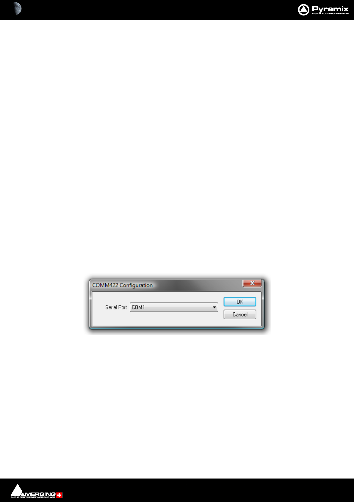
Remote Control : Control by External Device 24 - 587
• Speed 1 into Playback
Note: When using a controller with a jog wheel please set Jog/Var/Shuttle ... Speed = 0.
Note: Interpreting a Sony reverse varispeed command as Reverse Playback is sometimes neces-
sary to achieve proper (locked to video) reverse playback.
Monitoring
Filter Monitoring Commands (EE On/Off) when ticked, E to E On and off commands are filtered out.
Print Masters Track Banks
The selected banks of 8 tracks are armed for recording when any OTHER track is armed. This is primarily useful
when recording a Print Master or Masters at the same time as stems. E.g. if you are recording Dialogue, Music and
Effects stems it is common practice to update an element on one stem only. However, the final mix Print Master,
which is the sum of all the stems must be updated at the same time. Print Masters Track banks allow the user to
forget about arming the Print Master Tracks and concentrate on the stems.
Filter Arming of Print Masters Tracks
When ticked, arming a Print Master Track will not arm the other Print Master Tracks.
No Tallies for Print Masters Tracks
When ticked, record tally commands are filtered out for the Print Masters Tracks.
Port
• Serial (RS422) Select this option if the connection uses conventional 9-pin cabling
• IP (Ethernet) Select this option if connecting to Pyramix or VCube machine(s) using Sony P2 over IP.
Configuration is automatic when the OK button is pressed to close the dialog.
Configure
Clicking the Configure button opens the respective configuration dialog.
COMM422 Configuration:
Serial Port
Shows the current Serial Port selected from the drop-down list. If not already highlighted, select the desired serial
COM port. Standard choices are either COM1 or COM2.
Click OK to confirm the choice. This automatically sets the selected COM port with the proper parameters of the
Sony 9-pin communication protocol.
Transport Commands Filtering
• Filter Transport Commands Except Edit On/Off When ticked all transport commands apart from Edit On
or Edit Off are filtered out.
•Always Process Stop Some controllers send a Chase Off command for Stop. If you need this command
when filtering Transport Commands, checking the box will allow it through.
• Play Command Resets Loop Mode (I.e. the transport Loop)
COMM422 Configuration dialog

Remote Control : Control by External Device 24 - 588
Note: These filter settings are mainly relevant where multiple controllers are in use. E.g. where a
Mixing console controls monitoring and recording.
Edit On/Off Frame Alignment and Delay
Edit On and Edit Off boxes enable delays (in ms) to be entered.
Note: 0 = Immediate Punch, 1 = Align to next Frame boundary, 2 or more = Align to the given
following Frame boundary.
Edit Preset (Track Arming) Mapping
The Map Track # combo box allows you to select a Track between 1 and 96 to be mapped to a choice made in the
second combo box from:
• Default
•No change
•Always Off
•Always On
or any Track between 1 and 96
This function is useful if more than one Pyramix is to be controlled by the same controller. E.g. with two machines
set up to record 32 Tracks each, Pyramix one is mapped 1 - 1 to 32 - 32 and Pyramix two is mapped 1 - 33 to 32 -
64
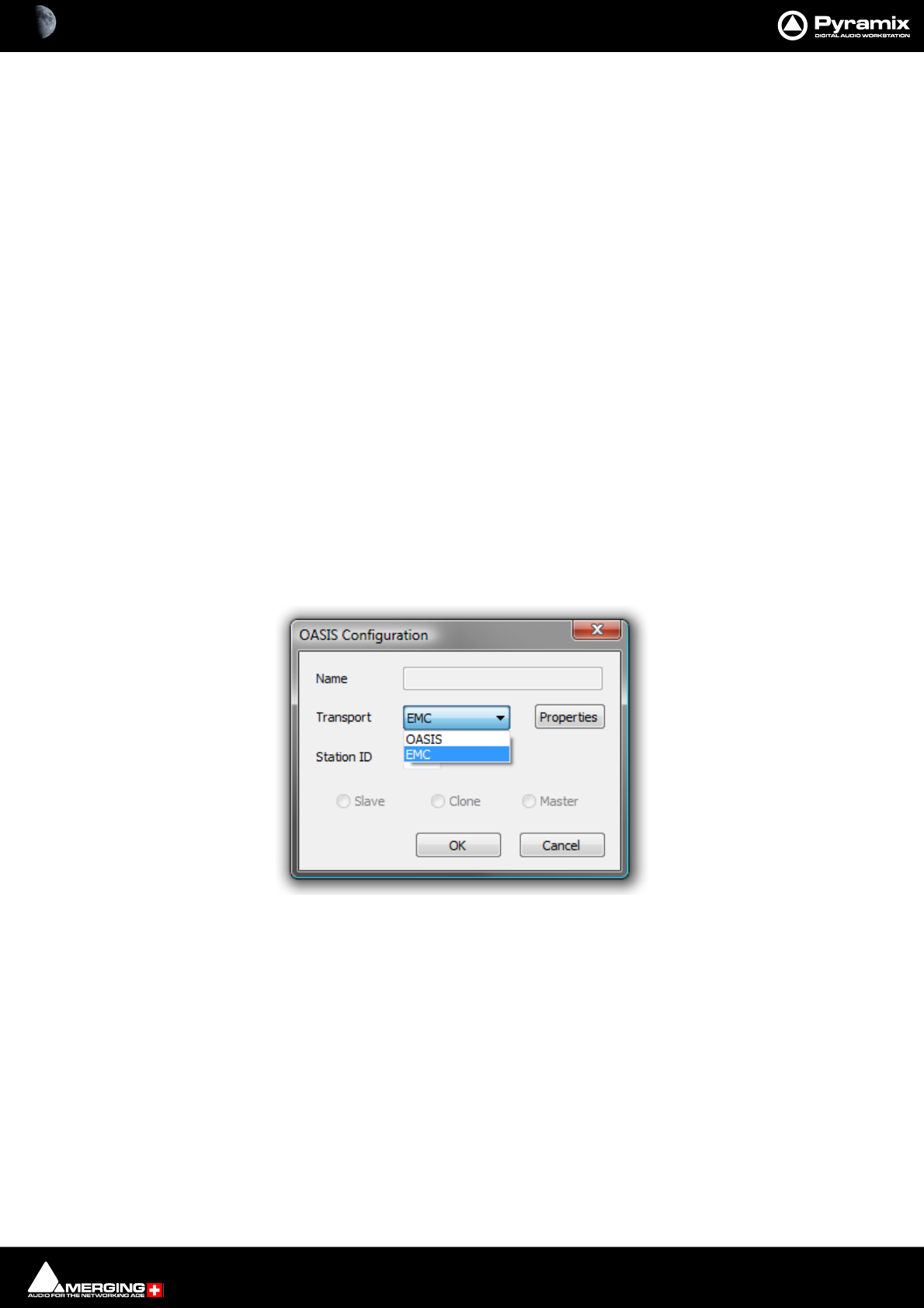
Remote Control : EMC 24 - 589
EMC
Scope
EMC includes HUI and Mackie Control Support.
The following controllers are supported and validated:
• Mackie MCU in HUI and MackieControl modes
• Yamaha DM1000 in HUI mode
• Yamaha DM2000 in HUI mode
• Raditec SAC2-k in HUI mode (MackieControl is not working properly)
• Tascam US-2400 in HUI mode (US-2400 MackieControl mode is specifically configured for other DAWs
than Pyramix)
Note: Please see also: Controllers Table on page 585
Key
Valid Remote Control Support and Remote Control – Midi Enhanced Midi protocol keys are required to use EMC.
Configuration
Configuring a Remote EMC Connection
Since EMC is implemented as a subset of OASIS, to configure a remote connection, an OASIS controller must be
added in Settings > All Settings > Remote Control and then EMC must be chosen by clicking the Properties
button which opens the OASIS Configuration dialog:
Faders, Solo, Mute, Pan, Surround Panning, Auxes, Vu-Meter, Advance channel display, Strip tools,
transport (Internal and Externals machines), Bank switching and Jog are all fully supported. Please see the EMC
User Guide for full configuration details.
OASIS Configuration Dialog

Remote Control : OASIS Protocol 24 - 590
OASIS Protocol
OASIS is a generic TCP/IP based protocol for integrating disparate digital audio consoles and controllers with
Merging’s Pyramix digital audio workstation. Although Pyramix supports several other protocols OASIS is in a dif-
ferent league.
The Oasis Advantage
• Allows control surface mapping to faders, rotary encoders, keys, machine control functions etc.
•TCP/IP Network based
•High bandwidth
• Flexible connectivity from any unit to any other unit on a LAN/WAN
• Low delay transmission performance (provided there is adequate Network topology.)
• No additional hardware needed for a console/controller that has an Ethernet (IEEE 802.3) connection.
• Low cost and upgradeability of the Ethernet technologies
Overview of Pyramix Controls
Mixing:
The virtual Pyramix mixing console is fully exported over OASIS with a high degree of control precision.
Editing:
Everything that is available in the Pyramix menu is remote controllable
Machine Transport Control:
Internal Pyramix machine control and all connected machines (Sony P2, MMC) can be remote controlled over
OASIS in a unified protocol.
Multiple DAW Control:
• The virtual mixer power can be distributed on multiple mix engines
• The number of available Play/Record Tracks may be expanded seamlessly without limits over any number
of Pyramix engines
Export of useful information to the console:
• “Units of” parameters (%, dB, ms...)
• The range of each specific control
• The default value of controls
• Mixer strips/bus names
• Floating point number based (32 bits)
• Possibility of choosing between the DAW and/or the Console Automation engine
OASIS In Practice
OASIS allows:
• 384 channel I/O multi-track player/recorder and dubber (Pyramix V6.1)
• Access to all the editing and processing functionality of Pyramix

Remote Control : OASIS Protocol 24 - 591
• The internal mixer can be configured as a 384 input into several buses types.
• Up to 16 surround simultaneous stems can be sent to the console as part of the main mix.
• Multi-layer mixing - switch between the DAW mixing layer and the main mix on the console retaining dis-
crete control over pre-mixed channels.
• With two or three Pyramix systems connected, as in a film dubbing environment, this allows for virtual,
non-destructive, pre-mixes and any changes to the pre-mix can be made instantly by simply switching to
the relevant layer.
Comparison with MIDI based Solutions
• MIDI vs. Ethernet… No comment!
• Peak-meter refresh rates of 25-30 times per seconds
• Pyramix evolution will enable the protocol to develop still further.
• All third party (VST, DirectX) plug-ins can be fully described and parameters can be exported over OASIS.
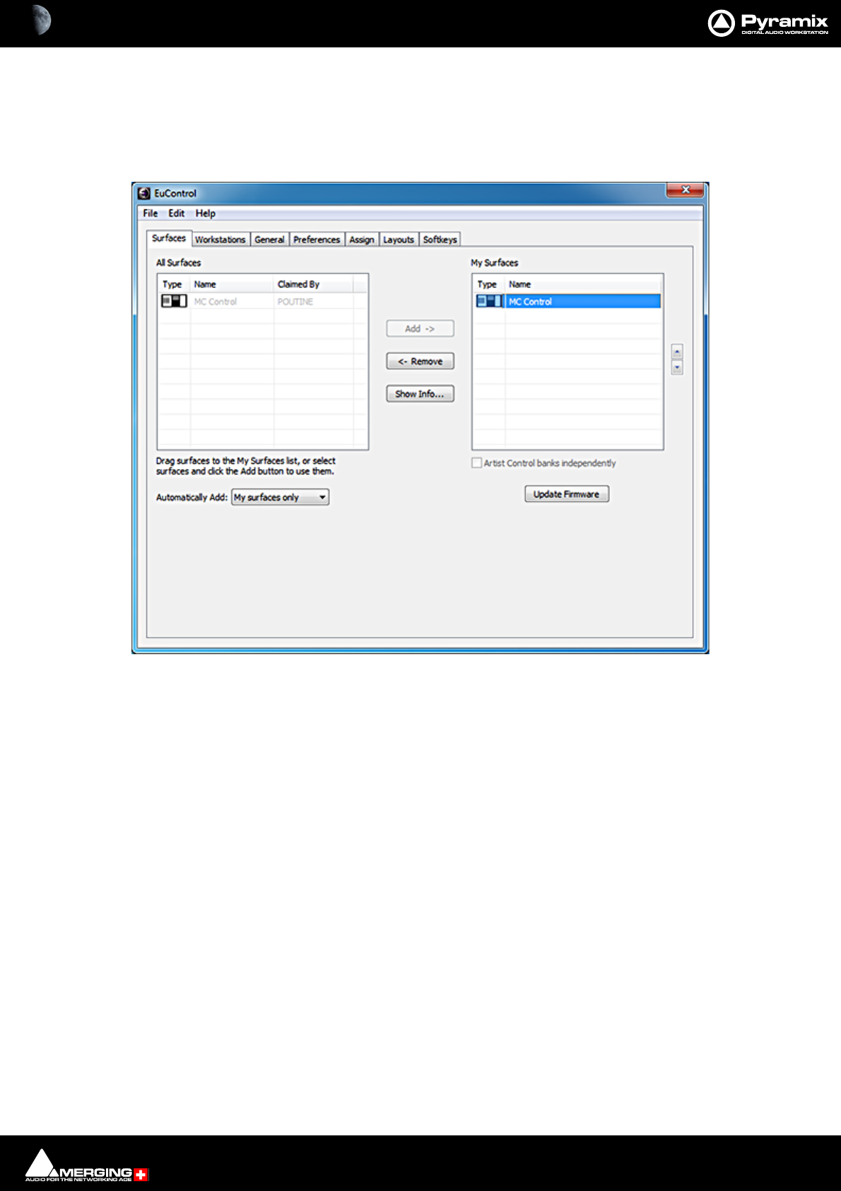
Remote Control : EUCON Control Surfaces 24 - 592
EUCON Control Surfaces
Avid control surfaces supporting the EUCON protocol require the following setup to work with Pyramix.
1. Open the EUCON EUCONtrol application and in the Surfaces tab add MC Control Surface to My Surface:
EUCONtrol application Surfaces tab
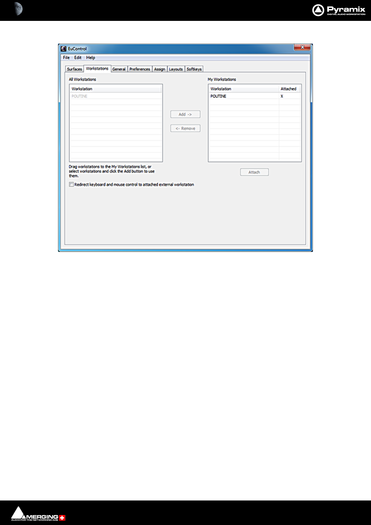
Remote Control : EUCON Control Surfaces 24 - 593
2. In the Workstation tab. Make sure the Pyramix PC is attached:
EUCONtrol application Workstations tab
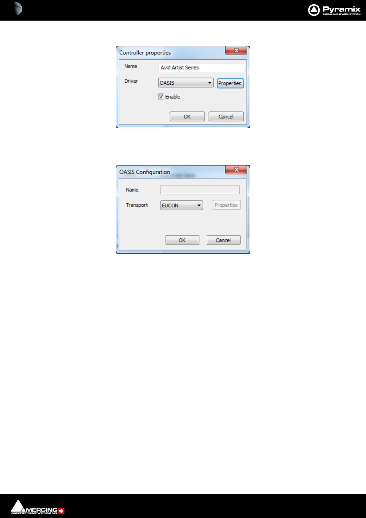
Remote Control : EUCON Control Surfaces 24 - 594
3. Launch Pyramix and go to Settings > Remote Control > Controllers.
4. Add controller and select OASIS.
5. Click on OASIS Properties to open the OASIS Configuration dialog:
6. In the Transport drop-down list select EUCON.
Pyramix Controller Properties dialog
OASIS Configuration Dialog

25 - 595
www.merging.com/Pyramix
USER MANUAL
GPI / GPO Control
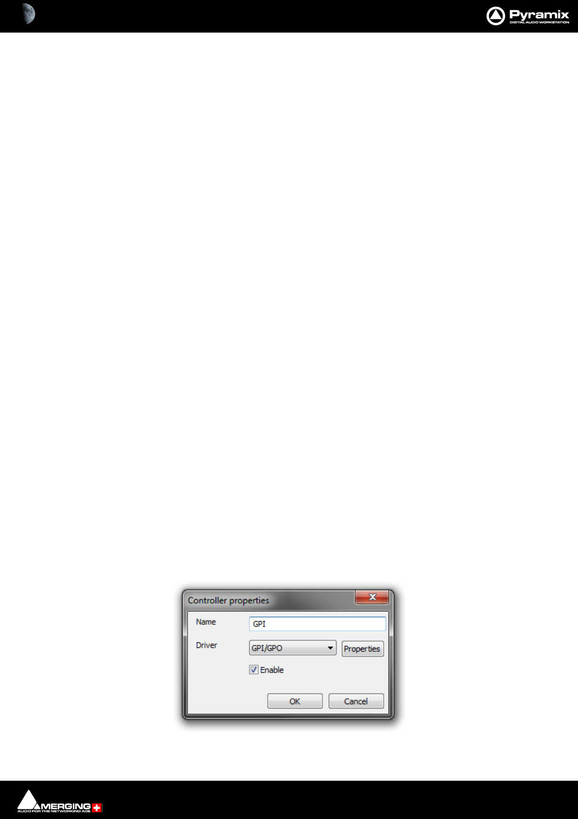
GPI / GPO Control : GPI / GPO Support 25 - 596
GPI / GPO Support
GPI/O support is available as a Remote Controller module.
Note: For the present the only supported GPI/O interfaces are the following models manufac-
tured by Sealevel:
• SeaPORT PLC-16** 8 in 8 out
• SeaI/O-410U 16 in 16 out
• SeaI/O-420U* 16 in 8 out
• SeaI/O-430U* 32 in 0 out
• SeaI/O-440U* 0 in 32 out
• SeaI/O-450U* 0 in 16 out
• SeaDAC P/N 8221* 16 in 16 out
• SeaDAC P/N 8222 16 in 8 out
• SeaDAC P/N 8223* 32 in 0 out
• SeaDAC P/N 8224* 0 in 32 out
• SeaDAC P/N 8225* 0 in 16 out
* Obtainable on special order.
** No longer available.
Note: Note: USB drivers are included in the Pyramix Installer. There is no need to download the
driver from the supplier’s website. For more information about the specification of the GPIO
hardware device please see:
http://www.sealevel.com
Using the GPI/O controller
Add a GPI/O Controller
Before Pyramix can use the adaptor, it must be set up.
Select the Settings > All Settings > Remote Control > Controller page
Click the Add button. The Controller Properties dialog opens. Type a name for the Controller and select GPI/GPO
from the Driver drop down list. Click OK to close the dialog and click OK to close the Pyramix Settings window.
Note: Do not do this more than once. Only one GPI/GPO controller is allowed. However this can
control more than one physical GPI/GPO USB Module
GPIO Controller Properties dialog
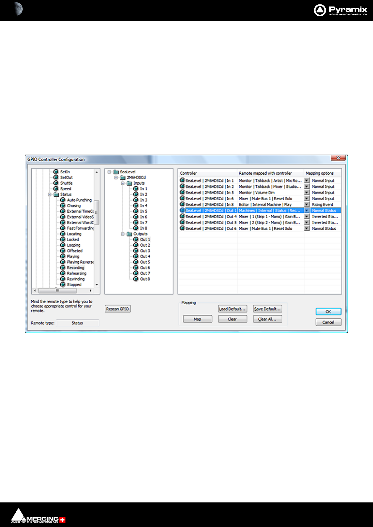
GPI / GPO Control : GPI / GPO Support 25 - 597
Enable/Disable
The GPI/GPO controller may be disabled by unchecking the Enable box in the Controller Properties Dialog.
Some GPI/GPO USB Modules can be individually enabled or disabled by clicking on the Properties button to the
right of the Driver combo box.
Configuring the GPI/O controller for a specific project
Open the Settings > All Settings > Project > Controller Mapping page.
Select your GPI/O controller and click Properties. The GPI/O Controller Configuration Window will appear; On the
left you can browse the Remotes list. Next to this is the GPI/O Controllers list. To map a Remote to a GPI/O Input or
Output pin just drag the Remote onto the Controller pin; The right-hand pane is a list of all currently mapped Con-
troller pins. By clicking in the Mapping Options column you can configure how the pin works.
Click OK to accept the changes to the GPI/O configuration, or Cancel to abort.
Mapping Example
Mapping Description of Example Shown Above
Input triggering:
In 1 : Monitor | Talkback | Artist | Mix Room | On
The Artist opens the talkback circuit to the Mix Room
In 2 : Monitor | Talkback | Mixer | Studio | On
The Mixer (Engineer) opens the talkback circuit to the Studio
In 5 : Monitor | Volume Dim
Dim the Monitor output section
In 6 : Mixer | Mute Bus 1 | Reset Solo
Reset the solo in the Mixer
In 8 : Machines | Internal Machine | Play
Put Pyramix in playback. I.e when the Artist is ready.
Output are triggered by:
Out 1 : Machines | Internal | Status | Recording
GPIO Controller Configuration dialog

GPI / GPO Control : GPI / GPO Support 25 - 598
Control of the Record Red light.
Out 4 : Mixer | 1 (Strip 1 - Mono) | Gain Bus 1 | Gain
Fader start of the first mixer fader. For dB value the threshold is -90 dB
Out 5 : Mixer | 2 (Strip 2 - Mono) | Gain Bus 1 | Gain
Fader start of the second mixer fader. For dB value the threshold is -90 dB
Out 6 : Mixer | Mute Bus 1 | Reset Solo
Control of an additional indicator in the mixer room when a mixer strip is soloed.
GPI/O Remote types
There are 5 different types of Remote that can be used with GPI/O Input and/or Output pin:
•Toggle can be associated with both input and output pins.
•Range can be associated with both input and output pins and acts like a toggle 0 =off, other = on
•Event can only be associated with input pins.
•Event-Status can be associated with input and/or output pins;
•Status can be only associated with output pins.
The other Remotes cannot be mapped to GPI/O pins.
GPI/O Input and Output Pin Configuration
• Input pins mapped to Toggle or Range remotes can be configured as:
• Normal Input
•Inverted Input
• Rising Event
• Falling Event
Input pins mapped to Event or Event-Status remotes can be configured as:
• Rising Event
• Falling Event
Output pins mapped to Toggle or Range remotes can be configured as:
• Normal Status
• Inverted Status
Output pins mapped to Status or Event-Status remotes can be configured as:
• Normal Status
• Inverted Status

26 - 599
www.merging.com/Pyramix
USER MANUAL
CD/SACD Mastering
and Album Publishing
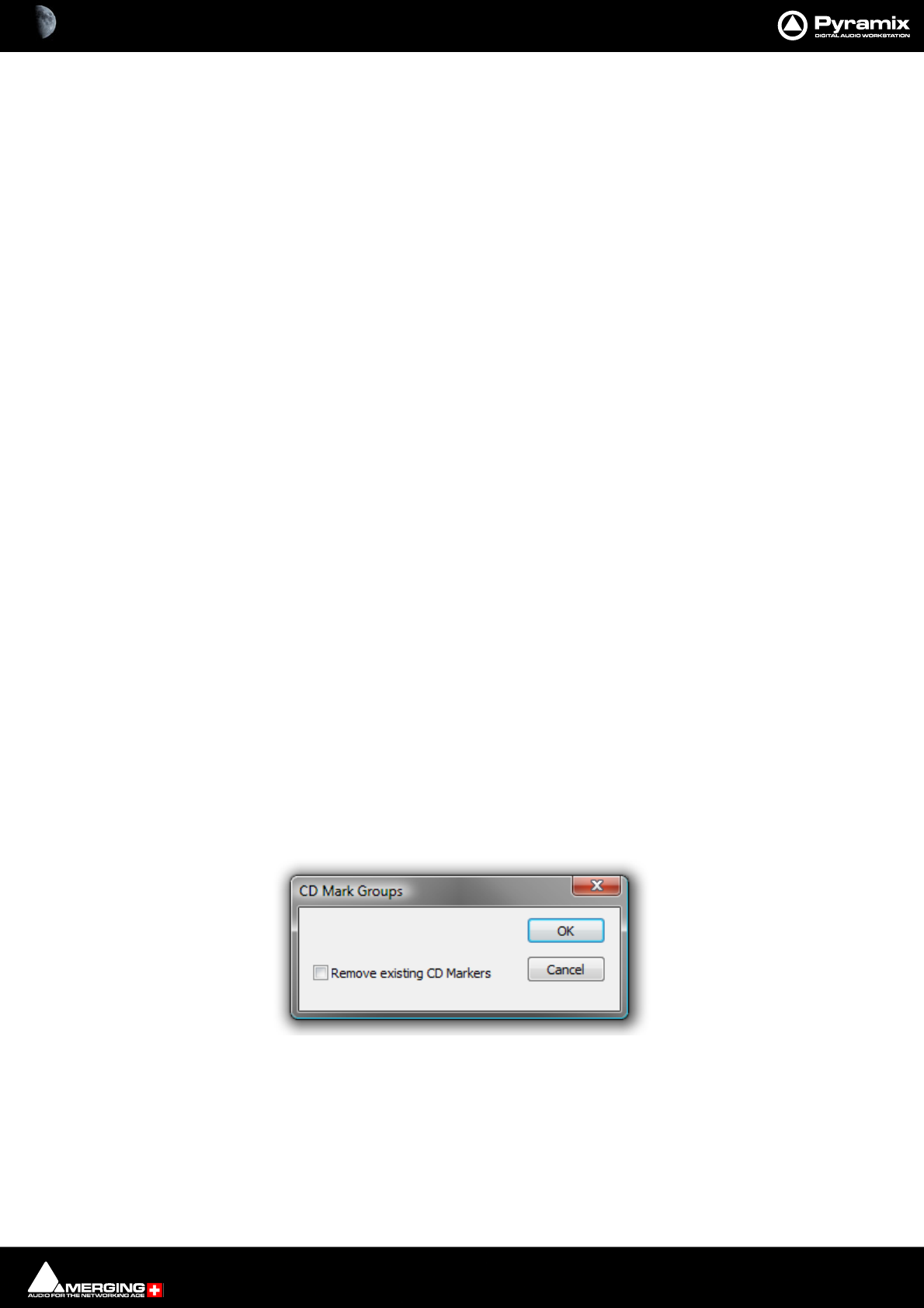
CD/SACD Mastering and Album Publishing : Mastering a Composition to CD-R 26 - 600
Overview
Pyramix has comprehensive mastering features for CD, Album production for digital delivery and SACD mastering
as an option.
Mastering a Composition to CD-R
Pyramix is used to set CD Track Start, Stop, and Index Markers for CD-R Mastering, and a separate application
called DiscWrite is provided to actually burn a CD-R or make a DDP.
One of the advantages to this way of working is that multiple ‘virtual discs’ can exist. This makes it simple to pro-
duce several different versions using the same material.
Note: For a step-by-step guide to producing a simple CD please see the Pyramix Quick Start
Guide, Page 70 Quick CD
IMPORTANT! - First Steps
Open the CD/SACD Tab Window and Double-click <New Disc> in the Album tab. Type a name for the CD then
proceed to add CD Markers
CD Markers
CD Markers are much like other User Flags or Markers.
To set a CD Start Marker (which indicates the beginning of a CD track), place the Play Head at an appropriate CD
track Start location and choose Cursors & Marks > Add CD Start Marker to Cursor; similarly, to set the CD Stop
Marker (which indicates the ending of a CD track), place the Play Head at the appropriate CD track End location
and choose Cursors & Marks > Add CD Stop Marker to Cursor. A named CD Index Marker can also be added
using Cursors & Marks > Add CD Index Marker to Cursor. These CD Markers can be examined, named and
changed in the CD/SACD Tab window.
Add CD Markers Automatically
CD track Start Markers and Stop Markers can be added automatically to Grouped Clips in a Composition. To
accomplish this, first create a CD in the CD/SACD Tab window and select it. Make an appropriate Group of Clips
which correspond to CD tracks. Then choose Cursors & Marks > CD Mark Groups from the CD/SACD Tab window
Markers menu or from the main Cursor and Marks menu to open the CD Mark Groups dialog:
The only option is a check box to Remove existing CD Markers. Click on OK to automatically create CD markers
for all grouped Clips.
Note: If the gap between Clips in the Pyramix TimeLine is less than one second only Start Mark-
ers are placed or required. (There will always be a Stop Marker after the last Clip). Stop Markers
can be useful where there is applause after a piece which may not be wanted when broadcasting
from a CD. Suitably equipped CD Players can be set to stop when they find a Stop Marker.
CD Mark Groups dialog

CD/SACD Mastering and Album Publishing : SACD Notes 26 - 601
Convert Text Markers to CD
Text Markers can be converted into a CD.
Simply right-click on a selection of Text Markers in the Markers Tab pane and choose Create CD Disc.
This will create a new CD disc and select it. A final Stop marker will be added at the end of the next Clip found (if
any) after the TimeCode of the last Start marker. (So it only creates CD Start Markers on the first and intermediate
Cues, but also creates a Stop Marker after the Cue that has the last Start Marker, in order for the CD to be valid).
SACD Notes
D.4 High Frequency DSD Signal + Noise Level
The accumulated RMS signal + noise level of the DSD signal, measured after a 40 kHz Butterworth 30dB/Oct high
pass filter and a 100 kHz Butterworth 30dB/Oct low pass filter, is maximally equal to the RMS level of an input sin-
ewave with a peak amplitude of -20 dB SA-CD (see D.2).
The averaging filter used to calculate the RMS level must be a first order unity gain IIR filter with a coefficient of 1/
524288 ( 2-19 ), corresponding to an IIR filter with a cutoff frequency of about 0.85 Hz.
and annex E.2 of the same:
E.2 Analog Post-filter
To protect analog amplifiers and loudspeakers, it is recommended that a Super Audio CD player contain at its out-
put an analog low pass filter with a cut-off frequency of maximum 50 kHz and a slope of minimum 30 dB/Oct. For
use with wide-band audio equipment, filters with a cut-off frequency of over 50 kHz can be used.
Note: When releasing material at higher than 44.1 or 48 kHz sampling rate, Merging recom-
mends to add a gentle low pass filter (typically 6 to 12 dB/octave) in the range from 30 to 50 kHz
for all recordings made originally in DSD 64. The corner frequency of such low pass filters can be
doubled whenever converting from DSD 128 and even quadrupled when converting from
sources originally recorded in DSD 256 (which essentially means that even when converting
from DSD 256 to PCM at 192 kHz, there is no need to add such a filter).
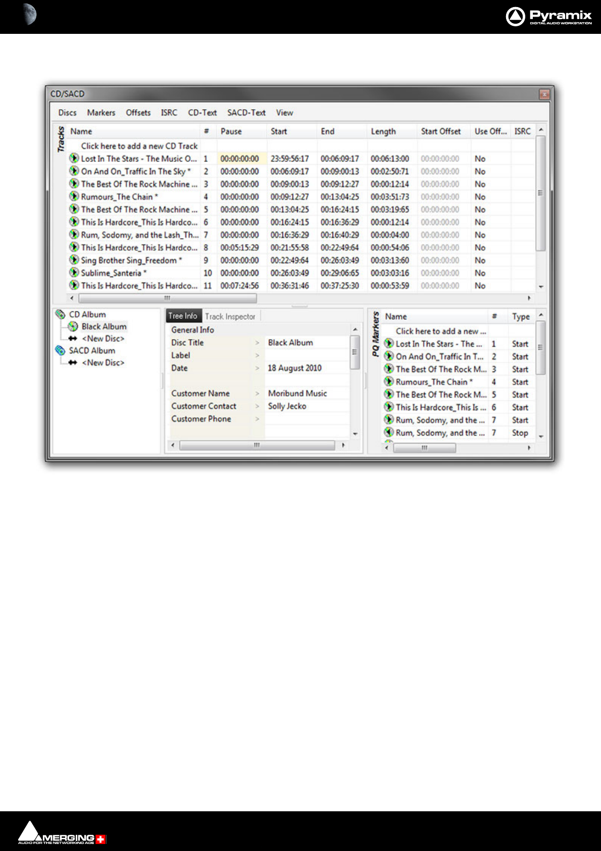
CD/SACD Mastering and Album Publishing : CD/SACD Tab Window 26 - 602
CD/SACD Tab Window
All the mastering features are grouped in the CD View; in three sections.
The Top Pane is the Tracks list for the current CD/SACD Project.
The lower half of the window is divided into three, the Album area, the Tree Info/Track Inspector section and the
PQ Markers list.
Album, All Markers and Track Inspector
The Right pane shows the track list fields. (see below)
Album Section:
The bottom left-hand pane shows a tree view of CD and SACD Albums and Discs with <New Disc> entries to cre-
ate new Discs. The middle pane Tree info default Tab enables properties and default parameters to be set for the
selected Disc.
Tree Info/Track Inspector Section
Tree Info Tab
(Global – CD Header). In addition, there are similar fields for each track in the CD Track grid.
General Info
•Disc Title CD Title
CD/SACD Tab window
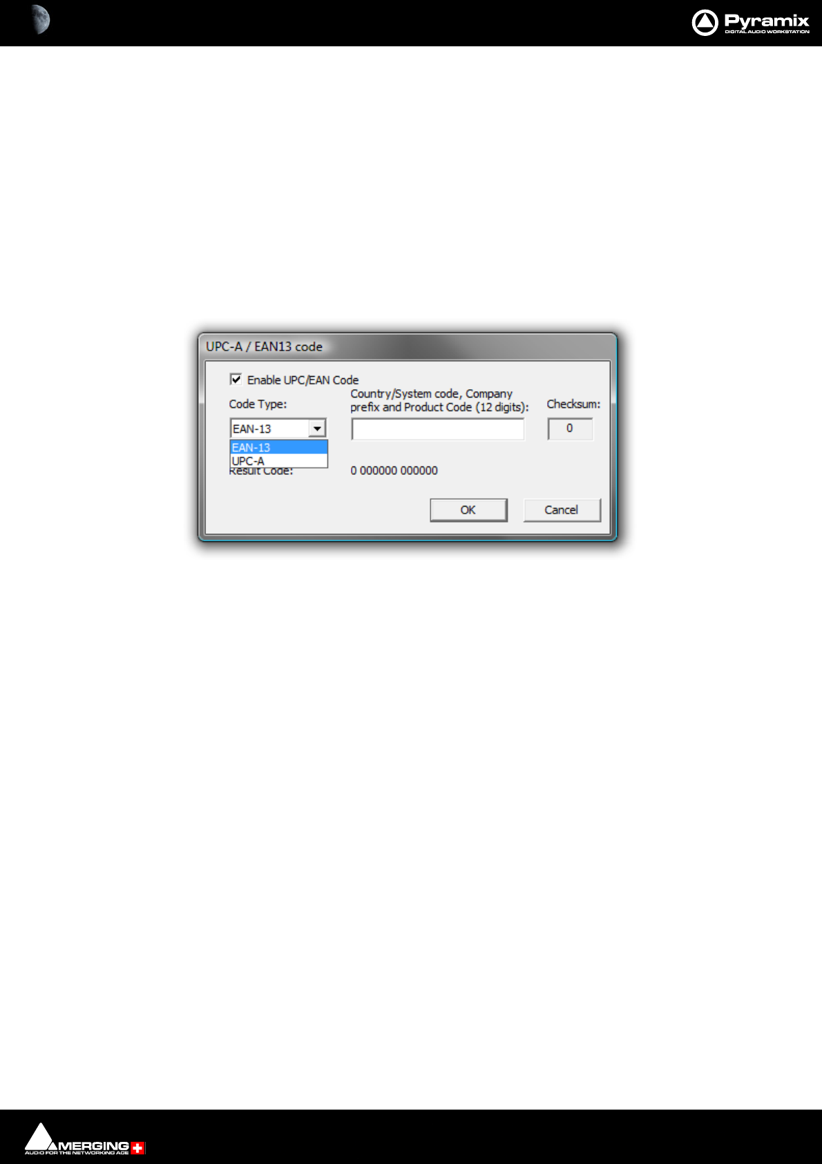
CD/SACD Mastering and Album Publishing : CD/SACD Tab Window 26 - 603
•Label CD Production Label
•Date CD Date
• Customer Name The company the Disc is being made for.
•Customer Contact Customer Contact (name).
•Customer Phone Customer contact phone number.
•Master ID Code CD Identifying code (if one is required)
•Ref Code CD Reference Code (if one is required)
•UPCEAN Code Clicking in this field opens the UPC-A / EAN13 code dialog box.
UPC/EAN capture for CD/SACD Albums, Discs and Areas is handled via this dialog box.
Enable UPC/EAN Code: When ticked UPC/EAN Code is enabled.
Code Type: offers a choice of UPC-A or EAN-13 barcode formats. Enter the 11 or 12 digit Company prefix and
Product Code. The Checksum is calculated automatically and the resulting code displayed. Click OK to enter the
result in the field.
The number of digits is checked according the type of code and the CheckSum: digit (the last one) is automati-
cally calculated (to ensure its validity).
Moreover, the TOC information part of a Pyramix generated CDImage file (PMI) will always contain a 13 digits
UPCEAN code (left 0-padded if UPC-A type code) or no UPCEAN code at all if the field is left blank.
• Catalog Number Free text field.
•Artwork Section heading
•Front Cover Click in the field to open a browser window to select a picture (PNG or
JPEG) for Cover Art.
Note: Recommended size is 300 x300. (iTunes up to 600 x 600) High resolution (e.g. 1600 x1200)
pictures may fail to display on some media players and are not recommended.
• CD Disk info
• CD Text Character Set
•CD Text Genre
•CD Text Title
•CD Text Performer CD General Performer
•CD Text SongWriter CD General Song Writer
•CD Text Composer CD General Composer
UPC-A / EAN-13 code dialog

CD/SACD Mastering and Album Publishing : CD/SACD Tab Window 26 - 604
•CD Text Arranger CD General Arranger
Markers/Tracks Relation
• Markers are linked to Clicking in the field shows a list of choices. These are the same as the Mark-
ers Tab window choices: <Independent>, Any Track or any Track without Group
Track Inspector Tab
The second Tab in the bottom middle pane shows, and allows editing of, data pertaining to the track selected in
the top Tracks pane.
•Name Track Name.The “*” suffix tells you that this name was auto generated.
•# (Number) The track number in ascending order from the beginning of the Disc.
•Pause
•Start
•End
•Length
•Start Offset. The Offset between the Start of the Track and the Marker. Click in the field to type a new
value
•Use Offset Clicking in the field toggles between Yes and No
•ISRC Clicking in the field allows an ISRC code to be entered
•Copy Clicking in the field toggles the copy protect flag for the track between Yes and No
• Comment Free text field for authoring comments
CD Text Info
•Genre
•Title
• Performer
•Song Writer
•Composer
•Arranger
Clicking in any of these fields enables text to be entered which will appear in the relevant CD Text fields on the
disc.
PQ Markers Section
In the lower right-hand pane PQ Markers shows and allows editing of all the PQ markers. Here only the PQ is mod-
ified, not the audio edit. CD Markers can be Cut / Copied / Pasted like standard Markers by right clicking an entry.
The CD Marker List is linked to the Disc (in the case of CD) and Area (in the case of SACD). There is no longer a CD
Marker List in the Track Group tab window or a Global CD Marker List. If necessary the CD Marker List in Disc/Area
can be linked to a Track Group to associate Audio content to a CD Marker List.
At the top of the list, the first entry is Click here to add a new CD Marker does what it says. Clicking on it places a
text cursor in the Name field of a new PQ Marker entry. You can type a name for the Marker and fill in the other
fields to suit.
Fields
Name
Name of the PQ Marker. When the markers are automatically created with the function “CD Mark Group”, the stop
marker gets the same name as the start marker + a Stop suffix at the end. The “*” tells you that this marker was
auto generated.
# (Number)

CD/SACD Mastering and Album Publishing : CD/SACD Tab Window 26 - 605
(Read only) Number of the PQ Marker. The stop marker has the same number as the start. The index markers begin
at 2 then Inc… This is a Read only property; it depends on the position of the marker in relation to the others.
Type
Type of the Marker.
Time
Time position of the Marker.
Offset
Offset of the Marker. Grayed out when offset is disabled.
Use Offset
Enable or disable the Offset of a marker.
Tracks List Section
The top pane is the CD Tracks List which enables viewing and editing the content of the CD; by track. All modifi-
cations applied here automatically affect your edit. For example, if you modify a track pause from 4 to 6 sec-
onds, all the Clips (from the first one in the selected track to the last Clip of the last track), markers and automation
will be rippled to the right to add 2 seconds to the pause.
All operations can be undone.
The fields are:
Name
Name of the CD Track
# (Number)
Number of the Track. Click on the Value to display a drop-down list with all available track position numbers, then
you can select a new location for the track (E.g. Send track 9 to 2).
Pause
Pause of the CD Track: Time between the start of the track and the stop of the previous one. The pause of the first
track is always 0 (the 2 second pause required by the RED Book standard are automatically added for you in the
final TOC) except in the case of a Ghost track (see the Ghost Track section for more detail).
Start
Start of the CD Track in the Timeline. Modify this value to ripple the track and all the tracks after.
End
Stop of the CD Track in the Timeline. Modify this value to ripple all the tracks after (performs a similar function to
Length).
Length
Length of the CD Track. Modify this value to increase or decrease the length of the track and ripple all the tracks
after.
Start Offset
Negative Offset for the start marker of the track.
Use Offset Click in the field to toggle No or Yes.
Enable or disable the offsets of the track (start, stop, and index). To individually apply offset to start, stop and
index, go the All Markers page in the left-hand panel.
ISRC
International Standard Recording Code. See the CD Properties section in the left-hand panel to get a complete
description of this code. See the Extra Functions section to see how to automatically create this code. This field

CD/SACD Mastering and Album Publishing : CD/SACD Tab Window Menus 26 - 606
has a validation routine. The code may be entered as you wish and will automatically be validated. (E.g. “(FR) W01 -
02 / 1” gives “FRW010200001”).
Copy
Toggles the Copy Protection bit. No or Yes
Comment
General purpose comment. For ‘in house notes’.
Genre
CD Text fields
All the remaining fields can be copied from the CD Properties page, see the Extra functions section, after this:
CD Text Title
CD Text Performer
CD Text Song Writer
CD Text Composer
CD Text Arranger
CD/SACD Tab Window Menus
Discs
Create SACD Disc From CD Disc Does what it says. Only available when current Disc is a CD.
Create CD Disc From SACD Disc Does what it says. Only available when current Disc is an SACD
Markers
CD Mark Groups Generate PQ markers automatically from Clips or Clip groups.
Add Start Marker Add a Start Marker to the cursor position.
Add Stop Marker Add a Stop Marker to the cursor position.
Add Index Marker Add a Index Marker to the cursor position.
Delete Selected Marker(s) Deletes selected Markers
Delete Selected Track(s) Deletes selected Track(s) complete with Clip, Markers, Automation etc.
Clear All Markers Clear all the PQ markers.
Validate name For a track selected in the right-hand pane: Removes the “*”, which is included in
the name of an auto-generated marker and copy the name of the Start Marker to
the Stop marker (if it is the last track in a disc), with a “stop” suffix added at the end
of the Stop Marker name.
Validate PQ Validates the PQ for the disc. (Please see Red-Book Validation on page 610)
Offsets
Show Offset Move the PQ marker to reflect the final position of the markers with offset. The
Table of Content page always displays the final PQ code with offset; so this func-
tion is useful to show the real position of the marker on the Timeline or when you
want simulate the final CD with the CD player.
Copy First Start Apply the Offset before first Track value.
Copy Last Stop Apply the Offset after last Stop value.
Copy Start Apply the Offset before start value.
Copy Stop Apply the Offset after stop value.

CD/SACD Mastering and Album Publishing : CD/SACD Tab Window Menus 26 - 607
ISRC
Create Create ISRC for the selected track(s) using the ISRC default parameters in the CD
Properties page. If there is more than one selected track, the ISRCs are first created
on the first selected track then incremented for the other(s).
Inc. Selection Increment the designation code part of the ISRC for the selected track(s).
Validate ISRC Check if the ISRC code is correct and correct it if it’s bad.
CD Text
Export>
CD-Text File (.TXT)
Set All Track CD-Text form Disc info Copy all the CD Disc information to the selected track(s) CD Text fields.
Set Track Performer from Disc Info Copy the CD Performer to the selected track(s) CD Text Performer field.
Set Track Song Writer from Disc info Copy the CD Song Writer to the selected track(s) CD Text Song Writer
field.
Set Track Composer from Disc info Copy the CD Composer to the selected track(s) CD Text Composer field.
Set Track Arranger from Disc info Copy the CD Arranger to the selected track(s) CD Text Arranger field.
Set Track Title from Track Name Copy the Track Name to the CD Text Title for the selected track(s).
SACD Text
Import>
Philips Album file (.lbm)
Sony STT Disc file (.mts)
Export>
CD-Text File (.TXT)
Copy Album Info to selected Disc Info
Set Track Performer from Disc Artist
Set Track Title from Track Name
View
Show CD Player Opens the CD Player floating window Please see: Show CD Player on page 609
Display TOC... Opens the XToc dialog. The left hand pane shows all Discs in CD Albums and
SACD Albums associated with the current project. Click on a Disc to select it, then
click on the Display XTOC button to display the complete TOC for the Disc in the
right-hand pane.

CD/SACD Mastering and Album Publishing : Default Settings 26 - 608
Default Settings
CD Offset default parameters and ISRC default parameters are set in the Settings > All Settings > Application >
CD/SACD page.
CD Offset default parameters
These parameters are used when the offset of a PQ marker is set to zero and you enable them by ticking the boxes.
CD Start Offset Enabled
CD Index Offset Enabled
CD Stop Offset Enabled
Offset values can be typed and/or adjusted using the increment decrement buttons.
Offset before first Start
Negative offset applied to the first PQ start marker only.
Offset before Start
Negative offset applied to all PQ Start markers except the first one.
Offset after stop
Positive offset applied to PQ Stop marker except the last one.
Offset after last stop
All Settings Application CD/SACD Page
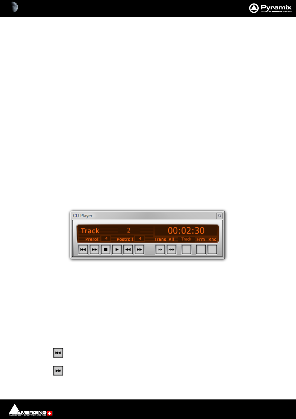
CD/SACD Mastering and Album Publishing : Show CD Player 26 - 609
Positive offset applied to the last PQ stop marker.
Offset before Index
Negative offset applied to PQ index marker.
ISRC default parameters
These parameters are used to automatically create or increment ISRC with the function ISRC > Create & ISRC > Inc
Selection are invoked from the Offsets and ISRC menus. (Right-click anywhere in the right-hand pane)
All these parameters are stored in the project. If you want to define the value as Default value, right click on the
value and select “Set as Default”.
Country Code
2 characters (GB, SW, FR etc…)
Producer
3 characters (W01).
Year of Referen ce
2 digits (02).
Designation Code
5 digits (00012, 80010).
Increment by
Used to auto increment the designation code part of the ISRC. The default value is “1”.
Show CD Player
View > Show CDPlayer in the CD/SACD Tab window displays an “always on top” small CD Player which enables
simulation of the CD playback (like a “real” CD player). The CD can be simulated with or without the markers offset.
Choose Show Offset in the Track list pane pop-up menu to take care of the offset The player has standard play-
back functions (play, stop, next, previous, scan etc…) and some special functions:
Preroll
Clicking in the number box allows a value (in seconds) to be entered.
Postroll
Clicking in the number box allows a value (in seconds) to be entered.
Skip Track Backwards
Skip Track Forwards
CD Player floating Window
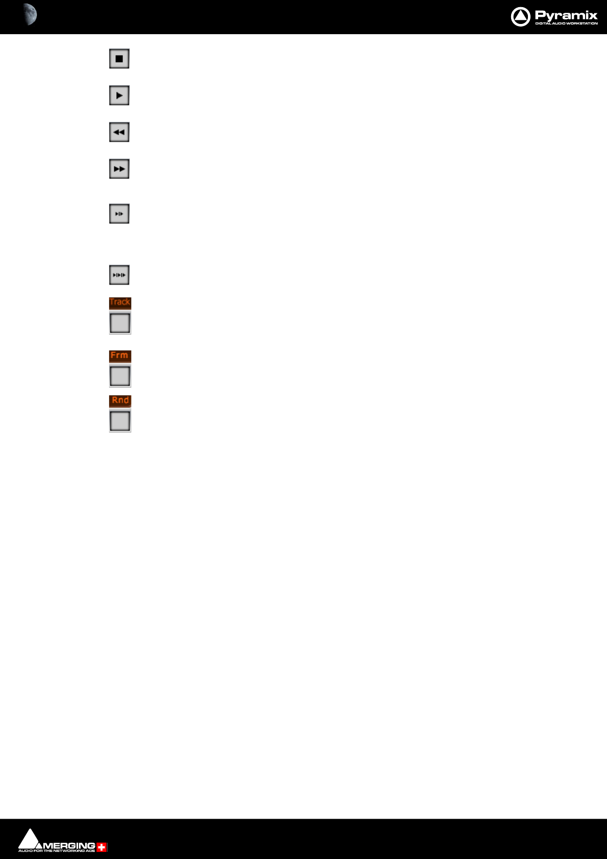
CD/SACD Mastering and Album Publishing : Ghost Track 26 - 610
Stop
Play
Rewind
Fast Forward
Play Transition Play the current track from the previous Stop marker minus pre-roll to the
current Start marker plus post-roll. Pre and Post roll can be edited directly on the CD player
interface.
Play All Transitions Has the same functionality as Play Transition but plays all transitions
between CD tracks.
Track Clicking on the third from the right button cycles through four different time display
options. Elapsed time from start of CD, Time remaining from the End of the CD. Elapsed time
of Track and Time remaining from end of Track
Frame Shows/hides the CD frames display
Rnd
Ghost Track
Normally a CD begins from the first track which has a 2 second pause. Pyramix allows you to modify this and create
a ghost track; a track before the first track. To accomplish this simply add a CD Index Marker at the beginning of
your ghost track, before the first start marker. You can also edit the pause of the first track then this will create or
move the ghost marker index for you.
Multiple CDs or versions in one Project
All CD Information and CD Markers can be either "global" or per Track Group. Each Track Group that has the Desti-
nation type and Free Markers enabled has its own CD Information and CD Markers. This enables multiple versions
of PQ editing for an album to be handled and for multiple CD albums in the same document. The CD Info and
Markers displayed in the CD Tab Window follow the currently selected Track Group.
Red-Book Validation
Validate PQ: This function ensures that the PQ conforms to the Red Book specifications by carrying out the fol-
lowing checks and corrections.
• When a pause is less than 1 second, the pause is removed. (The offset is automatically dealt with).
• Track Length is set to 4 second if it is less. (The offset is automatically dealt with).
• Track count is reduced to 99 if greater
• ISRC is removed if it is incorrect
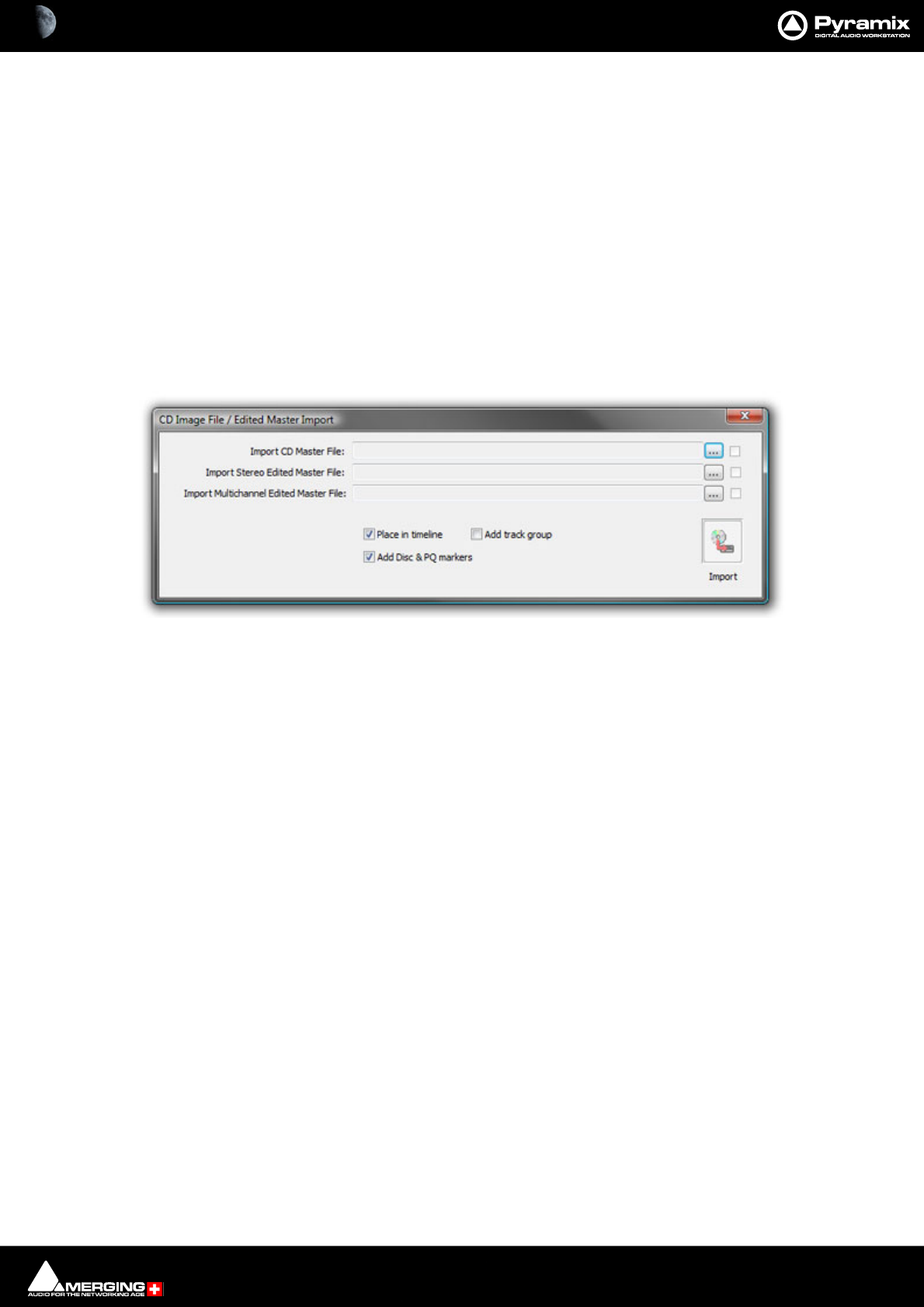
CD/SACD Mastering and Album Publishing : DDP Import 26 - 611
• UPC/EAN is removed if it is incorrect
This function an be undone if necessary.
DDP Import
You can use the DDP import function Project > Import > DDP Import to import a DDP tape or file and generate a
new CD image file. From this CD image file you can burn a CD or generate a new DDP tape.
CD Image File / SACD Edited Master Import
Import audio and PQ Markers from a CD Image file or SACD Edited Master. Project > Import > CD Image File /
SACD Edited Master Import.
Each ... button opens a File Browser Window to locate the desired file(s).
The boxes at the bottom of the screen determine how the data will be processed on import.
Place in Timeline When ticked the audio will be placed in the Timeline on an appropriate number of
Tracks.
Add Track Group When ticked a Track Group will be created containing all the relevant audio tracks.
Add Disc & PQ markers When ticked Disc and PQ markers will be added to the Marker bar.
SACD Functions
Accessed from the right-click context menu:
CD Image File / Edited master Import dialog
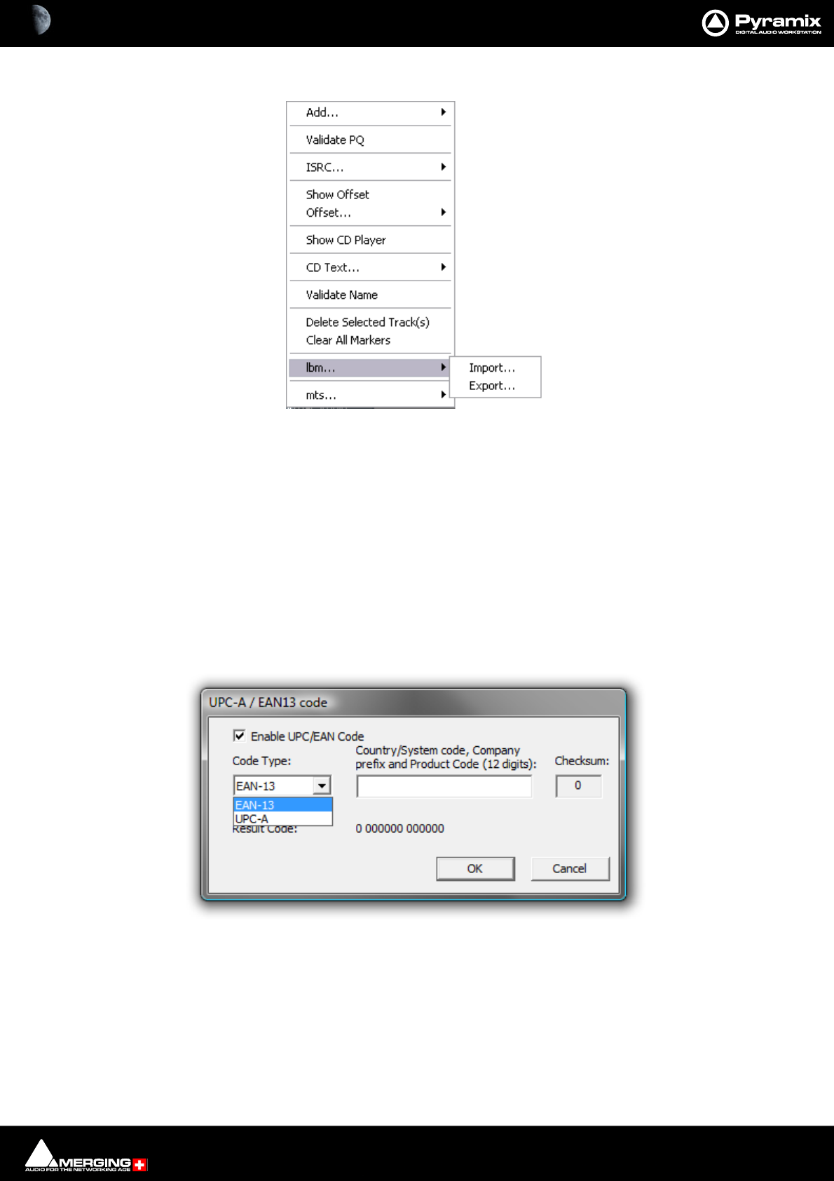
CD/SACD Mastering and Album Publishing : Exporting Projects to CD Image Files 26 - 612
lbm...
Import... / Export...
Opens a Windows browser window to save or load SACD text .lbm files.
mts...
Opens a Windows browser window to save or load SACD text .mts files.
Exporting Projects to CD Image Files
To export a previously Marked Composition to a CD-R image file and Cue Sheet text file:
Open the CD/SACD Tab window. Fill in CD information as appropriate. Clicking in the UPC/EAN Code field opens
the UPC-A / EAN13 code dialog:
UPC/EAN capture for CD/SACD Albums, Discs and Areas is handled via this dialog box.
Enable UPC/EAN Code: When ticked, UPC/EAN Code is enabled.
Code Type: offers a choice of UPC-A or EAN-13 barcode formats. Enter the 11 or 12 digit Company prefix and
Product Code. The checksum is calculated automatically and the resulting code displayed. Click OK to enter the
result in the field.
The number of digits is checked according the type of code and the CheckSum: digit (the last one) is automatically
calculated (to ensure its validity).
lbm... sub-menu
UPC-A / EAN-13 code dialog
CD/SACD Mastering and Album Publishing : Exporting Projects to CD Image Files 26 - 613
Moreover, the TOC information part of a Pyramix generated CDImage file (PMI) will always contain a 13 digits
UPCEAN code (left 0-padded if UPC-A type code) or no UPCEAN code at all if the field is left blank.Choose Project
> Generate CD Image / SACD Edited Master. This opens the Generate CD Image dialog.
Select a CD-Disc from the left-hand pane.
Target Settings
Image Format
Choose the required format from the drop-down list. Options available are:
Red Book CD Image (Stereo 16 bit 44.1kHz) Produces a disk image compliant with the CD ‘Red
Book’ standard.
Digital Release 24 bit Linear PCM (for PCM deliveries) Improves quality for Album Publishing
formats since no intermediate 44.1kHz 16bit step is involved. Please see:
Album Publishing on page 616
Digital Release 32 bit Floating point PCM (for DSD deliveries)
SACD Edited Master - Mixing Mode
Image Name
Type a suitable name for the image.
Image Location
The combo box has a list of all mounted media folders or you can use the button to open the Choose a
media folder to mount dialog.
Mix Sources
Double clicking the box on a Mix Source toggles it active or inactive.
Note: Only one bus can be selected. Inappropriate choices are hidden. E.g. a multichannel bus
when Red Book CD is selected as the Image Format.
Generate CD Image / SACD Edited Master

CD/SACD Mastering and Album Publishing : Exporting Projects to CD Image Files 26 - 614
Mixdown Processing
Real Time
Tick the box if you want to generate in real time or if you wish to listen to the CD while the image is being gener-
ated.
Offline Controllers
Untick the box if you want to use a Hardware Controller while generating the image in realtime for e.g. changing
Monitor volume etc. or to fade out.
SRC Filter Type
If Sample Rate Conversion is necessary this option will be available. It uses the Merging technologies HeptaCon
technology. Choose the desired Filter Type from the drop-down list :
•Linear Phase features constant group delay, thanks to the linear phase, and has a symmetric impulse
response, but also longer rings. This offers the best preservation of stereo image. There will be a minimum
of phase distortion from the anti-aliasing filter.
•Minimum Phase features an asymmetric impulse response with minimum phase response. This gives the
lowest amount of phase variation along the frequency spectrum and allows slightly better results for tran-
sient sounds.
•Apodizing offers the steepest response around the Nyquist point and linear phase. It offers the best of
both worlds for the about the same computational effort as the 2 other designs. There is a steep transition
band in the LPF filter using an almost linear phase. Arguably this is the best compromise between linear
and minimum phase types.
Dithering
Note: There is no necessity to manually disable dither in the Mixer.
There is a choice between two dither processing units:
Use Mixer Settings (default)
Applies the same treatment as the Mixer's Dither (parameters are those selected in the Mixer) or
Use 16 bits WLC/Noise Shaper
This is the same as the dither in v4.2, available even if no SRC is applied. The combo box offers a choice of settings:
Select the required quality of Noise Shaping from the drop-down list.
1st Order is simple single order shaping with
8th Order and
49th Order offering improved quality.
A higher quality setting will produce better results, but the processing time will also increase.
Generate CD/SACD dialog - Dither options


CD/SACD Mastering and Album Publishing : Album Publishing 26 - 616
Album Publishing
Digital Release
Overview
Online downloadable album publishing is tending to supersede classic Audio CD production and Pyramix
includes features intended to make the process of generating suitable files easier.
Formats supported currently:
•FLAC (lossless compression),
•Ogg Vorbis (lossy compression),
•WAVE (uncompressed)
•AIFF (uncompressed)
•PMI CD Image
•MTFF (uncompressed or lossless compression)
•DSF (uncompressed) DSD64, DSD128, DSD256
•DSDIFF Edited Master
•LC-AAC (lossy compression)
•MP3-ABR (lossy compression)
Multiple formats and multiple versions of each format with different settings can be generated simultaneously.
Album Publishing is available in four ways:.
In the Generate CD Image window :
• As an additional output or outputs when generating a PMI CD Image from a Pyramix Timeline.
• As a stand alone Digital Release from a Pyramix Timeline.
In the separate application DiscWrite
• As an additional output or outputs when making a disk from a PMI CD Image or DDP file.
• As a stand-alone Digital Release from a PMI CD Image or DDP file.
For users wishing to deliver high resolution files without generating a PMI CD Image (e.g. 96k, 192k-24bits FLAC/
OGG/WAV/AIFF/MTFF) from a higher than 44.1k project, the Digital Release Target format will ensure optimal
quality throughout the processing workflow by creating a stereo mixdown (same sampling rate as project, 24 bit
resolution in MTFF format) and using this audio file as input for Album Publishing processing.
CD/SACD Mastering and Album Publishing : Album Publishing 26 - 617
Album Publishing Settings
Generate CD Image and Publish Album
Proceed exactly as you would when making a CD Image. In the Generate CD Image / SACD Edited Master win-
dow ensure that the Album Publishing checkbox in the Export section is ticked. Click on the adjacent Settings
button to open the Album Publishing options Properties dialog, make the appropriate settings and click Gen-
erate Image to commence the process.
Target Settings
Digital Release
If the release is purely for download/streaming proceed as you would when making a CD Image. In the Generate
CD Image / SACD Edited Master window select one of the Digital Release formats in the Target Settings :
Image Format dropdown.
Note: Rather than ticking the Album Publishing checkbox when CD Image (Red Book) is the
target, using Digital Release as the target instead will avoid an unnecessary intermediate con-
version to 44.1kHz 16 bits. This is obviously desirable when the original material is at a higher
sampling rate and or bit depth.
Generate CD Image / SACD Edited Master : Album Publishing check box
CD/SACD Mastering and Album Publishing : Album Publishing 26 - 618
Various items in the Generate CD Image / SACD Edited Master window change to reflect the Digital Release selec-
tion:
Target Settings
Image Format
Red Book CD Image (Stereo 16 bit 44.1khz
Digital Release 24 bit Linear PCM (for PCM deliveries)
Digital Release 32 bit Floating Point PCM (for DSD deliveries)
SACD Edited Master - Mixing Mode
Note: Multichannel only possible when supported by the target format.
Note: Digital Release 32 bit Floating Point PCM creates a DSD Digital Release in 32bit MTFF to
allow for the transmission of +0dBFS information for DSD delivery. This enables DSD files to be
published while taking advantage of the extra [0, +3] dB DSD dynamic range allowed by the DSD
domain.
Digital Release file Name
The file has the same name as the CD Album by default. Type an alternative in the field if required.
Image Location
Click on the down arrow to choose a folder (mounted currently) where the file will be written. Or click on the ...
button to open the Choose a media folder to mount dialog.
Note: The Image file is retained. If you wish to delete it, use a Windows file browser to navigate to
the location chosen and delete the file.
Generate CD Image / SACD Edited Master : Digital Release (Stereo or Mch)
CD/SACD Mastering and Album Publishing : Album Publishing 26 - 619
Mix Sources
Double clicking the box on a Mix Source toggles it active or inactive. Only one bus may be selected at a time. If a
multi-channel bus is selected a drop-down offers a choice of channel mappings.
Mixdown Processing
Real Time
Tick the box if you want to generate in real time or if you wish to listen to the output while the image is being gen-
erated.
Offline Controllers
Check the box to turn any connected controllers off during the image generation process.
SRC Filter Type
If Sample Rate Conversion is necessary this option will be available. It uses the Merging technologies HeptaCon
technology. Choose the desired Filter Type from the drop-down list :
•Linear Phase features constant group delay, thanks to the linear phase, and has a symmetric impulse
response, but also longer rings. This offers the best preservation of stereo image. There will be a minimum
of phase distortion from the anti-aliasing filter.
•Minimum Phase features an asymmetric impulse response with minimum phase response. This gives the
lowest amount of phase variation along the frequency spectrum and allows slightly better results for tran-
sient sounds.
•Apodizing offers the steepest response around the Nyquist point and linear phase. It offers the best of
both worlds for the about the same computational effort as the 2 other designs. There is a steep transition
band in the LPF filter using an almost linear phase. Arguably this is the best compromise between linear
and minimum phase types.
Dithering
Note: There is no necessity to manually disable dither in the Mixer.
There is a choice between two dither processing units:
Use Mixer Settings (default)
Applies the same treatment as the Mixer's Dither (parameters are those selected in the Mixer) or
Use 16 bits WLC/Noise Shaper
This is the same as the dither in V4.2, available even if no SRC is applied. The combo box offers a choice of settings:
Select the required quality of Noise Shaping from the drop-down list.
1st Order is simple single order shaping with
8th Order and
49th Order offering improved quality.
A higher quality setting will produce better results, but the processing time will also increase.
Generate CD/SACD dialog - Dither options

CD/SACD Mastering and Album Publishing : Album Publishing 26 - 620
Controllers
Offline Controllers
Untick the box if you want to use a Hardware Controller while generating the image in realtime for e.g. changing
Monitor volume etc. or to fade out.
Post Processing Album Publishing
Check the Album Publishing box to generate files in one or more formats.
Click on the Settings button in the Album Publishing section to open the Album Publishing options Proper-
ties dialog, make the appropriate settings and click Generate Image to commence the process.
CD/SACD Mastering and Album Publishing : Album Publishing 26 - 621
Settings
Output Formats
All output formats currently added are listed here. Tick the check-box next to the name to generate an album in
this format. Multiple formats may be selected. Multiple instances of the same format with different settings can be
produced simultaneously. For example, you could produce two FLAC and three WAV versions, with different set-
tings at the same time.
Album Publishing options Properties dialog

CD/SACD Mastering and Album Publishing : Album Publishing 26 - 622
The settings on the right of the dialog are specific to each instance of each format and reflect the format instance
highlighted in the Output Formats list. (In the above screenshot FLAC is highlighted and the settings are specific
to this.
Note: Double-clicking an entry in the Outputs Formats list opens the Modify Output Format
dialog which is functionally identical to the Add Output Format dialog.
Add - Adding Output Formats
Clicking on Add opens the Add new output format dialog. (See below)
The formats available currently are:
•FLAC (lossless compression),
•Ogg Vorbis (lossy compression),
•WAVE (uncompressed)
•AIFF (uncompressed)
•PMI CD Image
•MTFF (uncompressed or lossless compression. Merging Technologies File Format)
•DSF
•DSDIFF Edited Master DSD64, DSD128 or DSD256 Enables DSD Edited Masters to be produced for e.g.
future SACD delivery.
• LC-AAC (lossy compression. Low Complexity Advanced Audio Coding.)
•MP3 (lossy compression. MP3 Average Bit-Rate compression or the more aggressive VBR)
CD/SACD Mastering and Album Publishing : Album Publishing 26 - 623
Click on the Add button to open the Add New Output Format dialog.
Format Choose the format required from the drop-down list.
Sampling Rate The default is No Change in which case the Project sampling rate will be used.
Otherwise, choose the required sampling rate from the drop-down list.
Wordlength The default is No Change in which case the Project Wordlength will be used. Other
wise choose the required Wordlength from the drop-down list.
Dither Noise Shaping Filter This is based on MT-r Dither using Triangular Noise with the choice of None, High
Pass or Equal Loudness
SRC filter type For appropriate formats the drop-down offers the choice of :
Linear Phase Features constant group delay, thanks to the linear phase, and has a sym-
metric impulse response, but also longer rings. This offers the best preser-
vation of stereo image. There will be a minimum of phase distortion from
the anti-aliasing filter.
Minimum Phase Features an asymmetric impulse response with minimum phase response.
This gives the lowest amount of phase variation along the frequency spec-
trum and allows slightly better results for transient sounds.
Apodizing Offers the steepest response around the Nyquist point and linear phase. It
offers the best of both worlds for the about the same computational effort
as the 2 other designs. There is a steep transition band in the LPF filter using
an almost linear phase. Arguably this is the best compromise between lin-
ear and minimum phase types.
Add new output format dialog

CD/SACD Mastering and Album Publishing : Album Publishing 26 - 624
Sigma Delta Type For appropriate formats the drop-down offers the choice of:
SDM D
SDM Trellis E (8paths)
SDM Trellis E (16paths)
SDM Trellis E (24paths)
SDM Trellis E (32paths)
Post-SRC Gain (dB) Gain adjustment made here is applied before Sigma Delta (DSD output format) or
after SRC (PCM output format).
Click on OK to add the format to the Output list and close the dialog.
Click on Cancel to close the dialog without adding a new format to the output list.
Settings for (format name) export
One contiguous audio file + Cue File When ticked a single contiguous audio file and a Cue file will be generated.
Unicode (UTF8) encoded CUE Sheet When ticked a Unicode CUE Sheet is also generated. (CDEx generates CUE
files this way while ExactAudioCopy uses ASCII/multibyte coding.)
One audio file per track When ticked an audio file is produced for each track in the Album.
Include Pause When ticked (default) CD pauses are included. Untick to produce CD Pause
free exports.
Compression Setting :
The slider varies the compression settings.
For FLAC the choice is on a scale between 0 - Fast Encoding and 8 - Best compression.
For Ogg Vorbis the choice is on a scale between ~64kbps - Lower quality - smaller files and ~500kbps - Higher
quality - bigger files.
For MTFF the choice is between Not Compressed and Lossless compressed.
For LC-AAC the choice is on a scale between 8kbps - Lower quality - smaller files and 320kbps - Higher quality
- bigger files.
For MP3 the choice is on a scale between 32kbps - Lower quality - smaller files and 320kbps - Higher quality -
bigger files.
File Naming and Destination
Contiguous audio files convention :
For a Single contiguous file the file naming can be specified by typing in the field and tags (e.g. <TagName>) can
be used (information will be retrieved from the Disc info. Use upper/lower case for tag names to change the
default capitalization :
• <FileFormat> When substituted by the name of the output format a subfolder is created for that format.
• <DiscTitle> Album title
• <DiscPerformer> Album artist
• <DiscSongwriter> Album songwiter
• <DiscComposer> Album Composer
• <DiscArranger> Album Arranger
• <UPCEAN> Album UPC/CEAN code
• <SampRate> Target Sampling Rate
• <Wordlength> Target Resolution
• <DiscNum> Disc Number
CD/SACD Mastering and Album Publishing : Album Publishing 26 - 625
One file per track convention :
For One file per CD Track, the file naming can be specified by typing in the field and tags (e.g. <TagName>) can be
used (information will be retrieved from the Disc/Track CD-Text info and Track number). Use upper/lower case for
tag names to change the default capitalization :
• <FileFormat> When substituted by the name of the output format a subfolder is created for that format.
• <DiscTitle> Album title
• <DiscPerformer> Album artist
• <DiscSongwriter> Album songwiter
• <DiscComposer> Album Composer
• <DiscArranger> Album Arranger
• <UPCEAN> Album UPC/CEAN code
• <TrackTitle> (only for one file per CD Track)
• <TrackPerformer> (only for one file per CD Track)
• <TrackSongwriter> (only for one file per CD Track)
• <TrackComposer> (only for one file per CD Track)
• <TrackArranger> (only for one file per CD Track)
• <SampRate> Target Sampling Rate
• <Wordlength> Target Resolution
• <DiscNum> Disc Number
• #,## or ### (only for one file per CD Track) : Track number, with eventual leading 0(s).
For both Contiguous and One File Per Track the buttons on the right have these functions:
The <> button shows a list of tags which, when selected are added to the field.
The Presets button shows the list of available factory presets and offers the option New to create a new User pre-
set from the present contents of the field. User Presets are stored in a separate file.
The ? button pops up a list of available tags e.g. :
? List of available tags

CD/SACD Mastering and Album Publishing : Album Publishing 26 - 626
Creating Sub-folders
Subfolders are created by adding a / or \ in the naming convention field.
To create a subfolder per File Format, enter :
<FileFormat>/ (e.g. <FileFormat>/<TrackTitle> - <TrackPerfomer> => WAV/Transmission - Sonic Rade)
To create a subfolder per File Format and Sampling Rate, enter :
<FileFormat><SampRate>/ (e.g. <FileFormat><SampRate>/<TrackTitle> - <TrackPerfomer> => WAV96k/
Transmission - Sonic Rade)
To create a subfolder per File Format, and inside this subfolder, other subfolders per Sampling Rate, enter :
<FileFormat>/<SampRate>/ (e.g. <FileFormat>/<SampRate>/<TrackTitle> - <TrackPerfomer> => WAV/
96k/Transmission - Sonic Rade)
Published files which could not be written to a specific destination folder will be written by default to
C:\User\<login name>\My Music\<filename(s)>
Output Folder :
The current output path is shown (if any). Clicking on the ... button opens a File Browser window where a suitable
path may be selected and a destination folder selected or created.
Misc
Generate Disc Summary XML file (required for publishing on Abeille Musique, HDTracks, ...) Tick the box to
generate an additional XML file summarizing the disc information as specified by a
few online music stores like Abeille Musique and HDTracks.
The resulting file will be placed and named according to the specified Output Folder and Contiguous Filenaming
convention.
OK
Click on OK to accept the settings and close the dialog.
Cancel
Click on Cancel to reject any changes made to settings and close the dialog.
Encoding Process
When all the relevant settings have been made click on the Start button in the main Generate CD Image/ SACD
Edited master dialog.
CD/SACD Mastering and Album Publishing : Album Publishing 26 - 627
When the initial pass completes the encoding process begins and the Album Publishing Encoding dialog
appears:
Source Summary
Shows a digest of the job parameters. Cover Art is shown at top right. (If present)
The green bar shows progress.
The table shows information about each generated file.
The icon on the left indicates:
Processing underway
Processing could not start
Processing Successful Process was successfully completed and verified. Peak value is
below the maximum value (Max 0 dB Fs for PCM Files - max 3.1 dB SACD)
Warning This icon appears if the processed file contains peaks exceeding the following:
• Full scale: Above 0 dB
• True Peak: Above 0.1 dB
• DSD: From and above 3.9 dB
Note: Note: a warning will occur if you cancel the publishing process
Album Publishing Encoding dialog
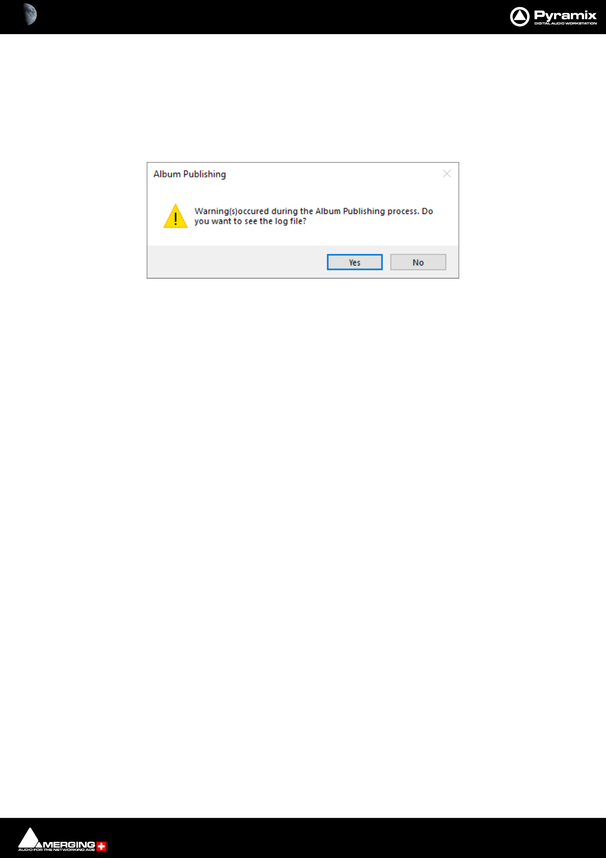
CD/SACD Mastering and Album Publishing : Album Publishing 26 - 628
The rest of the fields show:
Peak value In dB True Peak and dBFS
Nb Ch. The number of channels
Format The format of the generated file
Sampling Rate Sampling Rate of the generated file
At the conclusion of the encoding process, if any errors have occurred the warning dialog appears:
Ye s opens the log file in Notepad. No closes the dialog.
The log file is located in the destination folder of the published files
Cover Artwork
A picture file can be embedded, PNG or JPEG. Recommended size is 300x300. High resolution (e.g. 1600x1200)
pictures may fail to display on some media players and are not recommended.
Output formats supported: Ogg/Vorbis, FLAC, MP3, MP4-M4A, AIFF and MTFF
In Pyramix clicking on the Front Cover field in the Tree Info section of the CD-SACD Tab Window opens a browser
window to select a picture file.
In DiscWrite: the Settings button has a Select Cover Artwork option when Target is set to Album Publishing.
Note: Recommended size is 300 x300 for MP3/ID3 tag. (iTunes may be up to 600 x 600 separate
to Wave files). High resolution (e.g. 1600 x1200) pictures may fail to display on some media play-
ers and are not recommended.
Note: The Cover artwork is embedded in a MTFF Digital Release when generated from Pyramix
Generate CD/SACD Image. The Cover artwork embedded into an MTFF can be utilized within
DiscWrite for Album Publishing without the necessity to specify a file.
Album Publishing Warning dialog

CD/SACD Mastering and Album Publishing : Standalone Album Publishing Application 26 - 629
Standalone Album Publishing Application
An Album Publishing standalone application is installed with Pyramix v11.1
An Album Publisher Short-cut Icon will appear on the desktop after installing Pyramix v11.1:
Album Publisher can also be installed in standalone mode from the Pyramix Custom Install option.
Standalone Album Publisher includes the MT Security Settings that may require the necessary keys depending on
the selected Output Media Formats.
Several instances of standalone Album Publishing can be running concurrently with independent Settings for
each instance (upon initial Settings changes)

CD/SACD Mastering and Album Publishing : Standalone Album Publishing Application 26 - 630
Cue Sheets
The Cue Sheet file is a metadata file which describes how the tracks of an album are laid out. Cue sheets are stored
as plain text files and commonly have a .cue filename extension. CDRWIN first introduced cue sheets, which are
now supported by many optical disc authoring applications and media players.
For an Audio CD, a Cue Sheet specifies titles and performers for the disc and its tracks as well as the names of one
or more audio files to be used. MP3, WAV and MTFF files are often used, although some programs support other
formats. Cue sheets are especially useful when burning or listening to live sets where all tracks are recorded in one
file
Generating Cue Sheet Files
A Cue Sheet file is only generated when Album Publishing is active, one or more Output Formats for export are
selected and One contiguous audio file + Cue file mode is active.
Cue Sheet file Contents
The Cue Sheet file will display information in this form when opened in a text editor the exact fields present will
depend on which fields are populated in the Tree Info section of the CD/SACD Tab :
REM Customer Name: “Ricardo Ryan”
REM Origination date: 8-18-2011
REM DATE 2011
REM DISCID 9507880a
PERFORMER "U2"
SONGWRITER "Bono"
FILE "G:\Digital Release\Test\Album.mp3" WAVE
TRACK 01 AUDIO
TITLE "Pride"
Album Publishing options Properties dialog - section
CD/SACD Mastering and Album Publishing : Standalone Album Publishing Application 26 - 631
INDEX 01 00:00:00
TRACK 02 AUDIO
TITLE "Unforgettable Fire"
INDEX 00 00:59:17
INDEX 01 01:56:57
TRACK 03 AUDIO
TITLE "Sweetest thing"
INDEX 00 03:08:5
INDEX 01 03:40:19
Audio Cue Sheet Compatibility
CD Burning
application
Tested Features
ImgBurn
v2.4.2.0
(freeware)
Ahead Nero
v6.3.1.15
Ahead Nero
v7.2.3.2
to Nero
v9.0.9.4
CDRDAO
(multi
platform
command line
app.
Open CUE file OK OK Crash OK
CD Text Disc Title OK OK - OK
CD Text Disc Performer OK OK - OK
CD Text Disc Songwriter ---?
Catalog Number (UPC/EAN) OK - - OK
CD Text Track Title OK OK - OK
CD Text Track Performer OK OK - OK
CD Text Songwriter ---?
Track ISRC OK OK - OK
PreGap / Pauses OK OK - OK
Index markers OK OK - OK

CD/SACD Mastering and Album Publishing : Standalone Album Publishing Application 26 - 632
Generating Album(s)
Clicking on Generate Image in the Generate CD Image / SACD Edited Master window initiates the process.
The generated files will be placed in the specified paths (folders will be created if necessary) and metadata will be
written based on the CD Image TOC + CD Text information.
Album Publishing Exported Metadata
The file exported will contain metadata sourced from the CD Authoring/CD Text fields.
Exported Fields:
• Encoding Tool
• Track title
• Artist (per track)
• Album artist (disc artist)
•Composer
•Album name
• Track number/Total number of tracks
• Disc number / Total number of discs
•ISRC code
• UPC/EAN code (as Barcode and Catalog Number)
• Label code (also as comment)
•Year
•Genre
• Comments
Tagging Formats:
• ID3v2: for AIFF, MP3
• Xiph Comments: for Ogg Vorbis and FLAC
• Quicktime metadata atoms: M4A
The field mapping between various Tagging formats (ID3v2, Xiph Comments, Quicktime metadata atoms) follows
the same convention as MusicBrainz Picard. Please see
http://wiki.musicbrainz.org/PicardTagMapping
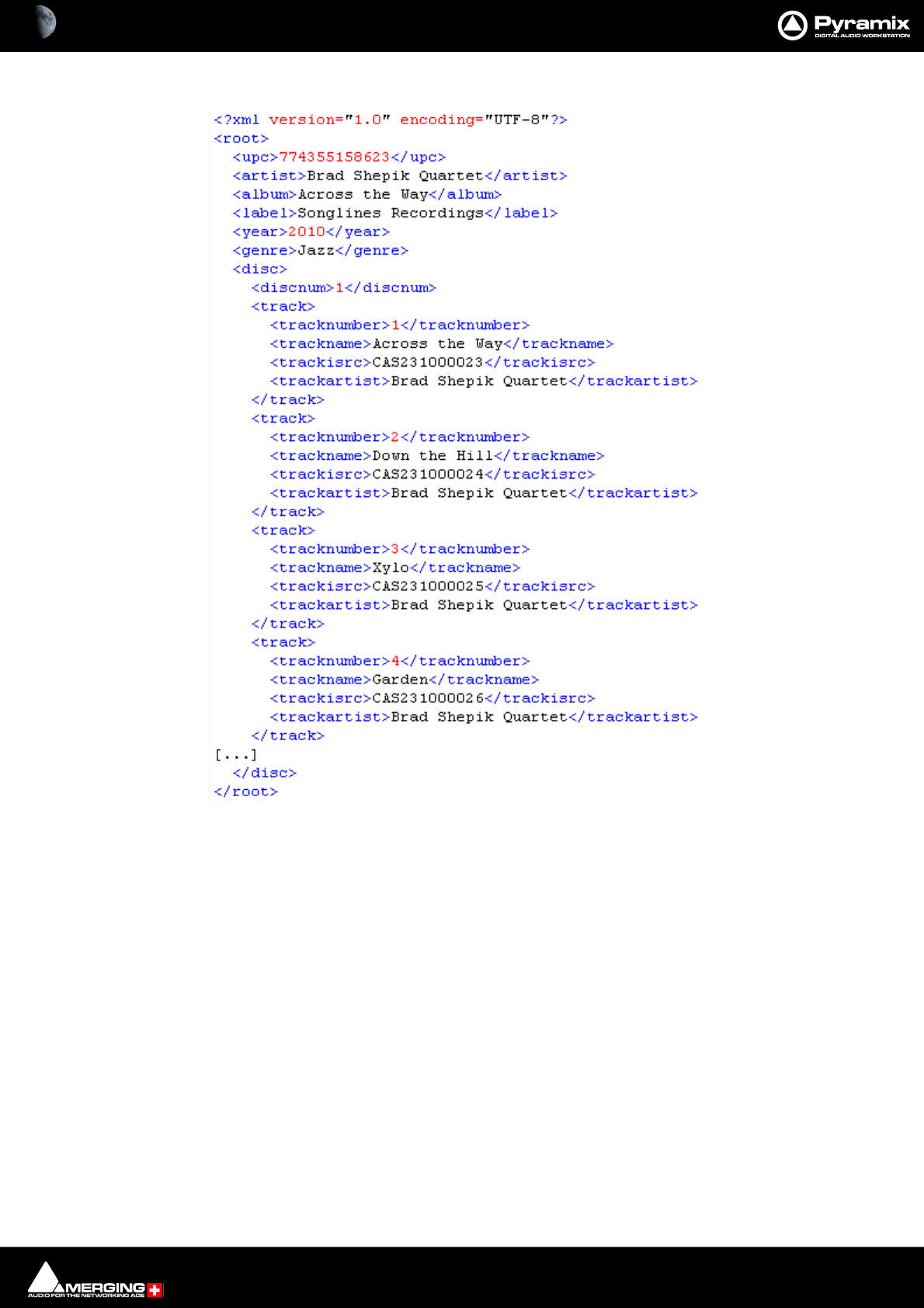
CD/SACD Mastering and Album Publishing : Standalone Album Publishing Application 26 - 633
Example of Exported File
Album Publishing Log File
A Log File is created in the selected Main Output Folder.
A notification will appear if an error occurred during the publishing process. Look in the Log File to help identify
the source of the error.
Example of Disc Summary XML file
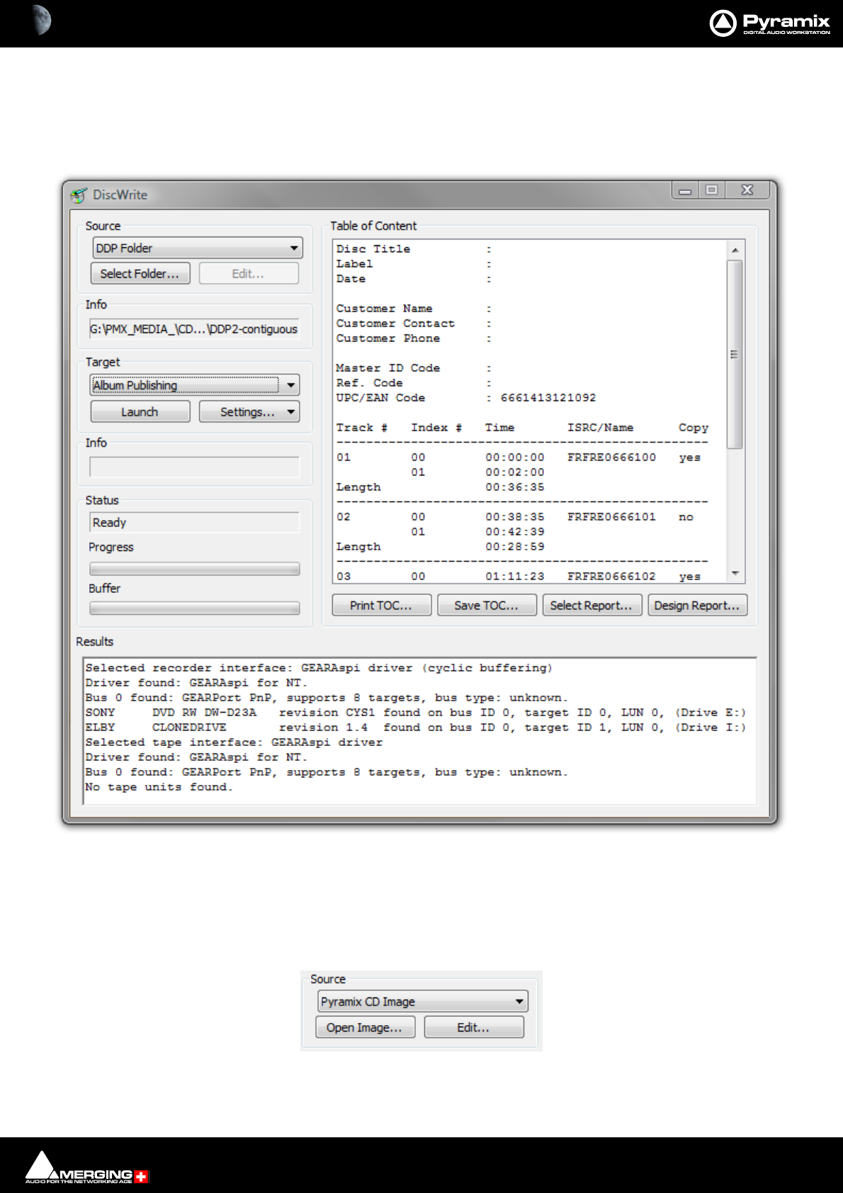
CD/SACD Mastering and Album Publishing : DiscWrite 26 - 634
DiscWrite
DiscWrite is a separate application bundled with Pyramix Virtual Studio that is used to write the CD image out to
a CD-R disc or a DDP image file to a folder or DDP tape drive.
Source
The drop-down list enables the user to choose between a Pyramix CD Image, all installed optical drives, a U-
Matic Tape or an existing DDP master file as the source for the new CD-R or DDP file.
Source - Pyramix CD Image
DiscWrite application window
DiscWrite Source - CD Image
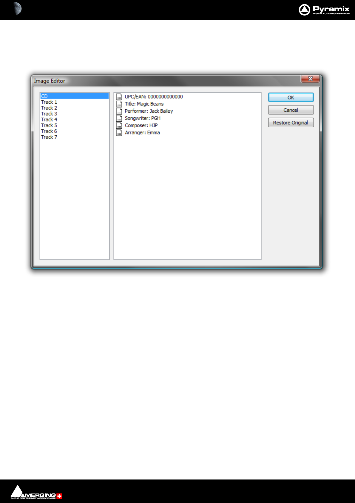
CD/SACD Mastering and Album Publishing : DiscWrite 26 - 635
When the chosen Source is Pyramix CD Image, the left-hand button below the Source drop-down list will be
Open Image... Clicking on Open Image... leads to a file browser window where you can navigate to the desired
image file. The right-hand button will be Edit...
Clicking on the Edit... button opens the Image Editor dialog:
CD-Text can be edited freely.
Note: Opening a pmi image with Discwrite may display the following warning: CD text has
been truncated:
CD Text Notes:
A CD-Text Block may be made up of a maximum of 256 so-called Packs.
4 packs are used for internal purposes.
The other 252 packs can be used for CD-Text information.
Each pack contains 12 characters.
Thus a total of 3024 characters of CD-Text can be saved.
One character is needed as a separation character per Track, thus with the maximum number of 99 Tracks (+ 1
pseudo-track for the CD Title), 2924 characters remain. If Artist and Title are entered for every Track, 2 * 100 char-
acters have to be subtracted, since Artist and Title are saved separately (so 2 separation characters per Track are
required), i.e. 2824 characters still remain - there are still 28 characters per Track (for Artist and Title, i.e. 19 charac-
ters each for Artist and Title or any other distribution)!
Restore Original
Undoes any changes made since the dialog was opened.
DiscWrite Image Editor dialog
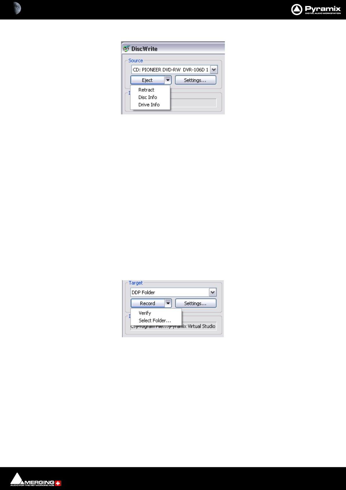
CD/SACD Mastering and Album Publishing : DiscWrite 26 - 636
Source - CD Drive
When the chosen Source is CD: ...., the left-hand button below the Source drop-down list will be Eject and the
right-hand one Settings...
Eject
opens the loading tray of the selected optical disk drive (or ejects the disk if the drive is a slot-loader). Clicking on
the down arrow next to the Eject button drops down a list of other optical disk drive commands.
Retract Closes the loading tray on the source drive
Disk Info Reads the disc information and displays it in the Results box
Drive Info Interrogates the optical drive firmware and displays information about the drive in
the Results box
Info
The Info box shows either the read speed of the optical drive or the path to the image file.
Target
The drop-down list enables the user to choose between any installed CD-R or DDP drives, a DDP Folder or Album
Publishing.
DDP Folder
When DDP folder is the selected target the button beside the Record button drops-down a list of options:
Verify Verifies the recording
Select Folder... Opens a Browser to enable a suitable folder to be chosen
DiscWrite Source - CD Eject Drop-Down
DiscWrite Target - CD Record Drop-Down

CD/SACD Mastering and Album Publishing : DiscWrite 26 - 637
Settings...
This button opens a Settings window with DDP settings information and options.
Clicking on an entry reveals a drop-down with a list of available options for example Create Checksums file(s)
This drop-down offers the choice between:
•None
•CRC32
•MD5
•SHA
•All
The other entries in the list offer appropriate choices.
DiscWrite DDP General and Advanced Settings
DiscWrite DDP CreateChecksums file(s) Settings

CD/SACD Mastering and Album Publishing : DiscWrite 26 - 638
Album Publishing
When Album Publishing is the selected target the Record button changes to Launch :
Settings... opens the Album Publishing options Properties window. Please see: Settings on
page 621. When suitable settings have been made the Launch button initiates the Album export.
Cover Art
When Album Publishing is the selected target the down arrow to the right of the Settings button has a Select
Cover Artwork option.
Note: Recommended size is 300 x300. (iTunes up to 600 x 600) High resolution (e.g. 1600 x1200)
pictures may fail to display on some media players and are not recommended.
DiscWrite Target - Album Publishing
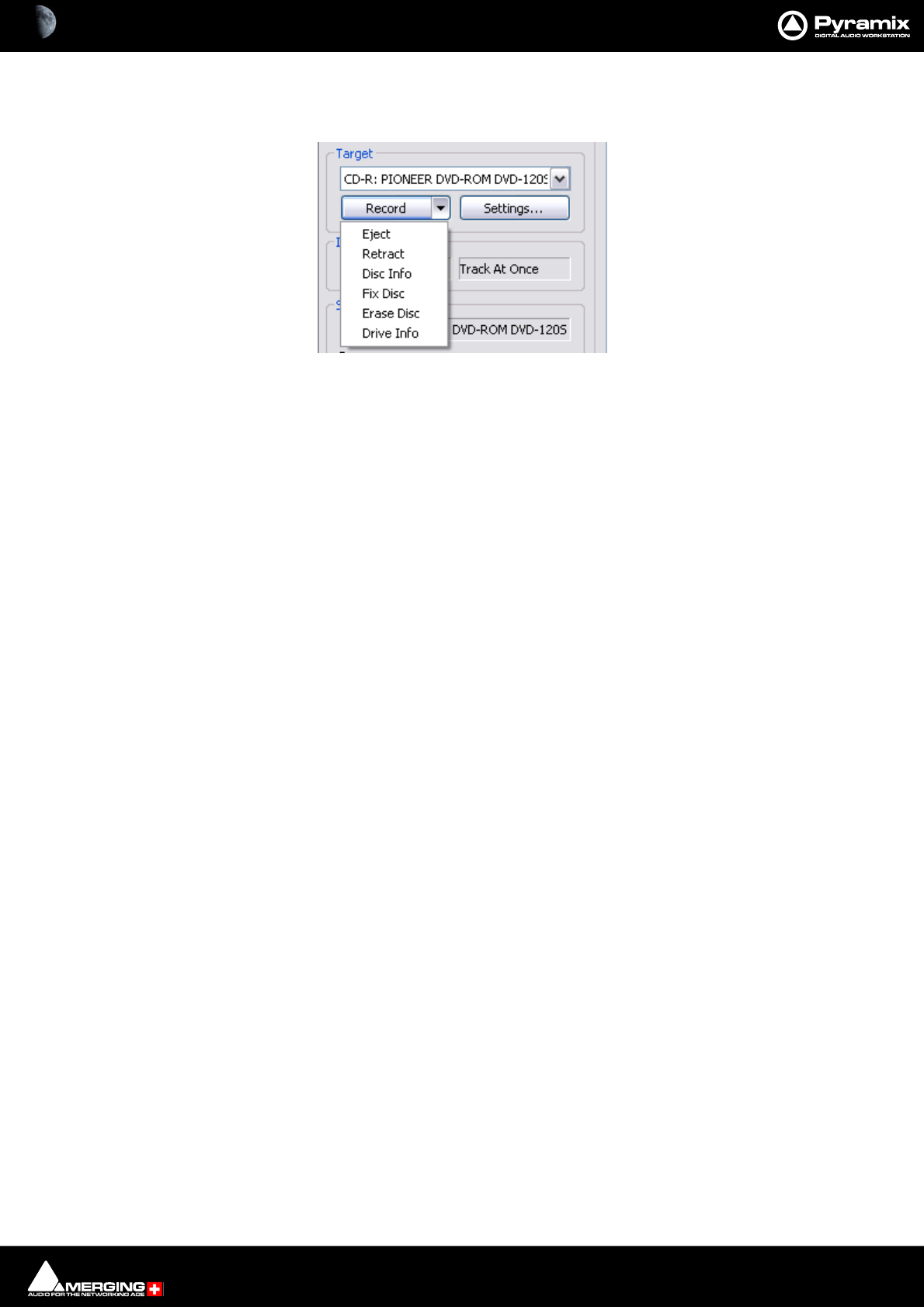
CD/SACD Mastering and Album Publishing : DiscWrite 26 - 639
CD-R/CD-RW
When a CD-R(RW) is the selected target, the arrow beside the Record button drops-down a list of options:.
Eject Opens the loading tray on the target drive
Retract Closes the loading tray on the target drive
Disk Info Reads the target disc’s information and displays it in the Results box
Fix Disc Writes the information necessary to allow a Track at Once disc to be read by a CD
player.
Erase Disc Erases a re-writable disc
Drive Info Interrogates the optical drive firmware and displays information about the drive in
the Results box
Settings...
The Settings... button is grayed out unless a suitable optical drive or image file has been selected. When available,
clicking on Settings... opens a dialogue with access to all relevant settings. In particular, this is where you can
choose between Disc-at-Once and Track-at Once modes. Use Disc-at-Once for maximum compatibility.
Record
Clicking on the Record button initiates the recording process.
Detailed reporting about the progress of the process is shown in the Results box as the recording is made.
Info
Shows the Write speed of the target drive or the path if you are writing a DDP file to a folder. Also shows the cho-
sen record mode, e.g. Track At Once or Disk At Once.
Status
Shows the status of the recording device/process
Progress
A ‘thermometer’ bar graphically shows the progress of the recording.
Buffer
Another ‘thermometer’ showing the state of the record buffer.
Results
This box displays detailed information about various aspects of the process depending on what you are doing at
the time.
Table Of Content
Displays the TOC in detail.
Print TOC...
Opens a Print Options dialog. The actual options available will depend on the printer you have selected.
DiscWrite Target - CD-R Record drop-down

CD/SACD Mastering and Album Publishing : DiscWrite 26 - 640
Save TOC...
Opens a File Browser dialog. Here, you can type a name for the TOC file and choose a suitable folder to save it in.
Select Report...
Opens a File Browser dialog where you can select a report style for the TOC
Design Report
Opens the Report Designer application. With this you can design your own report formats for TOCs.
Please see the Design Report List and Label Designer documentation, which is installed with Pyramix and can be
found here:
C:\Program Files\Common Files\Merging Technologies\LL\Docs\ListAndLabelDesigner.pdf
Optical Drives - Important Note:
Most, if not all the issues you might encounter when working with optical drives, Windows and DiscWrite can be
solved by installing the latest firmware for your drive. This, together with installation instructions, should be avail-
able from the drive manufacturer’s website. This is true for CD-Text writing, write speed & buffer issues, as well as
for CD-Import.
CD Text
CD-Text has been successfully tested with several high quality DVD-R and CD-R drives. However, DiscWrite and its
CD-text functionality should work with most of the writers available on the market, provided care has been taken
to install the latest available firmware for the unit.
A warning will appear when a non CD-Text writer is intended to be used to write a Disc Image containing CD-Text.
Compatibility with CD-Text can be confirmed in the Target area by making sure the desired drive is selected and
choosing Drive Info from the Record drop down menu.
Writing CD-Text (audio, disc at once): Yes. Should be found in the Supported write methods: section of the list
in the Results window. (You will have to scroll the list to find this)
Burning a CD-R
Launch DiscWrite. (A normal Pyramix installation places a DiscWrite icon on the desktop) To burn a CD-R from a
previously created CD image file:
1. In the Source section, click the Open Image... button, then navigate to and select a previously created CD
Image file (an .img or .pmi file).
2. In the Target section, click in the drop-down menu to select a CD-R device. DiscWrite should recognize a pre-
viously configured CD-R device which is also recognized by the OS itself.

27 - 641
www.merging.com/Pyramix
USER MANUAL
Productivity

Productivity : Locating Clips 27 - 642
Locating Clips
In projects containing a large number of Clips it can be very helpful to be able to find where a particular Media file
or files are being used. For example if you wish to replace all instances of a particular sound effect.
The Media Manager Tab Window Edit Menu has two commands to assist:
Locate Locates the Playhead Cursor to the start of the first (or only instance) of a single item
selected in the Media Manager list and Selects it in the Timeline
Show Usage Selects all instances in the Timeline of the item(s) selected in the Media Manager list and
zooms the Timeline to show them.
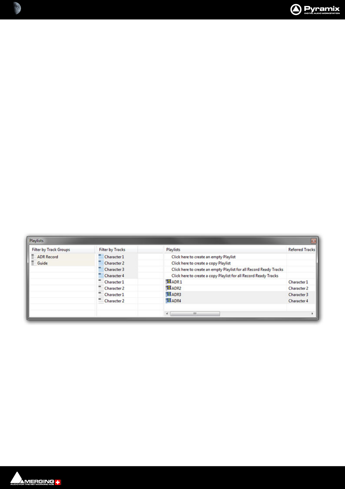
Productivity : Playlists 27 - 643
Playlists
Overview
Playlists in Pyramix are a way in which multiple takes of a recording can be held on a single timeline, in essence
keeping them in layers. Each layer is called a playlist and it contains its own EDL containing audio file, Clip Gain
and Envelope information.
The purpose of this is to be able to access multiple versions of a recording from the same place on the timeline
(cursor position) by switching the Playlist (layer) that the user is looking at.
Playlists can be managed and changed on a Track by Track basis, by Track Group, or the entire Timeline can be
affected at once if required. All of this is managed from the Playlist Tab, which allows views to be filtered and con-
trols, with a simple overview, which Playlist(s) is(are) affecting which Tracks on the Timeline.
New Playlists can either be Copy Playlists or Empty playlists. An empty playlist is a new layer on the Track contain-
ing no clips. A Copy Playlist makes a new layer but places into it the Clip information from the last layer used. The
Copy Playlist is a perfect tool when a record pass will not necessarily be recording the exact same thing over and
over again, and when it may be a requirement to hear previous recordings on either side of the latest drop in.
Application
Comp a Vocal Recording:
A vocalist comes in to do a Lead vocal overdub on a multitrack session recorded previously. The intention is to
record take after take of the vocalist singing in time with the rest of the music in as efficient a manner as possible.
By using a separate Playlist for each take, when the record in finished, the operator can then cycle quickly through
the layers to find the sections of the vocal they want, placing them in a final "destination" Playlist layer.
Playlists Tab Window
By selecting a Track Group or one or more Tracks in the Playlist Tab Window, you can:
• Create a new empty Playlist for these Tracks
• Create a new Playlist for these Tracks containing a copy of their current content
You can also:
• Create a new empty Playlist for all Tracks in Record Ready mode
• Create a new Playlist for all Tracks in Record Ready containing a copy of their current content
Double-clicking on a Playlist icon replaces the content of the Tracks it references with the version it contains.
Modifications made on the Tracks referenced by a Playlist are updated in the last recalled Playlist when another
one is recalled. A new Playlist can be automatically created for each recording for every recorded Track by check-
ing this option in Playlists section of Settings > All Settings > Project > Record.
Playlists Tab Window - floating
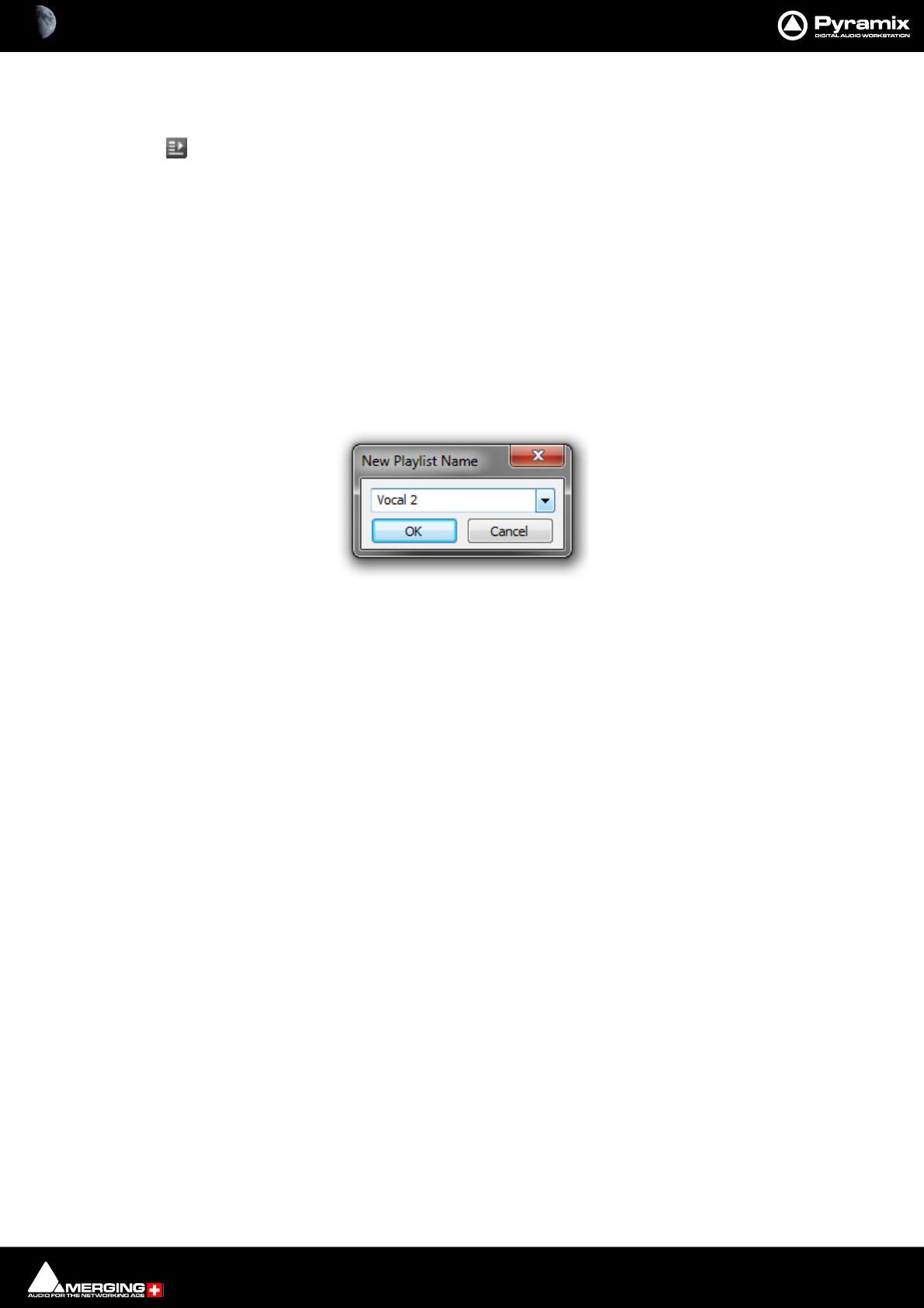
Productivity : Playlists 27 - 644
Playlist Button
Clicking the Playlist button in the Track Header pops up a menu with the following choices:
Create New Playlist
for all Record Ready Tracks
for all Tracks in Group/Strip
for this Track
Create Copy Playlist
for all Record Ready Tracks
for all Tracks in Group/Strip
for this Track
Each of these options opens the New Playlist Name dialog. However, for all Record Ready Tracks will only do so
when one or more Tracks is/are armed for recording.
Recall Playlist>
All the existing Playlists for the Track/Track Group are listed. Selecting one brings it to the top layer.
Merge Playlist
All the existing Playlists for the Track/Track Group are listed. Selecting one merges it with the current top layer.
Note: If you create a new Playlist on a Track with existing Cues these will be deleted from the
Track. If you wish to retain the existing material use Create Copy Playlist first and then create a
new Playlist or Playlists.
New Playlist Name dialog
Productivity : Bars & Beats 27 - 645
Bars & Beats
Overview
Bars & Beats mode is the method by which a recording or edit can be managed easily to ensure that the timing
within a song follows a rigid structure. The various tools within the module enable the user to record, edit and
manage the media coherently.
Activating Bar and Beats Mode
Simply click on Main in the Main Timescale Ruler and choose Bars & Beats. (Or View > Scales / Toolbars > Bars &
Beats.)
Once activated, this will show the Bars & Beats Timescale Ruler and grid on the Timeline, enable use of the Tempo
Map and open up the Bars & Beats Control Toolbar in the toolbar area at the top of the edit window.
Bars & Beats Toolbar
If you like working with toolbar buttons you may wish to turn on any or all of the Bars & Beats Toolbar buttons.
Settings > All Settings > Desktop Layout : View
In the Commands list change Toolbar Status to Present for:
Bars & Beats Toggles the Bars & Beats Timescale Ruler and Ruler Control Bar visible / hidden
Bars & Beats Settings Toggles the Bars & Beats Settings window visible / hidden
Bars & Beats Grid Toggles the Bars & Beats Grid visible / hidden
Tempo Map Toggles the Tempo Map visible / hidden
Note: When the Bars & Beats Timescale Ruler is not visible the other buttons are grayed out
and unavailable.
Scale : Settings : Grid : Tempo Map
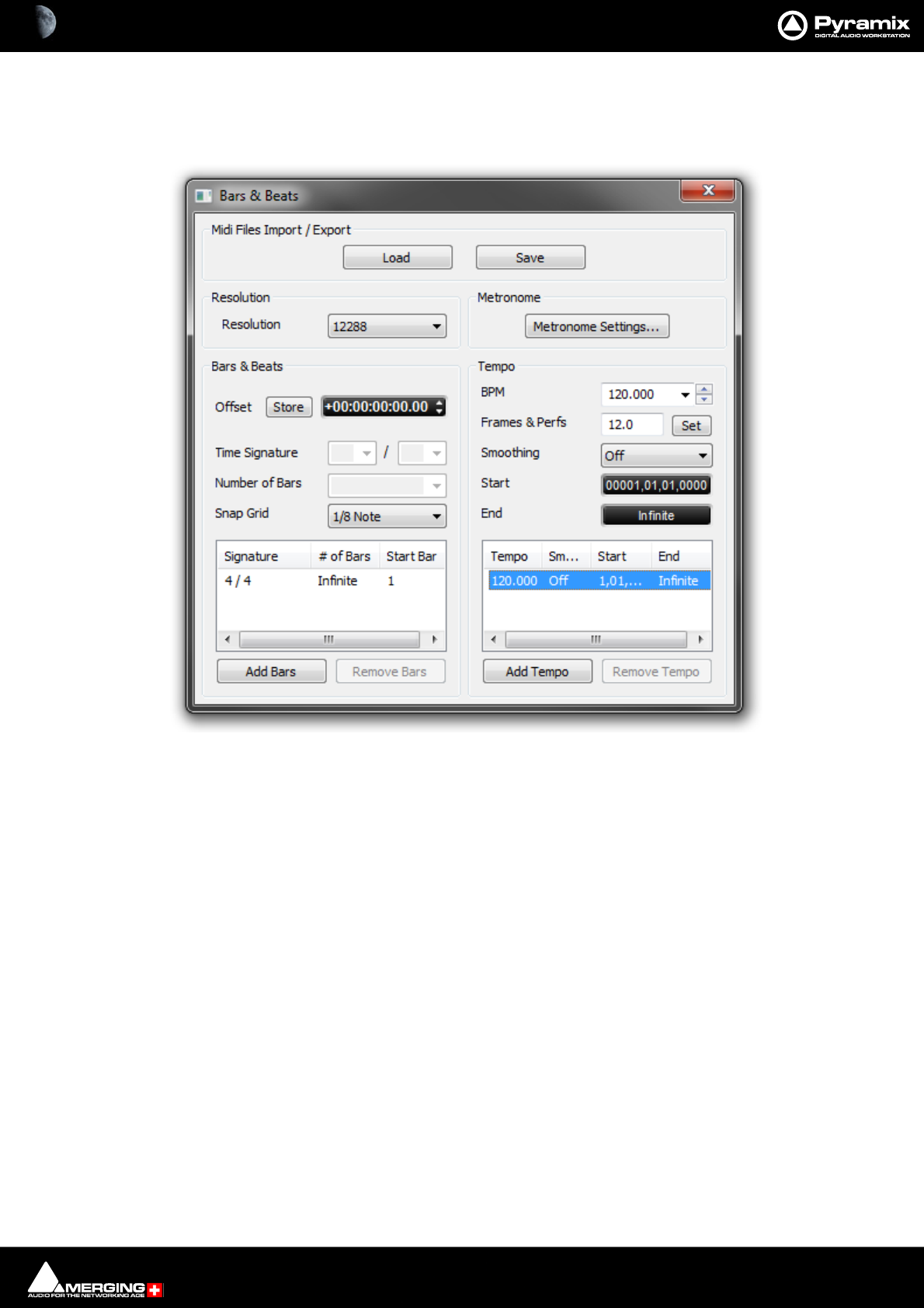
Productivity : Bars & Beats 27 - 646
Bars & Beats Settings
The Bars and Beats Settings window can be accessed by clicking on the Bars and Beats label in the ruler and
selecting Bars & Beats Settings or View > Scales / Toolbars > Bars & Beats Settings.
Here, you can set the grid Resolution, Metronome Settings including the sound, the Time Signature and manu-
ally edit the Tempo map to change between certain bars. Once made, these settings are saved with the project.
Midi Files Import / Export
Load
Save
Both buttons open a Browser Window to enable navigation to a file to load or a location to save to.
Currently, when type 2 Midi files are imported, only the Track 1 Tempo Map and Time Signature are
imported.
Resolution
Resolution Choose the required grid resolution from the drop-down list.
Bars & Beats Settings Window
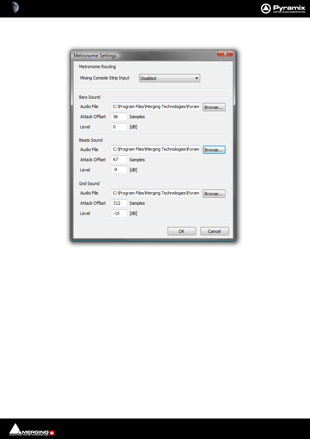
Productivity : Bars & Beats 27 - 647
Metronome
Metronome Settings... Opens the Metronome Settings dialog:
Note: The Metronome Settings can also be accessed by clicking on Metro on the Bars & Beats
Ruler Toolbar. See below.
Metronome Routing
Mixing Console Strip Input Choose a console strip for the Metronome sound from the drop-down list.
Bars Sound
Audio File Shows the audio file currently selected. Browse... opens a Browser window to
locate and select audio files.
Attack Offset Enter a value in Samples to adjust the exact timing.
Level Enter a value in [dB] to set the Bars Sound playback level.
The Beats Sound and Grid Sound settings are the same as for Bars Sound.
Any audio file can be used, for the Bars, Beats and Grid sounds. By default, some suitable WAV files are installed
with Pyramix in the same location where you installed the Pyramix software. By default. this will be:
C:\Program Files\Merging Technologies\Pyramix Virtual Studio\Metronome Bars.wav etc.
Bars & Beats
Offset Offsets the Bars & Beats scale start from the main Time Scale. Value can be typed
in the TimeCode register and or nudged up or down with the increment, decre-
ment buttons.
Store Offsets the Bars & Beats scale start to the current Playhead Cursor position.
Metronome Settings dialog
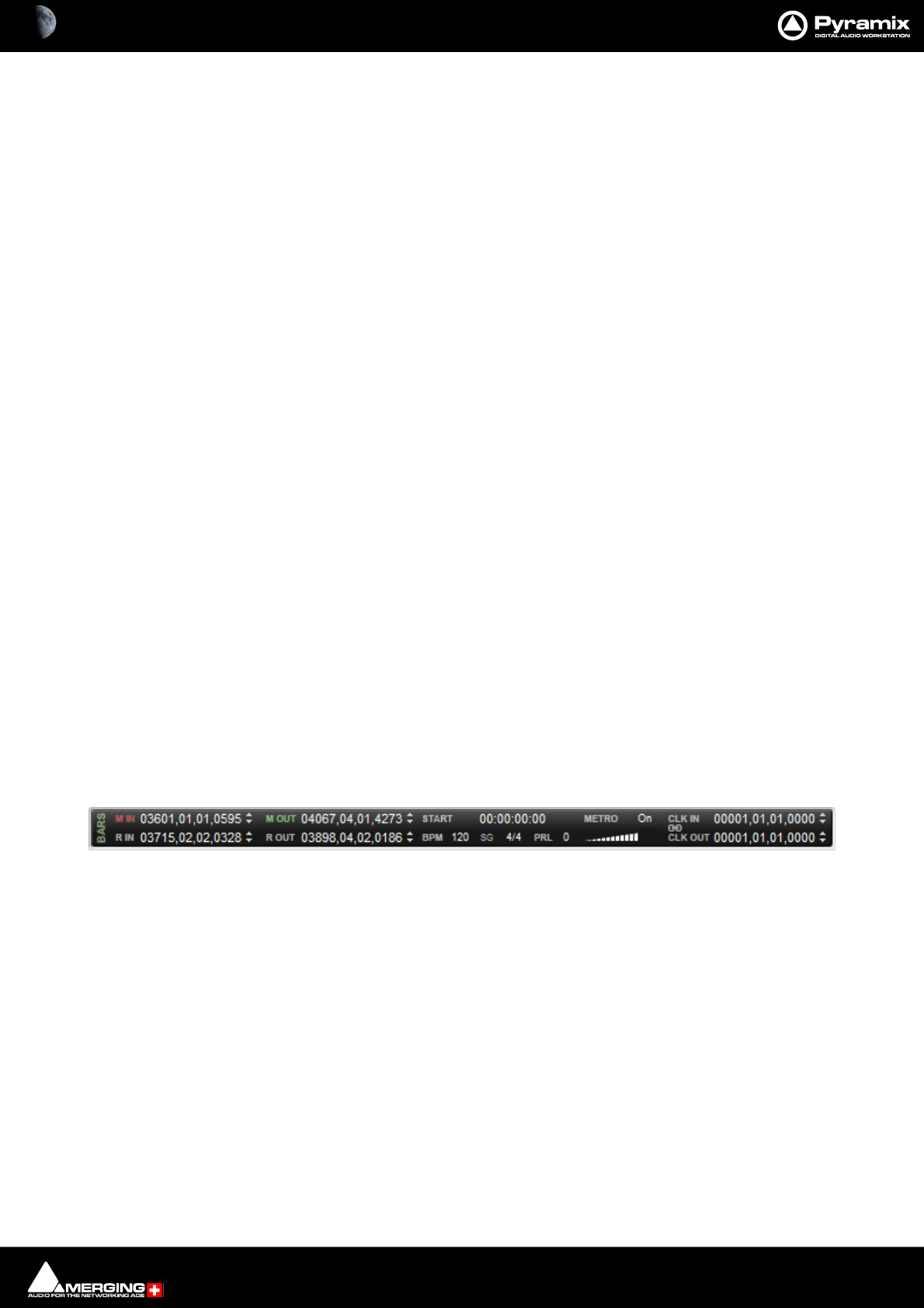
Productivity : Bars & Beats 27 - 648
Note: Offsets can be negative or positive.
Time Signature Set the Time Signature by selecting from the drop-down lists.
Number of Bars Type the Number of Bars required or choose Infinite from the drop-down list.
Snap Grid Select the required resolution from the drop-down list
The Information pane shows all currently defined Time Signatures. The Time Signature, Number of Bars and
Snap Grid fields reflect the values for the highlighted (selected) Bars & Beats section.
Tempo
BPM Choose a tempo from the common values in the drop-down list, increment or dec-
rement in 1bpm steps with the up and down buttons or type a value in the box.
Frames & Perfs Another way of expressing BPM. The value entered here will be reflected in the
BPM field.
Smoothing Smoothing is a ramp, used mainly when a tempo changes at some point in a proj-
ect. For example you could smooth up gradually the passing from a 120 bpm to a
80 bpm tempo. Values can be selected between Note and 1/64 . (or OFF)
Start Enter a Start value
End Enter an End value or choose Infinite from the drop-down list.
Time Signature and Bars
The bottom left panel displays a list of blocks of bars in the order they appear in the ‘song’. The following settings
apply to the currently selected entry in the list.
Time Signature Use the combo boxes to set the Time Signature
Number of Bars Type a value or choose Infinite from the combo box dropdown list.
Snap Grid Combo box offers a choice of Off or values between Note and 1/64 Note .
Add Bars
Click to add a new block of bars to the list above.
Remove Bars
Deletes the selected entry from the list above.
Bars & Beats Ruler Toolbar
From within the Bars and Beats Control Toolbar, the following can be accomplished:
M IN Centers the Timeline on the In Marker.
M Out Centers the Timeline on the Out marker.
R In Centers the Timeline on the beginning of the current Selection or Range.
R Out Centers the Timeline on the end of the current Selection or Range.
Start The Start register enables an Offset to be entered for the first Bar, counting from
00.00.00.00, independent of the Playhead Cursor position.
Note: in the Bars & Beats Settings dialog, the Offset field will reflect the value entered in Start.
However, pressing the Store button, will default the offset value to the difference between 00.00.00.00 and the
present Playhead Cursor position.
Metro Clicking on Metro opens the Metronome Settings dialog. Clicking on the label to
the right toggles through On, Pre-Roll only and Off.
Volume Below Metro the volume slider sets the metronome click level.
Bars & Beats Ruler Toolbar
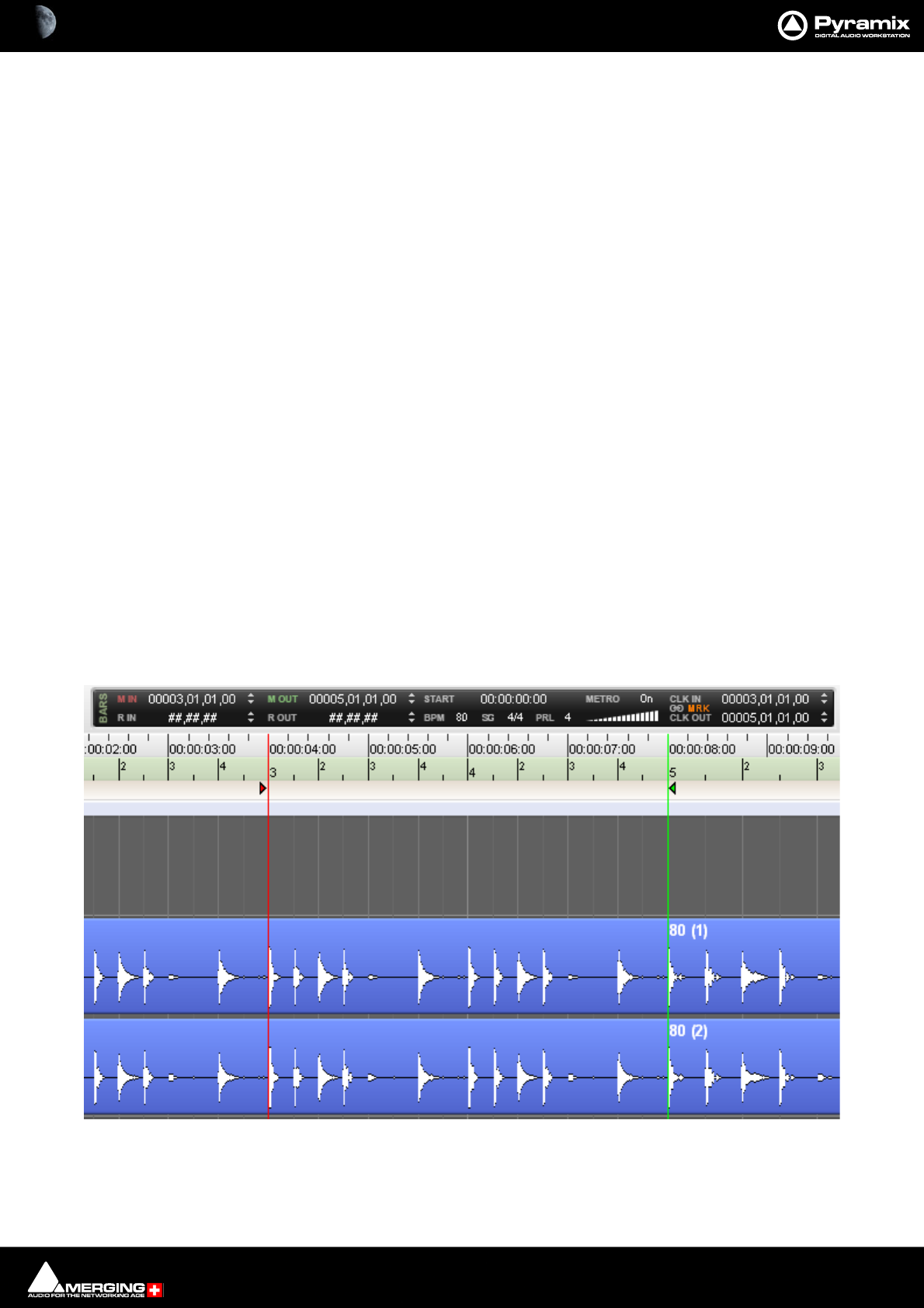
Productivity : Bars & Beats 27 - 649
BPM Clicking BPM enables an alternative value to be entered.The BPM counter displays
and allows modification of the tempo map section where the Cursor is currently.
Note: To display the Tempo Map, click on the Bars & Beats label on the corresponding Timescale Ruler and
enable Tempo Map from the drop-down menu.
SG Toggles Time Signature
4/4 Click on the Time Signature displayed currently to enter and alternative.
PRL Click on the number adjacent to PRL to enter a Pre-Roll value. The PRL values are
entered in Beats. The PRL tempo defaults to the tempo of the Bar that follows
immediately after the end of the Pre-Roll count.
Note: When the PRL is set to a value other than 0 and the Click In is set (to a value other than 1,1,1) the Pre-Roll
pre-counts to Click In Bar/Beat, otherwise it pre-counts to the first Bar.
CLK IN When Click IN is set ( to a value other than 1,1,1) the Metronome will start playing
at the entered Bar/Beat value.
CLK OUT When Click Out is set (to a value other than 1,1,1) the Metronome will mute auto-
matically at the entered Bar/Beat value..
Lock (chain) S ymbol Toggles between blank (off ), MRK (In/Out Markers) and RGN (Region). Click In/
Out time is then linked to either Between Marks section or selected Region
length automatically.
This is very useful for quick setting of pre-determined Metronome In and Out times, saving the user the trouble of
switching the Metronome on and off repeatedly at different parts of a song when this is required. When used
along with the Pre Roll (PRL) function it becomes a really handy tool.
Setting the Click In and Click Out values is easy:
Using MRK
Simply select MRK next to the chain symbol and then set your Mark In and Mark Out at the desired Timeline posi-
tions to define the Metronome active (playing) section. When the Playhead Cursor arrives at the Mark In position,
the Metronome starts playing, when it reaches the Mark Out position, it mutes. You can of course define a Pre-
Roll value and use the two functions at the same time :
Metronome set to start and end at Mark In/Mark Out time, using a 4 beat Pre Roll
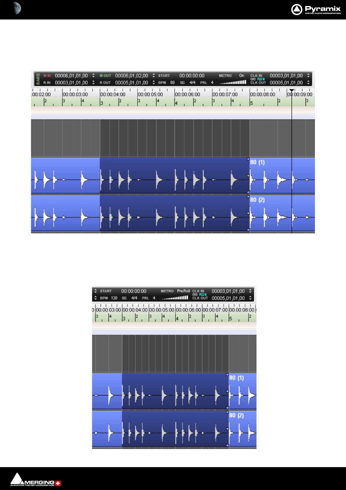
Productivity : Bars & Beats 27 - 650
Using RGN (Region)
Simply select RGN next to the chain symbol and then select/draw a region at the desired Timeline positions to
define the Metronome active (playing) section. When the Playhead Cursor arrives at the Region selection Start
position, the Metronome starts playing, when it reaches the Region selection End position, it mutes. You can of
course define a Pre-Roll value and use the two functions at the same time.
Another useful combination of a pre-defined Metronome section and a Pre-Roll value is to quickly select a part of
a song (other than the start) prior to which the Pre Roll should count. To achieve this, set the Metronome to Pre-
Roll and set the Click In and Click Out to a determined value, using one of the examples above. For instance draw
a Region with the mouse with Snap Region Selection enabled.The Pre Roll will start counting by the amount
defined in PRL but the Metronome will switch off at the start of the pre defined Click In position.
Metronome set at Region Selection Start and End time, using a 4 beat Pre Roll value.
Metronome set to a Pre-Roll of 4 beats before a given section
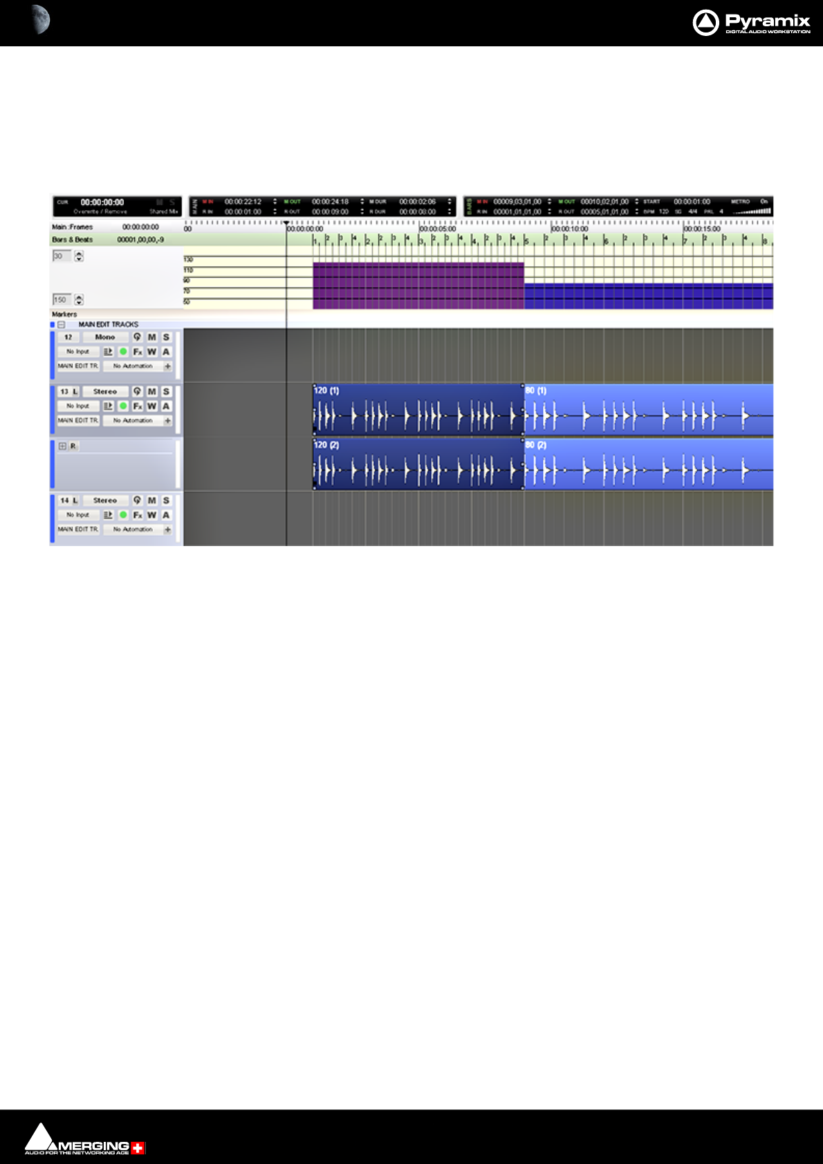
Productivity : Bars & Beats 27 - 651
This is useful for those situations in which you might want a Pre-Roll count to a given section in a song, but don´t
want the Metronome playing after that section starts. If you also want the Metronome to play the first beat after
the Pre Roll countdown, just reduce the Region to the first beat of the first bar at which your Click In starts. Easy.
Tempo Map
The Tempo Map is accessed by clicking on the Bars & Beats label in the Ruler Bar and selecting Tempo Map.
From within this window, it is possible to be able to adjust the length of each Bar and Beat to match that of an ini-
tial recording, via keyboard modifiers.
Shift + Left-click, hold and drag in the ruler bar:
When the mouse cursor is over a grid line it changes to a double-headed arrow with a clock. Dragging left or right
then modifies, up or down, the BPM of the area following the mouse cursor position.
If there is only one tempo section in the timeline, then it effectively changes the BPM for the entire project.
So, operationally, the user would make the initial recording, then, using a reference waveform (like a Kick Drum)
would go through and adjust the tempo at each point the grid moves away from the transients in the waveform
denoting the kickdrum pattern.
Ctrl + Left-click, hold and drag in the ruler bar:
When the mouse cursor is over a grid line it changes to a double-headed arrow with a clock and knife. Dragging
left or right then modifies, up or down, the BPM of the previous tempo change (By Bar) in the tempo map.
Ctrl + Shift + Left-click, hold and drag in the ruler bar:
When the mouse cursor is over a grid line it changes to a double-headed arrow with boundaried arrows below.
Dragging left or right then adjusts, up or down, the previous Beat.
Snap
When Bars & Beats mode is active, it is possible to have edits snap to the Bars & Beats Grid.
Edit > Snap > Snap to bars & Beats Grid
This will help speed up the syncing process.
Tempo Map showing tempo variation and grid offset start of 1 second

Productivity : Bars & Beats 27 - 652
Note: that if Auto Crossfade by default is enabled in Settings > All Settings >Application
>Editing : Drag & Drop, you´ll need to hold down the Ctrl key to achieve Clip snapping to the
Bars & Beats grid while dragging on the Timeline.
In addition, to draw regions quickly on the Timeline, which also snap to the Bars & Beats grid, enable:
Edit > Snap >Snap Region Selection
This allows easy drawing of regions on the Timeline for the Click In and Out for instance.

Productivity : Tab Windows 27 - 653
Tab Windows
Tab Windows have long been a powerful aid to productivity in Pyramix. You can still use Tab Windows in the same
way as version 5 and earlier but you will miss out on some major ‘Power User’ features if that is all you do.
Just as before, clicking on a Tab opens the associated Window in the space below the Project Editing Panel and
double-clicking a Tab opens the associated Window floating. Double-clicking the title-bar of a floating Tab Win-
dow restores it to the space below the Project Editing panel.
Tab Behavior
Tabs can be ‘torn away’ to open as floating Windows in blank screen space by simply clicking on the Tab and drag-
ging. clicking the X closes a floating Window and the Tab is removed from the Tab pool. This means that the inter-
face can be streamlined by removing Tabs you never use or which are inappropriate for the specific task in hand.
Tabs removed in this way can be restored by choosing View > Editor Tabs and clicking on the required Tab or
Show all Tabs to restore all closed Tabs.
Apart from this last feature, the ability to remove Tabs from the user interface, simple Tab behavior is almost iden-
tical to previous versions. However, there are many other things you can do with Tabs to enhance productivity.
Tab Arrangement
Hiding and Showing All Tabs
To quickly Close all Tabs, Show all Tabs, or Toggle Show/Close all Tabs and to find the other Tab display options
go to the menu View > Editor Tabs.
In the Project Editing pane, clicking on the Magnify/Maximize Timeline box at the junction of the vertical and
horizontal scroll bars also actuates Toggle Show/Close all Tabs.
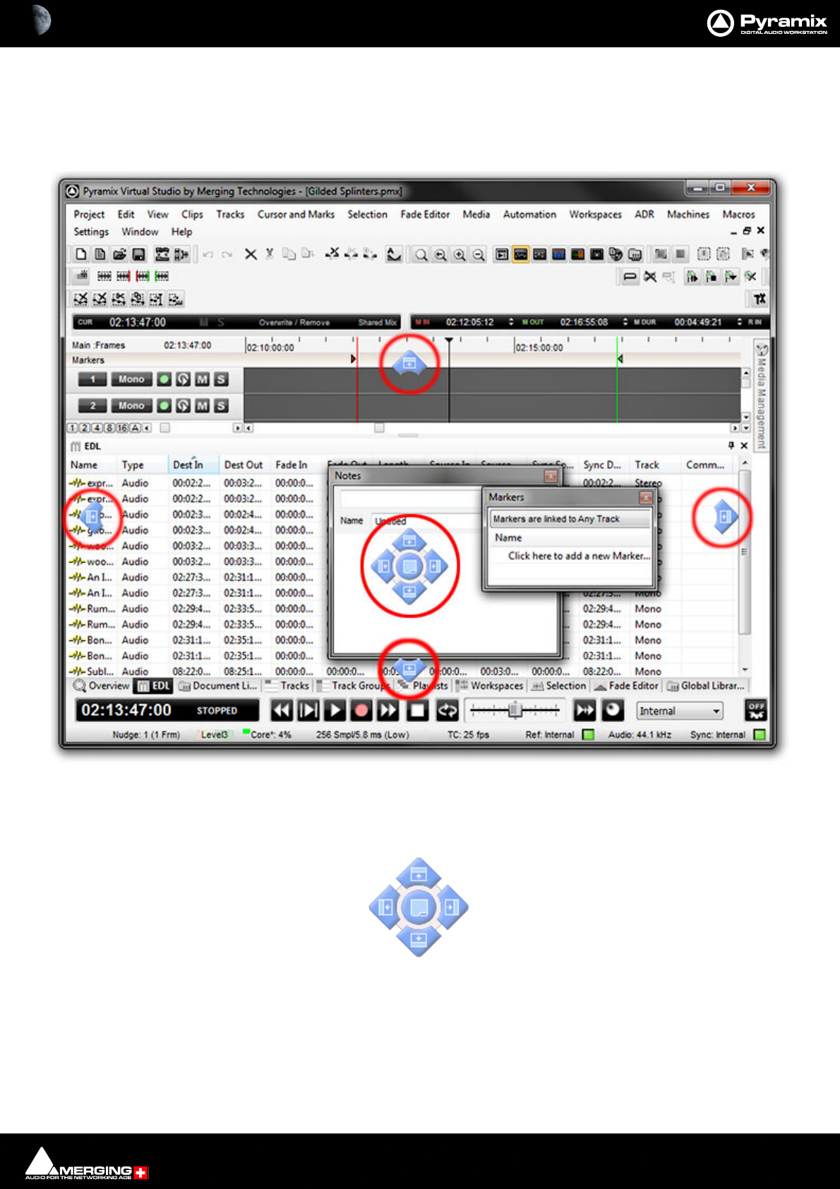
Productivity : Tab Windows 27 - 654
Tab Docking and Nesting
Floating Tab Windows can be nested or docked together in the Program Window or in floating Windows by simply
clicking and dragging. When a Tab Window or group of Windows is clicked and dragged, small blue “landing
lights” appear indicating where the Tab can be docked in the main Program Window with a center block of five
indicating where the Tab can be docked in the Window or panel it is currently being dragged over.
Thus, in the highly artificial screenshot above, it is the Markers Tab Window that has been clicked and dragged.
The peripheral blue landing lights indicate where in the main programme window it can be docked and the centre
landing lights indicate where in the Notes Tab Window it can be docked.
Tab Window “Landing Lights”
Productivity : Tab Windows 27 - 655
Note: The centre button is only available when the Tab can be docked as a Tab in another Tab
Window.
Placing the mouse cursor over a specific Landing Light determines what will happen when the mouse button is
released. In order to help avoid confusion blue “ghost images” appear showing where the Tab Window will land. In
the screenshot above, if the mouse button is released the Markers Tab Window will become nested with the
Notes floating Tab Window thus:
If a nested, floating Tab’s title bar is double-clicked all the nested Tabs are returned to the main Tab dock.
Tab Window “Landing Lights” and “Ghost Image”
Nested Tab Windows
Productivity : Tab Windows 27 - 656
Layout Example
Here, the Overview Tab has been ‘torn off’ by clicking and dragging.
It is often useful to have the Overview above the Timeline and so that is the landing light used here.
When the mouse button is released, the Overview will be positioned above the Timeline and can then be re-sized
as required.
Main Project Window Tab Window with “Landing Lights” and “Ghost Image”
Productivity : Tab Windows 27 - 657
Pinned and Unpinned Tab Windows
By now you’ve probably noticed the small ‘pin’ icon next to the close box on the title bar of each Tab window:
With the Pin in the vertical position the Tab Window behaves as normal. Clicking on the Pin toggles between the
default ‘Pinned’ state and ‘Unpinned’ - Auto-Hide mode:
Note: The Pin is only present where the unpinned, Auto-Hide mode is available.
IMPORTANT: If there is only one Tab Window at the bottom of the main screen and you unpin it
you will lose access to all other Tabs until you open the Tab and unpin it.
Once a Tab Window is Unpinned it collapses down to a Tab a second or so after the mouse cursor leaves the Tab
Window. Hovering the mouse cursor over an Unpinned Tab opens the Tab Window which can then be used as nor-
mal until the mouse cursor leaves the Tab Window again. Clicking in the title bar ‘locks’ the Tab Window open as if
it were pinned. Alternatively, clicking on the Tab to open it does the same thing.
Overview Tab Window in place above Timeline
Pinned
Unpinned
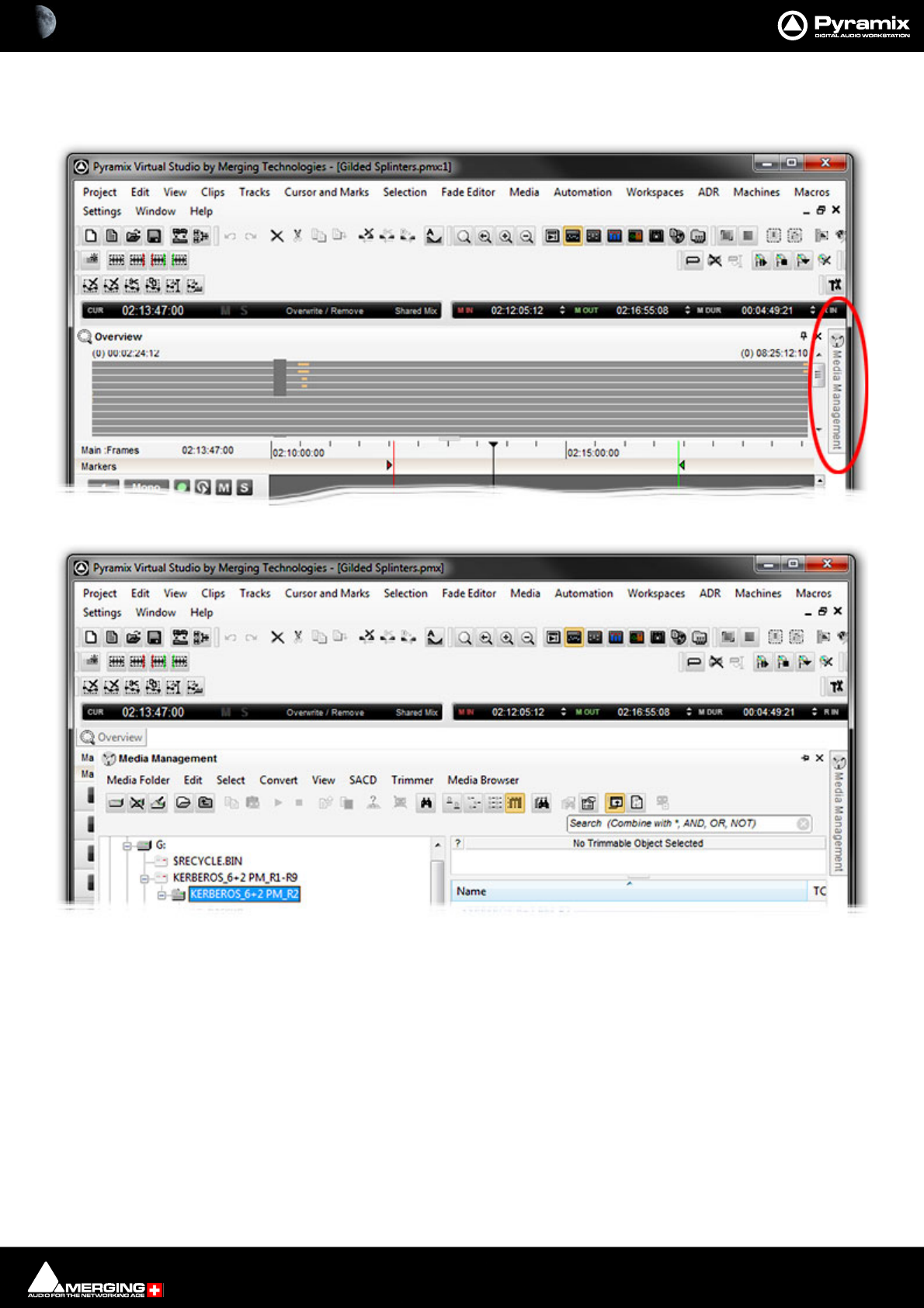
Productivity : Tab Windows 27 - 658
An unpinned Tab can be extremely useful, for example, to give near instant access to the Media Management Tab
Window without disturbing the layout. It is shown here first as a Tab and then with the Tab Window open (both
screenshots cut down to save space):
Note: Unpinned Tab Windows cannot be moved by clicking and dragging until they are pinned
once again.
Note: Once a Tab Window has been unpinned, double clicking on the title bar will pin it, a sec-
ond double-click will open it as a floating Tab Window. A subsequent double-click will now
return it to the place it was unpinned from until it is manually returned to the main Tab Dock.
Media Management Tab Unpinned with Mouse Cursor elsewhere
Media Management Tab Unpinned with Mouse Cursor in Tab Window
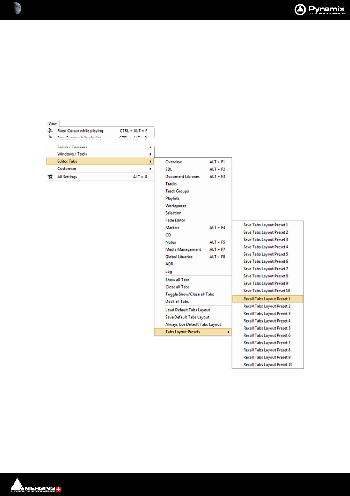
Productivity : Tab Windows 27 - 659
Managing Tab Windows
The button at the bottom-right of the main timeline (at the conjunction of both scroll bars) Toggles Show/Close
all Tabs. This is extremely useful with big projects when screen space is at a premium.
The All Settings > Timeline Layout > General : Display Timeline on Top/Left of Tab Windows setting is ren-
dered obsolete by the Tab enhancements, but can still be used for brand new projects to initially place Tabs as
before in the screen (to the right or at the bottom). But the following considerations demonstrate that employing
Project Templates makes for a more streamlined way of working.
The Default Tabs layout and up to ten Tab Layout Presets can be stored and recalled from the View > Editor
Tabs menu :
Binding Tabs Layouts to Shortcut Keys
These presets can be bound to short-cut keys by using the Keyboard Shortcuts Editor (Settings > Keyboard
Shortcut Editor : View Tab
•The Default Tabs Layout and Tab Layout Presets are saved with the application. I.e. available in all proj-
ects.
•View > Editor Tabs > Load Default Tabs Layout and Save Default Tabs Layout enable the complete
Tabs layouts to be saved and loaded. If you open a Project that does not have a suitable layout simply call
View Menu - Editor Tabs >Tab Layout Presets sub-menu

Productivity : Tab Windows 27 - 660
one of your Tab Layout Presets or you can Load Default Tabs Layout to invoke the Tabs Settings previ-
ously saved as your Default.
•If Always Use Default Tabs Layout mode is engaged (View > Editor Tabs > Always Use Default Tabs
Layout ticked), then the default layout is always used when loading any project, bypassing the layout
stored in the project, so your own familiar environment will always be properly displayed no matter what
layout has been saved in the project.
•Workspaces include a column called Tabs Layout. If ticked the Workspace stores and recalls a complete
Tabs Layout. Since the 10 first workspaces can have an associated keyboard shortcut, this is very useful
method for switch rapidly from one Tab Layout to another For example, Editing, Recording, Browsing
Media, etc. etc.
Please see also: Workspaces on page 661
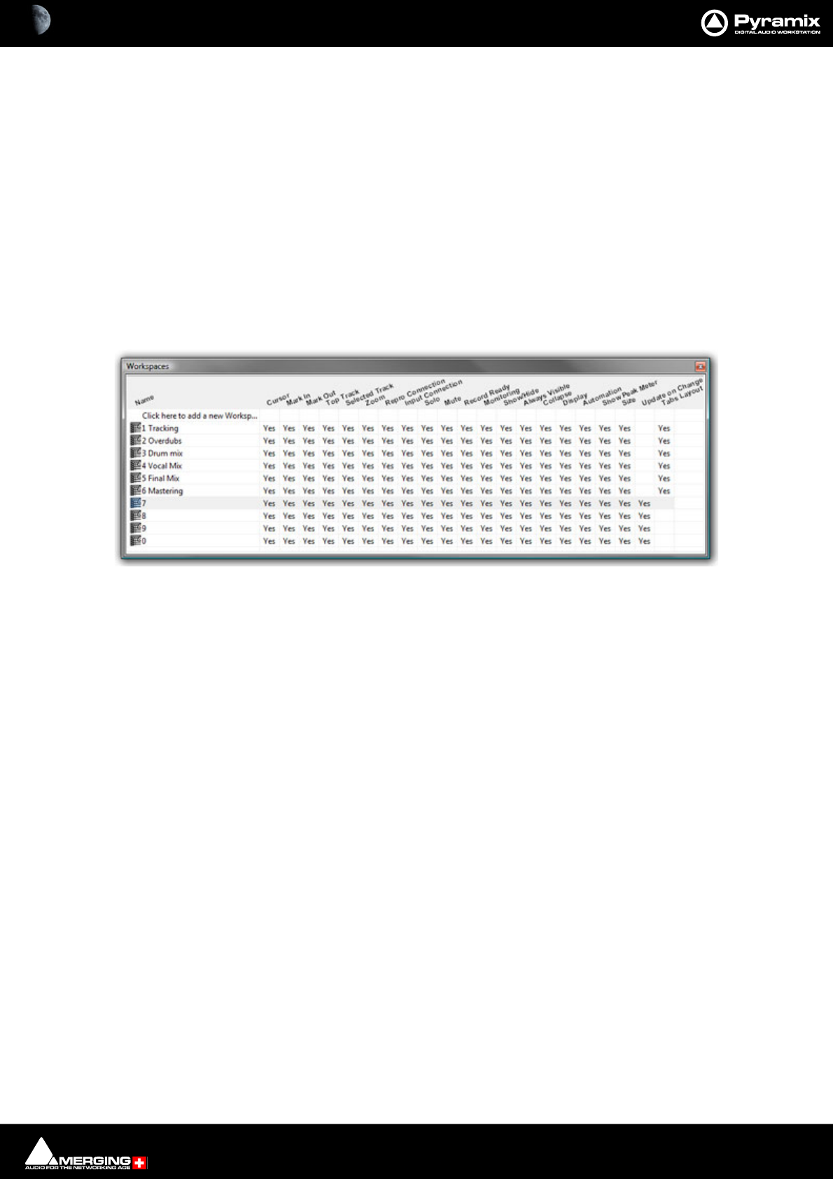
Productivity : Workspaces 27 - 661
Workspaces
Overview
Workspaces are a method of creating presets of Timeline views and setups. A whole range of parameters including
Track Header switches can be saved into a Workspace and recalled via the Workspaces Tab window or assignable
short-cut keys.
The object of the exercise with Workspaces is to be able to change a large number of Timeline parameters simulta-
neously and quickly. Anything from Zoom level and Visible Tracks to Input Connections and Record Ready Status,
Monitoring mode etc. can be saved together in a Workspace for later recall with a single key press.
Workspaces can be accessed via the pull-down menu on the Pyramix Virtual Studio Window Toolbar or via the
Project Management Panel Tab.
Workspaces Tab Window
The Workspaces Tab window is a Row and Column based area, where the rows correspond to the Workspace
being configured and the column refers to the parameter within the Workspace itself.
To create a new workspace, simply click on the Click here to add a new Workspace row at the top of the list, type
in a suitable name and press Enter/Return to add the new Workspace to the top of the list.
Once created the Workspace can be saved into a slot by selecting Workspaces > Save > Save Workspace 1 ...
Save Workspace 10.
When a Workspace is saved, every parameter column enabled YES will have that parameter saved as part of the
Workspace.
Workspaces may be re-named by clicking the name.
Workspaces can be deleted by selecting them and pressing the 'Delete’ key.
Recalling a Workspace can be achieved by double-clicking on the Workspace icon to the left of the name.or select
the menu item Workspaces > Recall > Recall Workspace (X). However, the quickest method is to use keyboard
shortcuts. By default, Workspaces 1 to 10 are mapped to Shift + 1 to Shift + 0.
Parameters remembered by Workspaces are selectable per Workspace by clicking in the appropriate columns.
Workspaces Tab Window - floating

Productivity : Workspaces 27 - 662
Update on change
If the Update on change column is set to Yes. The current state of all selected parameters is saved to the current
Workspace when another Workspace is selected.
Note: Before using the Update on change feature it is strongly advised that you save the Work-
space using Workspaces > Save > Save Workspace {name of workspace} to avoid undesired
behavior.
Update on change in practice:
It is often useful to have a quick way to view the entire Timeline, with as many Tracks as possible in view, from time
to time whilst in the middle of an edit.
This would require the creation of two workspaces. The first would be the view of the entire Timeline including the
Track Size, Zoom Level, Hidden and top track parameters. This Workspace would then be saved with the Zoom
level fitting the entire Composition into the Timeline window and the Tracks all reduced in height to fit all or as
many as possible in the window.
The second workspace would be saved with the same parameters except, it would also have Update on Change
enabled.
Thus, whenever you leave the 2nd Workspace (in progress edit) and go to the 1st Workspace to see the entire
Timeline, the edit Workspace will be exactly the same as when you left it when you return.

Productivity : Optimizing Pyramix 27 - 663
Optimizing Pyramix
PC/OS Setup
For optimal performance:
• Disable Windows File Indexing
•Open My computer
• Right-click on each drive and select
• Un-Check the Indexing check box
• Verify the Power Management:
• Look in the Windows Control Panel and open Power options.
•XP Users: Set Power Scheme to Always On and set Turn off Hard disks to Never and System
Standby to Never.
• MassCore users Under Vista & 7: Power plan should be RTX – recommendedB.
• Native Users: Make sure you select the High Performance power plan.
Recommended (not mandatory)
• Set your Antivirus to Off while running Pyramix.
• Set Windows Automatic-Update to notify me.
• Avoid having an active internet connection while running Pyramix.
Housekeeping
Database Location
For optimum housekeeping perfomance Merging recommend strongly that the Default Database Location
should be set to point to the fastest drive on your system. SSDs or SATA2 - 7200 rpm Disks are recommended
and, where possible, not the C:\OS defaultdrive (since a drive with less activity and higher speed should perform
better).
Saving
Project Save times will be faster if Saves are made to a high-performance Disk (e.g. SSD or SATA2 7200rpm). Saving
to older Disks (e.g. IDE, 5400 rpm etc.) or saving to the Disk where the OS is located (this disk is often very busy
with other tasks) could slow down Saves times.
Keep Mounted Folders
Keeping Mounted Folders when closing and restarting Pyramix can speed up workflow: Set the option under:
Settings > All Settings > Application > General : Mount all Media folders that were Mounted at
previous Application Exit.
Media Manager History
In order to reduce Database size and improve performance the Media Manager History can be cleared: Media
Manager Media Manager > Media Folder > Clear Media Manager History.
Use Templates
The supplied Templates have settings appropriate to their purpose and are the fastest way of optimizing Pyramix.
However, the following information should help when deciding what settings to use when creating your own
projects and templates.
Pyramix File Format .PMF
We strongly recommend the use of the native .PMF format for a number of reasons.

Productivity : Optimizing Pyramix 27 - 664
The first issue is the size limitation of the WAV and BWF formats. These are LIMITED TO 2 GB in size by design (they
use 32 bit signed, which gives a total of 2 to the power of 31 Bytes addressable = 2'147'483'648 Bytes precisely).
2GB may sound a lot but a little elementary arithmetic will show it is easy to exceed this limit when using higher
sample rates and bit depths for multi-track recordings of real-world durations.
AIFF is slightly better in the sense that it is "only" LIMITED TO 4 GB (it uses 32 bit unsigned, which gives a total of 2
to the power of 32 Bytes addressable = 4'294'967'296 Bytes precisely.
PMF uses 64 bit addressing which would probably allow 128 tracks to be recorded for about 10,000 years (If you
can afford the disks!), which should be more than enough for any practical applications.
The second advantage of the Pyramix File Format for large multitrack projects is that it is not "sample-interleaved"
but "block-interleaved". Which means that instead of (as with WAV, BWF and AIFF) recording on disk one sample of
channel 1, then 1 sample of channel 2, and so on to 1 sample of channel n, .pmf was designed from day one to
optimize disk access by recording a quite large block of samples for each channel in a sequence. Typically 64 kB of
channel 1, then 64 kB of channel 2, etc, finally 64 kB of channel n.
This setting (default 64 kB) can be changed by the user to one of four alternative values in the Record Block Size
section of the Playback/Record page of All Settings > Settings > Application. However, the alternatives are
really only applicable to certain RAID and Network-Attached-Storage set-ups and, unless you have considerable
knowledge and experience, the default setting should be used.
Note: PMF is optimized for interleaved multi-channel as opposed to single.
One File Per Track option
For non PMF formats
Found in the All Settings > Settings > Project > Record page, The One file per track option should always be
chosen (checked) whenever more than 2 tracks of recording are contemplated as there is a rather high potential
performance penalty that can occur with all the (non PMF) sample-interleaved file formats (E.g.WAV and AIFF) on
playback, when not all tracks of a multi-channel recording are used or played in their original sync relationship on
the Timeline. This is because with other, interleaved, formats the hard disk head will still have to go through all the
bits of all the channels, even if only 1 or 2 tracks of that file are used at a given point in time.
For maximum performance with One File Per Track choose BWF in preference to PMF.
Reducing Unnecessary Disk Access
Track and Mixer Muting
There is a subtle difference between muting a Track Output (with the button in the Track Header) and muting
the same signal in it’s associated mixer input strip. Muting a Track stops disk access for the Track (There is a delay
before the sound stops while the replay buffer is emptied). Muting a mixer strip doesn't affect disk access but sim-
ply mutes the strip (Therefore muting is immediate). Muting Track outputs enables multi-track recordings with
many Tracks (E.g. 48 Track music recordings) to be edited on hardware which cannot support this number of
Tracks. (E.g. a laptop) Providing the Clips are grouped across all Tracks, then any editing changes made on the
Tracks used for the editing guide will also be reflected in the muted Tracks. Track Grouping can be used to make
operation simpler and more convenient.

Productivity : Optimizing Pyramix 27 - 665
Core Power Saving
Although MassCore automatically optimizes Core allocation certain large configurations may still benefit from
the following Core husbandry strategies.
Core Power Saving
Core Power saving modes can be found in the All Settings > Settings > Hardware > Mixer > Core Power Saving
page:
Player/Recorder mode
Transforms the mixer's full nodal matrix topology into a "diagonal" topology where only the direct paths are com-
puted (i.e. Input 1 to Output 1, Input 2 to Output 2, Input n to Output n)
This allows Pyramix to accommodate very large player/recorder Track counts (up to 128. It MUST be used with
Multiple Mono Mix buses.
Disable Punch in / Punch Out
is another DSP processing saving function that, as it name indicates, disables concurrent record stream manage-
ment whenever no Punch recordings are required during certain phases of a project's life. This might save another
couple of % of DSP load.
Disable Mixdown
is similar to the above. Disables concurrent Master outputs possible extra paths used for recording as mixdowns.
MassCore & VST Core Allocation
CPU Core Allocation
MassCore
MassCore can be allocated one or more cores for its exclusive use. If it is desired to allocate more than one core to
MassCore, the optional SMP Key is required.
MassCore SMP
Without the MassCore SMP key the engine dedicates one core to MassCore. (Two cores will be hidden in hyper-
threaded configurations.)
With the MassCore SMP key multiple dedicated processor cores may be allocated to MassCore. This makes it eas-
ier to manage lower latency and massive mixers.
SMP provides more real-time power and also benefits users requiring multiple RAVENNA I/O connections in their
workflow.
Remaining Cores
By default Pyramix allocates all but one of the remaining cores to Windows as VST cores.
Example: Intel i7 4 core CPU (with Hyperthreading switched off) where MassCore is installed and running.
• 1 core is allocated at boot-up for RTX/MassCore. This separation of MassCore audio processing and non-
real-time Windows environment functions is absolute.
• The remaining 3 cores are available to Windows as seen in the Task Manager.
• Of the remaining 3 cores, Pyramix allocates 2 cores for use by VST plug-ins by default thus leaving one
core totally free for Windows.

Productivity : Optimizing Pyramix 27 - 666
• The 2 cores allocated for use by Pyramix for VST threads are still solicited by Windows and in essence are
simply multi-tasking both Pyramix VST tasks and anything else Windows needs to process, so the separa-
tion of audio processing and non-real-time Windows functions is not absolute, contrary to the case with
MassCore and Windows.
• The VST core allocation slider in Settings > All Settings > Hardware > MassCore enables the user to allo-
cate the remaining 3rd core, in exceptional circumstances, for extended VST processing power. The evi-
dent trade-off cost is a possible reduction in Windows performance and (in the extreme) rendering the
entire system sluggish and even unstable.
VST Core Allocation
VST threads are one of the highest priority threads (godlike) in relation to the overall Pyramix priority scheme
because we try to keep the latency of VST plug-ins as low as (humanly) possible. Pyramix treats every instance of a
real-time VST plug-in in the mixer’s strips and buses as a separate thread of processing.
Each group of VST plug-in threads in a single Strip or Bus will receive that Strip’s or Buses’ audio stream of data to
be processed, one plug-in after the next, so they cannot be dissociated and become a single “thread process
group” in themselves.
When Pyramix has only one core allocated for VST use then all VST thread process groups are sent to that single
core (logical enough). The more VST threads are added and the more those threads are CPU intensive, the more
that core will peak. However, when two or more cores are made available for dynamic VST thread distribution,
Pyramix divides the mixer as per it’s “best guess” of which combination of groups of strips and busses will con-
sume as equal amount of CPU resources as predictably possible and distributes the VST process threads between
the number of available cores allocated for VST plug-ins.
This means that if you had, for example, a mixer with 8 strips of which each strip has an evenly distributed array of
identical VST plug-ins and Pyramix has two cores allocated for VST plug-ins then Pyramix assigns strips one
through four to the first core and strips five through eight to the second core at the moment of mixer allocation.
This helps to keep the chances of peaking on one VST core through unevenly distributed VSTs.
Another more complex example would be to illustrate an uneven distribution of plug-ins on a system with three
cores allocated for VST plug-ins. Picture a mixer of eight strips with two instances of a huge VST reverb on strips
one and two with strips three through eight only having low-consumption VST instances of an equalizer plug-in.
Pyramix would find that the big reverb on strip one consumes nearly half of the resources required to process all
VST threads for that mixer and assign it to one core on its own. It would then assign the second instance of the
reverb on strip two to the second core. The remaining EQ plug-ins on strips three through eight would then be
allocated to the third core basically cutting the mixer in three VST processing zones. Zone 1= Strip 1, Zone 2= Strip
2, Zone 3= Strips 3-8 (and buses).
With this understanding of the distribution by Strips and Buses of VST plug-ins over the allocated cores, you can
analyze more clearly the consumption of CPU resources displayed in the VST core meters at the bottom of the GUI
and better understand when you need to widen the core allocation to compensate for VST core peaks.
Note: As a general rule of thumb it should be considered that the allocation of every available
core for VST plug-ins be an exceptional event and not a recipe for a normal Pyramix setup. This is
much the same as pushing audio buffers to extremes for a demanding Project and resetting
them to their default values for smaller Projects and day-to-day use whenever possible. Pyramix
was designed to work at optimum efficiency with the default values and should be “tweaked”
only when demanding Project circumstances call for it.
Note: MassCore Core Allocation is automatic unless the optional SMP key is present.
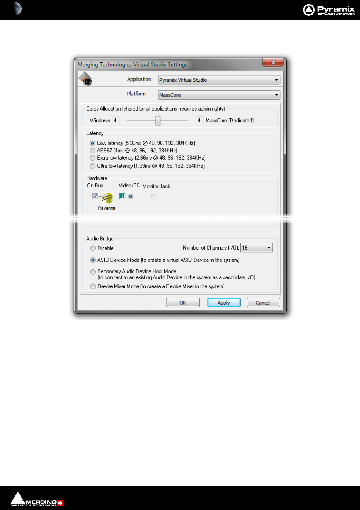
Productivity : Optimizing Pyramix 27 - 667
SMP
The optional SMP key enables more cores to be allocated to MassCore.
In the screen shot above, the SMP key is present, the processor has four cores with Hyperthreading switched on in
the BIOS hence the 8 cores shown.
VS3 Control Panel Settings Window

Productivity : Optimizing Pyramix 27 - 668
Use Workspaces
Workspaces provide a powerful means of storing and recalling the state of a number of parameters of the Project
Editing Panel, especially Track Header Panel switches. In effect a Workspace is a snapshot which enables the oper-
ator to quickly switch between set-ups for a variety of common tasks.
• New Workspaces can be added by clicking on the first line of the Tab Window and typing a name.
• Workspaces can be deleted by selecting them and pressing the Delete key.
• Applying a Workspace is achieved by double-clicking on the Workspace icon.
• Parameters remembered by Workspaces are selectable per Workspace by clicking in the appropriate col-
umns.
The penultimate column Update on Change allows a stored Workspace to be automatically updated to the cur-
rent values before switching to another one and the last one, Tabs Layout stores the physical positions and sizes
etc. of all Tab Windows.
Creating Tracks via paste
This is a fast way of creating Tracks.
If a Clip is dragged and dropped or copied and pasted from Media Management or a Library onto a blank area of
the TimeLine where no Tracks exist, sufficient Tracks will be created below the last existing Track to accommodate
the number of channels in the Clip.
Disable Skin
This option can be found on the All Settings > Application > Desktop layout page. It may improve performance
on certain older systems.

28 - 669
www.merging.com/Pyramix
USER MANUAL
Menus
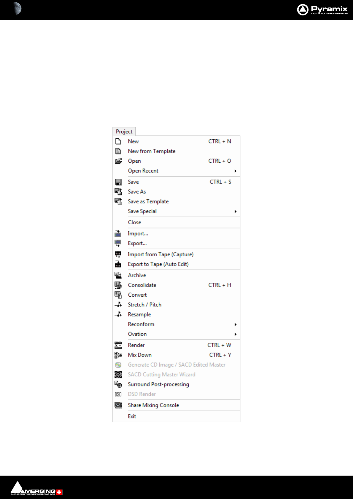
Menus : Pyramix Default Menus 28 - 670
Pyramix Default Menus
Menus are highly configurable in Pyramix. Commands can be hidden or added and entire menus shown or hid-
den. If a command cannot be found check if it is currently hidden in the relevant tab page of Settings > All Set-
tings > Application > Desktop Layout. Please see also Toolbars and Menus on page 508
Many Pyramix menu entries are self-explanatory. These are simply listed. Other menu entries are either described
here or elsewhere in this manual. Wherever menu options have Toolbar Icon alternatives, these are shown in the
menu screenshots.
Project
New Create a new Editing Project or Digitizing session
New from Template Create a new Project based on an existing factory or user Template
Project menu
Menus : Project 28 - 671
Open Open an existing Editing Project or Digitizing session
Open Recent The sub-menu shows the 9 most recent Projects opened. Click on a Project to open it.
Save Save current Project. If the project has never been saved, the Save As dialog box will
appear
Save As Save current Project with a new name
Save as Template Save current Project as a Template
Save Special>
Save as Version 10.0 For compatibility
Save as Version 9.0
Save as Version 8.1
Save as Version 8.0
Save as Version7.1
Save as Version 7.0
Save as Version 6.2
Save as Version 6.1.7 MR1 / 6.1.8 MR2
Save as Version 6.016 SP2
Save as Version 6.015 SP1
Save as Version 6.08
Save as Version 5.1
Save as Version 5.0
Save as Version 4.3
Note: v10 and v11 Projects can only be saved as earlier Versions if Legacy Buses only are instan-
tiated.
Close Close the current Project. If the file has changed since last saved, the Save dialog box will
appeart
Import... Opens the InterChange Import Manager
Export... Opens the InterChange Export Manager
Import from Tape (Capture) Allows media on external devices to be captured into the current Project
Export to Tape (Auto Edit) Allows the current composition to be exported to an external device
Archive Creates a copy of the current project with all associated media to another location
Consolidate Create an optimized set of media for the current project
Convert Convert the whole project to an other sampling rate
Stretch / Pitch Stretch or Pitch the whole project from 24fps to 25fps (4% time compression or pitch
reduction) or 25fps to 24fps (4.17% time expansion or pitch rise)
Resample Opens the resampler
Reconform >
Relink to New Media Opens a dialog offering various options similar to the CMX Import function. This
allows relinking all or a selection of Clips to new media. Typically. this is used for
replacement of 16 bit versions of audio files with 24 bit versions based on the Clip
name, media name, Scene & Take information or original TimeCode.

Menus : Project 28 - 672
Load Change EDL & Reconform Allows a so-called “Change EDL” generated from a “State 1 EDL” and a “State 2
EDL” to be loaded. Cues are rearranged within the current project to reflect the
change from State 1 to State 2
Detect Picture Change & Reconform You can use Pyramix to perform a Reconform from two Video Projects.
After loading the Video Projects select this option to begin the Reconform process.
Ovation Only Applicable to Ovation Systems. Please see the Ovation User Guide for details.
Render Render the project or current selection to a new Media File
Mix Down Opens the Mix Down dialog to Mix the Project or current Selection down to a new Media
File or files through the Mixer
Generate CD Image / SACD Edited Master Opens the Generate CD Image / SACD Edited Master Dialog:
DSD options are only available for DSD Projects
SACD Cutting Master Wizard Only applicable to SACD systems. Please see the SACD User Guide.
Surround Post-processing Enables the current composition to be encoded in different Surround format such as AC3
or DTS (if the appropriate optional encoder plug-in is installed)
DSD Render Enables Timeline edits (Fades/Gain/Cuts) to be processed. Applies to DSD64, DSD128,
DSD256 and DXD Projects. Also applies to 352.8 kHz PCM projects containing only DSD
material. For DXD the sampling rate must be specified. With DSD projects the sampling
rate is forced to the Project rate. Media Phase Invert is supported.
Note: The DSD Render function does NOT apply any Envelope changes. Gain changes, fades
and Phase invert are applied.
Share Mixing Console Activates or terminates Sharing the current Mixing Console with other Projects.
Exit To quit the application, choose Exit from the File menu. If there have been changes since
the last time you saved the project, the system will prompt you to save your changes
Note: The Stretch / Pitch menu selection requires the optional Prosoniq MPEX.

Menus : Edit 28 - 673
Edit
Edit menu
Paste Sub-menu

Menus : Edit 28 - 674
The Edit menu in Pyramix contains the conventional Delete, Cut and Copy commands, and a Paste sub-menu,
also options for Undo and Redo of previous edit operations and special edit commands for placing Clips in the
Pyramix Composition Editor.
Undo clip(s) move Undo command changes to show the last edit action and cancels it when selected
Undo history > leads to a sub-menu with a list of all previous editing actions which can be undone
Redo clip(s) move Redo command changes to show the last action undone and cancels it when selected
Redo history > leads to a sub-menu with a list of all editing actions which have been undone and can be
redone
Delete Deletes the currently selected Clip/selection
Cut Cuts the current selection from the project and saves it on the Clipboard
Copy Copies the current selection from the project and saves it on the Clipboard
Paste >
Paste to Cursor Inserts the object on the Clipboard at the current Cursor position
Paste Tail to Cursor Inserts the object on the Clipboard with the end at the current Cursor position
Paste Sync Point to Cursor For a single Clip Pastes the Clip with the Sync Point at the current Cursor position
Paste & Place This command opens the Placement Tool to allow for more extensive placement
options
Paste to Original TimeCode Inserts the object on the Clipboard to the pasted Clip's original source TimeCode
position
Paste to End of Selection Inserts the object on the Clipboard to the end point of the current selection
Fill Selection This command will substitute the Clipboard contents for the selected Clip or Region for
the duration of the Clipboard contents. No Ripple of following Clips will occur.
Replace Selection This command will substitute the Clipboard contents for the selected Clip or Region and
will ripple all subsequent Clips if the duration of the clipboard contents is greater or
shorter than the selected Clip or Region.
Loop Selection This command will substitute a loop of the Clipboard contents within the selected Clip or
Region boundaries, creating a 10ms cross-fade between the inserted iterations of the
Clipboard contents. No ripple will occur.
Note: all Clips within a region’s boundaries will be replaced.
Fit Selection This command allows a Clip on the Clipboard to be fitted into a user defined Region on
the Timeline by stretching or squeezing it. (to maxima of 50% and 200%) This requires
one of the optional Time compression/Expansion plug-ins to be present.
Delete and Ripple Deletes the currently selected Clip/selection, forcing a ripple to occur
Cut and Ripple Cuts the current selection from the project and saves it on the Clipboard, forcing a ripple
to occur
Paste and Ripple Inserts what's on the Clipboard to the current cursor position, forcing a ripple
Insert Silence This command will insert blank space (silence) into to the current selection
Delete and Join Deletes the currently selected Clip/selection and ripples the end of the Clip.
Cut and Join Cuts and saves to the clipboard the currently selected Clip/selection and ripples the end
of the Clip.
Delete and Ripple to Black Deletes the currently selected Clip/selection and ripples all following butted or cross-
faded Clips.
Cut and Ripple to Black Cuts and saves to the clipboard the currently selected Clip/selection and ripples all fol-
lowing butted or crossfaded Clips.
Split This command uses the play cursor as a razor blade to split selected Clips into two Clips at
the point where the play cursor crosses the selected Clips

Menus : Edit 28 - 675
Unsplit Clips that have been Split, Cut or Crossfaded can now be joined back together providing
they are still in sync and referencing the same media
Trim When a Region is selected, Trims the Clip(s) In and Out points to the region boundaries.
Trim In to Cursor Trims the Clip In point to the current Cursor position.
Trim Out to Cursor Trims the Clip Out point to the current Cursor position.
Stretch Opens the Stretch dialog. The selected Clip can be stretched or squeezed by maxima of
50% and 200%. Requires one of the optional Time Stretch plug-ins.
Reverse Reverses the Clip in the Timeline so it plays backwards.
Normalize Apply the normalize process to the selected Clip
Consolidate The Consolidate function will make a selective backup of the media segments in the
Composition
Spread Opens the Enter gap time dialog which enables a space (silence) to be inserted between
selected Clips
Abut to selected This command abuts all Clips between the Mark In and Mark Out on a Track to a selected
Clip between the marks on the same Track
Automatic Silence Removal This command opens the Automatic Silence Removal dialog box
Delete with Media Removes the current selected Clip from the composition, and delete the associated
media file
Update Original TC to Media Files Updates the Media Original TC for all selected Clips with their TimeCode position in the
composition. This operation modifies the Media and is not reversible
Update Media Markers to Media Files Updates the original Media Markers for all selected Clips with the Media Marker posi-
tions in the composition. This operation modifies the Media and is not reversible
Source-Destination >
Auto-Edit Source to Destination
Executes the appropriate Source/Destination 2, 3 or points editing operation
depending on the Gates status
Overwrite Source to Destination
Overwrites the content between the Destination Track Group Gates with the con-
tent between the Source Track Group Gates
Insert Source to Destination Inserts the content between the Source Track Group Gates to the Destination Track
Group Gates
Replace Source to Destination
Replaces the content between the Destination Track Group Gates with the content
between the Source Track Group Gates by rippling the Destination
Fit Source to Destination Replaces the content between the Destination Track Group Gates with the content
between the Source Track Group Gates by stretching the Source
Auto Set Destination Gate In after Edit
When this option is checked (enabled), the Destination Gate In point is automati-
cally set to the current Gate Out point after any Source-Destination operation
Auto Select Destination after Edit
When this option is checked (enabled), the Destination Track Group is automati-
cally selected after any Source-Destination operation
Limit 1 Gate Sources to End/Beginning of Clip
When this option is checked (enabled), then the Source material between the
Source Gate and the end of the Clip under the Gate instead of the whole Track is
copied to the Destination

Menus : Edit 28 - 676
3 Gates Auto-Edit does Overwrite
When this option is checked (enabled), then when 2 Gates are set in a Source and 1
is set in the Destination then AutoEdit performs an Overwrite operation.
3 Gates Auto-Edit does Insert
When this option is checked (enabled), then when 2 Gates are set in a Source and 1
is set in the Destination then AutoEdit performs an Insert operation
Automation Unchanged for Source Track Groups
Automation Off for Source Track Groups
Automation Play for Source Track Groups
Note: For the above options: If the main Automation Mode is Write, then this mode is automatically changed to
Unchanged, Off or Play when a Source Track Group is selected, and changed back to Write when any other
Track Group is selected (typically the Destination one).
Note: When the following modes are enabled:
• Automation Off for Source Track Groups
•Automation Play for Source Track Groups
Then this also affects the Enable Cut/Copy/Paste Automation mode (set to Off for Source Tracks).
Automation Editing
Enable Automation Editing Enabled By Default. Enables Timeline Automation Editing. Mode is determined by
the next three entries:
Link to Media Content When enabled automation data is linked to the content so that if the Media Con-
tent is slipped the Automation data moves with it.
Cut/Copy/Delete Displayed Automation Will only affect Automation Curves visible in the Timeline when Editing
Cut/Copy/Delete Whole Strip Automation Enabled By Default. Will affect ALL Automation, even the curves not
visible currently in timeline Track(s) when editing.
Erase Points on Cut/Delete Erases all points contained within the selection. Does not add Automation points
to the selection boundaries.
Delete and Interpolate on Cut/Delete Enabled By Default. Interpolates a curve from the start of the selection to
end of the selection.
Delete and Maintain on Cut/Delete Does not interpolate the curve from start to end of the selection. Therefore
maintains a flat curve on Cut or Delete.
Jog-Wheel Editing>
A number of editing actions may be undertaken on a selected Clip or group
of Clips using a jog-wheel on an external hardware controller.
First select the Clip or group of Clips, then select the desired Jog-Wheel Editing
Mode from the choice of:
Move
Move And XFade
Lock XFade Trim
Force XFade Trim Lock
Force XFade Trim Unlock
Trim In
Trim Out
Trim Fade In
Trim Fade Out
Trim Fade In X (Symmetrically)

Menus : Edit 28 - 677
Trim Fade Out X (Symmetrically)
Trim Source In
Trim Source Out
Trim Sync Point
Slide Media
Previous Clip Trim Out
Previous Clip Trim Fade Out
Previous Clip Trim Fade Out X (symmetrically)
Previous Clip Trim Source Out
Now simply move the jog wheel to Move, Trim, or Slide Media of the selected Clip(s)
Pressing the Spacebar or Enter confirms the change(s), Esc cancels.
Editing Modes > Insert Mode >
Overwrite When checked, any Clip placed so that it overlaps an existing Clip will overwrite the
part of that Clip where the two overlap.
Insert Track When checked, any Clip placed on a Track will be inserted into the Track and will rip-
ple all other material on the Track later in time (to the right) by the length of the Clip
being inserted.
Editing Modes > Remove Mode >
Remove When checked any selected material will simply be removed from the Timeline.
Everything else will be left intact and in the same place.
Remove and Ripple When checked any selected material will be removed from the Timeline. Everything
else to the right (after) the removed material will be Rippled (moved) to the left (ear-
lier) to take up the space left by the removed material.
Editing Modes > Snap Mode >
Don’t Snap No snap mode set. This mode doesn't affect the behavior of objects placed on a
Track. Behavior follows the existing Insert and Remove modes.
Head to End This mode will cause the beginning of any Clip placed on a Track to snap to the end
of the last Clip on the Track, abutting the head of the new Clip to the end (tail) of the
last Clip.
Tail to Beginning This mode will cause any Clip placed on a Track to snap to the beginning of the first
Clip on the Track, abutting the tail of the new Clip to the head of the first Clip.
Head to Nearest This mode will cause any Clip placed on a Track to snap the head of the Clip to the
nearest edit point or mark on the Track. This includes the head or tail of existing
Clips on the Track, as well as the Play Head Cursor, Mark In, Mark Out, Named Mark-
ers, or CD Marks. The Clip will interact with existing Clips according to the Insert
Mode setting.
Tail to Nearest This mode will cause any Clip placed on a Track to snap the tail of the Clip to the
nearest edit point or mark on the Track. This include the head or tail of existing Clips
on the Track, as well as the Play Head Cursor, Mark In, Mark Out, Named Markers, or
CD Marks. The Clip will interact with existing Clips according to the Insert Mode set-
ting.
Snap to Original TimeCode This mode will cause any Clip placed on a Track to snap the head of the Clip to the
time location represented by the Clips original TimeCode. The Clip will interact with
existing Clips according to the Insert Mode setting.
Library Editing
Library Cut
Library Copy
Library Copy Trimmer Selection

Menus : Edit 28 - 678
Library Paste
Library Paste with Media
Auto-Ripple When this option is checked (enabled) all Insert or Remove operations ripple the rest of
the Track
Auto-Crossfade When this option is checked (enabled) the default cross-fade (defined in the Fade Editor
Tab Window is applied to any Paste or Source-Destination operation
Update Original TC on Move When this option is checked (enabled) the original TimeCode stamp of any copied/move
selection is updated to the position it was in before the current move
Snap >
Snap Off When this option is checked (enabled), Snap mode is disabled
Snap to Edits When this option is checked (enabled), Snap mode is set to Edits
Snap to Scale When this option is checked (enabled), Snap mode is set to Scale
Snap to Feet Scale When this option is checked (enabled), Snap mode is set to Feet Scale
Snap to Bars & Beats Grid When this option is checked (enabled), Snap mode is set to Bars & Beats Grid
Snap Cursor When this option is checked (enabled), the Cursor is also snapped following the cur-
rent mode
Snap Region Selection When this option is checked (enabled), the Selection is also snapped following the
current mode
Snap Selection Head When this option is checked (enabled), Snap mode is set to Head of selection
Snap Selection Tail When this option is checked (enabled), Snap mode is set to Tail of selection
Snap Selection Sync Point When this option is checked (enabled), Snap mode is set to Sync Point of Selection
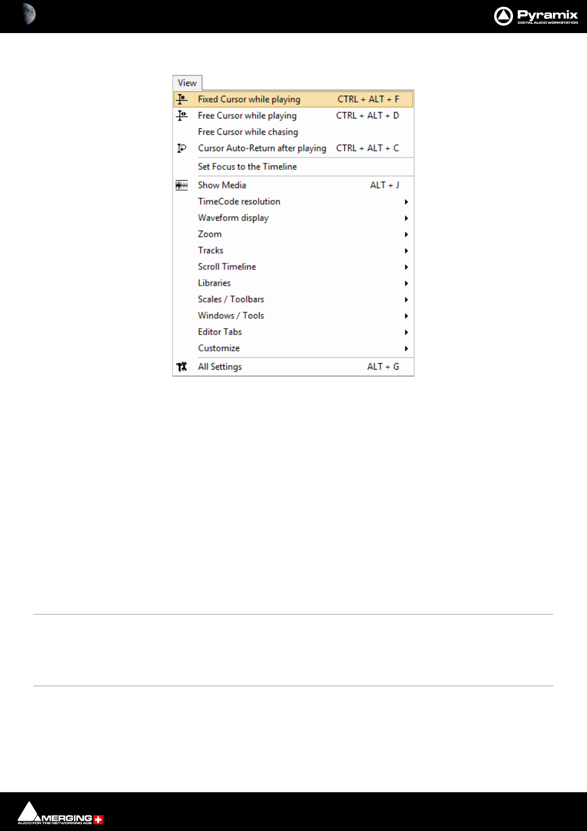
Menus : View Menu 28 - 679
View Menu
Fixed Cursor while playing When checked (enabled) Playhead Cursor remains stationary while playing at the posi-
tion set in the Settings > All Settings > Playback/Record page and the Tracks scroll
from right to left.
Free Cursor while playing When checked (enabled) Playhead Cursor disappears when the screen boundary is
reached. I.e. the Timeline is not redrawn.
Free Cursor while chasing When checked (enabled) in conjunction with either of the above options the Playhead
Cursor and Timeline position can be freely manipulated from the workstation whenever
the TimeCode Master machine is in Stop, Rew, FF, Play, Locate, etc. as well as while chas-
ing, but as soon as Pyramix has locked to incoming TimeCode, the cursor will "jump" to
current TC. This used to be the default behavior. When disabled, the Cursor will always be
locked to TimeCode when Pyramix is set to chase, whether in Stop, Rew, FF, Play, Locate,
etc. as well as while chasing.
Cursor Auto-Return after playing
When checked (enabled) Playhead Cursor returns to its starting position when playback
stops
Set Focus to the Timeline Most useful when mapped to a keyboard shortcut. When a floating Tab or other window
has been opened that keeps the focus and monopolizes some commands, typically the
Space Bar and Cursor buttons invoking this command is the direct equivalent of clicking
in the Timeline to restore the focus, but avoids having to grab the mouse and loosing any
selections.
Show Media When checked (enabled) shows the full extent of the underlying digital media for a
selected Clip as a red line on the Track above and below the selected Clip with a grayed
out image of the waveform when this is on
TimeCode Resolution >
Frames Sets the < 1 second Cursor TimeCode display resolution to frames
View menu
Menus : View Menu 28 - 680
Samples Sets the < 1 second Cursor TimeCode display to samples
[ms] Sets the < 1 second Cursor TimeCode display to display milliseconds
CD frames Sets the < 1 second Cursor TimeCode display to display CD frames
Display as CD time Sets the TimeCode display to CD Track elapsed time (only available when CD Mark-
ers are present)
Alternate TimeCode Scale - Frames
Alternate TimeCode Scale - Samples
Alternate TimeCode Scale - [ms]
Alternate TimeCode Scale - CD Frames
Alternate TimeCode Scale Settings
Waveform Display >
Larger Increase the size of the current waveform display
Smaller Decrease the size of the current waveform display
x1 Sets the magnification factor of the current waveform display to 1x
x2 Sets the magnification factor of the current waveform display to 2x
x4 Sets the magnification factor of the current waveform display to 4x
x8 Sets the magnification factor of the current waveform display to 8x
x16 Sets the magnification factor of the current waveform display to 16x
x32 Sets the magnification factor of the current waveform display to 32x
x64 Sets the magnification factor of the current waveform display to 64x
dB Sets the current waveform display to decibels
Auto-Scale Individual Waveform Sets the current waveform display to automatically display an optimal wave-
form for the Clip(s) selected currently.
Auto-Scale Visible Waveform Auto-scales the Waveform for the Track selected currently, based on what is cur-
rently seen on screen
Show Full Waveform Sets the current waveform display to display a symmetrical waveform
Show Half Waveform / OriginSets the current waveform display to display a half waveform from the bottom up
which also shows the 0dB origin
Show Dynamic Waveform
Sets the current waveform display to display a waveform that shows the dynamic
range from the minimum to maximum excursion within the media file. I.e the lowest
and highest Peak values
Hide Clip Name when Waveform Shown
Hides the Clip names when the waveform is displayed
Zoom >
Fit in window Adjusts the horizontal magnification (zoom level) of the Project Editor panel to fit
the selected Clip or Region
Previous zoom Restores the Project Editor Panel view to the previous zoom resolution and location
Zoom In Zooms in by a factor of 2x, centered around the middle of the Project Editor Panel
Zoom Out Zooms out by a factor of 2x, centered around the middle of the Project Editor Panel
Recall Preset >
Zoom 1 Recall Preset Zoom 1
Zoom 2 Recall Preset Zoom 2
Zoom 3 Recall Preset Zoom 3
Zoom 4 Recall Preset Zoom 4

Menus : View Menu 28 - 681
Zoom 5 Recall Preset Zoom 5
Set Preset >
Zoom 1 Set Preset Zoom 1
Zoom 2 Set Preset Zoom 2
Zoom 3 Set Preset Zoom 3
Zoom 4 Set Preset Zoom 4
Zoom 5 Set Preset Zoom 5
Auto Zoom Selection Project Editor Panel display automatically zooms-in to any selection made on the
Timeline
Tracks >
Show all Tracks Show (Unhide) all Tracks and Expand (Uncollapse) all Track Groups
Hide Tracks without selection Hide all Tracks that have nothing selected
Fit View to >
Fit View to 1 Track Fit current View to 1 Track
Fit View to 2 Tracks Fit current View to 2 Tracks
Fit View to 4 Tracks Fit current View to 4 Tracks
Fit View to 8 Tracks Fit current View to 8 Tracks
Fit View to 16 Tracks Fit current View to 16 Tracks
Fit View to All Tracks Fit current View to All Tracks
Enlarge Track Size Enlarge current Track Size
Reduce Track Size Reduce current Track Size
Track Size Mini Shows the Track at the height of one row of Track header
Track Size Medium Shows the Track at the height of two rows of Track header
Track Size Large Shows the Track at the height of three row of Track header
Track Size Extra Large Shows the Track at the height of 8 rows of Track header
Scroll Timeline
Scroll Timeline Left Scroll the whole Timeline to the left
Scroll Timeline Right Scroll the whole Timeline to the right
Scroll Timeline Up Scroll the whole Timeline up
Scroll Timeline Down Scroll the whole Timeline down
Libraries
Folders
Library Folders Up
Library Folders Down
Library Folders Collapse
Library Folders Expand / Focus on List
List
Library List Up
Library List Down
Library List Focus On Folders
Library List Focus On Trimmer
Trimmer
Library Trimmer Focus On List
Library Trimmer Play From In
Library Trimmer Play From Start

Menus : View Menu 28 - 682
Library Trimmer Stop
Library Trimmer Set In Point
Library Trimmer Set Out Point
Library Trimmer Set Sync Point
Scales / Toolbars >
Hide All Toolbars Hides all Toolbars visible currently. A second click restores
TimeCode Toolbar Shows/Hides the main TimeCode Toolbar
Alternate TimeCode Scale
Alternate TimeCode Scale Settings Opens the Alternate TimeCode Scale Settings dialog box. (Only available
when Alternate TimeCode Scale ruler is present.)
Feet Adds a ruler calibrated in Feet below the Time ruler (if present)
Feet Settings Opens the Feet Settings dialog box (Only available when Feet Time Scale ruler is
present.)
Bars&Beats Adds a ruler calibrated in Bars&Beats below the Time ruler (if present)
Bars&Beats Settings Opens the Bars&Beats Settings dialog box. (Only available when Bars&Beats Scale
ruler is present.)
Bars&Beats Grid Shows/Hides the Bars&Beats Grid. (Only available when Bars&Beats Scale ruler is
present.)
Tempo Map Adds a Tempo map below the Main Timescale ruler. (Only available when
Bars&Beats Time Scale ruler is present.)
Source - Destination Shows / Hides the Source - Destination Timescale Ruler(s) and Toolbar
Transport Toolbar Shows/Hides the Transport Toolbar
Automation Toolbar Shows/Hides the Automation Toolbar
Windows / Tools >
Transport Displays/Hides the Transport Large Control
Mixer Displays/Hides the Mixer
Monitor Displays/Hides the Monitor
Meter Bridge Displays/Hides the Meter Bridge
Final Check Metering Displays/Hides the optional Final Check Metering Window
Media Management Displays/Hides the Media Management folders
Global libraries Displays/Hides the Global Libraries
Fade Library Displays/Hides the Fade library
RAVENNA Easy Connect Opens the RAVENNA Easy Connect application
Information Displays/Hides the Information Window
Take Logger Opens the Take Logger Window
Recording Status Displays/Hides the Recording Status Window
I/O Status Displays/Hides the I/O Status Window
Editor Tabs >
Overview Open Overview Tab window
EDL Open EDL Tab window
Document Libraries Open Document Libraries Tab window
Tracks Open Tracks Tab window
Track Groups Open Track Groups Tab window
Menus : View Menu 28 - 683
Playlists Open Playlists Tab window
Workspaces Open Workspaces Tab window
Selection Open Selection Tab window
Fade Editor Open Fade Editor Tab window
Markers Open Markers Tab window
CD Open CD Tab window
Notes Open Notes Tab window
Media Management Open Media Management Tab window
Global Libraries Open Global Libraries Tab window
ADR Open ADR Tab window (Only when the optional ADR key is present.)
Log Open Log Tab window
Show all Tabs Shows all Tabs in docking area
Close all Tabs Hides all Tabs
Toggle Show/Close all Tabs As it says. Mainly useful when bound to keyboard shortcut.
Dock all Tabs Return all floating Tabs to the Tab dock
Load Default Tabs Layout As it says
Save Default Tabs Layout Saves the current Tabs Layout as the default
Always Use Default Tabs Layout Default Tabs Layout is used regardless of Tab layout saved with Project
Tabs layout Presets
Save Tabs Layout Preset 1
to
Save Tabs Layout Preset 10
Load Tabs Layout Preset 1
to
Load Tabs Layout Preset 10
Customize>
Keyboard Shortcut Editor Opens the Keyboard Shortcut Editor
Macro Editor Opens the Macros Window
All Settings Opens the Pyramix Settings Window

Menus : Clips 28 - 684
Clips
Select >
Select All Select all Clips on Timeline
Select All to Mark In Select all Clips on Timeline, to the current Mark In Point
Select All between Marks Select all Clips on Timeline, between current In/Out Marks
Select All from Mark Out Select all Clips on Timeline, from the current Mark Out Point
Select Source Select all Clips on current audio Track
Select Online Clips Selects all Clips on the Timeline which are On-line currently
Select offline Clips Selects all Clips on the Timeline which are Offline currently
Deselect All Deselect all currently selected Clips
Select Previous Clip Select Clip to left of currently selected Clip
Select Next Clip Select Clip to right of currently selected Clip
Add Previous Clip to Selection
Apply selection to Clip to left of currently selected Clip
Add Next Clip to Selection Apply selection to Clip to right of currently selected Clip
Add all Preceding Clips to Selection
Apply selection to all Clips preceding the currently selected Clip
Add all Following Clips to Selection
Apply selection to all Clips following the currently selected Clip
Select Next Clip Crossfade Selects the Next Crossfade
Clips menu

Menus : Clips 28 - 685
Select Previous Clip Crossfade Selects the Previous Crossfade
Nudge >
Nudge to Previous Edit Nudges the selected Clip to the left (earlier in time) to the previous edit points in
the Track or marks in the editor
Nudge to Next Edit Nudges the selected Clip to the right (later in time) to the next edit points in the
Track or marks in the editor
Nudge to Left Nudges the selected Clip to the left (earlier in time) by an amount equal to the cur-
rent Nudge setting
Nudge to Right Nudges the selected Clip to the right (later in time) by an amount equal to the cur-
rent Nudge setting
Nudge to Left Custom Nudges the selected Clip to the left (earlier in time) by an amount that can be
entered with the keyboard
Nudge to Right Custom Nudges the selected Clip to the right (later in time) by an amount that can be
entered with the keyboard
Nudge to Left Custom in Bars/Beats
Nudges the selected Clip to the left (earlier in time) by an amount that can be
entered in Bars/Beats with the keyboard
Nudge to Right Custom in Bars/Beats
Nudges the selected Clip to the right (later in time) by an amount that can be
entered in Bars/Beats with the keyboard
Nudge In to Left Moves selected Clip’s In point to the Left by an increment of the current Nudge
value
Nudge In to Right Moves selected Clip’s In point to the Right by an increment of the current Nudge
value
Nudge Out to Left Moves selected Clip’s Out point to the Left by an increment of the current Nudge
value
Nudge Out to Right Moves selected Clip’s Out point to the Right by an increment of the current Nudge
value
Nudge Media to Left Moves selected Clip’s Media to the Left by an increment of the current Nudge
value
Nudge Media to Right Moves selected Clip’s Media to the Right by an increment of the current Nudge
value
Move Up Moves the selected Clip or Region up to the adjacent Track above it
Move Down Moves the selected Clip or Region up to the adjacent Track below it
Move Up with Fade Moves the selected Clip or Region up to the adjacent Track above it. If there is
another Clip on the adjacent Track at that location, it will interact with it by cross-
fading
Move Down with Fade Moves the selected Clip or Region up to the adjacent Track below it. If there is
another Clip on the adjacent Track at that location, it will interact with it by cross-
fading
Current Setting >
Nudge Setting 1 Apply Nudge Setting 1
Nudge Setting 2 Apply Nudge Setting 2
Nudge Setting 3 Apply Nudge Setting 3
Nudge Setting 4 Apply Nudge Setting 4
Nudge Setting 5 Apply Nudge Setting 5
Set Sync Point to Cursor Sets the selected Clip’s Sync Point at the current cursor position
Menus : Clips 28 - 686
Send Sync Point to Cursor Sends (moves) the currently selected Clip so that its Sync Point is aligned with the current
position of the Play Cursor
Group Groups together all selected Clips in the Timeline
Ungroup Ungroups members of a selected group Clip in the Timeline
Lock Locks selected Clips so that they can no longer be edited or moved in the Timeline
Unlock Unlocks selected locked Clips so that they can be edited again
Lock Horizontal Drag When enabled, Clips cannot be dragged horizontally (left to right)
Clip Gain Displays an audio fader to set the audio level for the selected Clips
Mute Clip Mutes all selected Clips
Rename Enables a selection of Clips to be renamed with various combinable options chosen in
the Rename Clips dialog
Options
Keep Current Name When checked the current name is retained but with the choice of keeping or
removing the current Track number in parenthesis
Remove Track Number Removes Track Number from the Clip Name
Prefix Text entry box where a new custom Prefix may be added adding a custom prefix
and suffix text to the automatic renaming and automatically renumbering all
Clips.
Track Name
Rename Clips dialog

Menus : Clips 28 - 687
Track Number - X
Media Scene & Take (if available)
Media Name
Media Track Number (X)
Media Tape Name
Media File Name
Ignore File Extension
Include Full Path
Suffix Text entry box where a new custom Suffix may be added
Auto number clips When checked Clips are numbered starting with the value in:
Starting Numbering at:
Items Separator Text entry box where a new custom Separator may be added
Edit Fade near Cursor Opens the Fade Editor with the audio fade located near the current Playhead cursor
position ready to be edited
Edit Fade near Mouse Opens the Fade Editor with the audio fade located near the current mouse cursor posi-
tion ready to be edited
Fade In >
Fade Out >
X Fade >
Note: Sub-menu options for Fade In, Fade Out, and X Fade are the same. For brevity, only the
Fade In sub-menu options are listed.
Fade In New Apply new Fade In
Fade In Edit
Default > Edit Fade In
Fade In Default Apply Fade In Default
Fade In Default Curve Apply Fade In Default Curve
Fade In Standard >
Fade In Power Linear Apply Fade In Power Linear
Fade In Tension Linear Apply Fade In Tension Linear
Fade In dB Linear Apply Fade In dB Linear
Fade In Cosine Apply Fade In Cosine
Fade In Root Cosine Apply Fade In Root Cosine
Envelope >
Envelope Reset Reset the gain envelope for the whole selection by deleting all envelope nodes
within the selection only on the Track under the mouse cursor when Reset is cho-
sen.
Envelope Reset Selection Reset the gain envelope for the whole selection by deleting all envelope nodes
within the selection.
Envelope Copy to Selection Copies the values of all envelope nodes within the selection from the Track
under the mouse cursor when Copy to Selection is chosen to all other Tracks in the
selection
Envelope Punch Places four new envelope nodes at the bounds of the selection on the Track under
the mouse cursor when Punch is chosen and opens the Punch Envelope dialog
box
Envelope Punch Selection Carries out the same operation as Punch but to all Tracks in the current Selection.
Menus : Tracks 28 - 688
Waveform >
Waveform follow Track Waveform display of the Clip will always correspond to the setting for the entire
Track in the Track information and Settings panel
Waveform force Waveform Clip will always show the waveform display regardless of the waveform display set-
tings for the Track
Waveform force Name Clip will always show the Clip name regardless of the waveform display settings for
the Track
Generate Waveform Generate the waveform data in the background for the selected Clip
Properties Opens the Selection Properties display window, which shows details concerning the
currently selected Clip
Tracks
Add Audio Track Opens the Create Tracks dialog to enable new Audio Tracks / Mixer Strips to be created in
the Timeline and Mixer
Add Video Track Adds a Video Track above the Track selected currently. If no Track is selected adds a Video
Track at the top of the Timeline.
Delete Track Removes the currently selected Track from the composition editor
Tracks menu

Menus : Tracks 28 - 689
Delete to Last Track Deletes all Tracks between the currently selected Tracks to the last Track on the Composi-
tion Editor
Auto-connect Automatically connect all Tracks sequentially to any available Mixer Strip inputs
Select Previous Track Group Selects the Track group above the currently selected Track group
Select Next Track Group Selects the Track group below the currently selected Track group
Duplicate Selected Track Group Duplicates the currently selected Track group
Auto Create/Delete Track Groups When enabled allows Track Groups to be automatically created when Clips insertion
requires creation of new Tracks
Select Previous Track Selects the audio Track above the currently selected Track
Select Next Track Selects the audio Track below the currently selected Track
Deselect Track Deselects the currently selected audio Track
Auto Select Tracks The audio Track is automatically selected on any Click / Move in its content
Selected Track >
Mute
Solo
Monitoring Mode
Record Ready
Display Mode
Show/Hide Automation
Show/Hide Automation Sub-Tracks
Automation Init
Automation Snapshot
Automation Snapshot Region
Automation Delete
Automation Erase
Automation Trim
Synchronize Tracks & Strips The audio Track and its associated mixing console strip are always selected together.
Also, When Strips are Created Deleted or Moved in the Mixer Configuration page (or with
the right mouse button context menus) the connected Tracks are also Created/Destroyed
or moved accordingly.
When Strips are Created or Moved the Tracks are Created or Moved seamlessly. On Delet-
ing a Strip or Strips, only empty Tracks are destroyed. Tracks containing Clips are pre-
served, disconnected and set to minimum size.
Select All Clips This command selects and highlights all Clips on the selected Track
Select All Clips to Mark In Selects all Clips on the Track from the beginning of the composition up to the mark in
Select All Clips between Marks Selects all Clips on the Track between the Mark In and Mark Out
Select All Clips from Mark Out Selects all Clips on the Track from the Mark Out to the end of the composition
Deselect All Clips Deselects all Clips on the selected Track
Ripple Launches the Ripple Tracks dialog box
Extend Automatically extends the number of Tracks to accommodate all the Media channels of
each of the Clips of one or more timeline Track(s)
Menus : Cursor & Marks 28 - 690
Cursor & Marks
Nudge Cursor >
Nudge Cursor to Previous Edit Nudge Cursor to Previous Edit
Nudge Cursor to Next Edit Nudge Cursor to Next Edit
Nudge Cursor to Previous Clip Nudge Cursor to Previous Clips
Nudge Cursor to Next Clip Nudge Cursor to Next Clip
Nudge Cursor to Previous Clip Fade Nudge Cursor to Previous Clip Fade
Nudge Cursor to Next Clip Fade Nudge Cursor to Next Clip Fade
Nudge Cursor to Left Nudge Cursor to Left
Nudge Cursor to Right Nudge Cursor to Right
Nudge Cursor to Left with Region Nudge Cursor to Left and update the nearest selection
boundary to this location
Cursor & Marks menu

Menus : Cursor & Marks 28 - 691
Nudge Cursor to Right with Region Nudge Cursor to Right and update the nearest selection
boundary to this location
Nudge Cursor to Left Custom Nudge Cursor to Left by an amount entered with the Key-
board
Nudge Cursor to Right Custom Nudge Cursor to Right by an amount entered with the Key-
board
Nudge Cursor to Left Custom in Bars/Beats Nudge Cursor to Left by an amount entered in Bars/Beats
with the Keyboard
Nudge Cursor to Right Custom in Bars/Beats Nudge Cursor to Right by an amount entered in Bars/Beats
with the Keyboard
Nudge Cursor to Previous Foot Nudge Cursor to the Previous Foot
Nudge Cursor to Next Foot Nudge Cursor to the Next Foot
Nudge Cursor to Previous Foot Frame Nudge Cursor to the Previous Foot Frame
Nudge Cursor to Next Foot Frame Nudge Cursor to the Next Foot Frame
Nudge Cursor to Previous Bar Nudge Cursor to the Previous Bar
Nudge Cursor to Next Bar Nudge Cursor to the Next Bar
Nudge Cursor to Previous Beat Nudge Cursor to the Previous Beat
Nudge Cursor to Next Beat Nudge Cursor to the Next Beat
Nudge Cursor to Previous Grid Step Nudge Cursor to the Previous Grid Step
Nudge Cursor to Next Beat Grid Step Nudge Cursor to the Next Grid Step
Nudge Marks >
Nudge Mark In to Left Nudge Mark In to Left
Nudge Mark In to Right Nudge Mark In to Right
Nudge Mark In to Left Custom Nudge Mark In to Left by an amount entered with the Key-
board
Nudge Mark In to Right Custom Nudge Mark In to Right by an amount entered with the Key-
board
Nudge Mark In to Left Custom in Bars/Beats Nudge Mark In to Left by an amount entered in Bars/Beats
with the Keyboard
Nudge Mark In to Right Custom in Bars/Beats Nudge Mark In to Right by an amount entered in Bars/Beats
with the Keyboard
Nudge Mark Out to Left Nudge Mark Out to Left
Nudge Mark Out to Right Nudge Mark Out to Right
Nudge Mark Out to Left Custom Nudge Mark Out to Left by an amount entered with the Key-
board
Nudge Mark Out to Right Custom Nudge Mark Out to Right by an amount entered with the
Keyboard
Nudge Mark Out to Left Custom in Bars/Beats Nudge Mark Out to Left by an amount entered in Bars/Beats
with the Keyboard
Nudge Mark Out to Right Custom in Bars/Beats Nudge Mark Out to Right by an amount entered in Bars/
Beats with the Keyboard
Nudge Gates > (Use with Source Destination Editing Projects)
Nudge Gate In to Left Nudge Gate In to Left
Nudge Gate In to Right Nudge Gate In to Right
Nudge Gate Out to Left Nudge Gate Out to Left
Nudge Gate Out to Right Nudge Gate Out to Right
Current Nudge Setting>

Menus : Cursor & Marks 28 - 692
Nudge Setting 1
Nudge Setting 2
Nudge Setting 3
Nudge Setting 4
Nudge Setting 5
Goto TimeCode Opens the Goto TimeCode dialog box, which allows the Play Cursor to be positioned to a
specific TimeCode position
Goto Foot Allows the Play Cursor to be positioned to a specific Footage
Goto Beat Allows the Play Cursor to be positioned to a specific Beat
Cursor to Mark In Moves the Play Cursor to the Mark In
Cursor to Mark Out Moves the Play Cursor to the Mark Out
Cursor to Gate In Moves the Play Cursor to the selected Track Group Gate In
Cursor to Gate Out Moves the Play Cursor to the selected Track Group Gate Out
Cursor to Start of Selected Track Moves the Play Cursor to the start position of the first Clip on the selected Track
Cursor to End of Selected Track Moves the Play Cursor to the end position of the first Clip on the selected Track
Auto Center on Goto When enabled, the Project Editor will automatically center the display to the new Play
Cursor position when the Goto TimeCode command is used .
Mark In to Cursor Moves the Mark In to the Play Cursor
Mark Out to Cursor Moves the Mark Out to the Play Cursor
Gate In to Cursor Moves the selected Track Group Gate In to the Play Cursor
Gate Out to Cursor Moves the selected Track Group Gate Out to the Play Cursor
Marks to Selection Moves the Mark Out to the current selection
Lock Marks Prevents the Mark In/Out points from being changed
Hide Marks Removes the Mark In/Out cursors
Show Cursor Automatically centers the display of the Project Editor to the Play Cursor
Show Mark In Automatically centers the display of the Project Editor to Mark In current position
Show Mark Out Automatically centers the display of the Project Editor to Mark Out current position
Show Gate In Automatically centers the display of the Project Editor to the selected Track Group Gate In
Show Gate Out Automatically centers the display of the Project Editor to the selected Track Group Gate
Out
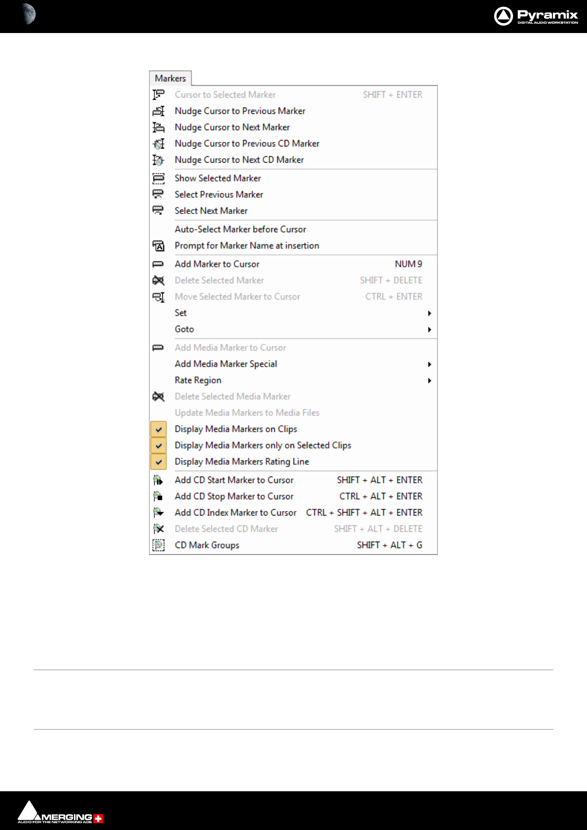
Menus : Markers 28 - 693
Markers
Cursor to Selected Marker [Shift + Enter]Moves the Play Cursor to the Selected Marker
Nudge Cursor to Previous Marker Nudge Cursor to Previous Marker
Nudge Cursor to Next Marker Nudge Cursor to Next Marker
Nudge Cursor to Previous CD MarkerNudge Cursor to Previous CD Marker
Nudge Cursor to Next CD Marker Nudge Cursor to Next CD Marker
Show Selected Marker Automatically centers the display of the Project Editor to the currently selected Marker
Select Previous Marker Selects the Previous Marker (left) of the currently selected Marker
Select Next Marker Selects the Next Marker (right) of the currently selected Marker
Auto-Select Marker Before Cursor When enabled the Marker immediately before the Cursor will be selected. As the Cursor is
moved the selection will change as the next Marker is passed
Markers menu
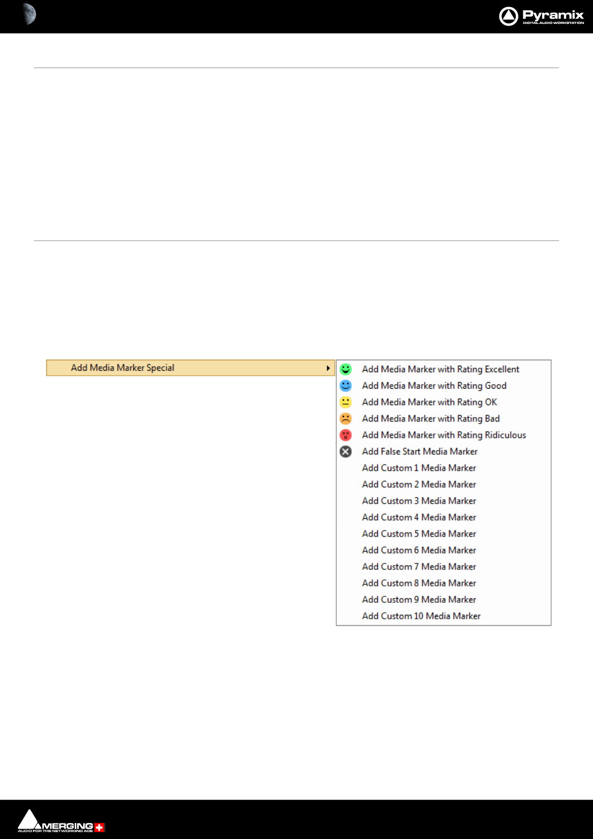
Menus : Markers 28 - 694
Prompt for Marker Name at insertion When ticked the Add New Marker dialog opens when a new marker is inserted
Add Marker to Cursor [NUM 9] Adds a new Marker to the current Play Cursor Position
Delete Selected Marker [SHIFT + DELETE] Deletes the currently selected Marker
Move Selected Marker to Cursor [CTRL + ENTER] Moves the selected Marker to the current Play Cursor Position
Set >
Set Marker 1 Set the Marker #1 to the current Play Cursor Position
Note: Set Markers 2 - 10 not shown
Goto>
Goto Marker 1 Set the Play Cursor position to Marker #1
Note: Goto Markers 2 - 10 not shown
Add Media Marker to Cursor
Add Media Marker to Cursor The Clip to be marked must first be selected. Adds a Media Marker at the current Cursor
position.
Add Media Marker Special > When Display Media Marker Line is on the line to the right of the Media Marker will be
colored according to the rating selected when a Media Marker is added from this sub-
menu until the next Media Marker. Default, in the absence of a Media Marker is yellow i.e.
OK.
Add Media Marker with Rating Excellent
Add Media Marker with Rating Good
Add Media Marker with Rating OK
Add Media Marker with Rating Bad
Add Media Marker with Rating Ridiculous
Add False Start Media Marker
Add Custom 1 Media Marker to:
Add Custom 10 Media Marker
Markers > Add Media Markers Special sub-menu
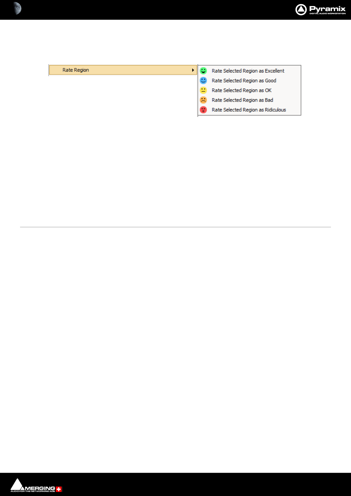
Menus : Markers 28 - 695
Note: Media Markers are added to the current recording ONLY when no other Clip or Clips is/are
selected in the Timeline.
Rate Region The Sub-menu offers a choice of Ratings for the Region Currently selected:
Rate Selected Region as Excellent
Rate Selected Region as Good
Rate Selected Region as OK
Rate Selected Region as Bad
Rate Selected Region as Ridiculous
Delete Selected Media Marker Deletes the selected Media Marker.
Display Media Markers Rating Line When active a colored line is shown reflecting the color of the most recent Media Marker.
Default in the absence of a Media Marker is yellow i.e. OK
Update Media Markers to Media Files
Add CD Start Marker to Cursor [ SHIFT + ALT + ENTER] Adds a CD Start marker at the Play Cursor position
Add CD Stop Marker to Cursor [CTRL + ALT + ENTER] Adds a CD Stop marker at the Play Cursor position
Add CD Index Marker to Cursor [CTRL + SHIFT + ALT + ENTER] Adds a CD Index marker at the Play Cursor position
Delete Selected CD Marker [SHIFT + ALT + DELETE] Deletes the currently selected CD Marker
CD Mark Groups [SHIFT + ALT + G] Enables automatic creation of CD Markers Groups in the Project Editor
Markers > Rate Region sub-menu
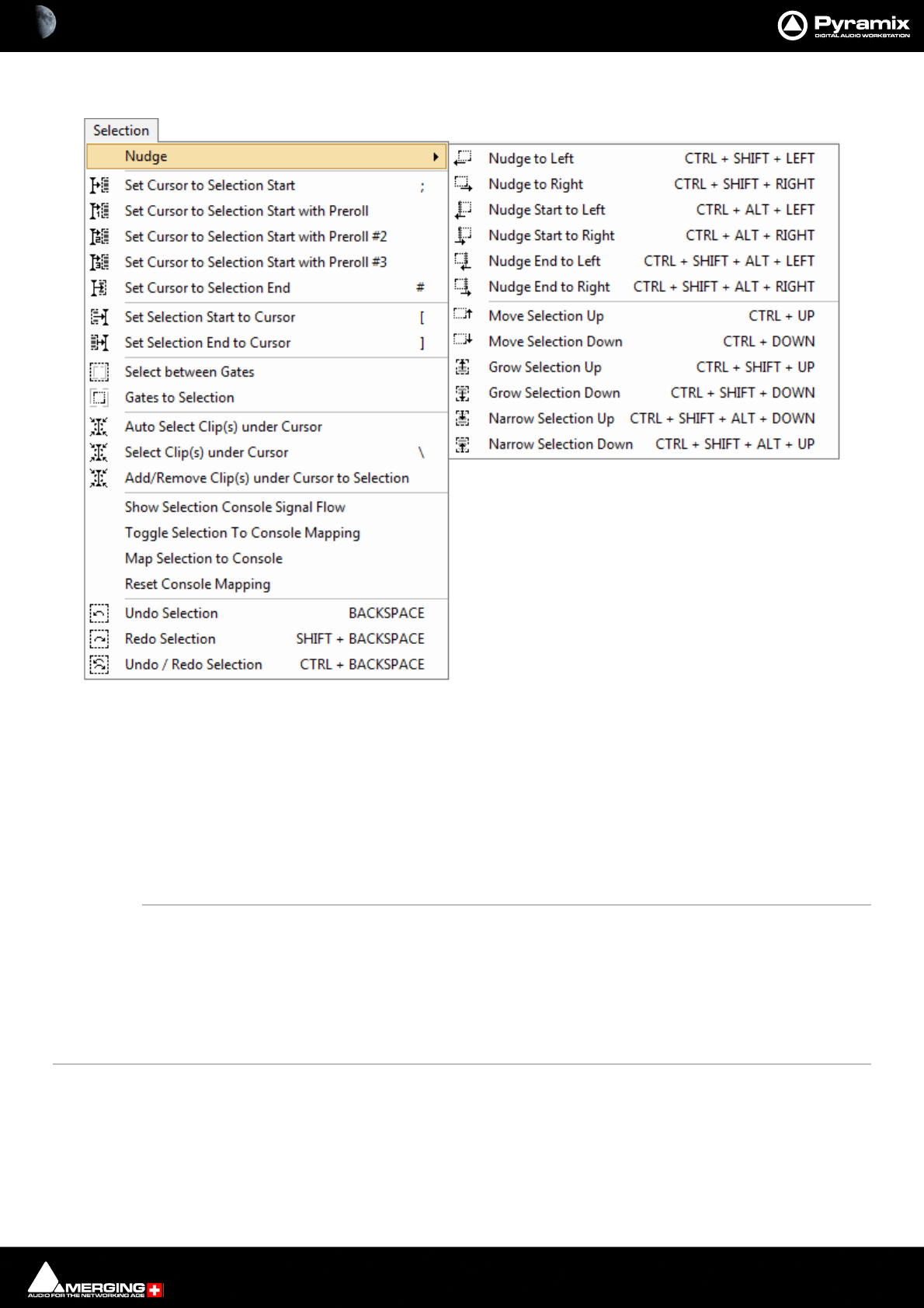
Menus : Selection 28 - 696
Selection
Nudge >
Nudge to Left Nudges the selection to the left
Nudge to Right Nudges the selection to the right
Nudge Start to Left Nudges the selection start to the right
Nudge Start to Right Nudges the selection start to the left
Nudge End to Left Nudges the selection end to the right
Nudge End to Right Nudges the selection end to the left
Move Selection Up Moves the current selection to the Track above its current position
Move Selection Down Moves the current selection to the Track below its current position
Grow Selection Up Applies the current selection to the Track above its current position
Grow Selection Down Applies the current selection to the Track below its current position
Narrow Selection Up Removes the current selection from the Track above its current position
Narrow Selection Down Removes the current selection from the Track below its current position
Set Cursor to Selection Start Positions the Play Cursor to the start point of the current selection
Set Cursor to Selection Start with PrerollPositions the Play Cursor to the start point of the current selection, adding the
defined Preroll value
Set Cursor to Selection Start with Preroll #2Positions the Play Cursor to the start point of the current selection, adding the
defined Preroll #2 value
Selection menu
Menus : Fade Editor 28 - 697
Set Cursor to Selection Start with Preroll #3Positions the Play Cursor to the start point of the current selection, adding the
defined Preroll #3 value
Set Cursor to Selection End Positions the Play Cursor to the end point of the current selection
Set Selection Start to Cursor Positions the start point of the current selection to the Play Cursor position
Set Selection End to Cursor Positions the end point of the current selection to the Play Cursor position
Select between Gates Sets the Selection between the selected Track Group Gates
Gates to Selection Moves the Gates to the extremities of the current selection
Auto Select Clip(s) under Cursor Automatically Selects the Clip(s) currently in contact with the Playhead Cursor
Select Clip(s) under Cursor Selects the Clip(s) currently in contact with the Playhead Cursor
Add/Remove Clip(s) under Cursor to Selection
Show Selection Console Signal Flow Displays the signal flow on the console of the Clips currently selected on the Timeline
Toggle Selection To Console Mapping Toggles Map Selection to Console. (Enables this to be bound to as ingle keyboard
shortcut.)
command/keyboard shortcut
Map Selection to Console Shrinks the console UI to display only strips carrying the signal flow of current Timelinese-
selection. (Clips or Region).
Reset Console Mapping Resets the Console UI to normal after Map Selection to Console.
Undo Selection Cancels the last selection command
Redo Selection Cancels (redoes) the last Undo Selection command
Undo / Redo Selection Toggles between the last Undo / Redo Selection command
Fade Editor
Open Editor Opens the Fade Editor window
Fade Editor menu

Menus : Fade Editor 28 - 698
Accept & Close Editor Approve changes to the fade and close Fade Editor window
Restore & Close Editor Restore fade to original state and close Fade Editor window
Restore Fade Restore fade to original state
Undo Fade Change Undoes the last parameter change
Previous Fade Select / Edit previous fade
Next Fade Select / Edit net fade
Xify Makes an asymetrical fade symmetrical by using the fade length and curve from the side
of the crossfade that is not selected and applying it to the selected side. E.g. to create the
mirror image of a fade out select the incoming clip and choose XIFY
Show Faders & Control Show the Faders and Control Section of the Fade Editor
Show Parameters & Options Show the Parameters and Options section of the Fade Editor
Display & Zoom >
Fit Fade Zoom around the current Fade (Reset Zoom)
Zoom In Zoom in on graphic display
Zoom Out Zoom out on graphic display
Display & Zoom Options >
No Auto-Center Auto-Centering off
Auto-Center Fade Auto-Centering on
Auto-Center Reference Point Auto Center on Reference Point
Free Zoom Follows only Zoom Reset, In and Out
Auto-Zoom Automatically Zooms around the current Fade after some operations
Auto-Zoom/Free Automatically Zooms around the current Fade but only when it enters the
Fade Editor, thereafter, the Zoom is Free
Timeline Zoom Follows the Timeline Zoom factor
Zoom Preset 1 Recall Preset Zoom #1
Zoom Preset 2 Recall Preset Zoom #2
Zoom Preset 3 Recall Preset Zoom #3
Zoom Preset 4 Recall Preset Zoom #4
Zoom Preset 5 Recall Preset Zoom #5
Faders & Control >
Nudge Out Gain Less
Nudge Out Gain More
Nudge In Gain Less
Nudge In Gain More
Nudge Intercept Less
Nudge Intercept More
Nudge Asymmetry Less
Nudge Asymmetry More
Nudge Out Length Less
Nudge Out Length More
Nudge In Length Less

Menus : Fade Editor 28 - 699
Nudge In Length More
Nudge Out Position Left
Nudge Out Position Right
Nudge In Position Left
Nudge In Position Right
Nudge In Media Left
Nudge In Media Right
Nudge Out Media Left
Nudge Out Media Right
Faders & Control Options >
Link Length Links length of Fade Out & In
Mirror Length Length of Fade Out and In will be changed symmetrically (centered)
Link Position Links position of Fade Out & In
Fade Safe Ensures all following fades (to the right of the one being edited) are left
intact while editing the current fade.
Force Safe
Audition >
Audition X Fade
Audition X Fade with Ref
Audition Out with Curve
Audition Out without Curve
Audition Out after Fade
Audition Out with Curve with Ref
Audition Out without Curve with Ref
Audition Out after Fade with Ref
Audition Out Original Material
Audition In with Curve
Audition In without Curve
Audition In before Fade
Audition In with Curve with Ref
Audition In without Curve with Ref
Audition In before Fade with Ref
Audition In Original Material
Audition Options >
Audition Pre-Roll 1
Audition Pre-Roll 2
Audition Pre-Roll 3
Audition Post-Roll 1
Audition Post-Roll 2
Audition Post-Roll 3
Audition Speed 100%
Audition Speed 50%
Audition Speed 25%

Menus : Fade Editor 28 - 700
Audition Solo
Audition Loop
Audition After Nudge
Memory >
Set Memory 1
Set Memory 2
Set Memory 3
Set Memory 4
Set Memory 5
Recall Memory 1
Recall Memory 2
Recall Memory 3
Recall Memory 4
Recall Memory 5
Presets >
Load Default X Curve
Load Default X Preset
Save Default X Preset
Load Default Out Curve
Load Default Out Preset
Save Default Out Preset
Load Default In Curve
Load Default In Preset
Save Default In Preset
Menus : Media 28 - 701
Media
Search Media Opens the Search Media dialog.
Mount Referenced Media Mounts all media not already mounted and used in the current Project
Auto-Mount Media When selected, whenever a reference from an Offline library is placed in the current Proj-
ect, the Media will automatically be mounted.
Select Online Clips Selects all Clips in the Timeline whose Media files are currently mounted
Select Offline Clips Selects all Clips in the Timeline whose Media files are not currently mounted
Select Used Media Opens a floating Media Manager window containing all Media used by the current Proj-
ect.
Select Media present on Project Default Folder Opens a floating Composition Library window with all Media present in the
Project Default folder selected (highlighted)
Select Media NOT present on Project Default Folder Opens a floating Composition Library window with all Media NOT pres-
ent in the Project Default folder selected (highlighted)
Collect Media to current Project Default Folder Copies all media files used in the current project (as shown when the previous
Select Media not present ... is invoked to the current Project Default Folder. This func-
tion is especially useful if moving a machine or disk to another studio or where network
resources may not be available.
Clean-Up Media Opens the Choose a Media Folder to Clean-Up window. Choose the Media Folder you
wish to clean-up and click OK. All media not referenced by the current Project will be per-
manently removed from the selected folder.
Media menu
Menus : Automation 28 - 702
Automation
Automation Off Automation system is disabled.
Automation Play Automation system is set to playback any previously recorded automation data.
Automation Write Automation system is set to playback any previously recorded automation data and
record new automation data for all enabled controls .
Automation Preview Automation system is set to playback any previously recorded automation data and new
automation data is recorded for all enabled controls touched. This new information is
retained or discarded as the user wishes.
Automation Snapshot Creates an automation key frame at the current cursor position, for all currently armed
automation controls.
Automation menu
Menus : Automation 28 - 703
Automation Snapshot Last Selection Applies the last Snapshot without the need to open the Filter automation Tracks to
Snapshot window. Ctrl + Click on the single Camera button does the same thing. I.e. the
last selection is applied directly thus improving the workflow.
Note: The the last entry is lost after a Mixer rebuild so, if a rebuild occurs between Snap-
shots the Filter automation Tracks to Snapshot Window will open.
Automation Snapshot Range Places automation key frames at the currently defined In / Out cursor positions, for all cur-
rently armed automation controls..
Automation Snapshot Range Last Selection Applies the last Snapshot Range without the need to open the Filter automa-
tion Tracks to Snapshot window. Ctrl + Click on the double Camera button does the
same thing. I.e. the last selection is applied directly thus improving the workflow.
Note: The the last entry is lost after a Mixer rebuild so, if a rebuild occurs between Snap-
shots the Filter automation Tracks to Snapshot Window will open.
Delete Selected Points & Interpolate Deletes all automation points contained in the selected Region and interpolates
between the last existing point before the selection and the first point after the selection.
Delete Selected Points Deletes all automation points contained in the selected Region.
Cut Selected Points Cuts all automation points contained in the selected Region
Copy Selected Points Copies all automation points contained in the selected Region
Paste Points to Cursor Pastes all copied or cut automation points at the cursor on the selected Track
Paste Points to Original TC Pastes all copied or cut automation points at the Original TimeCode on the selected Track
Bus Reassignment on Paste When set on the Automation Buses Reassignment dialog will appear if some auto-
mated bus elements of a strip are available in the automation clipboard. When set off the
dialog will appear only when at least one bus in the clipboard is not available in the tar-
get mixer.
Console Strips Mode - Touch The automation starts writing a new pass when the control is touched and stops writing
when the control is released.
Console Strips Mode - Latch The automation starts writing a new pass when the control is touched. The value when
the control is released will continue to be written until the transport stops.
Console Strips Mode - Trim Touch The automation starts updating the current pass when the control is touched and stops
updating when the control is released.
Console Strips Mode - Trim Latch The automation starts updating when the control is touched but continues when the
control is released and stops only when the transport stops.
Console Strips Mode - Record
Console Strips Mode - Read
Console Strips Mode - Isolate
Console Strips Release Mode - Release An interpolation is created from the current value to the value written in the previous
pass. I.e. a fade. The length of this is defined in Automation Settings > Auto-Release
Time.
Console Strips Release Mode - Snap A straight jump is made from the current control value to the value written in the previ-
ous pass.
Console Strips Release Mode - Write to Next The same value is kept after the last written point until the next point is found
in the previous pass.
Console Strips Release Mode - Write to End Writes the current value to the end, ignoring previously written points. (If any).
Release Auto-Writing Immediately releases all controls currently recording automation.
Automation Tracks Opens the Automation Tracks window. This view allows the automation versions for a
specific control to be displayed. Once the desired control has been located in the tree
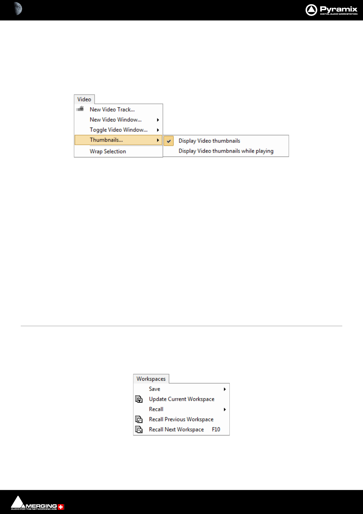
Menus : Video 28 - 704
view, simply double-clicking on the control will update the Automation Track Versions
window.
Automation Settings Opens the Settings > All Settings > Application > Automation page which allows
automation parameters and settings to be defined.
Video
New Video Track... Adds a Video Track above the Track selected currently. If no Track is selected adds a Video
Track at the top of the Timeline.
New Video Window... Opens a sub-menu with the choice of opening floating windows displaying:
New Video Window Output 1
New Video Window Output 2
New Video Window Output 3
New Video Window Output 4
Toggle Video Window... Opens a sub-menu with the choice of toggling Video windows open/closed:
Toggle Video Window Output 1
Toggle Video Window Output 2
Toggle Video Window Output 3
Toggle Video Window Output 4
Thumbnails... Opens a sub-menu with the choice of:
Display Video thumbnails
Display Video thumbnails while playing
Wrap Selection Initiates wrapping of selected Audio Clips into a selected Audio Clip. Please
see: Wrapping Timeline Tracks Files into Video Files using Mixdown on page 531
Workspaces
Save >
Save Workspace 1 Save Workspace 1
Video menu
Workspaces menu
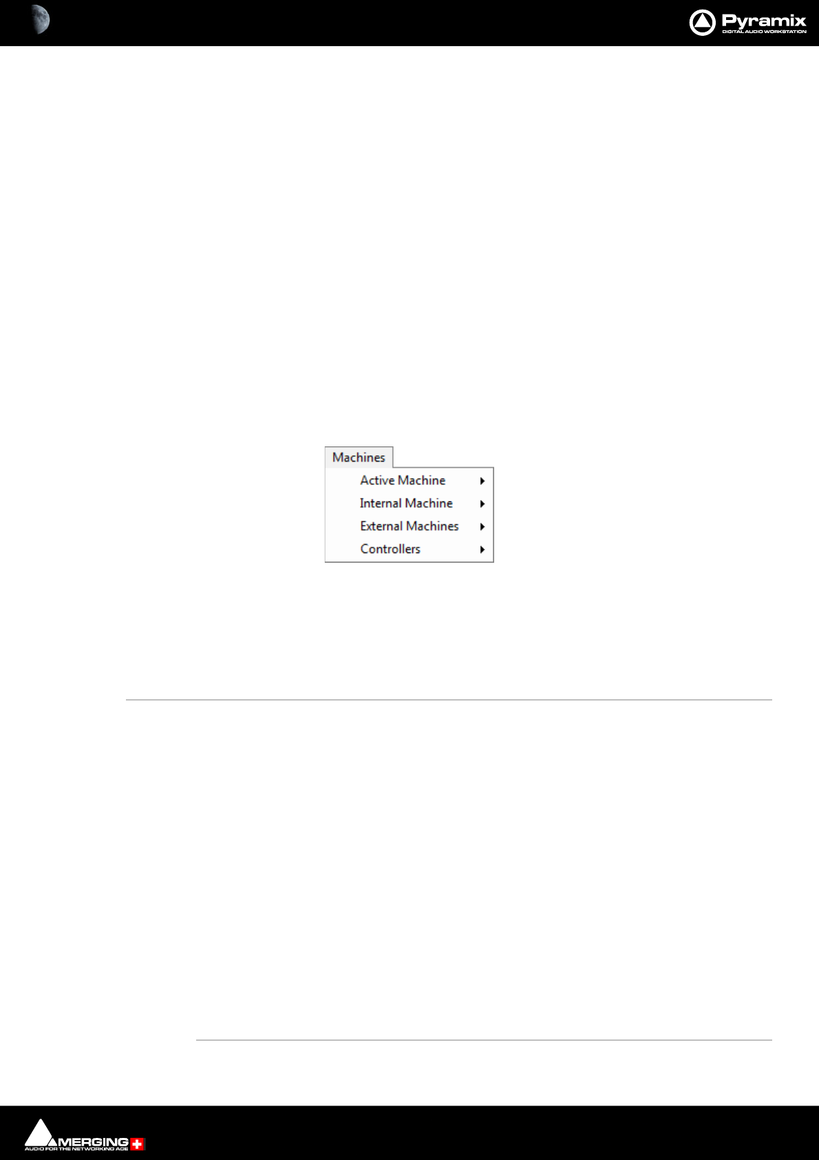
Menus : ADR 28 - 705
Note: Save Workspace 2 to 10 omitted
Update Current Workspace Updates (overwrites) the current stored Workspace with current settings
Recall >
Recall Workspace 1 Recall Workspace 1
Note: Recall Workspace 2 - 10 omitted
Recall Previous Workspace Toggles backwards through the list of available Workspaces
Recall Next Workspace Toggles forwards through the list of available Workspaces
ADR
For details of the ADR Menu please see the ADR User Guide
Machines
Active machine >
Note: Active machine Sub-menus will reflect whichever machine is currently chosen as the
active machine.
Toggle machines Toggle between installed machines
Stop Stop
Pause Pause
Play Play
Play Special >
Play Reverse Play Reverse
Play 1/2 Play 1/2
Play 1/2 Reverse Play 1/2 Reverse
Play 1/4 Play 1/4
Play 1/4 Reverse Play 1/4 Reverse
Play 1/16 Play 1/16
Play 1/16 Reverse Play 1/16 Reverse
Play 2x Play 2x
Play 2x Reverse Play 2x Reverse
Play 4x Play 4x
Play 4x Reverse Play 4x Reverse
Toggle Play/Stop Toggle Play/Stop
Machines menu
Menus : Machines 28 - 706
Toggle Play/Pause Toggle Play/Pause
Toggle Play/Record Toggle Play/Record
Record Record
Fast Forward Fast Forward
Fast Rewind Fast Rewind
Scan Forward Scan Forward
Scan Rewind Scan Rewind
Start Goto Start
End Goto End
Goto TimeCode Goto TimeCode
Nudge +1 frame
Nudge -1 frame
Nudge to Right
Nudge to Left
Set Loop In At current Playhead Cursor position
Set Loop Out At current Playhead Cursor position
Goto Loop In
Goto Loop Out
Chase
Store Chase Offset
Internal Machine>
Stop Stop
Pause Pause
Play Play
Play Special >
Play Reverse Play Reverse
Play 1/2 Play 1/2
Play 1/2 Reverse Play 1/2 Reverse
Play 1/4 Play 1/4
Play 1/4 Reverse Play 1/4 Reverse
Play 1/16 Play 1/16
Play 1/16 Reverse Play 1/16 Reverse
Play 2x Play 2x
Play 2x Reverse Play 2x Reverse
Play 4x Play 4x
Play 4x Reverse Play 4x Reverse
Toggle Play/Stop Toggle Play/Stop
Toggle Play/Pause Toggle Play/Pause
Toggle Play/Record Toggle Play/Record
Toggle Play/Stop Record Safe

Menus : Machines 28 - 707
Note: This command toggles between Play and Stop (or other state) but has no effect when
recording. In this case the real Stop command has to be issued to stop a recording.
Play with Preroll
Play with Preroll #2
Play with Preroll #3
Record Record
Fast Forward Fast Forward
Fast Rewind Fast Rewind
Scan Forward Scan Forward
Scan Rewind Scan Rewind
Start Start
End End
Punch >
Punch Selection Punch Selection
Punch Selection with PrerollPunch Selection with Preroll
Punch Selection with Preroll #2Punch Selection with Preroll #2
Punch Selection with Preroll #3Punch Selection with Preroll #3
Auto-punch with Preroll Auto-punch with Preroll
Auto-punch with Preroll #2 Auto-punch with Preroll #2
Auto-punch with Preroll #3 Auto-punch with Preroll #3
Remake last Punch (In only)Repeat last Punch operation (Punch In only)
Remake last Punch (In - Out)Repeat last Punch operation
Safety Record When this mode is active the only way to stop a recording is to return to this menu and
de-activate it. (Or use an assigned keyboard Shortcut)
Play Selection Play Selection
Loop Selection Loop Selection
Play between Marks Play between Marks
Loop between Marks Loop between Marks
Play between Gates Play between selected Track Group Gates
Loop between Gates Loop between selected Track Group Gates
Audition >
Audition Pre Audition Pre
Audition Pre (Preroll #2) Audition Pre (Preroll #2)
Audition Pre (Preroll #3) Audition Pre (Preroll #3)
Audition Audition
Audition (Pre/Postroll #2) Audition (Pre/Postroll #2)
Audition (Pre/Postroll #3) Audition (Pre/Postroll #3)
Audition Post Audition Post
Audition Post (Postroll #2) Audition Post (Postroll #2)
Audition Post (Postroll #3) Audition Post (Postroll #3)
Audition Gate In Pre Audition selected Track Groups Gate In Pre

Menus : Machines 28 - 708
Audition Gate In Pre (Preroll #2) Audition selected Track Groups Gate In Pre (Preroll #2)
Audition Gate In Pre (Preroll #3) Audition selected Track Groups Gate In Pre (Preroll #3)
Audition Gate In Audition selected Track Groups Gate In
Audition Gate In (Pre/Postroll #2) Audition selected Track Groups Gate In (Pre/Postroll #2)
Audition Gate In (Pre/Postroll #3) Audition selected Track Groups Gate In (Pre/Postroll #3)
Audition Gate In Post Audition selected Track Groups Gate In Post
Audition Gate In Post (Postroll #2) Audition selected Track Groups Gate In Post (Postroll #2)
Audition Gate In Post (Postroll #3) Audition selected Track Groups Gate In Post (Postroll #3)
Audition Gate Out Pre Audition selected Track Groups Gate Out Pre
Audition Gate Out Pre (Preroll #2) Audition selected Track Groups Gate Out Pre (Preroll #2)
Audition Gate Out Pre (Preroll #3) Audition selected Track Groups Gate Out Pre (Preroll #3)
Audition Gate Out Audition selected Track Groups Gate Out
Audition Gate Out (Pre/Postroll #2) Audition selected Track Groups Gate Out (Pre/Postroll #2)
Audition Gate Out (Pre/Postroll #3) Audition selected Track Groups Gate Out (Pre/Postroll #3)
Audition Gate Out Post Audition selected Track Groups Gate Out Post
Audition Gate Out Post (Postroll #2) Audition selected Track Groups Gate Out Post (Postroll #2)
Audition Gate Out Post (Postroll #3) Audition selected Track Groups Gate Out Post (Postroll #3)
Goto TimeCode Goto TimeCode
Nudge +1 frame
Nudge -1 frame
Set Loop In At current Playhead Cursor position
Set Loop Out At current Playhead Cursor position
Goto Loop In
Goto Loop Out
Loop On/Off Loop On/Off
Chase Chase (According to setting in, Settings > All Settings > Application > Jog/Chase :
Chase Settings)
Store Chase Offset Store Chase Offset
Auto Chase
Freeze External Machines
Cursor Auto-Return after playing Auto Return On/Off
External Machines>
Stop Stop
Pause Pause
Play Play
Play Special >
Play Reverse Play Reverse
Play 1/2 Play 1/2
Play 1/2 Reverse Play 1/2 Reverse
Play 1/4 Play 1/4

Menus : Machines 28 - 709
Play 1/4 Reverse Play 1/4 Reverse
Play 1/16 Play 1/16
Play 1/16 Reverse Play 1/16 Reverse
Play 2x Play 2x
Play 2x Reverse Play 2x Reverse
Play 4x Play 4x
Play 4x Reverse Play 4x Reverse
Toggle Play/Stop Toggle Play/Stop
Toggle Play/Pause Toggle Play/Pause
Toggle Play/Record Toggle Play/Record
Record Record
Fast Forward Fast Forward
Fast Rewind Fast Rewind
Scan Forward Scan Forward
Scan Rewind Scan Rewind
Start Goto Start
End Goto End
Goto TimeCode Goto TimeCode
Nudge +1 frame Nudge +1 frame
Nudge -1 frame Nudge -1 frame
Set Loop In At current Playhead Cursor position
Set Loop Out Out At current Playhead Cursor position
Goto Loop In Goto Loop In
Goto Loop Out Goto Loop Out
Chase (According to setting in, Settings > All Settings > Application > Jog/Chase : Chase Set-
tings)
Store Chase Offset
Auto-Chase
Eject Eject
Preview Rehearse the Edit taking into account the current Pre and Post Roll settings.
Auto Edit Perform the Edit
Review Review the Edit taking into account the current Pre and Post Roll settings.
Enable Record On/Off Enable Record On/Off
Record Ready >
Record Ready V1 Record Ready V1
Record Ready A1 Record Ready A1
Record Ready A2 - A7 omitted
Record Ready A8 Record Ready A8

Menus : Machines 28 - 710
Locator >
Goto Locator 1 Goto Locator 1
Goto Locator 2 to 9 omitted
Goto Locator 10 Goto Locator 10
Set Locator 1 Set Locator 1
Set locator 2 to 9 omitted
Set Locator 10 Set Locator 10
Controllers>
Offline Controllers Toggle Controllers On/Off line
Jog-Wheel Mode - Jog
Jog-Wheel Mode - Shuttle
Jog-Wheel Mode - Loop repeats a short loop, starting at the cursor position
Jog-Wheel Mode - Navigate Navigate is silent jog mode
Jog-Wheel Mode - Zoom
Jog-Wheel Mode - Track Size
Jog-Wheel Mode - Volume
Jog Wheel Mode - Pitch Varies the pitch in normal speed playback. Clockwise increases, anti-clock-
wise decreases. Range is limited to -25% to +25%.
Jog-Wheel Mode - Off
Jog-Wheel Listen - Mix Listen to mix out when Jog is active
Jog-Wheel Listen - Selection Listen only to Tracks included in the current Selection
Jog-Wheel Fine Change jog-wheel ‘gearing’ to the sensitivity factor set in Settings > All
Settings > Application > Jog/Chase : Fine Jog sensitivity factor (Default
0.25) I.e. a quarter of nominal sensitivity.
E.g. if nominal = 1.00 seconds per revolution then Fine will be a quarter of a
second per revolution.
Auto Show Plugins When selected Plugins parameters windows are automatically opened
when selected on the remote controller.

Menus : Monitor 28 - 711
Monitor
The Monitor menu is intended mainly for use with hardware controllers such as the Merging Technologies
Ramses. I.e. it makes these functions available for mapping to hardware controls. For full details of the functional-
ity, please see: Monitor on page 310
Next Mix Source
Previous Mix Source
Next External Source
Previous External Source
Next Speaker Set
Previous Speaker Set
Next Down Mix
Previous Down Mix
Mute
Dim
Volume Up
Volume Down
Talk to All
Macros
Macro Editor Opens the Macros Window
Please see User Macros on page 511
Monitor menu
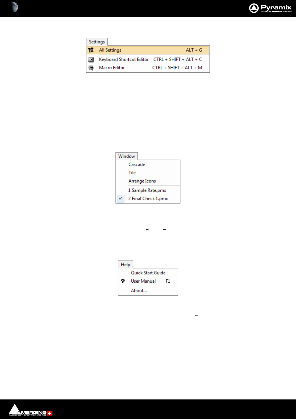
Menus : Settings 28 - 712
Settings
The Settings menu brings together access to the main All Settings window, the Keyboard Shortcut Editor and
the Macro Editor.
All Settings Opens the Pyramix Settings Window
Keyboard Shortcut Editor Opens the Keyboard Shortcuts Window
Macro Editor Opens the Macros Window
Window
The Window menu maintains a list of open projects and enables switching between them. It also enables multiple
open project windows to be arranged on screen, Tiled or Cascaded. When there are many Projects open and min-
imized Arrange Icons will tidy up the view.
Help
The Help Menu gives quick on-line access to this manual and others. About pops up a Window with the Pyra-
mix logo and details about the registered user and software version.
Settings menu
Window menu
Help menu

29 - 713
www.merging.com/Pyramix
USER MANUAL
Settings

Settings : Configuration - The Settings Dialog Window 29 - 714
Overview
Pyramix is massively configurable to suit diverse applications and personal preferences. To keep the vast number
of parameters manageable, Pyramix has an intuitive Settings dialog window. The Pyramix Settings dialog win-
dow brings together all Pyramix settings apart from the Keyboard Shortcut Editor and the Macro Editor, both of
which can be accessed from the Settings menu. Although you will find information about individual pages else-
where in this document, all the Settings pages are detailed in this chapter.Settings can be accessed from a Tool
Bar icon, the menu Settings > All Settings or Alt + G.
Configuration - The Settings Dialog Window
The left-hand side of the window shows all available settings grouped in folders. Folders can be collapsed or
expanded by clicking on the folder icons. By default, all folders are open, displaying the settings pages they con-
tain by name. Clicking on a settings page opens it in the right-hand side of the window for viewing and editing.
Settings Buttons
Apply changes to ...
Below the Settings folders tree view the first large button’s function and label changes to reflect the currently
open settings page (if any). Apply changes to ... does as it says without saving the changes to a Settings file. Set-
tings can be saved selectively or in their entirety for future use.
Pyramix Settings Window - No folder open

Settings : Configuration - The Settings Dialog Window 29 - 715
Save
To save all settings, Click on the: Save button to open a Save As browser window. If necessary, navigate to a suit-
able location for the file. Type a suitable name in the File name: box and click the Save button to save the file and
close the browser window.
Load
Load opens a Browser window to enable location of settings Profile (*.pms) files. When the required file has been
located clicking on the Open button loads the file and opens the Load Settings dialog.
Loading Settings Selectively
Load Settings loads only the settings with ticked boxes. The Load Settings dialog auto selects the currently
selected page. Clicking a folder check box checks the boxes of all the sub-folders and pages they contain. Thus,
clicking the All Settings box checks all the boxes.
OK
Saves any changes made to settings and exits the Pyramix Settings window.
Cancel
Cancels any changes made to settings and exits the Pyramix Settings window.
Load Settings dialog

Settings : Hardware 29 - 716
Hardware
Formats and Sync
Note: The capabilities of this page vary according to the platform. The screenshot above applies
to a MassCore Ravenna system.
All Settings Hardware Formats & Sync Page
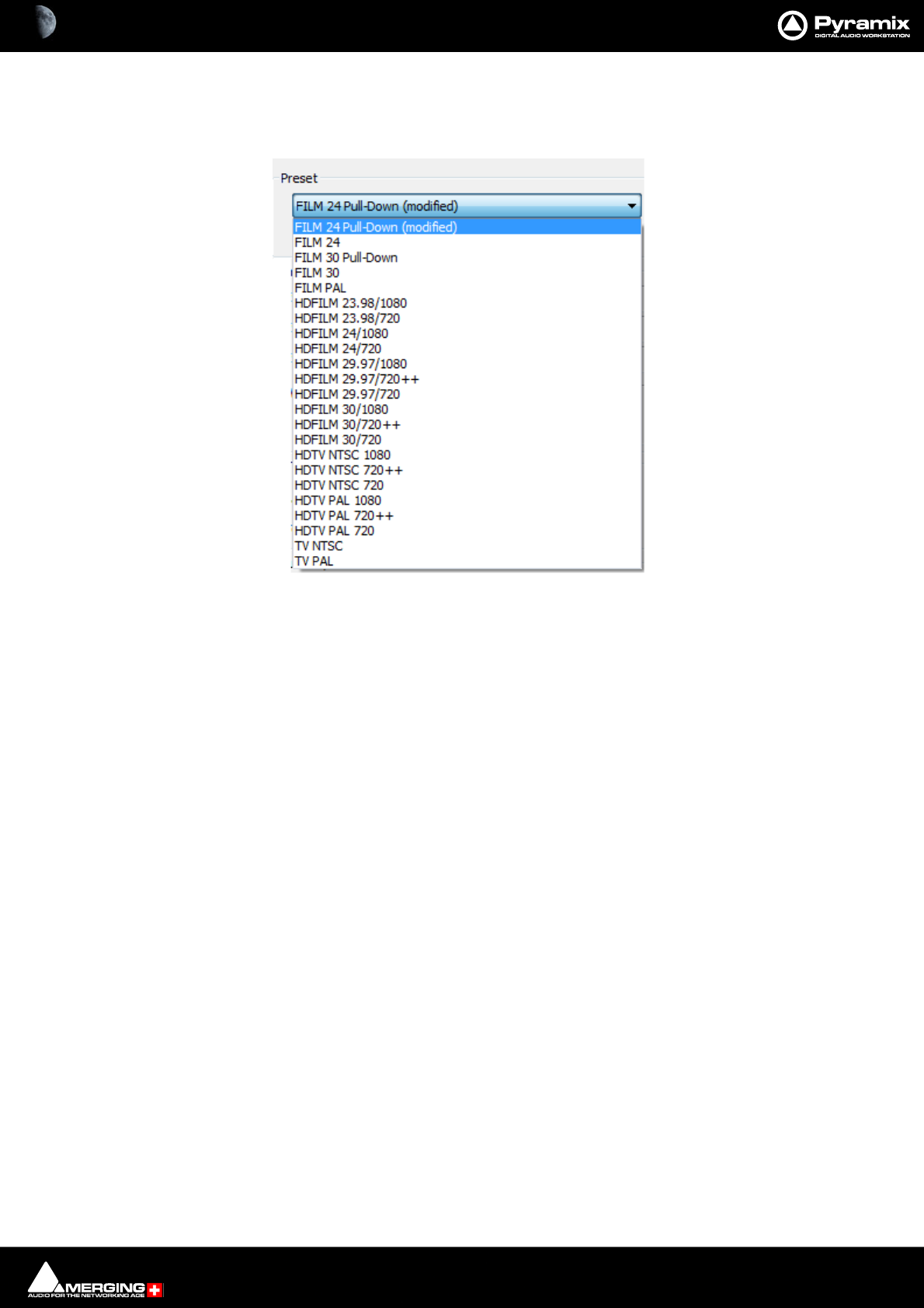
Settings : Hardware 29 - 717
Preset
This section allows the user to Save and ReLoad or Delete Presets of all the parameters in this page. A variety of
common scenarios are covered in the supplied Presets:
Information
Effective Sample Rate
Displays the sampling rate including the effect of any pull-up or down or Varispeed settings.
The sampling rate display in the Status Bar also displays the resulting sampling rate.
Effective TC Frame Rate
Displays the TC Frame Rate including the effect of any pull-up or down or Varispeed settings.
Warnings
Displays any caveats about the selected rates.
Frequencies
Sampling Rate
The drop-down list presents a choice of all available nominal sampling rates.
TC Frame Rate
The drop-down list presents a choice of all available TC Frame Rates
Drop
Only available for NTSC Frame Rates I.e. 29.97fps and 30fps. When checked drop-frame counting is applied.
All Settings Hardware Formats & Sync Preset List
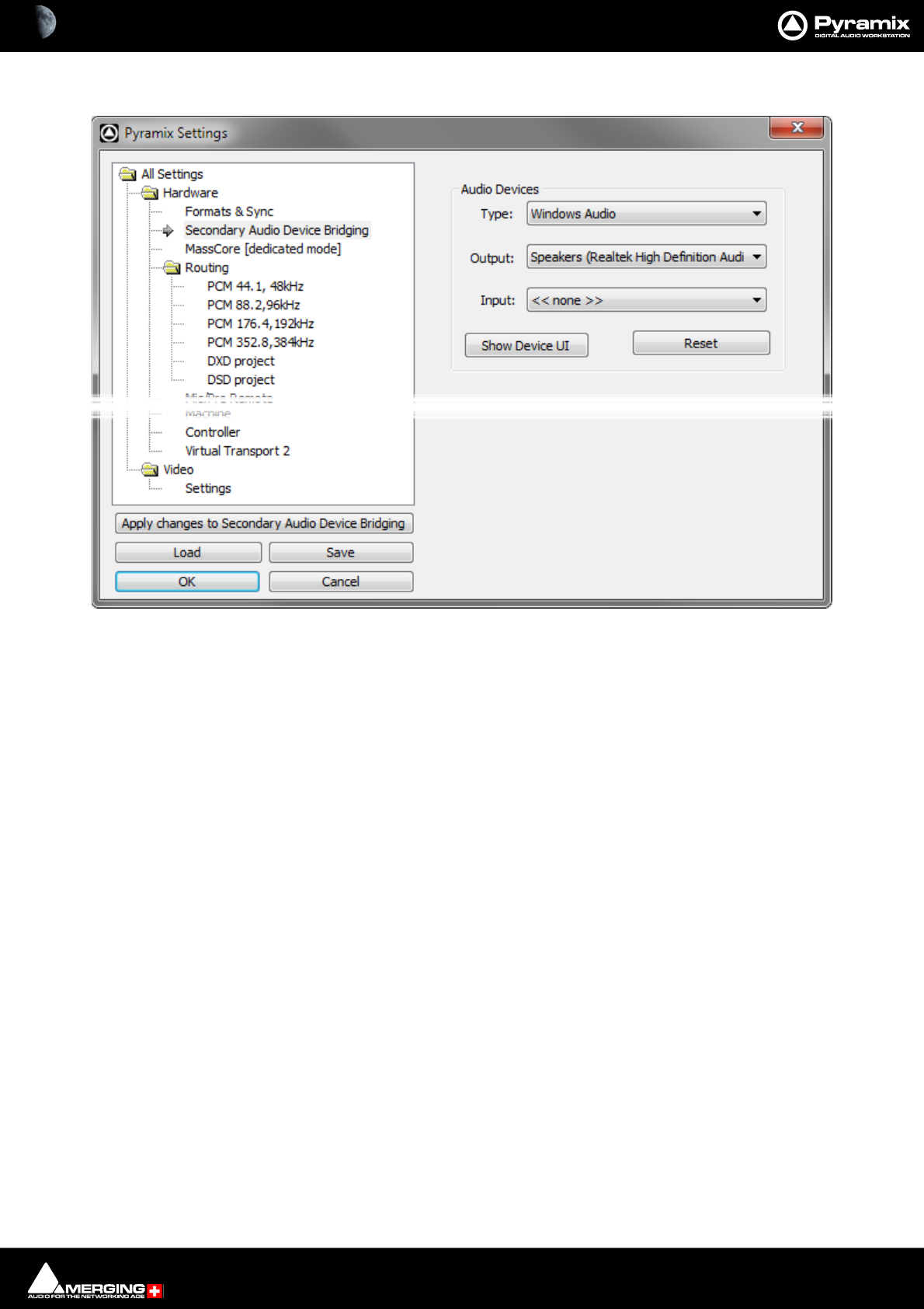
Settings : Hardware 29 - 718
Secondary Audio Device Bridging
Audio Devices
Type: The drop-down list offers the choice of Windows Audio, DirectSound or ASIO.
Note: ASIO only supports Outputs.
Output: The drop-down list offers the choice of all audio devices with drivers of the Type
selected.
Input: The drop-down list offers the choice of all audio devices with drivers of the Type
selected. (Windows Audio or DirectSound only.
Show Device UI Opens the User Interface for the selected Audio Device.
Reset Reinitializes the Secondary Audio Device. Use if you experience Mutes or glitches.
Note: This Settings page is only present when Secondary Audio Device Mode has been selected
in the VS3 Control Panel.
All Settings > Hardware > Secondary Audio Device Bridging
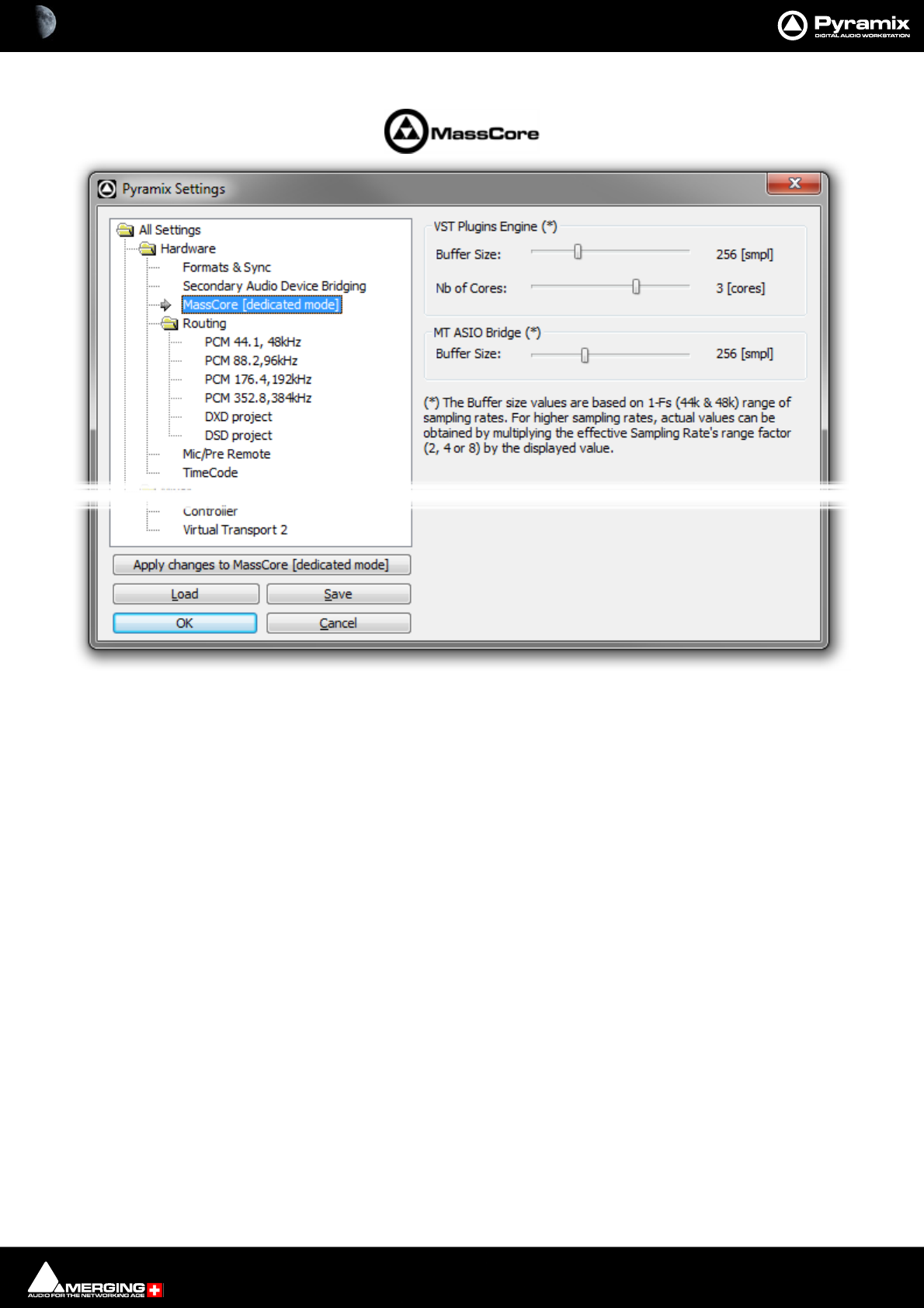
Settings : Hardware 29 - 719
MassCore
Note: The MassCore mode is indicated in brackets but is determined by the hardware present in
the PC.
VST Plugins Engine(*)
This sets the VST buffer size in samples. The smaller the buffer the lower the latency and vice-versa. Some third-
party VST plug-ins require very large buffer sizes. This setting is provided to give the user control over the required
value. Increasing the value can prevent clicks at the expense of increased latency.
Values up to 8192 samples may be set.
No of Cores:
On a Quad Core sets the number of VST cores used 1, 2 or 3 for a quad core CPU. (Default is two, one CPU core is
already dedicated to MassCore.) This option is useful when dealing with extreme Projects and for a few VST plug-
ins which do not like Multithreading processing. For a better understanding of VST and MassCore core allocation
please see: MassCore & VST Core Allocation on page 665
MT ASIO Bridge (*)
This sets the Virtual ASIO buffer size in samples.
Note: (*) The Buffer size values are based on the 1Fs (44.1k and 48k) range of sampling rates. For
higher sampling rates, actual values can be obtained by multiplying the effective Sampling
Rate’s range factor (2,4 or 8) by the value displayed.
Routing
Note: For systems using HORUS or HAPI please see the respective User Guides.
All Settings Hardware MassCore
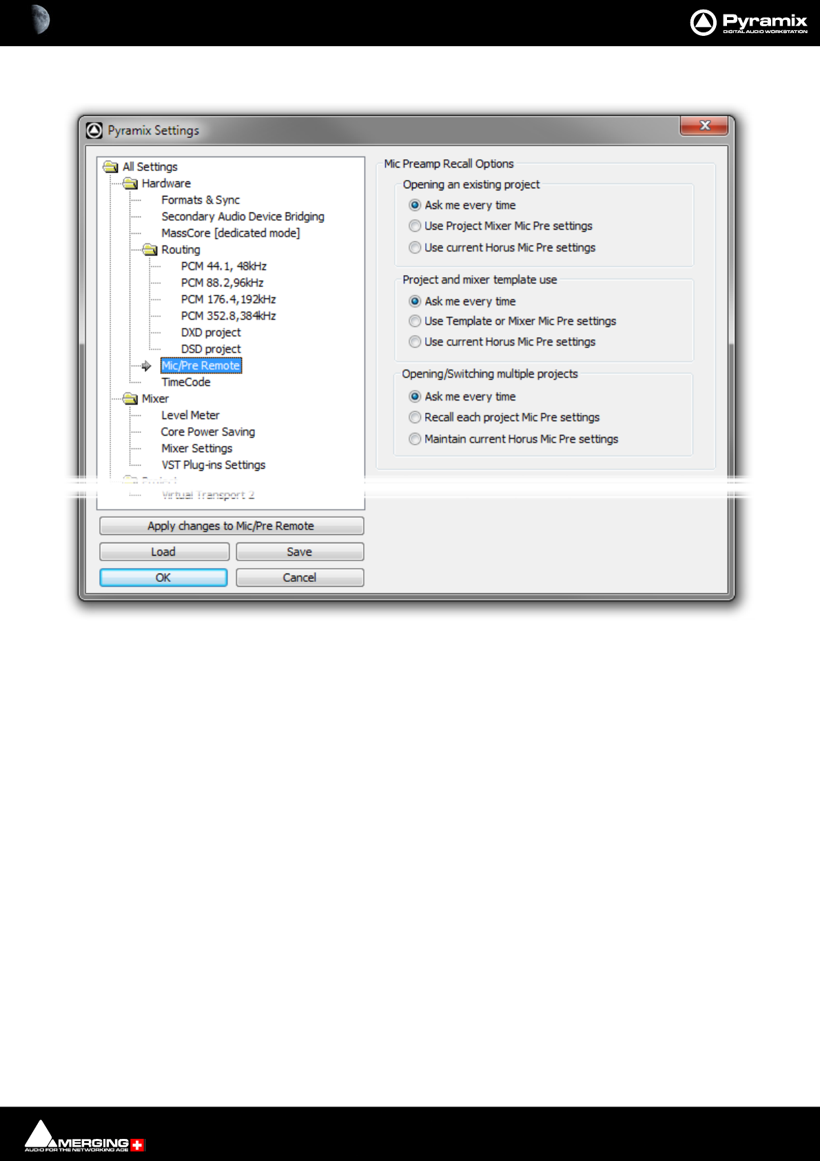
Settings : Hardware 29 - 720
Mic/Pre Remote
Mic Preamp Recall Options
Opening an existing project
Ask me every time When selected a dialog opens whenever an existing project is opened asking if
you would like to keep the current Mic Pre settings.
Use Project Mixer Mic Pre Settings When selected the Mic Pre Settings saved with the project replace the cur-
rent settings.
Use Current Horus Mic Pre Settings When selected the current Horus Mic Pre settings are retained.
Project and mixer template use
Ask me every time When selected a dialog opens whenever a new project is created whether from
scratch or from a template asking if you would like to keep the current Mic Pre set-
tings.
Use Template or Mixer Mic Pre Settings
Use Current Horus Mic Pre settings
Opening/Switching multiple projects
Ask me every time When selected a dialog opens whenever an existing project is opened and when
switching between open projects asking if you would like to keep the current Mic
Pre settings.
Recall each project Mic Pre settings When selected each project opened or switched to uses the settings save
with the project(s).
Maintain current Horus Mic Pre Settings When selected the current Horus Mic Pre settings are retained.
See also: Horus/Hapi Preamp Remote Controls on page 237
All Settings Hardware Mic/Pre Remote page

Settings : Hardware 29 - 721
MIDI Sync
DIN MIDI
Input The drop-down list shows all connections physically present on the system.
Output The drop-down list shows all connections physically present on the system.
Apple MIDI
Session : Shows the local Apple MIDI name of the Pyramix system (What you see on the net-
work.)
Session port : The UDP port used for the local Apple MIDI connection. This defaults to port 5016
but may be changed if required.
All Settings Hardware MIDI Sync Page

Settings : Hardware 29 - 722
Directory : The list shows a real-time view of the Apple MIDI connections available on the net-
work.
E.g. Horus/Hapi, Pyramix system (another v9.1 or later if available on the network,
any Apple MIDI port available on the network.
Hovering the mouse cursor over an entry in the list displays its IP address and port
number.
>> button Adds a selected directory entry to the Participants list.
<< button Removes a selected Participant from the list.
Participants : OK will appear to the right of an entry in the list when connected.
NOK is shown to the right of an entry in the list when not connected.
Note: When a MIDI connection is configured and is providing MTC, the MIDI TimeCode Reader is
displayed in the Pyramix Transport panel under Available Machines. Pyramix will output the
MIDI TimeCode on all the configured MIDI connections.
Note: USB Sync users will find their USB Sync MIDI ports under the DIN MIDI section. Please
ensure the USB Sync Board is set to MIDI mode. Check this in the USB Sync Control Panel.
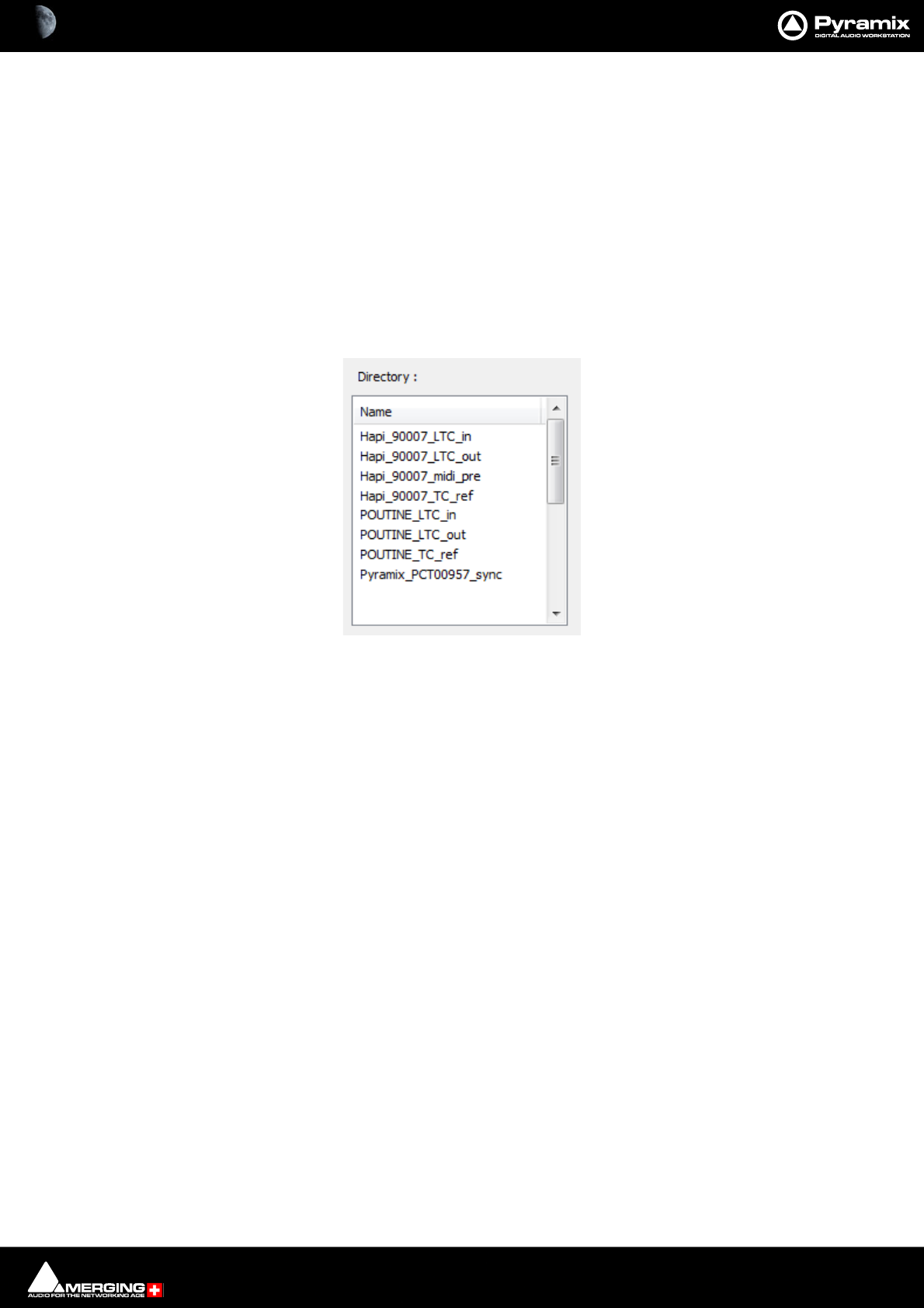
Settings : TimeCode Setup 29 - 723
TimeCode Setup
Networked Audio Interface TimeCode Setup
TimeCode connections to Horus/Hapi are handled by Apple Bonjour.
Apple Bonjour MIDI Connection Discovery
This may be seen in:
Settings > All Settings > Hardware > MIDI Sync
rtp MIDI (Windows third party utility.)
MIDI Network Setup (Mac OSX)
Directory :
The list shows a real-time view of all the Apple MIDI participants discovered on the network.
Naming/Nomenclature
Horus/Hapi_<SERIAL>_LTC_in Physical LTC input (seen as MTC) used to receive Timecode to DAW
Horus/Hapi_<SERIAL>_LTC_out Physical LTC output (seen as MTC) used to send out Timecode to Horus/Hapi
Horus/Hapi_<SERIAL>_midi_pre Used to remotely access the Horus/Hapi MicPre
Horus/Hapi_<SERIAL>_TC_ref Internal connection used to synchronize to a Video ref source
<Computer Name>_LTC_in MassCore virtual LTC input
<Computer Name>_LTC_out MassCore virtual LTC output
<Computer Name>_LTC_ref Internal connection used to synchronize to a Video ref source
Pyramix_<Computer Name>_sync Pyramix shows a MIDI in/out connection for transferring MTC
MIDI Sync Page - Directory section
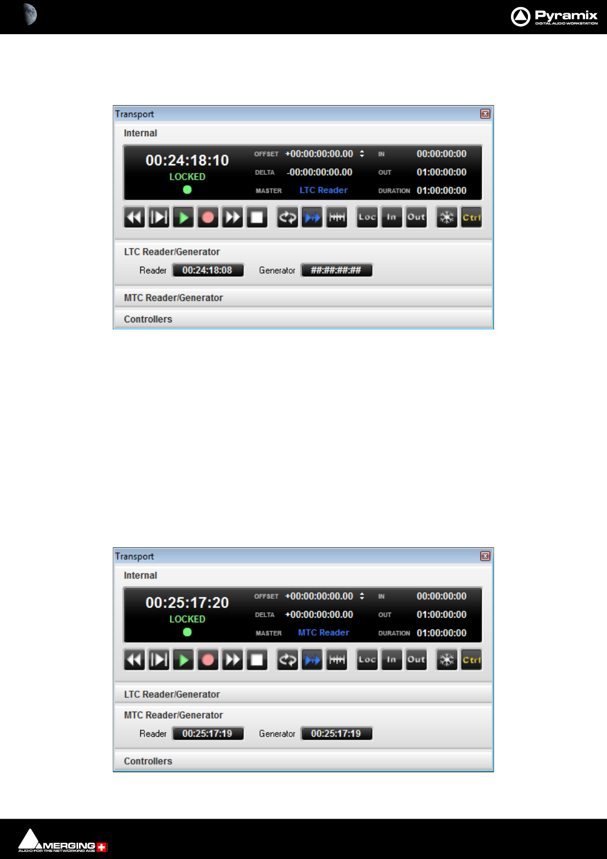
Settings : TimeCode Setup 29 - 724
Networked Audio Interface LTC IN-OUT for MassCore users
MassCore users please refer to the RAVENNA Network Guide, use the Easy Connect TimeCode connections and
set the Pyramix Transport to LTC Reader chase mode.
Note: We recommend NOT using the Settings > All Settings > MIDI Sync : Participant entries.
Networked Audio Interface LTC IN-OUT for Pyramix Native users
• Ensure that the Project Frame Rate is set to match the incoming TimeCode.
•Open Settings > All Settings > Hardware > MIDI Sync
• Add the Networked Audio Interface LTC IN and Networked Audio Interface LTC Out entries to the Par-
ticipants : list.
•Click on OK to save the settings and close the window.
• Open the Pyramix Transport window. [Alt + T].
•Set the Pyramix to Chase the MTC Reader.
• Pyramix will Generate MTC once a MIDI connection is on the Participants : list.
Transport window
Transport window
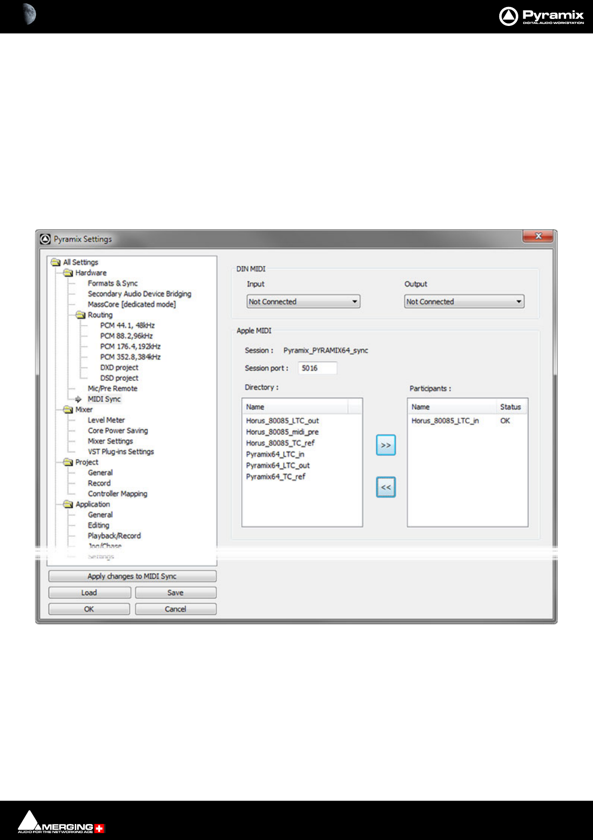
Settings : TimeCode Setup 29 - 725
TimeCode over Physical MIDI (MTC) Horus/Hapi
Horus/Hapi firmware supports of the transport of TimeCode over physical MIDI (MTC) using the DIN connectors on
the Sync breakout cable (part code: CON-D15-VTC). Timecode is transmitted to the workstation via the network
(RAVENNA connection).
Note: Horus / Hapi firmware version 3.1.0 b28867 or above is required.
Horus/Hapi hardware Prerequisite:
Please refer to the Horus or Hapi User Manuals. The Ethertube dip switches (1 and 2) must be set to OFF in order to
enable physical MIDI (MTC) support over the Sync breakout cable (part code: CON-D15-VTC).
Pyramix Configuration
Configuration is undertaken in the Settings > All Settings > Hardware > MIDI Sync page:
In the Directory: list, choose an Apple MIDI service with a ...midi_din suffix. This nomenclature corresponds to
the Physical MIDI DIN port of a Horus/Hapi.
Settings > All Settings > Hardware > MIDI Sync
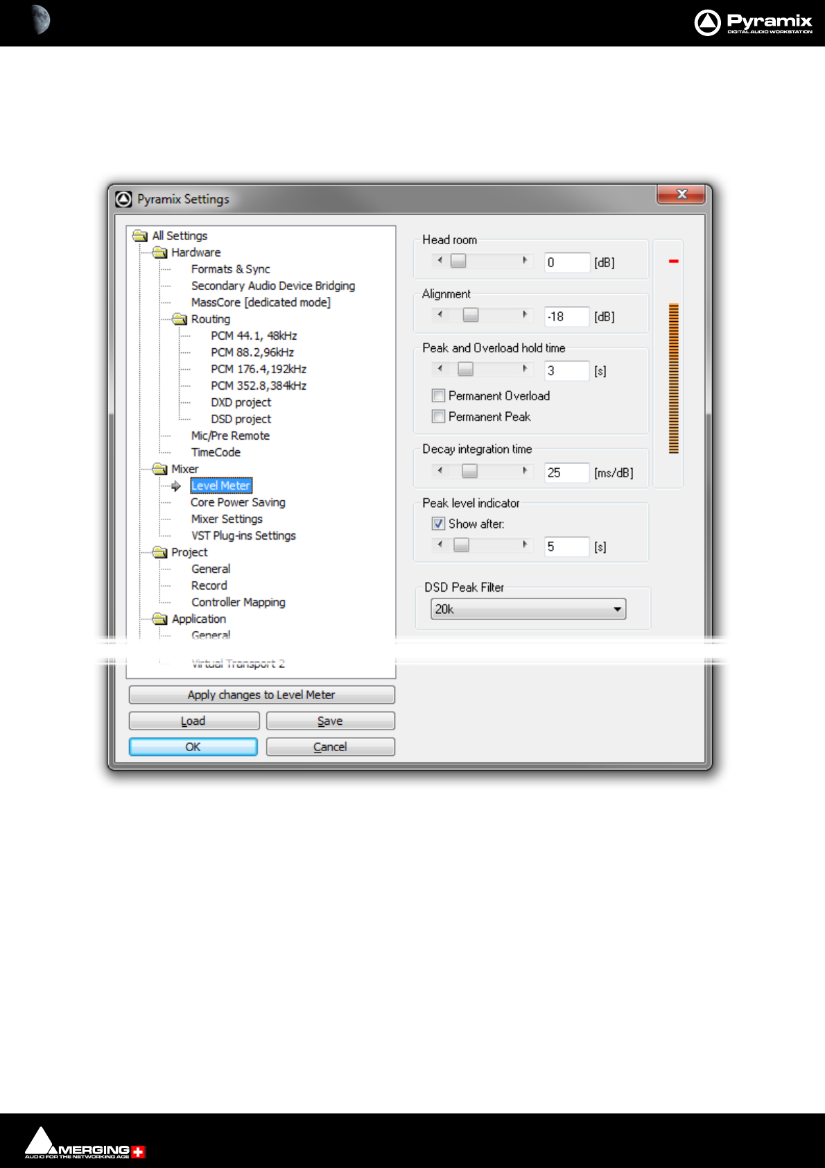
Settings : Mixer 29 - 726
Mixer
Level Meter
This page determines the appearance and behavior of the level meters in the Mixer and Track Headers.
These settings only apply to the current Mixer. This allows each Mixer to have its own custom General and Level
Meter settings.
To change any of the settings, click the left or right buttons or drag the horizontal scroll bar to increment or decre-
ment the selected parameter. Alternatively, type directly into the number field for each parameter (these fields will
only accept numbers within the permissible range for each parameter). The color graphic display of the level
meter will respond immediately to show the effect of Headroom and Alignment parameter changes.
All Settings Project Mixer Level Meter Page
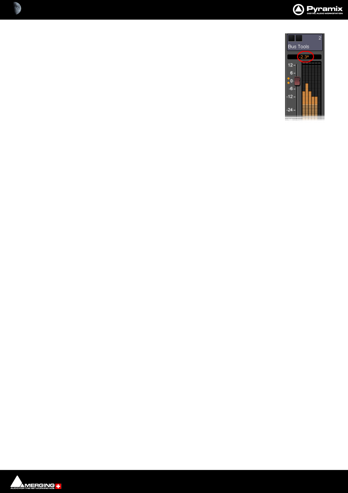
Settings : Mixer 29 - 727
Headroom
Sets the amount of headroom displayed as red meter segments before clipping. I.e. the num-
ber of dB below 0dBFs at which the red meter segments begin.
Note: This headroom value is only for the Mixer meter displays and will not (and
cannot) be reported to the Plug-in (VU Meter or Meter Bridge). The VU meter
Plug-in has it’s own headroom setting.
Note: If the mixer displays an * next to the Level field value it indicates that a cus-
tom value was entered in the Headroom settings.
Alignment
Sets the alignment level. Displayed by the point on the scale at which the dark orange seg-
ments begin.
Peak and Overload Hold Time
Sets the amount of time in seconds that the peak segment or overload segment (topmost red segment) of the
level meter remains illuminated.
Permanent Overload
When the box is checked, the red Overload LED above a Track will remain lit, even after playback is stopped. To
clear the LED, double-click it. When not checked, the Overload LED will automatically clear itself after a few sec-
onds and remain off until the next overload occurrence.
Note: The overload LED will go on after one sample with the maximum level.
Permanent Peak
This parameter works in conjunction with the Peak Level Display. When this is on (checked), the Peak Level pop-up
display will show the value and location of the highest level reached on a Track up to the time when the mouse
was clicked on the meter. The level display will not be updated until the next time playback is stopped and re-
started. If it is not on (unchecked), the Peak Level Popup Display will show the highest level reached in that Track
from the last time the Popup Display is activated (while playback continues). For example, clicking a channel’s
meter while playing back will display the Peak Level Popup, which will show the peak level (and its location)
reached so far. Click away from the Popup, and it will disappear. Click on that meter again, and the Popup will
appear again, this time showing the peak level/location reached since the last time the Popup was displayed.
Decay integration time
This parameter sets the rate at which the level meter display decays after the level falls below the most recent
peak. The slope of the decay is given in terms of milliseconds per decibel (ms/dB).
Peak level indicator
Show After
When the box is checked, the Fader/Input Level displays located above the faders on each mixer strip display the
peak level of the signal running through the corresponding mixer strip. The value are updated at the interval set
by the slider below the check box. If the check box Show After is off, the Fader/Input Level displays always show
the setting of their corresponding fader.

Settings : Mixer 29 - 728
DSD Peak Filter
For DSD projects this drop-down list offers the choice between two filtering options which will be applied to the
DSD signal before it is measured by the level meter.
This will help enable you to ensure that the DSD signal is compatible with Annex D.4 of the SACD Scarlet Book
concerning the high frequency and noise shaping.
20k
Applies a 20 kHz low pass filter to the signal, thus only the audible audio content is measured.
40k-100k
Applies a band pass filter with a frequency range of 40 kHz to 100kHz to the signal. According to Annex D.4 of the
SACD Scarlet Book the signal level in this frequency range should not exceed -20 dB.
Note: Further to Annex D.4 of the SACD Scarlet Book:
D.4 High Frequency DSD Signal + Noise Level.
The accumulated RMS signal + noise level of the DSD signal, measured after a 40 kHz Butter-
worth 30dB/Oct high pass filter and a 100 kHz Butterworth 30dB/Oct low pass filter, is maximally
equal to the RMS level of an input sinewave with a peak amplitude of -20 dB SA-CD (see D.2).
The averaging filter used to calculate the RMS level must be a first order unity gain IIR filter with a
coefficient of 1/524288 ( 2-19 ), corresponding to an IIR filter with a cutoff frequency of about
0.85 Hz.
Note: E.2 Analog Post-filter
To protect analog amplifiers and loudspeakers, it is recommended that a Super Audio CD player-
contain at its output an analog low pass filter with a cut-off frequency of maximum 50 kHz and a
slope of minimum 30 dB/Oct. For use with wide-band audio equipment, filters with a cut-off fre-
quency of over 50 kHz can be used.
Note: When releasing material at higher than 44.1 or 48 kHz sampling rate, Merging recom-
mends adding a gentle low pass filter (typically 6 to 12 dB/octave) in the range from 30 to 50 kHz
for all recordings made originally in DSD 64. The corner frequency of such low pass filters can be
doubled whenever converting from DSD 128 and even quadrupled when converting from
sources originally recorded in DSD 256 (which essentially means that even when converting
from DSD 256 to PCM at 192 kHz, there is no need to add such a filter).
Settings : Mixer 29 - 729
Core Power Saving
Special Modes
DSP Time Saving
Disable the Punch in/out
When the box is checked, Punch-in and out recording capabilities are disabled.
Important! Pyramix still will allow you to arm Tracks and to start the recording process, but the resulting
media file will contain digital nulls.
Disable Mix Down
When the box is checked, the digital mixdown function activated with the menu command Project->Mix Down is
disabled.
Important! Pyramix still will allow you to start the mixdown process, but the resulting media file will con-
tain digital nulls.
All Settings Mixer Core Power Saving Page
Settings : Mixer 29 - 730
Mixer Settings
Virtual Room / Stereo Pan Law
The drop-down menu offers a choice between the default Sin/Cos law, Constant Power, -3dB center and Square
Root law, Constant Power, -3dB center.
Delay Compensation Policy
Mode
The drop-down menu offers the choice between:
Full Delay Compensation
Off
Note: Automatic Delay Compensation does not support more than 3 nested I/O loops. When
there are morer than 3 loops the signal flow continues but will not be delay compensated.
All Settings Mixer Mixer Settings Page
Settings : Mixer 29 - 731
Automatic Delay Compensation
When ticked, turns Automatic Delay Compensation On
Note: Any changes to the delay required that occur during playback or recording will only be
computed and applied when the Transport is next in Stop.
Max Mixer Delay Compensation
When required by the Mixer error: Delay compensation dialog the slider should be set to a value just above the
delay latency value requested.
Reset to Factory
Click the button to restore the factory computed maximum delay value.
VST Plug-Ins Settings
VST Plug-ins
The Plug-ins List Menu.display type buttons offer a choice of how the VST Plug-ins are ordered and grouped.
Company Name The list will be ordered by Company Name.
Category Groups the plug-ins according to function type.
VST Plug-ins Folder Structure Organises the Plug-ins in the same way as they are in the Windows filing system.
Please see also: VST Plug-ins Display Order on page 391
All Settings MixerVST Plug-ins Settings Page
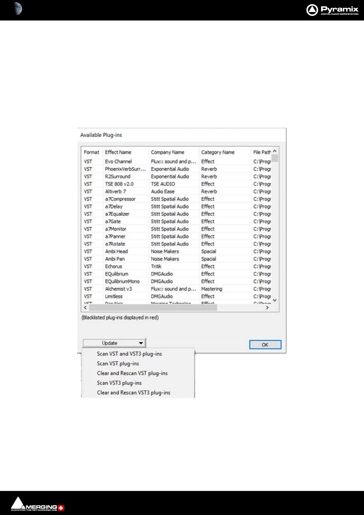
Settings : Mixer 29 - 732
Plug-ins locations
The box shows which folders Pyramix will scan for VST Plug-ins on launch.
By default, \Program Files\VSTPlugins and or \Program Files\Steinberg\VSTPlugins directories are scanned if
they exist. Further directories may be added to the scan list using the Add Folder button, which opens a File
Browser window. Directories are removed from the list by selecting them in the list and clicking on the Remove
Selected button.
Available Plug-ins
The Show button opens the Available Plug-ins list dialog:
Show Available plug-ins
Clicking on the button opens the Available Plug-ins dialog:
The list shows all VST Plug-ins which have been scanned and are available to Pyramix. Blacklisted plug-ins are dis-
played in red.
Update
The Update button drops-down a menu with the following options:
Scan VST and VST3 plug-ins Initiates a scan of any directories added to the VST Plug-ins Folders list since
Pyramix was launched.
Scan VST plug-ins As above but restricted to VST2 Plug-ins (VST = VST2)
Available Plug-ins dialog

Settings : Mixer 29 - 733
Clean and scan VST plug-ins (forces a VST2 rescan)
Scan VST3 plug-ins Restricts the scan to VST3 Plug-ins
Clean and scan VST3 plug-ins (forces a VST3 rescan)
OK Closes the dialog.
Settings : Project 29 - 734
Project
General
The General Page has fields for displaying and entering information concerning the current project. This informa-
tion is specific to the Project and will always be available in this display.
All Settings Project Information Page

Settings : Project 29 - 735
Project Media Folder
When a Project is created, either with Project > New or Project > New From Template and a Media Folder is cre-
ated or selected, the Project Media Folder, the Record : Target settings Media Folder, the Project > Render :
Target Settings Media Folder and the Project > Mix Down : Target Settings Media Folder all point to the same
folder.
The combo box has a list of all mounted Media Folders and the button opens the Choose a Media Folder to
Mount dialog where you can browse for and mount or create and mount any other Media Folder. Please
See: Housekeeping on page 45
When a Project operation will generate new Media Files, the radio buttons below the combo box offer the choice
of either:
• Generate new Media in the Project Media Folder
• Generate New Media in their Original Folder
Project mounted Media Folders
All folders mounted by the Project are listed here. Further folders may be mounted or existing ones unmounted by
using the Add and Remove buttons.
Composition Information
Lists three categories of Composition data:
Number of Groups
Number of Clips
Number of Cross-fades
Settings : Project 29 - 736
Record
All Settings Project Record Page

Settings : Project 29 - 737
Target Settings
Take Name
Type a ‘seed’ name here. This is used to begin the name of new recordings. E.g, if you type "Vocal" the next record-
ing you make into a Track will be called "Vocal". This field works in conjunction with the "Increment take number"
function (see below). If you leave this field blank, Pyramix will apply the name "Untitled" as a default.
Prefix with Track Name
When checked the name of the recording will be prefixed by the name of the Track it was recorded on, like:
Guitar-Take 001_##001##_.wav
Guitar-Take 002_##001##_.wav
Suffix with Strip Name
When checked allows Multitrack recording of typed sources, typically for archiving Film stems, or Render of Mixes/
Dubs:
With a set of multi-channels strips (GPS strips) properly named and typed, the Suffix with Strip Name option will
create files named like:
Episode3-M&E-Ls.wav
Episode3-M&E-Rs.wav
Episode3-LtRt-L.wav
Episode3-LtRt-R.wav
Name is Scene & Take
When checked, the name of a take recorded in Pyramix will be used as the source for the Scene and Take fields in
BWF and PMF audio files with the proper tag set. The last numeric digits of the name are used as the Take number
and any preceding characters are used as the Scene name.
E.g. 203/5 003 will be interpreted as SCENE = 203/5 TAKE = 003
Media Folder
Displays the selected Media Folder for recording. Clicking the adjacent button opens the Choose a Media Folder
to Mount window. This enables folders to be created mounted and managed. Please See: Housekeeping on
page 45
Settings : Project 29 - 738
Format
Displays the current recording format from the choice available in the drop-down list. (PMF, SD2, AIFF, AVI, WAVE,
BWF, CD Image or OMF)
Settings
If PMF is chosen as the Format then the Settings button becomes active. When clicked the PMF Settings dialog
appears:
Options
Unbuffered read Improves general Playback performance but may impact on waveform display and update.
Default = OFF
Unbuffered Write (Recommended for large number of tracks) Default = ON (may have a negative effect when
recording over a network. If you experience problems set this to OFF.
Both the above options enable/disable the Windows Disk Cache.
MT Active Key Encryption
Under Construction
Do not lock or encrypt files Default =ON
Lock files (No data will be encrypted, keys will be required only to open the files)
Encrypt files (All data will be encrypted, keys will be required to open and play the files back)
MT Active Key used to lock or encrypt the file
Copy and paste or type the appropriate key or choose from the drop-down list.
All Settings Project Record : Format PMF Settings dialog

Settings : Project 29 - 739
If Wave is chosen as the Format then the Settings button becomes active. When clicked the Wave/BWF Settings
dialog appears:
The only option is Unbuffered, ticked by default. When files are read the Windows cache is not used. This
improves performance in most cases. Un-check the box to turn buffering on. The System Cache disk is then used
to buffer.
Resolution
Displays the number of bits per sample for recordings from the choice available in the drop-down list. (16bps,
24bps or 32bps)
Read Options
Unbuffered read Improves general Playback performance but may impact on waveform display and update.
Default = ON
This option enables/disables the Windows Disk Cache.
Request Size
The default value is 64kB. This can be increased to a maximum of 320kB if problems are experienced during play-
back.
Waveform
Displays the current Waveform generation mode from the choice available in the drop-down list. (None, Generate
AFTER recording or Generate WHILE Recording for all supported formats) (Default is WHILE)
Source Name
This field allows you to give a name to indicate the source of the material being recorded into Pyramix. For exam-
ple, you might enter "Reel #1" to indicate the first source reel, etc. If the MediaType field (see below) is set to
"None", the Source Name field will be grayed out and not available.
Media Type
Displays the type of media the source material came from, chosen from the drop-down list. Clicking on the EDIT
button allows existing names to be edited or new ones created. The media type chosen here and the source name
given in the previous field are saved with the media file created by the new recording. This information can then
be viewed by selecting a Clip and displaying its Properties page.
Dubbing Mode
Please see also: Dubbing Mode on page 516
This mode is provided principally for film re-recording. It allows Tracks to be Armed or Disarmed for recording
while recording is taking place.
Enable Dubbing
When checked, Dubbing Mode is engaged.
All Settings Project Record : Format Wave/BWF Settings dialog
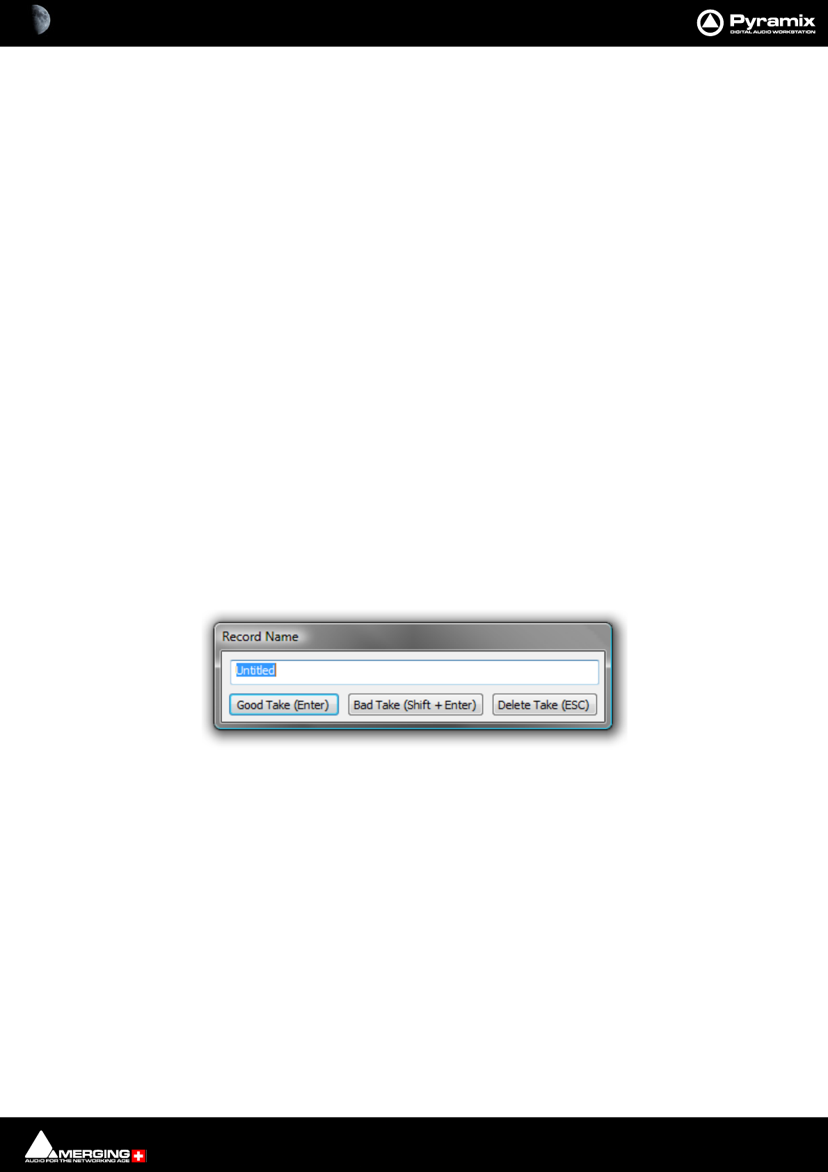
Settings : Project 29 - 740
Confirm Track Arming
Only available when Dubbing Mode is selected in the adjacent check box. A check in this box means that any
changes to Track arming made whilst recording must be confirmed by a new Record command before they will
take effect.
Media option
One file per track
When checked, each recording on each Track of a multi-track recording is recorded into a separate file. When this
option is off (which is the default), one single media file is created containing all the Tracks.
Flatten track numbers
When a recording is made on a Track, Pyramix always adds a media number to it. When checked on (default), Pyra-
mix starts enumerating at one. E.g. If a recording is made on Tracks 5 and 9 of a multitrack session simultaneously,
the media numbers will be 1 and 2. When this option is off, Pyramix adds the real Track numbers to the media. In
the example above, this would be 5 and 9.
Unique filename extension
When checked, Pyramix will append a random number to the name of each new recording in order to avoid dupli-
cate file names.
Quiet if creation failed
Unless this box is checked, Pyramix displays a dialog with an error message when the creation of a media file fails.
This can be annoying if Pyramix is remotely controlled. Checking the box suppresses the error message.
Post Processing
These options determine what Pyramix will do after each recording is finished.
Prompt for name after recording
When checked, a Record Name dialog box will open immediately after recording is finished and playback of Pyra-
mix is stopped.
If a name was entered in the Take Name field (see above) it will automatically appear in the Record Name dialog
box when it opens. You can edit the existing name, or replace it completely with a new name.
Keep in default library
When checked, new recordings will automatically appear in the Default library of the current Project.
Increment take number
When checked, each successive recording will have the name in the Take Name field applied to it, plus a number
that will increment with each new recording. E.g, if the first recording is named "Take", the next recording will
automatically be named "Take 2", etc.
Place on new tracks
When checked, Pyramix will place the newly recorded Clips on new Tracks. These new Tracks will be added to the
Project Editor as soon as playback is stopped following a punch in/punch out recording. When first created, these
Tracks are not assigned to mixer channels, so it will be necessary to assign them when you want to output them. If
this item is not checked, the new Clips will be placed on the Track(s) set to record them.
Record Name dialog box

Settings : Project 29 - 741
Clean up Media after recording
Note: This option is automatically set OFF when a Project is opened.
This mode makes Pyramix work like an analog or DASH multitrack. I.e. All punch-ins are highly destructive !! With
modern, large hard drives, we would rather recommend:
View > Used Media > Invert selection > Delete media (after a good archive/consolidate/back-up has been
made) or:
b) Project > clean-up media, etc.
All these functions destroy media on the hard drive, but b & c offer more control over what is permanently
deleted.
Group Recorded Clips
When checked, Clips in a multi-track recording are automatically grouped.
Auto Cross-fade
When checked a cross-fade is automatically applied when punching in or out. The current fade shape is displayed
form the choice available in the drop-down list (Power, Linear, dB, Cosine or Root-Cosine) Duration can be set in
frames, samples or milliseconds depending on which box is selected.
Playlists
These buttons toggle between three possible choices:
Don’t create Playlist
Create an empty Playlist for each recording
Create a copy Playlist for each recording
Please see: Playlists on page 643
Archiving Metadata
Insert Archiving Metadata if Target is BWF
Generate Archiving Metadata XML along recorded files
Please see: Archiving Metadata on page 441
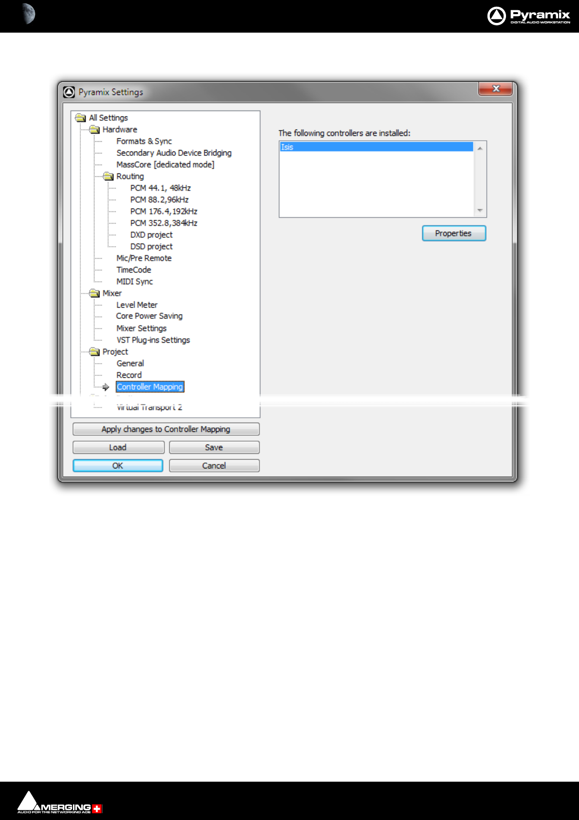
Settings : Project 29 - 742
Controller Mapping
Please see Guides for specific controllers. E.g. Merging Technologies Ramses MSC and ISIS and for Sony P-2 Proto-
col 9-pin controllers please see: Sony 9 - Pin Protocol Configuration (Pyramix controlled by external device)
on page 775.
All Settings Project Controller Mapping Page

Settings : Application 29 - 743
Application
General
Application Loading
At Application Loading:
Mount the Folders listed in:
All Settings > Application > Location Page > Permanently Mounted Media Folders
Mount all Media Folders that were mounted at previous Application Exit
Keep Media Manager History
All Settings Application General Page

Settings : Application 29 - 744
Project Opening
This section determines Pyramix behavior when the application is launched.
Automatically open previous projects
When checked, Pyramix opens all projects that were open when the application was last used.
On Project Opening:
Rescan and Mount all Media Folders for that project (see Project > General page)
Can result in long opening times when there are very large Media Folders
Mount all Media Folders for that project (see Project > General page)
Default. Usually results in the fastest opening time.
Mount only Media Folders containing Media used by that project
May be quicker than previous option when Project points to folders containing media not used in the project.
Do not try Mounting any Media or Folders
Media must be mounted manually.
Search for missing Media
When checked, Pyramix automatically searches for unmounted or missing media when a project is opened.
Ask for DSD/DXD conversion
When checked, Pyramix will open a dialog whenever a DSD or DXD Project is opened. This offers the opportunity
to convert to the opposite format.
Open Video Clips in VCube
Single or multiple Video Clips are opened in VCube.
Undo
Number of Undo / Redo
Sets the Number of Undo / Redo levels. Also sets the number of automation versions to be kept when the Auto-
mation tab option, Optimization : Limit versions to the number of Undo/Redo is enabled. The default is 32.
Note: Increasing this value uses more RAM.
Auto-Saving
Pyramix can be set to automatically perform a save of all open projects at regular intervals. This does not create a
backup unless a value in excess of 1 is entered in Auto-Backup Versions (see below).
Enable
When checked the current Project will be automatically saved at the interval set by:
Frequency
Sets the time between saves between 1 and 60 minutes.
Auto-Backup Versions
Number of versions to preserve
The number in the box determines how many previous versions will be kept. This ensures that every Save opera-
tion (Automatic or Manual) preserves at least one version of any projects being saved in their last stored state. The
number of previously saved versions to preserve can be set by the user. The minimum is one.

Settings : Application 29 - 745
Alternate Backup
Enable
When enabled all projects saved (automatically or manually) are also saved to the chosen alternate location. The
Backup Versions are not saved to the alternate location. This offers increased security if another drive or network
drive is chosen.
Note: Only project files are stored into this directory, not the media files.
Location
Displays and sets the alternative location. The Browse button opens a Browser window to enable navigate to a
suitable location.
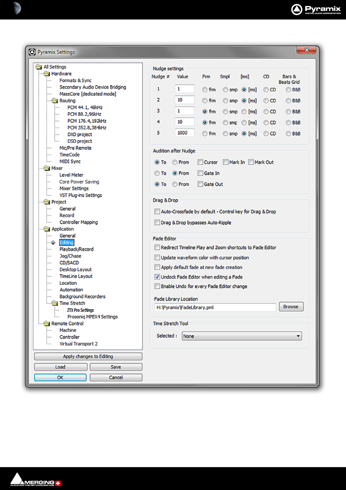
Settings : Application 29 - 746
Editing
Nudge settings
These settings control the amount by which a cursor or Clip will be nudged when using the left and right Arrow
keys. Five Nudge Settings can be stored. Any one of these can be selected as the current nudge setting using Clips
> Nudge > Current Setting or Cursors&Marks > Current Nudge Setting.
Pyramix Settings Application Editing page

Settings : Application 29 - 747
Nudge #1~Nudge #5
For each nudge preset, enter an numeric value and click the appropriate check box to set increments to frames,
samples, milliseconds, CD frames or the current Bars & Beats grid.
Audition after Nudge
These options set automatic Audition on for the selected actions.
To
When checked, the playback will start before the selected option and stop when this is reached (cursor, mark in or
mark out)
From
When checked, the rehearse will be performed from the selected option (cursor, mark in or mark out)
Separate To and From options are provided for Gate In and Gate Out
Drag & Drop
Auto-Crossfade by default - Control key for Drag & Drop
When checked, dragging a selection or Clip over another results in a crossfade. (Cursor changes to a hand with an
X.) Otherwise, dragging a selection or Clip over another overwrites it. (Cursor is a hand) Holding down the control
key when dragging selects the alternate function.
Drag & Drop bypasses Auto-Ripple
When checked, dragging a selection on the Timeline to a new location does not cause a ripple to take place even
when in Auto-Ripple mode.
N.B. If a Clip is dragged from the Media Manager over a Timeline clip a Ripple WILL result.
Fade Editor
Redirect Timeline Play and shortcuts to Fade Editor
When checked, the Timeline Zoom commands are redirected to the Fade editor. Also, the Active Machine > Tog-
gle Play/Stop command usually mapped to the Spacebar is replaced with the Fade Editor > Audition X Fade
command but only if the Fade Editor has been opened with the Fade Editor > Open Editor command.
Update waveform color with cursor position
When checked the waveform color will change from the default to the color set in Settings > All Settings >
Application > TimeLine Layout : Waveform Position Color whenever the Playhead cursor is on the right-hand
side of the Reference Point (default is centre fade position) in the Fade Editor.
Apply default fade at fade creation
When checked the default Fade In/Out default will be applied when a new fade is created.
Undock Fade Editor when editing a fade
On by default. When checked the Fade Editor Tab is automatically undocked when editing a fade.
Enable Undo for every Fade Editor Change
Fade library location
This is the path for the fade library. The Browse button launches an Explorer window allowing any local or net-
work path to be set.
Note: If you do decide to change the default location, copy the FadeLibrary.pml file from the
default location to the new location and include it in the path.
Time Stretch Tool
The Selected: combo box offers a choice of Time Stretch algorithms depending on which keys are installed.
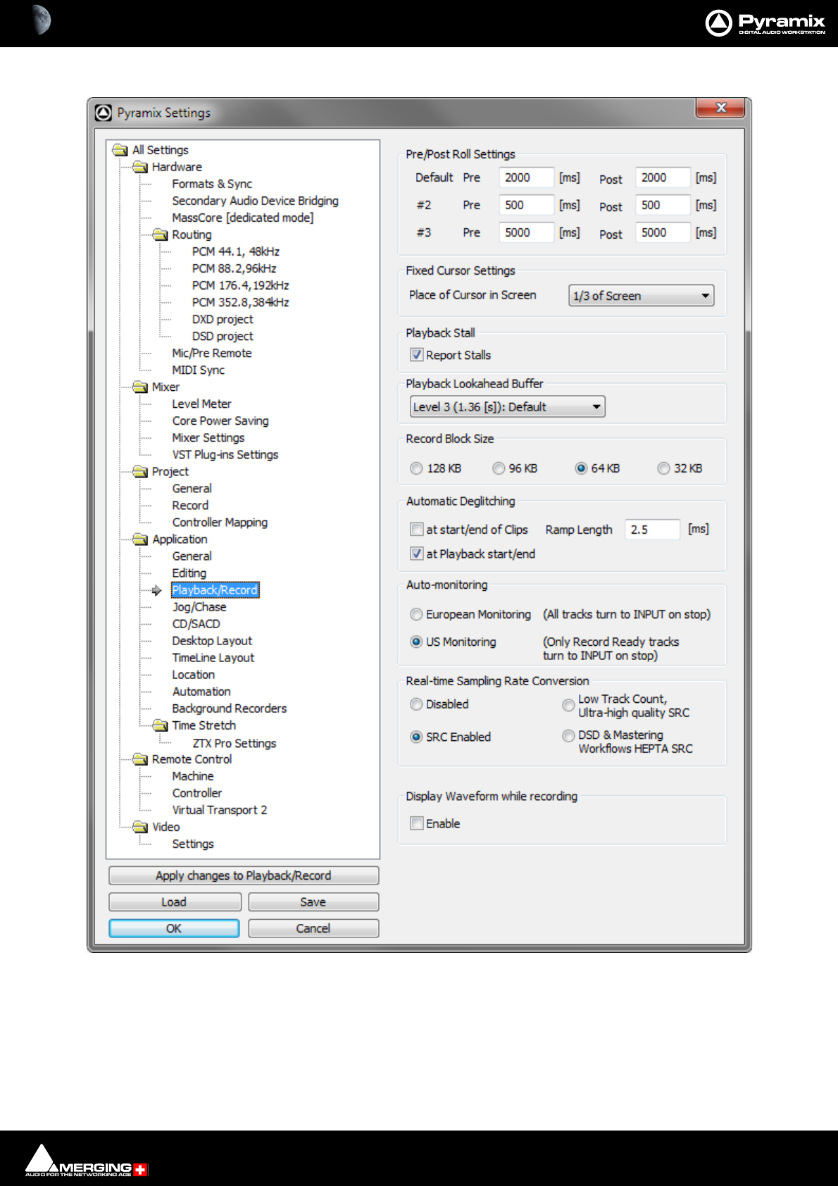
Settings : Application 29 - 748
Playback/Record
Pre/Post Roll Settings
Allows values to be set for the Default and two alternative Pre and Post-roll settings.
Fixed Cursor Settings
The drop-down list offers nine possible positions for the Playhead cursor position on screen when scrolling Time-
line with fixed cursor is selected. (View > Fixed Cursor while playing)
All Settings Application Playback/Record Page
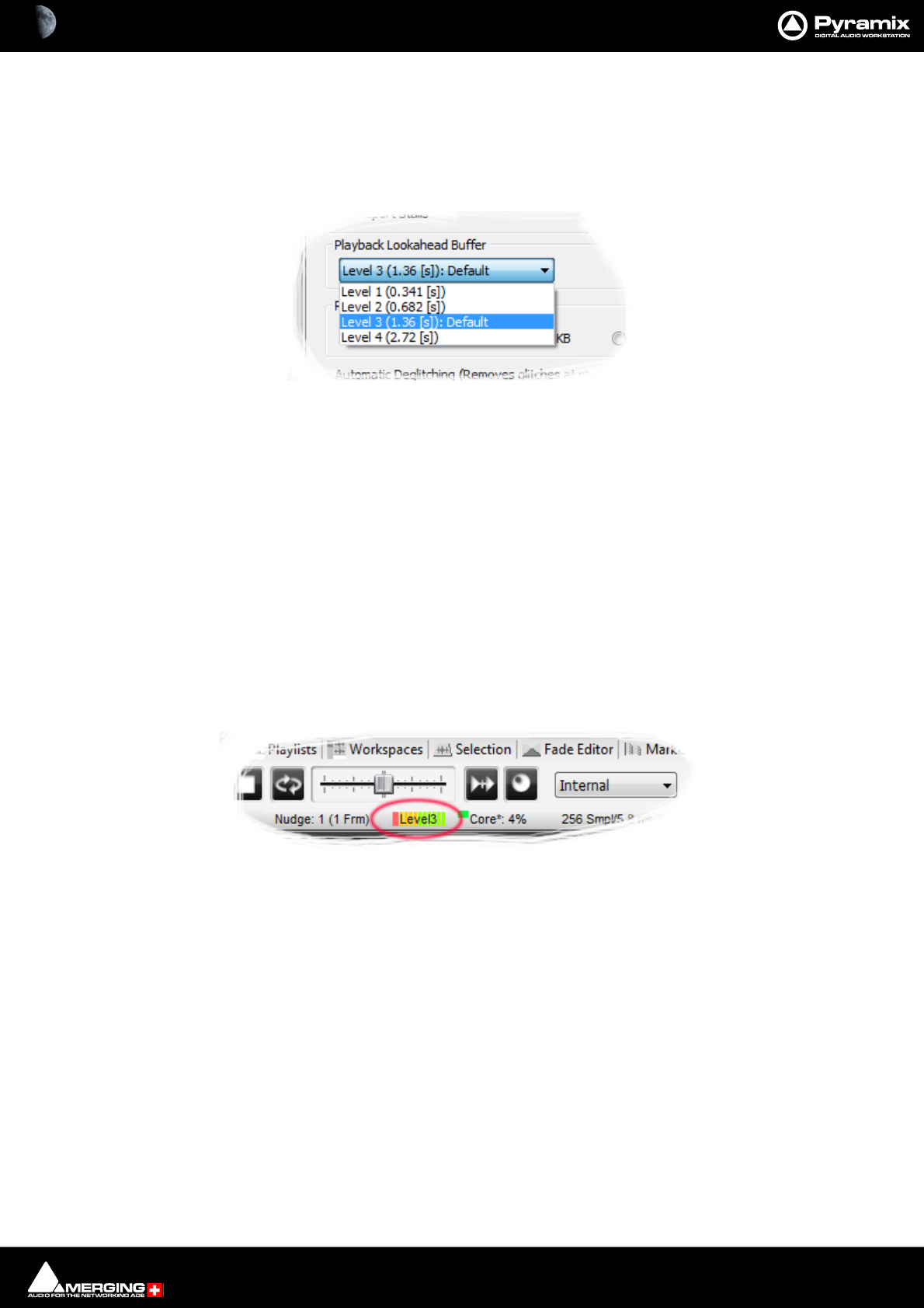
Settings : Application 29 - 749
Playback Stall
When checked, interruptions to playback will pop-up a message box with details of when the stall occurred.
Playback Lookahead Buffer
Sets the length of audio that will be pre-loaded into buffers prior to playback. Four levels are available in the drop-
down list:
• Level 1 (0.341 [s])
• Level 2 (0.682 [s])
• Level 3 (1.36 [s]): Default
• Level 4 (2.72 [s]
The default value is Level 3). A larger value may enable you to playback certain large projects. For example it can
improve track count with one file per track BWF on some projects. This value should be increased gradually until
behavior is as you wish.
Note: The higher the Level the longer the PreLoad Buffer will be. The longer the Preload Buffer
the greater the Memory consumption.
Note: The higher the PreLoad level the longer the Playback Cursor will pause before playback
commences.
The current Buffer Level is shown in the Pyramix Info bar during normal operation:
Record Block Size
Offers a choice of four possible values. Should be left at the default 64kB in most circumstances.
Automatic Deglitching (Removes glitches at start / end of Clips)
at start/end of Clips
at Playback start/end
When the boxes are checked a short fade is applied to the start and end of every Clip and or when Playback is
started or stopped.
Playback start/end deglitch is 64 samples long when active.
Ramp Length [ms] sets the fade duration when at start/end of Clips is active.
Note: If Automatic deglitching at Playback start/end is set to zero then high level clicks will be
experienced

Settings : Application 29 - 750
Auto-Monitoring
Toggles between two options:
European Monitoring (All tracks turn to INPUT on stop) (default) or
US Monitoring (Only Record Ready tracks turn to INPUT on stop)
Real-time Sampling Rate Conversion
Toggles between three options:
Disabled SRC will not be employed in real time on the Timeline. Files at sample rates not matching the Project
sampling rate can still be placed in the Timeline, but will play back at the wrong speed.
SRC Enabled SRC will be employed on the Timeline to correct the playback speed of files which do not match the
Project sampling rate
Ultra High Quality SRC A more refined SRC for when even better real-time conversion is required on smaller ses-
sions. Due to the additional processing resources required this should only be used on Projects with lower Track
counts. If drop-outs occur when using this SRC, revert to SRC enabled as the Project is drawing too many
resources to play back faithfully.
HEPTA SRC Specially designed real time SRC for use with DSD playback in DXD projects or with ultra-low track
count mastering projects. This SRC should not be employed outside of these specific work flows since the process-
ing power required will not allow for faithful playback in other scenarios.
Note: The Hepta SRC option MUST be enabled when working with DSD Media Files in a DXD
Project.
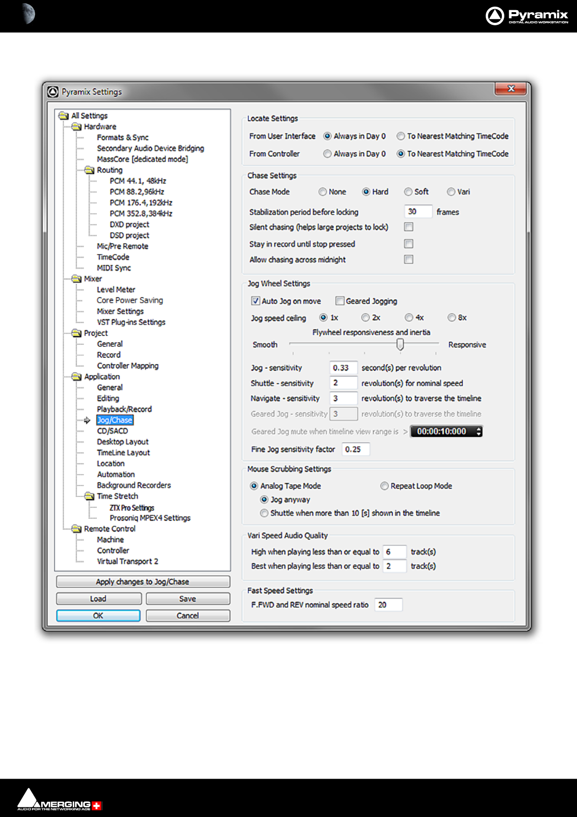
Settings : Application 29 - 751
Jog/Chase
Locate Settings
The radio buttons determine how Pyramix will locate. I.e. only within the current TimeCode day (0) or to the near-
est iteration of the target TimeCode. (Which may be in Day -1 or +1).
From user Interface
Always in Day 0 Default selection. Retains V7.1 behavior.
To Nearest Matching TimeCode
All Settings Application Jog/Chase Page

Settings : Application 29 - 752
From Controller
Always in Day 0
To Nearest Matching TimeCode Default selection. Retains V7.1 behavior.
Chase Settings
Chase Mode
The radio buttons give a choice of Chase Mode
None Pyramix does not chase external TimeCode
Hard When Hard Chase is active, Pyramix will only playback when valid TimeCode is
detected on the chosen TimeCode input port. If there is a jump in the incoming
TimeCode, Pyramix will adjust to the new TimeCode, re-synchronize and begin
playback from the new TimeCode position. Pyramix will run on its own internal
TimeCode for up to 1 frame if there is a drop out in the time code. If no valid Time-
Code is detected after that time, playback will stop.
Soft When Soft Chase is active, Pyramix will only playback when valid TimeCode is
detected on the chosen TimeCode input port. If there is a jump in the incoming
TimeCode, Pyramix will not adjust to the new TimeCode, but will continue play-
back with an offset from the incoming TimeCode position. Pyramix will continue to
run on its own internal TimeCode for up to 1 frame if there is a drop out in the
TimeCode. If no valid TimeCode is detected after that time, playback will stop.
Vari When the Vari Chase is active, Pyramix will Varispeed, I.e. alter its sampling rate to
follow fluctuations in an external TimeCode. (going back and forth, slowing down,
accelerating, playing normally or backwards, up to 8x nominal speed) while in
playback (not in record)
Stabilization period before locking
Although Pyramix is capable of locking to incoming TimeCode within 3 - 4 frames, there are cases where synchro-
nization is more stable if there is a longer waiting time. This is because some external devices take a considerable
time to stabilize their speed after playback is started. This parameter allows a waiting time to be defined before
Pyramix will start chasing the TimeCode. 30 frames is a good starting point if you experience problems with exter-
nal machines.
Silent Chasing (helps large projects to lock)
When checked Pyramix allows large projects to lock immediately while chasing. In this mode locking time does
not depend on the number of Tracks. The drawback is that sound only appears one second after a lock is estab-
lished.
Stay in record until stop pressed
If this box is checked Pyramix will remain in record (once properly locked to TimeCode) regardless of disturbances
/ discontinuities in the code until the Pyramix Stop button is pressed.
Allow chasing across midnight
When this option is unchecked the Chase engine always locks between 00:00:00:00 and 23:59:59:2X of Day 0
When this option is checked the Chase engine allows locking anywhere in the Pyramix timeline (-1000 days to
+1000 days). The engine interprets the incoming timecode to be the nearest position to the current cursor posi-
tion, thus allowing chasing around midnight of any days of the timeline.
For additional security and comfort, if Pyramix is in the "locked" state while crossing the midnight barrier, then
even with this setting unchecked setting, there will not be an immediate jump from midnight back to zero while
playing or recording in sync. The playback or recording will remain seamless, uninterrupted and cross the day bar-
rier until an out-of-lock status is recognized. Only then is a re-chase triggered to whatever the incoming Timecode
value is at that point.
Jog Wheel Settings
Auto Jog on move
When checked moving the jog-wheel enters Jog mode. When Auto-Jog is enabled, all Jog Commands are pro-
cessed a slightly different way. Pyramix temporarily stops chasing and starts Jogging while sending Goto com-

Settings : Application 29 - 753
mands to the External Machine. The audio is therefore perfectly scrubbed and the external machine follows the
audio as well as it possibly can. When the user stops Jogging, Pyramix automatically returns to chase mode.
Geared Jogging
When checked the jog wheel “gearing” I.e. the amount you have to turn the wheel for a given amount of cursor
movement is related to the current Zoom level.
Jog Speed ceiling
Sets the maximum jog speed from a choice of 1X, 2X, 4X or 8X play speed
Flywheel responsiveness and inertia
Responsive follows the actual movements as sent by the jog wheel. Smooth passes the actual movement
through a smoothing filter. So, when the slider is set to Responsive the Smoothing Filter parameters have no
effect.
For sound to picture work where tight sync to picture is required use a setting biased to Responsive. For a more
pronounced flywheel effect choose a Smoother setting.
The Middle position is a good starting point.
Jog - sensitivity [0.33] second(s) per revolution
Sets the time moved in one revolution of the jog wheel. Type the required value in the box.
Shuttle - sensitivity [2] revolution(s) for nominal speed
Sets the fraction of a revolution or number of revolutions required to maintain nominal speed. E.g. an entry of 0.25
will require a quarter of a turn clockwise to achieve nominal speed.
Navigate - sensitivity [3] revolution(s) to traverse the timeline
Navigate is silent jog mode. Sets the number of revolutions of the jog wheel required to traverse the visible time-
line. I.e. the actual speed varies with the zoom setting.
Geared Jog mute when timeline view range is > 00:00:10:00
Audio will be muted when the TimeLine view range exceeds the value in the register.
Fine Jog sensitivity factor [ ]
Sets the fraction of the regular Jog Sensitivity Setting that will be invoked when Fine Jog is selected in the
Machines > Controllers menu
Mouse Scrubbing Settings
Gives a choice between Analog Tape Mode with two options or Repeat Loop Mode
Analog Tape Mode gives a similar response to ‘reel-rocking’ on an analogue tape machine.
Jog anyway
When lit, Jog Mode is used regardless of how much audio is visi-
ble in the Timeline
Shuttle when more than 10 [s] is shown in the Timeline
When lit, if there is more than 10 seconds of audio visible in the
Timeline scrub will be in Shuttle Mode
Repeat Loop Mode continuously repeats a short loop starting at the cursor position.
Vari Speed Audio Quality
High when playing less than of equal to [6] track(s)
Best when playing less than or equal to [2] track(s)
Fast Speed Settings
F.FWD and REW nominal speed ratio [20]
Type in the box to set the nominal F.FWD and REW speed. (I.e. a value of 20 means 20 times sync play speed)
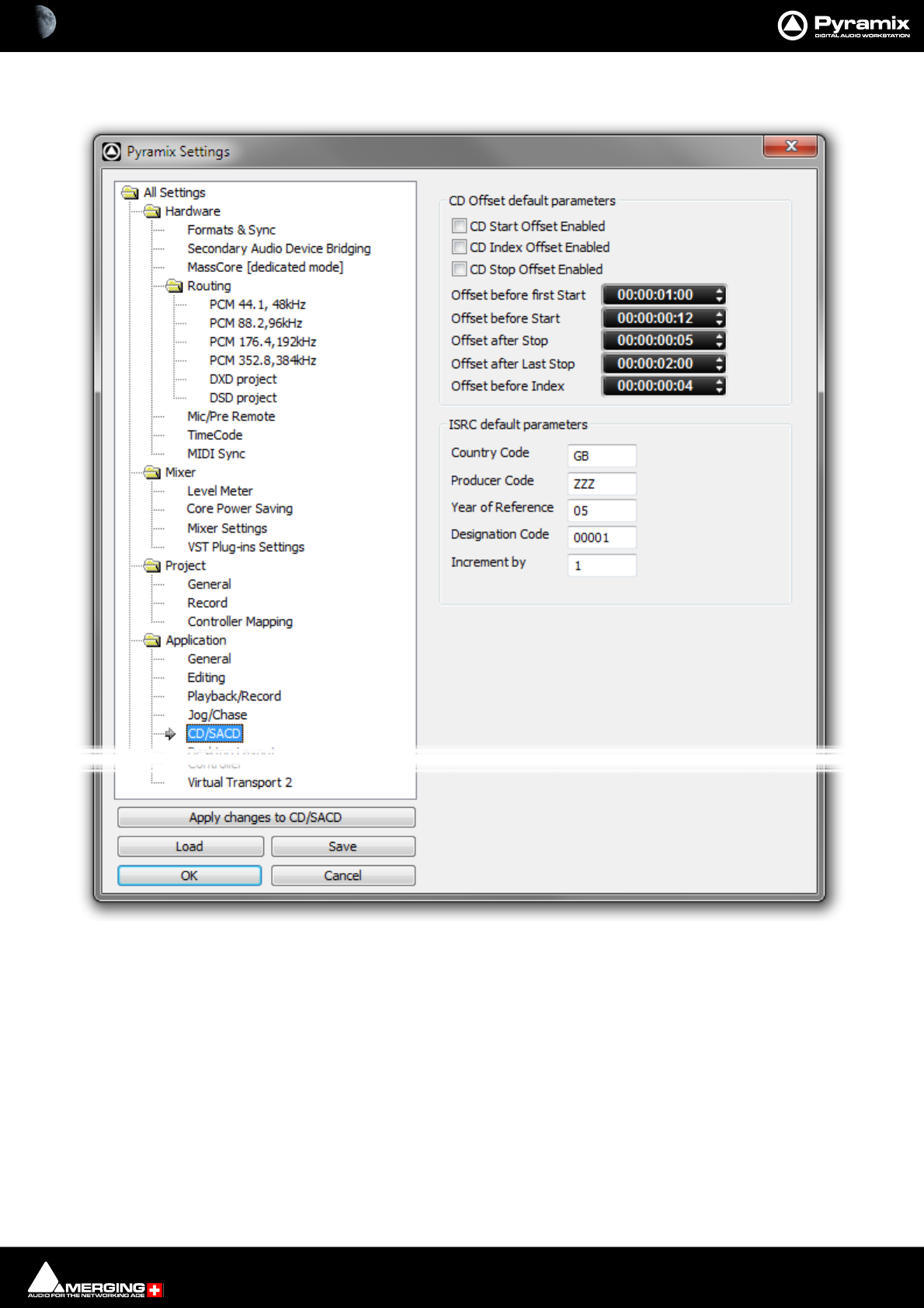
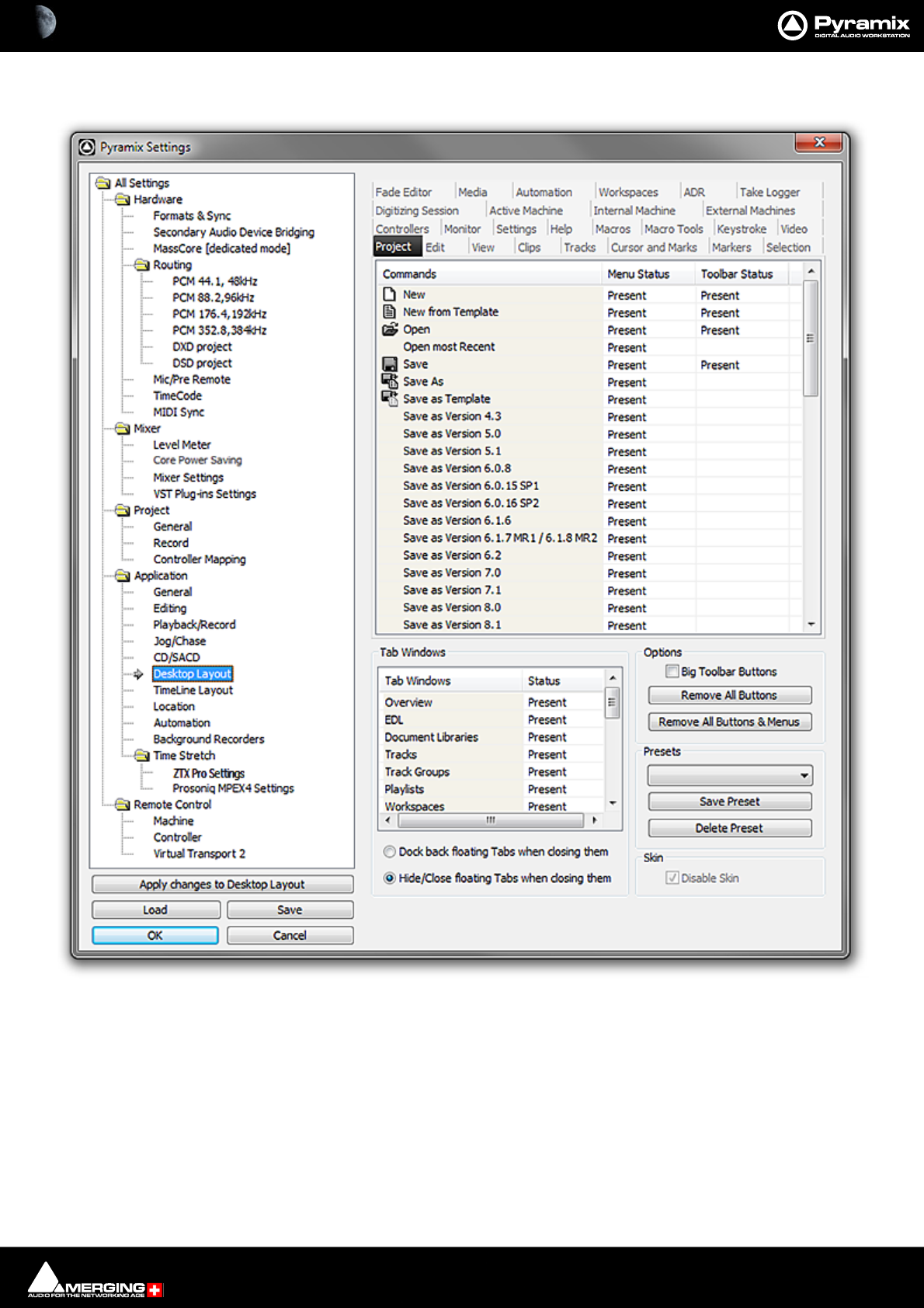
Settings : Application 29 - 755
Desktop Layout
This is where you can customize the content of Menus and Toolbars. Clicking in the Menu Status and Toolbar
Status cells toggles each entry Present or blank (absent). This can be used to tailor the user interface for specific
tasks or operators.
Tab Windows
Clicking in the Status cells toggles each Tab Window entry Present or blank (absent).
Dock back floating Tabs when closing them as it says. Toggles with:
Hide/Close floating Tabs when closing them
All Settings Application Desktop Layout Page

Settings : Application 29 - 756
Options
Big Toolbar Buttons Doubles the size of the Toolbar buttons when checked.
Remove All Buttons As it says - use with extreme caution.
Remove all Buttons and Menus Likewise - leaves a limited number of essential menu entries
Presets
The combo box offers a choice of previously saved Presets
Save Preset Pops up a simple Save Preset dialog
Delete Preset Deletes the preset currently shown in the Presets combo box above.
Skin
Disable Skin Only applicable to Windows XP based systems. When ticked, reverts to earlier
“look”. This may be useful to improve performance on certain (older) systems.
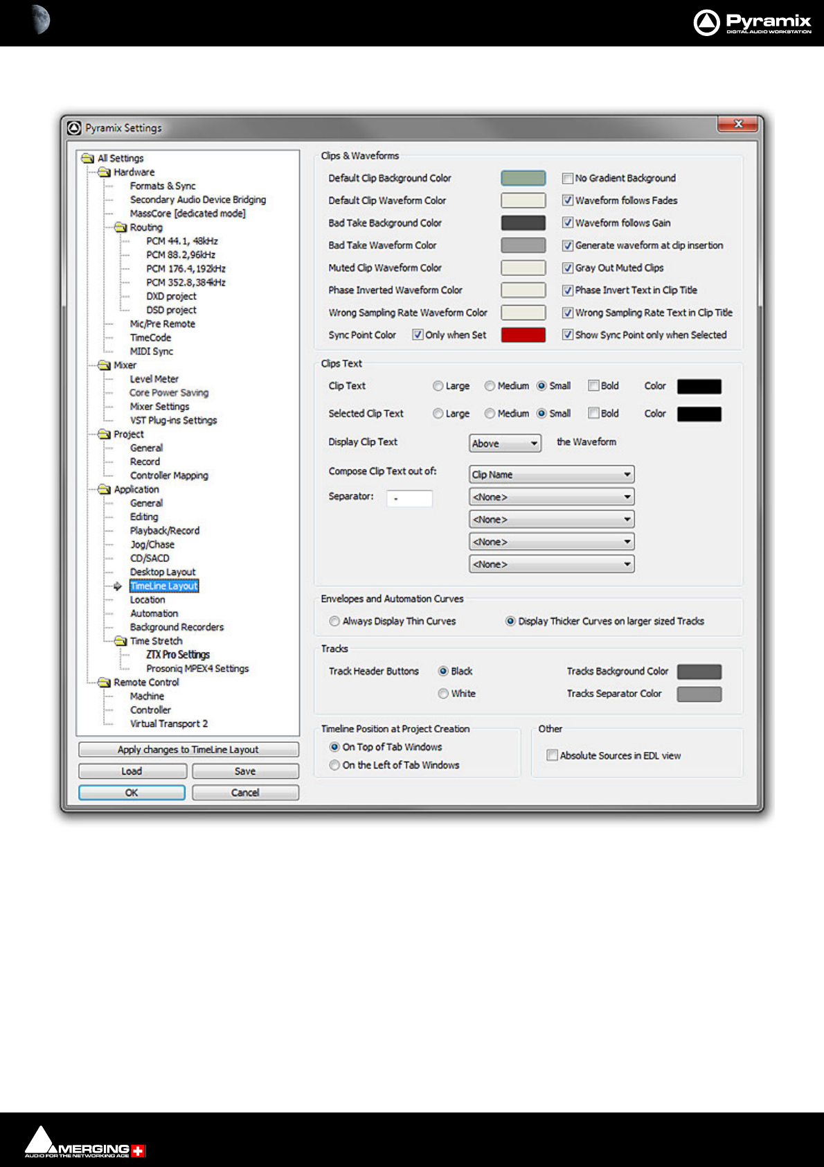
Settings : Application 29 - 757
TimeLine layout
For all the color options, clicking on the colored block pops up a list of defined colors. At the bottom of the list
selecting More Color... opens a full Color picker dialog.
Clips and Waveforms
Default Clip Background Color No Gradient Background When checked Clip Background color is solid.
Default Clip Waveform Color Waveform follows Fades When checked the waveform display is scaled in
height during fades and crossfades. The original
waveform is shown grayed out.
Bad Take Background Color Waveform follows Gain When checked the waveform display is scaled in
height to follow Gain changes. The original wave-
form is shown grayed out.
All Settings Application Timeline Layout Page
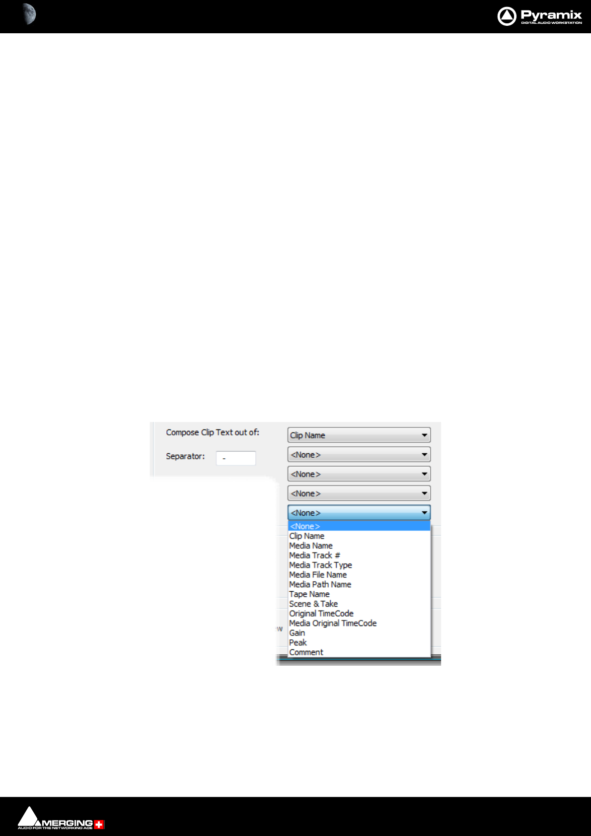
Settings : Application 29 - 758
Bad Take Waveform Color Generate Waveform at Clip insertion When checked Waveform display is generated
when the Media File is placed on the Timeline.
Muted Clip Waveform Color Gray Out Muted Clips When checked Muted Clips are grayed out in the
Timeline.
Phase Inverted Waveform Color Phase Invert Text in Clip Title When checked Phase Invert is shown in the Clip
Title when the Clip phase is inverted.
Wrong Sampling Rate Waveform Color Wrong Sampling Rate Text in Clip Title When checked Wrong Sampling Rate is
shown in the Clip Title when the Clip phase is
inverted.
Sync Point Color Only when set When checked, means that Sync Points are only vis-
ible when set somewhere other than the default
position at the beginning of the Clip.
Show Sync Point only when selected When checked the Sync Point(s) is/are displayed
only when the Clip(s) are selected.
Clips Text
Clip Text Font Size The radio buttons offer a choice of Large, Medium or Small and the Bold check
box emBoldens.
Clip Text Color
Selected Clip Text Font Size The radio buttons offer a choice of Large, Medium or Small and the Bold check
box emBoldens.
Selected Clip Text Color
Display Clip Text The combo box offers a choice of Above, Below, In Front Of or Behind the Wave-
form
Compose Clip Text out of: The Clip text displayed can consist of up to five elements chosen from the five
combo boxes, separated by the character typed in the Separator box:
Envelopes and Automation Curves
Always Display Thin Curves When checked, curves are always shown “thin” as in previous versions.
Display Thicker Curves on Tracks with larger size When checked, curves are displayed thicker on Tracks with
increased Track height.
Compose Clip Text out of : combo box

Settings : Application 29 - 759
Tracks
Track Header Buttons Black Toggles
White
Tracks Background Color
Tracks Separator Color
Timeline Position at Project Creation
On Top Of Tab Windows Radio buttons toggle between this and:
On the Right of Tab Windows Provided to allow for good use of dual monitors. Check this box when using a dual
monitor set-up to enable the Timeline to be displayed on one screen and all Tab
Windows on the other one.
Other
Absolute Sources in EDL View When checked, the original Source In, Source Out and Sync Point times are
shown in Absolute Time in the EDL View. Absolute time is the incoming TimeCode
recorded at the audio capture. When this mode is disabled, the default start time
of TimeCode for the captured Clip is 00:00:00:00.
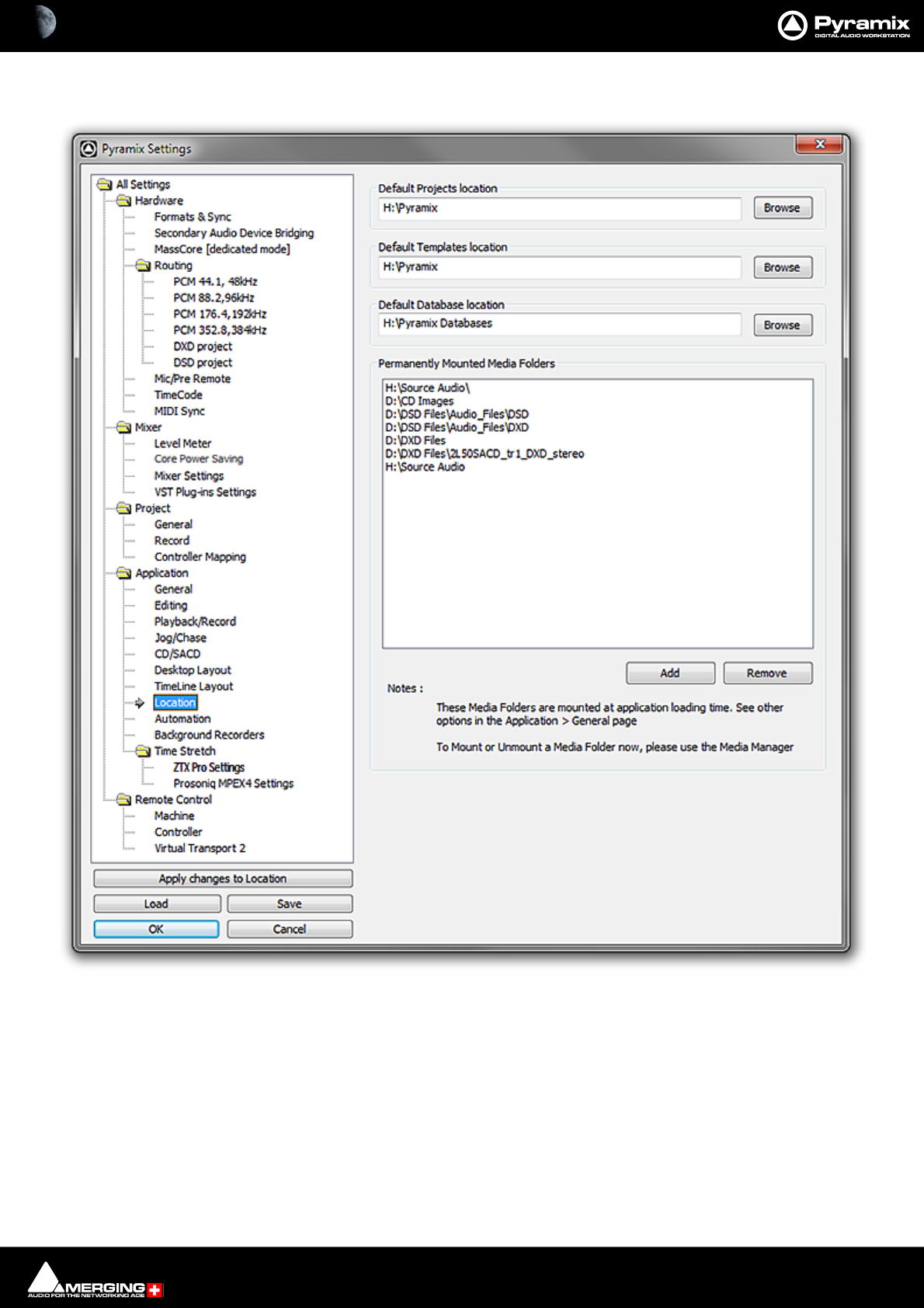
Settings : Application 29 - 760
Location
Default Projects Location
This path is set when a new Project Workspace is created. It can be changed here either by typing the path into the
box or browsing the Windows filing system using the Browse button
Default Templates Location
This path is set when Pyramix is installed. It can be change here in the ways described above.
Default Database Location
This path is set when Pyramix is installed. It can be change here in the ways described above.
All Settings Application Location Page

Settings : Application 29 - 761
Permanently Mounted Media Folders
Shows a list of Media Folders available to all projects. Clicking Add opens the Choose a Media Folder to Mount
window. Here you can browse for Folders or create new ones.
Folders are removed by highlighting their list entry and clicking the Remove button.
Note : these folders are mounted at application loading time. See other options in the Application > General
page
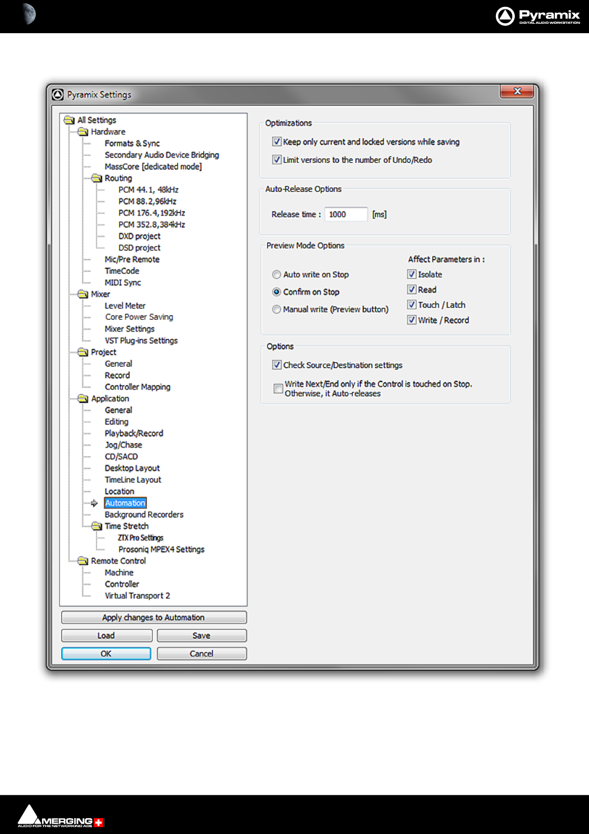
Settings : Application 29 - 762
Automation
Optimizations
Keep only current version while saving when checked does as it says
Limit versions to the number of Undo/Redo when checked does as it says. Number of Undo/Redos is defined in
the Settings > All Settings > Application General page.
All Settings Application Automation Page

Settings : Application 29 - 763
Auto-Release Options
Release time If Auto Release is enabled any control will, when released or when the transport is
stopped, return to its value or state in the previous automation pass or the default
where no previous pass exists. This occurs either immediately if the control only
has two states (e.g. a button) or over a period of time if the control is a fader or
knob. The time period is determined by the value entered in the Release Time box
in ms.
Preview Mode Options
The selections here affect actions in Automation Preview Mode.
Auto write on Stop Automation goes into Auto write mode when a Preview pass is stopped.
Confirm on Stop A confirmation dialog pops-up when a Preview pass is stopped.
Manual write Clicking on the Preview button writes the Preview pass.
Affect Parameters in :
Isolate When checked, parameters are affected in Isolate mode.
Read When checked, parameters are affected in Read mode.
Touch / Latch When checked, parameters are affected in Touch /Latch mode.
Write / Record When checked, parameters are affected in Write / Record mode.
Options
Check Source/Destination settings When enabled (default) verifies the project when it is opened and ensures
that the Automation > Automation Tracks : Master Controls Link setting is set
to Master Controls are linked to any Track.
Write Next/End only if the Control is touched on Stop. Otherwise it Auto-releases
Settings : Application 29 - 764
Background Recorders
Number of Active Background Recorders The drop-down list offers the choice of: 0, 1, 2, 3 or 4.
Settings for Recorder # The drop down list offers the choice of any of the Background Recorders specified
in Number of Active Background Recorders. Settings made in the rest of the
page will affect the Recorder selected here ONLY.
Recorder Color Clicking on the button pops-up a box with four colors and More Color... Selecting
More Color... opens a standard Color Picker dialog. The color chosen for the
Recorder here is reflected in the recorder’s associated Mixer, in the Transport Con-
trol Panel and the color of resultant Clips in the Timeline. (The button displays the
color selected currently.)
Time Stamp The drop-down list offers the choice of 00:00:00 (I.e. the recorded media files will
be time-stamped according to elapsed time from the start of recording.) or with
Time of Day according to the PC internal clock. (Time Stamp will be incoming
TimeCode when in Chase mode.)
All Settings Application Background Recorders page

Settings : Application 29 - 765
Pre-Buffering The drop-down list offers the choice of: 0[s], 5[s], 10[s], 20[s] or 30[s]. This setting
determines how much audio is recorded before recording is initiated.
Confirm Stop When checked a confirmation dialog is displayed when Stop is pressed. (Default
Off)
Take Name Type a name here which will be applied to ALL media files recorded by the
selected Recorder.
Increment Take Number When checked a number is added to each media file name for each take and is
incremented on subsequent takes. (default On)
Number of Media Sets to record to : The drop-down offers the choice of 1 or 2.
Settings for Media Set # The drop down list offers the choice of either Media Set 1 or 2 if 2 is specified in
Number of Active Media Sets to record to :. Settings made in the rest of the page
will affect the Media Set selected here ONLY.
Media Folder The drop-down list offers the choice of any Media Folder mounted currently.
... button Clicking on the ... button opens the Choose a media folder to mount dia-
log. This enables a folder to be selected or created on any storage device
accessible to Pyramix.
Format The drop-down offers the choice of BWF or MTFF.
Resolution The drop-down list offers the choice of: 32[bps], 24[bps] or 16[bps].This setting
applies to BOTH Media Sets where two are specified and the setting is grayed out
for the second Media Set.
Media File Count The drop-down list offers the choice of: Single Media, One File per Track or One
File per Strip.
Waveform The drop-down list offers the choice of None or Generate while recording.
Edit in Active Project The drop-down list offers the choice of: No, Edit while Recording or Edit at End
of Recording.
Please click here to return to Background Recorders on page 150

Settings : Time Stretch 29 - 766
Time Stretch
ZTX Pro Settings
Quality: The drop-down list offers the choice of Good, Better or Best
Time / Frequency localization: The slider enables the processing bias to be altered between Full Time localiza-
tion (single instr. & voice) and Full Freq. localization (good for classical music)
All Settings > Application > Time Stretch > ZTX Pro Settings Page
Settings : Time Stretch 29 - 767
Prosoniq MPEX4 Settings
Optimize MPEX4 Settings by making appropriate choices from the Quality Mode and Formant Type combo
boxes.
Quality Mode
Formant Type
All Settings Application Time Stretch Prosoniq MPEX4 Settings Page
Settings : Remote Control 29 - 768
Remote Control
Machine
The following machines are installed:
Displays a list of all installed machines. Machines in this list will be available as possible machine choices in the
Transport Control.
Internal and External machine(s) links
The buttons determine which machine functions will be linked. Simply tick the boxes to link any or all of the fol-
lowing functions for all active machines:
Play and Record
Play-Record Toggle
In / Out Points
Offset
Apply only on Chasing Machine When ticked the links are only applicable to machines currently in
Chase mode.
All Settings Remote Control Machine Page
Settings : Remote Control 29 - 769
Add
Clicking on the Add button opens the Machine Properties dialog box (see below)
Remove
If a machine is selected (highlighted) in the list, clicking Remove uninstalls the machine and removes it from the
list.
Properties
Clicking on the Properties button opens the Machine Properties dialog box (see below)
OK
Click OK to accept changes (if any) and close the Machines page.
Cancel
Click Cancel to reject changes (if any) and close the Machines page.
Apply
Click Apply to apply changes without closing the Machines page.
Machine Properties
When the Machine Properties dialog is opened by the Add button, the Name, Protocol and Port displays are
blank. When the dialog is opened by the Properties button the displays reflect the name etc. for the selected
machine.
Name
Displays the name of the current selected machine. When adding a new machine, type a suitable name here.
Driver
Displays the current interface protocol Sony (9-pin P2 protocol) in the drop-down list. (Currently Sony only)
Driver - Properties
Opens the Sony 9 - Pin Protocol Configuration dialog box (see below) when SONY is selected. There are cur-
rently no options for MMC
Machine Properties dialog
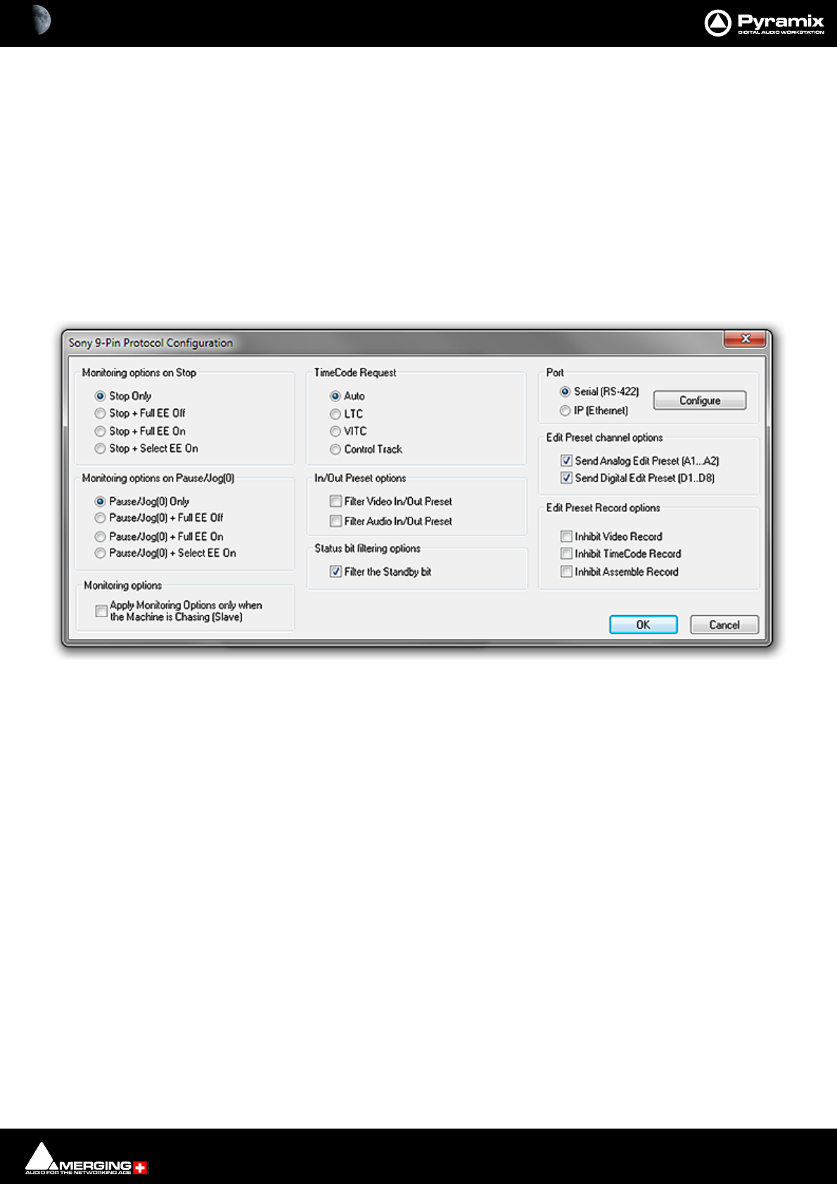
Settings : Remote Control 29 - 770
Settings
Inhibit Video Record
When checked prevents record arming of video in order to ensure video cannot be accidently overwritten.
Pre Roll
Shows the current Pre Roll time for the external machine. Type in the box to change the value.
Post Roll
Shows the current Post Roll time for the external machine. Type in the box to change the value.
Driver Properties
Sony 9-Pin Protocol Configuration (Machine)
This dialog determines Monitoring Options on Stop, Monitoring Options on Pause/Jog, Preset Channel and
Record Options the type of TimeCode Request, In/Out Preset options and gives access to the Serial Port con-
figuration dialog.
Port
• Serial (RS422) Select this option if the connection uses conventional 9-pin cabling
• IP (Ethernet) Select this option if connecting to remote Pyramix or VCube machine(s) using Sony P2 over
IP.
Configure
Clicking the Configure button (Serial (RS-422 only) opens the configuration dialog.
Sony 9-Pin Protocol Configuration dialog
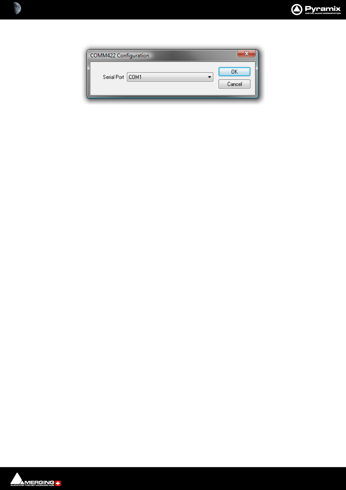
Settings : Remote Control 29 - 771
COMM422 Configuration:
Serial Port
Shows the current Serial Port selected from the drop-down list. If not already highlighted, select the desired serial
COM port. Standard choices are either COM1 or COM2.
Click OK to confirm the choice. This automatically sets the selected COM port with the proper parameters of the
Sony 9-pin communication protocol.
Monitoring options on Stop
After a Stop command the following command will be issued:
•Stop Only
• Stop + Full EE Off
• Stop + Full EE On
• Stop + Select EE On
Monitoring Options on Pause/Jog(0)
After a Pause/Jog command the following command will be issued:
• Pause/Jog(0) Only
• Pause/Jog(0) + Full EE Off
• Pause/Jog(0) + Full EE On
• Pause/Jog(0) + Select EE On
Monitoring options
Selecting:
• Apply Monitoring Options only when the Machine is Chasing (Slave)
ensures that the above options, Monitoring options on Stop and Monitoring options on Pause/Jog(0) are only
applied when the 9-pin external machine is chasing the Internal Machine (being synchronized, i.e. editing). When
the 9-pin external machine is Master (the Internal Machine is chasing it, typically for recording back to tape) then
the 9-pin external machine is in normal Input/Repro Auto mode.
TimeCode Request
•Auto
•LTC
•VITC
• Control Track
The radio buttons select the source of the TimeCode from the external machine. Sony machines usually respond
to all requests, so the Auto setting will probably be appropriate. If necessary E.g. where there are several different
TimeCodes present on a tape, you can specify a desired TimeCode source to override the automatic setting. U-
Matic machines do not respond to all requests, therefore you must specify the TimeCode source.
COMM422 Configuration dialog
All Settings Application Automation Page

Settings : Remote Control 29 - 772
Send In/Out Preset options
By default, Pyramix sends Edit Video In/Out and Edit Audio In/Out points when an In/Out point is set in the Trans-
port Control panel. These options enable these commands to filtered out if necessary.
• Filter In/Out Preset (video)
• Filter Audio In/Out Preset
Status Bit Filtering Options
Some SonyP2 devices do not report the Standby bit correctly (always in Standby). In this case the Pyramix Trans-
port Window reports Standby status continuously, thereby hiding the true status. You may wish to set filter if the
target machine fails to report standby correctly.
• Filter the Standby bit
Edit Preset channel options
Edit Preset in the 9-pin P2 protocol world means Track Arming.
These options enable Track Arming commands to be filtered out if required.
• Send Analog Edit Preset (A1..A2)
• Send Digital Edit Preset (D1..D8)
This feature is mostly relevant where a console or a third-party record/monitoring controller is used for record
commands.
Edit Preset Record Options
These 3 options Inhibit Recording when one of the Video/Timecode/Assemble Edit preset modes is checked and
the corresponding Track is armed. In a typical TV workflow, when audio is laid back to the tape, it is essential to
prevent the video track entering record (edit) These options avoid nasty accidents.
• Inhibit Video Record
• Inhibit TimeCode Record
• Inhibit Assemble Record
This feature is mostly relevant where a console or a third-party record/monitoring controller is used for record
commands.
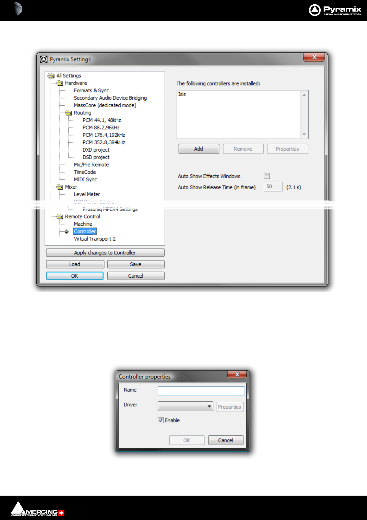
Settings : Remote Control 29 - 773
Controller
The Controller page shows a list of all external controllers currently installed (if any) in the The following control-
lers are installed pane.
Note: Please see also: Controller Mapping on page 742
Add
Pops up the Controller properties dialog.
All Settings Remote Control Controller Page
Controller properties dialog
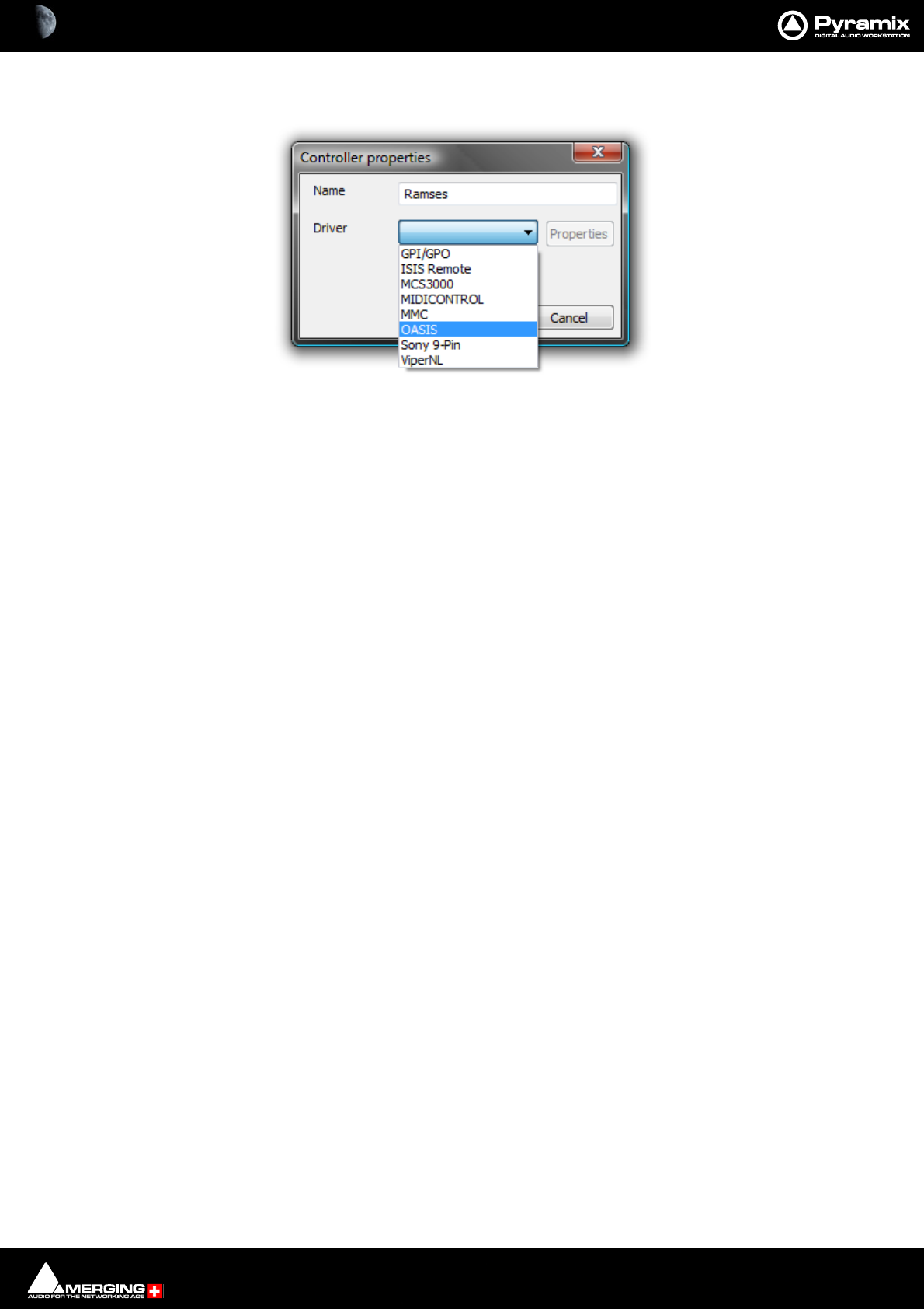
Settings : Remote Control 29 - 774
Type a suitable name for the controller you wish to add in the Name field. Click on the down arrow to drop down
the list of drivers.
Select the correct driver for the controller you are installing.
Clicking on Properties will open a configuration dialog specific to the driver.
Ensure that the Enable check-box is ticked and Click on OK to add the controller.
Remove
Removes the Controller currently highlighted in the The following controllers are installed list (if any)
Properties
Pops up the configuration window for the selected controller.
Please see: Control by External Device on page 585 for further details.
Auto Show Effects Windows
When selected moving a control on the hardware controller mapped to an effect will open the relevant plug-in’s
window.
Auto Show Release Time (in frames)
Sets the amount of time an Auto Shown window persists after the last detected control move.
Controller properties dialog
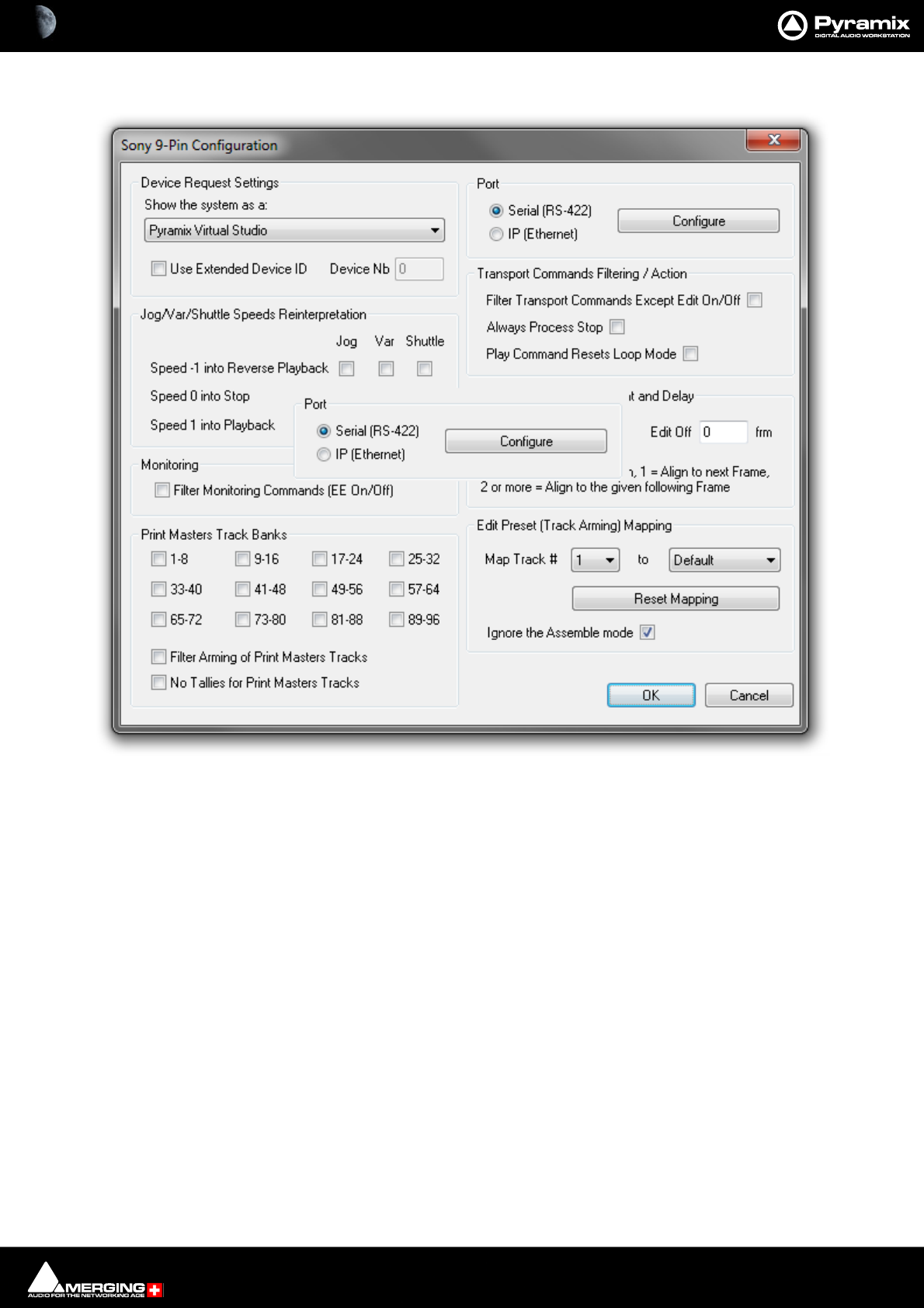
Settings : Remote Control 29 - 775
Sony 9 - Pin Protocol Configuration (Pyramix controlled by external device)
Device Request Settings
The Sony 9-pin P2 protocol transmits a code to identify the machine. Some machine controllers will do nothing or
exhibit aberrant behavior if they do not recognize the identifier code. Therefore, Pyramix can masquerade as
another device. The device identifier can be selected from a long list in the Show the system as a: combo box.
Jog/Var/Shuttle Speeds Reinterpretation
The radio buttons determine Pyramix behavior when specific Jog/Var or Shuttle commands are received.
• Speed -1 into Reverse Playback
• Speed 0 into Stop
• Speed 1 into Playback
Note: When using a controller with a jog wheel please set Jog/Var/Shuttle ... Speed = 0.
Note: Interpreting a Sony reverse varispeed command as Reverse Playback is sometimes neces-
sary to achieve proper (locked to video) reverse playback.
Monitoring
Filter Monitoring Commands (EE On/Off) when ticked, E to E On and off commands are filtered out.
Sony 9-Pin Configuration dialog
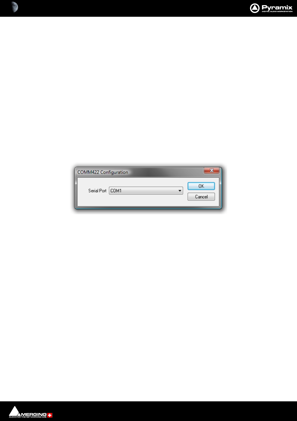
Settings : Remote Control 29 - 776
Print Masters Track Banks
The selected banks of 8 tracks are armed for recording when any OTHER track is armed. This is primarily useful
when recording a Print Master or Masters at the same time as stems. E.g. if you are recording Dialogue, Music and
Effects stems it is common practice to update an element on one stem only. However, the final mix Print Master,
which is the sum of all the stems must be updated at the same time. Print Masters Track banks allow the user to
forget about arming the Print Master Tracks and concentrate on the stems.
Filter Arming of Print Masters Tracks
When ticked, arming a Print Master Track will not arm the other Print Master Tracks.
No Tallies for Print Masters Tracks
When ticked, record tally commands are filtered out for the Print Masters Tracks.
Port
• Serial (RS422) Select this option if the connection uses conventional 9-pin cabling
• IP (Ethernet) Select this option if connecting to Pyramix or VCube machine(s) using Sony P2 over IP.
Configure
Clicking the Configure button opens the respective configuration dialog.
COMM422 Configuration:
Serial Port
Shows the current Serial Port selected from the drop-down list. If not already highlighted, select the desired serial
COM port. Standard choices are either COM1 or COM2.
Click OK to confirm the choice. This automatically sets the selected COM port with the proper parameters of the
Sony 9-pin communication protocol.
Transport Commands Filtering
• Filter Transport Commands Except Edit On/Off When ticked all transport commands apart from Edit On
or Edit Off are filtered out.
•Always Process Stop Some controllers send a Chase Off command for Stop. If you need this command
when filtering Transport Commands, checking the box will allow it through.
• Play Command Resets Loop Mode (I.e. the transport Loop)
Note: These filter settings are mainly relevant where multiple controllers are in use. E.g. where a
Mixing console controls monitoring and recording.
Edit On/Off Frame Alignment and Delay
Edit On and Edit Off boxes enable delays (in ms) to be entered.
Note: 0 = Immediate Punch, 1 = Align to next Frame boundary, 2 or more = Align to the given
following Frame boundary.
COMM422 Configuration dialog

Settings : Remote Control 29 - 777
Edit Preset (Track Arming) Mapping
The Map Track # combo box allows you to select a Track between 1 and 96 to be mapped to a choice made in the
second combo box from:
• Default
•No change
•Always Off
•Always On
or any Track between 1 and 96
This function is useful if more than one Pyramix is to be controlled by the same controller. E.g. with two machines
set up to record 32 Tracks each, Pyramix one is mapped 1 - 1 to 32 - 32 and Pyramix two is mapped 1 - 33 to 32 -
64
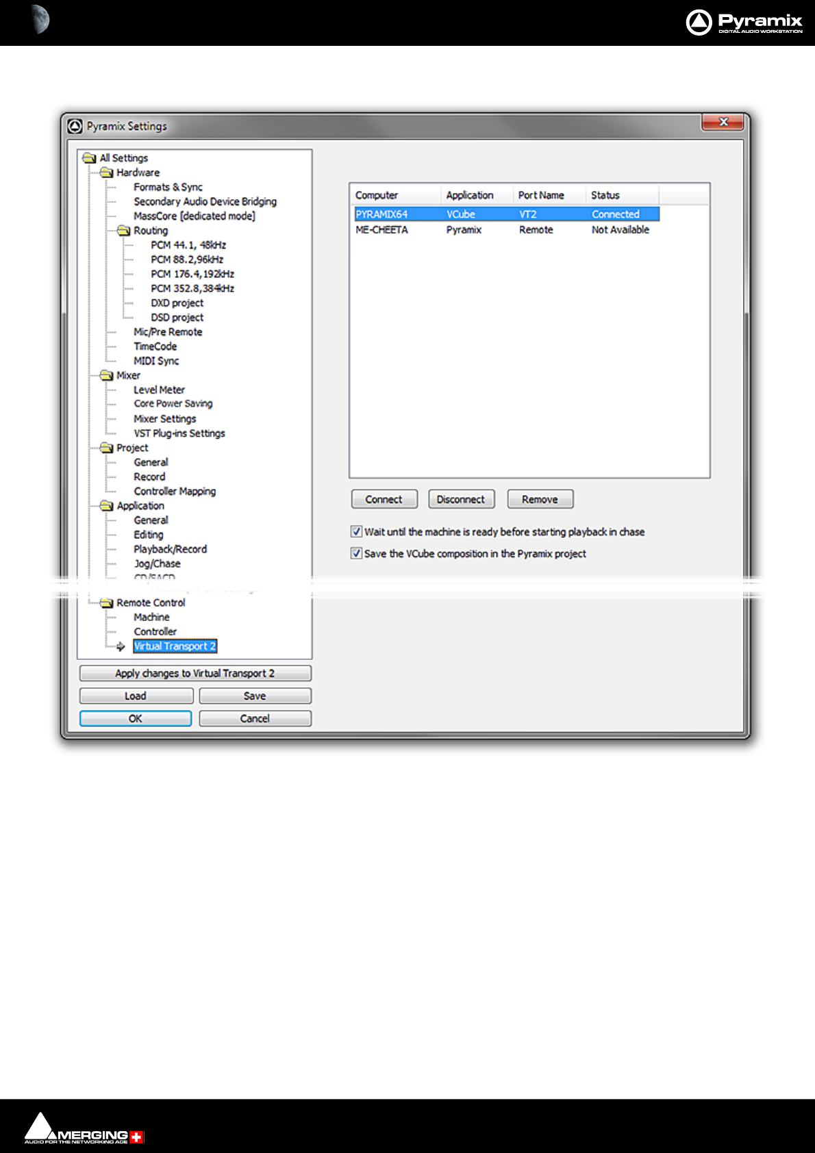
Settings : Remote Control 29 - 778
Virtual Transport 2
General
Connect
Click on a machine name in the list. Click Connect to connect to a local or remote VCube. Or a remote Pyramix set
up as a slave using the Sony 9-pin protocol over IP. Please see also: Configuring Pyramix for Control by
another Pyramix using P2 over IP / VT2 on page 585
Disconnect
Click to disconnect the selected client.
Remove
Click to remove the selected client from the list.
Wait until the machine is ready for use before starting playback in chase When box is checked.
Save the VCube composition in the Pyramix project When box is checked. Use this option
when importing Video clips into a Pyramix Project so that the video Clips will load
automatically when the Project is re-opened and the VCube is active.
All Settings Remote Control Virtual Transport Page
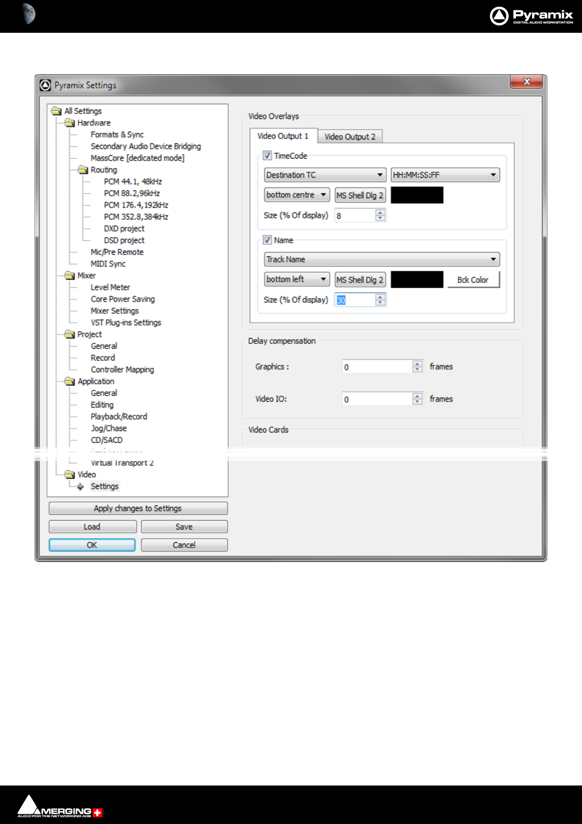
Settings : Video 29 - 779
Video
Overlays
Each of the Video Output x tabs are identical in contents and set the parameters for each of the Video Outputs
independently.
Note: The following field labels match the screenshot above. Since the drop-down lists offer
choices, what you actually see on screen may differ.
TimeCode
When checked TimeCode is overlayed on the Video Output according to the parameters set here.
Source TC The drop-down list offers the choice of:
Source TC
Destination TC
All Settings Video Overlays Page

Settings : Video 29 - 780
HH:MM:SS The drop-down list offers the following choice of TimeCode display formats:
HH:MM:SS
HH:MM:SS:FF
S :HH:MM:SS
S : HH:MM:SS:FF
(D) HH:MM:SS
(D)HH:MM:SS:FF
MM:SS:FF
Bottom Left The drop-down list offers the following choice of TimeCode display positions:
top left
top centre
top right
centre left
centre
centre right
bottom left
bottom centre
bottom right
MS Shell Dlg2 Clicking in the field opens a Select Font dialog with a choice of Font, Font style
and size.
Text Color Clicking in the field opens a color picker where the Text Color may be selected.
Size (% Of display) The percentage may be typed directly, set with the increment/decrement buttons
or with the mouse scroll wheel when the cursor is over the field.
Name
When checked a Name is overlayed on the Video Output according to the parameters set here.
Clip Name The drop-down list offers the choice of:
Track Name
Clip Name
Media Name
MS Shell Dlg2 Clicking in the field opens a Select Font dialog with a choice of Font, Font style
and size.
Text Color Clicking in the field opens a color picker where the Text Color may be selected.
Bck Color (Background color) Clicking in the field opens a color picker where the Background Color may be
selected.
Size (% Of display) The percentage may be typed directly, set with the increment/decrement buttons
or with the mouse scroll wheel when the cursor is over the field.
Delay compensation
Use Delay Compensation when the Video output is delayed with respect to the Audio
Graphics delay Compensates for the graphic card(s) output delay.(computer screen) Type a value
(in frames) or use the increment / decrement buttons.
Video delay Compensates for the video card(s) output(s) (Blackmagic Design). Type a value (in
frames) or use the increment / decrement buttons.
Note: These are global user settings.

30 - 781
www.merging.com/Pyramix
USER MANUAL
Troubleshooting

Troubleshooting : Keeping Up To Date 30 - 782
Troubleshooting is always a moving target as users discover ever more exotic ways to use Pyramix. Therefore, this
section is necessarily historic.
If the answer to your problem cannot be found here or elsewhere in the documentation, for the latest information
please consult the FAQ sections at:
http://www.merging.com
If you need further technical support, please e-mail
support@merging.com
Keeping Up To Date
Acquiring and installing regularly the latest Drivers/Firmware/BIOS or Operating System available for equipment
such as: Graphic Cards, CD/DVD writers, Network Adapters, Motherboards, (but exercise especial caution), external
drives, RAID controllers and other third party hardware add-ons, will ensure that your system will always perform
as efficiently as possible. Always accept any ‘rollback’ options, just in case the driver updates have unforeseen con-
sequences.
Keeping Windows (and DirectX) up to date with latest service packs is also, in general, a positive move towards
maintaining a healthy system.
Note: These operations are not required for Mykerinos and Daughterboards simply because the
latest firmware for your hardware (if any) is automatically installed by the most recent Pyramix
installer.
Pyramix Busy Warning
When Pyramix is engaged on a very demanding task, such as a opening a huge project, or a long and complex
render, the user interface may appear to freeze with the window changed to white and the interface not respond-
ing.
A status window opens at the bottom right of the main Pyramix window to inform the user that Pyramix is still
operational. One of the following messages may be displayed:
• Pyramix Virtual Studio busy (during tasks like: opening project, mount, renders, libraries,…)
• AAF Parser busy (during AAF import task)
• Merging Technologies VS3 busy (during Mixer tasks)
• Merging Technologies Convert busy (during Convert task)
Note: The small progress bar within the Pyramix status window (white) will progress at different
speeds. Please be aware that the progress bar does not necessarily indicate the remaining busy
time.
Error Messages
Audio Engine Drops Warning
This message informs users about possible CPU delays leading to potential audio errors in record or playback.
Mykerinos sends or requests audio data to or from the CPU in “frames” of 26ms. If one of these frames is not given
to, or taken from, the Mykerinos driver in time, this will result in a loss of audio data, and the Audio Engine Drops
Warning will be shown.

Troubleshooting : Multi-channel Audio Files 30 - 783
Playback Stalls Warning
Playback Stall messages are triggered by access delays impacting the VS3, resulting in audio drops while preserv-
ing the synchronization of the Tracks. In the latter case the stall may also endanger the integrity of the synchroni-
zation between Tracks being recorded.
Record Stalls Warning
The Your Recording may be at risk warning indicates that the Destination Media Drive performance may be
insufficient. If so, we detect it and recommend that you change the destination media drive or optimize it.
MassCore Drops
Please see MassCore Overload Diagnosis and Cures on page 38
Multi-channel Audio Files
Wave, Broadcast Wave, AIFF or SDII multi-channel files are seen as mono files by the Pyramix Media Manager
unless their file names conform to Pyramix requirements.
Audio File Formats
Some audio file formats (like Pyramix native format, PMF and OMF) embed the Track/Channel number(s) in the file
itself. In this case, Pyramix recognizes the Track as mono, stereo or multi-channel without problem even if the dif-
ferent audio Tracks/Channels of these files are actually stored in separate files.
Some other formats (like Wave, Broadcast Wave Format, AIFF or MacIntosh SDII) do not keep this information in
the file itself but in the filename. Unless the correct naming convention is followed, Pyramix will see files in these
formats as individual mono, regardless of whether they are part of a stereo pair or multi-channel recording.
Broadcast WAV Files
BWF-P means polyphonic. I.e. multitracks within the same file
BWF-M means monophonic. I.e. one file per track
Pyramix Requirements
In order for Pyramix to recognize that separate audio files in these formats are actually part of a stereo or multi-
channel recording, Pyramix requires the following naming convention:
The filename of the different Tracks/Channels must be the same except for one section containing the Tracks/
Channels number as 3 digits surrounded by _## and ##_. For example: MyStereoSound_##001##_.wav and
MyStereoSound_##002##_.wav are seen by Pyramix as a single two Track media named MyStereoSound.
Other systems, the Zaxcom DEVA portable recorder for example, do not use the same convention. They may name
the files they produce in this fashion: MyStereoSound-1.bwf and MyStereoSound-2.bwf. These files will be rec-
ognized by Pyramix as two mono media files.
Solution
MultiFileFixer is a small ‘tool’ application that automatically renames all files in a given folder and sub-folders,
that fit selected parameters, to follow the Pyramix convention.
In a normal Pyramix installation the MultiFileFixer application can be found on the Windows Start menu:
Start > Programs > Pyramix > MultiFileFixer
Clip Display Problems
No Waveform Display
Symptoms
Files are dragged into the Timeline from a mounted folder but no waveform is generated. Manually invoking Gen-
erate Waveform doesn’t work.

Troubleshooting : Relaunch After Improper Exit 30 - 784
Solution
This problem with Waveform Generation is likely to be due to the fact that the audio files are in Read Only mode.
This will often be the case when copying files from a CD-ROM. In Windows Explorer simply select all the Tracks
from the CD, right click, select Properties and uncheck the Read Only box under Attributes.
Clip Names are Unreadable
Symptoms
With some color schemes, Clip Names are unreadable.
Solution
Simply choose a more suitable Windows color scheme to resolve this. You also can change the background and
waveform colors (right click) for individual Clips and Tracks in Pyramix.
Relaunch After Improper Exit
In the case of an ‘improper application exit’ (politically correct term for crash) the system does not attempt to
open the last backed up project automatically, since the most up to date version is the project itself in its last
saved state. All ProjectXXX (Backup).pmx, ProjectXXX (backup 2).pmx,etc… documents are older versions of Pro-
jectXXX.pmx which is now always the last one saved.
Debug Menu
Right-clicking on bottom right of the Status bar opens a context menu with a choice of Debug, I/O Status Input
Check and Cancel Waveform Generation (grayed out unless Waveform Generation is in progress.
Selecting Debug opens a further sub-menu with a number of tools primarily intended for Merging Technologies
Support use. One option, Profiling is worth examining in detail.
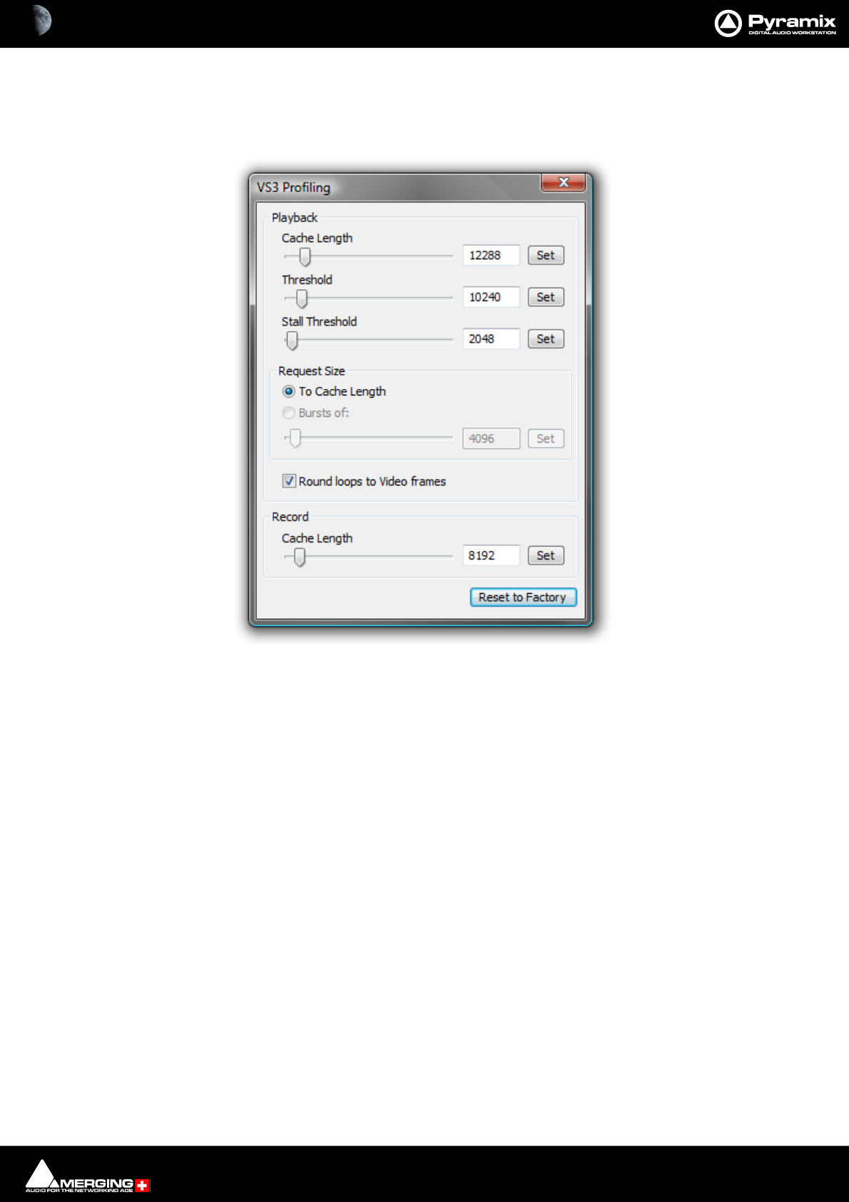
Troubleshooting : Debug Menu 30 - 785
The Profiling Window
The VS3 Profiling window contains the parameters used to fine-tune the performance of hard disk accesses for
Pyramix. These parameters are not intended for user modifications, and Merging cannot guarantee the proper
functionality of Pyramix when modifications are made in this window.
Cache length
This is the size of the playback buffers allocated in the host PC’s RAM. Pyramix allocates one buffer per Track. When
the audio playback is started, all the buffers are completely loaded by reading the data from the hard disk before
the actual playback starts. Increasing the buffer size offers the benefit of a larger immunity against short term hard
disk access stalls and other operating system slow-downs at the cost of longer latency at initial playback start.
Threshold
During playback, the audio data is read from the playback buffers, which are thus progressively emptied. When
the amount of data in a buffer falls below the threshold value, new data is read from the hard disk to refill the buf-
fer.
Request size
This parameter determines how much data is read from the hard disk when the threshold level is reached. One
option is to completely fill (To Cache Length), the other option is to load a defined amount of data (Bursts of).
Stall Threshold
When the amount of data falls below the stall threshold, this means that the system has serious performance
problems. Playback will be temporarily stopped, while a stall warning is issued.
Round loops to Video Frames
This option, which is enabled by default, rounds the start and the end point of a playback loop to complete video
frames. The start point will always be rounded down, and the end point will always be rounded up, so that the
loop will always contain at least the initial range intended for the loop.
Record cache length
VS3 Profiling window

Troubleshooting : Debug Menu 30 - 786
This is the size of the buffer used while recording new data.
Reset to Factory
This button restores all the values to their factory default.
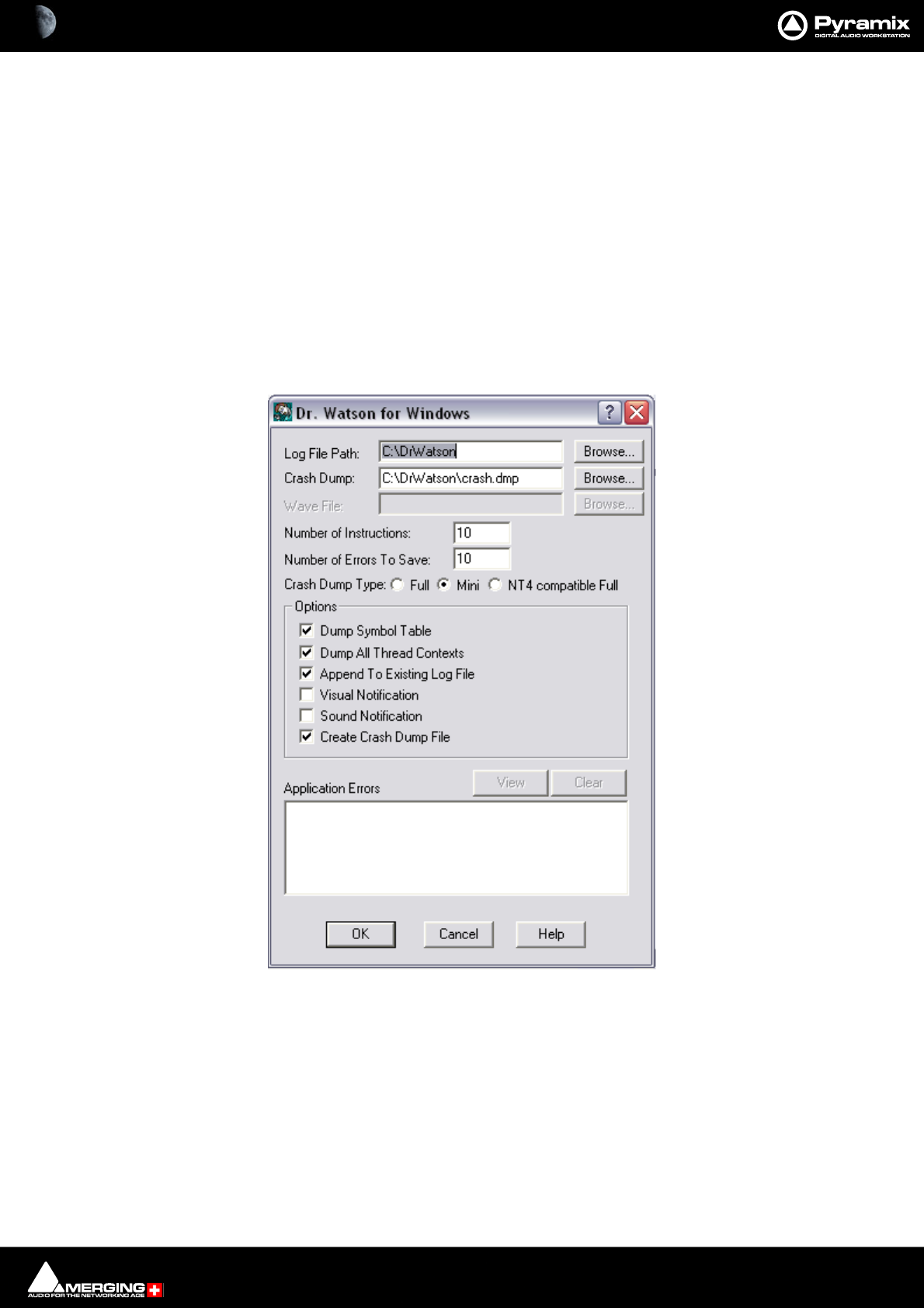
Troubleshooting : General Troubleshooting 30 - 787
General Troubleshooting
DrWatson, Crash Log Activation:
Note: You will need to download DrWatson first, since it is no longer included in the Windows
distribution.
http://download.merging.com/beta/SupportTools/DrWatson.zip
1. Create a new folder named DrWatson at the root of C drive
2. Launch DrWatson 32bit exe, found in: C:\WINDOWS\system32\drwtsn32.exe
3. Set-it up as shown in ScreenShot 1 below
4. Activate DrWatson as the default debugger tool, as shown in ScreenShot 2 below
Dr. Watson Screenshot 1
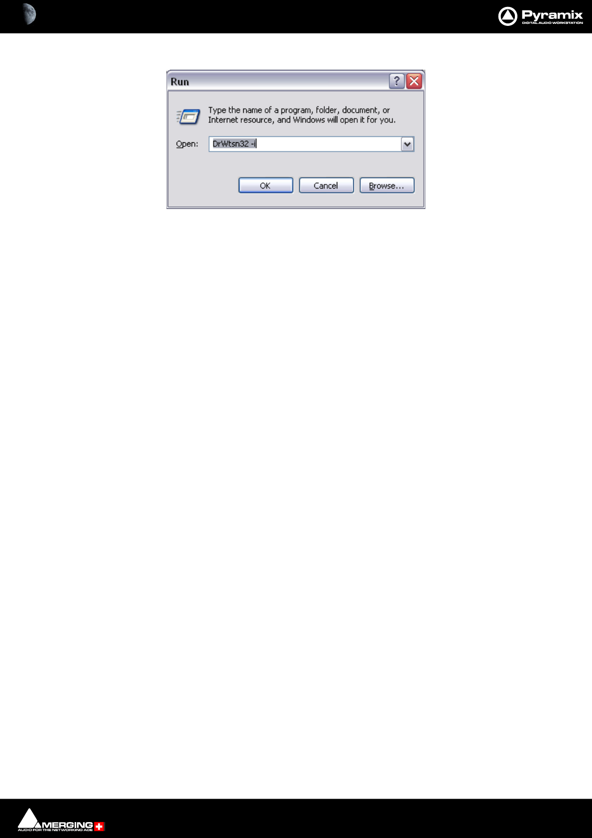
Troubleshooting : General Troubleshooting 30 - 788
Then, once a crash has happened, send us the log file that you will find in the C:\DrWatson folder. Please, also
remember that access to support is free, according to the following conditions:
With a valid ASM (Annual Software Maintenance) or:
Within the first year following the purchase of a new Pyramix Virtual Studio system.
Dr. Watson Screenshot 2

31 - 789
www.merging.com/Pyramix
USER MANUAL
Appendices

Appendices : Appendix I - Mouse Modifier Keys 31 - 790
Appendix I - Mouse Modifier Keys
This table shows the valid modifier keys which can be used in conjunction with some mouse operations
Main Editor
Left Mouse Button
Click In the TimeCode Scale
Set Cursor to the mouse None
Set Mark In to the mouse Shift
Set Mark Out to the mouse Ctrl
Set New Marker to the mouse Ctrl + Shift
Click In the Bars & Beats Scale
Set Cursor to the mouse None
Adjust tempo to the end Shift
Adjust tempo for the current portion Ctrl
Adjust tempo for the current Beat Ctrl + Shift
Click In the Tempo Map
Create a new tempo portion Ctrl
Click In the Track headers zone
Repeat action for the same button on all Tracks Shift
Click In the Clips zone (anywhere)
Draw a Region to zoom in Alt
Dyna-Zoom Z
Draw a Region to select None
Draw a Region to select Clips completely Shift
Extend/Reduce the current Region to this Track E
Invert No Selection mode for Track Groups Q
Invert Auto Select Tracks Q
Click In a Clip handle
Move only the Clip handle under the mouse (no groups) Shift
Move only the envelope point under the mouse (no groups) Shift
Click In a Clip
Add remove Clips to the selection Shift
Drag the selection (to a library) Shift + Alt
Move selected Clips None
Move selected Clips with auto-crossfade Ctrl
Slide the underlying media of a Clip Ctrl + Shift
Slide a Clip over its underlying media Ctrl + Alt
Move selected Clips constrained in time Ctrl + Shift + Alt
Cutter C
Duplicate Clip D
Duplicate Clip constrained in time F

Appendices : Appendix I - Mouse Modifier Keys 31 - 791
While moving
Auto-crossfade while moving Clips Ctrl
Force crossfade while moving Clips lower handle Ctrl
Detach crossfade while moving Clips middle handle Ctrl
Don't merge Envelope points Ctrl
Constrain Envelope in time V
Constrain Envelope in value H
Don't merge Automation points Ctrl
Constrain Automation in time V
Constrain Automation in value H
Select only what is under the mouse (no groups) Shift
Select all Tracks Ctrl + Shift
Select and limit selection the Clips boundaries Ctrl + Alt
Snap Sync Point S
Snap Head H
Snap Tail T
Audition while moving (Scrubbing) A
Double-click in a Clip
Selection Properties
Clip Properties Ctrl
Double-click in a fade
Edit the fade in the Fade Editor
Double-click in an envelope point
Reset the envelope point
Reset only the envelope point under the mouse (no groups) Shift
Middle Mouse Button
Edit crossfade Ctrl
Create & Edit crossfade Ctrl + Shift
Select between edits None
Enlarge selection between edits Shift
Click In the TimeCode Scale
Scrub Audio None
Mouse Scroller
Scroll Tracks up and down None
Increase / Decrease Track height Shift
Zoom Alt
Scroll horizontal Ctrl
Right Mouse Button
Contextual Menu None
Clip Gain Ctrl
On dropping a fade or crossfade from a library
Apply to whole group Shift

Appendices : Appendix I - Mouse Modifier Keys 31 - 792
Overview
Left Mouse Button
Draw a Region to zoom in Alt
Drag the current composition (to a library) Shift + Alt
Notes
Left Mouse Button
Drag the notes (to a library) Shift + Alt
Media Folder
Left Mouse Button
Replace media for target Clip(s) Ctrl
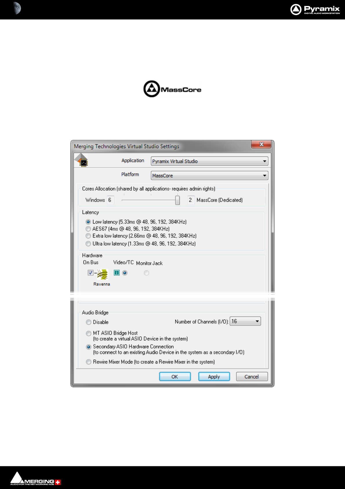
Appendices : Appendix II VS3 Control Panel 31 - 793
Appendix II VS3 Control Panel
The VS3 Control Panel is a separate application that should only be launched when Pyramix is not running. Here,
you can set various parameters relating to Merging Technologies hardware and software. If you are running both
VCube and Pyramix on one system you can assign separate audio I/O to each application. In the case of a system
running MassCore this is also where you can set global latency.
Application
The drop-down list enables you to choose which Merging Technologies application the settings apply to. E.g.
Pyramix Virtual Studio, VCube, ASIO Driver etc. The rest of the settings in the VS3 Control Panel Window update to
reflect the current settings for the selected application.
VS3 Control Panel Window MassCore Platform
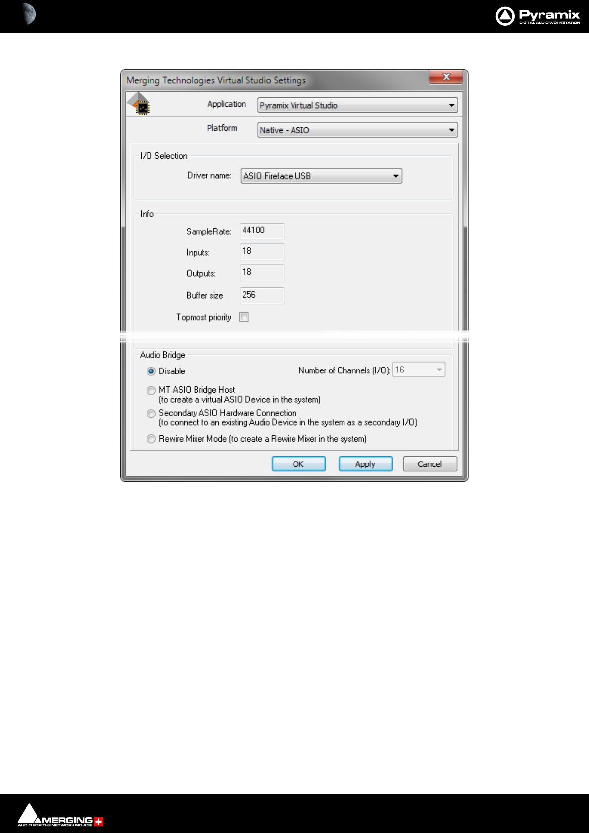
Appendices : Appendix II VS3 Control Panel 31 - 794
Platform
This drop-down list determines which processing platform mode will be used. Dependant on the options installed
these may include MassCore and Native - ASIO.
Core Allocation
Note: This setting is only available in MassCore Systems and only when the MassCore SMP key is
present. This setting applies to ALL applications.
The slider enables the number of processor cores dedicated to MassCore to be varied. The numbers shown vary
according to the number of cores available on the specific system and on whether Hyperthreading is switched on
in the BIOS.
Latency
These options are only available when MassCore is installed and chosen as the Platform. Please see: Pyramix
Latency Modes for MassCore on page 38
I/O Selection
Only present when Native - ASIO is the selected Platfom. The drop-down list offers the choice of all ASIO devices
present on the system.
VS3 Control Panel Window Native - ASIO Platform
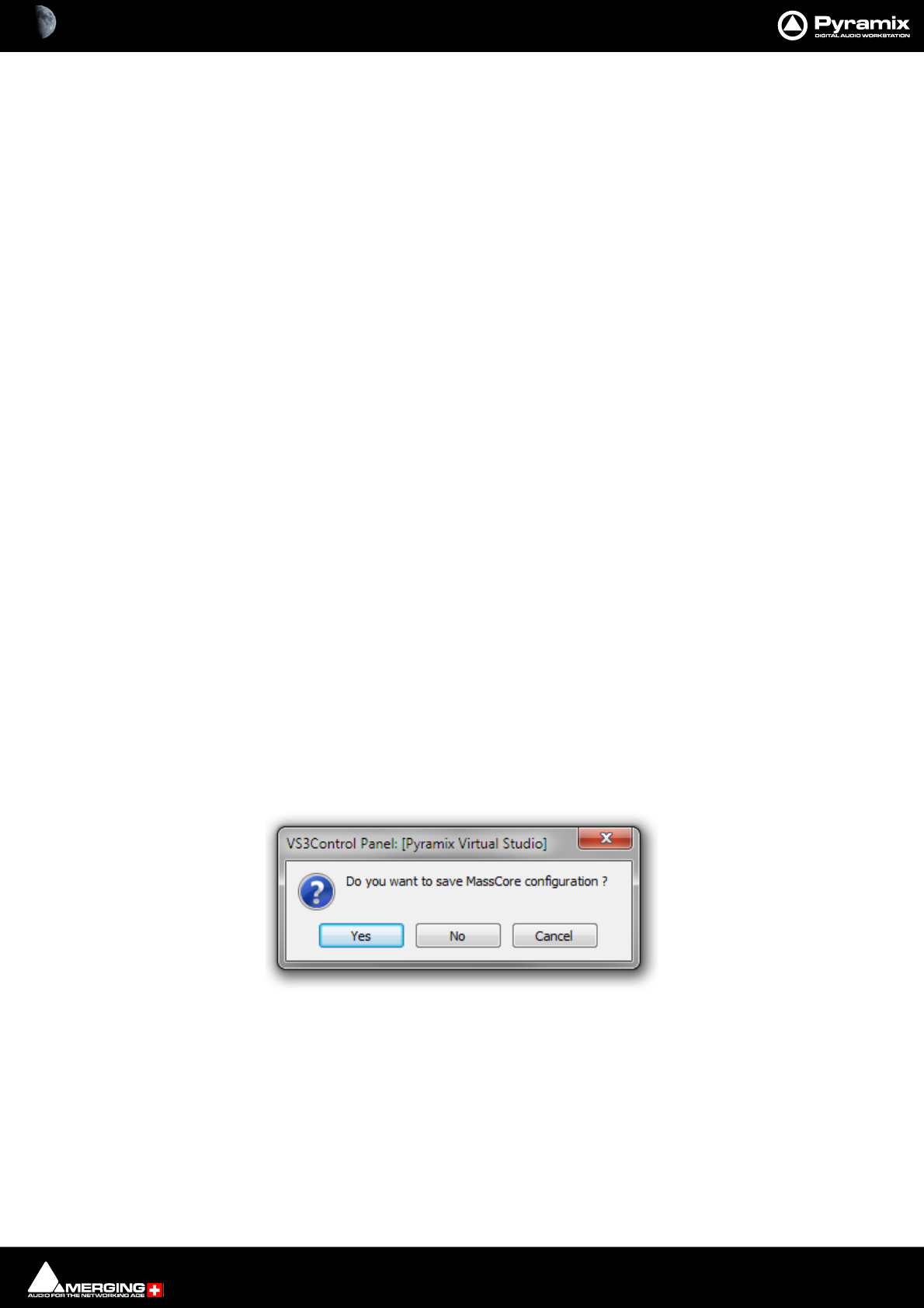
Appendices : Appendix II VS3 Control Panel 31 - 795
Info
This section shows the following information when ASIO is the selected Platform.
Sample Rate: Shows the Sample Rate the selected interface is operating at.
Inputs: Shows the number of Inputs available on the selected ASIO device.
Outputs: Shows the number of Outputs available on the selected ASIO device.
Buffer Size: Shows the Buffer Size set for the selected ASIO device.
Hardware
All Horus or Hapi units discovered on the RAVENNA network are shown here with check-boxes which determine if
they are On Bus (I.e. will be used), for the selected application and will be used for Video/TC.
Audio Bridge
The Audio Bridge is the mechanism used by Pyramix to accommodate ASIO and Rewire applications into the
Pyramix mixer.
Audio Bridge
The radio buttons offer the choice of
Disable Audio Bridge disabled.
ASIO Device Mode (to create a virtual ASIO Device in the system).
Secondary Audio Device Host Mode Secondary Audio Device
(To connect to an existing Audio Device in the system as a secondary I/O)
Rewire Mixer Mode
Number of Channels
The drop-down list offers the choice of how many channels will be dedicated to ASIO or Rewire.
Please see also: Rewire on page 289, Secondary Audio Device Host Mode on page 286 and ASIO Device
Mode on page 285.
Saving Settings
If you change any settings for a given application then clicking on Apply opens the Save MassCore Configura-
tion dialog :
Click on Yes to save.
VS3Control Panel Save MassCore Configuration dialog

Appendices : Appendix III Optional Features 31 - 796
Appendix III Optional Features
Pyramix DSD / DXD / SACD
Pyramix v10 and v11support 64 IO of DXD/DSD64/DXD128/DSD256.
Note: This only applies to 8FS/DXD or DSD. 1FS capability is still 384 Live I/O (768 simultaneous).
Requirements:
• Pyramix v10 or v11
• A Merging Technologies Turnkey System running Windows 7 Professional 64-bit
•MassCore 256 + Key
• System configuration based on Intel Core i7-4790 or above
• SSD required (Recommended 4 x SSD Crucial® M550 disks configured in Raid 0 / 64k block size) or 4x Cru-
cial® MX200 1TB 2.5” SSD in Raid 0 / 64k or SSD-SAMSUNG MZ1000 available on Merging price list)
•MassCore must be set to Low latency mode
• Record in single media (not one file per track)
• For better performance disable Waveform Generation while recording
•Use a Windows 7 Basic Theme (avoid Windows 7 Aero)
Note: DSD256 or DSD128 (DSDIFF) in a DXD project requires a lot of resources therefore the
number of I/Os may need to be reduced in such a missmatched format Record scenario. For Edit-
ing please be aware that edits such as CrossFade require twice the processing resources, so Track
counts must be divided by two in such a case. Crossfading a Media file with itself is not recom-
mended.
Merging Technologies Horus
Merging Technologies Horus is the ideal solution to DSD and DXD interfacing.
The tables below shows the capabilities you can expect:
For complete information about Horus please see its own documentation and for full information about DSD /
DXD and SACD please see the forthcoming DSD / DXD / SACD Guide.
Note: Recording DXD using the Horus / Hapi A to D converters in DSD is very intensive in CPU
processing with AD in DSD. In such a scenario MassCore SMP users may need to allocate more
Cores to Windows than to MassCore (e.g. 6 Windows and 2 MassCore).
MEDIA
(single media)
Playback*
& Outputs Record
Playback*
& Outputs Record
Playback*
& Outputs Record
Playback*
& Outputs Record
DXD 64 Tracks
& Outputs 64 inputs NA NA NA NA NA NA
DSD64 64 Tracks
& Outputs 64 inputs 64 Tracks
& Outputs 64 inputs NA NA NA NA
DSD128 48 Tracks***
& Outputs 48 inputs NA NA 64 Tracks
& Outputs 64 inputs NA NA
DSD256 32 Tracks***
& Outputs 32 inputs ** NA NA NA NA 64 Tracks
& Outputs 64 inputs
Project DXD Project DSD64 Project DSD128 Project DSD256
Merging RAVENNA MassCore - DXD/DSD Specifications
(Requires Pyramix v10 and above, with 4xSSD in RAID 0, Windows 7 Basic Theme and a Merging Turnkey i7 4790 or better.)
* Projects have no tracks limitation, the specified playback track value is based on the tracks containing media.
*** Playback track count without Edits (such as crossfades). When editing with Crossfades performance can reduce significantly and stalls may
occur, we recommend not crossfading between the same media source and if performance cannot be sustained to convert your medias to DXD
during the editing work, you could consider relinking to the DSD256 medias for the final processing.
** Requires optimal configuration (turnkey) with MassCore SMP (benchmarks were performed in Hyperthreaded mode
with a 4 Core s to MassCore and 4 cores to Windows repartition)

Appendices : Appendix III Optional Features 31 - 797
ASIO
For details of the capabilities you can expect when using the Merging Technologies RAVENNA ASIO / Core Audio
Driver please see:
http://www.merging.com/uploads/assets/Installers/ravenna/ASIO/Merging%20Ravenna%20ASIO%20Guide.pdf
RAVENNA ASIO Driver overview is available here:
http://www.merging.com/products/networked-audio/for-3rd-party-daw
Wordclock settings.
In DSD mode it is imperative Pyramix wordclock settings correspond with the requirements of the converters
employed. To date all the DSD compatible converters we have tested generate and expect wordclock at the stan-
dard nominal rate. I.e. 44.1kHz.
Failure to set Pyramix to expect only 44.1kHz in DSD operation will prevent proper locking to the external source
and therefore prevent correct decoding of the DSD bitstreams, resulting in very loud noise on its outputs. Check
the setting via:
Settings > All Settings > Formats & Sync
make sure that the "Wordclock is Input at 44.1k x 2" check-box is NOT checked when operating in DSD mode.
To verify Pyramix is correctly locked to incoming Word clock:
Left-click on the red 'LED' in the Sync: WordClock box (bottom right of Pyramix screen in the status bar). This will
open the I/O status window The green LEDs indicate active inputs and there will be a red LED in front of the cho-
sen sync source if this is locked.
Right-click on the same (Sync: WordClock) red 'LED'. Select, Debug > Input Check. This window will enable you
to check that Pyramix is effectively locked at the correct frequency.
Project Types
DXD versus DXD Mixing
In principle both modes will produce essentially the same results in the resultant file.
The subtle differences occur only in the way in which signals are managed in the Pyramix mix engine, in particular
when displaying the Peak or VU meters, as well as in certain plugins, especially in the side chain of Dynamic Pro-
cessing. In 352.8 kHz mode, no filtering is applied above 20 kHz while a gentle low-pass filtering will be applied in
DXD mode to avoid being affected by possible High Frequency noise that could be contained in the source mate-
rial (either by conversion from DSD source material or A/D converters presenting significant levels of High Fre-
quency noise due to their Sigma-Delta Noise shaping topology.
So, Merging recommends operating by default in DXD mode, unless one specifically wants to assess how much
energy (inaudible) is present in the signals above 20 kHz.
When using exclusively DXD material originating from Horus or Hapi AD8P or AD8DP converters (which exhibit
ultra-flat noise up to and beyond 100 kHz) there should be very little difference between modes.
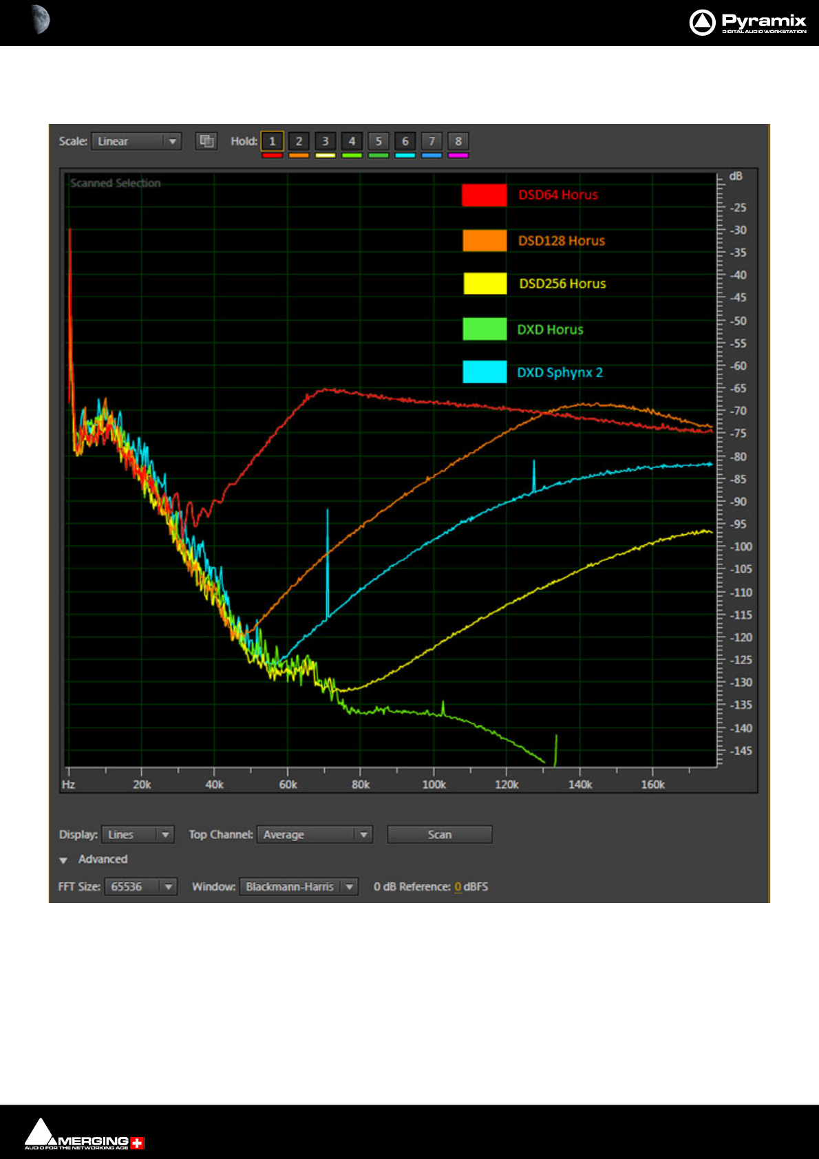
Appendices : Appendix III Optional Features 31 - 798
The following plots of different source material show the importance of such filtering:
FFT Plot - All
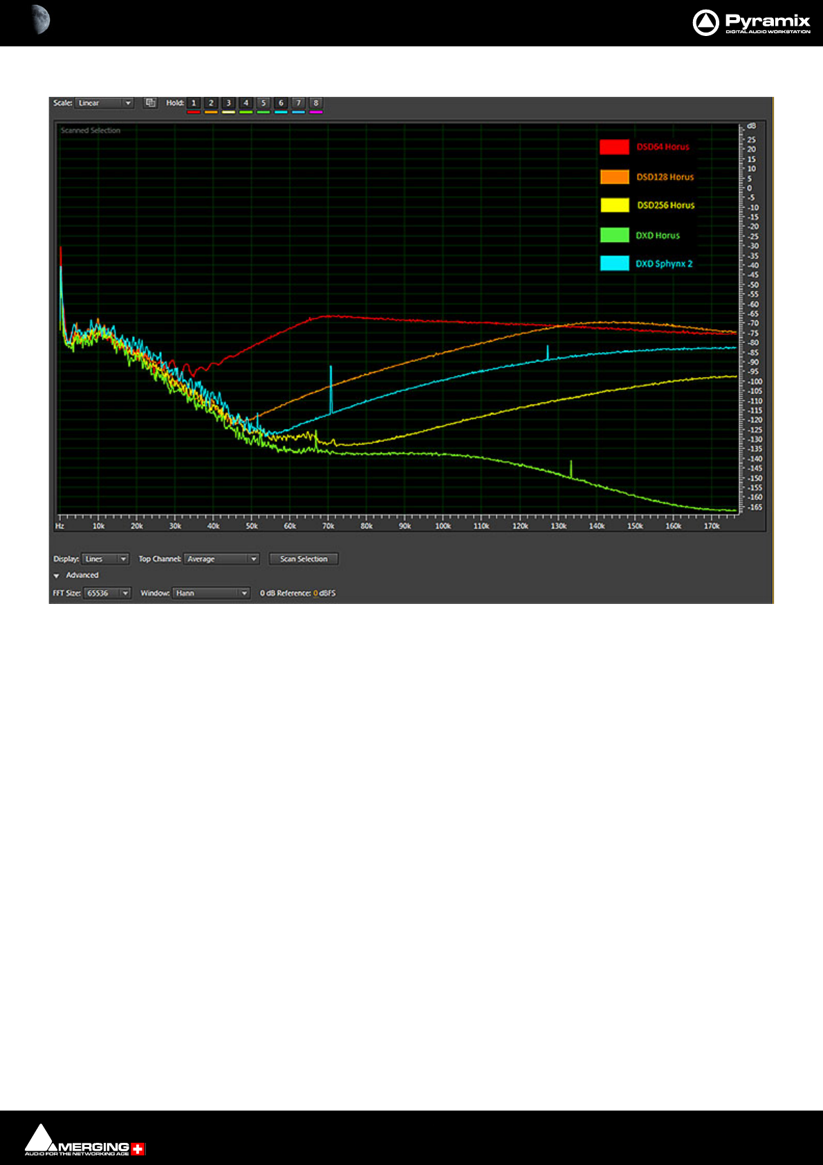
Appendices : Appendix III Optional Features 31 - 799
FFT Plot - All Linear Hann
Appendices : Appendix III Optional Features 31 - 800
DXD Mixing Project
The DXD Mixing Project can be used use for recording, editing, mixing, processing and mastering DSD/SACD in
DXD format (352.8 kHz - 32 bits).
Opening a DXD Mixing Project
When an existing DXD Mixing Project is opened this dialog appears:
Would you like to convert this DXD Mixing Project into a DSD only Project?
If the answer is YES the project will be opened in DSD mode and the DXD mixer will be replaced by a default
mono mix 8x8.
FFT Plot - Log Hann
Convert DXD Project to DSD Project mode? dialog
Appendices : Appendix III Optional Features 31 - 801
If the answer is NO the project will be opened in DXD Mixing mode with the DXD Mixer in the same configuration
as it was when the Project was Saved.
DSD Project
The DSD Project - can be used recording, editing and mastering DSD/SACD in DSD format (2.8 MHz - 1 bit) Project
for recording, editing and mastering DSD/SACD in DSD format (2.8 MHz - 1 bit
Opening a DSD Project
When an existing DSD Project is opened this dialog appears:)
Would you like to convert this DSD Project into a DXD Mixing Project ?
If the answer is YES the project will be opened in DXD Mixing mode. (Though all your media files will remain in
DSD IFF format)
If the answer is NO the project will be opened in DSD mode as it was when created.
Peak Values in DSD and DSDIFF Media Files
Peak Computations
For DXD audio media, the peak displayed in the media Properties page is computed from the audio without a
[20..20kHz] filter.
For DSD audio media (DSDIFF), the peak displayed in the media Properties page is computed from the audio after
a [20..20kHz] filter.
This could change the behavior of Auto-scale Waveform and Normalize.
For example:
A DXD file generated from a 1kHz sine @-10dB -> peak = -10dB
A DSDIFF file generated from a 1kHz sine @-10dB -> peak = -9.9dB
Convert DSD Project to DXD Mixing Project mode? dialog
Appendices : Appendix III Optional Features 31 - 802
MTDSD Converter
A stand alone DSD converter application is installed with Pyramix.
You will find it in Start > All Programs > Merging Technologies > Pyramix.
The input file format can be 8FS, DXD or DSD. The output file type is chosen from the select a file type. drop-down
list.Sampling rate is selected from the select a sampling rate. drop-down list such as DSD64, DSD128 or DSD256.
•DFF = DSDIFF
• All formats support up to DSD256 except WSD (DSD 64 and DSD128 supported).
• Edited masters can only be DSDIFF (Stereo, 5.0 or 5.1).
• DSDIFF can support up to 64 channels
•DSF supports 1 to 6 channels.
•WSD is limited to 256.
•MTFF supports up to 6 channels with specified channel mapping as a Digital Release (TOC included). Other-
wise, as regular media support is up to 256 channels.
MTDSD Converter user interface
Appendices : Appendix IV 9-Pin connection 31 - 803
Appendix IV 9-Pin connection
PC RS-232 Serial Port to External Sony P2 RS-422 Controller
The RS-232 ports of a standard PC are slightly different from the RS-422 format used for the Sony P2 protocol. We
recommend the use of an external RS-232/RS-422 adapter. One example is the USB Sync option which can be
ordered from your Merging sales partner.
Connecting an RS422 device using a direct cable
(without RS-232 / RS-422 adapter)
For emergency use and for short distances, a direct cable may be used. However, Merging Technologies does not
guarantee the correct function of an external controller if this cable is used. Different cables are required depend-
ing on whether Pyramix is controlled by a master device or is controlling a slave device.
Direct Cable for a Master Device
This pinout should work in most of the cases where Pyramix is controlled by a Master device (check on your con-
troller if the RS422 connector has to be male or female). It has been tested with various mixers such as Sony DMX-
R100, Soundcraft Spirit, Soundtracs DPC II and DS3, and various other Sony P2 protocol capable controllers:
The RS422 standard is not implemented consistently on all devices, so the cable pinouts may differ. Please consult
your controller's user guide for appropriate connector cabling.
Function
GND
Pin #
1
Function
DCD/RLSD
Rx
Tx
DTR
GND
DSR
RTS
CTS
RI
2
3
4
5
6
7
8
9
Rcv -
Xmit +
GND
N.C.
GND
Rcv +
Xmit -
GND
Shield Shield
Pin #
1
2
3
4
5
6
7
8
9
RS422 Male (or Female) DB9 RS232 Female DB9
RS422 DIrect Cable for Master Device pinouts
Appendices : Appendix IV 9-Pin connection 31 - 804
Direct Cable for a Slave Device
This pinout should work in most of the cases where Pyramix is controlling a Slave device.
The RS422 standard is not implemented consistently on all devices, so the cable pinouts may differ. Please consult
your controller's user guide for appropriate connector cabling.
Function
GND
Pin #
1
2
3
4
5
6
7
8
9
Rcv -
Xmit +
GND
N.C.
GND
Rcv +
Xmit -
GND
Shield
Function
DCD/RLSD
Rx
Tx
DTR
GND
DSR
RTS
CTS
RI
Shield
Pin #
1
2
3
4
5
6
7
8
9
RS422 Male (or Female) DB9RS232 Female DB9
RS422 DIrect Cable for Slave Device pinouts
Appendices : Appendix V - Network Connections 31 - 805
Appendix V - Network Connections
Note: Direct Ethernet connection of Workstations (i.e.: 1x VCube and 1x Pyramix) with stan-
dard factory default DHCP settings and without a proper DHCP server available in the net-
work may lead to unexpected behavior, E.g. software or system freezes. (ISIS controller will
default to a fixed IP address, if no DHCP server is available).
At all times proper, individual, TCP-IP addresses for each machine, assigned either automati-
cally (DHCP, if available) or manually (Fixed IP) are required, as described below.
This caution is not relevant for machines operating without network connection.
Ethernet Connection & Settings
1. Create an Ethernet connection between the machines, via an Ethernet switch or using a direct, cross-wired,
Ethernet cable. (100Mbit for Sync/Control, 1000Mbit for file sharing recommended)
2. If, on your existing network, an Admin DHCP server is giving TCP/IP addresses to all connected clients, leave
all Pyramix, Isis and VCube machines with the default "DHCP" settings ("Obtain IP address automatically" in
the Local Area Connection Properties / Internet Protocol (TCP/IP) properties. (If you are connected to an exist-
ing network with no active DHCP server, please contact the (human) server administrator to obtain a range of
available IP address from him, and enter these as shown below).
3. If no admin DHCP server is available, manually give each of your machines a unique TCP/IP number, in the
Local Area Connection Properties / Internet Protocol (TCP/IP) properties. Typically, IP addresses can be,
respectively: 192.168.0.3 (PMX) 192.168.0.4 (VCube) and 192.168.0.5 (Isis), with a common Subnet mask being
255.255.255.0. No default gateway is necessary.
Set-up for Pyramix & VCube in: Control Panel > Network Connections > Local Area Connection > Proper-
ties / Internet Protocol TCP/IP / Properties.
Set-up for Isis: Press STOP key for 5 seconds during power up. Set-up address with left/right cursor and Track
keys 1 to 10, then Set key. See also ISIS User Manual page 14.
Fixed IP address range, examples:
*Use an address from column A or B, then stick to the selected range for all machines connected on a single
network.
Set subnet mask to 255.255.255.0
Checking IP Configuration
To check the IP Configuration of the machine you are working on do the following:
Open a Command Prompt window. (Start > All programs > Accessories > Command Prompt) then type in
the following command:
Choice A* Choice B* Typical use
192.168.0.1 10.0.0.1 Usually reserved (for Gateway or Server)
192.168.0.2 10.0.0.2 Usually reserved
192.168.0.3 10.0.0.3 Pyramix A
192.168.0.4 10.0.0.4 VCube A
192.168.0.5 10.0.0.5 ISIS A
192.168.0.6 10.0.0.6 Pyramix B
192.168.0.7 10.0.0.7 VCube B
192.168.0.8 10.0.0.8 ISIS B
192.168.0.9 10.0.0.9 Pyramix C
etc. etc. Increase only right-most number (up to 254)
Appendices : Appendix V - Network Connections 31 - 806
IPCONFIG followed by Enter. The IP configuration for the machine will be shown like this:
Checking Network Connections
Using “Ping”
To check that the connections you have set up are operational do the following:
Open a Command Prompt window. (Start > All programs > Accessories > Command Prompt) then type in
the following command:
PING 192.168.0.3 (or whatever TCP/IP address is currently assigned to the workstation or device you wish to
check) followed by Enter then wait for the machine to reply. Repeat the process for all other connected work-
stations / controllers.
Using Windows Explorer
In a Windows Explorer window, right-click on My Network Places and choose Explore > Entire Network /
Microsoft Windows Network / Workgroup or Domain (choose whichever is appropriate) then verify that all
Pyramix and VCube workstations can search/see each other on the network, including shared hard drives and
folders. (Having all machines in the same “Workgroup” (default workgroup is “WORKGROUP”) helps.
Note: It may take some time for the TCP/IP lists to be appropriately updated to reflect the
complete network topology on all machines. (Particularly when additional computers are
added to a large existing network). Please allow for time for these operations to be properly
carried out in the background. It may in fact take something like 10 to 50 minutes depend-
ing on the size of the network. (In certain situations, E.g. a small 2 machine peer-to-peer net-
work, rebooting both machines may speed up the process).
Command Prompt Window with IPCONFIG

Appendices : Appendix V - Network Connections 31 - 807
Synchronization with Virtual Transport 2
Synchronization is automatic between Pyramix and VCube(s) listed and connected in Settings > All Settings
> Remote Control > Virtual Transport.
Note: For proper synchronization between Pyramix and VCube in a non MassCore Native mode
PyraCube the ASIO buffer size of the ASIO device should be set to 256 samples. If this is not pos-
sible for the ASIO device then switch the VCube configuration from Platform Native - ASIO to
No VS3/ASIO audio in the VS3 Control Panel. In this case, synchronization between Pyramix and
VCube may take longer, but will work.
Appendices : Appendix VI - Pyramix iXML Implementation 31 - 808
Appendix VI - Pyramix iXML Implementation
Key: O = Supported X=Not Supported
VENDOR Merging Technologies DATE 21.03.2006
MODEL Pyramix Virtual Studio
V
ERSION 5
IXML MASTER TAG IXML SUB TAGS WRITTEN READ REMARKS
<PROJECT> X X
<SCENE> O O
<TAKE> O O
<TAPE> O O
<CIRCLED> X X
<FILE_UID> O O BWF like Originator Reference
<UBITS> X O
<NOTE> O O
<BEXT> O O
<USER>
X
X
<SPEED> X X
<SPEED> <NOTE> X X
<SPEED> <MASTER_SPEED> X X
<SPEED> <CURRENT_SPEED> X X
<SPEED> <TIMECODE_FLAG> X X
<SPEED> <TIMECODE_RATE>
X
X
<SYNC_POINT_LIST> X X
<SYNC_POINT> <SYNC_POINT_TYPE> X X
<SYNC_POINT> <SYNC_POINT_FUNCTION> X X
<SYNC_POINT> <SYNC_POINT_COMMENT> X X
<SYNC_POINT> <SYNC_POINT_LOW> X X
<SYNC_POINT> <SYNC_POINT_HIGH> X X
<SYNC_POINT> <SYNC_POINT_EVENT_DURATION>
X
X
<HISTORY> X X
<HISTORY> <ORIGINAL_FILENAME> X X
<HISTORY> <PARENT_FILENAME> X X
<HISTORY> <PARENT_UID>
X
X
<FILE_SET> O O
<FILE_SET> <TOTAL_FILES> O O
<FILE_SET> <FAMILY_UID> O O BWF like Originator Reference
<FILE_SET> <FAMILY_NAME> O O
<FILE_SET> <FILE_SET_INDEX> O O
<TRACK_LIST> O O
<TRACK_LIST> <TRACK_COUNT> O O
<TRACK> <CHANNEL_INDEX> O O
<TRACK> <INTERLEAVE_INDEX> O O
<TRACK> <NAME> O O
<TRACK> <FUNCTION> O O
XML Encoding UTF-8 O O
BWF Mono O O up to 128 channels
BWF Poly O O up to 128 channels
BWF Dual Poly O O up to 128 channels
NOTES:

32 - 809
www.merging.com/Pyramix
USER MANUAL
Index

Index 32 - 810
Numerics
2,3 and 4 Point Edits 198
3D Room Editor 264
3DConnexion 263
9-pin (Sony P2 protocol) 569
Color Framing 569
9-pin Configuration (Pyramix controlled by external device)
585
9-pin Control of External Machine 569
9-Pin Controller/Synchronizer Explained 573
9-Pin Machine Monitoring Options 770
A
AAC 478
AAF 485
Export 491
Import 486
Absolute Sources in EDL View 194, 759
Absolute Time 759
AC3 encoded files 520
Active Machine 580
Add Bars 127, 648
Adding Strips 277
Adding Tracks to a Selected Region 179
ADM - Audio Definition Module 521
Advanced Query 50
AES-31 493
Akai DD / DR 492
Album Publishing 616, 638
Cover Artwork 628
Digital Release 616
Encoding Process 626
Exported Metadata 632
Log File 633
Output Formats 621
Properties 620
Album Publishing Application - Standalone 629
Algorithmix 383
Allow chasing across midnight 752
Alternate Backup 745
Alternate Time Scale Bar 122
Alternate TimeCode Ruler Toolbar 131
Aneman 26
Angel Class Dynamic Processors 381
Angudion 352
AnguDion II 353
Annex D.3 Verification 69
Apple Macintosh, File interchange 479
Apply default fade at fade creation 747
Archiving
Metadata 441
Metadata Fields 443
Metadata Tab Window 441
Render with Metadata 443
Archiving Metadata 441
Archiving Projects 448
Arithmetic Timecode Entry 32
ASIO
Virtual 284
ASIO Device Mode 285
Audio Bridge 284, 795
Audio current sample rate & sync source 29
Audio Engine Drops Warning 782
Audio Import Options 483
Audio Network Manager 26
Audio Tracks 99
Audition after Nudge settings 747
Audition Play 46
Auto Cross-fade 33, 741, 747
By Default 180
Mode 180
Auto Deglitching 33, 176, 749
Auto Edit 579
Auto Gain Compensation 344
Auto Jog on move 141
Auto Return 128
Auto Silence Removal 192
Auto-chase 520, 580
Autoconforming 168
Auto-mapping 584
Automatic CD Markers 600
Automatic Delay Compensation 269, 432, 436, 454
Automation 400
Actions and Modifiers 415
Auto-Release Options 421
Bus and VCA Group Tracks 110
Check Source/Destination settings 422, 763
Cursors 415
Curve Colors 409, 415
Editing and Automation 414
Editing Data 415
Fader Alignment with bus 401
Filter Automation Tracks to Snapshot Dialog 418
Filter Automation Tracks to Snapshot Dialog Options 419
Hide Empty Tracks 411
in editing and libraries 422
Link to Media Content 676
Menu Editing options 417
Modes 402
Off 143
Opening projects with existing automation 409
Play 143
Preview Mode 408
Preview Mode Options 422
Preview mode Popup Snapshot window on Stop 422
Sub-Tracks 108
Track Versions 413
Tracks 108
Tracks Versions 413
TrackTrim 412
Trim Mode Notes 403
VCA Follow Masters 414

Index 32 - 811
VS3 Effects 406
Write 143
Automation Menu 702
Automation Modes
Auto-Write 404
Isolate 404
Read 404
Write 404
Automation Settings 421
Auto-Monitoring 750
Auto-Mount Media 56, 701
AutoPunch Mode 150
AutoPunch Ready enable/disable 104
Auto-Release Options 421
Auto-Ripple 182
Auto-Saving 744
Auto-Scale Individual Waveform 680
Auto-Scale Visible Waveform 680
Aux Send Bus Channels 297
Aux Send Buses 297
AUX Send Buses In-Place Panning 300
Aux Send Routing 299
Aux v Mix-group 209
B
Background Recorders 150
Multitrack Recording 151
Settings 764
Set-up and Operation 151
Backward Compatibility 40
Bars & Beats 645
Ruler Toolbar 648
Settings 646
Bars & Beats Ruler Toolbar 131
Bars & Beats Scale Ruler 126
Basic Strip 302
Bios 782
Bit-Depth 739
Broadcast WAV file Tips 476
Burning a CD-R 640
Bus + - Pop-up Menus 217
Bus and VCA Group Automation Tracks 110
Bus Architecture and Panning 208
Bus Reassignment on Paste 703
Bus Returns
Recording 271
Bus Tools 432
Bus Tools Sections 433
Bus Trim 228
Buses 226
Aux Send 297
Mix 293
Multiple Mix 295
Repro button 293
Subgroup 297
Surround 295
Buttons 221, 302
BWF 475, 737
Bypass all Effects 344
C
CD
Album 602
Burning a CD-R 640
CD Text and optical drives 640
CD Text Notes 635
CD Writer drivers 640
CD-Text 607
Convert Text Markers to CD 601
Cue Sheet Compatibility 631
DDP Import 611
DiscWrite 634
Target 636
Exporting Projects to CD Image Files 612
Generate CD Image / SACD Edited Master 613, 672
Ghost Track 610
Image File / SACD Edited Master Import 611
Import 493
Online database of track names 496
ISRC 607
Markers 600
Multiple CDs or versions in one Project 610
Player 609
Red-Book Validation 610
Text fields 606
Track Inspector 604
UPC/EAN 603
UPC/EAN code 612
CD/SACD Tab Window Menus 606
CD-R First Steps 600
Cedar Audio Restoration Suite for Pyramix 383
Channel Direct Outputs 224
Chase 143
Settings 752
Chase Mode 579, 752
Hard 580, 752
Soft 580, 752
Vari 580, 752
Chase Synchronizer 573
Check Source/Destination settings 422, 763
Check Sync 148
Checking AC3 encoded files 520
Choose a media folder to mount dialog 61
Clean up Media after recording 741
Cleaning Up Project media 457
Clean-Up Media 56, 701
Clear Media Manager History 62
Clip
Clips and Compositions 170
Clips in a Composition 170
Default start time of captured Clips 759
Display Problems 783
Editing 173

Index 32 - 812
Fade Commands 181
Fade Handles 171
Gain 172
Head 171
Name 172
Properties 173
Red Clips 180
Selection 177
Sync Point 171
Tail 171
Trim Handle 171
Waveform Display 171
Clip Information Only Fields 176
Media Offset 176
Original TimeCode 176
Peak Level 176
Clips Menu 684
Clips, Locating 642
CMX EDL 540
Autoconform 543
EDL 497
Exporting a CMX EDL 498
Format 542
import 540
Variants 541
Codecs 478
Collect Media to current Project Default Folder 56, 701
Composition Information 735
Composition Library 82
Compositions to Libraries 83
Compressed Audio File Formats 478
Configuration 714
Conforming and Reconforming 540
CMX Autoconform 543
CMX EDL
Format 542
CMX EDL import Options 541
Common CMX Variants 541
Reconform from Change EDL 546
Reconforming Using Pyramix for Picture Change Detection
548
Reconforming Using VCube for Picture Change Detection 556
Reconforming With An Existing Change EDL 544
Relink to New Media 565
Consolidate 191
Consolidating Projects 449
Control by another Pyramix using P2 over IP 585
Control by another Pyramix using P2 over RS422 585
Control by External Device 585
Control Menu 92
Control of External Device 569
Control Points 171
Controller
Sony 9 - Pin Protocol Configuration 586, 775
Controller properties 773
Controllers 710
Automatically set offline 581
Controllers Online 143
Controllers Online/Offline 581
Controllers without touch sense 403
Conversion processes 71
Convert 64
Export Masterclips 65
Export XML Description 65
Quick Convert 65
Quick Export 64
Quick Import 64
Reverse 65
Convert Text Markers to CD 601
Converting Projects 450
Copy 188
Copy and Paste 179
Clip 179
Copy Selection or Region to library 178
Copy to Project Default Folder 47
Core 29
Core Load Indicators 36
Core Power Saving 665, 729
Cover Art 638
Cover Artwork 628
Create Quick Mount Libraries 62
Creating and Configuring Mixers 273
Creating Effects Snapshots 423
Creating tracks via paste 97, 668
Crossfade 180
Cue Sheet Export 630
Cue Sheet Printer 505
Cuepoint 493
Cursor & Marks Menu 690
Cursor & Timescale Ruler Toolbars 129
Cursor Toolbar 129
Cursor, Playhead 128
Customizing the User Interface 508
Cut 188
Cut and Join 189
Cut and Ripple 189
Cut and Ripple to Black 189
Cutter 183
D
D (red) in Track Header 104
DAR WAV file import 95
Database
Location 46, 663
Views 47
Databases 45
DC Meter 366
DC Removal 73
DDP 498
DDP Create Checksums file(s) 637
DDP Import 611
Debug Menu 784
Default Database Location 760

Index 32 - 813
Default Library 82
Default Menus 670
Default Mixer 281
Default Projects Location 760
Default Templates Location 760
Delay 221, 302, 350
Delay Comp Mode 252
Delay Compensation 269, 432, 436
Detail 271
Input Strips fed from Internal Return Buses 224
of External Inputs 272
Delay Compensation Policy 730
Delay vs Delay Compensation 271
Delete and Join 189
Delete and Ripple 189
Delete and Ripple to Black 189
Delta 576
Destination Wordlength 74
Detect Picture Change & Reconform 672
Determining Delay Compensation for External Effects Loops
272
Digital Release 613, 616, 617
32 bit Floating Point PCM 618
Digitizing a Tape with Discontinuous TimeCode 518
Digitizing Sessions 166
DIN MIDI 721
Direct Monitoring Input Strips 224
Direct Output 221, 302
Direct Outputs 252
Direct X Plug-ins 394
Disable Mix Down 729
Disable Punch in/out 729
Disable Skin 668
Discontinuous TimeCode 150, 516
DiscWrite 634
Display and Editing of Automation Data 409
Display Blocks 106
Display Envelope 106, 115
Display Waveform 106
Dither 440
Noise shaping order 74, 619
Dither Type 279
Dithering
Noise Shaping order 614
Dithering Window 279
DMA 38
Dolby 479
Dolby Dialnorm™ 472
Don’t Show too Large Media/Compositions 69, 91
Don’t Snap 182
Drag & Drop bypasses Auto-Ripple 747
Drag and Drop and Copy to Project Default Folder 47
Drag and Drop Media Files 46
Dragging Clips into a Composition 179
Drivers 782
DrWatson 787
DSD
Converter 802
File formats 477
Peak Filter 728
Peak Values 801
Project 801
Render 672
DSD / DXD / SACD 796
DSD Media Files in a DXD Project. 750
DSDIFF Peak Values 801
DSP load and latency 29
DSP Time Saving 729
DST Decoder 68
DST Encoder 67
DST Estimator 68
Dual Monitors 32
Dubbing Mode 516, 739
Duplicate Selection 183
DXD
Mixing Project 800
recording from DSD 796
VS3 Plug-ins 341
Dynamic Automation
Levels 401
Dynamic Automation Modes 403
Dynamic Automation V Envelopes 400
Dynamic Waveform 680
Dynamic-Meter 355
Dynamics 348
E
Edit Commands 188
Edit Menu 673
Edit menu 673
Edit Modes Context Menu 182
Edit while Recording 155
Editing 170
Clip & Selection 173
Editing Automation data 415
Editing Context Menu 184
Editing Modes 181
Editing Multitrack Recordings 519
EDL Tab Window 193
Effective Sampling Rate 717
Effective TC Frame Rate 717
Effects
Adding in Mix ! mode 241
Removing, Copying or Moving VS3 Effects and VST Plug-Ins
242
Effects (FX) Rendering Tab Window 396
Effects and Plug-in Automation 369
Effects and Plug-ins 277, 340
Effects Automation 346
Effects Delay indication 272

Index 32 - 814
Effects Rack 454
Effects Snapshots 369, 423
EMC 589
Enable Undo for every Fade Editor Change 747
Envelope 115
Actions and Mdifiers 415
Editing Data 415
Punch 117
Shortcuts 117
Envelope Cursors 115
Eq, Comp/Limiter/Expander 425
EQ-X 370
Error Messages 782
Ethernet Connection & Settings 805
EUCON Control Surfaces 592
European Monitoring 750
Exit 672
Expand / Collapse Horizontal 216
Expand / Collapse Vertical 215
Export 504
Export to a File 445
Export XML Description 65
Exporting Projects to CD Image Files 612
Extend Tracks 689
External Edit
Review Edit 579
External Effects 277, 395
External Effects Inserts 257
External Insert 243, 395
External Machine
Auto Edit 579
Fast Forward 578
Play 578
Preview Edit 579
Properties 769
Record button 579
Rewind 578
External machine
Stop 578
External Machine panel - Features 578
External Machines 520, 569
External Metering 320
F
F.FWD and REW nominal speed ratio 142, 753
Fade Editor 200
Context Menu 203
Faders & Control Section 203
Graphical Display 202
Parameters & Options Section 203
Save Fade 206
Settings 747
Toolbar 200
Undo 202
Undo setting 747
Waveform Color Change 202
Fade Editor Menu 697
Fade handles 171
Fade library location 747
Fade Out 181
Fader 221, 302
Fader Keyboard Shortcuts 210, 221, 302
Fades and Crossfades
Automatic 33
Summary 33
Fast Forward 142, 577
Fast Speed Settings 142, 753
File Conversion 479
File Format and Disk Limitations 148
File Format Conversions 81
File Formats 474
File Interchange 474
File Settings - Record 738
File Size Limitations 148, 474
Fill Selection 189
Film 24 to NTSC Sync 519
Film Feet Ruler Toolbar 131
Film Feet Scale Bar 124
Filter Automation Tracks Dialog 418
Filter Automation Tracks to Snapshot Dialog 419
Filter Type
Apodizing 78, 164, 614
Linear Phase 77, 164, 614
Minimum Phase 78, 164, 614
Final Check
History Graphs 465
Context Menu 465
Individual Meters Setup 469
LIar
Context Menu 465
Loudness Meter 464
LRA Curve 465
Metering Page
Keyboard Shortcuts 461
Peak Programme Meter (PPM) 463
Phase meter 461
Phase Meter Surround 461
Phase Oscilloscope 462
Setup 467
Surround Monitor 462
True Peak Meter 463
Final Check Metering 459
Final Check Window 459
Final Cut Pro XML 499
Fit Selection 189
Fixed Cursor Settings 748
Fixed or Moving Playhead Cursor 128
FIXREEL 543
FLAC 616
FLAC Decoding 478
Flanger 351
Flatten track numbers 740

Index 32 - 815
Flux
Syrah v3 382
Flywheel Inertia 141, 753
Focus + 211
Focus to Timeline 679
Folders
With a conflict 94
With Mounting Rule(s) 94
Foot Type 124
Format - file 738
Free Cursor while chasing 128
Freeze Mode 580
Using 520
Frequencies 717
Full Waveform 680
Function Generator 368
FX Rendering Tab Window 396
Effects Graph 397
Effects Graph Context Menu 398
Filter Graph 398
Processing Mode 396
G
Gain Window 114, 173
Gain window 114
Gate colors 196
Geared Jogging 141, 753
Generate CD Image and Publish Album 617
Generate new Media in the Project Media Folder 735
Generate New Media in their Original Folder 735
Generating Album(s) 632
Ghost Effects and Plug-ins 242
Ghost Track 610
Glitch and Pops finder 452
Glitch finder 452
Global Dynamic Automation Modes 400
Global Libraries 82
Using 83
Global Strip Channel Routing 298
GP Bus Channel Configuration or ‘3D Room’ types 265
GPI/O controller 596
GPI/O Input and Output Pin Configuration 598
GPI/O Remote types 598
Graphic Cards 782
Graphic EQ 347
Green Folders 94
Group Normalize 73
Group Recorded Clips 741
Grouping Clips 172
Groups, VCA 236
H
Half Waveform 106
Half Waveform / Origin 680
Halo Meters 312
Hard Drive Size Limitations 148
Hardware Control Surfaces 584
Head to End 182
Head to Nearest 182
Headroom, Meter Settings 727
Help Menu 712
Hepta Sample Rate Converter. 76, 163
HeptaCon 77
HORUS Preamp Remote Controls 273
Horus/Hapi
LTC I/O Native 724
Housekeeping 663
Performance Tips! 46
HUI 589
I
I/O Assignments 277
I/O Bus Capacity 259
Import 503
Video Clips 503
Importing a CMX EDL 497
Importing Audio Files 163
improper application exit 784
Incorrect Media File in Timeline 93
Increment take number 740
In-Place Aux Panning Source 300
Input Assignment 221, 302
Input Strip Mode 271
Input Strips 220, 277
fed from Internal Return Buses 224
Insert Silence 189
Inserts, External Effects 257
Internal / External Machine panels - Features 575
Internal and External machines links 768
Internal Machine panel - Specific Features 577
Internal Return Buses 235, 259
Introduction 22
IP address range 805
ISIS 584
ISRC 607
iXML 476
J
Jog / Shuttle 141
Jog Sensitivity 141
Jog Shuttle
Auto Jog 141
Jog Speed ceiling 141, 753
Jog Wheel
Settings 141
Jog Wheel Mode 581
Pitch 143
Jog Wheel Sensitivity 141, 753
Jog Wheel Settings 752

Index 32 - 816
Jogging
Geared 141, 753
Jog-Wheel Editing 187
Jog-Wheel Modes 710
K
Keep in default library 740
Keep Mounted Folders 663
Keep only current version while savin 421
Keeping Up To Date 782
Keyboard Shortcuts 509
Knobs 426
L
Latency 29
LC-AAC 616
Length / Pitch, Changing 450
LEQ(A) ? 472
Level Meter 726
Libraries
Closing 83
Default 82
Global 82
Offline / Reference 93
Project 82
Rearranging Columns 57
Relocate 45
Shelves 82
Shelves, deleting 83
Updating 93
User 82
Libraries Tab 52
Library
Conversion of Previous Version (v6.x) 45
Location on disk 45
Library Maintenance 83
Library Menus 86
Library Tab
Context Menu 92
Limit versions to the number of Undo/Redo 421
Linking Functions of External and Internal Machines 573
LKFS 472
Load Change EDL & Reconform 672
Locate 642
Settings 751
Locating Clips 642
Locking Clips 172
Loop Play 143, 577
Loop Recording with simultaneous Playlist Creation 518
Loop Selection 189
Loudness and Peak Metering 472
Loudness Metering Notes 471
LTC IN-OUT for Pyramix Native 724
LTC sync 516
LUFS 472
M
M&S Stereo Strips 223
Machines function linking 768
Machines Menu 705
Macintosh File Interchange 479
Mackie Control 589
Macro Menu 711
Macros 511
Main (Markers and Selected Range) Toolbar 131
Manual Digitizing 167
Markers 133, 140
Auto Select Marker Before Cursor 692
GoTo Marker 133
Media Markers 135
Project 133
Renaming or Deleting in the Tray 133
Tab window 140
Timeline 141
Track Group 134
Markers Menu 693
Markers Project
Filter By Track Groups 134
Tracks Linking 133
MassCore 24
Core Load Indicators 36
Latency Modes 38
Memory 35
No of VST Cores 719
Overload Diagnosis and Cures 38
Settings 719
Windows Boot Choice 35
MassCore & VST Core Allocation 665
Master Automation Transport Controls 400
MasterClip
Properties 80
Masterclips
Export 65, 90
Mastering Peak/Vu Meters 354
Mastering to CD-R 600
Maximum Delay Compensation 270
Media Browser 61
Menu 70
Media Folder Menu 61, 62
Media Folder Syncronization 46
Media Folders Tab 53
Media Information Only Fields 176
Author 177
File Creation Date 177
File Location 177
File Name 177
File Size 177
Format 176
Length 177
Name 176
Notes 177
Original TimeCode 177
Peak 177

Index 32 - 817
Sample Rate 176
Scene 177
Take 177
Tape 177
Tracks 177
UBITS 177
Word Length 177
Media Management 45, 56
Media Management Tab
Context Menu 79
Media Management Tab Menus 61
Media Manager & Library Monitoring 319
Media Manager History 60, 663
Media Markers 135
Contents 136
Custom Markers 139
Display 136
Editing 137
Rate Playback / Record Zone 137
Rate Selected Region 137
Settings 139
Undo 139
Media Menu 56, 701
Media Offset 176
Media option 740
Media reconnection 543
Media Target Settings 46
Media Track Information Only Fields 177
File Name 177
Media Type 739
Menu
Video 704
Menus
Automation 702
Clips 684
Cursor & Marks 690
Default 670
Edit 673
Fade Editor 697
Help 712
Machines 705
Controllers 710
Macro 711
Markers 693
Media 701
Monitor 711
Project 670
Selection 696
Settings 712
Tracks 688
View 679
Window 712
Workspaces 704
Metadata 476
Archiving 441
Fields 443
Tab Window 441
Meter Alignment level 727
Meter Bridge 332
Automation Fader Mode and Group Indicators 338
Configuration 334
General Purpose Buses 332
Global Mute and Solo Indicators 334
Switch 332
Window 333
Meter Decay integration time 727
Meter Headroom setting 727
Meter Permanent Overload 727
Meter Permanent Peak 727
Meters 354
Alignment Tab Settings 357
DSD Settings Tab 359
Global Settings and Presets 356
Peak Hold and Overload Reset 304
Priority Settings Tab 359
Scale Tab Settings 358
Strip 304
Timing Tab Settings 357
Metronome 647
Metronome Settings... 127, 647
MIDI
DIN 721
MIDI Files Import / Export 126, 646
MIDI Sync 721
Mix ! 210
Mix Bus 293
Mixdown 445
Disable 665
Loudness and True peak Limiting 446
non real-time 448
SRC 446
Mixer
211
Bus Architecture and Panning 208
Buses 226
Colors 245
Components 220
Configuration from the Mix! page 248
Configure
Strip and Bus operations 250, 253
Controls 210
Legacy Buses, Converting 293
M&S Stereo Strips 223
Multiple Strip Selection and Operations 247
Organize Page 260
Pages 210
Rearranging Strips 248
Sharing 290
Static Channel Routing 299
Strip Pop-up Menus 212
VCA Groups 236
Mixer and Plug-in Snapshots 423
Mixer Configuration Further Options 278
Mixer Configuration Summaries 252
Mixer Configure 277
Mixer Context Pop-up menu 278

Index 32 - 818
Mixer error
Delay compensation 270
Mixer Pages 273
Mixer Presets 281
Mixer Settings 730
Mixer Snapshots 423
Recalling 423
Saving 423
Mixer Surround Components 281
Mixing Down Projects 445
Modulometer 366
Monitor
Adding an External Machine 321
Available Sets 316
Buses / Externals button 312
Dim Value 317
External Inputs 320
Halo Meters 312
Hardware Control 311
Max Volume 316
Output Patch 318
Reference Volume 317
Talkback 322
Talkback Page 323
Monitor ! 311
Monitor Configure page 315
Monitor Menu 711
Mono Mix 293
Motherboards 782
Mount Media Folder 61
Mount Referenced Media 56, 701
Mounting Media Folders / Drives 163
Mounting Rules 62, 94
Mouse Modifier Keys 790
Mouse Scrubbing Settings 141, 753
MP3 478
MP3-ABR 616
MP4 478
MPEG-H 521, 523
MPEX4 457
Properties 72
Timestretch and pitch change 384
MS Encoder 352
MT ASIO Bridge 719
MT Hepta SRC module Properties 77
MTDSD Converter 802
MTFF 477, 616
MTInterchange Import/Export 87
Multi-channel Audio Files 783
Multi-Channel Track Control Grouping 103
Multi-channel VST Plug-ins 388
MultiFileFixer 783
Multiple CDs or versions in one Project 610
Multiple Mix Buses (Stems) 295
Multiple Stereo Mix 293
Multiple Surround Mix 295
Multi-track Editing 515
MXF 479
N
Native
Sampling Rate 148
Navigation 121
Network Adapters 782
Network Connections 805
Network manager 26
Network Recording - setting if problematic 738
Networked Audio Interface TimeCode Setup 723
New Project 40
Noise Shaping 74, 280
Non Real-time Mixdown 448
Normalize 190
according to the selection peak 191
Normalize Properties 73
Notes Tab Window 31
Nudge 28
Nudge settings 746
O
OASIS Protocol 590
Object Based Audio Workflow 521
Offline / Reference Libraries 93
Ogg Vorbis 616
OMF 499
Import Settings 500
Mounting Rules 500
Open Folder 62
Operating System 782
Optical Drive drivers 640
Optional Plug-ins 370
Original Timecode 176
orphaned media 83
Output assignment shown in orange 318
Output Metering Patch - External Meters 316
Overview 146
Overwrite 182
P
Panning Control Bus Window 262
PanNoir Panner 372
Parametric EQ 346
Paste 188
Paste & Place 188
Paste and Ripple 189
Paste Sync Point to Cursor 188
Paste Tail to Cursor 188
Paste to Cursor 188
Paste to Mouse 179, 188
Paste to Original TimeCode 189
Paste to Selection 189

Index 32 - 819
PDF (Probability Density Function) 279
Peak and Overload Hold Time 727
Peak level indicator 727
Peak Logger 282
Peak Meter in Track Header 105
Peak/Vu Meters 354
Peak-Meter 355
Pencil 456
Pencil Tool 456
Permanent Mount 61
Permanently Mounted Media Folders 761
Phase Invert 176
Phase-Oscillo 362
Ping 806
Place 79
Place in VCube - Notes 447
Place on new tracks 740
Placement Tool 195
Platform 794
Play 108, 142, 149, 577
Play Head Position 128
Play Special 706
Playback Buffer Meter 28
Playback Lookahead Buffer setting 749
Playback Stall indication 749
Playback Stalls Warning 783
Player/Recorder Mode 515, 665
Playhead Cursor 128
Playhead Cursor Options 128
Playlist 105
Playlist Button 644
Playlists 643, 741
Playlists Tab Window 643
Plug-in and Effects Automation 369
Plug-Ins
adding in Mix ! mode 241
Ghost 242
Settings 731
VST 241
Plug-ins
adding in Mixer Configure page 255
Plug-Ins and Effects 240, 340
PMF 475
Position/Speaker Control 307
Post Processing 740
POW-r 280
PQ Markers 604
Pre/Post Roll Settings 748
Pre-Anticipation 432, 438
Preview Mode Options 422
Process Plug-ins 452
Profiling Window 785
Program and Project Settings 714
Program Window 27
Project
Files 40
Interchange 480
Libraries 82
Media Folder 735
Menu 670
New 40
Notes 457
Project Editing Panel 29
Project Management Panel 29
Project Window 28
Project mounted Media Folders 735
Prompt for name after recording 149
Properties 62
Prosoniq 384
MPEX4 457
Properties 72
Punch Envelope 117
Punch in / Punch Out - Disable 665
Pure Series plug-ins 382
PyraCube 568
Pyramix and VCube 515, 568
Pyramix audio file format 148
Pyramix Busy Warning 29, 782
Pyramix Guides 24
Pyramix Virtual Studio Overview 25
Q
Query Database 496
Query Tab 49
Quick Convert 65, 70, 71
Quick Export 64
Quick Import 64
Quicktime 476
Quiet if creation failed 740
R
RAID 782
Real-time Sampling Rate Conversion 750
Reconform 544
Reconforming a Project 450
Reconforming to Original Media from Avid &/or OMF 517
Record
Block Size 749
Name 149, 740
Source Before or After Effects 149
Record button 142, 577
Record File Settings 738
Record Mode
Safety 150
Record Punch In (Auto) 108, 149
Record Ready (Manual) 108, 149
Record Stalls Warning 783
Recorders, Background 150
Recording Audio into a Pyramix Virtual Studio Project 148
Recording Bus Returns 271

Index 32 - 820
Recording DXD using the Horus / Hapi A to D converters in
DSD 796
Recording from a Tape with Discontinuous TimeCode 150
Recording Status 156
Recursive mount 61
Red Folders 94
Redirect Timeline Play and shortcuts to Fade Editor 747
Refresh Media Folder 62
Region Selection 178
Regions 83
Regions and Compositions to Libraries 83
Rel. box 114
Relative TimeCode Entry 32
Relaunch After Improper Exit 784
Release time 763
Relink to New Media 565, 671
Remote Controllers
Strip Cloning 584
Remove 182
Remove and Ripple 182
Remove Bars 127, 648
Removing Mixer Presets 281
Removing Strips 277
Rename Clips 686
Renaming Clips 174
Render 451
only solo tracks 452
with MetaData 443
ReNOVAtor 457
Reordering Columns 57
Replace 16 bit with 24 bit 671
Replace Selection 189
Report Printer 501
Repro button 293
Request Size (Wave file playback) 739
Resampler Properties 71
Reset Recent Mounted Folders List 62
Resolution 739
Reverse 65, 70, 190
Reverse Play 121
Rewind 142, 577
Rewire 292
Rewire Mixer Mode 289
Rotary Controls 302
Routing Tracks to / from the Mixer 101
Rules for cache file decompression 95
Rules for Wave files 94
Rules for Wave/BWF and AIFF files containing OMF informa-
tion 95
S
SACD
Scarlet Book notes 728
SACD Edited Master - Import 502
SACD Edited Master Import 611
SACD Functions 611
SACD Media Management Menu 67
Annex D.3 Verification 69
DST Decoder 68
DST Estimator 68
DSTEncoder 67
SACD Notes 601
SACD Production Guide 25
SACD Text 607
Safety Record 150, 707
Sample and TC Rate Warnings 717
Sample Rate Conversion 33, 163
Sample Rate Converter 76, 163
Sample Rate Mismatch 170
Samplerate Converter 76
Save Fade 206
Save Special 40
Save X Fade 205
Saving 46, 663
Saving / Loading Mixer Presets 281
Scene & Take 737
Scroll Wheel 145
Scrub
Analog Tape Mode 141
Repeat Loop Mode 141
Search 48
Search Filters 55
Search Media 49, 56, 701
Dialog Tabs 49
Search Results 54
Deleting 54
Secondary Audio Device
Host Mode 286
Reset 718
Secondary Audio Device Bridging
Settings 718
Sel. box 114
Select Media NOT present on Project Default Folder 56, 701
Select Media present on Project Default Folder 56, 701
Select Offline Clips 56, 701
Select Online Clips 56, 701
Selecting a Clip 179
Selecting Automation Modes 404
Selecting, Copying and Moving Effects 256
Selection
adjusting 183
Menu 696
moving 183
Operations 177
splitting 183
Tab Window 175
Track Groups 119
Selection and Clip Modifiable Fields 175
Auto Deglitching 176
Comment 176
Level 176
Mute 176

Index 32 - 821
Name 175
Phase Invert 176
Selections and Region Selections 177
Set Focus to the Timeline 679
Settings 714
Application 743
(File) Location(s) 760
Automation 762
General Settings 743
Time Stretch 766
TimeLine layout 757
Hardware 716
MassCore 719
Mic/Pre Remote 720
MIDI Sync 721
Secondary Audio Device Bridging 718
Mixer 726
Core Power Saving 729
Level Meter 726
Mixer Settings 730
VST Plug-Ins Settings 731
Project 734
Controller Mapping 742
General 734
Record 736
Remote Control
Controller 773
Machine 768
Virtual Transport 2 778
Routing 719
Video 779
Overlays 779
Settings Menu 712
Shelves 82
Shift Order 256
Show Usage 642
Show Used Media 56, 701
Shuttle 141
Shuttle Control 143
Shuttle sensitivity 141, 753
Silent Chasing 752
Silent Jog - sensitivity 141, 753
Simple Query Syntax 50
Skin 756
Slip Clip Mode 180
Slip Media Mode 180
Snap to Original TimeCode 182
Snapshot 143
Snapshot a Selection or Region 178
Snapshot Automation 400
Snapshot Range 143
Snapshot Timeline 178
Solera + 381
Sonic Solutions 502
Sony 9-Pin (P2) Protocol Support Over IP 515
Sony 9-Pin connection 803
Sony P2 Protocol Over IP 569
sound effects libraries 93
Source - Destination Editing 196
Source - Destination environment 196
Source Names - FIXREEL 543
Source-Destination Timescale Ruler Toolba 196
Space Navigator 263
SpaceMouse Pro 263
Speaker Delays 318
Speaker Sets 314, 315
Special Modes 729
Splitting Clips 183
Splitting Clips and Regions 183
Spread 191
SRC Filter Type
Apodizing 619, 623
Linear Phase 619, 623
Minimum Phase 619, 623
Stall Warning 783
Static Channel Routing 299
Static Gain 114
Status Bar 28
stem mixing 295
Stems 295
Input Strip routing 294
Stereo Mix 293
Stereo Pan Law 730
Stereo Panners 303
Stereo Strips 222, 302
Stop 143, 577
Storing and Recalling Mixer Presets 281
Storing New Mixer Presets 281
Stretch 190
Strip & Bus Types 296
Strip and Bus Tools 425
Automation mode switches 436
Display Options 425
Group assignment mode buttons 435
Linking Strip-Tools controls 434
Modules 425
Routing Button Matrix 434
Sections 426
Strip Cloning 584
Strip Meters 304
Characteristics 726
Peak Hold and Overload Reset 304
Strips/Tracks - Synchronized Creation/Deletion 101, 251
SubGroup Buses 297
Supported Controllers Table 584
Surround Components (Mixer) 306
Joystick Panner 306
LFE Level 306
Speaker Controls 306
Stereo Input Strips Surround Panner 306
Strip and Bus Tools 282
Surround Stem select 306
Surround Control 306

Index 32 - 822
Surround Control window 307
Level Meter 308
Link 309
Stereo Surround Control 309
Surround Meter 309
Surround Panning Algorithm 307
Surround Meter 365
Surround Mix - 5.1 294
Surround Post-Processing 385, 450
Sync & Format Preset 717
Synchroniser 573
Synchronized Creation/Deletion of Tracks/Strips 101, 251
T
Tab Windows 30, 653
Binding Tabs Layouts to Shortcut Keys 659
Managing 659
Tail to Beginning 182
Tail to Nearest 182
Take Logger 158
Talkback 322
Example 323
Reset 328
Talk to All 328
Talkback Page 323
Target Settings 449, 737
Tascam Open TL 501
Templates, User 43
Tempo Map 651
Time fit 385
Time Scale Rulers and Toolbars 121
Time Scale Zoom and Pan 145
Time Stretch and Pitch Change for Film Applications 384
Time Stretch Tool
Settings 747
TimeCode
Entry 32
Frame rate and reference source 29
Increment / Decrement UP & DOWN Arrow Buttons 32, 129
Midnight 121, 498, 518, 752
Scale 121
Setup 723
Networked Audio Interface 723
TimeCode over Physical MIDI (MTC) Horus/Hapi 725
TimeLine
layout 757
Timeline
Structure 121
Toggle Stop/Record Safe 706
Tone Control 347
Toolbars 31
Toolbars and Menus 508
Toolbars Layout 508
Track
Add to Track Group 118
Display Height 102
Global 102
Individual Presets 102
Envelope and Static Gain 114
Track and Mixer Muting 664
Track Automation Menu 410
Track Column Fields 112
Always Visible 112
Background Color 113
Collapsed 112
Display Mode 112
Group 112
Hidden 112
Input Connection 112
Monitoring 112
Mute 112
Name 112
Record Ready 112
Recording Media Folder 113
Repro Connection 112
Show Automation 113
Show Peak-Meter 113
Size 113
Solo 112
Waveform Color 113
Track Control Grouping 103
Track Groups 118
Add Tracks 118
adding Tracks 118
Column Fields 118
Auto Collapse 119
Auto Hide 119
Auto Mute 119
Auto Record Ready 119
Auto Solo 119
Collapsed Display 118
Exclusive Show 119
Free Markers 119
Free Zoom 119
Keep Cursor 119
Markers Locked 119
Name 118
No Selection 119
Show Scale 119
Type 118
Markers 134
Tab Window 118
Track Header
red D 104
Track header
Button Grouping 103
Track Header Components 104
Track Height Zoom 102, 145
Track Inspector, CD 604
Track Numbering 97
Track Record Modes 108, 149
Track Types 99
Tracklay Versioning 84
Tracks 97

Index 32 - 823
Adding 97
Changing Repro or Input connections 112
Creating via paste or drag and drop 97, 668
Deleting 101
Feeding Direct Monitoring Input Strips 103
Grouping 100
Making Settings Changes to Multiple Tracks 112
Menu 688
Tab pop-up 111
View 681
Tracks Menu 688
Tracks Tab window 111
Tracks/Strips
Creation/Deletion - Synchronized 101
Synchronize 689
Tracks/Strips - Creation/Deletion - Synchronized 251
Transport Control 121
TimeCode Registers 580
Transport Control Panel 144, 574
Controllers Section 581
Transport Controls 142
Trim Handles 171
Trimmer 59
Select/de-select tracks for playback 59
Trimmer Menu 69, 91
Troubleshooting 787
U
Undo / Redo 744
Undo for every Fade Editor Change 747
Undock Fade Editor when editing a fade 747
Unique filename extension 740
Unmount Media Folder 62
UPC/EAN 603, 612
Update waveform color with cursor position 747
Updating Libraries
Adding new files 93
Orphaned Entries 93
US Monitoring 750
User Libraries 82
User Templates 43
Using Global Libraries 83
V
Vari Speed Audio Quality 142, 753
VB VS3 Plug-ins Maximum Sampling Rates 342
VCA
Coalesce 420
Follow Masters 414
VCA Groups 236
Automation Editing 420
Automation Tracks 110
VCube
and Pyramix 568
Synchronization with Pyramix 807
VCube with Pyramix 515
Versioning 84, 521
Video
Clips 503
Clips Export 504
Delay Compensation 526
Formats 525
Hardware 525
Import Options 483
Menu 704
Recommendations 526
Track 688
Video Wrap
Channel Mapping Warning 536
View Menu 679
View Windows 83
Vincent Burel 383
Virtual Multi-track 513
Virtual Room / Stereo Pan Law 730
Virtual Transport 2 146, 778
VoiCode 376
VS3
Native Effects 241
Plug-ins maximum sampling rates 341
VS3 Control Panel 793
Saving Settings 795
VS3 Effects
Automation 406
Common Components 343
VST
Core Allocation 666
Core Allocation MassCore 665
Ghost Plug-ins 390
Multi-channel plug-in routing 388
Multi-channel plug-ins 388
Plug-in Automated Control Values 393
Plug-in Automation 393
Plug-in Automation Mode 393
Plug-in Caption Bar 389
Plugin clicks 719
Plug-in Processing Delay Display 391
Plug-ins 241, 388
Plug-ins Display Order 391
Plugins Engine MassCore 719
Plug-ins On/Off and Bypass 389
Plug-Ins Settings 731
Plug-ins Without a User Interface 390
Routing 390
Scanner 388
Support 388
VST3 388
VST3 390
VU-Meter 355
VU-Meter controls 356
W
Warnings 782
WAV and BWF 475
WAV Files 783
Wave/BWF file Record Settings 739
Waveform

Index 32 - 824
Generate WHILE/AFTER Recording or None 739
Half / Origin 106
Waveform Display 171, 680
Width control 209
Wildcard search 50
Window Menu 712
Windows 10 23
Word Length 279
Wordlength Converter Properties 74
Wordlength Meter 368
Working with Selections and Ranges 178
Workspaces 661
Menu 704
Tab Window 661
using 668
Wrap in Video 531
Failed Wrap 535
Source Video 532
Wrapped Video 532
X
X Fade 181
Xify 201
XML 504
Y
Your Recording may be at risk 783
Z
Zoom 680
Zooming and Panning the Track display 145
ZTX Pro 75, 386, 453
ZTX Pro Settings 766
Zynaptiq 386

Index 32 - 825