VPET User Guide
VPET_UserGuide
User Manual: Pdf
Open the PDF directly: View PDF ![]() .
.
Page Count: 31

VPET - Documentation - User’s guide 1
developed by
the R&D department
of
Animationsinstitut at Filmakademie Baden-Württemberg

VPET - Documentation - User’s guide VPET - Documentation - User’s guide
2 3
VPET - Virtual Production Editing Tool
Congratulations on employing VPET - an unique, holistic toolset for real-time on-set light, asset and animation editing devel-
oped by the R&D-Department of the Animationsinstitut at Filmakademie Baden-Württemberg.
VPET is a tablet based onset editing application to work within a virtual production environment. It is designed to run on mobile
and head mounted devices, allowing easy access to operators without dedicated training. Additionally, it is designed to be easi-
ly set-up and modied by your technical director, simplifying smooth cooperation and quick exchange for all parties on-set.
This guide will enable you to unlock the full creative potential within the combination of VPET and your mobile device.
1. User’s Guide
1.1. Starting VPET using your mobile device
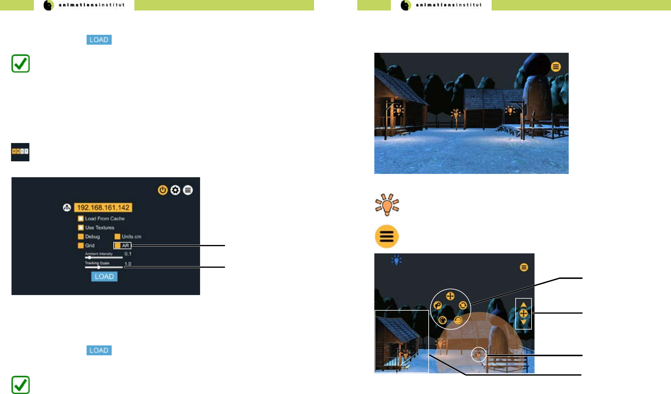
IP-adress eld
control scale checkbox
In this chapter, you will learn how to launch VPET on your device and connect it to the distribution server.
The IP-adress in texteld (a) should be predened by your IT-support.
If you can’t connect to the server, check troubleshooting (chapter 1.7.)
Checkbox (b) allows the loading of a precached scene. Unless instructed otherwise, uncheck it.
Checkbox (c) toggles textures. High resolution textures may lead to slower performance on some mobile
devices.
scene load checkbox
1. Consult your IT-support to check if VPET is installed on your mobile device.
2. If it is, just tap the “VPET” icon on your screen once.
3. The conguration menu will appear full-screen.
(e)
(a)
(b)
textures checkbox
(c)
debug mode
checkbox (d)
grid display checkbox
(f)
ambient intensity
slider (g)
Checkbox (d) loads the scene in debug mode. Consult with your IT-support before checking this option.
Checkbox (e) decreases the measurement units. This increases control accuracy in small-scaled virtual
scenes.
Checkbox (f) overlays your virtual scene with a grid.
Contents
1. User’s Guide 3
1.1. Starting VPET using your mobile device 3
1.2. Starting VPET using your AR - mobile device 4
1.3. The viewport 5
1.4. Touch Screen Controls 6
1.5. VPET Tools 12
1.6. VPET Menu Tree overview 26
1.7. Troubleshooting 27
2. Administrator’s Guide 28
2.1.Technical Requirements 28
2.2. Setting up your network 31
2.3. The distribution protocol 32
2.4. The synchronization protocol 35
2.5. Setting up VPET + Katana 37
2.6. Setting up your scene in Unity 47
2.7. Building your VPET - app 52
2.8. Optional VPET addons 60
3. Imprint 60
VPET - Documentation - User’s guide VPET - Documentation - User’s guide
4 5
1.2. Starting VPET using your AR - mobile device
Some AR-equipped mobile devices of the iOS- and Google Tango product lines allow for inside-out tracking,
enhancing the control cababilities of the user. While the conguration menu remains largely the same as in
chapter 1.1.,
(g)
(h) AR positional sensitivity
slider
VPET connects to the Distribution Server and loads the scene.
1. Consult your IT-support to check if an AR-enabled VPET-build is installed on your mobile device.
2. If it is, just tap the “VPET” icon on your screen once.
3.The conguration menu will appear full-screen.
4.Once all options are set, tap once.
AR - toggle
Checkbox (g) toggles positional control by AR on or o. By default, AR is inactive.
Slider (h) allows scaling the sensitivity of AR-positioning (relational scale of user’s movements)
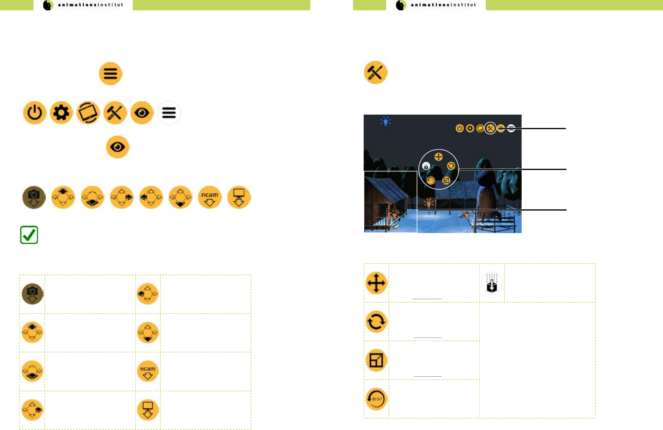
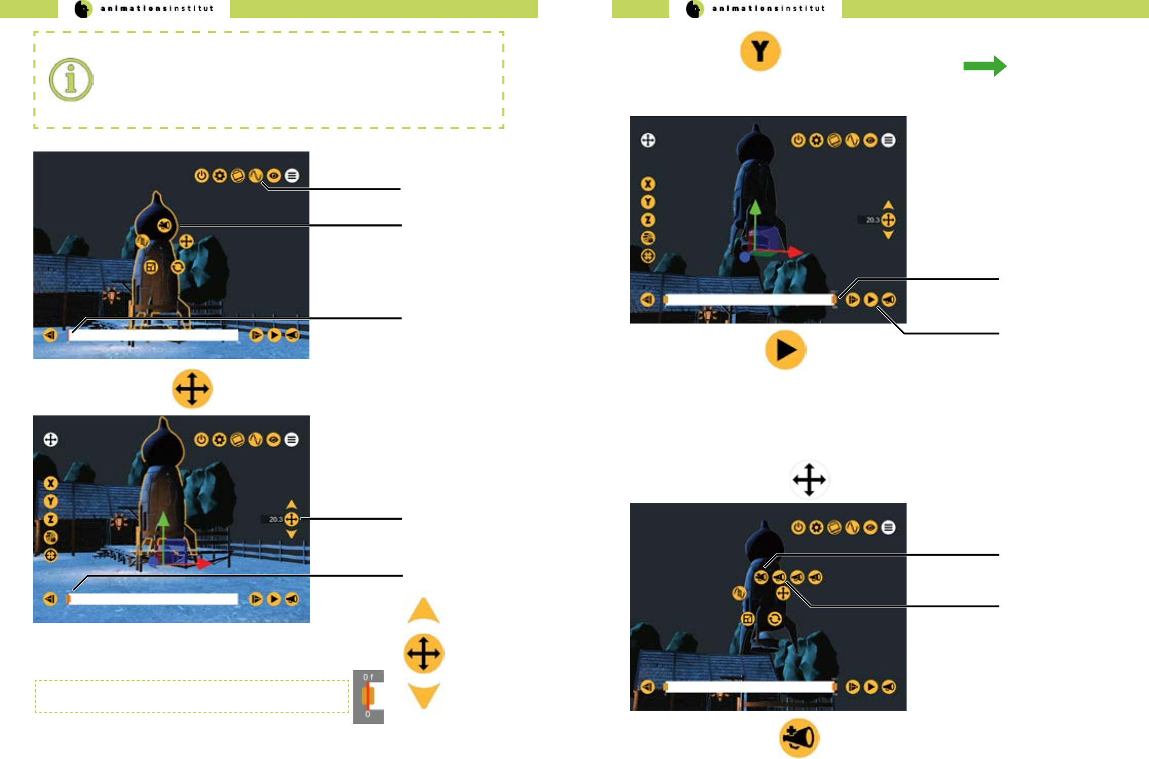
1.3. The viewport
In this chapter, you will learn about the viewport and the rst basic options for on-set editing.
This is the basic VPET view with the precached “farm scene” already loaded.
This symbol denotes a light source within your scene.
This icon opens up the options dialog and contains most of your tools
within VPET.
In this image, a light source (c) has already been selected. Whenever an asset is selected, the available tools
will be displayed in the center of the screen in a radial pattern (a).
Parameters of various assets may be adjusted by the value controller (b)
Selected light sources will be displayed within a translucent light volume. (c)
Selecting a movable asset will display a yellow outlining (d).
radial toolset
selected movable asset
(b)
(a)
(d)
(c) selected lightsource
value controller
VPET connects to the Distribution Server and loads the scene.
4.Once all options are set, tap once.
Slider (g) increases or decreases ambient light intensity of your scene, allowing for improved overall view for
darker virtual scenes.
All other options remain unchanged from the standard conguration menu as described in chapter 1.1.
VPET - Documentation - User’s guide VPET - Documentation - User’s guide
6 7
Tapping this symbol toggles the VPET tracking on or o, as explained in 1.4.3.
Tapping this symbol takes you to the conguration menu, as explained in chapters 1.1. and 1.2.. Use this
if you are instruced to change your settings.
Tapping this symbol quits VPETs and takes you back to the main screen of your mobile device.
1.4. Touch Screen Controls
In this chapter, you will learn how to control the virtual camera within your VPET scene on your mobile
device. While we presume that you are familiar with mobile devices, the multitude of features of VPET calls
for some particular control methods, which are nevertheless easy to master.
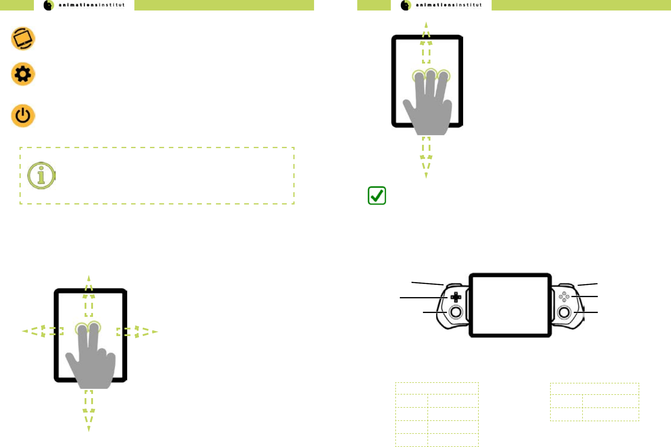
1.4.1. Three-dimensional camera movement controls
1. Touch the ngertips of both index- and middle nger to
the interface of your mobile device.
2. With both ngertips touching the glass, move your
ngers up / down / left / right.
3. This allows you to move up (pedestal up) / down
(pedestal down) / or move laterally left (truck left) /
right (truck right).
Once you are familiar with the two-digit movement controls, move to the next
step.
4.Touch the ngertips of index- and middle and ring nger to
the interface of your mobile device.
5.With all three ngertips touching the glass, move your ngers
up / down.
6.This allows you to move forward (dolly in) / backward (dolly
out.
You are now able to move three-dimensionally through your VPET scene.
1.4.2. Optional joystick movement controls
Some mobile devices can be equipped with additional controllers, i.e. the gamevice product range for iOS
devices. If available, analogue thumbsticks oer smooth and fast control of your virtual camera within VPET.
Most commercially availabe controllers oer one or more joysticks / thumbsticks (conguration may deviate from above
gure) - usually, the right thumbstick will be congured for controlling the horizontal virtual camera movement.
The secondary joystick controls vertical virtual camera movement. Manual virtual camera control as described in chapter
1.4.1 remain unchanged and may be used for accurate control.
Primary Joystick (c)
Up Dolly in
Down Dolly Out
Left Truck Left
Right Truck Right
Secondary Joystick (f)
Up Pedestal Up
Down Pedestal Down
D-Pad (b)
Primary Joystick (c)
Left Trigger (a) (d) Right Trigger
(e) Face Buttons
(f) Secondary Joystick
Process termination:
As of the update 6.0 of the Android OS and iOS in general, apps are not authorized to
shut themselves down. The VPET app will continue running as a suspended background
process.
VPET - Documentation - User’s guide VPET - Documentation - User’s guide
8 9
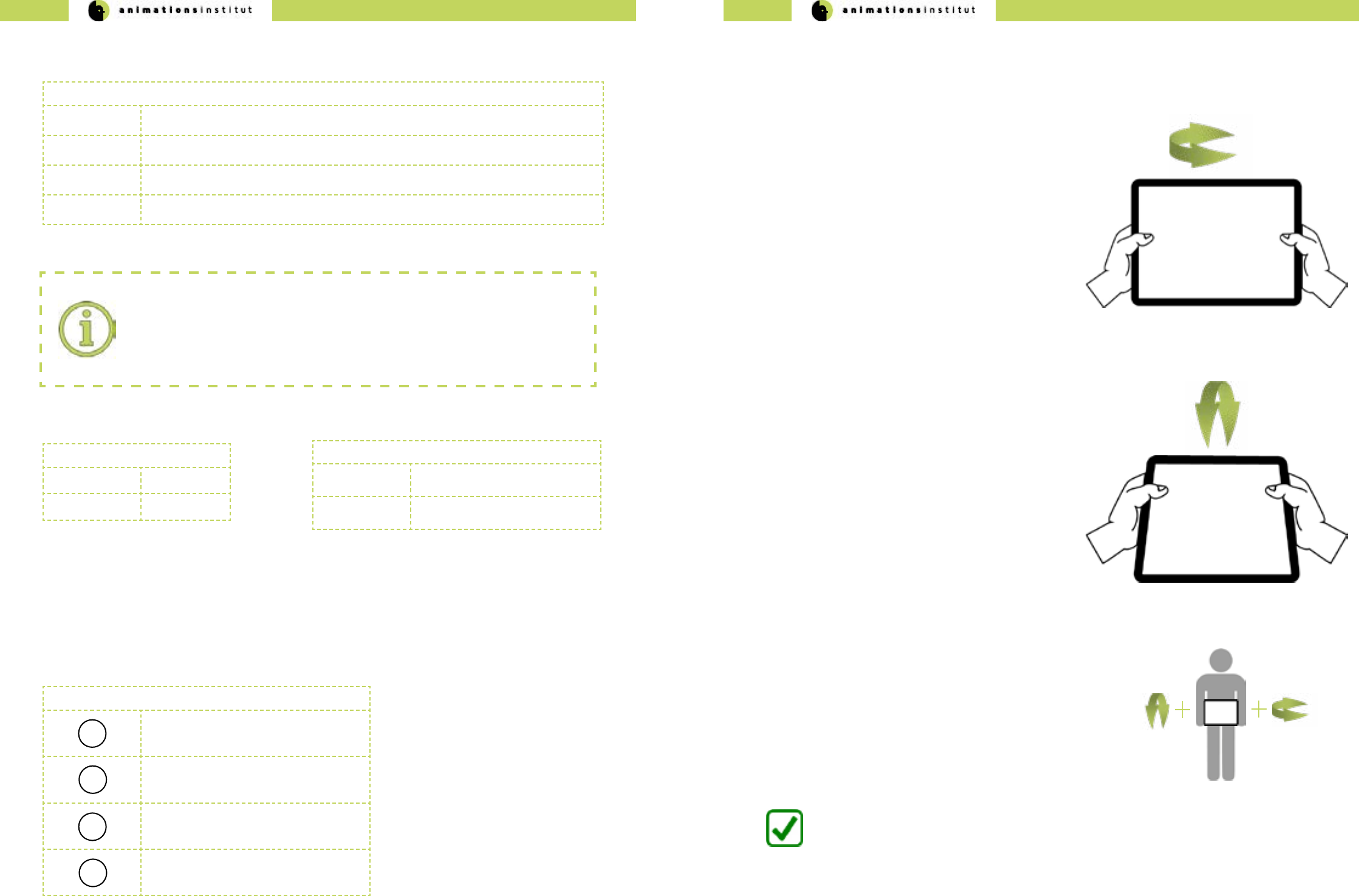
In this chapter, you will learn how to control your camera view within your VPET scene. VPET utilizes the
rotational tracking in your mobile device for view control. Rotating your tablet allows you to rotate the virtual
camera.
1.4.3. View controls.
1. Take your tablet rmly in both hands.
2.Turn your tablet left or right. The virtual camera in your
scene will follow your tablet’s movement.
3.This allows you to turn the virtual camera left (pan left) /
and right (pan right).
4.Tilt your tablet down / up. The virtual camera in your scene
will follow your tablet’s movement.
5.This allows you to tilt the virtual camera up (tilt up) and
down.
Once you are familiar with the panning camera movement controls, move to
the next step.
You are now able to control your virtual camera in your VPET-scene.
Once you are familiar with the tilting camera movement,
try to combine these controls - cycle through your
dierent cameras as explained in chapter 1.5.1, or
modify your cameras position as described in chapter
1.5.4.
Additional control options are available with usage of the triggers (a and d) respectively, which are grouped in the upper
and lower trigger. See below for details.
Left Trigger (a)
Upper Trigger -
Lower Trigger -
Right Trigger (d)
Upper Trigger toggle VPET view controls (see
chapter 1.4.3.)
Lower Trigger cycle through the predened cam-
era views (see chapter 1.5.4)
Deactivating View Control:
It is recommended to deactivate tracking input (as described in chapters 1.4.1. and
1.4.2.) while utilizing a controller. Simultaneous input from dierent sources may lead
to aberrant behaviour. See below for details on how to deactivate the standard view
controls.
The Face Buttons (e) allows for direct call-up of the editing options for an editable object, specically:
√ translation
√ rotation
√ scale
√ gravity
With an editable object selected, press the face buttons to call up the editing functions as described below.
Face Button (a)
AScale - Editing Tool
BRotation - Editing Tool
YTranslation - Editing Tool
XToggle virtual gravity on / o
Pressing the D-Pad (b) in any direction will cycle you through the available editable objects in your scene, and automati-
cally calls up the available editing options (see chapter 1.5.3.).
D-Pad(b)
Up-Arrow Cycle through available lightsource assets forwards.
Down-Arrow Cycle through available lightsource assets backwards.
Left-Arrow Cycle through available geometrical assets forwards.
Right-Arrow Cycle through available geometrical assets backwards.
To deselect any asset, just tap in any inactive part of your scene.
VPET - Documentation - User’s guide VPET - Documentation - User’s guide
10 11
1.4.4. Positional controls
Technical innovation led to several mobile devices with inside-out tracking. VPET fully utilizes this feature
to enhance the user experience with exceptionally natural and accurate movement controls. At the time of
writing those products encompass devices using Tango AR or operating on Apple iOS, starting with the
iPhone 6s (based on the A9 CPU). If these are available, a build with positional tracking enabled should be
installed on your mobile device.
Watch your surroundings:
Remain aware of moving through a movie set.
Negligence may lead to material or even personal damage.
Do not keep eyes on screen while moving.
While the view controls remain the same as described as in chapter 1.4.3.., the positional control gains authenticity
when compared to the three-dimensional movement controls as described in chapter 1.4.1.
After extensive testing, we concluded that a combination of three-dimensional movement controls and positional track-
ing provide the user with the most intuitive and eective method of control.
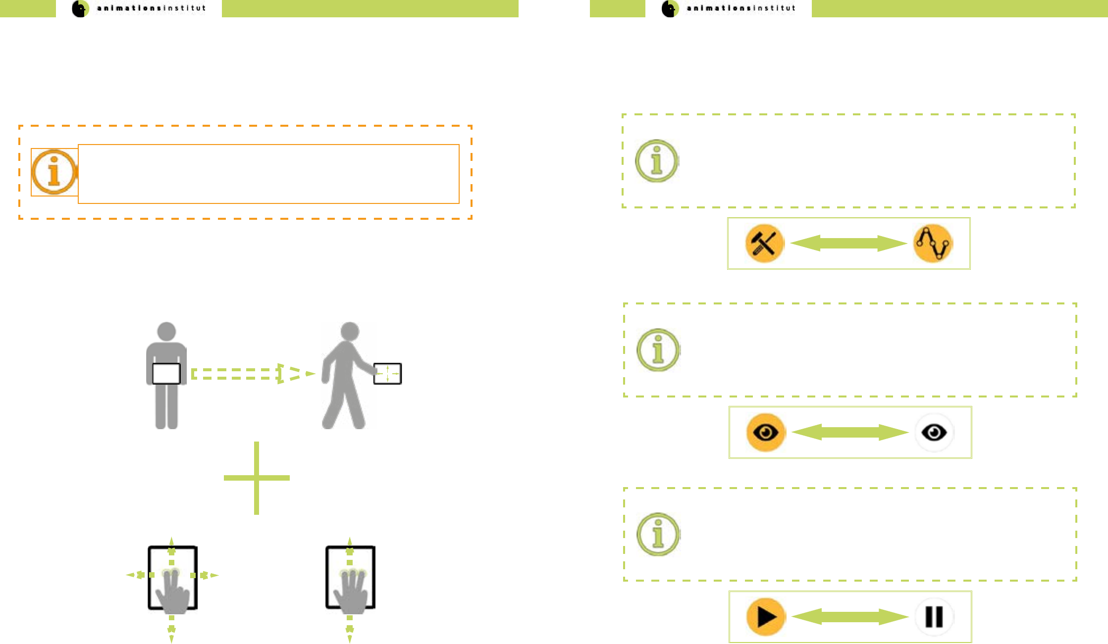
1.4.5. Icons
Icon Swapping:
VPET aims for a maximum of clarity and usability in your mobile interface. To condense
as many features as possible within the smallest possible space, VPET regularly swaps
icons. We will notify you within this guide whenever an icon swap occurs. An example of
said notication is shown below.
Icons within VPET work by the common single-tap method like most mobile apps.
Special mechanics regarding icons will be explained in the chapter below.
Greying out icons:
Some icons will be replaced with a greyed-out version of themselves when tapped.
In most cases, this means the icon is “active” and the icons of the corresponding options
are displayed.
Greyed out swap:
Some icons will be replaced with a greyed-out version of another icon.
Normally, this icon has a separate function which will be explained accordingly in this
guide. An example of the corresponding notication is shown below.
VPET - Documentation - User’s guide VPET - Documentation - User’s guide
12 13
This chapter will give a brief overview of the predened camera view functions in VPET
1.Tap the Menu - icon once.
2.The upper menu bar will be displayed.
3.Tap the View - button once.
Tapping the snapshot icon
calls up your dened virtual
camera positions, as explained
in chapter 1.5.7.
This feature is not yet active.
Tapping the Camera Left - icon
brings you in a predened
horizontal ortographic view of
the scene.
Tapping the Camera Top - icon
brings you in a predened
top-down ortographic view of
the scene.
Tapping the Camera Bottom -
icon brings you in a predened
bottom-up ortographic view of
the scene.
Tapping the Camera Front -
icon brings you in a predened
horizontal ortographic view of
the scene.
If available, tapping the
NCAM - icon allows you to
connect / disconnect to the
NCAM realtime camera track-
ing system.
Tapping the Camera Right -
icon brings you in a predened
horizontal ortographic view of
the scene.
Tapping the Perspective - icon
cycles through a set of
predened cameras.
1.5. VPET Tools
1.5.1. View tools
4.The “general toolset” menu bar will be displayed at the bottom of the screen
You are now able to utilize the preset camera positions. Refer to the table below
for specic information regarding the icons.
When the Edit - icon is displayed in the upper menu bar, Toolset - mode is active (a).
radial asset toolset icons
(c)
(b)
(a)
selected geometry
Edit icon
1.5.2. Geometry toolsets
The real-time modication of assets is the heart and centre of VPET.
In this chapter, you will learn how to handle and modify your scene’s assets with the VPET toolset.
The applications starts in Toolset - mode by default.
1. Select a geometrical asset by tapping on it once. For demonstration purposes, we selected
the farmhouse on the left, as indicated by the yellow outline (b).
2.Once an asset has been selected, the radial asset toolset icons (c) are displayed.
Tapping the Translation - icon
enables you to move the se-
lected geometrical asset along
the X-/Y-/Z-Axis
(see this section).
Tapping the Gravity - icon
enables you to engage or
disengage the scene’s virtual
gravitational forces. (gravity is
active by default).
Tapping the Rotation - icon
enables you to rotate the se-
lected geometrical asset along
the X-/Y-/Z-Axis
(see this section).
Tapping the Scale - icon ena-
bles you to scale the selected
geometrical asset up and
down along the X-/Y-/Z-Axis
(see this section).
Tapping the Reset - icon resets
the selected geometrical asset
to its default state.
VPET - Documentation - User’s guide VPET - Documentation - User’s guide
14 15
axes icons
(c)
(b)
(a)
value controller
colored axes
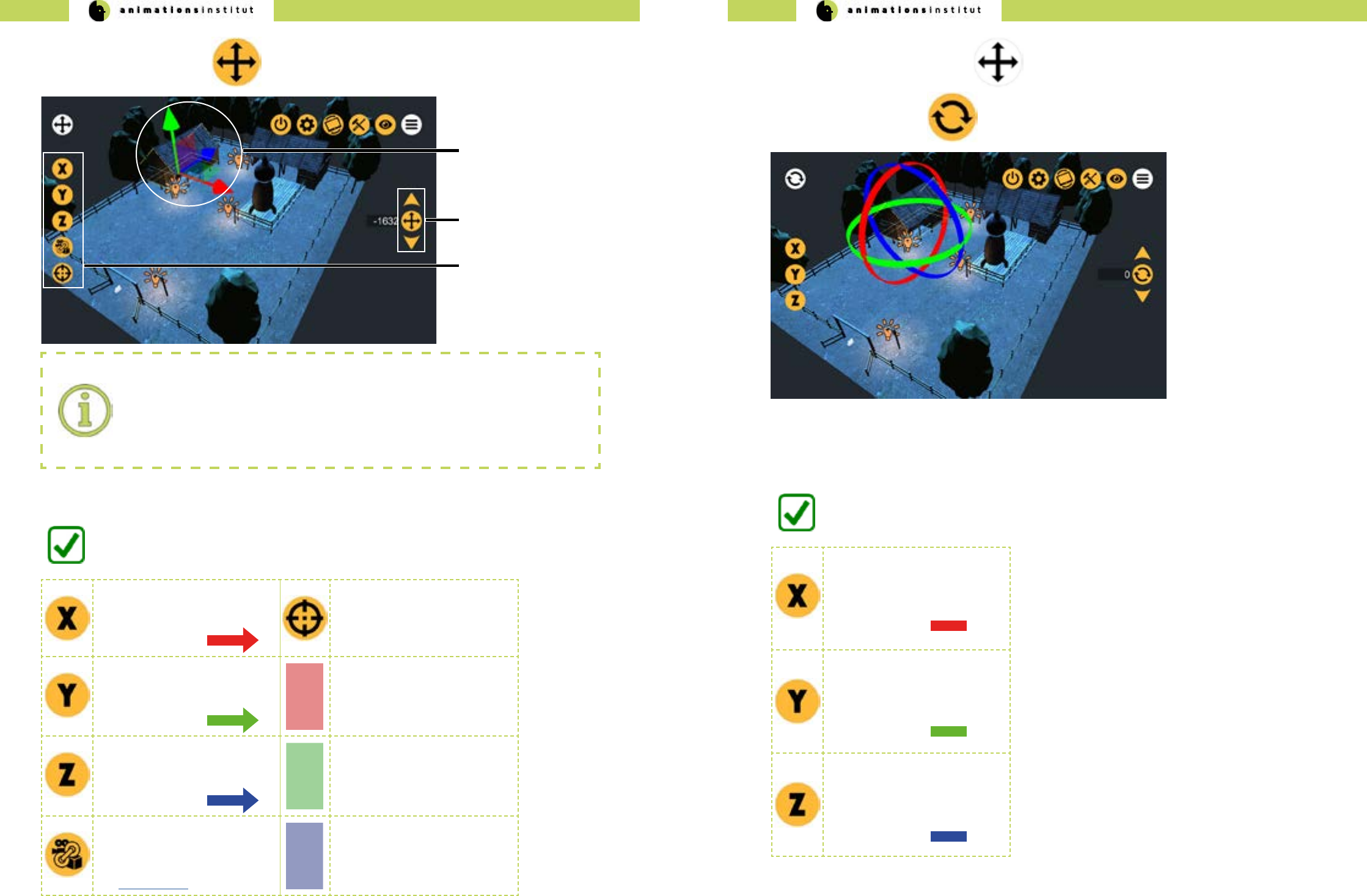
1. Tap the Translation Icon once.
2. Tap and hold either an axis(a) or single-tap the corresponding axis-icon (c).
Analogue controls:
If the axes are displayed, VPET controls are modeled for exibility - either tap and scroll
the colored axes (a), or choose the corresponding Axis icon (c) and utilize the value
controller (b). Corresponding symbols are explained in the table below.
3. Depending on your choice, scroll along the axis, or scroll the value controller (b) up / down.
Tapping the “X” - icon enables
you to move the selected asset
along the X-Axis. Correspond-
ing axis color is
Tapping the “point to oor” -
icon allows you to move the
selected asset automatically to
a user-specied (single-tap)
point at the scene’s oor.
Tapping the “Y” - icon enables
you to move the selected asset
along the Y-Axis. Correspond-
ing axis color is
Tapping and holding the YZ -
translation plane allows you to
move the selected asset along
the Y- and Z- axes synchrone-
ously.
Tapping the “Z” - icon enables
you to move the selected asset
along the Z-Axis. Correspond-
ing axis color is
Tapping and holding the XZ -
translation plane allows you to
move the selected asset along
the X- and Z- axes synchrone-
ously.
Tapping the “attach to cam-
era” - icon moves the selected
asset according to your mobile
devices view tracking (see
section 1.4.3.)
Tapping and holding the XY -
translation plane allows you to
move the selected asset along
the X- and Y- axes synchrone-
ously.
You are now able to move your geometries along the three dimensional axes.
1. Tap the greyed Translation Icon once. This takes you back to the radial asset toolset icons.
2. Tap the Rotation Icon once.
Tapping the “X” - icon enables
you to rotate the selected
geometrical asset round the
Y-Axis. Corresponding axis
color is
Tapping the “Y” - icon enables
you to rotate the selected
geometrical asset round the
Y-Axis. Corresponding axis
color is
Tapping the “Z” - icon enables
you to rotate the selected
geometrical asset round the
Z-Axis. Corresponding axis
color is
You are now able to rotate your geometrical assets around the three dimensional axes.
3. Tap and hold either an axis or single-tap the corresponding axis-icon.
4. Depending on your choice, scroll the axis along its curvature, or scroll the value controller (b) up / down.
VPET - Documentation - User’s guide VPET - Documentation - User’s guide
16 17
1. Tap the greyed Rotation Icon once. This takes you back to the radial asset toolset icons.
2.Tap the Scale Icon once.
Tapping the X - icon enables
you to scale the selected
geometrical asset up and
down along the X-axis. Corre-
sponding axis color is
Uniform scale:
The scale - toolset oers the additional option of scal-
ing assets up or down at the same rate in all
three dimensions.
To do so, tap and hold the yellow-colored cube at the
center of the three axles, then push or pull to scale
up or scale down, respectively.
Corresponding cube color is
Tapping the Y - icon enables
you to scale the selected
geometrical asset up and
down along the Y-axis. Corre-
sponding axis color is
Tapping the Z - icon enables
you to scale the selected
geometrical asset up and
down along the Z-axis. Corre-
sponding axis color is
You are now able to transform your geometrical assets around the three dimensional axes.
3.Tap and hold either an axis or single-tap the corresponding axis-icon.
4. Depending on your choice, scroll along the axis, or scroll the value controller (b) up / down.
1.5.3. Virtual camera toolsets
In this chapter, you will learn how to handle and modify your scene’s virtual camera assets.
The translucent camera denotes a Virtual Camera asset. Virtual Cameras and their respective positions are prede-
ned in your scene, as described in chapter 1.5.1. - you may cycle through available virtual cameras by tapping
The available tools are completely the same as those of the VPET geometry toolset (chapter 1.5.3) - enabling you
to move and turn the camera in three dimensions.

VPET - Documentation - User’s guide VPET - Documentation - User’s guide
18 19
1.5.4. Lightsource toolsets
When the edit icon is displayed in the upper menu bar, edit - mode is active (a).
radial lightsource toolset
icons
(c)
(b)
(a)
selected lightsource asset
Toolset icon
In this chapter, you will learn how to handle and modify your scene’s lightsource assets with the VPET tool-
set. The applications starts in “Edit” - mode by default.
1. Select a lightsource asset by tapping on it once. For demonstration purposes, we selected
the lantern in the middle, as indicated by the translucent sphere (b)
2.tap once on a lightsource icon.
Reuse of icons:
For ease of handling, graphical user interface icons will be reused as often as possible in
VPET. The translation, rotation, and reset - icons in the radial lightsource tools look and
work the same as in the radial geometry asset tools (see section 1.5.2.). All other icons
will be described below.
3.Once an asset has been selected, the radial lightsource toolset icons are displayed.
4.Tap the Palette Icon once.
5.To the right, the light colour palette will be displayed. Tap or scroll to the color of choice.
You are now able to change your lightsource asset’s color.
1. Tap once on a lightsource icon.
2. Once an asset has been selected, the radial lightsource toolset icons are displayed.
3. Tap the light settings icon once.
4. The corresponding submenu will be displayed at the left side of the screen, as shown below.
Light setting can only be modied by using the value controller.
Tapping the light intensity -
icon enables you to change
the lightsources intensity by
scrolling the value controller
up / down.
Tapping the light range - icon
enables you to change the
range of your lightsource by
scrolling the value controller
up / down.
Tapping the light cone angle
- icon enables you to change
the angle of a spotlight source
by scrolling the value controller
up / down. This works
exclusively for spotlight assets.
You are now able to change your lightsources’ settings.
VPET - Documentation - User’s guide VPET - Documentation - User’s guide
20 21
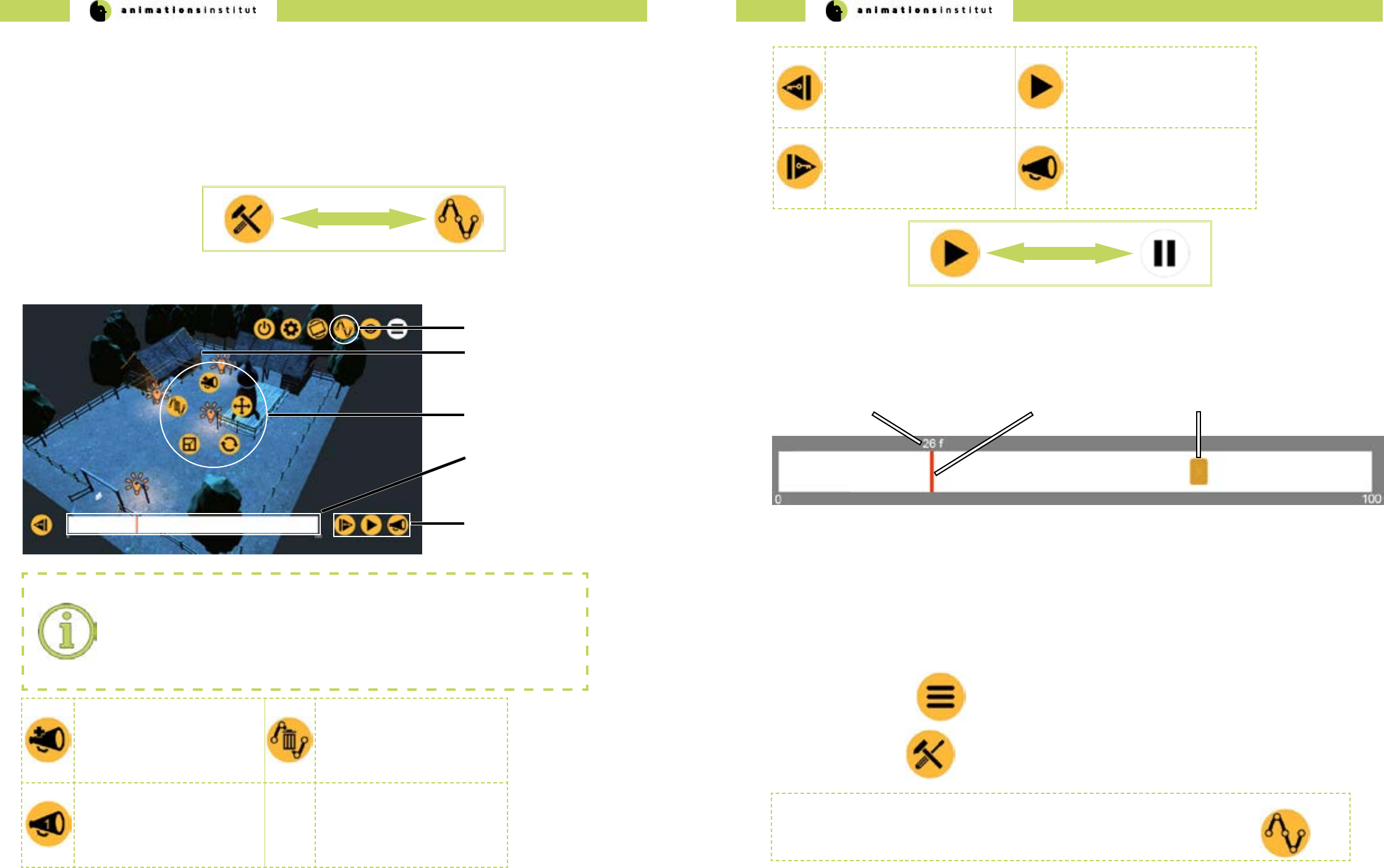
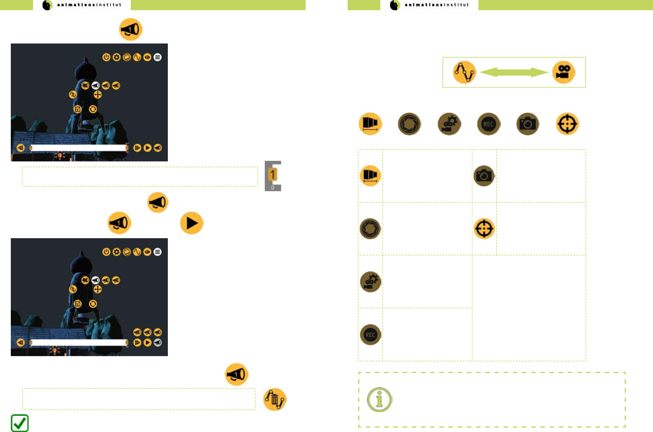
1.5.5. Animation tools
In this chapter, you will learn how utilize VPETs animation controls. VPET enables you to conveniently realize your vision by
using an automated keyframe system in an easy-to-use playback tool. Additionally, you are enabled to synchronize up to
three animation commandes via the numbered layers.
Tap once on the toolset - icon in the upper menu bar. It is swapped with the animation icon.
The radial toolset menus are automatically switched for their animation counterparts.
New components within the user interface are explained below.
animation mode timeline
(e)
radial animation icons
animation icon
(a)
(b) selected asset
(c)
(d)
animation control icons
Reuse of icons:
As mentioned in section 1.5.6., several icons that are in use in the asset toolset will
return within the animation subset. Translation-, rotation-, and scale icons funtionalities
remain unchanged. Note: animation mode currently only allows translation, rotation and
scaling of lightsource assets.
The add layer - icon enables
you to assign an animated
asset to a numbered layer, as
shown in the row below.
The cancel animation - icon
enables you to delete all
keyframes in the animation
timeline.
The numbered layer - icon
enables you to set/recall a
previously dened animation
timeline. There are three num-
bered cues available.
1.5.5.1. The animation toolset
You are now working within the animation toolset, as indicated by the animation icon
in the upper menu bar. Additionally, the timeline is displayed at the bottom of your screen.
The play - icon will be automatically swapped for the pause icon, as shown above. The pause icon allows you to stop
the running animation.
Tapping the previous keyframe
- icon brings you to the last
previous dened keyframe in
the timeline.
Tapping the play - icon allows
you to start the currently active
animation timeline. Once ac-
tive, the icon is swapped with
the pause - Icon.
Tapping the next keyframe -
icon brings you to the next de-
ned keyframe in the timeline.
Tapping the layer - icon allows
you to call up one of the three
numbered animation timelines.
The timeline is the central operating element within the animation toolset. As demonstrated below,
the measurement scale in use are frames (0-100).
frame number
(a) frame indicator
(b) keyframe symbol
(c)
1.5.5.2. Using the animation toolset
This chapter demonstrates step by step how to create a working animation in VPET, from start to nish.
Ease of use in regard to automated keyframes, animation qeueing and playback are the key features of VPET and oer
a unique advantage to the creative process on-set.
1.Tap the menu icon once.
2.Tap the edit icon once.
3. Select the geometrical asset “rocket”. Your screen should now look approximately like this.
For demonstration purposes, we will move the selected rocket (b) to the middle of the scene and back, while
simultaneously scaling the rocket, then down.
VPET - Documentation - User’s guide VPET - Documentation - User’s guide
22 23
Animation icon active
(a)
Selected asset “rocket”
Keyframes:
in the context of animation and lmmaking a keyframe is dened as the starting and
ending points of any smooth transition. If you want to animate any asset, it is especially
crucial to dene the starting keyframe for the animation to take eect. Each animation
layer within VPET allows up to a 100 keyframes.
(b)
12.Tap the translation icon once
unnumbered keyframe
(b)
Translation icon
value controller
(a)
13. Tap the center translation icon of the value controller (shown to the right) once.
Step 7 denes your rst (starting) keyframe. If you followed this
guide correctly this far, your timeline should look like this.
14. Tap once on the frame indicator and scroll it to frame number 100.
frame indicator
(c)
15. Use either the Y-axis icon and the value controller, or scroll
the axis to move the selected asset (“rocket”) upwards.
The keyframe is generated automatically (c).
frame indicator
(a)
16.Tap the play icon (c) once. The animation plays in a loop, moving your selected asset (“rocket”)
to your dened positions.
play icon
(b)
1.5.5.3. Creating layered animations
VPET allows you to create single, dedicated animation processes for one or several assets, which can be replayed on
command by using numbered layers. The following chapter will demonstrate how to create layered animations and
continues from the instructions in chapter 1.5.5.2.
1.Tap the greyed-out play icon once. This takes you back to the radial animation toolset icons.
2.Tap the add layer icon (a) once.
add layer icon
(a)
numbered layer icon
(b)
VPET - Documentation - User’s guide VPET - Documentation - User’s guide
24 25
This assigns your currently selected asset’s animation to the “1” layer. Whatever modications
you carry out, they can be called up by tapping the corresponding numbered layer.
3.Tap the numbered layer - icon 1 (b) once.
4. To replay your numbered layer, tap the layer icon (a).
5. Next, tap the numbered layer 1 icon, then the play icon.
6. Your numbered layer - animation will play once, as often as it is called up by tapping.
You are now able to provide an animation with keyframes and add numbered layers.
If you are unsure of your results so far, just delete the current animation keyframes by tapping
the Cancel - Animation Icon and start over.
1.5.6. Camera Tools
In this chapter, you will learn how to utilize VPETs virtual camera controls.
Tap once on the Animation Icon in the upper menu bar. It is swapped with the Camera Icon.
The camera toolset menu bar will be displayed at the bottom of the screen
Tapping the focal length icon
allows you to change the focal
length by scrolling the value
controller.
The snapshot icon allows you
to capture specic camera po-
sitions, which can be called up
in the view tool menubar (see
chapter 1.5.1.)
This feature is not yet active.
Tapping the sensor size
icon allows you to adjust the
camera sensor size values,
creating an exact simulation of
the camera in use on-set.
This feature is not yet active.
Tapping the Point to Floor -
icon allows you to move the
active camera automatically to
a user-specied (single-tap)
point at the scene’s oor.
Tapping the camera parame-
ters icon allows you to adjust
additional values, creating an
exact simulation of the camera
in use on-set.
This feature is not yet active.
Tapping the recording icon
saves your cameras movement,
allowing you to replay tracking
shots.
This feature is not yet active.
Camera Tools:
Several of the Camera Tools have yet to be fully implemented.
VPET - Documentation - User’s guide VPET - Documentation - User’s guide
26 27
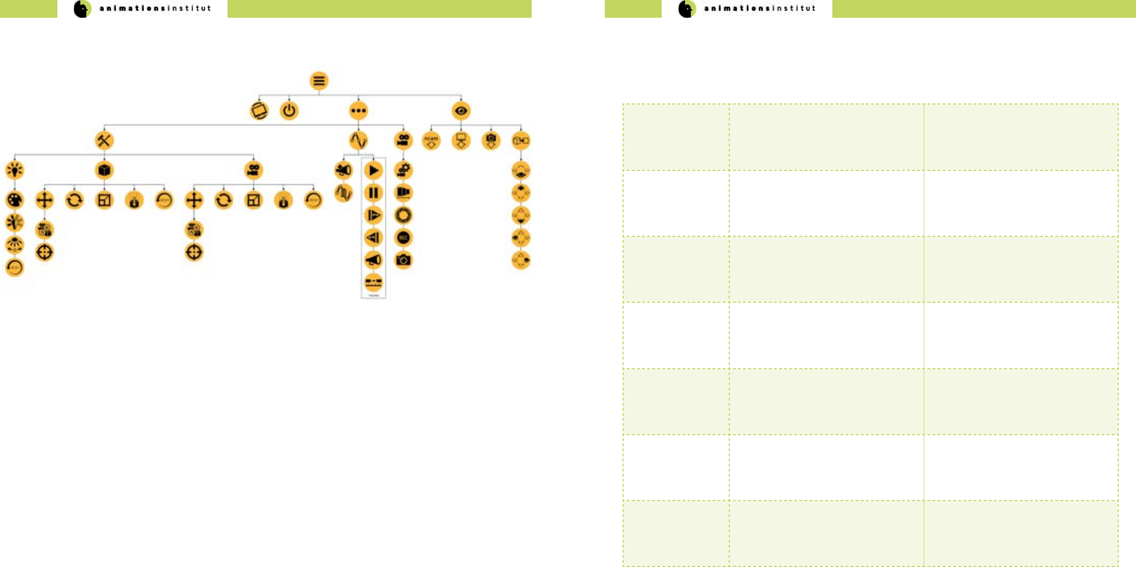
1.6. VPET Menu Tree overview 1.7. Troubleshooting
Being an open-source software in ongoing development, VPET may show some unexpected behaviour. While the develop-
ers and community strive to eliminate those, this chapter should enable you to work around the currently known technical
hangups.
Operating System
/ VPET build
Problem Solution
Android + Tango
iOS + ARKit
Loss of AR-positional tracking AR - positioning depends strongly on
your camera tracking structured sur-
faces. Avoid featureless, plain textured
surfaces when tracking your position via
AR.
Android / Tango
iOS / ARKit
Occasional disappearance of radial
menus in animation mode
restart VPET
Android / Tango
iOS / ARKit
unresponsive animation controls Reset objects animation status and/or
transformation.
Desktop
Android / Tango
iOS / ARKit
outdated animation keyframes get re-
loaded upon restarting VPET.
Manually delete all numbered / un-
nummbered animation cues, reset
geometrical / lightsource assets
Desktop
Android / Tango
iOS / ARKit
On connecting VPET to the distribution
server, loading stops at 10%.
Check distribution server.
Check IP - conguration on client,
alternatively check general network
conguration.
Desktop
Android / Tango
iOS / ARKit
Scene changes are not synchronized on
multiple clients
Check if the synchronization server is
running correctly.

VPET - Documentation - Administrator’s guide VPET - Documentation - Administrator’s guide
28 29
2. Administrator’s Guide
2.1.Technical Requirements
2.1.1. Hardware requirements
As an administrator, using VPET gives you unprecedented freedom by speeding up interdisciplinary cooperation and ex-
panding the scope of data currently available on set.
As the production’s administrator, your job is realizing the technical setup, deciding on software choices and exploiting
optional addons. The the R&D - Department of Filmakademie continues to develop VPET for the express purpose of simpli-
fying your tasks and lessen the pressure on those technical responsible in any modern media production.
This guide will take you through building a suitable scene for VPET, deploying a Unity Game Engine build for the currently
supported operating systems and setting up the necessary network requirements.
This chapter will comprehensibly list the technical requirements for deploying VPET from an IT-standpoint.
A further distinction will be made between technical core requirements and additional options that enhance VPETs
capabilities.
VPET user clients
(mobile / desktop)
VPET core setup
VPETServer
Although VPET comes with a prepared scene (“ranch scene”), you can realize your own creative vision and start from
there. You need a working scene managed by the digital content creation software of your choice. While VPET was devel-
oped with Katana, it is completely adaptable for any software, depending on the available plugins in future development or
already in existence. For demonstration purposes, we will show the process of deploying VPET using Katana and Unity.
Katana is basically a look development and lighting software suite and serves as a scene management tool in regard to
VPET: creating and assigning asset IDs, applying textures and correlating values.
Additionally, you need a plug-in that enables Katana to receive updates from the Network, the Katana listener, as well as
the scene distribution plug-in. If you want to run multiple clients, the synchronization server has to run as well.
√ Katana software suite
√ Katana listener-plugin
√ Katana scene distribution plug-in. (included with the VPET-Master)
√ a network - connected VPET client (mobile or desktop)
√ renderer of choice
√ synchronization server (for multiple clients)
and of course, a prepared scene.
If using Katana, any changes made to the scene by any client are managed by the Katana Listener.
Communication works without a synchronization server, though synchronizing the input of more than one client requires its
use.
Depending on your choice of software, a dierent approach may be viable - as long as input and output of your scene are
functionally received and redistributed by your DCC and scene management tool, you are able to deploy a basic
VPET-setup, which consists of:
√ VPETServer
√ one or more client devices able to run VPET.
√ the SyncServer (in case of >1 client in your setup).
To take full advantage of VPET, the optional components enhance your interaction features within your virtual.
These are listed in detail in chapter 2.8.
2.1.2. Software requirements
2.1.2.5. Katana
VPET was developed within the eu fp7 project dreamspace and is designed to work with Katana.
Out of the box, Katana works with the following rendering software options:
Renderman V-Ray Arnold 3Delight
Adaption and integration of other renderers is possible and welcome in the open-source-development of
VPET. The renderer needs to support Live Update. VPET was extensively tested with the Arnold renderer,
update functionality of any other render software depends on working plugins.
This chapter will detail the necessary hardware for a basic VPET setup, using only the core components.
For demonstration purposes, we will presume an installation based on the combination of Katana and VPET, which are
available with the required plugins.
In general, the choice of software suites and their combination is up to the user. VPET is designed for utmost adaptability,
and depends only on the respective plugins, which are either available or may be developed to your standards and needs.
Host application
scene distribution
Host application
listener
Synchronization
server
VPET - Documentation - Administrator’s guide VPET - Documentation - Administrator’s guide
30 31
VPET for iOS / ARKit
building VPET as standalone mobile version for iOS-based devices requires:
√ A Mac computer running running OS X 10.11 or later.
√ The latest version of Xcode.
√ A device running iOS.
√ Your prepared scene.
Apart from exporting your VPET build to the desired mobile devices, Unity can also serve as the VPETServer to
setup your scene and control your assets.
Get the most recent version of Unity here.
Operating systems + builds
At the time of writing, VPET may be run on ve common operating systems.
Depending on the OS you want to deploy to, you may need to full some
further requirements in regard to your VPET build.
VPET for Windows / Mac / Linux standalone
buidling VPET as standalone desktop version for windows does not require any additional software.
VPET for Android / Tango
building VPET as standalone mobile version for iOS-based devices requires:
√ The latest Java Development Kit (JDK)
√ Either Android Studio, alternatively the Android SDK Platform Tools.
√ A device running Android.
√ Your prepared scene.
Building for iOS requires at least a free Apple ID or enrollment in the Apple Developer Program.
JDK as well as SDK is regularly updated. Building your app in unity relies on those components, and will not
work if there are conicts. Keep your software development kits updated.
If you encounter any problems after an update, refer to the troubleshooting section xxx, the unity forums or
post a bug report / feature request to the VPET github repository.
2.1.2.6. Unity 2.2. Setting up your network
Naturally, VPET can only work with an established network, adhering to the IPv4 protocol standard.
When using mobile clients and/or a camera tracking system, you need a wireless router for handling network
communication. For heavy workload (i.e. video streams, or the principal camera image), you might consider
using a bre channel network card for your real-time renderer of choice.
The VPET-network setup requires the following components:
√ WiFi - router
√ clients (desktop or mobile)
√ a running scene distribution plug-in for your DCC (included with the VPET-Master)
√ a running listener plugin (included with the VPET-Master)
√ a running synchronization server (included with the VPET-Master)
√ a conict-free network conguration (including the subnet mask)
1. Set up your network.
2. Connect the VPETServer to the WiFi router and make sure the client uses the correct
wireless network. Double check the IP addresses.
3. Make sure your host application listener is running.
4. Opening the VPET app, you will be asked to enter the IP address of the LiveView server.
5. If everything has been set up correctly VPET will start to load the scene directly from the server.
10% loading freeze.
In case of VPET locking up at 10% loaded status, it has not connected to the VPETServer
correctly. The reason is usually an incorrect IP on the client, or a general network adress
conict.
6. If edits from VPET are not applied at the VPETServer workstation, make sure that the system is not expect-
ing any data to be handled by the synchronization server (e.g. NCam data), if not providing this data. In case
of need, remove the correspondent part in the startup script:
-nacmserver 192.168.11.1
7. Inversely, when using multiple clients and/or the NCam system requires the synchronization server to run
and having the necessary lines included in the code. (see chapters 2.4. and 2.6.2.).
You have learned the requirements of the VPET network and the respective addons.

VPET - Documentation - Administrator’s guide VPET - Documentation - Administrator’s guide
32 33
Header
Node
Mesh
Texture
Host
Application
(e.g. Katana)
bundle
bundle
bundle
bundle
VPET client
Header contains global scene infomation
Node contain further attributes (objects, hierarchy information, transformations, object specic information
as name, type, object parameters etc.)
Mesh polygonal meshes with asset-matching topology with unique IDs.
Textures textures contain image material with unique IDs
Animations are not yet transferable between host application / distribution application and VPET.
2.3. The distribution protocol
The distribution of your scene and the data stored within is at the core of the ccoperation-mindset in which VPET was
developed.
The following chapter gives a detailed overview over the distribution message itself and the contents of its components,
giving greater scope of creative capabilities and potentially enabling you to enhance the possibilities of VPET
in development.
The illustration below gives a basic idea of the distribution messages structure.
In this case, the message is not sent in one block, but is separated into four separate bundles.
The following chapter details the messages in the order in which they are sent, with data type and ranges denoted.
2.3.1. The distribution message in detail
Header
data type Object default value possible value range (if applicable)
oat lightIntensityFactor 1.0 -1000 to 1000
int textureBinaryType 0 0, 1
The header message consists of information regarding the global light intensity factor and texture type.
Node
Objects dened within the general struct Node are common to all inheriting nodes, the specic objects
of the -Geo / -Light / -Cam nodes dene either ags (like editable), references or the parameters of your scene’s assets.
Node
data type type default value possible value range (if applicable)
bool editable false true / false
int childCount 0 positive integer range
oat3position 1, 2, 3 oat range
oat3scale 1, 2, 3 oat range
oat4rotation 1, 2, 3, 4 oat range
char[64] name ‘ ‘ ASCII char range
Geo:Node
data type parameter default value possible value range (if applicable)
int geoId -1 positive integer range
int textureId -1 positive integer range
oat roughness positive oat range
oat3 color { 1,1,1 } positive oat range(rgb-color values)
To reiterate, all objects of the Node Struct and their respective values are inherited by the follwing structs:
Light:Node
data type parameter default value possible value range (if applicable)
int type SPOT SPOT, DIRECTIONAL, POINT, AREA,
NONE=0
oat intensity 1.0 positive oat range
oat angle 60.0 oat range
oat range 500.0 positive oat range
oat exposure 3.0 positive oat range
oat3 color 1.0,1.0,1.0 positive oat range(rgb-color values)
Cam:Node
data type parameter default value possible value range (if applicable)
int type SPOT SPOT, DIRECTIONAL, POINT, AREA,
NONE=0
oat intensity 1.0 positive oat range
oat angle 60.0 oat range
VPET - Documentation - Administrator’s guide VPET - Documentation - Administrator’s guide
34 35
Mesh
The next message handled by the distribution package contains information about any polygon mesh within your
scene, divided into vertices, indices, normals and UVs.
Mesh
data type parameter default value possible value range (if applicable)
int number vertices - positive integer range
int number indices - positive integer range
int number normals - positive integer range
int number UVs - positive integer range
oat[] vertex array - positive oat range
int[] index array - positive integer range
oat[] normal array - positive oat range
oat[] uv array - positive oat range
Texture
The next message handled by the distribution package contains information textures, as data array in use and
dimensions.
Texture
data type parameter default value possible value range (if applicable)
int size color data array - positive integer range
int texture width - positive integer range
int texture height - positive integer range
byte[] texture data - byte range
2.4. The synchronization protocol
VPET is designed for creative exchange on-set. Accordingly, the synchronisation protocol is one of the core components.
At the time of writing, distribution of messages is handled by netMQ.
Though every message contains a series of standard strings with all necessary values, this chapter will detail the individual
sections.
Each message adheres to a specic form, as shown below as an example. Subsequently, it is broken down in its
specic components.
client 129|r|CubeParent/Cube|0.01386935|-0.1318762|-0.6923447|0.7092779|physics
client 129 r CubeParent/Cube 0.01386935 -0.1318762 -0.6923447 0.7092779 physics
a b c d e f g h i
component avaiiable values
a topic = client / ncam / record
b unique ID of the sender
c information type = r / t / s / c / i / a / d / k / l / f
d directory path to a scene node, separated by “/”
e values according to information type (see section”c”).
f values according to information type (see section”c”).
g values according to information type (see section”c”).
h additional (optional) value for information type rotation (r) and translation (t)
i “physics” or blank (see following page)
Message separation:
Correct separation of netMQ - messages warrants particular attention:
while the topic is separated by a simple space, every other value is separated by a simple
“|”. As usual, special characters should be avoided, unless used in the example above.
Every component is described in full detail on the following page.
VPET - Documentation - Administrator’s guide VPET - Documentation - Administrator’s guide
36 37
topic according to the netMQ Publish / Subscribe pattern, the following topics are available for VPET:
• client = updates are directly transfered from the clients (tablets).
• ncam = ncam data (position / rotation / focal length) for each frame (provided the
synchronization server is used.
• record = the synchronization server stores the current scene state and is thereby
able to provide an initialisation update to new subscribers (this functionality is in
BETA status and is not yet reliable).
unique ID a string of numbers issued by the synchronization server, identiying the sender within your network.
information
type
The exact nature of available types of information processed by VPET is listed below:
√ rotation (r)
√ translation (t)
√ scale (s)
√ light color (c)
√ light intensity (i)
√ light spot angle (a)
√ light range (d)
√ kinematic change (k) = enables / disables gravity for an object.
√ lock boolean value (l) = denes true / false and locks an object if edited,
avoiding conicts in parallel editing.
√ focal length (f) of the optional ncam camera
directory
path
the path to the object (lightsource / geometrical / camera) is relative to the scene folder, with the
exception of ncam data (in this case, it is “cam”). Separation of values by “/”
values information types - dependant value. Four to one values, as listed in detail below:
type number / value type Value Range if applicable
r / rotation 4 oat values (quaternion) -
t / translation 3 oat values (xyz-axes) -
s / scale 3 oat values (xyz-axes) -
c / light color 3 oats (rgb - color) 0 - 1
i / light intensity 1 oat. 0 - 8
a / light spot angle 1 oat. 0 - 179 (degrees, incl. penumbra angle)
d / light range 1 oat 0 - innity
k / kinematic change 1 bool 0 - 1
l / lock bool 1 bool 0 - 1
f / focal length 1 oat -
optional
spatial value
This value is only added if the information type is either “rotation / r” or “translation / t”, its value is al-
ways “physics”. On clients with an active physics engine (commonly tablets and other mobile devices),
the “physics” - component will be ignored, since physics can be individually calculated by these clients.
On clients without physics engine (most desktop renderers), this enables watching the physics interac-
tion and should be handled as a normal scene update.
2.4.1. The synchronization message in detail 2.5. Setting up VPET + Katana
Although usage of Katana is not implicit, VPET was developed due to the numerous choices of rendering software for easy
integration. If you prefer a dierent software suite, developing the necessary plugin is absolutely possible. For this guide,
we will presume that Katana will be used for the management of the scene.
If any other scene management software is used, please refer to the respective documentation.
2.5.1. Katana setup
Preparing your scene for the specic handling of assets and customizing it to the requirements of Katana (or your DCC of
choice) is considerably easier to handle when adhering to this le structure.
(b) rendering software
(a) Katana listener
(c) Katana scene distribution
Pivots and transformations:
Setting correct pivots for every asset is imperative to avoid erroneous bounding boxes
when transfering to Unity (and VPET, respectively).
Additionally, transformations may not be frozen.
Choice of 3D-computer animation software
You are completely free in your choice of 3D modeling / animation software, provided the import in your
host application works. For restrictions regarding the import process, see below.
VPET - Documentation - Administrator’s guide VPET - Documentation - Administrator’s guide
38 39
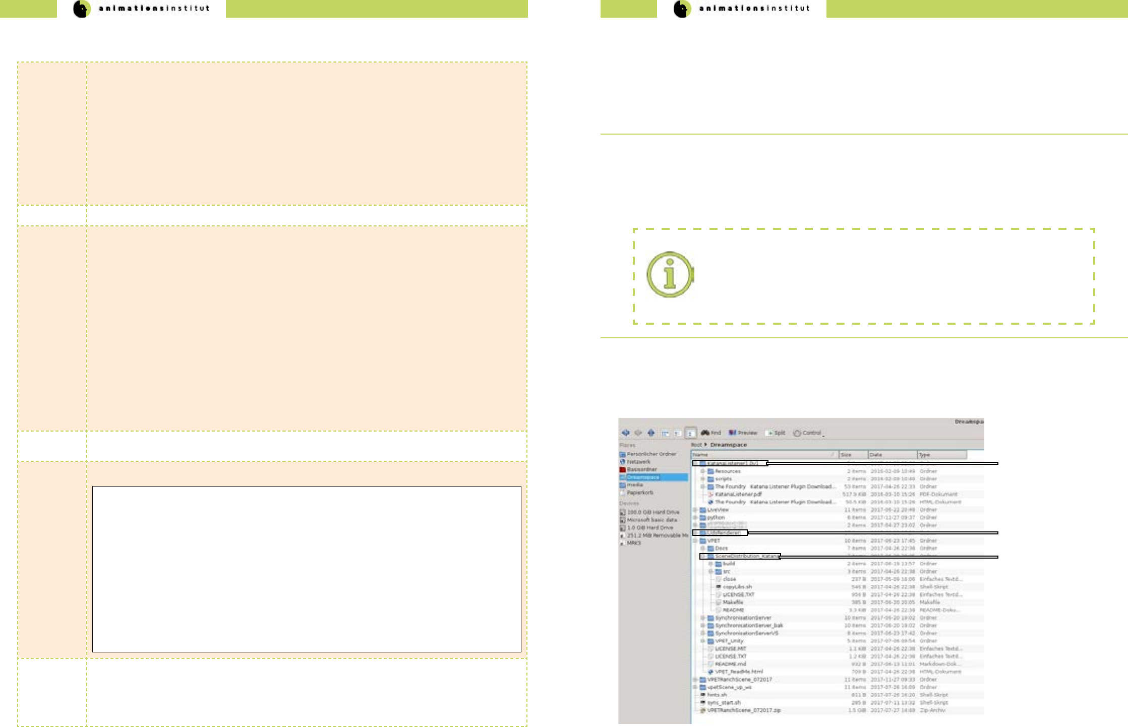
Next, Katana needs to be pointed to the relevant directories for the plugins.
Open the shell in the directory, and create a startup script to set the environment variables and enable automatic startup of
Katana once the script is complete.
Naming / File Locations:
All described actions within this guide regarding le location, le naming and designations
used in scripting are exemplary and do not have to be imitated for Katana to work.
This guide will eplicitly point out if this does not apply.
Create your bash script within the appropriate folder containting the les.
create script:
[rnd@localhost YourVPETscene]$ gvim vpetYourDCC
[rnd@localhost YourVPETscene]$ ./vpetYourDCC
run script:
[rnd@localhost YourVPETscene]$ chmod 744 vpetYourDCC
set permissions:
Using Katana, our example script looks like the gure on the following page (in Vi style editing).
Run the script, Katana will now automatically start up.
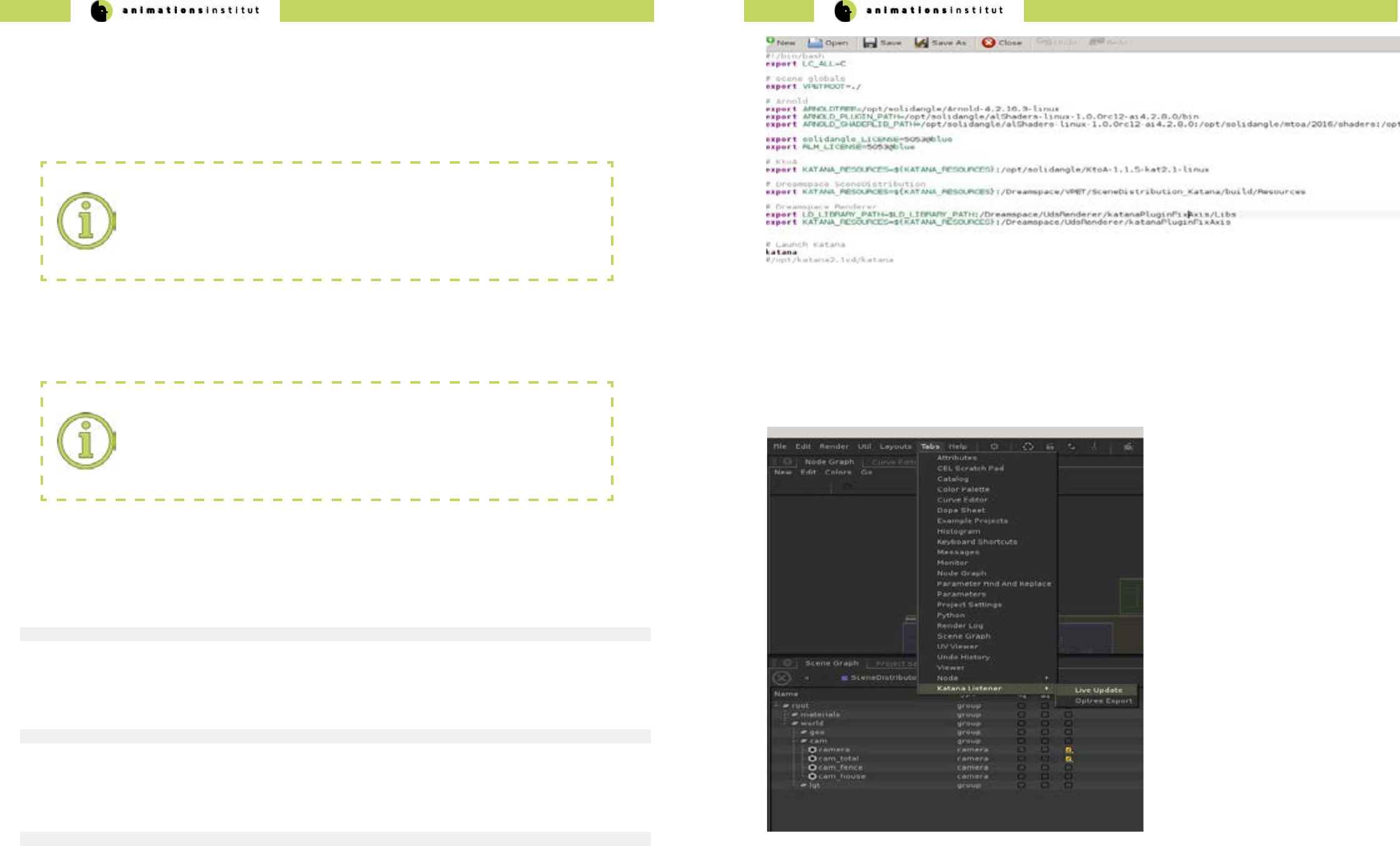
Successful integration of the plugins is tested by checking for “Katana Live update” within Katana, as pictured below.
In the context of VPET, Katana “live update” is directly tied to the listener plugin. Any change made to the scene by
any client is received within the DCC, and resynchronized to every other client in the network automatically by the
SyncServer.
1. Click the LMB once on the tab “Tabs”.
1. A drop-down menu is displayed.
2. click LMB once on “Katana Listener” tab.
3. A slide-out menu is displayed.
4. Click the LMB once on “Live Update”.
The “Katana Listener / Live Update” window will open. Since it is a central module in the scene management, we
strongly suggest xing it to a Katana compartment window as described below.
5. Drag and drop the “Katana Listener / Live Update” into the present “Parameters” compartment.
Renderer Software:
As mentioned in chapter 2.1.2.1., the VPET-user is completely free in the choice of the
preferred rendering software. Arnold will be used as an example in this guide and does
not indicate benets or disadvantages.
Katana needs three components in dened le locations to work as your scene management tool.
√ the Katana listener “resources” (a)
√ a rendering software (b)
√ the Katana scene distribution “resources” (c)
VPET - Documentation - Administrator’s guide VPET - Documentation - Administrator’s guide
40 41
You have succesfully dened the Katana plugin paths, started up Katana, and integrated the Katana
Listener in your workspace.
(a) Render Node in viewport (b) View parameters of selected Node
(c) Live Update (d) Session Cache activity indicator / session log
2.5.2. Opening the example scene in Katana
This chapter deals with the loading of your scene and gives an overview of additional options oered by VPET within
Katana, as well as detailing their content.
1.Click LMB on “File” once, then open up your scene as shown exemplary below.
2.Next, click on the yellow-tinted menu in the top bar.
3. Choose your available variables. The most common variables (depending on your scene’s setup) are:
(b) available scene variables
(a) variables menu
daytime denes lighting settings
lod level of detail for rendered objects
renderer allows the choice of rendering software
view allows the choice of virtual camera
within your scene
Depending on your choice of view mode, the nodes will be displayed either by directly choosing the specic node to
be rendered in the viewport (a), or displaying the node parameters (b).
The Live Update texteld (toggled by start/stop in the gure below) is used to start / stop the live rendering and
Katana Listener respectively, as well as dening the network port for the Listener. By default, the network port in use
ist set to 5555.
Of specic importance is the Session cache - attributes and values received by the listener are shown here, and may
be used as an indication of a functioning VPET setup.
The session log / network activity indicator (d) incorporates any changes made to the scene in human-readable text,
archiving transmitted data objects consisting of attribute–value pairs and array data types, and may be dumped into
the .json - le when you nish your VPET session or cleared if deemed unnecessary.
Listener / Live Update:
Independet of your choice of DCC, the Listener / Live Update (or any equivalent plugin
with analogue functionality) are at the center of your VPET setup.
We strongly suggest testing your setup before deploying on-set to avoid delays in your
producation pipeline.
Once the Listener / Live Update is active, Katana is ready to act as scene management tool.
The next page gives a more detailed overview over its functions.
VPET - Documentation - Administrator’s guide VPET - Documentation - Administrator’s guide
42 43
2.5.3. Setting level of detail
While the rendering in Katana usually shows your scene in the selected LoD, distribution to your mobile devices
works by delivering an alternative version of your scene with a lower polygon count.
To avoid unnecessary complexity, this is achieved by creating tags for your assets.
These tags assign your assets to either the high-polygon group rendered within Katana or to the low-polygon group
for distribution to the mobile devices.
(c) asset - LoD - tag
(b) LoD Switch
(a) Node Graph
The common abbreviation for “level of detail” is LoD or lod.
The common abbreviation for “high” or “low” polygon count is “hi” and “lo” respectively.
These abbreviations will be used in this guide.
The Node Grap (b) gives a general overview of your scene’s structure.
VPET requires a certain set of prerequisites for a scene, which are explained in chapter 2.5.. The central distinction
at the core of the inner workings of VPET and its scene management software Katana is the LoD-switch (b) as ex-
plained above. these switches work by assigning tags (c) to your assets.
The switch shown above is exemplary, but the node structure of your scene will be similar.
(c) scene Distribution
Global statements
(b) asset attributes
(a) chosen asset (d) LoD - tag “lo”
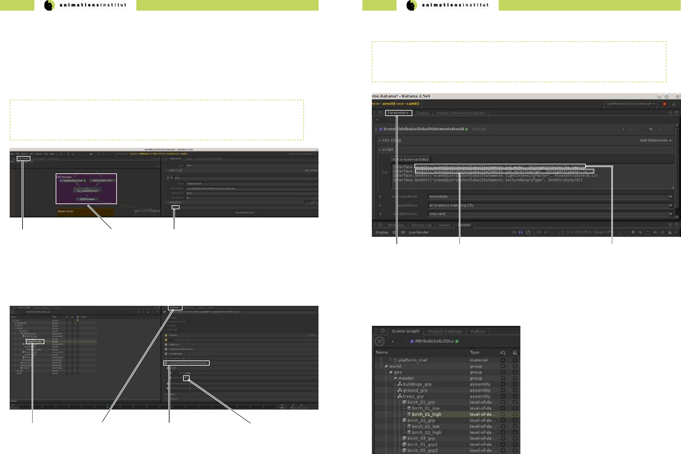
As shown in the gure above, setting the level of detail for a specic asset is possible in the sceneDistributorGlobal-
Statements by typing in the appropriate tag (d).
Depending on the node which denes chosen LoD in your scene setup, the gure above demonstrates the method
of dening and calling the respective LoD settings. By design, VPET calls by mode of tag (c).
In this exemplary case, scene assets will be called by the tag “lo”, as shown in (b).
The same method is used to call assets assigned to the assets dened with the tag “hi”.
For distribution to your mobile devices, your library must contain a set of “lo” and “hi” version of every asset, as
shown below.
At this point, your assets needs to be assigned the LoD-tag according to its polygonal count.
high polygonal count tag = hi
low polygonal count tag = lo
(b) LoD call method denition.
(a) Parameters (c) LoD - tag mode
VPET - Documentation - Administrator’s guide VPET - Documentation - Administrator’s guide
44 45
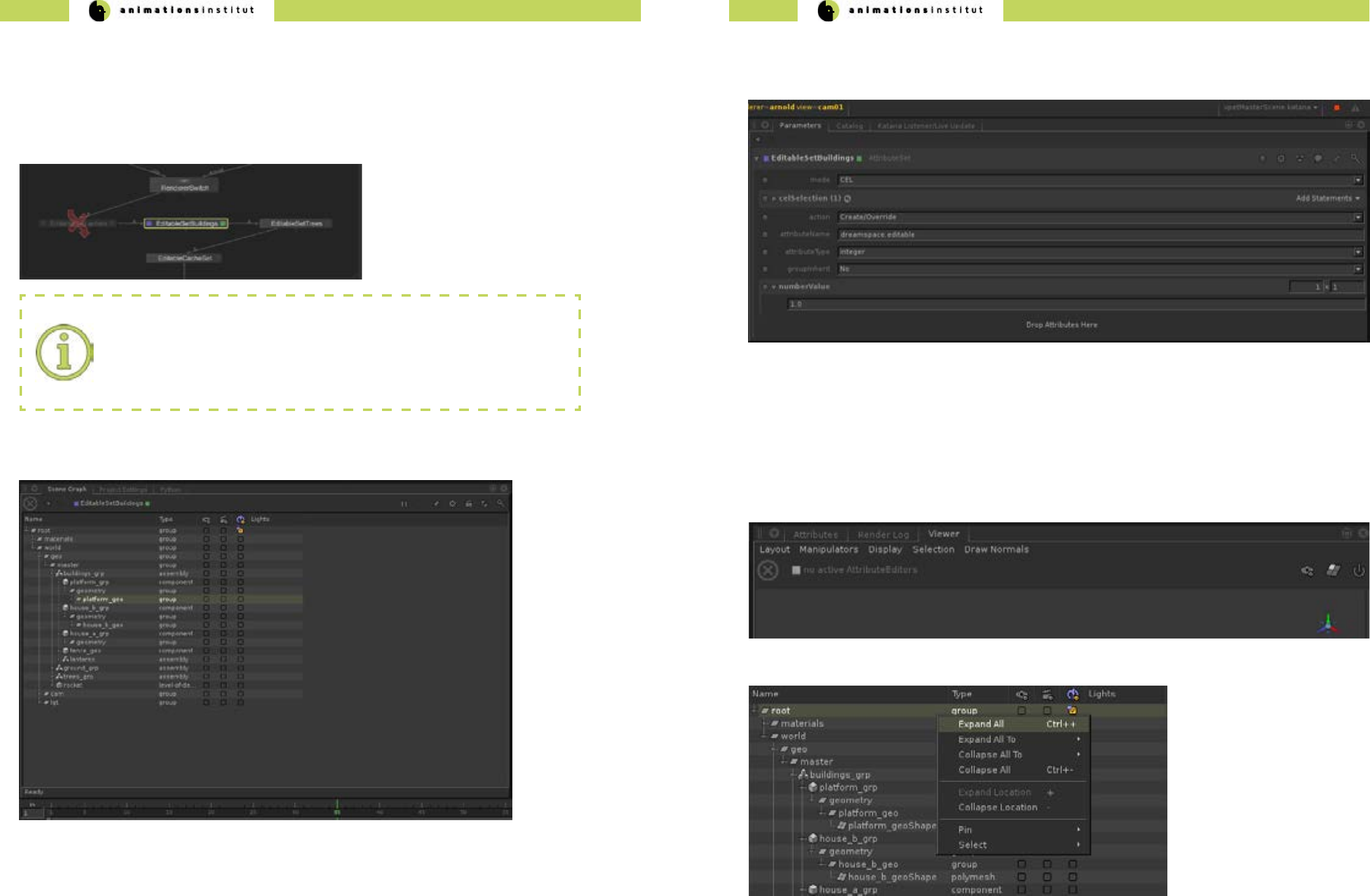
2.5.4. Dening editable objects
As mentioned in the user’s guide, most scenes consist of edtiable assets as well as uneditable assets. This distinction
must be made within your scene management tool.
For demonstration purposes, this chapter will show how to ag an obect as editable within Katana. As usual, you are
free to do so within any other scene management software.
Normally, there will be a categorized set of
editable assets with appropriate naming, as
depicted in the left gure.
Scene clarity:
every camera, geometrical, or lightsource asset in your scene may be agged as editable,
this is generally not recommended though.
Pinpoint selection of assets is impeded by an excess of editable assets.
The ag itself is set within the “Parameters” tab of the respective asset within Katana, as shown in the gure below.
Denition of editable assets should be decided in consultation with your creative team.
Make sure to select the asset itself, not the groupings.
Central element is the “attributeName” - tag.
For any editable object, the text eld needs to be set as
Every editable asset within your scene will be dened this way. This allows for quick addition and removal of editable
assets on-set.
2.5.5. Your VPET scene in the Katana Viewer
To check if your scene works with Katana and is ready for deployment to your mobile devices, use the Katana Viewer
(by default in the lower right compartment of your screen within Katana) as shown below.
1. Expand the complete hierarchy of your scene by clicking RMB once, and clicking LMB once on “expand all”.
dreamspace.editable

VPET - Documentation - Administrator’s guide VPET - Documentation - Administrator’s guide
46 47
2. Choose the appropriate node to render from by doubleclicking it with LMB, then click RMB once.
3. Click “Live Render” with LMB once.
4. If your scene does not show in the Viewer Grip Map, press “F” once to focus on the chosen object.
5. Your Viewer should show your scene in preview, as shown in the “ranch” example below.
You are now able to check your compability of your scene with your dened rendering softwares in Katana.
2.6. Setting up your scene in Unity
This chapter explains the setup of your scene within Unity as well as possible options and settings.
This will take you from opening the project itself, to setting and changing the options for your scene within Unity, as
well as deploying it to the currently supported mobile operating systems.
This is the general layout of your VPET le structure, provided you
pulled the repository from github.
We are using the prepared VPET_client scene as an example.
Your own scene will have to be prepared and structured according to
chapter 2.5.1.
This chapter explains the setup of your scene within Unity as well as possible options and settings.
This will take you from opening the project itself, to setting and changing the options for your scene within Unity, as
well as deploying it to the currently supported mobile operating systems.
1.Make sure to save your prepared VPET-scene in a memorizable
location.
2.Once you have started Unity and created a new project, click
the tab “Assets” once with LMB.
3.In the dropdown menu (see left), click “import package”.
4. Click “custom package” once.
5.Check for the icon / name - combination of your VPET-scene
6.Select the Unity package of your scene. (marked left)
7.Click “open” once.
“Live Render” oers the same options as the
“View Node”, as explained in chapter 2.5.1.
The VPET-package contains not only the exemplary “ranch”
scene, but the complete VPET program, including the plugins
and necessary export options.
While the ranch scene is used for demonstration purposes,
please keep this distinction in mind.
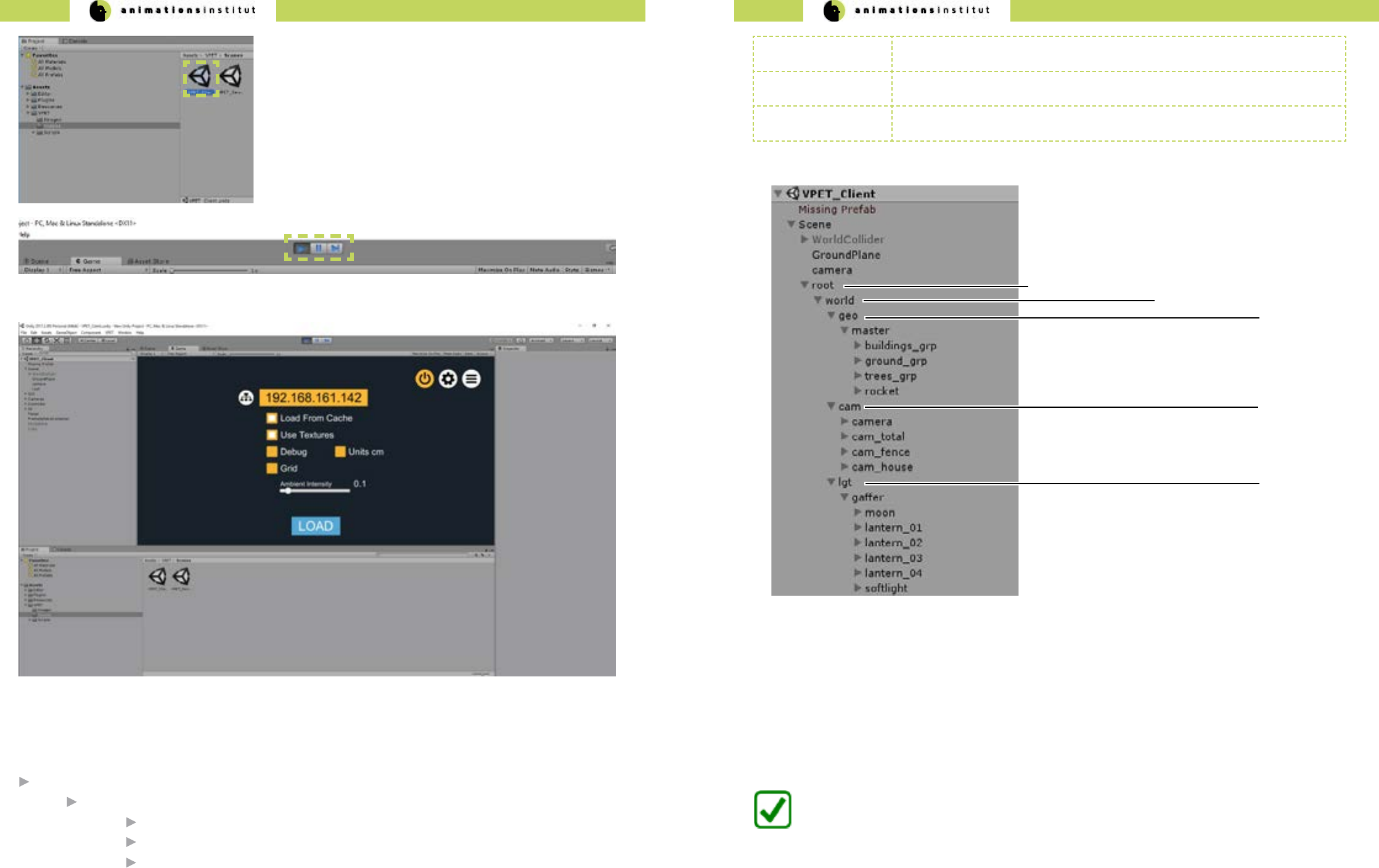
VPET - Documentation - Administrator’s guide VPET - Documentation - Administrator’s guide
48 49
8.By default, the “Project” - folder of Unity is placed in the lower
left compartment of your screen. Click LMB once on “Assets”, then
“VPET”, then “Scenes”.
9.Double click the aproppriate Scene symbol (marked in the left
gure).
10.Once selected, click the “Play” icon in the top bar of Unity once,
as marked below.
11. The selected scene is displayed in the “Game” preview screen of Unity, as shown below.
Depending on your choice of scene and setup, load a scene from your server after supplying your IP, or load a
cached scene.
You are now able to load and correctly deploy a VPET-customized scene in Unity.
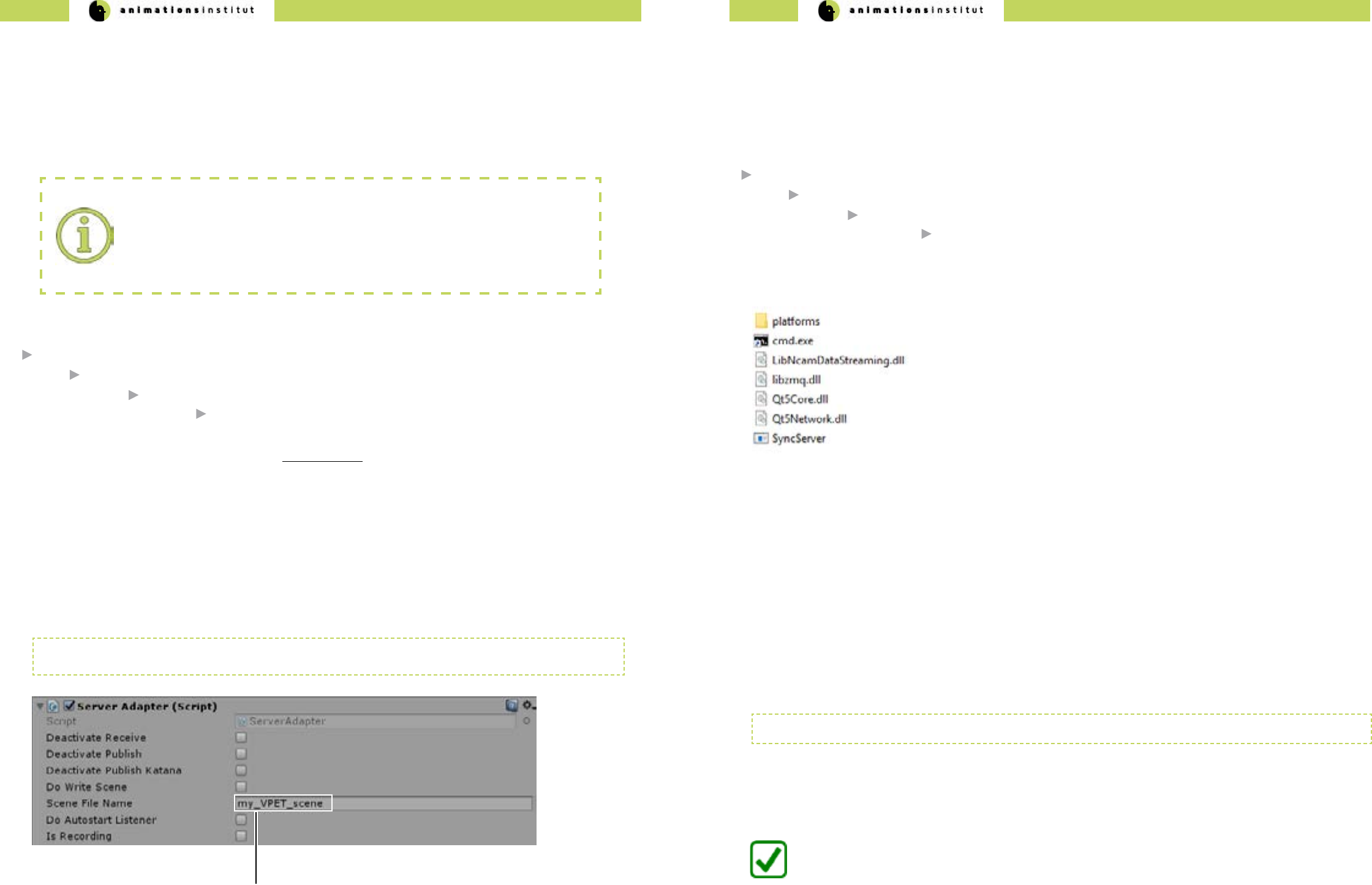
Independent of the chosen host software, the following scene structure is denite for successful distribution.
root directory
world directory
geo directory containing geometrical assets
cam directory containing virtual cameras
lgt directory containing lightsource assets
root node must contain all objects to be transfered to mobile devices
editable tag must be set up in distribution application (e.g. Unity), and applied to assets for editing
in VPET
camera creating one or more virtual cameras for switching views within VPET.
(a) root directory
(b) world directory
(c) geo directory
(d) cam directory
(e) lgt directory
Cached scenes
while not dependent on the distribution tool or script, the usage of cached scenes on your desktops or mobile
devices follows the same guidelines as described above, i.e. scene structure.
Instead of live distribution and synchronization, cached scenes are stored on the device you are using VPET on.
VPET - Documentation - Administrator’s guide VPET - Documentation - Administrator’s guide
50 51
VPET root directory
VPET_Unity
Assets
VPET editing_tool.cfg
2.6.1. Creating the client conguration le
Deploying your VPET build to your mobile devices is simple, quick and ecient. The process of building VPET as an app is
explained in detail in this chapter.
1. First, check your additional software requiremenets in regard to your build or builds, depending on the operating system
used on your mobile devices (see chapter 2.7.).
Cong le creation:
Although not inherently necessary, it is highly advised to customize the editing_tool.cfg.
This denes the prest values on the client devices, and drastically reduces time spent in
on-set client setup.
2. The VPET cong le is by default stored in:
3.The .cfg reads colon separated key value pairs per line, which are case sensitive.
Every value key which matches a public property in VPETSettings.cs (see API documentation) will be read from the cong
le.
4. Common property examples:
serverIP:172.17.21.188
doLoadFromResource:False
sceneFileName:my_VPET_scene
doLoadTextures:True
sceneFileName is replaced by the individual name for your scene, set in the Server Adapter/Inspector Window of
Unity (as in texteld (a) shown below).
(a) Scene le name texteld
2.6.2. Setting up the SyncServer
The Synchronisation Server Script is included within the VPET Master Package.
Its main purpose is synchronizing changes made to the scene by the clients on-set. This chapter explains the contents and
deployment of the Syncserver functionality.
By default, the SyncServer directory can be found under:
VPET root directory
VPET_Master
install
SyncServer.exe
The folder structure should contain the les shown in the following gure:
1. Call up the cmd.exe. and enter:
-h, -help: display this help
-ownIP: NP address of this computer
-ncamIP: ncam server IP address
-ncomPort: ncam server port, necessary if not 38860
2. This gives you the following options:
SyncServer.exe
3. For the purpose of synchronizing your client, just add your server’s IP adress in the command line.
SyncServer.exe -ownIP 172.17.21.165
as usual, the values used are exemplary.
4. As long as your rewall allows, your SyncServer is running.
You have successfully deployed the Syncserver and enabled the clients to synchronize on-set editing.
VPET - Documentation - Administrator’s guide VPET - Documentation - Administrator’s guide
52 53
2.7. Building your VPET - app
Deploying your VPET build to your mobile devices is simple, quick and ecient if done via Unity. As usual in the scope
of VPET, you are completely free to utilize any other distribution application, provided you develop suitable plugins. The
process of building VPET as an app is explained in detail in this chapter.
1. First, check your additional software requiremenets in regard to your build or builds, depending on the operating system
used on your mobile devices (see chapter 2.1.2.2.)
2. Depending on the operating system you want to deploy VPET to, proceed to the corresponding subchapter.
VPET for Windows / Mac / Linux standalone
VPET for iOS / and ARKit
VPET for Android / Google Tango
VPET for Android / Lenovo Phab 2 Pro
3. Depending on your technical options and needs in regards to devices running iOS, you may install the ARKit for
VPET. Please refer to the corresponding chapter.
Building for desktop - standalone versions is a simple process in general.
Any detail regarding OS - specic builds is explained in this chapter
Linux (various distributions)
Due to the multitude of Linux variants avaiable and the respective frequency of updates, make sure to recompile your
builds regularly. There is a high probability of conicts with older Linux versions.
MacOS
When building a standalone desktop version for MacOS, please make sure you have all necessary provisioning proles
installed in your keychain. For further details, please visit the relevant Unity documentation topic.
Windows
When building a standalone desktop or mobile version for Windows, all you need to to do is setting the “architecture”
to x86_64 (b).
2.7.3. VPET for Windows / Mac / Linux standalone
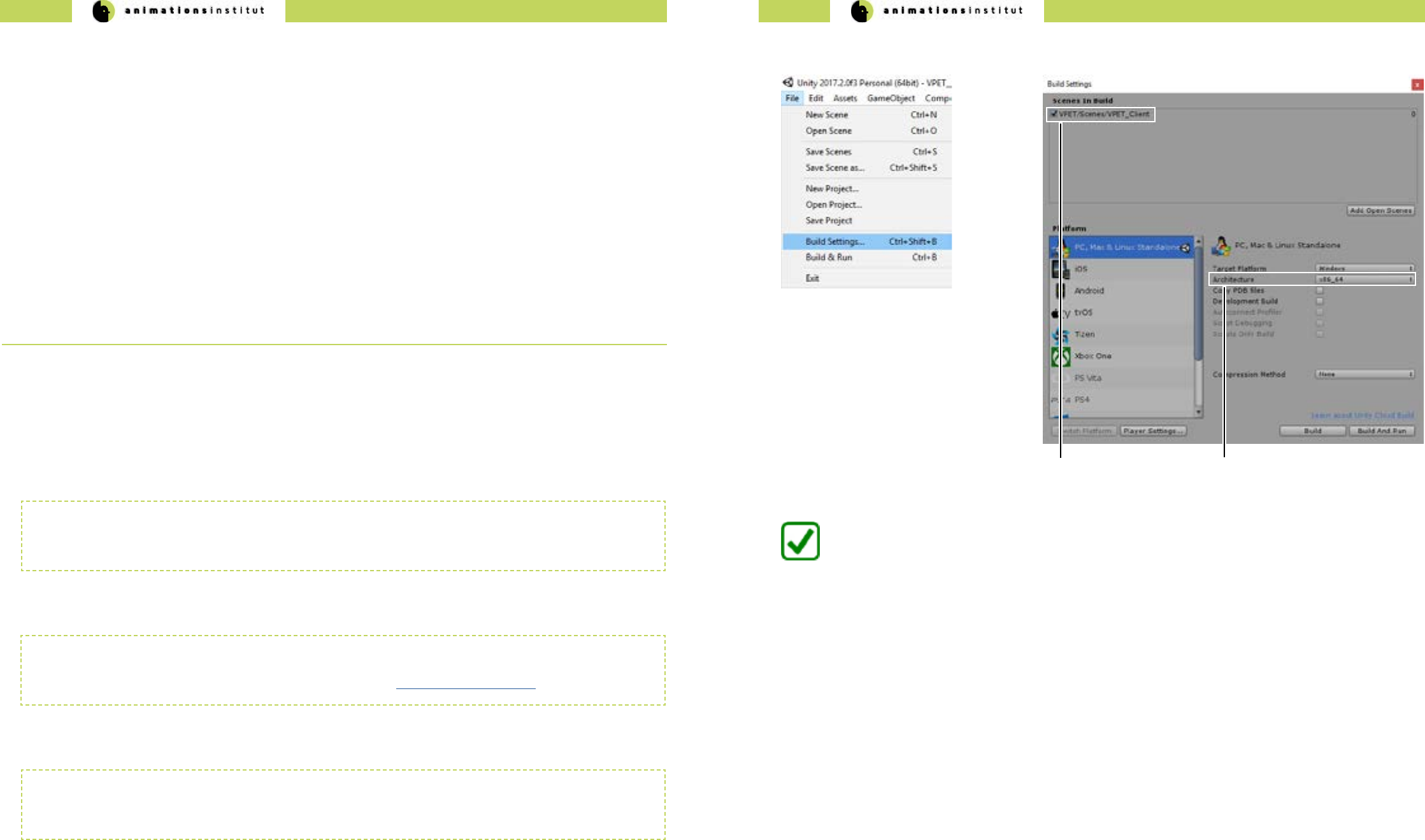
1. Within Unity, check your “build settings” - options, as shown below.
2. Click “Build” once, and select an easily
memorizable le location for your build.
(a) cached scene
for build
3. Copy your build to the directory of your
choice and start VPET.
You are now able to build and deploy your VPET-app to the Windows, MacOS and most Linux
Distributions.
(b) architecture
dropdown menu
VPET - Documentation - Administrator’s guide VPET - Documentation - Administrator’s guide
54 55
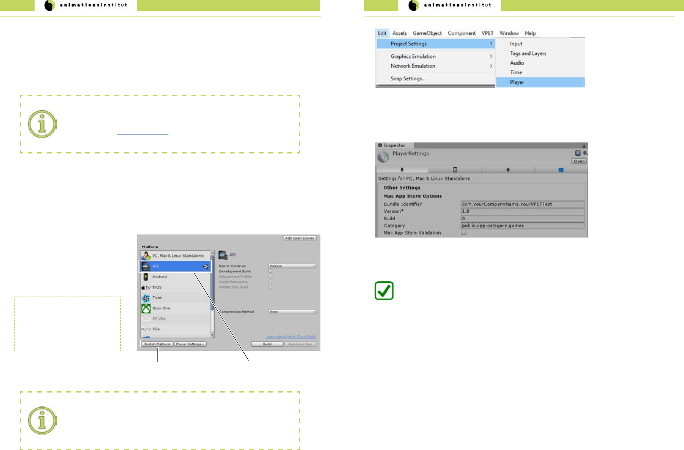
2. Within Unity, check your “build settings” - options, as shown below.
3. After choosing “iOS” (a) from the available
options click once on “Switch Platform”.
Building for iOS wfrom VPET works largely analogous to building for Windows, but enforces some specic require-
ments for deployment.
The few key dierences will be explained in this subchapter.
4. The required les will be loaded, and the
output format will be changed to Xcode.
(b) selected OS
(a) Switch Platform
5. At this point, it is imperative to enter the
correct bundle identier.
XCode requirements:
We strongly advise to aquire and update the required les and licenses for
XCode - projects before trying to deploy. If unsure how to proceed, deploy a test build
as described in the Unity documentation to ensure a smooth workow for your VPET -
project.
XCode
Switching to SCode reimports all
assets within the project.
Depending on the size and
complexity of your scene, this may
take some time.
These are the specic elements required:
√ an Apple ID (either personal or linked to a team).
√ an Apple Developer Program certicate (if submitting your project to the App Store).
√ a valid provisioning prole certicate (if submitting your project to the App Store).
Bundle identier:
While it is not unusual to use a personal Apple ID during development and testing of your
VPET build, submitting it to the App Store requires a dierent bundle identier than the
one linked to a free Apple ID / Personal Team.
2.7.4. VPET for iOS and ARKit
6. Within Unity, Navigate to Edit / Project Settings / Player.
You are now able to build and deploy your VPET-app to a mobile device running iOS.
7. In the Inspector window, check for “Mac App Store Options” and ll out the texteld “bundle identier” according to this
format:
com.yourCompanyName.yourVPETTest
8. Connect your iOS device to your desktop, add it to trusted devices via the Apple ID settings, and deploy your build
for testing the functionality.
VPET - Documentation - Administrator’s guide VPET - Documentation - Administrator’s guide
56 57
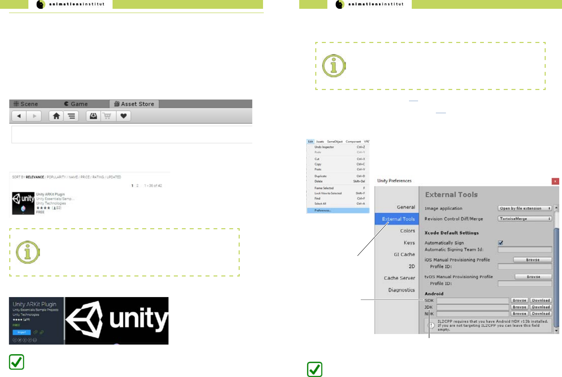
1. Get the most recent Java development kit from here.
2. Get the most recent Android software development kit from here.
This will most likely be in form of Android Studio, which contains the SDK in bundled form along with the required toolkits
3. After installing Android SDK and Java JDK, please memorize the location of the kits carefully.
4. Navigate to “Edit / Preferences” within Unity.
(b)
File Location for
Android SDK
(a)
External Tools Menu
5. Click on “External Tools” (a) once.
(c) File Location for Java JDK
6. Click “Browse”, and point Unity to the le locations of your Android SDK (a) and Java JDK (c) respectively.
You are now able to build and deploy your VPET-app to a mobile device running Android.
Deployment for devices running on Android is not fundamentally dierent from deploying to other OS, though there
are some key dierences. These will be explained in detail in this chapter.
2.7.5. VPET for Android
Software development kit conicts:
As a rare instance, the occasionally rapid development of Android builds may result in
conicts between Android SDK / Tango SDK / Java JDK.
If you encounter these conicts, please consult the respective help desks, and report the
problem to the VPET-development team on Github.
2. In the search texteld within the asset store, type in “Arkit Unity”. Make sure the chosen plugin is developed by
Unity Technologies.
3. Import the Unity ARKit plugin.
Project import:
Since the assets for the Unity AR-Kit are directly imported, it is strongly advised to do
so without an active project within Unity. If unsure, close your project, restart Unity and
import the AR-Kit rst, before loading your project to avoid conicts.
You are now able to employ Unity AR - functionalities within your VPET scene.
1. By default, the “Asset Store” - tab is located above the scene preview - window within Unity.
2.7.4.1. Importing the ARKit
Employing AR-features widens the scope und useability of VPET considerably due to an improved user experience.
Additionally, it enhances your scene by optional camera video input. light estimation, hit testing API and
plane detection.
Deploying your user’s devices along with the Unity-embedded ARkit is free at the time of writing. The process will be
explained below.
VPET - Documentation - Administrator’s guide VPET - Documentation - Administrator’s guide
58 59
2. Point the dialog window to the le location of your Google Tango
SDK . At the time of writing, Ikariotikos SDK is the latest version. - this
may have changed at the time of reading).
1.Once downloaded, open Assets / Import Package / Custom Package
within Unity.
4. After importing, check if the “Tango Manager” is active (see below).
5. Next, check for the active “Tango Application Script”.
2.7.5.2. VPET for Google Tango
You have now successfully imported the Google Tango SDK.
6. Finally, click the “Player Settings” - button in your “Build Settings” - dialogue window. (as described in chapter 2.7.)
Make sure to have switched the platform to Android.
7. Check under the “Inspector” tab at the right
side of your screen.
Under “other settings”, check for the Scripting
Dene Symbols texteld. It should look exactly
like shown to the right.
1. Click the “Player Settings” - button in your “Build Settings” -
dialogue window (as described in chapter 2.7.).
Make sure to have switched the platform to Android.
At the time of writing, the latest commercially available Tango - enabled AR Product is the Lenovo Phab 2 Pro Smartphone.
Since there are a few peculiarities to take into account, this chapter will demonstrate the build and deployment for this
specic device. Beyond that, the building of an Android - app is described in chapter 2.7..
2. Under the “Inspector” - tab to the right of your screen,
check for “Other Settings / Identication”.
3. Set your Minimum API Level to Android 6.0 “Marshmallow”.
4. Navigate to “Hierarchy / Cameras / Main Camera”.
5. In your Inspector, check for “Move Camera (Script)”.
Activate the checkbox “Tango Build 4 Lenovo Phab 2 Pro”
(a)
You are now able to build and deploy your
VPET-app to a Lenovo Phab 2 Pro.
(a)
checkbox Tango
Build 4 Lenovo
The last tested SDK-version for deploying on Google Tango was Caporales (Version 1.49). As mentioned, conicts
between various SDKs or the upstream software of VPET is possible. Please check on xxx for updates in regard to
compability.
2.7.5.3. VPET for Lenovo Phab 2 Pro
3. Leave the default settings and click “Import”.
If you plan to build your VPET app for an AR-equipped Google Tango device, get the latest Tango SDK for Unity from here.
Beyond that, the building of an Android - app is described in chapter 2.7..
VPET - Documentation - Administrator’s guide 60
video stream
preview
monitor
main camera
VPET core setup
VPET optional addons
camera
tracking
light capture
and estimation
lighting
controller
client
DMX
controller
camera
parameters
tracking
data
VPETServer
Synchronization
server
Host application
listener
Host application
scene distribution
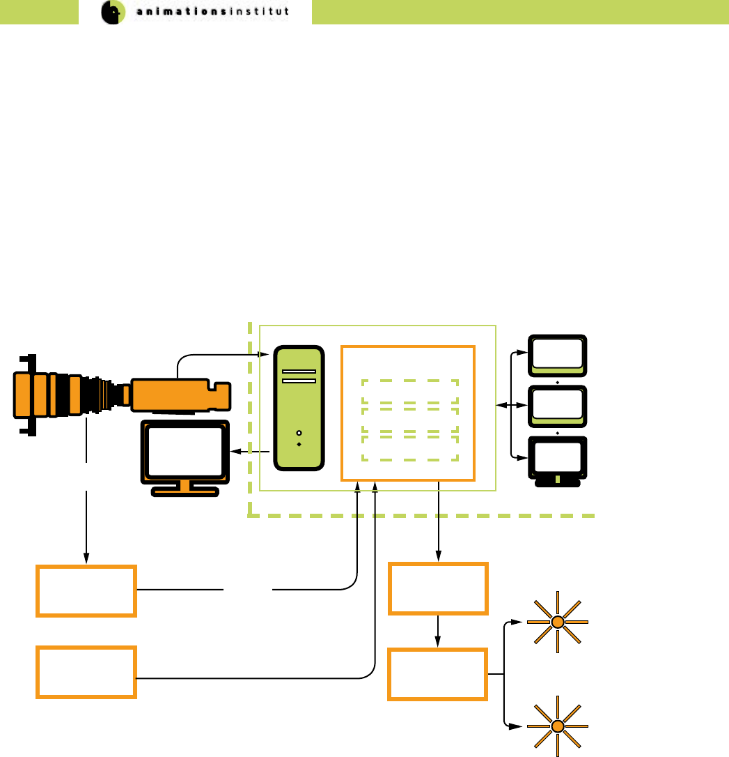
2.8. Optional VPET addons
By now, this guide has enabled you to install a working VPET - Server, distributing, receiving and synchronizing with its
respective clients.
To widen cooperation capabilities and encompass common on-set technologies, VPET can include the following addons:
√ Camera tracking systems
√ Motion capturing systems
√ DMX-controller lighting systems
This chapter will give a brief overlook on how to utilize these addons. Please refer to the documentation of the respective
product of your choice for detailed information.
Basically, every addon works as an additional client, feeding specic data into
the host application listener. VPET has been extensively tested with NCAM cam-
era tracking systems and motion capturing systems like Optitrack.
Please refer to the respective documentaton when utilizing your addons of
choice.
3. Imprint
Filmakademie Baden-Württemberg GmbH,
Animationsinstitut
Akademiehof 10
71638 Ludwigsburg
www.animationsinstitut.de
Institutsleiter:
Prof. Andreas Hykade
Eintragung Amtsgericht Stuttgart, HRB 205016
Vorsitzende des Aufsichtsrates:
Petra Olschowski
Staatssekretärin im Ministerium für Wissenschaft,
Forschung und Kunst Baden-Württemberg
Geschäftsführer:
Prof. Thomas Schadt
