VPROC_SDK_Package_QuickStart_Guide VPROC SDK Package Quick Start Guide
VPROC_SDK_Package_QuickStart_Guide
User Manual: Pdf
Open the PDF directly: View PDF ![]() .
.
Page Count: 32

Quick Start Guide
Part Numbers: ZLS38100
VPROC SDK
Release: P3.0.0
Issue Date: December 20, 2017
VPROC SDK Package
This page left intentionally blank

Document ID#157959 Date: December 20, 2017
Revision: 1
Distribution: Per License Agreement
TABLE OF CONTENTS
CHAPTER 1 INTRODUCTION . . . . . . . . . . . . . . . . . . . . . . . . . . . . . . . . . . . . . . . . . . . . . . . . . . . . . . . . . . . . . . 1
1.1 Overview . . . . . . . . . . . . . . . . . . . . . . . . . . . . . . . . . . . . . . . . . . . . . . . . . . . . . . . . . . . . . . . 1
1.2 ZLS38100 Software Design Flow . . . . . . . . . . . . . . . . . . . . . . . . . . . . . . . . . . . . . . . . . . . . . 1
1.3 VPROC Software Package Components . . . . . . . . . . . . . . . . . . . . . . . . . . . . . . . . . . . . . . . 2
CHAPTER 2 FIRST STEPS . . . . . . . . . . . . . . . . . . . . . . . . . . . . . . . . . . . . . . . . . . . . . . . . . . . . . . . . . . . . . . . . 5
2.1 Step 1: Configure the VPROC SDK PRE-COMPILE OPTIONS . . . . . . . . . . . . . . . . . . . . . 5
2.2 Step 2: Write/Modify the SSL and HAL modules . . . . . . . . . . . . . . . . . . . . . . . . . . . . . . . . . 7
2.3 Step 3: Test the HBI and HAL . . . . . . . . . . . . . . . . . . . . . . . . . . . . . . . . . . . . . . . . . . . . . . . 8
2.4 Step 4: Load a firmware and config into the VPROC . . . . . . . . . . . . . . . . . . . . . . . . . . . . . . 8
2.5 Step 5: Write the Final Application . . . . . . . . . . . . . . . . . . . . . . . . . . . . . . . . . . . . . . . . . . . . 9
CHAPTER 3 PORTING. . . . . . . . . . . . . . . . . . . . . . . . . . . . . . . . . . . . . . . . . . . . . . . . . . . . . . . . . . . . . . . . . . . 11
3.1 The Ambarella platform SDK . . . . . . . . . . . . . . . . . . . . . . . . . . . . . . . . . . . . . . . . . . . . . . . 11
3.2 Ambarella SDK device tree modifications . . . . . . . . . . . . . . . . . . . . . . . . . . . . . . . . . . . . . 11
3.2.1 Device tree modification for VPROC HBI=I2C device registration . . . . . . . . . . . . 11
3.2.2 Device tree modification for VPROC HBI=SPI device registration . . . . . . . . . . . . 12
3.2.3 Device tree modification for VPROC SOUND device registration . . . . . . . . . . . . . 13
3.3 Loading and testing the VPROC SDK on an Ambarella platform. . . . . . . . . . . . . . . . . . . . 13
CHAPTER 4 QUICK START APPLICATIONS. . . . . . . . . . . . . . . . . . . . . . . . . . . . . . . . . . . . . . . . . . . . . . . . . 15
4.1 Overview . . . . . . . . . . . . . . . . . . . . . . . . . . . . . . . . . . . . . . . . . . . . . . . . . . . . . . . . . . . . . . 15
4.2 User Modifications . . . . . . . . . . . . . . . . . . . . . . . . . . . . . . . . . . . . . . . . . . . . . . . . . . . . . . . 16
CHAPTER 5 BUILDING THE CUSTOMER APPLICATION. . . . . . . . . . . . . . . . . . . . . . . . . . . . . . . . . . . . . . . 19
5.1 Generating VPROC configuration record and convert files:. . . . . . . . . . . . . . . . . . . . . . . . 21
5.2 Compile/Recompile the Application and Run . . . . . . . . . . . . . . . . . . . . . . . . . . . . . . . . . . . 25
5.3 Next Steps . . . . . . . . . . . . . . . . . . . . . . . . . . . . . . . . . . . . . . . . . . . . . . . . . . . . . . . . . . . . . 26

ii
VPROC SDK QUICKSTART GUIDE

CHAPTER
1
1INTRODUCTION
1.1 OVERVIEW
The ZLS38100 Software Development Kit (SDK) is a collection of software, tools, code examples,
and documents that allow rapid application development with the Microsemi Timberwolf device
series. With the ZLS38100 Software Package, little or no knowledge of the low-level control of
Timberwolf ICs is needed to fully utilize the chipset. The ZLS38100 software is designed to simplify
implementation and reduce customers' time to market.
This Quick Start Guide provides an overview of the ZLS38100 SDK and how the Package is used
to demonstrate some of the features supported by the Timberwolf devices.
Note: Within this document, the terms VPROC SDK and ZLS38100 SDK or ZLS38100 Software package are
used interchangeably
1.2 ZLS38100 SOFTWARE DESIGN FLOW
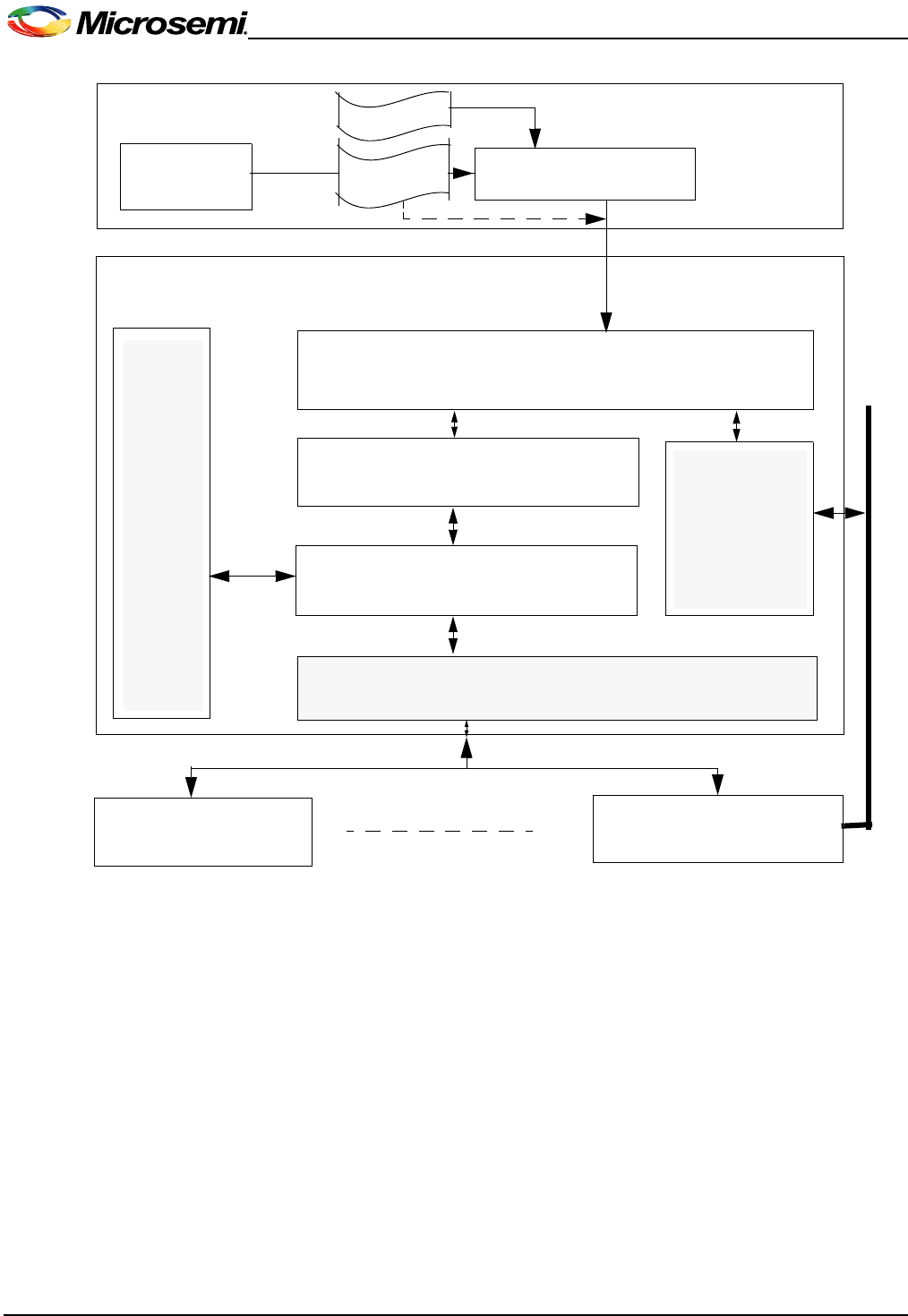
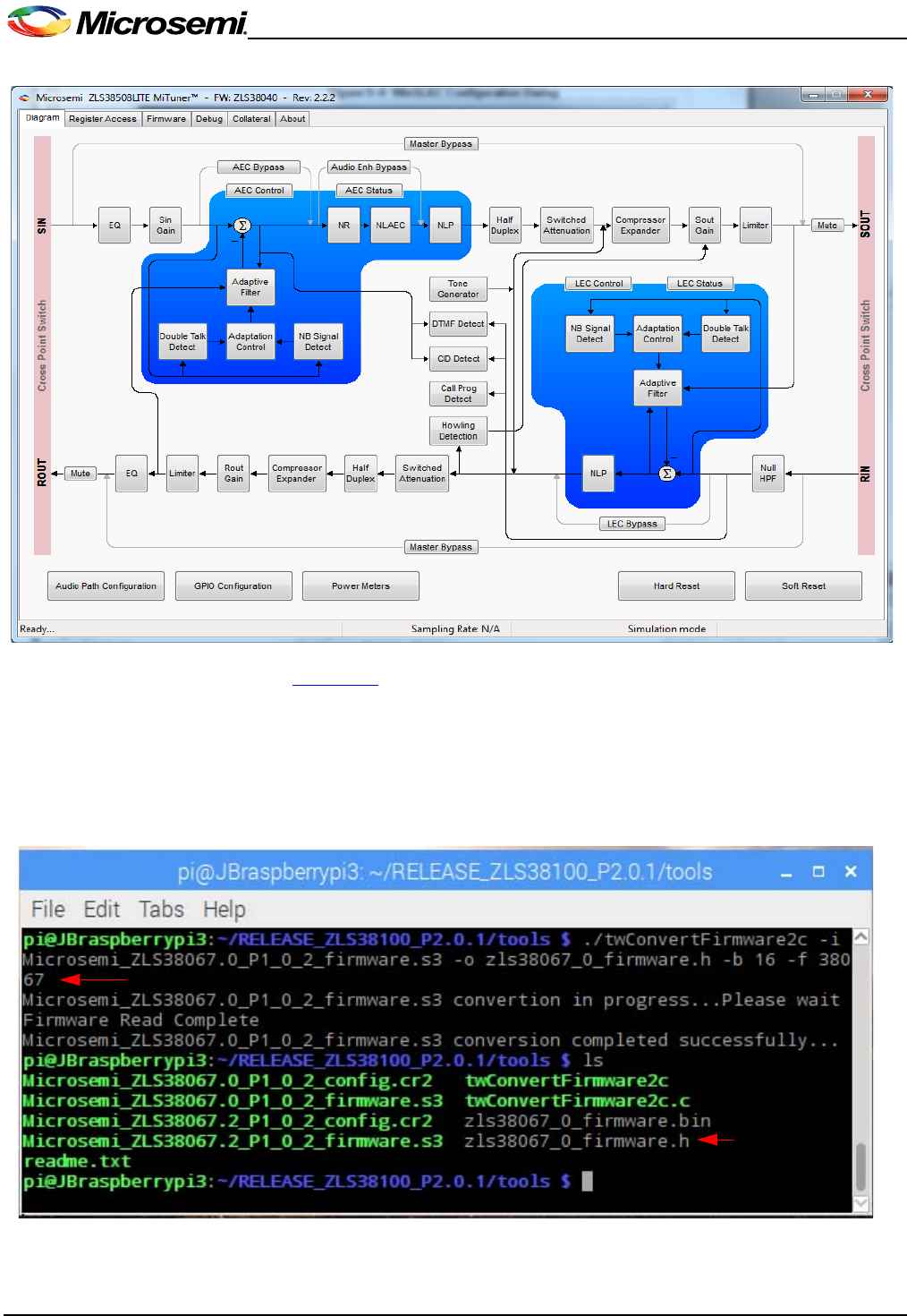
The following diagram introduces the prominent elements of the VPROC SDK software architecture.
It is recommended that the user reads the VPROC SDK Reference Guide introduction for more
precise details on these elements.
2
VPROC SDK QUICKSTART GUIDE
Figure 1–1 System Diagram
1.3 VPROC SOFTWARE PACKAGE COMPONENTS
The ZLS38100 Software Package contains tools, code, documentation, and examples applications
for developing products based on the Timberwolf chipset. The following is a list of components
distributed in the SDK.
• ZLS38100 SDK (source and documentation)
• ZLS38100 Software Release and Errata Notice
• Quick Start Demo Applications
• Platform - SPI, I2C, ALSA & SSL Example drivers (See shaded blocks in the above software
block diagram)
MiTuner
Customer
PC
Customer Host Micro-Controller
Customer Application or
Microsemi Quick Start Application
VPROC HBI OS independent Layer
(API)
VPROC HBI OS dependent Layer
Hardware Abstraction Layer (HAL)
SPI or I2C
System
Service
Layer
(SSL)
VPROC device 1 VPROC device n
Audio driver
( codec)
*.cr file
Host Bus Interface (HBI)
I2S/PCM
*.s3
twConvertFirmware2c
*.bin, *.h

3
VPROC SDK QUICKSTART GUIDE
To find more about these items and where they (and their documentation) can be located, refer to
Table 1 below. The pathnames found in the table use "xxx" to represent version numbers and
product strings that are subject to change.
Table 1–1 Common Components List
Component Description Documentation
Makefile,
Makefile.globals
Main makefiles for the SDK. The makefile.globals
contains system hardware and software
configurations that must be set accordingly by the
VPROC SDK user, prior to compiling the SDK.
See first Steps chapter within this
document
config.mk It converts the Makefile.globals variables to "C"
compiler options and add relevant include paths.
VPROC HBI
This C-language library provides a common,
consistent interface to Microsemi’s Timberwolf
Voice Processing devices. This is refered in this
document as the VPROC API layer of the SDK,
which is executed on a host processor, simplifies
the task of communicating with the VPROC
chipset.
Location: install_dir//drivers/hbi
VPROC SDK Reference Guide -
the primary reference to consult
when developing VPROC
application software.
("/install_dir/documents")
Location: install_dir/
documents
VPROC Linux
This component exists only in release that
depends on Linux. It is the C-language library that
binds the VPROC HBI layer to the platform layer
to the application layer of the SDK.This layer of
code is divided into a kernel specific library that
provides the interfacing between the VPROC HBI
layer and the platform (HAL drivers) layer, and a
user-space library that provides the interfacing
between the VPROC HBI layer to the user-
applications layer.
Sound drivers
The sound codec and machine driver are
integrated to the VPROC SDK in order to
interface the Timberwolf to an audio controller.
These modules must be tailored to meet the
specific underlying platform. The example
working implementation of the machine driver is
provided for a Linux platform based on the
Ambarella S2L Micro-controllers. The codec
driver is not controller specific.
Location:
install_dir//platform/ambarella/driver/
sound
VPROC SDK getting started
guide
Location: install_dir/
documents
Firmware and
Configuration
Conversion tool
The Conversion tool must be used to format the
Timberwolf firmware into either a binary file that
can be loaded into the device dynamically or in c
source code that can be compiled with the
VPROC SDK application statically.
Location: install_dir/tools

4
VPROC SDK QUICKSTART GUIDE
HAL & SSL
Examples
These C language samples of Hardware
Abstraction Layer and System Services Layer
implementations provide examples of the
functions the user must implement for their
architecture. Extensively commented.
Location: install_dir//platform/ambarella/driver/
ssl
Note:
There are two samples of the HAL (for I2C and
SPI) and one sample of the System Services
Layer. User should choose the one that is most
appropriate for their application when starting
development of a VPROC application.
VPROC SDK Reference Guide
Location: install_dir/
documents
Quick Start
Applications
This source code may be compiled to create an
application that demonstrates functional aspects
of the VPROC SDK.
Location: install_dir/apps/
This directory contains examples VPROC
application initializing and controlling the
Timberwolf chipset.
Chapter 4, on page 15
Table 1–1 Common Components List
Component Description Documentation
CHAPTER
5
2FIRST STEPS
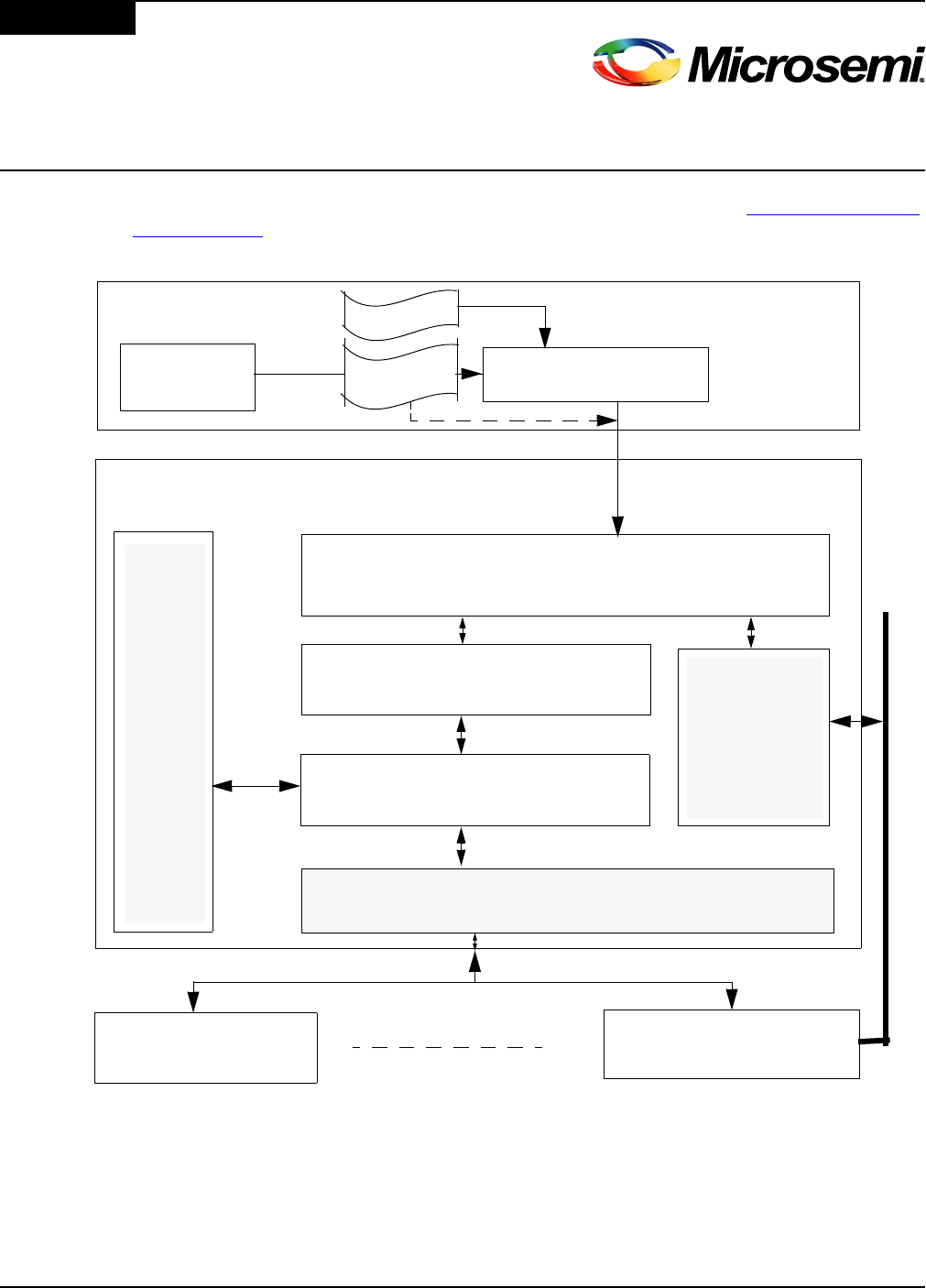
There is a natural sequence to VPROC system development to ensure quick and proper system
operation. The first steps in bringing up a new VPROC design are shown in Figure 2–1, Steps To
Take, on page 5. Steps to follow.
Figure 2–1 Steps To Take
2.1 STEP 1: CONFIGURE THE VPROC SDK PRE-COMPILE OPTIONS
The API contains several pre-processor options used throughout the code that must be configured
in accordance to the platform and design. These options are defined in the "Makefile.globals"
located in the "root" directory of the VPROC SDK source tree. The options that must be set for a
basic configuration are:
MiTuner
Customer
PC
Customer Host Micro-Controller
Customer Application or
Microsemi Quick Start Application
VPROC HBI OS independent Layer
(API)
VPROC HBI OS dependent Layer
Hardware Abstraction Layer (HAL)
SPI or I2C
System
Service
Layer
(SSL)
VPROC device 1 VPROC device n
Audio driver
( codec)
*.cr file
Host Bus Interface (HBI)
I2S/PCM
*.s3
twConvertFirmware2c

6
VPROC SDK QUICKSTART GUIDE
PLATFORM= this option must be named as per the directory created under the platform
folder of the SDK. For the ZLS38100 the platform is by default set to ambarella, since the
platform related codes for the Ambarella Micro-controllers are located within a folder named
"ambarella".
VPROC_MAX_NUM_DEVS= this option must be set to the exact number of Timberwolf
VPROC chipsets that need to be controlled by the SDK. Default setting is set to 1. Example
to support 4 Timberwolf devices in the design, simply set this variables to 4.
HBI_MAX_INST_PER_DEV= this option must set to the number of instances that can be
opened per device driver. This is only required for multi-threaded or multi-process
applications that want’s to access the device from multiple threads or processes.
KSRC= this variable must be set to the exact path to where to find the Linux kernel for which
to compile the kernel related codes of the SDK.
Example:
export KSRC=$(PLATFORM_DIR)/s2l_purelinux_sdk2_0/Ambarella/out/s2lm_kiwi/kernel
TOOLSPATH= this must be set to the exact path to where the tool chain needed to compile
the SDK is located on the development machine.
ARCH= Micro-controller architecture. For the ZLS38100 release this is set to arm for an
arm cortex architecture.
CROSS_COMPILE= this must be set to the exact compiler that should be used to compile
the SDK.
Example
export TOOLSPATH=$(PLATFORM_DIR)/tools/linaro-multilib-2014.09-gcc4.9
All other options can be left as per default definition. See table below for a full list of the
variables defined within the "Makefile.globals".
Option Value Comments
BOOT_FROM_HOST yes,
no
yes if the VPROC firmware is to be
loaded into the device via the SPI/I2C.
no, otherwise
HBI_MAX_INST_PER_DEV a value from 1 to 2^31
Specifies the maximum number of
simultaneous user per VPROC device.
Keep it to 1
FLASH_PRESENT yes,
no
yes, if the VPROC device is controlling
a slave FLASH. no, otherwise
VPROC_DEV_ENDIAN big Endianness of the VPROC device.
Keep this setting to big
HBI_BUFFER_SIZE a value greater than 16
This must set to a value large enough to
support large HBI transaction to the
VPROC device. This option must not
be set to a value lower than 16.
HBI_ENABLE_PROCFS 0,
1
This is optional profc fs interface to the
SDK. It provided an alternative way to
perform all the device access features
supported by the SDK
VPROC_MAX_NUM_DEVS a value from 1 to 2^31
Specifies the total number of VPROC
devices in the design to be supported
by the SDK.

7
VPROC SDK QUICKSTART GUIDE
2.2 STEP 2: WRITE/MODIFY THE SSL AND HAL MODULES
These thin layers provide functions allowing the VPROC SDK to enforce mutual exclusion and to
communicate with the VPROC device through the HBI bus. The SDK supports both I2C or SPI
interfacing to the Host controller.
Example implementations of both of these layers in accordance to a Linux platform are available in
the "/install_dir/platform/driver/ssl" directory of the VPROC SDK. (See the Porting the SDK to the
Raspberry Pi platform chapter for more info)
Note:
These modules are platform dependant, therefore, the user must ensure that the types defined in "/
install_dir/platform//include/typedefs.h" are applicable to the customer’s target environment.
At this point, the VPROC SDK should be able to compile.
TARGET TW
This defines the VPROC device type.
Currently only TW VPROC device type
is supported by the SDK
HBI I2C,
SPI
Specifies the physical host control bus
interfaced to the VPROC device.
BUILD_TYPE DEBUG,
RELEASE
Set to release if the SDK is to be built
for a formal release. For release,
Debug print are disabled. Debug level
are only accessible in DEBUG build
type
HOST_ENDIAN big,
little Endianness of the host platform
VPROC_DEV_NAME_SIZE any decimal number
up to 2^31
This is optional. It specifies the
maximum number of characters for the
device name.
NUM_MAX_LOCKS a value from 1 to 2^31
This is optional. It indicates the
maximum number of SSL locks that
can be used by the driver.
DEBUG_LEVEL
Bitmask for
VPROC_DBG_LVL
0 - none
1 - function entry/exit
2 - information
3 - warning
4 - error
5 - All (levels: 2-4)
This debug level to the exception of
error are only available if the
BUILD_TYPE = DEBUG
VPROC_CODEC_MIXER_EN
ABLE
yes,
no
yes, to enable the ALSA mixer option.
no, otherwise
HBI_ENABLE_FWR_BIN yes,
no
yes, to enable the support for the linux
device firmware loader library, no
otherwise
HBI_LOAD_FWR_STATIC
HBI_LOAD_CFGREC_STATIC
yes,
no
yes, to compile a firmware and related
configuration record with the SDK, no
otherwise
Option Value Comments

8
VPROC SDK QUICKSTART GUIDE
Compile the SDK by issuing the command or as per your compile environment.
make hbi_clean
make hbilnx_clean
make hbilnx <options>
This will build /platform, /hbi and /hbilnx components and save output hbi.ko,
s2l_zl380xx_audio.ko, and snd-soc-zl380xx.ko in /libs directory.
<options>: HBI=I2C to build the HBI for I2C host access or HBI=SPI to build the HBI for SPI host
access. If the HBI option is omitted then the SDK will be compiled by default with HBI=SPI as
defined within the Makefile.globals.
If error during compile, verify the following are included in the build process:
1. Compiler or tool chain needed to compile the SDK is defined within the Makefiel.globals.
2. If using a Linux OS then make sure the Linux kernel path is defined within the Makefile.globals
as indicated in step 1 above.
2.3 STEP 3: TEST THE HBI AND HAL
Various examples of demo host applications are provided within the install_dir/APPS directory of
the SDK. Compile the hbi_test.c host application, use it to verify that the host can communicate with
the VPROC device. This Quick Start application demonstrates successful top-to-bottom integration
of the system from the user application, to the VPROC HBI, to the HAL/SSL drivers, to the
hardware.
To compile the apps issue the command
make apps HBI_TEST=1
If compiled successfully, the executable hbi_test will be located in the same apps directory.
Use the hbi_test apps to write the following bytes into register 0x000C of the Microsemi VPROC
device ID 0
Write: 0x1234, 0x5678 into register 0x00C of the VPROC device ID 0
hbi_test -d 0 -w 0x00C 0x1234 0x5678
Then read back the 4 bytes of data from register 0x00C
hbi_test -d 0 -r 0x00C 4
If successful, the expected read data from the VPROC device should be 0x1234, 0x5600. The
last byte of the read is zeroed out by the VPROC device in order to signal to the host that it is alive
and working properly.
2.4 STEP 4: LOAD A FIRMWARE AND CONFIG INTO THE VPROC
Optionally, if a firmware is to be loaded into the VPROC device via the host, then use the
twConvertFirmware2c tool within the install_dir/tools directory to convert the Timberwolf
firmware into a file format supported by the SDK.
The tool can be compiled and used on a Microsoft Windows system or a Linux system. Compile the
twConvertFirmware2c.c code using any gcc compiler or optionally the same compiler used to
compile the SDK.
Example:
gcc twConvertFirmware2c.c -o twConvertFirmware2c
The tool can convert the Timberwolf firmware *.s3 image and *.cr2 config record files into either a
binary format that can be loaded into the device at runtime or into a c code header format that can
be compiled with the SDK.
Example:

9
VPROC SDK QUICKSTART GUIDE
To see usage menu, run
twConvertFirmware2c.exe -h
To convert the a firmware image named zl38040_firmware.s3 in c-code format with block size
of 16 words
twConvertFirmware2c -i zl38040_firmware.s3 -o zl38040_firmware.h
-b 16 -f 38040
To convert a Timberwolf firmware image named zl38040_firmware.s3 in binary format
twConvertFirmware2c -i zl38040_firmware.s3 -o zl38040_firmware.bin
-b 16 -f 38040
To convert a Timberwolf VPROC configuration record into c-code format
twConvertFirmware2c i zl38040_config.cr2 -o zl38040_config.h -b 16 -f
38040
Note: the block size is optional. If specified it must be a multiple of 16 (Ex: 16*2^n, where n: 0, 1,
2, 3) for the firmware and 1 (Ex: 16*1^n, where n: 0, 1, 2, 3, 4, 5, 6, 7)for the configuration record,
and the maximum supported block size is 128. If not specified the block size default to 16 for the
firmware and 1 for the configuration record.
Compile the hbi_load_firmware.c demo application and execute to load the converted
firmware and the config record into the device
Example: to load the converted zl38040_firmware.bin and related zl38040_config.bin
configuration record into the VPROC device
hbi_load_firmware -i zl38040_firmware.bin -c zl38040_config.bin
Run the Quick Start Application by following the instructions in Chapter 4, on page 15.
2.5 STEP 5: WRITE THE FINAL APPLICATION
All physical connections are now verified to be working correctly, greatly simplifying the control
application troubleshooting process. Refer to the VPROC Reference Guide for information on the
API interface used by the host program to control the VPROC chipset. Please see also Chapter 5,
on page 19 for further advice.

10
VPROC SDK QUICKSTART GUIDE

CHAPTER
11
3PORTING
3.1 THE AMBARELLA PLATFORM SDK
The Ambarella S2L SDK is based on Linux kernel 3.10.xx, the Ambarella S2L device driver
registration is based on the Linux device tree driver registration method. Therefore the Microsemi
HBI drivers for the Ambarella platform are implemented accordingly. The code within the platform
folder is specific to the Ambarella SDK. The code implements both Hardware Abstraction Layer
(HAL) and System Service Layer (SSL) codes, but also ALSA sound codec driver for the Microsemi
VPROC device.
The HAL and SSL codes are located in directory "install_dir/platform/ambarella/
driver/ssl/".
Note: Although the coce was verified on an Ambarella S2L platform, but it is compatible with all Ambarella SxL
(x:2, 3, 5 etc.) based platforms
3.2 AMBARELLA SDK DEVICE TREE MODIFICATIONS
Ambarella provides a device configuration overlay with their SDK. The device tree configuration
overlay (*.dts) file for the S2L SDK is located within the particular S2L board bsp folder (“/
s2l_purelinux_sdk2_x/ambarella/boards/s2lm_xx/bsp/s2lm_xx.dts” . This
file must be modified as per below to support the VPROC SDK.
The HAL drivers of the VPROC SDK supports either SPI or I2C HBI mode. the SDK can only be
compiled for one or the other.
3.2.1 Device tree modification for VPROC HBI=I2C device registration
If the VPROC SDK is compiled with the HBI option set to I2C, then the following device tree node
must be added into the S2L device tree (*.dts) for your board under the related I2C bus node within
the *.dts file.
Example: If the VPROC device is interfaced to the S2L via I2C bus 0
i2c0: i2c@e8003000 {
status = "ok";
zl380i2c0: codec@45 {
compatible = "ambarella, zl380i2c0";
reg = <0x45>;
};
};
Note: change the I2C address defined by the variable reg accordingly. The VPROC device can be
configured for I2C address 0x45 if the HDIN pin of the device is tied to ground. Or, address 0x52 if
the HDIN pin is tied to 3.3V. If registering multiple VPROC devices, then add extra nodes in the
main i2cx node accordingly
Example: to support two VPROC devices one at address 0x45 and the other at address 0x52
i2c0: i2c@e8003000 {
status = "ok";
zl380i2c0: codec@45 {
compatible = "ambarella, zl380i2c0";
reg = <0x45>;
};
zl380i2c1: codec@52 {

12
VPROC SDK QUICKSTART GUIDE
compatible = "ambarella, zl380i2c1";
reg = <0x52>;
};
}; .
3.2.2 Device tree modification for VPROC HBI=SPI device registration
If the VPROC SDK is compiled with the HBI option set to SPI, then comment out the uart1 node
within the S2L *.dts file related node, and make sure the SPIx (x=0 in example below) node entry
is as per below.
/*
uart1: uart@e0032000 {
compatible = "ambarella,uart";
reg = <0xe0032000 0x1000>;
interrupts = <25 0x4>;
pinctrl-names = "default";
pinctrl-0 = <&uart1_pins_d &uart1_flow_pins_e>;
status = "ok";
};
*/
spi0: spi@e0020000 {
cs-gpios = <&gpio 37 0>, <&gpio 38 0>;
};
The VPROC SPI driver can also be instantiated using the device tree method by defining the
following macro within the install_dir/platform/ambarella/driver/ssl/hal_spi.c driver code
#define SUPPORT_LINUX_DEVICE_TREE_OF_MATCHING.
If this macro is defined, then a zl380xx node must be added within the SPI node of the dts file.
Example below is given for a zl380spi01 connected to the S2L via SPI bus 0, and Chip Select 1.
The SPI clock frequency is configured to 25MHz. The VPROC device can support SPI clock up to
25MHz (25000000). Keep the clock setting definition in the device tree file to the maximum
25MHz, if a lower SPI clock is desired set the desired value in the "install_dir/platform/
Ambarella/driver/ssl/hal_spi.c" driver probe function code.
/*
uart1: uart@e0032000 {
compatible = "ambarella,uart";
reg = <0xe0032000 0x1000>;
interrupts = <25 0x4>;
pinctrl-names = "default";
pinctrl-0 = <&uart1_pins_d &uart1_flow_pins_e>;
status = "ok";
};
*/
spi0: spi@e0020000 {
cs-gpios = <&gpio 37 0>, <&gpio 38 0>;
zl380spi01: codec@1 {
compatible = "ambarella, zl380spi01";
spi-max-frequency = <25000000>;
reg = <1>;
spi-cpha;
spi-cpol;
};
};

13
VPROC SDK QUICKSTART GUIDE
An example modified *.dts file for the Ambarella S2L Kiwi platform in compatibility with the
ZLS38120 SDK is included with the "install_dir/platform/ambarella/driver/ssl/"
directory for guidance in modifying the Ambarella provided *dts file.
3.2.3 Device tree modification for VPROC SOUND device registration
To add support for ALSA SoC audio driver, the sdk includes a codec driver that must be registered
as a platform driver in order to keep it independent from the I2C or SPI communication driver. To
port that codec driver into the Ambarella S2L SDK, first modify the device tree sound node within
the *dts file by adding the following two nodes as per below to add an entry for the zl380xx codec
driver:
Add a dummy node as per below within the dts existing bogus_bus sub-node
bogus_bus {
zl380snd0: zl380snd0@1 {
compatible = "ambarella,zl380snd0";
status = "okay";
};
};
Then add a sound node as per below
sound {
compatible = "ambarella,s2lmkiwi-zl380snd0";
amb,model = " zl380snd0 @ S2LMKIWI";
amb,i2s-controllers = <&i2s0>;
amb,audio-codec = <& zl380snd0>;
};
Optionally, the VPROC SDK includes a modified version of the Ambarella ALSA machine driver for
the Ambarella S2LM SoC in compliance with the Microsemi ZL380xx devices codec driver. The
ALSA audio driver is located within "install_dir/platform/ambarella/driver/sound/
lnxalsa/"
This file implements the ALSA machine driver aspect of the Ambarella S2L SoC in accordance to
the Ambarella S2L SDK. Ambarella provides an equivalent ALSA machine driver with their SDK
which can be modified as a replacement by simply modifying the following structures as per the
ALSA machine driver provided with the ZLS38120.
static struct snd_soc_dai_link
static const struct of_device_id
Save the modified *.dts file and recompile the Ambarella S2L SDK.
If the specified bus resources assigned to zl380xx driver are unused, the driver will register itself
with the Ambarella controller within the Linux kernel
3.3 LOADING AND TESTING THE VPROC SDK ON AN AMBARELLA PLATFORM
If the VPROC SDK is successfully compiled as described in the "First Steps" chapter of this
document, then these resulting *.ko modules will be created.
install_dir/libs/lib/modules/`uname –r`/extra/hbi.ko
install_dir/libs/lib/modules/`uname –r`/extra/s2l_zl380xx_audio.ko
install_dir/libs/lib/modules/`uname –r`/extra/snd-soc-zl380xx.ko
Load these modules into the Ambarella platform using the insmod command or simply modify the
Ambarella’s SDK config and makefiles accordingly to load these drivers at platform power up. A
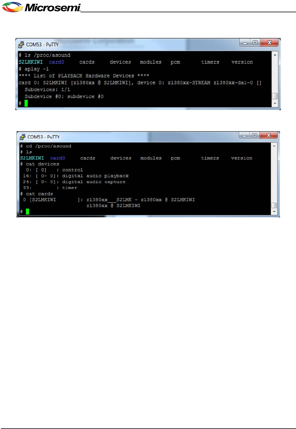
successfully loading of these modules will result in the creation of the sound card entry under
/proc/asound
14
VPROC SDK QUICKSTART GUIDE

CHAPTER
15
4QUICK START APPLICATIONS
The Quick Start Applications located in directory "install_dir/apps" demonstrate some of the
basic functionalities of the VPROC API. The purpose of these applications is to ensure that the
major system components (HBI, HAL, SSL) are configured properly without the user having to write
custom application code. The Quick Start applications provide basic device functionality sanity
check and these example codes can be used as starting point for the customer application
development.
4.1 OVERVIEW
The VPROC SDK is provided with 3 examples quickstart applications.
hbi_test.c: is a simple application to test the HBI driver functions. This application demonstrates
the usage of the API functions implemented by the VPROC HBI (API) layer of the SDK such as:
• Reset the VPROC device (This macro TEST_RST must be defined in order to enable this
feature)
• Read one or more registers of the VPROC device via SPI or I2C
• Write one or more registers of the device via SPI or I2C
• Load pre-stored VPROC firmware and related configuration from an external slave flash
device controlled by the VPROC device into the VPROC device internal RAM. (this macro
TEST_LOAD_FWRCFG_FROM_FLASH must be defined in order to eable this feature)
• Erase specific or all VPROC firmware image(s) and related configuration record(s) from an
external slave flash device controlled by the VPROC device into the VPROC device internal
RAM. (this macro TEST_ERASE_IMAGE must be defined in order to enable this feature)
Note: the amount of bytes for the above transactions is defined by the following macro within the
application
#define MAX_RW_SIZE 64 /*in bytes*/
The registers and data words of the VPROC devices are 16-bit in size, therefore a MAX_RW_SIZE
of 64 bytes allows to perform access read or write of up to 32 registers of the device at a time.
For execution usage run ’hbi_test -h’.
hbi_load_firmware.c: is a simple application to load the VPROC device firmware and related
configuration record into the VPROC device internal memory and optionally save the combined
image to a slave flash device controlled by the VPROC device.
Prior to compiling this application the user must first perform the followings:
The VPROC firmware image for the VPROC device is formatted as a Motorola S-record format, this
format can not be used directly by the VPROC SDK. The VPROC SDK provides a tool to convert
the S-record file into either a binary or c- code header file format.
The binary file format can be loaded into the VPROC device dynamically (at runtime), the c-code
file format must be statically compiled into the hbi_load_firmware application.
For static compilation, user needs to define the following four macros at compile time along with
TEST_FWR_LOAD
LOAD_FWR_STATIC - if defined, expects user to provide a C header (*.h) file containing firmware boot
image for static compilation

16
VPROC SDK QUICKSTART GUIDE
LOAD_CFGREC_STATIC - if defined, expects user to provide C header (*.h) file containing configuration
record
The conversion tool is located in the"install_dir/tools" directory of the VPROC SDK. This
code can be compiled on a Microsoft Windows machine or a Linux machine. Compile the
twConvertFirmware2c.c code and use it to convert the firmware and related config in accordance
to the VPROC SDK VPROC image file format requirements.
With the above hbi_load_firmware application the user can:
• Load the VPROC firmware image and related config into the VPROC device
• Save firmware and related config currently running into the VPROC device into a slave flash
device controlled by the VPROC device
For execution usage run ’hbi_load_firmware -h’.
hbi_load_grammar.c: Is a simple application to load a sensory grammar file into the ZL380xx
device and optionally save it to a flash device controlled by the ZL380xx.
For execution usage run ’hbi_load_grammar -h’.
4.2 USER MODIFICATIONS
There are several platform specific parameters that need to be set accordingly prior to compiling
the QuickStart applications. The parameters that need to be modified are described below. This
section assumes the user has completed configuring the VPROC and written or modified the
example SSL and HAL modules. If not, consult the "First Steps" section of this guide.
The HBI parameters:
Default settings for this parameters are configured as per below within
each of the example applications. These parameters need to be configured
accordingly.
#undef I2C /*define to use HBI=I2C*/
#ifdef I2C
static int bus_num = 0; /*Host I2C bus number*/
static int dev_id = 0x45; /*I2C slave device address*/
#else /*if I2C is not defined, then HBI=SPI will be used*/
static int bus_num = 0; /*Host SPI bus number*/
static int dev_id = 0; /*Host SPI Chip Select*/
#endif
Example Quickstart execution logs:
root@:/home/Public/RELEASE_ZLS38100_P2.0.1/apps# ./hbi_test -d 0 -w 0x000C 0x1234
0x5678
HBI_init Entry..
Returned HBI handle 0xa9500000
wr: addr 0x000C = 0x1234
wr: addr 0x000E = 0x5678

17
VPROC SDK QUICKSTART GUIDE
root@:/home/Public/RELEASE_ZLS38100_P2.0.1/apps# ./hbi_test -d 0 -r 0x000C 4
HBI_init Entry..
Returned HBI handle 0xa9500000
Read 4 bytes
RD: addr 0x000c = 0x1234
RD: addr 0x000e = 0x5600
root@:/home/pi/Public/RELEASE_ZLS38100_P2.0.1/apps#
root@:/home/Public/RELEASE_ZLS38100_P2.0.1/apps# ./hbi_load_firmware -d 0 -i
zls38051_firmware.bin -c zls38051_config.bin
inpath zls38051_firmware.bin
HBI_init Entry..
Returned HBI handle 0xa9600000
Calling HBI_get_header()
image_type 0, major 0 minor 0, block size 128,total len 154112, code 0, endian 0
Start firmware load ...
Firmware loaded into Device
Loading file Configuration Record...
opened config file zls38051_config.cr2 ....
using getline..
Image Loading Done.
Start Firmware
root@:/home/Public/RELEASE_ZLS38100_P2.0.0/apps# ./hbi_load_grammar -d -l
grammar_light.bin
Info - Grammar successfully loaded to RAM

18
VPROC SDK QUICKSTART GUIDE
CHAPTER
19
5BUILDING THE CUSTOMER
APPLICATION
This section continues from the previous chapter with steps to build the customer application.
Customer’s should have completed all steps from Chapter 2, on page 5 before proceeding with the
following.
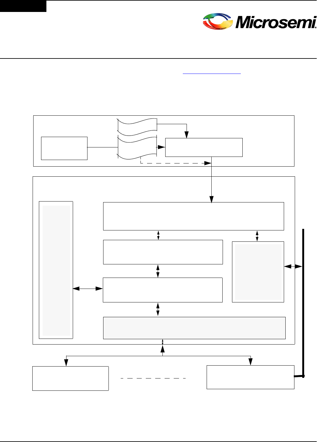
Referring to the "Steps to Take" figure, repeated here for convenience (this chapter will cover "Step
5" from the figure):
Figure 5–1 Steps To Take
The customer application can either be built from an existing quickstart application or created from
scratch (with guidance from what has been learned from the previous steps). While this document
is not intended to be a tutorial on MiTuner (See MiTuner guide document for more info on usage of
MiTuner
Customer
PC
Customer Host Micro-Controller
Customer Application or
Microsemi Quick Start Application
VPROC HBI OS independent Layer
(API)
VPROC HBI OS dependent Layer
Hardware Abstraction Layer (HAL)
SPI or I2C
System
Service
Layer
(SSL)
VPROC device 1 VPROC device n
Audio driver
( codec)
*.cr file
Host Bus Interface (HBI)
I2S/PCM
*.s3
twConvertFirmware2c
*.bin, *.h

20
VPROC SDK QUICKSTART GUIDE
MiTuner), it is intended to walk the customer through the basic procedure of SW development using
these tools

21
VPROC SDK QUICKSTART GUIDE
5.1 GENERATING VPROC CONFIGURATION RECORD AND CONVERT FILES:
If Microsemi Customer Support has provided the necessary *.cr2 file, the customer may skip this
step and move on to implementation of their application.
Prerequisites:
• Installation of Microsemi ZLS38508LITE: MiTuner version 6.2.0 or later.
• Compile the install_dir/tools/twConvertFirmware2c.c source
•
Steps:
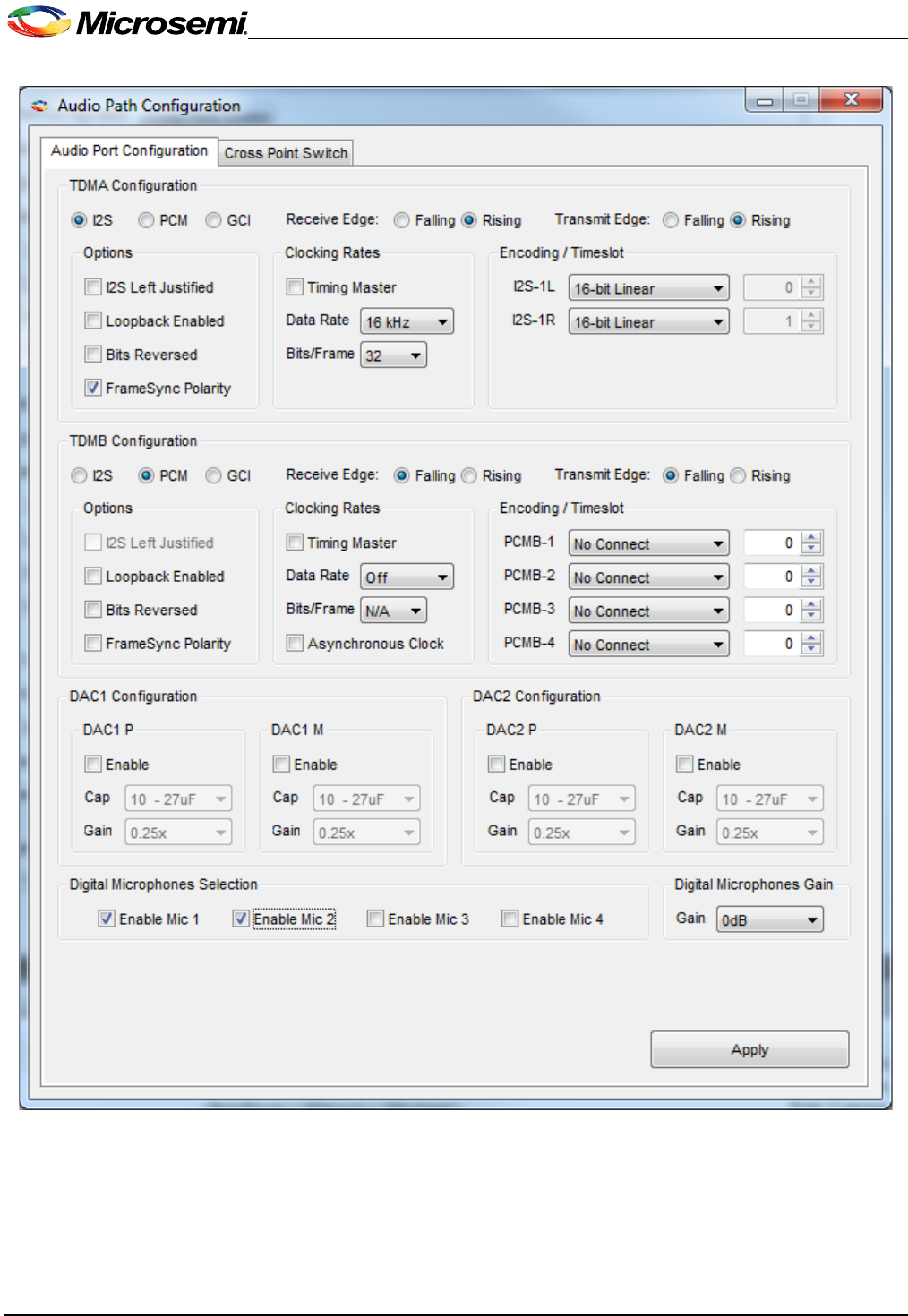
1. Launch MiTuner, then from MiTuner "Audio Path Configuration" configure the TDM and audio
cross-point switch settings accordingly to the design
22
VPROC SDK QUICKSTART GUIDE
Figure 5–2 TDM Configuration
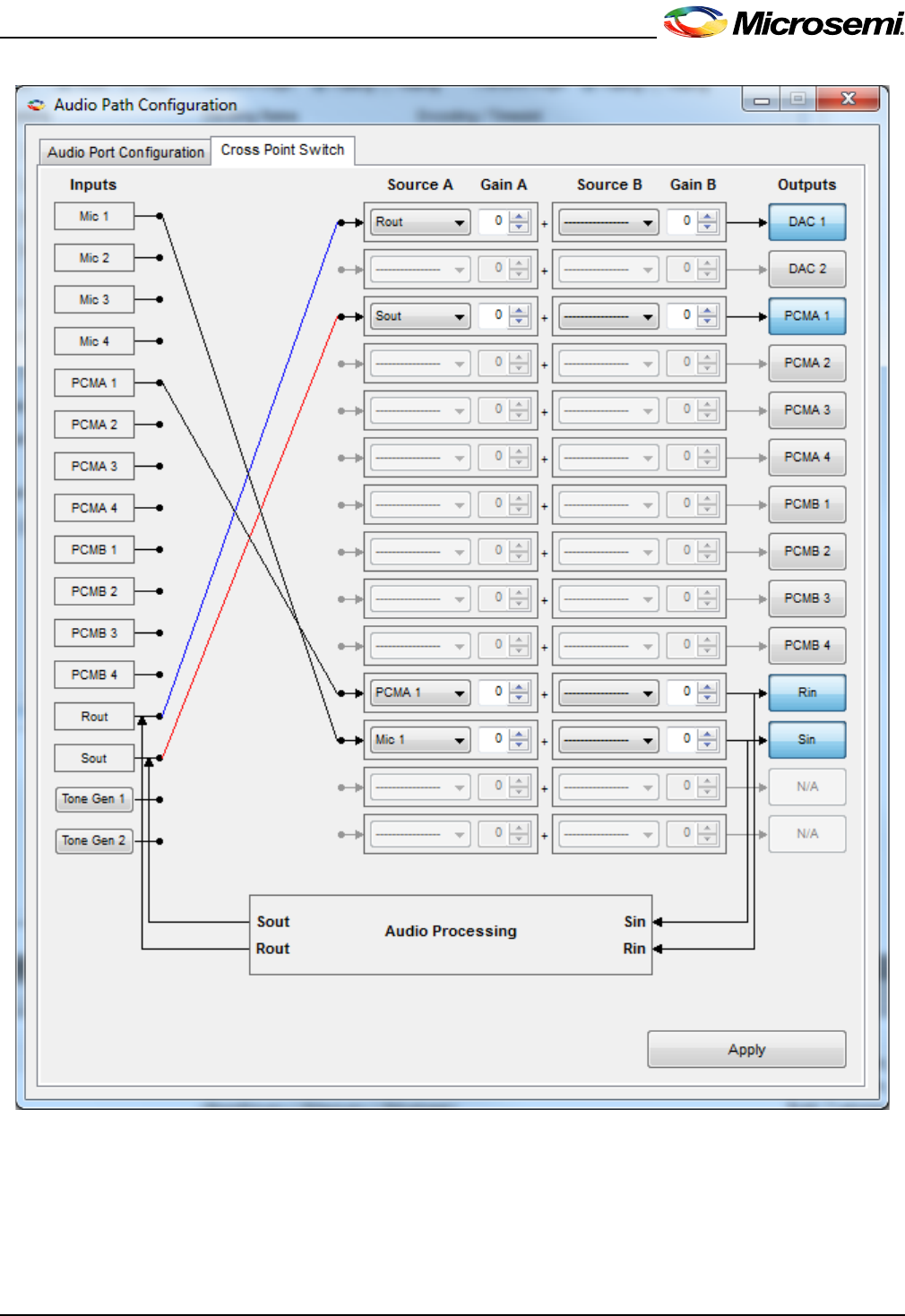
2. Configure the Audio Cross-Point switch in accordance to how audio should be routed in and out
of the VPROC device. See example configuration below
23
VPROC SDK QUICKSTART GUIDE
Figure 5–3 Audio Cross-point Switch Selection
3. Configure the VPROC audio processing block. This step requires considerable knowledge of
the VPROC device in order to properly configure these parameters. Therefore, either the help
of a Microsemi Field Application Engineer is required or the customer can use our Auto Tuner
Kit to tune these parameters.
24
VPROC SDK QUICKSTART GUIDE
Figure 5–4 VPROC Audio Processing Configuration
The dialog shown in Figure 5–4 configures the Acoustic Echo Canceller, input and output gains and
other processing parameters of the VPROC device in accordance to the design. Once these
parameters are configured, then save the resulting configuration record by clicking on the
"Firmware" tab, then "Save Config to PC".
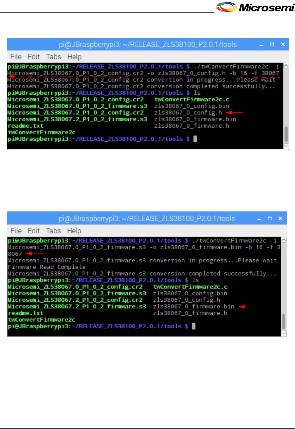
4. If the VPROC firmware and the generated configuration record in step 3 are to be compiled with
the SDK, then use the twConvertFirmware2c tool to convert each file into c code.
Figure 5–5 Convert firmware to c header
5. Copy the converted firmware *.h file into the SDK apps folder or set the path within the Makefile
accordingly to where to find the file.
25
VPROC SDK QUICKSTART GUIDE
6. Convert the *.cr2 to c code.
Figure 5–6 Convert Configuration to c code
7. Copy the converted *h file into the apps directory of the VPROC SDK or modify the makefile
accordingly to where to find these files. To convert the *.cr2 to *.bin simply change the ouput file
name extension to .bin
8. If the firmware and configuration record are to be loaded dynamically (at runtime), then convert
the firmware *.s3 file into a binary format.
Figure 5–7 Convert firmware to binary
9. The *.cr2 configuration record and the converted firmware *.bin firmware files can be loaded
into the VPROC device dynamically (at runtime).
5.2 COMPILE/RECOMPILE THE APPLICATION AND RUN
1. If the previous steps were done on an existing quickstart application (and none of the file names
changed), simply recompile the application as-is and run.
2. If the previous steps contained modification to the converted files or names, update the Makefile
and application to refer to the new names.
3. Recompile the application and run it.

26
VPROC SDK QUICKSTART GUIDE
5.3 NEXT STEPS
The customer is strongly encouraged to experiment with both MiTuner software and the
configuration of the VPROC processing parameters until comfortable with the use of the tool and
the configuration of the parameters of the device for rapid product development.

27
VPROC SDK QUICKSTART GUIDE

Information relating to products and services furnished herein by Microsemi Corporation or its subsidiaries (collectively “Microsemi”) is
believed to be reliable. However, Microsemi assumes no liability for errors that may appear in this publication, or for liability otherwise
arising from the application or use of any such information, product or service or for any infringement of patents or other intellectual
property rights owned by third parties which may result from such application or use. Neither the supply of such information or purchase
of product or service conveys any license, either express or implied, under patents or other intellectual property rights owned by
Microsemi or licensed from third parties by Microsemi, whatsoever. Purchasers of products are also hereby notified that the use of
product in certain ways or in combination with Microsemi, or non-Microsemi furnished goods or services may infringe patents or other
intellectual property rights owned by Microsemi.
This publication is issued to provide information only and (unless agreed by Microsemi in writing) may not be used, applied or
reproduced for any purpose nor form part of any order or contract nor to be regarded as a representation relating to the products or
services concerned. The products, their specifications, services and other information appearing in this publication are subject to
change by Microsemi without notice. No warranty or guarantee express or implied is made regarding the capability, performance or
suitability of any product or service. Information concerning possible methods of use is provided as a guide only and does not
constitute any guarantee that such methods of use will be satisfactory in a specific piece of equipment. It is the user’s responsibility to
fully determine the performance and suitability of any equipment using such information and to ensure that any publication or data used
is up to date and has not been superseded. Manufacturing does not necessarily include testing of all functions or parameters. These
products are not suitable for use in any medical and other products whose failure to perform may result in significant injury or death to
the user. All products and materials are sold and services provided subject to Microsemi’s conditions of sale which are available on
request.
For more information about all Microsemi products
visit our website at
www.microsemi.com
TECHNICAL DOCUMENTATION – NOT FOR RESALE
Microsemi Corporation (NASDAQ: MSCC) offers a comprehensive portfolio of semiconductor
solutions for: aerospace, defense and security; enterprise and communications; and industrial
and alternative energy markets. Products include high-performance, high-reliability analog and
RF devices, mixed signal and RF integrated circuits, customizable SoCs, FPGAs, and
complete subsystems. Microsemi is headquartered in Aliso Viejo, Calif. Learn more at
www.microsemi.com.
Microsemi Corporate Headquarters
One Enterprise, Aliso Viejo CA 92656 USA
Within the USA: +1 (949) 380-6100
Sales: +1 (949) 380-6136
Fax: +1 (949) 215-4996
© 2017 Microsemi Corporation. All rights reserved. Microsemi and the Microsemi logo are trademarks of
Microsemi Corporation. All other trademarks and service marks are the property of their respective owners.
