Versa Nail Femoral Universal System Surgical Technique
2016-04-01
: Pdf Versanail Femoral Universal Nail System Surgical Technique VersaNail_Femoral_Universal_Nail_System_Surgical_Technique 4 2016 pdf
Open the PDF directly: View PDF ![]() .
.
Page Count: 48
VersaNail® Femoral Universal
Product Rationale
and Surgical Technique
TRAUMA

VersaNail® Femoral Universal
Note: This brochure presents a surgical technique available for use with the Biomet VersaNail® Platform instruments and implants. Surgeons may need to make modifications
as appropriate in their own surgical technique with these devices depending on individual patient requirements.
1
Contents
Design Summary ........................................................................................................................................................3
Implant Overview ........................................................................................................................................................4
Antegrade Entry and Canal Preparation ......................................................................................................................6
Antegrade Nail Insertion ............................................................................................................................................10
Antegrade Locking ...................................................................................................................................................13
Retrograde Entry and Canal Preparation ...................................................................................................................20
Retrograde Nail Insertion ..........................................................................................................................................24
Retrograde Locking ..................................................................................................................................................29
End Cap Placement and Nail Removal .....................................................................................................................35
Ordering Information ................................................................................................................................................. 38
Flexible Reaming System .......................................................................................................................................... 42
3
• Anatomically designed for treatment of both antegrade
and retrograde applications
• The intuitive, universal instrumentation system enables
efficiency in the OR
• Universal design to aid inventory management
One Implant Designed for the Efficient Treatment
of a Range of Femur Fractures
VersaNail® Femoral Universal
The VersaNail
®
Femoral Universal Nail is part of a long bone nailing
system that offers a complete portfolio of implants and instruments
based on a single, standardized technology platform. The Femoral
Universal Nail System from the VersaNail Platform offers options to treat
a range of femoral fractures using either an antegrade or retrograde
approach with one implant. The VersaNail Platform instrumentation
system is designed for intuitive assembly and ease-of-use by OR staff
and surgeons, enabling a simpler and more efficient procedure. The
instrumentation is designed to provide intra-operative options including
entry portals, reduction tools and color-coded screw placement, while
being standardized to maintain commonality across the platform.
VersaNail® Femoral Universal
4
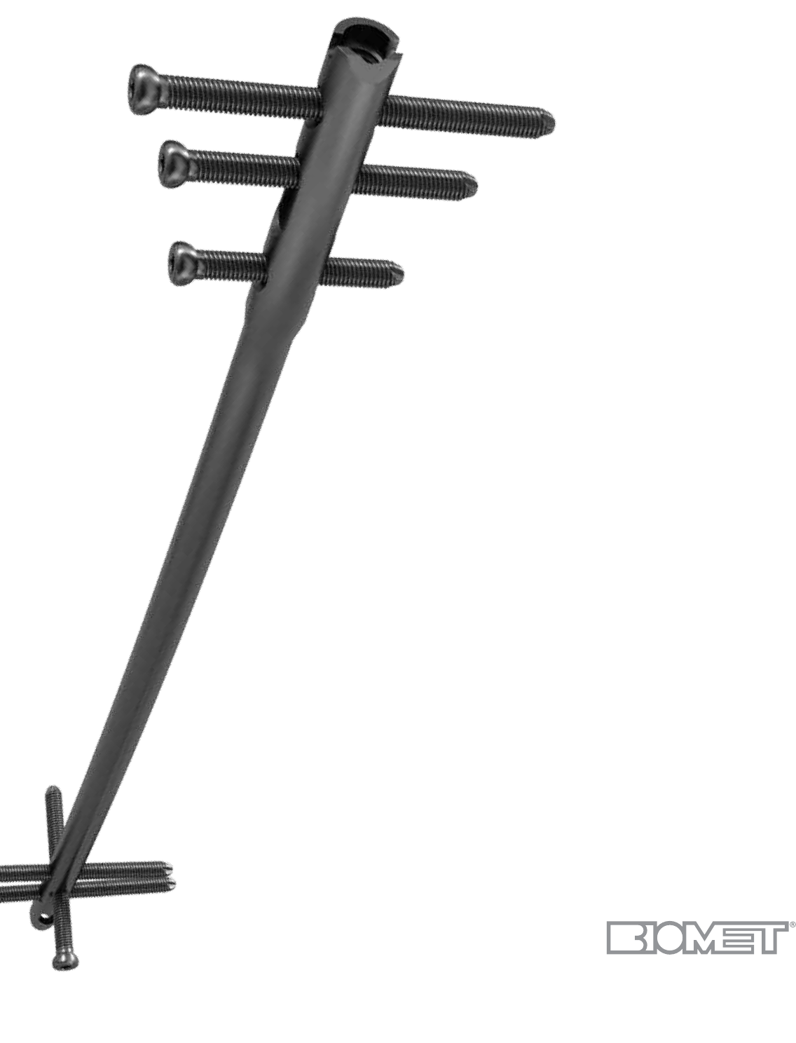
Universal design allows one nail for either
antegrade or retrograde application to treat
right- or left-sided fractures.
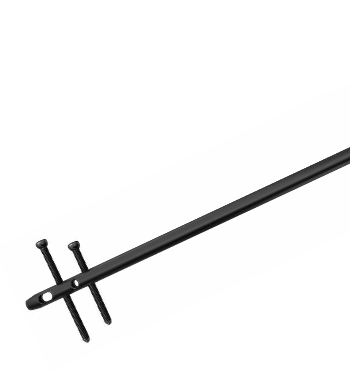
Enlarged nail cannulation accepts the ball
nose guide wire, eliminating the need for an
exchange tube.
2.2 meter radius of curvature accommodates
the anterior bow of the femur.
The Femoral Universal Nail is designed to treat:
• Femoral shaft fractures
• Proximal or mid-shaft femoral non-unions and malunions
• Pathologic fractures in osteoporotic bone of the diaphyseal area
• Revision procedures
The VersaNail Platform instrumentation system is designed to be intuitive, enabling a simpler and more efficient procedure. The VersaNail
Platform’s modular nature facilitates the use of common instruments across all VersaNail nailing systems, reducing confusion among the
OR staff. For example, VersaNail Platform jigs look and function the same way, and common instruments (such as awls, entry portals,
guide wires, nail length gauge, locking instrumentation and screw caddies) can be used across all VersaNail Platform nailing systems.
Large core diameter of 4.5 mm non-drive end
screws decreases the risk of screw breakage.
Distal locking options to treat a greater range
of fracture patterns.
Bullet-style tip increases ease of insertion.
5 mm Dynamization option allows compression
at the fracture site.
5
0 mm
14 mm
10 mm
Dymanization
Range
5 mm
Dymanization
Range
12 mm Drive End Diameter
for 9-12 mm Nails
Drive End Diameter
Equal to Nail Diameter
for 13-15 mm Nails
29 mm
28 mm
48 mm
38 mm
18 mm
13 mm
0 mm
64 mm
39 mm
54 mm
12 mm drive end accommodates 6.5 mm screws.
Large core diameter of 6.5 mm screws decreases
risk for screw breakage.
10 mm Dynamization option allows compression
at the fracture site.
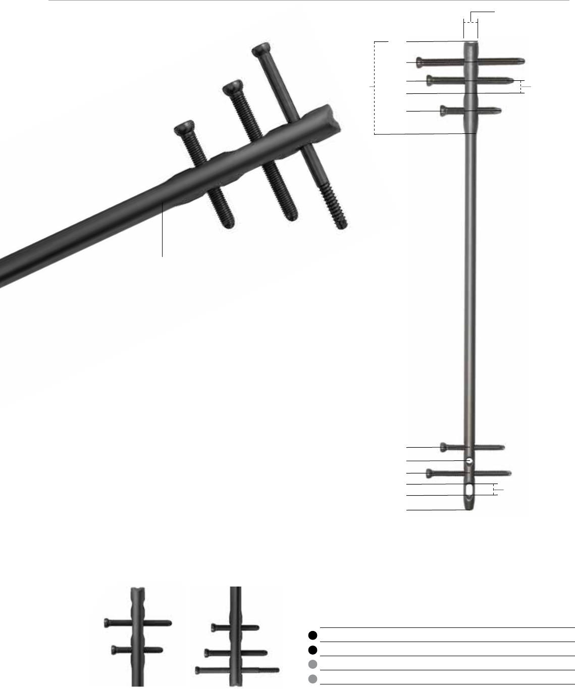
Multiple locking options for optimum implant stability
The Femoral Universal Nail hole configurations provide a number of locking possibilities.
The Femoral Universal Nail is locked with 6.5 mm screws on the drive end and 4.5 mm screws on the non-drive end.
The locking instrumentation is color-coded for ease of use:
Color Screw Size Drill Bit Size
Black 6.5 mm Cortical 5.3 mm
Gold 6.5 mm Cancellous 6.5 mm/4.8 mm Step Drill
Silver 3.2 mm Guide Pin Sleeve
Green 4.5 mm Cortical 3.8 mm
VersaNail® Femoral Universal
6
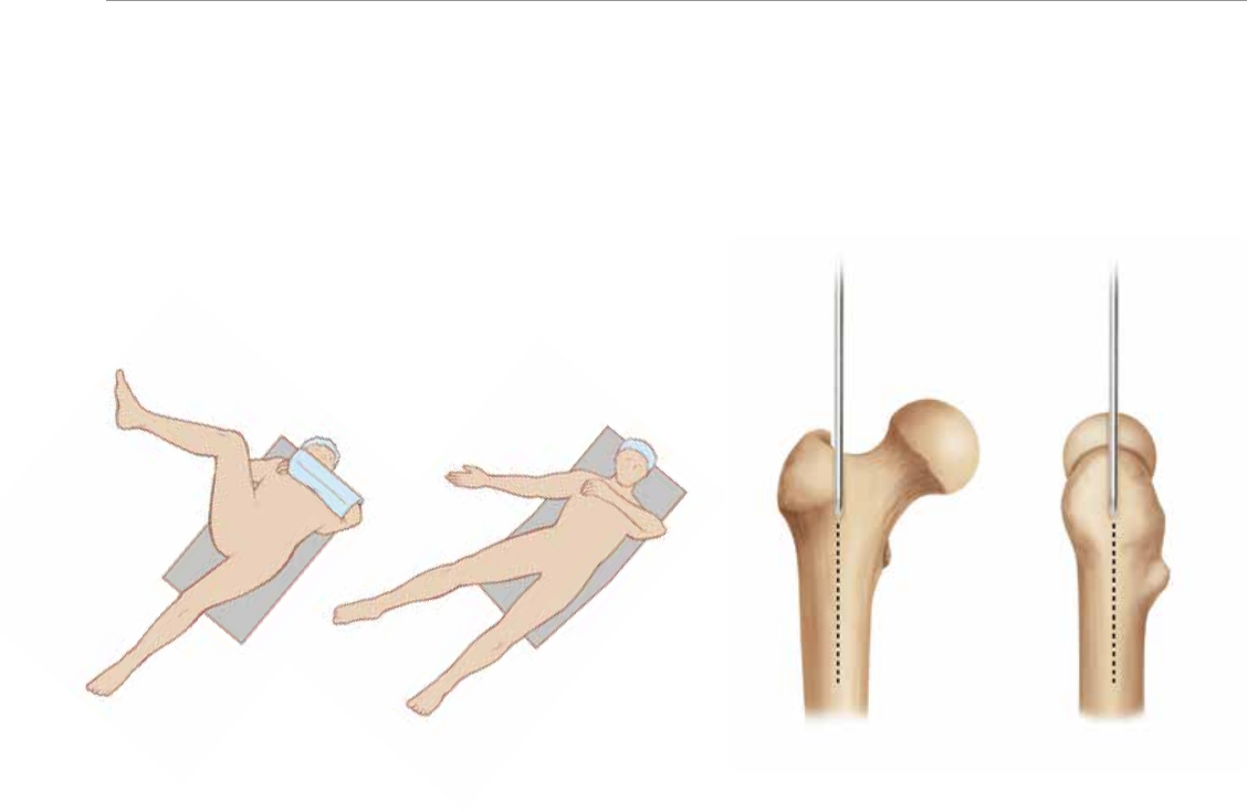
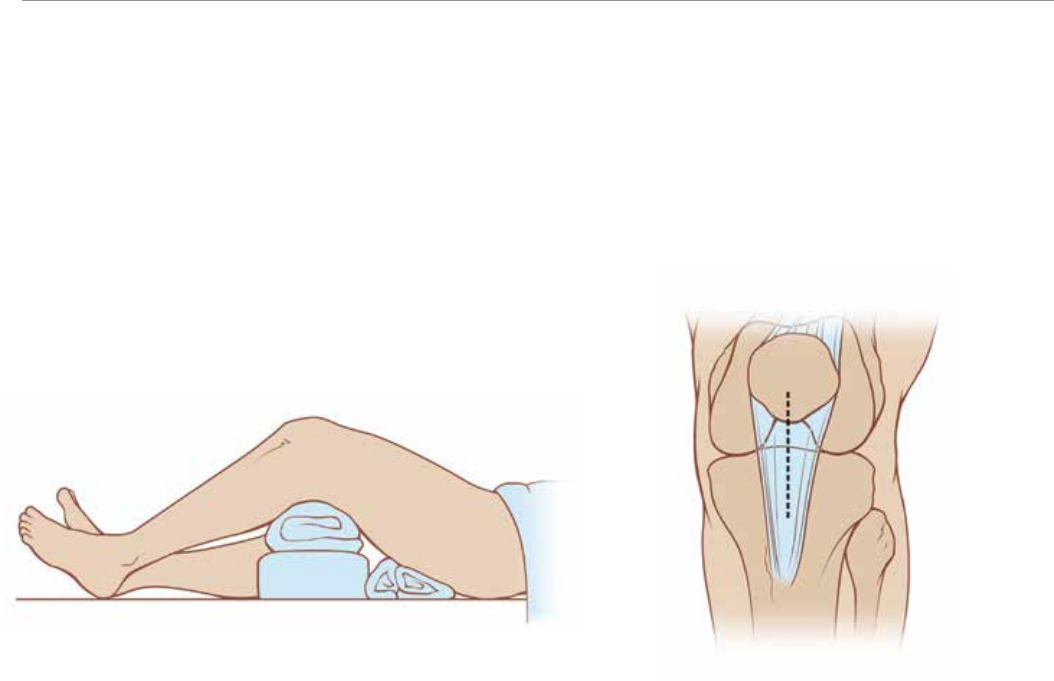
Entry Site and Surgical Approach
Identify the entry site, which is in the piriformis fossa. The
ideal entry point is adjacent to the greater trochanter at
the lateral edge of the piriformis fossa.
Initiate the entry site with a 3.2 mm guide pin through a stab
incision proximal to the trochanteric region, in line with the
femoral axis. Confirm correct entry location and guide pin
placement radio-graphically with A/P and lateral views
(Figure 2). The guide pin placement should be in line with
the center of the femoral canal in both views.
Patient Positioning
Place the patient in the supine position on a fracture or
radiolucent imaging table (Figure 1). Lateral access to
the proximal femur is required. The affected leg must be
adducted and the trunk secured and bent toward the
opposite side. The contralateral leg may be flexed at the
hip or scissored below the affected leg.
Antegrade Entry and Canal Preparation
Figure 1 Figure 2
7
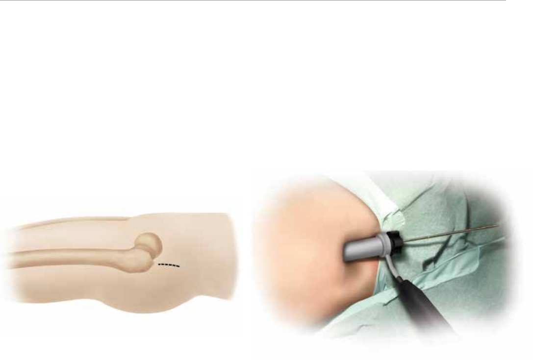
Once the ideal entry point has been achieved, an
appropriate incision can be made. Extend the entry
incision 1-2 cm (Figure 3).
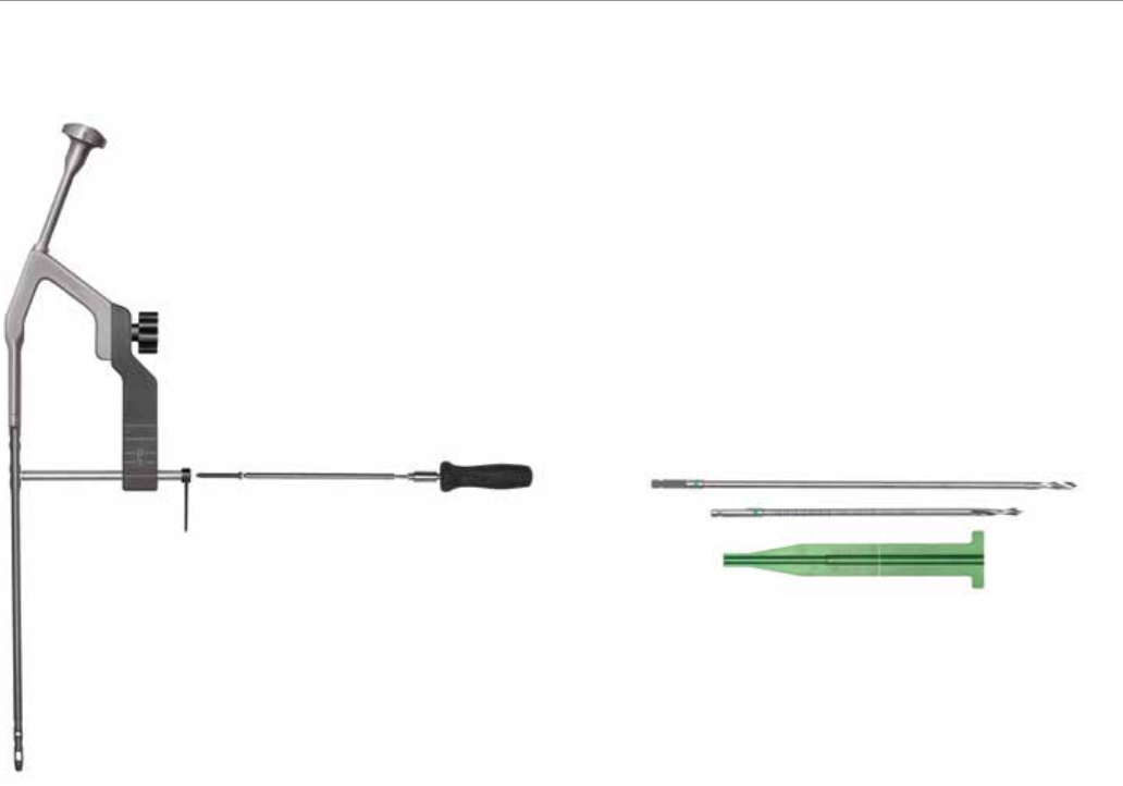
The Entry Portal Sheath (2810-13-005) and Trocar (2810-
13-004) can be advanced over the guide pin down to
the piriformis fossa. Parallel guide holes allow for accurate
adjustment of pin positioning. Remove the trocar from the
entry portal, keeping the guide pin in place.The entry portal
sheath may be left in place to protect soft tissues during
canal entry and reaming (Figure 4).
Figure 3 Figure 4
VersaNail® Femoral Universal
8
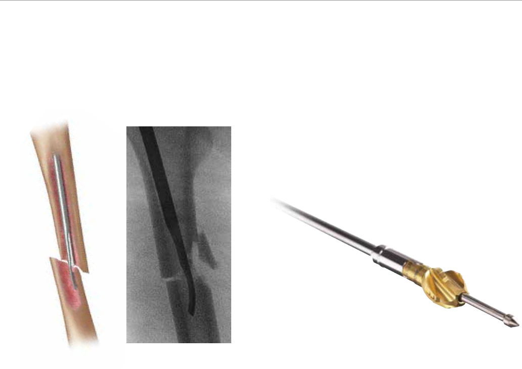
Once access to the femoral canal has been gained, place
the ball nose guide wire into the entry site utilizing the
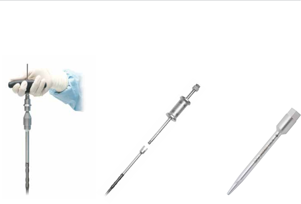
pistol-style Guide Wire Gripper (2810-01-001) (Figure 7).
If preferred, a T-handle Guide Wire Gripper (2810-01-002)
is also available as an option.
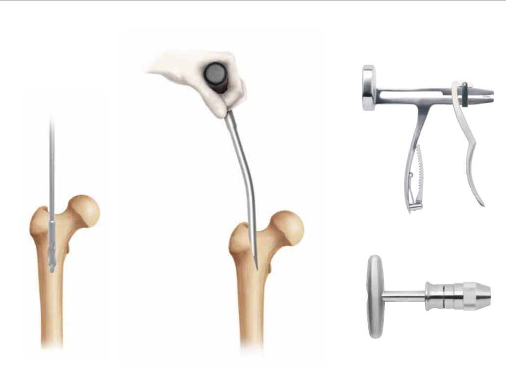
Entry Site and Surgical Approach
(cont.)
Canal access can be obtained using either a Cannulated
Entry Reamer or Cannulated Awl (2810-01-005). Both
12 mm (2810-13-001) and 13 mm (2810-13-002) entry
reamers are available depending on surgeon preference.
The proximal nail diameter is 12 mm for all nail sizes equal
to or less than 12 mm, and 13 mm to 15 mm nails have a
proximal diameter equal to the nail diameter. Use A/P and
lateral fluoroscopic views to confirm accurate placement
(Figures 5 and 6). Use the awl or entry reamer to open the
proximal femur in the piriformis fossa.
Note: If utilizing the cannulated entry reamer, the length
of the distal portion of the reamer is enlarged and
matches the length of the drive end portion of the nail.
Fluoroscopically verify the entry reamer has been inserted
to the proper depth that will correspond with the depth of
the nail.
Antegrade Entry and Canal Preparation
Figure 5 Figure 7Figure 6
9
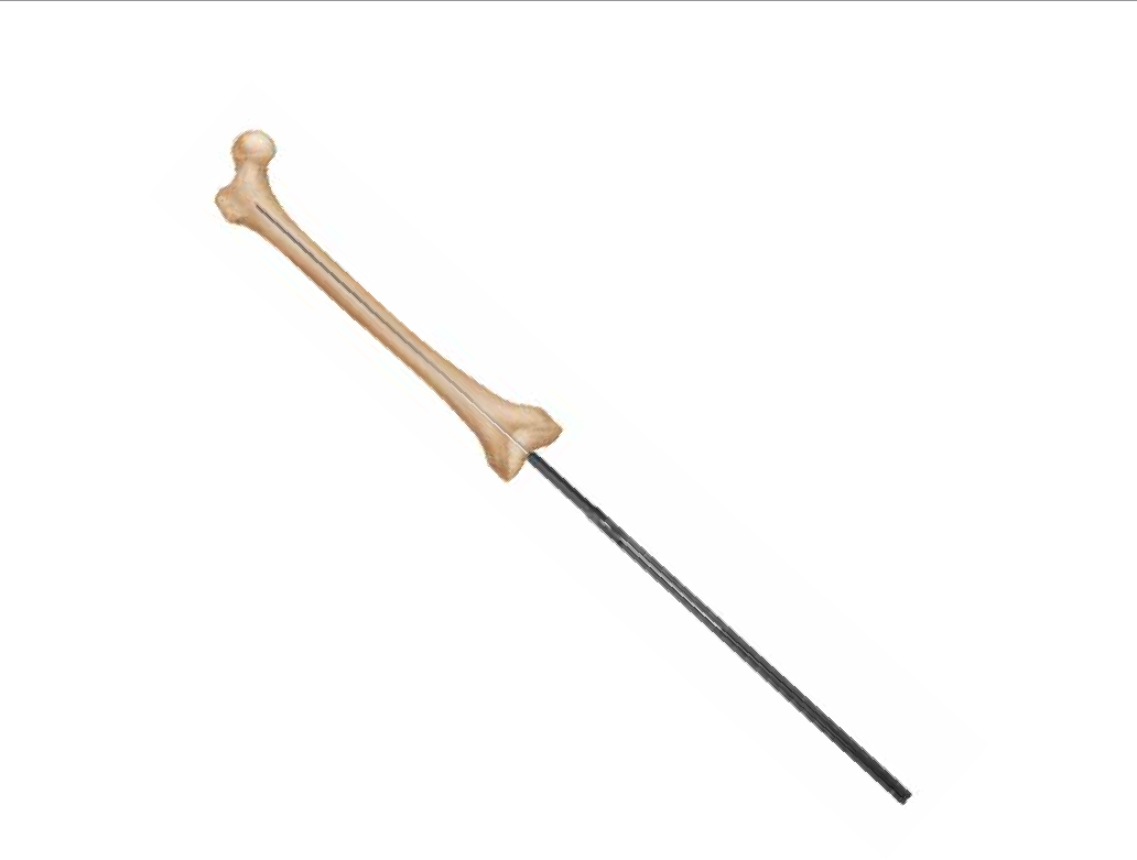
Fracture Reduction
Once access to the femoral canal has been gained, obtain
appropriate anatomic reduction in order to restore length,
alignment and rotation of the injured limb. Reduction can
be achieved through the surgeon’s preferred method such
as traction and/or an external fixator. To aid in manipulating
the fracture fragments and passing the Ball Nose Guide
wire, large (7.5 mm diameter, 2810-01-007) and small
(6.5 mm diameter, 2810-01-008) reduction tools are avail-
able (Figure 8).
Insert the reduction tool into the medullary canal, past the
fracture site. Once the fracture is aligned, pass the Ball
Nose Guide Wire, available in both 80 cm (2810-01-080)
and 100 cm (2810-01-100) lengths, across the fracture
site. Remove the reduction tool.
Canal Preparation
Achieve proper alignment of the fracture prior to reaming
and maintain it throughout the reaming process to
avoid eccentric reaming. Initiate reaming by placing
the VersaNail Flexible Reamers over the 3.0 mm ball
nose guide wire (Figure 9). Ream the medullary canal in
millimeter increments until cortical bone is reached and
half-millimeter increments thereafter. Surgeon preference
should dictate the actual extent of intramedullary reaming.
Monitor the reaming procedure using image intensification
to avoid eccentric or excessive cortical reaming.
Figure 8 Figure 9
VersaNail® Femoral Universal
10
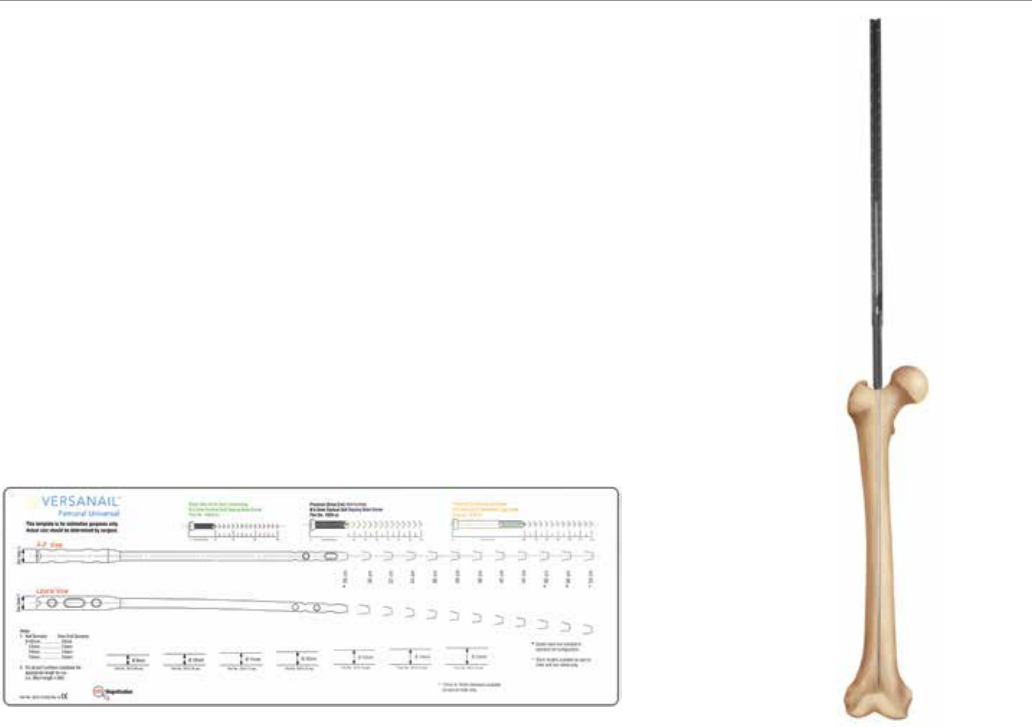
Nail Size Selection
An X-ray template (2810-13-025) including 10 percent
magnification is available to determine nail size
preoperatively (Figure 10).
Nail Diameter Selection
Generally, a nail diameter 1 mm to 1.5 mm less than the
final reamer diameter is chosen. Femoral Universal Nails
are available in 1 mm increments from 9 mm to 15 mm
diameters.
Antegrade Nail Insertion
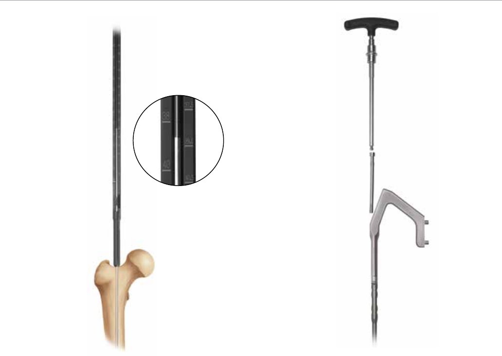
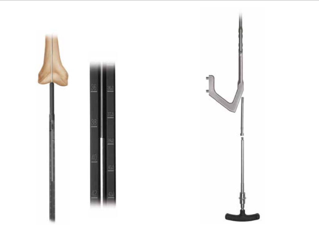
Nail Length Selection
With the tip of the ball nose guide wire at the level of
the desired depth of nail insertion, slide or snap the Nail
Length Gauge (2810-01-031) onto the ball nose guide
wire until the nose contacts the bone, ensuring the tip
does not fall into the existing entry canal, which could
result in an inaccurate measurement (Figure 11).
Figure 10 Figure 11
11
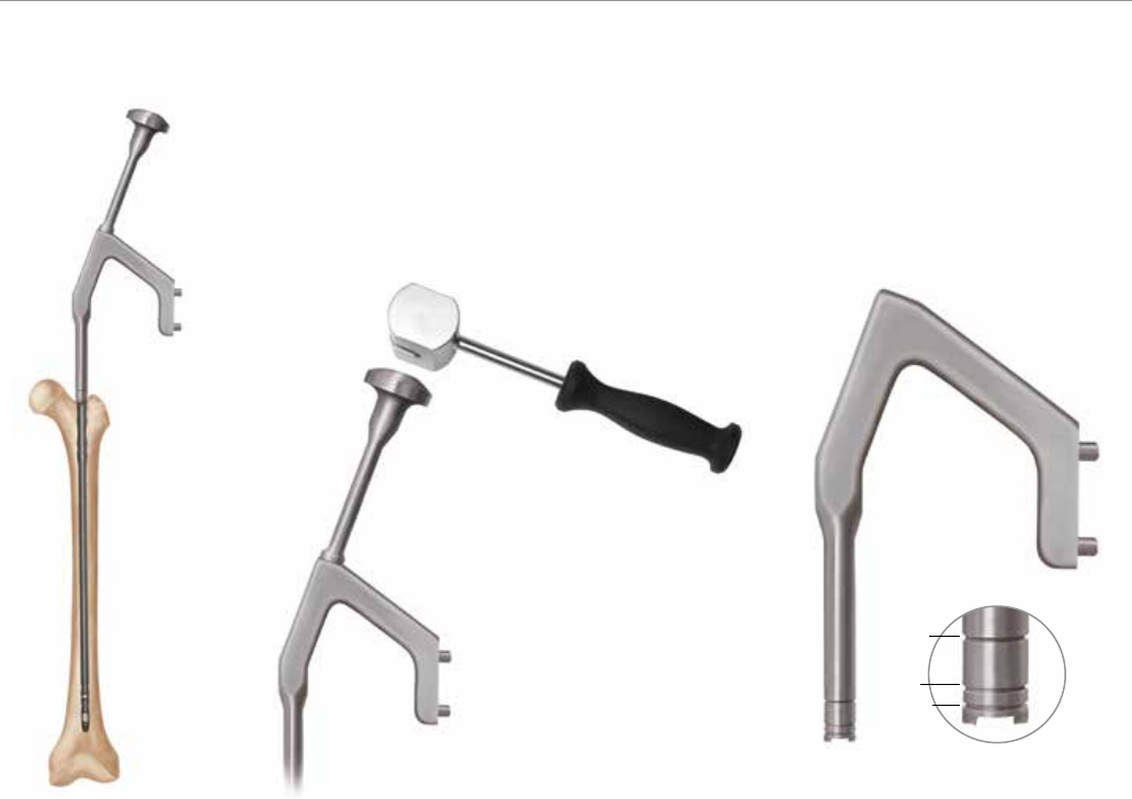
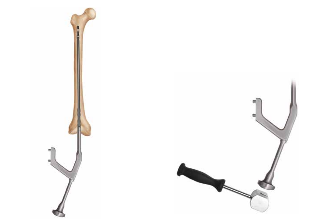
Nail/Jig Assembly
Place the nail on the femoral insertion handle in the correct
orientation. The nail should be oriented on the femoral
insertion handle such that the anterior bow of the nail is in
line with the anterior bow of the femur and the jig is lateral
to the nail. Secure the nail to the femoral insertion handle
by inserting the Femoral Jig Bolt (2810-13-008) through
the cannulation of the nose and tightening with the Jig
Bolt Driver (2810-13-006) and T-handle (2810-01-004)
(Figure 13).
To obtain the appropriate nail length, read the measurement
mark on the nail length gauge that is closest to the
beginning of the black transition area on the guide wire
(Figure 12). If a nail of the exact measured length is
not available, choose a shorter nail of the next closest
available length. A direct measurement can also be taken
of the uninjured extremity using either radiographs with
magnification markers, or directly on the uninjured limb.
Figure 12 Figure 13
VersaNail® Femoral Universal
12
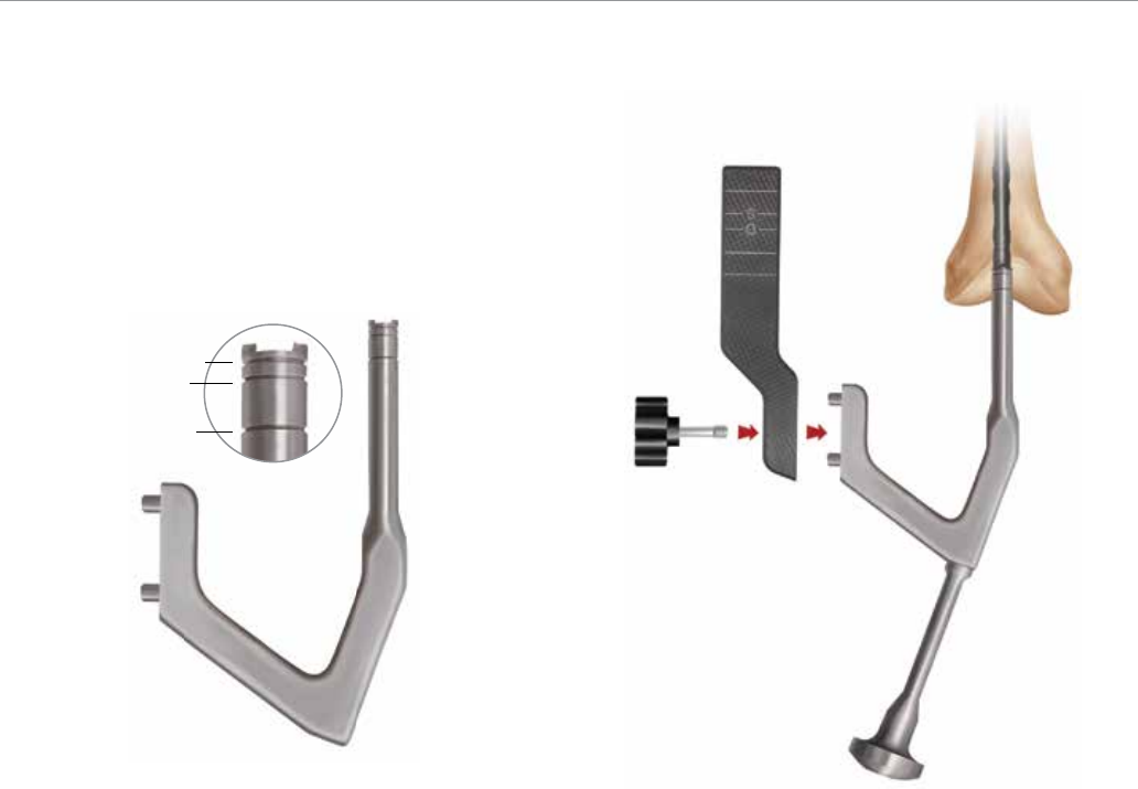
Note: The femoral insertion handle is marked with three
grooves (Figure 16). The groove closest to the nail is an
indicator for the nail/insertion handle junction. A K-wire
can be inserted lateral to medial through the target arm if
additional identification of the nail/ insertion handle junction
is needed. The middle groove is marked 5 mm from the
top of the nail and the groove farthest from the nail is
marked 15 mm from the top of the nail. Ensure the nail is
seated to proper depth for planned dynamization.
Confirm fracture reduction and ensure appropriate nail
insertion depth proximally and distally with biplanar
fluoroscopy. Remove the ball nose guide wire.
Nail Insertion
Once proper reduction has been achieved, insert the nail
over the 3 mm ball nose guide wire into the medullary
canal (Figure 14). It is important not to strike the femoral
insertion handle directly.
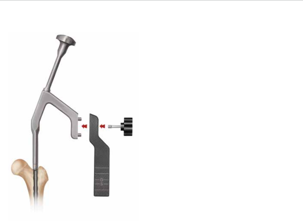
Attach the Hammer Pad (2810-13-011) to the insertion
handle (Figure 15). Ensure that the hammer pad is
tightened thoroughly prior to impaction. Avoid excessive
force when inserting the nail. If the nail jams in the
medullary canal, extract it and choose the next-smaller
diameter nail or enlarge the canal appropriately.
15 mm
5 mm
Nail/Jig
Junction
Antegrade Nail Insertion
Figure 15Figure 14 Figure 16
13
Antegrade Locking
Dynamization
A dynamic slot has been incorporated in the drive end
and non-drive end of the nail. The drive end slot has a
10 mm range of dynamization. The non-drive end slot has
a 5 mm range of dynamization. If dynamization is planned,
countersink the nail to the appropriate depth to avoid
backing out of the nail into the proximal soft tissues. Lock
the M/L slot in the dynamic mode. Delayed dynamization
may be performed at a later date with the removal of the
static screws.
Universal Target Arm Assembly
Attach the radiolucent Universal Target Arm (2810-13-009)
onto the insertion handle, using the Target Arm Attachment
Bolt (2810-13-026) and hand tighten (Figure 17). Ensure
the target arm is properly secured to the insertion handle
for excellent targeting.
Locking
Prior to locking both proximally and distally, check femoral
length and rotational alignment. The nail can be locked
either distally or proximally first, depending on surgeon
preference.
Figure 17
VersaNail® Femoral Universal
14
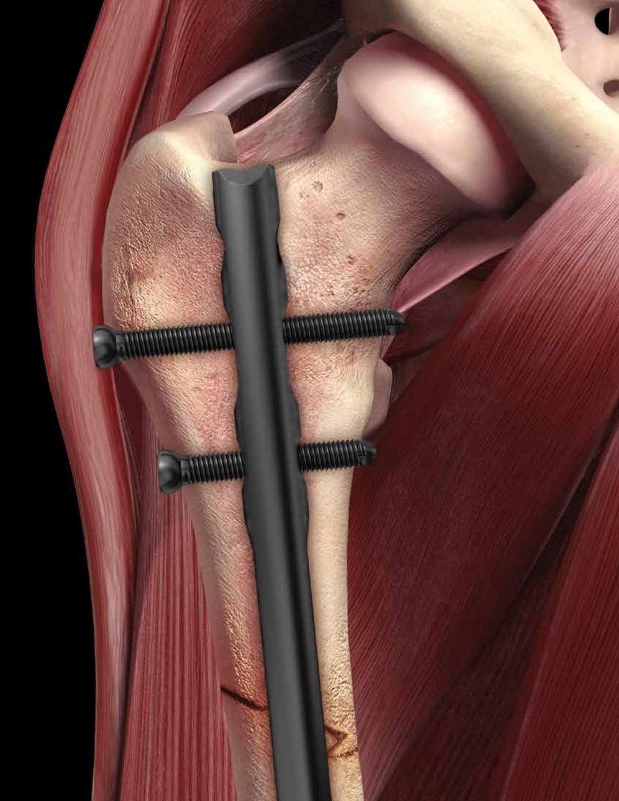
Proximal Locking
The universal target arm is marked to identify which
locking option is being targeted (Figure 18).
Place 6.5 mm cortical locking screws using the black
instrumentation (Figure 19).
Antegrade Locking
Place the 6.5 mm Screw Sheath (2810-13-020) and
Trocar (2810-13-021) through the appropriate holes in the
jig’s targeting arm to locate the incision site (Figure 20).
Make a stab incision and advance the sheath and trocar
to the bone. Soft tissue dissection should be completed
sharp and precise to clear a path for the sheath.
Undue soft tissue tension against the sheath can cause
misdirect drilling.
K-wire (indicator for nail/jig junction)
Static Locking Hole
Slot - Dynamic Mode
Slot - Static Mode
Static Locking Mode
Figure 18 Figure 19 Figure 20
15
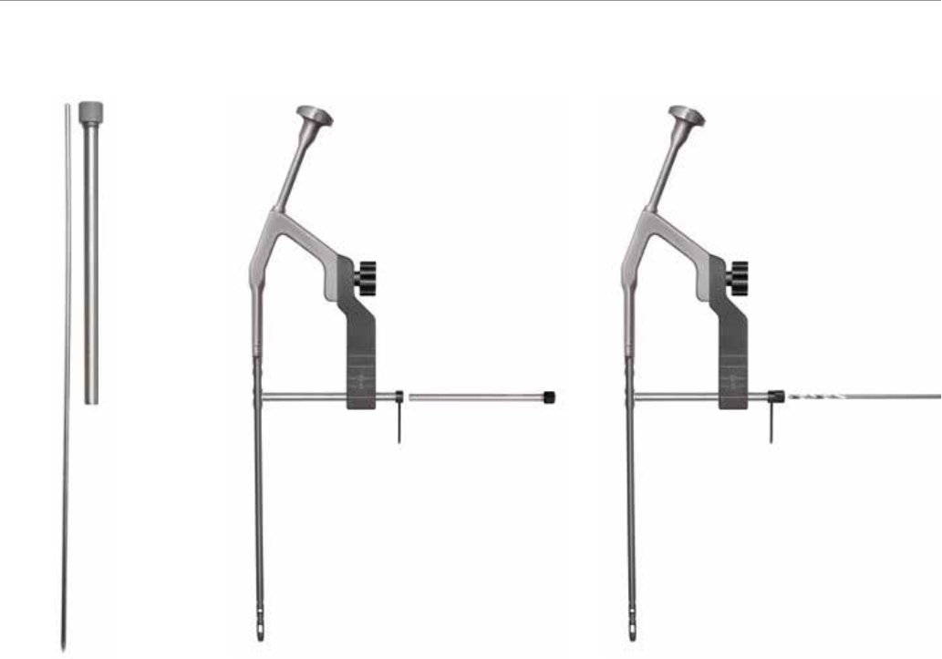
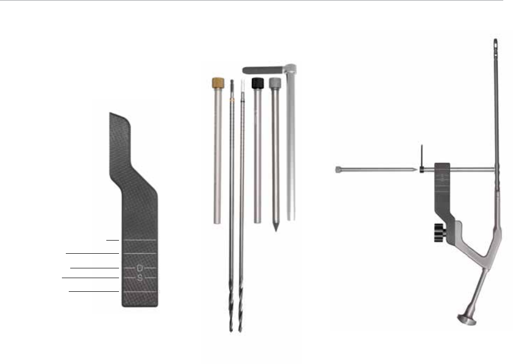
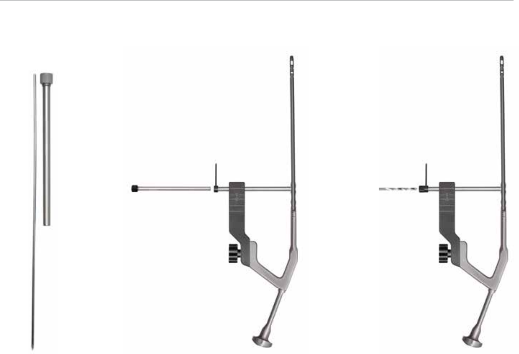
Note: A 3.2 mm x 17.5 in Guide Pin (9030-03-004) and
3.2 mm Pin Guide Sleeve (2810-13-018) can be used to
verify screw position prior to drilling (Figure 21).
Remove the trocar and replace it with the 5.3 mm Drill
Sleeve (2810-13-022) (Figure 22).
Utilizing the 5.3 mm Drill Bit (2810-13-153) drill through
the drill sleeve and sheath until the far cortex is penetrated
(Figure 23).
Figure 21 Figure 22 Figure 23
VersaNail® Femoral Universal
16
Proximal Locking (cont.)
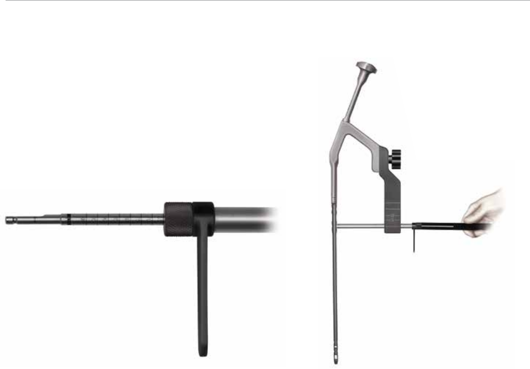
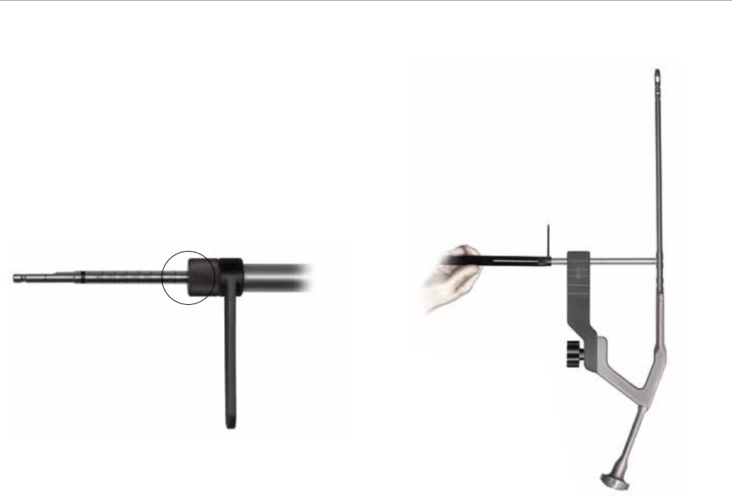
Read the calibration on the drill bit that lines up with the
drill sleeve to determine the screw length (Figure 24).
Ensure the drill sleeve is on bone and read the calibration
on the drill bit at the end of the drill sleeve to determine
the appropriate screw length (Figure 24). If penetrating
the far cortex prior to taking the reading, use the screw
length indicated on the drill bit at the screw depth
measurement line. If you are not penetrating the far cortex
prior to taking the reading, add 5 mm in length to the
screw length reading.
If further screw length is required, or if the locking hole
has been initiated with a guide pin, a 6.5 mm Screw Depth
Gauge (2810-13-035) is available to read screw length
off of the 3.2 mm x 17.5 in guide pin (Figure 25).
Antegrade Locking
Figure 24 Figure 25
17
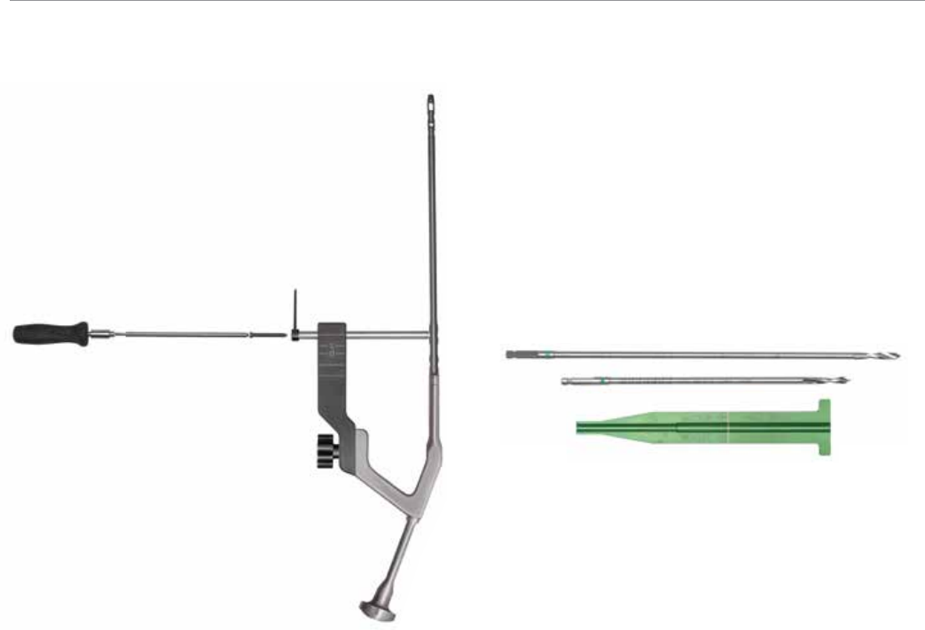
Verify fluoroscopically to assure the proper screw length
selection. Remove the drill sleeve. Using the 6.5 mm
Screwdriver Shaft (2810-13-024), insert the 6.5 mm
cortical screw through the sheath. The etch mark on the
screwdriver corresponds with the screw sheath to indicate
when the screw is fully seated (Figure 26).
Use caution as the most proximal screw position could
be in femoral neck, depending on the depth of the nail.
Repeat above steps for additional screw placement.
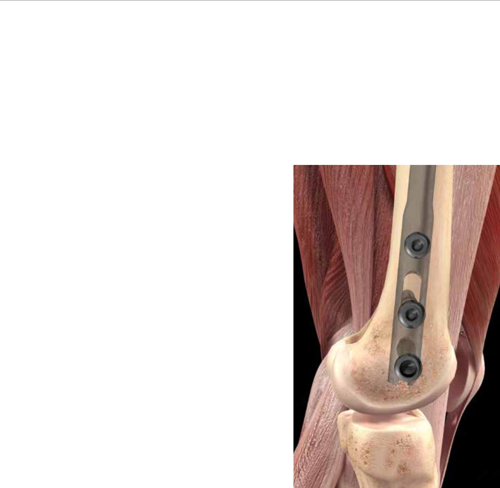
Distal Locking
Place 4.5 mm cortical locking screws using the green
instrumentation (Figure 27).
Figure 26 Figure 27
VersaNail® Femoral Universal
18
Antegrade Locking
Distal Locking (cont.)
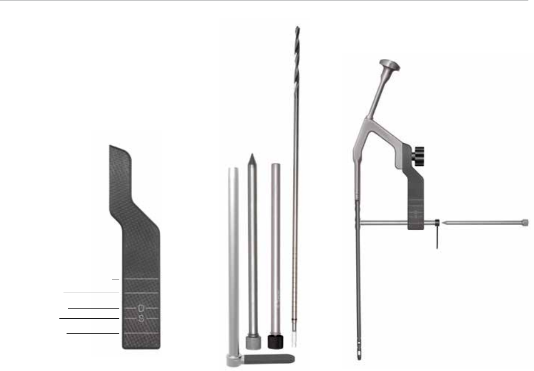
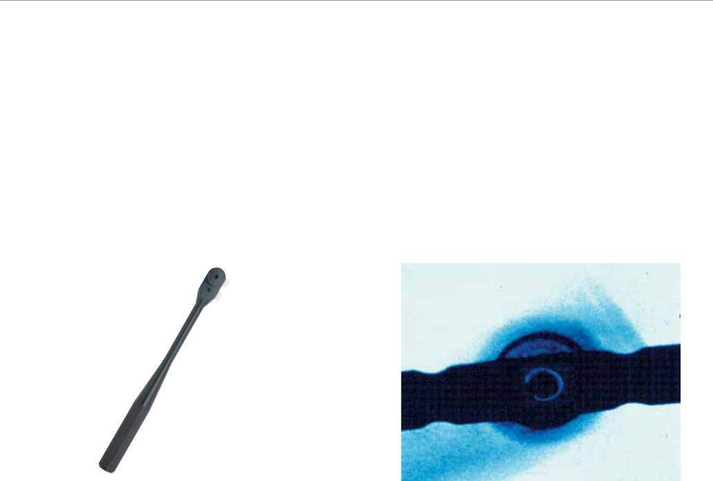
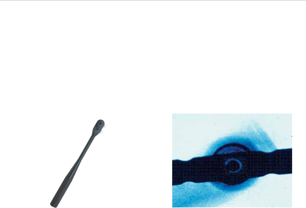
Use fluoroscopy to conduct freehand locking utilizing a
familiar freehand technique. A Black Radiolucent Wand
(2810-12-016) is available to aid in freehand locking
(Figure 28).
Accurate C-arm position is confirmed when the distal
nail hole appears to be a perfect circle. Once correct
placement has been verified fluoroscopically, make a stab
wound in direct alignment with the distal hole (Figure 29).
Figure 28 Figure 29
19
A compensation factor is built into the measurement of the screw depth gauge (for the screw head and cutting flutes), and the calibrated drills
(for the screw head only).
If penetrating the far cortex prior to taking the reading, use the screw length indicated on the drill bit at the screw depth measurement line.
If you are not penetrating the far cortex prior to taking the reading, add 5 mm in length to the screw length reading.
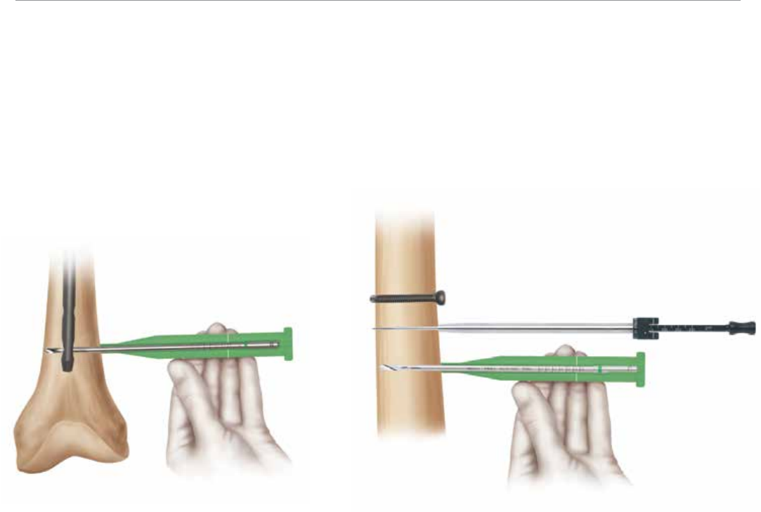
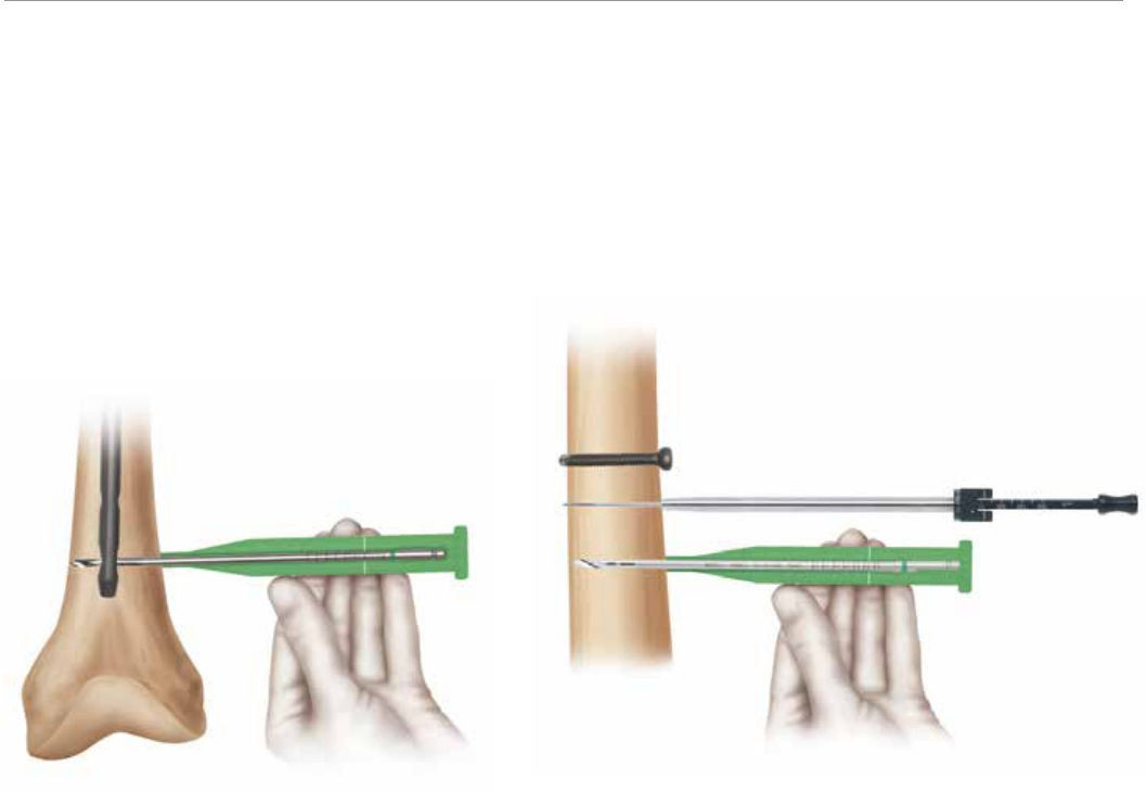
Using the 3.8 mm Drill Bit (6 in: 2810-12-138 or 8 in:
2810-13-138), drill until the second cortex is reached or
penetrated. Verify the drill bit position fluoroscopically prior
to taking any measurements. Place the green 4.5 mm
Screw Length Gauge (2810-01-032) onto the calibrated
drill bit and advance down to the bone. Read the calibration
on the drill bit that corresponds to the measurement line
indicated on the screw length gauge (Figure 30). A Screw
Depth Gauge (2810-01-017) is also provided for further
screw length verification. For an accurate reading, take
care to ensure the 4.5 mm screw length gauge or screw
depth gauge sheath is fully seated on the bone. Remove
the drill bit and advance the 4.5 mm screw. Repeat above
steps for additional screw placement. The SolidLok®
Screwdriver (2810-01-020 and 2810-01-021) can be
utilized to capture the screw while passing it through soft
tissue during screw placement.
Determining Screw Length
The screw size indicates the total measurement from the
tip to the screw head. The calibrated drills and the screw
depth gauges have a compensation factor built into the
measurement such that the reading should indicate the
exact size screw to achieve bi-cortical purchase. To ensure
a proper reading, the screw depth gauge and drill sleeves
must be touching bone. Fluoroscopy is recommended to
verify the correct screw length (Figure 31).
Figure 30 Figure 31
VersaNail® Femoral Universal
20
Patient Positioning
Place the patient in the supine position on a fracture or
radiolucent imaging table (Figure 32). Place the knee in
approximately 45 degrees of flexion. Use manual traction,
a femoral distractor or an external fixator to reduce
severely displaced fractures and maintain length. Special
attention is needed to maintain proper length when using a
retrograde approach to treat a comminuted fracture.
Retrograde Entry and Canal Preparation
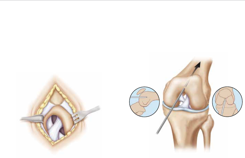
Entry Site and Surgical Approach
Identify the entry site, which is above the intercondylar
notch (Figure 33).
Figure 32 Figure 33
21
Approach the distal femur through a midline longitudinal
incision between the patella and the tibial tubercle (Figure
34). Obtain access to the intercondylar notch by splitting
the tendon longitudinally or displacing the tendon laterally.
Alternative approach: Approach the distal femur through a
longitudinal incision from the superior pole of the patella to
the tibial tubercle, placed along the medial border of the
patellar tendon. Expose the intercondylar notch by using
retractors to reflect the patellar tendon laterally or perform
the procedure percutaneously.
Place the guide pin in the center of the intercondylar notch
approximately 1 cm anterior to the posterior cruciate
ligament and confirm accurate guide pin placement in two
planes fluoroscopically prior to reaming. The guide pin
placement should be in line with the center of the femoral
canal in both views (Figure 35).
Figure 34 Figure 35
VersaNail® Femoral Universal
22
Retrograde Entry and Canal Preparation
Entry Site and Surgical Approach
(cont.)
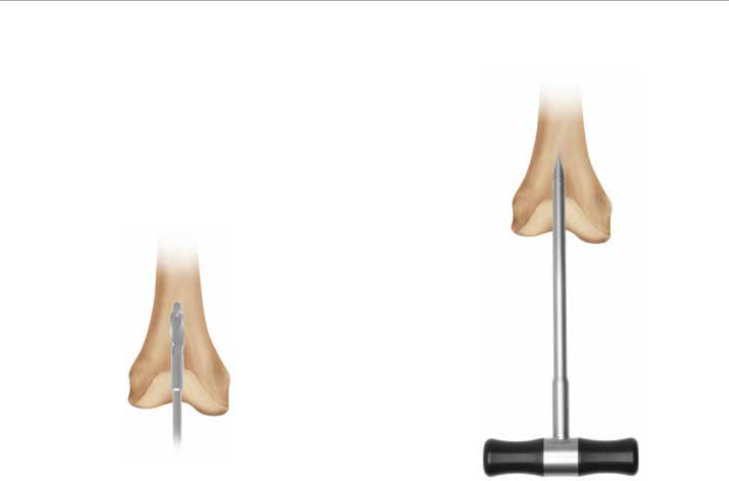
Canal access can be obtained using either a Cannulated
Entry Reamer or Cannulated Awl (2810-01-005) (Figures
36 and 37). Both 12 mm (2810-13-001) and 13 mm
(2810-13-002) entry reamers are available depending on
surgeon preference. The distal (drive end) nail diameter is
12 mm for all nail sizes equal to or less than 12 mm, and
13 mm to 15 mm nails have a distal diameter equal to the
nail diameter. Use A/P and lateral fluoroscopic views to
confirm accurate placement. Use the awl or entry reamer
to open the distal femur in the intercondylar notch. As an
option, an Entry Portal Sleeve (2810-12-001) is available
for soft tissue protection, as great care must be taken
to protect the undersurface of the patella.
Note: If utilizing the cannulated entry reamer, the length
of the distal portion of the reamer is enlarged and
matches the length of the drive end portion of the nail.
Fluoroscopically verify the entry reamer has been inserted
to the proper depth that will correspond with the depth of
the nail.
Figure 36 Figure 37
23
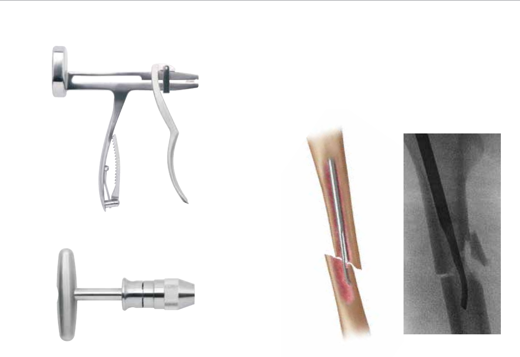
Once access to the femoral canal has been gained, place
the ball nose guide wire into the entry site utilizing the
pistol-style Guide Wire Gripper (2810-01-001) (Figure 38).
If preferred, a T-handle Guide Wire Gripper (2810-01-002)
is also available as an option.
Fracture Reduction
Obtain appropriate anatomic reduction in order to restore
length, alignment and rotation of the injured limb. Reduction
can be achieved through the surgeon’s preferred
method such as traction and/or an external fixator. To aid
in manipulating the fracture fragments and passing the Ball
Nose Guide Wire, large (7.5 mm diameter, 2810-01-007)
and small (6.5 mm diameter, 2810-01-008) reduction tools
are available (Figure 39). Insert the reduction tool into the
medullary canal, past the fracture site. Once the fracture
is aligned, pass the Ball Nose Guide Wire, available in both
80 cm (2810-01-080) and 100 cm (2810-01-100) lengths,
across the fracture site. Remove the reduction tool.
Figure 38 Figure 39
VersaNail® Femoral Universal
24
Canal Preparation
Achieve proper alignment of the fracture prior to reaming
and maintain it throughout the reaming process to
avoid eccentric reaming. Initiate reaming by placing the
VersaNail Flexible Reamers over the 3.0 mm Ball Nose
Guide Wire (Figure 40). Ream the medullary canal in
millimeter increments until cortical bone is reached and
half-millimeter increments thereafter. Surgeon preference
should dictate the actual extent of intramedullary reaming.
Monitor the reaming procedure using image intensification
to avoid eccentric or excessive cortical reaming.
Retrograde Nail Insertion
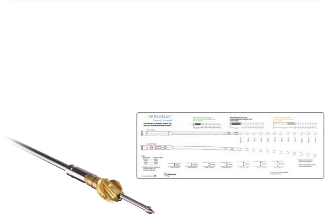
Nail Size Selection
An X-ray Template (2810-13-025) including 10 percent
magnification is available to determine nail size preopera-
tively (Figure 41).
Figure 40 Figure 41
25
Nail Diameter Selection
Generally, a nail diameter 1 mm less than the final reamer
diameter is chosen. Femoral Universal Nails are available
in 1 mm increments from 9 mm to 15 mm diameters.
Nail Length Selection
With the tip of the ball nose guide wire at the level of
the desired depth of nail insertion, slide or snap the Nail
Length Gauge (2810-01-031) onto the ball nose guide wire
until the nose contacts the bone, ensuring the tip does not
fall into the existing entry canal, which could result in an
inaccurate measurement (Figure 42).
Figure 42
VersaNail® Femoral Universal
26
Retrograde Nail Insertion
Nail Length Selection (cont.)
To obtain the appropriate nail length read the measurement
mark on the nail length gauge that is closest to the
beginning of the black transition area on the guide wire
(Figure 43). The selected nail length must be at least 5 mm
less than the measured length to allow for the required
recessing of the drive end of the nail, ensuring that the
nail will not protrude into the patellofemoral joint. If the
dynamization mode is to be used at the drive end of the
nail, nail length should be further appropriately shortened.
If a nail of the exact measured length is not available,
choose a shorter nail of the next closest available length.
A direct measurement can also be taken of the uninjured
extremity using either radiographs with magnification
markers, or directly on the uninjured limb.
Nail/Jig Assembly
Place the nail on the femoral insertion handle in the
correct orientation. The nail should be oriented on the
femoral insertion handle such that the anterior bow of the
nail is in line with the anterior bow of the femur and the jig
is lateral to the nail. Secure the nail to the femoral insertion
handle by inserting the Femoral Jig Bolt (2810-13-008)
through the cannulation of the nose and tightening with
the Jig Bolt Driver (2810-13-006) and T-handle (2810-01-
004) (Figure 44).
Figure 43 Figure 44
27
Nail Insertion
Once proper reduction has been achieved, insert the nail
over the 3 mm ball nose guide wire into the medullary
canal (Figure 45). It is important not to strike the femoral
insertion handle directly.
Attach the Hammer Pad (2810-13-011) to the insertion
handle (Figure 46). Ensure that the hammer pad is
tightened thoroughly prior to impaction. Avoid excessive
force when inserting the nail. If the nail jams in the
medullary canal, extract it and choose the next-smaller
diameter nail or enlarge the canal appropriately.
Figure 45 Figure 46
VersaNail® Femoral Universal
28
Nail Insertion (cont.)
Note: The femoral insertion handle is marked with three
grooves (Figure 47). The groove closest to the nail is an
indicator for the nail/insertion handle junction. A K-wire
can be inserted lateral to medial through the target arm if
additional identification of the nail/insertion handle junction
is needed. The middle groove is marked 5 mm from the
top of the nail and the groove farthest from the nail is
marked 15 mm from the top of the nail. Ensure the nail is
seated to proper depth for planned dynamization.
Confirm fracture reduction and ensure appropriate nail
insertion depth proximally and distally with biplanar
fluoroscopy. Remove the ball nose guide wire.
Retrograde Nail Insertion
Dynamization
A dynamic slot has been incorporated in the drive end
and non-drive end of the nail. The drive end slot has a 10
mm range of dynamization. The non-drive end slot has a
5 mm range of dynamization. If dynamization is planned,
countersink the nail to the appropriate depth to avoid
backing out of the nail. Lock the M/L slot in the dynamic
mode. Delayed dynamization may be performed at a later
date with the removal of the static screws.
Universal Target Arm Assembly
Attach the radiolucent Universal Target Arm (2810-13-
009) onto the insertion handle, using the Target Arm
Attachment Bolt (2810-13-026) and hand tighten. Ensure
the target arm is properly secured to the insertion handle
for excellent targeting (Figure 48).
Nail/Jig
Junction
5 mm
15 mm
Figure 47 Figure 48
29
Retrograde Locking
K-wire (indicator for nail/jig junction)
Static Locking Hole
Slot - Dynamic Mode
Slot - Static Mode
Static Locking Mode
Locking
Prior to locking both proximally and distally, check femoral
length and rotational alignment. The nail can be locked
either distally or proximally first, depending on surgeon
preference.
Distal Locking
The universal target arm is marked to identify which drive
end locking option is being targeted (Figure 49).
Place 6.5 mm cortical locking screws using the black
instrumentation (Figure 50).
Note: Depending on surgeon preference, a 6.5 mm lag
screw is also available for distal locking. If a lag locking
technique is preferred, place the 6.5 mm cancellous lag
screw using the gold instrumentation.
Place the 6.5 mm Screw Sheath (2810-13-020) and
Trocar (2810-13-021) through the appropriate holes in the
jig’s targeting arm to locate the incision site (Figure 51).
Make a stab incision and advance the sheath and trocar
to the bone. Soft tissue dissection should be completed
sharp and precise to clear a path for the sheath. Undue
soft tissue tension against the sheath can cause misdirect
drilling.
Figure 50Figure 49 Figure 51
VersaNail® Femoral Universal
30
Distal Locking (cont.)
Note: A 3.2 mm x 17.5 in Guide Pin (9030-03-004) and
3.2 mm Pin Guide Sleeve (2810-13-018) can be used to
verify screw position prior to drilling (Figure 52).
Remove the trocar and replace it with the 5.3 mm Drill
Sleeve (2810-13-022) (Figure 53).
Retrograde Locking
Utilizing the 5.3 mm Drill Bit (2810-13-153) drill through
the drill sleeve and sheath until the far cortex is penetrated
(Figure 54).
Figure 52 Figure 53 Figure 54
31
Read the calibration on the drill bit that lines up with the
drill sleeve to determine the screw length (figure 55).
Ensure the drill sleeve is on bone and read the calibration
on the drill bit at the end of the drill sleeve to determine
the appropriate screw length (Figure 55). If penetrating the
far cortex prior to taking the reading, use the screw length
indicated on the drill bit at the screw depth measurement
line. If you are not penetrating the far cortex prior to taking
the reading, add 5 mm in length to the screw length reading.
If further screw length is required, or if the locking hole has
been initiated with a guide pin, a 6.5 mm Screw Depth
Gauge (2810-13-035) is available to read screw length off
of the 3.2 mm x 17.5 in guide pin (Figure 56).
Figure 55 Figure 56
VersaNail® Femoral Universal
32
Distal Locking (cont.)
Verify fluoroscopically to assure the proper screw length
selection. Remove the drill sleeve. Using the 6.5 mm
Screwdriver Shaft (2810-13-024), insert the 6.5 mm
cortical screw through the sheath (Figure 57). The etch
mark on the screwdriver corresponds with the screw
sheath to indicate when the screw is fully seated.
Repeat above steps for additional screw placement.
Proximal Locking
Place 4.5 mm cortical locking screws using the green
instrumentation (Figure 58).
Retrograde Locking
Figure 57 Figure 58
33
Use fluoroscopy to conduct freehand locking utilizing a
familiar freehand technique. A black Radiolucent Wand
(2810-12-016) is available to aid in freehand locking
(Figure 59).
Accurate C-arm position is confirmed when the distal
nail hole appears to be a perfect circle (Figure 60). Once
correct placement has been verified fluoro-scopically,
make a stab wound in direct alignment with the distal hole.
Figure 59 Figure 60
VersaNail® Femoral Universal
34
Proximal Locking
Using the 3.8 mm Drill Bit (6 in: 2810-12-138 or 8 in:
2810-13-138), drill until the second cortex is reached
or penetrated. Verify the drill bit position fluoroscopically
prior to taking any measurements (Figure 61). Place the
green 4.5 mm Screw Length Gauge (2810-01-032) onto
the calibrated drill bit and advance down to the bone.
Read the calibration on the drill bit that corresponds to the
measurement line indicated on the screw length gauge.
A Screw Depth Gauge (2810-01-017) is also provided for
further screw length verification. For an accurate reading,
take care to ensure the 4.5 mm screw length gauge or
screw depth gauge sheath is fully seated on the bone.
Remove the drill bit and advance the 4.5 mm screw.
Repeat above steps for additional screw placement. The
SolidLok Screwdriver (2810-01-020 and 2810-01-021)
can be utilized to capture the screw while passing it
through soft tissue during screw placement.
Retrograde Locking
A compensation factor is built into the measurement of the screw depth gauge (for the screw head and cutting flutes), and the calibrated drills
(for the screw head only).
If penetrating the far cortex prior to taking the reading, use the screw length indicated on the drill bit at the screw depth measurement line.
If you are not penetrating the far cortex prior to taking the reading, add 5 mm in length to the screw length reading.
Determining Screw Length
The screw size indicates the total measurement from the
tip to the screw head. The calibrated drills and the screw
depth gauges have a compensation factor built into the
measurement such that the reading should indicate the
exact size screw to achieve bi-cortical purchase. To ensure
a proper reading, the screw depth gauge and drill sleeves
must be touching bone. Fluoroscopy is recommended to
verify the correct screw length (Figure 62).
Figure 61 Figure 62
35
End Cap Placement and Nail Removal
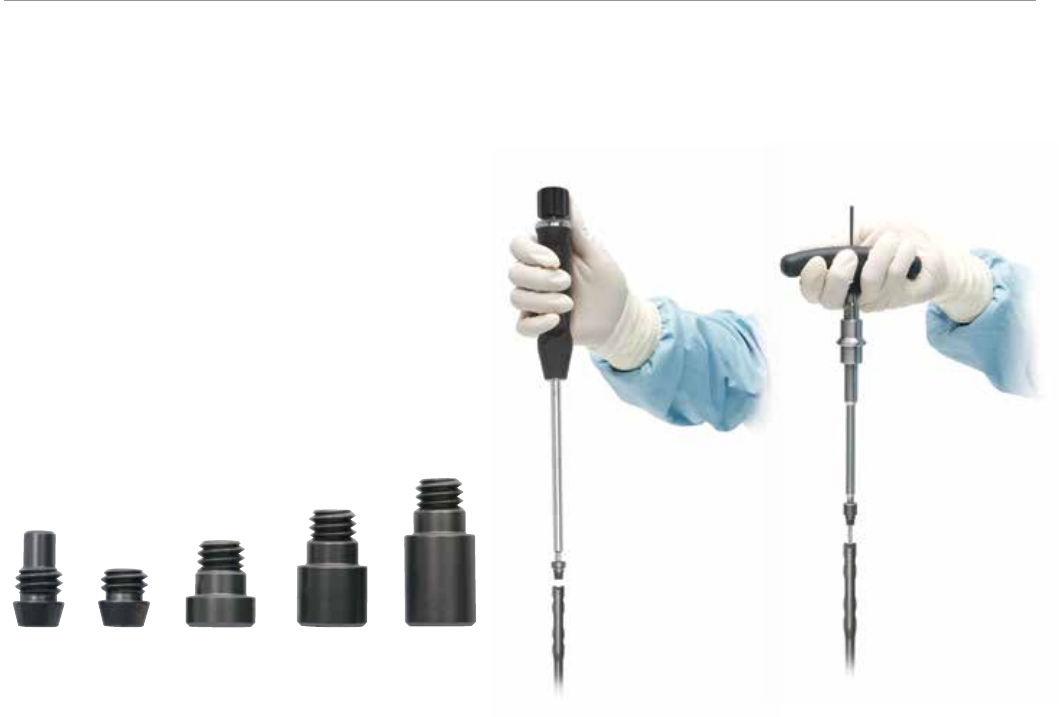
End Cap Placement
Impinging and non-impinging cannulated end caps are
provided in the system to both prevent bony ingrowth and
add length when needed (Figure 63).
End caps have a double hex of 5 mm and 3.5 mm and
are cannulated to accept a 3.2 mm guide pin. Place the
end cap into the end of the nail with the 4.5/5.5 mm
Screwdriver (2810-01-015) or the SolidLok Screwdriver
(2810-01-020 and 2810-01-021) (Figure 64). If the end
cap will be placed using a 3.2 mm guide pin, place the end
cap with the 5 mm Hex Driver (2810-01-037). Irrigate the
joint to ensure that no debris remains. Close the wound.
Figure 63 Figure 64
VersaNail® Femoral Universal
36
End Cap Placement and Nail Removal
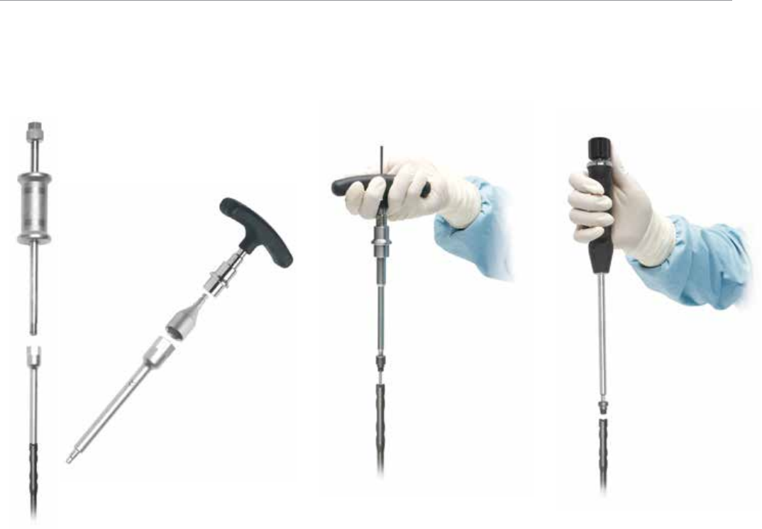
Nail Removal
If the surgeon deems it appropriate to remove the nail,
a Cannulated Extractor Bolt (2810-01-023), used with
3/4 in Hex Driver (2810-01-027) and T-handle Hudson
(2810-01-004), is provided to aid in nail extraction
(Figure 65).
Locate the top of the nail through an appropriate incision.
Remove the end cap. End caps have a double hex of 5 mm
and 3.5 mm and are cannulated to accept a 3.2 mm
guide pin. If using the guide pin method, insert the 3.2 mm
guide pin and remove the end cap using the cannulated
5 mm Hex Driver (2810-01-037), which is connected to
the T-handle Hudson (2810-01-004) (Figure 66).
The SolidLok® Locking Screwdriver (2810-01-020 and
2810-01-021) is also available to aid in removing the
end cap, if not utilizing a guide pin. Insert the SolidLok
screwdriver into the Hex Tip (2810-01-019) and tighten
the handle to lock the end cap’s hex tip into the inner end
cap’s 3.5 mm hex (Figure 67). The end cap can also be
removed with a standard 3.5 mm hex screwdriver.
Make the appropriate incisions and remove all locking
screws. Remove all overgrown bone around the nail’s
proximal aspect to avoid iatrogenic fracture during nail
extraction.
Figure 65 Figure 66 Figure 67
37
Once locking screws are removed, drive a 3.2 mm guide
pin into the cannulation in the nail’s proximal section. Insert
the extractor bolt over the 3.2 mm guide pin and thread it
into the nail (Figure 68).
Then thread the impactor rod into the extractor bolt and
use either the slotted mallet or sliding hammer to remove
the nail (Figure 69).
If nail removal is unobtainable utilizing the standard
extractor bolt, a Conical Nail Extractor Bolt (2810-01-022)
is available for removal cases where the nail threads are
difficult to engage (Figure 70). This instrument is designed
to work with various nail thread/cannulation designs.
Note: Nail thread/cannulation condition may limit the
purchase amount that can be gained using the conical
extractor bolt.
Figure 68 Figure 69 Figure 70
VersaNail® Femoral Universal Ordering Information
38
CATALOG NUMBER DESCRIPTION
Femoral Universal Nail 9 mm 28-50 cm
1813-09-280 9 mm x 28 cm
1813-09-300 9 mm x 30 cm
1813-09-320 9 mm x 32 cm
1813-09-340 9 mm x 34 cm
1813-09-360 9 mm x 36 cm
1813-09-380 9 mm x 38 cm
1813-09-400 9 mm x 40 cm
1813-09-420 9 mm x 42 cm
1813-09-440 9 mm x 44 cm
1813-09-460 9 mm x 46 cm
1813-09-480 9 mm x 48 cm
1813-09-500 9 mm x 50 cm
Femoral Universal Nail 10 mm 28-50 cm
1813-10-280 10 mm x 28 cm
1813-10-300 10 mm x 30 cm
1813-10-320 10 mm x 32 cm
1813-10-340 10 mm x 34 cm
1813-10-360 10 mm x 36 cm
1813-10-380 10 mm x 38 cm
1813-10-400 10 mm x 40 cm
1813-10-420 10 mm x 42 cm
1813-10-440 10 mm x 44 cm
1813-10-460 10 mm x 46 cm
1813-10-480 10 mm x 48 cm
1813-10-500 10 mm x 50 cm
Femoral Universal Nail 11 mm 28-50 cm
1813-11-280 11 mm x 28 cm
1813-11-300 11 mm x 30 cm
1813-11-320 11 mm x 32 cm
1813-11-340 11 mm x 34 cm
1813-11-360 11 mm x 36 cm
1813-11-380 11 mm x 38 cm
1813-11-400 11 mm x 40 cm
1813-11-420 11 mm x 42 cm
1813-11-440 11 mm x 44 cm
1813-11-460 11 mm x 46 cm
1813-11-480 11 mm x 48 cm
1813-11-500 11 mm x 50 cm
Femoral Universal Nail 12 mm 28-50 cm
1813-12-280 12 mm x 28 cm
1813-12-300 12 mm x 30 cm
1813-12-320 12 mm x 32 cm
1813-12-340 12 mm x 34 cm
1813-12-360 12 mm x 36 cm
1813-12-380 12 mm x 38 cm
1813-12-400 12 mm x 40 cm
1813-12-420 12 mm x 42 cm
1813-12-440 12 mm x 44 cm
1813-12-460 12 mm x 46 cm
1813-12-480 12 mm x 48 cm
1813-12-500 12 mm x 50 cm
Femoral Universal Nail 13 mm 28-50 cm
1813-13-280 13 mm x 28 cm
1813-13-300 13 mm x 30 cm
1813-13-320 13 mm x 32 cm
1813-13-340 13 mm x 34 cm
1813-13-360 13 mm x 36 cm
1813-13-380 13 mm x 38 cm
1813-13-400 13 mm x 40 cm
1813-13-420 13 mm x 42 cm
1813-13-440 13 mm x 44 cm
1813-13-460 13 mm x 46 cm
1813-13-480 13 mm x 48 cm
1813-13-500 13 mm x 50 cm
Femoral Universal Nail 14 mm 28-50 cm
(Special Order Only)
1813-14-280 14 mm x 28 cm
1813-14-300 14 mm x 30 cm
1813-14-320 14 mm x 32 cm
1813-14-340 14 mm x 34 cm
1813-14-360 14 mm x 36 cm
1813-14-380 14 mm x 38 cm
1813-14-400 14 mm x 40 cm
1813-14-420 14 mm x 42 cm
1813-14-440 14 mm x 44 cm
1813-14-460 14 mm x 46 cm
1813-14-480 14 mm x 48 cm
1813-14-500 14 mm x 50 cm
Femoral Universal Nail 15 mm 28-50 cm
(Special Order Only)
1813-15-280 15 mm x 28 cm
1813-15-300 15 mm x 30 cm
1813-15-320 15 mm x 32 cm
1813-15-340 15 mm x 34 cm
1813-15-360 15 mm x 36 cm
1813-15-380 15 mm x 38 cm
1813-15-400 15 mm x 40 cm
1813-15-420 15 mm x 42 cm
1813-15-440 15 mm x 44 cm
1813-15-460 15 mm x 46 cm
1813-15-480 15 mm x 48 cm
1813-15-500 15 mm x 50 cm
End Caps
1813-00-005 End Cap
Universal 5 mm
1813-00-010 End Cap
Universal 10 mm
1813-00-015 End Cap
Universal 15 mm
1813-00-002 End Cap
Universal Impinging
1813-00-001 End Cap
Universal Flush
6.5 mm Self Tapping Cortical Screws
Full Thread (Drive End)
1020-40 40 mm Length
1020-45 45 mm Length
1020-50 50 mm Length
1020-55 55 mm Length
1020-60 60 mm Length
1020-65 65 mm Length
1020-70 70 mm Length
1020-75 75 mm Length
1020-80 80 mm Length
1020-85 85 mm Length
1020-90 90 mm Length
1020-95 95 mm Length
1020-100 100 mm Length
8050-65-105 105 mm Length
8050-65-110 110 mm Length
8050-65-115 115 mm Length
8050-65-120 120 mm Length
6.5 mm Solid Cancellous Lag Screws
(Drive End)
1030-60 60 mm Length
1030-65 65 mm Length
1030-70 70 mm Length
1030-75 75 mm Length
1030-80 80 mm Length
1030-85 85 mm Length
1030-90 90 mm Length
1030-95 95 mm Length
1030-100 100 mm Length
1030-105 105 mm Length
1030-110 110 mm Length
1030-115 115 mm Length
1030-120 120 mm Length
4.5 mm Self Tapping Cortical Screws
Full Thread (Non-Drive End)
14022-24 24 mm Length
14022-28 28 mm Length
14022-32 32 mm Length
14022-36 36 mm Length
14022-40 40 mm Length
14022-44 44 mm Length
14022-48 48 mm Length
14022-52 52 mm Length
14022-56 56 mm Length
14022-60 60 mm Length
14022-65 65 mm Length
14022-70 70 mm Length
14022-75 75 mm Length
14022-80 80 mm Length
( 4.5 mm screws available in 2 mm
increments up to 60 mm)
Indicates outlier size not included in standard set configuration.
Indicates special orders only. Not an inventory item. Packaged non-sterile only.
Sterile packaged.
39
1
2
15
18
19
20
21 23
22
16
17
11
6
7
8
12
13
14
34
5
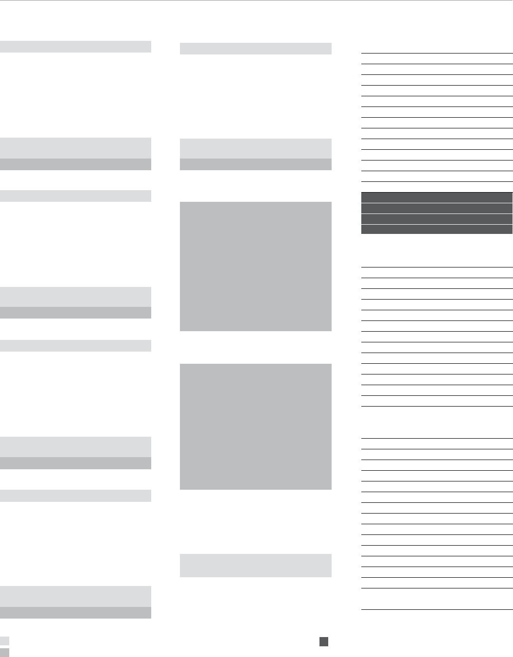
General
2810-01-001 Pistol Guidewire Gripper 1
2810-01-002 T-Handle Guidewire Gripper (optional) 2
2810-01-003 Slotted Mallet 3
2810-01-004 T-Handle Hudson 4
1096 Sliding Hammer 5
Canal Prep
2810-01-007 Long Reduction Tool 6
2810-01-008 Short Reduction Tool 7
2810-01-005 Curved Cannulated Awl 8
2810-13-004 Entry Portal Trocar 9
2810-13-005 Long Entry Portal 10
2810-13-002 13 mm Entry Reamer, Femur 11
2810-13-001 12 mm Entry Reamer, Femur 12
2810-01-025 Awl Stylus 13
2810-01-026 Guidewire Pusher 14
Nail Insertion
1186 3/4 in Combination Wrench 15
2810-13-011 Hammer Pad Femur 16
2810-13-026 Target Arm Attachment Bolt 17
2810-13-009 Universal Target Arm 18
2810-13-007 Femoral Insertion Handle 19
2810-13-006 Jig Bolt Driver, 8 mm 20
1095 Impactor Rod/Extraction 21
2810-13-047 Fem Univ Compression Bolt 22
2810-13-046 Compression Rod 23
9
10
VersaNail® Femoral Universal Ordering Information
40
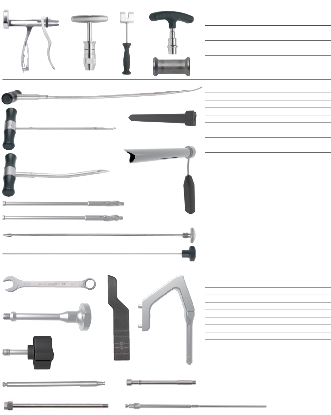
Promixal Locking
2810-13-020 6.5 mm Screw Sheath 24
2141-49-000 AO Quick Couple Screwdriver 25
2810-13-024 6.5 mm Screwdriver Shaft 26
2810-13-035 6.5 mm Screw Depth Gauge 27
2810-13-018 3.2 mm Guide Pin Sleeve - Silver 28
2810-13-021 6.5 mm Screw Trocar 29
2810-13-022 5.3 mm Drill Sleeve - Black 30
2810-13-023 6.5/4.8 mm Step Drill Sleeve - Gold 31
Disposables
14012-14 3.2 mm x 14 in Short Threaded Guide Pin
9030-03-004 3.2 mm x 17 1/2 in Threaded Guide Pin 41
2810-01-019 SolidLok Hex Tip, 3.5 mm 42
2810-01-080 Ball Nose Guide Wire 80 cm 43
2810-01-100 Ball Nose Guide Wire 100 cm 43
2810-12-138 3.8 mm Drill Bit 6 in, Non-sterile 44
2810-13-138 3.8 mm Drill Bit 8 in, Non-sterile 45
2810-13-153 5.3 mm Drill Bit, Non-sterile 46
2810-13-165 6.5/4.8 mm Step Drill Bit, Non-sterile 47
Nail Removal
2810-01-023 Extractor Bolt, Tibia/Femur 38
2810-01-022 Conical Extractor Tool 39
2810-01-027 3/4 in Hex Driver 40
Distal Locking
2810-01-032 4.5 mm Screw Length Gauge 32
2810-12-016 Freehand Distal Targ. Dev.
Universal - Black 33
2810-01-020 SolidLok Screwdriver Handle 34
2810-01-015 4.5/5.5 mm Screwdriver Shaft 35
2810-01-017 Screw Depth Gauge 36
2810-01-021 SolidLok Driver Inner Shaft 37
38
39
40
42
41
43
44
45
46
47
24 25
28
29
30
31
26
27
33
32
34
35
36
37
41
53
54
55
56
51
52
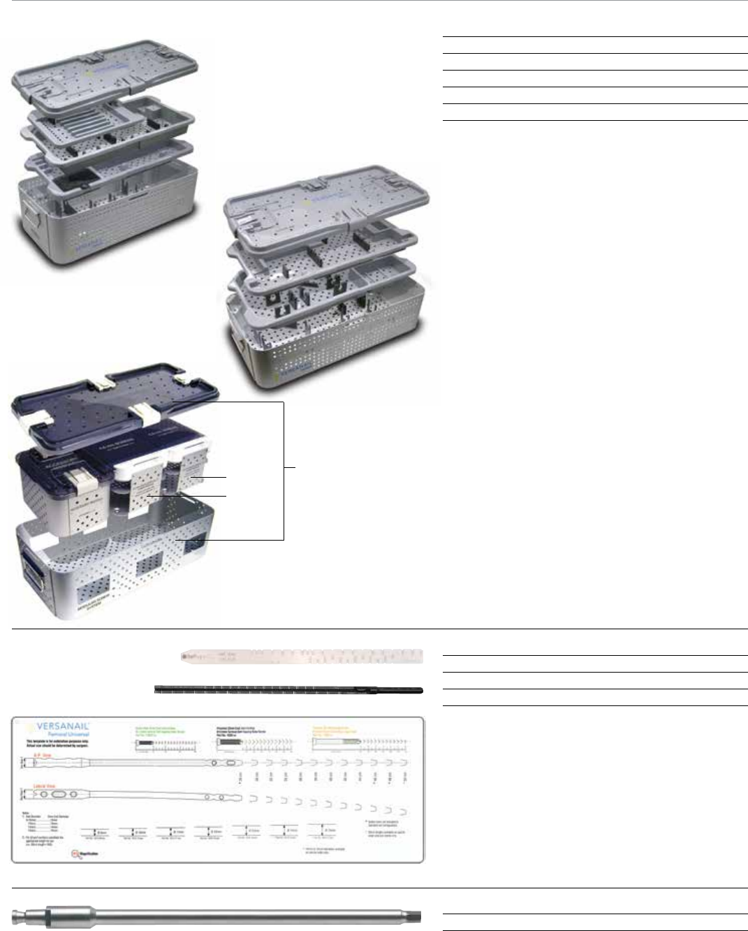
50 Outer Case
Cases & Trays
2810-13-030 Femoral Tray Entry & Jigs 48
2810-13-031 Femoral Tray Locking & Extraction 49
8299-10-500 Modular Screw System Outer Case 50
8299-10-065 6.5 mm Screw Module 51
8299-10-045 4.5 mm Cort Screw Module 52
Endcap Placement
2810-01-037 5.0 mm Hex Driver, Long 56
Nail Measurement
1245 Radiographic Ruler 53
2810-01-031 Nail Length Gauge, 14 mm 54
2810-13-025 VersaNail Femoral Universal Template 55
48
49
VersaNail® Femoral Universal Ordering Information
42
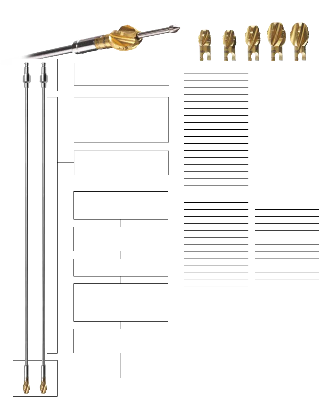
Monobloc Reamer Hudson
Cat. No. Diameter
2810-02-060 6.0 mm
2810-02-065 6.5 mm
2810-02-070 7.0 mm
2810-02-075 7.5 mm
2810-02-080 8.0 mm
2810-02-085 8.5 mm
2810-02-090 9.0 mm
2810-02-095 9.5 mm
2810-02-100 10.0 mm
2810-02-105 10.5 mm
2810-02-110 11.0 mm
2810-02-115 11.5 mm
2810-02-120 12.0 mm
2810-02-125 12.5 mm
2810-02-130 13.0 mm
Modular Reamer Head
Cat. No. Diameter
2810-04-090 9.0 mm
2810-04-095 9.5 mm
2810-04-100 10.0 mm
2810-04-105 10.5 mm
2810-04-110 11.0 mm
2810-04-115 11.5 mm
2810-04-120 12.0 mm
2810-04-125 12.5 mm
2810-04-130 13.0 mm
2810-04-135 13.5 mm
2810-04-140 14.0 mm
2810-04-145 14.5 mm
2810-04-150 15.0 mm
2810-04-155 15.5 mm
2810-04-160 16.0 mm
2810-04-165 16.5 mm
2810-04-170 17.0 mm
2810-04-175 17.5 mm
2810-04-180 18.0 mm
2810-04-185 18.5 mm
2810-04-190 19.0 mm
2810-04-195 19.5 mm
2810-04-200 20.0 mm
2810-04-205 20.5 mm
2810-04-210 21.0 mm
2810-04-215 21.5 mm
2810-04-220 22.0 mm
Nitinol Modular
Reamer Shaft Hudson
Cat. No. Length
2810-02-400 400 mm
2810-02-470 470 mm
Reamer Extension
Cat. No. Length
2810-02-015 150 mm
Ball Nose Guide Wires
Cat. No. Length
3.0 mm
(use with 8.0-22.0 mm Reamers)
2810-01-080 800 mm
2810-01-100 1000 mm
2.0 mm
(use with 6.0-7.5 mm Reamers)
2810-17-006 700 mm
Flexible Reamer Case
2810-02-016
Small shaft diameters allow debris to be
removed and transported up to the open
proximal end of the medullary canal.
Excellent cleanability - Nitinol (Nickel-
Titanium) alloy allows for a smooth
cannulated shaft that provides
the required flexibility without the
cleaning problems associated with
coil-cut or spring shaft designs.
Deep cutting flutes allow debris to
be moved proximally away from
the reamer head, maintaining
cutting edge efficiency.
Sharp side cutting edges are designed
to remove bone without generating a
substantial increase in temperature.
Surface coating titanium nitride (TiNi)
will keep cutting edge sharper longer.
Ellipsoidal head shape allows the
cutting edge to remove bone gradually
and transport debris away, while bone
chipping design decreases the size
of debris, reducing canal pressure.
Reverse cutting feature minimizes
the potential for the reamer to
catch in the medullary canal.
Coupling design is simple,long
established and easy to clean
(AO and/or HUDSON).
Flexible Reaming System

43

44
Notes

Notes
45
This publication and all content, is protected by copyright, trademarks and
other intellectual property rights owned by or licensed to Biomet Inc. or its
affiliates unless otherwise indicated.
This material is intended for the physicians and the Biomet sales force only.
The distribution to any other recipient is prohibited.
This publication must not be used, copied or reproduced in whole or in part
without the express written consent of Biomet or its authorized representatives.
For product information see package insert and Biomet’s website.
Biomet does not practice medicine and does not recommend any particular
orthopaedic implant or surgical technique and is not responsible for the kind
of treatment selected for a specific patient. The surgeon who performs any
implant procedure is responsible for determining and utilizing the appropriate
techniques for implanting prosthesis in each individual patient.
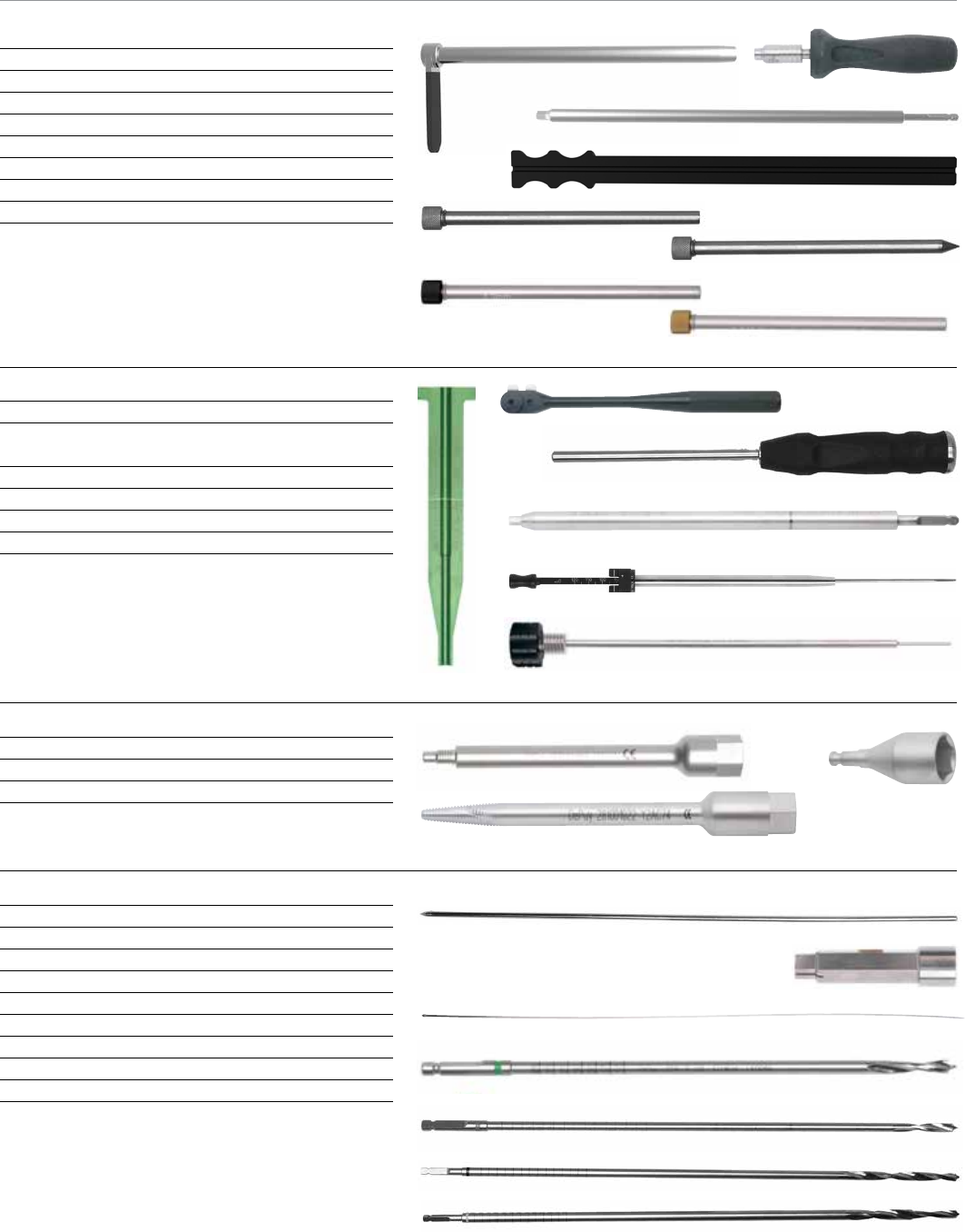
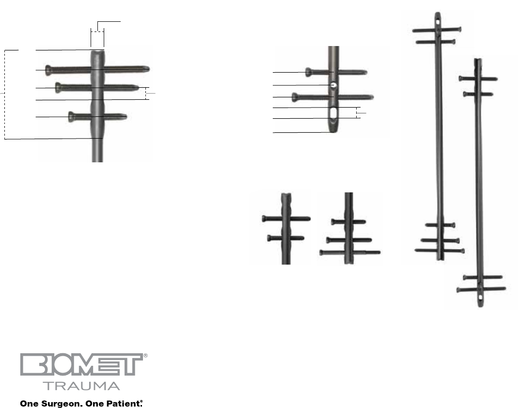
Proximal End Distal End
Locking Options
0 mm
14 mm
10 mm
Dymanization
Range
12 mm Drive End Diameter
for 9-12 mm Nails
Drive End Diameter
Equal to Nail Diameter
for 13-15 mm Nails
29 mm
64 mm
39 mm
54 mm 5 mm
Dymanization
Range
28 mm
48 mm
38 mm
18 mm
13 mm
0 mm
Screws, Plates, Intramedullary Nails, Compression Hip Screws, Pins and Wires
Important:
This Essential Product Information does not include all of the information necessary
for selection and use of a device. Please see full labeling for all necessary information.
Indications:
The use of metallic surgical appliances (screws, plates, intramedullary nails,
compression hip screws, pins and wires) provides the orthopaedic surgeon a
means of bone fixation and helps generally in the management of fractures and
reconstructive surgeries. These implants are intended as a guide to normal healing,
and are NOT intended to replace normal body structure or bear the weight of the
body in the presence of incomplete bone healing. Delayed unions or nonunions in
the presence of load bearing or weight bearing might eventually cause the implant
to break due to metal fatigue. All metal surgical implants are subjected to repeated
stress in use, which can result in metal fatigue.
Contraindications:
Screws, plates, intramedullary nails, compression hip screws, pins and wires are
contraindicated in: active infection, conditions which tend to retard healing such as
blood supply limitations, previous infections, insufficient quantity or quality of bone
to permit stabilization of the fracture complex, conditions that restrict the patient’s
ability or willingness to follow postoperative instructions during the healing process,
foreign body sensitivity, and cases where the implant(s) would cross open epiphyseal
plates in skeletally immature patients.
Additional Contraindication for Orthopaedic Screws and Plates only: Cases with
malignant primary or metastatic tumors which preclude adequate bone support or
screw fixations, unless supplemental fixation or stabilization methods are utilized.
Additional Contraindication for Retrograde Femoral Nailing:
A history of septic arthritis of the knee and knee extension contracture with inability
to attain at least 45º of flexion.
Additional Contraindications for Compression Hip Screws only:
Inadequate implant support due to the lack of medial buttress.
Warnings and Precautions:
Bone screws and pins are intended for partial weight bearing and non-weight bearing
applications. These components cannot be expected to withstand the unsupported
stresses of full weight bearing.
Adverse Events:
The following are the most frequent adverse events after fixation with orthopaedic
screws, plates, intramedullary nails, compression hip screws, pins and wires:
loosening, bending, cracking or fracture of the components or loss of fixation in bone
attributable to nonunion, osteoporosis, markedly unstable comminuted fractures;
loss of anatomic position with nonunion or malunion with rotation or angulation;
infection and allergies and adverse reactions to the device material. Surgeons
should take care when targeting and drilling for the proximal screws in any tibial nail
with oblique proximal screws. Care should be taken as the drill bit is advanced to
penetrate the far cortex. Advancing the drill bit too far in this area may cause injury
to the deep peroneal nerve. Fluoroscopy should be used to verify correct positioning
of the drill bit.
Additional Adverse Events for Compression Hip Screw only:
Screw cutout of the femoral head (usually associated with osteoporotic bone).
Responsible Manufacturer
Biomet Trauma
P.O. Box 587
56 E. Bell Drive
Warsaw, Indiana 46581-0587
USA
www.biomet.com
©2013 Biomet Trauma • Form No. BMET0027.1 • REV1113
