User Guide M211840EN D WXT530 Users
User Manual: Pdf
Open the PDF directly: View PDF ![]() .
.
Page Count: 222 [warning: Documents this large are best viewed by clicking the View PDF Link!]
- WXT530 Series User Guide
- Table of Contents
- List of Figures
- List of Tables
- 1. About This Document
- 2. Product Overview
- 3. Functional Description
- 4. Installation
- 5. Wiring and Power Management
- 6. Connection Options
- 7. Retrieving Data Messages
- 7.1 General Commands
- 7.2 ASCII Protocol
- 7.2.1 Abbreviations and Units
- 7.2.2 Device Address (?)
- 7.2.3 Acknowledge Active Command (a)
- 7.2.4 Wind Data Message (aR1)
- 7.2.5 Pressure, Temperature and Humidity Data Message (aR2)
- 7.2.6 Precipitation Data Message (aR3)
- 7.2.7 Supervisor Data Message (aR5)
- 7.2.8 Combined Data Message (aR)
- 7.2.9 Composite Data Message Query (aR0)
- 7.2.10 Polling with CRC
- 7.2.11 Automatic Mode
- 7.2.12 Automatic Composite Data Message (aR0)
- 7.3 SDI-12 Protocol
- 7.3.1 Address Query Command (?)
- 7.3.2 Acknowledge Active Command (a)
- 7.3.3 Change Address Command (aAb)
- 7.3.4 Send Identification Command (aI)
- 7.3.5 Start Measurement Command (aM)
- 7.3.6 Start Measurement Command with CRC (aMC)
- 7.3.7 Start Concurrent Measurement (aC)
- 7.3.8 Start Concurrent Measurement with CRC (aCC)
- 7.3.9 Send Data Command (aD)
- 7.3.10 Examples of aM, aC and aD Commands
- 7.3.11 Continuous Measurement (aR)
- 7.3.12 Continuous Measurement with CRC (aRC)
- 7.4 NMEA 0183 v3.0 Protocol
- 8. Sensor and Data Message Settings
- 8.1 Sensor Configuration and Data Message Formatting
- 8.1.1 Wind Sensor
- 8.1.2 Pressure, Temperature, and Humidity Sensors
- 8.1.3 Precipitation Sensor
- 8.1.4 Supervisor Message
- 8.1.5 Composite Data Message (aR0)
- 8.1.6 Analog Input
- 8.1.6.1 Enabling and Disabling Analog Input
- 8.1.6.2 Common Sensor Settings (aIU)
- 8.1.6.3 Aux Input Averaging Time [A]
- 8.1.6.4 Parameter Selection [R]
- 8.1.6.5 Getting Data Messages
- 8.1.6.6 Aux Rain Sensor Settings [aIA]
- 8.1.6.7 Solar Radiation Sensor Settings [aIB]
- 8.1.6.8 Ultrasonic Level Sensor Settings [aIS]
- 8.1.6.9 Aux.temperature Sensor Settings [aIP]
- 8.1.6.10 Parameter Order for SDI-12 Mode
- 8.1.7 Analog Output
- 8.1 Sensor Configuration and Data Message Formatting
- 9. Maintenance
- 10. Troubleshooting
- 11. Technical Specifications
- Appendix A. Networking
- Appendix B. SDI-12 Protocol
- Appendix C. CRC-16 Computation
- Appendix D. Wind Measurement Averaging Method
- Appendix E. Factory Configurations
- Appendix F. Connecting External Sensors to WXT536
- Appendix G. Complete Set of Accessories
- Appendix H. Configuration Parameters
- Index
- Warranty
- Recycling
- Technical Support
M211840EN-D
User Guide
Vaisala Weather Transmitter
WXT530 Series

PUBLISHED BY
Vaisala Oyj
Street address: Vanha Nurmijärventie 21, FI-01670 Vantaa, Finland
Mailing address: P.O. Box 26, FI-00421 Helsinki, Finland
Phone: +358 9 8949 1
Fax: +358 9 8949 2227
Visit our Internet pages at www.vaisala.com.
© Vaisala Oyj 2017
No part of this manual may be reproduced,
published or publicly displayed in any form
or by any means, electronic or mechanical
(including photocopying), nor may its
contents be modified, translated, adapted,
sold or disclosed to a third party without
prior written permission of the copyright
holder. Translated manuals and translated
portions of multilingual documents are
based on the original English versions. In
ambiguous cases, the English versions are
applicable, not the translations.
The contents of this manual are subject to
change without prior notice.
Local rules and regulations may vary and
they shall take precedence over the
information contained in this manual.
Vaisala makes no representations on this
manual’s compliance with the local rules
and regulations applicable at any given
time, and hereby disclaims any and all
responsibilities related thereto.
This manual does not create any legally
binding obligations for Vaisala towards
customers or end users. All legally binding
obligations and agreements are included
exclusively in the applicable supply
contract or the General Conditions of Sale
and General Conditions of Service of
Vaisala.
This product contains software developed
by Vaisala or third parties. Use of the
software is governed by license terms and
conditions included in the applicable
supply contract or, in the absence of
separate license terms and conditions, by
the General License Conditions of Vaisala
Group.
Table of Contents
1. About This Document........................................................................................9
1.1 Documentation Conventions................................................................................9
1.2 Trademarks............................................................................................................. 9
1.3 ESD Protection......................................................................................................10
1.4 Version Information............................................................................................. 10
2. Product Overview................................................................................................11
2.1 WXT530 Series Weather Transmitters................................................................11
2.1.1 WXT536...........................................................................................................13
2.1.2 WXT535 and WXT534................................................................................... 14
2.1.3 WXT533 and WXT532....................................................................................15
2.1.4 WXT531............................................................................................................16
2.2 Components.......................................................................................................... 17
2.3 Optional Features................................................................................................. 19
2.3.1 USB Cables.................................................................................................... 20
2.3.2 Mounting Kit....................................................................................................21
2.3.3 Surge Protector............................................................................................. 22
2.3.4 Bird Kit............................................................................................................ 23
2.3.5 Vaisala Configuration Tool........................................................................... 24
2.3.6 Sensor Heating.............................................................................................. 24
2.4 Backward Compatibility......................................................................................25
2.5 Regulatory Compliances.....................................................................................25
3. Functional Description.................................................................................... 27
3.1 Wind Measurement Principle............................................................................. 27
3.2 Precipitation Measurement Principle................................................................ 28
3.3 PTU Measurement Principle............................................................................... 29
3.4 Heating................................................................................................................. 30
3.5 Analog Input Interface......................................................................................... 31
3.6 Analog Output Interface...................................................................................... 31
4. Installation............................................................................................................33
4.1 Installing WXT530............................................................................................... 33
4.1.1 Maritime Installations....................................................................................33
4.2 Placing WXT530.................................................................................................. 33
4.3 Unpacking WXT530............................................................................................ 36
4.4 Mounting WXT530.............................................................................................. 38
4.4.1 Mounting WXT530 on Vertical Pole Mast without Mounting Kit............ 39
4.4.2 Mounting WXT530 on Vertical Pole Mast with Mounting Kit.................. 39
4.4.3 Mounting WXT530 on Sensor Support Arm..............................................43
4.5 Grounding.............................................................................................................45
4.5.1 Grounding with Bushing and Grounding Kit............................................. 45
4.6 Aligning WXT530................................................................................................ 46
4.6.1 Aligning WXT530 with Compass................................................................ 48
4.6.2 Configuring Wind Direction Oset.............................................................48
4.7 Installing Vaisala Configuration Tool.................................................................49
4.8 Installing USB Cable Driver..................................................................................51
Table of Contents
1
5. Wiring and Power Management..................................................................53
5.1 Power Supplies.....................................................................................................53
5.2 Power Management............................................................................................ 56
5.3 Wiring with 8-pin M12 Connector...................................................................... 58
5.3.1 External Wiring..............................................................................................58
5.3.2 Internal Wiring................................................................................................61
5.4 Wiring Using Screw Terminals........................................................................... 64
5.5 Data Communication Interfaces........................................................................ 67
6. Connection Options......................................................................................... 69
6.1 Communication Protocols..................................................................................69
6.2 Connection Cables.............................................................................................. 69
6.3 Connecting with Service Cable..........................................................................70
6.3.1 Connecting through M12 Bottom Connector or Screw Terminal..............71
6.4 Communication Setting Commands................................................................. 72
6.4.1 Checking Current Communication Settings (aXU)................................... 72
6.4.2 Settings Fields............................................................................................... 73
6.4.3 Changing the Communication Settings (aXU).......................................... 75
7. Retrieving Data Messages..............................................................................77
7.1 General Commands............................................................................................. 77
7.1.1 Reset (aXZ).................................................................................................... 77
7.1.2 Precipitation Counter Reset (aXZRU).........................................................78
7.1.3 Precipitation Intensity Reset (aXZRI)......................................................... 79
7.1.4 Measurement Reset (aXZM)........................................................................80
7.2 ASCII Protocol....................................................................................................... 81
7.2.1 Abbreviations and Units................................................................................81
7.2.2 Device Address (?)........................................................................................82
7.2.3 Acknowledge Active Command (a)............................................................83
7.2.4 Wind Data Message (aR1)............................................................................ 83
7.2.5 Pressure, Temperature and Humidity Data Message (aR2).....................84
7.2.6 Precipitation Data Message (aR3).............................................................. 85
7.2.7 Supervisor Data Message (aR5)..................................................................85
7.2.8 Combined Data Message (aR).....................................................................86
7.2.9 Composite Data Message Query (aR0)......................................................87
7.2.10 Polling with CRC............................................................................................87
7.2.11 Automatic Mode............................................................................................89
7.2.12 Automatic Composite Data Message (aR0)..............................................90
7.3 SDI-12 Protocol.................................................................................................... 90
7.3.1 Address Query Command (?).......................................................................91
7.3.2 Acknowledge Active Command (a).............................................................91
7.3.3 Change Address Command (aAb).............................................................. 92
7.3.4 Send Identification Command (aI)..............................................................93
7.3.5 Start Measurement Command (aM)........................................................... 94
7.3.6 Start Measurement Command with CRC (aMC)........................................95
7.3.7 Start Concurrent Measurement (aC).......................................................... 96
7.3.8 Start Concurrent Measurement with CRC (aCC).......................................97
WXT530 Series User Guide M211840EN-D
2
7.3.9 Send Data Command (aD)........................................................................... 97
7.3.10 Examples of aM, aC and aD Commands.....................................................98
7.3.11 Continuous Measurement (aR)................................................................. 100
7.3.12 Continuous Measurement with CRC (aRC).............................................. 102
7.4 NMEA 0183 v3.0 Protocol................................................................................. 102
7.4.1 Device Address (?)...................................................................................... 102
7.4.2 Acknowledge Active Command (a)..........................................................103
7.4.3 MWV Wind Speed and Direction Query...................................................104
7.4.4 XDR Transducer Measurement Query.......................................................105
7.4.5 TXT Text Transmission..................................................................................113
7.4.6 Automatic Mode........................................................................................... 114
7.4.7 Automatic Composite Data Message (aR0)..............................................115
8. Sensor and Data Message Settings........................................................... 117
8.1 Sensor Configuration and Data Message Formatting.................................... 117
8.1.1 Wind Sensor.................................................................................................. 117
8.1.2 Pressure, Temperature, and Humidity Sensors........................................ 122
8.1.3 Precipitation Sensor.................................................................................... 127
8.1.4 Supervisor Message.....................................................................................132
8.1.5 Composite Data Message (aR0)................................................................ 135
8.1.6 Analog Input.................................................................................................136
8.1.7 Analog Output............................................................................................. 143
9. Maintenance....................................................................................................... 147
9.1 Cleaning...............................................................................................................147
9.1.1 Cleaning the Radiation Shield.................................................................... 147
9.2 Replacing PTU Module...................................................................................... 147
10. Troubleshooting.................................................................................................151
10.1 Self-Diagnostics..................................................................................................153
10.1.1 Error Messaging/Text Messages................................................................ 153
10.1.2 Rain and Wind Sensor Heating Control.................................................... 154
10.1.3 Operating Voltage Control......................................................................... 155
10.1.4 Missing Readings and Error Indication......................................................155
11. Technical Specifications................................................................................ 157
11.1 Performance........................................................................................................157
11.2 Inputs and Outputs............................................................................................ 159
11.3 Environmental Conditions..................................................................................161
11.4 Mechanical Specifications................................................................................. 162
11.5 Options and Accessories...................................................................................163
11.6 Type Label...........................................................................................................164
11.7 Dimensions (mm / inch)....................................................................................165
Appendix A: Networking.......................................................................................171
A.1 Connecting Several Transmitters on Same Bus...............................................171
A.2 SDI-12 Serial Interface......................................................................................... 171
A.2.1 Wiring SDI-12................................................................................................. 171
A.2.2 SDI-12 Communication Protocol................................................................. 171
A.3 RS-485 Serial Interface......................................................................................172
A.3.1 RS-485 Wiring..............................................................................................172
A.3.2 RS-485 Communication Protocol.............................................................. 172
A.3.3 ASCII, Polled................................................................................................. 172
A.3.4 NMEA 0183 v3.0, Query.............................................................................. 173
A.3.5 NMEA 0183 v3.0 Query with ASCII Query Commands............................175
Table of Contents
3
Appendix B: SDI-12 Protocol...............................................................................177
B.1 SDI-12 Electrical Interface..................................................................................177
B.1.1 SDI-12 Communications Protocol...............................................................177
B.1.2 SDI-12 Timing................................................................................................177
Appendix C: CRC-16 Computation................................................................... 179
C.1 Encoding the CRC as ASCII Characters........................................................... 179
C.2 NMEA 0183 v3.0 Checksum Computation......................................................180
Appendix D: Wind Measurement Averaging Method................................181
Appendix E: Factory Configurations...............................................................183
E.1 General Unit Settings.........................................................................................183
E.2 Wind Configuration Settings............................................................................ 183
E.3 PTU Configuration Settings..............................................................................184
E.4 Rain Configuration Settings..............................................................................185
E.5 Supervisor Settings............................................................................................185
Appendix F: Connecting External Sensors to WXT536...........................187
F.1 Connecting Ultrasonic Level Sensor to WXT536............................................187
F.2 Connecting Pyranometer to WXT536.............................................................190
F.3 Connecting Resistance Temperature Sensor..................................................194
F.4 Connecting Rain Gauge to WXT536................................................................197
Appendix G: Complete Set of Accessories...................................................199
Appendix H: Configuration Parameters........................................................203
Index............................................................................................................................... 211
Warranty.......................................................................................................................217
Recycling......................................................................................................................217
Technical Support.....................................................................................................217
WXT530 Series User Guide M211840EN-D
4
List of Figures
Figure 1 Vaisala Weather Transmitter WXT530 Series.............................................11
Figure 2 WXT536............................................................................................................... 14
Figure 3 WXT535 and WXT534......................................................................................15
Figure 4 WXT533 and WXT532......................................................................................15
Figure 5 WXT531.................................................................................................................16
Figure 6 WXT536 Components......................................................................................17
Figure 7 Cut-Away View of WXT536............................................................................ 18
Figure 8 Bottom of WXT536...........................................................................................19
Figure 9 USB Cable...........................................................................................................20
Figure 10 Mounting Kit........................................................................................................21
Figure 11 Surge Protector................................................................................................. 22
Figure 12 Bird Kit................................................................................................................. 23
Figure 13 WXT536 with Bird Kit......................................................................................23
Figure 14 Vaisala Configuration Tool............................................................................. 24
Figure 15 Analog Inputs for External Sensors..............................................................31
Figure 16 Recommended Mast Location in Open Area............................................34
Figure 17 Recommended Mast Length on Top of Building......................................35
Figure 18 Contents of Shipping Container...................................................................36
Figure 19 Installing with Protective Packaging...........................................................37
Figure 20 Mounting WXT531 on Vertical Pole Mast...................................................40
Figure 21 WXT530 North Arrow..................................................................................... 47
Figure 22 Sketch of Magnetic Declination....................................................................47
Figure 23 Average Operational Current Consumption (with 4Hz
Wind Sensor Sampling)..................................................................................54
Figure 24 Heating Instant Current and Power vs Vh (WXT536,
WXT535, WXT533, and WXT532)................................................................55
Figure 25 Heating Instant Current and Power vs Vh (WXT531)..............................55
Figure 26 Pins of 8-pin M12 Connector..........................................................................59
Figure 27 Internal Wiring for RS-232, SDI-12, and RS-485...................................... 64
Figure 28 Screw Terminal Block...................................................................................... 65
Figure 29 Data Communication Interfaces...................................................................67
Figure 30 Termination Jumper Positions......................................................................68
Figure 31 Service Cable Connection..............................................................................70
Figure 32 Analog Input Connector Pins.......................................................................137
Figure 33 Analog Input Settings in Vaisala Configuration Tool.............................138
Figure 34 Type Label.........................................................................................................164
Figure 35 WXT536 Dimensions in mm [in].................................................................165
Figure 36 WXT535 and WXT534 Dimensions in mm [in].......................................166
Figure 37 WXT533 and WXT532 Dimensions in mm [in]....................................... 167
Figure 38 WXT531 Dimensions in mm [in]..................................................................168
Figure 39 WXT530 Series Mounting Kit (212792) Dimensions..............................169
Figure 40 Mounting Accessory (WMSFIX60) for Connecting
Mounting Kit (212792) and 60 mm Tube..................................................170
Figure 41 Timing Diagram............................................................................................... 178
Figure 42 Wind Measurement Averaging Method.................................................... 182
Figure 43 Connecting External Sensors to WXT536................................................ 187
Figure 44 Connecting Ultrasonic Level Sensor to WXT536................................... 188
Figure 45 Wiring Ultrasonic Level Sensor to WXT536.............................................189
Figure 46 Connecting CMP3 to WXT536......................................................................191
Figure 47 Peeling CMP3 Cable Sheath.........................................................................192
Figure 48 Wiring CMP3 to WXT53.................................................................................193
Figure 49 Pt1000 Connected to WXT536 M12 Connector......................................194
List of Figures
5
Figure 50 Wiring Temperature Sensor Pt1000 to WXT536....................................195
Figure 51 Wiring Temperature Sensor TM-Pt1000 to WXT536............................ 195
Figure 52 TM-Pt1000 Connector...................................................................................196
Figure 53 Wiring RG13/RG13H to WXT536................................................................. 197
Figure 54 Complete Set of Accessories.......................................................................199
Figure 55 WXT536 with Surge Protector WSP150................................................... 201
Figure 56 WXT536 with Surge Protector WSP152...................................................202
WXT530 Series User Guide M211840EN-D
6
List of Tables
Table 1 Document Versions.............................................................................................10
Table 2 Available Options.................................................................................................12
Table 3 Heater Resistance...............................................................................................30
Table 4 Standby Power Consumption......................................................................... 56
Table 5 Economic Power Management....................................................................... 57
Table 6 Pin-outs for WXT530 Series Serial Interfaces and Power Supplies......59
Table 7 Screw Terminal Pin-outs...................................................................................59
Table 8 WXT532 mA Output Option Screw Terminal Pin-outs............................ 60
Table 9 RS-232 Wiring...................................................................................................... 61
Table 10 RS-485 Wiring.....................................................................................................62
Table 11 SDI-12 Wiring....................................................................................................... 62
Table 12 RS-422 Wiring..................................................................................................... 63
Table 13 mA Output Wiring..............................................................................................63
Table 14 Screw Terminal Pin-outs for Serial Interfaces and Power Supplies......65
Table 15 Available Serial Communication Protocols................................................. 69
Table 16 Connection Cable Options ..............................................................................70
Table 17 Default Serial Communication Settings for M12/Screw
Terminal Connection...........................................................................................71
Table 18 Abbreviations and Units.................................................................................... 81
Table 19 Transducer IDs of Measurement Parameters.............................................107
Table 20 Transducer Table.................................................................................................113
Table 21 Wind Parameters Bits 1-8.................................................................................119
Table 22 Wind Parameters Bits 9-16.............................................................................. 119
Table 23 PTU Parameters Bits 1-8.................................................................................. 124
Table 24 PTU Parameters Bits 9-16................................................................................124
Table 25 Precipitation Parameters Bits 1-8..................................................................128
Table 26 Precipitation Parameters Bits 9-16............................................................... 129
Table 27 Supervisor Parameters Bits 1-8......................................................................133
Table 28 Supervisor Parameters Bits 9-16...................................................................134
Table 29 Analog Input Signals........................................................................................ 137
Table 30 Analog Input Setting Definitions.................................................................. 138
Table 31 aIU Setting Fields [R]...................................................................................... 140
Table 32 Analog Output Scaling.................................................................................... 144
Table 33 aWU Setting Fields [R]................................................................................... 146
Table 34 Data Validation....................................................................................................151
Table 35 Communication Problems.............................................................................. 152
Table 36 Error Messaging/Text Messages................................................................... 154
Table 37 WXT530 Series Barometric Pressure Measuring Specifications.......... 157
Table 38 WXT530 Series Air Temperature Measuring Specifications..................157
Table 39 WXT530 Series Relative Humidity Measuring Specifications...............157
Table 40 WXT530 Series Precipitation Measuring Specifications........................ 158
Table 41 WXT530 Series Wind Measuring Specifications...................................... 158
Table 42 WXT530 Series Electrical Specifications....................................................159
Table 43 WXT536 Analog Input Options.....................................................................160
Table 44 WXT532 Analog mA Output Options......................................................... 160
Table 45 WXT530 Series Environmental Specifications...........................................161
Table 46 WXT530 Series Electromagnetic Compatibility........................................161
Table 47 WXT530 Series Mechanical Specifications................................................ 162
Table 48 Options and Accessories.................................................................................163
Table 49 General Unit Settings....................................................................................... 183
Table 50 Wind Configuration Settings......................................................................... 184
Table 51 PTU Configuration Settings........................................................................... 184
List of Tables
7
Table 52 Rain Configuration Settings...........................................................................185
Table 53 General Unit Settings....................................................................................... 185
Table 54 Ultrasonic Level Connections........................................................................190
Table 55 Pyranometer Connections..............................................................................194
Table 56 Temperature Sensor Connections................................................................ 196
Table 57 Rain Gauge Connections.................................................................................198
Table 58 General Parameters.........................................................................................203
Table 59 Pressure, Temperature and Humidity Parameters.................................. 205
Table 60 Wind Parameters............................................................................................. 206
Table 61 Precipitation Parameters............................................................................... 207
Table 62 Auxiliary Sensor Parameters.........................................................................208
Table 63 Analog mA Output Parameters................................................................... 209
WXT530 Series User Guide M211840EN-D
8
1. About This Document
1.1 Documentation Conventions
Warning alerts you to a serious hazard. If you do not read and follow
instructions carefully at this point, there is a risk of injury or even death.
WARNING!
Caution warns you of a potential hazard. If you do not read and follow
instructions carefully at this point, the product could be damaged or important data
could be lost.
CAUTION!
Note highlights important information on using the product.
Tip gives information for using the product more eciently.
Lists tools needed to perform the task.
Indicates that you need to take some notes during the task.
1.2 Trademarks
Vaisalaâ, BAROCAPâ, HUMICAPâ, RAINCAPâ, and THERMOCAPâ are registered
trademarks of Vaisala Oyj.
Microsoftâ and Windowsâ are either registered trademarks or trademarks of Microsoft
Corporation in the United States and other countries.
All other product or company names that may be mentioned in this publication are trade
names, trademarks, or registered trademarks of their respective owners.
Chapter 1 – About This Document
9

1.3 ESD Protection
Electrostatic Discharge (ESD) can damage electronic circuits. Vaisala products are
adequately protected against ESD for their intended use. However, it is possible to damage
the product by delivering electrostatic discharges when touching, removing, or inserting any
objects in the equipment housing.
To avoid delivering high static voltages to the product:
• Handle ESD-sensitive components on a properly grounded and protected ESD
workbench or by grounding yourself to the equipment chassis with a wrist strap and a
resistive connection cord.
• If you are unable to take either precaution, touch a conductive part of the equipment
chassis with your other hand before touching ESD-sensitive components.
• Hold component boards by the edges and avoid touching component contacts.
1.4 Version Information
Table 1 Document Versions
Document Code Date Description
M211840EN-D April 2017 Added information about external sensors. Updated technical
drawings. Added grounding information. Added index.
M211840EN-C February 2016 Previous version
WXT530 Series User Guide M211840EN-D
10
2. Product Overview
2.1 WXT530 Series Weather Transmitters
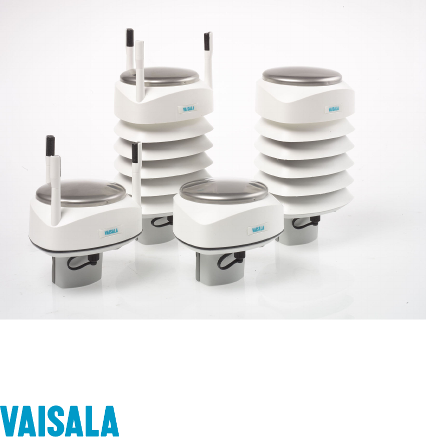
The WXT530 product family consists of the following transmitters.
Figure 1 Vaisala Weather Transmitter WXT530 Series
The WXT530 series transmitters are suitable for several purposes, such as:
• Agro-meteorological applications
• Building control systems
• Cruisers
• Energy applications
• Environmental monitoring
• Fire weather
• Meteorological test beds
• Noise monitoring
• Researchers
• Sport events
• Weather stations
The product family oers a variety of weather parameters. The following table lists the
measurement combinations of each model.
Chapter 2 – Product Overview
11
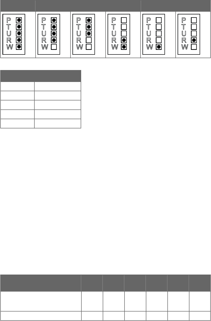
WXT536 WXT535 WXT534 WXT533 WXT532 WXT531
Parameter Description
PPressure
TTemperature
UHumidity
RRain
WWind
The transmitters power up with 5 … 32 VDC and output serial data with a selectable
communication protocol:
• SDI-12
• ASCII automatic and polled
• NMEA 0183 with query option
The WXT530 series has four serial interface options:
• RS-232
• RS-485
• RS-422
• SDI-12
The transmitter is equipped with the following connectors:
• 8-pin M12 connector for installation
• 4-pin M8 connector for service use
The transmitter housing is IP65/66 rated.
The following table shows dierent options available for the product family.
Table 2 Available Options
Available options WXT53
6
WXT53
5
WXT53
4
WXT53
3
WXT53
2
WXT53
1
Service Pack 2: Windows-based Vaisala
Configuration Tool software with USB
service cable (1.4 m)
✔ ✔ ✔ ✔ ✔ ✔
USB RS-232/RS-485 cable (1.4 m) ✔ ✔ ✔ ✔ ✔ ✔
WXT530 Series User Guide M211840EN-D
12

Available options WXT53
6
WXT53
5
WXT53
4
WXT53
3
WXT53
2
WXT53
1
Mounting kit ✔ ✔ ✔ ✔ ✔ ✔
Surge protector ✔ ✔ ✔ ✔ ✔ ✔
Bird kit ✔ ✔ ✔ ✔ ✔ ✔
Shielded cables (2 m, 10 m, 40 m) ✔ ✔ ✔ ✔ ✔ ✔
Bushing and grounding kit ✔ ✔ ✔ ✔ ✔ ✔
Heating ✔ ✔ ✔✔✔
Analog input option ✔
mA output option ✔
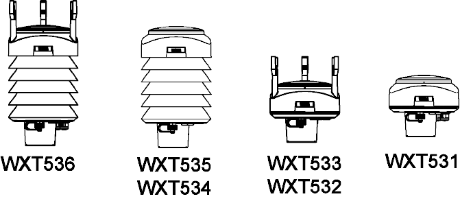
2.1.1 WXT536
WXT536 measures:
• Pressure
• Temperature
• Humidity
• Rain
• Wind speed
• Wind direction
It oers an analog input option.
Chapter 2 – Product Overview
13
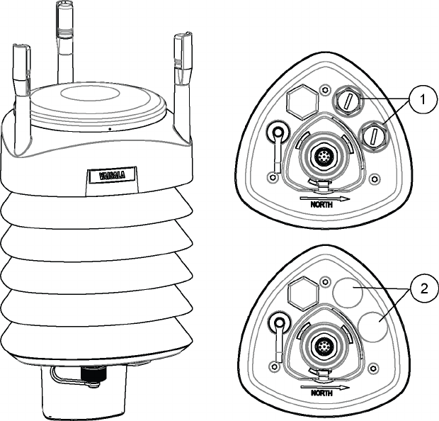
Figure 2 WXT536
1Analog input option
2Analog input option not ordered
2.1.2 WXT535 and WXT534
WXT535 measures:
• Pressure
• Temperature
• Humidity
• Rain
WXT534 measures:
• Pressure
• Temperature
• Humidity
WXT530 Series User Guide M211840EN-D
14
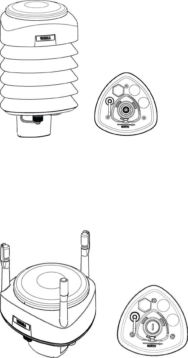
Figure 3 WXT535 and WXT534
2.1.3 WXT533 and WXT532
WXT533 measures:
• Rain
• Wind
WXT532 measures wind and oers an mA output option.
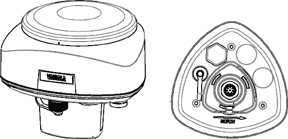
Figure 4 WXT533 and WXT532
Chapter 2 – Product Overview
15
2.1.4 WXT531
WXT531 measures rain.
Figure 5 WXT531
WXT530 Series User Guide M211840EN-D
16
2.2 Components
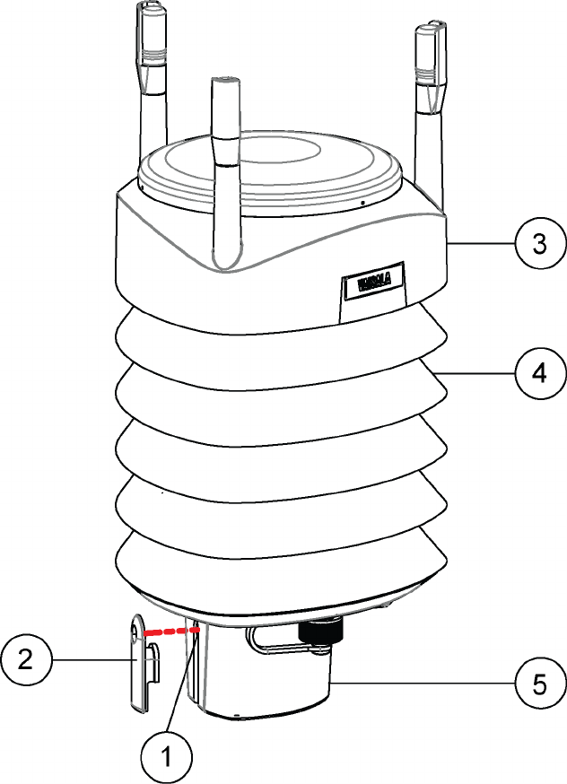
Figure 6 WXT536 Components
1Fixing screw and chassis grounding point
2Screw cover
3Top of the transmitter
4Radiation shield
5Bottom of the transmitter
Chapter 2 – Product Overview
17
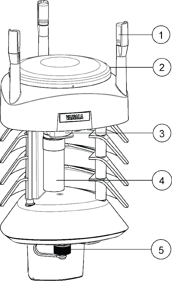
Figure 7 Cut-Away View of WXT536
1Wind transducers (3 pcs)
2Precipitation sensor
3Pressure sensor inside the PTU module
4Humidity and temperature sensors inside the PTU module
5Service port
WXT530 Series User Guide M211840EN-D
18
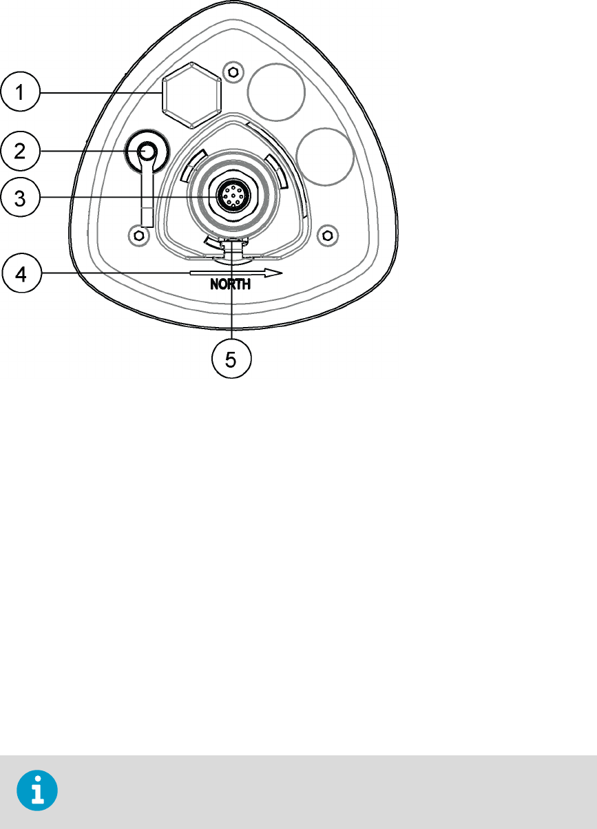
Figure 8 Bottom of WXT536
1Opening for cable gland (if unused, cover with a hexagonal plug).
Watertight cable gland (optional, included in the Bushing and Grounding Kit)
24-pin M8 connector for service port
38-pin M12 connector for power or data communications cable
4Alignment direction indicator arrow
5Fixing screw and chassis grounding point
2.3 Optional Features
The WXT530 series includes the following optional features:
• USB cables
• Mounting kit
• Surge protector
• Bird kit
• Vaisala Configuration Tool
• Heating
You must select these options when placing the order.
More Information
‣Options and Accessories (page 163)
Chapter 2 – Product Overview
19

2.3.1 USB Cables
Figure 9 USB Cable
• USB RS-232/RS-485 cable with 8-pin M12 threaded connector (1.4 m)
• USB service cable with 4-pin M8 threaded connector (1.4 m)
The service cable, while connected between the service port and PC, forces the service port
to RS-232 / 19200, 8, N, 1.
You need a driver for the USB cable.
WXT530 Series User Guide M211840EN-D
20
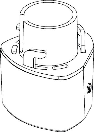
2.3.2 Mounting Kit
Figure 10 Mounting Kit
The optional mounting kit helps mounting the transmitter on a pole mast. When using the
mounting kit, alignment is needed only when mounting for the first time.
Using the mounting kit improves the transmitter IP classification to IP66. Without the
mounting kit, the WXT530 series transmitters are rated IP65.
Chapter 2 – Product Overview
21

2.3.3 Surge Protector
Figure 11 Surge Protector
Vaisala recommends using surge protectors:
• When weather instruments are installed in areas with an elevated risk of lightning
strike, such as on top of high buildings or masts, or in open areas.
• If your cable length exceeds 10 m.
• If you have unshielded, open-wire lines.
Vaisala provides the following surge protectors:
• Vaisala Surge Protector WSP150. A compact transient overvoltage suppressor designed
for outdoor use. It can be used with all Vaisala wind and weather instruments. Install
WSP150 close to the protected instrument (maximum 3 m).
• Vaisala Surge Protector WSP152. Designed for use with Vaisala WXT transmitters and
WMT sensors. WSP152 protects the host PC against surges entering through the USB
port. Install WSP152 close to the PC, no further than the USB cable can reach (1.4 m).
WXT530 Series User Guide M211840EN-D
22

2.3.4 Bird Kit
Figure 12 Bird Kit
The optional bird kit reduces the interference that birds cause to the wind and rain
measurement.
The kit consists of a metallic band with spikes pointing upward. The kit is installed on top of
the transmitter. The shape and location of the spikes has been designed so that the
interference with wind and rain measurement is minimal.
Figure 13 WXT536 with Bird Kit
The spikes do not hurt the birds; they are simply a barrier that makes it dicult for birds to
land on top of the transmitter. The bird spike kit does not provide complete protection
against birds, but it does render the transmitter unsuitable for roosting and nest building.
Chapter 2 – Product Overview
23
When the kit is in place, more snow can accumulate on the transmitter, and the snow can
melt away more slowly.
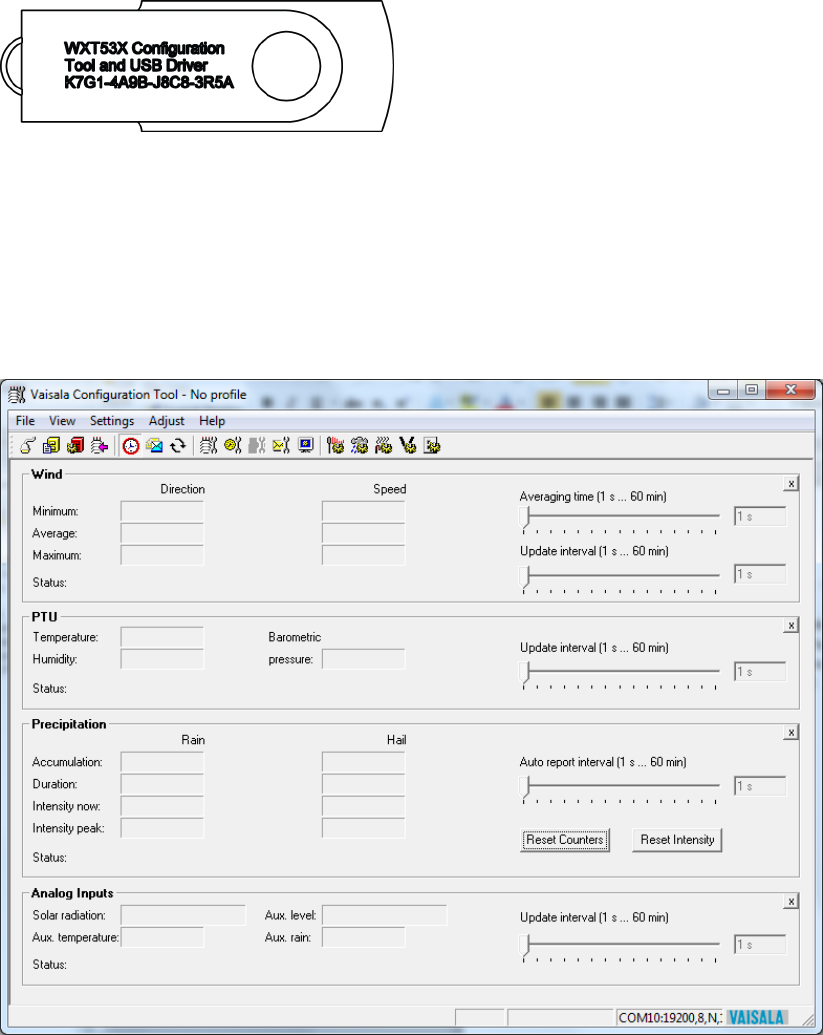
2.3.5 Vaisala Configuration Tool
Vaisala Configuration Tool is a Windows-based, user-friendly parameter setting software for
WXT530 transmitters. It is also fully compatible with WMT52 and WXT520.
Figure 14 Vaisala Configuration Tool
2.3.6 Sensor Heating
Heating helps to improve the measurement accuracy.
More Information
‣Heating (page 30)
WXT530 Series User Guide M211840EN-D
24

2.4 Backward Compatibility
Always use the latest version of WXT530 Configuration Tool.
The WXT530 series transmitters are fully compatible with WXT520 and WMT52. This applies
to mounting, cable options, and communication.
When you upgrade from WMT52 to WXT532 or from WXT520 to WXT536, you must use the
same profile and communication option as you had before. Regenerate the setup files (WXC
files) for WXT530 with the latest version of WXT530 Configuration Tool .
Because the WXT530 series has several product variants, the old configuration code does
not apply to the new WXT530 sensor. You must generate and apply a new order code for it.
More Information
‣Vaisala Configuration Tool (page 24)
2.5 Regulatory Compliances
The electromagnetic compatibility of the WXT530 series has been tested according to the
following product family standard:
• EN 61326-1 Electrical equipment for measurement, control and laboratory use - EMC
requirements - for use in industrial locations.
• The WXT530 series has been enhanced for marine use according to the appropriate
sections of the IEC 60945 Maritime Navigation and Radiocommunication Equipment
and Systems - General requirements - Methods of testing.
• The WXT530 series is in conformance with the provisions of the RoHS directive of the
European Union:
• Directive on the Restriction of the Use of Certain Hazardous Substances in Electrical
and Electronic Equipment (2002/95/EC)
Chapter 2 – Product Overview
25
WXT530 Series User Guide M211840EN-D
26

3. Functional Description
3.1 Wind Measurement Principle
WXT536 WXT535 WXT534 WXT533 WXT532 WXT531
✔ ✔ ✔
The transmitters use Vaisala WINDCAP sensor technology for wind measurement.
The wind sensor has an array of three equally spaced ultrasonic transducers on a horizontal
plane. The unit determines wind speed and wind directions by measuring the time it takes
the ultrasound to travel from one transducer to the other two.
The wind sensor measures the transit time (in both directions) along the three paths
established by the array of transducers. The transit time depends on the wind speed along
the ultrasonic path. For zero wind speed, both the forward and reverse transit times are the
same. With wind along the sound path, the up-wind direction transit time increases and the
down-wind transit time decreases.
The unit calculates wind speed from the measured transit times using the following formula:
Vw = 0.5 × L × (1/tf – 1/tr)
VwWind speed
LDistance between the two transducers
tfTransit time in forward direction
trTransit time in reverse direction
Measuring the six transit times allows Vw to be computed for each of the three ultrasonic
paths. The computed wind speeds are independent of altitude, temperature, and humidity,
which are cancelled out when the transit times are measured in both directions, although
the individual transit times depend on these parameters.
The Vw values of two array paths are enough to compute wind speed and wind direction. A
signal processing technique ensures that wind speed and wind direction are calculated from
the two array paths with the best quality.
The wind speed is represented as a scalar speed in selected units (m/s, kt, mph, km/h). The
wind direction from which the wind comes is expressed in degrees (°). North is represented
as 0°, East as 90°, South as 180°, and West as 270°.
Chapter 3 – Functional Description
27

The wind direction is not calculated when the wind speed drops below 0.05 m/s. In this
case, the last calculated direction output remains until the wind speed increases to the level
of 0.05 m/s.
The average values of wind speed and direction are calculated as a scalar average of all
samples over the selected averaging time (1 ... 3600 s) with a selectable updating interval.
The sample count depends on the selected sampling rate: 4 Hz (default), 2 Hz, or 1 Hz. The
minimum and maximum values of wind speed and direction represent the corresponding
extremes during the selected averaging time.
You can select the computation of the wind speed extreme values in one of two ways:
• Traditional minimum/maximum calculation
• 3-second gust & calm calculation recommended by the World Meteorological
Organization (WMO). In this case the highest and lowest 3-second average values
(updated once a second) replace the maximum and minimum values in reporting of
wind speed, while the wind direction variance is returned in the traditional way.
The transmitter constantly monitors the wind measurement signal quality. If poor quality is
detected, the wind values are marked as invalid. If over half of the measurement values are
considered invalid, the last valid wind values are returned as missing data. However, in the
SDI-12 protocol, the invalid values are marked as zero (0).
More Information
‣Wind Measurement Averaging Method (page 181)
3.2 Precipitation Measurement Principle
WXT536 WXT535 WXT534 WXT533 WXT532 WXT531
✔✔ ✔ ✔
The transmitter uses Vaisala RAINCAP Sensor 2-technology in precipitation measurement.
The precipitation sensor comprises of a steel cover and a piezoelectrical sensor mounted on
the bottom surface of the cover.
The precipitation sensor detects the impact of individual raindrops. The signals from the
impact are proportional to the volume of the drops. The signal of each drop can be
converted directly to accumulated rainfall. An advanced noise filtering technique filters out
signals originating from other sources than raindrops.
The measured parameters are:
• Accumulated rainfall
• Rain current and peak intensity
• Duration of a rain event
Detecting each drop enables the computing of rain amount and intensity with high
resolution.
WXT530 Series User Guide M211840EN-D
28

Precipitation current intensity is internally updated every 10 seconds and represents the
intensity during the one minute period before requesting/automatic precipitation message
sending (for fast reactions to a rain event, during the first minute of the rain event, the
intensity is calculated over the period rain has lasted in 10-second steps instead of a fixed
period of one minute). Precipitation peak intensity represents the maximum of the
calculated current intensity values since last precipitation intensity reset.
The sensor can also distinguish hail stones from raindrops. The measured hail parameters
are the cumulative number of hail stones, current and peak hail intensity and the duration of
a hail shower.
The precipitation sensor operates in four modes:
• Precipitation Start/End mode:
Transmitter automatically sends a precipitation message 10 seconds after the
recognition of the first drop. The messages are sent continuously as the precipitation
proceeds and stop when the precipitation ends.
• Tipping bucket mode:
This mode emulates tipping bucket type precipitation sensors. Transmitter sends
automatically a precipitation message when the counter detects one unit increment
(0.1 mm/0.01 in).
• Time mode:
Transmitter sends automatically a precipitation message in the update intervals defined
by the user.
• Polled mode:
Transmitter sends a precipitation message whenever requested by the user.
More Information
‣Precipitation Sensor (page 127)
3.3 PTU Measurement Principle
WXT536 WXT535 WXT534 WXT533 WXT532 WXT531
✔✔✔
The PTU module contains separate sensors for pressure, temperature, and humidity
measurement.
The measurement principle of the transmitter is based on an advanced RC oscillator and two
reference capacitors against which the capacitance of the sensors is continuously measured.
The microprocessor of the transmitter performs compensation for the temperature
dependency of the pressure and humidity sensors.
The PTU module includes:
• Capacitive silicon BAROCAP sensor for pressure measurement,
• Capacitive ceramic THERMOCAP sensor for air temperature measurement
• Capacitive thin film polymer HUMICAP180 sensor for humidity measurement.
Chapter 3 – Functional Description
29

3.4 Heating
WXT536 WXT535 WXT534 WXT533 WXT532 WXT531
✔✔ ✔ ✔ ✔
When operating the sensor in temperatures below 0 °C (32 °F), select a model with an
internal heater and enable the heater for operation.
The heating elements located below the precipitation sensor and inside the wind
transducers help keeping the sensors clean from snow and ice. A heating temperature (Th)
sensor underneath the precipitation sensor controls the heating. Note that Th is measured
inside the equipment, where temperature is much higher than the ambient temperature
(Ta).
The heating control tries to keep Th at +15 °C by adjusting the heating power. The heater
control switches heating resistors on and o based on heating voltage and Th.
Table 3 Heater Resistance
Transmitter model Heater resistance when Vh < 15 V Heater resistance when Vh > 15 V
WXT536, WXT535, WXT533,
WXT532
15 57
WXT531 27
The instant current depends on the heater voltage. You must select the power supply with
the instant current in mind. The average heating power and heater performance do not
depend on the heating voltage.
When the heating function is disabled, the heating is o in all conditions.
Snow accumulation can cause temporary wind measurement problems even when
heating is enabled.
More Information
‣Supervisor Message (page 132)
WXT530 Series User Guide M211840EN-D
30

3.5 Analog Input Interface
WXT536 WXT535 WXT534 WXT533 WXT532 WXT531
✔
WXT536 oers an analog input option for solar radiation, external temperature, level
measurement, and tipping bucket.
Figure 15 Analog Inputs for External Sensors
1Analog input 1
Sensor A: Solar radiation
2Analog input 2
Sensor B: Temperature
Sensor C: Level sensor
Sensor D: Tipping bucket
3.6 Analog Output Interface
WXT536 WXT535 WXT534 WXT533 WXT532 WXT531
✔
WXT532 oers an analog output option for wind speed and wind direction measurement.
The output settings are preconfigured at the factory according to your order. WXT532 takes
measurements according to the configured averaging time and synthesizes the analog
outputs of wind speed and wind direction with an update interval of 0.25 seconds.
Chapter 3 – Functional Description
31
WXT530 Series User Guide M211840EN-D
32

4. Installation
Do not store the transmitter outdoors. Make sure you switch on the transmitter right after
installation.
4.1 Installing WXT530
At the measurement site, you must mount, ground, align, and connect the transmitter to the
data logger and the power source.
You can install the instrument on top of a pole mast or on a sensor support arm.
For the most reliable measurements:
• Avoid trees or other objects nearby which could disturb wind flow.
• Install the sensor to the height that best represents the prevailing wind conditions on
site.
To prevent equipment damage, install an air terminal so that the tip is as
high above the instruments and sensors as possible.
CAUTION!
To prevent corrosion and oxidation, use copper paste or equivalent on screws and
connector threads.
4.1.1 Maritime Installations
In maritime installations according to IEC 60945, the WXT530 series belongs to the
installation category C, which means that it is exposed to weather. When making maritime
installations, pay attention to the following:
• Do not install WXT530 near a magnetic compass. The compass safe distance is 5 m. The
transmitter must be installed in open space to avoid disturbance in measurements.
• Do not place WXT530 directly in front of a radar.
• Do not install WXT530 next to a powerful RF-transmitter antenna.
4.2 Placing WXT530
Select a site that represents the general area of interest to ensure representative ambient
measurements. Make sure that the site that is free from turbulence caused by nearby
objects, such as trees and buildings.
Chapter 4 – Installation
33
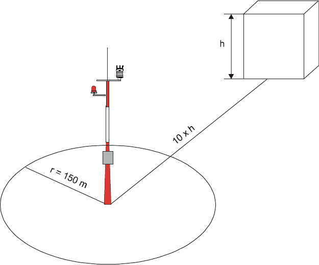
Following World Meteorological Organization (WMO) guidelines, a general recommendation
is that there is at least 150 m open area in all directions from the mast. Any object of height
(h) does not significantly disturb wind measurement at a minimum distance of 10 times the
height of the object.
The recommended minimum length (h) for the mast that is installed on top of a building is
1.5 times the height of the building (H). When the diagonal (W) is less than the height (h),
the minimum length of the mast is 1.5 W. However, follow the application specific
instructions and local regulations when placing WXT530.
Figure 16 Recommended Mast Location in Open Area
WXT530 Series User Guide M211840EN-D
34
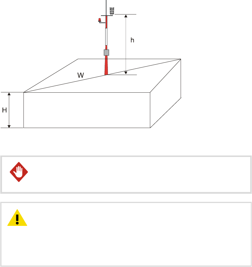
Figure 17 Recommended Mast Length on Top of Building
To protect personnel and the transmitter, install an air terminal with the
tip at least one meter above the transmitter. It must be properly grounded, compliant
with all applicable local safety regulations.
WARNING!
Installations on top of high buildings or masts and in sites on open grounds
are vulnerable to lightning strikes. A nearby lightning strike can induce a high-voltage
surge not tolerable by the internal surge suppressors of the instrument.
Additional protection is needed in regions with frequent, severe thunderstorms,
especially when long line cables (> 30 m) are used. Vaisala recommends using a surge
protector, such as WSP150 and WSP152, in all sites with an elevated risk of lightning
strike.
CAUTION!
Chapter 4 – Installation
35
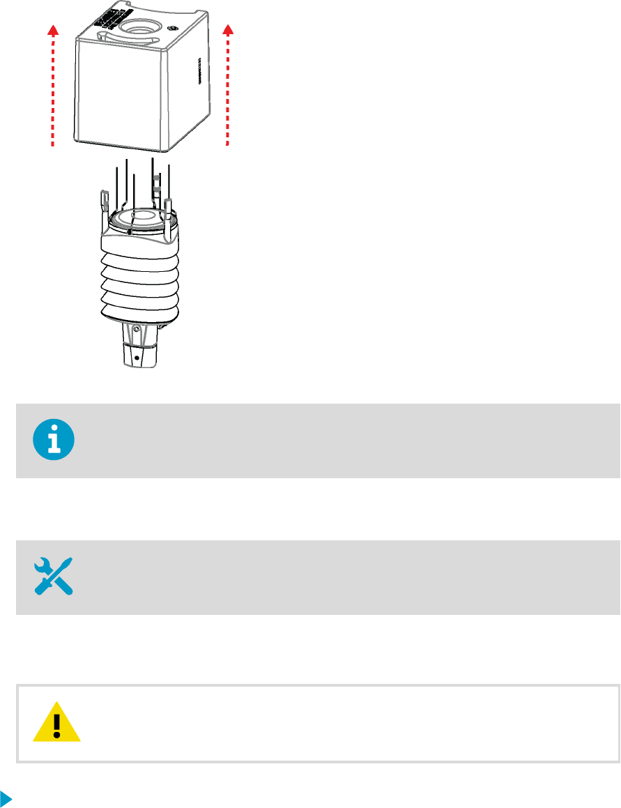
4.3 Unpacking WXT530
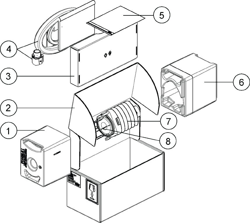
The transmitter comes in a custom shipping container. The following figure shows the
contents of the carton.
Figure 18 Contents of Shipping Container
1Protective packaging top
2Shipping carton
3Inner box
4Manual, cables, mounting kit (optional)
5Installation note
6Protective packaging bottom
7Transmitter
8Bird kit (optional)
WXT530 Series User Guide M211840EN-D
36
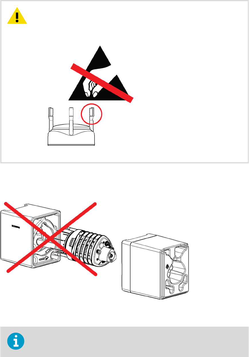
Be careful not to damage the wind transducers located at the top of the
three antennas. Dropping the device can break or damage the transducers. If the
antenna bends or twists, re-aligning can be dicult or impossible.
CAUTION!
Do not remove the top of the package protecting the transducer until you have installed the
transmitter. The polypropylene cushion protects the transducers during installation.
Figure 19 Installing with Protective Packaging
Save the container and the packaging materials for future transportation and shipping.
Chapter 4 – Installation
37

4.4 Mounting WXT530
The transmitter is easy to install as it does not have any moving parts.
The transmitter can be mounted on:
• Vertical pole mast
• Sensor support arm
Install the transmitter upright.
The transmitter radiation shield reflects light. If you install the transmitter next to a
pyranometer or a temperature and humidity sensor, the pyranometer or temperature and
humidity sensor can give incorrect measurements. Install the transmitter on the same level
with the pyranometer or temperature and humidity sensor so that the distance between
the units is approximately 800 mm (31.5 in).
WXT530 Series User Guide M211840EN-D
38
4.4.1 Mounting WXT530 on Vertical Pole Mast without
Mounting Kit
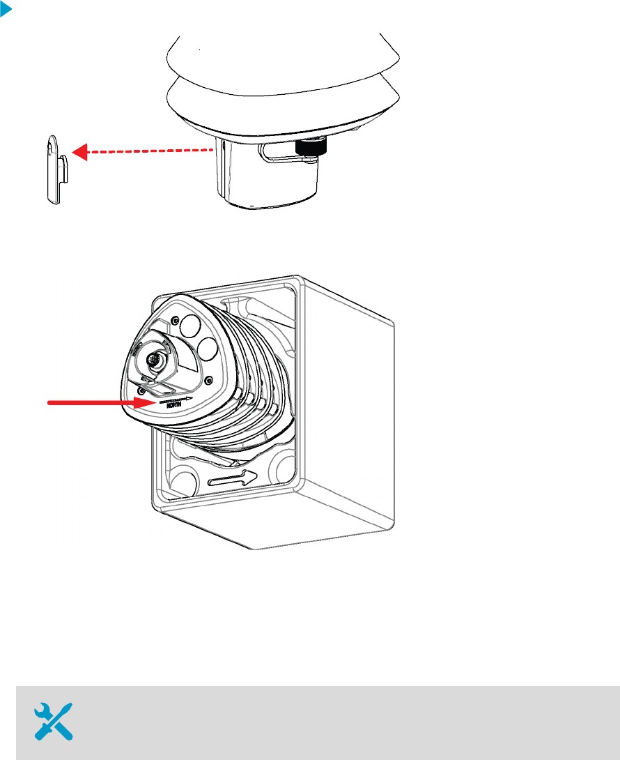
1. Remove the screw cover and insert the transmitter to the pole mast.
2. Align the transmitter so that the arrow points to North.
3. Tighten the fixing screw and replace the screw cover.
4.4.2 Mounting WXT530 on Vertical Pole Mast with Mounting
Kit
2.5‑mm and 5‑mm Allen keys
When mounting a transmitter on a pole mast, you can use an optional mounting kit to ease
mounting.
Chapter 4 – Installation
39
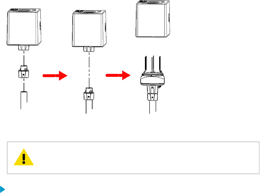
Figure 20 Mounting WXT531 on Vertical Pole Mast
Handle with care. Any impact on the instrument or sensor array may cause
damage and lead to incorrect measurements.
CAUTION!
1. Remove the adapter sleeve from the mounting kit.
2. Lead the sensor cable through the mounting kit, and connect the cable to the bottom
part of the sensor.
WXT530 Series User Guide M211840EN-D
40
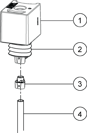
3. Insert the mounting kit adapter to the transmitter bottom.
1Protective cushion
2Transmitter
3Mounting kit
4Pole
4. Turn the kit firmly until you feel the adapter snap into the locked position.
Chapter 4 – Installation
41
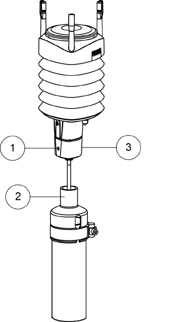
5. Holding the sensor from its body, run the sensor cable through the mounting adapter,
and slide the sensor onto the adapter. Do not tighten the fixing screw yet.
1Fixing screw. Tightening torque
1.5 Nm.
2Mounting accessory between
mounting kit and 60 mm tube
(WMSFIX60)
3Mounting kit (212792)
6. Align the transmitter so that the arrow on the bottom of the transmitter points North.
7. To attach the adapter to the pole mast, tighten the fixing screw of the mounting
adapter.
WXT530 Series User Guide M211840EN-D
42
8. Remove the protective cushion.
When removing a transmitter from the pole, turn the transmitter so that it snaps out from
the mounting kit. Realignment is not needed when replacing the device.
4.4.3 Mounting WXT530 on Sensor Support Arm
10‑mm wrench
If you use the optional mounting kit, you only need to align the sensor when mounting it for
the first time.
Handle with care. Any impact on the instrument or sensor array may cause
damage and lead to incorrect measurements.
CAUTION!
1. Remove the screw cover.
2. Align the sensor support arm in South–North direction.
If you cannot align the sensor support arm, adjust the wind direction oset.
Chapter 4 – Installation
43
3. Mount the transmitter on the sensor support arm.
1Nut M6 DIN 934
2Mounting bolt M6 DIN 933
3Screw cover
1Nut M6 DIN 934
2Mounting bolt M6 DIN 933
WXT530 Series User Guide M211840EN-D
44
4.5 Grounding
A transmitter is typically grounded by installing it on a mast or a cross arm that provides a
good connection to earth ground.
As grounding is provided through the fixing screw (or mounting bolt), it is important that it
makes a good ground connection.
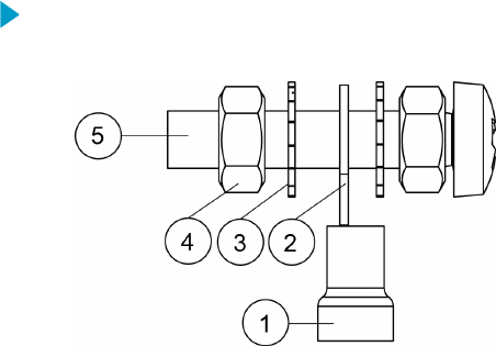
4.5.1 Grounding with Bushing and Grounding Kit
If the surface of the mounting point is painted or has some other finishing that prevents a
good electrical connection, consider using the Bushing and Grounding Kit (222109) and a
cable to ensure ground connection.
Use the Bushing and Grounding Kit to run a cable from the fixing screw to a grounding
point. The kit does not include a grounding cable. The minimum grounding conductor size is
4 mm2 (AWG 11).
1. Assemble the grounding kit so that the connector for the grounding cable is between
the washers and nuts.
1Connector for grounding cable
2Abiko connector
3Washer (2 pcs)
4Nut (2 pcs)
5Fixing screw
2. Connect a grounding cable to the connector. Use a 16 mm2 conductor to achieve a good
ground connection.
3. Remove the transmitter fixing screw.
Chapter 4 – Installation
45
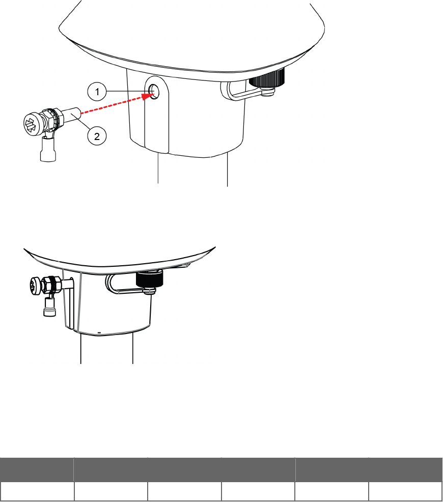
4. Insert the grounding kit through the hole in the seal. Make sure the nuts are tight so
that the connector has a good connection.
1Seal
2Fixing screw
5. Connect the other end of the cable to a good grounding point.
4.6 Aligning WXT530
WXT536 WXT535 WXT534 WXT533 WXT532 WXT531
✔ ✔ ✔
To help the alignment, there is an arrow and the text North on the bottom of the transmitter.
Align the transmitter so that the arrow points North.
WXT530 Series User Guide M211840EN-D
46
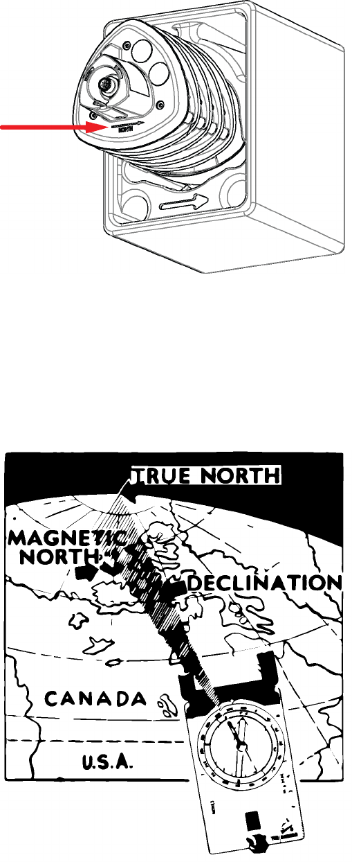
Figure 21 WXT530 North Arrow
Wind direction can be referred either to true North, which uses the Earth’s geographic
meridians, or to the magnetic North, which is read with a magnetic compass. The magnetic
declination is the dierence in degrees between the true North and magnetic North. The
source for the magnetic declination should be current as the declination changes over time.
Figure 22 Sketch of Magnetic Declination
Chapter 4 – Installation
47

4.6.1 Aligning WXT530 with Compass
• 2.5‑mm Allen key
• Compass
Do not remove the instrument or sensor from the mounting kit during alignment.
1. If the transmitter is mounted, loosen the fixing screw on the bottom of the transmitter
so that you can rotate it.
2. Use a compass to determine that the transducer heads of the transmitter are exactly in
line with the compass and that the arrow on the bottom of the transmitter points North.
3. Tighten the fixing screw. Tightening torque 1.5 Nm.
4.6.2 Configuring Wind Direction Oset
If the transmitter cannot be aligned so that the arrow on the bottom points North, make a
wind direction oset by configuring the deviation angle in the transmitter.
1. Mount the transmitter to a desired position.
WXT530 Series User Guide M211840EN-D
48
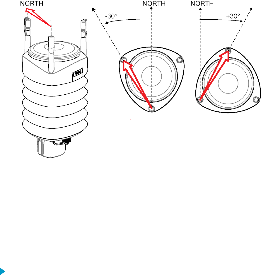
2. Define the deviation angle from the North (zero) alignment. Use the ± sign indication to
express the direction from the North line.
3. Enter the deviation angle in the device using the wind message formatting command
aWU,D (direction oset).
Now the transmitter transmits the wind direction data using the changed zero alignment.
More Information
‣Mounting WXT530 (page 38)
‣Mounting WXT530 on Sensor Support Arm (page 43)
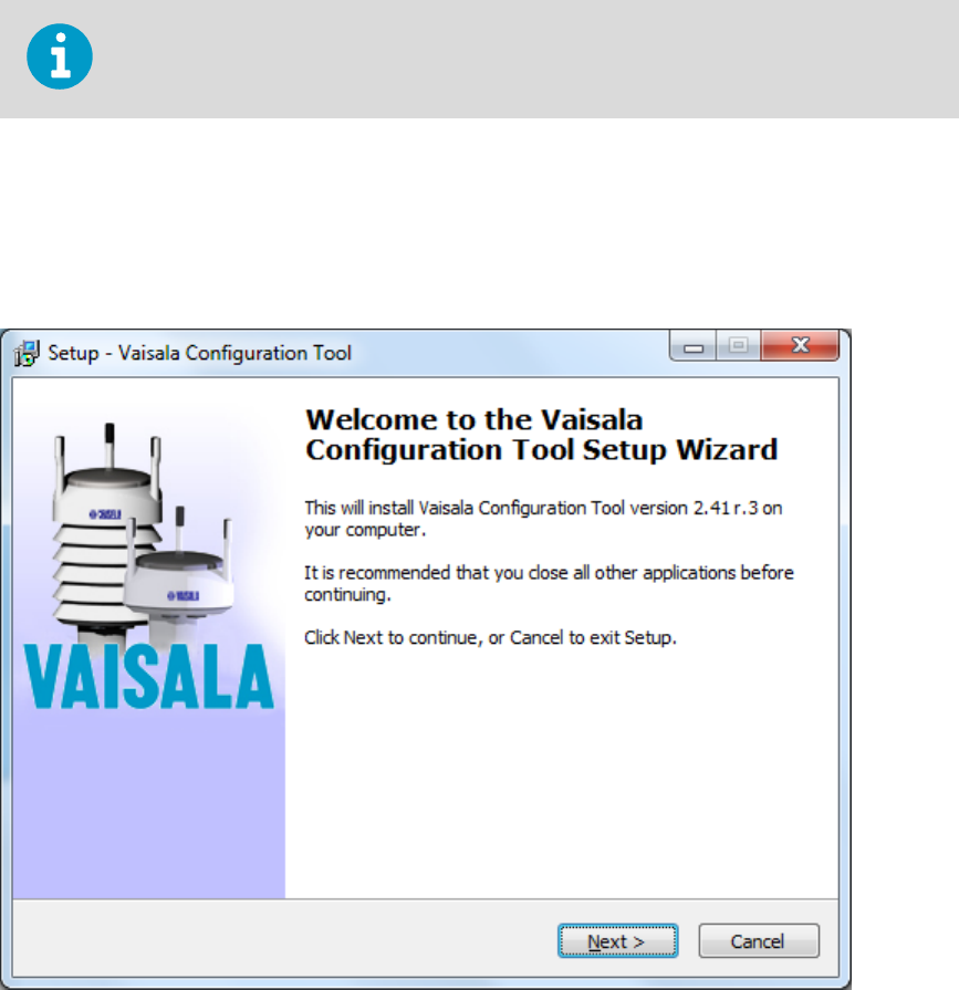
4.7 Installing Vaisala Configuration Tool
1. Insert the WXT530 driver memory stick in the USB port.
2. Go to the WXT_Series_Conf_Tool folder and run WXTConf-2.41 r.3Setup.exe.
3. When Vaisala Configuration Tool Setup Wizard opens, select Next.
Chapter 4 – Installation
49
4. In the User Information window, fill in the User Name, Organization, and License Key
fields. The license key is shown on the sticker on the memory stick. Select Next.
5. In the Select Destination Location window, select a folder and select Next.
6. In the Select Start Menu Folder window, select a folder for shortcuts and select Next.
7. In the Select Additional Tasks window, select Additional Tasks and select Next.
8. In the Ready to Install window, select Install. Installing window opens.
9. Select Launch Vaisala Configuration Tool and select Finish to launch the tool.
More Information
‣Backward Compatibility (page 25)
WXT530 Series User Guide M211840EN-D
50
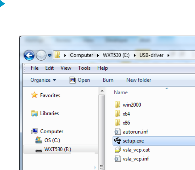
4.8 Installing USB Cable Driver
Before taking the USB cable into use, you must install the USB cable driver on your PC. The
driver is compatible with Windows 7, Windows 8, and Windows 10.
1. Make sure that the USB cable is not connected.
2. Insert the WXT530 driver memory stick in the USB port.
3. Go to the USB-driver folder and start installation by running setup.exe.
4. When Vaisala USB Device Driver Setup Wizard opens, select Next.
5. In the Select Additional Tasks window, select the tasks you want to perform and select
Install.
Chapter 4 – Installation
51
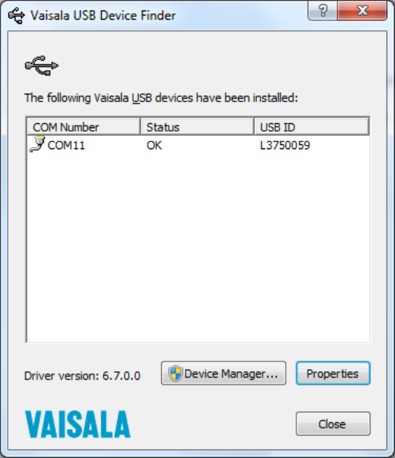
6. Select Display Vaisala USB Device Finder > Finish. The driver is started.
7. Plug in the cable.
Remember to use the correct port in the settings of your terminal program. Windows
recognizes each individual cable as a dierent device, and reserves a new COM port.
There is no reason to uninstall the driver for normal use. However, if you wish to remove the
driver files and all Vaisala USB cable devices, uninstall the entry for Vaisala USB Instrument
Driver from the program manager tool in the Windows Control Panel.
WXT530 Series User Guide M211840EN-D
52

5. Wiring and Power
Management
This chapter describes how to connect the power supply and the serial interfaces and how
to manage and estimate power consumption.
You can access the transmitter through the following serial interfaces:
• RS-232
• RS-485
• RS-422
• SDI-12
• mA output (WXT532)
You can wire them either through the internal screw terminal or the 8-pin M12 connector.
You can use only one serial interface at a time.
The cable opening in the transmitter bottom assembly is covered with
hexagonal rubber plugs. If you are not using the cable gland (included in the Bushing
and Grounding Kit), keep the opening covered.
CAUTION!
More Information
‣Wiring SDI-12 (page 171)
5.1 Power Supplies
The minimum consumption graph is for SDI-12 standby mode.
Chapter 5 – Wiring and Power Management
53
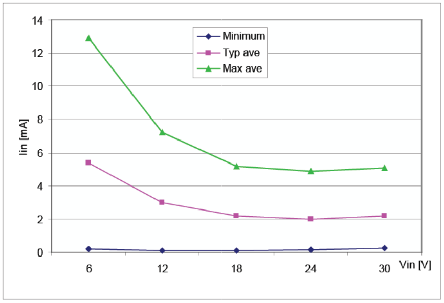
Figure 23 Average Operational Current Consumption (with 4Hz Wind Sensor Sampling)
The input power supply must be capable of delivering 60 mA (at 12 V) or 100 mA (at 6 V)
instant current spikes with duration of 30 ms. These are drawn by the wind sensor
(whenever enabled) at 4 Hz rate, which is the default value for wind sampling. Wind
sampling at 2 Hz and 1 Hz rate is also available.
Because wind measurement is the most consuming operation in the system, the average
current consumption decreases almost in proportion to the sampling rate.
Typically, the average consumption is less than 10 mA. The higher the voltage, the lower the
current.
Heating voltage Vh+ (one of the following three alternatives):
• 12 … 24 VDC (-10 % … + 30 %)
• 12 … 17 VACrms (-10 % … +30 %)
The typical DC voltage ranges are:
• 12 VDC ± 20 % (max 1.1 A)
• 24 VDC ± 20 % (max 0.6 A)
Nominally at 15.7 V heating voltage level, the transmitters automatically change the heating
element combination to reduce instant current. The input resistance (Rin) is radically
increased with voltages above 16 V as shown in the following graph. The average (5s) power
does not depend on the input voltage.
The recommended range for AC is:
WXT530 Series User Guide M211840EN-D
54
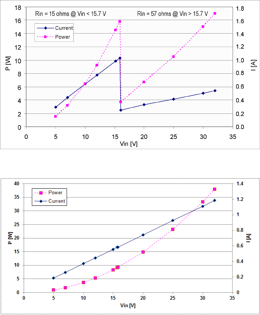
• 12 … 17 VACrms (-10 % … +30 %) max 1.1 A for AC
Figure 24 Heating Instant Current and Power vs Vh (WXT536, WXT535, WXT533, and WXT532)
Figure 25 Heating Instant Current and Power vs Vh (WXT531)
The power supply must meet the values shown above.
Chapter 5 – Wiring and Power Management
55

Make sure that you connect only de-energized wires.WARNING!
To avoid exceeding the maximum ratings in any condition, the voltages
must be checked with no load at the power supply output.
CAUTION!
More Information
‣Power Management (page 56)
5.2 Power Management
The power consumption varies significantly, depending on the selected operating mode or
protocol, the data interface type, the sensor configuration, and the measurement and
reporting intervals.
Lowest consumption is achieved with the Native SDI-12 mode, typically about 1 mW in
standby (0.1 mA at 12 V), while with ASCII RS-232 or Continuous SDI-12 modes it is about 3
mW in standby. Any activated sensor measurement adds its own extra consumption to the
standby power.
Some hints for economic power management are given below. The consumption values are
all defined for 12 V supply. For 6 V supply, multiply the values by 1.9. For 24 V supply,
multiply the values by 0.65.
Table 4 Standby Power Consumption
Mode Standby Wind
4 Hz sampling
rate
4 Hz sampling
rate
1 Hz sampling
rate
1 Hz sampling
rate
Continuous
measurement
10 s average
every 2 min
Continuous
measurement
10 s average
every 2 min
RS-232
RS-485
RS-422
SDI-12
continuous
1.5 mA +4.5 mA + 0.6 mA +1.3 mA +0.2 mA
SDI-12 native 0.1 mA N/A +1 mA N/A +0.7 mA
Analog output
(mA)
N/A 16 … 90 mA 16 ... 90 mA 16 ... 90 mA 16 ... 90 mA
WXT530 Series User Guide M211840EN-D
56

Mode Standby PTU PT1000 Level Tipping
bucket
Solar
radiation
Precipitation
Continuous
rain
RS-232
RS-485
RS-422
SDI-21
continuous
1.5 mA +0.9 mA +0.1 mA +0.4 mA +0.1 mA +0.4 mA +0.4 mA
SDI-12 native 0.1 mA +0.9 mA
(interval
5 s)
+0.1 mA
(interval
5 s)
+0.4 mA
(interval
5 s)
+0.1 mA
(interval 1 s)
+0.4 mA
(interval
5 s)
+0.4 mA
(interval 5 s)
Analog
output (mA)
N/A N/A N/A N/A N/A N/A N/A
SDI-12 native mode power save is based on measurements only when requested. Due to
SDI-12 polling mode operation, only periodic wind measurement results are comparable
with other communication modes. Continuous measurement is not relevant for SDI-12
mode. Every measurement request increases power consumption for the first time
measurement. The total SDI-12 power consumption can be changed by changing
measurement request intervals.
Table 5 Economic Power Management
Measurement Consumption
Wind measurement The most consuming operation in the system, with extra variations depending on
how the wind is reported. If you need long time averages and measure wind
constantly, there are no large dierences between requesting periods or modes.
Fully continuous wind measurement with a 4 Hz sampling rate adds about 4.5 mA
to the standby current, depending on the wind and some other climatic conditions.
A 10-second average requested every 2 minutes consumes 8 times less. 1 Hz
sampling rate decreases it to about one fourth.
PTU measurement Adds approximately 0.9 mA to the standby consumption. Each single measurement
takes 5 seconds (including the warm-up period). This can be used for estimating the
average consumption of the PTU.
Continuous
precipitation
Adds approximately 0.4 mA to the standby consumption. A single, isolated raindrop
increases current consumption for about 10 seconds (continued, if more raindrops
are detected within the 10-second period).
ASCII RS-232 Standby
consumption
Typically 1.5 mA. The jumper wires across TX+/RX+ and TX-/RX- (only necessary in
2-wire RS-485) increase consumption slightly.
ASCII RS-232 Polling
mode and Automatic
mode
Equal consumption. The Automatic mode is a little more economic, since
interpreting the poll takes more processing time than starting the Automatic
message. However, note that when selecting the Precipitation Auto-send mode, the
sub-modes M=R and M=C can cause extra consumption in rainy conditions due to
triggers for sending messages about rain incidents.
Chapter 5 – Wiring and Power Management
57

Measurement Consumption
ASCII RS-232 Data
transmission
Adds 1 ... 2 mA to the standby consumption during the message sending time. Note
that the host device's input (data logger or PC) can constantly draw some current
from the TX line.
RS-485 and RS-422
Data interfaces
Consume about the same amount of power as RS-232. With long data cables the
data consumption during data transmission can be much higher, especially when
termination resistors are used. On the other hand, the RS-485 driver is in high
impedance state when not transmitter. In idle state, no current can be drawn by the
host input.
NMEA modes They consume about the same as ASCII modes.
SDI-12 Native mode M=S, C=1 has the lowest stand by consumption, about 0.1 mA. Note that it can also
be used with RS-232 terminals. See the SDI-12 connection diagram in 5.5 Data
Communication Interfaces (page 67). In this case, the commands must be in
SDI-12 format, but no special line break signals are required. The SDI-12 mode is for
polling only.
SDI-12 Continuous mode M=R consumes about the same as the ASCII RS-232 mode.
If the optional sensor heating is enabled, SDI-12 Native mode consumes the same as ASCII
RS-232 mode.
When heating is on (or the temperature is such that it should be on), some 0.08 mA
additional current is drawn from the operational power supply.
While in Service mode and/or while supplied through the service port the transmitter
consumes 0.3 ... 0.6 mA more than in normal mode, when supplied through the
main port (M12 connector or screw terminals). When supplied through the service port the
minimum voltage level for reliable operation is 6 V. This can also be seen in the supply
voltage reading of the Supervisor message - the Vs value is 1 V lower than the actual input
voltage.
5.3 Wiring with 8-pin M12 Connector
5.3.1 External Wiring
The 8-pin M12 connector is located on the bottom of the transmitter.
WXT530 Series User Guide M211840EN-D
58

Figure 26 Pins of 8-pin M12 Connector
The following table shows the pin connections for the 8-pin M12 connector and the wire
colors of the respective M12 cable (optional, 2/10 m).
Table 6 Pin-outs for WXT530 Series Serial Interfaces and Power Supplies
Wire Color M12 Pin# RS-2321) SDI-121) RS-4851) RS-4221) mA
Output2)
White 1 Data in (RxD) Data in/out
(Rx)
- Data out (TX-) Iout2
Brown 2 Vin+
(operating)
Vin+
(operating)
Vin+
(operating)
Vin+ (operating) Vin+
(operating)
Green 3 GND for data GND for data GND for data Data out (TX+) GND Iout2
Yellow 4 Vh+ (heating) Vh+ (heating) Vh+ (heating) Vh+ (heating) Vh+ (heating)
Gray 5 - - Data+ Data in (RX+) GND Iout1
Pink 6 Vh- (heating) Vh- (heating) Vh- (heating) Vh- (heating) Vh- (heating)
Blue 7 Data out
(TxD)
Data in/out
(Tx)
Data- Data in (RX-) Iout1
Red 8 Vin-
(operating)
Vin-
(operating)
Vin-
(operating)
Vin- (operating) Vin-
(operating)
1) Available for all models
2) WXT532 option
Table 7 Screw Terminal Pin-outs
Screw terminal RS-232 SDI-12 RS-485 RS-422
10 HTG- Vh- (heating) Vh- (heating) Vh- (heating) Vh- (heating)
9 HTG+ Vh+ (heating) Vh+ (heating) Vh+ (heating) Vh+ (heating)
8 SGND GND for data GND for data GND for data GND for data
7 RXD Data in (RxD) Data in (Rx) - -
6 TX+ - - Data+ Data out (TX-)
Chapter 5 – Wiring and Power Management
59

Screw terminal RS-232 SDI-12 RS-485 RS-422
5 TX- Data out (TxD) Data out (Tx) Data - Data out (TX+)
4 RX+ - - - Data in (Rx+)
3 RX- - - - Data in (Rx-)
2 VIN- Vin- (operating) Vin- (operating) Vin- (operating) Vin- (operating)
1 VIN+ Vin+ (operating) Vin+ (operating) Vin+ (operating) Vin+ (operating)
The signal names Data in (RxD) and Data out (TxD) in the table describe the direction of
data flow as seen from the transmitter.
Ground the external wiring shield. The shield is not connected inside WXT.
In true SDI-12, Data in (Rx) and Data out (Tx) lines must be combined.
Short circuit loops are required between terminals 3 & 5, and 4 & 6 for RS-485. See 5.3.2
Internal Wiring (page 61).
Do not use operating power supply ground (VIN-) for communication (RS-232, RS-485,
SDI-12, RS-422). Use SGND communication ground (GND).
Table 8 WXT532 mA Output Option Screw Terminal Pin-outs
Screw terminal mA Output
10 HTG- Vh- (heating)
9 HTG+ Vh+ (heating)
8 GND2 GND Iout2
7 Iout2 Iout2 (direction)
6 GND1 GND Iout1
5 Iout1 Iout1 (wind)
4 NC -
3 NC -
WXT530 Series User Guide M211840EN-D
60
Screw terminal mA Output
2 VIN- Vin- (operating)
1 VIN+ Vin+ (operating)
The terms "Default wiring" and "RS-422 wiring" refer to the internal wiring options.
5.3.2 Internal Wiring
By default, the 8-pin M12 connector is wired for:
• RS-232
• RS-485
• SDI-12
• RS-422
• mA output
Ground the external wiring shield. The shield is not connected inside WXT.
Table 9 RS-232 Wiring
Internal Wiring External Wiring
Pin # Internal
Connector Pin
Internal Connector Pin
function for RS-232
Internal Wiring
for RS-232
M12
Pin
External Wiring
for RS-232
1 VIN+ Vin+ (Operating) Brown 2 Brown
2 VIN- Vin- (Operating GND) Red 8 Red
3 RX-
4 RX+
5 TX- Data out (TxD) Blue 7 Blue
6 TX+ Gray 5 Gray
7 RXD Data in (RxD) White 1 White
8 SGND Communication ground
(GND)
Green 3 Green
9 HTG+ Vh+ (Heating) Yellow 4 Yellow
10 HTG- Vh- (Heating) Pink 6 Pink
Shield
Chapter 5 – Wiring and Power Management
61

Table 10 RS-485 Wiring
Internal Wiring External Wiring
Pin # Internal
Connector Pin
Internal Connector Pin
function for RS-485
Internal Wiring
for RS-485
M12
Pin
External Wiring
for RS-485
1 VIN+ Vin + (Operating) Brown 2 Brown
2 VIN- Vin- (Operating GND) Red 8 Red
3 RX- Data- Loop with Blue
4 RX+ Data+ Loop with Gray
5 TX- Data- Blue 7 Blue
6 TX+ Data+ Gray 5 Gray
7 RXD White 1 White
8 SGND Communication ground
(GND)
Green 3 Green
9 HTG+ Vh+ (Heating) Yellow 4 Yellow
10 HTG- Vh- (Heating) Pink 6 Pink
Shield
Table 11 SDI-12 Wiring
Internal Wiring External Wiring
Pin # Internal
Connector Pin
Internal Connector Pin
function for SDI-12
Internal Wiring
for SDI-12
M12
Pin
External Wiring
for SDI-12
1 VIN+ Vin+ (Operating) Brown 2 Brown
2 VIN- Vin- (Operating GND) Red 8 Red
3 RX-
4 RX+
5 TX- Data in/out (Tx) Blue 7 Blue
6 TX+ Gray 5 Gray
7 RXD Data in/out (Rx) White 1 White
8 SGND Communication ground
(GND)
Green 3 Green
9 HTG+ Vh+ (Heating) Yellow 4 Yellow
10 HTG- Vh- (Heating) Pink 6 Pink
Shield
WXT530 Series User Guide M211840EN-D
62

Table 12 RS-422 Wiring
Internal Wiring External Wiring
Pin # Internal
Connector Pin
Internal Connector Pin
function for RS-422
Internal Wiring
for RS-422
M12
Pin
External Wiring
for RS-422
1 VIN+ Vin+ (Operating) Brown 2 Brown
2 VIN- Vin- (Operating GND) Red 8 Red
3 RX- Data in (RX-) Blue 7 Blue
4 RX+ Data in (RX+) Gray 5 Gray
5 TX- Data out (TX-) White 1 White
6 TX+ Data out (TX+) Green 3 Green
7 RXD
8 SGND
9 HTG+ V+ (Heating) Yellow 4 Yellow
10 HTG- Vh- (Heating) Pink 6 Pink
Shield
Table 13 mA Output Wiring
Internal Wiring External Wiring
Pin # Internal
Connector Pin
Internal Connector Pin
function for mA Output
Internal Wiring
for mA Output
M12
Pin
External Wiring
for mA Output
1 VIN+ Vin+ (Operating) Brown 2 Brown
2 VIN- Vin- (Operating GND) Red 8 Red
NC NC
NC NC
Iout1 Iout1 Iout1 Blue 7 Blue
GND GND GND Gray 5 Gray
Iout2 Iout2 Iout2 White 1 White
GND GND GND Green 3 Green
9 HTG+ Vh+ (Heating) Yellow 4 Yellow
10 HTG- Vh- (Heating) Pink 6 Pink
Shield
Chapter 5 – Wiring and Power Management
63
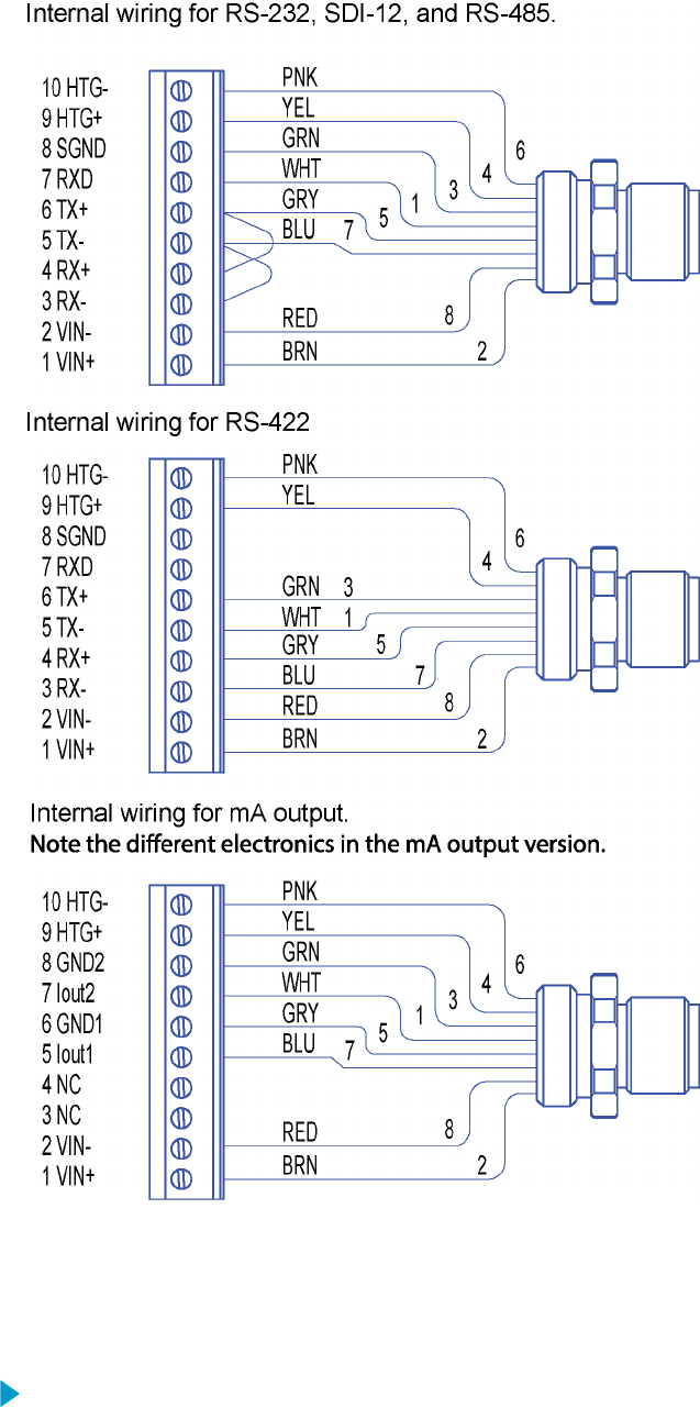
Figure 27 Internal Wiring for RS-232, SDI-12, and RS-485
5.4 Wiring Using Screw Terminals
1. Loosen the 3 long screws at the bottom of the transmitter.
WXT530 Series User Guide M211840EN-D
64
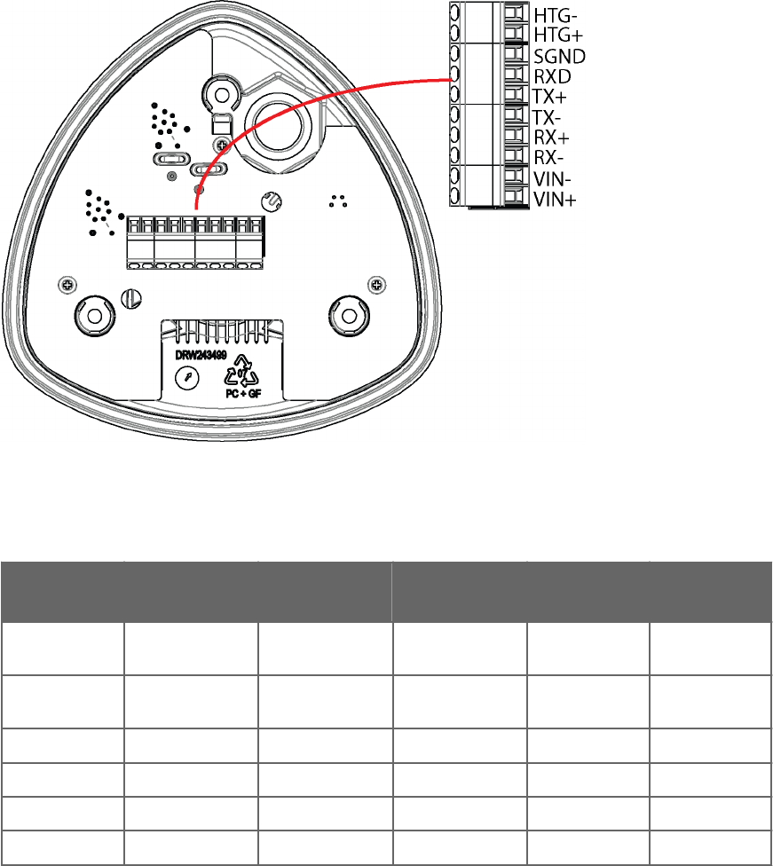
2. Pull out the bottom part of the transmitter.
3. Insert the power supply wires and signal wires through the cable gland(s) in the bottom
of the transmitter. Cable glands are included in the optional Bushing and Grounding Kit
(222109).
4. Connect the wires as shown in the following table.
5. Replace the bottom part and tighten the three screws. Make sure that the flat cable
does not get squeezed or stuck between the top and the funnel for the flat cable and it
is properly connected. To make sure that the radiation shield stays straight, do not
tighten the screws all the way in one go. Do not overtighten.
Figure 28 Screw Terminal Block
Table 14 Screw Terminal Pin-outs for Serial Interfaces and Power Supplies
Screw
Terminal PIN
RS-232 SDI-12 RS-485 RS-422 mA Output
1 VIN+ Vin+ (Operating) Vin+ (Operating) Vin+ (Operating) Vin+
(Operating)
Vin+
(Operating)
2 VIN- Vin- (Operating
GND)
Vin- (Operating
GND)
Vin- (Operating
GND)
Vin- Operating
GND)
Vin- (Operating
GND)
3 RX- Data- Data in (RX-)
4 RX+ Data+ Data in (RX+)
5 TX- Data out (TxD) Data in/out (Tx) Data- Data out (TX-) Iout1
6 TX+ Data+ Data out (TX+) GND
Chapter 5 – Wiring and Power Management
65

Screw
Terminal PIN
RS-232 SDI-12 RS-485 RS-422 mA Output
7 RXD Data in (RxD) Data in/out (Rx) Iout2
8 SGND Communication
ground (GND)
Communication
ground (GND)
Communication
ground (GND)
GND
9 HTG+ Vh+ (Heating) Vh+ (Heating) Vh+ (Heating) Vh+ (Heating) Vh+ (Heating)
10 HTG- Vh- (Heating) Vh- (Heating) Vh- (Heating) Vh- (Heating) Vh- (Heating)
Use a shielded cable and ground the external wiring shield.
For the SDI-12 mode, the Data in/out (Tx) and Data in/out (Rx) signals must be connected
internally by looping pins 5 and 7, or, externally by looping the M12 pins 1 and 7.
If the transmitter was ordered with any other serial communication than RS-422, the
internal wiring has loops between pins 3 and 5, and between 4 and 6. For RS-422
operation, you must remove the loops. For the RS-485 communication mode, short-circuit
loops are required between pins 3-5 and 4-6.
3 = RX Data-, Loop with Blue
4 = RX Data+, Loop with Gray
5 = TX Data-, Blue wire
6 = TX Data+, Gray wire
The transmitter has by default factory-installed loops in all serial communication options
except RS-422.
WXT530 Series User Guide M211840EN-D
66
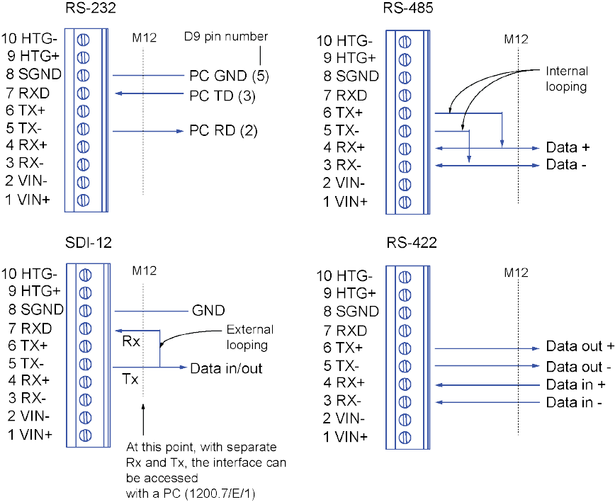
5.5 Data Communication Interfaces
Figure 29 Data Communication Interfaces
With RS-485 and RS-422 interfaces, if the data rate is 9600 Bd or higher and the cabling
from the transmitter to the host is 600 m (2000 ft) or longer, you must use termination
resistors at both ends of the line.
The WXT530 series transmitters with serial communication interface have built-in
termination options. Plain resistor (R) termination or termination with resistor connected
series with capacitor can be selected with jumpers. By default, no termination is selected. In
RS-422 mode, built-in termination is only between RX- and RX+ lines.
If external line termination is used, resistor range 100 … 180 Ω is suitable for twisted pair
lines. Resistors are connected across RX- to RX+ and across TX- to TX+ (with RS-485 only
one resistor needed).
Chapter 5 – Wiring and Power Management
67
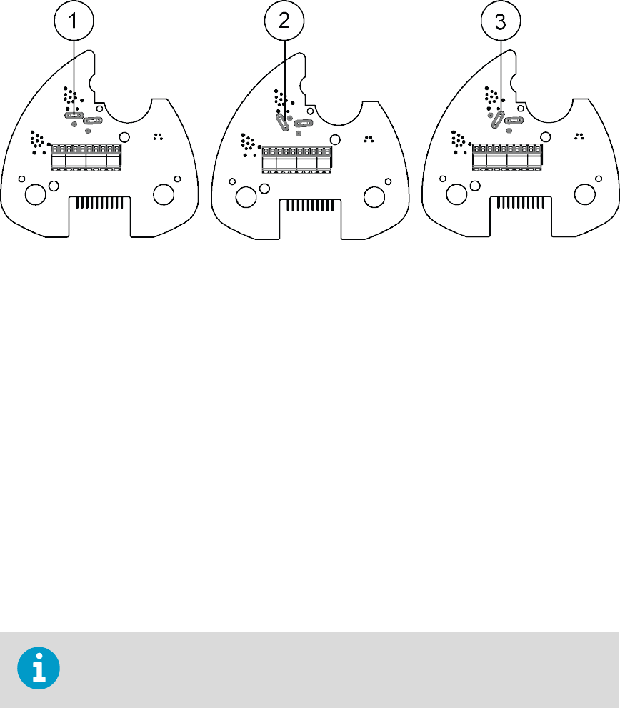
Figure 30 Termination Jumper Positions
1NC, no termination
2R, 121 Ω termination
3RC, 121 Ω series with 4.7 nF capacitor termination
The termination resistors increase power consumption significantly during data
transmission. If low power consumption is a must, connect a 0.1 uF capacitor in series with
each external termination resistor or use internal RC termination.
Note that the RS-485 interface can be used with four wires (as RS-422).
The main dierence between the RS-485 and RS-422 interfaces is their protocol:
• In the RS-422 mode the transmitter is constantly enabled
• In the RS-485 mode the transmitter is enabled only during transmission (for allowing
the host’s transmission in the two-wire case).
The RS-232 output swings only between 0 ... +4.5 V. This is enough for modern PC inputs.
The recommended maximum for the RS-232 line length is 100 m (300 ft) with 1200 Bd data
rate. Higher rates require shorter distance, for instance, 30 m (100 ft) with 9600 Bd.
If you use the transmitter on an RS-485 bus with other polled devices, always disable the
error messaging feature with the command: 0SU,S=N<crlf>.
WXT530 Series User Guide M211840EN-D
68

6. Connection Options
6.1 Communication Protocols
Once the transmitter is properly connected and powered up, the data transmission can start.
The following table shows the communication protocols available in each serial interface.
Table 15 Available Serial Communication Protocols
Serial Interface Communication Protocols Available
RS-232 ASCII automatic and polled
NMEA 0183 v3.0 automatic and query
SDI-12 v1.3 and SDI-12 v1.3 continuous measurement
RS-485 ASCII automatic and polled
NMEA 0183 v3.0 automatic and query
SDI-12 v1.3 and SDI-12 v1.3 continuous measurement
RS-422 ASCII automatic and polled
NMEA 0183 v3.0 automatic and query
SDI-12 v1.3 and SDI-12 v1.3 continuous measurement
SDI-12 SDI-12 v1.3 and SDI-12 v1.3 continuous measurement
You chose the communication protocol (ASCII, NMEA 0183, or SDI-12) when placing your
order. To check the communication settings, see and/or change the protocol or other
communication settings, see the following sections.
You cannot access the RS-485 and RS-422 interfaces directly with a standard PC terminal.
They require a suitable converter.
You can access RS-232 and SDI-12 with a standard PC terminal, if for SDI-12, the Data
in/out lines have not been combined inside the transmitter.
6.2 Connection Cables
The following table shows the connection cable options for the WXT530 series transmitters.
The USB cables connect the transmitter to a PC using a standard USB port. The USB cables
also provide operation power to the transmitter when connected. Note that the USB cables
do not provide power to the sensor heating.
Chapter 6 – Connection Options
69
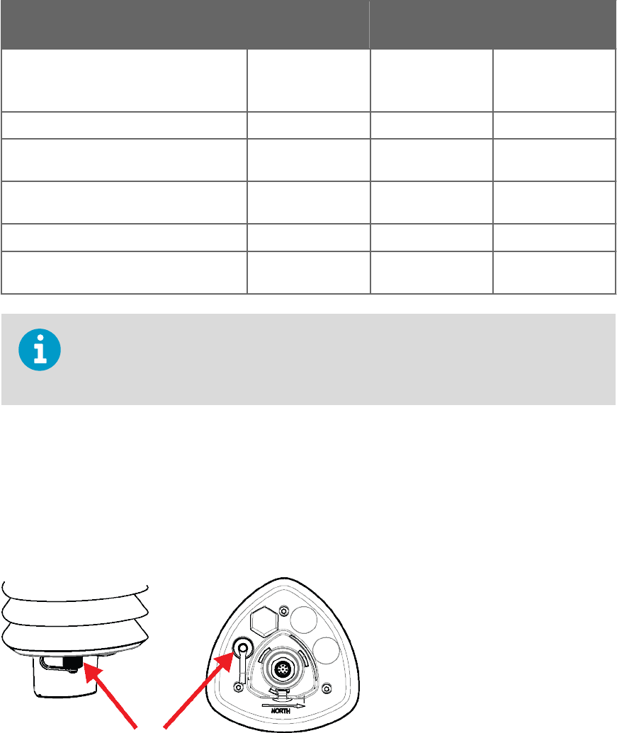
Table 16 Connection Cable Options
Cable Name Connector on
Sensor End
Connector on User
End
Order Code
USB service cable (1.4 m) M8 female USB type A 220614
(includes Vaisala
Configuration Tool)
USB RS-232/RS-485 cable (1.4 m) M12 female USB type A 220782
2-meter cable M12 female No connector; open
end wires
222287
10-meter cable M12 female No connector; open
end wires
222288
10-meter extension cable M12 male M12 female 215952
40-meter cable No connector; open
end wires
No connector; open
end wires
217020
If you use the USB RS-232/RS-485 cable for a permanent installation, Vaisala
recommends that you use the WSP152 surge protector to protect the host PC against
surges entering through the USB port.
6.3 Connecting with Service Cable
The USB service cable has a 4-pin M8 connector for service port. Use the service cable
connection for checking and changing device settings. When making the changes, use the
Vaisala Configuration Tool or a standard PC terminal program.
Figure 31 Service Cable Connection
The USB service cable is included in the Service Pack 2.
WXT530 Series User Guide M211840EN-D
70

When you connect the USB service cable between the service connector and PC USB port,
the service port settings are forced automatically to RS-232 / 19200, 8, N, 1, and the main
serial port at the M12 connector at the screw terminals is disabled.
1. Use the USB service cable to establish a connection between the USB port of your PC
and the M8 service port connector on the bottom plate of the transmitter.
2. Open the Vaisala Configuration Tool or a terminal program.
3. Select the COM port reserved for the USB cable and select the following default
communication settings:
19200, 8, N, 1.
4. Use the Vaisala Configuration Tool or a terminal program to make the configuration
changes.
5. When removing the service cable, support the transmitter while pulling the 4-pin M8
connector for service port. The connection is tight, and it is possible to change the
alignment of the transmitter if you pull too hard.
Changes to the serial interface/communication protocol/baud settings take place when
you disconnect the service cable or reset the transmitter.
If these settings are not changed during the service connection session, the original main
port settings (at M12 and screw terminals) are returned when the service cable is
disconnected from either end.
More Information
‣Communication Setting Commands (page 72)
6.3.1 Connecting through M12 Bottom Connector or Screw
Terminal
You can check and change the device settings through the 8-pin M12 bottom connector or
screw terminal.
To do this, you must know the device communication settings, have a suitable cable
between the device and the host, and, if needed, use a converter (for example, RS-485/422
to RS-232, if the host is a PC). The following table shows the factory default settings:
Table 17 Default Serial Communication Settings for M12/Screw Terminal Connection
Serial Interface Serial Settings
SDI-12 1200 baud, 7, E, 1
RS-232 ASCII 19200 baud, 8, N, 1
Chapter 6 – Connection Options
71

Serial Interface Serial Settings
RS-485 ASCII 19200 baud, 8, N, 1
RS-422 ASCII 19200 baud, 8, N, 1
RS-422 NMEA 4800 baud, 8, N, 1
6.4 Communication Setting Commands
In this section, the commands the user types are presented in normal text while the
responses of the transmitter are presented in italic.
6.4.1 Checking Current Communication Settings (aXU)
Use this command to request the current communication settings.
Command format in ASCII and NMEA 0183:
aXU<cr><lf>
Command format in SDI-12:
aXXU!
aDevice address, which can consist of the following characters: 0 (default) ... 9, A ... Z,
a ... z.
XU Device settings command in ASCII and NMEA 0183
XXU Device settings command in SDI-12
<cr><lf> Command terminator in ASCII and NMEA 0183
!Command terminator in SDI-12
Example response in ASCII and NMEA 0183:
aXU,A=a,M=[M],T=[T],C=[C],I=[I],B=[B],D=[D],P=[P],S=[S],
L=[L],N=[N],V=[V]<cr><lf>
Example response in SDI-12:
WXT530 Series User Guide M211840EN-D
72

aXXU,A=a,M=[M],T=[T],C=[C],I=[I],B=[B],D=[D],P=[P],S=[S],
L=[L],N=[N],V=[V]<cr><lf>
You can add the Id information field in the supervisor data message to provide
identifying information in addition to the transmitter address. The information field is set
as part of the factory settings. You can only modify it with the Vaisala Configuration Tool.
More Information
‣Supervisor Message (page 132)
‣General Unit Settings (page 183)
6.4.2 Settings Fields
Parameter Description
aDevice address
XU Device settings command in ASCII and NMEA 0183
XXU Device settings command in SDI-12
[A] Address: 0 (default) … 9, A … Z, a … z
[M] Communication protocol:
A = ASCII, automatic
a = ASCII, automatic with CRC
P = ASCII, polled
p = ASCII, polled, with CRC
N = NMEA 0183 v3.0, automatic
Q = NMEA 0183 v3.0, query (= polled)
S = SDI-12 v1.3
R = SDI-12 v1.3 continuous measurement
[T] Test parameter (for testing use only)
[C] Serial interface:
1 = SDI-12
2 = RS-232
3 = RS-485
4 = RS-422
[I] Automatic repeat interval for Composite data message: 1 … 3600 s, 0 = no automatic repeat
Chapter 6 – Connection Options
73

Parameter Description
[B] Baud rate: 1200, 2400, 4800, 9600, 19200, 38400, 57600, 115200
[D] Data bits: 7/8
[P] Parity:
O = Odd
E = Even
N = None
[S] Stop bits: 1/2
[L] RS-485 line delay: 0 … 10000 ms. Defines the delay between the last character of the query
and the first character of the response message from the transmitter. During the delay, the
transmitter is disabled. Eective in ASCII, polled and NMEA 0183 query protocols. Eective
when RS-485 is selected (C = 3).
[N] Name of the device: WXT536 (read-only)
[V] Software version: for example, 1.00 (read-only)
[H] Parameter locking
0 = Parameters can be changed
1 = Parameters locked. Vaisala recommends that you set this parameter to 1 after you have
configuration. This prevents accidental changes, for instance, in RS- 485 use when there is
interference.
<cr><lf> Response terminator
There are two SDI-12 modes available for providing the functionality of the SDI-12 v1.3
standard.
The lowest power consumption is achieved with the Native SDI-12 mode (aXU,M=S), as it
makes measurements and outputs data only on request.
In the continuous SDI-12 mode (aXU,M=R) internal measurements are made at a user-
configurable update interval. The data is outputted on request.
Example (ASCII and NMEA 0183, device address 0):
0XU<cr><lf>
0XU,A=0,M=P,T=0,C=2,I=0,B=19200,D=8,P=N,S=1,L=25,
N=WXT530,V=1.00<cr><lf>
Example (SDI-12, device address 0):
0XXU!0XXU,A=0,M=S,T=0,C=1,I=0,B=1200,D=7,P=E,S=1,L=25,
N=WXT530,V=1.00<cr><lf>
WXT530 Series User Guide M211840EN-D
74
6.4.3 Changing the Communication Settings (aXU)
Use this command to change communication settings.
Command format in ASCII and NMEA 0183:
aXU,A=x,M=x,C=x,I=x,B=x,D=x,P=x,S=x,L=x<cr><lf>
Command format in SDI-12:
aXXU,A=x,M=x,C=x,I=x,B=x,D=x,P=x,S=x,L=x!
A, M, C, I, B, D,
P, S,L
The communication setting fields.
xInput value for the setting
<cr><lf> Command terminator in ASCII and NMEA 0183
!Command terminator in SDI-12
When changing the serial interface and communication protocol, note the following:
Each serial interface requires its specific wiring and/or jumper settings.
Change first the serial interface field C and then the communication protocol field M.
Changing the serial interface to SDI-12 (C=1) automatically changes the baud settings to
1200, 7, E, 1 and the communication protocol to SDI-12 (M=S).
Reset the transmitter to validate the changes of communication parameters by
disconnecting the service cable or using the reset command aXZ.
Example (ASCII and NMEA 0183, device address 0):
Changing the device address from 0 to 1:
0XU,A=1<cr><lf>
1XU,A=1<cr><lf>
Checking the changed settings:
Chapter 6 – Connection Options
75

1XU<cr><lf>
1XU,A=1,M=P,T=1,C=2,I=0,B=19200,D=8,P=N,S=1,L=25, N=WXT530V=1.00<cr><lf>
Example (ASCII, device address 0):
Changing RS-232 serial interface with ASCII, polled communication protocol and baud
settings 19200, 8, N, 1 to RS-485 serial interface with ASCII, automatic protocol and baud
settings 9600, 8, N, 1.
Checking the settings:
0XU<cr><lf>
0XU,A=0,M=P,C=2,I=0,B=19200,D=8,P=N,S=1,L=25,N=WXT530, V=1.00<cr><lf>
You can change several parameters in the same command as long as the command length
does not exceed 32 characters (including command terminator characters ! or
<cr><lf>).You do not have to type setting fields you do not wish to change.
Changing several settings with one command:
0XU,M=A,C=3,B=9600<cr><lf>
0XU,M=A,C=3,B=9600<cr><lf>
Checking the changed settings:
0XU<cr><lf>
0XU,A=0,M=A,T=1,C=3,I=0,B=9600,D=8,P=N,S=1,L=25, N=WXT530,V=1.00<cr><lf>
More Information
‣Wiring and Power Management (page 53)
‣Settings Fields (page 73)
WXT530 Series User Guide M211840EN-D
76

7. Retrieving Data Messages
Each communication protocol has its own section for data message commands.
Type commands in CAPITAL letters.
The parameter order in messages is as follows:
Wind (M1): Dn Dm Dx Sn Sm Sx
PTU (M2): Ta Tp Ua Pa
Rain (M3): Rc Rd Ri Hc Hd Hi Rp Hp
Supv (M5): Th Vh Vs Vr Id
Comp (M): Wind PTU Rain Supv (parameters in above order)
The order of the parameters is fixed, but you can exclude any parameter from the list
when configuring the transmitter.
7.1 General Commands
With general commands you can reset the transmitter.
If error messaging is disabled, the general commands given in ASCII and NMEA formats
do not work.
7.1.1 Reset (aXZ)
This command performs software reset on the device.
Command format in ASCII and NMEA 0183:
aXZ<cr><lf>
Command format in SDI-12:
aXZ!
aDevice address
XZ Reset command
Chapter 7 – Retrieving Data Messages
77

<cr><lf> Command terminator in ASCII and NMEA 0183
!Command terminator in SDI-12
The response depends on the communication protocol as shown in the examples.
Example (ASCII):
0XZ<cr><lf>
0TX,Start-up<cr><lf>
Example (SDI-12):
0XZ!0<cr><lf> (=device address)
Example (NMEA 0183):
0XZ<cr><lf>
$WITXT,01,01,07,Start-up*29
7.1.2 Precipitation Counter Reset (aXZRU)
This command resets the rain and hail accumulation and duration parameters Rc, Rd, Hc,
and Hd.
Command format in ASCII and NMEA 0183:
aXZRU<cr><lf>
Command format in SDI-12:
aXZRU!
aDevice address
XZRU Precipitation counter reset command
<cr><lf> Command terminator in ASCII and NMEA 0183
!Command terminator in SDI-12
WXT530 Series User Guide M211840EN-D
78

Example (ASCII):
0XZRU<cr><lf>
0TX,Rain reset<cr><lf>
Example (SDI-12):
0XZRU!0<cr><lf> (= device address)
Example (NMEA 0183):
0XZRU<cr><lf>
$WITXT,01,01,10,Rain reset*26<cr><lf>
7.1.3 Precipitation Intensity Reset (aXZRI)
This command resets the rain and hail intensity parameters Ri, Rp, Hi, and Hp.
Command format in ASCII and NMEA 0183:
aXZRI<cr><lf>
Command format in SDI-12:
aXZRI!
aDevice address
XZRI Precipitation intensity reset command
<cr><lf> Command terminator in ASCII and NMEA 0183
!Command terminator in SDI-12
The precipitation counter and precipitation intensity parameters are reset also when the
supply voltage is disconnected, the command aXZ is issued, precipitation counter reset
mode is changed, or when the precipitation/surface hits units are changed.
Example (ASCII):
Chapter 7 – Retrieving Data Messages
79

0XZRI<cr><lf>
0TX,Inty reset<cr><lf>
Example (SDI-12):
0XZRI!0<cr><lf> (= device address)
Example (NMEA 0183):
0XZRI<cr><lf>
$WITXT,01,01,11,Inty reset*39<cr><lf>
7.1.4 Measurement Reset (aXZM)
This command interrupts all ongoing measurements except rain measurement and restarts
them.
Command format in ASCII and NMEA 0183:
aXZM<cr><lf>
Command format in SDI-12:
aXZM!
aDevice address
XZM Measurement break command
<cr><lf> Command terminator in ASCII and NMEA 0183
!Command terminator in SDI-12
Example (ASCII):
0XZM<cr><lf>
0TX,Measurement reset<cr><lf>
WXT530 Series User Guide M211840EN-D
80

Example (SDI-12):
0XZM!0 (= device address)
Example (NMEA 0183):
0XZM<cr><lf>
$WITXT,01,01,09,Measurement reset*50<cr><lf>
7.2 ASCII Protocol
7.2.1 Abbreviations and Units
Table 18 Abbreviations and Units
Abbreviation Name Unit Status 1)
Sn Wind speed minimum m/s, km/h, mph, knots #, M, K, S, N
Sm Wind speed average m/s, km/h, mph, knots #, M, K, S, N
Sx Wind speed maximum m/s, km/h, mph, knots #, M, K, S, N
Dn Wind direction minimum deg #, D
Dm Wind direction average deg #, D
Dx Wind direction maximum deg #, D
Pa Air pressure hPa, Pa, bar, mmHg, inHg #, H, P, B, M, I
Ta Air temperature °C, °F #, C, F
Tp Internal temperature °C, °F #, C, F
Ua Relative humidity %RH #, P
Rc Rain accumulation mm, in #, M, I
Rd Rain duration s #, S
Ri Rain intensity mm/h, in/h #, M, I
Rp Rain peak intensity mm/h, in/h #, M, I
Hc Hail accumulation hits/cm2, hits/in2, hits #, M, I, H
Hd Hail duration s #, S
Hi Hail intensity hits/cm2h, hits/in2h,
hits/h
#, M, I, H
Chapter 7 – Retrieving Data Messages
81

Abbreviation Name Unit Status 1)
Hp Hail peak intensity hits/cm2h, hits/in2h,
hits/h
#, M, I, H
Th Heating temperature °C, °F #, C, F
Vh Heating voltage V #, N, V, W, F 2)
Vs Supply voltage V V
Vr 3.5 V ref. voltage V V
Id Information field alphanumeric
1) The letters in the status field indicate the Unit, the # character indicates invalid data.
2) For heating # = heating option is not available (has not been ordered).
N = heating option is available but have been disabled by user or the heating temperature is over the high control limit.
V = heating is on at 50% duty cycle and the heating temperature is between the high and middle control limits.
W = heating is on at 100% duty cycle and the heating temperature is between the low and middle control limits.
F = heating is on at 50% duty cycle and the heating temperature is below the low control limit.
7.2.2 Device Address (?)
This command queries the address of the device on the bus.
Command format:
?<cr><lf>
?Device address query command
<cr><lf> Command terminator
Response:
b<cr><lf>
bDevice address (default = 0)
<cr><lf> Response terminator.
Example:
?<cr><lf>
0<cr><lf>
WXT530 Series User Guide M211840EN-D
82

If more than one transmitter is connected to the bus, see A.1 Connecting Several
Transmitters on Same Bus (page 171).
7.2.3 Acknowledge Active Command (a)
This command checks that a device responds to a data recorder or another device. It asks a
sensor to acknowledge its presence on the bus.
Command format:
a<cr><lf>
aDevice address
<cr><lf> Command terminator
Response:
a<cr><lf>
aDevice address
<cr><lf> Response terminator
Example:
0<cr><lf>
0<cr><lf>
7.2.4 Wind Data Message (aR1)
This command requests the wind data message.
Command format:
aR1<cr><lf>
aDevice address
R1 Wind message query command
Chapter 7 – Retrieving Data Messages
83

<cr><lf> Command terminator
Example of the response (the parameter set is configurable):
0R1,Dn=236D,Dm=283D,Dx=031D,Sn=0.0M,Sm=1.0M, Sx=2.2M<cr><lf>
aDevice address
R1 Wind message query command
Dn Wind direction minimum (D = degrees)
Dm Wind direction average (D = degrees)
Dx Wind direction maximum (D = degrees)
Sn Wind speed minimum (M = m/s)
Sm Wind speed average (M = m/s)
Sx Wind speed maximum (M = m/s)
<cr><lf> Response terminator
7.2.5 Pressure, Temperature and Humidity Data Message (aR2)
This command requests a pressure, temperature, and humidity data message.
Command format:
aR2<cr><lf>
aDevice address
R2 Pressure, temperature and humidity message query command
<cr><lf> Command terminator
Example of the response (the parameter set is configurable):
0R2,Ta=23.6C,Ua=14.2P,Pa=1026.6H<cr><lf>
aDevice address
R2 Pressure, temperature and humidity message query command
Ta Air temperature (C = °C)
WXT530 Series User Guide M211840EN-D
84

Ua Relative humidity (P = % RH)
Pa Air pressure (H = hPa)
<cr><lf> Response terminator
7.2.6 Precipitation Data Message (aR3)
This command requests the precipitation data message.
Command format:
aR3<cr><lf>
aDevice address
R3 Precipitation message query command
<cr><lf> Command terminator
Example of the response (the parameter set is configurable):
0R3,Rc=0.0M,Rd=0s,Ri=0.0M,Hc=0.0M,Hd=0s,Hi=0.0M,Rp=0.0M,Hp=0.0M<cr><lf>
aDevice address
R3 Precipitation message query command
Rc Rain accumulation (M = mm)
Rd Rain duration (s = s)
Ri Rain intensity (M = mm/h)
Hc Hail accumulation (M = hits/cm2)
Hd Hail duration (s = s)
Hi Hail intensity (M = hits/cm2h)
Rp Rain peak intensity (M = mm/h)
Hp Hail peak intensity (M = hits/cm2h)
<cr><lf> Response terminator
7.2.7 Supervisor Data Message (aR5)
This command requests a supervisor data message containing self-check parameters of the
heating system and power supply voltage.
Chapter 7 – Retrieving Data Messages
85

Command format:
aR5<cr><lf>
aDevice address
R5 Supervisor message query command
<cr><lf> Command terminator
Example of the response (the parameter set is configurable):
0R5,Th=25.9C,Vh=12.0N,Vs=15.2V,Vr=3.475V,Id=HEL___<cr><lf>
aDevice address
R5 Supervisor message query command
Th Heating temperature (C = °C)
Vh Heating voltage (N = heating is o)
Vs Supply voltage (V = V)
Vr 3.5 V reference voltage (V = V)
<cr><lf> Response terminator
Id Information field
The content of the parameter Id is a text string which you can modify with the Vaisala
Configuration Tool. The field can include customer-specific, additional information. For more
information on changing the settings, see the Vaisala Configuration Tool online help for the
Info field in the Device Settings window.
More Information
‣Supervisor Message (page 132)
7.2.8 Combined Data Message (aR)
This command requests all individual messages aR1, aR2, aR3, and aR5 with one
command.
Command format:
aR<cr><lf>
WXT530 Series User Guide M211840EN-D
86

aDevice address (default = 0)
RCombined message query command
<cr><lf> Command terminator
Example of the response:
0R1,Dm=027D,Sm=0.1M<cr><lf>
0R2,Ta=74.6F,Ua=14.7P,Pa=1012.9H<cr><lf>
0R3,Rc=0.10M,Rd=2380s,Ri=0.0M,Hc=0.0M,Hd=0s, Hi=0.0M<cr><lf>
0R5,Th=76.1F,Vh=11.5N,Vs=11.5V,Vr=3.510V,Id=HEL___<cr><lf>
7.2.9 Composite Data Message Query (aR0)
This command requests a combined data message with user-configurable set of wind,
pressure, temperature, humidity, precipitation, and supervisor data.
Command format:
aR0<cr><lf>
aDevice address (default = 0)
R0 Combined message query command
<cr><lf> Command terminator
Example of the response (you can select the parameters included from the full parameter
set of the commands aR1, aR2, aR3, and aR5):
0R0,Dx=005D,Sx=2.8M,Ta=23.0C,Ua=30.0P,Pa=1028.2H,
Rc=0.00M,Rd=10s,Th=23.6C<cr><lf>
7.2.10 Polling with CRC
Use the same data query commands as in the previous sections but type the first letter of
the command in lower case and add a correct three-character CRC before the command
terminator. The response also contains a CRC.
Requesting a wind data message with a CRC:
Command format:
Chapter 7 – Retrieving Data Messages
87
ar1xxx<cr><lf>
aDevice address
r1 Wind message query command
xxx Three-character CRC for ar1 command
<cr><lf> Command terminator
Example of the response (the parameter set is configurable):
0r1,Dn=236D,Dm=283D,Dx=031D,Sn=0.0M,Sm=1.0M,Sx=2.2MLFj<cr><lf>
The three characters before <cr><lf> are the CRC for the response.
To request the correct CRC for each command, type the command with an arbitrary three-
character CRC.
Example of asking the CRC for the wind data message query ar1:
Command format:
ar1yyy<cr><lf>
aDevice address
r1 Wind message query command
yyy Arbitrary three-character CRC
<cr><lf> Command terminator
Response:
atX,Use chksum GoeIU~<cr><lf>
aDevice address (default = 0)
tX,Use chksum Text prompt
WXT530 Series User Guide M211840EN-D
88

Goe Correct three-character CRC for the ar1 command
IU~ Three-character CRC for the response message
<cr><lf> Response terminator
Example of the other data query commands with CRC (when the device address is 0):
Parameter Description
Pressure, humidity and
temperature message query
0r2Gje<cr><lf>
Precipitation query 0r3Kid<cr><lf>
Supervisor query 0r5Kcd<cr><lf>
Combined message query 0rBVT<cr><lf>
Composite data message
query
0r0Kld<cr><lf>
In every case the response contains a three-character CRC before the <cr><lf>.
More Information
‣CRC-16 Computation (page 179)
‣CRC-16 Computation (page 179)
‣Sensor Configuration and Data Message Formatting (page 117)
7.2.11 Automatic Mode
When the automatic ASCII protocol is selected, the transmitter sends data messages at
user-configurable update intervals.
The message structure is the same as with data query commands aR1, aR2,aR3 , and aR5.
You can choose an individual update interval for each sensor.
Example:
0R1,Dm=027D,Sm=0.1M<cr><lf>
0R2,Ta=74.6F,Ua=14.7P,Pa=1012.9H<cr><lf>
0R3,Rc=0.10M,Rd=2380s,Ri=0.0M,Hc=0.0M,Hd=0s,Hi=0.0M<cr><lf>
0R5,Th=76.1F,Vh=11.5N,Vs=11.5V,Vr=3.510V<cr><lf>
Example (with CRC):
Chapter 7 – Retrieving Data Messages
89

0r1,Sn=0.1M,Sm=0.1M,Sx=0.1MGOG<cr><lf>
0r2,Ta=22.7C,Ua=55.5P,Pa=1004.7H@Fn<cr><lf>
0r3,Rc=0.00M,Rd=0s,Ri=0.0MIlm<cr><lf>
0r5,Th=25.0C,Vh=10.6#,Vs=10.8V,Vr=3.369VO]T<cr><lf>
Stop the automatic output by changing the communication protocol to polled mode
(aXU,M=P). You can also use polling commands aR1, aR2, aR3, and aR5 in ASCII
automatic protocol for requesting data.
7.2.12 Automatic Composite Data Message (aR0)
When automatic composite data messaging is selected, the transmitter sends composite
data messages at user-configurable intervals. The message structure is the same as with the
composite data query command aR0 and contains a user-configurable set of wind,
pressure, temperature, humidity, precipitation, and supervisor data.
Example of the response (you can select the parameters included from the full parameter
set of the commands aR1, aR2, aR3, and aR5):
0R0,Dx=005D,Sx=2.8M,Ta=23.0C,Ua=30.0P,Pa=1028.2H,
Hd=0.00M,Rd=10s,Th=23.6C<cr><lf>
For selecting the parameter set in the response message, see 8.1 Sensor Configuration and
Data Message Formatting (page 117).
Automatic composite data messaging is a concurrent, not an alternate mode to either the
polled or automatic modes.
7.3 SDI-12 Protocol
There are two modes available for providing the functionality of the SDI-12 v1.3 standard.
The Native SDI-12 profile (aXU,M=S) oers the lowest power consumption as it makes
measurements and outputs data only when requested. In this mode all the commands
presented in this chapter are available except those for the continuous measurement.
In the Continuous mode (aXU,M=R) measurements are made at user-configurable update
intervals. The data is outputted on request. In this mode all the commands presented in this
chapter are available.
In the Native SDI-12 mode (aXU,M=S) the transmitter is in idle state most of the time (power
consumption < 1 mW). More power is consumed only during the measurements and data
transmit requested by the host device.
WXT530 Series User Guide M211840EN-D
90

In particular, wind measurement typically consumes 60 mW average power (with 4 Hz
sampling rate), throughout the averaging period. In the Continuous mode (aXU=M,R) the
power consumption is determined by the internal update intervals of the sensors and wind
averaging time. These have certain limits, so very long measurement intervals cannot be
achieved with this mode. Also the power consumption between the measurements is about
three times that of the Native mode.
More Information
‣Sensor Configuration and Data Message Formatting (page 117)
7.3.1 Address Query Command (?)
This command queries the address of the device on the bus.
If more than one sensor is connected to the bus, they all respond, causing a bus collision.
Command format:
?!
?Address query command
!Command terminator
Response:
a<cr><lf>
aDevice address (default = 0)
<cr><lf> Response terminator
Example (device address 0):
?!0<cr><lf>
7.3.2 Acknowledge Active Command (a)
This command checks that a device responds to a data recorder or another SDI-12 device. It
asks device to acknowledge its presence on the SDI-12 bus.
Command format:
Chapter 7 – Retrieving Data Messages
91

a!
aDevice address
!Command terminator
Response:
a<cr><lf>
aDevice address
<cr><lf> Response terminator
Example:
0!0<cr><lf>
7.3.3 Change Address Command (aAb)
This command changes the device address. After the command has been issued and
responded to, the sensor is not required to respond to another command for one second to
ensure writing the new address to the non-volatile memory.
Command format:
aAb!
aDevice address
AChange address command
bAddress to change to
!Command terminator
Response:
b<cr><lf>
WXT530 Series User Guide M211840EN-D
92

bDevice address = the new address (or the original address, if the device is
unable to change it)
<cr><lf> Response terminator
Example (changing address from 0 to 3):
0A3!3<cr><lf>
7.3.4 Send Identification Command (aI)
This command queries the device for the SDI-12 compatibility level, model number, firmware
version, and serial number.
Command format:
aI!
aDevice address
ISend identification command
!Command terminator
Response:
a13ccccccccmmmmmmvvvxxxxxxxx<cr><lf>
aDevice address
13 The SDI-12 version number, indicating SDI-12 version compatibility; for example,
version 1.3 is encoded as 13
cccccccc 8-character vendor identification Vaisala_
mmmmmm 6 characters specifying the sensor model number
vvv 3 characters specifying the firmware version
xxxxxxxx 8-character serial number
<cr><lf> Response terminator
Example:
Chapter 7 – Retrieving Data Messages
93

0I!013VAISALA_WXT530103Y2630000<cr><lf>
7.3.5 Start Measurement Command (aM)
This command asks the device to make a measurement. The measured data is not sent
automatically. You must request it with the Send data command aD.
The host device is not allowed to send any commands to other devices on the bus until the
measurement is completed.
When several devices are connected to the same bus and simultaneous measurements from
the many devices are needed, use start concurrent measurement aC or start concurrent
measurement with CRC aCC.
Command format:
aMx!
aDevice address
MStart measurement command
xThe desired sensor to make the measurement
1 = Wind
2 = Temperature, humidity, pressure
3 = Precipitation
4 = Analog input
5 = Supervisor
If x is left out, the query refers to the combined data message used for requesting
data from several sensors with one command.
!Command terminator
For analog input measurements, the measurement completing time is the bigger one of
the aUI,A and aIP,A values (averaging times for solar radiation, ultrasonic level sensor
and Aux.temperature).
The response is sent in two parts.
Part one:
atttn<cr><lf>
WXT530 Series User Guide M211840EN-D
94
Part two (indicates that the data is ready to be requested):
a<cr><lf>
aDevice address
ttt The measurement completing time in seconds
nThe number of the measured parameters available (maximum number is 9)
<cr><lf> Response terminator
When the measurement takes less than one second, part two of the response is not sent.
This is the case in the precipitation measurement aM3.
The maximum number of parameters that can be measured with aM and aMC commands
is nine. If more parameters must be measured, use Start concurrent measurement
commands aC and aCC (for which the maximum number of parameters to be measured is
20).
More Information
‣Examples of aM, aC and aD Commands (page 98)
‣Sensor Configuration and Data Message Formatting (page 117)
‣Start Concurrent Measurement (aC) (page 96)
‣Start Concurrent Measurement with CRC (aCC) (page 97)
7.3.6 Start Measurement Command with CRC (aMC)
Command format:
aMCx!
This command asks the device to make a measurement and a three-character CRC is added
to the response data strings before <cr><lf>.
To request the measured data, use the Send data command aD.
More Information
‣Send Data Command (aD) (page 97)
Chapter 7 – Retrieving Data Messages
95

7.3.7 Start Concurrent Measurement (aC)
Use this command when there are several devices on the same bus and simultaneous
measurements are needed from the devices, or if more than 9 measurement parameters are
requested from a single device.
The measured data is not sent automatically. You must request it with the Send data
command aD.
Command format:
aCx!
aDevice address
CStart concurrent measurement command
xThe desired measurement
1 = Wind
2 = Temperature, humidity, and pressure
3 = Precipitation
4 = Analog input
5 = Supervisor
If x is left out, the query refers to combined data message in which the user can
request data from several sensors with just one command. See the following
example.
!Command terminator
Response:
atttnn<cr><lf>
aDevice address
ttt The measurement completing time in seconds
nn The number of the measured parameters available (maximum number is 20)
<cr><lf> Response terminator
For information on changing the message parameters, units and other settings, see 8.1
Sensor Configuration and Data Message Formatting (page 117).
WXT530 Series User Guide M211840EN-D
96
7.3.8 Start Concurrent Measurement with CRC (aCC)
Command format:
aCCx!
Use this command when there are several devices on the same bus and simultaneous
measurements are needed from the devices but a three-character CRC is added to the
response data strings before <cr><lf>.
To request the measured data, use the Send data command aD.
7.3.9 Send Data Command (aD)
Use this command to request the measured data from the device.
Start measurement command indicates the number of parameters available. The number
of the parameters that can be included in a single message depends on the number of
characters in the data fields. If not all the parameters are retrieved in a single response
message, repeat the Send data commands until all the data is obtained.
Command format:
aDx!
aDevice address
DSend data command
xThe order of consecutive Send data commands. Make sure the first Send data
command is addressed with x=0. If all the parameters are not retrieved, send
the next Send data command with x=1 and so on. The maximum value for x is 9.
!Command terminator
Response:
a+<data fields><cr><lf>
aDevice address
<data fields> The measured parameters in selected units, separated with '+' marks (or - marks
in case of negative parameter values).
Chapter 7 – Retrieving Data Messages
97

<cr><lf> Response terminator
aD0 command can also be used to break the measurement in progress started with
commands aM, aMC, aC, or aCC.
In SDI-12 v1.3 Continuous measurement mode (aXU,M=R) the sensor makes
measurements at configurable update intervals. The aD command following the aM, aMC,
aC, or aCC command always returns the latest updated data. Thus in aXU,M=R mode
issuing consecutive aD commands can result in dierent data strings if the values are
updated between the commands.
7.3.10 Examples of aM, aC and aD Commands
The parameter order in messages:
Wind (M1): Dn Dm Dx Sn Sm Sx
PTU (M2): Ta Tp Ua Pa
Rain (M3): Rc Rd Ri Hc Hd Hi Rp Hp
Supv (M5): Th Vh Vs Vr Id
Comp (M): Wind PTU Rain Supv (parameters in above order)
The order of the parameters is fixed, but you can exclude any parameter from the list
when configuring the transmitter.
The parameter order in SDI-12 mode:
Analog in (M4): Tr Ra Sl Rt Sr
The device address is 0 in all examples.
Example 1:
Start a wind measurement and request the data (all 6 wind parameters are enabled in the
message):
0M1!00036<cr><lf>
(measurement ready in 3 seconds and 6 parameters available)
0<cr><lf>
(measurement completed)
WXT530 Series User Guide M211840EN-D
98

0D0!0+339+018+030+0.1+0.1+0.1<cr><lf>
Example 2:
Start a concurrent pressure, humidity and temperature measurement and request the data:
0C2!000503<cr><lf>
(measurement ready in 5 seconds and 3 parameters available, for aC command device
address not sent as a sign of a completed measurement)
0D0!0+23.6+29.5+1009.5<cr><lf>
Example 3:
Start a precipitation measurement and request the data:
0M3!00006<cr><lf>
(6 parameters available immediately, thus the device address is not sent)
0D0!0+0.15+20+0.0+0.0+0+0.0<cr><lf>
Example 4:
Start a supervisor measurement with CRC and request the data:
0MC5!00014<cr><lf>
(measurement ready in one second and 4 parameters available)
0<cr><lf>
(measurement completed)
0D0!0+34.3+10.5+10.7+3.366DpD<cr><lf>
Example 5:
Chapter 7 – Retrieving Data Messages
99

Start a composite measurement and request the data. The configuration of the parameter
set is such that 9 parameters are available. Thus start measurement command aM can be
used. Due to the 35-character limit in response message, aD0 returns only 6 parameters. The
remaining parameters are retrieved with aD1.
0M!00059<cr><lf>
(measurement ready in 5 seconds and 9 parameters available)
0<cr><lf>
(measurement completed)
0D0!0+340+0.1+23.7+27.9+1009.3+0.15<cr><lf>
0D1!0+0.0+0+0.0<cr><lf>
Example 6:
Start a composite measurement and request the data. The configuration of the parameter
set is such that 20 parameters are available. Thus Start concurrent measurement command
aC is used. Due to the 75-character limit in response message, aD0 returns only 14
parameters. The remaining parameters are retrieved with aD1.
0C!000520<cr><lf>
(measurement ready in 5 seconds and 20 parameters available, for aC command device
address not sent as a sign of a completed measurement))
0D0!0+069+079+084+0.1+0.6+1.1+21.1+21.7+32.0+1000.3+0.02+20+0.0+0.0<cr><lf>
0D1!0+0+0.0+1.3+0.0+0+77.1<cr><lf>
7.3.11 Continuous Measurement (aR)
The device can be configured so that all the parameters can be requested instantly with the
command aR instead of the two-phase request procedure of commands aM, aMC, aC, aCC,
and aD.
In this case the obtained parameter values are those from the latest internal updating. For
details on setting update intervals, see 8.1 Sensor Configuration and Data Message
Formatting (page 117).
WXT530 Series User Guide M211840EN-D
100

For using Continuous measurement commands for all WXT530 series parameters (wind,
PTU, precipitation, and supervisor) the select the respective protocol (aXU,M=R).
The M=S selection requires use of aM, aMC, aC, aCC, and aD commands, only the
precipitation data can be retrieved continuously (using aR3 command).
Command format:
aRx!
aDevice address
RStart continuous measurement command:
xThe desired sensor to make the measurement:
1 = Wind
2 = Temperature, humidity, pressure
3 = Precipitation
5 = Supervisor
If x is left out, the query refers to the combined data message used for requesting
data from several sensors with just one command.
!Command terminator
Response:
a+<data fields><cr><lf>
aDevice address
<data fields> The measured parameters in selected units, separated with '+' marks (or '-' marks
in case of negative parameter values). The maximum number of parameters to be
measured with one request is 15.
<cr><lf> Response terminator
Examples (device address 0):
Chapter 7 – Retrieving Data Messages
101

0R1!0+323+331+351+0.0+0.4+3.0<cr><lf>
0R3!0+0.15+20+0.0+0.0+0+0.0+0.0+0.0<cr><lf>
0R!0+178+288+001+15.5+27.4+38.5+23.9+35.0+1002.1+0.00+0+0.0+23.8<cr><lf>
7.3.12 Continuous Measurement with CRC (aRC)
Command format:
aRCx!
The device can be configured so that all the parameters can be requested instantly with the
command aRC but a three-character CRC is added to the response data strings before
<cr><lf>.
Example (device address 0):
0RC3!0+0.04+10+14.8+0.0+0+0.0INy
7.4 NMEA 0183 v3.0 Protocol
This section lists the data query commands and data message formats for the NMEA 0183
v3.0 query and automatic protocols.
A two-character checksum (CRC) field is transmitted in all data request sentences.
More Information
‣Sensor Configuration and Data Message Formatting (page 117)
‣CRC-16 Computation (page 179)
7.4.1 Device Address (?)
This command queries the address of the device on the bus.
Command format:
?<cr><lf>
?Device address query command
<cr><lf> Command terminator
WXT530 Series User Guide M211840EN-D
102

Response:
b<cr><lf>
bDevice address (default = 0)
<cr><lf> Response terminator.
Example:
?<cr><lf>
0<cr><lf>
If more than one transmitter is connected to the bus, see A.1 Connecting Several
Transmitters on Same Bus (page 171).
7.4.2 Acknowledge Active Command (a)
This command checks that a device responds to a data recorder or another device. It asks a
sensor to acknowledge its presence on the bus.
Command format:
a<cr><lf>
aDevice address
<cr><lf> Command terminator
Response:
a<cr><lf>
aDevice address
<cr><lf> Response terminator
Example:
Chapter 7 – Retrieving Data Messages
103

0<cr><lf>
0<cr><lf>
7.4.3 MWV Wind Speed and Direction Query
Use the MWV query command to request the wind speed and direction data. To use the MWV
query, the NMEA Wind formatter parameter in the wind sensor settings must be set to W.
The MWV command only queries only wind speed and direction average values.
Command:
$--WIQ,MWV*hh<cr><lf>
$Start of the message
-- Device identifier of the requester
WI Device type identifier (WI = weather instrument)
QDefines the message as Query
MWV Wind speed and direction query command
*Checksum delimiter
hh Two-character checksum for the query command.
<cr><lf> Command terminator
Response:
$WIMWV,x.x,R,y.y,M,A*hh<cr><lf>
$Start of the message
WI Talker identifier (WI = weather instrument)
MWV Wind speed and direction response identifier
x.x Wind direction value 1)
RWind direction unit (R = relative)
y.y Wind speed value
MWind speed unit (m/s)
AData status: A = valid, V = Invalid
WXT530 Series User Guide M211840EN-D
104

*Checksum delimiter
hh Two-character checksum for the response
<cr><lf> Response terminator
1) Wind direction is given in relation to the devices north-south axis. An oset value to the measured direction can be set, see
Chapter 8.
The checksum typed in the query depends on the device identifier characters. To find the
correct checksum in the WXT530 series transmitters, type any three characters after the
$--WIQ,MWV command.
Example
If you type the command $--WIQ,MWVxxx<cr><lf>(xxx arbitrary characters) , the
transmitter responds:
$WITXT,01,01,08,Use chksum 2F*72<cr><lf>
which indicates that 2F is the correct checksum for the $--WIQ,MWV command.
Example
$--WIQ,MWV*2F<cr><lf>
$WIMWV,282,R,0.1,M,A*37<cr><lf>
(Wind angle 282 degrees, Wind speed 0.1 m/s)
More Information
‣XDR Transducer Measurement Query (page 105)
7.4.4 XDR Transducer Measurement Query
The XDR query command outputs the data of all sensors except wind.
To request wind data with the XDR command, set the NMEA Wind formatter parameter in
the wind sensor settings to T.
Command:
$--WIQ,XDR*hh<cr><lf>
$Start of the message
Chapter 7 – Retrieving Data Messages
105

-- Device identifier of the requester
WI Device type identifier (WI = weather instrument)
QDefines the message as Query
XDR Transducer measurement command
*Checksum delimiter
hh Two-character checksum for the query command.
<cr><lf> Command terminator
The response includes the parameters activated in the data messages.
The parameter order in the output is as shown in the parameter selection setting field. See
8.1 Sensor Configuration and Data Message Formatting (page 117).
Response:
$WIXDR,a1,x.x1,u1,c--c1, ... ... ..an,x.xn,un,c--cn*hh<cr><lf>
$Start of the message
WI Device type identifier (WI = weather instrument)
XDR Transducer measurement response identifier
a1) Transducer type for the first transducer, see the following transducer table.
x.x1) Measurement data from the first transducer
u1) Units of the first transducer measurement, see the following transducer table.
c--c1First transducer identification (id). The transmitter’s address aXU,A is added as a base
number to the transducer id. (command aXU,A= [0 ... 9/A ... Z/a ... z]. 1)
an Transducer type for the transducer n, see the following transducer table.
x.xn Measurement data from the transducer n
un Units of the transducer n measurement, see the following transducer table.
c--cn Transducer n id. the transmitter's address aXU,A is added as a base number to the
Transducer #ID. The address is changeable, see command aXU,A= [0 ... 9/A ... Z/
a ... z]. 1)
*Checksum delimiter
hh Two-character checksum for the response
WXT530 Series User Guide M211840EN-D
106

<cr><lf> Response terminator
1) NMEA-format transmits only numbers as transducer ids. If the transmitter address is given as a letter, it is shown as a number
(0 ... 9, A = 10, B = 11, a = 36, b = 37 etc.)
The checksum to be typed in the query depends on the device identifier characters and can
be asked from the WXT530 Series, see example below.
Example:
Typing the command $--WIQ,XDRxxx<cr><lf> (xxx arbitrary characters) the
transmitter responds
$WITXT,01,01,08,Use chksum 2D*72<cr><lf>
indicating that 2D is the correct checksum for the $--WIQ,XDR command.
If there are several distinct measurements of the same parameter (according to the
transducer table), they are assigned dierent transducer ids.
For example, minimum, average and maximum wind speed are measurements of the same
parameter (wind speed) so if all three are configured to be shown in the XDR message, they
get transducer ids A, A+1 and A+2, respectively, where A is the transmitter address aXU,A.
The same applies for the wind direction. Temperature, internal temperature and heating
temperature have the same unit, thus they are assigned with transducer ids A, A+1 and A+2,
respectively. Accumulation, duration and intensity for rainfall and hails are measurements of
the same parameters so they get transducer ids A for rainfall and A+1 for hails. Rain and hail
peak intensities are assigned with transducer ids A+2 and A+3, respectively.
For example, for a transmitter with device address 0 the transducer ids of all the
measurement parameters are as follows:
Table 19 Transducer IDs of Measurement Parameters
Measurement Transducer ID Type
Wind direction min 0 A
Wind direction average 1 A
Wind direction max 2 A
Wind speed min 0 S
Wind speed average 1 S
Wind speed max 2 S
Pressure 0 P
Air temperature 0 C
Internal temperature 1 C
Relative humidity 0 H
Chapter 7 – Retrieving Data Messages
107

Measurement Transducer ID Type
Rain accumulation 0 V
Rain duration 0 Z
Rain current intensity 0 R
Hail accumulation 1 V
Hail duration 1 Z
Hail current intensity 1 R
Rain peak intensity 2 R
Hail peak intensity 3 R
Heating temperature 2 C
Supply voltage 0 U
Heating voltage 1 U
3.5 V reference voltage 2 U
Information field 4 G
Aux. rain (tipping bucket) 1 V
Solar radiation 3 U
Ultrasonic level sensor 4 U
Aux. temperature (pt1000) 3 C
To ensure correct XDR response, activate either hail accumulation or Aux. rain (tipping
bucket), not both at the same time.
Example of the XDR Query (all parameters of each sensor enabled and NMEA wind
formatter set to T):
$--WIQ,XDR*2D<cr><lf>
Example of the response when all the parameters of each sensor are enabled (NMEA wind
formatter set to T):
Wind sensor data
$WIXDR,A,302,D,0,A,320,D,1,A,330,D,2,S,0.1,M,0,S,0.2,M,1,S,0.2, M,2*57<cr><lf>
P, T, and RH data
WXT530 Series User Guide M211840EN-D
108

$WIXDR,C,23.3,C,0,C,24.0,C,1,H,50.1,P,0,P,1009.5,H, 0*75<cr><lf>
Precipitation data
$WIXDR,V,0.02,M,0,Z,30,s,0,R,2.7,M,0,V,0.0,M,1,Z,0,s,1,R,0.0,M,1, R,6.3,M,2,R,
0.0,M,3*51<cr><lf>
Supervisor data
$WIXDR,C,20.4,C,2,U,12.0,N,0,U,12.5,V,1,U,3.460,V,2,G,HEL/___,,4*2D
The structure of the wind sensor response message:
$Start of the message
WI Device type (WI = weather instrument)
XDR Transducer measurement response identifier
ATransducer id 0 type (wind direction)
302 Transducer id 0 data (min wind direction)
DTransducer id 0 units (degrees, min wind direction)
0Transducer id for min wind direction
ATransducer id 1 type (wind direction)
320 Transducer id 1 data (average wind direction)
DTransducer id 1 units (degrees, average wind direction)
1Transducer id for average wind direction
ATransducer id 2 type (wind direction)
330 Transducer id 2 data (max wind direction)
DTransducer id 2 units (degrees, max wind direction)
2Transducer id for max wind direction
STransducer id 0 type (wind speed)
0.1 Transducer id 0 data (min wind speed)
MTransducer id for min wind speed
STransducer id 1 type (wind speed)
0.2 Transducer id 1 data (average wind speed)
MTransducer id 1 units (m/s, average wind speed)
Chapter 7 – Retrieving Data Messages
109

1Transducer id for average wind speed
STransducer id 2 type (wind speed)
0.2 Transducer id 2 data (max wind speed)
MTransducer id 2 units (m/s, max wind speed)
2Transducer id for max wind speed
*Checksum delimiter
57 Two-character checksum for the response
<cr><lf> Response terminator
The structure of the pressure, temperature and humidity sensor response message:
$Start of the message
WI Device type (WI = weather instrument)
XDR Transducer measurement response identifier
CTransducer id 0 type (Temperature), see the following Transducer table
23.3 Transducer id 0 data (Temperature)
CTransducer id 0 units (C, Temperature)
0Transducer id for Temperature
CTransducer id 1 type (temperature)
23.3 Transducer id 1 data (Tp internal temperature)
CTransducer id 1 units (C, Tp internal temperature)
1Transducer id for Tp internal temperature
HTransducer id 0 type (Humidity)
50.1 Transducer id 0 data (Humidity)
PTransducer id 0 units (%, Humidity)
0Transducer id for Humidity
PTransducer id 0 type (Pressure)
1009.1 Transducer id 0 data (Pressure)
HTransducer id 0 units (hPa, Pressure)
0Transducer id for Pressure
*Checksum delimiter
75 Two-character checksum for the response
<cr><lf> Response terminator
The structure of the precipitation sensor response message:
WXT530 Series User Guide M211840EN-D
110

$Start of the message
WI Device type (WI = weather instrument)
XDR Transducer measurement response identifier
VTransducer id 0 type (Accumulated rainfall)
0.02 Transducer id 0 data (Accumulated rainfall)
ITransducer id 0 units (mm, Accumulated rainfall)
0Transducer id for Accumulated rainfall
ZTransducer id 0 type (Rain duration)
30 Transducer id 0 data (Rain duration)
sTransducer id 0 units (s, Rain duration)
0Transducer id for Rain duration
RTransducer id 0 type (Rain intensity)
2.7 Transducer id 0 data (Rain intensity)
MTransducer id 0 units (mm/h, Rain intensity)
0Transducer id for Rain intensity
VTransducer id 1 type (Hail accumulation)
0.0 Transducer id 1 data (Hail accumulation)
MTransducer id 1 units (hits/cm2, Hail accumulation)
1Transducer id for Hail accumulation
ZTransducer id 1 type (Hail duration)
0Transducer id 1 data (Hail duration)
sTransducer id 1 units (s, Hail duration)
1Transducer id for Hail duration
RTransducer id 1 type (Hail intensity)
0.0 Transducer id 1 data (Hail intensity)
MTransducer id 1 units (hits/cm2h, Hail intensity)
1Transducer id for Hail intensity
RTransducer id 1 type (Rain peak intensity)
6.3 Transducer id 1 data (Rain peak intensity)
MTransducer id 1 units (mm/h, Rain peak intensity)
2Transducer id for Rain peak intensity
RTransducer id 1 type (Hail peak intensity)
0.0 Transducer id 1 data (Hail peak intensity)
MTransducer id 1 units (hits/cm2, Hail peak intensity)
Chapter 7 – Retrieving Data Messages
111

3Transducer id for Hail peak intensity
*Checksum delimiter
51 Two-character checksum for the response
<cr><lf> Response terminator
The structure of the supervisor response message:
$Start of the message
WI Device type (WI = weather instrument)
XDR Transducer measurement response identifier
CTransducer id 2 type (temperature), see the following Transducer table
20.4 Transducer id 2 data (Heating temperature)
CTransducer id 2 units (C, Heating temperature)
2Transducer id for Heating temperature
UTransducer id 0 type (voltage)
12.0 Transducer id 0 data (Heating voltage)
MTransducer id 0 units (N = heating disabled or heating temperature too high Heating
voltage)
0Transducer id for Heating voltage
UTransducer id 1 type (Supply voltage)
12.5 Transducer id 1 data (Supply voltage)
VTransducer id 1 units (V, Supply voltage)
1Transducer id for Supply voltage
UTransducer id 2 type (voltage)
3.460 Transducer id 2 data (3.5 V reference voltage)
VTransducer id 2 units (V, 3.5 V reference voltage)
2Transducer id for 3.5 V reference voltage
GTransducer id 4 type (generic)
HEL/___ Transducer id 4 data (info field)
Transducer id 4 units (none, null)
4Transducer id for generic field
*Checksum delimiter
2D Two-character CRC for the response.
<cr><lf> Response terminator
WXT530 Series User Guide M211840EN-D
112

Table 20 Transducer Table
Transducer Type Units Field Comments
Temperature C C = Celsius
F = Fahrenheit
Angular displacement (wind
direction)
A D = degrees
Wind speed S K = km/h
M = m/s
N = knots
S = mph, non-standardized1)
Pressure P B = bars
P = Pascal
H = hPa
I = inHg
M = mmHg
Humidity H P = Percent
Accumulated precipitation V M = mm
I = in
H = hits
Non-standardized 1)
Time (duration) Z S = seconds Non-standardized 1)
Intensity (flow rate) R M = mm/h
I = in/h
H = hits/h for rainfall
M = hits/cm2h
I = hits/in2h
H = hits/h for hails
Non-standardized 1)
Voltage U V = volts (also 50 % duty
cycle for heating)
N = not in use
F = 50 % duty cycle for
heating
W = full power for heating
Generic G None (null)
P=Percent
1) Not specified in the NMEA 0183 Standard.
7.4.5 TXT Text Transmission
The text transmission response format:
$WITXT,xx,xx,xx,c--c*hh<cr><lf>
$Start of the message
Chapter 7 – Retrieving Data Messages
113

WI Talker identifier (WI = weather instrument)
TXT Text transmission identifier.
xx Total number of messages, 01 to 99
xx Message number.
xx Text identifier (see text message table)
c---c Text message (see text message table)
*Checksum delimiter
hh Two-character checksum for the query command.
<cr><lf> Response terminator
Examples:
Wind data request when all the wind parameters were disabled from the wind message:
$WItXT,01,01,01,Unable to measure error*6D<cr><lf>
Unknown command 0XO!<cr><lf>:
$WITXT,01,01,03,Unknown cmd error*1F
Wrong checksum used in MWV query command:
$WITXT,01,01,08,Use chksum 2F*72
7.4.6 Automatic Mode
When NMEA 0183 v3.0 automatic protocol is selected, the transmitter sends data messages
at user-configurable update intervals. The message format is the same as in the MWV and
XDR data queries. The NMEA wind formatter parameter in the wind sensor settings
determines whether the wind messages are sent in MWV or XDR format.
You can use ASCII data query commands aR1, aR2, aR3, aR5, aR, aR0 and their CRC-
versions ar1, ar2, ar3, ar5, ar and ar0 also in NMEA 0183 protocol. The responses to
these commands are in standard NMEA 0183 format.
More Information
‣Sensor Configuration and Data Message Formatting (page 117)
WXT530 Series User Guide M211840EN-D
114

7.4.7 Automatic Composite Data Message (aR0)
When automatic composite data messaging is selected, the transmitter sends composite
data messages at user-configurable intervals. The message structure is the same as with the
composite data query command aR0 and contains a user configurable set of wind, pressure,
temperature, humidity, precipitation, and supervisor data.
Example (the parameters included can be chosen from the full parameter set of the
commands aR1, aR2, aR3 and aR5):
$WIXDR,A,057,D,1,S,0.6,M,1,C,22.6,C,0,H,27.1,P,0,P,1013.6,H,0,V,0.003,I,0,U,
12.0,N,0,U,12.4,V,1*67<cr><lf>
Example (rain and voltage parameters removed):
$WIXDR,A,054,D,1,S,0.4,M,1,C,22.5,C,0,H,26.3,P,0,P,1013.6,H,0*79<cr><lf>
For information on selecting the parameter set in the response message, see 8.1 Sensor
Configuration and Data Message Formatting (page 117).
Automatic composite data messaging is in concurrent, not alternate mode to either the
polled or automatic modes.
Chapter 7 – Retrieving Data Messages
115
WXT530 Series User Guide M211840EN-D
116

8. Sensor and Data Message
Settings
8.1 Sensor Configuration and Data
Message Formatting
This chapter lists the sensor configuration and data message formatting commands for all
communications protocols:
• ASCII
• NMEA 0183
• SDI-12
You can also modify sensor and data message settings with the Vaisala Configuration Tool.
More Information
‣Error Messaging/Text Messages (page 153)
8.1.1 Wind Sensor
WXT536 WXT535 WXT534 WXT533 WXT532 WXT531
✔ ✔ ✔
8.1.1.1 Checking the Settings (aWU)
With the following command you can check the current wind sensor settings.
Command format in ASCII and NMEA 0183:
aWU<cr><lf>
Command format in SDI-12:
aXWU!
aDevice address
WU Wind sensor settings command in ASCII and NMEA 0183
XWU Wind sensor settings command in SDI-12
<cr><lf> Command terminator in ASCII and NMEA 0183
Chapter 8 – Sensor and Data Message Settings
117

!Command terminator in SDI-12
The response in ASCII and NMEA 0183:
aWU,R=[R],I=[I],A=[A],G=[G],U=[U],D=[D],N=[N],F=[F]<cr><lf>
The response in SDI-12:
aXWU,R=[R],I=[I],A=[A],G=[G],U=[U],D=[D],N=[N],F=[F]<cr><lf>
where [R][I][A][G][U][D][N] are the setting fields.
Example (ASCII and NMEA 0183, device address 0):
0WU<cr><lf>
0WU,R=01001000&00100100,I=60,A=10,G=1,U=N,D= -90,N=W,F=4<cr><lf>
Example (SDI-12, device address 0):
0XWU!0XWU,R=11111100&01001000,I=10,A=3,G=1,U=M,D=0,N=W,F=4<cr><lf>
More Information
‣Configuring Wind Direction Oset (page 48)
8.1.1.2 Setting Fields
Parameter Description
[R] Parameter selection. This field consists of 16 bits defining the wind parameters
included in the data messages. The bit value 0 disables and the bit value 1 enables
the parameter.
Bits 1-8 determine the parameters in the data message obtained with the following
commands:
• ASCII: aR1 and ar1
• NMEA 0183: $--WIQ,XDR*hh
• SDI-12: aM1, aMC1, aC1, and aCC1
• SDI-12 continuous: aR1 and aRC1
WXT530 Series User Guide M211840EN-D
118

Table 21 Wind Parameters Bits 1-8
Bit Description
1st bit (most left) Dn Direction minimum
2nd bit Dm Direction average
3rd bit Dx Direction maximum
4th bit Sn Speed minimum
5th bit Sm Speed average
6th bit Sx Speed maximum
7th bit output mode
8th bit spare
& delimiter
Bits 9-16 determine the parameters in the data message obtained with the following
commands:
• ASCII: aR0, ar0
• NMEA 0183: aR0, ar0
• SD-12: aM, aMC, aC, and aCC
• SDI-12 continuous:aR and aRC
Table 22 Wind Parameters Bits 9-16
Bit Description
9th bit Dn Wind direction minimum
10th bit Dm Wind direction average
11th bit Dx Wind direction maximum
12th bit Sn Speed minimum
13th bit Sm Speed average
14th bit Sx Speed maximum
15th bit spare
16th bit (most right) 0
Parameter Description
[I] Update interval: 1 ... 3600 seconds
Chapter 8 – Sensor and Data Message Settings
119

Parameter Description
[A] Averaging time: 1 ... 3600 seconds
Defines the period over which the wind speed and direction averaging is
calculated. Same period is also used for maximum and minimum calculation. See
Appendix D Wind Measurement Averaging Method on page 201 for dierence in
averaging practices when A<I and A>I.
[G] Wind speed max/min calculation mode: 1 or 3 seconds G =1: Traditional max/min
calculation is performed both for speed and direction. G =3: Gust & lull are
calculated for wind speed, while direction calculation is as it is with G =1. In the
output messages, gust & lull replace the wind speed max/min values (Sx, Sn),
respectively.
[U] Speed unit: M = m/s, K = km/h, S = mph, N = knots
[D] Direction oset: -180 ... 180°, see Wind Direction Oset on page 51.
[N] NMEA wind formatter: T = XDR (transducer syntax), W = MWV (wind speed and
angle) Defines whether the wind message is sent in XDR or MWV format.
[F] Sampling rate: 1, 2, or 4 Hz Defines how frequently the wind is measured. Lower
sampling rate reduces the power consumption, but it also weakens the
measurement representativeness.
<cr><lf> Response terminator
When using MWV wind messages in NMEA 0183, one of the [R] field bits 1-6 must be 1.
For representative wind values, use an averaging time that is long enough in relation to
sampling rate (at least four samples per averaging time).
8.1.1.3 Changing the Settings (aWU)
You can change the following settings:
• Parameters included in the wind data message
• Update interval
• Averaging time
• Wind speed max/min calculation mode
• Speed unit
• Direction oset
• NMEA wind formatter
Change the settings with the following command.
Command format in ASCII and NMEA 0183:
aWU,R=x,I=x,A=x,G=x,U=x,D=x,N=x,F=x<cr><lf>
WXT530 Series User Guide M211840EN-D
120
Command format in SDI-12:
aXWU, R=x,I=x,A=x,G=x,U=x,D=x,N=x,F=x!
R, I, A, G, U, D,
N, F
Wind sensor setting fields.
xValue for the setting
<cr><lf> Command terminator in ASCII and NMEA 0183
!Command terminator in SDI-12
If averaging time [A] is greater than update interval [I], it is a multiple of the update
interval and at maximum 12 times greater. Example: If I = 5 s, Amax = 60 s.
Examples (ASCII and NMEA 0183, device address 0):
You need a 20-second averaging time for wind speed and direction both in wind data and
composite data message in every 60 seconds. Wind speed is in knots and wind direction
oset +10°.
Changing the measurement interval to 60 seconds:
0WU,I=60<cr><lf>
0WU,I=60<cr><lf>
Several parameters can be changed with the same command as long as the command
length does not exceed 32 characters.
Changing the averaging time to 20 seconds, the wind speed unit to knots, and direction
oset to +10°:
0WU,A=20,U=N,D=10<cr><lf>
0WU,A=20,U=N,D=10<cr><lf>
Changing the wind parameter selection:
Chapter 8 – Sensor and Data Message Settings
121

0WU,R=0100100001001000<cr><lf>
0WU,R=01001000&00100100<cr><lf>
Character '&' is not allowed in the command.
The wind message response after the change above:
0R1<cr><lf>
0R1,Dm=268D,Sm=1.8N<cr><lf>
Example (SDI-12, device address 0):
Changing the measurement interval to 10 seconds:
0XWU,I=10!0<cr><lf>
In SDI-12 mode a separate enquiry (0XWU!) must be given to check the data.
8.1.2 Pressure, Temperature, and Humidity Sensors
WXT536 WXT535 WXT534 WXT533 WXT532 WXT531
✔✔✔
8.1.2.1 Checking the Settings (aTU)
Use this command to check the current pressure, temperature, and humidity sensor settings.
Command format in ASCII and NMEA 0183:
aTU<cr><lf>
Command format in SDI-12:
aXTU!
WXT530 Series User Guide M211840EN-D
122

aDevice address
TU Pressure, temperature and humidity sensor settings command in ASCII and NMEA
0183
XTU Pressure, temperature and humidity sensor settings command in SDI-12
<cr><lf> Command terminator in ASCII and NMEA 0183
!Command terminator in SDI-12
The response in ASCII and NMEA 0183:
aTU,R=[R],I=[I],P=[P],H=[H]<cr><lf>
The response in SDI-12:
aXTU,R=[R],I=[I],P=[P],H=[H]<cr><lf>
where [R][I][P][H] are the setting fields, see the following section.
Example (ASCII and NMEA 0183, device address 0):
0TU<cr><lf>
0TU,R=11010000&11010000,I=60,P=H,T=C<cr><lf>
Example (SDI-12, device address 0):
0XTU!0XTU,R=11010000&11010000,I=60,P=H,T=C<cr><lf>
8.1.2.2 Setting Fields
Parameter Description
[R] Parameter selection: This field consists of 16 bits defining the PTU parameters
included in the data messages. The bit value 0 disables and the bit value 1 enables
the parameter.
Bits 1-8 determine the parameters included in the message obtained with the following
commands:
• ASCII: aR2 and ar2
• NMEA 0183: $--WIQ,XDR*hh
• SDI-12: aM2, aMC2, aC, and aCC2
• SDI-12 continuous: aR2 and aRC2
Chapter 8 – Sensor and Data Message Settings
123

Table 23 PTU Parameters Bits 1-8
Bit Description
1st bit (most left) Pa Air pressure
2nd bit Ta Air temperature
3rd bit Tp Internal temperature 1)
4th bit Ua Air humidity
5th bit spare
6th bit spare
7th bit spare
8th bit spare
& delimiter
1) Tp temperature value is used in pressure calculation, it does not express the air temperature.
Bits 9-16 determine the PTU parameters included in the composite data message obtained
with the following commands:
• ASCII: aR0 and ar0
• NMEA 0183:aR0, ar0
• SDI-12: aM, aMC, aC, and aCC
• SDI-12 continuous: aR and aRC
Table 24 PTU Parameters Bits 9-16
Bit Description
9th bit Pa Air pressure
10th bit Ta Air temperature
11th bit Tp Internal temperature1
12th bit Ua Air humidity
13th bit spare
14th bit spare
15th bit spare
16th bit spare
Parameter Description
[I] Update interval: 1 … 3600 seconds
[P] Pressure unit: H = hPa, P = Pascal, B = bar, M = mmHg,
I = inHg
WXT530 Series User Guide M211840EN-D
124

Parameter Description
[T] Temperature unit: C = Celsius, F = Fahrenheit
<cr><lf> Response terminator
[N] NMEA formatter:
T = XDR (transducer syntax)
D =MDA Defines whether the wind message is sent in
XDR or MDA format.
8.1.2.3 Changing the Settings (aTU)
You can change the following settings:
• Parameters included in the data message
• Update interval
• Pressure unit
• Temperature unit
Change the setting with the following command.
Command format in ASCII and NMEA 0183:
aTU,R=x,I=x,P=x,T=x<cr><lf>
Command format in SDI-12:
aXTU,R=x,I=x,P=x,T=x!
R, I, P, T The pressure, temperature and humidity sensor setting fields.
xValue for the setting
<cr><lf> Command terminator in ASCII and NMEA 0183
!Command terminator in SDI-12
Example
Selecting how the NMEA message operates: 0TU,N=
NMEA wind formatting settings:
Wind XDR mode: aWU,N=T
Wind MWV mode: aWU,N=W
NMEA PTU formatting settings:
PTU XDR mode: aTU,N=T
PTU MDA mode: aTU,N=D
Chapter 8 – Sensor and Data Message Settings
125

An example of MDA:
$WIMDA,29.88,I,1.0120,B,22.5,C,,C,31.5,,,C,,T,,M,,N,,M*3F
Examples (ASCII and NMEA 0183, device address 0)
You need the temperature and humidity data to be available in every 30 seconds
Changing the parameter selection:
0TU,R=0101000001010000<cr><lf>
0TU,R=01010000&01010000<cr><lf>
Character '&' is not allowed in the command.
Changing the update interval:
0TU,I=30<cr><lf>
0TU,I=30<cr><lf>
The response after the change:
0R2<cr><lf>
0R2,Ta=23.9C,Ua=26.7P<cr><lf>
Example (SDI-12, device address 0)
Changing the temperature unit to Fahrenheit:
0XTU,U=F!0<cr><lf>
To check the data content in SDI-12 mode, you must type 0XTU!.
WXT530 Series User Guide M211840EN-D
126

8.1.3 Precipitation Sensor
WXT536 WXT535 WXT534 WXT533 WXT532 WXT531
✔✔ ✔ ✔
8.1.3.1 Checking the Settings (aRU)
Use this command to check the current precipitation sensor settings.
Command format in ASCII and NMEA 0183:
aRU<cr><lf>
Command format in SDI-12:
aXRU!
aDevice address
RU Precipitation sensor settings command in ASCII and NMEA 0183
XRU Precipitation sensor settings command in SDI-12
<cr><lf> Command terminator in ASCII and NMEA 0183
!Command terminator in SDI-12
The response in ASCII and NMEA 0183:
aRU,R=[R],I=[I],U=[U],S=[S],M=[M],Z=[Z],X=[X],Y=[Y]<cr> <lf>
The response in SDI-12:
aXRU,R=[R],I=[I],U=[U],S=[S],M=[M],Z=[Z],X=[X],Y=[Y]<cr><lf>
where [R][I][U][S][M][Z][X][Y] are the setting fields.
Example (ASCII and NMEA 0183, device address 0):
0RU<cr><lf>
0RU,R=11111100&10000000,I=60,U=M,S=M,M=R,Z=M,X=100, Y=100<cr><lf>
Chapter 8 – Sensor and Data Message Settings
127

Example (SDI-12, device address 0):
0RU!0RU,R=11111100&10000000,I=60,U=M,S=M,M=R, Z=M,X=100,Y=100<cr><lf>
8.1.3.2 Setting Fields
Parameter Description
[R] Parameter selection: This field consists of 16 bits defining the precipitation parameters
included in the data messages. The bit value 0 disables and the bit value 1 enables the
parameter.
Bits 1-8 determine the parameters included in the messages obtained with the following
commands:
• ASCII: aR3 and ar3
• NMEA 0183: $--WIQ,XDR*hh
• SDI-12: aM3, aMC3, aC3, aCC3
• SDI-12 continuous: aR3 and ar3
Table 25 Precipitation Parameters Bits 1-8
Bit Description
1st bit (most
left)
Rc Rain amount
2nd bit Rd Rain duration
3rd bit Ri Rain intensity
4th bit Hc Hail amount
5th bit Hd Hail duration
6th bit Hi Hail intensity
7th bit Rp Rain peak
8th bit Hp Hail peak
& delimiter
Bits 9-16 determine the precipitation parameters included in the composite data messages
obtained with the following commands:
• ASCII:
• NMEA 0183: aR0, ar0
• SDI-12: aM, aMC, aC, aCC
• SDI-12 continuous: aR and aRC
WXT530 Series User Guide M211840EN-D
128

Table 26 Precipitation Parameters Bits 9-16
Bit Description
9th bit Rc Rain amount
10th bit Rd Rain duration
11th bit Ri Rain intensity
12th bit Hc Hail amount
13th bit Hd Hail duration
14th bit Hi Hail intensity
15th bit Rp Rain peak
16th bit (most
right)
Hp Hail peak
Parameter Description
[I] Update interval: 1 … 3600 seconds. This interval is valid only if the [M] field is = T
[U] Precipitation units:
M= metric (accumulated rainfall in mm, Rain duration in s, Rain intensity in mm/h)
I= imperial (the corresponding parameters in units in, s, in/h)
[S] Hail units:
M = metric (accumulated hailfall in hits/cm2, Hail event duration in s, Hail intensity in hits/
cm2h)
I = imperial (the corresponding parameters in units hits/in2, s, hits/in2h), H = hits (hits, s,
hits/h) Changing the unit resets the precipitation counter.
[M] Auto-send mode: R = precipitation on/o, C = tipping bucket, T = time based
R = precipitation on/o: The transmitter sends a precipitation message 10 seconds after the
first recognition of precipitation. Rain duration Rd increases in 10 s steps. Precipitation has
ended when Ri = 0. This mode is used for indication of the start and the end of the
precipitation.
C= tipping bucket: The transmitter sends a precipitation message at each unit increment (0.1
mm/0.01 in). This simulates conventional tipping bucket method.
T= time based: Transmitter sends a precipitation message in the intervals defined in the [I]
field. Do not use the auto-send mode tipping bucket in polled protocols as it decreases the
resolution of the output (quantized to tipping bucket tips).
Chapter 8 – Sensor and Data Message Settings
129

Parameter Description
[Z] Counter reset: M = manual, A = automatic, L= limit Y = immediate
M = manual reset mode: The counter is reset with aXZRU command. See 7.1.2 Precipitation
Counter Reset (aXZRU) (page 78).
A = automatic reset mode: The counts are reset after each precipitation message whether in
automatic mode or when polled.
L = overflow reset mode. The rain counter or hail counter is reset, when it reaches the
predefined limit. The overflow limits (x, y) are defined with the commands aRU,X=x for rain
counter and aRU,Y=y for hail counter.
Y = immediate reset: The counts are reset immediately after receiving the command.
[X] Rain accumulation limit : 100...65535. Sets the rain accumulation counter resetting limit.
When the value exceeds the limit, the counter is reset to zero. If the precipitation unit
aRU,U=x is metric, the limit corresponds the range between 1.00 … 655.35 mm. If the
precipitation unit is imperial, the equivalent range varies between 0.100 … 65.535 in.
To enable this feature, set the counter reset to aRU,Z=L (overflow reset mode).
[Y] Hail accumulation limit: 100 … 65535. Sets the hail accumulation counter resetting limit. When
the value exceeds the limit, the counter is reset to zero. If the hail unit aRU,S=x is metric, the
limit corresponds the range between 10.0 … 6553.5 hits/ cm2. If the unit is imperial, the
equivalent range varies between 100 … 65535 hits/in2. If the unit is hits, the limit matches
directly to the amount of hits: 100 … 65535 hits.
To enable this feature, set the counter reset to aRU,Z=L (overflow reset mode).
<cr><lf> Response terminator
The auto-send mode parameter is significant only in ASCII automatic (+CRC) and NMEA
0183 automatic protocols.
Changing the counter reset mode or precipitation/surface hits units also resets
precipitation counter and intensity parameters.
The field [Z] defines how the counters are reset. Use "L" to enable the rain overflow reset
mode. Now the rain accumulation limit feature (X and Y) becomes particularly useful for
systems using an analog interface adapter. Thus, the dataloggers have no serial interface
that would enable them to reset the rain counters.
8.1.3.3 Changing the Settings (aRU)
You can change the following settings:
• Parameters included in the precipitation data message
• Update interval in the time based auto-send mode
• Precipitation units
• Hail units
• Auto-send mode
• Counter reset
• Rain accumulation limit
WXT530 Series User Guide M211840EN-D
130

• Hail accumulation limit.
Make the desired setting with the following command. Select the correct value/letter for the
setting fields.
Command format in ASCII and NMEA 0183:
aRU,R=x,I=x, U=x,S=x,M=x,Z=x, X=x, Y=x<cr><lf>
Command format in SDI-12:
aXRU,R=x,I=x,U=x,S=x,M=x,Z=x, X=x,Y=x!
R, I, U, S, M, Z,
X, Y
Precipitation sensor setting fields.
xInput value for the setting
<cr><lf> Command terminator in ASCII and NMEA 0183
!Command terminator in SDI-12
Examples (ASCII and NMEA 0183):
Changing the precipitation units to imperial:
0RU,U=I<cr><lf>
0RU,U=I<cr><lf>
Changing the auto-send mode to the tipping bucket mode:
0RU,M=C<cr><lf>
0RU,M=C<cr><lf>
Making the Rain amount Rc and Rain intensity Ri available both in the precipitation
message and composite data message:
0RU,R=1010000010100000<cr><lf>
0RU,R=10100000&10100000<cr><lf>
The response after the change:
Chapter 8 – Sensor and Data Message Settings
131

0R3<cr><lf>
0R3,Rc=0.00M,Ri=0.0M<cr><lf>
Example (SDI-12, device address 0):
Changing the counter reset mode (resets the precipitation counters):
0XRU,Z=M!0<cr><lf>
More Information
‣Setting Fields (page 128)
8.1.4 Supervisor Message
8.1.4.1 Checking the Settings (aSU)
Use this command to check the current supervisor settings.
Command format in ASCII and NMEA 0183:
aSU<cr><lf>
Command format in SDI-12:
aXSU!
aDevice address
SU Supervisor settings command in ASCII and NMEA 0183
XSU Supervisor settings command in SDI-12
<cr><lf> Command terminator in ASCII and NMEA 0183
!Command terminator in SDI-12
The response in ASCII and NMEA 0183:
aSU,R=[R],I=[I],S=[S],H=[Y]<cr><lf>
The response in SDI-12:
WXT530 Series User Guide M211840EN-D
132

aXSU,R=[R],I=[I],S=[S],H=[Y]<cr><lf>
8.1.4.2 Setting Fields
Parameter Description
[R] Parameter selection: This field consists of 16 bits
defining the supervisor parameters included in the
data messages. The bit value 0 disables and the bit
value 1 enables the parameter.
Bits 1-8 determine the parameters included in the message obtained with the following
commands:
• ASCII: aR5 and ar5
• NMEA 0183: $--WIQ,XDR*hh
• SDI-12: aM5, aMC5, aC5, and aCC5
• SDI-12 continuous: aR5 and aRC5
Table 27 Supervisor Parameters Bits 1-8
Bit Description
1st bit (most left) Th Heating temperature
2nd bit Vh Heating voltage
3rd bit Vs Supply voltage
4th bit Vr 3.5 V reference voltage
5th bit Id Information field
6th bit spare
7th bit spare
8th bit spare
& delimiter
Bits 9-16 determine the supervisor parameters included in the composite data message
obtained with the following commands:
• ASCII: aR0 and ar0
• NMEA 0183: aR0and ar0
• SDI-12: aM, aMC, aC, and aCC
• SDI-12 continuous: aR and aRC
Chapter 8 – Sensor and Data Message Settings
133

Table 28 Supervisor Parameters Bits 9-16
Bit Description
9th bit Th Heating temperature
10th bit Vh Heating voltage
11th bit Vs Supply voltage
12th bit Vr 3.5 V reference voltage
13th bit Id Information field
14th bit spare
15th bit spare
16th bit (most right) spare
Parameter Description
[I] Update interval: 1 … 3600 seconds. When the heating
is enabled the update interval is forced to 15 seconds.
[S] Error messaging: Y = enabled, N = disabled
[H] Heating control enable: Y = enabled, N = disabled
Heating enabled: The control between full and half
heating power is on as described in Heating on page
34. Heating disabled: Heating is o in all conditions.
<cr><lf> Response terminator
Example (ASCII and NMEA 0183, device address 0):
0SU<cr><lf>
0SU,R=11110000&11000000,I=15,S=Y,H=Y<cr><lf>
Example (SDI-12, device address 0):
0XSU!0XSU,R=11110000&11000000,I=15,S=Y,H=Y<cr><lf>
8.1.4.3 Changing the Settings (aSU)
You can change the following settings:
• Parameters included in the supervisor data message
• Update interval
• Error messaging on/o
• Heating control
WXT530 Series User Guide M211840EN-D
134

Make the desired setting with the following command. Select the correct value/letter for the
setting fields.
Command format in ASCII and NMEA 0183:
aSU,R=x,I=x,S=x,H=x<cr><lf>
Command format in SDI-12;
aXSU,R=x,I=x,S=x,H=x!
R, I, S, H The supervisor setting fields.
xValue for the setting
<cr><lf> Command terminator in ASCII and NMEA 0183
!Command terminator in SDI-12
Example (ASCII and NMEA 0183, device address 0):
Disabling the heating and error messaging:
0SU,S=N,H=N<cr><lf>
0SU,S=N,H=N<cr><lf>
Example (SDI-12, device address 0):
Changing the update interval to 10 seconds:
0XSU,I=10!0<cr><lf>
In SDI-12 mode a separate enquiry (0XSU!) must be given to check the data content.
8.1.5 Composite Data Message (aR0)
You can define the parameters to be included in the composite data message aR0 in the
parameter selection fields of each parameter (aWU,R, aTU,R, aRU,R, and aSU,R).
When changing the bits 9-16 of the parameter selection of any sensor, you can shorten the
command by replacing the bits 1-8 with a single '&' character, see the examples.
Example (ASCII and NMEA 0183, device address 0):
Chapter 8 – Sensor and Data Message Settings
135

To format a composite data message with average wind direction, average wind speed,
temperature, humidity and pressure data when the original composite data message
contains following data: maximum wind direction, maximum wind speed, temperature,
humidity, pressure, accumulated rainfall, supply voltage and heating voltage:
0R0<cr><lf>
0R0,Dx=009D,Sx=0.2M,Ta=23.3C,Ua=37.5P,Pa=996.8H,
Rc=0.000I,Vs=12.0V,Vh=0.0N<cr><lf>
Replace the maximum wind direction (Dx) and speed (Sx) with average wind direction (Dm)
and average wind speed (Sm):
0WU,R=&01001000<cr><lf>
0WU,R=11110000&01001000<cr><lf>
Remove the heating voltage (Vh) and temperature (Th) data from the composite data
message, and include the information field (Id):
0SU,R=&00001000<cr><lf>
0SU,R=11110000&00001000<cr><lf>
Remove the accumulated rainfall (Rc) from the composite data message:
0RU,R=&00000000<cr><lf>
0RU,R=11111100&00000000<cr><lf>
The final composite data message query and response in ASCII:
0R0<cr><lf>
0R0,Dm=009D,Sm=0.2M,Ta=23.3C,Ua=37.5P, Pa=996.8H,Id=HEL___<cr><lf>
8.1.6 Analog Input
The following figure shows the pins of the analog input connectors.
WXT530 Series User Guide M211840EN-D
136
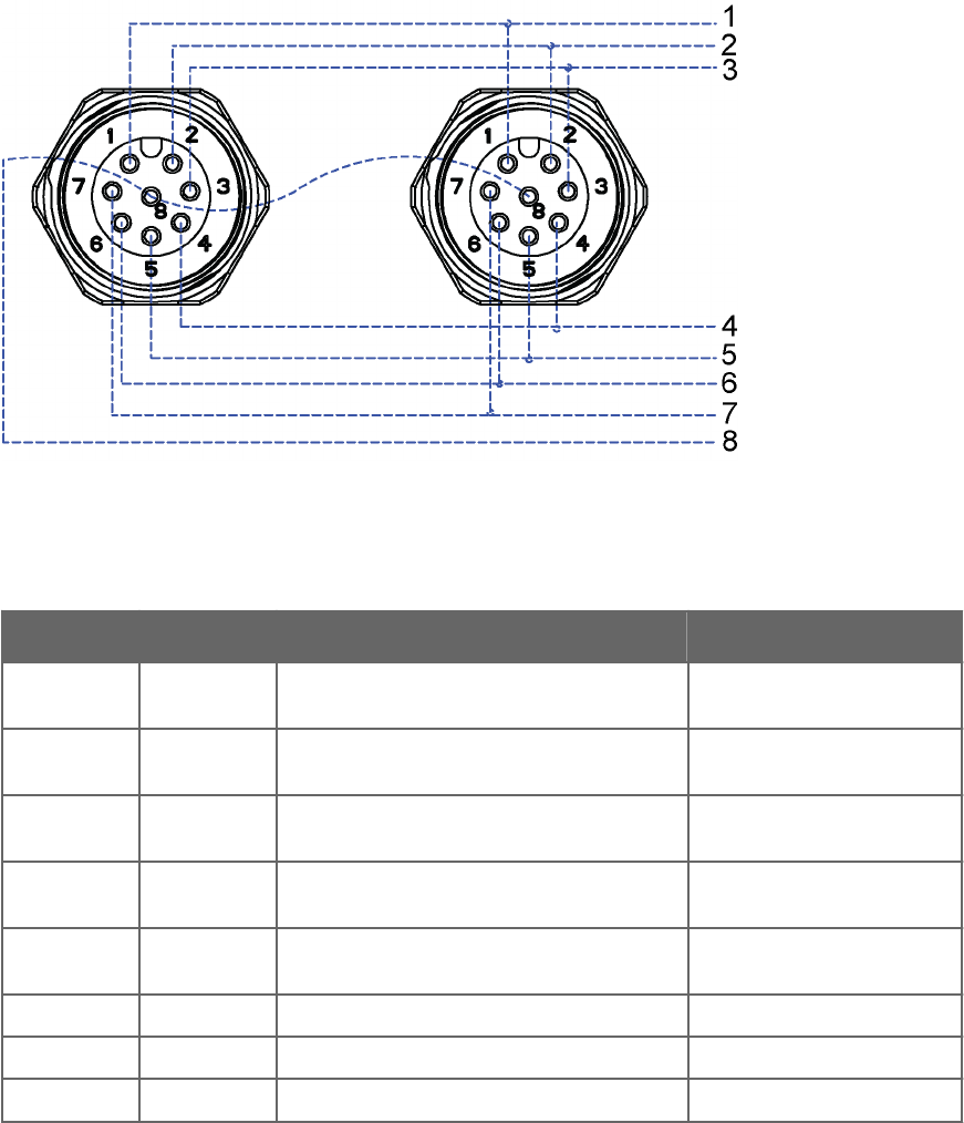
Figure 32 Analog Input Connector Pins
Table 29 Analog Input Signals
Signal name M12 Pin Description Use example
PTI+ 1 PT1000 measuring current PT1000 temperature sensor
Current feed
PT+ 2 PT1000 input+ PT1000 temperature sensor.
Sense+
PT- 3 PT1000 input- PT1000 temperature sensor
Sense-
AGND 4 Analog ground Common ground for level,
tipping bucket, and PT1000
TIP IN 5 Pulse counting input (pulled up with resistor) Tipping bucket type rain
sensor
SR+ 6 Dierential 0 … 25 mV input, + Pyranometer
SR- 7 Dierential 0 … 25 mV input, - Pyranometer
WS IN 8 0 … 2.5/0 … 5/0 … 10 V input Level sensor
The following figure shows the analog input settings in Vaisala Configuration Tool.
Chapter 8 – Sensor and Data Message Settings
137
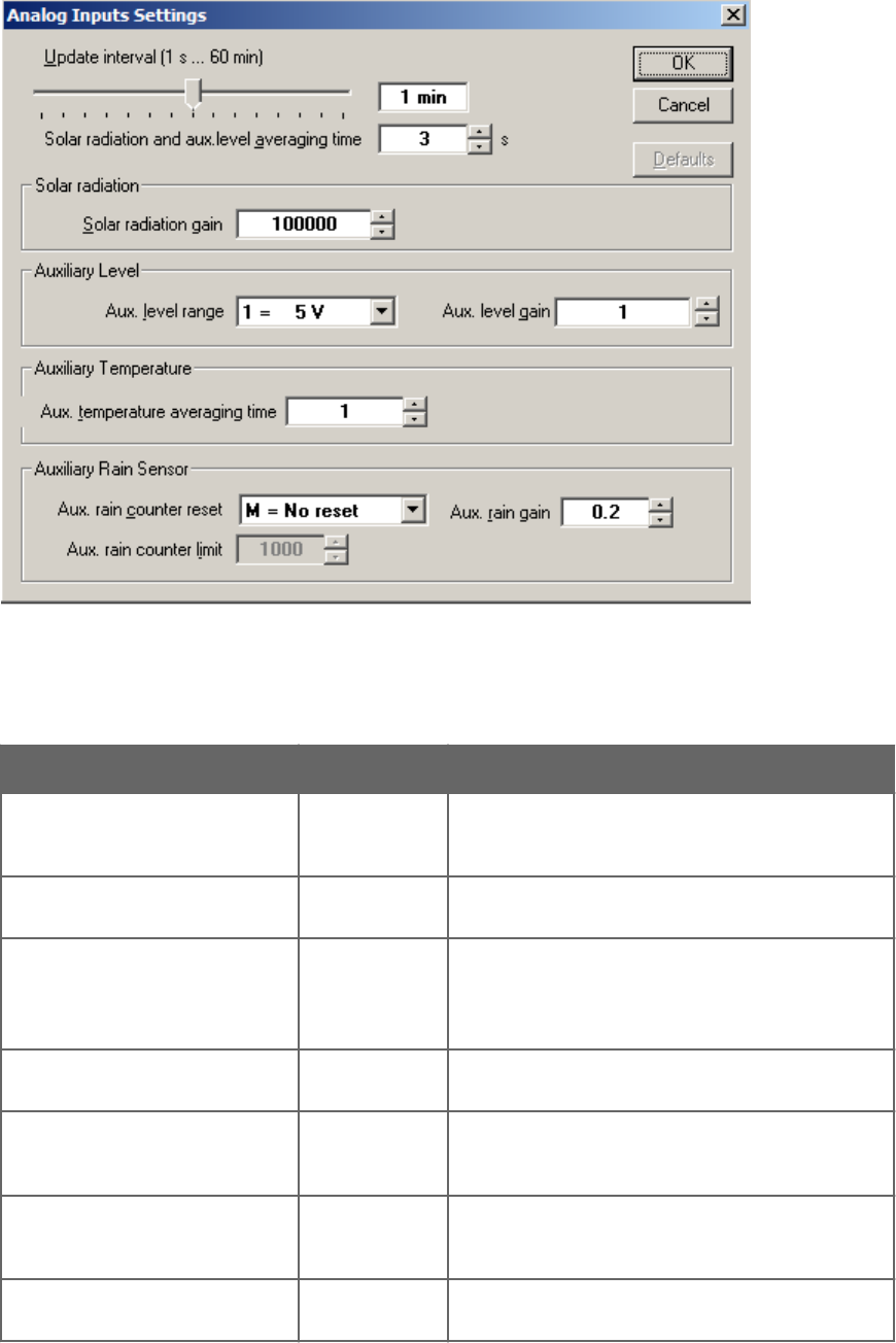
Figure 33 Analog Input Settings in Vaisala Configuration Tool
Table 30 Analog Input Setting Definitions
Setting Default value Definition
Update interval 1 min Defines analog input measurement interval. A shorter
interval and a longer averaging time increase power
consumption.
Solar radiation and ultrasonic level
sensor averaging time
3 s Defines averaging times for solar radiation and
ultrasonic level sensor voltage measurement.
Solar radiation gain 100000 Taken from solar radiation sensor calibration
documents provided with the sensor. For example for
sensitivity 19.71µV/W/m2 gain is 1 /
0.00001971V/W/m2 = 50736
Ultrasonic level sensor range 0 … 5 V Selects voltage measurement range. Available ranges:
0 … 2.5 V, 0 … 5 V, 0 … 10 V
Ultrasonic level sensor gain 1 Defines gain factor for auxiliary level voltage
measurement. Gain can be used to convert voltage
reading directly to distance/height.
Aux. temperature averaging time 1 Defines PT1000 temperature sensor measurement
averaging time in seconds. To minimize sensor self-
heating eect, make it short.
Aux. rain counter reset M = No reset Defines how to reset the rain counter. M means that
you have to manually reset the counter.
WXT530 Series User Guide M211840EN-D
138

Setting Default value Definition
Aux. rain gain 0.2 mm Comes from the rain sensor tipping bucket size. It
means pulses / user rain unit (for example, mm). If the
aux. sensor has 5 pulses per mm of rain, and the user
sets the gain to 0.2, the rain value reported by the
transmitter is in mm.
Aux. rain counter limit Used only when L = based on limit is selected. Resets
the rain counter when it reaches this value. The same
unit as the gain G has.
• All measurement messages enabled
• Update interval 60 s
• Solar radiation and ultrasonic level sensor averaging time 3 s
• Solar radiation gain 100 000
• Ultrasonic level sensor range 5 V
• Ultrasonic level sensor gain 1
• Aux temperature average time 1 s
• Aux rain counter reset: manual
• Aux rain gain 0.2 (for 0.2 mm per tip)
WXT530 Series settings:
0IU,R=11111000&11111000,I=60,A=3.0
0IB,G=100000.0
0IS,M=1,G=1.0
0IP,A=1.0
0IA,M=M,G=0.2
8.1.6.1 Enabling and Disabling Analog Input
If the analog input option is selected for WXT536, all analog inputs are enabled by default.
You can enable and disable analog input with the aIU,R= command.
For example, PT1000 temperature enabled, all other disabled:
aIU,R=1000000010000000
You must reset the transmitter to apply the new setting. When analog input is in use, the
serial port does not work. The service connector functions.
More Information
‣Enabling or Disabling Analog Output (page 145)
Chapter 8 – Sensor and Data Message Settings
139

8.1.6.2 Common Sensor Settings (aIU)
Update Interval [I]
The update interval in seconds. This parameter defines the measurement interval for analog
inputs:
• Pt1000
• Solar radiation
• Aux rain
The range: 0.5 … 3600.
8.1.6.3 Aux Input Averaging Time [A]
The Aux Input averaging time in seconds. This parameter defines the averaging time for
ultrasonic level sensor and solar radiation measurement. Pt1000 and the tipping bucket are
not aected by this setting.
Make sure the averaging time is smaller than the update interval [I]. The smallest value
0.25 s means single measurement. A longer averaging time can decrease noise. A shorter
averaging times gives a slightly smaller current consumption.
8.1.6.4 Parameter Selection [R]
[R] defines the active measurements.
Table 31 aIU Setting Fields [R]
Normal message 1 st bit (most left) Tr pt1000 temperature
2 nd bit Ra Aux rain amount
3 rd bit Sl ultrasonic level sensor
4 th bit Sr solar radiation
5 th bit Rt pt1000 resistance
6 th bit
7 th bit Analog output mode
8 th bit
& delimiter
Composite message 9 th bit Tr pt1000 temperature
10 th bit Ra Aux rain amount
11 th bit Sl Ultrasonic level sensor
12 th bit Sr solar radiation
13 th bit Rt pt1000 resistance
14 th bit 0
15 th bit 0
WXT530 Series User Guide M211840EN-D
140

16 th bit (most right) 0
8.1.6.5 Getting Data Messages
You can get data messages with the aR4 command.
An example response:
0R4,Tr=111.3C,Ra=0.0M,Sl=0.001208V,Sr=0.000029V
Tr Pt1000 (C = Celsius, F = Fahrenheit)
Ra Aux rain accumulation (M = mm)
Sl Ultrasonic level sensor (V = volts at input * gain)
Sr Solar radiation (V = volts at input * gain)
You can set the gain for Sr and Sl.
8.1.6.6 Aux Rain Sensor Settings [aIA]
Gain [G]
[G] defines the pulses per rain unit, for example in mm.
If the Aux sensor has 10 pulses per a millimeter of rain and the user sets the gain to 1/10, the
transmitter reports the rain value in mm.
The range: 0.000 000 001 … 1 000 000
For example, you can set aux rain gain for Vaisala RG13 Tipping Bucket Rain Gauge. The
resolution is 0.1 mm per tip. Set the gain to 0.1 * 2 = 0.2 so that the Ra rain amount WXT
reports is in millimeters. The multiplier 2 means that the tipping bucket sends one pulse per
2 tips.
Reset Mode [M]
M defines the reset mode.
Parameter Description
MNo reset
LBased on limit
AAutomatic (aux rain message sent)
Chapter 8 – Sensor and Data Message Settings
141
The initial tip counter overflows if it reaches 65536 and it starts from 0. If the tipping bucket
resolution is 0.2 mm per tip, the gain is 0.2, and the maximum rain amount before overflow
is 65536 × 0.2 = 13107 mm.
Limit [L]
[L] defines the reset limit. The rain counter resets when it reaches this value. The unit is the
same as in gain [G].
The range: 0.000 000 001 … 1 000 000
Parameter Selection [aIU,R = bit 2 and bit 10]
Bits 7 and 14 enable normal and composite message for aux rain accumulation. You can
select the parameter with the aIU command. The maximum value for the rain counter is
65535 * gain.
8.1.6.7 Solar Radiation Sensor Settings [aIB]
Gain
[G] defines the volts / user unit, for example, μV/W/m2. WXT reports the voltage at solar
radiation input multiplied with gain [G].
For example, if the solar radiation sensor has sensitivity 5 μV/W/m2 and you set the gain [G]
to 1/ μV = 200 000, the solar radiation value reported by WXT is in W/m2. WXT reports the
value always with six decimals.
The range: 0.000 000 001 … 1 000 000
Parameter Selection [aIU,R= bit 3 and bit 11]
The bits enable normal and composite messages. You can select the parameters with the
aIU command.
8.1.6.8 Ultrasonic Level Sensor Settings [aIS]
Gain [G]
[G] defines the volts / user unit, for example, V/m. WXT reports the voltage at input
multiplied with the gain [G].
For example, if the sensor has gain 2 V/meter and the user sets the gain [G] to 0.5, the value
reported by WXT is in meters. WXT reports the value with 6 decimals.
The range: 0.000 000 001 … 1 000 000
Parameter Selection [aIU,R= (bit 3 and bit 11)]
The bits enable normal and composite messages. You can select the parameters with the
aIU command.
8.1.6.9 Aux.temperature Sensor Settings [aIP]
You can set the temperature settings for the temperature unit with the aTU,U= command.
WXT530 Series User Guide M211840EN-D
142

Averaging Time [A]
The averaging time in seconds, resolution 0.5 s. You can set a short averaging time (0.5 s) to
reduce the Pt1000 sensor self-heating. The message interval defines how often the
measurement starts. The measurement is performed every 0.5 s for averaging time.
The range: 0.5 … 3600
Parameter Selection [aIU,R= (bit 1 and bit 9)]
The bits 7 and 14 enable normal and composite message for Aux rain accumulation. You can
select the parameters with the aIU command.
8.1.6.10 Parameter Order for SDI-12 Mode
The parameter order for SDI-12 mode is:
Analog in (M4): Tr Ra Sl Rt Sr
8.1.7 Analog Output
You can change the analog output type and scaling of WXT532.
WXT532 provides the following analog outputs:
• AOUT1 for wind speed data
• AOUT2 for wind direction data
The analog output value is updated based on aWU,I= settings. Wind measurement uses
aWU settings, such as Averaging Time.
More Information
‣Analog Output Scaling (page 144)
‣Wiring and Power Management (page 53)
8.1.7.1 Analog Output Operation
You can order WXT532 with either 4 … 20 mA scaling or 0 … 20 mA scaling.
You can scale the output with the command aSU.
Example commands to set 4 … 20 mA operation:
Parameter Description
Wind Speed Gain aSU,a=0.333333<cr><lf>
Wind Speed Oset aSU,b=4 <cr><lf>
Wind Speed minimum aSU,c=0<cr><lf>
Wind Speed maximum aSU,d=22<cr><lf>
WS error indication aSU,e=2<cr><lf>
Wind Direction Gain aSU,f=0.044444<cr><lf>
Chapter 8 – Sensor and Data Message Settings
143

Parameter Description
Wind Direction Oset aSU,g=4<cr><lf>
WD minimum aSU,h=0<cr><lf>
WD maximum aSU,j=22<cr><lf>
WD error indication aSU,k=2<cr><lf>
The output o in mA is o=i* gain + oset. o is clamped between min and max. If wind
measurement fails, the output value is err.
8.1.7.2 Analog Output Scaling
You can specify the transfer function between measured values and output analog values.
You can select the analog output gain and oset used in the transfer function.
The factory default settings for the dierent analog output modes are displayed in the
following table.
Table 32 Analog Output Scaling
Parameter 4 … 20 mA
option (max 60
m/s)
0 … 20 mA
option (max 60
m/s)
Command example (4 … 20 mA)
Aout1, Wind Speed Gain 0.266667 mA /
m/s
0.333333 mA /
m/s
aSU,a=0.266667<cr><lf>
Aout1, Wind Speed Oset 4 mA 0 mA aSU,b=4<cr><lf>
Aout1, Wind Speed Minimum 0 mA 0 mA aSU,c=0<cr><lf>
Aout1, Wind Speed Maximum 22 mA 22 mA aSU,d=22<cr><lf>
Aout1, Wind Speed Error
Indication
2 mA 22 mA aSU,e=2<cr><lf>
Aout2, Wind Direction Gain 0.044444 mA / ° 0.055556 mA / ° aSU,f=0.044444<cr><lf>
Aout2, Wind Direction Oset 4 mA 0 mA aSU,g=4<cr><lf>
Aout2, Wind Direction Minimum 0 mA 0 mA aSU,h=0<cr><lf>
Aout2, Wind Direction Maximum 22 mA 22 mA aSU,j=22<cr><lf>
Aout2, Wind Direction Error
Indication
2 mA 22 mA aSU,k=2<cr><lf>
You can configure output scaling or transfer function settings by changing the custom gain
and oset. The basic measurement units are m/s and degrees. The physical output unit is A.
The following formula shows the impact of gain and oset values on the produced output:
o = y0 + k×s
WXT530 Series User Guide M211840EN-D
144

oProduced analog output (A)
sMeasured wind speed or direction (in m/s or °)
kSelected gain value
y0 Selected oset value
8.1.7.3 Analog Output Signal for Wind Speed Channel
The analog interfaces setup, default configuration:
Current output 4 ... 20 mA, oset 4 mA
4 mA = 0 m/s
20 mA = 60 m/s (0,266667 mA/m/s)
Error indication sets output to 2 mA.
The analog interfaces setup, configuration 2:
Current output 0 … 20 mA, oset 0 mA
0 mA = 0 m/s 20 mA = 60 m/s (0.333333 mA/m/s)
Error indication sets output to 22 mA.
8.1.7.4 Analog Output Signal for Wind Direction Channel
Analog interfaces setup default configuration:
Current output 4 ... 20 mA, oset 4 mA
4 mA = 0 degree 20 mA = 360 degree (0,044444 mA/°)
Error indication sets output to 2 mA
Analog interfaces setup, configuration 2:
Current output degree 0 ... 20 mA, oset 0 mA
0 uA = 0 degree
20 mA = 360 degree (0,055556 mA/°)
Error indication sets output to 22 mA
8.1.7.5 Enabling or Disabling Analog Output
When changing the analog output setting, the setting is applied after the transmitter reset.
When analog output is in use, the serial port does not work but the service connector does.
The 12th bit from left determines if analog output is enabled:
• Analog output enabled at the factory: 0XF,f=1111111111110000
• Analog output disabled at the factory: 0XF,f=1111111111100000
You can enable or disable analog output with the aWU,R= command.
• To enable analog output: Change bit 7 to 1. 0WU,R=1111111111111100
• To disable analog output: Change bit 7 to 0. 0WU,R=1111110111111100
Chapter 8 – Sensor and Data Message Settings
145

Table 33 aWU Setting Fields [R]
Normal message 1 st bit (most left) 15
2 nd bit 14
3 rd bit 13
4 th bit 12
5 th bit 11
6 th bit 10
7 th bit Analog output mode 9
8 th bit 8
& delimiter
Composite message 1 st bit (most left) 7
2 nd bit 6
3 rd bit 5
4 th bit 4
5 th bit 3
6 th bit 2
7 th bit 1
8 th bit (most right) 0 0
More Information
‣Enabling and Disabling Analog Input (page 139)
WXT530 Series User Guide M211840EN-D
146
9. Maintenance
9.1 Cleaning
To ensure the accuracy of measurement results, clean the transmitter when it gets
contaminated. Remove leaves and other such particles from the precipitation sensor and
clean the transmitter carefully with a soft, lint-free cloth moistened with mild detergent.
Wipe with soft cloth or sponge and rinse with clean water.
Do not use solvents or abrasive sponges when cleaning painted surfaces.
9.1.1 Cleaning the Radiation Shield
Vaisala recommends that you clean the radiation shield once a year.
1. Clean the radiation shield with a soft cloth.
Do not paint the radiation shield.
2. If the radiation shield looks worn and yellow, you can replace it with a radiation shield
spare part (218817SP).
9.2 Replacing PTU Module
• 3-mm Allen key
In demanding customer applications, Vaisala recommends changing the PTU module every
two years.
WXT536 WXT535 WXT534 WXT533 WXT532 WXT531
✔✔✔
1. Turn o the power.
Chapter 9 – Maintenance
147
2. Loosen the 3 mounting screws at the bottom assembly of the transmitter and pull them
out.
1Fixing screws
2Top of transmitter
3PTU module
4Latch
5Flat cable
6O-ring
3. Turn out the top of the transmitter.
4. Release the small white latch and remove the PTU module.
5. Remove the vacuum bag protecting the PTU module.
6. Connect the new PTU module.
Avoid touching the white filter cap.CAUTION!
WXT530 Series User Guide M211840EN-D
148

7. Turn the top back in. Make sure the flat cable does not get stuck or squeezed between
the top and the funnel for the flat cable and it is properly connected.
8. If the O-rings are damaged, replace them with new ones.
9. Tighten the fixing screws.
To make sure that the radiation shield stays straight, do not tighten the screws all the
way in one go. Do not overtighten.
Chapter 9 – Maintenance
149
WXT530 Series User Guide M211840EN-D
150

10. Troubleshooting
Table 34 Data Validation
Problem Possible causes Action(s)
Wind measurement failure. Both
the speed and direction units are
replaced by a # sign or the data
values are irrelevant.
Blockage (trash, leaves, branches,
bird, snow, ice) between the wind
transducers. Incorrect <cr><lf>
settings in the terminal program.
Remove the blockage, and check
that the wind transducers are not
damaged.
If the blockage is ice or snow, it will
melt after some time if heating is
enabled. Time for clearance
depends on the severity of the
weather event.
If birds are causing the blockage,
consider using the bird kit.
In ASCII and NMEA protocols both
<cr> and <lf> are required after
each command. Check that your
terminal program sends both when
pressing enter. Note: The direction
unit is # for the wind speeds less
than 0.05 m/s.
Pressure, humidity or temperature
measurement failure. The unit is
replaced by a # sign or the data
values are irrelevant.
The PTU module may not be
properly connected. There may be
water in the PTU module.
Ensure the proper connection of
the PTU module. Remove and dry
the module.
Chapter 10 – Troubleshooting
151

Table 35 Communication Problems
Problem Possible causes Action(s)
No response to any
commands.
Wrong wiring or operation voltage not
connected. Baud rate/start bits/parity/
stop bit settings do not match between
the device and the host.
Check the wiring and operation
voltage. See 5. Wiring and Power
Management (page 53).Connect the
service cable, use the communication
settings 19200,8 N,1. Check the serial
port settings of the device with
Configuration Tool or with terminal
program. Use command aXU! (SDI-12)
or aXU<cr><lf> (ASCII/NMEA).
Change the values if needed. A
software/hardware reset is needed to
validate the changes. When you have
no service cable, try typing address
query commands ?! and ?<cr><lf>
with dierent serial settings in
terminal program. When the
communication parameters match, the
device responds with its address. The
settings can now be changed using
aXU! (SDI-12) or aXU<cr><lf>
(ASCII/NMEA) commands. A
software/hardware reset is needed to
validate the changes.
Incorrect <cr><lf> settings in the
terminal program.
In ASCII and NMEA protocols both
<cr> and <lf> are required after each
command. Check that your terminal
program sends both when pressing
enter.
Connection works but data
messages not available.
Wrong device address in a SDI-12
command or a mistyped SDI-12
command (in SDI-12 a mistyped
command is in no way responded). A
command mistyped in ASCII/NMEA
mode while error messaging/text
messages is disabled (aSU,S=N).
Request the device address with ?!
command and then retype the
command now with the correct
address. Check the data query
commands. See 7. Retrieving Data
Messages (page 77). Enable the error
messaging using the Vaisala
Configuration Tool or any terminal by
setting aSU,S=Y, then try the
command again.
Data messages are not in
expected format.
The communication protocol may not
be the one you want.
Check the communication protocol of
the device by using the Vaisala
Configuration Tool or any terminal
with command aXU,M! (SDI-12)
aXU,M<cr><lf> (ASCII/NMEA) and
change it if needed.
Some parameters are
missing from the data
messages.
The formatting of the data messages is
not what you expect.
Format the data messages of the
concern by using the Vaisala
Configuration Tool or any terminal
program.
An error message as a
response to a command.
See 10.1.1 Error Messaging/Text
Messages (page 153) .
See 10.1.1 Error Messaging/Text
Messages (page 153).
WXT530 Series User Guide M211840EN-D
152

Problem Possible causes Action(s)
The transmitter keeps
sending the message "TX
Sync/address error".
The polling address and the transmitter
address do not match. The transmitter is
on an RS-485 bus with other polled
devices and Error Messages are
enabled.
Set correct address either for the
transmitter or to the polling request.
Disable the Error Messages with the
command aSU,S=N <cr><lf>.
mA messages cannot be
found.
No mA output ordered. You must specify the mA option when
you place the order.
Analog input messages are
missing.
Analog input messages are not enabled. Enable analog input messages. See
8.1.7.5 Enabling or Disabling Analog
Output (page 145).
Precipitation messages
missing.
No precipitation measurement in
models WXT534 and WXT532.
10.1 Self-Diagnostics
10.1.1 Error Messaging/Text Messages
The transmitter sends a text message when certain type of errors occur. The function works
in all communication modes except in the SDI-12 mode. You can disable error messaging by
using the supervisor message aSU, S=N.
Examples:
0R1!0TX,Unable to measure error<cr><lf>
(request of wind data while all the wind parameters were disabled from the wind message)
1XU!0TX,Sync/address error<cr><lf>
(wrong device address. Ask the correct address with ? or ?! command.)
0XP!0TX,Unknown cmd error<cr><lf>
0xUabc!0TX,Use chksum CCb<cr><lf>
(wrong checksum applied to the 0xU command)
Chapter 10 – Troubleshooting
153

Table 36 Error Messaging/Text Messages
Text message
identifier (in
NMEA 0183
v3.0 protocol
only)
Text Message Interpretation and action
01 Unable to measure
error
The requested parameters are not activated in the message and
check the parameter section fields.
02 Sync/address error The device address in the beginning of the command is invalid.
Ask the device address with the ?! (SDI-12) or ?<cr><lf> (ASCII
and NMEA) command and retype the command with the correct
address.
03 Unknown cmd error The command is not supported, use the correct command format.
See 7. Retrieving Data Messages (page 77).
04 Profile reset Checksum error in configuration settings during power-up.
Factory settings used instead.
05 Factory reset Checksum error in calibration settings during power-up. Factory
settings used instead.
06 Version reset New software version in use.
07 Start-up Software reset. Program starts from the beginning.
08 Use chksum xxx Given checksum not correct for the command. Use the proposed
checksum.
09 Measurement reset The ongoing measurement of all the sensors interrupted and
started from the beginning.
10 Rain reset The precipitation sensor counter reset.
11 Inty reset Precipitation sensor intensity counter reset.
If you use a WXT530 transmitter on an RS-485 bus with other polled devices, you must
disable error messaging with the command: 0SU,S=N<crlf>.
More Information
‣Troubleshooting (page 151)
‣Sensor Configuration and Data Message Formatting (page 117)
10.1.2 Rain and Wind Sensor Heating Control
The supervisor message aSU shows you continuously monitored information about rain and
wind sensor heating (heating temperature Th and heating voltage Vh).
WXT530 Series User Guide M211840EN-D
154

The heating temperature should stay above 0 °C when the heating is on (except in
extremely cold conditions where the heating power is not sucient). The heating voltage
Vh should correspond to the heating voltage supplied. If there is a remarkable deviation,
check the wiring. Note that wire gauge should be large enough to avoid remarkable voltage
drop in the cable.
In case AC or full-wave rectified AC is used for the heating, the Vh measurement behaves
as follows:
While heating is o, Vh indicates the positive peak value (Vp) of the heating voltage
waveform.
While heating is on, Vh indicates:
• 0.35 × Vp in case of AC voltage
• 0.70 × Vp in case of full-wave rectified AC voltage
10.1.3 Operating Voltage Control
The supervisor message aSU shows you continuously monitored supply voltage level (Vs). In
case of deviations between the supplied voltage and monitored voltage, check the wiring
and the power supply.
10.1.4 Missing Readings and Error Indication
If the transmitter is not able to measure the wind, it indicates a missing reading in the
output. The most common reasons for measurement problems are foreign objects, such as
ice, birds, or other foreign objects, on the line of measurement, or sound reflections from
nearby objects, such as wind tunnel walls.
Chapter 10 – Troubleshooting
155
WXT530 Series User Guide M211840EN-D
156

11. Technical Specifications
11.1 Performance
Table 37 WXT530 Series Barometric Pressure Measuring Specifications
Property Description/Value
Observation range 600 ... 1100 hPa
Accuracy (for sensor element) ±0.5 hPa at 0 … +30 °C (+32 … +86 °F)
±1 hPa at -52 … +60 °C (-60 … +140 °F)
Output resolution 0.1 hPa / 10 Pa / 0.001 bar / 0.1 mmHg / 0.01 inHg
Units available hPa, Pa, bar, mmHg, inHg
Table 38 WXT530 Series Air Temperature Measuring Specifications
Property Description/Value
Observation range -52 ... +60 °C (-60 ... +140 °F)
Accuracy (for sensor element) at +20 °C (+68 °F) 1) ±0.3 °C (±0.17 °F)
Output resolution 0.1 °C (0.1 °F)
Units available °C, °F
1) A naturally aspirated radiation shield is applied which can aect readings in calm wind.
Table 39 WXT530 Series Relative Humidity Measuring Specifications
Property Description/Value
Observation range 0 ... 100 %RH
Accuracy (for sensor element) 1) ±3 %RH at 0 ... 90 %RH
±5 %RH at 90 ... 100 %RH
Output resolution 0.1 %RH
PTU measuring interval 1 ... 3600 s (= 60 min), at 1 s steps
1) A naturally aspirated radiation shield is applied which can aect readings in calm wind.
Chapter 11 – Technical Specifications
157

Table 40 WXT530 Series Precipitation Measuring Specifications
Property 1) Description/Value
Rainfall Cumulative accumulation after the latest automatic or
manual reset.
Collecting area 60 cm2
Output resolution 0.01 mm (0.001 in)
Field accuracy for daily accumulation 2) Better than 5 %, weather-dependent
Units available mm, in
Rain
Duration Counting each 10‑second increment whenever droplet
detected
Output resolution 10 s
Intensity Running 1‑minute average in 10‑second steps
Observation range 0 ... 200 mm/h (0 ... 7.87 in/h) (broader range with
reduced accuracy)
Units available mm/h, in/h
Hail Cumulative amount of hits against collecting surface
Duration Counting each 10‑second increment whenever
hailstone detected
Output resolution 0.1 hits/cm2, (1 hits/in2), 1 hit
Intensity 1‑minute running average in 10‑second steps
Units available hits/cm2, hits/in2, hits
Output resolution 10 s
Observation range 0.1 hits/cm2h (1 hits/in2h), 1 hit/h
Units available hits/cm2h, hits/in2h, hits/h
1) Precipitation measurement is performed for liquid precipitation.
2) Due to the nature of the phenomenon, deviations caused by spatial variations may exist in precipitation readings, especially
in short time scale. The accuracy specification does not include possible wind-induced error.
Table 41 WXT530 Series Wind Measuring Specifications
Property Description/Value
Wind speed 1)
Observation range 0 ... 60 m/s (134 mph)
Response time 0.25 s
Available variables Average, maximum, and minimum
WXT530 Series User Guide M211840EN-D
158

Property Description/Value
Accuracy ±3 % at 10 m/s
Output resolution 0.1 m/s (km/h, mph, knots)
Units available m/s, km/h, mph, knots
Wind direction 1)
Azimuth 0 ... 360°
Response time 0.25 s
Available variables Average, maximum, and minimum
Accuracy ±3.0° at 10 m/s
Output resolution 1°
Wind measurement frame
Averaging time 1 ... 3600 s (= 60 min), at 1 s steps, on the basis of
samples taken at 4, 2, or 1 Hz rate (configurable)
Update interval 1 ... 3600 s (= 60 min), at 1 s steps
1) NTP (normal temperature and pressure) condition applied for wind tunnel testing.
11.2 Inputs and Outputs
Table 42 WXT530 Series Electrical Specifications
Property Description/Value
Operating voltage 6 ... 24 VDC (-10 % ... +30 %)
Average current consumption
Minimum 0.1 mA at 12 VDC (SDI-12 standby)
Typical 3.5 mA at 12 VDC with typical measuring intervals1)
Maximum 15 mA at 6 VDC (with constant measurement of all
parameters)
Heating voltage Options: DC, AC, full-wave rectified AC
12... 24 VDC (-10 % ... + 30 %)
12 ... 17 VACrms (-10 % ... +30 %)
Typical heating current 12 VDC: 0.8 A
24 VDC: 0.4 A
12 VACrms: 1.1 A
17 VACrms: 0.8 A
Chapter 11 – Technical Specifications
159

Property Description/Value
Digital outputs SDI-12, RS-232, RS-485, RS-422
Communication protocols SDI-12 v1.3, ASCII automatic and polled, NMEA 0183
v3.0 with query option
Self-diagnostic Separate supervisor message, unit/status fields to
validate measurement stability
Start-up Automatic, < 5 seconds from power on to the first
valid output
1) Wind 10
‑
second average with 2
‑
minute interval at 4
‑
Hz sampling rate, RS
‑
232 19200 bps with jumper wires, PTU 1 s interval,
Pt1000, level, tipping bucket, and solar radiation 5 s interval.
Table 43 WXT536 Analog Input Options
Parameter Element Range Input1) Excitation Resolution
Temperature
PT1000
Resistor 800 … 1330 Ω 2-wire
4-wire
2.5 V 16 bits
Solar Radiation
Kipp & Zonen
CMP3
Thermopile 0 … 25 mV 4 MΩ - 12 bits
Level
measurement
IRU-9429
Voltage 0 … 2.5 V
0 … 5 V
0 … 10 V
> 10 kΩ - 12 bits
Tipping Bucket
RG13
Frequency 0 … 100 Hz 18 kΩ 3.5 V -
1) The input can be wiring type, input impedance, or pull-up resistor value.
Table 44 WXT532 Analog mA Output Options
Parameter1) Description/Value
Wind speed 0 … 20 mA or 4 … 20 mA
Wind direction 0 … 20 mA or 4 … 20 mA
Load impedance 200 Ω max
Update interval 4 Hz max
1) When the analog output option is applied, digital communication is not available.
WXT530 Series User Guide M211840EN-D
160
11.3 Environmental Conditions
Table 45 WXT530 Series Environmental Specifications
Property Description/Value
Operating temperature -52 ... +60 °C (-60 ... +140 °F)
Storage temperature -60 ... +70 °C (-76 ... +158 °F)
Relative humidity 0 ... 100 %RH
Pressure 600 ... 1100 hPa
Wind 1) 0 ... 60 m/s (134 mph)
IP rating IP65 (without mounting kit)
IP66 (with mounting kit attached)
1) Due to the measurement frequency used in the sonic transducers, RF interference in the 200 ... 400 kHz range can disturb
wind measurement.
Select a heated sensor model if you operate the sensor in humid conditions.
Select a heated model if you operate the sensor in temperatures below 0 °C (+32 °F).
Make sure that you power the sensor after installation. Storing the sensor
outdoors without proper package or not powering up after installation can aect the
sensor's expected lifespan.
CAUTION!
Any temporary object (such as snow, ice, or a bird) that blocks the
observation path between the ultrasonic transducer heads may lead to inaccurate or
incorrect measurements.
CAUTION!
Table 46 WXT530 Series Electromagnetic Compatibility
Applicable
Standard
Description Level tested Performance 1)
CISPR 22 Radiated emissions 30 Hz ... 18 GHz Class B
Chapter 11 – Technical Specifications
161

Applicable
Standard
Description Level tested Performance 1)
CISPR 22 Conducted emissions DC 150 Hz ... 30 MHz Class B
IEC 61000-4-2 Electrostatic discharge 8 kV con / 15 kV air B
IEC 61000-4-3 RF field immunity 2) 10 V/m and 3 V/m A
IEC 61000-4-4 Electric fast transient 3 kV B
IEC 61000-4-5 Surge 2 kV B
IEC 61000-4-6 Conducted RF immunity 3 V A
IEC 60945 Radiated emissions 150 kHz ... 2 GHz All locations including
Bridge and Open
Deck
IEC 60945 Conducted emissions 10 kHz ... 30 MHz All locations including
Bridge and Open
Deck
IEC 60945 Electrostatic discharge 8 kV con / 15 kV air B
IEC 60945 RF field immunity 10 V/m and 3 V/m A
IEC 60945 Electric fast transient 3 kV B
IEC 60945 Surge 2 kV B
IEC 60945 Conducted RF immunity 3 kV A
IEC 60945 Conducted low frequency
interference immunity
10 %Vnom B
IEC 60945 Extreme power supply
variation
-10 % +30 % A
IEC 60945 Power supply failure 3 times 60 s B
1) A = Normal performance
B = Temporary degradation (self-recoverable)
C = Temporary degradation (operator intervention needed)
D = Not recoverable
2) Within frequency range 600 ... 700 MHz immunity for PTU is 8 V/m.
11.4 Mechanical Specifications
Table 47 WXT530 Series Mechanical Specifications
Property Description/Value
Weight
WXT534, WXT535, WXT536 0.7 kg (1.54 lbs)
WXT531, WXT532, WXT533 0.5 kg (1.1 lbs)
WXT530 Series User Guide M211840EN-D
162

Property Description/Value
Materials
Radiation shield, top, and bottom parts Polycarbonate +20 % fiberglass
Precipitation sensor plate Stainless steel (AISI 316)
11.5 Options and Accessories
Table 48 Options and Accessories
Description Order code
Vaisala Configuration Tool and USB service cable SP 220614
Cable USB RS-232/RS-485 1.4 m USB M12 SP 220782
Cable 2 m shielded 8-pin M12 SP 222287
Cable 10 m shielded 8-pin M12 SP 222288
Cable 10 m shielded 8-pin M12, connectors on both ends SP 215952
Cable 40 m shielded 12-pin, open end wires SP 217020
Bushing and grounding accessory kit 222109
Mounting kit 212792
Mounting accessory between Mounting kit and 60 mm tube WMSFIX60
Bird Kit 212793
Vaisala surge protector, no connectors WSP150
Vaisala surge protector with connectors for 220782 and 215952 WSP152
Nokeval converter 229104
Nokeval programming kit 229110
WXT radiation shield set SP 218817SP
WXT PTU module SP WXTPTUSP
WXT bottom connector kit SP 224171
Analog input connectors SP, IP67, 8P, M12, Shielded 214273
WXT530 bottom assembly with digital board SP WXT530BOTTOMDIGISP
WXT530 bottom assembly with analog input board SP WXT530BOTTOMANAINSP
WXT530 bottom assembly with mA output board SP WXT530BOTTOMMAOUTSP
Chapter 11 – Technical Specifications
163
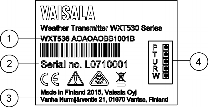
11.6 Type Label
All WXT530 Series transmitters can be identified from the type label.
Figure 34 Type Label
1Product code
2Serial number in bar code
3Place of manufacture
4Symbols indicating measurement options included:
• P = pressure
• T= temperature
• U = humidity
• R = precipitation
• W = wind
WXT530 Series User Guide M211840EN-D
164
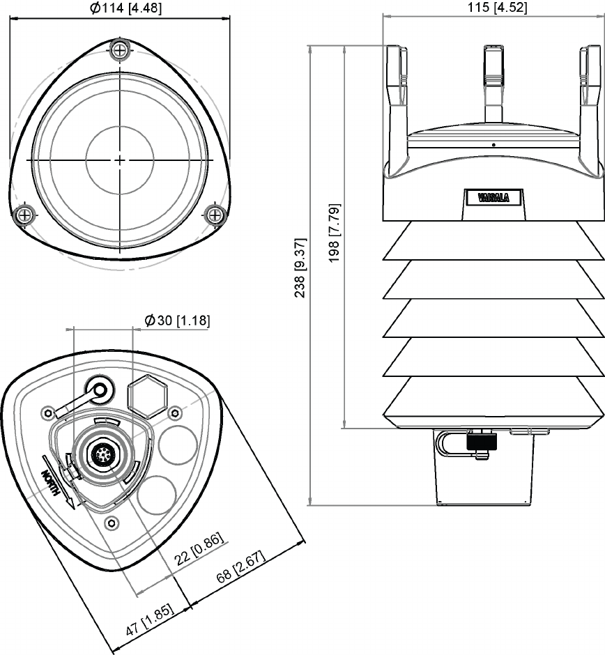
11.7 Dimensions (mm / inch)
Figure 35 WXT536 Dimensions in mm [in]
Chapter 11 – Technical Specifications
165
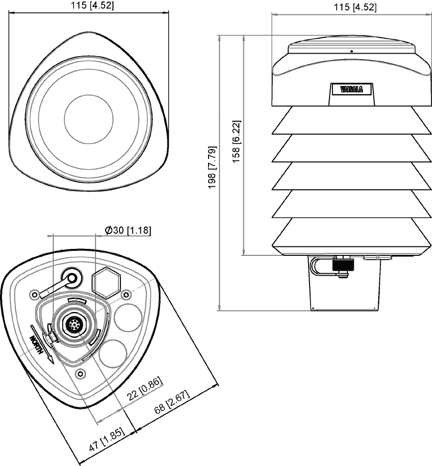
Figure 36 WXT535 and WXT534 Dimensions in mm [in]
WXT530 Series User Guide M211840EN-D
166
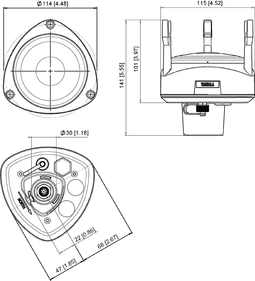
Figure 37 WXT533 and WXT532 Dimensions in mm [in]
Chapter 11 – Technical Specifications
167
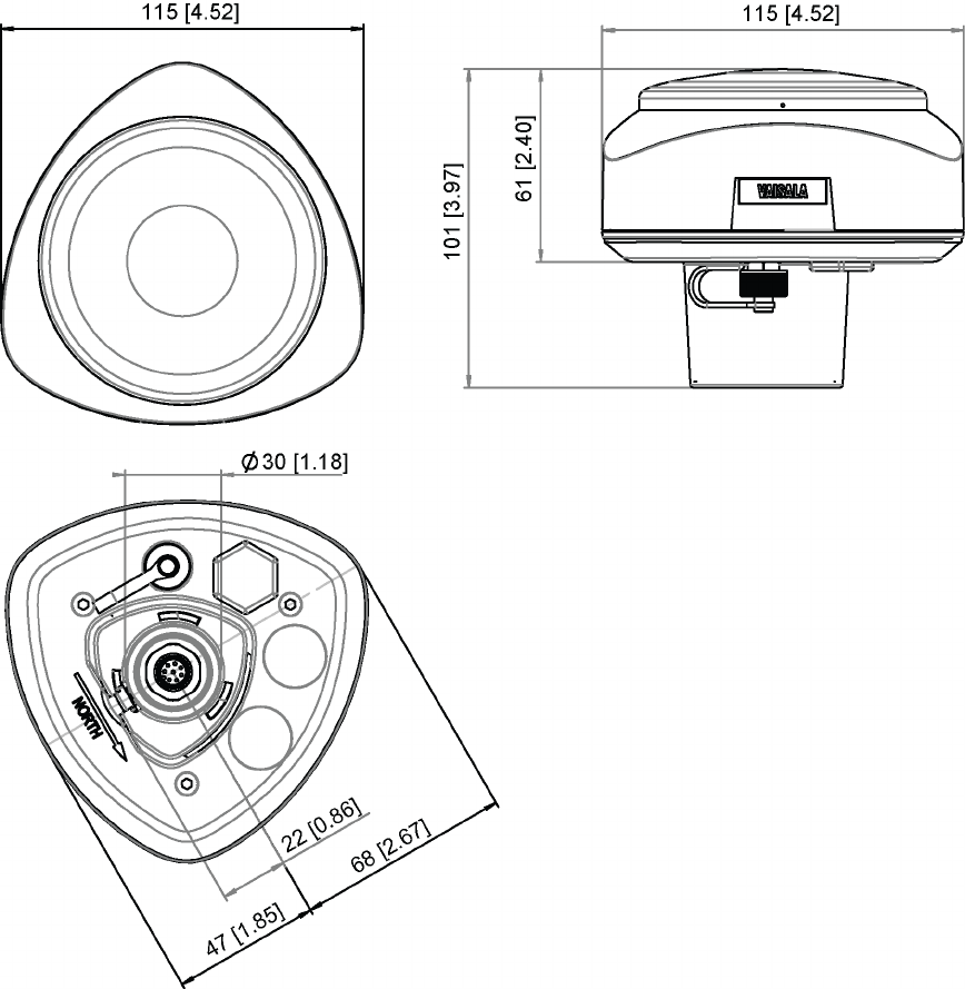
Figure 38 WXT531 Dimensions in mm [in]
WXT530 Series User Guide M211840EN-D
168

Figure 39 WXT530 Series Mounting Kit (212792) Dimensions
1Mounting kit (212792) with adapter sleeve for Ø 26.7 mm (1.05 in) mast tube
2Mounting kit (212792) without adapter sleeve for Ø 30 mm (1.18 in) mast tube
Chapter 11 – Technical Specifications
169
Figure 40 Mounting Accessory (WMSFIX60) for Connecting Mounting Kit (212792) and 60 mm
Tube
WXT530 Series User Guide M211840EN-D
170

Appendix A. Networking
A.1 Connecting Several Transmitters on
Same Bus
There are two options for connecting several transmitters on the same bus:
• Using SDI-12 serial interface and communication protocol
• Using RS-485 serial interface and one of the communication protocols: ASCII or NMEA
0183 v3.0.
A.2 SDI-12 Serial Interface
A.2.1 Wiring SDI-12
1. Perform SDI-12 wiring in the transmitter as described in 5. Wiring and Power
Management (page 53). Make sure you combine the two "Data in/out" wires of each
transmitter either in the internal screw terminal inside or outside the transmitter.
2. In the data logger end, combine the "GND for data" wires of each transmitter to the
logger "GND for data" wire. Connect the "Data in/out" wires of each transmitter to the
logger "Data" wire.
A.2.2 SDI-12 Communication Protocol
Set the communication protocol SDI-12 v 1.3 (aXU,C=1,M=S) or SDI- 12 v1.3 continuous
(aXU,C=1,M=R).
Assign the transmitters on the bus with dierent addresses (for
example:aXU,A=0,1,2,...). After that, the transmitters on the bus do not respond to the
commands not assigned to them nor to the data messages sent by the other transmitters.
Example (A bus with three WXT530 Series transmitters):
WXT530 #1 communication settings:
0XXU,A=0,M=S,C=1,B=1200,D=7,P=E,S=1, L=25
WXT530 #2 communication settings:
1XXU,A=1,M=S,C=1,B=1200,D=7,P=E,S=1, L=25
WXT530 #3 communication settings:
Appendix A – Networking
171

2XXU,A=2,M=S,C=1,B=1200,D=7,P=E,S=1, L=25
If simultaneous measurements of the dierent units are needed, Start concurrent
measurement commands aC and aCC must be used for all devices. If the measurements are
to be performed consecutively for only one unit at a time, in addition to these also Start
measurement commands aM and aMC can be used. Start continuous measurement
commands aR1, aR2, aR3, aR5, aR, aRC1, aRC2, aRC3, aRC5 and aRC available only in
SDI-12 continuous protocol (aXU,M=R) can be used either for simultaneous measurements
of the units or consecutive measurements for one unit at time.
A.3 RS-485 Serial Interface
A.3.1 RS-485 Wiring
1. Make the RS-485 wiring of the transmitter. See 5. Wiring and Power Management
(page 53).
2. In the data logger end, combine the "Data +" wires of each transmitter to the logger
"Data +" wire. Connect the "Data-" wires of each transmitter to the logger "Data -" wire.
A.3.2 RS-485 Communication Protocol
Set the communication protocol to ASCII polled (with or without CRC) or NMEA query.
When using NMEA query, the wind message must be set to XDR (aWU,N=T).
No matter which communication protocol, ASCII polled or NMEA query is chosen, the
error messaging parameter of the supervisor message must be inactivated with aSU,S=N
for each transmitter on the bus to prevent the units responding to the commands not
assigned to them.
A.3.3 ASCII, Polled
Assign dierent addresses to the transmitters on the bus (for example, aXU,A=0,1,2, ...).
Example (a bus with three transmitters):
WXT530 #1 communication settings:
0XU,A=0,M=P,C=3,I=0,B=19200,D=8,P=N,S=1,L=25
WXT530 #2 communication settings:
WXT530 Series User Guide M211840EN-D
172

1XU,A=1,M=P,C=3,I=0,B=19200,D=8,P=N,S=1,L=25
WXT530 #3 communication settings:
2XU,A=2,M=P,C=3,I=0,B=19200,D=8,P=N,S=1,L=25
Example (composite data message queries to the sensors 1 and 3 are assigned as
follows):
0R0<cr><lf>
1R0<cr><lf>
2R0<cr><lf>
A.3.4 NMEA 0183 v3.0, Query
The NMEA 0183 query messages do not contain device address information. Individual
query commands can thus not be directed to dierent transmitters. Instead, a specific time
slot method can be used for receiving data from several transmitters on the bus, just with a
single query command.
To generate dierent time slots, each transmitter is given an individual delay for its query
response, by using the RS-485 line delay parameter aXU,L. This parameter defines the time
(in milliseconds) between the last character of the query and the first character of the
response from the transmitter.
Example (a bus with three transmitters):
WXT530 #1 communication settings:
0XU,A=0,M=Q,C=3,I=0,B=4800,D=8,P=N,S=1,L=25
WXT530 #2 communication settings:
0XU,A=0,M=Q,C=3,I=0,B=4800,D=8,P=N,S=1,L=1000
WXT530 #3 communication settings:
0XU,A=0,M=Q,C=3,I=0,B=4800,D=8,P=N,S=1,L=2000
Appendix A – Networking
173

When the XDR query command $--WIQ,XDR*2D<cr><lf> is sent, WXT530 #1 responds
after 25 ms, WXT530 #2 after 1000 ms, and WXT530 #3 responds after 2000 ms. The
sucient delays depend on the maximum number of characters in the response messages
and the baud rate. Note that all the transmitters are assigned with the same address. The
data logger, after sending the query, sorts out the response messages on the basis of the
individual response times.
To gain even more addressability transducer ID information provided in the XDR response
messages can also be used. If WXT530 address is set to 0 (aXU,A=0) and all parameters are
chosen except Rain peak intensity and Hail peak intensity in the precipitation message, the
response to the XDR query $--WIQ,XDR*2D<cr><lf> is:
$WIXDR,A,316,D,0,A,326,D,1,A,330,D,2,S,0.1,M,0,S,0.1,M,1,S,0.1, M,2*57<cr><lf>
$WIXDR,C,24.0,C,0,C,25.2,C,1,H,47.4,P,0,P,1010.1,H, 0*54<cr><lf>
$WIXDR,V,0.000,I,0,Z,10,s,0,R,0.01,I,0,V,0.0,M,1,Z,0,s,1,R,0.0,M, 1*51<cr><lf>
$WIXDR,C,25.8,C,2,U,10.7,N,0,U,10.9,V,1,U,3.360,V,2*7D<cr><lf>
For the transducer IDs, see 7.4 NMEA 0183 v3.0 Protocol (page 102).
The maximum transducer ID is three when the transmitter address is 0. Assigning address 4
for the second and address 8 for the third transmitter on the bus the following responses to
the XDR query $--WIQ,XDR*2D<cr><lf> will be obtained from these transmitters (same
message parameter configuration):
The second transmitter (address 4):
$WIXDR,A,330,D,4,A,331,D,5,A,333,D,6,S,0.1,M,4,S,0.1,M,5,S,0.2, M,6*55<cr><lf>
$WIXDR,C,23.5,C,4,C,24.3,C,4,H,49.3,P,4,P,1010.1,H, 3*59<cr><lf>
$WIXDR,V,0.000,I,4,Z,0,s,4,R,0.00,I,4,V,0.0,M,5,Z,0,s,5,R,0.0,M, 5*67<cr><lf>
$WIXDR,C,25.8,C,6,U,10.6,N,4,U,10.9,V,5,U,3.362,V,6*78<cr><lf>
The third transmitter (address 8):
$WIXDR,A,341,D,8,A,347,D,9,A,357,D,10,S,0.1,M,8,S,0.2,M,9,S,0.2,M,10*53<cr><lf>
$WIXDR,C,23.5,C,8,C,24.3,C,9,H,49.3,P,8,P,1010.1,H, 8*5F<cr><lf>
$WIXDR,V,0.000,I,8,Z,0,s,8,R,0.00,I,8,V,0.0,M,9,Z,0,s,9,R,0.0,M, 9*61<cr><lf>
$WIXDR,C,25.8,C,10,U,10.6,N,8,U,10.9,V,9,U,3.360,V, 10*7C<cr><lf>
WXT530 Series User Guide M211840EN-D
174

Now the response messages of all three transmitters can be recognized and parsed by the
data logger.
The transmitter address may consist of letter characters but the transducer IDs in the
NMEA XDR messages can only be numbers. The addresses given in letters show in the
transducer IDs in the following way: transmitter address = A => transducer ID = 10, B => 11,
a => 36, b => 37, and so on.
A.3.5 NMEA 0183 v3.0 Query with ASCII Query Commands
You can use ASCII query commands aR1, aR2, aR3, aR5, aR, aR0 and their CRC-versions
ar1, ar2, ar3, ar5, ar, and ar0 also in NMEA 0183 protocol. The responses to these
commands will be in standard NMEA 0183 format and the transmitters are assigned with
dierent addresses (for example: aXU,A=0,1,2,...). The RS-485 line delays are not
needed.
Example (a bus with three transmitters, data requests with combined data message query
commands; the same message parameter configuration as in the previous example):
WXT530 #1 communication settings:
0XU,A=0,M=Q,C=3,I=0,B=4800,D=8,P=N,S=1,L=25
WXT530 #2 communication settings:
0XU,A=1,M=Q,C=3,I=0,B=4800,D=8,P=N,S=1,L=25
WXT530 #3 communication settings:
0XU,A=2,M=Q,C=3,I=0,B=4800,D=8,P=N,S=1,L=25
The query for WXT530 #1 and the response:
0R<cr><lf>
$WIXDR,A,316,D,0,A,326,D,1,A,330,D,2,S,0.1,M,0,S,0.1,M,1,S,0.1, M,2*57<cr><lf>
$WIXDR,C,24.0,C,0,C,25.2,C,1,H,47.4,P,0,P,1010.1,H, 0*54<cr><lf>
$WIXDR,V,0.000,I,0,Z,10,s,0,R,0.01,I,0,V,0.0,M,1,Z,0,s,1,R,0.0,M, 1*51<cr><lf>
$WIXDR,C,25.8,C,2,U,10.7,N,0,U,10.9,V,1,U,3.360,V,2*7D<cr><lf>
The query for WXT530 #2 and the response:
Appendix A – Networking
175

1R<cr><lf>
$WIXDR,A,330,D,1,A,331,D,2,A,333,D,3,S,0.1,M,1,S,0.1,M,2,S,0.2, M,3*55<cr><lf>
$WIXDR,C,23.5,C,1,C,24.3,C,2,H,49.3,P,1,P,1010.1,H, 1*59<cr><lf>
$WIXDR,V,0.000,I,1,Z,0,s,1,R,0.00,I,1,V,0.0,M,2,Z,0,s,2,R,0.0,M, 2*67<cr><lf>
$WIXDR,C,25.8,C,3,U,10.6,N,1,U,10.9,V,1,U,3.362,V,2*78<cr><lf>
The query for WXT530 #3 and the response:
2R<cr><lf>
$WIXDR,A,341,D,2,A,347,D,3,A,357,D,4,S,0.1,M,2,S,0.2,M,3,S,0.2, M,4*53<cr><lf>
$WIXDR,C,23.5,C,2,C,24.3,C,3,H,49.3,P,2,P,1010.1,H, 2*5F<cr><lf>
$WIXDR,V,0.000,I,2,Z,0,s,2,R,0.00,I,2,V,0.0,M,3,Z,0,s,3,R,0.0,M, 3*61<cr><lf>
$WIXDR,C,25.8,C,4,U,10.6,N,2,U,10.9,V,2,U,3.360,V,3*7C<cr><lf>
If needed, for making the transducers IDs distinguishable, device addresses 0, 4, 8 can be
used as described in the previous section.
WXT530 Series User Guide M211840EN-D
176
Appendix B. SDI-12 Protocol
SDI-12 is a standard for interfacing data recorders with microprocessor-based sensors. The
name stands for serial/digital interface at 1200 baud. More information of the complete
SDI-12 standard text is available from the SDI-12 website: http://www.sdi-12.org.
B.1 SDI-12 Electrical Interface
The SDI-12 electrical interface uses the SDI-12 bus to transmit serial data between SDI-12
data recorders and sensors. The SDI-12 bus is the cable that connects multiple SDI-12
devices. The cable has three conductors:
• Serial data line
• Ground line
• 12 V line
The SDI-12 bus can have at least 10 sensors connected to it. The bus topology is a parallel
connection, where each of the three wires of dierent sensors are connected in parallel.
B.1.1 SDI-12 Communications Protocol
SDI-12 data recorders and sensors communicate by an exchange of ASCII characters on the
data line. The data recorder sends a break to wake up the sensors on the data line. A break is
continuous spacing on the data line for at least 12 milliseconds. The data recorder then sends
a command. The sensor, in turn, returns the appropriate response. Each command is for a
specific sensor. The first character of each command is a unique sensor address that
specifies with which sensor the recorder wants to communicate. Other sensors on the SDI-12
bus ignore the command and return to low-power standby mode. When a data recorder tells
a sensor to start its measurement procedure, the recorder does not communicate with any
other sensor until the data collection from the first sensor is complete.
A typical recorder/sensor measurement sequence proceeds in the following order:
• The data recorder wakes all sensors on the SDI-12 bus with a break.
• The recorder transmits a command to a specific, addressed sensor, instructing it to
make a measurement.
• The addressed sensor responds within 15.0 ms returning the maximum time until the
measurement data is ready and the number of data values it returns.
• If the measurement is immediately available, the recorder transmits a command to the
sensor instructing it to return the measurement(s). If the measurement is not ready, the
data recorder waits for the sensor to send a request to the recorder, which indicates
that the data is ready. The recorder then transmits a command to get the data.
• The sensor responds, returning one or more measurements.
B.1.2 SDI-12 Timing
The following figure shows a timing diagram for a SDI-12 command and its response. The
tolerance for all SDI-12 timing is ±0.40 ms.
Appendix B – SDI-12 Protocol
177
The exception to this is the time between the stop bit of one character and the start bit of
the next character. The maximum time for this is 1.66 ms, with no tolerance.
• A data recorder transmits a break by setting the data line to spacing for at least 12 ms.
• The sensor does recognize a break condition for a continuous spacing time of less than
6.5 ms. The sensor will always recognize a break when the line is continuously spacing
for more than 12 ms.
• When receiving a break, a sensor must detect 8.33 ms of marking on the data line
before it looks for an address.
• A sensor must wake up from a low-power standby mode and be capable of detecting a
start bit from a valid command within 100 ms after detecting a break.
• After a data recorder transmits the last character of a command, it must relinquish
control of the data line within 7.5 ms.
Figure 41 Timing Diagram
• After receiving the break and the command, the addressed sensor sets the data line to
marking at 8.33 ms and then sends the response (tolerance: -0.40 ms). The start bit of
the first response byte must start within 15 ms after the stop bit of the last byte of the
command (tolerance: +0.40 ms).
• After a sensor transmits the last character of a response, it must relinquish control of
the data line within 7.5 ms (tolerance: +0.40 ms).
• No more than 1.66 ms of marking are allowed between the end of the stop bit and the
start bit (for example between characters) on any characters in the command or the
response (no tolerance.) This permits a response to an M command to be sent within a
380 ms window.
• Sensors must return to a low-power standby mode after receiving an invalid address or
after detecting a marking state on the data line for 100 ms (tolerance: +0.40 ms).
• When a recorder addresses a dierent sensor, or if the data line has been in the
marking state for more than 87 ms, the next command must be preceded by a break.
The low-power standby mode, in addition to being a low-power consumption state, is a
protocol state and it takes a moment to leave that state.
WXT530 Series User Guide M211840EN-D
178

Appendix C. CRC-16
Computation
The computation of the CRC is performed on the data response before parity is added. All
operations are assumed to be on 16-bit unsigned integers. The least significant bit is on the
right. Numbers preceded by 0x are in hexadecimal. All shifts shift in a zero. The algorithm is:
Initialize the CRC to zero. For each character beginning with the address, up
to but not including the carriage return (<cr>), do as follows:
{
Set the CRC equal to the exclusive OR of the character and itself
for count =1 to 8
{
if the least significant bit of the CRC is one
{
right shift the CRC one bit set
CRC equal to the exclusive OR of 0xA001 and
itself
}
else
{
right shift the CRC one bit
}
}
}
C.1 Encoding the CRC as ASCII
Characters
The 16-bit CRC is encoded to three ASCII characters by using the following algorithm:
1st character = 0x40 OR (CRC shifted right 12 bits)
2nd character = 0x40 OR ((CRC shifted right 6 bits) AND 0x3F)
3rd character = 0x40 OR (CRC AND 0x3F)
The three ASCII characters are placed between the data and <cr><lf>. Parity is applied to all
three characters, if selected for the character frame.
The CRC computation code is added to the end of the response, if the first letter of the
command is sent by using lower case.
Appendix C – CRC-16 Computation
179
C.2 NMEA 0183 v3.0 Checksum
Computation
The checksum is the last field in the NMEA sentence and follows the checksum delimiter
character "*". It is the 8-bit exclusive OR of all characters in the sentence, including "," and
"^" delimiters, between but not including the "$" or "!" and the "*" delimiters. The
hexadecimal value of the most significant and least significant four bits of the result is
converted to two ASCII characters (0-9,A-F) for transmission. The most significant character
is transmitted first.
WXT530 Series User Guide M211840EN-D
180

Appendix D. Wind
Measurement Averaging
Method
The following figures represent the wind measurement averaging for dierent selections of
communication protocol, wind measurement update interval (I) and averaging time (A).
Scalar averaging is used for both wind speed and direction.
Grey boxes indicate that the measurement is in progress during the corresponding
second.
Update (= internal calculation) is always made in the end of the update interval.
In the auto sending protocols (ASCII automatic (+ CRC) and NMEA automatic) outputting
the data messages is synchronized to take place immediately after the update.
In ASCII polled (+ CRC), NMEA query and SDI-12 continuous measurement protocols
trying to request data before the update interval is completed will result in getting the
data from the previous completed update interval.
Wind measurement sampling rate (4, 2, or 1 Hz) does not have any eect on the averaging
scheme. It determines from how many samples the one second values seen in the figures
are calculated.
Appendix D – Wind Measurement Averaging Method
181
I I
A A
time
1 sec
time
1 sec
...
...
I > A, all communication p rotocols other than SDI-12 (aXU,M=S). In this example I=5 sec and A=3 sec.
I < A, all communication p rotocols other than SDI-12 (aXU,M=S). In this example I=2 sec and A=5 sec.
III I
...
...
A
A
A
A
A
time
1 sec
...
Comm unication protocol SDI-12 (aXU,M=S). In this example A=3 sec. I does no t have any function in this protocol.
Issuing
measurement
comm and
Data
ready
A
Issuing
measurement
comm and
Data
ready
...
Case 1
Case 2
Case 3
Figure 42 Wind Measurement Averaging Method
WXT530 Series User Guide M211840EN-D
182

Appendix E. Factory
Configurations
The factory configurations are read-only settings which cannot be modified. For each
settings command, the following information is shown:
• Command to retrieve the settings (ends to ! character)
• Example response from the transmitter
• Table describing the message contents
E.1 General Unit Settings
0XF!0XF,f=11111111&11100010,o=AAC1DB1A,c=A263,
i=HEL___,n=A3430012,2=2528,3=3512 <cr><lf>
Table 49 General Unit Settings
Field
Character
Field Name Description
f Factory options Selection of parameters
o Order code Ordering identity as delivered (10 characters)
c Calibration date Y=2003, A, B,…=2005, 2006, 1..52 = week, 1 … 7, weekday
i Info Factory signature (10 characters)
n Device s/n A,B,...=2005,2006..., 1..52 = week, 1 … 7 = weekday , 1 … 9999 = serial
number
2 2.5 V reference 2500 mV (default)
3 3.5 V reference 3500 mV (default)
E.2 Wind Configuration Settings
0WF!0WF,g=A,l=N,t=A,
0=273.00,1=273.01,2=273.00,3=273.00,4=273.00,5=273.00,a=45.1,b=50.2,u=54.9,v=63
.1,x=65.1,y=65.1<cr><l f>
Appendix E – Factory Configurations
183

Table 50 Wind Configuration Settings
Field Character Field Name Description
g Strategy A=All
N=North
E=East
S=South
l Pulse length N=Normal, auto
A=Adjusted on half
S=Short
E=Extended
T=Test
t Single transducer mode A=All
N=North
E=East
S=South
0..5 Zero adjustment 1 … 655.35 us (default 273.00 us)
a,b Detect level btw. N and
E
0 … 100 % (default 70 %)
u,v Detect level btw. E and S 0 … 100 % (default 70 %)
x,y Detect level btw. S and
N
0 … 100 % (default 70 %)
E.3 PTU Configuration Settings
0TF!0TF,n=A0430432 <cr><lf>
Table 51 PTU Configuration Settings
Field Character Field Name Description
nPTU serial number A,B,… = 2005,2006…
1 ... 52 = week
1 ... 7 = weekday
1 ... 9999 = serial number
WXT530 Series User Guide M211840EN-D
184

E.4 Rain Configuration Settings
0RF!0RF,p=1.0,n=3.0,d=N,f=0<cr><lf>
Table 52 Rain Configuration Settings
Field
Character
Field Name Description
p, n Positive and
negative gain
0.1 … 25.5 (p=1.0, n=1.0)
d Bypass all hits Y=Enabled, N= Disabled (default)
f Wind filter bypass 0,1 … 4 (0=wind depended, 1,2,3,4=threshold level)
E.5 Supervisor Settings
0SF!0SF,t=19.8,b=17159,l=-4.0,m=0.0,h=4.0<cr><lf>
Table 53 General Unit Settings
Field Character Field Name Description
t CPU temperature calibration temperature °C
b Direct ADC value of CPU temperature diode 0 … 4096
l Heater control gain -100.0 ...[m] °C (default
-4.0 °C)
m Heating set point °C
h Not used
Appendix E – Factory Configurations
185
WXT530 Series User Guide M211840EN-D
186
Appendix F. Connecting
External Sensors to WXT536
This section describes how to connect the following external sensors to WXT536:
• Ultrasonic level sensor
• Pyranometer
• Resistance temperature sensor
• Rain gauge
Figure 43 Connecting External Sensors to
WXT536
1Ultrasonic level sensor IRU-9429
2Pyranometer CMP3
3Resistance temperature sensor Pt1000
4Rain gauge RG13
F.1 Connecting Ultrasonic Level Sensor to
WXT536
The following figure shows how to connect the ultrasonic level sensor IRU-9429 to WXT536.
IRU-9429 needs excitation voltage set to a 5 V level to get readings out to the WXT536
input. You need a power box between WXT536 and IRU-9429.
Appendix F – Connecting External Sensors to WXT536
187
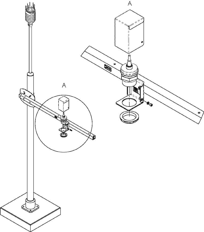
Figure 44 Connecting Ultrasonic Level Sensor to WXT536
The following figure shows how to wire the ultrasonic level sensor to WXT536.
WXT530 Series User Guide M211840EN-D
188
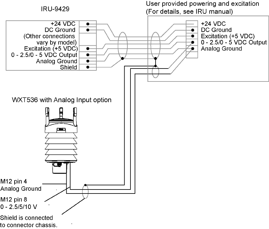
Figure 45 Wiring Ultrasonic Level Sensor to WXT536
Appendix F – Connecting External Sensors to WXT536
189

Table 54 Ultrasonic Level Connections
Level sensor connections IRU-9429
Pin Pin function Wire color Function
1 - - -
2 - - -
3 - - -
4 AGND
Common analog ground for
Pt, TIP, and WS
Green Analog ground
5 - - -
6 - - -
7 - - -
8 WSIN
Ultrasonic level sensor input+
AGND= -
0 ... 2.5 V
0 ... 5 V
0 ... 10 V
White 0 ... 2.5 VDC
F.2 Connecting Pyranometer to WXT536
The following figure shows how to connect pyranometer CMP3 to WXT536.
WXT530 Series User Guide M211840EN-D
190
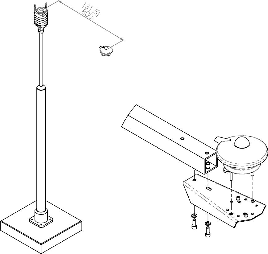
Figure 46 Connecting CMP3 to WXT536
The following figure shows how to peel CMP3 cable sheath.
Appendix F – Connecting External Sensors to WXT536
191
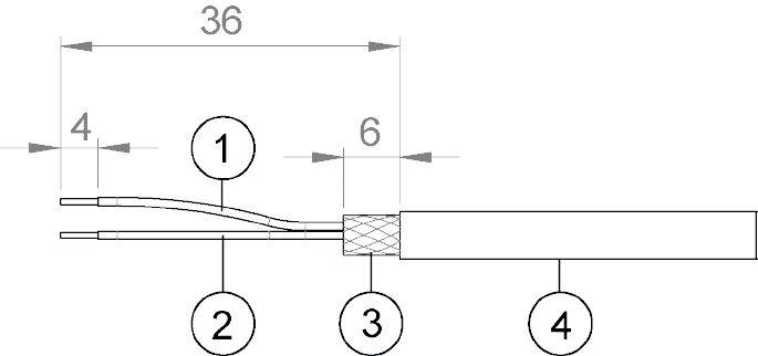
Figure 47 Peeling CMP3 Cable Sheath
1Red cable
2Blue cable
3Cable sheath
4CMP3 cable
The following figure shows how to wire the pyranometer to WXT536.
WXT530 Series User Guide M211840EN-D
192
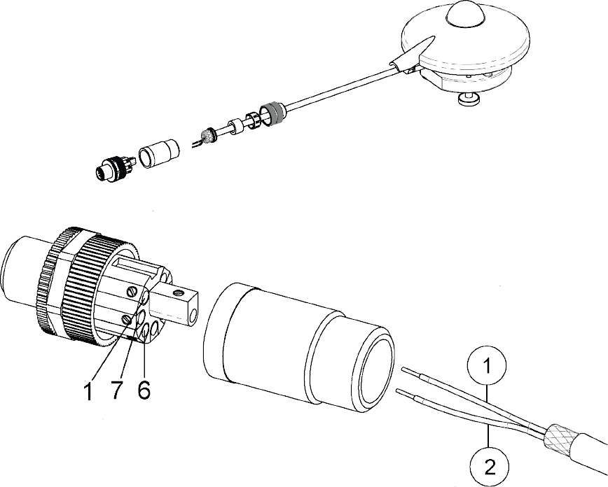
Figure 48 Wiring CMP3 to WXT53
1Red cable
2Blue cable
Appendix F – Connecting External Sensors to WXT536
193
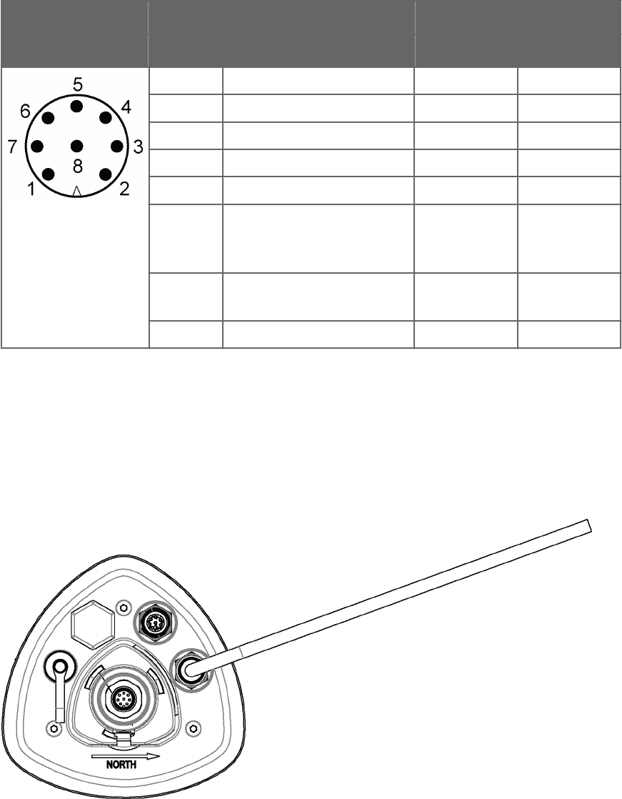
Table 55 Pyranometer Connections
Solar radiation connections CMP3
Pin Pin function Wire color Function
1 - - -
2 - - -
3 - - -
4 - - -
5 - - -
6 SR+
Solar radiation sensor input +
0 ... 25 mV
Red +
7 SR-
Solar radiation sensor input -
Blue -
8 - - -
F.3 Connecting Resistance Temperature
Sensor
Connect the temperature sensor to the M12 connector of the transmitter.
Figure 49 Pt1000 Connected to WXT536 M12 Connector
The following figure shows how to wire a temperature sensor to the transmitter.
WXT530 Series User Guide M211840EN-D
194
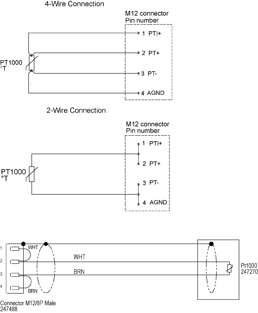
Figure 50 Wiring Temperature Sensor Pt1000 to WXT536
Figure 51 Wiring Temperature Sensor TM-Pt1000 to WXT536
Appendix F – Connecting External Sensors to WXT536
195
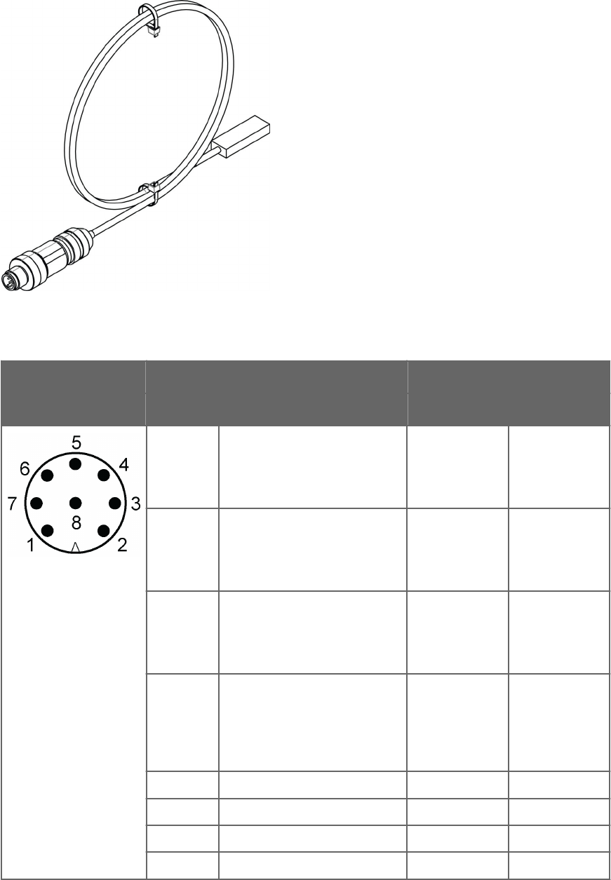
Figure 52 TM-Pt1000 Connector
Table 56 Temperature Sensor Connections
Sensor connections TM-Pt1000
Pin Pin function Wire color Function
1 PTI+
PT1000 measuring current.
PT1000 temperature sensor
current feed.
- -
2 PT+
PT1000 input+
PT1000 temperature sensor.
Sense +.
White +
3 PT-
PT1000 input-
PT1000 temperature
sensor.Sense-.
Brown -
4 AGND
Common analog ground for PT,
TIP, and WS.
Common ground for level,
tipping bucket, and Pt1000.
- -
5 - - -
6 - - -
7 - - -
8 - - -
WXT530 Series User Guide M211840EN-D
196
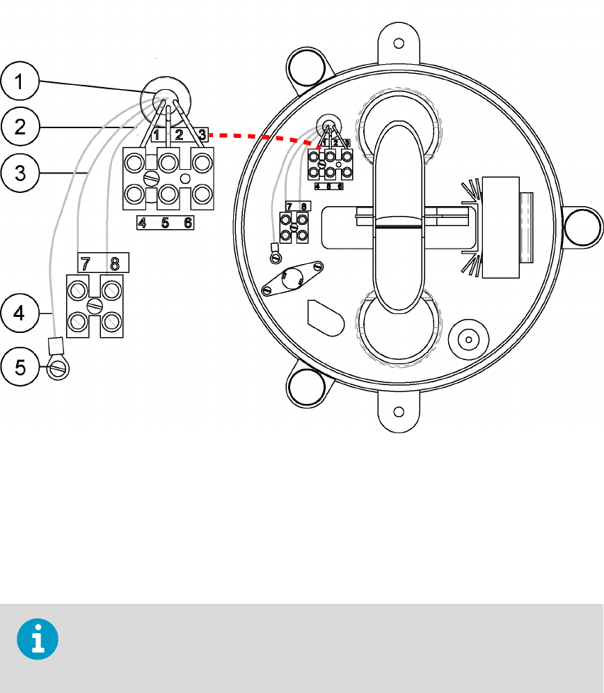
F.4 Connecting Rain Gauge to WXT536
The following figure shows how to wire rain gauge RG13 to WXT536.
Figure 53 Wiring RG13/RG13H to WXT536
1Cable tie
2Screw terminal 8
3Screw terminal 7
4Cable shield
5Grounding point
Only the heated rain gauge RG13H has terminals 4, 5, and 6 for the heating power. RG13H
requires 33 W power to enable heating. You need a power box between WXT536 and
RG13H
Appendix F – Connecting External Sensors to WXT536
197

Table 57 Rain Gauge Connections
Sensor connections RG13/RG13H
Pin Pin function Wire color Function
1 - - -
2 - - -
3 - - -
4 AGND
Common analog ground for Pt,
TIP, and WS
Terminal 7
(Blue wire)
Normally open
contact
5 TIP IN
Tipping bucket digital input
connect to AGND for pulse
Terminal 8
(Red wire)
Normally open
contact
6 - - -
7 - - -
8 - - -
After wiring the sensor and connecting it to WXT536, you can configure the analog input
through Vaisala Configuration Tool.
WXT530 Series User Guide M211840EN-D
198
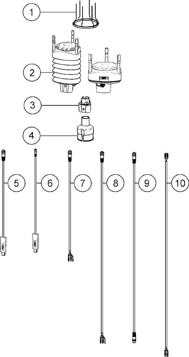
Appendix G. Complete Set of
Accessories
Figure 54 Complete Set of Accessories
Appendix G – Complete Set of Accessories
199
1Bird kit 212793
2WXT530 Series transmitter
3Mounting kit 212792
4Mounting accessory between Mounting kit and 60 mm tube WMSFIX60
5Cable USB RS-232/RS-485 1.4 m USB M12 SP 220782
6USB service cable delivered with the Vaisala Configuration Tool 220614
7Cable 2 m shielded 8-pin M12 SP 222287
8Cable 10 m shielded 8-pin M12 SP 222288
9Cable 10 m shielded 8-pin M12 SP, connectors on both ends SP 215952
10 Cable 40 m shielded 12-pin, open end wires SP 217020
The following figure shows how to connect surge protector WSP150 to WXT536.
WXT530 Series User Guide M211840EN-D
200
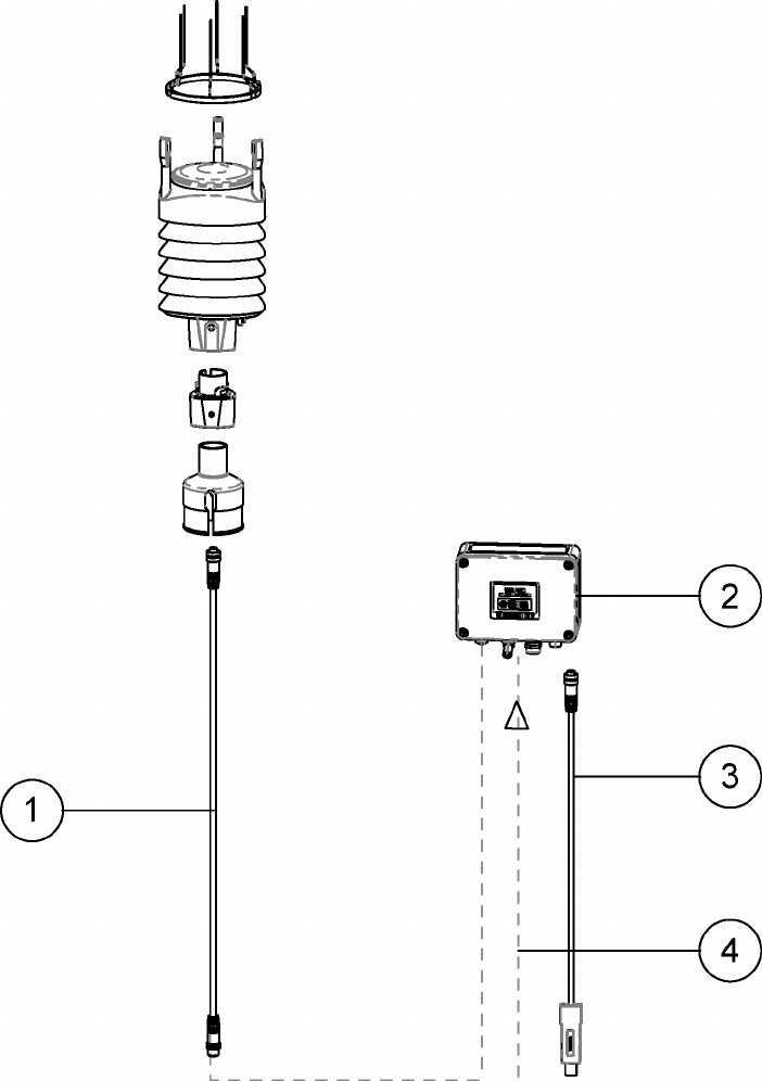
Figure 55 WXT536 with Surge Protector WSP150
1Cable with open leads 222287 or 222288
2WSP150 surge protector
3Data output cable
4Operating and heating powers
Appendix G – Complete Set of Accessories
201
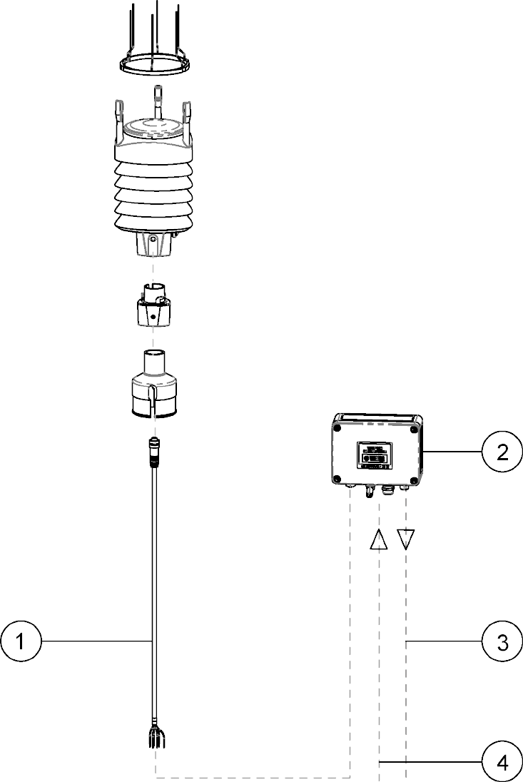
Figure 56 WXT536 with Surge Protector WSP152
1Cable with connectors on both ends 225952
2WSP152 surge protector
3USB cable 220782
4Operating and heating powers
WXT530 Series User Guide M211840EN-D
202

Appendix H. Configuration
Parameters
Table 58 General Parameters
Parameter Factory Range Info Command
Supervisor
settings
Order option
defined*
1 = Th Heating temperature Format:1111000011000000
First 8 are for combined
message and last 8 for
composite message.
1 = Data is on
0 = Data is o
Note that you write the
parameter format
1111000011000000 but the
unit answers:
11110000&11000000
* For the heated unit factory
the setting is
1111000011000000and for the
non-heated
0000000000000000
SU,R
1 = Vh Heating voltage
1 = Vs Supply voltage
1 = Vr 3.5 V reference voltage
1 = Id Information field
0 = Reserved
0 = Reserved
0 = Reserved [& = Delimiter]
1 = Th Heating temperature
1 = Vh Heating voltage
0 = Vs Supply voltage
0 = Vr 3.5 V reference voltage
0 = Id Information field
0 = Reserved
0 = Reserved
0 = Reserved
Device
address
0 0 … 9, A. … Z, a … z Address identifier XU,A
Protocol
selection
Order option
defined
A = ASCII, automatic XU,M
a = ASCII, automatic w. crc
P = ASCII, polled
p = ASCII, polled w. crc
N = NMEA, automatic
Q = NMEA, query
S = SDI-12, R
R = SDI, continuous meas
Test message 0 For test purposes XU,T
Appendix H – Configuration Parameters
203

Parameter Factory Range Info Command
Serial
interface
Order option
defined
1 = SDI-12 *Note that RS-422 hardware is
wired dierently inside the
unit.
XU,C
2 = RS-232
3 = RS-485
4 = RS-422*
Repeat
interval in
seconds
0 0 … 3600 seconds XU,I
Baud rate Order option
defined
1200, 2400, 4800, 9600,
19200, 38400, 57600, 115200
Bauds
XU,B
Data bits Order option
defined
7, 8 XU,D
Parity Order option O = Odd
E = Even
N = None
XU,P
Stop bits Order option
defined
1, 2 XU, S
RS-485 delay 25 0 … 10000 ms XU,L
Device name Order option
defined
WXT531 ... WXT536 Read-only XU,N
Software
version
3.xx 3.xx Read-only XU,V
WXT530 Series User Guide M211840EN-D
204

Table 59 Pressure, Temperature and Humidity Parameters
Parameter Factory Range Info Command
PTU data
controls
Order option
defined
1 = Pa Air pressure Format:1101000011010000
The first 8 are for combined
message and the last 8 for
composite message.
1 = Data is on
0 = Data is o
Note that you write the
parameter format:
1101000011010000 but the
unit answers
11010000&11010000.
TU,R
1 = Ta Air temperature
0 = Tp internal temperature
1 = Ua Air humidity
0 = Reserved
0 = Reserved
0 = Reserved
0 = Reserved[& = Delimiter]
1 = Pa Air pressure
1 = Ta Air temperature
0 = Tp internal temperature
1 = Ua Air humidity
0 = Reserved
0 = Reserved
0 = Reserved
0 = Reserved
PTU update
interval
60 1 ... 3600 seconds TU,I
Pressure unit H H = hPa
P = Pascal
B = bar
I = inHg
TU,P
Temperature
unit
C C = Celsius, F = Fahrenheit TU,T
Appendix H – Configuration Parameters
205

Table 60 Wind Parameters
Parameter Factory Range Info Command
Wind data
controls
Order option
defined
1 = Dn Direction minimum Format:1111110001001000
The first 8 are for combined
message and the last 8 for
composite message.
1 = Data is on
0 = Data is o
Note that you write the
parameter format
1111110001001000 but the unit
answers 11111100&01001000.
WU,R
1 = Dm Direction average
1 = Dx Direction maximum
1 = Sn Speed minimum
1 = Sm Speed average
1 = Sx Speed maximum
0 = Reserved
0 = Reserved[& = Delimiter]
0 = Dn Direction minimum
1 = Dm Direction average
0 = Dx Direction maximum
0 = Sn Speed minimum
1 = Sm Speed average
0 = Sx Speed maximum
0 = Reserved
0 = Reserved
Wind update
interval
5 1 … 3600 seconds WU,I
Wind
averaging
time
3 1 … 3600 seconds WU,A
Wind speed
calculation
mode
1 1 = Max/min calculation 3 =
Gust/lull calculation
WU,G
Wind speed
unit
M M = m/s, K = km/h, S = mph,
N = knots
WU,U
Wind
direction
oset
0 -180 ... 180 WU,D
NMEA format W T = XDR, W = MWV WU,N
Sampling rate 4 1, 2, 4 Hz WU,F
WXT530 Series User Guide M211840EN-D
206

Table 61 Precipitation Parameters
Parameter Factory Range Info Command
Precipitation
data controls
1 = Rc Rain amount Format:1111110010000000
The first 8 are for combined
message and the last 8 for
composite message.
1 = Data is on
0 = Data is o
Note that you write the
parameter format
1111110010000000 but the
unit answers
11111100&10000000.
RU,R
1 = Rd Rain duration
1 = Ri Rain intensity
1 = Hc Hail amount
1 = Hd Hail duration
1 = Hi Hail intensity
1 = Rp Rain peak
1 = Rp Hail peak[& =
Delimiter]
1 = Rc Rain amount
1 = Rd Rain duration
1 = Ri Rain intensity
1 = Hc Hail amount
1 = Hd Hail duration
1 = Hi Hail intensity
1 = Rp Rain peak
1 = Rp Hail peak
Precipitation
update
interval
60 1 … 3600 seconds RU,I
Precipitation
unit
M M = metric (mm, s, mm/h)
I = imperial (in, s, in/h)
RU,U
Appendix H – Configuration Parameters
207

Table 62 Auxiliary Sensor Parameters
Parameter Factory Range Info Command
Auxiliary
sensor
controls
Order option
defined
1 = Tr pt1000 temperature Format: 1111100011111000
The first 8 are for combined
message and the last 8 for
composite message.
1 = Data is on
0 = Data is o
Note that you write the
parameter format
1111100011111000 but the unit
answers 11111000&11111000
Note that Analog output
mode is never set when
external sensors are in use.
IU,R
1 = Ra Aux. rain amount
1 = Sl Ultrasonic level sensor
1 = Sr Solar radiation
1 = Rt pt1000 resistance
0 = Reserved
1 = Analog output mode*
0 = Reserved[& = Delimiter]
1 = Tr pt1000 temperature
1 = Ra Aux. rain amount
1 = Sl Ultrasonic level sensor
1 = Sr Solar radiation
1 = Rt pt1000 resistance
0 = Reserved
0 = Reserved
0 = Reserved
Auxiliary
sensor
update
interval
60 0.5 … 3600 seconds IU,I
Auxiliary
sensor
averaging
time
3 0.25 … 3600 seconds IU,A
Auxiliary rain
sensor gain
0.2 0.000000001 … 1000000 IA,G
Reset mode
(cumulative
rain amount
resetting)
M M = resets rain when pulse
amount exceeds 65535.
When gain is 0.2, it resets at
65536*0.2 = 13107 (mm)
L = resets when reaching limit
value
A = Cumulative rain value is
reset every time rain
information is sent out from
transmitter (user counts
cumulative rain amount).
IA,M
Rain reset
limit
1000 0.000000001 … 1000000 IA,L
WXT530 Series User Guide M211840EN-D
208

Parameter Factory Range Info Command
Auxiliary
solar sensor
gain
100000 0.000000001 … 1000000 IB,G
Auxiliary level
sensor gain
1 0.000000001 … 1000000 IS,G
Auxiliary level
sensor
operating
range
1 0 = 0 to 2.5 V range IS,M
1 = 0 to 5.0 V range
2 = 0 to 10.0 V range
Auxiliary
temperature
averaging
1 0.5 … 3600 IP,A
Table 63 Analog mA Output Parameters
Parameter Factory Range Info Command
Auxiliary
sensor
definitions
Order option
defined
1 = Tr pt1000 temperature Format:
0000001000000000
1 = mA output is in use
0 = mA output is o
Note that you write the
parameter format
0000001000000000 but
the unit answers
00000010&00000000
Note that the analog output
mode is used only inWXT532
with the mA output option.
IU,R
1 = Ra Aux. rain amount
1 = Sl Ultrasonic level sensor
1 = Sr Solar radiation
1 = Rt pt1000 resistance
0 = Reserved
1 = Analog output mode
0 = Reserved[& = Delimiter]
1 = Tr pt1000 temperature
1 = Ra Aux. rain amount
1 = Sl Ultrasonic level sensor
1 = Sr Solar radiation
1 = Rt pt1000 resistance
0 = Reserved
0 = Reserved
0 = Reserved
Wind speed
gain
Order option
defined
0.000000001 … 1000000 4 … 20 mA = 0.266667 (20
mA = 60 m/s)
0..20 mA = 0.333333 (20 mA
= 60 m/s)
SU,a
Appendix H – Configuration Parameters
209

Parameter Factory Range Info Command
Wind speed
oset
Order option
defined
0 … 24 4 … 20 mA = 4 SU,b
0 … 20 mA = 0
Wind speed
minimum
0 0 … 24 4 … 20 mA = 0 SU,c
0 … 20 mA = 0
Wind speed
maximum
20 0 … 24 4 … 20 mA = 20 SU,d
0 … 20 mA = 20
Wind speed
error
indication
22 0 … 24 4 … 20 mA = 22 SU,e
0 … 20 mA = 22
Wind
direction gain
Order option
defined
0.000000001 … 1000000 4 … 20 mA = 0.044444 SU,f
0 … 20 mA = 0.055556
Wind
direction
oset
Order option
defined
0 … 24 4 … 20 mA = 4 SU,g
0 … 20 mA = 0
Wind
direction
minimum
0 0 … 24 4 … 20 mA = 0 SU,h
0 … 20 mA = 0
Wind
direction
maximum
20 0 … 24 4 … 20 mA = 20 SU,j
0 … 20 mA = 20
Wind
direction
error
indication
22 0 … 24 4 … 20 mA = 22 SU,k
0 … 20 mA = 22
WXT530 Series User Guide M211840EN-D
210
Index
Symbols
# sign........................................................................... 151
A
abbreviations..............................................................81
accessories.........................................................19, 199
bird kit..................................................................... 23
mounting kit...........................................................21
order codes..........................................................163
surge protector.................................................... 22
USB cable...............................................................20
Vaisala Configuration Tool...............................24
accumulated rainfall.......................................28, 135
AC range..................................................................... 53
address query............................................................ 91
air humidity.............................................................. 123
air pressure............................................................... 123
air temperature...............................................123, 157
air terminal................................................................. 33
aligning................................................................ 46, 48
alignment direction indicator.............................. 17
ambient temperature.............................................30
analog input................................................................13
connector pin...................................................... 136
enabling/disabling.............................................139
interface................................................................... 31
options...................................................................159
signal name..........................................................136
analog output..........................................................143
enabling/disabling............................................ 145
interface................................................................... 31
operation.............................................................. 143
scaling....................................................................144
wind direction channel....................................145
wind speed channel..........................................145
AOUT1 / AOUT2............................................ 143, 144
ASCII..................................................................... 81, 172
protocol.................................................................. 89
auto-send mode.....................................................130
Aux rain.......................................................................141
available options........................................................11
averaging time......................................136, 140, 142
B
backward compatibility........................................ 25
BAROCAP.................................................................. 29
barometric pressure..............................................157
bird kit.................................................................23, 199
bits
precipitation parameters................................ 128
PTU parameters..................................................123
wind parameters................................................. 118
Bushing and Grounding Kit...........................17, 45
C
cable gland.......................................................... 17, 53
cables......................................................................... 199
connectors.............................................................69
order codes........................................................... 69
USB RS-232/RS-485..........................................20
USB service cable....................................... 20, 70
Vaisala USB cable.................................................51
cable sheath............................................................ 190
changing
averaging time....................................................120
communication settings................................... 75
data message......................................................120
device address..................................................... 92
direction oset...................................................120
NMEA wind formatter..................................... 120
settings................................................ 125, 130, 134
speed unit.............................................................120
update interval................................................... 120
wind speed...........................................................120
cleaning......................................................................147
CMP3.......................................................................... 190
see also pyranometer
CMP3 connection.................................................. 190
combined data message, see composite
message
commands
?.................................................................................. 91
(?)................................................................... 82, 102
a..................................................................83, 91, 103
aAb............................................................................ 92
aC....................................................................... 96, 98
aCC............................................................................ 97
aD....................................................................... 97, 98
aI...............................................................................93
aIU..................................................................139–142
aM.......................................................................94, 98
aMC............................................................................ 95
aR..................................................................... 86, 100
aR0.................................................... 87, 90, 115, 135
aR1.....................................................................83, 89
aR2.....................................................................84, 89
aR3.....................................................................85, 89
aR4............................................................................141
aR5.....................................................................85, 89
aRC...........................................................................102
aRU..................................................................127, 130
aSU.................................................132, 134, 153–155
aTU......................................................... 122, 125, 142
Index
211
aWU................................................................... 117, 145
aXU..................................................................... 72, 75
aXZ.............................................................................77
aXZM......................................................................... 80
MWV.......................................................................... 104
XDR.......................................................................... 105
XZRI..........................................................................79
XZRU..........................................................................78
communication protocols...........................117, 159
RS-232.....................................................................69
RS-422.....................................................................69
RS-485............................................................69, 172
SDI-12............................................................... 69, 171
communication settings................................ 72, 75
compass, see aligning
compass safe distance.......................................... 33
compatibility............................................................. 25
compliance.................................................................25
components................................................................17
composite data message.................... 90, 115, 135
concurrent measurement.....................................96
concurrent measurement with CRC.................97
configuration parameters..................................203
configuration tool, see Vaisala Configuration
Tool
connecting
external sensors................................................. 187
level sensor...........................................................187
M12 connector....................................................... 71
pyranometer........................................................190
rain gauge.............................................................197
resistance temperature sensor.....................194
screw terminal....................................................... 71
service cable.........................................................70
several transmitters............................................171
connection cables...................................................69
connectors.................................................................. 17
4-pin M8................................................................. 20
8-pin M12....................................53, 58, 61, 71, 194
analog input.........................................................136
TM-Pt1000........................................................... 194
continuous measurement......................... 100, 102
corrosion protection...............................................33
counter reset........................................................... 130
CRC...................................................................... 87, 102
ASCII....................................................................... 179
CRC-16 computation.............................................179
current consumption............................................ 159
D
Data- / Data+...........................................................172
data communication interfaces......................... 67
data message.......................................................... 134
getting.................................................................... 141
precipitation..........................................................85
retrieving................................................................ 77
settings.................................................................. 125
wind..........................................................................83
DC voltage range.....................................................53
deviation angle.........................................................48
device address.................................................82, 102
digital outputs.........................................................159
dimensions............................................................... 165
document version.................................................... 10
driver, see Vaisala USB Instrument Driver
E
earthing, see grounding
economic power management..........................56
electromagnetic compatibility................... 25, 161
error............................................................ 151, 153, 155
error messaging..................................................... 134
ESD protection..........................................................10
external sensors............................................... 31, 187
pyranometer........................................................190
rain gauge.............................................................197
resistance temperature sensor.....................194
ultrasonic level sensor......................................187
external temperature.............................................. 31
F
factory configuration............................................183
failure........................................................................... 151
fixing screw.................................................................17
G
gain............................................................. 136, 141, 142
grounding...................................................................45
grounding point........................................................ 17
H
hail................................................................................128
hail accumulation...................................................130
hail intensity.............................................................. 28
handling...................................................................... 36
heated sensors.........................................................30
heater resistance.....................................................30
heating........................................................ 24, 30, 154
heating control...............................................133, 134
heating instant current..........................................53
heating temperature.............................30, 133, 135
heating voltage....................................... 53, 133, 135
HUMICAP180............................................................. 29
humidity......................................................................84
humidity sensor................................................ 17, 122
I
ingress protection...................................................161
WXT530 Series User Guide M211840EN-D
212
inputs..........................................................................159
installation site..........................................................33
installing
maritime..................................................................33
pyranometer..........................................................38
USB cable driver...................................................51
Vaisala Configuration Tool.............................. 49
WXT530..................................................................33
internal temperature............................................. 123
IP classification.................................................. 21, 161
IRU-9429................................................................... 187
J
jumper position........................................................ 67
L
level measurement...................................................31
level sensor...............................................................187
see also IRU-9429
level sensor settings............................................. 142
license key..................................................................49
lightning protection.........................................22, 33
lightning rod, see air terminal
location........................................................................33
M
mA...................................................................... 143, 144
magnetic compass..................................................33
magnetic North........................................................46
manual..........................................................................10
mA output................................................................ 159
maritime installation...............................................33
mast length................................................................33
mast location.............................................................33
material...................................................................... 162
maximum wind direction.................................... 135
maximum wind speed..........................................135
measurement accuracy.........................................24
measurement combination....................................11
measurement failure.............................................. 151
measurement interval..........................................140
measuring
humidity..................................................................29
precipitation..........................................................28
pressure.................................................................. 29
PTU........................................................................... 29
temperature...........................................................29
memory stick............................................................ 49
missing message..................................................... 151
missing parameters................................................ 151
missing reading.......................................................155
models
WXT531...............................................................11, 16
WXT532.............................................................. 11, 15
WXT533..............................................................11, 15
WXT534.................................................................... 11
WXT535.................................................................... 11
WXT536..............................................................11, 13
mounting
pole mast.................................................................21
sensor support arm.....................................38, 43
vertical pole mast........................................ 38, 39
with mounting kit................................................39
mounting kit...............................................21, 39, 199
N
negative gain........................................................... 185
NMEA 0183 v3.0.....................................................102
automatic mode..................................................114
checksum computation.................................. 180
query.............................................................. 173, 175
North.................................................................... 46, 48
North arrow............................................................... 39
O
operating voltage..........................................155, 159
optional features.......................................................19
options.................................................................19, 163
order codes.............................................................. 163
outputs.......................................................................159
overvoltage, see surge protector
P
package.......................................................................36
parameters.............................................................. 203
precipitation........................................................ 128
PTU..........................................................................123
supervisor............................................................. 133
wind......................................................................... 118
parameter selection.....................................140, 142
peak intensity............................................................28
piezoelectrical sensor............................................ 28
pin-outs
analog input.........................................................136
screw terminal.............................................. 58, 64
serial interfaces....................................................58
polling with CRC......................................................87
positive gain.............................................................185
power consumption........................................ 53, 56
powering up..............................................................161
power management............................................... 56
power supply.............................................................53
precipitation.............................................................157
precipitation counter reset.................................. 78
precipitation intensity............................................79
precipitation measurement................................. 28
precipitation sensor........................................ 17, 127
precipitation sensor modes.................................28
Index
213
precipitation unit................................................... 130
pressure...............................................................84, 161
pressure sensor.................................................17, 122
pressure unit............................................................ 125
problem.......................................................................151
product code...........................................................164
protocol, see communication protocols
Pt1000...............................................................142, 194
PTU.............................................................................. 122
configuration settings..................................... 184
data message....................................................... 84
measurement principle.....................................29
module............................................................29, 147
pulse length..............................................................183
pulses per mm..........................................................141
pyranometer................................................... 187, 190
see also CMP3
R
radiation shield.......................................... 17, 38, 147
rain............................................................................... 128
see also precipitation
rain accumulation.................................................. 130
RAINCAP.................................................................... 28
rain configuration.................................................. 185
rain counter............................................................... 141
rain current.................................................................28
rain duration.............................................................. 28
rain gauge.................................................. 31, 187, 197
rain measurement....................................................28
read-only setting....................................................183
relative humidity............................................. 157, 161
replacing PTU module..........................................147
reset limit................................................................... 141
reset mode................................................................ 141
resetting hail accumulation................................. 78
resetting rain accumulation.................................78
resetting software................................................... 77
resistance temperature sensor................ 187, 194
retrieving data messages..................................... 77
retrofit .........................................................................25
RG13 connections...................................................197
RS-485 wiring..........................................................172
rubber plug................................................................ 53
S
safety............................................................................ 10
sampling rate.............................................................27
screw cover..........................................................17, 39
SDI-12...................................................................171, 177
continuous mode................................................90
electrical interface.............................................177
native mode.......................................................... 90
parameter order.................................................143
protocol......................................................... 90, 177
timing..................................................................... 177
wiring.......................................................................171
self-diagnostics.......................................................153
sending data..............................................................97
serial communication..............................................71
serial connector........................................................53
serial interfaces........................................................ 53
serial number...........................................................164
service cable ............................................................ 70
see also cables
Service Pack 2.......................................................... 70
service port......................................................... 17, 70
setting fields.............................................................. 73
settings
changing.................................... 120, 125, 130, 134
checking................................................................ 122
data message....................................................... 117
PTU..........................................................................122
rain configuration.............................................. 185
sensor .....................................................................117
temperature.........................................................142
shipping container.................................................. 36
single transducer mode.......................................183
size, see dimensions
snow accumulation, see heating
software, see Vaisala Configuration Tool
solar radiation..........................................31, 142, 190
specifications
air temperature measurement...................... 157
analog input.........................................................159
analog mA output............................................. 159
barometric pressure measurement.............157
electrical................................................................159
electromagnetic compatibility...................... 161
environmental...................................................... 161
mechanical........................................................... 162
precipitation measurement............................157
wind measurement............................................157
standards....................................................................161
starting measurement....................................94, 95
storage.........................................................................33
strategy......................................................................183
supervisor message.............................................. 132
supervisor settings....................................... 132, 185
supply voltage................................................ 133, 155
surge protector................................................. 22, 33
T
temperature...............................................................84
below zero, see heating
operative................................................................ 161
setting....................................................................142
storage....................................................................161
WXT530 Series User Guide M211840EN-D
214
temperature sensor.........................................17, 122
temperature unit.....................................................125
terminal program.................................................... 70
termination jumper................................................. 67
termination resistor................................................ 67
text message............................................................153
text transmission..................................................... 113
THERMOCAP............................................................ 29
time slot..................................................................... 173
tip counter................................................................. 141
tipping bucket, see rain gauge
TM-Pt1000................................................................194
trademark..................................................................... 9
transducer............................................................ 17, 27
transducer measurement query...................... 105
transmitters on same bus.................................... 171
troubleshooting....................................................... 151
true North.................................................................. 46
type label.................................................................. 164
U
ultrasonic level sensor..........................................187
units............................................................................... 81
unit setting............................................................... 183
unpacking...................................................................36
update interval....................125, 130, 133, 134, 140
USB cable driver................................................20, 51
V
Vaisala Configuration Tool...........49, 70, 117, 136
Vaisala USB Instrument Driver............................ 51
voltage range............................................................ 53
volts / user unit.......................................................142
W
weight.........................................................................162
wind.............................................................................157
WINDCAP ..................................................................27
wind configuration................................................ 183
wind direction................................................... 27, 118
wind direction oset..............................................48
wind direction query............................................104
wind filter bypass...................................................185
wind measurement................................................. 27
wind measurement averaging method.......... 181
wind sensor............................................................... 117
wind speed......................................................... 27, 118
wind speed query..................................................104
wind speed range................................................... 161
wiring........................................................................... 53
level sensor...........................................................187
M12 connector...................................................... 58
mA output...............................................................61
pyranometer........................................................190
resistance temperature sensor.....................194
RS-232...................................................................... 61
RS-422......................................................................61
RS-485............................................................. 61, 172
screw terminals....................................................64
SDI-12.................................................................61, 171
WMT52, see backward compatibility
WSP150/WSP152, see surge protector
WXT520, see backward compatibility
WXT531................................................................... 11, 16
WXT532................................................... 11, 15, 31, 143
WXT533.................................................................. 11, 15
WXT534..................................................................11, 14
WXT535.................................................................. 11, 14
WXT536.................................................................. 11, 13
components............................................................17
X
XDR..................................................................... 172, 173
Z
zero adjustment......................................................183
Index
215
WXT530 Series User Guide M211840EN-D
216

Warranty
For standard warranty terms and conditions, see www.vaisala.com/warranty.
Please observe that any such warranty may not be valid in case of damage due to normal
wear and tear, exceptional operating conditions, negligent handling or installation, or
unauthorized modifications. Please see the applicable supply contract or Conditions of Sale
for details of the warranty for each product.
Recycling
Recycle all applicable material.
Follow the statutory regulations for disposing of the product and packaging.
Technical Support
Contact Vaisala technical support at helpdesk@vaisala.com. Provide at least the following
supporting information:
• Product name, model, and serial number
• Name and location of the installation site
• Name and contact information of a technical person who can provide further
information on the problem
For more information, see www.vaisala.com/support.
217
WXT530 Series User Guide M211840EN-D
218