Merge Job Opening Letter WA 13A05xy Series UL Report (03) 131030
2016-04-06
: Pdf Wa-13A05Xy Series Ul Report (03) 131030 WA-13A05xy_Series__UL_Report_(03)_131030 CertsReports 178495 ProductFiles
Open the PDF directly: View PDF ![]() .
.
Page Count: 69
330
台灣 桃園縣
桃園市龍壽街83巷5號
亞源科技股份有限公司
MR. RENSHAN HU, SAFETY ENGINEER

MR. JIE LI
ASIAN POWER DEVICES INC
5 LANE 83 LUNG-SOU ST
TAOYUAN CITY Date: 2013/10/31
330 TAIWAN Subscriber: 189681001
PartySite: 23910
File No: E168210
Project No: 13NB04948
PD No: 13O50706
Type: R
PO Number:
Subject: Procedure And/Or Report Material
The following material resulting from the investigation under the above numbers is enclosed.
Issue
Date Vol Sec Pages Revised Date
2009/11/12 X1 A94 Revised Proc/Rpt Section
“If there are illegible images in this package, legible images may be found online via MyHome@UL
under My UL Reports/CDA.”
"This PR is for the Project 4786090063."
Please file revised pages and illustrations in place of material of like identity. New material
should be filed in its proper numerical order.
NOTE: Follow-Up Service Procedure revisions DO NOT include Cover Pages, Test Records and Conclusion
Pages. Report revisions DO NOT include Authorization Pages, Indices, Section General Pages and
Appendixes.
Please review this material and report any inaccuracies to UL's Customer Service Professionals.
Contact information for all of UL's global offices can be found at
http://www.ul.com/global/eng/pages/corporate/contactus.
If you’d like to receive updated materials FASTER, UL offers electronic access and/or delivery of
this material. For more details, contact UL's Customer Service Professionals as shown above.
This material is provided on behalf of UL LLC(UL) or any authorized licensee of UL.
CAM File

Issue Date:
2009-11-12
Page 1 of 16
Report Reference #
E168210-A94-UL
2013-10-30
Copyright © 2013
UL TEST REPORT AND PROCEDURE
Standard:
UL 60950-1, 2nd Edition, 2007-03-27 (Information Technology
Equipment - Safety - Part 1: General Requirements)
CSA C22.2 No. 60950-1-07, 2nd Edition, 2007-03 (Information
Technology Equipment - Safety - Part 1: General Requirements)
Certification Type:
Listing
CCN:
QQGQ, QQGQ7 (Power Supplies for Information Technology
Equipment Including Electrical Business Equipment)
Complementary CCN:
AZSQ, AZSQ7 (Audio/Video Apparatus)
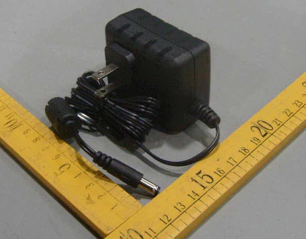
Product:
AC Adapter
Model:
(1) WA-08B05FU, WA-08B05R
(2) WA-10I05FU, WA-10I05R
(3) WA-13A05FU, WA-13A05R
(4) WA-10A06FU, WA-10A06R
Rating:
(1) WA-08B05FU, WA-08B05R:
I/P: 100-240 Vac, 50-60 Hz, 0.3 A Max.
O/P: 5 Vdc, 1.5 A.
(2) WA-10I05FU, WA-10I05R:
I/P: 100-240 Vac, 50-60 Hz, 0.3 A Max.
O/P: 5 Vdc, 2 A.
(3) WA-13A05FU, WA-13A05R:
I/P: 100-240 Vac, 50-60 Hz, 0.3 A Max.
O/P: 5 Vdc, 2.5 A.
(4) WA-10A06FU, WA-10A06R:
I/P: 100-240 Vac, 50-60 Hz, 0.3 A Max.
O/P: 5.5 Vdc, 1.81 A.
Applicant Name and Address:
ASIAN POWER DEVICES INC
5 LANE 83 LUNG-SOU ST
TAOYUAN CITY
330 TAIWAN
This is to certify that representative samples of the products covered by this Test Report have been investigated in accordance with the
above referenced Standards. The products have been found to comply with the requirements covering the category and the products are
judged to be eligible for Follow-Up Service under the indicated Test Procedure. The manufacturer is authorized to use the UL Mark on
such products which comply with this Test Report and any other applicable requirements of UL LLC ('UL') in accordance with the Follow-
Up Service Agreement. Only those products which properly bear the UL Mark are considered as being covered by UL's Follow-Up
Service under the indicated Test Procedure.
The applicant is authorized to reproduce the referenced Test Report provided it is reproduced in its entirety.
Any information and documentation involving UL Mark services are provided on behalf of UL LLC (UL) or any authorized licensee of UL.
Prepared by:
Jack Huang
Reviewed by:
Derek Xu

Issue Date:
2009-11-12
Page 2 of 16
Report Reference #
E168210-A94-UL
2013-10-30
Supporting Documentation
The following documents located at the beginning of this Procedure supplement the requirements of this Test
Report:
A.
Authorization - The Authorization page may include additional Factory Identification Code markings.
B.
Generic Inspection Instructions -
i.
Part AC details important information which may be applicable to products covered by this Procedure.
Products described in this Test Report must comply with any applicable items listed unless otherwise
stated in the body of this Test Report.
ii.
Part AE details any requirements which may be applicable to all products covered by this Procedure.
Products described in this Test Report must comply with any applicable items listed unless otherwise
stated in the body of each Test Report.
iii.
Part AF details the requirements for the UL Certification Mark which is not controlled by the technical
standard used to investigate these products. Products are permitted to bear only the Certification
Mark(s) corresponding to the countries for which it is certified, as indicated in each Test Report.
Product Description
A direct plug-in switching power supply adaptor intended for use with indoor ITE or AV products.
Consists of Class B switching transformer, Y capacitor, MOSFET, optical isolator, and other electronic
components, then housed with two-piece plastic enclosures secured together by ultrasonic welding.
Model Differences
Models WA13A05R and WA-10I05R are similar to Model WA08B05R except for output rating and rating of
some primary and secondary components.
Model WA-08B05FU is similar to Model WA-08B05R except for fixed or replaceable blade plug and model
designation.
Model WA-10I05FU is similar to Model WA-10I05R except for fixed or replaceable blade plug and model
designation.
Model WA-13A05FU is similar to Model WA-13A05R except for fixed or replaceable blade plug and model
designation.
Model WA-10A06FU is similar to Model WA-10A06R except for fixed or replaceable blade plug and model
designation.
Models WA-10A06FU, WA-10A06R are identical to models: WA-10I05FU, WA-10I05R, except for output
rating (depend on secondary voltage sampling resistors).
Technical Considerations
Equipment mobility : direct plug-in
Connection to the mains : pluggable A
Operating condition : continuous
Access location : operator accessible
Over voltage category (OVC) : OVC II
Mains supply tolerance (%) or absolute mains supply values : +10%, -10%
Tested for IT power systems : N/A
IT testing, phase-phase voltage (V) : N/A

Issue Date:
2009-11-12
Page 3 of 16
Report Reference #
E168210-A94-UL
2013-10-30
Class of equipment : Class II (double insulated)
Considered current rating (A) : The building installation circuit breaker rated 20 A
Pollution degree (PD) : PD 2
IP protection class : IP X0
Altitude of operation (m) : Maximum 3048
Altitude of test laboratory (m) : Not exceeded 2000
Mass of equipment (kg) : 0.106 kg
The product was submitted and evaluated for use at the maximum ambient temperature (Tma)
permitted by the manufacturer’s specification of: 40 degree C
The means of connection to the mains supply is: Pluggable A, Direct Plug-In Device
The product is intended for use on the following power systems: TN
The equipment disconnect device is considered to be: Plug
The product was investigated to the following additional standards: - The product was investigated to
the following additional standards: UL 60065, 7th Edition, 2007-12-11 (Audio, video and similar
electronic apparatus - Safety requirements); CAN/CSA-C22.2 No. 60065-03, 1st Edition, 2006-04 +
A1:2006 (Audio, video and similar electronic apparatus - Safety requirements). - This equipment is
intended to be operated under altitude up to 10,000 ft, so the clearance is multiplied by the altitude
correction factor (1.15, linear interpolation used), specified in table A.2 of IEC 60664-1, 1992+A1:
2000.
The following accessible locations (with circuit/schematic designation) are within a limited current
circuit: Secondary side of CY1
The following circuit locations (with circuit/schematic designation) were investigated as a limited
power source (LPS): Output terminal
The following are available from the Applicant upon request: Installation (Safety) Instructions /
Manual
The blade dimension was additional evaluated according to UL1310. to be complied with NEMA
configurations in accordance with Wiring Devices - Dimensional Specifications, ANSI/NEMA WD6.
Additional Information
- This equipment is intended to be operated under altitude up to 10,000 ft, so the clearance is multiplied by
the altitude correction factor (1.15, linear interpolation used) specified in Table A.2 of IEC 60664-1, 1992+A1:
2000.
- The product covered in this report was additionally evaluated to UL 60065 7th edition and CAN/CSA C22.2
No. 60065:03 for Complementary Listing with UL 60950-1 under this investigation. File E168210 serves as
basic file.
Revision 1: add new MODELS: WA-10A06FU and WA-10A06R, which with NEW output rating, the new
models are identical to models: WA-10I05FU, WA-10I05R, except for output rating (depend on secondary
voltage sampling resistors).
Markings and instructions
Clause Title
Marking or Instruction Details
Power rating - Ratings
Ratings (voltage, frequency/dc, current)

Issue Date:
2009-11-12
Page 4 of 16
Report Reference #
E168210-A94-UL
2013-10-30
Power rating -
Company identification
Listee's or Recognized company's name, Trade Name, Trademark or File
Number
Power rating -
Model
Model Number
Power rating -
Class II symbol
Symbol for Class II construction
(60417-2-IEC-5172)
Disconnect device -
Pluggable equipment
Statement indicating that the socket-outlet shall be installed near the
equipment and shall be easily accessible. (Instruction)
Fuses - Rating
Rated current and voltage and type located on or adjacent to fuse or
fuseholder.
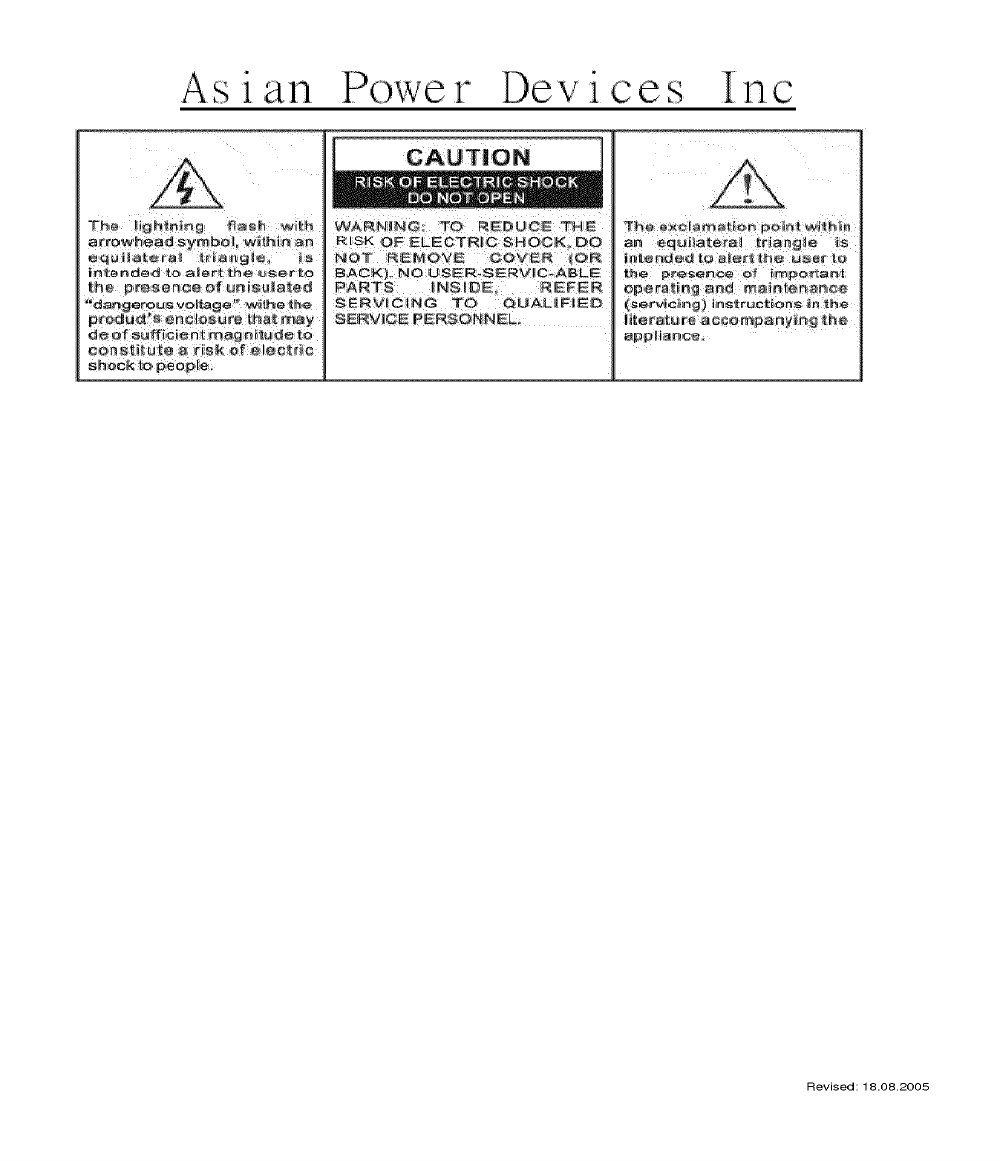
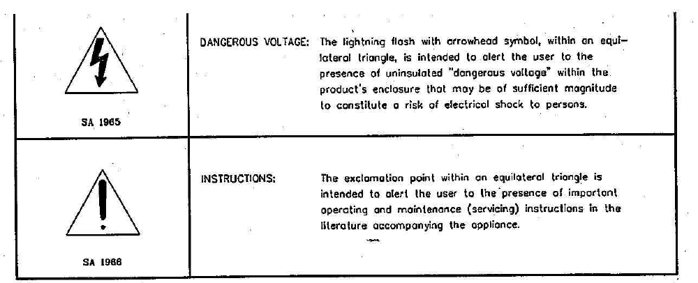
Explanation of Safety-
Related Symbols
Explanation shall precede any operating instructions. See
Enclosure/Miscellaneous 7-04 for details. Location: On the cover page, the
reverse side of cover page, or the very next page of the instruction manual which
may optionally provide safety instructions with each carton of shipment to O.E.M.
manufacturer.
Outdoor Use
(For UL)
"WARNING: To Reduce The Risk Of Fire Or Electric Shock, Do Not Expose
This Apparatus To Rain Or Moisture"
Wet Location
Marking (For C-UL)
"Apparatus shall not be exposed to dripping or splashing and no objects
filled with liquids, such as vases, shall be placed on the apparatus."
Disconnect
Device - Mains Plug or
Appliance Coupler
Statement indicating that when the mains plug or appliance coupler shall
remain readily operable. (Instruction)
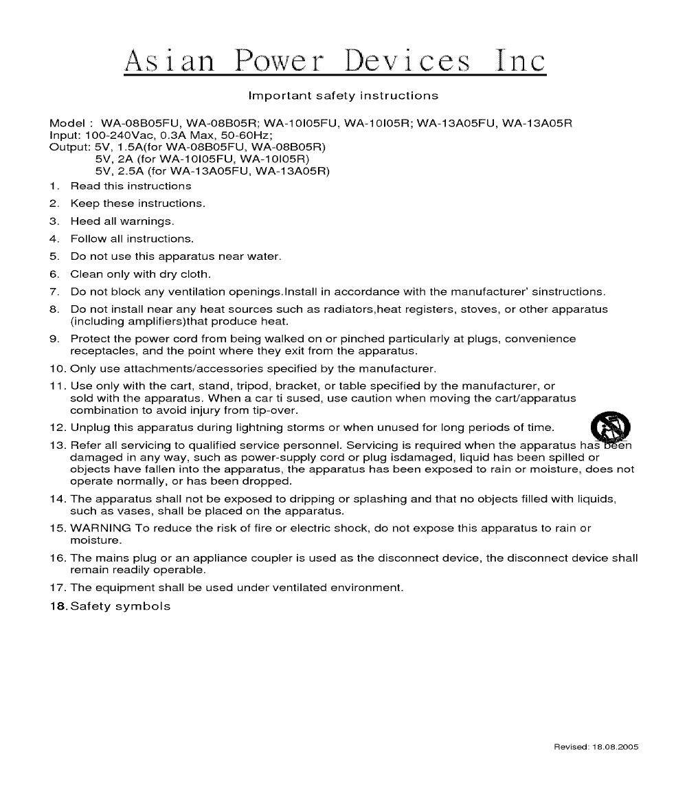
Important Safety
Instructions
Refer to Enclosure - Miscellaneous 7-03 for details
Service
"CAUTION - These servicing instructions are for use by qualified service

Issue Date:
2009-11-12
Page 5 of 16
Report Reference #
E168210-A94-UL
2013-10-30
Instruction Manual
personnel only. To reduce the risk of electric shock, do not perform any servicing
other than that contained in the operating instructions unless you are qualified to do
so."
Factory ID
Refer to Authorization Page
Date of
Manufacture
Location: Provided with each product. One of the three types: (1)
YYYY.MM.DD. YYYY indicates year, MM=01 -- 12 indicates month, DD=01 - 31
indicates date. (2) Serial No. ym9xxxxxx. Characters y indicates year, and m
indicates month. y = 9 indicates year 2009. m = 1-9, A, B, C to indicate January to
December. (3) Serial No. Y XXX X yy m dd XXXXXXX XX. Characters yy
indicates year, m indicates month, dd indicates date. yy = 09 indicates year 2009.
m = 1-9, O (Oct.), N (Nov.), D (Dec.). dd = 01 - 31. See Enclosure/Miscellaneous
7-02 for details.
Shock Hazard
Graphical Symbol
See Enclosure/Miscellaneous 7-05 for details.
Fuseible
Resistor
Rated resistance and power and type located on or adjacent to fuse resistor
or fuseholder.
Special Instructions to UL Representative
Inspect the transformer(s) listed in Production-Line Testing Requirements (Electric Strength Test Special
Constructions) per AA1.1- (C). When the tests are conducted at other location, Inspect test record and
specification sheet provided by the component manufacturer. Verify the specification sheet indicates 100%
routine test specified in Production-Line Testing Requirements (Electric Strength Test Special Constructions)
be conducted at the component manufacturer.

Issue Date:
2009-11-12
Page 6 of 16
Report Reference #
E168210-A94-UL
2013-10-30
Production-Line Testing Requirements
Electric Strength Test Special Constructions - Refer to Generic Inspection Instructions, Part AC for
further information.
Model
Component
Removable
Parts
Test probe location
V
rms
V dc
Test Time,
s
All
T1
N/A
Primary and Secondary
300
0
Vrm
s
4242 Vdc
1 s
Earthing Continuity Test Exemptions - This test is not required for the following models:
All
Electric Strength Test Exemptions - This test is not required for the following models:
N/A
Electric Strength Test Component Exemptions - The following solid-state components may be
disconnected from the remainder of the circuitry during the performance of this test:
N/A
Sample and Test Specifics for Follow-Up Tests at UL
Model
Component
Material
Test
Sample(s)
Test
Specifics
--
--
--
--
--
--

Issue Date:
2009-11-12
Page 7 of 16
Report Reference #
E168210-A94-UL
2013-10-30
TABLE: List of Critical Components
Object/part or
Description
Manufacturer/
trademark
type/model
technical data
CCN
Marks of
Conformity
01. Label
--
--
Maximum surface temperature specified, or 63
degree C if not specified.
PGDQ2, PGJI2
UL
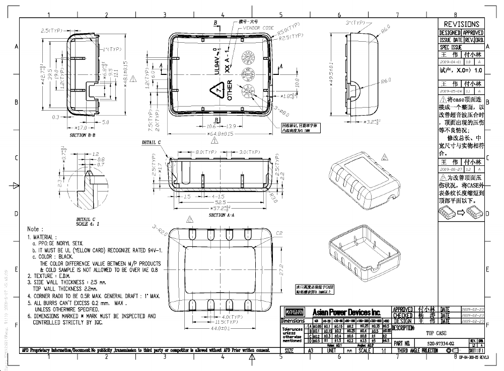
02. Plastic Enclosure (for
models WA-08B05FU,
WA-10I05FU, WA-
13A05FU)
Sabic Innovative
Plastics
945
Two piece construction, secured together with
ultrasonic welding, overall 64.8 by 49.5 by 31.6
mm, V-0 minimum, 1.5 mm thick minimum, 120
degree C. See Supplement 4-01 for details.
QMFZ2
UL
02a. Plastic Enclosure
(for models WA-
08B05FU, WA-10I05FU,
WA-13A05FU)
(Alternate)
Sabic Innovative
Plastics
SE1, SE1X
Two piece construction, secured together with
ultrasonic welding, overall 64.8 by 49.5 by 31.6
mm, V-1 minimum, 1.5 mm thick minimum, 105
degree C. See Supplement 4-01 for details.
QMFZ2
UL
02b. Plastic Enclosure
(for models WA-
08B05FU, WA-10I05FU,
WA-13A05FU)
(Alternate)
LG Chemical
(Guangzhou)
Engineering Plastics
Co., Ltd.
LUPOY EF-
1006F(m)
Two piece construction, secured together with
ultrasonic welding, overall 64.8 by 49.5 by 31.6
mm, V-0 minimum, 1.5 mm thick minimum, 115
degree C. See Supplement 4-01 for details.
QMFZ2
UL
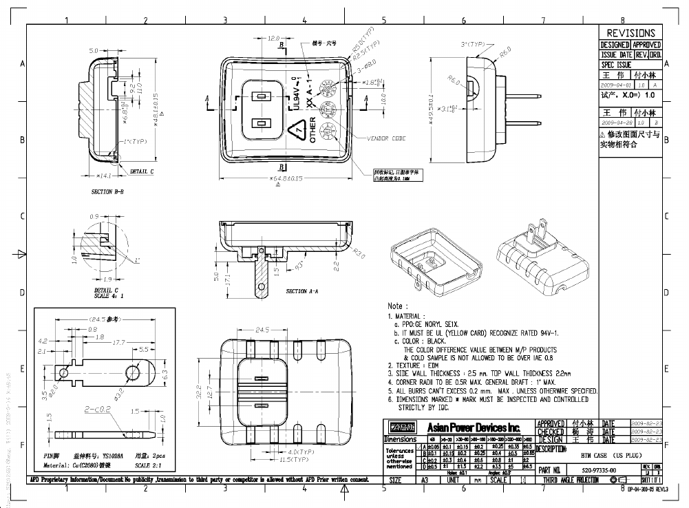
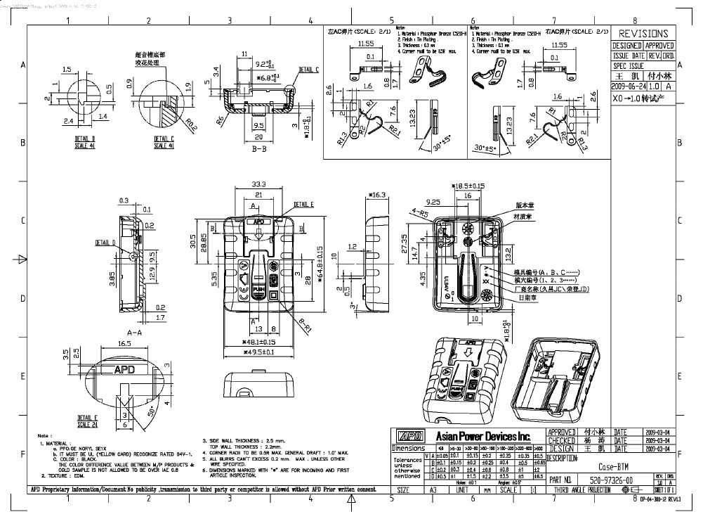
03. Plastic Enclosure (for
models WA-08B05R,
WA-10I05R, WA-
13A05R) (Alternate)
Sabic Innovative
Plastics
945
Two piece construction, secured together with
ultrasonic welding, overall 64.8 by 49.5 by 33.8
mm, V-0 minimum, 1.5 mm thick minimum, 120
degree C. See Supplement 4-02 for details.
QMFZ2
UL
03a. Plastic Enclosure
(for models WA-08B05R,
WA-10I05R, WA-
13A05R) (Alternate)
Sabic Innovative
Plastics
CH6410
Two piece construction, secured together with
ultrasonic welding, overall 64.8 by 49.5 by 33.8
mm, V-0 minimum, 1.5 mm thick minimum, 100
degree C. See Supplement 4-02 for details.
QMFZ2
UL
03b. Plastic Enclosure
(for models WA-08B05R,
WA-10I05R, WA-
13A05R) (Alternate)
Sabic Innovative
Plastics US L L C
SE1, SE1X
Two piece construction, secured together with
ultrasonic welding, overall 64.8 by 49.5 by 33.8
mm, V-1 minimum, 1.5 mm thick minimum, 105
degree C. See Supplement 4-02 for details.
QMFZ2
UL
03c. Plastic Enclosure
(for models WA-08B05R,
WA-10I05R, WA-
13A05R) (Alternate)
LG Chemical
(Guangzhou)
Engineering Plastics
Co., Ltd.
LUPOY EF-
1006F(m)
Two piece construction, secured together with
ultrasonic welding, overall 64.8 by 49.5 by 33.8
mm, V-0 minimum, 1.5 mm thick minimum, 115
degree C. See Supplement 4-02 for details.
QMFZ2
UL
04. Plug Holder (for
Sabic Innovative
945
V-0, 1.5 mm thick minimum, 120 degree C, see
QMFZ2
UL

Issue Date:
2009-11-12
Page 8 of 16
Report Reference #
E168210-A94-UL
2013-10-30
Object/part or
Description
Manufacturer/
trademark
type/model
technical data
CCN
Marks of
Conformity
models WA-08B05R,
WA-10I05R, WA-
13A05R)
Plastics Us L L C
Supplement 4-03 for details.
04a. Plug Holder (for
models WA-08B05R,
WA-10I05R, WA-
13A05R) (Alternate)
Sabic Innovative
Plastics US L L C
SE1, SE1X
V-1, 1.5 mm thick minimum, 105 degree C, see
Supplement 4-03 for details.
QMFZ2
UL
04b. Plug Holder (for
models WA-08B05R,
WA-10I05R, WA-
13A05R) (Alternate)
LG Chemical
(Guangzhou)
Engineering Plastics
Co., Ltd.
LUPOY EF-
1006F(m)
V-0, 1.5 mm thick minimum, 115 degree C, see
Supplement 4-03 for details.
QMFZ2
UL
05. PWB
--
--
V-0 or better, 130 degree C. See Enclosure 5-01
for details.
ZPMV2
UL
06. Fuse (FS1)
--
--
T1AL, 250Vac
JDYX/7
UL
06a. Fuse (FS1)
(Alternate)
Bel Fuse Inc.
RST series
T1AL, 250Vac
JDYX2/8
UL
06b. Fuse (FS1)
(Alternate)
Cooper Bussmann
Inc.
SS-5
T1AL, 250Vac
JDYX2/8
UL
06c. Fuse (FS1)
(Alternate)
Hollyland Co., Ltd.
5 ET series
T1AL, 250Vac
JDYX2/8
UL
06d. Fuse (FS1)
(Alternate)
Conquer Electronics
Co., Ltd.
MST series
T1AL, 250Vac
JDYX2/8
UL
06e. Fuse (FS1)
(Alternate)
Smart Electronics
Inc.
SPT250TE,
SPT250TS
T1AL, 250Vac
JDYX2/8
UL
06f. Fuse (FS1)
(Alternate)
Littelfuse Wickmann
Werke
392
T1AL, 250Vac
JDYX2/8
UL
06g. Fusible Resistor
(FS1)
Shenzhen Great
Electronics Co., Ltd.
RXF
1W, 0.22 ohms
FPEW2/8
UL
06h. Fusible Resistor
(FS1)
Conquer Electronics
Co Ltd
SPT
1W, 4.7 ohms
FPEW2/8
UL
06i. Fusible Resistor
(FS1)
Shenzhen Great
Electronics Co Ltd
RXF
1W, 4.7 ohms
FPEW2/8
UL
06j. Fusible Resistor
Yageo Components
FKN1WS
1W, 4.7 ohms
FPEW2/8
UL

Issue Date:
2009-11-12
Page 9 of 16
Report Reference #
E168210-A94-UL
2013-10-30
Object/part or
Description
Manufacturer/
trademark
type/model
technical data
CCN
Marks of
Conformity
(FS1)
(Suzhou) Co Ltd
06k. Fusible Resistor
(FS1)
Asia Akita Electronic
Technology
(Shenzhen) Co Ltd
KNP
1W, 4.7 ohms
FPEW2/8
UL
06l. Fusible Resistor
(FS1)
Shenzhen Xianyang
Huaxing Machinery-
Electronic Co Ltd
KNP
1W, 4.7 ohms
FPEW2/8
UL
07. Bridge Diode (DB1-
DB4)
--
--
Minimum 1A, 600V minimum.
--
--
08. Electrolytic Capacitor
(CK1, CK2)
--
--
400V minimum, 6.8-15 uF, minimum 105 degree C.
--
--
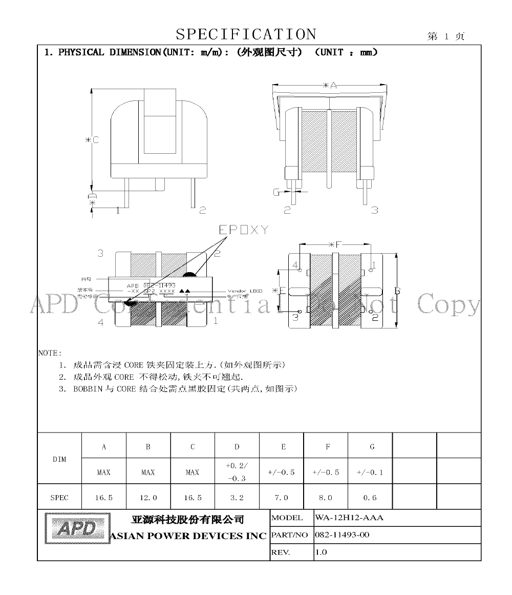
09. Inductor (LF1)
(Optional)
Asian Power Devices
Inc.
082-11493
105 degree C. See Supplement 4-04 for
construction details.
--
--
09-1. Core
--
--
Ferrite, overall 14.5 by 10.0 mm, 2.7 mm thick
--
--
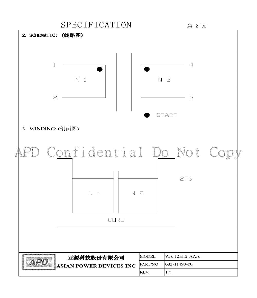
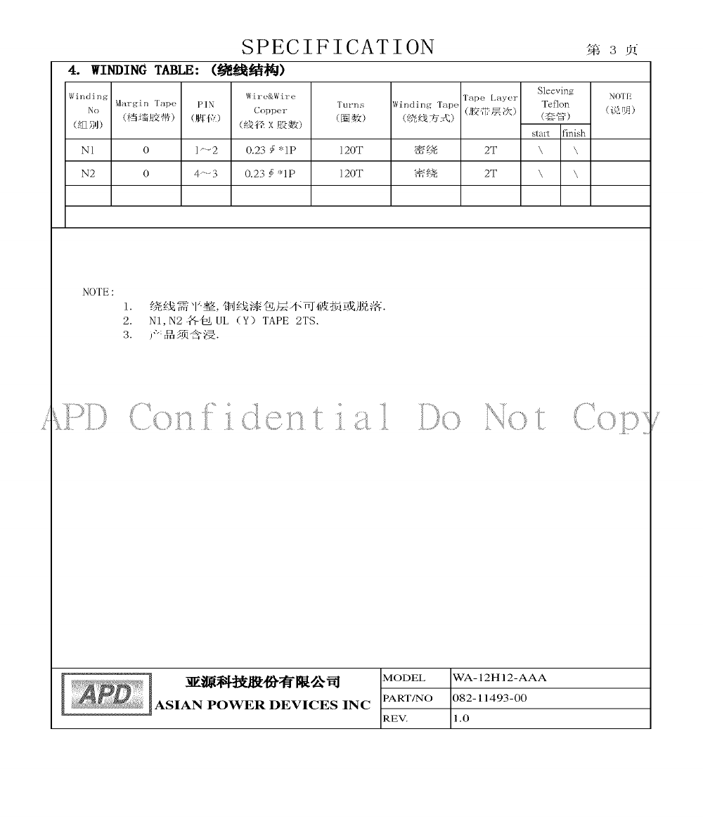
09-2. Coil
--
--
Copper magnet wire wound concentrically on core.
Two windings, each 0.23 mm diameter by 120
turns, 130 degree C
OBMW2
UL
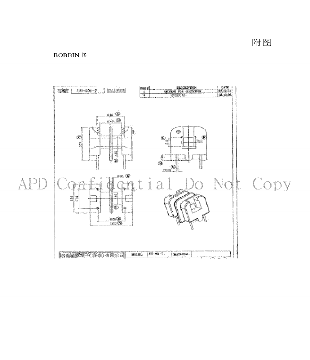
09-3. Bobbin
Chang Chun Plastics
Co., Ltd.
T375J
Two-flange, phenolic, rated V-0, minimum 150
degree C, minimum 0.65 mm thick. Leads exit
directly through integral flanges in bobbin and are
mechanically secured and soldered to pins which
are molded into bobbin.
QMFZ2
UL
09-3a. Bobbin
(Alternate)
Sumitomo Bakelite
Co., Ltd.
PM-9630, PM-
9850, PM-9820,
PM-9830
Two-flange, phenolic, rated V-0, minimum 150
degree C, minimum 0.65 mm thick. Leads exit
directly through integral flanges in bobbin and are
mechanically secured and soldered to pins which
are molded into bobbin.
QMFZ2
UL
09-4. Insulation Tape
--
--
Minimum 130 degree C.
OANZ2
UL
10. Transistor (Q1)
--
--
2 - 6A, minimum 600V.
--
--
11. Current Sensor
Resistor (Rs1)
--
--
Minimum 1.2 ohms, minimum 1/4W.
--
--
12. Optical Isolator
(PC1)
Lite-On Technology
Corp.
LTV-817
Insulation voltage minimum 5000 Vac.
FPQU2
UL

Issue Date:
2009-11-12
Page 10 of 16
Report Reference #
E168210-A94-UL
2013-10-30
Object/part or
Description
Manufacturer/
trademark
type/model
technical data
CCN
Marks of
Conformity
12a. Optical Isolator
(PC1) (Alternate)
Cosmo Electronics
Corp.
K1010, KP1010
Insulation voltage minimum 5000 Vac.
FPQU2
UL
12b. Optical Isolator
(PC1) (Alternate)
Everlight Electronics
Co., Ltd.
EL817
Insulation voltage minimum 5000 Vac.
FPQU2
UL
12c. Optical Isolator
(PC1) (Alternate)
Fairchild
Semiconductor Corp.
H11A817,
H11A817A,
H11A817B,
H11A817C,
H11A817D,
Insulation voltage minimum 5000 Vac.
FPQU2
UL
13. Bridging Capacitor
(CY1) (Optional)
TDK Corp.
CD
Maximum 3300pF, 250Vac minimum, 125 degree
C minimum. Class Y1.
FOWX2
UL
13a. Bridging Capacitor
(CY1) (Optional)
(Alternate)
Murata Mfg Co., Ltd.
KX
Maximum 3300pF, 250Vac minimum, 125 degree
C minimum. Class Y1.
FOWX2
UL
13b. Bridging Capacitor
(CY1) (Optional)
(Alternate)
Walsin Technology
Corp.
AH
Maximum 3300pF, 250Vac minimum, 125 degree
C minimum. Class Y1.
FOWX2
UL
13c. Bridging Capacitor
(CY1) (Optional)
(Alternate)
Panasonic
Coproration,
Panasonic
Corporation of North
America
NS-A
Maximum 3300pF, 250Vac minimum, 125 degree
C minimum. Class Y1.
FOWX2
UL
13d. Bridging Capacitor
(CY1) (Optional)
(Alternate)
Success Electronics
Co., Ltd.
SE
Maximum3300pF, 250Vac minimum, 125 degree C
minimum. Class Y1.
FOWX2
UL
13e. Bridging Capacitor
(CY1) (Optional)
(Alternate)
Jya-Nay Co., Ltd.
JN
Maximum 3300pF, 250Vac minimum, 125 degree
C minimum. Class Y1.
FOWX2
UL
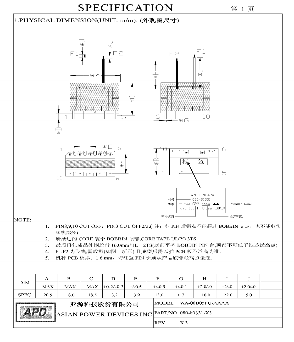
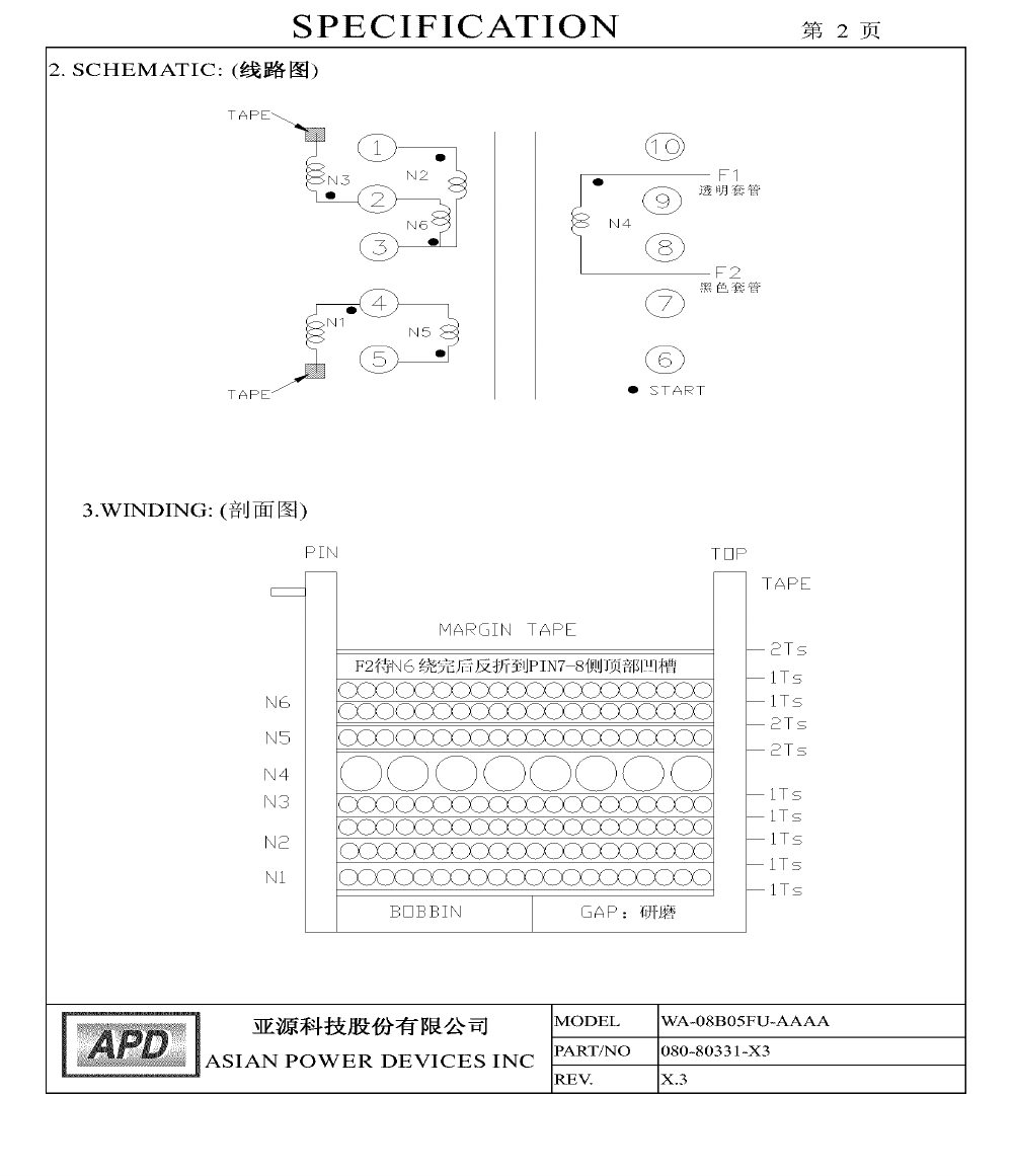
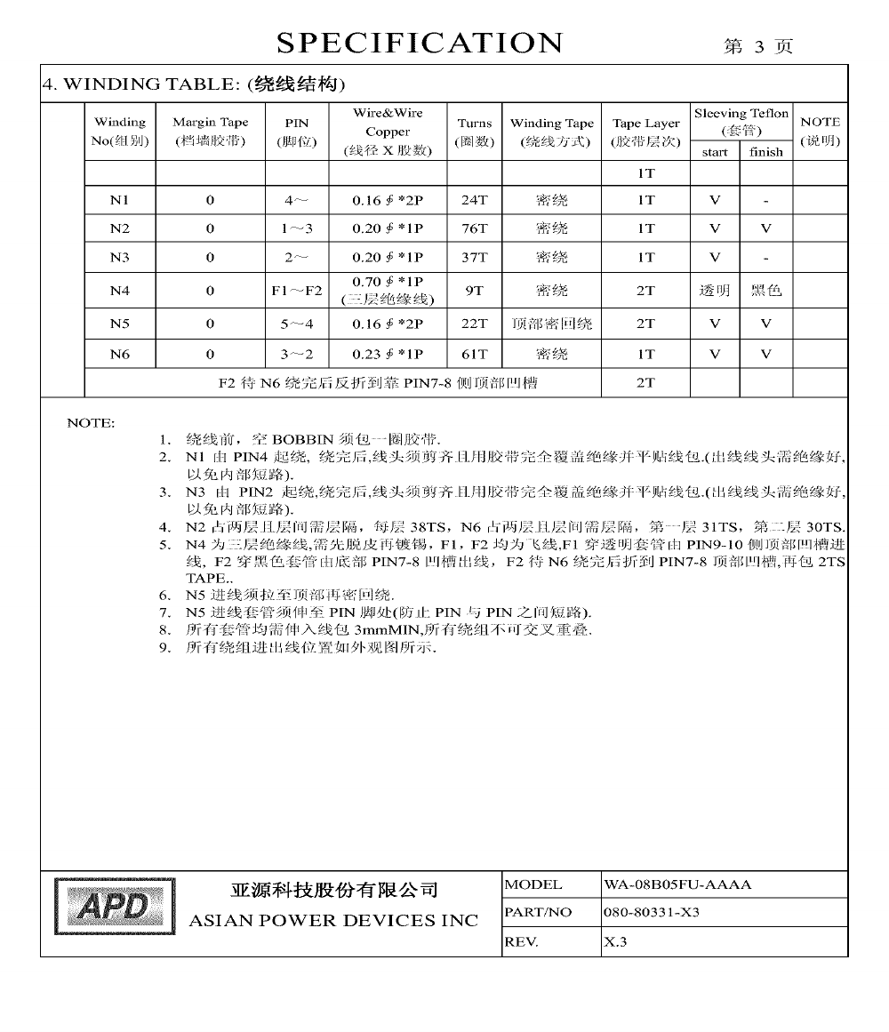
14. Transformer (T1) (for
Models WA-08B05FU
and WA-08B05R)
Asian Power Devices
Inc.
080-80331
See Supplement 4-05 for winding and construction
details. A means indicating/referring the
manufacturer and type shall be marked.
--
--
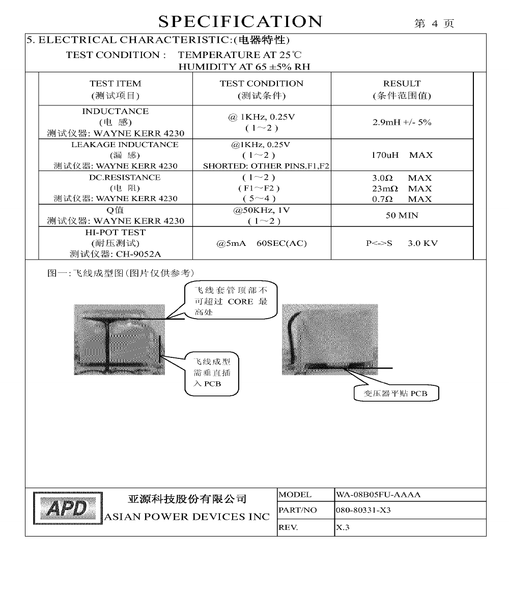
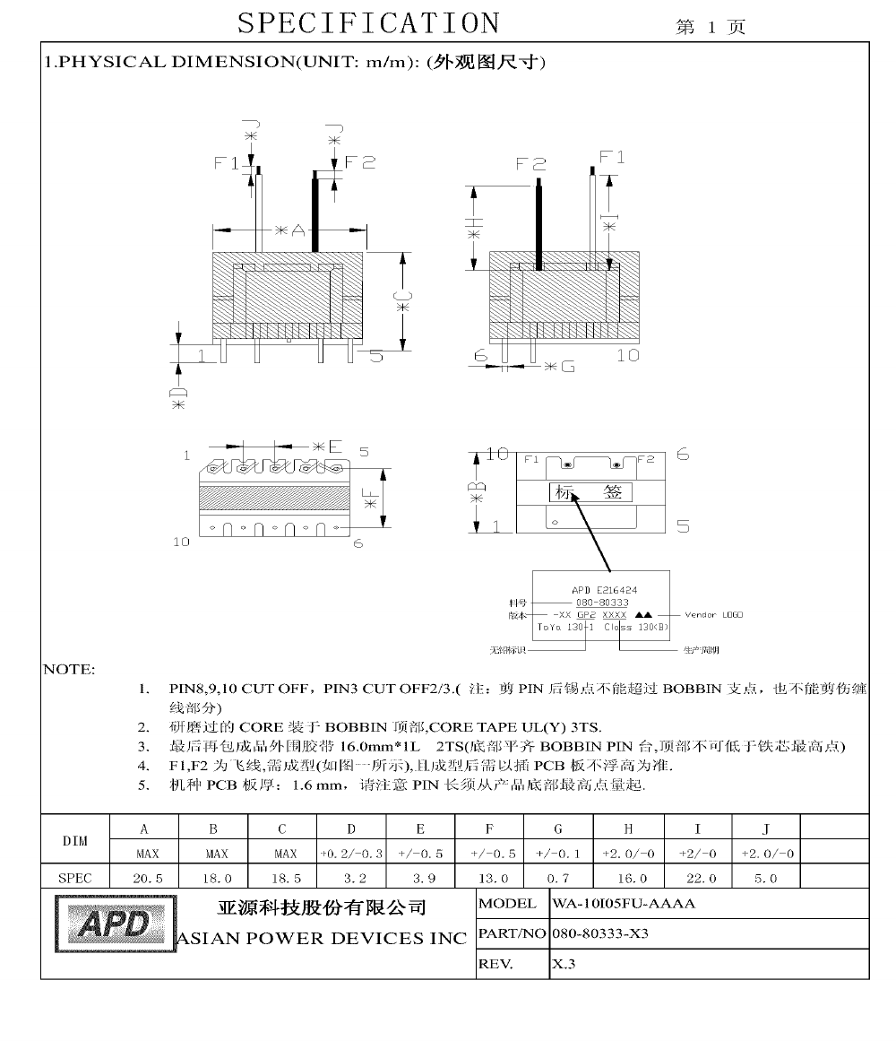
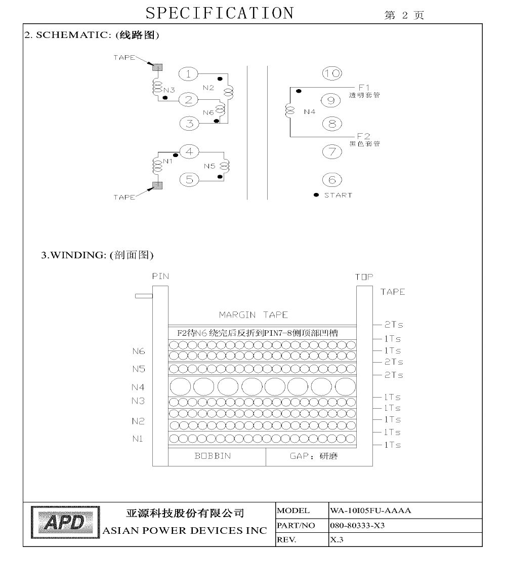
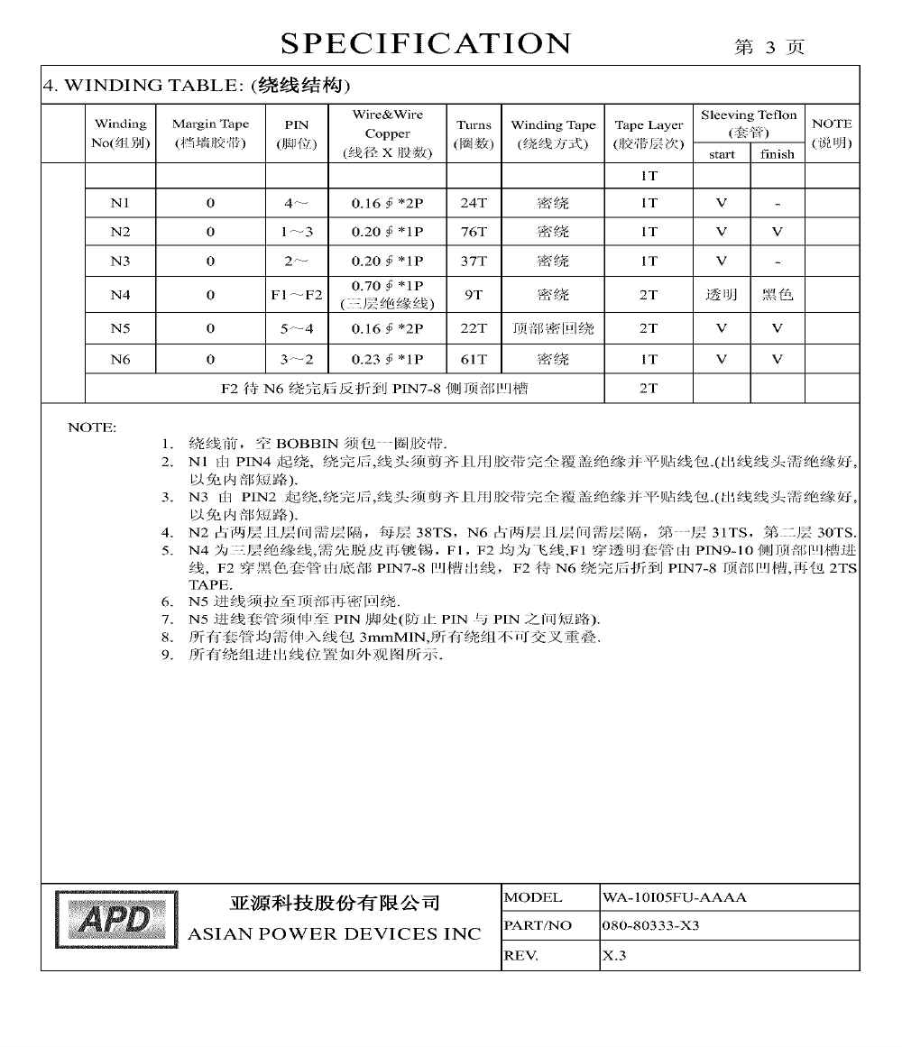
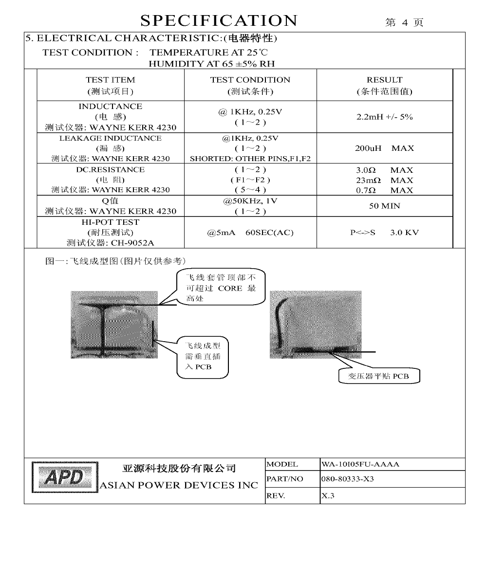
14a. Transformer (T1)
(for Models WA-10I05FU
and WA-10I05R)
Asian Power Devices
Inc.
080-80333
See Supplement 4-06 for winding and construction
details. A means indicating/referring the
manufacturer and type shall be marked.
--
--

Issue Date:
2009-11-12
Page 11 of 16
Report Reference #
E168210-A94-UL
2013-10-30
Object/part or
Description
Manufacturer/
trademark
type/model
technical data
CCN
Marks of
Conformity
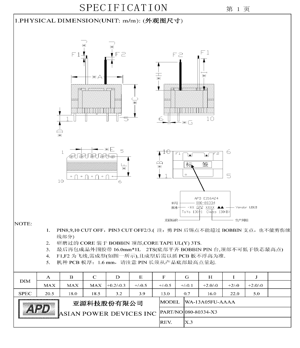
14b. Transformer (T1)
(for Models WA-
13A05FU and WA-
13A05R)
Asian Power Devices
Inc.
080-80334
See Supplement 4-07 for winding and construction
details. A means indicating/referring the
manufacturer and type shall be marked.
--
--
14-1. Insulation System
Asian Power Devices
Inc.
TaYa 130-1
Class B
OBJY2
UL
14-2. Core
--
--
Ferrite, overall 19.7 by 16.5 by 4.8 mm. Provided
with two layers of Insulation Tape wrapped around
core body.
--
--
14-3. Coil
--
MW28, MW75,
MW79, MW80,
MW82
Copper magnet wire wound concentrically on
bobbin.
OBMW2
UL
14-4. Bobbin
Chang Chun Plastics
Co., Ltd.
T375J
Two-flange, phenolic, rated V-0, minimum 150
degree C, minimum 0.65 mm thick. Leads exit
directly through integral flanges in bobbin and are
mechanically secured and soldered to pins which
are molded into bobbin.
QMFZ2
UL
14-4a. Bobbin
(Alternate)
Sumitomo Bakelite
Co., Ltd.
PM-9630, PM-
9850, PM-9820,
PM-9830
Two-flange, phenolic, rated V-0, minimum 150
degree C, minimum 0.65 mm thick. Leads exit
directly through integral flanges in bobbin and are
mechanically secured and soldered to pins which
are molded into bobbin.
QMFZ2
UL
14-5. Insulation Tape
3M Company
Electrical Markets Div
(Emd)
1350F-1, 1318-1
Minimum 130 degree C.
OANZ2
UL
14-5a. Insulation Tape
(Alternate)
Nitto Denko Corp.
31CT-1, 31CT-2.
Minimum 130 degree C.
OANZ2
UL
14-5b. Insulation Tape
(Alternate)
Symbio Inc.
35660, 35661
Minimum 130 degree C.
OANZ2
UL
14-5c. Insulation Tape
(Alternate)
Jingjiang Yahua
Pressure Sensitive
Glue Co., Ltd.
CT, PZ, WF
Minimum 130 degree C.
OANZ2
UL
14-6. Tubing
Zeus Industrial
Products Inc.
TFE-LW-150,
TFE-TW-300,
200 degree C.
YDPU2
UL

Issue Date:
2009-11-12
Page 12 of 16
Report Reference #
E168210-A94-UL
2013-10-30
Object/part or
Description
Manufacturer/
trademark
type/model
technical data
CCN
Marks of
Conformity
TFE-SW-600
14-6a. Tubing (Alternate)
Great Holding
Industrial Co., Ltd.
TFL, TFS, TFT
200 degree C.
YDPU2
UL
14-7. Varnish
Elantas Electrical
Insulation Elantas
Pdg Inc.
468-2(+), 468-
2FC(+)
Minimum 130 degree C.
OBOR2
UL
14-7a. Varnish
(Alternate)
John C Dolph Co.
BC-346A, BC-
346B
Minimum 200 degree C.
OBOR2
UL
14-8. Triple insulation
wire
Ta Ya Electric Wire &
Cable Co., Ltd.
TILW-B TILW-E
TILW-F
130 degree C.
OBJT2
UL
15. Internal Wiring
(Primary)
--
--
FEP, PTFE, PVC, TFE, neoprene, polyamide or
marked VW-1 or FT-1; minimum 300 V, 80 degree
C. Routed away from sharp edges, moving parts.
routed away from Secondary parts.
AVLV2
UL
16. Glue
--
--
V-2 minimum, provided on CK1, LF1, CK2, Ch1,
secondary wire of T1.
QMFZ2
UL
17. Output Cord and
Strain Relief (For LPS)
--
--
Non-detachable, maximum 3.05 m long, FEP,
PTFE, PVC, TFE, neoprene, polyimide or marked
VW-1or FT-1; minimum 30 V, 80 degree C.
AVLV2
UL
18. Connectors and
Receptacles (Sec.)
(ELV, SELV)
--
DC Jack
Minimum 30 V
ECBT2, RTRT2
UL
18a. Connectors and
Receptacles (Sec.)
(ELV, SELV) (Alternate)
--
DC Jack
Copper alloy pins housed in bodies of (QMFZ2),
and V-2 minimum.
QMFZ2
UL
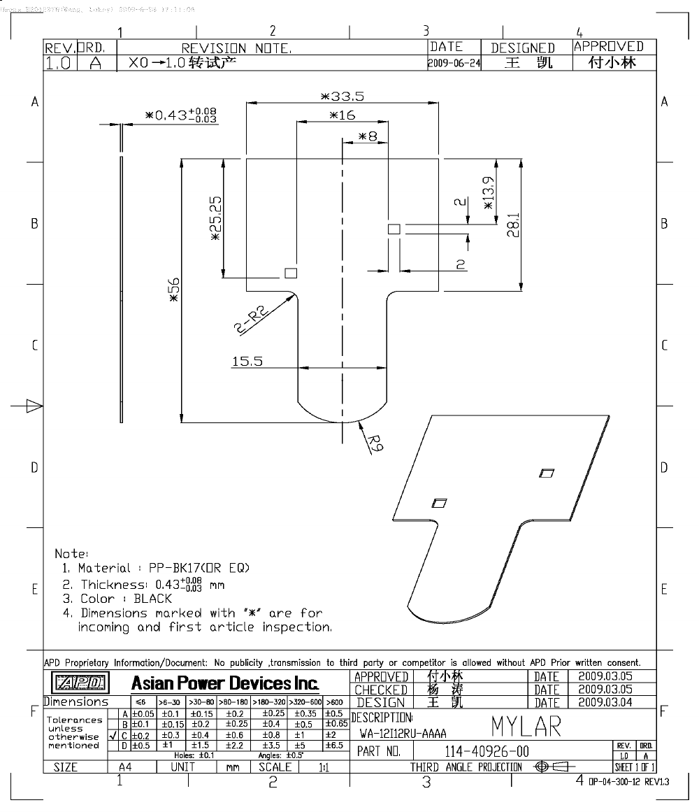
19. Mylar Sheet (for
model WA-08B05R, WA-
10I05R, WA-13A05R)
Mianyang Longhua
Film Co., Ltd.
PP-BK17, PP-
BK18
T-shaped, VTM-0, 100 degree C, overall 56.0 by
33.5 mm, minimum 0.4 mm thick. See Supplement
4-09 for details.
QMFZ2
UL
19a. Mylar Sheet (for
model WA-08B05R, WA-
10I05R, WA-13A05R)
(Alternate)
Sabic Innovative
Plastics Us L L C
FR1(E) (GG)
T-shaped, VTM-0, 125 degree C, overall 56.0 by
33.5 mm, minimum 0.4 mm thick. See Supplement
4-09 for details.
QMFZ2
UL
19b. Mylar Sheet (for
Sabic Innovative
FR700(GG),
T-shaped, V-0, 125 degree C, overall 56.0 by 33.5
QMFZ2
UL

Issue Date:
2009-11-12
Page 13 of 16
Report Reference #
E168210-A94-UL
2013-10-30
Object/part or
Description
Manufacturer/
trademark
type/model
technical data
CCN
Marks of
Conformity
model WA-08B05R, WA-
10I05R, WA-13A05R)
(Alternate)
Plastics Us L L C
FR25A
mm, minimum 0.4 mm thick. See Supplement 4-09
for details.
19c. Mylar Sheet (for
model WA-08B05R, WA-
10I05R, WA-13A05R)
(Alternate)
Formex,Div Of Il Tool
Works Inc.,Frmrly
Fastex,Div Of Il Tool
Works Inc.
FORMEX GK-
(a)(b)(f2)
T-shaped, V-0, 115 degree C, overall 56.0 by 33.5
mm, minimum 0.4 mm thick. See Supplement 4-09
for details.
QMFZ2
UL
19d. Mylar Sheet (for
model WA-08B05R, WA-
10I05R, WA-13A05R)
(Alternate)
Formex,Div Of Il Tool
Works Inc.,Frmrly
Fastex,Div Of Il Tool
Works Inc.
FORMEX-
(a)(b)(f1)
T-shaped, V-0, 105 degree C, overall 56.0 by 33.5
mm, minimum 0.41 mm thick. See Supplement 4-
09 for details.
QMFZ2
UL
19e. Mylar Sheet (for
model WA-08B05R, WA-
10I05R, WA-13A05R)
(Alternate)
Formex,Div Of Il Tool
Works Inc.,Frmrly
Fastex,Div Of Il Tool
Works Inc.
FORMEX-
(a)(b)(f2)
T-shaped, V-0, 95 degree C, overall 56.0 by 33.5
mm, minimum 0.4 mm thick. See Supplement 4-09
for details.
QMFZ2
UL
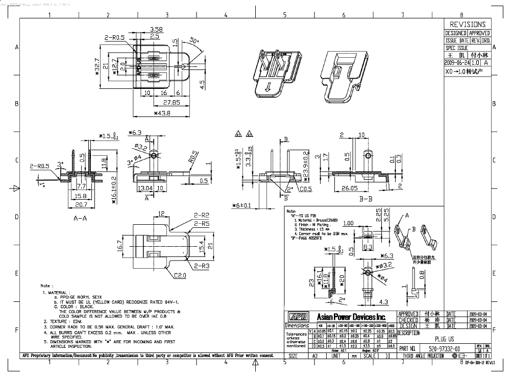
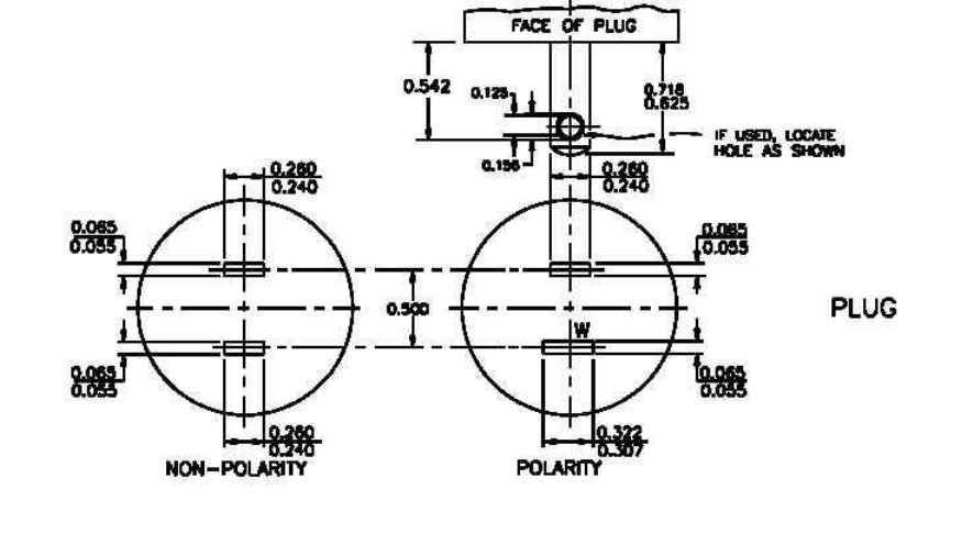
20. Blade
--
--
Solid copper alloy, non-polarized secured internal
wire by soldering than soldering to PWB and are
located minimum 5.1 mm from edge of enclosure.
See Supplement 4-08 for details.
--
--

Issue Date:
2009-11-12
Page 14 of 16
Report Reference #
E168210-A94-UL
2013-10-30
Enclosures
Type
Supplement Id
Description
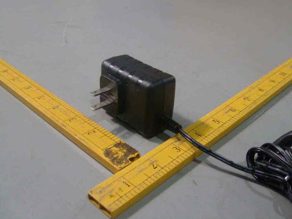
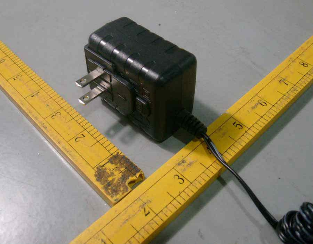
Photographs
3-01
Overall View 1 for Models WA-08B05FU, WA-10I05FU, and WA-
13A05FU
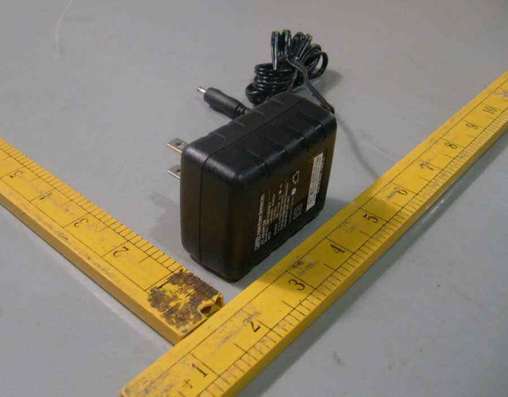
Photographs
3-02
Overall View 2 for Models WA-08B05FU, WA-10I05FU, and WA-
13A05FU
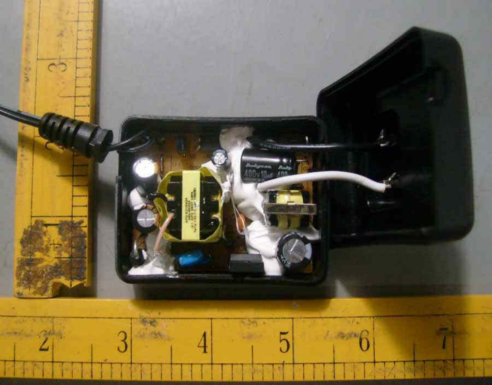
Photographs
3-03
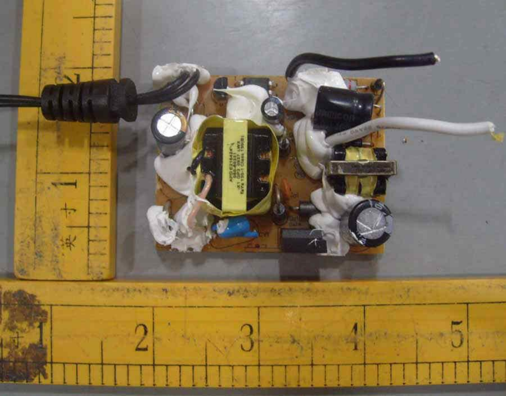
Internal View for Models WA-08B05FU, WA-10I05FU, and WA-
13A05FU
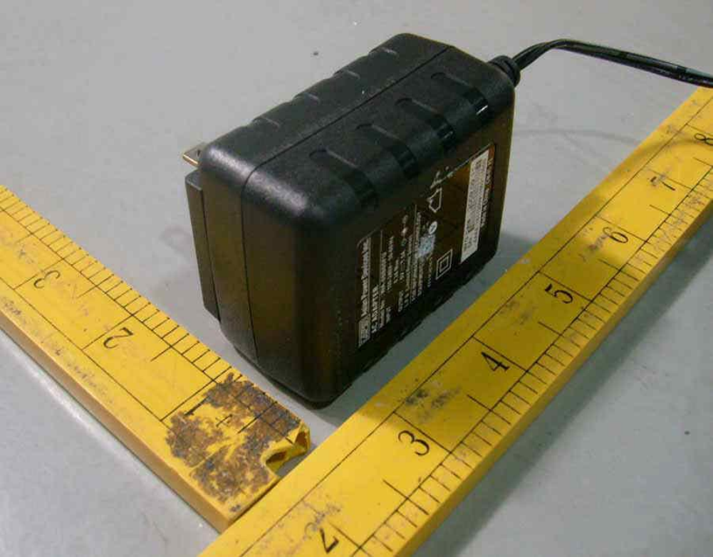
Photographs
3-04
Overall View 1 for Models WA-08B05R, WA-10I05R, and WA-
13A05R
Photographs
3-05
Overall View 2 for Models WA-08B05R, WA-10I05R, and WA-
13A05R
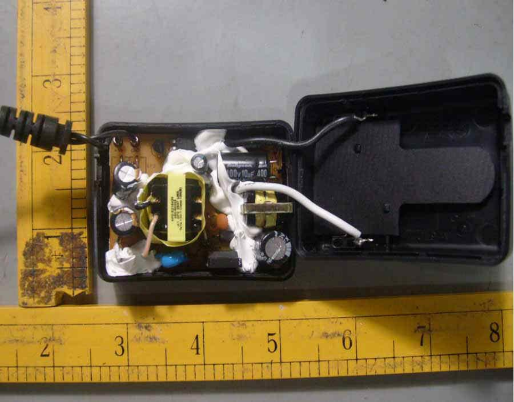
Photographs
3-06
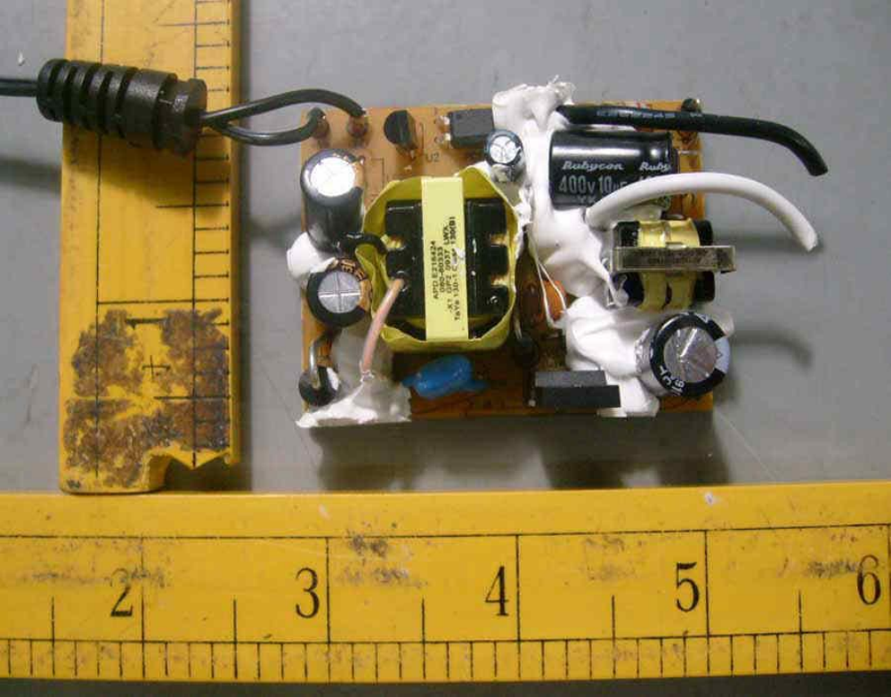
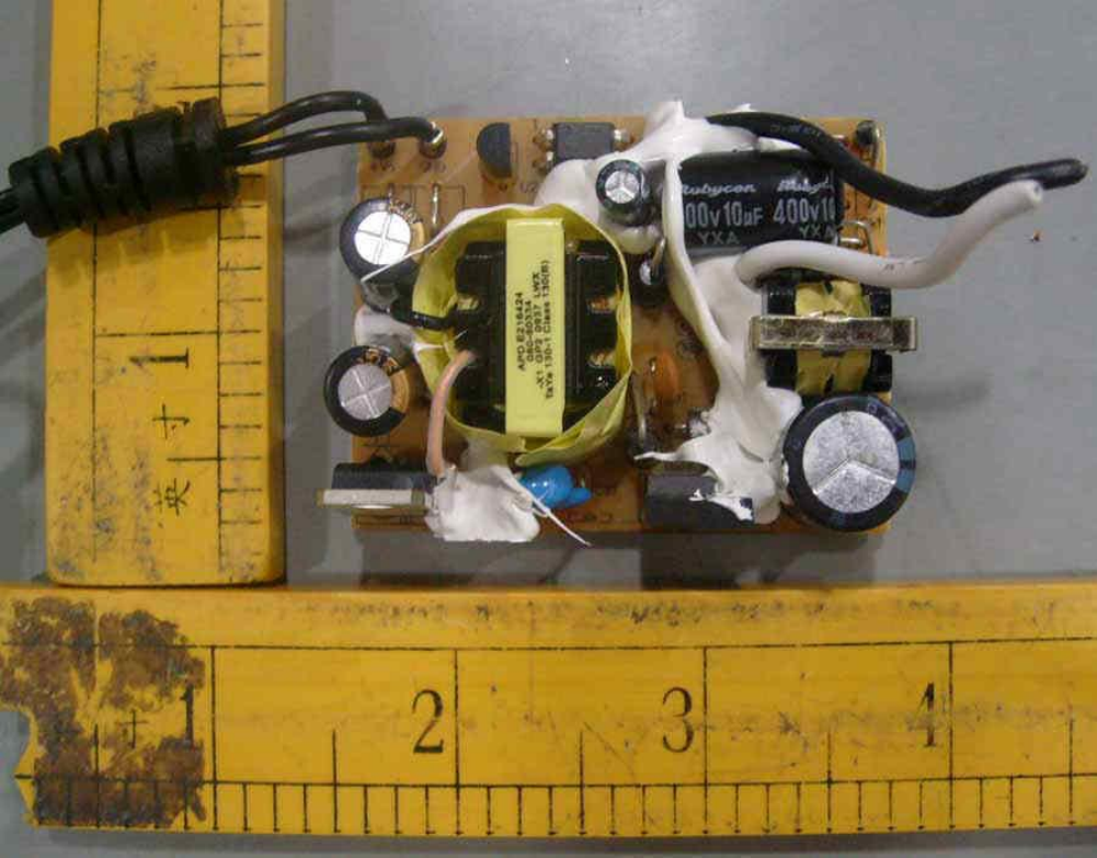
Internal View for Models WA-08B05R, WA-10I05R, and WA-
13A05R
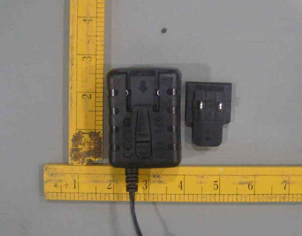
Photographs
3-07
Removable Plug Side View 1 for Models WA-08B05R, WA-
10I05R, and WA-13A05R
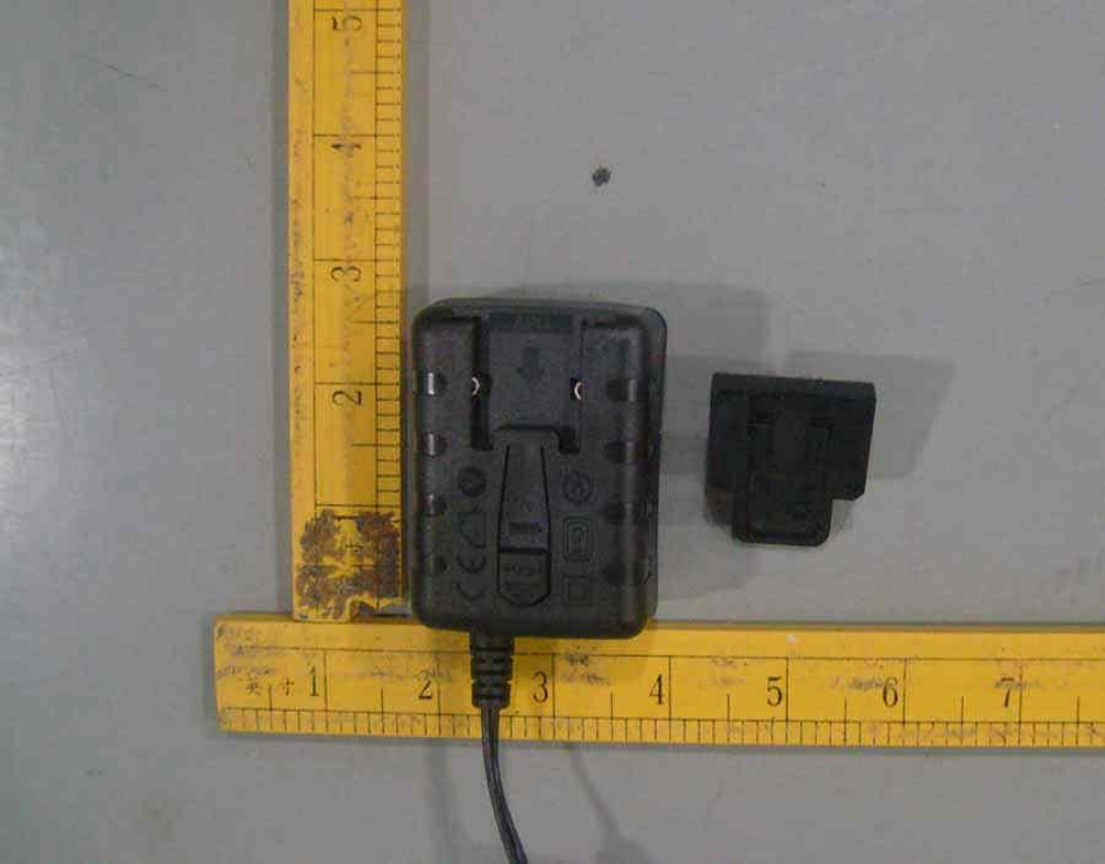
Photographs
3-08
Removable Plug Side View 2 for Models WA-08B05R, WA-
10I05R, and WA-13A05R
Photographs
3-09
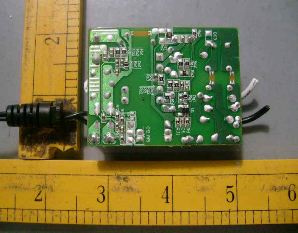
PWB Trace Side View for All Models
Photographs
3-10
PWB Component Side View for Models WA-08B05FU and WA-
08B05R
Photographs
3-11
PWB Component Side View for Models WA-10I05FU and WA-
10I05R
Photographs
3-12
PWB Component Side View for Models WA-13A05FU and WA-
13A05R
Photographs
3-13
Overall View of WA-10A06FU, WA-10A06R
Diagrams
4-01
Enclosure Drawing for Models WA-08B05FU, WA-10I05FU, and
WA-13A05FU
Diagrams
4-02
Enclosure Drawing for Models WA-08B05R, WA-10I05R, and WA-
13A05R
Diagrams
4-03
Plug Holder for Models WA-08B05R, WA-10I05R, and WA-
13A05R
Diagrams
4-04
Inductor LF1 for All Models
Diagrams
4-05
Transformer T1 for Models WA-08B05FU and WA-08B05R
Diagrams
4-06
Transformer T1 for Models WA-10I05FU and WA-10I05R
Diagrams
4-07
Transformer T1 for Models WA-13A05FU and WA-13A05R
Diagrams
4-08
Blade for NEMA 1-15P
Diagrams
4-09
Mylar Sheet for Models WA-08B05R, WA-10I05R, and WA-
13A05R
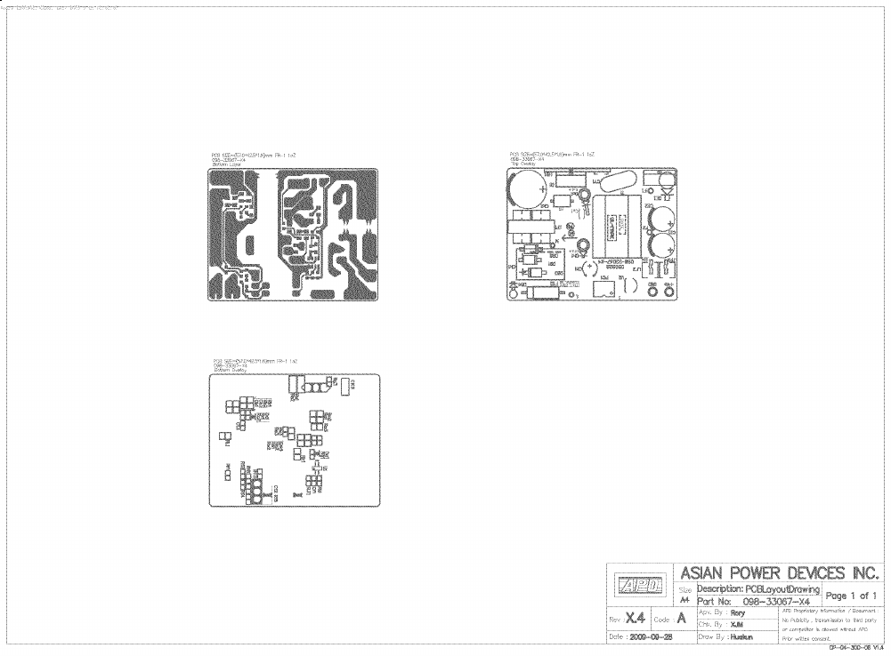
Schematics + PWB
5-01
PWB Layout

Issue Date:
2009-11-12
Page 15 of 16
Report Reference #
E168210-A94-UL
2013-10-30
Manuals
Miscellaneous
7-01
Additional Test Table
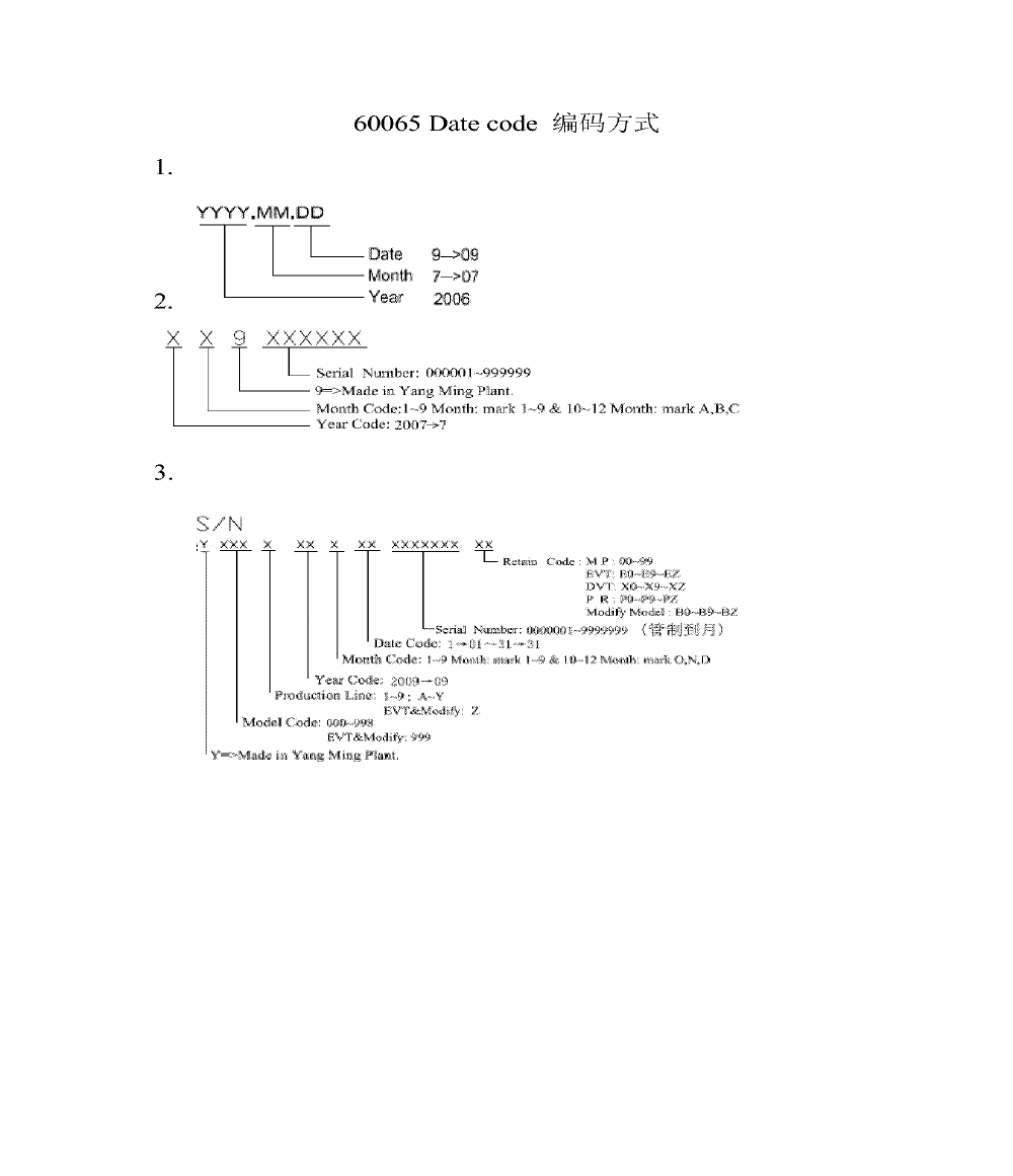
Miscellaneous
7-02
Date Code
Miscellaneous
7-03
Important safety instructions
Miscellaneous
7-04
Explanation of Safety Related Symbols
Miscellaneous
7-05
Shock Hazard Graphical Symbol
Miscellaneous
7-06
LPS for WA-10A06R
File E168210 Vol. X1 Sec. A94 PHO-01 Issued: 2009-11-12
File E168210 Vol. X1 Sec. A94 PHO-02 Issued: 2009-11-12
File E168210 Vol. X1 Sec. A94 PHO-03 Issued: 2009-11-12
File E168210 Vol. X1 Sec. A94 PHO-04 Issued: 2009-11-12
File E168210 Vol. X1 Sec. A94 PHO-05 Issued: 2009-11-12
File E168210 Vol. X1 Sec. A94 PHO-06 Issued: 2009-11-12
File E168210 Vol. X1 Sec. A94 PHO-07 Issued: 2009-11-12
File E168210 Vol. X1 Sec. A94 PHO-08 Issued: 2009-11-12
File E168210 Vol. X1 Sec. A94 PHO-09 Issued: 2009-11-12
File E168210 Vol. X1 Sec. A94 PHO-10 Issued: 2009-11-12
File E168210 Vol. X1 Sec. A94 PHO-11 Issued: 2009-11-12
File E168210 Vol. X1 Sec. A94 PHO-12 Issued: 2009-11-12
File E168210 Vol. X1 Sec. A94 PHO-13 Issued: 2009-11-12
File E168210 Vol. X1 Sec. A94 DIA-01(Page 1)Issued: 2009-11-12
File E168210 Vol. X1 Sec. A94 DIA-01(Page 2)Issued: 2009-11-12

File E168210 Vol. X1 Sec. A94 DIA-02(Page 1)Issued: 2009-11-12
File E168210 Vol. X1 Sec. A94 DIA-02(Page 2)Issued: 2009-11-12
File E168210 Vol. X1 Sec. A94 DIA-03 Issued: 2009-11-12
File E168210 Vol. X1 Sec. A94 DIA-04(Page 1)Issued: 2009-11-12
File E168210 Vol. X1 Sec. A94 DIA-04(Page 2)Issued: 2009-11-12
File E168210 Vol. X1 Sec. A94 DIA-04(Page 3)Issued: 2009-11-12
File E168210 Vol. X1 Sec. A94 DIA-04(Page 4)Issued: 2009-11-12
File E168210 Vol. X1 Sec. A94 DIA-05(Page 1)Issued: 2009-11-12
File E168210 Vol. X1 Sec. A94 DIA-05(Page 2)Issued: 2009-11-12
File E168210 Vol. X1 Sec. A94 DIA-05(Page 3)Issued: 2009-11-12
File E168210 Vol. X1 Sec. A94 DIA-05(Page 4)Issued: 2009-11-12
File E168210 Vol. X1 Sec. A94 DIA-06(Page 1)Issued: 2009-11-12
File E168210 Vol. X1 Sec. A94 DIA-06(Page 2)Issued: 2009-11-12
File E168210 Vol. X1 Sec. A94 DIA-06(Page 3)Issued: 2009-11-12
File E168210 Vol. X1 Sec. A94 DIA-06(Page 4)Issued: 2009-11-12
File E168210 Vol. X1 Sec. A94 DIA-07(Page 1)Issued: 2009-11-12

File E168210 Vol. X1 Sec. A94 DIA-07(Page 2)Issued: 2009-11-12

File E168210 Vol. X1 Sec. A94 DIA-07(Page 3)Issued: 2009-11-12

File E168210 Vol. X1 Sec. A94 DIA-07(Page 4)Issued: 2009-11-12
File E168210 Vol. X1 Sec. A94 DIA-08 Issued: 2009-11-12
File E168210 Vol. X1 Sec. A94 DIA-09 Issued: 2009-11-12
File E168210 Vol. X1 Sec. A94 SCH-01 Issued: 2009-11-12
File E168210 Vol. X1 Sec. A94 MIS-01(Page 1)Issued: 2009-11-12
File E168210 Vol. X1 Sec. A94 MIS-01(Page 2)Issued: 2009-11-12
File E168210 Vol. X1 Sec. A94 MIS-02 Issued: 2009-11-12
File E168210 Vol. X1 Sec. A94 MIS-03(Page 1)Issued: 2009-11-12
File E168210 Vol. X1 Sec. A94 MIS-03(Page 2)Issued: 2009-11-12
File E168210 Vol. X1 Sec. A94 MIS-04 Issued: 2009-11-12
File E168210 Vol. X1 Sec. A94 MIS-05 Issued: 2009-11-12
File E168210 Vol. X1 Sec. A94 MIS-06 Issued: 2009-11-12
Issue Date:
2009-11-12
Page 1 of 7
Report Reference #
E168210-A94-UL
Revision Date:
2013-10-30
Test Record
Test Record No. 1
- The manufacturer submitted representative production sample of AC Adapter, Models
(1) WA-08B05FU, WA-08B05R
(2) WA-10I05FU, WA-10I05R
(3) WA-13A05FU, WA-13A05R
- TPTDP: Unless otherwise noted in the below list of tests, all tests were conducted by Cerpass Technology
(Dongguan) Co., Ltd. and located at ChangAn, Dongguan, GuangDong, China, under the TPTDP program.
- Unless otherwise indicated, all tests were conducted on Models WA-13A05R and WA-13A05FU.
- Tests performed on Models WA-13A05R and WA-13A05FU were considered to be representative of
Models WA-08B05FU, WA-08B05R, WA10I05FU, and WA-10I05R.
- Overload in Transformer Abnormal Operation was considered covered by Power Supply Output
Short-Circuit/Overload Test, based upon engineering judgement after analyzing the circuit.
- The following test of UL60065 and CAN/CSA-C22.2 No. 60065:03 were also conducted:
Test Conditions:
Fault Conditions: Clearance and Creepage, Insulating Materials and Electronic Components (4.3.2)
Fault Conditions: Output Terminal Overload (4.3.9)
Touch Current After Fault Conditions (9.1.1.1)
Marking Durability And Legibility (5)
Heating Under Normal Operating Conditions (7)
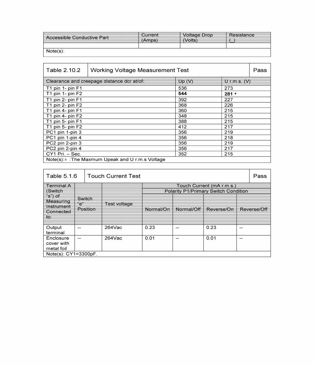
Touch Current (9.1.1)
Enclosure Resistance To External Forces (9.1.7)
Surge Test (10.1)
Impact (12.1.3)
Dielectric Strength After Impact (10.3, Table 5)
Blade Torque Test - Direct Plug-In Unit (15.4.3b)
Blade Secureness Pull Test - Direct Plug-In Unit (15.4.3c)
- The following following test of UL60065 and CAN/CSA-C22.2 No. 60065:03 were considered covered by
CAN/CSA-C22.2 No. 60950-1 and the second edition of UL 60950-1. Dated March 27, 2007:
Input Test for Apparatus Not Employing Signal Inputs And Not Containing An Audio Amplifier.
Dielectric Strength After Fault Conditions
Humidity Treatment
Drop Test
Dielectric Strength After Drop Test
Stress Relief Test
Determination of Operating Voltage
- Softening Temperature of Thermoplastics of UL60065 and CAN/CSA-C22.2 No. 60065:03 was considered
covered by E168210-A91 and not conducted.
- The results of this investigation, including construction review and testing, indicate that the products
evaluated comply with the applicable requirements in the U.S. and Canadian (Bi-National) Standard for
Safety of Information Technology Equipment, Including Electrical Business Equipment - Safety - Part 1:
General Requirements. It is the second edition of CAN/CSA-C22.2 No. 60950-1 and the second edition of
UL 60950-1. Dated March 27, 2007, and UL 60065, Seventh Edition, Dated June 30, 2003, contains
revisions through and including December 11, 2007, and CAN/CSA-C22.2 No.60065:03 dated April, 2003,
Amendment 1 dated April 2006, and, therefore, such products are judged eligible to bear UL's Mark as
Issue Date:
2009-11-12
Page 2 of 7
Report Reference #
E168210-A94-UL
Revision Date:
2013-10-30
Test Record
described on the Conclusion Page of this Report. Any information and documentation involving UL Mark
services are provided on behalf of Underwriters Laboratories Inc. (UL) or any authorized licensee of UL.

Issue Date:
2009-11-12
Page 3 of 7
Report Reference #
E168210-A94-UL
Revision Date:
2013-10-30
Test Record
The following tests were conducted:
Test
Testing Location/Comments
End Product Reference Page
General Guidelines
Power Supply Reference Page
Maximum Output Voltage, Current, and Volt-Ampere Measurement
(1.2.2.1)
Input: Single-Phase (1.6.2)
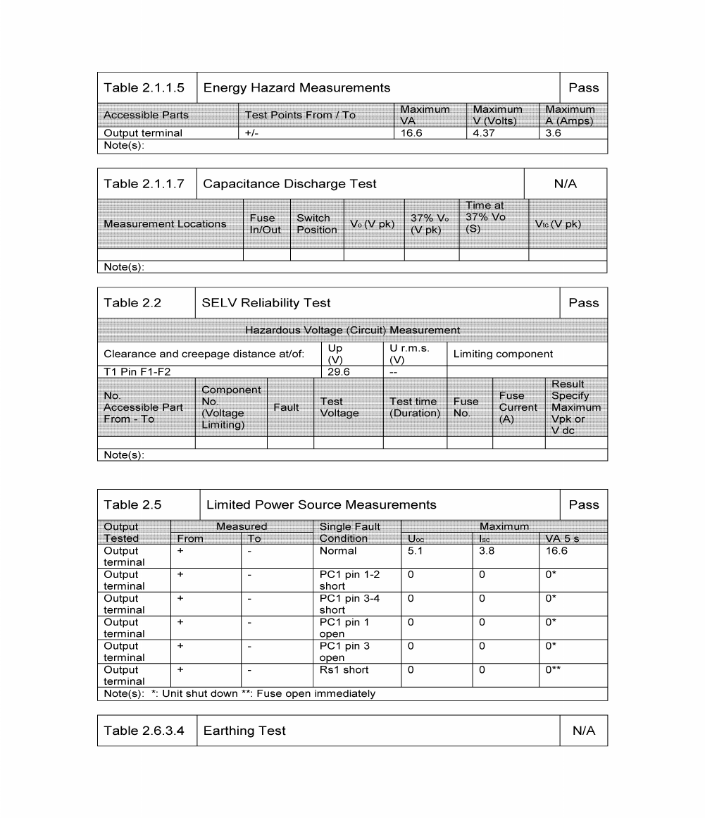
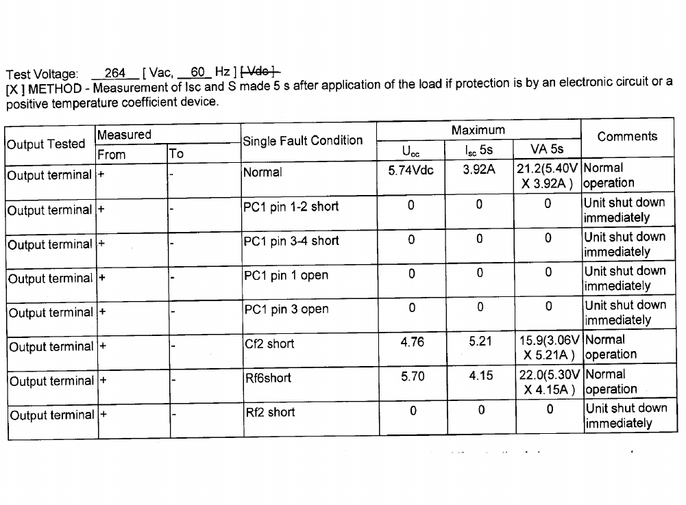
Energy Hazard Measurements (2.1.1.5, 2.1.2, 1.2.8.10)
Limited Current Circuit Measurement (2.4.1, 2.4.2)
Limited Power Source Measurements (2.5)
Humidity (2.9.1, 2.9.2, 5.2.2)
Determination of Working Voltage; Working Voltage Measurement
(2.10.2)
Determination of Working Voltage; Hazardous Voltage (Circuit)
Measurement (2.10.2, Part 22 6.1)
Transformer and Wire /Insulation Electric Strength (2.10.5.13)
Steady Force (4.2.1 - 4.2.4)
Drop (4.2.6, 4.2.1)
Stress Relief (4.2.7, 4.2.1)
Direct Plug-In Equipment-Moment (4.3.6)
Direct Plug-In Blade Securement (4.3.6)
Direct Plug-In Security of Input Contacts (4.3.6)
Direct Plug-In Resistance to Crushing (4.3.6)
Direct Plug-In Rod Pressure (4.3.6)
Direct Plug-In Input Blade Endurance (4.3.6)
Heating (4.5.1, 1.4.12, 1.4.13)
Ball Pressure (4.5.5, 4.5)
Touch Current (Single-Phase; TN/TT System) (5.1, Annex D)
Electric Strength (5.2.2)
Component Failure (5.3.1, 5.3.4, 5.3.7)
Transformer Abnormal Operation (5.3.3, 5.3.7b, Annex C.1)
Power Supply Output Short-Circuit/Overload (5.3.7)
Test results are valid only for the tested equipment. These tests are considered representative of the products
covered by this Test Report. The test methods and results of the above tests have been reviewed and found to
be in accordance with the requirements in the Standard(s) referenced at the beginning of this Test Report.

Issue Date:
2009-11-12
Page 4 of 7
Report Reference #
E168210-A94-UL
Revision Date:
2013-10-30
Test Record
The following supplements are provided as a part of this Test Record. NOTE: These supplements are only
available to the Applicant via the CDA system.
Type
Supplement Id
Description
Attachment
2-01
Construction Review Datasheet (60950-1)
Datasheet
2-02
Test Datasheet (60950-1)
Attachment
2-03
Construction Review Datasheet (60065)
Datasheet
2-04
Test Datasheet (60065)
Issue Date:
2009-11-12
Page 5 of 7
Report Reference #
E168210-A94-UL
Revision Date:
2013-10-30
Test Record
Test Record No. 2
-- Manufacturer submitted representative production, AC Adapter, Models WA-10A06FU, WA-10A06R,
which with NEW output rating, the new models are identical to models: WA-10I05FU, WA-10I05R, except for
output rating (depend on secondary voltage sampling resistors), for examination and test.
-- Model WA-10A06FU is similar to Model WA-10A06R except for fixed or replaceable blade plug and model
designation.
-- The model WA-10A06R was used for test purposes and considered representative of model
WA-10A06FU.
-- Only limited tests were performed on Model WA-10A06R because of similarity in construction to
previously evaluation.
-- All tests were conducted in Cerpass Technology (Dongguan) Co.,Ltd under TPTDP program.
-- Test results relate only to the items tested.
-- The test methods and results of the following tests also have been reviewed and found in accordance with
UL 60065, Audio, video and similar electronic apparatus - Safety requirements, 7th edition, 2007-12-11 that
were considered representative of the same tests required by Canadian Standard, CAN/CSA-C22.2 No.
60065-03, Audio, Video and similar electronic apparatus - Safety requirements, 1st edition, 2006-04 + A1:
2006.
-- The tests in according with UL 60065 and CAN/CSA-C22.2 No. 60065-03 including:
- TEST CONDITIONS
- INPUT TEST FOR APPARATUS NOT EMPLOYING SIGNAL INPUTS AND NOT CONTAINING
AN AUDIO AMPLIFIER (4.2)_ See datasheet of UL60950-1 (Supplement ID: 2-DataSheet-01) for details.
- FAULT CONDITIONS - GENERAL (4.3)
- FAULT CONDITIONS - CLEARANCE AND CREEPAGE, INSULATING MATERIALS AND
ELECTRONIC COMPONENTS (4.3.1, 4.3.2, 4.3.4)
- FAULT CONDITIONS - OUTPUT TERMINAL OVERLOAD (4.3.9)
- DIELECTRIC STRENGTH AFTER FAULT CONDITIONS (11)
- TOUCH CURRENT AFTER FAULT CONDITIONS (11.1)
- HEATING UNDER NORMAL OPERATING CONDITIONS (7)
- DETERMINATION OF OPERATING VOLTAGE (13.2)_ See datasheet of UL60950-1
(Supplement ID: 2-DataSheet-01) for details.
-- Any information and documentation involving UL Mark services are provided on behalf of Underwriters
Laboratories Inc. (UL) or any authorized licensee of UL.
-- The following tests conducted in accordance with UL60950-1, 2nd Edition, Dated March 27, 2007,
Information Technology Equipment - Safety - Part 1: General Requirements were representatives of the
same tests required by Canadian National Standard, CAN/CSA-C22.2 No. 60950-1-07, 2nd Edition, Date
March 01, 2007, Information Technology Equipment - Safety - Part 1: General Requirements.
Issue Date:
2009-11-12
Page 6 of 7
Report Reference #
E168210-A94-UL
Revision Date:
2013-10-30
Test Record
The following tests were conducted:
Test
Testing Location/Comments
End Product Reference Page
General Guidelines
Power Supply Reference Page
Maximum Output Voltage, Current, and Volt-Ampere Measurement
(1.2.2.1)
Input: Single-Phase (1.6.2)
Limited Power Source Measurements (2.5)
Determination of Working Voltage; Working Voltage Measurement
(2.10.2)
Determination of Working Voltage; Hazardous Voltage (Circuit)
Measurement (2.10.2, Part 22 6.1)
Heating (4.5.1, 1.4.12, 1.4.13)
Electric Strength (5.2.2)
Component Failure (5.3.1, 5.3.4, 5.3.7)
Transformer Abnormal Operation (5.3.3, 5.3.7b, Annex C.1)
Power Supply Output Short-Circuit/Overload (5.3.7)
Test results are valid only for the tested equipment. These tests are considered representative of the products
covered by this Test Report. The test methods and results of the above tests have been reviewed and found to
be in accordance with the requirements in the Standard(s) referenced at the beginning of this Test Report.
The following supplements are provided as a part of this Test Record. NOTE: These supplements are only
available to the Applicant via the CDA system.
Type
Supplement Id
Description
Datasheet
2-05
2-datasheet-01 for UL60950
Datasheet
2-06
2-datasheet-02 for UL60065
Attachment
2-07
CRD for 60950
Attachment
2-08
CRD for 60065
Issue Date:
2009-11-12
Page 7 of 7
Report Reference #
E168210-A94-UL
Revision Date:
2013-10-30
Test Record
Test Record No. 3
-- Manufacturer submitted representative production, AC Adapter, Models WA-13A05FU (alternate the one
fusing resistor, see Crtical Components for more details), for examination and test.
-- Only limited tests were performed on Model WA-13A05FU because of similarity in construction to
previously evaluation.
-- Unless otherwise indicated, all tests were conducted in YANG MING INDUSTRIAL under DAP (WTDP)
Program.
-- Test results relate only to the items tested.
-- The test methods and results of the following tests also have been reviewed and found in accordance with
UL 60065, Audio, video and similar electronic apparatus - Safety requirements, 7th edition, 2007-12-11 that
were considered representative of the same tests required by Canadian Standard, CAN/CSA-C22.2 No.
60065-03, Audio, Video and similar electronic apparatus - Safety requirements, 1st edition, 2006-04 + A1:
2006.
-- The tests in according with UL 60065 and CAN/CSA-C22.2 No. 60065-03 including:
FAULT CONDITIONS - GENERAL (4.3)
FAULT CONDITIONS - CLEARANCE AND CREEPAGE, INSULATING MATERIALS AND ELECTRONIC
COMPONENTS (4.3.1, 4.3.2, 4.3.4)
DIELECTRIC STRENGTH AFTER FAULT CONDITIONS (11)
TOUCH CURRENT AFTER FAULT CONDITIONS (11.1)
(Supplement ID: 3-DataSheet-02) for details.
-- Any information and documentation involving UL Mark services are provided on behalf of UL LLC (UL) or
any authorized licensee of UL.
The following tests were conducted:
Test
Testing Location/Comments
End Product Reference Page
Power Supply Reference Page
Component Failure (5.3.1, 5.3.4, 5.3.7)
Test results are valid only for the tested equipment. These tests are considered representative of the products
covered by this Test Report. The test methods and results of the above tests have been reviewed and found to
be in accordance with the requirements in the Standard(s) referenced at the beginning of this Test Report.
The following supplements are provided as a part of this Test Record. NOTE: These supplements are only
available to the Applicant via the CDA system.
Type
Supplement Id
Description
Attachment
2-09
CRD
Datasheet
2-11
3-Datasheet-01 for UL 60950
Datasheet
2-12
3-Datasheet-02 for UL 60065
