Workflow Manager User Guide
Workflow_Manager_User_Guide
Workflow_Manager_User_Guide
User Manual: Pdf
Open the PDF directly: View PDF ![]() .
.
Page Count: 68
- Table of Contents
- About This Guide
- Overview
- Getting Started
- Defining Nodes
- Defining Transitions
- Roles and Users
- Validating and Saving Plans
- Glossary of Terms and Abbreviations
- Index

Trilogy MultiChannel
Commerce Workflow
Manager
User's Guide
Trilogy MultiChannel Commerce Workflow Manager User’s Guide
Trilogy is a trademark of Trilogy Software, Inc., Reg. U.S. Pat. & Tm Off. and in other
countries.
Trilogy MultiChannel Commerce, Trilogy MultiChannel Commerce Workflow and Trilogy MultiChannel
Commerce Workflow Manager are trademarks of Trilogy.
All other trademarks and tradenames are the property of their respective owners.
TRILOGY CONFIDENTIAL - This guide and the processes, methods, ideas and information relating to
the software described herein are proprietary to Trilogy and its licensors. Your rights to execute the
software and use and copy the accompanying documentation are governed by the license agreement
between your company and Trilogy.
© 2001 - 2005 Trilogy

Who Should Use This Guide 5
Table of Contents
About This Guide .................................................................................................................................9
Who Should Use This Guide......................................................................................................9
In This Guide...............................................................................................................................9
Typographical Conventions.....................................................................................................10
Related Documentation............................................................................................................10
Chapter 1: Overview....................................................................................................................11
Automating Business Processes...............................................................................................11
The Trilogy MCC Workflow Software...................................................................................11
Workflow Plans.........................................................................................................................12
Nodes 12
Transitions.......................................................................................................................12
Roles and Users...............................................................................................................13
The Trilogy MCC Workflow Engine......................................................................................13
The Trilogy MCC Workflow Manager Application..............................................................13
The Trilogy MCC Workflow Process .....................................................................................13
Chapter 2: Getting Started..........................................................................................................15
Starting the Trilogy MCC Workflow Manager Application................................................15
Trilogy MCC Workflow Manager User Interface Components ..........................................16
The Canvas......................................................................................................................16
The Toolbar.....................................................................................................................16
The Properties Window...................................................................................................19
Menus 22
Chapter 3: Defining Nodes...........................................................................................................30
Workflow Node Concepts ........................................................................................................30
Types of Nodes ...............................................................................................................30
Root Nodes......................................................................................................................30
Creating Nodes................................................................................................................31
Activity Nodes ...........................................................................................................................31
The Action Node.............................................................................................................31

Trilogy MCC Workflow Manager User’s Guide
6 Who Should Use This Guide
The Approval Node.........................................................................................................32
The Dispatch Node..........................................................................................................34
Transition Nodes.......................................................................................................................36
The Branch Node ............................................................................................................36
The Case Node................................................................................................................38
The Delay Node ..............................................................................................................39
The Fork Node ................................................................................................................40
The Join Node .................................................................................................................41
The Sub-Process Node ....................................................................................................43
The Noop Node...............................................................................................................44
Chapter 4: Defining Transitions .................................................................................................47
Understanding and Defining Transitions ...............................................................................47
Anatomy of a Transition .................................................................................................47
Adding Transitions..........................................................................................................47
Understanding Transitions from Nodes ..........................................................................48
Understanding Transition Types.............................................................................................49
Basic Transitions.............................................................................................................49
Yes/No Transitions..........................................................................................................49
Case Transitions..............................................................................................................50
Dispatch Transitions........................................................................................................50
Chapter 5: Roles and Users .........................................................................................................53
Understanding Roles and Users...............................................................................................53
Assigning a Role or Assigning a User ............................................................................53
Working with Roles..................................................................................................................53
Creating a Role................................................................................................................54
Assigning Roles ..............................................................................................................54
Highlighting Nodes Assigned to Roles...........................................................................55
Removing a Role.............................................................................................................56
Working with Users..................................................................................................................56
Creating a User................................................................................................................56
Assigning Users ..............................................................................................................57
Highlighting Nodes Assigned to Roles...........................................................................58
Removing a User.............................................................................................................58

About This Guide
Who Should Use This Guide 7
Chapter 6: Validating and Saving Plans ....................................................................................61
Validating a Workflow Plan ....................................................................................................61
Transition Validation ......................................................................................................61
Manual Validation...........................................................................................................61
Role and User Validation................................................................................................62
Saving a Workflow Plan...........................................................................................................62
Saving as XML ...............................................................................................................62
Saving as an Image..........................................................................................................63
Glossary of Terms and Abbreviations..............................................................................................65

Who Should Use This Guide 9
About This Guide
This guide provides detailed information for the Trilogy MultiChannel Commerce Workflow
Manager (Trilogy MCC Workflow Manager)™ application. The Trilogy MCC Workflow
Manager application enables business analysts to create, validate, and manage workflow
plans.
Who Should Use This Guide
This guide is for consultants, developers, or system administrators responsible for developing
workflow plans using the Trilogy MCC Workflow Manager software.
In This Guide
This guide is organized as follows:
! Chapter 1: Overview — Introduces the Trilogy approach to workflow, explains
the purpose and capabilities of the Trilogy MCC Workflow Manager application,
and highlights several key Trilogy MCC Workflow concepts.
! Chapter 2: Getting Started — Explains how to start the Trilogy MCC Workflow
Manager application, and describes the main components of the Trilogy MCC
Workflow Manager user interface.
! Chapter 3: Defining Nodes — Provides detailed instruction in creating and
defining nodes in the Trilogy MCC Workflow Manager application.
! Chapter 4: Defining Transitions — Provides detailed instruction in creating and
defining transitions between nodes in the Trilogy MCC Workflow Manager
application.
! Chapter 5: Defining Roles and Users — Provides detailed instruction in creating
roles and users, and assigning them in the Trilogy MCC Workflow Manager
application.
! Chapter 6: Validating and Saving Plans — Explains the various mechanisms for
validating and saving workflow plans in the Trilogy MCC Workflow Manager
application.

Trilogy MCC Workflow Manager User’s Guide
10 Typographical Conventions
Typographical Conventions
Bold text indicates the following:
! Named interface elements
! Menu commands and options
Courier text indicates the following:
! Filenames, pathnames, and file extensions
! Code examples and literal values
Italic text indicates the following:
! Book titles and glossary terms
Blue, underlined text indicates the following:
! References to other sections of this guide. In the PDF version of the
documentation, the blue, underlined area is also a hyperlink to the section.
Related Documentation
! The Trilogy MultiChannel Commerce Workflow Developer’s Guide
Provides detailed instruction in customizing and integrating the Trilogy MultiChannel
Commerce Workflow software.

Automating Business Processes 11
Chapter 1: Overview
The Trilogy MCC Workflow software facilitates the tasks of defining, sequencing,
performing, and analyzing business activities. This chapter details the basic concepts central
to the Trilogy MCC Workflow software and includes the following sections:
! Automating Business Processes
! The Trilogy MCC Workflow Software
! Workflow Plans
! The Trilogy MCC Workflow Engine
! The Trilogy MCC Workflow Manager Application
! The Trilogy MCC Workflow Process
Automating Business Processes
Workflow is the automation of business processes, such as contract or ordering systems. The
key to properly implemented workflow systems is to deliver the right information to the right
person at the right time. Workflow accomplishes this by taking advantage of repeatable paths
for information flow throughout the organization.
The automation of business processes is complex, requiring the advanced knowledge of top
business analysts. It is important that business analysts can configure process rules, rather
than IT professionals. This ability allows business analysts to make crucial decisions
including routing, dynamic pricing, creating purchase requests, and so on.
The Trilogy MCC Workflow Software
Using the Trilogy MCC Workflow software, you can automate complex business processes
such as processing a contract. The Trilogy MCC Workflow software includes the following
components:
! Workflow Plans
! Trilogy MCC Workflow Engine
! The Trilogy MCC Workflow Manager Application
Trilogy MCC Workflow Manager User’s Guide
12 Workflow Plans
Workflow Plans
A workflow plan, also called a plan definition, acts as a flowchart for the Trilogy MCC
Workflow software to determine which path to follow, which tasks to schedule, and which
parties to assign to tasks. This plan represents a business process such as requesting and
scheduling a vacation or submitting paperwork for work orders.
System integrators embed workflow plans within the Trilogy MCC Workflow software to
watch for events, to start and end tasks, and to determine activity paths to accomplish
complicated processes. After creating and embedding the plan into a Trilogy Workflow-
enabled application, users can interact with the plan transparently, easily automating business
practices.
Plan developers create plans by combining graphical elements that represent process
components. Those components include:
! Nodes
! Transitions
! Roles and Users
Nodes
Workflow nodes are plan elements that describe some business activity or flow control and
are linked by causal or sequential relationships. For example, one node might describe an
action that a user or program should perform, while another creates a branch in the workflow
plan that occurs after the completion of the action. For more information about nodes, see
Chapter 3: Defining Nodes.
Transitions
Transitions specify the flow of control between nodes. For example, one transition may
specify that a manager’s approval occurs directly after a contract has been submitted. If the
control flow from a node requires it, a transition may specify extra information, such as yes
or no, or a condition. For example, an approval node would have two transitions out, one to
the node that should execute if the contract is approved, and the other to the node that should
execute if the contract is not approved. For more information about transitions, see Chapter 4:
Defining Transitions.

Overview
The Trilogy MCC Workflow Engine 13
Roles and Users
Some nodes, such as those associated with an action or approval, are assigned a role or user.
A user is an individual that uses the Trilogy Workflow-enabled software. A role is a group of
users that have the same permissions or assignments. For example, the creation of a contract
may be assigned to a particular user, while the approval of the contract may be assigned to
anyone in the manager role. For more information about roles and users, see Chapter 5: Roles
and Users.
The Trilogy MCC Workflow Engine
The Trilogy MCC Workflow engine provides a runtime environment for executing a
workflow plan. The engine is integrated with other applications to listen for business events
and respond by taking the appropriate action. For example, a plan may specify that the
submission of a contract, an event, is followed by the approval of that contract by a specific
manager. A third-party contract application integrated with the Trilogy MCC Workflow
engine could respond to a user submitting a contract in the third-party application by sending
an email to the manager, informing her that the contract needs to be approved.
The Trilogy MCC Workflow Manager Application
The Trilogy MCC Workflow Manager application is a Java application that simplifies the
process of implementing or maintaining workflow plans. It allows plan developers to use
graphical elements to define nodes, link nodes with transitions, assign roles and users, and
validate and save plans. The Trilogy MCC Workflow engine can then access those plans to
enforce business process rules.
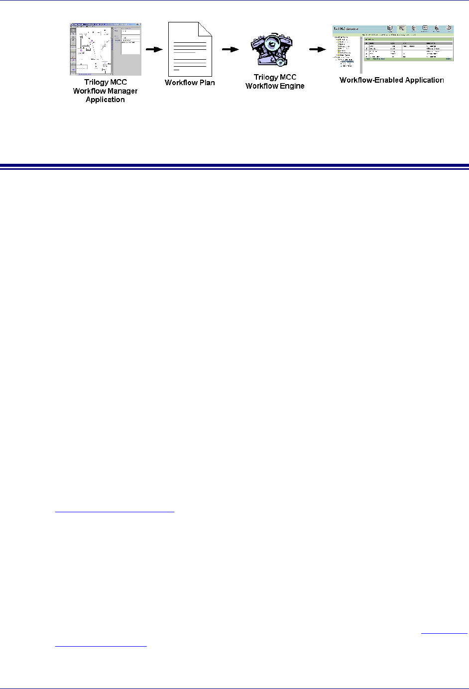
The Trilogy MCC Workflow Process
The following sequence describes the process of enforcing business rules with the Trilogy
MCC Workflow software:
1. Use the Trilogy MCC Workflow Manager application to create or edit a workflow plan.
Each self-contained business process is represented by a separate workflow plan.
Creating a workflow plan includes the following steps:
− Define nodes for each step in the business process
− Define transitions between nodes
− Create and assign roles and users to nodes

Trilogy MCC Workflow Manager User’s Guide
14 The Trilogy MCC Workflow Process
2. Use the Trilogy MCC Workflow Manager application to verify that the workflow plan
has no errors and that it correctly implements the business process
3. Integrate the Trilogy MCC Workflow engine into each application that is part of the
business process
4. Run the Trilogy MCC Workflow engine with a workflow plan to enforce business rules
This document describes how to complete steps one and two above. For more information on
completing steps three and four, refer to the Trilogy MCC Workflow Developer’s Guide.
Starting the Trilogy MCC Workflow Manager Application 15
Chapter 2: Getting Started
This chapter explains how to design a workflow plan and describes the components of the
Trilogy MCC Workflow Manager user interface. The chapter includes the following topics:
! Starting the Trilogy MCC Workflow Manager Application
! Components of the Trilogy MCC Workflow Manager User Interface
Starting the Trilogy MCC Workflow Manager Application
The Trilogy MCC Workflow Manager application is a Java-based application, accessible on
any operating system where Java is available. This section describes how to start the Trilogy
MCC Workflow Manager application.
Start the Trilogy MCC Workflow Manager Application
1. Open a command prompt and type
java com.trilogy.workflow.maint.ProcessDesigner
2. The Trilogy MCC Workflow Manager application opens.
Note: Contact your system administrator if the application does not open.
Trilogy MCC Workflow Manager User’s Guide
16 Trilogy MCC Workflow Manager User Interface Components
Trilogy MCC Workflow Manager User Interface Components
This section describes the following user interface elements:
! The Canvas
! The Toolbar
! The Properties Window
! Menus
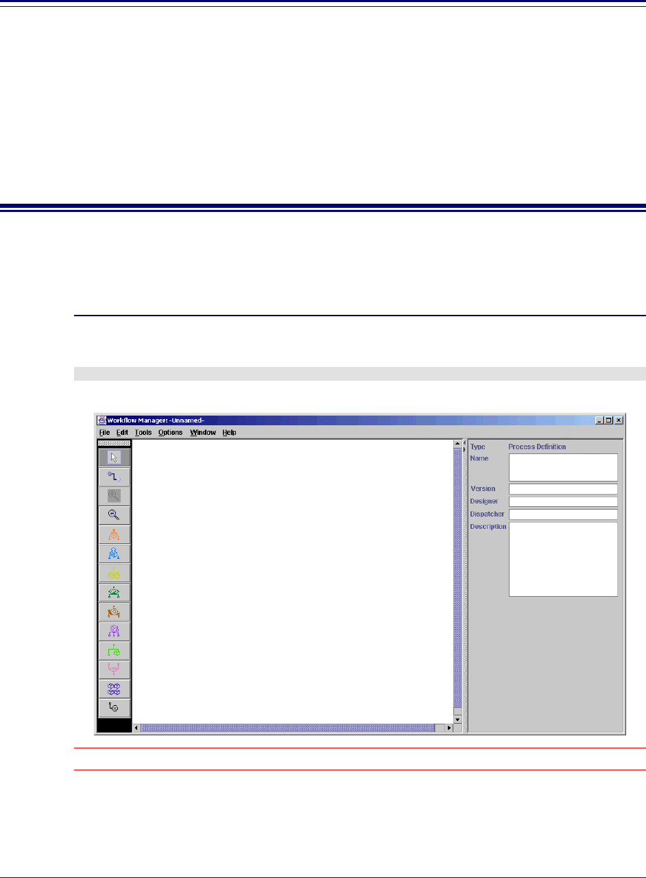
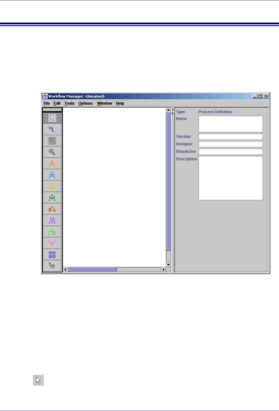
The Canvas
The canvas is the workplace of the Trilogy MCC Workflow Manager application. Use it like
a desktop to create or modify workflow plans
The Toolbar
! The Toolbar contains all tools and elements that you use to create or modify workflow
plans.
Select Tool
Canvas Properties
Window
Toolbar

Getting Started
Trilogy MCC Workflow Manager User Interface Components 17
Use this tool to select elements or groups of elements in the workflow plan. The selection tool
is on by default when the Trilogy MCC Workflow Manager opens.
Zoom In Tool
Use this tool to zoom in to the canvas.
Zoom Out Tool
Use this tool to zoom out of the canvas.
Transition Tool
Use this tool to add transitions to your workflow plan. See Chapter 4: Defining Transitions
for further instructions about adding transitions to a workflow plan.
Action Node Tool
Use this tool to add an Action node to your workflow plan. See the section The Action Node
in Chapter 3: Defining Nodes for further instructions about using Action nodes in a workflow
plan.
The Approval Node Tool
Use this tool to add an Approval node to your workflow plan. See the section The Approval
Node in Chapter 3: Defining Nodes for further instructions about using Approval nodes in a
workflow plan.
The Branch Node Tool
Use this tool to add a Branch node to your workflow plan. See the section The Branch Node
in Chapter 3: Defining Nodes for further instructions about using Branch nodes in a workflow
plan.

Trilogy MCC Workflow Manager User’s Guide
18 Trilogy MCC Workflow Manager User Interface Components
The Case Node Tool
Use this tool to add a Case node to your workflow plan. See the section The Case Node in
Chapter 3: Defining Nodes for further instructions about using Case nodes in a workflow
plan.
The Delay Node Tool
Use this tool to add a Delay node to your workflow plan. See the section The Delay Node in
Chapter 3: Defining Nodes for further instructions about using Delay nodes in a workflow
plan.
The Dispatch Node Tool
Use this tool to add a Dispatch node to your workflow plan. See the section The Dispatch
Node in Chapter 3: Defining Nodes for further instructions about using Dispatch nodes in a
workflow plan.
The Fork Node Tool
Use this tool to add a Fork node to your workflow plan. See the section The Fork Node in
Chapter 3: Defining Nodes for further instructions about using Fork nodes in a workflow
plan.
The Join Node Tool
Use this tool to add a Join node to your workflow plan. See the section The Join Node in
Chapter 3: Defining Nodes for further instructions about using Join nodes in a workflow plan.
The Sub-Process Node Tool
Use this tool to add a Sub-Process node to your workflow plan. See the section The Sub-
Process Node in Chapter 3: Defining Nodes for further instructions about using Sub-Process
nodes in a workflow plan.
Getting Started
Trilogy MCC Workflow Manager User Interface Components 19
The Noop Node Tool
Use this tool to add a Noop node to your workflow plan. See the section The Noop Node in
Chapter 3: Defining Nodes for further instructions about using Noop nodes in a workflow
plan.
The Properties Window
On selection of a workflow plan element, the Properties Window displays the attributes of
the selected element. Use the Properties Window to edit the related attributes. See Chapter
3: Defining Nodes and Chapter 4: Defining Transitions for instructions on defining the
properties of workflow plan elements.
This section describes the following properties of workflow plan elements:
! Canvas Properties
! Node Properties
Note: If the Properties window is not visible, select Display Properties Window from the Window menu.
The Type Property Display
All plan elements share the Type property. This property displays the type of plan element
currently selected. The Type property is always located at the top of the Properties window.
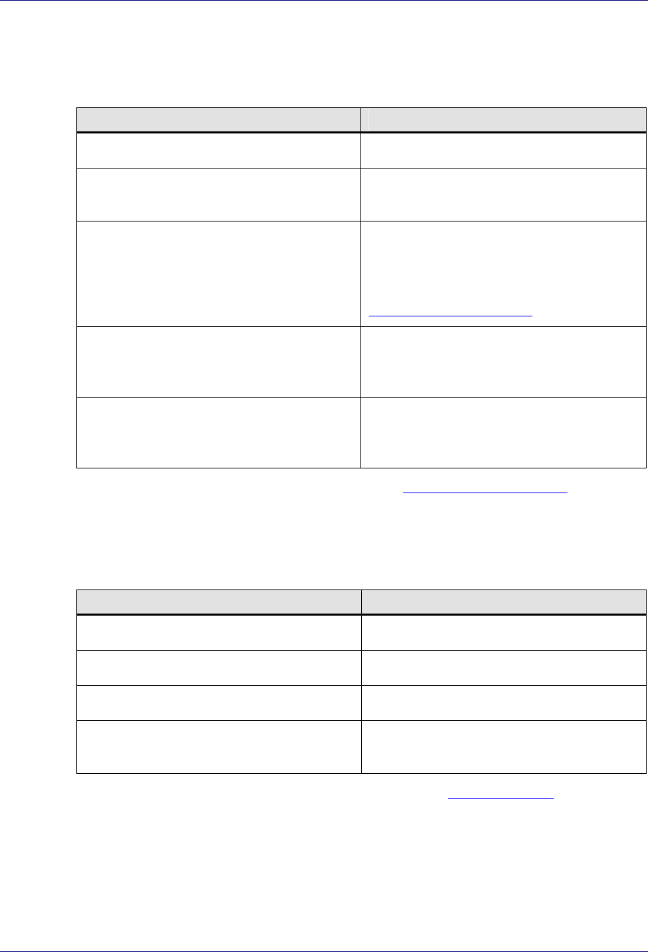
Canvas Properties
The properties of the Canvas display when the Canvas is selected. The following table
outlines the name and purpose of each of the Canvas properties.
Canvas Property Name Canvas Property Description
Name The name of the current workflow plan.
Version The version of the current workflow plan.
Designer The person that created the current
workflow plan.
Description A brief description of the current workflow
plan.
Node Properties
The properties of a node display in the Properties window when the node is selected. The
following sections outline the properties of each type of node.
Trilogy MCC Workflow Manager User’s Guide
20 Trilogy MCC Workflow Manager User Interface Components
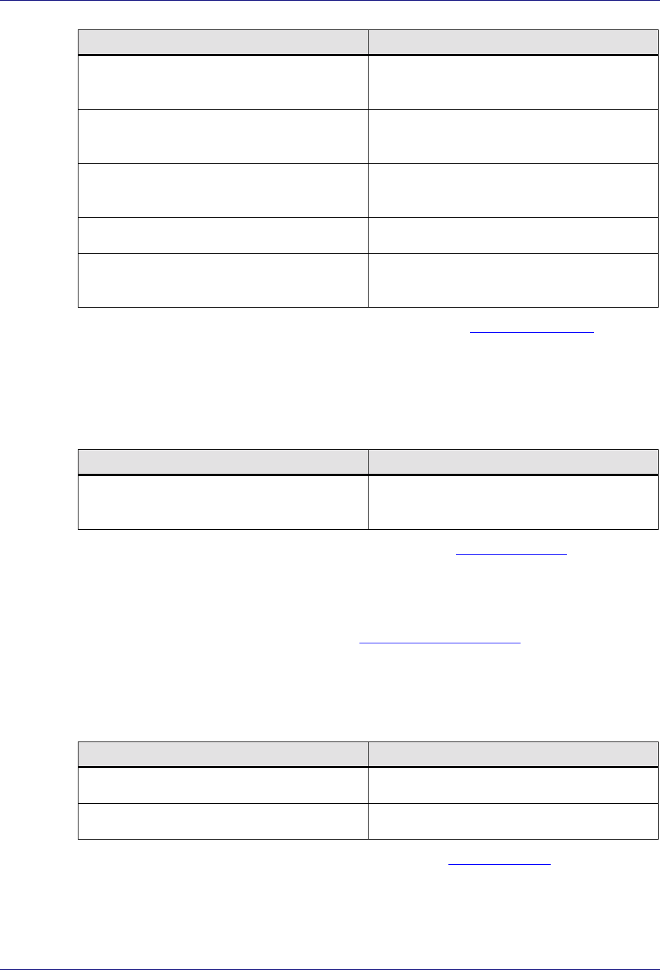
Common Node Properties
All nodes share some basic properties. The following table outlines the name and purpose of
each of the properties common to all nodes.
Node Property Name Node Property Description
Name The name of the currently selected node.
Description A brief description of the currently selected
node.
Root Checked if the currently selected node is the
root node of the workflow plan.
For more information on root nodes, see
Chapter 3: Defining Nodes.
X The horizontal position of the currently
selected node, in pixels, from the left side of
the Canvas.
Y The vertical position of the currently
selected node, in pixels, from the bottom of
the Canvas.
For mode information on setting node properties, see Chapter 3: Defining Nodes.
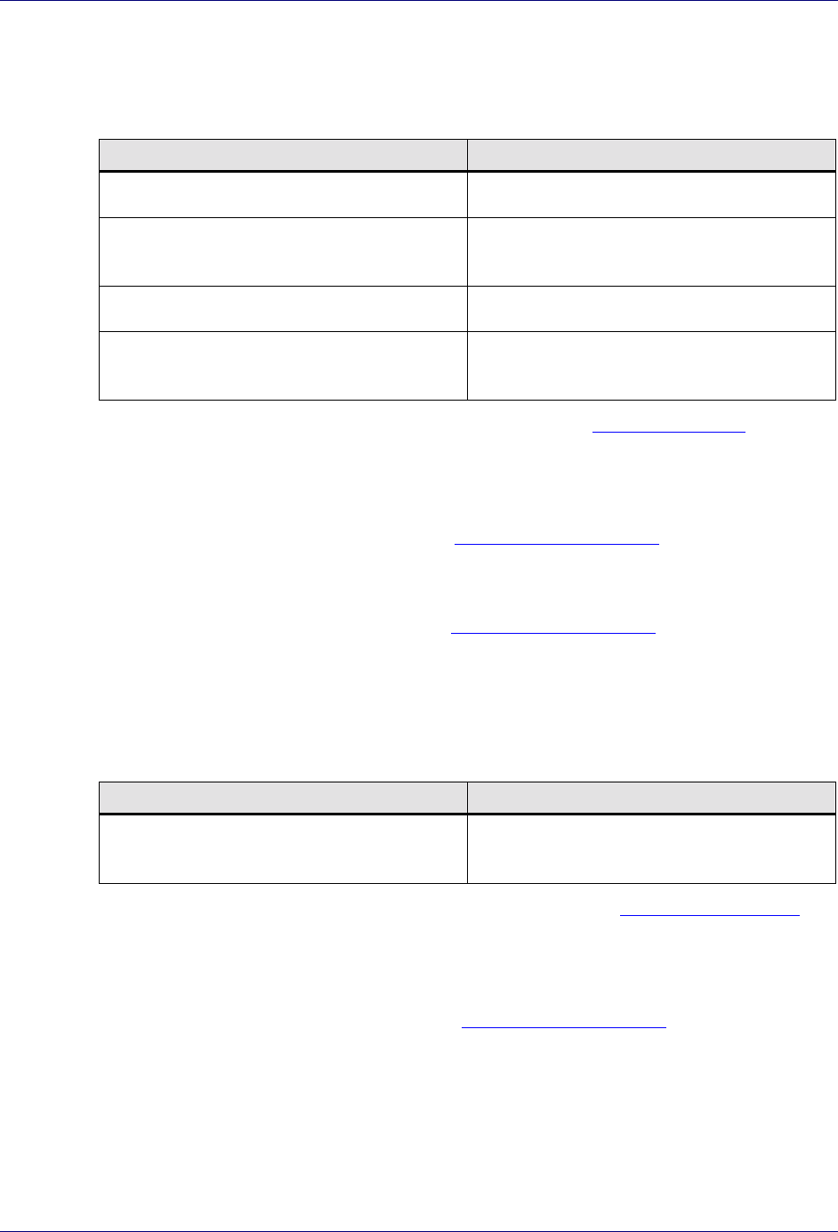
Action Node Properties
The properties of the Action node describe the details of the action represented. The
following table outlines the name and purpose of each of the properties of the Action node.
Node Property Name Node Property Description
Role The name of a role that performs the action.
User The name of a user that performs the action.
Duration The amount of time that the action takes.
Priority The relative priority of this action over
other actions.
For mode information on setting Action node properties, see The Action Node in Chapter 3:
Defining Nodes.
Approval Node Properties
The properties of the Approval node describe the details of the approval represented. The
following table outlines the name and purpose of each of the properties of the Approval node.
Getting Started
Trilogy MCC Workflow Manager User Interface Components 21
Node Property Name Node Property Description
Condition The condition on which the approval is
made.
Role The name of a role that performs the
approval.
User The name of a user that performs the
approval.
Duration The amount of time that the approval takes.
Priority The relative priority of this approval over
other approvals.
For more information on setting Approval node properties, see The Approval Node in
Chapter 3: Defining Nodes.
Branch Node Properties
The properties of the Branch node describe the details of the branch represented. The
following table outlines the name and purpose of each of the properties of the Branch node.
Node Property Name Node Property Description
Condition The condition on which the branch
transition executes.
For more information on setting Branch node properties, see The Branch Node in Chapter 3:
Defining Nodes.
Case Node Properties
The only properties on the Case node are the Common Node Properties.
Delay Node Properties
The properties of the Delay node describe the details of the delay represented. The following
table outlines the name and purpose of each of the properties of the Delay node.
Node Property Name Node Property Description
Time The amount of time taken by the delay.
Condition The condition on which the delay occurs.
For more information on setting Delay node properties, see The Delay Node in Chapter 3:
Defining Nodes.
Trilogy MCC Workflow Manager User’s Guide
22 Trilogy MCC Workflow Manager User Interface Components
Dispatch Node Properties
The properties of the Dispatch node describe the details of the dispatch represented. The
following table outlines the name and purpose of each of the properties of the Dispatch node.
Node Property Name Node Property Description
Role The name of a role that dispatches activities.
User The name of a user that dispatches
activities.
Duration The amount of time that the dispatch takes.
Priority The relative priority of this dispatch over
other dispatches.
For more information on setting Dispatch node properties, see The Dispatch Node in Chapter
3: Defining Nodes.
Fork Node Properties
The only properties on the Fork node are the Common Node Properties.
Join Node Properties
The only properties on the Join node are the Common Node Properties.
Sub-Process Node Properties
The properties of the Sub-Process node describe the details of the sub-process represented.
The following table outlines the name and purpose of each of the properties of the Sub-
Process node.
Node Property Name Node Property Description
Filename The full path and filename of an XML
workflow plan file used as a sub-process.
For more information on setting Sub-Process node properties, see The Sub-Process Node in
Chapter 3: Nodes.
Noop Node Properties
The only properties on the Noop node are the Common Node Properties.
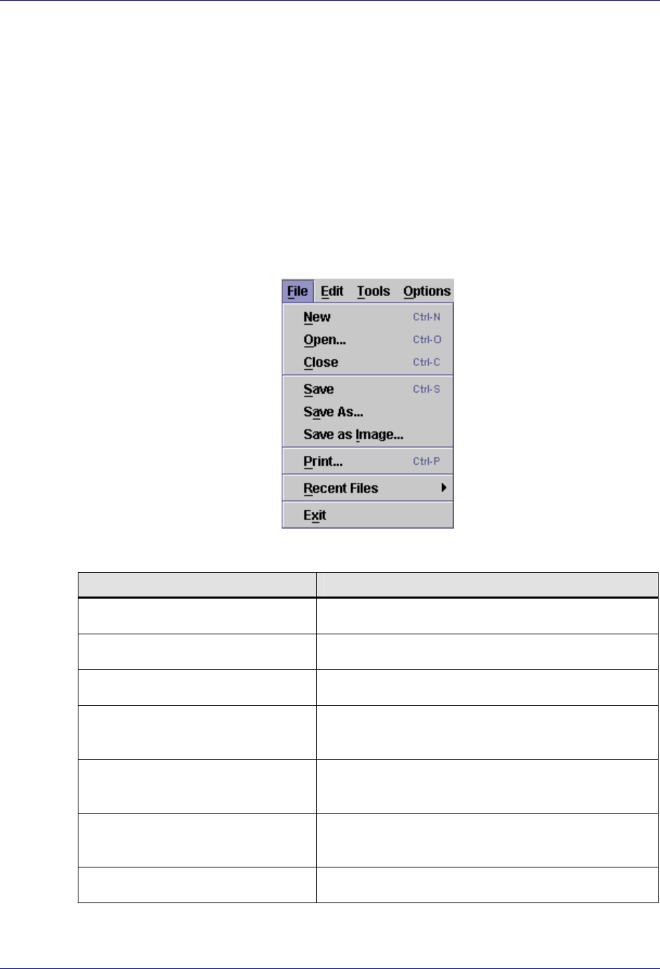
Menus
You can use the menus to perform most functions in the application. You can access menus
using the menu bar at the top of the application. The menus often display keyboard shortcuts
that you can alternatively use to execute commands.
Getting Started
Trilogy MCC Workflow Manager User Interface Components 23
This section describes the following menus:
! File Menu
! Edit menu
! Tools Menu
! Options Menu
! Window Menu
! Help Window
File Menu
Use the File menu to perform operations on the workflow plan as a whole.
The following table describes each function of the File menu.
Menu Item Description
New Create a new workflow plan.
Open… Open an existing workflow plan.
Close Close the current workflow plan.
Save Save the current workflow plan to an XML file with
the same name in the same location.
Save As… Save the current workflow plan to an XML file with
a new name or in a new location.
Save as Image… Save the current workflow plan as a JPEG image
file.
Print… Print the current workflow plan.

Trilogy MCC Workflow Manager User’s Guide
24 Trilogy MCC Workflow Manager User Interface Components
Menu Item Description
Recent Files Provides a sub-menu of workflow plans that have
been accessed recently. Select Clear Menu to clear
the list.
Exit Exit the application.
Edit Menu
Use the Edit menu to select all or some of the elements of a workflow plan.
The following table describes each function of the Edit menu.
Menu Item Description
Select All Select all of the elements of the current
workflow plan.
Find… Find particular elements in the current
workflow plan. The Name property of each
node and the Even property of each
transition in the plan are searched for the
text specified in the Find text box.
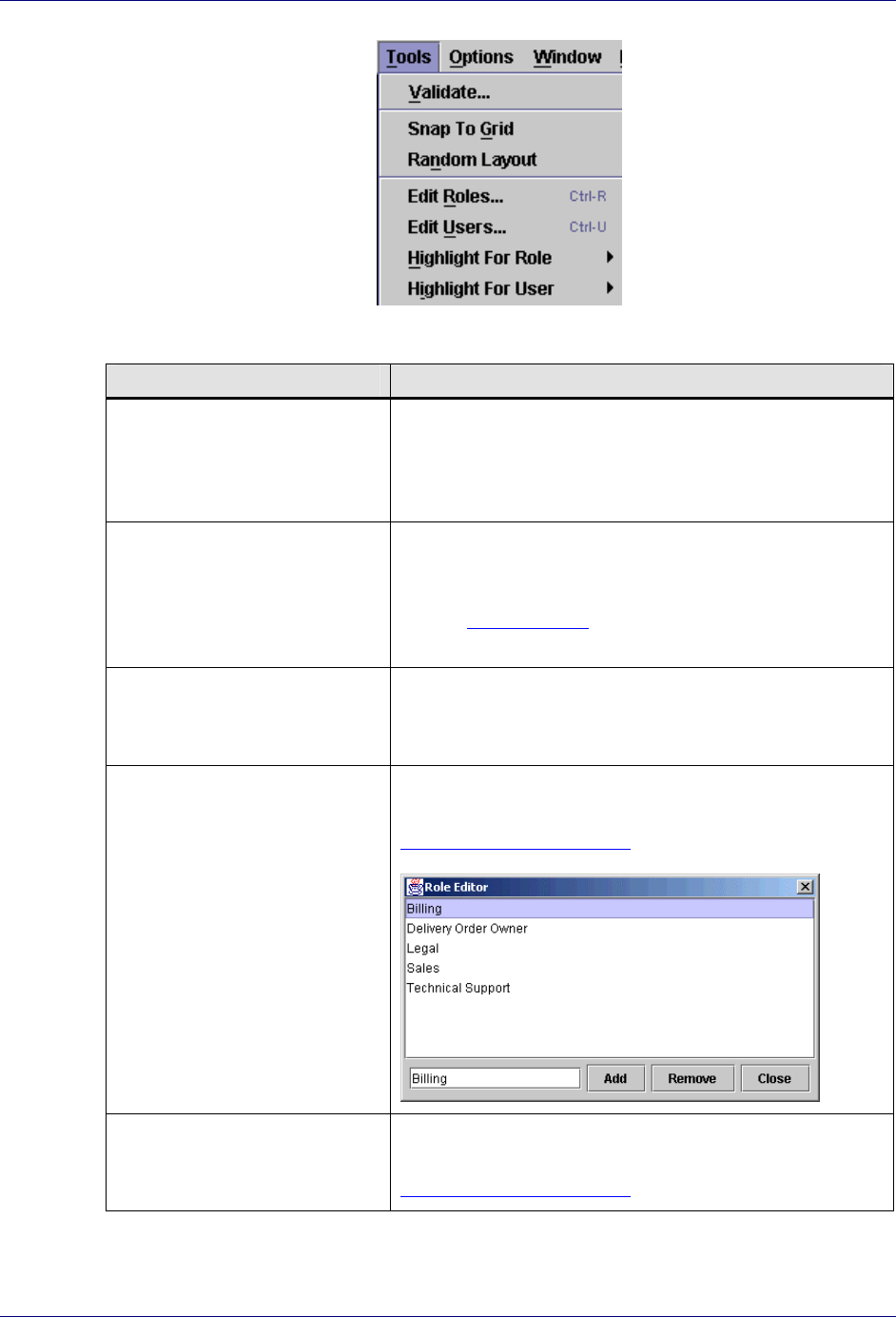
Tools Menu
Use the Tools menu to perform operations on the plan and its components.
Getting Started
Trilogy MCC Workflow Manager User Interface Components 25
The following table describes each function of the Tools menu.
Menu Item Description
Validate… Checks the current workflow plan for any errors and
reports any errors found in a message. If no errors are
found, a message displaysstating that validation was
successful.
Snap To Grid Moves each of the elements in the workflow plan so that
the nodes display spaced out as on a grid.
See the Options Menu for information on Snap To Grid
options.
Random Layout Moves each of the elements in the workflow plan so that
each of the nodes display in a randomly chosen location.
Transitions between nodes are preserved.
Edit Roles… Launch the Role Editor, which allows you to add and
remove roles. For more information on editing roles, see
Chapter 5: Roles and Users.
Edit Users… Launch the User Editor, which allows you to add and
remove users. For more information on editing users, see
Chapter 5: Roles and Users.
Trilogy MCC Workflow Manager User’s Guide
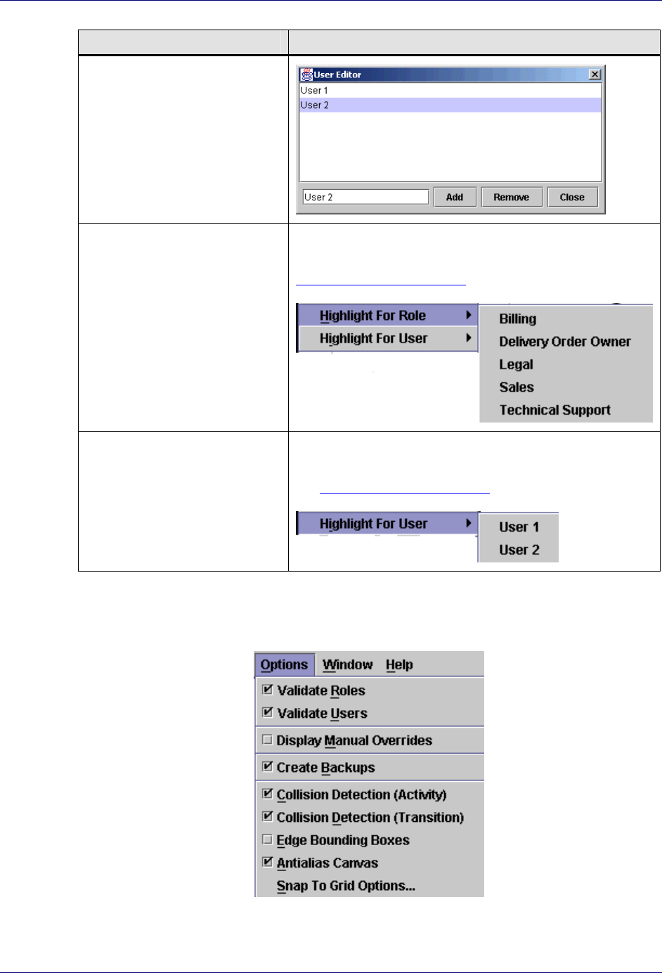
26 Trilogy MCC Workflow Manager User Interface Components
Menu Item Description
Highlight For Role Highlight all workflow plan elements assigned the
specified role. For more information on editing roles, see
Chapter 5: Roles and Users.
Highlight For User Highlight all workflow plan elements assigned the
specified user. For more information on editing users,
see Chapter 5: Roles and Users.
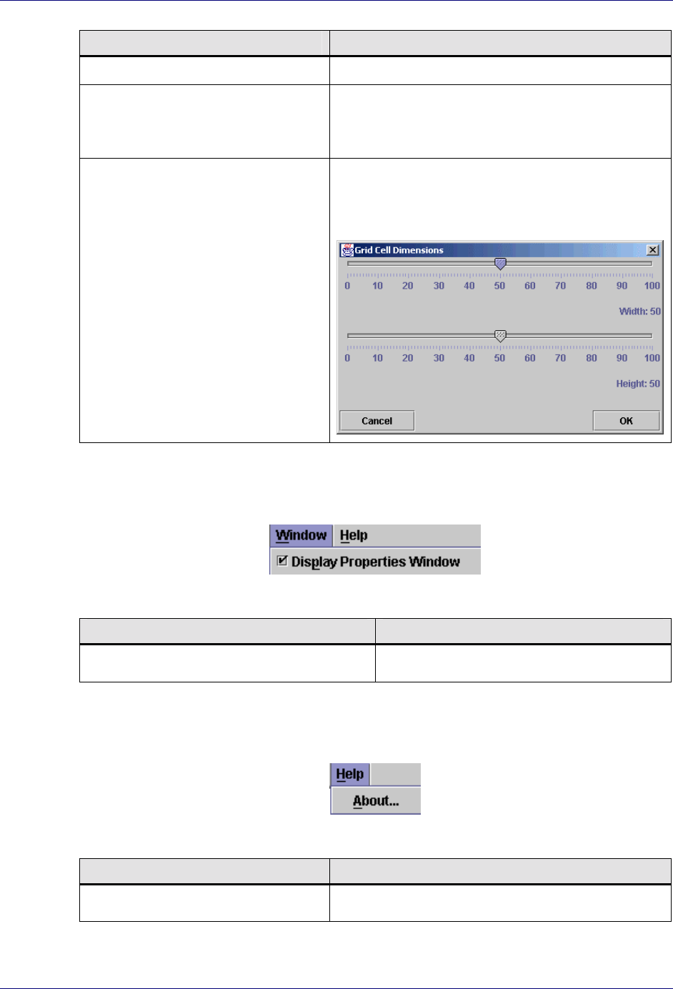
Options Menu
Use the Options menu to set Trilogy MCC Workflow Manager environment options.
The following table describes each function of the Options menu.

Getting Started
Trilogy MCC Workflow Manager User Interface Components 27
Menu Item Description
Validate Roles Ensures that any roles specified as properties on
workflow plan elements have already been created
using the Role Editor.
For more information on editing roles, see Chapter
5: Roles and Users.
Note: This functionality is for advanced
users only.
Validate Users Ensures that any users specified as properties on
workflow plan elements have already been created
using the User Editor.
For more information on editing users, see Chapter
5: Roles and Users.
Note: This functionality is for advanced
users only.
Display Manual Overrides Displays additional text entry fields in the
Property window of the selected workflow plan
element, which allows customized XML code to be
entered. This code overrides XML that is generated
by default for the related node.
Note: This functionality is for advanced
users only.
Create Backups Saves a backup of the previous version of the
workflow plan with a *.bak extension.
For example, if you modify and save plan1.xml
with the Create Backups option turned on, the
application creates two workflow plans:
plan1.xml with the latest changes, and
plan1.xml.bak without the latest changes.
Collision Detection (Activity) Prevent node icons from overlapping on the
canvas.
Collision Detection (Transition) Prevent transition icons from overlapping on the
canvas.
Edge Bounding Boxes When a transition is selected, surround the
transition lines with a box. When this option is
turned off, the transition is sim
p
l
y
hi
g
hli
g
hted u
p
on
Trilogy MCC Workflow Manager User’s Guide
28 Trilogy MCC Workflow Manager User Interface Components
Menu Item Description
selection.
Antialias Canvas Smoothes jagged edges that may occur on
workflow plan elements, by subtly blending the
edge into the Canvas.
Snap to Grid Options… Launches the Grid Cell Dimensions window,
which allows you to set the height and width of
Canvas grid cells.
Window Menu
Use the Window menu to hide or show the Properties window.
The following table describes each function of the Window menu.
Menu Item Description
Display Properties Window Hide or show the Properties window.
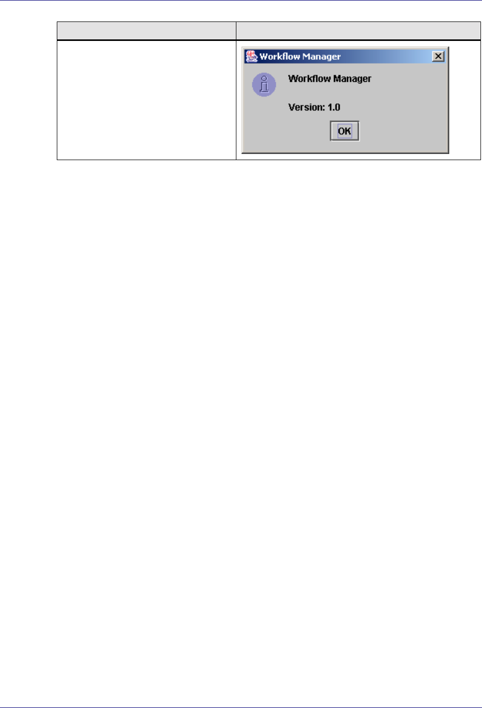
Help Menu
Use the Help menu to display a window that provides version information.
The following table describes each function of the Help menu.
Menu Item Description
About… Display the Workflow Manager window.
Getting Started
Trilogy MCC Workflow Manager User Interface Components 29
Menu Item Description
.

Trilogy MCC Workflow Manager User’s Guide
30 Workflow Node Concepts
Chapter 3: Defining Nodes
This chapter explains how to create and define nodes in a workflow plan using the Trilogy
MCC Workflow Manager application.
Workflow Node Concepts
Workflow nodes are the basic elements that make up a workflow plan. This section discusses:
! Types of Nodes
! Root Nodes
! Creating Nodes
Types of Nodes
The Trilogy MCC Workflow Manager application supports two types of nodes: Activity
nodes and Transition nodes.
Activity nodes represent activities that can be performed by a user, role, or the application.
Examples of processes represented by Activity nodes are the creation of a contract and the
approval of an order.
Transition nodes represent activities that control the flow of the business process. Examples
of processes represented by Transition nodes include deciding which activity to perform
based on a value, and a delay in process flow for a specific period of time.
Root Nodes
A root node is the place in the workflow plan where execution begins. Every plan must have
one and only one root node. Any node may act as the root node. For more information on
setting root nodes, see Common Node Properties in Chapter 2: Getting Started.
The following diagram shows the typical use of a root node.

Defining Nodes
Activity Nodes 31
In the diagram above, the node Action 1 is the root node. The Trilogy MCC Workflow
engine executes Action 1 before executing any other nodes, including Action 2.
Creating Nodes
To create a node, complete the following steps:
Create a Node
1. Click the appropriate Node tool on the toolbar.
2. Click the place on the Canvas where the node should display.
3. Set the properties on the node.
For more information on setting properties on nodes, see each node below.
4. Define transitions in and out of the node.
For more information on defining transitions, see Chapter 4: Defining Transitions.
Activity Nodes
There are three types of Activity nodes:
! The Action Node
! The Approval Node
! The Dispatch Node
This section describes how and when to add each type of node, and how to set properties on
each of those nodes.
The Action Node
An action node describes an activity that a user or application must perform. The Action
Node can be used for both manual and automatic actions. However, designers should
remember that a key objective is to automate as many steps in the process as possible.
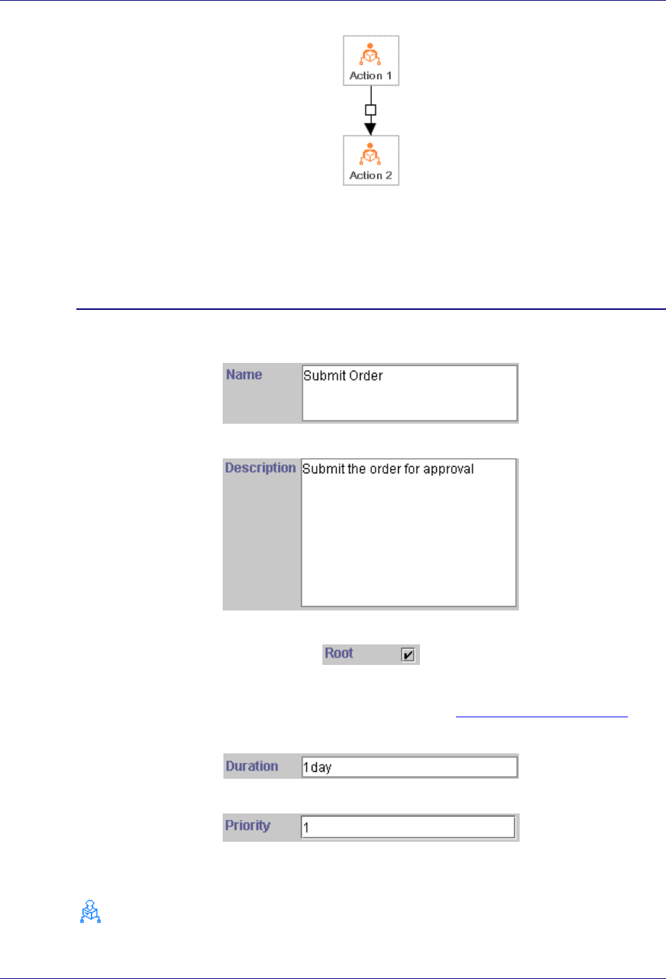
The following diagram shows the typical use of an Action node.
Trilogy MCC Workflow Manager User’s Guide
32 Activity Nodes
In the diagram above, the Action node Action 2 follows the Action node Action 1. The
Trilogy MCC Workflow engine executes Action 1 before executing Action 2.
To set properties of an Action node, complete the following steps:
Define an Action Node
1. Specify the name of the node.
2. Provide a description of the node.
3. Specify whether the node is the root of the workflow plan.
4. Specify which role or user is responsible for the action.
For more information on specifying roles and users, see Chapter 5: Roles and Users.
5. Define how long the action takes.
6. Specify the relative priority of the action.
The Approval Node
Defining Nodes
Activity Nodes 33
An Approval node details an approval decision that a user or a program must make.
Approval nodes require a decision by a user or external program that must evaluate to either
“yes” or “no”. After the program or user has completed the activity, the workflow engine
evaluates an SCFormula expression to determine which path to take. An SCFormula is a
Trilogy format for a generic expression, such as o.managerApproves() or x +1 == y.
For more information on creating SCFormula expressions, refer to the Trilogy Multichannel
Commerce Workflow Developer’s Guide.
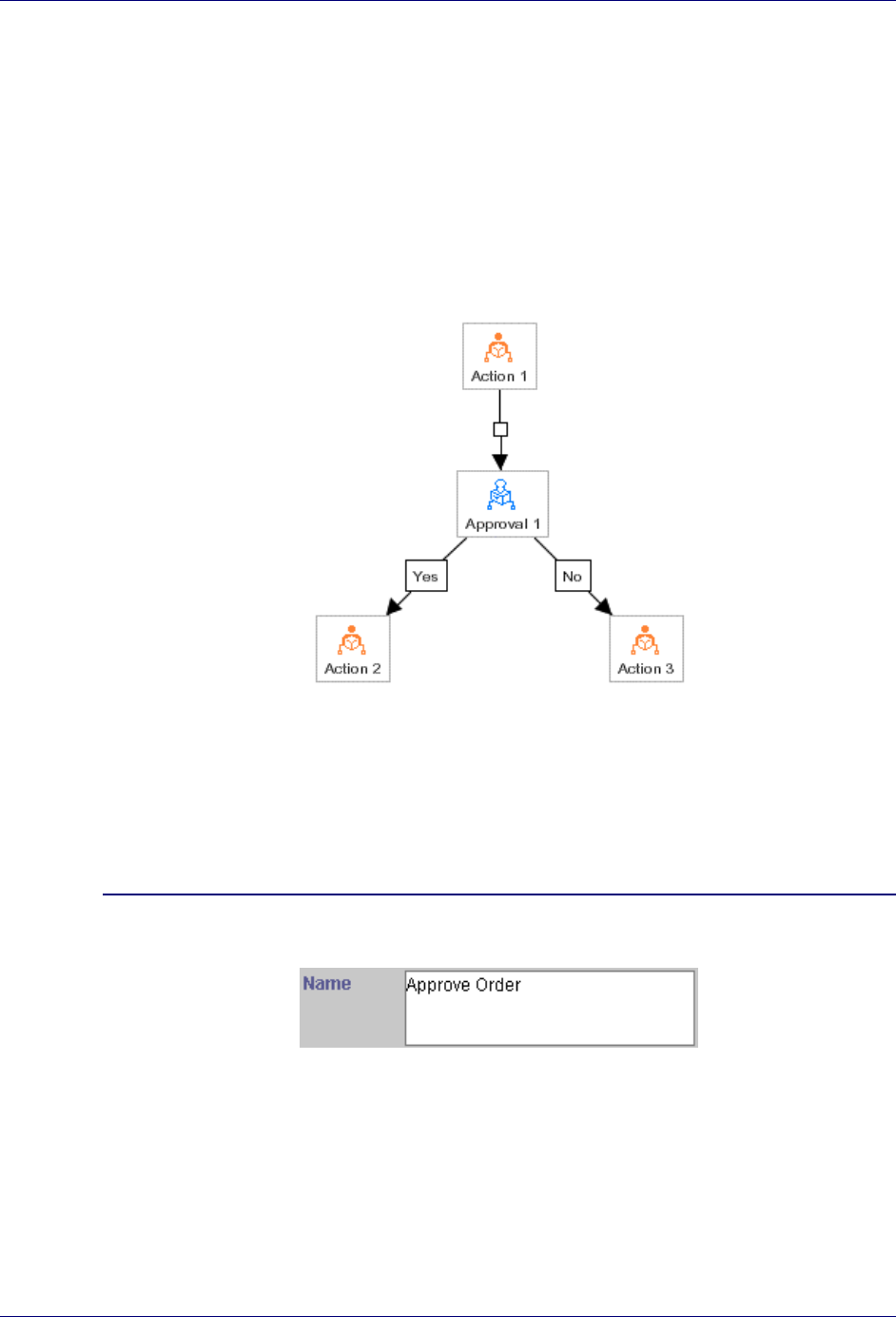
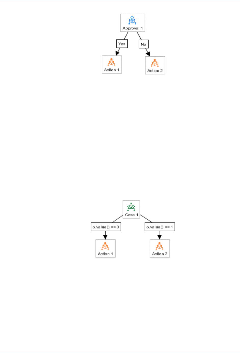
The following diagram shows the typical use of an Approval node.
In the diagram above, the Approval node Approval 1 follows the Action node Action 1.
There are two Actions that follow the approval: Action 2 is executed if the condition of
Approval 1 evaluates to true, and Action 3 is executed if the condition of Approval 1
evaluates to false.
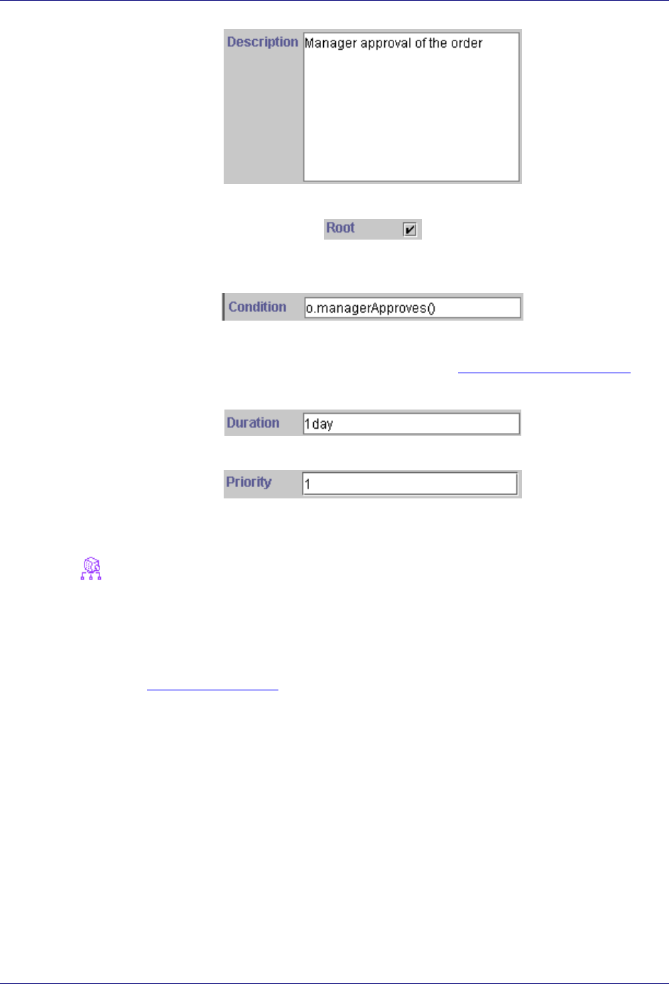
To set properties of an Approval node, complete the following steps:
Define an Approval Node
1. Specify the name of the node.
2. Provide a description of the node.
Trilogy MCC Workflow Manager User’s Guide
34 Activity Nodes
3. Specify whether the node is the root of the workflow plan.
4. Provide an
SCFormula expression that evaluates to true if the Yes path should be taken
and false if the No path should be taken.
5. Specify which role or user is responsible for the action.
For more information on specifying roles and users, see Chapter 5: Roles and Users.
6. Define how long the action takes.
7. Specify the relative priority of the action.
The Dispatch Node
A Dispatch node is similar to an approval node, in that it describes a decision that a user or
application must make. Unlike the approval node, a Dispatch node is followed by an
unlimited number of paths, and an event received by the Trilogy MCC Workflow engine
determines which path to follow. For more information on defining transitions on Dispatch
nodes, see Dispatch Transitions in Chapter 4: Defining Transitions.
The following diagram shows the typical use of a Dispatch node.

Defining Nodes
Activity Nodes 35
In the diagram above, the Dispatch node Dispatch 1 follows the Action node Action 1.
There are four actions that follow the dispatch. Action 2, Action 3, Action 4 and
Action 5 may all execute after Dispatch 1, but each executes only if the event on the
path leading to it occurs.
To set properties of a Dispatch node, complete the following steps:
Define a Dispatch Node
1. Specify the name of the node.
2. Provide a description of the node.
3. Specify whether the node is the root of the workflow plan.
4. Specify which role or user is responsible for the action.
For more information on specifying roles and users, see Chapter 5: Roles and Users.
5. Define how long the action takes.

Trilogy MCC Workflow Manager User’s Guide
36 Transition Nodes
6. Specify the relative priority of the action.
Transition Nodes
There are seven types of Transition nodes:
! The Branch Node
! The Case Node
! The Delay Node
! The Fork Node
! The Join Node
! The Sub-Process Node
! The Noop Node
This section describes how and when to add each type of node, and how to set properties on
each of those nodes.
The Branch Node
A Branch node has two branches and decides which branch to take without waiting for an
event to occur. You should use a Branch node when determining a path without a decision
from a user or the application. For example, an order processing system may process orders
differently depending on the total price of each order. If the total price of the order is under
$500, the order is submitted directly to Billing. If the total price of the order is over $500, the
order must be approved by a manager before it is submitted to Billing. Using the Branch
node, the system could evaluate the total price of the order and determine the path without the
input of a user or an external application.
When the Trilogy MCC Workflow engine encounters a Branch node, the engine evaluates an
SCFormula expression to determine which path to take. For more information on creating
SCFormula expressions, refer to the Trilogy Multichannel Commerce Workflow Developer’s
Guide.
The Branch node can be used to simulate if-then logic, because it does not run two paths in
parallel. If you need to run two or more paths in parallel, refer to The Case Node.
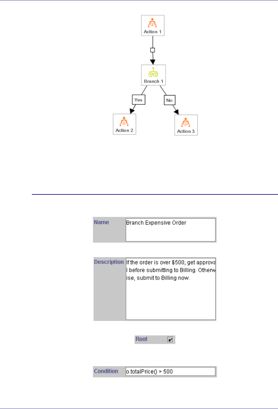
The following diagram shows the typical use of a Branch node.
Defining Nodes
Transition Nodes 37
In the diagram above, the Branch node Branch 1 follows the Action node Action 1. There
are two Actions that follow the branch: Action 2 is executed if the condition of Branch 1
evaluates to true, and Action 3 is executed if the condition of Branch 1 evaluates to false.
To set properties of a Branch node, complete the following steps:
Define a Branch Node
1. Specify the name of the node.
2. Provide a description of the node.
3. Specify whether the node is the root of the workflow plan.
4. Provide an
SCFormula expression that evaluates to true if the Yes path should be taken
and false if the No path should be taken.
Trilogy MCC Workflow Manager User’s Guide
38 Transition Nodes
The Case Node
A Case node splits a process into any number of parallel paths. Unlike the Branch node, the
expression evaluated to determine the path taken by the Case node is not a property of the
node itself, but a property of the outgoing transition. For more information on defining
transitions on Case nodes, see Case Transitions in Chapter 4: Defining Transitions.
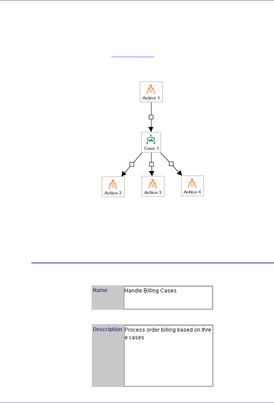
The following diagram shows the typical use of a Case node.
In the diagram above, the Case node Case 1 follows the Action node Action 1. There are
three actions that follow the case. Action 2, Action 3, and Action 4 may all execute
after Case 1, but each executes only if the condition on the path leading to it evaluates to
true.
To set properties of a Case node, complete the following steps:
Define a Case Node
1. Specify the name of the node.
2. Provide a description of the node.

Defining Nodes
Transition Nodes 39
3. Specify whether the node is the root of the workflow plan.
The Delay Node
The Delay node is a Branch node that executes after a specified delay. Like the Branch node,
the Delay node checks to see if a specific condition has occurred. However, the delay node
differs by first waiting a specified amount of time before checking. If the condition has
occurred, then the Trilogy MCC Workflow engine executes the true branch that follows.
Otherwise it executes the false branch. Typically, the false branch is not specified, indicating
the end of execution if the condition evaluates to false.
You can use a forked Delay node to delay the approval of an order for three days. After the
delay, the delay node executes. If the order has not been approved, then the Trilogy MCC
Workflow engine might send a reminder email and perhaps go into a second stage escalation
path. The false path would be blank, meaning that execution ends if the order has been
approved.
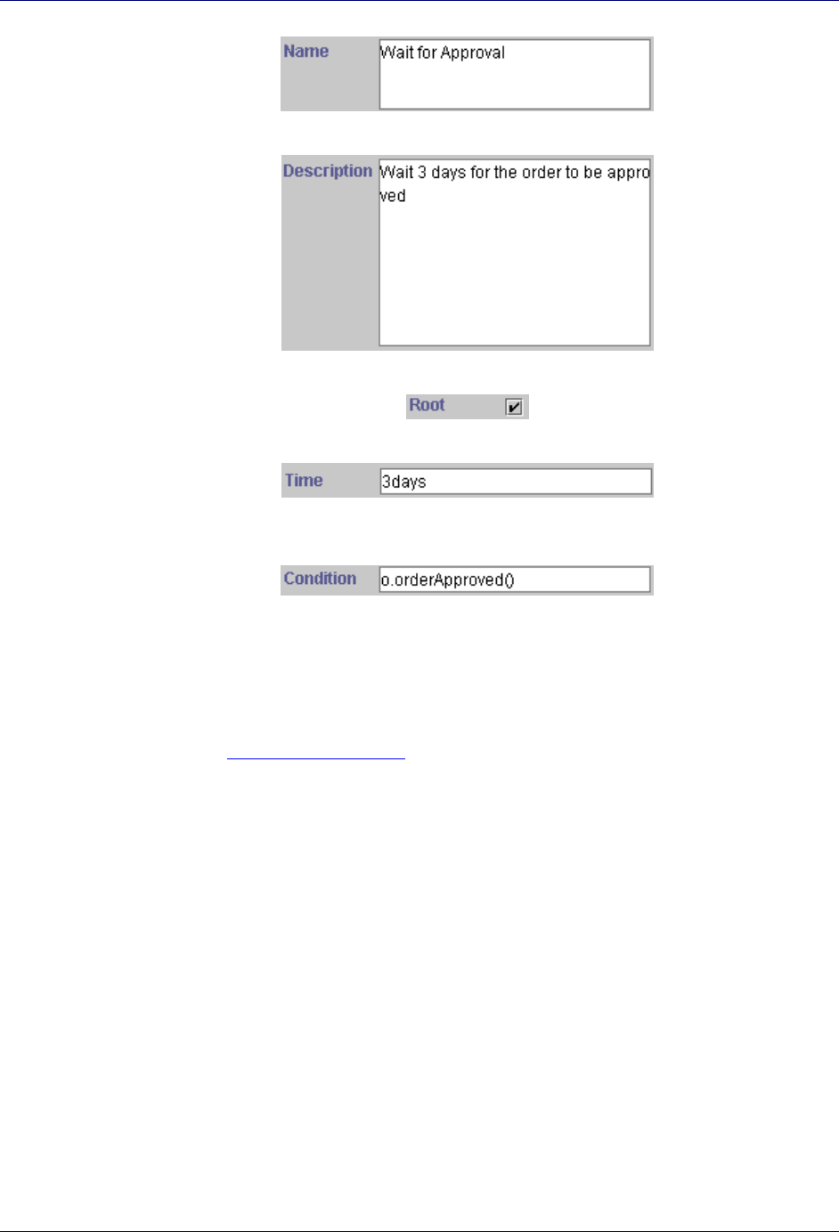
The following diagram shows the typical use of a Delay node.
In the diagram above, the Delay node Delay 1 follows the Action node Action 1. After
waiting the length of the delay associated with Delay 1, the condition of Delay 1 is
evaluated. There are two Actions that follow the delay: Action 2 executes if the condition
of Delay 1 evaluates to true, and Action 3 executes if the condition of Delay 1 evaluates
to false.
To set properties of a Delay node, complete the following steps:
Define a Delay Node
1. Specify the name of the node.
Trilogy MCC Workflow Manager User’s Guide
40 Transition Nodes
2. Provide a description of the node.
3. Specify whether the node is the root of the workflow plan.
4. Define the length of delay before evaluating the condition.
5. Provide an
SCFormula expression that evaluates to true if the Yes path should be taken
and false if the No path should be taken.
The Fork Node
The Fork node splits parallel execution paths unconditionally. A Fork node has multiple
branches like a Case node, but there are no expressions on the transitions. The workflow
engine executes all transitions of the node. For more information on defining transitions on
Fork nodes, see Fork Node Transitions in Chapter 4: Defining Transitions.
The following diagram shows the typical use of a Fork node.
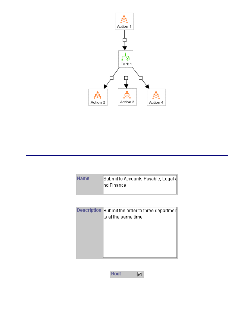
Defining Nodes
Transition Nodes 41
In the diagram above, the Fork node Fork 1 follows the Action node Action 1. There are
three actions that follow the fork. Action 2, Action 3, and Action 4 all execute after
Case 1.
To set properties of a Fork node, complete the following steps:
Define a Fork Node
1. Specify the name of the node.
2. Provide a description of the node.
3. Specify whether the node is the root of the workflow plan.
The Join Node
The Join node is the converse of the Fork node. A Join node unites parallel branches back
into a single path. The Trilogy MCC Workflow engine waits for all the precedents of the Join
node to finish before proceeding over it.
Trilogy MCC Workflow Manager User’s Guide
42 Transition Nodes
The Join node should be used when an activity has to wait for several parallel activities to
finish. It should lead to an action node that is associated with that activity.
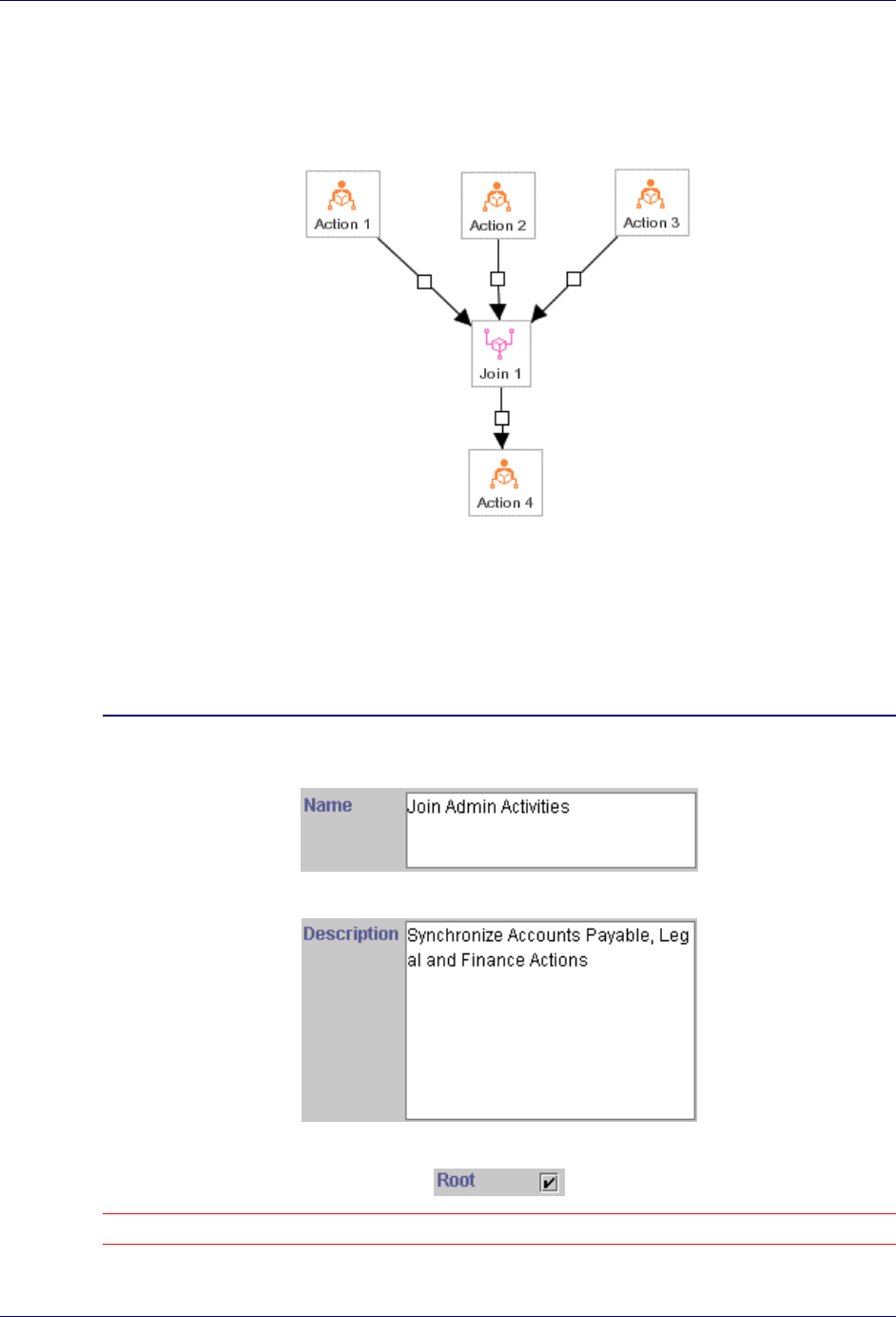
The following diagram shows the typical use of a Join node.
In the diagram above, the Join node Join 1 does not execute until all of the Action nodes
Action 1, Action 2, and Action 3 have completed. After completion of the join,
Action 4 executes.
To set properties of a Join node, complete the following steps:
Define a Join Node
1. Specify the name of the node.
2. Provide a description of the node.
3. Specify whether the node is the root of the workflow plan.
Note: You should never make a Join node the root of a workflow plan, as it joins previous activities.
Defining Nodes
Transition Nodes 43
The Sub-Process Node
A Sub-Process node represents a workflow plan that is a part of a larger workflow plan. Sub-
Process nodes simplify workflow plan management by dividing a large workflow into smaller
groups. Dividing the run-time logic of a large workflow into smaller sub-workflows may also
improve performance.
The Trilogy MCC Workflow software supports any level of nesting, allowing you to nest
workflow plans within workflow plans. Through the nesting of workflow plans, you can
revise a process section without affecting the higher-level plan.
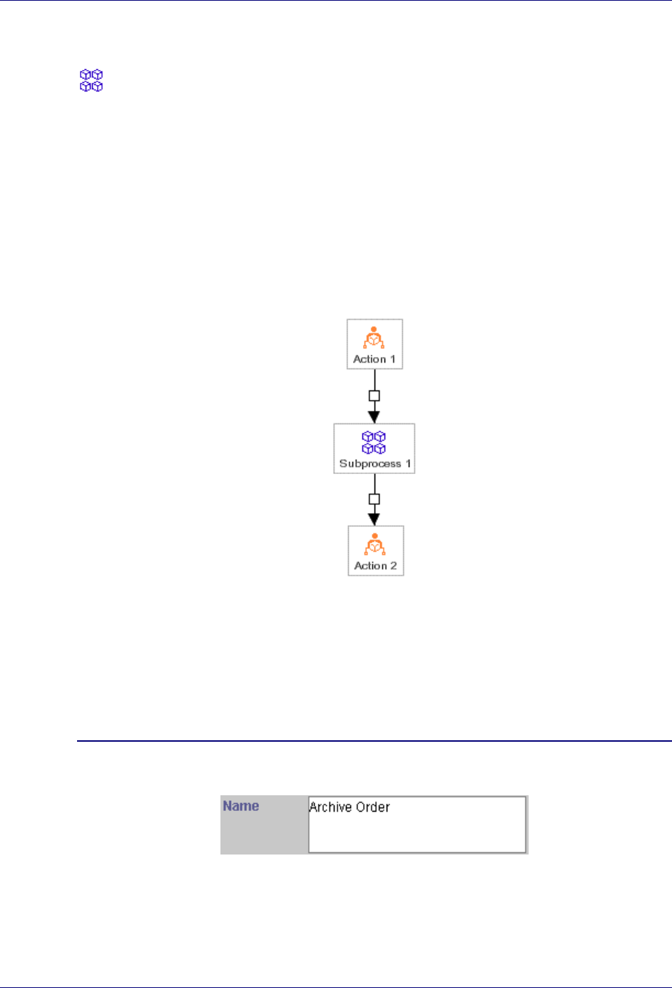
The following diagram shows the typical use of a Sub-Process node.
In the diagram above, the Sub-Process node Subprocess 1 follows the Action node
Action 1. After completing execution of Action 1, the Trilogy MCC Workflow engine
executes the workflow plan represented by Subprocess 1. When Subprocess 1
terminates, the Trilogy MCC Workflow engine executes Action 2.
To set properties of a Sub-Process node, complete the following steps:
Define a Sub-Process Node
1. Specify the name of the node.
2. Provide a description of the node.

Trilogy MCC Workflow Manager User’s Guide
44 Transition Nodes
3. Specify whether the node is the root of the workflow plan.
4. Browse for the XML file that details the sub-workflow plan.
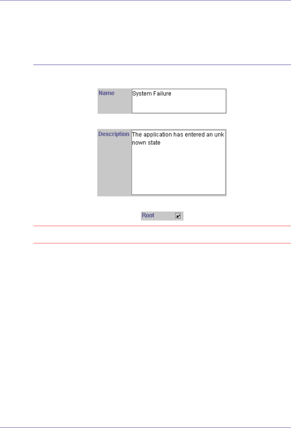
The Noop Node
The Noop (no operation) node is used when no action should be taken in the business process.
Because no paths can exit from a Noop node, it acts as an execution termination point of the
workflow plan. Examples of processes represented by Noop nodes are the rejection of an
order or system failure.
The following diagram shows the typical use of a Noop node.
Defining Nodes
Transition Nodes 45
In the diagram above, the Noop node Noop 1 follows the Approval node Approval 1. If
the approval fails, execution of the workflow plan terminates with execution of the Noop
node Noop1.
To set properties of a Noop node, complete the following steps:
Define a Noop Node
1. Specify the name of the node.
2. Provide a description of the node.
3. Specify whether the node is the root of the workflow plan.
Note: A Noop node should never be the root of a workflow plan. Since no paths can originate from a Noop
node, the plan would be meaningless, as it would only contain the root element.
Understanding and Defining Transitions 47
Chapter 4: Defining Transitions
This chapter explains how to create and define transitions in a workflow plan using the
Trilogy MCC Workflow Manager application.
Understanding and Defining Transitions
Transitions link nodes in a workflow plan, and specify which nodes execute before others.
This section covers the following topics:
! Adding Transitions
! Understanding Transitions
Anatomy of a Transition
Each transition has the following components:
! Originating Node: The node from which the transition leads. Each transition must have
exactly one originating node.
! Terminating Node: The node to which the transition leads. Each transition must have
exactly one terminating node.
! Transition Handle: The box in the middle of the transition, by which the developer can
change the position of the transition. For some transition types, the Transition Handle
contains informational text.
! Transition Arrow: The arrow that points from the originating node to the terminating
node.
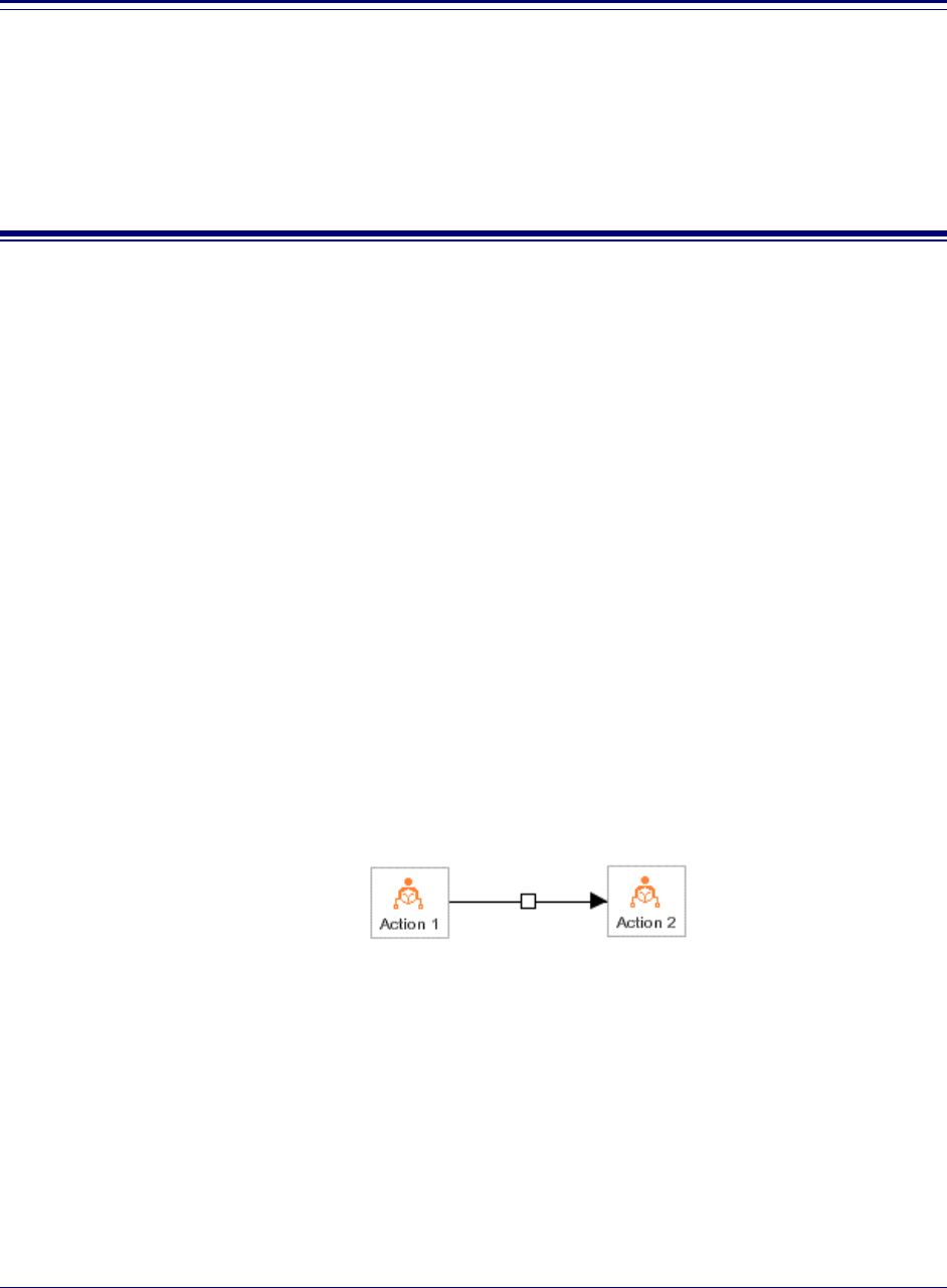
The following diagram shows a typical transition:
In the diagram above, the Action node Action 1 is the originating node, the Action node
Action 2 is the terminating node and the box in the middle is the transition handle. The
transition arrow points to Action 2.
Adding Transitions
The Transition Tool is used to create transitions. Create a transition by specifying the starting
node, the ending node, and the properties of the transition. Complete the following steps to
add a transition to a workflow plan.

Trilogy MCC Workflow Manager User’s Guide
48 Understanding and Defining Transitions
Add a Transition to a Workflow Plan
1. Click the Transition Tool in the Toolbar.
2. Click the node from which the transition starts.
3. Click the node to which the transition leads.
4. Specify the properties of the transition in the Properties window.
Understanding Transitions from Nodes
All node types accept any number of transitions and any transition type coming in. The
number of transitions and the types of properties on the transition are determined by the type
of node linked, and whether the transition is linked to the node or from the node. The table
below describes the effect of linking from the various types of nodes.
Node Type Meaning of Transition
Action Node Basic transition. The linked node executes
immediately. One transition allowed.
Approval Node Yes/No transition. The linked node executes
only if the proper Yes/No value was
evaluated on the Condition property of the
Approval node. Two transitions allowed.
Branch Node Yes/No transition. The linked node executes
only if the proper Yes/No value was
evaluated on the Condition property of the
Branch node. Two transitions allowed.
Case Node Case transition. The linked node executes
only if the Condition property of the
transition evaluates to true.
Delay Node Yes/No transition. The linked node executes
only if the proper Yes/No value was
evaluated on the Condition property of the
Delay node. Two transitions allowed.
Dispatch Node Dispatch transition. The linked node
executes only if the Event property of the
transition occurs.
Fork Node Basic transition. The linked node executes
immediately. Multiple transition allowed.
Join Node Basic transition. The linked node executes
immediately. One transition allowed.
Sub-Process Node Basic transition. The linked node executes
immediately One transition allowed
Defining Transitions
Understanding Transition Types 49
Node Type Meaning of Transition
immediately. One transition allowed.
Noop Node No transitions allowed.
Understanding Transition Types
Transitions mean different things going in and going out for each type of node.
Basic Transitions
The Basic Transition type is the simplest type of transition. When the Trilogy MCC
Workflow engine encounters a basic transition, it executes the terminating node immediately.
There are no conditions or events associated with the transition.
The properties of the Basic Transition are the Type property, and the X and Y properties. The
X and Y properties specify the position on the Canvas of the transition handle.
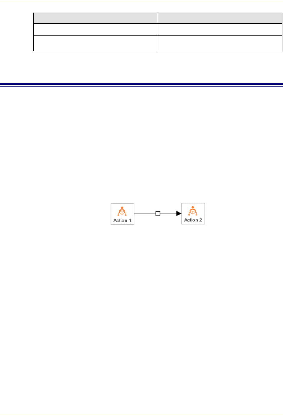
The following diagram shows the typical usage of a Basic transition:
In the diagram above, the completion of the Action node Action 1 is followed immediately
by the execution of the Action node Action 2.
Yes/No Transitions
The Yes/No Transition type is used when the originating node is an Approval, Branch or
Delay node. When the Trilogy MCC Workflow engine encounters a Yes/No transition, it
executes the terminating node only if the Yes/No property of the transition has the same value
as the result of the Condition property of the previous node.
The properties of the Yes/No Transition are the Type property, the X and Y properties, and
the Yes/No property. The X and Y properties specify the position on the Canvas of the
transition handle. The Yes/No property specifies whether the Condition property of the
originating node must evaluate to true or false for the engine to take this path.
The following diagram shows the typical usage of a Yes/No transition:
Trilogy MCC Workflow Manager User’s Guide
50 Understanding Transition Types
In the diagram above, the Action node Action 1 executes only if the Condition property of
the Approval node Approval 1 evaluates to true. Otherwise the Action node Action 2
executes.
Case Transitions
The Case Transition type is used when the originating node is a Case node. When the Trilogy
MCC Workflow engine encounters a Case transition, it evaluates the Condition property of
the transition, and executes the terminating node only if the result of the evaluation is true.
The properties of the Case Transition are the Type property, the X and Y properties, and the
Condition property. The X and Y properties specify the position on the canvas of the
transition handle. The Condition property specifies the expression that must evaluate to true
for the engine to take this path.
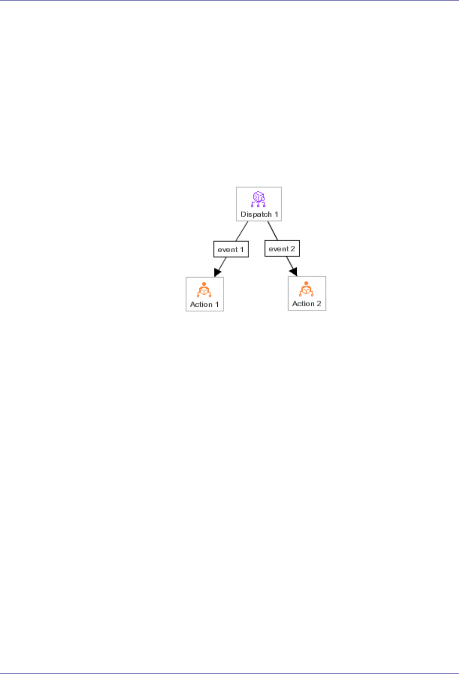
The following diagram shows the typical usage of a Case transition:
In the diagram above, the Action node Action 1 executes only if the expression
o.value() == 0 evaluates to true. If the expression o.value() == 1 evaluates to true,
the Action node Action 2 executes. Otherwise, execution of the workflow plan terminates,
as there are no other nodes.
Dispatch Transitions
The Dispatch Transition type is used when the originating node is a Dispatch node. When
the Trilogy MCC Workflow engine encounters a Dispatch node, it expects for an event to
occur at that time, such as clicking a “Submit for Approval” button. The engine then checks
Defining Transitions
Understanding Transition Types 51
the Event property of each transition that leads from the Dispatch node, and executes that
transition whose Event property has the name of the event that occurred. If no event occurred
whose name matches the Event property of a transition, the engine waits for an event to occur
before proceeding with execution of the workflow plan. For more information on events,
refer to the Trilogy MCC Workflow Developer’s Guide.
The properties of the Dispatch Transition are the Type property, the X and Y properties, and
the Event property. The X and Y properties specify the position on the canvas of the
transition handle. The Event property specifies the event that must occur for the engine to
take this path.
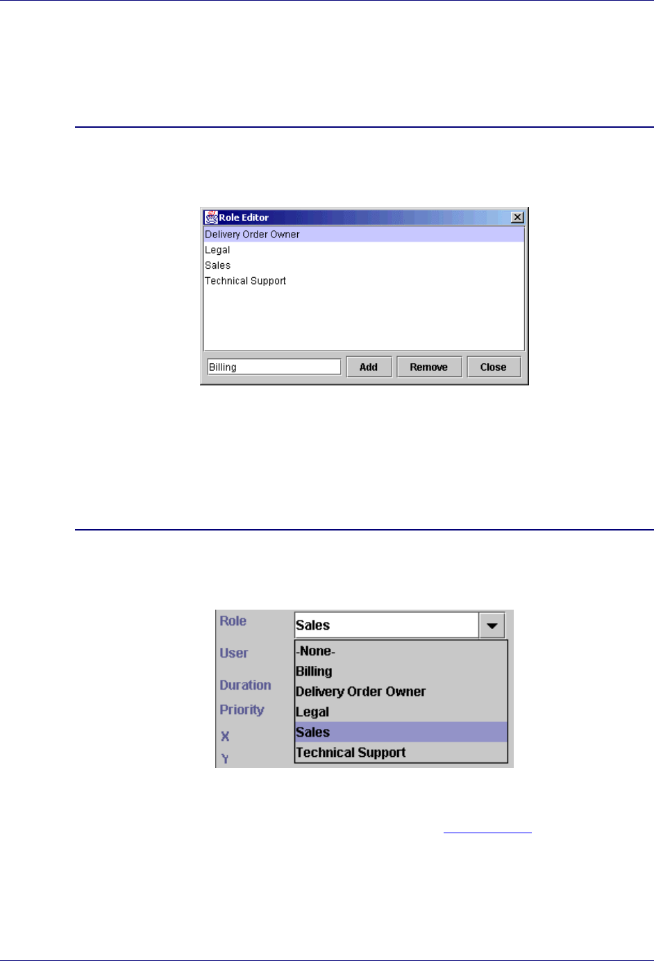
The following diagram shows the typical usage of a Dispatch transition:
In the diagram above, the Action node Action 1 executes only after the Event property of
the Dispatch transition event 1 occurs. Similarly, the Action node Action 2 executes only
after the Event property of the Dispatch transition event 2 occurs.

Understanding Roles and Users 53
Chapter 5: Roles and Users
This chapter explains how and when to create and define roles and users in a workflow plan
using the Trilogy MCC Workflow Manager application. Topics include:
! Understanding Roles and Users
! Working with Roles
! Working with Users
Understanding Roles and Users
Every action node or approval node must specify a role or user. The assignment of a role or
user to a node specifies who is allowed to perform the activity associated with that node. If a
named user is assigned to a node, only that user is allowed to perform the activity. If a role is
assigned to a node, any user assigned to that role may perform the activity.
Assigning a Role or Assigning a User
Although the Trilogy MCC Workflow engine supports specifying a named user instead of a
role, this practice is strongly discouraged, as users frequently change responsibilities within
an organization. If a named user is associated with an activity, all related workflow plans
must be revised when the user changes roles. If roles are used, the method for routing work
may be changed independently of the workflow plan.
If you need to assign a specific user to an activity, create a specialized role and assign it only
to a single individual. This approach provides the benefits of named users with the flexibility
of role assignment.
Working with Roles
Assign roles to nodes when you do not know the specific user that performs the activity
represented by the node at the time you create the workflow plan. This section explains the
following activities:
! Creating a Role
! Assigning Roles
! Highlighting Nodes Assigned to Roles
! Removing a Role
Trilogy MCC Workflow Manager User’s Guide
54 Working with Roles
Creating a Role
You must create a role before you can assign it to a node. To create a role in the Trilogy
MCC Workflow Manager application, complete the following steps:
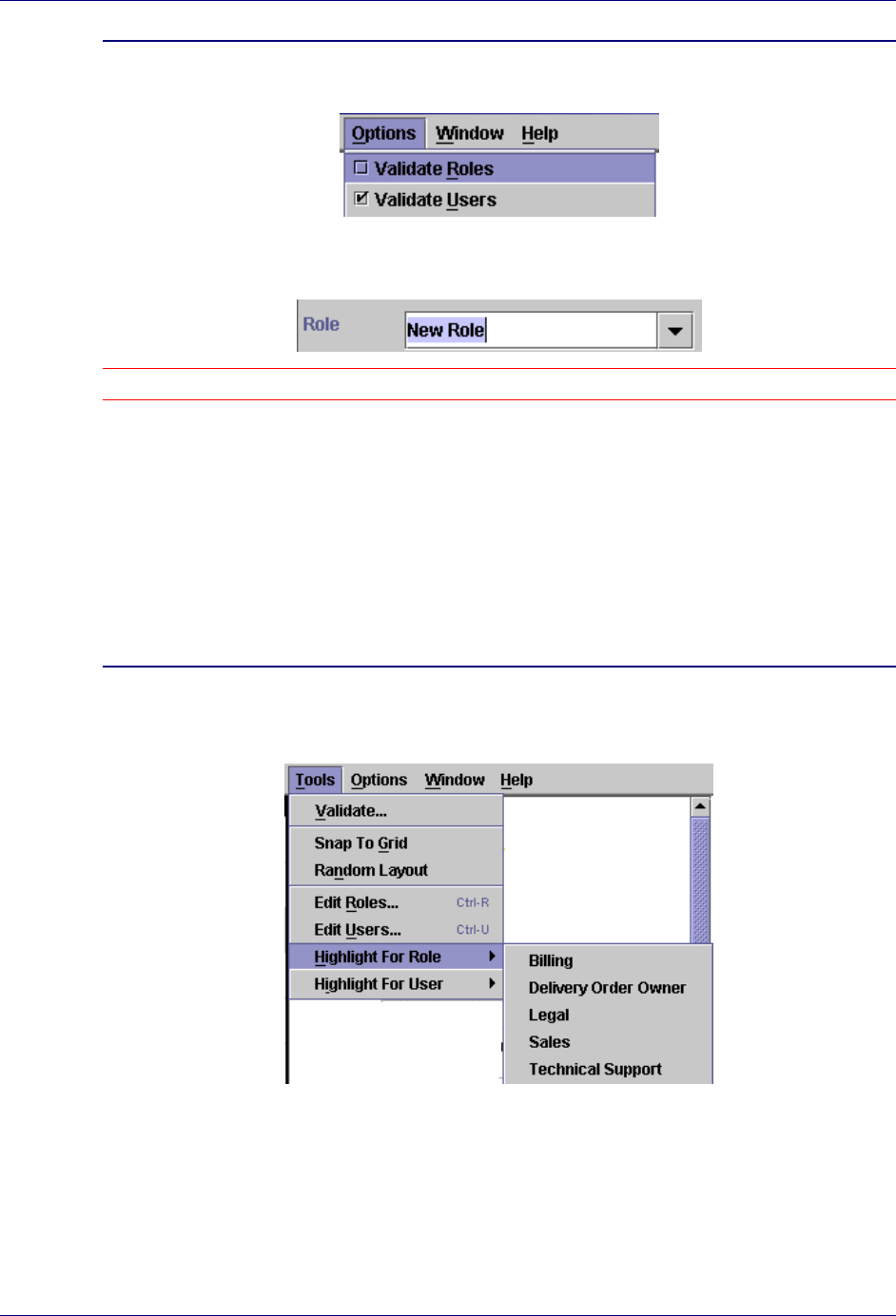
Create a New Role
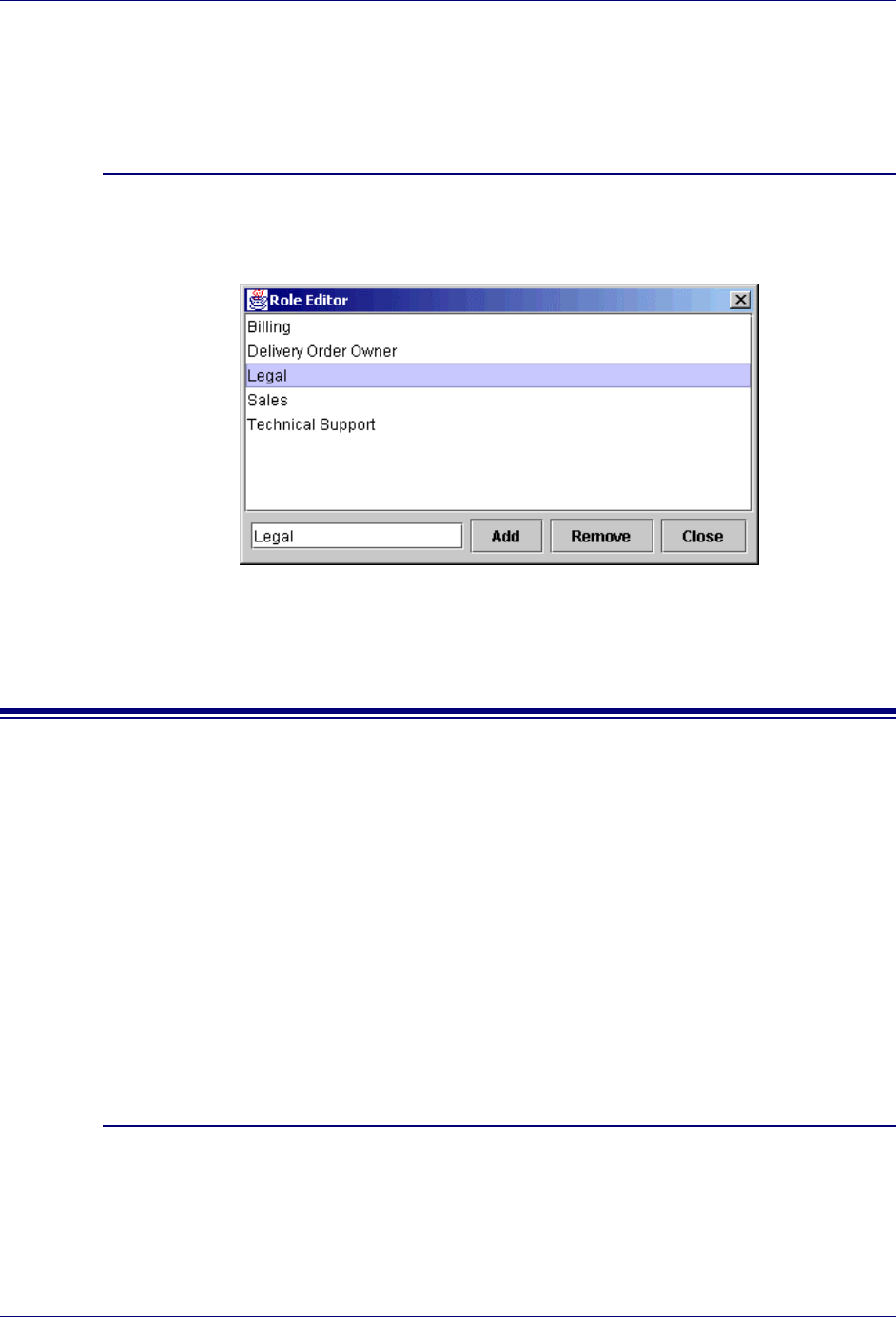
1. Select Edit Roles… from the Tools menu. The Role Editor window opens.
2. Type the name of the new role at the bottom of the Role Editor window.
3. Click Add to add the new role to the list of roles available to the workflow plan.
Assigning Roles
To assign an existing role in the Trilogy MCC Workflow Manager application, complete the
following steps:
Assign an Existing Role to a Node
1. Click the node to which the role should be assigned.
2. Choose the appropriate role from the Role menu in the Properties window.
You can also assign roles may by typing the name of the role in the Role menu in the
Properties window. This option is only available if the Validate Roles option is turned off.
For more information on the Validate Roles option, see the Options Menu in Chapter 2:
Getting Started. To assign a non-validated role in the Trilogy MCC Workflow Manager
application, complete the following steps:
Roles and Users
Working with Roles 55
Assign an Existing Role to a Node
1. Make sure the Validate Roles item in the Options menu is unchecked.
2. Select the node to which you want to assign a role.
3. Type the name of the role at the top of the Role menu in the Properties window.
Note: It is rarely a good idea to assign non-validated roles to nodes, as misspellings are not checked.
Highlighting Nodes Assigned to Roles
It is often convenient to highlight all the nodes associated with a particular role. For example,
you may be asked to streamline the approval process where managers are concerned. You can
highlight all nodes assigned to the manager role to make your job easier.
To highlight all nodes in a workflow plan that are associated with a particular role, complete
the following steps:
Highlight Nodes Assigned to an Existing Role
1. Move your mouse cursor over the Highlight for Role item in the Tools menu. A list of
roles displays to the right.
2. Select the appropriate role from the list. The Trilogy MCC Workflow Manager
application highlights all nodes assigned to the selected role in that workflow plan.
Trilogy MCC Workflow Manager User’s Guide
56 Working with Users
Removing a Role
To remove a role from a workflow plan in the Trilogy MCC Workflow Manager application,
complete the following steps:
Remove an Existing Role
1. Select Edit Roles… from the Tools menu. The Role Editor window opens.
2. Highlight the name of the role you want to remove from the list of available roles.
3. Click Remove to remove the role from the list of roles available to the workflow plan.
Working with Users
Users are assigned to nodes when the specific user that performs the activity represented by
the node is known when creating the workflow plan, and only that specific individual is
allowed to perform the activity. This section explains the following activities:
! Creating a User
! Assigning Users
! Highlighting Nodes Assigned to Users
! Removing a User
Creating a User
To create a user in the Trilogy MCC Workflow Manager application, complete the following
steps:
Create a New User
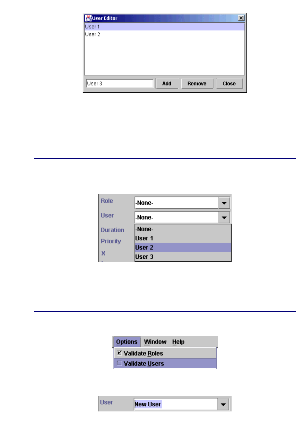
1. Select Edit Users… from the Tools menu. The User Editor window opens.
2. Type the name of the new user at the bottom of the User Editor window.
Roles and Users
Working with Users 57
3. Click Add to add the new user to the list of roles available to the workflow plan.
Assigning Users
To assign an existing user in the Trilogy MCC Workflow Manager application, complete the
following steps:
Assign an Existing User to a Node
1. Select the node to which you want to assign the user.
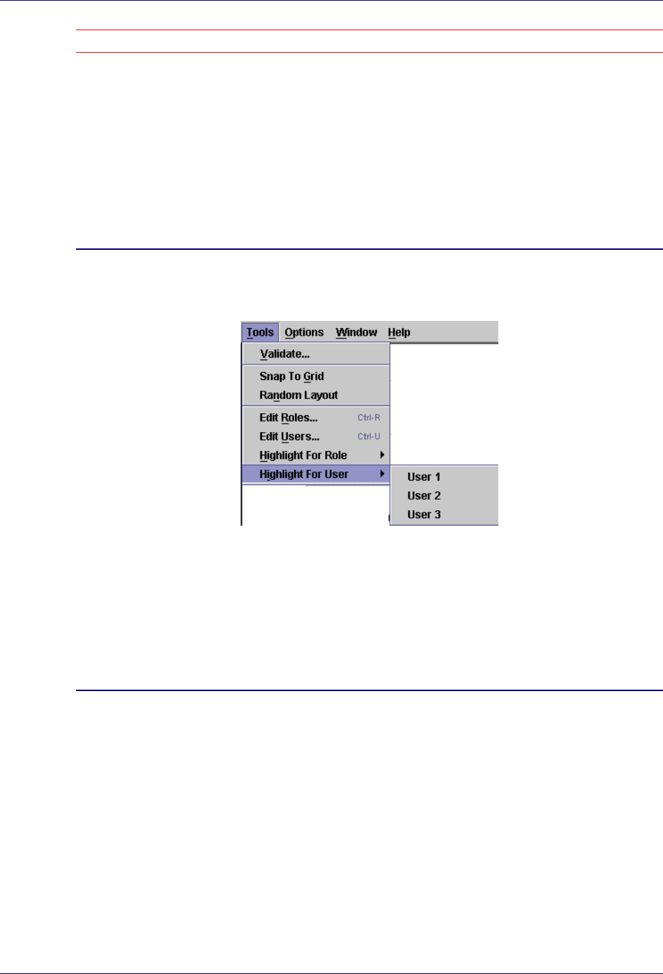
2. Choose the appropriate user from the User menu in the Properties window.
You can also assign users by typing the name of the user in the User menu in the Properties
window. This option is only available if the Validate Users option is turned off. To assign a
non-validated user in the Trilogy MCC Workflow Manager application, complete the
following steps:
Assign a Non-Validated User to a Node
1. Make sure the Validate Users item in the Options menu is unchecked.
2. Select the node to which you want to assign the user.
3. Type the name of the user at the top of the Role menu in the Properties window.
Trilogy MCC Workflow Manager User’s Guide
58 Working with Users
Note: It is rarely a good idea to assign non-validated users to nodes, as misspellings are not checked.
Highlighting Nodes Assigned to Roles
It is often convenient to highlight all the nodes associated with a particular user. For example,
you may be asked to streamline the approval process where your boss is concerned. You can
highlight all nodes assigned to your boss to make your job easier.
To highlight all nodes in a workflow plan that are associated with a particular user, complete
the following steps:
Highlight Nodes Assigned to an Existing User
1. Move your mouse cursor over the Highlight for User item in the Tools menu. A list of
users displays to the right.
2. Select the appropriate user from the list. The Trilogy MCC Workflow Manager
application highlights all nodes assigned to the selected user in that workflow plan.
Removing a User
To remove a user from a workflow plan in the Trilogy MCC Workflow Manager application,
complete the following steps:
Remove an Existing User
1. Select Edit Users… from the Tools menu. The Role Editor window opens.
2. Highlight the name of the user to remove from the list of available users.

Roles and Users
Working with Users 59
3. Click Remove to remove the user from the list of users available to the workflow plan.
Validating a Workflow Plan 61
Chapter 6: Validating and Saving Plans
This chapter explains how to validate and save a workflow plan using the Trilogy MCC
Workflow Manager application. Topics discussed include:
! Validating a Workflow Plan
! Saving a Workflow Plan
Validating a Workflow Plan
The Trilogy MCC Workflow Manager application provides several mechanisms for
validating the current workflow plan. These mechanisms include:
! Transition Validation
! Manual Validation
! Role and User Validation
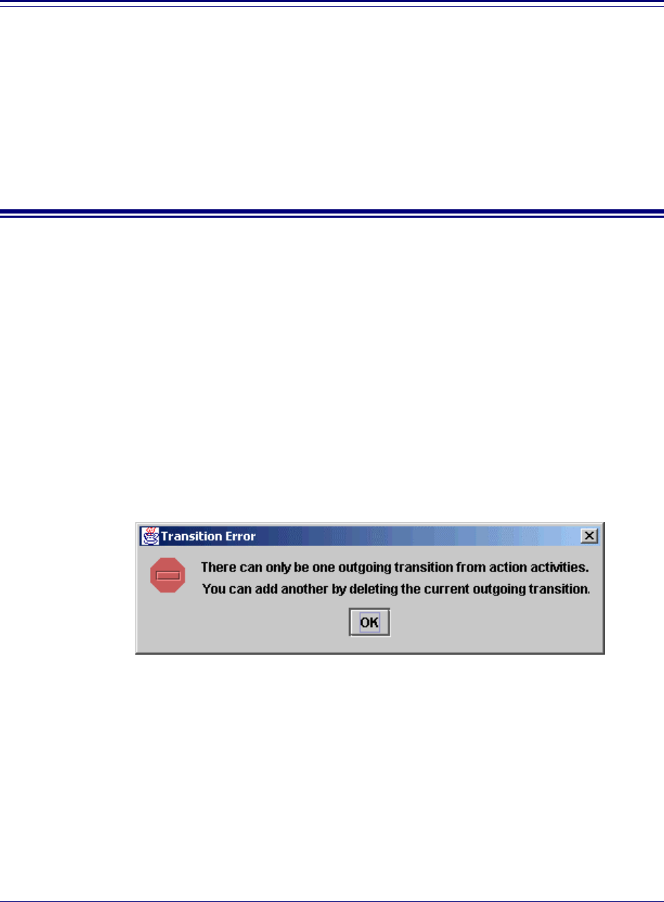
Transition Validation
As you add nodes and transitions, the Trilogy MCC Workflow Manager application ensures
proper transitions placement. If you attempt to place a transition where it cannot go, the
application displays an error message. For example, if you attempt to define two transitions
from a single Action node, the Trilogy MCC Workflow Manager application displays a
Transition Error message similar to the following:
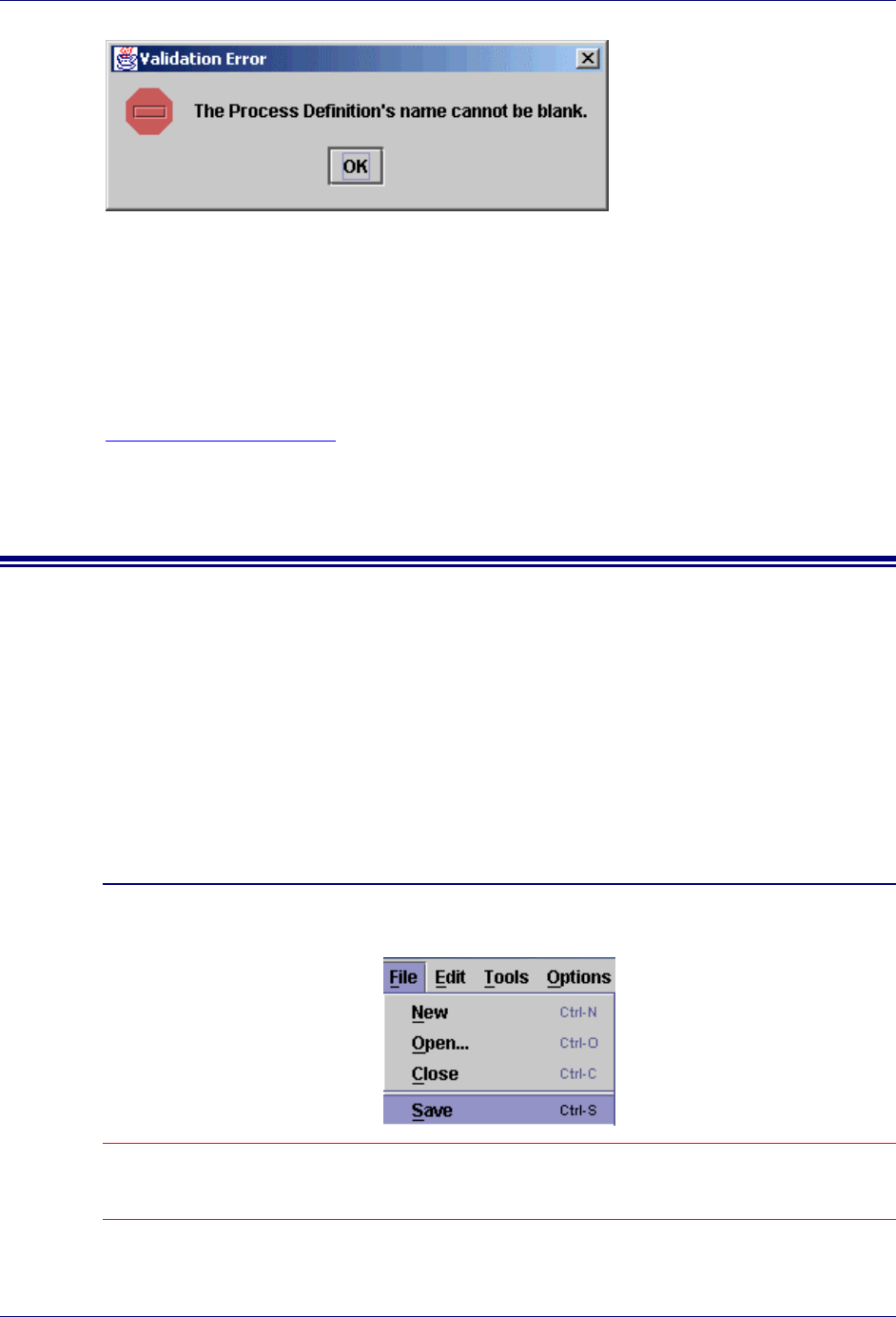
Manual Validation
To ensure that a workflow plan works correctly with the Trilogy MCC Workflow engine,
validate the workflow plan by selecting Validate… from the Tools menu. The Trilogy MCC
Workflow Manager application checks all components of the workflow plan, to ensure that
there are no errors or omissions that impede proper engine execution. If the Trilogy MCC
Workflow Manager application encounters an error or omission during validation, it displays
a Transition Error message. For example, if you validate a workflow plan before specifying
the name of the plan, the application displays a Validation Error message, indicating that the
name cannot be left blank.
Trilogy MCC Workflow Manager User’s Guide
62 Saving a Workflow Plan
Role and User Validation
The Trilogy MCC Workflow Manager application provides the option to validate the users
and roles assigned to nodes. If the Validate Roles item on the Options menu is checked, you
must select from a list of existing roles when assigning a role to a node. Similarly, if the
Validate Users item of the Options menu is checked, you must select from a list of existing
users when assigning a user to a node. For more information about roles and users, see
Chapter 5: Roles and Users.
Saving a Workflow Plan
The Trilogy MCC Workflow Manager application provides two mechanisms for saving a
workflow plan. These mechanisms include:
! Saving as XML
! Saving as an image
Saving as XML
The Trilogy MCC Workflow engine only reads an XML representation of the workflow plan.
To save a workflow plan as XML, complete the following steps:
Saving a Workflow Plan as XML
1. Select Save from the File menu. Alternatively, you can use the keyboard shortcut Ctrl-S.
Note: If you have saved the workflow plan before, the previously saved plan is overwritten. If you are saving
the plan for the first time, the Save as XML window opens. Specify the location and name of the new
workflow plan.
Validating and Saving Plans
Saving a Workflow Plan 63
Saving a Workflow Plan as XML to a New Location or Name
1. Select Save As… from the File menu. The Save as XML window opens.
2. Specify the location and name of the workflow plan. Click Save to save the plan.
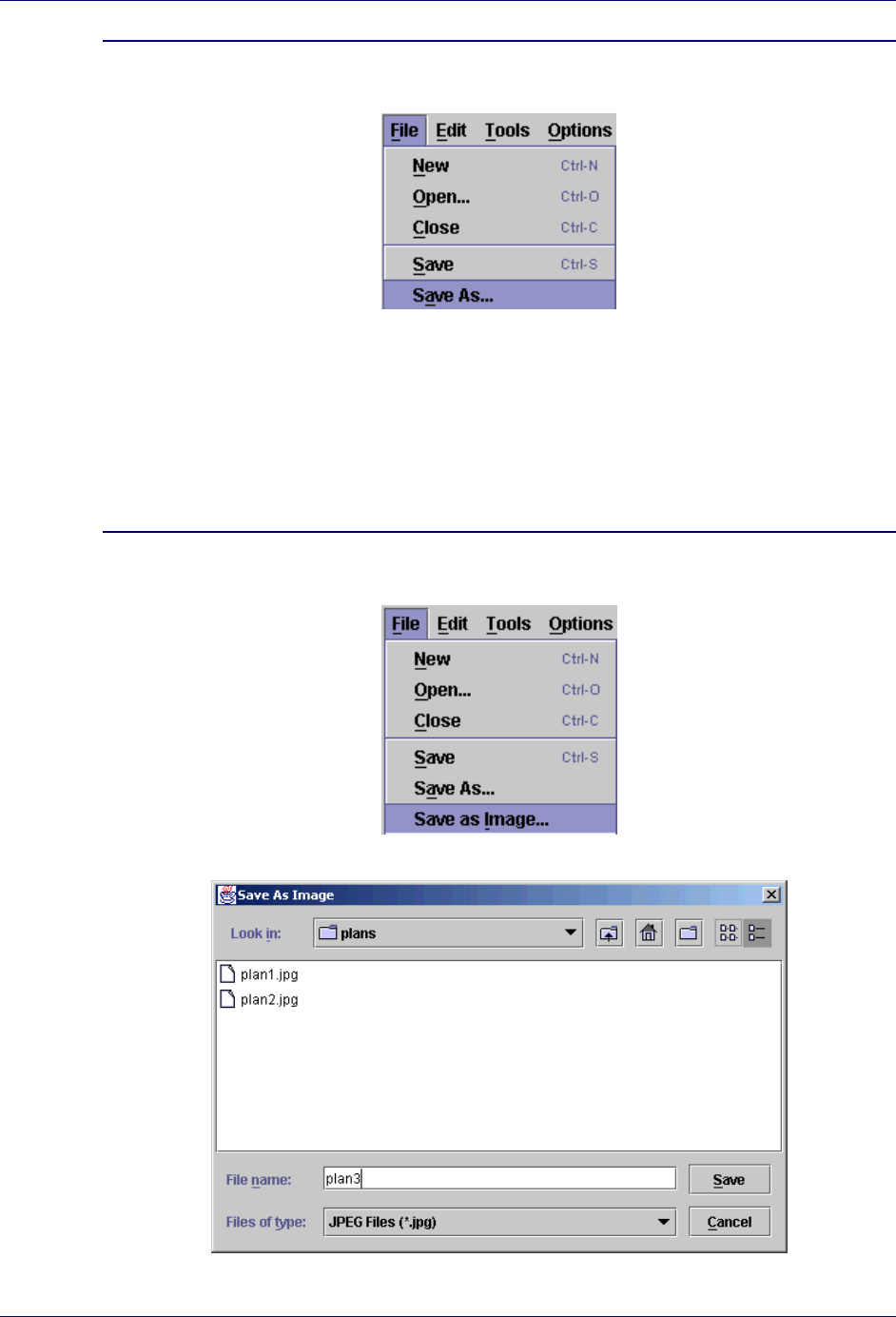
Saving as an Image
It is often convenient to create an image file that represents the workflow plan. For example,
you might need to communicate the structure of the plan in a report or on a team web site. To
save a workflow plan as a JPEG image file, complete the following steps:
Saving a Workflow Plan as an Image
1. Select Save as Image… from the File menu. The Save As Image window opens.
2. Specify the location and name of the image. Click Save to save the plan.

Trilogy MCC Workflow Manager User’s Guide
64 Saving a Workflow Plan

65
Glossary of Terms and Abbreviations
Action Node Activity node that describes an activity that a user or application must perform.
Activity Node A node that represents an activity that can be performed by a user, role, or the
application. Types of Activity nodes include: Action node, Approval node, Dispatch
node, and Noop node.
Approval Node Activity node that details an approval decision that a user or a program must
make.
Basic Transition Transition that executes its terminating node immediately.
Branch Node Transition node that has two branches and decides which branch to take without
waiting for an event to be fired.
Case Node Transition node that splits a process into any number of parallel paths.
Case Transition Transition that executes its terminating node only if the Condition property of the
transition evaluates to true.
Delay Node Transition node that is simply a Branch node that executes after a specified delay.
Dispatch Node Activity node that describes a decision that a user or application must make, and is
followed by an unlimited number of paths. An event received by the Trilogy MCC
Workflow engine determines which path to follow.
Dispatch
Transition Transition that executes its terminating node only after the event specified in the
Event property of the transition has occurred.
Event A user action that allows the Trilogy MCC Workflow engine to continue execution
of the workflow plan. An example of an event is the clicking of a Submit button.
Fork Node Transition node that splits parallel execution paths unconditionally. Converse of the
Join node.
Join Node Transition node that unites parallel branches back into a single path. Converse of
the Fork node.
Node A workflow plan element that describes a business activity, linked by causal
relationships.
Noop Node Transition node that is used when no action should be taken in the business process.
Originating
Node The node from which a transition leads.
Path Another name for a transition.
Role A group of users that have the same permissions or assignments
Root Node The node in the workflow plan where execution begins.

Trilogy MCC Workflow Manager User’s Guide
66 Saving a Workflow Plan
SCFormula A Trilogy format for a generic expression, such as o.managerApproves() or x
+1 == y
Sub-Process
Node Activity node that represents a workflow plan that is a part of a larger workflow plan.
Terminating
Node The node to which a transition leads.
Transition Specifies the flow of control between nodes.
Transition Node A node that controls the flow of the business process.
Trilogy MCC
Workflow
Engine
Software that uses workflow plans to implement business processes.
Trilogy MCC
Workflow
Manager
Application for creating workflow plans.
User An individual that uses Trilogy Workflow-enabled software.
Workflow Plan A flowchart representing a business process, used by the Trilogy MCC Workflow
engine to enforce business rules.
Yes/No
Transition Transition that executes its terminating node only if the Yes/No property of the
transition has the same value as the result of evaluating the Condition property of
the originating node.

67
Index
A
Action Node, 31
Properties, 20
Tool, 17
Activity Node, 30
Types, 31
Approval Node, 33
Properties, 21
Tool, 17
B
Basic Transition, 49
Branch Node, 36
Properties, 21
Tool, 17
C
Canvas, 16
Properties, 19
Case Node, 38
Properties, 21
Tool, 18
Case Transition, 50
D
Delay Node, 39
Properties, 21
Tool, 18
Dispatch Node, 34
Properties, 22
Tool, 18
Dispatch Transition, 51
F
Fork Node, 40
Properties, 22
Tool, 18
J
Join Node, 41
Properties, 22
Tool, 18
M
Menus, 23
Edit Menu, 24
File Menu, 23
Help Menu, 29
Options Menu, 26
Tools Menu, 25
Window Menu, 28
N
Node, 30
Action. See Action Node
Approval. See Approval Node
Branch. See Branch Node
Case. See Case Node
Creating, 31
Defined, 12
Delay. See Delay Node
Dispatch. See Dispatch Node
Fork. See Fork Node
Highlighting for Role, 55
Highlighting for User, 58
Join. See Join Node
Meaning of Outgoing Transitions, 48
Noop. See Noop Node
Originating. See Originating Node
Properties, 19
Common, 20
Root. See Root Node
Sub-Process. See Sub-Process Node
Terminating. See Terminating Node
Types, 30
Activity. See Activity Node
Transition. See Transition Node
Noop Node, 44
Properties, 23
Tool, 19
O
Originating Node, 47

Trilogy MCC Workflow Manager User’s Guide
68
P
Plan Definition. See Workflow Plan
Properties Window, 19
R
Role, 53
Assigning, 54
vs. Assigning User, 53
Creating, 54
Defined, 13
Highlighting Associated Nodes, 55
Removing, 56
Validation. See Validation:Roles and Users
Root Node, 30
S
Saving
Workflow Plans, 62
As Image, 63
As XML, 62
Select Tool, 17
Sub-Process Node, 43
Properties, 22
Tool, 18
T
Terminating Node, 47
Toolbar, 16
Transition, 47
Adding, 48
Basic. See Basic Transition
Case. See Case Transition
Defined, 12
Dispatch. See Dispatch Transition
Tool, 17
Validation. See Validation Transition
Yes/No. See Yes/No Transition
Transition Arrow, 47
Transition Handle, 47
Transition Node, 30
Types, 36
Trilogy MCC Workflow
Engine, 13
Manager, 13
Starting, 15
User Interface, 16
Overview, 11
Plan
Defined, 12
Process, 13
U
User, 53, 56
Assigning, 57
vs. Assigning Role, 53
Creating, 56
Defined, 13
Highlighting Associated Nodes, 58
Removing, 58
Validation. See Validation:Roles and Users
V
Validation
Manual, 61
Roles and Users, 62
Transition, 61
Workflow Plans, 61
W
Workflow Plan
Saving. See Saving:Workflow Plans
Validating. See Validation:Workflow Plans
Y
Yes/No Transition, 49
Z
Zoom In Tool, 17
Zoom Out Tool, 17
