MPLABXpress_Intro Xpress Ecosystem User Guide
User Manual: Pdf
Open the PDF directly: View PDF ![]() .
.
Page Count: 55
- Chapter 1. Overview of the MPLAB® Xpress Ecosystem
- Chapter 2. Equipment Used
- Chapter 3. Programming the Evaluation Board
- Chapter 4. Launching MPLAB® Xpress MCC Plugin
- Chapter 5. Using the MPLAB® Code Configurator (MCC)
- Chapter 6. Building a Serial Communications Link
- Appendix A. MPLAB® Xpress Evaluation Boards
- Appendix B. MPLAB® Xpress Evaluation Board Schematics
- Index
- AMERICAS
- ASIA/PACIFIC
- ASIA/PACIFIC
- EUROPE
- Austria - Wels
- Denmark - Copenhagen
- Finland - Espoo
- France - Paris
- Germany - Garching
- Germany - Heilbronn
- Germany - Karlsruhe
- Germany - Munich
- Germany - Rosenheim
- Israel - Ra’anana
- Italy - Milan
- Italy - Padova
- Netherlands - Drunen
- Norway - Trondheim
- Spain - Madrid
- Sweden - Gothenberg
- UK - Wokingham
- Worldwide Sales and Service

2018 Microchip Technology Inc. DS50002710A
Getting Started Using
8-bit MCUs in the
MPLAB® Xpress Ecosystem

DS50002710A-page 2 2018 Microchip Technology Inc.
Information contained in this publication regarding device
applications and the like is provided only for your convenience
and may be superseded by updates. It is your responsibility to
ensure that your application meets with your specifications.
MICROCHIP MAKES NO REPRESENTATIONS OR
WARRANTIES OF ANY KIND WHETHER EXPRESS OR
IMPLIED, WRITTEN OR ORAL, STATUTORY OR
OTHERWISE, RELATED TO THE INFORMATION,
INCLUDING BUT NOT LIMITED TO ITS CONDITION,
QUALITY, PERFORMANCE, MERCHANTABILITY OR
FITNESS FOR PURPOSE. Microchip disclaims all liability
arising from this information and its use. Use of Microchip
devices in life support and/or safety applications is entirely at
the buyer’s risk, and the buyer agrees to defend, indemnify and
hold harmless Microchip from any and all damages, claims,
suits, or expenses resulting from such use. No licenses are
conveyed, implicitly or otherwise, under any Microchip
intellectual property rights unless otherwise stated.
Note the following details of the code protection feature on Microchip devices:
• Microchip products meet the specification contained in their particular Microchip Data Sheet.
• Microchip believes that its family of products is one of the most secure families of its kind on the market today, when used in the
intended manner and under normal conditions.
• There are dishonest and possibly illegal methods used to breach the code protection feature. All of these methods, to our
knowledge, require using the Microchip products in a manner outside the operating specifications contained in Microchip’s Data
Sheets. Most likely, the person doing so is engaged in theft of intellectual property.
• Microchip is willing to work with the customer who is concerned about the integrity of their code.
• Neither Microchip nor any other semiconductor manufacturer can guarantee the security of their code. Code protection does not
mean that we are guaranteeing the product as “unbreakable.”
Code protection is constantly evolving. We at Microchip are committed to continuously improving the code protection features of our
products. Attempts to break Microchip’s code protection feature may be a violation of the Digital Millennium Copyright Act. If such acts
allow unauthorized access to your software or other copyrighted work, you may have a right to sue for relief under that Act.
Microchip received ISO/TS-16949:2009 certification for its worldwide
headquarters, design and wafer fabrication facilities in Chandler and
Tempe, Arizona; Gresham, Oregon and design centers in California
and India. The Company’s quality system processes and procedures
are for its PIC® MCUs and dsPIC® DSCs, KEELOQ® code hopping
devices, Serial EEPROMs, microperipherals, nonvolatile memory and
analog products. In addition, Microchip’s quality system for the design
and manufacture of development systems is ISO 9001:2000 certified.
QUALITY MANAGEMENT S
YSTEM
CERTIFIED BY DNV
== ISO/TS 16949 ==
Trademarks
The Microchip name and logo, the Microchip logo, AnyRate, AVR,
AVR logo, AVR Freaks, BeaconThings, BitCloud, chipKIT, chipKIT
logo, CryptoMemory, CryptoRF, dsPIC, FlashFlex, flexPWR,
Heldo, JukeBlox, KEELOQ, KEELOQ logo, Kleer, LANCheck, LINK
MD, maXStylus, maXTouch, MediaLB, megaAVR, MOST, MOST
logo, MPLAB, OptoLyzer, PIC, picoPower, PICSTART, PIC32
logo, Prochip Designer, QTouch, RightTouch, SAM-BA, SpyNIC,
SST, SST Logo, SuperFlash, tinyAVR, UNI/O, and XMEGA are
registered trademarks of Microchip Technology Incorporated in
the U.S.A. and other countries.
ClockWorks, The Embedded Control Solutions Company,
EtherSynch, Hyper Speed Control, HyperLight Load, IntelliMOS,
mTouch, Precision Edge, and Quiet-Wire are registered
trademarks of Microchip Technology Incorporated in the U.S.A.
Adjacent Key Suppression, AKS, Analog-for-the-Digital Age, Any
Capacitor, AnyIn, AnyOut, BodyCom, CodeGuard,
CryptoAuthentication, CryptoCompanion, CryptoController,
dsPICDEM, dsPICDEM.net, Dynamic Average Matching, DAM,
ECAN, EtherGREEN, In-Circuit Serial Programming, ICSP, Inter-
Chip Connectivity, JitterBlocker, KleerNet, KleerNet logo, Mindi,
MiWi, motorBench, MPASM, MPF, MPLAB Certified logo, MPLIB,
MPLINK, MultiTRAK, NetDetach, Omniscient Code Generation,
PICDEM, PICDEM.net, PICkit, PICtail, PureSilicon, QMatrix,
RightTouch logo, REAL ICE, Ripple Blocker, SAM-ICE, Serial
Quad I/O, SMART-I.S., SQI, SuperSwitcher, SuperSwitcher II,
Total Endurance, TSHARC, USBCheck, VariSense, ViewSpan,
WiperLock, Wireless DNA, and ZENA are trademarks of Microchip
Technology Incorporated in the U.S.A. and other countries.
SQTP is a service mark of Microchip Technology Incorporated in
the U.S.A.
Silicon Storage Technology is a registered trademark of Microchip
Technology Inc. in other countries.
GestIC is a registered trademark of Microchip Technology
Germany II GmbH & Co. KG, a subsidiary of Microchip Technology
Inc., in other countries.
All other trademarks mentioned herein are property of their
respective companies.
© 2018, Microchip Technology Incorporated, All Rights Reserved.
ISBN: 978-1-5224-2607-3

2018 Microchip Technology Inc. DS50002710A-page 3
INTRODUCTION TO THE
MPLAB® Xpress ECOSYSTEM
Table of Contents
Chapter 1. Overview of the MPLAB® Xpress Ecosystem
1.1 Introduction ..................................................................................................... 5
1.2 MPLAB Xpress IDE ........................................................................................ 5
1.3 MPLAB Code Configurator ............................................................................. 5
1.4 MPLAB Xpress Evaluation Boards ................................................................. 5
1.5 Other Compatible Hardware ........................................................................... 6
Chapter 2. Equipment Used
2.1 Introduction ..................................................................................................... 7
2.2 Hardware ........................................................................................................ 7
2.3 Software ......................................................................................................... 7
2.4 Additional Resources ..................................................................................... 7
Chapter 3. Programming the Evaluation Board
3.1 Introduction ..................................................................................................... 9
3.2 Opening an Example Project in the MPLAB Xpress IDE ............................... 9
3.3 Download an Example Project to the Evaluation Board ............................... 12
3.4 Setup Serial Communication with the Evaluation Board .............................. 13
3.5 Programming Result ..................................................................................... 14
Chapter 4. Launching MPLAB® Xpress MCC Plugin
4.1 Introduction ................................................................................................... 15
4.2 Opening the MCC Plugin for the First Time ................................................. 15
4.3 MCC in MPLAB Xpress ................................................................................ 19
Chapter 5. Using the MPLAB® Code Configurator (MCC)
5.1 Introduction ................................................................................................... 21
5.2 Project Resources ........................................................................................ 22
5.3 Device Resources ........................................................................................ 23
5.4 Composer Area ............................................................................................ 27
5.5 Pin Manager ................................................................................................. 29
Chapter 6. Building a Serial Communications Link
6.1 Introduction ................................................................................................... 33
6.2 How to Create a New Project in MPLAB XPress IDE .................................. 34
6.3 How to Set Up MCC to Generate Project Code ........................................... 36
6.4 How to Use the MCC-Generated Serial Function ........................................ 39

INTRODUCTION TO THE MPLAB® Xpress Ecosystem
DS50002710A-page 4 2018 Microchip Technology Inc.
6.5 How to Display the Serial Message on a Host Computer ............................ 41
Appendix A. MPLAB® Xpress Evaluation Boards
A.1 Introduction .................................................................................................. 43
A.2 Powering the Boards .................................................................................... 43
A.3 General Purpose MPLAB Xpress Evaluation Board .................................... 44
A.4 Device-Specific MPLAB Xpress Evaluation Boards ..................................... 45
Appendix B. MPLAB® Xpress Evaluation Board Schematics
B-1 General Purpose Evaluation Board Schematic (Application Section) ........ 47
B-2 General Purpose Evaluation Board Schematic (Programmer Section) ....... 48
B-3 20-Pin Device-Specific Evaluation Board Schematic .................................. 49
B-4 28-Pin Device-Specific Evaluation Board Schematic .................................. 50
B-5 40-Pin Device-Specific Evaluation Board Schematic .................................. 51
Index .............................................................................................................................53
Worldwide Sales and Service .....................................................................................55

2018 Microchip Technology Inc. DS50002710A-page 5
GETTING STARTED USING
8-BIT MCUs IN THE MPLAB®
Xpress ECOSYSTEM
Chapter 1. Overview of the MPLAB® Xpress Ecosystem
1.1 INTRODUCTION
MPLAB® Xpress is an ecosystems is comprised of:
•MPLAB Xpress IDE
•MPLAB Code Configurator
•MPLAB Xpress Evaluation Boards
•Other Compatible Hardware
1.2 MPLAB XPRESS IDE
MPLAB Xpress cloud-based IDE is an online development environment that contains
the most popular features of our award-winning MPLAB X IDE. This simplified and dis-
tilled application is a faithful reproduction of our desktop-based program, which allows
users to easily transition between the two environments.
MPLAB Xpress is a perfect starting point for new users of PIC® microcontrollers
(MCUs) – no downloads, no machine configuration, and no waiting to get started on
your system development.
MPLAB Xpress incorporates the latest version of MPLAB Code Configurator, which
enables users to automatically generate initialization and application C code for 8-bit
and 16-bit PIC MCUs and dsPIC® DSCs using a graphical interface and pin map.
With massive amounts of storage available to users, you can store your current proj-
ects in the cloud. The Community feature allows you to share your ideas with others,
or gain inspiration from the shared code repository.
Best of all, MPLAB Xpress IDE is free, and can be accessed from any Internet-con-
nected PC or Mac, anywhere in the world.
1.3 MPLAB CODE CONFIGURATOR
MPLAB Code Configurator (MCC) is a free, graphical programming environment that
generates seamless, easy-to-understand C code to be inserted into your project. Using
an intuitive interface, it enables and configures a rich set of peripherals and functions
specific to your application.
MPLAB Code Configurator supports 8-bit, 16-bit and 32-bit PIC microcontrollers. MCC
is incorporated into both the downloadable MPLAB X IDE, and the cloud based MPLAB
Xpress IDE.
1.4 MPLAB XPRESS EVALUATION BOARDS
MPLAB Xpress evaluation boards are the easiest way to get started. They feature an
easy-to-use USB programmer, and offer full access to the features of the target MCU.

Using 8-bit MCUs with MPLAB® Xpress
DS50002710A-page 6 2018 Microchip Technology Inc.
1.5 OTHER COMPATIBLE HARDWARE
Additional hardware that may be used with MPLAB Xpress IDE are listed below.
Curiosity Development Boards
Curiosity Development Boards are cost-effective, fully integrated MCU development
platforms targeted at first-time users, makers, and those seeking a feature-rich rapid
prototyping board. The family offers a full on-board programmer/debugger, and several
add-on board options.
Explorer 16/32 Development Board
The Explorer 16/32 Development Kit is a flexible, convenient and ready to start devel-
opment, demonstration and testing platform for 16-bit PIC24 MCUs, dsPIC DSCs and
32-bit PIC32 MCUs. It features all the necessary hardware to begin developing and
debugging a complete embedded application.
PICkit™ 3 Programmer/Debugger
PICkit 3 is a standalone programmer/debugger for use with any PIC MCU or dsPIC
DSC DSC. PICkit 3 is the perfect option for those with their own custom prototype hard-
ware.

2018 Microchip Technology Inc. DS50002710A-page 7
GETTING STARTED USING
8-BIT MCUs IN THE MPLAB®
Xpress ECOSYSTEM
Chapter 2. Equipment Used
2.1 INTRODUCTION
This content of this document was developed using the tools listed in the following
sections:
•Hardware
•Software
•Additional Resources
2.2 HARDWARE
• MPLAB Xpress Evaluation Boards: http://www.microchip.com/xpress
• USB cable type A to type micro-B
2.3 SOFTWARE
• MPLAB Xpress IDE: http://www.microchip.com/xpress
• Free Terminal Emulation Software:
- Tera Term (Windows only): http://www.teraterm.org
- CoolTerm (Windows, Linux, MAC OS): http://freeware.the-meiers.org/
2.4 ADDITIONAL RESOURCES
• MPLAB XC8 C Compiler Homepage: http://www.microchip.com/xc8
• MPLAB Code Configurator Homepage: http://www.microchip.com/mcc
• MPLAB Xpress Wiki Homepage: http://microchip.wikidot.com/xpress:start

Using 8-bit MCUs with MPLAB® Xpress
DS50002710A-page 8 2018 Microchip Technology Inc.
NOTES:
2018 Microchip Technology Inc. DS50002710A-page 9
GETTING STARTED USING
8-BIT MCUs IN THE MPLAB®
Xpress ECOSYSTEM
Chapter 3. Programming the Evaluation Board
3.1 INTRODUCTION
The purpose of this lab is to introduce basic concepts of the MPLAB Xpress IDE with
one of the available example projects.
•Opening an Example Project in MPLAB Xpress IDE
•Download an Example Project to the Evaluation Board
•Setup Serial Communication with the Evaluation Board
•Programming Result
3.2 OPENING AN EXAMPLE PROJECT IN MPLAB XPRESS IDE
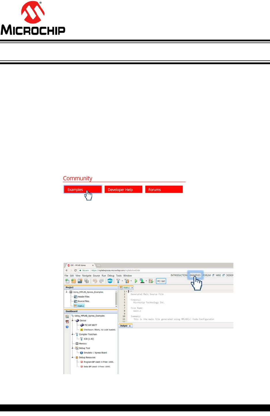
1. Navigate to the MPLAB Xpress IDE homepage and click on the Examples link at
the bottom of the page under the “Community” heading:
https://www.microchip.com/xpress
OR
You can navigate directly to the examples page via:
https://www.microchip.com/xpress/examples
OR
Navigate to the examples page from within the MPLAB Xpress IDE by clicking
on the Examples link at the top of the IDE window.

Using 8-bit MCUs with MPLAB® Xpress
DS50002710A-page 10 2018 Microchip Technology Inc.
2. On the MPLAB Xpress Examples homepage, filter through the examples as fol-
lows:
a) Author: Microchip Technology
b) Tags: #GettingStarted
c) Board: Xpress Board
d) Device: <the device you are using>
In this example the PIC16F18877 is used.
The name of the device populating a given MPLAB Xpress Evaluation Board
can be found next to the board's USB connector.
Scroll through the available examples and locate “Using MPLAB Xpress Exam-
ples”. A description of the example, along with any additional resources which
could include videos links to step-by-step tutorials and more, can be accessed
by clicking on the title of the example.
Open the example inside the online MPLAB Xpress IDE by clicking on the
button in the Open column.
Programming the Evaluation Board
2018 Microchip Technology Inc. DS50002710A-page 11
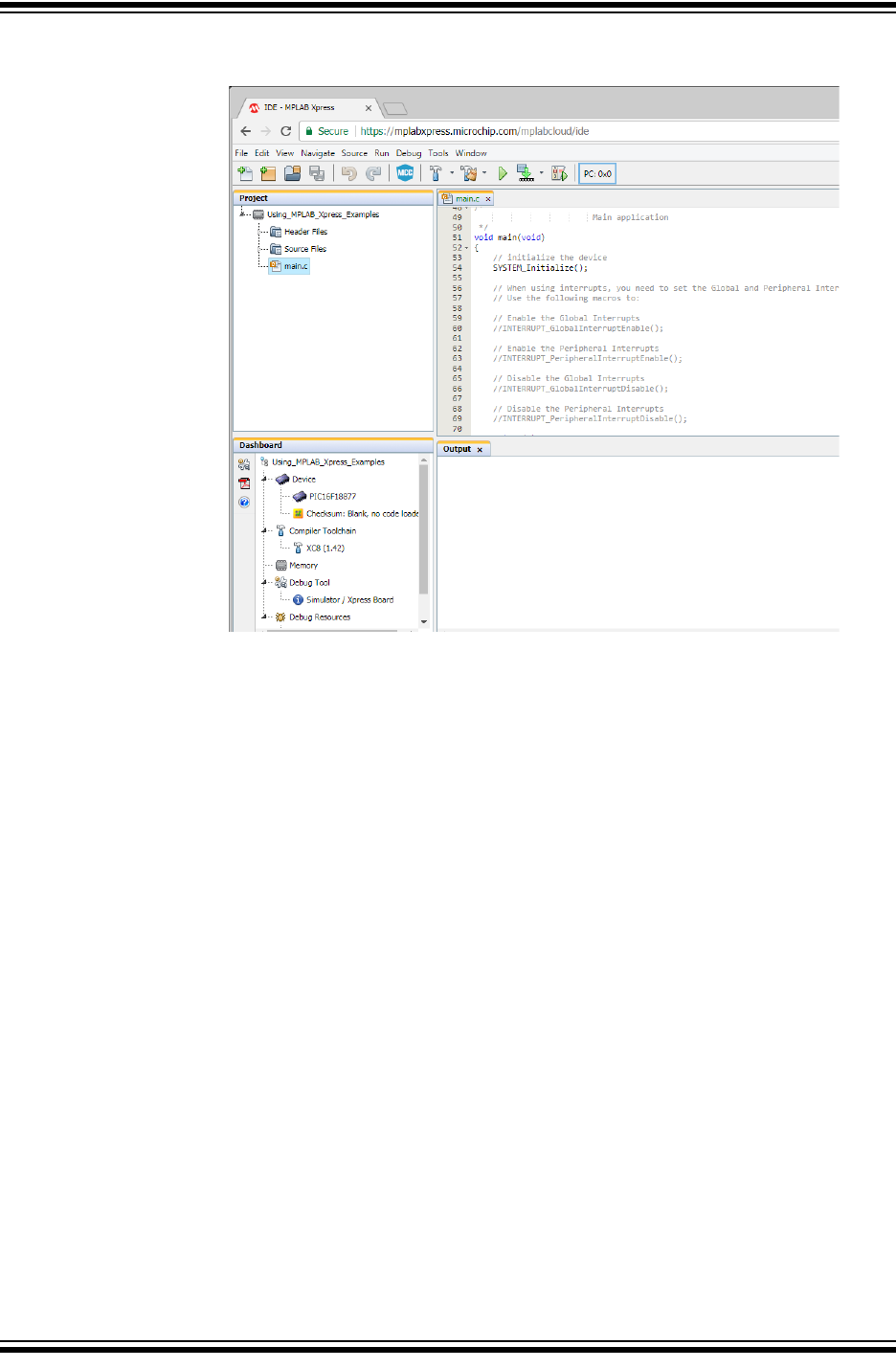
All source code is available along with information related to the development
tools and device that the project was configured to use.
Using 8-bit MCUs with MPLAB® Xpress
DS50002710A-page 12 2018 Microchip Technology Inc.
3.3 DOWNLOAD AN EXAMPLE PROJECT TO THE EVALUATION BOARD
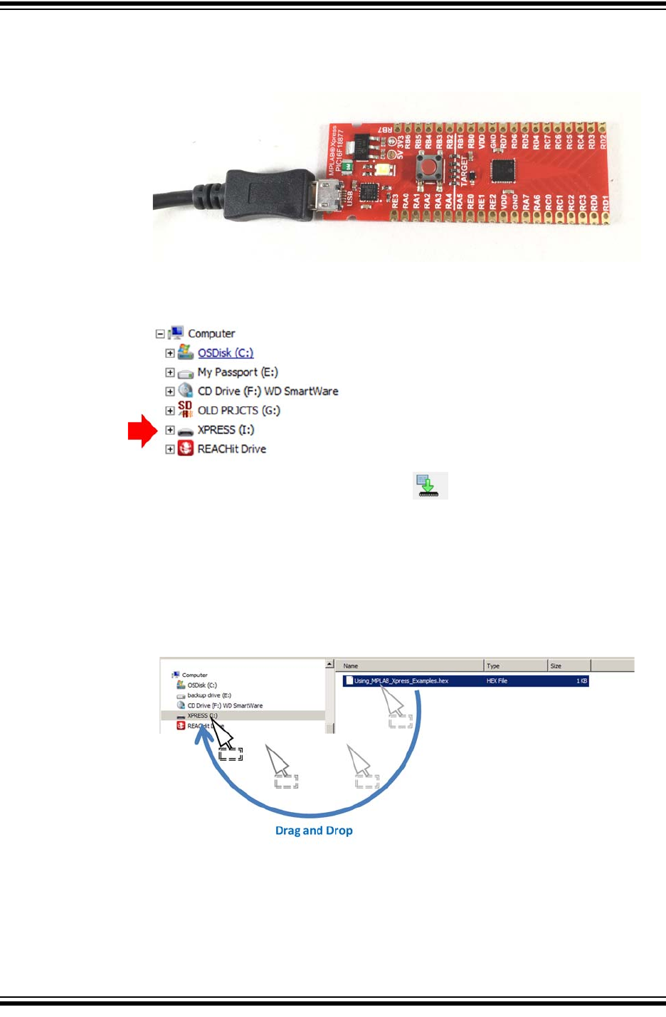
1. Connect the MPLAB Xpress Evaluation board to an available USB Port on the
computer.
2. Once connected and the device drivers have completed installation, the MPLAB
Xpress Board should be recognized as a Mass Storage Device on the Host Com-
puter and listed as an available drive (Windows® Explorer shown here).
3. Click on the Make and Program Device button at the top of the MPLAB
Xpress IDE to generate and download a .hex file that will be used to program
the PIC16F18877 microcontroller populating this particular MPLAB Xpress Eval-
uation Board.
In some browsers the generated .hex file may be available within the browser
window or may need to be accessed from a “Downloads” folder associated with
the browser. Navigate to the downloaded .hex file and drag it into the XPRESS
directory shown in Step 2.
Once the Using_MPLAB_Xpress_Examples.hex file has been dragged and
dropped into the XPRESS directory, the LED on the MPLAB Xpress Board will
briefly flash red indicating that the PIC16F18877 is programmed.
Programming the Evaluation Board
2018 Microchip Technology Inc. DS50002710A-page 13
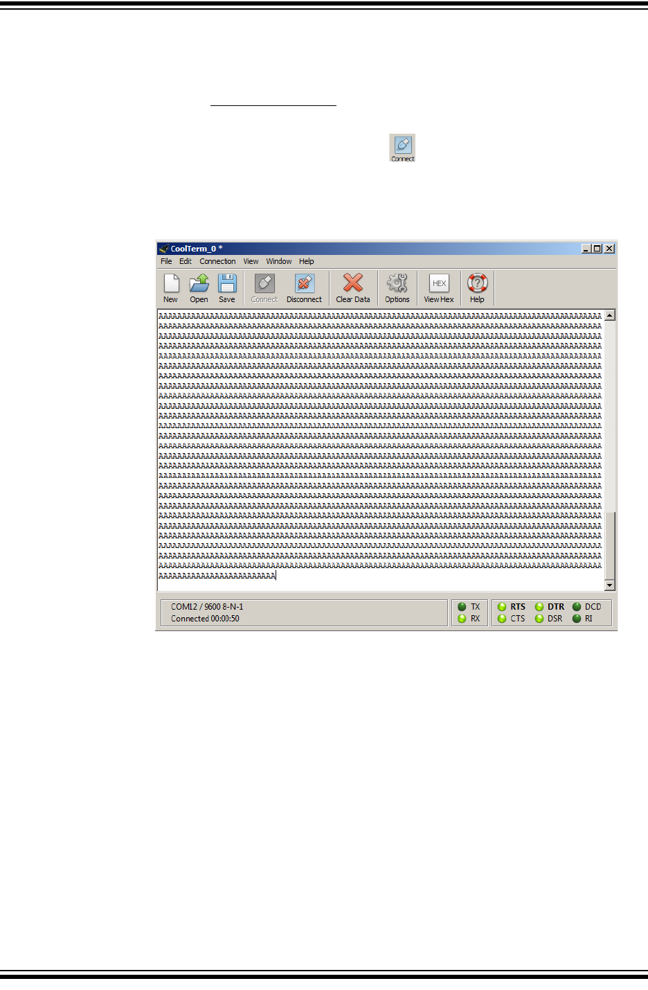
3.4 SETUP SERIAL COMMUNICATION WITH THE EVALUATION BOARD
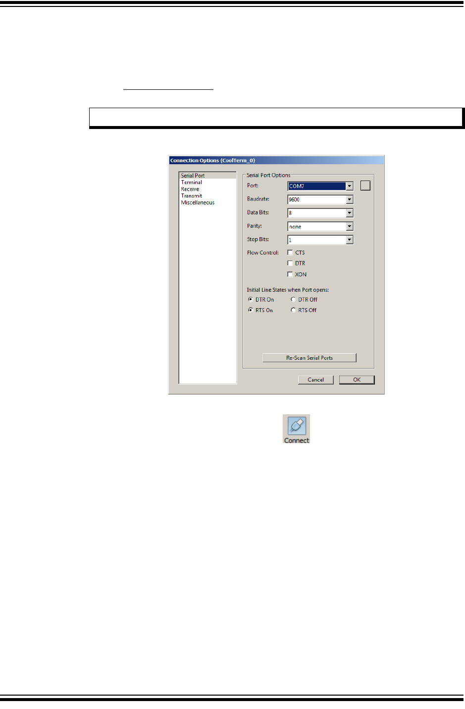
1. Open a terminal emulator program on the host computer and select the COM
port associated with the MPLAB Xpress board.
In this example a free program called CoolTerm is used. If using CoolTerm, open
the Connection>Options dialog and configure the serial port at the 9600 baud
rate.
Click OK to continue.
2. Inside the terminal window, click on the button to establish connection
with the MPLAB Xpress board.
Note: The COM port number will vary from that shown below.
Using 8-bit MCUs with MPLAB® Xpress
DS50002710A-page 14 2018 Microchip Technology Inc.
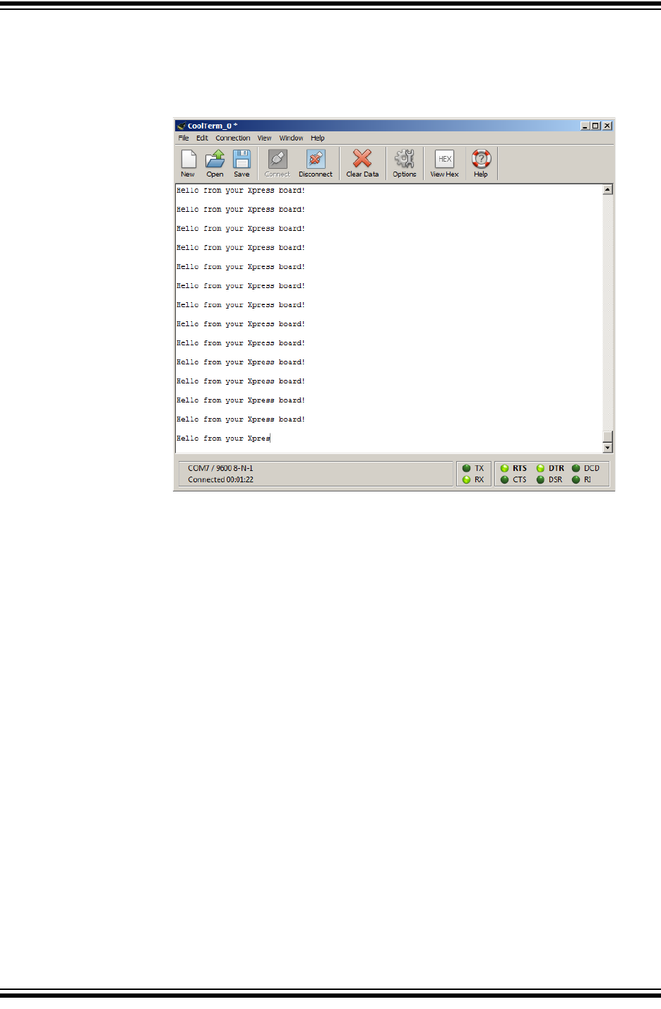
3.5 PROGRAMMING RESULT
Once communication is established, the terminal window should display the message
“Hello from your Xpress board!”
2018 Microchip Technology Inc. DS50002710A-page 15
GETTING STARTED USING
8-BIT MCUs IN THE MPLAB®
Xpress ECOSYSTEM
Chapter 4. Launching MPLAB® Xpress MCC Plugin
4.1 INTRODUCTION
This chapter demonstrates how to launch the MPLAB Code Configurator (MCC) plugin
from within MPLAB Xpress IDE. MCC is a free graphical programming environment
that generates seamless, easy-to-understand C code that is inserted into your project.
Using an intuitive interface, MCC enables and configures a rich set of peripherals and
functions.
The example project from the previous chapter will be used.
•Opening the MCC Plugin for the First Time
•MCC in MPLAB Xpress
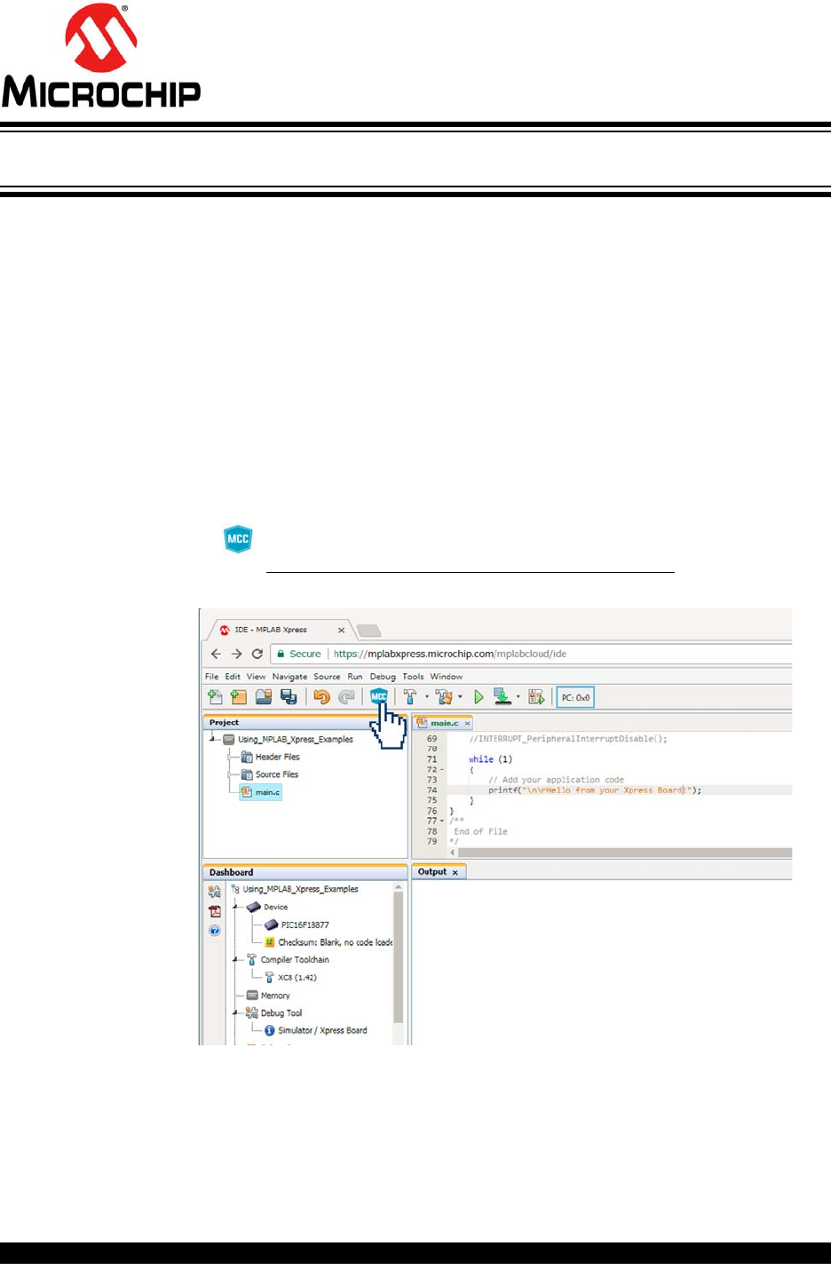
4.2 OPENING THE MCC PLUGIN FOR THE FIRST TIME
1. Launch the Manage MPLAB Xpress Code Configurator dialog by clicking on
the button at the top of the IDE or
through Tools>Embedded>MPLAB Xpress Code Configurator.
Using 8-bit MCUs with MPLAB® Xpress
DS50002710A-page 16 2018 Microchip Technology Inc.
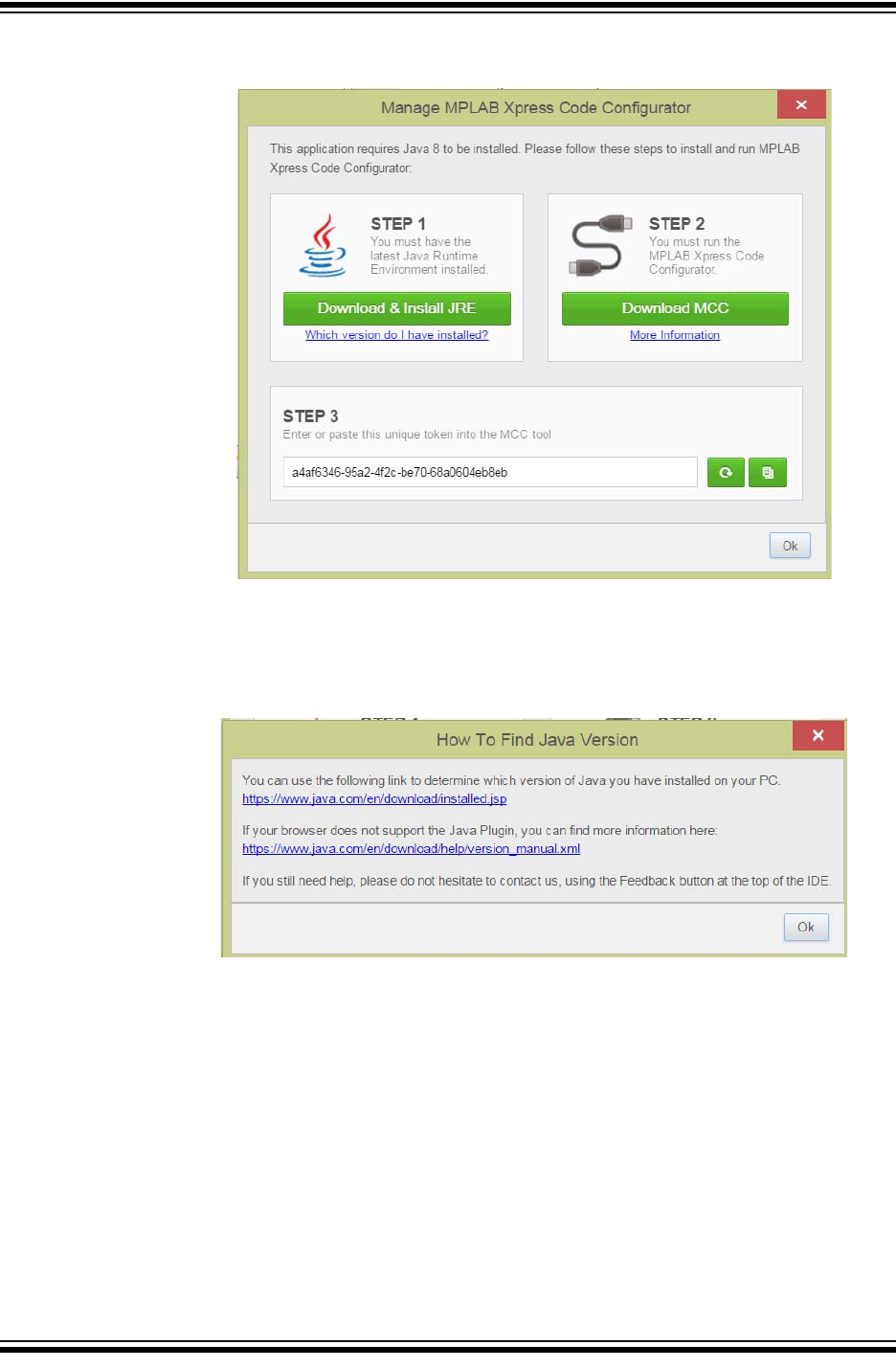
The Manage MPLAB Xpress Code Configurator dialog should now be open.
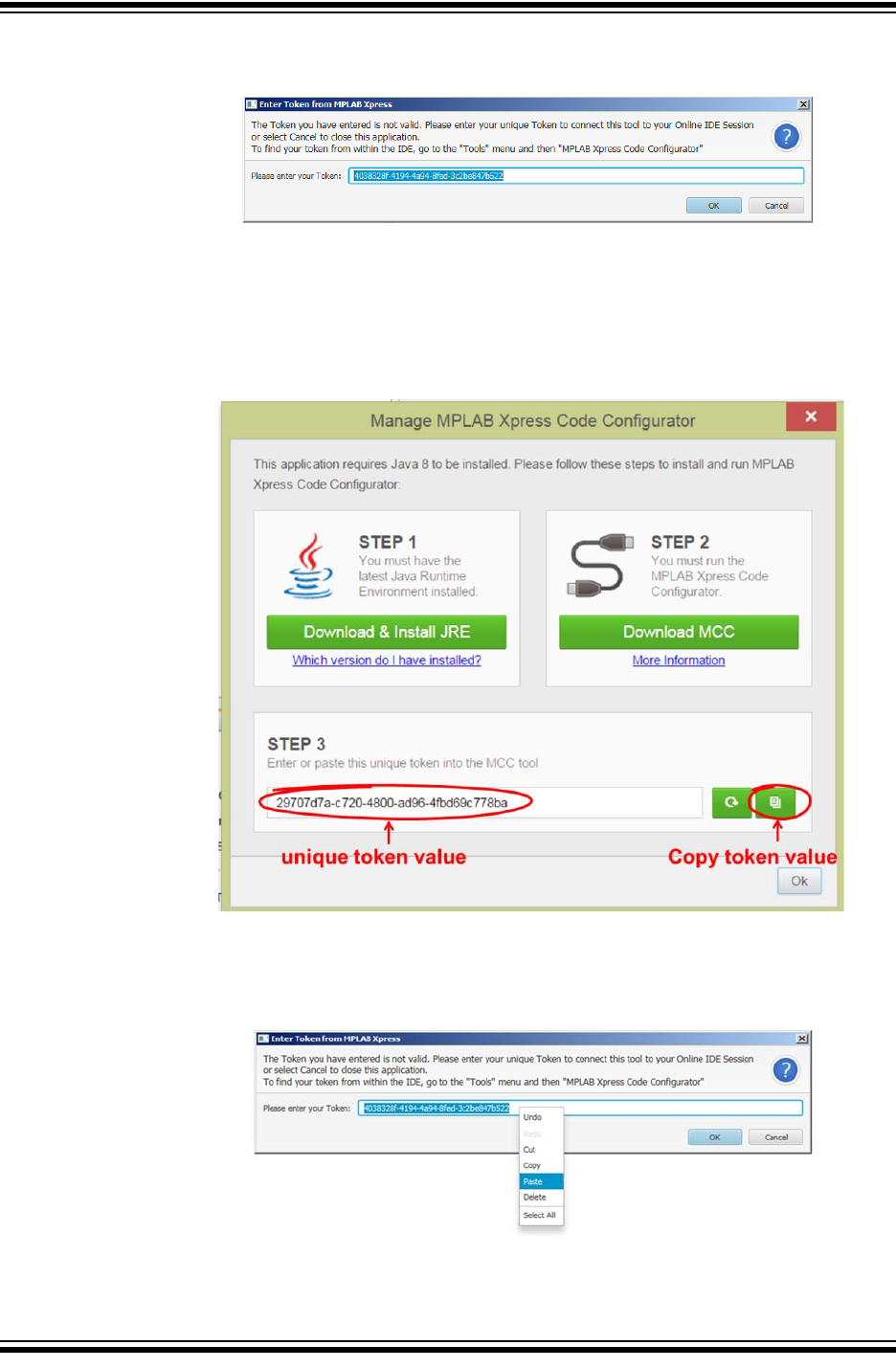
2. STEP 1 ensures that the latest Java Runtime Environment (JRE) is installed on
your computer. If unsure of the current version of the JRE on your computer, click
on the 'Which version do I have installed?' link and follow the steps.

Launching MPLAB® Xpress MCC Plugin
2018 Microchip Technology Inc. DS50002710A-page 17
Clicking on the green Download & Install JRE button will redirect you to the
Java Runtime Environment homepage. To install JRE, simply follow the instruc-
tions.
3. STEP 2 is used to download the necessary .jnlp file to launch MCC.
MCC is a Java application that runs directly from the internet using a web
browser (Chrome is used here). This requires the use of the Java Web Start
application software which follows the Java Network Launching Protocol (JNLP)
to download and launch the application.
a) Click the green Download MCC button to download the JNLP file. Then click
on the MCC_Xpress.jnlp file to launch the Code Configurator.
b) Click Run when prompted to run the application.
Using 8-bit MCUs with MPLAB® Xpress
DS50002710A-page 18 2018 Microchip Technology Inc.
c) The Enter Token from MPLAB Xpress window will now open.
4. STEP 3 provides a unique token value that will be used in the Enter Token from
MPLAB Xpress window. To locate the token, return to the Manage MPLAB
Xpress Code Configurator window. Then click on the Copy button next to the
unique token value.
5. Return to the Enter Token from MPLAB Xpress window. Past the copied token
value into the “Please enter your Token” field.
Launching MPLAB® Xpress MCC Plugin
2018 Microchip Technology Inc. DS50002710A-page 19
6. Click OK to initialize the device-specific libraries for the microcontroller selected
and open the MCC.
If the token is not valid, refresh the token value in STEP 3 by clicking on the
Refresh Token Value button in the Manage MPLAB Xpress Code
Configurator window, recopy the new Unique Token Value, and paste into the
“Please enter you Token” field of the Enter Token from MPLAB Xpress window.
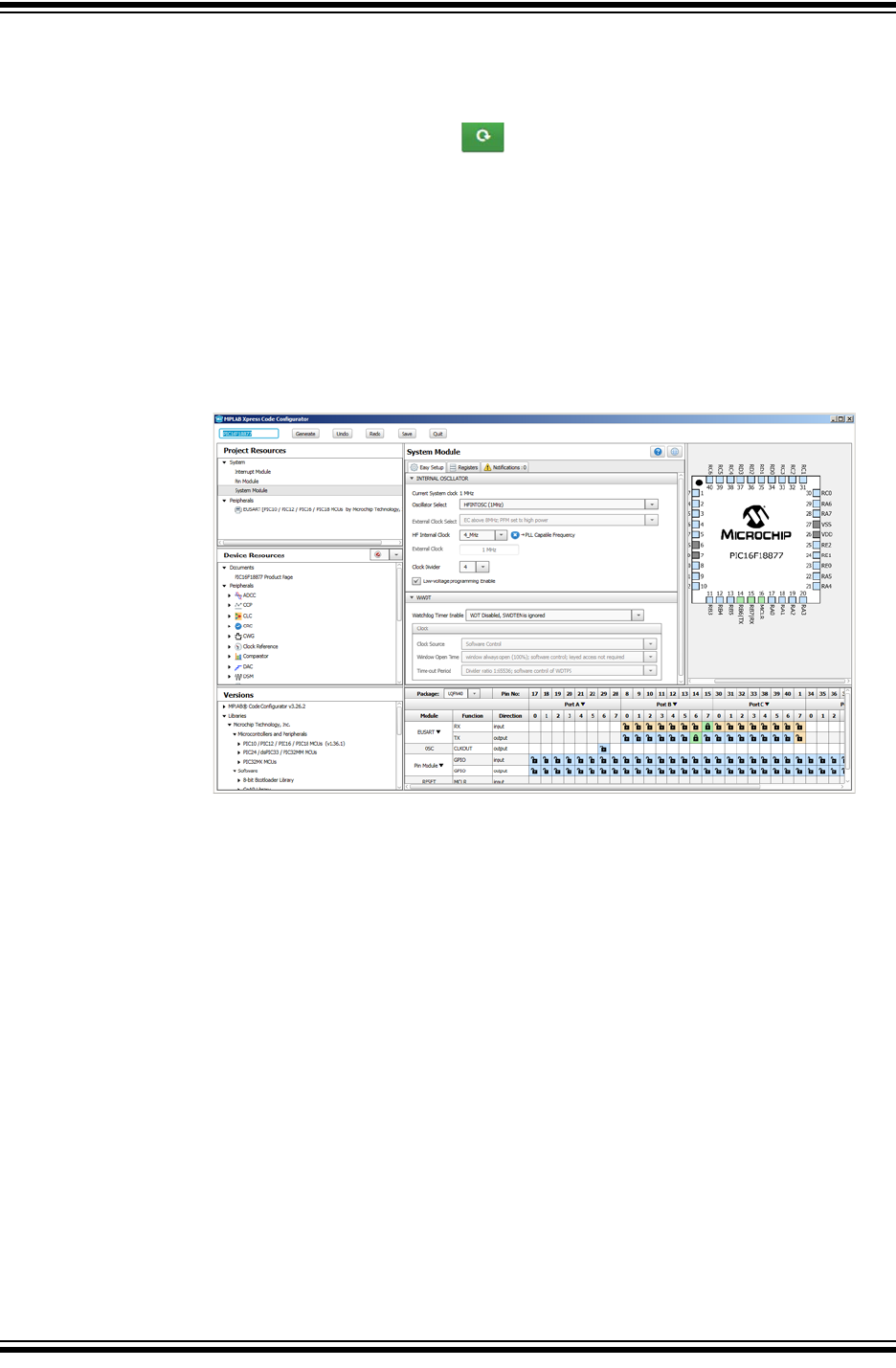
4.3 MCC IN MPLAB XPRESS
The MCC is a graphical programming environment used to configure device features
including oscillator setup, peripheral configuration and assign signals within the micro-
controller to pins on the device package. You are encouraged to take some time and
explore the configurator to see how the MCU was configured to implement the “Using
MPLAB Xpress Examples” example project.
Using 8-bit MCUs with MPLAB® Xpress
DS50002710A-page 20 2018 Microchip Technology Inc.
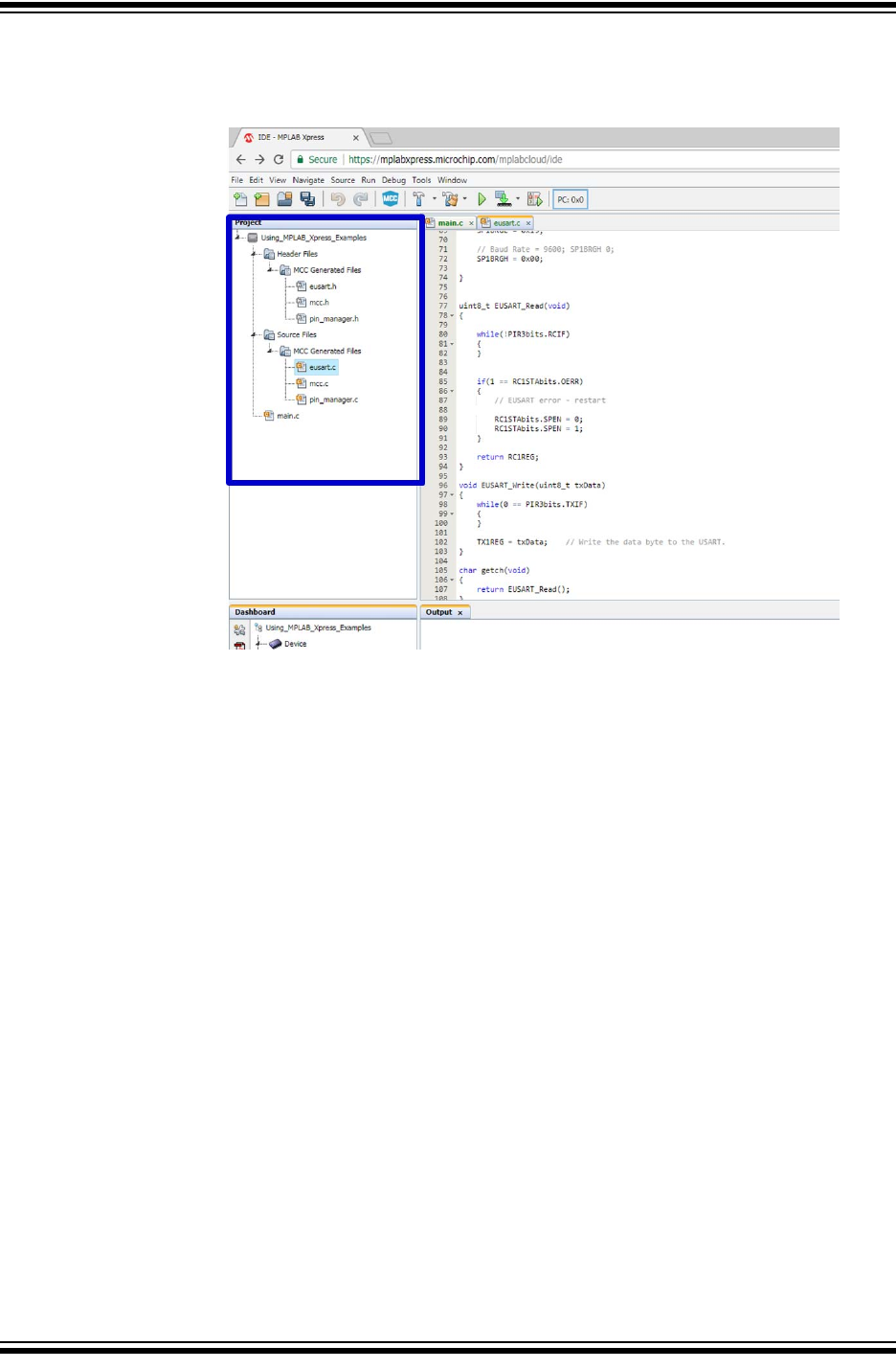
Source and header files generated for the original project can be viewed in the Project
pane of the MPLAB Xpress IDE under the Header Files and Source Files folders.
2018 Microchip Technology Inc. DS50002710A-page 21
GETTING STARTED USING
8-BIT MCUs IN THE MPLAB®
Xpress ECOSYSTEM
Chapter 5. Using the MPLAB® Code Configurator (MCC)
5.1 INTRODUCTION
The MPLAB Code Configurator (MCC) is a Graphical User Interface (GUI) that gives
the developer a high level view of a given microcontroller making it much easier to con-
figure:
• Core device capabilities
• Peripherals and configuration
• MCU signal pin assignment
• Related libraries
These features can all be configured through the use of intuitive drop-down menus,
check boxes, and fields. In this way the developer can quickly configure the target
device, minimizing the amount of time spent reviewing registers in a data sheet.
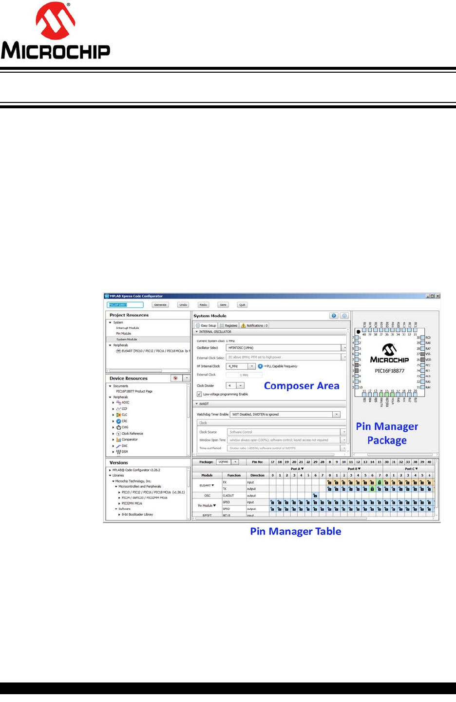
Key MCC tool areas are shown in the screen capture below.
Key tool areas are discussed further in these topics:
•Project Resources
•Device Resources
•Composer Area
•Pin Manager

Using 8-bit MCUs with MPLAB® Xpress
DS50002710A-page 22 2018 Microchip Technology Inc.
5.2 PROJECT RESOURCES
Displays device features currently being used in this project.
5.2.1 System Module
Configure core parameters such as the system clock, configuration bits and other
device-level functions.
5.2.2 Interrupt Module
Enable or configure interrupt priority for interrupt sources available in the project.
5.2.3 Pin Module
Configuration of individual pins selected from the Pin Manager such as pin direction
(input or output), analog functionality and weak pull-up resistors, if available. In some
instances a custom name can be given for a pin that will be referenced throughout gen-
erated code.
Using the MPLAB® Code Configurator (MCC)
2018 Microchip Technology Inc. DS50002710A-page 23
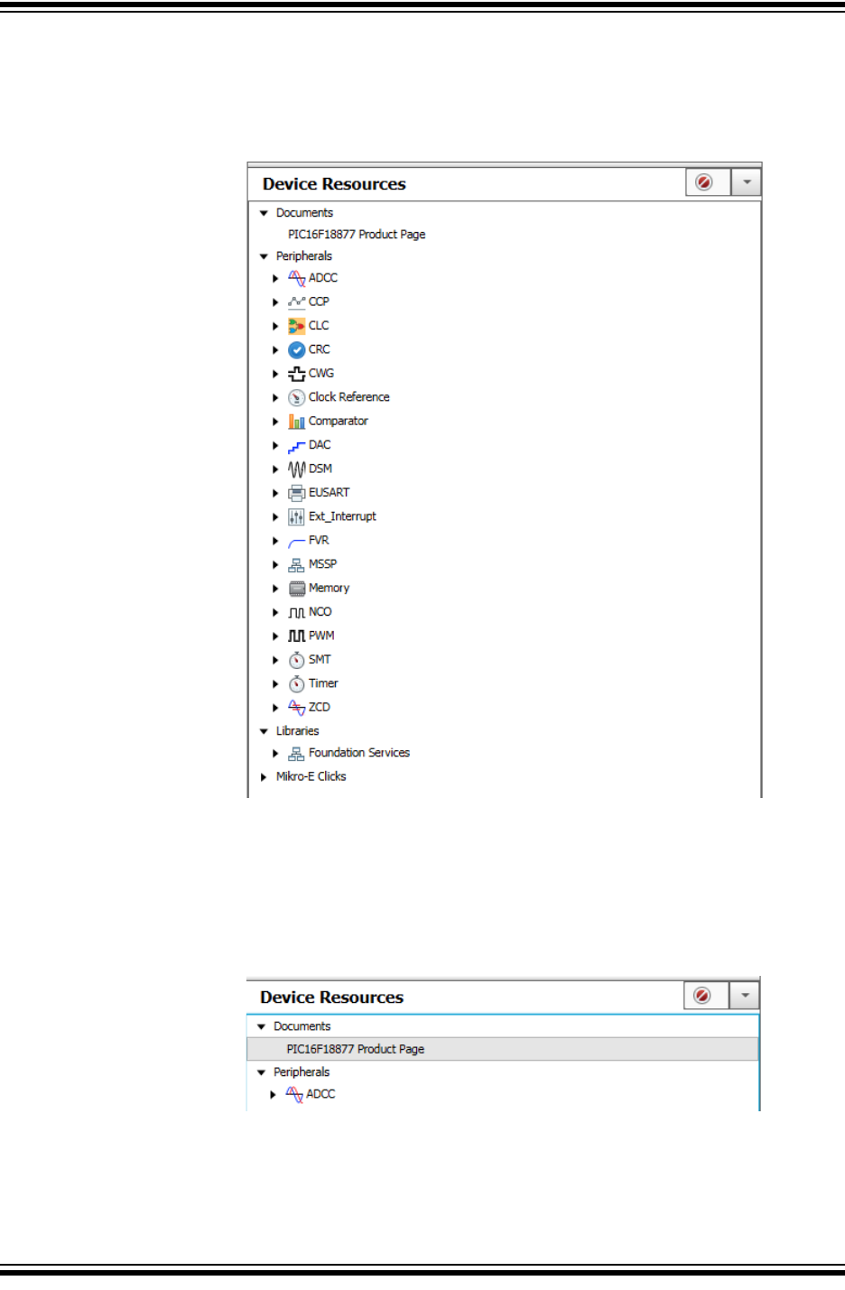
5.3 DEVICE RESOURCES
This area displays features that are available for use for the selected target device.
Features are added by double clicking on the listing in the Device Resources section.
5.3.1 Product Page
Links to the selected device's product homepage where the data sheet and other doc-
umentation, such as relevant application notes, can be found.
Using 8-bit MCUs with MPLAB® Xpress
DS50002710A-page 24 2018 Microchip Technology Inc.
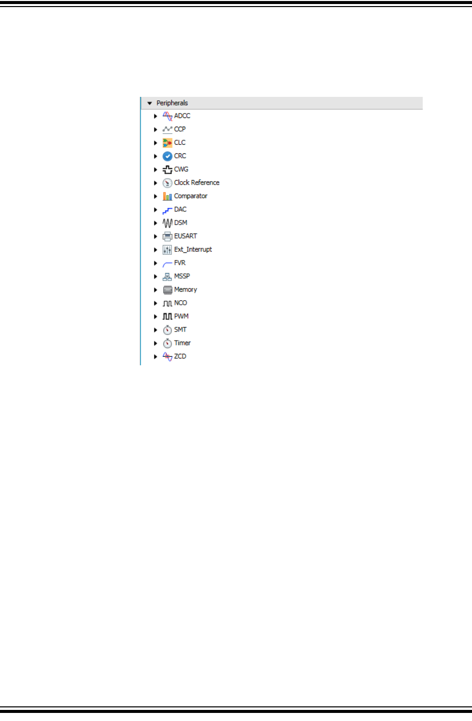
5.3.2 Peripherals
Displays all peripherals that are available on the selected target device. Different
devices will have different peripherals. Peripherals are added to the project by double
clicking on the listing.
Using the MPLAB® Code Configurator (MCC)
2018 Microchip Technology Inc. DS50002710A-page 25
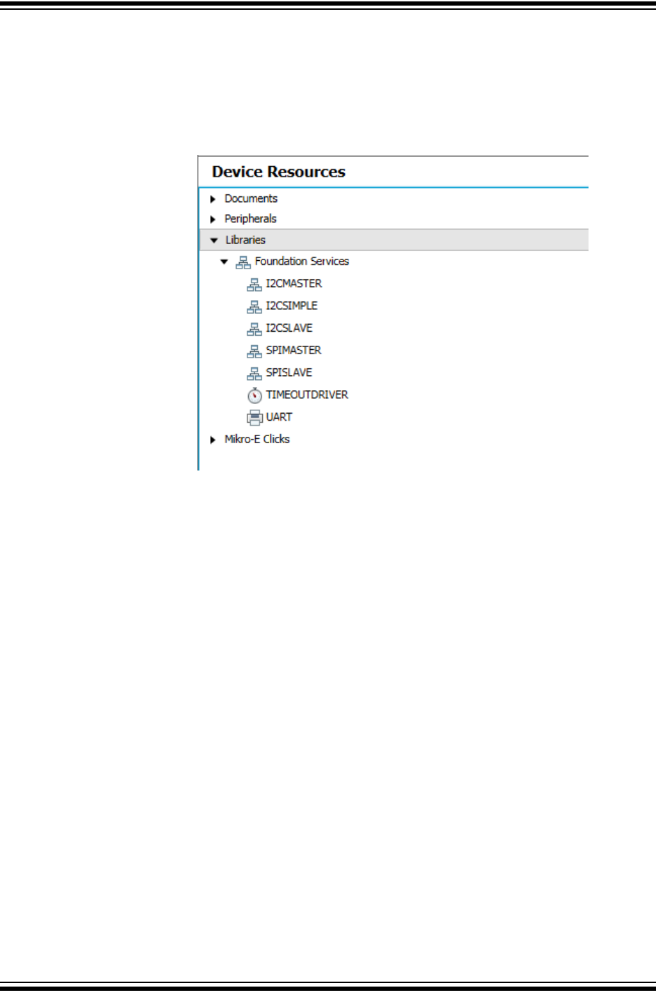
5.3.3 Libraries
Lists available libraries that have been created to simplify certain functionality such as
using serial communication protocols. These libraries are presented to the user as any
other module in the MCC using an easy-to-use graphical interface to configure various
library parameters. Libraries are added to the project by double clicking on the listing.
Using 8-bit MCUs with MPLAB® Xpress
DS50002710A-page 26 2018 Microchip Technology Inc.
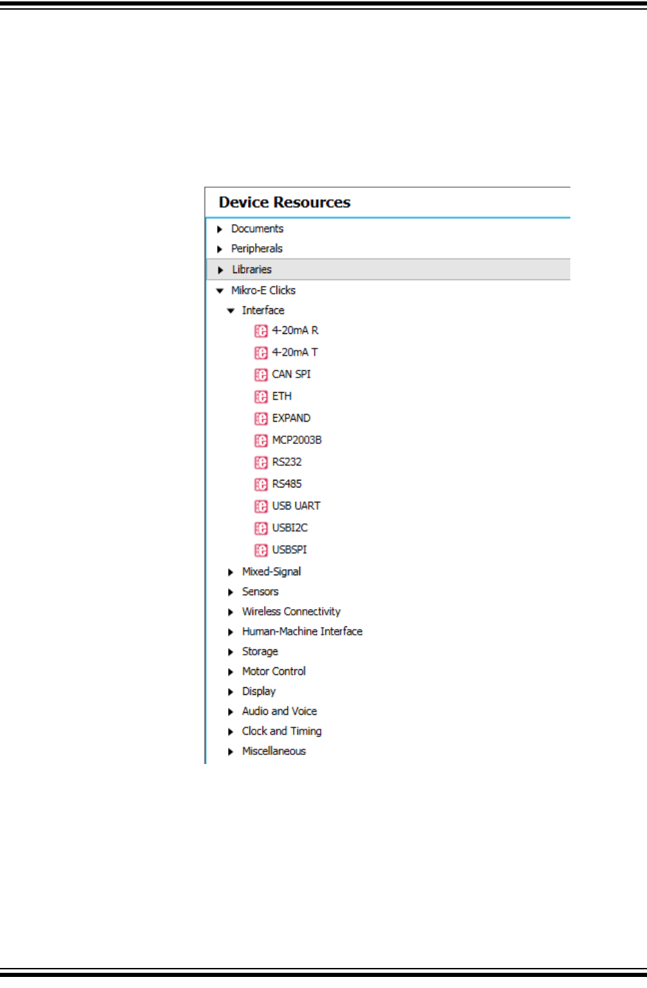
5.3.4 MIKRO-E Clicks
MikroElektronika Click Boards are expansion daughter cards featuring various types of
sensors, communication modules and other interface components that can be used
with the target device to quickly add additional functionality to an application. Click
boards are added to the project by double clicking on the listing in the Device
Resources, which adds required peripherals as needed that interface with the selected
module.
Using the MPLAB® Code Configurator (MCC)
2018 Microchip Technology Inc. DS50002710A-page 27
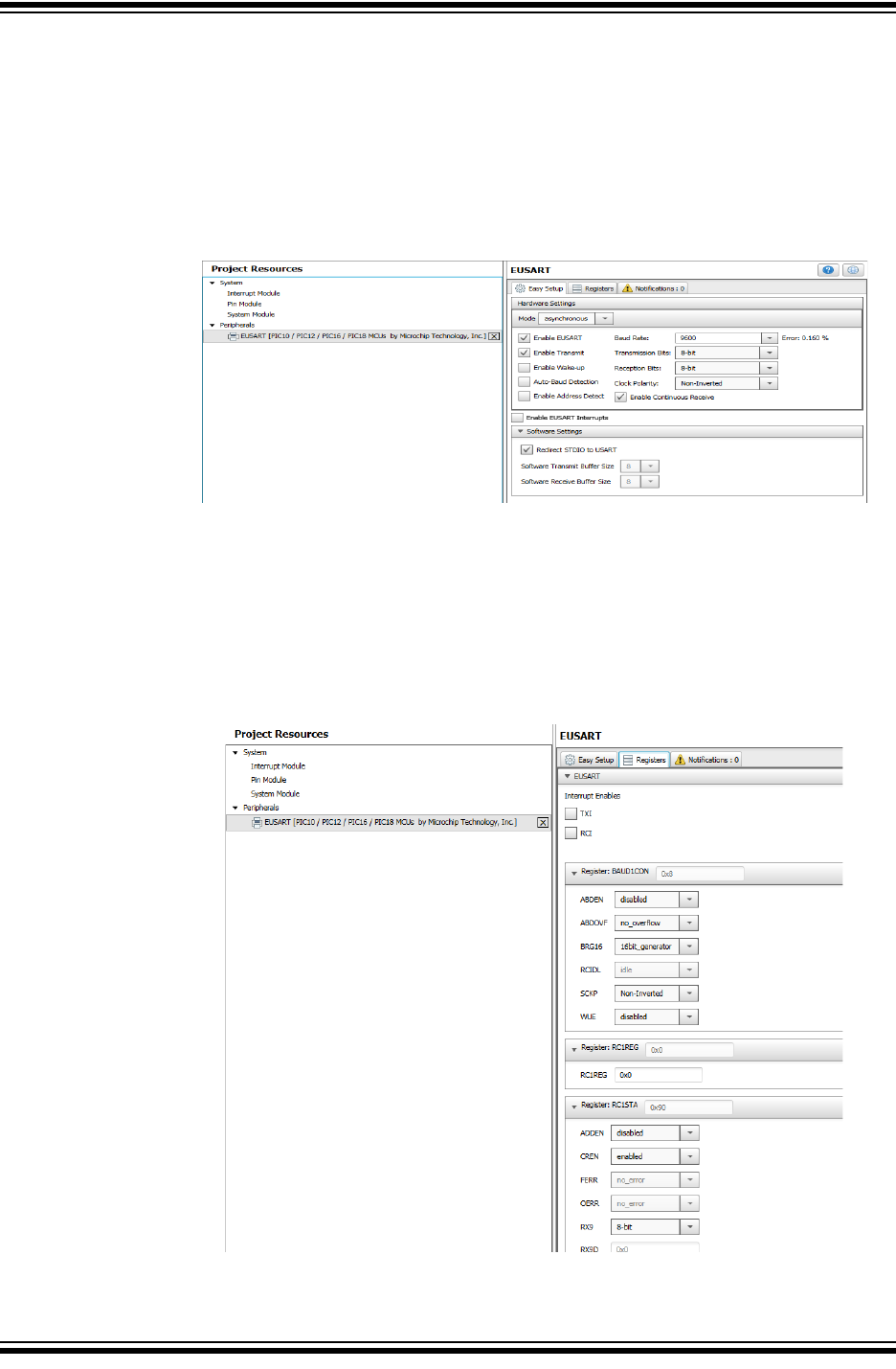
5.4 COMPOSER AREA
Main interface area in which a peripheral, library or driver is configured.
5.4.1 Easy Setup Tab
This tab presents the peripheral, library or driver at a high level so that it can be config-
ured using intuitive check boxes, value fields and drop-down selections (EUSART
peripheral Easy Setup shown).
5.4.2 Registers Tab
Presents the registers associated with device peripherals and features. Registers can
be configured using either drop-down menus or by entering a hexadecimal value next
to the register name representing individual bit settings (EUSART peripheral Registers
shown).
Using 8-bit MCUs with MPLAB® Xpress
DS50002710A-page 28 2018 Microchip Technology Inc.
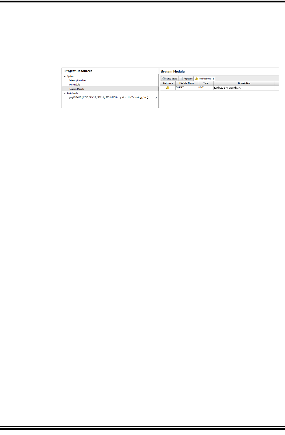
5.4.3 Notifications Tab
This tab displays important information concerning various modules that have been
configured including warnings, hints and general information (EUSART Notifications
shown where the System Clock was set to a lower frequency that is insufficient to
obtain the desired Baud rate).
Using the MPLAB® Code Configurator (MCC)
2018 Microchip Technology Inc. DS50002710A-page 29
5.5 PIN MANAGER
Many signals internal to the device can be routed to a user-selectable variety of pins.
Signals can even be routed to multiple pins at the same time and pins can be shared
by multiple modules. The Pin Manager simplifies this process using Table and Package
views.
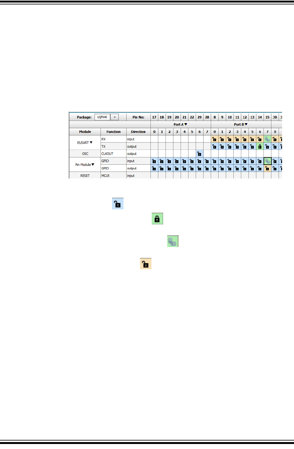
5.5.1 Pin Manager Table View
Lists the pin by package pin number across the top of the table, by Port just below the
pin number and by Module, signal Function and Direction along the left side of the
table.
• Blue colored pins indicate pins that can be used by a module signal.
• Green colored pins (with a lock) indicate that the pins have been allocated to
a module signal.
• Green colored pins (with a chain link) indicate that the pins are shared
between multiple modules.
• Yellow/Orange colored pins indicate possible alternate pins for an already
allocated pin function.
• The Package drop down menu can be used to change the Package View to any
available package for the target device.
Using 8-bit MCUs with MPLAB® Xpress
DS50002710A-page 30 2018 Microchip Technology Inc.
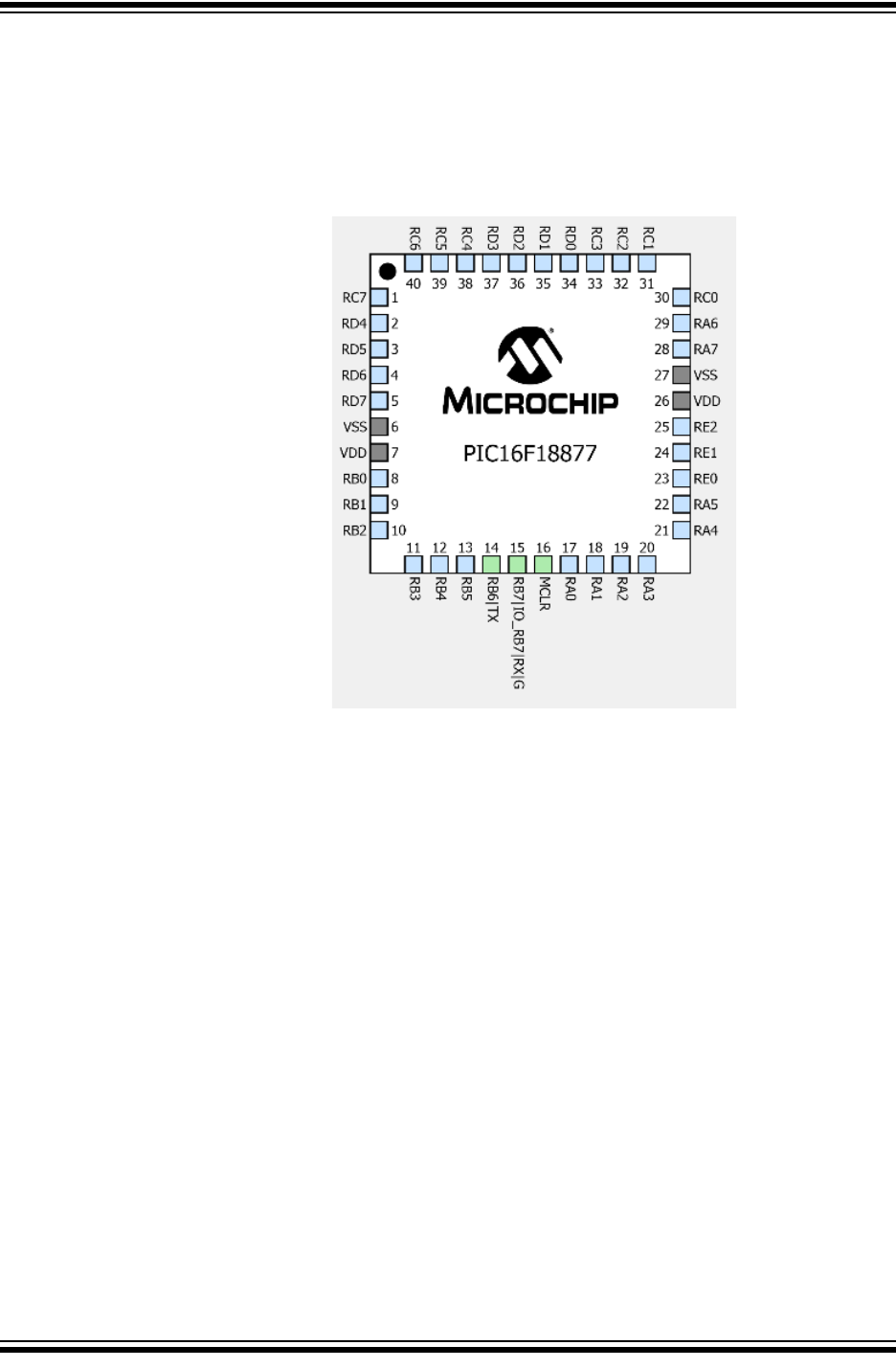
5.5.2 Pin Manager Package View
Displays pins on the selected device package. Color codes follow above adding Gray
colored pins indicating that the pin is not usable in the selected configuration. Micro-
controller signals can also by assigned to pins in this view by right clicking on the pin
and selecting the available signal.
Using the MPLAB® Code Configurator (MCC)
2018 Microchip Technology Inc. DS50002710A-page 31
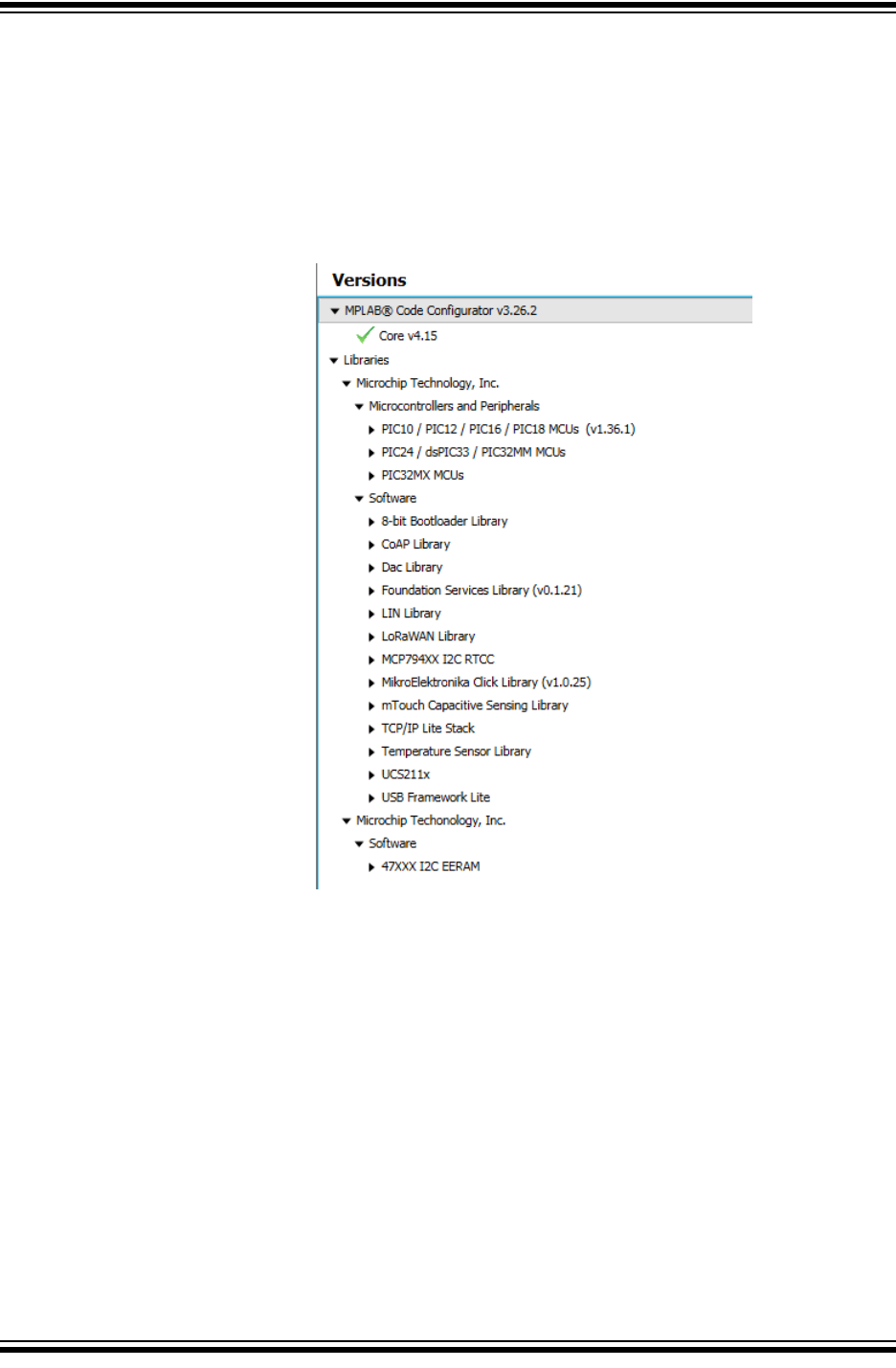
5.5.3 Versions
This section of the MCC provides information about the versions of the component
groups that make up MCC. These component groups are called libraries. Intermediate
users can configure the MCC to use a specific version of a library for a given MCC proj-
ect. More information is available in the MCC User's Guide available in the MCC home-
page in the documents section at the bottom of the page:
http://www.microchip.com/mcc

Using 8-bit MCUs with MPLAB® Xpress
DS50002710A-page 32 2018 Microchip Technology Inc.
NOTES:
2018 Microchip Technology Inc. DS50002710A-page 33
GETTING STARTED USING
8-BIT MCUs IN THE MPLAB®
Xpress ECOSYSTEM
Chapter 6. Building a Serial Communications Link
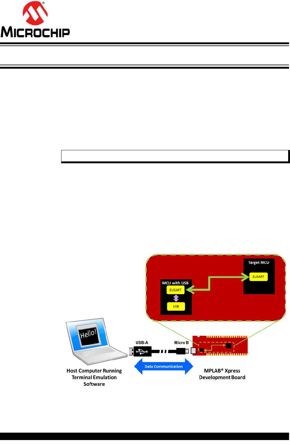
6.1 INTRODUCTION
The purpose of this chapter is to demonstrate how to build the serial communications
link that has been used throughout this document between an MPLAB Xpress Evalua-
tion Board and a host computer. This communication is enabled by a second MCU with
USB capabilities that populates the board along with the target MCU. This second MCU
with USB performs the following USB tasks:
• USB Mass Storage Device (MSD) Class: Receives .hex files from the host PC
and then programs the target device using Microchip's In-Circuit Serial Program-
ming™ (ICSP™) technology.
• USB Communications Device Class (USB CDC): Translates EUSART data trans-
missions from the target MCU and transmits over the USB connection to the host
PC
Using the latter CDC configuration enables the target MCU to send and receive infor-
mation through the second MCU with USB capabilities to an available USB port on a
host computer. Terminal emulation software (see links in Chapter 2. “Equipment Used”)
running on the host computer connected to the associated COM Port can then be used
to display information from the target MCU or allow the user to send commands back
to the microcontroller.
Note: Hardware debugging is not available.
Using 8-bit MCUs with MPLAB® Xpress
DS50002710A-page 34 2018 Microchip Technology Inc.
6.2 HOW TO CREATE A NEW PROJECT IN MPLAB XPRESS IDE
At this point only existing projects have been covered. In this section, you will create a
new original project in MPLAB Xpress IDE.
1. Navigate to MPLAB Xpress IDE.
https://mplabxpress.microchip.com/mplabcloud/ide
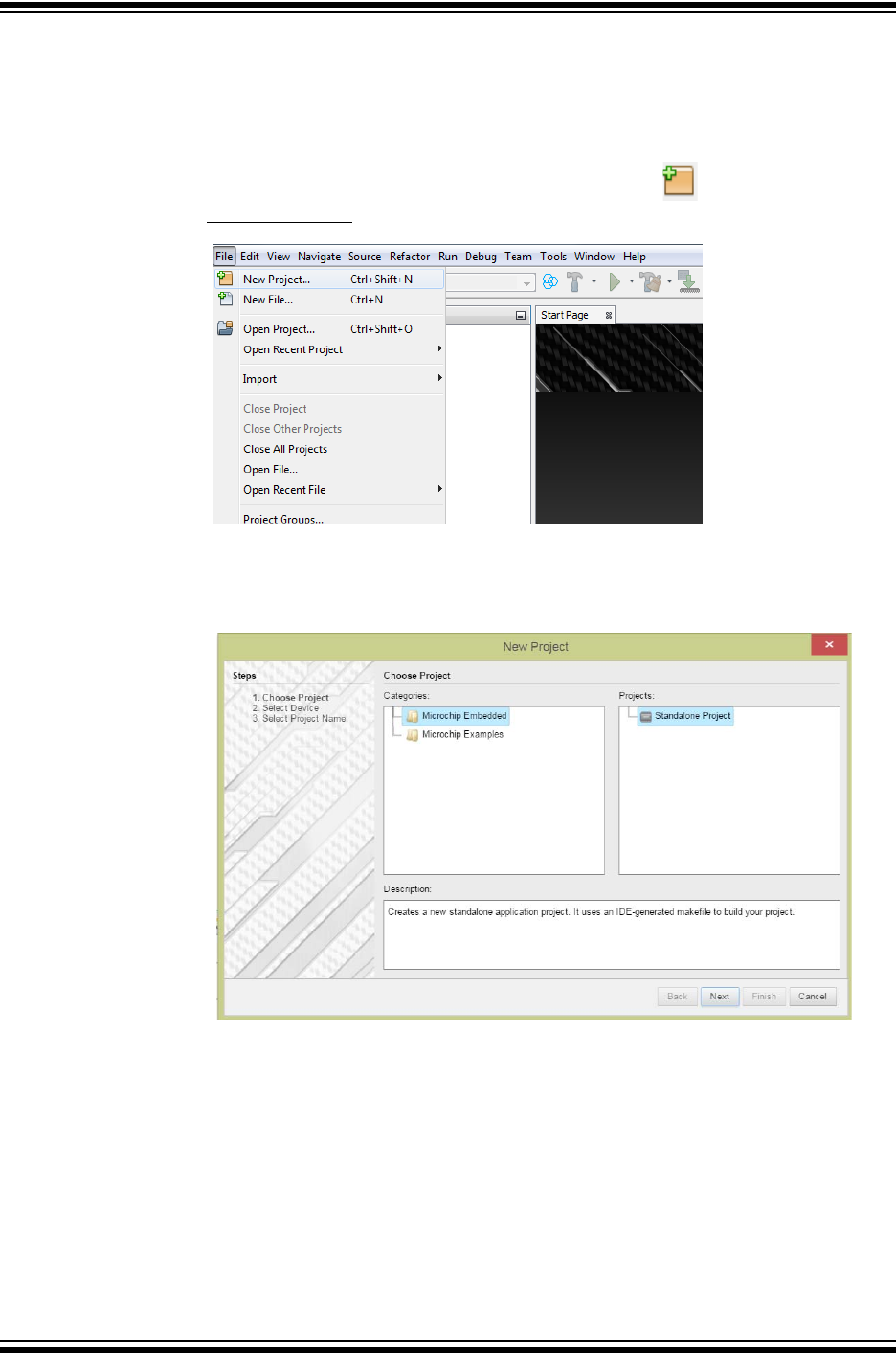
2. Create a new project by clicking the New Project icon or by selecting
File>New Project.
3. In the New Project window, select “Microchip Embedded” in the “Categories”
frame and “Standalone Project” in the “Projects” frame. Click Next.
Building a Serial Communications Link
2018 Microchip Technology Inc. DS50002710A-page 35
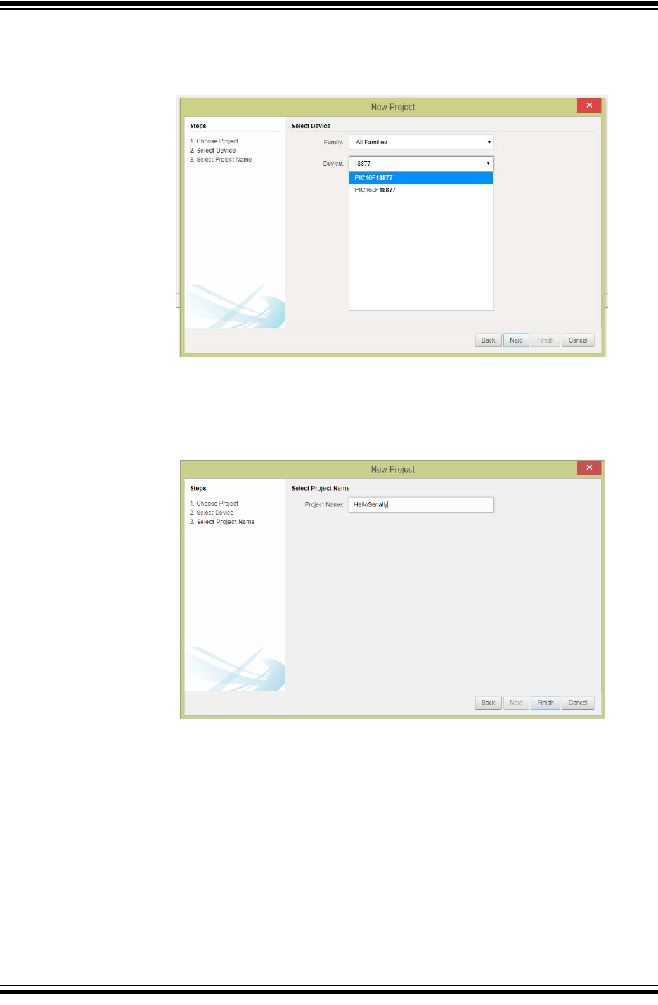
4. Select or type in the MCU being used (PIC16F18877 shown) in the “Device”
drop-down in the Select Device window. Click Next.
5. Name the project something relevant, like HelloSerially, in the “Project Name”
field of the Select Project Name window. Click Finish.
Using 8-bit MCUs with MPLAB® Xpress
DS50002710A-page 36 2018 Microchip Technology Inc.
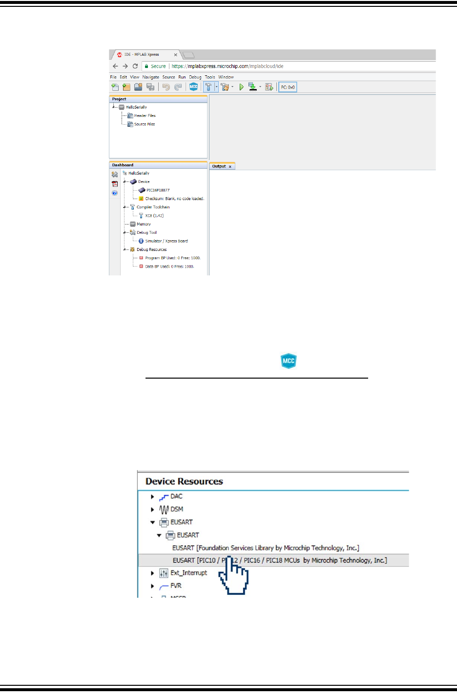
The MPLAB Xpress IDE workspace should look similar to below.
6.3 HOW TO SET UP MCC TO GENERATE PROJECT CODE
Once your MPLAB Xpress project is created, you will set up MPLAB Code Configurator
(MCC) options for generating code.
1. Open the MCC plugin by clicking on the button at the top of the IDE or
through Tools>Embedded>MPLAB Xpress Code Configurator. For details on the
MCC GUI, see Chapter 5. “Using the MPLAB Code Configurator (MCC)”.
2. In the open MCC window, the default parameters for the “Project
Resources>System” can be used.
3. In the “Device Resources” area, scroll down to locate the EUSART peripheral
and expand. Double click on the EUSART to add the peripheral to “Project
Resources”.
Building a Serial Communications Link
2018 Microchip Technology Inc. DS50002710A-page 37
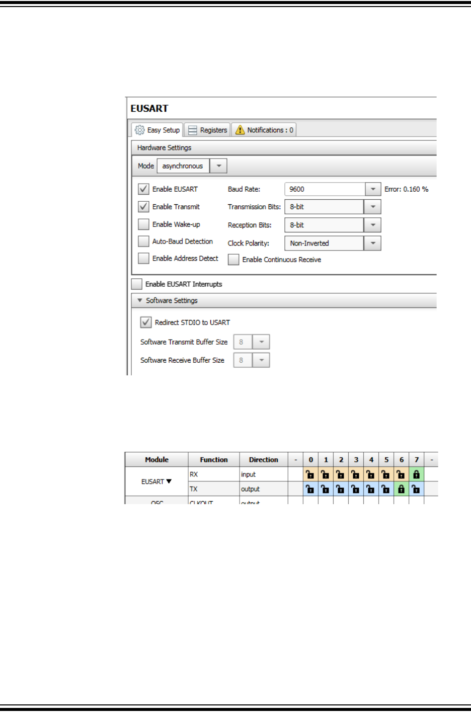
4. Select the EUSART peripheral under the “Peripheral” heading in the “Project
Resources” pane to open the peripheral configuration and configure as follows:
a) Enable Transmit
b) Baud Rate: 9600 (default)
5. In the “Pin Manager” section, connect the EUSART TX signal to pin RB6 and the
RX signal to pin RB7 by clicking on the blue unlock button, turning it to a green
locked symbol, for the associated signal row and pin columns as shown below.
When communicating with the second microcontroller using USB, the RB6 pin is
for the EUSART transmit (TX) signal, and the RB7 pin is for the EUSART receive
(RX) signal on most MPLAB Xpress Evaluation Boards, including the green
“General Purpose MPLAB Xpress Evaluation Board” and 40-pin variants of the
red “Device-Specific MPLAB Xpress Evaluation Boards”. The 20-pin red
“Device-Specific MPLAB Xpress Evaluation Board” will use the RA1 pin for
EUSART TX and the RA0 pin for the EUSART RX signal.
Using 8-bit MCUs with MPLAB® Xpress
DS50002710A-page 38 2018 Microchip Technology Inc.
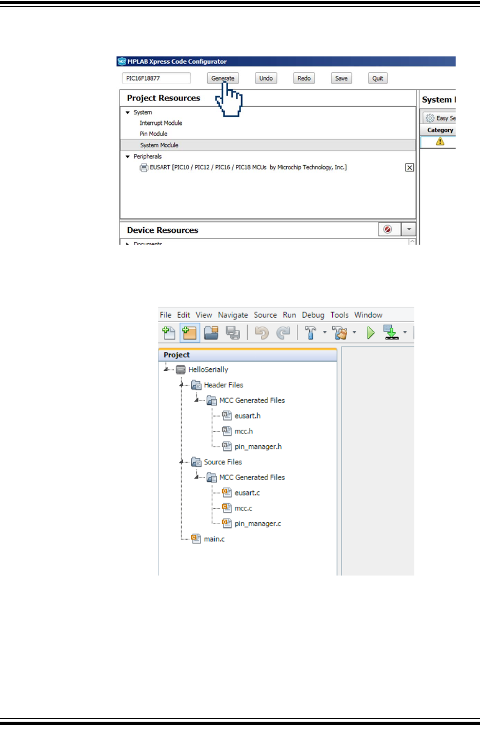
6. Click the Generate button in MCC to create the appropriate header and source
files for this configuration.
7. The new MCC Generated header and source files should now be present in the
Project window of the MPLAB Xpress IDE including a new main.c source file.
Building a Serial Communications Link
2018 Microchip Technology Inc. DS50002710A-page 39
6.4 HOW TO USE THE MCC-GENERATED SERIAL FUNCTION
The MPLAB Code Configurator generates code used to configure the device and
selected peripherals. Additionally, a series of functions are generated for a number of
the selected resources that enable you to write your own code which can facilitate
dynamic system changes to occur at runtime. Function descriptions along with exam-
ple code can be referenced in the associated peripheral's header file.
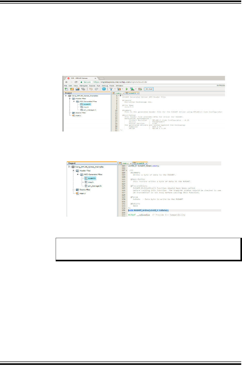
1. Highlight the eusart.h file under the “Header Files>MCC Generated Files”
folder inside the Project pane of the MPLAB Xpress IDE to open the file.
2. Scroll through the eusart.h file to locate the EUSART_Write() function.
Highlight the function and copy using Ctrl+X (Windows keyboard shortcut).
Note: Copy and paste within the MPLAB Xpress IDE must be done using key-
board shortcuts. Using these functions from the toolbar or from the right
click Context Menu is not supported.
Using 8-bit MCUs with MPLAB® Xpress
DS50002710A-page 40 2018 Microchip Technology Inc.
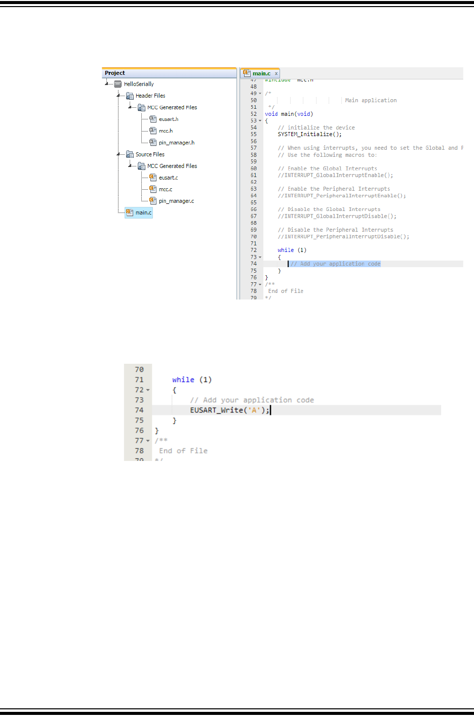
3. Click on the main.c source file in the Project pane to open the file and scroll
through the code to locate the // Add your application code comment
inside of the while(1) loop inside main().
Paste the copied EUSART_Write() function at this location and replace the
arguments within the brackets to a character such as 'A'.
4. Compile and download the project .hex file by clicking on the Make and
Program Device button at the top of the MPLAB Xpress IDE.
5. Program the MPLAB Xpress board by dragging the project .hex file from the
downloads section of the browser and dropping the file into the XPRESS drive
as shown in Chapter 3. “Programming the Evaluation Board”.
Building a Serial Communications Link
2018 Microchip Technology Inc. DS50002710A-page 41
6.5 HOW TO DISPLAY THE SERIAL MESSAGE ON A HOST COMPUTER
1. Open a terminal emulator program (see Section 2.3 “Software”) on the host com-
puter and select the COM port associated with the MPLAB Xpress board.
2. Open the Connection>Options dialog and configure the serial port at the 9600
baud rate that was configured earlier in the project when configuring the
EUSART in MCC.
3. Inside the terminal window, click on the button to establish connection with
the Xpress board.
Once communication is established, the terminal window should display the character
added to the EUSART_Write() earlier in the project.

Using 8-bit MCUs with MPLAB® Xpress
DS50002710A-page 42 2018 Microchip Technology Inc.
NOTES:

2018 Microchip Technology Inc. DS50002710A-page 43
GETTING STARTED USING
8-BIT MCUs IN THE MPLAB®
Xpress ECOSYSTEM
Appendix A. MPLAB® Xpress Evaluation Boards
A.1 INTRODUCTION
MPLAB Xpress Evaluation Boards have been designed to work in conjunction with the
cloud-based MPLAB Xpress Integrated Development Environment (IDE). The combi-
nation of the IDE and the MPLAB Xpress Evaluation Board provide a platform for rapid
development of applications without having to download or update the IDE or compil-
ers.
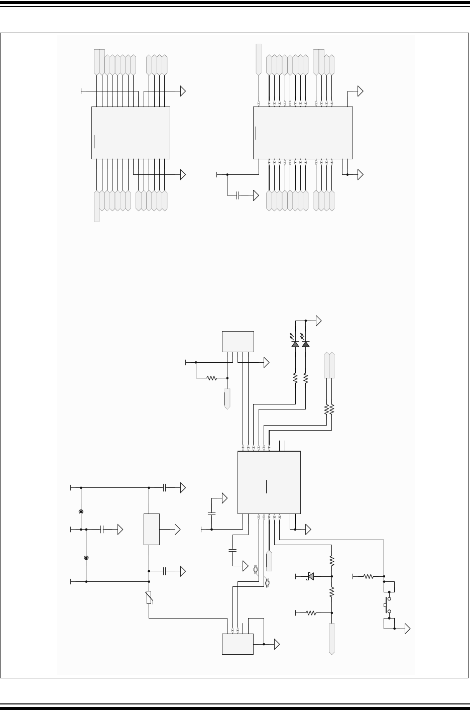
All MPLAB Xpress boards contain two sections:
1. The programmer section, which contains the circuitry necessary to serve as a
dedicated drag-and-drop programmer for the target device using Microchip Tech-
nology's proprietary In-Circuit Serial Programming (ICSP) protocol. In this way,
no additional hardware is needed to program the target device other than a sim-
ple USB connection to a host computer.
2. The application section, which contains the circuitry that is used by the micro-
controller application.
Additionally, MPLAB Xpress Evaluation Boards feature a Communications Device
Class (CDC) interface to facilitate serial communication between the target device and
a host computer.
There are three variants of MPLAB Xpress Evaluation Boards:
1. General Purpose MPLAB Xpress Evaluation Board
2. Device Specific MPLAB Xpress Evaluation Board (20-pin variant)
3. Device Specific MPLAB Xpress Evaluation Board (40-pin variant)
A.2 POWERING THE BOARDS
The MPLAB Xpress Evaluation Boards can be powered in one of two ways, depending
on its usage. It should be noted that only one power source should be connected at a
time.
A.2.1 USB Connector
The USB connector will power the entire MPLAB Xpress Evaluation Board. With USB
power connected, the power LED will always be on (green) to indicate that +3.3V is
available on the board.
A.2.2 2.7V-16V External Power Supply (General Purpose MPLAB
Xpress Board Only)
The external power supply option is available on the General Purpose MPLAB Xpress
Board only. It will also power the entire MPLAB Xpress Evaluation Board. The external
power supply is connected to a Low Dropout (LDO) voltage regulator, configured to
deliver 3.3V to the board. The external power supply range is from 2.7V to 16V, allow-
ing use with two to six primary cells, 9V alkaline batteries, or one or two-cell Li-Ion bat-
teries. LED D1 will illuminate green when the external power supply is active and
supplying sufficient voltage.
Using 8-bit MCUs with MPLAB® Xpress
DS50002710A-page 44 2018 Microchip Technology Inc.
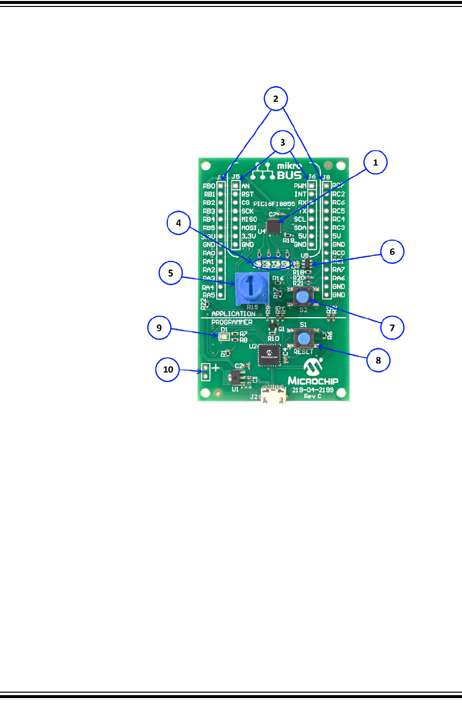
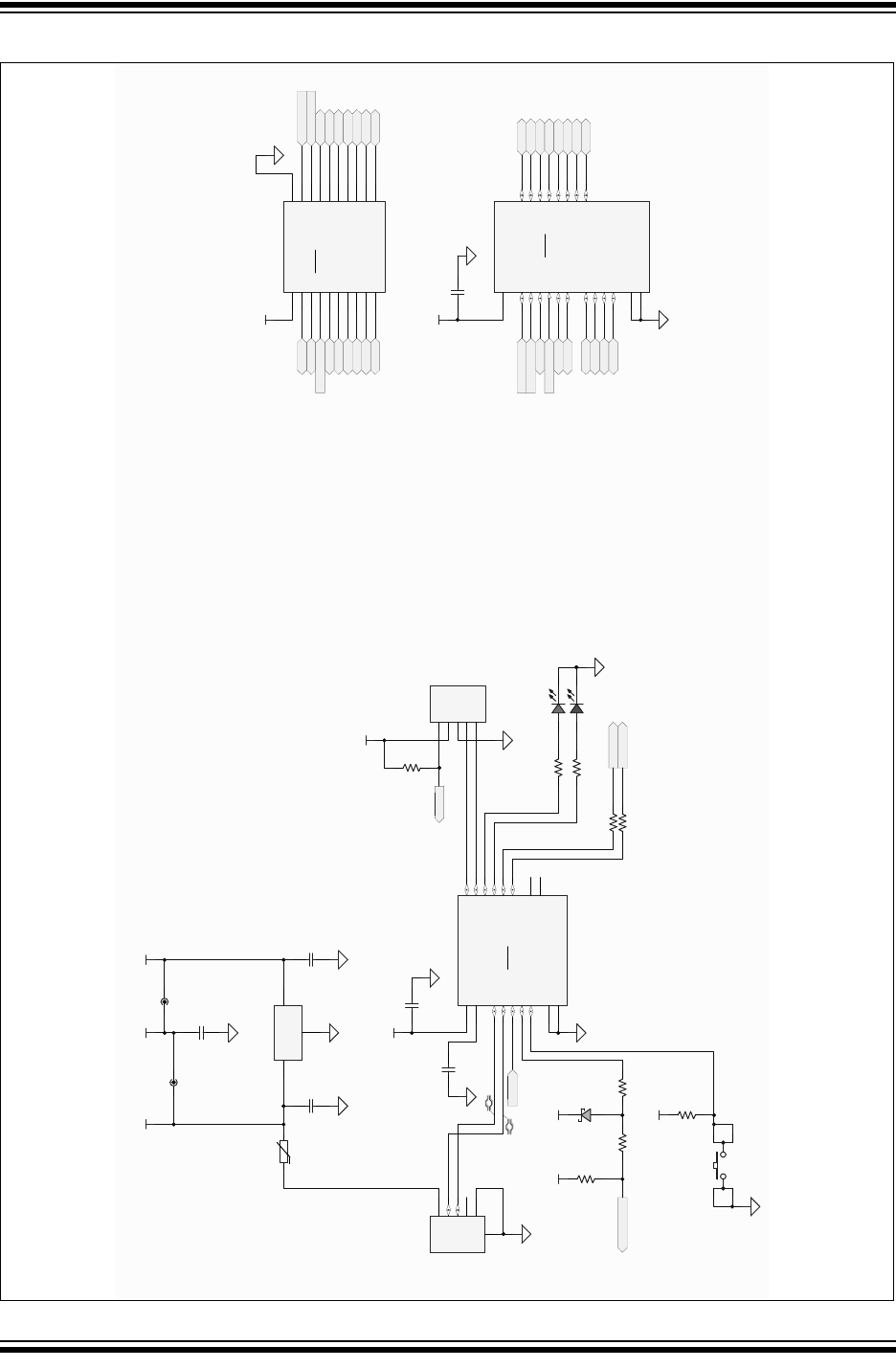
A.3 GENERAL PURPOSE EVALUATION BOARD
The MPLAB Xpress General Purpose Evaluation Board features an 8-bit PIC16F18855
microcontroller. This board differs from other variants in that it also features basic inter-
face components to the target device such as LEDs, potentiometer, switch and more.
1. PIC16F18855 target microcontroller
2. Connection header corresponding to target microcontroller pins
3. mikroBUS™ socket to accommodate a variety of plug-in MikroElektronika Click
Boards that can be used in application development
4. Four user LEDs
5. Potentiometer
6. EMC1001 temperature sensor
7. Push button switch
8. Master RESET switch
9. Power LED:
a) Green: power to target
b) Flashing Red: target being programmed
10. 2.7V-16V Battery/External power connection
MPLAB® Xpress Evaluation Boards
2018 Microchip Technology Inc. DS50002710A-page 45
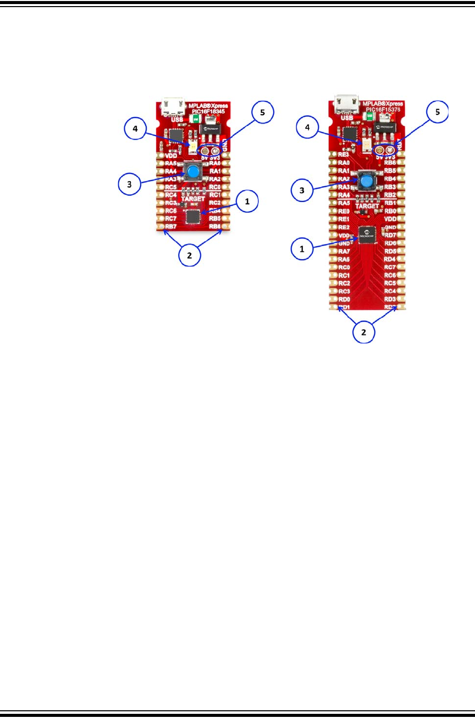
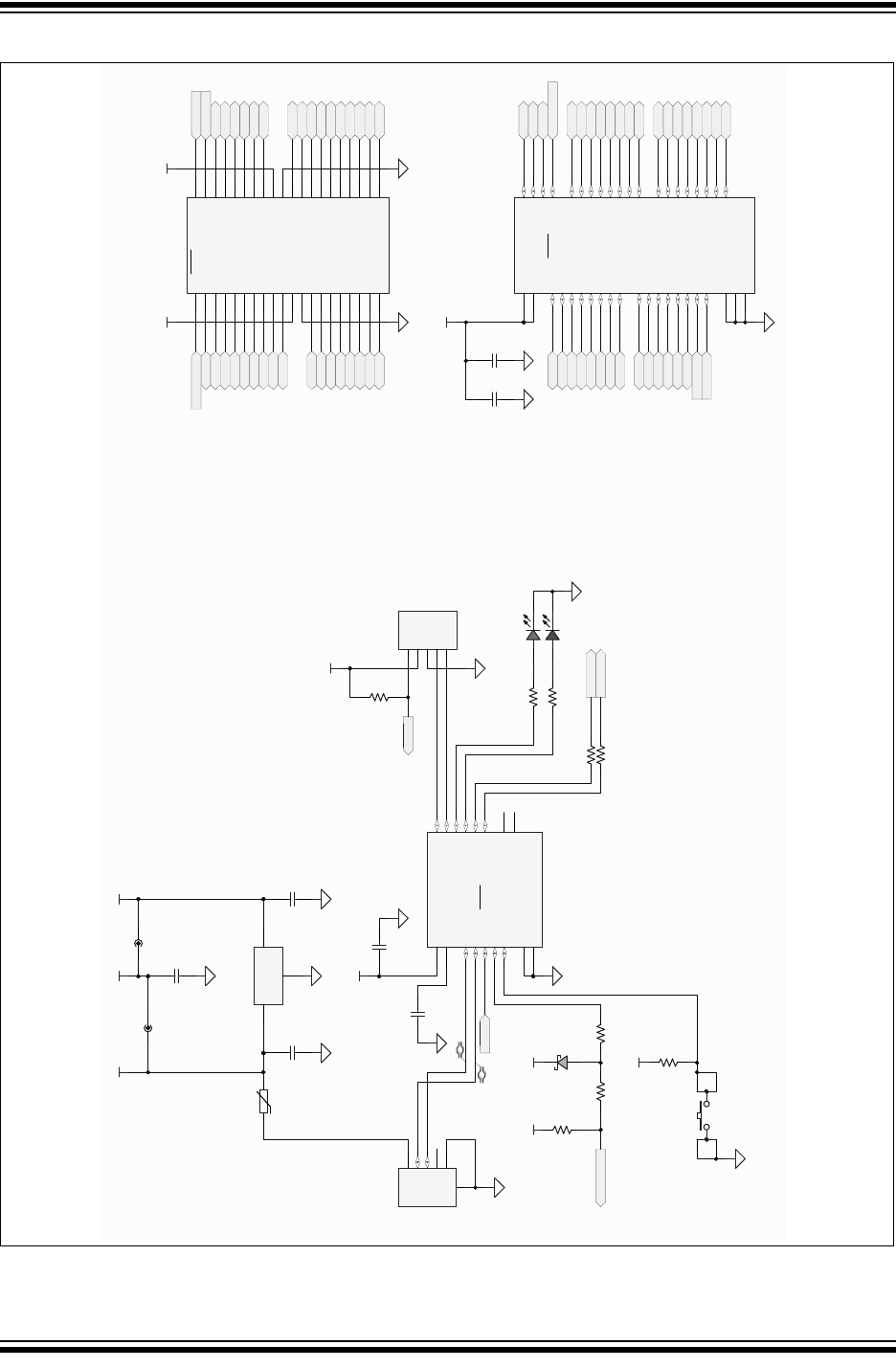
A.4 DEVICE-SPECIFIC EVALUATION BOARDS
The MPLAB Xpress Device Specific Evaluation Boards contain a specific PIC16 or
PIC18 device the board is targeted towards in addition to the built-in programmer. They
are available in 20-pin and 40-pin variants based on the device.
1. Target microcontroller
2. Connection header corresponding to target microcontroller pins
3. Master RESET switch
4. Power LED:
a) Green: power to target
b) Flashing Red: target being programmed
5. Selects 5V from USB supply or 3.3V from LDO regulator output to power target
device (default is 3.3V)

Using 8-bit MCUs with MPLAB® Xpress
DS50002710A-page 46 2018 Microchip Technology Inc.
NOTES:
2018 Microchip Technology Inc. DS50002710A-page 47
GETTING STARTED USING
8-BIT MCUs IN THE MPLAB®
Xpress ECOSYSTEM
Appendix B. MPLAB® Xpress Evaluation Board Schematics
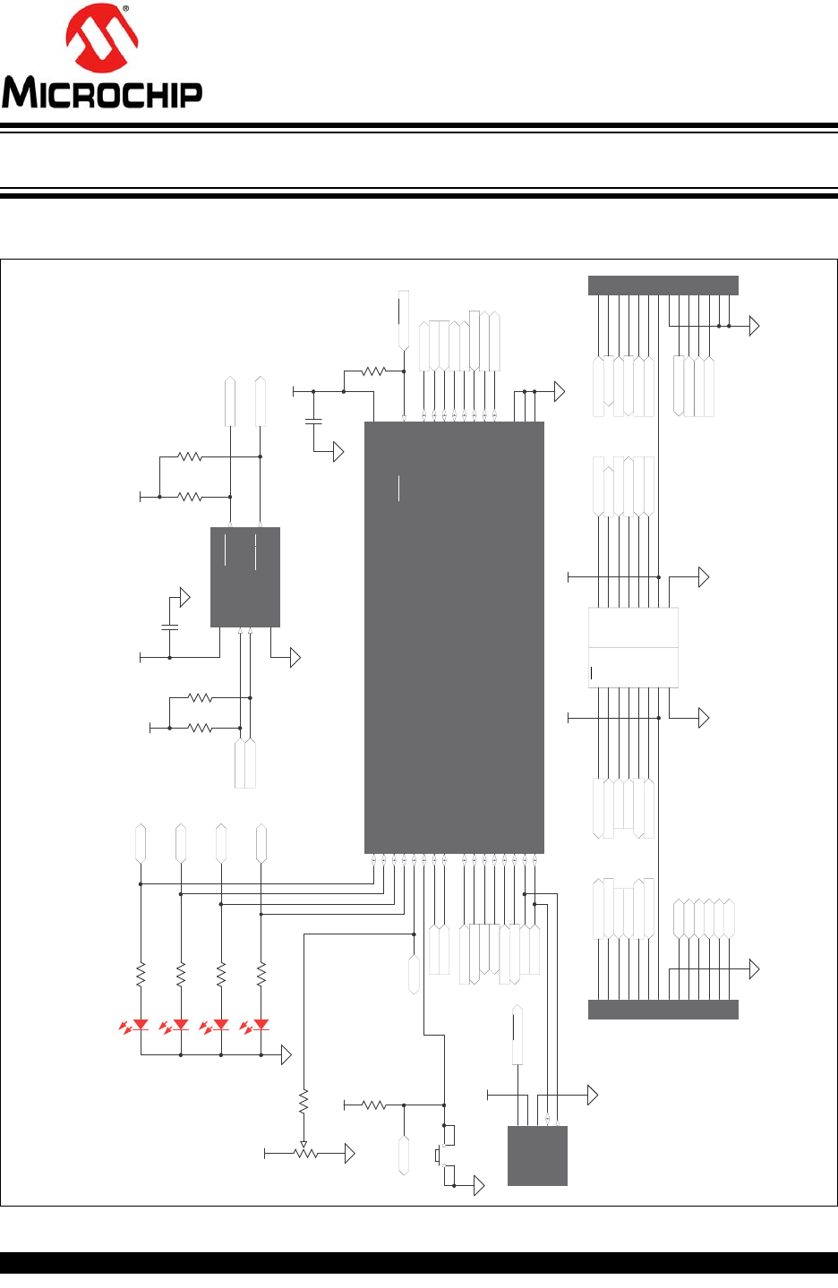
FIGURE B-1: GENERAL PURPOSE EVALUATION BOARD SCHEMATIC (APPLICATION
SECTION)
ADDR/THERM 1
GND
2
3V
DD
SMCLK
4
ALERT/THERM2 5
SMDATA
6
EMC1001-AFZQ -TR
U5
0.1μF
C8
+3.3V
F188SCL
F188SDA
+3.3V
DNP
R21
ALARM1
ALARM2
20.0K
R20
10K
R18
10K
R19
+3.3V
AN
1
RST
2
CS
3
SCK
4
MISO
5
MOSI
6
+3.3V
7
GND
8
J5
GND 8
+5V 7
SDA 6
SCL 5
TX 4
RX 3
INT 2
PWM 1
J6
F188PWMF188ANA1
+3.3V
F188RXM
F188TXM
F188INT
V
USB
F188SDA
F188SCL
F188RST
F188CS
F188SCK
F188MISO
F188MOSI
1
2
3
4
5
6
7
8
9
10
11
12
13
14
DNP
J7
1
2
3
4
5
6
7
8
9
10
11
12
13
14
DNP
J8
F188ANA1
F188RST
F188CS
F188SCK
F188MISO
F188MOSI
F188PWM
F188RXM
F188TXM
F188INT
F188SDA
F188SCL
ALARM1
ALARM2
F188TXU
F188RXU
RA0
RA1
RA2
RA3
RA5
RA4
Host
Connector
mikroBUS
70
RA2/ANA2/VREF-/DAC1OUT1/C1IN0+/C2IN0+/IOCA2/PPS
1
RA 3/A NA 3/V REF+/C1 IN1+/M DCI N1/I OCA 3/P PS
2
RA4/ANA4/MDCIN2/T0CKI/CCP5/IOCA4/PPS
3
RA5/ANA5/SS1/MDMIN/IOCA5/ PPS
4
RA7/ANA7/IOCA7/OSC1/CLKIN
6RA6/ANA6/IOCA6/OSC2/CLKOUT
7PPS/SOSCO/IOCC0/SMTWIN1/T3G/T3CKI /T1CKI/ANC0/RC0 8
PPS/SOSCI/IOCC1/CCP2/SMTSIG1/ANC1/RC1 9
PPS/IOCC2/CCP1/T5CKI /ANC2/RC2 10
PPS/IOCC3/T2IN/SCK1/SCL1/ANC3/RC3 11
PPS/IOCC4/SDI1/SDA1/ANC4/RC4 12
PPS/IOCC5/T4IN/ANC5/RC5 13
PPS/IOCC6/CK/ANC6/RC6 14
PPS/IOCC7/DT/RX/ANC7/RC7 15
V
SS
5
1
V
SS
29
6
V
DD
RB0/A NB0/C2 IN1 +/ZCD/SS2 /CCP 4/CWG1 IN/I NT/I OCB0/PP S
18
RB1/ANB1/C1IN3-/C2IN3-/SCL 2/SCK2/CWG2IN/IOCB1/ PPS
19
RB2/ANB2/SDA2/SDI2/CWG3IN/IOCB2/PPS
20
RB3/ANB3/C1IN2-/C2IN2-/IOCB3
21
RB4/ANB4/ADCACT/T5G/SMTWIN2/IOCB4/PPS
22
RB5/ANB5/T1G/SMTSIG2/CCP3/I OCB5/ PPS
23
RB6/ANB6/CLCI N2/I OCB6/ICSPC LK/PPS
24
RB7/ANB7/DAC1OUT2/T6IN/CLCIN3/I OCB7/ICSPDAT/PPS
25
V
PP
/MCLR/IOCE3/RE3
RA0/ANA0/C1IN0-/C2IN0-/CLCIN0/IOCA0/PPS
27
RA1/ANA1/C1IN1-/C2IN1-/CLCIN1/IOCA1/PPS
28
EP
U4
+3.3V
0.1μF
C7
+3.3V
+3.3V
F188TXU
F188RXU
F188MCLR
F188MCLR
ALARM1
ALARM2
F188INT
F188PWM
F188SCL
F188SDA
F188ANA1
F188RXM
F188CS
F188SCK
F188MISO
F188MOSI
F188RST
F188TXM
S2
10K
R17
+3.3V
Red
D2
Red
D3
Red
D4
Red
D5
F188CLK
F188DAT
2
1
3CW
CCW
10K
R15
1K
R16
RA0
RA3
1K
R11
1K
R12
1K
R13
1K
R14
RA1
RA2
V
PP
/MCLR1
2
GND
V
DD
3
ICSPDAT 4
I CSPC LK 5
DNP
PICNLW
70
3
J4
RA5
RA4
10K
R22
PIC16F18855-I/MV

Using 8-bit MCUs with MPLAB® Xpress
DS50002710A-page 48 2018 Microchip Technology Inc.
FIGURE B-2: GENERAL PURPOSE EVALUATION BOARD SCHEMATIC (PROGRAMMER
SECTION)
MPLAB Xpress
Evaluation Board
Schematic
RA2/C2IN+/AN2/DA COUT/V REF-
1
RA3/C1IN+/AN3/VREF+
2
RA4/C1OUT/SRQ/T0CK I
3
RA5/C2OUT/SRNQ/SS/HLVDI N/AN4
4
VSS
5
RA 7/CL KI /OSC1
6RA6/CL K O/OSC2
7
SOSC0/T1CKI/T3G/T3CKI/IOCC0/RC0 8
SOSCI/CCP2/IOCC1/RC1 9
A N14/I OCC2/CCP1/P1A/CTPLS/RC2 10
VUSB3V3
11
D-/I OCC4
12
D+/I OCC5
13
A N18/CK /TX /I OCC6/RC6 14
AN19/DT/RX/IOCC7/SDO/RC7 15
VSS
16
VDD
17
AN12/SDA/SDI/SRI/FLT0/INT0/RB0 18
AN10/C12IN3-/SCL/SCK/P1C/INT1/RB1 19
AN8/P1B/CTED1/INT2/RB2 20
AN9/C12IN2-/SDO/CCP2/CTED2/RB3 21
AN11/P1D/IOCB4/RB4 22
AN13/T1G/T3CKI/IOCB5/RB5 23
PGC/I OCB6/RB6 24
PGD/IOCB7/RB7 25
MCLR/VPP/RE3 26
RA0/C12IN0-/A N0
27
RA1/C12IN1-/A N1
28
EP
29
PIC 18L F25K50-I/ ML
U2
USB - micro B
VBUS 1
D- 2
D+ 3
ID 4
GND 5
6
7
J2
+3.3V
0.1μF
C4
+3.3V
1.0μF
C1
1.0μF
C2
VUSB
+3.3V
10K
R1
S1
D_P
D_N
PGC
PGC
PGD
PGD
D_N
D_P
10K
R6
+3.3V
F188RXU
F188TXU
2N7002
1
2 3
Q1
F188MCLR
F188C LK
F188DAT
10K
R10
RESET F188
4 2
31
RG
LTST-C195KGJRKT
D1
GND
1
VIN
2VOUT 3
MCP1703T- 3302E / MB
U1
1KR7
1KR8
VPP/ MCLR
1
VDD
2
GND
3
ICSPDAT
4
ICSPC LK
5
DNP
PICKIT 3
J1
100RR5
100RR2
100RR3
100RR4
100R
R9
1
2
DNP
BATT
MPLAB® Xpress Evaluation Board Schematics
2018 Microchip Technology Inc. DS50002710A-page 49
FIGURE B-3: 20-PIN DEVICE-SPECIFIC EVALUATION BOARD SCHEMATIC
,'
9%86
*1'
'
'
86%0,&52%
86%
'B3
'B1
X)
&
0&/5
0&/5
5
5
7*0&/5 7*&/.
7*'$7
*
5
)
'
35*0&/5
N
5
N
5
N
5
0&/5
3*&
3*'
966
9''
'13
-
9''
986%9
966
5$',&63'$7
5$',&63&/.
5$9330&/5
5$
5$
,&63'$75&
,&63&/.5&
5&
5&
5&
5&
1&
1&
3$'
3,&),-4
8
X)
&
W
P$
7+
986%
5
5
%$7
'
9''
5
5
5
5
5
5
5
5
986%
*1'
9,1
9287
0&37('%
8
986%
X)
9
&
9''
32:(5
',6&211(&7
986%
9''
5&
5&
5&
5&
5&
5&
5$
5$
5$
5%
5%
X)
&
7*'$7
7*&/.
7*0&/5
9''
5$
5$
5$
5&
5&
5&5&
5%
5%
5&
5&
7*0&/5
7*'$7
7*&/.
5&
5&
5&
5&
5%
5%
3,&3URJUDPPLQJ$GDSWHU
9''
5$
5$
5$0&/5
5&
5&
5&
5&
5&
5%
5%
5%
5%
5&
5&
5&
5$
,&63&/.5$
,&63'$75$
966
8
5%5%
9
9
9
9''
6
X)
9
&
X)
9
&
5$9SS0&/5
5&
5&
5&
5&
5&
5%
5%
5%
5%
5&
5&
5&
5$
5$,&63&/.
5$,&63'$7
966
9''
5$26&
5$26&
(3
8
3,&))3,1'(9,&(6
Using 8-bit MCUs with MPLAB® Xpress
DS50002710A-page 50 2018 Microchip Technology Inc.
FIGURE B-4: 28-PIN DEVICE-SPECIFIC EVALUATION BOARD SCHEMATIC
,'
9%86
*1'
'
'
86%0,&52%
86%
'B3
'B1
X)
&
0&/5
0&/5
5
5
7*0&/5 7*&/.
7*'$7
*
5
)
'
35*0&/5
N
5
9''
5&
5&
5&
5&
5&
5&
5$
5$
5$
5$
5$
5$
5$
5$
5%
5%
5%
5% 5%
5%
9''
X)
&
N
5
7*'$7
7*&/.
7*0&/5
9''
5$
5$
5$
5$
5$
5$
5$
5$
5&
5&
5&
5&
5%
5%
5%
5%
5%
5%
5&
5&
7*0&/5 7*'$7
7*&/.
N
5
5&
5&
5&
5&
0&/5
3*&
3*'
966
9''
'13
-
9''
986%9
966
5$',&63'$7
5$',&63&/.
5$9330&/5
5$
5$
,&63'$75&
,&63&/.5&
5&
5&
5&
5&
1&
1&
3$'
3,&),-4
8
X)
&
W
P$
7+
5
5
%$7
'
9''
5
5
5
5
5
5
5
5
986%
986%
X)
9
&
32:(5
',6&211(&7
986%
986% 9''
9
9
9
6
X)
9
&
X)
9
&
3',3
5(0&/5
5$
5$
5$
5$
5$
5$
966
5$
5$
5&
5&
5&
5&
5&
5&
5&
5&
966
9''
5%
5%
5%
5%
5%
5%
5%3*&
5%3*'
3,&3URJUDPPLQJ$GDSWHU
8
*1'
9,1
9287
0&37('%
8
5$
5$
5$
5$
5$
5$
5$
5$
5%
5%
5%
5%
5%
5%
5%,&63&/.
5%,&63'$7
5&
5&
5&
5&
5&
5&
5&
5&
0&/59335(
966
966
9''
3$'
8
3,&))3,1'(9,&(6
MPLAB® Xpress Evaluation Board Schematics
2018 Microchip Technology Inc. DS50002710A-page 51
FIGURE B-5: 40-PIN DEVICE-SPECIFIC EVALUATION BOARD SCHEMATIC
,'
9%86
*1'
'
'
86%0,&52%
86%
'B3
'B1
X)
&
0&/5
0&/5
5
5
7*0&/5 7*&/.
7*'$7
*
5
)
'
35*0&/5
N
5
9''
5'
5'
5'
5'
5'
5'
5'
5'
5(
5(
5(
5&
5&
5&
5&
5&
5&
5$
5$
5$
5$
5$
5$
5$
5$
5%
5%
5%
5%
5%
5%
9''
X)
&
X)
&
N
5
7*'$7
7*&/.
7*0&/5
9'' 9''
5$
5$
5$
5$
5$
5$
5(
5(
5(
5$
5$
5&
5&
5&
5&
5'
5'
5%
5%
5%
5%
5%
5%
5'
5'
5'
5'
5&
5&
5'
5'
7*0&/5 7*'$7
7*&/.
352*5$00,1*$'$37(5
N
5
5&
5&
5&
5&
0&/5
3*&
3*'
966
9''
'13
-
5(0&/5
5$
5$
5$
5$
5$
5$
5(
5(
5(
9''
966
5$
5$
5&
5&
5&
5&
5'
5'
5'
5'
5&
5&
7;5&
5;5&
5'
5'
5'
5'
966
9''
5%
5%
5%
5%
5%
5%
5%3*&
5%3*'
3,&3URJUDPPLQJ$GDSWHU
8
9''
986%9
966
5$',&63'$7
5$',&63&/.
5$9330&/5
5$
5$
,&63'$75&
,&63&/.5&
5&
5&
5&
5&
1&
1&
3$'
3,&),-4
8
X)
&
W
P$
7+
5
5
%$7
'
9''
5
5
5
5
5
5
5
5
986%
*1'
9,1
9287
0&37('%
8
986%
X)
9
&
32:(5
',6&211(&7
986%
986% 9''
9
9
9
6
X)
9
&
X)
9
&
9''
5$
5$
5$
5$
5$
5$
5$
5$
5%
5%
5%
5%
5%
5%
5%,&63&/.
5%,&63'$7
5&
5&
5&
5&
5&
5&
5&
5&
0&/59335(
966
966
3$'
9''
5'
5'
5'
5'
5'
5'
5'
5'
5(
5(
5(
8
3,&))3,1'(9,&(6

Using 8-bit MCUs with MPLAB® Xpress
DS50002710A-page 52 2018 Microchip Technology Inc.
NOTES:
2018 Microchip Technology Inc. DS50002710A-page 53
USING 8-BIT MCUS IN
MPLAB® XPRESS
Index
C
Composer Area in MCC........................................... 27
CoolTerm ................................................................... 7
D
Device Resources in MCC....................................... 23
Download Example Project...................................... 12
E
Easy Setup Tab (EUSART) in MCC......................... 27
Enter Token from MPLAB Xpress............................ 18
EUSART .................................................................. 36
EUSART_Write()................................................... 39
Example Project......................................................... 9
H
Header File .............................................................. 39
I
Interrupt Module in MCC.......................................... 22
J
Java Version ............................................................ 16
L
Libraries List in MCC................................................ 25
M
main.c .................................................................... 40
Manage MPLAB Xpress Code Configurator ............ 16
MikroElektronika Click Boards List in MCC.............. 26
MPLAB Code Configurator (MCC)............7, 21, 36, 39
MCC_Xpress.jnlp.......................................... 17
Plugin................................................................ 15
MPLAB XC8 C Compiler............................................ 7
MPLAB Xpress Ecosystem ........................................ 5
MPLAB Xpress Evaluation Boards............................. 7
Device Name .................................................... 10
Device Specific ................................................. 45
General Purpose............................................... 44
Powering........................................................... 43
Programming ...................................................... 9
MPLAB Xpress IDE.................................................... 7
MPLAB Xpress Wiki................................................... 7
N
New Project.............................................................. 34
Notifications Tab in MCC ......................................... 28
P
Peripherals List in MCC ........................................... 24
Pin Manager Package View in MCC........................ 30
Pin Manager Table View in MCC............................. 29
Pin Module in MCC .................................................. 22
Product Page in MCC .............................................. 23
Project Resources in MCC....................................... 22
R
Registers Tab in MCC.............................................. 27
S
Serial Communications ............................................ 13
Build Link .......................................................... 33
System Module in MCC ........................................... 22
T
Tera Term .................................................................. 7
U
USB Link .................................................................. 33
V
Versions of MCC Components................................. 31

Using 8-bit MCUs in MPLAB® Xpress
DS50002710A-page 54 2018 Microchip Technology Inc.
NOTES:

DS50002710A-page 55 2018 Microchip Technology Inc.
AMERICAS
Corporate Office
2355 West Chandler Blvd.
Chandler, AZ 85224-6199
Tel: 480-792-7200
Fax: 480-792-7277
Technical Support:
http://www.microchip.com/
support
Web Address:
www.microchip.com
Atlanta
Duluth, GA
Tel: 678-957-9614
Fax: 678-957-1455
Austin, TX
Tel: 512-257-3370
Boston
Westborough, MA
Tel: 774-760-0087
Fax: 774-760-0088
Chicago
Itasca, IL
Tel: 630-285-0071
Fax: 630-285-0075
Dallas
Addison, TX
Tel: 972-818-7423
Fax: 972-818-2924
Detroit
Novi, MI
Tel: 248-848-4000
Houston, TX
Tel: 281-894-5983
Indianapolis
Noblesville, IN
Tel: 317-773-8323
Fax: 317-773-5453
Tel: 317-536-2380
Los Angeles
Mission Viejo, CA
Tel: 949-462-9523
Fax: 949-462-9608
Tel: 951-273-7800
Raleigh, NC
Tel: 919-844-7510
New York, NY
Tel: 631-435-6000
San Jose, CA
Tel: 408-735-9110
Tel: 408-436-4270
Canada - Toronto
Tel: 905-695-1980
Fax: 905-695-2078
ASIA/PACIFIC
Asia Pacific Office
Suites 3707-14, 37th Floor
Tower 6, The Gateway
Harbour City, Kowloon
Hong Kong
Tel: 852-2943-5100
Fax: 852-2401-3431
Australia - Sydney
Tel: 61-2-9868-6733
Fax: 61-2-9868-6755
China - Beijing
Tel: 86-10-8569-7000
Fax: 86-10-8528-2104
China - Chengdu
Tel: 86-28-8665-5511
Fax: 86-28-8665-7889
China - Chongqing
Tel: 86-23-8980-9588
Fax: 86-23-8980-9500
China - Dongguan
Tel: 86-769-8702-9880
China - Guangzhou
Tel: 86-20-8755-8029
China - Hangzhou
Tel: 86-571-8792-8115
Fax: 86-571-8792-8116
China - Hong Kong SAR
Tel: 852-2943-5100
Fax: 852-2401-3431
China - Nanjing
Tel: 86-25-8473-2460
Fax: 86-25-8473-2470
China - Qingdao
Tel: 86-532-8502-7355
Fax: 86-532-8502-7205
China - Shanghai
Tel: 86-21-3326-8000
Fax: 86-21-3326-8021
China - Shenyang
Tel: 86-24-2334-2829
Fax: 86-24-2334-2393
China - Shenzhen
Tel: 86-755-8864-2200
Fax: 86-755-8203-1760
China - Wuhan
Tel: 86-27-5980-5300
Fax: 86-27-5980-5118
China - Xian
Tel: 86-29-8833-7252
Fax: 86-29-8833-7256
ASIA/PACIFIC
China - Xiamen
Tel: 86-592-2388138
Fax: 86-592-2388130
China - Zhuhai
Tel: 86-756-3210040
Fax: 86-756-3210049
India - Bangalore
Tel: 91-80-3090-4444
Fax: 91-80-3090-4123
India - New Delhi
Tel: 91-11-4160-8631
Fax: 91-11-4160-8632
India - Pune
Tel: 91-20-3019-1500
Japan - Osaka
Tel: 81-6-6152-7160
Fax: 81-6-6152-9310
Japan - Tokyo
Tel: 81-3-6880- 3770
Fax: 81-3-6880-3771
Korea - Daegu
Tel: 82-53-744-4301
Fax: 82-53-744-4302
Korea - Seoul
Tel: 82-2-554-7200
Fax: 82-2-558-5932 or
82-2-558-5934
Malaysia - Kuala Lumpur
Tel: 60-3-6201-9857
Fax: 60-3-6201-9859
Malaysia - Penang
Tel: 60-4-227-8870
Fax: 60-4-227-4068
Philippines - Manila
Tel: 63-2-634-9065
Fax: 63-2-634-9069
Singapore
Tel: 65-6334-8870
Fax: 65-6334-8850
Taiwan - Hsin Chu
Tel: 886-3-5778-366
Fax: 886-3-5770-955
Taiwan - Kaohsiung
Tel: 886-7-213-7830
Taiwan - Taipei
Tel: 886-2-2508-8600
Fax: 886-2-2508-0102
Thailand - Bangkok
Tel: 66-2-694-1351
Fax: 66-2-694-1350
EUROPE
Austria - Wels
Tel: 43-7242-2244-39
Fax: 43-7242-2244-393
Denmark - Copenhagen
Tel: 45-4450-2828
Fax: 45-4485-2829
Finland - Espoo
Tel: 358-9-4520-820
France - Paris
Tel: 33-1-69-53-63-20
Fax: 33-1-69-30-90-79
Germany - Garching
Tel: 49-8931-9700
Germany - Haan
Tel: 49-2129-3766400
Germany - Heilbronn
Tel: 49-7131-67-3636
Germany - Karlsruhe
Tel: 49-721-625370
Germany - Munich
Tel: 49-89-627-144-0
Fax: 49-89-627-144-44
Germany - Rosenheim
Tel: 49-8031-354-560
Israel - Ra’anana
Tel: 972-9-744-7705
Italy - Milan
Tel: 39-0331-742611
Fax: 39-0331-466781
Italy - Padova
Tel: 39-049-7625286
Netherlands - Drunen
Tel: 31-416-690399
Fax: 31-416-690340
Norway - Trondheim
Tel: 47-7289-7561
Poland - Warsaw
Tel: 48-22-3325737
Romania - Bucharest
Tel: 40-21-407-87-50
Spain - Madrid
Tel: 34-91-708-08-90
Fax: 34-91-708-08-91
Sweden - Gothenberg
Tel: 46-31-704-60-40
Sweden - Stockholm
Tel: 46-8-5090-4654
UK - Wokingham
Tel: 44-118-921-5800
Fax: 44-118-921-5820
Worldwide Sales and Service
10/10/17
