Yaesu FT 50R User Manual 50
User Manual: Pdf YAESU--FT-50-User-Manual
Open the PDF directly: View PDF ![]() .
.
Page Count: 60
- FT-50F Manual
- Contents
- Accessories & Options
- Display Indications
- Safety Tips
- Getting Started
- Powering On
- Knob Functions
- The Keypad
- Your first QSO
- Adjusting the Volume
- Squelch Setting
- Tuning & Direct Frequency Entry
- Transmitting
- Basic Operation
- Memory Operation
- Advanced Operation
- Dual Watch DW
- V/M Dual Watch
- M/M Dual Watch
- H/M Dual Watch
- V/V Dual Watch
- Memory-Only Mode
- Locking the Controls
- Introduction to DTMF Paging
- Paging Transmit Delay
- Playback Speed
- Paging Bell
- Paging Bell
- ARTS (Auto Range Transpond System)
- ARTS Modes
- CW ID (Morse Identifier)
- Digital Voice Recorder
- Microphone Recording
- Addendum
- Appendix
- About this Document
FT-5OR
Dual-Band Amateur
I
I
Hand-Held Transceiver with
Digital Voice Recorder Option

Contents
Description
Accessories and Options
Optional
FTT-12
Keypad
Control and Connectors
Display Indications
Specifications
Before You Begin
Getthg
Started
Basic Operation
Frequency Selection Modes (VFO and MR)
Sub Display Options, Tuning, Transmitting
VFO Duplex Mode
Extended Recption, WFM sql, Auto-Mode select
Rx Mode override, Repeater Operation, T
X
offset
Repeater Shift, Input Track, Input Monitor
Memory Operation
Storing and Displaying Memories,
VFO-k
MR, MR
MR-+VFO,
HOME memory, Custom T
X
offset, MT
Scanning, Scan Resume Modes, Skip Scan, Lamp
PTS (Preset Tuning and Scanning)
Advanced Operation
Dual Watch (VIM,
M/M,
H/M, V/V)
Naming Memories
Memory Masking
1
3
4
7
9
10
11
73
19
19
20
21
22
23
24
25
25
26
27
28
29
29
30
31
Memory-only Mode, Locking the Controls, T
X
TOT 32
Tone Squelch Modes (CTCSS, DCS) 33
CTCSS or DCS Bell Paging 34
Tone/Code Scanning, DTMF Code Squelch/Paging 35
Programming/Selecting DTMF Paging Code Memories 37
DTMF Paging Operation (receiving/sending page calls) 38
Trigger Paging, Auto-Respond Paging 39
Paging T
X
Delay, Playback Speed, Paging Bell 40
ARTS (Auto Range Transpond System)
41
ARTS Modes, CW (Morse Code) IDer 42
ARTS Polling Speed, Beeper, DTMF Autodial Feature 43
Autodialer Playback, DTMF Decoder 44
Digital Voice Recorder, Microphone Recording 45
Spkr. Playback, Rx Rec., T
X
Playback, Record Protect 46
VMPS (Voice Mail Paging System) 47
Addendum 49
Extending Battery Life, APO, Rx Batt. Saver 49
T
X
Batt. Saver, Beeper Disable, LED Disable 49
Lamp Illumination Modes, Battery Care
51
Packet Radio 52
Cloning 53
Customizations, MON switch, RV/HM key 54
Appendix 55
Menu FunctionTable, Key Entry Tables 55
The
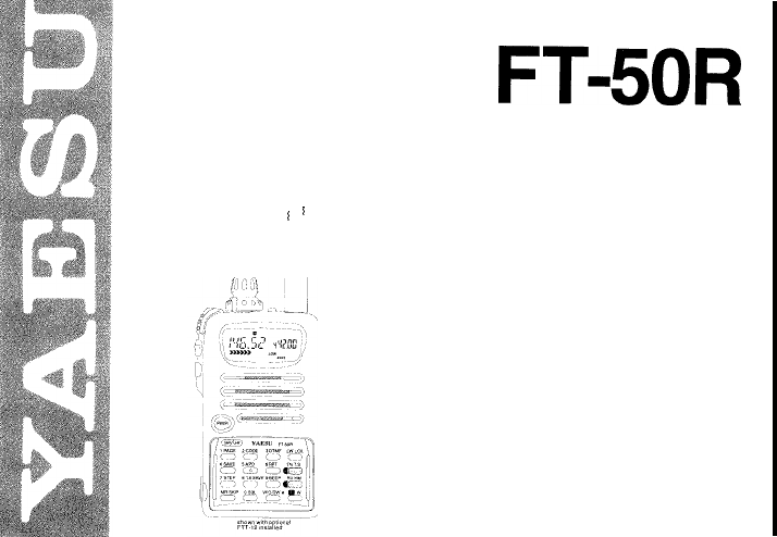
FT-5OR
compact FM hand-held transceiver pro-
vides up to 5 watts of transmitter output on the 2-m
and
70-cm
amateur bands. The optional FTT-12 key-
pad provides tone systems and digital voice func-
tions, while the standard version includes Digital
Code Squelch (DCS) encoding and decoding,
CTCSS encoding, and a wide range of battery pre-
serving features.
Description
The compact “clamshell” design mounts the battery
on the rear, for optimum simplicity and portability. A
multi-function knob with concentric volume control
allows setting most functions, minimizing the need
for complex key sequences. The front half of the
case high-impact polycarbonate plastic, while the
transceiver chassis/heat sink is die-cast alloy. A
choice of 4 rechargeable Ni-Cd packs or a dry cell
battery case are available. Rubber gaskets protect
against dust and rain or spray. The LCD (display) has
selectable lighting modes, and shows all significant
frequency digits and most programmable functions,
plus relative signal strength and power output.
Two independent VFOs and up to 100 freely tunable
memories are programmable from the knob and key-
pad. The duplex mode allows split VFO operation,
and dual-watch monitors a sub-channel VFO or
memory while operating from the main channel.
USA versions include extended reception in the VHF,
UHF, FM broadcast, and 800 MHz bands (cellular
blocked). A separate squelch and bandwidth setting
is available to enhance FM broadcast reception.
Memory features include independent tx/rx frequen-
cies or programmable offsets, up to five pairs of
subband limits for band scanning, selectable scan
skip for busy channels, scan resume on carrier drop
or after
5-second
pause, and independent instant-re-
call HOME channel for VHF and UHF. Memories also

store tuning steps, tone selections, and transmit
power level. Standard channel steps from 5 to 50
kHz,
plus l-MHz steps, are available for tuning. You
can assign 4-character names to memories.
Also include is a DCS encoder/decoder (104 codes),
and a
39-tone
CTCSS (Continuous Tone-Coded
Squelch System) encoder. The DCS system (and
CTCSS decoder provided with the optional FTT-12
keypad) can be set to sound an alert tone when a
selective call opens the squelch. Also, the
FT-5OR
can scan a received carrier and determine if a
CTCSS tone or DCS code is being used, and display
that tone/code.
The ARTS (Auto Range Transpond System) uses
DCS signalling to poll another station to indicate
when they are within or out of range, and can auto-
matically ID with your
callsign
in Morse code every
five minutes.
In addition to the
4-step
power output selection,
unique features to extend battery charge life include
a battery saver which optimizes save duration ac-
cording to selectable receiver “sleep” periods TX
Save, which automatically reduces transmit power
during periods of high incoming signal strength; se-
lectable time delay APO (Automatic Power Off), and
continuous or
5-second
display illumination.
The keypad generates DTMF tones during transmis-
sion, and up to 8 DTMF autodialer memories can
store 16 digits each for quick playback of commonly
used numbers. A special autodialer memory is
re-
served for decoding and displaying DTMF digits off-
the-air.
Also, DTMF-based selective calling and private pag-
ing capabilities let you select any of 999 three-digit
ID codes for your transceiver, and then have it stay
quiet until your code is received (from any standard
DTMF-equipped transceiver).
Upon
receiving the
DTMF ID code, you can have a paging beeper sound
(1,
3, 5, 8 times, or repeating). In the paging mode,
your display shows the DTMF ID code of the calling
party. Nine 3-digit code memories store your ID plus
those of eight other stations or groups you wish to
monitor, and an extra code memory always stores
the last 3-digit DTMF code heard.
With the optional FTT-12 keypad installed, the trans-
ceiver also provides 20 seconds of voice recording
from the microphone or receiver, for playback
through the speaker or the transmitter. Voice record-
ing can be activated manually or by an incoming
signal.
VMPS (Voice Mail Paging System) combines the
capabilities of both digital recording and DTMF pag-
ing to provide automated response to stations calling
you while you are away. The FT-50R allows calling
stations to leave a voice message, then answers with
your stations CW ID, followed by a pre-stored voice
message (that you record).
Please read this manual carefully to familiarize your-
self with the transceiver’s features,

Accessories
&
Options
Keypads
FTT-11 (supplied as standard)
FTT-12 DTMF Keypad with Digital Recording,
CTCSS decode, and DTMF paging and DTMF code
squelch
Rechargeable
Ni-Cd
Battery Packs
FNB-40 6.0 V, 650 mAh
FNB-41 9.6 V, 600 mAh
FNB-42 9.6 V, 1100 mAh
FNB-49 6.0 V, 600 mAh
Ni-Cd
Battery Chargers
NC-50 Dual-Slot Rapid Charger
CA-l 4 Charger Sleeve (required w/NC-50)
NC-GOB/C Compact
15-Hour
Charger
(‘B’ suffix for 117-V AC, ‘C’ suffix for 234-V AC)
Other Accessories
FBA-15 Battery Case for 4 AA-size Dry-Cells
CSC-68 Soft Case for FBA-15, FNB-41
CSC-69 Soft Case for FNB-40
CT-27 Cloning Cable
CT-30 Microphone Adapter
E-DC-5B Cigarette Lighter DC Power Cable
E-DC-6 External DC Power cable
MH-34B4B Speaker/Microphone
MH-37A4B Earpiece Microphone
PA-l 7 Battery Cable Extender
RH-1
Rubber Case Protector
VC-23 VOX Headset
CN-3 BNC -to- SMA Adapter
Availability of accessories may vary: some accessories
are supplied as standard per local requirements, others
may be unavailable in some regions. Check with your
Yaesu dealer for changes to the above list.
FTT-12 Keypad
_.__-----
-
-.
FT-SOR
DUAL
1‘
BAND
4SAVE
5AP0 6RPT
cm>
co>
cl
7STEP
6 TX SAVE
9BEEP
c
j
c
j
c3
I
MR
SKIP+
OSQL VFO DW
#
Cl
Cl
c-1
---- -
.-I--..-
FTT-12
FTT-12
ONLY
The optional
FTT-12
keypad offers additional trans-
ceiver functions, as shown in the chart below. See
your Yaesu dealer for pricing and availability.
Functions
_
DCS
&
ARTS
Tone Encoder
-
bTMF Encoder
-S,
DTMF Memory
Direct Frequency
_
Entry
(keypad)
I
CTCSS Decode
DTMF Code
Squelch
1
Digital Recorder
FTT-1
1
(standard)
0
0
0
0
-
.o----
0
~.,Jy
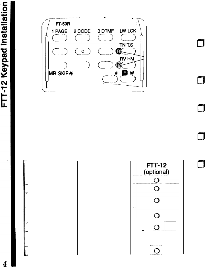
Installation
The FTT-12 keypad kit includes a keypad, rubber
gasket, Ni-Cd recycling label, and small Phillips
screwdriver:
0
Turn the radio off, and remove the battery. Peel off
the black Ni-Cd information seal, and loosen (but
do not completely remove) the two screws on
either side of the slot behind the original keypad.
m
From the rear, carefully press on both screws with
both thumbs to eject the keypad slightly, then re-
move the screws to free the keypad.
m
Gently but firmly press the new keypad into place
on the front of the radio, ensuring an even gasket
seal around the keypad periphery (no “pinching”).
m
Replace the two screws removed from the slot
behind the keypad, making sure the keypad and
gasket fit evenly, without pinching.
m
Affix the new
NiCd
label and replace the battery.

Batteries
&
Chargers
The FT-50R requires the FNB-41 or FNB-42
9.6~volt
rechargeable
NiCd
battery packs for full
5-watt
transmitter power output. However, where slightly
lower maximum power output is acceptable, the
6-
volt FNB-40 and -49 Ni-Cd packs offer smaller size
and lighter weight. Any
NiCd
pack should be fully
charged before it is used with the transceiver for the
first time.
Two types of battery chargers are available: the
NC-60 K-hour compact charger and the NC-50
Rapid Charger (used with CA-14 Charge Adapter).
The NC-60 is available with a “B” suffix for operation
from 117-V AC, or with a “C” suffix for operation from
220-234-V AC.
NC-50 Dual-Slot Rapid Charger
This AC mains battery charger features rapid and
trickle charging modes for all FNB Ni-Cd packs. It
requires the CA-14 Charger Sleeve for the FNB-40,
-41, -42, and FNB-49, and comes wired for the mains
voltage in the area sold.
The rapid mode automatically brings the battery pack
up to full charge as fast as safely possible using a
peak voltage sensor. A red LED lights during rapid
charging, and when the pack approaches full charge,
the charger reverts to trickle mode (green LED), to
prevent self-discharge. The rapid mode recharges a
fully-discharged battery in about one hour.
FBA-15 Dry-Cell Battery Case
The FBA-15 dry-cell battery case uses four
“AA”-size
(UM-3) batteries. Maximum power output is about 2
watts VHF, 1.5 watts on UHF. Use alkaline cells for
best performance. For ease of battery installation,
insert the + end in first, then press the
-
end so that
the battery “snaps” into place. Note: the lower single
battery can be ejected by pulling upward on the thin
strip.
Caution! The FBA-15 must not be used with re-
chargeable cells. It lacks the necessary thermal and
over-current protection circuits provided in the FNB
series Ni-Cd Packs.
One or more of the above battery packs/cases may
be supplied with the transceiver. If you need a bat-
tery, contact your Yaesu dealer. We do not recom-
mend using any other type of battery, and doing so
may affect your warranty.
Battery Removal
&
Replacement
m
Make sure the power is switched off, and remove
the protective soft case, if used.
m
Hold the radio face down in your left hand, and with
your right hand, press the Battery Release button
behind the antenna jack while sliding the battery
down
1/4
inch. Then lift the battery away.
To open the FBA-15 battery case, hold it in your right
hand, inside up, and slide the release catch upward
while slipping your left index finger under the notch
to the left of the release catch to lift the panel. Always

replace all four batteries, paying attention to the
polarity indicated inside the case.
To replace the battery case panel, align the two
notches at the bottom edge first, then press the top
edge into the case.
Do not attempt to open any of the rechargeable
Ni-Cd packs, and do not install rechargeable cells in
the FBA-15, as they could explode if accidentally
short-circuited.
VC-23 VOX
Headset
The VC-23 connects to the
MIC/EAR
jack on the right
side of the radio. It consists of a headband-supported
earphone and attached boom microphone, allowing
hands-free VOX (voice-actuated transmit) operation
with the transceiver. For further details, refer to the
VC-23 Operation Manual.
Other Accessories
MH-34 Speaker/Microphone
The Speaker/Mic can increase operating conven-
ience and extend communications range. It includes
a 4-contact plug which mates with the
Mic/Ear
jack
on the right side of the transceiver, disabling the
internal speaker whenever the plug is inserted. The
cable lets you clip the transceiver to your belt, or hold
it above obstructions for better coverage.
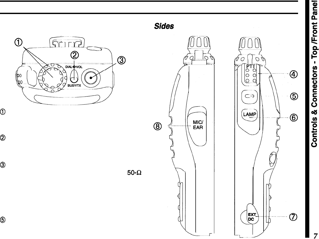
Controls
&
Connectors
TOP
& Front Panel
@
The outer ring adjusts receiver volume, and the
inner knob tunes, selects memories and other
menu
functions and settings.
@
This LED glows red when transmitting, and green
when the noise squelch is open (channel busy) dur-
ing reception.
@
This SMA jack accepts the supplied flexible an-
tenna, or another antenna designed to provide
50-52
impedance on the 2-m and
70-cm
band.
@The upper PTT (Push-to-Talk) button activates the
transmitter. Hold this button while speaking across
the front of the radio to transmit.
@
Press this button to override the squelch, either to
set the volume, or to defeat tone squelch temporarily
so you can hear weak or all signals.
@
-
L.--r
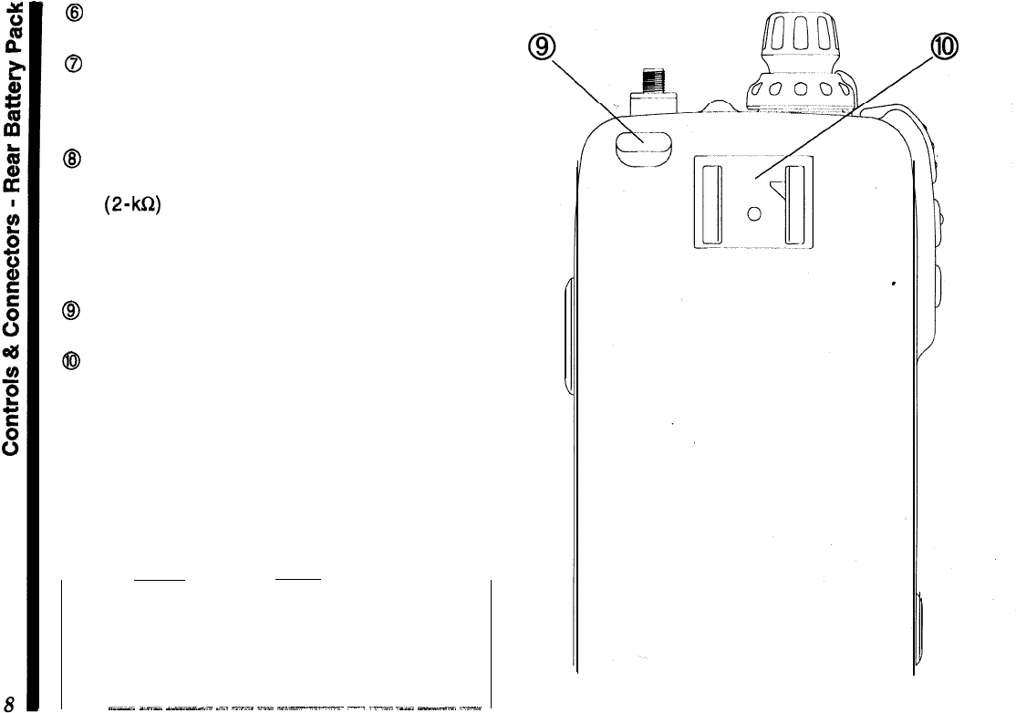
8
The (lower) LAMP button illuminates the display
when operating in the dark.
@
This
4-mm
coaxial jack accepts 5-13 VDC at
2A,
via the E-DC-5B cable, to power the transceiver from
an external supply. We recommend using this jack
only with the optional cable.
@
This Q-conductor,
3.5-mm
mini phone jack pro-
vides 8-R audio output and accepts microphone in-
put (2-kQ) for using an optional earphone,
speaker/mic
or packet tnc. The internal loudspeaker
and microphone are disabled when this jack is used.
Rear (battery pack installed)
8
Press this button to release the battery for re-
moval.
@
Install the latch-on belt clip here.
Note:
the protective rubber covers over the EXT DC
and Mic/Ear jacks must be pressed over them when
not in use, to protect the inside of the transceiver
from dust and water.
_~-~
_-_
_-.“--l.
._..
--.”
~.“-
-“--.-.-x~
-.
._.“.”
._._.
---_.
“.--
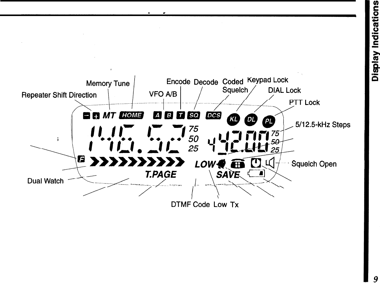
Display
Indications
HoME
Channel CTCSS CTCSS Digital
Alt. Key Functions
Active Page Code Enable
DTMF Autodial
Rx Signal Strength
LOW
DW SKIP
T.PAGE
CODE
-------yL
-..-_-..-_
-/IL,
..,._”
__
I-
.
_--
.---
Auto Power Off
I
\
\\
’
Weak Battery Voltage
Memory Scan
Skip
DTMF
paging
DTMF’Code I..~w
TX
Battery
’
CTCSS Bell
Trigger Paging
Squelch
Power Saver

Specifications
General Receiver
Frequency range (MHz):
Circuit type: Double-conversion
superheterodyne
(transmit)
, (receive)*
Channel steps:
Emission type: .
Supply voltage:
Current consumption:
Antenna (SMA jack):
Case size (WH D):
Weight (approx.):
144
~
148,430
~
450
IFS:
45.1
MHz
&
455
kHz
76
~
200,300
-
400 Sensitivity: 0.16uV for 12
dB
SINAD
(VHF)
400
~
540,590
~
999 0.18uV for 12
dB
SINAD
(UHF)
(cellular blocked on 800 MHz) Adj. ch. selectivity: 65
dB
5,
10,
12.5,
15,
20,
25,
&
50
kHz Intermodulation:
65
dB
F2, F3
4~16VDC
AF output:
0.5 W
@
81R
(10% THD)
250
uA
Auto Power Off
24
mA
Stby (saver on)
Transmitter
Power output
(@
9.6 V):
approx. 5.0, 2.8, 1,
&
0.1 W
200
mA
Rx (approx.)
55
mA
Rx (squelched)
1.5ATx(5
W)VHF
Frequency stability:
Modulation system:
better than lt5 ppm
variable reactance
1.6ATx(5
W) UHF
YHA-58 rubber helical
57x99x30 mm w/FNB-40
355 grams with FNB-40,
antenna, belt clip
Maximum deviation:
*:5
kHz
FM Noise
(8
1
kHz):
better than -40
dB
Spurious emissions:
>60
dB
below carrier
AF distortion
(@
1
kHz):
<
5%,
w/3.0
kHz
deviation
Microphone type:
2-k&I
condenser
*Specifications are subject to change without notice, and are
guaranteed within amateur bands
on/y.
Frequency ranges and repeater shift vary according to trans-
ceiver version, check with your dealer.
Before You Begin
A Few Notes on Safety
When properly cared for, the
FT-S5OR
should provide
many years of operating pleasure. However, please
read the following items concerning its use:
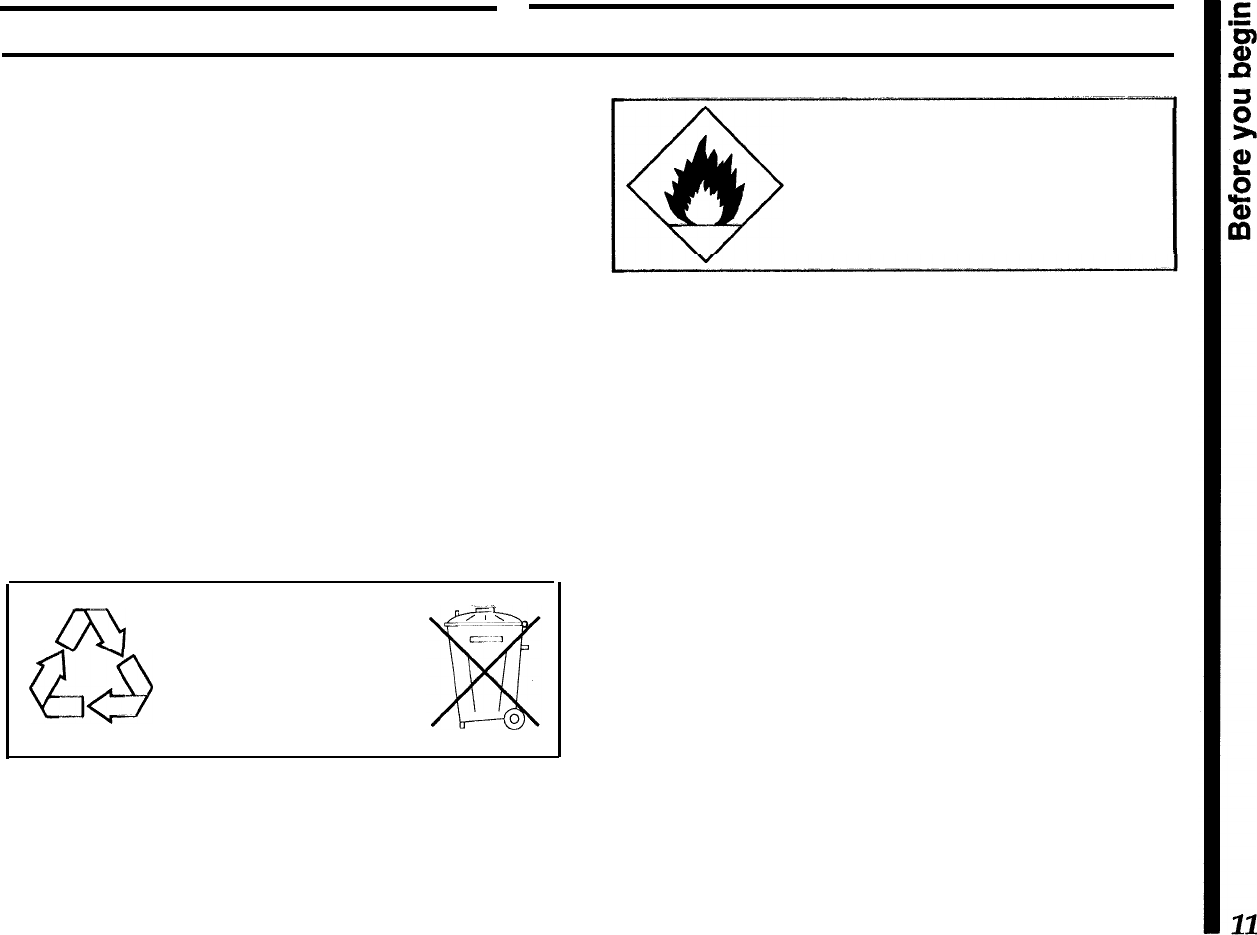
Battery Charging
Rechargeable batteries contain encapsulated
NiCd
(Nickel Cadmium) or
NiMH
(Nickel Metal Hydride)
cells. When used properly, they present no operator
hazard; however, please note the following points:
l
Do not dispose of
NiCd
cells in the public waste
system, as this may present a possible soil contami-
nation hazard. Check with your local waste man-
agement bureau for recycling programs available in
your area.
ml
Nickel-Cadmium Rechargeable
aa
Battery
-
do not dispose of into
waste system.
Recycle batteries in accordance
NiCd
with local regulations.
l
Never discard any batteries into a fire!
Never allow the charging terminals on
the battery to short
-
the ceils can be
damaged and the heat generated can
burn the skin!
l
Do not recharge the battery pack with unapproved
chargers.
Modern battery chargers use special circuitry to pro-
vide the optimum charge rate and place the battery
in a trickle charge state when complete. The use of
other chargers could possibly damage your battery
pack, and your radio.
l
Never allow the battery charging terminals to short!
While the recessed charging terminal on the battery
pack offers a degree of safety from inadvertent short-
ing, never insert any metallic objects into or across
the terminals. When separating the battery from the
transceiver, never lay it down onto a metallic surface.
The heat generated from a shorted pack can destroy
the cells and possibly burn the hand holding it.
Exposure to Water
While the
FT-50R
utilizes a water-resistant “clam-
shell” design with rubber o-rings to seal out moisture,
common
sense must prevail...should the radio be-
come exposed to water, use a soft cloth to wipe off
any excess drops.
If for any reason the radio is submersed, do not
turn
it
on...remove
the battery pack, wipe off the excess
water from both the radio and battery, and allow them
to dry at roorn temperature (no forced heat) for sev-
eral days before powering it on again. If the radio fails
to function, turn it off immediately and contact your
dealer for service information.
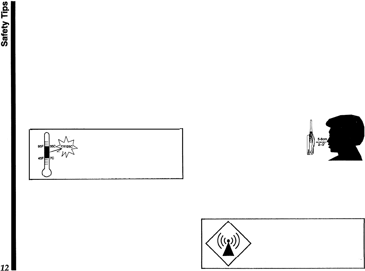
Whenever possible, charge batteries
at close to room temperature. Charg-
ing at temperatures below 77F/23C
,can
cause electrolyte leakage and re-
sult in battery damage. Charging at
high temperatures (above
95F/35C)
may reduce charge capacity.
RF Radiation Hazard Statement
In 1985, the US. Federal Communications Commis-
sion (FCC) adopted a safety standard for human
exposure to Radio Frequency (RF) electromagnetic
radiation generated by FCC-regulated equipment.
The proper use and operation of this transceiver will
result in exposure to the operator substantially below
those limits recommended by the FCC. However, the
following tips are recommended for maximum opera-
tor safety:
l
Do not press the PTT (Push To Talk) switch unless
you actually desire to transmit.
l Hold the transceiver a few
inches from your mouth when
transmitting, so that the an-
tenna is not in direct contact
with your face or eyes.
l When not using the trans-
ceiver, store it in a safe place, out of the reach of
children.
l
Do not operate any transmitting equipment near
unshielded blasting caps!
Do not hold the transceiver with the
antenna touching exposed parts of
the body while transmitting, especially
the face and eyes.
Getting Started
First Steps
Before operating the transceiver the first time:
n
Charge the battery pack completely (if using a
rechargeable pack). If using an FBA-15 dry-cell
battery case, install alkaline batteries as described
on page 5.
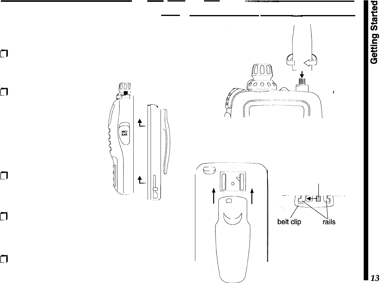
m
Mount the battery pack on
the back of the radio: hold it
with the rounded top edge
1/3
-inch (8 mm) lower than
top,
edge of the radio, press
the four tabs on the battery
into the slots on the radio,
and slide the battery up until
it clicks.
m
Screw the supplied antenna
onto the
antenna jack. Never
operate the transceiver with-
out an antenna connected.
t
t.
-‘t
1
I
n
To install the belt clip, slide it up onto the battery
pack rails until it “clicks” (locks into place). To re-
move it, slide the release lever to the left, then
press the clip down and off of the mounting rails.
CT)
If you have a
speaker/mic,
we suggest you not
connect it until you are familiar with basic opera-
tion.
antenna
installation
belt clip
installation
slide lever left
to release
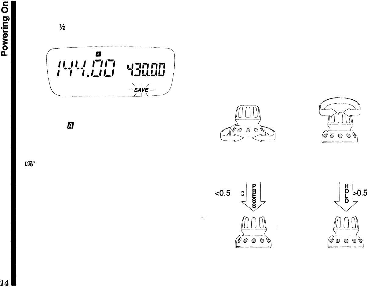
Powering On
To turn the transceiver on, push in the orange
PWR
button for
M
second. If the radio has not been used
before, the display should appear like that below.
The larger frequency readout is the
main
channel,
while the smaller one to the right is called the
sub
channel. The
6!
symbol indicates which VFO (A or B)
is selected for operation, and the
blinking
SAVE
indi-
cator lets you know that the
battery
saver is enabled
from the factory (we will cover more on this later).
63
When you turn on the radio the first time, you will
hear channel noise, and will
need to set the squelch
/eve/ as explained on the following page.
Knob Functions
Let’s spend a few moments on how the knob func-
tions, as understanding its proper use will make it
easier to operate the rig and configure various fea-
tures as we continue through the manual.
As shown in the illustration, the lower ring adjusts the
volume. Set
it
for a comfortable level while receiving
a station, or else press the middle monitor switch
(below the PTT) to disable the squelch, and adjust
the volume level on background noise.
Rotating the knob tunes in the default step size on
the VFO, or else selects programmed memories dur-
ing MR (Memory Recall) operation.
Pressing the knob
mornentariljl
(<
0.5s)
selects the
band of operation.
Holding
it longer recalls the menu
list, from which various transceiver functions are
enabled and their settings are configured.
Lower Ring
-
rotate for
volume level adjustment
knob
-
rotate to tune
channels,select
mem-
-ories or menu settings
<0.5
sec
I4
L/J
E
S
knob
-
press to switch
bands or view default
menu settings.
H-
~
P
bO.5
sec
D
knob,
-
hold to recall
the menu function list,
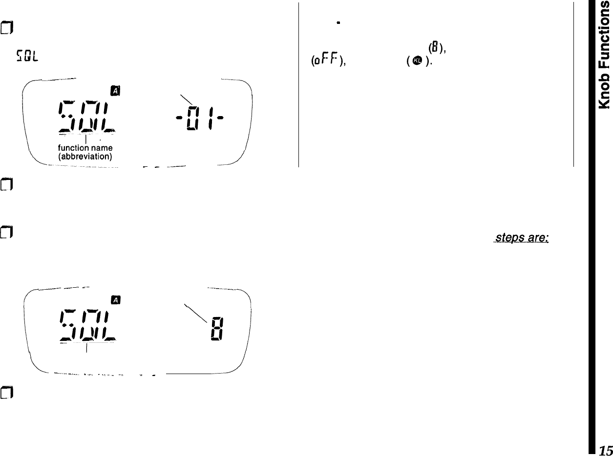
Let’s start by setting the receiver squelch:
a
Hold
(>
0.5 sec.) the knob down until the beep
sounds, then turn the knob (if necessary) to select
GIL -or-.
c--
.__I_-
----
or
funqtion #
‘7
SAVE
_
--
__-.
---
m
The name or abbreviation at the left is the function
title, with its number displayed to the right. You can
turn the knob to scroll through all 32 functions.
m
Momentarily pressing the knob shows the default
setting for the displayed function (in this case it is
the squelch level, which ranges from 0 to 15):
r
_~__..._
-~-.
-~
1--.-__
El
setting
\
function
L
-____._
I_^
._..
~.
SAVE
_
_
m
Rotate the knob a click or two past the point where
channel noise is muted, then exit the menu list by
simply pressing the PTT (the radio does not trans-
mit). The display reverts to show channel data.
Note
-
Pressing the knob with a menu active replaces
the function number (at the right in the sub display)
with either a number
(8),
letter or abbreviation
(OFF), or a symbol
(Q?
).
In some cases the function
name (at the left) may also change, to describe the
setting more clearly.
Follow the instructions carefully when starting out,
until you become familiar with the abbreviations and
symbols used with each menu function and its asso-
ciated settings.
Things to remember...
The procedure just covered is used throughout the
manual to access functions and change settings as
desired. Once again,
the
three basic
l
Hold the
knob down to recall the tnenu list, then turn
the knob to select the desired
tnenu
function
(number).
l
Press the knob to display the various function set-
tings or state, then turn the knob to change or select
it as desired.
l
Press the
PTT to
save the change and exit.
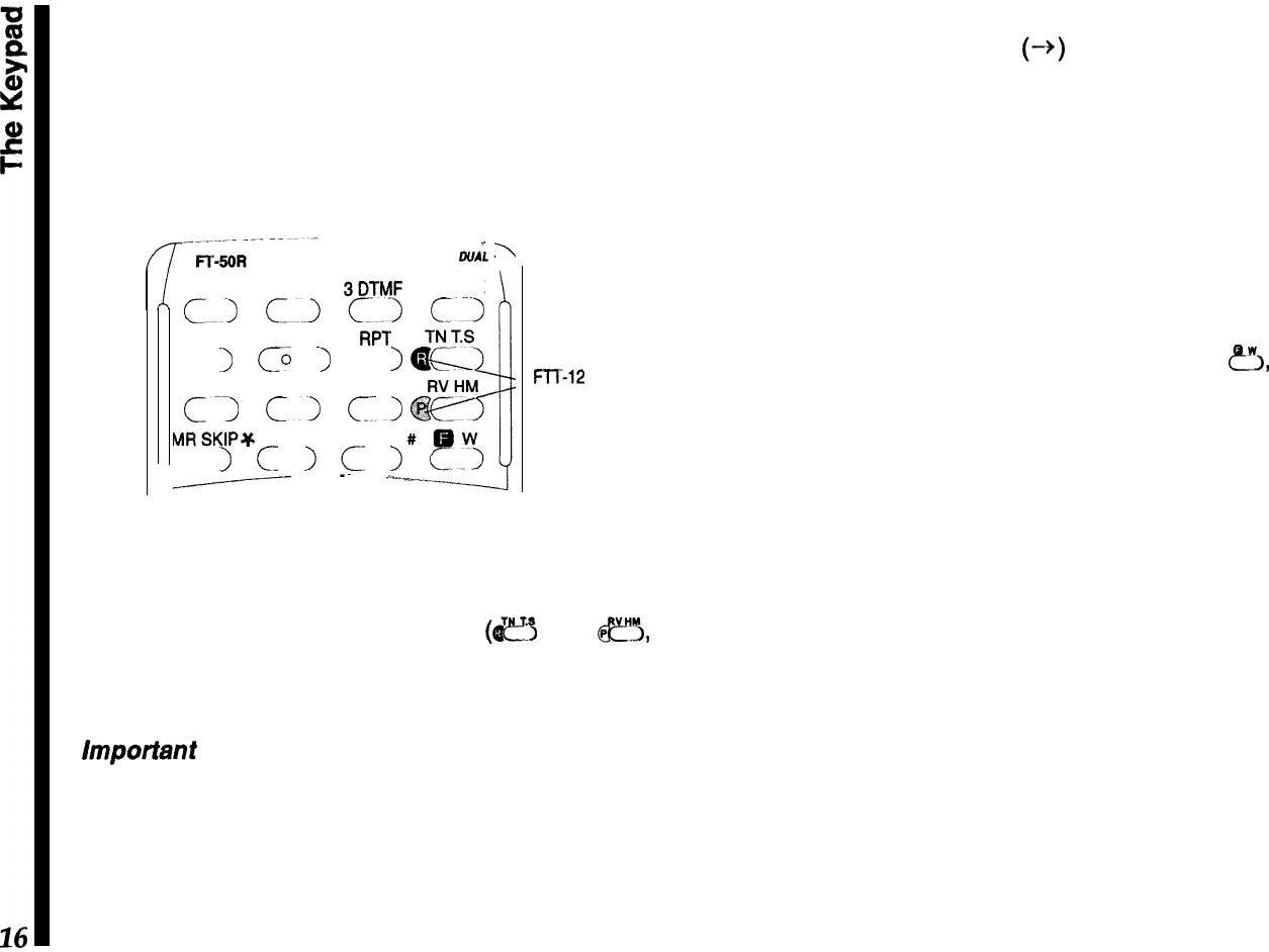
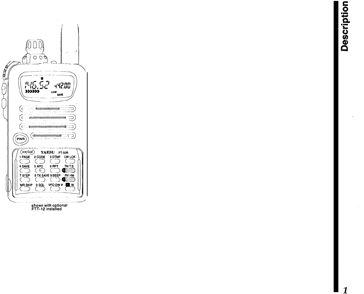
The Keypad
The standard FTT-11 keypad permits quick access
to the most commonly-used transceiver functions.
The optional FTT-12 keypad adds digital voice re-
cording/playback, DTMF code squelch and CTCSS
decode capability.
--
-
\
DUAL
BAND
\
1 PAGE 2 CODE
BDTMF
LW LCK
cjc.~c~c~
4SAVE 5AP0
6 RPT
c
1
CL
I
c
I
7 STEP 8 TX SAVE 9 BEEP
Cl
Cl
Cl
MRSKIP+ OSQL VFODW
c
I
c
>
c-
I
-Y
--
-~
,..-
FTT-12
FTT-12
ONLY
Both keypads are similar in appearance, with the
FTT-12 having two additional labels on the pad sur-
face for the digital recording system
(I$!?$
and
fi,
specifically). Throughout the manual, features re-
quiring the FTT-12 are highlighted as such.
important
-
Normal key presses should be very
quick -just a tap. Keys, like the knob, are sensitive
to the duration they are depressed. In some cases
tapping a key and holding it ‘longer will activate a
different function, and produce different results and
display indications. The instructions specify when a
key is to be held down.
To indicate when several keys have to be pressed in
sequence, we show an arrow (-+) between them. Do
not press more than one key at time unless the
instructions say so.
One or more beeps indicate key contact has been
made (if the key has a function). You can disable the
beeper as described later, but we recommend keep-
ing it enabled while getting to know the key functions,
since the pitch and number of beeps can be useful
feedback.
A several-second timer starts when you press
&,
and automatically restarts when you turn the knob.
Pressing other keys may shut off the timer as the
resulting change in operation occurs, or restart the
timer so you can select various functions.
Also, after changing a setting, you can usually return
to the operating frequency display by pressing the
PTT button at the top left corner of the radio. It does
not transmit unless the operating frequency is dis-
played. The front keypad generates standard DTMF
tones when pressed while transmitting.
While reading about operation, if you are unsure
about the location or function of a button or display
item, refer to Controls and Connectors and Display
sections on pages 7 and 8.
Your first
QSO
Adjusting the Volume
0
Turn the outer ring of the knob on the top panel
control to adjust the volume. If there is no signal,
you can override the squelch by holding the center
button (on the left side below the PTT switch), to
set the volume on background noise.
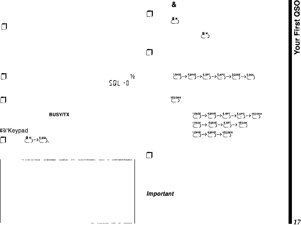
Squelch Setting
m
To adjust the squelch, hold the knob down for
%
second,
then turn it, if necessary, so that CDL
-0 I-
is displayed.
m
Press the knob again momentarily, then turn it to
set the squelch threshold (0 to 15) so the receiver
is silenced (the
BUSY/TX
LED turns off). Press the
PTT momentarily when done.
US’Keypad
shortcut for setting the squelch
n
Press
?I->?),
turn the knob to set the squelch
level, then press the PTT to save
and exit.
--
~-
_.-._
-.-..-
.----.--
.--;-
_...
-__,-_l”-_LI-l
,__
_
__-__-___.,
Squelch Sensitivity
First set the volume to mid range, then adjust the
squelch (with no signal): slightly past the point where
background noise is silenced and the green
BUSY/TX
LED is extinguished. If set higher, sensitivity to weak
signals is reduced, if set too low, “falsing” on back-
ground noise and weak stations will result.
AL
._-__..-
_.~‘.
-.
_-_-..
Tuning
&
Direct Frequency Entry
n
Tune to the desired frequency using the inner knob:
press
8
at the lower right momentarily, and turn
the knob to select the MHz range, then wait 5
seconds or press
ewj
again and turn the knob to
select the frequency.
m
You can enter frequencies directly from the keypad
as well; just key in all the digits. For example, for
146.520 MHz enter:
‘~~~-,‘~;-,~~-,~“,-)2~j_)~,
If you want to enter an even whole frequency, like
140.00 MHz or 146.000 MHz, there’s a shortcut,
Pressing
“?“P
after any entry truncates the remaining
digit places to zero:
enter 146.500
l~~~,'~j~,~,~,~pg~,V~pp
enter 146.000
yGj+
4~3+5r3+
vp",
enter 140.000
'~~-->'~j&QPp
Transmitting
cfl
To transmit, wait unit the channel is clear; press the
PTT (Push To Talk) and speak in a normal voice.
Keeping the transceiver a few centimeters from
your mouth will result in best audio clarity. Release
the PTT to receive again.
Important
-
The PTT switch should be pressed in-
ward and in a slightly downward direction for proper
operation. Do not press the PTT switch in an upward
direction, as this cause unreliable closure of the PTT
switch, and it may damage the rubber boot.
This angle of PTT switch actuation is designed to be
ergonomically optimum when the radio is being held
in the palm of your hand.
When you transmit, the
BUSY/TX
LED turns red, and
all or a few of the meter bar-segments appear, de-
pending on your transmit power. One of four power
output levels can be selected using
either
the keypad
or menu method:
From the menu:
g
Hold
the
knob down to recall the menu list, then
turn the knob one click so that
T
::
PC’
-
2?
-
ap-
pears.
n
Press the knob once to view the default power
level, then rotate the knob to select
L
I,
t
I
?,
t
3, or
/{I,
Press the PTT to save the change and exit.
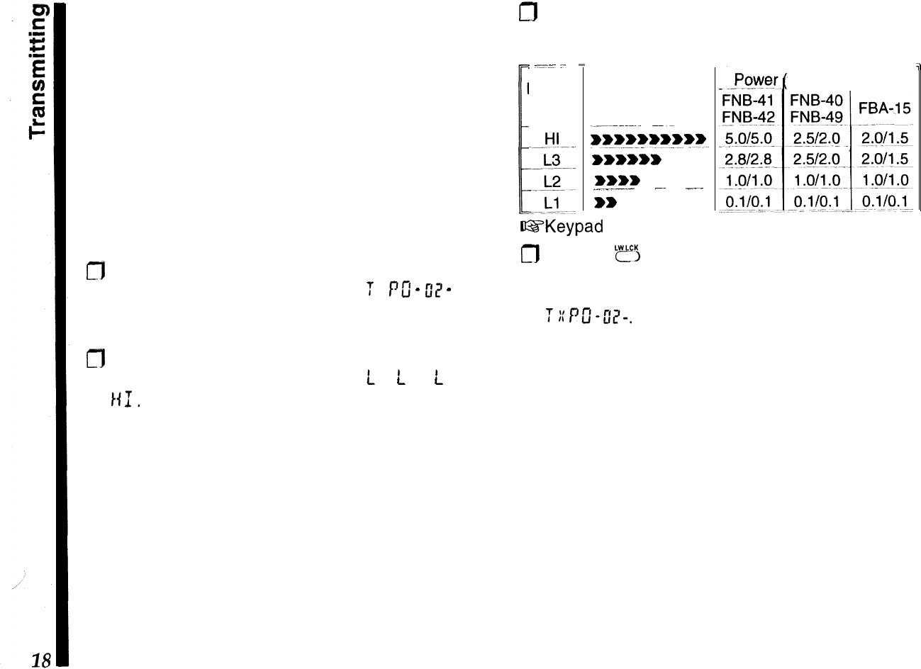
m
Refer to the following table for power output vs.
battery type:
I
1
:
-1-
.-
Display
Code
-
PO Meter
Segments
iwwwwww~~ww~
wwwwww
wwww
___~-.-
-~
_...
ww
71
watts)
VHF/UHF
GYKeypad
shortcut for selecting high/low tx power:
m
Pressing
‘fl
only lets you toggle between
high and
low power
(
LOW
displayed when active). The low
power level will correspond to that set previously in
2:/q-s&
Remember!
-
good operating practice and profes-
sional courtesy mean using the least transmit power
needed to maintain communications.
Basic Operation
Frequency Selection Modes
There are two frequency selection modes. These
affect the behavior of the knob and keys when tuning
or keying in frequencies, scanning coverage, and the
right half of the display.
VFO
D
@
Use this to tune around for clear or active channels.
As mentioned before, the knob tunes in the selected
step size (or in l-MHz steps if you press
&
first),
and scanning tunes in the selected step size. The
transceiver has two
VFOs,
A and B, which you select
by pressing
“?E”
(see below) when receiving on
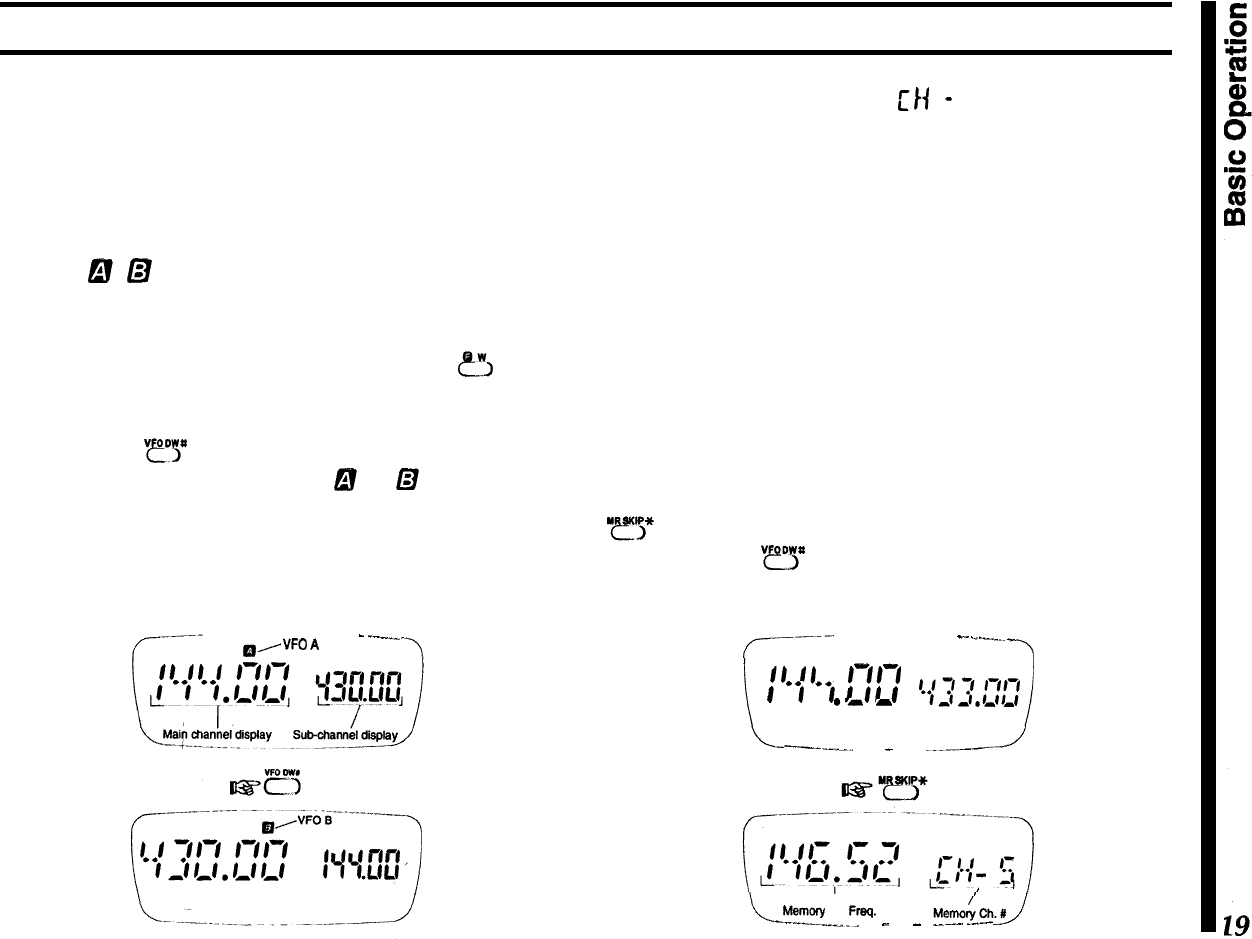
either VFO. The display shows
B
or
D
near the top
center
to indicate indicate
which VFO is selected for tuning;
the frequency is displayed in large numbers at the
left. The frequency of the other VFO is displayed in
small numbers at the right.
r----
a/
“FO
A-
_--__
--I
MR (Memory Recall)
LrH
-
I
Use this to select and operate on stored memories.
There are 100 memories, each of which stores re-
peater shift, transmit power level, tone settings, and
tuning steps (for the Memory Tune mode), and can
also hold a name tag and a separate transmit fre-
quency.
Either the operating frequency or the memory name,
if assigned, is displayed in large letters at the left,
and the memory number is displayed at the right.
Each memory can be used in the
Memory
Tune
mode, which works like the VFO mode. Special
memory mode functions like this are described later,
but you should keep these terms in mind. Pressing
“r”,”
switches from the VFO mode to the last-used
memory, and
“fl
switches from the memory mode
to the last-used VFO. While in the memory mode,
your previous VFO mode selections are preserved.
r-------
--111
-
.-
._._..
_
-3
i
f/
0
f
f-f/-f
f
‘j
‘j
f
ff
f
.-
a
c{T3;‘;‘;‘;’
--.-a
I
\-
-------l.l_.
_
.._-.~--
-J
I
Meinory Ch. Fmq.
----.._-_-
-
_ .
..~...
.--
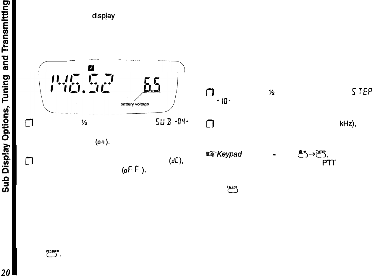
Sub Display Options
Tuning Steps
The right side of the display (with the smaller digits)
Channel (tuning) steps can be set to match the
is referred to as the sub-display. It normally displays standard channel spacing in your region: typically 25
the channel selection for VFO B; however, you can
kHz
on UHF (and on VHF in Europe), and 15 or 20
display the battery voltage instead, or else disable
kHz
on VHF in America. Note that coarser steps tune
the sub display completely: and scan faster, and that
5-
and 15-kHz steps require
f
--
--...--
;-
.
----.-_
. ..--..-..-.
an extra digit when entered from the keypad. Each
VFO and memory has its own tuning step setting.
To change step size:
0
Press the knob
‘/2
second, then turn it to
f;
TEP
-
IO-
. Press it again momentarily to display the
current step size.
fl
Press the knob
%
second, then turn it to
);L/
3
-
DY
-
.
0
Turn it to choose the new step size (in
kHz),
then
I
Press it again momentarily to display the default
press it again momentarily to accept the new size.
sub-display choice
(an). Press the PTT to save the entry and exit.
a
Turn it a click to choose battery voltage
(AI:),
or
@SKeypad
Shortcut
-
press
?I--@?&
turn the knob
again disable the sub-display
(OF
f:
).
Press the PTT
for the desired steps, and press the PTT to exit.
to save the entry and exit.
Transmitting
Press
LB
so that LOW appears below the center of
Tuning
the display. To transmit, wait until the channel is clear
(BUSY/TX
LED off), then press and hold the PTT while
As mentioned before, you turn the knob to tune in the
speaking into the microphone (at the right side of the
selected step size, or press
@!!I
first to tune in 1 -MHz
front panel). The
BUSY/TX
indicator glows red when
steps. You can select a new frequency from a VFO, transmitting, and the bargraph shows relative trans-
or by tuning a memory. For now, use the VFO mode: mitter power output. Release the PTT to receive.
press
mt
You can enter a frequency by turning the If you need more power to maintain communications,
knob, or by numeric key entry. See Locking the
you can select another power setting as described
Controls
on page 32 if the keys or knob don’t work. on page 18. However, remember that your batteries
last longer and you cause minimum interference by
using the lowest level possible.
Note that if you decide to change the power settings
on a memorized channel, you must first re-load that
memory (otherwise it reverts to the original memo-
rized power level the next time it is recalled).
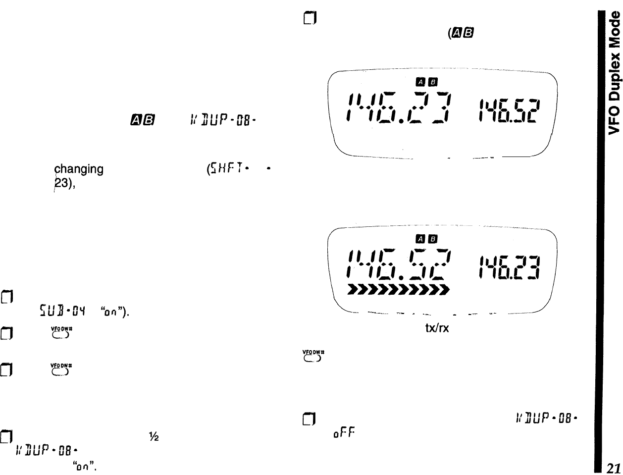
VFO Duplex Mode
&!a
1/J/,,,pft&
If you need to transmit on a different frequency than
your receive channel, but don’t want to go to the
trouble of
Changing
the default tx offset
(f;l{F
T
-
Of
-
,
on page
23),
or programming an independent tx
offset in a’ memory, try out the VFO “duplex” mode.
This feature simply uses one VFO to store the trans-
mit frequency, and the other for the receive fre-
quency. You receive on the main channel, and
always transmit on the sub channel, regardless of
which VFO (A or B) is in which display (main or sub).
m
First make sure the sub-channel display is enabled
(set
St’8
-
CIq
to
“ofi”).
m
Press
“?P
to toggle between VFO A and B, setting
up-each VFO with the desired frequency.
m
Press
“e!‘y>”
again, as necessary, so that the desired
receive frequency is displayed to the left (main
channel), with the transmit frequency at the right
(sub channel).
a
Press and hold the knob
%
second, then turn it to
11’
311P
-
08
-
. Press it again momentarily, then turn
it to select
“0r7”.
fl
Press it momentarily again, then press the PTT to
save the entry and exit
(@a
now appears at the
top of the display).
./
_
.~---
-
Now, when you transmit, the main and sub display
frequencies will switch, indicating transmission is oc-
curring on the sub channel VFO frequency.
L-
.-.---..
.-
_
.__
_
__
--
---1
Note that setting a new
Wrx
pair is as easy as dialing
in new frequencies for VFO A and B, then pressing
“IY
so the VFOs are in the correct display. You are
not limited to V/V or U/U operation; you can mix VHF
and UHF VFO channels for cross-band semi-duplex
operation!
0
To disable
VFO
duplex operation, set
L’
ILIP
-
08
-
to
0Ff:
again.
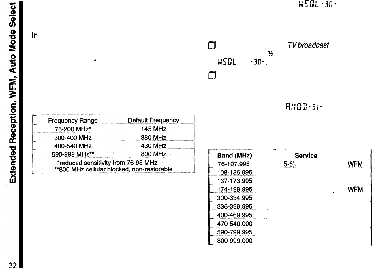
Extended Reception
Introduction
In
addition to amateur band operation, the FT-50R
offers extended receiver tuning and scanning. This
feature may not be available in all countries and all
transceiver versions
-
please check with your dealer.
While operating from VFO A or B, each momentary
press of the knob recalls four preset band-ranges for
tuning and scanning:
Note
-
If your radio only switches between 2-m and
70-cm bands, you can expand receiver coverage by
hold the knob and
LAMP
button depressed while
turning the transceiver on.
WFM Squelch Setting
t:E;m.
-313-
The default squelch threshold for WFM (wide band-
width FM) is preset to 0 (recommended for broadcast
reception). To change this setting:
m
While tuned to a FM or
TVbroadcast
band, hold the
knob down for
%
second, then turn it to select
t:uJt
-3O-.
a
Press it again to display the current squelch set-
ting, then rotate the knob to select the desired level.
Press the PTT to save the setting and exit.
Auto-Mode Select
Rr:E3-31-
By default, the correct demodulation mode (FM,
WFM or AM) is automatically selected according to
frequency ranges, as shown below:
--
-
Sty&x
Mode
TV (Ch
5-61,
FM Broadcast-
WFlvj
Aviation
Nav/Com
LMR
amateur marine,
Wx
AM
FM
TV
CH 7-10
WV!‘!
em
Gov.
(Military
Aviation) AM
_
Gov. (Military)
FM
_.
Gov.
amateur
LMR NFM
UHF/TV
(Ch
14-24)
WFM
UHF TV
(Ch
34-68)
”
WFM
trunked,
SMR FM
If you would like to disable the auto-mode selection:
fl
Hold the knob down for
M
second, then turn it to
select
fV?Cf
fl
- 3 I - .
m
Press it again to display the default setting, then
rotate the knob to select
on
or oFf: (reception de-
faults to narrow
F@
for ail frequencies). Press the
PTT to save the setting and exit
Reception Mode Override
nr:m-32-
If you would like to override the mode selection
temporarily while receiving on a channel, you can
enable this feature. Auto-mode selection takes effect
again as soon as you turn the knob and change the
channel (unless you have it disabled
-
NFM only).
m
Hold the knob down for
M
second, then turn it to
/
select
P!ffII
-37-.
m
Press it again to display the default setting, then
rotate the knob to select
!J
-
F
ff
,
n
!f or
1:
-
f:
ff
. Press
the PTT to save the setting and exit.
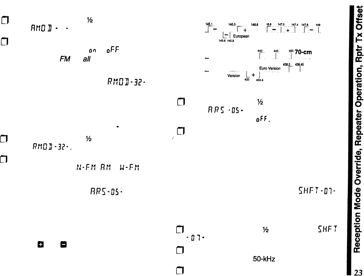
Repeater Operation
RRZ-U”S-
Fortunately, repeater operation usually requires just
tuning to the correct channel, pressing the PTT, and
speaking. The ARS (automatic repeater shift) feature
sets the correct shift and offset as you tune through
the 2-m and
70-cm
repeater sub-bands. You can
observe the
0
and
0
indicators activate and change
as you tune across the amateur band. The chart
shows the ARS ranges for common transceiver ver-
sions.
ARS-Repeater Subbands
Version A
2-m
,451
146.6
146.6
146.4
14e.*
~-
,
r+
,
r;'4y+'4i.4
"pi".
,4~~,wwan
Version
-
Version A
y.
+
.Tm
__
7
70wc~
438.2 439.45
-
EuroVysion 1
/--
.
Euro
V&&n
2
A
-f-
1,’
1
ARS is enabled at the factory. To disable it:
m
Hold the knob down
?4
second, then turn it to
display
fl
P
5
-05
-
. Now press it again momentar-
ily, and turn it to select
OFF.
m
Press the PTT to accept your setting and return
the display to the operating frequency.
You can still manually select a new shift, if ARS is
activated or not. However, if you change frequency
with ARS activated, manual repeater shift selections
are terminated and the ARS shifts are restored.
Setting Repeater T
X
Offset il;HFT-tlf-
Although you should keep the repeater offset pro-
grammed to that used in your area, you can change
the default repeater offset for special applications:
n
Hold the knob down for
%
second, select
s/if:
T
:
0
T
-
, the press it again to display the offset.
m
Turn the knob to select the new shift offset fre-
quency (selectable in
50-kHz
increments only).
n
Press the PTT to save the setting and exit.
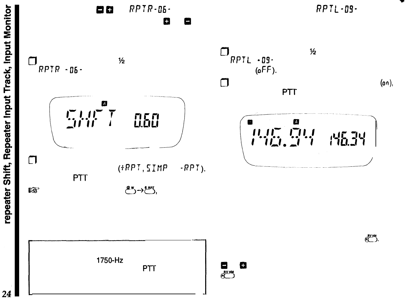
Repeater Shift
0
m
RPTR-0ti-
When a repeater shift is active, either
CI
or
13
ap-
pears in the display. If neither appears when tuned to
a repeater output frequency, you can activate the
shift manually:
0
Hold the knob down for
%
second, turn it to select
6’P
‘T
R-
06
-
, then, press it to display the current
shift.
Repeater Input Track
f3PTL
-w
If you would like to view the repeater input frequency
along with the output, and have it track as you tune
channels, this can be done using the sub-display:
D
Hold the knob down for
%
second, turn it to select
6’P
f
L-
u”S-
, then press it to display the default
setting
(OFF).
0
Turn the knob one click to enable this feature
(CM),
then press the PTT to accept your change, and
exit.
L
SAVE
-big
-_--.--
--.J
fl
Press the knob momentarily, and turn it to set
repeater shift direction (+RPT,
s:tlP
or
-nPT).
Press the PTT to accept your change and exit
~22’
Keypad
Shortcut: Press
?J-)=,
turn the knob
to select the desired shift, then press the PTT to exit.
Tone Burst
For repeaters using 1750-Hz burst tone
access, you
can configure the switch below the PTT to sends the
tone when pressed. See page 54 for details.
/
The display will show the input frequency
tracking
the output as you tune. During transmit, the repeater
output appears in the sub-@splay.
Repeater Input Monitor
With a repeater split activated, you can
temporarily
reverse tx and rx frequencies by pressing
fl.
Use
this to check a signal’s strength on a repeater
input
frequency (to see if you can work them direct).
Either
Cr
or
ZT
blinks while reverse split is selected. Press
@?3
again to return to the normal shift direction.
Memorv Otxxation
Storing and Displaying Memories
When you store a memory, the current tuning step,
displayed receive frequency, repeater shift, transmit-
ter power level, DCS, and CTCSS tone settings are
copied into a memory slot. The slots are labeled
numerically from 1 to 100 and
Ll
&
Ul
through
L5
&
U5, for the,lower and upper limits of programmable
scanning (PMS, described later).
VFO
-)
MR (copying a VFO into memory)
To store a frequency in memory:
r]l
Preset the desired frequency, shift, power level
(etc.) in the VFO mode as already described.
fl
Hold
e3
for
1/2
sec. (until a second beep sounds) to
display the memory slot (blinking) at the right.
m
Within five seconds of releasing
?J,
turn the knob
and select a memory channel for storage. If you
select one that was already used, it will be overwrit-
ten with new data in the next step.
m
Press
tr(,
to store the displayed data into the se-
lected memory slot. The memory number stops
blinking for a second, and then disappears as op-
eration continues in the VFO mode.
If you timed out, operation switched to the memory
mode. Simply press
“?y
to return to the VFO, and
start again.
MR (Memory Recall)
Pressing
“!l*
changes from VFO to MR (memory
recall) operation. The memory number appears at
the right, and the receive frequency to the left (unless
you assign a name to a memory, or activate Dual
Watch as described later). Notice that pressing
m
from the VFO mode always recalls the last stored
or
last-used memory.
\
After storing several memories, you can select them
by turning the knob, or by direct keypad access:
m
Enter the number of the desired memory, followed
by
“@iJ*.
If you hear two beeps and return to the
previous display, the requested memory is empty.
0
To exit and return to the last-used VFO, press
“fl.
.
..I..
_
“- ,._
I_-
.
““..-,
..1.
._-.....
_
.- .
..-.
-
-..
..-..
i-
Filled and Empty Memories
When selecting memories for data entry, you can
determine if they are already in
use
by the display
format;
C
I(u
means unfilled, while “C
Ii-
”
means it
contains previous data. You can overwrite filled
memories at any time, but of course old data will be
lost. Note: c
k(
-
I is always preset with 144.00 MHz.
MR
->
VFO (copying a memory into a VFO)
After storing memories, you may want to copy one
back to a VFO. You can copy the current memory into
the last-used VFO by holding
?!?j
for
M
second, and
pressing
??!I”.
HOME Memory
m
Although invisible to the procedures just described,
the HOME memory can be instantly recalled by
pressing
c?%>
e’$:
l36I@#
appears above the fre-
quency at the left. There is a default simplex fre-
quency stored in the HOME memory, but you can
reprogram it with any frequency, repeater, power,
and tone settings, or even a separate transmit fre-
quency.
To copy the displayed VFO settings into the HOME
memory, hold
?‘I
for
%
second until the right half of
the display blinks, then press
fl.
Custom TX Offset
C!B
All memories can store an non-standard tx offset, for
operation on repeaters with non-standard shift. To do
this:
CT]1
Store the receive frequency using the method al-
ready described under
Simple
Memory Storage
(any repeater offset will be ignored).
m
Tune to the desired transmit frequency, then press
and hold ?“‘I for
M
second to display a slot at the
right.
fl
Press and ho/d the
Pl”7’
switch while pressing
?I
momentarily (this does not key the transmitter). Or
course, if you’re storing this in the HOME channel,
you press ?!? when holding the PTT).
When a separate transmit frequency memory is
dis-
ICI
appear at the top left corner. You can
press
e?
to display the transmit frequency,
QCI
blinks while the pair are reversed.
After storing a memory with a separate transmit fre-
quency, if you rewrite the receive frequency in that
memory, the separate transmit frequency is deleted.
Memory Tuning MT
While receiving on a memory, you can re-tune it and
change any other settings:
m
First press
“y>*
so that
Nappears;
can tune it like
a VFO.
m
To store the new frequency and settings in the
current or other memory, hold
c!?”
for M-second,
select the new slot (if desired), and press
?I.
Operation remains on the new memory, as the old
memory is restored.
m
After re-tuning a memory, to discard your changes,
press
“r!*
to restore the original memory data.
Scanning
!mbi
Before scanning, ensure the squelch is closed. You
can scan either stored memories, or each VFO at the
selected tuning step. To scan memories, first recall
MR operation (press
“??‘!j*
momentarily), then hold
“?‘fj”
for
%
second. To scan a VFO (press
“YJ*
mo-
mentarily to select VFO &! or @), then press and hold
??‘!?
for
M
second
(5f:
RQ
appears at the right).
Scanning pauses when a signal opens the squelch,
and the decimal point in the frequency display at the
left blinks. For VFO scanning, a double beep sounds
each time the scanner reaches a band edge, unless
you have disabled the beeper
(?1-+‘??5).
Scanning
resumes according to how you set the
s&n
resume
mode, described next.
Stop the scanner manually by pressing “yij”(on
memories), “cDr (on a VFO) or the PTT to stay on the
current frequency, Note
-
You can change scan
di-
rection
(up/down) by rotating the knob (left/right)
while memory or VFO scanning is active.
Scan Resume Modes
f7E
srf
-
II
-
Scanning resumes after pausing on a signal: either
after 5 seconds, or after the signal stops transmitting
(carrier drops):
m
Press the knob
M
second, then turn it to nE srf
-
ff
-
. Press it again momentarily to display the
current setting
(5
or
I:
R
f
r
),
Turn it to choose the desired setting, and press the
PTT to return to the operating display. Your scan
resume setting applies universally: that is, the one
setting applies to all scanning modes.
Memory Skip Scanning
SK/P
When you have some very busy channels stored in
memories, you may wish to skip them when scan-
ning, but still have them available for manual selec-
tion. You can mark a memory to be skipped by
pressing
?>--)‘!!5*
while receiving on the memory.
SK/P
appears at the lower left.
To cancel scan-skip and allow the memory to be
scanned, just repeat the step used to disable it:
select the memory manually, and press
~~-->“~‘5*
.
Scan Lamp
5wt-r;l-
If you would like the LCD to illuminate when scanning
pauses on activity, the scan lamp can be enabled:
m
Press the knob
‘/2
second, then turn it to
cc
tJL
-
I?
-
. Press it again momentarily to display the
default setting
(OFF).
a
Turn it to enable the scan lamp (on), and press the
PTT
to return to the operating display.
PTS
(Preset
Tuning
and Scanning)
You can set the transceiver to tune or scan on/y
within a preset band. Ten special memories (which
form five preset pairs when programmed) are avail-
able for PTS operation. Each pair
(LIWI
,
L2&U2,
L38U3, L4&U4, and
L5&U5)
define a preset. tuning
and scanning range, with an upper and lower limit
stored in a “L” and “U” memory.
Although PTS memories are recalled, viewed and
programmed the same as regular memories, they
are ignored during regular memory scanning.
Let’s try an example:
Program
L
I and
u
1
to limit operation (tuning and
scanning) to 444.00
-
446.00 MHz:
0
From either VFO, copy 444.00 into
L
I, and 446.00
into
U
I as you would for regular memories.
c]l Press
“@r”5*
to switch to MR mode (if needed), and
recall either memory of the preset pair (it makes no
difference if you select
L
I
or
fi
I).
m
Press
“r5*
again to activate memory tuning (MT
blinks). Turning the knob now tunes the memory
up/down the same as before, however, operation is
now restricted to 444.00-446.00 MHz.
0
To scan, hold
“?!?
for
%
second. Just as with
regular VFO scanning, a double beep sounds each
time the scanner reaches a preset band edge,
unless the beeper is disabled (page 50).
Channel Resolution for PTS Limits
Although you can tune and scan in the default chan-
nel
step size during PTS operation, you can only
store even or
700-kHz
resolution frequency limits
into PTS memories.
For example, while 146.00 or 146.100 are accept-
able preset limits, 146.035 or 146.150 are invalid
(they would be rounded down to the nearest 1 00-kHz
channel).
I
If ARS or manual repeater shift is activated, the
offset is applied automatically when you transmit
(even if the resulting transmit frequency is outside
the programmed limits).
n
To exit PTS, press
“r’s”
to return to MR operation,
then
“fl*
to return to a VFO.
I@’
Note
-
you cannot activate PTS tuning or scan-
ning if either PTS memory is marked for skip-scan-
ning, or hidden.
Advanced Operation
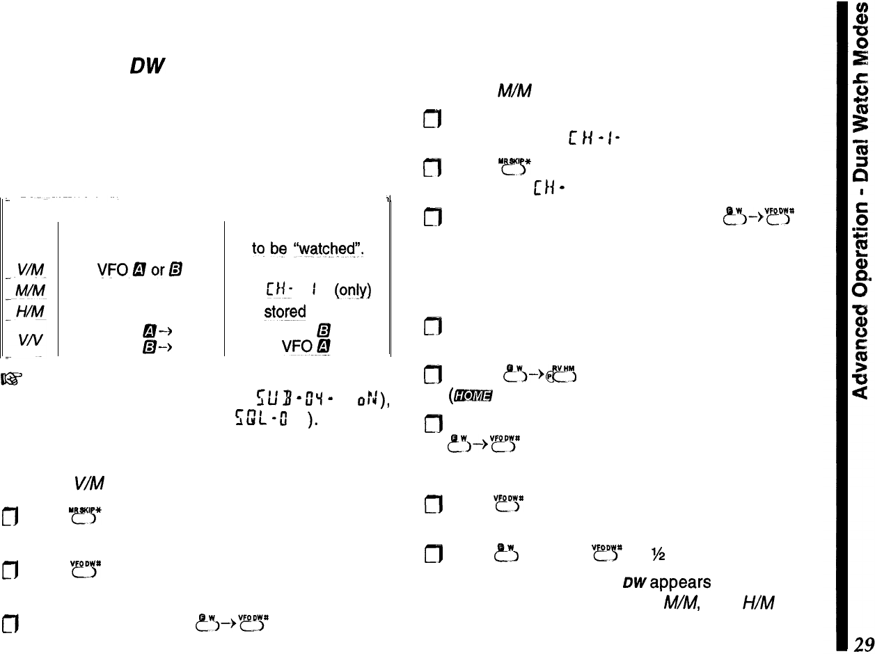
Dual Watch
OW
Dual watch receives on the main channel while
checking for stations on the sub channel. If activity is
detected, operation shifts there while the signal is
present. There are four dual watch choices, as out-
lined below in the table:
Mode
II
Dual Watch Operation
~~
Main Channel Sub Channel
for operation.
tq
be
“watche$‘.
VFODorD
any stored memory
any stored memory
w
1
b??!Y)
HOME channel
any
stored
memory
VFO
a-+
VFO
LZI
VFO
B-k
VW@
~-3’
Before using dual watch, ensure that the sub
channel display is enabled (set f;l;
3
-
O’i
-
to
o::),
and the squelch is closed (use
sw”L
-u”
I-
).
V/M Dual Watch
To set up
V/M
dual watch:
cfl
Press “ys* and select any stored memory for dual
watch to check.
m
Press
“ry
as necessary to select either VFO A or
B for the main channel.
a
From the VFO, press
&?+“?Y
to activate dual
watch.
M/M Dual Watch
To set up M/M dual watch:
m
Store a frequency that you want dual watch to
check
in memory
t
14
-
I- .
n
Press
“.ff’y
and select another stored memory
(other than L/f
-
I-) for main channel operation.
0
With the memory displayed, press ~?Y-%~~ to
activate Dual Watch.
H/M
Dual Watch
To set up H/M dual watch:
elf Select any stored memory for main channel opera-
tion.
m
Press
e_w>-+m
to recall the HOME memory
(G@%@
appears at the display top).
m
With the HOME memory displayed, press
&8’--,“?y
to activate dual watch.
V/V Dual Watch
n
Press
“?“>”
as needed to select VFO A and B for the
main and sub channel, as desired.
m
Press
?I
and ho/d
“?y
for
%
second.
For all dual watch modes, owappears at the bottom
left of the display. During V/M
M/M,
and
I-//M
dual
watch, the sub channel memory is checked every
five seconds for activity (you will see the main and
sub channels briefly switch as this occurs). For
VN
dual watch, the sub channel is sampled much faster
(every 200 ms), and this checking is “transparent” to
the operator.
If a signal appears on the subchannel, two beeps
sound, the receiver jumps to the subchannel, then
Dwand the decimal on the display blinks. Dual watch
resumes according to how you set the scan-resume
mode (5 sets. or carrier drop).
Otherwise, you can operate on the main channel
VFO, or select other memories. If you wish to talk on
the subchannel, press
“ry
or
I??!?
to cancel dual
watch operation, then the
Pm.
Note that you can use any memory as a subchannel
for
V/M
Dual Watch, but only memory
L’
I(-
I for
M/M.
You can use Memory Tune during Dual Watch, if you
activate Memory Tune first, although it may be easier
to copy the memory into a VFO instead. You cannot,
however, switch
VFOs,
or between memory and VFO
operation (pressing the necessary buttons cancels
Dual Watch).
If you want to talk on the subchannel, you have to
recall it, or press
‘ys*
to quit Dual Watch operation.
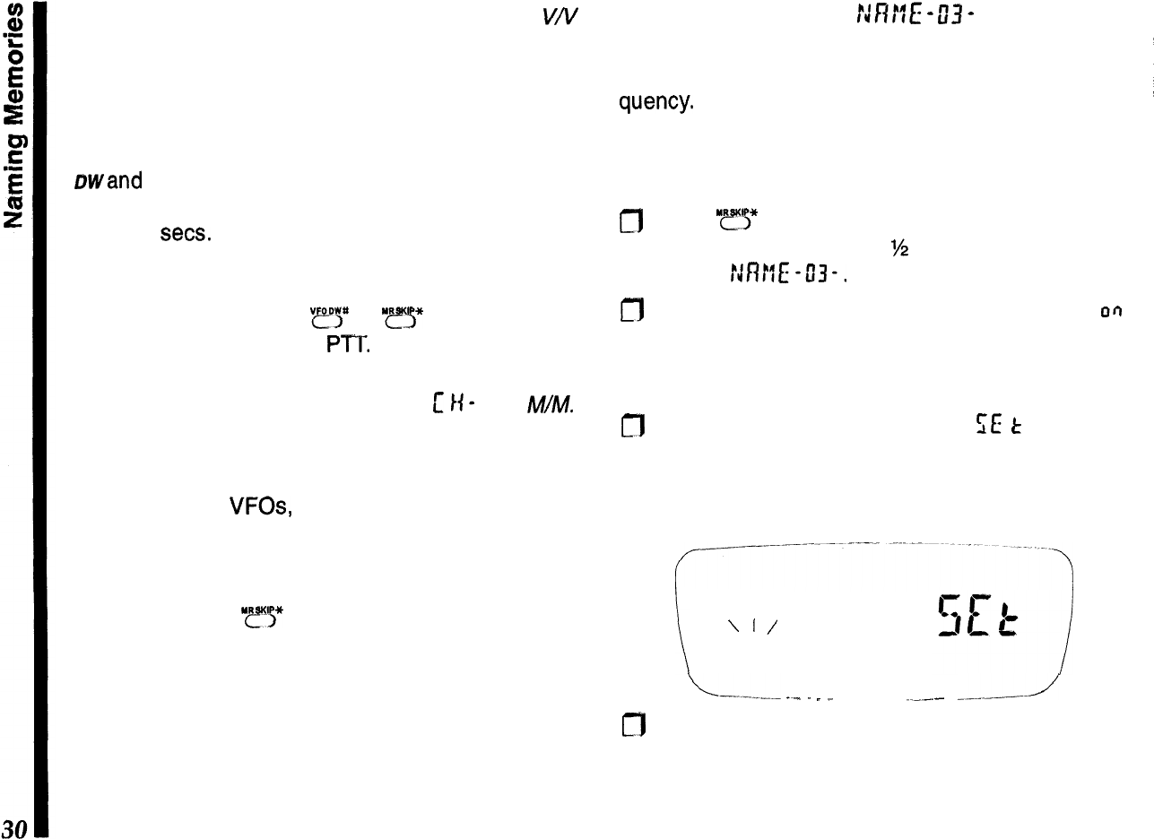
Naming Memories
NFWE
-
03
-
You can assign a name of up to 4 characters to
1
memories, and have it displayed with name or fre-
i
quency.
There are 48 different characters for nam-
/
ing, including a space and 11 special symbols.
I
Before naming a memory, first store its frequency
and other settings as described previously, then:
I
;
m
Press
“ry
and select the memory you wish to
i
name. Hold the knob for
%
second, then turn it to
1
display r:n!lE -03-,
m
Press the knob momentarily, then turn it so that
CI~I
L
appears at the right. If this memory has been
=
named previously, that name now appears at the
left. Otherwise, the left side is blank.
n
Press the knob again momentarily;
SE
t
appears to
the right, with an blinking underline cursor appear-
ing at the left-most digit location. Turn the knob to
select a character.
\
\
I/
----
‘I’
\-.---.-
_-
.
.
__
.___
----J
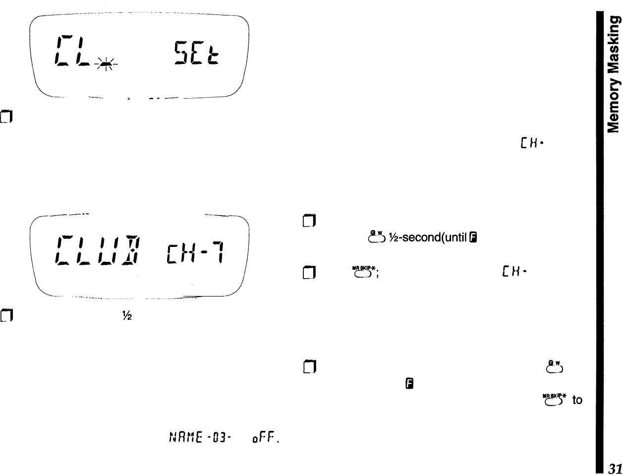
m
With the desired character displayed, press the
knob momentarily. The cursor moves one digit to
the right. Turn the knob to select the next character.
L-.
-.--.._
”
_
.
___
-2
m
Repeat the above step until all characters (up to
four) are entered. To change any characters, press
the knob momentarily to step the cursor through
the characters to get to the one to change. Entered
characters disappear when the cursor is on them,
but reappear when the cursor moves.
f-
._.--.
---
--
---
-7
fl
Hold the knob down
‘/2
second to store the name in
memory, then press the PTT to return to the oper-
ating display; the name appears to the left, with the
memory channel number at the right.
Note that blank spaces can also be entered instead
of characters, and names do not have to begin at the
first (left-most) character location. To cancel the dis-
play of memory names, set
MM
43-
to
OFF.
You can always turn the names back on as they are
preserved with the memories.
Memory Masking
You can mask stored memories from selection and
display. Stored data remains and can be restored,
until you overwrite it or reset the CPU. You can also
restore unused memories, in which case you will find
they are set to the bottom edge of the band. You can
use this feature to easily check which memories you
have not yet stored. You cannot hide
[
I(
-
I (this
memory must always be accessible).
To hide a memory:
m
Recall the memory you wish to hide, then press
and hold
fi
‘/2-second(until
0
blinks).
n
Press
“FJ$*;
the display changes to
c
I(
-
I, and the
previously memory can no longer be recalled
manually, or included for scanning.
To restore a memory:
cfl
Recall any memory, then press and hold
FJ
for
M-second (until
0
blinks). Use the knob to select
the memory to be restored, then press
“r
finish.
Be careful not to overwrite hidden memories acci-
dentally; you cannot recover their previous contents.
Memory-Only Mode
This allows operation only on stored memories,
which are displayed by name (if any) at the left, and
the memory channel number to the right. No fre-
quency is displayed, and only hyphens appear if you
haven’t assigned a name to a memory.
Repeater shift and tone setting indicators are dis-
played, although they cannot be changed. In fact, the
alternate functions of most keys are disabled, as well
as the functions accessed by holding the knob down.
Only these functions are available, as indicated:
l
Hi/Low TX Power: “rcl
l
Channel Selection: knob or keypad
l
.Memory
Scanning:
“y!*
l
Reverse Repeater Split:
&?“?I
l
Dual Watch: ?‘I-->
“tiit”lj”
l
Digital Voice (with optional FTT-12)
After programming memories, you can toggle mem-
ory-only operation on and off by turning the radio off,
then holding the
PTI’
and LAMP buttons (top and
bottom buttons on the left side) while holding the
PWR button for
%
second to turn it on again.
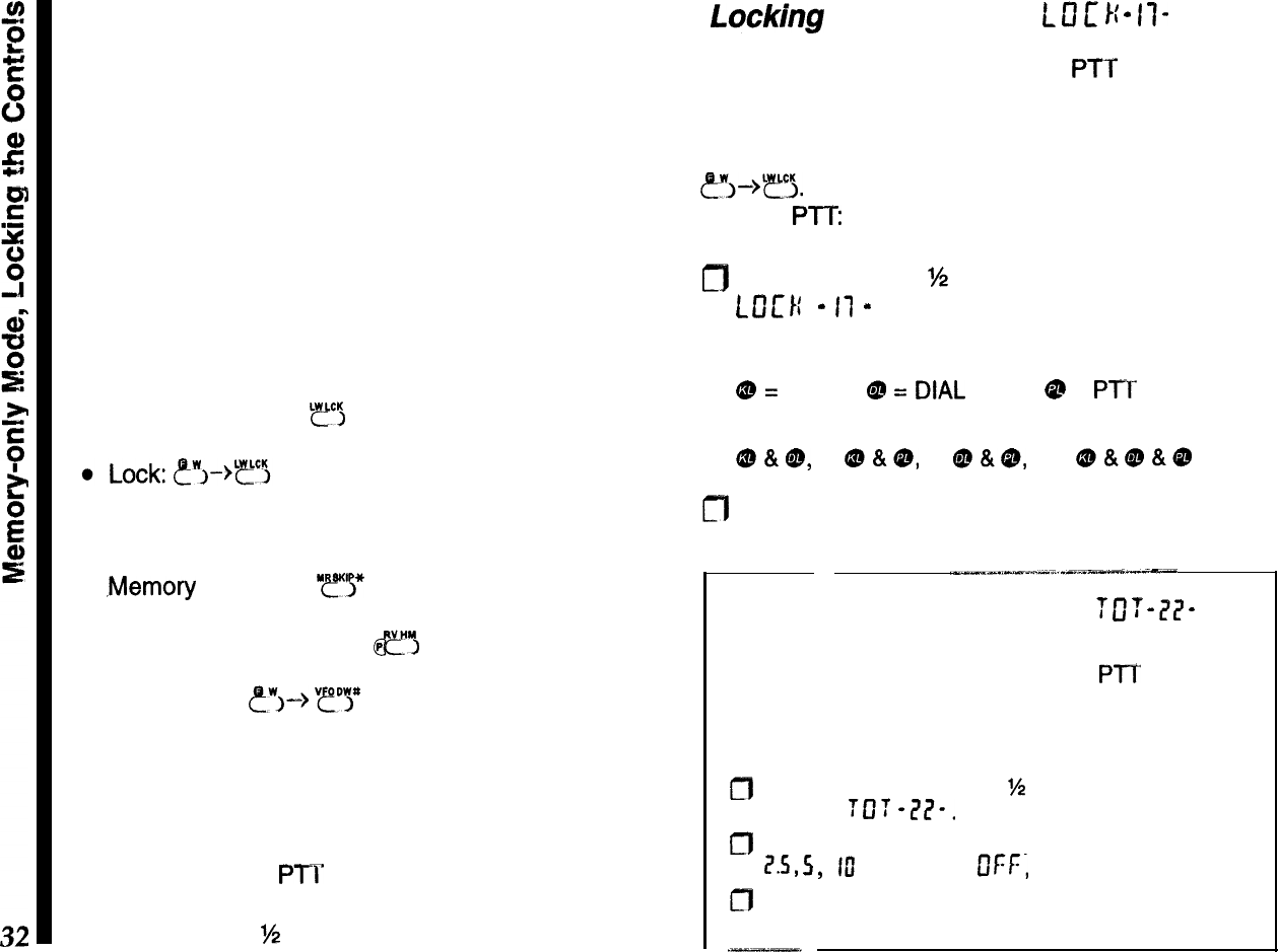
Locking
the Controls
L
13
E
I{
-
II-
The keypad buttons, knob and
PTT
can each be
“locked” (disabled), to prevent inadvertent transmis-
sions or adjustments. By default, only the keypad
locks. To activate or deactivate the lock, press
?!J->T~.
To change the locking scheme to lock the
knob or
PTT:
m
Hold the knob for
?4
second, then turn it to display
t
0
1:
1:
-
I1
-
. Press the knob momentarily, and turn
it to select the items to lock :
QJ
=
keypad,
Qs
=
DlAL
(knob),
@
=
Pl’T
button,
or their combinations:
CD&@,
@&9,
@&&,
or oO&@&@
fl
Press the PTT to return to the operating display..
Transmit Time-Out Timer
7
0
7
-
77
-
To limit accidental transmissions, such as if the radio
slips between the car seat with the PTT squeezed,
the time-out timer shuts off the transmitter after con-
tinuous transmission of 2.5 minutes. To change the
time-out duration:
a
Press the knob down for
W
second, then turn it to
display
TOT
-L?I?-.
f”‘J
Press the knob momentarily, then turn it to select I,
1?.5,
5,
ftl
minutes (or
DFr,
to disable the timer).
g
Press the PTT to save and exit.
Tone
Squelch
Modes
These systems allow silently monitoring until a call
directed to you is received, and offer privacy on an
otherwise busy channel.
---
CTCSS Tone Squelch
L----.
~._-
--..-
-.
,..-.-..-_-.._
.--.-.--..----_I-
I
Note
-
CTCSS
decode
(tone squelch) operation re-
quires the optional FTT-12 keypad, and
a@
cannot
be selected until the unit is installed.
CTCSS am
(C
on lnuous Tone Coded Squelch System)
t’
This imposes a continuous, subaudible tone on your
transmitted audio. When decoded at the other sta-
tion, this allows their squelch to open and receive
your
transmission. Some “closed” repeaters use this
to limit access, or to prevent signals intended for
other repeaters (with the same input frequency) in
fringe areas from locking up the repeater. There are
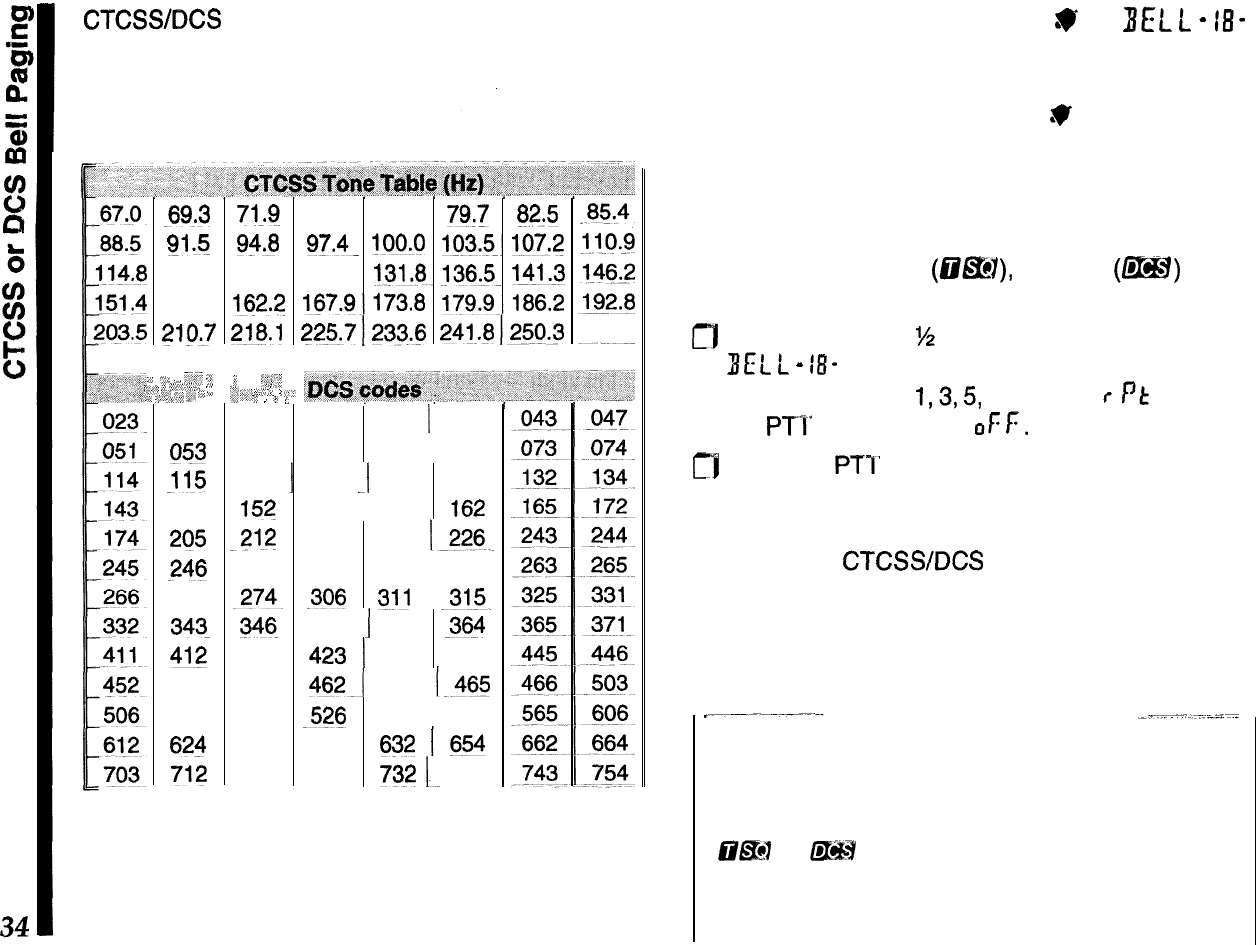
39 selectable CTCSS tones.
DCS
m
(Digital Coded Squelch)
DCS operation modulates a subaudible tone accord-
ing to a digital protocol (continuous 32-bit synchro-
nous code). DCS is widely used in the commercial
land-mobile industry for its high performance and
104 codes (offers greater privacy than CTCSS).
To use either CTCSS or DCS, both stations must be
on the same frequency, and have selected the same
CTCSS tone or DCS code.
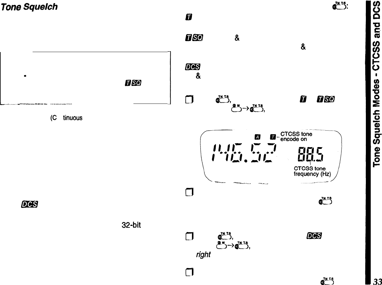
To activate CTCSS or DCS operation, press
a:
88
(encode) appears when the CTCSS tone gener-
ator is activated for transmission only.
E@EI
(encode
&
decode) appears when the CTCSS
tone squelch is activated for both tx & rx (only signals
“encoded” with the matching tone open the squelch).
m
appears when the digital code squelch system
(tx
&
rx) is active.
To select a CTCSS tone:
0
Press
e5,
as needed, to select
@
or
iil&I
opera-
tion. Press
&-%e3,
to display the default tone at
the right side of the display.
--_--
-.“_^
.___
m
Next, turn the knob to select the desired tone (see
the
table on the next page), then press
~~
to exit.
To select a DCS code:
fl
Press
c’i,
as needed, to select
&!BY
operation.
Press
&--+e+j,
to display the default code at the
right
side of the display.
m
Next, turn the knob to select the desired code (see
the table on the next page), then press
e5
to exit.
CTCSS/DCS
settings are stored in each memory
along with other data. To change a programmed
tone/code or state, recall the memory, change the
value, and save the memory again.
;:
,C”
,,:
‘;
-69.3
Sl
*!j
118.8
156.7
2lQ.7
__,.
ii .-z;
;
:,
,-,_;,i,
,,
“‘Z
“,,,z
3,;
‘,~
,I,
;,,
025
053
_115
145
205
246
271
343-
412
454
516
624
712
71,q 74.4 77.0 79:7 82.5
93.8
97.4-
!OO.O
lQ3.5~
107.2
123.0 127.3 131.8.
!36&
141.3
162.2 167.9~.173.8
179.9.jEJ6.2
218.1
225.7
1232.6
24j_.fj
1250.3
‘,
::_“_l
‘{,;
,,,,
q,,<
‘_ 2
,’ I ?
026
054
116
15?
-212
251
-274~
346
413
455
523
627
723
,_<.
‘.
I
031
032
1
036
065
071
072
12
2
125
131
155
156
-162
223 225
226
252
255
261
I
306
$11
-315.
351
1
356
364
423 ] 431 432
462-I
464 1.465
526 532-l 546
631
632
1
654
731
732
1~
734
CTCSS or DCS Bell Paging
W
BELL
-
18-
Bell Paging adds an alert ringer to CTCSS and DCS
tone squelch operation, for added convenience. The
CTCSS/DCS Bell mode displays
.V
at the bottom of
the frequency display when enabled. When you re-
ceive a call with a matching CTCSS tone or DCS
code, the ringer sounds to alert you to the call.
To activate CTCSS or DCS Bell operation (with either
CTCSS tone squelch
(Q@!?I),
or DCS
(m)
opera-
tion already enabled):
0
Hold the knob for
M
second, then turn it to display
I(EC
t
-
18-
. Press the knob, then turn it to activate
the bell and select
1,3,5,
or 8 rings, r
Pt
(rings until
the PTI’ is pressed), or
of:
F.
m
Press the PTT to save and exit.
Note that other stations do not need to have the
CTCSS or DCS Bell function to call you: they can just
use standard
CTCSS/DCS
encoding. You can store
the Bell ringer activated in a memory, along with
different CTCSS tones, DCS codes, and encode/de-
code states.
Operating Tip
When you reply to a CTCSS or DCS Bell call, you
may want to turn off the Bell function (but leave
OEM or
f@H
on), or else the transceiver will ring
every time your squelch opens.
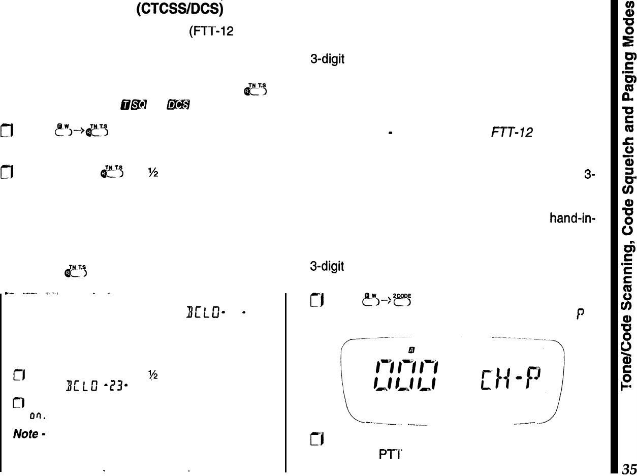
Tone/Code Scanning (CTCSWDCSj
When using CTCSS tone squelch (FTT-12 required)
or DCS, you can have the radio scan through the
tones or codes to determine which one is present on
a received signal. Before tone scanning, either tone
squelch or DCS must be activated (press
&?
as
necessary until either
clE47
or
f&&H
is displayed).
fl
Press
t”~-->~~
to display the CTCSS tone fre-
quency or DCS tone
code
at the right.
m
Press and hold
e
for
%
second to start scanning
for a matching tone or code.
Scanning slows when a signal is present, and
pauses and blinks when the matching tone/code is
found. To accept the displayed tone frequency or
code for operation and return to the operating dis-
play, press
e’i
twice, momentarily.
--
_--.
._._
.
_
Busy Channel Lock-Out
Bc
t
0
-
73
-
To prevent transmitting on top of other stations, you
can prevent the transmitter from operating whenever
a signal is present. To turn on BCLO:
fJ
Hold the knob down for
‘(2
second, then turn it to
display
BL’
L
u”
-
1?3
-
.
n
Press the knob momentarily, then turn it to select
on.
Press the PT I’ to exit.
Note
-
BCLO may cause problems with repeaters
that require response before the carrier drops.
_
. .
-
. .
DTMF Code Squelch/Paging Modes
DTMF (Dual-Tone, Multi-Frequency) encoding and
decoding allow paging and selective calling using
3-digit codes transmitted as DTMF sequences. Your
receiver remains silent until it receives three DTMF
digits that match/ those stored in a dedicated code
memory. The squelch then opens so the caller is
heard, and, in the paging modes, an alert ringer
sounds. Note
-
requires optional
FTT-112
keypad.
Introduction to DTMF Code Squelch
With code squelch, both stations use the same
3-
digit DTMF code, sent automatically each time you
transmit. The 999 code combinations give an added
degree of privacy over CTCSS, and works hand-in-
hand with the DTMF paging schemes, covered later.
After you and the other station have agreed upon a
3-digit
DTMF code, you need to store this in a private
code memory:
rj
Press
&“!>--->*?5
so the display appears as below,
turn the knob (if needed) to select code memory
f
.
L
--.---a
.-.-“-. _._..
./
tf*l
Use the keypad to enter a three-digit code, and
press the
PTI’
to save the code and exit.
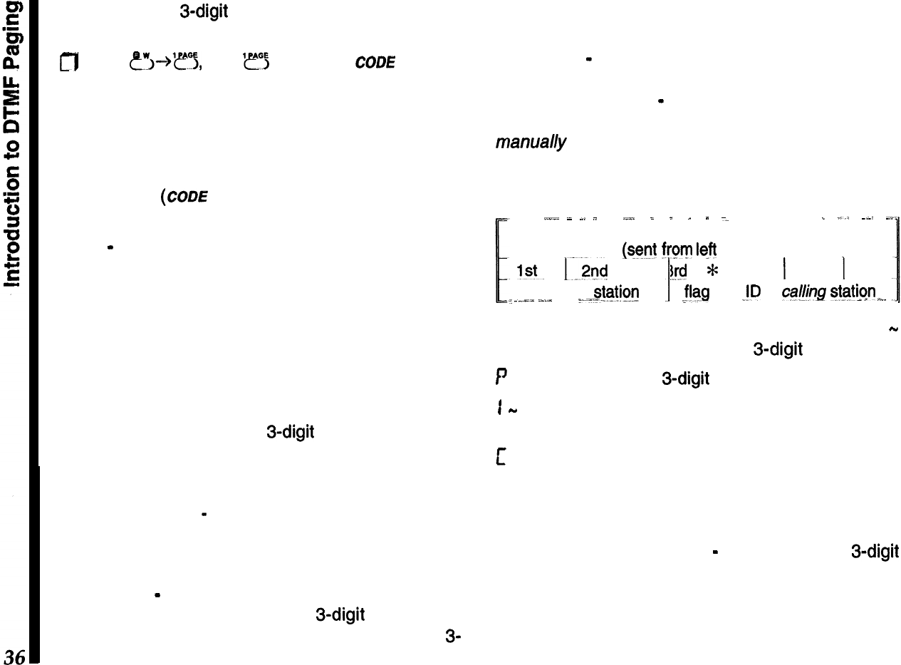
Now, with your 3-digit squelch code stored, you can
activate DTMF Code Squelch operation:
g
Press
CL”,-+‘??,
then ‘I!? again until
cam
appears
at the display bottom.
When a call opens your squelch
(
CODE
blinks), you
can begin your QSO as normal. DTMF code squelch
“hangs” open for about three seconds after the re-
ceived carrier drops, to give you time to respond,
then “resets”
(COD!?
stops blinking).
Each time you transmit, you will hear three DTMF
tones
-
remember to pause a moment before speak-
ing (as the code is sent). You won’t hear their DTMF
tones the first time you receive a call, as your squelch
does not open until after they are decoded. After-
wards, however, you will hear them while your
squelch remains open.
Introduction to DTMF Paging
DTMF paging allows selectively calling other friends
or groups by transmitting 3-digit ID codes that are
known beforehand. It extends the previously covered
DTMF code squelch mode a step further by providing
a means of identifying stations that called you while
you were absent
-
their (paging) ID codes can be
displayed and recalled.
There are two types of DTMF paging calls:
Private Call
-
Here you only receive paging calls that
are prefixed with your private
3-digit
code; your
squelch opens, the alert ringer sounds, and the
3-
digit code of the station calling is stored in code
memory C, which automatically displays the identity
of the calling station.
Group Call
-
You can receive paging calls for up to
six other groups (paging codes match one of those
in code memories 1
-
6). The calling station’s ID is
still entered in code memory C; however, you must
manually recall it to see who called.
DTMF Paging uses a specially-formatted string of 7
DTMF digits, as shown below.
--
,.I.~
_
~.
_
.._.
_
_
_
”
=
_
_,,
~~~
~.
Format of DTMF Paging Sequence
@ent
from
left
to right)
1st.
13x!
I..
3rd
*
ID of
called sjgtibn __
i
.___
~_..I
__
_-f
I
I
4th
1
5th
1
6th
E!s
JD
of
ca/&g
gtgtion
_“.
-.
There are eight DTMF code memories (labeled 1
-
6, P, and C ), which each store a 3-digit code:
P
stores your private 3-digit paging code.
1
-
6 store the codes of other friends or groups you
expect to communicate with.
c is read-only, and stores the ID decoded from a
received DTMF paging string. This can be recalled to
see the code of the station who called you.
When you want to page someone, you must first
select the code memory (1
-
6) holding their 3-digit
code. Then, when you transmit, their code is auto-
matically formatted along with yours, and is sent as
the DTMF paging string. Actually, this sequence can
be sent manually if needed using any transceiver
equipped with a DTMF keypad.
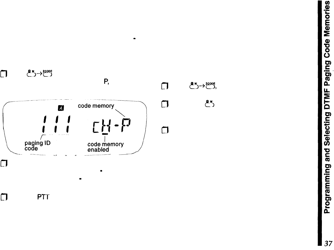
Programming DTMF Paging Code Memories
Before using DTMF Paging, you will need to store
your ID code in Code Memory P to receive private
calls (you may have already done this, as this slot is
also used for DTMF code squelch operation
-
see
page 35). Afterwards, you can store up to six other
codes of your friends’ for group calls.
Follow this procedure to store code memories:
m
Press
?y”---@?‘j
to recall the code memory list. Turn
the knob to select code memory
P,
then use the
keypad to enter a three-digit code.
-----
.-.----__
-_
_
_
_.__...._.._-.-
--’
n
If you know other paging codes of other friends or
groups, you can enter them now
-
turn the knob to
select code memories 1
-
6 and repeat the code
digit entry process.
m
Press the PTT to save the code entries and exit.
Select Code Memories for Operation
In the previous step, you entered your private paging
ID in code memory P, along with other group codes
in memories l-6. By default, code memories l-6 and
P are automatically enabled for operation as soon as
they are stored with a code, and Code memory P
cannot be turned off. Likewise, code memory C is
read-only. Code memories 1-6, however, can be en-
abled/disabled individually, should you not want to be
bothered receiving calls for particular groups:
m
Press
fi--+*e,
and rotate the knob to select a
code memory that you want to temporarily disable.
m
Now, press e”~ as necessary to enable/disable the
selected code memory (the under bar disappears
for disabled code memories).
m
Turn the kn
ob to select other code memories, and
repeat the process as needed to enable/disable
others (except C and P) as needed.
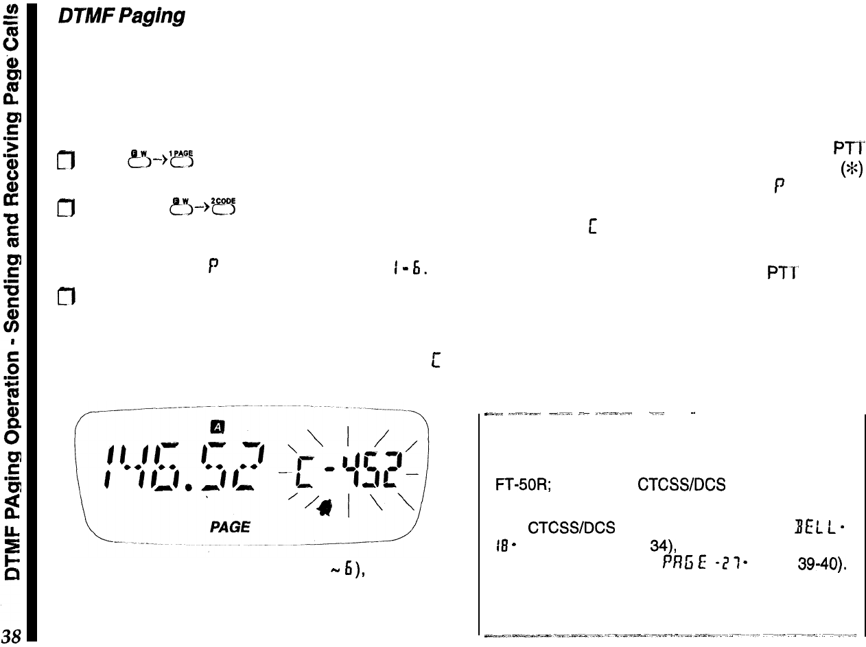
DTMF
Paghg
Operation
Receiving DTMF Paging Calls PAGE
The only difference between receiving private and
group paging calls is how the transceiver responds
when the call is decoded. To
set
up to receive DTMF
paging calls, you must first turn on this feature:
m
Press
~I-->‘~~
so that
PAGE
appears. If the ringer
is enabled (see note below),
l
V also appears.
m
Next, press
?5-+*??
and turn the knob to select
the code memory holding the paging code you
want to monitor. To receive private calls, this must
be code memory
P
, for group calls, select
I
-
6.
fl
Press the PTT to save and exit.
You are now ready to receive DTMF paging calls. If
a private page call is decoded, the alert ringer
sounds, the squelch opens, and code memory
c
appears at the right.
For group calls (code memories I
-
6),
the ringer
sounds and squelch opens as before, but the group
code appears instead of the calling station’s code.
You can still find out who called your group or friend,
remember that code memory C (read-only) always
holds the ID of the station sending the page call. This
time, you must recall it manually (it only appears
automatically for private calls).
Sending DTMF Paging Calls
To respond to a private page call, pressing the
PTI
sends the other station’s ID code, a DTMF “star”
(%)
then your private ID code (code memory
f’
) automat-
ically, and resets to receive another call. In this case,
Code memory
c
is displayed and formatted so you
can respond directly.
For group calls, however, pressing the
PTl’
sends a
group call using the group ID of the selected (and
displayed) code memory (i.e., you wouldn’t answer
the calling station, but page the called group). Re-
sponse is designed this way since the original call
was directed to another group, rather than to you.
_-_
,.,..-__.
-__.
_-
..,~~=~_;-
___
~.
~~
Note about
Ringer Settings
There are two separate ringers that sound in the
FT-SOR;
one for the
CTCSWDCS
bell feature, and
another used for DTMF paging modes.
The
CTCSWDCS
bell is configured using
BEL
L
-
18
-
(covered on page
34),
while the DTMF paging
ringer is a function within
PRG
E
-2
7
-
(pages 39-40).
Remember that these are configured separately to
eliminate any confusion during feature descriptions.
To send a page call:
fl
Press
&“,-->E
and turn the knob to select (dis-
play) the code memory of the station you want to
page. Press the PTT to exit.
m
If
you haven’t done so already, press
?‘“~--%‘ef”E
to
enable the DTMF paging mode
(
PAGE
).
n
Make sure the channel is clear, and press the PTT
(follow with your callsign, of course).
To talk after receiving and responding to their call,
just switch from paging to code squelch mode:
n
Press
e’~-)‘rs,
then
‘?j
as necessary so that
CODE
appears, then press the PTT to exit. When
you finish your QSO, reactivate DTMF Code Pag-
ing in the same way
(PAGEdisplayed).
Trigger Paging
T.PAGE
With regular DTMF paging just described, to have a
OS0
after responding to a page call, either you or the
other station (but not both) must select code memory
L’
, to use a common DTMF code when switching to
DTMF code squelch operation.
Trigger paging overcomes this inconvenience of
manually switching to/from code squelch operation,
however,
U.
can only be .ur~d.beiw-een-transceivers
SQlX&@?~d~.Wfih..th~.S
feat
Ur
@..
To activate trigger paging:
n
Press
?~--)‘?j,
then
‘efo;
as necessary so that
ITPAGE
is displayed, then press the PTT to exit.
When a call is received,
T.PAGE
blinks, and the alert
ringer sounds. If the other station
@also
using trigger
paging, you can respond by just pressing the PTT
and talking within 3 seconds after the DTMF code
sequence is sent. The pager resets to receive a new
call if either station fails to respond to the other within
3 seconds.
Auto-Respond Paging PRlSE-?I-
This feature responds automatically (without opera-
tor intervention) to received calls by “paging back”
the calling station. This has the same effect as if you
manually pressed the PTT after receiving a call in
either regular or trigger paging modes.
There are two auto-respond modes:
Answer-Back
-
this acknowledges a page call by
“paging back” the calling station (just as if you manu-
ally selected their 3-digit code and pressed the PTT).
Page
Fonn/arding
-
this “repeats” a page call in its
original sequence (rather than reversing the ID code
pair as in answer-back format), [ela_vngjhe
cad
to
extend your paging range.
You can leave your radio with this mode enabled in
your vehicle, office or other vantage point when you
are temporarily away, but will be using another trans-
ceiver and don’t want to miss any paging calls.
To enable auto-respond paging:
fl
Recall
Pf?ti
E
-
?I-
, press the knob momentarily,
then turn it to select
RzJ!:
.
fl
Press the knob momentarily again to display the
current answer-back mode:
R
0
5,
f:
o
r , or
0
f:
r.
fl
Turn the knob to select the desired mode, then
press the PTT to save the change and exit.
Now, with either auto-respond mode enabled, the
transceiver reacts to a valid page call by answering
or forwarding the DTMF page sequence, according
to selected mode.
Paging Transmit Delay
IL
fly
When calling other stations using DTMF paging or
DTMF code squelch (particularly through repeaters),
you may find that some stations are unable to receive
your calls. This can be caused by their squelch not
opening fast enough (after receiving your transmitted
carrier) to allow all of the DTMF digits to be received
and decoded.
To correct this problem, you can set a longer delay
between the time your transmitter is keyed and the
first DTMF digit is sent:
m
Recall
PnG
E
-
?I
-
, press the knob momentarily,
then turn it to select
JL
RY.
n
Press the knob momentarily again to display the
current time delay
(ms):
750,
YS0,
TSD,
or
KfDct.
This is the delay between the moment your press
the PTT and transmission of the first DTMF code
digit. Set it to
IS0
ms or
IDOEf
ms if operating
through a repeater that cuts off the first digit.
a
Turn the knob to select the desired delay, then
press the PTT to save the change and exit.
Playback Speed
‘;
P
E
B
This selects the tone duration (50 or 100 ms) for each
DTMF paging digit, to select fast or slow playback
speed during paging operation. The 50 ms tone du-
ration are preferable, but the slower tones may work
better under weak signal conditions.
CT)
Recall PflG
E-
i)l
-
, press the knob momentarily to
display
5
PE
u”
(DTMF code sending speed).
n
Press the knob momentarily again to display the
current speed setting, and turn it to change the
setting: SO or
KKI
ms per tone. Press the knob
again (or press the PTT to exit).
Paging Bell
’
1
e
I..
L
0
Rotate the knob one click to display
EEL
L
(or
press PTT to quit), then press the knob momentar-
ily again to display the current bell setting: I,
3, S
or
El
rings,
r
Pt
(rings until the PTT is pressed), or
OFF.
m
Set it to DFf: only if you do not want the ringer to
sound (these settings do not affect the CTCSS or
DCS ringer). Press the PTT to exit.
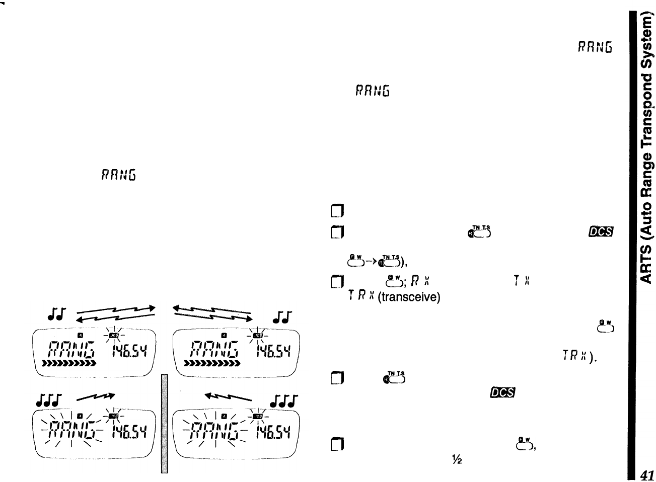
ARTS Auto Range Transpond System
This system uses DCS signaling to inform you when
you and another ARTS-equipped station are within
communications range. Both stations must first se-
lect DCS operation using the same DCS code. The
ringer can be activated or not, as desired
Whenever you push the
PTT,
or every 15 seconds
after ARTS is activated, your radio transmits a
(subaudible) DCS signal for about 1 second. If the
other radio is in range, a beeps sound and their
display shows
n!i’r:G
(in range), or yours does if their
radio polls yours first.
Whether you talk or not, both radios continue polling
each other. If your CW
IDer
(covered on the next
page) is turned on, your radio
IDS
in Morse code
every nine minutes. As long as your stations remain
within range, two beeps sound each time a poll is
received (or each time they presses their PTT).
If you move out of range for more than one minute
(four pollings), your radio senses that no signal has
been received, three beeps sound, and
RRfJG
b/inks. If you then move back into range, as soon as
they transmit (or their radio polls) your radio sounds,
and
PRNfi
stops blinking
During ARTS operation, your operating frequency is
displayed, but you cannot change it or other settings.
Also, the squelch does not open until a signal is
received for about one second, so remember to
pause before speaking after pressing the
PTT.
To use ARTS:
0
First ensure the battery saver feature is disabled.
0
Activate DCS (press
ej
repeatedly until f@H
appears). Display the DCS tone code (press
p-“~+eJ),
and set it to match the other station.
jJ
Press
&5;
I?
:(
(receive-only),
T
::
(transmit-only),
T
R
I:
(transceive)
or just your operating frequency
appears at the left, indicating the current ARTS
mode (described on the next page). Press
ey:,
again if you want to change it (the operating de-
scriptions assume both radios are set to
TR
:C
).
m
Press
e>
alone when done. The display returns
to normal, except that now 6?!H is blinking (indicat-
ing ARTS is enabled, as opposed to regular DCS
operation).
m
Finally, to activate ARTS, press
?I,
and then hold
the knob down for
%
second. Two beeps sound,
and your ARTS mode selection appears at the left,
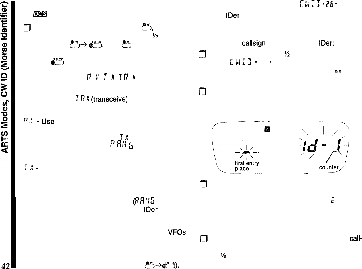
with your operating frequency at the right, and with
@B#
blinking.
m
To cancel ARTS operation, press &!I, and then
press down on the knob and hold it for
M
second.
Next, press
~~~--+
c$,
then
&
again, as neces-
sary, to display the frequency at the left again, then
press I&!“, to finish.
ARTS Modes
f?
i
T
iI
ff7
K
In the previous ARTS description, both transceivers
were set to the
T
R
)I
(transceive)
mode. There are
two other ARTS modes available, as outlined below:
RI:
-
Use
this mode if you only want your radio to
listen, and not poll the other station (in which case
their radio should be set to the
T
I(
mode). Here, your
radio will beep and display
f?
f?!J
fi
(steady or blink-
ing) to indicate the state of connection.
f
II
-
This puts your radio into a transmit-only “bea-
con” mode where you won’t hear the polling beeps
(but you can still hear when the other station talks).
When activated, you have no display of whether the
other station is in range, or not
(RflrJG
does not
appear). You should have your CW
IDer
enabled
when this mode is activated (explained at the right).
Your ARTS mode selection is retained by the VFOs
and can be stored in memories. If you want to use
normal DCS operation, you have to cancel ARTS by
by selecting the operating frequency when the DCS
tone number is displayed (by pressing P”J-+&?~).
CW ID (Morse
Identifier)
mn-i5i-
The CW IDer sends your CW ID about once every 16
pollings during ARTS polling and DTMF answer-back
paging (covered later).
To store your
callsign
and activate the
IDer:
m
Hold the knob down for
W
second, then turn it to
display
c
1:
13
-
76
-
. Now press the knob momen-
tarily, then turn it if necessary, to display
00
at the
right.
n
Press the knob again momentarily. The digit loca-
tion counterappears at the right, with a segment for
the ID entry position at the far left (all flashing).
---
c.
_._
\I/
-
-
--
‘l’
fk&ntry
-
-.
0
entry
court9
_.--
-----
n
Turn the knob to change the character at the left to
be the first letter of your callsign. Press the knob
momentarily. The digit location number
7
now ap-
pears at the left. Again turn the knob to select the
second character of your callsign.
cf7
Repeat the above step to finish entering your
call-
sign (up to 16 characters), then hold the knob down
for
‘/2
second to accept your entry, and finally press
the PTT to quit.
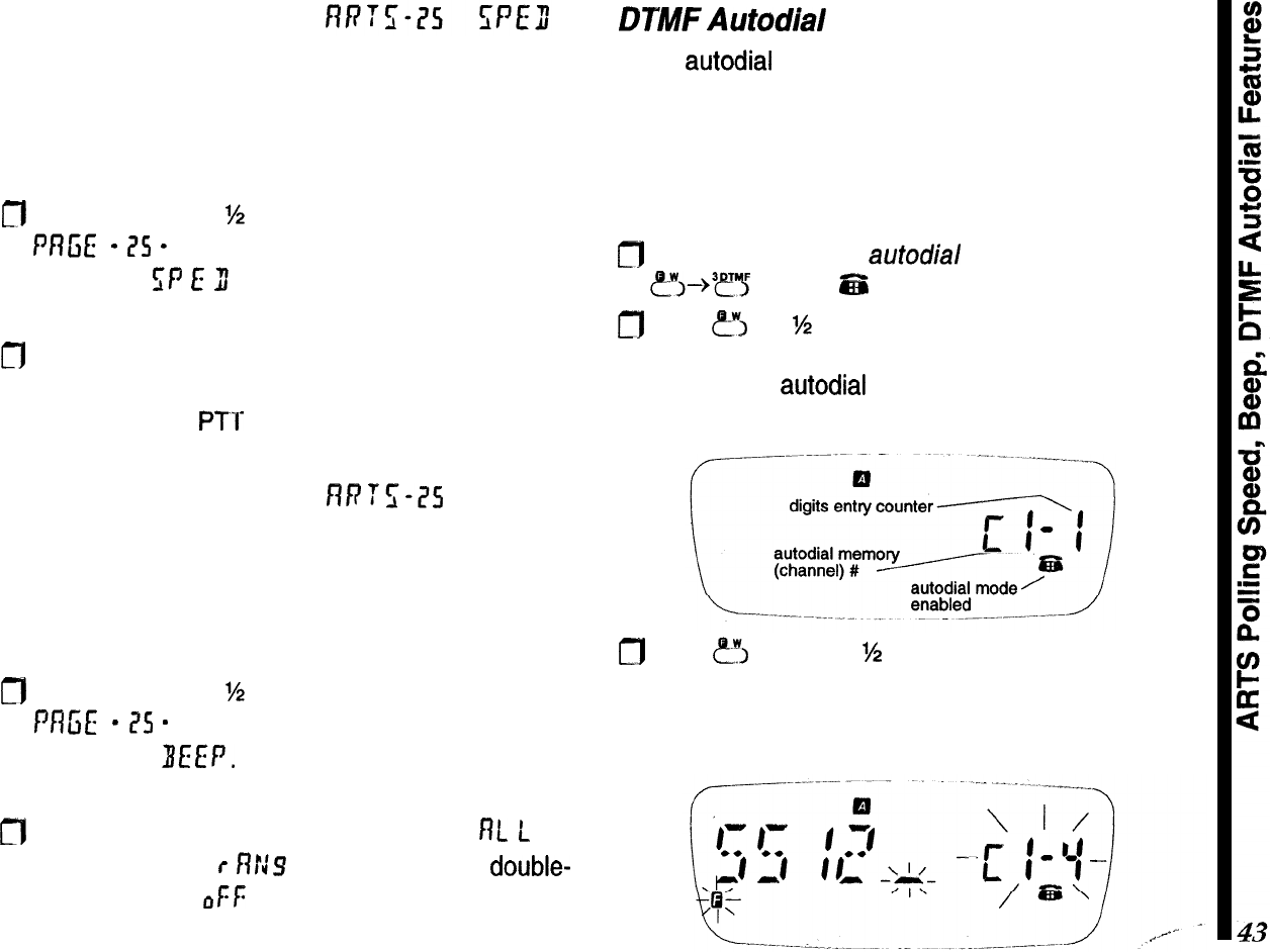
ARTS Polling Speed
You can increase the ARTS polling rate, to have the
radio check propagation state more frequently, such
as when one or both stations are mobile.
fl
Hold the knob for
%
second, then turn it to display
f
Rfi
E
-
ZS
-
. Press the knob momentarily, and turn
it to select
SP
E
3 (polling speed).
m
Press the knob again momentarily, and turn it to
change the setting: 15 or 25 second polling inter-
vals. Press the PTT to save and exit.
ARTS Polling Beeper
flF7fWS
BEEP
You can disable the two beeps that sound each time
the radio validates a polling (in-range), and three
beeps that sound when the units are out-of-range:
m
Hold the knob for
%
second, then turn it to display
Pfl
ci
E-
isS
-
. Press the knob momentarily, and turn
it to display BEEP.
fl
Press the knob again, and turn it to select
f?L
L
(all
beeps enabled),
r
RN9 (disable in-range,
double-
beeps only), or
&f:
(all beeps disabled). Press the
PTT to save and exit.
DPMF
Autodial
Feature
Eight
autodial
memories each store DTMF tone se-
quences of up to 16 digits for remote DTMF control,
or telephone numbers for autopatch calls. A ninth
memory is read-only and stores DTMF sequences
(up to 32 digits) decoded off-the-air.
To store a DTMF autodialer memory:
fl
First activate the
autodial
mode by pressing
?j--~~fl
so that
zfil
appears in the display.
0
Hold
?J
for
%
‘second (two beeps), and within 5
seconds, press a numbered key (l-8) correspon-
ding to the
autodial
memory number you want to
store (see below).
m
Hold
?J
again for
M
second, then (within 5 sec-
onds) key in the phone number you want to store.
As you do so, the digit counter increments as the
entered digit is displayed to the right of it.
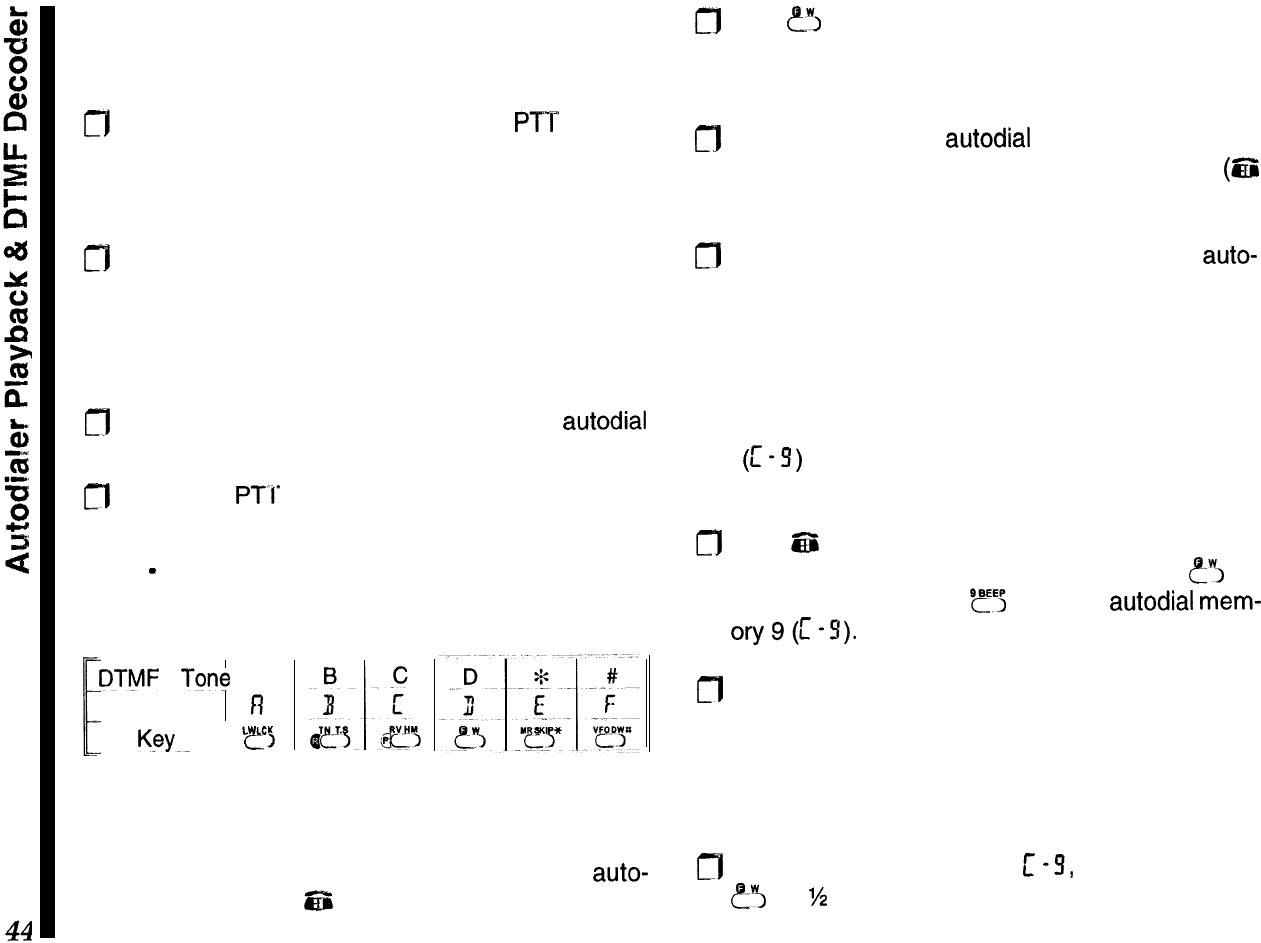
If you make a mistake, hold the knob for %-second to
clear all entries for that memory and re-enter all the
digits,
0
After entering the final digit, press the
PTT
momen-
tarily to revert to the edit display. You can turn the
knob to review your stored number, or press the
key corresponding to that memory to replay it.
n
If you want to select another DTMF memory to
store, press a numbered key, as before, corre-
sponding to the desired memory number. Other-
wise, pressing the PTT again exits to the frequency
display.
fl
Repeat the last two steps, and enter the
autodial
digits, as desired.
n
Press the
PTI’
twice to return to the frequency
display.
Note
-
The non-numeric DTMF tones map to the
FTT-12 keypad as follows:
DTMF
Tone
A
F
Display fi
K~YK
I
e
L
!&CK
>
Autodialer Playback
You can manually check the contents of DTMF
auto-
dial memories while
EZi
is displayed. Also use this to
play back stored memories into a telephone.
cfl
Hold
err,
for %-second, then press any numbered
key to display and play that DTMF memory. Turn
the knob to review each stored digit.
n
To play back DTMF
autodial
memories on the air,
first ensure the DTMF memory mode is on
(6%
displayed).
m
Close the PTT and press the number of the
auto-
dial memory to transmit. Once the DTMF sequence
has begun, you can release the PTT.
DTMF Decoder
You can use a reserved, read-only, autodialer mem-
ory
(c
-S)
to display and store DTMF sequences
decoded off-the-air as they are received:
0
With
ES
displayed on the operating channel you
expect to receive DTMF transmissions, hold
?‘I
for
%-second, then press
SF5
to select
autodial
mem-
ory9(1-S).
m
Now, and DTMF tones received are decoded, then
stored into C-9. The digits scroll from right to left as
the are decoded, and up to 32 digits can be stored.
Any additional digits overwrite previous ones, on a
first-in, first-out basis.
fl
To clear the stored digits in
c
-9, push and hold in
e-3
for
?4
second, then push and hold in the knob
for ?&second.
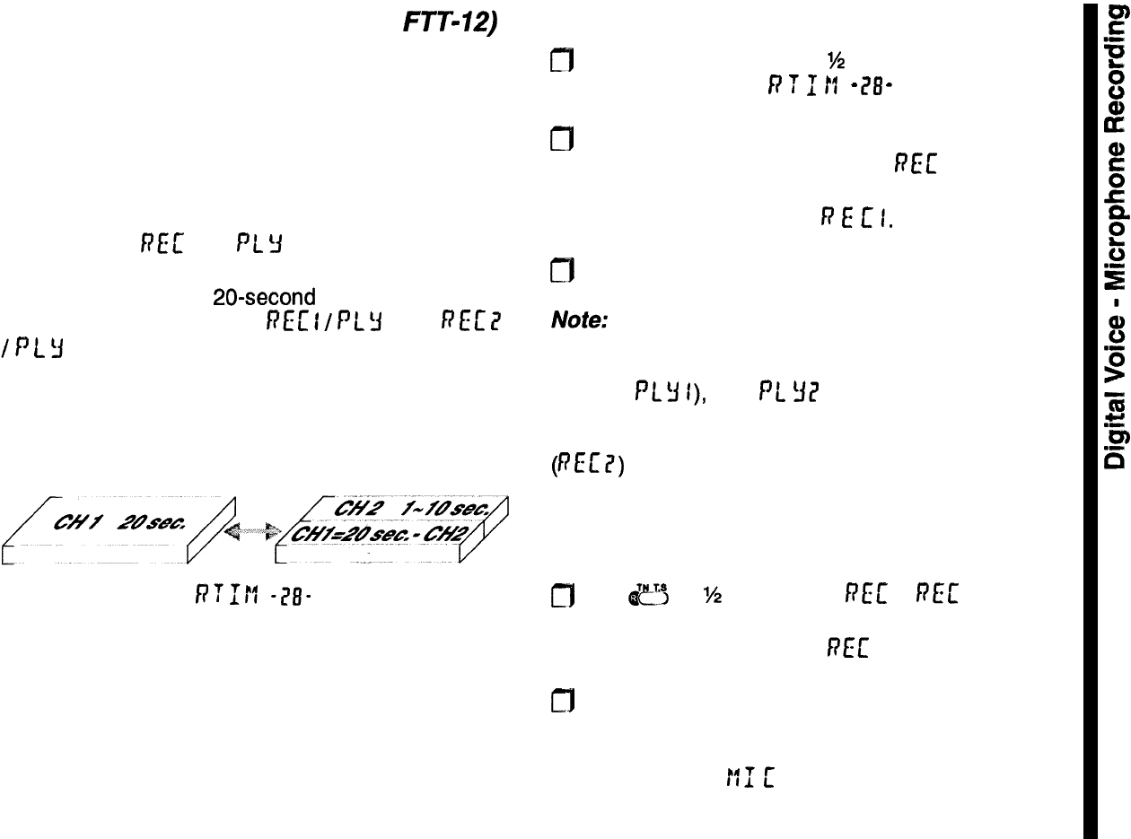
Digital
Voice
Recorder (requires
FTT-12)
The FTT-12 includes a digital voice recorder that
stores one or two messages up to 20 seconds long.
You can record messages by the microphone for,
playback manually or automatically over the air, and
you can manually or automatically record received
signals.
By default, one message can be recorded, and is
displayed as
RET
and
PL
Y
during recording and
playback, respectively. Before recording, you may
wish to partition the 20-second voice memory into
two segments, displayed as REc
I
/
PL
Y
I and
f?
Et
?
/
P
L
3
i? . The second segment can be up to 10 sec-
onds long, with the first segment using the remainder
(see illustration).
voice memory partition
f;‘?M
-?I?-
Both segments can be used for manual recording
and playback, but only the first segment can be used
for automatic receive recording, and only the second
segment can be used for automatic voice transmis-
sion.
To partition the voice memory recording time:
m
Hold the knob down for
%
second, then release
and turn it to display
P
T
1
If
-
78
-
.
0
Press the knob momentarily and turn it to set the
number of seconds to record for
FEE
7 (up to ten
seconds). The remaining time (20 minus the se-
lected time) is allocated to
P
E
c
I.
0
Press the PTT to return to the operating display.
Note:
If you record without first partitioning the voice
memory, and later partition it, the secondpart of your
previous message will be in the first partition (played
back as PLY
I),
and
Pt
YE’
will play back the entire
original message, but with the partitions reversed! To
clear this condition, record the second partition
(PEE?) again.
Microphone Recording
To record your voice through the microphone:
m
Hold
dcy
for
%
second until
PEE
or
FEL’
I appears,
if you have partitioned the voice memory, turn the
knob if you want to record PEE 7.
a
Press the PTT and speak your message into the
microphone (no transmission occurs).
During recording,
!:I
[
appears at the left, and the
number of seconds remaining in the segment counts
down at the right. You can release the PTT to stop.
45
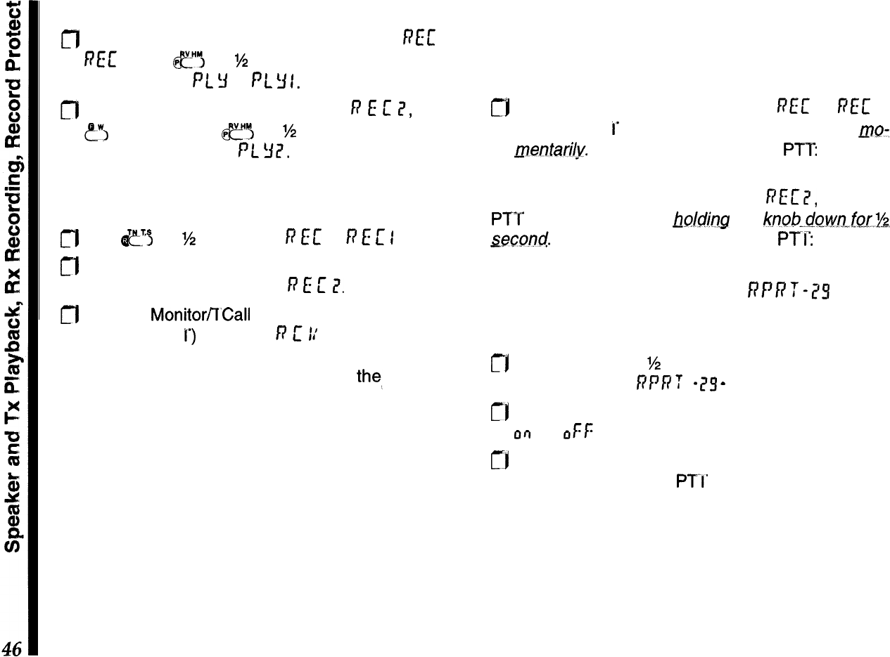
Speaker Playback
m
To play back a message recorded as
REL’
or
RE[
I, hold
fl
for
M
second. The left side of the
display shows PL
!I’
or PL
Y
I.
m
To play back a message recorded as
R
E
L’
II,
press
eW,
and then hold
CJ
for
M
second. The left side
of the display shows PL
32.
Receiver Recording
To record a signal from the receiver:
0
Hold
ef
for M second until
fs
EC
or
R
E
L’
I
appears.
n
If you have partitioned the voice memory, turn the
knob if you want to record in
R
E
L’
?.
m
Hold the Monitorfl’Call button (on the left side, just
below the PT
T’)
to record:
)9
L’
11’
appears at the left,
and the remaining seconds of memory counts
down at the right. You can release
the_
button to
stop, or wait until the counter runs down. Recording
level is not affected by the volume control.
Speaker playback is as described above.
Transmitter Playback
You can manually play back any recorded messages
over the air. You can hear them through the speaker
during transmission.
rj
To transmit recordings made with
REc’
or F(E[ I,
hold the PT
1’
while pressing the knob down mo-
mentari1.y.
You can then release the PTT the mes-
sage transmits until it is done.
To transmit a recording made with
REc’2,
hold the
PTT while pressing and
~olcJing
the
knoh..dowo-fsr.%,
seccmd.
Then release the knob and
PTI:
the mes-
sage transmits until done.
Recording Protection RPRT-75
This protects any or all recordings from being acci-
dentally over-written:
CI Hold the knob for
%
second, and then release and
turn it to display RPP
T
-
25
-
.
rj
Press the knob momentarily, then turn it to select
or)
(or oFf: to deactivate).
cj
Press the knob again momentarily to accept your
setting, and press the
PTI’
to exit.
Now, attempting to overwrite any voice memory with
a new recording is blocked.
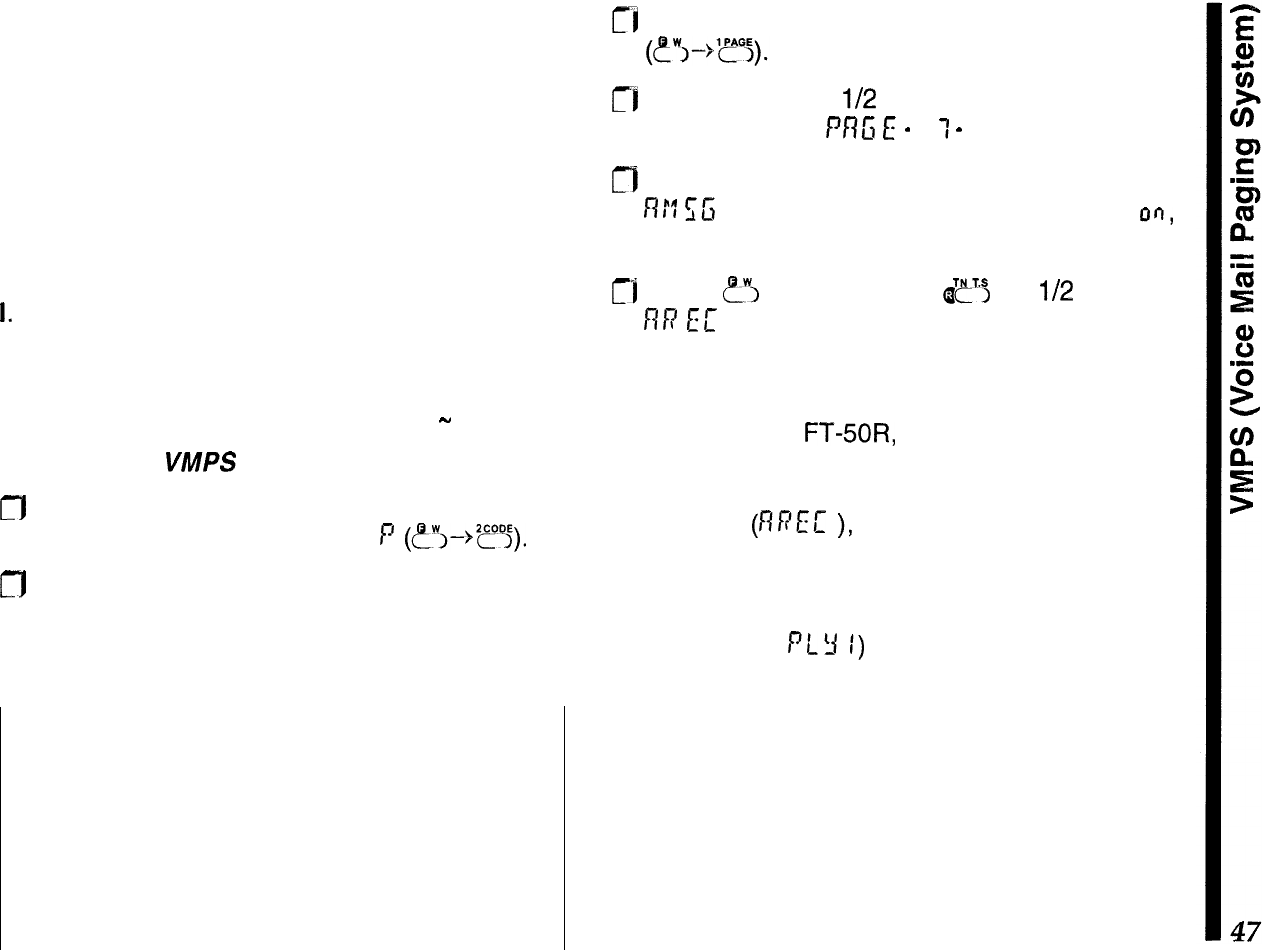
VMPS (Voice Mail Paging System)
The DTMF Paging and Automatic Recording ca-
pability of the FTT-12 keypad may be utilized to
allow the storage of “Voice Mail” in an FT-50R
which is so equipped. A message of up to 20
seconds in length may be stored in your radio for
later recall.
To use this system, two conditions must be met:
I.
The calling station must know your private or
group DTMF paging ID code (see page 37).
II. Your transceiver must have DTMF paging or
Trigger paging activated (see page 38
-
40).
To set up for
VMPS
operation:
CT]1
First, ensure that your private paging ID code is
stored in DTMF Code memory
P
(~~-~z??j).
CJ
If you haven’t already done so, partition the
voice memory so as to set up the desired Voice
Mail time limit. Without this partitioning, the full
20 seconds of recording time will be available.
IMPORTANT !
ARTS, VMPS, and the auto-response modes for
DTMF
paging transmit
without operator presence.
Ensure this type of operation is legal in your coun-
try before using it, and adhere to any or all regula-
tions regarding timed station identification (CW ID).
ri
Activate DTMF paging or Trigger paging
rj
Hold the Knob for
l/2
second, then release it and
turn it to display
PRG
E
-
7
1
-
.
n
Press the knob momentarily, then turn it to select
R1”7
f;G
. Press the Knob again, turn it to select on,
then press the PTT switch to exit.
rl
Press
?I
and then hold
I$~S
for
l/2
second;
RR
EE
will appear on the left side of the display,
and the receiving frequency at the right.
When a station bearing the correct DTMF paging
code calls your
FT+OR,
the alert ringer of your
radio will sound, and the receiver squelch will
open. Automatic off-the-air recording will then
commence
(nPEC
),
storing until the recording
partition time limit has been reached, or until the
other station stops transmitting (whichever comes
first). You may now play back the stored message
(from register PLY
1)
when you return to your
transceiver. The blinking DTMF code indicator on
the right-hand side of the display provides a visual
indication that a message has come in during your
absence.
Only one Voice Mail message may be stored at
any time, and newer messages will overwrite pre-
vious ones.

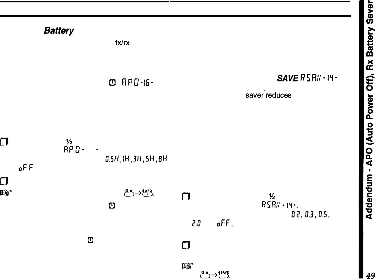
Addendum
Extending
Battety
Life
Operating time depends largely on
b&x
duty cycle,
and how you care for the battery pack. The FT-50R
offers several ways to conserve battery power, and
extend the life of each charge.
APO (Automatic Power-Off)
Cl
fl
P
c
-
15
-
Obviously the best way to save battery life is to turn
the set off when not in use. You can activate APO to
turn the transceiver off after a half hour, one, three,
five, or eight hours of key inactivity. APO is disabled
by default, but you can activate it as follows:
fl
Hold the knob for
M
second, and then release and
turn it to display
flf
tf
-
16
-
. Press the knob mo-
mentarily, then turn it to select
fI.SII,
II+,
3/i,
94,
BIi
or
oF
f:
(APO deactivated).
n
Press the PTT to exit.
t@?
shortcut to setting the APO delay:
p”i--$??.
When the APO timer is active,
[fl
appears in the
display, and the timer resets every time you press a
key or move the knob. If you don’t press any keys for
the selected time-out period, and you are not scan-
ning or using Dual Watch,
t!l
begins blinking, and if
you have the key beeper activated (see the following
page), an alert melody plays about a minute before
the radio turns itself off. Press a key in that minute if
you want the radio to stay on.
Once it turns off, you must switch the radio back on
for use. If you need to monitor for a long period, or if
using an external DC supply, you can deactivate
APO by the same steps above.
Receive Battery Saver
SAVE
h?%’
-
II-
The receive battery saverreduces current drain dur-
ing squelched monitoring by putting the receiver to
“sleep” after the squelch closes, and then “waking it
up” periodically to check for activity. When enabled,
SAVE
blinks near the bottom right of the display.
You can select from five monitor/sleep durations,
from 200 ms to 2 sec. The battery saver is enabled
by default. To check or change the ratio or disable the
Battery Saver:
n
Hold the knob down for
%
second, then release it
and turn it to display
Rsf?l:
-
f”l-. Press the knob
momentarily, then turn it to select
IL?,
0.3,
D.S,
1.11,
Z.0
, or
OFF.
c[7
Press the PTT to exit.
l@?
shortcut to setting the Rx battery saver “sleep”
time:
?~--%‘?“5.
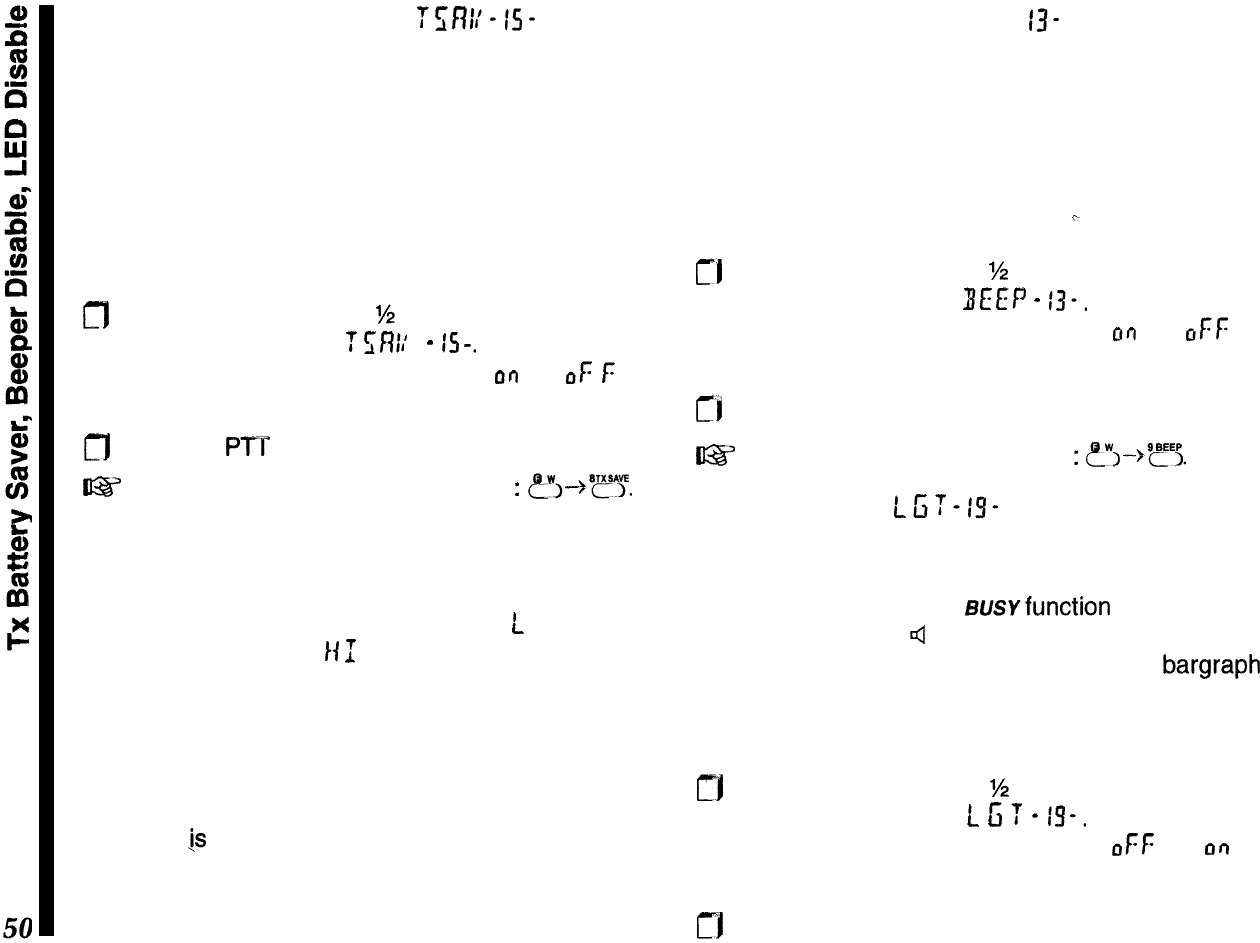
Transmit Battery Saver
Tr;fWis-
Always use the lowest transmitter power necessary
to maintain reliable communications (this may be the
law in your country). As described on page 18, there
are four T
X
power levels: high, low 1, low 2 and low
3. Activating TX Save can reduce transmitter current
drain even further, by reducing power output when a
full-scale signal is sensed on the receive frequency.
TX Save can be turned on as follows:
n
Hold the knob down for
%
second, then release it
and turn it to display
f
rni/
-
IS-.
Press the knob
momentarily, then turn it to select
OQ
(or
OF
f:
to
deactivate).
m
Press the PTT to exit.
I@%’
shortcut to set the T
X
battery saver
:
~Y--~~??.
Notice that the SAVE indicator is displayed during
transmission when the TX Save function is activated.
Regardless of whether you use the TX Save feature,
remember that the current drain of the
L
I setting is
much less than the
141
setting, so it is good to
develop the habit of always using the lowest setting
possible, switching to high power only when low
power fails to get through.
If you need better range, consider using a higher gain
antenna instead of high power (the effect on trans-
missions
1s
the same, but receive performance im-
proves as well). Make sure any external antenna is
designed for 50 ohms impedance at the operating
frequency.
Beeper Disable BEEP-
13-
The keypad beeper draws several milliamperes, so
you may want to disable it if you need to conserve
power while using the controls a lot. Note, however,
that you will lose the audible feedback that indicates
key functions and errors.
To disable the beeper:
c
!-I
Hold the knob down for
M
second, then release it
and turn it to display
BEEP
-
13-.
Press the knob
momentarily, then turn it to select
or)
(or
ctFf:
to
disable).
cl
Press the PTP to exit.
U%Y
shortcut to disable the beeper
:
?~-,@?5.
LED Disable LC;T-IS-
The LED draws about 15 milliamperes when the
squelch is open, and when transmitting. However,
you may not need it: the susvfunction of the LED is
duplicated by the 4 icon at the right side of the
display when the squelch is open, and the bargraph
always shows the TX power level when transmitting.
You can disable the LED to conserve power:
rj
Hold the knob down for
%
second, then release it
and turn it to display
L
6
T
-
is-.
Press the knob
momentarily, then turn it to select
CIF~:
(or
or7
to
enable).
rj
Press the PTT to exit.
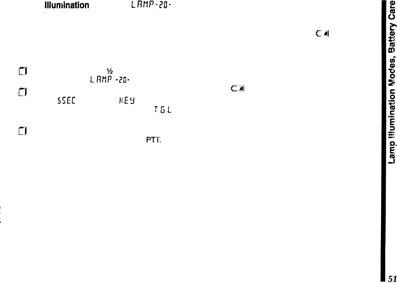
Lamp
Illumination
Modes
uwf
-a?-
The (lower) LAMP button illuminates the display
when operating in the dark. By default, it lights for 5
seconds, but you can change it so that it lights (for 5
seconds) every time a key is pressed or the knob
turned, or so that the LAMP button turns the light on
until you press it again. To change the setting:
rj
Hold the knob down for
%
second, then release it
and turn it to select
L
ntff)
-
7u”
-
.
m
Press the knob momentarily, and turn it to select
between
5
SEC
(the default),
1:
E
3
(the keypad and
knob activate the lamp for 5 seconds) or
T
G
L
(the
LAMP button toggles the lamp on and off).
rj
Press the knob again momentarily to accept your
setting, then release it and press the
PTI:
Battery Care
As the battery discharges, the voltage drop (espe-
cially when transmitting) increases. When battery
voltage drops to around 4.0 volts,
C
41
blinks at the
bottom right of the display, indicating the batteries
should be replaced or recharged. As battery voltage
drops further, the transceiver shuts off.
If using rechargeable batteries, switch the trans-
ceiver off and recharge or replace the battery as
soon as
C.:2l
appears. Try to avoid recharging Ni-Cd
batteries often with little use between charges, as
that can degrade the charge capacity and useful life
of the cells. Since it is hard to know exactly when the
charge will run out, you may want to carry an extra,
fully-charged pack with you to avoid having operation
interrupted.
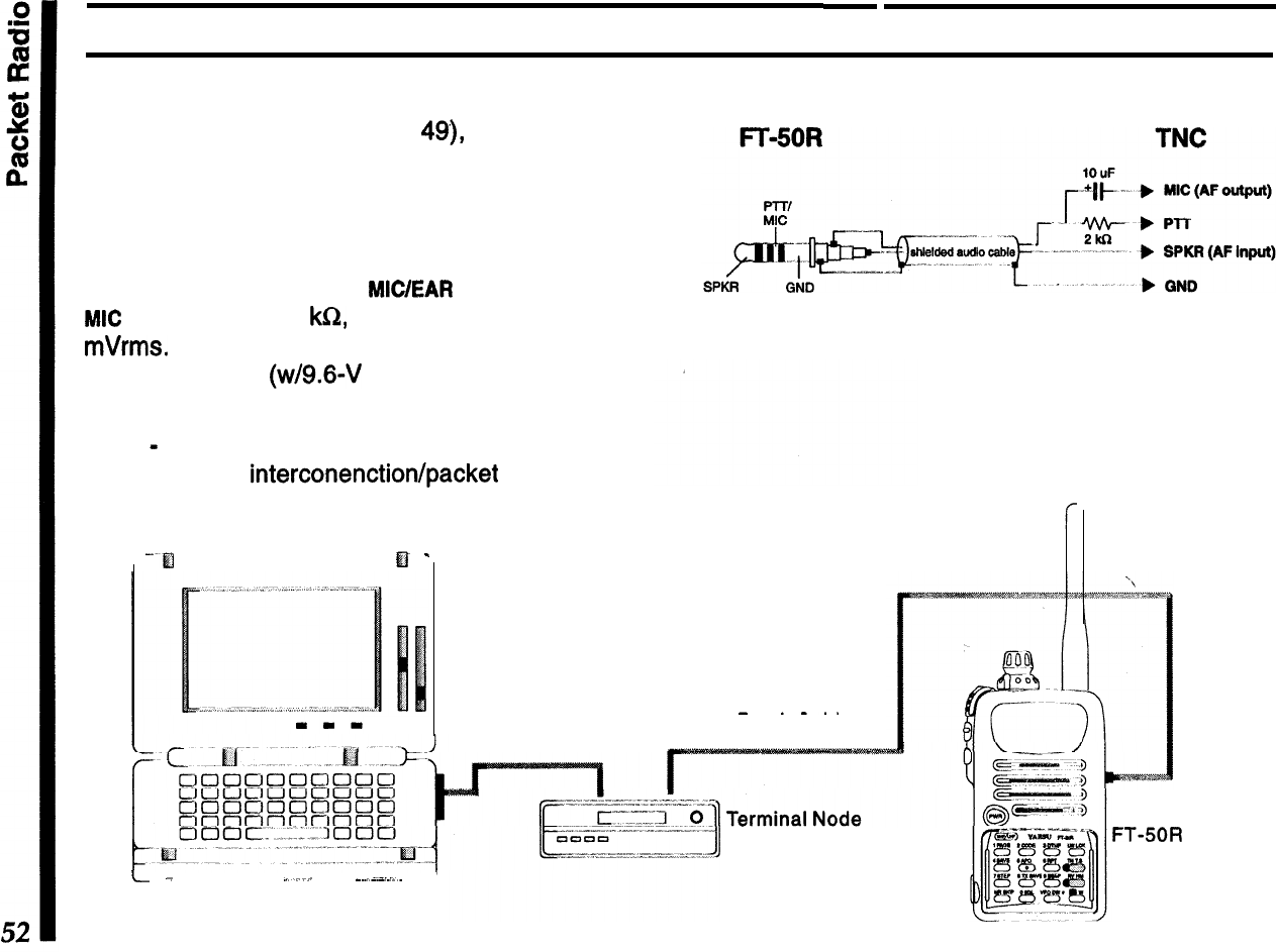
To use the radio for packet, the receiver battery saver
should be disabled (see page
49),
since the “sleep”
periods used in power saving can cause packets to
be missed.
Construct a TNC interface cable as shown in the
drawing, and connect the
MICIEAR
jack to your TNC.
MIC
impedance is 2
klCZ,
and maximum input is 300
mVrms.
EAR impedance is 8 ohms, and maximum
output is 2 Vrms (w/9.6-V supply).
Note
-
the FT-50R is not recommend for use with
9600 bps data interconenctiortlpacket operation.
Packet Radio
Detail of packet cable construction.
-El
El
-
Station Interconnections for
Packet Operation
AFSK Packet
-
.-..
RS-232C
Serial
interface Cable
Patch Cable
Controller Unit
L.-
-
_.
_~_..~
J
Personal Computer
with Terminal Software
Package installed.
FT-50R
Transceiver
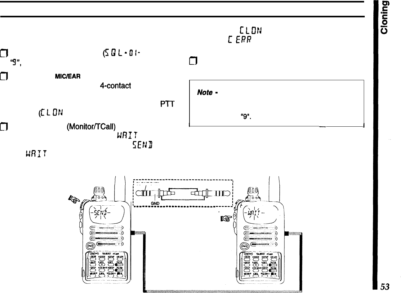
Cloning
You can copy all memories and settings from one
radio to another of the same type, as follows:
m
Set the squelch threshold level
(5
0
L
-
0
I- ) to below
“!!I”,
if necessary.
0
Connect the
MC/EAR
jacks of the two radios to-
gether using a cable with a
4-contact
plug at each
end. With both radios turned off, turn each one on
while holding both the knob down and the
PIT
pressed
(c
L
D!J
appears on both radios).
m
Press the middle
(MonitoVTCall)
button on the left
side of the destination radio (
1:RI
T
appears).
Press the PTT on the source radio,
WJI)
blinks
and
tJR
f
T
blinks on the other radio as data is
transferred.
If successful,
c
L
Cf!J
reappears on both displays.
Otherwise,
E
ERR
appears, indicating an error oc-
curred (see box).
/-J
Restore the original squelch threshold level, as
desired.
Note
-
if your cloning attempt fails, recheck the clone
cable connections, and ensure that the receiver
squelch threshold level on the destination radio is set
to below level
“9".
I
-
1
After correcting the problem, if you want to try cloning
again, press the PTT to reset the source radio, or
turn the destination radio off and back on (while
holding the knob and button).
.--““‘-““‘--“-‘-“--“------------*,
CLONE DATA
_-_-----_-------------------
Detail of clone cable construction.
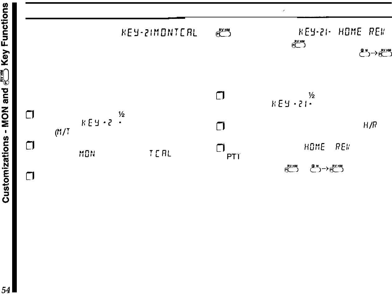
Customizations
I
MON Switch Function
1;
E
3
-
Z
1
!!
0
f3
T
L’
f?L
By default, pressing the middle switch on the left side
of USA version transceivers disables the receiver
squelch to monitor weak stations. In European trans-
ceiver versions, this transmits a 1750 Hz tone for
repeater access instead.
These functions assignments can be reversed, if
desired:
ct)
Hold the knob down for
M
second, release it and
turn to display
1;
E
3
-
Z
I
-
. Press the knob momen-
tarily
(W
appears).
0
Press the knob momentarily, then turn the knob to
select either
!lOrJ
(for monitor) or
T
c
flL
(for tone
call).
n
Press it again momentarily, then press PTT to exit.
Now you can press the switch to access the assigned
function.
c?
Key Function
m,w1-
MM
RE1:
By default, pressing
&?I
reverses ‘repeater shift
(tx/rx frequencies), while pressing c!?$-@?
switches operation to and from the Home memory.
The default key function assignments can be re-
versed, if desired:
m
Hold the knob down for
%
second, release it and
turn to display
1:
E
3
-
I?
I
-
. Press the knob momen-
tarily.
m
Turn the knob if necessary, to select
/c/P
(for
HOME/reverse), then press it again momentarily.
n
Turn the knob to select /{D!!E or
REI:
, then press
PT‘C
to exit.
Now you can press
&I!‘$
or
?j--@??
to access the
assigned function(s).
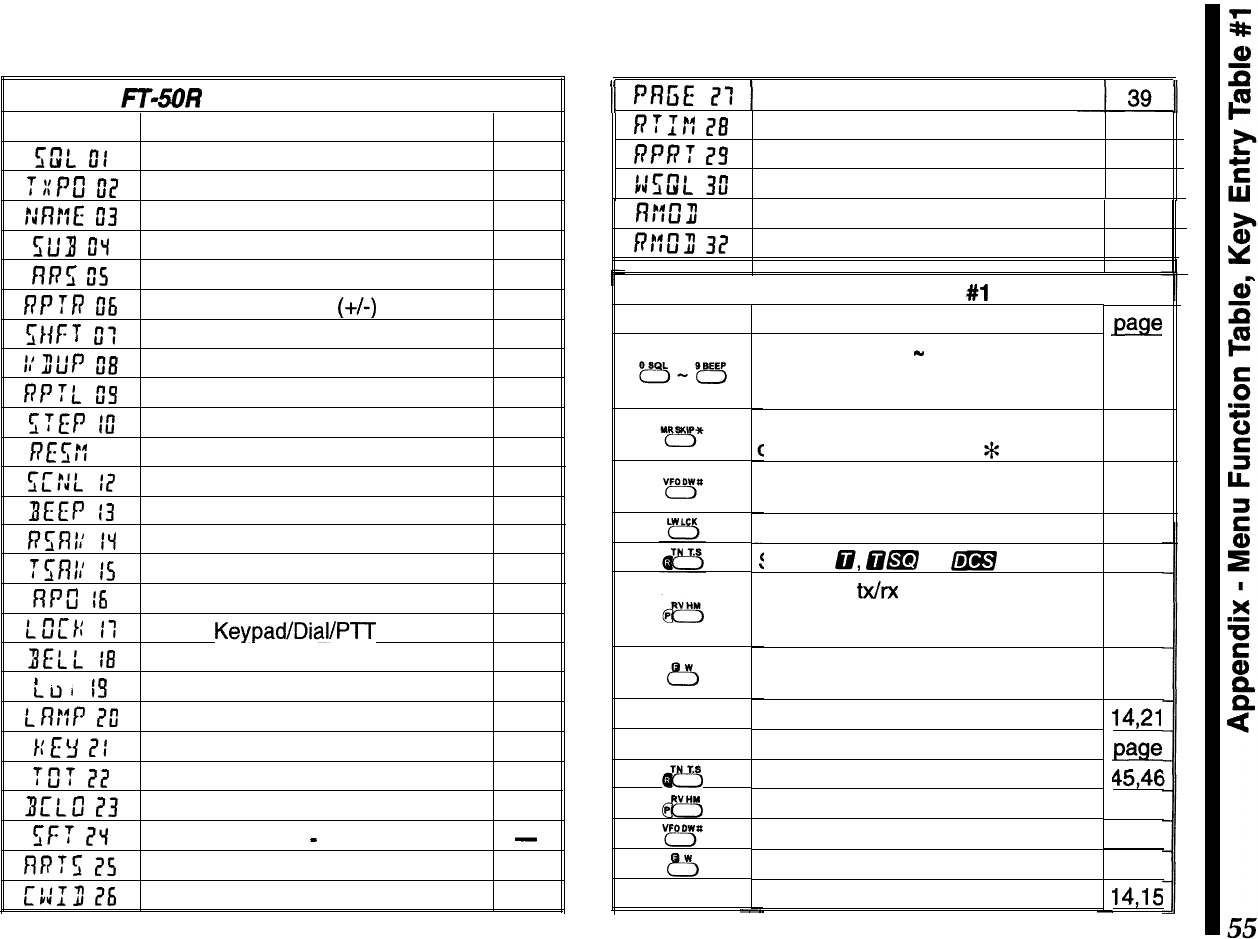
Appendix
FTISOR
Menu Function Table
Menu #Function
page
E;w”L
ot
Receiver squelch threshold I7
T::Pu”
02
TX power level I8
::nr:L:
If3
Alpha-numeric memory name 30
slf3
u”“l
Sub display option 20
nn5
0s
Auto Repeater Shift
~
23
RPTR
Dli
Simplex or duplex
(+/-)
operation 24
ZHF:
I
T
II:
T
X
shift (offset)
23
I:u”tiP
El3
Duplex (split) VFO operation
21
RPTL
05
Repeater input tracking 24
STEP
lu”
Tuning step size 20
RE
E;::
II Scan resume mode 27
I;CfiL
I7
Scan lamp on/off 27
ZIEEP
13
Keypad beeper on/off 50
R5Rl;
IV
Rx battery saver 49
:5nr:
IS
TX power saver 50
nrcl
I6
Auto Power Off 49
r_u”LTt:
I-l
Keypad/Dial/P-l-T
lock
32
BELL
18
Ringer (off, Ix, 3x, 5x, 8x, repeat) 34
t
I-T ,
CLll
,!I
BUSY/TX LED disable 50
LR::P
l?ll
LCD illumination mode
51
r:I:y
ITI
MON switch/e key assignment 54
Tfi?
?I!
TX Time-Out Timer 32
3L’LS
I?3
Busy Channel Lock-Out 35
I;F?
I?“1
CPU clock shift
-
do not change!!!
-
nn:z;
l?s
Auto Range Transpond System
41
c::Iu”
26
CW identification 42
)I
PR5E
I?:
1
Pager settings
/??I#
28
Digital record time 45
RPRT
I?5
Record protect 46
Kl;w”L
3il
Wide-FM squelch threshold 22
n::u”3
31
Auto Rx mode select 22
RE2U”
32
Rx mode override 23
Press
&5
knob
HOLD
B
@y
8
knob
-
Key Entry Table
#l
Function
Enter digits 0
-
9 for frequency
entry during rx, DTMF digits during
tx.
Selects MR and MT operation
luring rx, enters DTMF
*
during tx.
Selects VFO A/B during receive,
enters DTMF # during tx.
Toggle low/high tx power.
selects
cir,
CsIm or
m
operation.
Reverse tx/rx frequency channels
for a duplex pair (used to monitor
repeater input frequency).
Activate alternate key function
setting entry (5 seconds).
Toggle main operating band.
Function
Start digital voice recording.
Playback digital voice recording.
Start VFO scanning.
Recall memory for programming.
Recall menu list.
page
I7
I9
19
I8
33
24
16
14,21
pElge
4546
46
27
25
14,15
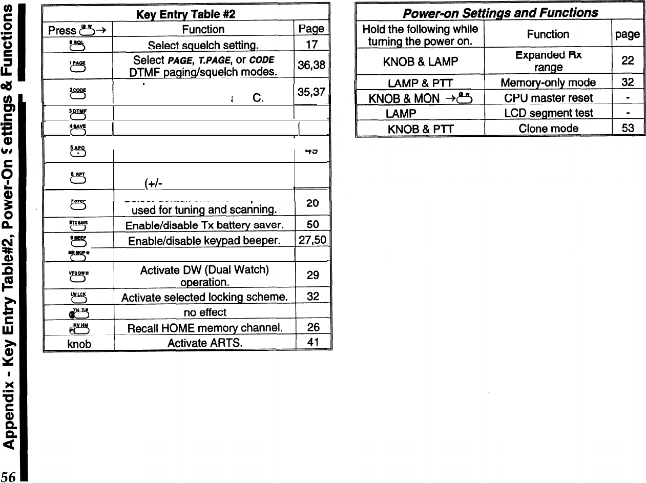
4
1
u
‘B
Recall/select DTMF code
memories l-6. P
i
.
-
I
a, and
C.
F
‘??s
Activate DTMF autodialer.
1
43
.I
%
I
II
4
vc
r”-,
1
Select Rx battery saver feature.
1
49
I
IA SAP0
I
Enable/disable APO
AA
3
LL
c3
t5
( auto power off) feature.
Select simplex or duplex
(+/-
T
X
offset) operation.
-?J
24
Select default channel steps size
Tag memory for scan skip.
j
27
CAUTION !
Changes or modifications to this device not expressly approved by Yaesu Musen could
void the user’s authorization to operate this device.
,..__.__.___________.-.--.*.---*----.-....---.
*_*____._.__*____.______________________-.**.-----..
:
‘.
:
1. Changes or modifications to this device not expressly approved by Yaesu
Musen could void the user’s authorization to operate this device.
i
:
2. This device complies with part 15 of the FCC Rules. Operation is subject to
:
:
the following two conditions; (1) this device may not cause harmful
:
interference, and (2) this device must accept any interference including
interference that may cause undesired operation.
i
*
;
3. The scanning receiver in this equipment is incapable of tuning, or readily
:
being altered, by the User to operate within the frequency bands allocated
I
ito the Domestic public Cellular Telecommunications Service in Part 22.
‘.
a’
~.~__.._....______._____________________~~~~~.~~~~~~~~..~~~~~~~.~~~~~~.~.~~~~~~~~.~~..~~~~.~~.~~.’
,,..____._.____..._.__________________
______--...*____________________________-..-------------*.-..
:
:
This device complies with RSS-210 of Industry Canada. Operation is subject
i
:
to the following two conditions;
(1)
this device may not cause interference,
i
:
and
(2)
this device must accept any interference, including interference that
:
1
may Gause undesirable operation of the device.
;
‘.
-._.____.--._.*_..__.-----.--*-..*-.--------.---*..--..*------....-----.------*...------..-----.
.,’
YAESU
Peformance
without
compromise.SM
YAESU MUSEN CO., LTD.
l-20-2 Shimomaruko, 0%.Ku, Tokyo 146. Japan
YAESU U.S.A.
17210 Edwards Rd., Cerritos, CA 90703, U S A.
YAESU INTERNATIONAL DIVISION,
(Caribbean.
Mexico.
Central
8
So
America)
7270 NW 12th St,
Sute
320, Miami, FL 33126, U S A
YAESU EUROPE B.V.
Snioweo 3. 1118DN Schmhol. The Netherlands
YiESij
UK LTD.
Unit 2, Maple Grove Business Centre,
Lawrence Rd Hounslow. Middlesex. TW4
6DR,
U K
YAESU GERMANY
GmbH
Am Kronberqer Hang 2. D-65624 Schwalbach, Germany
YAESU Hit LTD.-
1 lth Floor Tslm Sha
TSUI
Centre, 66 Mody Rd
Tsim Sha
Tw
East, Kowloon, Hong Kong
Copyright 1996
Yaesu Musen Co., Ltd.
All rights reserved.
No portion of this manual
may be reproduced without
the permission of
Yaesu Musen Co., Ltd.
E07521002(9609F-FA)
