Yaesu FT 757 GX II User 757GXII Manual
User Manual: Pdf YAESU--FT-757GXII-User-Manual
Open the PDF directly: View PDF ![]() .
.
Page Count: 37
- FT-757 GX ll ENG 01.PDF
- FT-757 GX ll ENG 02.PDF
- FT-757 GX ll ENG 03.PDF
- FT-757 GX ll ENG 04.PDF
- FT-757 GX ll ENG 05.PDF
- FT-757 GX ll ENG 06.PDF
- FT-757 GX ll ENG 07.PDF
- FT-757 GX ll ENG 09.PDF
- FT-757 GX ll ENG 10.PDF
- FT-757 GX ll ENG 11.PDF
- FT-757 GX ll ENG 12.PDF
- FT-757 GX ll ENG 13.PDF
- FT-757 GX ll ENG 14.PDF
- FT-757 GX ll ENG 15.PDF
- FT-757 GX ll ENG 16.PDF
- FT-757 GX ll ENG 17.PDF
- FT-757 GX ll ENG 18.PDF
- FT-757 GX ll ENG 19.PDF
- FT-757 GX ll ENG 20.PDF
- FT-757 GX ll ENG 21.PDF
- FT-757 GX ll ENG 22.PDF
- FT-757 GX ll ENG 23.PDF
- FT-757 GX ll ENG 24.PDF
- FT-757 GX ll ENG 240001.PDF
- FT-757 GX ll ENG 25.PDF
- FT-757 GX ll ENG 26.PDF
- FT-757 GX ll ENG 27.PDF
- FT-757 GX ll ENG 28.PDF
- FT-757 GX ll ENG 29.PDF
- FT-757 GX ll ENG 30.PDF
- FT-757 GX ll ENG 31.PDF
- FT-757 GX ll ENG 32.PDF
- FT-757 GX ll ENG 33.PDF
- FT-757 GX ll ENG 34.PDF
- FT-757 GX ll ENG 35.PDF
- FT-757 GX ll ENG 36.PDF
- FT-757 GX ll ENG 37.PDF
FT.757GX ]I
HF ALL MODE
COMPUTER
AIDED
TRANSCEIVER
GENERAL DESCRIPTION
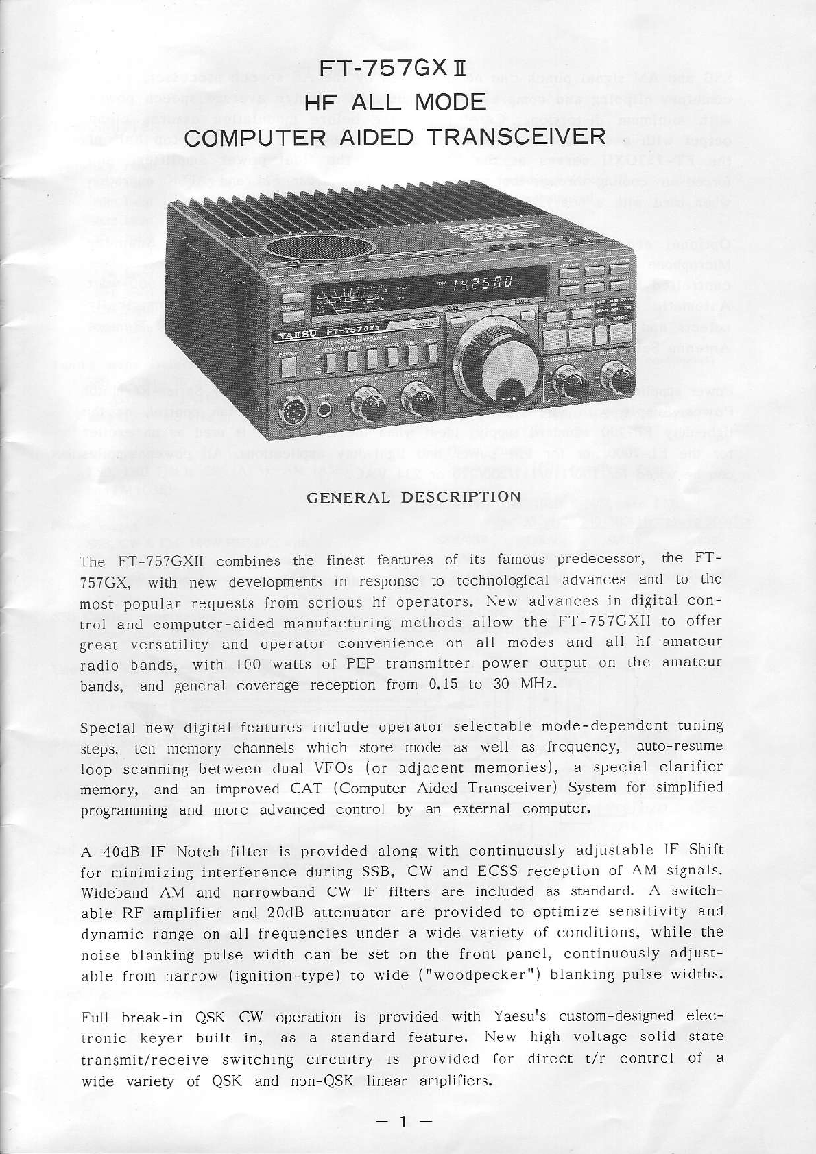
The FT-7s7GXII combines the finest features of its famous predecessor, the FT_
?57GX, with new developments in response to technological advances and to the
most popular requests from serìous
hf operators.
New advances
in djgj!al
con
trol and computer-aided
manufacturìng
methods aÌlow the FT-757GXIl to offer
great versatility and operator convenience
on all modes and all hf amateur
radio bands, with 100 watts of PEP transmitter power oùtput on the amateur
bands, and general coverage reception from 0.15 to 30 MHz.
Special new digital
features
include operator selectable
mode-dependent
tunìng
steps, ten memory channels which store mode as well as fÎequency, auto-resume
loop scanning between
dual VFOs (or adjacent memories), a special clarìiier
memory, and an improved CAT (Computer Aided Transceiver) System for simplified
programming aùd more advanced control by an external computer.
A 40dB IF Notch filter is provided along wiih continuously adjustabÌe lF Shift
for minimizing
interference during
SSB,
CW and ECSS reception
of AM signals.
wídeband AM and narrowband CW IF filters are included as standard. A switch-
able RF amplifier and
20dB attenuator are provided
to optimize
sensitivity
and
dynamic
range
on all frequencies
under a wide variety of condjtions,
while the
noíse blanking
pulse
width can be set on the front panel, continuously
adjust
able from narrow (ignition-type)
to wide ("woodpecker")
blanking
pulse
widths.
Full break-in QSK CW operation is provided {'ith Yaesurs custorn designed elec-
tronic keyer built in, as a standard feature. l\ew high voltage solid state
transmit/receive svritching circuitry is provided for direct t/r control of a
wide variety of QSK and non-QSK linea. amplifìers.
I
SSB
and
AM signal
punch can be increased
by the AF speech
processor'
which
combines
clipping
and compressìon
circuitry to optimize
average
speecll
power
\ir'ith minimurn distortion. Careful fillering before úodulation assures clean
output with a substantial
increase
in average
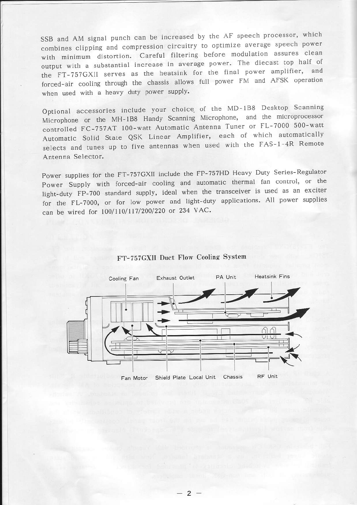
power' The diecast
top half of
the FT-757GXll serves as the heatsink for the final power amplifier' and
forced-air cooling through the chassis allows full power FM and AFSK operation
when used with a heavy duty power supply'
Optional accessories
include your choice-
of the lvlD
lB8 Desktop Scanning
Mìcrophone or the MH_188 Handy Scanning
Microphone' and the microprocessor
controlled
FC-75?AT 100-watt
Automatic
Antenna
Tuner or FL-7000 500-watt
Automatic Solid State QSK Linear Amplifier, each of whlch autornatically
selects
and tunes up to five antennas
when used with the FAS-1 4R Remote
Antenna
Selector'
Power supplies
for the FT-757GXIÌ include the FP-757HD Heavy Duty Series-
ReguÌator
Power Suppiy with forced-air cooling and automatic thermal fan control' or the
light-duty FP-700 standard supply, ìdeal when the transceiver ìs used as an exclter
for the FL-7000, or for low power and ]i8ht duty applications.
AÌl power supplies
can be wired îor l)o/ll1/117/200/220
or 231 vAC'
F'l'-757GXll Dùct Flo$ Cooling S''rslem
Fan fvloto. Shleld
Plate Loca Unit Chassls
2
SPECIFICATIONS
TRANSMITTER
l60m band i.5 to 1.99999
MHz
80m band 3.5 to 3.99999
MHz
40m band 7.0 to 7.49999 MHz
30m band 10.0 to 10,49999
MHz
20m band 14.0 to 14,49999
MHz
l?m band 18.0 to 18.49999
MHz
l5m band 21,0 to 21.49999
MHz
lzm band 24.5 ta 24,99999
MHz
l0ú band 28.0 to 29.99999 MHz
Tuning steps (selecrablel
SSB
& CW: 10 Hz or 1 kHzlstep
AM: I kHz or 10
kHzlstep
FM: 2.5 kHz or l0 kHz/step
Emission types
LSB, USB
(J3E)i
Cw (A1A); AM (AsE)
3Nd FM
(G3E)
SSB, CW & FM: 100W
PEPIDC, witl
sÌightly Less
on 10m band
AM: 25W Carrier
SSB Carrier suppression
betÈr than 40dB below peak ourplrl
Maximum FM deúanon
15
kHz
RF Output inpedance {nominall
50 ohms, unbalanced
Microphone impedarìce
500 to 600 ohms
RECEIVER
150 kHz to 29.99999 MHz (contjnuous)
Circuìt type
Triple-conversion superheterodyne
Clarifier range
unlimited (full receiver range)
Sensitivity (for iodB S+N/N, exc FM)
1s0-250kHz 250-s00kllz
è09!9
sookllz
SSB/CW l.0LrV 0.5uV 0.25uV
AM lùrv .1uV 1uV
FM: o.suv for 12dB SINAD
(above
500kHz)
Intemediate frequencies
47.060MH2, 8.2l5MHz,
455kHz
Unwanted sideband suppre.\sion (SSB) Image rejection
better than 50dB beÌow peak ourpul better lhan 70dB
(l kHz tone)
IF rejection
SpurÌous radiatioD beffèr rhàn 70dB {ali frequencies)
better than 50dB beÌow peak ouLpur
Selectivity { 6/ 6odB)
Audio response SSB, CW(W) & FSK 2.7/4.5 k{z
Less
rhan -6dB from 350 ro 2g00Hz CW(N) 600 Hzl1.3 kHz
AM 6/18 kHz
3rd order intermodùlation distortion FM 15/30 kHz
better than -35d8 beÌow peak outplrt
(@l.1MHz,
100!v) Dynamic range
(CW(N)
@l4MHz)
better tha. 100d8
Reference oscillator stability
betrer than 110ppm lrom 0 to ,10'C MaxinuÌn audio power ourpur
after l5 mìnute wa.mup at least 1.5W inro 4 ohms w/10o/' TllD
Modulation systems Audio output imp€dance
SSB/cw: active balanced
moduìator ,1
to 16 ohms
AM: earÌy stage (low Ìevel)
Fi\l: variable reacrance
3
GENERAL
Supply voltage
13.5
\DC !100/o
Pover @nsumption
Tramsitter (100W outpul)
Dimensions
(wHD)
238 x 93 x 238mm
{without
Weight (approx)
5.2 kg
(11.5
lb)
Supplied
DC Power Cord (w/o fuse)
Fuses (2 suppÌied)
FT TsTGXrr (20A)
FT-7s7SXIj (64)
3-pin Phone
pluC (SH3603)
RCA (phono)
pÌugs
(STP-58,
2 pcs)
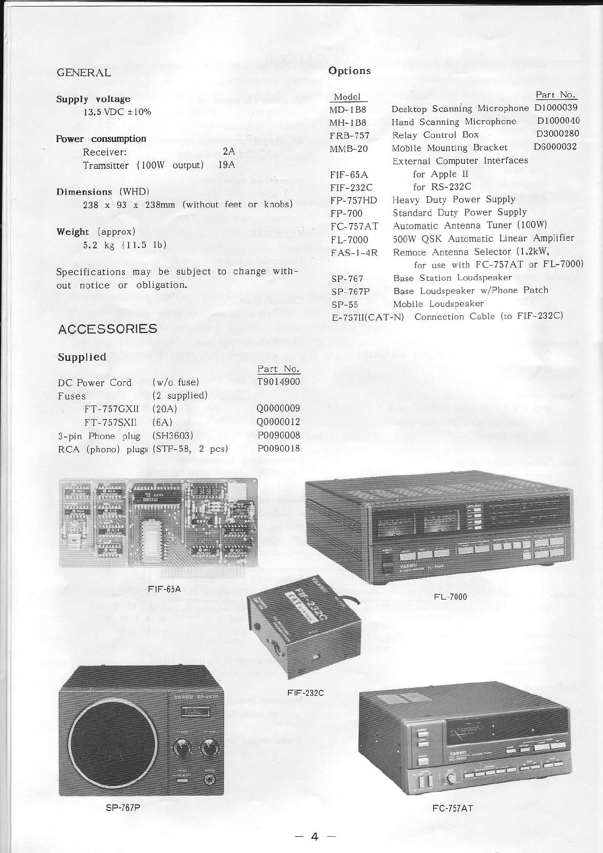
Options
Model
MD IB8
MH-IBE
FRB 757
MMB 20
Part No.
Desktop Scannlng Mic.oPhone D1000039
Hand Scanning Microphone D1000040
Relay Control Box D3000280
l\'lobiìeMountlngBracket D6000032
External Computer ln|erfaces
2A
l9A
SpecifÌcalions may be subject to change with
out notice or oblì8ation.
ACCÉSSORIES
FIF 65A for APPIe tI
FIF-232C for RS 232C
FP-757HD Heavy Duty Power SUPPIY
fP /00 rtanda_d DrtY PoEè-
suPDì)
FC 757AT Automatic
Antenna
Tuner (100w)
FL 7000 500W QSK Automatic Linear Ampìifier
FAS 1 ,1R Remote
Anten.a Selector
(l.2kw,
lor use wìth FC 757AT or FL-7000)
SP-767 Base
Statlon LoudsPeaker
SP ?6?P Base Loudspeaker v/Phone Patch
SP-55 Mobrle Lotdspèafe.
E-?5711(CAT-N)
connecrion
Cable (to FlF 232C)
T9014900
Q0000009
Q0000012
P0090008
P0090018
F)F-232C
FC
-757
Ar
FRONT PANEL CONTROLS
L7 lq
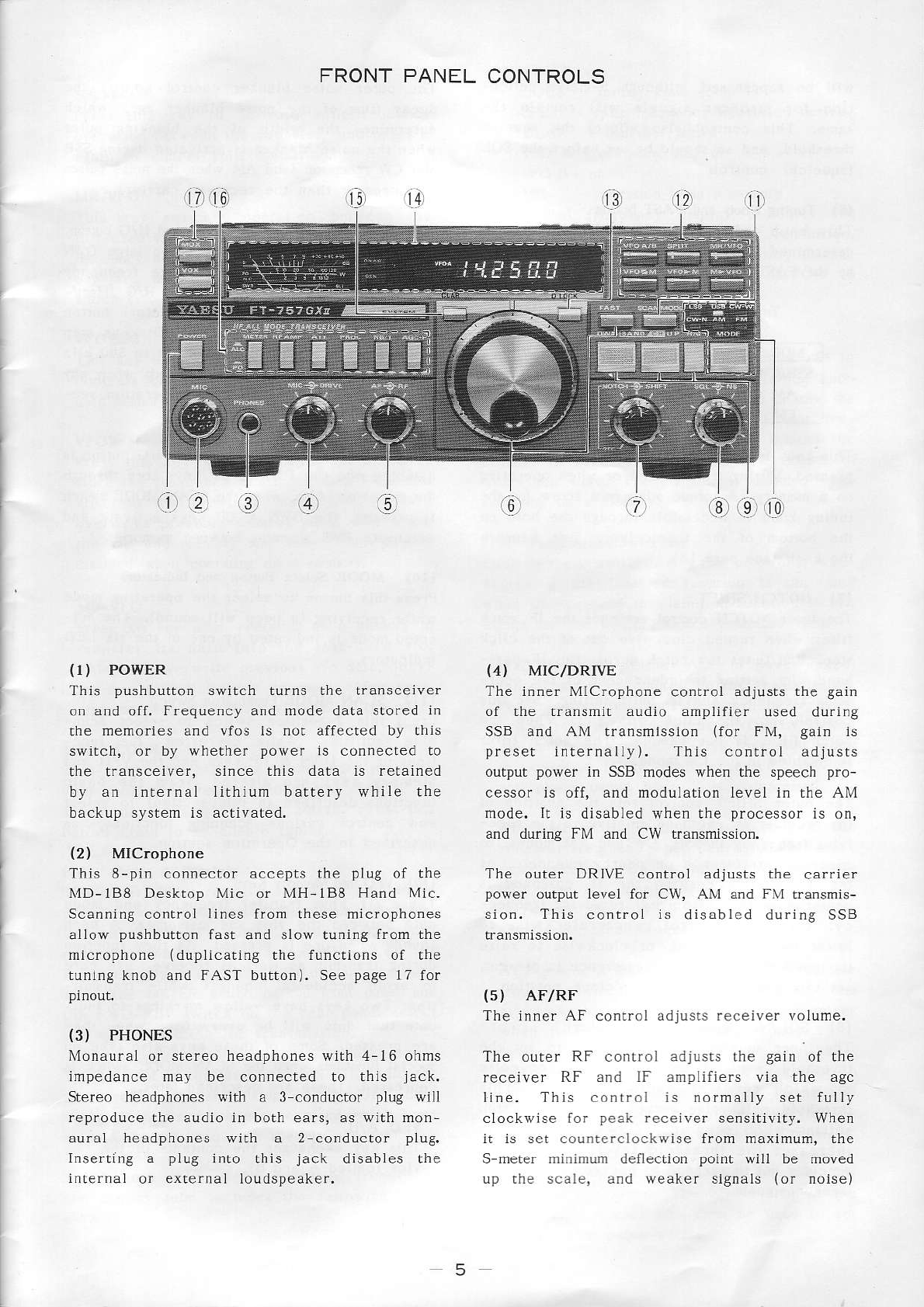
{r) PowER
lhis pushbutton switch turns the lransceive.
o. and off. Frequency and rnode data stored in
rhe memories and vfos is not affecred by thjs
swirch, or by whether power is connecred ro
the transceiver, since this dara is retalned
by an internal lithium battery while the
backup system is activated.
(2) MlCrophone
This 8-pin co.nector accepts the plug of the
MD-188 Desktop Mic or MH-188 Hand MÌc.
Scanning controì lines from these microphones
alloiv pushbutton fast and slow tuning from the
microphone (dupljcatjng the functions of the
tuning knob and FAST button). See page l7 for
(3) PHONES
Monaural or stereo headphones with 4-t6 ohms
impedance may be connected to this jack.
Stereo headphones with a 3 conductor plug wÌll
reproduce the audio in both ears, as with mon-
auraÌ headphones with a 2-conductor plù9.
Inserting a pÌug ìnto this jack dìsables the
internaÌ or exlernaì loudspeaker.
(4) MIC/DRIVE
The inner MlCrophone control adjusts the gain
o. rh. -ur
'Tir .Jdio anp
itie- r5-d du
r 8
SSB and AM transmission {for FM, gain is
preset internally). This control adjrists
output power in SSB modes when the speech pro-
cessor is off, and modulation level in the AM
nodr. Ir is di hbt-d . en I F pro.ó.5of o
and during FM and CW transmission.
Th^ ort.r DRI\E '
olt o dú.rii. 'h" .arrie_
power outpùt level for CW, AM and FM rransmis-
sion. This control is disabled during SSB
{5) AFIRF ói ér \olrme.
lhe or Fr h .or
rrol dotu)1
. thc Sajn ol rl
c
receiver RF and IF anrpliliers via rhe agc
llne. This conlrol js normally set fully
clockwise tor peak .eceive. sensjtivity. When
it is set counterclockwise from maximum, the
S meter rìinimum deflection point will be moved
Lrp the scale, and weaker signals (or noisel
-5
(6) Tuning
Knob
This knob tunes
determined by the
by the FAST button:
and FAST butto.
!he transcelver at a fate
operati.g mode and selecled
wìll be suppressed,
although
S-meler defÌec-
rion for stronger signals will remai. rhe
same. This control also affects the squelch
threshold,
and so slould be set before
the SQL
(squelch)
co.troÌ.
'the outer noise blanker control adiusts the
decay time of the noise bÌanker agc, whrch
determìnes the wid.h of the bÌatking pulse
when the nojse blanker is activated durÌng SSB
and L
\\ -p.èpr
o 'a d \\4 q èr | .F 'o s Dllsps
are stronger than the received carrier).
{9) BAND/CH (D\{N & uP keys) and H/C button
DurÍng reception with a vfo, the two large D\\'l"l
and LIP keys are used to change frequency
bands, and for 500 kHz steps. The H/G (Ham/
GeneraÌ coverage band step selector) butto.
determines rhether the DWN & UP keys step
rhrough the amateur bands only, or in 500 kHz
general coverage steps. A beep sou.ds when any
of these a.e pfessed. See the Operation sec-
tìon of lhis mànual for detalls.
When receiving on a memory the H/G button is
disabled and the DWN & UP keys step through
the memories. Also, when the SCAN MODE swÌtch
is pressed, the DwN & UP keys activate and
oeJ ;\dr- pv\ ..
d.nirg o-ruF-r ìèîoric..
(10) MODE Seìect Burton and Indicators
Press rhis button to selecl the operating mode
while receìvjng
(a beep will sound). The sel-
ected mode js indicated by one ol the six LED
(r1) SCAN MODE Pushbunon Switch
Press this 2 posillo. swirch to select sca.-
ning facjlities. While depressed, the func
tions of Lhe DWN & UP keys and the VFO and
Memory keys a.e altered (from the basic
luncrjons described in this section) to select
and control various scanning functions, as
described in the Operarion section.
(12) vFo and Memory Keys
These six keys transfer frequency and mode
JarJ b-rq.p rlrF v-o. a d TeTo I \. A bèép
sounds when ore ls pressed. As they funcllon
during transmil as well as .eceive, use care
to avoid accidental changes whiìe rransmit-
ting. lwo keys have ),eLlo1v
markings lo indr-
cate that data wlll be overwrirlcn when !hey
àre pressed. some of rhese keys aiso take on
special functìons when the SCA\ NIODE switch ls
c,pè. èa. Tl
.
\F é-p la,flLaI dar.
VFO A/B
This key exchanges
rhc co.tents of the t{o
vfos
(called
A and Bl.
Tuning Rates Ín kllzlstep
MODE FAST ON FAST OFF
SSB/CW
AM
FM
1 kHz
l0 kHz
l0 kLIz
10
Hz
2.5 kllz
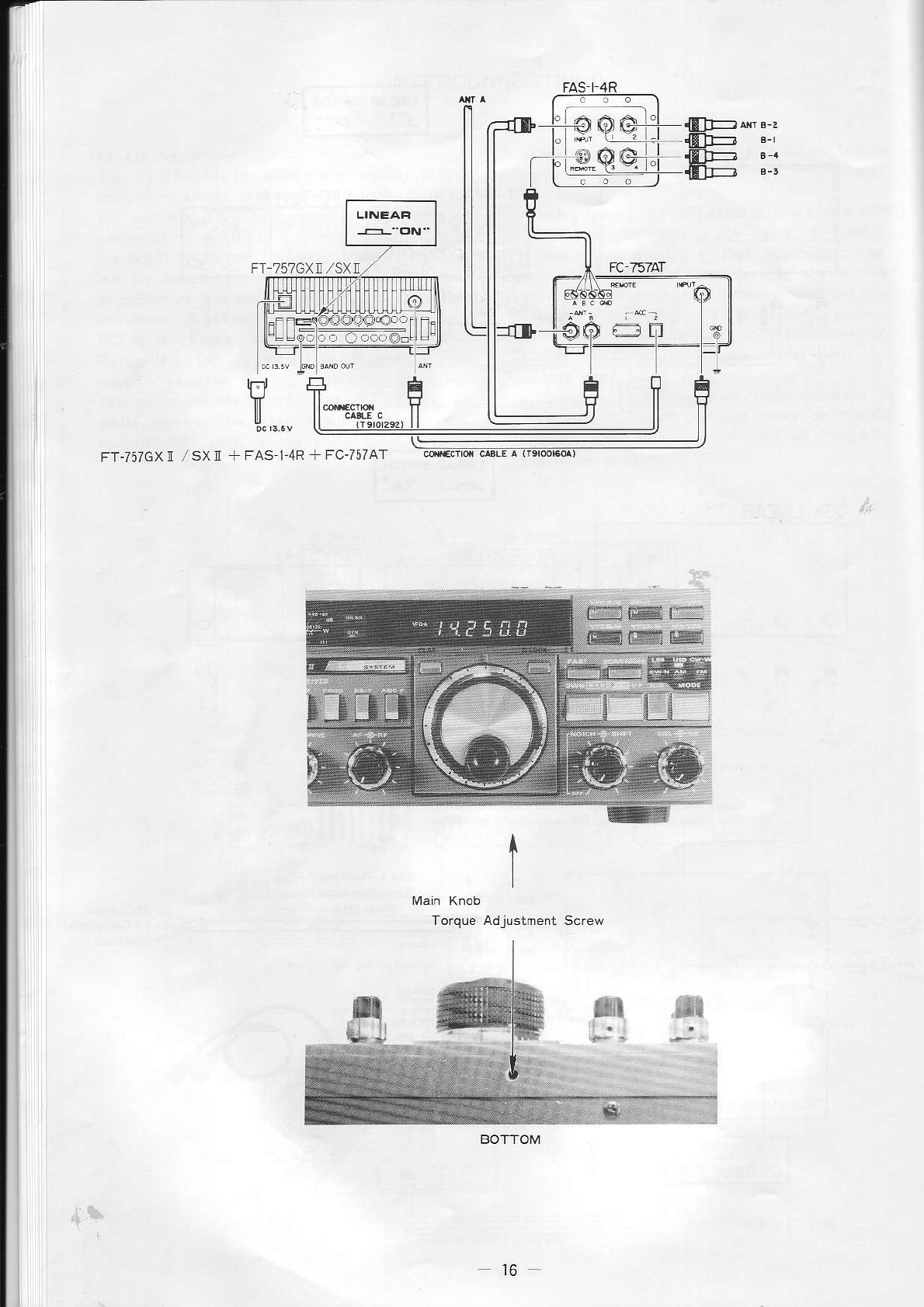
This knob is disabled when the LOCK button Ìs
pressed, durÌng transmÌssÌón or when operating
on a memory. A torque adjusmenL screw for úe
tuning knob is accessible through the hoÌe on
the bottom of the transceiver, just benealh
the knob (see
page
16).
(7) NOTCH/SHIFT
The inner NOTCH controÌ actlvates lhe IF notch
filre. when turned clockwise out of the click
stop, and tunes the notch across the IF pass
band. Its settjng is independen. of lhe oper-
ating freque.cy and IF Shift setting. Ser rhis
conrrol inro rhe clÌck stop (olf) when the
.orch fìlter is not needed. The norch fiìler
is disabled in the l_M mode.
The outer SHIFT conlrol seLs the position of
the receiver IF !assband
relatlve to the rece
iving frequency in SSB, CW and AM modes, to
suppress inrc.fe.ence o. neàrby chanrers. Al
the l2 o!clock posìtion the IF passband
is
centered on the (dÌsplayed) receiving ireque.
cy; tufn this control counlerclockwise lo
'o\^pr
rhp lf p1
òo-.d. or .,o(au!.é ro ra:\r
the passba.d. When no interference is prese.l,
set this conlroÌ to the l2 orclock position.
(8) SQL/NB (squeìch/Noise BÌanker)
The inner squeÌch control is used to se! lhe
rfrp.ho
d è\él or .r'on g srgn- nr roisa
at rhich recciver audio is muled. lhis
th.eshoÌd poi.t also serves as the scan stoP
setting when scanni.g. Clockwise rotation
Ìncreases
the rhreshold
level, causing the
| ,o r..p . d ,o b
'-l8ro I' d oisF o-
6
SPLIT
Press this key to activate split frequency
opera!ìon between the two vfos, and press il
again ro cancel sPlir oPeration.
MR/VFO
ThÌs key switches operation beLween the
last-used vfo and the last used memory. The
frequency and mode data in the vfo and mem
ory are unaffected. The disPlay indicales
which (vfo or nenlory) is currently selected.
VFOZ|.l
This key excharges the frequency and mode
contents of the last used vfo and lhe last
VFO>M
P.ess this key when oPeratÌng on a vfo to
srore the frequency and mode data from thal
vfo into the lasl used memory. This wilÌ
ov€rwrite previous memory data, and leave
the vfo and memory lhe same. This key is
ai.rbled $l.pr op^rd.inS
on à îemor\
M>VFO
Press this key when operaung
on a memorv
Lo
lransfer its dala into the lasl-used vfo.
This will overwrite prevìous vfo data, leav
irg r-è vlo dra nerru"y de '"np. A'èr Dre
-
sìng this key operation wiÌl be on the vfo.
(13) DLOCK
This button disables the tuning knob to pre
vent accidental frequency changes. "LOCK" is
shown on the display when active. Press this
buúon again to re enabìe tuninS.
(14) Meter & Dispray
The neier shows relacive signal slrength Ìn S-
units on the uppermost scaLe wnen recelvÌn8'
and either reLative power output (PO), trans_
mitter automatic level control (ALC) or
refrci
rèd pow-. pur
(s$Rì du g .-dn
ri"-
sion. The METER button on the lronr panel and
rhe FwD REV switch on lhe rear pLìnel serect
rhe meter functio. for rransmìssìon.
To the right of lhe meter the ON AIR iidicator
glows red when t.ansmìtting, a.d the cEN i.di_
caror glows Sreen when general coverage band
stepping is selected {via lhe rllG bltton).
LOCK - auning knob locked
SPLT - split frequency operation actlve
CLAR clarifier active
VFO A operatjng vfo, or
vFOB - or
MR - operation is on a memory
The digital frequency display indicates the
operating frequency with 100 Hz resolutÌon.
When operating on a memory, the memory channel
number (0 thru 9) is displayed wìth 'CH' Lo
the rlght of the frequency.
(15) CLAR
Press this butlon whlle recejving on a vio to
actjvate cla.ifier operarion. The luning knob
and D\4N & UP keys can lhen be used to lune the
receivef witho!t affecting the transmit fre-
quency. Press this button again to cancel the
change in receiver frequency and retur. to
r,vhere you were. The clarifìer is dÌsabled when
receiving on a memory.
{ 16) Pushbutton Svitches
Each of these swilches has two positions; when
depressed the ÌabelÌed function is on, and
when undepressed rhe labeLled function is off,
except for the NIETER swìtch descrjbed next.
MhThR "e è.
rs pr'hp ALC or potré- oL.p
rl
functions of the meter during transmrssron.
Power outpul lunctions (forward, or reverse)
are in turn selecred by the FWD REV switcb
on the rear panel. ALC is indicated whe.
this switch ìs i. the depressed posÌtion,
and power output when il ìs undepressed,
RF AMP activates the rf ampÌilier Ìn lhe
recelver front end when depressed, tor màx
imum receiver gain. ln the undepressed posi-
!lon the RF ampìifi€r is bl,!assed, for
increased immunity to overload l.om strong
signals on other frèquencies.
ATT pd's a 20dB
"nc','u ia l' -'.Fr!p
front end circult, to reduce sensitrvrry and
avoid overload of the rf anplilier and mìxer
when listening ro verl st.ong slgnals.
PROC acrìvates
the AF speech
processo.
to
increase average speech power during SSB
tfansmìssjon, according
to the level set by
the coNlP LE\JEL conrol on the rear panel.
NB/T actilates rhe noise blarker fbr SSB, CW
and ,à\l reception. The NB control at the
lower rìghr then be used ro set
the blanki.g pulse wÌdth.
At the left side of the operating frequency,
the display tube jncìudes
the foÌlowing Ìnd:-
7
AGC-F activates fast agc decay time for SSB,
(!r and AM rF.óprion. to fd' iliréLF
\.rnn; g
dr a rJring or lrsrerinS
ro \c') wédh
si8
naLs. When not depressed, slow agc decay is
provided for more comfortable recep!ion ol
strong s i8n a ls,
(17) MOX and VOX Pushbutton Swilches
The transmjtter can be manually switched on
and off by the MOX swirch. Tìris is useful for
SWR measurement and antenna tuning.
The VOX switch activates voice-actuated
$ansmit/receive switching, and serni break in
CW keying. In SSB, AM & FM modes, when this
switch is in the depressed positio., the
transmìtter wilÌ be activated just by speaking
into the micfophone. When finished speaking or
releasing the CW key {Ìn CW node), the recei-
ver wjll be automarically reactivated after a
short delay, as set by the DELAY control on
REAR
PANEL CONTROLS & CONNECTORS
ií. 11.
'.i: .!..'.41
.c_, €', ..91
'roì
Ll i?-ì
i9
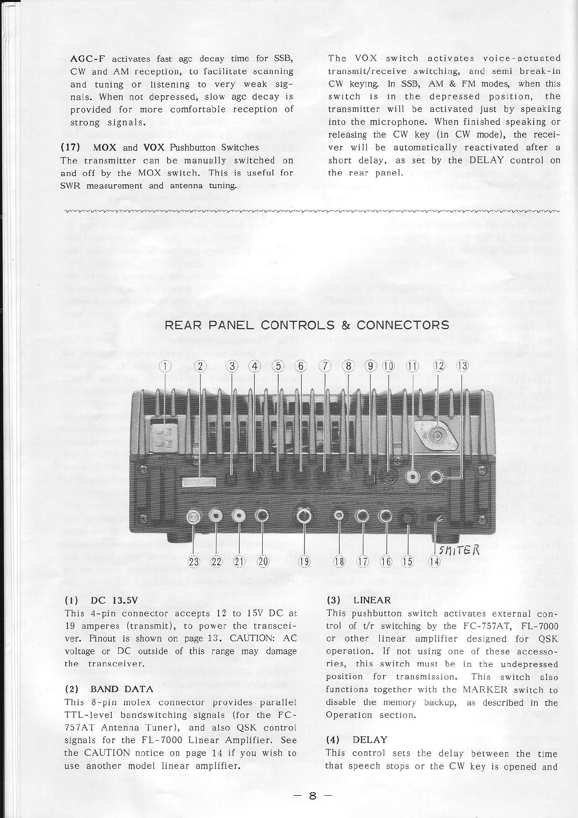
{r) DC 13.5V
This 4-pi. connector accepts l2 to 15V DC at
l9 amperes
(transmit),
to power the transcei-
ver. Pinout is shown on page 13. CAUTION: AC
voltage or DC outside of this range may damage
the transceiver.
(2) BAND DATA
This 8 pin molex connector provides parallel
TTL-leve1 bandswitching signals (for rhe FC-
7574T Antenna Tunef), and also QsK conÍol
signaLs for the FL 7000 Lìnear Amplifier. See
the CAUTÌON .otice on page 14 ìl you wish to
use another model linear anplifier.
(3) LINEAR
This pushbutton switch activates e{rernai con-
troì of t/r sivirching by rhe FC-757AT, FL 7000
or other linear amplifier desìsned for QSK
operation. If not using o.e of these accesso-
ries, this switch mùst be in rhe undepressed
position for transmissìon. This srvitch atso
functions togerher wìtì the MARKER swrLcn ro
disable the memory backup, as described in rhe
Operation section.
(4) DELAY
This controÌ sers rhe delay between the time
that speech stops or the CW key is opened and
I
tktTE
a
the tirne that the receiver is reactivated when
the VOX system is activated by lhe swÌtch on
the front panel.
(5) ANTI TRIP
This controÌ sets the amount ol negalive
receiver audio feedback applied to the VOX
an1pLifier durìng VOX operarion. The level
should be set so that speaker audio does nol
key the transmitter,
(6) VOX GAIN
This control sets the gain of the VOX anpli-
fier for VOX operaLion. The optimum seLting
depends on the microphone used and the voice
characreristìcs of the operator.
(12) ANT Coaxial Jack
This type-M (SO-239) jack is for the antenna
system, antenna tuner or Ìinear amplÌfier
input. impedance requiremenl is 50 ohms' un
balanced. Use onìy a properLy
matÌng type-M
{PL 259) pìug and 50 or 52-ohm coaxial cable.
(I3) PATCH/AFSK
This phono jack accepts transmitter input from
a phonp pJr'h o- AF\K ronp
gererdror. lmDè-
dance is 600 ohms, and the ìevel should be
exrernalÌy adjusted to match rhat of the oper-
atorrs micropho.e, producing the same power
output wirh the same MIC gain control setting.
{
I4) FWD-REV
This switch selects meter indicatÌon of either
forward or reverse relàtive rt power ourput
during fansmission, when the METER swiLch on
the fronl paneì ìs ìn the depressed (PO)
positjon. Refer to the following description
of the FWD SET control, and the description ol
SwP nFa\u'èré r lé OpF-arior sp' io].
(15) FWD SET
Thìs potentìometer adjusts the sensitivity of
the metef for forward and reverse PO funcrions
during transmissìon. Adjust this conlrol for
full scale meter deflection ìvhile tra.smltting
a carrier wiah the FwD-REV swirch ser to rhe
FWD position, so that SWR can be read on the
meter in the REV positìon.
{
16) EXT ALC
This phono jack accepls transmìtter automatic
level control volaage from a linear ampljfier
lor l'F l dr ri -' Fr
p\ iP. Thr "pp i-d \oÌ -gP
should be be.leen 0 and -5V DC, referenced to
the outer contact (chassis ground).
(I7) AF OUT
This phono jack provides consta.t ìow-level
receiver audio, unaffected by rhe AF gaìn
control, for tape recording, digitaÌ demodula-
tors capable of hlgh impedance input or an
external audio amplifier. Oùtput level is ap
proxlmately 200mV peak ar 50 kllohms.
(18) EXT SP (Erternal Speaker)
'Ihis 1/8-ìnch 2-conductor mìni phone jack
provides ampÌifièd receiver output to drive an
external 4- to 16-ohn Ìoudspeaker.
(
l9) KEY
This ì inch 3-co.ductor phone jack accepts
(7) COMP LEVEL
This control sets the compression level of the
éucio
!pèe. .omprè\Lor arr. g sSB r:ì mr'
sion wlth lhe processor (PROC switch) on See
Lhe Operation section for adjustmena,
(8) AM CAR
This (recessed) trimmer potentiometer sets the
ratio of transmìtted carrler to modulatio. ior
AM rransmission. Adjuslmenl ls described in
the OperaLion sectìon.
(9) MARKER
Set this pushbutton switch to the dePressed
position to actìvate the 25kHz marker signal
generator, which produces a carrier at n1ultl
p.. ,r 2itH/ d' .. rlè l-Pqupn.\
'ìrg^ or
the receìver. When the callbration signaì is
not needed, this siritch should be olf (oul),
ovorc inr--fé.è
,.é { |lh norn- -'. F! io ,.
lhls swirch aìso functions in conjuncron wrth
the LINEAR switch to disabìe the memo.y backup
as described later.
(10) cAT
This 6 pin mini DIN jack provides access
to
rhe seriaÌ dara lines from rhe microcompuler
a4a A D ' orvp, -_, fo_ .4nrrol of rhc lrJ-\
ceìver from an external computer. See the CAT
sectio. of this maDual for details.
(ll) PTT Jack
This phono jack provides access to the PTT
line, for external .eceive/t.ansmiL control by
a lootswitch or other devlce. Connectlng the
inner contact to the outer contact (chassjs
ground) activares the transmitter. Maximurn
open circLrit voltage present is 13.5V, and
minimum cÌosed ci.cuit currenL is Lì.3 mA.
9
keyer paddles for rhe irternal electronic
keyer, or a straighr
CW key (when
the Ìnternal
keyer is switched off). Wjring connections are
shown on page
17. Open circuit vollage
is +sV
DC a.d closed circuit current is 0.5 mA.
CAUTION: None of the ùree KEY jack conracts
are connecled to chassìs
ground. DO NOT con-
nect the outer contact to chassis
grourd-
{20) RF OLIT
This phono jack provides low ievel RF oulpul
from an early stage of the transmitter, for
e)!clung a rfansverrer.
Poiver ìeveÌ ìs approxjmately
-6dBm (0.1
Vrms)
at 50 ohms.
{21} +8V
This phono jack provides 8V DC at up to 100mA
fof low power accessories.
The center contact
122) +rs.sv
This phono jack provides 13.5V DC at up to 500
mA for poweri.g accessories.
The cenrer con-
tacl is positive.
Note: Repairs to damage caused by exceeding
lhe current capabiììties of the accessory DC
jacks ("8V and +13.5V)
may .or be covered by
the warranry policy.
(23) GND
For best perfo.mance and safety, connecr this
terminal to a good earth ground through the
shortest path possib
le.
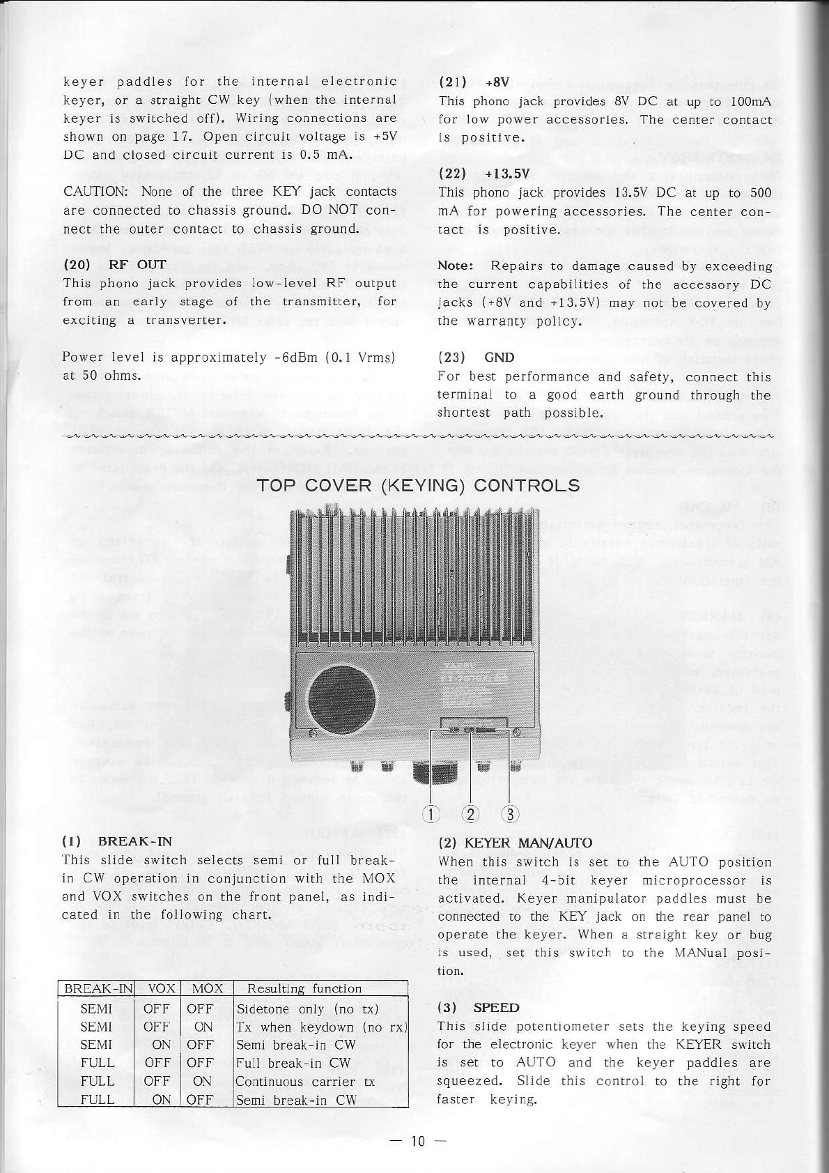
{I) BREAK.IN
Thls slide switch seÌects semi
in CW operation in conjunction
and VOX swìtches on the front
cated in .he folÌowing chart,
TOP COVER
(KEYING)
CONTROLS
'.2 rol
wìth lhe l\'1()x
{2) KEYER MAN/AUTO
When
this switch is set to Lhe AUTO position
llp in
èr1.' t bit - r.t I prn(é
.o I.
actìvated. Keyer manipulato. paddìes musr be
connected to the KEY jack on the rear faÌrcl ro
operate the keyer. Whe. a straìght key or bug
ls used, set this srvitch io rhe XlANual posi
(3) SPEED
'Ihis slide poleftionerer sers the keying speed
for rhe electronic ker-er when the KÈYER switch
ls ser to AUTaJ and lhe keyer paddÌes are
squeezed. Slìde this control to the right for
faster kcying.
11.
BRTAK IN VOX MOX ResuÌti.s functio.
SEl/II
SEMI
SE\fI
FULL
FULL
FULL
OFF OFF
OFF ON
ON OFF
oFF I ON
oN I oFF
Sidetone only (no L\)
Tx wheÍ keydown (no rx)
Seni break-in Cw
Full break in CW
Continuous carrler LÌ
Semi break-in CW
t0
INSTALLATION
PRELIMINARY INSPECTION
Upon opening the packing carton, inspect the
transceiver carefùlly for any signs of danage.
Check to ensure lhat all exposed controls and
switches move freely, and that the cabinet has
no dents or scratches. If you notice any dam-
age, document
it completely and contact the
shipping company ìrnmediarely. Save dìe packing
materials for possible futu.e use.
BASE STATION INSTALLATION
AC Power Supply
The FT-757GXIÌ requires a power
source of i2
to 15 volts DC, capable of up to 20 amperes on
voice peaks. For base station insrallations,
Yaesu offers a variety of AC power sÌrpplies,
alÌ of which rnay be used vith AC line voltages
of 100, 110, 117, 200, 220 or 234 VAC.
Ho$,ever, before connectiDg any power supply to
the transceiver or AC line, make certain that
the supply is properly ser up for the local
ljne voltage, and that the correct fuse in
instaued.
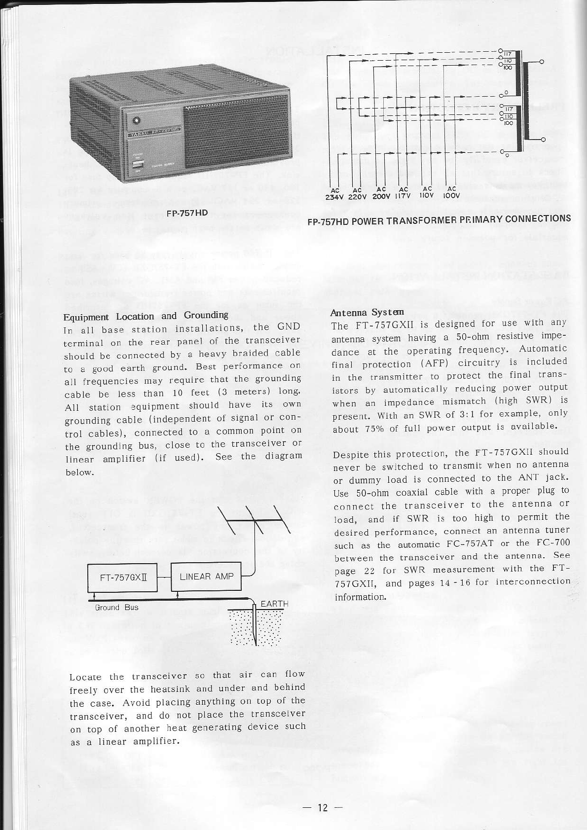
The FP-757HD is a heavy duty series regulator
power supply capable of 50% duty cycle opera-
tion with full po\r'er transmissions for up to
30 minutes at a tim€. Forced-ai. eooling is
provided over an extra large internal heat-
sink. The FP-757HD requires a 6-amp fuse for
100, 110 or 117 VAC, or a 3-amp fuse fo! 200,
220 or 234 VA.. Potrèr
lranqformer
primarJ
connections for lhe different line voltages
are shor/n on the next pa8e.
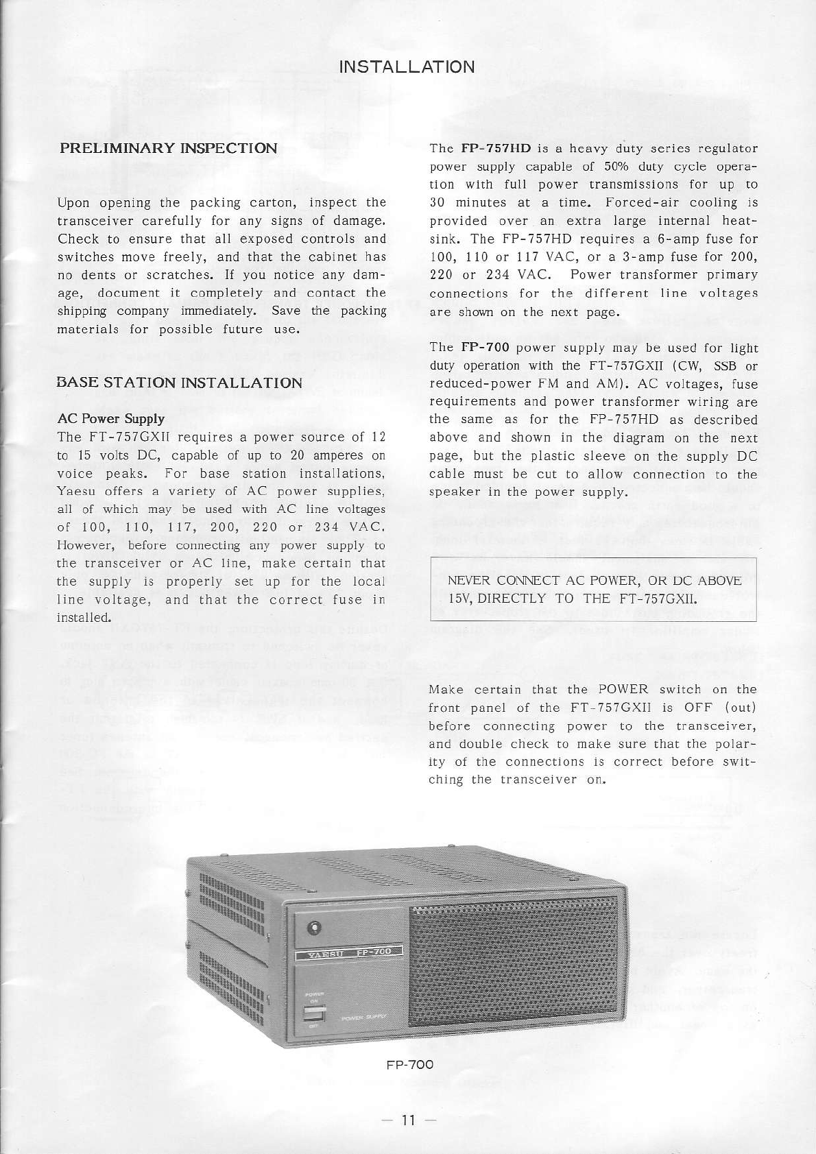
The FP-700 pover supply may be used for light
duty operation
with the FT-757GXII (CW, SSB
or
reduced-power FM and AM). AC voltages, fuse
reqìiirements and power transformer wiring are
the same as for the FP 757HD as described
above and shown in the diagram
on the nexr
page, but the plastic sleeve on rhe supply DC
cable must be cut to allo\r connecrion ro rhe
speaker in the power supply.
Make certain that the POWER switch on the
front panel of the FT-757GXÌI is OFF {out)
before connecling power to the tra.sceiver,
aDd doúbte check to make sure that the polar-
ity of the connections is correcr before swil-
chjng the transcelver on,
NE\ER CONNECT AC POWER, OR DC
15V, DIRECTLY TO THE FT 75?GXIt.
ffi
rr
tl-tf
f
t-
I
ll
FP.757HD
Equipment Location and GroÙnding
lf all base slation inslalLations, the GND
te rin un I ol rhP
r'
'n
'è \F_
should
be connected
bv a heavy braided cabÌe
to a good earth ground. Best perlornànce oo
all frequencles mav requÌre that the groundlng
cable be less ùan 10 leer (3 meters) long'
All station squipment shouid have ils own
grounding cable (jndepe.denr of signal or con-
troÌ cables), connected !o à conmon point on
the grounding bus, close Lo thc trans'eìver or
lÌnear anrpÌifier {if used). See the dragram
FP.757HD
POWER
TRANSFORMER
PNt[4ABY
CONNECTIONS
The FT-7;7GXII is designed for use wrth anv
antenna sysrem having a 50-ohm resistve rmpe-
dance a! the operatjng frequencv ArirÒmarlc
finaÌ protecrion (AFP) circuitfy is included
in !he transmitter to protect thc final tra's
istors by automaticallv reduci'g power outpur
when a. jmPedance misnatch (high SWR) is
present. \lith a. SNR ot 3:l Ior exarìple, onLl
about ?50/o of full poser outpur is avàilable.
Despile
this prolection,
the FT-757GXll should
never be swÌtched to transmit when no anrenna
or dummy load is connecred to the ANT jack'
Use so-ohm coaxiaL cabLe with a proper plug to
connecl !he lransceiver to the anrenna or
load, and if SWR is too high lo pe'miL the
desired performa.cc, connect an anlenna tuner
such as the automatic FC-757AT or the FC 700
betveen the transceiver a.d rhe anrennlì See
page 22 for SWR measurement wllh the FT
757GXll, dnd pages 11-16 for inter'Ónnection
Locare the transcerver
freeiy over the heatsink
!he case. Avold PÌacing
transcejver, and do not
on top of anorher heat
as a linear amPlilier.
so that air can flow
a.d u.def and behind
anylhing on top of Lhe
pÌace !he traùscelver
generatìng devìce such
12
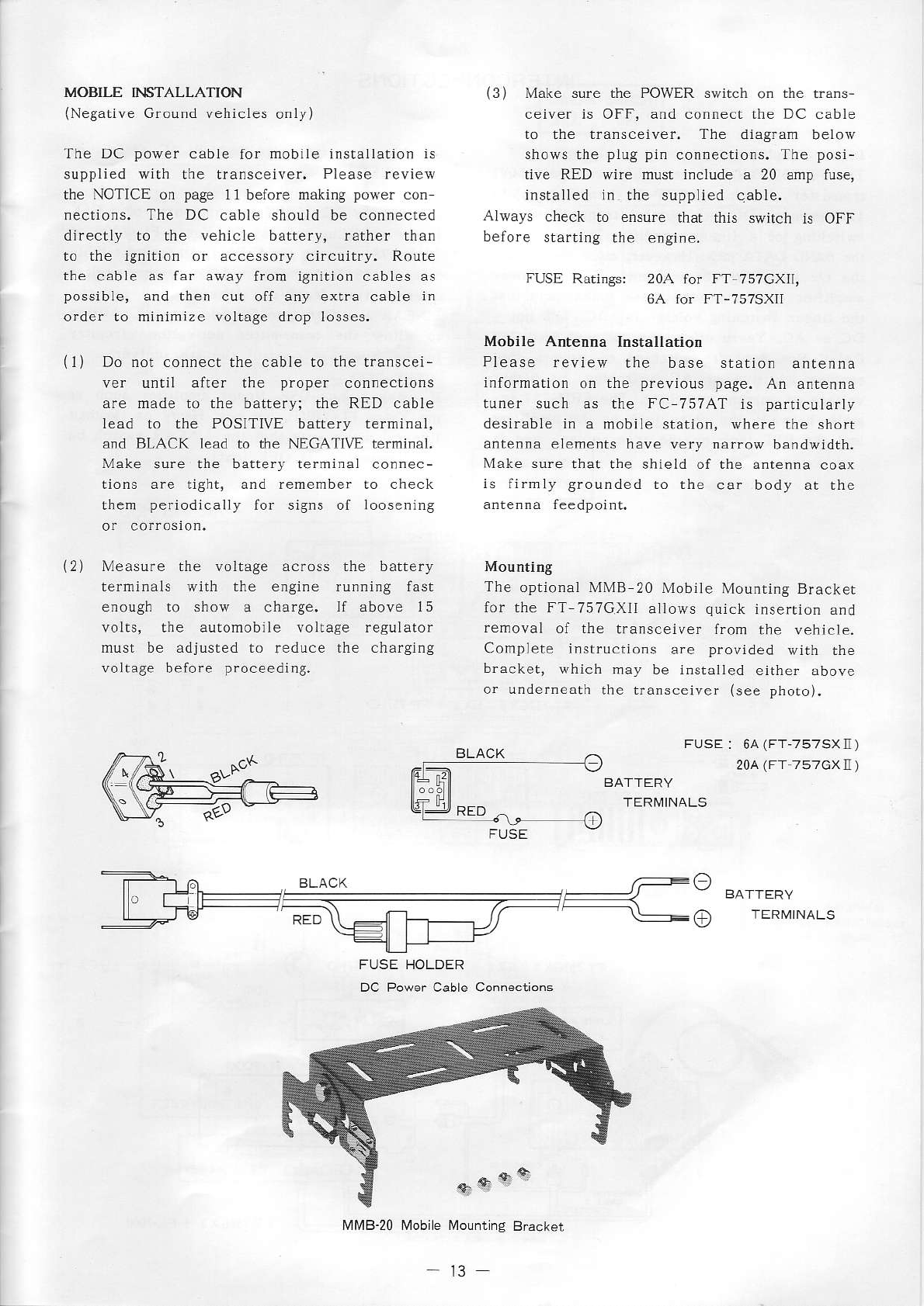
MOBILE INSTALLATIOT{
(Negatìve Ground vehicles oniy)
The DC power cable for mobile instaÌlarion is
.uppÌiFd
$ L I F rransrptrer,
Pìéaqp
r,!irù
the NOTICE on page 11befo.e making power con
nections. The DC cable should be connected
directly to the vehicle battery, rather than
to the Ìgnition or accessory circuitry. Route
the cable as far away from ignition cables as
possible, and then cut off any exrra cable in
order to minimìze voltage drop losses
(3) Make sure the POWER srvitch on the trans-
ceiver is OFF, and connect rhe DC cable
TL P ni .o..,F be os
shows the plug pjn connections. The posi-
tive RED wire must includ€ a 20 amp luse,
instaìled in rhe supplied qable.
Always check to ensure that dìis srrirch is OFF
beiore startirg the engire.
(r)
\2)
Do nor .onnecr the L.ble ro t'e tra r5ce:-
\'r unr,r drrcr thF p_oDer conne. ior s
are made to the battery; the RED cable
lead to the POSITIVE battery termjnal,
and BLACK lead to the NEGATIVE terminal.
Make sure the battery terminal connec-
Lions are light, and remember !o check
rLrF1]
period..dl
) for ".9n" ol oo.- rirg
\4è,su
- rlè .olrdgè
Ji
,os. he bJr,èr)
termìnals with the e.gine running fast
e.ough to show a charge. ll above l5
volts, the aulomobile voìlage regulator
r u" bF "Jjus,Fd ru --Jr
,
p ha .ha-ging
voltage belore proceedìng,
FUSE Ratings: 20A for FT 757GXÌ1,
6A.or fT-7575\I
Mobile Antenna Installation
Please review the base station anrenna
information on the previous page. An antenna
tuner such as the FC 757AT is particularìy
desirable i. a mobile statlon, where the shorr
antenna elements have very narrow bandwidth.
Make sure rhat the shield of rhe snrenna coax
is fi.mÌy grounded to the car body ar rhe
antenna feedpoint.
Mounting
The optional MMB 20 Mobiìe Mounring Bracker
for the FT-757GXlI aÌìows
quick insertion
and
removal of the transceiver from rhe vehicle.
Complete instructions are provided wjth the
b.acket, which lr1ay
be installed eitter aDove
o. underneath the rransceiver (see phoro).
BLACK FUSE : 64
(FT-757SXIl )
20a
(Ff 757GXIl
)
BATfERY
TER]\4INALS
. F-r r:r BLAcr /;::::::r- a
'''__-_---
-Fì-t--.-----------_\\ - //-- \
J e' QED l\ -] - !! \:r- ) TLRI/INALS
u-
FUSE HOLDER
DC Power Cable Connections
lvlÀ48-20 Mobile À,lountlng
B.acker
t3
IN
TERCON N
ECT ION S
T
1l
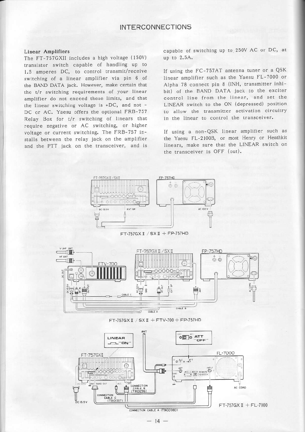
Linear Amplifiers
The FT-757GXII includes a high voltage (1s0V)
rrdas:sror ,$ir.t .apable of handlirB Lp lo
1.5 amperes DC, to control transmit/receive
switching of a linear ampiifier via pin 6 of
the BAND DATA jack. However, make ceràrn that
the t/r switching requirements of your linear
amplifier do not exceed these limÌls, and that
the lìnear switching voltage is +DC, and not -
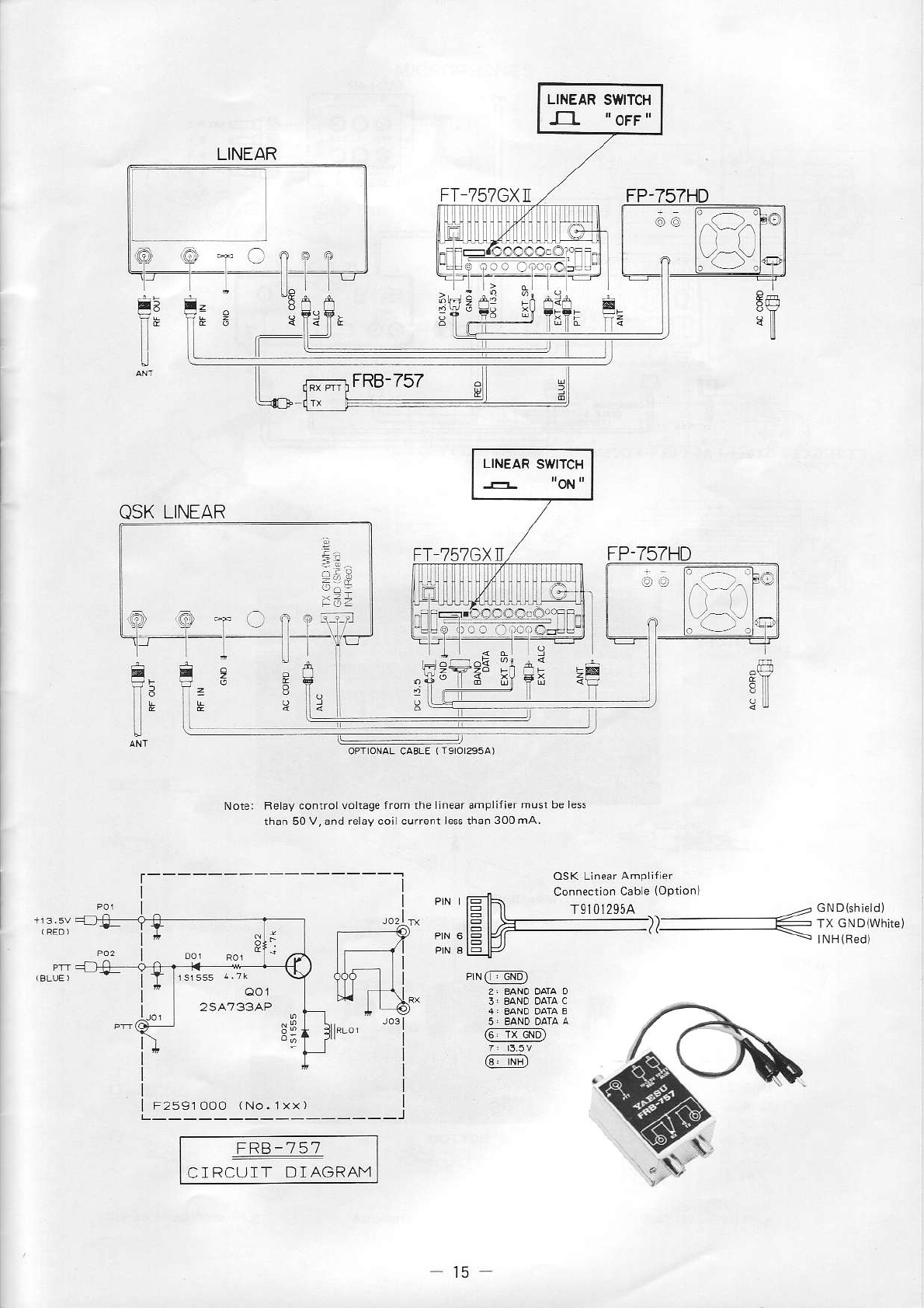
DC or AC. Yaesu offers the oplional FRB-757
Relay Box for l/r switching of linears that
require negative or AC switching, or higher
voltage or current srvitchÌng. The FRB-757 in-
stalls between the relay jack on !he amplÌfier
and the PTT jack on the transceìver, ancl rs
capable of switching uP to 250V AC or DC, at
up to 2.54.
If using the FC-757AT antenna tuner or a QSK
linear amplifier such as the Yaesu FL-?000 or
Alpha 78 connect pin 8 (INH, transmjrter inhi
bit) of the BAND DATA jack to the exciter
control llne from the linear, and set the
LINEAR switch to the ON (depressed) position
ro a t4$ rhe dns
nire|- a.t.raIor . r.urrrv
in the Linear Lo control the transceiver.
If using a non-QSK linear amplifier s'ch as
the Yaesu FL-21008, or most Henry or Heathkit
linears, make sure thal the LINEAR switch on
che rransceiver is oFF (outl.
:m.
r f|flfl
F f-757GXrl SX ll + FP-/5IHD
FT-I57GX II /SXN + FTV.7OO+
FP.757I]D
F*;_l
L =:Ì]
VFT 757GX]I
+ FL TO(](]
FT ?57GXN,/SXN f,!
FL-7000
i-
LINÉAR
T
8
È:
I
t
QSK
LINEAR
E
f,É
I
r- i--,
I
FRB-757
CIRCUIT DIAGRAM
-- g::
Belav controlvólrage
iiom rhe lnearamplilièr
mùsr be le$
rhan 50V,ónd
relay coi cutrenl le$ thao
300m,A.
!Í9
E1
PLNI, aMl
@
@
Ff 751GXn FP.757ND
9
-.,- -t,-
I
.r.",.T,\î:,'.,
_____l
t5
IEF
{EF
fltt--
{f,F
rc 757AT
FT-757GX
II ,iSX]i + FAS I 4R
+ FC.75IAT
Torque Adjustme.t Sdew
FI 757GXN SXN
BOTTOM
l6
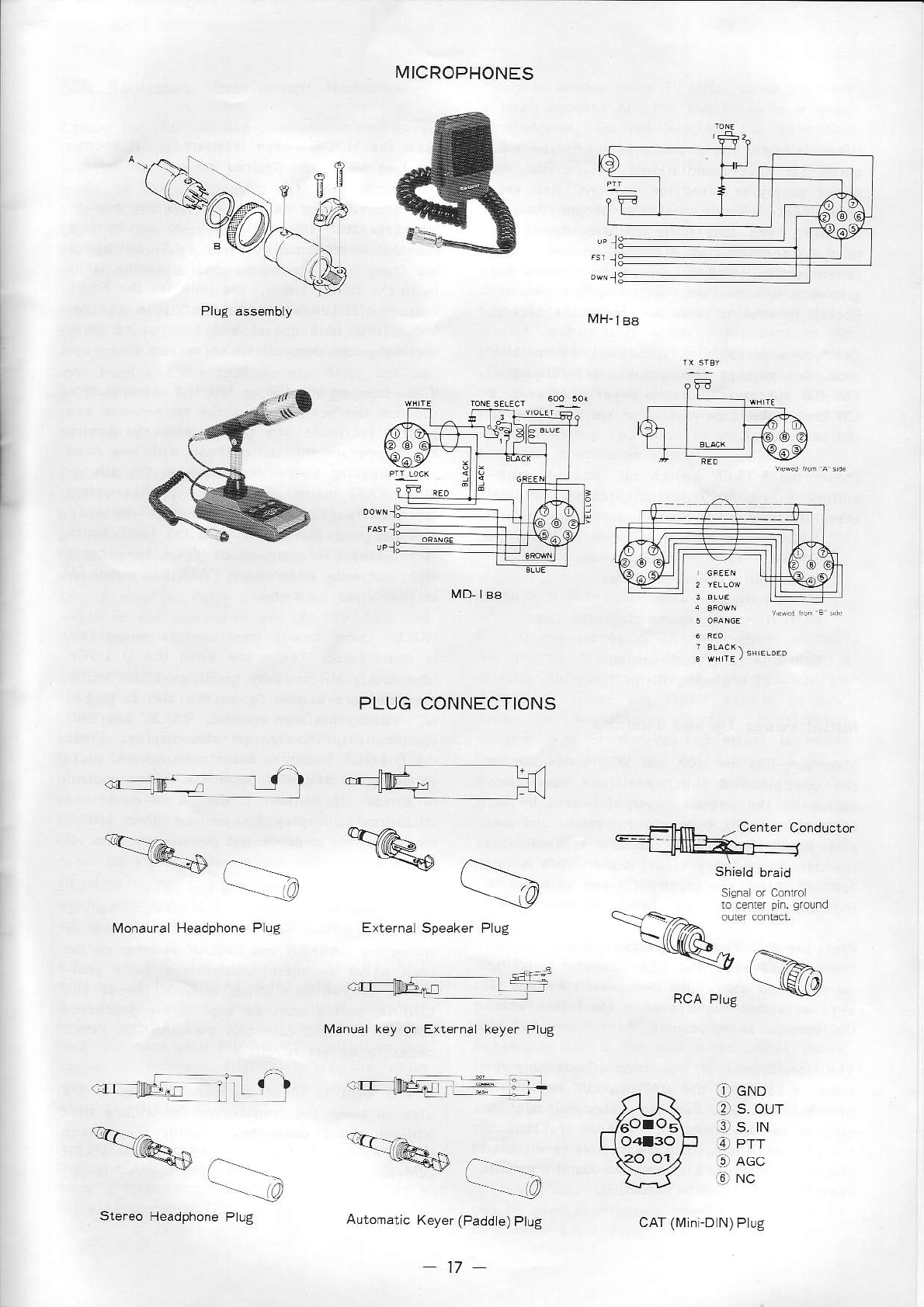
fvlH-
f Bs
rvltcRoPHoNEs
MD. EA
PLUG CONNECTIONS
, f----_-.-
------{4
L'I T
Externa keyer P ug
::rrlneq-,rt
.-'rffiiÉn!
a___o
:r''''''É .hI ), -t
'DF= N0 v -
ù*L
*-,,,@,+
C..-..-O
[4o.aura Headphone Pl!g
qrì%.p
a--.-ì
-llnn , Center Conducto.
--llll1Ì:à-È
._--
ar
cND
12)
s. ou_f
it s. rN
(4-ì
PÌr
l5_iì
AGc
oNC
Ste.eo Headphóne
P ug
17
caT(Mn D N)
Pug
OPERATION
Before plugging
lhe power supply inro the walì
outlet (in base installation), ensure rhat !he
power supply is wired for your AC line vol-
tage. Make certain thar rhe proper fuse 1s
instaìled, and that ir is p.ope.Ìy connecred
to the transceiver as described in the lnstal
lation sectio.. Also nake sure the antenna a.d
ground are connected. Refef to Lhe Memory
Backup informatìor below to enabie the backup.
Connect a microphone, if desired, ro the trllC
jack. See page 17 for microphone informatìon.
For CW operation, co.necr ke)ref paddles or a
Cw key as shown on page
17 to the KEY jack on
Preser the POIVER swirch off, and all push
buttons to lhe undepressed posìtìo.. Set dre
other controls as folÌows:
MIC flrlly counterclockwise
DRIVE - fuÌly cou.rerclockwise
AF - fulìy countercìockwise
RF - fuily clockwise
NOTCH - fully counterclockwise (lnto
rhe OFF cÌicksrop)
SHIFT - l2 orclock positìon
NB 12 orclock posjtìon.
Initial Poq,er Up and Tuning
V!. - |
rè . d r,c \lO\ ord VO\ bJflo 5 .ró I I
the u.depressed
(out) positions, and then
switch on the power suppiy, followed by the
fansceiver POWER swltch. lhe neter and dìs
play should Ìight, vith the display ìndicating
the default (memory clear) state: VFO A and
7.000.0. Also, the green GEN and yelÌow LSB
indicarors shouìd ljght (also defaults).
Press the MODE button (repeatedly, if neces-
sary) lo selecr the desÌred mode of emission.
Turn dre AF gajn conrrol clockwise for comfor-
tabÌe receiver voÌume. lf you do not have a
scanning microphone, qse the FAST buLton on
."F r or Pdl.l J.\ó .J ing
cr.po
(with the tuning knob), and then set the FASI'
Notice that both coarse and fìne tuning sreps
are mode dependent, as shown on page
6.
If
,or ".. è- \'D-l88 \4H-l88 dn r,g n -
rophone
rhe scan keys on the mìcrophone can
greatly faciìitate vfo tuning wìth rhe tuning
knob: operate .he tuning knob wilh one ha.d
"ì e l-Fp
g.ou o - h"rd
orrhè n.ro-
phone, FAST bLrtbn. This alLows qulck searching
fo d. r\ r-\ l " r'l ", fAqT b|.t.on 1 - ed
and then easl fine tuning when the FAST button
js reÌeased. To juÌnp up or dowi one coarse
slep, press the mìcrophone FAST and either UP
or DO\\N kcy logether.
NOTE: U.der certain condjtìons the tunlDg knob
ìs deac.ivated.
These are rhen the D LOCK
(dial lock), \,1R (memory recall) o. SCAN À,IODE
functio.s are active. When rhe dial is locked
or a memory has been
recaiÌed, iLOCKT
and rMR'
appear, respecrively, on the dlsplay, Press
the D LOCK buftor to deactivate Lhe dìal lock,
or press the MR/VFO button to return control
lo a vfo. If nelther of the above-lnentioned
conditions is dispìayed reset the SCAN lvlODE
button lo the u.depressed position to turn off
Press rhe H/G key and observe the steps of lhe
DwN and UP keys (the GEN indicator js olf lof
amateur ba.d steps)r and then press D\1N and UP
keys to select the operatìng band (for which
rhe antenna is resonanr).
The Ham/Gen (H/G) selection affects only the
stepping action of the DWN and UP keys when
tu.ìng a vlo. You c:i. use either selection lo
receive on any frequency, or to transmit in
!hc amareur bands. The transmitter is dlsabled
oulside of the 500 kHz amareur band segments
regardless of Ham/Gen selection.
Memory Backup
Betore leaving the factory the memory backùp
systen1 is turned olf. Actjvate the backrip by
settìng the N{ARKIR and LINEAR swìrches on the
rear panel to rheìr undepresscd
(off) posi
!ions. lf you are usi.g a QSK linear rhe
LINEAR slvitch Íìust be kept ìn the depressed
position, in vhich case onÌI the IUARKER svirch
reeds to be set ro off.
If you want to cÌear aìl nrenories, of if you
plan to srore the trrìnsceivef lor a long time
vithout po\!er con.ecred, dìsable rhe backup
system bv pressing borh the LINEAR and MARKER
swirches (to O\) rvlriie rhe transceiver is off.
t8
SSB Reception, Interference Reduction rarely be needed below l0 MHz, unless you have
a sll]all antenna or your sration is ìn a quiet
environmen!. Do not activate the attenuator
and RF Ai\{P at rhe same timet instead, swìtch
'l
he setti.gs described up to this point a.e
besL lor tLrning and receiving weak signals
under most conditlons, In most cases, once you
have runed in a starion, you eill vant Lo set
the AGC F off (out, slow agc) for most comfor-
iable listenlng. If you are working a strong
sration (consistently
above S-9), tur. on the
rhe atrenuator if ir isn't already on, or turn
off the RF AlvlP (if jt's on), and decrease rhe
Rl_ gaìf so thar his sigùal just moves the S
meter above its (raised) restìng
posìtion.
You
should.orice a reduclion in background noise
and more comfrìftable copy.
Whe. .etu.ing the vfo, set the AGC-F back on
(last), and return the RF and ATT ro rheir
prevìous
settings
(ìf you are liste.ing for
iF Shift & Notch Fllter
lf you expcrience interlefe.ce lrom stàtions
o' ,
urb/ f.aqua ìè "frFr rur.ng i| à
',aroI d,d -r.,,c L-, i
i-olr q u\l
described, .otare the SHIFT control to sup
press thc intcrference. Lrsuaìly, interference
o. one sjde of the desired sjgnaì is wofse
rl 'r
o ,-.hr. u,cb "hiÍr ng l-p,.
band rowa.d the cÌearer sjde reception ot Llìe
desired signal can be improved. Noricet
ho$ever, that the passband
ol thc desired
signal is also shifted, so tu..ing the SfllFT
control too faf may cut off too nuch of the
low or high aùdlo components and make the
signal u.i.telllgible.
Excepr for the vfo and memory conlrol keys,
'la remdrn.
g .u |lo fo \é rè éitP
provjded to reduce or eli|ninate Lhe v:tnous
types of noise, inrerference and distortlon
thar can obslruct comfortable receplion, Oper
ation is fjrst described for SSB (USB or LSB)
reception o. an amateur band, with varìalìons
for orher modes descfibed later.
Press the MODE button to select USB and tune
ro the 14, 21 or 28 À4Hz
phone
band (if your
antenna is for a band below 10 MHz, select
rhat band and rhe LSB mode). Aiso, set the
AGC F butto. for fast agc actìon (depressed).
Rl_ AMP & Attenuator
Careful adjusment ol !he receiver front end
is necessary for optìmum
reception, and shouÌd
be treated as first prioriLy al the starl of
an operating
session, or ehen changìn8
modes,
bands o. afte.nas. To ser up rhe receiver for
optimun sensitivityi first make sure the RF
gain conLrol ìs fuLly clockwise, and the rf
ampÌifier and att€nualor àre off (RF AMP and
ATT undepfessed).
On a cleaf frequency, check for any S meter
reading on the background nojse
Ìevel (hiss
or
crackÌe). if the S-meter deflects above 3,
turn on the attenùaror
(press
ATT). Otherwise,
if the background noise gives no defÌection,
rurn on the RF AMP and agai. norc the S_meter
reading or backgIou.d roìse: if it is above 3
S-units, turn the RF AMP back off (leaving
it
on r!ould :ncrease the S meler readings ol
received slgnals, but vould .ot improve the
signal-!o-noise ratio {redl sensitiviry), a.d
would increase the likeLìhood of overÌoad
from
strong sìgfaìs on other lrequencies.
After selecting the proper ATT and RF AMP
settlngs, if backgrou.d noise stiÌì causes the
S meter ro defÌect, note the Ìeveì and theD
rotate the RF_ gain conlrol counlercÌockwise
lrom maximum until the S meter deflectjon jusl
begi.s to increase slighlly àbove the noise
level. This rill reduce the back$ound noise
when you Ìisten lo slgnals,
ln generaÌ, Lhe atteDualor nay ofren be needed
on lrequencles belorv i0 MHz, and when you are
I
s g a la
8e )ou- \.ar.o. ò ir o
nolsy environment (ciry). îhe RF A\,lP should
The lf- notch lilt.r is prjmafily uselul for
Lpprp.
' I har-rodvr- ' .$ .., -aq< 'p.-!-
tion as described later. However, ir is also a
powefful tooi for suppressl.g odrer !y!es of
inra-tórè-i nD
r.- 8-,P-drpd
buzzing noise, in the SSB mode. Afler lunjng
in the desired sig.al and serting the SHIFT
lor opLlmLtm copl, if !ou a.e receiving
a buz-
zj.g type noìse, rurn rhe NOTCH on (our of the
click sto!), and {arch the S-meter while
'u-:r8 hó r. nr"ot
.or rrn n. n cé t.
-_
tion on.he noise (when rhe other starìon
| ,"t .. o ""u-
- r.r qamp.,.\-,q.,
can be used ro suppress interferìng CW signals
or carrier hererodynes
durjng SSB reception.
t9
SSB Recepfion, Interference Reduction
Excepr for the vfo and memory conrrot keys,
ilg "o
rrro
"
p.o!idad
o redu,F
or er m,'dé I'e \arioLr
types of noise, inre.ference and dìsro.tion
that ca. obstruct comfortable reception. Oper-
ation is firsr described for SSB (USB or LSB)
reception on an amaleur band, wirh varjations
for other modes desc.ibed later.
Press the ìVIODE
button ro selecr USb ano cune
to rhe 14, 2l or 28 MHz phone
band (if your
antenna 1s for a band beÌow 10 MHz, selecr
that band and rhe LSB mode). Atso, set the
AGC-F butron for fasr agc action fdepresseo,.
Ill_ AMP & Aftenuaror
Careful adjustment of rhe receiver f.onr end
is necessary for optimum receprjon, and shoutd
be treated as fi.sr pflority ar the sÈart of
an operating session! or when changing úodes,
Oands or anrennas, To set up rhe receiver for
optimum sensitlviiy, first make sure rhe RF
gain conarol is fÌrÌly clockwise, and rhe rl
amplifier a.d atrenuaror are off lRF AMp and
ATT undepressed).
O. a ciear freque.cy, check for any s-merer
feadirg on the backgrou.d
noise tevet (hiss
o.
cfackie). If the S-merer detlecrs above 3,
turn on lhe atLenuator
lpress
ATT). OÈherwjs€,
if dìe backgrou.d noise gjves .o deftection,
turn on the RF AMP and again note rhe S meter
reading on backgroLrnd
nojse: if i! is above 3
s-units, turn rhe RF AMP back off (teaving
ir
on s ud t "-d.. r-r Sî -. -noai
,8. ol
recejved signaÌs, but woutd not improve the
sig.al to-noise farjo (.eal se.sitiviryr, ano
would ìncrease
the Iikelitrood
ol overÌoad from
srrong srgnals
on other frequencies.
Atter selecrìng the proper ATT a.d RF AMp
settings, if background noise stiu causes rhe
S me.er to deflect, nore rhe level and rhen
roÈate the RF gain control counterclockwise
from naximum unrìl rhe S-merer defÌecùon lusl
begins to increase slighrly above the noise
level. This will reduce rhe back$ound Doise
when you lisren ro signals.
In gene.al, the artenuator ùay ofte. be needecl
on frequencies
below l0 Mllz, and ùher JUu are
usrng a ra.8e a.tenna or your starion is in a
norsy
envjronmen!
(city), The RF AMP should
rarely be needed below l0 MHz, unless you have
a smal anlenna or your starion is in a quiet
envìronmenr. Do not activate the arEenuaror
and RF AMP ar rhe same rìme; i.sread, switch
The seftings described up to this poinr are
best for tuning and receiving weak signais
u.der most conditjons. In mosa
cases, once you
have tuned in a station, you will wanr ro ser
the AGC F off {our, slow agc) ror most comfor_
tabìe listening. If you are working a srrong
sratio. (consisrendy
above S 9), turn on rhe
rhe atrenuator jf jt isn't already on, or rufn
off rhe RF AMP {if ir's on), and decrease the
RF gai. so that his signal just moves rhe S
meler above jts (raised) resrìng posltion. you
shouÌd notice a reducrion in background noise
and more comfortable copy.
When retuning rhe vfo, set rhe AGC-F back on
(fast), and rerurn rhe RF and ATT to theì.
preyious setrings (if you are listening for
lF Shift & Notch Fitrer
lf you experience inrerference from sralions
on nearby irequc.cies after tu.ing in a
sratìon and setring the rf conrroÌs as jusr
described, Ìotare rhe SHIFT controì ro sup
press the interference. usually, inrerrerence
o .1r .d- o. l,é dpsr- d .,grd, i. -.o-.-
rna. on the other, and by shìfting the pass-
band
toward thc clearcr side receptìon
ol rhe
desifed signal can be improved. Notice,
ho$ever, thar rhe passband of the desired
srgral js aìso shjfted, so rurni.g the SlltFT
conrrol roo far mey cur off roo much of the
Ìo$ or hlgh audio components and n]ake lhe
sìgnar uninreltigible.
Tàe lF norch fìlter js primarity usefut for
suppressrng heterodynes l. CW and ECSS reccp_
tron as described ìater, However, it ts also a
powerlul rooi for suppressl.g orher ry!es of
i.rerference, such as compurer generaLed
buzzing noise, in rhe SSB mode. After turjng
rn rhe desired sig.al and setrìng the S IFT
for optimum copy, if you are receivj.g a bur-
zj.g type noise, rurn the NOTCH or (our or tne
ciick srop), !ìnd
warch rhe S-meter whìte
runrng tne notch co.rroi for mhimum deflec
tion on the nojse (whe. rhe other statron
lsn't talking). Of course this same technique
can De used to suppress inrerferj.g C!V signats
or carne. heterodyres during ssB receptio..
Note: once the NOTCH has been set, adjùsting
the receìvÌng frequency or the SHIFT control
will move the notch setting, which will then
have to be readjusted.
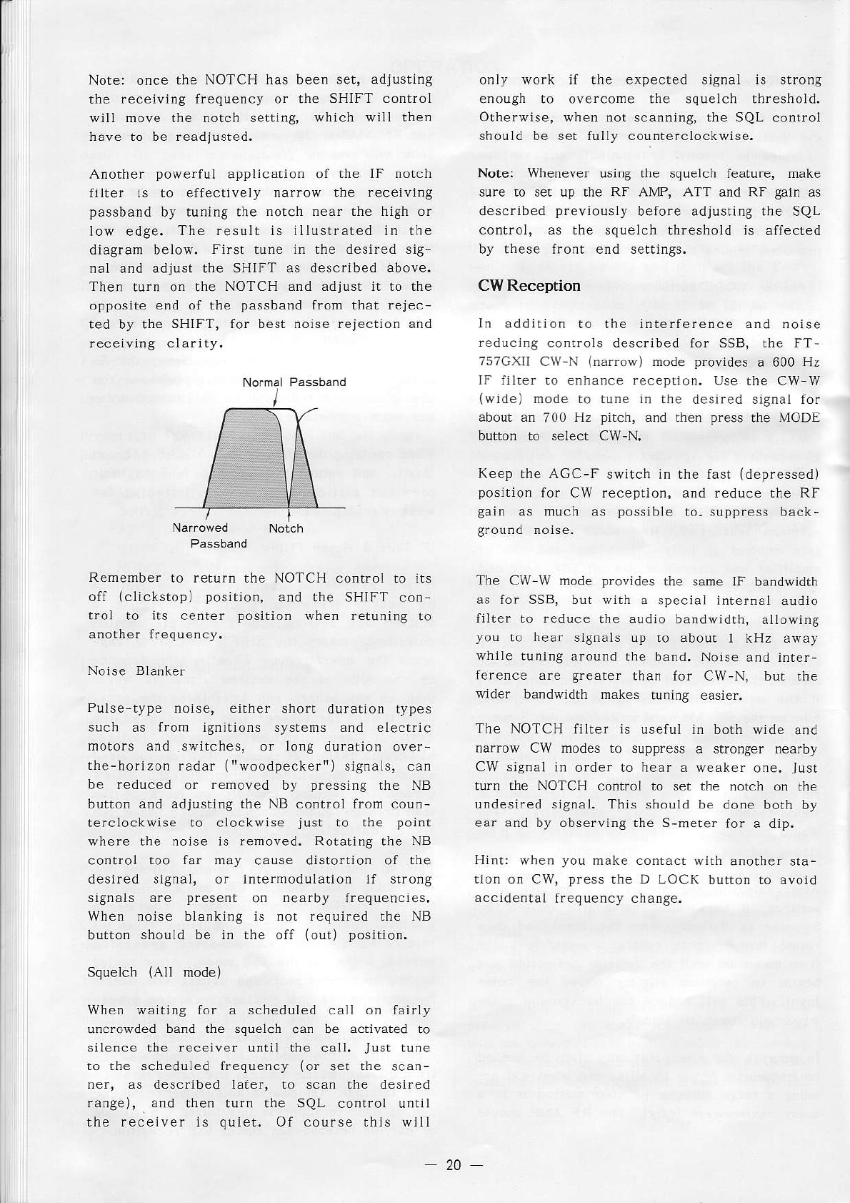
Another powerful application of the IF notch
fllter is to effectively narrow the receiving
passband by tuning the notch near the high or
low edge. The result is illustrated in the
diagram below, First tune in the desired sig-
nal and adjust the SHIFT as described above.
Then turn on the NOTCH and adjust it to the
oppos
re pnd of ,he pasrbdnd f.or rhîr rrlei
ted by the SHIFT, for best noise rejec.ion and
receiving clarÌty.
only work if the expected signal is strong
enough to overcome the squelch threshold.
Othe.wise, when not scanning, the SQL conrrol
should be set flrlly counterclockwise.
Note: lvhenever using the squelch feature, make
sure to set up the RF AMP, ATT and RF gain as
described previously beîore adjusting the SQL
control, as the squelch th.eshold is affected
by these front end settings.
CW Reception
ln addition to the inlerference and noise
reduclng conlrols described for SSB, the FT-
T5TGXII
CW N (nar.ow) mode provjdes
a 600 Hz
'f fi r-r tr.p rhe cw tr
(wide) mode ro tune in the desired signal for
about an 700 Hz pìtch, and then press the MODE
button to select CW-N,
Keep the AGC-F switch in
position for CW reception,
gain as much as p.,sslble
rhe fast (depressed)
and reduce rhe RF
ro. suppress
DacK-
Remembe. to return the NOTCH control to its
off (clickstop) posjtjon, and the SHIFT con
t.oÌ to ìts center position when retunìng to
another frequency.
Pulse-rype nolse, ei!her shorr duration types
sucl as from iSnilions sysrems and electric
motors and switches, or lo.g du.ation over-
the-horizon
radar {rrwoodpeckerr')
signals,
can
b€ reduced or removed by pressing rhe NB
button and adjusting the NB control from coun-
terclockwise to clockwise just to the point
where lhe noise is removed. Rolating the NB
control too far may cause distorrio. of the
dèsrr"d .jCnal. or Inrarmodulal|or .l s ro-C
.
igr"ìs "'p prè\èn. I n<. b) frèquF
r. -\,
When noise blanking is not required the NB
button shouLd be in the off (out) position.
Squelch (AÌl mode)
When waitjng for a scheduled call on fairly
uncrowded band the squelch ca. be activated to
siÌence the receiver until the call. Just tu.e
to the scheduled frequency (or set the scan-
ner, as described ìater, to scan the desired
range), 3nd then tu.. the SQL conrrol unriì
the receiver 1s quiet. Of course this will
The CW W mode provides ùe same IF bandwidth
as for SSB, but wÌth a special internal audio
filter to reduce the audio bandwidth, allowing
you to hear sjgnals up to about I kHz away
while tuning around the band. Noise and inter-
ference are $eater than for CW-N, DuL rne
wider bandwidth makes tu.ing easier.
The NOTCH liiter is useful in borh wide and
narrow CW modes to suppress a stronger nearby
CW signal ìn o.der to hear a weaker one, Jus!
turr the NOTCH control to set the norch on rhe
undesired signal. This shouÌd be done both by
ear and by observing the S-meter for a dip.
Hint: when you make contact with anolher sta-
tjon on CW, press the D LOCK button .o avoro
accidental frequency change.
20
I
AM Reception
iF l-7s7(;\lI
i ,l,
das a 6 lH, iì,"r .or
good
fidelity during reception of medium-,rnd
shortwave AM broadcasts. The NOTCH filter ìs
LsèfJl or èl
ninarinB
.d F- arórodJ
.ó.
r\\iis lesl p_od'l.rd whpt rwo sralto
's aré
transmittìng near the same frequency, but when
not needed, ir should be switched ofl for besL
fldeLity. The SHIFT co.tÌol is ìess effecrlve
than in the narrower nodes, but ìr is useful
for eliminating hìgh-pilch hiss and herero-
dynes from sradons more than 3 kHz away.
When interference or noise is severe, ECSS
lfré rpd adn tFr \él-.taD F siacood
ro rp.ep
tion may be preterabìe for recejving AM
signals. This special technique allows you to
seÌect either the upper or lower sideband
ol
an AM signal; eljmi.ati.g inrerference thar
may be present on the other sideband dLre
ro a
nearby signal. k also provides grealer selec
tivity resuLting i. grearer sensirlvity :rnd
SHIFT control effecriveness, but does not
provide as much fidelity for stfong signals as
To use the ECSS techniquc, first rune in the
starion precisely (shortwave broadcasters gen
eralÌy transmit
on precìs€
rnultiples of 5 kllz)
usìng the AM mode, and rhen select eìther L,SB
or LSB, whicheve. gives besr feceprio..
Now carefully fine tuoe for zero beat o. the
received carrier. To hear the carrier, set the
SHIFT control a1Ì the way in the dìrecrion
lhar gives emphasis to birss, and very slowly
lu.e for the point where the signaÌ sounds
most na!uraL and undisrorred, with no accom-
Panying whis!le or dìsso.:rnce.
When
you have tuned to zero bear, return the
SHIFT control to center (or adjusr for ml.imum
interfe.ence and the desired tone), and push D
Lco( o.o.do'. lo"s",f, ,qu" ",.
H -r: Tqro bFarrrS "ì c\"1 "ign"l '( \\ r-..p
tio. requires a very carefuÌ rouch on rhe
run. g l r 'b. qon orac .p $ In r. roe òr8-
nals fìrsr will make tu.ing the weak ones
easier. Coarse tunirìg cannot be used for ECSS.
When receiving AM signals in either ANi or ECSS
mode, the noise bÌanker should be off unless
it is reaily needed. Irs eflecrìveness will
vary depending on the signal strengrh of rhe
received signal and those on adjacent chan-
nels; beìng most effective when rhe signals
dré úFak
a-d roisa
pu
!F. -rp \r-o48.
FM Receition
The FT-757cXll ìs equipped
for FM operadon
wrthour addilionai accessories.
However, FM is
gene.ally not used on frequenci€s
below 29 MHz,
so a VHF or UHF r.arsverrer may be used to
extend the range of tlìe FT-757GXII ro rhe amareur
bands abovc 30 MHz.
The SHIFT, NOTCH, Noise Blanker and AcC con-
trols are nor active in FM reception. However,
rhe RF AMP, RF gain, ATT and SQL setrjngs are
especially imporlant. For weak sig.aì work,
set the SQL conrrol only after rhe other con-
troLs have been set. The FT-757GXI] FM cir-
cuitry ìs designed for !5 kllz deviation, as is
mosr common l. 2-way FM comnunicatlons.
RTTY and Packet Reception
An external TU (termlnal unjt) or TNC (termi
nat .ode controiler) is required for R'ITY or
packet operation, fespectlvely. Receiver audio
ls best obtained from the AF OUT jack on rhe
rear panel, as the ìevel of the slgnal ar rhis
jack is not affected by the AF gain control.
llowever, your TU or TNC musr be capable of
high impedance input (200mvp-p @50-kjìolrms)
ro
use this sig.al. Otheririse, Ìow iÌnpedance our-
prlt is available from rhe EXT SP jackJ but
rl.. r" ,f
è.
rFo by F ^f g-rn on. .r, aro
L ig r i _.r di
.dblp,
rhé 'r- é \prrLc",
The SHIFT conrrol ìs especìally convenienr for
RTTY and hf pàcket operarìon, using the SSB
modes (generally LSB is used for anareur digi-
tal modes below 29 MHz). Ser rhe SH1FT conrrot
so that lsk rones are centered in the pass-
band
(the center posirion is 1500 lt2)
As for SSB, the NOTCH fiÌter may be adjusred
ro suppress an unwanred carfrer, or ro narrow
the passband af.er the SHIFT control has been
set. Thc agc should be fast (AGC F dep.essed),
and the noise blanker may be left on ar a
moderale
setting
(abour
10 or 11 orcÌock).
L
TRAI.ISMITTER OPERATION
The solÌd state rransmitter in the FT 757GXll
rèqu rès '4 rd-u"rme I ol F|hrr .érr'.g
r'è
desired output level. The maximum poríer outPul
is determined by the mode and the capabiÌìly
of the power supply (in AM, FM and alsk, power
may have to be restricLed to avoid overheating
the power supply]. Also, there are certain
precaurions ro be observed at 3lÌ Èimes when
transmÌtring to avoìd possible damage to the
t.ansceiver, and to assure a clean signal.
Never transmit withouL having a dummy load or
anrenna tuned to the operatlng frequency
connected to the transceiver (or linear ampli
fier, if used). If you have any doubl of the
suitability of a pa.ticuÌar antenna on a cer-
rain frequency, check the swR (standìng wave
Ratio) first, as described below.
q!oid r dngi
o trpqLp rc c ''.rg rran5m's\ o-.
First return to receive, tune to the new
transmit frequency, and listen for at least a
mi.ute or two to make sure Ìt is not already
occupìedi or ask if the frequency is occupied
and then listen for a response, When using a
lighl- or medium duly power supply such as the
FP-700, do not attempt to lransúit FM, AM or
fsk at full output power. Although Lhe trans-
ceiver is capable of this, some power suppltes
are not, and they may rapìdÌy overheat a.d be
seriously damaged. In any mode, feel Lhe
supply occasionalÌy !ìnd reduce power or slop
transmitting for a while iî it feels hot.
Never begin to transmit (except into a dummy
load) without first listenÌng for a few m,n-
utes to make su.e the frequency is clear, and
then transmit your callsign. This wiLl avoid
accidental interference co other stations'
SWR Checking & Measuring
Before transn1itting, the SWR of the anrenna
.)qrer
ònoulc oè
'
hó.Ppd èr lfÈ opF"drrng
l-_-
quency to ensure that the proPer impedance is
being presenled to the transmitter. The trans_
mitter includes protection circuits that will
automatically reduce the output Power if SWR
is hlgh. For example,
with an SWR of 3:1 only
about 75olo of full power ìs available,
If using the FC-?5?AT Automadc Antenna Tuner
or FL 7000 Linea. Amplifier, SWR ìs calcuÌated
and displayed automatically, and rhe foÌlowing
procedures are not necessary. ln this case,
keep the METER swltch on *ìe FT-7s7GXll in the
ALC (undepressed)
posilion. See the Tuner or
{Tpl I'e rirual o- .omplèrè
deta.ìò.
Keyjng
the Transmitter
Use
the MOX button to activate
rhe rransmirter
du' ng rhé follos
n8
pro.èdurè
. BF
orè bFgil
nin& s€r the BREAK lN swirch on rhe top panel
to FULL, and the VOX button on the front panel
to off (out). To tra.smiL, seÈ the MOX bìrtron
.o rha aeDrFc.co po\irion.
dnd ttF- prprs I
again to .eceive (undepressed position).
SWRChecking
This procedure checks the approximate SWR
using jùst a few (arrs, ro avojd inte.le.ence
ard srrain on rhe equipment when SWR is ùn-
knosn, such as on a new a.renna.
On the rear panel, set the FWD-REV sLide
switch ro the FWD position, and turn the
FWD SET control lully clockwise (as viewecl
Make sure the DRIVE control ìs ser fully
counterclockwise. Set the METER switch to
the PO (depressed) posilion, and seiect
Tune the vfo to a clear frequency, and
listen for a minute to make sure its ciear
before proceeding.
Press rhe MoX button (the red oN AIR
indicator will light), and ve.y gradually
advance the DRÌVE controÌ whiÌe wàtching
the meter for any detlection. Now adjust
rhe DRIVE LonrroL io llar rì
. îè èr dé
flecls exactly to the SET marker (white
line cufting the red bar at the rÌght side
of rhe swR meter scale).
Set the MOX switch back off (our). Reach
back around to the rear paneÌ, and move
rrè fr^D-R \ ' id. .i r.i' o | - IrtV po.i
tion. Now press the NlOX swìtch again to
key the transmìtref, and note the SWR
approrimatìo. on the bottom scale of the
meter. Press the MOX switch again lo
return ro receivel
(r)
12)
(4)
(5)
(3)
It the SWR indicàtion was above 3, the antenna
syslem is too far fron resonance to be used at
the test frequency v'ithout substanlially
degraded
performance (not recommended). SwR
22
indicarion close to 3 indicates a poor antenna
match at this frequency, but an antenna luner
such as the FC-7574T may be used to match the
anrenna better, .educing the swR. of course
rh
s w
ll not c d rgó hó radiari
,g qudlrt.p.
of rhe antenna itself, and will require retun_
irg wnèrFrer 'hè rrd-\m ing frpqLe
.\ iò
changed, so it ìs better !o correcl the anlen
na or feedline mÌsmatch firsl, Ìf PossÌble.
SWR indications of 1.5 or less lndrcales a
matched antenna for use at the test frequency.
SWR Measuring
Use full power to measure SWR nore preclselv:
(l) set rhe FwD SET control on the rear psner
to midrange, and set the FWD REV swirch to
FWD. use the CW W mode and MOX but1ion
as
above for lhe following sleps.
(2) Set the METER se'itch to ALC (olrt).
(3) Make sure ùe frequency is clear' and Úen
press the MOX button and advance lhe DRIVE
untÌl lhe meter jusa begins to deflect,
(4) Press the NIETER svitch to PO (in).
{5) Whlle still transmifting, carefullv reach
around to the rear Paneì and adjust lhe
FWD SET controì fo. fulì scale dellection
ro the 5ti mdrk on tfe merer.
(6) Move the FWD-REV switch to REv, and note
ùe SWR reading on the bottom scale of the
merer. set the Mox button off (oull.
Again, ìf the SWR is above 3, a change in the
i -e'on 1 a_o
Power Meter Calibration
The meter may be calibrated using the ClV node
to indicate approxìmate transmitter RF ourput
powe. in eatts as follows. lhis is necessary
for prope. tra.smitter adjustment for AM, FM
and RTTY or packeL transmission, and is help_
ful for reduced power operation in olher
modes. lf using the FC-7574T Antenna Tuner
this procedure is nor necessary, ds the ìrC-
757AT includes a wattmeter and dmrìy load,
Before beginnin& measure the SWR as described
above and make sure the antenna is properìy
matched, or connect a 50-ohm dummy load.
With the MOX swìtch off, select the CW-W
node, ser the METER svilch lo PO (Ìn), and
sè. rhé DR.vr '
orr'ol fJl
) .lo wse
(maximum). On the rear panel, set the FwD-
REV switch to FWD.
Check that the frequency ìs clear, then
press the MOX button and carefully adjusr
the FWD SET control on the rear panei so
that the meter indicates 100W or rhe PO
(center) scale. Return the MoX button to
(1)
12J
The accuracy of this calibration is very
rough, as the actual fulì power output depends
on the band of operation and the antenna SWR.
If you have an accurate wattmeler and 50-ohm
dumdy load, you can use these in lhe above
procedure. Set the DRI\E contro] for l00W out-
put before adjusting the FWD SET control.
SSB Transmission
Wilh a microphone connected to the MIC jack on
the front panel, ensure the folÌowing controls
are preset as indicated:
Mc.
ta \è F.ro Al
C rourì
!1l.
gar'ortro, . l2 o'clo"'
(inner krìob right of the MIC jack)
PROC sv rrch OFF
(out)
\o\ stir' I oFf loulì
MODE . select LSB or USB
Tune ro a valid tra!smitting frequencv (in lhe
To activate the transmile., cLose lhe PTT
switch on the lilcrophone, and watchiq the ALC
indÌcarion (blue scaìe) on lhe meter, adlust
the MIC gain conlrol so that the meter de-
flecrs within the ALC zone (heavy blue line on
!he scale) o. voìce peaks. ThÌs wiÌl resuÌt in
full power output: reduce the MIC gain to
Speech Processor
After setling the MIC 8ai. as above, press the
PROC switch to activate the processor- The
average ALC indicarion on the mere. will in
crease, but if the peak indication deflects
palr rné al. /onè. .cdu'
- rhè \4lC Cdr
r.
23
The COMP LEVEL contlol on the rear panel
adjusts the level of speech processor co'npres
sior, and is carefully set for optimum perfor-
mance at the factory. However, usÌng difÍerent
microphones or variations in voice prtch mav
make it desirable to readiust lhis control.
This can b€ done by monitorjng the transmitted
sigral on ar os,
i los(ope or èxrerlaì receivp-
and adjusting rhe COMP LEVEL control to the
point just below that at which distortion
appears on the signal. lf set beyond this
poinb, average porÀ'er
will still be increased,
bur disrorrio. will cause signal intelligibil
ity ro be decreased.
VOX (Voice
actuated T.ansmjl Switchingl
ln any of the voìce modes, you can use the VOX
system to automalically activate the transmit
ter rvhen you speak jnto the microphone. Pless
the VOX switch to activate VOX, a.d then
adjust rhe VOX conlrol on lhe rear panel so
that the transmitler actÌvates when you speak
r$.rho,
I pre5òi
g .hè
Pl s$i
. r o1
'rrè
Tr' a-
p on r. \4
'en
)o srop dlt.rg rrP
rr.nsi eivcr
should rerurn lo receive alter a slight delav.
The DELAY adjustment on the rear panel sets
the hang tjme for VOX switching trom transmit
lf the audio from the receiver lriggers the
VOX system, make the above adjustments wtth
rhe AF control set lor low voÌume. Then in-
crease the volume to the desired operaling
level and adjusl the ANTI-TRIP control on the
rear panel jusr to lhe point where receÌver
audio fron the speaker ceases to triP the VOX.
Clarifier (ReceÌver Orfset)
When receiving on a vfo, the CLAR butron can
be pressed to allow independent tuning and
mode charging of the receiver wùhout affec_
ting the transmit frequency (CLAR is dlsPlayed
to the left of the operating frequency). This
feature is useful it, after making contact
with anorher statior, his transmitter drìfts;
you can retune hÌs siSnal without changjng
yoLr oú
| rransn
r,ing lfèouFnc).
Al'o, .è
the range of the cla.ifier is unlimited, iL
can be used for spìit frequency operation.
While the clarÌfier is on the tuning knob and
mode seleclor affect only the receiver: the
rransmitting frequency and mode will remain
the same as before the clarifier was acti-
vated, and this frequency and mode will be
displayed rrhen transmilting.
The FT-?5?GXII incorporates a specialrclaîi-
fier menoryr, which alìows you to lisren on
the transmit frequency by swilching off the
clarjfier. As long as you donrt touch Lhe
tunÌng knobJ pressing CLAR again returns you
to rhe {offset) receive frequency,
When the contact is finished, remember to
switch off the clarifier so that lhe transmit
and receive frequencies and modes.,vill be re-
aljgned when yoù retune.
Cw Transmission
The FT 757GXIl offers bolh semi and ruìÌ
break in (QSK) operation for both simplex and
spliî-frequenct op€ratiotu Hose!er. QSK opera
rion musr nor be arrempred
shrle ù.r'; a
linear amplifier nor specificall! desianed lor
r, or aamaSè
ro thc ampllfier or rransceivel
may result. see page l{.
The FT 757GXll incÌudes an internal electronic
keyer, which can be used by connecting keyer
paddles to the KEY jrck. You can also use a
slraiSht key or an external eìecironic keyer,
in which cases the internal keyer must be
switched off (top panel KEYER switch to MAN).
Be careful not to shorL the outer contact of
the KEY jack to chassis ground.
s-r up rhè ollowrng Í_o
t pa pì .on, o \:
VOX switch oN (dPpressed)
METER switch ,., ALC (out)
DR\l 'o,trol lo.-
rr.F
(nd')
MODE switch . . , . . select CW-W or CW N
A1so, o. rhe top panel, set rhe KEYER switch
ro MAN initially. Close the key to activate
the tra.smltter, a.d adjust the DRIVE conlrol
so that the ALc meter jusr starts to deflect.
This se.ting provides full power output: after
making contacr with another station, reduce
power wlth the DRIVE control if you can wirh
our roosrng conracr.
You should be abLe to hear the sidetone from
tlre Ìoudspeaker (or headphones) when you close
'I P , èr.np .în .i, lilr,oe rhe
hole near the rear of the bottom cover) can be
adjusted for comfortable sidetone volume.
24
To ser the (internal) keyer speed or to prac-
rice sendjng CW, set the VOX switch off (out),
and the BREAK-IN switch to SEMI. Also set the
KEYER switch to AUTO if usirg keyer paddles.
Now, cìosìng
the key will generate the side-
tone buL no signal will be tfansmirted. Ad-
just the KEYER control for the desired speed,
AM Transmission
Because carrier power is only one fourth of
rhe totaL PEP of an AM slgnal, it must be
limired ro 25 watts or less when transmitting
lith the FT 757GXII. When rhe power Òf the
îodrlar,lB . apbard" is dddeo ro rhÈ
cd rier
nE'
-. ..r a Pl
P o-.p.r rs 100
wart
. dì-
though this does not show on the meter.
To adjusr rhe FT 7s7cxll for AM transmission,
first calibrate the PO meter as described on
pdgè h orupc '\rè--dr
$arlmerp..
(1) Preset the MIC gai. fully counterclock-
wise, and ser the METER switch lo PO.
For QSK transmlssÌon set the VOX switch OFF
(out) and BREAK IN to FULL.
For semi break-ln operation, as required wjth
sorìe linear ampÌifiers, set the VOX switch ON
{depressed) and BREAK-IN ro SEMI. The DELAY
control on the rear pareì adjusts the hang
time betwee. key up and receiver enable.
FM Transmission
For FM transÌ]]ission, just select the FM mode
ard close the PTT swltch to lransmit. The MIC
gain co.trol ls disabÌed for FNl, as the galn
or . è 'nrcroj
hor' 'rpl t.pr r: o_-sFr iì pr
naìly lor 5 kHz deviarion, and should require
no iurther adjustment. RF power outpul is
adjusted by the DRIVE conl.ol. Ior full power
output (using the FP 757HD porver supply),
adjusr the DRIVE so that the meter (set for
ALC) just deflec|s slightl).. When contact is
estabìished, reduce rhe DRIVE, (4)
t2)
(3)
Make sure the frequency is clear, and then
close the PTT swilch on the microphone and
advance the DRIVE for power output of 25
\ldt s or lers 0n Lhè .rdlsÎirlpd i ar- èr,
Set the METER swirch ro ALC (out), Speak
into the microphone and advance the MÌC
gaÌn control untjl slight movement of the
meter occurs on voice peaks. PEP outlul
is now 100 warts. Do not advance the MlC
gain further, or overmodulatìon (and dis-
roruonJ may resull.
Use the DRIVE control |o reduce power once
contacr has been established.
CAUTION
When the Fî-757GXII is used with the FP-
757HD power supply, full power Flvl, AM or
AFSK (RTTY) transmìssions must be ìimiled
ro 30 minutes maximuÌn,
The Al speech processor can be acrivated for
AM Lransmissions by pressing
the PROC button.
ì:lowever, if speech processing is necessary to
maintain conÈact, we recommend switchirg to an
SSB mode for higher efficie.cy.
The VOX systen and cìarifi€r controÌ can aÌso
be used for AM, as described for SSB.
The AM CAR control on the rear panel adjusts
.ìè ìudr d io p-r.è
r'àgF
Ìevel. This contlol is alìgned at the factory
to provide 100% modulatio. rlien the DRIVE
cont.ol is set for a carrief leveÌ of 25
rLF \4
4 g';r .on -n J .pL
ro
about the same !osjtion as required for full
power output i. SSB, For 100% modulation with
a lower carrÍer ìevel, the AM CAR cont.ol can
be readjusted with an osciÌloscope connected
to monitor the llf outpur.
To set the AìU CAR control fo. i0090 modulation
al fulÌ po\yer outpu!, use an RF voltmeter for
the following steps;
\4nè thè P-700
o, 4.1èr rgfr'drr)
supply is used, rransmi!ter power i. the
above modes must be iinìted ro 50 watts
at all tjmes, to avoÌd overhearing and
subseque.t damage to the suppìy.
Regardless of the power source or node,
we recommend reducing power lron the
maximum leveÌs mentioned above whenever
rransmitting for more than l0 minutes, or
if the ambienr air temperarure is very
hot or the power supply feels hot.
25
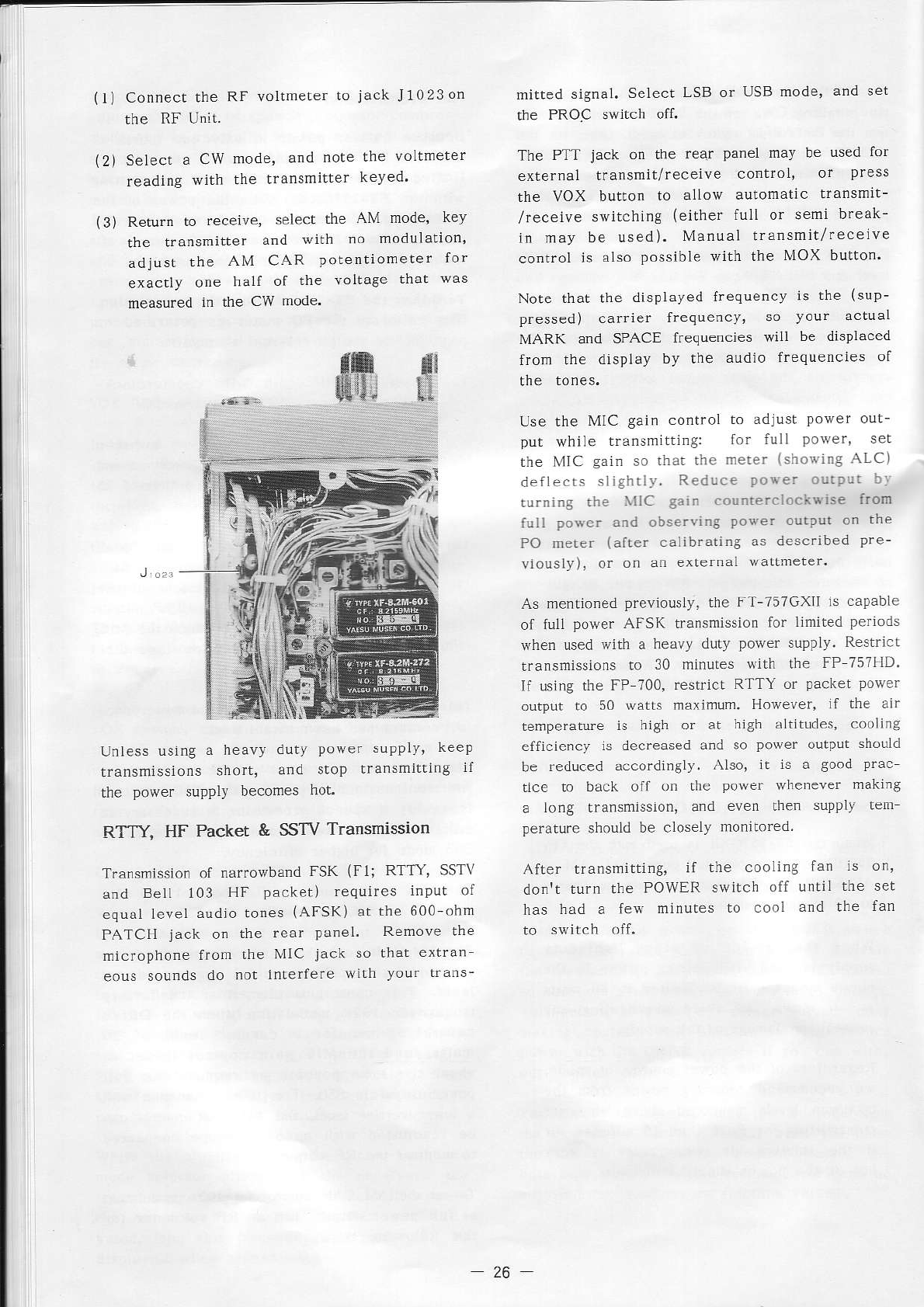
(1)
Connect rhe RF vollmeter
to jack J1023on
the RF Unit.
Select a CW mode, and note the vollmeter
reading with the !ransmifter keyeo
Return to receive, select the AM mode, key
the !ransmitter and wÌth no modulation'
adjust the AM CAR potentiometer for
exactly one half of the voltage that as
measured in the CW mode.
milt€d signal. SeÌecl LSB or USB mode' and set
t|e PROC switch oft.
The PTT jack on the rear panel mav be used lor
external transmit/receive control, of press
the VOX butlorì to al1ow auromatic transmlt-
/receive svitchirg (eilher full or semi break-
in may be used). Manual transmit/receive
control is aLso
possible with the MOX button.
Note that the dispÌayed frequency is the (sup-
pressed) carrier frequency, so vour actuaÌ
MARK and SPACE frequencies wiLl be displaced
fronl the display by the audio frequencÌes of
Use the MIC gain control to adjust power ouL-
put while transmltting: lor full power' sel
the l\'flC gain so rhat thc meter lsho\jng ALC)
dellec!s sÌigh!Ì1. Reduce po$er output br
lurning the \llC gain counrercìocli* ise Írom
fuÌl po$er and obser\ing pose. ou!put on the
PO meter (after caìib.atÍng
as described
pre-
\,lously), or on an externaL wartneter-
As mentioned
previously, the Fî-757GXll is capabLe
of fulL power AI-SK ùarsmission for linited periods
rvhen used wilh a heavy duty powef supply. Restrlcl
rransmissions
ro 30 minutes with !he FP 75?llD.
If using the FP 700, restrìcl RITY or packel power
output io 50 watrs maximum.
Howeler, ìf ihe àir
Lemperatue is high o. ar hìgh aÌtitudes, cooLing
eificiency is decreased and so power output should
be feduced accordinSÌy.
Also, it is a good Prac
tlce to back ofl on úe porver whe.ever maKr.g
a long transmission,
and even then supply tem
per.ìture shouLd
be closely monitored.
\ Lè r dnrrir';-t. rt r'r' '
ool " al
don't turn the POWER switch off unlil the set
has bad a few minutes to cool and the lan
\2)
(3)
Unless
usÌng
a heavy dutv power supplv' Keep
\ ì^fi, d4d .
loD ra rsffil'.rb
ùc power supply becomes
hot.
RTry, HF Packet & SSTV TransmissÍon
Transmission ot narrowband FSK (F1; RTTY' SSTV
an<1
BelÌ 103 HF packet) requires input of
equal ìeveÌ audio tones (AFSK) ar the 600 ohm
PATCH jack on the rear panel' Remove the
micfophone fron the MIC jack so thal extran-
eous sounds do not inlerfere $'iLh your trans-
26
MEMORY OPERATION
Ten nemo.y channels, nunbered 0 through I, are
available for storing operatÍng trequency aùd mode
of emission selected on a VFO. In addition there
are two VFOS denoted VFO A and VFO B and a
rcÌariller
memory', each of which hold boLh operaling
frequency and mode independently, giving a total
of l3 memories. Selection and manipulation of
the memories and VFOS is accomplished via the
six keypad keys at the upper' riSht corner of the
Note that rhe VFO>LI and M>VFO keys have yellow
markìng i. the notch on the keyfaces. This is
intended to caution tha! these keys
cause dara ro be overwritten (erasedl.
VFO A/B Selection
The operating
vfo is indlcared
by VFO A or VFO
B displayed to the left of the operaring frequency.
Each vfo holds an indepe.dent fiequency and node
ol rîi.s J . o \pla,
I tnF a.tnr-dlè
\fo. p-as lhF
VFO A/B ker.
VFO/Memory Selection
The MR/VFO key at the upper riSht selects be
rwee. memory and vfo operation. wheneve. this
key is pressed, the selecled vfo or memory and
its displàyed freqLrency
and indicated mode are
srored (except wirh tempo..rry memory modes,
descfibed beÌow), rvhlle operation shifts from vfb
to a memory channel, or vice ve.sa. The vfo or
memo.y channel rccalled is always the one that
was last used. (When a memory channeÌ ls sel
ected, rlvlRr appears to the left of lhe djsPlayed
frequency, and rCHr appears to the ri8ht, wìth
the channel nLmber be.eath it.)
Split Frequency Operation
The two vfos and the SPLiT key can be used for
splil frequency ope.ation as foìlows:
(l) Press VFO A/8, if necessary, to select
VFO B (displayed
at the left).
Now receiving is on VFO A, but wher the PTT
switch or key is closed, lransmission is on VFO
B. fo reverse rransmil and receive frequencies
(for example, to listen on lhe ùansmit frequency)l
just press VFO A/B.
An dtr.r.dl
\Ò frel,od ro opF-atF
\pti. ir ro Lrsè
one vfo and the clarifier, Ìnertioned previously
i. the SSB Transmission sectior, Tune the vfo to
lhe transmit frequency, lhen press CLAR and ítne
ro the receive freque.cy (and other mode, if re
To iisten on the transmil frequency, press CLAR
again, a.d then once more to retuÌ. to the receive
frequency (which is srored in a 'clarifier menory').
Note, however, that the cÌarifier memory is Ìost
if rhe írning knob moves while checking the transmit
Memory Storage
ThÌs procedure aìÌows storage of the vfo mode
and frequency into a memory channel;
(1) Set the VFO ro lhe frequency and mode
of emission to be slored.
(2) WhiLe receiving,
press MR/VFO to swjtch
lrom vfo to memories.
(3) Press the D\ryN/UP keys, if necessary,
to seLect an uùused memory clanneì
(default data is 7.000 MHz LSB Ìn all
(4) Press MR/VFO again to return to the
(a) Press SPLI
I
.
(5) Press VFO>M (lower center) to write
the data from the vfo to fte memory.
Note that the VFO>MR key overwrites (erases!)
the prevìos memory contents. Steps (2), (3) and
(4) are required onÌy to select the memory channel
rhar is Lo be written. If you already k.ow that
rhe lasl selecred memofy is free lo accept new
data, these steps can be skipped.
(2) Tu.e to ihe deslred transmit frequency
(3) Press VFO A/B to select VIrO A, and
tune to the desired .eceive lrequency
27
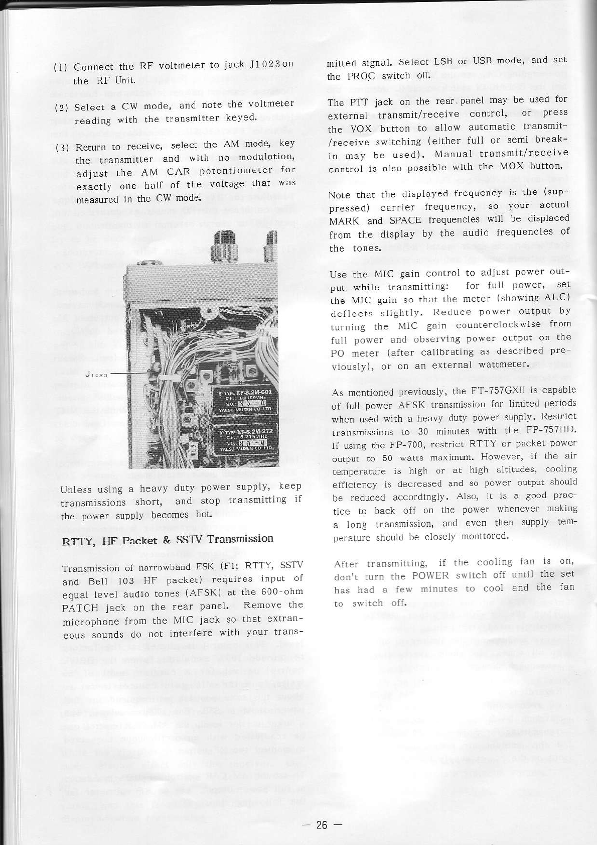
(1) Connect
the RF voltmeter
to jack J1023on
rhe RF U.it.
Select a CW mode' and note the voltmeter
reading with lhe transmitter keyed'
Return lo receive, select the AM mode' key
the tfansmitler and with no moduìation,
adjust the AM CAR potentiometer lor
exactly one half ol the voltage lhat was
measured Ìn the cw mode'
mitted signal. Select LSB or USB mode, and sel
the PROC switch off.
The PrT jack on lhe rear panel mav be Ùsed for
external transmit/.ecejve controì, or press
the VOX buúon to allow automatÌc !'ansmit
/receive swÌtching (either full or seni break-
ifl n1ay be used). Manùal transmil/recerve
conrrol is also possible wìth lhe MOX button'
Note that the disPLaved
frequencv is the (sup
pressed) carrÌer frequencv, so vour actuar
MARK and SPACE frequencies wtlL be displaced
from the display by lhe audio frequencies of
Use the MIC gain contfol to adjust power oul
put while transmittìng: for lull Power' set
the \,flc gain so thar the neter (showing ALC)
deflects slìghtly- Reduce power output bv
tLrrning the VIC gair counlerclockwise lrom
fuÌl pover and observì.g power outPÙr on the
PO meter (afrer calibraLing as described pre-
viously), or on an erternal wattmeter'
As mentioned
Previously,
lhe FT-757GXI] is capable
of full power AFSK ransmissìon
for Ìintrcd Periods
when used with a heavy dutv powef supplv ReslrÌc!
transmlssions
to 30 minutes with lhe FP-757HD'
lf usìng the FP 700, resrict RTTY or packet power
outpu! to 50 warts maxlmÙm. Hotever, if ùe ajr
temperature is high or aL high aÌurudes, coolLng
efficienc), is .lecreased and so power oulput sbould
be reduced accordirglv. Also' Ìt is a good prac
tice |o back off on the power rvhenever making
a long tr.ìnsmission, and even ùen supply rcn1
peratufe should
be closely monìtored
r\fter !ransmirti.g. il the cooling tan rs on,
don't tufn the PO\\'ER s\!itch off until the sel
has had a fe$ minutÈs
.o cooL and the tan
\2)
(3)
Unless
using
a heavy dutv power supplv, keep
lrdniTlJsiu rd òloD
rra
'ri t rg '
the power suPPlY becomes lioL
RTTY, HF Packet & SSTV Transmisslon
Transmission
of narrowband
FSK
{F1; RTn, SSTV
and Bell 103 HF packel) reqÙires input of
equal Level audio Lones
(AFSK) at the 600 ohn1
PATCH jack on the rear paneì RemÒve the
microphone from rhe l\4lc jack so that ex'ran
eous sounds do not interfere with vour trans-
26
Memory Recall
(l) Press MR/VFO to recall memories: the
dispÌay and mode indicators wilÌ change
to the last memory channel accessed.
While watching lhe displayed
channel
number
press the DWN and LrP keys to
select different memory channels.
be set for Èhe desired sensitiviry belore adjnsting
the SQL controÌ, as these will affect the squelch
I re S( \\ \4ODl rhe .canrinS
modes, durÌng which rhe VFO A/B and MR/VFO
keys adopl aìternate functions, as explained below.
The mode ol emissìon of s recalled memorv channel
may be changed temporarily by the MODE keys.
when another memory or vfo is selected, the tempo-
rary mode seÌection is cancelled. Changing rhe
fraquen'
) or hè srorèd
noaè 4f rhè
neror\ rèqtjreJ
restoring from a vfo.
Changing Memory Mode & Frequency
\2)
To change the data stored in a memory chan.el
it is rìecessary to shift Lhe data to a vfo where
it can be nanipulated.
(l) Press r\aR./VFO and the DWN/UP keys
to select ùe menory to be changed.
(2) Press MR/VFO agaln to return to lhe
vfo (either
A or B: data wilì not be Ìost).
(3) Press VFOZzM to exchange the vfo
and memory conren$.
(a) Now retune or change node as desired.
Memory Channel Scanning
To scan the 10 memory channels:
(1) Preset the SQL control |o the point
where background noise is just silen-
(2) Pr"., \aR/VIO ro rp.a rh, npmoria).
(31 Prèss
\Cq\ MODL. ara \.rR./VfO agdrn
to start me scanner.
Scan.ing will pause on any channel having a signal
strong enoùgh to open the squelch, ard will resu,'ne
again if lhe signal drops out. lvhile paused, if
)ou press MIVVFO a double beeP will sound and
operation wiÌÌ shift to úe neat higher_nlmLìered
To slop lhe scan.ef nanualÌy press MR/VFO or
the PTT switch morn€ntarily. Return the SCAN
MODE swirch to the off (ou, positlon to return
the vfo/memory keys to thejr sLandard functions.
Scanning Between Vfos
If you set up the vfos as scanring
limits,
you
.
an .,
dn aìì rr-quèr
ie in bè,bóér b) p éo\i
t
SCAN MODE and the. VFO A,/B while operating
on a vfo, Press FAST to select high-speed scanniù9.
Sca.ning wìÌì pause on a signal and resume if
the signal drops out (or manually, by turning the
SQL clock\rise). Pressing VFO A/B while paused
moves the ffequencr-'
one srep.
To r" ."1..
..op . r'g u'd .è rl-c
-,c,,a
vfo to .he displated f.eque.cy, press VFO A/B
o. the PTT ssitch morìentariÌy. To canceÌ scan-
nrng alrogethert retun SCAN MOIIE to the out
Programmable Memory Scanning (PMS)
The Pì\']S feature alÌows you to scan aÌl frequencjes
between úose stored in any two adjacent memory
channeìs. The starting freqùency and mode of
the scanner are determìned by the seìecrcd memofy
(s) Press VFOZM to exchange the vfo
and memory agaÍn, restoring the new
data from the vfo to memory, and orìginal
vfo data back from the memory to lhe
If operating on a memory a.d you don't care lo
preserve the vfo data, you can lusl press jvl>vFO
to copy the memory channel data to the lasL seìected
vfo, This leaves the memory data intact, bur
overwrites all data 1n the vfo and leaves operàLion
SCANNING
When the squelch control is adjusted to siÌence
the receìver, either the memorjes or a preselecred
"rèquen.)
-pgm-r, mév be ,c- r-d a,,on"', 4 ì/.
Signais that are srrong enough to open the squelch
wiLl haLt the scanner. Note that the RF AMP
and ATT swirches and the RF (gaìn) control must
28
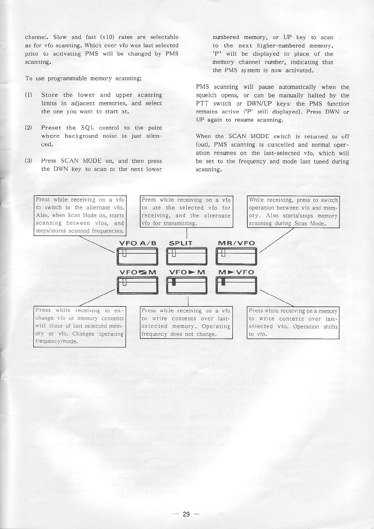
channel. Slow and fast (x10) rates are selectable
as lor vio scanning, Which ever vfo was last selected
prior to activating PMS wÌll be changed by PMS
To use programmabìe memory scannjng;
ll) 5 or. rhè loue' ara pDF. \.dn ing
limjts in adjacent memories, and seÌect
the one you wànt to start at,
(2) Preser the SQL control to the point
(3) P.€ss SCAN MODE on, and the. press
the DWN key to scan b the next lower
numbered memory, or UP key to scan
to the nexl higher nmbered memory.
rPr wìll be displayed in place of ùe
memory channeÌ number, indicating that
rhe PMS system is now acLivated.
PMS scanning wìll pause automatically when the
squelch opens, or can be nanually halted by the
PTT switch or DWN/UP keys: the PMS function
remaìns
active (rP' stilt displayed).
Press DWN or
uP again to resume sca.ning.
When the SCAN MODE switch Ìs retuned to off
(oul), PMS scan.ing ìs cancelled and normal oper
ation resumes on the Last-selected vio, which will
be set to the frequency and mode last tùed during
VFO A/B SPLIT M R
/\/FO
Pfess while receivj.g on a vfo
io ùse the selected rlo ior
feceiving, aód the aì!ernare
vio ior transnirtinS.
P.ess whjÌe feceivi.[.. a !rì
to swirch to rhe !ÌîenaLc vfo,
Also, rvlren Scàr llode o., starts
scanning b.t$ecr vfos, and
stéts/s!ores
s.a.ned f.cquencies.
WhiÌe receivnrg, press to srvirch
oferadon betqeen vio and nem
ory. /\rso sra.|s/stops nenory
scannrng
du.ing
scaD
l\4Òde.
P.ess shilc .ecejvrng
ni er
cnange rto or nemorl coften$
!.ith rhose
of Ì.st seiecied ùcm
o.y o. vrì. Ch..ses operating
rlffir
rr'FO2:/M VFO>M M>VFO
rEE
P..ss while.eceivrnE
o. a !ao
to rv.rte conle.rs over last
se I ec ted nenory. Ope.ating
treqùe.c)
does not change.
P.ess
whil. receivr.g
on
a rnemory
ao wrire co.rents
o!e. Ìasl-
sele.ted vlo. Ope.arion shifrs
29
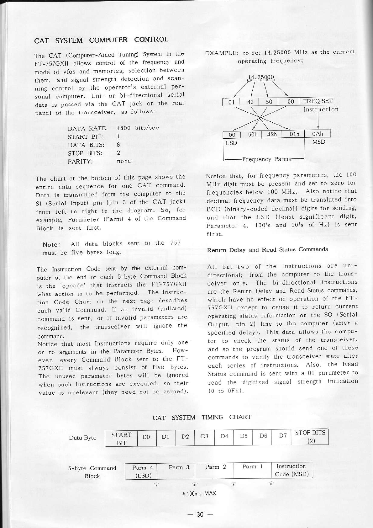
CAT SYSTEM COMPUTER CONTROL
The CAT (Computer-Aided Tuning) Svstem in the
FT-757GXII allows control of the ffequencv and
mode ol vfos and memories' selection berwee'
theú, and signal slrength detection and scan
ning confol by the operator's exlernal per-
sonal compuler. Uni or bi_direcrional serÌal
dala is passed via the CAT jack on ihe rear
panel of the transceiver, as folÌows:
EXAMPLE: to set 14.25000
Ml'lz as the currenl
oPerating frequencY;
Norice that, for lrequency parameters' the 100
MHz digir must be present and set to zero for
ffequencies
below 100 MHz. Also notrce
maL
decimaÌ lrequency data musL be translated rnto
BCD (binary-coded decimal) digits for sending,
and that the LSD (least signiiicant drgrt,
Parameter ,1, 100rs and l0rs of H,) Ìs sent
Return Delay and Read Status Commands
AI brr rru ol hé
lr'rrr'r.or'
of_ rj_
directional; from !he computer lo the !rans
.èi\ar .rl). l\e br-ai
è'rrorà ' s
ru riors
are lhe Return Delay and Read Status commands,
which have no elfect on operation of the FT-
757CXll except to cause il lo return currenl
operating status informalion on rhe SO (Serial
OLrtput, pin 2) line to the computer (alrer a
specified delay). Thls data alloii's rhe compu-
rer to check the starus ol the transcelver'
and so lhe program should send o.e of these
commands ro verify the transceiver state after
each series of i.structions. Also, the Read
Starus
command
is sent
lvith a 0l Paraneler
ro
read the digill2ed siSnal strength indrcatron
(0 ro 0Fh).
DATA RATE:
START BIT:
DATA BITS:
STOP
BITS:
PARITY:
4800 bits/sec
ó
2
The chart at lhe boltom of this page shows tne
entÍre data sequence for one CAI conmand'
Data is transmitted from the compuler to Lhe
SI (Serial Input) pin (pin 3 of the CAT jack)
lrom left to right in the diagram So' for
example, Pafameter (Parm) 4 of the cofìmand
Bìock is sent first.
Note: Aìl data blocks sent to the 7:7
must be five bYtes Ìon8.
The Instruction Code sent by the exterraÌ com-
puler at the end of each s-bvte Comnand Block
is the 'oPcoder that instructs the FT-757CXll
what actio! is to be performed. The lnslruc
tion Code Chart on the next page descfibes
each valid Comnìand. If an invalid (unListed)
command is senl, or if invalid pafamelers are
recognized, lhe transceiver wiÌl ign're the
Notice that most lnsLructions reqùire onÌy o'e
or no arguments in the Paraneter Byles Hoù
ever, every Conrìand Block sent to fhe FT-
757CXll musl àlways consist of five bvtes.
The unused parameter bytes will be Ìgnored
wherì such lnstructions are executed' so their
value is irfeLevanr
(rhey
need nor be zeroed).
CAT SYSTEM T1MNG CHART
Data Byte
Block
* l00ms
fvlAx
START
B]T DO D1 D2 D3 D.l D5 D6 D1 STOP
BITS
l2)
Code
(MSD)
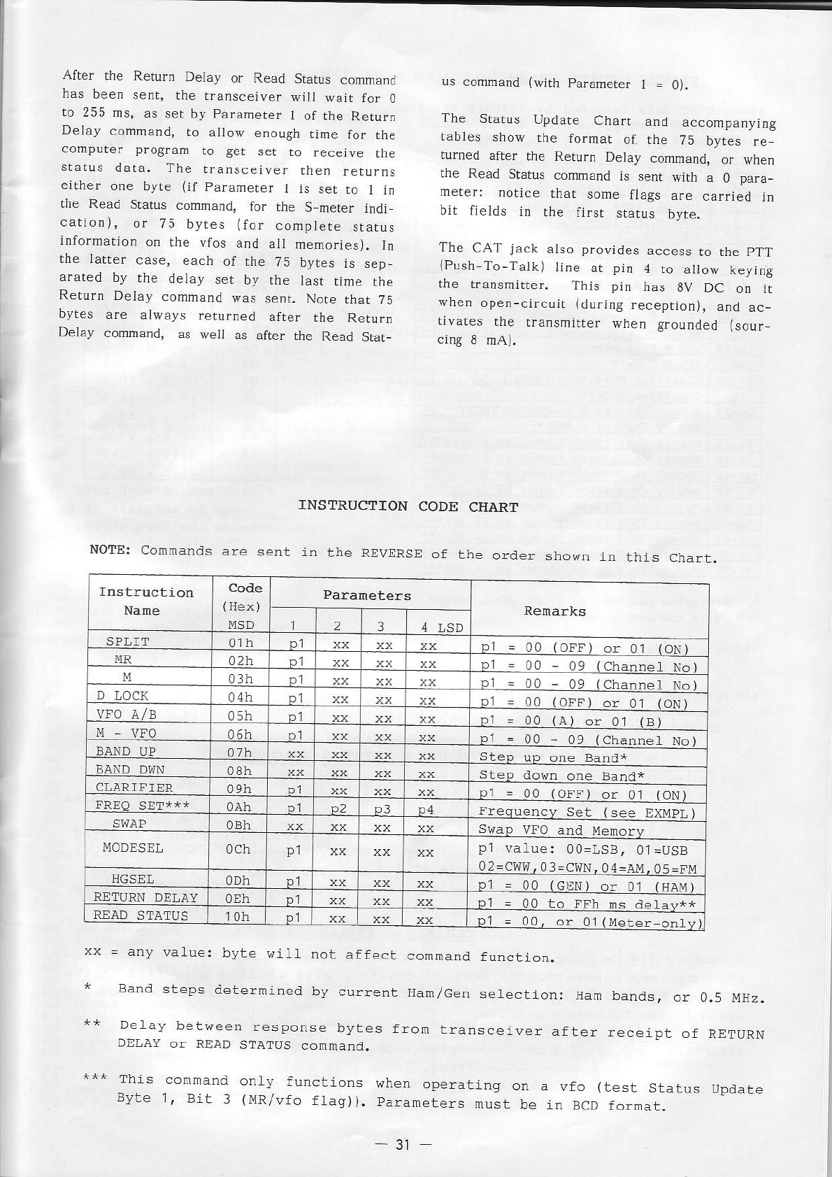
Aiter ùe Rerurn Detay or Read Stalus comma.a
nas Deen
sent, the rransceiver
wili waìt for 0
to 255
ms, as ser by parameter
I of the Retur.
Delay comnand, ro a|oiv enough
.ime for rh€
conìpùrer program to ger set ro .ecejve the
status dara. The transceiver then rerurns
eirher one byre (if Paramerer
I is set ro 1 ì.
ùe Read SLatus
conmand, tor the S merer rndr
catio.), or 75 bytes (for complete status
informarion
on the vros and aI memories). tn
rl_è
rdr
-r .a.-. 7r oy
-, r" ,-p
arated by rhe detay set by rhe tast uùre rne
Return D€lay command
was sent. Note
thar 75
bytes are always returned after rhe Relurn
Delay command, as well as afrer rhe Read Srat_
*** This connand onty functions ùhen operating
Byte 1, Bit : (MR/vfo flas)). parameters nust
us command (wlrh Paramerer 1 = 0).
The Starus Update Chaft and accompanying
tables show t|e formar of rhe 75 byres re
turned after rhe Rerurn Deìay command, or when
the Read StaÍrs conmand is sent wìth a u pa.a_
merer: noLice rhar some flags
bit lields ìn the fjrsr starus byte.
'fhe CAT jack atso provides access ro the pTT
(Push
To-Talk) ljne ar pjn ,1
to allow Key,ng
the transmirte.. 'Ihis pin has 8V DC on it
wnen open-circui! (during
receprìon),
and ac_
tivates the transùjtrer when grourded (sour
cing 8 mA).
INSTRUCTION CODE CHART
NOTE:
Cornmands
ai:e sent in the REVERSE
of the order shown in tnrs chart.
code
(
llex)
MSD 2l4 LSD
SPIIT 01h p1 = 00 (oFF) or 0t (oN)
14R a2h pl = 00 - 09 (qtranneÌ
No)
Mp00 09 (
channel No)
D LOCK 04h pl = 00 (qFF) or 0'l (oN)
VlO A/E 05h !1 = 00 (A) o. 01 (B)
U VFO 06h p1 = 00 - 09 (ChanneÌ No)
BAND UP 07h Step up one Band+
BAND DI{N 08h !!e! dolln one Band*
CLARIFIER 09h trl = 00 (OFF) or 01 (oN)
FREO SEî+++ 0Ah D2 pl Frequency Set (
see ExMpL
)
SWAP 0Bh Swa
p VfO and Memory
IlODESEL 0ch p1 p'l vaÌue: 00=LSB, 01=USB
02=cww, 0
3=cwN,
04=Ar1,
05=F!1
IIGSEL 0Dh pt = 00 (csN) or o1 {HArrl t
RETURN DEIAY 0Eh pl - 00 to FFh ms detav**
FEAD STATUS t0h Pl = 00r or 0l (Meter onÌv
Eam
bands, or 0.5 t4Hz-
DeÌay betlreen response bytes from transceiver after receipr or RETURN
DELÀY or READ STATUS conmand.
on a vfo (test starus Update
be in ÈCD
fo.nat.
rx - any vaLue: byte witÌ not affect command function.
* aand steps determined by current Ean/cen seÌectron:
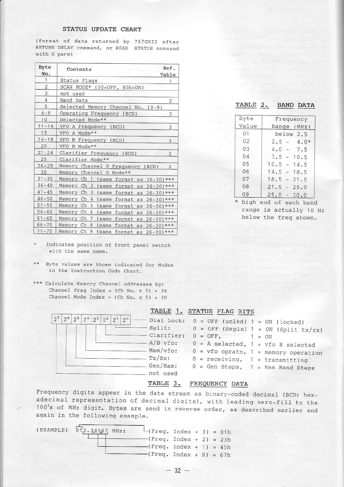
(
EvAÀ4pLE
) '01è:Àl4f Mttzt Lrr."q.
I
I
l
I
I
i
i'
I
I
I
I
contents Ref-
Table
Statqs Flaqs 1
2scaN
MoD!* (0o=oFf. 8oh=oNì
l
4Band Dàta 2
5èÌectèd Mènory channel No. (O 9l
69 operali4s Frequency (BCD) :
t0
1-14 lFo A Freqtredcy {BCD) 3
15
16 19 vFO
B Freg-ùency
(BCD) 3
20
21-24 clarifier Frequebcv IBCD) 3
2S cÌa!ifier r4ode**
26-29 Menorv Clanne1 0 Frequèncy {BcD) 3
30 Memory Channèl 0 Mode+*
.ll-f5 samè tormat as 26-10
36-40 same format as 26-:01+*+
41- 45 same folmat as 26-30
46-50 same forma! as 26-30
M@ry ch 5same format as 26 t0
56-60 sane folnat as 26-:ì0
sane format as 26 30
66 10 Menqay ch Isane fornat as 2
6
-.10
11 75 same fornat as 26 30
STAÎUS UPDATE CHART
(fornat of data returned by 757cxrr aftèi
REîuRN DEI-AY
connand, or READ sTAîUs conmand
TABLE BAìID DA,TA
Byte
Ranqe fMEz )
01
o2
03
a4
05
06
a1
08
09
2.5 4-0*
7.5 - 1 0.5
10.5
- 14.5
14.5 1 8.
5
18.5
- 2t.5
21
.5 25.A
25 -O 30. 0
* hish end of each band
iange is actuaÌly 10 Hz
belorìr the freq shown-
Indìcates position of front panèt swalcn
with lhe sane namè.
Byte vaLues a!è lhosè indicated for Modes
ia !hè lnstruction Code Char!.
calculaLe Menory channel adalresses by;
Channet Freq lndex = (ch No. x 5) + 26
Channel Mode lndex = (Ch No. x 5) + 30
TABLE 'I. STATUS FLAG BITS
Dial I-ock: 0 = OIî funlkd) 1 = ON (tocked)
Split: 0 = oFF (snptx) 1 = oN (sptir txlrx)
Cfarifier: 0 = OtF, 1=oN
A/Bvfo: 0 = A seÌecteat, t =vfoBselected
Mem/vfo: 0 = vfo opiatn, j = nenory operarion
Tx/Rx: 0 = receivins, j = transmittins
Gen/Ham: 0 = cen Steps, 1 = Ean Band Steps
TABLE 3. FREQUENCY DATA
Frequency diqits appear in the data strean as binary-coded atecimal {BCD: hex-
adeclnal representation of decimaÌ digirs), sith leading zero_fil1 to the
'100's of À{H2
digit, Bytes aÌ:e send in reverse order, as described earfier anal
again in the followinq example.
Index +
lndex +
lndei< +
lndex t
3) = 01h
2) = 23t,
1) = 45h
o) = 67}r
32-
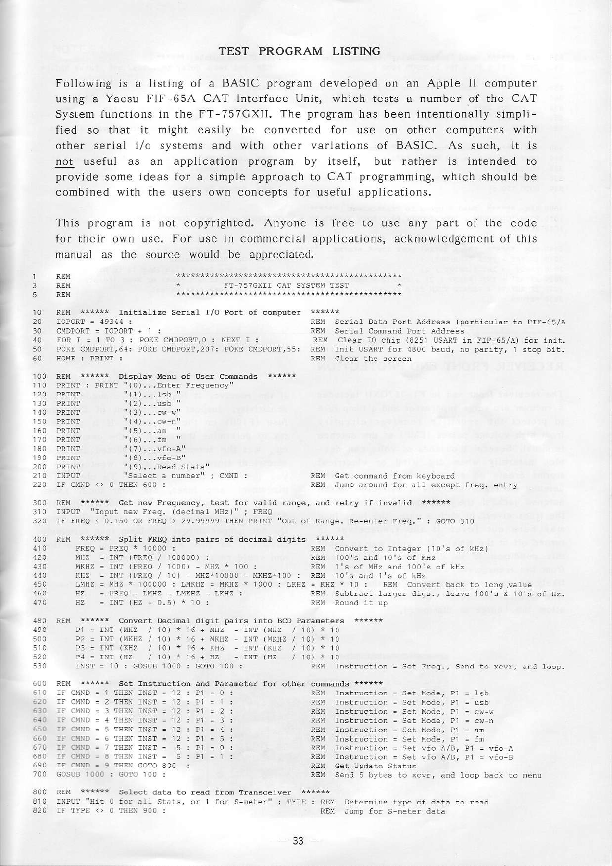
TEST PROGRAM LISTING
Followìng is a Iisting of a BASIC program developed on an Apple [I computer
using a Yaesu FIF-654 CAT lnterface Unit, which tests a number of the CAT
System firnctions in the FT-7s7GXII. The pro$aú has been intentionally simpli-
fied so that it might easily be converted for use on other compùters with
other serial i/o systems and with other variations of BASIC. As such, it is
!!! usefirl as an application program by itself, but rather is intended to
provide some ideas for a simple approach to CAT programming,
which should be
combined with the users own concepts for useful applications.
This program
for their own
manual as the
is not copyrighted. Anyone is free to use any part of the code
use. For use in commercial applications, acknowledgement of this
source would be appreciated
REy +{rr+r InlLidt izÈ sè..aI r/o porf of 6ùputè! r+rrr*
FOR I = 1 TO 3 : PO(E CMDPORT.O :
Po(E cl4DPoRî,64: ?onE cMDPoRÍr207:
Data Port addrèss (particùÌar to rrî 65la
Port address
chtp (425r usaRr in rlF 65la) for init.
for 4300 batrd. no parity, I stop bit.
"(0)...Enter rreqùèncy"
rr(e
)...Rèàd statstr
fron keybóard
to lnteqer (r0 s Òf ksz)
REM 100 s and 10 s of úEz
and 100 s Òf kHz
1èawe 100 s & t0,s of r:2.
send to xcvr, and loop.
cét ne* Prèqùèncy, test foi waÌid
ne{ Freq. {decinal ùrz)" ; rREo
rF IREO < o.rso oR fREo > 29.99999 €nter !req." : GOTO tto
FREA inlo pdirs of decifrl d;9rls 'r{}rl
6,I0
.REO : aREO i 10000 :
MEZ = rNT (|REQ / 100000) :
IrxHz = rNT (IREO / r000t r,rHz
r r00 :
sz = IREo
sz - rNT
(Hz
+
0.s)
* r0:
I{dz = rNr (FRÈo
/ 10) Ez*r0000 s(Ezir00 : REù lo's and I's of kriz
DéciÌal atlgit
r1 = rNr (MHz / 10J + 16 + úEz rNr {ù'sz / 10) * 10
P? = rNr (ùKrz / r0) * 16 + ú(Iìz - rNr (Mruz / r0) * 10
F3 = rNr lxnz / 10) + 16 + Krz rNr (ruz / r0) * r0
14 = rNr (rz / 10) * 16 + Ez rNr (!z / r0) * r0
1000 : Goro 100 :
sèt rnstructi@ anit Padèt* for othèr cóllìmnds ;***'*
IFCMND=2T]ìEN
rF cúND
= 3 rsm rNsr - 12: P1
= 2:
rNsT=12: P1
=3:
IFCÙND:5TSEN
rNsT=12: P1
=5:
rFiaD.aTEN
rF o{D = 9 TsN GOrO 300 :
GOSùB 1000 . Gol! r00 :
= set Mode. Pl = lsb
REù rnstrùclion = set Moder ?1 = cr-q
REú rnstructión - set Modè, Pl = an
lEd rnstruction = set vfo a/8, Pr = vfo a
- ser wfo a/8, P] = vfo È
s€lèct atata
for alf srars,
33
Dèternine typè
rmp for s neter data
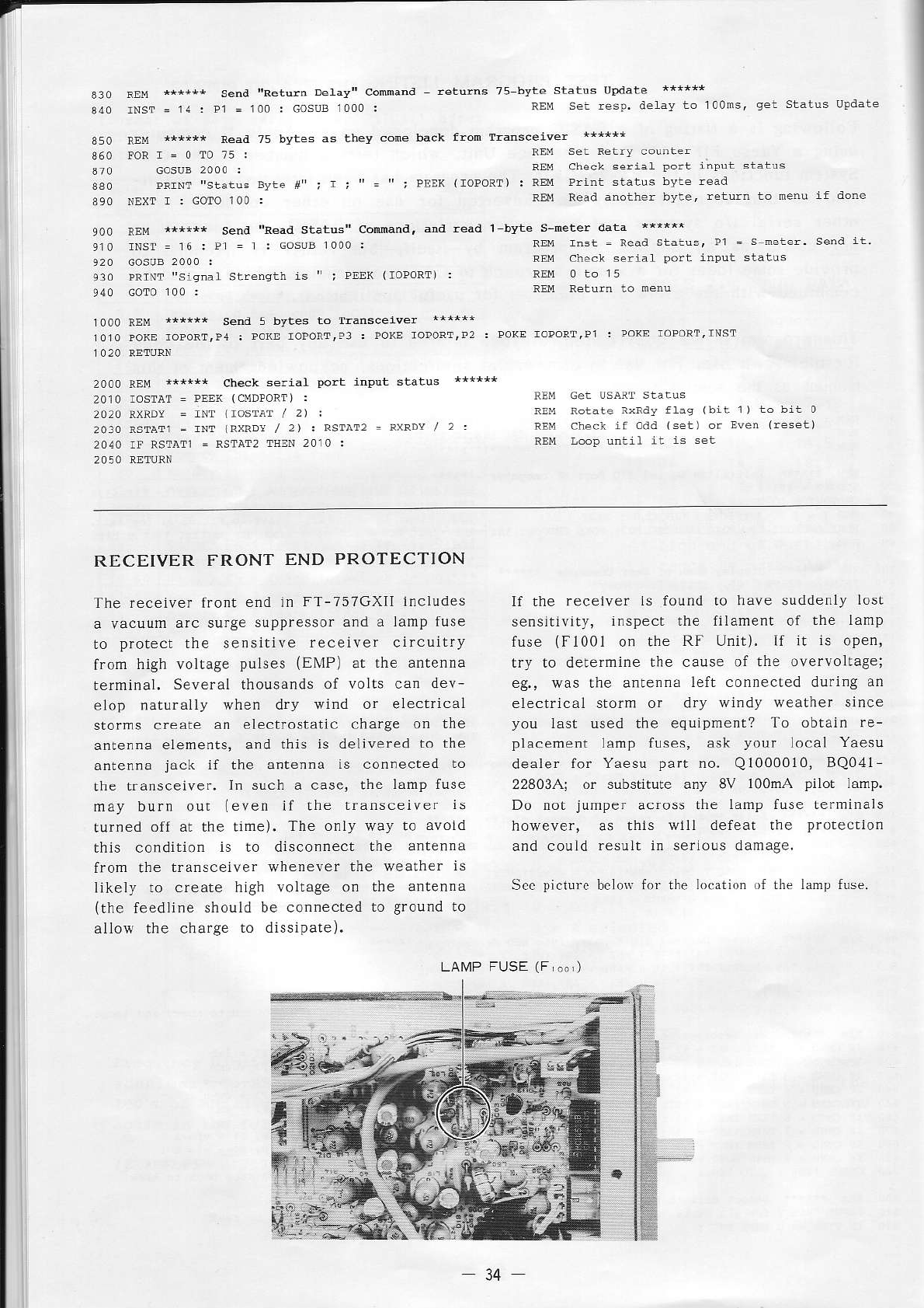
7
send "Retufn Dè1av" connand rèlurns 75 bYtè statùs update i**i-'
340
lNSr.14: ?1
=
100: GOsuB
r00o:
7s bytes as èhev Trarscèiwèr *++"**
!r'te lri ; I , lroPorr) : REù Prirt statls bvt€ rèad
NEXT r : COTO lO0 : REù Read àno'h€r
: Porn loPoRT'P]
check serial
20r0 rosraT = PEr< (CrlDrOÌTl
:
rNr (rosîar / 2) :
2Or0
RSTÀT]
= rNr lRxRDt / 2) . RSaÀr2
= R\RDY
/ 2 :
RlM i+++** Send conmandr dtr rèad
rNsl=r6:P]
!Rl\r "siqnal ; Pnn( lroPorr) :
I bl-te s-úète! data ******
REú rnst = read
ixrcy flag (bir r) to bit 0
o.rd 1sèt) or Even lrèset)
REM io.p untrl it is set
RECEIVER FRONT END PROTECTION
The feceiver front end in FT-757GXIÌ includes
surge suppressor and a lamp fuse
to protect the sensitive receiver clrcultry
ffom high voìtage pulses (ENlP) at the antenna
terminal. Several thousands of voÌts can dev-
elop natu.ally when dry wind or elec.ricaL
storms create an electrostatic charge on the
an!enna eLements, a.d this is delivered to the
antenna jack jf the antenna is connected to
lhe transceiver. In such a case, the lamp fuse
may burr out (even ii rhe transceive. is
rurned off at the lìme). The onll' way to avoid
this condilion is to disconnect the àntenna
from rhe transceiver $,ìrenever the wealher is
ìikeìy to create high voÌtàge on rhe a.tenna
(the feedline should be connected to ground to
allow lhe charge to dissipare).
If the receiver is found to have suddenly losl
sensirlviry, i.spect the filament of the lamp
r"p (l
l00i o ,l- af U r'ì. If t rs
npFr.
try to determine the cause of the overvolrage;
eg., was rhe antenna lefL connecied durlng an
F,c.
-r.t \ ) \ ,c) sódrì
èr -inc-
you Ìast used the equipment? lo obtain re-
placement Lamp fuses, ask your local Yaesu
deaìer for Yaesu part no. Q1000010,
BQ0,11
22803Aj of substitule any 8V l00mA pÌlot lamp.
Do not jumper across the lamp fus€ lerminals
however, as this will defeat rhe protecLion
and could resuÌt in serious damage.
S.c pictùrc
bclo\r
f.r the lo.ation of the lanr! fuse.
LAMP FUSE
(F )
34
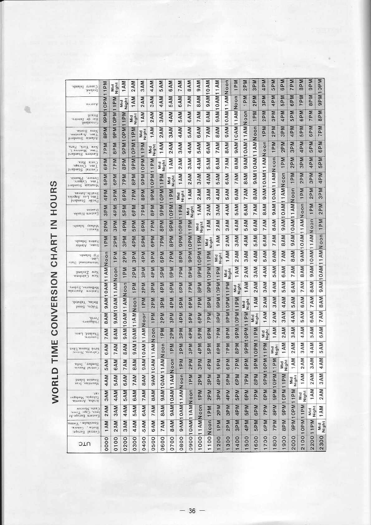
E
T
z
F
î
z
IT,J
z
o
IJJ
F
3
:>
ì i ; 6 i 6 ó ó : '; - Ì . 6 2 = :
F E E E E-F E
E
E
E;lE
F 3 3 i:
E;
F:
i
=: F F F F r: F F J :=: ?: e: a e
= à
=i!i-.zzzzz+z=j
=
E
i E
R E E E E
-È É 5 É
É;'ei
i 3
i : : t r
"
;
E i!
E
F
E
E
F
E
E
E;
E E':=:
= 3;::À
= a t = ! >
> > > > > > > ; ! J=.
e + z z z z
é
r
É:
;:
R
s
"': E
È È È
{ i;:3
*
i
3
Í
í
€
) - -,zL
>E:EE:
É
, t = > E > E
= = > I =
-'
= e = = z z z z E
t
=
!:
*
g
s
F È
a
È È È
E;::
Í
q:;:
s
i; É
36
