Z Stack Developer's Guide
Z-Stack%20Developer's%20Guide
Z-Stack%20Developer's%20Guide
User Manual: Pdf
Open the PDF directly: View PDF ![]() .
.
Page Count: 35
- 1. Introduction
- 2. ZigBee
- 3. Addressing
- 4. Binding
- 5. Routing
- 6. ZDO Message Requests
- 7. Portable Devices
- 8. End-to-end acknowledgements
- 9. Miscellaneous
- 10. Security
- 11. Network Manager
- 12. Inter-PAN Transmission
- 13. ZMAC LQI Adjustment

Copyright 2006-2011 Texas Instruments, Inc. All rights reserved.
Z-Stack
Developer’s Guide
Document Number: SWRA176
Texas Instruments, Inc.
San Diego, California USA

Z-Stack Developer's Guide SWRA176 Version 1.11
Copyright 2006-2012 Texas Instruments, Inc. All rights reserved.
i
Revision
Description
Date
1.0 Initial release 12/13/2006
1.1 Added section on ZDO Message Request 09/29/2007
1.2 Updates for ZigBee 2007 and ZigBee PRO features 02/24/2008
1.3 Updated location of zgPreConfigKeys 01/06/2009
1.4 Updated for 2.2.0 Release 03/30/2009
1.5 Replaced references to ZDNwkManager with ZDNwkMgr 04/14/2009
1.6 Updated section 4.1.1.1 08/03/2009
1.7 Updated section 10.5 for multiple preconfigured trust center link keys 01/15/2010
1.8
Updated section 4
Updated section 9.6.3. NV range for application use
Fixed misspelling of zgPreConfigKeys variable
Added section 10.6 on Security key data management
Added section 13 on ZMAC LQI Adjustment 08/11/2010
1.9 Added Extended PAN IDs section 11/20/2010
1.10 Editorial changes to sections 2.1 and 2.1.1 03/23/2011
1.11 Added section 5.6 for Router Off-Network Association Cleanup 03/14/2012

Z-Stack Developer's Guide SWRA176 Version 1.11
Copyright 2006-2012 Texas Instruments, Inc. All rights reserved.
ii
TABLE OF CONTENTS
1. INTRODUCTION .................................................................................................................................................................. 1
1.1 PURPOSE .......................................................................................................................................................................... 1
1.2 SCOPE .............................................................................................................................................................................. 1
1.3 ACRONYMS ...................................................................................................................................................................... 1
1.4 REFERENCE DOCUMENTS .................................................................................................................................................. 1
2. ZIGBEE .................................................................................................................................................................................. 2
2.1 DEVICE TYPES .................................................................................................................................................................. 2
2.1.1 Coordinator ............................................................................................................................................................ 2
2.1.2 Router ..................................................................................................................................................................... 2
2.1.3 End-device .............................................................................................................................................................. 2
2.2 STACK PROFILE ................................................................................................................................................................ 3
3. ADDRESSING ....................................................................................................................................................................... 4
3.1 ADDRESS TYPES ................................................................................................................................................................ 4
3.2 NETWORK ADDRESS ASSIGNMENT ..................................................................................................................................... 4
3.2.1 Tree Addressing ...................................................................................................................................................... 4
3.2.2 Stochastic Addressing ............................................................................................................................................. 4
3.3 ADDRESSING IN Z-STACK ................................................................................................................................................. 5
3.3.1 Unicast ................................................................................................................................................................... 5
3.3.2 Indirect ................................................................................................................................................................... 6
3.3.3 Broadcast ............................................................................................................................................................... 6
3.3.4 Group Addressing ................................................................................................................................................... 6
3.4 IMPORTANT DEVICE ADDRESSES ....................................................................................................................................... 6
4. BINDING ................................................................................................................................................................................ 7
4.1 BUILDING A BINDING TABLE ............................................................................................................................................ 7
4.1.1 ZigBee Device Object Bind Request ....................................................................................................................... 7
4.1.1.1 The Commissioning Application ....................................................................................................... 7
4.1.1.2 ZigBee Device Object End Device Bind Request .............................................................................. 7
4.1.2 Device Application Binding Manager .................................................................................................................... 8
4.2 CONFIGURING SOURCE BINDING ....................................................................................................................................... 8
5. ROUTING .............................................................................................................................................................................. 9
5.1 OVERVIEW ....................................................................................................................................................................... 9
5.2 ROUTING PROTOCOL ......................................................................................................................................................... 9
5.2.1 Route Discovery and Selection ............................................................................................................................. 10
5.2.2 Route maintenance ............................................................................................................................................... 10
5.2.3 Route expiry .......................................................................................................................................................... 10
5.3 TABLE STORAGE ............................................................................................................................................................. 10
5.3.1 Routing table ........................................................................................................................................................ 10
5.3.2 Route discovery table ........................................................................................................................................... 11
5.4 MANY-TO-ONE ROUTING PROTOCOL .............................................................................................................................. 11
5.4.1 Many-to-one routing overview ............................................................................................................................. 11
5.4.2 Many-to-one route discovery ................................................................................................................................ 11
5.4.3 Route record command ......................................................................................................................................... 12
5.4.4 Many-to-one route maintenance ........................................................................................................................... 13
5.5 ROUTING SETTINGS QUICK REFERENCE .......................................................................................................................... 13
5.6 ROUTER OFF-NETWORK ASSOCIATION CLEANUP ............................................................................................................ 14
6. ZDO MESSAGE REQUESTS ............................................................................................................................................ 15
7. PORTABLE DEVICES ....................................................................................................................................................... 17
8. END-TO-END ACKNOWLEDGEMENTS ....................................................................................................................... 17
9. MISCELLANEOUS............................................................................................................................................................. 18
9.1 CONFIGURING CHANNEL ................................................................................................................................................. 18
9.2 CONFIGURING THE PAN ID AND NETWORK TO JOIN ........................................................................................................ 18
9.3 MAXIMUM PAYLOAD SIZE ............................................................................................................................................... 18
9.4 LEAVE NETWORK ........................................................................................................................................................... 18
9.5 DESCRIPTORS ................................................................................................................................................................. 19
9.6 NON-VOLATILE MEMORY ITEMS .................................................................................................................................... 19

Z-Stack Developer's Guide SWRA176 Version 1.11
Copyright 2006-2012 Texas Instruments, Inc. All rights reserved.
iii
9.6.1 Global Configuration Non-Volatile Memory ........................................................................................................ 19
9.6.2 Network Layer Non-Volatile Memory ................................................................................................................... 19
9.6.3 Application Non-Volatile Memory ........................................................................................................................ 19
9.7 ASYNCHRONOUS LINKS .................................................................................................................................................. 19
9.8 MULTICAST MESSAGES .................................................................................................................................................. 20
9.9 FRAGMENTATION ........................................................................................................................................................... 20
9.9.1 Quick Reference ................................................................................................................................................... 21
9.10 EXTENDED PAN IDS ...................................................................................................................................................... 21
10. SECURITY ...................................................................................................................................................................... 22
10.1 OVERVIEW ..................................................................................................................................................................... 22
10.2 CONFIGURATION ............................................................................................................................................................. 22
10.3 NETWORK ACCESS CONTROL ........................................................................................................................................... 22
10.4 KEY UPDATES ................................................................................................................................................................ 22
10.5 SMART ENERGY SECURE JOINING ................................................................................................................................... 22
10.6 SECURITY KEY DATA MANAGEMENT ................................................................................................................................ 25
10.7 QUICK REFERENCE ......................................................................................................................................................... 25
11. NETWORK MANAGER ................................................................................................................................................ 26
11.1 OVERVIEW ..................................................................................................................................................................... 26
11.2 CHANNEL INTERFERENCE ............................................................................................................................................... 26
11.2.1 Channel Interference Detection ............................................................................................................................ 26
11.2.2 Channel Interference Resolution .......................................................................................................................... 26
11.2.3 Quick Reference ................................................................................................................................................... 27
11.3 PAN ID CONFLICT ......................................................................................................................................................... 27
11.3.1 PAN ID Conflict Detection ................................................................................................................................... 28
11.3.2 PAN ID Conflict Resolution ................................................................................................................................. 28
12. INTER-PAN TRANSMISSION ..................................................................................................................................... 29
12.1 OVERVIEW ..................................................................................................................................................................... 29
12.2 DATA EXCHANGE ........................................................................................................................................................... 29
12.2.1 Quick Reference ................................................................................................................................................... 30
13. ZMAC LQI ADJUSTMENT .......................................................................................................................................... 31
13.1 OVERVIEW ..................................................................................................................................................................... 31
13.2 LQI ADJUSTMENT MODES .............................................................................................................................................. 31
13.3 USING LQI ADJUSTMENT ............................................................................................................................................... 31

Z-Stack Developer's Guide SWRA176 Version 1.11
Copyright 2006-2012 Texas Instruments, Inc. All rights reserved.
1
1. Introduction
1.1 Purpose
This document explains some of the components of the Texas Instruments ZigBee stack and their functioning. It
explains the configurable parameters in the ZigBee stack and how they may be changed by the application developer
to suit the application requirements.
1.2 Scope
This document describes concepts and settings for the Texas Instruments Z-Stack™ Release. This is a ZigBee-2007
compliant stack for the ZigBee and ZigBee PRO stack profiles.
1.3 Acronyms
AF Application Framework
AES Advanced Encryption Standard
AIB APS Information Base
API Application Programming Interface
APS Application Support Sub-Layer
APSDE APS Date Entity
APSME APS Management Entity
ASDU APS Service Datagram Unit
CCM* Enhanced counter with CBC-MAC mode of operation
EPID Extended PAN ID
MSG Message
NHLE Next Higher Layer Entity
NIB Network Information Base
NWK Network
PAN Personal Area Network
SE Smart Energy
ZDO ZigBee Device Object
1.4 Reference Documents
[1] ZigBee Specification, R17, ZigBee Alliance document number 053474r17ZB.
[2] Z-Stack API (SWRA195)
Z-Stack Developer's Guide SWRA176 Version 1.11
Copyright 2006-2012 Texas Instruments, Inc. All rights reserved.
2
2. ZigBee
A ZigBee network is a multi-hop network with battery-powered devices. This means that two devices that wish to
exchange data in a ZigBee network may have to depend on other intermediate devices to be able to successfully do
so. Because of this cooperative nature of the network, proper functioning requires that each device (i) perform
specific networking functions and (ii) configure certain parameters to specific values. The set of networking
functions that a device performs determines the role of the device in the network and is called a device type. The set
of parameters that need to be configured to specific values, along with those values, is called a stack profile.
2.1 Device Types
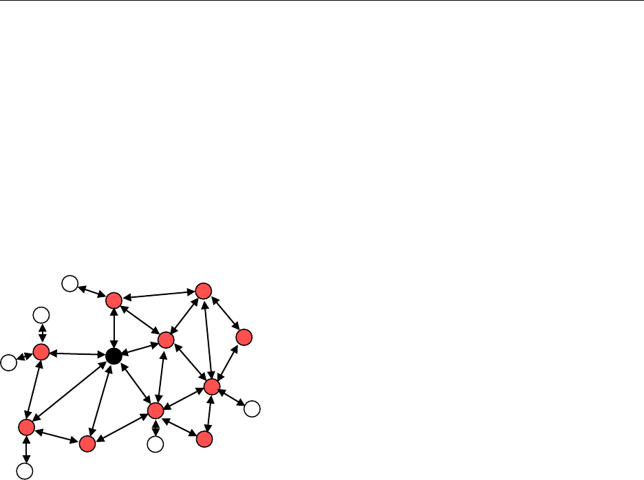
There are three logical device types in a ZigBee network – (i) Coordinator (ii) Router and (iii) End-device. A
ZigBee network consists of a Coordinator node and multiple Router and End-device nodes. Note that the device type
does not in any way restrict the type of application that may run on the particular device.
An example network is shown in the diagram above, with the ZigBee Coordinator (black), the Routers (red), and the
End Devices (white).
2.1.1 Coordinator
This is the device that “starts” a ZigBee network. It is the first device on the network. The coordinator node scans
the RF environment for existing networks, chooses a channel and a network identifier (also called PAN ID) and then
starts the network.
The coordinator node can also be used, optionally, to assist in setting up security and application-level bindings in
the network.
Note that the role of the Coordinator is mainly related to starting up and configuring the network. Once that is
accomplished, the Coordinator behaves like a Router node (or may even go away). The continued operation of the
network does not depend on the presence of the Coordinator due to the distributed nature of the ZigBee network.
2.1.2 Router
A Router performs functions for (i) allowing other devices to join the network (ii) multi-hop routing (iii) assisting in
communication for its child battery-powered end devices.
In general, Routers are expected to be active all the time and thus have to be mains-powered.
2.1.3 End-device
An end-device has no specific responsibility for maintaining the network infrastructure, so it can sleep and wake up
as it chooses. Thus it can be a battery-powered node.
Generally, the memory requirements (especially RAM requirements) are lower for an end-device.

Z-Stack Developer's Guide SWRA176 Version 1.11
Copyright 2006-2012 Texas Instruments, Inc. All rights reserved.
3
Notes:
In Z-Stack, the device type is usually determined at compile-time via compile options (ZDO_COORDINATOR and
RTR_NWK). All sample applications are provided with separate project files to build each device type.
2.2 Stack Profile
The set of stack parameters that need to be configured to specific values, along with the above device type values, is
called a stack profile. The parameters that comprise the stack profile are defined by the ZigBee Alliance.
All devices in a network must conform to the same stack profile (i.e., all devices must have the stack profile
parameters configured to the same values).
The ZigBee Alliance has defined two different stack profiles for the ZigBee-2007 specification, Zigbee and Zigbee
PRO, with the goal of promoting interoperability. All devices that conform to this stack profile will be able to work
in a network with devices from other vendors that also conform to it.
If application developers choose to change the settings for any of these parameters, they can do so with the caveat
that those devices will no longer be able to interoperate with devices from other vendors that choose to follow the
ZigBee specified stack profile. Thus, developers of “closed networks” may choose to change the settings of the stack
profile variables. These stack profiles are called “network-specific” stack profile.
The stack profile identifier that a device conforms to is present in the beacon transmitted by that device. This
enables a device to determine the stack profile of a network before joining to it. The “network-specific” stack profile
has an ID of 0 while the ZigBee stack profile has ID of 1, and a ZigBee PRO stack profile has ID of 2. The stack
profile is configured by the STACK_PROFILE_ID parameter in nwk_globals.h file.
Normally, a device of 1 profile (ex. ZigBee PRO) joins a network with the same profile. If a router of 1 profile (ex.
ZigBee PRO) joins a network with a different profile (ex. ZigBee-2007), it will join as a non-sleeping end device.
An end device of 1 profile (ex. ZigBee PRO) will always be an end device in a network with a different profile.

Z-Stack Developer's Guide SWRA176 Version 1.11
Copyright 2006-2012 Texas Instruments, Inc. All rights reserved.
4
3. Addressing
3.1 Address types
ZigBee devices have two types of addresses. A 64-bit IEEE address (also called MAC address or Extended address)
and a 16-bit network address (also called logical address or short address).
The 64-bit address is a globally unique address and is assigned to the device for its lifetime. It is usually set by the
manufacturer or during installation. These addresses are maintained and allocated by the IEEE. More information on
how to acquire a block of these addresses is available at http://standards.ieee.org/regauth/oui/index.shtml. The 16-bit
address is assigned to a device when it joins a network and is intended for use while it is on the network. It is only
unique within that network. It is used for identifying devices and sending data within the network.
3.2 Network address assignment
3.2.1 Tree Addressing
ZigBee 2007 uses a distributed addressing scheme for assigning the network addresses. This scheme ensures that all
assigned network addresses are unique throughout the whole network. This is necessary so that there is no ambiguity
about which device a particular packet should be routed to. Also, the distributed nature of the addressing algorithm
ensures that a device only has to communicate with its parent device to receive a unique network-wide address.
There is no need for network-wide communication for address assignment and this helps in scalability of the
network.
The addressing scheme requires that some parameters are known ahead of time and are configured in each router
that joins the network. These are the MAX_DEPTH, MAX_ROUTERS and MAX_CHILDREN parameters. These are
part of the stack profile and the ZigBee-2007 stack profile has defined values for these parameters (MAX_DEPTH =
5, MAX_CHILDREN = 20, MAX_ROUTERS = 6).
The MAX_DEPTH determines the maximum depth of the network. The coordinator is at depth 0 and its child nodes
are at depth 1 and their child nodes are at depth 2 and so on. Thus the MAX_DEPTH parameter limits how “long” the
network can be physically.
The MAX_CHILDREN parameter determines the maximum number of child nodes that a router (or coordinator) node
can possess.
The MAX_ROUTERS parameter determines the maximum number of router-capable child nodes that a router (or
coordinator) node can possess. This parameter is a subset of the MAX_CHILDREN parameter and the remaining
(MAX_CHILDREN – MAX_ROUTERS) entries are for end devices.
If developers wish to change these values, they need to follow the following steps:
• First it must be ensured that the new values for these parameters are legal. Since the total address space is
limited to about 216, there are limits on how large these parameters can be set to.
• After choosing legal values, the developer needs to ensure not to use the standard stack profile and instead
set it to network-specific (i.e. change the STACK_PROFILE_ID in “nwk_globals.h” to
NETWORK_SPECIFIC) because the values are different from the values defined for the ZigBee profile.
Then the MAX_DEPTH parameter in “nwk_globals.h” may be set to the appropriate value.
• In addition, the array’s CskipChldrn and CskipRtrs must be set in the nwk_globals.c file. These arrays are
populated with the values for MAX_CHILDREN and MAX_ROUTERS value for the first MAX_DEPTH
indices followed by a zero value.
3.2.2 Stochastic Addressing
ZigBee PRO uses a stochastic (random) addressing scheme for assigning the network addresses. This addressing
scheme randomly assigns short addresses to new devices, and then uses the rest of the devices in the network to

Z-Stack Developer's Guide SWRA176 Version 1.11
Copyright 2006-2012 Texas Instruments, Inc. All rights reserved.
5
ensure that there are no duplicate addresses. When a device joins, it receives its randomly generated address from
its parent. The new network node then generates a “Device Announce” (which contains its new short address and its
extended address) to the rest of the network. If there is another device with the same short address, a node (router)
in the network will send out a broadcast “Network Status – Address Conflict” to the entire network and all devices
with the conflicting short address will change its short address. When the conflicted devices change their address
they issue their own “Device Announce” to check their new address for conflicts within the network.
End devices do not participate in the “Address Conflict”. Their parents do that for them. If an “Address Conflict”
occurs for an end device, its parent will issue the end device a “Rejoin Response” message to change the end
device’s short address and the end device issues a “Device Announce” to check their new address for conflicts
within the network.
When a “Device Announce” is received, the association and binding tables are updated with the new short address,
routing table information is not updated (new routes must be established). If a parent determines that the “Device
Announce” pertains to one of its end device children, but it didn’t come directly from the child, the parent will
assume that the child moved to another parent.
3.3 Addressing in Z-Stack
In order to send data to a device on the ZigBee network, the application generally uses the AF_DataRequest()
function. The destination device to which the packet is to be sent is of type afAddrType_t (defined in
“ZComDef.h”).
typedef struct
{
union
{
uint16 shortAddr;
ZLongAddr_t extAddr;
} addr;
afAddrMode_t addrMode;
byte endPoint;
} afAddrType_t;
Note that in addition to the network address, the address mode parameter also needs to be specified. The destination
address mode can take one of the following values (AF address modes are defined in “AF.h”)
typedef enum
{
afAddrNotPresent = AddrNotPresent,
afAddr16Bit = Addr16Bit,
afAddr64Bit = Addr64Bit,
afAddrGroup = AddrGroup,
afAddrBroadcast = AddrBroadcast
} afAddrMode_t;
The address mode parameter is necessary because, in ZigBee, packets can be unicast, multicast or broadcast. A
unicast packet is sent to a single device, a multicast packet is destined to a group of devices and a broadcast packet is
generally sent to all devices in the network. This is explained in more detail below.
3.3.1 Unicast
This is the normal addressing mode and is used to send a packet to a single device whose network address is known.
The addrMode is set to Addr16Bit and the destination network address is carried in the packet

Z-Stack Developer's Guide SWRA176 Version 1.11
Copyright 2006-2012 Texas Instruments, Inc. All rights reserved.
6
3.3.2 Indirect
This is when the application is not aware of the final destination of the packet. The mode is set to
AddrNotPresent and the destination address is not specified. Instead, the destination is looked up from a
“binding table” that resides in the stack of the sending device. This feature is called Source binding (see later section
for details on binding).
When the packet is sent down to the stack, the destination address and end point is looked up from the binding table
and used. The packet is then treated as a regular unicast packet. If more than one destination device is found in the
binding table, a copy of the packet is sent to each of them. If no binding entry is found, the packet will not be sent.
3.3.3 Broadcast
This address mode is used when the application wants to send a packet to all devices in the network. The address
mode is set to AddrBroadcast and the destination address can be set to one of the following broadcast addresses:
NWK_BROADCAST_SHORTADDR_DEVALL (0xFFFF) – the message will be sent to all devices in the network
(includes sleeping devices). For sleeping devices, the message is held at its parent until the sleeping device polls for
it or the message is timed out (NWK_INDIRECT_MSG_TIMEOUT in f8wConfig.cfg).
NWK_BROADCAST_SHORTADDR_DEVRXON (0xFFFD) – the message will be sent to all devices that have the
receiver on when idle (RXONWHENIDLE). That is, all devices except sleeping devices.
NWK_BROADCAST_SHORTADDR_DEVZCZR (0xFFFC) – the message is sent to all routers (including the
coordinator ).
3.3.4 Group Addressing
This address mode is used when the application wants to send a packet to a group of devices. The address mode is
set to afAddrGroup and the addr.shortAddr is set to the group identifier.
Before using this feature, groups must be defined in the network [see aps_AddGroup() in the Z-Stack API doc].
Note that groups can also be used in conjunction with indirect addressing. The destination address found in the
binding table can be either a unicast or a group address. Also note that broadcast addressing is simply a special case
of group addressing where the groups are setup ahead of time.
Sample code for a device to add itself to a group with identifier 1:
aps_Group_t group;
// Assign yourself to group 1
group.ID = 0x0001;
group.name[0] = 6; // First byte is string length
osal_memcpy( &(group.name[1]), “Group1”, 6);
aps_AddGroup( SAMPLEAPP_ENDPOINT, &group );
3.4 Important Device Addresses
An application may want to know the address of its device and that of its parent. Use the following functions to get
this device’s address (defined in Z-Stack API Doc):
• NLME_GetShortAddr() – returns this device’s 16 bit network address.
• NLME_GetExtAddr() – returns this device’s 64 bit extended address.
• Use the following functions to get this device’s parent’s addresses (defined in Z-Stack API Doc). Note that
the term “Coord” in these functions does not refer to the ZigBee Coordinator, but instead to the device’s
parent (MAC Coordinator):
• NLME_GetCoordShortAddr() – returns this device’s parent’s 16 bit short address.
• NLME_GetCoordExtAddr() – returns this device’s parent’s 64 bit extended address.

Z-Stack Developer's Guide SWRA176 Version 1.11
Copyright 2006-2012 Texas Instruments, Inc. All rights reserved.
7
4. Binding
Binding is a mechanism to control the flow of messages from one application to another application (or multiple
applications). The binding mechanism is implemented in all devices and is called source binding.
Binding allows an application to send a packet without knowing the destination address, the APS layer determines
the destination address from its binding table, and then forwards the message on to the destination application (or
multiple applications) or group.
4.1 Building a Binding Table
There are 3 ways to build a binding table:
• ZigBee Device Object Bind Request – a commissioning tool can tell the device to make a binding record.
• ZigBee Device Object End Device Bind Request – 2 devices can tell the coordinator that they would like to
setup a binding table record. The coordinator will make the match up and create the binding table entries in
the 2 devices.
• Device Application – An application on the device can build or manage a binding table.
4.1.1 ZigBee Device Object Bind Request
Any device or application can send a ZDO message to another device (over the air) to build a binding record for that
other device in the network. This is called Assisted Binding and it will create a binding entry for the sending device.
4.1.1.1 The Commissioning Application
An application can do this by calling ZDP_BindReq() [defined in ZDProfile.h] with 2 applications (addresses and
endpoints) and the cluster ID wanted in the binding record. The first parameter (target dstAddr) is the short
address of the binding’s source address (where the binding record will be stored). Calling ZDP_UnbindReq()can
be used, with the same parameters, to remove the binding record.
The target device will send back a ZigBee Device Object Bind or Unbind Response message which the ZDO code
on the coordinator will parse and notify ZDApp.c by calling ZDApp_ProcessMsgCBs()with the status of the action.
For the Bind Response, the status returned from the coordinator will be ZDP_SUCCESS, ZDP_TABLE_FULL,
ZDP_INVALID_EP, or ZDP_NOT_SUPPORTED.
For the Unbind Response, the status returned from the coordinator will be ZDP_SUCCESS, ZDP_NO_ENTRY,
ZDP_INVALID_EP, or ZDP_NOT_SUPPORTED.
4.1.1.2 ZigBee Device Object End Device Bind Request
This mechanism uses a button press or other similar action at the selected devices to bind within a specific timeout
period. The End Device Bind Request messages are collected at the coordinator within the timeout period and a
resulting Binding Table entry is created based on the agreement of profile ID and cluster ID. The default end device
binding timeout (APS_DEFAULT_MAXBINDING_TIME) is 16 seconds (defined in nwk_globals.h), but can be
changed if added to f8wConfig.cfg or as a compile flag.
All sample applications have a function that handles key events [for example, TransmitApp_HandleKeys() in
TransmitApp.c]. The SW2 key handler calls ZDP_EndDeviceBindReq() [ZDProfile.c] to send the End Device
Bind Request message to the coordinator, with only the cluster IDs relevant to the TransmitApp application. Or, as
in SampleLight and SampleSwitch, ZDP_EndDeviceBindReq() is called directly with only the cluster IDs
relevant to the lamp On/Off functions.
For the Coordinator End Device Binding process, the coordinator registered [ZD_RegisterForZDOMsg()] to receive
End Device Bind Request, Bind Response and Unbind Response ZDO messages [in ZDApp_RegisterCBs() -

Z-Stack Developer's Guide SWRA176 Version 1.11
Copyright 2006-2012 Texas Instruments, Inc. All rights reserved.
8
ZDApp.c] When these message are received they are sent to ZDApp_ProcessMsgCBs(), where they are parsed and
processed.
Coordinator end device binding is a toggle process. Meaning that the first time your go through the process, it will
create a binding entry in the requesting devices. Then, when you go through the process again, it will remove the
bindings in the requesting devices. That’s why, in the following process, it will send an unbind, and wait to see if
the unbind was successful. If the unbind was successful, the binding entry must have existed and been removed,
otherwise it sends a binding request to make the entry.
When the coordinator receives 2 matching End Device Bind Requests, it will start the process of creating source
binding entries in the requesting devices. The coordinator follows the following process, assuming matches were
found in the ZDO End Device Bind Requests:
1. Send a ZDO Unbind Request to the first device. The End Device Bind is toggle process, so the unbind
is sent first to remove an existing bind entry.
2. Wait for the ZDO Unbind Response, if the response status is ZDP_NO_ENTRY, send a ZDO Bind
Request to make the binding entry in the source device. If the response status is ZDP_SUCCESS,
move on to the cluster ID for the first device (the unbind removed the entry – toggle).
3. Wait for the ZDO Bind Response. When received, move on to the next cluster ID for the first device.
4. When the first device is done, do the same process with the second device.
5. When the second device is done, send the ZDO End Device Bind Response messages to both the first
and second device.
4.1.2 Device Application Binding Manager
Another way to enter binding entries on the device is for the application to manage the binding table for itself.
Meaning that the application will enter and remove binding table entries locally by calling the following binding
table management functions (ref. Z-Stack API Document – Binding Table Management section):
• bindAddEntry() – Add entry to binding table
• bindRemoveEntry() – Remove entry from binding table
• bindRemoveClusterIdFromList() – Remove a cluster ID from an existing binding table entry
• bindAddClusterIdToList() – Add a cluster ID to an existing binding table entry
• bindRemoveDev() – Remove all entries with an address reference
• bindRemoveSrcDev() – Remove all entries with a referenced source address
• bindUpdateAddr () – Update entries to another address
• bindFindExisting () – Find a binding table entry
• bindIsClusterIDinList() – Check for an existing cluster ID in a table entry
• bindNumBoundTo() – Number of entries with the same address (source or destination)
• bindNumOfEntries() – Number of table entries
• bindCapacity() – Maximum entries allowed
• BindWriteNV() – Update table in NV.
4.2 Configuring Source Binding
To enable source binding in your device include the REFLECTOR compile flag in f8wConfig.cfg. Also in
f8wConfig.cfg, look at the 2 binding configuration items (NWK_MAX_BINDING_ENTRIES &
MAX_BINDING_CLUSTER_IDS). NWK_MAX_BINDING_ENTRIES is the maximum number of entries in the
binding table and MAX_BINDING_CLUSTER_IDS is the maximum number of cluster IDs in each binding entry.
The binding table is maintained in static RAM (not allocated), so the number of entries and the number of cluster
IDs for each entry really affect the amount of RAM used. Each binding table entry is 6 bytes plus
(MAX_BINDING_CLUSTER_IDS * 2 bytes). Besides the amount of static RAM used by the binding table, the
binding configuration items also affect the number of entries in the address manager.

Z-Stack Developer's Guide SWRA176 Version 1.11
Copyright 2006-2012 Texas Instruments, Inc. All rights reserved.
9
5. Routing
5.1 Overview
A mesh network is described as a network in which the routing of messages is performed as a decentralized,
cooperative process involving many peer devices routing on each others’ behalf.
The routing is completely transparent to the application layer. The application simply sends data destined to any
device down to the stack which is then responsible for finding a route. This way, the application is unaware of the
fact that it is operating in a multi-hop network.
Routing also enables the “self healing” nature of ZigBee networks. If a particular wireless link is down, the routing
functions will eventually find a new route that avoids that particular broken link. This greatly enhances the
reliability of the wireless network and is one of the key features of ZigBee.
Many-to-one routing is a special routing scheme that handles the scenario where centralized traffic is involved. It is
part of the ZigBee PRO feature set to help minimize traffic particularly when all the devices in the network are
sending packets to a gateway or data concentrator. Many-to-one route discovery is described in details in Section
5.4.
5.2 Routing protocol
ZigBee uses a routing protocol that is based on the AODV (Ad-hoc On-demand Distance Vector) routing protocol
for ad-hoc networks. Simplified for use in sensor networks, the ZigBee routing protocol facilitates an environment
capable of supporting mobile nodes, link failures and packet losses.
Neighbor routers are routers that are within radio range of each other. Each router keeps track of their neighbors in
a “neighbor table”, and the “neighbor table” is updated when the router receives any message from a neighbor router
(unicast, broadcast or beacon).
When a router receives a unicast packet, from its application or from another device, the NWK layer forwards it
according to the following procedure. If the destination is one of the neighbors of the router (including its child
devices) the packet will be transmitted directly to the destination device. Otherwise, the router will check its routing
table for an entry corresponding to the routing destination of the packet. If there is an active routing table entry for
the destination address, the packet will be relayed to the next hop address stored in the routing entry. If a single
transmission attempt fails, the NWK layer will repeat the process of transmitting the packet and waiting for the
acknowledgement, up to a maximum of NWK_MAX_DATA_RETRIES times. The maximum data retries in the NWK
layer can be configured in "f8wconfig.cfg". If an active entry can not be found in the routing table or using an entry
failed after the maximum number of retries, a route discovery is initiated and the packet is buffered until that process
is completed.
ZigBee end-devices do not perform any routing functions. An end-device wishing to send a packet to any device
simply forwards it to its parent device which will perform the routing on its behalf. Similarly, when any device
wishes to send a packet to an end-device and initiate route discovery, the parent of the end-device responds on its
behalf.
Note that the ZigBee Tree Addressing (non-PRO) assignment scheme makes it possible to derive a route to any
destination based on its address. In Z-Stack, this mechanism is used as an automatic fallback in case the regular
routing procedure cannot be initiated (usually, due to lack of routing table space).
Also in Z-Stack, the routing implementation has optimized the routing table storage. In general, a routing table
entry is needed for each destination device. But by combining all the entries for end-devices of a particular parent
with the entry for that parent device, storage is optimized without loss of any functionality.
ZigBee routers, including the coordinator, perform the following routing functions (i) route discovery and selection
(ii) route maintenance (iii) route expiry.

Z-Stack Developer's Guide SWRA176 Version 1.11
Copyright 2006-2012 Texas Instruments, Inc. All rights reserved.
10
5.2.1 Route Discovery and Selection
Route discovery is the procedure whereby network devices cooperate to find and establish routes through the
network. A route discovery can be initiated by any router device and is always performed in regard to a particular
destination device. The route discovery mechanism searches all possible routes between the source and destination
devices and tries to select the best possible route.
Route selection is performed by choosing the route with the least possible cost. Each node constantly keeps track of
"link costs" to all of its neighbors. The link cost is typically a function of the strength of the received signal. By
adding up the link costs for all the links along a route, a “route cost” is derived for the whole route. The routing
algorithm tries to choose the route with the least “route cost”.
Routes are discovered by using request/response packets. A source device requests a route for a destination address
by broadcasting a Route Request (RREQ) packet to its neighbors. When a node receives an RREQ packet it in turn
rebroadcasts the RREQ packet. But before doing that, it updates the cost field in the RREQ packet by adding the
link cost for the latest link and makes an entry in its Route Discovery Table (5.3.2). This way, the RREQ packet
carries the sum of the link costs along all the links that it traverses. This process repeats until the RREQ reaches the
destination device. Many copies of the RREQ will reach the destination device traveling via different possible
routes. Each of these RREQ packets will contain the total route cost along the route that it traveled. The destination
device selects the best RREQ packet and sends back a Route Reply (RREP) back to the source.
The RREP is unicast along the reverse routes of the intermediate nodes until it reaches the original requesting node.
As the RREP packet travels back to the source, the intermediate nodes update their routing tables to indicate the
route to the destination. The Route Discovery Table, at each intermediate node, is used to determine the next hop
of the RREP traveling back to the source of the RREQ and to make the entry in to the Routing Table.
Once a route is created, data packets can be sent. When a node loses connectivity to its next hop (it doesn’t receive
a MAC ACK when sending data packets), the node invalidates its route by sending an RERR to all nodes that
potentially received its RREP and marks the link as bad in its Neighbor Table. Upon receiving a RREQ, RREP or
RERR, the nodes update their routing tables.
5.2.2 Route maintenance
Mesh networks provide route maintenance and self healing. Intermediate nodes keep track of transmission failures
along a link. If a link (between neighbors) is determined as bad, the upstream node will initiate route repair for all
routes that use that link. This is done by initiating a rediscovery of the route the next time a data packet arrives for
that route. If the route rediscovery cannot be initiated, or it fails for some reason, a route error (RERR) packet is
sent back to source of the data packet, which is then responsible for initiating the new route discovery. Either way
the route gets re-established automatically.
5.2.3 Route expiry
The routing table maintains entries for established routes. If no data packets are sent along a route for a period of
time, the route will be marked as expired. Expired routes are not deleted until space is needed. Thus routes are not
deleted until it is absolutely necessary. The automatic route expiry time can be configured in "f8wconfig.cfg". Set
ROUTE_EXPIRY_TIME to expiry time in seconds. Set to 0 in order to turn off route expiry feature.
5.3 Table storage
The routing functions require the routers to maintain some tables.
5.3.1 Routing table
Each ZigBee router, including the ZigBee coordinator, contains a routing table in which the device stores
information required to participate in the routing of packets. Each routing table entry contains the destination
address, the next hop node, and the link status. All packets sent to the destination address are routed through the next
hop node. Also entries in the routing table can expire in order to reclaim table space from entries that are no longer
in use.
Z-Stack Developer's Guide SWRA176 Version 1.11
Copyright 2006-2012 Texas Instruments, Inc. All rights reserved.
11
Routing table capacity indicates that a device routing table has a free routing table entry or it already has a routing
table entry corresponding to the destination address. The routing table size is configured in "f8wconfig.cfg". Set
MAX_RTG_ENTRIES to the number of entries in the (default is 40). See the section on Route Maintenance for
route expiration details.
5.3.2 Route discovery table
Router devices involved in route discovery, maintain a route discovery table. This table is used to store temporary
information while a route discovery is in progress. These entries only last for the duration of the route discovery
operation. Once an entry expires it can be used for another route discovery operation. Thus this value determines the
maximum number of route discoveries that can be simultaneously performed in the network. This value is
configured by setting the MAX_RREQ_ENTRIES in "f8wconfig.cfg".
5.4 Many-to-One Routing Protocol
The following explains many-to-one and source routing procedure for users’ better understanding of ZigBee routing
protocol. In reality, all routings are taken care in the network layer and transparent to the application. Issuing many-
to-one route discovery and route maintenance are application decisions.
5.4.1 Many-to-one routing overview
Many-to-one routing is adopted in ZigBee PRO to help minimize traffic particularly when centralized nodes are
involved. It is common for low power wireless networks to have a device acting as a gateway or data concentrator.
All nodes in the networks shall maintain at least one valid route to the central node. To achieve this, all nodes have
to initiate route discovery for the concentrator, relying on the existing ZigBee AODV based routing solution. The
route request broadcasts will add up and produce huge network traffic overhead. To better optimize the routing
solution, many-to-one routing is adopted to allow a data concentrator to establish routes from all nodes in the
network with one single route discovery and minimize the route discovery broadcast storm.
Source routing is part of the many-to-one routing that provides an efficient way for concentrator to send response or
acknowledgement back to the destination. The concentrator places the complete route information from the
concentrator to the destination into the data frame which needs to be transmitted. It minimizes the routing table size
and route discovery traffic in the network.
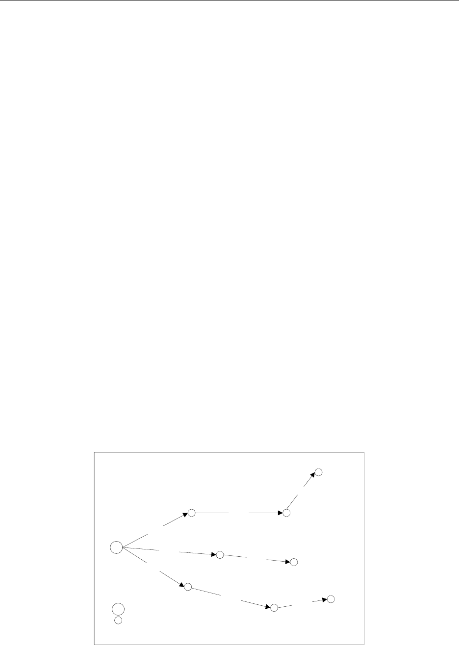
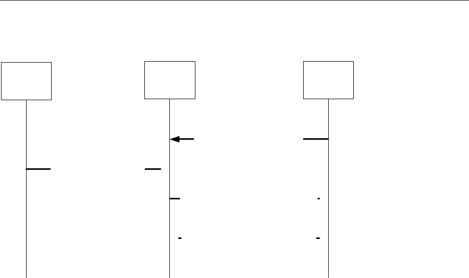
5.4.2 Many-to-one route discovery
The following figure shows an example of the many-to-one route discovery procedure. To initiate many-to-one
route discovery, the concentrator broadcast a many-to-one route request to the entire network. Upon receipt of the
route request, every device adds a route table entry for the concentrator and stores the one hop neighbor that relays
the request as the next hop address. No route reply will be generated.
C
RREQ
RREQ
RREQ
RREQ
RREQ
RREQ
RREQ RREQ
Concentrator
Router
C
RREQ - Route Request
Figure 1: Many-to-one route discovery illustration
Z-Stack Developer's Guide SWRA176 Version 1.11
Copyright 2006-2012 Texas Instruments, Inc. All rights reserved.
12
Many-to-one route request command is similar to unicast route request command with same command ID and
payload frame format. The option field in route request is many-to-one and the destination address is 0xFFFC. The
following Z-Stack API can be used for the concentrator to send out many-to-one route request. Please refer to the Z-
Stack API documentation for detailed usage about this API.
ZStatus_t NLME_RouteDiscoveryRequest( uint16 DstAddress, byte options, uint8 radius )
The option field is a bitmask to specify options for the route request. It can have the following values:
Value
Description
0x00
Unicast route discovery
0x01 Many-to-
one route discovery with route cache (the
concentrator does not have memory constraints).
0x03
Many-to-one route discovery with no route cache (the
concentrator has memory constraints)
When the option field has value 0x01 or 0x03, the DstAddress field will be overwritten with the many-to-one
destination address 0xFFFC. Therefore, user can pass any value to DstAddress in the case of many-to-one route
request.
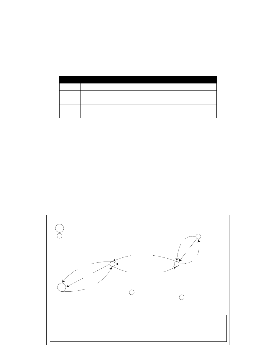
5.4.3 Route record command
The above many-to-one route discovery procedure establishes routes from all devices to the concentrator. The
reverse routing (from concentrator to other devices) is done by route record command (source routing scheme). The
procedure of source routing is illustrated in Figure 2. R1 sends data packet DATA to the concentrator using the
previously established many-to-one route and expects an acknowledgement back. To provide a route for the
concentrator to send the ACK back, R1 sends route record command along with the data packet which records the
routing path the data packet goes through and offers the concentrator a reverse path to send the ACK back.
C
DATA
DATA
DATA
Concentrator
Router
C
RREC[Relay list] – Route Record Command
DATA – Data sent from R1 to the concentrator
ACK[Source route, Ack payload] – Ack packet from the Concentrator to
R1.
R1
R2
R3
RREC[ ]
ACK[ack]
RREC[R2]
ACK[(R2,R3), ack]
RREC[R2,R3]
ACK[(R2,R3), ack]
Figure 2: Route record command (source routing) illustration
Upon receipt of the route record command, devices on the relay path will append their own network addresses to the
relay list in the route record command payload. By the time the route record command reaches the concentrator, it
includes the complete routing path through which the data packet is relayed to the concentrator. When the
concentrator sends ACK back to R1, it shall include the source route (relay list) in the network layer header of the
packet. All devices receiving the packet shall relay the packet to the next hop device according to the source route.

Z-Stack Developer's Guide SWRA176 Version 1.11
Copyright 2006-2012 Texas Instruments, Inc. All rights reserved.
13
For concentrator with no memory constraints, it can store all route record entries it receives and use them to send
packets to the source devices in the future. Therefore, devices only need to send route record command once.
However, for concentrator without source route caching capability, devices always need to send route record
commands along with data packets. The concentrator will store the source route temporarily in the memory and then
discard it after usage.
In brief, many-to-one routing is an efficient enhancement to the regular ZigBee unicast routing when most devices
in the network are funneling traffic to a single device. As part of the many-to-one routing, source routing is only
utilized under certain circumstances. First, it is used when the concentrator is responding to a request initiated by the
source device. Second, the concentrator should store the source route information for all devices if it has sufficient
memory. If not, whenever devices issue request to the concentrator, they should also send route record along with it.
5.4.4 Many-to-one route maintenance
If a link failure is encountered while a device is forwarding a many-to-one routed frame (notice that a many-to-one
routed frame itself has no difference from a regular unicast data packet, however, the routing table entry has a field
to specify that the destination is a concentrator), the device will generate a network status command with code
“Many-to-one route failure”. The network status command will be relayed to the concentrator through a random
neighbor and hopefully that neighbor still has a valid route to the concentrator. When the concentrator receives the
route failure, the application will decide whether or not to re-isssue a many-to-one route request.
When the concentrator receives network status command indicating many-to-one route failure, it passes the
indication to the ZDO layer and the following ZDO callback function in ZDApp.c is called:
void ZDO_ManytoOneFailureIndicationCB()
By default, this function will redo a many-to-one route discovery to recover the routes. You can modify this function
if you want a more complicated process other than the default.
5.5 Routing Settings Quick Reference
Setting Routing Table Size Set MAX_RTG_ENTRIES
Note: the value must be greater than 4. (See f8wConfig.cfg)
Setting Route Expiry Time Set ROUTE_EXPIRY_TIME to expiry time in seconds. Set to
0 in order to turn off route expiry. (See f8wConfig.cfg)
Setting Route Discovery Table Size Set MAX_RREQ_ENTRIES
to the maximum number of
simultaneous route discoveries enabled in the network. (See
f8wConfig.cfg)
Enable Concentrator Set CONCENTRATOR_ENABLE (See ZGlobals.h)
Setting Concentrator Property –
With Route
Cache Set CONCENTRATOR_ROUTE_CACHE (See ZGlobals.h)
Setting Source Routing Table Size Set MAX_RTG_SRC_ENTRIES (See ZGlobals.h)
Setting Default Concentrator Broadcast Radius Set CONCENTRATOR_RADIUS (See ZGlobals.h)

Z-Stack Developer's Guide SWRA176 Version 1.11
Copyright 2006-2012 Texas Instruments, Inc. All rights reserved.
14
5.6 Router Off-Network Association Cleanup
In case a ZigBee Router gets off network for a long period of time, its children will try to join an alternative parent.
When the router is back online, the children will still appear in its child table, preventing proper routing of egress
traffic to them.
In order to avoid this, it is recommended that routers prone to get off and on the network will have
zgRouterOffAssocCleanup flag set to TRUE (mapped to NV item: ZCD_NV_ROUTER_OFF_ASSOC_CLEANUP):
uint8 cleanupChildTable = TRUE;
zgSetItem( ZCD_NV_ROUTER_OFF_ASSOC_CLEANUP, sizeof(cleanupChildTable),
&cleanupChildTable );
When enabled, deprecated end-device entries will be removed from the child table if traffic received from them was
routed by another parent.
Z-Stack Developer's Guide SWRA176 Version 1.11
Copyright 2006-2012 Texas Instruments, Inc. All rights reserved.
15
6. ZDO Message Requests
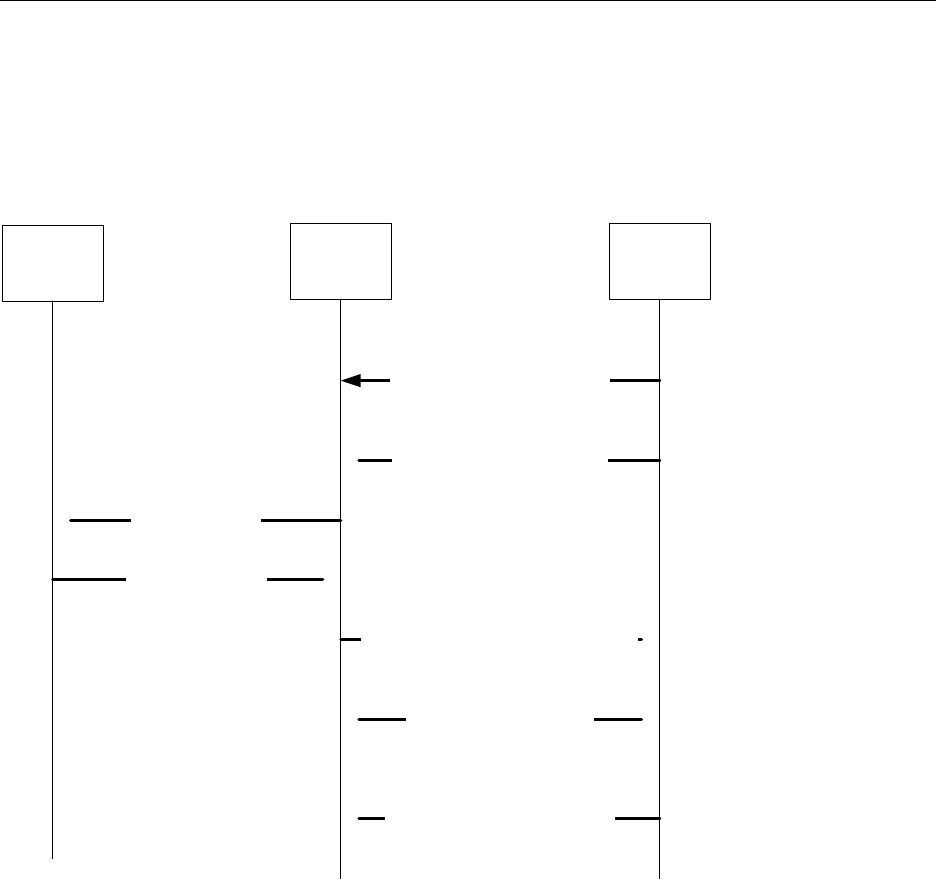
The ZDO module provides functions to send ZDO service discovery request messages and receive ZDO service
discovery response messages. The following flow diagram illustrates the function calls need to issue an IEEE
Address Request and receive the IEEE Address Response for an application.
Other Devices ZDO Layer Application Layer
ZDO_RegisterForZDOMsg( taskID,
IEEE_addr_rsp ); Register with ZDO that you want the
ZDO IEEE Address Response
Request a ZDO IEEE Address Request
ZDP_IEEEAddrReq( devAddr, ... );
Over the air Request
Over the air Response
Osal Message (ZDO_CB_MSG) for the ZDO
IEEE Address Response ( IEEE_addr_rsp )
This message is delivered to the
application’s event processor as an
OSAL message.
ZDO_ParseAddrRsp( inMsg );
Parse the incoming message. The
function returns an allocated structure
that contains the IEEE Address
Response fields.
ZDO_RemoveRegisteredCB( taskID,
IEEE_addr_rsp ); Remove the registration for all incoming
IEEE Address Response messages.
Figure 3: ZDO IEEE Address Request and Response
Z-Stack Developer's Guide SWRA176 Version 1.11
Copyright 2006-2012 Texas Instruments, Inc. All rights reserved.
16
In the following example, an application would like to know when any new devices join the network. The
application would like to receive all ZDO Device Announce (Device_annce) messages.
Other Devices ZDO Layer Application Layer
ZDO_RegisterForZDOMsg( taskID,
Device_annce ); Register with ZDO that you want all ZDO
Device Announce Messages
Over the Air Device Announce
Osal Message (ZDO_CB_MSG) for the ZDO
Device Annouce ( Device_annce )
This message is delivered to the
application’s event processor as an
OSAL message.
ZDO_ParseDeviceAnnce( inMsg, pAnnce );
Parse the incoming message. The
application passes into the function a
pointer to the Device Annouce structure.
The parsing function will parse the
incoming message into that structure.
Figure 4: ZDO Device Announce delivered to an application

Z-Stack Developer's Guide SWRA176 Version 1.11
Copyright 2006-2012 Texas Instruments, Inc. All rights reserved.
17
7. Portable Devices
End devices are automatically portable. Meaning that when an end device detects that its parent isn’t responding
(out of range or incapacitated) it will try to rejoin the network (joining a new parent). There are no setup or
compile flags to setup this option.
The end device detects that a parent isn’t responding either through polling (MAC data requests) failures and/or
through data message failures. The sensitivity to the failures (amount of consecutive errors) is controlled by
MAX_POLL_FAILURE_RETRIES, which is changeable in f8wConfig.cfg (the higher the number – the less
sensitive and the longer it will take to rejoin).
When the network layer detects that its parent isn’t responding, it will call ZDO_SyncIndicationCB(), which
will initiate a “rejoin”. The rejoin process will first orphan-scan for an existing parent, then scan for a potential
parent and rejoin (network rejoin command) the network with the potential parent.
In a secure network, it is assumed that the device already has a key and a new key isn’t issued to the device.
In a ZigBee PRO network, the end device’s short address is retained when it moves from parent to parent. In a
ZigBee network, because of the tree addressing, the new parent will give the end device a new address. In either
case, routes to the moved end device have to be re-established either automatically (as the old one fails) or
intentionally (by the application).
8. End-to-end acknowledgements
For non-broadcast messages, there are basically 2 types of message retry: end-to-end acknowledgement (APS
ACK) and single-hop acknowledgement (MAC ACK). MAC ACKs are always on by default and are usually
sufficient to guarantee a high degree of reliability in the network. To provide additional reliability, as well as to
enable the sending device get confirmation that a packet has been delivered to its destination, APS
acknowledgements may be used.
APS acknowledgement is done at the APS layer and is an acknowledgement system from the destination device to
the source device. The sending device will hold the message until the destination device sends an APS ACK
message indicating that it received the message. This feature can be enabled/disabled for each message sent with the
options field of the call to AF_DataRequest(). The options field is a bit map of options, so OR in
AF_ACK_REQUEST to enable APS ACK for the message that you are sending. The number of times that the
message is retried (if APS ACK message isn’t received) and the timeout between retries are configuration items in
f8wConfig.cfg. APSC_MAX_FRAME_RETRIES is the number of retries the APS layer will send the
message if it doesn’t receive an APS ACK before giving up. APSC_ACK_WAIT_DURATION_POLLED is the time
between retries.

Z-Stack Developer's Guide SWRA176 Version 1.11
Copyright 2006-2012 Texas Instruments, Inc. All rights reserved.
18
9. Miscellaneous
9.1 Configuring channel
Every device must have a DEFAULT_CHANLIST (in f8wConfig.cfg) that controls the channel selection. For a
ZigBee coordinator, this list will be used to scan for a channel with the least amount of noise. For ZigBee Routers
and End Devices, this list will be used to scan for existing networks to join.
9.2 Configuring the PAN ID and network to join
This is an optional configuration item to control which network a ZigBee Router or End Device will join. The
ZDO_CONFIG_PAN_ID parameter in f8wConfig.cfg can be set to a value (between 0 and 0xFFFE). A coordinator
will use this value as the PANId of the network that it starts. A router or end-device will only join a network that has
a PANId configured in this parameter. To turn this feature off, set the parameter to a value of 0xFFFF.
For further control of the joining procedure, the ZDO_NetworkDiscoveryConfirmCB function in the
ZDApp.c should be modified. ZDO_NetworkDiscoveryConfirmCB() is called when the network layer has
finished with the Network Discovery process [started by calling NLME_NetworkDiscoveryRequest()
defined in the Stack API document].
9.3 Maximum payload size
The maximum payload size for an application is based on several factors. The MAC layer provides a constant
payload length of 116 (can be changed in f8wConfig.cfg – MAC_MAX_FRAME_SIZE). The NWK layer requires
a fixed header size, one size with security and one without security. The APS layer has a required, but variable,
header size based on a variety of settings, including the ZigBee Protocol Version, APS frame control settings, etc.
Ultimately, the user does not have to calculate the maximum payload size using the aforementioned factors. The AF
module provides an API that allows the user to query the stack for the maximum payload size, or the maximum
transport unit (MTU). The user can call the function, “afDataReqMTU” (see “af.h”) which will return the MTU, or
maximum payload size.
typedef struct
{
uint8 kvp;
APSDE_DataReqMTU_t aps;
} afDataReqMTU_t;
uint8 afDataReqMTU( afDataReqMTU_t* fields )
Currently the only field that should be set in the “afDataReqMTU_t” structure is “kvp”, which indicates whether
KVP is being used and this field should be set to FALSE. The “aps” field is reserved for future use.
9.4 Leave Network
The ZDO Management implements the function, “ZDO_ProcessMgmtLeaveReq”, which offers access to the
“NLME-LEAVE.request” primitive. The “NLME-LEAVE.request” allows a device to remove itself or remove a
child device. The “ZDO_ProcessMgmtLeaveReq” removes the device based on the provided IEEE address. If a
device removes itself, it will wait for approximately 5 seconds and then reset. Once the device resets, it will come
back up in an idle state. It will not attempt to associate or rejoin. If a device removes a child device it will remove
the device from the local “association table”. The NWK address will only be reused in the case where a child device
is a ZigBee End Device. In the case of a child ZigBee Router, the NWK address will not be reused.
If the parent of a child device leaves the network, the child will stay on the network.
Although the “NLME-LEAVE.request” offers several optional parameters, ZigBee 2007 (as well as Texas
Instrument’s current implementation) limits the use of these parameters. Currently, the optional parameters
(“RemoveChildren”, “Rejoin”, and “Silent”) should be set to the default values used in
“ZDO_ProcessMgmtLeaveReq”. If these values are changed unexpected results may occur.

Z-Stack Developer's Guide SWRA176 Version 1.11
Copyright 2006-2012 Texas Instruments, Inc. All rights reserved.
19
9.5 Descriptors
All devices in a ZigBee network have descriptors that describe that type of device and its applications. This
information is available to be discovered by other devices in the network.
Configuration items are setup and defined in ZDConfig.c and ZDConfig.h. These 2 files also contain the
Node, Power Descriptors and default User Descriptor. Make sure to change these descriptors to define your device.
9.6 Non-Volatile Memory Items
9.6.1 Global Configuration Non-Volatile Memory
Global device configuration items are stored in ZGlobal.c, things like PAN ID, key information, network settings.
The default values for most of these items are stored in f8wConfig.cfg. These items are stored in RAM and
accessed throughout ZStack. To store and restore these items from non-volatile memory include the NV_INIT
compile flag in your project.
9.6.2 Network Layer Non-Volatile Memory
A ZigBee device has lot of state information that needs to be stored in non-volatile memory so that it can be
recovered in case of an accidental reset or power loss. Otherwise, it will not be able to rejoin the network or function
effectively.
To enable this feature include the NV_RESTORE compile option. Note that this feature must usually be always
enabled in a real ZigBee network. The ability to turn it off is only intended to be used in the development stage.
The ZDO layer is responsible for the saving and restoring of the Network Layer’s vital information. This includes
the Network Information Base (NIB - Attributes required to manage the network layer of the device); the list of
child and parent devices, and the table containing the application bindings. Also, if security is used, some
information like the frame counters will be stored.
When a device starts up after a reset, this information is restored into the device. This information is used to restore
the device in the network if the device is reset. In ZDApp_Init, a call to NLME_RestoreFromNV() instructs
the network layer to restore its network state from values stored in NV. This function call will also initialize the NV
space needed for the network layer if the space isn’t already established.
9.6.3 Application Non-Volatile Memory
NV can also be used to save information specific to the application and the User Descriptor is a good example. The
NV item ID for the User Descriptor is ZDO_NV_USERDESC (defined in ZComDef.h).
In ZDO_DefaultUserDescriptor() [which is called from ZDApp_Init()], osal_nv_item_init()
is called to initialize the NV space needed for the User Descriptor. If this is the first time that this function is called
for this NV item, the init function will reserve the space for the User Descriptor and set the default value to
ZDO_DefaultUserDescriptor.
Then when the NV stored User Descriptor is needed, as in ZDO_ProcessUserDescReq() (in ZDObject.c), it
calls osal_nv_read() to get the User Descriptor from NV.
To update the User Descriptor in NV, as in ZDO_ProcessUserDescSet() (in ZDObject.c), it calls
osal_nv_write() to set the updated User Descriptor in NV.
Remember: the NV items are each unique and if your application creates its own NV item is must select an ID from
the application value range (0x0401 – 0x0FFF).
9.7 Asynchronous Links
An asynchronous link occurs when a node can receive packets from another node but it can’t send packets to that
node. Whenever this happens, this link is not a good link to route packets.

Z-Stack Developer's Guide SWRA176 Version 1.11
Copyright 2006-2012 Texas Instruments, Inc. All rights reserved.
20
In ZigBee PRO, this problem is overcome by the use of the Network Link Status message. Every router in a ZigBee
PRO network sends a periodic Link Status message. This message is a one hop broadcast message that contains the
sending device’s neighbor list. The idea is this – if you receive your neighbor’s Link Status and you are either
missing from the neighbor list or your receive cost is too low (in the list), you can assume that the link between you
and this neighbor is an asynchronous link and you should not use it for routing.
To change the time between Link Status messages you can change the compile flag
NWK_LINK_STATUS_PERIOD, which is used to initialize _NIB.nwkLinkStatusPeriod. You can also
change _NIB.nwkLinkStatusPeriod directly. Remember that only PRO routers send the link status message
and that every router in the network must have the same Link Status time period.
_NIB.nwkLinkStatusPeriod contains the number of seconds between Link Status messages.
Another parameter that affects the Link Status message is _NIB.nwkRouterAgeLimit (defaulted to
NWK_ROUTE_AGE_LIMIT). This represents the number of Link Status periods that a router can remain in a
device’s neighbor list, without receiving a Link Status from that device, before it becomes aged out of the list. If we
haven’t received a Link Status message from a neighbor within (_NIB.nwkRouterAgeLimit *
_NIB.nwkLinkStatusPeriod), we will age the neighbor out and assume that this device is missing or that it’s
an asynchronous link and not use it.
9.8 Multicast Messages
This feature is a ZigBee PRO only feature (must have ZIGBEEPRO as a compile flag). This feature is similar to
sending to an APS Group, but at the network layer.
A multicast message is sent from a device to a group as a MAC broadcast message. The receiving device will
determine if it is part of that group: if it isn’t part of the group, it will decrement the non-member radius and
rebroadcast; if it is part of the group it will first restore the group radius and then rebroadcast the message. If the
radius is decremented to 0, the message isn’t rebroadcast.
The difference between multicast and APS group messages can only be seen in very large networks where the non-
member radius will limit the number of hops away from the group.
_NIB.nwkUseMultiCast is used by the network layer to enable multicast (default is TRUE if ZIGBEEPRO defined)
for all Group messages, and if this field is FALSE the APS Group message is sent as a normal broadcast network
message.
zgApsNonMemberRadius is the value of the group radius and the non-member radius. This variable should be
controlled by the application to control the broadcast distribution. If this number is too high, the effect will be the
same as an APS group message. This variable is defined in ZGlobals.c and
ZCD_NV_APS_NONMEMBER_RADIUS (defined in ZComDef.h) is the NV item.
9.9 Fragmentation
Message Fragmentation is a process where a large message – too large to send in one APS packet – is broken down
and transmitted as smaller fragments. The fragments of the larger message are then reassembled by the receiving
device.
To turn on the APS Fragmentation feature in your Z-Stack project include the ZIGBEE_FRAGMENTATION
compile flag. In the same applications, this compile flag will include the APS Fragmentation task [APSF_Init() and
APSF_ProcessEvent()]. If you have an existing application, copy the code in the OSAL_xxx.c (ie.
OSAL_GenericApp.c) sample application file – search for ZIGBEE_FRAGMENTATION.
When APS Fragmentation is turned on, sending a data request with a payload larger than a normal data request
payload will automatically trigger fragmentation.

Z-Stack Developer's Guide SWRA176 Version 1.11
Copyright 2006-2012 Texas Instruments, Inc. All rights reserved.
21
There are a couple of fragmentation control variables that the application (or profile) can set/change (defined in
ZGlobals.c):
• zgApscMaxWindowSize - The size of a tx window when using fragmentation. This is the number of
fragments that are sent before an APS Fragmentation ACK is expected. So, if the message is broken up
into 10 fragments and the max window size is 5 then an ACK will be sent by the receiving device after 5
fragments are received. ZCD_NV_APSF_WINDOW_SIZE is the NV item for this variable. If one packet
of the window size isn’t received, the ACK is not sent and all the packets (within that window) are resent.
• zgApsInterframeDelay – The delay between fragments within a window. This is used by the sending
device. ZCD_NV_APSF_INTERFRAME_DELAY is the NV item for this variable.
It is recommended that the application/profile update the MaxInTransferSize and MaxOutTransferSize of the ZDO
Node Descriptor for the device [ZDConfig_UpdateNodeDescriptor() in ZDConfig.c]. This fields are initialized with
MAX_TRANSFER_SIZE (defined in ZDConfig.h). These values are not used in the APS layer as maximums, they
are information only.
9.9.1 Quick Reference
Compile flag to activate the feature ZIGBEE_FRAGMENTATION
Maximum fragments in a window zgApscMaxWindowSize (defined in ZGlobals.h)
Interframe delay zgApsInterframeDelay (defined in ZGlobals.h)
Application/Profile maximum buffer size MAX_TRANSFER_SIZE (defined in ZDConfig.h)
9.10 Extended PAN IDs
There are two Extended PAN IDs used in the Z-Stack:
• zgApsUseExtendedPANID: This is the 64-bit PAN identifier of the network to join or form. This
corresponds to the ZCD_NV_APS_USE_EXT_PANID NV item.
• zgExtendedPANID: This is the 64-bit extended PANID of the network to which the device is joined. If it
has a value of 0x0000000000000000, then the device is not connected to a network. This corresponds to the
ZCD_NV_EXTENDED_PAN_ID NV item.
When a device starts up, it checks the value of zgExtendedPANID. If zgExtendedPANID has a non-zero value, then
the device assumes it has all the network parameters required to operate on a network.
If the device finds it is not connected to a network, then it checks to see if it’s configured to become a ZigBee
coordinator. If it’s configured as a coordinator, then it will form a network using zgApsUseExtendedPANID if
zgApsUseExtendedPANID has a non-zero value. If zgApsUseExtendedPANID is 0x0000000000000000, then the
device will use its 64-bit Extended Address to form the network.
When the device is not the designated coordinator and zgApsUseExtendedPANID has a non-zero value, then it will
attempt to rejoin the network specified in zgApsUseExtendedPANID. The device will join only the specified network
and the procedure will fail if that network is found to be inaccessible. If zgApsUseExtendedPANID is equal to
0x0000000000000000, then the device will join the best available network.

Z-Stack Developer's Guide SWRA176 Version 1.11
Copyright 2006-2012 Texas Instruments, Inc. All rights reserved.
22
10. Security
10.1 Overview
ZigBee security is built with the AES block cipher and the CCM* mode of operation as the underlying security
primitive. AES/CCM* security algorithms were developed by external researchers outside of ZigBee Alliance and
are also used widely in other communication protocols.
ZigBee offers the following security features:
• Infrastructure security
• Network access control
• Application data security
10.2 Configuration
In order to have a secure network, first all device images must be built with the preprocessor flag SECURE set equal
to 1. This can be found in the "f8wConfig.cfg" file.
The default key (defaultKey in nwk_globals) can be preconfigured on each device in the network or it can be
configured only on the coordinator and distributed to each device over-the-air as it joins the network. This is chosen
via the zgPreConfigKeys option in “ZGlobals.c” file. If it is set to TRUE, then the value of default key must be
preconfigured on each device ( to the exact same value ). If it is set to FALSE, then the default key parameter needs
to be set only on the coordinator device. Note that in the latter case, the key will be distributed to each joining device
over-air. So there is a “moment of vulnerability” during the joining process during which an adversary can
determine the key by listening to the on-air traffic and compromise the network security.
10.3 Network access control
In a secure network, the trust center (coordinator) is informed when a device joins the network. The coordinator has
the option of allowing that device to remain on the network or denying network access to that device.
The trust center may use any logic to determine if the device should be allowed into the network or not. One option
is for the trust center to only allow devices to join during a brief time window. This may be possible, for example, if
the trust center has a “push” button. When the button is pressed, it could allow any device to join the network for a
brief time window. Otherwise all join requests would be rejected. A second possible scenario would be to configure
the trust center to accept (or reject) devices based on their IEEE addresses.
This type of policy can be realized by modifying the ZDSecMgrDeviceValidate() function found in the
"ZDSecMgr.c" module.
10.4 Key Updates
The Trust Center can update the common Network key at its discretion. Application developers have to modify the
Network key update policy. The default Trust Center implementation can be used to suit the developer's specific
policy. An example policy would be to update the Network key at regular periodic intervals. Another would be to
update the NWK key upon user input (like a button-press). The ZDO Security Manager (ZDSecMgr.c) API provides
this functionality via ZDSecMgrUpdateNwkKey() and ZDSecMgrSwitchNwkKey(). ZDSecMgrUpdateNwkKey()
allows the Trust Center to broadcast a new Network key to all devices on the network. At this point the new
Network key is stored as an alternate key in all devices. Once the Trust Center calls ZDSecMgrSwitchNwkKey(), a
network wide broadcast will trigger all devices to use their alternate key.
10.5 Smart Energy Secure Joining
The Smart Energy Profile requires that all devices have a pre-configured Trust Center Link Key (TCLK) and that
the network key is delivered to joining devices secured with that link key. There are basically 2 joining scenarios for
a Smart Energy Profile device.
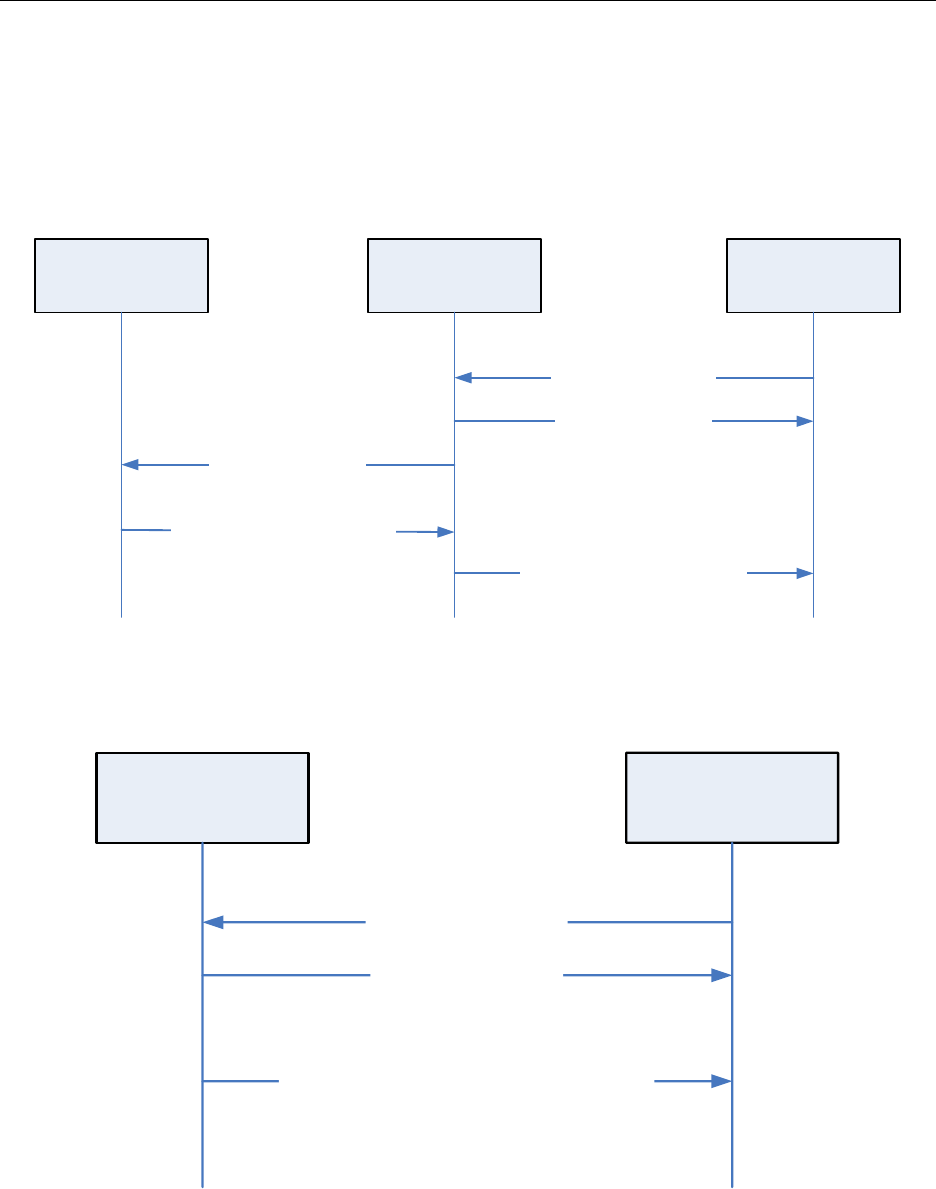
Z-Stack Developer's Guide SWRA176 Version 1.11
Copyright 2006-2012 Texas Instruments, Inc. All rights reserved.
23
When a device joins the network, but its parent isn’t the Trust Center, the transport key command is tunneled from
the Trust Center, through the parent of the joining device, to the joining device. The joining procedure is illustrated
in the following figure. Notice that the APS Update Device command sent from the parent to the trust center is
network layer encrypted. The APS Tunnel Command with APS Transport Key command as the payload is also
network layer encrypted but the payload is APS layer encrypted with the trust center link key between the trust
center and the joining device. Finally, The APS Transport Key command forwarded from the parent to the joining
device is APS encrypted with the trust center link key between the trust center and the joining device.
Parent (Router) Joining Device
Join Request (Assoc Request)
Join Response (Assoc Resp)
APS Transport Key Command
(delivers the network key)
- APS secure (key: Trust Center Link Key)
Trust Center
APS Update Device
(Joining Device’s Addresses)
- Nwk Secure
APS Tunnel Command – Network Secure
Payload: APS Transport Key Command
-APS Secure (key: Trust Center Link key)
Figure 5: Smart Energy Secure Joining – Parent is not the Trust Center
When a device joins the network, and its parent is the Trust Center, the transport key command is encrypted in the
pre-configured Trust Center Link key.
Trust Center
Joining Device
Join Request (Assoc Request)
Join Response (Assoc Resp)
APS Transport Key Command (delivers the network key)
- APS secure (key: Trust Center Link Key)
Figure 6: Smart Energy Secure Joining – Parent is the Trust Center
To enable the Smart Energy Secure Joining feature, set SECURE=1 in f8wConfig.cfg and include the SE_PROFILE
compile flag. Also, there are needed compiler flags, global variables (ZGlobals) and NV Items.

Z-Stack Developer's Guide SWRA176 Version 1.11
Copyright 2006-2012 Texas Instruments, Inc. All rights reserved.
24
There are two modes in using smart energy secure joining: Multiple Key Mode and Single Key Mode. In multiple
key mode, unique pre-configured trust center link keys are used between the trust center and each individual device
joining the network. Multiple key mode is required by the recommended secure procedure in ZigBee SE profile
Specification. In single key mode, all devices are using the same pre-configured trust center link key to join the
network. The single key mode provides a simplified alternative procedure to set up the network. It can be used for
testing and debugging purpose.
To start the network using Multiple Key Mode:
• Set zgUseDefaultTCLK=FALSE (defined in ZGlobals). The NV item for this global is
ZCD_NV_USE_DEFAULT_TCLK (defined in ZComDef.h).
• Set compile time option ZDSECMGR_TC_DEVICE_MAX to the maximum number of devices joining the
network. Notice that it has to be no more than 255, as only 255 continuous NV ID space is reserved for
preconfigured trust center link keys.
• All preconfigured trust center links keys are stored as separate NV items. The NV item ids range from
ZCD_NV_TCLK_TABLE_START to ZCD_NV_TCLK_TABLE_START+
ZDSECMGR_TC_DEVICE_MAX-1. Preconfigured trust center link keys are set by configuring the NV
items using SYS_OSAL_NV_WRITE for the attributes listed below:
Attribute Description Value
Id NV ID for the trust center link key. ZCD_NV_TCLK_TABLE_START plus an offset.
Len Length in bytes of the item. 0x20
Offset The memory offset into the NV item. 0x0
Value The data array to be written to the
NV item. Its byte format is listed in the following table. All
fields follow little endian first.
Table for byte format of NV item value:
Length 8 Octets 16 Octets 4 Octets 4 Octets
Attribute Field Extended Address Key Data TX Frame Counter RX Frame Counter
Description Extended Address of
the peer devices
which shares the
preconfigured tclk
The
preconfigured
trust center link
key data
The tx frame
counter of the trust
center link key
The rx frame
counter of the trust
center link key
• To remove a preconfigured trust center link key, simply write all zeros to the NV item.
• It is highly recommended to erase the entire flash before using the multiple key mode to make sure there is
no existing NV item for the preconfigured trust center link keys.
To start the network using Single Key Mode:
• Set zgUseDefaultTCLK=TRUE (defined in ZGlobals). The NV item for this global is
ZCD_NV_USE_DEFAULT_TCLK (defined in ZComDef.h).
• The default preconfigured trust center link key is written to NV item ZCD_NV_TCLK_TABLE_START if
it has not been initialized yet. To differentiate the default preconfigured trust center link key, the extended
address for default preconfigured trust center link key is all 0xFFs. The key data is initialized with
defaultTCLinkKey (defined in nwk_globals). The RX and TX frame counters are initialized to all zeros.
• The default preconfigured tclk can be changed by changing the key data, RX and TX frame counter fields
in the NV item directly.
• It is highly recommended to erase the entire flash before using the single key mode to make sure there is no
existing NV item for the default preconfigured trust center link key.
• To remove the default preconfigured trust center link key, simply write all zeros to that NV item.
Please note that the Single Key Mode and Multiple Key Mode shall be used exclusively.

Z-Stack Developer's Guide SWRA176 Version 1.11
Copyright 2006-2012 Texas Instruments, Inc. All rights reserved.
25
10.6 Security key data management
Management and access of security keys in NV through MT commands is disabled by default. In order to have
access to security key data, the compiler flag MT_SYS_KEY_MANAGEMENT must be included in the project. It
is highly recommended to disable this compiler flag for production devices, to prevent any potential vulnerability
that comes from having direct access to security key data in NV.
NV IDs for security keys are defined in ZComDef.h and summarized in the table below. Active and Alternate
Network keys are defined as individual items, while Trust Center, Application and Master keys each reserve a range
of NV IDs, allowing up to 255 keys of each type.
Value NV ID Description
ZCD_NV_NWK_ACTIVE_KEY_INFO 0x003A Active Network key
ZCD_NV_NWK_ALTERN_KEY_INFO 0x003B Alternate Network Key
ZCD_NV_TCLK_TABLE_START 0x0101 First element of TCLK table
ZCD_NV_TCLK_TABLE_END 0x01FF Last element of TCLK table
ZCD_NV_APS_LINK_KEY_DATA_START 0x0201 First element of APS Link Key table
ZCD_NV_APS_LINK_KEY_DATA_END 0x02FF Last element of APS Link Key table
ZCD_NV_MASTER_KEY_DATA_START 0x0301 First element of Master Key table
ZCD_NV_MASTER_KEY_DATA_END 0x03FF Last element of Master Key table
10.7 Quick Reference
Enabling security Set
SECURE
= 1 (in f8wConfig.cfg)
Enabling preconfigured Network key Set z
gPreConfigKeys
= TRUE (in ZGlobals.c)
Setting preconfigured Network key Set
defaultKey
= {KEY} (in nwk_globals.c)
Enabling/disabling joining permissions on the
Trust Center Call ZDSecMgrPermitJoining() (in ZDSecMgr.c)
Specific device validation during joining Modify
ZDSecMgrDeviceValidate
(in ZDSecMgr.c)
Network key updates Call ZDSecMgrUpdateNwkKey() and
ZDSecMgrSwitchNwkKey()
(in ZDSecMgr.c)
Enabling Smart Energy Secure Joining with
Pre-Configured Trust Center Link Keys Set SECURE = 1 (in f8wConfig.cfg) and include
SE_PROFILE as a compile flag.
Use single(default) Preconfigured Trust
Center Link Key Set zgUseDefaultTCLK=TRUE (in ZGlobals.c). The NV
item for this global is ZCD_NV_USE_DEFAULT_TCLK
(defined in ZComDef.h).
Use multiple Preconfigured Trust Center
Link Keys Set zgUseDefaultTCLK=FALSE (in ZGlobals.c). The NV
item for this global is ZCD_NV_USE_DEFAULT_TCLK
(in ZComDef.h). Configure a preconfigured trust center
link key for each device joining the network via
SYS_OSAL_NV_WRITE.

Z-Stack Developer's Guide SWRA176 Version 1.11
Copyright 2006-2012 Texas Instruments, Inc. All rights reserved.
26
11. Network Manager
11.1 Overview
A single device can become the Network Manager. This device acts as the central mechanism for reception of
network:
• Channel Interference reports and changing the channel of the network if interference is detected, and
• PAN ID Conflict reports and changing the PAN ID of the network if conflict is detected.
The default address of the Network Manager is the coordinator. However, this can be updated by sending a
Mgmt_NWK_Update_req command with a different short address for the Network Manager. The device that is the
Network Manager sets the network manager bit in the server mask in the node descriptor and responds to
System_Server_Discovery_req commands.
The Network Manager implementation resides in ZDNwkMgr.c and ZDNwkMgr.h files.
11.2 Channel Interference
The Network Manager implements frequency agility measures in the face of interference. This section explains how,
through the use of the Mgmt_NWK_Update_req and Mgmt_NWK_Update_notify commands, the channel of a
network can be changed.
11.2.1 Channel Interference Detection
Each router or coordinator tracks transmit failures using the Transmit Failure field in the neighbor table and also
keeping a NIB counter for Total Transmissions attempted. Once the total transmissions attempted is over
ZDNWKMGR_MIN_TRANSMISSIONS (20), if the transmit failures exceeds ZDNWKMGR_CI_TX_FAILURE (25)
percent of the messages sent, the device may have detected interference on the channel in use.
The device then takes the following steps:
1. Conduct an energy scan on all channels. If this energy scan does not indicate higher energy on the current
channel than other channels, no action is taken. The device should continue to operate as normal and the
message counters are not reset.
2. If the energy scan does indicate increased energy on the channel in use, a Mgmt_NWK_Update_notify
should be sent to the Network Manager to indicate interference is present. This report is sent as an APS
unicast with acknowledgement and once the acknowledgment is received the total transmit and transmit
failure counters are reset to zero.
3. To avoid a device with communication problems from constantly sending reports to the Network Manager,
the device does not send a Mgmt_NWK_Update_notify more than 4 times per hour.
11.2.2 Channel Interference Resolution
Upon receipt of an unsolicited Mgmt_NWK_Update_notify, the Network Manager applies different methods to best
determine when a channel change is required and how to select the most appropriate channel.
The Network Manger does the following:
1. Upon receipt of the Mgmt_NWK_Update_notify, the Network Manager determines if a channel change is
required using the following criteria:
a. If any single device has more than ZDNWKMGR_CC_TX_FAILURE (50) percent transmission
failures a channel change should be considered.
b. The Network Manager compares the failure rate reported on the current channel against the
stored failure rate from the last channel change. If the current failure rate is higher than the
last failure rate then the channel change is considered.
2. If the above data indicate a channel change should be considered, the Network Manager completes the
following:

Z-Stack Developer's Guide SWRA176 Version 1.11
Copyright 2006-2012 Texas Instruments, Inc. All rights reserved.
27
a. Select a single channel based on the Mgmt_NWK_Update_notify based on the lowest energy.
This is the proposed new channel. If this new channel does not have an energy level below an
acceptable threshold ZDNWKMGR_ACCEPTABLE_ENERGY_LEVEL, a channel change
should not be done.
3. Prior to changing channels, the Network Manager stores the energy scan value as the last energy scan
value and the failure rate from the existing channel as the last failure rate.
4. The Network Manager broadcasts (to all routers and coordinator) a Mgmt_NWK_Update_req notifying
devices of the new channel. It then increments the nwkUpdateId parameter in the NIB and beacon
payload, and includes it in the Mgmt_NWK_Update_req. The Network Manager sets a timer based on
the value of ZDNWKMGR_UPDATE_REQUEST_TIMER (i.e., apsChannelTimer) upon issue of a
Mgmt_NWK_Update_req that changes channels and will not issue another such command until this
timer expires.
5. Upon issue of a Mgmt_NWK_Update_req with a change of channels, the local Network Manager sets a
timer equal to the nwkNetworkBroadcastDeliveryTime and switches channels upon expiration of this
timer.
Upon receipt of a Mgmt_NWK_Update_req with a change of channels from the Network Manager, a device sets a
timer equal to the nwkNetworkBroadcastDeliveryTime and switches channels upon expiration of this timer. Each
node stores the received nwkUpdateId in the NIB and beacon payload, and also resets the total transmit count and
the transmit failure counters.
For devices with RxOnWhenIdle equals FALSE, any network channel change will not be received. On these devices
or routers that have lost the network, an active scan is conducted on the channelList in the NIB (i.e.,
apsChannelMask) using the extended PANID (EPID) to find the network. If the extended PANID is found on
different channels, the device selects the channel with the higher value in the nwkUpdateId parameter. If the
extended PANID is not found using the apsChannelMask list, a scan is completed using all channels.
11.2.3 Quick Reference
Setting minimum transmissions attempted for Channel
Interference detection Set ZDNWKMGR_MIN_TRANSMISSIONS
(in ZDNwkMgr.h)
Setting m
inimum transmit failure rate for Channel
Interference detection Set ZDNWKMGR_CI_TX_FAILURE
(in ZDNwkMgr.h)
Setting m
inimum transmit failure rate for Channel
Change Set ZDNWKMGR_CC_TX_FAILURE
(in ZDNwkMgr.h)
Setting acceptable energy level threshold for Channel
Change Set ZDNWKMGR_ACCEPTABLE_ENERGY_LEVEL
(in ZDNwkMgr.h)
Setting APS channel timer for issuing Channel
Changes Set ZDNWKMGR_UPDATE_REQUEST_TIMER
(in ZDNwkMgr.h)
11.3 PAN ID Conflict
Since the 16-bit PANID is not a unique number there is a possibility of a PAN ID conflict in the local neighborhood.
The Network Manager implements PAN ID conflict resolution. This section explains how, through the use of the
Network Report and Update commands, the PAN ID of a network can be updated.

Z-Stack Developer's Guide SWRA176 Version 1.11
Copyright 2006-2012 Texas Instruments, Inc. All rights reserved.
28
11.3.1 PAN ID Conflict Detection
Any device that is operational on a network and receives a beacon in which the PAN ID of the beacon matches its
own PAN ID but the EPID value contained in the beacon payload is either not present or not equal to
nwkExtendedPANID, is considered to have detected a PAN ID conflict.
A node that has detected a PAN ID conflict sends a Network Report command of type PAN ID conflict to the
designated Network Manager identified by the nwkManagerAddr in the NIB. The Report Information field will
contain a list of all the 16-bit PAN identifiers that are being used in the local neighborhood. The list is constructed
from the results of an ACTIVE scan.
11.3.2 PAN ID Conflict Resolution
On receipt of the Network Report command, the Network Manager selects a new 16-bit PAN ID for the network.
The new PAN ID is chosen at random, but a check is performed to ensure that the chosen PAN ID is not contained
within the Report Information field of the network report command.
Once a new PAN ID has been selected, the Network Manager first increments the NIB attribute nwkUpdateID and
then constructs a Network Update command of type PAN identifier update. The Update Information field is set to
the value of the new PAN ID. After it sends out this command, the Network Manager starts a timer with a value
equal to nwkNetworkBroadcastDeliveryTime seconds. When the timer expires, it changes its current PAN ID to the
newly selected one.
On receipt of a Network Update command of type PAN ID update from the Network Manager, a device (in the same
network) starts a timer with a value equal to nwkNetworkBroadcastDeliveryTime seconds. When the timer expires,
the device changes its current PAN ID to the value contained within the Update Information field. It also stores the
new received nwkUpdateID in the NIB and beacon payload.

Z-Stack Developer's Guide SWRA176 Version 1.11
Copyright 2006-2012 Texas Instruments, Inc. All rights reserved.
29
12. Inter-PAN Transmission
12.1 Overview
Inter-PAN transmission enables ZigBee devices to perform limited, insecure, and possibly anonymous exchange of
information with devices in their local neighborhood without having to form or join the same ZigBee network.
The Inter-PAN feature is implemented by the Stub APS layer, which can be included in a project by defining the
INTER_PAN compile option and including stub_aps.c and stub_aps.h files in the project.
12.2 Data Exchange
Inter-PAN data exchanges are handled by the Stub APS layer, which is accessible through INTERP-SAP, parallel to
the normal APSDE-SAP:
• The INTERP_DataReq() and APSDE_DataReq() are invoked from AF_DataRequest() to send Inter-PAN
and Intra-PAN messages respectively.
• The INTERP_DataIndication() invokes APSDE_DataIndication() to indicates the transfer of Inter-PAN
data to the local application layer entity. The application then receives Inter-PAN data as a normal
incoming data message (APS_INCOMING_MSG) from the APS sub-layer with the source address
belonging to an external PAN (verifiable by StubAPS_InterPan() API) .
• The INTERP_DataConfirm() invokes afDataConfirm() to send an Inter-PAN data confirm back to the
application. The application receives a normal data confirm (AF_DATA_CONFIRM_CMD) from the AF
sub-layer.
The Stub APS layer also provides interfaces to switch channel for Inter-PAN communication and check for Inter-
PAN messages. Please refer to the Z-Stack API document for detailed description of the Inter-PAN APIs.
The StubAPS_InterPan() API is used to check for Inter-PAN messages. A message is considered as an Inter-PAN
message if it meets one the following criteria:
• The current communication channel is different that the device’s NIB channel, or
• The current communication channel is the same as the device’s NIB channel but the message is destined for
a PAN different than the device’s NIB PAN ID, or
• The current communication channel is the same as the device’s NIB channel and the message is destined
for the same PAN as device’s NIB PAN ID but the destination application endpoint is an Inter-PAN
endpoint (0xFE). This case is true for an Inter-PAN response message that’s being sent back to a requestor.
A typical usage scenario for Inter-PAN communication is as follows. The initiator device:-
• Calls StubAPS_AppRegister() API to register itself with the Stub APS layer
• Calls StubAPS_SetInterPanChannel() API to switch its communication channel to the channel in use by the
remote device
• Specifies the destination PAN ID and address for the Inter-PAN message about to be transmitted
• Calls AF_DataRequest() API to send the message to the remote device through Inter-PAN channel
• Receives back (if required) a message from the remote device that implements the Stub APS layer and is
able to respond
• Calls StubAPS_SetIntraPanChannel() API to switch its communication channel back to its original
channel

Z-Stack Developer's Guide SWRA176 Version 1.11
Copyright 2006-2012 Texas Instruments, Inc. All rights reserved.
30
12.2.1 Quick Reference
Setup application as InterPAN application Call StubAPS_RegisterApp( app_endpoint )
Set InterPAN channel. Call StubAPS_SetInterPanChannel( channel )
Send InterPAN Message. Call AF_DataRequest() with:
• dstPanID different from _NIB.nwkPanId
• dst address endpoint ==
STUBAPS_INTER_PAN_EP
Receive an InterPAN message Receive an OSAL AF_INCOMING_MSG_CMD
message with an incoming DstEndPoint ==
STUBAPS_INTER_PAN_EP
End the InterPAN session by putting back the IntraPAN
channel. Call StubAPS_SetIntraPanChannel()

Z-Stack Developer's Guide SWRA176 Version 1.11
Copyright 2006-2012 Texas Instruments, Inc. All rights reserved.
31
13. ZMAC LQI Adjustment
13.1 Overview
The IEEE 802.15.4 specification provides some general statements on the subject of LQI. From section 6.7.8: "The
minimum and maximum LQI values (0x00 and 0xFF) should be associated with the lowest and highest IEEE
802.15.4 signals detectable by the receiver, and LQ values should be uniformly distributed between these two
limits." From section E.2.3: "The LQI (see 6.7.8) measures the received energy and/or SNR for each received
packet. When energy level and SNR information are combined, they can indicate whether a corrupt packet resulted
from low signal strength or from high signal strength plus interference."
The TI MAC computes an 8-bit “link quality index” (LQI) for each received packet from the 2.4 GHz radio. The
LQI is computed from the raw “received signal strength index” (RSSI) by linearly scaling it between the minimum
and maximum defined RF power levels for the radio. This provides an LQI value that is based entirely on the
strength of the received signal. This can be misleading in the case of a narrowband interferer that is within the
channel bandwidth – the RSSI may be increased even though the true link quality decreases.
The TI radios also provide a “correlation value” that is a measure of the received frame quality. Although not
considered by the TI MAC in LQI calculation, the frame correlation is passed to the ZMAC layer (along with LQI
and RSSI) in MCPS data confirm and data indication callbacks. The ZMacLqiAdjust() function in zmac_cb.c
provides capability to adjust the default TI MAC value of LQI by taking the correlation into account.
13.2 LQI Adjustment Modes
LQI adjustment functionality for received frames processed in zmac_cb.c has three defined modes of operation -
OFF, MODE1, and MODE2. To maintain compatibility with previous versions of Z-Stack which do not provide for
LQI adjustment, this feature defaults to OFF, as defined by an initializer (lqiAdjMode = LQI_ADJ_OFF;) in
zmac_cb.c – developers can select a different default state by changing this statement.
MODE1 provides a simple algorithm to use the packet correlation value (related to SNR) to scale incoming LQI
value (related to signal strength) to 'derate' noisy packets. The incoming LQI value is linearly scaled with a
"correlation percentage" that is computed from the raw correlation value between theoretical minimum/maximum
values (LQI_CORR_MIN and LQI_CORR_MAX are defined in ZMAC.h).
MODE2 provides a “stub” for developers to implement their own proprietary algorithm. Code can be added after the
“else if ( lqiAdjMode == LQI_ADJ_MODE2 )” statement in ZMacLqiAdjust().
13.3 Using LQI Adjustment
There are two ways to enable the LQI adjustment functionality:
(1) alter the initialization of the lqiAdjMode variable as described in the previous section
(2) call the function ZMacLqiAdjustMode() from somewhere within the Z-Stack application, most likely from the
application’s task initialization function. See the “Z-Stack API” document on details of this function.
The ZMacLqiAdjustMode() function can be used to change the LQI adjustment mode as needed by the application.
For example, a developer might want to evaluate device/network operation using a proprietary MODE2 compared to
the default MODE1 or OFF.
Tuning of MODE1 operation can be achieved by altering the values of LQI_CORR_MIN and/or LQI_CORR_MAX.
When using IAR development tools, alternate values for these parameters can be provided as compiler directives in
the IDE project file or in one of Z-Stack’s .cfg files (f8wConfig.cfg, f8wCoord.cfg, etc.). Refer to the radio’s data
sheet for information on the normal minimum/maximum correlation values.
