Zimmer ITST® Intertrochanteric/ Subtrochanteric Fixation System MIS And Standard Surgical Technique ITST Intertroch Subtroch
2016-04-01
: Pdf Zimmer Itst Intertroch Subtroch Mis Standard Surgical Technique Zimmer_ITST_Intertroch_Subtroch_MIS__Standard_Surgical_Technique 3 2016 pdf
Open the PDF directly: View PDF ![]() .
.
Page Count: 32
Zimmer® ITST ®
Intertrochanteric/
Subtrochanteric
Fixation System
MIS and Standard
Surgical Technique

ITST® System MIS and Standard Surgical Technique 1
Surgical Technique
for Fixation with ITST
Intramedullary
Nail System
This technique is written for standard
or MIS procedure. Differences between
the standard and MIS techniques
are noted.
Table of Contents
Indications 2
Surgical Technique 3
Preoperative Planning 3
Patient Positioning 3
Reduction 4
Radiographic Control 4
Prep and Drape 4
Starting Point and Steinman Pin Insertion and Incision
Using Long Cannulated Awl 5
Incision 5
Creating the Entry Portal 5
Guide Wire Placement 6
Measure 6
Reaming 7
Guide Assembly 8
Nail Assembly 8
Nail Insertion 9
Monitoring Insertion 10
Screw Options 10
Lag Screw Positioning 11
Lag Screw Preparation 12
Lag Screw Insertion with ITST Compression Device 15
Standard Lag Screw Insertion (Optional) 16
Anti-Rotation Screw Insertion 17
Distal Screw Fixation –
180mm/Short Nails 18
Distal Screw Fixation –
Long Nails – Freehand Technique 20
Completion 22
Closure and Postoperative Care 24
Extraction 24
Implant and Instrument Case Options 25

ITST® System MIS and Standard Surgical Technique
2
The ITST Intramedullary Nail System
is designed to treat comminuted,
proximal and distal fractures of the
femur, including, the Intertrochanteric
and Subtrochanteric regions. The
implant supports the anatomic
reduction and internal fixation of the
femoral head and neck.
The ITST Intramedullary Nail System
features a sliding or non-sliding Lag
Screw. System includes options for
dynamic and static distal locking.
Indications
The ITST Intramedullary Nail is indicated
for use in a variety of femoral fractures,
such as:
• Subtrochanteric Fractures
• Intertrochanteric Fractures
• Comminuted Fractures
• Segmental Fractures
• Fractures with Bone Loss
• Proximal and Distal Fractures
• Nonunions
WARNING: The surgeon should be
aware that use in osteoporotic bone,
or improper placement of the nail-
screw construct could increase the
risk of failure or cut out of the implant.
ITST® System MIS and Standard Surgical Technique 3
Surgical Technique
Preoperative Planning
The ITST Fixation System implants are
designed to place the Lag Screw at
130°, with 15° of anteversion on the
long nails, to accommodate the most
common anatomic femoral neck angle.
A/P and lateral C-arm images should be
obtained prior to the surgical procedure.
NOTE: The suitability of this implant
for the patient should be determined
by templating prior to surgery using
X-rays of the affected femur.
An A/P preoperative X-ray should be
taken of the contralateral hip or of
the affected limb once an anatomic
reduction has been achieved.
X-rays taken at a 36-inch distance from
the source result in 10-15 percent
magnification of the bone. An Ossimeter,
which takes this magnification into
account, should be used to help
determine the actual nail length and
diameter to be used. The angle of the
intersection of the femoral shaft axis
andfemoral neck axis should be
observed. The ITST Implant Templates
reflect a 15 percent magnification of
actual size.
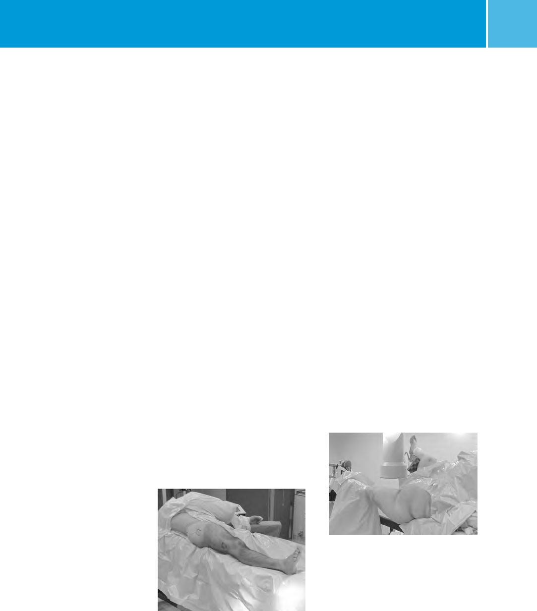
Patient Positioning
The patient may be placed in either the
supine (free legged or traction)
or lateral (traction) position.
(1) SUPINE FREE LEGGED – Place the
patient supine on a radiolucent table
(Fig. 1). The table should not have a
central pole or metal sidebars. Place
the patient’s buttock next to the edge
of the table with a radiolucent bump
(not a bean bag) under the buttock.
The eccentric position and elevated
buttock improves starting site posi-
tion and reduces drape encroachment.
Furthermore, the elevated buttock
enhances fluoroscopic lateral
viewing of the femoral head and neck.
The ipsilateral upper trunk and
extremity should angle towards the
contralateral shoulder. The ipsilateral
arm should be placed above the chest
on an arm holder or on a pillow with
stockinet. This upper extremity
placement improves starting point
entry and unencumbered implant
insertion.
(2) SUPINE TRACTION ON FRACTURE
TABLE – Place the patient supine on the
fracture table (Fig. 2). Pad all areas of
potential pressure. Flex and abduct the
non-injured leg onto a well padded leg
holder. Or, place the non-injured
leg into a scissor type position.
Position the buttock of the injured
leg as close to the edge of the table
as possible. Some tables will allow
for an eccentric peroneal post
connection to the table. Make sure
the peroneal post is padded and wide
in order to dissipate the pressure on
the groin area.
Place the injured leg into skeletal
traction (distal femoral or proximal
tibial) or boot-traction. The ipsilateral
arm should be placed above the chest
on an arm holder or on a pillow with
stockinet.
(3) LATERAL TRACTION ON FRACTURE
TABLE – Use the radiolucent table with
a radiolucent peroneal post. Place the
traction boots on the patient during
anesthesia induction. Turn the patient
in a lateral position, with the operative
leg over the top of the peroneal post.
Attach the boots to the table with
straight traction applied through
the boots.
Fig. 1
Fig. 2

ITST® System MIS and Standard Surgical Technique
4
If heavy traction is necessary, a pin is
placed in the distal femur and the knee
is flexed, applying traction through
the pin. Flex and adduct the operative
leg. Straighten the non-operative
leg in line with the body. Rotate the
patella slightly inwards towards the
floor, to help prevent an external
rotation deformity. Bring the C-arm in
perpendicular to the long axis of the
femur. When moving proximally and
distally, the entire C-arm is moved, to
stay perpendicular to the long axis. To
visualize the proximal femur and the
head, rotate the C-arm 15° over the top
and tilted 45° cephalad.
Patient Positioning for
Standard Technique
The patient should be placed in
either the supine or lateral decubitus
position on the table. The sacral rest
and perineal post should be well
padded. In multiple trauma patients,
the supine position may be used for
easier access to the patient’s airway,
as well as to facilitate the treatment
of other injuries. The supine position
also facilitates fracture reduction
and rotational alignment of
the femur.
Reduction
It is critical to reduce the fracture before
beginning the surgical procedure. An
anatomic reduction or a slight valgus
reduction of the femoral head and
neck, should be seen in the A/P film.
Occasionally, a slight sag of the fracture
may be seen on the lateral view. This
should be taken into consideration
during the surgical procedure.
Occasionally, flexion of the injured
limb will facilitate sagittal reduction.
As a rule of thumb, intertrochanteric
fractures are locked into position with
internal rotation of the leg. The patella
should point towards the ceiling.
Prep and Drape
The prep includes the ipsilateral
axilla, trunk, buttock, hip, thigh
(circumferentially), and knee. The drape
should extend up to the axilla with
U-shaped drapes. The free trunk and
buttock skin improves nail insertion
and diminishes guide entrapment on
the drapes. Furthermore, the free area
increases the freedom for percutaneous
insertion and incision closure. The
drape should extend past the knee to
allow for distal interlock insertion.
Prep and Drape for
Standard Technique
Prep and drape similar to the MIS
technique, although it is only
necessary to drape proximally to the
distal portion of the thoracic cavity
for the standard technique, not all
the way to the axilla. If the patient is
obese, prep and drape to the axilla
and use a more proximal entry point.
Fracture Site Reduction After
Prep and Drape
An attempt at fracture site reduction
should be performed initially to
facilitate the starting site placement,
central reaming, and nail-screw
insertion. The rotation and alignment
should have been performed before the
prep and drape. In fractures with varus
alignment despite traction, placement
of the patient in a lateral position of the
percutaneous reduction instruments
can help assist the reduction. A spike
pusher or tenaculum clamp can be
inserted through a 25 to 30mm
incision to realign the proximal
fragment. The classic flexion,
abduction, and external rotation of the
proximal fragment requires reduction
at this time. A spike pusher or
tenaculum clamp in an anterior to
posterior direction will help
accomplish the reduction.
For Pertrochanteric or Subtrochaneric
fractures (especially with involvement
of the lesser trochanter) the fracture
is reduced with the leg in external
rotation. Oblique roll over or roll
back fluoroscopic views can assist
visualization of proper rotation. This is
most important when considering the
starting point of the Steinman Pins or
cannulated awl into the femur.
Radiographic Control
NOTE: It is essential to obtain excellent
A/P and lateral images of the femoral
head and neck prior to beginning the
surgery regardless of which patient
position is used.
The use of image intensification or
other x-ray imaging is required. The
image intensifier should be sterile-
draped and may be positioned from the
contralateral or ipsilateral side of the
operating table.
Confirm visualization of the hip as well
as the shaft of the femur using image
intensification before prepping and
draping. Bend the patient’s torso away
from the affected extremity to improve
access to the greater trochanter. If
access to the greater trochanter is still
inadequate, adduct the affected leg.
However, to achieve proper alignment
of the fracture, this adducted position
must be corrected prior to insertion
of the nail.

ITST® System MIS and Standard Surgical Technique 5
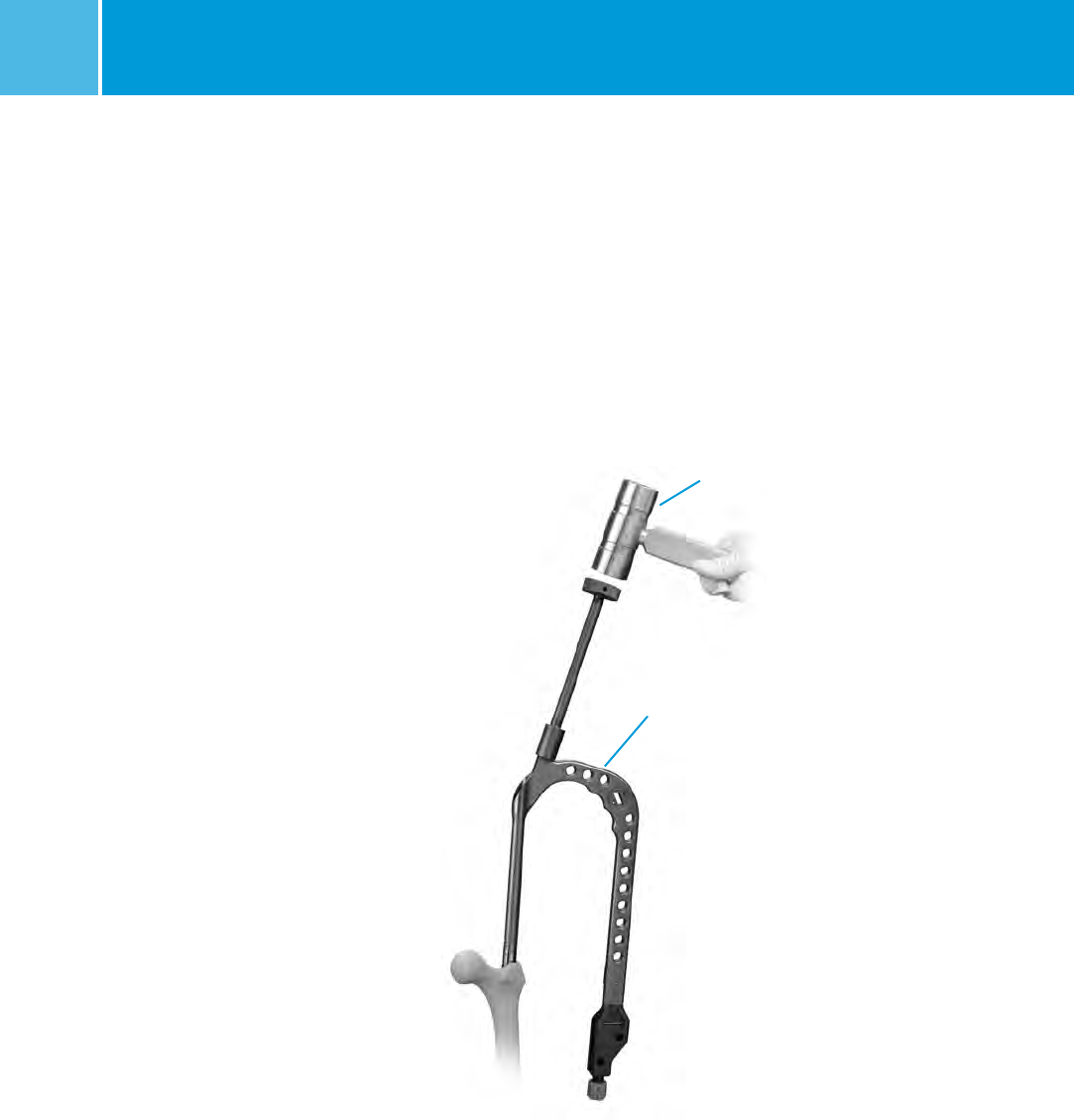
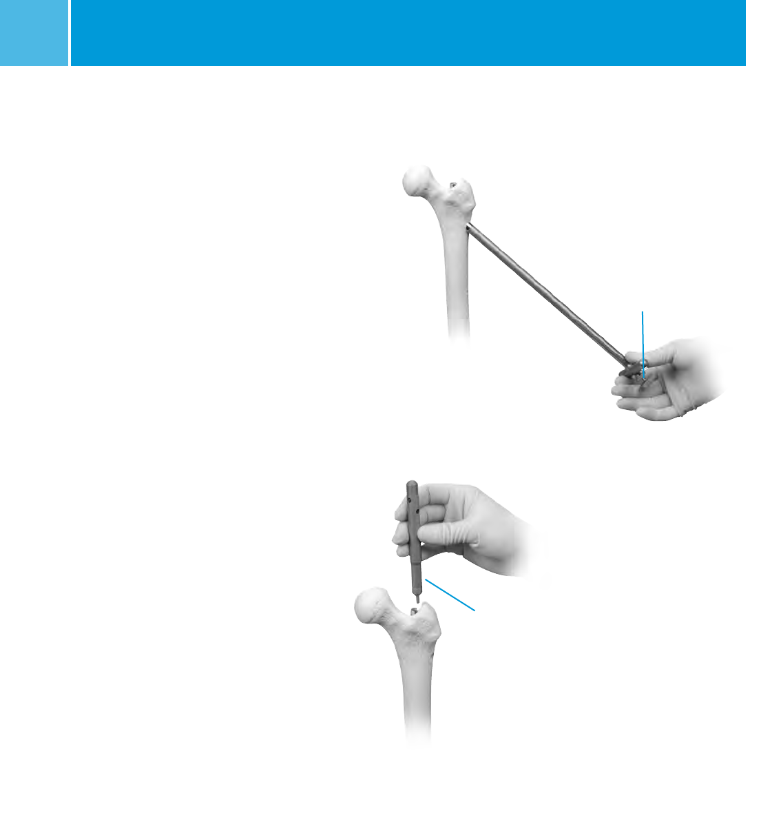
Starting Point and Steinman
Pin Insertion and Incision Using
Long Cannulated Awl
Palpate the line of the femur starting
at the greater trochanter. Continue
this line of insertion proximally until
reaching the level approximating the
iliac crest (more proximal with obese
patients) (Fig. 3).
Using a sterile marking pen, mark the
line of intersection between these two
lines; this corresponds to the insertion
site. Insert the 3.2mm terminally
threaded Steinman pin through the
soft tissues. The correct starting point
on the AP view is the medial half of the
greater trochanter. The correct starting
point on the lateral view corresponds
to the central half of the femoral neck.
An optional cannula can also be used
to help guide the pin into the correct
position. The cannula is inserted
through a 25mm incision at the level of
the iliac crest. The cannula can also be
used to protect tissues while reaming.
Fig. 4
Fig. 3
Incision
Use a #15 blade to create an incision
centered around the Steinman pin.
The incision needs to be only
15mm-20mm in length.
Starting Point and Incision
for Standard Technique
Begin the skin incision 1cm proximal
to the tip of the greater trochanter,
and extend it proximally for about
5cm in a longitudinal direction.
Continue the incision down through
the subcutaneous tissues and
split the fascia lata.
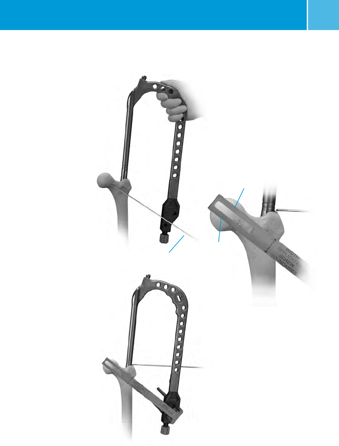
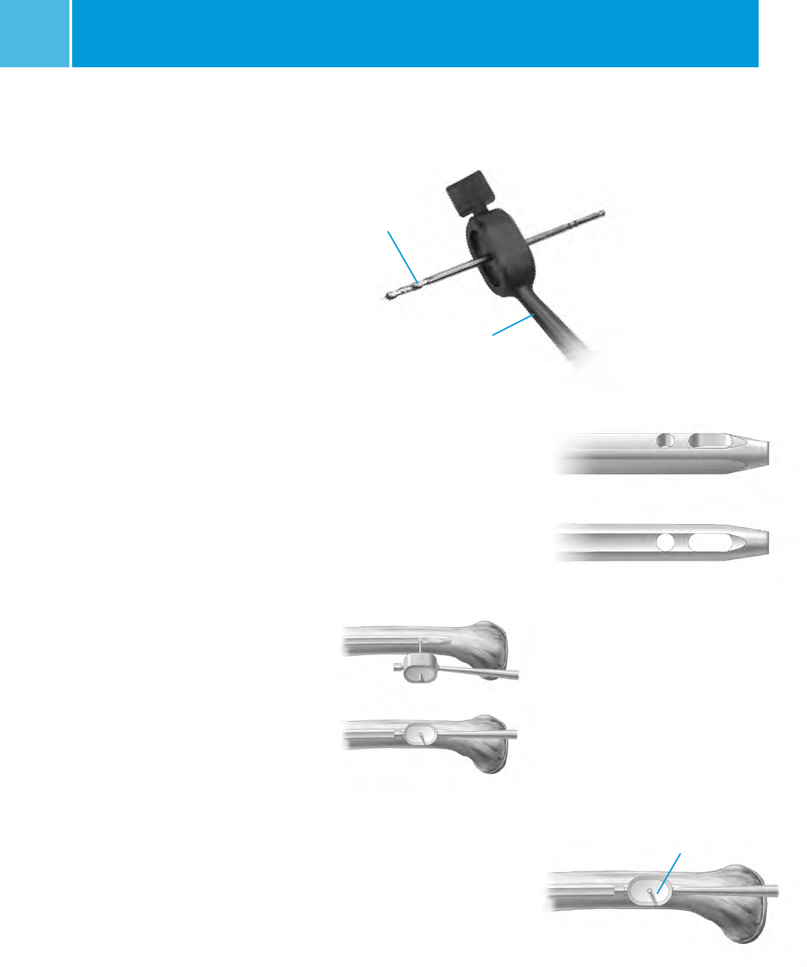
Creating the Entry Portal
Insert the terminally threaded Steinman
pin through the greater trochanter
down to the level of the lesser
trochanter (about 8cm). Ream using the
8mm trochanteric reamer (for
comminuted fracture lines extending
into or around the insertion site)
followed by the 17mm trochanteric
reamer (initially for fractures without
fracture lines extending into the
starting site). The reamers can be
inserted freely through the soft tissues
or through the cannula. The entry
portal should be in line with the
planned nail insertion and should line
up with the femoral canal on the AP
and lateral views (not aiming to the
medial or anterior cortices).
OPTIONAL TECHNIQUE
A cannulated awl can be used instead
of a guide wire to create the entry
portal. Place the tip of the awl in the
selected starting point (confirm using
bi-planer fluoroscopy). Advance the
awl through the greater trochanter into
the canal in line with the planned nail
insertion (Fig. 4).

ITST® System MIS and Standard Surgical Technique
6
Fig. 7 Reduction Instruments
Reduction Finger
Balled Spiked Pusher
Bone Hook
Fig. 6
The surgeon determines the proper nail
length using the Nail Length Gauge.
Slide the gauge over the guide wire
until the tip rests along the proximal
aspect of the greater trochanter (Fig. 8).
The proper nail depth will be deter-
mined by individual anatomy, varus or
valgus reduction, and most importantly
by the position of the lag screw within
the central aspect of the femoral head.
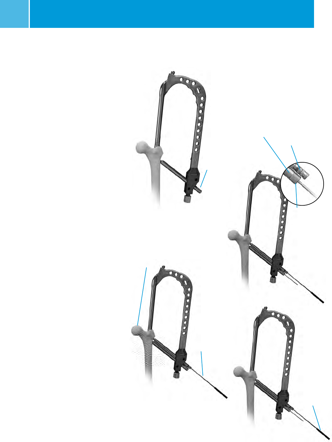
Reaming
Fig. 8
Guide Wire Placement
On the back table, attach the 3.0mm
Bulb-tipped Guide Wire to the Wire Grip
T-Handle, and tighten (Fig. 5). To aid in
manipulation, bend the tip of the guide
wire at about a 10 degree angle 5cm
from the end.
CAUTION: If the guide wire is bent
shorter than 5cm from the end of the
wire and/or more than 10 degrees it
may be difficult to remove from the nail.
If the wire becomes lodged inside the
nail, utilize the WIRE GRIP T-HANDLE and
mallet to remove the guide wire from the
nail.
NOTE: If using a cannulated awl, the
3.0mm Bulb-Tipped Guide Wire may be
passed directly through the cannulated
awl without the 45° bend (Fig. 6).
Insert the Guide Wire through the
entry hole and manipulate it down the
proximal femur across the fracture site.
At the fracture site, manipulate the Guide
Wire under C-arm control across the
Bulb-tipped
Guide Wire
Fig. 5
Wire Grip
T-Handle
fracture site. If reductionof the abducted
and flexed hip is difficult, place pressure
on the proximal fragment, either with
the hand or directly with a reduction
rod or other instrument. An alternative
technique is to reduce the fracture using
the Reduction Instruments shown in
Figure 7.
The reduction finger can also be used to
assist in reduction if the surgeon creates
an initial oblique starting portal. Once
in the distal canal, pass the wire to the
distal epiphyseal scar. Gently tap the
guide wire into the dense distal bone, so
that the wire will not retract with reamer
removal.
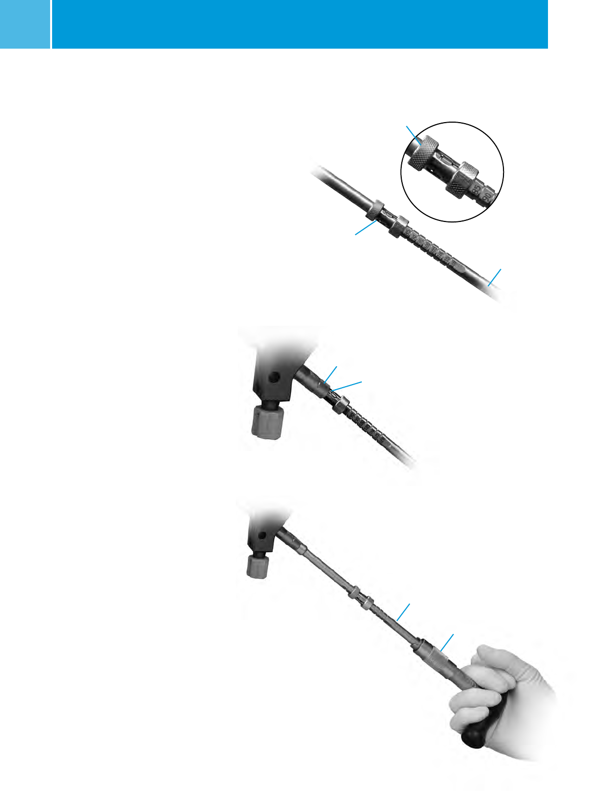
Measure

ITST® System MIS and Standard Surgical Technique 7
Fig. 9
Pressure Sentinel
Reamer
Over-reaming the canal by one or two
millimeters may facilitate preparation
of the bone to accommodate the
implant. The trochanteric region
should be reamed to 17mm using the
Trochanteric Reamer for all patients to
accommodate the implant and avoid
separation or widening of known or
unknown fracture lines (Fig. 10). Use
caution in advancing the Taper Reamer.
An alternative to reaming with the
Taper reamer is to sequentially ream
with a Pressure Sentinel Intramedullary
Reamer to 17mm diameter.
Ream to the level of the lesser trochanter
(or about 8cm depth), to accommodate
the implant by advancing the Taper
reamer into the proximal canal opening
until the reamer flutes are sunk to the
level of the lesser trochanter (Fig. 11).
Confirm position using the C-arm.
Replace the Bulb-Tipped Guide Wire with
the Smooth Guide Wire through the
Exchange Tube.
If using a 3.0mm Ball-Tip Guide Wire
that has a gold-coated end [Part
numbers 00-2255-008-01 or 47-2255-
008-11 (sterile)], the Ball-Tip Guide
Wire can remain in place and removed
after nail insertion. Otherwise, replace
the Bulb-Tipped Guide Wire with
the Smooth Guide Wire through an
Exchange Tube.
NOTE: Reaming amounts will depend
on the quality of the bone present,
the minimum diameter of the femoral
shaft, and the amount of femoral
curvature present.
NOTE: If the Guide Wire becomes
lodged within the reamer, use the
Wire-Grip T-Handle to push the Guide
Wire back into the IM canal.
The ITST MIS Cannula can be inserted
into the incision to protect the soft
tissue while reaming. Thread the
Centering Bushing into the Cannula
and place the Cannula firmly against
the bone. Remove Centering Bushing.
Ream the femoral canal sequentially
in 0.5mm increments using the Long
Pressure Sentinel® Intramedullary
Reaming System (Fig. 9). Ream until
cortical chatter is experienced. Based
on bone quality and curvature of
radius, nail diameter is 1-2mm less
than the last reamer used.
Taper
Reamer
Fig. 10
Fig. 11
ITST® System MIS and Standard Surgical Technique
8
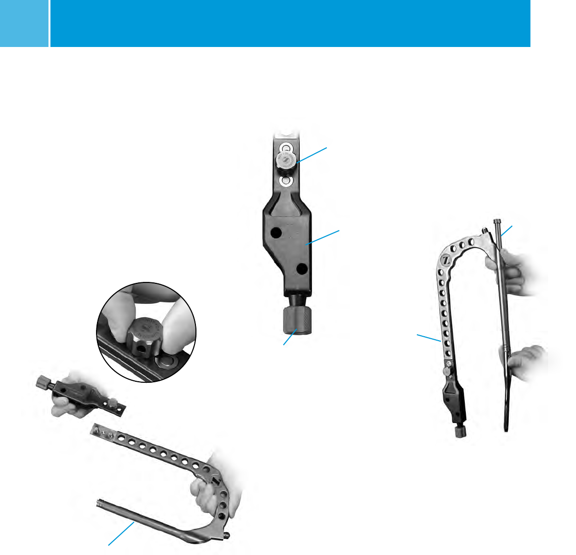
Guide Assembly
Thread the connecting bolt all the way
through the blue Modular Targeting
Arm. Attach the blue Modular
Targeting Arm to the Barrel using
the Connecting Bolt. Tighten the
Connecting Bolt by hand (Fig. 12).
Twist the Targeting Arm Nut on to the
end of the Blue Targeting Guide in
preparation for lag screw insertion
(Fig. 13). The Nut should not be
tightened at this point.
Proximal
Targeting Guide
Assembly
Fig. 14
Locking Bolt
Nail Assembly
Select the appropriate size ITST
Femoral Nail.
Slide the ITST Locking Bolt through
the barrel (Fig. 14). Approximate
the nail to the external “keys” on
the barrel.
Fig. 12
Barrel
Fig. 13
Connecting Bolt
Targeting Arm
Targeting Arm Nut
ITST® System MIS and Standard Surgical Technique 9
Fig. 17
Correct Alignment:
arrow to arrow
Lag Screw
Bushing
Fig. 18
Guide Pin
Locking Bolt
Inserter
Fig. 16
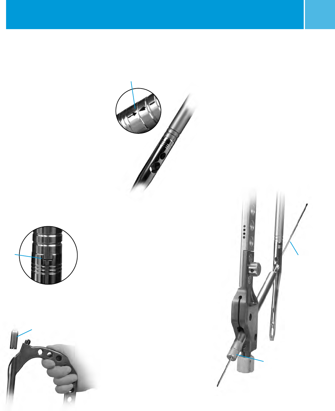
Nail Insertion
NOTE: Prior to inserting the implant,
insert the two sets of Drill and Screw
Bushings into the appropriate holes
in the Targeting Guide. Slide a drill or
guide pin through the Bushings, and
through the screw holes in the implant
to assess correct instrument assembly
(Fig. 18).
Nail may be inserted by hand.
If insertion cannot be achieved by
hand, please see note on page 10.
Insert nail (assembled with targeting
guide) into the femoral canal.
Fig. 15
Key and
Keyway
NOTE: The Guide is universal and it is
critical that the nail be properly aligned
with the Guide for a Left or Right
implant. Line up the keys of the
Guide with the keyways of the nail
so that they fit snugly (Fig. 15).
Place the T-Handled Locking Bolt
Inserter into the guide barrel (Fig. 16).
Toggle and rotate the Inserter slightly
until it seats into the teeth of the
Locking Bolt. The etched arrow at the
proximal rim of the nail should be
exactly aligned with the arrow on the
distal rim of the Targeting Guide
(Fig. 17). Using downward pressure on
the Locking Bolt Inserter, thread the
Locking Bolt into the threads of the
proximal end of the nail until secured.
Completely tighten.
ITST® System MIS and Standard Surgical Technique
10
Monitoring Insertion
Monitor the progression of the nail
down the canal using a C-arm.
A percutaneous 3.2mm Threaded Guide
Pin may be placed along the anterior
axis of the femoral neck paralleling
the femoral neck on the AP and lateral
views to mark the correct anteversion.
Align the Targeting Guide parallel (on
the lateral view) to the percutaneous
pin to assure that accurate implant
anteversion has been achieved. Check
the final position of the implant using
C-arm. If the nail fails to progress easily
down the canal, remove it, and use a
smaller nail, or over-ream the canal in
0.5mm increments until the implant
passes more easily down the femoral
canal. The surgeon should also check
the status of the nail in the distal
femur. If the nail is too long, a shorter
nail should be used to avoid distal
femoral cortical or articular penetration.
If the curvature of the femur does
not accommodate the nail, using
a shorter or smaller nail will assist
nail placement.
NOTE: If nail insertion can not be
achieved by hand, thread the Small
or Long Threaded Driver on the Barrel
(Fig. 19). Insert the nail into the canal
using a series of gentle impactions, if
necessary, on the Threaded Driver until
the nail is seated at the desired depth.
Mallet
Fig. 19
Top of the Proximal
Targeting Guide
CAUTION: Do not impact directly on
the ITST Targeting Guide or Barrel.
Screw Options
The ITST Nail accommodates both an
11mm Lag Screw and a 6.5mm
Anti-Rotation Screw. The Anti-Rotation
Screw may be utilized in the case of
certain fractures, where the bone stock
and femoral neck/head bone stock is
able to accommodate it. If only one screw
is used, it must be the 11mm Lag Screw.
NOTE: The 6.5mm Anti-Rotation Screw
may be used to enhance fracture
stability if the femoral neck is able to
accommodate it; however, it should
not be used if there is any concern that
the femoral head or neck bone will not
accommodate it.
WARNING: Use of this system in
osteoporotic bone or improper
placement of the nail could increase the
risk of failure or cut out of the implant.
Remember the goal of lag screw
placement is perfect placement into
the central position of the femoral
head on the AP and lateral view.
ITST® System MIS and Standard Surgical Technique 11
Lag Screw Positioning
The projected path of the Lag Screw
into the Femoral Head should be
assessed using the C-arm (Fig. 20).
This may be verified using the Screw
Position Outrigger and the 3.2mm
Threaded Guide Pin. Assemble the
Outrigger into the Modular Targeting
Arm and place a Threaded Guide
Pin into the Anteversion Verification
Hole in the barrel (Fig. 21).
Verify under C-arm that the Guide Pin
appears in the center of the femoral
neck in a superior/lateral view.
This will help prevent any parallax error.
The outer aspect of the windowed arm
of the Outrigger, which lies directly
over the femoral neck, represents the
superior and inferior position of the
Lag and Anti-Rotation Screws (Fig. 22).
If the nail anteversion requires
adjustment, move the nail up or down
in the canal by hand or by gently
impacting the Threaded Driver until
the correct depth is achieved. Check
the position of the nail with the C-arm.
Adjusting nail depth may be useful in
accommodating various femoral
neck anatomies.
NOTE: If the C-arm is off axis, the
alignment of the Outrigger may not
accurately predict the position of Lag
and Anti-Rotation Screws. In the event
this occurs, adjust the position of the
C-arm until it is on axis.
Fig. 20
Lag Screw
Projected Path
Fig. 22
Inferior Lag
Screw Position
Superior Anti-rotation
Screw Position
Fig. 21
ITST® System MIS and Standard Surgical Technique
12
Fig. 25
3.2mm
Threaded
Guide Pin
Subchondral
Bone
Fig. 26
Screw Inserter
Adaptor
Fig. 24
Lag Screw Bushing
8.0mm Drill Bushing
3.2mm Threaded
Guide Pin Bushing
Lag Screw Preparation
NOTE: The 6.5mm Anti-Rotation Screw
may be used to enhance fracture
stability if the femoral neck is able to
accommodate it.
Remove the 3.2mm Guide Wire.
Assemble the Lag Screw Pin Bushing
and Lag Screw Bushing together and
place the assembly into the inferior
screw hole in the Targeting Arm
(Fig. 23). Assemble the 3.2mm Arm
Pin Bushing, the 5.0mm Drill Bushing
and the 8.0mm Screw Bushing and
insert the assembly into the superior
screw hole in the Targeting Arm
(Fig. 24). When both bushings are
inserted, the 8.0mm Drill Bushing will
slide freely in the Targeting Arm. Make
small incisions in the soft tissue and
through the iliotibial band, down to the
lateral cortex of the femur. Be certain
that the bushings are firmly seated on
the bone. Do not force the bushings
or impact.
Insert a 3.2mm Threaded Guide Pin into
the inferior set of bushings. Drill
the Guide Pin to the level of the
subchondral bone of the femoral head,
without penetrating the femoral head
cortex (Fig. 25). Insert a Guide Pin into
the superior set of bushings. The Screw
Inserter Adapter may be used with this
Guide Pin to prevent impingement on
the adjacent Guide Pin during insertion
(Fig. 26). Drill the Guide Pin to the level
of the subchondral bone of the femoral
head, without penetrating the femoral
head cortex. Assess the position of the
Guide Pins using C-arm in the A/P and
lateral planes.
NOTE: Ideally each Guide Pin should
be situated well inside the femoral
neck to allow adequate room for screw
placement without contacting the
cortical wall. If there is not sufficient
cortical wall surrounding the Guide
Pins on examination with the C-arm,
the nail may be repositioned and
implanted using only the Lag Screw.
Fig. 23
Lag Screw
Bushing

ITST® System MIS and Standard Surgical Technique 13
Remove the Lag Screw Pin Bushing.
Slide the Cannulated Depth Gauge
over the lag screw Guide Pin, (i.e. the
inferior of the two guide pins), until the
gauge contacts the lateral aspect of the
femur (Fig. 27). Assess that the Gauge
is seated against the bone using the
C-arm. Read and record the length of
the guide pin from the calibrated
depth gauge.
NOTE: This measurement designates
the correct length of the Lag Screw to
be implanted (Fig. 28).
Slide the Stop Assembly onto the ITST
Lag Screw Reamer, keeping the gold
portion of the Stop Assembly toward
the cutting end of the reamer (Fig. 29).
Move the Stop Assembly along the
incremented lengths listed on the
reamer. Align the threaded end of the
Stop Assembly with the notch denoting
the appropriate length.
Fig. 27
Cannulated
Depth Gauge
Fig. 28 Threaded
Guide Pin
Cannulated
Depth Gauge
Fig. 29
Stop Assembly
Lag Screw Reamer
Gold Knob Gold portion of Stop
Assembly pointed toward
gold cutting edge of reamer
Gold cutting
edge of reamer
ITST® System MIS and Standard Surgical Technique
14
When the Stop Assembly is fully seated,
the arrow on the Stop Assembly will
indicate the appropriate depth level.
This “length” corresponds to the
measurement obtained from the guide
pin (Fig. 30).
Place the ITST Lag Screw Reamer over
the Guide Pin and seat it against the
femoral cortex. Under power, advance
the reamer until the Stop Assembly
stops against the Lag Screw Bushing
(Fig. 31). Monitor progress of the reamer
using the C-arm. Remove the reamer.
If necessary, assemble the Lag Screw
Tap by locking the Stop Assembly at the
level of the appropriate measurement,
in the same fashion as the Lag Screw
Reamer. Place the Lag Screw Tap over
the Guide Pin and through the Lag
Screw Bushing. Advance the tap until
the Stop Assembly stops against the
collar of the Lag Screw Bushing (Fig. 32).
Confirm Tap position with the C-arm.
Fig. 30
Fig. 31
Fig. 32
Stop Assembly
Lag Screw
Reamer
Lag Screw
Bushing
Stop Assembly is flush
against the Lag Screw Bushing
Lag Screw Tap
T-Handle
Gold
ITST® System MIS and Standard Surgical Technique 15
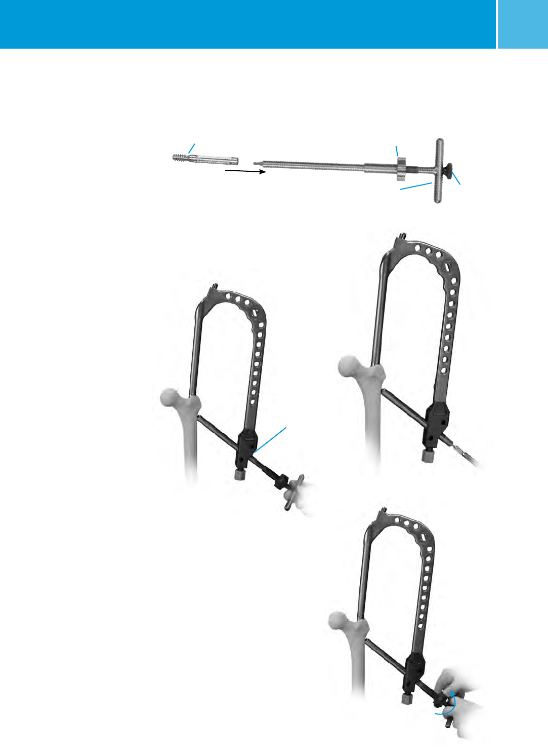
Lag Screw Insertion With ITST
Compression Device
If not using the ITST Compression
Device, proceed to page 16.
Thread the Compressor onto the Lag
Screw Compression Device T-Handle.
Insert Compression Retainer through
the Lag Screw Compression Device
T-Handle (Fig. 33) and thread into
the appropriate Lag Screw until it is
securely fastened to the Lag Screw
Compression Device T-Handle. Pass
the Lag Screw Compression Device
assembly through the Lag Screw
Bushing and over the Guide Pin
(Fig. 34). Thread Lag Screw to within
5mm of the subchondral bone,
monitoring the Lag Screw advancement
with the C-arm.
If planning to use a Nail Cap which
prevents rotation or limits sliding,
rotate the Lag Screw Compression
Device T-Handle (Fig. 35) such that one
of the four etched lines is in line with
the vertical slot on the Targeting Guide.
After inserting the Lag Screw to the
appropriate depth, confirm Lag Screw
position using the C-arm. To begin
compression of the femoral neck,
advance the Compressor clockwise
against the Lag Screw Bushing
(Fig. 36). Continue to advance the
Compressor while monitoring femoral
neck compression using the C-arm,
until the desired fracture reduction
is achieved.
After reduction, unthread the
Compression Retainer from the Lag
Screw. After removing the Compression
Retainer, the Lag Screw Compression
Device Assembly can be removed.
Remove the Superior Guide Pin and
Bushings if used. If using ITST Global
Long Nail, remove Targeting Guide
using the Pin Wrench and Locking
Bolt Extractor.
Fig. 33
Lag Screw Compressor
Compression
Device T-Handle
Compression
Retainer
(Replacement Part 00-2258-097-01)
Fig. 34
Fig. 35
Proximal
Targeting
Guide
Indicator Line
Fig. 36
Rotate Clockwise
ITST® System MIS and Standard Surgical Technique
16
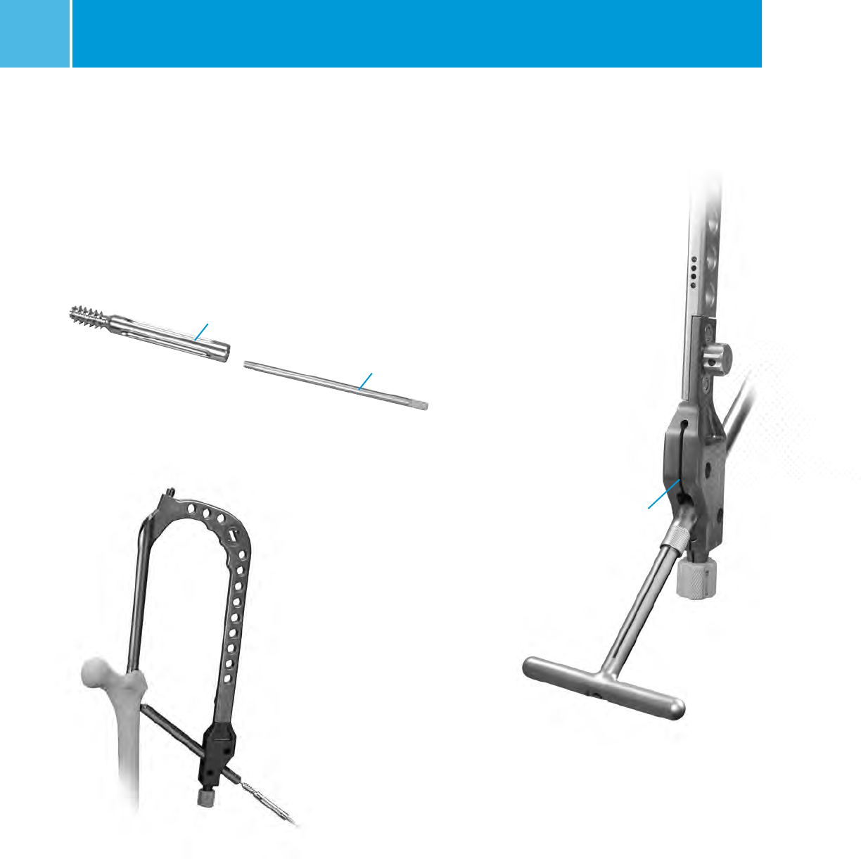
Standard Lag Screw Insertion
(Optional)
Thread the Inserter Link (Fig. 37) into
the Lag Screw until securely fastened.
Slide the Lag Screw Inserter Shaft over
the Inserter Link (Fig. 38).
Insert this assembly over the Guide Pin.
Thread the Lag Screw to within 5mm
of the Subchondral bone. Rotate the
Inserter Shaft (Fig. 39) and align one of
the four etch lines on the Inserter Shaft
with the vertical slot on the Targeting
Guide (Fig. 48). Check the Lag Screw
position using the C-arm. Leave the
Inserter Link attached to the
Lag Screw.
Fig. 37
Lag Screw
Inserter Link
Fig. 38
Fig. 39
Proximal Targeting
Guide Indicator Line

ITST® System MIS and Standard Surgical Technique 17
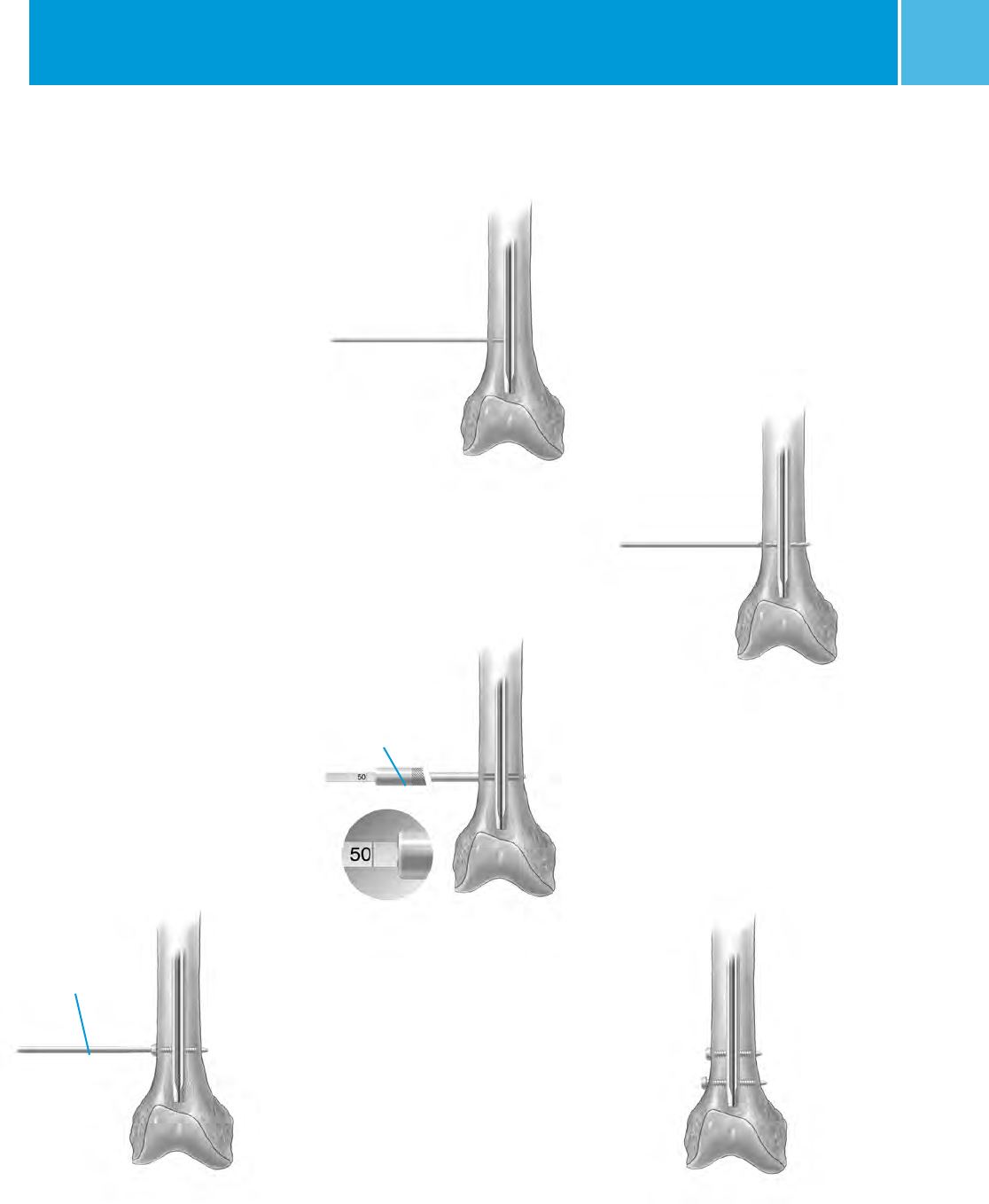
Anti-Rotation Screw Insertion
Remove the 3.2mm Pin Bushing. Slide
the Cannulated Depth Gauge over the
Guide Pin, until the Gauge contacts
the lateral aspect of the femur. Confirm
the position of the Depth Gauge using
the C-arm. Read the depth of the guide
pin from the Cannulated Depth Gauge.
The Anti-Rotation Screw length should
be 15mm to 20mm shorter than the
depth gauge measurement. This will
provide the proper screw placement
to help minimize femoral neck cutout1
(Fig. 40). Remove the Guide Pin. Under
C-arm control, drill into the femur
with the 5.0mm Drill until the correct
calibration on the drill is level with the
outer collar of the Drill Bushing.
Remove the 5.0mm Drill Bushing and
Drill. Insert the Anti-Rotation Screw
using the 5.0mm T-Handle Screwdriver
through the 8mm Screw Bushing and
into the femoral head until seated.
Placement of the screw should be
monitored using the C-arm.
Fig. 40
1 Baumgaertner, MR, et al., J Bone Joint Surg. AM.
1996 Sep; 78(9):1447-1448.
ITST® System MIS and Standard Surgical Technique
18
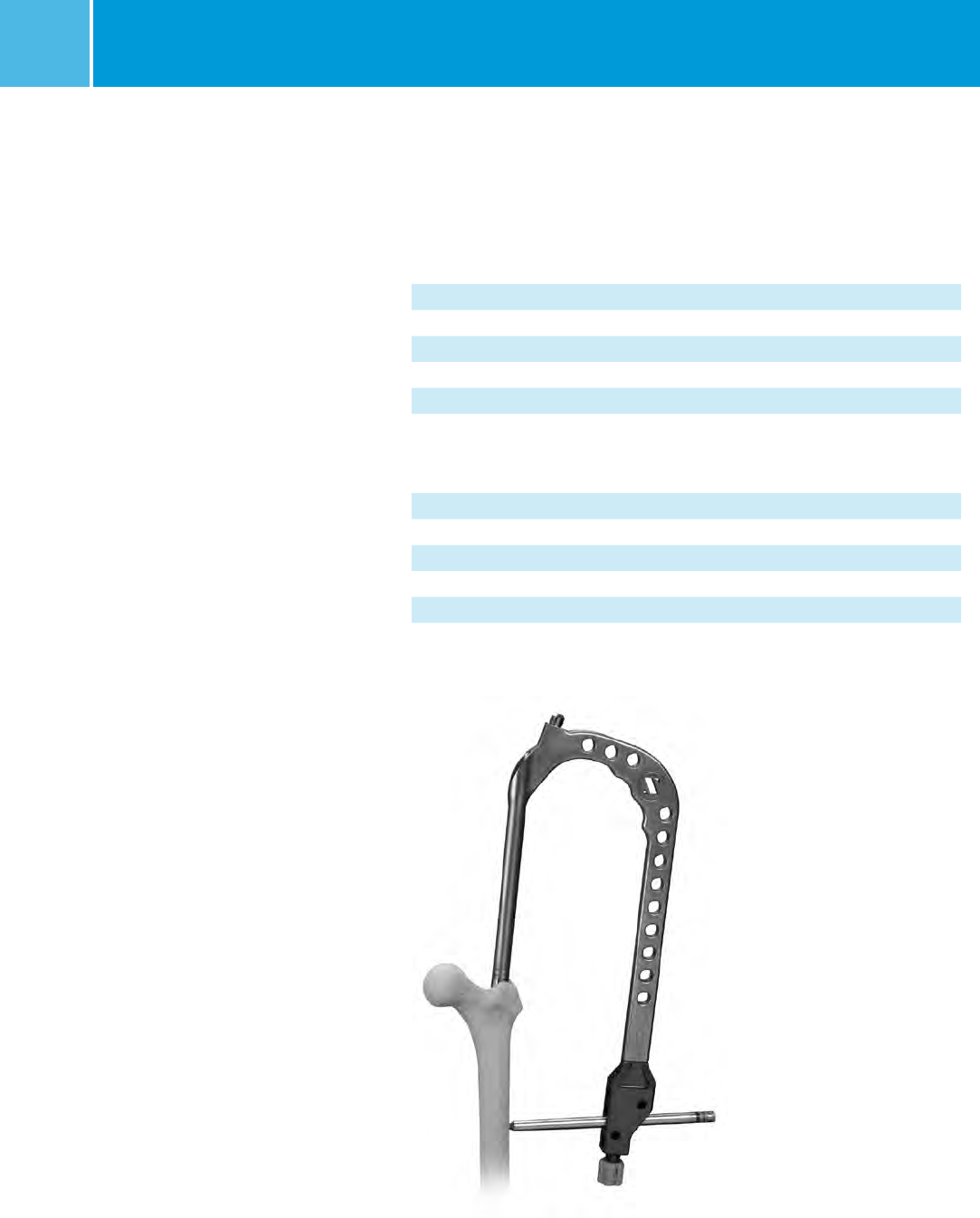
Distal Screw Fixation –
180mm / Short Nails
With the Proximal Targeting Guide still
in place, retighten the Locking Bolt if
necessary. Assemble the appropriate
Drill Bushing (see Table 1) into the
8.0mm Screw Bushing, and place
the nested bushings through one of
the distal targeting holes in the ITST
Modular Targeting Guide (Fig. 41).
Make a small incision through the skin
and fascia lata. Spread the soft tissue
down to the bone. Advance the bushing
until it contacts the lateral femoral
cortex. Advance the appropriate size
Drill through the bushings until both
cortices of bone have been penetrated.
NOTE: If using the Calibrated 3.7mm or
5.0mm Drill, read calibrations from end
of bushing to determine screw length.
Table 1.
ITST Global
Nails 180mm Diameter Distal Screw Drill Size
10mm Nail 4.5mm Screw 3.7mm Drill
11mm Nail 5.5mm Screw 5.0mm Drill
12mm Nail 5.5mm Screw 5.0mm Drill
13mm Nail 5.5mm Screw 5.0mm Drill
14mm Nail 5.5mm Screw 5.0mm Drill
15mm Nail 5.5mm Screw 5.0mm Drill
ITST Global
Nails 300-500mm
10mm Nail 4.5mm Screw 3.7mm Drill
11mm Nail 5.5mm Screw 5.0mm Drill
12mm Nail 5.5mm Screw 5.0mm Drill
13mm Nail 5.5mm Screw 5.0mm Drill
14mm Nail 5.5mm Screw 5.0mm Drill
Fig. 41
ITST® System MIS and Standard Surgical Technique 19
OPTIONAL TECHNIQUE
Remove the Drill and Drill Bushing,
and insert the ITST Screw Depth
Gauge through the 8.0mm Screw
Bushing until the gauge captures the
far cortex of bone.
Read the measurement for the screw
from the end of the depth gauge.
NOTE: Choose a screw length that is
at least 2.5mm longer than the depth
measured, to ensure that bicortical
screw fixation is attained.
If the bone quality is good, it may be
necessary to tap the channel using the
4.5mm Tap (Fig. 42).
Place the appropriate length Cortical
Screw onto the 3.5mm T-Handle Hex
Screwdriver and insert the screw into
the bone through the 8.0mm Screw
Bushing, until it is flush against the
lateral cortex of the femur (Fig. 43).
Confirm the position of the screw in the
A/P and lateral views with the C-arm.
Place the second distal locking screw in
the same fashion as the first.
Fig. 43
Fig. 42
Tap
ITST® System MIS and Standard Surgical Technique
20
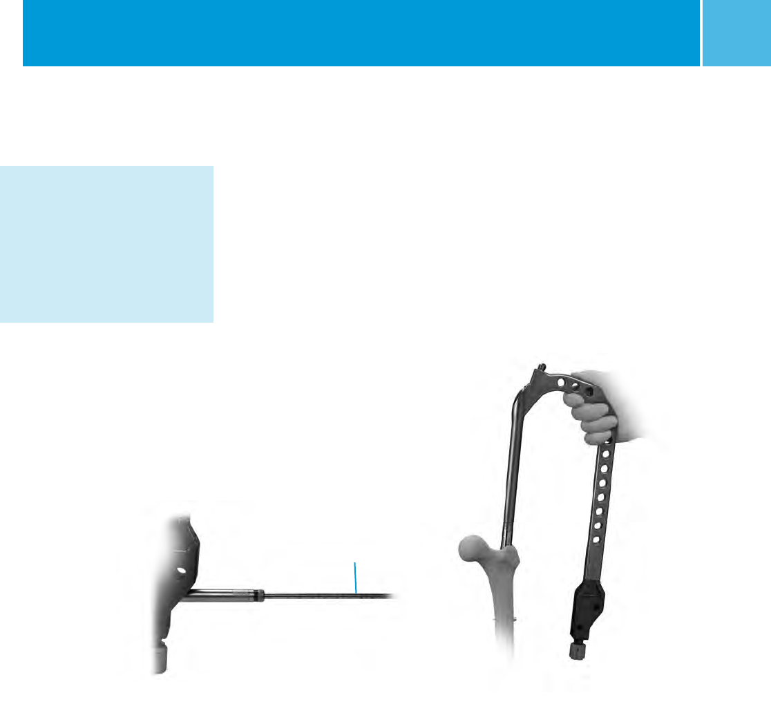
Distal Screw Fixation – Long
Nails – Freehand Technique
The distal locking screws may be
inserted with a freehand technique
using the Freehand Targeting Device
(Fig. 44). Insert a 3.7mm Drill (Color
Code: Blue) for a 4.5mm screw, or
insert a 5.0mm Drill (Color Code: Green)
for 5.5mm screw into the Freehand
Targeting Device. Finger tighten the
set screw.
Choose the appropriate locking hole
based on the need for dynamization.
The superior locking hole on the ITST
Nail is used for static locking, while the
distal locking hole is used for dynamic
locking. If static locking is preferred,
but there is a potential need for later
dynamization, insert screws in both
locking holes. The locking screw in the
static hole can then be removed to
achieve dynamization later.
For success with this technique, proper
placement of the lateral X-ray beam
is critical. Position the C-arm so that
the locking hole of the nail appears
perfectly round on the monitor
(Fig. 45 & 46).
When this is achieved, bring the tip
of the 3.7mm Drill to the skin and use
the C-arm to center it over the hole.
Make a lateral stab wound opposite the
appropriate locking hole, and dissect
down to the bone. Bring the tip of the
3.7mm Drill to the bone and center it
over the locking hole using the C-arm.
Align the 3.7mm Drill with the axis of
the X-ray beam. Drive the 3.7mm Drill
into the bone and across the hole in
the nail in line with the lateral X-ray
beam (Fig. 47). Before drilling through
the medial cortex, check the A/P and
lateral C-arm image to assure that the
drill is in the hole in the nail.
Fig. 44
Trocar Drill
Freehand
Targeting Device
Fig. 45
Incorrect
Correct
Incorrect
Correct
Fig. 46
Fig. 47
Bone Drill
ITST® System MIS and Standard Surgical Technique 21
Drill through the medial cortex (Fig. 48
& 49). Remove the Drill and insert the
Distal Screw Depth Gauge (Fig. 50).
The length of the screw is determined
by reading it directly off the Distal
Screw Depth Gauge.
NOTE: Select an appropriate length
screw to ensure adequate engagement
of the medial cortex.
Insert the appropriate size M/DN®
Screw using the Distal Screwdriver
(Fig. 51).
If desired, insert the second screw
in the second locking hole of the nail
in an identical manner. Check the
position of both screws with the C-arm
in the A/P and lateral planes (Fig. 52).
Bushings are available that can be
used with the Freehand Targeting
Device. A separate radiolucent Bushing
Insert is available to aid in targeting.
Fig. 48
Lateral Cortex
Fig. 49
Medial Cortex
Fig. 50
Distal Screw
Depth Gauge
Fig. 51
Distal
Screwdriver
Bi-cortical
Fixation
Fig. 52
Example of
Static Locking
ITST® System MIS and Standard Surgical Technique
22
Completion
Remove the ITST Barrel Targeting Arm,
Threaded Driver and Locking Bolt using
the Locking Bolt Extractor. Take care
to leave the Lag Screw Inserter Link in
place for final Nail Cap seating.
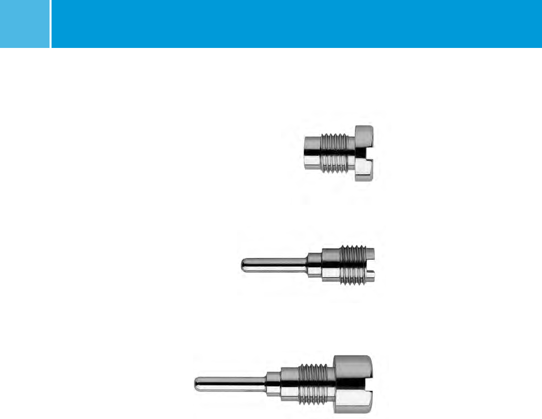
Insert the appropriate Nail Cap: Neutral
Nail Cap (Fig. 53), Sliding Nail Cap
(Fig. 54), or Locking Nail Cap (Fig. 55)
with the Nail Cap Inserter (Fig. 57).
Fig. 53 Neutral Cap* (5mm shown)
Fig. 54 Sliding Cap* (0mm shown)
Fig. 55 Locking Cap* (15mm shown)
* All Nail Caps are available in 0, 5, 10, 15, and
20mm head sizes.
ITST® System MIS and Standard Surgical Technique 23
Fig. 57
Nail Cap Inserter
Nail Cap
Fig. 56
Lag Screw Inserter Shaft
Fig. 58
Tighten until fully seated. If using a
Sliding or Locking Cap, slide the Lag
Screw Inserter Shaft over the Insert Link
and into the Lag Screw (Fig. 57). Slowly
rotate the Lag Screw Inserter and Nail
Cap Inserter until the Nail Cap flange
can be felt seating into one of the four
lag screw shaft grooves (Fig. 56, 57).
Lag Screw/Nail Cap construct in situ.
ITST® System MIS and Standard Surgical Technique
24
Closure and Postoperative Care
Close the proximal wound and apply a
soft compression dressing.
Postoperative range of motion
exercises and weight bearing should be
individually determined by the surgeon
based on patient age, fracture pattern,
and surgeon evaluation.
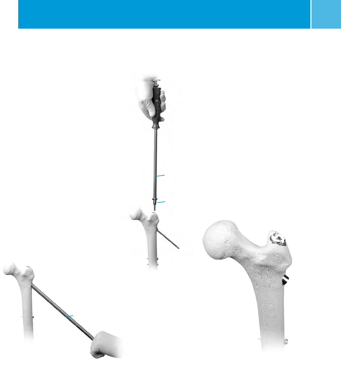
Extraction
In order to extract the nail, remove any
existing distal screws with the 3.5mm
T-Handle Hex Screwdriver. Remove
the Nail Cap with the 5.0mm T-Handle
Screwdriver. Make a small incision
in the area of the existing proximal
incision to expose the ends of the Lag
Screw and Anti-Rotation Screw. Clear
any bony ingrowth away from the Lag
Screw hex, and thread the Retaining
Shaft into the Lag Screw. Slide the
Lag Screw Inserter into the Lag Screw,
and tighten the Extraction Knob.
Remove the lag screw, turning counter
clockwise, with a slight backward
pulling motion (Fig. 59). Once the Lag
Screw has been removed, use the
5.0mm T-Handled Hexdriver to remove
the Anti-Rotation Screw.
Attach the Extractor Bolt (00-2258-064-
00) into the nail (Fig. 60). Screw the
Slaphammer onto the Extractor Bolt
and remove the nail.
Extraction instruments are not included
in the Standard Set and must be
procured separately.
Fig. 59
Retaining Shaft
Fig. 60
Extractor Bolt

ITST® System MIS and Standard Surgical Technique 25
Implant and Instrument Case Options
Prod. No. Description Size
00-2257-000-07 ITST Asia Set
(contains the following)
00-2256-180-10 Univ L/R Fem IM Nail 10mmDX18cm
00-2256-180-11 Univ L/R Fem IM Nail 11mmDX18cm
00-2256-180-12 Univ L/R Fem IM Nail 12mmDX18cm
00-2256-180-13 Univ L/R Fem IM Nail 13mmDX18cm
00-2256-180-14 Univ L/R Fem IM Nail 14mmDX18cm
00-2256-180-15 Univ L/R Fem IM Nail 15mmDX18cm
00-2257-000-05 ITST Global Short Set
(contains the following)
00-2257-180-10 Univ L/R Fem IM Nail 10mmDX18cm
00-2257-180-11 Univ L/R Fem IM Nail 11mmDX18cm
00-2257-180-12 Univ L/R Fem IM Nail 12mmDX18cm
00-2257-180-13 Univ L/R Fem IM Nail 13mmDX18cm
00-2257-180-14 Univ L/R Fem IM Nail 14mmDX18cm
00-2257-180-15 Univ L/R Fem IM Nail 15mmDX18cm
00-2257-000-06 ITST Global Long Set
(contains the following)
00-2257-300-00 Left Fem IM Nail 10mmDX30cm
00-2257-300-01 Left Fem IM Nail 11mmDX30cm
00-2257-300-02 Left Fem IM Nail 12mmDX30cm
00-2257-300-03 Left Fem IM Nail 13mmDX30cm
00-2257-300-04 Left Fem IM Nail 14mmDX30cm
00-2257-300-10 Right Fem IM Nail 10mmDX30cm
00-2257-300-11 Right Fem IM Nail 11mmDX30cm
00-2257-300-12 Right Fem IM Nail 12mmDX30cm
00-2257-300-13 Right Fem IM Nail 13mmDX30cm
00-2257-300-14 Right Fem IM Nail 14mmDX30cm
00-2257-320-00 Left Fem IM Nail 10mmDX32cm
00-2257-320-01 Left Fem IM Nail 11mmDX32cm
00-2257-320-02 Left Fem IM Nail 12mmDX32cm
00-2257-320-03 Left Fem IM Nail 13mmDX32cm
00-2257-320-04 Left Fem IM Nail 14mmDX32cm
00-2257-320-10 Right Fem IM Nail 10mmDX32cm
00-2257-320-11 Right Fem IM Nail 11mmDX32cm
00-2257-320-12 Right Fem IM Nail 12mmDX32cm
00-2257-320-13 Right Fem IM Nail 13mmDX32cm
00-2257-320-14 Right Fem IM Nail 14mmDX32cm
00-2257-340-00 Left Fem IM Nail 10mmDX34cm
00-2257-340-01 Left Fem IM Nail 11mmDX34cm
00-2257-340-02 Left Fem IM Nail 12mmDX34cm
00-2257-340-03 Left Fem IM Nail 13mmDX34cm
00-2257-340-04 Left Fem IM Nail 14mmDX34cm
00-2257-340-10 Right Fem IM Nail 10mmDX34cm
00-2257-340-11 Right Fem IM Nail 11mmDX34cm
00-2257-340-12 Right Fem IM Nail 12mmDX34cm
00-2257-340-13 Right Fem IM Nail 13mmDX34cm
00-2257-340-14 Right Fem IM Nail 14mmDX34cm
00-2257-360-00 Left Fem IM Nail 10mmDX36cm
00-2257-360-01 Left Fem IM Nail 11mmDX36cm
00-2257-360-02 Left Fem IM Nail 12mmDX36cm
00-2257-360-03 Left Fem IM Nail 13mmDX36cm
00-2257-360-04 Left Fem IM Nail 14mmDX36cm
00-2257-360-10 Right Fem IM Nail 10mmDX36cm
00-2257-360-11 Right Fem IM Nail 11mmDX36cm
00-2257-360-12 Right Fem IM Nail 12mmDX36cm
00-2257-360-13 Right Fem IM Nail 13mmDX36cm
00-2257-360-14 Right Fem IM Nail 14mmDX36cm
00-2257-380-00 Left Fem IM Nail 10mmDX38cm
00-2257-380-01 Left Fem IM Nail 11mmDX38cm
00-2257-380-02 Left Fem IM Nail 12mmDX38cm
00-2257-380-03 Left Fem IM Nail 13mmDX38cm
00-2257-380-04 Left Fem IM Nail 14mmDX38cm
00-2257-380-10 Right Fem IM Nail 10mmDX38cm
00-2257-380-11 Right Fem IM Nail 11mmDX38cm
00-2257-380-12 Right Fem IM Nail 12mmDX38cm
00-2257-380-13 Right Fem IM Nail 13mmDX38cm
00-2257-380-14 Right Fem IM Nail 14mmDX38cm
00-2257-400-00 Left Fem IM Nail 10mmDX40cm
00-2257-400-01 Left Fem IM Nail 11mmDX40cm
00-2257-400-02 Left Fem IM Nail 12mmDX40cm
00-2257-400-03 Left Fem IM Nail 13mmDX40cm
00-2257-400-04 Left Fem IM Nail 14mmDX40cm
00-2257-400-10 Right Fem IM Nail 10mmDX40cm
00-2257-400-11 Right Fem IM Nail 11mmDX40cm
00-2257-400-12 Right Fem IM Nail 12mmDX40cm
00-2257-400-13 Right Fem IM Nail 13mmDX40cm
00-2257-400-14 Right Fem IM Nail 14mmDX40cm
00-2257-420-00 Left Fem IM Nail 10mmDX42cm
00-2257-420-01 Left Fem IM Nail 11mmDX42cm
00-2257-420-02 Left Fem IM Nail 12mmDX42cm
00-2257-420-03 Left Fem IM Nail 13mmDX42cm
00-2257-420-04 Left Fem IM Nail 14mmDX42cm
00-2257-420-10 Right Fem IM Nail 10mmDX42cm

ITST® System MIS and Standard Surgical Technique
26
00-2257-420-11 Right Fem IM Nail 11mmDX42cm
00-2257-420-12 Right Fem IM Nail 12mmDX42cm
00-2257-420-13 Right Fem IM Nail 13mmDX42cm
00-2257-420-14 Right Fem IM Nail 14mmDX42cm
00-2257-440-00 Left Fem IM Nail 10mmDX44cm
00-2257-440-01 Left Fem IM Nail 11mmDX44cm
00-2257-440-02 Left Fem IM Nail 12mmDX44cm
00-2257-440-03 Left Fem IM Nail 13mmDX44cm
00-2257-440-04 Left Fem IM Nail 14mmDX44cm
00-2257-440-10 Right Fem IM Nail 10mmDX44cm
00-2257-440-11 Right Fem IM Nail 11mmDX44cm
00-2257-440-12 Right Fem IM Nail 12mmDX44cm
00-2257-440-13 Right Fem IM Nail 13mmDX44cm
00-2257-440-14 Right Fem IM Nail 14mmDX44cm
00-2257-460-00 Left Fem IM Nail 10mmDX46cm
00-2257-460-01 Left Fem IM Nail 11mmDX46cm
00-2257-460-02 Left Fem IM Nail 12mmDX46cm
00-2257-460-03 Left Fem IM Nail 13mmDX46cm
00-2257-460-04 Left Fem IM Nail 14mmDX46cm
00-2257-460-10 Right Fem IM Nail 10mmDX46cm
00-2257-460-11 Right Fem IM Nail 11mmDX46cm
00-2257-460-12 Right Fem IM Nail 12mmDX46cm
00-2257-460-13 Right Fem IM Nail 13mmDX46cm
00-2257-460-14 Right Fem IM Nail 14mmDX46cm
00-2257-480-00 Left Fem IM Nail 10mmDX48cm
00-2257-480-01 Left Fem IM Nail 11mmDX48cm
00-2257-480-02 Left Fem IM Nail 12mmDX48cm
00-2257-480-03 Left Fem IM Nail 13mmDX48cm
00-2257-480-04 Left Fem IM Nail 14mmDX48cm
00-2257-480-10 Right Fem IM Nail 10mmDX48cm
00-2257-480-11 Right Fem IM Nail 11mmDX48cm
00-2257-480-12 Right Fem IM Nail 12mmDX48cm
00-2257-480-13 Right Fem IM Nail 13mmDX48cm
00-2257-480-14 Right Fem IM Nail 14mmDX48cm
00-2257-500-00 Left Fem IM Nail 10mmDX50cm
00-2257-500-01 Left Fem IM Nail 11mmDX50cm
00-2257-500-02 Left Fem IM Nail 12mmDX50cm
00-2257-500-03 Left Fem IM Nail 13mmDX50cm
00-2257-500-04 Left Fem IM Nail 14mmDX50cm
00-2257-500-10 Right Fem IM Nail 10mmDX50cm
00-2257-500-11 Right Fem IM Nail 11mmDX50cm
00-2257-500-12 Right Fem IM Nail 12mmDX50cm
00-2257-500-13 Right Fem IM Nail 13mmDX50cm
00-2257-500-14 Right Fem IM Nail 14mmDX50cm
Nail Caps
00-2259-007-00 ITST 1-Piece Slide Nail Cap 0mm
00-2259-007-05 ITST 1-Piece Slide Nail Cap 5mm
00-2259-007-10 ITST 1-Piece Slide Nail Cap 10mm
00-2259-007-15 ITST 1-Piece Slide Nail Cap 15mm
00-2259-007-20 ITST 1-Piece Slide Nail Cap 20mm
00-2259-008-00 ITST 1-Piece Lock Nail Cap 0mm
00-2259-008-05 ITST 1-Piece Lock Nail Cap 5mm
00-2259-008-10 ITST 1-Piece Lock Nail Cap 10mm
00-2259-008-15 ITST 1-Piece Lock Nail Cap 15mm
00-2259-008-20 ITST 1-Piece Lock Nail Cap 20mm
00-2259-009-00 ITST 1-Piece NTRL Nail Cap 0mm
00-2259-009-05 ITST 1-Piece NTRL Nail Cap 5mm
00-2259-009-10 ITST 1-Piece NTRL Nail Cap 10mm
00-2259-009-15 ITST 1-Piece NTRL Nail Cap 15mm
00-2259-009-20 ITST 1-Piece NTRL Nail Cap 20mm
00-2257-000-09 Anti-Rotation Screws
(contains the following)
00-2257-060-65 ITST Anti-Rotation Screw 6.5mmDX60mm
00-2257-065-65 ITST Anti-Rotation Screw 6.5mmDX65mm
00-2257-070-65 ITST Anti-Rotation Screw 6.5mmDX70mm
00-2257-075-65 ITST Anti-Rotation Screw 6.5mmDX75mm
00-2257-080-65 ITST Anti-Rotation Screw 6.5mmDX80mm
00-2257-085-65 ITST Anti-Rotation Screw 6.5mmDX85mm
00-2257-090-65 ITST Anti-Rotation Screw 6.5mmDX90mm
00-2257-095-65 ITST Anti-Rotation Screw 6.5mmDX95mm
00-2257-100-65 ITST Anti-Rotation Screw 6.5mmDX100mm
00-2257-105-65 ITST Anti-Rotation Screw 6.5mmDX105mm
00-2257-110-65 ITST Anti-Rotation Screw 6.5mmDX110mm
ITST Asia Lag Screws
00-2256-002-27 Asia 1-Piece Lag Screw 11mmDX70mm
00-2256-002-30 Asia 1-Piece Lag Screw 11mmDX75mm
00-2256-002-32 Asia 1-Piece Lag Screw 11mmDX80mm
00-2256-002-35 Asia 1-Piece Lag Screw 11mmDX85mm
00-2256-002-37 Asia 1-Piece Lag Screw 11mmDX90mm
00-2256-002-40 Asia 1-Piece Lag Screw 11mmDX95mm
00-2256-002-42 Asia 1-Piece Lag Screw 11mmDX100mm
00-2256-002-45 Asia 1-Piece Lag Screw 11mmDX105mm
00-2256-002-47 Asia 1-Piece Lag Screw 11mmDX110mm
00-2256-002-50 Asia 1-Piece Lag Screw 11mmDX115mm
00-2256-002-52 Asia 1-Piece Lag Screw 11mmDX120mm

ITST® System MIS and Standard Surgical Technique 27
ITST Standard Lag Screws
00-2259-001-27 1-Piece Lag Screw 11mmDX70mm
00-2259-001-30 1-Piece Lag Screw 11mmDX75mm
00-2259-001-32 1-Piece Lag Screw 11mmDX80mm
00-2259-001-35 1-Piece Lag Screw 11mmDX85mm
00-2259-001-37 1-Piece Lag Screw 11mmDX90mm
00-2259-001-40 1-Piece Lag Screw 11mmDX95mm
00-2259-001-42 1-Piece Lag Screw 11mmDX100mm
00-2259-001-45 1-Piece Lag Screw 11mmDX105mm
00-2259-001-47 1-Piece Lag Screw 11mmDX110mm
00-2259-001-50 1-Piece Lag Screw 11mmDX115mm
00-2259-001-52 1-Piece Lag Screw 11mmDX120mm
00-2258-000-11 ITST Nail Instrument Set
for use with Mod Targeting Guide
00-2258-007-00 ITST Short Nail Instrument Case Tray
00-2258-008-00 ITST Instrument Case Lid
00-2237-053-00 Wire Grip T-Handle
00-2237-061-00 Cannulated Awl
00-2255-028-00 9/16 in. Pin Wrench
00-2255-038-00 T-Handle
00-2258-051-01 Locking Bolt Extractor
00-2258-051-02 Locking Bolt Inserter
00-2258-090-00 ITST Cannula
00-2258-091-00 ITST Centering Bushing
00-2258-092-03 MIS Nail Cap Inserter Link
00-2258-092-04 MIS Nail Cap Inserter
00-2258-096-00 U-Joint Sleeve
00-5791-049-00 Screw Inserter/Extractor
00-2258-054-00 Threaded Guide Pin Bushing
00-2258-056-00 Lag Screw Bushing
00-2258-058-00 Lag Screw Reamer
00-2258-059-00 Lag Screw Tap
00-2258-062-00 Stop Assembly (Qty: 2)
00-2258-068-32 ITST Pin Bushing 3.2mm
00-2258-068-50 ITST Drill Bushing 5.0mm
00-2258-068-80 ITST Screw Bushing 8.0mm (Qty: 2)
00-2258-069-50 ITST Femoral Drill 5.0mm
00-2258-097-00 ITST Lag Screw Compression Device
00-2258-000-06 ITST Modular Targeting Guide Set
(Standard and MIS Technique Options)
00-2258-052-03 ITST Standard Barrel
00-2258-052-04 ITST MIS Barrel
00-2258-052-05 ITST Targeting Arm
00-2258-052-06 Targeting Arm Nut
00-2258-052-09 Modular Connecting Bolt
00-2258-087-00 ITST Standard Locking Bolt
00-2258-087-01 ITST MIS Locking Bolt
00-2258-053-01 Modular Targeting Guide Outrigger
00-2255-060-01 8mm MIS Trochanteric Reamer
00-2258-050-02 Long ITST Taper Reamer
00-2258-067-01 Long 3.2mm Threaded Guide Pin
00-2258-057-01 Long Cannulated Depth Gauge
00-2258-006-50 ITST Short Nail Instrument Case Base
00-2258-000-03 ITST Accessory Instrument Set
(includes all of the following listed below)
00-2258-010-00 ITST Accessory Instrument Case
00-2237-043-00 5.0mm T-Handle Screwdriver
00-2237-062-00 Long Threaded Driver
00-2237-064-00 Nail Length Gauge
00-2255-015-01 Wand Insert
00-2255-015-02 Wand Set Screw
00-2255-015-03 Wand Handle
00-2255-018-00 Distal Screw Depth Gauge (short)
00-2255-033-37 3.7mm Distal Trocar Drill (Qty: 2)
00-2255-033-50 5.0mm Distal Trocar Drill (Qty: 2)
00-2255-034-00 Reduction Finger
00-2258-068-37 ITST 3.7mm Drill Bushing
00-2258-069-37 ITST 3.7mm Drill
00-2258-071-45 ITST 4.5mm Screw Tap
00-2258-072-00 ITST Screw Depth Gauge (long)
00-2258-077-00 Driver Extension
00-2258-078-00 Driver Extension Bolt (Qty: 1)
Optional ITST Instrumentation
00-4816-060-00 Straight Ball Spike Pusher
00-4817-011-00 Medium Bone Hook (Shoulder Hook)
00-2258-092-00 ITST One-Piece Nail Cap Inserter
00-2258-092-01 ITST Linked Nail Cap Inserter
00-2258-097-00 ITST Lag Screw Compression Assembly
(Note: 00-2258-097-00 includes:
Compression Device T-Handle, Compressor,
Compression Retainer.)
00-2258-097-01 Compression Retainer (Replacement Part)
00-2258-000-10 ITST Modular Targeting Guide Asia Set
(set includes all instruments and case)
00-2258-052-12 ITST Asia Barrel
00-2258-052-13 ITST Asia Targeting Arm
00-2258-052-06 Targeting Arm Nut
00-2258-052-09 Modular Connecting Bolt
00-2258-087-02 ITST Asia Locking Bolt
00-2258-053-01 Modular Targeting Guide Outrigger
00-2258-067-01 Long 3.2mm Threaded Guide Pin
00-2258-057-01 Long Cannulated Depth Gauge
00-2258-006-50 ITST Short Nail Instrument Case Base

ITST® System MIS and Standard Surgical Technique
28
Cortical Screws
Prod. No. Description
00-2253-020-45 Cortical Screw 4.5mmDX20mm
00-2253-022-45 Cortical Screw 4.5mmDX22.5mm
00-2253-025-45 Cortical Screw 4.5mmDX25mm
00-2253-027-45 Cortical Screw 4.5mmDX27.5mm
00-2253-030-45 Cortical Screw 4.5mmDX30mm
00-2253-032-45 Cortical Screw 4.5mmDX32.5mm
00-2253-035-45 Cortical Screw 4.5mmDX35mm
00-2253-037-45 Cortical Screw 4.5mmDX37.5mm
00-2253-040-45 Cortical Screw 4.5mmDX40mm
00-2253-042-45 Cortical Screw 4.5mmDX42.5mm
00-2253-045-45 Cortical Screw 4.5mmDX45mm
00-2253-047-45 Cortical Screw 4.5mmDX47.5mm
00-2253-050-45 Cortical Screw 4.5mmDX50mm
00-2253-052-45 Cortical Screw 4.5mmDX52.5mm
00-2253-055-45 Cortical Screw 4.5mmDX55mm
00-2253-057-45 Cortical Screw 4.5mmDX57.5mm
00-2253-060-45 Cortical Screw 4.5mmDX60mm
00-2253-062-45 Cortical Screw 4.5mmDX62.5mm
00-2253-065-45 Cortical Screw 4.5mmDX65mm
00-2253-067-45 Cortical Screw 4.5mmDX67.5mm
00-2253-070-45 Cortical Screw 4.5mmDX70mm
00-2253-072-45 Cortical Screw 4.5mmDX72.5mm
00-2253-075-45 Cortical Screw 4.5mmDX75mm
00-2253-077-45 Cortical Screw 4.5mmDX77.5mm
00-2253-080-45 Cortical Screw 4.5mmDX80mm
00-2253-082-45 Cortical Screw 4.5mmDX82.5mm
00-2253-085-45 Cortical Screw 4.5mmDX85mm
00-2253-087-45 Cortical Screw 4.5mmDX87.5mm
00-2253-090-45 Cortical Screw 4.5mmDX90mm
00-2253-020-55 Cortical Screw 5.5mmDX20mm
00-2253-022-55 Cortical Screw 5.5mmDX22.5mm
00-2253-025-55 Cortical Screw 5.5mmDX25mm
Prod. No. Description
00-2253-027-55 Cortical Screw 5.5mmDX27.5mm
00-2253-030-55 Cortical Screw 5.5mmDX30mm
00-2253-032-55 Cortical Screw 5.5mmDX32.5mm
00-2253-035-55 Cortical Screw 5.5mmDX35mm
00-2253-037-55 Cortical Screw 5.5mmDX37.5mm
00-2253-040-55 Cortical Screw 5.5mmDX40mm
00-2253-042-55 Cortical Screw 5.5mmDX42.5mm
00-2253-045-55 Cortical Screw 5.5mmDX45mm
00-2253-047-55 Cortical Screw 5.5mmDX47.5mm
00-2253-050-55 Cortical Screw 5.5mmDX50mm
00-2253-052-55 Cortical Screw 5.5mmDX52.5mm
00-2253-055-55 Cortical Screw 5.5mmDX55mm
00-2253-057-55 Cortical Screw 5.5mmDX57.5mm
00-2253-060-55 Cortical Screw 5.5mmDX60mm
00-2253-062-55 Cortical Screw 5.5mmDX62.5mm
00-2253-065-55 Cortical Screw 5.5mmDX65mm
00-2253-067-55 Cortical Screw 5.5mmDX67.5mm
00-2253-070-55 Cortical Screw 5.5mmDX70mm
00-2253-072-55 Cortical Screw 5.5mmDX72.5mm
00-2253-075-55 Cortical Screw 5.5mmDX75mm
00-2253-077-55 Cortical Screw 5.5mmDX77.5mm
00-2253-080-55 Cortical Screw 5.5mmDX80mm
00-2253-082-55 Cortical Screw 5.5mmDX82.5mm
00-2253-085-55 Cortical Screw 5.5mmDX85mm
00-2253-087-55 Cortical Screw 5.5mmDX87.5mm
00-2253-090-55 Cortical Screw 5.5mmDX90mm
00-2253-092-55 Cortical Screw 5.5mmDX92.5mm
00-2253-095-55 Cortical Screw 5.5mmDX95mm
00-2253-097-55 Cortical Screw 5.5mmDX97.5mm
00-2253-100-55 Cortical Screw 5.5mmDX1000m

97-2257-202-00 Rev. 4 7-29-15 ©2005, 2015 Zimmer, Inc.
Contact your Zimmer representative or visit us at www.zimmer.com
DISCLAIMER:
This documentation is intended exclusively for physicians and is not intended for laypersons. Information on the products and
procedures contained in this document is of a general nature and does not represent and does not constitute medical advice or
recommendations. Because this information does not purport to constitute any diagnostic or therapeutic statement with regard
to any individual medical case, each patient must be examined and advised individually, and this document does not replace
the need for such examination and/or advise in whole or in part.
Please refer to the package inserts for important product information, including, but not limited to, indications,
contraindications, warnings, precautions, and adverse effects.
The CE mark is valid only if it is also printed on the product label.
