Diesel Engine Manual
User Manual: Pdf
Open the PDF directly: View PDF ![]() .
.
Page Count: 63
OWNER’S
MANUAL
AIR-COOLED
DIESEL
ENGINE
170F
/
FE
/
FS
/
FSE
178F
/
FE
/
FS
/
FSE
186F
/
FE
/
FS
/
FSE
PREFACE
Thank you for purchasing products from Eastern Tool & Equipment, INC.
The following
manual is only a guide to assist you and is not a complete or comprehensive manual of all
aspects of maintaining and repairing your engine.
The engine you have purchased is a complex
piece of machinery.
We recommend that that you consult with a dealer if you have doubts or
concerns as to your experience or ability to properly maintain or repair your engine.
You will
save time and the inconvenience of having to go back to the store if you choose to write or call
us concerning missing parts, service questions, operating advice, and/or assembly questions.
Engine Features and Highlights
Direct fuel injected intake system
Recoil-type manual starter and or optional electric starter system
Forced air convection cooling system
Composite steel fan cover for minimum noise levels
Our four stroke diesel engines are air cooled with a direct fuel injected intake system.
They offer
maximum efficiency through the minimal conservation of energy and materials.
These diesel
engines are compact and lightweight.
They are easily maintained and portable making it
convenient to move.
They are widely used as a source of mechanical power for industrial,
agricultural, and machinery equipment.
Some applications include irrigation equipment, diesel
powered pressure sprayers, grass-cutting machines, and soil-sampling machines.
Other
applications include vibration rammers, shock rammers, marine engines, lightweight transport
vehicles, portable compressors, and lightweight portable generators.
This operating manual will explain how to operate and maintain your series of engines.
Please
read it before running the engine for correct operation.
To ensure long engine life please follow the operating requirements listed in this manual.
If you have any questions or suggestions about this manual, please contact your local dealer or
us.
Consumers
should
notice
that
this
manual
might
differ
slightly
from
the
actual
product
as
more
improvements
are
made
to
our
products.
Some
of
the
pictures
in
this
manual
may
differ
slightly
from
the
actual
product
as
well.
Eastern
Tools
and
Equipment,
Inc.
reserves
the
right
to
make
changes
at
any
time
without
notice
and
without
incurring
any
obligation.
2
TABLE
OF
CONTENTS
Page number
Safety Precautions 4
Chapter 1 Technical Specifications and Data 7
1-1
Technical Specifications 7
1-2
Overall Dimensions and Installation Conditions 9
1-2.1 Belt wheel and engine clearance requirements 10
1-2.2 Crankshaft driving angle conditions 11
1-2.3 Engine electrical system 11
1-3
Diesel engine shaft specifications 12
1-4
Diesel engine part names 13
1-5
Valve timing, initial angle of fuel delivery and valve clearances 14
1-5.2 Initial angle of fuel delivery 14
1-5.3 Valve clearances 14
1-6
Temperature ranges for exhaust and injection pressure specifications 14
1-7
Various engine torque specifications 15
Chapter 2 Diesel Engine Operation Procedures 16
2-1 Engine safety precautions 16
2-2 Fuel choices 16
2-3 Starting the diesel engine 19
2-3.1 Recoil Starting 19
2-3.2 Electric starter 21
2-3.3 Cold starting 21
2-4 Running and stopping the diesel engine 23
2-4.1 Running the diesel engine 23
2-4.2 Routine checks while engine is running 23
2-4.3 Stopping the engine 23
Chapter 3 Technical Maintenance of Diesel Engine 25
3-1 Daily checks and maintenance 25
3-2 Regularly checks and maintenance 25
3-3 Storing the engine for long periods of time 27
Chapter 4 Part Listings 29
4-1 Engine block 30
4-2 Cylinder head assembly 33
4-3 Piston connecting rod and crankshaft balancing mechanism 36
4-4 Fuel system parts 39
4-5 Oil and speed control system 41
4-6 Cooling and recoil starting system 44
4-7 Air cleaner and silencer system 47
Chapter 5 Engine Troubleshooting 50
5-1 Engine is not starting 50
5-2 Diesel engine lacks power 51
5-3 Engine stops automatically 51
5-4 Engine exhaust very black 51
5-5 Engine exhaust very blue 51
5-6 Engine exhaust white 52
5-7 Various methods of checking to see if engine is malfunctioning 52
Limited Warranty 53
Registration Card 55
Comment Card 55
3
SAFETY
PRECAUTIONS
Please
be
sure
to
follow
each
instruction
carefully
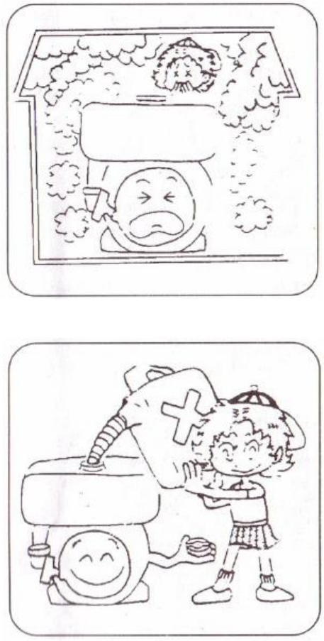
EXHAUST PRECAUTIONS
Never inhale the exhaust gases, it contains
carbon monoxide, a colorless, odorless and
extremely dangerous gas which can cause
unconsciousness or death
Never operate the engine indoors or in a
poorly ventilated area, such as a tunnel or
cave, etc.
Exercise extreme care when operating the
engine near people or animals.
Keep the
exhaust pipe free of external objects.
REFUELING PRECAUTIONS
Be sure to stop the engine before refueling.
Do not overfill the fuel tank.
If fuel is spilled, wipe it away carefully and
wait until the fuel has dried before starting
the engine again.
When changing oil, make sure that the fuel
cap is tightly secured to prevent fuel
leakage.
4
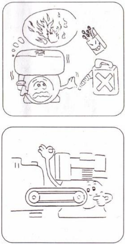
FIRE PREVENTION
Never operate the engine while
smoking or near an open flame.
Never use the engine around dry brush,
twigs, cloth-rags, or other flammable
materials.
Keep the engine at least 3 feet (1 meter)
away from buildings or other
structures.
Keep the engine away from flammables
and other hazardous materials.
PROTECTIVE COVER
Always place the protective covers
over the rotating parts.
If rotating parts
such as the driving pulley, belts, and
shafts are exposed, serious injuries can
be caused.
To prevent injury, please
equip all rotating parts with protective
covers.
Be careful of hot parts.
The muffler
and other engine parts can become very
hot while the engine is running or after
the engine has been run.
Always
operate the engine in a safe area and
keep children away from running
engines.
5
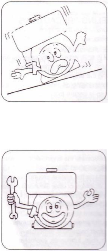
SURROUNDINGS
Operate the engine on a table or level
surface free of small rocks and loose
gravel.
Operate the engine on a level surface.
If
the engine is tilted, fuel may spill from the
gas tank.
NOTE:
Operating the engine at a steep incline
may cause the engine to seize up due to
improper lubrication even when the oil level is
a maximum.
Be careful of fuel spillage when
transporting the engine.
Always tighten
the fuel cap and close the fuel strainer cock
before moving the engine around.
Never move the engine while it is in
operation.
If the engine will be transported over a
long distance, drain all the fuel from the
fuel tank to prevent fuel leakage.
PRE-OPERATION CHECKS
Carefully check fuel pipes and fuel joints
for fuel leakage.
Leaked fuel creates a
dangerous situation.
Verify that all the nuts and bolts of the
engine are tights.
A loose nut or bolts may
cause serious engine failure and could lead
to serious injuries.
Always check the engine oil and refill it if
necessary.
Always check the fuel level and refill it if
necessary.
Never
overfill
the
fuel
tank
Avoid wearing dangling or long clothes
such as loose aprons, towels, and waist
belts, as these items may be caught in a
rotating part of the engine.
6

Chapter
1
Technical
Specifications
and
Data
1-1 Technical specifications in English Units
7
Model
Item
170F
178F
186F
Type
Single vertical cylinder, 4-stroke, air-cooled, direct injection
Bore x Stroke (in.)
2.76 x 2.17
3.01 x 2.44
3.39 x 2.76
Displacement (cu. in.)
13.36
18.67
25.51
Speed (rpm)
3600
3600
3600
Output
(HP)
Continuous
4.0
5.9
8.85
Maximum
4.5
6.6
9.85
Fuel tank capacity
(US gallons)
.66
.9
1.45
Lube-oil
Capacity
(oz)
Full
27.1
37.17
55.75
Effective
8.45
13.51
20.27
Crankshaft direction
Clockwise from flywheel end
Cooling type
Forced air cooled by flywheel fan
Lubrication type
Pressure splash
Starting system
Recoil manual start and or optional electric start
Dry weight (recoil) (lbs)
60
73
106
Dry weight (elec.) (lbs)
68
84
117
Dimensions (LxWxH)
(inch)
13.1 x 14.8 x 16.3
15.1 x 16.6 x 17.7
16.4 x 17.4 x 19.5

Technical specifications in SI units
8
Model
Item
170F
178F
186F
Type
Single vertical cylinder, 4-stroke, air-cooled, direct injection
Bore x Stroke (mm)
70 x 55
78 x 62
86 x 70
Displacement (cc)
211
296
406
Speed (rpm)
3600
3600
3600
Output
(kw)
Continuous
2.98
4.4
6.6
Maximum
3.36
4.92
7.3
Fuel tank capacity
(Liters)
2.5
3.4
5.5
Lube-oil
Capacity
(L)
Full
.8
1.10
1.65
Effective
.25
.40
.60
Crankshaft direction
Clockwise from flywheel end
Cooling type
Forced air cooled by flywheel fan
Lubrication type
Pressure splash
Starting system
Recoil manual start and or optional electric start
Dry weight (recoil) (kg)
27
33
48
Dry weight (elec.) (kg)
31
38
53
Dimensions (LxWxH)
(mm)
332 x 376 x 415
383 x 421 x 450
417 x 441 x 494
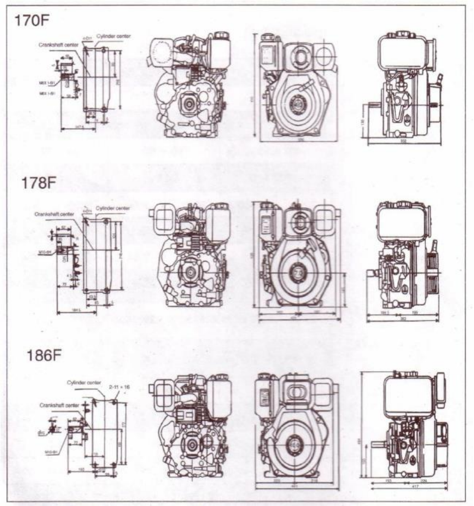
1-2
Overall
engine
dimensions
Installation Conditions
(1) There must be a tight stationary foundation for the diesel engine to avoid vibrations or
movement when the engine is running.
For prolonged engine life, consider using some
type of motor mount.
(2) Make sure that the centering position of the output shaft is properly aligned.
9
(3)
Verify that the dimensions of the hole on the belt wheel and keyway shaft match or
correspond with each other.
Also make sure that the bolt of the engine shaft is
tightened to the proper torque specifications.
(4)
When the engine is matched with other belt driven machines, the total desired belt
distance traveled by the driven wheel must equal the total distance traveled by the
driver wheel.
If this is not properly calculated and matched, the desired speed on the
driven wheel will be incorrect.
A formula used to calculate the necessary diameters of
the various wheels is provided below.
The diameter of driving wheel (belt wheel) can be calculates as follows:
Diameter of engine driving wheel (engine pulley) =
Diameter of driven machine x speed of driven machine
Diesel speed (engine speed)
(5)
Make sure that the belt has a correct tension to it.
Note:
If the belt is to tight, the engine bearings will wear at a high rate leading to engine failure.
If the belt is to loose, the belt will slip at high speeds and high loads causing high pitch whistling
noises.
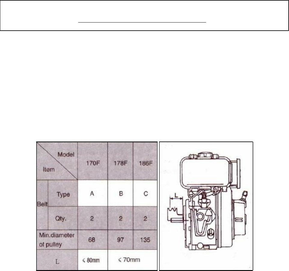
1-2.1 Allowed clearance between belt wheel and engine
The belt pulley wheel should be as close to the engine as possible.
The values of L are tabulated
in table 1-1.
Table 1-1.
Allowed belt pulley wheel to engine distances.
10
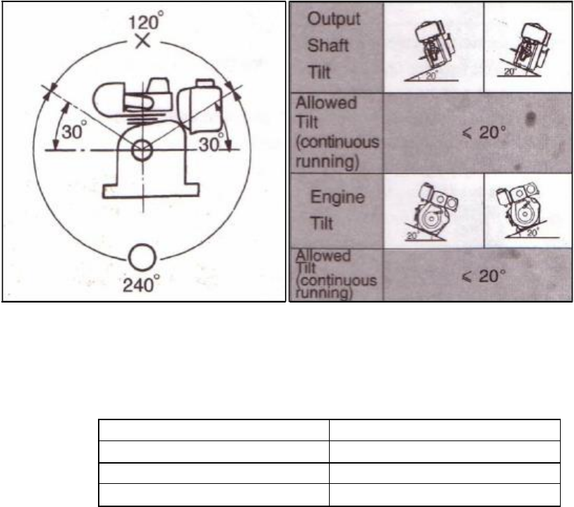
1-2.2
Crankshaft
driving
angles
must
be
less
than
120
o
,
see
Fig
1-1
The tilt must be kept within the allowed values shown in Fig 1-2
Fig 1-1.
Allowed driving angles. Fig 1-2.
Allowed tilt angles.
1-2.3
Please contact our dealers about the electric circuits involved with this engine.
We recommend the use of accumulators rated at 20 hours shown in table 1-2.
Model
Units:
(amp-hours)
170F
18~24
178F
24~26
186F
36~45
Table 1-2.
11
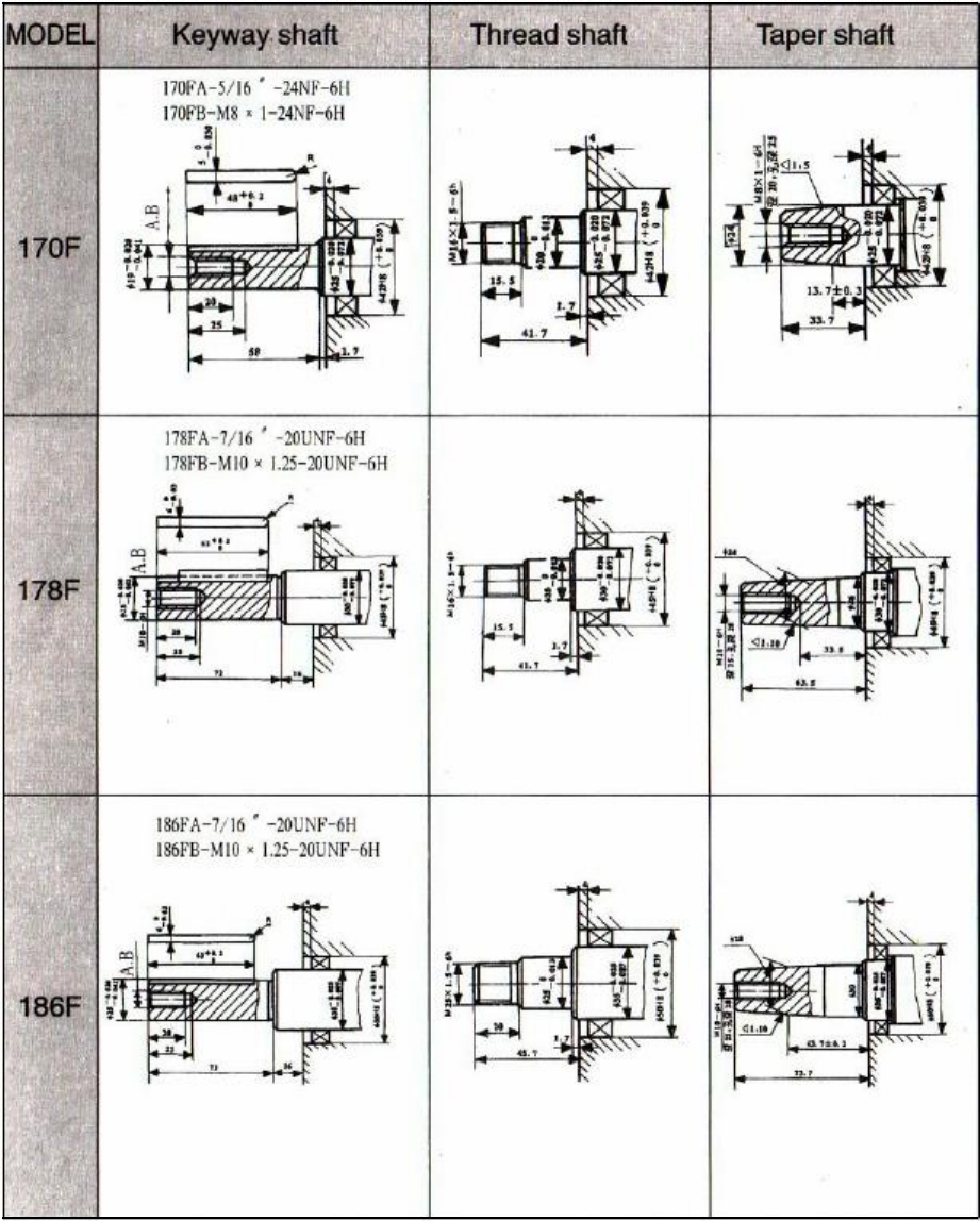
1-2
Diesel
Engine
shaft
specifications
units: mm
12
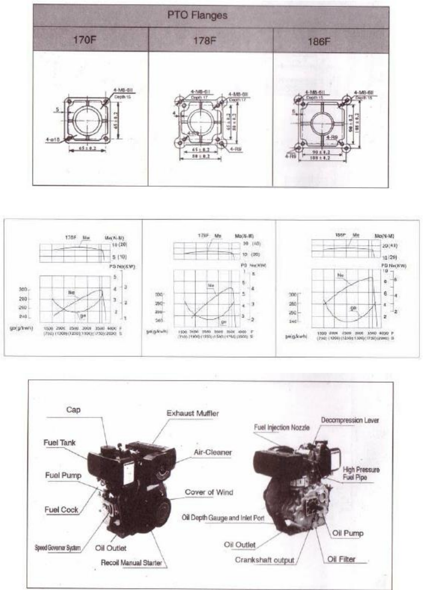
Sizes of PTO flanges
Diesel
Engine
Power
Curves
1-4
Names
of
Diesel
Engine
Parts
13
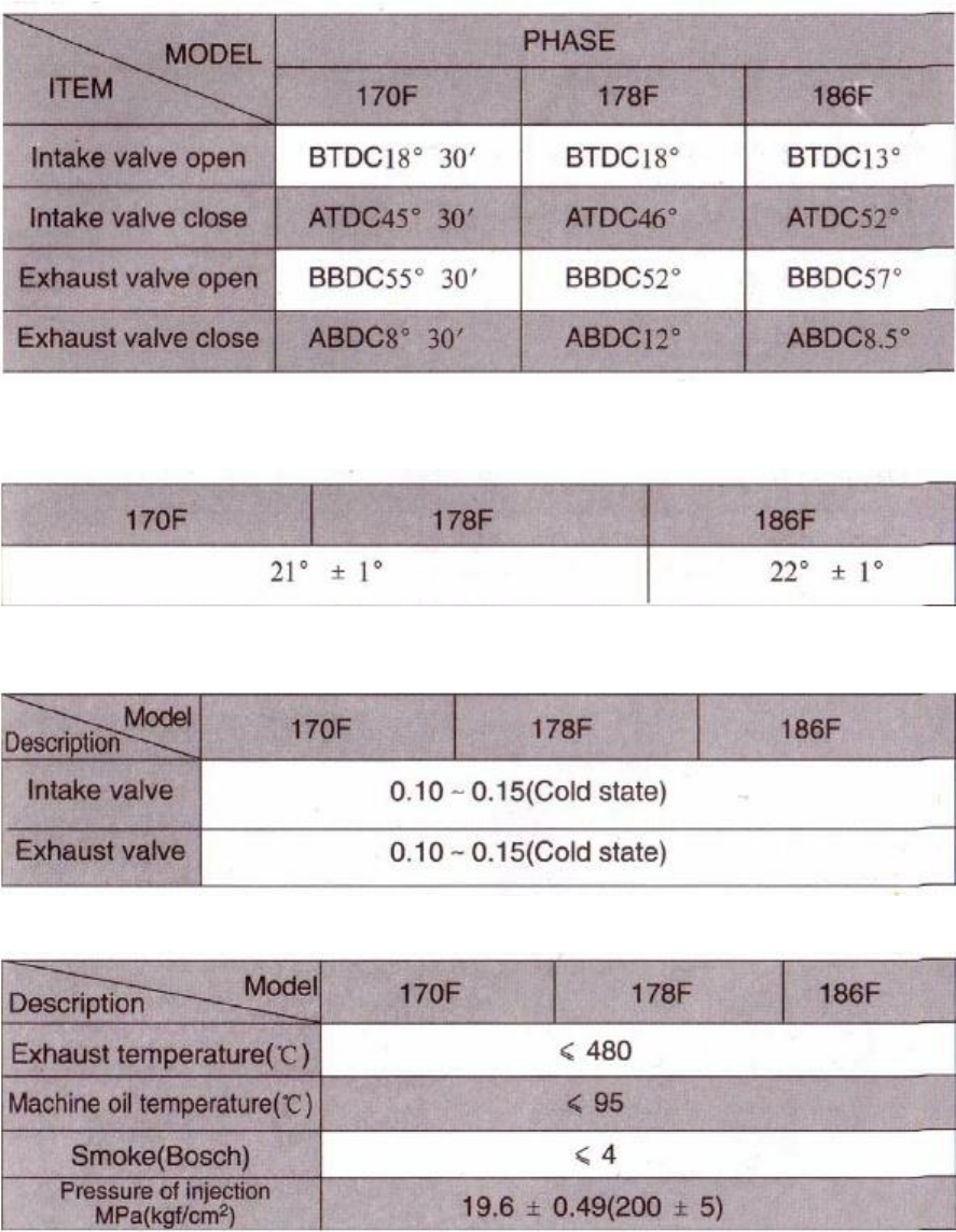
1-5
Valve
timing,
initial
angle
of
fuel
delivery
and
valve
clearances.
Units: Degrees
Table 1-3.
1-5.2
Initial
angle
of
fuel
delivery
Units:
Degrees
Table 1-4
1-5.3
Valve
Clearances
Table 1-5
1-6
Temperature
ranges
for
exhaust
and
injection
pressure
specifications
14
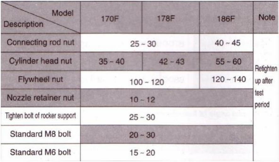
1-7
Torque
specifications
for
various
engine
nuts
and
bolts
Table 1-7.
Torque specifications in SI units Units:
N m
15
CHAPTER
2
DIESEL
ENGINE
OPERATION
2-1
Please
pay
close
attention
for
safe
operation
of
the
diesel
engine.
1. The fuel used must be filtered by silk fabric or settled for 24 hours before it is used in the
engine.
Never add oil to the crankcase when the engine is running.
2. Keep flammable and combustible goods away from engine while engine is running.
The
engine should be placed in a simple ventilated place.
3. Do not touch the muffler when the engine is running or just after it has stopped.
4. The diesel engine should be operated at its rated power and rated speed.
If abnormal
operating conditions are detected, stop the engine immediately to check and fix the
problem.
5. A new engine must be properly broken in.
For the first 20 hours, run the engine at low
speed and low loads.
Do not allow engine to run at high speeds and high loads during the
break in period.
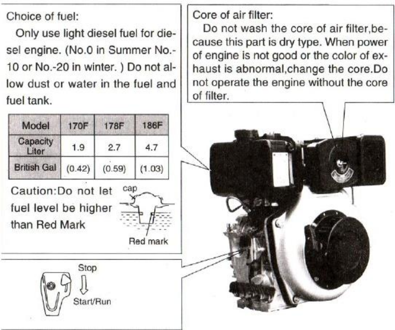
2-2
Fuel
Choices
16
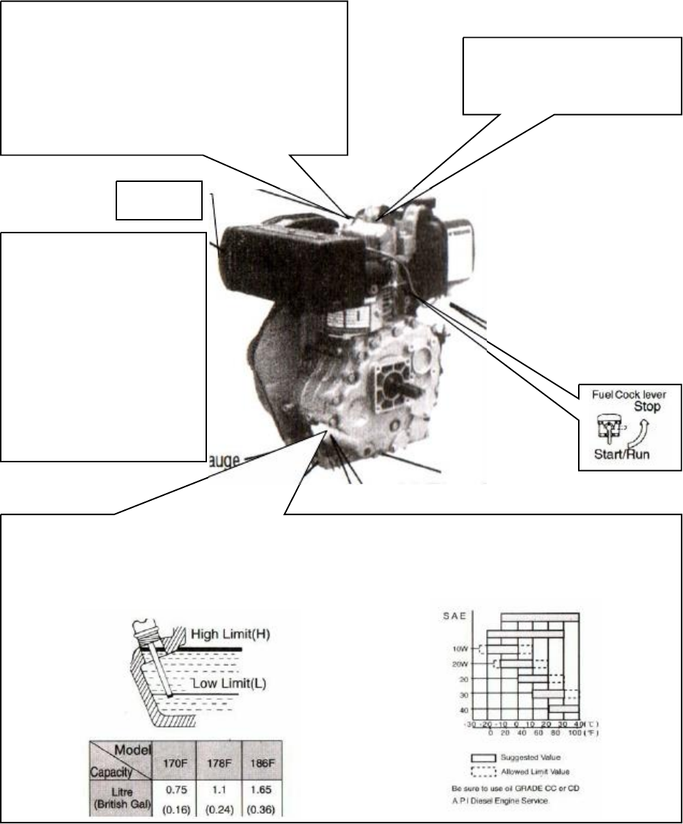
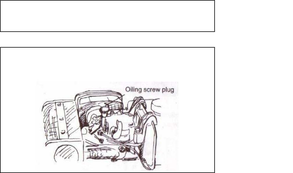
Oiling plug:
In winter, if it is difficult to start the
engine, pull the plug out and fill 2cc of lube oil
into the hole and then put the plug back in
place.
Make sure the plug is tight, if not, the
Compression release lever:
Push the lever down
to start the engine
engine can absorb dust into the combustion
chamber and damage itself.
Muffler
The factory has replaced the
engine fuel and engine oil
once already.
To check the
fuel pipeline, make sure the
fuel line is completely
drained.
IF there is air in the
pipeline, drain it out.
To do
this, loosen the nut between
the injection pump and fuel
pipe, then drain out the air
until there are no bubbles
left in fuel line.
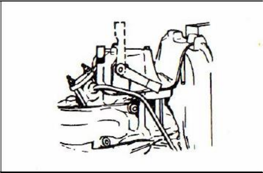
Oil Lubricant Inlet:
Place the engine on level ground and fill the lubricant into the inlet.
When checking the
oil level, gently place the dipstick into the oil.
Do not turn the oil scale.
17
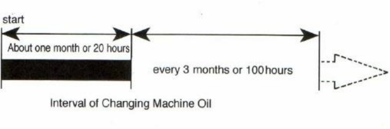
If your engine is still relatively new, follow the break in procedure.
The life of the engine
will shorten if it is overloaded during its break in period.
For the first 20 hours, the engine
must be started and stopped according to the test run method.
Avoid overloading the engine
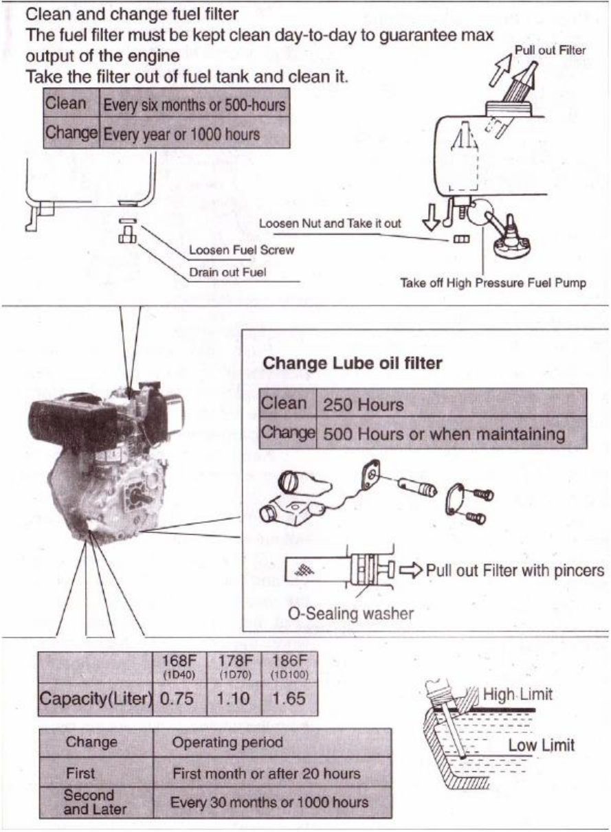
Change the engine oil regularly.
Below a table for the interval of oil changes will be
provided.
18
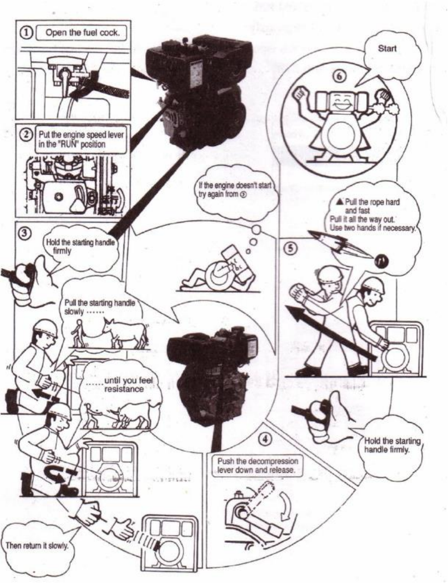
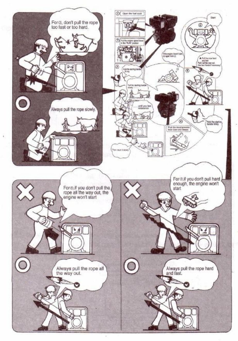
2-3
Starting
the
Diesel
Engine
2-3.1
Recoil
Starting
Note:
When the engine is running, do not pull the recoil handle, otherwise the engine may be
damaged.
19
20
2-3.2
Diesel
engine
with
electric
starter
system
(1)
Starting
The preparation of the diesel engine for the electric starting system is the same as the
manual recoil type.
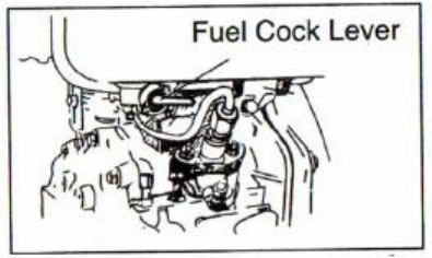
a.
Open the fuel cock.
b.
Set the speed governor lever to the start position.
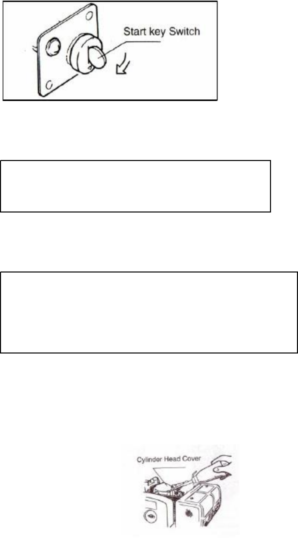
c.
Turn the start switch clockwise to the “Start” position.
d.
If the engine is started, immediately remove your hand away from the key
switch.
e.
If the engine does not start after 10 seconds, wait awhile (about 15 seconds)
before trying to start the engine again.
If you run the starter motor to long, the voltage of
the accumulator will drop and the motor may be
damaged.
Keep the key switch in the “ON” position
(2)
Battery
a.
Always check the liquid level of the battery every month, if the level is lower
than the low limit mark, refill the battery with distilled water till you reach the
upper limit mark.
If the liquid level in the battery is to low, the electric
starter will not function to its best potential.
Always keep
the level of the liquid in the battery between the upper and
lower limits.
If there is too much liquid, the liquid will
splash onto other nearby parts thereby ruining the battery.
2-3.3
Cold
starting
If the engine is difficult to start in winter, take off the rubber seal plug and put 2cc of
machine oil into the hole.
Notice:
Engines supplied to the Torrid Zone will not contain the rubber plug.
A solid
plug is provided instead.
21
Warning:
Never use flammable liquids as fuel, such as gasoline etc.
Also, never
take away the air cleaner for easy starting of the engine, doing so may
cause explosions from the intake gases.
Never take the oil plug unless you’re planning on filling the oil.
If the
plug is not in place, rain, dust, and other impurities may be sucked into
the engine causing serious damage to the engine parts.
22
Set
2-4
Running
and
stopping
of
the
Diesel
Engine
2-4.1
Running
the
Diesel
engine
(1) Preheat the engine for three minutes at no load.
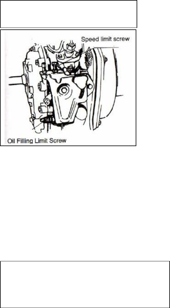
(2) Set the speed governor lever to the desired speed.
Use the speed governor lever to control the
speed of the engine.
Never loosen or
readjust the speed limiting screw and the
2-4.2
Checks
on
the
engine
while
the
engine
is
running.
(1) Check to see whether there are abnormal noises such as vibration.
(2) Check to make sure there is good combustion.
(Extremely high speeds
are not recommended for the engine, as that will decrease engine life.)
(3) Check to see the color of the exhaust gases to see if it is to white or to
black.
(4) If any of these conditions are detected, stop the engine immediately
and contact your nearest dealer for repair information.
2-4.3
Stopping
the
engine
(1) First, bring down the speed of the engine by using the speed governor.
Let it run for 3 minutes at no load before stopping it.
(2) Then stop the engine.
Sudden stops to the engine will cause abnormal
temperature increases in the block of the engine.
Decrease the load gradually when stopping the engine.
Also, never stop the engine with the decompression
(3)lever. the fuel cock at “S” (stop position)
23
(4)
If the engine comes with an electric starter, turn the starting switch to
the “Off” position.
(5)
Pull the recoil handle slowly until pressure is felt by your hand, this
means the piston is on the compression stroke; where the intake and
exhaust valves are closed and then let the handle recoil back into the
engine.
This natural position will prevent rust from occurring when
the engine is being stored for long periods of time.
Note:
Only perform step 5 when the engine is off.
Doing so otherwise
will damage the engine.
24
CHAPTER
3.
TECHNICAL
MAINTENANCE
OF
DIESEL
ENGINE
3-1
Daily
checks
and
maintenance
Check the oil level of the engine to see whether it is between the upper and lower limits.
Check to see whether there any oil leaks within the engine.
Keep the engine clean by cleaning up the dirt and other greasy deposits on the engine.
3-2
Regularly
checks
and
maintenance
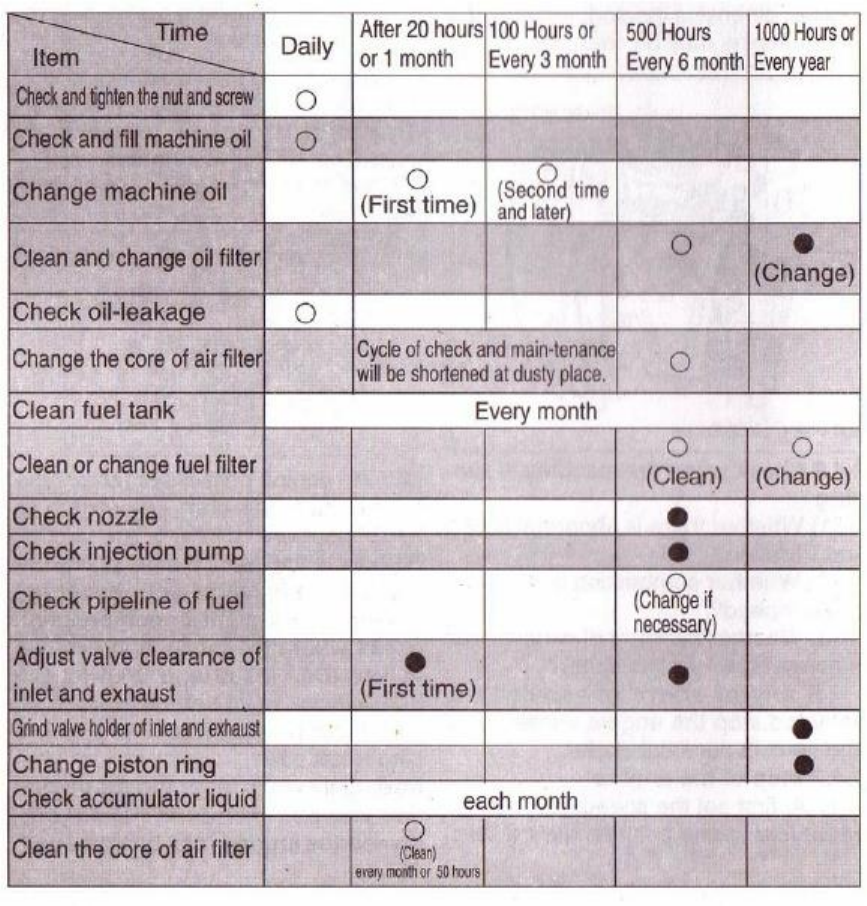
Regular checks and maintaining are very important for normal operation and engine life.
The
following table indicates what is necessary to be performed at specific time intervals.
The
marks signify that a special tool or technique is needed for maintenance.
Please contact your
local dealer for special maintenance.
25
26
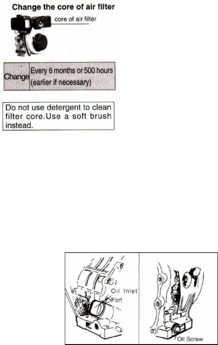
The core of the air filter may become dirty from various impurities.
If this occurs, the
performance of the engine will decrease because the amount of air entering the combustion
chamber is incorrect.
Also, because the amount of air is incorrect, the amount of fuel entering
also becomes incorrect leading to an overall incorrect air/fuel mixture.
This will lead to poor
performance of the diesel engine.
Always keep the air filter and air filter core clean.
3-3
Storing
the
engine
for
long
periods
of
time.
Please follow the instructions below if you plan on storing the engine for long periods of time.
(1)
Run the engine for three minutes to burn out the excess fuel in the chamber.
(2)
Quickly drain way the engine oil lubricant before the engine becomes cool and refill it
with new oil.
The figure below shows where the oil plugs are.
27
(3)
Take the rubber plug off the cover of the rocker shaft and put about 2cc of lubricant into
it and put the plug back in place.
The figure below shows where to access the plug.
(4)
For
recoil
starting
engines
, push the decompression lever down and pull the recoil
starter two or three times.
This pushes all the excess intake mixture out of the
combustion chamber.
(5)
For
engines
that
come
with
an
electric
starter
, hold down the decompression lever and
turn the start key switch to the start position.
Let the engine rotate for about two to three
seconds.
Once again, this pushes all the excess intake mixture out of the combustion
chamber.
(6)
Now pull the decompression lever up and pull on the recoil starter slowly until you feel
resistance.
The resistance point occurs on the compression stroke where the intake and
exhaust valves are closed.
It is also the point that will prevent moisture from entering the
chamber to cause rust.
(7)
Finally, clean excess oils from the engine and put the engine in a nice dry place.
28
CHAPTER
4
PART
LISTINGS
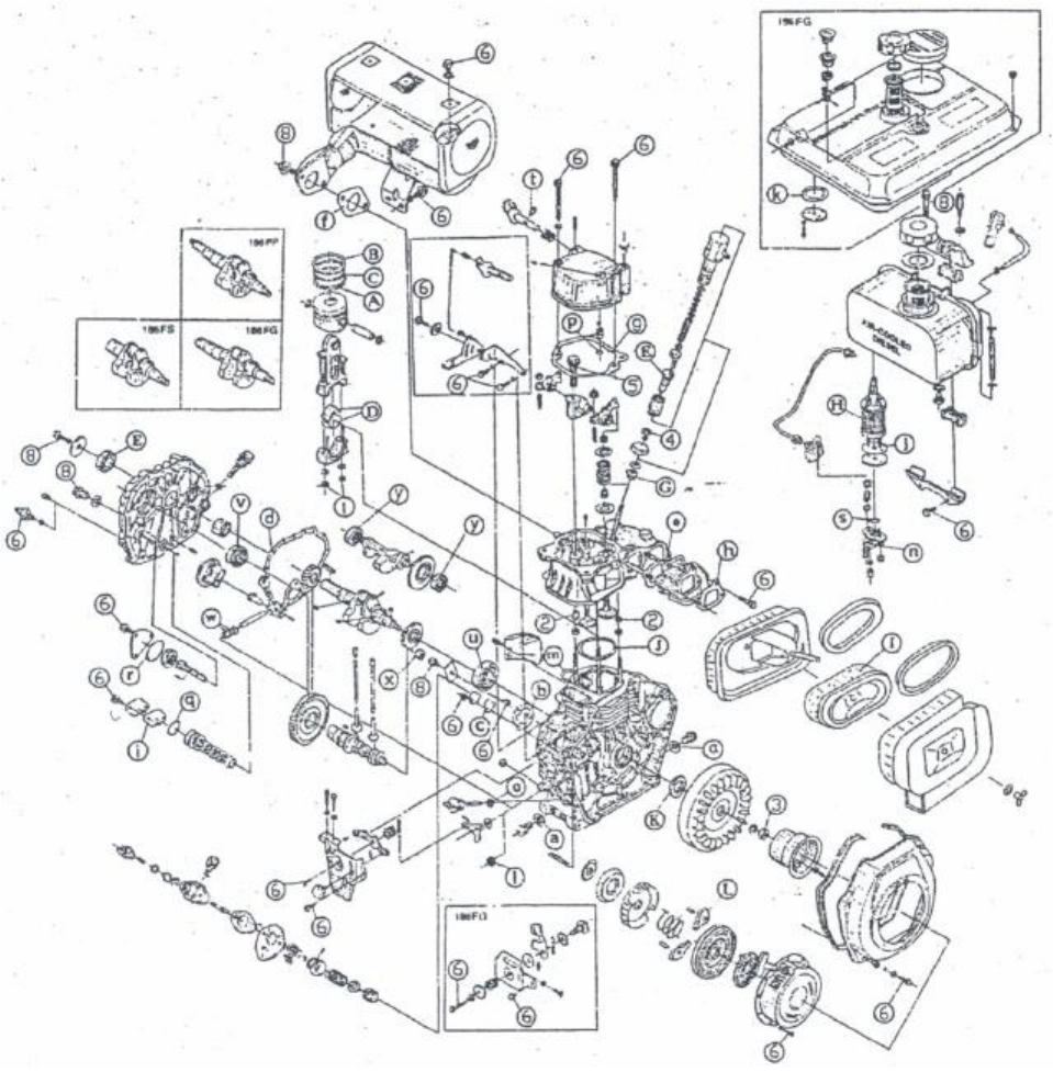
Diesel
Engine
Exploded
View
29

Table
4-1
. Please refer to Fig 4-1 for illustration
4-1
Engine
Block
30
Number
Part Number
Name of Part
Qty each set
1
ETQ1710626
Bolt M10 x 20 (GB5787-86)
2
2
ETQ 17138
Starter motor hole cover
2
ETQ 70-1704901
2
3
ETQ 78-1704902
Cylinder head nuts (long)
2
ETQ 86-1704903
2
ETQ 70-1705001
2
4
ETQ 78-1705002
Cylinder head nuts (short)
2
ETQ 86-1705003
2
ETQ 70-1704801
2
5
ETQ 78-1704802
Cylinder head nut gasket
2
ETQ 86-1704803
2
ETQ 70-1719504
1
6
ETQ 78-1719704
Cylinder head gasket (0.4)
1
ETQ 86-1706314
1
7
ETQ 70/78-17182
Oval ring gasket 5.1 x2.5
1
ETQ 86-1720106
Oval ring gasket 5.1 x2.6
1
ETQ 70-1700201
2
8
ETQ 78-1700202
Cylinder head bolts (long)
2
ETQ 86-1700203
2
ETQ 70-1700301
2
9
ETQ 78-1700302
Cylinder head bolts (short)
2
ETQ 86-1700303
2
ETQ 70-1700107
2
10
ETQ 78-1700103
Engine block
1
ETQ 86-1700110
1
ETQ 70-1711702
1
11
ETQ 78-1711702
Rear oil seal 30 x 45 x 8
1
ETQ 86-1711704
Rear oil seal 35 x 50 x 8
1
12
ETQ 17121
Oil drain plug
1
13
ETQ 17120
Oil drain plug gasket
1
14
ETQ 1711324
O ring for oil dipstick
2
15
ETQ 17123
Fuel pump fastening bolt (short)
1
16
ETQ 17122
Fuel pump fastening bolt (long)
2
17
ETQ 1719605
Fuel injector gasket (0.5)
1
18
ETQ 70-1702001
Oil dipstick
2
ETQ 78/86-1702002
2
19
ETQ 1710103
M6 nut
3
20
ETQ 17159
Sealing plate gasket
1
21
ETQ 17158
Sealing plate
1
22
ETQ 17195
Thrust piece
1
23
ETQ 1710636
Flange face with bolts (GB5789-86)
1

Note:
If purchasing the engine cylinder block, the included parts are numbers 1, 2, 8, 9, 10, 12,
13, 14, 15, 16, 18 and 24.
The parts of the crankcase cover include numbers 14, 18, 27, 28, 29,
30, 31, 35 and 38.
31
24
ETQ 1710010
Needle bearing 7941/15
1
ETQ 70-1710006
Ball bearing 306 (GB/T276-94)
1
25
ETQ 78-1710007
Ball bearing 307 (GB/T276-94)
1
ETQ 86-1710008
Ball bearing 308 (GB/T276-94)
1
ETQ 70-1704601
1
26
ETQ 78-1704602
Crankcase cover gasket
1
ETQ 86-1704603
1
ETQ 70-1710002
Bearing 205 (GB/T276-94)
1
27
ETQ 78-1710003
Bearing 206 (GB/T276-94)
1
ETQ 86-1710004
Bearing 207 (GB/T276-94)
1
28
ETQ 1711111
Retaining pin 8x12 (GB119-86)
2
29
ETQ 78/86-17080
Fuel Pipe
1
ETQ 70-1701901
1
30
ETQ 78-1701902
Crankcase cover
1
ETQ 86-1701904
1
31
ETQ 17133
Inner Hexagon Plug G1/8
1
ETQ 70-1710083
M8 x 33.5 Bolt
1
ETQ 70-1711062
M6 x 25
14
32
ETQ 78-1710083
M8 x 33.5 Bolt
15
ETQ 86-1710083
M8 x 33.5 Bolt
16
ETQ 70-1711701
Front oil seal 25 x 42 x 10
1
33
ETQ 78-1711703
Front oil seal 30x 45 x 10
1
ETQ 86-1711705
Front oil seal 35 x 50 x 10
1
ETQ 70-1701801
1
35
ETQ 78-1701802
Main Bushing
1
ETQ 86-1701803
1
36
ETQ 78-1701903
Front side crankcase cover
1
37
ETQ 78-1711703
Front side oil seal
1
38
ETQ 70-1711602
Aluminum Plug Diameter 8 x 8
2
ETQ 78/86-1711602
3
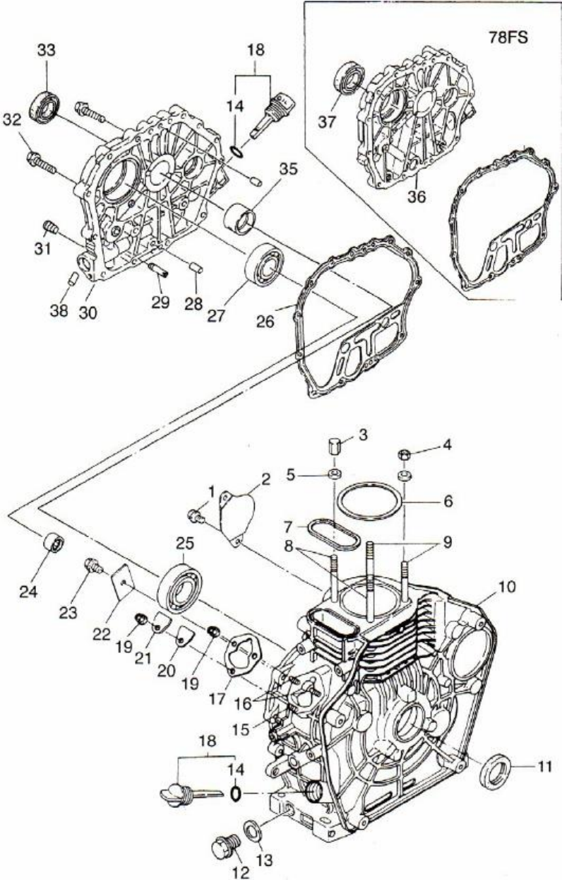
Fig
4-1.
Exploded view of engine block assembly
32

4.2
Cylinder
head
Assembly
Table
4-2.
Part listing for cylinder head assembly.
Please refer to Fig 4-2
No. Code Names of Parts Qty each set
1 ETQ 70/78-1710755 M6 x 55 Flanged Bolt (GB5789-86) 2
ETQ 86-1710730 M6 x 70 Flanged Bolt (GB5789-86) 2
2 ETQ 17142 Oiling hole plug 1
3 ETQ 17139 Decompression shaft 1
4 ETQ 1711310 O ring 10 x 1.9 (GB1235-76) 1
5 ETQ 17140 Decompression shaft spring 1
6 ETQ 1711103 Retaining pin 3 x 16 (GB119-86) 1
7 ETQ 70/78-17066 Cylinder head cover 1
ETQ 86-1706603 1
8 ETQ 70/78-17170 Cylinder head cover gasket 1
ETQ 86-1717001 1
9 ETQ 70/78-17168 Rocker arm 1
ETQ 86-1716801 1
9A ETQ 17165 Valve clearance adjusting screw 2
10 ETQ 70/78-1710745 Rocker arm shaft fastening bolt 1
ETQ 86-1716901 1
ETQ 70-1705201 2
11 ETQ 78-1705202 Adjusting valve spacer 2
ETQ 86-1705203 2
ETQ 70-1702701 4
12 ETQ 78-1702702 Valve clip 4
ETQ 86-1702703 4
ETQ 70-1702801 2
13 ETQ 78-1702802 Valve spring seat 2
ETQ 86-1702803 2
ETQ 70-1702901 2
14 ETQ 78-1702902 Valve spring 2
ETQ 86-1702903 2
ETQ 70-1702003 2
15 ETQ 78-1702004 Valve guide oil seal 2
ETQ 86-1702100 2
16 ETQ 70/78-17136 Valve spring washer 2
ETQ 86-1713601 2
17 ETQ 1711104 Pin 4 x 8 (GB119-86) 1
18 ETQ 1710920 Double ended stud AM8 x 20
(GB899-88) 2
ETQ 70-1702403 1
19 ETQ 78-1702402 Cylinder Head 1
ETQ 86-1702404 1
20 ETQ 70/78-1710955
Double ended bolt AM6 x 55 (GB900-88) 2
ETQ 86-1710956 Double ended bolt AM6 x 75 (GB900-88) 2
ETQ 70-1702501 1
21 ETQ 78-1702601 Intake valve 1
33

Note:
The parts of the cylinder head cover included are numbers 2, 3, 4, 5, 6, 7, 27, 28 and 29.
The parts of the rocker arm include 9 and 9a.
The parts of the cylinder head include 12, 13, 14, 15, 16, 17, 18, 19, 20, 22 and 26.
34
ETQ 86-1702503
1
22
ETQ 70-1702502
Exhaust valve
1
ETQ 78-1702602
1
ETQ 86-1702605
1
23
ETQ 1710103
M6 (GB6177-86) Nut
2
24
ETQ 1717302
Fuel injector pressure plate
1
25
ETQ 1724502
Fuel injector gasket
1
26
ETQ 70-1712201
AM 6 x 42 Fuel injector bolt
2
ETQ 78-1712201
AM 6 x 42 Fuel injector bolt
2
ETQ 86-17122
Fuel injector bolt (long)
2
27
ETQ 17141
Breather assembly
1
28
ETQ 1711312
O ring 12 x 1.9
1
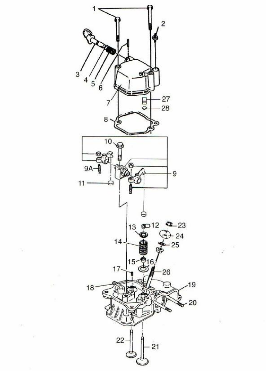
Fig
4-2.
Exploded view of cylinder head
35

4-3
Piston
connecting
rod
and
crankshaft
balancing
mechanism
No.
Code
Name of Part
Qty each set
1
ETQ70-1701403
Piston Rings
1
ETQ 78-1701402
1
ETQ 86-1701404
1
2
ETQ 70-1701601
Retainer clip of Piston pin Dia. 19mm
2
ETQ 78-1701602
Retainer clip of Piston pin Dia. 21mm
2
ETQ 86-1701603
Retainer clip of Piston pin Dia. 23mm
2
3
ETQ 70-1701200
Piston
1
ETQ 78-1701202
1
ETQ 86-1701204
1
ETQ 78FS-1701203
1
4
ETQ 70-1701701
Piston pin
1
ETQ 78-1701702
1
ETQ 86-1701703
1
5
ETQ 70-1701301
Connecting rod
1
ETQ 78-1701302
1
ETQ 86-1701303
1
6
ETQ 70-1701501
Connecting rod journal bearing
1
ETQ 78-1701502
1
ETQ 86-1701503
1
7
ETQ 70-1710001
Bearing 202 (GB/T276-94)
2
ETQ 78-1710001
2
ETQ 86-1710000
Bearing 203 (GB/T276-94)
2
8
ETQ 70-1706501
Balancing Shaft
1
ETQ 78-1706502
1
ETQ 86-1706503
1
9
ETQ 1710507
Key 5 x 7
(GB1096-79)
2
10
ETQ 70-1707701
Balancing Shaft Timing Gear
1
ETQ 78-1707702
1
ETQ 86-1707703
1
11
Bolt (included with diesel engine)
1
12
ETQ 70-1700801
Crankshaft timing gear
1
ETQ 78-1700802
1
ETQ 86-1700803
1
13
ETQ 70/78-1710512
Key 5 x 12 (GB1096-79)
2
ETQ 86-1710512
Key 5 x 12 (GB1096-79)
1
13A
ETQ 86-1710514
Key 5 x 14 (GB1096-79)
1
14
ETQ 70-1710530
Key 5 x 30 (GB1096-79)
1
ETQ 78/86-1710563
Key 6 x 63 (GB1096-79)
1
15
ETQ 70-1700601
Crankshaft
1
ETQ 78-1700701
1
ETQ 86-1700708
1
16
ETQ 1711601
6 x 8 Plug
1
Table
4-3
. Please refer to Fig 4-3 for a complete illustration of the parts.
36

Note:
The included parts with the piston connecting rod are numbers 1,2,3,4,5 and 6
The included parts with the balancing shaft are numbers 8, 9 and 10.
The included parts with the crankshaft are numbers 9, 12, 13, 15 and 17.
37
17
ETQ 70-1707801
Balancing Shaft Driving Gear
1
ETQ 78-1707802
1
ETQ 86-1707803
1
18
ETQ 70-1704400
Flywheel
1
ETQ 78-1704404
1
ETQ 86-1704409
1
19
ETQ 70/78-17156
Flywheel nut gasket
1
ETQ 86-1715601
1
20
ETQ 70/78-17155
Flywheel nut
1
ETQ 86-1715501
1
21
ETQ 70-1704501
Flywheel ring gear (for electric starter)
1
ETQ 78-1704502
1
ETQ 86-1705504
1
22
ETQ 1704705
Sleeve of fuel pump rod
1
23
ETQ 70-1705101
Push rod
2
ETQ 78-1705102
2
ETQ 86-1705103
2
24
ETQ 70-17157
Tappet
2
ETQ 78-17157
2
ETQ 86-1715701
2
25
ETQ 70/86-1710514
Key 5 x 14 (GB1096-79)
1
ETQ 78-1710504
Key 4 x 12 (GB1096-79)
1
26
ETQ 70-1701001
Camshaft
1
ETQ 78-1701002
1
ETQ 86-1701000
1
26S
ETQ 78-1701003
Front Side Camshaft
1
27
ETQ 70-1701101
Camshaft timing gear
1
ETQ 78-1701102
1
ETQ 86-1701103
1
28
ETQ 78-1700702
FS crankshaft
1
30
ETQ 78-1710545
Key 8 x 45 (GB1096-79) camshaft key
1
31
ETQ 78-1704403
FS Flywheel
1
32
ETQ 78-1704503
FS flywheel ring gear
1
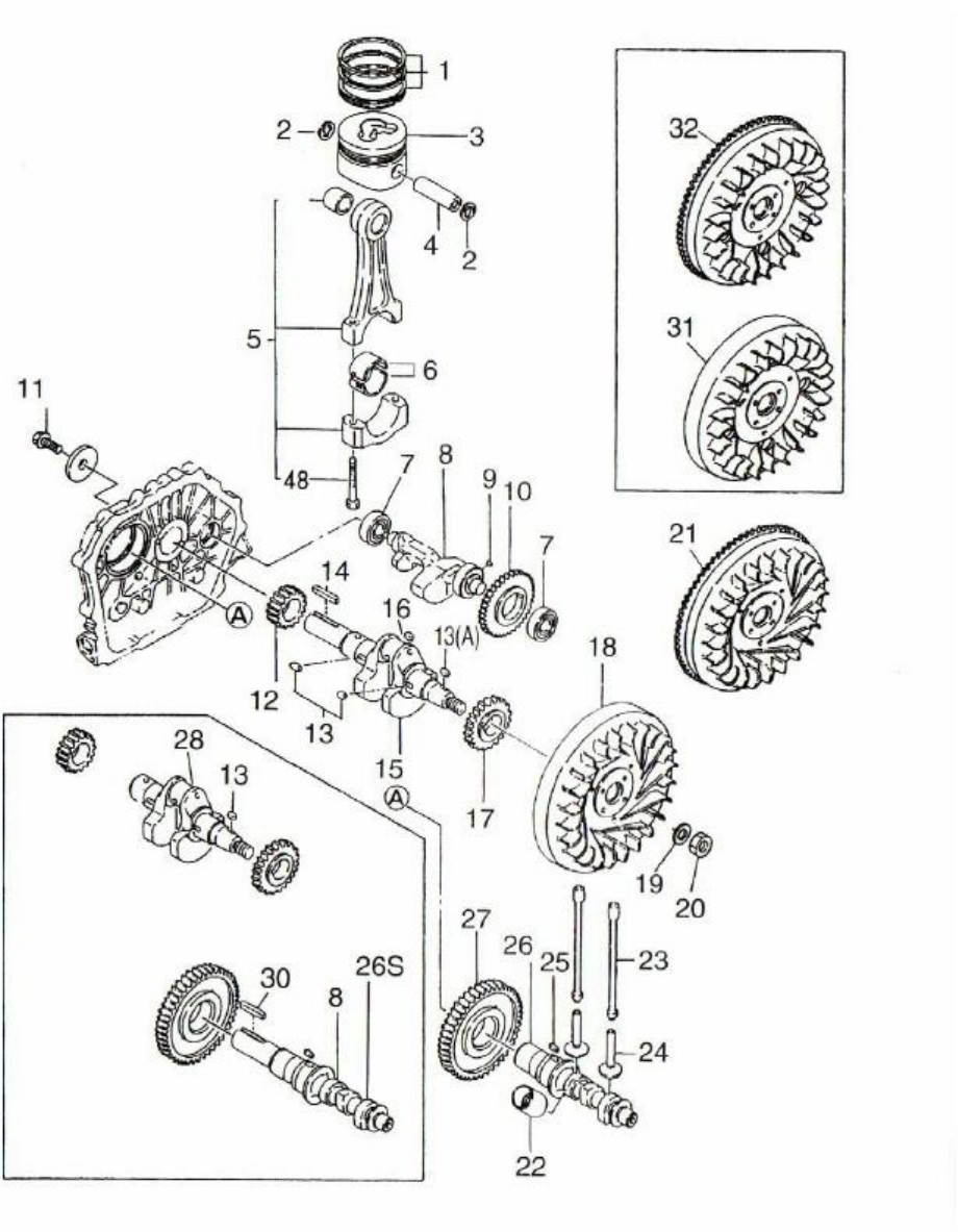
Fig
4-3.
Exploded view of Piston / Crank Assembly
38

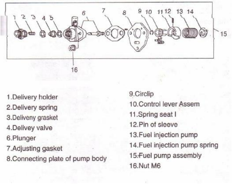
Table
4-4.
Fuel system parts; please refer to Fig 4-4 for a complete illustration.
4-4 Fuel System Parts
Note:
The fuel tank assembly comes with numbers 9, 10, 11, 12, 13, 16, 17, 18, 19, 22, 23, 26
and 27.
39
No.
Code
Name of part
Qty each set
1
ETQ 1710745
M8 x 45 (GB5787-86) Bolt
1
2
ETQ 17185
Upper fuel tank bracket fastener
1
3
ETQ 1710208
Flat washer 8 (GB97.1-85)
1
4
ETQ 70-1705801
Upper fuel tank bracket
1
ETQ 78-1705802
1
ETQ 86-1705803
1
5
ETQ 1705301
Injector
1
6
ETQ 17212
Hose Clamp
2
7
ETQ 17192
Fuel Pipe
1
8
ETQ 17184
Rubber fuel tank mount
4
9
ETQ 70-1704201
Fuel Tank
1
ETQ 78-1704202
1
ETQ 86-1704203
1
10
ETQ 17212
Fuel Pipe connectors
2
11
ETQ 17147
Fuel Pipe
1
12
ETQ 17151
M6 (GB6177-86) Fuel drain gasket
1
13
ETQ 17152
Fuel drain plug
1
14
ETQ 17183
Lower fuel tank bracket
1
15
ETQ 1710714
M6 x 14 (GB5787-86) Bolt
2
16
ETQ 1710106
M6 (GB6177-86) Nut
2
17
ETQ 1710206
M6 (GB97.1-85) Flat washer
1
18
ETQ 17150
Fuel tank cock assembly
1
19
ETQ 17154
Flat washer
1
20
ETQ 1719403
Fuel pipe clamp
2
21
ETQ 17189
Fuel pipe
1
22
ETQ 17148
Fuel filter gasket
1
23
ETQ 70-1704301
Fuel filter assembly
1
ETQ 78-1044302
1
ETQ 86-1704303
1
24
ETQ 70-1704702
Fuel injector pump
1
ETQ 78-1704702
1
ETQ 86-1704700
1
25
ETQ 70-1705601
High pressure fuel pipe
1
ETQ 78-1705602
1
ETQ 86-1705603
1
26
ETQ 17146
Fuel cup filter
1
27
ETQ 17153
Fuel cap assembly
1
28
ETQ 1705302
Fuel injector cap
1
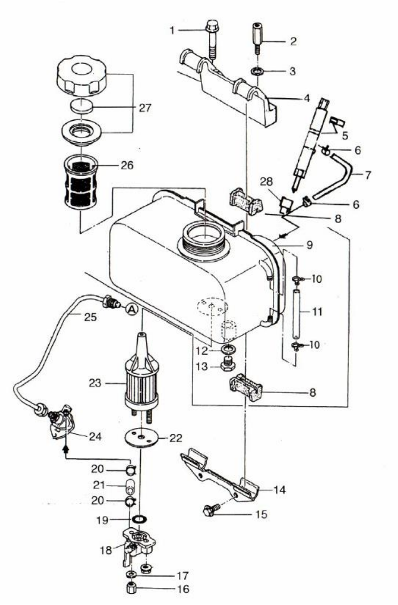
Fig
4-4.
Exploded view of fuel tank parts
40

4-5
Oil
and
speed
control
system
Table
4-5.
Please refer to Fig 4-5 for a complete illustration.
No. Code Name of part Qty each set
1 ETQ 70-1710712 M6 x 12 (GB5787-86) Bolt 2
2 ETQ 70-17187 Oil filter cover 1
3 ETQ 70-17188 Oil filter cover gasket 1
4 ETQ 70-1711314 Sealing Ring 20 x 2.5 1
ETQ 78/86-1711316 Sealing Ring 20X2.65 1
5 ETQ 70-1702101 Oil filter assembly 1
6 ETQ 1710712 M6 x 12 (GB5787-86) Bolt 3
7 ETQ 17022 Oil pump cover 1
8 ETQ 1711334 O ring 34.5 x 1.8 (GB3452.1-82) 1
ETQ 70-17135 1
9 ETQ 78-17135 Oil Pump 1
ETQ 86-1713501 1
10 ETQ 1711103 3 x 16 (GB119-82) pin 1
11 ETQ 78/86-1710714 M6 x 14 (GB5789-86) 1
12 ETQ 78/86-1702103 Oil filter cleaning element 1
13 ETQ 70-1711314 Sealing ring 20 x 2.5 1
ETQ 78/86-1711316 Sealing ring 20 x 2.65 1
14 ETQ 78/86-17080 Oil Guide 1
ETQ 70-1702301 1
15 ETQ 78-1702302 Oil pump driving gear 1
ETQ 86-1702302 1
16 ETQ 17132 Fly block pin 1
17 ETQ 17131 Fly block 2
18 ETQ 17234 Governor fork tappet 2
19 ETQ 17125 Lever shaft gasket 1
20 ETQ 1710009 Bearing 7941/8 (GB290-64) 1
ETQ 70-1700501 2
21 ETQ 78-1700502 Fork lever assembly 1
ETQ 86-1700503 1
22 ETQ 17124 Washer 1
ETQ 70-17126 1
23 ETQ 78-17126 Fuel controller parts 1
ETQ 86-1712601 1
24 ETQ 17164 Handle bracket 1
25 ETQ 17167 Speed-control lever 1
26 ETQ 1710714 M6 x 14 (GB5787-86) 1
27 ETQ 1710714 M6 x 18 (GB5787-86) 1
28 Lead seal 1
29 ETQ 17162 Return spring 2 1
30 ETQ 17161 Return spring 1 1
ETQ 70-17160 1
41

42
31
ETQ 78-17160
Speed-control spring
1
ETQ 86-1716001
1
32
ETQ 1710645
M6 x 45 (GB6172-86) Bolt
1
33
ETQ 1710111
M10 x 1.25 Nut
1
34
ETQ 1706701
FG Lever
1
35
ETQ 1706901
FG governor spring
1
36
ETQ 1710714
M6 x 14 (GB5789-86) Bolt
1
37
ETQ 1710106
M6 (GB39-88) Nut
1
38
ETQ 1716801
Washer
2
39
ETQ 1730720
Shaft Handle
1
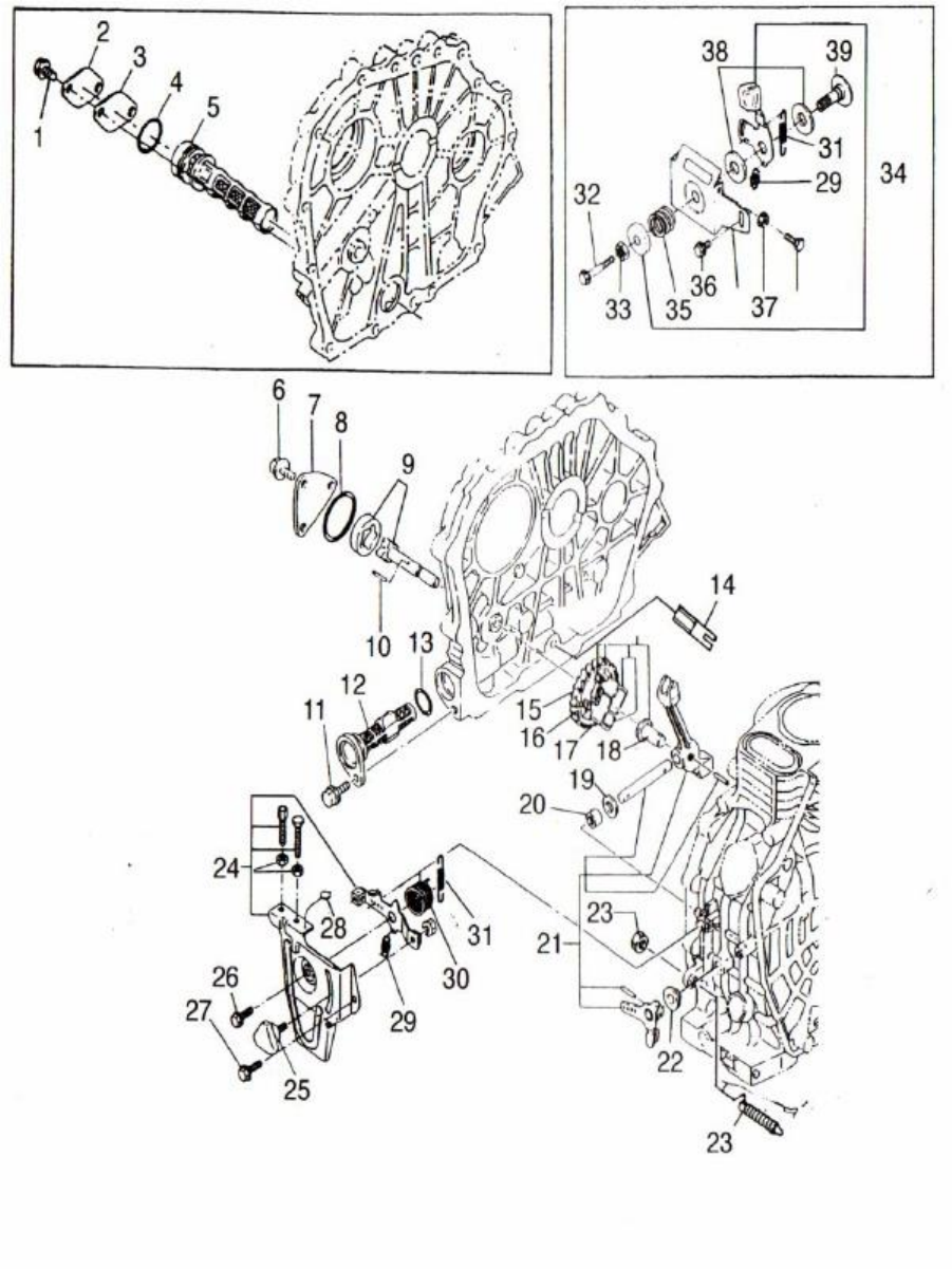
Fig
4-5.
Lubrication and speed control system
43

4-6
Cooling
and
recoil
starting
system
No.
Code
Name of part
Qty each set
1
ETQ 70-1703401
Recoil case assembly
1
ETQ 78-1703402
1
ETQ 86-1703404
1
1S
ETQ 78-1703404
178FS case assembly
1
2
ETQ 1710708
M6 x 8 (GB5787-86)
4
3
ETQ 70-1703501
Recoil starter rope
1
ETQ 78-1703502
1
ETQ 86-1703503
1
4
ETQ 70-1703801
Recoil starter handle
1
ETQ 78-1703802
1
ETQ 86-1703802
1
5
ETQ 70/78-1703301
Flat Torsional spring
1
ETQ 86-1703303
1
6
ETQ 70-1703201
Recoil reel
1
ETQ 78-1703202
1
ETQ 86-1703203
1
7
ETQ 70-1704003
Starting claw
2
ETQ 78/86-1704005
2
8
ETQ 70-17218
Helical spring
1
ETQ 78/86-1721801
1
9
ETQ 70-17219
Torsional spring
1
ETQ 78/86-1721901
1
10
ETQ 70-1704004
Starting claw plate
1
ETQ 78/86-1704006
1
11
ETQ 70-17039
Friction plate
1
ETQ 78/86-1703902
1
12
ETQ 70-1703903
Friction plate gasket
1
ETQ 78/86-1703803
1
13
ETQ 1710306
Spring washer
1
14
ETQ 1710106
M6 (GB6170-86) Nut
1
15
ETQ 1710712
M6 x 12 (GB6170-86)
3 or 4
16
ETQ 70-1705701
Starter
1
ETQ 78-1705702
1
ETQ 86-1705703
1
17
ETQ 70-1704101
Recoil starter cover
1
ETQ 78-1704102
1
ETQ 86-1704105
1
17S
ETQ 78-1704106
Recoil starter cover assembly
1
18
ETQ 78-1710622
M6 x 22 (GB5787-86) Bolt
5
ETQ 70/86-1710622
4
19
ETQ 78-1710207
M6 washer (GB90-85)
5
ETQ 70/86-1710207
4
Table
4-6.
Please refer to Fig 4-6 for illustration.
44

45
20
ETQ 78-17145
Collar
5
ETQ 70/86-17145
4
21
ETQ 78-17143
Shock absorber
5
ETQ 70/86-17143
4
22
ETQ 17144
Shock pads
1
23
ETQ 78/86-17127
Shock isolator
1
24
ETQ 78/86-17129
Collar
1
25
ETQ 78/86-17128
Pad
1
26
ETQ 70-1700401
Wind leading plate
1
ETQ 78-1700402
1
ETQ 86-1700403
1
27
ETQ 70-1710712
M6 x 12 (shaped piece) Bolt
1
ETQ 78-1710718
M6 x 18 (shaped piece) Bolt
1
ETQ 86-1710614
M6 x 22 (shaped piece) Bolt
1
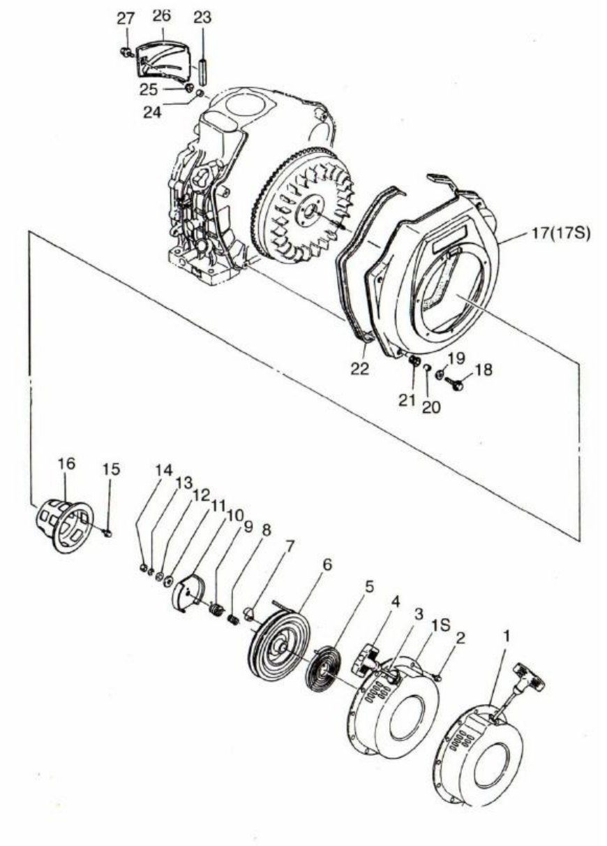
Fig
4-6.
Exploded view of cooling and recoil starting system.
46

4-7
Air
cleaner
and
silencer
system
No.
Code
Name of part
Qty each set
1
ETQ 70-1703101
Intake pipe gasket
2
ETQ 78-1703102
1
ETQ 86-1703103
1
2
ETQ 70-1703001
Intake pipe
1
ETQ 78-1703002
1
ETQ 86-1703003
1
3
ETQ 70/78-17175
Air cleaner gasket
3
ETQ 86-1717501
1
4
ETQ 17137
Bolt
1
5
1
ETQ 1710722
M6 x 22 (GB5789-86) Shaped bolt
1
1
6
ETQ 70/78-17174
Air filter assembly
1
ETQ 86-1717401
1
7
ETQ 1710103
M6 (GB6177-86) Nut
1
8
ETQ 70/78-1717602
Air filter element
1
ETQ 86-1717601
1
9
ETQ 70/78-17186
Muffler gasket
1
ETQ 86-1718601
1
10
ETQ 70-1705401
Muffler assembly
1
ETQ 78-1705402
1
ETQ 86-1705403
1
11
ETQ 1710208
Flat washer Dia. 8
2
12
ETQ 1710308
Spring washer Dia. 8
2
13
ETQ 1710108
M8 (GB6170-86) Nut
1
14
ETQ 70-1710714
M6 x 14 (GB5789-86) Bolt
2
ETQ 78/86-1710757
M8 x 14 (GB5789-86) Bolt
2
15
ETQ 70-1705501
Muffler screen cover
1
ETQ 78-1705502
1
ETQ 86-1705503
1
16
ETQ 1710708
M6 x 14 (GB5789-86) Bolt
1
17
ETQ 70/78-1705404
Muffler tail pipe
1
ETQ 86-1705406
1
18
ETQ 70/78-17179
Inner shock proof sealing ring
1
ETQ 86-1718002
1
19
ETQ 70/78-17180
Bottom case assembly of Air Cleaner
1
ETQ 86-1718003
1
20
ETQ 70/78-17178
Outer shock proof sealing ring
1
ETQ 86-1718001
1
21
ETQ 70/78-17181
Air filter shock absorber
1
ETQ 86-1718101
1
22
ETQ 70/78-1710103
Collar (GB6177-86)
1
ETQ 86-1720106
Collar (GB6177-86)
1
Table
4-7.
Please refer to Fig 4-7 for a complete illustration.
47
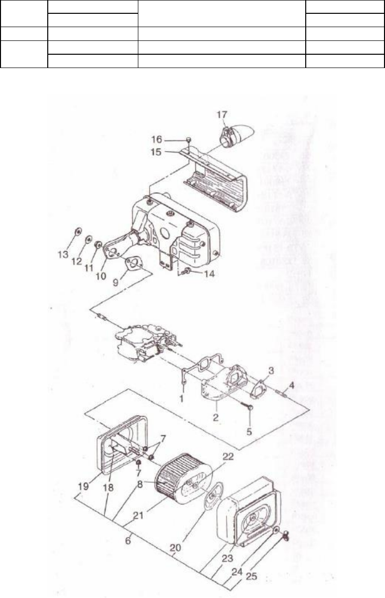
Fig
4-7
.
Exploded view of muffler assembly
48
23
ETQ 70/78-17182
Air filter shock absorber
1
ETQ 86-1720106
1
24
ETQ 17177
1
25
ETQ 70/78-1710107
M6 butterfly nut
1
ETQ 85-1710109
M8 butterfly nut
1
49

CHAPTER
5
ENGINE
TROUBLESHOOTING
5-1
Engine
is
not
starting
5-2
Diesel
engine
lacks
power
50
Possible Cause
Remedy
Weather is cold.
Engine oil may have become
overly adhesive.
Put engine oil into crankcase after preheated.
Put
engine oil into the inlet manifold.
Disconnect the
belts to the engine and run engine under no load
conditions until the engine becomes hot.
Then
connect the belts back and start the engine again.
Fuel system may be contaminated with water.
Clean the fuel filter and fuel pipe, and then replace
the fuel with new fuel.
The fuel has thickened and does not permit easy
flow.
Use the correct specific fuel.
There is air in the fuel system.
Drain out the air and fuel and tighten the
connectors of the fuel pipe.
Very little fuel injected into cylinder or the injected
spray is bad.
Check the position of the speed governor handle
and clean the fuel injector spray nozzle.
Check the
fuel pump and change the pump or fuel nozzle if
necessary.
Incomplete combustion
The spray nozzle may be bad, or the delivery angle
may be incorrect.
The gasket of the cylinder head
may be leaking and the pressure of compression is
not held.
Fix each component that is necessary to
achieve correct compression and a correct angle of
spray.
Fuel delivery is not constant
Fuel level in fuel tank may be to low.
Fill the fuel
tank until it is full.
Or the fuel pipe or fuel filter
may be clogged, fix this by replacing them.
Low compression
Replace head gasket or tighten the cylinder head
bolts in a diagonal line pattern.
If changing the
head gasket, tighten the cylinder head bolts once
again after running the engine.
Piston rings worn leading to low compression
Change the piston rings.
Piston ring gaps may all be set up in a line
Make sure each piston ring gap is off by an angle
of 120 degrees from each other.
Piston rings are stuck or broken
Clean the rings and cylinder with diesel fuel and or
replace the rings if necessary.
Gas valves are leaking
Grind the gas valves, if the vestige is too deep,
please send it to the factory for replacement
Incorrect valve clearance
Adjust the clearance as specified in the technical
specifications chart.
The valve stem is clipped on the guide pipe
Disassemble the gas valve and clean the stem and
guide pipe.

5-3
Engine
stops
automatically
5-4
Engine
exhaust
very
black
5-5
Engine
exhaust
very
blue
51
Possible Cause
Remedy
Fuel system clogged.
Clogged fuel line or clogged
fuel filter.
Clean fuel filter and fuel pipe.
Check the fuel
switch, it should be opened fully.
Fuel pump is bad.
Service or change the damaged parts of the fuel
pump.
Nozzle not operating correctly or incorrect
injection pressure.
Adjust the injection pressure.
Carbon deposits in the spray hole.
Clean out the spray hole.
Adhered needle valve.
Clean or change needle valve.
Fitting between the needle valve and needle valve
body is too loose.
Change the needle valve or needle valve body.
Air filter is dirty.
Disassemble the air filter assembly and clean the
core and air filter.
Engine may be to slow.
Check the speed of the tachometer.
Adjust the
high speed limiting screw.
Possible cause
Remedy
No fuel in system.
Add fuel to the fuel tank.
Fuel line is clogged.
Clean out fuel line.
There is air in fuel system.
Clean out the system and put new fuel in.
Needle valve of nozzle adhered.
Clean or grind the nozzle if necessary replace the
nozzle.
Air filter is clogged.
Clean the air filter.
The load suddenly increases.
Decrease the load.
Possible cause
Remedy
Engine oil in the cylinder.
Check the oil level and drain out unnecessary engine
oil.
Piston ring worn or piston ring gaps are all
aligned to permit oil to travel up into
combustion chamber.
Check or change the piston rings and make sure the
gaps are not all aligned.
Worn piston or worn cylinder.
Replace as necessary.
Valve and or valve guide worn.
Change the valve or valve guide as necessary.
Possible cause
Remedy
Overloaded engine
Decrease the load.
If driven machine is not
properly fitted with proper engine, change the
engine.
Bad fuel injection.
Check the fuel injection pressure and spraying
conditions.
Correct or replace the nozzle.
Not enough intake air or problems with leaking air.
Clean the air filter and check to see what the cause
of the leak is and fix as necessary.

5-6
Engine
exhaust
white
5-7
Various
methods
of
checking
to
see
if
the
engine
is
malfunctioning
52
Possible cause
Remedy
High and low speed fluctuation.
Check the speed governor system to see if it is
loose.
Also, check to make sure there is no air
in the fuel system.
Abnormal sounds suddenly appear.
Check each rotating part carefully.
Sudden appearance of black smoke from
exhaust.
Check the fuel system, especially the injection
nozzle.
There are metal knocking sounds in the
cylinder.
The fuel delivery angle is too large.
Adjust it
to the correct specifications.
Possible cause
Remedy
There is water in the diesel fuel
Clean the fuel tank and diesel filter, replace the
diesel fuel.
WARRANTY
PERIOD***
Limited
Warranty
Eastern Tools & Equipment, Inc. will repair or replace, free of charge, any part or parts of the generator that are defective in
material or workmanship or both.
Transportation charges on parts submitted for repair or replacement under this Warranty must
be borne by purchaser.
This warranty is effective for the time period and subject to the conditions provided for in this policy.
For warranty service, find the nearest Authorized Service Dealer by contacting the place of purchase or Eastern Tools &
Equipment, Inc.
THERE IS NO OTHER EXPRESSED WARRANTY.
IMPLIED WARRANTIES, INCLUDING THOSE OF
MERCHANTABILITY AND FITNESS FOR A PARTICULAR PURPOSE, ARE LIMITED TO ONE YEAR FROM
PURCHASE, OR TO THE EXTENT PERMITED BY LAW ANY AND ALL IMPLIED WARRANTIES ARE EXCLUDED.
LIABILITY FOR CONSEQUENTIAL DAMAGES UNDER ANY AND ALL WARRANTIES ARE EXCLUDED TO THE
EXTENT EXCLUSION IS PERMITTED BY LAW.
Some states do not allow limitations on how long an implied warranty
lasts, and some states do not allow the exclusion or limitation of incidental or consequential damages, so the above limitation and
exclusion may not apply to you.
This warranty gives you specific legal rights and you may also have other rights, which vary
from state to state.
Eastern
Tools
&
Equipment,
Inc.
About Your Product Warranty
Eastern Tools & Equipment, Inc. welcomes warranty repair and apologizes to you for being inconvenienced.
Any Authorized
Service Dealer may perform warranty repairs.
Most warranty repairs are handled routinely, but sometimes warranty service may
be inappropriate.
For example, warranty would not apply if an engine is damaged because of misuse, lack of routine
maintenance, shipping, handling, warehousing and improper installation.
Similarly, warranty is void if the serial number on the
engine has been removed or if the engine has been altered or modified.
If a customer differs with the decision of the Service
Dealer, an investigation will be made to determine whether the warranty applies.
Ask the Service Dealer to submit all supporting
facts to his Distributor or the factory for review.
If the distributor or the factory decides that the claim is justified, the customer
will be fully reimbursed for those items that are defective.
To avoid misunderstanding, which might occur between the customer
and the dealer, listed below are some of the causes of engine failure that the warranty does not cover.
Normal wear:
Engines and generators, like all mechanical devices, need periodic parts service and replacement to perform well.
Warranty will
not cover repair when normal use has exhausted the life of a part of an engine.
ENGINES
WITHIN
U.S.A
AND
CANADA
OUTSIDE
U.S.A.
AND
CANADA
CONSUMER
USE
COMMERCIAL
USA
CONSUMER
USE
COMMERCIAL
USE
DIESEL ENGINE
1 year
or 1000 hours
1 year
or 1000 hours
1 year
or 1000 hours
1 year
or 1000 hours
53
Improper maintenance:
The life of an engine or your equipment depends upon the conditions under which it operates, and the care it receives.
Some
applications, such as tillers, pumps, and rotary movers, are very often used in dusty or dirty conditions, which can cause what
appears to be premature, wear.
Such wear, when caused by dirt, dust, spark pug cleaning grit, or other abrasive material that has
entered the engine because of improper maintenance is not covered by warranty.
54
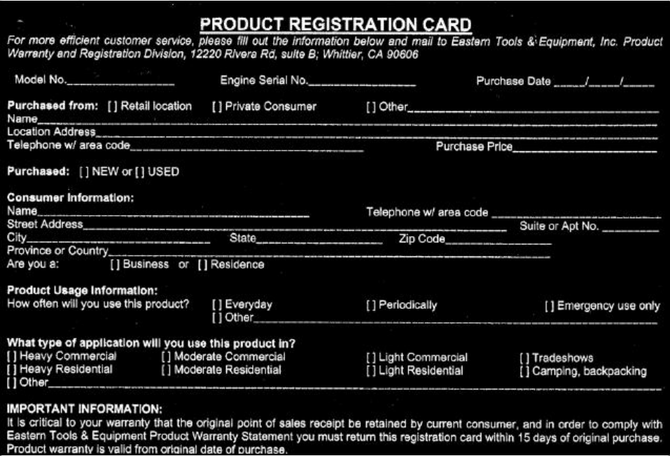
Note:
Please mail the above card to:
Eastern
Tools
&
Equipment,
Inc.
4951
Commerce
Dr.
Baldwin
Park,
CA
91706
55

https://capetillers.co.za
