Eb500UserManual Eb500 Manual
eb500_Manual
User Manual: Pdf
Open the PDF directly: View PDF ![]() .
.
Page Count: 90

EmbeddedBlue™ 500
User Manual

2 User Manual
Copyright ©2003 A7 Engineering, Inc.
Part Number 0000033 – Revision A
Last revised on December 4, 2003 – Printed in the United States of America
A7 Engineering, Inc.
12860 C Danielson Court
Poway, CA 92064
Copyright ©2003 A7 Engineering, Inc. All rights reserved. EmbeddedBlue is a trademark of
A7 Engineering, Inc. PBASIC is a trademark and BASIC Stamp is a registered trademark of
Parallax, Inc. Bluetooth and the Bluetooth logo are registered trademarks of the Bluetooth
SIG. Windows is a registered trademark of Microsoft Corporation. Other brand and product
names are trademarks or registered trademarks of their respective holders.
The information contained in this document is subject to change without notice. A7
Engineering, Inc. and its staff make no warranty of any kind for the correctness,
completeness, interpretation or use of the information contained herein. It is the user’s
responsibility to comply with all applicable copyright laws.

EmbeddedBlue 500 3
Copyright ©2003 A7 Engineering, Inc.
Table of Contents
Introduction .......................................................................................................................................... 7
Manual Conventions .......................................................................................................................... 7
eb500 Basics ........................................................................................................................................ 8
Command Mode ................................................................................................................................ 8
Data Mode ......................................................................................................................................... 8
I/O Lines............................................................................................................................................. 9
Resetting the eb500 to the Factory Default Settings......................................................................... 9
Switching between Data Mode and Command Mode ....................................................................... 9
BASIC Stamp Application Debugging ............................................................................................. 13
Hardware Connections ...................................................................................................................... 14
Board Of Education ......................................................................................................................... 15
Basic Stamp Activity Board.............................................................................................................. 16
BS2P40 Demo Board ...................................................................................................................... 17
Javelin Stamp Demo Board............................................................................................................. 18
SumoBoard...................................................................................................................................... 19
Super Carrier Board......................................................................................................................... 20
Establishing a Connection................................................................................................................ 21
Connecting two eb500 Modules ...................................................................................................... 21
Connecting a PC with an eb600 to a Board of Education ............................................................... 25
Connecting a PC with a DBT-120 to a BOE.................................................................................... 28
Connecting a BOE to a PC with a DBT-120 .................................................................................... 32
Connecting an iPAQ h1940 to a Board of Education ...................................................................... 35
Connecting a Board of Education to an iPAQ h1940 ...................................................................... 37
Communications ................................................................................................................................ 40
Communicating between Two eb500 Modules................................................................................ 40
Communicating between a PC with an eb600 and a BOE.............................................................. 46
Communicating between a PC with a DBT-120 and a BOE ........................................................... 51
Communicating between an iPAQ h1940 an a BOE....................................................................... 57
eb500 Commands .............................................................................................................................. 63
Command Basics............................................................................................................................. 63
BASIC Stamp Application eb500 Command Error Handling........................................................... 64
Connect............................................................................................................................................ 65
Disconnect ....................................................................................................................................... 66
Get Address..................................................................................................................................... 67
Get Connectable Mode.................................................................................................................... 68
Get Discoverable Mode ................................................................................................................... 69
Get Escape Character ..................................................................................................................... 70
Get Flow Control.............................................................................................................................. 71
Get Link Timeout ............................................................................................................................. 72
Help.................................................................................................................................................. 73
List ................................................................................................................................................... 74
Return to Data Mode ....................................................................................................................... 75
Set Baud Rate ................................................................................................................................. 76
Set Connectable Mode .................................................................................................................... 77
Set Discoverable Mode.................................................................................................................... 78

4 User Manual
Copyright ©2003 A7 Engineering, Inc.
Set Escape Character...................................................................................................................... 79
Set Flow Control .............................................................................................................................. 80
Set Link Timeout.............................................................................................................................. 81
Switch to Command Mode............................................................................................................... 82
Version............................................................................................................................................. 83
eb500 Error Codes ............................................................................................................................. 84
Technical Specifications ................................................................................................................... 85
Operating Parameters ..................................................................................................................... 85
Dimensions ...................................................................................................................................... 86
Pinout Diagram ................................................................................................................................ 87
Frequently Asked Questions ............................................................................................................ 88
Contact Information ........................................................................................................................... 90

EmbeddedBlue 500 5
Copyright ©2003 A7 Engineering, Inc.
Table of Figures
Figure 1: eb500 Module........................................................................................................ 14
Figure 2: Board of Education Board ..................................................................................... 15
Figure 3: Basic Stamp Activity Board ................................................................................... 16
Figure 4: BS2P40 Demo Board ............................................................................................ 17
Figure 5: Javelin Stamp Demo Board................................................................................... 18
Figure 6: SumoBoard............................................................................................................ 19
Figure 7: Super Carrier Board .............................................................................................. 20
Figure 8: eb500 Bluetooth Address Output .......................................................................... 23
Figure 9: iPAQ Bluetooth Authorization Request Dialog ...................................................... 39
Figure 10: HyperTerminal Input and Debug Output.............................................................. 47
Figure 11: HyperTerminal Output - Hello World ................................................................... 50
Figure 12: Hello World Pocket PC Application ..................................................................... 58
Figure 13: iPAQ Bluetooth Brower Dialog ............................................................................ 59
Figure 14: RXEB500 Pocket PC Application ........................................................................ 61
Figure 15: eb500 Dimensions............................................................................................... 86
Figure 16: eb500 Pinout Diagram......................................................................................... 87

6 User Manual
Copyright ©2003 A7 Engineering, Inc.
Table of Tables
Table 1: eb500 Error Codes ................................................................................................. 84
Table 2: eb500 Operating Parameters ................................................................................. 85
Table 3: eb500 Dimensions .................................................................................................. 86
Table 4: eb500 Pinout Description........................................................................................ 87

EmbeddedBlue 500 7
Copyright ©2003 A7 Engineering, Inc.
Introduction
Congratulations on your purchase of the EmbeddedBlue 500 (eb500) module. The eb500
module provides Bluetooth® connectivity for 8/16 bit microcontroller applications without
having to know the details of Bluetooth technology. Hobbyists, developers, and OEMs can
take advantage of advanced wireless connectivity with this easy to use module.
The eb500 module provides a point to point connection much like a standard serial cable.
Connections are made dynamically and can be established between two eb500 modules or
an eb500 module and a standard Bluetooth v1.1 device. Devices can be dynamically
discovered and connected in an ad-hoc manner.
Manual Conventions
Below is a list of typographical conventions used in this manual:
Text in this font
• Is used to show data that is sent to the eb500.
• Inside a gray box is used to show data that is sent from
the eb500.
Text in this font
• Is used to show source code.
In the eb500 Commands section of this manual
• Required parameters and placeholders appear in standard lowercase type.
• Placeholders appear in italics. For example, if address shows up in a syntax line,
the actual address of the device must be entered.
• Required parameter options are separated by a vertical bar |.
• Optional parameters are enclosed in brackets [ ].

8 User Manual
Copyright ©2003 A7 Engineering, Inc.
eb500 Basics
The eb500 supports two main operating modes: command mode and data mode. Upon
power up the eb500 enters command mode and is ready to accept serial commands. The
factory default communication parameters are 9600 Baud, 8 Data Bits, 1 Stop Bit, No Parity,
and No Flow Control. The eb500 supports commands to modify the baud rate and flow
control settings.
Command Mode
In this mode there are a number of commands that can be sent to change the baud rate,
locate other devices that are in range, check the firmware version, etc. All commands are
sent using visible ASCII characters (123 is 3 bytes “123”). Upon the successful transmission
of a command, the ACK string will be returned. If there is a problem in the syntax of the
transmission a NAK string is returned. After either the ACK or NAK, a carriage-return <CR>
character is returned. When a prompt (<CR> followed by a ‘>’) is returned, it means that the
eb500 radio is in the idle state and is waiting for another command. White spaces do matter
and are used to separate argument parameters of the command and a carriage-return
<CR> (ASCII 13) is used to mark the end of the command.
Data Mode
Once the eb500 radio is connected to another Bluetooth device, the eb500 automatically
switches into data mode. All data transmitted while in this mode will be sent to the remote
device and, therefore, NO further commands can be sent until the eb500 radio is
disconnected or switched back to command mode by use of the mode control I/O line or the
Switch to Command Mode command.
The connection status line of the eb500 module can be monitored to determine if there is an
active connection. Additionally, whenever a connection is present, the Connection Status
LED (Figure 1) on the eb500 module will be on.

EmbeddedBlue 500 9
Copyright ©2003 A7 Engineering, Inc.
I/O Lines
The eb500 module features a 20 pin header for connecting to the Parallax AppMod header.
A full device pinout is available in the Technical Specifications section of this manual. There
are several pins that are important when performing the exercises in the Establishing a
Connection and Communications sections of this manual.
Pin 3 of the eb500 module, which aligns with the pin designated “P0” of the AppMod
header, is the UART data output pin.
Pin 4 of the eb500 module, which aligns with the pin designated “P1” of the AppMod
header, is the UART data input pin.
Pin 8 of the eb500 module, which aligns with the pin designated “P5” of the AppMod
header, is the Connection Status pin. A BASIC Stamp application can interrogate this
pin to determine the connection status of the eb500 radio.
Pin 9 of the eb500 module, which aligns with the pin designated “P6” of the AppMod
header, is the Mode Control pin. A BASIC Stamp application can drive this pin high
to enter Data Mode or low to enter Command Mode.
Resetting the eb500 to the Factory Default Settings
The eb500 module can be reset to the factory default settings by shorting Pin 8 and Pin 9
and then applying power to the eb500 module.
Switching between Data Mode and Command Mode
When a Connection command is issued, the eb500 attempts to establish a connection to the
device with the address specified in the command. Once a connection is established, the
eb500 switches into data mode. At this point all data sent to the eb500 is transmitted to the
remote Bluetooth device over the wireless link. It is possible to switch from data mode to
command mode, issue commands, and then return to data mode, while maintaining a
connection. The eb500 allows you to switch between data mode and command mode by
issuing the Switch to Command Mode and Return to Data Mode serial commands or by
driving the mode control I/O line (Pin 9) of the eb500 module.
The following BASIC Stamp application uses the Switch to Command Mode and Return to
Data Mode serial commands to switch between data mode and command mode. This
application is available in electronic form on the accompanying CD in the Samples folder in
the file CmdModeSoft.bs2.
'{$STAMP BS2}
szData VAR BYTE(20)
'Wait for the eb500 radio to be ready
PAUSE 1000
'Connect to the remote device

10 User Manual
Copyright ©2003 A7 Engineering, Inc.
SEROUT 1,84,["con 00:0C:84:00:07:D8",CR]
SERIN 0,84,[WAIT("ACK",CR)]
WaitForConnection:
IF in5 = 0 THEN WaitForConnection
DEBUG "Connected",CR
SEROUT 1,84,["This text is sent in data mode",CR]
'Switch to Command Mode
PAUSE 2000
SEROUT 1,84,["+++"]
SERIN 0,84,[WAIT(CR,">")]
DEBUG "In Command Mode",CR
'Get the eb500 Bluetooth Address
SEROUT 1,84,["get addr",CR]
SERIN 0,84,[WAIT("ACK",CR)]
'Read the local address from the get command
SERIN 0,84,[STR szData\17]
SERIN 0,84,[WAIT(CR,">")]
szData(17) = 0
DEBUG STR szData\17,CR
'Return to Data Mode
SEROUT 1,84,["ret",CR]
SERIN 0,84,[WAIT("ACK",CR)]
DEBUG "In Data Mode",CR
SEROUT 1,84,["My Bluetooth address is ",STR szData,CR]
'Switch to Command Mode
PAUSE 2000

EmbeddedBlue 500 11
Copyright ©2003 A7 Engineering, Inc.
SEROUT 1,84,["+++"]
SERIN 0,84,[WAIT(CR,">")]
DEBUG "In Command Mode",CR
'Disconnect from remote device
SEROUT 1,84,["dis",CR]
SERIN 0,84,[WAIT(CR,">")]
DEBUG "Disconnected",CR
The following BASIC Stamp application uses the mode control I/O line of the eb500 module
to switch between data mode and command mode. Switching between data mode and
command mode via the mode control I/O line is preferred, as it is faster than the serial
method. This application is available in electronic form on the accompanying CD in the
Samples folder in the file CmdModeHard.bs2.
'{$STAMP BS2}
szData VAR BYTE(20)
'Wait for the eb500 radio to be ready
PAUSE 1000
'Connect to the remote device
SEROUT 1,84,["con 00:0C:84:00:07:D8",CR]
SERIN 0,84,[WAIT("ACK",CR)]
WaitForConnection:
IF in5 = 0 THEN WaitForConnection
DEBUG "Connected",CR
SEROUT 1,84,["This text is sent in data mode",CR]
'I/O Line 6 allows us to switch to Command Mode
OUTPUT 6
'Switch to Command Mode
LOW 6
SERIN 0,84,[WAIT(CR,">")]
DEBUG "In Command Mode",CR

12 User Manual
Copyright ©2003 A7 Engineering, Inc.
'Get the eb500 Bluetooth Address
SEROUT 1,84,["get addr",CR]
SERIN 0,84,[WAIT("ACK",CR)]
'Read the local address from the get command
SERIN 0,84,[STR szData\17]
SERIN 0,84,[WAIT(CR,">")]
szData(17) = 0
DEBUG STR szData\17,CR
'Return to Data Mode
HIGH 6
PAUSE 50
DEBUG "In Data Mode",CR
SEROUT 1,84,["My Bluetooth address is ",STR szData,CR]
'Switch to Command Mode
LOW 6
SERIN 0,84,[WAIT(CR,">")]
DEBUG "In Command Mode",CR
'Disconnect from remote device
SEROUT 1,84,["dis",CR]
SERIN 0,84,[WAIT(CR,">")]
DEBUG "Disconnected",CR

EmbeddedBlue 500 13
Copyright ©2003 A7 Engineering, Inc.
BASIC Stamp Application Debugging
When debugging your BASIC Stamp application that uses an eb500 it is important that the
BASIC Stamp application and the eb500 are in sync. When the BASIC Stamp Editor begins
the downloading process the BASIC Stamp is reset; however, this reset does not reset the
eb500. This can cause an existing application on the BASIC Stamp to begin executing,
which can lead to a situation where the new application and the eb500 are not in sync. It is
possible that the eb500 could be in Data Mode or in an unpredictable command mode state,
due to the execution of the existing BASIC Stamp application. Therefore, during the
application debugging process, it is recommended that the following code be inserted at the
beginning of your BASIC Stamp application, before you read or set any I/O points or issue
any commands to the eb500.
‘*************************************************************
IF in5 = 0 THEN ClearCmd
DEBUG “eb500 Connected (in Data Mode)”,CR
‘Switch to Command Mode
LOW 6
SERIN 0,84,[WAIT(CR,”>”)]
‘Disconnect from the remote device
SEROUT 1,84,[“dis”,CR]
SERIN 0,84,[WAIT(CR,”>”)]
GOTO Start
ClearCmd:
DEBUG “eb500 in Command Mode”,CR
‘Issue a carriage-return to clear any commands
SEROUT 1,84,[CR]
SERIN 0,84,[WAIT(“>”)]
‘*************************************************************
14 User Manual
Copyright ©2003 A7 Engineering, Inc.
Hardware Connections
The eb500 module is designed to interface with a 5V CMOS signal environment. It supports
a power supply of 5 – 12V and can be connected directly to boards supporting the Parallax
AppMod header. When inserting the eb500 module to any of the supported Parallax boards,
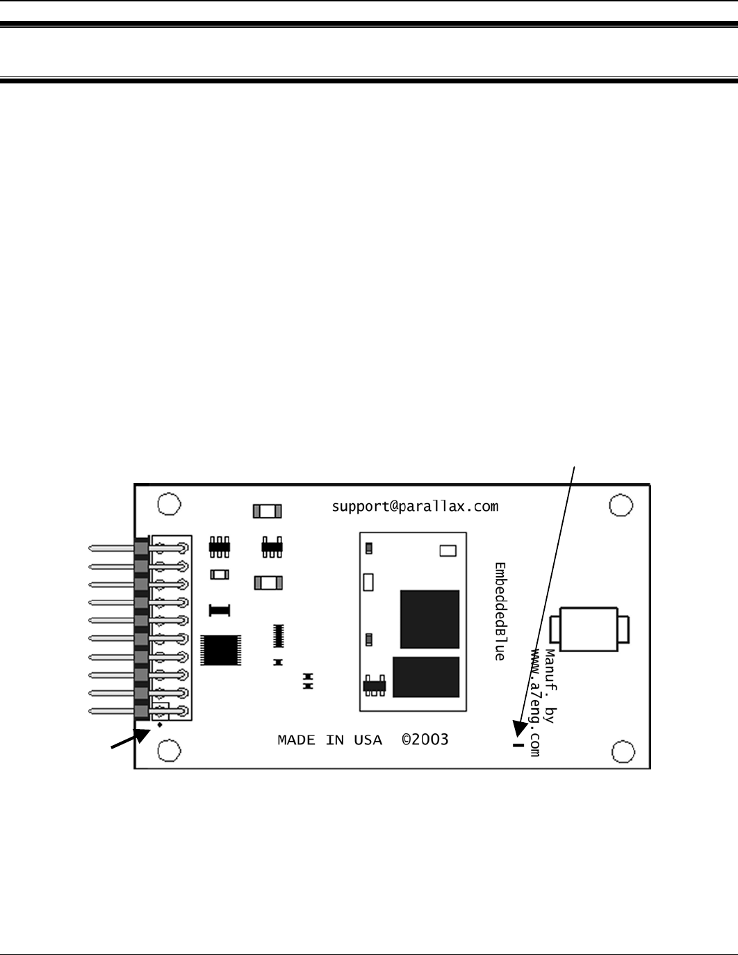
it is important that Pin 1 of the eb500 module, marked with a white dot and a square (Figure
1), is inserted into the VSS pin of the AppMod header on the Parallax boards. A full device
pinout is available in the Technical Specifications section of this manual.
Figure 1: eb500 Module
Pin 1
Connection
Status LED
EmbeddedBlue 500 15
Copyright ©2003 A7 Engineering, Inc.
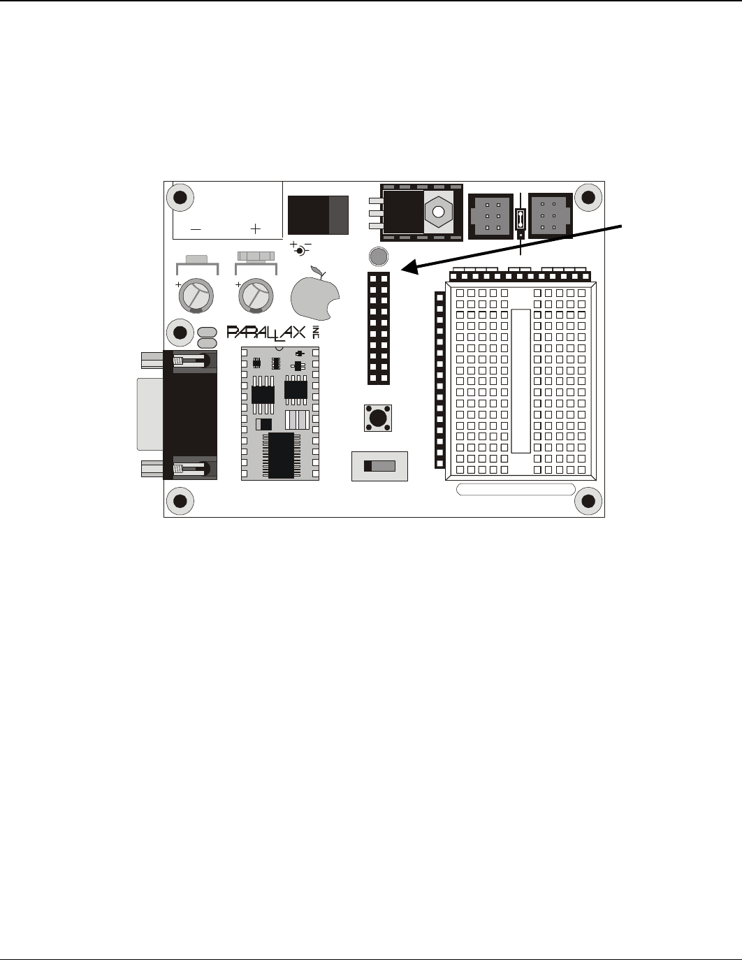
Board Of Education
The Board Of Education (BOE) contains an AppMod header and supports a direct
connection with the eb500 module. On the Board of Education, the AppMod header
is labeled X1 (Figure 2). When inserting the eb500 module into the Board of
Education AppMod header, assure that you insert Pin 1 of the eb500 module,
marked with a white dot and a square, into the VSS pin of the AppMod header.
www.stampsinclass.com
Reset
STAMPS
CLASS
in
Board of Education
Pwr
9 Vdc
Battery
6-9VDC
Sout
Sin
ATN
Vss
P0
P1
P2
P3
P4
P5
P6
P7
P11
P9
P8
Vin
P10
P15
P14
P13
P12
Vdd
Rst
Vss
Black
Red
X4 X5
15 14 13 12
1
X1
Vss
P1
P3
P5
P7
P9
P11
P13
P15
Vin
Vss
P0
P2
P4
P6
P8
P10
P12
P14
Vdd
U1
TM
0 1 2
© 2000-2003
Vdd
P15
P14
P13
P12
P11
P10
P9
P8
P7
P6
P5
P4
P3
P2
P1
P0
X2
X3
Vdd VssVin
Figure 2: Board of Education Board
AppMod
Header
VSS Pins
16 User Manual
Copyright ©2003 A7 Engineering, Inc.
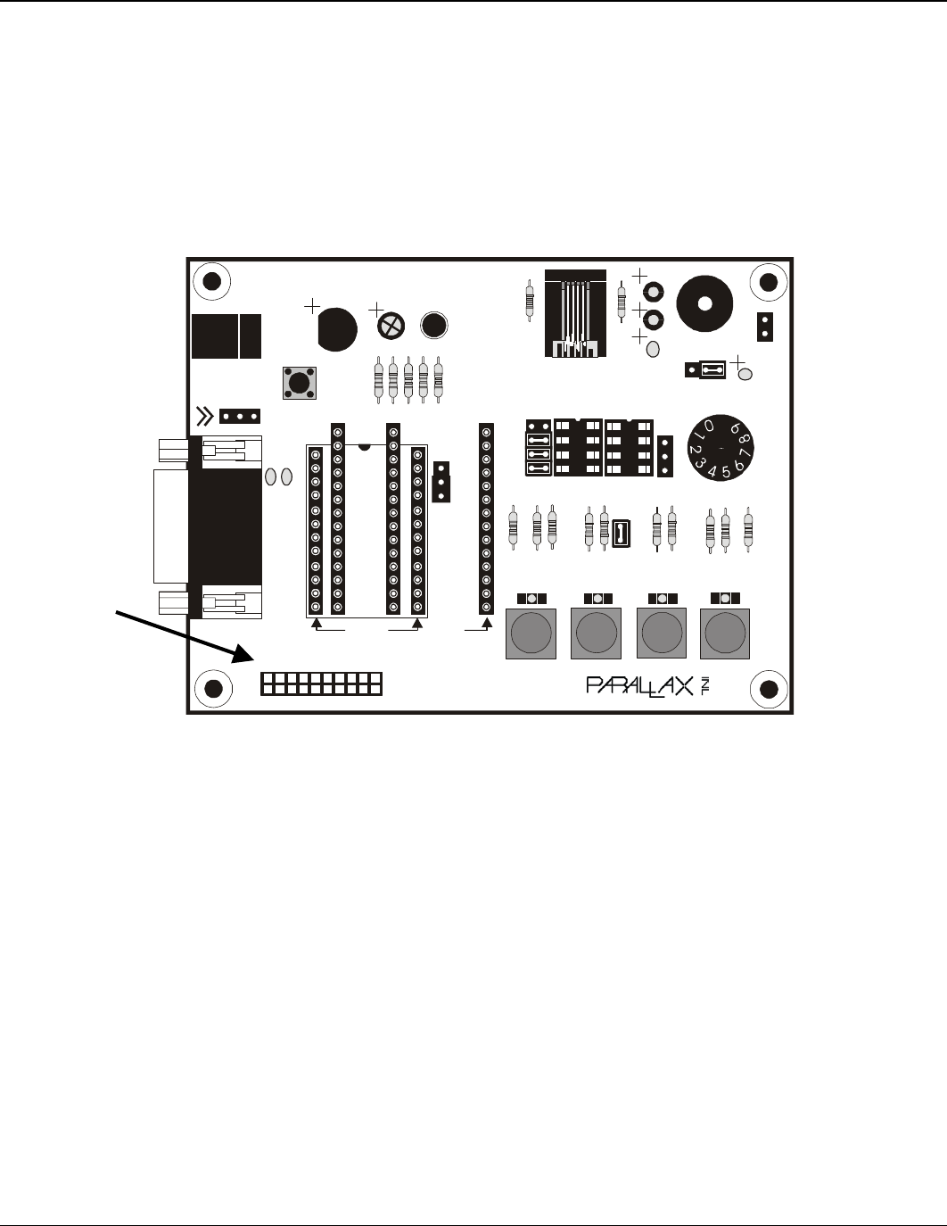
Basic Stamp Activity Board
The Basic Stamp Activity Board contains an AppMod header and supports a direct
connection with the eb500 module when using a BS2 processor. On the Basic Stamp
Activity Board, the AppMod header is labeled X7 (Figure 3). When inserting the
eb500 module into the Basic Stamp Activity Board AppMod header, assure that you
insert Pin 1 of the eb500 module, marked with a white dot and a square, into the
VSS pin (Pin 1) of the AppMod header.
Pwr
Reset
Stamp Activity Board
(c)1998
6-12VAC
9-24VDC
Need Tech Support?
email stamptech@parallaxinc.com
www.parallaxinc.com
X7
20
19
X1 X4
X5
P4/11 P5/10 P6/9 P7/8
TM
P5/7
C5
P3/12
X3
P4/11
X2
A B
Aout
+
_
P0=mPin
P1=zPin
Rev C
1 2
↓
X6
2
1
C6C71
1
1
BS1-IC
BS2-IC
X8
1
2
Figure 3: Basic Stamp Activity Board
AppMod
Header
VSS Pins
EmbeddedBlue 500 17
Copyright ©2003 A7 Engineering, Inc.
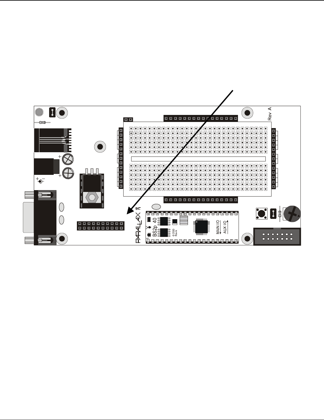
BS2P40 Demo Board
The BS2P40 Demo Board contains an AppMod header and supports a direct
connection with the eb500 module. On the BS2P40 Demo Board, the AppMod
header is labeled X1 (Figure 4). When inserting the eb500 module into the BS2P40
Demo Board AppMod header, assure that you insert Pin 1 of the eb500 module,
marked with a white dot and a square, into the VSS pin of the AppMod header.
P40 Demo Board
Power
© 2002
X6
JU2
Reset
6-9 VDC
1 2 3 4 5 6 7 8 9 101112131415161718192021222324252627282930
1 2 3 4 5 6 7 8 9 101112131415161718192021222324252627282930
a
b
c
d
e
f
g
h
I
j
k
l
a
b
c
d
e
f
g
h
I
j
k
l
A15
A14
A13
A12
A11
A10
A9
A8
A7
A6
A5
A4
A3
A2
A1
A0
X5
P15
P14
P13
P12
P11
P10
P9
P8
P7
P6
P5
P4
P3
P2
P1
P0
X4
JU1
Vdd
P14
P12
P10
P8
P6
P4
P2
P0
Vin
Vin
P15
P13
P11
P9
P7
P5
P3
P1
Vss
X1
1
BS2p24
BS2p40
1
1
U1
X2
VddVss
Vin
X3
Vdd
VssVin
Figure 4: BS2P40 Demo Board
AppMod
Header
VSS Pins
18 User Manual
Copyright ©2003 A7 Engineering, Inc.
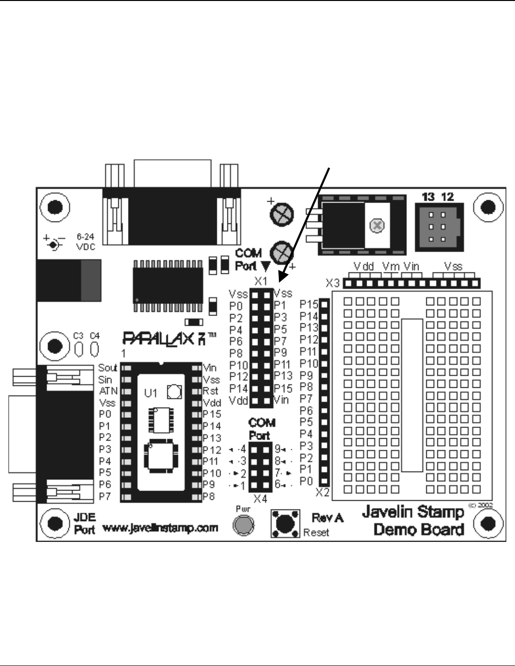
Javelin Stamp Demo Board
The Javelin Stamp Demo Board contains an AppMod header and supports a direct
connection with the eb500 module. On the Javelin Stamp Demo Board, the AppMod
header is labeled X1 (Figure 5). When inserting the eb500 module into the Javelin
Stamp Demo Board AppMod header, assure that you insert Pin 1 of the eb500
module, marked with a white dot and a square, into the VSS pin of the AppMod
header.
Figure 5: Javelin Stamp Demo Board
AppMod
Header
VSS Pins
EmbeddedBlue 500 19
Copyright ©2003 A7 Engineering, Inc.
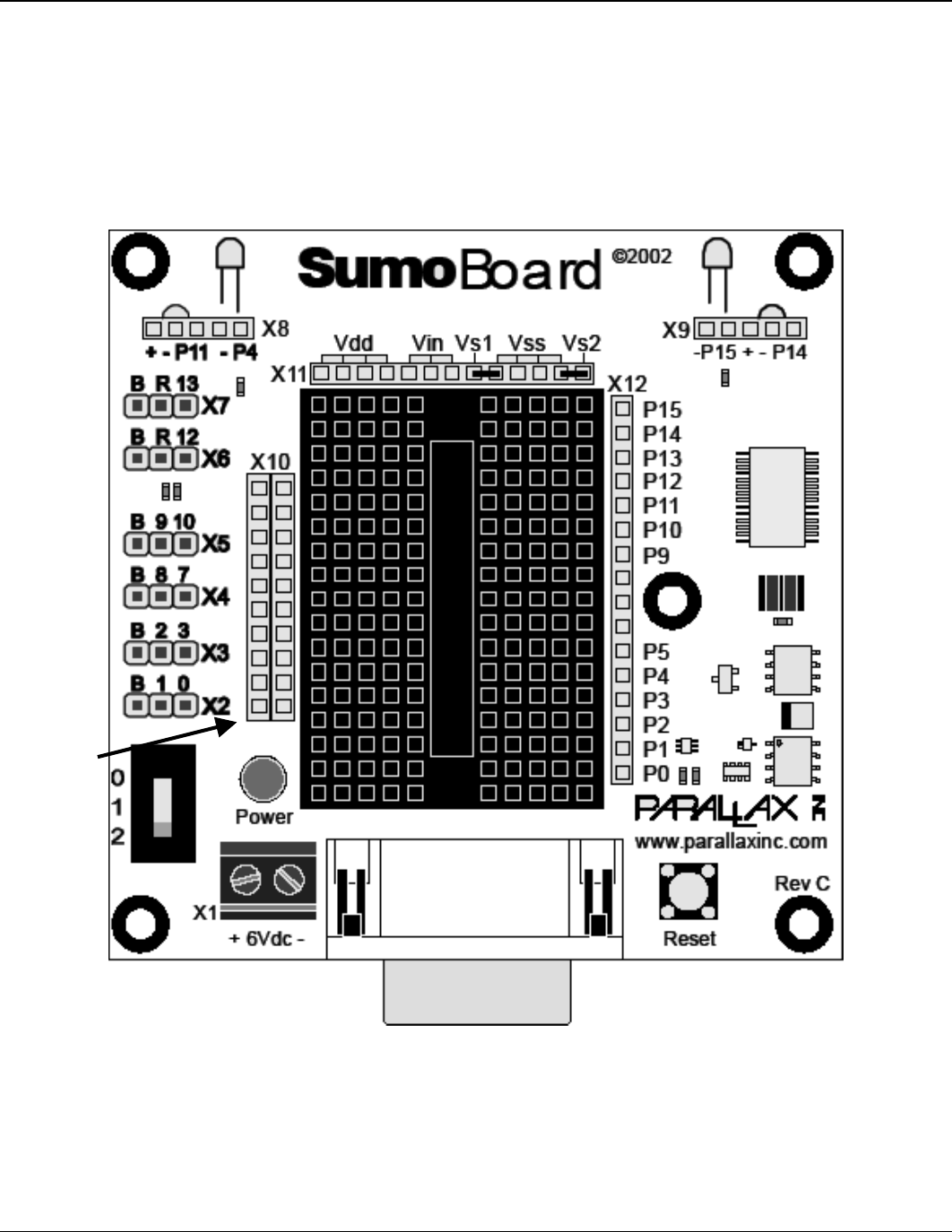
SumoBoard
The SumoBoard contains an AppMod header and supports a direct connection with
the eb500 module. On the SumoBoard, the AppMod header is labeled X10 (Figure
6). When inserting the eb500 module into the SumoBoard AppMod header, assure
that you insert Pin 1 of the eb500 module, marked with a white dot and a square, into
the VSS pin of the AppMod header.
Figure 6: SumoBoard
AppMod
Header
VSS Pins
20 User Manual
Copyright ©2003 A7 Engineering, Inc.
Super Carrier Board
The Super Carrier Board contains an AppMod header and supports a direct
connection with the eb500 module. On the Super Carrier Board, the AppMod header
is labeled X1 (Figure 7). When inserting the eb500 module into the Super Carrier
Board AppMod header, assure that you insert Pin 1 of the eb500 module, marked
with a white dot and a square, into the VSS pin of the AppMod header.
Reset
Pwr
Need Tech Support?
Send email to:
stamptech@parallaxinc.com
Basic Stamp Super Carrier
www.parallaxinc.com (916) 624-8333 ©1999
J3
TM
C2
+
Rev A
C3
J1
C4
P15
P14
P13
P12
P11
P10
P9
P8
P7
P6
P5
P4
P3
P2
P1
P0
Vdd
Vdd
Vss
Vss
Vss
C1
Vin
Vss
PCO
PCI
Vdd
Rst
P0
P1
P2
P3
P4
P5
P6
P7
Vin
J2
Vss
Rocklin, CA - USA
Figure 7: Super Carrier Board
AppMod
Header
VSS Pins

EmbeddedBlue 500 21
Copyright ©2003 A7 Engineering, Inc.
Establishing a Connection
This section contains a number of exercises that demonstrate methods of establishing
Bluetooth wireless connections with the eb500. The scenarios described are not meant to
form an exhaustive list, but rather illustrate a number of more common and useful
configurations. All source code shown in these exercises is available in electronic form on
the accompanying CD, in the Samples folder, using the filename used in this manual.
Connecting two eb500 Modules
In this exercise we will step through the process of establishing a connection between an
eb500 inserted into a Board of Education board and an eb500 inserted into a SumoBoard
board.
To perform this exercise, as documented, you will need a Board of Education board, a
SumoBoard board, and two eb500 modules. If you are using any of the other supported
Parallax boards, you may need to make adjustments to this exercise.
Step 1: Write a BASIC Stamp Application to Get the eb500 Address
In this step we will write a BASIC Stamp application to interrogate an eb500 for its
unique Bluetooth address.
1. Open the Basic Stamp Editor.
2. Enter the following program code into the editor.
'{$STAMP BS2}
szData VAR BYTE(20)
'Wait for the eb500 radio to be ready
PAUSE 1000
'Get the eb500 Bluetooth Address
SEROUT 1,84,["get addr",CR]
SERIN 0,84,[WAIT(“ACK”,CR)]

22 User Manual
Copyright ©2003 A7 Engineering, Inc.
'Read the local address from the get command
SERIN 0,84,[STR szData\17]
SERIN 0,84,[WAIT(CR,”>”)]
szData(17) = 0
DEBUG STR szData\17,CR
The BASIC Stamp application issues an eb500 Get Address command and then
reads and displays the response in the debug window. The response is the Bluetooth
address of the local eb500 module.
3. On the File menu, click Save As.
4. In the File name box, enter a file name to which to save the program just created.
For example, GetAddress.bs2.
5. Click Save.
Step 2: Insert the eb500 Modules into the BOE and SumoBoard Boards
In this step we will insert the eb500 modules into the Board of Education (BOE) and
SumoBoard boards.
1. Insert an eb500 module into the AppMod header of the Board of Education board;
assuring that Pin 1 of the eb500 module is inserted into the VSS pin of the AppMod
header.
2. Insert an eb500 module into the AppMod header of the SumoBoard board; assuring
that Pin 1 of the eb500 module is inserted into the VSS pin of the AppMod header.
Step 3: Get the Address of the eb500 on the Board of Education Board
In this step we will get the Bluetooth address of the eb500 module on the Board of
Education board. We will then use this address in the next step.
1. Connect the Board of Education board serial port to the PC.
2. Apply power to the Board of Education board.
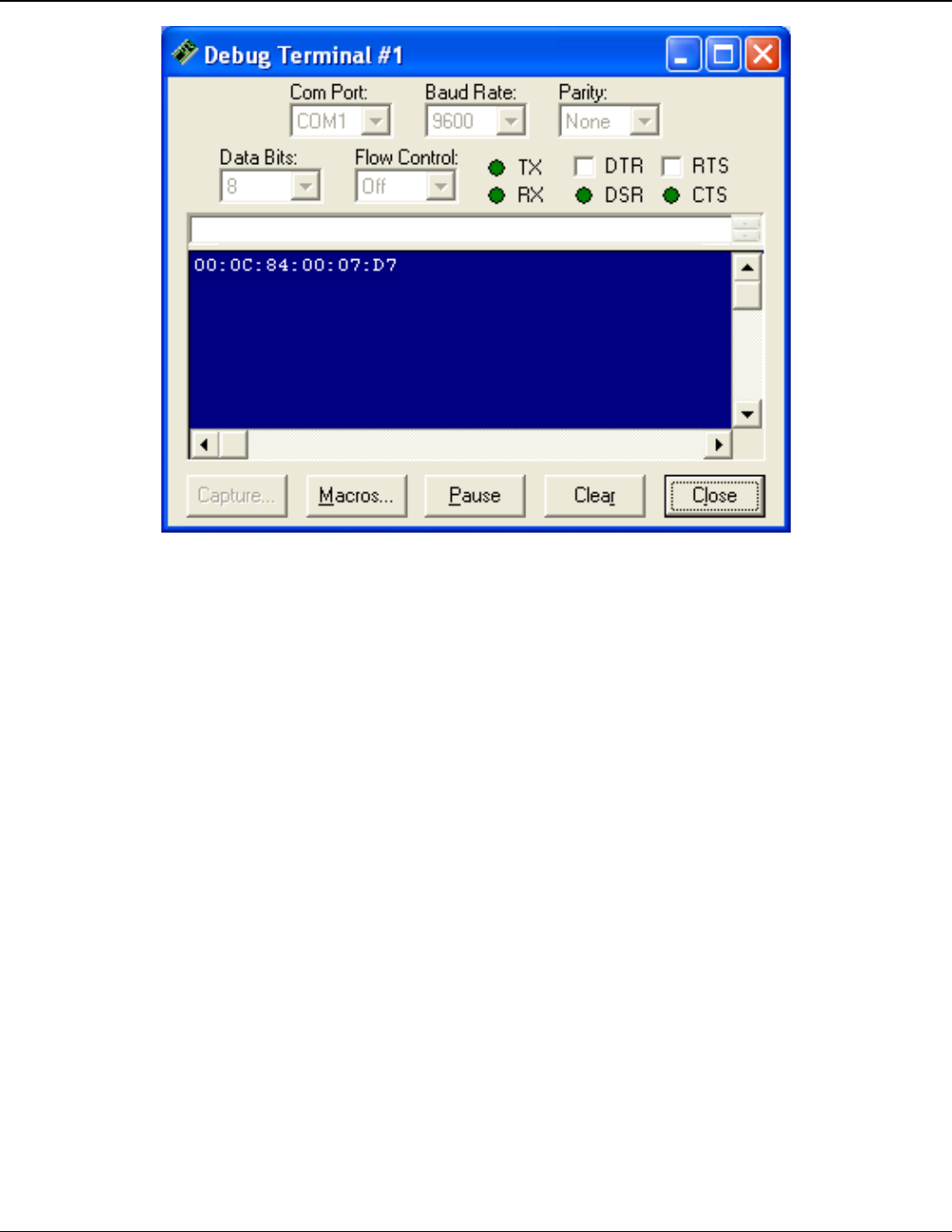
3. On the Run menu, click Run.
The Bluetooth address for the eb500 on the Board of Education board is shown in
the debug window (Figure 8).
4. On the Debug Terminal #1 dialog click Close.
5. Disconnect the power from the Board of Education board.
6. Disconnect the Board of Education board serial port from the PC.
EmbeddedBlue 500 23
Copyright ©2003 A7 Engineering, Inc.
Figure 8: eb500 Bluetooth Address Output
Step 4: Connect the eb500 on the SumoBoard to the eb500 on the BOE
In this step we will develop and run a BASIC Stamp application on the SumoBoard to
establish a connection with the Board of Education.
1. Using the BASIC Stamp Editor; on the File menu, click New.
This will create a new project window within the BASIC Stamp Editor.
2. Enter the following program code into the editor, replacing the Bluetooth device
address with the device address of the eb500 on the Board of Education board,
which we obtained in the previous step.
‘{$STAMP BS2}
‘I/O Line 5 provides the connection status
INPUT 5
‘Wait for the eb500 radio to be ready
PAUSE 1000
‘Connect to the remote device
SEROUT 1,84,[“con 00:0C:84:00:07:D7”,CR]
SERIN 0,84,[WAIT(“ACK”,CR)]
WaitForConnection:

24 User Manual
Copyright ©2003 A7 Engineering, Inc.
IF in5 = 0 THEN WaitForConnection
DEBUG “Connected”,CR
‘Wait for 20 seconds
PAUSE 20000
‘I/O Line 6 allows us to switch to Command Mode
OUTPUT 6
‘Switch to Command Mode
LOW 6
SERIN 0,84,[WAIT(CR,”>”)]
‘Disconnect from the remote device
SEROUT 1,84,[“dis”,CR]
SERIN 0,84,[WAIT(CR,”>”)]
DEBUG “Disconnected”,CR
The BASIC Stamp application establishes a connection with the remote Bluetooth
device, waits twenty seconds, switches back to command mode and then
disconnects from the remote device.
3. On the File menu, click Save As.
4. In the File name box, enter a file name to which to save the program just created.
For example, Connect.bs2.
5. Click Save.
6. Apply power to the Board of Education board.
7. Apply power to the SumoBoard board.
8. On the Run menu, click Run.
The Connection Status LED (Figure 1) on both eb500 modules will turn on when a
connection is established between the two eb500 modules.
9. Disconnect the power from the Board of Education board.
10. Disconnect power from the SumoBoard board.

EmbeddedBlue 500 25
Copyright ©2003 A7 Engineering, Inc.
Connecting a PC with an eb600 to a Board of Education
In this exercise we will step through the process of establishing a connection between a PC
that has an eb600 PC Adapter to an eb500 inserted into a Board of Education board.
To perform this exercise, as documented, you will need an eb600 PC Adapter, a Board of
Education board and two eb500 modules. If you are using any of the other supported
Parallax boards, you may need to make adjustments to this exercise.
Step 1: eb600 PC Adapter Setup
In this step we will attach an eb500 module to the eb600 PC Adapter and apply
power to the device.
1. Insert an eb500 module into the eb600 PC Adapter header; assuring that Pin 1 of
the eb500 module is inserted into Pin 1 of the header on the eb600 PC Adapter.
2. Connect the eb600 PC Adapter to a serial port on the PC using the provided
straight through serial cable.
The PC serial port must be available for HyperTerminal use.
3. Apply power to the eb600 PC Adapter.
Step 2: HyperTerminal Setup
In this step we will setup the Windows HyperTerminal application to establish a
connection with the eb500 attached to the eb600 PC Adapter.
1. Open HyperTerminal.
This will display the Connection Description dialog.
2. In the Name box, type the name of your connection. For example, EB600.
3. Click OK.
This will display the Connect To dialog.
4. In the Connect using dropdown, select the serial port to which you have connected
the eb600 PC Adapter.
5. Click OK.
This will display the Properties dialog.
6. In the Bits per second dropdown, select 9600.
7. In the Data bits dropdown, select 8.
8. In the Parity dropdown, select None.
9. In the Stop bits dropdown, select 1.

26 User Manual
Copyright ©2003 A7 Engineering, Inc.
10. In the Flow control dropdown, select None.
11. Click OK.
This will establish a connection with the serial port.
12. On the Call menu, click Disconnect.
This will disconnect the connection just established, so that we can modify the
connection properties in the following actions.
13. On the File menu, click Properties.
This will display the Properties dialog.
14. On the Settings tab, click ASCII Setup.
This will display the ASCII Setup dialog.
15. Check the Send line ends with line feeds checkbox.
16. Check the Echo typed characters locally checkbox.
17. Check the Append line feeds to incoming line ends checkbox.
18. Check the Wrap lines that exceed terminal width checkbox.
19. Click OK.
This will return to the Properties dialog.
20. Click OK.
21. On the Call menu, click Call.
This will establish a connection with the serial port.
Step 3: Board of Education – eb500 Setup
In this step we will attach an eb500 module to the Board of Education board and
apply power to the device.
1. Insert an eb500 module into the AppMod header of the Board of Education board;
assuring that Pin 1 of the eb500 module is inserted into the VSS pin of the AppMod
header.
2. Apply power to the Board of Education board.
Power can be applied by attaching a 9 Volt battery, or the AC-Adapter provided by
Parallax.

EmbeddedBlue 500 27
Copyright ©2003 A7 Engineering, Inc.
Step 4: Establish a Connection
In this step we will establish a connection between the PC and the Board of
Education.
1. Using HyperTerminal, get the address of the eb500 module that is connected to the
Board of Education board by using the eb500 LST serial command.
By issuing the LST command, the eb500 connected to the eb600 lists other
Bluetooth devices that are in range and visible. Please note that this operation will
take 30 seconds to complete.
To obtain the address, type lst at the “>” prompt and press the return key.
Example:
>lst
ACK
00:0C:84:00:07:D7
>
2. Using HyperTerminal, establish a connection with the eb500 that is connected to the
Board of Education board by using the eb500 CON serial command.
To establish a connection, type con followed by a space, followed by the address
returned in the previous action, followed by a carriage-return. The Connection Status
LED (Figure 1) on both eb500 modules will turn on when a connection is established.
Example:
>con 00:0C:84:00:07:D7
ACK
>
3. Disconnect power from both the eb600 PC Adapter and the Board of Education
boards.
The removal of power resets the eb500 so that when power is restored the eb500
will boot into command mode.

28 User Manual
Copyright ©2003 A7 Engineering, Inc.
Connecting a PC with a DBT-120 to a BOE
In this exercise we will step through the process of establishing a connection from a PC that
has a D-Link® DBT-120 Bluetooth USB Adapter to an eb500 module inserted into a Board
of Education (BOE) board.
To perform this exercise, as documented, you will need a D-Link DBT-120, a Board of
Education board, and an eb500 module. If you are using any of the other supported Parallax
boards, you may need to make adjustments to this exercise.
On the PC, the DBT-120 Bluetooth Software associates a COM port for establishing a
connection from the PC to a remote Bluetooth device and a separate COM port for
connections that are established from a remote Bluetooth device to the PC. This exercise
demonstrates establishing a connection from the PC to a remote eb500. The next exercise
will demonstrate establishing a connection from a remote eb500 to the PC.
The D-Link DBT-120 Bluetooth USB Adapter software must be fully installed prior to
establishing a connection. The PC settings shown in this exercise are based upon the
software provided with the D-Link DBT-120 Bluetooth USB Adapter.
Step 1: DBT-120 Setup
In this step we will attach the DBT-120 USB Adapter to the PC. The software for the
DBT-120 should already be setup.
1. Connect the DBT-120 to an available USB port on the PC, following the instructions
provided with the DBT-120 Bluetooth USB Adapter.
Step 2: Board of Education – eb500 Setup
In this step we will attach an eb500 module to the Board of Education board and
apply power to the device.
1. Insert an eb500 module into the AppMod connector of the Board of Education
board; assuring that Pin 1 of the eb500 module is inserted into the VSS pin of the
AppMod header.
2. Apply power to the Board of Education board.
Power can be applied by attaching a 9 Volt battery, or the AC-Adapter provided by
Parallax.

EmbeddedBlue 500 29
Copyright ©2003 A7 Engineering, Inc.
Step 3: Establish a Connection Using the DBT-120 Bluetooth Software
In this step we will establish a connection from the PC to the eb500 module inserted
into the Board of Education board.
The actions in this step need to be performed only once for the eb500. After
performing the actions in this step, the connection details will be stored on the PC.
Therefore, future connections can be established to an eb500 by simply opening the
associated COM port.
1. Open My Bluetooth Places by double-clicking on the desktop icon.
This will display the My Bluetooth Places dialog.
2. Click View devices in range to locate the eb500 module connected to the Board of
Education.
Provided the eb500 on the Board of Education is within range, eb500 will be shown
in the window.
3. Select eb500 and click Discover services.
The A7 Serial Port service will be shown in the window.
4. Select A7 Serial Port and click Connect to this service.
This will establish a connection from the PC to the eb500 on the Board of Education
board and associate this connection with a specific COM port.
5. If the A7 Serial Port dialog is shown, click OK.
6. Select A7 Serial Port and click Display service properties.
This will display the Bluetooth Properties dialog.
7. In the Port dropdown, which is disabled, please note the COM port shown.
The DBT-120 Bluetooth software associates a specific COM port for a connection
from the PC to an eb500. Applications, such as HyperTerminal, use this COM port to
establish a connection and communicate with an eb500 from the PC. Remember,
this COM port is used to establish a connection from the PC to the eb500. A different
COM port is used when a connection is established from the eb500 to the PC.
8. Click OK.
9. Select A7 Serial Port and click Disconnect from this service.
This will disconnect the connection to the eb500 on the Board of Education board.

30 User Manual
Copyright ©2003 A7 Engineering, Inc.
Step 4: HyperTerminal Setup
In this step we will setup the Windows HyperTerminal application to establish a
connection with the eb500 on the Board of Education board.
1. Open HyperTerminal.
This will display the Connection Description dialog.
2. In the Name box, type the name of your connection. For example, eb500-BOE.
3. Click OK.
This will display the Connect To dialog.
4. In the Connect using dropdown, select the serial port to which the DBT-120
Bluetooth software associated with the connection from the PC to the eb500 on the
Board of Education board.
The COM port associated with the connection was discovered in the previous step.
5. Click OK.
This will display the Properties dialog.
6. In the Bits per second dropdown, select 9600.
7. In the Data bits dropdown, select 8.
8. In the Parity dropdown, select None.
9. In the Stop bits dropdown, select 1.
10. In the Flow control dropdown, select None.
11. Click OK.
This will establish a connection with the eb500 on the Board of Education board.
12. On the Call menu, click Disconnect.
This will disconnect the connection just established, so that we can modify the
connection properties in the following actions.
13. On the File menu, click Properties.
This will display the Properties dialog.
14. On the Settings tab, click ASCII Setup.
This will display the ASCII Setup dialog.
15. Check the Send line ends with line feeds checkbox.
16. Check the Echo typed characters locally checkbox.
17. Check the Append line feeds to incoming line ends checkbox.

EmbeddedBlue 500 31
Copyright ©2003 A7 Engineering, Inc.
18. Check the Wrap lines that exceed terminal width checkbox.
19. Click OK.
This will return to the Properties dialog.
20. Click OK.
Step 5: Establish a Connection Using HyperTerminal
In this step we will establish a connection from the PC to the eb500 on the Board of
Education, using HyperTerminal. This step relies on the connection information
created previously in Step 3.
1. On the Call menu, click Call.
This will establish a connection with the eb500 on the Board of Education board.
The Connection Status LED (Figure 1) on the eb500 module will turn on when a
connection is established.
2. On the Call menu, click Disconnect.
This will close the connection with the eb500 on the Board of Education.

32 User Manual
Copyright ©2003 A7 Engineering, Inc.
Connecting a BOE to a PC with a DBT-120
In this exercise we will step through the process of establishing a connection from an eb500
module inserted into a Board of Education (BOE) board to a PC that has a D-Link® DBT-
120 Bluetooth USB Adapter.
To perform this exercise, as documented, you will need a D-Link DBT-120, a Board of
Education board, and an eb500 module. If you are using any of the other supported Parallax
boards, you may need to make adjustments to this exercise.
On the PC, the DBT-120 Bluetooth Software associates a COM port for establishing a
connection from the PC to a remote Bluetooth device and a separate COM port for
connections that are established from a remote Bluetooth device to the PC. This exercise
demonstrates establishing a connection from a remote eb500 to the PC. When a remote
Bluetooth device establishes a connection with the PC, the connection is established with
the DBT-120 Bluetooth USB Adapter software running on the PC. To gain access to the
data, an application, such as HyperTerminal, must open the COM port associated with the
connection established from the remote device. In the Communications section, we will step
through this process.
The D-Link DBT-120 Bluetooth USB Adapter software must be fully installed prior to
establishing a connection. The PC settings shown in this exercise are based upon the
software provided with the D-Link DBT-120 Bluetooth USB Adapter.
Step 1: DBT-120 Setup
In this step we will attach the DBT-120 USB Adapter to the PC. The software for the
DBT-120 should already be setup.
1. Connect the DBT-120 to an available USB port on the PC, following the instructions
provided with the DBT-120 Bluetooth USB Adapter.
Step 2: Obtain the Bluetooth Address of the PC
In this step we will obtain the Bluetooth address of the DBT-120 USB Adapter
attached to the PC.
1. Open My Bluetooth Places by double-clicking on the desktop icon.
This will display the My Bluetooth Places dialog.
2. Click View or modify configuration.
This will display the Bluetooth Configuration dialog.
3. Select the Hardware tab and note the Device Address shown in the Device
Properties section of the dialog.
The device address will be used in the BASIC Stamp application developed in the
next step.

EmbeddedBlue 500 33
Copyright ©2003 A7 Engineering, Inc.
4. Click Cancel
This will close the Bluetooth Configuration dialog.
Step 3: Write a BASIC Stamp Application to Connect to the PC
In this step we will attach an eb500 module to the Board of Education board and
develop a BASIC Stamp application to establish a connection with the PC.
1. Insert an eb500 module into the AppMod connector of the Board of Education
board; assuring that Pin 1 of the eb500 module is inserted into the VSS pin of the
AppMod header.
2. Connect the Board of Education board serial port to the PC.
3. Open the BASIC Stamp Editor.
4. Enter the following program code into the editor, replacing the Bluetooth device
address with the device address of the PC, which we obtained from the Hardware
tab of the Device Properties section of the Bluetooth Configuration dialog in the
previous step.
‘{$STAMP BS2}
‘I/O Line 5 provides the connection status
INPUT 5
‘Wait for the eb500 radio to be ready
PAUSE 1000
‘Connect to the remote device
SEROUT 1,84,[“con 00:80:C8:35:2C:B8”,CR]
SERIN 0,84,[WAIT(“ACK”,CR)]
WaitForConnection:
IF in5 = 0 THEN WaitForConnection
DEBUG “Connected”,CR
‘Wait for 20 seconds
PAUSE 20000
‘I/O Line 6 allows us to switch to Command Mode
OUTPUT 6
‘Switch to Command Mode
LOW 6
SERIN 0,84,[WAIT(CR,”>”)]
‘Disconnect from the remote device
SEROUT 1,84,[“dis”,CR]

34 User Manual
Copyright ©2003 A7 Engineering, Inc.
SERIN 0,84,[WAIT(CR,”>”)]
DEBUG “Disconnected”,CR
The BASIC Stamp application establishes a connection with the remote Bluetooth
device, waits twenty seconds, switches back to command mode and then
disconnects from the remote device.
5. On the File menu, click Save As.
6. In the File name box, enter a file name to which to save the program just created.
For example, ConnectPC.bs2.
7. Click Save.
Step 4: Connect the eb500 on the Board of Education to the PC
1. Apply power to the Board of Education board.
Power can be applied by attaching a 9 Volt battery, or the AC-Adapter provided by
Parallax.
2. On the Run menu, click Run.
The Connection Status LED (Figure 1) on the eb500 module will turn on when a
connection is established. Additionally, on the My Bluetooth Places window, in the
Additional Information column, the text “Connected” will be shown while a connection
exists between the eb500 and the PC.

EmbeddedBlue 500 35
Copyright ©2003 A7 Engineering, Inc.
Connecting an iPAQ h1940 to a Board of Education
In this exercise we will step through the process of establishing a connection from an iPAQ
h1940, which has integrated Bluetooth, to an eb500 module inserted into a Board of
Education board.
To perform this exercise, as documented, you will need an iPAQ h1940, a Board of
Education board, and an eb500 module. If you are using a different model of Pocket PC,
with integrated Bluetooth, or any of the other supported Parallax boards, you may need to
make adjustments to this exercise.
Step 1: Board of Education – eb500 Setup
In this step we will attach an eb500 module to the Board of Education board and
apply power to the device.
1. Insert an eb500 module into the AppMod connector of the Board of Education
board; assuring that Pin 1 of the eb500 module is inserted into the VSS pin of the
AppMod header.
2. Apply power to the Board of Education board.
Power can be applied by attaching a 9 Volt battery, or the AC-Adapter provided by
Parallax.
Step 2: iPAQ h1940 Setup
In this step we will setup the iPAQ for connecting to the eb500.
1. Tap the Bluetooth icon in the system tray on the Today screen and select
Bluetooth Manager.
This will display the Bluetooth Manager dialog.
2. On the New menu, select Connect.
This will display the first page of the Connection Wizard.
3. Select Explore a Bluetooth device and tap Next.
This will display the next page of the Connection Wizard.
4. Tap in the Device box.
This will display the Connection Wizard Bluetooth Browser dialog containing a list of
found devices.
5. Tap eb500.
This will display the next page of the Connection Wizard.
6. In the Service Selection box, select A7 Serial Port.

36 User Manual
Copyright ©2003 A7 Engineering, Inc.
7. Tap Next.
This will create a shortcut for the service.
8. Tap Finish.
This will display the Bluetooth Manager dialog with the shortcut created in the
window, eb500: A7 Serial Port.
Step 3: Establish a Connection
In this step we will establish a connection from the iPAQ to the Board of Education.
1. Tap-and-hold the shortcut created in the previous step, eb500: A7 Serial Port.
2. Select Connect.
This will establish a connection with the eb500 on the Board of Education board.
The Connection Status LED (Figure 1) on the eb500 module will turn on when a
connection is established.
3. Tap Active Connections.
This will display the Bluetooth Manager Active Connections page showing the status
of your active Bluetooth connections.
4. Tap My Shortcuts.
5. Tap-and-hold the shortcut created in the previous step, eb500: A7 Serial Port.
6. Select Disconnect.
This will close the connection with the eb500 on the Board of Education board. The
Connection Status LED on the eb500 module will turn off.

EmbeddedBlue 500 37
Copyright ©2003 A7 Engineering, Inc.
Connecting a Board of Education to an iPAQ h1940
In this exercise we will step through the process of establishing a connection from an eb500
module inserted into a Board of Education board to an iPAQ h1940, which has integrated
Bluetooth.
To perform this exercise, as documented, you will need an iPAQ h1940, a Board of
Education board, and an eb500 module. If you are using a different model of Pocket PC,
with integrated Bluetooth, or any of the other supported Parallax boards, you may need to
make adjustments to this exercise.
Step 1: Obtain the Bluetooth Address of the iPAQ
In this step we will obtain the Bluetooth address of the iPAQ.
1. Tap the Bluetooth icon in the system tray on the Today screen and select
Bluetooth Settings.
This will display the Settings dialog.
2. Tap the Accessibility tab and note the Address shown in the Device Identification
section of the dialog.
The device address will be used in the BASIC Stamp application developed in the
next step.
3. Tap OK to close the dialog.
Step 2: Write a BASIC Stamp Application to Connect to the iPAQ
In this step we will attach an eb500 module to the Board of Education board and
develop a BASIC Stamp application to establish a connection with the iPAQ.
1. Insert an eb500 module into the AppMod connector of the Board of Education
board; assuring that Pin 1 of the eb500 module is inserted into the VSS pin of the
AppMod header.
2. Connect the Board of Education board serial port to the PC.
3. Open the BASIC Stamp Editor.
4. Enter the following program code into the editor, replacing the Bluetooth device
address with the device address of the iPAQ, which we obtained from the iPAQ in
the previous step.
‘{$STAMP BS2}
‘I/O Line 5 provides the connection status
INPUT 5
‘Wait for the eb500 radio to be ready

38 User Manual
Copyright ©2003 A7 Engineering, Inc.
PAUSE 1000
‘Connect to the remote device
SEROUT 1,84,[“con 00:04:3E:62:FE:01”,CR]
SERIN 0,84,[WAIT(“ACK”,CR)]
WaitForConnection:
IF in5 = 0 THEN WaitForConnection
DEBUG “Connected”,CR
‘Wait for 20 seconds
PAUSE 20000
‘If there is no connection just exit
IF in5 = 0 THEN Exit
‘I/O Line 6 allows us to switch to Command Mode
OUTPUT 6
‘Switch to Command Mode
LOW 6
SERIN 0,84,[WAIT(CR,”>”)]
‘Disconnect from the remote device
SEROUT 1,84,[“dis”,CR]
SERIN 0,84,[WAIT(CR,”>”)]
Exit:
DEBUG “Disconnected”,CR
The BASIC Stamp application establishes a connection with the remote Bluetooth
device, waits twenty seconds, switches back to command mode and then
disconnects from the remote device.
On the h1940 model of the iPAQ, the Bluetooth software closes the connection after
a short period of time if there is not an application running on the iPAQ to receive the
data over the connection. Therefore, after the twenty second wait, the BASIC Stamp
application checks if there is still a valid connection before switching to Command
Mode. If there is no connection, the eb500 is already in Command Mode.
5. On the File menu, click Save As.
6. In the File name box, enter a file name to which to save the program just created.
For example, ConnectPPC.bs2.
7. Click Save.
EmbeddedBlue 500 39
Copyright ©2003 A7 Engineering, Inc.
Step 3: Establish a Connection
In this step we will establish a connection from the Board of Education to the iPAQ.
1. Turn on the iPAQ.
2. Tap the Bluetooth icon and select Bluetooth Manager.
This will display the Bluetooth Manager dialog.
3. Tap the Active Connections tab.
4. Apply power to the Board of Education board.
Power can be applied by attaching a 9 Volt battery, or the AC-Adapter provided by
Parallax.
5. Using the Basic Stamp Editor, on the Run menu, click Run.
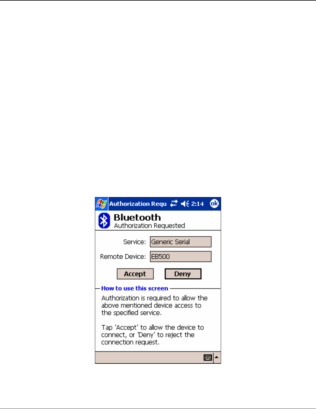
Depending on your current iPAQ Bluetooth configuration, the Authorization
Requested Dialog may appear (Figure 9). If this dialog appears, tap Accept to accept
the connection. The Connection Status LED (Figure 1) on the eb500 module will turn
on when a connection is established. On the iPAQ the connection will be shown in
the Incoming Connections section of the Active Connections tab on the Bluetooth
Active Connections dialog.
Figure 9: iPAQ Bluetooth Authorization Request Dialog

40 User Manual
Copyright ©2003 A7 Engineering, Inc.
Communications
This section contains a number of exercises that demonstrate methods of communicating
over a Bluetooth wireless connection with the eb500. The scenarios described are not
meant to form an exhaustive list, but rather illustrate a number of more common and useful
configurations. All source code shown in these exercises are available in electronic form on
the accompanying CD, in the Samples folder, using the filename used in this manual.
Communicating between Two eb500 Modules
In this exercise we will step through the process of communicating between two eb500
modules, one inserted into a Boe-Bot robot and the other inserted into a SumoBot robot. We
will program the SumoBot to use its infrared sensors to follow an object and then transmit its
movements to the Boe-Bot. The Boe-Bot will use the received information to mimic the
movements of the SumoBot.
To perform this exercise, as documented, you will need a Boe-Bot, a SumoBot, and two
eb500 modules. If you are using any of the other supported Parallax robots, you may need
to make adjustments to this exercise.
Step 1: Create a Monkey-See Application for the SumoBot
In this step we will create a BASIC Stamp application that will use the infrared
sensors of the SumoBot to follow an object and transmit its movements to a remote
eb500.
1. Open the BASIC Stamp Editor.
2. Enter the following program code into the editor, replacing the Bluetooth device
address with the device address of the eb500 inserted into the Boe-Bot robot.
'{$STAMP BS2}
‘I/O Line 5 provides the connection status
INPUT 5
'-----[I/O Definitions]---------------------------------------

EmbeddedBlue 500 41
Copyright ©2003 A7 Engineering, Inc.
LMotor CON 13
RMotor CON 12
LfIrOut CON 4
LfIrIn VAR In11
RtIrOut CON 15
RtIrIn VAR In14
'-----[Constants]----------------------------------------------
LFwdFast CON 1000
LRevFast CON 500
RFwdFast CON 500
RRevFast CON 1000
'-----[Variables]-----------------------------------------------
irBits VAR NIB
irLeft VAR irBits.Bit1
irRight VAR irBits.Bit0
lastIr VAR NIB
bBuffer VAR BYTE(4)
bErrorCode VAR BYTE
'-----[Initialization]------------------------------------------
'Wait for the eb500 radio to be ready
PAUSE 1000
Connect:
'Connect to Monkey-Do
SEROUT 1,84,["con 00:0C:84:00:07:D7",CR]
SERIN 0,84,[WAIT(“ACK”,CR)]
‘Either an Err #<CR> or a ">" will be received
SERIN 0,84,[STR bBuffer\6\”>”]
IF bBuffer(0) = “E” THEN ErrorCode
WaitForConnection:
IF in5 = 0 THEN WaitForConnection

42 User Manual
Copyright ©2003 A7 Engineering, Inc.
'-----[Main Code]-----------------------------------------------
Main:
'Verify the connection is still up before each loop
IF in5 = 0 THEN Connect
GOSUB Read_IR_Sensors
BRANCH irBits,[Hold, Turn_Right, Turn_left, Move_Fwd]
Move_Fwd:
SEROUT 1,84,["3"]
PULSOUT LMotor,LFwdFast
PULSOUT RMotor,RFwdFast
GOTO Main
Turn_Right:
SEROUT 1,84,["1"]
PULSOUT LMotor,LFwdFast
PULSOUT RMotor,RRevFast
GOTO Main
Turn_Left:
SEROUT 1,84,["2"]
PULSOUT LMotor,LRevFast
PULSOUT RMotor,RFwdFast
GOTO Main
Hold:
GOTO Main
'-----[Subroutines]---------------------------------------------
Read_IR_Sensors:
FREQOUT LfIrOut,1,38500
irLeft = ~LfIrIn
FREQOUT RtIrOut,1,38500
irRight = ~RtIrIn

EmbeddedBlue 500 43
Copyright ©2003 A7 Engineering, Inc.
RETURN
BadCommand:
DEBUG "A bad command was received."
END
ErrorCode:
bErrorCode = bBuffer(4)
DEBUG "An error was received: ",STR bErrorCode,CR
END
3. On the File menu, click Save As.
4. In the File name box, enter a file name to which to save the program just created.
For example, MonkeySee.bs2.
5. Click Save.
Step 2: Create a Monkey-Do Application for the Boe-Bot
In this step we will create a BASIC Stamp application that will receive information
from the remote SumoBot and perform movements based on that information.
1. On the File menu, click New.
This will create a new project window within the BASIC Stamp Editor.
2. Enter the following program code into the editor.
'{$STAMP BS2}
'-----[I/O Definitions]-----------------------------------------
LMotor CON 15
RMotor CON 14
'-----[Constants]-----------------------------------------------
LFwdFast CON 1000
LRevFast CON 500
RFwdFast CON 500
RRevFast CON 1000
'-----[Variables]-----------------------------------------------
CmdData VAR BYTE

44 User Manual
Copyright ©2003 A7 Engineering, Inc.
'-----[Initialization]------------------------------------------
Initialize:
'Wait for the eb500 radio to be ready
PAUSE 1000
'Set the initial state to hold
CmdData = 3
'-----[Main Code]-----------------------------------------------
Main:
'Wait for a command
SERIN 0,84,[DEC1 CmdData]
'Process the command
BRANCH CmdData,[Hold, Turn_Right, Turn_left, Move_Fwd]
'If the command was invalid just loop again
GOTO Main
Move_Fwd:
PULSOUT LMotor,LFwdFast
PULSOUT RMotor,RFwdFast
GOTO Main
Turn_Right:
PULSOUT LMotor,LFwdFast
PULSOUT RMotor,RRevFast
GOTO Main
Turn_Left:
PULSOUT LMotor,LRevFast
PULSOUT RMotor,RFwdFast
GOTO Main
Hold:

EmbeddedBlue 500 45
Copyright ©2003 A7 Engineering, Inc.
GOTO Main
3. On the File menu, click Save As.
4. In the File name box, enter a file name to which to save the program just created.
For example, MonkeyDo.bs2.
5. Click Save.
Step 3: Download the Applications to the Robots
In this step we will download the applications we just created to the respective
robots.
1. Click the MonkeySee.bs2 tab in the BASIC Stamp Editor.
2. Connect the SumoBoard board serial port to the PC.
3. Apply power to the SumoBoard board.
4. On the Run menu, click Run.
5. On the Debug Terminal #1 dialog click Close.
6. Disconnect the power from the SumoBoard board.
7. Disconnect the SumoBoard board serial port from the PC.
8. Click the MonkeyDo.bs2 tab in the BASIC Stamp Editor.
9. Connect the Board of Education board serial port to the PC.
10. Apply power to the Board of Education board.
11. On the Run menu, click Run.
12. Disconnect the Board of Education board serial port from the PC.
Step 4: Run the Monkey-See / Monkey-Do Applications
In this step we will run the Monkey-See / Monkey-Do applications.
1. Apply power to the SumoBoard board.
2. Make the Boe-Bot robot mimic the movements of the SumoBot by putting your
hand in front of the SumoBot IR sensors.
As you move your hand left, right and forward, the SumoBot will follow your hand
and the Boe-Bot will mimic the same movements.

46 User Manual
Copyright ©2003 A7 Engineering, Inc.
Communicating between a PC with an eb600 and a BOE
In this exercise we will step through the process of communicating between an eb500
module inserted into a Board of Education (BOE) board and a PC that has an eb600 PC
Adapter.
To perform this exercise, as documented, you will need to have two serial ports available on
your PC, an eb600 PC Adapter, a Board of Education board, and two eb500 moduels. One
serial port will be used to connect the PC to the Board of Education serial port. The other
serial port will be used to connect to the eb600 PC Adapter. If you are using any of the other
supported Parallax boards, you may need to make adjustments to this exercise.
Step 1: Transmit Data from the PC to the BASIC Stamp
In this step we will create a BASIC Stamp application to read data from the eb500
and display the data in the BASIC Stamp Editor Debug window. We will then
download and run the application.
1. Connect the Board of Education board serial port to the PC.
2. Open the BASIC Stamp Editor.
3. Enter the following program code into the editor.
‘{$STAMP BS2}
bData VAR BYTE
‘Wait for the eb500 radio to be ready
PAUSE 1000
Main:
SERIN 0,84,[STR bData\1]
DEBUG STR bData\1
GOTO Main
The application waits for an individual byte of data to arrive and then displays the
byte in the debug window and then repeats this process.
4. On the File menu, click Save As.
5. In the File name box, enter a file name to which to save the program just created.
For example, Receive.bs2.
6. Click Save.
7. Apply power to the Board of Education board.
8. On the Run menu, click Run.

EmbeddedBlue 500 47
Copyright ©2003 A7 Engineering, Inc.
9. Establish a connection from the PC to the Board of Education.
Please see the section titled Connecting a PC with an eb600 to a Board of Education
for information on establishing the connection.
10. Using HyperTerminal, type a series of characters.
These characters will be transmitted over the wireless link, read by the BASIC Stamp
application, and then displayed in the debug window (Figure 10).
Figure 10: HyperTerminal Input and Debug Output
Step 2: Transmit Data from the BASIC Stamp to the PC
In this step we will create a BASIC Stamp application to send data out the eb500 to
the PC where we will use HyperTerminal to display the data received by the eb500
module attached to the eb600 on the PC.
1. Reset the eb500 attached to the eb600 PC Adapter to place the eb500 into
command mode.
To reset the eb500 attached to the eb600 PC Adapter, disconnect the power, wait a
couple of seconds, and then reconnect the power.
2. Reset the eb500 attached to the Board of Education board to place the eb500 into
command mode.
To reset the eb500 attached to the Board of Education board, disconnect the power,
wait a couple of seconds, and then reconnect the power. The Reset push button on
the Board of Education board will NOT reset the eb500.

48 User Manual
Copyright ©2003 A7 Engineering, Inc.
3. Using HyperTerminal, acquire the device address of the eb500 connected to the
eb600 PC Adapter by using the eb500 GET ADDR serial command.
Please note the device address as it will be used in the BASIC Stamp application
developed in the following actions.
By issuing the GET ADDR command, the eb500 connected to the eb600 will return
its own device address.
To obtain the device address, type get addr at the “>” prompt and press the return
key.
Example:
>get addr
ACK
00:0C:84:00:07:D8
>
4. Using the BASIC Stamp Editor, on the File menu, click New.
This will create a new project window within the BASIC Stamp Editor.
5. Enter the following program code into the editor, replacing the device address with
the device address obtained from the GET ADDR command issued above.
‘{$STAMP BS2}
nCount VAR BYTE
‘I/O Line 5 provides the connection status
INPUT 5
‘Wait for the eb500 radio to be ready
PAUSE 1000
‘Connect to the remote device
SEROUT 1,84,[“con 00:0C:84:00:07:D8”,CR]
SERIN 0,84,[WAIT(“ACK”,CR)]
WaitForConnection:
IF in5 = 0 THEN WaitForConnection
DEBUG “Connected”,CR
FOR nCount = 1 to 10
SEROUT 1,84,[“Hello World”,CR] ‘sending data
PAUSE 1000 ‘wait for 1 second
NEXT
‘I/O Line 6 allows us to switch to command mode.

EmbeddedBlue 500 49
Copyright ©2003 A7 Engineering, Inc.
OUTPUT 6
‘Switch to Command Mode
LOW 6
SERIN 0,84,[WAIT(CR,”>”)]
‘Disconnect from the remote device
SEROUT 1,84,[“dis”,CR]
SERIN 0,84,[wait(CR,”>”)]
DEBUG “Disconnected”,CR
The application establishes a connection with the remote eb500 device, transmits
“Hello World” ten times, switches back to command mode and then disconnects from
the remote device.
The first call to SEROUT is used when the eb500 is in command mode and instructs
the eb500 to establish a connection with the device specified. Once a connection is
established the eb500 is in data mode, which causes further calls to SEROUT to be
sent to the remote device.
6. On the File menu, click Save As.
This will display the Save As dialog.
7. In the File name box, enter a file name to which to save the program just created.
For example, HelloWorld.bs2.
8. Click Save.
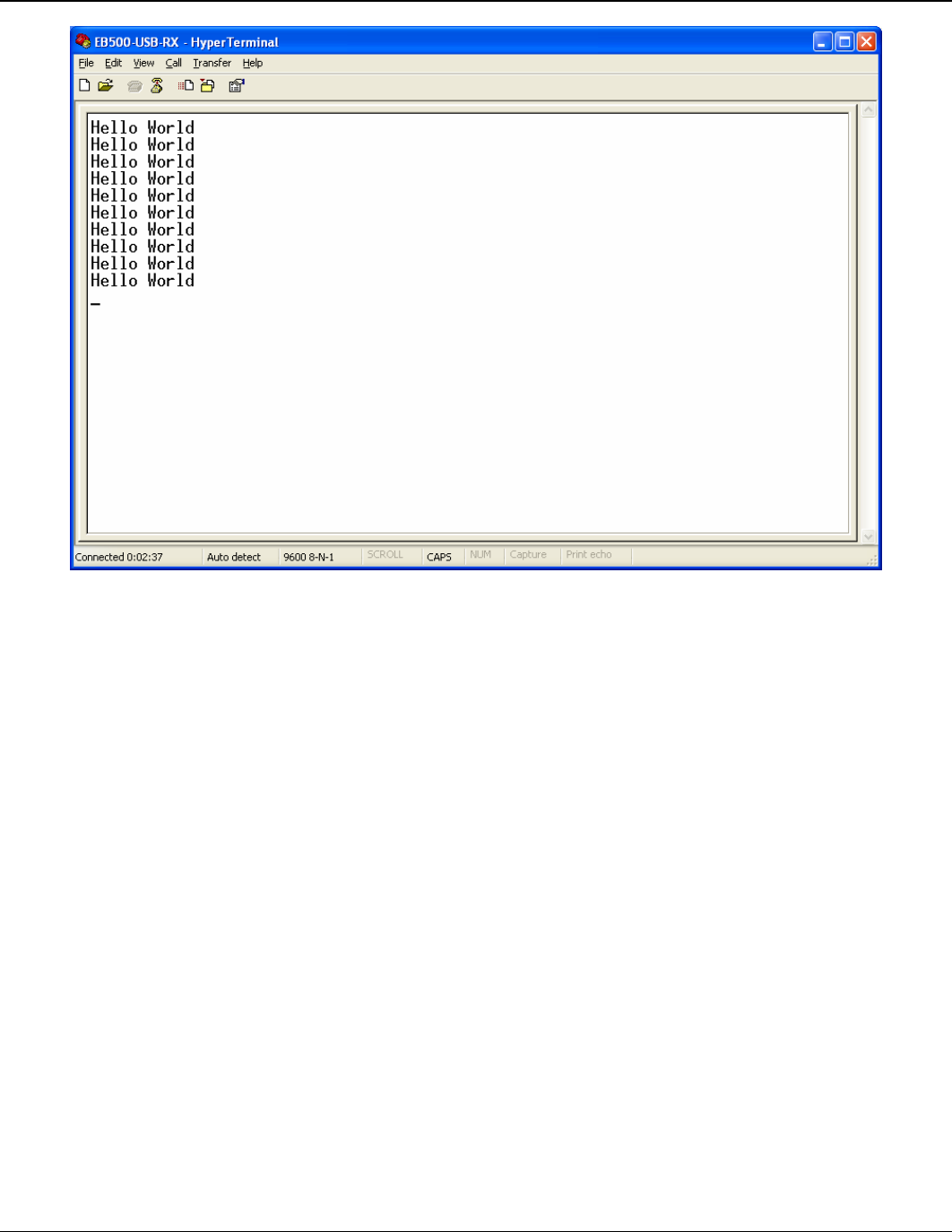
9. On the Run menu, click Run.
This will display the Download Program dialog while downloading the program to the
BASIC Stamp. After the download is complete the BASIC Stamp application will
transmit “Hello World” over the wireless link, and HyperTerminal will display the
received data (Figure 11).
50 User Manual
Copyright ©2003 A7 Engineering, Inc.
Figure 11: HyperTerminal Output - Hello World

EmbeddedBlue 500 51
Copyright ©2003 A7 Engineering, Inc.
Communicating between a PC with a DBT-120 and a BOE
In this exercise we will step through the process of communicating between a PC that has a
D-Link® DBT-120 Bluetooth USP Adapter and an eb500 module inserted into a Board of
Education board.
To perform this exercise, as documented, you will need a D-Link DBT-120, a Board of
Education board, and an eb500 module. If you are using any of the other supported Parallax
boards, you may need to make adjustments to this exercise.
On the PC, the DBT-120 Bluetooth Software associates a COM port for establishing a
connection from the PC to a remote Bluetooth device and a separate COM port for
connections that are established from a remote Bluetooth device to the PC. Step 1 of this
exercise demonstrates establishing a connection from the PC to the eb500 on the Board of
Education and then transmitting data over the connection. Step 2 of this exercise
demonstrates establishing a connection from the eb500 on the Board of Education to the PC
and then transmitting data over the connection.
The D-Link DBT-120 Bluetooth USB Adapter software must be fully installed prior to
establishing a connection. The PC settings shown in this exercise are based upon the
software provided with the D-Link DBT-120 Bluetooth USB Adapter.
Step 1: Transmit Data from the PC to the BASIC Stamp
In this step we will create a BASIC Stamp application to read data from the eb500
and display the data in the BASIC Stamp Editor Debug window. We will then
download and run the application.
1. Connect the Board of Education board serial port to the PC.
2. Open the BASIC Stamp Editor.
3. Enter the following program code into the editor.
‘{$STAMP BS2}
bData VAR BYTE
‘Wait for the eb500 radio to be ready
PAUSE 1000
Main:
SERIN 0,84,[STR bData\1]
DEBUG STR bData\1
GOTO Main
The application waits for an individual byte of data to arrive and then displays the
byte in the debug window and then repeats this process.
4. On the File menu, click Save As.

52 User Manual
Copyright ©2003 A7 Engineering, Inc.
5. In the File name box, enter a file name to which to save the program just created.
For example, Receive.bs2.
6. Click Save.
7. Apply power to the Board of Education board.
8. On the Run menu, click Run.
This will display the Download Progress dialog while downloading the program to the
BASIC Stamp. After the download is complete, the Debug Terminal #1 dialog will be
shown.
9. Establish a connection from the PC to the Board of Education.
Please see the section titled Connecting a PC with a DBT-120 to a BOE for
information on establishing a connection.
10. Using HyperTerminal, type a series of characters.
These characters will be transmitted over the wireless link, read by the BASIC Stamp
application, and then displayed in the debug window.
Step 2: Transmit Data from the BASIC Stamp to the PC
In this step we will create a BASIC Stamp application to send data out the eb500 to
the PC where we will use HyperTerminal to display the data received by the DBT-
120 Bluetooth USB Adapter.
1. Reset the eb500 attached to the Board of Education board to place the eb500 into
command mode.
To reset the eb500 attached to the Board of Education board, disconnect the power,
wait a couple of seconds, and then reconnect the power. The Reset push button on
the Board of Education board will NOT reset the eb500.
2. Close HyperTerminal.
3. Close the BASIC Stamp Editor Debug dialog.
4. Open My Bluetooth Places by double-clicking on the desktop icon.
This will display the My Bluetooth Places dialog.
5. Click View or modify configuration.
This will display the Bluetooth Configuration dialog.

EmbeddedBlue 500 53
Copyright ©2003 A7 Engineering, Inc.
6. Select the Local Services tab and note the COM Port for the Bluetooth Serial Port
service. You may have to scroll to the right to see the COM Port column of the table.
This COM port is the serial communications port that the DBT-120 Bluetooth
software has associated for connections that are established from a remote
Bluetooth device. This COM port can be used to communicate with the eb500 from
applications, such as HyperTerminal, when connections are established from remote
Bluetooth devices to the PC.
7. Select the Hardware tab and note the Device Address shown in the Device
Properties section of the dialog.
The device address will be used in the BASIC Stamp application developed in later
actions.
8. On the Bluetooth Configuration dialog, click Cancel.
This will close the Bluetooth Configuration dialog.
9. Close the My Bluetooth Places window.
10. Open HyperTerminal.
This will display the Connection Description dialog.
11. In the Name box, type the name of your connection. For example, EB500-USB-RX.
12. Click OK.
This will display the Connect To dialog.
13. In the Connect using dropdown, select the serial port to which the DBT-120
Bluetooth software associated with the connection from the eb500 on the Board of
Education board to the PC.
This is the COM port that we previously noted as being the COM port that is used to
communicate with the eb500 when connections are established from remote
Bluetooth devices to the PC.
14. Click OK.
This will display the Properties dialog.
15. In the Bits per second dropdown, select 9600.
16. In the Data bits dropdown, select 8.
17. In the Parity dropdown, select None.
18. In the Stop bits dropdown, select 1.
19. In the Flow control dropdown, select None.

54 User Manual
Copyright ©2003 A7 Engineering, Inc.
20. Click OK.
This will establish a connection with the DBT-120 Bluetooth USB Adapter software.
This does NOT establish a connection with the remote Bluetooth device. The remote
Bluetooth device establishes a connection with the DBT-120 Bluetooth USB Adapter
software and applications, such as HyperTerminal, establish a connection to the
DBT-120 Bluetooth USB Adapter software using the COM port that is used when
connections are established from remote Bluetooth devices to the PC to gain access
to the data being transmitted from the remote device.
21. On the Call menu, click Disconnect.
This will disconnect the connection just established, so that we can modify the
connection properties in the following actions.
22. On the File menu, click Properties.
This will display the Properties dialog.
23. On the Settings tab, click ASCII Setup.
This will display the ASCII Setup dialog.
24. Check the Send line ends with line feeds checkbox.
25. Check the Echo typed characters locally checkbox.
26. Check the Append line feeds to incoming line ends checkbox.
27. Check the Wrap lines that exceed terminal width checkbox.
28. Click OK.
This will return to the Properties dialog.
29. Click OK.
30. On the Call menu, click Call.
This will establish a connection with the DBT-120 Bluetooth USB Adapter Software.
31. Using the BASIC Stamp Editor, on the File menu, click New.
This will create a new project window within the BASCIC Stamp Editor.
32. Enter the following program code into the editor, replacing the device Bluetooth
address with the device address obtained from the Hardware tab of the Device
Properties section of the Bluetooth Configuration dialog on the PC.
‘{$STAMP BS2}
nCount VAR BYTE
‘I/O Line 5 provides the connection status
INPUT 5

EmbeddedBlue 500 55
Copyright ©2003 A7 Engineering, Inc.
‘Wait for the eb500 radio to be ready
PAUSE 1000
‘Connect to the remote device
SEROUT 1,84,[“con 00:80:C8:35:2C:B8”,CR]
SERIN 0,84,[WAIT(“ACK”,CR)]
WaitForConnection:
IF in5 = 0 THEN WaitForConnection
DEBUG “Connected”,CR
FOR nCount = 1 to 10
SEROUT 1,84,[“Hello World”,13] ‘sending data
PAUSE 1000 ‘wait for 1 second
NEXT
‘I/O Line 6 allows us to switch to command mode
OUTPUT 6
‘Switch to Command Mode
LOW 6
SERIN 0,84,[WAIT(CR,”>”)]
‘Disconnect from the remote device
SEROUT 1,84,[“dis”,CR]
SERIN 0,84,[WAIT(CR, “>”)]
DEBUG “Disconnected”,CR
The BASIC Stamp application establishes a connection with the remote eb500
device, waits for the connection to be established, then transmits “Hello World” ten
times, switches back to command mode, and then disconnects from the remote
device.
The first call to SEROUT is used when the eb500 is in command mode and instructs
the eb500 to establish a connection with the device specified. Once a connection is
established the eb500 is in data mode, which causes further calls to SEROUT to be
sent to the remote device.
33. On the File menu, click Save As.
This will display the Save As dialog.
34. In the File name box, enter a file name to which to save the program just created.
For example, HelloWorld.bs2.
35. Click Save.

56 User Manual
Copyright ©2003 A7 Engineering, Inc.
36. On the Run menu, click Run.
This will display the Download Program dialog while downloading the program to the
BASIC Stamp. After the download is complete the BASIC Stamp application will
transmit “Hello World” over the wireless link, and HyperTerminal will display the
received data (Figure 11).

EmbeddedBlue 500 57
Copyright ©2003 A7 Engineering, Inc.
Communicating between an iPAQ h1940 an a BOE
In this exercise we will step through the process of communicating between an iPAQ h1940,
which has integrated Bluetooth, and an eb500 module inserted into a Board of Education
board.
To perform this exercise, as documented, you will need an iPAQ h1940, a Board of
Education board, and an eb500 module. If you are using a different model of Pocket PC,
with integrated Bluetooth, or any of the other supported Parallax boards, you may need to
make adjustments to this exercise.
Step 1: Transmit Data from the iPAQ to the BASIC Stamp
In this step we will create a BASIC Stamp application to read data from the eb500
and display the data in the BASIC Stamp Editor Debug window. We will then
download and run the application. The application for the iPAQ is too verbose to
include in this manual; therefore, the application, along with the source code, is
available on the accompanying CD in the Samples folder. To modify the Pocket PC
application you will need eMbedded Visual C++ 4.0 with Service Pack 2 and the SDK
for Windows Mobile™ 2003-based Pocket PCs.
1. Connect the Board of Education board serial port to the PC.
2. Open the BASIC Stamp Editor.
3. Enter the following program code into the editor.
‘{$STAMP BS2}
szData VAR BYTE(20)
‘Wait for the eb500 radio to be ready
PAUSE 1000
Main:
SERIN 0,84,[STR szData\20\CR]
DEBUG STR szData,CR
GOTO Main
4. On the File menu, click Save As.
5. In the File name box, enter a file name to which to save the program just created.
For example, ReceivePPC.bs2.
6. Click Save.
7. Apply power to the Board of Education board.
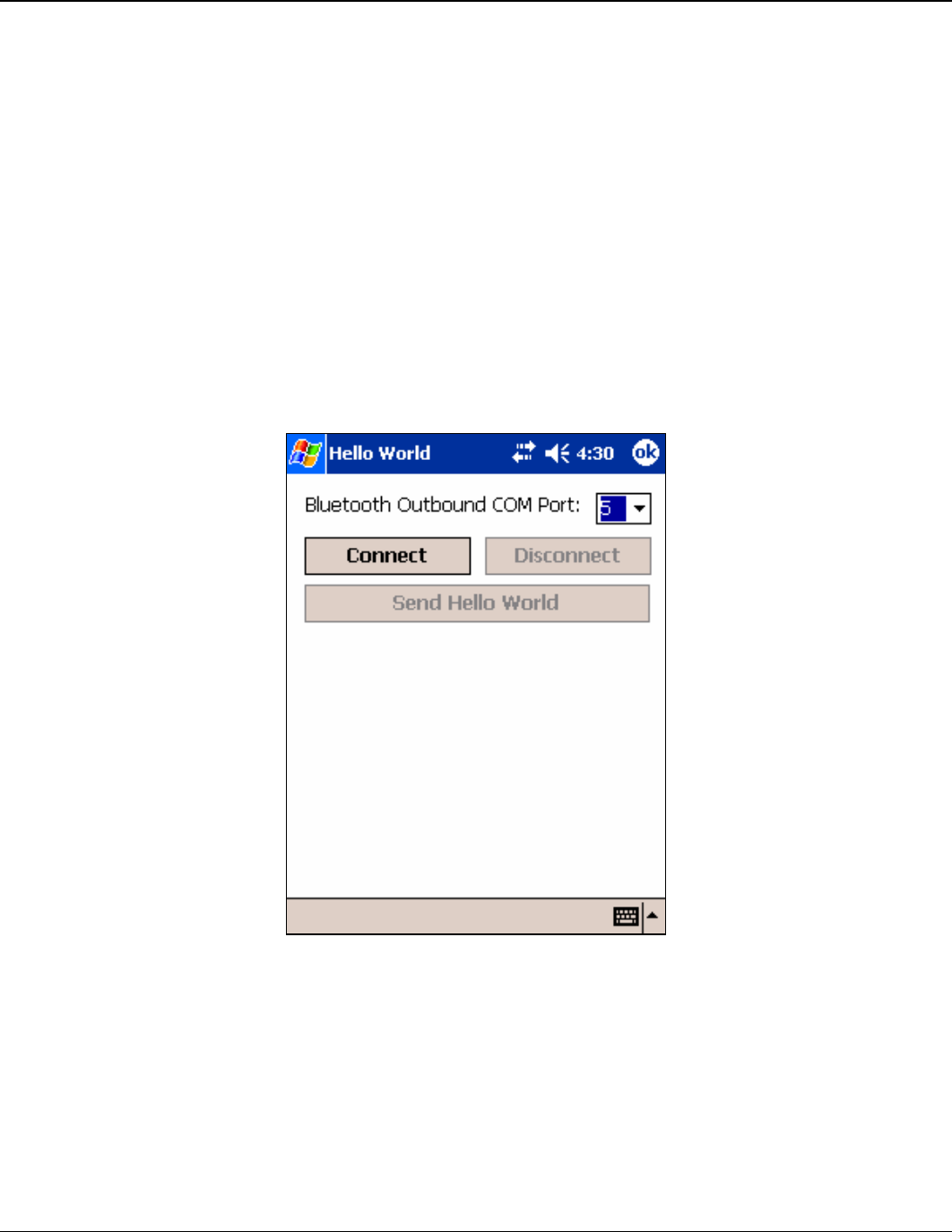
58 User Manual
Copyright ©2003 A7 Engineering, Inc.
8. On the Run menu, click Run.
This will display the Download Progress dialog while downloading the program to the
BASIC Stamp. After the download is complete, the Debug Terminal #1 dialog will be
shown.
9. On the iPAQ, tap the Bluetooth icon in the system tray on the Today screen and
select Bluetooth Settings.
This will display the Settings dialog.
10. Scroll to the right, tap the Serial Port tab and note the Outbound COM port.
The Outbound COM port will be used in the iPAQ application later in this step.
11. Download the Hello World Pocket PC application to the iPAQ.
12. Run the Hello World Application (Figure 12).
Figure 12: Hello World Pocket PC Application
13. In the Bluetooth Outbound COM Port dropdown, select the COM port number that
matches the Bluetooth Outbound COM Port, which we discovered in a previous
action.
14. Tap the Connect button.
This will display the Bluetooth Browser dialog (Figure 13).
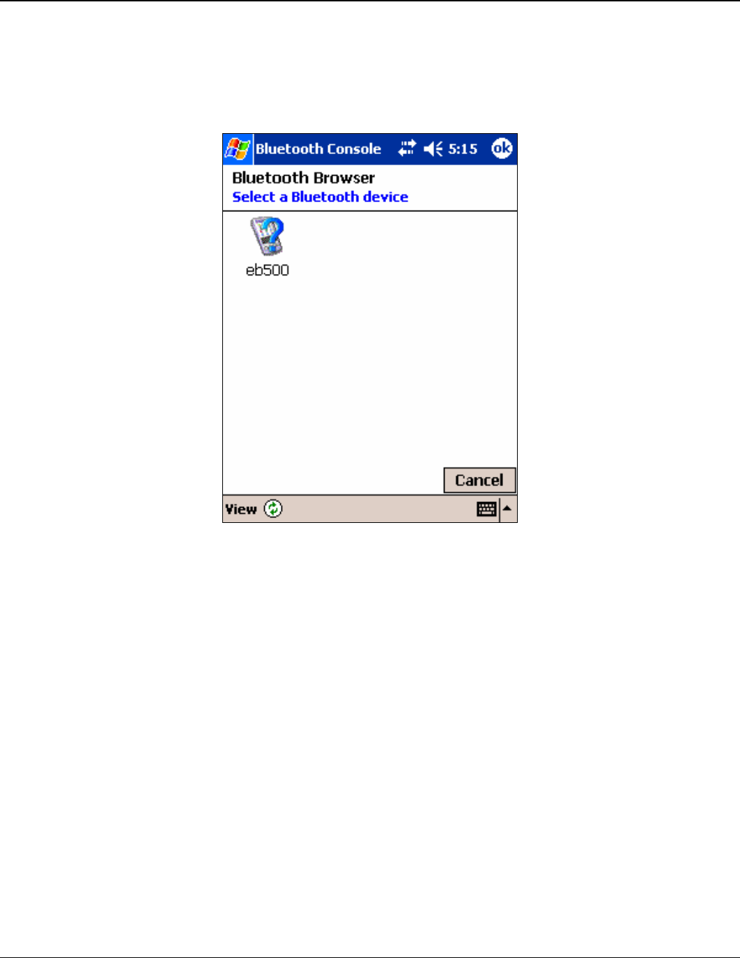
EmbeddedBlue 500 59
Copyright ©2003 A7 Engineering, Inc.
15. Tap eb500 in the Bluetooth Browser dialog to establish a connection with the eb500
on the Board of Education.
If there are no devices shown in the Bluetooth Browser dialog, tap the refresh icon to
search for your Bluetooth device.
Figure 13: iPAQ Bluetooth Brower Dialog
16. Tap the Send Hello World button.
This will transmit the ASCII text “Hello World” over the wireless link. The BASIC
Stamp application will then receive these characters and display them in the BASIC
Stamp Editor Debug window.
17. Tap the Disconnect button to close the Bluetooth connection.
Step 2: Transmit Data from the BASIC Stamp to the iPAQ
In this step we will create a BASIC Stamp application to send data out the eb500 to
the iPAQ. We will then download and run the application. The application for the
iPAQ is too verbose to include in this manual; therefore, the application, along with
the source code, is available on the accompanying CD in the Samples folder. To
modify the Pocket PC application you will need eMbedded Visual C++ 4.0 with
Service Pack 2 and the SDK for Windows Mobile™ 2003-based Pocket PCs.
1. Using the BASIC Stamp Editor, on the File menu, click New.
This will create a new project window within the BASIC Stamp Editor.

60 User Manual
Copyright ©2003 A7 Engineering, Inc.
2. Enter the following program code into the editor, replacing the device address with
the device address obtained from the iPAQ.
‘{$STAMP BS2}
nCount VAR BYTE
‘I/O Line 5 provides the connection status
INPUT 5
‘Wait for the eb500 radio to be ready
PAUSE 1000
‘Connect to the remote device
SEROUT 1,84,[“con 00:04:3E:62:FE:01”,CR]
SERIN 0,84,[WAIT(“ACK”,CR)]
WaitForConnection:
IF in5 = 0 THEN WaitForConnection
DEBUG “Connected”,CR
FOR nCount = 1 to 10
SEROUT 1,84,[“Hello World”,CR] ‘sending data
PAUSE 1000 ‘wait for 1 second
NEXT
‘I/O Line 6 allows us to switch to Command Mode
OUTPUT 6
‘Switch to Command Mode
LOW 6
SERIN 0,84,[WAIT(CR,”>”)]
‘Disconnect from the remote device
SEROUT 1,84,[“dis”,CR]
SERIN 0,84,[WAIT(CR,”>”)]
DEBUG “Disconnected”,CR
The BASIC Stamp application establishes a connection with the iPAQ, transmits
“Hello World” ten times, switches back to command mode, and then disconnects
from the remote device.
The first call to SEROUT is used when the eb500 is in command mode and instructs
the eb500 to establish a connection with the device specified. Once a connection is
established the eb500 is in data mode, which causes further calls to SEROUT to be
sent to the remote device.
3. On the File menu, click Save As.
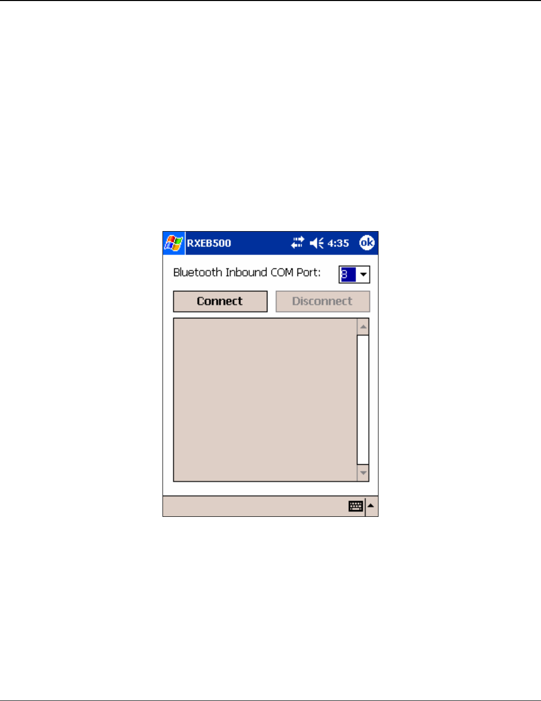
EmbeddedBlue 500 61
Copyright ©2003 A7 Engineering, Inc.
4. In the File name box, enter a file name to which to save the program just created.
For Example, HelloWorld.bs2.
5. Click Save.
6. On the iPAQ, tap the Bluetooth icon in the system tray on the Today screen and
select Bluetooth Settings.
This will display the Settings dialog.
7. Scroll to the right, tap the Serial Port tab and note the Inbound COM port.
The Inbound COM port will be used in the iPAQ application later in this step.
8. Download the RXEB500 Pocket PC application to the iPAQ.
9. Run the RXEB500 Application (Figure 14).
Figure 14: RXEB500 Pocket PC Application
10. In the Bluetooth Inbound COM Port dropdown, select the COM port number that
matches the Bluetooth Inbound COM Port, which we discovered in a previous action.
11. Tap the Connect button.
12. Apply power to the Board of Education board.

62 User Manual
Copyright ©2003 A7 Engineering, Inc.
13. Using the BASIC Stamp Editor, on the Run menu, click Run.
This will display the Download Progress dialog while downloading the program to the
BASIC Stamp. After the download is complete the BASIC Stamp application will
establish a connection with the iPAQ. Depending on your current iPAQ Bluetooth
configuration, the Authorization Request Dialog may appear (Figure 9). If this dialog
appears, tap Accept to accept the connection. Once the connection is established,
the BASIC Stamp application will transmit “Hello World” over the wireless link, and
the iPAQ Pocket PC application will display the received data.
14. On the iPAQ, tap the Disconnect button to close the connection.

EmbeddedBlue 500 63
Copyright ©2003 A7 Engineering, Inc.
eb500 Commands
The eb500 command set is comprised of visible ASCII characters. Therefore, a command
can be issued from a terminal application, such as HyperTerminal, or directly from a custom
application program, written in a programming language such as C++ or Visual Basic,
running on a PC, using the eb600 PC Adapter. From a BASIC Stamp application, these
commands can be issued by using the PBASIC™ SERIN and SEROUT commands.
Command Basics
Commands may only be sent to the eb500 when the module is in Command Mode. White
spaces are used to separate parameters of the command and a carriage-return is used to
mark the end of the command. Upon receipt of a command the eb500 begins to parse the
parameters. If the syntax of the command is correct the eb500 returns an ACK string, not
the ACK character (0x06); otherwise, a NAK string is returned. Following the ACK or NAK
string is a carriage-return (0x0D) character. If an error occurs while processing the
command an error string is returned followed by a carriage-return followed by the prompt (>)
character. If the command executed successfully the eb500 will issue the prompt (>)
character. Please see the eb500 Error Codes section for a description of the error codes.
The following example shows the basic structure of a command. A prompt (>) is issued by
the eb500. A command followed by a carriage-return is sent to the eb500. The eb500
responds with either an ACK or NAK string followed by a carriage-return. If an error occurs,
the eb500 responds with an Err string followed by a space followed by an ASCII string
numeric value followed by a carriage-return. A prompt (>) is then issued by the eb500.
>command<CR>
ACK | NAK<CR>
Err number<CR>
>

64 User Manual
Copyright ©2003 A7 Engineering, Inc.
BASIC Stamp Application eb500 Command Error Handling
The BASIC Stamp has a software based UART; meaning it does not buffer incoming serial
data. Therefore, the checking of errors from the issuing of an eb500 command must be
performed immediately after the issuing of the command; otherwise, the data may be lost.
Below is a sample of BASIC Stamp code that issues an eb500 Connect command, waits for
the ACK<CR> response from the eb500, then waits for the error string or the prompt (>) to
be returned from the eb500. It then checks the first bye of the data returned to determine if
an error has occurred. If an error has occurred, the code jumps to the error handler code,
where an error string along with the error number is shown in the debug window of the Basic
Stamp Editor.
'Connect to remote Bluetooth device
SEROUT 1,84,["con 00:0C:84:00:07:D8",CR]
SERIN 0,84,[WAIT(“ACK”,CR)]
‘Either an Err #<CR> or a ">" will be received
SERIN 0,84,[STR bBuffer\6\”>”]
IF bBuffer(0) = “E” THEN ErrorCode
… Progam Logic …
ErrorCode:
bErrorCode = bBuffer(4)
DEBUG “Error: “,STR bErrorCode,CR
END

EmbeddedBlue 500 65
Copyright ©2003 A7 Engineering, Inc.
Connect
The connect command establishes a connection to another Bluetooth device. The
connect command may be canceled before a connection is established by issuing a
carriage-return to the eb500. The connect command may be canceled before the
timeout is reached by issuing a carriage-return to the eb500. It can take up to four
seconds to cancel the connection request.
Syntax
con address [timeout]<CR>
Parameters
address The Bluetooth address of the remote device. The Bluetooth
device address is the 48-bit IEEE address which is unique for
each Bluetooth unit. The format of a Bluetooth device address
is a series of six hexadecimal byte values separated by
colons, i.e., 00:0C:84:00:07:D7.
timeout An optional parameter used to abort the connection request
after the specified number of seconds. The maximum value is
120 seconds.
Example
>con 00:0C:84:00:07:D7<CR>
ACK<CR>
>

66 User Manual
Copyright ©2003 A7 Engineering, Inc.
Disconnect
The disconnect command closes the connection with the remote Bluetooth device.
Syntax
dis<CR>
Example
>dis<CR>
ACK<CR>
>

EmbeddedBlue 500 67
Copyright ©2003 A7 Engineering, Inc.
Get Address
The get address command returns the address of the local eb500 module.
Syntax
get addr<CR>
Returns
The unique address of the local eb500 module used to identify the module
when making connections. In Bluetooth terminology this is the Bluetooth
Device Address.
Example
>get addr<CR>
ACK<CR>
00:0C:84:00:07:D7<CR>
>

68 User Manual
Copyright ©2003 A7 Engineering, Inc.
Get Connectable Mode
The get connectable mode command returns the connectable mode setting of the
local eb500 module.
Syntax
get con<CR>
Returns
The current connectable mode setting of the local eb500 module. In
Bluetooth terminology, the returned value reflects the current setting for page
scan.
on The eb500 will accept connections.
off The eb500 will NOT accept connections.
Example
>get con<CR>
ACK<CR>
on<CR>
>

EmbeddedBlue 500 69
Copyright ©2003 A7 Engineering, Inc.
Get Discoverable Mode
The get discoverable mode command returns the discoverable mode setting of the
local eb500 module.
Syntax
get dis<CR>
Returns
The current discoverable mode setting of the local eb500 module. In
Bluetooth terminology, the returned value reflects the current setting for
inquiry scan.
on The eb500 is visible to other devices.
off The eb500 is NOT visible to other devices.
Example
>get dis<CR>
ACK<CR>
on<CR>
>

70 User Manual
Copyright ©2003 A7 Engineering, Inc.
Get Escape Character
The get escape character command returns the current character used in the Switch
to Command Mode command to instruct the eb500 to leave Data Mode and enter
Command Mode.
Syntax
get escchar<CR>
Example
>get escchar<CR>
ACK<CR>
+<CR>
>

EmbeddedBlue 500 71
Copyright ©2003 A7 Engineering, Inc.
Get Flow Control
The get flow control command returns the flow control setting of the local eb500
module.
Syntax
get flow<CR>
Returns
none The eb500 is configured for no flow control and both the RTS
and CTS lines are configured as high Z inputs. A BASIC
Stamp application is free to use these lines as normal I/O
without regard to the eb500.
hardware The eb500 is configured for hardware flow control and the
RTS line is used for receive flow control and the CTS line is
used for transmit flow control.
Example
>get flow<CR>
ACK<CR>
none<CR>
>

72 User Manual
Copyright ©2003 A7 Engineering, Inc.
Get Link Timeout
The get link timeout command returns the amount of time it takes for the local eb500
module to notice that the connection has been broken, if the remote device
disappears. This timeout also has an effect on how robust the communications link is
to interference. If this value is set very low, the link may be lost if interference picks
up for several seconds, such as when a heavy burst of 802.11 traffic is encountered.
Syntax
get linktimeout<CR>
Example
>get linktimeout<CR>
ACK<CR>
5<CR>
>

EmbeddedBlue 500 73
Copyright ©2003 A7 Engineering, Inc.
Help
The help command returns a listing of the eb500 commands and a brief description
of each command.
Syntax
hlp [command]<CR>
Parameters
command The eb500 command name (con, dis, get, lst, set and ver) for
which to return help.
Examples
>hlp<CR>
ACK<CR>
… Help Information …
<CR>
>
>hlp con<CR>
ACK<CR>
… Help Information on the Connect Command …
<CR>
>

74 User Manual
Copyright ©2003 A7 Engineering, Inc.
List
The list command returns a listing of other Bluetooth devices that are in range and
visible. The list command may be canceled before the timeout is reached by sending
an additional carriage-return to the eb500.
Syntax
lst [timeout]<CR>
Parameters
timeout An optional parameter used to abort the list request after the
specified number of seconds. The default value is 30. The
maximum value is 120 seconds.
Returns
The addresses of the Bluetooth devices that are in range and visible.
Example
>lst<CR>
ACK<CR>
00:0C:84:00:07:D7<CR>
00:80:C8:35:2C:B8<CR>
>

EmbeddedBlue 500 75
Copyright ©2003 A7 Engineering, Inc.
Return to Data Mode
The return to data mode command instructs the eb500 to enter Data Mode when
there is an active connection.
Syntax
ret<CR>
Example
>ret<CR>
ACK<CR>
>

76 User Manual
Copyright ©2003 A7 Engineering, Inc.
Set Baud Rate
The set baud rate command sets the baud rate for communications with the local
eb500 module.
Syntax
set baud rate [*]<CR>
Parameters
rate The baud rate value. Valid baud rates are 9600 (default),
19200, 38400, 57600, 115200, and 230400. Once the baud
rate has been set, applications, such as HyperTerminal, must
also be configured to the same baud rate to continue
communicating with the eb500.
* An optional parameter used to persist the new setting when
the module is powered down.
Example
>set baud 19200<CR>
ACK<CR>
>

EmbeddedBlue 500 77
Copyright ©2003 A7 Engineering, Inc.
Set Connectable Mode
The set connectable mode command provides control over whether the local eb500
module will accept connections from other Bluetooth devices. In Bluetooth
terminology, this command controls the setting for page scan.
Syntax
set con on | off [*]<CR>
Parameters
on Configures the eb500 so that other Bluetooth devices may
establish a connection.
off Configures the eb500 so that other Bluetooth devices may not
establish a connection.
* An optional parameter used to persist the new setting when
the module is powered down.
Example
>set con off<CR>
ACK<CR>
>

78 User Manual
Copyright ©2003 A7 Engineering, Inc.
Set Discoverable Mode
The set discoverable mode command provides control over whether the local eb500
module is visible to other Bluetooth devices. In Bluetooth terminology, this command
controls the setting for inquiry scan.
Syntax
set dis on | off [*]<CR>
Parameters
on Configures the eb500 so that other Bluetooth devices may
detect the presence of this eb500.
off Configures the eb500 so that other Bluetooth devices may not
detect the presence of this eb500.
* An optional parameter used to persist the new setting when
the module is powered down.
Example
>set dis on<CR>
ACK<CR>
>

EmbeddedBlue 500 79
Copyright ©2003 A7 Engineering, Inc.
Set Escape Character
The set escape character command provides control over the character used in the
Switch to Command Mode command to instruct the eb500 to leave Data Mode and
enter Command Mode. The factory default escape character is the plus sign (+).
Syntax
set escchar character [*]<CR>
Parameters
character The character the eb500 should recognize as the escape
character used in the Switch to Command Mode command.
Example
>set escchar & *<CR>
ACK<CR>
>

80 User Manual
Copyright ©2003 A7 Engineering, Inc.
Set Flow Control
The set flow control command provides control over the flow control setting of the
local eb500 module.
Syntax
set flow none | hardware [*] <CR>
Parameters
none Configures the eb500 for no flow control and both the RTS and
CTS lines are configured as high Z inputs. This allows a
BASIC Stamp application to use these lines a normal I/O
without regard to the eb500.
hardware Configures the eb500 for hardware flow control. The RTS line
is used for receive flow control and the CTS line is used for
transmit flow control.
* An optional parameter used to persist the new setting when
the module is powered down.
Example
>set flow none<CR>
ACK<CR>
>

EmbeddedBlue 500 81
Copyright ©2003 A7 Engineering, Inc.
Set Link Timeout
The set link timeout command sets the amount of time it takes for the local eb500
module to notice that the connection has been broken, if the remote device
disappears. This timeout also has an effect on how robust the communications link is
to interference. If this value is set very low, the link may be lost if interference picks
up for several seconds, such as when a heavy burst of 802.11 traffic is encountered.
In Bluetooth terminology, this command controls the setting for link supervisor
timeout.
Syntax
set linktimeout timeout [*]<CR>
Parameters
timeout The time it takes for the eb500 to notice that a connection has
been broken. The default value is 5. The maximum value is 40
seconds.
* An optional parameter used to persist the new setting when
the module is powered down.
Example
>set linktimeout 10<CR>
ACK<CR>
>

82 User Manual
Copyright ©2003 A7 Engineering, Inc.
Switch to Command Mode
The switch to command mode command instructs the eb500 to enter Command
Mode.
Syntax
<2 second pause>esc sequence<2 second pause>
Parameters
esc sequence Three consecutive instances of the escape character. The
factory default escape character is the plus sign (+). A different
escape character can be set in the eb500 by using the Set
Escape Character command.
Example
>con 00:0C:84:00:07:D7<CR>
ACK<CR>
>This text is sent in data mode<CR>
<2 second pause>+++<2 second pause><CR>
>get addr<CR>
ACK<CR>
00:0C:84:00:07:D8<CR>
>ret<CR>
ACK<CR>
>This text is sent in data mode<CR>
<2 second pause>+++<2 second pause><CR>
>dis<CR>
ACK<CR>
>
Command
Mode
Data Mode
Command
Mode
Data Mode
Command
Mode

EmbeddedBlue 500 83
Copyright ©2003 A7 Engineering, Inc.
Version
The version command returns the current firmware version of the local eb500
module.
Syntax
ver [all] <CR>
Parameters
all An optional parameter used to return the build number, model
number, serial number, and manufacturer.
Example
>ver all<CR>
ACK<CR>
Firmware Version: 1.0<CR>
Firmware Build: 189<CR>
Model Number: eb500<CR>
Serial Number: 8<CR>
Manufacturer: A7 Engineering<CR>
>

84 User Manual
Copyright ©2003 A7 Engineering, Inc.
eb500 Error Codes
While using the eb500 you may encounter an error. Below is a listing of all eb500 error
codes with a description of what causes the error to occur.
Error Code Description
1 General connection failure. This error occurs if the remote Bluetooth device
is not configured properly. For example, this error may occur if the remove
device requires Bluetooth security for a serial port connection.
2 Connection attempt failed. This error occurs when attempting to connect
with an invalid Bluetooth address or a device that is not available.
3 Command not valid while active. This error occurs when there is an active
connection and a command is issued that is not valid while connected with
a remote device.
4 Command only valid while active. This error occurs when there is not an
active connection and a command is issued that is only valid while
connected with a remote device.
Table 1: eb500 Error Codes

EmbeddedBlue 500 85
Copyright ©2003 A7 Engineering, Inc.
Technical Specifications
Operating Parameters
The operating parameters of the eb500 are shown below in Table 2.
Transmit Power 4dBm (max) class 2 operation
Open Field Range More than 100 meters (328 feet)
Receiver Sensitivity -85dBm
Operating Temperature 0° to 70°C
Supply Power 5 to 12VDC
Current Consumption 115.2kbps data transfer: 35mA
38.4kbps data transfer: 30mA
9.6kbps data transfer: 25mA
connected and idle: 8mA
no connection: 3mA
Interfaces 5V logic level UART or RS232 serial w/ optional eb600
adapter
Baud rate 9.6k – 230.4k
Flow control: RTS/CTS or none
Connector 10x2 AppMod compatible 20 pin header with 0.1” spacing
Antenna Matched internal surface mount
Bluetooth Support Version 1.1 compliant with profiles L2CAP, RFCOMM, SDP,
SPP
Firmware Upgradeable with optional eb600 adapter
Table 2: eb500 Operating Parameters
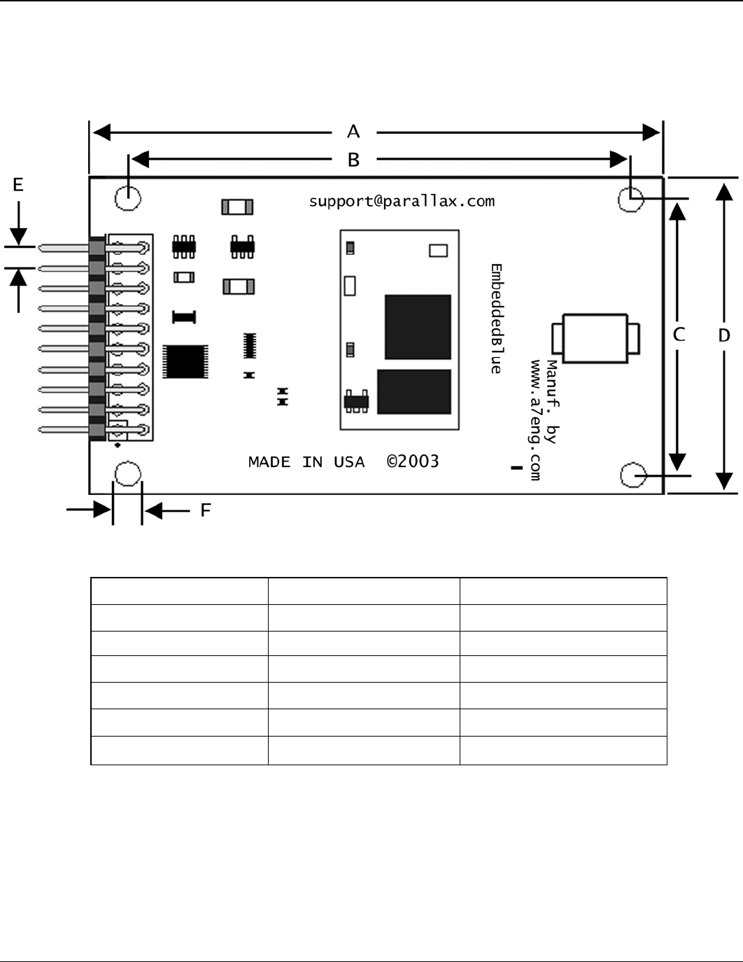
86 User Manual
Copyright ©2003 A7 Engineering, Inc.
Dimensions
The dimensions of the eb500 are shown below in Table 3. Please reference Figure 15 to
locate the referenced dimension on the eb500.
Figure 15: eb500 Dimensions
Dimension inches mm
A 2.7 68
B 2.4 61
C 1.3 33
D 1.6 40.2
E 0.1 2.5
F 0.125 3.2
Table 3: eb500 Dimensions

EmbeddedBlue 500 87
Copyright ©2003 A7 Engineering, Inc.
Pinout Diagram
The eb500 module features a 20 pin header with 0.1” spacing for connection to the AppMod
header. Currently, nine of the pins are in use (seven when flow control is set to none). The
other pins are reserved for future use.
1 3 5 7 9 11 13 15 17 19
z z z z z z z z z
z z z z z z z z z z
2 4 6 8 10 12 14 16 18 20
Figure 16: eb500 Pinout Diagram
Pin Name Pin Type Description
VSS 1, 2 GND Ground
RX 3 TTL output UART data output
TX 4 CMOS/TTL input UART data input
RX Flow (RTS) 5 CMOS/TTL input,
weak pull down
Signaled high to stop module data
transmission
TX Flow (CTS) 6 TTL output Signaled high to stop host data
transmission
7 Reserved Reserved for future use.
Connection
Status 8 TTL output
High when there is an active wireless
connection
Mode Control 9 CMOS/TTL input,
weak pulled down
Low for command mode / High for
data mode
10 - 19 Reserved Reserved for future use.
VIN 20 VCC Module supply, 5 to 12V DC
Table 4: eb500 Pinout Description

88 User Manual
Copyright ©2003 A7 Engineering, Inc.
Frequently Asked Questions
Question: My robots appear to be operating normally, but why will my eb500 not
connect?
Answer: Check the battery power to the robot. Although the motors may still run, the
voltage from the batteries may have fallen well below 5V preventing the
eb500 from operating normally.
Question: I changed the baud rate on my eb500 to 115200 and persisted the setting. I
am unable to communicate at that speed from my BASIC Stamp. How can I
reset the value to 9600 baud?
Answer: You can reset the eb500 module to its factory default settings by shorting Pin
8 and Pin 9 and applying power to the eb500 module. Alternatively, if you
have an eb600 PC Adapter you can modify and persist a new setting using
your PC, since the PC is capable of communicating at 115200 baud.
Question: How do I obtain eMbedded Visual C++ 4.0 to develop Pocket PC
applications?
Answer: The eMbedded Visual C++ 4.0 development tool is available from Microsoft.
In addition, you will need eMbedded Visual C++ 4.0 SP2 and the SDK for
Windows Mobile™ 2003-based Pocket PCs. These tools can be downloaded
free of charge from the Microsoft Windows Mobile web site:
http://www.microsoft.com/windowsmobile.
Question: Why is my eb500 not displayed when I try to discover it from my PC or iPAQ?
Answer: Verify that the eb500 module is properly powered. Check the battery power to
the robot. It is likely you will discover the eb500 on the first attempt; however,
because Bluetooth discovery is not deterministic, discovery on the first
attempt is not guaranteed. On the PC or iPAQ, use the refresh option to
search for devices again. Verify that the discoverable mode setting in the
eb500 is set to on.

EmbeddedBlue 500 89
Copyright ©2003 A7 Engineering, Inc.
Question: I can discover my eb500, but why am I unable to establish a connection?
Answer: Verify that the connectable mode setting in the eb500 is set to on.
Question: I have Bluetooth Authentication Security enabled on my iPAQ. Why am I
unable to connect my iPAQ to the eb500 on my Board of Education board?
Answer: Currently, the eb500 does not support Bluetooth Authentication Security.
However, you can achieve a measure of security for receiving connections on
your iPAQ by enabling Bluetooth Authorization.

90 User Manual
Copyright ©2003 A7 Engineering, Inc.
Contact Information
Parallax provides technical support both through email, an online newsgroup, and by
telephone. It is recommended that you use email as the first line of questioning because
common questions can be answered quickly and in greater detail in this manner
Website: www.parallax.com
Support Email: support@parallax.com
Sales Email: sales@parallax.com
Parallax, Inc
599 Menlo Drive, Suite 100
Rocklin, Ca 95765
888.512.1024 main
916.624.8003 fax
A7 Engineering has created the EmbeddedBlue product line of easy to use wireless
solutions for 8 and 16 bit embedded systems. In addition, A7 provides several levels of
support for OEM product integration, certification, and even custom solutions.
Website: www.a7eng.com
Sales Email: sales@a7eng.com
A7 Engineering Incorporated
12860 Danielson Court, Suite C
Poway, Ca 92064
858.679.7708 main
858.391.5616 fax
