Everybot Build Guide
User Manual: Pdf
Open the PDF directly: View PDF ![]() .
.
Page Count: 49
The Robonauts Everybot, with a final budget of $1000, is an
affordable, robust, and simplistic robot that can be built with
nothing but basic tools and items found in either the kit of parts,
purchased from your local hardware store, or FRC retailer such
as AndyMark and VEXPro.

Table of Contents
●The Robot Can………………………………………………………………2
●The Robonauts Everybot Robot Will………………………………………..4
●The Everybot Chassis………………………………………………………..5
●Intake………………………………………………………………………...7
●Switch Scoring Arm………………………………………………………..13
●Bumpers…………………………………………………………………....29
●Everybot Photos…………………………………………………………....32
1

A 2018 Robot Can:
On the Sunday after the game reveal we created a list of everything we could think
of that a robot could do in FIRST Power UP. We tried to avoid putting things in the
robot can that have to do with robot design. Bolded are things that the Robonauts
Everybot does/attributes it has. Those that are underlined went into the robot will.
●Accurately navigate the field
●Track at Minute Maid
●Determine the switch/scale target
●Pick up a cube from the floor
●Receive cube from portal/exchange
●Be agile/fast
●Have a Low CoG
●Score in Switch
●Stand its ground
●Avoid Defense
●Put Cubes in Exchange
●Score on Scale at all Heights
●Provide visual aid to drivers
●Have a touch it own it intake
●Strafe
●Be light
●Drive onto the platform
●Drive over cable protectors
●Climb by itself
●Climb and get out of the way
●Assist another robot in climbing
●Assist another robot in climbing and also climb
●Assist 2 robots in climbing
●Assist 2 robots in climbing and also climb
●Place cube while moving
2

●Track cube (vision)
●Throw cubes
●Lift a cube
●Pick up cube from anywhere
●Cimb on other robots
●Drag dead robots
●Flip tipped over robots
●Flip ourselves
●Herd a cube
●Index off of a wall
●See vision targets
●Index off the exchange
●Grab cube in all orientations (13” and 11” side)
●Accept cube from another robot
●Give cubes to other robot
●Reorient cubes once inside the robot
3

The 2018 Robonauts Everybot Robot Will
Bolded capabilities in the robot can list were then put into the robot will. For
certain capabilities in the robot can we said we will not put resources into having
those capabilities but would be nice if they came for free.
●Deposit cubes in the exchange
●Place cubes on a switch
●Accept cubes from the portal
●Be able to be lifted by an alliance partner for climb points
●Cross the auto line in autonomous
To be more specific, the following is a basic breakdown of time allotment
for tasks in matches:
●Auton should dump a cube into the switch
●If Auton did not place the cube, place cube in your own switch, then
drive to the other end of the field. 15 seconds
●Cycle cubes from the portal to your opponent’s switch. Strive for 5
second cycle times. Empty out one portal (5-6 cubes). 25-30 seconds
●Drive back to your end of the field. 10 seconds
●Cycle cubes from your power cube pile to the exchange. Strive for 7
second cycle times. Score 9 cubes for all power ups. 63 seconds
●Total time: ~115 seconds (conservatively) Strive to complete these
tasks in any given match. We think this equals success.
This is a tight timeline of tasks… This accounts for one reason we decided
the floor intake did not need to feed into the switch scoring mechanism. We think
the cube you place in auton will either keep ownership of your switch for a large
portion of the match, or that you will not be able to outpace a robot playing this
same strategy against you. The other reason we decided to segregate the scoring
mechanisms was to be able to optimize each mechanism for its one task rather than
compromise each to achieve another task. Everybot should be simple and fast at
placing in the opponent’s switch and gaining power ups for its own alliance.
4
The Everybot Chassis
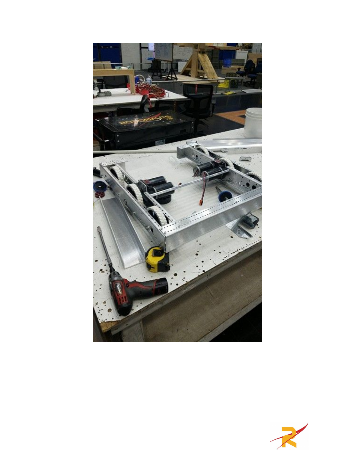
Chassis Type: We decided to use the AM14U3 chassis since it comes in the kit, is
a decent chassis, and with the 6 inch rubber treaded wheels that come with it allow
it to drive onto the platform with almost no issue (bumper scrapes a little).
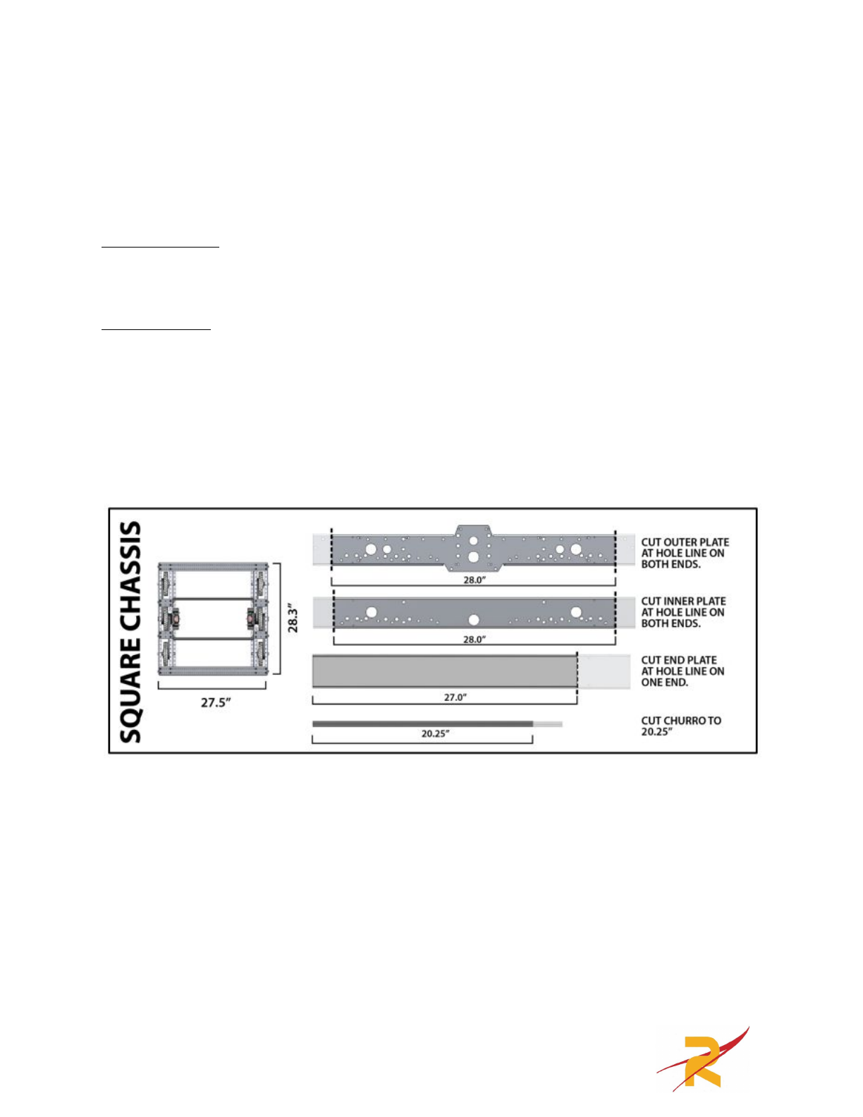
Chassis Size: For the frame size we knew we did not want to build a wide robot as
wide robots are harder to maneuver around cluttered fields. We cut the frame to be
27.5” X 28.3” which is the square configuration of the AM14U3. We also cut the
front end plate to where there was a 6” long section at each corner on the front of
the robot to satisfy rule R23 that states that at least 6 inches of bumper must be
placed on each side of each outside corner.
5
6
Intake
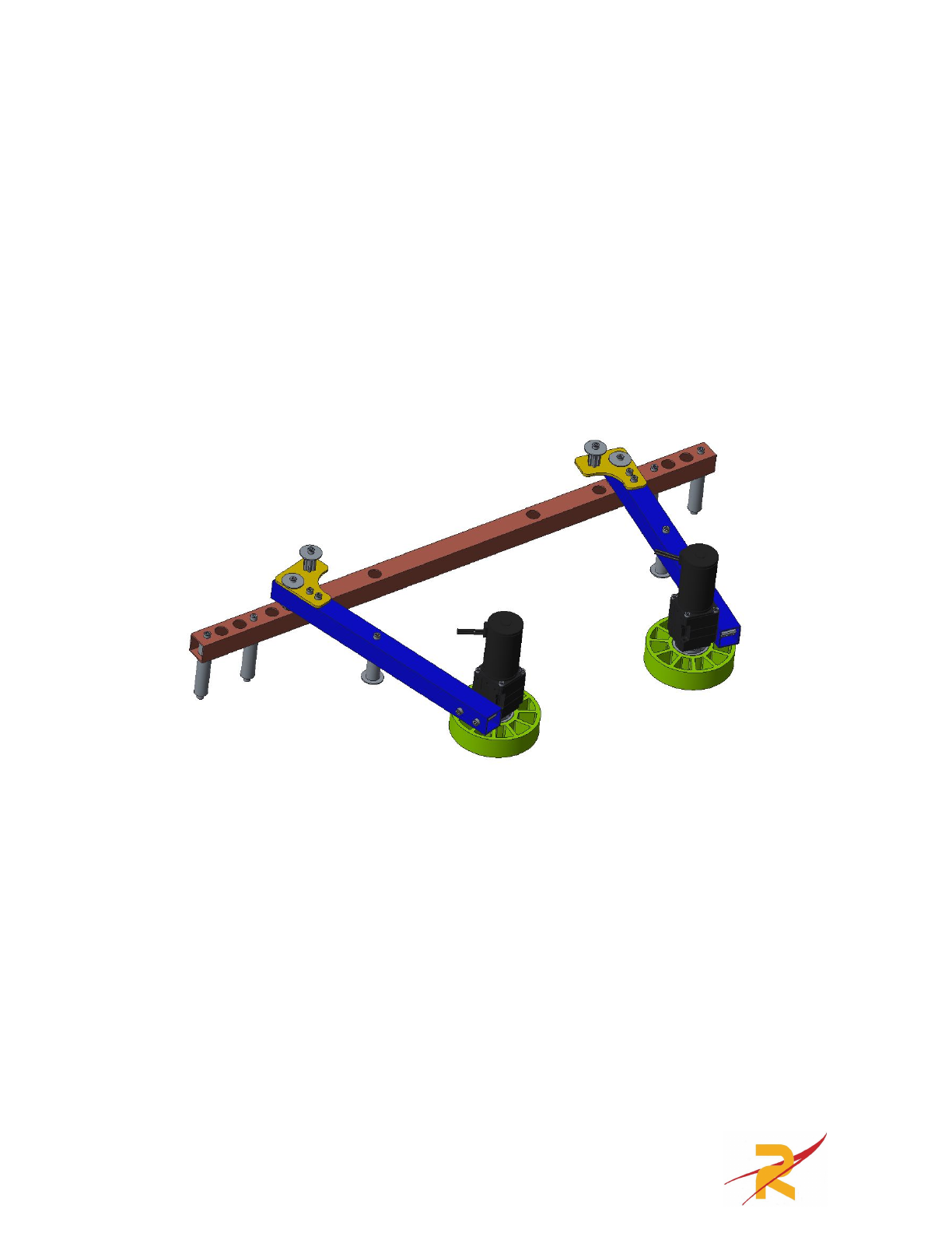
We decided early on that a side-roller intake similar to the popular landfill
tote intakes from 2015’s Recycle Rush would be a good solution for picking up
power cubes. Everybot’s intake structure is made up of 1x1 1/16” wall aluminum
square tube that comes in the kit of parts. At the end of each of two pivoting arms,
we put BAG motors into 10:1 versaplanetary gearboxes driving AndyMark
compliant wheels.
There are four types of aluminum extrusion used on the intake:
●1” x 1” x 1/16” wall boxtube (16’ in the KoP also available at Home Depot)
○Qty(1) x 27.5”
○Qty(2) x 12.75”
●⅝” round aluminum (hard anodized igus rod in the KoP)
○Qty(4) x 3.1875”
○Qty(4) x 2.125”
●Churro shaft (left over from the AM14U KoP drivetrain)
○Qty(6) x 0.875”
●⅛” plate (left over from the cutout in the front of the AM14U frame)
○Qty(2) x ~2.7” x ~2.45”
7
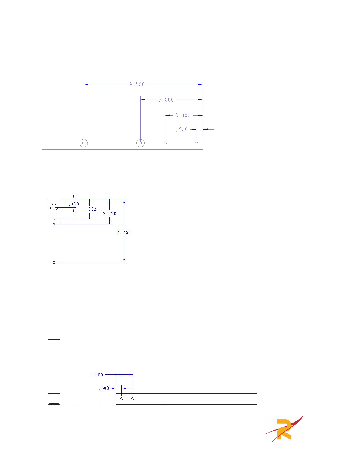
To manufacture the boxtube parts one they are cut to size, measure out the
positions of the holes you’ll be drilling based on the drawings below:
Ladder bar (27.5” part):
(mirror on the other side of the boxtube)
Intake arms (12.75” parts):
8
(there are two of this part; be sure to check the CAD or other pictures to be sure
you drill each hole out to the right size)
All “small” holes are clearance holes for 10-32 bolts (#7 drill bit).
All “large” holes on the ladder bar are ⅝”, created using a step drill.
All “large” holes on the intake arms are ¾”, created using a step drill.
To ensure that the holes on each side of the tube line up with each other, first
drill all the way through the tube using the 10-32 clearance drill, then drill out the
applicable holes to ⅝” using the step drill.
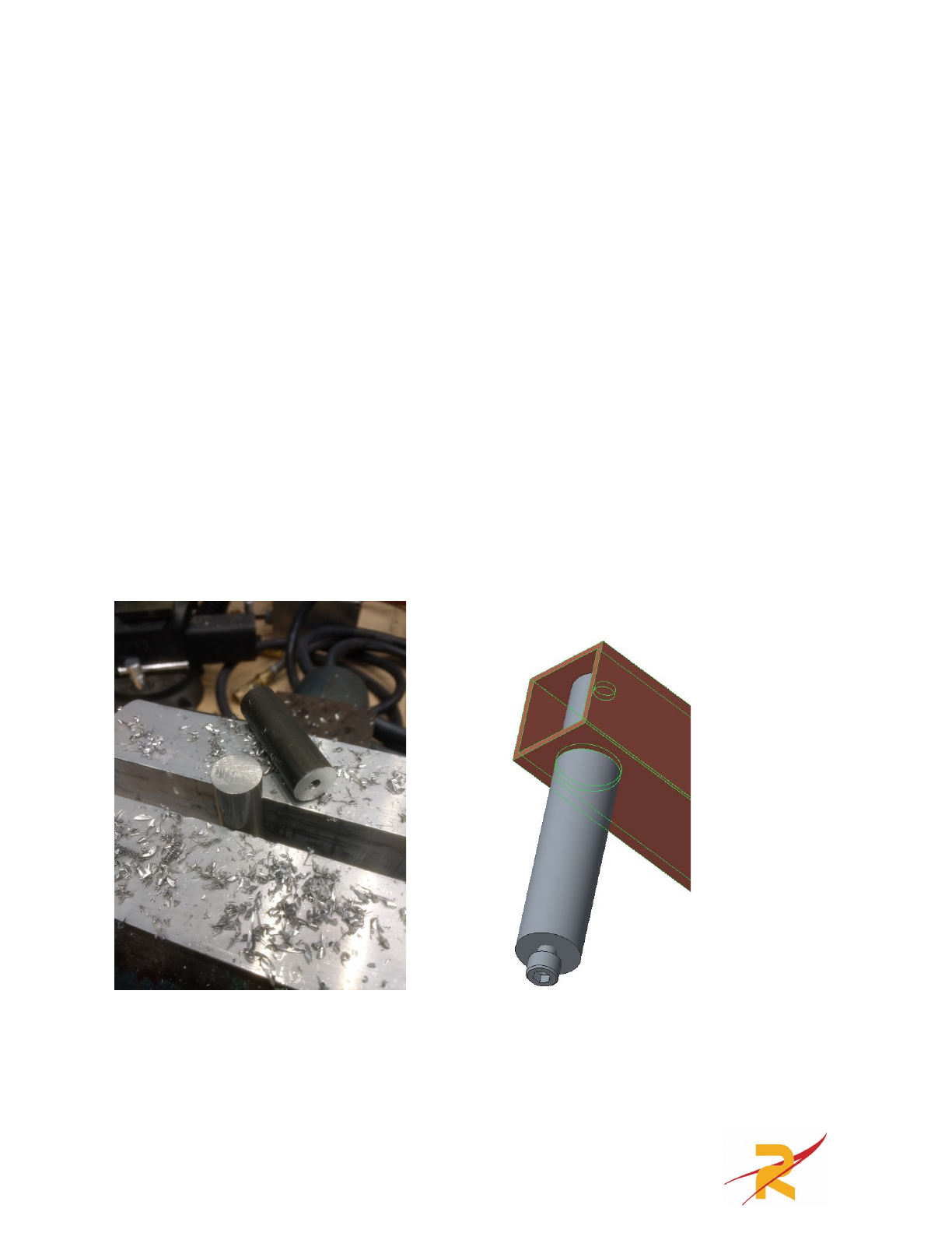
When assembling the structure with the ⅝” aluminum rod standoffs, you can
estimate the center to drill and tap to 10-32 by hand. This operation could be done
on a lathe, but it will be close enough for this application. To ensure that the holes
line up, we drilled and tapped many of these standoffs in place while assembling.
They may be a tight fit into the holes you made with a step drill. You may need to
press in your custom standoffs using a vice.
9
To create the pivot points for the intake arms, press the Igus plain bearings
(in the Igus bag in the kit) into the ¾” holes you put in the intake arms. These
should make for a low-friction and sturdy joint.
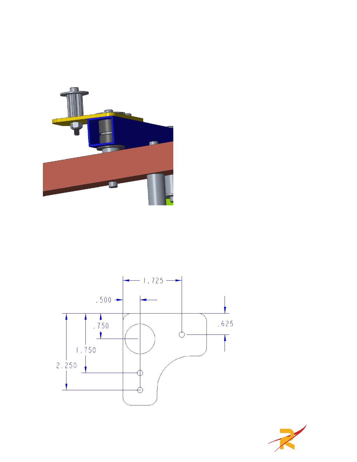
The final part you need to fabricate is from the leftover ⅛” plate from the
front section of the AM14U chassis. Just cut a flat section from the C-channel and
measure measure out these dimensions. This is the yellow part in the pictures
above. The positions of the holes are the only critical dimensions, not the shape of
the part.
10
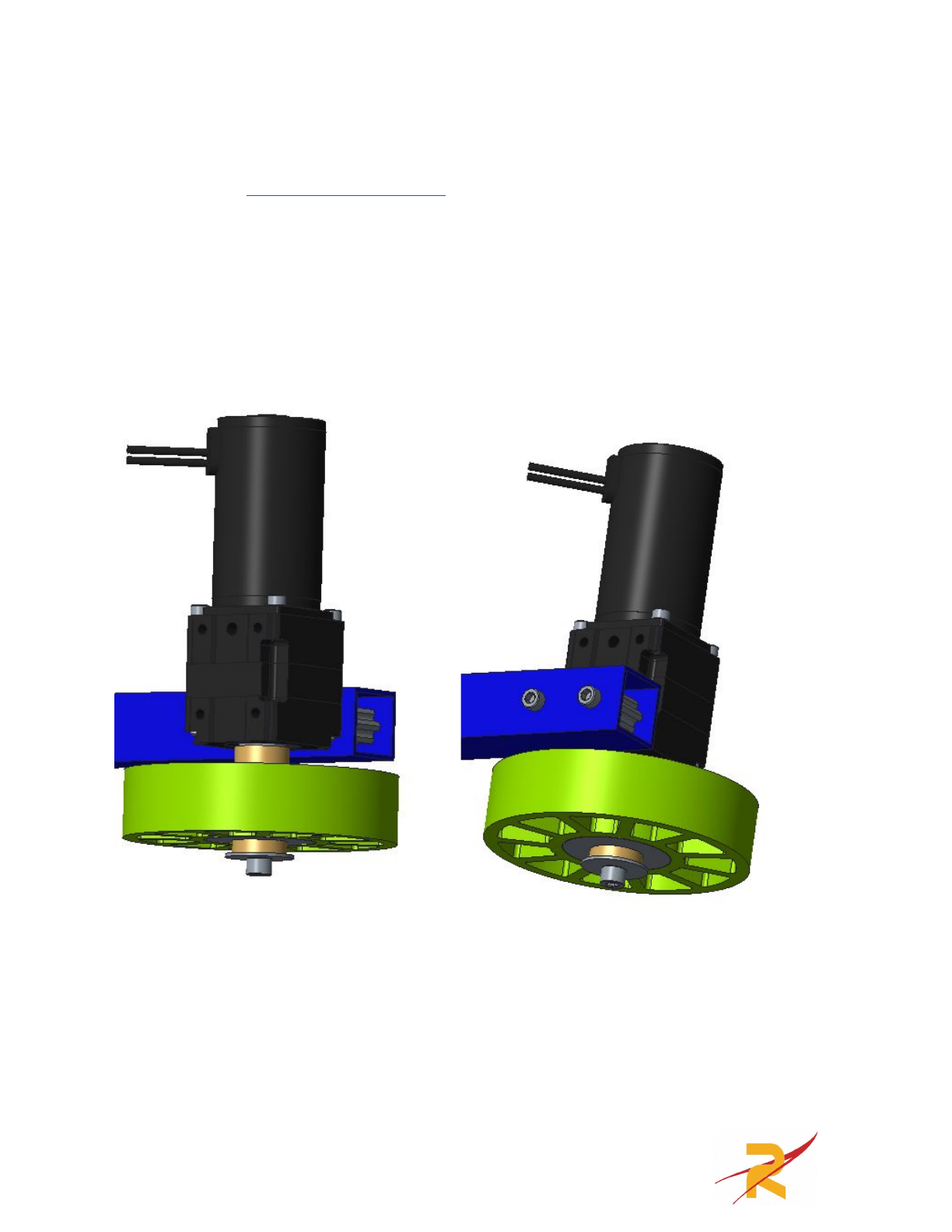
Roller assembly:
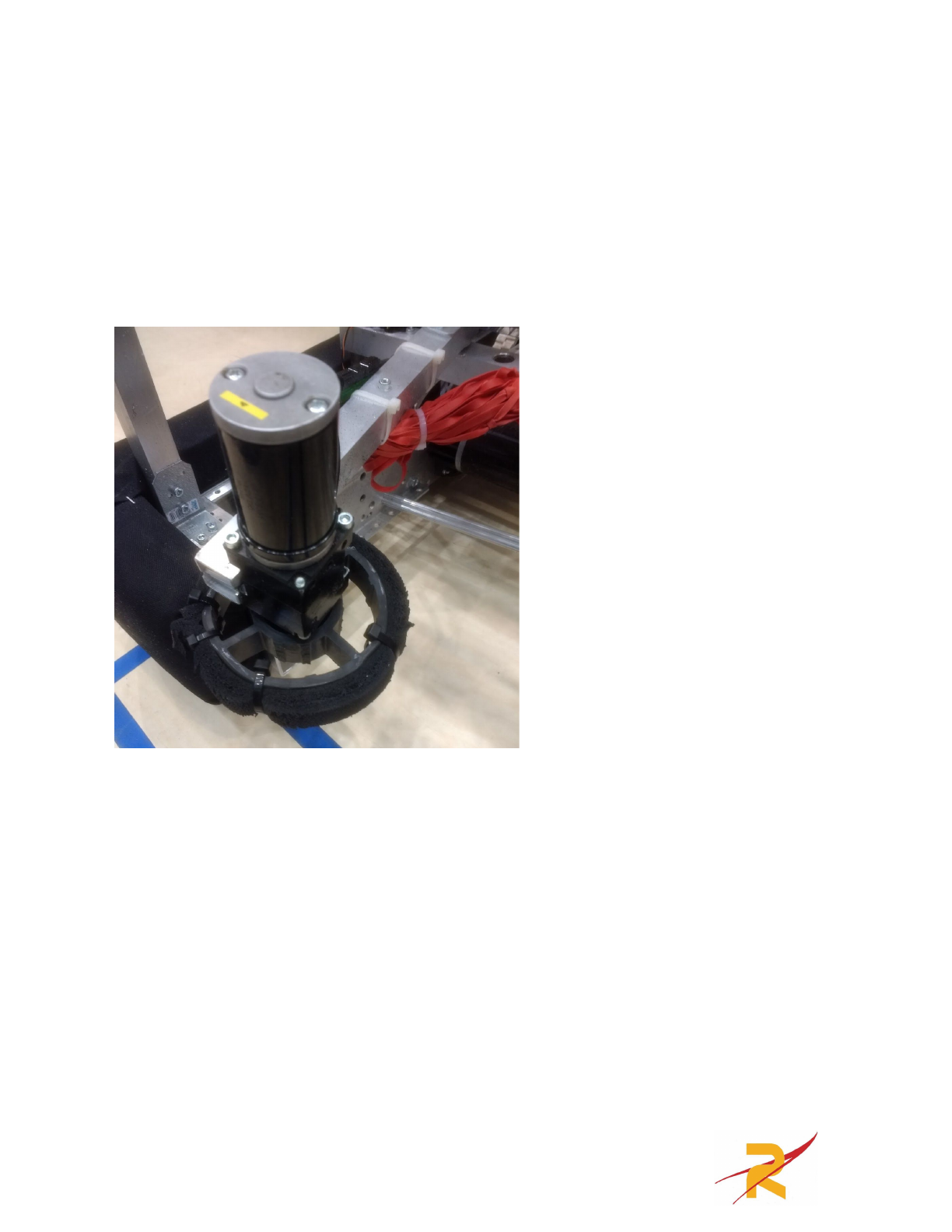
Build up two versaplanetary gearboxes with 10:1 reductions and BAG
motors. See the VEXPro product page for assembly instructions. Space out the
AndyMark compliant wheel such that they do not touch the box tubes using
schedule 40 ½” PVC spacers. We cut ours to about ¼” long. Cap the end of the
versaplanetary output shaft using a ¼”-20 bolt and large washer. Bolt each
versaplanetary gearbox to each of the intake arm boxtube parts. Be sure to use the
0.875” long churro pieces to keep from crushing the boxtube as you tighten the
10-32 bolts.
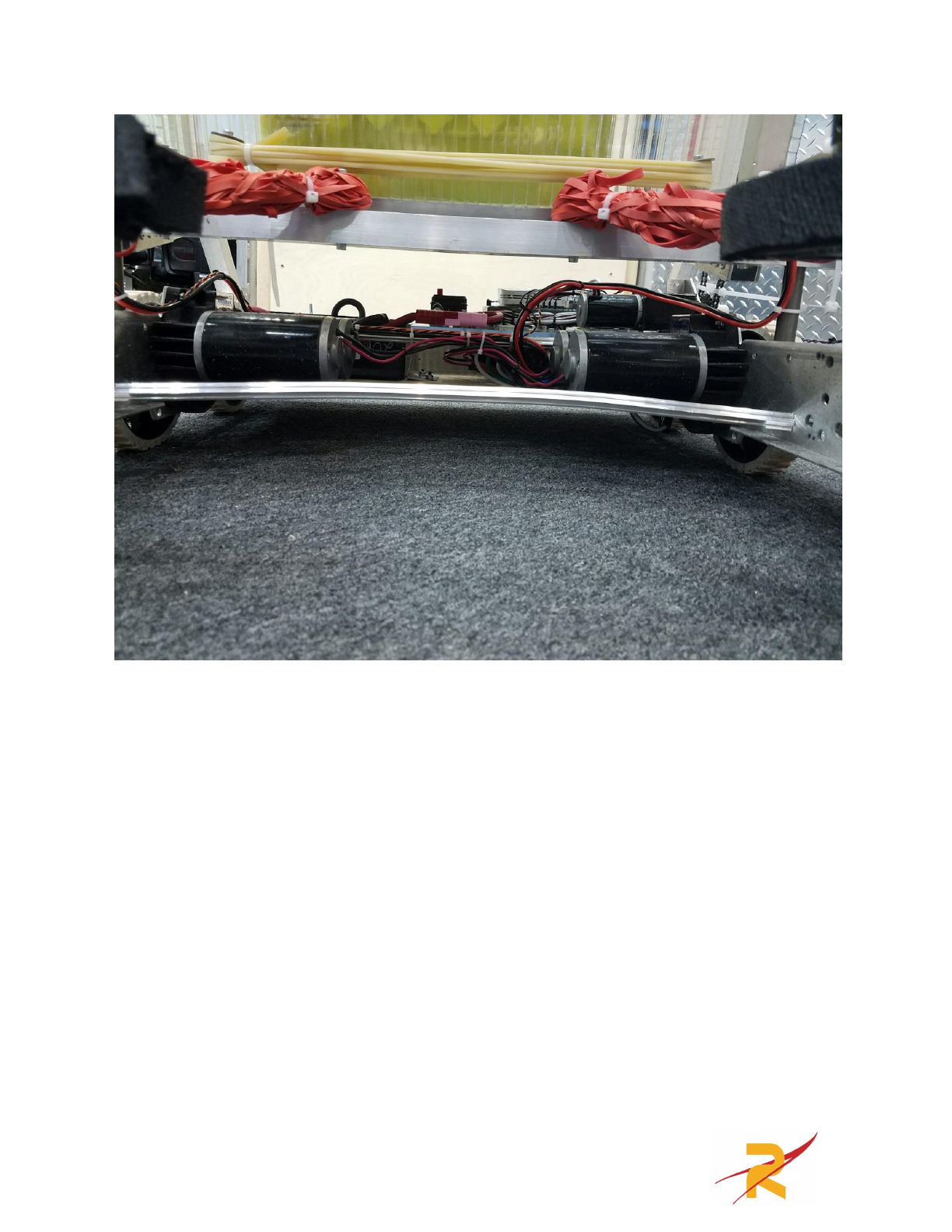
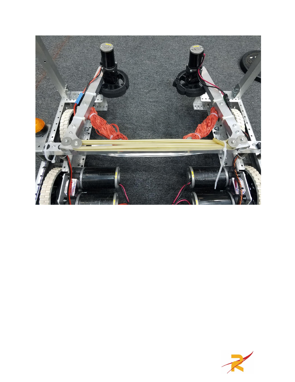
Tensioning configuration:
There are three sets of elastic. One, done with 5’ of latex tubing (in the kit)
pulls the arms out from a stowed position. The other two sets, made up of size 64
rubber bands (lots of them) are slack until the arms have folded out to the correct
width for intaking cubes. They stretch as cubes are sucked into the robot and
provide force between the rollers and the cube.
11
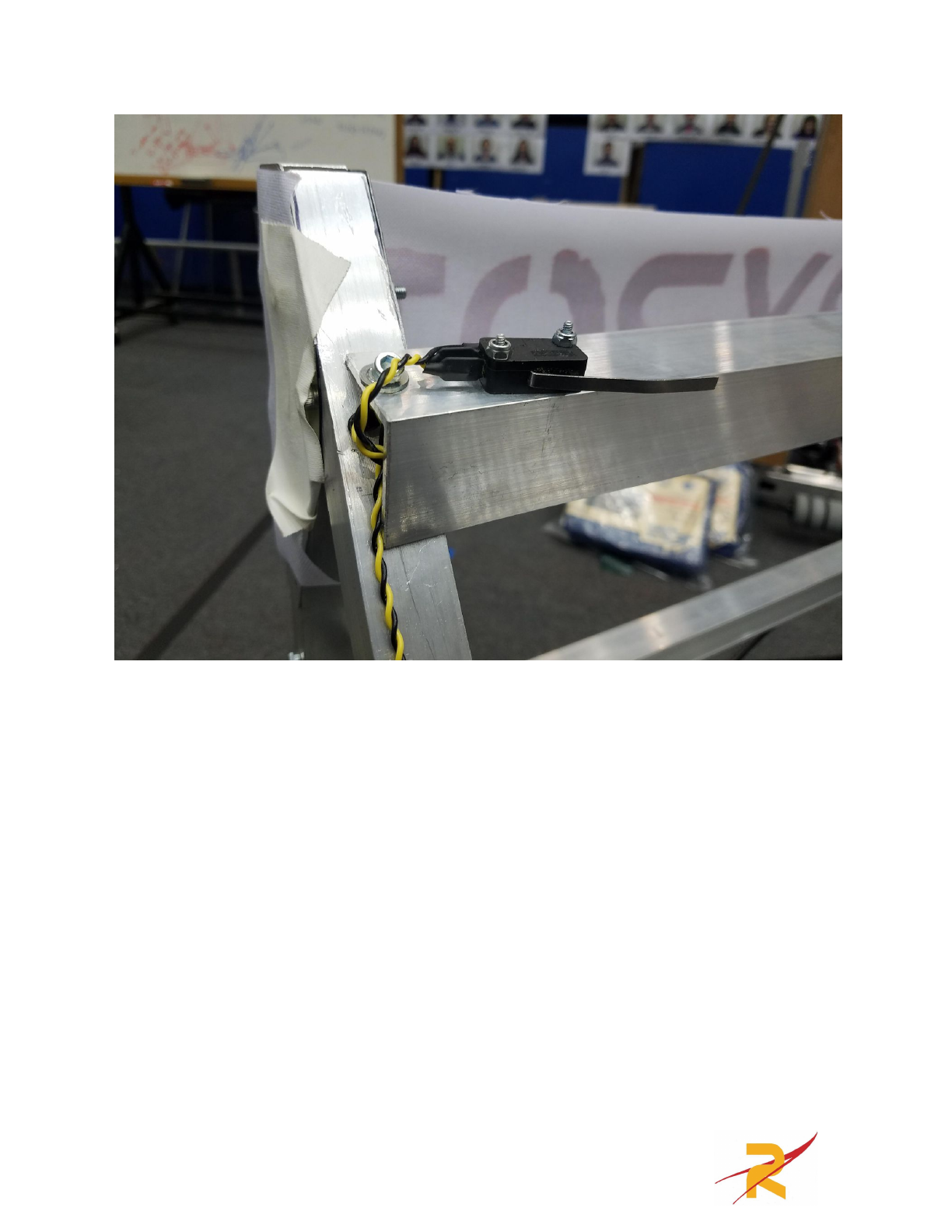
To start the match, the rollers are folded in towards each other and a zip tie
is put loosely around the BAG motors. This loop is attached to the arm so that
when it lifts, the intake flips outward, extending past the frame perimeter above the
bumpers.
12
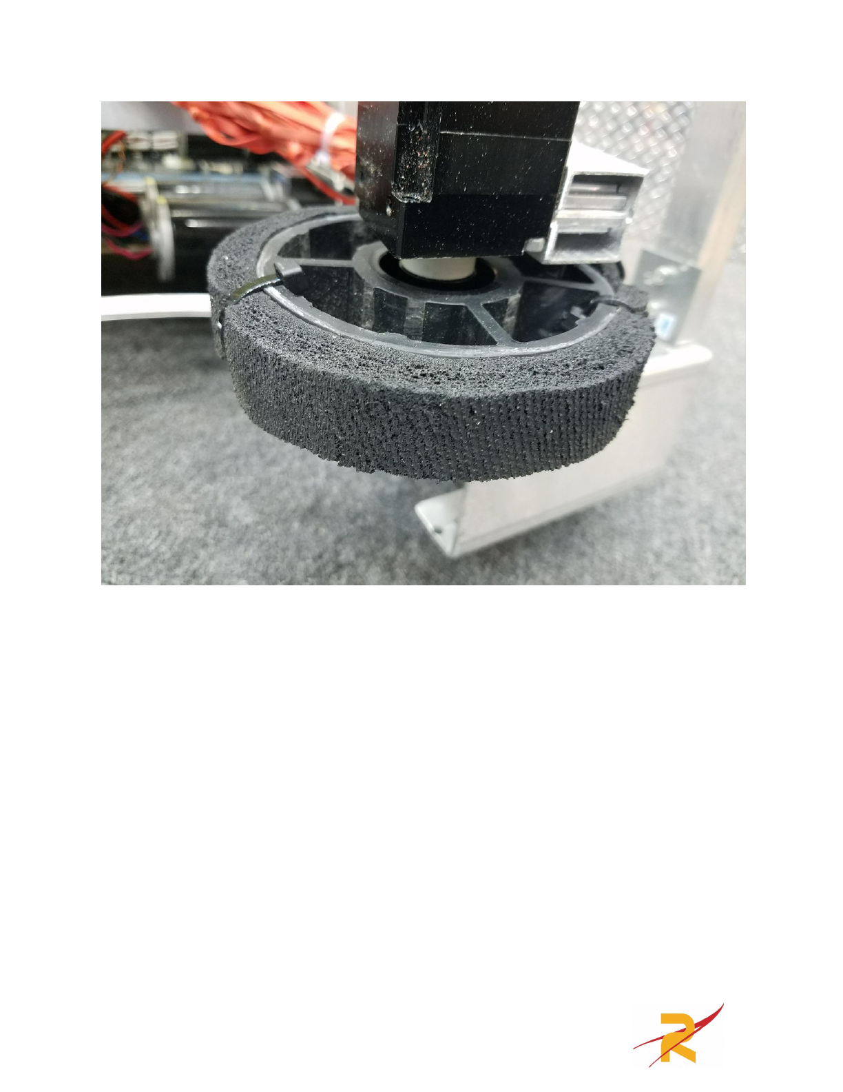
We struggled with getting the intake wheels to grip cubes reliably. The black
AndyMark 4” compliant wheels were too stiff so we cut out some of the spokes so
they would compress more easily. To make them more grippy, we stretched latex
rubber bands around them. This worked well but they often fell off. We settled on
strips of gum rubber zip tied to the outside of the wheels. There’s a million ways to
increase the coefficient of friction between your wheels and the cube. You should
experiment with materials you have.
13
Switch Scoring Arm
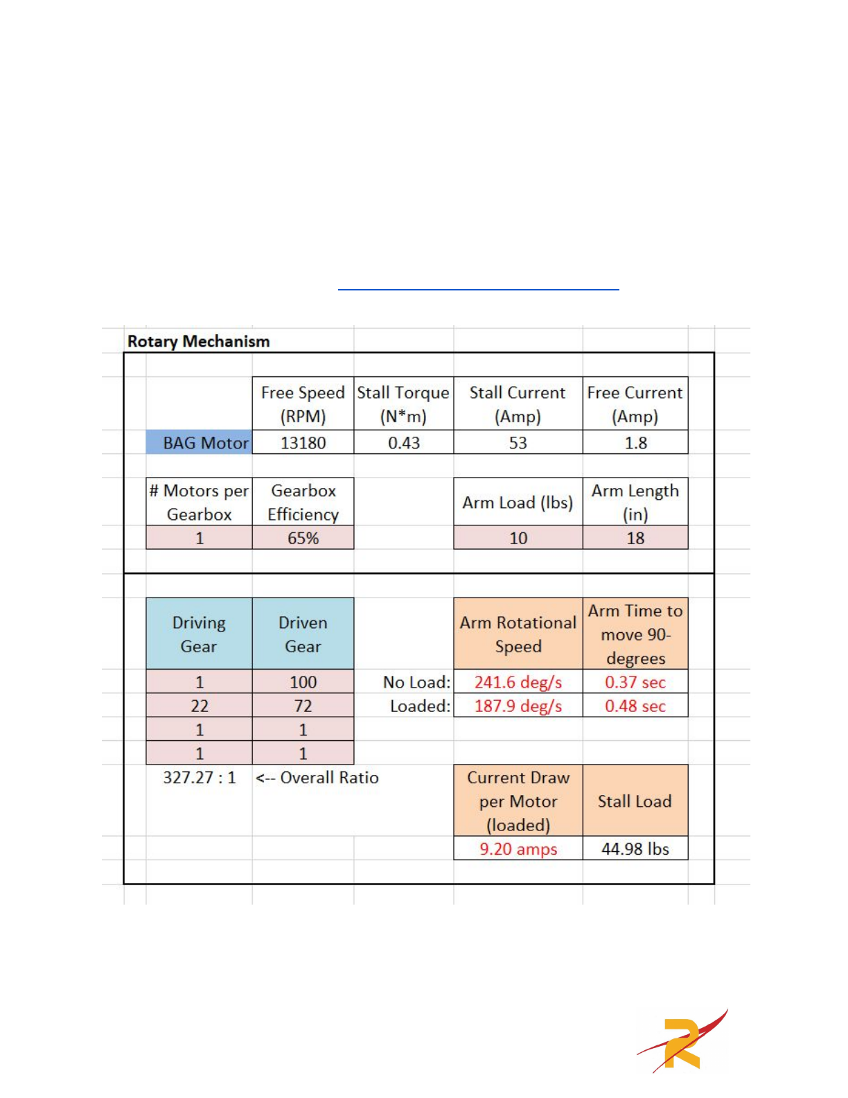
When conceptualizing the scoring arm we knew we wanted to get cubes on
one side of the robot and score them on the other. This lead to an “over the head”
scoring arm. We looked into using the 775 Redline and the 4:1 57 Sport gearbox
along with a very large external reduction however we settled on a VexPro BAG
motor on a 100:1 VersaPlanetary gearbox with a 22:72 Chain reduction. The
following is a screenshot if the JVN Mechanical Design Calculator used to
determine what ratio would be appropriate.
14

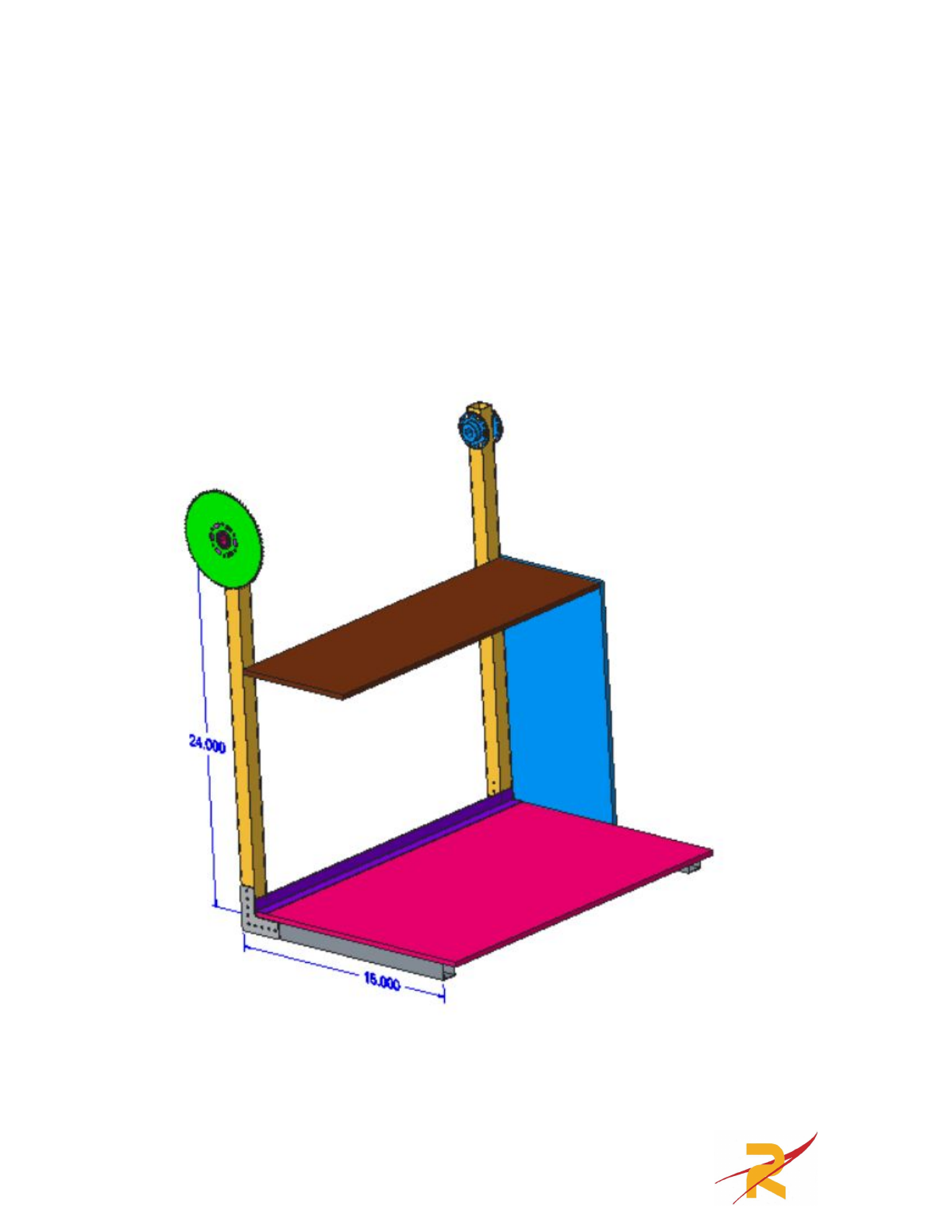
This is the cut list for the scoring arm:
●1” x 1” x 1/16” wall boxtube (16’ in the KoP also available at Home Depot)
○Qty(2) x 33.875”
○Qty(2) x 41.5”
○Qty(2) x 24”
○Qty(2) x 15”
●¾” x ¾” Aluminum Angle (From Home Depot)
○Qty(1) x 22”
●¾” x 9/16” Aluminum C-Channel (From Home Depot)
○Qty(1) x 27.75”
●1-½” x 1-½” Aluminum Angle (From Home Depot)
○Qty(1) x 27.75”
○Qty(1) x 22”
●⅛” Thick Aluminum Plate (From Home Depot)
○Qty(2) @ 2” x 9”
●.300” Corrugated Polycarbonate (From Home Depot)
○Qty(2) @ 8.5” x 13”
○Qty(1) @ 7.5” x 32”
○Qty(1) @ 15” x 22”
○Qty(1) @ 12” x 22”
●3/16” Thick Plywood (From Home Depot)
○Qty(1) @ 20.25” x 10.125”
●½” VexPro Hex Shaft
○Qty(1) x 27.75”
●½” Schedule 40 PVC
○Qty(1) x 1.1”
○Qty(1) x .10”
○Qty(1) x 1.875
○Qty(1) x 1.175”
○Qty(1) x 1.19”
15
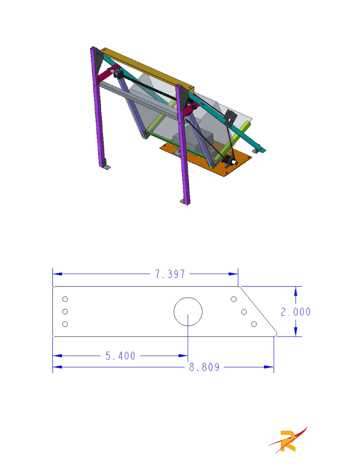
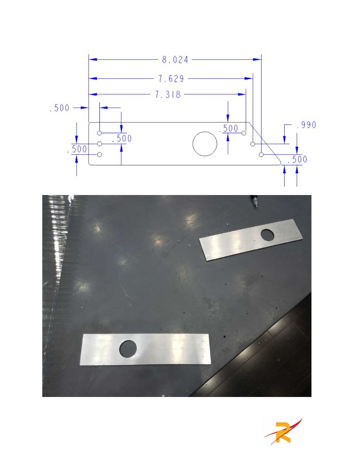
Once all the parts are cut to the sizes specified above the ⅛” thick plates should be
cut according to the drawings below. The large hole is a 1.125” bearing hole and
the smaller holes are .201” a number 10 clear hole.
16
17
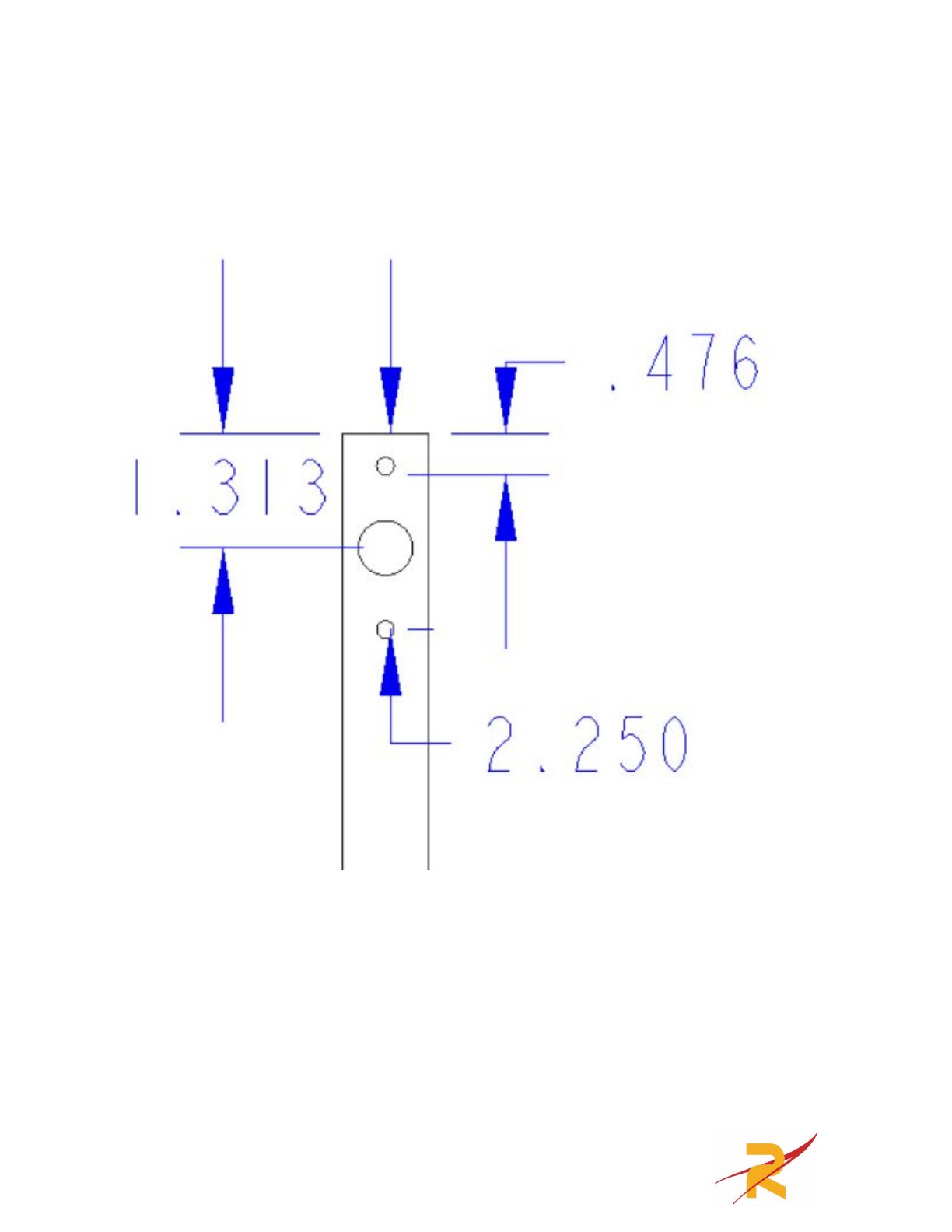
The two 24” long 1”x1” box tubes need to be machined on one end according to
the following drawings. The small holes are #10 clears (.201”) and the large hole is
.75” to allow for a ½” hex shaft to fit through. I recommend drilling this hole with
a step drill.
These are the only parts that need to be machined before being assembled. The rest
will be clamped together and match drilled.
18
Arm Assembly
Most of the assembly on the arm was done by clamping parts into place and
then match drilling. For the most part this eliminated any part misalignment.
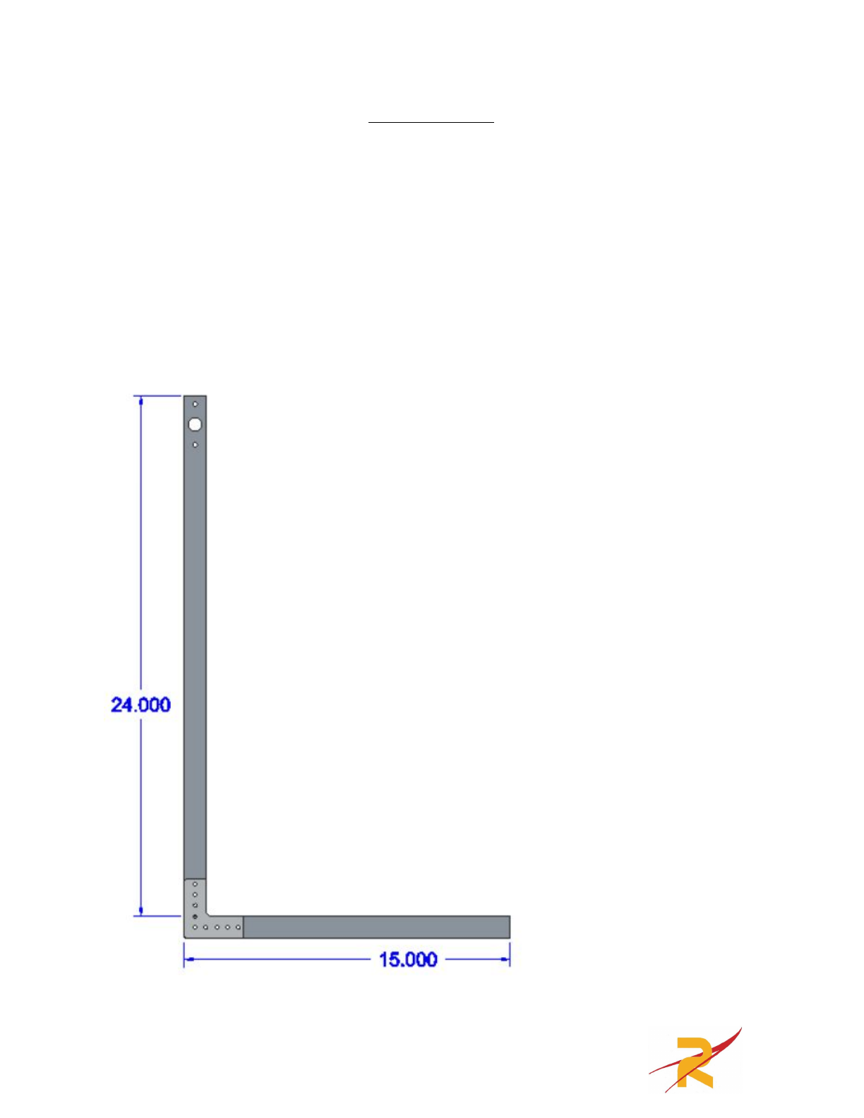
To begin the arm assembly we will put together the actual arm. To start we
need the two 24” long 1”x1” box tubes machined above along with the two 15”
long 1”x1” box tubes and two VexPro Versaframe 90 degree gussets. Everything
should be clamped together and match drilled. 5/32” rivets or 8-32 bolts can be
used to attach these components. The following drawing shows how the parts
should be clamped together. You will need to put two of these together.
19
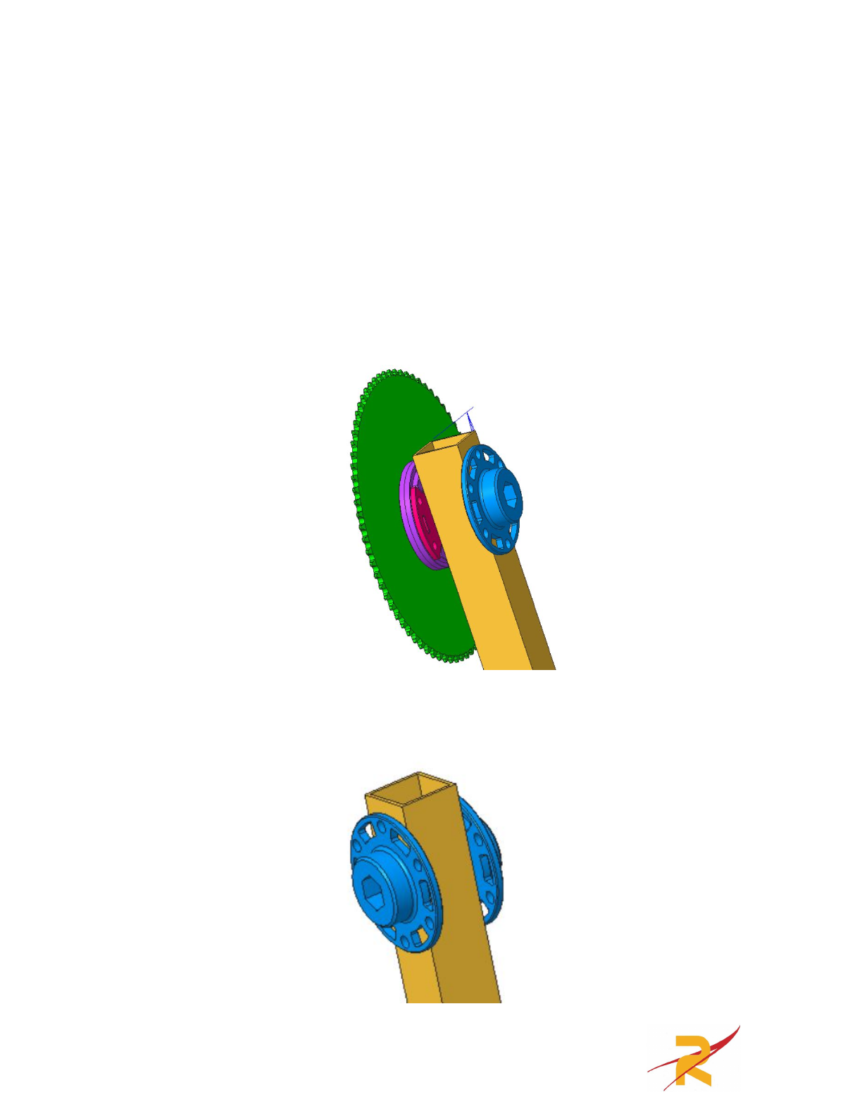
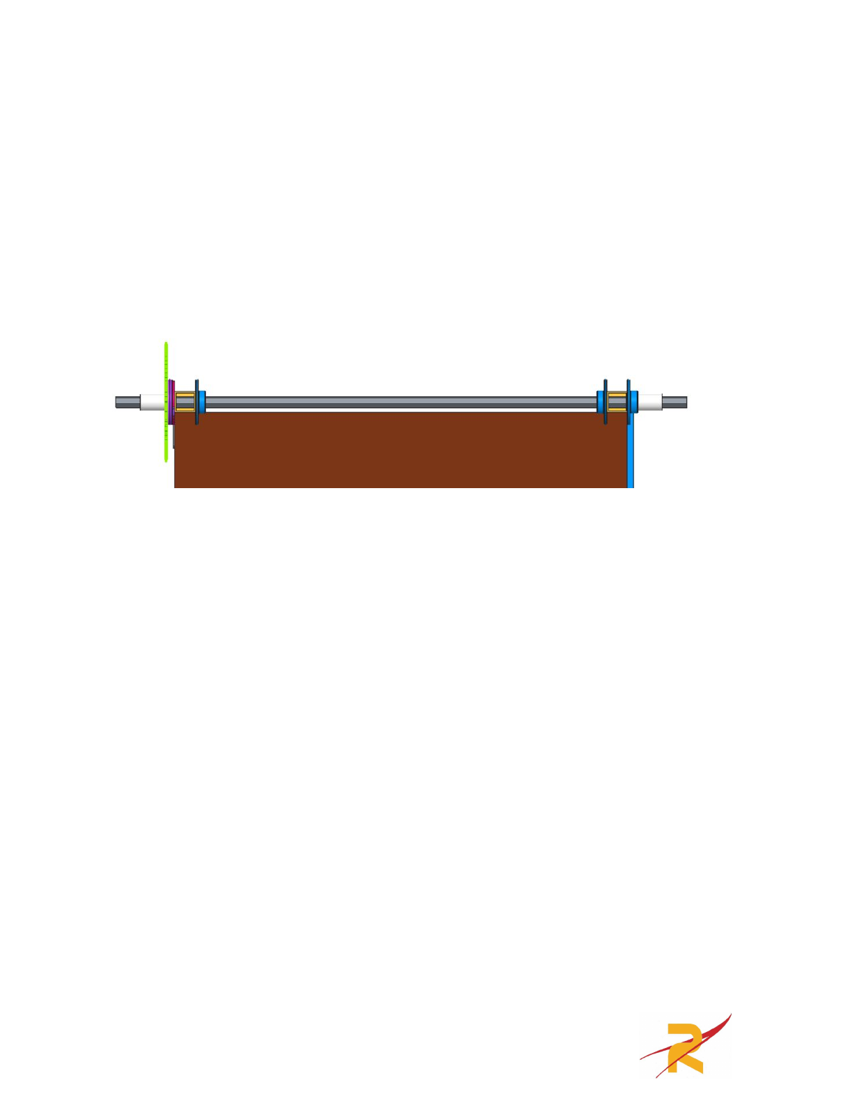
Once both arm sides are assembled VexPro Versahubs and the 72 tooth plate
sprocket need to be attached to the arm. The left arm will be assembled according
to the following drawing. The holes on the 24” long arm should line up with the
holes on the VexPro components. Green is the 72 tooth plate sprocket, purple is the
1.125” ID bearing bore VersaHub, pink is the plastic ½” hex VersaHub, yellow is
the 24” long arm and blue is the ½” hex metal VersaHub. The holes in these Vex
components will need to be drilled out to a #10 clear (.210”) to allow the bolts we
are using to fit through them.
The right arm should be assembled to the following drawing which matches
the color scheme above.
20
After both sides of the arm are assembled the ¾” x ¾” angle (purple)can be
attached to both arm sides using rivets or bolts. All of the polycarbonate plates
were attached with VHB tape that is included in the kit. In the following drawing
the blue plate is the 8.5” x 13” polycarbonate sheet, there is one on each side of the
arm. The pink plate is the 22” x 15” polycarbonate plate. The brown plate is the
22” x 7.5” polycarbonate plate. The 22” long 1-½” x 1-½” angle gets mounted
below the brown polycarbonate plate using rivets or bolts.
21
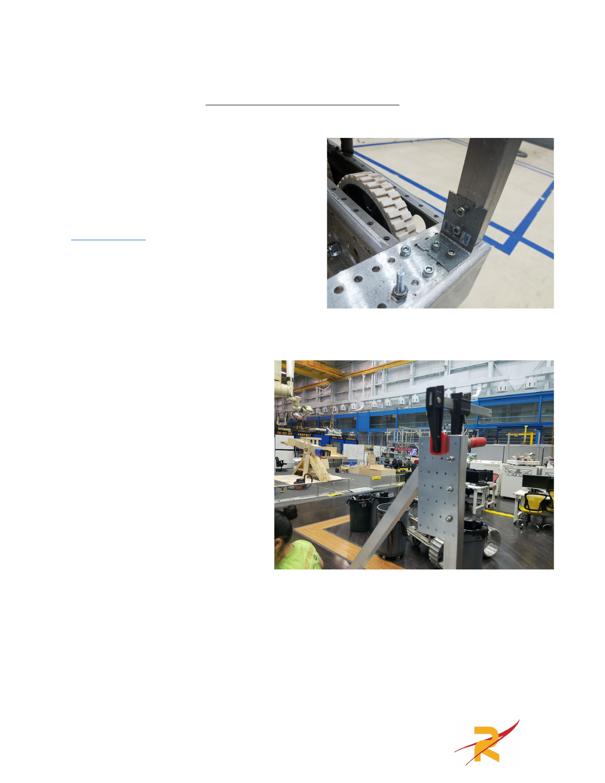
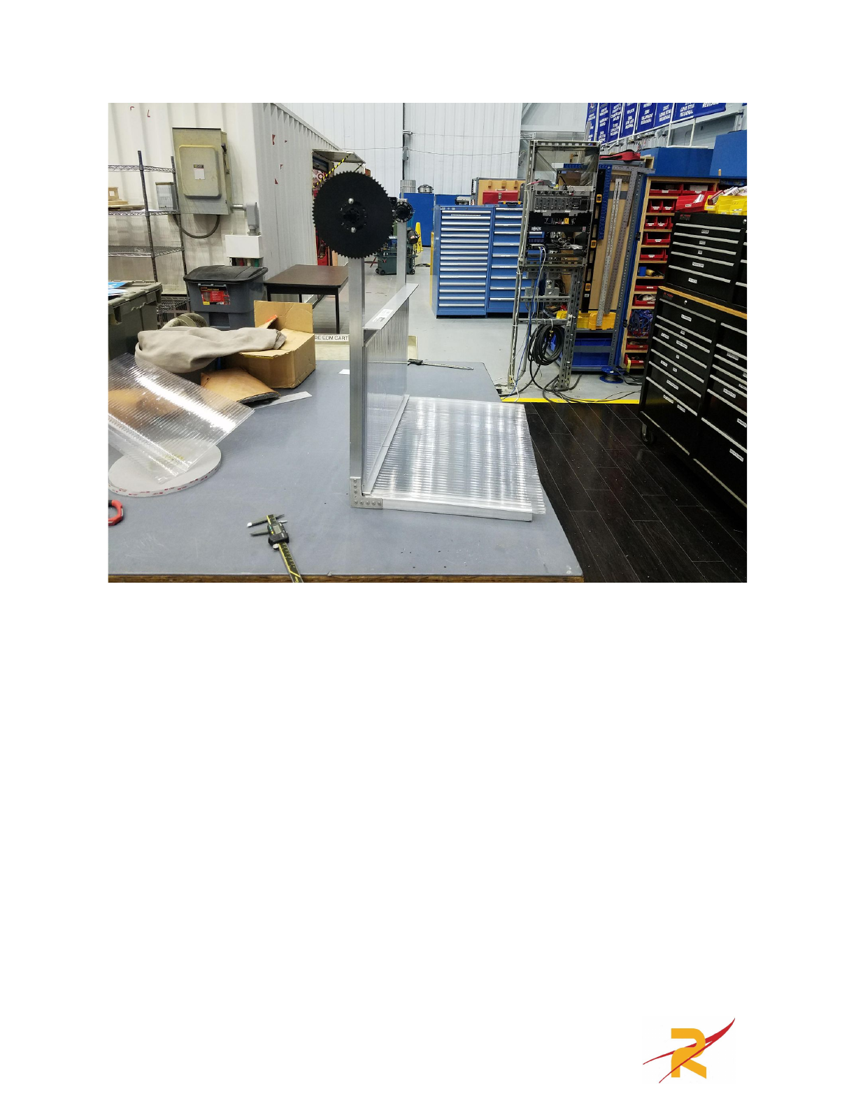
Master Pivot A-Frame Assembly
Most of the master pivot A-frame is
match drilled. We placed the two 33.875”
1” x 1” box tubes in the two front corners of
the robot and attached them at the bottom
with 10-32 bolts to steel angle gussets from
Home Depot. The gussets are also attached
to the chassis using 10-32 bolts. During this
process it is best to have someone holding
the box tubes vertical until the rest of the a
frame is assembled to keep the angle
gussets from bending.
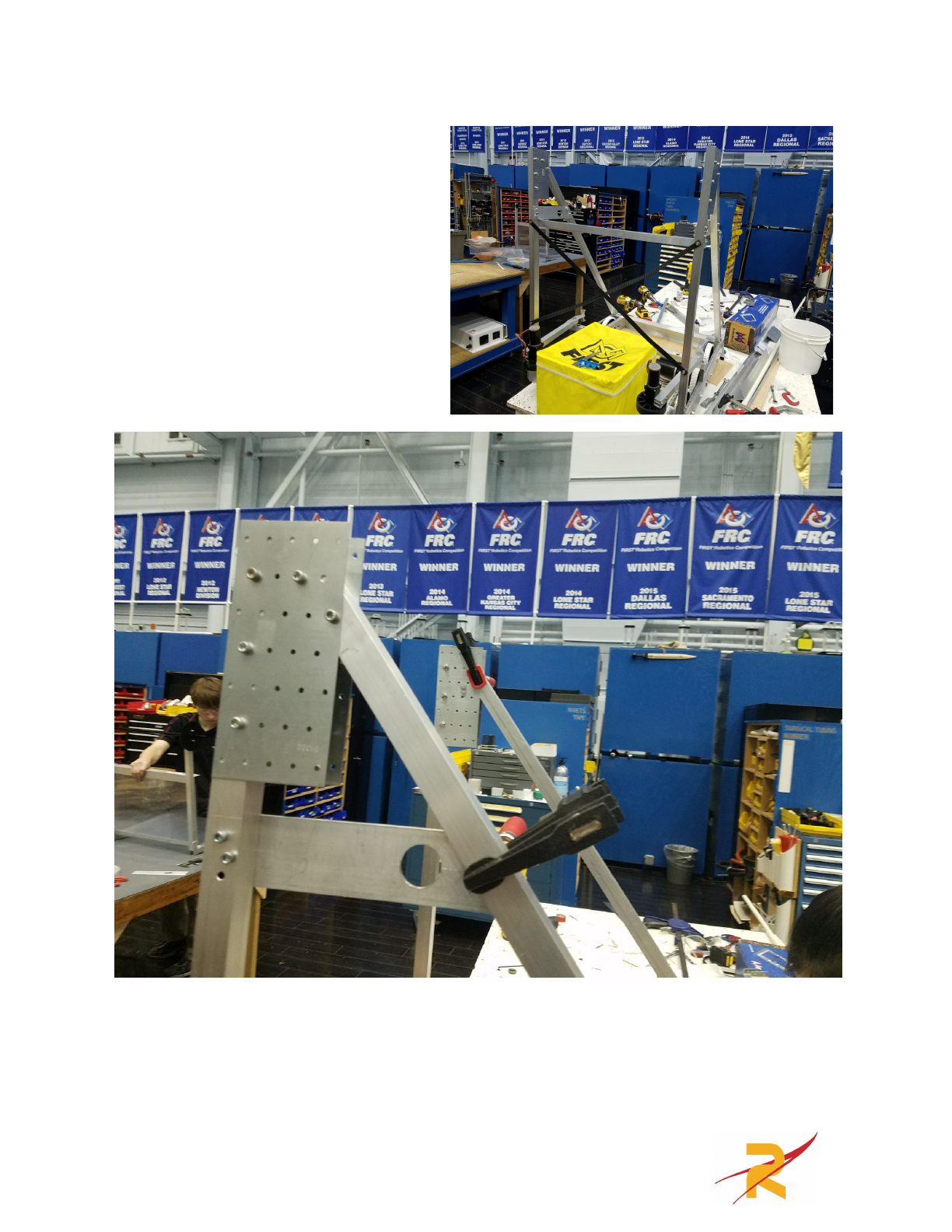
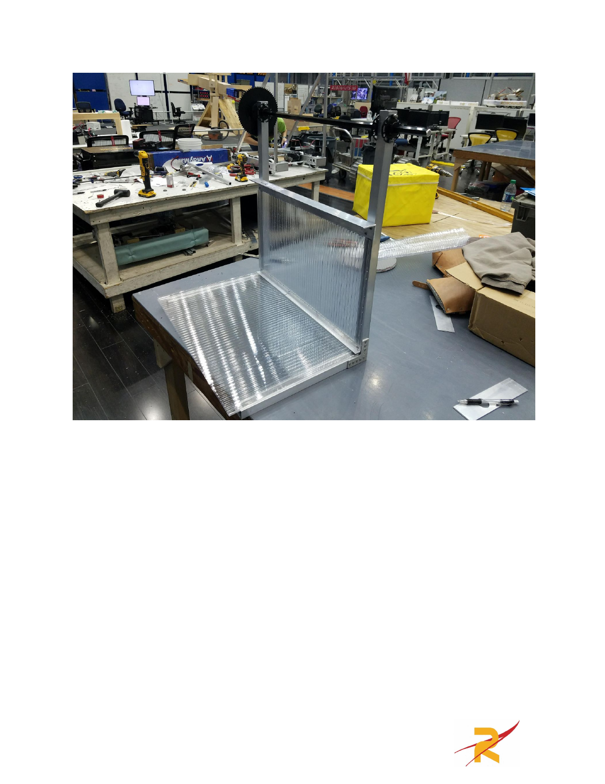
After the vertical box tubes
are installed the tie plates can be
clamped to either side of the 1x1s
at the top. They need to be match
drilled for a 10-32 bolt (.201”)
1.5” long bolts need to be used to
attach these components. If
desired you can mark them and
trim them to make them match the
box tubes. Once the tie plates are
installed the the two 41.5” 1” x 1”
box tubes can be installed to
support the vertical box tubes. Two 10-32 bolts should connect the box tube at the
top and at the bottom it should be attached to the frame using another steel angle
gusset. We also connected the two vertical box tubes with two timing belts (come
in the kit as a part of the kit chassis) that were cut to act as tension members. These
greatly strengthened the arm assembly.
22
Next the ⅛” master pivot
plates need to be installed, these
should be clamped to the box tubes
and then match drilled and bolted in
with 1.5” long 10-32 bolts. Below
these plates we mounted the 27.75”
long C-Channel with 10-32 bolts.
23
Next the ½” hex bearings can be placed into these bearing holes. The arm
can also be placed in with the PVC Spacers. The 1.175“ long spacer goes on the
left and the 1.19“ long spacer goes on the right when looking from the back of the
robot. The ½” hex shaft is then pressed in, you may need to loosen the bolts on the
Versahubs on the arm to get the shaft through all of them. Shaft collars then go on
each end of the shaft.
24
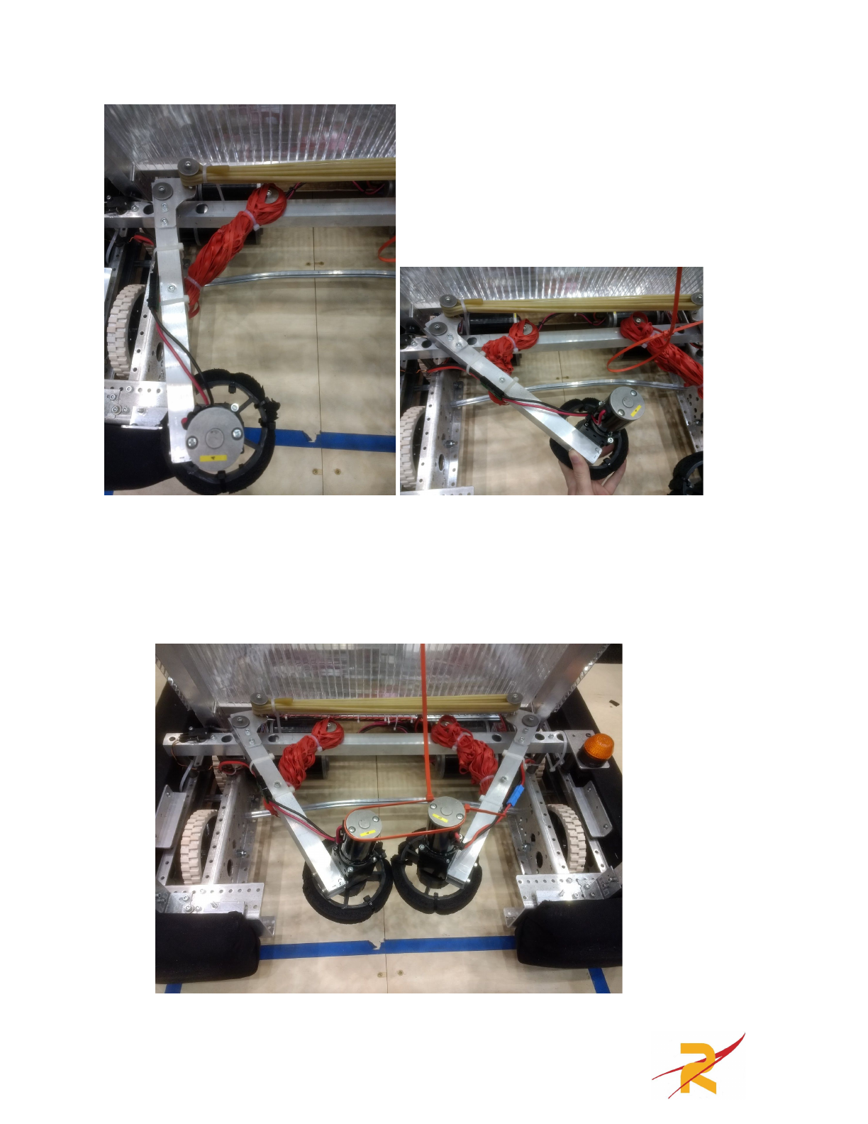
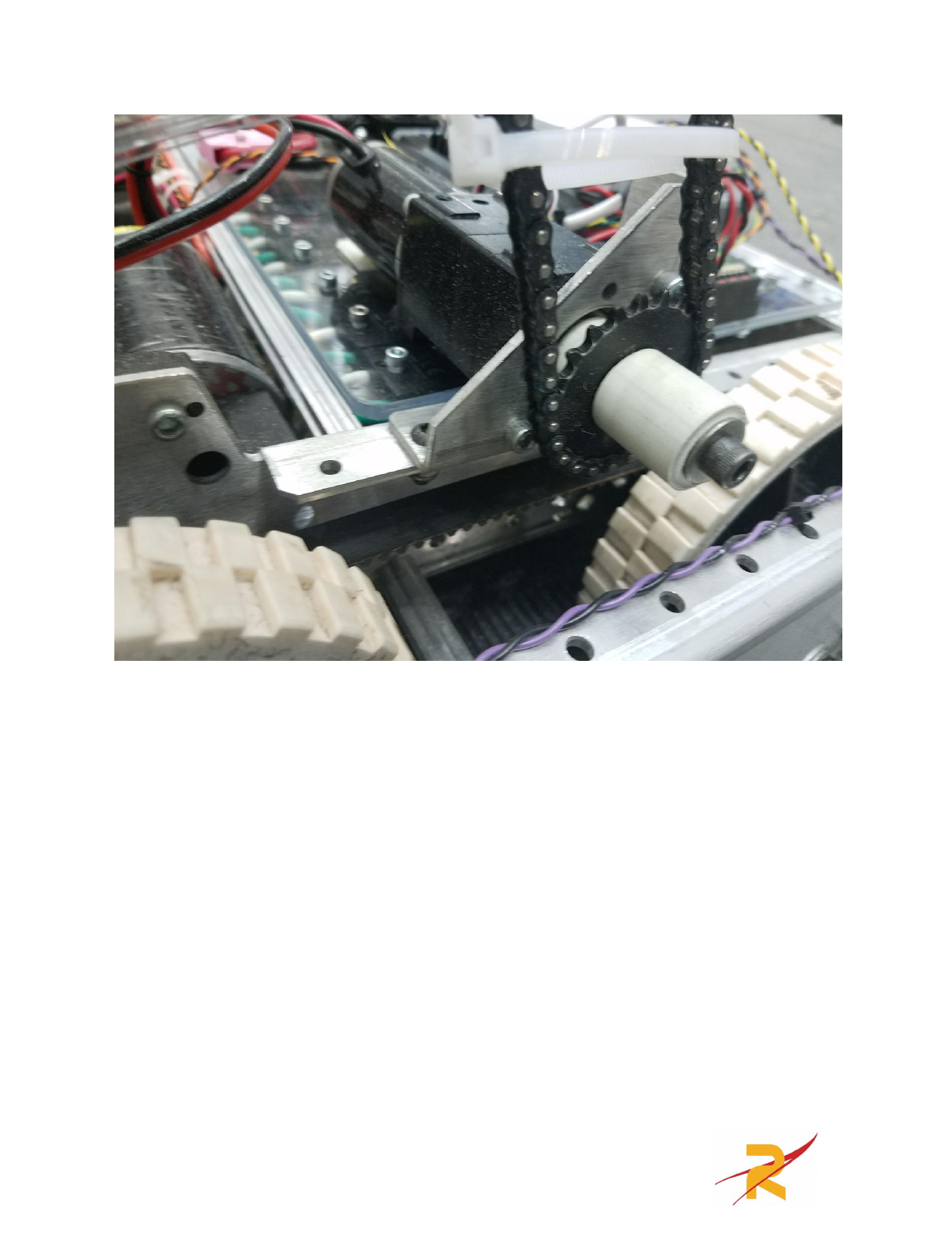
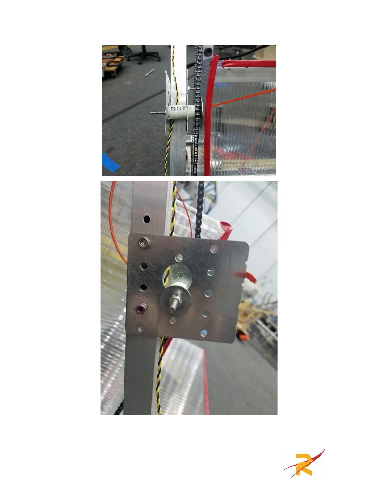
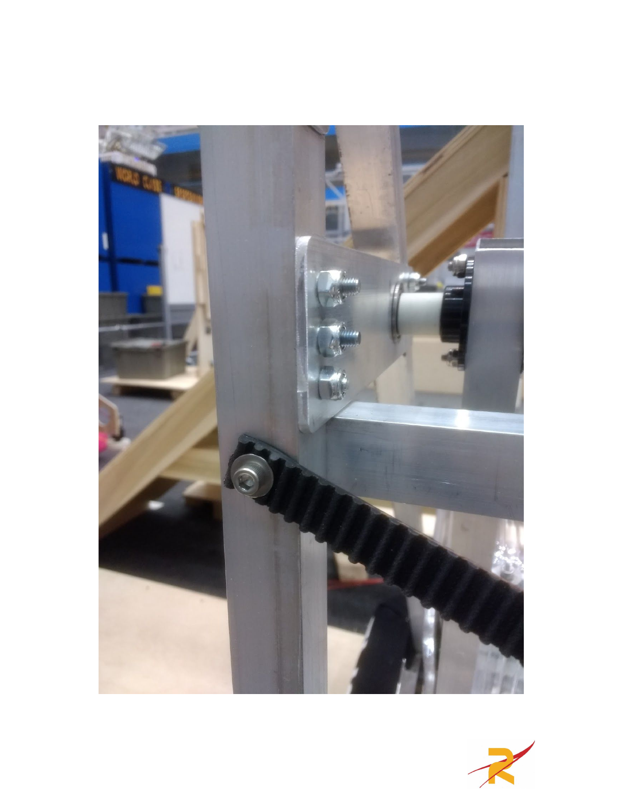
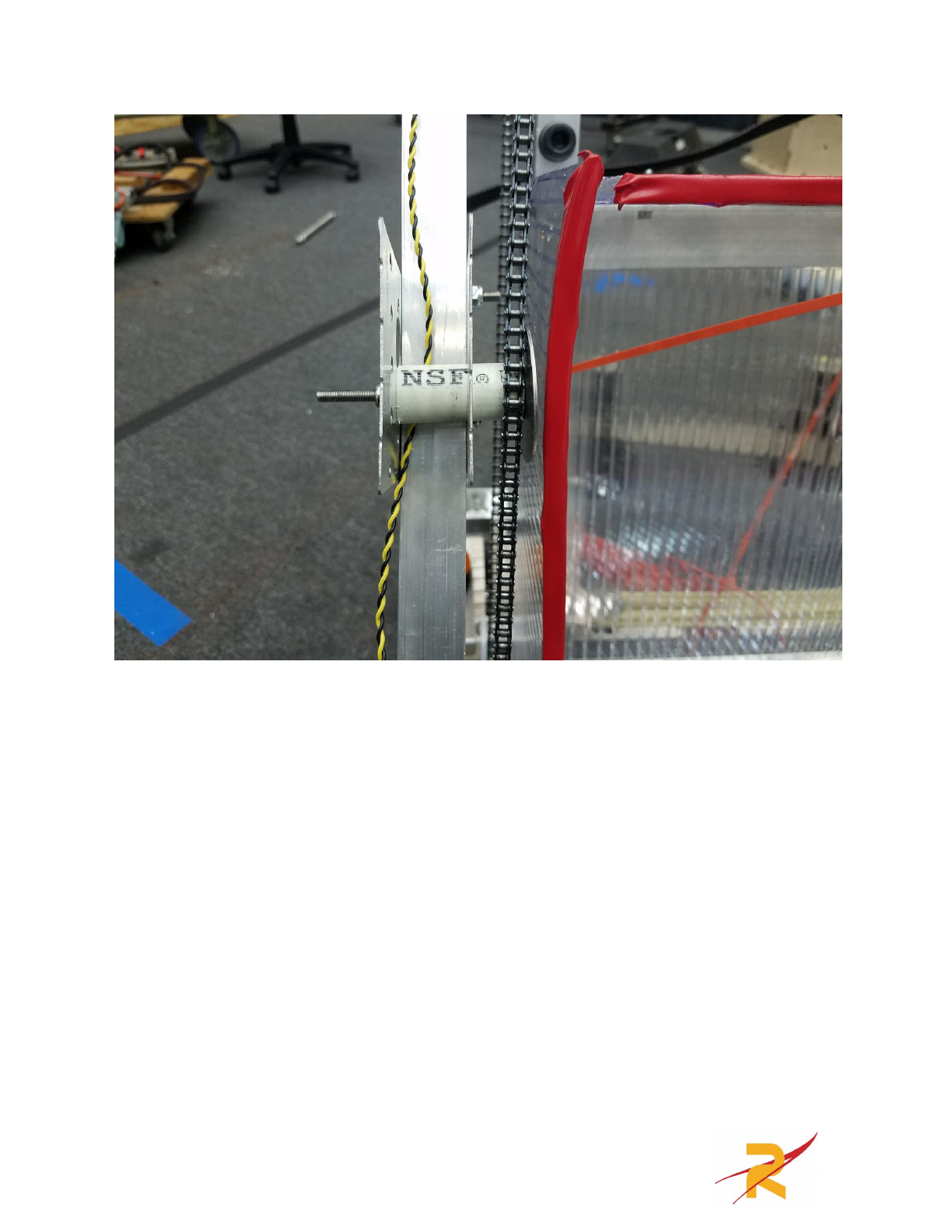
The last major thing to do for the arm is install the motor and the chain
tensioner. Assemble a VersaPlanetary with a 100:1 and a BAG motor. Bolt the
VersaFrame Corner Gusset in the location shown in the photo below with 10-32
button head bolts and then install the .10” long spacer closest to the motor followed
by the 22 tooth sprocket followed by the 1.1” spacer then use a large ¼-20 washer
and bolt to retain the spacers on the shaft.
25
The chain tensioner consists of a tie plate cut in half with one of the holes
drilled out to .86” A metric step drill is ideal for this, but it’s ok if the hole is a little
oversized. The other plate needs to have the hole directly across from the .86” hole
drilled out for a 10-32 (.201”) The following photos show how the tensioner is
mounted with 10-32 bolts.
26
27

For the length of the chain run we just put together pieces of chain until it
looked about right and then added a tensioner. There are better ways to do this such
as calculating the center-to-center distance for the shafts however the VexPro
Corner Gusset flexes making a chain tensioner necessary. Slide the assembled
tensioner under the chain along the box tube until the chain is tight and match drill
the holes for a 10-32 bolt, 1.5” long.
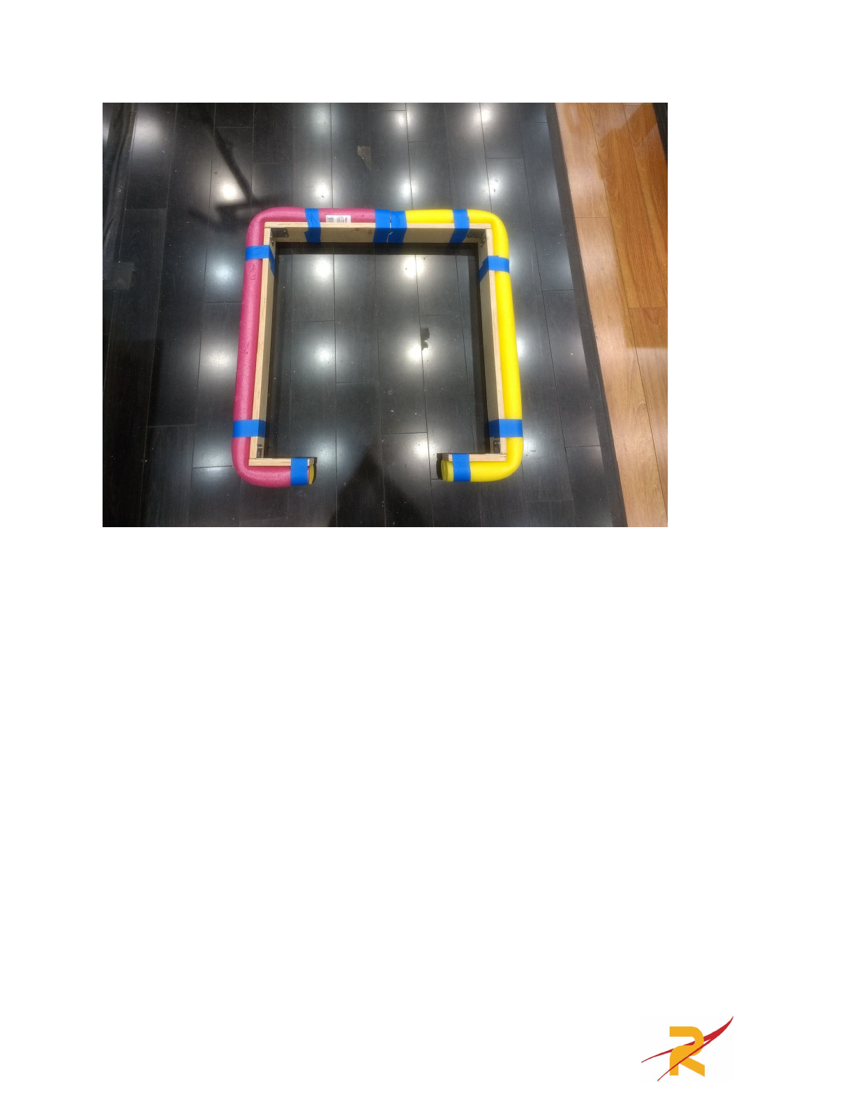
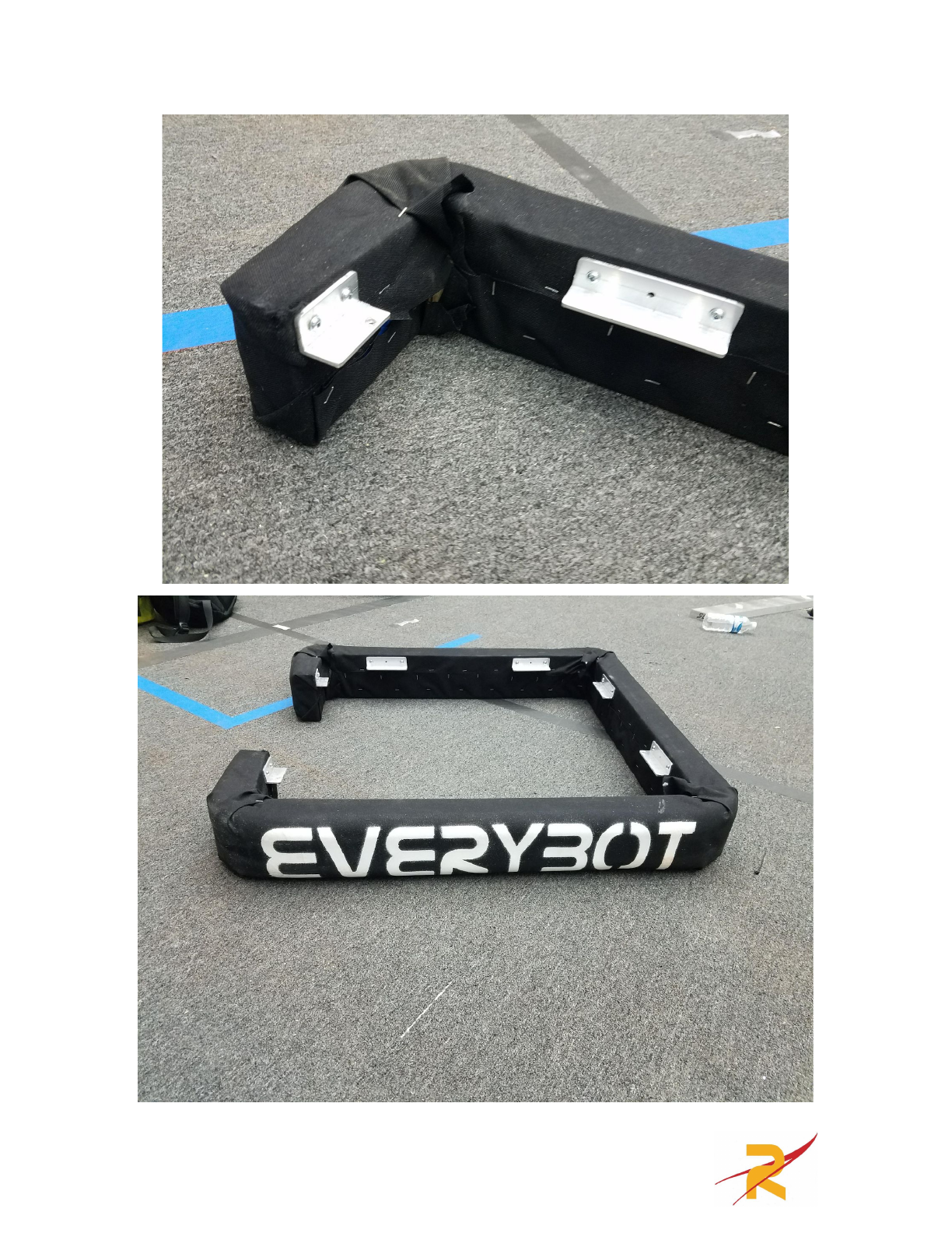
Bumpers
For the bumpers we made a single piece unibumper with wood that was 4.5”
tall due to the rule stating your bumper wood must be 5+/- ½”. The bumper wood
is ¾” thick as required. The bumper cut list is as follows
●1” x 1” Aluminum Angle .125” Thick (From Home Depot)
○Qty(2) x 4”
○Qty(2) x 2”
●¾” Thick Plywood
○Qty(2) @ 4.5” x 7.25”
○Qty(2) @ 4.5” x 28.75”
○Qty(1) @ 4.5” x 30”
28
29
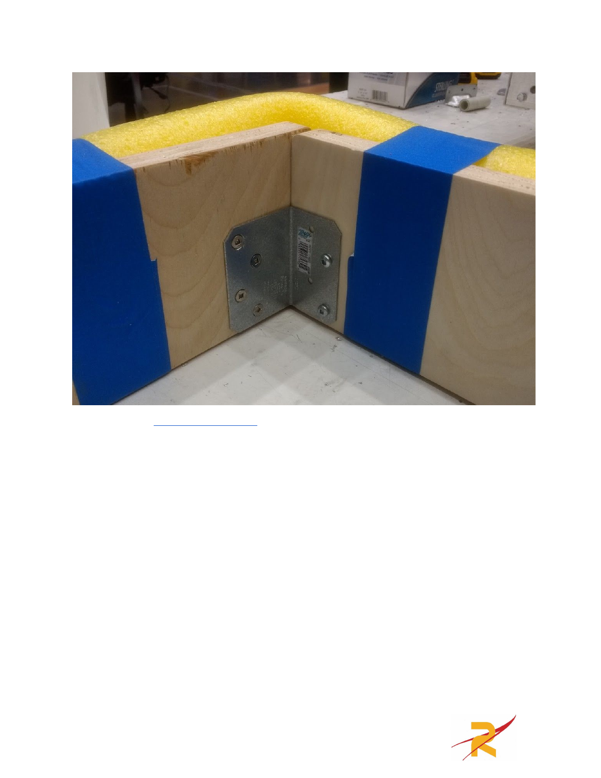
We used these steel gussets in the corners and attached them with wood
screws. The two 4” long segments of angle mount the back of the bumper to the
robot and the 2” long segments of angle attach the front of the bumper to the robot.
Wood screws are used to attach the angle to the bumpers and then 10-32 bolts are
used to attach the angle to the robot. The following pictures show an example of
this.
30
31
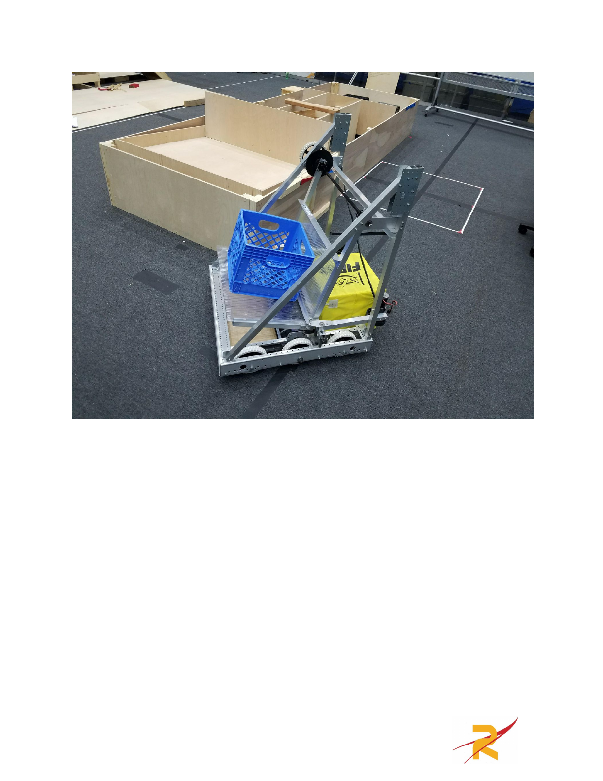
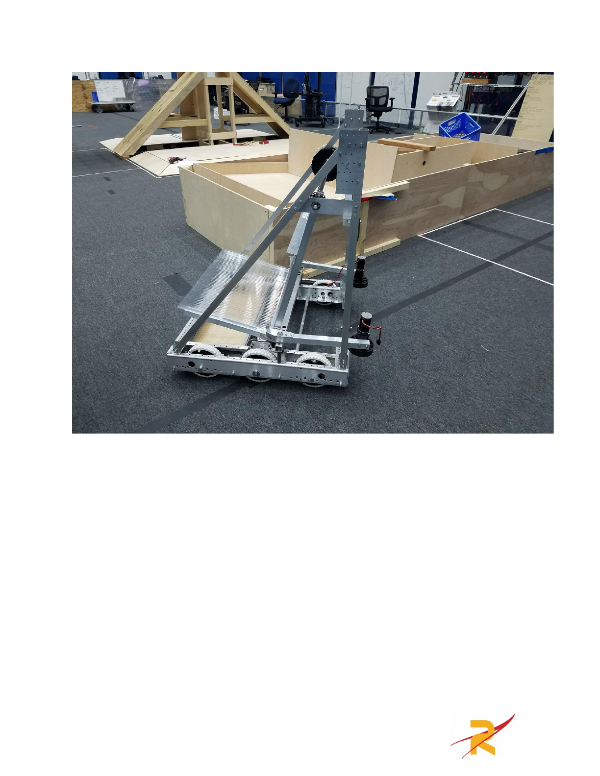
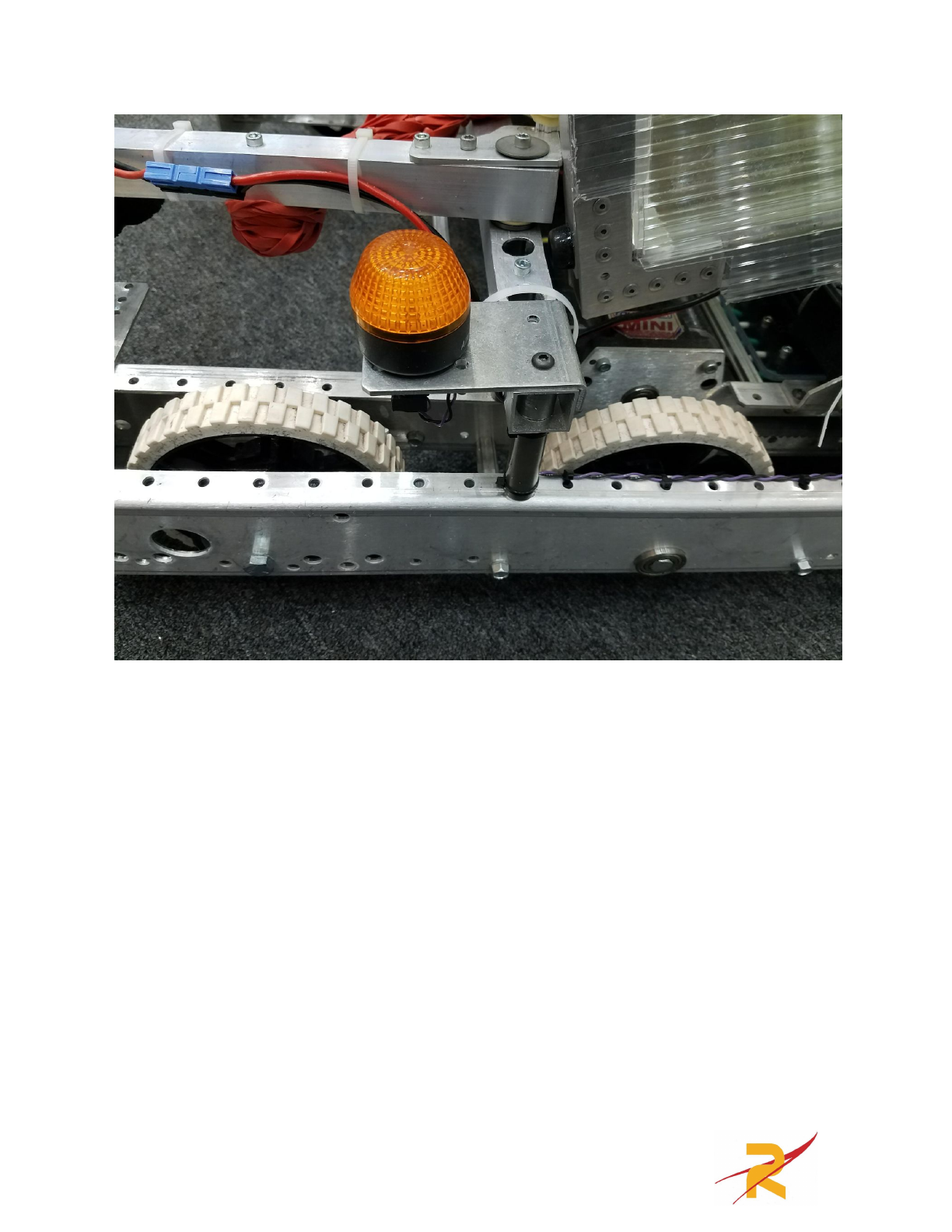
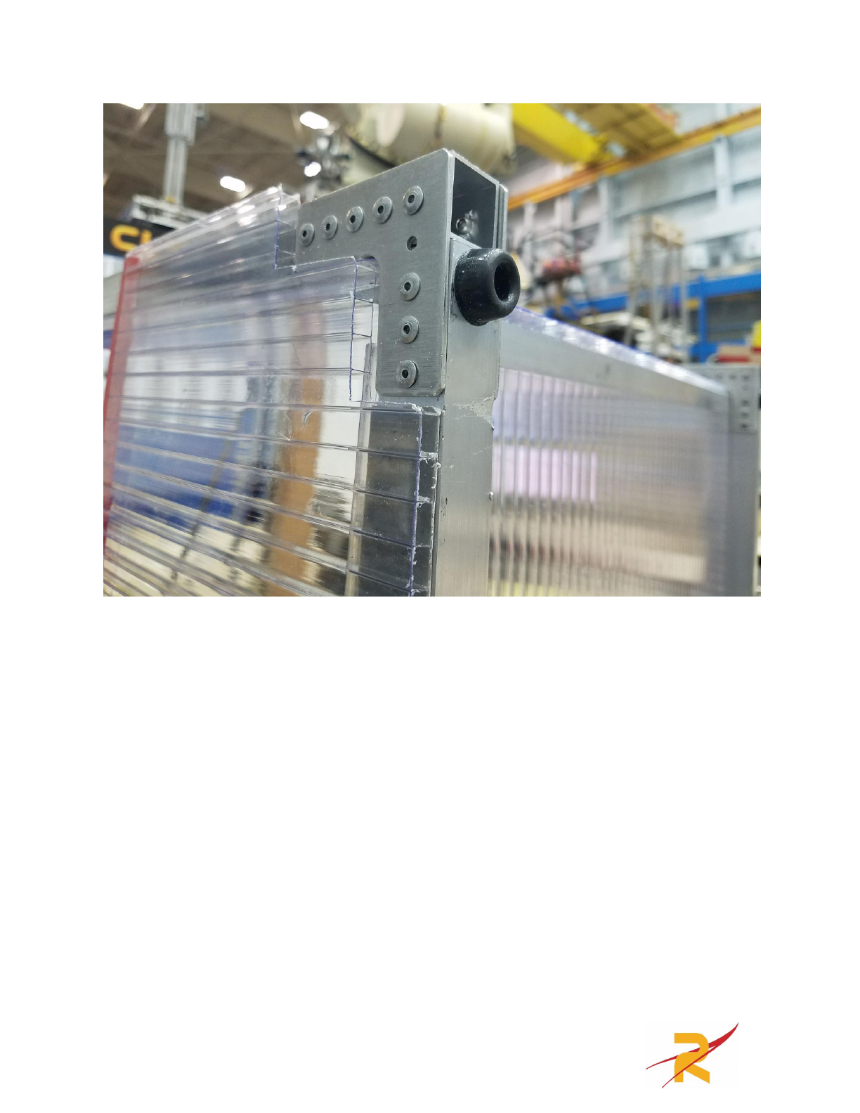
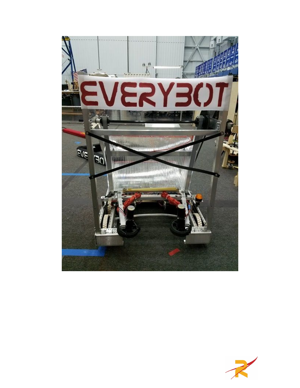
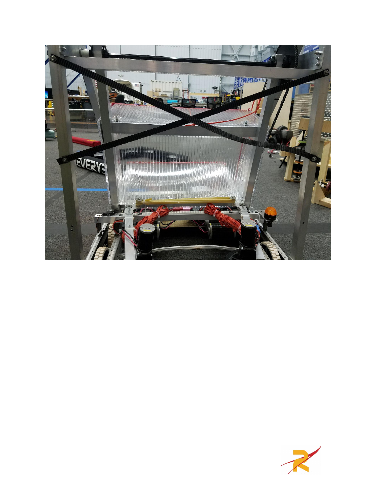
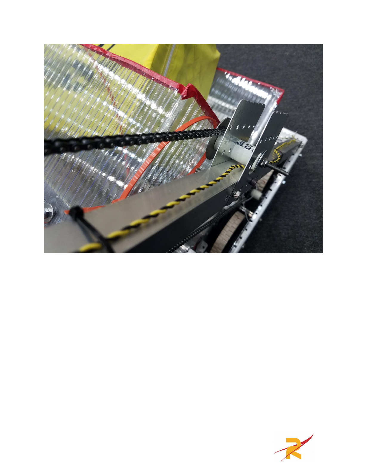
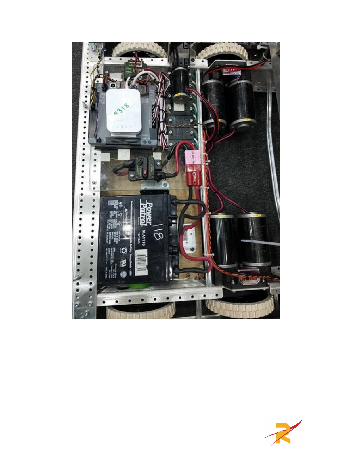
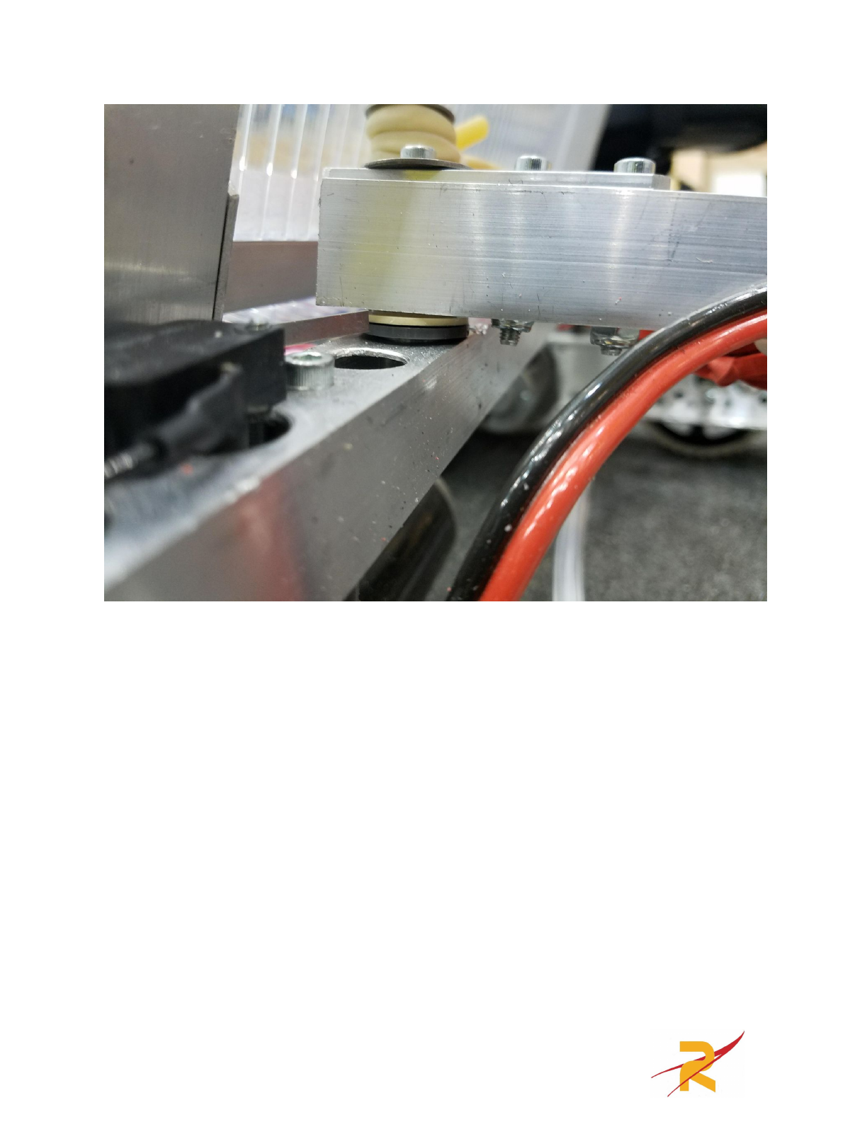
Everybot Photos
32
33
34
35
36
37
38
39
40
41
42
43
44
45
46
47
48
