Guide
User Manual: Pdf
Open the PDF directly: View PDF ![]() .
.
Page Count: 16
Let’s build electrostatic headphones
Arno Mayrhofer Benedikt Becsi
January 2, 2018
Contents
1 Introduction 2
2 Required tools 2
3 Required materials 3
4 Building the driver 4
4.1 Design of the stators and spacers . . . . . . . . . . . . . . . . . . . . . . . . . . . . . . . . . . 4
4.1.1 Gcodecreation ........................................ 5
4.2 Etchingthestators.......................................... 7
4.3 Tensioning the Mylar diaphragm . . . . . . . . . . . . . . . . . . . . . . . . . . . . . . . . . . 7
4.4 Coatingthediaphragm........................................ 9
4.5 Cable ................................................. 9
4.6 Assembly ............................................... 10
5 Building the enclosure 10
6 Building the headband 11
7 Building the earpads 11
8 Assembly 11
9 Amplifier 11
10 Measurements 13
11 What to do different in the future 13
11.1Closedheadphones .......................................... 13
12 Collaboration & License 14
13 Appendix 15
13.1Circuitdiagramforcircuitjs..................................... 15
1
1 Introduction
The following document will describe the journey to construct your own electrostatic headphones starting
with zero, zilch, nada, niente and nichts. In Section 2 we will list the tools required for the building process,
which will be followed by a list of materials in Section 3. The actual construction process is split into five
parts, the building of the driver (Section 4), enclosure (Section 4), headband (Section 6) and earpads (Section
7) with a final assembly in Section 8. Finally, the last two chapters will deal with measurements (Section
10) and things that we would do differently for the second pair (Section 11).
The whole construction is based on the Head-Fi.org thread [1], with different and more detailed sources
([2, 4, 3]) given in the respective sections.
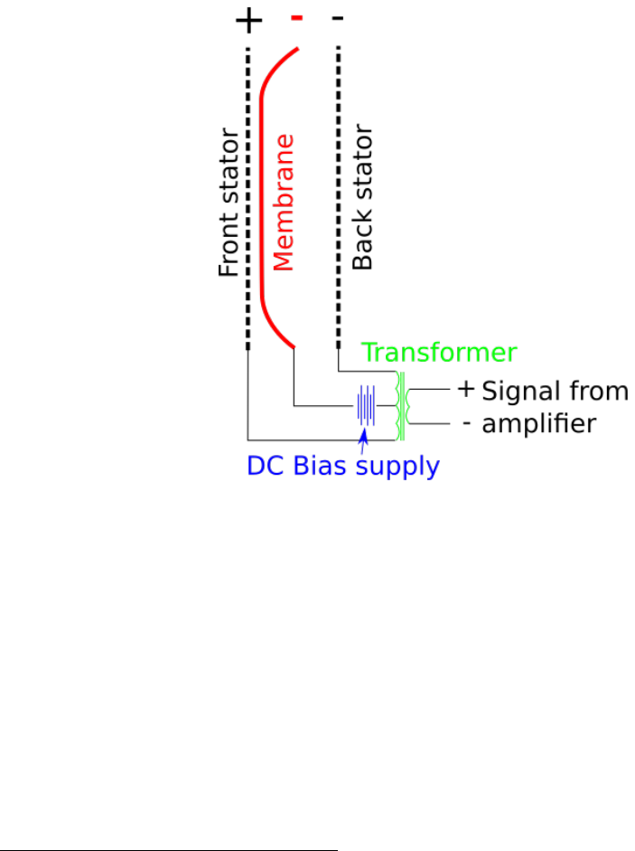
Figure 1: Electrical concept
The basic electrical concept of a electrostatic headphone can be seen in Fig. 1. An amplifier provides
an input signal that is then transformed to yield the desired output voltage that drives the two stators.
Additionally, there is a negative DC current that keeps the diaphragm charged.
2 Required tools
To build the drivers it is highly recommended that you have access to a good CNC machine. Since we didn’t
have one of those standing around, we looked for a so called fablab, i.e. a community led workshop for
creative projects. We eventually ended up at the Viennese Metalab1which gave us access to a heavy duty
level CNC machine and an introduction on how to use it by Sebastian Bachmann2, which eased the learning
curve significantly. The principal introduction included instructions on how to set up, start and operate the
machine and the control terminal, as well as some GGode basics (the programming language that controls
the machine’s behaviour - more on that in section 4.1.1). Most importantly, as it can be potentially quite
1https://metalab.at/
2https://www.reox.at/
2

dangerous to operate one of those things, it covered security basics, which is definitely the first starting point
for anyone new to CNC. Don’t skip your tutorial lessons, kids!
Since you might be interested in the budget needed for this, it of course depends on the lab’s membership
policy - most labs we found had a monthly fee with a minimum subscription period, but we were able to
come to an arrangement with a voluntary contribution without binding membership. Most people running
those kinds of open creative space are pretty chill, so don’t be afraid to ask!
If you can’t find a place or plan to work on more DIY-projects in the future, it might be worth it to
purchase a CNC mill for yourself or with a group of like-minded people. It’s amazing what’s going on in the
field of affordable, small-scale, DIY and hobby-use CNC in the last couple of years. Here are some links if
you’re more interested in a purchase:
https://www.millrightcnc.com/product-page/millright-cnc-m3-kit-bundle
http://www.makerdreams.it/
https://www.sorotec.de/shop/
Also, some labs require you to buy the wearout parts yourself. You can get CNC tools here:
http://cnc-plus.de/
https://www.sorotec.de/shop/
An electric drill was used for the assembly screws and headband construction. The earpads were sewn
from hand and as such only thread and needle was required for that. The step up transformer that we built
to drive the headphones required a basic electronics lab and in particular a soldering station.
3 Required materials
In this section we list all the materials we had to purchase for the headphones and our DIY step-up trans-
former. We provide you with the links where we bought the materials, but depending on where you live you
might find better suppliers yourself.
1. 1 mm PCB FR-4 for stators and dust protection spacers: 3
2. 0.5 mm PCB for spacers: 4
3. 3 µm Mylar (for diaphragm): 5(with that, you should have all your mylar needs covered for years to
come!)
4. 1 µm Mylar (for dust protection): 6
5. Anti-static display cleaner for diaphragm coating: 7
6. Acrylic spray for insulating the stators: 8
7. Thin and stretchy artificial leather for the earpads and headband (should be available in a textile shop)
8. Wood for the enclosure and headband, several boards with 4mm and 10mm thickness; we used lime
and spruce
3https://www.conrad.com/ce/en/product/523656/PCB-material-Photo-coating-positive-single-sided-35-m?ref=
list
4https://www.conrad.com/ce/en/product/523630/PCB-material-Photo-coating-positive-single-sided-35-m?ref=
list
5https://www.ebay.com/itm/Electrostatic-Speaker-Membrane-Dupont-Mylar-C-3um-40M/172781729300?epid=
666335680&hash=item283a97f614:g:jg0AAOSwrklVPe61
6https://www.freeflightsupplies.co.uk/index.php/products/lightweight-covering-materials
7https://www.conrad.com/ce/en/product/995207/DataFlash-DF1620-Content-250-ml?ref=searchDetail
8https://www.conrad.com/ce/en/product/1198455/Acrylic-paint-Revell-Black-matt-08-Spray-can-100?ref=
searchDetail
3

9. Metal rods (3mm welding rods) for the headband
10. 3 cm acoustic foam (pads and headband)
11. Cable plus connectors
12. Screws for the assembly (2,5 x 20 mm)
13. Clear varnish or glaze for wood finish
14. Two-component glue: 9
15. Contact glue for gluing the membrane to the stators and the earpads: 10
Head-fi.org 11 has a more comprehensive list of material suppliers.
Materials needed for the amplifier:
1. 4 Audio transformers 6V - 230V (OEP N35A002F) 12
2. 1 Power transformer 230V - 230V (Triad Magnetics FP230-25) 13
3. 2 1 Ohm wirewound resistors 14
4. 6 1kV diodes 15
5. 2 10 MOhm resistors 16
6. 6 10 nF capacitors 17
7. 1 3.9 kOhm resistor 18
8. Power cord plus plug
9. Cables
10. Test circuit board
4 Building the driver
4.1 Design of the stators and spacers
In the following the stators and spacers will be designed and the designs will be prepared for CNC milling.
As the stators and spacers are 2-D, we decided to use Inkscape 19 for our design purposes. There are plenty
of guides on how to use Inkscape around so we assume that the reader is familiar with it. But in the end we
almost exclusively used the basic objects like spheres and ellipses and boolean operators (to be found under
the Path menu).
9https://www.conrad.com/ce/en/product/478703/UHU-Plus-Schnellfest-Two-component-adhesive-45700-35-g?ref=
list
10https://www.conrad.com/ce/en/product/631802/UHU-greenit-Contact-adhesive-45401-650-g?ref=searchDetail
11http://www.head-fi.org/t/826032/electrostatic-ear-speaker-diyers-suppliers-list
12https://uk.rs-online.com/web/p/audio-transformers/2106475/
13https://eu.mouser.com/search/ProductDetail.aspx?r=553-FP230-25
14https://eu.mouser.com/search/ProductDetail.aspx?r=71-RS0101R000FE73
15https://eu.mouser.com/search/ProductDetail.aspx?r=625-RGP10M-E3
16https://eu.mouser.com/search/ProductDetail.aspx?r=594-SFR25H0001005JR5
17https://eu.mouser.com/search/ProductDetail.aspx?r=75-564R30GAS10
18www.aliexpress.com
19https://www.inkscape.org
4

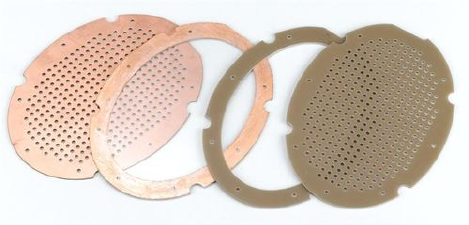
(a) Stator (b) Front spacer (c) Back spacer
(d) Spacer for dust protec-
tor
Figure 2: All PCB driver components
In general the ellipse which contains all driver components is 130 mm high and 94 mm wide. The inner
ellipse that determines the active area is 110 mm high and 74 mm wide. The holes drilled into the stator only
cover this active area and are laid out such that approximately 40% of the active area is open, i.e. covered by
holes. The distance between the holes is 0.8421 mm in vertical and 0.88 mm in horizontal direction and each
hole has a diameter of 2 mm. To generate such a tiled array of holes in Inkscape draw one hole and then use
the Create tiled clones option that can be found under Edit - Clone. The holes outside the active are where
removed manually. The resulting stator can be seen in Fig. 2a. A total of four stators need to be milled
from 1mm FR4 PCB. The eight cut-outs that are present in each driver component were designed to allow
easier screw insertion in the enclosing. It turned out though that we only needed four screws in the end and
it would have been possible to work without those cut-outs at all. At the bottom of the components there
is a varying number of half-circle cut-outs. These ensure that cables can be connected at other components
and provide insulation to the present one. The front and back stator seen in Fig. 2b and Fig. 2c are made
from 0.5 mm FR4 PCB. The dust spacer in Fig. 2d is made from 1 mm PCB. Each spacer needs to be
produced twice, one for each side.
A few general design guidelines that we found on the head-fi thread indicated the following. The diameter
of the holes (2 mm in our case) should not be larger than the distance from stator to spacer. The reason for
not having the holes cover the whole stator is that this increases the stability of the stator. A large diaphragm
size is quite important as this improves low frequency response. Obviously, if the open area becomes too
large then the diaphragm will be too flexible and touch the stators which will cause it to discharge. Because
of this the ratio of spacer thickness to diaphragm width should not be larger than 1:120. If this ratio is very
large a lower bias voltage can be used to avoid the membrane touching the stators.
All *.svg files that are used for the CNC milling can be found in the resources.zip which can be found
on github.com20.
4.1.1 Gcode creation
After creating the *.svgs with the outline of all shapes the next step is to produce Gcode, i.e. the instructions
for the CNC machine that can be understood by it. Note that we were using a CNC machine that was using
LinuxCNC and it pretty much understood the Gcode produced by the tool presented in the following. The
first important step is to create a milling strategy. For all FR4 parts (stators and spacers) we decided to
use double sided tape to glue the FR4 boards to a flat piece of scrap wood. This means that all paths will
20https://github.com/Azrael3000/headphone-guide/raw/master/resoures.zip
5
be cut 0.2mm deeper than the FR4 thickness. This ensures that the milling is deep enough and only leaves
some scratches on the scrap wood.
Before we start with the Gcode creation we need to decide on which drills and end mills to use. Our
choice for the FR4 milling consisted of a 2mm drill and a 2mm diamond coated end mill. The drill is only
used for the creation of the stator holes and the end mill is used for everything else. The end mill used in
our case would allow us for a vertical feed rate of 300 mm/min and a horizontal feed rate of 1000 mm/min.
The spindle speed was set to 24000 rpm.
To create the Gcode from the Inkscape file we use www.makercam.org which allows a platform independent
operation. It’s a flash tool which allows for 2.5D designs and does everything we need for the headphone
construction.
After creating the *.ngc file a few manual modifications needed to be made in our case. What is required
here exactly depends on your CNC machine so either use your own personal experience or talk to someone
who knows the machine you are using to avoid damaging it. In our case we needed to warm up the spindle
first starting with 6000 rpm and then increasing it slowly to 24000 rpm. An exemplary Gcode file is listed
below where we only took the first few lines of the file as only those need modification.
(Generated by PartKam Version 0.05)
G21 G90 G40
(drill 1)
G0 Z15
T0 M6
G17
M3
G0 X11.05 Y65
G1 Z-1.1 F300
G3 X11.761421319796954 Y53.845177664974614 I87.68274111675127 J0 F1000
Let us go through this line by line now. The first line is a comment as indicated by the brackets around
it. The second line G21 G90 G40 sets the units to mm relative to the zero position of the part and turns
off cutter radius compensation. It is again followed by a comment. Line four then has the first movement
command G0 Z15. The G0 indicates that it is a fast move, i.e. a move in the air and not inside the material.
It moves the the tip of our tool to a position which is 15mm above 0 at it’s current x and y position. Note
that in our case the x axis indicated left and right, y front and back and z up and down. You should ensure
that you know the movement axes of your machine. The next command T0 M6 is a tool selector. As our
CNC machine did not have the capability to change its tools this irrelevant and will be deleted. The G17
command sets the working plane to the XY axes. The M3 command turns on the spindle. Not that it
does not indicate a spindle speed so we need to change this. G0 is a fast movement command, as X and Y
positions are specified, no movement in Z direction will happen. Such a movement can be seen in the next
line, i.e. the G1 command. This is a linear movement to the specified, in this case Z position. In contrast
to the G0 command, this movement does not happen at maximum speed but at the specified one, here
F300 specifies 300 mm/min which corresponds to the plunge rate. The G3 command specifies a circular
interpolation and for us indicates the begin of the horizontal movement with a feed rate of 1000 mm/min.
We make some modifications to this file as can be seen below. The first change is that we move the tool
to Z5 before starting the spindle. The spindle is then switched on and set to 6000 rpm with the M3 S6000
command. The following G4 command indicates a pause which is specified to last 60 seconds in our case.
After that the spindle speed is increased to 12000 rpm up to 24000 rpm with 60 second dwelling periods.
This allows the spindle to warm up for milling. Note that the duration of this warm up period depends on
your machine. After this warm up a first movement in the X-Y plane is performed as above which is followed
by a 5 second pause to check whether everything is correct. Next, the mill is lowered and the main part of
the program starts.
(Generated by PartKam Version 0.05)
6

G21 G90 G40
(profile 1)
G0 Z5
G17
M3 S6000
G4 P60
S12000
G4 P60
S18000
G4 P60
S24000
G4 P60
G0 X11.05 Y65
G4 P5
G1 Z-1.1 F300
G3 X11.761421319796954 Y53.845177664974614 I87.68274111675127 J0 F1000
After milling it is particularly important to deburr the stator holes, but it also makes sense to sand down
the edges of all workpieces.
4.2 Etching the stators
TODO-BB: Write particularly about what areas are left with copper (maybe a diagram) Etching the PCB
board ensures that electrical contacts are only where they absolutely need to be. Furthermore, having less
copper surface will result in a reduced capacitance and they will be easier to drive because of that. Toner
transfer can be used to define the areas that should not be etched.
http://www.instructables.com/id/Stop-using-Ferric-Chloride-etchant!--A-better-etc/
Etching is achieved by using 2 parts Hydrogen Peroxide (3%) with 1 part Hydrochloric acid (30%). Most
PCBs have a photosensitive coating that needs to be removed for this to work. The etching can be achieved
by using a paintbrush to apply the solution to the desired location. The copper will be taken away rather
quickly and the solution will turn greenish.
4.3 Tensioning the Mylar diaphragm
Mylar with 3 µm thickness is used to create the diaphragm. Thinner Mylar will cause a lack of bass, while
thicker one will cause problem in treble and mids. The tensioning should be high enough as otherwise the
diaphragm will collapse onto a stator, loosing its charge, but also low enough in order to not reduced the
bass. Two different ways of tensioning the Mylar were established in the head-fi thread. The first method
can be seen in Fig. 3 and consists of using several weights equally distributed around a circular surface. This
is also the method that we will use in the following. The other option, shown in Fig. 4, uses a bicycle tire
that is fixed to the outside of a cylinder. The Mylar is stretched over the cylinder and fixed on the bottom
using adhesive tape. The tire is then inflated until the desired stretching has been achieved. A discussion
on this method can be found on the head-fi thread21 . As mentioned above we will use the method with the
weights in the following. In our case we used 8 weights with 1 kg each and attach it to the Mylar. A picture
of our improvised jig can be seen in Fig. 5. We used a pan and placed a thick sheet of paper on it in order
to provide a flat base for the Mylar to lie on. Gaffer tape was used to attach the weights equally around the
21http://www.head-fi.org/t/498292/my-diy-electrostatic-headphones/1095#post_9907534
7
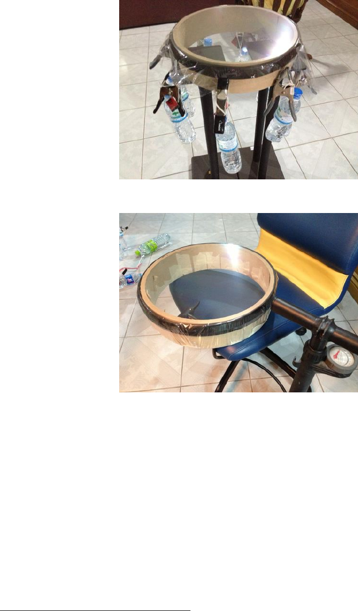
Figure 3: A Mylar tensioning rig using weights
Figure 4: A Mylar tensioning rig using an inflatable tire
outside. Next, we put our two back spacers on the Mylar and drew the outline onto the Mylar. Gluing both
spacers at the same time ensures that the tension is the same on both sides. The spacers were then removed
and both the spacer and their outline on the Mylar were covered with a thin layer of UHU Greenit. This
is a contact cement or synthetic rubber glue, alternatives include UHU Por, 3M 4693. The glue is allowed
to dry for 15 minutes, after which the spacers are placed onto the Mylar and pressed firmly onto them. We
actually used a rolling pin to increase the pressure and thus the glueing strength22. After this, the weights
can be removed and the excess Mylar can be cut away from the spacers. Note that it is very important to
not have any Mylar overlap the edge of the spacer. We used a small scissor and then went around the edges
with an old soldering iron to ensure this. After completing this step the spacers can be knocked on the side
of a table to check whether the sound of both diaphragms is similar. If not, a hot air gun can be used to
loosen the tension of a diaphragm.
An idea on how to identify the correct tension of the diaphragm by checking the free-air resonance
frequency (should be between 100 and 200 Hz) using a white noise generator on one side and a microphone
on the other was also mentioned in the thread23, but we did not try this.
22http://www.head-fi.org/t/498292/my-diy-electrostatic-headphones/1215#post_10400583
23http://www.head-fi.org/t/498292/my-diy-electrostatic-headphones/1770#post_11440100
8

Figure 5: Our Mylar tensioning rig using weights
Note, while this step sounds easy, it is actually the most difficult one to get right and has probably the
most significant impact on the sound of your headphones. Because of this is makes sense to actually produce
a few extra back spacers to try different configurations. Alternatively, UHU Greenit can be removed from
the spacers using Acetone, so a new attempt can be made.
4.4 Coating the diaphragm
As Mylar is not conductive an additional coating is required so that it can be charged. It basically should
act as if it was a capacitor, so a coating that is conductive and has a high resistivity is ideal. Coating agents
mentioned in the thread are:
1. Staticide 6300 (anti-static cleaner for monitors)
2. Licron antistatic spray
3. Swash Floor cleaner
In our case we simply bought a anti-static spray for computer monitors, which worked without any issues.
Coating is achieved by applying a small drop of the coating agent onto the diaphragm and then spreading it
with a sponge or microfibre cloth (lint free). The coating only happens on one side of the diaphragm namely
the side pointing away from the spacer. It should be ensured that the coating also happens on the part of the
diaphragm that is above the spacer, i.e. all the way to the edge. After the coating has dried the surface can
be cleaned again with a dry lint free cloth. It is advisable to check the surface before the assembly to ensure
that there is no dust on it. Otherwise pressurized air or masking tape can be used to clean the diaphragm.
Diyaudio.com also has a thread about coating24.
4.5 Cable
The cable that connects the headphone with the step up transformer consists of three about 3m long litz
wires (0.14mm2)that were braided together. One side was soldered directly onto the stators and one spacer
whereas the other side was fitted with banana plugs to connect the headphones to the transformer.
While this might not be the perfect solution in terms of elegance and signal transmission it was a
inexpensive and functional way to make the headphones sing.
Alternatives include replacement cables for KOSS headphones. Apparently an extension cable for the
ESP-950 headphone should do the trick. 25
24http://www.diyaudio.com/forums/planars-exotics/109789-esl-diaphragm-coating.html
25https://www.head-fi.org/threads/my-diy-electrostatic-headphones.498292/page-51#post-9325470
9
4.6 Assembly
Before assembling the driver a dust protector needs to be built using the 1 mm spacer made from FR4 and
a 1 µm Mylar film. The Mylar is crumpled by hand and then slightly stretched using masking tape on a
flat surface. We then follow the same procedure as for the diaphragm, i.e. putting glue on both the spacer
and the Mylar, letting it dry and then pressing the two firmly together. The crumpling of the Mylar should
ensure that this film is acoustically transparent but keeps dust out of the driver. The slight stretching is
needed so that it doesn’t touch the spacer. The dust protection is only between the ear and the driver as
the coated side of the diaphragm is also towards the ear. Because of this, no dust protection is required on
the outside.
As we chose to have no connector directly at the headphone, we soldered the cables directly onto the two
stators and the 0.5 mm front spacer without the diaphragm. Then the conducting side of the two stators
was sprayed with (in our case black) acrylic spray to insulate them. This avoids arching once the stators
and diaphragm are charged.
Afterwards the driver can be assembled. See Fig. 6 for a visual representation of the arrangement of the
different parts. The part furthest away from the ear is the stator with negative wire with the acrylic covered
copper side pointing towards the ear. This is followed by the spacer with the diaphragm where the side with
the diaphragm and the coating points towards the ear. Next, the front spacer is added with its copper side
pointed away from the ear so that an electric connection between the diaphragm and the front spacer with
the cable is made. The remaining stator is then placed onto the spacer with the acrylic covered copper side
pointing away from the ear. Finally, the dust spacer is placed on the assembly with the crumpled Mylar
pointing towards the ear to complete the driver.
Figure 6: Arrangement and orientation of stators and spacers (missing the dust protection spacer and film)
To perform some tests we used some clothespins to keep the driver together. Be careful when running
tests with the driver outside the enclosure as nearly all parts will be charged. The driver can be tested by
hooking it up to the amp and leave it as is for 3 to 4 hours without playing any music. The diaphragm
should not be sucked to one side during this. It is also easy to hear any arching that occurs due to dust or
other mistakes in the production. Sometimes it is easy to see where the arching occurs and it is usually easy
to correct the cause (by using pressurized air or sanding the corners). After testing and before the driver is
disassembled, e.g. for correcting something, it is advisable to connect all three wires to ground in order to
allow the parts to discharge.
5 Building the enclosure
TODO-AM
Since we were already using a CNC machine to manufacture the drivers we opted for the same toolchain
to create the enclosure. As wood is a common material in enclosure construction we decided to use it as
well. We again designed the enclosure as a 2.5-D shape using Inkscape. The Gcode was created using
www.makercam.com similarly to the driver. To machine the enclosure we used a 6mm and a 2mm 2-flute end
10
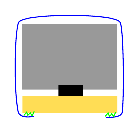
Figure 7: Earpad cut-through; materials: wood (yellow), foam (grey), screw nut (black), artificial leather
(blue), contact cement (green)
mill.
6 Building the headband
TODO-BB
http://www.head-fi.org/t/498292/my-diy-electrostatic-headphones/675#post_8943826
Headband can be made out of a metal ruler and then covered with leather http://www.head-fi.org/
t/498292/my-diy-electrostatic-headphones/2385#post_13037825.
7 Building the earpads
The earpads should be thick enough so that the bass is powerful and deep enough. The earpad is based
on a wooden ellipse with 4mm thickness that was also manufactured using the CNC. After we had the full
enclosing together we put the front and the back of the enclosing together with this ellipse to drill four holes
for the assembly. The screw nuts were glued to the inside of the ellipse using copious amounts of epoxy.
A schematic of the earpad can be seen in Fig. 7. After the glue has hardened (see your glue for the time,
for ours it was about 24h) we loosened the screws and disassembled everything. The next step consisted of
cutting the same ellipse from acoustic foam with 3cm thickness.
The leather cover is made from a thin and stretchy synthetic leather. It’s made of two parts, a rectangular
one with dimension 4 x 32 cm and an elliptic one which is of the same size as the wooden ellipse of the pad
plus 1 cm inside and 3 cm on the outside. The rectangular patch is sewn on the inside of the ellipse and
then it’s wrapped over the foam and the wooden pad connector. The leather is glued to the wood using the
contact cement that was also used to glue the diaphragm to the spacers. Finally, we also glued a mesh to
the wood so that the ears cannot get in touch with the dust protector.
8 Assembly
TODO-AM write about screws.
9 Amplifier
Due to the requirement of a continuously charged diaphragm and the high voltage requirements of the stators
a dedicated amplifier is required for electrostatic headphones. A discussion on this amplifier design can be
11
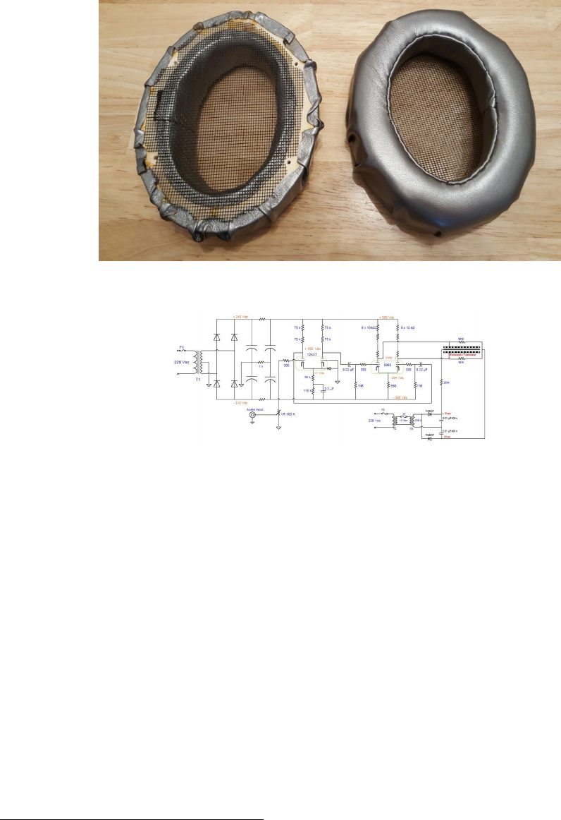
Figure 8: Final earpads
Figure 9: Amplifier design by Wachara C.
found on Head-fi.org 26. However, to not make out lives too difficult we decided against building a full
amplifier. Instead we opted to construct a step up transformer based on the designs of Charlie Mimbs 27.
A note of warning before we continue with the details. We will be dealing with electronic equipment in
the following which can cause serious injury or death so make sure you have a good understanding of what
you are doing and follow proper safety procedures.
Since we are not building a speaker we opted for a toned down version of Charlie’s step up that would
only lead to 580 volts at the diaphragm. A circuit diagram can be seen in Fig. 10 that was copied from
circuitjs 28.
The final step-up transformer can be seen in Fig. 11. As can be seen, we did not put it in a nice enclosing
and this will also be part of next years project. The step-up transformer is divided in three parts, the blue
and yellow part are the transformers for the left and right stators, respectively. Each of these section consists
of one 1 Ohm resistor and 2 audio transformers from 6 V to 230 V. The OEP transformers that we used
(see Section 3) were connected on the B-D and 1-4 pins. This yields a 4000k to 95k winding ratio. The two
transformers are connected in series and the output side is connected to the step-up part of the transformer
as can be seen in Fig. 10. Note that in the circuit diagram only one of these stator sections is depicted.
The green part in Fig. 11 corresponds to the lower part in the circuit diagram (Fig. 10) and is responsible
for converting the 230 V, 50 Hz AC input to a 580 V DC current. The AC input was connected to the Triad
power transformer including a 250mA fast blow fuse. On the output side a 3.9 kOhm resister is put before
26http://www.head-fi.org/t/498292/my-diy-electrostatic-headphones/720#post_9182523
27https://jazzman-esl-page.blogspot.co.at/2010/01/update-new-toroidal-step-up.html
28http://lushprojects.com/circuitjs/circuitjs.html
12
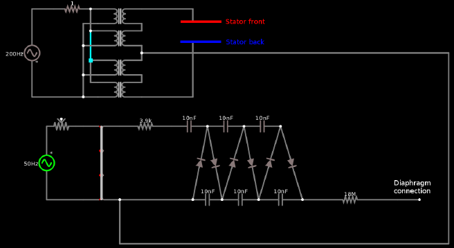
Figure 10: Step up transformer: circuit diagram
the actual step-up ladder that can be seen in the circuit diagram. This ladder consists of 6 10 nF capacitors
and 6 diodes to rectify the AC current. At the end of this ladder a 18 MOhm resistor is put before the
connection to the diaphragm is made. Note that we made only one step-up ladder that is connected to both
left and right diaphragms.
Note that when operating the headphone its component will be charged and this charge will persist even if
power to the transformer has been shut down. It is necessary to discharge all components before disassembly
which can be achieved by leaving the power cord connected after shutdown and using the ground connection
of the power cord. We hooked up a cable to the ground connection and discharge all outgoing ports by
touching them briefly with this cable.
10 Measurements
As part of the current build we did not perform any measurements and this will become a topic for the
future. The head-fi thread suggests to perform measurements with and without seal. The latter should give
a peak at around 200 Hz which is the free-air resonance frequency. This frequency should be lower than 150
Hz for a good bass response.
11 What to do different in the future
Allow for a little space between enclosing and driver.
Shrink wrapped cable with proper xlr connector and connector at the headphone. Space for the cables
milled out when creating the enclosure.
Earpad made out of three pieces (2 rectangular ones and one ellipse).
Proper enclosing for the step-up transformer or even a real amplifier for electrostatic headphones. Addi-
tional cables to connect the step-up transformer to headphone amplifiers.
11.1 Closed headphones
Materials used for damping included felt, wool or other acoustically semi-transparent materials. Some also
coat the inside of the enclosure with Bitumen.
13
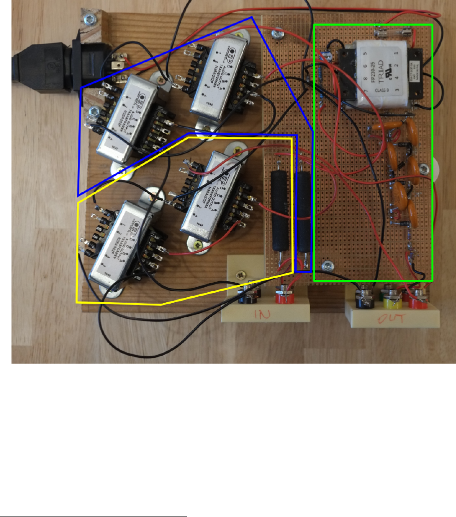
Figure 11: Step up transformer from the top
12 Collaboration & License
This work is licensed under a Creative Commons Attribution-ShareAlike 4.0 International License 29 . The
official repository for this guide can be found on github.com 30. There is an issue tracker available if you do
not know how to work with L
A
T
E
Xand git. We very much jumped into this venture without prior knowledge
of a lot of things that we had to tackle. Because of this there might very well be mistakes in this guide or
in our approach that we are happy to learn about. So do get in touch with us if you have any remarks and
want to help us improve this document. We plan to build version 2 of the headphones in 2018 and with this
we will also update and improve this guide.
29http://creativecommons.org/licenses/by-sa/4.0/
30https://github.com/Azrael3000/headphone-guide
14

13 Appendix
13.1 Circuit diagram for circuitjs
This file can also be found in the resources.zip file which can be found on github.com 31.
$ 13 0.000005 146.80153516788286 47 120 28
v 448 512 448 352 0 1 50 230 0 1.5707963267948966 0.5
c 720 352 800 352 0 1e-8 -121.77903323034391
w 608 512 608 608 0
w 608 512 768 512 0
d 768 512 800 352 1 0.805904783
d 800 352 832 512 1 0.805904783
d 832 512 880 352 1 0.805904783
d 880 352 912 512 1 0.805904783
d 912 512 960 352 1 0.805904783
d 960 352 1008 512 1 0.805904783
c 800 352 880 352 0 1e-8 -188.52952984256655
c 880 352 960 352 0 1e-8 -148.45206709826482
c 768 512 832 512 0 1e-8 -188.38552969850758
c 832 512 912 512 0 1e-8 -148.28294550190276
c 912 512 1008 512 0 1e-8 -133.83898987162684
r 1008 512 1216 512 0 18000000
w 1216 512 1264 512 0
w 608 608 1328 608 0
v 416 96 416 288 0 1 200 6 0 0 0.5
T 560 96 656 112 0 4 20 -0.0002165438913044398 0.000008783616360946498 0.999
T 560 176 656 144 0 4 20 0.00021654389130444608 -0.000008783616360946477 0.999
T 560 240 656 208 0 4 20 0.00021654389130505795 -0.00000878361636097594 0.999
T 560 288 656 256 0 4 20 0.00021654389130505323 -0.000008783616360975917 0.999
w 656 128 656 144 0
w 656 240 656 256 0
r 544 96 464 96 0 1
w 544 96 560 96 0
w 544 208 560 208 0
w 544 144 560 144 0
w 544 208 544 256 0
w 544 256 560 256 0
w 544 208 544 144 0
w 544 144 544 96 0
w 560 128 528 128 0
w 528 128 528 176 0
w 528 176 560 176 0
w 528 176 528 240 0
w 528 240 560 240 0
w 560 288 528 288 0
w 528 288 528 240 0
w 416 288 528 288 0
w 464 96 416 96 0
w 1328 608 1328 192 0
w 1328 192 656 192 0
31https://github.com/Azrael3000/headphone-guide/raw/master/resoures.zip
15
w 656 208 656 192 0
w 656 192 656 176 0
w 656 288 768 288 0
w 768 288 768 160 0
w 656 96 768 96 0
c 768 96 768 160 0 2e-11 -328.31758099807905
T 608 352 528 192 0 2 1 -4.752600223090209e-16 -0.18138620921599558 0.999
r 608 352 720 352 0 3900
w 448 512 528 512 0
174 448 352 512 352 0 1000 0.5 Resistance
w 512 352 528 352 0
o 16 64 0 2083 1280 0.00009765625 0 -1 0
o 49 64 0 2083 1280 0.0001953125 1 -1 0
o 51 64 0 2083 5 0.0015625 2 -1 0
o 1 64 0 2083 320 0.0015625 3 -1 0
o 3 64 0 2083 640 0.0015625 4 -1 0
o 54 64 0 2083 640 0.4 5 -1 0
References
[1] Wachara Chinsettawong. My diy electrostatic headphones, 2016.
[2] Jarosz N. Electrostatic headphone design and construction, 2013.
[3] Pollock N. Electrostatic headphones. Wirless World, 11, 1979.
[4] N.N. Electrostatic headphones, 2012.
16
