I2/b3 885 VAV Controller Installation Ftp://ftp.zenex.pl/katalogi/schneider/5_systemy_automatyki_i_bezpieczenstwa_w_budynkach/5_1_andover_continuum/pdf/instrukcje_materialy_techniczne/i2_b3_885_vav_controller_installation_instructions.en I2 B3 Instructions.en
User Manual: Pdf ftp://ftp.zenex.pl/katalogi/schneider/5_systemy_automatyki_i_bezpieczenstwa_w_budynkach/5_1_andover_continuum/pdf/instrukcje_materialy_techniczne/i2_b3_885_vav_controller_installation_instructions.en instructions pdf
Open the PDF directly: View PDF ![]() .
.
Page Count: 2
30-3001-848 Rev F
Full programming and installation information can be found
in the following documents:
i2885 i2 Controller Technical Reference 30-3001-861
b3885 b3 and b4920 Technical Reference 30-3001-862
Mechanical Installation
The 885 is designed for mounting directly to the damper shaft of
a VAV box. The shaft is inserted through the opening in the
actuator and secured using a U-bolt. It is secured via one sheet
metal screw.
Note: The unit requires that the VAV damper shaft be at least
1.5” (38 mm) in length and 1/4”- 5/8” (6-16 mm) in diameter
(1/4”-7/16” (6-11 mm) square) for proper mounting. The unit
may be mounted in any orientation.
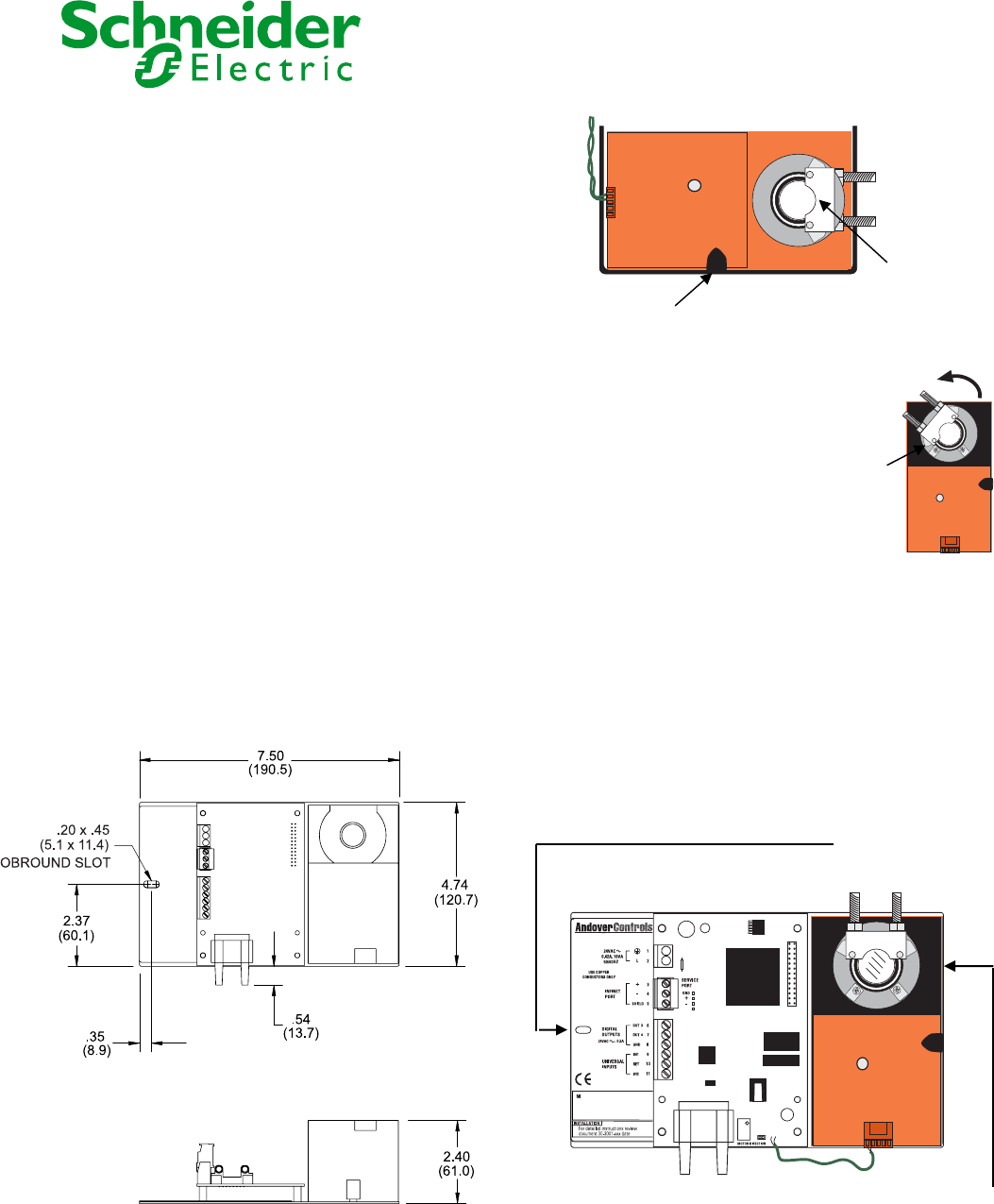
Overall Dimensions
Note:
This equipment is intended for field installation within the
enclosure of another product.
Attach the controller to the VAV box using the following procedure:
1. Loosen the nuts that attach the mounting U-bolt to the actuator
motor.
i2/b3 885 VAV Controller
Installation
U-bolt clamp with nuts
Manual override button
2. Manually, position the damper blade at its fully closed position.
3. With the manual override button
depressed, rotate the actuator clamp of
the controller motor to approximately 1/16
- 1/8” between the actuator stop and
clamp, depending on seal design. The
rotation direction to turn depends on the
setting of the rotation direction jumper on
the controller. The default direction to
position the clamp would be counter-
clockwise (full ‘-‘ position). See the other
side of this sheet for details on the
rotation direction jumper.
Sto
p
4. Position the unit at the proper perspective on the VAV box.
Carefully insert the shaft of the VAV unit into the opening of the
actuator motor through the U-bolt. Make sure the controller is flush
with the VAV housing. Finger-tighten the nuts to secure the shaft to
the actuator.
5. Insert a #8 self-tapping screw through the mounting slot to secure
the controller to the housing. Position the screw in the center of the
slot. Do not over-tighten. The controller should move freely on this
screw.
#8 Self-tapping screw
secures the unit to
the housing
6. Tighten the U-Bolt to the shaft using an 8 mm wrench.
Shaft inserted into
the actuator
© 2010 Schneider Electric All Rights Reserved. Schneider Electric – One High Street – North Andover MA USA 01845
ODEL
S/N
DATE
IN x
RET
V
+
-
ODEL
S/N
DATE
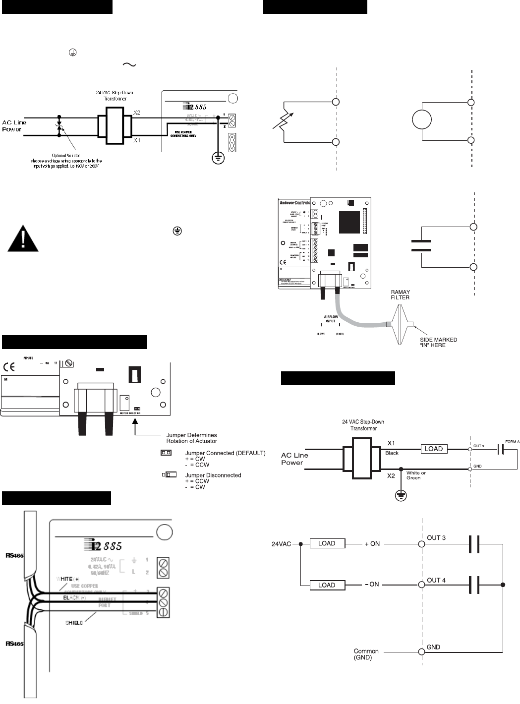
24 VAC Connection
The 885 controller is powered by an external 24 VAC source.
PIN Function
1 24 VAC RETURN (Earth GND)
2 L 24 VAC
The ground wire should not exceed 12” in length and it must be
connected to a good earth ground. The screw that connects the
ground wire with earth ground shall have a green colored head that
is hexagonal, slotted or both.
Caution: Earth ground ( ) must b
e
connected to avoid module damage.
Powering Multiple Controllers
Unless all the controllers you intend to power are resident in the
same cabinet, it is imperative that you use a separate
transformer for each controller.
Damper Direction Jumper
RS-485 Connection
Input Connections
Caution: Do not externally ground any input signal or
damage may result.
Temperature Voltage
0-5V Max.
IN x
Thermistor
RET
Airflow Contacts
ODEL
S/N
DATE
IN
OU T
IN x
RET
Contact
Closure
Output Connections
Form A
Tri-State
