Avalon® Interface Specifications Manual Avalon Spec
User Manual: Pdf
Open the PDF directly: View PDF ![]() .
.
Page Count: 60
- Avalon Interface Specifications
- Contents
- 1 Introduction to the Avalon Interface Specifications
- 2 Avalon Clock and Reset Interfaces
- 3 Avalon Memory-Mapped Interfaces
- 3.1 Introduction to Avalon Memory-Mapped Interfaces
- 3.2 Avalon Memory-Mapped Interface Signal Roles
- 3.3 Interface Properties
- 3.4 Timing
- 3.5 Transfers
- 3.6 Address Alignment
- 3.7 Avalon-MM Slave Addressing
- 4 Avalon Interrupt Interfaces
- 5 Avalon Streaming Interfaces
- 5.1 Terms and Concepts
- 5.2 Avalon Streaming Interface Signal Roles
- 5.3 Signal Sequencing and Timing
- 5.4 Avalon-ST Interface Properties
- 5.5 Typical Data Transfers
- 5.6 Signal Details
- 5.7 Data Layout
- 5.8 Data Transfer without Backpressure
- 5.9 Data Transfer with Backpressure
- 5.10 Packet Data Transfers
- 5.11 Signal Details
- 5.12 Protocol Details
- 6 Avalon Conduit Interfaces
- 7 Avalon Tristate Conduit Interface
- A Deprecated Signals
- B Document Revision History for the Avalon Interface Specifications


Contents
1 Introduction to the Avalon Interface Specifications......................................................... 4
1.1 Avalon Properties and Parameters.............................................................................7
1.2 Signal Roles ..........................................................................................................7
1.3 Interface Timing ....................................................................................................7
2 Avalon Clock and Reset Interfaces .................................................................................. 8
2.1 Avalon Clock Sink Signal Roles ................................................................................ 8
2.2 Clock Sink Properties ............................................................................................. 9
2.3 Associated Clock Interfaces .....................................................................................9
2.4 Avalon Clock Source Signal Roles .............................................................................9
2.5 Clock Source Properties..........................................................................................9
2.6 Reset Sink ......................................................................................................... 10
2.7 Reset Sink Interface Properties............................................................................... 10
2.8 Associated Reset Interfaces ..................................................................................10
2.9 Reset Source ......................................................................................................10
2.10 Reset Source Interface Properties.........................................................................11
3 Avalon Memory-Mapped Interfaces................................................................................12
3.1 Introduction to Avalon Memory-Mapped Interfaces ................................................... 12
3.2 Avalon Memory-Mapped Interface Signal Roles......................................................... 14
3.3 Interface Properties ..............................................................................................18
3.4 Timing ................................................................................................................21
3.5 Transfers ............................................................................................................ 21
3.5.1 Typical Read and Write Transfers ................................................................ 22
3.5.2 Transfers Using the waitrequestAllowance Property........................................23
3.5.3 Read and Write Transfers with Fixed Wait-States .......................................... 27
3.5.4 Pipelined Transfers ................................................................................... 28
3.5.5 Burst Transfers ........................................................................................ 30
3.5.6 Read and Write Responses......................................................................... 34
3.6 Address Alignment ............................................................................................... 36
3.7 Avalon-MM Slave Addressing ................................................................................. 36
4 Avalon Interrupt Interfaces .......................................................................................... 38
4.1 Interrupt Sender ..................................................................................................38
4.1.1 Avalon Interrupt Sender Signal Roles ..........................................................38
4.1.2 Interrupt Sender Properties .......................................................................38
4.2 Interrupt Receiver ................................................................................................39
4.2.1 Avalon Interrupt Receiver Signal Roles ........................................................39
4.2.2 Interrupt Receiver Properties ..................................................................... 39
4.2.3 Interrupt Timing ...................................................................................... 39
5 Avalon Streaming Interfaces .........................................................................................40
5.1 Terms and Concepts ............................................................................................. 41
5.2 Avalon Streaming Interface Signal Roles ................................................................. 42
5.3 Signal Sequencing and Timing ............................................................................... 43
5.3.1 Synchronous Interface ..............................................................................43
5.3.2 Clock Enables .......................................................................................... 43
5.4 Avalon-ST Interface Properties ...............................................................................43
Contents
Avalon® Interface Specifications
2

5.5 Typical Data Transfers ...........................................................................................44
5.6 Signal Details ...................................................................................................... 44
5.7 Data Layout ........................................................................................................ 45
5.8 Data Transfer without Backpressure ........................................................................46
5.9 Data Transfer with Backpressure ............................................................................ 46
5.10 Packet Data Transfers ......................................................................................... 48
5.11 Signal Details .................................................................................................... 49
5.12 Protocol Details ..................................................................................................49
6 Avalon Conduit Interfaces .............................................................................................50
6.1 Avalon Conduit Signal Roles .................................................................................. 51
6.2 Conduit Properties ............................................................................................... 51
7 Avalon Tristate Conduit Interface ................................................................................. 52
7.1 Avalon Tristate Conduit Signal Roles ....................................................................... 54
7.2 Tristate Conduit Properties .................................................................................... 55
7.3 Tristate Conduit Timing .........................................................................................55
A Deprecated Signals........................................................................................................ 57
B Document Revision History for the Avalon Interface Specifications............................... 58
Contents
Avalon® Interface Specifications
3

1 Introduction to the Avalon Interface Specifications
Avalon® interfaces simplify system design by allowing you to easily connect
components in an Intel FPGA. The Avalon interface family defines interfaces
appropriate for streaming high-speed data, reading and writing registers and memory,
and controlling off-chip devices. These standard interfaces are designed into the
components available in Platform Designer. You can also use these standardized
interfaces in your custom components. By using these standard interfaces, you
enhance the interoperability of your designs.
This specification defines all of the Avalon interfaces. After reading it, you should
understand which interfaces are appropriate for your components and which signal
roles to use for particular behaviors. This specification defines the following seven
interfaces:
• Avalon Streaming Interface (Avalon-ST)—an interface that supports the
unidirectional flow of data, including multiplexed streams, packets, and DSP data.
• Avalon Memory Mapped Interface (Avalon-MM)—an address-based read/write
interface typical of master–slave connections.
• Avalon Conduit Interface— an interface type that accommodates individual signals
or groups of signals that do not fit into any of the other Avalon types. You can
connect conduit interfaces inside a Platform Designer system. Or, you can export
them to make connections to other modules in the design or to FPGA pins.
• Avalon Tri-State Conduit Interface (Avalon-TC) —an interface to support
connections to off-chip peripherals. Multiple peripherals can share pins through
signal multiplexing, reducing the pin count of the FPGA and the number of traces
on the PCB.
• Avalon Interrupt Interface—an interface that allows components to signal events
to other components.
• Avalon Clock Interface—an interface that drives or receives clocks.
• Avalon Reset Interface—an interface that provides reset connectivity.
A single component can include any number of these interfaces and can also include
multiple instances of the same interface type. For example, in the first figure below,
the Ethernet Controller includes the following six different interface types:
• Avalon-MM
• Avalon-ST
• Avalon Conduit
• Avalon-TC
• Avalon Interrupt
• Avalon Clock.
MNL-AVABUSREF | 2018.03.22
Intel Corporation. All rights reserved. Intel, the Intel logo, Altera, Arria, Cyclone, Enpirion, MAX, Nios, Quartus
and Stratix words and logos are trademarks of Intel Corporation or its subsidiaries in the U.S. and/or other
countries. Intel warrants performance of its FPGA and semiconductor products to current specifications in
accordance with Intel's standard warranty, but reserves the right to make changes to any products and services
at any time without notice. Intel assumes no responsibility or liability arising out of the application or use of any
information, product, or service described herein except as expressly agreed to in writing by Intel. Intel
customers are advised to obtain the latest version of device specifications before relying on any published
information and before placing orders for products or services.
*Other names and brands may be claimed as the property of others.
ISO
9001:2008
Registered
Note: Avalon interfaces are an open standard. No license or royalty is required to develop
and sell products that use, or are based on Avalon interfaces.
The following figures illustrate the use of the Avalon interfaces in system designs.
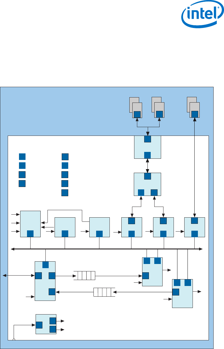
Figure 1. Avalon Interfaces in a System Design with Scatter Gather DMA Controller and
Nios II Processor
IRQ1 IRQ2
C1
Conduit
Avalon-MM
C2
Avalon-ST
C1
C1
Avalon-ST
FIFO Buffer
FIFO Buffer
Avalon-ST Avalon-ST
C2
C2
C2
C1
C2
Ref Clk
FlashSSRAM DDR3
Intel FPGA
Printed Circuit Board
IRQ3
IRQ4
IRQ3
IRQ4
TimerUART
Nios II
C1
C1
Tristate Cntrl
SSRAM
PLL
TCM
TCM
TCS
TCS
M S
S
S S
MS
MS
TCM
S S
Cn
Cn
Cn
CSnk
CSrc
CSrc
CSnk
CSrc
Src
Src
Snk
Snk
Avalon-MM Master
Avalon-MM Slave
Avalon-ST Source
Avalon Conduit
Avalon-TC Master
Avalon-TC Slave
Avalon Clock Source
Avalon Clock Sink
Avalon-ST Sink
TCS
TCM
M
S
Cn
Src
Snk
Cn Cn Cn
TCS
Tristate Cntrl
Flash DDR3
Controller
Scatter Gather
DMA
Scatter Gather
DMA
Ethernet
Controller
Tristate Conduit
Bridge
Tristate Conduit
Pin Sharer
In this figure, the Nios® II processor accesses the control and status registers of on-
chip components using an Avalon-MM interface. The scatter gather DMAs send and
receive data using Avalon-ST interfaces. Four components include interrupt interfaces
serviced by software running on the Nios II processor. A PLL accepts a clock via an
1 Introduction to the Avalon Interface Specifications
MNL-AVABUSREF | 2018.03.22
Avalon® Interface Specifications
5
Avalon Clock Sink interface and provides two clock sources. Two components include
Avalon-TC interfaces to access off-chip memories. Finally, the DDR3 controller
accesses external DDR3 memory using an Avalon Conduit interface.
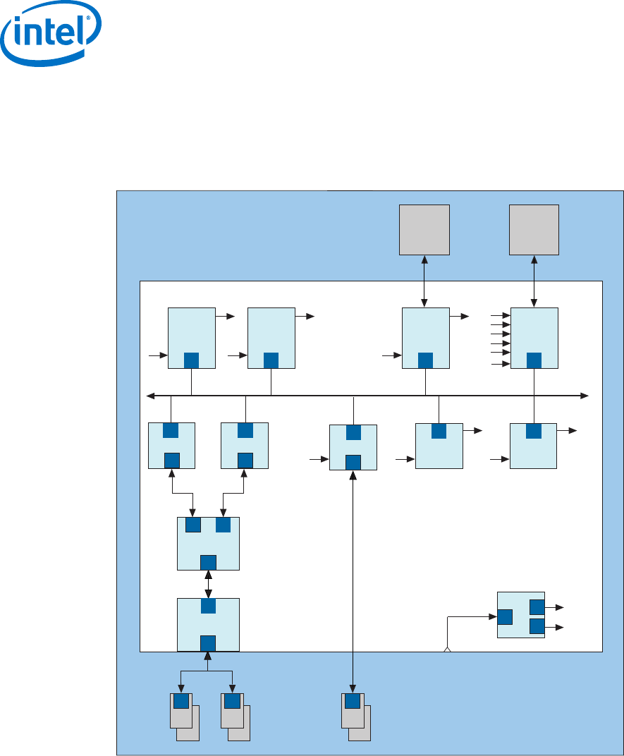
Figure 2. Avalon Interfaces in a System Design with PCI Express Endpoint and External
Processor
Avalon-MM
C1
C1
C1
C2
Ref Clk
Intel FPGA
Printed Circuit Board
IRQ1 IRQ2 IRQ3
C1
Custom
Logic
Ethernet
MAC
PLL
M M
S
Cn
CSnk
CSrc
CSrc
SDRAM
Controller
IRQ4
C2
IRQ5
C2
FlashSSRAM
C1
TCS
TCM TCM
TCS TCS
Cn
TCM
S
UART
S
Custom
Logic
SDRAM
CnCn Cn
S S
Tristate Cntrl
SSRAM Tristate Cntrl
Flash
Tristate Conduit
Pin Sharer
Tristate Conduit
Bridge
C1
PCI Express
Endpoint
M
IRQ1
IRQ2
IRQ3
IRQ4
IRQ5
External Bus
Protocol
Bridge
M
PCI Express
Root Port
External
CPU
In the previous figure, an external processor accesses the control and status registers
of on-chip components via an external bus bridge with an Avalon-MM interface. The
PCI Express Root Port controls devices on the printed circuit board and the other
components of the FPGA by driving an on-chip PCI Express Endpoint with an Avalon-
MM master interface. An external processor handles interrupts from five components.
A PLL accepts a reference clock via a Avalon Clock sink interface and provides two
clock sources. The flash and SRAM memories use an Avalon-TC interface to share
FPGA pins. Finally, an SDRAM controller accesses an external SDRAM memory using
an Avalon Conduit interface.
1 Introduction to the Avalon Interface Specifications
MNL-AVABUSREF | 2018.03.22
Avalon® Interface Specifications
6

Related Links
•Introduction to Intel FPGA IP Cores
Provides general information about all Intel FPGA IP cores, including
parameterizing, generating, upgrading, and simulating IP cores.
•Generating a Combined Simulator Setup Script
Create simulation scripts that do not require manual updates for software or IP
version upgrades.
•Project Management Best Practices
Guidelines for efficient management and portability of your project and IP files.
1.1 Avalon Properties and Parameters
Avalon interfaces use properties to describe their behavior. For example, the
maxChannel property of Avalon-ST interfaces allows you to specify the number of
channels supported by the interface. The clockRate property of the Avalon Clock
interface provides the frequency of a clock signal. The specification for each interface
type defines all of its properties and specifies the default values.
1.2 Signal Roles
Each of the Avalon interfaces defines a number of signal roles and their behavior.
Many signal roles are optional. You have the flexibility to select only the signal roles
necessary to implement the required functionality. For example, the Avalon-MM
interface includes optional beginbursttransfer and burstcount signal roles for
use in components that support bursting. The Avalon-ST interface includes the
optional startofpacket and endofpacket signal roles for interfaces that support
packets.
With the exception of Avalon Conduit interfaces, each interface may include only one
signal of each signal role. Active-low signals are permitted for many signal roles.
Active-high signals are generally used in this document.
1.3 Interface Timing
Subsequent chapters of this document include timing information that describes
transfers for individual interface types. There is no guaranteed performance for any of
these interfaces. Actual performance depends on many factors, including component
design and system implementation.
Most Avalon interfaces must not be edge sensitive to signals other than the clock and
reset. Other signals may transition multiple times before they stabilize. The exact
timing of signals between clock edges varies depending upon the characteristics of the
selected Intel FPGA. This specification does not specify electrical characteristics. Refer
to the appropriate device documentation for electrical specifications.
1 Introduction to the Avalon Interface Specifications
MNL-AVABUSREF | 2018.03.22
Avalon® Interface Specifications
7
2 Avalon Clock and Reset Interfaces
Avalon Clock interfaces define the clock or clocks used by a component. Components
can have clock inputs, clock outputs, or both. A phase locked loop (PLL) is an example
of a component that has both a clock input and clock outputs.
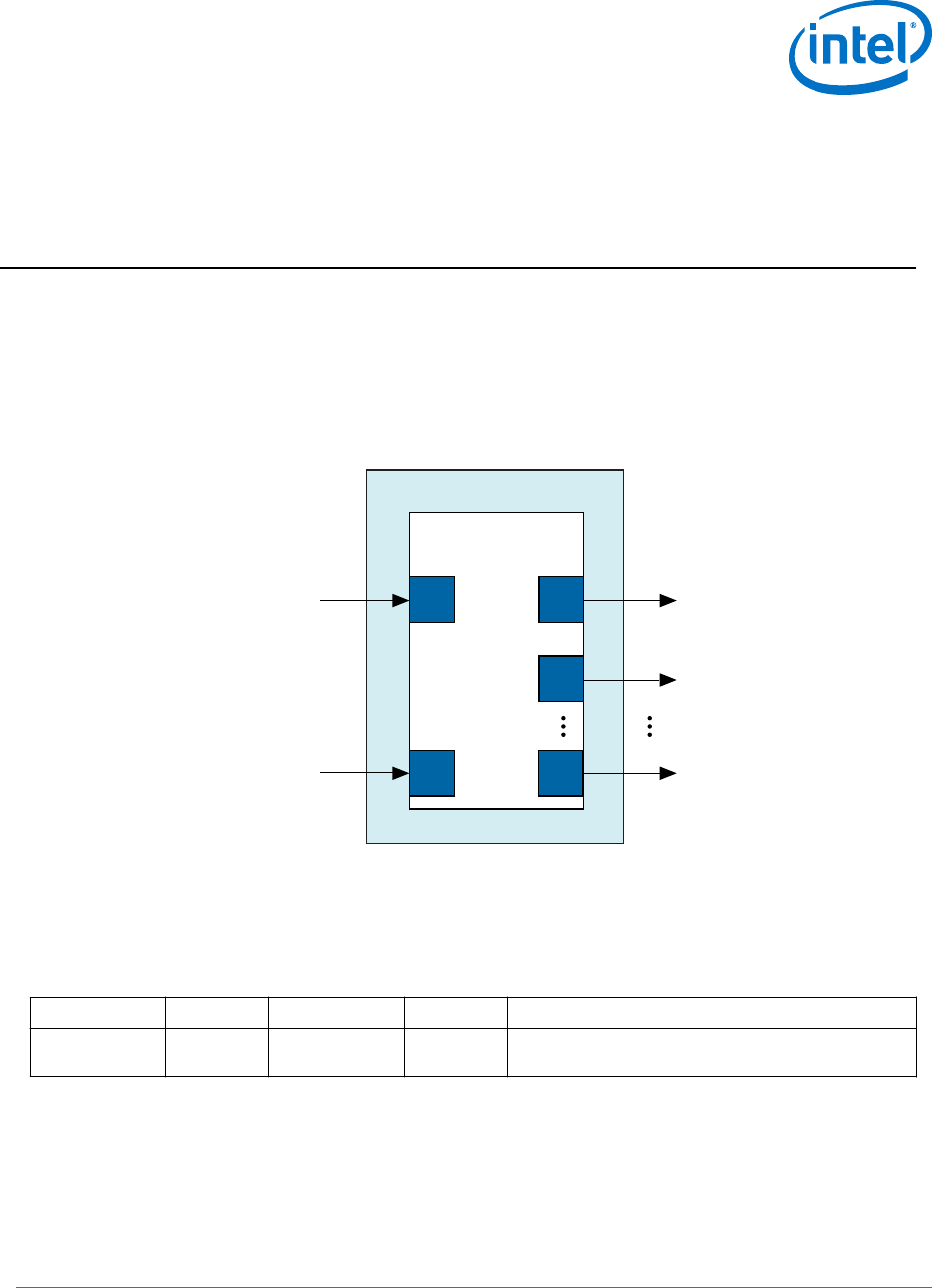
The following figure is a simplified illustration showing the most important inputs and
outputs of a PLL component.
Figure 3. PLL Core Clock Outputs and Inputs
PLL Core
altpll Megafunction
ref_clk
Clock Output
Interface1
Clock Output
Interface2
Clock Output
Interface_n
reset
Clock
Sink
Clock
Source
Clock
Source
Clock
Source
Reset
Sink
2.1 Avalon Clock Sink Signal Roles
A clock sink provides a timing reference for other interfaces and internal logic.
Table 1. Clock Sink Signal Roles
Signal Role Width Direction Required Description
clk 1 Input Yes A clock signal. Provides synchronization for internal
logic and for other interfaces.
MNL-AVABUSREF | 2018.03.22
Intel Corporation. All rights reserved. Intel, the Intel logo, Altera, Arria, Cyclone, Enpirion, MAX, Nios, Quartus
and Stratix words and logos are trademarks of Intel Corporation or its subsidiaries in the U.S. and/or other
countries. Intel warrants performance of its FPGA and semiconductor products to current specifications in
accordance with Intel's standard warranty, but reserves the right to make changes to any products and services
at any time without notice. Intel assumes no responsibility or liability arising out of the application or use of any
information, product, or service described herein except as expressly agreed to in writing by Intel. Intel
customers are advised to obtain the latest version of device specifications before relying on any published
information and before placing orders for products or services.
*Other names and brands may be claimed as the property of others.
ISO
9001:2008
Registered
2.2 Clock Sink Properties
Table 2. Clock Sink Properties
Name Default Value Legal Values Description
clockRate 0 0–232–1 Indicates the frequency in Hz of the clock sink interface. If 0, the
clock rate allows any frequency. If non-zero, Platform Designer
issues a warning if the connected clock source is not the
specified frequency.
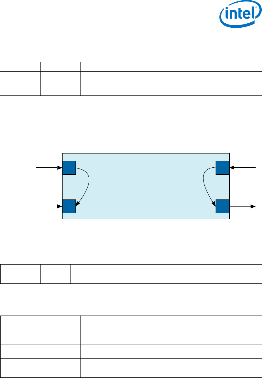
2.3 Associated Clock Interfaces
All synchronous interfaces have an associatedClock property that specifies which
clock source on the component is used as a synchronization reference for the
interface. This property is illustrated in the following figure.
Figure 4. associatedClock Property
Dual Clock FIFO
rx_clk
ST
Sink
Clock
Sink
tx_clk
ST
Source
associatedClock = "rx_clk" associatedClock = "tx_clk"
Clock
Sink
rx_data tx_data
2.4 Avalon Clock Source Signal Roles
An Avalon Clock source interface drives a clock signal out of a component.
Table 3. Clock Source Signal Roles
Signal Role Width Direction Required Description
clk 1 Output Yes An output clock signal.
2.5 Clock Source Properties
Table 4. Clock Source Properties
Name Default
Value
Legal
Values
Description
associatedDirectClock N/A an input
clock name
The name of the clock input that directly drives this
clock output, if any.
clockRate 0 0–232–1 Indicates the frequency in Hz at which the clock output
is driven.
clockRateKnown false true, false Indicates whether or not the clock frequency is known.
If the clock frequency is known, this information can be
used to customize other components in the system.
2 Avalon Clock and Reset Interfaces
MNL-AVABUSREF | 2018.03.22
Avalon® Interface Specifications
9

2.6 Reset Sink
Table 5. Reset Input Signal Roles
The reset_req signal is an optional signal that you can use to prevent memory content corruption by
performing reset handshake prior to an asynchronous reset assertion.
Signal Role Width Direction Required Description
reset,
reset_n
1 Input Yes Resets the internal logic of an interface or component
to a user-defined state. The synchronous properties of
the reset are defined by the synchronousEdges
parameter.
reset_req 1 input No Early indication of reset signal. This signal acts as a
least a one-cycle warning of pending reset for ROM
primitives. Use reset_req to disable the clock enable
or mask the address bus of an on-chip memory, to
prevent the address from transitioning when an
asynchronous reset input is asserted.
2.7 Reset Sink Interface Properties
Table 6. Reset Input Signal Roles
Name Default
Value
Legal
Values
Description
associatedClock N/A a clock
name
The name of a clock to which this interface is
synchronized. Required if the value of
synchronousEdges is DEASSERT or BOTH.
synchronous-Edges DEASSERT NONE
DEASSERT
BOTH
Indicates the type of synchronization the reset input
requires. The following values are defined:
•NONE–no synchronization is required because the
component includes logic for internal
synchronization of the reset signal.
•DEASSERT–the reset assertion is asynchronous and
deassertion is synchronous.
BOTH–reset assertion and deassertion are
synchronous.
2.8 Associated Reset Interfaces
All synchronous interfaces have an associatedReset property that specifies which
reset signal resets the interface logic.
2.9 Reset Source
Table 7. Reset Output Signal Roles
The reset_req signal is an optional signal that you can use to prevent memory content corruption by
performing reset handshake prior to an asynchronous reset assertion.
Signal Role Width Direction Required Description
reset
reset_n
1 Output Yes Resets the internal logic of an interface or component
to a user-defined state.
reset_req 1 Output Optional Enables reset request generation, which is an early
signal that is asserted before reset assertion. Once
asserted, this cannot be deasserted until the reset is
completed.
2 Avalon Clock and Reset Interfaces
MNL-AVABUSREF | 2018.03.22
Avalon® Interface Specifications
10

2.10 Reset Source Interface Properties
Table 8. Reset Interface Properties
Name Default
Value
Legal
Values
Description
associatedClock N/A a clock
name
The name of a clock to which this interface
synchronized. Required if the value of
synchronousEdges is DEASSERT or BOTH.
associatedDirectReset N/A a reset
name
The name of the reset input that directly drives this
reset source through a one-to-one link.
associatedResetSinks N/A a reset
name
Specifies reset inputs which will eventually cause a
reset source to assert reset. For example, a reset
synchronizer ORs a number of reset inputs to generate
a reset output.
synchronousEdges DEASSERT NONE
DEASSERT
BOTH
Indicates the reset output's synchronization. The
following values are defined:
•NONE–The reset interface is asynchronous.
•DEASSERT–the reset assertion is asynchronous and
deassertion is synchronous.
•BOTH–reset assertion and deassertion are
synchronous.
2 Avalon Clock and Reset Interfaces
MNL-AVABUSREF | 2018.03.22
Avalon® Interface Specifications
11

3 Avalon Memory-Mapped Interfaces
3.1 Introduction to Avalon Memory-Mapped Interfaces
You can use Avalon Memory-Mapped (Avalon-MM) interfaces to implement read and
write interfaces for master and slave components. The following are examples of
components that typically include memory-mapped interfaces:
• Microprocessors
• Memories
• UARTs
• DMAs
• Timers
Avalon-MM interfaces range from simple to complex. For example, SRAM interfaces
that have fixed-cycle read and write transfers have simple Avalon-MM interfaces.
Pipelined interfaces capable of burst transfers are complex.
MNL-AVABUSREF | 2018.03.22
Intel Corporation. All rights reserved. Intel, the Intel logo, Altera, Arria, Cyclone, Enpirion, MAX, Nios, Quartus
and Stratix words and logos are trademarks of Intel Corporation or its subsidiaries in the U.S. and/or other
countries. Intel warrants performance of its FPGA and semiconductor products to current specifications in
accordance with Intel's standard warranty, but reserves the right to make changes to any products and services
at any time without notice. Intel assumes no responsibility or liability arising out of the application or use of any
information, product, or service described herein except as expressly agreed to in writing by Intel. Intel
customers are advised to obtain the latest version of device specifications before relying on any published
information and before placing orders for products or services.
*Other names and brands may be claimed as the property of others.
ISO
9001:2008
Registered
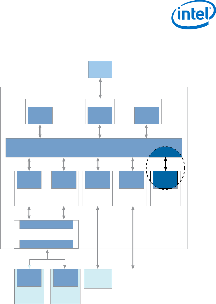
Figure 5. Focus on Avalon-MM Slave Transfers
The following figure shows a typical system, highlighting the Avalon-MM slave interface connection to the
interconnect fabric.
RS-232
Avalon-MM System
Interconnect
Ethernet
PHY
Avalon
Slave Port
Avalon-MM
Slave
Avalon-MM
Slave
RAM
Memory
Avalon-MM
Master
Processor
Flash
Memory
Tristate
Conduit
Slave
Tristate
Conduit
Slave
SRAM
Memory
Avalon-MM
Master
Avalon-MM
Master
Ethernet MAC Custom Logic
RAM
Controller UART Custom
Logic
Flash
Controller
Avalon-MM
Slave
Tristate Conduit Pin Sharer &
Tristate Conduit Bridge
Tristate Conduit Slave
Tristate Conduit Master
SRAM
Controller
Avalon-MM
Slave
Avalon-MM
Slave
Custom
Logic
Avalon-MM components typically include only the signals required for the component
logic.
3 Avalon Memory-Mapped Interfaces
MNL-AVABUSREF | 2018.03.22
Avalon® Interface Specifications
13
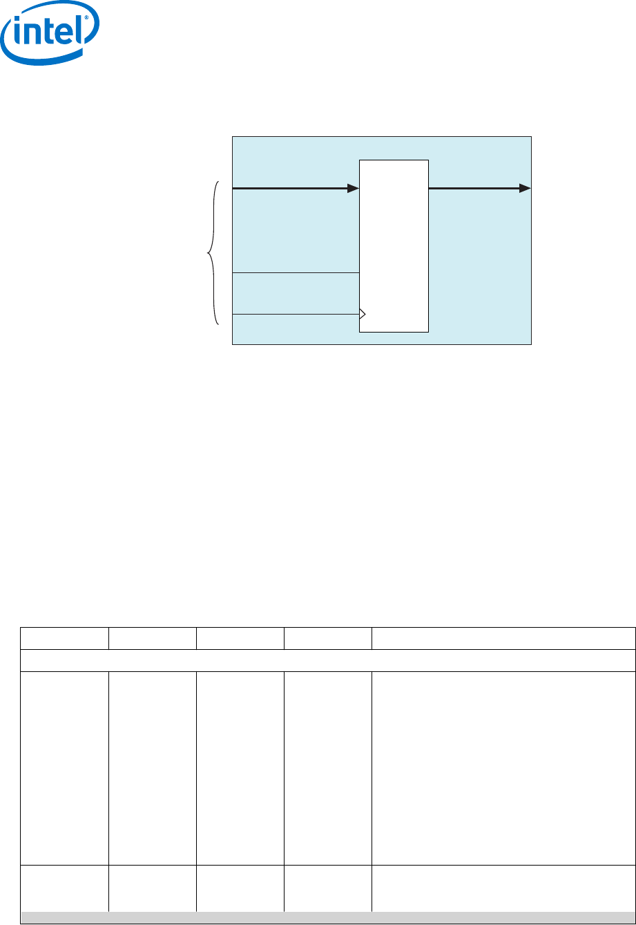
Figure 6. Example Slave Component
The 16-bit general-purpose I/O peripheral shown in the following figure only responds to write requests. This
component includes only the slave signals required for write transfers.
Avalon-MM
Interface
(Avalon-MM
Slave Interface)
Application-
Specific
Interface
writedata[15..0]
write
clk
pio_out[15..0]
CLK_EN
D Q
Avalon-MM Peripheral
Each signal in an Avalon-MM slave corresponds to exactly one Avalon-MM signal role.
An Avalon-MM interface can use only one instance of each signal role.
3.2 Avalon Memory-Mapped Interface Signal Roles
Signal roles define the signal types that are allowed on Avalon-MM master and slave
ports.
This specification does not require all signals to exist in an Avalon-MM interface. There
is no one signal that is always required. The minimum requirements for an Avalon-MM
interface are readdata for a read-only interface, or writedata and write for a
write-only interface.
The following table lists signal roles for the Avalon-MM interface:
Table 9. Avalon-MM Signal Roles
Some Avalon-MM signals can be active high or active low. When active low, the signal name ends with _n.
Signal Role Width Direction Required Description
Fundamental Signals
address 1 - 64 Master → Slave No Masters: By default, the address signal
represents a byte address. The value of the
address must be aligned to the data width. To write
to specific bytes within a data word, the master
must use the byteenable signal. Refer to the
addressUnits interface property for word
addressing.
Slaves: By default, the interconnect translates the
byte address into a word address in the slave’s
address space. Each slave access is for a word of
data from the perspective of the slave. For
example, address = 0 selects the first word of
the slave. address = 1 selects the second word
of the slave. Refer to the addressUnits interface
property for byte addressing.
byteenable 2, 4, 8, 16, 32,
64, 128
Master → Slave No Enables one or more specific byte lanes during
transfers on interfaces of width greater than 8 bits.
Each bit in byteenable corresponds to a byte in
continued...
3 Avalon Memory-Mapped Interfaces
MNL-AVABUSREF | 2018.03.22
Avalon® Interface Specifications
14

Signal Role Width Direction Required Description
byteenable_
n
writedata and readdata. The master bit <n> of
byteenable indicates whether byte <n> is being
written to. During writes, byteenables specify
which bytes are being written to. Other bytes
should be ignored by the slave. During reads,
byteenables indicate which bytes the master is
reading. Slaves that simply return readdata with
no side effects are free to ignore byteenables
during reads. If an interface does not have a
byteenable signal, the transfer proceeds as if all
byteenables are asserted.
When more than one bit of the byteenable signal
is asserted, all asserted lanes are adjacent. The
number of adjacent lines must be a power of 2.
The specified bytes must be aligned on an address
boundary for the size of the data. For example, the
following values are legal for a 32-bit slave:
• 1111 writes full 32 bits
• 0011 writes lower 2 bytes
• 1100 writes upper 2 bytes
• 0001 writes byte 0 only
• 0010 writes byte 1 only
• 0100 writes byte 2 only
• 1000 writes byte 3 only
To avoid unintended side effects, use the
byteenable signal in systems with different word
sizes.
Note: The AXI interface supports unaligned
accesses while Avalon-MM does not.
Unaligned accesses going from an AXI
master to an Avalon-MM slave may result in
an illegal transaction. To avoid this issue,
only use aligned accesses to Avalon-MM
slaves.
debugaccess 1Master → Slave No When asserted, allows the Nios II processor to
write on-chip memories configured as ROMs.
read
read_n
1Master → Slave No Asserted to indicate a read transfer. If present,
readdata is required.
readdata 8, 16, 32, 64,
128, 256, 512,
1024
Slave → Master No The readdata driven from the slave to the master
in response to a read transfer. Required for
interfaces that support reads.
response
[1:0]
2Slave → Master No The response signal is an optional signal that
carries the response status.
Note: Because the signal is shared, an interface
cannot issue or accept a write response and
a read response in the same clock cycle.
•00: OKAY—Successful response for a
transaction.
•01: RESERVED—Encoding is reserved.
•10: SLAVEERROR—Error from an endpoint
slave. Indicates an unsuccessful transaction.
•11: DECODEERROR—Indicates attempted
access to an undefined location.
continued...
3 Avalon Memory-Mapped Interfaces
MNL-AVABUSREF | 2018.03.22
Avalon® Interface Specifications
15

Signal Role Width Direction Required Description
For read responses:
•One response is sent with each readdata. A
read burst length of N results in N responses. It
is not valid to produce fewer responses, even in
the event of an error. It is valid for the
response signal value to be different for each
readdata in the burst.
• The interface must have read control signals.
Pipeline support is possible with the
readdatavalid signal.
•On read errors, the corresponding readdata is
"don't care".
For write responses:
• One write response must be sent for each write
command. A write burst results in only one
response, which must be sent after the final
write transfer in the burst is accepted.
•If writeresponsevalid is present, all write
commands must be completed with write
responses."
write
write_n
1Master → Slave No Asserted to indicate a write transfer. If present,
writedata is required.
writedata 8, 16, 32, 64,
128, 256, 512,
1024
Master → Slave No Data for write transfers. The width must be the
same as the width of readdata if both are
present. Required for interfaces that support
writes.
Wait-State Signals
lock 1Master → Slave No lock ensures that once a master wins arbitration,
it maintains access to the slave for multiple
transactions. It is asserted coincident with the first
read or write of a locked sequence of
transactions. It is deasserted on the final
transaction of a locked sequence of transactions.
lock assertion does not guarantee that arbitration
is won. After the lock-asserting master has been
granted, it retains grant until it is deasserted.
A master equipped with lock cannot be a burst
master. Arbitration priority values for lock-equipped
masters are ignored.
lock is particularly useful for read-modify-write
(RMW) operations. The typical read-modify-write
operation includes the following steps:
1. Master A asserts lock and reads 32-bit data
that has multiple bit fields.
2. Master A deasserts lock, changes one bit field,
and writes the 32-bit data back.
lock prevents master B from performing a write
between Master A’s read and write.
waitrequest
waitrequest
_n
1Slave → Master No Asserted by the slave when it is unable to respond
to a read or write request. Forces the master to
wait until the interconnect is ready to proceed with
the transfer. At the start of all transfers, a master
initiates the transfer and waits until waitrequest
is deasserted. A master must make no assumption
about the assertion state of waitrequest when
the master is idle: waitrequest may be high or
low, depending on system properties.
continued...
3 Avalon Memory-Mapped Interfaces
MNL-AVABUSREF | 2018.03.22
Avalon® Interface Specifications
16

Signal Role Width Direction Required Description
When waitrequest is asserted, master control
signals to the slave must remain constant with the
exception of beginbursttransfer. For a timing
diagram illustrating the beginbursttransfer
signal, refer to the figure in Read Bursts.
An Avalon-MM slave may assert waitrequest
during idle cycles. An Avalon-MM master may
initiate a transaction when waitrequest is
asserted and wait for that signal to be deasserted.
To avoid system lockup, a slave device should
assert waitrequest when in reset.
Pipeline Signals
readdataval
id
readdataval
id_n
1Slave → Master No Used for variable-latency, pipelined read transfers.
When asserted, indicates that the readdata signal
contains valid data. For a read burst with
burstcount value <n>, the readdatavalid signal
must be asserted <n> times, once for each
readdata item. There must be at least one cycle of
latency between acceptance of the read and
assertion of readdatavalid. For a timing
diagram illustrating the readdatavalid signal,
refer to Pipelined Read Transfer with Variable
Latency.
A slave may assert readdatavalid to transfer
data to the master independently of whether or not
the slave is stalling a new command with
waitrequest.
Required if the master supports pipelined reads.
Bursting masters with read functionality must
include the readdatavalid signal.
writerespon
sevalid
1Master → Slave No An optional signal. If present, the interface issues
write responses for write commands.
When asserted, the value on the response signal is
a valid write response.
Writeresponsevalid is only asserted one clock
cycle or more after the write command is accepted.
There is at least a one clock cycle latency from
command acceptance to assertion of
writeresponsevalid.
continued...
3 Avalon Memory-Mapped Interfaces
MNL-AVABUSREF | 2018.03.22
Avalon® Interface Specifications
17

Signal Role Width Direction Required Description
Burst Signals
burstcount 1 – 11 Master → Slave No Used by bursting masters to indicate the number
of transfers in each burst. The value of the
maximum burstcount parameter must be a
power of 2. A burstcount interface of width <n>
can encode a max burst of size 2(<n>-1). For
example, a 4-bit burstcount signal can support a
maximum burst count of 8. The minimum
burstcount is 1. The constantBurstBehavior
property controls the timing of the burstcount
signal. Bursting masters with read functionality
must include the readdatavalid signal.
For bursting masters and slaves using byte
addresses, the following restriction applies to the
width of the address:
<address_w> >=
<burstcount_w> +
log2(<symbols_per_word_of_interface>)
For bursting masters and slaves using word
addresses, the log2 term above is omitted.
beginburstt
ransfer
1Interconnect →
Slave
No Asserted for the first cycle of a burst to indicate
when a burst transfer is starting. This signal is
deasserted after one cycle regardless of the value
of waitrequest. For a timing diagram illustrating
beginbursttransfer, refer to the figure in Read
Bursts.
beginbursttransfer is optional. A slave can
always internally calculate the start of the next
write burst transaction by counting data transfers.
Warning: do not use this signal. This signal
exists to support legacy memory
controllers.
3.3 Interface Properties
Table 10. Avalon-MM Interface Properties
Name Default
Value
Legal
Values
Description
addressUnits Master -
symbols
Slave -
words
words,
symbols
Specifies the unit for addresses. A symbol is typically a
byte.
Refer to the definition of address in the Avalon
Memory-Mapped Interface Signal Types table for the
typical use of this property.
alwaysBurstMaxBurst false true, false When true, indicates that the master always issues the
maximum-length burst. The maximum burst length is
2burstcount_width - 1. This parameter has no effect for
Avalon-MM slave interfaces.
burstcountUnits words words,
symbols
This property specifies the units for the burstcount
signal. For symbols, the burstcount value is
interpreted as the number of symbols (bytes) in the
burst. For words, the burstcount value is interpreted
as the number of word transfers in the burst.
burstOnBurstBoundariesOnly false true, false If true, burst transfers presented to this interface begin
at addresses which are multiples of the burst size in
bytes.
continued...
3 Avalon Memory-Mapped Interfaces
MNL-AVABUSREF | 2018.03.22
Avalon® Interface Specifications
18

Name Default
Value
Legal
Values
Description
constantBurstBehavior Master -
false
Slave -false
true, false Masters: When true, declares that the master holds
address and burstcount constant throughout a burst
transaction. When false (default), declares that the
master holds address and burstcount constant only for
the first beat of a burst.
Slaves: When true, declares that the slave expects
address and burstcount to be held constant throughout
a burst. When false (default), declares that the slave
samples address and burstcount only on the first beat
of a burst.
holdTime(1) 0 0 – 1000
cycles
Specifies time in timingUnits between the
deassertion of write and the deassertion of address
and data. (Only applies to write transactions.)
linewrapBursts false true, false Some memory devices implement a wrapping burst
instead of an incrementing burst. When a wrapping
burst reaches a burst boundary, the address wraps
back to the previous burst boundary. Only the low-
order bits are required for address counting. For
example, a wrapping burst to address 0xC with burst
boundaries every 32 bytes across a 32-bit interface
writes to the following addresses:
• 0xC
• 0x10
• 0x14
• 0x18
• 0x1C
• 0x0
• 0x4
• 0x8
maximumPendingReadTransacti
ons (1)
1(2) 1 – 64 Slaves: This parameter is the maximum number of
pending reads that the slave can queue. For a timing
diagram that illustrates this property, refer to Figure 3–
5 on page 3–13. The value must be non-zero for any
slave with the readdatavalid signal. Refer to
Pipelined Read Transfer with Variable Latency on page
28 for additional information about using
waitrequest and readdatavalid with multiple
outstanding reads.
Masters: This property is the maximum number of
outstanding read transactions that the master can
generate. Do not set this parameter to 0. (For
backwards compatibility, the software supports a
parameter setting of 0. However, you should not use
this setting in new designs).
maximumPendingWriteTransact
ions
0 1 – 64 The maximum number of pending non-posted writes
that a slave can accept or a master can issue. A slave
asserts waitrequest once the interconnect reaches
this limit, and the master stops issuing commands.
The default value is 0, which allows unlimited pending
write transactions for a master that supports write
responses. A slave that supports write responses must
set this to a non-zero value.
minimumResponseLatency 1For interfaces that support readdatavalid or
writeresponsevalid, specifies the minimum
number of cycles between a read or write command
and the response to it.
continued...
3 Avalon Memory-Mapped Interfaces
MNL-AVABUSREF | 2018.03.22
Avalon® Interface Specifications
19

Name Default
Value
Legal
Values
Description
readLatency(1) 0 0 – 63 Read latency for fixed-latency Avalon-MM slaves. For a
timing diagram that uses a fixed latency read, refer to
Figure 13 on page 30.
Avalon-MM slaves that are fixed latency must provide a
value for this interface property. Avalon-MM slaves that
are variable latency use the readdatavalid signal to
specify valid data.
readWaitTime(1) 1 0 – 1000
cycles
For interfaces that do not use the waitrequest
signal. readWaitTime indicates the timing in
timingUnits before the slave accepts a read
command. The timing is as if the slave asserted
waitrequest for readWaitTime cycles.
setupTime(1) 0 0 – 1000
cycles
Specifies time in timingUnits between the assertion
of address and data and assertion of read or write.
timingUnits(1) cycles cycles,
nanosecond
s
Specifies the units for setupTime, holdTime,
writeWaitTime and readWaitTime. Use cycles for
synchronous devices and nanoseconds for
asynchronous devices. Almost all Avalon-MM slave
devices are synchronous.
An Avalon-MM component that bridges from an Avalon-
MM slave interface to an off-chip device may be
asynchronous. That off-chip device might have a fixed
settling time for bus turnaround.
waitrequestAllowance 0 Specifies the number of transfers that can be issued or
accepted after waitrequest is asserted.
When the waitrequestAllowance is 0, the write,
read and waitrequest signals maintain their existing
behavior as described in the Avalon-MM Signal Roles
table.
When the waitrequestAllowance is greater than 0,
every clock cycle on which write or read is asserted
counts as a command transfer. Once waitrequest is
asserted, only waitrequestAllowance more
command transfers are legal while waitrequest
remains asserted. After the waitrequestAllowance
is reached, write and read must remain deasserted
for as long as waitrequest is asserted.
Once waitrequestdeasserts, transfers may resume
at any time without restrictions until waitrequest
asserts again. At this time, waitrequestAllowance
more transfers may complete while waitrequest
remains asserted.
writeWaitTime(1) 0 0 – 1000
Cycles
For interfaces that do not use the waitrequest
signal, writeWaitTime specifies the timing in
timingUnits before a slave accepts a write. The
timing is as if the slave asserted waitrequest for
writeWaitTime cycles or nanoseconds.
For a timing diagram that illustrates the use of
writeWaitTime, refer to Figure 3–4 on page 3–12.
Interface Relationship Properties
associatedClock N/A N/A Name of the clock interface to which this Avalon-MM
interface is synchronous.
continued...
3 Avalon Memory-Mapped Interfaces
MNL-AVABUSREF | 2018.03.22
Avalon® Interface Specifications
20

Name Default
Value
Legal
Values
Description
associatedReset N/A N/A Name of the reset interface which resets the logic on
this Avalon-MM interface.
bridgesToMaster 0 Avalon-MM
Master
name on
the same
component
An Avalon-MM bridge consists of a slave and a master,
and has the property that an access to the slave
requesting a particular byte or bytes causes the same
byte or bytes to be requested by the master. The
Avalon-MM Pipeline Bridge in the Platform Designer
component library implements this functionality.
Notes:
1. Although this property characterizes a slave device, masters can declare this property to enable direct connections
between matching master and slave interfaces.
2. If a slave interface accepts more read transfers than allowed, the interconnect pending read FIFO may overflow with
unpredictable results. The slave may lose readdata or route readdata to the wrong master interface. Or, the system
may lock up. The slave interface must assert waitrequest to prevent this overflow.
Related Links
•Avalon Memory-Mapped Interface Signal Roles on page 14
•Read and Write Responses on page 34
•Read and Write Responses
Specifies the conditions under which Platform Designer merges read and writes
responses.
3.4 Timing
The Avalon-MM interface is synchronous. Each Avalon-MM interface is synchronized to
an associated clock interface. Signals may be combinational if they are driven from
the outputs of registers that are synchronous to the clock signal. This specification
does not dictate how or when signals transition between clock edges. Timing diagrams
are devoid of fine-grained timing information.
3.5 Transfers
This section defines two basic concepts before introducing the transfer types:
• Transfer—A transfer is a read or write operation of a word or one or more symbol
of data. Transfers occur between an Avalon-MM interface and the interconnect.
Transfers take one or more clock cycles to complete.
Both masters and slaves are part of a transfer. The Avalon-MM master initiates the
transfer and the Avalon-MM slave responds to it.
• Master-slave pair—This term refers to the master interface and slave interface
involved in a transfer. During a transfer, the master interface control and data
signals pass through the interconnect fabric and interact with the slave interface.
3 Avalon Memory-Mapped Interfaces
MNL-AVABUSREF | 2018.03.22
Avalon® Interface Specifications
21
3.5.1 Typical Read and Write Transfers
This section describes a typical Avalon-MM interface that supports read and write
transfers with slave-controlled waitrequest. The slave can stall the interconnect for
as many cycles as required by asserting the waitrequest signal. If a slave uses
waitrequest for either read or write transfers, it must use waitrequest for both.
A slave typically receives address, byteenable, read or write, and writedata
after the rising edge of the clock. A slave asserts waitrequest before the rising clock
edge to hold off transfers. When the slave asserts waitrequest, the transfer is
delayed. While waitrequest is asserted, the address and other control signals are
held constant. Transfers complete on the rising edge of the first clk after the slave
interface deasserts waitrequest.
There is no limit on how long a slave interface can stall. Therefore, you must ensure
that a slave interface does not assert waitrequest indefinitely. The following figure
shows read and write transfers using waitrequest.
Note: waitrequest can be decoupled from the read and write request signals.
waitrequest may be asserted during idle cycles. An Avalon-MM master may initiate
a transaction when waitrequest is asserted and wait for that signal to be
deasserted. Decoupling waitrequest from read and write requests may improve
system timing. Decoupling eliminates a combinational loop including the read,
write, and waitrequest signals. If even more decoupling is required, use the
waitrequestAllowance property. waitrequestAllowance is available starting
with the Quartus Prime Pro v17.1 Stratix® 10 ES Editions release.
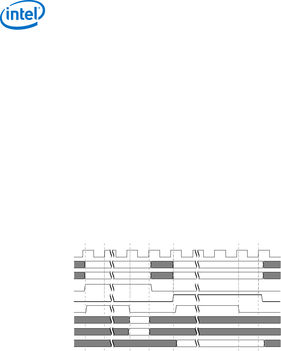
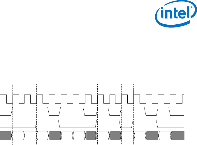
Figure 7. Read and Write Transfers with Waitrequest
clk
address
byteenable
read
write
waitrequest
readdata
writedata
address
byteenable
readdata
1 2 3 4 5 76
response
response
writedata
3 Avalon Memory-Mapped Interfaces
MNL-AVABUSREF | 2018.03.22
Avalon® Interface Specifications
22

The numbers in this timing diagram, mark the following transitions:
1. address, byteenable, and read are asserted after the rising edge of clk. The
slave asserts waitrequest, stalling the transfer.
2. waitrequest is sampled. Because waitrequest is asserted, the cycle becomes
a wait-state. address, read, write, and byteenable remain constant.
3. The slave deasserts waitrequest after the rising edge of clk. The slave asserts
readdata and response.
4. The master samples readdata, response and deasserted waitrequest
completing the transfer.
5. address, writedata, byteenable, and write signals are asserted after the
rising edge of clk. The slave asserts waitrequest stalling the transfer.
6. The slave deasserts waitrequest after the rising edge of clk.
7. The slave captures write data ending the transfer.
3.5.2 Transfers Using the waitrequestAllowance Property
The waitrequestAllowance property specifies the number of transfers an
Avalon-MM master can issue or an Avalon-MM slave must accept after the
waitrequest signal is asserted. waitrequestAllowance is available starting with
the Intel Quartus Prime 17.1 software release.
The default value of waitrequestAllowance is 0, which corresponds to the
behavior described in Typical Read and Write Transfers on page 22 where
waitrequest assertion stops the current transfer from being issued or accepted.
An Avalon-MM slave with a waitrequestAllowance greater then 0 would typically
assert waitrequest when its internal buffer can only accept
waitrequestAllowance more entries before becoming full. Avalon-MM masters with
a waitrequestAllowance greater than 0 have waitrequestAllowance additional
cycles to stop sending transfers, which allows more pipelining in the master logic. The
master must deassert the read or write signal when the waitrequestallowance
has been spent.
Values of waitrequestAllowance greater than 0 support high-speed design where
immediate forms of backpressure may result in a drop in the maximum operating
frequency (FMAX) often due to combinatorial logic in the control path. An Avalon-MM
slave must support all possible transfer timings that are legal for its
waitrequestAllowance value. For example, a slave with waitrequestAllowance
= 2 must be able to accept any of the master transfer waveforms shown in the
following examples.
3 Avalon Memory-Mapped Interfaces
MNL-AVABUSREF | 2018.03.22
Avalon® Interface Specifications
23
3.5.2.1 waitrequestAllowance Equals Two
The following timing diagram illustrates timing for an Avalon-MM master that has two
clock cycles to start and stop sending transfers after the Avalon-MM slave deasserts or
asserts waitrequest, respectively.
Figure 8. Master write: waitrequestAllowance Equals Two Clock Cycles
clock
write
waitrequest
data[7:0] A0 A1 A2 A3 A4 B0 B1 B3
1 2 3 4 5 6
The markers in this figure mark the following events:
1. The Avalon-MM master drives write and data.
2. The Avalon-MM slave asserts waitrequest. Because the
waitrequestAllowance is 2, the master is able to complete the 2 additional
data transfers.
3. The master deasserts write as required because the slave is asserting
waitrequest for a third cycle.
4. The Avalon-MM master drives write and data. The slave is not asserting
waitrequest. The writes complete.
5. The Avalon master drives write and data even though the slave is asserting
waitrequest. Because the waitrequestAllowance is 2 cycles, the write
completes.
6. The Avalon master drives write and data. The slave is not asserting
waitrequest. The write completes.
3 Avalon Memory-Mapped Interfaces
MNL-AVABUSREF | 2018.03.22
Avalon® Interface Specifications
24
3.5.2.2 waitrequestAllowance Equals One
The following timing diagram illustrates timing for an Avalon-MM master that has one
clock cycle to start and stop sending transfers after the Avalon-MM slave deasserts or
asserts waitrequest, respectively.
Figure 9. Master Write: waitrequestAllowance Equals one Clock Cycle
clk
write
waitrequest
data[7:0] A0 A1 A2 A3 A4 B0 B1 B2 B3
1 2 3 4 5 6 7 8
The numbers in this figure mark the following events:
1. The Avalon-MM master drives write and data.
2. The Avalon-MM slave asserts waitrequest. Because the
waitrequestAllowance is 1, the master is able to complete the write.
3. The master deasserts write because the slave is asserting waitrequest for a
second cycle.
4. The Avalon-MM master drives write and data. The slave is not asserting
waitrequest. The writes complete.
5. The slave asserts waitrequest. Because the waitrequestAllowance is 1
cycle, the write completes.
6. Avalon-MM master drives write and data. The slave is not asserting
waitrequest. The write completes.
7. The Avalon-MM slave asserts waitrequest. Because the
waitrequestAllowance is 1, the master is able to complete one additional data
transfer.
8. The Avalon master drives write and data. The slave is not asserting
waitrequest. The write completes.
3.5.2.3 waitrequestAllowance Equals Two - Not Recommended
The following timing diagram illustrates timing for an Avalon-MM master that can send
two transfers after waitrequest is asserted.
This timing is legal, but not recommended. In this example the master counts the
number of transactions, instead of the number of clock cycles. This approach requires
a counter that makes the implementation more complex and may affect timing
closure. When the master uses the waitrequest signal and a constant number of
cycles to determine when it can drive transactions as shown in the previous examples,
the master starts or stops transactions on the basis of the registered signals.
3 Avalon Memory-Mapped Interfaces
MNL-AVABUSREF | 2018.03.22
Avalon® Interface Specifications
25

Figure 10. waitrequestAllowance Equals Two Transfers
clk
write
waitrequest
data
1 2 3 4 5 6 7
The numbers in this figure mark the following events:
1. The Avalon-MM master asserts write and drives data.
2. The Avalon-MM slave asserts waitrequest.
3. The Avalon-MM master drives write and data. Because the
waitrequestAllowance is 2, the master drives data in 2 consecutive cycles.
4. The Avalon-MM master deasserts write because it has spent the 2-transfer
waitrequestAllowance.
5. The Avalon-MM master issues a write as soon as waitrequest is deasserted.
6. The Avalon-MM master drives write and data. The slave asserts waitrequest
for 1 cycle.
7. In response to waitrequest, the Avalon-MM master holds data for 2 cycles.
3.5.2.4 waitrequestAllowance Compatibility for Avalon-MM Master and Slave
Interfaces
Avalon-MM masters and slaves that support the waitrequest signal support
backpressure. Masters with backpressure can always connect to slaves without
backpressure. Masters without backpressure cannot connect to slaves with
backpressure.
Table 11. waitrequestAllowance Compatibility for Avalon-MM Masters and Slaves
Master and Slave
waitrequestAllowance Compatibility
master = 0
slave = 0 Follows the same compatibility rules as standard Avalon-MM interfaces.
master = 0
slave > 0
Direct connections are not possible.
Simple adaptation is required for the case of a master with a waitrequest signal. A
connection is impossible if the master does not support the waitrequest signal.
master > 0
slave = 0
Direct connections are not possible.
Adaptation (buffers) are required when connecting to a slave with a waitrequest signal or
fixed wait states.
master > 0
slave > 0
No adaptation is required if the master’s allowance <= slave’s allowance.
If the master allowance < slave allowance, pipeline registers may be inserted.
For point-to-point connections, you can add the pipeline registers on the command signals or
the waitrequest signals. Up to <d> register stages can be inserted where <d> is the
difference between the allowances.
Connecting a master with a higher waitrequestAllowance than the slave requires
buffering.
3 Avalon Memory-Mapped Interfaces
MNL-AVABUSREF | 2018.03.22
Avalon® Interface Specifications
26

3.5.2.5 waitrequestAllowance Error Conditions
Behavior is unpredictable for if an Avalon-MM interface violates the waitrequest
allowance specification.
•If a master violates the waitrequestAllowance = <n> specification by sending
more than <n> transfers, transfers may be dropped or data corruption may occur.
•If a slave advertises a larger waitrequestAllowance than is possible, some
transfers may be dropped or data corruption may occur.
3.5.3 Read and Write Transfers with Fixed Wait-States
A slave can specify fixed wait-states using the readWaitTime and writeWaitTime
properties. Using fixed wait-states is an alternative to using waitrequest to stall a
transfer. The address and control signals (byteenable, read, and write) are held
constant for the duration of the transfer. Setting readWaitTime or writeWaitTime
to <n> is equivalent to asserting waitrequest for <n> cycles per transfer.
In the following figure, the slave has a writeWaitTime = 2 and readWaitTime =
1.
Figure 11. Read and Write Transfer with Fixed Wait-States at the Slave Interface
clk
address
byteenable byteenable
read
write
readdata
writedata
address address
readdata
response response
writedata
4 51 2 3
The numbers in this timing diagram mark the following transitions:
1. The master asserts address and read on the rising edge of clk.
2. The next rising edge of clk marks the end of the first and only wait-state cycle.
The readWaitTime is 1.
3. The slave asserts readdata and response on the rising edge of clk. The read
transfer ends.
4. writedata, address, byteenable, and write signals are available to the
slave.
5. The write transfer ends after 2 wait-state cycles.
Transfers with a single wait-state are commonly used for multicycle off-chip
peripherals. The peripheral captures address and control signals on the rising edge of
clk. The peripheral has one full cycle to return data.
3 Avalon Memory-Mapped Interfaces
MNL-AVABUSREF | 2018.03.22
Avalon® Interface Specifications
27
read from BUS to master
write from master to BUS

Components with zero wait-states are allowed. However, components with zero wait-
states may decrease the achievable frequency. Zero wait-states require the
component to generate the response in the same cycle that the request was
presented.
3.5.4 Pipelined Transfers
Avalon-MM pipelined read transfers increase the throughput for synchronous slave
devices that require several cycles to return data for the first access. Such devices can
typically return one data value per cycle for some time thereafter. New pipelined read
transfers can start before readdata for the previous transfers is returned.
A pipelined read transfer has an address phase and a data phase. A master initiates a
transfer by presenting the address during the address phase. A slave fulfills the
transfer by delivering the data during the data phase. The address phase for a new
transfer (or multiple transfers) can begin before the data phase of a previous transfer
completes. The delay is called pipeline latency. The pipeline latency is the duration
from the end of the address phase to the beginning of the data phase.
Transfer timing for wait-states and pipeline latency have the following key differences:
• Wait-states—Wait-states determine the length of the address phase. Wait-states
limit the maximum throughput of a port. If a slave requires one wait-state to
respond to a transfer request, the port requires two clock cycles per transfer.
• Pipeline Latency—Pipeline latency determines the time until data is returned
independently of the address phase. A pipelined slave with no wait-states can
sustain one transfer per cycle. However, it may require several cycles of latency to
return the first unit of data.
Wait-states and pipelined reads can be supported concurrently. Pipeline latency can be
either fixed or variable.
3.5.4.1 Pipelined Read Transfer with Variable Latency
After capturing address and control signals, an Avalon-MM pipelined slave takes one or
more cycles to produce data. A pipelined slave may have multiple pending read
transfers at any given time. Variable-latency pipelined read transfers require one
additional signal, readdatavalid. readdatavalid indicates when read data is
valid. Variable-latency pipelined read transfers also include the same set of signals as
non-pipelined read transfers. Slave peripherals that use readdatavalid are
considered pipelined with variable latency. The readdata and readdatavalid
signals corresponding to a particular read command can be asserted the cycle after
that read command is asserted, at the earliest.
The slave must return readdata in the same order that it accepted the read
commands. Pipelined slave ports with variable latency must use waitrequest. The
slave can assert waitrequest to stall transfers to maintain an acceptable number of
pending transfers. A slave may assert readdatavalid to transfer data to the master
independently of whether or not the slave is stalling a new command with
waitrequest.
3 Avalon Memory-Mapped Interfaces
MNL-AVABUSREF | 2018.03.22
Avalon® Interface Specifications
28

Note: The maximum number of pending transfers is a property of the slave interface. The
interconnect fabric builds logic to route readdata to requesting masters using this
number. The slave interface, not the interconnect fabric, must track the number of
pending reads. The slave must assert waitrequest to prevent the number of
pending reads from exceeding the maximum number. If a slave has
waitrequestAllowance > 0, it must assert waitrequest early enough so that
the total pending transfers, including those accepted while waitrequest is asserted,
does not exceed the maximum number of pending transfers specified.
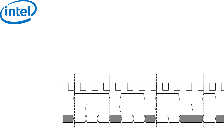
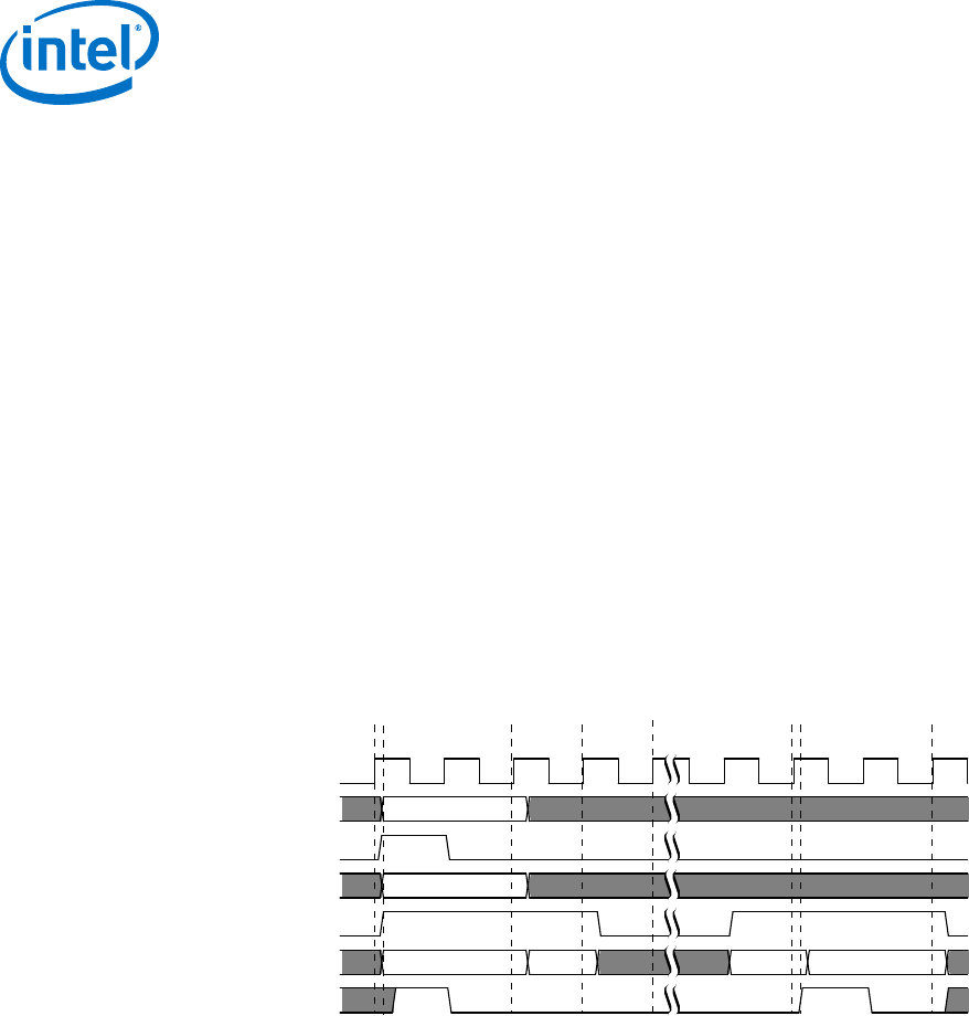
Figure 12. Pipelined Read Transfers with Variable Latency
The following figure shows several slave read transfers. The slave is pipelined with variable latency. In this
figure, the slave can accept a maximum of two pending transfers. The slave uses waitrequest to avoid
overrunning this maximum.
clk
address
read
waitrequest
readdata
readdatavalid
addr1 addr2 addr3 addr4 addr5
data 1 data2 data 3 data4 data5
1 2 3 4 6 115 9 1087
The numbers in this timing diagram, mark the following transitions:
1. The master asserts address and read, initiating a read transfer.
2. The slave captures addr1.
3. The slave captures addr2.
4. The slave asserts waitrequest because it has accepted a maximum of two
pending reads, causing the third transfer to stall.
5. The slave asserts data1, the response to addr1. It deasserts waitrequest.
6. The slave captures addr3. The interconnect captures data1. The interconnect
captures data1.
7. The slave captures addr4. The interconnect captures data2.
8. The slave drives readdatavalid and readdata in response to the third read
transfer.
9. The slave captures addr5. The interconnect captures data3. The read signal is
deasserted. The value of waitrequest is no longer relevant.
10. The interconnect captures data4.
11. The slave drives data5 and asserts readdatavalid completing the data phase
for the final pending read transfer.
If the slave cannot handle a write transfer while it is processing pending read
transfers, the slave must assert its waitrequest and stall the write operation until
the pending read transfers have completed. The Avalon-MM specification does not
define the value of readdata in the event that a slave accepts a write transfer to the
same address as a currently pending read transfer.
3 Avalon Memory-Mapped Interfaces
MNL-AVABUSREF | 2018.03.22
Avalon® Interface Specifications
29

3.5.4.2 Pipelined Read Transfers with Fixed Latency
The address phase for fixed latency read transfers is identical to the variable latency
case. After the address phase, a pipelined slave with fixed read latency takes a fixed
number of clock cycles to return valid readdata. The readWaitTime property
specifies the number of clock cycles to return valid readdata. The interconnect
captures readdata on the appropriate rising clock edge, ending the data phase.
During the address phase, the slave can assert waitrequest to hold off the transfer.
Or, the slave specifies the readWaitTime for a fixed number of wait states. The
address phase ends on the next rising edge of clk after wait states, if any.
During the data phase, the slave drives readdata after a fixed latency. For a read
latency of <n>, the slave must present valid readdata on the <nth> rising edge of
clk after the end of the address phase.
Figure 13. Pipelined Read Transfer with Fixed Latency of Two Cycles
The following figure shows multiple data transfers between a master and a pipelined slave . The slave drives
waitrequest to stall transfers. and has a fixed read latency of 2 cycles.
clk
address
read
waitrequest
readdata
addr1 addr2 addr3
data1 data2 data3
1 2 3 4 5 6
The numbers in this timing diagram, mark the following transitions:
1. A master initiates a read transfer by asserting read and addr1.
2. The slave asserts waitrequest to hold off the transfer for one cycle.
3. The slave captures addr1 at the rising edge of clk. The address phase ends here.
4. The slave presents valid readdata after 2 cycles, ending the transfer.
5. addr2 and read are asserted for a new read transfer.
6. The master initiates a third read transfer during the next cycle, before the data
from the prior transfer is returned.
3.5.5 Burst Transfers
A burst executes multiple transfers as a unit, rather than treating every word
independently. Bursts may increase throughput for slave ports that achieve greater
efficiency when handling multiple words at a time, such as SDRAM. The net effect of
bursting is to lock the arbitration for the duration of the burst. A bursting Avalon-MM
interface that supports both reads and writes must support both read and write
bursts.
Bursting Avalon-MM interfaces include a burstcount output signal. If a slave has a
burstcount input, it is considered burst capable.
3 Avalon Memory-Mapped Interfaces
MNL-AVABUSREF | 2018.03.22
Avalon® Interface Specifications
30

The burstcount signal behaves as follows:
•At the start of a burst, burstcount presents the number of sequential transfers
in the burst.
•For width <n> of burstcount, the maximum burst length is 2(<n>-1).The
minimum legal burst length is one.
To support slave read bursts, a slave must also support:
•Wait states with the waitrequest signal.
•Pipelined transfers with variable latency with the readdatavalid signal.
At the start of a burst, the slave sees the address and a burst length value on
burstcount. For a burst with an address of <a> and a burstcount value of <b>,
the slave must perform <b> consecutive transfers starting at address <a>. The burst
completes after the slave receives (write) or returns (read) the <bth> word of data.
The bursting slave must capture address and burstcount only once for each burst.
The slave logic must infer the address for all but the first transfers in the burst. A
slave can also use the input signal beginbursttransfer, which the interconnect
asserts on the first cycle of each burst.
3.5.5.1 Write Bursts
These rules apply when a write burst begins with burstcount greater than one.
•When a burstcount of <n> is presented at the beginning of the burst, the slave
must accept <n> successive units of writedata to complete the burst.
Arbitration between the master-slave pair remains locked until the burst
completes. This lock guarantees that no other master can execute transactions on
the slave until the write burst completes.
•The slave must only capture writedata when write asserts. During the burst,
the master can deassert write indicating that writedata is invalid. Deasserting
write does not terminate the burst. It delays it and no other master can access
the slave, reducing the transfer efficiency.
•The slave delays a transfer by asserting waitrequest forcing writedata,
write, burstcount, and byteenable to be held constant.
3 Avalon Memory-Mapped Interfaces
MNL-AVABUSREF | 2018.03.22
Avalon® Interface Specifications
31
•The functionality of the byteenable signal is the same for bursting and non-
bursting slaves. For a 32-bit master burst-writing to a 64-bit slave, starting at
byte address 4, the first write transfer seen by the slave is at its address 0, with
byteenable = 8'b11110000. The byteenables can change for different
words of the burst.
•The byteenable signals do not all have to be asserted. A burst master writing
partial words can use the byteenable signal to identify the data being written.
•The constantBurstBehavior property specifies the behavior of the burst
signals.
—When constantBurstBehavior is true for a master, it indicates that the
master holds address and burstcount stable throughout a burst. When
true for a slave, constantBurstBehavior declares that the slave expects
address and burstcount to be held stable throughout a burst.
—When constantBurstBehavior is false, it indicates that the master holds
address and burstcount stable only for the first transaction of a burst.
When constantBurstBehavior is false, the slave samples address and
burstcount only on the first transaction of a burst.
Figure 14. Write Burst with constantBurstBehavior Set to False for Master and Slave
The following figure demonstrates a slave write burst of length 4. In this example, the slave asserts
waitrequest twice delaying the burst.
clk
address
beginbursttransfer
burstcount
write
writedata
waitrequest
addr1
4
data1 data2 data3 data4
123 4 5 76 8
The numbers in this timing diagram, mark the following transitions:
1. The master asserts address, burstcount, write, and drives the first unit of
writedata.
2. The slave immediately asserts waitrequest, indicating that it is not ready to
proceed with the transfer.
3. waitrequest is low. The slave captures addr1, burstcount, and the first unit
of writedata . On subsequent cycles of the transfer, address and burstcount
are ignored.
4. The slave captures the second unit of data at the rising edge of clk.
5. The burst is paused while write is deasserted.
3 Avalon Memory-Mapped Interfaces
MNL-AVABUSREF | 2018.03.22
Avalon® Interface Specifications
32

6. The slave captures the third unit of data at the rising edge of clk.
7. The slave asserts waitrequest. In response, all outputs are held constant
through another clock cycle.
8. The slave captures the last unit of data on this rising edge of clk. The slave write
burst ends.
In the figure above, the beginbursttransfer signal is asserted for the first clock
cycle of a burst and is deasserted on the next clock cycle. Even if the slave asserts
waitrequest, the beginbursttransfer signal is only asserted for the first clock
cycle.
Related Links
Interface Properties on page 18
3.5.5.2 Read Bursts
Read bursts are similar to pipelined read transfers with variable latency. A read burst
has distinct address and data phases. readdatavalid indicates when the slave is
presenting valid readdata. Unlike pipelined read transfers, a single read burst
address results in multiple data transfers.
These rules apply to read bursts:
•When a master connects directly to a slave, a burstcount of <n> means the
slave must return <n> words of readdata to complete the burst. For cases
where interconnect links the master and slave pair, the interconnect may suppress
read commands sent from the master to the slave. For example, if the master
sends a read command with a byteenable value of 0, the interconnect may
suppress the read. As a result, the slave does not respond to the read command.
•The slave presents each word by providing readdata and asserting
readdatavalid for a cycle. Deassertion of readdatavalid delays but does not
terminate the burst data phase.
•For reads with a burstcount > 1, Intel recommends asserting all byteenables.
Note: Intel recommends that burst capable slaves not have read side effects. (This
specification does not guarantee how many bytes are read from the slave in order to
satisfy a request.)
3 Avalon Memory-Mapped Interfaces
MNL-AVABUSREF | 2018.03.22
Avalon® Interface Specifications
33
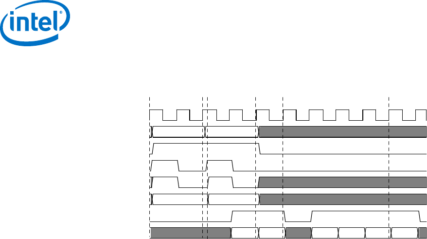
Figure 15. Read Burst
The following figure illustrates a system with two bursting masters accessing a slave. Note that Master B can
drive a read request before the data has returned for Master A.
clk
address
read
beginbursttransfer
waitrequest
burstcount
readdatavalid
readdata
A0 (master A) A1 (master B)
4 2
D(A0) D(A0+1) D(A0+2) D(A0+3) D(A1) D(A1+1)
2 3 5 61 4
The numbers in this timing diagram, mark the following transitions:
1. Master A asserts address (A0), burstcount, and read after the rising edge of
clk. The slave asserts waitrequest, causing all inputs except
beginbursttransfer to be held constant through another clock cycle.
2. The slave captures A0 and burstcount at this rising edge of clk. A new transfer
could start on the next cycle.
3. Master B drives address (A1), burstcount, and read. The slave asserts
waitrequest, causing all inputs except beginbursttransfer to be held
constant. The slave could have returned read data from the first read request at
this time, at the earliest.
4. The slave presents valid readdata and asserts readdatavalid, transferring the
first word of data for master A.
5. The second word for master A is transferred. The slave deasserts readdatavalid
pausing the read burst. The slave port can keep readdatavalid deasserted for
an arbitrary number of clock cycles.
6. The first word for master B is returned.
3.5.5.3 Line–Wrapped Bursts
Processors with instruction caches gain efficiency by using line-wrapped bursts. When
a processor requests data that is not in the cache, the cache controller must refill the
entire cache line. For a processor with a cache line size of 64 bytes, a cache miss
causes 64 bytes to be read from memory. If the processor reads from address 0xC
when the cache miss occurred, then an inefficient cache controller could issue a burst
at address 0, resulting in data from read addresses 0x0, 0x4, 0x8, 0xC, 0x10, 0x14,
0x18, . . . 0x3C. The requested data is not available until the fourth read. With line-
wrapping bursts, the address order is 0xC, 0x10, 0x14, 0x18, . . . 0x3C, 0x0, 0x4,
and 0x8. The requested data is returned first. The entire cache line is eventually
refilled from memory.
3.5.6 Read and Write Responses
For any Avalon-MM slave, commands must be processed in a hazard-free manner.
Read and write responses issue in the order in which commands they were accepted.
3 Avalon Memory-Mapped Interfaces
MNL-AVABUSREF | 2018.03.22
Avalon® Interface Specifications
34

3.5.6.1 Transaction Order for Avalon-MM Read and Write Responses (Masters and
Slaves)
For any Avalon-MM master:
• Commands to the same slave are guaranteed to reach the slave in command issue
order, and the slave responds in command issue order.
• Commands to different slaves may reach and be responded to by the slaves in a
different order than the order in which the commands were issued. When
successful, the slave responds in command issue order.
• Responses (if present) return in command issue order, regardless of whether the
read or write commands are directed to the same or different slaves.
• There is no guaranteed transaction order between different masters.
3.5.6.2 Avalon-MM Read and Write Responses Timing Diagram
The following diagram shows command acceptance and command issue order for
Avalon-MM read and write responses. Because the read and write interfaces share the
response signal, an interface cannot issue or accept a write response and a read
response in the same clock cycle.
Read responses, send one response for each readdata. A read burst length of <N>
results in <N> responses.
Write responses, send one response for each write command. A write burst results in
only one response. The slave interface sends the response after it accepts the final
write transfer in the burst. When an interface includes the writeresponsevalid
signal, all write commands must be completed with write responses
Figure 16. Avalon-MM Read and Write Responses Timing Diagram
clk
R0 W0 W1 R1
R1
address
read
write
readdatavalid
writeresponsevalid
response R0 W0 W1
3.5.6.2.1 minimumResponseLatency Timing Diagram with readdatavalid or
writeresponsevalid
For interfaces with readdatavalid or writeresponsevalid, the default a one-
cycle minimumResponseLatency can lead to difficulty closing timing on Avalon-MM
masters.
The following timing diagrams show the behavior for a minimumResponseLatency of
1 or 2 cycles. Note that the actual response latency can also be greater than the
minimum allowed value as these timing diagrams illustrate.
3 Avalon Memory-Mapped Interfaces
MNL-AVABUSREF | 2018.03.22
Avalon® Interface Specifications
35
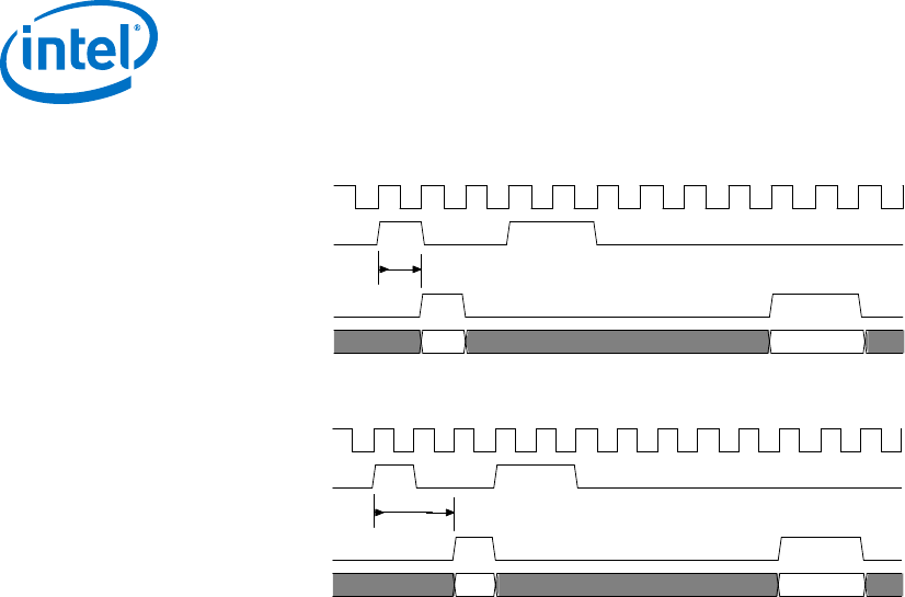
Figure 17. minimumResponseLatency Equals One Cycle
clk
read
readdatavalid
data
1 cycle minimum response latency
Figure 18. minimumResponseLatency Equals Two Cycles
clk
read
2 cycles minimumResponseLatency
readdatavalid
data
Compatibility
Interfaces with the same minimumResponseLatency are interoperable without any
adaptation. If the master has a higher minimumResponseLatency than the slave,
use pipeline registers to compensate for the differences. The pipeline registers should
delay readdata from the slave. If the slave has a higher
minimumResponseLatency than the master, the interfaces are interoperable without
adaptation.
3.6 Address Alignment
The interconnect only supports aligned accesses. A master can only issue addresses
that are a multiple of its data width in symbols. A master can write partial words by
deasserting some byteenables. For example, a write of 2 bytes at address 2 would
have 4’b1100 for the byteenables.
3.7 Avalon-MM Slave Addressing
Dynamic bus sizing manages data during transfers between master-slave pairs of
differing data widths. Slave data are aligned in contiguous bytes in the master address
space.
If the master data width is wider than the slave data width, words in the master
address space map to multiple locations in the slave address space. For example, a
32-bit master read from a 16-bit slave results in two read transfers on the slave side.
The reads are to consecutive addresses.
If the master is narrower than the slave, then the interconnect manages the slave
byte lanes. During master read transfers, the interconnect presents only the
appropriate byte lanes of slave data to the narrower master. During master write
transfers, the interconnect automatically asserts the byteenable signals to write
data only to the specified slave byte lanes.
3 Avalon Memory-Mapped Interfaces
MNL-AVABUSREF | 2018.03.22
Avalon® Interface Specifications
36

Slaves must have a data width of 8, 16, 32, 64, 128, 256, 512 or 1024 bits. The
following table shows how slave data of various widths is aligned within a 32-bit
master performing full-word accesses. In this table, OFFSET[N] refers to a slave word
size offset into the slave address space.
Table 12. Dynamic Bus Sizing Master-to-Slave Address Mapping
Master Byte
Address (1)
Access 32-Bit Master Data
When Accessing
an 8-Bit Slave Interface
When Accessing
a 16-Bit Slave Interface
When Accessing
a 64-Bit Slave Interface
0x00 1OFFSET[0]7..0 OFFSET[0]15..0 (2) OFFSET[0]31..0
2OFFSET[1]7..0 OFFSET[1]15..0 —
3OFFSET[2]7..0 — —
4OFFSET[3]7..0 — —
0x04 1OFFSET[4]7..0 OFFSET[2]15..0 OFFSET[0]63..32
2OFFSET[5]7..0 OFFSET[3]15..0 —
3OFFSET[6]7..0 — —
4OFFSET[7]7..0 — —
0x08 1OFFSET[8]7..0 OFFSET[4]15..0 OFFSET[1]31..0
2OFFSET[9]7..0 OFFSET[5]15..0 —
3OFFSET[10]7..0 — —
4OFFSET[11]7..0 — —
0x0C 1OFFSET[12]7..0 OFFSET[6]15..0 OFFSET[1]63..32
2OFFSET[13]7..0 OFFSET[7]15..0 —
3OFFSET[14]7..0 — —
4OFFSET[15]7..0 — —
... ... ...
Notes:
1. Although the master is issuing byte addresses, it is accessing full 32-bit words.
2. For all slave entries, [<n>] is the word offset and the subscript values are the bits in the word.
3 Avalon Memory-Mapped Interfaces
MNL-AVABUSREF | 2018.03.22
Avalon® Interface Specifications
37

4 Avalon Interrupt Interfaces
Avalon Interrupt interfaces allow slave components to signal events to master
components. For example, a DMA controller can interrupt a processor when it has
completed a DMA transfer.
4.1 Interrupt Sender
An interrupt sender drives a single interrupt signal to an interrupt receiver. The timing
of the irq signal must be synchronous to the rising edge of its associated clock. irq
has no relationship to any transfer on any other interface. irq must be asserted until
acknowledged on the associated Avalon-MM slave interface.
Interrupts are component specific. The receiver typically determines the appropriate
response by reading an interrupt status register from an Avalon-MM slave interface.
4.1.1 Avalon Interrupt Sender Signal Roles
Table 13. Interrupt Sender Signal Roles
Signal Role Width Direction Required Description
irq
irq_n
1-32 Output Yes Interrupt Request. An interrupt sender drives an
interrupt signal to an interrupt receiver.
4.1.2 Interrupt Sender Properties
Table 14. Interrupt Sender Properties
Property Name Default
Value
Legal Values Description
associatedAddressabl
ePoint
N/A Name of Avalon-MM
slave on this
component.
The name of the Avalon-MM slave interface that
provides access to the registers to service the
interrupt.
associatedClock N/A Name of a clock
interface on this
component.
The name of the clock interface to which this interrupt
sender is synchronous. The sender and receiver may
have different values for this property.
associatedReset N/A Name of a reset
interface on this
component.
The name of the reset interface to which this interrupt
sender is synchronous.
MNL-AVABUSREF | 2018.03.22
Intel Corporation. All rights reserved. Intel, the Intel logo, Altera, Arria, Cyclone, Enpirion, MAX, Nios, Quartus
and Stratix words and logos are trademarks of Intel Corporation or its subsidiaries in the U.S. and/or other
countries. Intel warrants performance of its FPGA and semiconductor products to current specifications in
accordance with Intel's standard warranty, but reserves the right to make changes to any products and services
at any time without notice. Intel assumes no responsibility or liability arising out of the application or use of any
information, product, or service described herein except as expressly agreed to in writing by Intel. Intel
customers are advised to obtain the latest version of device specifications before relying on any published
information and before placing orders for products or services.
*Other names and brands may be claimed as the property of others.
ISO
9001:2008
Registered
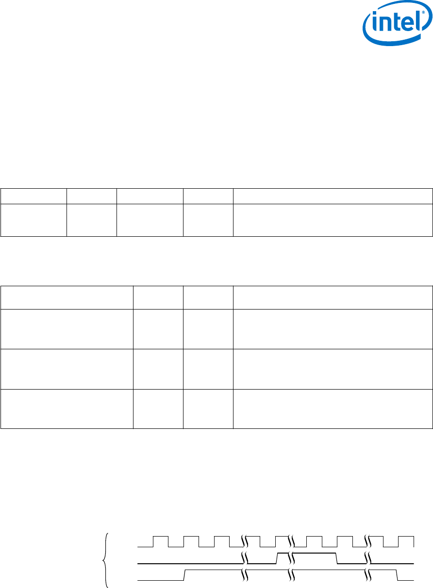
4.2 Interrupt Receiver
An interrupt receiver interface receives interrupts from interrupt sender interfaces.
Components with Avalon-MM master interfaces can include an interrupt receiver to
detect interrupts asserted by slave components with interrupt sender interfaces. The
interrupt receiver accepts interrupt requests from each interrupt sender as a separate
bit.
4.2.1 Avalon Interrupt Receiver Signal Roles
Table 15. Interrupt Receiver Signal Roles
Signal Role Width Direction Required Description
irq 1–32 Input Yes irq is an <n>-bit vector, where each bit corresponds
directly to one IRQ sender with no inherent assumption
of priority.
4.2.2 Interrupt Receiver Properties
Table 16. Interrupt Receiver Properties
Property Name Default
Value
Legal
Values
Description
associatedAddressable
Point
N/A Name of
Avalon-MM
master
interface
The name of the Avalon-MM master interface used to
service interrupts received on this interface.
associatedClock N/A Name of an
Avalon
Clock
interface
The name of the Avalon Clock interface to which this
interrupt receiver is synchronous. The sender and
receiver may have different values for this property.
associatedReset N/A Name of an
Avalon
Reset
interface
The name of the reset interface to which this interrupt
receiver is synchronous.
4.2.3 Interrupt Timing
The Avalon-MM master services the priority 0 interrupt before the priority 1 interrupt.
Figure 19. Interrupt Timing
In the following figure, interrupt 0 has higher priority. The interrupt receiver is in the process of handling int1
when int0 is asserted. The int0 handler is called and completes. Then, the int1 handler resumes. The
diagram shows int0 deasserts at time 1. int1 deasserts at time 2.
clk
int0
int1
12
Individual
Requests
4 Avalon Interrupt Interfaces
MNL-AVABUSREF | 2018.03.22
Avalon® Interface Specifications
39
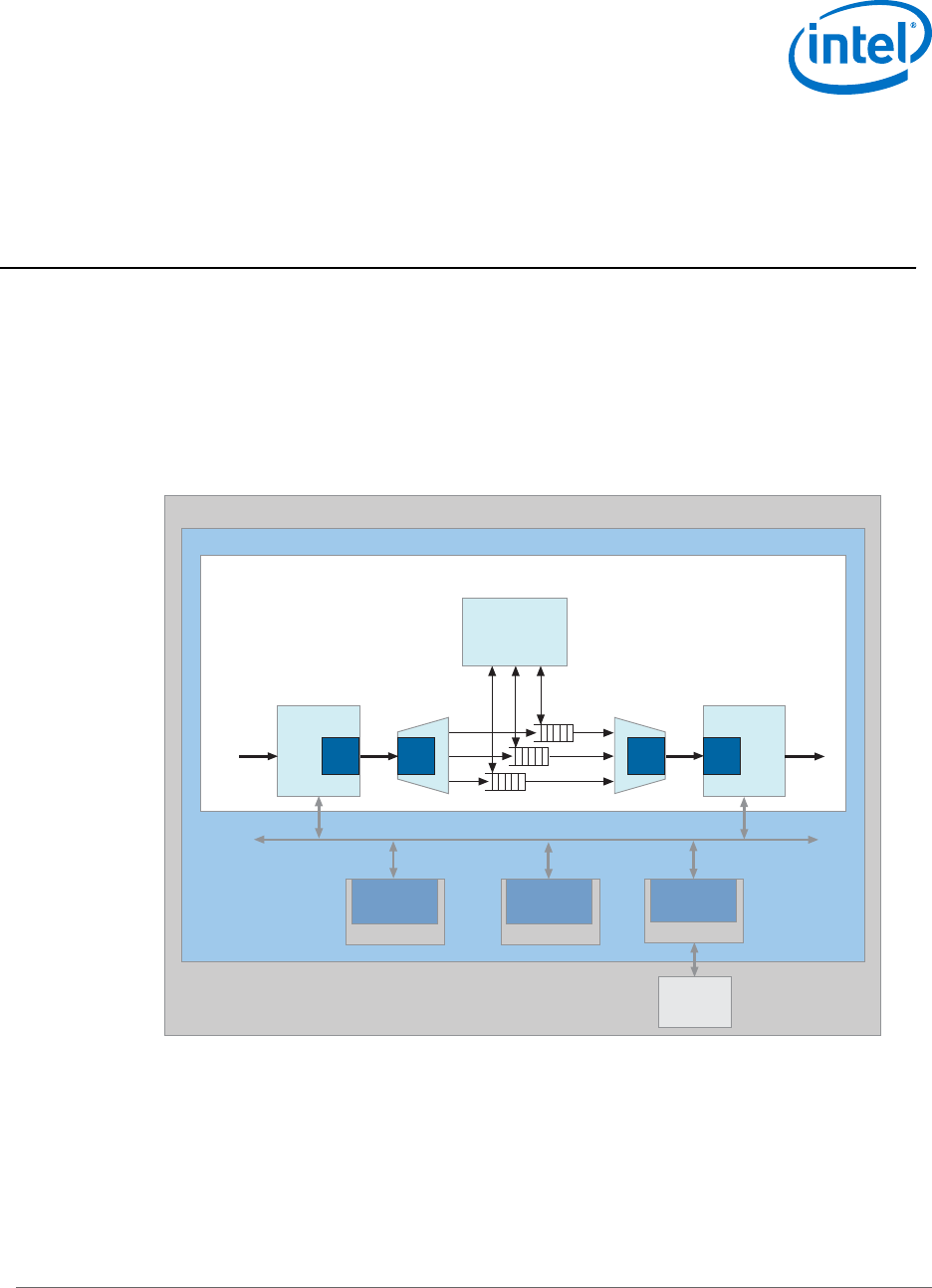
5 Avalon Streaming Interfaces
You can use Avalon Streaming (Avalon-ST) interfaces for components that drive high
bandwidth, low latency, unidirectional data. Typical applications include multiplexed
streams, packets, and DSP data. The Avalon-ST interface signals can describe
traditional streaming interfaces supporting a single stream of data without knowledge
of channels or packet boundaries. The interface can also support more complex
protocols capable of burst and packet transfers with packets interleaved across
multiple channels.
Figure 20. Avalon-ST Interface - Typical Application of the Avalon-ST Interface
SDRAM
Memory
Avalon-MM
Master Interface
Processor
Avalon-MM Interface (Control Plane)
Avalon-MM
Master Interface
IO Control
Avalon-MM
Slave Interface
SDRAM Cntl
Source Sink SinkSource
ch
0-2
2
1
0
Scheduler
Tx IF CoreRx IF Core
Avalon-ST
Input
Avalon-ST
Output
Avalon-ST Interfaces (Data Plane)
Intel FPGA
Printed Circuit Board
All Avalon-ST source and sink interfaces are not necessarily interoperable. However, if
two interfaces provide compatible functions for the same application space, adapters
are available to allow them to interoperate.
MNL-AVABUSREF | 2018.03.22
Intel Corporation. All rights reserved. Intel, the Intel logo, Altera, Arria, Cyclone, Enpirion, MAX, Nios, Quartus
and Stratix words and logos are trademarks of Intel Corporation or its subsidiaries in the U.S. and/or other
countries. Intel warrants performance of its FPGA and semiconductor products to current specifications in
accordance with Intel's standard warranty, but reserves the right to make changes to any products and services
at any time without notice. Intel assumes no responsibility or liability arising out of the application or use of any
information, product, or service described herein except as expressly agreed to in writing by Intel. Intel
customers are advised to obtain the latest version of device specifications before relying on any published
information and before placing orders for products or services.
*Other names and brands may be claimed as the property of others.
ISO
9001:2008
Registered

Avalon-ST interfaces support datapaths requiring the following features:
• Low latency, high throughput point-to-point data transfer
• Multiple channel support with flexible packet interleaving
• Sideband signaling of channel, error, and start and end of packet delineation
• Support for data bursting
• Automatic interface adaptation
5.1 Terms and Concepts
The Avalon-ST interface protocol defines the following terms and concepts:
• Avalon Streaming System—An Avalon Streaming system contains one or more
Avalon-ST connections that transfer data from a source interface to a sink
interface. The system shown above consists of Avalon-ST interfaces to transfer
data from the system input to output. Avalon-MM control and status register
interfaces provide for software control.
• Avalon Streaming Components—A typical system using Avalon-ST interfaces
combines multiple functional modules, called components. The system designer
configures the components and connects them together to implement a system.
• Source and Sink Interfaces and Connections—When two components are
connected, the data flows from the source interface to the sink interface. The
combination of a source interface connected to a sink interface is referred to as a
connection.
• Backpressure—Backpressure allows a sink to signal a source to stop sending data.
Support for backpressure is optional. The sink uses backpressure to stop the flow
of data for the following reasons:
— When its FIFOs are full
— When there is congestion on its output interface.
• Transfers and Ready Cycles—A transfer results in data and control propagation
from a source interface to a sink interface. For data interfaces, a ready cycle is a
cycle during which the sink can accept a transfer.
• Symbol—A symbol is the smallest unit of data. For most packet interfaces, a
symbol is a byte. One or more symbols make up the single unit of data transferred
in a cycle.
• Channel—A channel is a physical or logical path or link through which information
passes between two ports.
• Beat—A beat is a single cycle transfer between a source and sink interface made
up of one or more symbols.
• Packet—A packet is an aggregation of data and control signals that is transmitted
together. A packet may contain a header to help routers and other network
devices direct the packet to the correct destination. The packet format is defined
by the application, not this specification. Avalon-ST packets can be variable in
length and can be interleaved across a connection. With an Avalon-ST interfaces,
the use of packets is optional.
5 Avalon Streaming Interfaces
MNL-AVABUSREF | 2018.03.22
Avalon® Interface Specifications
41

5.2 Avalon Streaming Interface Signal Roles
Each signal in an Avalon-ST source or sink interface corresponds to one Avalon-ST
signal role. An Avalon-ST interface may contain only one instance of each signal role.
All Avalon-ST signal roles apply to both sources and sinks and have the same meaning
for both.
Table 17. Avalon-ST Interface Signals
In the following table, all signal roles are active high.
Signal Role Width Direction Required Description
Fundamental Signals
channel 1 – 128 Source → Sink No The channel number for data being transferred
on the current cycle.
If an interface supports the channel signal, it
must also define the maxChannel parameter.
data 1 – 4,096 Source → Sink No The data signal from the source to the sink,
typically carries the bulk of the information being
transferred.
The contents and format of the data signal is
further defined by parameters.
error 1 – 256 Source → Sink No A bit mask used to mark errors affecting the data
being transferred in the current cycle. A single bit
in error is used for each of the errors
recognized by the component, as defined by the
errorDescriptor property.
ready 1Sink → Source No Asserted high to indicate that the sink can accept
data. ready is asserted by the sink on cycle <n>
to mark cycle <n + readyLatency> as a ready
cycle. The source may only assert valid and
transfer data during ready cycles.
Sources without a ready input cannot be
backpressured. Sinks without a ready output
never need to backpressure.
valid 1Source → Sink No Asserted by the source to qualify all other source
to sink signals. The sink samples data and other
source-to-sink signals on ready cycles where
valid is asserted. All other cycles are ignored.
Sources without a valid output implicitly
provide valid data on every cycle that they are
not being backpressured. Sinks without a valid
input expect valid data on every cycle that they
are not backpressuring.
Packet Transfer Signals
empty 1 – 5 Source → Sink No Indicates the number of symbols that are empty,
that is, do not represent valid data. The empty
signal is not used on interfaces where there is
one symbol per beat.
endofpacket 1Source → Sink No Asserted by the source to mark the end of a
packet.
startofpacket 1Source → Sink No Asserted by the source to mark the beginning of
a packet.
5 Avalon Streaming Interfaces
MNL-AVABUSREF | 2018.03.22
Avalon® Interface Specifications
42

5.3 Signal Sequencing and Timing
5.3.1 Synchronous Interface
All transfers of an Avalon-ST connection occur synchronous to the rising edge of the
associated clock signal. All outputs from a source interface to a sink interface,
including the data, channel, and error signals, must be registered on the rising
edge of clock. Inputs to a sink interface do not have to be registered. Registering
signals at the source facilitates high frequency operation.
5.3.2 Clock Enables
Avalon-ST components typically do not include a clock enable input. The Avalon-ST
signaling itself is sufficient to determine the cycles that a component should and
should not be enabled. Avalon-ST compliant components may have a clock enable
input for their internal logic. But, they must ensure that the timing of the interface
control signals still adheres to the protocol.
5.4 Avalon-ST Interface Properties
Table 18. Avalon-ST Interface Properties
Property Name Default
Value
Legal
Values
Description
associatedClock 1 Clock
interface
The name of the Avalon Clock interface to which this
Avalon-ST interface is synchronous.
associatedReset 1 Reset
interface
The name of the Avalon Reset interface to which this
Avalon-ST interface is synchronous.
beatsPerCycle 8 Specifies the number of beats that are transferred in a
single cycle. This property allows you to transfer 2
separate, but correlated streams using the same
start_of_packet, end_of_packet, ready and
valid signals.
beatsPerCycle is a rarely used feature of the Avalon-
ST protocol.
dataBitsPerSymbol 8 1 – 512 Defines the number of bits per symbol. For example,
byte-oriented interfaces have 8-bit symbols. This value
is not restricted to be a power of 2.
emptyWithinPacket false true, false When true, empty is valid for the entire packet.
errorDescriptor 0 List of
strings
A list of words that describe the error associated with
each bit of the error signal. The length of the list must
be the same as the number of bits in the error signal.
The first word in the list applies to the highest order
bit. For example, “crc, overflow" means that bit[1]
of error indicates a CRC error. Bit[0] indicates an
overflow error.
firstSymbolInHigh
OrderBits
true true, false When true, the first-order symbol is driven to the most
significant bits of the data interface. The highest-order
symbol is labeled D0 in this specification. When this
property is set to false, the first symbol appears on the
low bits. D0 appears at data[7:0]. For a 32-bit bus, if
true, D0 appears on bits[31:24].
continued...
5 Avalon Streaming Interfaces
MNL-AVABUSREF | 2018.03.22
Avalon® Interface Specifications
43
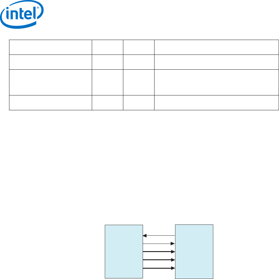
Property Name Default
Value
Legal
Values
Description
maxChannel 0 0 – 255 The maximum number of channels that a data
interface can support.
readyLatency 0 – 8 Defines the relationship between assertion and
deassertion of ready and cycles which are considered
to be available for data transfer. The readyLatency is
defined separately for each interface.
symbolsPerBeat 1 1 – 32 The number of symbols that are transferred on every
valid cycle.
5.5 Typical Data Transfers
This section defines the transfer of data from a source interface to a sink interface. In
all cases, the data source and the data sink must comply with the specification. It is
not the responsibility of the data sink to detect source protocol errors.
5.6 Signal Details
The following figure shows the signals that are typically included in an Avalon-ST
interface. As this figure indicates, a typical Avalon-ST source interface drives the
valid, data, error, and channel signals to the sink. The sink can apply
backpressure using the ready signal.
Figure 21. Typical Avalon-ST Interface Signals
valid
data
error
ready
Data SinkData Source
channel
<max_channel>
5 Avalon Streaming Interfaces
MNL-AVABUSREF | 2018.03.22
Avalon® Interface Specifications
44

Here are more details about these signals:
•ready—On interfaces supporting backpressure, the sink asserts ready to mark
the cycles where transfers may take place. If ready is asserted on cycle <n>,
cycle <n + readyLatency> is considered a ready cycle.
•valid—The valid signal qualifies valid data on any cycle where data is being
transferred from the source to the sink. On each valid cycle the data signal and
other source to sink signals are sampled by the sink.
•data—The data signal typically carries the bulk of the information being
transferred from the source to the sink. The data signal consists of one or more
symbols being transferred on every clock cycle. The dataBitsPerSymbol
parameter defines how the data signal is divided into symbols.
•error—Errors are signaled with the error signal, where each bit in error
corresponds to a possible error condition. A value of 0 on any cycle indicates the
data on that cycle is error-free. The action that a component takes when an error
is detected is not defined by this specification.
•channel—The optional channel signal is driven by the source to indicate the
channel to which the data belongs. The meaning of channel for a given interface
depends on the application. Some applications use channel as an interface
number indication. Other applications use channel as a page number or timeslot
indication. When the channel signal is used, all of the data transferred in each
active cycle belongs to the same channel. The source may change to a different
channel on successive active cycles.
An interface that uses the channel signal must define the maxChannel
parameter to indicate the maximum channel number. If the number of channels an
interface supports changes dynamically, maxChannel is the maximum number the
interface can support.
5.7 Data Layout
Figure 22. Data Symbols
The following figure shows a 64-bit data signal with dataBitsPerSymbol=16. Symbol 0 is the most
significant symbol.
symbol 0symbol 3
symbol 2
symbol 1
63 48 47 32 31 16 15 0
5 Avalon Streaming Interfaces
MNL-AVABUSREF | 2018.03.22
Avalon® Interface Specifications
45
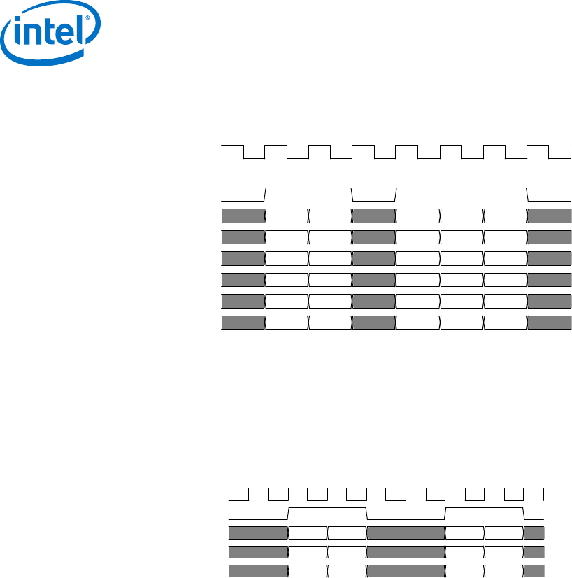
Figure 23. Layout of Data
The timing diagram in the following figure shows a 32-bit example where dataBitsPerSymbol=8,
symbolsPerBeat=4, and beatsPerCycle=1.
clk
ready
valid
channel
error
data[31:24]
data[23:16]
data[15:8]
data[7:0]
D0 D4 D8
D1
D2
D3
D5
D6
D7
D9
DA
DD
DC
DE
DF
D11
D12
DB
D10
D13
5.8 Data Transfer without Backpressure
The data transfer without backpressure is the most basic of Avalon-ST data transfers.
On any given clock cycle, the source interface drives the data and the optional
channel and error signals, and asserts valid. The sink interface samples these
signals on the rising edge of the reference clock if valid is asserted.
Figure 24. Data Transfer without Backpressure
clk
valid
channel
error
data D1 D2 D3D0
5.9 Data Transfer with Backpressure
The sink asserts ready for a single clock cycle to indicate it is ready for an active
cycle. Cycles during which the sink is ready for data are called ready cycles. During a
ready cycle, the source may assert valid and provide data to the sink. If it has no
data to send, it deasserts valid and can drive data to any value.
Each interface that supports backpressure defines the readyLatency parameter to
indicate the number of cycles from the time that ready is asserted until valid data can
be driven. If the readyLatency is nonzero, cycle <n + readyLatency> is a ready
cycle if ready is asserted on cycle <n>. Any interface that includes the ready signal
and defines the readyLatency parameter supports backpressure.
When readyLatency = 0, data is transferred only when ready and valid are
asserted on the same cycle. In this mode, the source does not receive the sink’s ready
signal before it begins sending valid data. The source provides the data and asserts
valid whenever it can. The source waits for the sink to capture the data and assert
ready. The source can change the data it is providing at any time. The sink only
captures input data from the source when ready and valid are both asserted.
5 Avalon Streaming Interfaces
MNL-AVABUSREF | 2018.03.22
Avalon® Interface Specifications
46
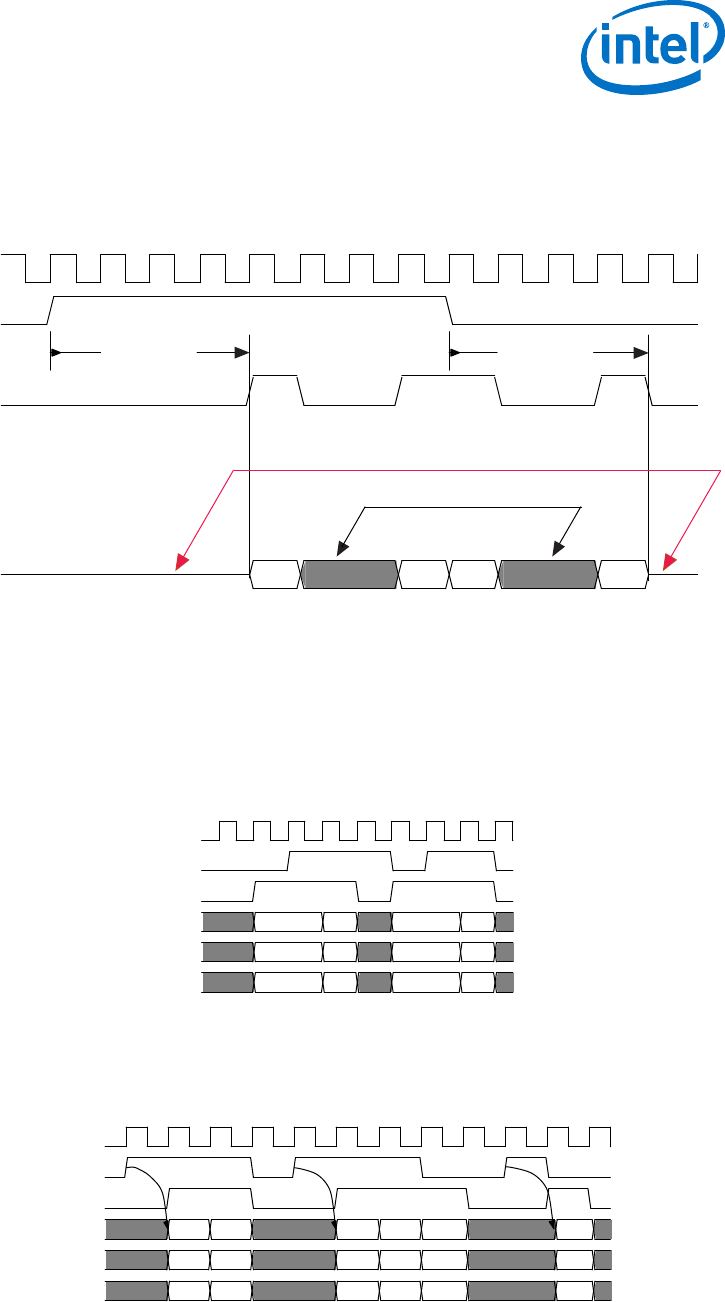
When readyLatency >= 1, the sink asserts ready before the ready cycle itself.
The source can respond during the appropriate cycle by asserting valid. It may not
assert valid during a cycle that is not a ready cycle.
Figure 25. Avalon-ST Interface with readyLatency = 4
clock
ready
valid
data[31:0]
readyLatency = 4 readyLatency = 4
1 2 3 4
source may not assert valid
source may assert valid
Figure 26. Transfer with Backpressure, readyLatency=0
The following figure illustrates these events:
1. The source provides data and asserts valid on cycle 1, even though the sink is not ready.
2. The source waits until cycle 2, when the sink does assert ready, before moving onto the next data cycle.
3. In cycle 3, the source drives data on the same cycle and the sink is ready to receive it. The transfer
occurs immediately.
4. In cycle 4, the sink asserts ready, but the source does not drive valid data.
clk
ready
valid
channel
error
data
0 1 2 3 5 6 7 84
D0 D1 D2 D3
Figure 27. Transfer with Backpressure, readyLatency=1
The following figures show data transfers with readyLatency=1 and readyLatency=2, respectively. In both
these cases, ready is asserted before the ready cycle, and the source responds 1 or 2 cycles later by providing
data and asserting valid. When readyLatency is not 0, the source must deassert valid on non-ready
cycles.
clk
ready
valid
channel
error
data D0 D1 D2 D3 D4 D5
5 Avalon Streaming Interfaces
MNL-AVABUSREF | 2018.03.22
Avalon® Interface Specifications
47
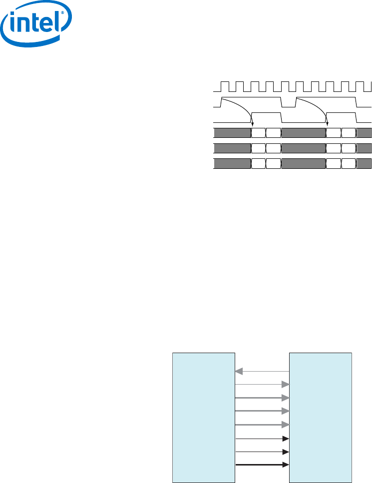
Figure 28. Transfer with Backpressure, readyLatency=2
clk
ready
valid
channel
error
data D0 D1 D2 D3
5.10 Packet Data Transfers
The packet transfer property adds support for transferring packets from a source
interface to a sink interface. Three additional signals are defined to implement the
packet transfer. Both the source and sink interfaces must include these additional
signals to support packets. You can only connect source and sink interfaces with
matching packet properties. Platform Designer does not automatically add the
startofpacket , endofpacket, and empty signals to source or sink interfaces that
do not include these signals.
Figure 29. Avalon-ST Packet Interface Signals
channel
<max channel>
valid
data
error
ready
Data Source Data Sink
empty
startofpacket
endofpacket
5 Avalon Streaming Interfaces
MNL-AVABUSREF | 2018.03.22
Avalon® Interface Specifications
48
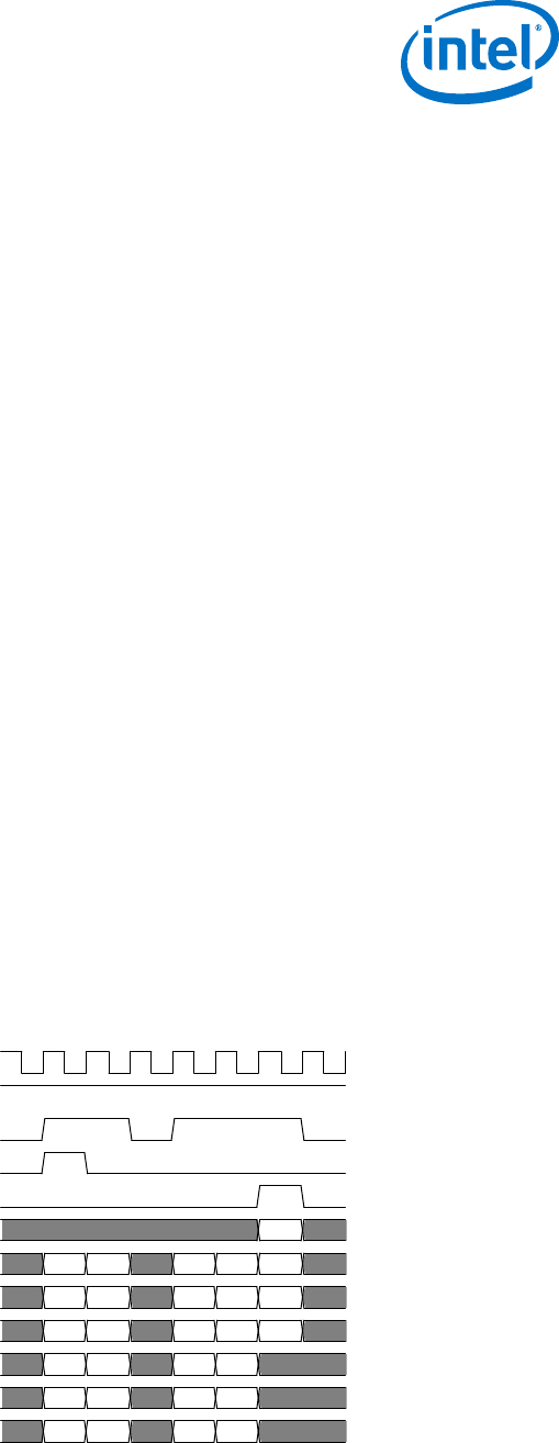
5.11 Signal Details
•startofpacket—All interfaces supporting packet transfers require the
startofpacket signal. startofpacket marks the active cycle containing the
start of the packet. This signal is only interpreted when valid is asserted.
•endofpacket—All interfaces supporting packet transfers require the
endofpacket signal. endofpacket marks the active cycle containing the end of
the packet. This signal is only interpreted when valid is asserted.
startofpacket and endofpacket can be asserted in the same cycle. No idle
cycles are required between packets. The startofpacket signal can follow
immediately after the previous endofpacket signal.
•empty—The optional empty signal indicates the number of symbols that are
empty during the endofpacket cycle. The sink only checks the value of the
empty during active cycles that have endofpacket asserted. The empty symbols
are always the last symbols in data, those carried by the low-order bits when
firstSymbolInHighOrderBits = true. The empty signal is required on all
packet interfaces whose data signal carries more than one symbol of data and
have a variable length packet format. The size of the empty signal in bits is
ceil[log2(<symbols per cycle>)].
5.12 Protocol Details
Packet data transfer follows the same protocol as the typical data transfer with the
addition of the startofpacket, endofpacket, and empty.
Figure 30. Packet Transfer
The following figure illustrates the transfer of a 17-byte packet from a source interface to a sink interface,
where readyLatency=0. It illustrates the following events:
1. Data transfer occurs on cycles 1, 2, 4, 5, and 6, when both ready and valid are asserted.
2. During cycle 1, startofpacket is asserted. The first 4 bytes of packet are transferred.
3. During cycle 6, endofpacket is asserted. empty has a value of 3. This value indicates that this is the
end of the packet and that 3 of the 4 symbols are empty. In cycle 6, the high-order byte, data[31:24]
drives valid data.
clk
ready
valid
startofpacket
endofpacket
empty
channel
error
data[31:24]
data[23:16]
data[15:8]
data[7:0]
0 0 0 0 0
0 0 0 0 0
D0 D4 D8 D12 D16
D1 D5 D9 D13
D2 D6 D10 D14
D3 D7 D11 D15
3
1 2 3 4 5 6 7
5 Avalon Streaming Interfaces
MNL-AVABUSREF | 2018.03.22
Avalon® Interface Specifications
49

6 Avalon Conduit Interfaces
Avalon Conduit interfaces group an arbitrary collection of signals. You can specify any
role for conduit signals. However, when you connect conduits, the roles and widths
must match and the directions must be opposite. An Avalon Conduit interface can
include input, output, and bidirectional signals. A module can have multiple Avalon
Conduit interfaces to provide a logical signal grouping. Conduit interfaces can declare
an associated clock. When connected conduit interfaces are in different clock domains,
Platform Designer generates an error message.
Note: If possible, you should use the standard Avalon-MM or Avalon-ST interfaces instead of
creating an Avalon Conduit interface. Platform Designer provides validation and
adaptation for these interfaces. It cannot provide validation or adaptation for Avalon
Conduit interfaces.
Conduit interfaces typically used to drive off-chip device signals, such as an SDRAM
address, data and control signals.
Figure 31. Focus on the Conduit Interface
Avalon-MM System
System Interconnect Fabric
Ethernet
PHY
Avalon
Slave
Avalon-MM
Slave
SDRAM
Memory
Avalon-MM
Master
Processor
Avalon-MM
Master
Avalon-MM
Master
Ethernet MAC Custom Logic
SDRAM
Controller
Custom
Logic
Conduit
Interface
Custom
Logic
MNL-AVABUSREF | 2018.03.22
Intel Corporation. All rights reserved. Intel, the Intel logo, Altera, Arria, Cyclone, Enpirion, MAX, Nios, Quartus
and Stratix words and logos are trademarks of Intel Corporation or its subsidiaries in the U.S. and/or other
countries. Intel warrants performance of its FPGA and semiconductor products to current specifications in
accordance with Intel's standard warranty, but reserves the right to make changes to any products and services
at any time without notice. Intel assumes no responsibility or liability arising out of the application or use of any
information, product, or service described herein except as expressly agreed to in writing by Intel. Intel
customers are advised to obtain the latest version of device specifications before relying on any published
information and before placing orders for products or services.
*Other names and brands may be claimed as the property of others.
ISO
9001:2008
Registered

6.1 Avalon Conduit Signal Roles
Table 19. Conduit Signal Roles
Signal Role Width Direction Description
<any> <n> In, out, or
bidirectional
A conduit interface consists of one or more input, output,
or bidirectional signals of arbitrary width. Conduits can
have any user-specified role. You can connect compatible
Conduit interfaces inside a Platform Designer (Standard)
system provided the roles and widths match and the
directions are opposite.
6.2 Conduit Properties
There are no properties for conduit interfaces.
6 Avalon Conduit Interfaces
MNL-AVABUSREF | 2018.03.22
Avalon® Interface Specifications
51
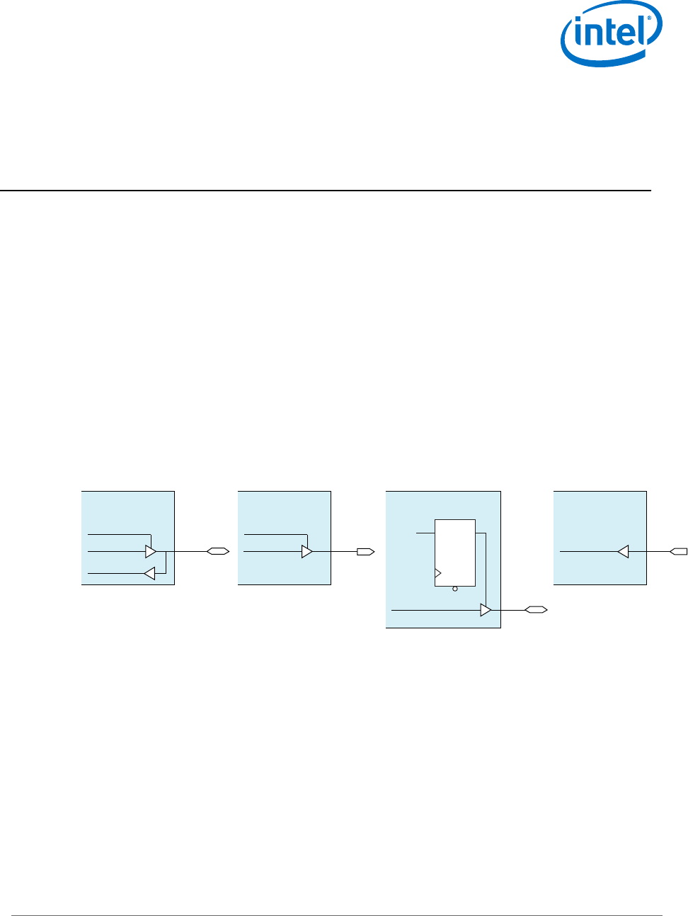
7 Avalon Tristate Conduit Interface
The Avalon Tristate Conduit Interface (Avalon-TC) is a point-to-point interface
designed for on-chip controllers that drive off-chip components. This interface allows
data, address, and control pins to be shared across multiple tristate devices. Sharing
conserves pins in systems that have multiple external memory devices.
The Avalon-TC interface restricts the more general Avalon Conduit Interface in two
ways:
•The Avalon-TC requires request and grant signals. These signals enable bus
arbitration when multiple Tristate Conduit Masters (TCM) are requesting access to
a shared bus.
• The pin type of a signal must be specified using suffixes appended to a signal’s
role. The three suffixes are: _out, _in, and _outen. Matching role prefixes
identify signals that share the same I/O Pin. The following illustrates the naming
conventions for Avalon-TC shared pins.
Figure 32. Shared Pin Types
data_out data
data_in
data_outen
Intel FPGA
Bidirectional Pin
busy_in busy
Intel FPGA
Input Only Pin
reset_out reset
Intel FPGA
Tri-State Output Only Pin
reset_outen ~reset
Intel FPGA
Output Only Pin
write_out write
MNL-AVABUSREF | 2018.03.22
Intel Corporation. All rights reserved. Intel, the Intel logo, Altera, Arria, Cyclone, Enpirion, MAX, Nios, Quartus
and Stratix words and logos are trademarks of Intel Corporation or its subsidiaries in the U.S. and/or other
countries. Intel warrants performance of its FPGA and semiconductor products to current specifications in
accordance with Intel's standard warranty, but reserves the right to make changes to any products and services
at any time without notice. Intel assumes no responsibility or liability arising out of the application or use of any
information, product, or service described herein except as expressly agreed to in writing by Intel. Intel
customers are advised to obtain the latest version of device specifications before relying on any published
information and before placing orders for products or services.
*Other names and brands may be claimed as the property of others.
ISO
9001:2008
Registered

The next figure illustrates pin sharing using Avalon-TC interfaces. This figure illustrates
the following points.
• The Tristate Conduit Pin Sharer includes separate Tristate Conduit Slave Interfaces
for each Tristate Conduit Master. Each master and slave pair has its own request
and grant signals.
• The Tristate Conduit Pin Sharer identifies signals with identical roles as tristate
signals that share the same FPGA pin. In this example, the following signals are
shared: addr_out, data_out, data_in, read_out, and write_out.
• The Tristate Conduit Pin Sharer drives a single bus including all of the shared
signals to the Tristate Conduit Bridge. If the widths of shared signals differ, the
Tristate Conduit Pin Sharer aligns them on their 0th bit. It drives the higher-order
pins to 0 whenever the smaller signal has control of the bus.
• Signals that are not shared propagate directly through the Tristate Conduit Pin
Sharer. In this example, the following signals are not shared: chipselect0_out,
irq0_out, chipselect1_out, and irq1_out.
• All Avalon-TC interfaces connected to the same Tristate Conduit Pin Sharer must
be in the same clock domain.
7 Avalon Tristate Conduit Interface
MNL-AVABUSREF | 2018.03.22
Avalon® Interface Specifications
53
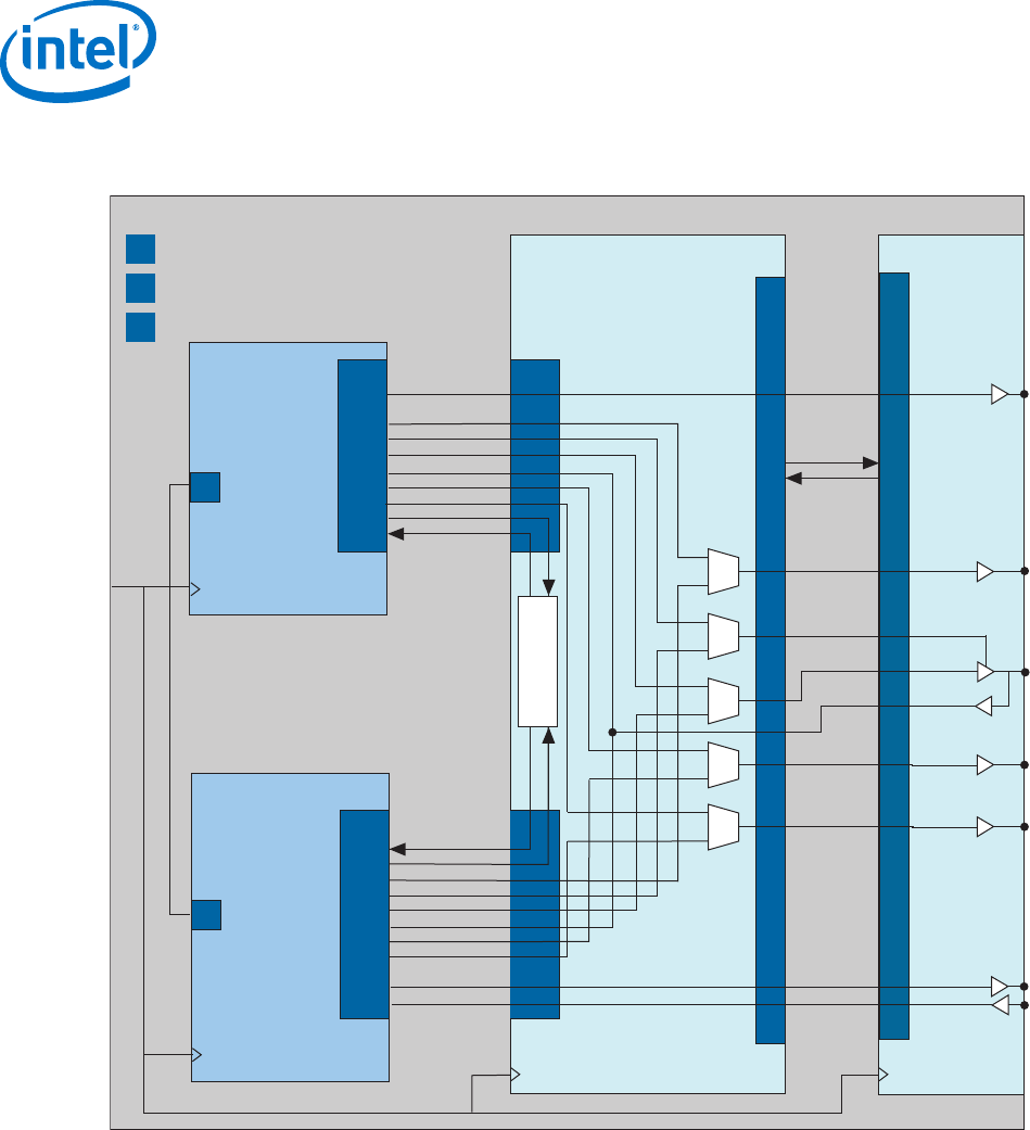
Figure 33. Tristate Conduit Interfaces
The following illustrates the typical use of Avalon-TC Master and Slave interfaces and signal naming.
Intel FPGA
TCM
Tristate Conduit
Pin Sharer TCS
Tristate Conduit
Bridge
S
Controller
for 2 MByte
x32 SSRAM
CS
IRQ
A[20:0]
D_EN
D[31:0]
DI[31:0]
Rd
Wr
Request
Grant
TCM
S
Grant
Req
A[22:0]
D_EN
D[15:0]
DI[15:0]
Rd
Wr
TCM
chipselect_out
dataout_outen
dataout_out[31:0]
data_in[31:0]
read_out
write_out
request
grant
request
grant
addr_out_[20:0]
chipselect_out
irq_in
Controller
for 8 MByte
x16 Flash
addr_out<n>
data_out<n>
data_in<n>
data_outen<n>
chipselect_out
request
grant
irq_in
chipselect_out
write_out
read_out
clock
Avalon-MM
Master
TCS
TCS
CS
IRQ
Avalon-MM Slave
S
TCM Tristate Conduit Master
Tristate Conduit Slave
TCS
Arb
dataout_outen
dataout_out[15:0]
data_in[15:0]
read_out
write_out
addr_out_[22:0]
For more information about the Generic Tristate Controller and Tristate Conduit Pin
Sharer, refer to the Avalon Tristate Conduit Components User Guide.
Related Links
Avalon Tristate Conduit Components User Guide
7.1 Avalon Tristate Conduit Signal Roles
The following table lists the signal defined for the Avalon Tristate Conduit interface. All
Avalon-TC signals apply to both masters and slaves and have the same meaning for
both
7 Avalon Tristate Conduit Interface
MNL-AVABUSREF | 2018.03.22
Avalon® Interface Specifications
54

Table 20. Tristate Conduit Interface Signal Roles
Signal Role Width Direction Required Description
request 1Master → Slave Yes The meaning of request depends on the state of the
grant signal, as the following rules dictate.
When request is asserted and grant is deasserted,
request is requesting access for the current cycle.
When request is asserted and grant is asserted,
request is requesting access for the next cycle.
Consequently, request should be deasserted on the
final cycle of an access.
The request is deasserted in the last cycle of a bus
access. It can be reasserted immediately following
the final cycle of a transfer. This protocol makes both
rearbitration and continuous bus access possible if no
other masters are requesting access.
Once asserted, request must remain asserted until
granted. Consequently, the shortest bus access is 2
cycles. Refer to Tristate Conduit Arbitration Timing
for an example of arbitration timing.
grant 1Slave → Master Yes When asserted, indicates that a tristate conduit
master has been granted access to perform
transactions. grant is asserted in response to the
request signal. It remains asserted until 1 cycle
following the deassertion of request.
<name>_in 1 – 1024 Slave → Master No The input signal of a logical tristate signal.
<name>_out 1 – 1024 Master → Slave No The output signal of a logical tristate signal.
<name>_outen 1Master → Slave No The output enable for a logical tristate signal.
7.2 Tristate Conduit Properties
There are no special properties for the Avalon-TC Interface.
7.3 Tristate Conduit Timing
The following illustrates arbitration timing for the Tristate Conduit Pin Sharer. Note that
a device can drive or receive valid data in the granted cycle.
7 Avalon Tristate Conduit Interface
MNL-AVABUSREF | 2018.03.22
Avalon® Interface Specifications
55
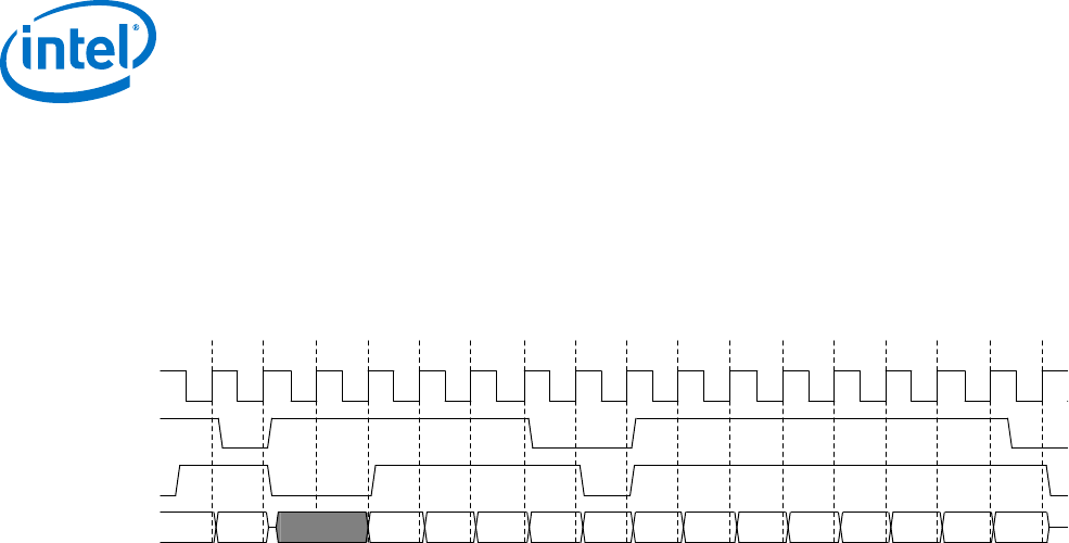
Figure 34. Tristate Conduit Arbitration Timing
This figure shows the following sequence of events:
1. In cycle 1, the tristate conduit slave asserts grant. The slave drives valid data in cycles1 and 2.
2. In cycle 4, the tristate conduit slave asserts grant. The slave drives valid data in cycles 5–8.
3. In cycle 9, the tristate conduit slave asserts grant. The slave drives valid data in cycles 10–17.
4. Cycles 3, 4 and 9 do not contain valid data.
clk
request
grant
data_out[31:0] 0a b c d e f 10 11 12 13 14 15 16 17
1 3 62 74 5 8 10 139 1411 12 16 1715
.
7 Avalon Tristate Conduit Interface
MNL-AVABUSREF | 2018.03.22
Avalon® Interface Specifications
56

A Deprecated Signals
Deprecated signals implement functionality that is no longer required or has been
superseded.
begintransfer
An output of Avalon-MM masters. Asserted for a single cycle at the beginning of a
transfer. This is signal is not used and not necessary.
chipselect or chipselect_n
chipselect or chipselect_n: The chip select signal as described below was
deprecated with the release of the Avalon Tristate Conduct (Avalon-TC) interface type
which includes a chip select signal.
Formerly chipselect was a 1-bit input to an Avalon Memory-Mapped (Avalon-MM)
slave interface signaling the beginning of a read or write transfer. The current Platform
Designer interconnect filters read and write signals from masters according to the
address and address map. The Platform Designer interconnect only drives read and
write signals to the appropriate Avalon-MM slave, making a chip select unnecessary.
This signal dates from very early microprocessor designs. CPLDs decoded
microprocessor addresses and generated chip selects for peripherals that typically
were frequently asynchronous. With synchronous systems this signal is typically
unnecessary.
flush
This signal was removed version 1.2 of the Avalon Interface Specifications. Formerly
available to masters to clear pending transfers for pipelined reads.
MNL-AVABUSREF | 2018.03.22
Intel Corporation. All rights reserved. Intel, the Intel logo, Altera, Arria, Cyclone, Enpirion, MAX, Nios, Quartus
and Stratix words and logos are trademarks of Intel Corporation or its subsidiaries in the U.S. and/or other
countries. Intel warrants performance of its FPGA and semiconductor products to current specifications in
accordance with Intel's standard warranty, but reserves the right to make changes to any products and services
at any time without notice. Intel assumes no responsibility or liability arising out of the application or use of any
information, product, or service described herein except as expressly agreed to in writing by Intel. Intel
customers are advised to obtain the latest version of device specifications before relying on any published
information and before placing orders for products or services.
*Other names and brands may be claimed as the property of others.
ISO
9001:2008
Registered

B Document Revision History for the Avalon Interface
Specifications
Table 21.
Document
Version
Intel Quartus Prime
Version
Changes
2018.03.22 17.1 Made the following changes:
• Made the following changes to the Read and Write Transfers with
Waitrequest timing diagram
—Removed readdatavalid signal which is not relevant when using
waitrequest
—Moved the number 4, readdata and response forward one cycle.
—Aligned the read signal to number 1.
• Expanded the Transfers Using the waitrequestAllowance Property
section. Provided more complex timing diagrams.
• Updated the discussion in the Read Bursts section. For reads with a
burstcount > 1, Intel recommends asserting all byteenables.
• Enhanced discussion in the waitrequestAllowance Equals Two - Not
Recommended topic. Corrected timing diagram. Data must be held for
2 cycles starting at clock cycle 11.
November 2017 17.1 Made the following changes:
• Updated the discussion of Read Bursts as follows:
— Qualified the statement, " When a master connects directly to a
slave, a burstcount of <n>, means the slave must return <n>
words of readdata to complete the burst. " This statement is true if
the master connects directly to the slave. It may not be true if
interconnect links the master and slave.
— Removed the following statement from the description of read
bursts: "The byteenables presented with a read burst command
apply to all cycles of the burst." This statement is no longer true.
However, Intel recommends that reads with burstcount > 1
assert all byteenables.
• Removed the following statement form the Pipelined Transfers section:
Write transfers cannot be pipelined. You can pipeline writes using the
writeresponsevalid signal.
• Expanded the description of read and write responses in the Avalon-
MM Read and Write Responses Timing Diagram section.
•Revised the description of the reset_req signal.
•Changed width of irq from 1 bit to 1-32 bits. Both the Intel Quartus
Prime Pro Edition and Intel Quartus Prime Standard Edition software
support interrupt vectors.
May 2017 Quartus Prime Pro v17.1
Stratix 10 ES Editions
Made the following changes:
• Added the following interface property parameters.
—waitrequestAllowance parameter to support high speed
operation. This parameter is available for Avalon-MM interfaces.
Added timing diagrams illustrating use of this parameter.
—minimumResponseLatency parameter to facilitate timing
closure for Avalon-MM interface. Added timing diagrams illustrating
use of this parameter.
continued...
MNL-AVABUSREF | 2018.03.22
Intel Corporation. All rights reserved. Intel, the Intel logo, Altera, Arria, Cyclone, Enpirion, MAX, Nios, Quartus
and Stratix words and logos are trademarks of Intel Corporation or its subsidiaries in the U.S. and/or other
countries. Intel warrants performance of its FPGA and semiconductor products to current specifications in
accordance with Intel's standard warranty, but reserves the right to make changes to any products and services
at any time without notice. Intel assumes no responsibility or liability arising out of the application or use of any
information, product, or service described herein except as expressly agreed to in writing by Intel. Intel
customers are advised to obtain the latest version of device specifications before relying on any published
information and before placing orders for products or services.
*Other names and brands may be claimed as the property of others.
ISO
9001:2008
Registered

Document
Version
Intel Quartus Prime
Version
Changes
December 2015 15.1 Made the following changes:
•Changed the width of the empty signal from a maximum of 8 bits to a
maximum of 5 bits.
•Improved the definition of the reset_req signal.
•Removed the readdatavalid signal from the Pipelined Read Transfer
with Fixed Latency of Two Cycles timing diagram. This signal is not
relevant for fixed latency transfers.
•Corrected equation defining the empty signal.
• Made the following changes in the Pipelined Read Transfers with
Variable Latency timing diagram:
—Moved the deassertion of the read signal to cycle 9
—Changed waitrequest to don't care in cycle 9.
March 2015 14.1 Fixed typo in Figure 1-1.
January 2015 14.1 Made the following changes:
• Clarified address alignment example. The Avalon-MM master and slave
interfaces are different widths.
• Improved discussion of Pipelined read Transfers with Variable Latency.
Corrected timing marker 2 which should be exactly on the rising edge
of clock.
• Improved discussion of Pipelined Read Transfer with Fixed Latency of
Two Cycles.
•Clarified use of beatsPerCycle property.
• Corrected the address range for line-wrapped bursts. The correct
address range for a 64-byte burst is 0x0–0x3C, not 0x0–0x1C.
• Corrected description of the Tristate Conduit Arbitration Timing
diagram in the following ways:
— The tristate conduit slave asserts grant, not the tristate conduit
master.
— The final grant comes in cycle 9, not cycle 8.
• Added a Deprecated Signals appendix.
•Added read response signal.
• Improved definitions of clock and reset signal types.
• Corrected definition of clock sink properties.
•Corrected definition of synchronousEdges for reset source interface.
•Clarified the Avalon-MM response signal type.
•Updated definition of empty. The signal must be interpreted
emptyWithinPacket is true.
• Edited for clarity and consistency.
June 2014 14.0 • Updated the Avalon-MM Signals table, begintransfer,
readdatavalid, and readdatavalid_n.
• Updated the Read and Write Transfers with Waitrequest figure:
— Moved deassertion of write to cycle 6.
—Moved assertion of readdatavalid and readdata to cycle 4.
• Updated the Pipelined Read Transfers with Variable Latency figure:
—Moved assertion of data1 to just after cycle 5, and assertion of
data2 to cycle 6.
—Moved assertion of readdatavalid to match data1 and data2.
April 2014 13.01 Corrected Read and Write Transfers with Waitrequest In Avalon Memory-
Mapped Interfaces chapter .
May 2013 13.0 Made the following changes:
continued...
B Document Revision History for the Avalon Interface Specifications
MNL-AVABUSREF | 2018.03.22
Avalon® Interface Specifications
59

Document
Version
Intel Quartus Prime
Version
Changes
• Minor updates to Avalon Memory-Mapped Interfaces.
• Minor updates to Avalon Streaming Interfaces.
• Updated Avalon Conduit Interfaces to describe the signal roles
supported by Avalon conduit interfaces.
• Updated Shared Pin Types figure in the Avalon Tristate Conduit
Interface chapter.
May 2011 11.0 Initial release of the Avalon Interface Specifications supported by Qsys.
B Document Revision History for the Avalon Interface Specifications
MNL-AVABUSREF | 2018.03.22
Avalon® Interface Specifications
60
