Meshlium Technical Guide
meshlium_technical_guide
User Manual: Pdf
Open the PDF directly: View PDF ![]() .
.
Page Count: 214 [warning: Documents this large are best viewed by clicking the View PDF Link!]
- 1. General and safety information
- 2. Important: read me before using
- 3. Meshlium v4.0 vs Meshlium v3.5
- 4. Contents of the box
- 5. Specifications
- 6. How to use Meshlium
- 7. Understanding Meshlium
- 8. Accessing Meshlium – make it easy!
- 9. Network interfaces setup
- 10. Wireless Sensor Networks
- 11. Meshlium Visualizer
- 12. Cloud Connectors
- 12.1. Premium Cloud Partners
- 12.2. Advanced Cloud Partners
- 12.3. Basic Cloud Partners
- 12.3.1. Amplía’s OpenGate
- 12.3.2. BaseN
- 12.3.3. B-Scada
- 12.3.4. C2M
- 12.3.5. DeviceLynk
- 12.3.6. eagle.io
- 12.3.7. Ensura
- 12.3.8. Ericsson AppIoT
- 12.3.9. Esri
- 12.3.10. Extunda
- 12.3.11. HaibuSmart
- 12.3.12. infiswift
- 12.3.13. IoT-Ticket
- 12.3.14. IoTSens
- 12.3.15. Kii
- 12.3.16. Labeeb
- 12.3.17. MQTT
- 12.3.18. Orchestra
- 12.3.19. Redd
- 12.3.20. RIOT Platform
- 12.3.21. SensorUp IoT Platform
- 12.3.22. Sentilo
- 12.3.23. Simfony
- 12.3.24. SmartPlants
- 12.3.25. TechEdge SAP HANA
- 13. Device connectors
- 14. Smartphone detection
- 15. Tools
- 16. Database management
- 17. System Information
- 18. Upgrading Meshlium
- 19. Rescue System
- 20. Expansion port
- 21. Manager System changelog
- 22. Documentation changelog
- 23. Certifications
- 24. Maintenance
- 25. Disposal and recycling


-2- v7.3
Meshlium
X
treme
Index
Document version: v7.3 - 07/2017
© Libelium Comunicaciones Distribuidas S.L.
INDEX
1. General and safety information ..........................................................................................6
2. Important: read me before using........................................................................................7
3. Meshlium v4.0 vs Meshlium v3.5 .........................................................................................8
3.1. Capabilities comparison ................................................................................................................... 8
3.2. Compatibility with Waspmote and Plug & Sense! nodes ............................................................. 9
3.3. Compatibility with current cloud software .................................................................................... 9
3.4. XBee-PRO 868 vs XBee 868LP ........................................................................................................ 10
3.5. XBee-PRO 900 vs XBee-PRO 900HP .............................................................................................. 11
3.6. 3G (SIM5215) vs 4G (LE910) ........................................................................................................... 11
4. Contents of the box ............................................................................................................13
5. Specications ......................................................................................................................15
6. How to use Meshlium ......................................................................................................... 18
6.1. Power supply ................................................................................................................................... 18
6.2. External SIM socket ......................................................................................................................... 20
6.3. How to install the antennas ........................................................................................................... 21
6.4. Installation of the IP65 Ethernet cable ......................................................................................... 22
6.5. Installing Meshlium ......................................................................................................................... 25
6.6. Initialization, restart and shutdown .............................................................................................. 25
6.7. Setting the time ............................................................................................................................... 26
7. Understanding Meshlium ..................................................................................................27
7.1. Concepts .......................................................................................................................................... 27
7.2. Meshlium models ........................................................................................................................... 27
7.3. Storage ............................................................................................................................................. 28
7.4. Application model by model .......................................................................................................... 28
8. Accessing Meshlium – make it easy! .................................................................................30
9. Network interfaces setup .................................................................................................. 32
9.1. Ethernet setup ................................................................................................................................. 32
9.2. WiFi Access Point setup .................................................................................................................. 35
9.2.1. Conguration .......................................................................................................................35
9.2.2. Clients connected ................................................................................................................37
9.3. Network setup conrmation ......................................................................................................... 38
9.4. 4G setup ........................................................................................................................................... 39

-3- v7.3
Meshlium
X
treme
Index
9.5. Proxy setup ...................................................................................................................................... 40
9.6. No-IP setup ...................................................................................................................................... 41
10. Wireless Sensor Networks ...............................................................................................43
10.1. Meshlium and Waspmote ............................................................................................................ 43
10.2. Receiving and storing data .......................................................................................................... 44
10.2.1. Receiving trough RF communications ............................................................................44
10.2.2. Receiving trough 4G / WiFi / Ethernet (HTTP) ................................................................51
10.3. Capturer ......................................................................................................................................... 51
10.3.1. Local database ...................................................................................................................53
10.3.2. External Database .............................................................................................................54
10.3.3. Show me Now ....................................................................................................................57
10.3.4. Advanced database options ............................................................................................57
10.4. Logs ................................................................................................................................................ 59
10.5. Sensor list ...................................................................................................................................... 60
10.6. OTA via FTP .................................................................................................................................... 61
11. Meshlium Visualizer .........................................................................................................63
11.1. Working with the Visualizer ......................................................................................................... 63
12. Cloud Connectors ..............................................................................................................66
12.1. Premium Cloud Partners ............................................................................................................. 68
12.1.1. Arrow ..................................................................................................................................68
12.1.2. IBM Bluemix .......................................................................................................................73
12.1.3. Microsoft Azure Event Hubs ............................................................................................74
12.1.4. Microsoft Azure IoT Hub ..................................................................................................81
12.1.5. Nexmachina .......................................................................................................................85
12.1.6. ElementBlue – RightSensor ..............................................................................................87
12.1.7. Soa2 ..................................................................................................................................89
12.1.8. ThingPlus ............................................................................................................................95
12.1.9. ThingWorx ..........................................................................................................................98
12.2. Advanced Cloud Partners .......................................................................................................... 102
12.2.1. Amazon IoT ..................................................................................................................... 102
12.2.2. Cumulocity ...................................................................................................................... 107
12.2.3. SmartCityPlatform .......................................................................................................... 108
12.2.4. Telefónica IoT Platform ................................................................................................. 110
12.2.5. Telit .................................................................................................................................. 111
12.3. Basic Cloud Partners .................................................................................................................. 115
12.3.1. Amplía’s OpenGate ........................................................................................................ 115
12.3.2. BaseN ............................................................................................................................... 116
12.3.3. B-Scada ............................................................................................................................ 118
12.3.4. C2M .................................................................................................................................. 120
12.3.5. DeviceLynk ...................................................................................................................... 122
12.3.6. eagle.io ............................................................................................................................ 124

-4- v7.3
Meshlium
X
treme
12.3.7. Ensura .............................................................................................................................. 125
12.3.8. Ericsson AppIoT .............................................................................................................. 126
12.3.9. Esri ................................................................................................................................... 129
12.3.10. Extunda ......................................................................................................................... 133
12.3.11. HaibuSmart ................................................................................................................... 134
12.3.12. inswift .......................................................................................................................... 135
12.3.13. IoT-Ticket ....................................................................................................................... 137
12.3.14. IoTSens .......................................................................................................................... 143
12.3.15. Kii ................................................................................................................................... 144
12.3.16. Labeeb ........................................................................................................................... 147
12.3.17. MQTT ............................................................................................................................. 150
12.3.18. Orchestra ...................................................................................................................... 153
12.3.19. Redd ............................................................................................................................... 156
12.3.20. RIOT Platform ............................................................................................................... 157
12.3.21. SensorUp IoT Platform ................................................................................................ 158
12.3.22. Sentilo ............................................................................................................................ 159
12.3.23. Simfony ......................................................................................................................... 160
12.3.24. SmartPlants .................................................................................................................. 163
12.3.25. TechEdge SAP HANA .................................................................................................... 164
13. Device connectors ..........................................................................................................166
13.1. Device Partners ........................................................................................................................... 167
13.1.1. Axis ................................................................................................................................... 167
14. Smartphone detection ...................................................................................................170
14.1. Devices detected ......................................................................................................................... 172
14.2. WiFi Scanner ................................................................................................................................ 177
14.2.1. Concepts .......................................................................................................................... 177
14.2.2. Local database ................................................................................................................ 180
14.2.3. External database .......................................................................................................... 181
14.3. Bluetooth Scanner ...................................................................................................................... 183
14.3.1. Concepts .......................................................................................................................... 183
14.3.2. Local database ................................................................................................................ 185
14.3.3. External database .......................................................................................................... 186
15. Tools .................................................................................................................................188
15.1. Fresnel calculator ........................................................................................................................ 188
15.2. Iperf .............................................................................................................................................. 188
15.3. Ping ............................................................................................................................................... 189
15.4. Traceroute ................................................................................................................................... 190
15.5. Netstat .......................................................................................................................................... 190
15.6. GPS ............................................................................................................................................... 191
15.6.1. Concepts .......................................................................................................................... 191
15.6.2. Conguring GPS service ................................................................................................ 191

-5- v7.3
Meshlium
X
treme
15.6.3. Local database ................................................................................................................ 193
15.6.4. External database .......................................................................................................... 194
15.7. Beep .............................................................................................................................................. 195
16. Database management ..................................................................................................196
16.1. Direct access ................................................................................................................................ 196
16.2. PhpMyAdmin ............................................................................................................................... 196
17. System Information ........................................................................................................198
17.1. Hostname .................................................................................................................................... 198
17.2. Password management ............................................................................................................. 198
17.3. Disk usage .................................................................................................................................... 199
17.4. Internal temperature sensor ..................................................................................................... 199
17.5. Time synchronization ................................................................................................................. 200
18. Upgrading Meshlium ......................................................................................................201
18.1. Checking for updates ................................................................................................................. 201
18.2. Local le ....................................................................................................................................... 202
18.3. URL ................................................................................................................................................ 203
19. Rescue System .................................................................................................................204
19.1. Rescue steps ................................................................................................................................ 204
20. Expansion port ................................................................................................................206
21. Manager System changelog ...........................................................................................207
22. Documentation changelog ............................................................................................209
23. Certications ................................................................................................................... 210
23.1. General overview ........................................................................................................................ 210
23.2. CE (Europe) .................................................................................................................................. 210
23.3. FCC (USA) ..................................................................................................................................... 211
23.4. IC (Canada) ................................................................................................................................... 212
23.5. ANATEL (Brazil) ............................................................................................................................ 212
23.6. RCM (Australia) ............................................................................................................................ 212
24. Maintenance ....................................................................................................................213
25. Disposal and recycling ....................................................................................................214

-6- v7.3
General and safety information
Meshlium
X
treme
1. General and safety information
Important:
•All documents and any examples they contain are provided as-is and are subject to change without notice.
Except to the extent prohibited by law, Libelium makes no express or implied representation or warranty of
any kind with regard to the documents, and specically disclaims the implied warranties and conditions of
merchantability and tness for a particular purpose.
•The information on Libelium’s websites has been included in good faith for general informational purposes
only. It should not be relied upon for any specic purpose and no representation or warranty is given as to its
accuracy or completeness.
Read carefully the Limited Warranty and Terms and Conditions of Use before using “Meshlium”.
•Read carefully the “General Conditions of Sale and Use of Libelium”. This document can be found at
http://www.libelium.com/development/meshlium/technical_service
As specied in the Warranty document which you can nd at
http://www.libelium.com/development/meshlium/documentation, the client has 7 days from the day the
order is received to detect any failure and report that to Libelium. Any other failure reported after these 7
days may not be considered under warranty.
•Do NOT open the enclosure. If you do so, you will lose the guarantee.
•Do not remove any of the components.
•Do not allow contact between metallic objects and the electronic part to avoid injury and burns.
•NEVER immerse the equipment in any liquid.
•Keep the equipment in a dry place away from any liquids that could spill.
•Check from the label that comes with the equipment the maximum permitted voltage and amperage range.
•Keep the equipment within the temperature range indicated in the specications section.
•Do not connect or power the equipment using cables that have been damaged.
•Place the equipment in an area to which only maintenance personnel can have access (in a restricted access
zone).
•In any case, keep children away from the machine.
•If there is a power failure, immediately disconnect from the mains electricity.
•If using the car lighter as a power source, make sure that you follow the voltage and current specications
indicated in the section “How to use Meshlium”.
•If a software failure occurs, consult the section web support.
•Do not place the equipment on trees or plants as they could be damaged by its weight.
•Be particularly careful if you are connected through Ethernet or WiFi; if the settings are incorrectly altered,
Meshlium could become inaccessible.

-7- v7.3
Important: read me before using
Meshlium
X
treme
2. Important: read me before using
The following list shows just some of the actions that produce the most common failures and warranty-
voiding. Complete documentation about usage can be found at:
http://www.libelium.com/development/meshlium/technical_service
Failure to comply with the recommendations of use will entail the guarantee cancellation.
•Do not interrupt the power supply before shutting down Meshlium properly through the “Shutdown” or
“Restart” buttons in the Manager System.
•Do not open the Meshlium enclosure in any case. This will automatically make the warranty void.
•Do not submerge Meshlium in liquids.
•Do not place Meshlium on places or equipment where the device could be exposed to shocks and/or vibrations.
•Do not expose Meshlium to temperatures below -20º C or above 50º C.
•Meshlium’s microprocessor must not overpass 75 Celsius degrees. The user must ensure that this temperature
never overpass. Especially when using WiFi Scan.
•Do not power Meshlium with other power sources than the original provided by Libelium.
For more information: http://www.libelium.com/meshlium

-8- v7.3
Meshlium v4.0 vs Meshlium v3.5
Meshlium
X
treme
3. Meshlium v4.0 vs Meshlium v3.5
This evolution of Meshlium includes an important upgrade of the hardware capabilities. The most important
changes are:
•Big step forward in performance, CPU performance 10 times better and RAM capacity 8 times bigger.
•Cellular connection upgraded to 4G for a very fast Internet connection and data synchronization.
•WiFi AP upgraded to WiFi b/g/n (up to 144 Mbps).
•New models of radio module for the 868 MHz and 900 MHz bands.
•Up to two RF (XBee) modules can be installed in the device, working with the 4G radio at the same time (2.4
GHz and 868/900 MHz).
•GPS/GLONASS capabilities for a faster global location.
•New improved design.
•Operating system updated including new versions of programs and system.
•New expansion port for future use of external I2C, USB or UART devices.
•New Meshlium is Microsoft Azure Certied (More info: https://azure.microsoft.com/es-es/marketplace/
programs/certied/).
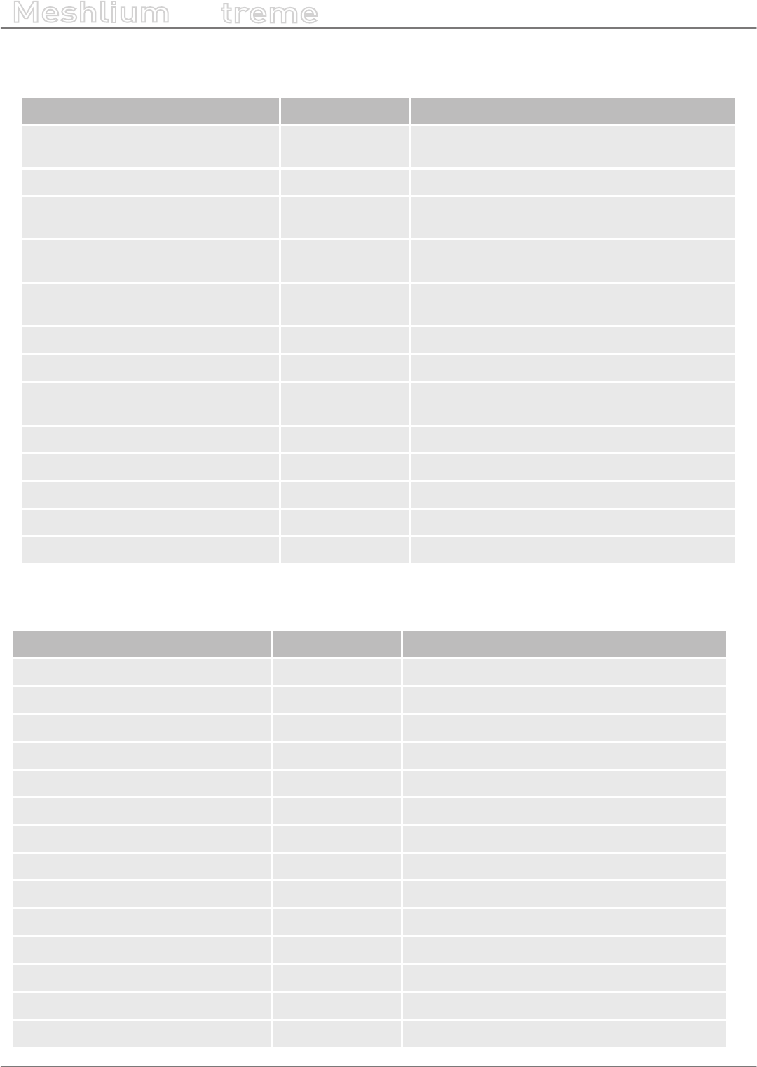
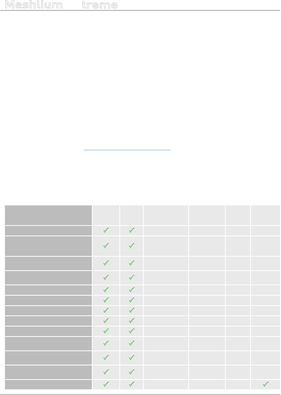
3.1. Capabilities comparison
Previous Meshlium version New Meshlium
CPU cores 1 4
CPU architecture 32 bits 64 bits
CPU frequency 500 MHz 1 GHz
RAM 256 MB DDR 2 GB DDR3
Storing Compact Flash 8 GB SSD disk 16 GB
Linux Kernel 2.6 3.16
Simultaneous cloud services 2-4 15-20
Boot time ~2 minutes Less than 1 minute
WiFi a/b/g (up to 54 Mbps) a/b/g/n (up to 144 Mbps)
Cellular
Up to 7.2 Mbps downlink (SIM5218)
Up to 384 kbps downlink (SIM5215)
Up to 42 Mbps downlink
Antenna connectors 4 10
RF module sockets 1 2
Geolocation GPS GPS + GLONASS
Root access Yes No
Power consumption ~10 W ~15 W (depending on number of
radios)
Enclosure (mm) 210 x 190 x 60 30 x 220 x 80
Certications CE / FCC / IC
CE (Europe) / FCC (US) / IC (Canada)
/ ANATEL (Brazil) / RCM (Australia) /
PTCRB (US) / AT&T (US)
-9- v7.3
Meshlium v4.0 vs Meshlium v3.5
Meshlium
X
treme
3.2. Compatibility with Waspmote and Plug & Sense! nodes
Old hardware Compatible Notes
Plug & Sense! (Waspmote v1.2)
802.15.4 YES
Plug & Sense! (Waspmote v1.2) ZigBee NO Old ZigBee modules are EoL
Plug & Sense! (Waspmote v1.2)
DigiMesh NO
Plug & Sense! (Waspmote v1.2) 900 NO Old 900 MHz modules are EoL. Substituted by
the new 900HP radios.
Plug & Sense! (Waspmote v1.2) 868 NO Old 868 MHz modules are EoL. Substituted by
the new 868 radios.
Plug & Sense! (Waspmote v1.2) WiFi YES
Plug & Sense! (Waspmote v1.2) 3G YES
Plug & Sense! (Waspmote v1.5)
802.15.4 YES
Plug & Sense! (Waspmote v1.5) 900 YES
Plug & Sense! (Waspmote v1.5) 868 YES
Plug & Sense! (Waspmote v1.5) WiFi YES
Plug & Sense! (Waspmote v1.5) 4G YES
Plug & Sense! (Waspmote v1.5) ZigBee NO Meshlium does not support this RF module
3.3. Compatibility with current cloud software
Cloud software Compatible Notes
Amazon IoT yes
Esri yes Only ArcGIS online
IBM Bluemix yes
IOT-Ticket yes
Azure Event Hubs yes
Azure Service Bus no Obsolete: use Event Hubs
MQTT yes
Telefónica yes
ThingWorx yes
amplía yes
Simfony yes
Smart City Platform yes
B-Scada yes
DeviceLynk yes

-10- v7.3
Meshlium v4.0 vs Meshlium v3.5
Meshlium
X
treme
Cloud software Compatible Notes
devicify yes
Eagle.io yes
ElementBlue yes
Extunda yes
IoTSens yes
Sentilo yes
Soa2 yes
Solvver yes
Thing+ yes
Compatibility with other software:
Software Compatible Notes
External DB synchronization of
sensor data. yes Some changes in the tables needed, can be
done without losing data.
3.4. XBee-PRO 868 vs XBee 868LP
The new XBee 868LP module supports some changes:
•The new XBee 868LP operates between 863 and 870 MHz, making it deployable in several regions throughout
the world including approved European countries and India by utilizing a software selectable channel masking
feature.
•The XBee 868LP is also the industry’s rst RF module using 868 MHz and surrounding frequencies for LBT
+ AFA (Listen Before Talk and Adaptive Frequency Agility). This virtually eliminates interference by listening
to the radio environment before any transmission starts, and automatically shifting to a new channel
when interference is detected. This patent-pending frequency scan occurs automatically and in a matter of
microseconds so as not to impact performance.
Features comparison:
Feature [Old] XBee-PRO 868 [New] XBee 868LP
Frequency band 868 MHz (1 channel) 863 to 870 MHz (32 channels)
RF data rate 24 kbps 10 kbps
Indoor/urban range Up to 550 m Up to 112 m
Outdoor/line-of-sight range Up to 40 km Up to 8.4 km
Transmit power 25 dBm 14 dBm
Receive sensitivity -112 dBm -106 dBm
Transmit current 500 mA 48 mA
Receive current 65 mA 27 mA
LBT + AFA No Yes

-11- v7.3
Meshlium v4.0 vs Meshlium v3.5
Meshlium
X
treme
3.5. XBee-PRO 900 vs XBee-PRO 900HP
The new XBee 900HP modules support some changes:
•The new XBee-PRO 900HP uses greater power transmission compared to the old version. Thus, the ranges
achieved by these new modules are larger than before.
•The XBee-PRO 900HP modules are certied for use in multiple countries: Brazil, Australia, US. Through the
new channel selection it is possible to enable/disable the preferred frequency channels within the 902-928
MHz band.
•The power consumption has been improved compared to the old modules. Better ranges have been achieved
with almost the same TX power. On the other hand, RX power consumption has been reduced.
Features comparison:
Feature [Old] XBee-PRO 900 [New] XBee-PRO 900HP
Frequency band 902-928 MHz (8 hopping patterns on 12
channels)
902 MHz to 928 MHz (64
channels)
RF data rate 156 kbps 10 kbps
Indoor/urban range Up to 450 ft (140 m) Up to 2000 ft (610 m)
Outdoor/line-of-sight
range Up to 1.8 miles (3 km) Up to 9 miles (15.5 km)
Transmit power 17 dBm 24 dBm
Receive sensitivity -100 dBm -110 dBm
Transmit current 210 mA 215 mA
Receive current 80 mA 29 mA
3.6. 3G (SIM5215) vs 4G (LE910)
The new 4G module module supports some changes:
•The new 4G counts with many dierent models, one specically designed for each market:
-LE910-EU (Europe / Brazil): CE, GCF, ANATEL
-LE910-NAG (US / Canada): FCC, IC, PTCRB, AT&T Approved
-LE910-AU V2 (Australia): RCM, Telstra Approved
•The GPS module also makes possible perform geolocation services using NMEA sentences oering information
such as latitude, longitude, altitude and speed what makes it perfect to perform tracking applications.
•The new 4G module oers the maximum performance of the 4G network as it uses two dierent antennas
(normal + diversity) for RX (MIMO DL 2x2) choosing the best received signal at any time and getting a maximum
download speed of 100 Mbps.
Features comparison:
Features [Old] 3G (SIM5215) [New] 4G (LE910)
Protocols 3G / GPRS / GSM 4G / 3G / GPRS / GSM / WCDMA / HSPA+ / LTE
Certications CE, GCF, FCC, IC,
PTCRB
CE, GCF, ANATEL, FCC, IC, PTCRB, AT&T Compliant, KCC, RCM,
NTT DoCoMo, KDDi
GPS No Yes

-12- v7.3
Meshlium v4.0 vs Meshlium v3.5
Meshlium
X
treme
Features [Old] 3G (SIM5215) [New] 4G (LE910)
Download max
speed 384 kbps 100 Mbps
Upload max speed 384 kbps 50 Mbps
Antenna diversity No Yes
Cellular carriers Any Any + Specially tested with AT&T, SK Telecom, Telstra, NTT
DoCoMo or KDDi
-13- v7.3
Contents of the box
Meshlium
X
treme
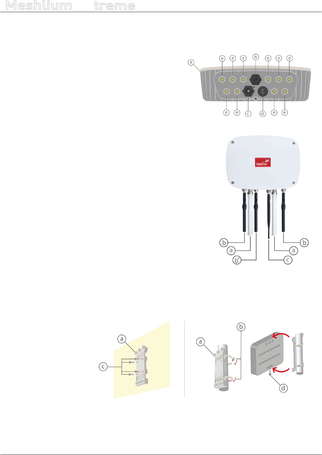
4. Contents of the box
Meshlium
a) IP65 casing
b) Ethernet connector
c) micro-SIM + micro-USB connector
d) Expansion connector
e) Antenna connectors
Antennas *
a) Dipole 5 dBi (Bluetooth, WiFi, XBee-PRO 802.15.4)
b) 4G / GPS (3 antennas for EU, US or BR models; 2 antennas for AU
models)
c) Dipole 4.5 dBi (XBee 868LP, XBee-PRO 900HP)
(*) Number and type of antennas depend on the model purchased.
Fixing
a) Fixing plate
b) 2 metal brackets
c) Screws and wall plugs
d) Mounting screw
-14- v7.3
Contents of the box
Meshlium
X
treme
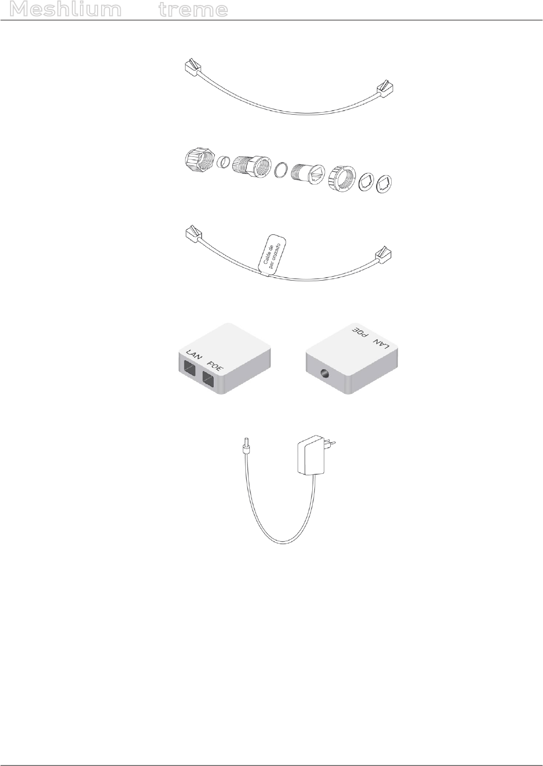
Ethernet cable
IP65 Ethernet cap
Ethernet crossover cable
POE injector
AC/DC adapter

-15- v7.3
Specications
Meshlium
X
treme
5. Specications
Processor 1 GHz Quad Core (x86)
RAM memory 2 GB (DDR3)
Disk memory 16 GB
Power 6 to 12 W (12 V)
Power source PoE (Power Over Ethernet)
Max current supply 2 A
Enclosure
Material Aluminum
Dimensions 300 x 220 x 87
mm
Weight 2.2 kg
External protection IP65
Temperature range -20 ºC / 50 ºC
Response time to
Ethernet ping 60 s
Time to have all the
services running 60 s
Types of power supply*
AC-220 V (DC-12 V)
Linux, Debian based
Meshlium Manager System
Management software (open source)
Security Authentication WEP, WPA, WPA2,
HTTPS
(*) Only with the accessories supplied by Libelium
Figure: Meshlium unit

-16- v7.3
Specications
Meshlium
X
treme
WiFi (2.4 GHz) radio (Access Point/Scanner)
WiFi radio
Chipset Qualcomm Atheros QCA9882
TX power 20 dBm
Range 500 m*
Antenna 5dBi dipole
Type Omni-directional, dipole
Gain 5 dBi
Dimensions 224 x 22 mm
(*) Depending on antenna and line of sight
RF radio modules
Model XBee-PRO 802.15.4
Frequency 2.4 GHz
TX power 18 dBm (10 dBm for EU models)
Rx sensitivity -100 dBm
Antenna 5 dBi dipole
Range 1.6 km (750 m in EU models)*
Model XBee 868LP
Frequency 868 MHz
TX power 14 mW
Rx sensitivity -106 dBm
Antenna 4.5 dBi dipole
Range 8.4 km*
Model XBee-PRO 900HP
Frequency 900 MHz
TX power 24 dBm
Rx sensitivity -110 dBm
Antenna 4.5 dBi dipole
Range 15.5 km*
(*) Depending on antenna and line of sight
-17- v7.3
Specications
Meshlium
X
treme
4G/LTE module
Protocols 4G, LTE, 3G, WCDMA, HSPA, UMTS, GPRS,
GSM
Frequency bands, EU/BR
version
LTE - 800 (B20) / 1800 (B3) / 2600 (B7)
UMTS - 850 (B5) / 900 (B8) / 2100 (B1)
GSM/GPRS - 900 /1800
Frequency bands, US
version
LTE - 700 (B17) / 850 (B5) / AWS1700 (B4)
/ 1900 (B2)
UMTS - 850 (B5) / 1900 (B2) GSM/GPRS -
850 / 1900
Frequency bands, AU
version
LTE - 700 (B17) / 1800 (B3) / 2600 (B7)
(AU models do not support 3G, GPRS or
GSM)
Output power
Class 4 (2 W, 33 dBm) @ GSM 850/900
Class 1 (1 W, 30 dBm) @ GSM 1800/1900
Class E2 (0.5 W, 27 dBm)@ EDGE 850/900
Class E2 (0.4 W, 26 dBm)@ EDGE
1800/1900
Class 3 (0.25 W, 24 dBm) @ UMTS
Class 3 (0.2 W, 23 dBm) @ LTE
RX rate Up to 100 Mb/s
TX rate Up to 50 Mb/s
Antenna 4 dBi
SIM card Access via the External micro-SIM socket
GPS Module
Modes Assisted GPS (A-GPS),
Standalone mode (NMEA frames)
Antenna 4 dBi
The AU models do not have a GPS receiver
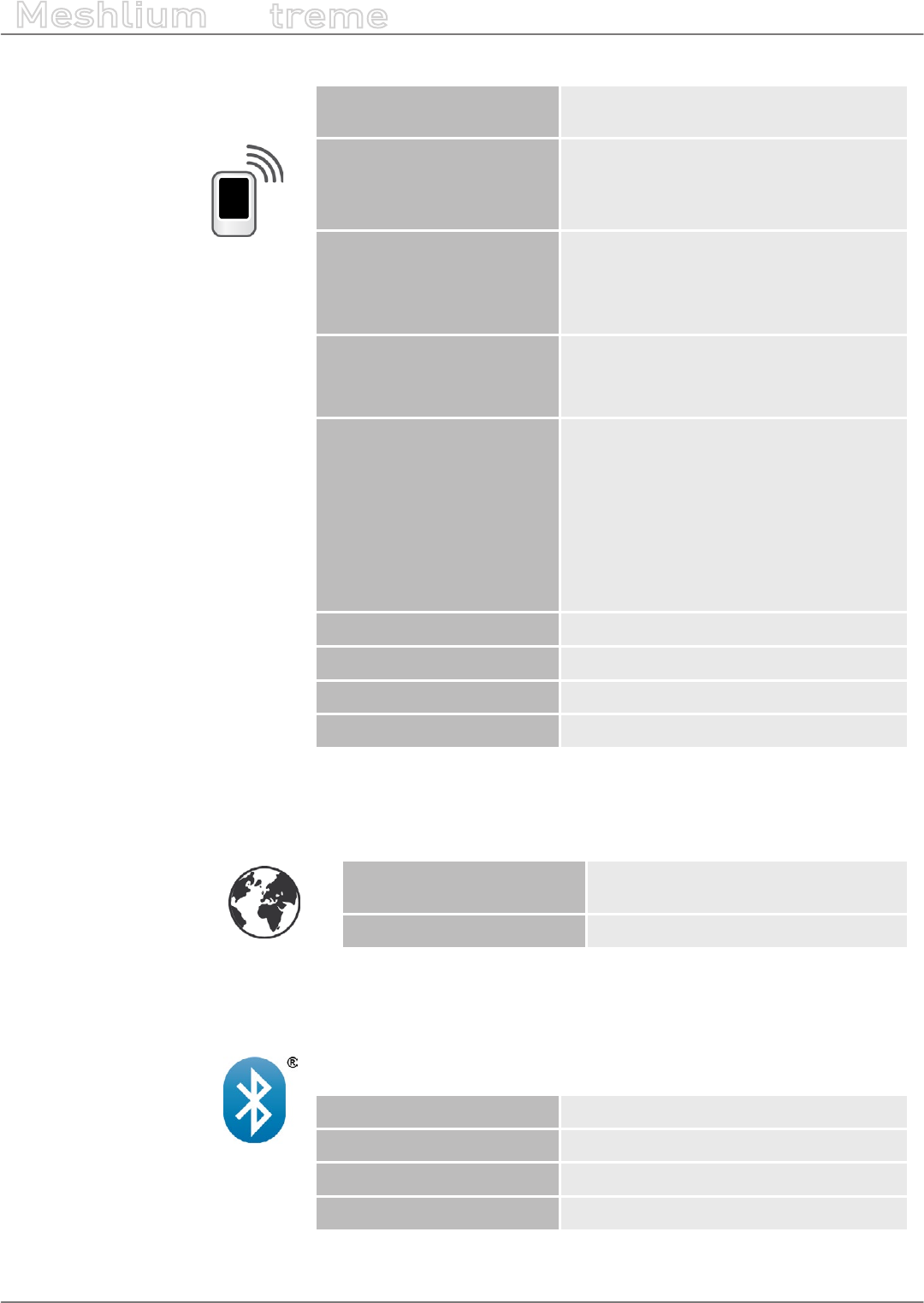
Bluetooth Scanner
Protocol Bluetooth 2.1 + EDR Class 2
TX power 3 dBm
Antenna 5 dBi dipole
Range 20-30 m*
(*) Depending on antenna and line of sight
-18- v7.3
How to use Meshlium
Meshlium
X
treme
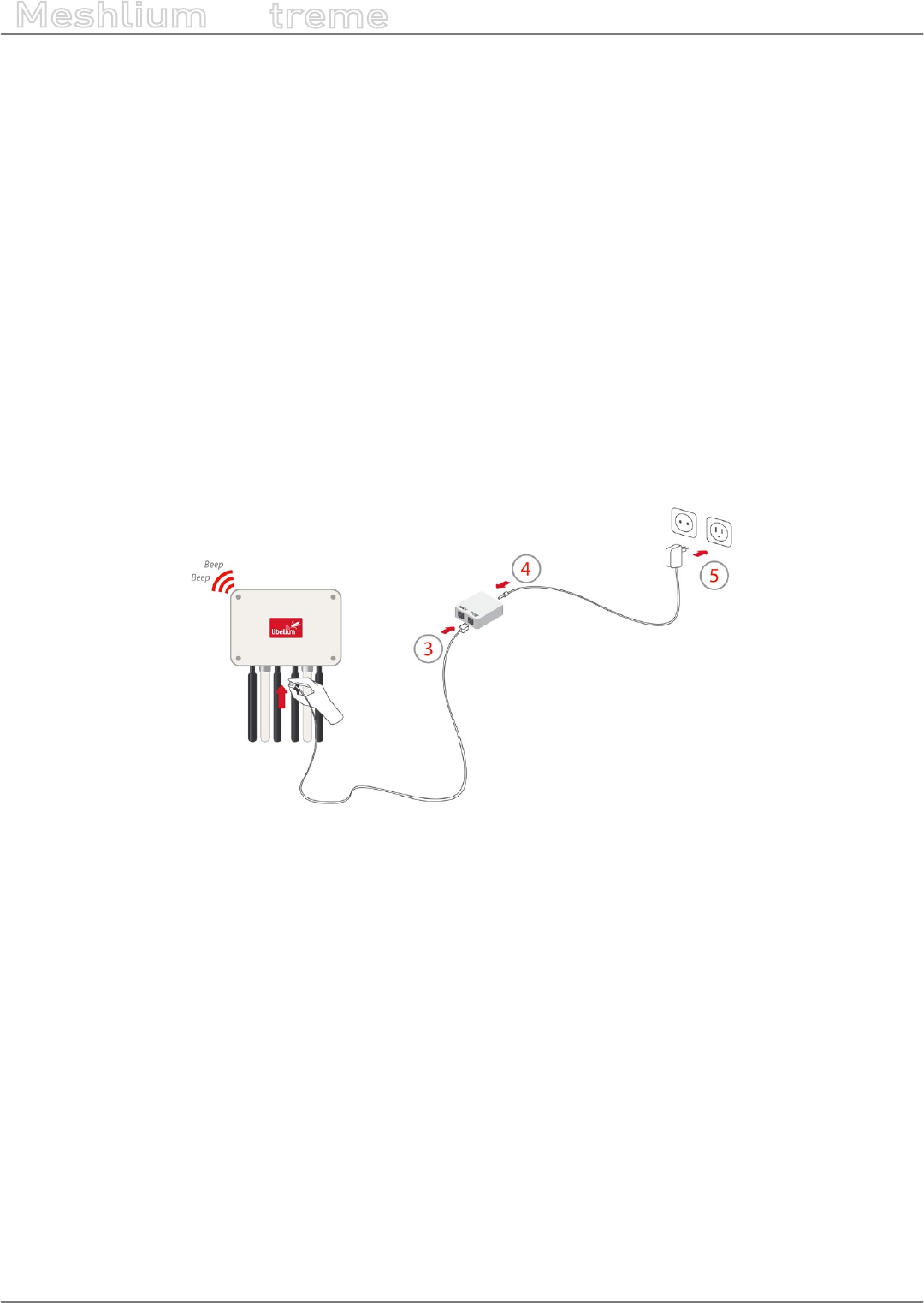
6. How to use Meshlium
6.1. Power supply
Meshlium needs a 220 V power connection. The device must be powered with the power source provided by
Libelium.
How to connect Meshlium to 220 V (110 V compatible):
•1. Unscrew the Ethernet connector cap in Meshlium.
•2. Join the end that has the IP65 protection of the Ethernet cable to the connector and screw the cap on to x
it.
•3. Connect the free end of the cable to the PoE injector input marked as PoE. As explained in the section
“Before using Meshlium”, make sure that the PoE is indoors.
•4. Take the supplied power adapter and plug it into the corresponding PoE injector connector, labeled as DC.
•5. Plug the other end of the adapter into the 220 V socket and your Meshlium is now ready to operate.
Note: For equipment powered by an electric outlet, a power outlet must be installed near the equipment, and it
must be easily accessible.
Figure: Connecting Meshlium to 220 V
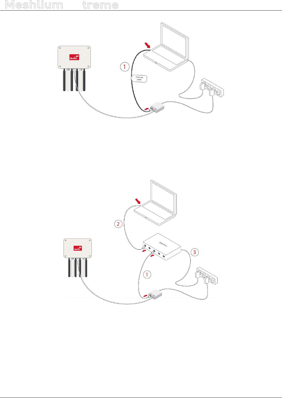
How to connect Meshlium in order to get access by the Ethernet interface:
•1. Connect the network crossover cable (it has an identifying label) included in the box to the PoE injector input
marked LAN and to the network socket of your PC as shown in the diagram.
(*) See the “Accessing Meshlium” section in order to see how to get access via wireless.
-19- v7.3
How to use Meshlium
Meshlium
X
treme
Figure: Connecting LAN cable to a PC
You can also carry out this connection through a switch (not supplied with Meshlium):
•1. Connect the Ethernet cable (not the crossover) to the PoE input marked LAN and to one of the switch inputs.
•2. Connect another Ethernet cable to another one of the switch inputs and the opposite end to the network
socket of your PC.
(*) See the “Accessing Meshlium” section in order to see how to get access via wireless.
Figure: Connecting LAN cable to a switch
-20- v7.3
How to use Meshlium
Meshlium
X
treme
6.2. External SIM socket
The External SIM socket is composed of 2 connectors:
•micro-SIM card
•micro-USB (type B)
Figure: External SIM socket in a Meshlium with 4G/3G/GPRS/GSM module
The micro-SIM card connector allows the user to connect the SIM card. You can ask your Mobile Network Operator
for a micro-SIM card. It is better to use a normal micro-SIM card, not a card which can be broken into a nano-SIM
card.
The micro-SIM card connector has a push-push mechanism, so it is really easy to remove the card using one nail
or a small tool. To insert the SIM, press until a click is heard. To release the card, press until a click is heard and
the spring will push the card free.
Figure: Push-push mechanism External SIM socket
-21- v7.3
How to use Meshlium
Meshlium
X
treme
It is very important to turn o Meshlium in a secure way before inserting a micro-SIM card, or removing an existing
SIM card. The user can damage the device if this operation is done with the device on.
Make sure the External SIM socket is closed with its protection cap tightly screwed before an outdoors deployment.
The operation with the micro-USB socket is just the same than with a normal USB socket. A USB OTG cable can be
used to plug in standard A USB connector (like pendrives).
Take into account that the External SIM socket has a limited resistance so please be gentle and push with care.
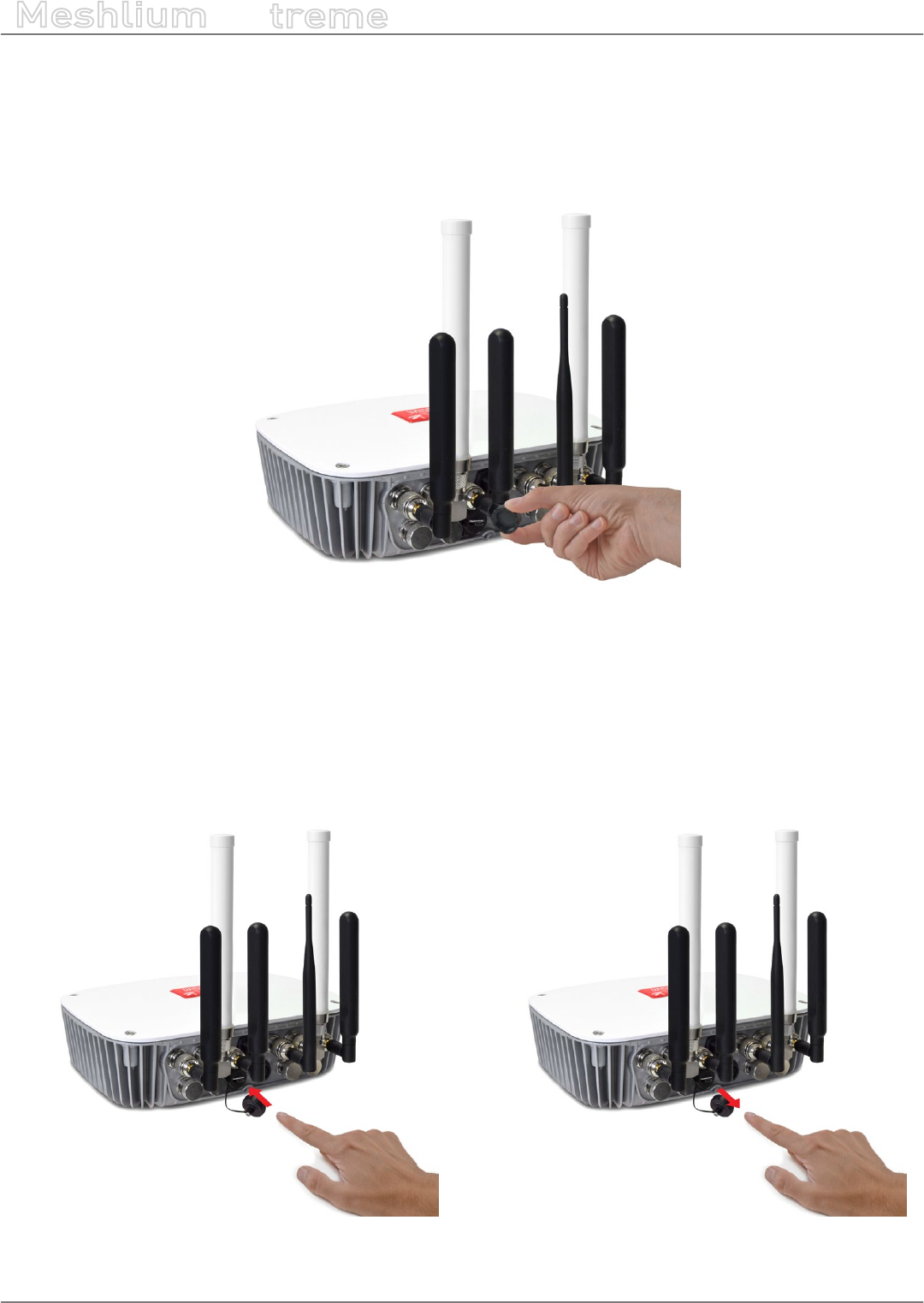
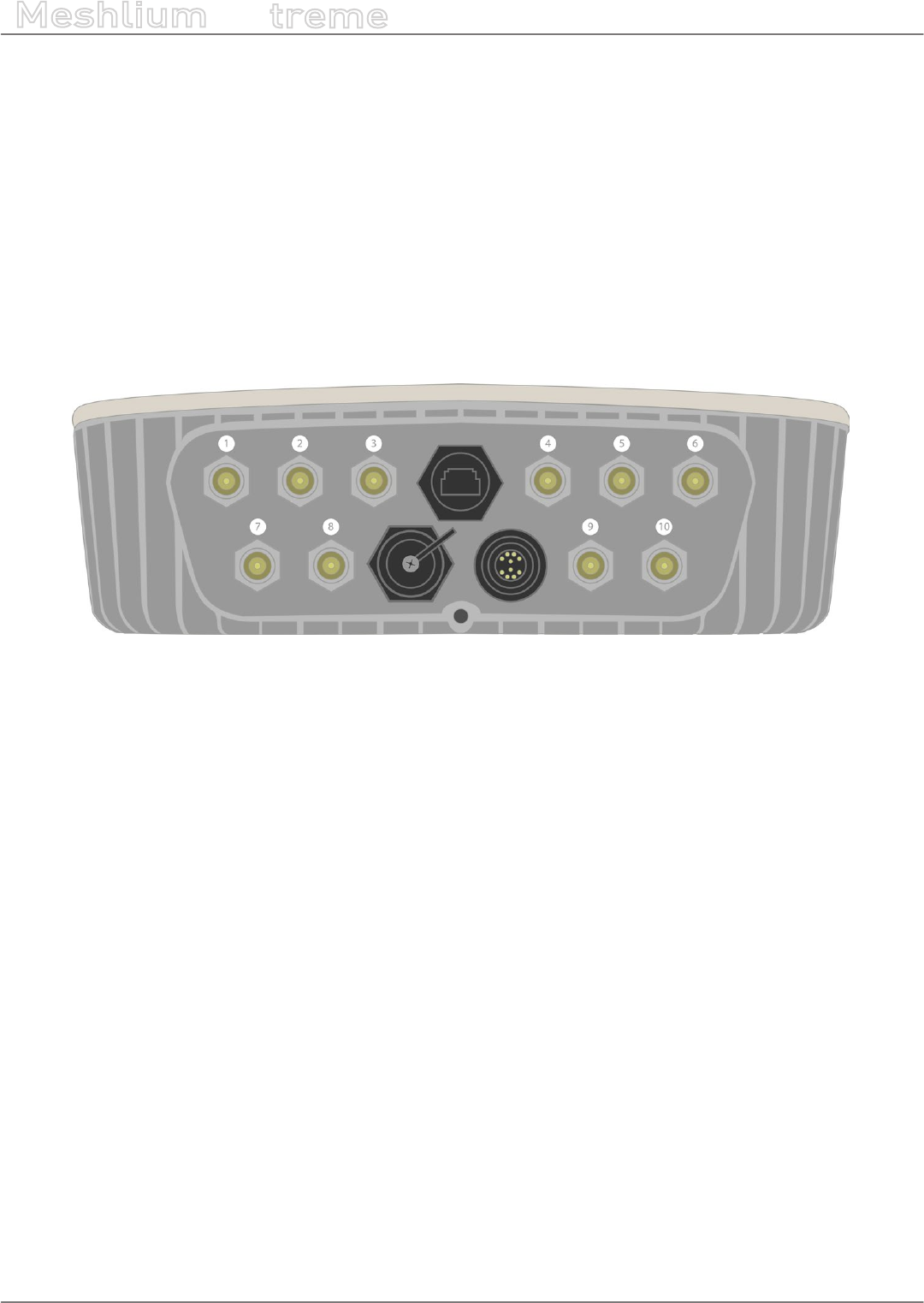
6.3. How to install the antennas
Every antenna for each technology has a dened position in which it has to be installed. The dierent positions
are:
Figure: Antenna socket numbers
•WiFi AP – Socket 2
•4G with adapter n-to-SMA– Socket 1 and 6
•GPS with adapter n-to-SMA – Socket 3
•RF module 802.15.4 – Socket 5
•RF module 868 MHz / 900 MHz with adapter n-to-RP-SMA – Socket 4
•Bluetooth Scanner – Socket 5
•WiFi Scanner – Socket 4
The antennas have to be gently screwed on the connector. Do not force the antenna, if you need too much
strength to screw it is probably being installed in a wrong position.
If you have any reception issue with 4G or GPS, you can try bending the aected antenna in order to improve
isolation.
-22- v7.3
How to use Meshlium
Meshlium
X
treme
6.4. Installation of the IP65 Ethernet cable
Installation of the IP65 cap:
In order to install the IP65 cap you will need a connector-free RJ45 cable. This cable is NOT included in the Meshlium
box.
Important: Make sure that you have a cable long enough to connect Meshlium from its denitive location to the
PoE located indoors. It is not recommended to install Meshlium too far from the PoE injector due to the power
loss in the cable. Always test the device with a cable of the same length before installing.
The Ethernet cable can be used for indoors and outdoors deployments. Just note that its resistance is limited, so
in order to maximize its lifetime in harsh conditions (direct sunlight, extreme temperatures, very wet climate), we
advise to protect the cable with some isolating tube or heat-shrink sleeve. This is also important for installations
where insects, birds, rats or other animals could try to bite the cable.
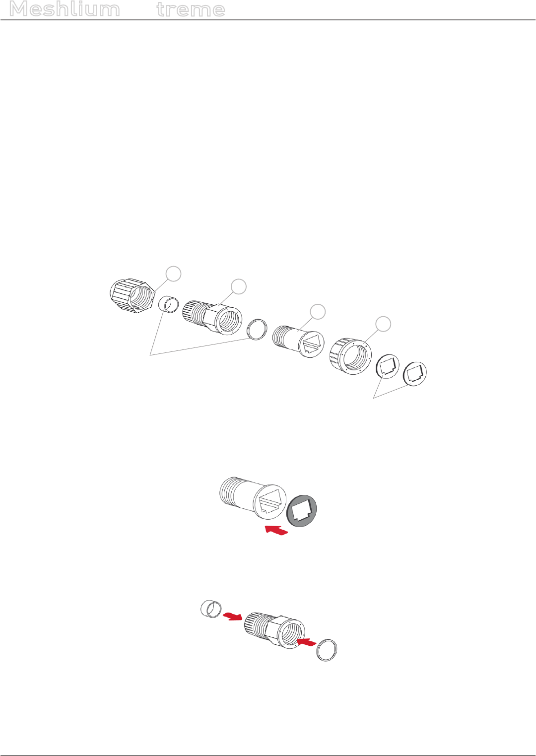
•1. Take from the Meshlium box the bag containing the parts for installing the IP65 cap. Check that you have all
the parts that appear in the picture.
c
b
d
Joints
Adhesive joints
a
Figure: Cap parts
•2. Stick one of the supplied adhesive joints to part C.
Figure: Stick joint
•3. Introduce the joints into part B as shown in the drawing.
Figure: Introduce joints
-23- v7.3
How to use Meshlium
Meshlium
X
treme
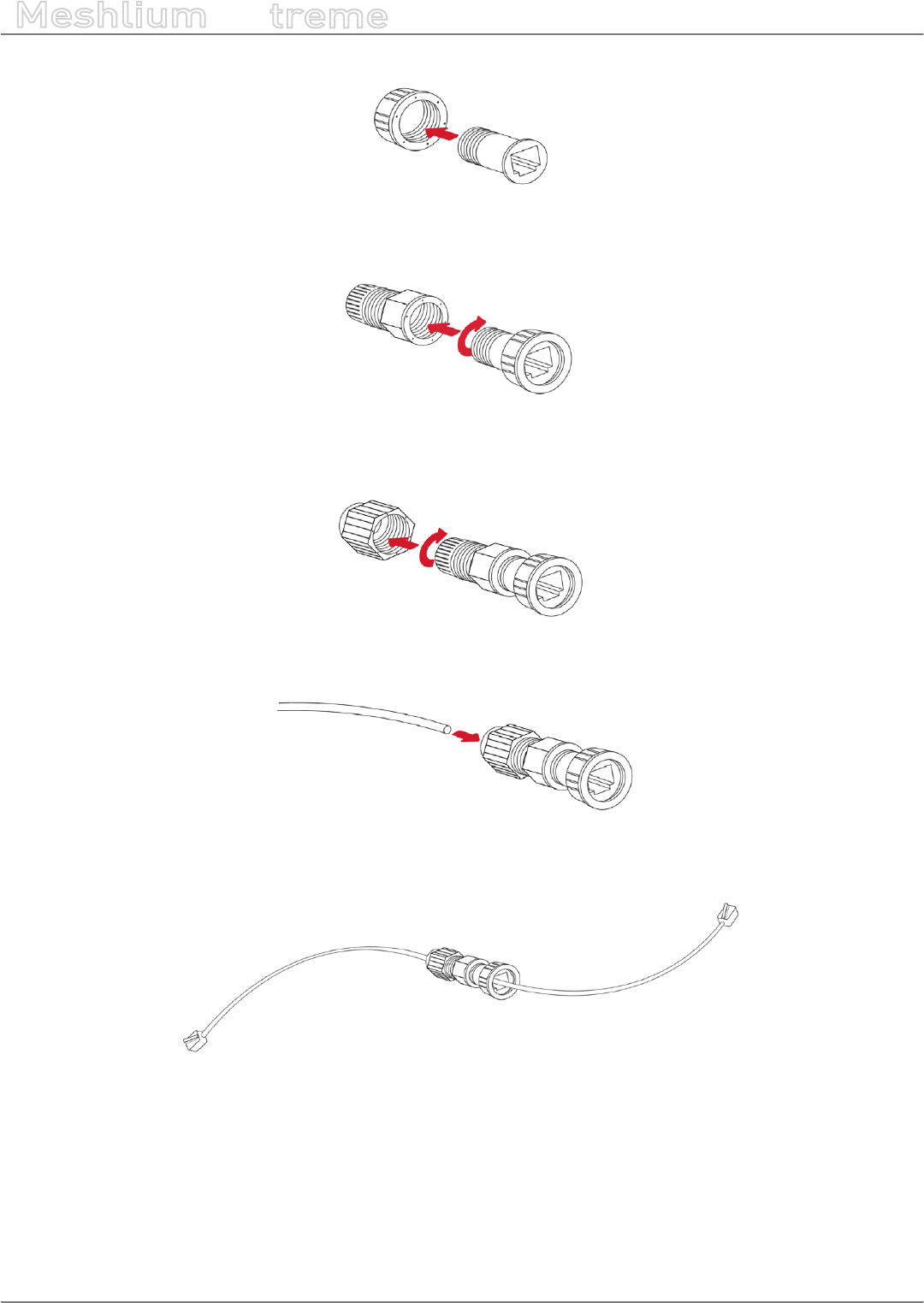
•4. Insert part C into part D.
Figure: Insert part C
•5. Screw both sets of parts in the direction shown in the diagram.
Figure: Screw both parts
•6. Partially screw part D to the end.
Figure: Screw part D
•7. Pass the cable through the tted cap.
Figure: Pass the cable
•8. Crimp the RJ45 connectors at the ends of the cable (the crimping tool is not supplied with Meshlium).
Figure: Crimp RJ45
Your IP65 Ethernet cable is now ready for use.
-24- v7.3
How to use Meshlium
Meshlium
X
treme
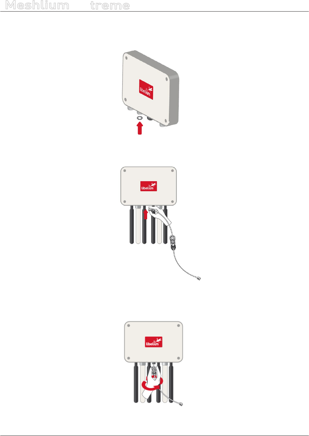
How to connect the IP65 Ethernet cable to Meshlium:
•1. Take the adhesive joint that has not been used for tting the cap and stick it to the Meshlium Ethernet
connector.
Figure: Stick joint
•2. Connect the end of the Ethernet cable to the Meshlium Ethernet socket.
Figure: Connect RJ45
•3. Screw part C onto the Meshlium connector. Screw tighter part D to x the cable too. Your Meshlium is now
ready to work outdoors.
Figure: Screw connector and tighten part D

-25- v7.3
How to use Meshlium
Meshlium
X
treme
6.5. Installing Meshlium
Meshlium has been designed to operate in a vertical position
with the antennas and connectors facing down. You will nd the
required bracket to mount Meshlium in a pole or in a wall.
To x the bracket to a wall:
•1. Attach bracket to the wall using wall plugs and screws.
Screws provided are for general use and could not be valid
for every surface. Use hardware adapted for the surface you
are installing Meshlium on.
To x the bracket to a mast:
•1. Attach the bracket to the mast using the hose clamps. Hose
clamps provided are for 50-70mm circumference masts. If
your mast is thicker, use clamps with the proper metric.
Once the bracket is xed:
•1. Attach the box to the bracket, tting the three top notches in the holes of the box.
•2. Secure the screw in the bottom of the box.
•3. Secure the Ethernet cable to avoid accidental pulls, do not let it loose. If the cable gets stretched, the joint
of the cable with its connector could be damaged.
6.6. Initialization, restart and shutdown
In order to allow Meshlium to close correctly all the daemons and applications it is important to use the buttons
Restart and Shutdown placed in the upper right corner in the Manager System. This way you will keep maximum
the performance and lifetime of the system.
Figure: Restart screen
Once you click on the Restart or Shutdown button of manager system you have one minute to conrm the
operation. If you do not conrm in that time, you will need to click in the button again to perform the operation.

-26- v7.3
How to use Meshlium
Meshlium
X
treme
Beep! System
Meshlium includes an internal speaker which will emit “beep!” sounds when initializing, rebooting and shutting
down in order to inform about the state of the process.
Initialization beeps:
•Long beep when Meshlium has nished starting and it is ready to be used
Reboot beeps:
•Long beep when the reboot order is executed
•Initialization beeps when Meshlium starts again
•Do not remove the power cable during this process is carried out
Shutting-down beeps:
•This process could take up to one minute
•Long beep when Meshlium is about to shut down. A few seconds after the beeps, Meshlium can be unplugged.
•Do not remove the power cable until this process is totally completed
Note: The “beep!” sound is not really loud so you will have to take attention and be close to the Meshlium box in order
to hear them clearly.
Note 2: If Meshlium is unplugged before the acoustic signal of shutdown, internal memory could be damaged. Be sure
to wait for several minutes if you are not sure the beeps sounded.
Note 3: The duration of the reboot or shut-down processes may vary. Make sure you heard the corresponding beeps
and be patient.
Note 4: If the user does not follow these instructions, the risk is very high. Meshlium will become unresponsive and
inaccessible. This problem is out of the warranty scope, because it is produced by bad use. The only possible solution will
be a repair process in Libelium’s facilities, paid by the user.
6.7. Setting the time
In order to get all the data stored in the Meshlium local database with the right timestamp, you must adjust the
System time.
To do so, go to the “Setting the Time” section, inside the “System Information” chapter in the current guide.
-27- v7.3
Understanding Meshlium
Meshlium
X
treme
7. Understanding Meshlium
7.1. Concepts
Meshlium is an IoT gateway that may contain up to 4 dierent radio interfaces: a WiFi 2.4 GHz (Access Point),
a 4G/3G/GPRS/GSM and 2 XBee/RF radios. Meshlium also integrates a GPS module for mobile and vehicular
applications and may include Bluetooth and WiFi radios too for scanning applications. These features along with
an aluminum IP65 enclosure allows Meshlium to be placed outdoors.
Meshlium can work as:
•an RF (XBee) to Ethernet router for Waspmote nodes*
•an RF (XBee) to 4G/3G/GPRS/GSM router for Waspmote nodes*
•a WiFi Access Point
•a WiFi to 4G/3G/GPRS/GSM router
•a GPS – 4G/3G/GPRS/GSM real-time tracker
•a smartphone scanner (detects iPhone and Android devices)
* More info about Waspmote at: http://www.libelium.com/waspmote
All the networking options can be controlled from the Manager System, a web interface which comes with
Meshlium. It allows you to control all the interfaces and system options in a secure, easy and quick way.
7.2. Meshlium models
There are dierent Meshlium models depending on the radios integrated:
Meshlium model Ethernet WiFi AP
4G/3G/GPRS/
GSM
802.15.4 868/900
WiFi &
Bluetooth
scanners
Meshlium 4G 802.15.4 AP 868 EU P P EU/BR version EU version 868
Meshlium 4G 802.15.4 AP 900 US P P US version
World
version
900 US
Meshlium 4G 802.15.4 AP 900 BR P P EU/BR version World
version 900 BR
Meshlium 4G 802.15.4 AP 900 AU P P AU version World
version 900 AU
Meshlium 4G AP 868 EU P P EU/BR version 868
Meshlium 4G AP 900 US P P US version 900 US
Meshlium 4G AP 900 BR P P EU/BR version 900 BR
Meshlium 4G AP 900 AU P P AU version 900 AU
Meshlium 4G 802.15.4 AP EU P P EU/BR version EU version
Meshlium 4G 802.15.4 AP US P P US version World
version
Meshlium 4G 802.15.4 AP BR P P EU/BR version World
version
Meshlium 4G 802.15.4 AP AU P P AU version World
version
Meshlium 4G AP Scanner EU/BR P P EU/BR version P
-28- v7.3
Understanding Meshlium
Meshlium
X
treme
Meshlium 4G AP Scanner US P P US version P
Meshlium 4G AP Scanner AU P P AU version P
Each model with RF modules can have XBee-PRO 802.15.4 and XBee 868LP or XBee-PRO 900HP (depending on
the region).
7.3. Storage
The size of the Meshlium hard disk is 16 GB. The Operating System and the Manager System take ~3 GB. This
means the space which can be used to store the data captured and to be used by the applications loaded by the
user is:
•16 GB – 3 GB = 13 GB
Some of this space (7.2 GB) is assigned to the user partition: “/mnt/user”.
The local database les can be found in: “/mnt/user/mysql/MeshliumDB”.
7.4. Application model by model
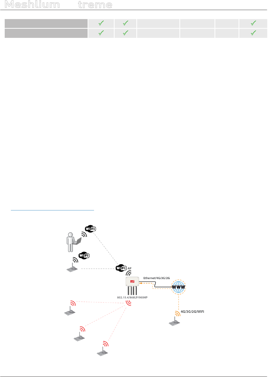
Meshlium RF 4G AP
Meshlium can take the sensor data which comes from a Wireless Sensor Network (WSN) made with Waspmote
sensor devices* equipped with RF (XBee) radios and send it to the Internet using the Ethernet interface or the
4G/3G/GPRS/GSM interface. Besides, Waspmotes with GPRS, GPRS+GPS, 3G, 4G or WiFi can send sensor info
through the access point or through the Internet via HTTP protocol. Users can connect directly to Meshlium using
the WiFi interface to control it and access to the sensor data. Users can also connect to Meshlium via WiFi with
laptops and smart phones and get access to the Internet (as a common Access Point).
(*) http://www.libelium.com/waspmote
Figure: Meshlium RF 4G AP
-29- v7.3
Understanding Meshlium
Meshlium
X
treme
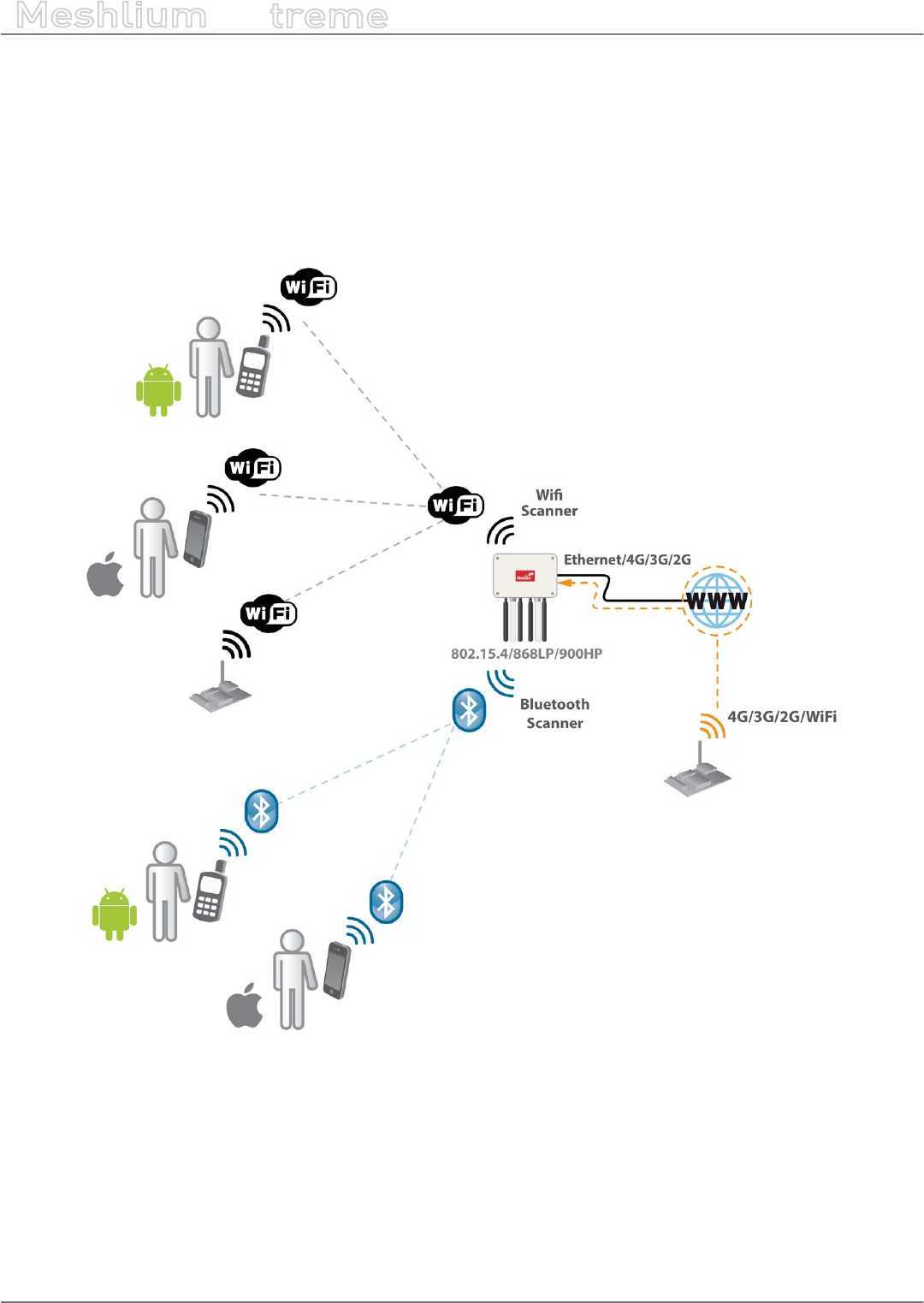
Meshlium Scanner 4G AP
It allows to detect Smartphones (iPhone, Android) and in general any device which works with WiFi or Bluetooth
interfaces. The collected data can be send to the Internet by using the Ethernet interface or the 4G/3G/GPRS/GSM
connectivity. Besides, Waspmotes with GPRS, GPRS+GPS, 3G, 4G or WiFi can send sensor info through the access
point or through the Internet via HTTP protocol. Users can connect directly to Meshlium using the WiFi interface
to control it and access to the sensor data. Users can also connect to Meshlium via WiFi with laptops and smart
phones and get access to the Internet (as a common Access Point).
Figure: Meshlium Scanner 4G AP
-30- v7.3
Accessing Meshlium – make it easy!
Meshlium
X
treme
8. Accessing Meshlium – make it easy!
Meshlium comes with all the radios ready to be used. All the Meshlium units come with the WiFi Access Point
ready, so that users can connect using their WiFi devices. Connect the Ethernet cable to your network hub, restart
Meshlium and it will automatically get an IP address from your network using DHCP.
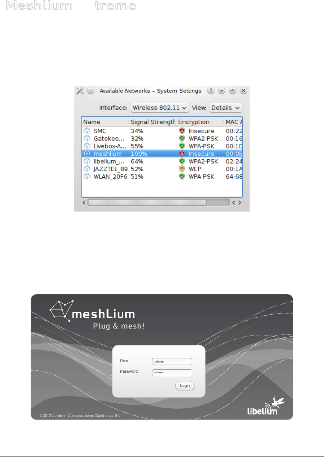
Then access Meshlium through the WiFi connection. First of all, search the available access points and connect to
“MeshliumXXXX”. The four digits at the end allow to identify dierent Meshliums when working near each other.
Figure: List of AP with Meshlium network
No password is needed as the network is open (you should change it later in the WiFi AP interface options). When
you select it, Meshlium will give an IP address from the range 10.10.10.10 – 10.10.10.250.
Now you can open your browser on your PC, tablet or smartphone and access the Meshlium Manager System:
•URL: http://10.10.10.1/ManagerSystem
•user: admin
•password: libelium
Figure: Manager System login screen
-31- v7.3
Accessing Meshlium – make it easy!
Meshlium
X
treme
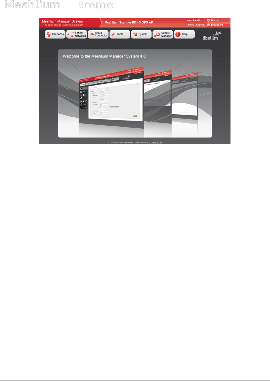
Figure: Manager System landing page
If your network does not oer DHCP service, Meshlium starts with a default IP address (192.168.1.100). In this case
you can connect Meshlium through the WiFi connection (which is always available) or with the crossover cable
provided with Meshlium.
If you want to access to the Manager System using the crossover Ethernet cable go to:
•URL: http://192.168.1.100/ManagerSystem
•user: admin
•password: libelium
-32- v7.3
Network interfaces setup
Meshlium
X
treme
9. Network interfaces setup
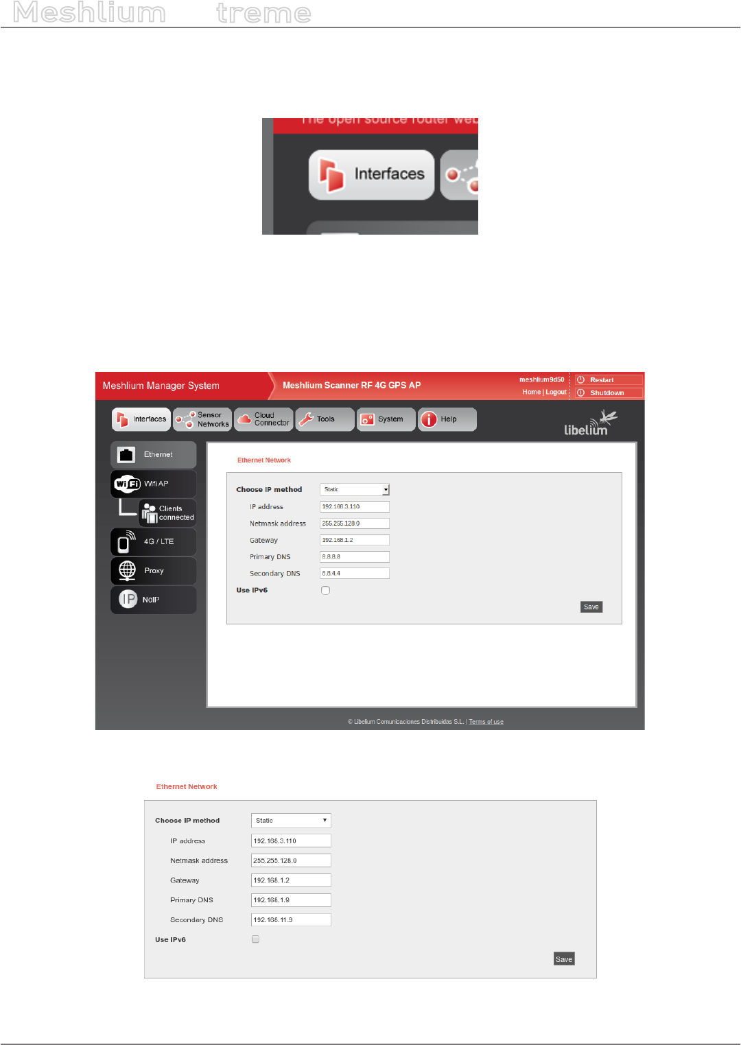
Access the network interfaces setup clicking on the button “Interfaces”:
Figure: Interfaces setup plugin
9.1. Ethernet setup
By default Meshlium comes with the Ethernet interface activated to get dynamically the IP using the DHCP service.
In case a static conguration is required the next parameters can be congured:
Figure: Ethernet setup
Figure: Ethernet setup form
-33- v7.3
Network interfaces setup
Meshlium
X
treme
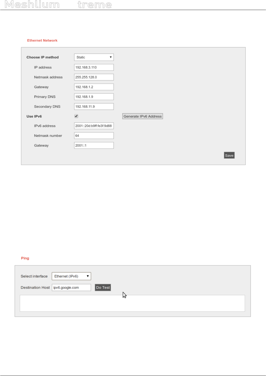
You can also use IPv6 (Internet Protocol version 6) by setting the check box “Use IPv6”. IPv6 is a version of the
Internet Protocol (IP) intended to replace IPv4. The next parameters can be congured:
Figure: IPV6 setup
In many cases, IPv6 addresses are composed of two logical parts: a prex of 64-bit (2001::) and a 64 bit part that
is generated automatically from the MAC address of the interface.
The button “Generate IPv6 address” performs this task.
After saving the new options and once you have restarted Meshlium you have to validate the new conguration
before the next 5 minutes, if not, the factory default conguration will be restored to avoid leaving Meshlium
without connectivity. See section “Network setup conrmation” for more information.
To check IPv6 conguration, after save and restart Meshlium, go to Tools → Ping. Select Ethernet (IPv6), by default
ipv6.google.com appears as destination host.
Figure: Ping IPv6 with name
-34- v7.3
Network interfaces setup
Meshlium
X
treme
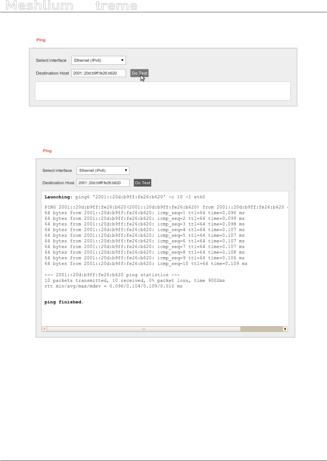
If your Internet Service Provider does not support external IPv6 addresses yet, you can change it to a local address.
Figure: Ping IPv6 with address
Then press “Do Test”. If something like next image appears, you have IPv6 correctly congured.
Figure: Ping results

-35- v7.3
Network interfaces setup
Meshlium
X
treme
9.2. WiFi Access Point setup
Meshlium is a WiFi Access Point and can supply network connectivity trough WiFi. The most useful feature of the
AP is to provide access to Manager System from a tablet or laptop without any physical connection with Meshlium.
By default the AP hast the ESSID “meshliumXXXX” where XXXX are the last four digits of Ethernet MAC. This allows
to identify dierent Meshliums installed nearby.
Figure: WiFi Access Point setup
9.2.1. Conguration
There three sections in the conguration page: Network, Radio and Security.
Network
Here you can change the IP of the device in the network and the DHCP setup. Here can be setup:
•IP address of the AP.
•Netmask of the Address.
•DHCP range. The address range in the DHCP setup must be inside the network dened by the IP address and
netmask of the AP.
•DHCP lease time.
Figure: WiFi AP Network setup
-36- v7.3
Network interfaces setup
Meshlium
X
treme
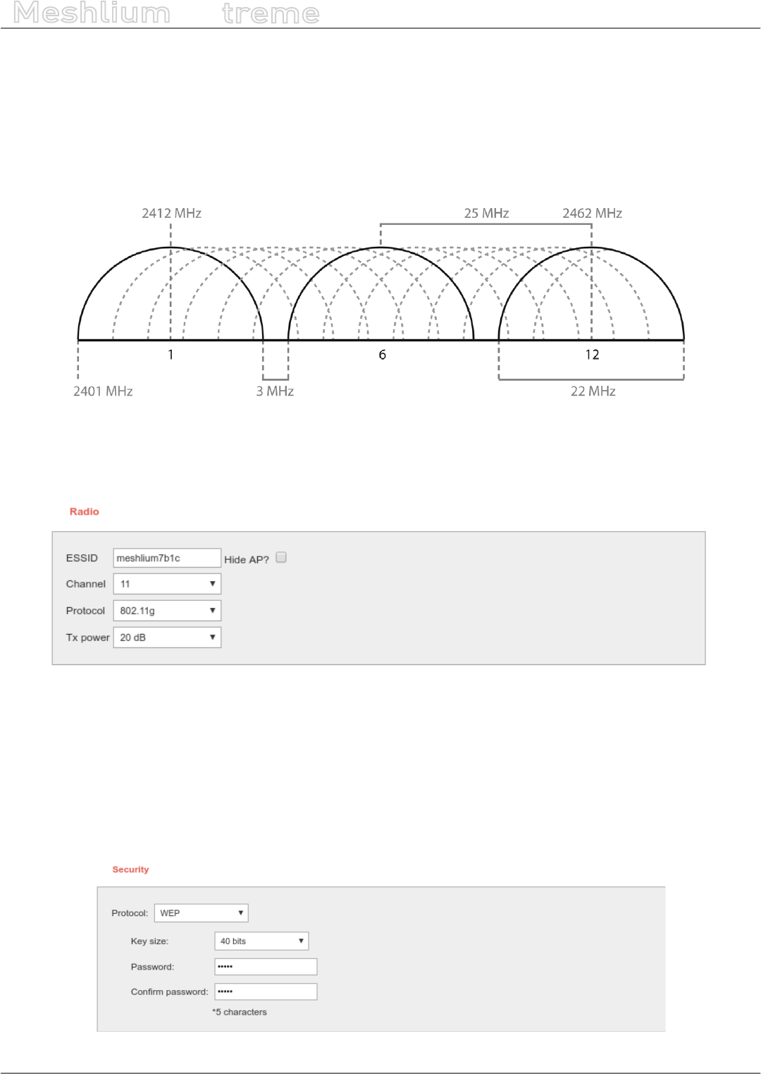
Radio
These are specic WiFi parameters. Here can be setup:
•ESSID of the network. This is the name that appear in the devices that are searching WiFi networks. It can be
public or hidden, allowing only connections manually started.
•Channel. It is possible to change the radio channel which is used for transmission, according to the next
diagram.
Figure: WiFi radio channels
•Protocol. It is possible to use 802.11g and 802.11n.
•Tx power. It allows to control the transmission power, thus the range of the AP.
Figure: WiFi radio settings
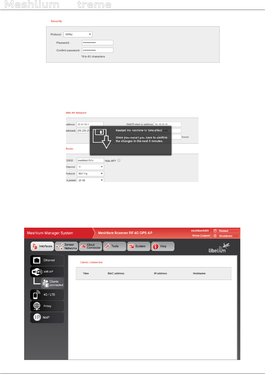
Security
The WiFi AP can be protected with encryption. WEP, WPA and WPA2 are available.
WEP is enabled in the 5 and 13 characters congurations while WPA-PSK can be used with a password from 8 to
63 characters.
We recommend use WPA2 in order to get the a good security in the network.
Figure: WiFi AP WEP setup
-37- v7.3
Network interfaces setup
Meshlium
X
treme
Figure: WiFi AP WPA2
Saving
After saving the setup, a message will warn the user about setup conrmation. A reboot is needed to apply new
settings. The setup has to be conrmed within 5 minutes after reboot. More info in “Network setup conrmation”.
Figure: Conrmation warning
9.2.2. Clients connected
This section shows the list of clients connected to the WiFi AP, showing information like the MAC address and the
IP assigned. It is a quick way to know how many devices are connected and who are they.
Figure: Clients connected
-38- v7.3
Network interfaces setup
Meshlium
X
treme
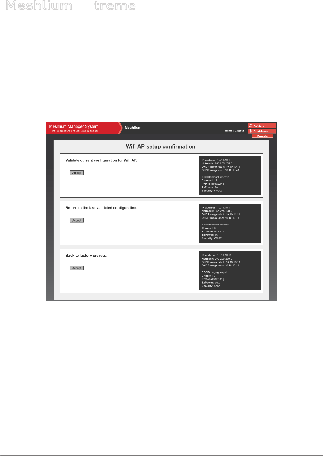
9.3. Network setup conrmation
After changing Ethernet or WiFi AP setup, a reboot is needed to apply new settings. After this reboot, the user
has to conrm the settings in order to denitely apply them. If after 5 minutes of the reboot the user has not
conrmed the new settings, last validated settings will be applied again. If there are no validated settings, default
settings will be applied.
In the conrmation screen the user can select to conrm new settings, change to last validated settings or change
to default settings. All the information of every setup will be shown. After the conrmation is done, the new
settings will be stored as last validated settings for future conrmations.
The system will show a conrmation window for every setting changed, one for Ethernet setup and one for WiFi
AP setup, so it can be independently conrmed.
Figure: Conrmation screen
-39- v7.3
Network interfaces setup
Meshlium
X
treme
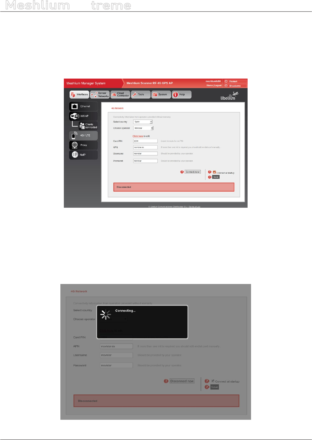
9.4. 4G setup
This plugin allows to setup the parameters of the modem connection. There is a list with some initial congurations
depending on the country and the operator. However, this list may not be updated with the last valid conguration
of your mobile provider. Ask your mobile company for the information required to connect (APN, Username,
Password) and add the PIN code of the SIM card used (leave empty if there is no PIN). We recommend to disable
the PIN in the SIM card as this will make easier the test and validation process and will avoid to block the SIM card.
Figure: 4G setup plugin
After setting the 4G parameters and before save them you can test your connection through the “Connect now”
button. It will try to connect to your carrier and get a valid IP. Once the connection has been made the default
gateway of the machine is changed so all the clients connected through WiFi will reach the Internet via 4G.
Important: once you get a valid 4G IP through the “Connect now” button, you will not be able to access Meshlium via
Ethernet unless you are connected through the same Local Area Network. For this reason we recommend to make all the
tests using the WiFi connection.
Figure: 4G connecting
-40- v7.3
Network interfaces setup
Meshlium
X
treme
If connection is established, the IP will be shown in the interface. Once the modem is connected a process will
check the connection every 15 minutes and will try to reconnect in case of disconnection.
Figure: 4G successfully connected
Once validated your settings press the Disconnect button and save your conguration. If you want the 4G to be
the Default Gateway of Meshlium each time it starts just activate the service in the “Set as Default Gateway” check
box before saving. Setting this on will connect to the Internet using the 4G radio each time Meshlium restarts.
If any problem is preventing the device to connect at boot or to reconnect after a connection fall, a message will be
displayed in the plugin. The user can manually stop automatic reconnection by pressing “Disconnect now” button.
Figure: 4G trying to reconnect
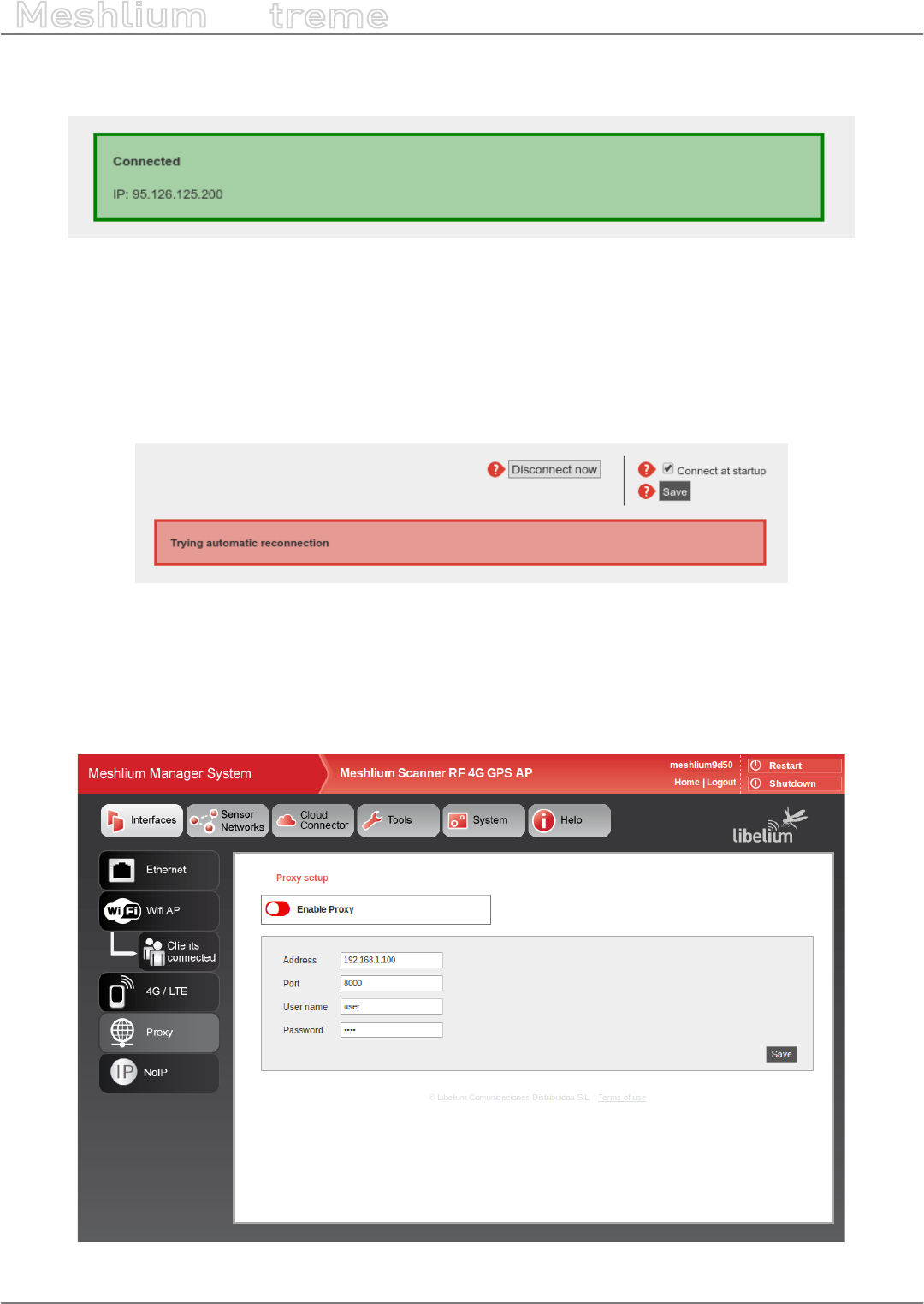
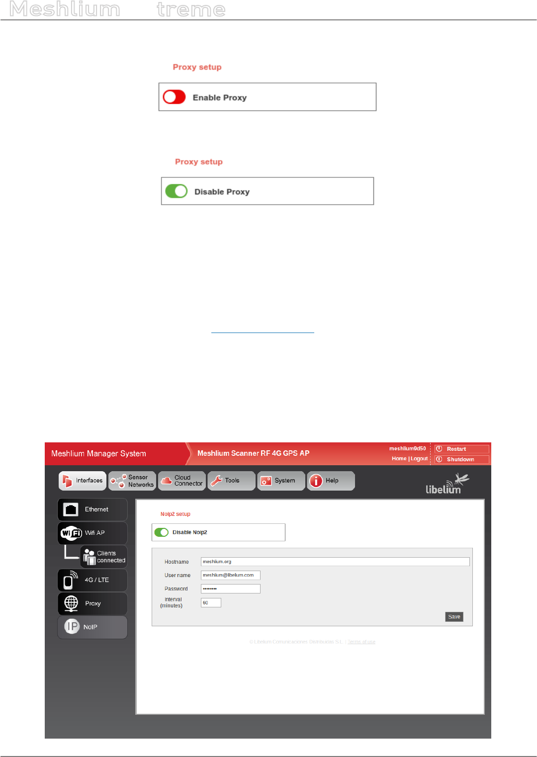
9.5. Proxy setup
This plugin allows to setup an HTTP proxy for some features of Meshlium. Here can be congured the proxy
address, the port and the credentials (leave blank if not authentication needed).
Figure: Proxy setup plugin
-41- v7.3
Network interfaces setup
Meshlium
X
treme
The proxy can be enabled or disabled from the control of the interface.
Figure: Proxy enable control
Figure: Proxy disable control
Note: Currently the proxy feature is only available for visualizer plugin. This feature will be gradually included in other
services.
9.6. No-IP setup
This plugin allows to setup a No-IP account (https://www.noip.com) for dynamic IP remote access.
Congure the following parameters with the information of a valid and active No-IP account, previously created
in the No-IP platform:
•Hostname: Name of the host to link with the Meshlium IP
•Username: No-IP account username
•Password: No-IP account password
•Interval: Update interval in minutes
Figure: NoIP setup plugin

-42- v7.3
Network interfaces setup
Meshlium
X
treme
Please, refer to the interface conguration section to use a proxy.
Figure: NoIP enable control
Figure: NoIP disable control
-43- v7.3
Wireless Sensor Networks
Meshlium
X
treme
10. Wireless Sensor Networks
10.1. Meshlium and Waspmote
One of the main applications of Meshlium is being a gateway for Wireless Sensor Networks based on Waspmote
and Plug & Sense! devices. These are sensor nodes that can work with dierent communication technologies like
WiFi, 4G or XBee among others. More than 70 sensors are already available and a complete open source IDE (API
libraries + compiler) make really easy to start working with the platform.
More info at:
http://www.libelium.com/products/waspmote/
http://www.libelium.com/products/plug-sense/
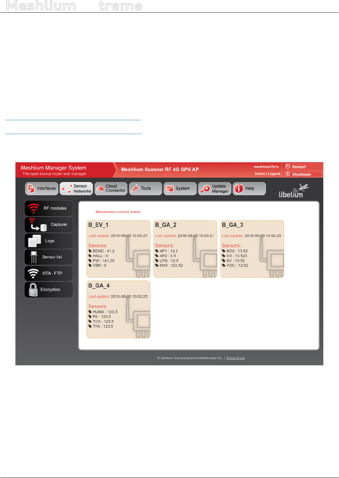
In the main page of “Sensor Networks” tab will be shown the devices in the system showing the last received
data.
Figure: Nodes with last data
-44- v7.3
Wireless Sensor Networks
Meshlium
X
treme
10.2. Receiving and storing data
10.2.1. Receiving trough RF communications
10.2.1.1. RF module setup
Meshlium can equip three dierent RF modules: XBee-PRO 802.15.4 (2.4 GHz), XBee 868LP (868 MHz) and XBee-
PRO 900HP (900 MHz). It can equip several modules at the same time.
RF modules setup can be found in:
Sensor Networks → RF modules
The plugin will show a tab for each module detected in the device.
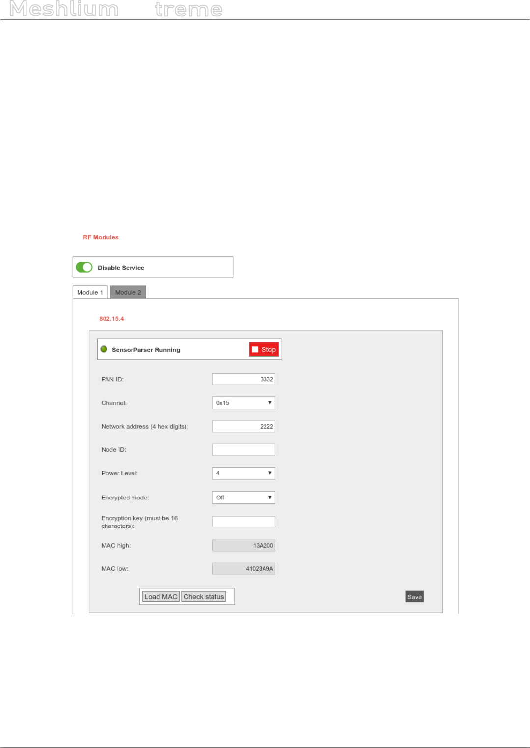
10.2.1.1.1. XBee-PRO 802.15.4 radio setup
Figure: XBee-PRO 802.15.4 setup

-45- v7.3
Wireless Sensor Networks
Meshlium
X
treme
In this module the parameters to setup are:
•PAN ID: Personal Area Network ID (also known as Network ID). It is the identier of the network. It has to be
the same in all the nodes in order to be able to send data to this Meshlium.
•Channel: Frequency channel used for transmissions.
•Network Address: User dened identier for the node in the network. 4 hexadecimal digits (MY).
•Node ID: readable name set for the device, by default “Meshlium”. Up to 20 characters.
•Power level: [0-4] By default 4.
•Encrypted mode: Internal XBee AES 128 bits encryption. Disabled by default.
•Encryption key: 16 characters.
•MAC: 64 bits hardware address of the module. It is a read-only value divided in two parts:
-MAC-high: 32 bits (8 hexadecimal digits)
-MAC-low: 32 bits (8 hexadecimal digits)
This setup must be consistent with those set on the Waspmote and Plug and Sense nodes.
In the bottom part of the interface, the button “Check status” allows to check if the module setup is concordant
with values shown in the interface. The button “Save” will write the parameters in the module.
Both process (“Save” and “Check status”) require the sensorParser daemon to be stopped. This means no frames
will be received while executing this actions. Be patient this can take up to 1 minute to nish.
-46- v7.3
Wireless Sensor Networks
Meshlium
X
treme
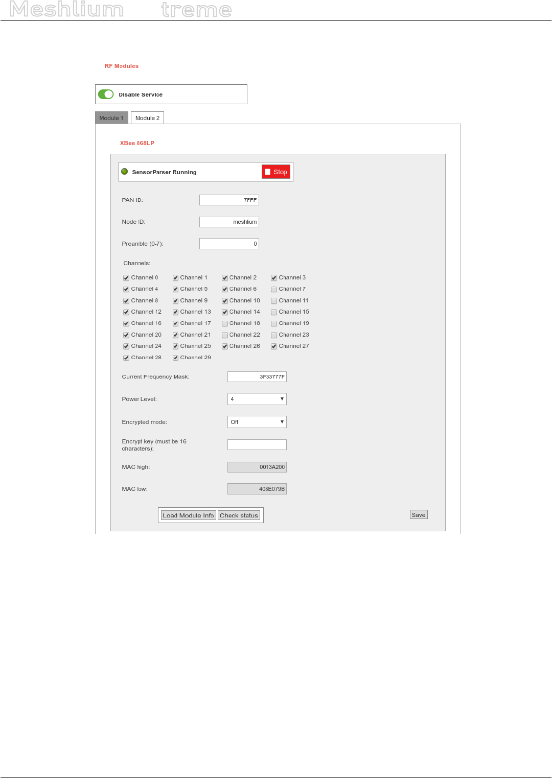
10.2.1.1.2. XBee 868LP radio setup
Figure: XBee 868LP setup
In this module the parameters to setup are:
•PAN ID: Personal Area Network ID (also known as Network ID). It is the identier of the network. It has to be
the same in all the nodes in order to be able to send data to this Meshlium.
•Node ID: readable name set for the device, by default “Meshlium”. Up to 20 characters.
•Preamble: An extension to PAN ID. It needs to be the same in the nodes too.
•Channel: This module allow to select the channels that can be used. The module automatically selects the
channel for the communication between available ones. Once the channels are selected, the plugin generates
the “Channel Frequency Mask” (read-only 8 hex digits) that the needs to be set in the nodes.
•Power level: [0-4] By default 4.
•Encrypted mode: Internal XBee AES 128 bits encryption. Disabled by default.
•Encryption key: 16 characters.
•MAC: 64 bits hardware address of the module. It is a read-only value divided in two parts:
-MAC-high: 32 bits (8 hexadecimal digits)
-MAC-low: 32 bits (8 hexadecimal digits)

-47- v7.3
Wireless Sensor Networks
Meshlium
X
treme
10.2.1.1.3. XBee-PRO 900HP radio setup
Figure: XBee-PRO 900HP setup
In this module the parameters to setup are:
•PAN ID: Personal Area Network ID (also known as Network ID). It is the identier of the network. It has to be
the same in all the nodes in order to be able to send data to this Meshlium.
•Node ID: readable name set for the device, by default “Meshlium”. Up to 20 characters.
•Preamble: An extension to PAN ID. It needs to be the same in the nodes too.
•Channel: This module allow to select the channels that can be used. The module automatically selects the
channel for the communication between available ones. Once the channels are selected, the plugin generates
the “Channel Frequency Mask” (read-only 16 hex digits) that the needs to be set in the nodes. In the bottom
part of the interface is shown the minimum number of channels that have to be selected.
•Power level: [0-4] By default 4.
•Encrypted mode: Internal XBee AES 128 bits encryption. Disabled by default.
•Encryption key: 16 characters.
•MAC: 64 bits hardware address of the module. It is a read-only value divided in two parts:
-MAC-high: 32 bits (8 hexadecimal digits)
-MAC-low: 32 bits (8 hexadecimal digits)
-48- v7.3
Wireless Sensor Networks
Meshlium
X
treme
10.2.1.2. Encryption setup
Link layer key management (AES-128)
This feature is provided by XBee modules.
Encryption is this layer provided through the AES 128b algorithm. Specically through the type AES-CTR. In this
case the Frame Counter eld has a unique ID and encrypts all the information contained in the Payload eld which
is the place in the link layer frame where the data to be sent is stored. The way in which the libraries have been
developed for module programming means that encryption activation is as simple as running the initialization
function and giving it a key to use in the encryption.
{
xbee.encryptionMode(1);
xbee.setLinkKey(key);
}
In Manager System, on Sensor Network section, users can encrypt messages on link layer. It can be achieved by
setting the parameters:
•Encrypted mode: true/false (by default false)
•Encryption Key: Must be 16 characters
See section “XBee module setup” for more details about setting encryption.
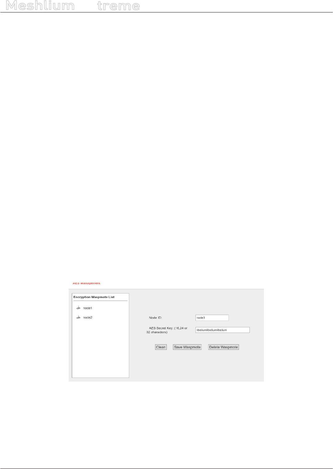
10.2.1.2.1. Application layer key management
Meshlium is capable to properly receive encrypted data from Waspmote. The coding process is made in the
application layer, so it is Waspmote and Meshlium processor and not XBee module who encrypts and decrypts
the messages.
The user have to set a key for the encryption in Waspmote and Meshlium.
In Manager System it can be found:
Sensor Networks → Encryption
Figure: Encryption key setup
For each Waspmote can send frames to Meshlium, Waspmotes keys can be added to an encryption Key le. In this
interface the user must specify the node ID and the Waspmote AES secret key (128, 192 or 256 bits).
After dening the above elds to press the button “Add Waspmote”. A new entry is generated in the left list.
To delete Waspmote of list, select the Waspmote and press “Delete Waspmote”. The encrypted frames received
from this node cannot be decrypted anymore.
The AES secret key is necessary to recognize the frames sent each Waspmote to Meshlium.

-49- v7.3
Wireless Sensor Networks
Meshlium
X
treme
Figure: Encryption in communications
Once the user has properly set the AES keys associated to every waspmote, receiving AES encrypted frames in
Meshlium is a straightforward process.
As an encrypted frame arrives to Meshlium, sensorParser program takes the appropriate key for the Waspmote
ID. The frame is decoded with the key and the information is extracted to the sensor database.
Bear in mind that to use this feature, the frame have to be created with the Waspmote libraries for AES frames.
You can see further information about this in the Waspmote guides.
http://www.libelium.com/waspmote
10.2.1.3. Capturing and storing sensor data from RF module
Meshlium will receive the sensor data sent by Waspmote and Plug and Sense using the RF radio and it will store
the frames in the local database.
That can be done in an automatic way thanks to the Sensor Parser.
The Sensor Parser is a software system which is able to do the following tasks in an easy and transparent way:
•receive frames from XBee modules (with the Data Frame format)
•parse these frames
•store the data in the local database
Besides, the user can add his own sensors, and the data will be parsed in the database too. In order to add your
own sensor frames properly go to the section “Sensor list”.
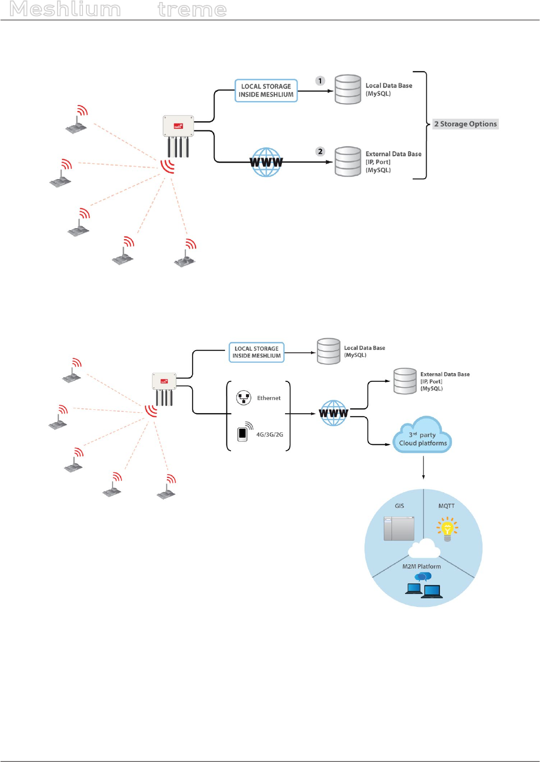
We can perform two dierent storage options with the frames captured:
•Local database
•External database
-50- v7.3
Wireless Sensor Networks
Meshlium
X
treme
All the data is stored in the local database in the rst place, then it can be synchronized to an external database
as per user needs.
Figure: Storage options
The data stored can be synchronized too to external services using the Internet connection.
Figure: External synchronization options
-51- v7.3
Wireless Sensor Networks
Meshlium
X
treme
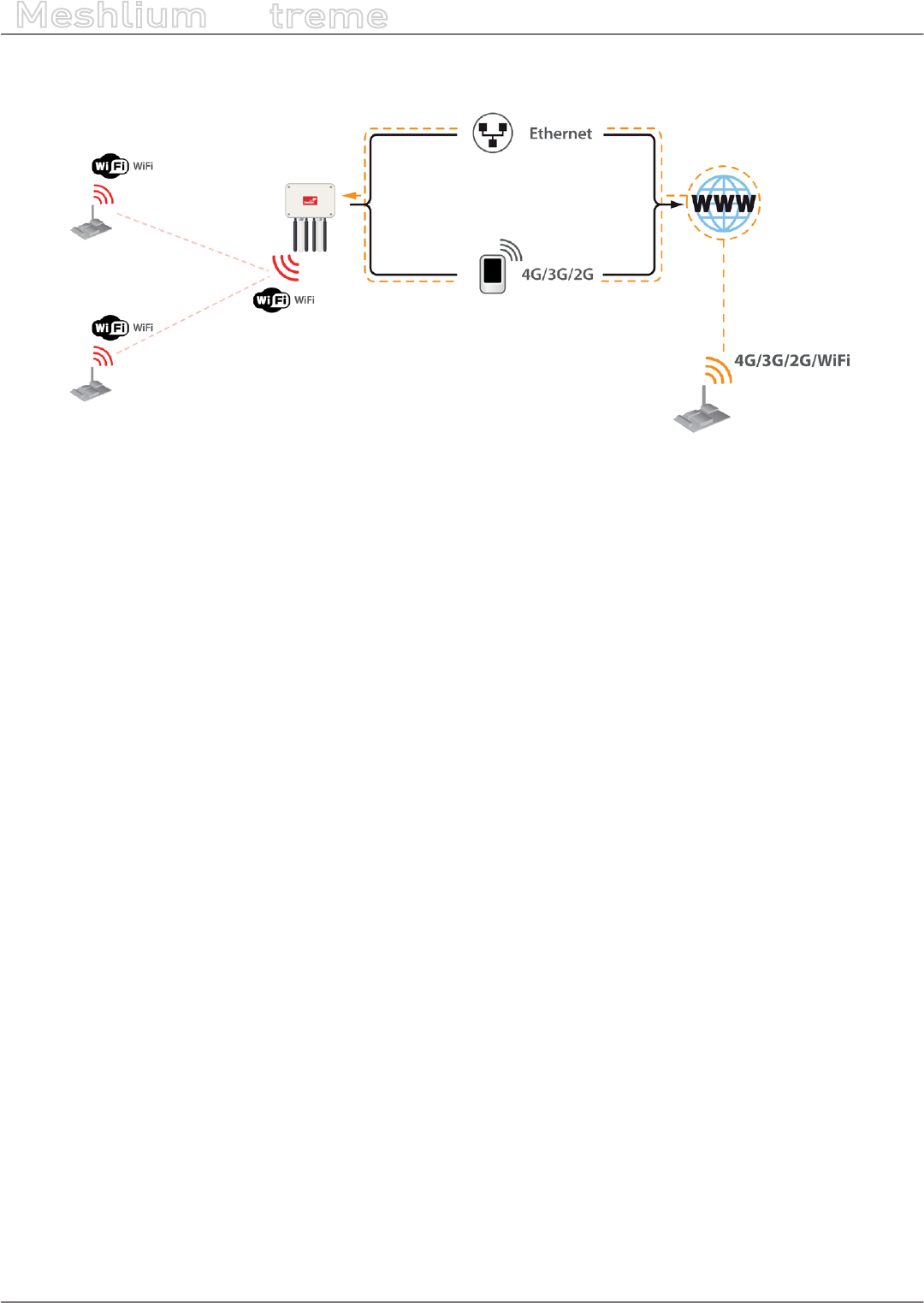
10.2.2. Receiving trough 4G / WiFi / Ethernet (HTTP)
Figure: HTTP data reception
Meshlium accepts POST and GET requests in any of its interfaces so Waspmotes are capable of sending frames,
through GPRS, 3G, 4G or WiFi modules, via HTTP requests. Meshlium, through HTTP requests is capable of:
•receive frames from 4G/3G/GPRS/GSM, WiFi or Ethernet via HTTP
•parse these frames
•store the data in local Database
•synchronize the local Database with an external database
Frames received by this method are stored the same way that RF frames, and are identically processed at
synchronization stage.
No conguration of any kind is needed to use HTTP. If HTTPS is needed, certicate conguration would be needed
in many cases (self signed certicate is included with Meshlium).
Like the case of RF modules reception, the user can add his own sensors.
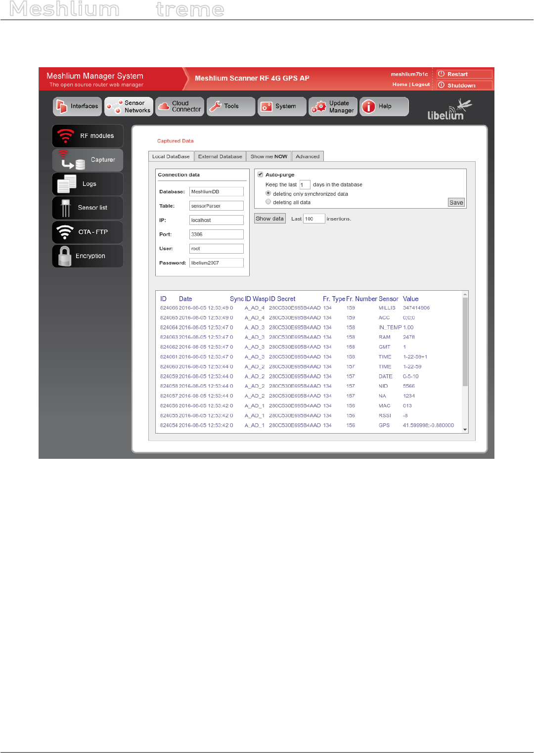
10.3. Capturer
The Capturer plugin is where the user can check most recent data received in order to check if the nodes are
sending information.
It can be found in:
Sensor Networks → Capturer
-52- v7.3
Wireless Sensor Networks
Meshlium
X
treme
Capturer plugin have several tabs where the user can see recent data received, manage external database
synchronization and perform some local database operations.
Figure: Capturer plugin
-53- v7.3
Wireless Sensor Networks
Meshlium
X
treme
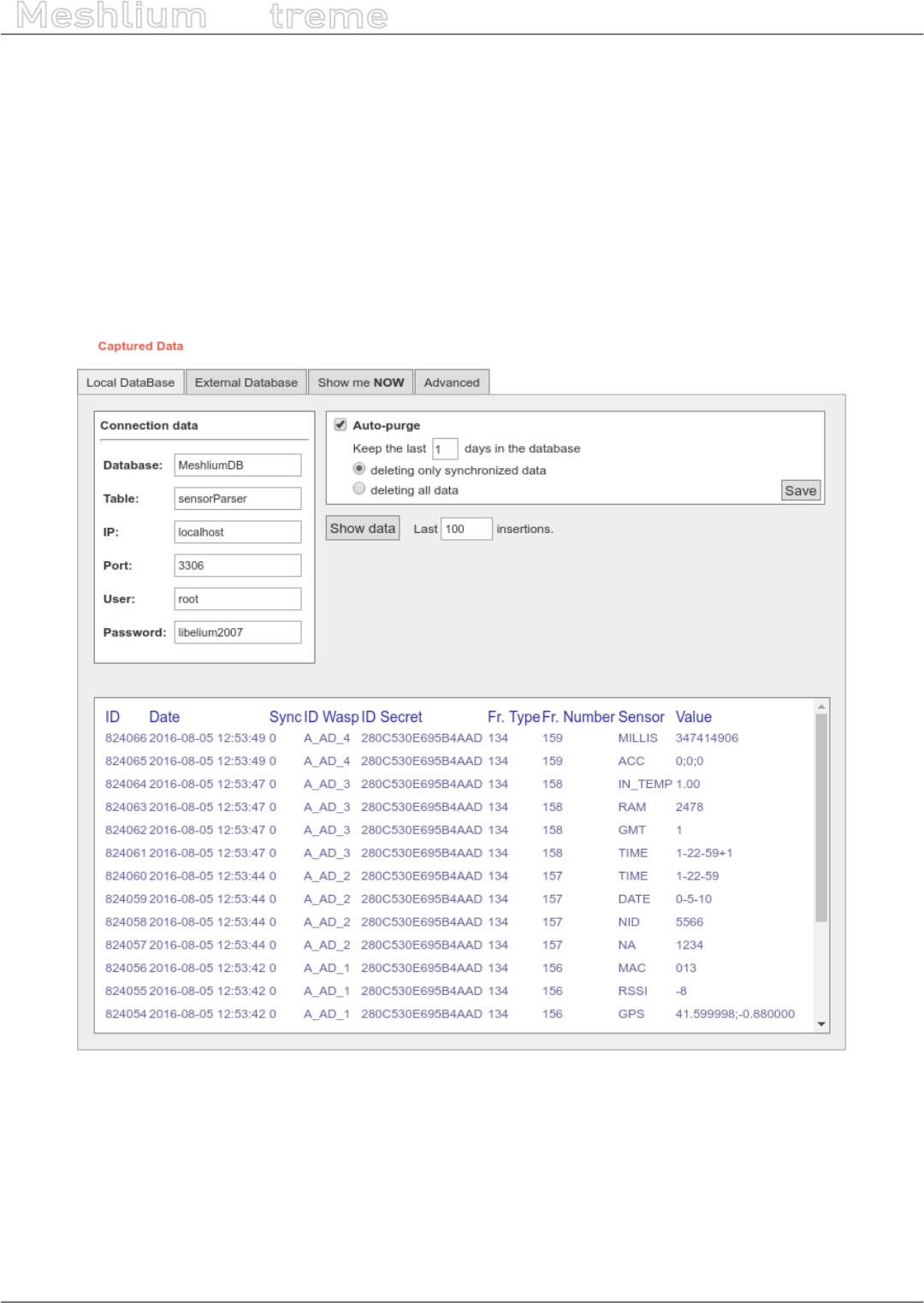
10.3.1. Local database
Meshlium has a MySQL database up and running which is used to locally store the information captured. In the
“Local Data Base” tab the user can see the default connection parameters.
•Database: MeshliumDB
•Table: sensorParser
•IP: localhost
•Port: 3306
•User: root
•Password: libelium2007
Figure: Local database tab
-54- v7.3
Wireless Sensor Networks
Meshlium
X
treme
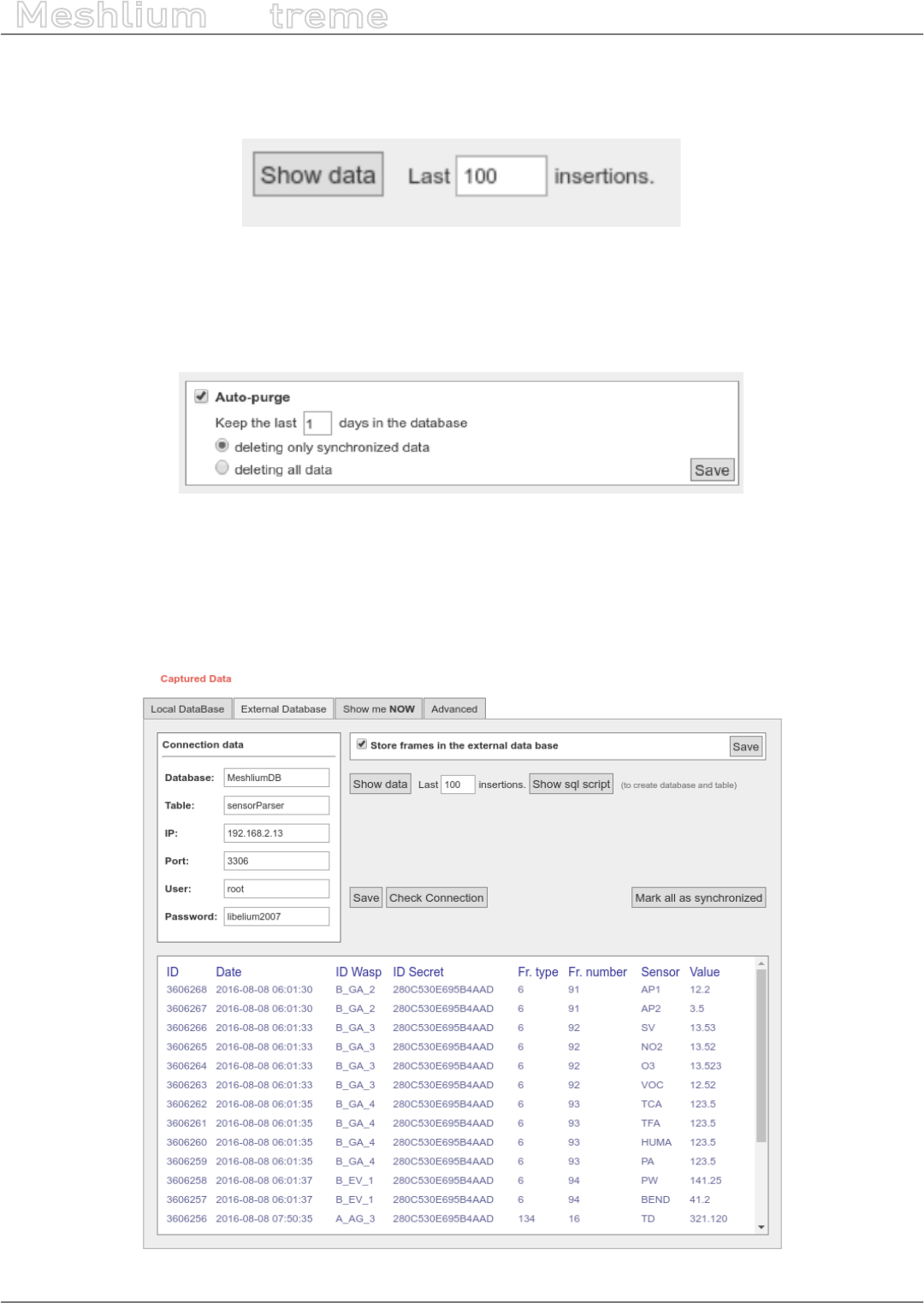
In this tab the user can:
•Show last insertions, up to 500.
Figure: Show last data
•Setup Auto-purge. This function allow to program a daily maintenance in the local database that deletes old
data, keeping only the number of days congured, and allowing to delete synchronized data (only external
database) or all data.
Figure: Autopurge setup
10.3.2. External Database
Meshlium can synchronize all the sensor information stored in the local database to an external MySQL database
managed by the user.
Figure: External database tab
-55- v7.3
Wireless Sensor Networks
Meshlium
X
treme
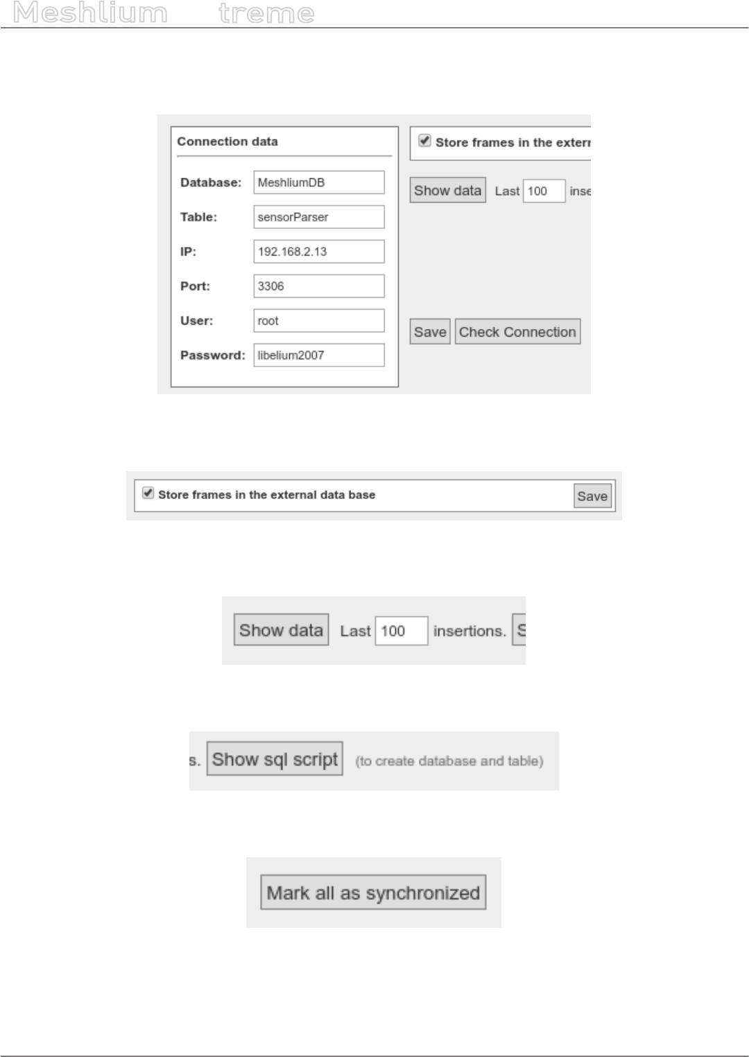
In this tab the user can:
•Setup the parameters of the external database and check the connection.
Figure: External database setup
•Enable or disable the synchronization.
Figure: Control to enable or disable synchronization
Show last data inserted in the external database (up to 500 data).
Figure: Show last inserted data
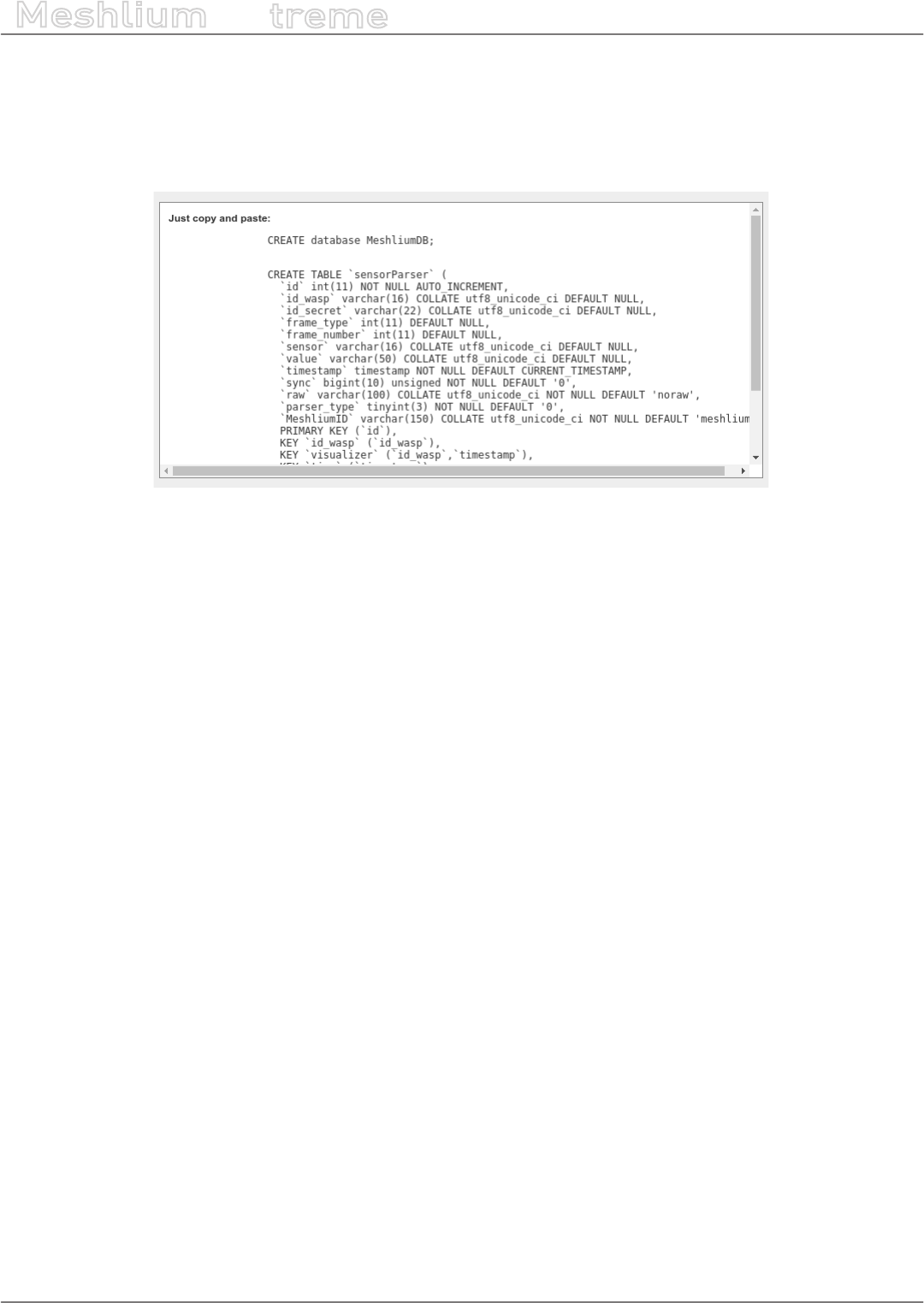
Show the SQL script used to create the database and table needed for the synchronization.
Figure: Show SQL script
Mark all data in the local database as synchronized so it will not be sent to the external database.
Figure: Mark as synchronized button
-56- v7.3
Wireless Sensor Networks
Meshlium
X
treme
The steps to setup the synchronization are:
•Before conguring anything, make sure you have a MySQL database working under your control. Make sure
the database listen to connections in an external IP.
•Press the “Show SQL script” button, copy the SQL code. You can modify user, password, database name and
table, as long as you change the setup of the connection to match.
Figure: SQL script
•Enter the connection settings and press “Save” button. You can check the connection now to ensure the
settings are correct.
•Enable the service with the checkbox and save.
The synchronization service runs every 60 seconds and synchronizes up to 200 data every loop. The service
synchronizes rst newer data, as it is more relevant for decision making. This could make data in external database
to be out of order. As every data has a timestamp, this should not be a problem for using the data in any external
application.

-57- v7.3
Wireless Sensor Networks
Meshlium
X
treme
10.3.3. Show me Now
In this tab the user can show the last frame received. The user can show only last frame or can specify if the
information will be updated periodically with the dened interval just checking the “Use the Dened Interval”
button.
Figure: Show me Now tab
The screen can be cleaned with the button in the top right.
10.3.4. Advanced database options
This tab shows information about local database.
Figure: Mark as synchronized button

-58- v7.3
Wireless Sensor Networks
Meshlium
X
treme
It shows:
•Database name
•Database size
•Database table used
•Number of total sensor entries
•Number of frames already synchronized with external services
•Number of unsynchronized frames
There are too two controls to:
•Remove synchronized data. It removes from the database all the frames already synchronized with external
database. Be careful as this could give unexpected results if you are using several cloud or external services.
A conrmation will be prompted.
•Remove ALL content. This removes all the sensor information from the database. A conrmation will be
prompted.
WARNING: The sensor data will permanently deleted from the database and will be impossible to recover. Be sure to
have a backup of the database before deleting the content.
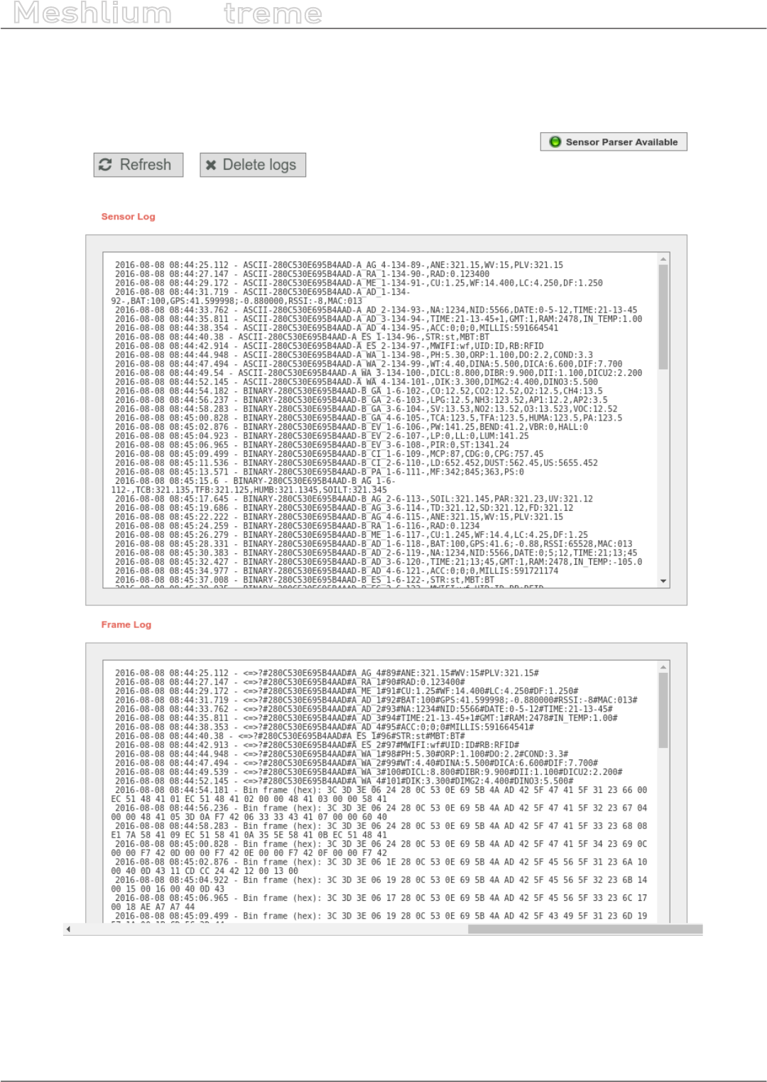
-59- v7.3
Wireless Sensor Networks
Meshlium
X
treme
10.4. Logs
In this section the user can see the last lines of the logs of frames and sensor data received.
Figure: Logs visualizing plugin
•The “Refresh” button will load again the log les
•The “Delete logs” button will delete the les, allowing to clean some space in the device
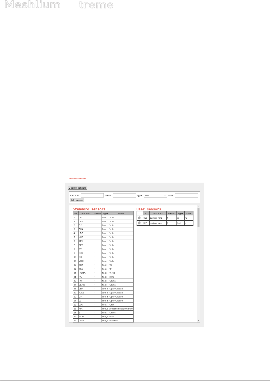
-60- v7.3
Wireless Sensor Networks
Meshlium
X
treme
10.5. Sensor list
In this section, the user can view the list of available sensors in the system and add or delete user custom sensors.
By default, Meshlium recognize all Libelium ocial sensors frames. All sensor frames that Meshlium can capture
and store must be specied in an XML le. The button “update sensors” update the Libelium ocial sensor list.
User sensors remaining unchanged.
Users can add and remove custom sensors in an easy and simple way.
To add a new sensor the user must complete the elds:
•ASCII ID: sensor id for ASCII frame.
•Fields: This eld species the number of sensor elds sent in the frame. This helps to calculate the frame
length.
•Type: type of elds:
-uint8_t
-int
-oat
-string
-ulong
-array (ulong)
•Units: Units for the sensor added.
Once all elds are lled in, click on the button “Add sensor”.
Figure: Sensor list plugin
Note: Extensive information about how to build the frame is available on the “Waspmote Data Frame Guide”.
To delete sensor the user must press the garbage can that appears to the left of the description of the sensor. To
complete the action should accept a conrmation message.
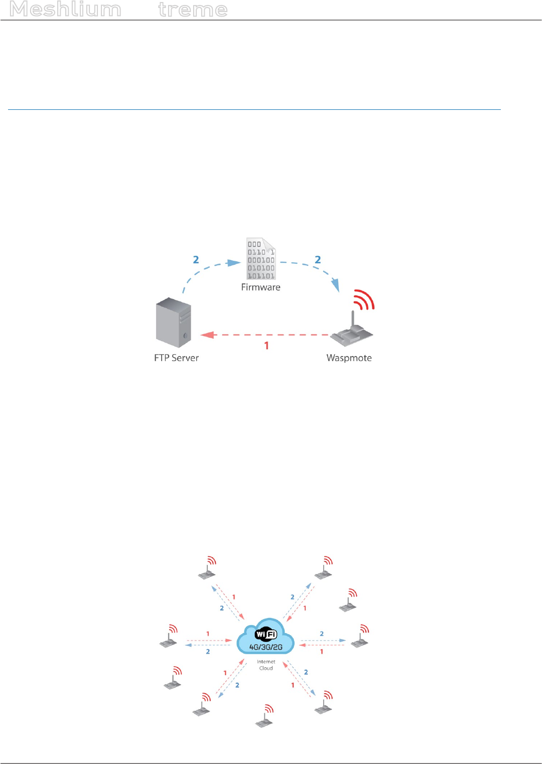
-61- v7.3
Wireless Sensor Networks
Meshlium
X
treme
10.6. OTA via FTP
Meshlium can also be used as an FTP server to prepare the binary les to be downloaded by Waspmote.
For more info about Over the Air Programming go to:
http://www.libelium.com/development/waspmote/documentation/over-the-air-programming-guide-otap/
This feature allows reprogramming Waspmote using an FTP server (inside Meshlium) and FTP client (Waspmote
itself).
There are two basic steps involved in OTA procedure:
•Step 1: Waspmote requests a special text le which gives information about the program to update: program
name, version, size, etc.
•Step 2: If the information given is correct, Waspmote queries the FTP server for a new program binary le and
it updates its ash memory in order to run the new program.
Figure: OTA via FTP protocol
Besides, a default user is congured in Meshlium FTP Server with the following settings:
•user: ota
•password: libelium
This user directly connects to the following path in Meshlium’s system directory where the application creates all
the binary and UPGRADE.TXT les:
/mnt/user/ota
Inside “Sensor Network” there is the section OTA - FTP. Users can prepare the binary les to be downloaded by
Waspmote. Then, the user can generate UPGRADE.TXT text le necessary to do OTA with 4G/3G/GPRS/GSM/WiFi
via FTP.
Figure: OTA-FTP in Meshlium
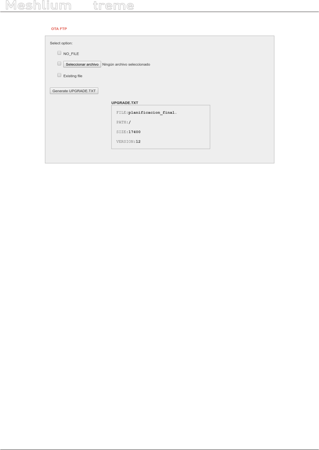
-62- v7.3
Wireless Sensor Networks
Meshlium
X
treme
Figure: OTA-FTP plugin
Firstly, there are three possibilities to be chosen:
•Select NO_FILE to inform Waspmote that no OTA is necessary
•Select a new le generated by the Waspmote platform IDE so as to update the Waspmote’s program.
•Select an existing binary if the user needs to update to an older program. The les are stored in the following
path: /mnt/user/ota.
Secondly, the program version is always set by the user before generating the new UPGRADE.TXT le. There is a
specic input to indicate the program version. It must be dened as a 1-unsigned-byte number (range: from 0 to
255).
Finally, there is a button to generate the new UPGRADE.TXT le.
Once these steps have been completed, the binary le and the proper UPGRADE.TXT le will be ready for the
Waspmote devices deployed which try to perform OTA via FTP transmission. This le is shown in the window of
the application representing the actual binary prepared for OTA.
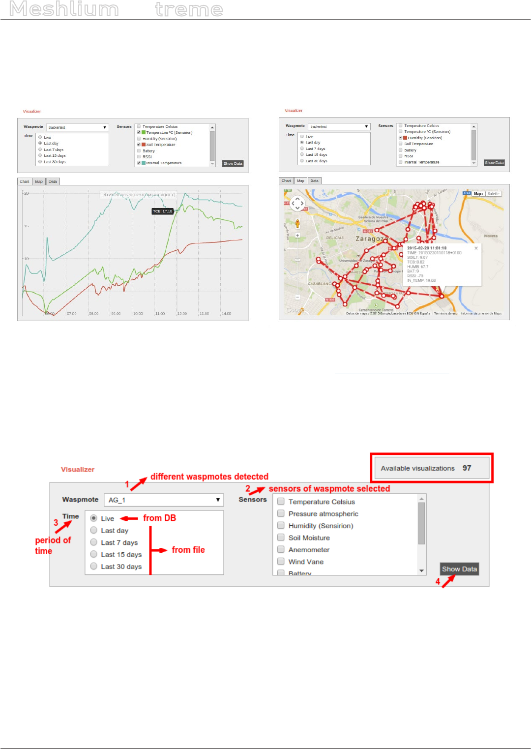
-63- v7.3
Meshlium Visualizer
Meshlium
X
treme
11. Meshlium Visualizer
Meshlium Visualizer is a plugin which plots graphs and maps with the data stored in the database. It can also
export data in common formats. Meshlium Visualizer is a special software feature only available in the Meshlium
units included in the IoT Vertical Kits (Smart Cities IoT Vertical Kit, Smart Water IoT Vertical Kit, etc).
Figure: Meshlium Visualizer can plot graphs and geo-locate data on maps
Please note that this is a paid service. In every IoT Vertical Kit, each Meshlium comes with 100 visualizations.
After 100 visualizations, users can contact Libelium Sales Department (salesteam@libelium.com) if they want to
continue using the service.
11.1. Working with the Visualizer
On the top of the page you can use a simple form to make all your queries. To do so, just follow these steps:
Figure: Filling Meshlium Visualizer’s form
1.- Select one Plug & Sense! from the list. All Plug & Sense! units with frames in the database will be shown.
2.- Once a Plug & Sense! Is selected, all its sensors will be loaded. This process is repeated each time you change
the selected Plug & Sense!.
3.- Select the period of time you want to see in the chart. The “Live” option reads directly from the database, while
the rest options read from a le generated everyday by the service cron. For each Plug & Sense!, cron generates
4 les each day, one for the last day, other for last 7 days, other for last 15 days and other for the last 30 days.
4.- Hit on the “Show Data” button and, if your query has results to show, Meshlium Visualizer will show them. The
remaining visualization number will decrease in one unit. If the query does not have any results, a message will
appear notifying the situation; the available visualizations remain without changes.

-64- v7.3
Meshlium Visualizer
Meshlium
X
treme
Figure: Meshlium Visualizer showing one graph
If your query has GPS results (data frames with GPS information), the “Map” tab will be shown. If it is not the case,
like in the previous picture, this tab remains disabled.
Figure: Locating nodes on a map thanks to Meshlium Visualizer

-65- v7.3
Meshlium Visualizer
Meshlium
X
treme
The “Data” tab shows a list of sensor values, ordered by time.
Figure: Meshlium Visualizer showing the Data tab
The “Export” tab shows two calendars to select the initial and nal date. This feature does not take into account
the block on the top of the page, it will export all data from all Plug & Sense! units between these dates. Data can
be exported in 5 formats (CSV, SQL, XML, TXT & HTML) and compressed in ZIP.
Figure: Conguring Meshlium Visualizer to export data
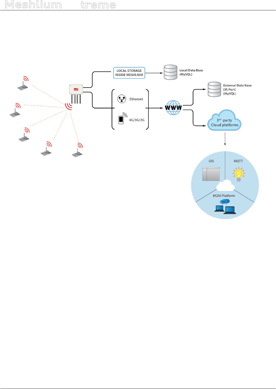
-66- v7.3
Cloud Connectors
Meshlium
X
treme
12. Cloud Connectors
The aim of this chapter is to introduce the user to the Meshlium Cloud Connector functionality. This section will
help you to connect your Meshlium to a third party cloud platform.
Only sensor data can be sent to the cloud services.
Figure: Cloud connector diagram
Interfacing Meshlium with 3rd party cloud services should be the last step the user develops in any project.
The user should analyze if the use of clouds is needed, and if so, that will be the last step in the project. Before
trying clouds, make sure all the Waspmote units are sending frames to Meshlium, and Meshlium is receiving and
inserting them on the local database properly.
What is a cloud platform?
Cloud computing is a major change in our industry. One of the most important parts of that paradigm are cloud
platforms. This kind of platforms let developers write applications that run in the cloud, use services provided
from the cloud or both.
Meshlium Cloud Connector
Meshlium runs a set of scripts for implementing the data synchronization from its internal database “to the cloud”.
In other words, those scripts send data to webservers where the cloud service providers host their clouds. Those
scripts are called Cloud Connector.
We have divided the Cloud Connector into 2 groups: “IoT Solutions” and “IoT Platforms”.
IoT Platforms are professional development frameworks for developing data management applications, including
Esri, ThingWorx, IBM Bluemix, Telefónica and Microsoft Azure.
IoT Solutions are specic applications focused in dierent verticals. Libelium promotes the Cloud Partnership
Program for any cloud service provider that would like to foster their very own solution using our products.
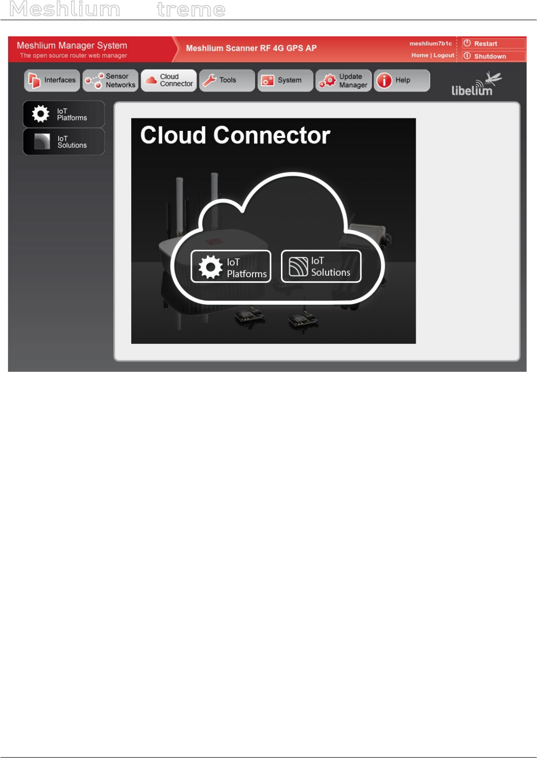
-67- v7.3
Cloud Connectors
Meshlium
X
treme
Figure: Cloud Connector main menu on the Manager System
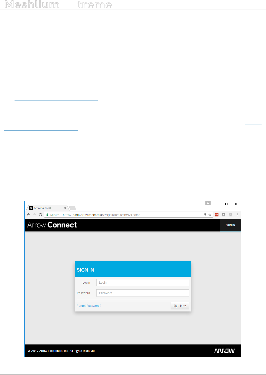
-68- v7.3
Cloud Connectors
Meshlium
X
treme
12.1. Premium Cloud Partners
12.1.1. Arrow
12.1.1.1. Arrow Connect IoT Cloud Platform
Arrow Connect is a software solution that plumbs the data from the edge to the cloud. Developed by Arrow
Electronics and designed with security, scale, exibility, device management, open APIs and extensibility as
core tenants enabling broad use cases across multiple industries. You can provision, control, import, assign,
activate, update, suspend, replace, deactivate, and more, all from a single platform. Arrow Connect makes device
management easy so you can focus on driving business value via data analytics and machine learning tools.
Visit http://iot.arrow.com/developer.html for more information.
12.1.1.2. Register Meshlium in Arrow Connect
To request for a developer account in Arrow Connect platform, follow the Developer Registration process on https://
portal.arrowconnect.io/#/signup or please email to tnguyen@arrow.com including the following information:
•Company name
•Full name
•Title
•Email address
•How did you hear about us?
•Short description of your project
Log on to the portal at https://portal.arrowconnect.io using your developer account.
Figure: Arrow portal

-69- v7.3
Cloud Connectors
Meshlium
X
treme
With the developer account, you have a private application instance with full admin access. Upon logging in, click
on Administration > Access Keys, then click on the Master Key. You can save the “Client Encrypted API Key” and
“Client Encrypted Secret Key” to the notepad. This pair of keys will be used to congure the Meshlium to connect
to your cloud account.
Figure: Access Key
12.1.1.3. Conguration
Paste the keys above into the 2 text areas as screen-shot below.
Figure: Congure Arrow
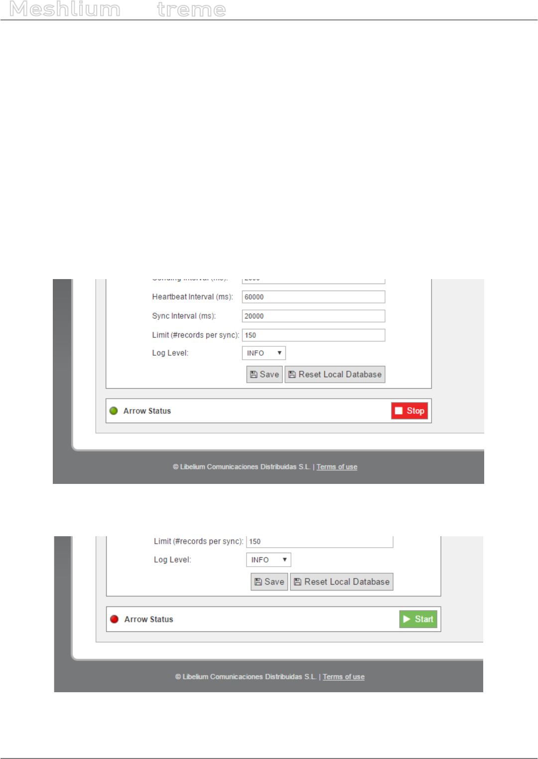
-70- v7.3
Cloud Connectors
Meshlium
X
treme
All the default conguration values should be appropriate and you do not need to change them. Click on the
“Save” button for storing the conguration elds.
•API URL
•MQTT URL
•Encrypted API Key
•Encrypted Secret Key
After clicking the “Save” button, you also need to click on “Reset Local Database”, otherwise your changes will not
be aected.
In all cases, to prevent local database corruption, the conguration should never be updated while the Arrow
Connect IoT Cloud Connector is running. Use the Start/Stop buttons as described below to stop it before making
changes, restart it after saving changes.
12.1.1.4. Controlling synchronization
Launch the Meshlium Arrow Connect IoT Cloud background process (Start button). The program will search for
the received frames on the local database, and will send them to the Arrow Connect IoT Cloud Platform. The
status indicator displays the current state. Green colour means running.
Figure: Synchronization stopped
Stop the Arrow Connect program anytime by clicking on the “Stop” button. Red colour means stopped.
Figure: Synchronization running

-71- v7.3
Cloud Connectors
Meshlium
X
treme
While the program is running, log on to the Arrow Connect portal to check that the Meshlium and Waspmotes
have been properly registered and are sending telemetry data. See some example screen-shots below:
Figure: Arrow gateways display
Figure: Arrow Meshlium display

-72- v7.3
Cloud Connectors
Meshlium
X
treme
Figure: Arrow Waspmote display
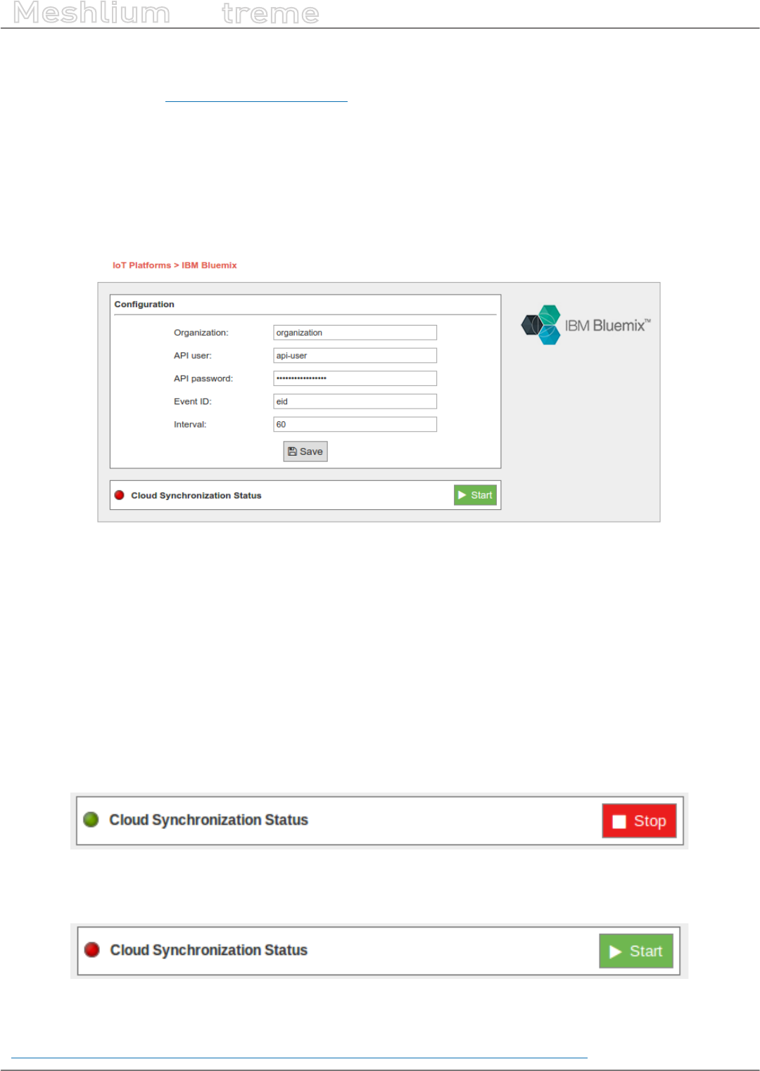
-73- v7.3
Cloud Connectors
Meshlium
X
treme
12.1.2. IBM Bluemix
IBM Bluemix is a cloud platform as a service (PaaS) developed by IBM that gives a wide scope of services to use
the cloud, one of them is based on MQTT communications. This is a great alternative if the user do not want to
build his own MQTT server.
12.1.2.1. Conguration
Conguration options are shown in the M2M Platform menu, enlarging the IBM Bluemix MQTT section. You will
notice that the conguration for this plugin is very straight-forward, you have most of the needed parameters on
the IBM Bluemix web panel:
Figure: Conguring IBM Bluemix in Meshlium
•Organization ID: Identier of your organization; you can get it from the platform credentials.
•API user: User generated in the API platform section.
•API password: Password generated in the API platform section.
•Event ID: Used to congure the event where you want to send the information. If you do not know what to
type in this eld, you can use ‘eid’.
•Interval: Used to delay the communication after a bunch of messages were sent.
12.1.2.2. Controlling synchronization
You can stop or start the IBM Bluemix synchronization process anytime, hitting on the buttons “Start” and “Stop”.
Then, the status indicator displays the current state, saying “Running” or “Stopped”.
Figure: IBM Bluemix synchronization service is running
You can stop the synchronization anytime clicking on the “Stop” button.
Figure: BM Bluemix synchronization service is stopped
More information can be found on this Recipe we created for IBM:
https://developer.ibm.com/recipes/tutorials/bluemix-conguration-guide-for-meshlium/
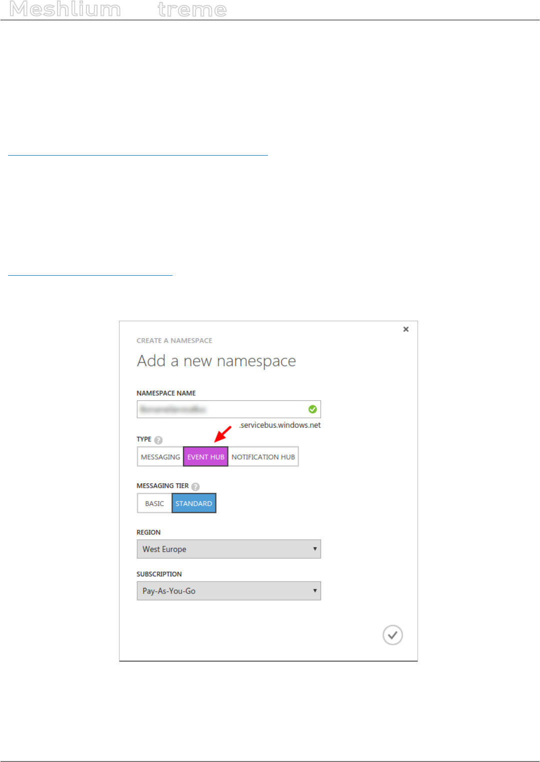
-74- v7.3
Cloud Connectors
Meshlium
X
treme
12.1.3. Microsoft Azure Event Hubs
Azure is a cloud platform provided by Microsoft. This platform has a lot of services to reach communication
between machines and devices.
This section focuses on Event Hubs, we can refer this technology as a way to send short messages via HTTP REST
request. Event Hubs is part of Service Bus. Event Hubs implements a simple message consumer M2M technology.
For more information about Event Hubs, see the following link:
https://azure.microsoft.com/en-us/services/event-hubs/
12.1.3.1. Setup in Azure - Creating NameSpace
Before getting the parameters to connect to Event Hub, it is necessary to create a Service Bus Namespace (skip
this section if you already have one).
Go to the Azure Event Hub Portal:
https://manage.windowsazure.com
Select the Service Bus menu. At the bottom of the Bus service manager screen you will see a NEW button with a
plus image, click on it. A pop-up window will appear where you must select message type “EVENT HUB”.
Figure: Create new Namespace

-75- v7.3
Cloud Connectors
Meshlium
X
treme
12.1.3.2. Setup in Azure - Creating an Event Hub
In this section we will create an Event Hub that will receive our data from Meshlium. After we dive into the Service
Bus we have previously created, we can see a menu on the top of the screen, then we should choose “Event Hubs”
and “Create a New Event Hub”:
Figure: Create New Event Hub
Figure: After clicking on this menu, a new screen will appear. At this point we can create a new event hub clicking
on the bottom left icon labeled as New:
Figure: Create a New Event Hub
After click this button, a pop-up window raises above and you are now able to create an event hub, we are going
to choose “quick create” option to make this step easier:
Figure: Quick Create
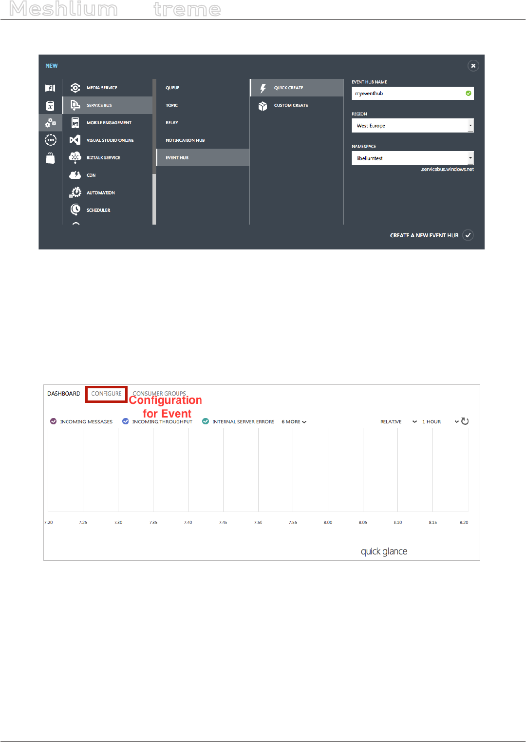
-76- v7.3
Cloud Connectors
Meshlium
X
treme
Type your event hub name and click “Create a new event hub” button to nish the conguration process.
Figure: Type the new Event Hub name
You have created an Event hub for one day data retention, which means that your data will be kept one day.This
method sets a partition section with value ‘4’, which means the number of partitions the Event Hub may have.
12.1.3.3. Setup in Azure – Setting up shared access in Event Hub
We set up a shared directive to send data with custom credentials.Once we entered on event hub information
(by clicking on event hub), these credentials can be set up in the conguration section, this menu is on top of the
screen:
Figure: Congure the Event
Click on the “congure” option and a new screen will be displayed. Here you can congure message retention,
event hub state, partition count and shared access policies. This last point (shared access policies) manages
credentials to send and listen messages (or both action), we will create a new credential to send messages. On
“shared access policies”, type a name for your key, and in the permissions drop-down menu, select “Manage”
permission. Then press “save” on the bottom of the screen.

-77- v7.3
Cloud Connectors
Meshlium
X
treme
Figure: Congure the Event Permissions
Finally, we will copy the information needed to connect the Event Hub connector. In order to do that, go to the
“Dashboard” of the Event Hub and select “View Connection String”.
Figure: Event Hub Dashboard

-78- v7.3
Cloud Connectors
Meshlium
X
treme
Copy the “Connection String” that appears in the screen.
Figure: Connection String
We will extract the information needed to connect the Meshlium from the “Connection String”. You have to copy
the NAMESPACE, the DIRECTIVE_NAME, the DIRECTIVE_KEY and the EVENTHUB_NAME from the string as the
following example:
Namespace=Endpoint=sb://NAMESPACE.servicebus.windows.net/;SharedAccessKeyName=DIRECTIVE_
NAME;SharedAccessKey=DIRECTIVE_KEY;EntityPath=EVENTHUB_NAME
Note that the namespace is only a part of the string Endpoint, it does NOT include the “sb://” neither the
“.servicebus.windows.net/” part.
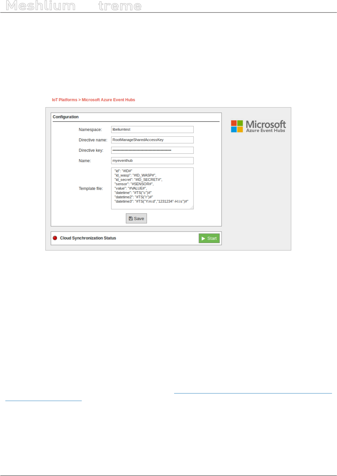
-79- v7.3
Cloud Connectors
Meshlium
X
treme
12.1.3.4. Conguration
As result of previous steps, we should have a namespace, a directive name, a directive key and an event hub
name. These are the main properties we should set in the Manager System to congure an Event Hub connection.
Now we can access the Meshlium Manager and fulll the Azure Event Hub elds with the previously obtained
conguration.
Figure: Conguring Azure Event Hubs in Meshlium
•Namespace: Name of the space created in the Azure service cloud.
•Directive name: Name of the directive created in Azure.
•Directive key: Key of the directive associated to the previous name.
•Name: Name of the Event Hub established in Azure.
•Template le: Users can dene their own data structure using these wild-cards (as you can see in the previous
gure):
-#ID# : Unique identier for data
-#ID_WASP#: Identies the Waspmote unit
-#ID_SECRET#: Secret identier
-#SENSOR#: Identies the sensor
-#VALUE#: Value obtained from the sensor
#TS(“c”)#: Date with custom format. The parameter passed in this wild-card corresponds to the same ones you
can use in PHP date function (see format parameters in http://php.net/manual/es/function.date.php#refsect1-
function.date-parameters).
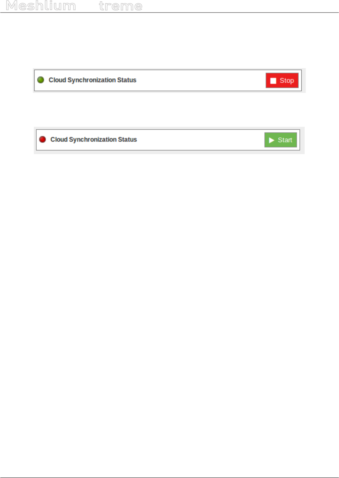
-80- v7.3
Cloud Connectors
Meshlium
X
treme
12.1.3.5. Controlling synchronization
Once you have saved the conguration, you can start sending your data via Event Hub to your Azure Cloud by
pressing the “Start” button. You will notice about it because the screen shows a spinning wheel when the process
starts and displays a “running” status.
Figure: Azure Event Hubs synchronization service is running
If you want to stop this process just press the “Stop” button. You can start/stop this process whenever you want.
Figure: Azure Event Hubs synchronization service is stopped
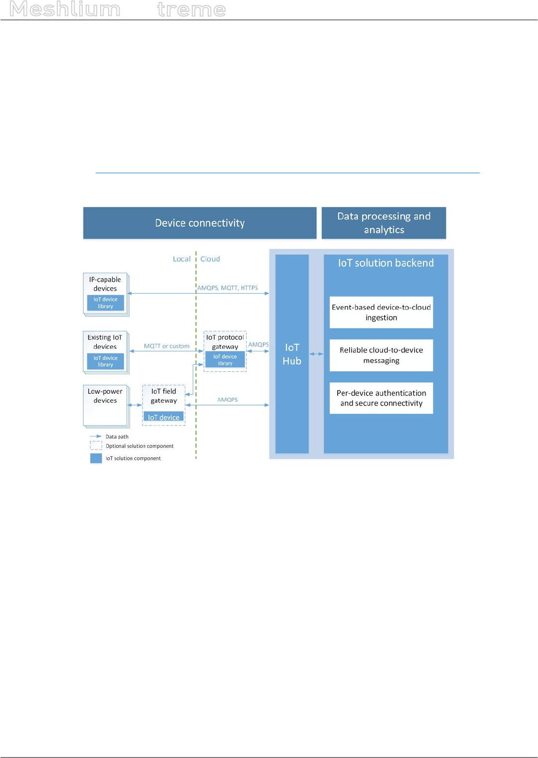
-81- v7.3
Cloud Connectors
Meshlium
X
treme
12.1.4. Microsoft Azure IoT Hub
Azure IoT Hub is a fully managed service that enables reliable and secure bi-directional communications between
millions of Internet of Things (IoT) devices and a solution back end. One of the biggest challenges that IoT projects
face is how to reliably and securely connect devices to the solution back end. To address this challenge, IoT Hub:
•Oers reliable device-to-cloud and cloud-to-device hyper-scale messaging.
•Enables secure communications using per-device security credentials and access control.
•Includes the most popular communication protocols.
More information: https://www.microsoft.com/en-us/cloud-platform/internet-of-things-azure-iot-suite.
With this plugin, Meshlium can send messages to your cloud back-end.
Figure: Azure IoT Hub plugin
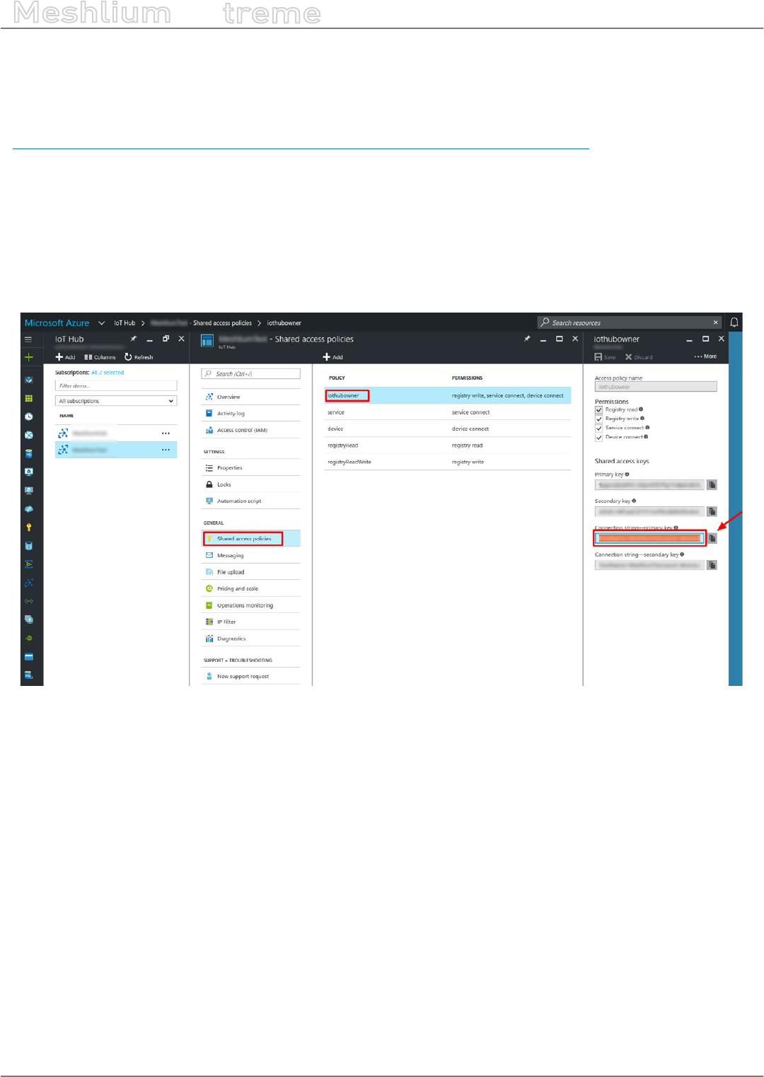
-82- v7.3
Cloud Connectors
Meshlium
X
treme
12.1.4.1. Register Meshlium in Azure Portal
To register Meshlium in Azure Portal, you have to follow the guide:
Get started with Azure IoT Hub for Java:
https://azure.microsoft.com/en-us/documentation/articles/iot-hub-java-java-getstarted/.
The guide explains how to create an IoT Hub and a device entity. It is important to annotate the connection string
generated after creating the device entity. You will need this parameter later for the Meshlium conguration.
In the Microsoft Azure Portal, go to IoT Hub menu and select:
Devices > myCreatedDevice > Shared access policies > iothubowner > Connection string – primary key
You have to annotate the value of this eld.
Figure: Annotate the value of the eld
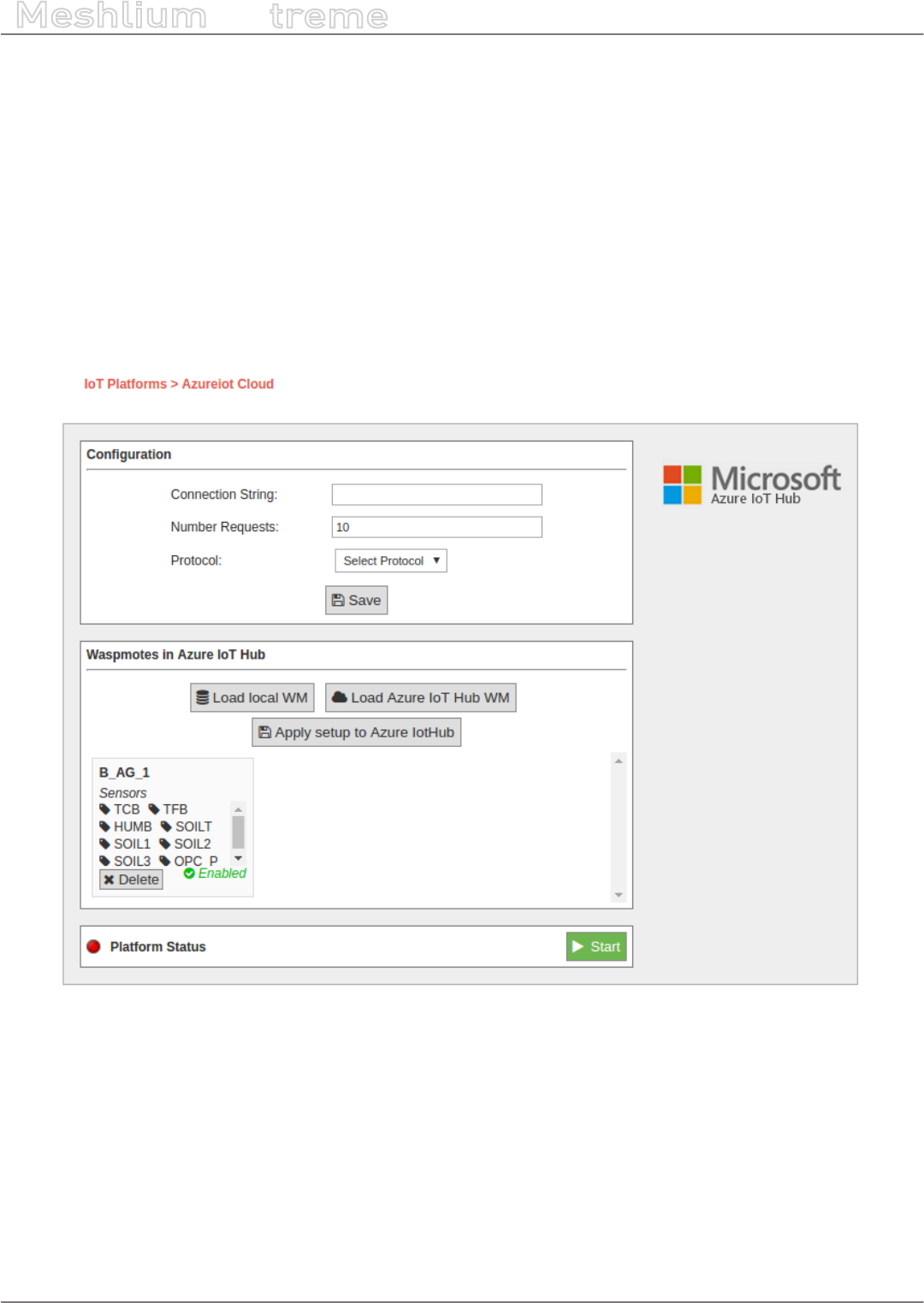
-83- v7.3
Cloud Connectors
Meshlium
X
treme
12.1.4.2. Conguration
You will use the previously obtained “connection string” from the Azure portal to certicate your Meshlium as a
valid sender of messages.
Microsoft Azure IoT Hub plugin is located in:
Manager System > Cloud Connector > IoT Platforms > Azure IoT Cloud
In the Conguration panel, the user can set:
•Connection String: Connection string previously copied.
•Number Requests: Number of requests to send per iteration.
•Protocol: Choose the protocol to communicate with Azure IoT Hub. Valid protocols are: MQTT (by default),
AMQPS and HTTPS.
Figure: Azure IoT Hub conguration panel

-84- v7.3
Cloud Connectors
Meshlium
X
treme
12.1.4.3. Controlling synchronization
Once congured the server/broker, the user can launch the Meshlium Microsoft Azure IoT Hub script (Start
button). The program will send test messages to the Azure IoT Hub platform via the selected protocol. The status
indicator displays the current state, saying “Running” or “Stopped”.
Figure: Azure IoT Hub sender is running
You can stop the Azure IoT Hub program anytime clicking on the “Stop” button.
Figure: Azure IoT sender is stopped

-85- v7.3
Cloud Connectors
Meshlium
X
treme
12.1.5. Nexmachina
12.1.5.1. What is iQmenic?
iQmenic is a cloud solution for the Internet of Things created by Nexmachina.
Characteristics:
•Simple and practical
•Multi-language
•Multi-device
•Multi-user
Features:
•Monitoring devices and sensors
•Display data
•Congurable alarms
•Export data
•Congurable interface
Technical requirements User:
Web browser Chrome, Firefox, IE8 or higher.
Figure: iQmenic Dashboard
Figure: Sensors on the map
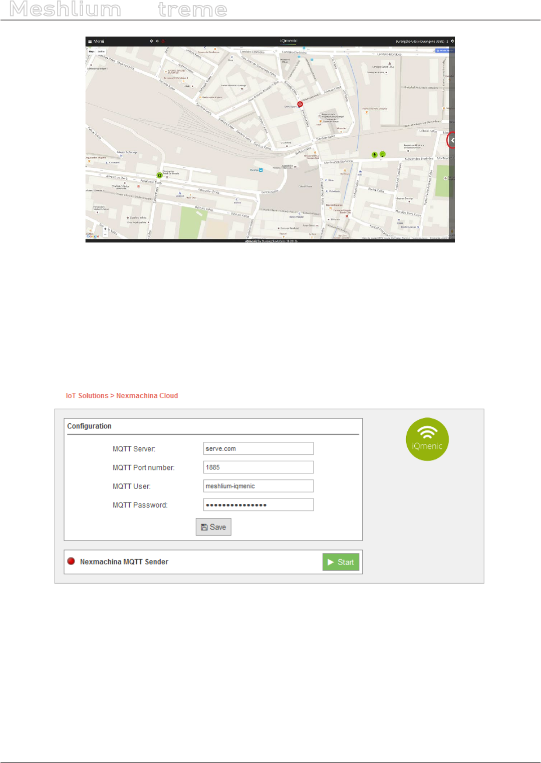
-86- v7.3
Cloud Connectors
Meshlium
X
treme
Figure: Graphic data from sensors
12.1.5.2. Meshlium cloud connection to iQmenic
If you want to connect your Meshlium with iQmenic, follow these steps:
•1. Contact Nexmachina. We will provide you a URL, User and Password for your iQmenic platform as well as
the conguration parameters for connecting your Meshlium to iQmenic.
•2. Log in your Meshlium and go to Cloud Connector > IoT Solutions > iQmenic. Fill the form with the
conguration data and click on the Save button.
Figure: Conguring Orchestra
•3. To send data from Meshlium to iQmenic, just click on the Start button. Data will be sent by MQTT protocol
and you will be able to check the reception on iQmenic.
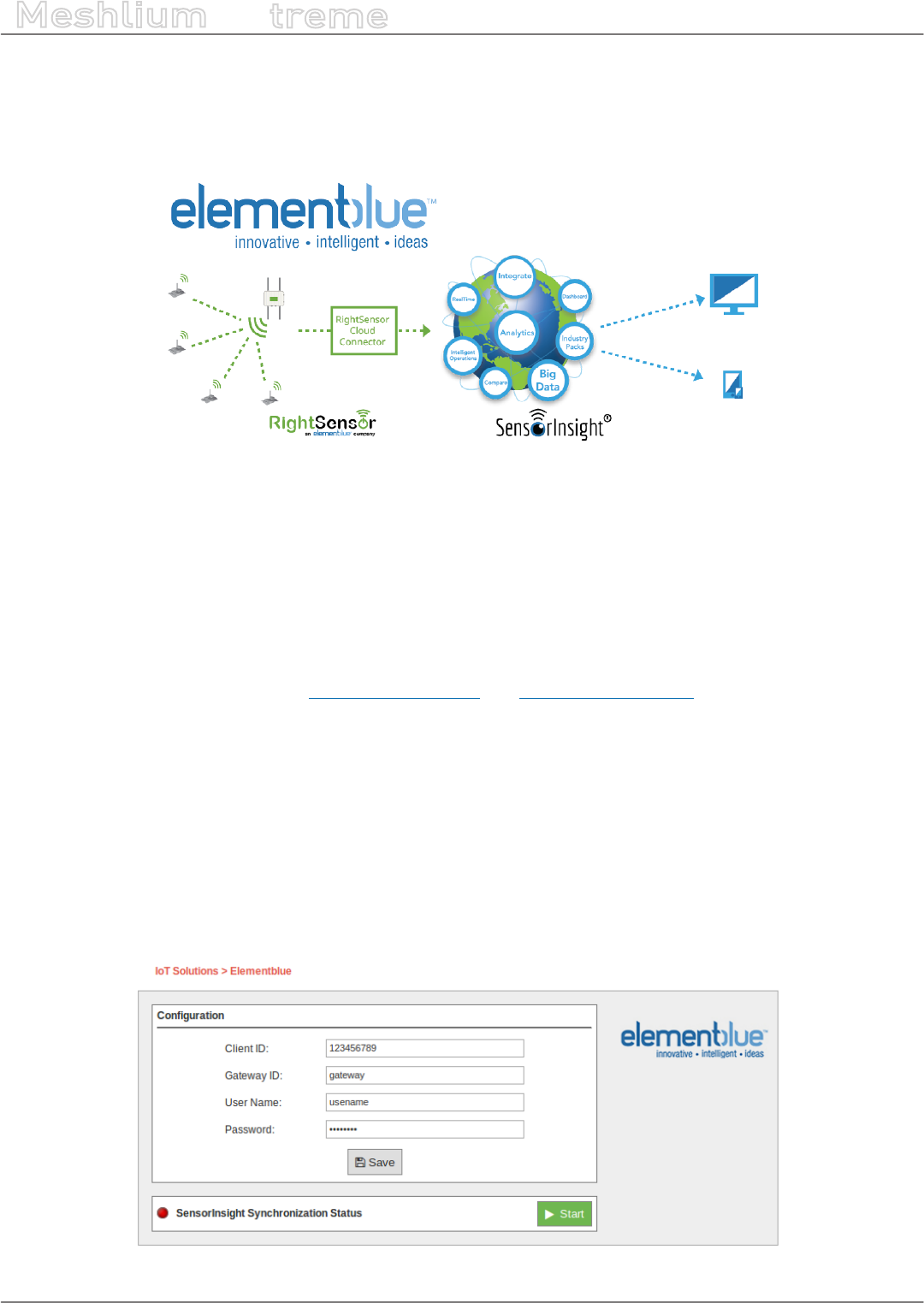
-87- v7.3
Cloud Connectors
Meshlium
X
treme
12.1.6. ElementBlue – RightSensor
RightSensor is a solution company designed to provide sensors, services and support for Industrial Internet of
Things projects.
Figure: ElementBlue RightSensor Cloud
The RightSensor cloud connects interface works directly with Element Blue’s SensorInsight® Industrial Internet of
Things Platform.
SensorInsight® is used by companies for the integration, display and detailed analysis of data from multiple
sources providing an environment where users can view and compare real-time and historic data patterns, receive
alerts and notications, and trigger workows and actions based on the data for use in industrial environments.
To use the service you must have an account with Element Blue’s SensorInsight Industrial Internet of Things
Platform. For more information visit: www.sensorinsight.io and www.rightsensor.com.
12.1.6.1. Conguration
By expanding the RightSensor menu item on the list you can see the form in which to set your connection
parameters. The form accepts the following 4 parameters:
•Client ID: This is a unique ID provided to you from the SensorInsight service.
•Gateway ID: This is an ID you provide to uniquely identify this Meshlium device.
•User Name: This is the Username required to send your data to the SensorInsight cloud.
•Password: This is the Password required to send your data to the SensorInsight cloud.
Figure: Conguring ElementBlue RightSensor in Meshlium
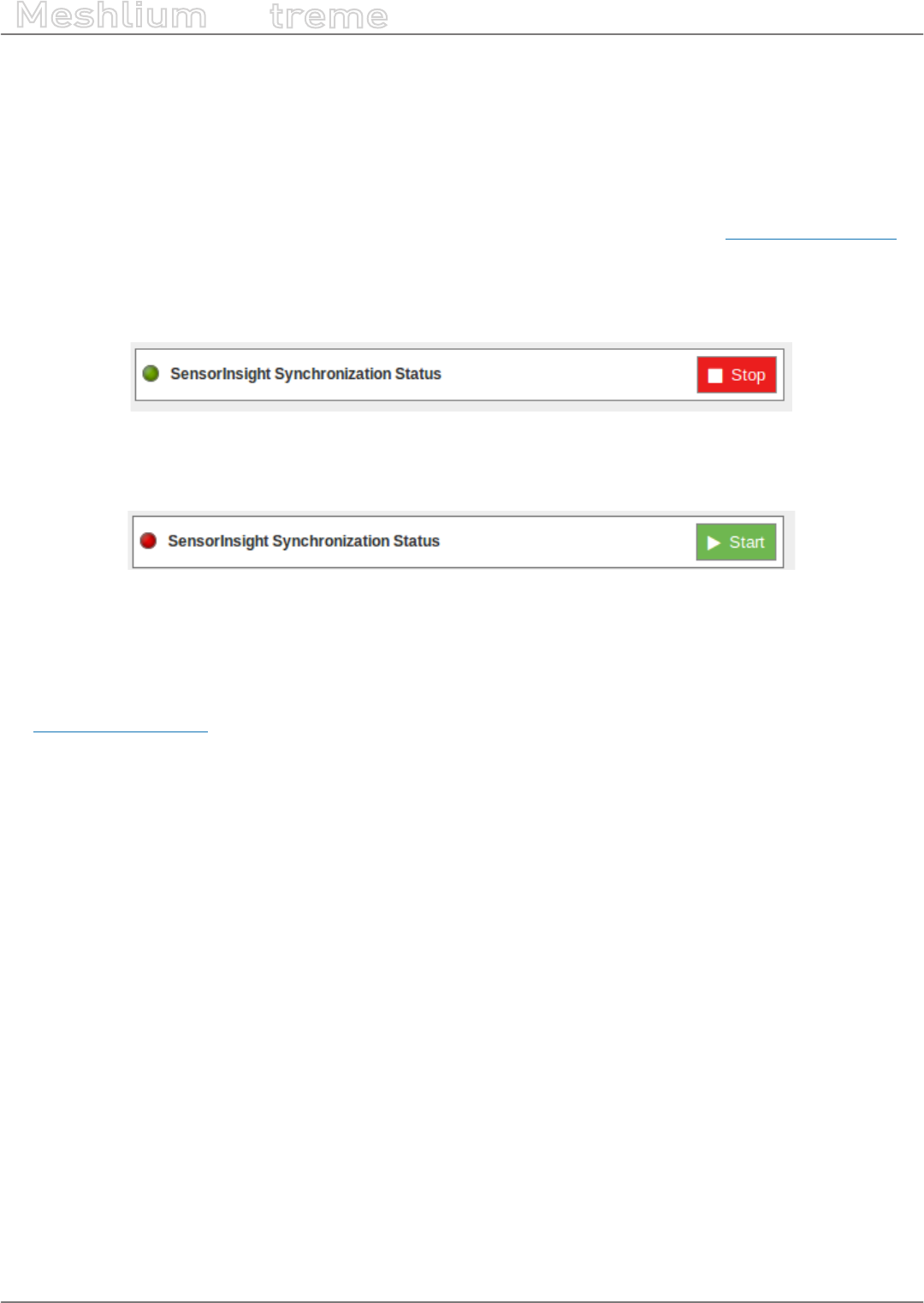
-88- v7.3
Cloud Connectors
Meshlium
X
treme
The form accepts the following 4 parameters:
•Client ID: This is a unique ID provided to you from the SensorInsight service.
•Gateway ID: This is an ID you provide to uniquely identify this Meshlium device.
•User Name: This is the Username required to send your data to the SensorInsight cloud.
•Password: This is the Password required to send your data to the SensorInsight cloud.
These parameters can be obtained from your SensorInsight account page. Learn more at www.sensorinsight.io.
12.1.6.2. Controlling synchronization
To launch the cloud connector service and start sending your data to RightSensor press the “Start” button.
Figure: ElementBlue RightSensor synchronization service is running
You can stop at any moment clicking on the “Stop” button.
Figure: ElementBlue RightSensor synchronization service is stopped
12.1.6.3. Problems
The RightSensor Cloud Connector service has built-in logging and debugging capability. Please contact RightSensor
at www.rightsensor.com for troubleshooting information.
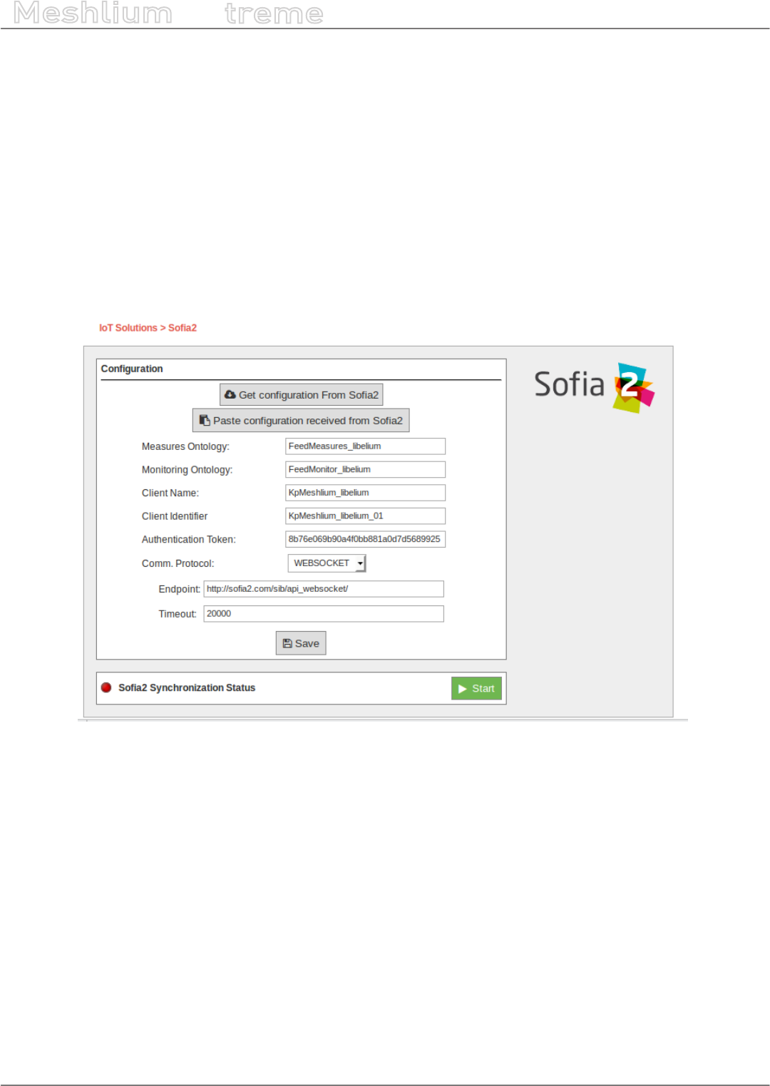
-89- v7.3
Cloud Connectors
Meshlium
X
treme
12.1.7. Soa2
Soa2 is a middleware developed by Indra that allows the interoperability of multiple systems and devices, oering
a semantic platform to make real world information available to smart applications (Internet of Things).
It is multi-language and multi-protocol, enabling the interconnection of heterogeneous devices. It provides
publishing and subscription mechanisms, facilitating the orchestration of sensors and actuators in order to
monitor and act on the environment.
12.1.7.1. Conguration
The plugin to connect Meshlium to Soa2 platform is in the Manager System section Cloud Connector > IoT
Solutions > Soa2.
Figure: Soa2 conguration
Registering the Meshlium device in Soa2 is a previous step required to connect the Meshlium with Soa2. At
the end of the registration process you will obtain the conguration parameters needed to set up the Meshlium
plugin properly.
This conguration includes the following information:
•Measures Ontology: Collection (table or storage) where the measures from Waspmote sensors sent by
Meshlium (the gateway) will be stored into the platform.
•Monitoring Ontology: Collection (table or storage) where monitoring values (internal temperature, battery
level…) of the Waspmotes connected to Meshlium, will be stored into the platform.
•Client Name: Name of the Meshlium unit to be identied by Soa2 platform, checking if it has permission to
write on the ontologies.
•Client Identier: Identier of the Meshlium unit to dierentiate between several Meshliums using the same
Client Name.
•Authentication Token: Token to authenticate the Meshlium device during the establishment of a session
with Soa2 platform.
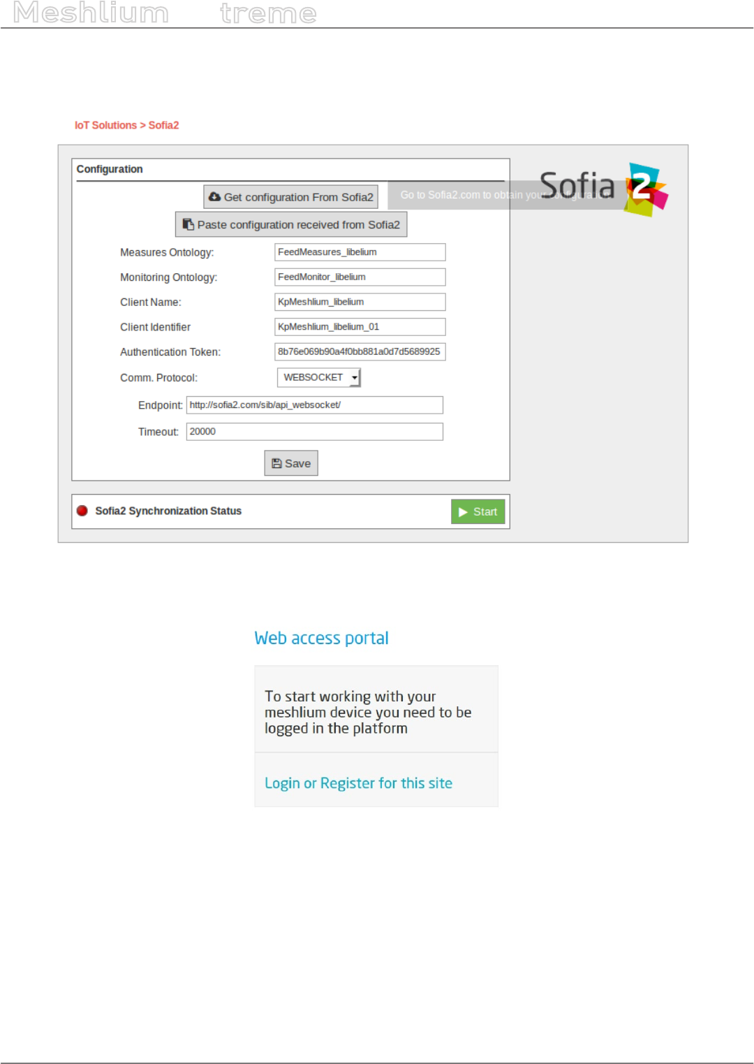
-90- v7.3
Cloud Connectors
Meshlium
X
treme
12.1.7.2. Register Meshlium in Soa2
To register Meshlium in Soa2, click on the link Get Conguration From Soa2.
Figure: Soa2 conguration link
You will be redirected to the following page:
Figure: Soa2 conguration portal
Where:
•Login using your Soa2 account.
•Create a new account if you do not have a valid login user.
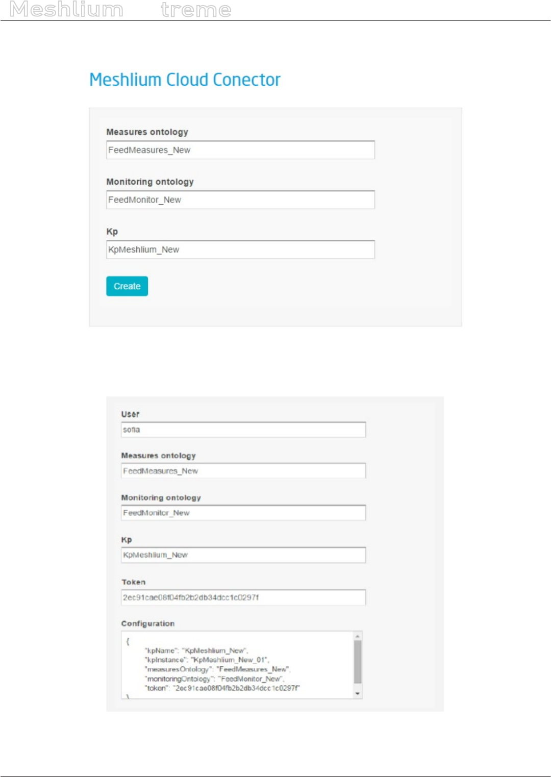
-91- v7.3
Cloud Connectors
Meshlium
X
treme
Logging in Soa2 platform will redirect to the following page that suggests a name for your collections of measures
and monitoring data, and for your gateway identier (KP in Soa2 terms):
Figure: Soa2 conguration information
Finally, after creating the conguration, you will obtain a JSON le containing all conguration values ready to be
pasted on the Manager System, in order to setup the Soa2 Cloud Connector:
Figure: Soa2 JSON conguration
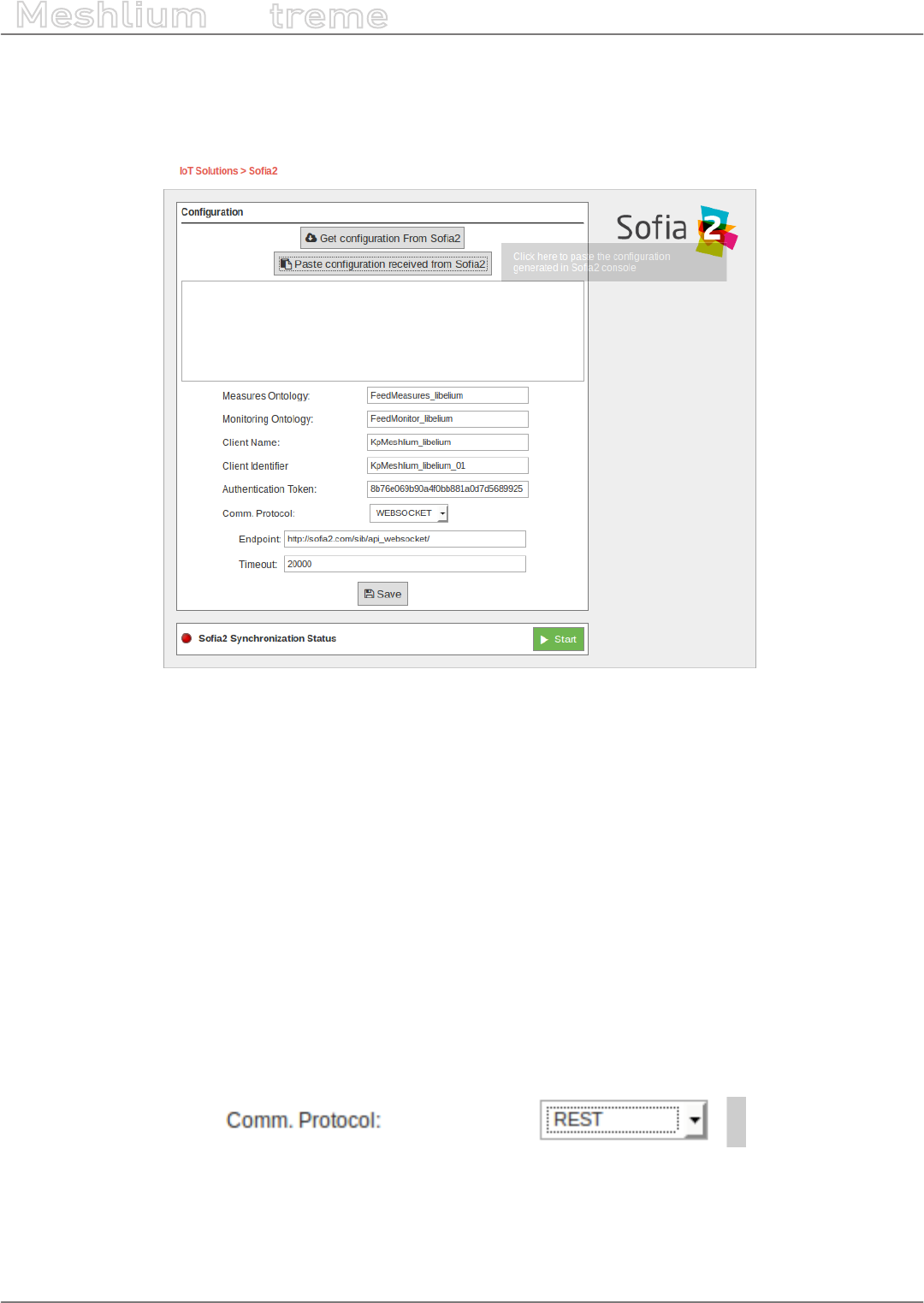
-92- v7.3
Cloud Connectors
Meshlium
X
treme
12.1.7.3. Congure the Cloud connector
The conguration from Soa2 can be setup in Meshlium just by clicking Paste conguration received from Soa2
and pasting the JSON generated in the previous step.
Figure: Soa2 pasting JSON conguration
Conguring the plugin this way, the elds for Measures Ontology, Monitoring Ontology, Client Name, Client
Identier and Authentication Token will be completed.
Alternatively, these elds can be lled in manually, with the information received from the conguration page of
Soa2 showed in the rst step.
12.1.7.4. Select communication protocol
12.1.7.4.1. REST
REST is a stateless communication protocol over HTTP. Using this protocol, the Cloud Connector is a client of
the Soa2 platform, that periodically opens a connection with the platform to send an HTTP POST operation
containing the sensor measurements.
The parameter of the REST protocol are:
Endpoint: URL of the REST Gateway of Soa2 platform. It is the REST server that will receive requests from clients.
Figure: Soa2 REST protocol
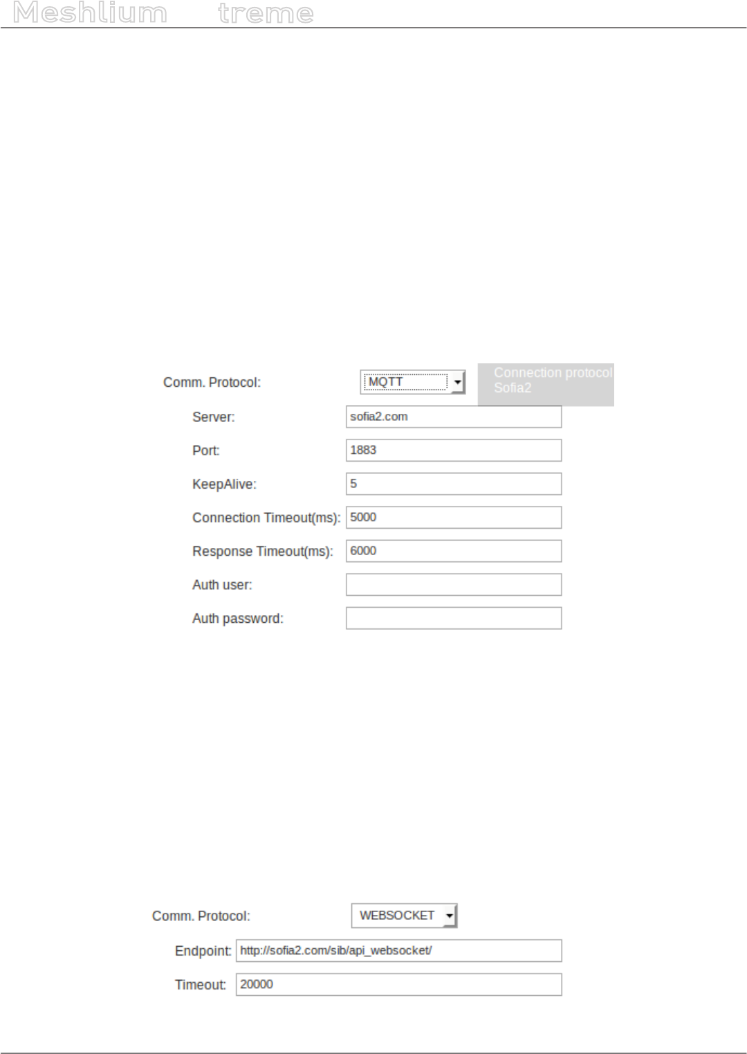
-93- v7.3
Cloud Connectors
Meshlium
X
treme
12.1.7.4.2. MQTT
MQTT is a stateful communication protocol over TCP. Using this protocol, the Cloud Connector is a client of
the Soa2 platform, that initially opens a connection with the platform, maintains it alive during that time, and
periodically sends an MQTT packet containing the sensor measurements. In case of disconnection, the connector
periodically tries to reconnect.
The parameters of the MQTT protocol are:
•Server: IP or machine name of the MQTT gateway in the Soa2 server.
•Port: Port of the MQTT gateway in the Soa2 server.
•KeepAlive: Interval in seconds that the connector will use to check the status of the connection.
•Connection Timeout: Timeout to establish a connection.
•Response Timeout: Timeout to wait response from the Soa2 server.
•Auth user: Optional. MQTT protocol authentication user.
•Auth password: Optional. MQTT protocol authentication password.
Figure: Soa2 MQTT protocol
12.1.7.4.3. Websocket
It is a stateful communication protocol over HTTP. Using this protocol, the Cloud Connector is a client of Soa2
platform, that initially open a connection with the platform, maintains it alive during a dened time, and periodically
sends a HTTP packet containing the sensor measurements. In case of disconnection, the connector periodically
tries to reconnect.
The parameters of the Websocket protocol are:
•Endpoint: URL of the Websocket gateway of Soa2 platform. It is the server that will receive requests from
clients.
•Timeout: Timeout for any operation with the server.
Figure: Soa2 Websocket protocol
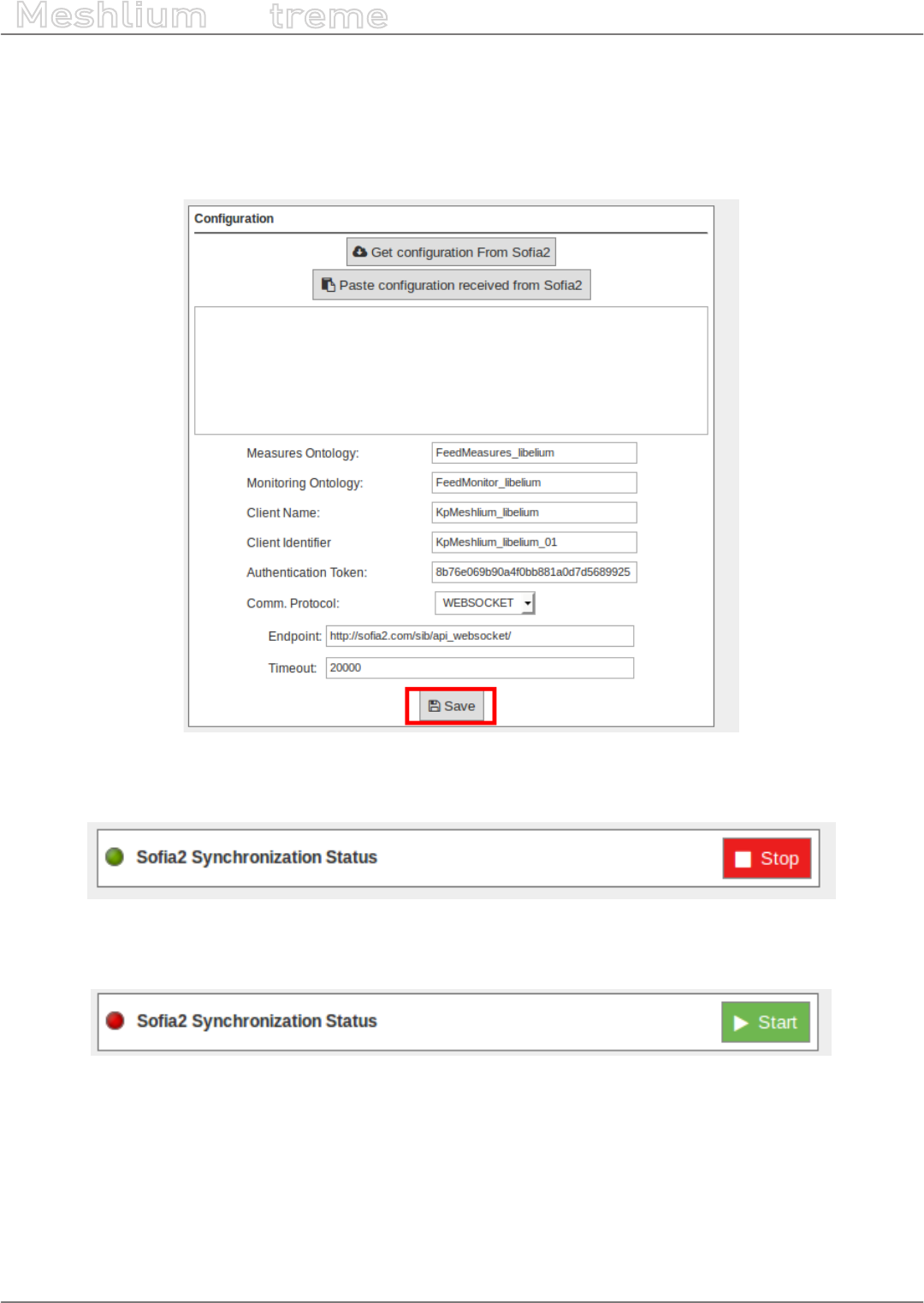
-94- v7.3
Cloud Connectors
Meshlium
X
treme
12.1.7.5. Save the conguration and start the connector
Once all conguration and connection parameters are setup, they can be stored and the connector can be started
to send information to Soa2.
To save the conguration, click on the “Save” button:
Figure: Soa2 save conguration button
After saving the conguration, the Cloud Connector can be started by clicking on the “Start” button:
Figure: Soa2 synchronization service running
You can stop the process at any moment by clicking on the “Stop” button.
Figure: Soa2 synchronization service stopped
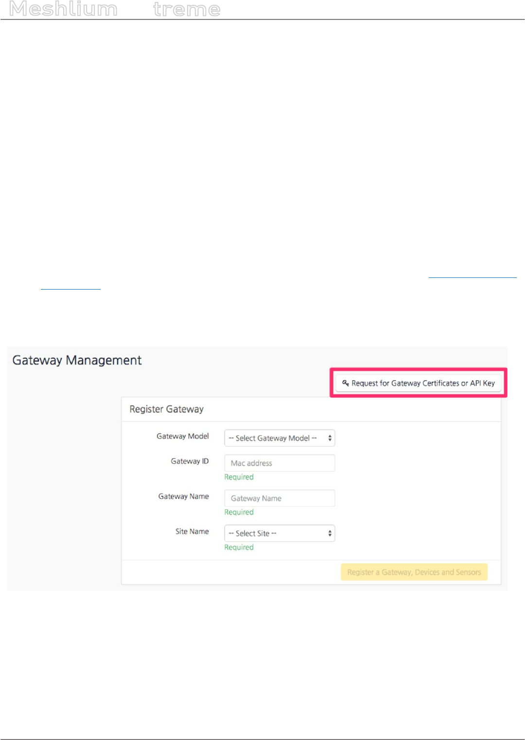
-95- v7.3
Cloud Connectors
Meshlium
X
treme
12.1.8. ThingPlus
Thing+ allows customers to build their own IoT services with high speed, reliability, scalability, and cost
competitiveness, connected by a SaaS or PaaS IoT platform. When Thing+ Embedded devices connect to the
Thing+ Cloud (public or private), customers can visualize various data graphs and charts from sensors directly on
the Thing+ Portal. Device registration is easy as the Thing+ Portal provides dashboard widgets, a trigger-condition-
action-based rule engine for alert notications or to control actuators, and results in the form of an event timeline.
12.1.8.1. Get API Key
•Get the “Gateway ID” to register:
-Open the Meshlium Manager System
-Click Cloud Connector
-Open the ThingPlus plugin
-You can see ThingPlus conguration and “Gateway ID”
-Copy the “Gateway ID”
•Get the API Key:
-Go to your ThingPlus service (if you have no registered service, register your service) https://yourservice.
thingplus.net
-Go to Gateway Management page (via upper right menu)
-Click the + button in the upper right corner
-Click “Request for Gateway certicates or API Key” button
Figure: Request API Key in the ThingPlus panel
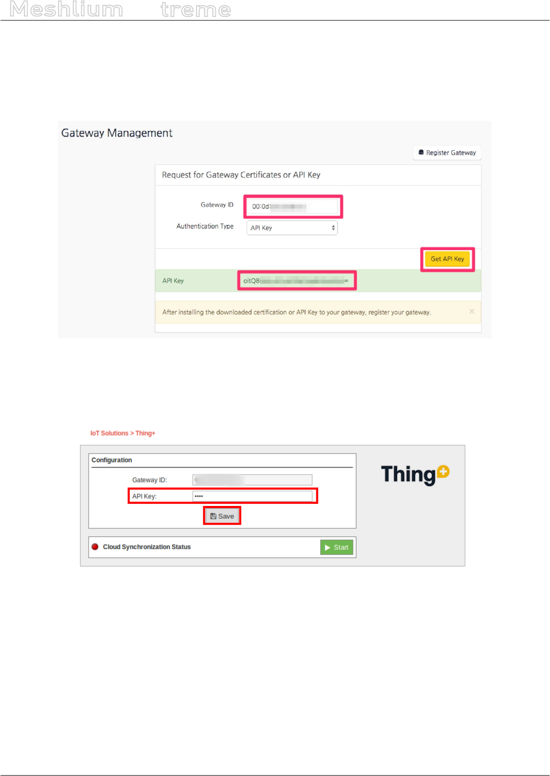
-96- v7.3
Cloud Connectors
Meshlium
X
treme
•Fill form
-Gateway ID
-Select “API Key” (Authentication Type)
•Click “Get API Key”
•Copy the “API Key”
Figure: Get the API Key in the ThingPlus panel
•Set “API Key” in the Meshlium Manager System
-Go to ThingPlus conguration again
-Paste the “API Key”
Figure: Enter API Key in the ThingPlus plugin
•Click the “Save” button (ThingPlus gateway app will restart)
•If the status is “STOPPED”, then click on the “Start” button after saving API Key

-97- v7.3
Cloud Connectors
Meshlium
X
treme
12.1.8.2. Register Gateway and Sensors
•Go to your ThingPlus service
•Go to Gateway Management page (via upper right menu)
•Click the + button in the upper right corner
•Fill the form:
-Select Gateway Model as “Libelium Meshlium”
-Input Gateway ID (the same MAC address when registering gateway)
-Select Device Model as “Waspmote Basic”
-Input Device Address (Waspmote address is the id_wasp eld)
-Input Device Name
-Select Sensors to register (all sensors are selected as default)
-Select Site Name (default)
•Click “Register a Gateway, Devices and Sensors” button:
-ThingPlus gateway app will restart and send the sensor data in a few minutes
-You can see the sensor data at Dashboard or Sensor page
Figure: Registering a Gateway in ThingPlus service.

-98- v7.3
Cloud Connectors
Meshlium
X
treme
12.1.9. ThingWorx
ThingWorx is the rst software platform designed to build and run the applications of the connected world.
ThingWorx reduces the time, cost, and risk required to build innovative Machine-to-Machine (M2M) and Internet
of Things applications by providing a complete application design, runtime, and intelligence environment. The
ThingWorx platform includes exible device connectivity options, rapid application development tools, scalable
storage, and supports various deployment models.
More information: http://www.thingworx.com.
ThingWorx includes the following features:
•ThingWorx Composer™ - an end-to-end application-modeling environment designed to help you easily build
the unique applications of today’s connected world. Composer makes it easy to model the Things, Business
Logic, Visualization, Data Storage, Collaboration, and Security required for a connected application.
•Codeless Mashup Builder – a “drag and drop” Mashup Builder empowers developers and business users
to rapidly create rich, interactive applications, real-time dashboards, collaborative workspaces, and mobile
interfaces without the need for coding.
•Execution and Storage Engine - ThingWorx’s event-driven execution engine and 3-Dimensional storage allows
companies to make business sense of the massive amounts of data from their people, systems, and connected
“Things” – making the data useful and actionable. It also features a data collection engine that provides unied,
semantic storage for time-series, structured, and social data at rates 10X faster than traditional RDBs.
•Search-based Intelligence - ThingWorx SQUEAL™ (Search, Query, and Analysis) brings Search to the world of
connected devices and distributed data. With SQUEAL’s interactive search capabilities, users can correlate
data that delivers answers to key business questions.
Note: If you need more information about these components, go to http://www.thingworx.com/platform/
12.1.9.1. Conguration
Inside the “ThingWorx” plugin you can setup which Waspmotes in the system will be published in ThingWorx
server.
Figure: ThingWorx conguration
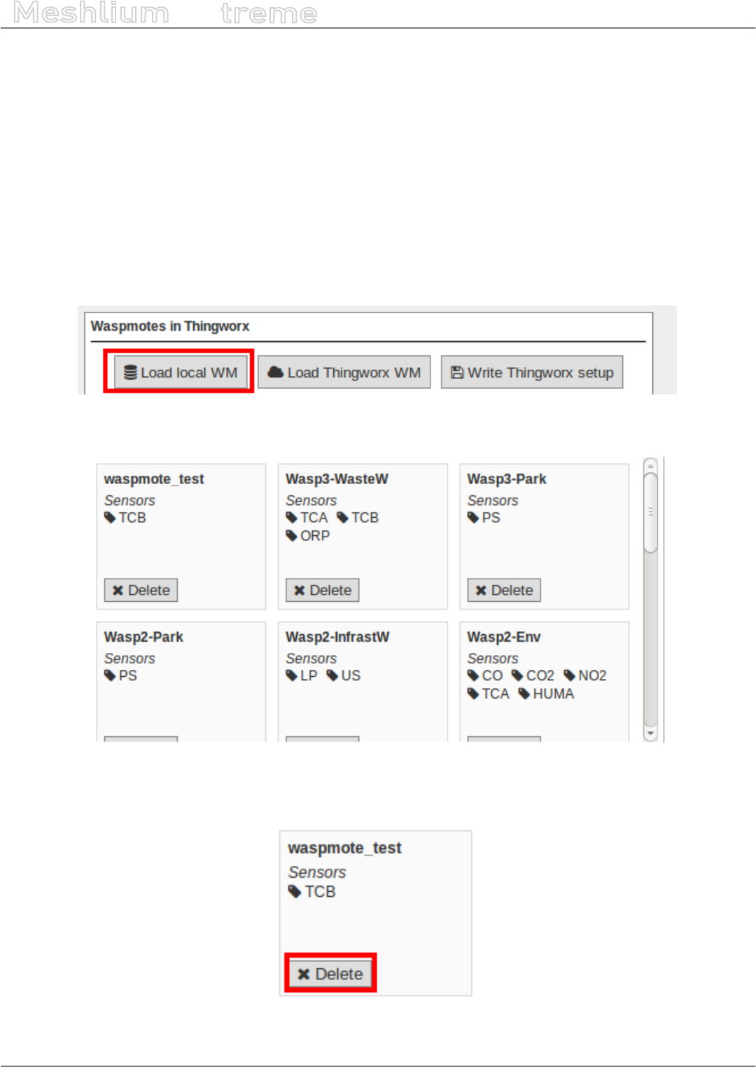
-99- v7.3
Cloud Connectors
Meshlium
X
treme
The parameters to setup are:
•Server address: The address of your ThingWorx server.
•Server Port: The port where your ThingWorx server is accessible.
•Meshlium bind name: The name of the Meshlium “thing” in ThingWorx. Meshlium thing is detected in
ThingWorx but will not send any data.
•ThingWorx App Key: Security key to send data to your ThingWorx server.
Click on the “Save” button to write this setup to the ThingWorx service.
The steps to setup Waspmotes to send to ThingWorx are:
•Click on the button “Load local WM”. This will read Waspmotes that have data in the sensor database.
Figure: Getting Waspmotes from the system
•A panel with the devices is displayed, with a list of the sensors received from each Waspmote.
Figure: Waspmotes to be send to ThingWorx
•It is possible to delete a Waspmote from the list clicking on its “Delete” button. This device will not be published
to the ThingWorx platform.
Figure: Delete a Waspmote from the list
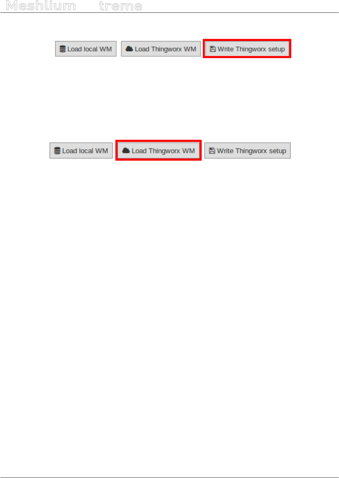
-100- v7.3
Cloud Connectors
Meshlium
X
treme
•Once the list is correct, clicking on the button “Write ThingWorx setup” will push this setup to the ThingWorx
EMS service.
Figure: Write the setup to ThingWorx service
After restarting the EMS and LUA Script services, the setup will be applied and you will see your devices in your
ThingWorx server.
If you click again on the “Get Waspmotes from DB” button, the plugin will read again the DB and display all the
Waspmotes. If you do not write this changes to ThingWorx setup, this will not propagate to the EMS service.
You can recover the current ThingWorx EMS service setup by clicking on the “Load WM from ThingWorx”.
Figure: Write the setup to ThingWorx service

-101- v7.3
Cloud Connectors
Meshlium
X
treme
12.1.9.2. Using the Edge MicroServer (EMS)
ThingWorx has the ability to connect very quickly and easily to the physical world and structured data systems.
ThingWorx supports a variety of communication protocols and system interfaces. Many are implemented directly
on the ThingWorx Platform. However, for edge devices or data stores that need to connect to the platform using
the Internet or through rewalls on an Intranet, ThingWorx provides an Edge MicroServer (EMS) solution that can
be deployed where the data is, and allows secure, ecient communication back to the ThingWorx Platform. This
section will concentrate on the EMS and the corresponding Edge Thing software components.
In order to send data to the ThingWorx environment, another component is needed: the LUA Script Resource
service. This service needs to be running at the same time with Edge Micro Server to allow data acquisition.
To launch the Edge MicroServer (EMS) press Start button, and to stop it, press Stop button.
Figure: ThingWorx Edge MicroServer running
Figure: ThingWorx Edge MicroServer stopped
To launch the LUA Script resource press the Start button, and to stop it, press the Stop button.
Figure: ThingWorx Edge MicroServer running
Figure: ThingWorx Edge MicroServer stopped
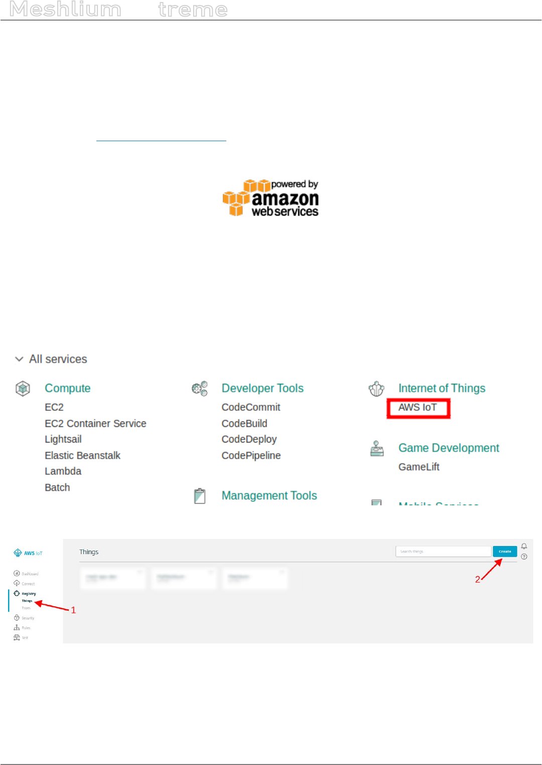
-102- v7.3
Cloud Connectors
Meshlium
X
treme
12.2. Advanced Cloud Partners
12.2.1. Amazon IoT
Amazon Web Services IoT enables secure, bi-directional communication between Internet-connected things (such
as sensors, actuators, embedded devices, or smart appliances) and the AWS cloud over MQTT and HTTP.
More information: http://aws.amazon.com/iot/.
With this plugin, Waspmote sensor data can be directly integrated with Amazon AWS IoT broker.
Figure: Amazon IoT plugin
12.2.1.1. Register Meshlium in Amazon IoT
To register Meshlium in Amazon IoT, you have to create a “thing” in your Amazon AWS IoT dashboard, attach a
security certicate and policy statement and copy the parameters to the plugin. Follow these steps to register your
Meshlium:
1. Select AWS IoT in the Amazon Dashboard
2. Create a “Thing”
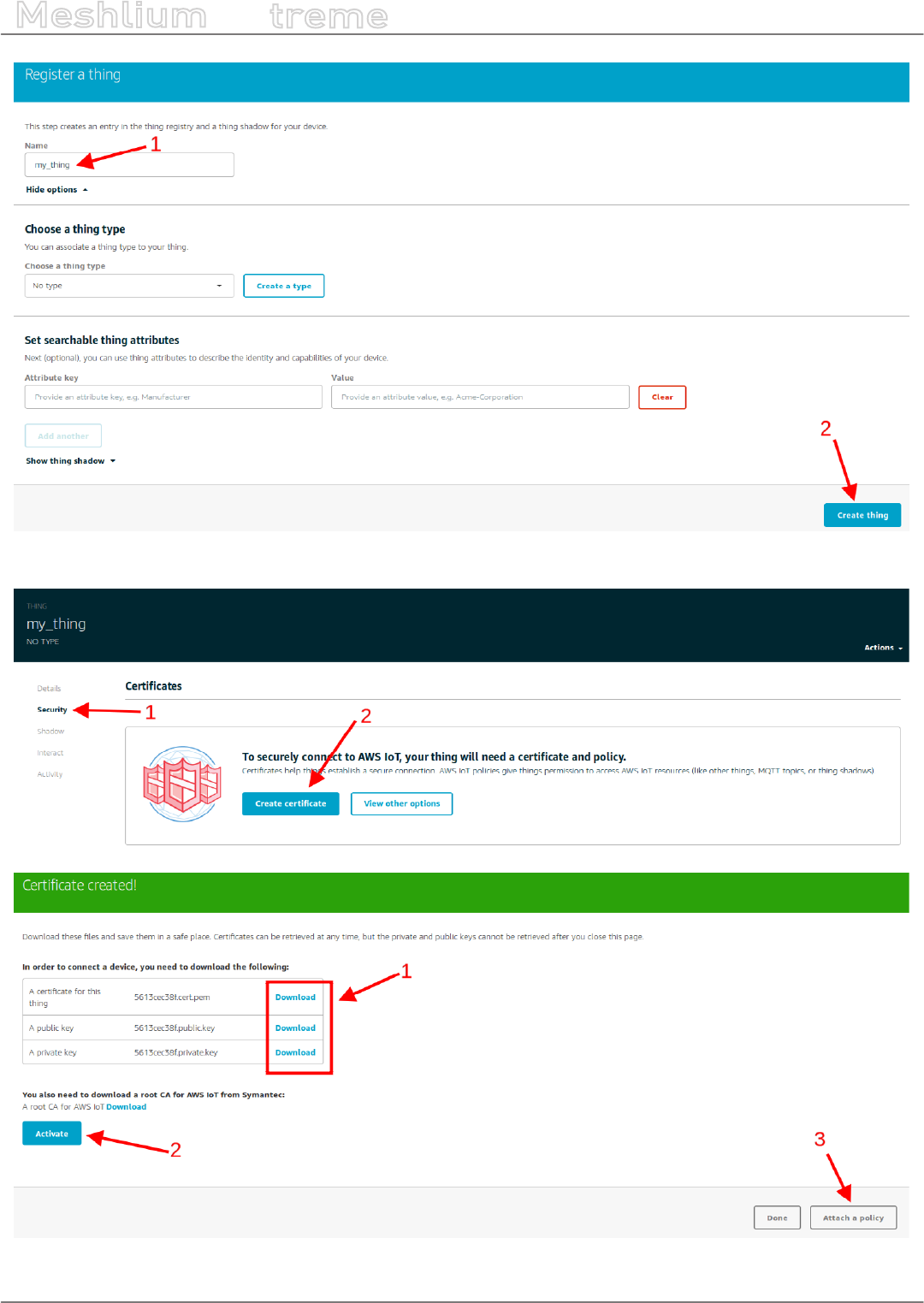
-103- v7.3
Cloud Connectors
Meshlium
X
treme
3. Create a security certicate and download the les for later use
Figure: Save the credential les when connecting device
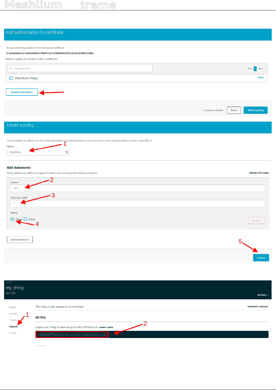
-104- v7.3
Cloud Connectors
Meshlium
X
treme
4. Create and attach a policy
5. Copy the HTTPS connection string for later use
Figure: Annotate the value of the eld
It is important to annotate the conguration displayed and save the credential les when connecting the device.
You will need these les and parameters later for the Meshlium conguration.

-105- v7.3
Cloud Connectors
Meshlium
X
treme
12.2.1.2. Conguration
You will use the previously obtained conguration from the AWS IoT platform to certicate your Meshlium as a
valid sender of MQTT messages.
Amazon IoT plugin is located in:
Manager System > Cloud Connector > IoT Platforms > Amazon Web Services
In the Conguration panel, the user can set:
•Public key: User public key le previously downloaded.
•Private key: User private key le previously downloaded.
•Certicate: Certicate le previously downloaded.
•Host: HTTPS connection string previously annotated.
•Port: AWS IoT MQTT port (by default 8883 for MQTT).
•ClientID: AWS IoT Client identication.
•Log Level: Generate log messages. From fewer to more details, the levels are: OFF, ERROR, INFO, DEBUG,
REPORT. Default is OFF.
•Topic template: Topic of your message. The user can use these wild-cards creating a personalized structure:
-#ID#: Unique identier for data
-#MESHLIUM#: Host name of the Meshlium unit
-#ID_WASP#: Identies the Waspmote unit
-#ID_SECRET#: Secret identier
-#SENSOR#: Identies the sensor
-#VALUE#: Value obtained from the sensor
-#TIMESTAMP#: MySQL TIMESTAMP type (‘YYYY-MM-DD HH:MM:SS’ UTC)
•Message template: Data structure of your message. The user can use these wild-cards creating a customized
content:
-#ID#: Unique identier for data
-#MESHLIUM#: host name of the Meshlium
-#ID_WASP#: Identies the Waspmote unit
-#ID_SECRET#: Secret identier
-#SENSOR#: Identies the sensor
-#VALUE#: Value obtained from the sensor
-#TIMESTAMP#: MySQL TIMESTAMP type (‘YYYY-MM-DD HH:MM:SS’ UTC)
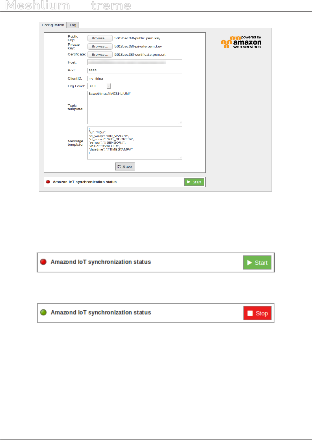
-106- v7.3
Cloud Connectors
Meshlium
X
treme
Figure: Amazon IoT conguration panel
12.2.1.3. Controlling synchronization
Once congured the server/broker, the user can launch the Meshlium Amazon IoT script (Start button). The
program will search for the received frames on the local database, and will send them to the Amazon IoT platform
via MQTT protocol. The status indicator displays the current state, saying “Running” or “Stopped”.
Figure: Amazon IoT sender is running
You can stop the Amazon IoT program anytime clicking on the “Stop” button.
Figure: Amazon IoT sender is stopped
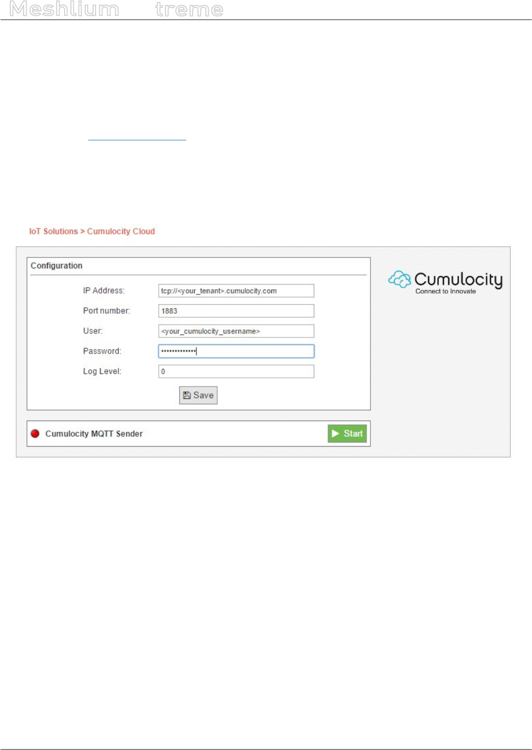
-107- v7.3
Cloud Connectors
Meshlium
X
treme
12.2.2. Cumulocity
Cumulocity IoT solution allows for a seamless integration of your Meshlium and Waspmote devices to the cloud.
Once Meshlium is connected to this cloud, the Cumulocity IoT solution will automatically manage all your devices.
Registering and gathering device data to Cumulocity Platform provides a fully customizable interface, allowing for
deep data analysis.
Cumulocity works with a multitude of devices, centralizing all your IoT technologies in a single place. For more
information, visit www.cumulocity.com.
12.2.2.1. Conguration
First of all, make sure your Meshlium is receiving data from your Waspmote or Plug & Sense! units. Please access
to the Cumulocity cloud congurator in the Manager System. You need to ll the following elds with your correct
Cumulocity account settings.
Figure: Conguring Cumulocity in Meshlium
•IP address: Address provided by Cumulocity
•Port number: Port Number provided by Cumulocity
•User: Username provided by Cumulocity
•Password: Password provided by Cumulocity
•Log level: Generate log messages. Valid values go from 0 (no log) to 4 (debug).
Then click “Save” to store your new settings.
After that, the only thing left to do is to activate the Cumulocity MQTT Sender by clicking on “Start”.
The Cumulocity platform will handle all the devices’ creation and data gathering for you. You can access now to
your Cumulocity account with your browser and you should be able to see your devices and incoming data.
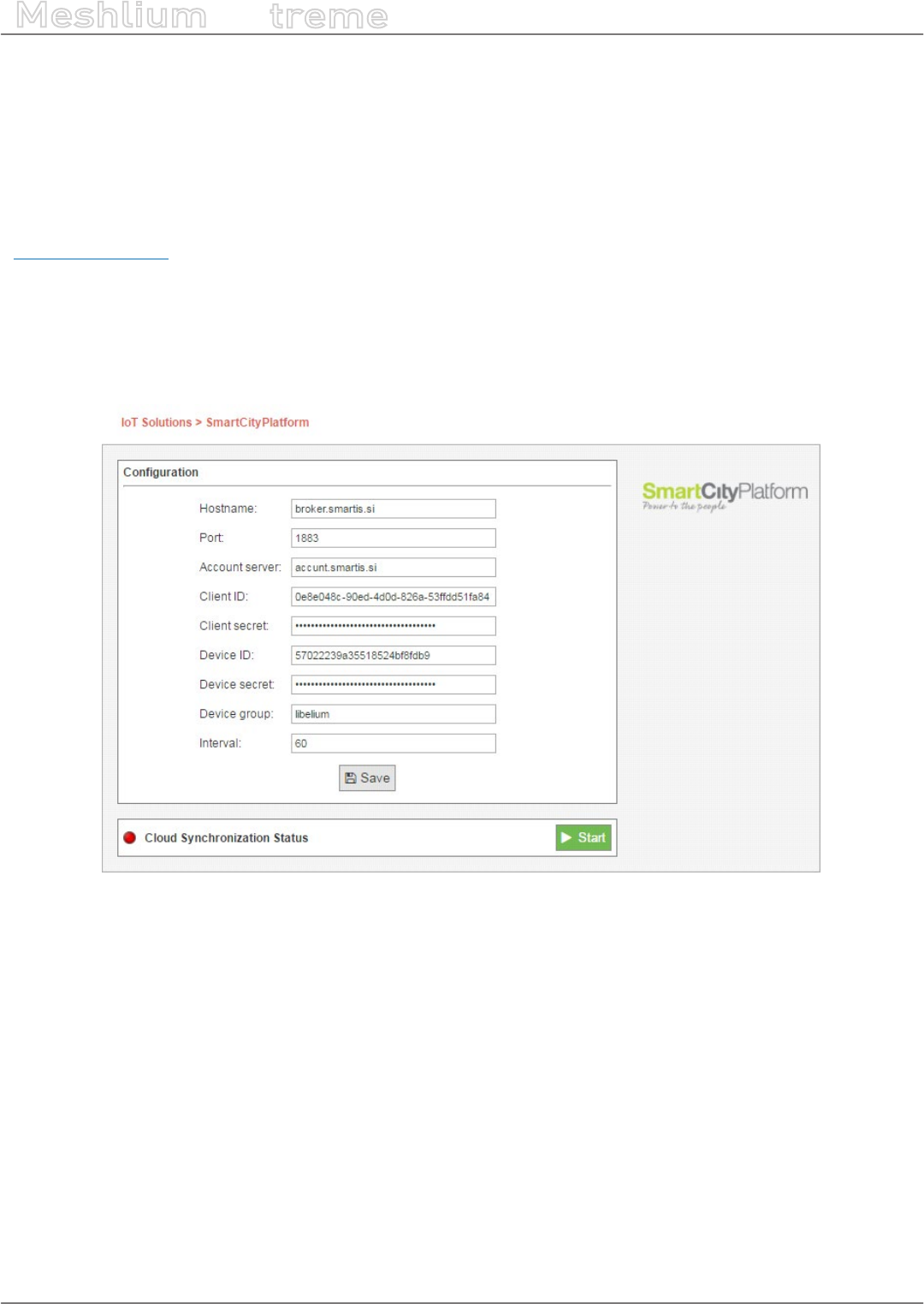
-108- v7.3
Cloud Connectors
Meshlium
X
treme
12.2.3. SmartCityPlatform
The SmartCityPlatform connects all the core elements of a successfully managed city. It allows the SmartMayor to
manage urban development, socio-economic development and technological development of the city, measuring
and reporting progress in real time.
By using this cloud connector, you connect to the Sense module, which is a part of SmartCityPlatform. It allows an
overview of the city’s pulse by gathering, measuring & monitoring happenings in the city.
www.smartiscity.eu
12.2.3.1. Conguration
To use the SmartCityPlatform cloud connector, you need to register your Meshlium in the authentication server.
The server provides you with credentials, which you will enter in the form below. When you nish conguring, click
the “Save” button to save the conguration.
Figure: SmartCityPlatform cloud connector conguration panel
•Hostname: the IP or hostname of the sensor broker.
•Port: the port where the sensor broker is listening for connections.
•Account server: the IP or hostname of the account server.
•Client ID: client identication provided by the authentication server.
•Client secret: client secret provided by the authentication server.
•Device ID: device identication provided by the authentication server.
•Device secret: device secret provided by the authentication server.
•Device group: the name you set for your device group.
•Interval: time duration in seconds between synchronizing data batches.
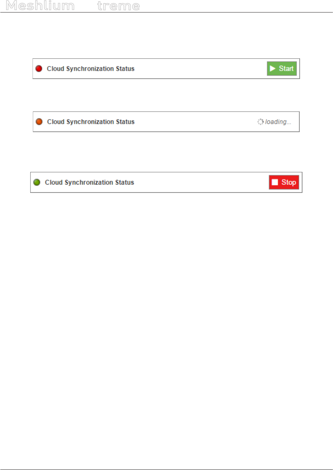
-109- v7.3
Cloud Connectors
Meshlium
X
treme
12.2.3.2. Controlling synchronization
With the conguration saved, you can start using the cloud connector. To start the synchronization, press the
green “Start” button on the right.
Figure: SmartCityPlatform start button
You get a “loading” status inside the synchronization control section, indicating the synchronization is starting.
Figure: SmartCityPlatform loading button
When the cloud connector starts, a green dot on the left appears, indicating the synchronization is running. To
stop the synchronization, simply click on the red “Stop” button on the right.
Figure: SmartCityPlatform stop button
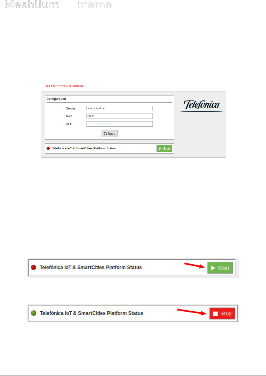
-110- v7.3
Cloud Connectors
Meshlium
X
treme
12.2.4. Telefónica IoT Platform
Telefónica provides an M2M cloud to collect and analyze data. This platform is based on assets and models and
you can optimize your business processes implementing rules and notications, and subscribing to data from
dierent hosts.
12.2.4.1. Conguration
A new option is shown in M2M Platform menu, in the Cloud Connector main option. If you expand it, you can see
this form with 3 elds in it:
Figure: Telefónica IoT setup example on Manager System
•URL: Address of the API service of Telefónica IoT. This address should be provided without the “http://”, usually
int.dca.tid.es.
•Port: The port in which the API listens to connections.
•API: The security key to send data to Telefónica IoT.
All this data are provided by Telefónica service administrators.
12.2.4.2. Controlling synchronization
The synchronization will be done in packs of 100 data at a time, so the system is not overloaded. You can start and
stop the data synchronization to the Telefónica service. In the interface, you can see an indicator of whether the
Telefónica service is running or not. If you click on “Start”, the synchronization will begin:
Figure: Telefónica IoT Start button
You can stop at any moment clicking on “Stop” button.
Figure: Telefónica IoT Stop button
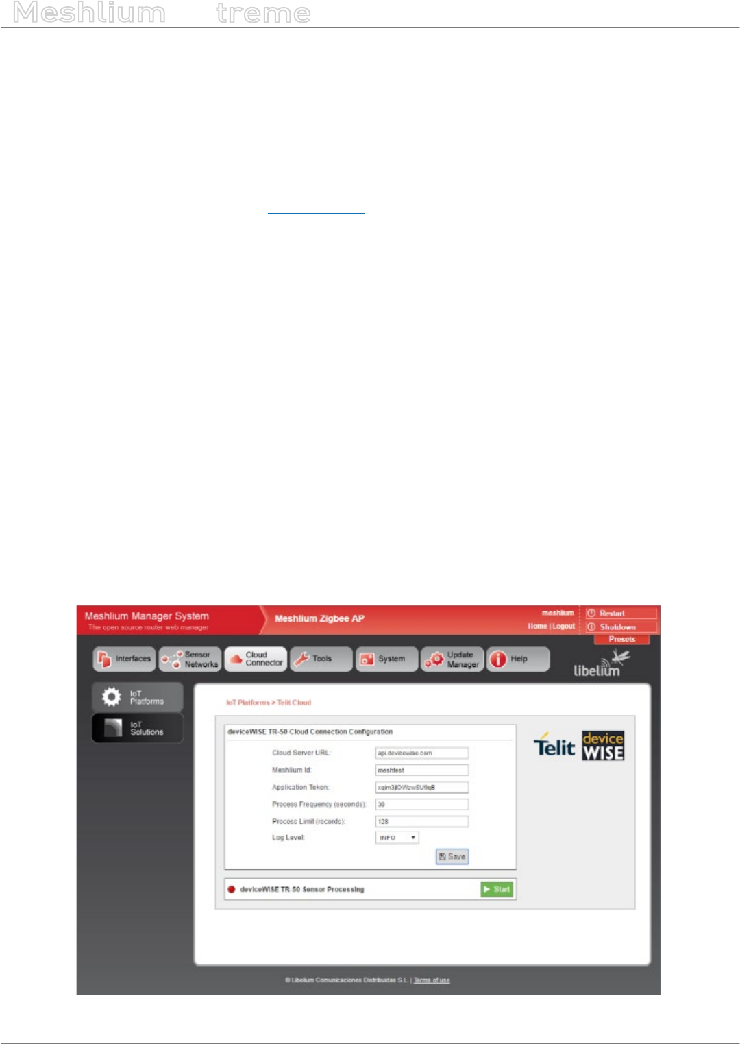
-111- v7.3
Cloud Connectors
Meshlium
X
treme
12.2.5. Telit
The Meshlium Cloud Connector for the Telit deviceWISE IoT Cloud platform is provided to connect Libelium
Waspmote sensor devices to the Telit Cloud Platform.
12.2.5.1. Register in Telit
The basic steps required to connect Waspmote sensors to the cloud platform are simple and straight forward:
A) Using the Telit Management Portal at portal.telit.com
•Create/Obtain a Telit IoT Portal Account on a Cloud Organization
•Dene 2 Thing Denitions:
-Meshlium Cloud Connector
-Waspmote Sensor
•Create an Application Token for the Meshlium Cloud Connector Denition
B) Using the Meshlium Manager System web browser interface
•Access the Telit deviceWISE TR-50 Cloud Platform Conguration Panel
•Enter and Save the conguration details for your Meshlium including the Application Token created above
•Start the deviceWISE TR-50 Sensor Processing Service
Once your Telit IoT Cloud account has been congured with the new ‘Thing Denitions’ and ‘Application’ in support
of the Meshlium Cloud Connector, you are ready to proceed with conguring your Meshlium gateway.
12.2.5.2. Conguration
Select the ‘Telit deviceWISE Cloud Connector’ service icon located on the ‘IoT Platforms’ panel. Congure the
elds to provide the required conguration and control information on the ‘Telit deviceWISE Cloud Connector’
management panel as shown below.
Figure: Telit conguration panel
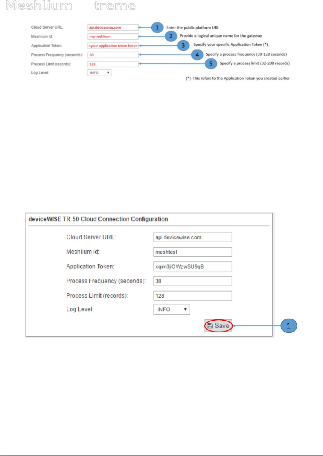
-112- v7.3
Cloud Connectors
Meshlium
X
treme
Figure: Telit conguration options
Where:
•‘Cloud Server URL’ species the target Telit IoT Cloud Platform.
•‘Meshlium Id’ indicates the unique name that you would like your Meshlium Gateway to be known as in the
Telit IoT Cloud Platform.
•‘Application Token’ indicates the unique secure token generated by the Telit IoT Cloud Platform for devices to
be able to access your private cloud organization.
•‘Process Frequency’ indicates how often the cloud connector should check for and process newly received
data frames from the associated Waspmote/Edge devices. Valid values range from 30 to 120 seconds.
•‘Process Limit’ species the maximum number of waiting records to process during the data frame processing
cycle. Valid values range from 8 to 200.
Once all settings are provided, save the conguration settings by pressing the Save button.
Figure: Save conguration error
In the event that a eld has been left blank or a string has been entered into a numeric data eld, the eld entry
frame will be highlighted and an error message will be displayed as shown in the screen images below.
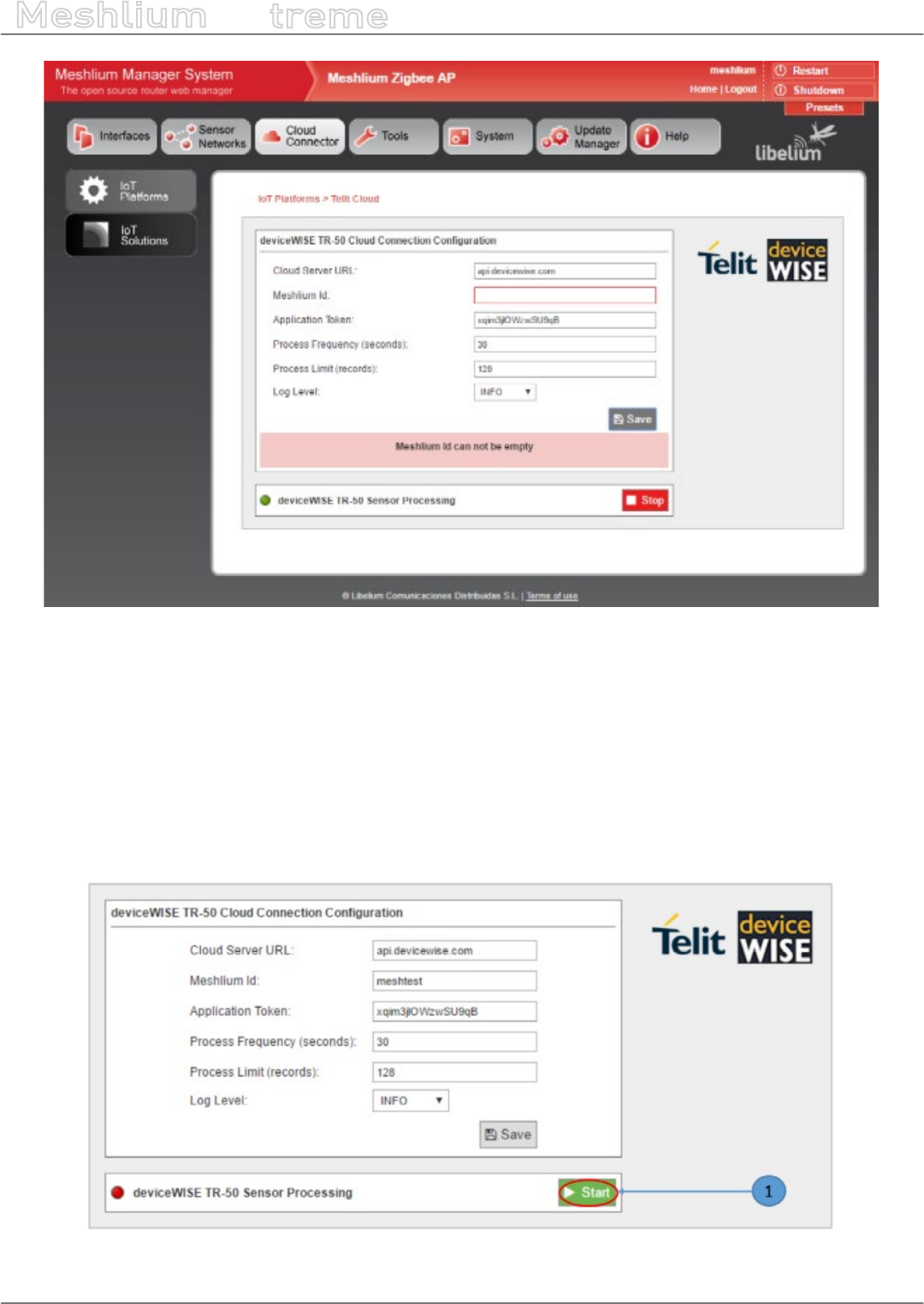
-113- v7.3
Cloud Connectors
Meshlium
X
treme
Figure: Save conguration button
At this point the Meshlium Cloud Connector is congured and ready to start.
12.2.5.3. Controlling synchronization
Once the Telit deviceWISE IoT Cloud Connector has been congured with the proper runtime parameters, it is
ready for operation. To initiate the connection from the Meshlium gateway to the Telit IoT Cloud Platform and
start the background service awaiting data frames from Waspmote sensor device nodes, press the Start button.
To initiate the connection from the Meshlium gateway to the Telit IoT Cloud Platform and start the background
service awaiting data frames from Waspmote sensor device nodes, press the Start button.
Figure: Telit Start button

-114- v7.3
Cloud Connectors
Meshlium
X
treme
To stop the background service from awaiting data frames from Waspmote sensor device nodes and terminate
the connection from the Meshlium gateway to the Telit IoT Cloud Platform, press the Stop button.
Figure: Telit Stop button

-115- v7.3
Cloud Connectors
Meshlium
X
treme
12.3. Basic Cloud Partners
12.3.1. Amplía’s OpenGate
12.3.1.1. Conguration
Inside the Amplía’s plugin you can nd the dierent elds that you must congure for using your Meshlium
against OpenGate.
Figure: Amplía Cloud Connector conguration panel
•Server Host: You must enter the host name that you are going to use for collecting the Meshlium events.
•Server Port: The port where the host is accessible.
•API-Key: Security key used for validating the access to the Host.
Click on the “Save” button for storing the conguration elds.
After that, press the “Start” button, and you will start to receive data from the congured Meshlium.
If you want to stop the event sending, just press the “Stop” button.
In the OpenGate OSS web portal you could check the dierent values collected by Meshlium and by the Waspmote
units which have sent messages using the congured Meshlium as gateway.
12.3.1.2. How to get your own API-key
For getting your own API-key you have to send an e-mail to info@amplia.es and Amplía Solutions will provide one
for you. In the same mail send the serial number of your device for creating it in the OpenGate platform.
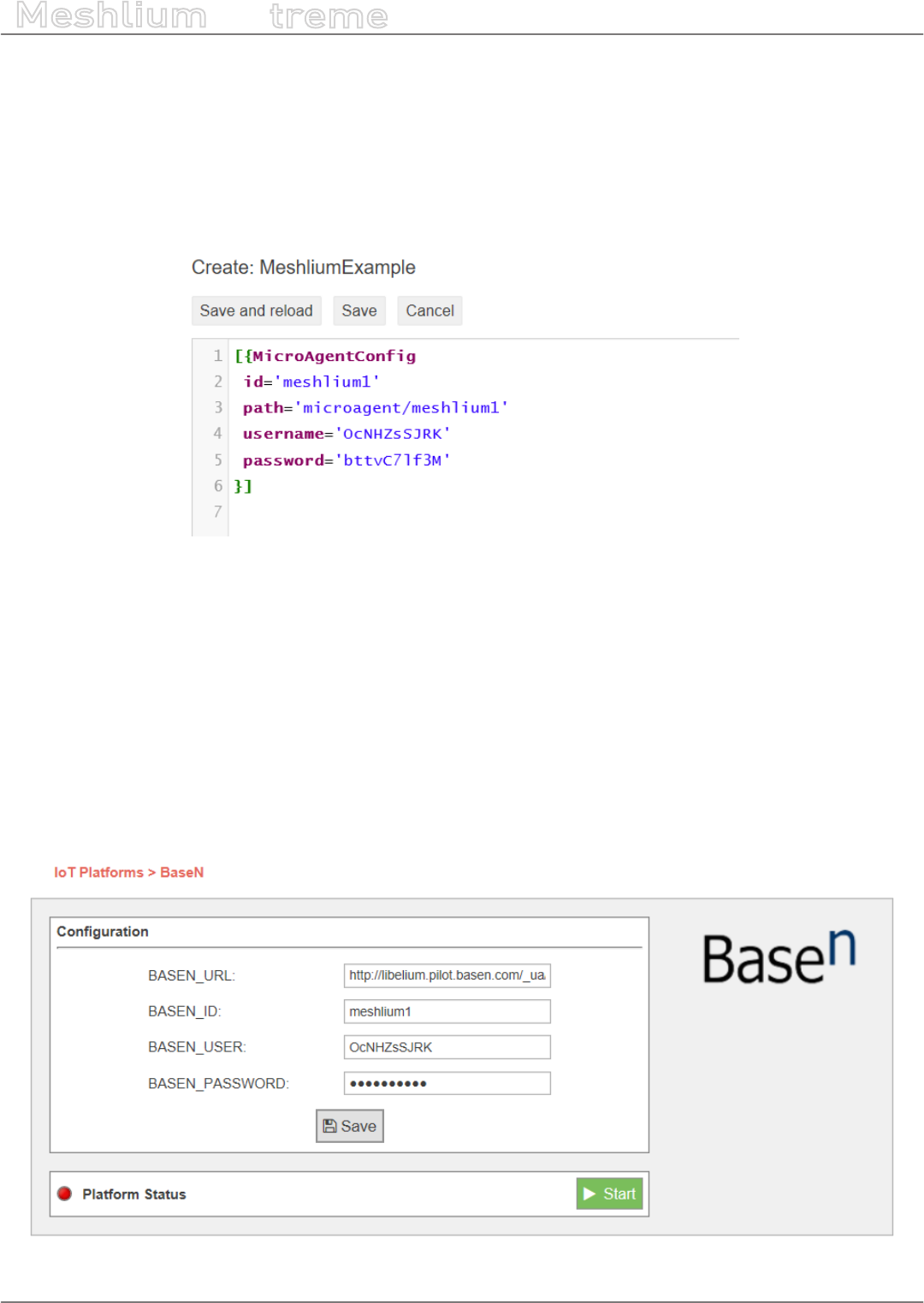
-116- v7.3
Cloud Connectors
Meshlium
X
treme
12.3.2. BaseN
Follow this short instruction to get Meshlium synchronized to BaseN Platform running. This guide assumes that
you are already a customer of BaseN and have access to your BaseN admin wiki.
12.3.2.1. Conguring Microagent receiver in the BaseN Platform
In your chosen wiki page, congure the following minimum setup for synchronizing with the BaseN Platform.
Figure: Conguration of Microagent Receiver
•Id: Unique ID of this Microagent receiver
•Path: Measurement data path for data storage
•Username: Username for authentication of Microagent receiver
•Password: Password for authentication of Microagent receiver
12.3.2.2. Conguring BaseN Platform in Meshlium
Use the same Microagent receiver parameters in the Meshlium BaseN Cloud Connector plugin.
BaseN plugin is located in:
Manager System > Cloud Connector > IoT Solutions > BaseN
Figure: Conguring BaseN Platform in Meshlium

-117- v7.3
Cloud Connectors
Meshlium
X
treme
•BASEN_URL: Usually http://customername.basen.com/_ua/customername/
•BASEN_ID: Unique ID of this Microagent receiver
•BASEN_USER: Username to authenticate the Microagent receiver
•BASEN_PASSWORD: Password to authenticate the Microagent receiver
After setting the parameters, save the conguration clicking on the “Save” icon.
12.3.2.3. Start BaseN Cloud Connector
Click on “Start” for Cloud Synchronization. A green icon should start rolling to indicate synchronization is running.
12.3.2.4. Verify BaseN Cloud Connector synchronization
Go to the BaseN Platform wiki where the Microagent Receiver and MicroAgentCong were congured, and check
under “Debug Information for <id>” and “Stats” that the Observer Request Counts does show requests arriving.
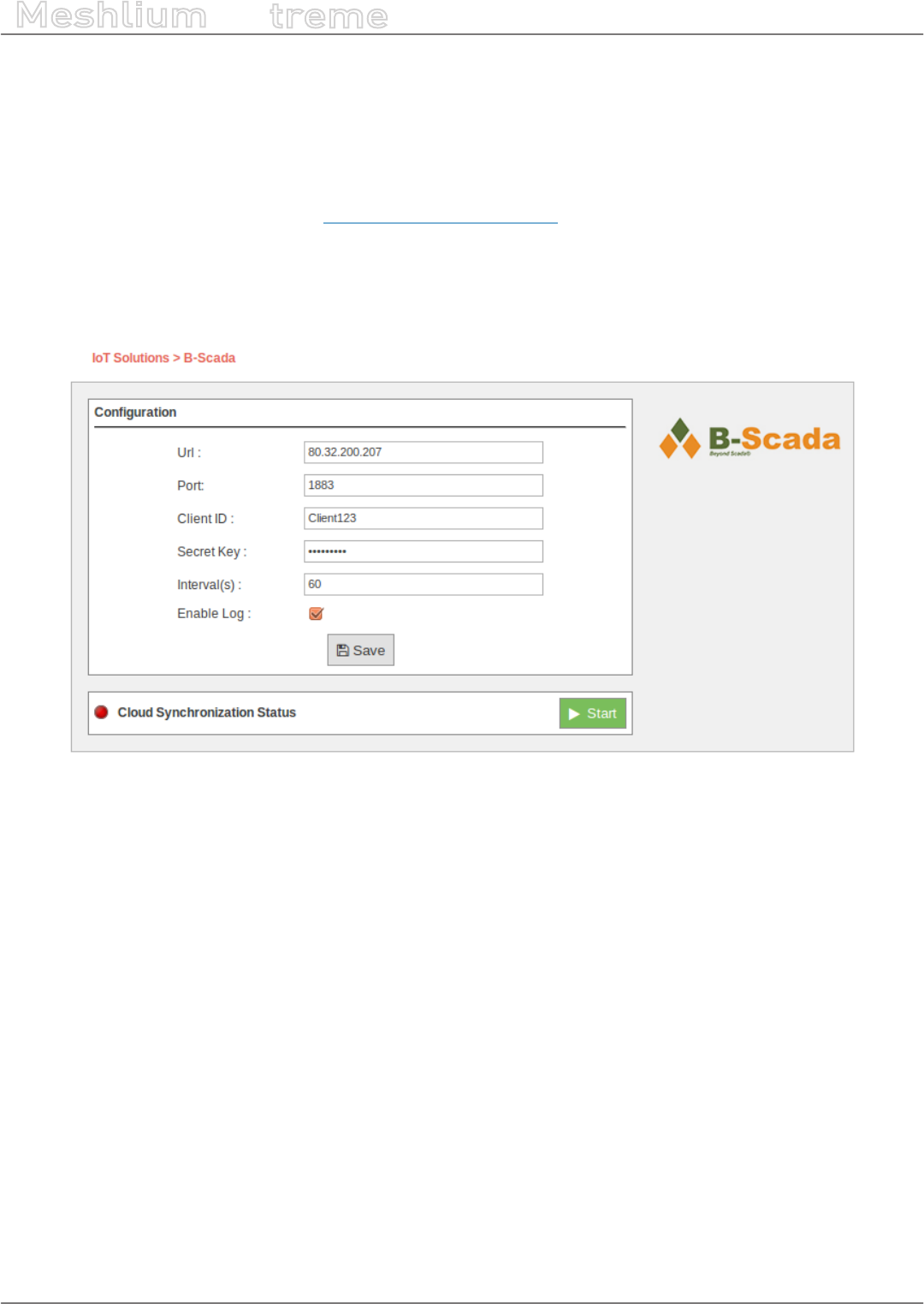
-118- v7.3
Cloud Connectors
Meshlium
X
treme
12.3.3. B-Scada
B-Scada® VoT platform allows you to create rich, sophisticated IoT and M2M applications that consolidate and
organize data from anywhere, and visualize it in real-time on any device. Connect to thousands of potential data
sources. Visualize your data using modern, high-performance customized graphics. Leverage powerful analytic
tools and automation. Connect your devices, processes and people in a continuous real-time information system.
More information about VoT Platform: http://www.votplatform.com/.
12.3.3.1. Conguration
A new option is shown in the M2M Platforms menu: the B-Scada Cloud Connector. If you expand it, you can see
this form with 6 elds in it:
Figure: Conguring B-Scada in Meshlium
•URL: IP address of the VoT platform service by B-Scada. This address should be provided by B-Scada.
•Port: The port in which the VoT Server is listening to connections.
•Client ID: Customer’s identier or company name.
•Secret Key: The security key to send encrypted data to VoT.
•Interval(s): Time duration in seconds between operations of updating data.
•Enable Log: This option enables the creation of log les to save all communications processed to the VoT
server.

-119- v7.3
Cloud Connectors
Meshlium
X
treme
12.3.3.2. Controlling synchronization
The synchronization will be done for all data that has not been synchronized in the Sensor Parser table each time.
You can start and stop the data synchronization to the VoT service. In the interface you can see an indicator of
whether the status service is running or not. If you click on “Start”, the synchronization will begin.
Figure: B-Scada synchronization service is running
You can stop the synchronization at any moment clicking on the “Stop” button.
Figure: B-Scada synchronization service is stopped
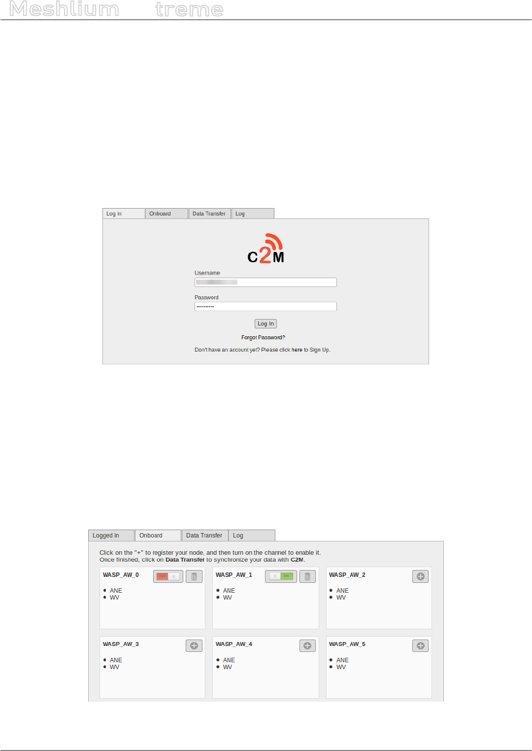
-120- v7.3
Cloud Connectors
Meshlium
X
treme
12.3.4. C2M
C2M® is an end-to-end IoT and Digital Enterprise platform that allows easy, secure and rapid prototyping and
deployment of IoT/M2M solutions.
12.3.4.1. Conguring C2M Platform in Meshlium
1. Select the C2M® plugin located in:
Manager System > Cloud Connector > Basic Cloud Partner > C2M
2. Login with your C2M® credentials.
(If you do not have C2M® credentials, please click the “Sign Up” button at the bottom of the screen to register).
Figure: C2M logging
12.3.4.2. Controlling synchronization
1. Select the Onboard tab and press the “+” button on the Waspmote/Sensors that you wish to onboard.
•Turn the switch On to enable the Waspmote/Sensor
•To Disable the Channel: Toggle the On/O switch to O
•To Delete the Channel: Press the Trashcan icon
Note: This will delete the channel and all data will be permanently removed.
For a temporary pause in sending data, see next step.
Figure: C2M Onboard tab
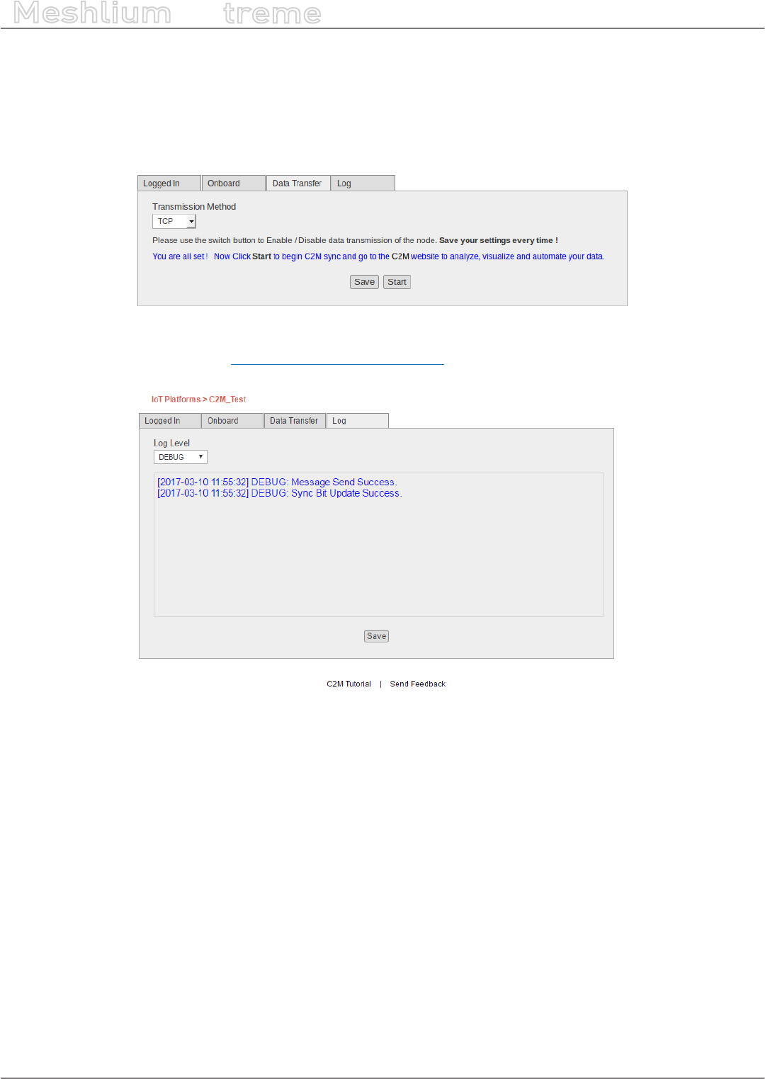
-121- v7.3
Cloud Connectors
Meshlium
X
treme
2. Select the Data Transfer tab. Here you will see your enabled Waspmote/Sensors. Select your Transmission
method, toggle on the devices in which you want to send data and press “Save”.
3. Click on the “Start” button to begin the C2M Sync service. Click the “Stop” button to terminate the C2M Sync
service.
To temporarily pause a node, toggle the On/O switch to O and press “Save”.
Figure: C2M Data Transfer tab
4. Login to your C2M account at https://cloud.c2m.net/login.aspx to analyze, visualize and automate your data.
Figure: C2M log
There is also a Log tab. Here you will nd access to various log levels. Default log view is set to WARNING. Once you
change the Log Level you must press “Save” to store this operation and to view the updated information.

-122- v7.3
Cloud Connectors
Meshlium
X
treme
12.3.5. DeviceLynk
DeviceLynk is a high-level cloud service based on the ThingWorx cloud.
Interface walk-through:
Interface Feature Description
DeviceLynk logo
Click to jump to the DeviceLynk website.
Server Address
The DeviceLynk Server address you wish
to connect to.
Meshlium Bind Name
The name that the DeviceLynk Server
uses to identify the Meshlium unit.
Logging Check-box
Check-box to enable/disable internal
logging.
Save Button
Click to save the Server Address, Meshlium
Bind Name, and Logging conguration.
Load Local Waspmotes button
Click this button to load the list of
Waspmotes that the Meshlium is
connected to.
Load WM Cong. from DeviceLynk button
Click to load the list of Waspmotes which
are connected to the DeviceLynk Server.
Write DeviceLynk Setup button
Click to write the current list of Waspmotes
to the DeviceLynk Server (Waspmotes
details are sent to the Server).
Waspmote
Click the “Delete” button to remove
that Waspmote unit from the current
Waspmote clicking the “Load Local
Waspmotes” button, or by clicking the
“Load WM Cong. from
DeviceLynk” button.

-123- v7.3
Cloud Connectors
Meshlium
X
treme
Interface Feature Description
DeviceLynk Agent Status
The status of the DeviceLynk Agent will
be indicated, displaying “Running” or
“Stopped”.
LUA Script Resource Status
The status of the LUA Script Resource
will be indicated, displaying “Running” or
“Stopped”.
Start/Stop Service Toggle button
Click to start/stop the service that this
button is next to.
Steps to start the DeviceLynk plugin:
•1. Type the DeviceLynk Server address that you wish to connect to in the Server Address eld.
•2. Type the Meshlium Bind Name that the DeviceLynk Server will use to identify the Meshlium device.
•3. Click the “Save” button.
•4. Click the “Load Local Waspmotes” button. All Waspmotes connected to this Meshlium unit will show up.
•5. Delete the Waspmotes that you do not want to be connected to the DeviceLynk Server by clicking on their
respective “Delete” button.
•6. Click the “Write DeviceLynk Setup” button to make the DeviceLynk Server listen to those Waspmotes.
•7. To show the Waspmotes units that the DeviceLynk Server is currently listening to, click the “Load WM Cong.
from DeviceLynk” button.
•8. Click the “Start” button under “DeviceLynk Agent Status”. “Running” will be displayed.
•9. Click the “Start” button under “LUA Script Resource Status”. “Running” will be displayed.
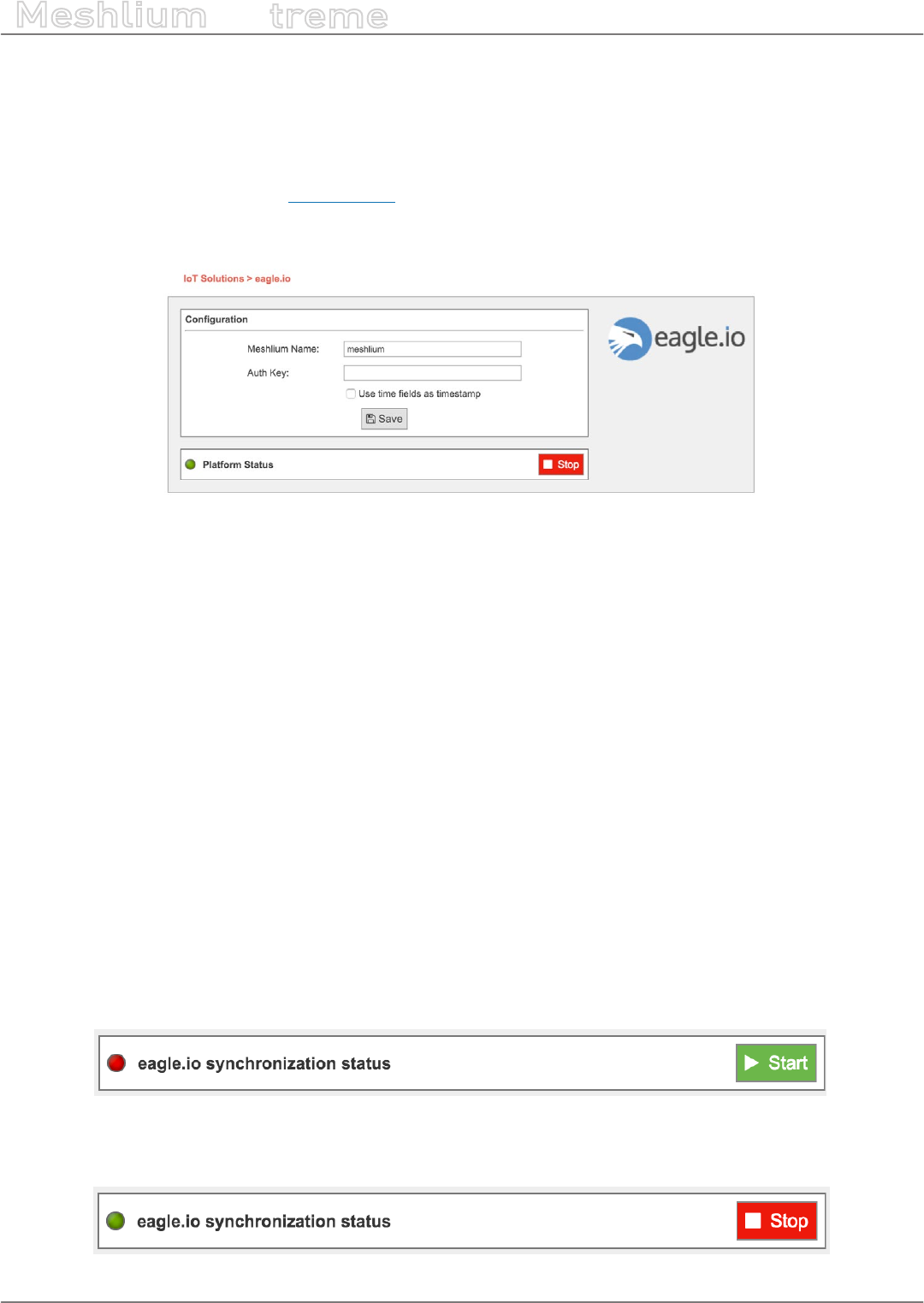
-124- v7.3
Cloud Connectors
Meshlium
X
treme
12.3.6. eagle.io
eagle.io is a hub connecting monitoring assets, engineers and decision makers. Acquire data in real-time from
Meshlium and Waspmote devices, receive alerts for critical events, and share access with stakeholders. Transform
your time-series data into beautifully presented, actionable information.
More information can be found at www.eagle.io.
12.3.6.1. Conguration
Figure: eagle.io cloud connector conguration panel
The eagle.io plugin is congured with the following three parameters:
•Meshlium Name: a name to help identify this device (required parameter).
•Auth Key: optional secret key; if this is dened then the same key will be required when conguring the device
within eagle.io as a data source. If this key is not dened, then the Meshlium device ID is sucient to identify
the device within eagle.io conguration.
•Use time elds as timestamp: if this box is checked, then any time eld contained in a Meshlium database
record will be used as the eagle.io timestamp for the record. If this box is not checked, the data reception time
of the record will be used as the eagle.io timestamp.
After changing any of these parameters, save the conguration by clicking the “Save” button, then restart the
eagle.io synchronization (if it is currently running) by clicking the “Stop” button followed by the “Start” button.
12.3.6.2. Controlling synchronization
The synchronization will be done in batches of 200 records at a time, so the system is not overloaded. The time
between batches is 60 seconds. This means that when synchronization is rst started on a device with many
existing records in the database, it may take some time for all the records on the device to be synchronized with
eagle.io.
When the synchronization is not running (red status indicator), it can be started by clicking the green “Start”
button.
Figure: Eagle.io start button
When the synchronization is running (green status indicator), it can be stopped by clicking the red “Stop” button.
Figure: Eagle.io stop button
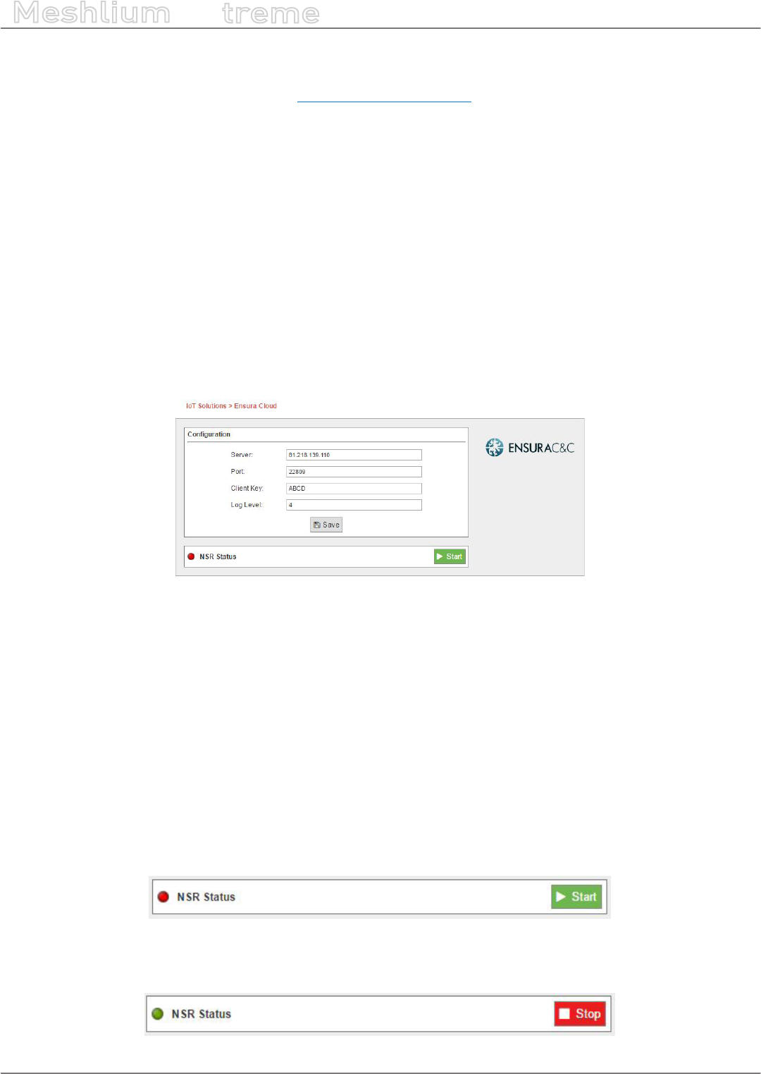
-125- v7.3
Cloud Connectors
Meshlium
X
treme
12.3.7. Ensura
The Ensura Command & Control platform (http://www.ensuracc.com/) manages live and recorded video, audio,
and data ows, and shows simultaneous live and recorded views in a single window. The system provides server-
side and sensor-side Video Content Analytics for all video channels, displaying triggered alerts from any 3rd party
end-element.
The system supports biometric and face recognition modules, ANPR systems, Access Control solutions, Security
and Failsafe platforms. Open-ended and integration-agnostic, additional systems can be rapidly and eectively
integrated into an Ensura deployment.
Ensura supports event-driven triggering of activities throughout the system, and supports denition of predened
scenarios for management of routine and emergency events.
Ensura enables users to manage multiple remote sites using a single client interface, displaying real-time and
archived data of all monitored sites concurrently.
Ensura uses its Sensor Server to receive data from the Meshlium devices over HTTP requests.
12.3.7.1. Conguration
Figure: Conguring Ensura in Meshlium
•Server: The IP address or the URL of your Ensura Sensor Server
•Port: The port number on which the Ensura Sensor Server is listening for connections
•Client Key: The identier that the Ensura Sensor Server is congured to accept information from
•Log Level: This is the log level used by the cloud connector within the Meshlium device. Should be 0, except
for debugging purposes.
This data will be provided by the administrators of the Ensura platform.
12.3.7.2. Controlling synchronization
The synchronization will be done for all data that has not been synchronized in the Sensor Parser table each
time. You can start and stop the data synchronization to the Ensura Sensor Server. In the interface you can see
an indicator of whether the status service is running or not. If you click on “Start”, the synchronization will begin.
Figure: Ensura cloud connector status “Stopped”
You can stop the synchronization at any moment clicking on the “Stop” button.
Figure: Ensura cloud connector status “Running”
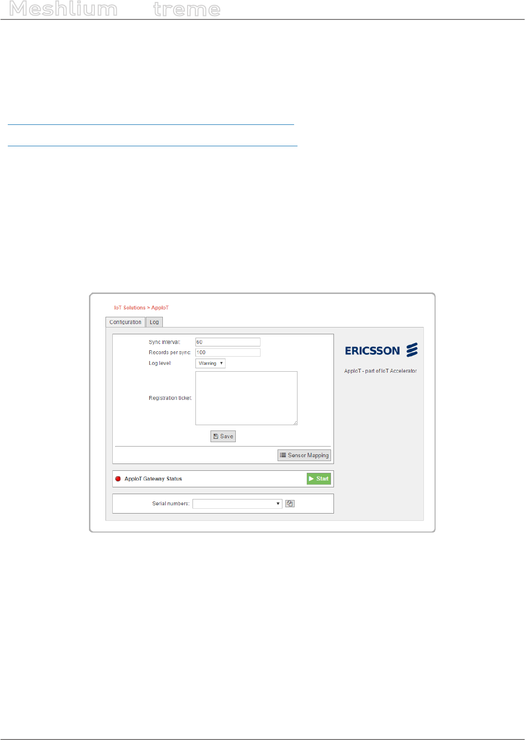
-126- v7.3
Cloud Connectors
Meshlium
X
treme
12.3.8. Ericsson AppIoT
The Ericsson AppIoT cloud connector will integrate Meshlium as an AppIoT gateway with minimal eort and
conguration.
More information on AppIoT and IoT Accelerator:
https://www.ericsson.com/en/industries/iot-for-industry/appiot
https://www.ericsson.com/ourportfolio/products/iot-accelerator
12.3.8.1. Register Meshlium in AppIoT
Register a gateway with the pre-congured Meshlium gateway type in your device network in AppIoT. If the
Meshlium gateway type is missing in your instance of AppIoT, please contact AppIoT support. If you are unfamiliar
with AppIoT, you can read more about how the platform works on http://docs.appiot.io/.
12.3.8.2. Conguration
The gure below shows the main conguration page for the AppIoT cloud connector. The following is a description
of the components in the connector’s User Interface.
Figure: Conguration overview
Sync Interval: Sets the number of seconds to synchronize with AppIoT. The default value is 60 seconds. Please
take into consideration when setting this value that Meshlium is a resource-constrained device. The shortest
synchronization interval is 30 seconds.
Records per sync: Sets the number of sensor values read from the Meshlium’s database per synchronization. The
default value is 100 records per synchronization. It is not recommended to set this value any higher than 200 due
to the memory limitations of Meshlium.
Log level: This controls the log output from the AppIoT connector. The log levels Severe and Warning will only
output messages that in some way may aect operational functionality of the cloud connector. All other levels
of logging, except O, will output general events from the cloud connector. The log level Info will focus on events
regarding actions taken by the connector. Other levels, like Fine, will output third party library logs as well.
Registration ticket: The registration ticket that will be used by the gateway integrated in the cloud connector.
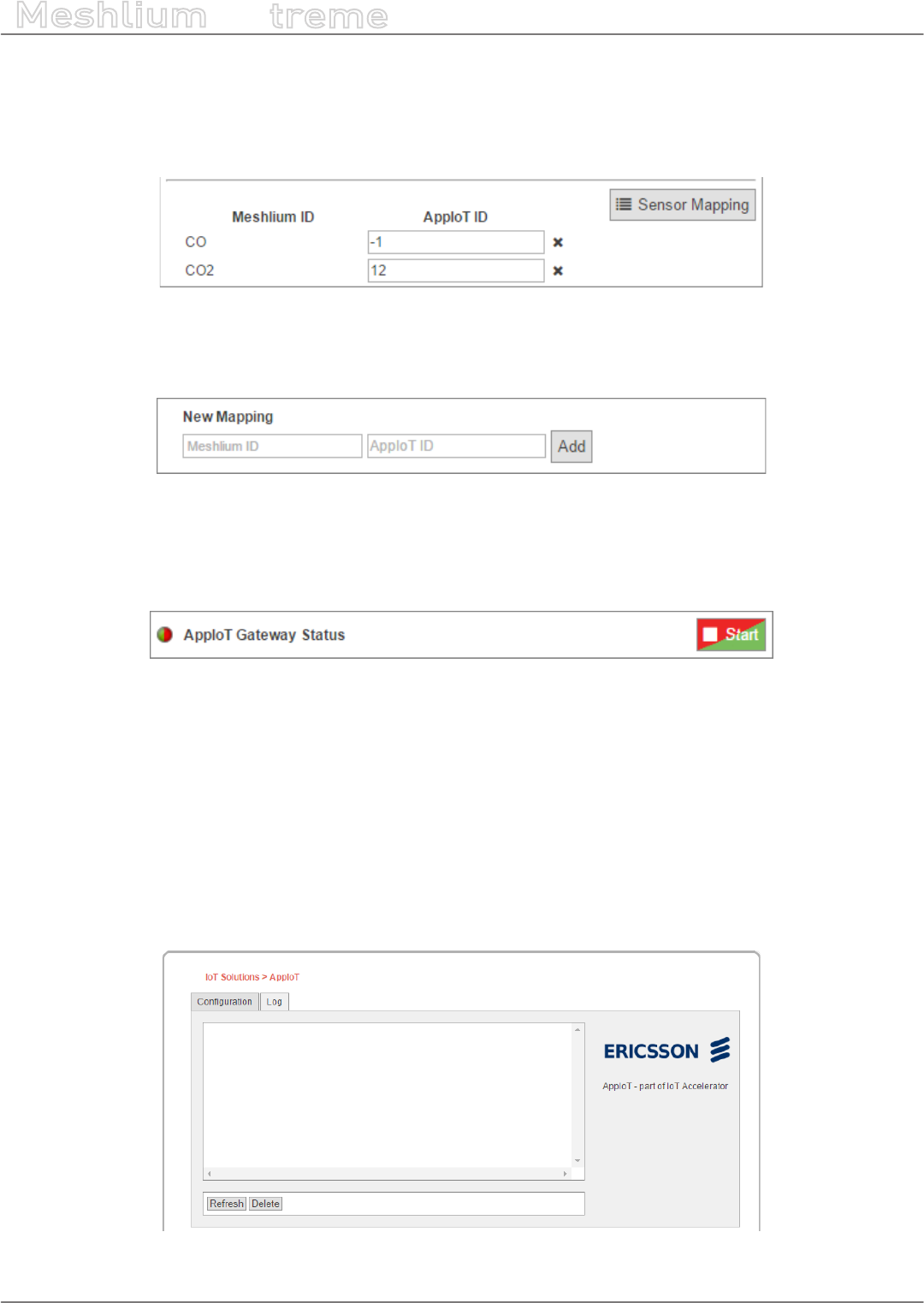
-127- v7.3
Cloud Connectors
Meshlium
X
treme
Sensor mapping: Toggles the sensor mapping table used to translate sensor types between Meshlium and
AppIoT. An example of the table can be seen in the next image, where the left hand side lists the sensors from
Meshlium and the right hand side lists the sensor hardware types from AppIoT. Note that the value -1 represents
an unmapped sensor. The AppIoT connector will only try to synchronize sensor values that have a non-negative
number.
Figure: Sensor mapping
As shown in the gure below, add custom mappings in the case that your sensor type is not present in the
standard set of sensor types on the Meshlium. Click the ‘X’ next to the mapping to remove a mapping.
Figure: Adding a sensor mapping
AppIoT Gateway Status and Start/Stop: The round icon indicates the current state of the connector. The icon
will be either green or red depending on if the connector is running or not. The green start button will start the
connector. When clicked, it changes into a stop button. To stop the connector press the red stop button.
Figure: Gateway status
Serial numbers: The drop-down lists all the Waspmotes available and/or registered in AppIoT. The congured
state between AppIoT and the Waspmotes are displayed next to the Waspmote ID. There are 3 states: Not
registered, Registered and Registered (Not seen). The Not registered state represents a Waspmote transmitting to
the Meshlium that is not registered in AppIoT. The Registered state represents a Waspmote transmitting to the
Meshlium that is registered in AppIoT. This is the state where the connector synchronizes data with AppIoT. The
last state, Registered (Not seen), is when a Waspmote is registered in AppIoT but has no record of transmitting to
the Meshlium. The button next to the drop-down will copy the selected Waspmote ID to your clipboard.
Log tab: As seen the following screenshot, you can review the latest logs from the connector. The refresh button
will reload the log window and display the latest logs. The delete button will empty the log le on the Meshlium
unit.
Figure: Log overview

-128- v7.3
Cloud Connectors
Meshlium
X
treme
12.3.8.3. Setup
•Create device types in AppIoT to represent your Waspmotes.
•Set the desired synchronization interval and limit, please select these parameters following recommendations.
•Set the desired logging level.
•Supply the registration ticket eld with a valid ticket.
•Map the Meshlium sensor types to the corresponding sensor hardware types in AppIoT.
•If you are using user-dened sensor types on Meshlium, make sure to add these to the connector’s sensor
mapping table.
•Register your Waspmotes in AppIoT with their unique IDs. The unique IDs will appear in the serial number drop-
down when the Waspmotes transmit data to the Meshlium or when registered in AppIoT. If the Waspmotes
are already transmitting to your Meshlium, use the copy function to get the correct IDs.
•Save and start. A restart of the connector is always required for saved changes to take eect. Stop the
connector before saving.
12.3.8.4. Notes
•When registering a Waspmote in AppIoT, the serial number used in AppIoT must correspond to the serial
number shown in the drop-down in the connector interface.
•The connector does not support string values.
•The connector can handle sensor types with multiple elds if they are dened in the sensors table on Meshlium.
Example: ACC has three elds and translates to APPIOT0_ACC, APPIOT1_ACC and APPIOT2_ACC. The APPIOT
prex will appear on all multi-eld types and the numbering is the index of each eld value.
•The connector does not support multi-eld, user-dened sensor types.
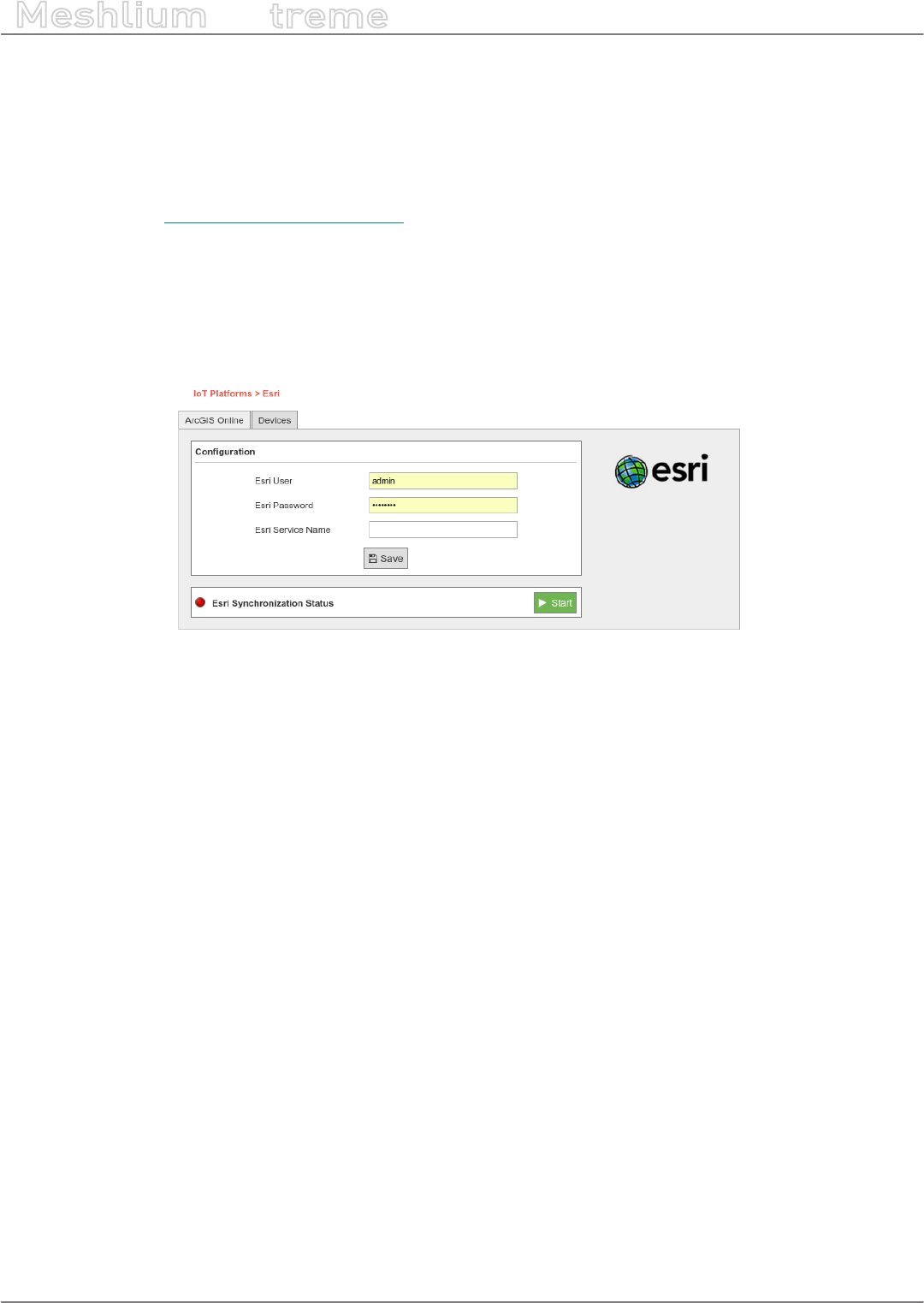
-129- v7.3
Cloud Connectors
Meshlium
X
treme
12.3.9. Esri
ArcGIS is a complete spatial information platform provided by Esri, that allows to create, analyze, store and
spread data, models, maps and 3D globes. It can be accessed via desktop application, browser or handsets. ArcGIS
is targeted at GIS professionals, location analysts and developers that want to create their own applications based
on geographical data.
More information: http://www.esri.com/products
Waspmote sensor data could be integrated into your existing maps and ArcGIS applications following the
conguration steps described for ArcGIS Online service.
12.3.9.1. ArcGIS Online
We can congure in this form all the parameters needed to connect and send data to the ArcGIS Online platform.
Figure: ArcGIS Online conguration
The parameters to setup are:
•esri_user: User for the Esri ArcGIS online platform.
•esri_password: Password for this Esri user.
•esri_service_name: Name of the service which will receive the data.
Clicking on the “Save” button, this setup is sent to the ArcGIS online service.
Clicking on the “Start” button enables the Esri Cloud Connector to send data periodically to the ArcGIS Online
service previously congured. A “running” status is displayed on screen showing that the Cloud Connector is
sending data.

-130- v7.3
Cloud Connectors
Meshlium
X
treme
Figure: ArcGIS Online “Start” button
Clicking on the “Stop” button will disable the Esri Cloud connector so Meshlium device stops feeding the ArcGIS
Online service with data.
Figure: ArcGIS Online “Stop” button
12.3.9.1.1. Check the Feature Server in ArcGIS Online
In order to check that data is arriving to ArcGIS Online, you should login in the platform:
https://www.arcgis.com/home/signin.html
Click on the option named “Gallery” and you should see a new Feature Server with the name that you provided in
the Meshlium conguration plugin:
Figure: ArcGIS Gallery
Opening the new content, you should see a map where each layer is one sensor type available in your project.
Clicking on the table icon, all the data collected for this type of sensor will be displayed.
Figure: ArcGIS sensor map view
At this point, it is possible to use this data to create new maps, collaborative apps or analytics making use of the
complete array of services provided by ArcGIS Online: https://developers.arcgis.com/en/.
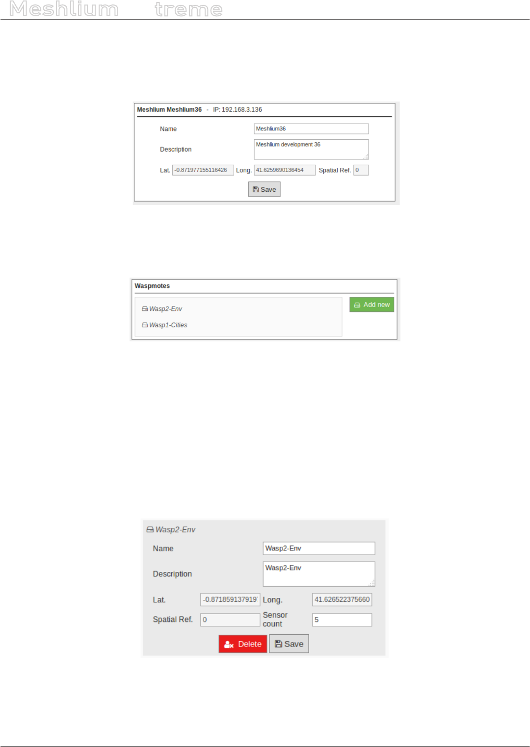
-131- v7.3
Cloud Connectors
Meshlium
X
treme
12.3.9.2. Devices
12.3.9.2.1. Meshlium
In the Meshlium section, the user can set and modify the name and description of the Meshlium.
Figure: Meshlium info in ArcGIS
12.3.9.2.2. Waspmotes
In the Waspmotes section, the user can manage the Waspmote units which are sending information to Meshlium.
Figure: Waspmotes list in ArcGIS
To add a new Waspmote, click on “Add new”. Then ll up this information:
•Name: The Waspmote name. Must match with the Waspmote identier used with the frame. See chapter
“Capturing and storing sensor data” for more information.
•Description: A description of that Waspmote unit.
•Sensor count: Number of sensors on that Waspmote. Must match with the number of elds of the frame.
See chapter “Capturing and storing sensor data” for more information.
And click on the “Add” button.
To modify a Waspmote, click on the Waspmote name for showing the attributes view.
Figure: Modify Waspmote in ArcGIS
Then the user can modify the name, description, and sensor count information. To save the properties, click on
“Save”.
To delete this Waspmote unit, click on “Delete”.
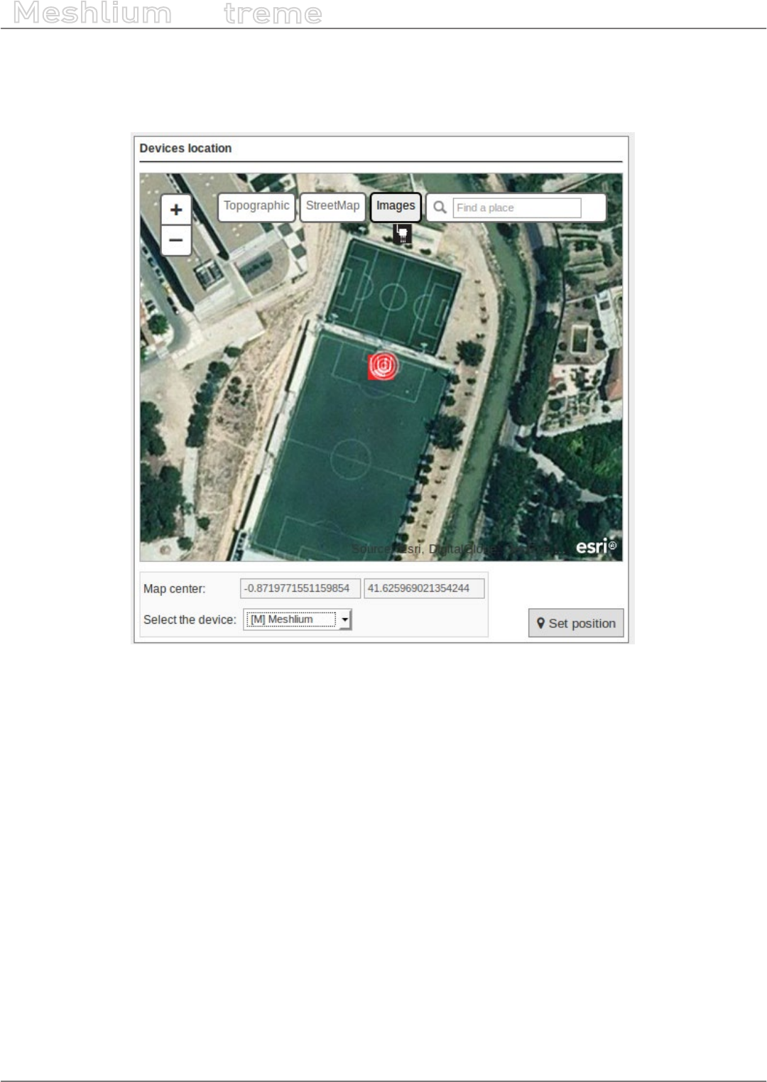
-132- v7.3
Cloud Connectors
Meshlium
X
treme
12.3.9.2.3. Devices location
In the section Devices location, there is a viewer where the user can see Meshlium and Waspmote located on a
map.
Figure: Devices location in ArcGIS
To change the location of the devices, center the map on the desired location, select the device, and click on “Set
Position”.
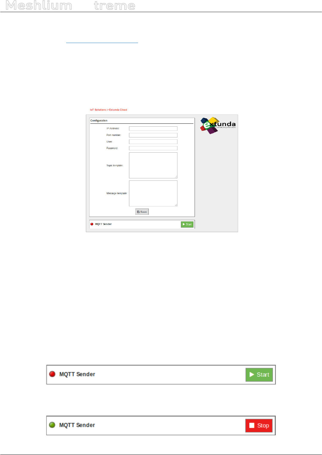
-133- v7.3
Cloud Connectors
Meshlium
X
treme
12.3.10. Extunda
Extunda IoT platform (http://www.extunda.com/) is a horizontal platform which also enables vertical applications.
Libelium Smart Cities, agriculture and various devices are ready to be launched for service over Extunda IoT
platform. The sensor data can be gathered, analyzed, stored and reported so the users can interpret and develop
actions based on online data.
Extunda uses MQTT structure for the integration of your Meshlium devices to its platform easily. Therefore, the
connector will easily send the sensor data to Extunda platform.
12.3.10.1. Conguration
Figure: Extunda cloud connector conguration panel
•IP Address / URL: The IP address or the URL will be provided to you by Extunda.
•Port Number: This is the port which Extunda server is listening for connections.
•User Name & Password: This is the Extunda Server username & password to be used for connecting to
Extunda servers. This information will be provided by Extunda.
•Waspmote ID: When you login to your Extunda IoT platform account with your username and password,
you are authorized to dene and match your Waspmote with a specic denition (i.e. Istanbul_gases_1). Your
Waspmote data will be transfered to the server as in the above message template.
12.3.10.2. Controlling synchronization
The synchronization will be done for all data that has not been synchronized in the Sensor Parser table each time.
You can start and stop the data synchronization to the Extunda service. In the interface you can see an indicator
of whether the status service is running or not. If you click on “Start”, the synchronization will begin.
Figure: Extunda start button
You can stop the synchronization at any moment clicking on the “Stop” button.
Figure: Extunda stop button
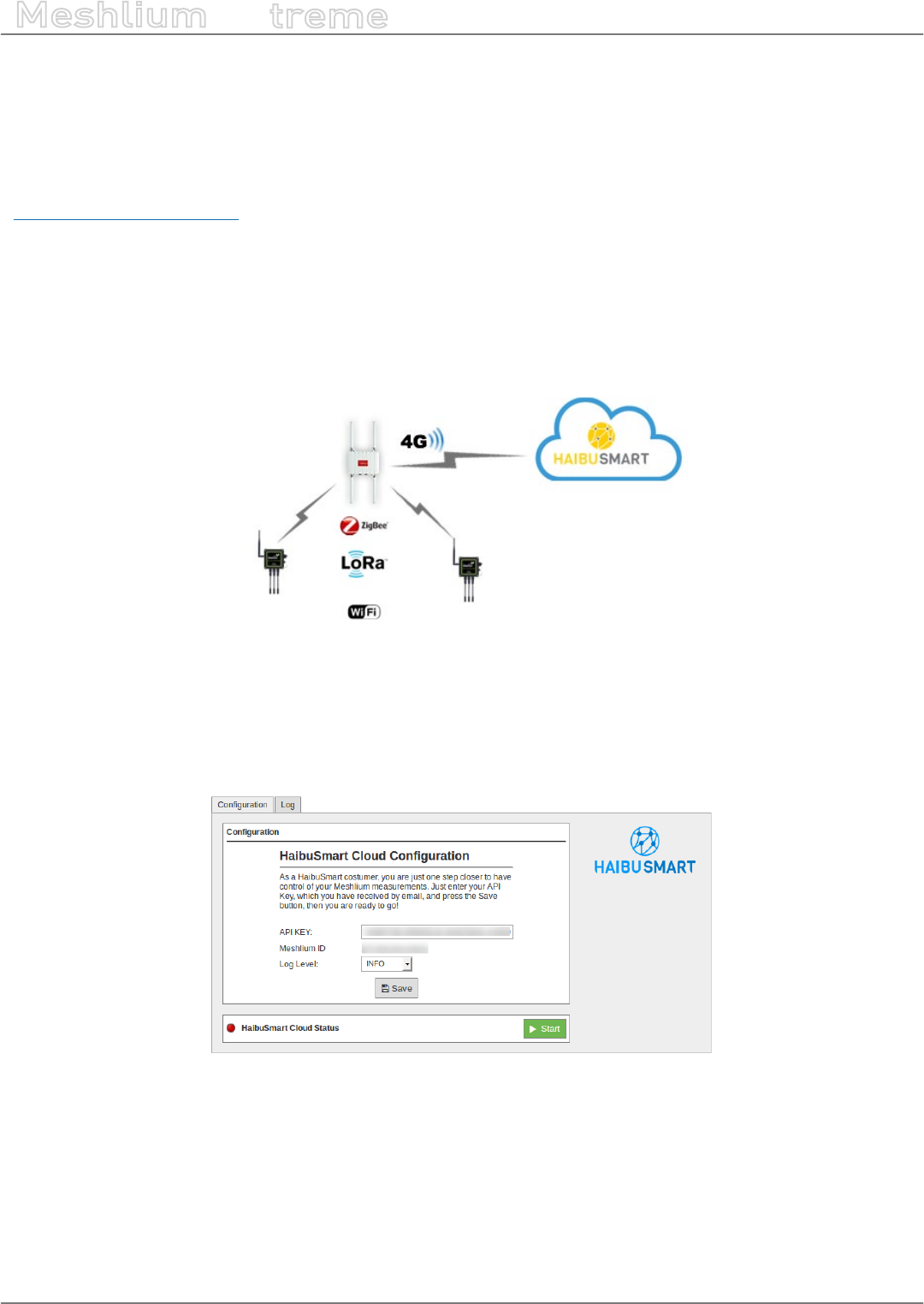
-134- v7.3
Cloud Connectors
Meshlium
X
treme
12.3.11. HaibuSmart
HaibuSmart is an IoT platform for business. The services include Enterprise Business Applications that involves
near real-time information and the integration of sensors as primary data acquisition point.
For more information you can reach us at:
http://www.haibusmart.com
12.3.11.1. HaibuSmart Cloud
This IoT platform was design to be simple and scalable and Meshlium ts perfectly in HaibuSmart’s solutions
catalog including Agriculture and other associated services.
The following diagram shows the interaction between Meshlium and HaibuSmart.
Figure: HaibuSmart architecture
12.3.11.2. Registering your Meshlium with HaibuSmart
Add your API KEY in the HaibuSmart panel of the Cloud Connector tab in the Manager System. Enter your API KEY,
choose the Log Level and press “Save”.
Figure: HaibuSmart Cloud conguration
12.3.11.3. Synchronization services
Pressing the “Start Button”, the HaibuSmart Cloud Connector will be launched. Every time that Meshlium receives
frames that are stored on the local database, the HaibuSmart Cloud Connector will send them to the HaibuSmart
Cloud Platform. You can check if the service is running with the message on the left and the red (stopped) / green
(running) indicators.
You can nd further information on our website at http://www.haibusmart.com/meshlium/#/connector.
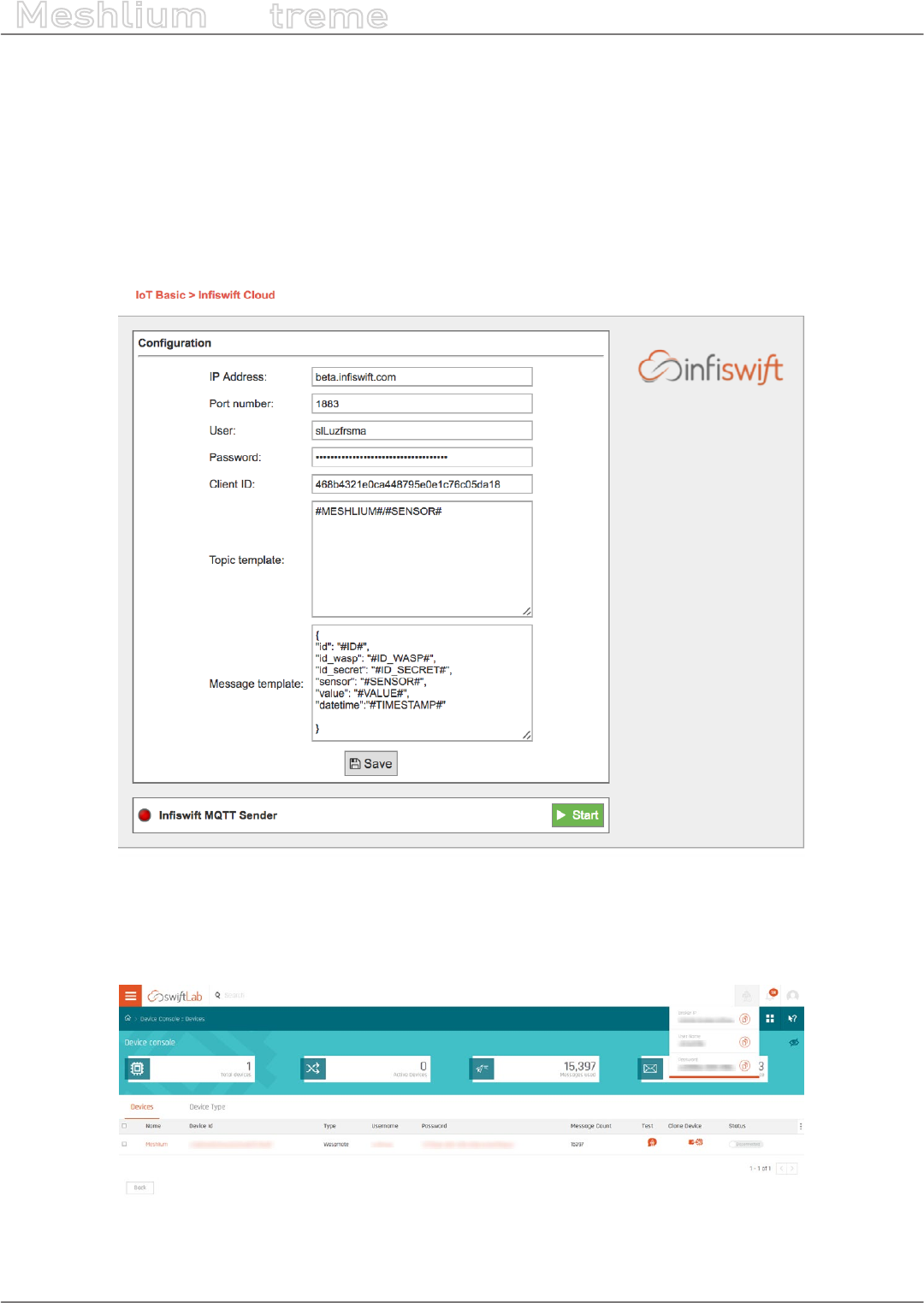
-135- v7.3
Cloud Connectors
Meshlium
X
treme
12.3.12. inswift
For more details on the platform, please visit https://www.inswift.com and review swiftLab documentation.
12.3.12.1. Conguration
In order to publish data from the Meshlium Gateway to the inswift broker, you will need to login to the Meshlium
Manager for conguration. Navigate to Cloud Connector > Basic Cloud Partner > inswift. You will need to
complete the following elds in the inswift Conguration:
Figure: Conguration panel
With this plugin, the Waspmote sensor data can be directly integrated with an inswift MQTT broker.
Pull required conguration information from inswift portal using email id created in previous steps.
Figure: inswift portal
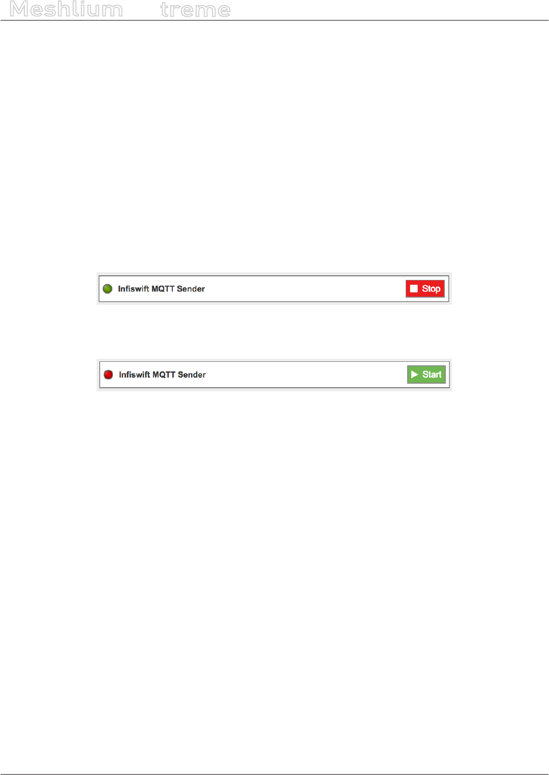
-136- v7.3
Cloud Connectors
Meshlium
X
treme
•IP Address: This is the broker IP address (beta.inswift.com) of the Gateway you want to connect to
•Port Number: This is the port you opened upon conguration of Meshlium plugin
•User: This is the username of the device created and to be supplied upon conguration of Meshlium plugin
•Password: This is the password of the device created and to be supplied upon conguration of your Meshlium
plugin
•Client ID: This is the device ID from DEVICE CONSOLE page and to be supplied upon conguration of Meshlium
plugin
•Topic Template: This is the topic you supplied upon conguration of Meshlium plugin
•Message Template: This is the message template of the data you want to send. Meshlium generates a default
template, but you can provide your own if it is aligned with the Meshlium specications.
Meshlium will start to listen for and ingest data coming from your device, and then forward it to inswift’s cloud.
12.3.12.2. Controlling synchronization
Once inswift’s swiftPV server/broker is congured, the user can launch the Meshlium inswift script (“Start”
button). The program will search for the received frames on the local database, and will send them to the swiftLab
platform via the MQTT protocol. The status indicator displays the current state, saying “Running” or “Stopped”.
Figure: swiftLab IoT sender is running
You can stop the inswift IoT program anytime by clicking on the “Stop” button on the bottom of the page.
Figure: swiftLab IoT sender is stopped

-137- v7.3
Cloud Connectors
Meshlium
X
treme
12.3.13. IoT-Ticket
IoT-Ticket is one of the world’s most complete, advanced and easy to use Industrial Internet of Things platforms
with over 1.6 million users mainly in the energy and mobile machinery industry. Using IoT-Ticket you can build IoT
applications in your web-browser in minutes, no plug-ins required. You can create dashboards, reports, analytics
or augmented reality based on big-data collected from your things.
Figure: IoT-Ticket panel examples
Some benets oered by IoT-Ticket:
•Complete, up-to-date solution. IoT-Ticket is a complete remote management system which includes the
electronics, software and server. The platform is continuously developed further with new features and
options.
•Easy to get started and integrated. You can use the platform as a service (SaaS or PaaS) or deploy to your
own servers. We can integrate IoT-Ticket with any of your other information systems.
•Flexibility and choice. Use the whole IoT-Ticket platform or part of it. Use IoT-Ticket specic electronics or
use your own, already deployed, electronics. Easy to use API in many programming languages allows a huge
selection of devices to be easily connected.
•Easy to use and Customizable. The IoT-Ticket web dashboards allows you to be up and running in minutes
using only your web browser. IoT-Ticket can be customized to meet your unique needs, even the look and feel
can be made to match your corporate brand identity.
More information can be found at www.iot-ticket.com.
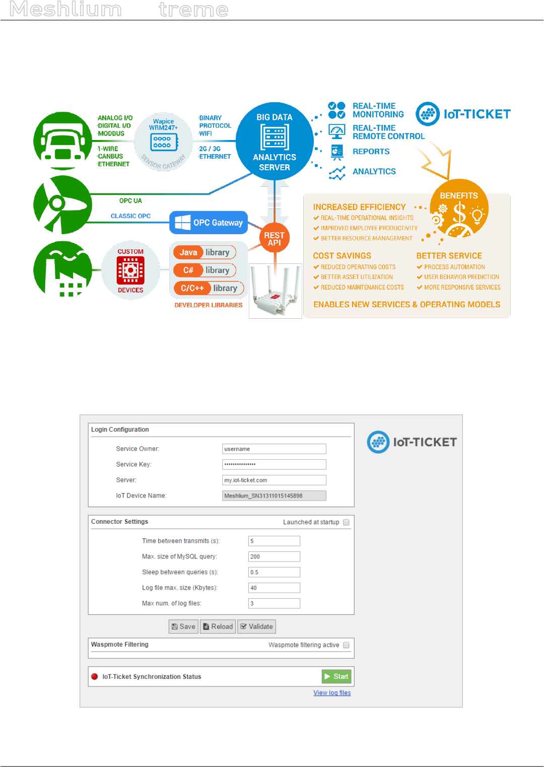
-138- v7.3
Cloud Connectors
Meshlium
X
treme
12.3.13.1. IoT-Ticket Meshlium integration
Once Libelium’s Cloud Connector has been congured, all your available data will show up automatically in your
IoT-Ticket web-based dashboard / report designer from where you can easily design Internet of Things applications.
Figure: IoT-Ticket Meshlium integration
The IoT-Ticket cloud connector settings can be found under the IoT section of the browser-based Meshlium
Manager System. The conguration is split into three parts Login Conguration, Connector Settings and Waspmote
Filtering, as well as a section for information about the current status of the connector with controls to start and
stop the program.
Figure: IoT-Ticket plugin panel
-139- v7.3
Cloud Connectors
Meshlium
X
treme
The Login Conguration section sets up the information for your IoT-Ticket account, and consists of four parts:
•Service Owner/Key gives the username and password of the my.iot-ticket.com service account to which you
wish to connect your Meshlium device.
•Server species the IoT-Ticket server to use, by default my.iot-ticket.com.
•IoT Device Name is a read-only eld showing the IoT-Ticket device name used for that Meshlium unit. It is set
when the connector is started and is empty if no name has yet been set (in such a case, use browser “Refresh”
after connector has started to see the name).
The Connector Settings section has parameters for the operation of the connector itself. These values aect time
between updates to IoT-Ticket as well as size of transmitted batches of data. More frequent data updates may
come at the cost of increased system resource usage.
•Launch at start. This checkbox indicates whether the connector is set to start automatically when the
Meshlium is powered on.
•Time between transmits gives the minimum elapsed time between transmissions to IoT-Ticket. Values less
than 60 seconds may consume high system resources.
•Sleep between queries is the time the program sleeps between SQL queries, in order to conserve resources.
•Max. size of SQL query is the maximum number of results for a single SQL query to the Meshlium database.
Values greater than 200 may lead to high system load.
The section also allows for conguring connector logging:
•Log le max. size (kbytes). The maximum size of a single log le in kilobytes.
•Max. num. of log les is the number of log les that can be written before the logging handler begins
overwriting the rst.
12.3.13.2. Save, load and verify
These buttons allow saving, loading and validating entered conguration data to a local le on the Meshlium disk
which is read by the connector. The saved data includes both the Login and Connector settings as well as any
entered Waspmote ltering rule (see “Waspmotes” section below).
Figure: Save, Load and Verify buttons
•Save validates the data entered into the form and saves to it to disk.
•Reload reads data back from disk, erasing any elds that have been changed since last save.
•Validate runs a check that entered elds are of the correct type and connects to IoT-Ticket to check the
entered username and password. If verication fails for a eld, it will be marked in red and an error message
appears.
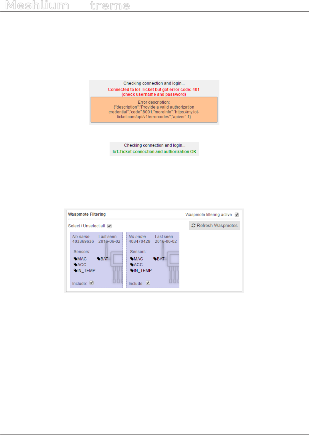
-140- v7.3
Cloud Connectors
Meshlium
X
treme
12.3.13.3. Validation of settings
Conguration settings are validated to make sure the entered data elds make sense (e.g. numeric elds such as
sleep and query size must be numbers). Additionally, the validation will issue warnings if any parameters might
cause high system load on Meshlium.
Additionally the “Validate” button checks entered login information with the IoT-Ticket server and shows a warning
if settings are incorrect and a green conrmation message if they are correct.
Figure: Validation error
Figure: Validation success
12.3.13.4. Waspmote ltering
This section allows ltering of which Waspmote data is synchronized to IoT-Ticket. The section is enabled by
ticking the Waspmote ltering active checkbox.
Figure: Waspmotes list
•Refresh Waspmotes reloads the list of Waspmotes from the Meshlium database
•Select / Unselect All allows for quick selection or deselection of all present Waspmotes
The Waspmote infobox contains the following values:
•Name in the top-left shows the name a Waspmote broadcasts to the Meshlium with its readings (this is set in
Waspmote code). If not set, No name is displayed instead.
•Last Seen is the last date at which a sensor entry was sent from the Waspmote to the Meshlium.
•Sensors is a list of sensors present on that Waspmote device. Only the latest detected set is displayed here,
in case sensors are changed. Full names may be seen by hovering the mouse over the abbreviated names in
the list.
•Include species whether the Waspmote should be included in the data transmitted by the connector.
Deselected Waspmotes have their info box greyed out.
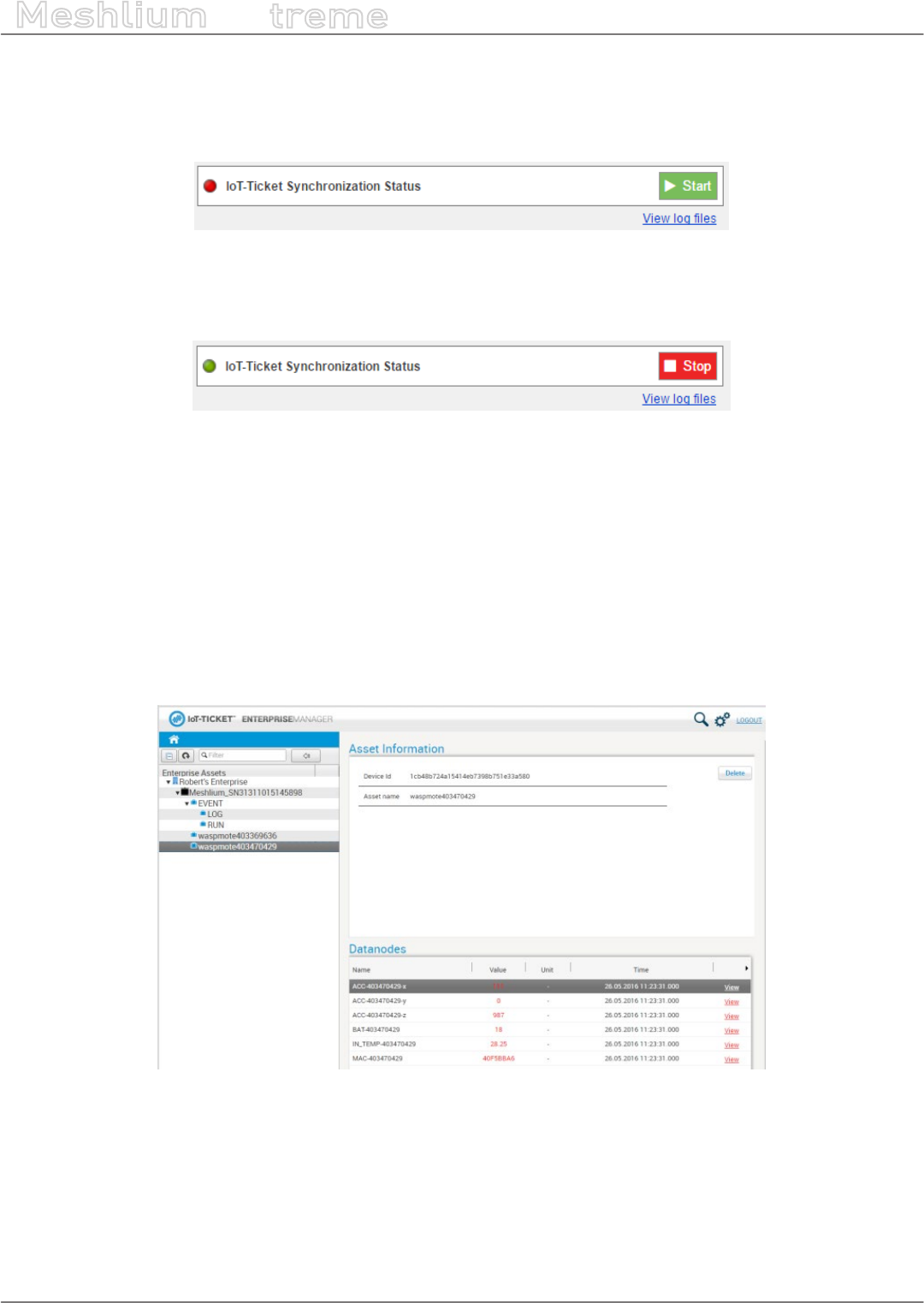
-141- v7.3
Cloud Connectors
Meshlium
X
treme
12.3.13.5. Synchronization status
This section allows the user to start and stop the connector and displays information about its current status.
When the connector is o, the indicator marker is red.
Figure: Start button
After clicking ”Start”, the connector shows a startup sequence, and when nished the running status will be
indicated by the status icon turning green. The start button becomes a red “Stop” button.
Figure: Stop button
The link “View log les” will allow you to see the status of the running connector via its log les. A ltered set of this
logging data will also be available as a data node in your IoT-Ticket enterprise.
12.3.13.6. IoT-Ticket view
Once the connector is running you can use your web browser to see the Meshlium data coming into your IoT-
Ticket Dashboards and Enterprise Manager on my.iot-ticket.com.
In your IoT-Ticket enterprise the Meshlium device will be viewable as an IoT-Ticket device under your enterprise
and can now easily be used in Enterprise Dashboards to create views of your incoming data, even mixing it with
data coming from other IoT sources.
Figure: IoT-Ticket panel
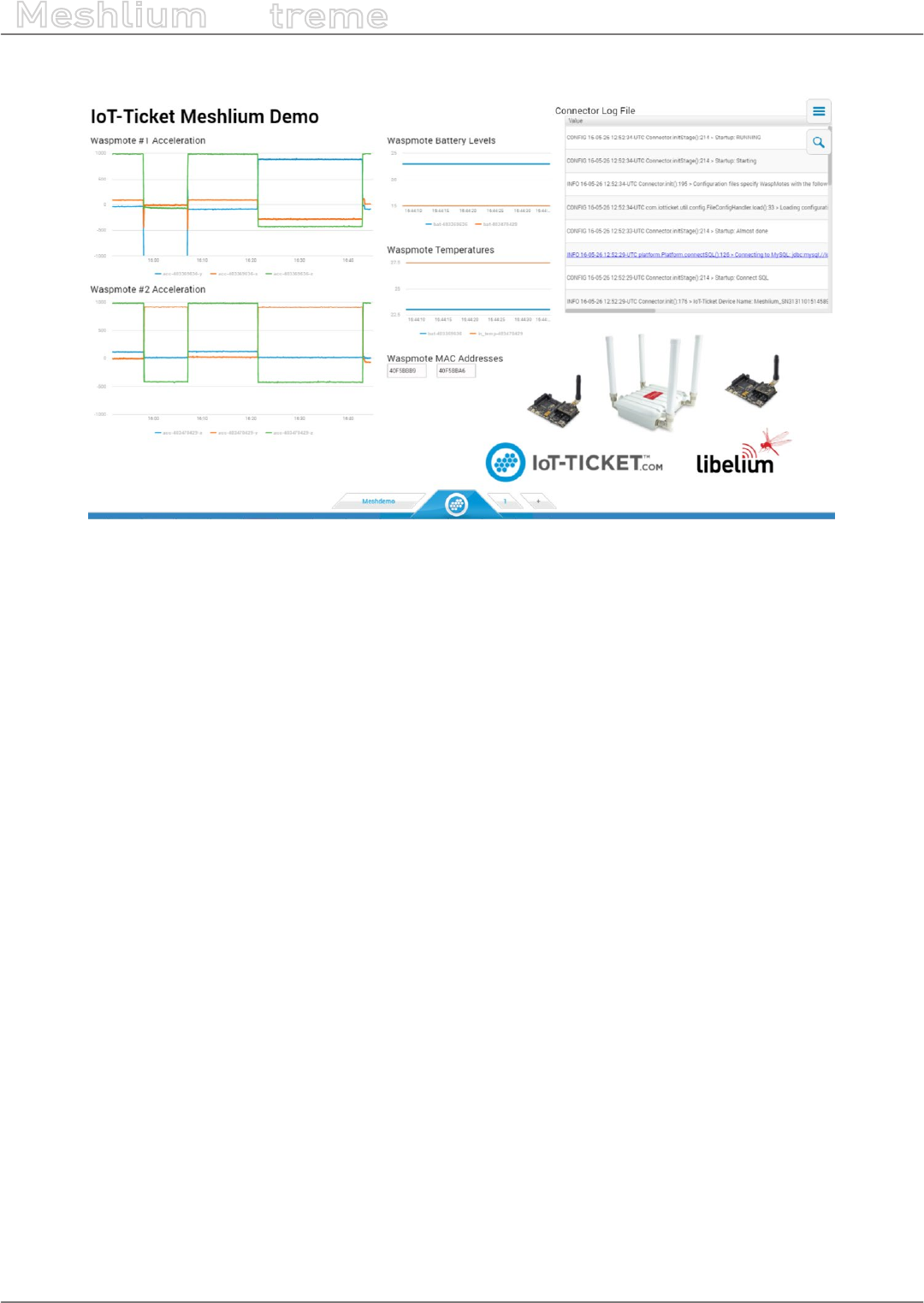
-142- v7.3
Cloud Connectors
Meshlium
X
treme
You can now congure your own dashboard with sensor data and have it up and running in a matter of minutes.
Figure: IoT-Ticket panel
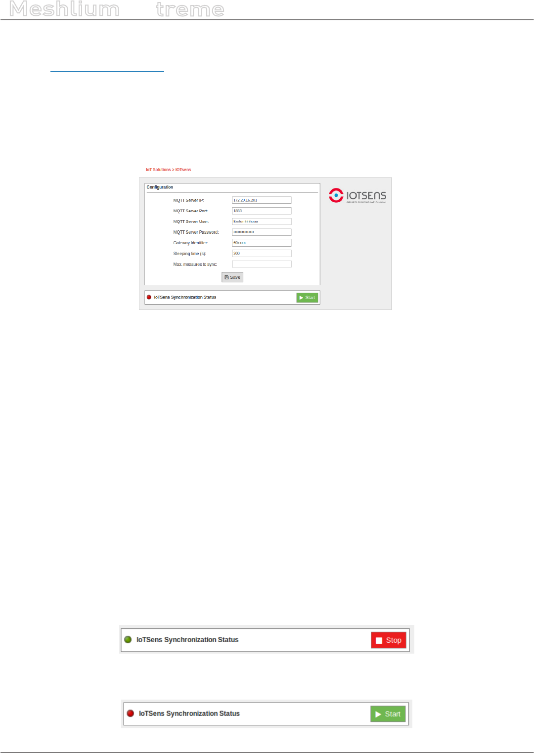
-143- v7.3
Cloud Connectors
Meshlium
X
treme
12.3.14. IoTSens
IoTSens (http://www.iotsens.com/) is a horizontal platform for the development of smart cities which provides
functionalities for gathering, integrating, storing and analyzing data from the city from a global point of view, so
managers and citizens know what is happening and can immediately act.
IoTSens seamlessly integrates with Meshlium devices by means of MQTT queues so the connector will send all the
sensors data to your IoTSens platform in order to be processed.
12.3.14.1. Conguration
Figure: Conguring IoTSens in Meshlium
The IoTSens provider will supply you with the MQTT connection conguration attending your particular deployment:
•MQTT Server IP: IP address where the MQTT Server is deployed.
•MQTT Server Port: Port number where the MQTT Server is listening for connections.
•MQTT Server User: User name for connecting to the MQTT Server. This eld can be empty if no user is
required.
•MQTT Server Password: Password for connecting to the MQTT Server. This eld can be empty if no user is
required.
Additionally, the IoTSens plugin supports the conguration of some parameters regarding how the synchronization
process works:
•Sleeping time: The synchronization process sleeps some time between executions. This parameter congures
how many seconds it will sleep before starting the synchronization process again once it has nished. The
sleeping time must be long enough to give time to other device processes to do their work.
•Max. measures to sync: This parameter congures how many sensor measures are synchronized at most in
every synchronization process. The number of measures to synchronize must be limited in order to avoid the
synchronization process to overload the system for a long time.
12.3.14.2. Controlling synchronization
You can start and stop the synchronization of the data to the IoTSens service. In the interface, you can see an
indicator of whether the IoTSens service is running or not. If you click on “Start”, the synchronization will begin.
Figure: IoTSens synchronization service is running
You can stop at any moment clicking on “Stop” button.
Figure: IoTSens synchronization service is stopped

-144- v7.3
Cloud Connectors
Meshlium
X
treme
12.3.15. Kii
12.3.15.1. Introduction
Kii Cloud is an MBaaS (Mobile Backend as a Service) and an IoT (Internet of Things) cloud platform provided by Kii
Corporation.
Kii oers a cloud service that provides various server-side functions as versatile APIs for mobile apps and IoT
solutions. By leveraging these APIs, the user can provide services making mobile apps and things Internet-ready
without the server-side implementations and operations.
To learn more about the advantages of using the Kii Cloud see this page:
http://docs.kii.com/en/starts/merits
In order to make it easier for developers and system integrators to use these APIs, Kii oers a set of SDKs (http://
docs.kii.com/en/references) for multiple platforms.
12.3.15.2. Internet of Things (IoT)
For IoT scenarios Kii oers the Thing-IF SDK (https://docs.kii.com/en/guides/thingifsdk). Thing Interaction
Framework (Thing-IF https://docs.kii.com/en/starts/iot-functions/basic_function) is a framework positioned above
the Kii Cloud SDK. It is a combination of selected features of the Kii Cloud SDK to accelerate IoT solutions.
Devices which are part of IoT solutions are called things in the Kii Cloud environment.
12.3.15.3. Connector basics
The Kii Cloud connector runs on Meshlium as an agent/daemon that periodically checks the local database for
incoming sensor data (eg. frames coming from remote Waspmotes). The Meshlium unit itself is registered as a
gateway against the Kii Cloud and the nodes sending sensor data are dynamically registered as end-nodes of the
gateway. The sensor data itself provided by the nodes is sent to the Kii Cloud as Thing-IF states (http://docs.kii.
com/en/functions/thingifsdk/thingifsdk/model/states) which reect a node’s sensor data snapshot at a specic
point in time.
Once the nodes are sending states on the Kii Cloud you could for example browse the node’s current and historical
sensor values on a mobile application by using the Thing-IF SDK for Android (https://docs.kii.com/en/guides/
thingifsdk/android) or iOS (https://docs.kii.com/en/guides/thingifsdk/ios).
12.3.15.4. Connector conguration and operation
You can congure the Kii Cloud connector in the Cloud Connector tab of the Meshlium Manager System. Click on
IoT Platforms and select Kii.
Figure: Kii Cloud Connector

-145- v7.3
Cloud Connectors
Meshlium
X
treme
Then ll in the elds as follows:
•Server Location: Enter server location of your app (either US, JP, EU, CN3 or SG) created at developer.kii.com.
For more info on creating an app see this page.
•App ID: Enter the App Id of your app created at developer.kii.com. For more info on creating an app see this
page.
•App Key: Enter the App Key of your app created at developer.kii.com. For more info on creating an app see
this page.
•Gateway Vendor ID: Enter a unique name for this gateway (Meshlium). It will be created if it does not exist
on the Kii cloud.
•Gateway Password: Enter a password for this gateway (Meshlium). If the gateway already exists on the Kii
cloud, the password must match the previous registration.
•Owner Username: Enter a username to dene which Kii user will own the gateway and nodes. It will be
created on the Kii cloud if it does not exist.
•Owner Password: Enter a password for the user you specied above. If the user already exists on the Kii
cloud, the password must match the previous registration.
•Update Interval: Enter the frequency in which the Kii agent queries the local database for new sensor data
(frames). Minimum and default is 60 seconds.
•Maximum Frames per Update: Enter the maximum number of frames to fetch from the local database per
update cycle. Default is 50, maximum is 200. Only frames not previously synchronized will be fetched. As a
general rule of thumb we advise you at least allow for 1 second per frame in order to allow the daemon to
keep up (eg. if you choose 200 frames, select an interval of at least 200 seconds).
•Log Level: Enter the log level. From fewer to more details, the levels are: OFF, ERROR, INFO, DEBUG, REPORT.
Default is OFF.
You can start and stop the service by using the “Start/Stop” button in the Manager System plugin:
Figure: Conguring Kii in Meshlium
Figure: Conguring Kii in Meshlium
12.3.15.5. How to verify that the Kii Cloud Connector is working properly
You can manually verify that the Kii Cloud Connector is working properly doing a visual inspection of the devices
and sent data at our developer console. These are the steps:
•Go to developer.kii.com and sign in with the same credentials you used to create the app as described in the
previous section of this document.
•Select the app you created before. You will see a set of icons representing the dierent services provided by
Kii.
•Click on the Things icon (the cube), then click on the Console tab and make sure you can see the Meshlium
(and the nodes that you tested to submit data) in the list.
•Click on the Objects icon (the cylinder), then click on the Data Browser tab. In the combo box select Normal
bucket and then click on Application scope. Now click on states. Make sure you see a row that when expanded
shows the data from one frame (this is ne, you can see them all here). Make sure the version column shows
a number equal to the number of frames you sent (if you click on Refresh on the top left, this number should
increase on each interval time by the number of maximum frames that you congured on the connector
conguration page).

-146- v7.3
Cloud Connectors
Meshlium
X
treme
•Click again on the Objects icon (the cylinder), then click on the Data Browser tab. In the combo box select Time
series bucket and then click on Thing scope. In the second combo box select Vendor Thing ID and in the text
box below, type the name of the node you want to verify. A pop-up box will appear with the node and you
must click on it. Now click on ts_history and you will see a list of sensor entries for that node. Click on each of
them to verify the sensor data.

-147- v7.3
Cloud Connectors
Meshlium
X
treme
12.3.16. Labeeb
Labeeb IoT is a Cloud and On-Premise Internet of Things (IoT) Services Enablement Platform. It provides an attractive
environment (i.e. platform-as-a-service, open APIs, development tools, and documentation) for entrepreneurs,
third party developers and companies to accelerate the development and deployment of new IoT services, and to
help them achieve faster time-to-market.
For more information: http://www.labeeb-iot.com.
Figure: Labeeb IoT plugin
12.3.16.1. Register Meshlium in Labeeb IoT Platform
Create a Labeeb IoT account previously to register Meshlium in Labeeb IoT Platform:
http://mea.labeeb-iot.com
Figure: Creating a new Labeeb account
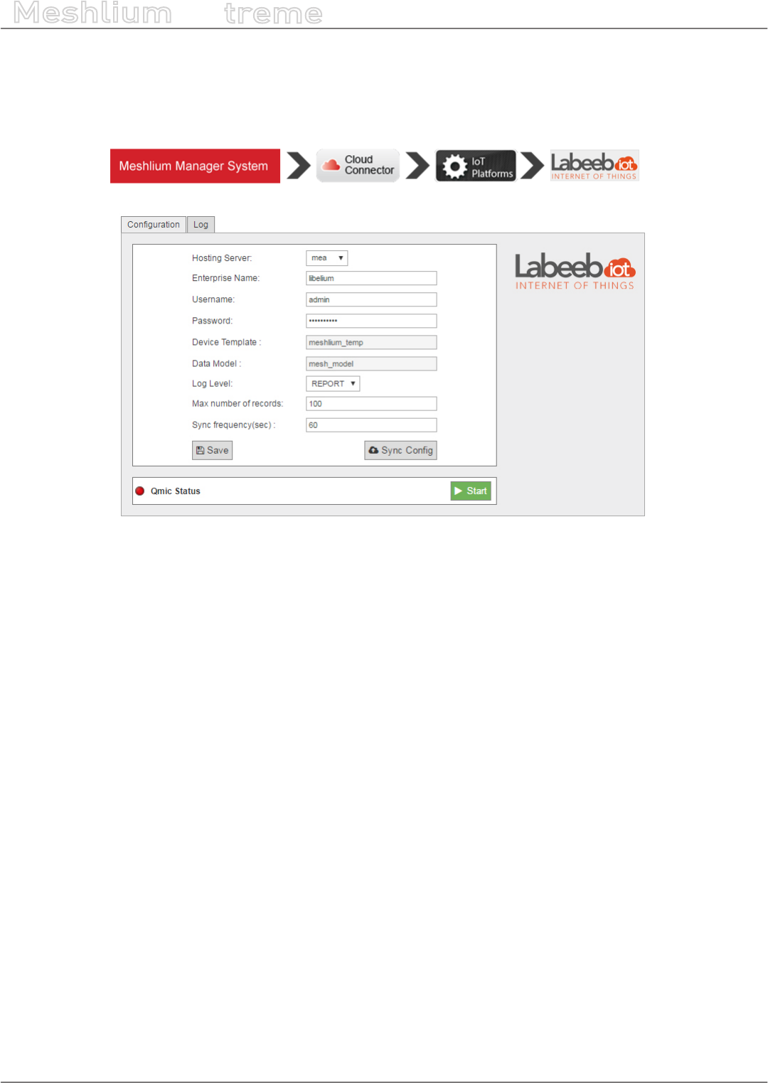
-148- v7.3
Cloud Connectors
Meshlium
X
treme
12.3.16.2. Conguration
After creating your account, you can use your credentials (enterprise name, username and password) to congure
Meshlium.
Figure: Labeeb IoT conguration panel
1. Fill the conguration elds with your Labeeb IoT credentials:
•Hosting Server: the server where your Labeeb IoT account is hosted in (default: MEA for mea.labeeb-iot.com)
•Enterprise Name: enterprise name used to create portal account
•Username: username of your portal account
•Password: password of your portal account
•Log level: used for debugging level, errors, reports, etc
•Max number of records: The maximum number of records to be synchronized to Labeeb IoT every some
time interval
•Sync frequency (sec): specic time interval to perform synchronization, dened in seconds
2. Save the conguration by pressing the button “Saves”. This will store them locally and create all needed devices
and sensors automatically on Labeeb IoT platform.
3. Whenever you make a change, add a sensor or a device, press on “Sync Cong” to update these parameters on
Labeeb IoT portal.
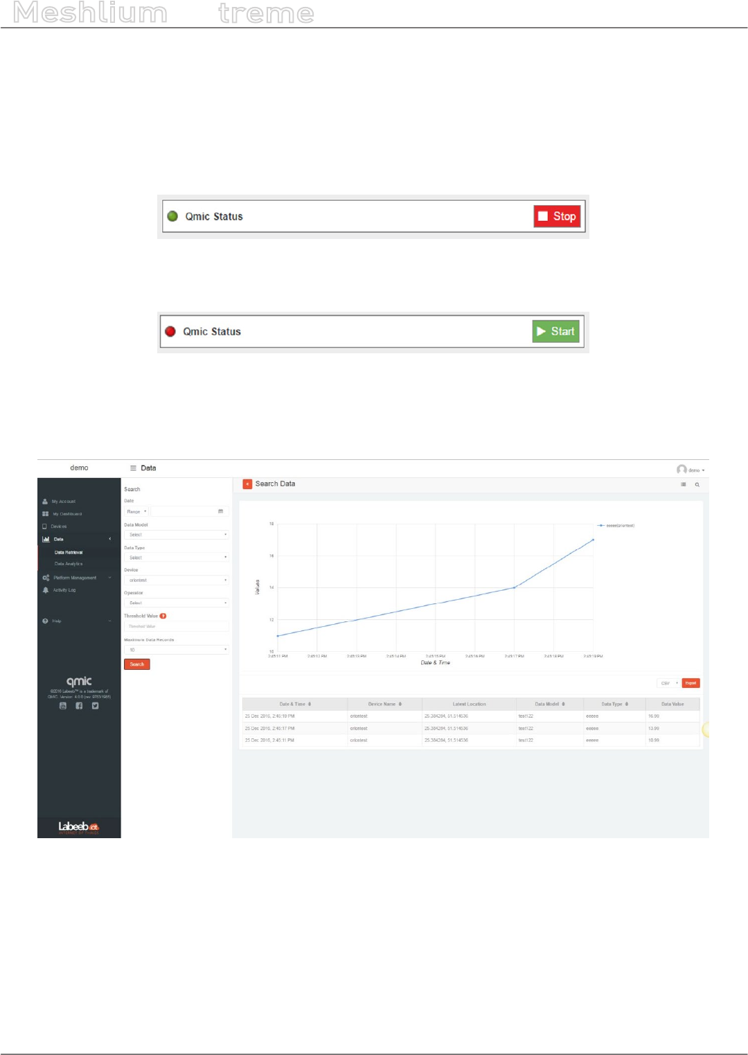
-149- v7.3
Cloud Connectors
Meshlium
X
treme
12.3.16.3. Controlling synchronization
Once the connector is congured, the user can launch the Meshlium Labeeb IoT script (“Start” button). The
program will search for the received frames on the local database, and will send them to the Labeeb IoT Platform.
The status indicator displays the current state: “Running” or “Stopped”.
The Meshlium Labeeb IoT cloud connector will start sending the data of any new Waspmote device to Labeeb IoT
Platform after a maximum of 60 min.
Figure: Labeeb IoT sender is running
You can stop the Labeeb IoT script anytime by clicking on the “Stop” button.
Figure: Labeeb IoT sender is stopped
You can get all the data sent from the Waspmote devices on the Labeeb IoT portal:
Click on Data > Data retrieval > select the related device or data type to retrieve collected data.
Figure: Labeeb IoT Platform data retrieval

-150- v7.3
Cloud Connectors
Meshlium
X
treme
12.3.17. MQTT
MQTT is a publish/subscribe, extremely simple and lightweight messaging protocol, designed by IBM for
constrained devices and low-bandwidth, high-latency or unreliable networks, where battery power is critical. Due
to its features of delivery assurance and bandwidth reduction, MQTT is being used by some Cloud platforms such
as IBM or Carriots, which means that Waspmote data can be stored inside them or in any other one based on this
protocol.
More information: http://mqtt.org/faq.
With this plugin, Waspmote sensor data can be directly integrated with a MQTT broker.
Figure: MQTT plugin
12.3.17.1. Conguration
The broker is a key agent in MQTT protocol. The broker is a server which receives all the frames and distributes
each one of them to the subscribers clients.
MQTT plugin is located in:
Manager System > Cloud Connector > IoT Platforms > MQTT Solutions
In Server/Broker Conguration, the user can set:
•IP Address: Server IP address.
•Port number: Server port number.
•User: Server user name to log in the MQTT system.
•Password: Server password to log in the MQTT server.
•Topic template: Topic of your message. The user can use these wild-cards creating a personalized structure:
-#MESHLIUM#: Identier for Meshlium
-#ID#: Unique identier for data
-#ID_WASP#: Identier for Waspmote
-#SENSOR#: Sensor identication
•Message template: Data structure of your message. The user can use these wild-cards creating a customized
content:
-#ID#: Unique identier for data
-#ID_WASP#: Identies the Waspmote unit
-#ID_SECRET#: Secret identier
-#SENSOR#: Identies the sensor
-#VALUE#: Value obtained from the sensor
-#TS(“c”)#: Date with custom format. The parameter passed in this wild-card corresponds to the same
ones you can use in PHP date function (see format parameters in http://php.net/manual/es/function.date.
php#refsect1-function.date-parameters).
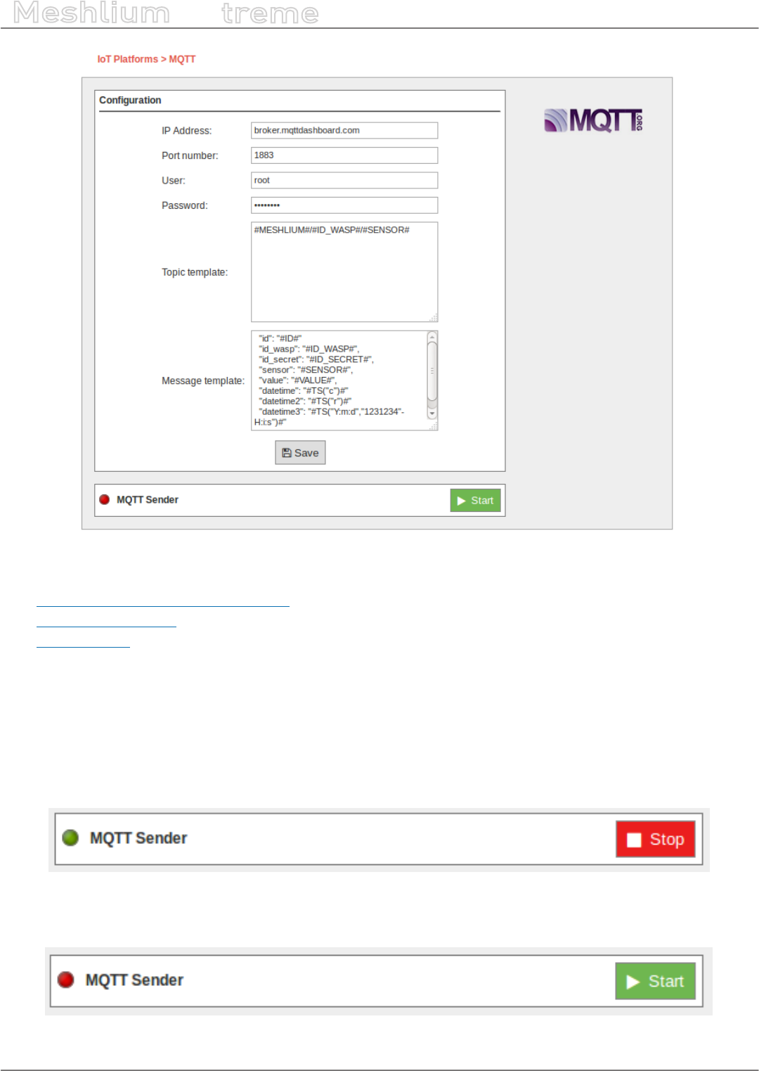
-151- v7.3
Cloud Connectors
Meshlium
X
treme
Figure: Server/Broker Conguration
Examples about MQTT Servers/Brokers:
•http://mqtt.org/wiki/doku.php/brokers
•http://mosquitto.org/
•http://mqtt.io/
Note: in this example, the broker was running on a computer inside our local network for test purposes only. For
professional use, it is recommended to work with a 24/7 server with static IP address.
12.3.17.2. Controlling status
Once congured the server/broker, the user can launch the Meshlium MQTT program (Start button). The program
will search for the received frames on the local database, and will send them to the broker via MQTT protocol. The
status indicator displays the current state, saying “Running” or “Stopped”.
Figure: MQTT sender is running
You can stop the MQTT sender anytime clicking on the “Stop” button.
Figure: MQTT sender is stopped

-152- v7.3
Cloud Connectors
Meshlium
X
treme
12.3.17.3. Platforms using MQTT
MQTT has been widely implemented across a variety of industries. As of March 2013, MQTT is in the process
of undergoing standardization at OASIS protocol stack. The protocol specication has been openly published
with a royalty-free license for many years, and companies such as Eurotech (formerly known as Arcom) have
implemented the protocol in their products.
Here are a number of notable projects that have made use of MQTT and related technologies. Companies like
Cisco, Eclipse Foundation, Eurotech, IBM, Kaazing, M2Mi, Red Hat, Software AG, TIBCO and Carriots, among other
companies, are working with this protocol.
More information about examples and uses: http://mqtt.org/wiki/doku.php/example_uses.

-153- v7.3
Cloud Connectors
Meshlium
X
treme
12.3.18. Orchestra
The Orchestra platform IoT enables the possibility to collect all the data from sensors attached to Meshlium over
MQTT and manage them in a user-friendly dashboard.
12.3.18.1. How to get your own API-key
For getting your own API-key you have to send a mail to services@orchestra.it with the subject “[ Libelium – Activation
] New activation request”, signaling the number of sensors and the numbers of venues or Meshliums being used,
and Orchestra will provide the account to access the platform where you can get the needed information.
Figure: Conguring Orchestra
Below there are a couple of images showing where you will nd the API information on the Orchestra website.
Figure: Orchestra platform user panel
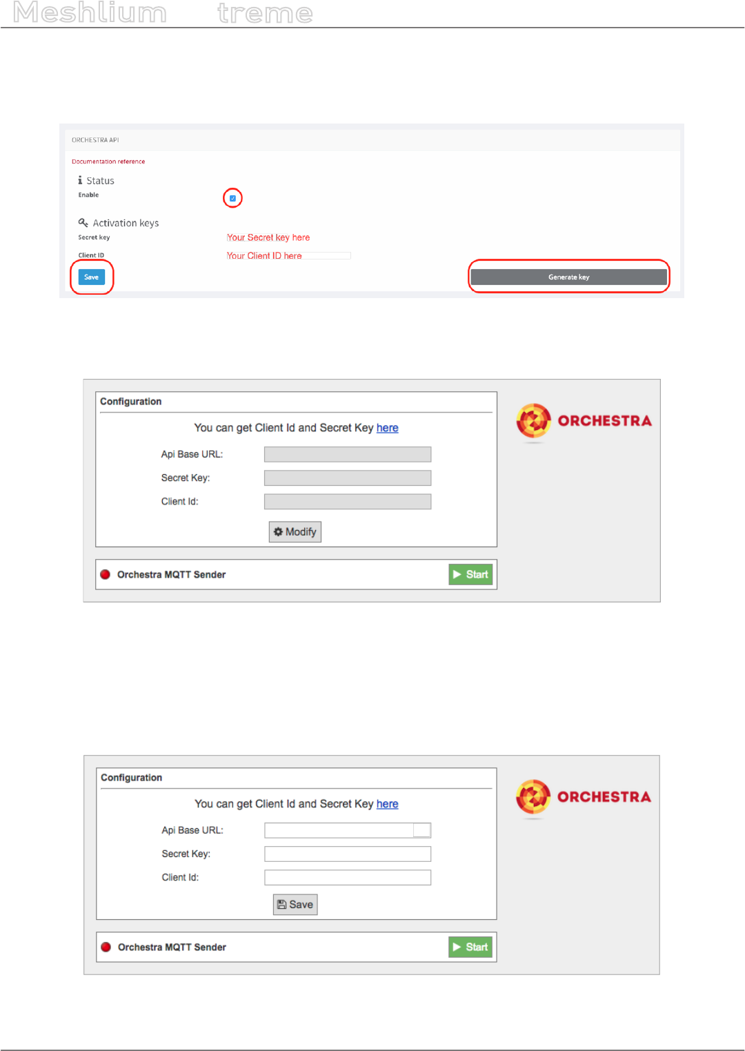
-154- v7.3
Cloud Connectors
Meshlium
X
treme
To activate the API secret key and get the client Id, you have to go to the “Prole” section of the Orchestra account
and then select the checkbox in the “Orchestra API” section and click the “Generate key” button.
Then you have to save the information generated by clicking on the “Save” button in the same section.
Figure: Orchestra platform API panel
12.3.18.2. Conguration
Figure: Orchestra Cloud Connector conguration panel
•API Base URL: You must enter the API URL that you are going to use for collecting the Meshlium data.
•Secret Key: The secret key to access the API.
•Client Id: Security key used for validating the access to the Host.
Click on the “Modify” button to enable the elds and insert the values previously obtained.
Figure: Orchestra Cloud Connector conguration panel
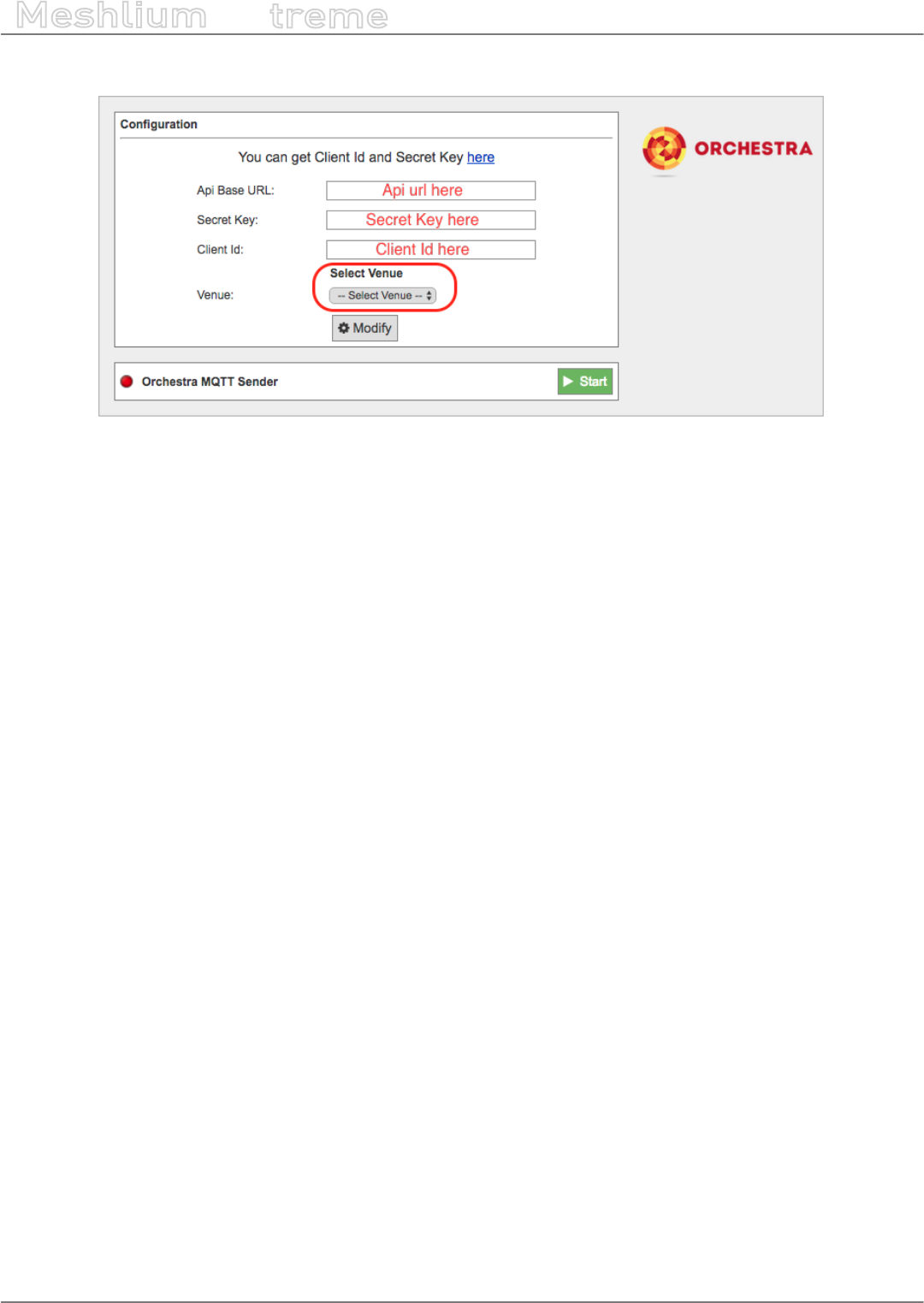
-155- v7.3
Cloud Connectors
Meshlium
X
treme
Once you click the “Save” button, a select box will appear with the venues you can choose.
Figure: Orchestra Cloud Connector conguration panel
After that, press the “Start” button, and you will start to receive data from the congured Meshlium.
If you want to stop the event sending, just press the “Stop” button.
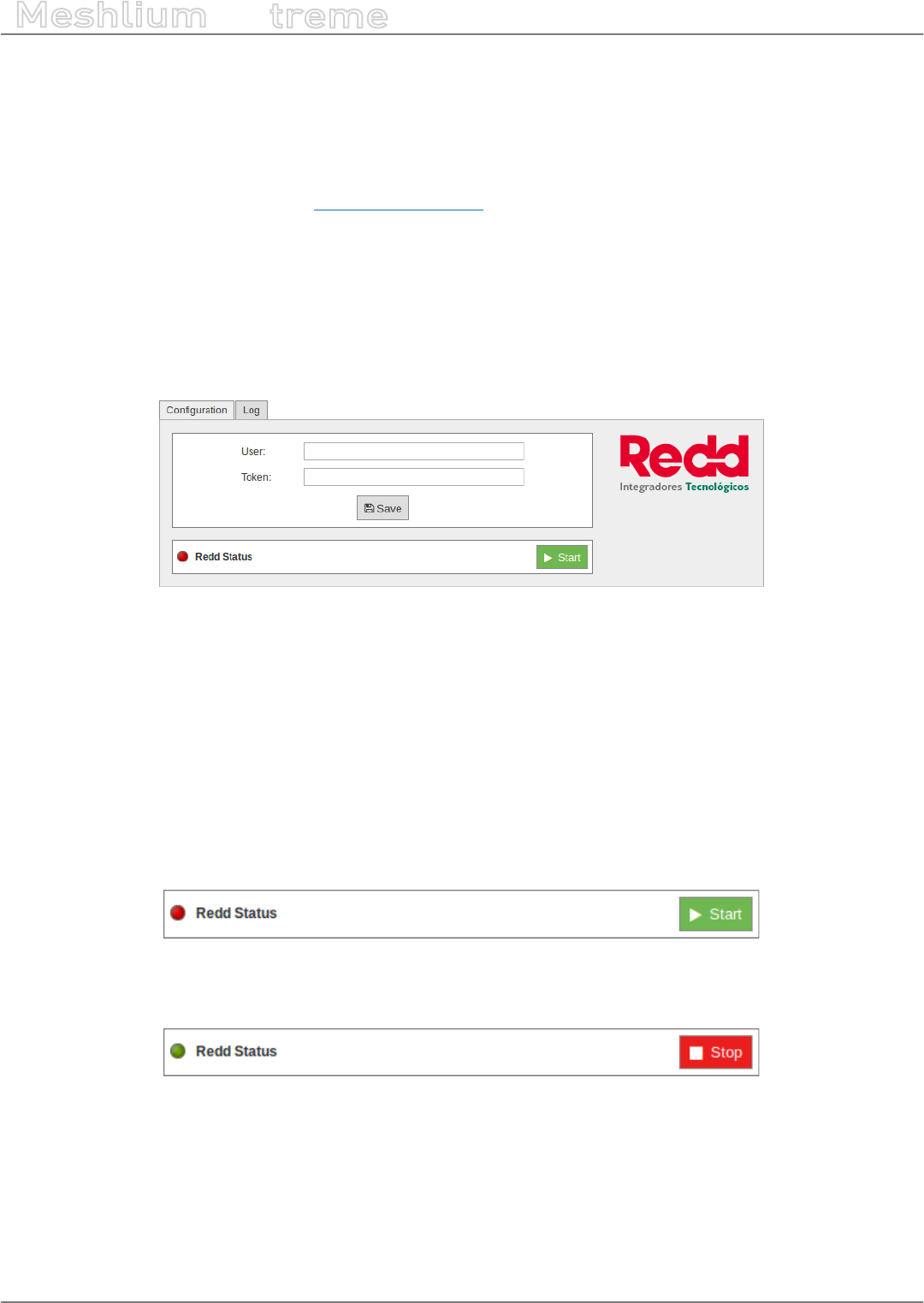
-156- v7.3
Cloud Connectors
Meshlium
X
treme
12.3.19. Redd
Redd is a company focused on delivering telemetry and telecontrol solutions for clients assets, with the aim of
optimizing and simplifying operations, and most importantly, providing them with the necessary information to
make quick and timely decisions.
For more information, please contact iot@reddsystem.com.
12.3.19.1. Conguration
You can locate the Redd Cloud Connector at:
Manager System > Cloud Connector > Basic Cloud Partner > Redd Cloud Connector
Inside the conguration panel you can ll 2 parameters with the information provided by Redd. These are:
Figure: Redd Cloud Connector conguration panel
•User: this eld recognizes the information sent to Redd by you
•Token: unique identier that enables access of your information to Redd
Click on the “Save” button for storing the conguration elds.
The tab “log” will allow you to see the status of the running connector via its log les.
12.3.19.2. Controlling synchronization
Once congured the Redd Cloud Connector, you can launch the sync script by pushing the “Start” button. The
synchronization will search for the received frames on the local database, and will send them to the Redd IoT
platform via TCP protocol.
Figure: Redd Cloud Connector synchronization service in standby
After clicking on the “Start” button, it becomes a red “Stop” button. Click again and you will stop the synchronization.
Figure: Redd Cloud Connector synchronization service running
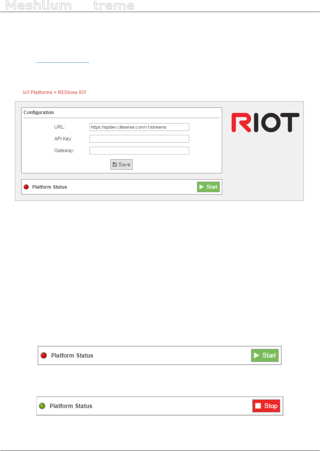
-157- v7.3
Cloud Connectors
Meshlium
X
treme
12.3.20. RIOT Platform
RIOT is a Sensing as a Service Platform developed by REDtone IOT. It manages connectivity from sensors or data
sources with various communication protocols including MQTT and RESTful.
Please visit http://riot.com.my/ for more information.
12.3.20.1. Conguration
Figure: RIOT plugin Conguration
The RIOT plugin is congured with the following parameters:
•URL: The IP address or the URL will be provided by REDtone IOT.
•API Key: An API Key will be provided by REDtone IOT as one of the authorization information in order to send
data to the RIOT platform.
•Gateway: Field to identify which Meshlium device the data came from when the platform receives the data,
so that we can trace the location.
Note: In the Waspmote sensor board, make sure you identify each board with their own ID so that we can trace which
sensor board the data originated.
12.3.20.2. Controlling synchronization
The synchronization will be executed for all the data that has not been synchronized in the Sensor Parser database
table. You can start and stop the synchronization process. In the interface of our service, you can see if the status
of our service is either running or not. If you click on “Start”, the synchronization will start.
Figure: RIOT sender is running
If you want to stop the synchronization process, you can simply just click on “Stop” and the process will stop.
Figure: RIOT sender is stopped
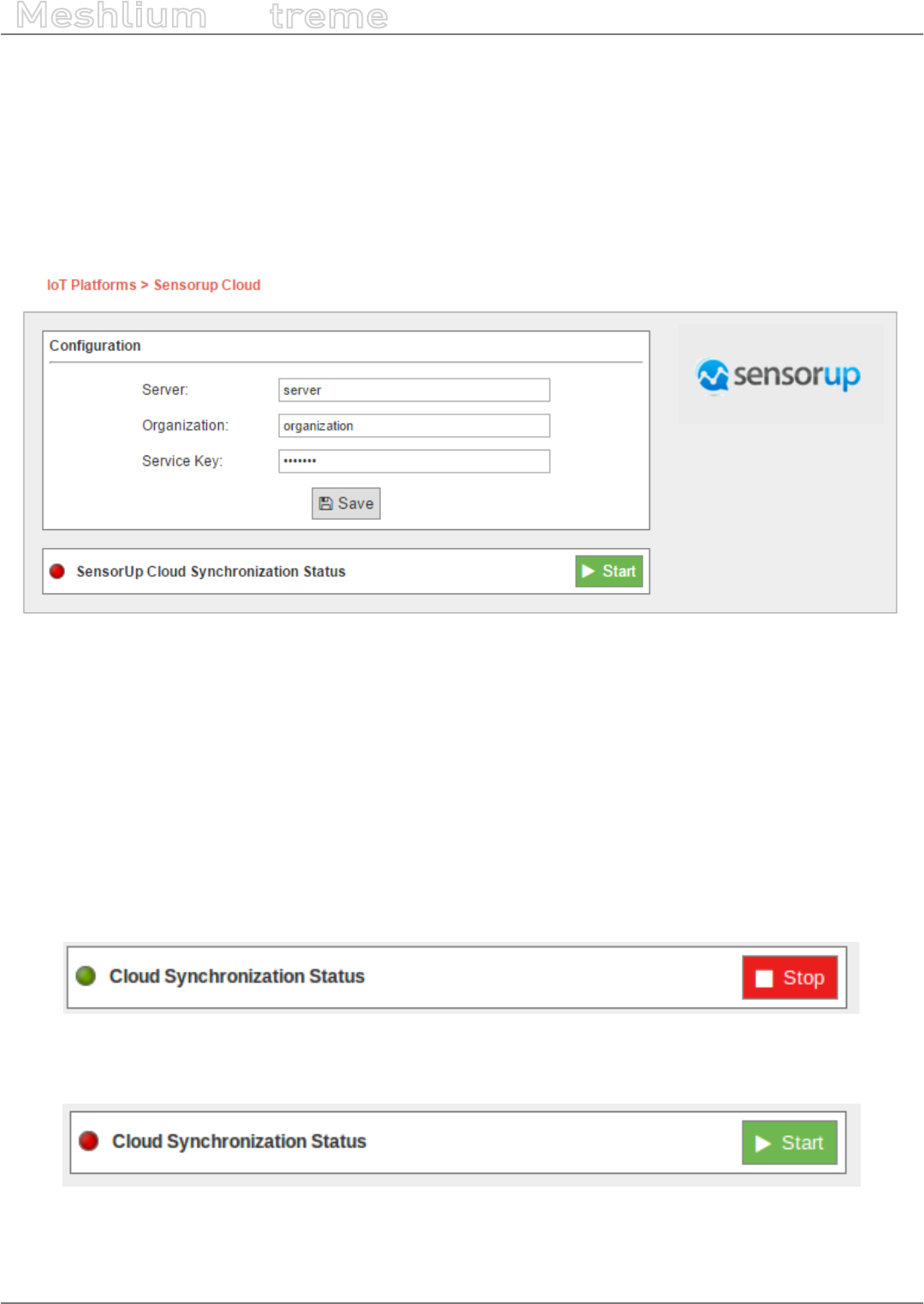
-158- v7.3
Cloud Connectors
Meshlium
X
treme
12.3.21. SensorUp IoT Platform
SensorUp provides an open standard IoT platform that enables information from all dierent kinds of sensors
accessible in a single platform.
12.3.21.1. Conguration
You can access the SensorUp IoT platform plugin from the Cloud Connector menu, and setup all the information
needed to connect Meshlium to the SensorUp IoT platform.
Figure: SensorUp conguring plugin
•Server: SensorUp IoT platform server
•Organization: Identier of your organization
•Service Key: Key used to access SensorUp IoT platform
All these parameters are provided by SensorUp.
12.3.21.2. Controlling synchronization
Once you have saved the conguration, you can send your data to the SensorUp IoT platform by pressing the
“Start” button. You will notice about it because the screen shows a spinning wheel when the process starts and
displays a “running” status.
Figure: SensorUp status “Running”
If you want to stop this process, just press the “Stop” button. You can start/stop this process anytime.
Figure: SensorUp status “Stopped”
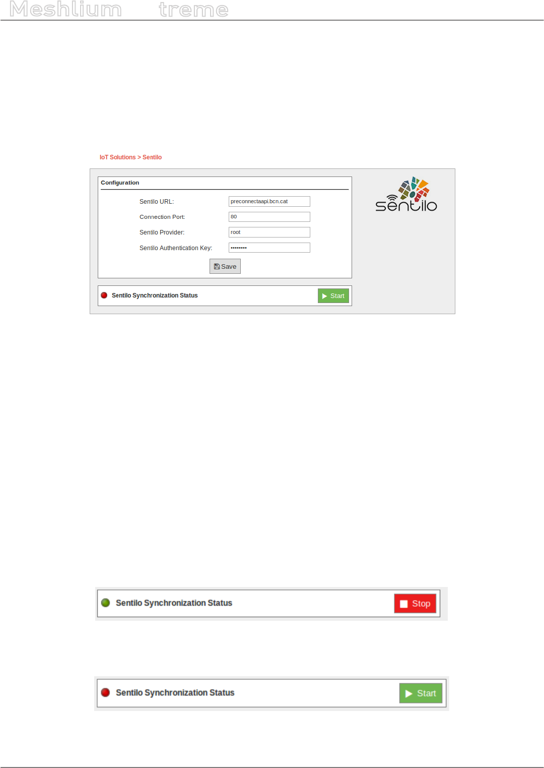
-159- v7.3
Cloud Connectors
Meshlium
X
treme
12.3.22. Sentilo
Sentilo is an open source sensor and actuator platform designed to t in the Smart City architecture of any city who
looks for openness and easy interoperability. It is built, used, and supported by an active and diverse community
of cities and companies that believe that using open standards and free software is the rst smart decision a
Smart City should take.
12.3.22.1. Conguration
Figure: Conguring Sentilo in Meshlium
Inside the “Sentilo” plugin, you have a form to introduce your credentials to access your Sentilo system. You have
to enter here these parameters:
•Sentilo URL: Address of the API service of Sentilo. This address should be provided without the “http://”.
•Connection Port: The port in which the API listens to connections.
•Sentilo Provider: The provider is the identity of who is sending data to Sentilo.
•Sentilo Key: The security key to send data to Sentilo.
This data will be provided by the administrators of the Sentilo system you are using.
Sensor, Types and Components are not created automatically, you need to manually create them in Sentilo as a
previous step.
12.3.22.2. Controlling synchronization
The synchronization will be done in packs of 100 data at a time, so the system is not overloaded. You can start and
stop the synchronization of the data to the Sentilo service. In the interface, you can see an indicator of whether
the Sentilo service is running or not. If you click on “Start”, the synchronization will begin.
Figure: Sentilo synchronization service is running
You can stop at any moment clicking on “Stop” button.
Figure: Sentilo synchronization service is stopped
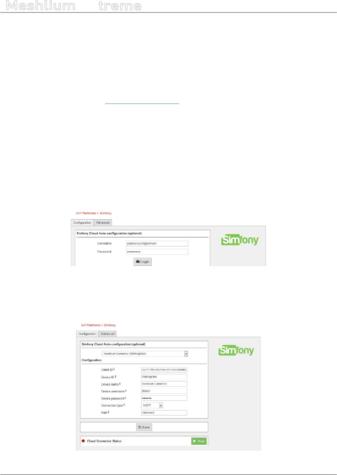
-160- v7.3
Cloud Connectors
Meshlium
X
treme
12.3.23. Simfony
Simfony’s IoT Platform is focused on providing the core set of tools that enables the rapid roll-out of any IoT
project or service. Companies can use the service to easily and rapidly design, prototype and deploy IoT projects
that match their exact needs and requirements, rather than looking for an o the shelf product that ts best. The
platform provides the following services: global mobile data connectivity, SIM management and control, device
authentication and authorization, a visual service designer, data storage, reporting and visualization, IoT VPN and
an extensive API exposing all of these capabilities for enterprise integration. All these services are available on a
“pick and choose” basis enabling maximum exibility and optimizing costs.
More information can be found at www.simfonymobile.com.
12.3.23.1. Conguration
The Simfony Cloud Connector is capable of self-conguration using data already provisioned from the Simfony
Cloud Platform. This function requires that the user is authenticated and authorized into the Cloud Service with a
specic set of credentials provided through the Self-Care portal. These credentials are not stored on the Meshlium
or by the Connector and will have to be entered manually each time an Auto-Conguration action is requested
through the web GUI. This functionality runs on the user’s browser that is connected to the Meshlium device and
requires Internet access, i.e. from the browser to the Cloud Platform API.
Once the user is authenticated, a list of all the Cloud provisioned devices is available for selection. If one of the
devices is selected in the drop-down list, the web GUI will automatically ll in or overwrite the following parameter:
Client ID, Device ID, Device Name, and Device Password.
Figure: Simfony cloud connector conguration panel
If the Cloud Connector is already congured with a valid Device ID the Auto-Conguration feature will automatically
retrieve the Cloud provisioned data corresponding to that Device ID and ll in the parameters mentioned above.
Any previous conguration is overwritten. This functionality can be used to resync the data provisioned in the
Cloud with the conguration data of the Connector.
Figure: Simfony cloud connector conguration synchronization panel
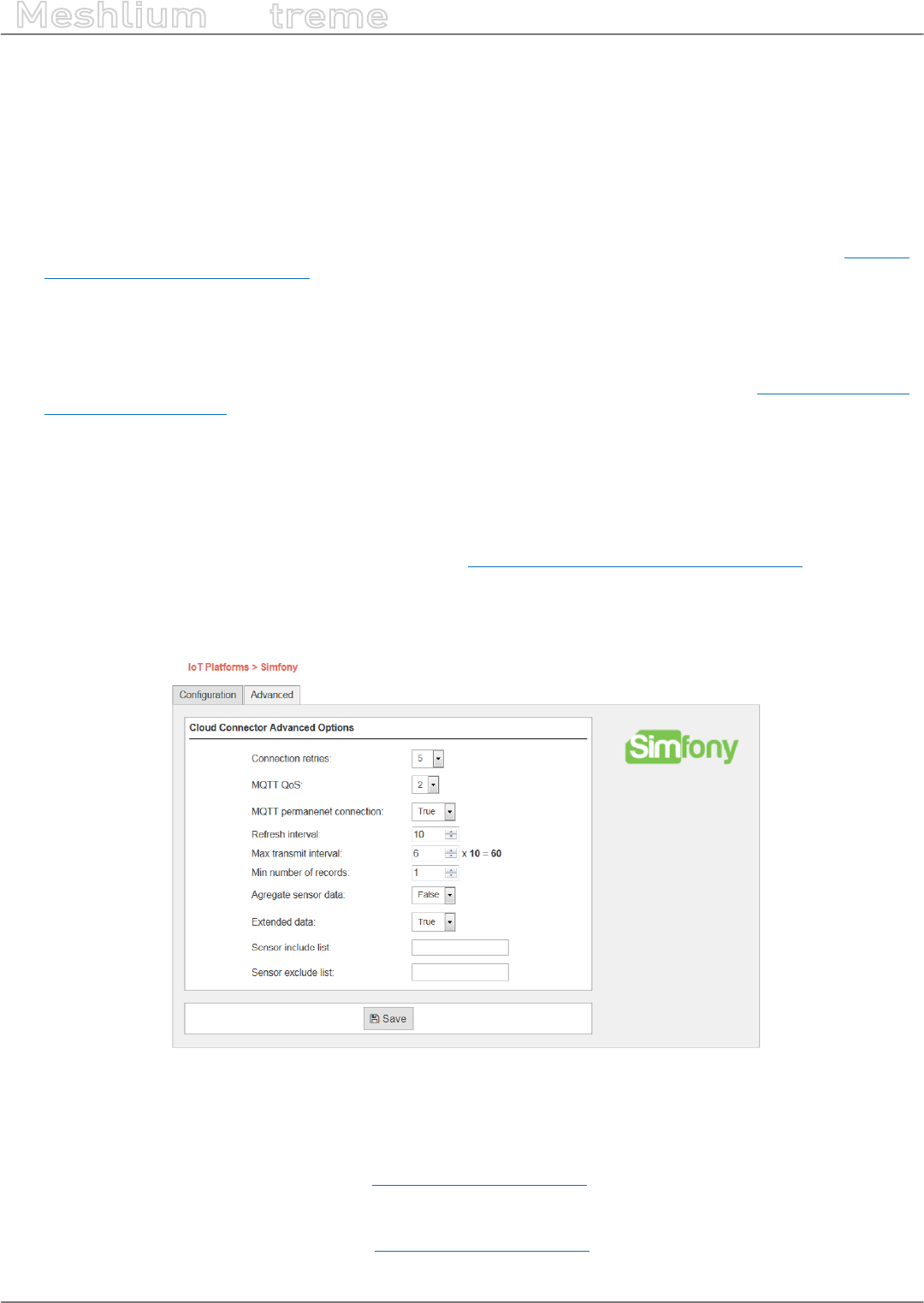
-161- v7.3
Cloud Connectors
Meshlium
X
treme
All the data retrieved automatically from the Cloud can also be entered manually.
The user must use the Save button to save any newly congured data or apply any changes to it.
12.3.23.2. Advanced conguration
The advanced conguration window of the Connector allows the setting of the following parameters:
•Connection retries: Controls the number of connection testing retries before suspending operations and
going to the sleeping phase (see the Functional description chapter, Test connectivity phase in “Simfony
Meshlium Connector- User Guide”). Default: 3.
•MQTT QoS: Controls the QoS of the MQTT PUBLISH messages. Default: 1.
•Permanent MQTT connection: In case of MQTT connections, controls if the Connector will close the MQTT
connection or not during the sleep phase. Default: false.
•Refresh Interval: The number of seconds the Connector will suspend its operations (sleep time) before
starting a new extract and transmit cycle (see the Functional description chapter in “Simfony Meshlium
Connector- User Guide”). Default: 300.
•Maximum transmit interval: The number of Refresh Intervals after which the Connector will transmit the
data independently of the number of new database records found and the “Minimum number of DB records”
parameter value. Default: 5.
•Minimum number of DB records: The minimum number of new database records that will trigger a sending
procedure of the Connector. If the found new number of records is lower (strictly) than the value of this
parameter, the transmit phase will be suspended until the number or records reaches the threshold or the
condition expires (see Maximum transmit interval in “Simfony Meshlium Connector- User Guide”). Default: 1.
•Aggregate sensor data: Controls the way the Connector aggregates the sensor data found in the DB. If “true”,
the connector will aggregate sensor data from the same Waspmote frames into a single message. If “false” the
Connector will transmit the data individually as extracted from the database. Default: true.
Figure: Simfony cloud connector advanced conguration panel
•Extended sensor data: Controls the number of parameters the Connector will transmit to the cloud. If “true”,
the whole data extracted from the database will be sent. If “false”, only a subset of the data stored in the database
is sent. Default: false.
•Include sensor list: The sensor ID list (Meshlium Technical Guide) that the Connector will look for when
extracting data from the Meshlium database. The “Include” and “Exclude” lists are exclusive with the Exclude
list having higher precedence. Default: empty.
•Exclude sensor list: The sensor ID list (Meshlium Technical Guide) that the Connector will exclude when
extracting data from the Meshlium database. The “Include” and “Exclude” list are exclusive with the Exclude
list having higher precedence. Default: empty.
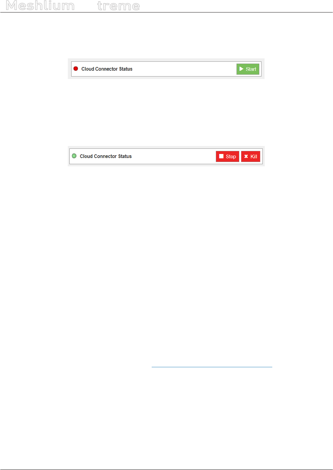
-162- v7.3
Cloud Connectors
Meshlium
X
treme
12.3.23.3. Running the connector
After the entire conguration is complete, the user can start the connector using the “Start” button of the GUI. The
Connector will be started and run seamlessly in background.
Figure: Simfony start button
The Status box will show the Connector’s state whenever the page is viewed by the user.
To stop the Connector, the user can press the “Kill” button that will stop the connector from running.
Warning: The “Kill” operation will terminate the Connector process and all it procedures abruptly independently
of the stage they are in, i.e. extracting, transmitting, etc.
Figure: Simfony stop/kill button
To stop gracefully the connector the “Stop” button can be used. This will not interrupt any ongoing operations but
rather wait for the connector to nish any ongoing activities. The Connector will look for this graceful stop signal
each time it is starting or nishing the sleep cycle.
12.3.23.4. Integration with Simfony’s IoT platform
The Simfony Cloud Connector is intended to work with any type of connectivity provided by the Meshlium device
it is deployed on. The Connector has two standard protocols available for communicating with the Simfony Cloud:
MQTT and HTTP. Both of them are available in the encrypted version also, i.e. MQTT+SSL and HTTPS. The customer
it is able to choose the most appropriate protocol for his application.
Each Cloud Connector/Meshlium device must be individually authenticated and authorized before it can send data
to the Simfony Cloud Service. The IoT platform will perform protocol specic authentication and authorization
procedures and will allow the connectors to send data only if these are successful. The Connector conguration
data must contain these credentials before the Connector can run properly.
Before data can be sent from the Connector to the Cloud Platform, a Cloud IoT Application must be deployed in
order to listen for data. Customers can easily create, test and deploy their own applications via the Application
Designer GUI. Each application can have a specic entry point for the data coming from the sensor and connectors.
This entry point is dened by the used Protocol (MQTT or HTTP) and a custom target (MQTT-topic; HTTP-path). This
entry point must be also congured in the Connector via the “Connection Type” and “Connection Path” parameters.
Once the application is deployed, the connectors can start sending data into it and the custom business logic will
be triggered.
Find out more about running the connector in the “Simfony Meshlium Connector- User Guide”.
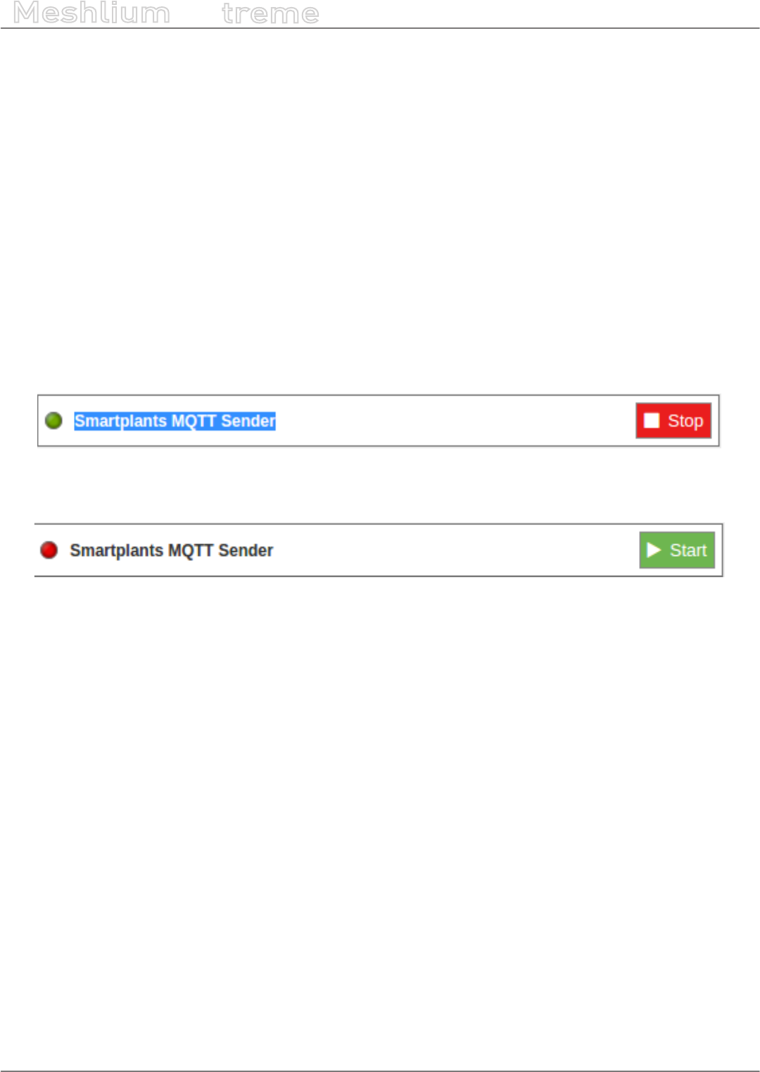
-163- v7.3
Cloud Connectors
Meshlium
X
treme
12.3.24. SmartPlants
Smartplants Cloud integration enables secure communications between the devices connected to the Meshlium
device and the cloud.
Smartplants plugin is located in:
Manager System > Cloud Connector > IoT Solutions > Smartplants
12.3.24.1. Conguration
You will receive the conguration information that is required to connect your Meshlium to the SmartPlants
system via an e-mail from Smartplants.
12.3.24.2. Controlling synchronization
Once you congured the server/broker, the user can launch the Meshlium SmartPlants script (clicking on the
“Start” button). The program will search for the received frames on the local database, and will send them to
the Smartplants Cloud platform via an MQTT protocol. The status indicator displays the current state, saying
“Running” or “Stopped”.
Figure: Smartplants sender is running
You can stop the Smartplants program anytime clicking on the “Stop” button.
Figure: Smartplants sender is stopped
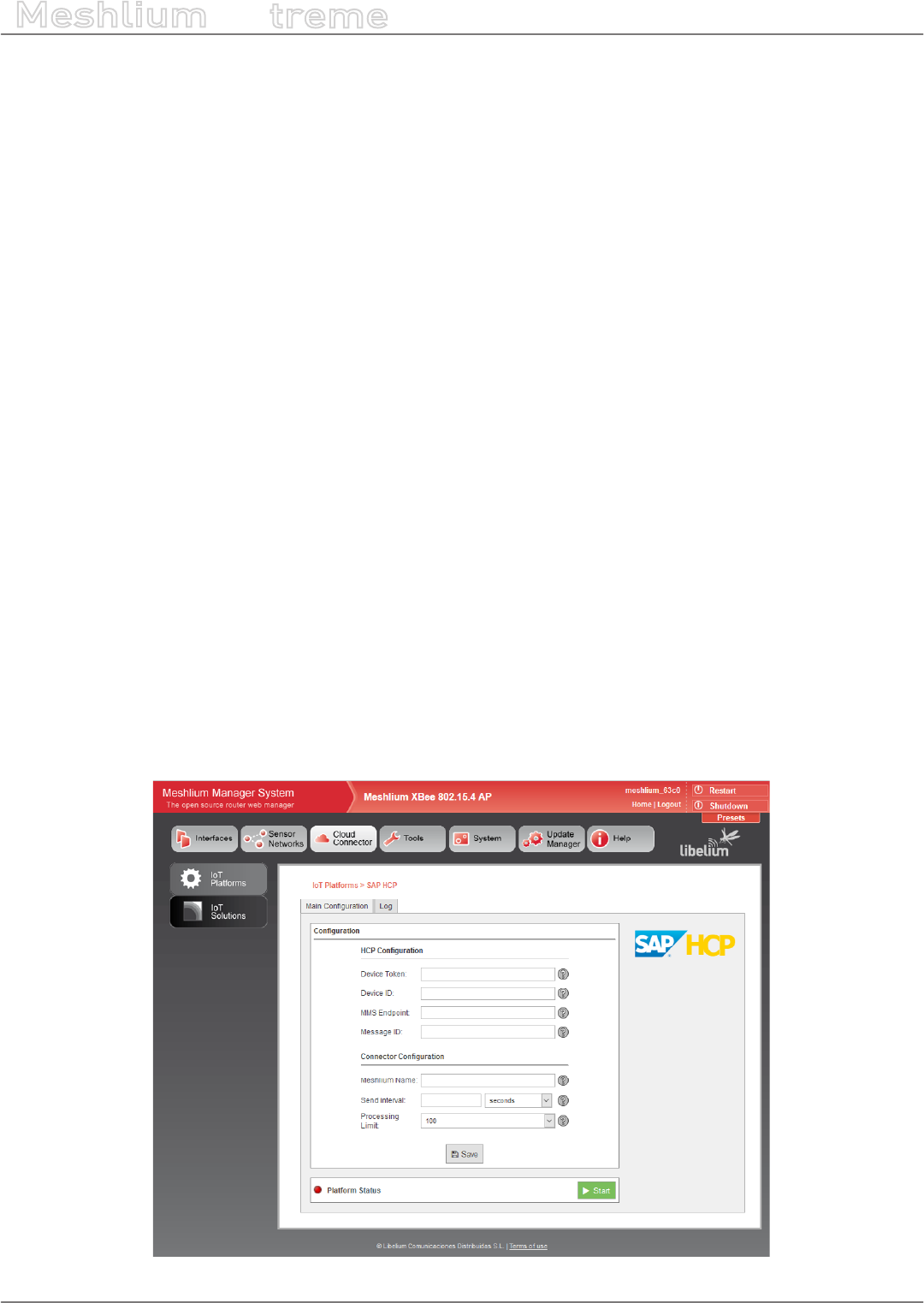
-164- v7.3
Cloud Connectors
Meshlium
X
treme
12.3.25. TechEdge SAP HANA
SAP HANA Cloud Platform is a platform-as-a-service open (PaaS) that provides unique services for databases and
applications in memory. It is the cloud platform that allows you to quickly develop new applications or extend
existing ones. Allowing anyone to extend SAP applications within minutes, all in the cloud.
With SAP HANA Cloud Platform you can:
•Deploy in the cloud and their existing on-premise applications. You can quickly add a new functionality to their
existing applications in the cloud and on-premise.
•Connect your cloud and on-premise applications to eliminate data silos and make a simple, secure and
scalable digital access
•Create and run new applications in the cloud to solve new problems, make new customers and new income
•It allows to connect the business processes with eld devices through Internet of things (IoT) services.
This platform allows:
•Enable remote services management of devices
•Communicate through secure protocols with eld devices
•Manage devices and their messages remotely through programming interfaces (API)
12.3.25.1. Conguring SAP HANA
To make the connection between the platform and the SAP HCP Gateway Meshlium by Libelium, so we can receive
the data sent from the gateway, a pre-conguration of Things Internet service is required.
For more information about how to congure the Things Internet service, please contact your TechEdge contact.
12.3.25.2. Conguration
Select the “IoT Platforms” and press on SAP HCP to access the service conguration screen of TechEdge cloud
connector for SAP HANA Cloud Platform.
By accessing the SAP HCP connector conguration screen, a form with the necessary elds to congure is displayed.
Figure: TechEdge conguration plugin
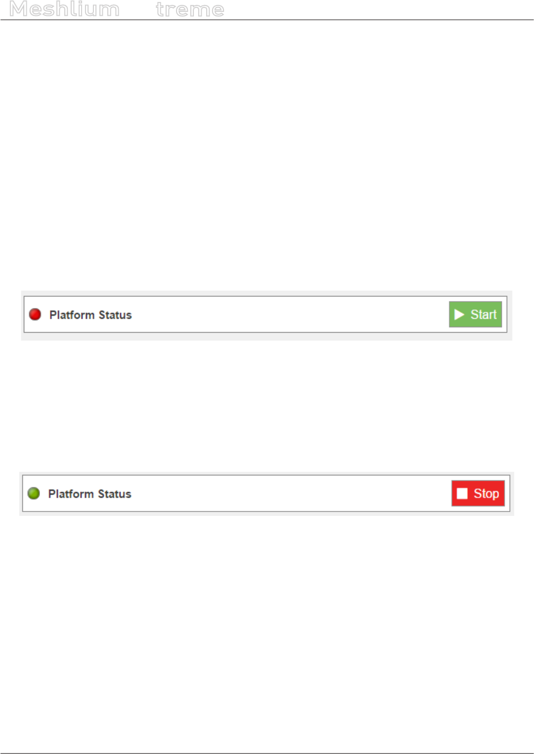
-165- v7.3
Cloud Connectors
Meshlium
X
treme
•Device Token: The Token OAuth2.0 provided by HCP to the device create (you must congure SAP HCP IoT
before, as described in the previous sections)
•Device ID: Identier of the device created in HCP
•MMS Endpoint: Data Endpoint of HCP MMS services
•Message ID: ID of message type created in HCP
•Meshlium Name: Meshlium unit identifying name (free eld)
•Send Interval: Denes the connector’s space of time to wait between each HCP cloud deliveries. Each delivery
contains between 100 and 200 sensors traces, and in order to not saturating the Gateway memory, the
minimum accepted is 5 seconds.
•Processing Limit: Limit of simultaneous messages processing in each of HCP cloud deliveries, the gures
are considered between 100 and 200, these are the gures recommended by Libelium to ensure a high
performance in the Gateway.
After setting all elds described above, it is necessary to save the changes by clicking the “Save” button at the
bottom of the conguration form.
12.3.25.3. Controlling synchronization
After saving the conguration, you can now start the service. To do this click on the “Start” button.
Figure: TechEdge status “Running”
When the service has started, “Platform Status” is displayed in green, and the “Start” button changes to “Stop”.
Note: The Data synchronization with Meshlium will be held as maximum packet size dened in “Processing Limit” eld.
All those new data received since the last delivery will be synchronized, if the data exceeds the maximum size set to
“Processing Limit” several deliveries will be made to complete the synchronization.
With the service has started, to stop the service you must click on the “Stop” button on the HCP conguration
screen in Meshlium.
Figure: TechEdge status “Stopped”
Pressing the “Stop” button, a stop will start in a controlled manner, allowing you to stop the service without
incident (close les, ends active processes of polling, etc.), ensuring a proper functioning of the Meshlium gateway.
When the service has stopped, “Platform Status” is displayed in red, and the “Stop” button will change by “Start”.

-166- v7.3
Device connectors
Meshlium
X
treme
13. Device connectors
The aim of this chapter is to introduce the user to the Meshlium’s Device Connector functionality. This section will
help you to connect your Meshlium to a 3rd party device platform.
3rd party certied connectors are linked with Meshlium by an IP interface.
What is a device platform?
Devices are equipments which could be easily correlated with Meshlium through an Ethernet or wireless connection.
Devices perform actions like taking images, activation on systems, industrial control, etc. Interfacing with 3rd party
devices allows Meshlium to execute actions manually or automatically responding to events detected in the info
sent by Waspmote or Plug & Sense! and received on Meshlium.
Meshlium Device Connector
Meshlium runs the software necessary for implementing the analysis of its internal database and the control of
devices. In other words, this software checks the occurrence of events and performs the rules specied to execute
actions on the device. This software is called Device Connector.
Figure: Device Connector main menu on the Manager System

-167- v7.3
Device connectors
Meshlium
X
treme
13.1. Device Partners
13.1.1. Axis
Axis oers a wide variety of network videocameras and advanced analytic applications. More information: https://
www.axis.com/global/en/products/network-cameras.
Thanks to this plugin, the sensor data received on Meshlium can trigger actions on Axis cameras.
Figure: Axis plugin
13.1.1.1. Conguration
Pior to congure Meshlium, make sure you set these parameters on the camera: IP, username, password and
presets.
For information about how to congure your camera, please check the installation guide of your camera model.
The Axis plugin is located in:
Manager System > Device Connector > Device Partner > Axis
In the “Conguration” panel, the user can set:
•Log Level: Generate log messages. From fewer to more details, the levels are: OFF, ERROR, INFO, DEBUG and
REPORT. The option by default is OFF.
•Execution interval: Time interval between checking camera’s rules.
In the “Add Camera” panel, the user can set:
•Name: Device rule name.
•IP: IP address of the camera.
•User: User name congured on the camera.
•Password: The password congured on the camera by the user (dened in the previous step).
•PTZ Preset: Preset of the camera to be used when the rule is executed. For obtaining a list of available presets
on the camera you have to ll the parameters above (IP, user and password). They will be used for getting the
presets when you press the button “Get Presets”. After pushing the button, the list of presets will be shown
and you will be able to select one of them.
•Threshold: Threshold in a sensor value for taking a picture. This eld is not mandatory, but if you want to add
a threshold, you have to select one:
-Waspmote sensor: Available sensor which will trigger the rule.
-Operation: Available operations are: greater, less, greater or equal, less or equal, equal than or dierent
from.
-Value: Value to be compared to the sensor selected.
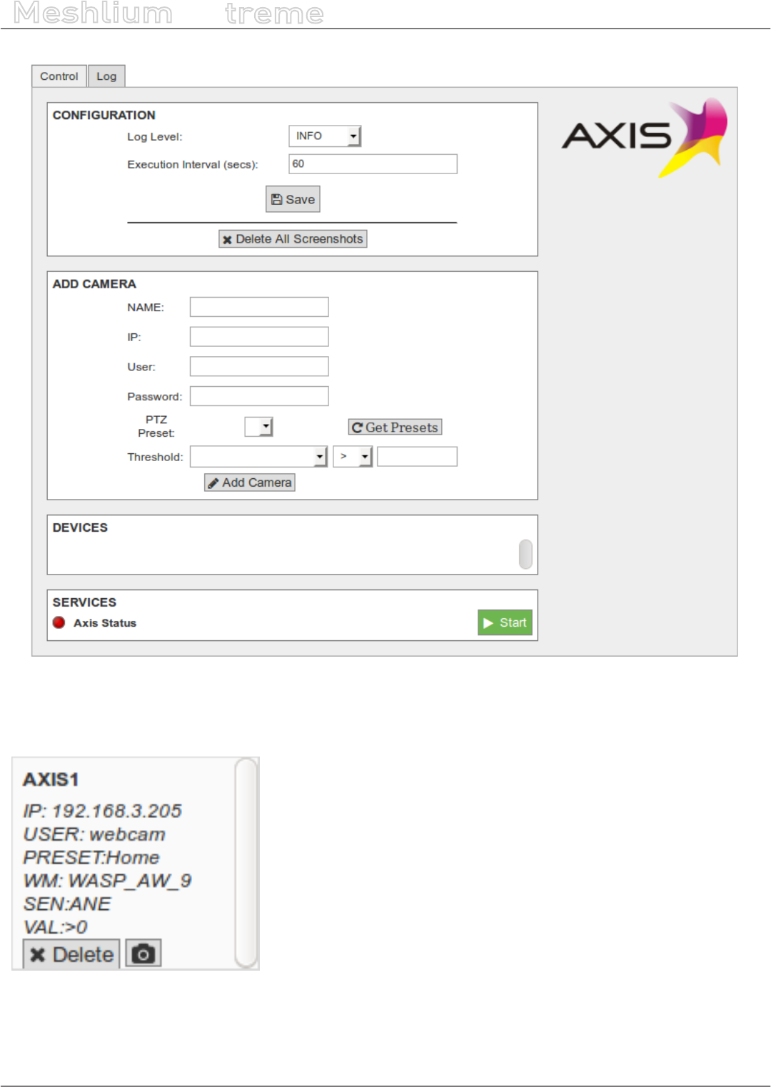
-168- v7.3
Device connectors
Meshlium
X
treme
Figure: Axis conguration panel
When all the parameters have been congured, press the “Add Camera” button. This action will add a new rule in
the “Devices” section.
Figure: New device
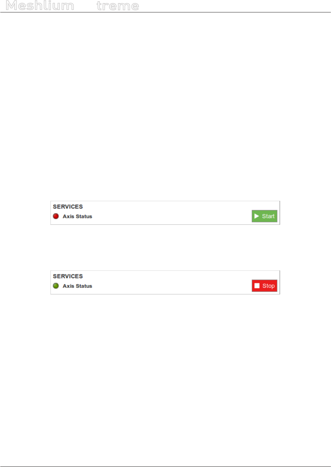
-169- v7.3
Device connectors
Meshlium
X
treme
13.1.1.2. Devices
In the “Devices” section you can see all the rules that will be evaluated for each device. Apart from checking that
the rules are properly congured, you can execute 2 actions:
•Delete: Delete the device. It will be disappear from this section and the rule will not be evaluated.
•Take a picture: The camera will take a picture in the predened preset.
For accessing to the pictures taken (both manual or automatic) you have to access to the FTP server of the
Meshlium unit. The folder “axis” inside the FTP main directory contains the images taken. The image names will
vary depending if the picture was taken manually or automatically:
•Manually: the name of the le will be NAME_YYYY-MM-DD_HH-MM-SS.jpg
•Automatically: the name of the le will be NAME_WASPNAME_SENSORNAME.jpg
13.1.1.3. Controlling synchronization
Once the devices are congured, the user can launch the Meshlium Axis service (“Start” button). The program will
search for the received frames on the local database, and will check the rules congured. If a rule is evaluated
positively, then a picture in the preset position of the rule will be taken and stored. The status indicator displays
the current state, red means ‘stopped’ and green means ‘running’.
Figure: Axis service is running
You can stop the Axis service anytime by clicking on the “Stop” button.
Figure: Axis service is stopped

-170- v7.3
Smartphone detection
Meshlium
X
treme
14. Smartphone detection
Meshlium allows to detect iPhone and Android devices and in general any device which works with WiFi or
Bluetooth interfaces.
These devices can be detected without the need of being connected to a specic Access Point, enabling the
detection of any smartphone, laptop or hands-free car kit device which comes into the coverage area of Meshlium.
The idea is to be able to measure the amount of people and cars which are present in a certain point at a specic
time, allowing the study of the evolution of the trac congestion of pedestrians and vehicles.
Figure: Smartphone detection
Users have to do nothing to be detected as the WiFi and Bluetooth radios integrated in their smartphones
periodically send a “hello!” message telling about their presence. The information read from each user contains:
•The MAC address of the wireless interface, which allows to identify it uniquely
•The strength of the signal (RSSI), which gives us the average distance of the device from the scanning point
•The vendor of the smartphone (Apple, Nokia, etc)
•The WiFi Access Point where the user is connected (if any) and the Bluetooth friendly name. Users no connected
to an AP will be showed as “free users”.
•The Class of Device (CoD) in case of Bluetooth which allows us to dierentiate the type of device (smartphone,
hands-free, laptop, LAN/network AP). With this parameter we can dierentiate among pedestrians and
vehicles.
The coverage areas may be modied by changing the power transmission of the radio interfaces allowing the
creation of dierent scanning zones from a few meters (in order to study a specic point) to dozens of meters (to
study the whole street or even the entire oor of a shopping mall).

-171- v7.3
Smartphone detection
Meshlium
X
treme
Applications related to shopping and street activities:
•Number of people passing daily in a street
•Average time of the stance of the people in a street
•Dierentiate between residents (daily matches) and visitants (sporadic matches)
•Walking routes of people in shopping malls and average time in each area
The Vehicle Trac Monitoring is also another important application as understanding the ow and congestion of
vehicular trac is essential for ecient road systems in cities. Smooth vehicle ows reduce journey times, reduce
emissions and save energy. Similarly the ecient ow of pedestrians in an airport, stadium or shopping center
saves time and can make the dierence between a good and a bad visit. Monitoring trac - whether road vehicles
or people - is useful for operators of roads, attractions and transport hubs.
Figure: Vehicle Trac Detection
Applications for Vehicle Trac Detection:
•Monitor in real time the number of vehicles passing for a certain point in highways and roads
•Detect average time of vehicle stance for trac congestion prevention
•Monitor average speed of vehicles in highways and roads
•Provide travel times on alternate routes when congestion is detected

-172- v7.3
Smartphone detection
Meshlium
X
treme
The monitoring system can also be used to calculate the average speed of the vehicles which transit over a roadway
by taking the time mark at two dierent points.
Figure: Calculate the average speed
14.1. Devices detected
Figure: Devices detection

-173- v7.3
Smartphone detection
Meshlium
X
treme
Detection includes any of the last models even those that implement low consumption techniques when using
the radio interfaces:
•• iPhone (*all models*): 4, 4S, 5, 5S, 5C, iPad (2, 3, 4, Air, Mini, Retina)
•• Android (*all models*): Nexus, Samsung Galaxy, LG, Sony Xperia, HTC, Motorola, Huawei, Asus…
Figure: Some of the supported smartphones
Vehicle Trac Monitoring
Due to the reduction of the time between scanning intervals, now vehicle trac detection rate has increased
from 50% to 80% even at a speed of 100 km/h (62 miles/h)
•Monitor in real time the number of vehicles passing for a certain point in highways and roads
•Detect average time of vehicle stance for trac congestion prevention
•Monitor average speed of vehicles in highways and roads
•Provide travel times on alternate routes when congestion is detected
Figure: WiFi and Bluetooth scanning in the street
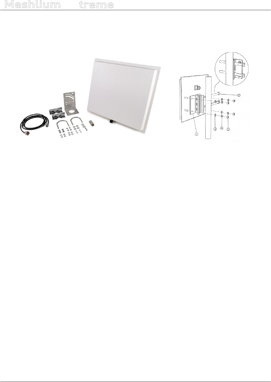
-174- v7.3
Smartphone detection
Meshlium
X
treme
For Vehicle Trac Monitoring applications, it is recommended to purchase the special pack of 2 directional
antennas which will extend the range of WiFi and Bluetooth scanning in the required direction. The size of one
antenna is 40 x 36 x 4 cm. Each one weights about 2 kg. The antennas are 18 dBi and come with the needed
mounting system, 2 m cables and screw adapters.
Figure: Directional antenna for Meshlium Scanner
Do the users need to have a specic app installed or interact somehow to be detected?
No, the scan is performed silently, Meshlium just detects the “beacon frames” originated by the WiFi and Bluetooth
radios integrated in the smartphones. Users just need to have at least one of the two wireless interfaces turned
on.
How do we dierentiate if the Bluetooth device detected is a car’s hands-free or a smartphone?
In the scanning process each Bluetooth device gives its “Class of Device” (CoD) attribute which allows to identify
the type of service it gives. We can dierentiate easily the CoD’s generated by the car’s hands-free from the
people’s phone ones.
How do I control the inquiry area?
In the Bluetooth inquiry there are seven dierent power levels which go from -27 dBm to 3 dBm in order to set
dierent coverage zones from 10 to 50m. In both WiFi and Bluetooth radios these zones can also be increased or
decreased by using a dierent antenna for the module as it counts with a standard N-Male connector. The default
antenna which comes with the scanning modules is an omnidirectional antenna with a gain of 5dBi.
How do I calculate the distance of any of the devices detected?
In the inquiry process we receive the MAC address of the Bluetooth device along with the Received Signal Strength
Indicator (RSSI) which gives us the quality of the transmission with each device. RSSI values usually go from -40
dBm (nearest nodes) to -90 dBm (farthest ones). In the tests performed Bluetooth devices at a distance of 10 m
reported -50 dBm as average, while the ones placed at 50 m gave us an average of -75 dBm.
What about privacy?
The anonymous nature of this technique is due to the use of MAC addresses as identiers. MAC addresses are not
associated with any specic user account or mobile phone number not even to any specic vehicle. Additionally,
the “inquiry mode” (visibility) can be turned o so people have always chosen if their device will or will not be
detectable.
How do the Bluetooth, WiFi and ZigBee radios coexist without causing interferences with each other?
WiFi, XBee and Bluetooth work in the 2.4GHz frequency band (2.400-2.480 MHz), however, the Bluetooth radio
integrated in Meshlium uses an algorithm called Adaptive Frequency Hopping (AFH) which improves the common
algorithm used by Bluetooth (FHSS) and enables the Bluetooth radio to dynamically identify channels already in
use by XBee and WiFi devices and to avoid them.

-175- v7.3
Smartphone detection
Meshlium
X
treme
Anyway, in the case of sending 802.15.4 frames from Waspmote or Plug & Sense! to a Meshlium Scanner
equipped with XBee-PRO 802.15.4, it is recommended to perform re-tries in the sender application,
just to minimize possible interferences and ensure a good percentage of received frames in Meshlium.
Figure: Bluetooth, WiFi and ZigBee radios coexist
Under which conditions do you get a 95% detection rate of devices?
A set of conditions must be respected to keep the detection rate high.
The devices to be detected must be some meters away from the Scanner and must remain some seconds inside
the coverage area to give time to the system to detect them.
The setup of the WiScan feature in Meshlium is 40 seconds of scan span. This means Meshlium Scanner listens
for 40 seconds and then stores the results of the scan.
Android and iOS devices have a special option to disable WiFi connection when the user locks the screen in order
to save battery. All cases are studied here. This option changes with the iOS version, but will be present in the
majority of iOS devices. It makes iOS devices dicult to detect: the device is not undetectable, but it would need
several scan cycles to get one beacon.
When a device is connected to a WiFi Access Point it is easier to detect, as it needs to send radio packets to allow
communication.
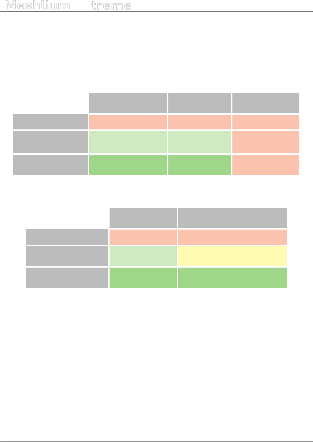
-176- v7.3
Smartphone detection
Meshlium
X
treme
The results not Android or iOS devices may vary depending on the type of system. Usually, APs are detected easily,
as they broadcast the SSID. Hidden SSID are detected too. The only APs that can be hard to detect are the APs
that do not broadcast their presence. This APs can only be detected when there is trac from connected devices.
Regarding other WiFi devices, the individual behaviour will dene if they are detectable. As a general rule, every
device that broadcasts beams or is connected generating trac will be detected.
Our tests results are shown in these tables:
Android:
Screen ON Screen OFF
(power saving o)
Screen OFF
(power saving on)
WiFi radio OFF NO NO NO
WiFi radio ON
(not connected to an
AP)
YES
(almost every scan cycle)
YES
(most of scan cycle) NO
WiFi radio ON
(connected to an AP) YES YES NO
iOS:
Screen ON Screen OFF
(power saving o)
WiFi radio OFF NO NO
WiFi radio ON
(not connected to an AP)
YES
(after several scans)
SOMETIMES
(after a random number of scans)
WiFi radio ON
(connected to an AP) YES YES
(after several scans)
Bluetooth scanning, unlike WiFi scanning, is based on polling, and not in passive listening. This makes Bluetooth
detection slower and left the device the chance of avoiding detection (it just needs to ignore the polling request).
Nevertheless, Bluetooth scan is still useful in some applications, like car detection, as most of modern cars have a
Bluetooth hands-free device, and these devices are most of the time listening for connections.
Any smartphone can be congured to be visible (or not) by other Bluetooth devices. Putting this option as “NOT
VISIBLE” will make the smartphone undetectable by any other Bluetooth device, which includes Meshlium Scanner.
Note that some latest-technology hands-free devices implement the “not visible” mode too.
When the Bluetooth interface is set as visible, the phone will be listening for incoming queries. This way the device
can be scanned. The visibility setup may be dierent in dierent devices. Some of them activate visibility for a
limited time (usually 30 seconds), some others have a manual control to enable/disable the visibility.
Dierent Android and iOS versions have dierent behaviours about Bluetooth visibility. In most of the modern
versions, Bluetooth visibility is disabled when the screen is locked (or even when the user exits the Bluetooth
conguration menu). There is no way to detect an Android or iOS phone with the screen o, which makes it very
dicult to scan Android or iOS devices in a real environment.
There are a lot of types of Bluetooth devices. Most of slave Bluetooth devices are designed to wait for incoming
connections. This makes highly possible to detect devices like hands-free car kits, headsets, HID, etc.
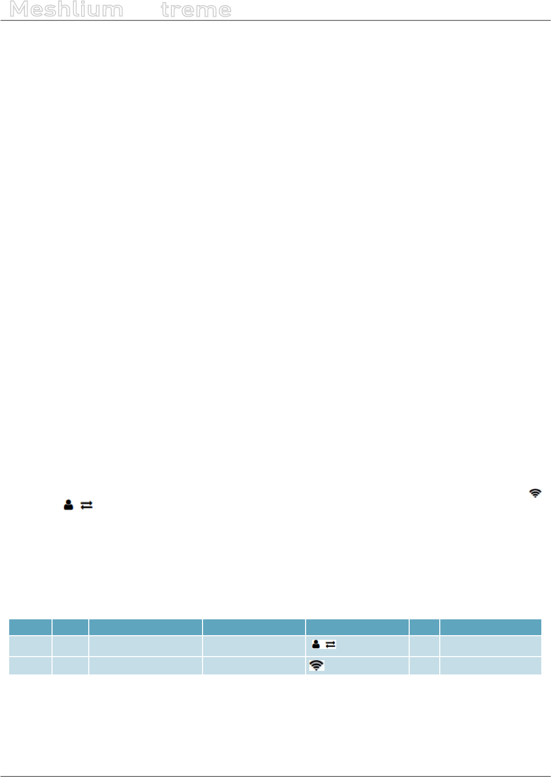
-177- v7.3
Smartphone detection
Meshlium
X
treme
The scanning time is more important in Bluetooth as the devices need some time to reply to the queries.
Device name is not always obtained, as some devices take some time to reply to the name queries. Nevertheless,
the device can be easily identied by its MAC address.
How can I calculate the total number of people from the number of detected devices?
It depends. Not all the people have a smartphone. Also, not all the people switch WiFi and/or Bluetooth radios on
their smartphones. It all depends on so many economic, social and cultural factors. The percentage of people with
WiFi or Bluetooth on depends on the scenario where they are too. For example, if a Meshlium Scanner is installed
in a college campus which provides free WiFi service, many students will be detected because they will probably
keep their smartphones, tablets or notebooks with WiFi on. The same would happen in a mall, airport or hotel
with free WiFi.
Besides, consider that not all the people who could be detected will remain enough time inside of the coverage
area of Meshlium Scanner.
Also, keep in mind that some people can carry several WiFi or Bluetooth devices. For example, a driver with
smartphone in his pocket and a Bluetooth device in his car can be detected as 2 dierent users by Meshlium.
To sum up, in Libelium we consider that the total number of people can be approximated multiplying the number
of detected devices by a factor, from 3 or 5:
3*Detected devices < Total people < 5*Detected devices
It all depends on a number of variables. The administrator of Meshlium Scanner can perform real tests in order
to nd the exact value of this factor in the specic scenario under study.
14.2. WiFi Scanner
14.2.1. Concepts
The additional 2nd WiFi radio integrated in Meshlium Scanner allows to scan WiFi devices in a range of action up
to 200 m depending on the line of sight conditions.
The idea is to search for WiFi devices in a dened interval which can be congured. Meshlium will get the MAC
address, information about the detected Device. Regarding these devices, we can distinguish Access Points
and Clients .In the case of each client, Meshlium gets which Access Point the device is connected to (if any).
Also, the signal strength (RSSI) of the devices along with a timestamp which identies when the scan detects it.
For this reason, it is important to set the correct time in the System before starting with the storage of the data.
See the Time Synchronization in the System section.
As extra information, the System also identies the Vendor of the WiFi devices using its MAC address and if the
information is synchronized to the external database (Sync).
Example of information scanned:
B ID Sync Timestamp MAC Device RSSI Vendor
53483 0 2012-04-24 07:56:25 C4:2C:03:96:0E:4A (not detected) 69 Apple
53482 1 2012-04-24 09:11:26 D8:2A:7E:10:1E:63 libelium_wsn1 60 Nokia Corporation
We can select the Scanning Time from a drop-down list. This time species how many seconds the scanner will
spend searching. After each scanning process, the system performs a pause of one second before starting again.
The Scanning Time must be trimmed in order to avoid that a temperature of 70 ºC is reached in the Meshlium’s
microprocessor. See chapter “Internal temperature sensors” to know how to monitor the microprocessor’s
temperature.
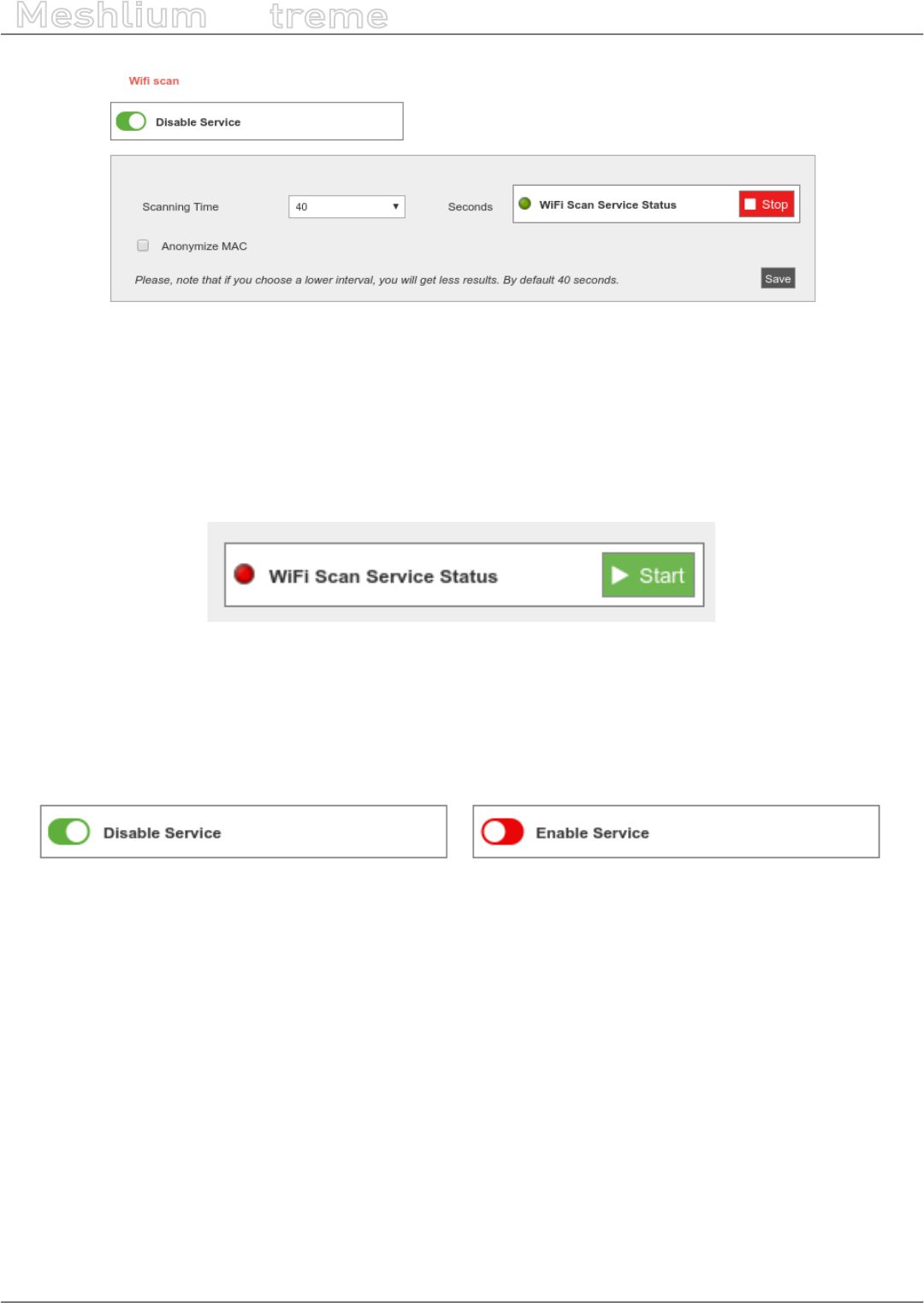
-178- v7.3
Smartphone detection
Meshlium
X
treme
Figure: Conguring WiFi Scanner
We can also activate the anonymization of the MAC addresses. This option will store the MAC address encoded
with an MD5 hash. The hash will be consistent in the same day, but will change from one day to another. This
system allows to follow a particular user in the same day, but keeps the privacy of the user, not storing the real
MAC of the device and not allowing to track a user more than one day.
From this section the user can start and stop the service from the button next to the status indicator.
Figure: WiFi Scanner was stopped
If the user manually stops the service, it will be automatically relaunched upon reboot. In order to completely
disable service, the user have to click on the slider “Disable Service”. This will stop the service and avoid it to run
upon reboot. Setup cannot be changed when disabled, but already stored data is available to be shown.
To enable the service again, click on the slider “Enable Service”.
Figure: Enable and Disable controls
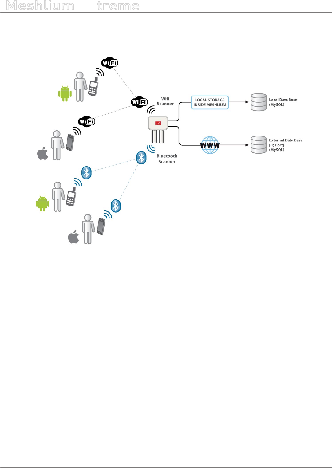
-179- v7.3
Smartphone detection
Meshlium
X
treme
It is possible to perform two dierent storage options with the data captured:
•Local database. This is always used.
•External database The data is synchronized to an external database from the local database.
Figure: WiFi Scanner data storing
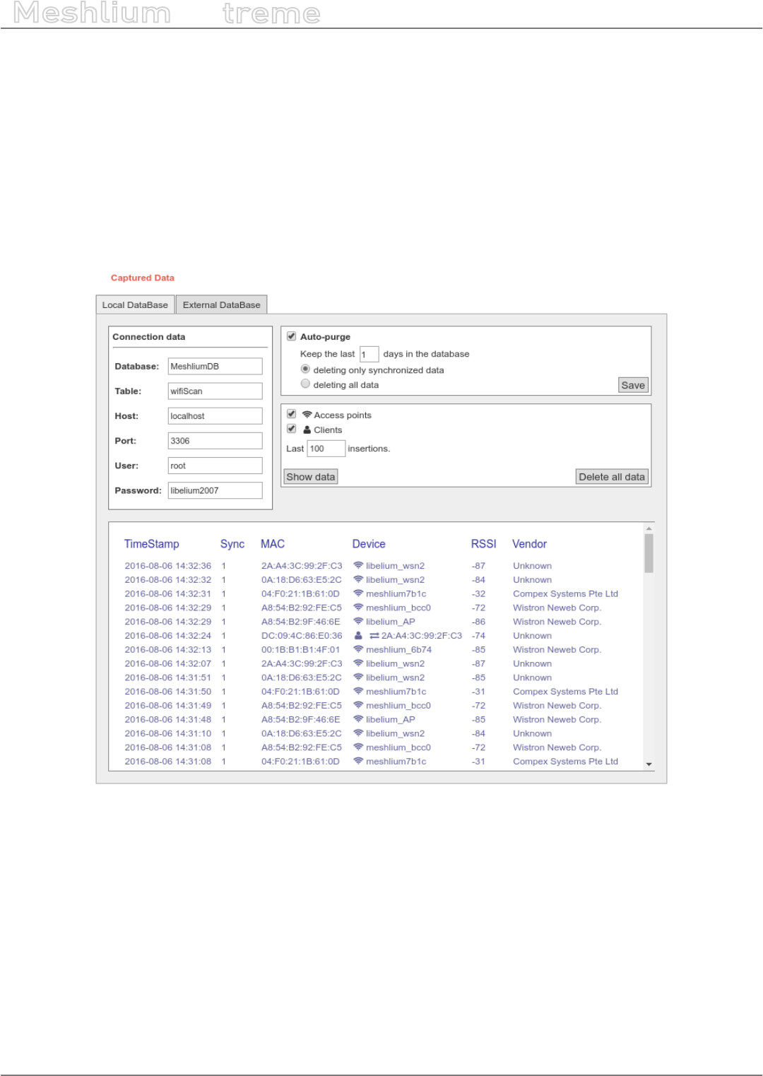
-180- v7.3
Smartphone detection
Meshlium
X
treme
14.2.2. Local database
Meshlium has a MySQL data base up and running which is used to store locally the information captured. In the
“Local Data Base” tab you can see the connection parameters.
•Database: MeshliumDB
•Table: wiScan
•IP: localhost
•Port: 3306
•User: root
•Password: libelium2007
Figure: Local database for WiFi Scanner
At any time you can see the last “x” records stored, ltered by access points or clients. Just set how many and what
kind of insertions you want to see and press the “Show data” button. The maximum number of data to display is
500.
The data from the database can be deleted pressing the button “Delete all data”. Be careful, as this option deletes
all the information of WiFi scans in the local database.
There is an option to program an automatic purge in the database every day, keeping the information in the
database the days you specify. Furthermore, if you intend to congure the external database, you can choose if
you want to delete only synchronized data or everything, taking care of the days established before.
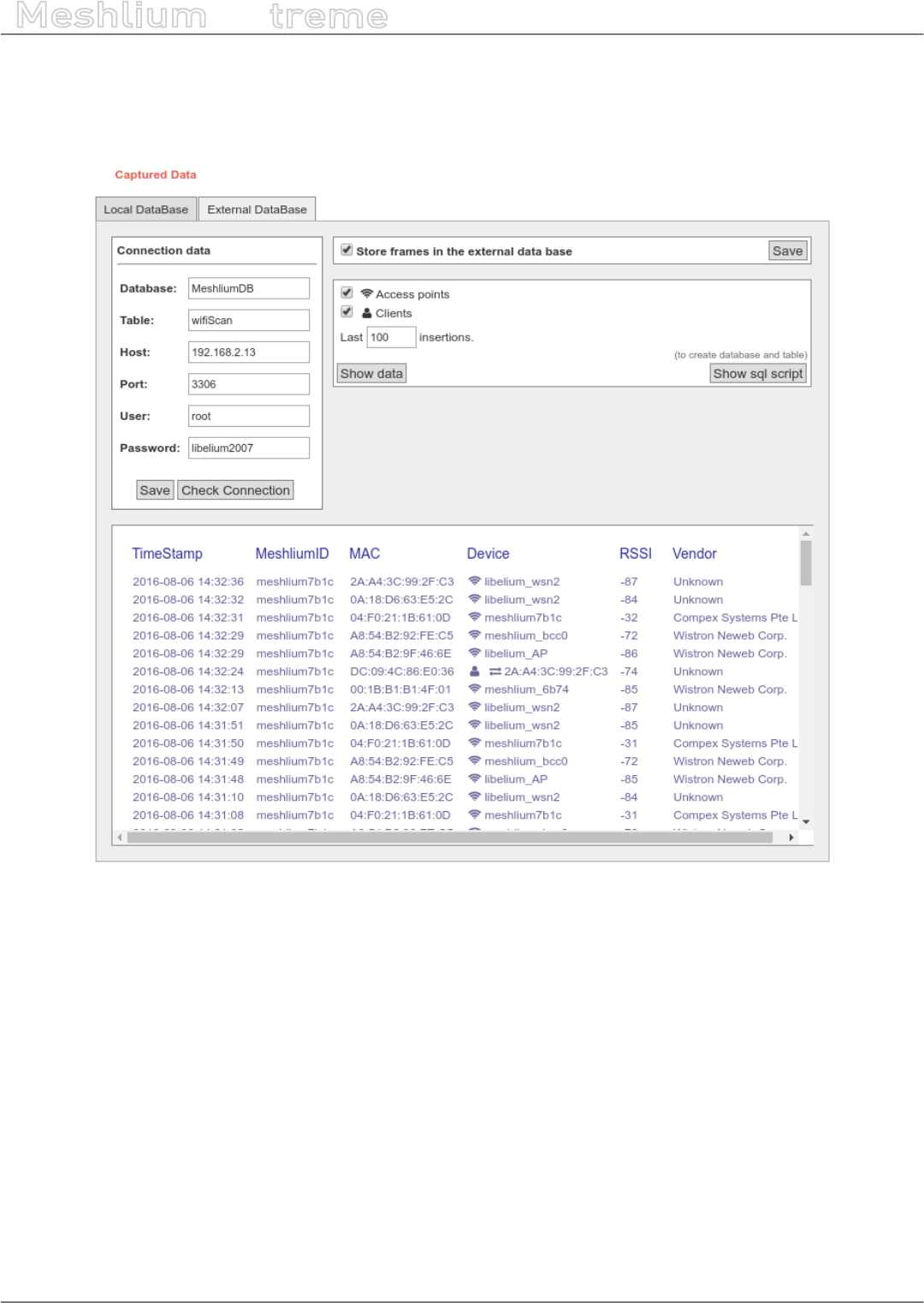
-181- v7.3
Smartphone detection
Meshlium
X
treme
14.2.3. External database
Meshlium can synchronize all the WiFi devices information stored in the local database to an external MySQL
database managed by the user.
Figure: External database tab
In this tab the user can:
•Setup the parameters of the external database and check the connection.
•Enable or disable the synchronization.
•Show last data inserted in the external database (up to 500 data).
•Show the SQL script used to create the database and table needed for the synchronization.
•Mark all data in the local database as synchronized so it will not be sent to the external database.
The steps to setup the synchronization are:
•Before conguring anything, make sure you have a MySQL database working under your control. Make sure
the database listen to connections in an external IP.
•Press the “Show sql script” button, copy the SQL code. You can modify user, password, database name and
table, as long as you change the setup of the connection to match.

-182- v7.3
Smartphone detection
Meshlium
X
treme
Figure: SQL script
•Enter the connection settings and press “Save” button. You can check the connection now to ensure the
settings are correct.
•Enable the service with the checkbox and save.
The synchronization service runs every 60 seconds and synchronizes up to 200 data every loop. The service
synchronizes rst newer data, as it is more relevant for decision making. This could make data in external database
to be out of order. As every data has a timestamp, this should not be a problem for using the data in any external
application.

-183- v7.3
Smartphone detection
Meshlium
X
treme
14.3. Bluetooth Scanner
14.3.1. Concepts
This Bluetooth radio integrated in Meshlium Scanner allows to scan Bluetooth devices in a range of action up to
200m depending on the line of sight conditions.
The idea is to search for Bluetooth devices in a dened interval which can be congured. Meshlium will get the
MAC address, the Bluetooth ID and the RSSI of the devices along with a timestamp which identies when the
scan was performed. For this reason it is important to set the correct time in the System before starting with the
storage of the data. See the Time Synchronization in the System section.
Other interesting parameters the system also detects are the Class of Device (CoD) which allows us to dierentiate
the type of device (smartphone, hands-free, laptop, LAN/Network AP) and the Vendor of the Bluetooth devices
using its MAC address.
With these parameters we can dierentiate among pedestrians and vehicles.
B ID Timestamp MAC ID RSSI CoD Vendor
45400 2012-05-16 16:18:1207:56:25 00:26:7e:5f:3c:18 myCar -72 Handsfree PARROT SA
78005 2012-04-20 12:59:27 09:11:26 D8:2A:7E:0E:C3:10 Tropic -85 Smartphone Nokia Corporation
We can congure the Scanning Type which species the use of our Bluetooth Scanner:
•Indoor type is recommended to scan static devices or devices with slow movement (oces, malls, etc). This
option retrieves device names after about 15 seconds scanning.
•Outdoor type focus on devices which stay a brief period of time in our Bluetooth action range (roads,
highways,...). This option does not ask the device name and the scanning period is about 45 seconds.
In both types, there is a second between two consecutive scans.
Figure: Conguring Bluetooth Scanner
We can also activate the anonymization of the MAC addresses. This option will store the MAC address encoded
with an MD5 hash. The hash will be consistent in the same day, but will change from one day to another. This
system allows to follow a particular user in the same day, but keeps the privacy of the user, not storing the real
MAC of the device and not allowing to track a user more than one day.
From this section the user can start and stop the service from the button next to the status indicator.
Figure: Bluetooth Scanner was stopped

-184- v7.3
Smartphone detection
Meshlium
X
treme
If the user manually stops the service, it will be automatically relaunched upon reboot. In order to completely
disable service, the user have to click on the slider “Disable Service”. This will stop the service and avoid it to run
upon reboot. Setup cannot be changed when disabled, but already stored data is available to be shown.
To enable the service again, click on the slider “Enable Service”.
Figure: Enable and Disable controls
Note: Last versions of Android and iOS devices may need the Bluetooth Setup Screen be activated to be detected.
We have two dierent storage options for the data captured:
•Local database. This is always active.
•External database. This synchronizes local database data to an external MySQL database.
Figure: Bluetooth scan storing options
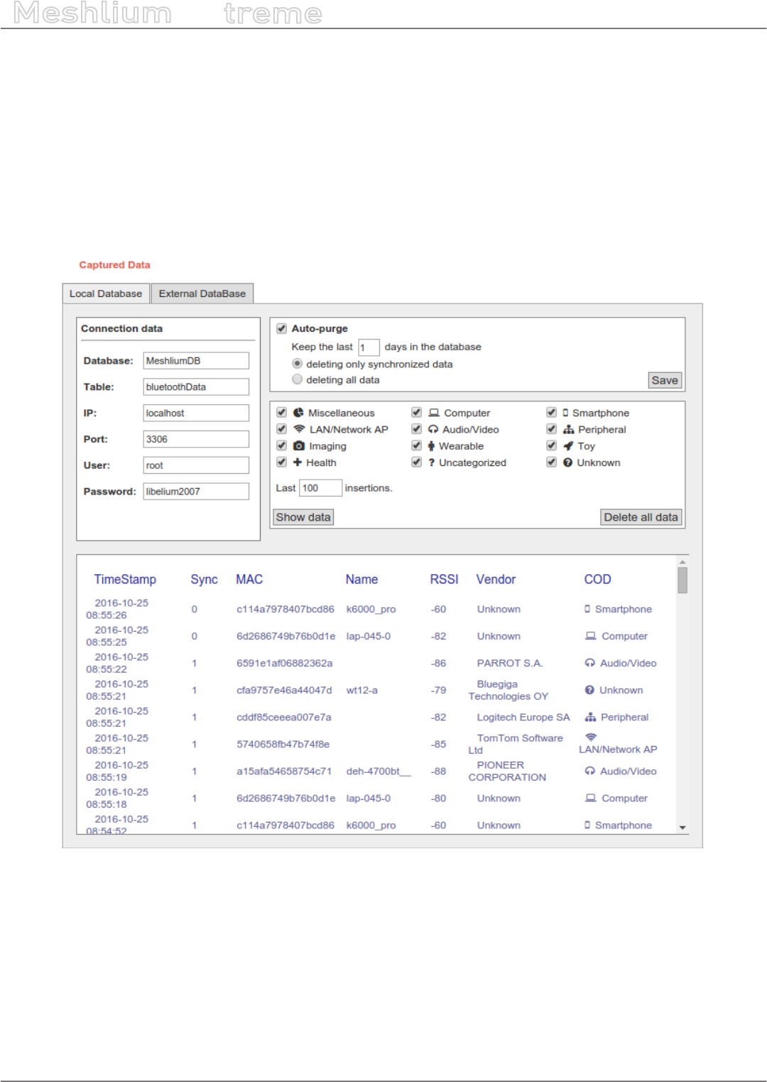
-185- v7.3
Smartphone detection
Meshlium
X
treme
14.3.2. Local database
Meshlium has a MySQL database up and running which is used to store locally the information captured. In the
“Local Data Base” tab you can see the connection parameters.
•Database: MeshliumDB
•Table: bluetoothData
•IP: localhost
•Port: 3306
•User: root
•Password: libelium2007
Figure: Local database for Bluetooth Scanner
At any time you can see the last “x” records stored, ltered by access points or clients. Just set how many and what
kind of insertions you want to see and press the “Show data” button. The maximum number of data to display is
500.
The data from the database can be deleted pressing the button “Delete all data”. Be careful, as this option deletes
all the information of Bluetooth scans in the local database.
There is an option to program an automatic purge in the database every day, keeping the information in the
database the days you specify. Furthermore, if you intend to congure the external database, you can choose if
you want to delete only synchronized data or everything, taking care of the days established before.

-186- v7.3
Smartphone detection
Meshlium
X
treme
14.3.3. External database
Meshlium can synchronize all the WiFi devices information stored in the local database to an external MySQL
database managed by the user.
Figure: External database tab
In this tab the user can:
•Setup the parameters of the external database and check the connection.
•Enable or disable the synchronization.
•Show last data inserted in the external database (up to 500 data).
•Show the SQL script used to create the database and table needed for the synchronization.
•Mark all data in the local database as synchronized so it will not be sent to the external database.
The steps to setup the synchronization are:
•Before conguring anything, make sure you have a MySQL database working under your control. Make sure
the database listen to connections in an external IP.
•Press the “Show SQL script” button, copy the SQL code. You can modify user, password, database name and
table, as long as you change the setup of the connection to match.

-187- v7.3
Smartphone detection
Meshlium
X
treme
Figure: SQL script
•Enter the connection settings and press “Save” button. You can check the connection now to ensure the
settings are correct.
•Enable the service with the checkbox and save.
The synchronization service runs every 60 seconds and synchronizes up to 200 data every loop. The service
synchronizes rst newer data, as it is more relevant for decision making. This could make data in external database
to be out of order. As every data has a timestamp, this should not be a problem for using the data in any external
application.
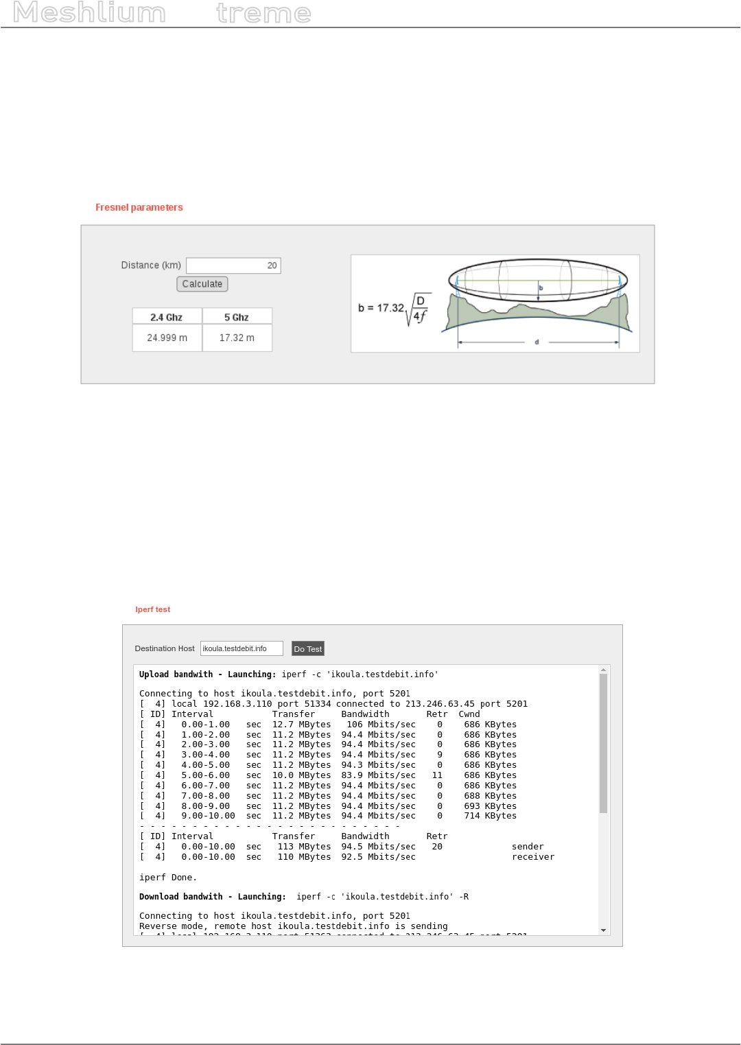
-188- v7.3
Tools
Meshlium
X
treme
15. Tools
15.1. Fresnel calculator
The Fresnel Zone is the space which should be empty of objects in a wireless transmission between two points
to get the maximum throughput and transmission quality. Here you can nd a tool in order to calculate when
choosing the right points for your nodes.
Figure: Fresnel calculator plugin
15.2. Iperf
This tool lets you know the real bandwidth between Meshlium and an iperf server. This plugin uses the correct
interface in local networks and uses the default gateway for external networks. The default gateway is 4G/LTE if
connected or Ethernet otherwise.
To use the tool, enter the IP address or the host of the iperf server. Iperf v3 is used so ensure the server is
compatible with that version.
Figure: Iperf plugin
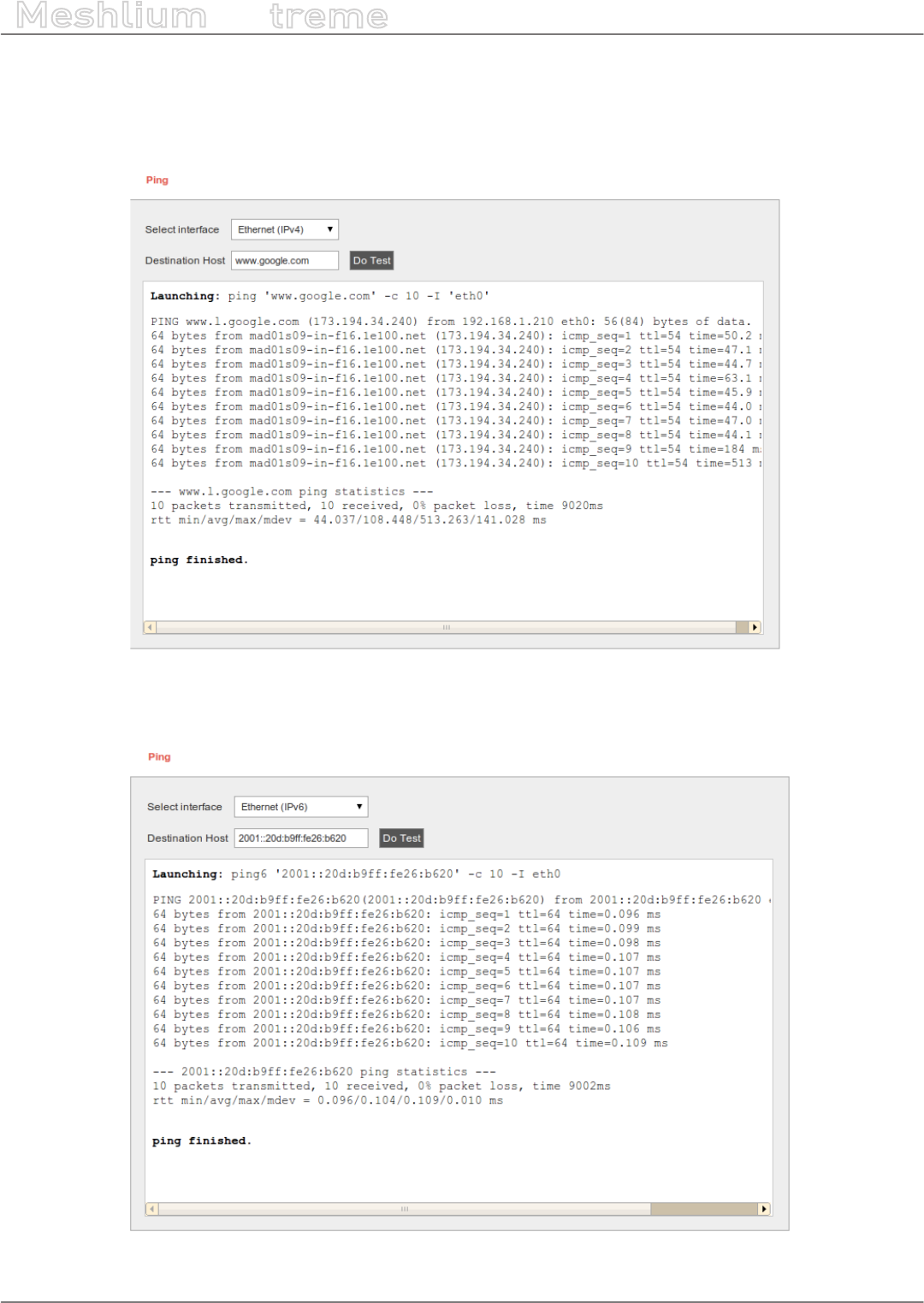
-189- v7.3
Tools
Meshlium
X
treme
15.3. Ping
It lets you test if you can reach a certain IP or Hostname through a specic network Interface: Ethernet (IPv4),
Ethernet (IPv6), WiFi AP, and 4G/LTE.
Figure: Ping plugin
Meshlium can also perform this test over IPv6 on Ethernet interface.
Figure: IPv6 ping
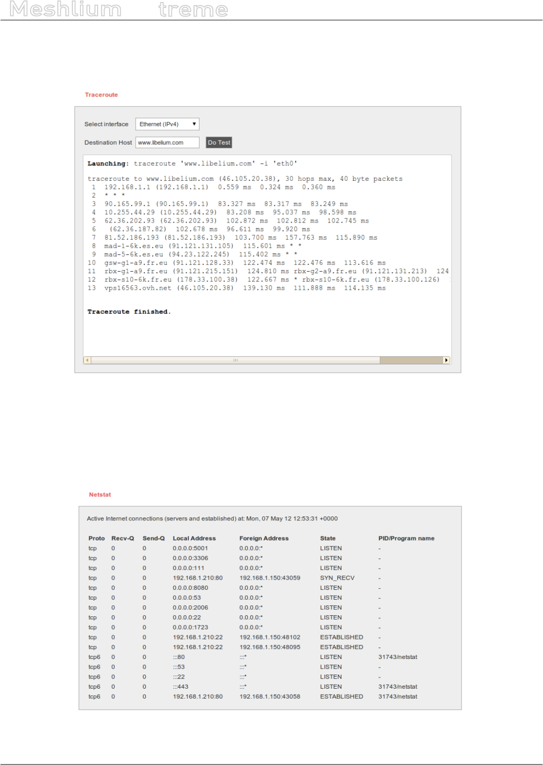
-190- v7.3
Tools
Meshlium
X
treme
15.4. Traceroute
Another interesting tool to discover the path of the communication between Meshlium and the selected host.
Figure: Traceroute plugin
Meshlium can also perform this test over the Ethernet (IPv6) interface.
15.5. Netstat
Discover which connections IPv4-Port (tcp), and IPv6-Port (tcp6) are active.
Figure: Netstat information
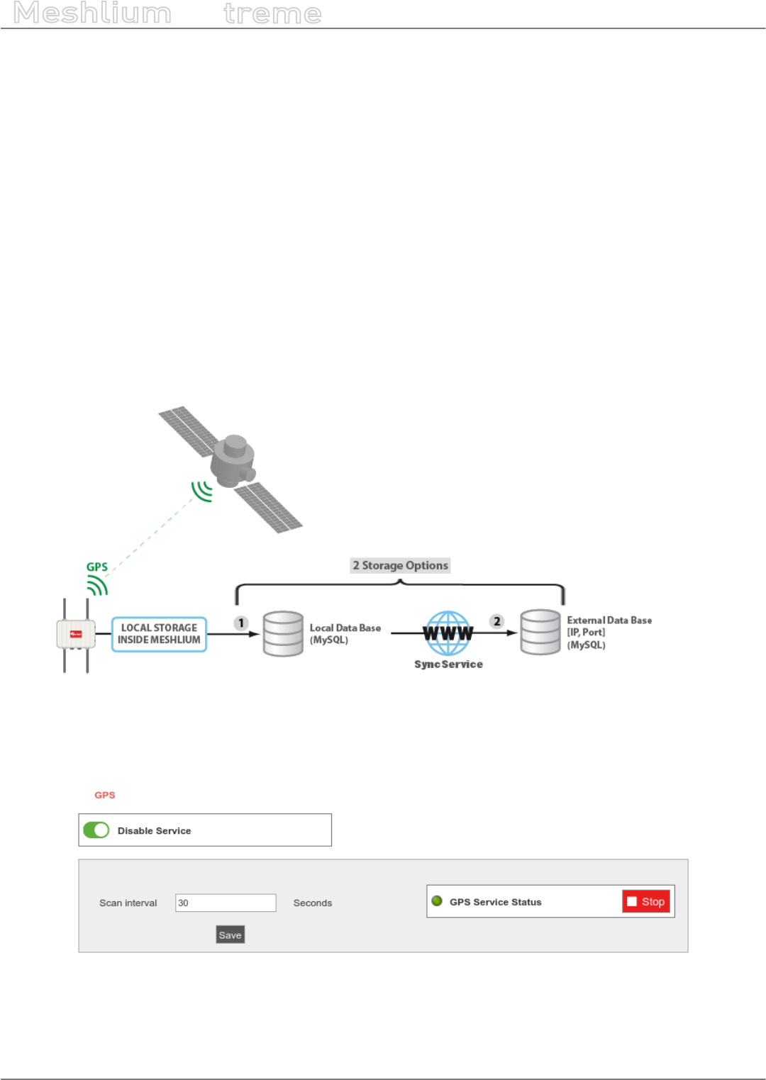
-191- v7.3
Tools
Meshlium
X
treme
15.6. GPS
15.6.1. Concepts
Meshlium can integrate a GPS receiver which allows to know the exact location of the router any time. It is specially
interesting for mobile and vehicular applications and when setting long range links as the GPS position also gives
information about the height of each point so the Fresnel Zone can be accurately known.
The GPS module gives us information about:
•latitude
•longitude
•height (meters)
•speed (km/h)
•date/time
Data captured form GPS is stored in the local database. In addition, the data can be synchronized to an external
MySQL database to be used in an other systems.
Figure: GPS storage options
15.6.2. Conguring GPS service
Figure: GPS plugin setup
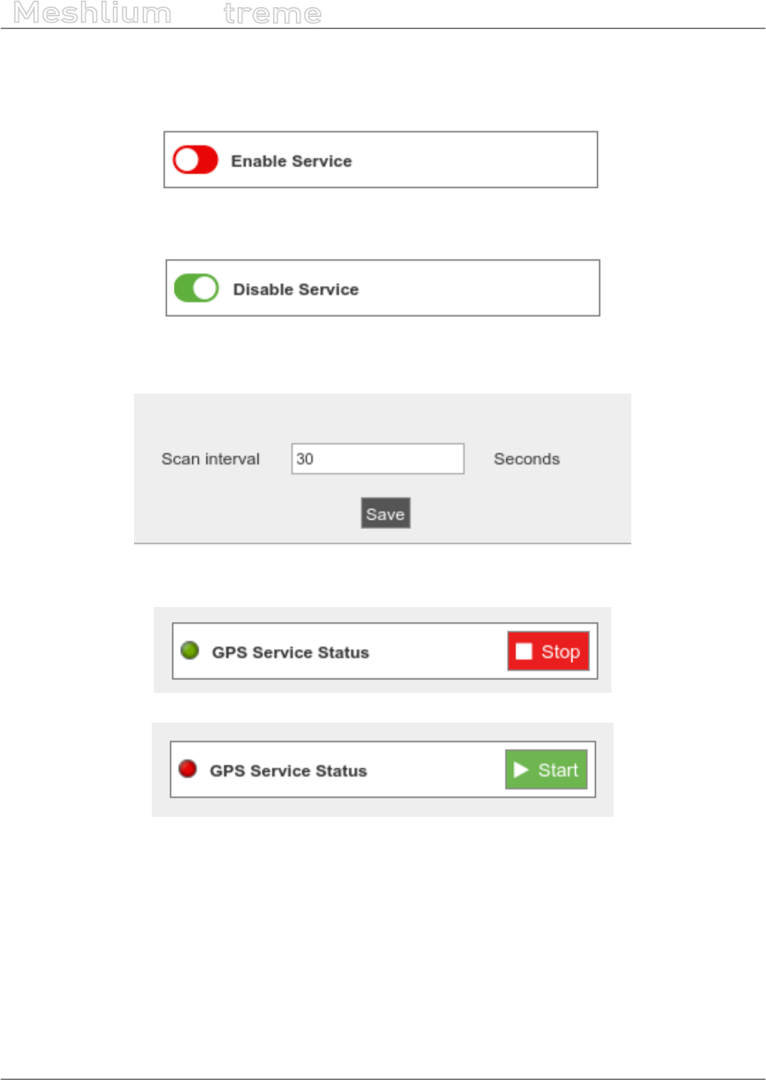
-192- v7.3
Tools
Meshlium
X
treme
The GPS service can be enabled or disabled. If the user disables the service the service will be stopped and will not
be launched when Meshlium is powered on. In addition, setup will be blocked and cannot be changed. When the
service is disabled no GPS information will be read or stored.
Figure: Enable control
Figure: Disable control
The user can set the time interval between data acquisition.
Figure: GPS data read interval
The service can be manually started and stopped.
Figure: Service stop button
Figure: Service start button
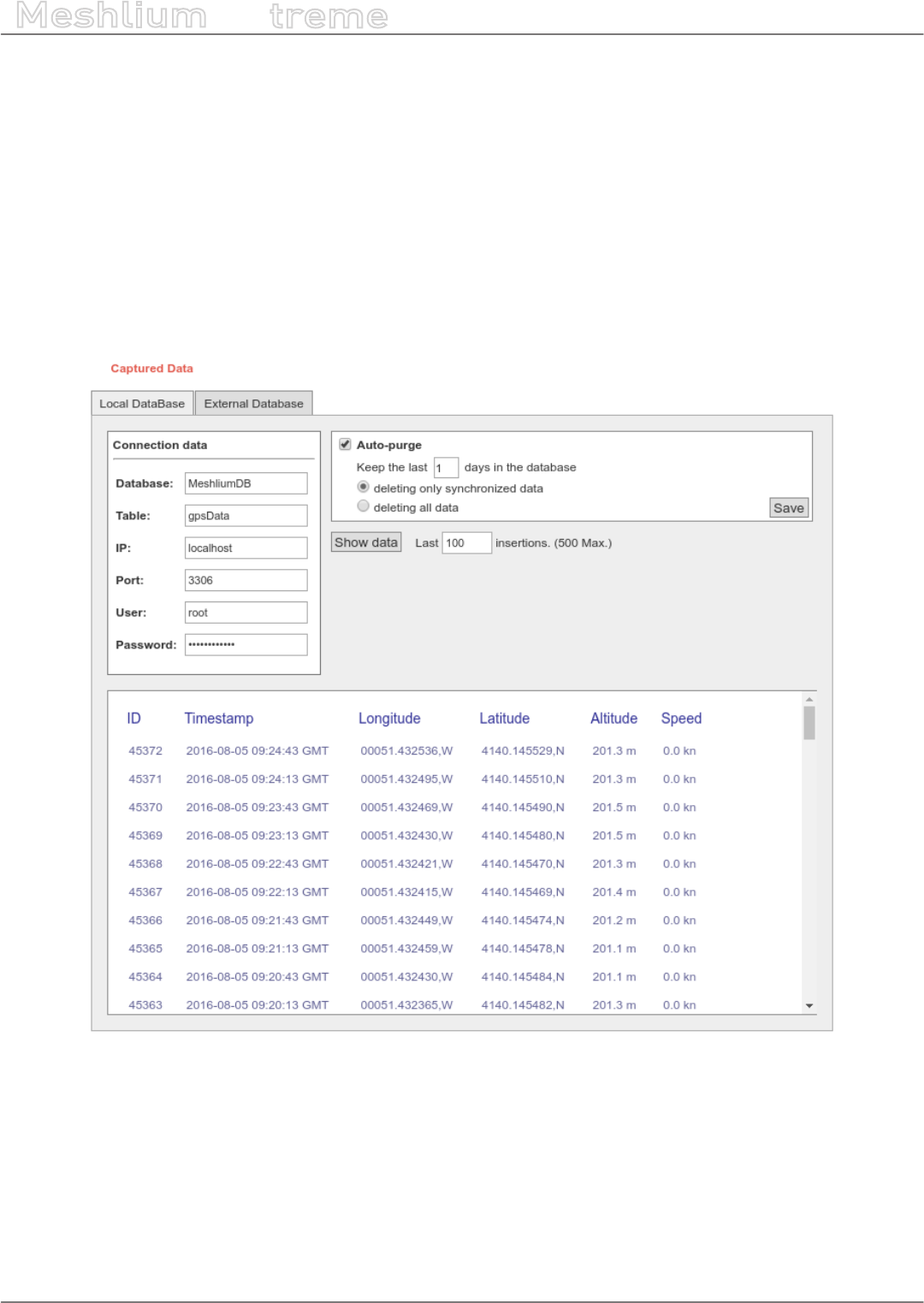
-193- v7.3
Tools
Meshlium
X
treme
15.6.3. Local database
Meshlium has a MySQL database up and running which is used to store locally the information captured. In the
“Local Data Base” tab you can see the connection parameters.
A service in Meshlium will read periodically the GPS to gather location and will store it in the local database.
•Database: MeshliumDB
•Table: gpsData
•IP: localhost
•Port: 3306
•User: root
•Password: libelium2007
Figure: Local database for GPS data
At any time you can see the last “x” records stored, ltered by access points or clients. Just set how many and what
kind of insertions you want to see and press the “Show data” button. The maximum number of data to display is
500.
The data from the database can be deleted pressing the button “Delete all data”. Be careful, as this option deletes
all the information of Bluetooth scans in the local database.
There is an option to program an automatic purge in the database every day, keeping the information in the
database the days you specify. Furthermore, if you intend to congure the external database, you can choose if
you want to delete only synchronized data or everything, taking care of the days established before.
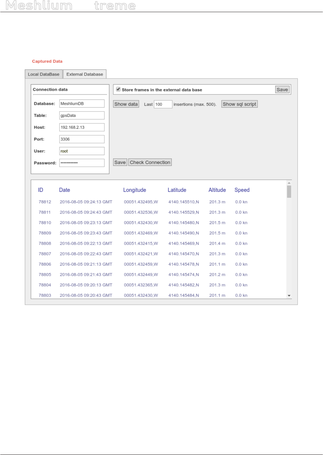
-194- v7.3
Tools
Meshlium
X
treme
15.6.4. External database
Meshlium can synchronize all the WiFi devices information stored in the local database to an external MySQL
database managed by the user.
Figure: External database tab
In this tab the user can:
•Setup the parameters of the external database and check the connection.
•Enable or disable the synchronization.
•Show last data inserted in the external database (up to 500 data).
•Show the SQL script used to create the database and table needed for the synchronization.
•Mark all data in the local database as synchronized so it will not be sent to the external database.
The steps to setup the synchronization are:
•Before conguring anything, make sure you have a MySQL database working under your control. Make sure
the database listen to connections in an external IP.
•Press the “Show sql script” button, copy the SQL code. You can modify user, password, database name and
table, as long as you change the setup of the connection to match.
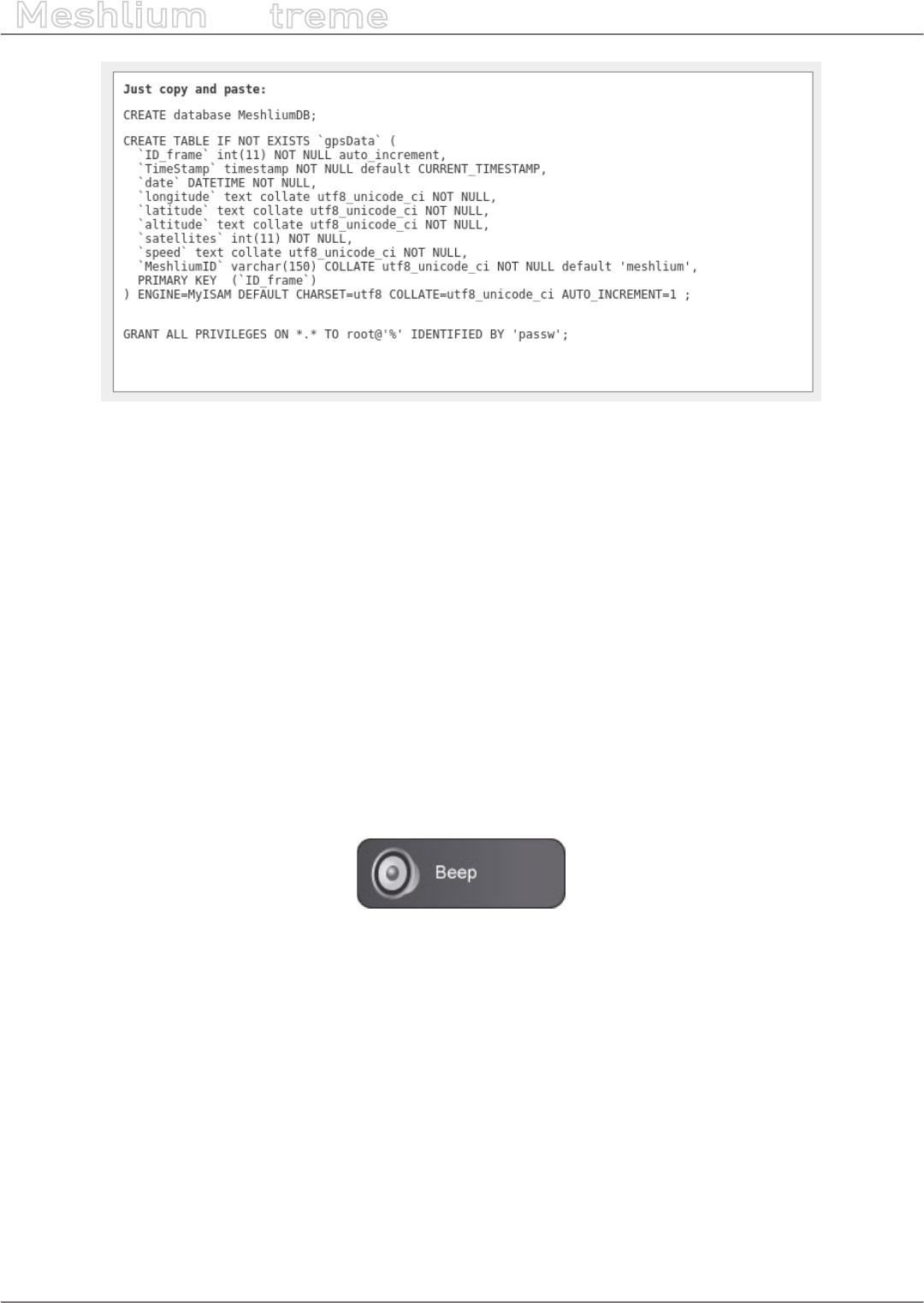
-195- v7.3
Tools
Meshlium
X
treme
Figure: SQL script
•Enter the connection settings and press “Save” button. You can check the connection now to ensure the
settings are correct.
•Enable the service with the checkbox and save.
The synchronization service runs every 60 seconds and synchronizes up to 200 data every loop. The service
synchronizes rst newer data, as it is more relevant for decision making. This could make data in external database
to be out of order. As every data has a timestamp, this should not be a problem for using the data in any external
application.
15.7. Beep
When conguring several Meshlium at the same time in the laboratory, it can be dicult to distinguish between
them (specially when the IP addresses are given by a external DHCP router). For this reason we have added a Beep
button in the Tools section which will make the current Meshlium emit a short sound (“beep!”).
Figure: Beep plugin

-196- v7.3
Database management
Meshlium
X
treme
16. Database management
16.1. Direct access
In order to access to the Meshlium Database from an external application you have to use the next parameters:
•IP:
-WiFi: 10.10.10.1
-Ethernet: Depending on your DHCP server (You can specify a static IP in the Interfaces section).
192.168.1.100 (if there is no DHCP server).
•Database: MeshliumDB.
•Table: Depending on the data to be extracted. Some options are: sensorParser, bluetoothData, gpsData,
wiScan. You can list the tables of the database.
•Port: 3306
•User: root
•Password: libelium2007
You can use any management MySQL application like MySQL Workbench or SQLYog to access the database in
Meshlium and perform any maintenance operation.
16.2. PhpMyAdmin
Meshlium has a built in PhpMyAdmin instance that allow local database management. Go to:
Tools → phpMyAdmin
Click on “Open in a new window” to open the phpMyAdmin panel.
You can directly access phpMyAdmin panel in the URL:
http://[Meshlium_IP]/phpmyadmin
Where [Meshlium_IP] has to be replaced for the IP used in Meshlium. It can be WiFi AP, Ethernet or 4G IP.
To login, use the credential shown in the section “Direct access”.
Figure: phpMyAdmin login page
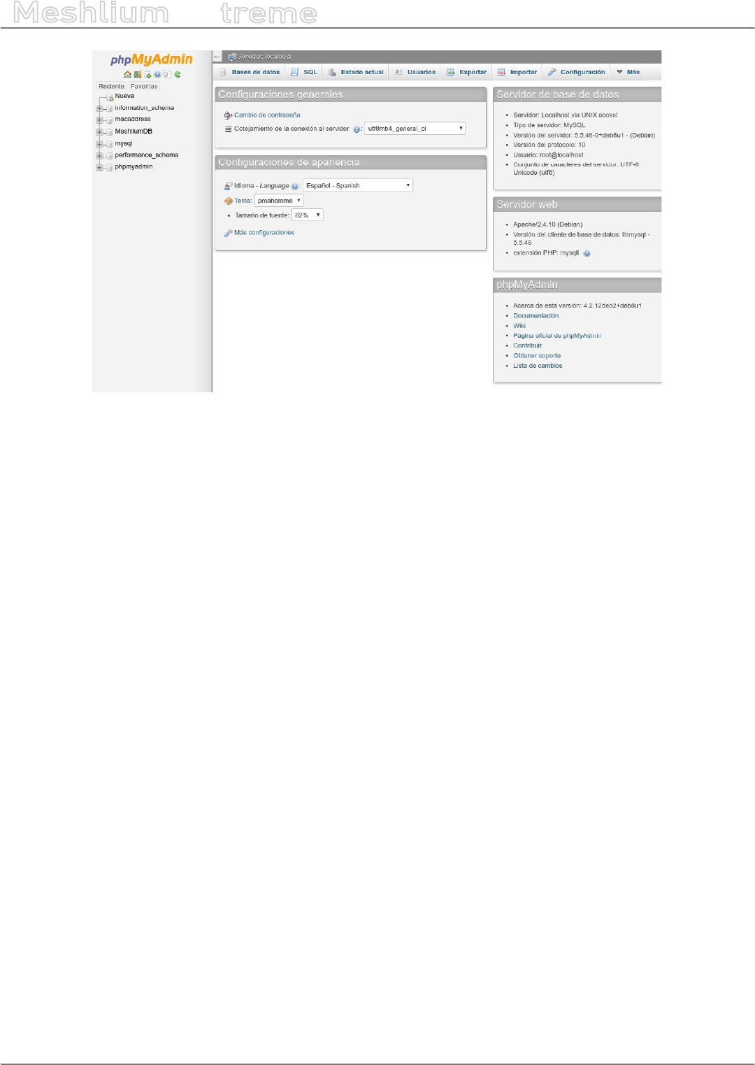
-197- v7.3
Database management
Meshlium
X
treme
Figure: phpMyAdmin panel
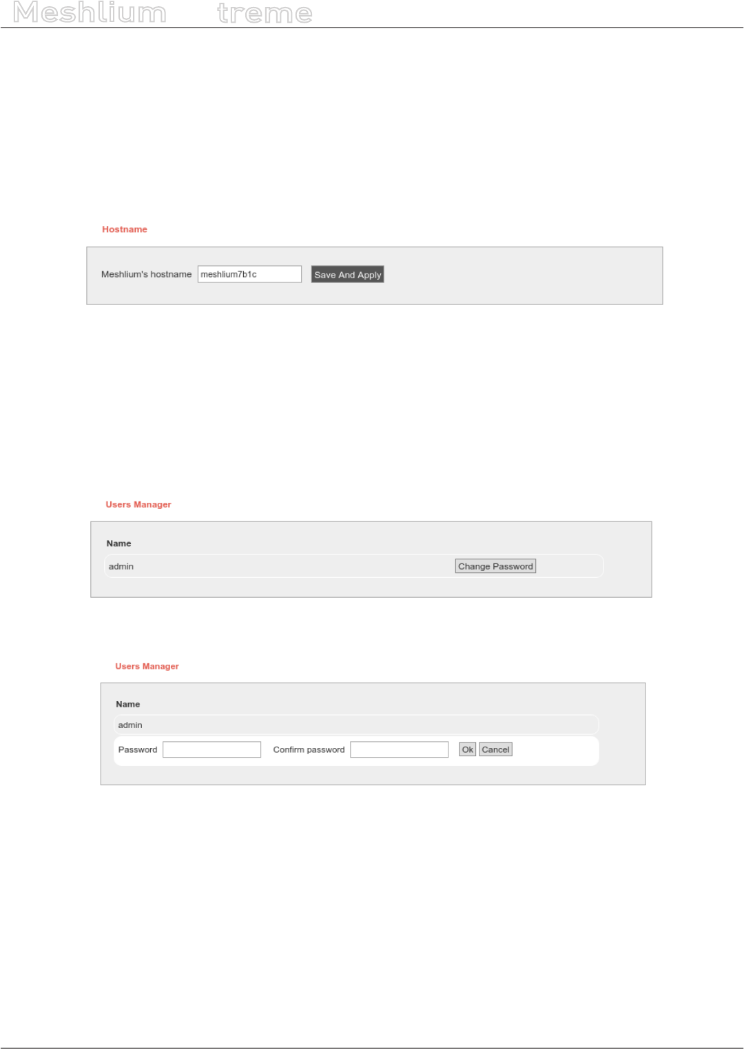
-198- v7.3
System Information
Meshlium
X
treme
17. System Information
17.1. Hostname
This plugin allow the user to change the hostname of the gateway. By default the name is “meshliumXXXX” where
XXXX are the last four digits of Ethernet MAC address.
To change the hostname, enter the desired value and press “Save and Apply” button.
Figure: Hostname change form
17.2. Password management
The “Users Manager” section is a plugin that allows to change the password needed to access to the Manager
System. The user is always “admin”. To change it press “Change Password” button, introduce and conrm new
password and press “Ok”. You can abort operation pressing “Cancel”.
Figure: Password change form
Figure: Introduce new password
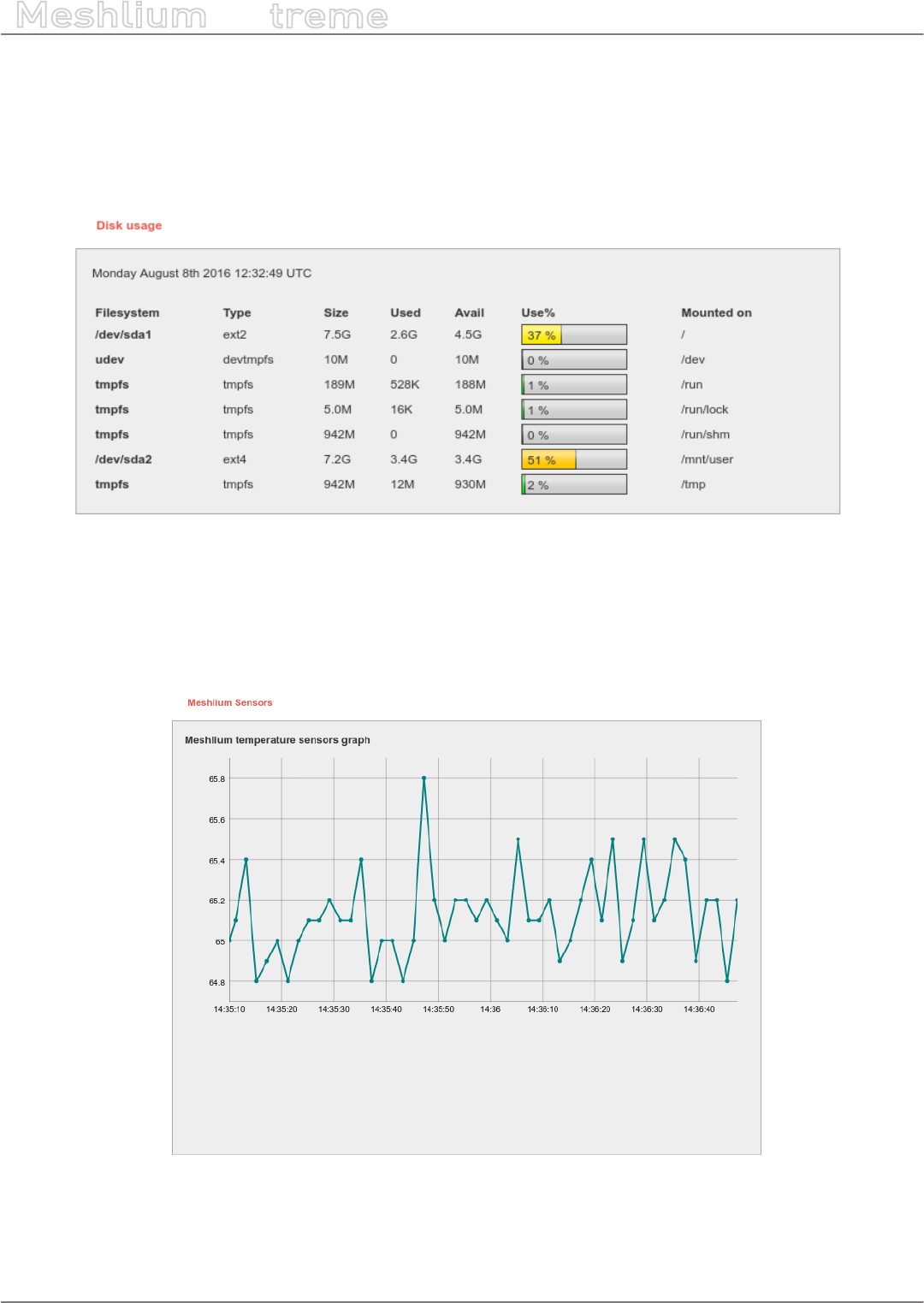
-199- v7.3
System Information
Meshlium
X
treme
17.3. Disk usage
This plugin oers a graphical board to see the amount of disk being used in each partition.
The most important partition is /dev/sda2 which is mounted in the “/mnt/user” folder. All the data captured (XBee,
Scanner, GPS) is stored in this partition. This partition also stores the logs of all the services.
Figure: Disk usage plugin
17.4. Internal temperature sensor
In this plugin the user can see in real time the processor temperature in Celsius degree.
Figure: Temperature Sensors plugin
A temperature above 70 ºC is considered high and a temperature above 100 ºC could be dangerous for the device.
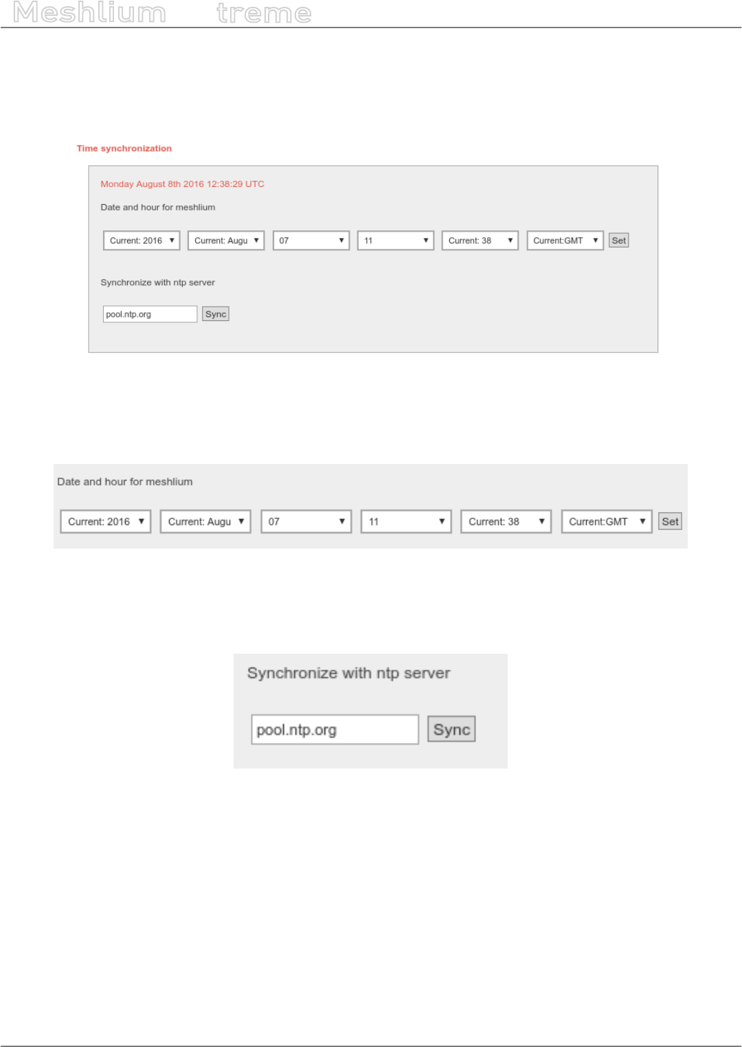
-200- v7.3
System Information
Meshlium
X
treme
17.5. Time synchronization
In order to store correctly in the le system and in the local database the data captured from the RF modules and
scanner is important to previously set the system time.
Figure: Time Synchronization plugin
The plugin allow the user to set the time, manually selecting the time from the selectors and setting the timezone.
Press the “Set” button to apply the time selected.
Figure: Manually selecting time and timezone
In the plugin, the user can use too an NTP server to perform a synchronization. This option runs a one-time
synchronization but does not activate any service for continuous synchronization. To perform the synchronization
ll the NTP server address (by default “pool.ntp.org”) and press “Sync” button.
Figure: NTP synchronization
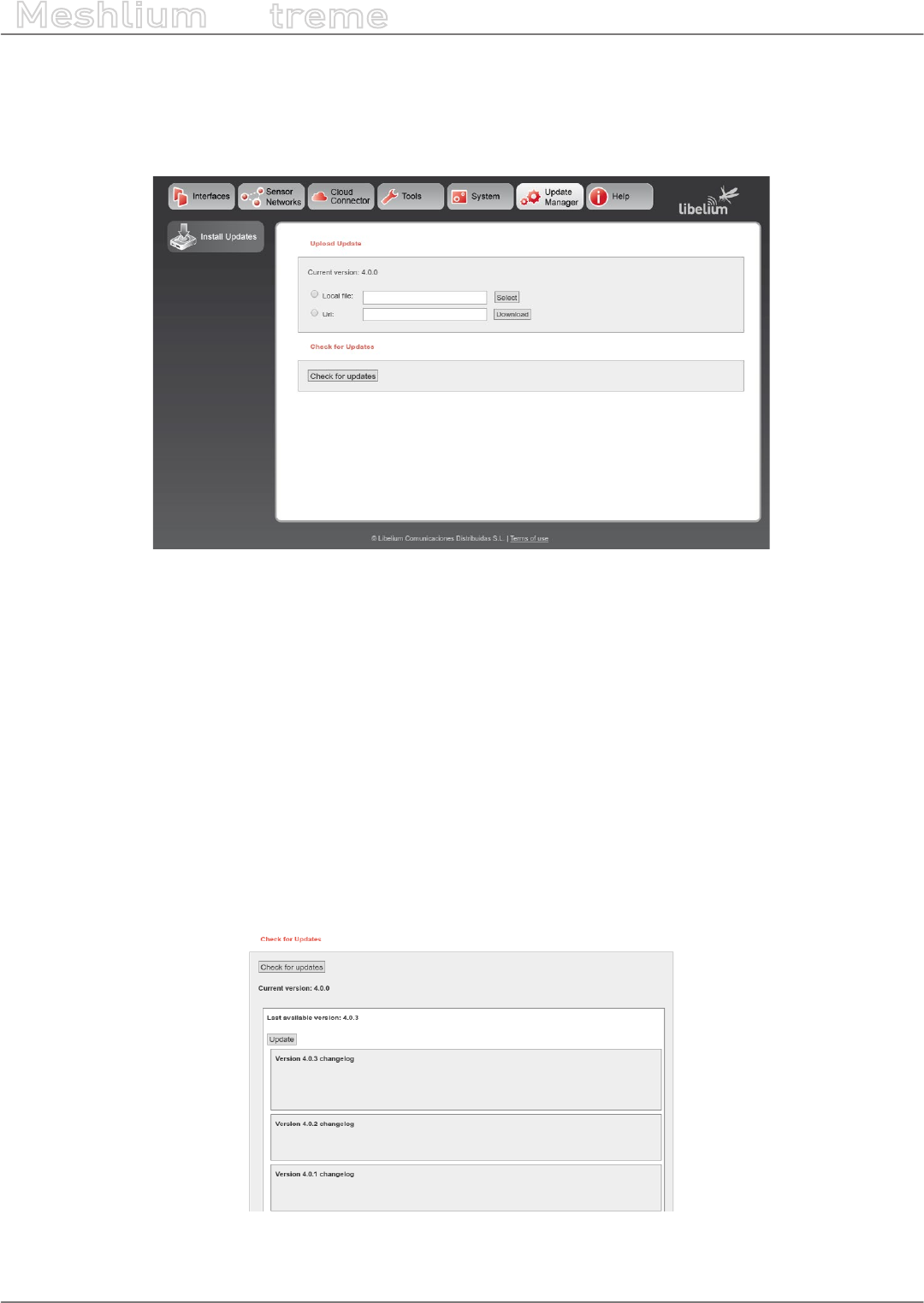
-201- v7.3
Upgrading Meshlium
Meshlium
X
treme
18. Upgrading Meshlium
In the updates plugin, the user can install new Manager System versions. To get to the plugin go to:
Update Manager → Install Updates
Figure: Install Updates plugin
There are three ways to install updates:
•Check Libelium repository for ocial updates
•Load the update le from a local computer
•Load the update le from an URL
18.1. Checking for updates
In order to use this feature Meshlium needs to be connected to the Internet and with access to Libelium web page.
Given so, press the “Check for updates” button to access the Libelium repository and search for new versions.
If there are new versions, the plugin will display the changelog of every version and will show an “Update” button.
This button will download and install ALL the pending updates in one step, always letting Meshlium with the latest
version available.
Figure: Updates found
Meshlium will reboot after installing the updates.
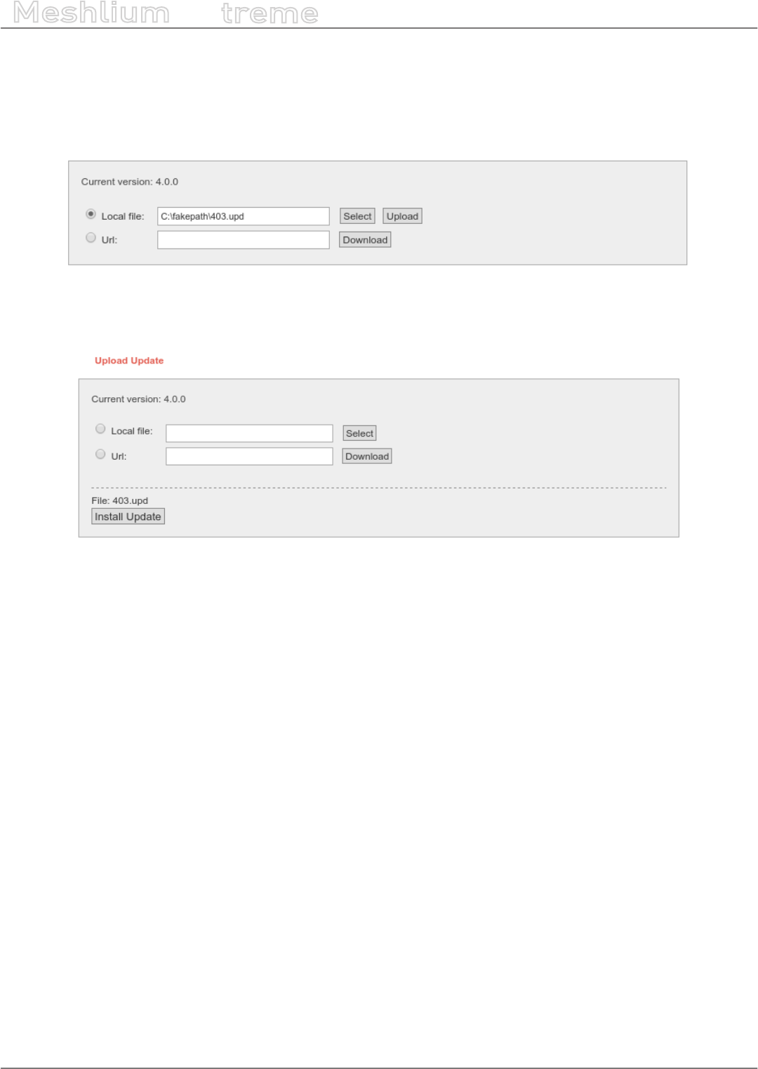
-202- v7.3
Upgrading Meshlium
Meshlium
X
treme
18.2. Local le
Meshlium allows to load updates oine, manually uploading the le from a PC. In order to do so, download the
update le and upload it to Meshlium selecting the “Local File” checkbox and pressing “Select” button. Browse the
le in your PC and upload it pressing “Upload” button.
Figure: Selecting an update le
The system will check the le and if it is a valid update le it will show the le and the button “Install Update”.
Figure: Install update
Pressing “Install Update” will install the update and reboot Meshlium.
Considerations: You have to nish the installation of a previous package in order to install the next one. If you
upload a new package without installing the previous one it will be removed.
Some updates can download big les from the Internet instead of packing them inside the update le. Ask Libelium
support for complete update les if this is stated in the update log.
All the updates must be applied in order, and in any case, all the updates must follow the sequence number. For
example, do not install 4.0.3 version without installing before 4.0.2.
Warning: Install only update les provided by Libelium. Any damage on the software caused by any update le not
provided by Libelium will not be covered by warranty terms.
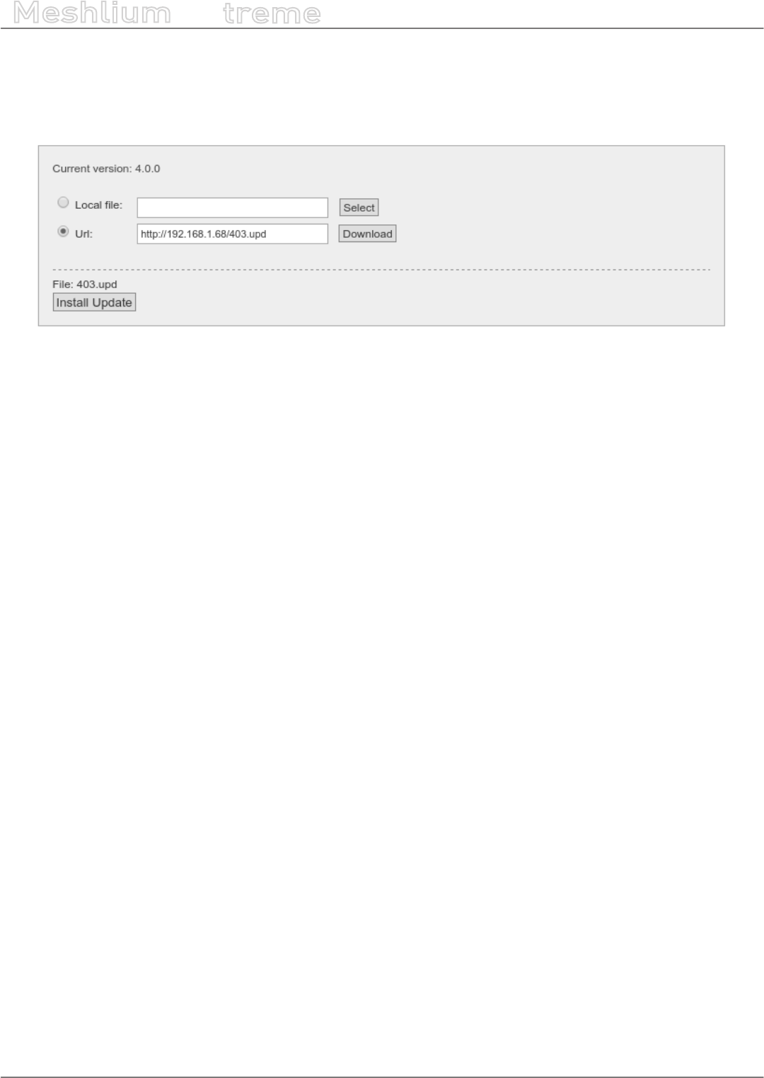
-203- v7.3
Upgrading Meshlium
Meshlium
X
treme
18.3. URL
Update les can be side loaded trough an URL. Enter the URL of the update le in the form and press “Download”
button. The system will download the le and check if it is a valid update.
Figure: Enter the URL of the le
If so, it will show the le and the “Install Update” button. Press “Install Update” button to perform the update.
Meshlium will reboot after nishing the update process.
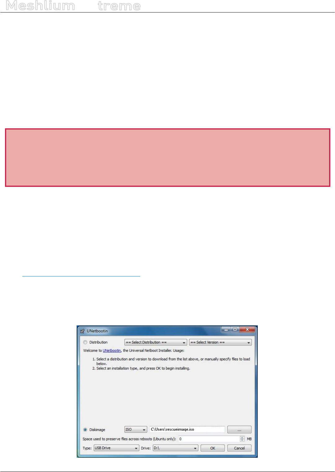
-204- v7.3
Rescue System
Meshlium
X
treme
19. Rescue System
The Rescue System allows the user to return Meshlium to factory defaults. After applying the rescue, the device
will be formatted and the disk will be left as it was brand new.
The rescue process is recommended when:
•The operating system is corrupt or malfunctioning
•The device has been wrongly setup and it is unreachable
•The device needs to be recovered after an unexpected error
The rescue process is not covered by warranty as described in the section “Important: read me before using”.
and must be considered an emergency process. This process is intended to help the user to recover the device of
software issues without having to send Meshlium to the technical support service.
Important:
Executing the rescue process will delete all the user information stored in Meshlium including sensor information
stored in the internal database.
The rescue process can potentially damage the device and left it unusable.
The rescue process may not work if the le system is severely damaged.
19.1. Rescue steps
You will need a USB pen drive of at least 8 GB.
The rst thing to do is download from the website of Libelium the image le “meshliumrescue.iso” needed to
restore Meshlium to factory defaults.
Note: You need to contact rst our Technical Service Department in order to get the user and password and URL
to download the image.
Go to https://www.libelium.com/contact/#RMA.
Once the le has downloaded, you must burn it in a USB pen drive. To perform this operation we recommend the
use of unetbootin.
Unetbootin is a freeware and multiplatform application that allows to create bootable USB pendrives. It can be
installed easily in Windows, Linux and MacOS machines.
Figure: unetbootin interface
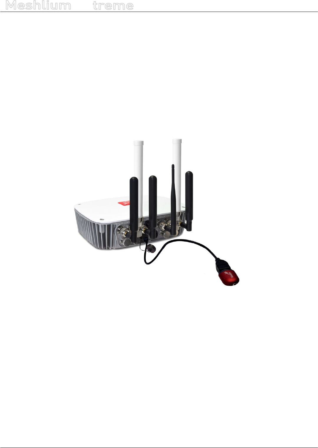
-205- v7.3
Rescue System
Meshlium
X
treme
To create the rescue you have to:
•Start unetbootin and select the option “Diskimage”
•Select the iso of the rescue image in the le selector
•Select the USB unit where the image will be written
•Click “OK” button to start the process
In some minutes the image will be written and the USB will be ready to use.
To apply the rescue in Meshlium:
•Power o the device
•Plug the USB pendrive in the micro-USB connector trough a USB-OTG cable
Figure: USB pendrive connected to Meshlium
•Power on the device
•When the rescue starts, Meshlium will emit a beep. The process can take a few minutes, so be patient.
•When the rescue process nishes, Meshlium will emit several beeps to notify
•Power o Meshlium and unplug the USB pendrive
•Your Meshlium should be now in a default state. It can be powered on now. The user can access Manager
System with default credentials and start the setup fresh and use Meshlium normally.
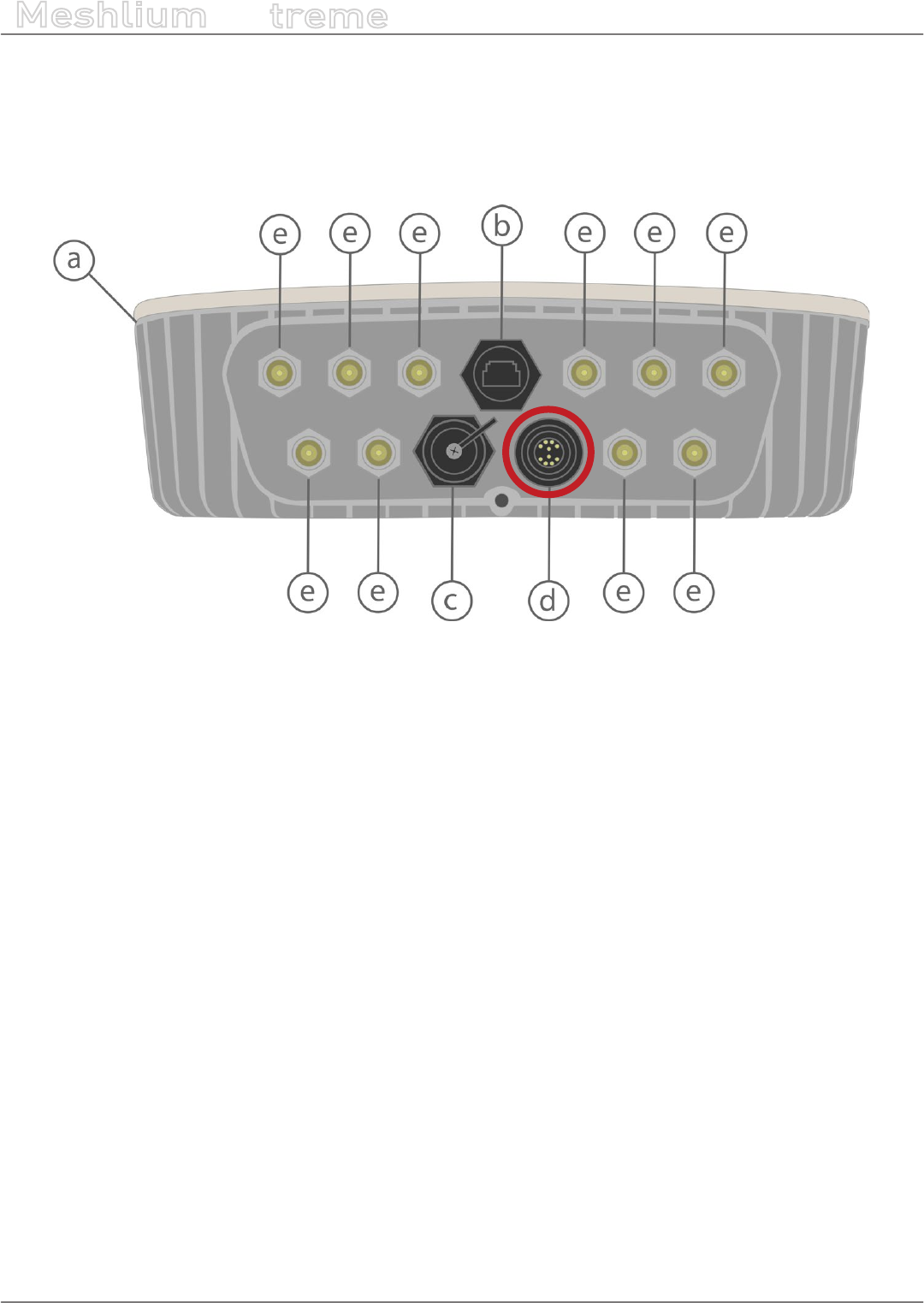
-206- v7.3
Expansion port
Meshlium
X
treme
20. Expansion port
Meshlium includes an expansion port with some extra connectivity options. It includes access to a UART, an I2C
bus and a USB port.
This port is available for development purposes.
Figure: Meshlium expansion port

-207- v7.3
Manager System changelog
Meshlium
X
treme
21. Manager System changelog
Version 4.0.4
•Added new menu “Devices”
•Added Axis device plugin
•Added new menu “Activity Monitor” for replacing “Disk Usage”
•Added option to change log level in Sensor Parser
•Allowed more characters for parameters in Bluetooth and WiFi Scanner
•Added SSL support in the ThingWorx cloud connector
•Now Azure cloud connector shows logs
•Corrected bug on list of sensors: use wrong sensor list
•Corrected bug on ThingPlus cloud connector: error at start time
•Removed Devicify cloud connector
Version 4.0.3
•Dynamic DNS conguration added with NoIP2 agent
•Added new cloud plugins: Ericsson, inswift, PlasmaComp, Redd System
•Updated cloud connectors: Azure Hub, Bluemix
•Augmented default log level in all the cloud plugins
•Corrected 4G connection bugs
•Corrected WiFiScan bug detection empty
Version 4.0.2
•Added support for new protocol Device to Cloud
•New cloud distribution: premium, advanced, basic
•Added new cloud connectors: Arrow, Haibu, Qmic
•Updated cloud plugins: Amazon, ElementBlue
•Removed deprecated plugin Microsoft Azure Service Bus
•Added a check process on the le system after system reboot
•Show Wi scan results on visualizations
•Updated sensor list for v15
•Several minor stability and interface updates incorporated
Version 4.0.1
•Added new cloud connectors:
-Cumulocity
-Kii
-Nexmachina
-RedTone
-SmartPlants
-TechEdge(SAP)

-208- v7.3
Manager System changelog
Meshlium
X
treme
Version 4.0.0
•Network setup reviewed
•Added “disable/enable” control to main services
•Added compatibility with several radio modules
•Added Auto-purge to sensor, Bluetooth scanner, WiFi scanner and GPS data
•Cellular connection mechanism improved
•Added Azure IoT Hub cloud connector
•Update process improved. No reboot between updates needed.
•Added option to synchronize with NTP server
•Improved speed and stability

-209- v7.3
Documentation changelog
Meshlium
X
treme
22. Documentation changelog
From v7.2 to v7.3
•Added the new chapter “Device connectors”
•Added new device connector for Axis
From v7.1 to v7.2
•Added new cloud connectors: Arrow (Arrow Connect), Ericsson (Ericsson AppIoT), Haibu (HaibuSmart), inswift,
PlasmaComp (C2M), Qmic-NexMachina (Labeeb), Redd System (Redd)
•Updated cloud connectors classication
•Added notes for NoIP cong in the “Interfaces” menu
From v7.0 to v7.1
•Added new cloud connectors: BaseN, Cumulocity, Ensura, Kii, Orchestra, Microsoft Azure IoT Hub, Nexmachina,
RedTone, SensorUP, SmartCityPlatform, SmartPlants, TechEdge SAP HANA, Telit
•Updated cloud connectors: Amazon IoT, Microsoft Azure Event Hubs, MQTT, Sentilo
•Updated antenna position in section “Contents of the box”
•Added Bluetooth radio specications in section “Specications”
•Removed SolvView cloud connector

-210- v7.3
Certications
Meshlium
X
treme
23. Certications
23.1. General overview
Products Europe US Canada Australia Brazil
Meshlium 4G 802.15.4 AP 868 EU CE - - - -
Meshlium 4G 802.15.4 AP 900 US - FCC / PTCRB / AT&T IC - -
Meshlium 4G 802.15.4 AP 900 AU - - - RCM -
Meshlium 4G 802.15.4 AP 900 BR - - - - ANATEL
23.2. CE (Europe)
Compliance with regulations:
•Electromagnetic Compatibility: EN 301 489-1 (1.9.2) / -17 (2.2.1) / -24 (1.5.1), EN 55022 (2010)
•Electrical Security: EN 60950-1 (2006) + A11 (2009) + A1 (2010) + A12 (2011) + Ac (2011) + A2 (2013) (except
appendix Zx)
Figure: Back sticker for Meshlium 4G 802.15.4 AP 868 EU

-211- v7.3
Certications
Meshlium
X
treme
23.3. FCC (USA)
This document applies to the following Meshlium models:
Model FCC ID
Meshlium 4G 802.15.4 AP 900 US XKM-MESHLIUM-V1
Compliance with regulations:
•Electromagnetic Compatibility: FCC Part 15B ed.10.1.13
•Radiofrequency (radiated spurious): FCC Part 15.247 (2013) + CFR 47 Part 15.247 (2013) + FCC Part 22 (2014) +
FCC Part 24 (2014) + FCC Part 27 (2014)
PTCRB compliance:
•Radiated Spurious Emissions: 3GPP TS 51.010-1 (s.12.2.x) + 3GPP TS 36.124 (s.8.2)
-Bands: LTE FDD2, FDD4, FDD5, FDD17, 2G 900/1800
•OTA: CTIA Test Plan for Mobile Station OTA Performance v3.3.2 + AT&T document 13340, version 5.6 - Device
Requirements.
-Bands: LTE FDD2, FDD4, FDD5, FDD17, 2G 900/1800
-Measures: TRP / TIS / ICS
•SIM electrical ETSI TS 102 230 (s. 5.x)
Figure: Back sticker for Meshlium 4G 802.15.4 AP 900 US

-212- v7.3
Certications
Meshlium
X
treme
23.4. IC (Canada)
This document applies to the following Meshlium models:
Model IC ID
Meshlium 4G 802.15.4 AP 900 US 8472A-MESHLIUMV1
Figure: Back sticker for Meshlium 4G 802.15.4 AP 900 US
23.5. ANATEL (Brazil)
Figure: Back sticker for Meshlium 4G 802.15.4 AP 900 BR
23.6. RCM (Australia)
Figure: Back sticker for Meshlium 4G 802.15.4 AP 900 AU
IC

-213- v7.3
Maintenance
Meshlium
X
treme
24. Maintenance
•Although Meshlium is a highly resistant product (IP65), please handle with care in order to enjoy a longer life
of the product.
•Handle Meshlium with care, do not allow it to drop or move roughly.
•Avoid placing the devices in areas reaching very high temperatures that could damage the electronic
components.
•The antennas screw on gently to the connector, do not force them while installing or you could damage the
connectors.
•Do not use any type of paint on the device, it could aect the operation of connections and closing mechanisms.
•Power accessories must only be used indoors.
•Do not store Meshlium in places exposed to dirt and dust in order to avoid damage to electronic components.
•Never open the casing, the guarantee will not cover products that have been opened.
•For cleaning, use a damp cloth, do not use aggressive chemical products.

-214- v7.3
Disposal and recycling
Meshlium
X
treme
25. Disposal and recycling
When Meshlium reaches the end of its useful life it must be taken to a recycling point for electronic equipment.
•The equipment should be disposed of separately from solid urban waste, please dispose of correctly.
•Your distributor will advise you on the most appropriate and environmentally-friendly way of disposing of the
product and its packing.
