NUFLO MC III WP Flow Analyzer Quick Start Guide Data Sheet
User Manual: Pdf NUFLO MC-III WP Flow Analyzer Quick Start Guide Data Sheet Resource Library
Open the PDF directly: View PDF ![]() .
.
Page Count: 16

Part No. 2296694-01, Rev. 03
Quick Start Guide
MC-III
TM Flow Analyzer
A Quick Reference on
Mounting, Wiring, & Configuring
the MC-III EXP or WP Flow Analyzer
For complete instructions, see
MC-III EXP User Manual, Part No. 9A-50165003
MC-III WP User Manual, Part No. 9A-50165009
in the MC-III software Help menu
2
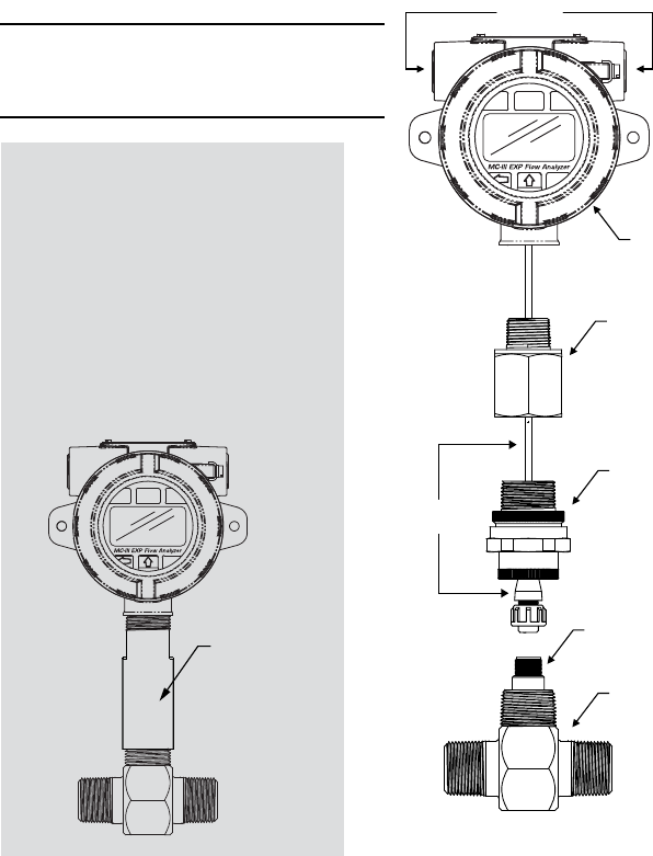
Pipe plugs
Explosion-proof
enclosure
3/4-in. to 1-in.
pipe reducer*
1-in. pipe union*
Cable
assembly
Magnetic pickup
Turbine flowmeter
MC-III EXP
1. PositiontheMC-IIIEXPabovetheowmeterpickupadapter.
2. PlugtheconnectoroftheMC-IIIEXPcableintothemagneticpickupand
hand-tightentheknurlednutontheconnector.
3. MounttheMC-IIIEXPontheowmeterpickupadapterwiththedisplay
facingthedesireddirection,andtightenallsectionsofthepipeunion.
BeforemountinganATEX-approveddevice,see“MC-IIIEXP(ATEX)”
below.
Caution: Do not use Teon tape on
threads of the union, adapter, or pipe
plugs.
Mounting Your MC-III
ATEX-approved
standoff tube
adapter
MC-III EXP (ATEX)
ATEX-approvedMC-IIIEXPsaretted
withastandofftubeadapterwhenpur-
chasedwithanATEX-approvedBarton
7000SeriesorNuFloturbinemeter.
Toavoiddamagingthesignalcable
duringinstallation,makesurethe
signalcableisdisconnectedfromthe
MC-IIIcircuitboardbeforemounting
theMC-IIItoaowmeter.
*Pipereducerandunionareusedin
CSA-approvedMC-IIIdevicesonly.
3
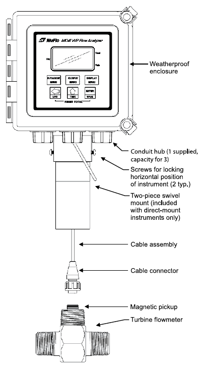
MC-III WP
1. PositiontheMC-IIIWPabovetheowmeter.
2. PlugtheMC-IIIWPcableconnectorintothemagneticpickupandhand-
tightentheknurlednutontheconnector.
3. ScrewtheMC-IIIWPmountontotheowmeterthreadssurroundingthe
magneticpickup.
4. Withthedisplayfacing
thedesireddirection,
tightenthetwoscrews
oneithersideofthe
mounttoprevent
horizontalshifting.
5. Withthedisplay
orientedverticallyin
thedesireddirection,
tightenthetwohex-
headboltsoneither
sideofthetopsection
ofthemounttoprevent
verticalshifting.
4
CAUTION—All eld wiring must conform to the National Electrical Code, NFPA 70,
Article 501-4(b) for installations within the United States or the Canadian Electric
Code for installations within Canada. Local wiring ordinances may also apply. All
eld wiring must have a wire range of 22 to 14 AWG and terminal block screws must
be tightened to a minimum torque of 5 to 7 in-lb to secure the wiring within the ter-
minal block. Only personnel who are experienced with eld wiring should perform
these procedures.
Wiring Your MC-III
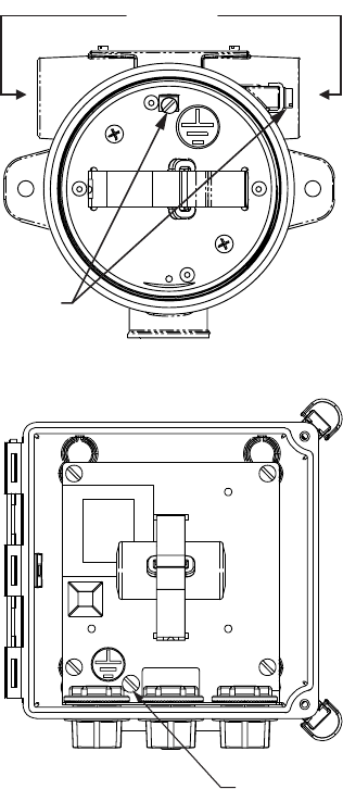
Ground screw
Pipe plugs
Ground
screws
MC-III EXP
FieldwiringenterstheMC-IIIEXP
enclosurethrougheitheroftwo
threadedconduitopeningsinthe
topoftheenclosure.Whennotin
use,theopeningsaresealedwith
pipeplugs.
MC-III WP
FieldwiringenterstheMC-IIIWP
enclosurethroughconduithubsin
thebottomoftheenclosure.One
hubissuppliedandtwoadditional
entrancesarepluggedbutavail-
ableforusewithcustomer-supplied
hubs).Theowmetercableis
routedthroughacordconnectorin
thebackofthebottomenclosure
panel.
ForDiv.2installations,aground
wiremustbeconnectedtothe
internalgroundscrewinsidethe
enclosure.
ForDC-poweredinstallations,route
thegroundconductorintothe
enclosurewiththeincomingpower
conductors.
5
6-30 VDC
TB1
PULSE
INPUT
RESET
INPUT
TFM
A&S
GND
TB3
EXT POWER
TURBINE
MAGNETIC PICKUP
VMAX = 3.9 V
J1
J2
RESET
SWITCH
BATTERY
A
B
BATTERY CONNECTION
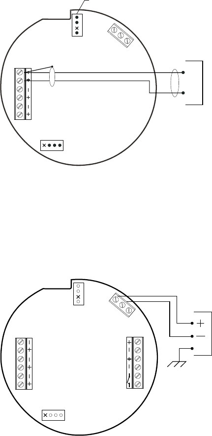
Caution: Never use external power
with a 4-20 mA output.
1. Ifthebattery/batterypackisnotalreadyconnectedtothecircuitboard,
attachthebatterycabletoconnectorJ1.
2. ConnecttheowmetersignalcabletoterminalblockTB1.
3. Ifanexternalpowersupplyistobeused(thebatterywillprovidebackup
power),wirethepowersupplytoterminalblockTB3.
ForMC-IIIWPDiv.2installations,connectaprotectiveovercurrent
deviceratedat0.5Amaximum(circuitbreakerorfuse)tothepositive
supplylineoftheDCpowersupplyinthesafearea.Adisconnectswitch
forthepowersupplymustalsobeinstalledinthesafearea.
AZenerdiode(PartNo.1.5KE33CA)mustbeinstalledforCEapproval.
TB3
TB1
PULSE
INPUT
RESET
INPUT
TFM
A&S
GND
EXT POWER
TB2
RS485
SLAVE
4-20
OUT
PULSE
OUT
6-30 VDC
POWER
SUPPLY
6 to 30
VDC
J1
J2
RESET
SWITCH
BATTERY
GROUND SCREW
REQUIRED FOR
DIV. 2 INSTALLATIONS
TB3 MARKING:
GND = SIGNAL GROUND
6
TB1
PULSE
INPUT
RESET
INPUT
TFM
A&S
GND
TB3
EXT POWER
TB2
RS485
SLAVE
4-20
OUT
PULSE
OUT
6-30VDC
J1
J2
RESET
SWITCH
BATTERY
Leave this
end of shield
disconnected.
POWER SUPPLY
5 to 50 VDC
*
Resistor may be included in pulse readout
device. Size the resistor to limit the current
to 60 mA.
*
PULSE READOUT
DEVICE
TB1
PULSE
INPUT
RESET
INPUT
TFM
A&S
GND
TB3
EXT POWER
TB2
RS485
SLAVE
4-20
OUT
PULSE
OUT
6-30 VDC
J1
J2
RESET
SWITCH
BATTERY
POWER SUPPLY
8 to 30 VDC
LOAD
Resistor may be
included in readout
device.
4-20 mA and
flowmeter frequency
(amp & square)
cannot be used
simultaneously.
*
*
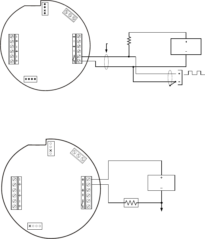
4. Ifapulseoutputistobeused,wirethepowersupplyandthepulse
readoutdevicetoterminalblockTB2.Themaximumcurrentratingofthe
pulseoutputcircuitis60mAat50VDC.
AZenerdiode(PartNo.1.5KE56CA)mustbeinstalledforCEapproval.
5. Ifa4-20mArateoutputistobeused,wirethepowersupplytoterminal
blockTB2.Thepowersupplyvoltagerequiredtopowerthecurrentloop
dependsontheloopresistance.SeeanMC-IIIusermanualfordetails.
Caution: Never use external power with a 4-20 mA output.
Wiring Your MC-III
7
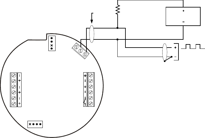
6. Ifaowmeterfrequencyoutputistobeusedtoprovideowrateand/
ortotalinformationtoperipheralequipment,wirethepowersupplyand
thefrequencyreadoutdevicetoterminalblockTB3.Thereadoutdevice
mustoperatewith50mAorless.
TB1
PULSE
INPUT
RESET
INPUT
TFM
A&S
GND
TB3
EXT POWER
TB2
RS485
SLAVE
4-20
OUT
PULSE
OUT
6-30VDC
J1
J2
RESET
SWITCH
BATTERY
Leave this
end of shield
disconnected.
POWER SUPPLY
5 to 30 VDC
FREQUENCY
READOUT DEVICE
*
Resistor may be included in frequency
readout device. Size the resistor to limit
the current to 50 mA.
4-20 mA and flowmeter frequency
(amp & square) cannot be used
simultaneously.
*
TB3 MARKINGS:
GND = SIGNAL GROUND
A&S = AMP & SQUARE
Caution: When using the owmeter frequency output
and powering the device from an external power
supply, make sure both power supplies share a
common negative (-) terminal or are totally isolated
from each other.
7. ToconguretheMC-IIIwithsoftware,connecttheMC-IIItoacomputer
bywiringaconvertercabletotheRS-485terminalsofTB2.Seepage12
forwiringdiagrams.
8
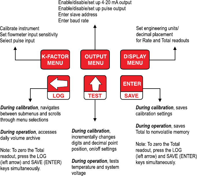
Configuring with the Keypad
Mostroutinefunctionscanbeconguredfromthesix-buttonkeypad.
Thisguideprovidesinstructionsforenteringacalibrationfactor,andselecting
theunitsforthetotalandowratedisplays.Forinstructionsonconguringall
otherparameters,seetheMC-IIIusermanuals.
9
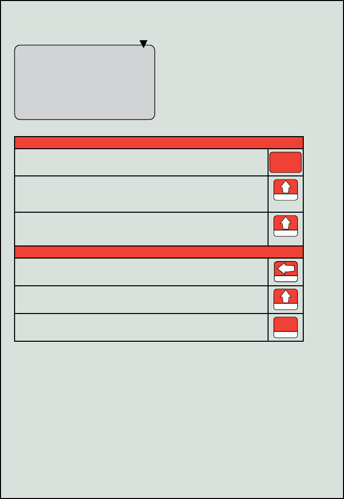
Parameterchangestypicallyrequirefourbasicsteps:
1. Selectamenu(K-FACTOR,OUTPUT,ORDISPLAY).
2. PressUPARROWtochangetheparameterorvaluedisplayed.
3. PressLEFTARROWtoadvancetothenextcongurable
parameterorvalue.
4. PressENTERtosavethenewcongurationsetting.
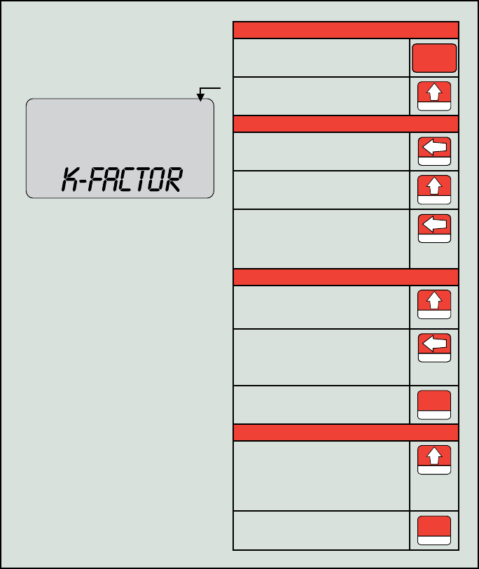
Enter a
Calibration Factor
00000000 M3
BBL
GAL
LIT
CF
CF
X1000
X1000
Select a K-Factor Unit.
PressK-FACTORMENU. K-FACTOR
MENU
PressUPARROWuntilthe
correctunitisdisplayed. TEST
Select a Decimal Point Position.
PressLEFTARROWtoselect
thedecimalpoint. LOG
PressUPARROWtochangethe
positionofthedecimalpoint. TEST
PressLEFTARROWtosavethe
decimalpointselectionand
proceedwithenteringacalibra-
tionfactor.
LOG
Enter a Calibration Factor.
PressUPARROWuntilthelast
digitofthecalibrationfactoris
displayed. TEST
ThenpressLEFTARROWto
selectthenextdigittotheleft.
RepeatusingUPandLEFT
arrowstoenterremainingdigits.
LOG
PressENTERtoadvancetothe
InputSensitivitymenu. SAVE
ENTER
Enter an Input Sensitivity Setting.
PressUPARROWtoselectlow,
medium,orhigh(foraturbine
meterinputsignal)or“pulse
input”(forapreamplierinput
signal).
TEST
PressENTERtosaveyour
selections. SAVE
ENTER
10
Select a Unit of Measure for Volume
00000000
000000
M3
BBL
GAL
LIT
M3
BBL
GAL
LIT
/SEC
/MIN
/HR
/DAY
CF
CF
X1000
X1000
STANDARD
Select a Volume Unit.
PressDISPLAYMENU.
DISPLAY
MENU
PressUPARROWuntilthecorrectunitisdisplayed.
Note—Ifacalculateddivisorwasentered,selectuser-dened(no
unitsvisible).
TEST
Toreadthevolumeintermsofthousandsofunits(ex.1.0=1,000
bbl),continuepressingUPARROWuntilboththeunitofchoice
andtheX1000optionaredisplayed.
TEST
Select a Decimal Point Position.
PressLEFTARROWuntilthedecimalpointintheTotaldisplay
beginsblinking. LOG
PressUPARROWtochangethepositionofthedecimalpoint.
TEST
PressENTERtosaveyourselections.
SAVE
ENTER
Configuring with the Keypad
11
Select a Unit of Measure for Rate
00000000
000000
M3
BBL
GAL
LIT
M3
BBL
GAL
LIT
/SEC
/MIN
/HR
/DAY
CF
CF
X1000
X1000
STANDARD
00000000
000000
M
3
BBL
GAL
LIT
M
3
BBL
GAL
LIT
/SEC
/MIN
/HR
/DAY
CF
CF
X1000
X1000
STANDARD
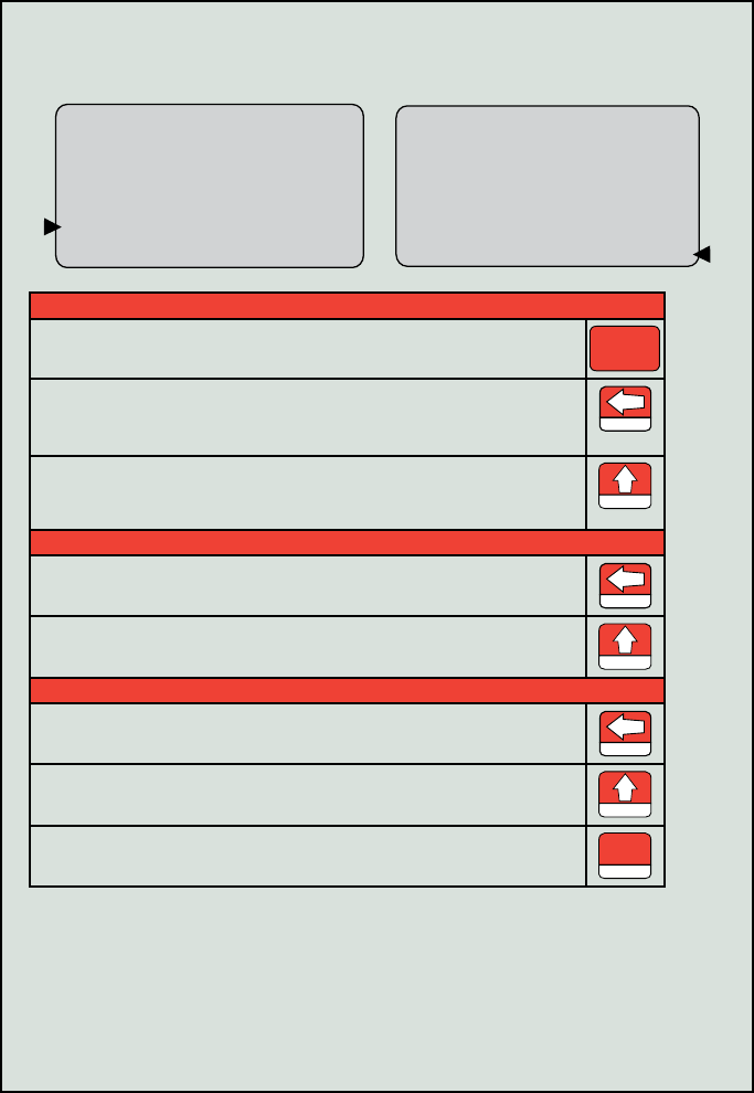
Select the Volume Portion of the Flow Rate Unit.
PressDISPLAYMENU.
DISPLAY
MENU
PressLEFTARROWuntilavolumeunitofmeasureisdisplayedin
theratedisplayportionoftheLCDwindow.Theseunitsarelocated
totheleftorjustabovetheRatedisplay.
LOG
PressUPARROWuntilthedesiredunitofmeasureisdisplayed.
Note—Ifacalculateddivisorwasentered,selectuser-dened
(nounitsvisible).
TEST
Select the Time Portion of the Flow Rate Unit.
PressLEFTARROWtoselectthetimeportionoftheRateunitof
measure. LOG
PressUPARROWuntilthedesiredunitofmeasureisdisplayed.
TEST
Select a Decimal Point Position.
PressLEFTARROWuntilthedecimalpointintheRatedisplay
beginsblinking. LOG
PressUPARROWtochangethepositionofthedecimalpoint.
TEST
PressENTERtosaveyourselections.
SAVE
ENTER
12
Step 1: Install the MC-III Software
FollowtheinstructionsonthecoveroftheCDpacketto
loadthesoftware.AnMC-IIIiconwillappearonthe
computerdesktopwheninstallationiscomplete.
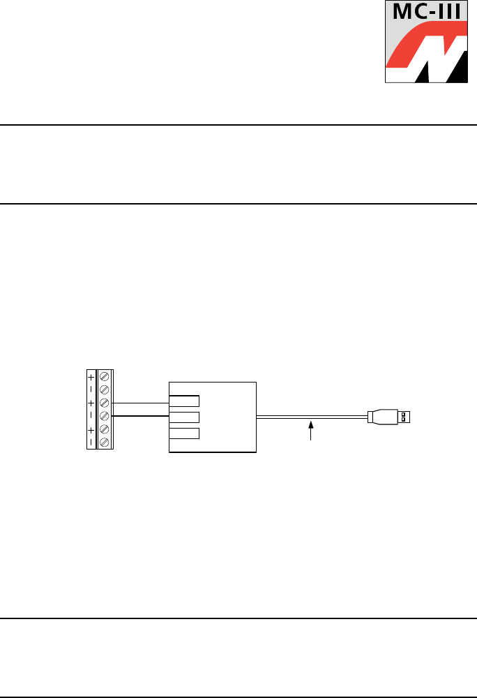
Step 2: Connect the Computer to the MC-III
Note—An RS-485 converter is required to connect a computer to the
MC-III ow analyzer. The instructions below are for an RS-485-to USB
converter (Part No. 2296650-01). An RS-485-to-RS-232 9-pin converter
(Part No. 9A-101283116) is also available.
1. RemoveoropenthecoveroftheMC-IIIenclosuretoaccessthecircuit
board.
2. VerifythatthebatteryisconnectedtotheJ1connector(page5).Ifusing
anexternalpowersupply,verifythatitiswiredproperly(page5).
3. ConnecttheRS-485toUSBconvertercabletotheRS-485terminalson
TB2oftheMC-IIIcircuitboardasshown.
4. UseauniversalA/BUSBcabletoconnectyourcomputertotheconverter.
TD ( B )
TD ( A )
GND
UNIVERSAL
A/B USB CABLE
TX +
TX -
TB2
4-20
OUT
RS485
SLAVE
PULSE
OUT
Part No. 2296650-01
Communication Adapters (RS-485 or USB)
Ifanoptionalcommunicationadapterisinstalled,theMC-IIIEXPmaybe
connectedtoacomputerwithoutopeningtheenclosureorinstallingaddition-
aleldwiring.CommunicationadaptersareavailableforusewithRS-232or
USBcomputerports.IfusingaUSBport,auser-supplieduniversalserialbus
USBA/Bcableisrequired.SeetheMC-IIIEXPUserManualfordetails.
Important—The RS-485 to RS-232 adapter is approved for use with
CSA-certied and ATEX-certied MC-III EXP analyzers. The RS-485 to
USB adapter is approved only for use with a CSA-certied MC-III EXP
analyzer.
Connecting to the MC-III
13
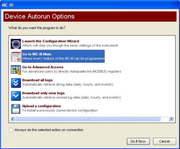
Step 3: Run the Program
1. Double-clicktheMC-IIIicononthedesktoporselectStart-Programs-
NuFlo-MC-III-MC-IIItolaunchthesoftware.
AWelcomescreenwillappear,followedbyaDeviceAutorunOptions
screen.
2. SelectLaunch the Conguration Wizardandfollowtheinstructions
onthescreen.
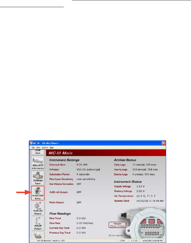
Foraccesstoallcongurableparameters,selectGo to MC-III Main
(seetheMC-IIIusermanualsforinstructions).
Toautomateafunctiontoruneachtimethesoftwareconnectswith
theinstrument,clickonthefunctionontheDeviceAutorunOptions
screenandchecktheAlways do...checkboxatthebottomofthe
screen.
14
Configuring with Software
Gas Volume Correction
Gasturbinemetersmeasuregasinactualcubicfeet(ACF).Tomeasure
gasintermsofstandardcubicfeet(SCF),owinggaspressuresand
temperaturesmustbereferencedbacktostandardconditions,basedon
xed(average)parameters.These parameters are accessible only through
MC-III interface software.
Toconguretheinstrumenttomeasuregasowinstandardcubicfeet,
performthefollowingsteps:
1. SelectGo to MC-III MainfromtheDeviceAutorunOptionsscreen.
2. ClicktheK-Factor Entryiconinthescrollbaratleft.
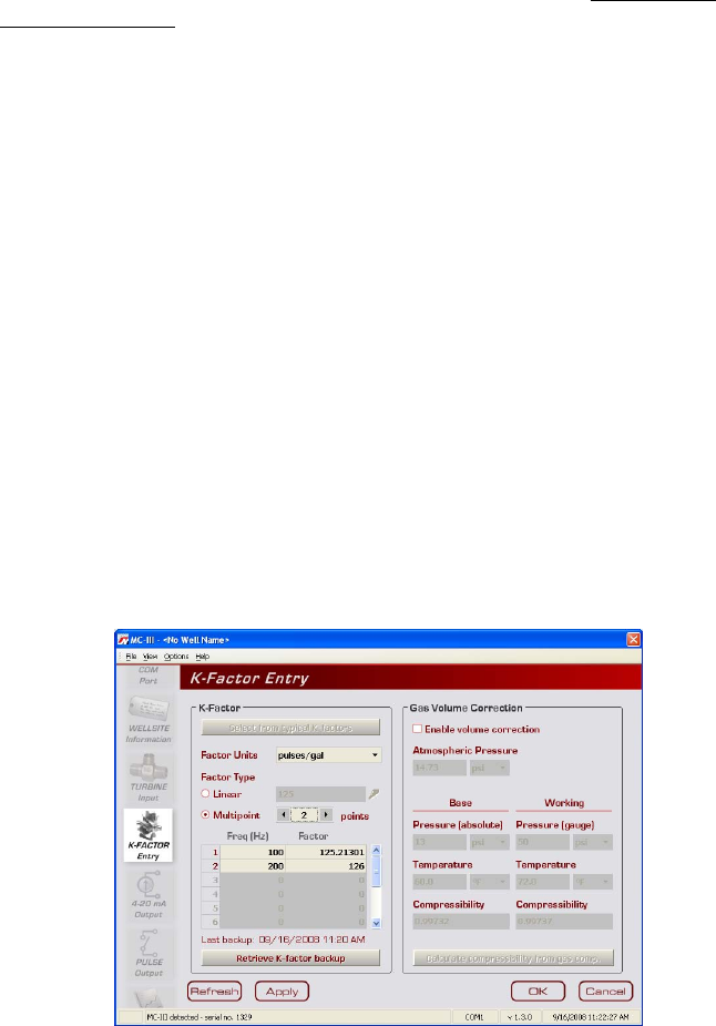
3. IntheGasVolumeCorrectionsectionoftheK-FactorEntryscreen,
checktheEnable volume correctioncheckbox(seescreenonpage15).
TheSTANDARDannunciatorwillappearontheLCD.
4. Adjustatmosphericpressure,ifdesired.
5. Enterthebasepressureandunitandthebasetemperatureandunit.
6. Entertheworkingpressure,workingtemperature,andcorresponding
units.
7. Enteraknowncompressibilityfactor,orpressCalculate compressibility
from gas comp.toenterthegascomposition.ClickCalculate.
8. PressApply or OKtosavethenewcompensationsettings.
15
Multipoint Linearization
TheMC-IIIcanbecalibratedwithupto12calibrationpointsusing MC-III
interface software.(Onlysingle-pointcalibrationissupportedthroughthe
CongurationWizard.)
Toconguretheinstrumentwiththeseparameters,performthefollowing
steps:
1. SelectGo to MC-III MainfromtheDeviceAutorunOptionsscreen.
2. ClicktheK-FactorEntryiconinthescrollbaratleft(seescreenonpage
14).
3. Selectthefactorunits.
4. Selectthemultipointcheckbox.
5. Enterthenumberofcalibrationpointsdesiredusingthe“plus”and
“minus”buttons(upto12pointsmaximum).
6. Clickoneachactivatedcalibrationpointeld,andentertheappropriate
frequency(Hz)andcalibrationfactor.
7. Repeatforallcalibrationpoints.
8. PressApply or OKtosavethenewcalibrationsettings.

Copyright 2013 Cameron International Corporation
HOUSTON
HEAD OFFICE 281.582.9500
NORTH
AMERICA 1.800.654.3760
ms-us@c-a-m.com
ASIA
PACIFIC +603.5569.0501
ms-kl@c-a-m.com
EUROPE,
MIDDLE EAST
& AFRICA
+44.1243.826741
ms-uk@c-a-m.com
MEASUREMENT SYSTEMS
USA • CANADA • UK • CHINA • UAE • ALGERIA • MALAYSIA • INDIA • RUSSIA
www.c-a-m.com/flo
