ManualsLib Makes It Easy To Find Manuals Online! Robot R30ia Maint Manual
User Manual: Pdf
Open the PDF directly: View PDF ![]() .
.
Page Count: 248 [warning: Documents this large are best viewed by clicking the View PDF Link!]


• Original Instructions
Before using the Robot, be sure to read the "FANUC Robot Safety Manual (B-80687EN)" and
understand the content.
• No part of this manual may be reproduced in any form.
• All specifications and designs are subject to change without notice.
The products in this manual are controlled based on Japan’s “Foreign Exchange and
Foreign Trade Law”. The export from Japan may be subject to an export license by the
government of Japan.
Further, re-export to another country may be subject to the license of the government of
the country from where the product is re-exported. Furthermore, the product may also be
controlled by re-export regulations of the United States government.
Should you wish to export or re-export these products, please contact FANUC for advice.
The products in this manual are manufactured under strict quality control. However, when
using any of the products in a facility in which a serious accident or loss is predicted due to
a failure of the product, install a safety device.
In this manual we have tried as much as possible to describe all the various matters.
However, we cannot describe all the matters which must not be done, or which cannot be
done, because there are so many possibilities.
Therefore, matters which are not especially described as possible in this manual should be
regarded as ”impossible”.
Downloaded from www.Manualslib.com manuals search engine

B-82725EN-1/07 PREFACE
p-1
PREFACE
This manual describes the following models (R-30iA Mate controller).
Model Abbreviation
FANUC Robot LR Mate 200iC LR Mate 200iC
FANUC Robot LR Mate 200iC/5C LR Mate 200iC/5C
FANUC Robot LR Mate 200iC/5F LR Mate 200iC/5F
FANUC Robot LR Mate 200iC/5H LR Mate 200iC/5H
FANUC Robot LR Mate 200iC/5L LR Mate 200iC/5L
FANUC Robot LR Mate 200iC/5LC LR Mate 200iC/5LC
FANUC Robot LR Mate 200iC/5WP LR Mate 200iC/5WP
LR Mate 200iC
FANUC Robot ARC Mate 100iC
FANUC Robot ROBOWELD 100iC ARC Mate 100iC
FANUC Robot ARC Mate 100iC/6L
FANUC ROBOWELD 100iC/6L ARC Mate 100iC/6L
FANUC Robot ARC Mate 100iCe ARC Mate 100iCe
FANUC Robot ARC Mate 100iCe/6L ARC Mate 100iCe/6L
ARC Mate 100iC
FANUC Robot M-10iA M-10iA
FANUC Robot M-10iA/6L M-10iA/6L
FANUC Robot M-10iAe M-10iAe
FANUC Robot M-10iAe/6L M-10iAe/6L
M-10iA
FANUC Robot ARC Mate 120iC
FANUC ROBOWELD 120iC ARC Mate 120iC
FANUC Robot ARC Mate 120iC/10L
FANUC ROBOWELD 120iC/10L ARC Mate 120iC/10L
ARC Mate 120iC
FANUC Robot M-20iA M-20iA
FANUC Robot M-20iA/10L M-20iA/10L M-20iA
FANUC Robot ARC Mate 50iC
FANUC ROBOWELD Mini iC ARC Mate 50iC
FANUC Robot ARC Mate 50iC/5L
FANUC ROBOWELD Mini iC/5L ARC Mate 50iC/5L
ARC Mate 50iC
FANUC Robot ARC Mate 0iA ARC Mate 0iA ARC Mate 0iA
FANUC Robot M-1iA/0.5A M-1iA/0.5A
FANUC Robot M-1iA/0.5S M-1iA/0.5S M-1iA
Downloaded from www.Manualslib.com manuals search engine


B-82725EN-1/07 SAFETY PRECAUTIONS
s-3
SAFETY PRECAUTIONS
For the safety of the operator and the system, follow all safety precautions when operating a robot and its
peripheral devices installed in a work cell.
In addition, refer to the “FANUC Robot SAFETY HANDBOOK (B-80687EN)”.
1 WORKING PERSON
The personnel can be classified as follows.
Operator:
• Turns robot controller power ON/OFF
• Starts robot program from operator’s panel
Programmer or teaching operator:
• Operates the robot
• Teaches robot inside the safety fence
Maintenance engineer:
• Operates the robot
• Teaches robot inside the safety fence
• Maintenance (adjustment, replacement)
- An operator cannot work inside the safety fence.
- A programmer, teaching operator, and maintenance engineer can work inside the safety fence. The
working activities inside the safety fence include lifting, setting, teaching, adjusting, maintenance,
etc..
- To work inside the fence, the person must be trained on proper robot operation.
During the operation, programming, and maintenance of your robotic system, the programmer, teaching
operator, and maintenance engineer should take additional care of their safety by using the following
safety precautions.
- Use adequate clothing or uniforms during system operation
- Wear safety shoes
- Use helmet
2 WORKING PERSON SAFETY
Working person safety is the primary safety consideration. Because it is very dangerous to enter the
operating space of the robot during automatic operation, adequate safety precautions must be observed.
The following lists the general safety precautions. Careful consideration must be made to ensure
working person safety.
(1) Have the robot system working persons attend the training courses held by FANUC.
FANUC provides various training courses. Contact our sales office for details.
Downloaded from www.Manualslib.com manuals search engine
SAFETY PRECAUTIONS B-82725EN-1/07
s-4
(2) Even when the robot is stationary, it is possible that the robot is still in a ready to move state, and is
waiting for a signal. In this state, the robot is regarded as still in motion. To ensure working
person safety, provide the system with an alarm to indicate visually or aurally that the robot is in
motion.
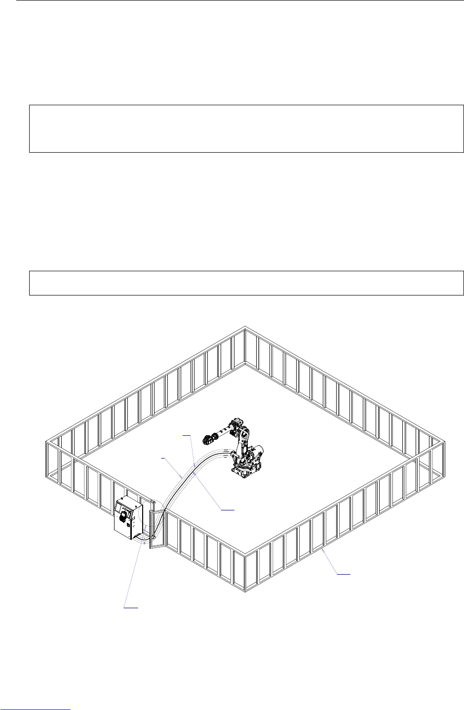
(3) Install a safety fence with a gate so that no working person can enter the work area without passing
through the gate. Install an interlocking device, a safety plug, and so forth in the safety gate so that
the robot is stopped as the safety gate is opened.
The controller is designed to receive this interlocking signal of the door switch. When the gate
is opened and this signal received, the controller stops the robot (Please refer to "STOP
TYPE OF ROBOT" in SAFETY for detail of stop type). For connection, see Fig.2 (a) and
Fig.2 (b).
(4) Provide the peripheral devices with appropriate grounding (Class A, Class B, Class C, and Class D).
(5) Try to install the peripheral devices outside the work area.
(6) Draw an outline on the floor, clearly indicating the range of the robot motion, including the tools
such as a hand.
(7) Install a mat switch or photoelectric switch on the floor with an interlock to a visual or aural alarm
that stops the robot when a working person enters the work area.
(8) If necessary, install a safety lock so that no one except the working person in charge can turn on the
power of the robot.
The circuit breaker installed in the controller is designed to disable anyone from turning it on
when it is locked with a padlock.
(9) When adjusting each peripheral device independently, be sure to turn off the power of the robot
RM1
Motor power/brake
RP1
Pulsecoder
RI/RO,XHBK,XROT
EARTH
Safety fence
Interlocking device and safety plug that are activated if the
gate is opened.
Fig.2 (a) Safety fence and safety gate
Downloaded from www.Manualslib.com manuals search engine
B-82725EN-1/07 SAFETY PRECAUTIONS
s-5
Panel board
EAS1
EAS11
EAS2
EAS21
(Note)
Connect EAS1 and EAS11, EAS2 and EAS21.
Terminals EAS1,EA11,EAS2,EAS21 are on the E-stop board.
Fig.2 (b) Limit switch circuit diagram of the safety fence
2.1 OPERATOR SAFETY
The operator is a person who operates the robot system. In this sense, a worker who operates the teach
pendant is also an operator. However, this section does not apply to teach pendant operators.
(1) If you do not have to operate the robot, turn off the power of the robot controller or press the
EMERGENCY STOP button, and then proceed with necessary work.
(2) Operate the robot system at a location outside of the safety fence
(3) Install a safety fence with a safety gate to prevent any worker other than the operator from entering
the work area unexpectedly and to prevent the worker from entering a dangerous area.
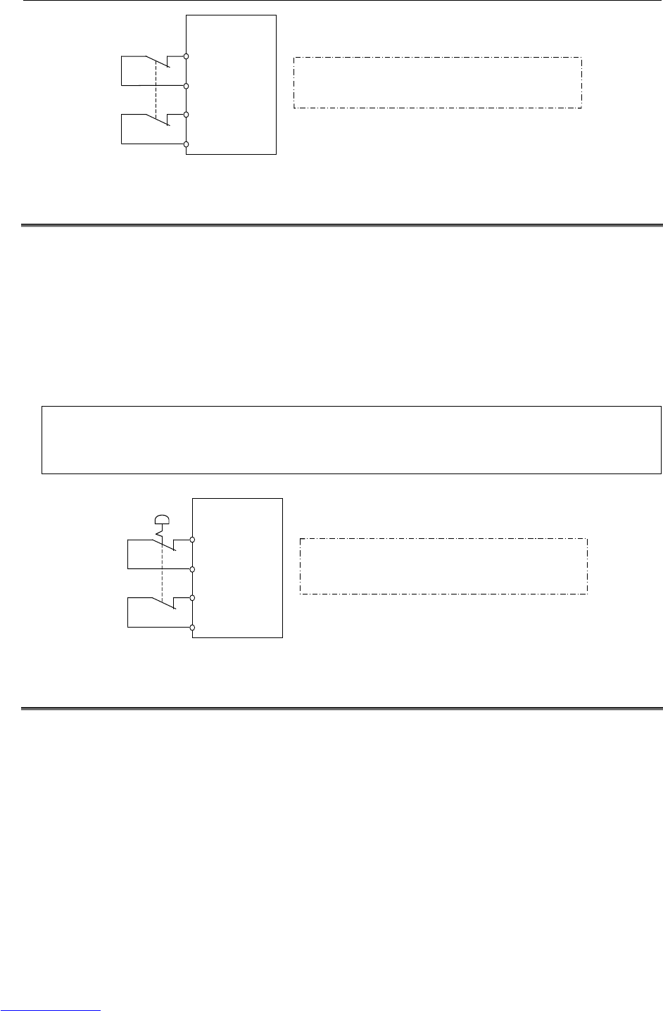
(4) Install an EMERGENCY STOP button within the operator’s reach.
The robot controller is designed to be connected to an external EMERGENCY STOP button.
With this connection, the controller stops the robot operation (Please refer to "STOP TYPE
OF ROBOT" in SAFETY for detail of stop type), when the external EMERGENCY STOP
button is pressed. See the diagram below for connection.
Panel board
EES1
EES11
EES2
EES21
(Note)
Connect EES1 and EES11, EES2 and EES21.
Terminals EES1,EES11,EES2,EES21 are on the E-stop board.
External EMERGENCY
STOP button
Fig.2.1 Connection diagram for external emergency stop button
2.2 SAFETY OF THE PROGRAMMER
While teaching the robot, the operator must enter the work area of the robot. The operator must ensure
the safety of the teach pendant operator especially.
(1) Unless it is specifically necessary to enter the robot work area, carry out all tasks outside the area.
(2) Before teaching the robot, check that the robot and its peripheral devices are all in the normal
operating condition.
(3) If it is inevitable to enter the robot work area to teach the robot, check the locations, settings, and
other conditions of the safety devices (such as the EMERGENCY STOP button, the DEADMAN
switch on the teach pendant) before entering the area.
(4) The programmer must be extremely careful not to let anyone else enter the robot work area.
Downloaded from www.Manualslib.com manuals search engine
SAFETY PRECAUTIONS B-82725EN-1/07
s-6
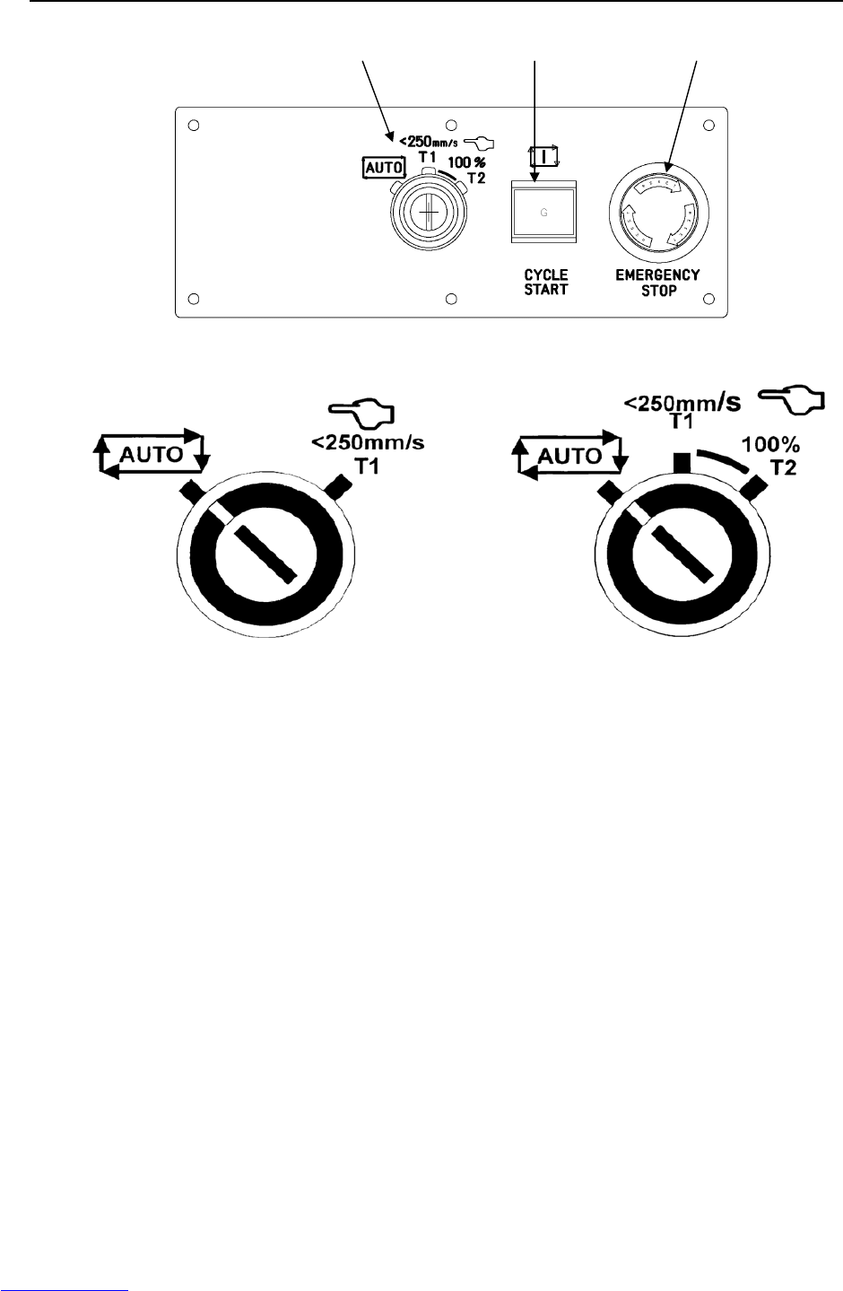
The operator panel is provided with an emergency stop button and a key switch (mode switch) for selecting the
automatic operation mode (AUTO) and the teach modes (T1 and T2). Before entering the inside of the safety
fence for the purpose of teaching, set the switch to a teach mode, remove the key from the mode switch to prevent
other people from changing the operation mode carelessly, then open the safety gate. If the safety gate is opened
with the automatic operation mode set, the robot stops (Please refer to "STOP TYPE OF ROBOT" in SAFETY for
detail of stop type). After the switch is set to a teach mode, the safety gate is disabled. The programmer should
understand that the safety gate is disabled and is responsible for keeping other people from entering the inside of
the safety fence.
The teach pendant is provided with a DEADMAN switch as well as an emergency stop button. These button and
switch function as follows:
(1) Emergency stop button: Causes an emergency stop (Please refer to "STOP TYPE OF ROBOT" in SAFETY
for detail of stop type) when pressed.
(2) DEADMAN switch: Functions differently depending on the mode switch setting status.
(a) Automatic operation mode: The DEADMAN switch is disabled.
(b) Teach mode: Servo power is turned off when the operator releases the DEADMAN switch or when the
operator presses the switch strongly.
Note) The DEADMAN switch is provided to stop the robot when the operator releases the teach pendant or
presses the pendant strongly in case of emergency. The R-30iA Mate employs a 3-position
DEADMAN switch, which allows the robot to operate when the 3-position DEADMAN switch is pressed
to its intermediate point. When the operator releases the DEADMAN switch or presses the switch
strongly, the robot stops immediately.
The operator’s intention of starting teaching is determined by the controller through the dual operation of setting the
teach pendant enable/disable switch to the enable position and pressing the DEADMAN switch. The operator
should make sure that the robot could operate in such conditions and be responsible in carrying out tasks safely.
The teach pendant, operator panel, and peripheral device interface send each robot start signal. However the
validity of each signal changes as follows depending on the mode switch of the operator panel, the teach pendant
enable/disable switch and the remote condition on the software.
Mode Teach pendant
enable/disable
switch
Software
remote
condition Teach pendant Operator panel Peripheral device
Local Not allowed Not allowed Not allowed
On Remote Not allowed Not allowed Not allowed
Local Not allowed Allowed to start Not allowed
AUTO
mode Off Remote Not allowed Not allowed Allowed to start
Local Allowed to start Not allowed Not allowed
On Remote Allowed to start Not allowed Not allowed
Local Not allowed Not allowed Not allowed
T1, T2
mode Off Remote Not allowed Not allowed Not allowed
T1,T2 mode: DEADMAN switch is effective.
(5) To start the system using the operator’s panel, make certain that nobody is the robot work area and
that there are no abnormal conditions in the robot work area.
(6) When a program is completed, be sure to carry out a test run according to the procedure below.
(a) Run the program for at least one operation cycle in the single step mode at low speed.
(b) Run the program for at least one operation cycle in the continuous operation mode at low
speed.
(c) Run the program for one operation cycle in the continuous operation mode at the intermediate
speed and check that no abnormalities occur due to a delay in timing.
(d) Run the program for one operation cycle in the continuous operation mode at the normal
operating speed and check that the system operates automatically without trouble.
(e) After checking the completeness of the program through the test run above, execute it in the
automatic operation mode.
Downloaded from www.Manualslib.com manuals search engine

B-82725EN-1/07 SAFETY PRECAUTIONS
s-7
(7) While operating the system in the automatic operation mode, the teach pendant operator should
leave the robot work area.
2.3 SAFETY OF THE MAINTENANCE ENGINEER
For the safety of maintenance engineer personnel, pay utmost attention to the following.
(1) During operation, never enter the robot work area.
(2) Except when specifically necessary, turn off the power of the controller while carrying out
maintenance. Lock the power switch, if necessary, so that no other person can turn it on.
(3) If it becomes necessary to enter the robot operation range while the power is on, press the
emergency stop button on the operator panel, or the teach pendant before entering the range. The
maintenance personnel must indicate that maintenance work is in progress and be careful not to
allow other people to operate the robot carelessly.
(4) When disconnecting the pneumatic system, be sure to reduce the supply pressure.
(5) Before the start of teaching, check that the robot and its peripheral devices are all in the normal
operating condition.
(6) Do not operate the robot in the automatic mode while anybody is in the robot work area.
(7) When you maintain the robot alongside a wall or instrument, or when multiple workers are working
nearby, make certain that their escape path is not obstructed.
(8) When a tool is mounted on the robot, or when any moving device other than the robot is installed,
such as belt conveyor, pay careful attention to its motion.
(9) If necessary, have a worker who is familiar with the robot system stand beside the operator panel
and observe the work being performed. If any danger arises, the worker should be ready to press
the EMERGENCY STOP button at any time.
(10) When replacing or reinstalling components, take care to prevent foreign matter from entering the
system.
(11) When handling each unit or printed circuit board in the controller during inspection, turn off the
circuit breaker to protect against electric shock.
If there are two cabinets, turn off the both circuit breaker.
(12) When replacing parts, be sure to use those specified by FANUC.
In particular, never use fuses or other parts of non-specified ratings. They may cause a fire or
result in damage to the components in the controller.
(13) When restarting the robot system after completing maintenance work, make sure in advance that
there is no person in the work area and that the robot and the peripheral devices are not abnormal.
3 SAFETY OF THE TOOLS AND
PERIPHERAL DEVICES
3.1 PRECAUTIONS IN PROGRAMMING
(1) Use a limit switch or other sensor to detect a dangerous condition and, if necessary, design the
program to stop the robot when the sensor signal is received.
(2) Design the program to stop the robot when an abnormal condition occurs in any other robots or
peripheral devices, even though the robot itself is normal.
(3) For a system in which the robot and its peripheral devices are in synchronous motion, particular care
must be taken in programming so that they do not interfere with each other.
(4) Provide a suitable interface between the robot and its peripheral devices so that the robot can detect
the states of all devices in the system and can be stopped according to the states.
Downloaded from www.Manualslib.com manuals search engine

SAFETY PRECAUTIONS B-82725EN-1/07
s-8
3.2 PRECAUTIONS FOR MECHANISM
(1) Keep the component cells of the robot system clean, and operate the robot in an environment free of
grease, water, and dust.
(2) Don’t use unconfirmed liquid for cutting fluid and cleaning fluid.
(3) Employ a limit switch or mechanical stopper to limit the robot motion so that the robot or cable does
not strike against its peripheral devices or tools.
(4) Observe the following precautions about the mechanical unit cables. When theses attentions are not
kept, unexpected troubles might occur.
• Use mechanical unit cable that have required user interface.
• Don’t add user cable or hose to inside of mechanical unit.
• Please do not obstruct the movement of the mechanical unit cable when cables are added to
outside of mechanical unit.
• In the case of the model that a cable is exposed, Please do not perform remodeling (Adding a
protective cover and fix an outside cable more) obstructing the behavior of the outcrop of the
cable.
• Please do not interfere with the other parts of mechanical unit when install equipments in the
robot.
(5) The frequent power-off stop for the robot during operation causes the trouble of the robot. Please
avoid the system construction that power-off stop would be operated routinely. (Refer to bad case
example.) Please execute power-off stop after reducing the speed of the robot and stopping it by
hold stop or cycle stop when it is not urgent. (Please refer to "STOP TYPE OF ROBOT" in
SAFETY for detail of stop type.)
(Bad case example)
• Whenever poor product is generated, a line stops by emergency stop.
• When alteration was necessary, safety switch is operated by opening safety fence and
power-off stop is executed for the robot during operation.
• An operator pushes the emergency stop button frequently, and a line stops.
• An area sensor or a mat switch connected to safety signal operate routinely and power-off stop
is executed for the robot.
(6) Robot stops urgently when collision detection alarm (SV050) etc. occurs. The frequent urgent stop
by alarm causes the trouble of the robot, too. So remove the causes of the alarm.
4 SAFETY OF THE ROBOT MECHANISM
4.1 PRECAUTIONS IN OPERATION
(1) When operating the robot in the jog mode, set it at an appropriate speed so that the operator can
manage the robot in any eventuality.
(2) Before pressing the jog key, be sure you know in advance what motion the robot will perform in the
jog mode.
4.2 PRECAUTIONS IN PROGRAMMING
(1) When the work areas of robots overlap, make certain that the motions of the robots do not interfere
with each other.
(2) Be sure to specify the predetermined work origin in a motion program for the robot and program the
motion so that it starts from the origin and terminates at the origin.
Make it possible for the operator to easily distinguish at a glance that the robot motion has
terminated.
Downloaded from www.Manualslib.com manuals search engine

B-82725EN-1/07 SAFETY PRECAUTIONS
s-9
4.3 PRECAUTIONS FOR MECHANISMS
(1) Keep the work areas of the robot clean, and operate the robot in an environment free of grease, water,
and dust.
4.4 PROCEDURE TO MOVE ARM WITHOUT DRIVE POWER
IN EMERGENCY OR ABNORMAL SITUATIONS
For emergency or abnormal situations (e.g. persons trapped in or by the robot), brake release unit can be
used to move the robot axes without drive power.
Please refer to this manual and mechanical unit operator’s manual for using method of brake release unit
and method of supporting robot.
5 SAFETY OF THE END EFFECTOR
5.1 PRECAUTIONS IN PROGRAMMING
(1) To control the pneumatic, hydraulic and electric actuators, carefully consider the necessary time
delay after issuing each control command up to actual motion and ensure safe control.
(2) Provide the end effector with a limit switch, and control the robot system by monitoring the state of
the end effector.
6 STOP TYPE OF ROBOT
The following three robot stop types exist:
Power-Off Stop (Category 0 following IEC 60204-1)
Servo power is turned off and the robot stops immediately. Servo power is turned off when the robot is
moving, and the motion path of the deceleration is uncontrolled.
The following processing is performed at Power-Off stop.
- An alarm is generated and servo power is turned off.
- The robot operation is stopped immediately. Execution of the program is paused.
Controlled stop (Category 1 following IEC 60204-1)
The robot is decelerated until it stops, and servo power is turned off.
The following processing is performed at Controlled stop.
- The alarm "SRVO-199 Controlled stop" occurs along with a decelerated stop. Execution of the
program is paused.
- An alarm is generated and servo power is turned off.
Hold (Category 2 following IEC 60204-1)
The robot is decelerated until it stops, and servo power remains on.
The following processing is performed at Hold.
- The robot operation is decelerated until it stops. Execution of the program is paused.
Downloaded from www.Manualslib.com manuals search engine

SAFETY PRECAUTIONS B-82725EN-1/07
s-10
WARNING
The stopping distance and stopping time of Controlled stop are longer than the
stopping distance and stopping time of Power-Off stop. A risk assessment for
the whole robot system, which takes into consideration the increased stopping
distance and stopping time, is necessary when Controlled stop is used.
When the E-Stop button is pressed or the FENCE is open, the stop type of robot is Power-Off stop or
Controlled stop. The configuration of stop type for each situation is called stop pattern. The stop pattern
is different according to the controller type or option configuration.
There are the following 3 Stop patterns.
Stop pattern Mode E-Stop
button External E-Stop FENCE open
AUTO P-Stop P-Stop C-Stop
A T1 P-Stop P-Stop DEADMAN-sw.
T2 P-Stop P-Stop DEADMAN-sw.
AUTO P-Stop P-Stop P-Stop
B T1 P-Stop P-Stop DEADMAN-sw.
T2 P-Stop P-Stop DEADMAN-sw.
AUTO C-Stop C-Stop C-Stop
C T1 P-Stop P-Stop DEADMAN-sw.
T2 P-Stop P-Stop DEADMAN-sw.
P-Stop: Power-Off stop
C-Stop: Controlled stop
DEADMAN-sw.: Power-Off stop when the operator releases the DEADMAN switch or when the
operator presses the switch strongly.
WARNING
In this manual, the term “Emergency-stop” is used for the stop by above safety
signals. Please refer to above table for actual stop type.
The following table indicates the Stop pattern according to the controller type or option configuration.
Option RIA type CE type
Standard A A
Stop type set (Stop pattern C) C C
The stop pattern of the controller is displayed in "Stop pattern" line in software version screen. Please
refer "Software version" in operator's manual of controller for the detail of software version screen.
"Stop type set (Stop pattern C)" option
"Stop type set (Stop pattern C)" is an optional function. When this option is loaded, the stop type of the
following alarms becomes Controlled stop but only in AUTO mode. In T1 or T2 mode, the stop type is
Power-Off stop which is the normal operation of the system.
Alarm Condition
SRVO-001 Operator panel E-stop Operator panel E-stop is pressed.
SRVO-002 Teach pendant E-stop Teach pendant E-stop is pressed.
SRVO-218 Ext.E-stop/Servo Disconnect External emergency stop input (EES1-EES11, EES2-EES21) is
open.
SRVO-408 DCS SSO Ext Emergency Stop In DCS Safe I/O connect function, SSO[3] is OFF.
SRVO-409 DCS SSO Servo Disconnect In DCS Safe I/O connect function, SSO[4] is OFF.
Downloaded from www.Manualslib.com manuals search engine
B-82725EN-1/07 SAFETY PRECAUTIONS
s-11
Controlled stop is different from Power-Off stop as follows:
- In Controlled stop, the robot is stopped on the program path. This function is effective for a system
where the robot can interfere with other devices if it deviates from the program path.
- In Controlled stop, physical impact is less than Power-Off stop. This function is effective for
systems where the physical impact to the mechanical unit or EOAT (End Of Arm Tool) should be
minimized.
- The stopping distance and stopping time of Controlled stop is longer than the stopping distance and
stopping time of Power-Off stop, depending on the robot model and axis. Please refer the operator's
manual of a particular robot model for the data of stopping distance and stopping time.
This function is available only in CE or RIA type hardware.
When this option is loaded, this function can not be disabled.
The stop type of DCS Position and Speed Check functions is not affected by the loading of this option.
WARNING
The stopping distance and stopping time of Controlled stop are longer than the
stopping distance and stopping time of Power-Off stop. A risk assessment for
the whole robot system, which takes into consideration the increased stopping
distance and stopping time, is necessary when this option is loaded.
7 WARNING LABEL
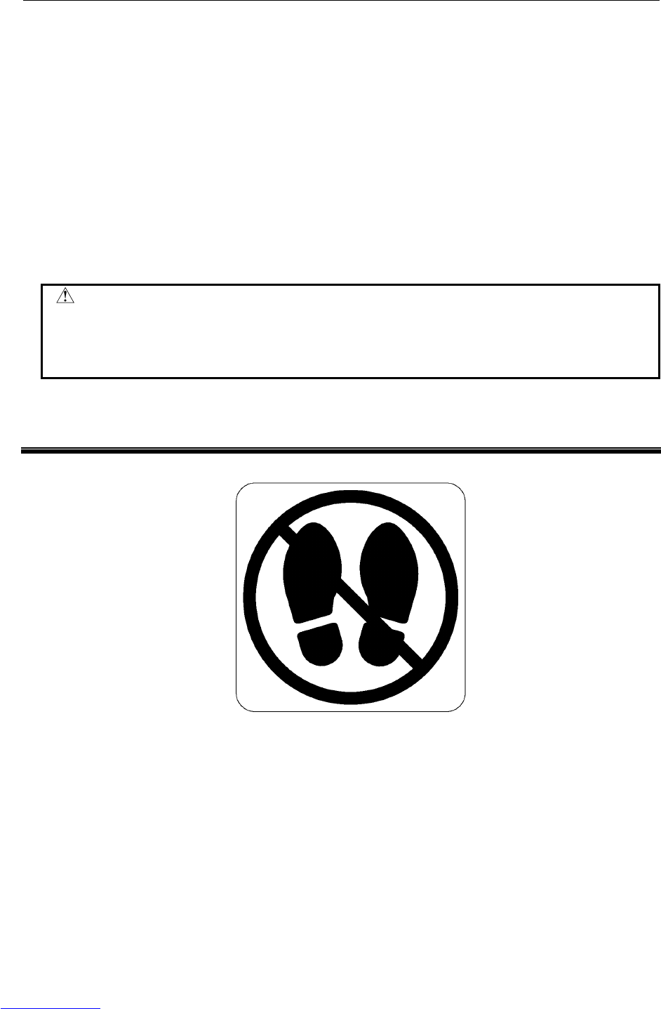
(1) Step-on prohibitive label
Fig.7 (a) Step-on prohibitive label
Description
Do not step on or climb the robot or controller as it may adversely affect the robot or controller
and you may get hurt if you lose your footing.
Downloaded from www.Manualslib.com manuals search engine
SAFETY PRECAUTIONS B-82725EN-1/07
s-12
(2) High-temperature warning label
Fig.7 (b) High-temperature warning label
Description
Be cautious about a section where this label is affixed, as the section generates heat. If you
must touch such a section when it is hot, use a protective provision such as heat-resistant
gloves.
(3) High-voltage warning label
Fig.7 (c) High-voltage warning label
Description
A high voltage is applied to the places where this label is attached.
Before starting maintenance, turn the power to the controller off, and turn the circuit breaker
off to avoid electric shock hazards. Take additional precautions with the servo amplifier and
other equipment, because high-voltage remains in these units for a certain amounts of time
Downloaded from www.Manualslib.com manuals search engine

B-82725EN-1/07 TABLE OF CONTENTS
c-1
TABLE OF CONTENTS
PREFACE....................................................................................................p-1
SAFETY PRECAUTIONS............................................................................s-1
I. MAINTENANCE
1 OVERVIEW .............................................................................................3
2 CONFIGURATION ..................................................................................4
2.1 EXTERNAL VIEW OF THE CONTROLLER ..................................................4
2.2 COMPONENT FUNCTIONS........................................................................11
2.3 PREVENTIVE MAINTENANCE...................................................................11
3 TROUBLESHOOTING ..........................................................................13
3.1 POWER CANNOT BE TURNED ON...........................................................13
3.1.1 When the Teach Pendant Cannot be Powered on...................................................13
3.1.2 When the Teach Pendant Does Not Change from the Initial Screen......................14
3.2 ALARM OCCURRENCE SCREEN..............................................................15
3.3 SAFETY SIGNALS ......................................................................................18
3.4 MASTERING ............................................................................................... 19
3.5 TROUBLESHOOTING USING THE ERROR CODE...................................21
3.6 FUSE-BASED TROUBLESHOOTING.........................................................65
3.7 TROUBLESHOOTING BASED ON LED INDICATIONS .............................69
3.8 CHECK AND REPLACEMENT SURGE ABSORBER .................................76
3.9 POSITION DEVIATION FOUND IN RETURN TO THE REFERENCE
POSITION (POSITIONING).........................................................................77
3.10 MANUAL OPERATION IMPOSSIBLE.........................................................77
4 PRINTED CIRCUIT BOARDS...............................................................79
4.1 MAIN BOARD (A20B-8200-0470)................................................................79
4.2 EMERGENCY STOP CONTROL BOARD (A20B-2004-0290) ....................82
4.3 BACKPLANE BOARD (A20B-8101-0580) ...................................................83
4.4 PROCESS I/O BOARD MA (A20B-2004-0380)...........................................84
4.5 PROCESS I/O BOARD MB (A20B-2101-0730)...........................................85
4.6 CONNECTOR CONVERTER BOARD (A20B-2004-0410) ..........................86
5 SERVO AMPLIFIERS ...........................................................................87
5.1 LED OF SERVO AMPLIFIER ......................................................................88
5.2 SETTING OF SERVO AMPLIFIER..............................................................89
6 SETTING THE POWER SUPPLY .........................................................90
6.1 BLOCK DIAGRAM OF THE POWER SUPPLY ...........................................90
6.2 CHECKING THE POWER SUPPLY............................................................91
7 REPLACING A UNIT.............................................................................92
7.1 REPLACING THE PRINTED-CIRCUIT BOARDS .......................................92
7.1.1 Replacing the Backplane Board (Unit)...................................................................92
Downloaded from www.Manualslib.com manuals search engine

TABLE OF CONTENTS B-82725EN-1/07
c-2
7.1.2 Replacing the Main board ......................................................................................93
7.2 REPLACING CARDS AND MODULES ON THE MAIN BOARD ................. 94
7.3 REPLACING THE REGENERATIVE RESISTOR UNIT ............................100
7.4 REPLACING THE E-STOP UNIT .............................................................. 103
7.5 REPLACING SERVO AMPLIFIERS ..........................................................104
7.6 REPLACING THE TEACH PENDANT and i PENDANT............................106
7.7 REPLACING THE CONTROL SECTION FAN MOTOR............................ 107
7.8 REPLACING THE AC FAN MOTOR ......................................................... 108
7.8.1 Replacing External Air Fan Unit and Door Fan...................................................108
7.9 REPLACING FUSES.................................................................................110
7.9.1 Replacing Fuses in the Servo Amplifier...............................................................110
7.9.2 Replacing Fuses in the Main board ......................................................................111
7.9.3 Replacing the Fuse on the E-stop Boards.............................................................112
7.10 REPLACING RELAYS............................................................................... 113
7.10.1 Replacing Relays on the E-stop Board.................................................................113
7.11 REPLACING BATTERY ............................................................................114
7.11.1 Battery for Memory Backup (3 VDC)..................................................................114
II. CONNECTIONS
1 GENERAL ...........................................................................................119
2 BLOCK DIAGRAM..............................................................................120
3 ELECTRICAL CONNECTIONS...........................................................121
3.1 CONNECTION DIAGRAM BETWEEN MECHANICAL UNITS .................. 121
3.2 FANUC I/O LINK........................................................................................123
3.2.1 Connection of I/O Link ........................................................................................123
3.2.2 Connection of I/O the Link Cable ........................................................................124
3.3 EXTERNAL CABLE WIRING DIAGRAM ................................................... 126
3.3.1 Robot Connection Cables.....................................................................................126
3.3.2 Teach Pendant Cable............................................................................................127
3.3.3 Connecting the Input Power Supply.....................................................................128
3.3.4 Connecting the External Emergency Stop............................................................129
3.3.5 Connecting the Auxiliary Axis Brake (CRR65 A/B)...........................................137
3.3.6 Connecting the Auxiliary Axis over Travel (CRM68).........................................138
4 PERIPHERAL DEVICE AND END EFFECTOR INTERFACES..........139
4.1 PERIPHERAL DEVICE INTERFACE BLOCK DIAGRAM.......................... 141
4.1.1 In Case of Main Board (CRMA15, CRMA16) ....................................................141
4.1.2 In the Case of the Process I/O Board MA ............................................................142
4.1.3 In the Case of the Process I/O Board MB ............................................................142
4.1.4 In the Case of the Connector Conversion Board..................................................143
4.2 I/O SIGNALS OF MAIN BOARD................................................................ 143
4.3 INTERFACE FOR PERIPHERAL DEVICES.............................................. 145
4.3.1 Connection between the Main Board (CRMA15, CRMA16) and Peripheral Devices
..............................................................................................................................145
4.3.2 Connection between the Process I/O Board MA and Peripheral Devices............152
4.3.3 Connection between the Connector Conversion Board and Peripheral Devices..156
4.3.4 Connection between the Process I/O Board MB and Welding Machines............157
4.4 INTERFACE FOR END EFFECTOR ......................................................... 159
4.4.1 Connection between the LR Mate 200iC, ARC Mate 50iC and End Effector.....159
Downloaded from www.Manualslib.com manuals search engine

B-82725EN-1/07 TABLE OF CONTENTS
c-3
4.4.2 Connection between the ARC Mate 100iC/M-10iA, ARC Mate 120iC/M-20iA,
ARC Mate 0iA and End Effector .........................................................................160
4.5 DIGITAL I/O SIGNAL SPECIFICATIONS.................................................. 162
4.5.1 Peripheral Device Interface..................................................................................162
4.5.2 End Effector Control Interface.............................................................................164
4.5.3 Specification for Arc Welding Machine Interface Input/Output Signals.............165
4.6 SPECIFICATIONS OF THE CABLES USED FOR PERIPHERAL DEVICES
AND WELDERS ........................................................................................168
4.6.1 Peripheral Device Interface A1 Cable
(CRMA15: Tyco Electronics AMP, D-1000 series, 40 pins)...............................168
4.6.2 Peripheral Device Interface A2 Cable
(CRMA16: Tyco Electronics AMP, D-1000 series, 40 pins)...............................168
4.6.3 Peripheral Device Interface B1 and B2 Cables
(CRMA52; Tyco Electronics AMP K.K. 30 pin).................................................169
4.6.4 ARC Weld Connection Cables
(CRW11; Tyco Electronics AMP K.K. 20 pin) ...................................................169
4.7 CABLE CONNECTION FOR THE PERIPHERAL DEVICES..................... 170
4.7.1 Peripheral Device Connection Cable....................................................................170
4.7.2 Peripheral Device Cable Connector .....................................................................171
4.7.3 Recommended Cables ..........................................................................................173
4.8 CONNECTING THE COMMUNICATION UNIT .........................................174
4.8.1 RS-232-C Interface...............................................................................................174
4.8.1.1 Interface........................................................................................................... 174
4.8.1.2 RS-232-C interface signals..............................................................................175
4.8.1.3 Connection between RS-232-C interface and I/O device................................ 176
4.8.2 Ethernet Interface .................................................................................................178
4.8.2.1 Connection to Ethernet .................................................................................... 178
4.8.2.2 Leading out the Ethernet cable ........................................................................ 179
4.8.2.3 100BASE-TX connector (CD38R) pin assignments ....................................... 179
4.8.2.4 Twisted-pair cable specification......................................................................180
4.8.2.5 Electrical noise countermeasures..................................................................... 183
4.8.2.6 Check items at installation............................................................................... 186
5 TRANSPORTATION AND INSTALLATION .......................................187
5.1 TRANSPORTATION..................................................................................187
5.2 INSTALLATION ......................................................................................... 188
5.2.1 Installation Method...............................................................................................188
5.3 MOUNTING METHOD OF TEACH PENDANT HOOK..............................191
5.4 INSTALLATION CONDITION .................................................................... 192
5.5 ADJUSTMENT AND CHECKS AT INSTALLATION ..................................193
5.6 RESETTING OVERTRAVEL AND EMERGENCY STOP AT INSTALLATION
...................................................................................................................193
5.6.1 Peripheral Device Interface Processing................................................................194
5.6.2 Resetting Overtravel.............................................................................................194
5.6.3 How to Disable/Enable HBK ...............................................................................194
5.6.4 How to Disable/Enable Pneumatic Pressure Alarm (PPABN).............................195
APPENDIX
A TOTAL CONNECTION DIAGRAM......................................................199
B BRAKE RELEASE UNIT.....................................................................217
B.1 SAFETY PRECAUTIONS..........................................................................217
Downloaded from www.Manualslib.com manuals search engine

TABLE OF CONTENTS B-82725EN-1/07
c-4
B.2 CONFIRMATIONS BEFORE OPERATION............................................... 217
B.3 OPERATION..............................................................................................218
B.4 HOW TO CONNECT THE PLUG TO THE POWER CABLE (IN CASE OF NO
POWER PLUG) ......................................................................................... 221
B.5 DIMENSION ..............................................................................................222
B.6 FUSE.........................................................................................................224
B.7 SPECIFICATIONS..................................................................................... 224
Downloaded from www.Manualslib.com manuals search engine


B-82725EN-1/07 MAINTENANCE 1.OVERVIEW
- 3 -
1 OVERVIEW
This manual describes the maintenance and connection of the R-30iA Mate robot controller (called the
R-30iA Mate).
Maintenance Part:
Troubleshooting, and the setting, adjustment, and replacement of units
Connection Part:
Connection of the R-30iA Mate controller to the robot mechanical unit and peripheral devices, and
installation of the controller
WARNING
Before you enter the robot working area, be sure to turn off the power to the
controller or press the EMERGENCY STOP button on the operator's panel or
teach pendant.
Otherwise, you could injure personnel or damage equipment.
Downloaded from www.Manualslib.com manuals search engine
2.CONFIGURATION MAINTENANCE B-82725EN-1/07
- 4 -
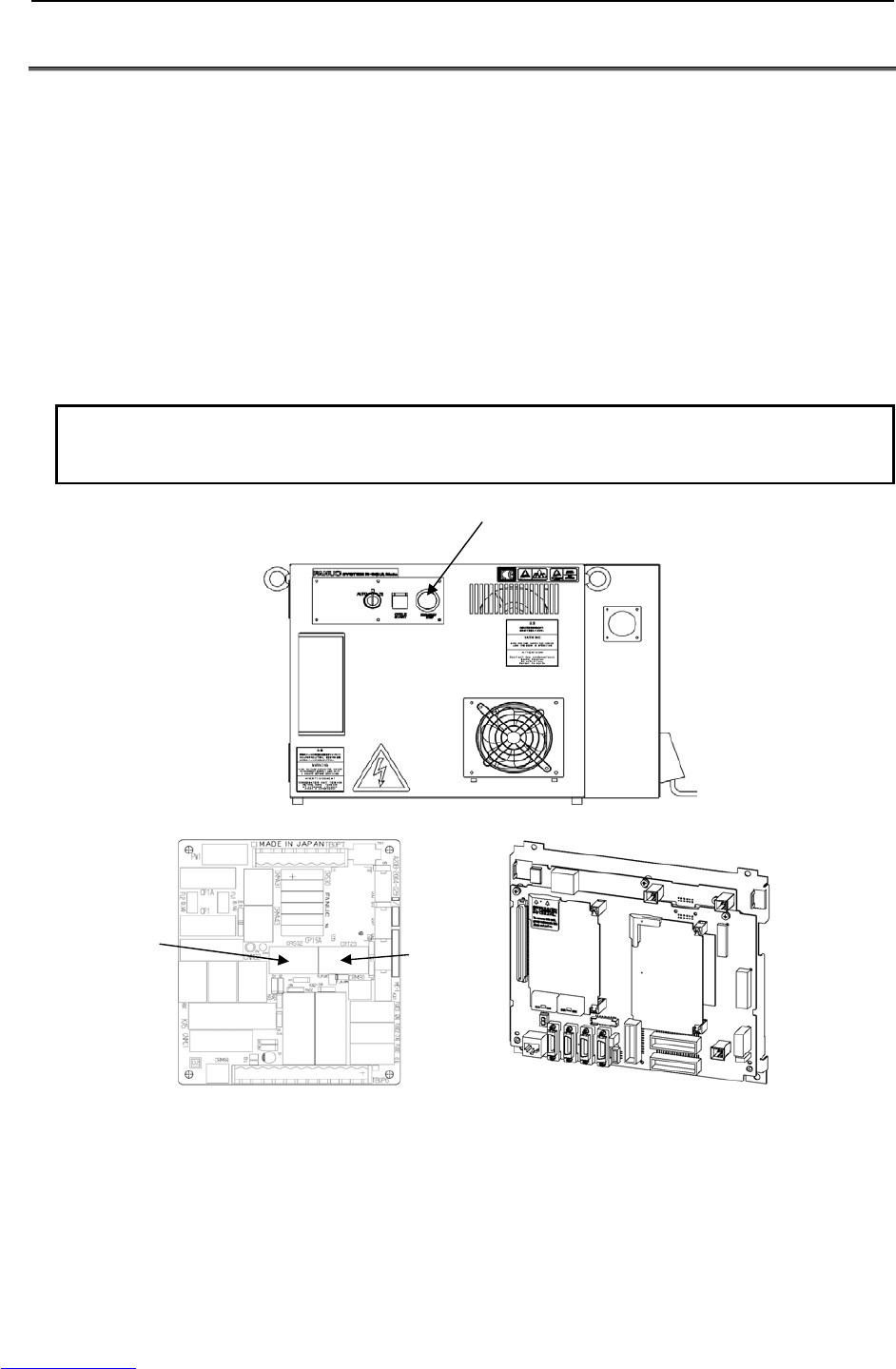
2 CONFIGURATION
2.1 EXTERNAL VIEW OF THE CONTROLLER
The appearance and components might slightly differ depending on the controlled robot, application, and
options used.
Fig.2.1 (a) shows the view of R-30iA Mate.
Fig.2.1 (b) to (d) show the construction of the R-30iA Mate controller.
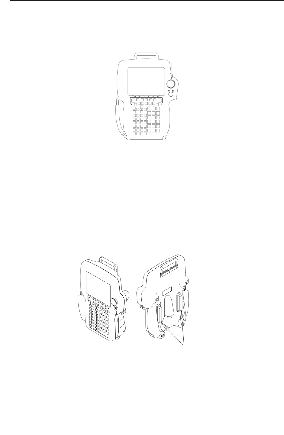
Fig.2.1 (e) to (g) show the external view of the operator’s panel.
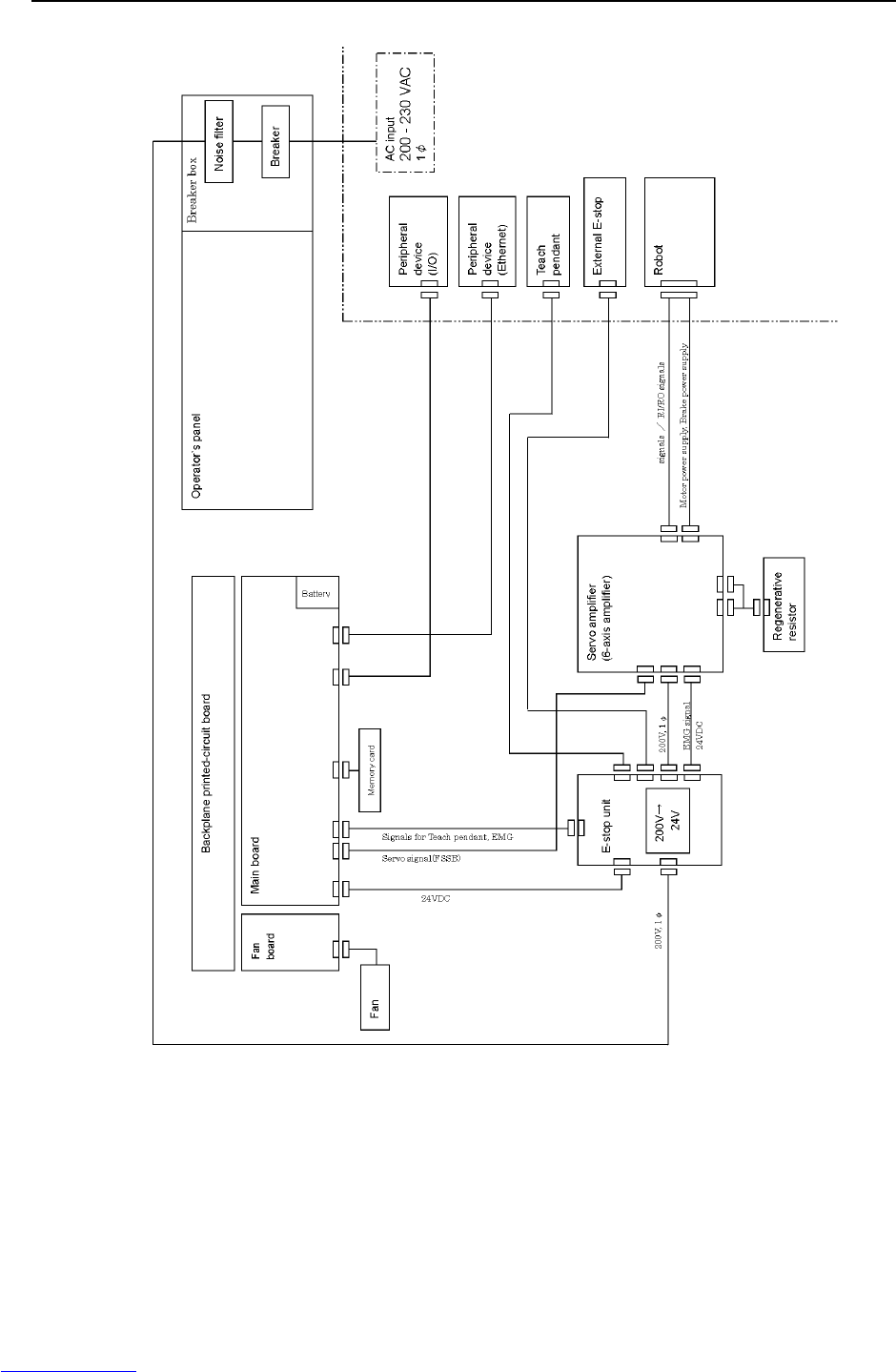
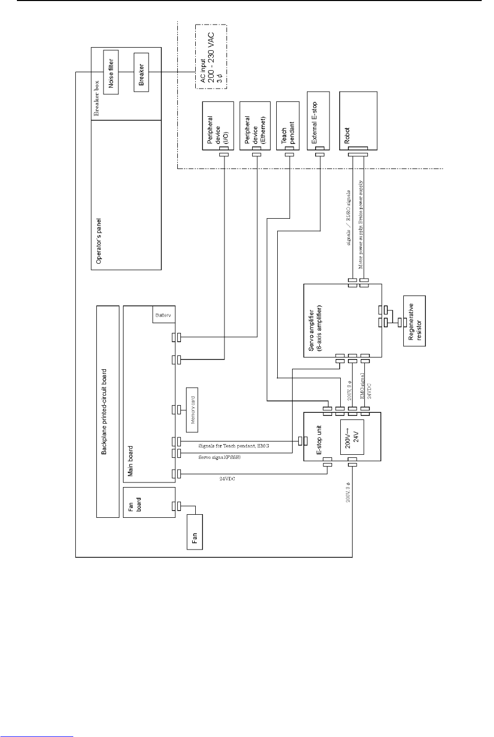
Fig.2.1 (h) to (i) show the block diagram of R-30iA Mate.
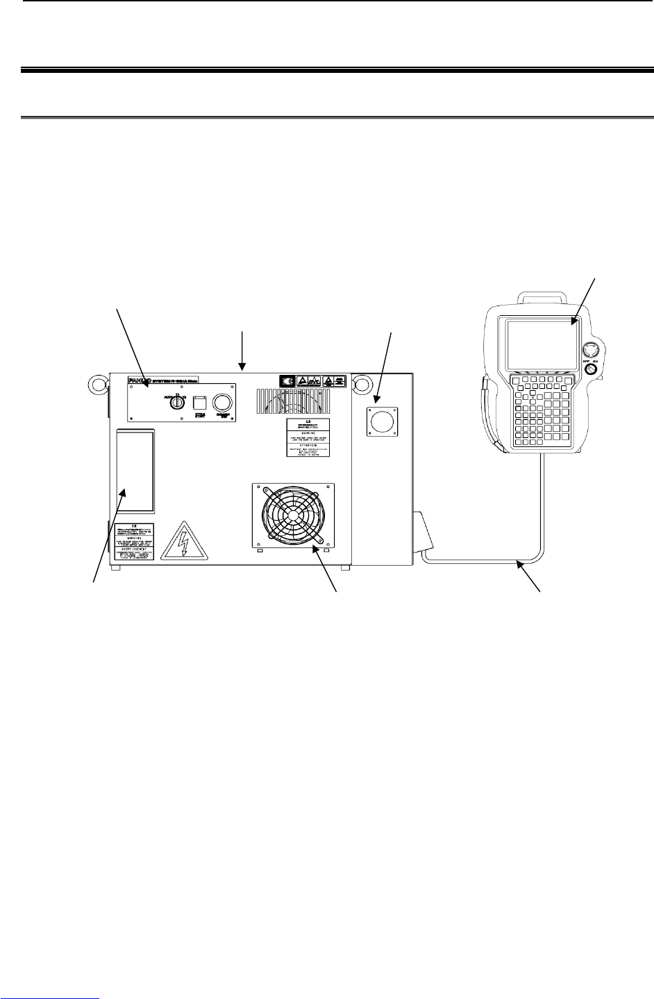
Fig.2.1 (a) External view of the R-30iA Mate controller
Teach pendant
Operator’s panel R-30iA Mate
controller
Teach pendant
cable
Fan unit
ON/OFF handle
Interface panel
Downloaded from www.Manualslib.com manuals search engine
B-82725EN-1/07 MAINTENANCE 2.CONFIGURATION
- 5 -
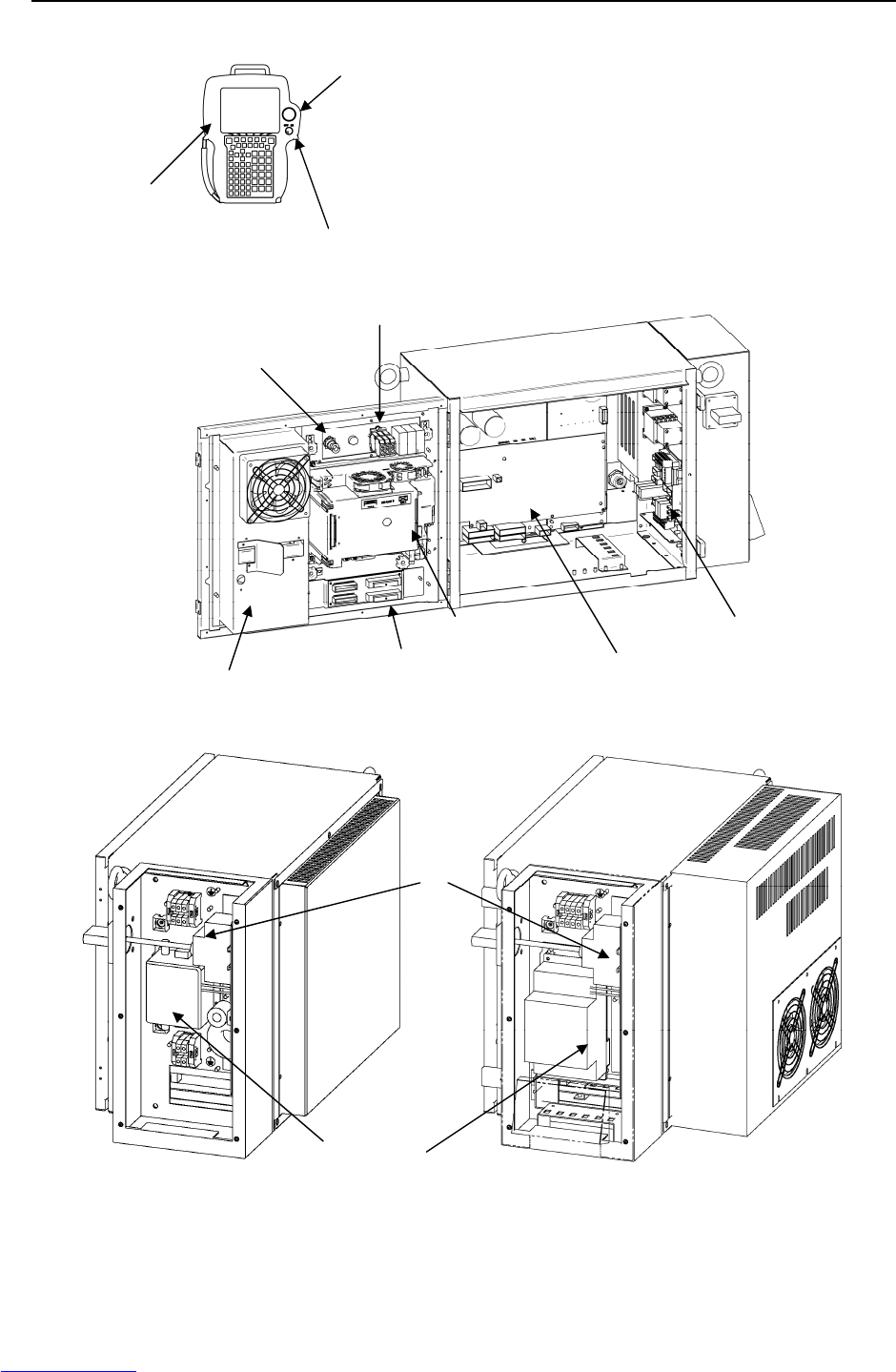
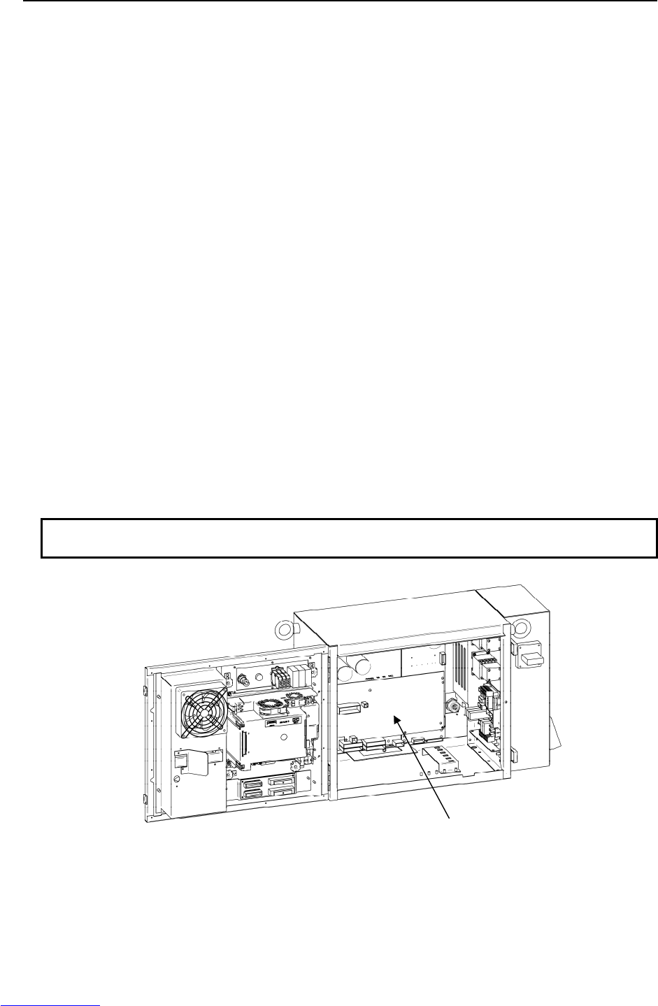
Fig.2.1 (b) R-30iA Mate interior (Front)
(LR Mate 200iC, M-1iA) (ARC Mate 100iC, M-10iA, ARC Mate 120iC,
M-20iA, ARC Mate 50iC, ARC Mate 0iA)
Fig.2.1 (c) R-30iA Mate interior (Side)
Noise filter
Breaker
Emergency stop unit
Main board
Heat exchange Servo amplifier
Teach pendant
Emergency stop
button
Enable switch
Emergency stop button
Mode switch
Process I/O or Connector
converter board
Downloaded from www.Manualslib.com manuals search engine
2.CONFIGURATION MAINTENANCE B-82725EN-1/07
- 6 -
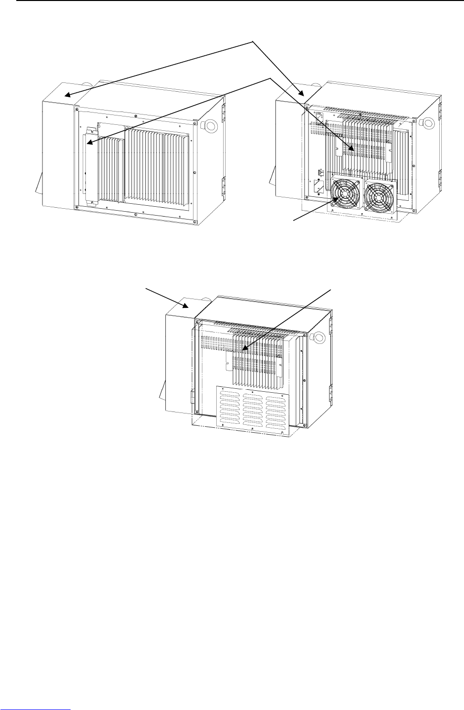
(LR Mate 200iC, M-1iA) (ARC Mate 100iC, M-10iA, ARC Mate 120iC
, M-20iA, ARC Mate 0iA)
(ARC Mate 50iC)
Fig.2.1 (d) R-30iA Mate interior
Regenerative resistor unit
Fan unit
Breaker Box
Breaker Box Regenerative resistor unit
Downloaded from www.Manualslib.com manuals search engine
2.CONFIGURATION MAINTENANCE B-82725EN-1/07
- 8 -
Fig.2.1 (g) interface overview
Table 2.1 Servo amplifier specifications
ROBOT SERVO AMPLIFIER REGENERATIVE RESISTOR
LR Mate 200iC A06B-6107-H005 A05B-2550-C050
M-1iA A06B-6107-H005 A05B-2550-C050
ARC Mate 50iC A06B-6107-H005 A05B-2550-C051
ARC Mate 100iC, M-10iA
ARC Mate 0iA A06B-6107-H004 A05B-2550-C051
ARC Mate 100iCe, M-10iAe A06B-6107-H004 A05B-2550-C053
ARC Mate 120iC, M-20iA A06B-6107-H002 A05B-2550-C052
PCMCIA
Downloaded from www.Manualslib.com manuals search engine

B-82725EN-1/07 MAINTENANCE 2.CONFIGURATION
- 11 -
2.2 COMPONENT FUNCTIONS
• Main board
The main board contains a microprocessor, its peripheral circuits, memory, and operator's panel
control circuit. The main CPU controls servo mechanism positioning.
• I/O printed circuit board, FANUC I/O Unit MODEL-A
Various types of printed circuit boards are provided for applications including process I/O. The
FANUC I/O unit MODEL-A can also be installed. When it is used, various I/O types can be
selected. These are connected with FANUC I/O Link.
• E-stop unit and MCC unit
This unit controls the emergency stop system for both of the magnetic contactor and the precharge of
the servo amplifier.
• Power supply unit
The power supply unit converts the AC power to various levels of DC power.
• Backplane printed circuit board
The various control printed circuit boards are mounted on the backplane printed circuit board.
• Teach pendant
All operations including robot programming are performed with this unit. The controller status and
data are indicated on the liquid-crystal display (LCD) on the pendant.
• Servo amplifier
The servo amplifier controls servomotor, Pulsecoder signal, brake control, overtravel and hand
broken.
• Operator's panel
Buttons and LEDs on the operator's panel are used to start the robot and to indicate the robot status.
The panel has a port and an USB interface for the serial interface to an external device and an
interface to connect the memory card for data backup. It also controls the emergency stop control
circuit.
• Transformer
The supply voltage is converted to an AC voltage required for the controller by the transformer.
• Fan unit, heat exchanger
These components cool the inside of the controller.
• Circuit breaker
If the electric system in the controller malfunctions, or if abnormal input power causes high current
in the system, the input power is connected to the circuit breaker to protect the equipment.
• Regenerative resistor
To discharge the counter electromotive force from the servomotor, connect a regenerative resistor to
the servo amplifier.
2.3 PREVENTIVE MAINTENANCE
Daily maintenance and periodic maintenance/inspection ensure reliable robot performance for extended
periods of time.
(1) Daily maintenance
Before operating the system each day, clean each part of the system and check the system parts for
any damage or cracks. Also, check the following:
(a) Before operation
Check the cable connected to the teach pendant for excessive twisting. Check the controller
and peripheral devices for abnormalities.
Downloaded from www.Manualslib.com manuals search engine

2.CONFIGURATION MAINTENANCE B-82725EN-1/07
- 12 -
(b) After operation
At the end of operation, return the robot to the specified position, and then turn off the
controller. Clean each part, and check for any damage or cracks. If the ventilation port of
the controller is dusty, clean it.
(2) Check after one month
Check that the fan is rotating normally. If the fan has dirt and dust built up, clean the fan according
to step (3) described below for inspection to be performed every 6 months.
(3) Periodic inspection performed every six months.
(a) Remove any dirt and dust from the inside of the cabinet.
Wipe off dirt and dust from the fan.
(b) Check that the surge absorbers are not damaged.
Please refer to the section 3.8.
(4) Battery daily check
Replace the battery on the front panel of the main board every 4 years. Please refer to the section
7.11.
(5) Maintenance tools
The following maintenance tools are recommended:
(a) Measuring instruments
AC/DC voltmeter (A digital voltmeter is sometimes required.)
Oscilloscope with a frequency range of 5 MHz or higher, two channels
(b) Tools
Phillips screwdrivers: Large, medium, and small
Standard screwdrivers: Large, medium, and small
Nut driver set (Metric)
Pliers
Needle-nose pliers
Diagonal cutting pliers
Downloaded from www.Manualslib.com manuals search engine
B-82725EN-1/07 MAINTENANCE 3.TROUBLESHOOTING
- 13 -
3 TROUBLESHOOTING
This chapter describes the checking method and corrective action for each error code indicated if a
hardware alarm occurs. Refer to the operator's manual to release program alarms.
3.1 POWER CANNOT BE TURNED ON
Inspection and action Illustration
(Inspection) Check that the circuit
breaker is on and has not
tripped.
(Action) Turn on the circuit breaker.
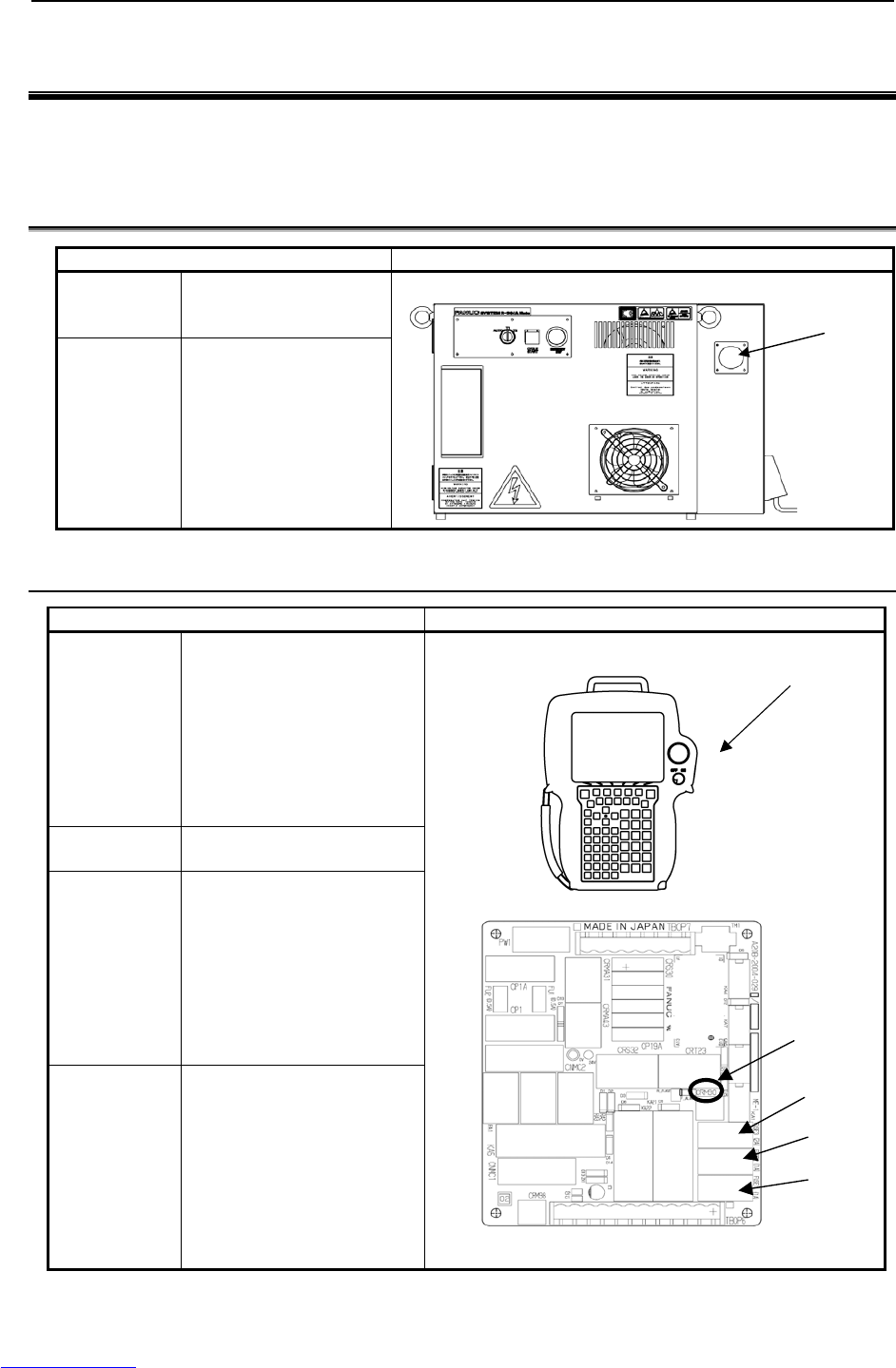
3.1.1 When the Teach Pendant Cannot be Powered on
Inspection and action Illustration
(Inspection 1) Confirm that fuse FUSE2 on
the emergency stop printed
circuit board is not blown.
When it is blown, the LED on
the emergency stop printed
circuit board lights in red.
When FUSE2 is blown, carry
out action 1 and replace the
fuse.
(Inspection 2) When FUSE2 is not blown,
carry out action 2.
(Action 1) (a) Check the cable of the
teach pendant for failure
and replace it as
necessary.
(b) Check the teach pendant
for failure and replace it as
necessary.
(c) Replace the emergency
stop printed circuit board.
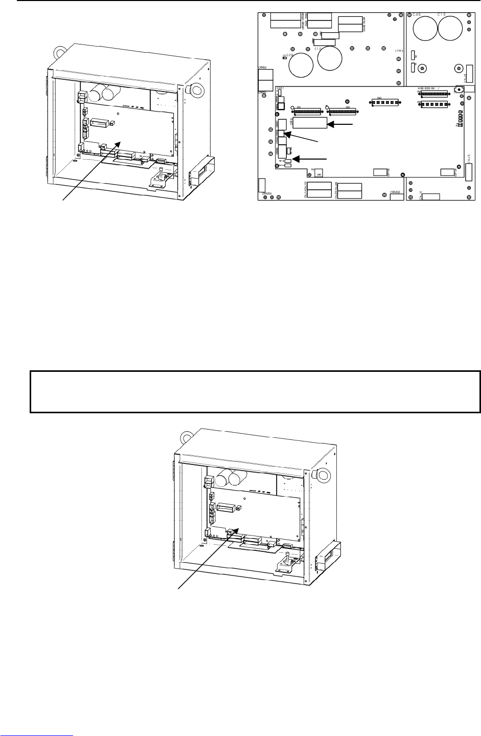
(Action 2) When the LED on the main
board does not light, replace
the emergency stop unit.
When the LED on the main
board lights, carry out action 1.
Teach Pendant
FUSE1
FUSE2
LED(Red)
FUSE3
Circuit breaker
Downloaded from www.Manualslib.com manuals search engine
3.TROUBLESHOOTING MAINTENANCE B-82725EN-1/07
- 14 -
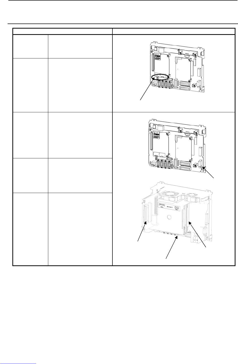
3.1.2 When the Teach Pendant Does Not Change from the Initial
Screen
Inspection and action Illustration
(Inspection 1) Check that the status display
LCD and 7-segment LED on
the main board operate
normally.
(Action) Carry out an action according
to the LED status. For details,
see "TROUBLESHOOTING
USING THE LEDS ON THE
MAIN BOARD".
(Inspection 2) When the LED on the main
board does not light in
inspection 1, check if FUSE1
on the main board is blown.
(a) When FUSE1 is blown
See action 1.
(b) When FUSE1 is not blown
See action 2.
(Action 1) (a) Replace the backplane
board.
(b) Replace the main board.
(c) When an option board is
installed in the option slot,
replace the option board.
(Action 2) (a) Replace the emergency
stop unit.
(b) Replace the cable between
the main board and the
emergency stop unit.
(c) Replace the boards
indicated in action 1.
7-segment LED and status display LED
(On the main board)
Back plane board
Main board
Option slot
FUSE1
Downloaded from www.Manualslib.com manuals search engine
B-82725EN-1/07 MAINTENANCE 3.TROUBLESHOOTING
- 15 -
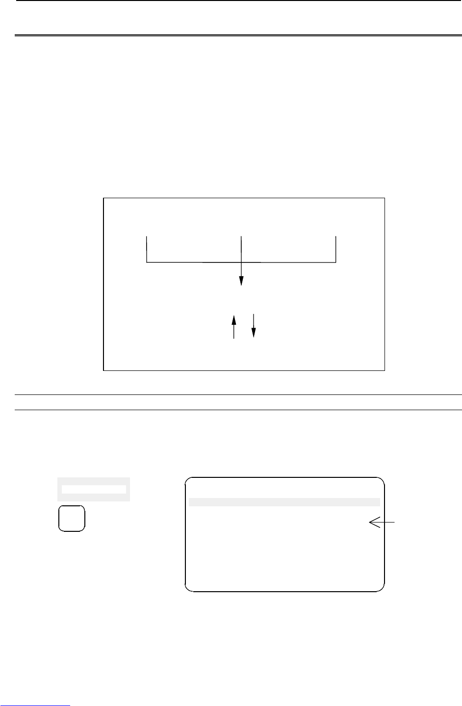
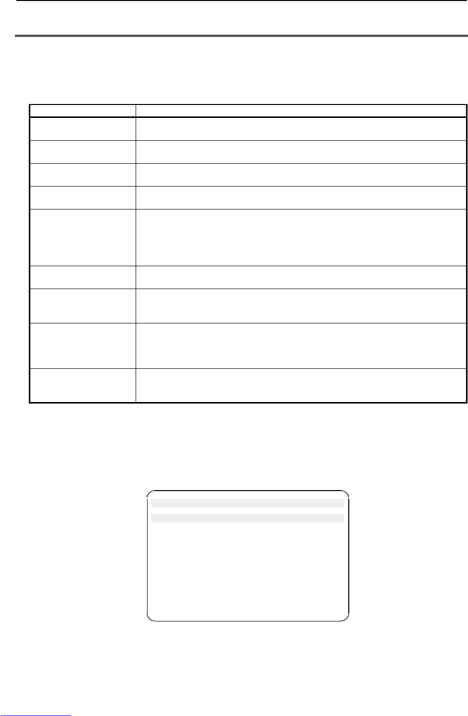
3.2 ALARM OCCURRENCE SCREEN
The alarm occurrence screen displays only the alarm conditions that are currently active. If an alarm reset
signal is input to reset the alarm conditions, the alarm occurrence screen displays the message "PAUSE or
more serious alarm has not occurred."
The alarm occurrence screen displays only the alarm conditions (if any) that occur after the most recently
entered alarm reset signal. To erase all alarm displays from the alarm occurrence screen. Press the
CLEAR key (+ shift) on the alarm history screen.
The alarm occurrence screen is intended to display PAUSE or alarms that are more serious. It will not
display WARN, NONE, or a reset. It is possible to disable PAUSE and some of more serious alarms from
being displayed by setting the $ER_NOHIS system variable appropriately.
If two or more alarms have occurred, the display begins with the most recent alarm.
Up to 100 lines can be displayed.
If an alarm has a cause code, it is displayed below the line indicating the alarm.
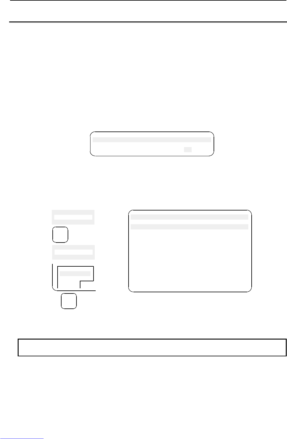
A
larm history screen displa
y
Press F3 [HIST].
Press F3 [ACTIVE].
A
larm occurrence screen displa
y
Press the alarm key.
A
utomatic alarm display
upon occurrence
Press the screen
selection key to select
[4 ALARM].
Fig.3.2 Alarm occurrence screen and alarm history screen display procedure
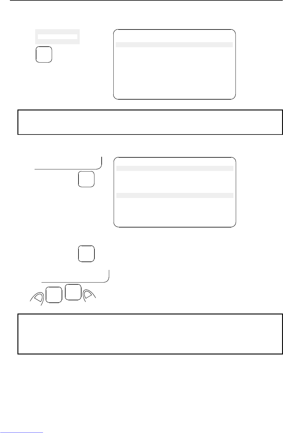
Displaying the alarm history/alarm detail information
Step
(1) Press the MENUS key to display the screen menu.
(2) Select [ALARM]. You will see a screen similar to the following
If an alarm has occurred, however, the alarm screen appears automatically.
MENUS
3
4 ALARM
5 I/O INTP-224 (SAMPLE1, 7) Jump label is fail
Alarm JOINT 30 %
1/1
MEMO-027 Specified line does not exist
[ TYPE ] HIST
ALARM detail code
Downloaded from www.Manualslib.com manuals search engine
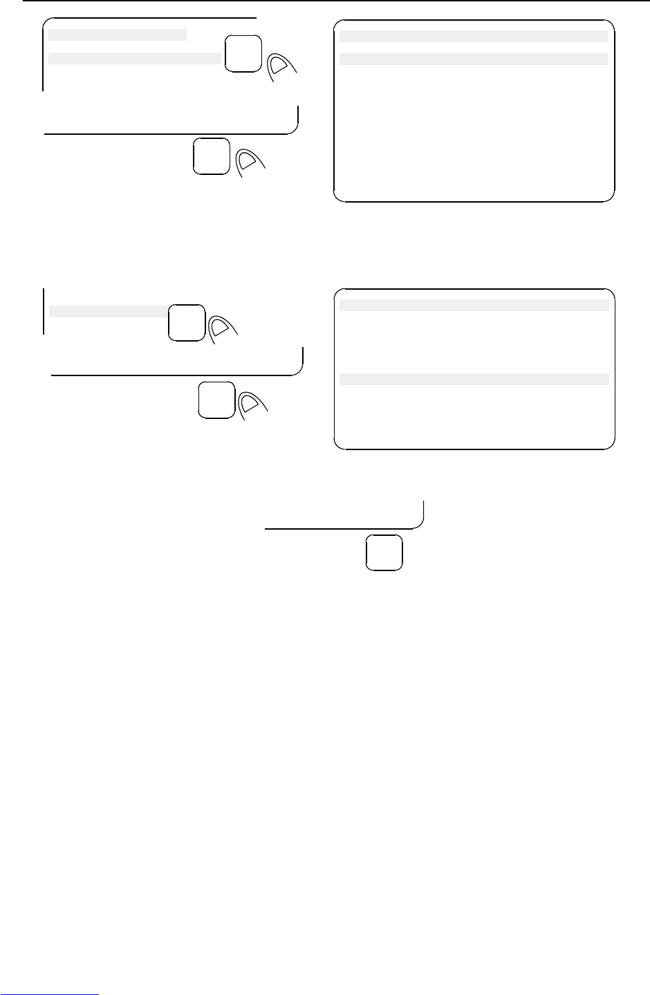
3.TROUBLESHOOTING MAINTENANCE B-82725EN-1/07
- 16 -
(3) To display the alarm history screen, press F3, [HIST].
Press F3 [ACTIVE] again, the alarm screen appears.
MENUS
3
4 ALARM
5 I/O
INTP-224 (SAMPLE1, 7) Jump label is fail
MEMO-027 Specified line does not exist
Alarm JOINT 30 %
1/25
1 INTP-224 (SAMPLE1, 7) Jump label is
2 SRVO-002 Teach pendant E-stop
3 R E S E T
4 SRVO-027 Robot not mastered(Group:1)
5 SYST-026 System normal power up
[ TYPE ] CLEAR HELP
NOTE
The latest alarm is assigned number 1. To view messages that are currently
not on the screen, press the F5, HELP, and then press the right arrow key.
(4) To display the alarm detail screen, press F5, [HELP].
INTP-224 (SAMPLE1, 7) Jump label is fail
INTP-224 (SAMPLE1, 7) Jump label is fail
MEMO-027 Specified line does not exist
30-MAY-44 07:15
STOP.L 00000110
Alarm
1/25
1 INTP-224 (SAMPLE1, 7) Jump label is
2 SRVO-002 Teach pendant E-stop
[ TYPE ] CLEAR HELP
CLEAR HELP
F5
(5) To return to the alarm history screen, press the PREV key.
PREV
(6) To delete all the alarm histories, press and hold down the SHIFT key, then press F4, [CLEAR].
CLEAR HELP
F4
SHIFT
NOTE
When system variable $ER_NOHIS = 1, NONE alarms or WARN alarms are not
recorded. When $ER_NOHIS=2, resets are not recorded in the alarm history.
When $ER_NOHIS=3, resets, WARN alarms, and NONE alarms are not
recorded.
Downloaded from www.Manualslib.com manuals search engine

B-82725EN-1/07 MAINTENANCE 3.TROUBLESHOOTING
- 17 -
The following map indicates teach pendant operations used to check an alarm.
4 ALARM
F1 [TYPE]
Alarm : Active
F1 [TYPE]
F3 HIST
Alarm : HIST
F1 [TYPE]
F3 [ACTIVE]
F4 CLEAR
F5 HELP
DETAIL Alarm
F1 [TYPE]
F3 [ACTIVE]
F4 CLEAR
F5 HELP
Downloaded from www.Manualslib.com manuals search engine
3.TROUBLESHOOTING MAINTENANCE B-82725EN-1/07
- 18 -
3.3 SAFETY SIGNALS
The safety signal screen indicates the state of signals related to safety.
To be specific, the screen indicates whether each safety signal is currently on. On this screen, it is
impossible to change the state of any safety signal.
Table 3.3 Safety signals
Safety signal Description
Operator’s panel
emergency stop
This item indicates the state of the emergency stop button on the operator’s panel. If
the EMERGENCY STOP button is pressed, the state is indicated as “TRUE”.
Teach pendant
emergency stop
This item indicates the state of the emergency stop button on the teach pendant. If the
EMERGENCY STOP button is pressed, the state is indicated as “TRUE”.
External emergency stop This item indicates the state of the external emergency stop signal. If the
EMERGENCY STOP signal is asserted, the state is indicated as “TRUE”.
Fence open This item indicates the state of the safety fence. If the safety fence is open, the state is
indicated as “TRUE”.
DEADMAN switch This item indicates whether the DEADMAN switch on the teach pendant is grasped. If
the teach pendant is operable, and the DEADMAN switch is grasped correctly, the
state is indicated as “TRUE”. If the DEADMAN switch is released or is grasped tightly
when the teach pendant is operable, an alarm occurs, causing the servo power to be
switched off.
Teach pendant operable This item indicates whether the teach pendant is operable. If the teach pendant is
operable, the state is indicated as “TRUE”.
Hand broken This item indicates the state of the hand safety joint. If the hand interferes with a
workpiece or anything like this, and the safety joint is opened, the state is indicated as
“TRUE”. In this case, an alarm occurs, causing the servo power to be switched off.
Robot overtravel This item indicates whether the current position of the robot is out of the operation
range. If any robot articulation goes out of the operation range beyond the overtravel
switch, the state is indicated as “TRUE”. In this case, an alarm occurs, causing the
servo power to be switched off.
Abnormal air pressure This item indicates the state of the air pressure. The abnormal air pressure signal is
connected to the air pressure sensor. If the air pressure is not higher than the
specified value, the state is indicated as “TRUE”.
Step
(1) Press the MENUS key to display the screen menu.
(2) Select STATUS on the next page.
(3) Press F1, [TYPE] to display the screen switching menu.
(4) Select Safety Signal. You will see a screen similar to the following.
SYSTEM Safety JOINT 30%
SIGNAL NAME STATUS 1/11
1 SOP E-Stop: FALSE
2 TP E-stop: FALSE
3 Ext E-Stop: FALSE
4 Fence Open: FALSE
5 TP Deadman: TRUE
6 TP Enable: TRUE
7 Hand Broken: FALSE
8 Over Travel: FALSE
9 Low Air Alarm: FALSE
[TYPE]
Downloaded from www.Manualslib.com manuals search engine
B-82725EN-1/07 MAINTENANCE 3.TROUBLESHOOTING
- 19 -
3.4 MASTERING
Mastering is needed if:
(1) The SRVO-062 BZAL or SRVO-038 pulse mismatch alarm occurs, or
(2) The Pulsecoder is replaced.
Item (1) requires quick mastering, while item (2) requires zero-degree or fixture position mastering.
(Zero-degree position mastering is just for quick-fix purposes. After zero-degree position mastering is
used, fixture position mastering should be performed later.)
The mastering procedure is described below. For the procedure of mastering other than fixture position
mastering, refer to the operator's manual of the mechanical unit.
For the procedure of fixture mastering, contact FANUC.
Condition
System variable $MASTER_ENB must be set to 1 or 2.
SYSTEM Variables JOINT 10%
57/136
57 $MASTER_ENB 1
Step
(1) Press <MENUS>.
(2) Select SYSTEM.
(3) Press F1, TYPE.
(4) Select Master/Cal you will see a screen similar to the following.
F1
Master
/
TYPE
SYSTEM Master/Cal JOINT 30%
1 FIXTURE POSITION MASTER
2 ZERO POSITION MASTER
3 QUICK MASTER
4 SINGLE AXIS MASTER
5 SET QUICK MASTER REF
6 CALIBRATE
Press 'ENTER' or number key to select.
[TYPE] LOAD RES_PCA DONE
5 POSITION
6 SYSTEM
7
MENUS
9
0 -- NEXT --
(5) Move the robot by jog feed to the mastering position. Release the brake on the manual brake control
screen if necessary.
NOTE
Mastering cannot be performed until axis is rotated enough to establish a pulse.
(6) Select "1 FIXTURE POSITION MASTER" and press the F4 key (yes). Mastering data is set.
Downloaded from www.Manualslib.com manuals search engine
3.TROUBLESHOOTING MAINTENANCE B-82725EN-1/07
- 20 -
F4
SYSTEM Master/Cal JOINT 30 %
1 FIXTURE POSITION MASTER
2 ZERO POSITION MASTER
3 QUICK MASTER
4 SINGLE AXIS MASTER
5 SET QUICK MASTER REF
6 CALIBRATE
Robot Mastered! Mastering Data:
<0> <11808249> <38767856>
<9873638> <122000309> <2000319>
[ TYPE ] LOAD RES_PCA DONE
SYSTEM Master/Cal
1 FIXTURE POSITION MASTER
2 ZERO POSITION MASTER
Master at master position?
[NO]
ENTER
Master at master position?
[]
[ TYPE ] YES NO
(7) Select "6 CALIBRATE" and press the F4 key (yes). Calibration is performed.
Alternatively, to perform positioning, turn the power off, and then turn it on again. Calibration is
performed whenever the power is turned on.
F4
SYSTEM Master/Cal JOINT 30 %
1 FIXTURE POSITION MASTER
2 ZERO POSITION MASTER
3 QUICK MASTER
4 SINGLE AXIS MASTER
5 SET QUICK MASTER REF
6 CALIBRATE
Robot Calibrated! Cur Jnt Ang(deg):
<10.000> <-25.000> <40.000>
<5.000> <-15.000> <0.000>
[ TYPE ] LOAD RES_PCA DONE
5 SET QUICK MASTER REF
6 CALIBRATE
Calibrate? [NO]
ENTER
Calibrate? [NO]
[ TYPE ] YES
(8) Press F5 "DONE", after mastering.
F5
DONE
Downloaded from www.Manualslib.com manuals search engine
B-82725EN-1/07 MAINTENANCE 3.TROUBLESHOOTING
- 21 -
3.5 TROUBLESHOOTING USING THE ERROR CODE
(1) SRVO-001 Operator panel E-stop
(Explanation) The emergency stop button on the operator's panel is pressed.
(Action 1) Release the emergency stop button pressed on the operator's panel.
(Action 2) Check the wires connecting between the emergency stop button and the E-stop
board (CRT23) for continuity. If an open wire is found, replace the entire harness.
(Action 3) With the emergency stop in the released position, check for continuity across the
terminals of the switch. If continuity is not found, the emergency stop button is
broken. Replace the switch unit or the operator's panel.
(Action 4) Replace the E-stop board.
Before executing the (Action 5), perform a complete controller back-up to save all
your programs and settings.
(Action 5) Replace the main board.
NOTE
If the LED (red) on the E-stop unit is lit, a fuse may have blown. Take the same
actions described in (3) in Section 3.6.
(E-stop board) (Main board)
Fig.3.5 (a) SRVO-001 Operator panel E-stop
Emergency stop button
CRS32 CRT23
Downloaded from www.Manualslib.com manuals search engine
3.TROUBLESHOOTING MAINTENANCE B-82725EN-1/07
- 22 -
(2) SRVO-002 Teach pendant E-stop
(Explanation) The emergency stop button on the teach pendant was pressed.
(Action 1) Release the emergency stop button on the teach pendant.
(Action 2) Replace the teach pendant.
Emergency stop
button
Fig.3.5 (b) SRVO-002 Teach pendant E-stop
(3) SRVO-003 DEADMAN switch released
(Explanation) The teach pendant is enabled, but the DEADMAN switch is not pressed.
Alternatively, the DEADMAN switch is pressed strongly.
(Action 1) Check the intermediate position of the DEADMAN switch on the teach pendant.
(Action 2) Check that the mode switch on the operator's panel and the enable switch on the
teach pendant are at the correct positions.
(Action 3) Replace the teach pendant.
(Action 4) Check the mode switch connection and operation. If trouble is found, replace the
mode switch.
(Action 5) Replace the E-stop board.
(Action 6) Replace the main board.
Enable switch DEADMAN switch
Fig.3.5 (c) SRVO-003 DEADMAN switch released
Downloaded from www.Manualslib.com manuals search engine

B-82725EN-1/07 MAINTENANCE 3.TROUBLESHOOTING
- 23 -
(4) SRVO-004 Fence open
(Explanation) In the automatic operation mode, the safety fence contact connected to
EAS1-EAS11 or EAS2-EAS21 of TBOP7 is open.
(Action 1) When a safety fence is connected, close the safety fence.
(Action 2) Check the cables and switches connected between EAS1 and EAS11 and between
EAS2 and EAS21 of the terminal block TBOP7 on the E-stop board.
(Action 3) If the safety fence signal is not used, make a connection between EAS1 and
EAS11 and between EAS2 and EAS21 of the terminal block TBOP7 on the E-stop
board.
(Action 4) Check the mode switch. If trouble is found, replace the mode switch.
(Action 5) Replace the E-stop board.
Before executing the (Action 6), perform a complete controller back-up to save all
your programs and settings.
(Action 6) Replace the main board.
NOTE
If the LED (red) on the E-stop unit is lit, a fuse may have blown. Take the same
actions described in (3) in Section 3.6.
(E-stop board)
2 mode switch 3 mode switch
(Mode switch)
Fig.3.5 (d) E-stop board and mode switch
WARNING
In a system using the safety fence signal, it is very dangerous to disable the
signal when a connection is made between EAS1 and EAS11 and between
EAS2 and EAS21 of TBOP7. Never make such an attempt. If a temporary
connection is needed for operation, separate safety measures must be taken.
Downloaded from www.Manualslib.com manuals search engine

3.TROUBLESHOOTING MAINTENANCE B-82725EN-1/07
- 24 -
(5) SRVO-005 Robot overtravel
(Explanation) The robot has moved beyond a hardware limit switch on the axes.
(Action 1)
1) Select [System OT release] on the overtravel release screen to release each robot
axis from the overtravel state.
2) Hold down the shift key, and press the alarm release button to reset the alarm
condition.
3) Still hold down the shift key, and jog to bring all axes into the movable range.
(Action 2) Replace the limit switch.
(Action 3) Check the FS2 fuse on the servo amplifier. If the SRVO-214 fuse blown alarm is
also generated, the FS2 fuse has blown.
(Action 4) Check the end effector connector.
(Action 5) Replace the servo amplifier.
(Action 6) Verify the following for connector RMP at the base of the robot:
1) There are no bent or dislocated pins in the male or female connectors.
2) The connector is securely connected.
Then verify that connectors CRF8 and CRM68 on the servo amplifier are securely
connected. Also, verify that the RMP cable is in good condition, and there are no
cuts or kinks visible. If no limit switch is in use, jumper connector must be
attached in the mechanical unit. Check for the jumper connector.
NOTE
It is factory-placed in the overtravel state for packing purposes.
If the Overtravel signal is not in use, it may have been disabled by
short-circuiting in the mechanical unit.
(6) SRVO-006 Hand broken
(Explanation) The safety joint (if in use) might have been broken. Alternatively, the HBK signal
on the robot connection cable might be a ground fault or a cable disconnection.
(Action 1) Hold down the shift key, and press the alarm release button to reset the alarm
condition. Still hold down the shift key, and jog the tool to the work area.
1) Replace the safety joint.
2) Check the safety joint cable.
(Action 2) Replace the servo amplifier.
(Action 3) Verify the following for connector RMP at the base of the robot:
1) There are no bent or dislocated pins in the male or female connectors.
2) The connector is securely connected.
Then verify that connector CRF8 on the servo amplifier is securely connected.
Also, verify that the RMP cable is in good condition, and there are no cuts or kinks
visible. Check the robot connection cable (RMP) for a ground fault or a cable
disconnection.
NOTE
If the Hand broken signal is not in use, it can be disabled by software setting.
Refer to Subsection 5.6.4 How to Disable/Enable HBK in Part III,
"CONNECTIONS" of "Maintenance Manual" to disable the Hand broken signal.
Downloaded from www.Manualslib.com manuals search engine
B-82725EN-1/07 MAINTENANCE 3.TROUBLESHOOTING
- 25 -
Connector (CRF8)
Connector (CRM68)
FS2
(Servo amplifier)
Fig.3.5 (e) SRVO-005 Robot overtravel
SRVO-006 Hand broken
(7) SRVO-009 Pneumatic pressure abnormal
(Explanation) An abnormal air pressure was detected. The input signal is located on the end
effector of the robot. Refer to the manual of your robot.
(Action 1) If an abnormal air pressure is detected, check the cause.
(Action 2) Check the end effector connector.
(Action 3) Check the robot connection cable (RMP) for a ground fault or a cable
disconnection. If a fault or a disconnection is detected, replace the cable.
(Action 4) Replace the servo amplifier.
(Action 5) Replace the internal cables of the robot.
NOTE
Pneumatic pressure alarm input is on the end effector. Please refer to the
manual of your robot.
Fig.3.5 (f) SRVO-009 Pneumatic pressure alarm
Servo amplifier
Servo amplifier
Downloaded from www.Manualslib.com manuals search engine
3.TROUBLESHOOTING MAINTENANCE B-82725EN-1/07
- 26 -
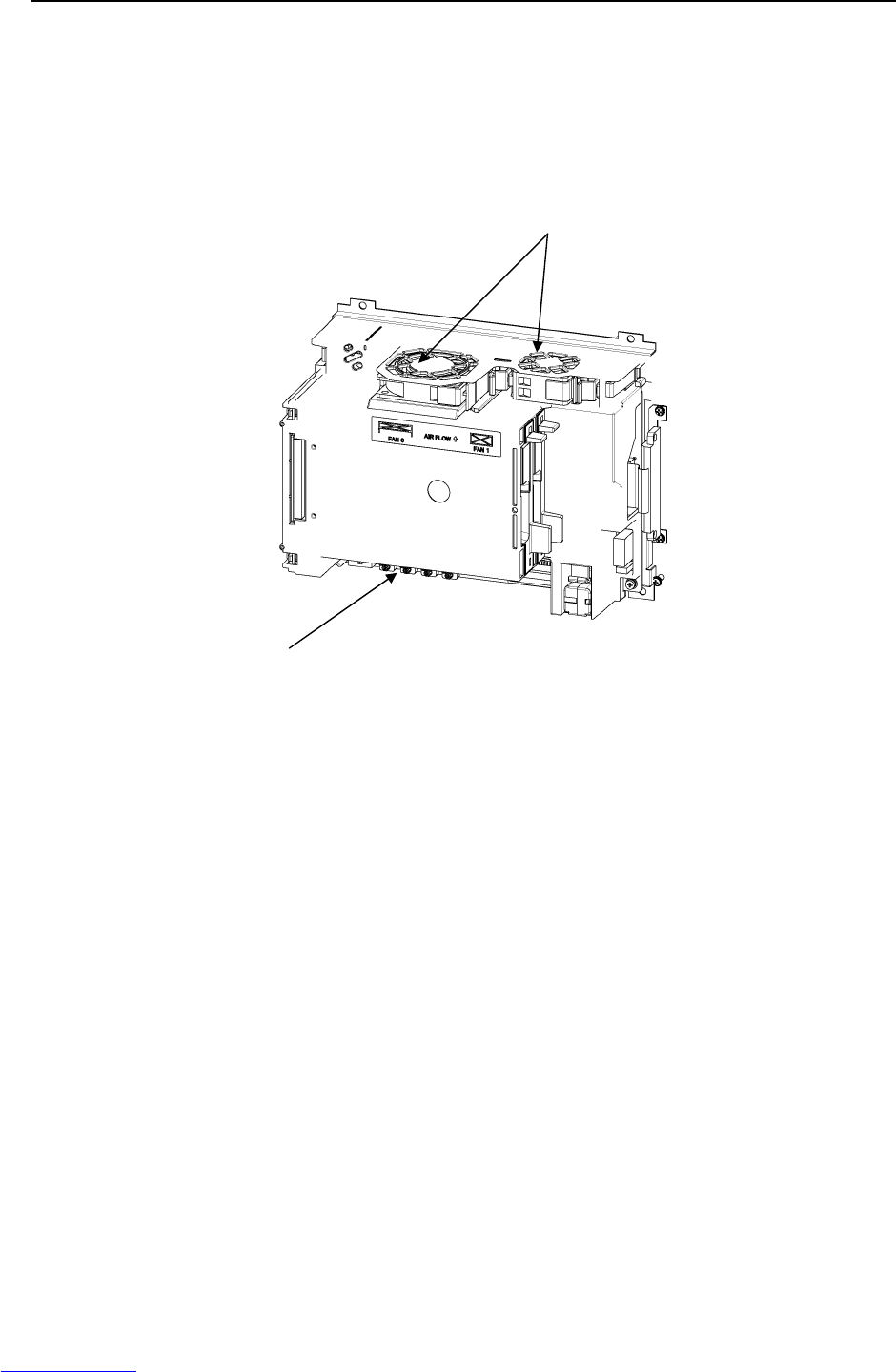
(8) SRVO-014 Fan motor abnormal
(Explanation) A fan motor in the controller backplane unit is abnormal.
(Action 1) Replace a fan motor in the controller backplane unit.
(Action 2) Replace the fan board.
Before executing the (Action 3), perform a complete controller back-up to save all your programs
and settings.
(Action 3) Replace the main board.
Fig.3.5 (g) SRVO-014 Fan motor abnormal
Main board
Fan moto
r
Downloaded from www.Manualslib.com manuals search engine
B-82725EN-1/07 MAINTENANCE 3.TROUBLESHOOTING
- 27 -
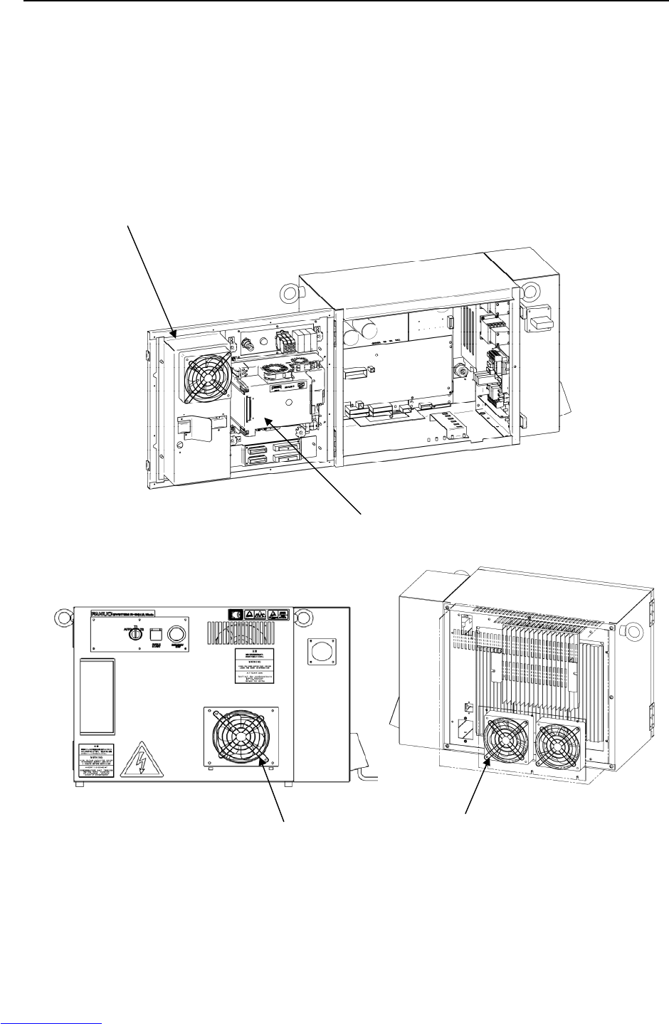
(9) SRVO-015 SYSTEM OVER HEAT (Group: i Axis: j)
(Explanation) The temperature in the control unit exceeds the specified value.
(Action 1) If the ambient temperature is higher than specified (45°C), cool down the
ambient temperature.
(Action 2) If the fan motor is not running, check it and its cables. Replace them if
necessary.
Before executing the (Action 3), perform a complete controller back-up to save
all your programs and settings.
(Action 3) Replace the main board. (The thermostat on the main board may be faulty.)
Fig.3.5 (h) SRVO-015 SYSTEM OVER HEAT
Main board
Heat exchan
g
e
r
Fan unit Fan unit (Rear)
(ARC Mate 100iC, M-10iA,ARC Mate 120iC, M-20iA,
ARC Mate 50iC, ARC Mate 0iA)
Downloaded from www.Manualslib.com manuals search engine

3.TROUBLESHOOTING MAINTENANCE B-82725EN-1/07
- 28 -
(10) SRVO-018 Brake abnormal
(Explanation) An excessive brake current is detected. The ALM LED on the servo amplifier is
lit.
(Action 1) Check the cables and motor brakes connected to CRR88 connector on the servo
amplifier.
If a short-circuit or grounding fault is found, replace the failed part.
(Action 2) Check the cables and motor brakes connected to CRR65A, CRR65B connector on
the servo amplifier. If a short-circuit or grounding fault is found, replace the failed
part.
(Action 3) Replace the servo amplifier.
CAUTION
This error can be caused by the optional brake release unit if the on/off switch is
left in on position while the operator attempts to jog the robot. To recover, turn
the brake release unit off and cycle the controller power.
(11) SRVO-021 SRDY off (Group: i Axis: j)
(Explanation) The HRDY is on and the SRDY is off, although there is no other cause of an alarm.
(HRDY is a signal with which the host detects the servo system whether to turn on
or off the servo amplifier magnetic contactor. SRDY is a signal with which the
servo system informs the host whether the magnetic contactor is turned on.)
If the servo amplifier magnetic contactor cannot be turned on when directed so, it
is most likely that a servo amplifier alarm has occurred. If a servo amplifier
alarm has been detected, the host will not issue this alarm (SRDY off). Therefore,
this alarm indicates that the magnetic contactor cannot be turned on for an
unknown reason.
(Action 1) Make sure that the E-stop board connectors CRMA43, CRMA31 and servo
amplifier SRMA43 are securely attached to the servo amplifier.
(Action 2) It is possible that an instant disconnection of power source causes this alarm.
Check whether an instant disconnection occurred.
(Action 3) Replace the E-stop unit.
(Action 4) Replace the servo amplifier.
(12) SRVO-022 SRDY on (Group: i Axis: j)
(Explanation) When the HRDY is about to go on, the SRDY is already on. (HRDY is a signal
with which the host directs the servo system whether to turn on or off the servo
amplifier magnetic contactor. SRDY is a signal with which the servo system
informs the host whether the magnetic contactor is turned on.)
(Action 1) Replace the servo amplifier as the alarm message.
Downloaded from www.Manualslib.com manuals search engine
B-82725EN-1/07 MAINTENANCE 3.TROUBLESHOOTING
- 29 -
(13) SRVO-023 Stop error excess (Group: i Axis: j)
(Explanation) When the servo is at stop, the position error is abnormally large.
Check whether the brake is released through the clack sound of the brake or
vibration.
In case that the brake is not released.
(Action 1) If the brake is not released, check the continuity of the brake line in the robot
connection cable and the robot internal cable.
(Action 2) If the disconnection is not found, replace the servo amplifier or the servo motor.
In case that the brake is released.
(Action 1) Check whether the obstacle disturbs the robot motion.
(Action 2) Make sure that connectors CNJ1A-CNJ6 are securely attached to the servo
amplifier.
(Action 3) Check the continuity of the robot connection cable and the internal robot power
cable.
(Action 4) Check to see if the load is greater than the rating. If greater, reduce it to within the
rating. (If the load is too great, the torque required for acceleration / deceleration
becomes higher than the capacity of the motor.
As a result, the motor becomes unable to follow the command, and an alarm is
issued.)
(Action 5) Check the input voltage to the controller is within the rated voltage and no phase is
lack. In addition, check the setting of the transformer is correct.
Check each phase voltage of the CRR38A connector of the three-phase power
(200 VAC) input to the servo amplifier. If it is 210 VAC or lower, check the line
voltage. (If the voltage input to the servo amplifier becomes low, the torque output
also becomes low. As a result, the motor may become unable to follow the
command, hence possibly causing an alarm.).
(Action 6) Replace the servo amplifier.
(Action 7) Replace the motor of the alarm axis.
NOTE
Incorrect setting of the brake number causes this alarm.
Fig.3.5 (i) SRVO-018 Brake abnormal
SRVO-021 SRDY off
SRVO-022 SRDY on
SRVO-023 Stop error excess
Servo am
p
lifie
r
Downloaded from www.Manualslib.com manuals search engine

3.TROUBLESHOOTING MAINTENANCE B-82725EN-1/07
- 30 -
(14) SRVO-024 Move error excess (Group: i Axis: j)
(Explanation) When the robot is running, its position error is greater than a specified value
($PARAM _ GROUP. $MOVER _ OFFST). It is likely that the robot cannot
follow the speed specified by program.
(Action 1) Take the same actions as SRVO-023.
(15) SRVO-027 Robot not mastered (Group: i)
(Explanation) An attempt was made to calibrate the robot, but the necessary adjustment had not
been completed.
(Action) Check whether the mastering is valid. If the mastering is invalid, master the robot.
WARNING
If the position data is incorrect, the robot or additional axis can operate
abnormally, set the position data correctly. Otherwise, you could injure personnel
or damage equipment.
(16) SRVO-030 Brake on hold (Group:i)
(Explanation) If the temporary halt alarm function is enabled ($SCR.$BRKHOLD ENB=1),
SRVO-030 is issued when a temporary halt occurs. When this function is not
used, disable the setting.
(Action) Disable [Servo-off in temporary halt] on the general item setting screen [6 General
Setting Items].
(17) SRVO-033 Robot not calibrated (Group: i)
(Explanation) An attempt was made to set up a reference point for quick mastering, but the robot
had not been calibrated.
(Action) Calibrate the robot.
1. Supply power.
2. Set up a quick mastering reference point using [Positioning] on the positioning
menu.
(18) SRVO-034 Ref pos not set (Group: i)
(Explanation) An attempt was made to perform quick mastering, but the reference point had not
been set up.
(Action) Set up a quick mastering reference point on the positioning menu.
(19) SRVO-036 Inpos time over (Group: i Axis: j)
(Explanation) The robot did not get to the effective area ($PARAM _ GROUP.$ STOPTOL)
even after the position check monitoring time ($PARAM _ GROUP. $INPOS _
TIME) elapsed.
(Action) Take the same actions as for SRVO-023 (large position error at a stop).
(20) SRVO-037 IMSTP input (Group: i)
(Explanation) The *IMSTP signal for a peripheral device interface was input.
(Action) Turn on the *IMSTP signal.
Downloaded from www.Manualslib.com manuals search engine
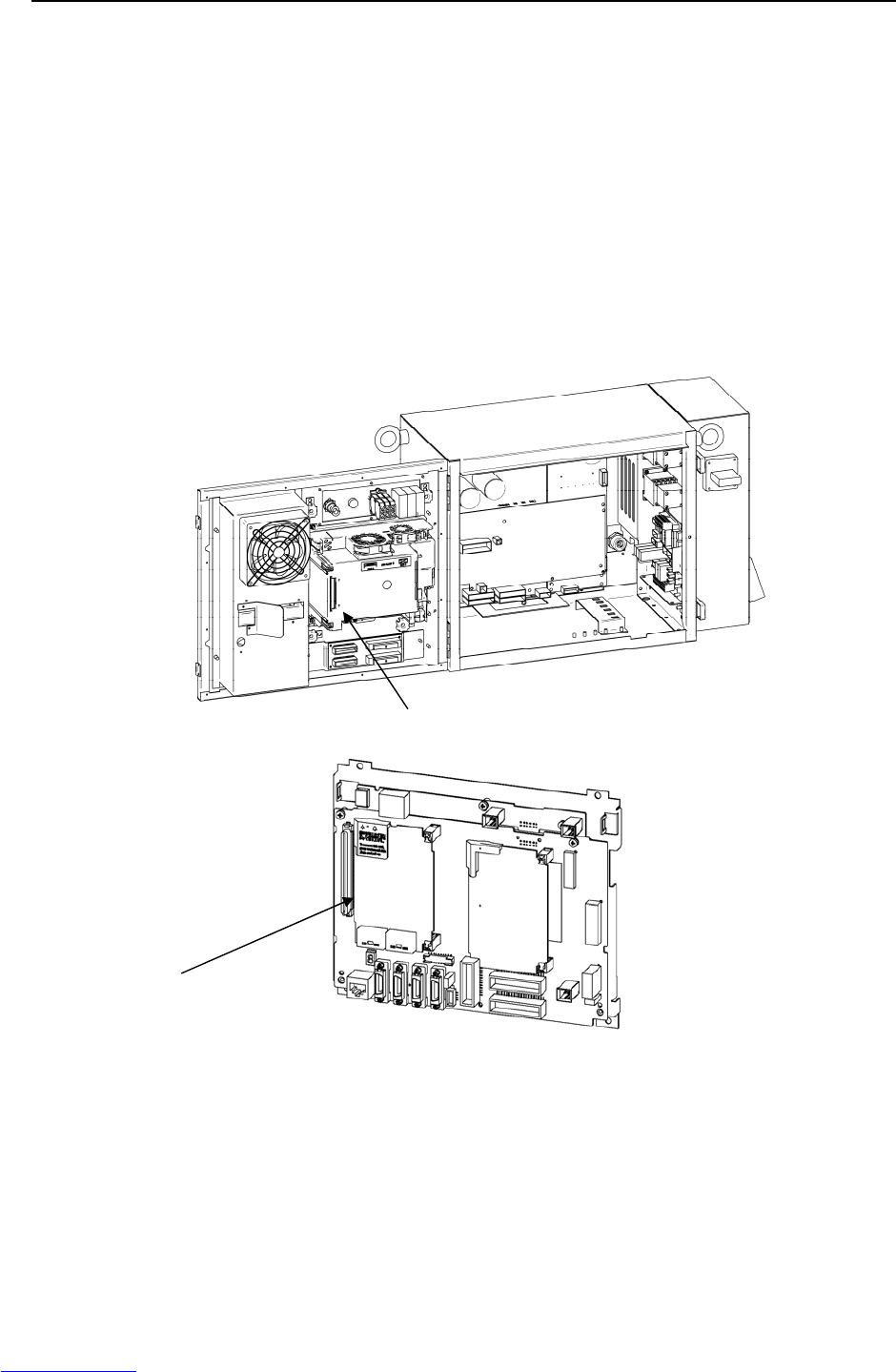
B-82725EN-1/07 MAINTENANCE 3.TROUBLESHOOTING
- 31 -
(21) SRVO-038 Pulse mismatch (Group: i Axis: j)
(Explanation) The pulse count obtained when power is turned off does not match the pulse count
obtained when power is applied. This alarm is asserted after exchange the
Pulsecoder or battery for back up of the Pulsecoder data or loading back up data to
the Main Board.
Check the alarm history.
(Action 1) If the brake number is set to the non-brake motors, this alarm may occur. Check
the software setting of the brake number.
(Action 2) In case the robot has been moved by using the brake release unit while the power
is off or when restoring the back-up data to the main board, this alarm may occur.
Remaster the robot.
(Action 3) If the robot has been moved because the brake failed, this alarm may occur. Check
the cause of the brake trouble. Then remaster the robot.
(Action 4) Replace the Pulsecoder and master the robot.
Fig.3.5 (j) SRVO-038 Pulse mismatch
Main board
Axis control card
Downloaded from www.Manualslib.com manuals search engine

3.TROUBLESHOOTING MAINTENANCE B-82725EN-1/07
- 32 -
(22) SRVO-042 MCAL alarm (Group: i Axis: j)
(Explanation) This alarm means that the contacts of the magnetic contactor have stuck to each
other. The alarm condition occurs if the magnetic contactor turns out to be already
on when an attempt is made to turn it on. The alarm condition is detected between
the time contact sticking occurs and the time an attempt is made to turn on the
magnetic contactor.
(Action 1) Replace the E-stop unit.
(Action 2) Replace the servo amplifier.
(23) SRVO-043 DCAL alarm (Group: i Axis: j)
(Explanation) The regenerative discharge energy was too high to be dissipated as heat. (To run
the robot, the servo amplifier supplies energy to the robot. When going down the
vertical axis, the robot operates from the potential energy. If a reduction in the
potential energy is higher than the energy needed for acceleration, the servo
amplifier receives energy from the motor. A similar phenomenon occurs even
when no gravity is applied, for example, at deceleration on a horizontal axis. The
energy that the servo amplifier receives from the motor is called the regenerative
energy. The servo amplifier dissipates this energy as heat. If the regenerative
energy is higher than the energy dissipated as heat, the difference is stored in the
servo amplifier, causing an alarm.)
(Action 1) This alarm may occur if the axis is subjected to frequent acceleration/deceleration
or if the axis is vertical and generates a large amount of regenerative energy.
If this alarm has occurred, relax the service conditions.
(Action 2) Check fuse FS3 in the servo amplifier. If it has blown, remove the cause, and
replace the fuse. One of the probable causes of a blown fuse is a ground fault in
the servo amplifier for the auxiliary axis.
(Action 3) The ambient temperature is excessively high. Or the regenerative resistor can't be
cooled effectively. Check the fan unit, and replace it if it stops. Clean up the fun
unit, the regenerative resistor and the louver if they are dirty.
(Action 4) Make sure that the phase-to-phase voltages of input power fall within the specified
range by measurement. If the voltages are out of the range, inspect the power
equipment. When no failure is found, replace the E-stop unit.
(Action 5) Make sure that the servo amplifier CRR63A and CRR63B connectors are
connected tightly. Then detach the cable from CRR63A and CRR63B connectors
on the Servo amplifier, and check for continuity between pins 1 and 2 of the
cable-end connector. If there is no continuity between the pins, replace the
regenerative resistor.
(Action 6) Make sure that the servo amplifier CRR45A and CRR45B are connected tightly,
then detach the cables from CRR45A and CRR45B on the servo amplifier and
check the resistance between pins 1 and 2 of each cable end connector. If the
resistance is not 9Ω, replace the regenerative resistor. CRR45B may not be used
depending on the robot model.
(Action 7) Replace the servo amplifier.
Downloaded from www.Manualslib.com manuals search engine
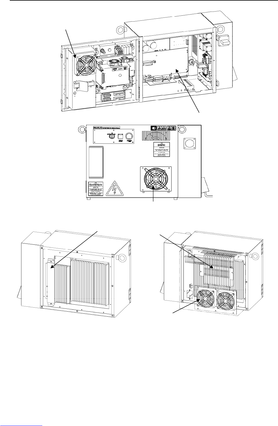
B-82725EN-1/07 MAINTENANCE 3.TROUBLESHOOTING
- 33 -
(LR Mate 200iC, M-1iA) (ARC Mate 100iC, M-10iA, ARC Mate 50iC
ARC Mate 120iC, M-20iA, ARC Mate 0iA)
Fig.3.5 (k) SRVO-042 MCAL alarm
SRVO-043 DCAL alarm
Servo amplifier
Heat exchanger
Fan unit
Regenerative resistor unit
Fan unit
Downloaded from www.Manualslib.com manuals search engine
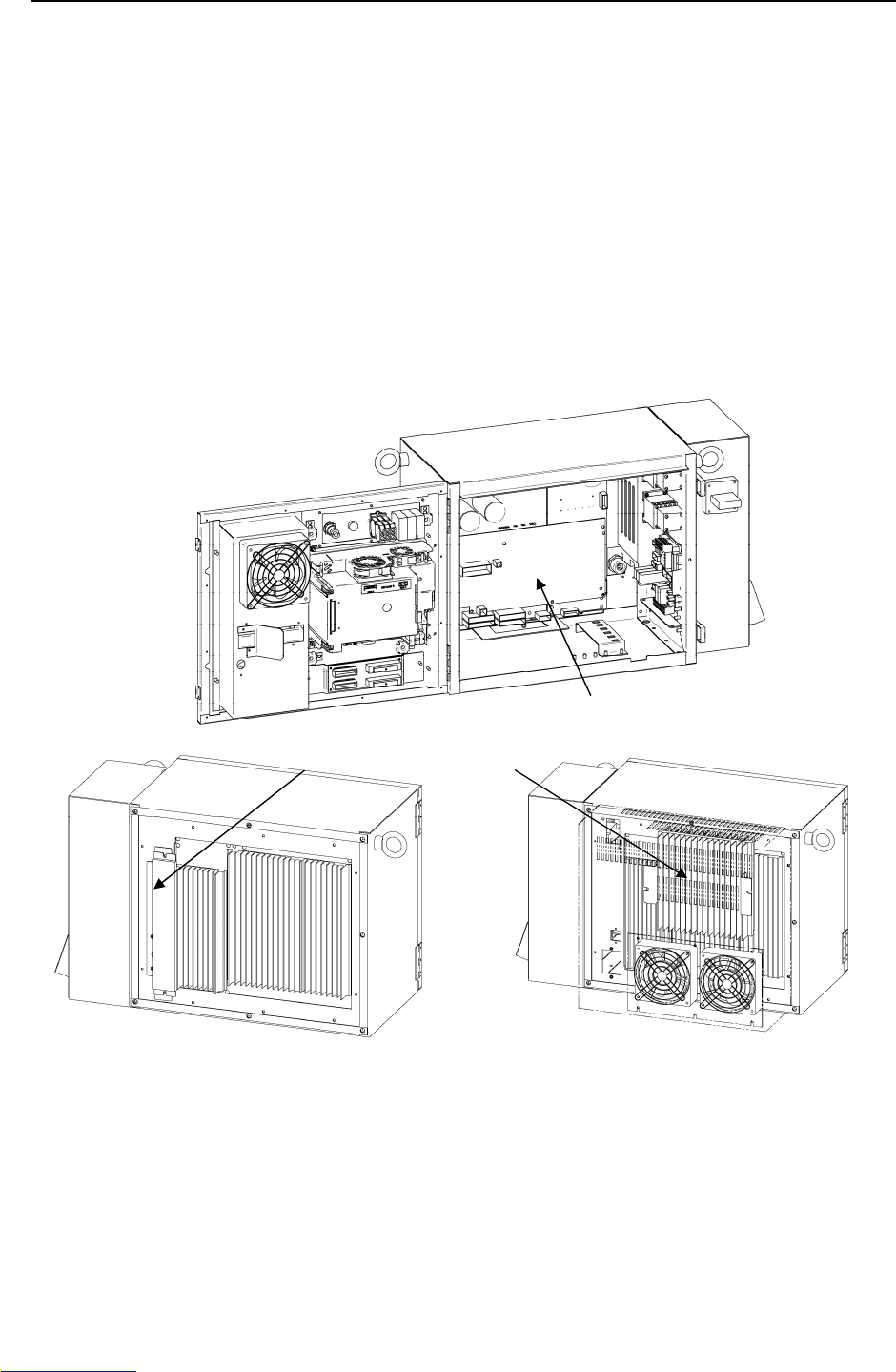
3.TROUBLESHOOTING MAINTENANCE B-82725EN-1/07
- 34 -
(24) SRVO-044 HVAL alarm (Group: i Axis: j)
(Explanation) The DC voltage (DC link voltage) of the main circuit power supply is abnormally
high.
(Action 1) Check the three-phase input voltage at the servo amplifier. If it is 230 VAC or
higher, check the line voltage. (If the three-phase input voltage is higher than
230 VAC, high acceleration/deceleration can cause in this alarm.)
(Action 2) Check that the load weight is within the rating. If it is higher than the rating,
reduce it to within the rating. (If the machine load is higher than the rating, the
accumulation of regenerative energy might result in the HVAL alarm even when
the three-phase input voltage is within the rating.)
(Action 3) Check that the CRR63A and CRR63B connectors of the servo amplifier are
attached firmly. Next, detach the cables then check the continuity between pins 1
and 2 of the cable-side connectors. If a disconnection is found, replace the
regenerative resistor.
(Action 4) Replace the servo amplifier.
(LR Mate 200iC, M-1iA) (ARC Mate 100iC, M-10iA, ARC Mate 50iC
ARC Mate 120iC, M-20iA, ARC Mate 0iA)
Fig.3.5 (l) SRVO-044 HVAL alarm
Servo am
p
lifie
r
Regenerative resistor unit
Downloaded from www.Manualslib.com manuals search engine
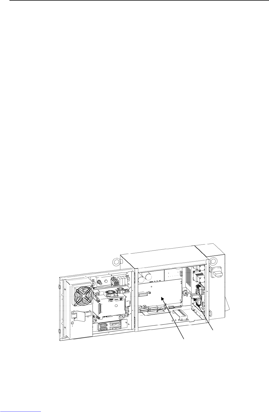
B-82725EN-1/07 MAINTENANCE 3.TROUBLESHOOTING
- 35 -
(25) SRVO-045 HCAL alarm (Group: i Axis: j)
(Explanation) Abnormally high current flowed in the main circuit of the servo amplifier.
(Action 1) Turn off the power, and disconnect the power cable from the servo amplifier
indicated by the alarm message. (And disconnect the brake cable (CRR88 on the
servo amplifier) to avoid the axis falling unexpectedly.) Supply power and see if
the alarm occurs again. If the alarm occurs again, replace the servo amplifier.
(Action 2) Turn off the power and disconnect the power cable from the servo amplifier
indicated by the alarm message, and check the insulation of their U, V, W and the
GND lines each other. If there is a short-circuit, replace the power cable.
(Action 3) Turn off the power and disconnect the power cable from the servo amplifier by the
alarm message, and measure the resistance between their U and V, V and W and
W and U with an ohmmeter that has a very low resistance range. If the resistances
at the three places are different from each other, the motor, the power cable is
defective. Check each item in detail and replace it if necessary.
(26) SRVO-046 OVC alarm (Group: i Axis: j)
(Explanation) This alarm is issued to prevent the motor from thermal damage that might occur
when the root meant square current calculated within the servo system is out of the
allowable range.
(Action 1) Check the operating condition for the robot and relax the service condition if
possible. If the load or operating condition has exceeded the rating, reduce the load
or relax the operating condition to meet the rating.
(Action 2) Check whether the voltage input to the controller is within the rated voltage and
check whether the voltage set for the transformer of the controller is correct.
(Action 3) Check whether the brake of the corresponding axis is released.
(Action 4) Check whether there is a factor that has increased the mechanical load on the
corresponding axis.
(Action 5) Replace the servo amplifier.
(Action 6) Replace the motor of the corresponding axis.
(Action 7) Replace the E-stop unit
(Action 8) Replace the motor power line (robot connection cable) of the corresponding axis.
(Action 9) Replace the motor power line and brake line (inside the mechanical section) of the
corresponding axis.
Fig.3.5 (m) SRVO-045 HCAL alarm
SRVO-046 OVC alarm
Servo am
p
lifie
r
E-sto
p
unit
Downloaded from www.Manualslib.com manuals search engine
3.TROUBLESHOOTING MAINTENANCE B-82725EN-1/07
- 36 -
Reference
Relationships among the OVC, OHAL, and HC alarms
- Overview
This section points out the differences among the OVC, OHAL, and HC alarms and describes the purpose
of each alarm.
- Alarm detection section
Abbreviation Designation Detection section
OVC Overcurrent alarm Servo software
OHAL Overheat alarm Thermal relay in the motor
Thermal relay in the servo amplifier
Thermal relay in the separate regenerative discharge unit
HC High current alarm Servo amplifier
- Purpose of each alarm
1) HC alarm (high current alarm)
If high current flow in a power transistor momentarily due to abnormality or noise in the control
circuit, the power transistor and rectifier diodes might be damaged, or the magnet of the motor might
be degaussed. The HC alarm is intended to prevent such failures.
2) OVC and OHAL alarms (overcurrent and overload alarms)
The OVC and OHAL alarms are intended to prevent overheat that may lead to the burnout of the
motor winding, the breakdown of the servo amplifier transistor, and the separate regenerative
resistor.
The OHAL alarm occurs when each built-in thermal relay detects a temperature higher than the rated
value. However, this method is not necessarily perfect to prevent these failures. For example, if
the motor frequently repeats to start and stop, the thermal time constant of the motor, which has a
large mass, becomes higher than the time constant of the thermal relay, because these two
components are different in material, structure, and dimension. Therefore, if the motor continues to
start and stop within a short time as shown in Fig. 3.5 (n), the temperature rise in the motor is steeper
than that in the thermal relay, thus causing the motor to burn before the thermal relay detects an
abnormally high temperature.
Temperature
Start StartStartStop Stop
Temperature at
which the winding
starts to burn
Thermal time constant of the
motor is high.
Thermal time constant of the
thermal relay is low.
Time
Fig.3.5 (n) Relationship between the temperatures of the motor and thermal relay on start/stop cycles
To prevent the above defects, software is used to monitor the current in the motor constantly in order to
estimate the temperature of the motor. The OVC alarm is issued based on this estimated temperature.
This method estimates the motor temperature with substantial accuracy, so it can prevent the failures
described above.
Downloaded from www.Manualslib.com manuals search engine
B-82725EN-1/07 MAINTENANCE 3.TROUBLESHOOTING
- 37 -
To sum up, a double protection method is used; the OVC alarm is used for protection from a short-time
overcurrent, and the OHAL alarm is used for protection from long-term overload. The relationship
between the OVC and OHAL alarms is shown in Fig.3.5 (o).
Current Protection area for
the motor and servo
amplifier
Protection by the OHAL
Limit current
Protection by
the OVC
Rated continuous current
Time
Fig.3.5 (o) Relationship between the OVC and OHAL alarms
NOTE
The relationship shown in Fig.3.5 (o) is taken into consideration for the OVC
alarm. The motor might not be hot even if the OVC alarm has occurred. In
this case, do not change the parameters to relax protection.
(27) SRVO-047 LVAL alarm (Group: i Axis: j)
(Explanation) The control power supply voltage (+5 V, etc.) supplied from the power supply
circuit in the servo amplifier is abnormally low.
(Action 1) Replace the servo amplifier.
(Action 2) Replace the power supply unit.
(28) SRVO-050 CLALM alarm (Group: i Axis: j)
(Explanation) The disturbance torque estimated by the servo software is abnormally high. (A
collision has been detected.)
(Action 1) Check whether the robot has collided and check whether there is a factor that has
increased the mechanical load on the corresponding axis.
(Action 2) Check whether the load settings are valid.
(Action 3) Check whether the brake of the corresponding axis is released.
(Action 4) If the load weight exceeds the rated range, decrease it to within the limit.
(Action 5) Check whether the voltage input to the controller is within the rated voltage and
check whether the voltage set for the transformer of the controller is correct.
(Action 6) Replace the servo amplifier.
(Action 7) Replace the motor of the corresponding axis.
(Action 8) Replace the E-stop unit.
(Action 9) Replace the motor power line (robot connection cable) of the corresponding axis.
(Action 10) Replace the motor power line and brake line (inside the mechanical section) of the
corresponding axis.
(29) SRVO-051 CUER alarm (Group: i Axis: j)
(Explanation) The offset of the current feedback value is abnormally high.
(Action) Replace the servo amplifier.
Downloaded from www.Manualslib.com manuals search engine
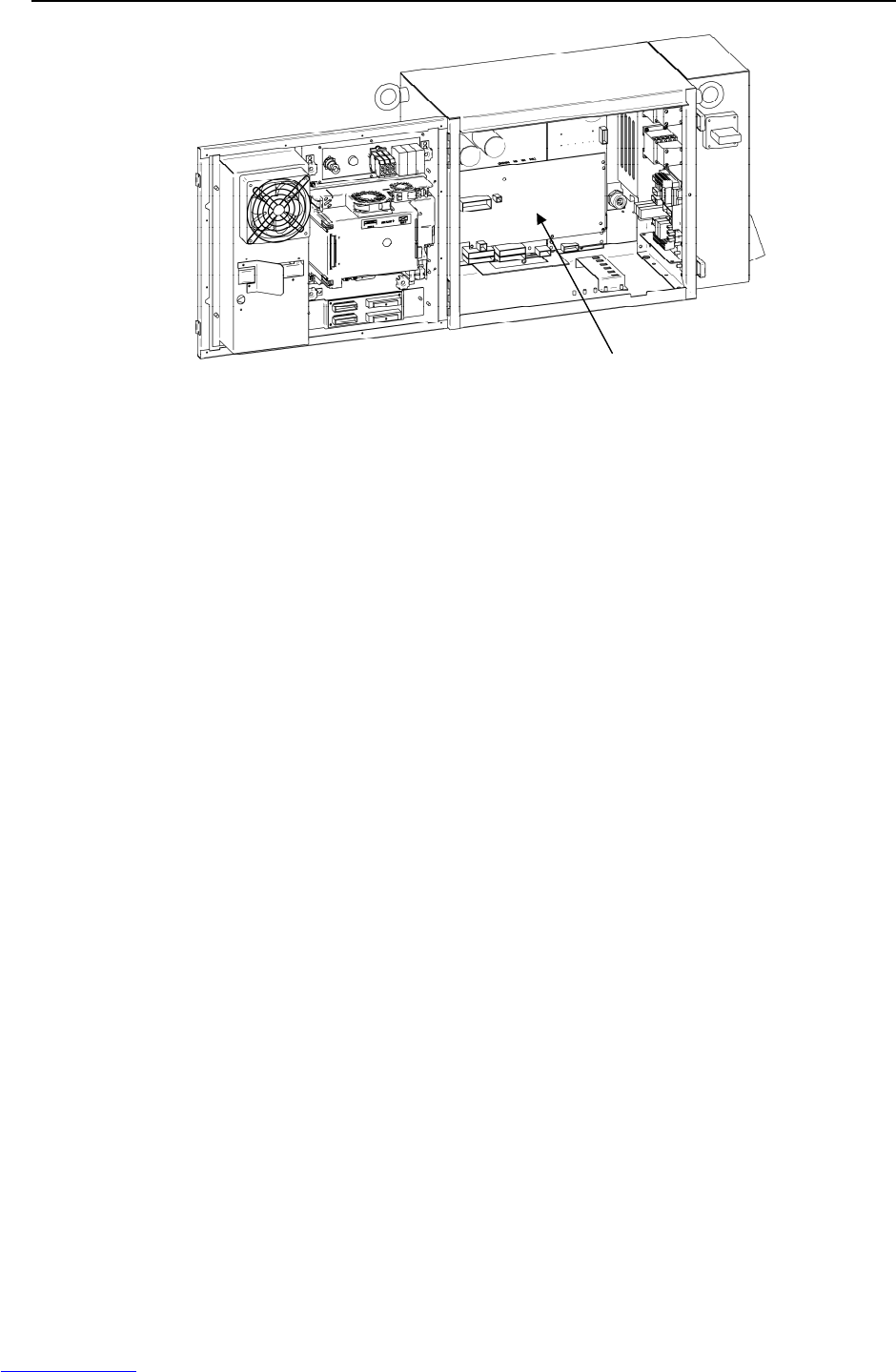
3.TROUBLESHOOTING MAINTENANCE B-82725EN-1/07
- 38 -
Fig.3.5 (p) SRVO-047 LVAL alarm
SRVO-050 CLALM alarm
SRVO-051 CUER alarm
(30) SRVO-055 FSSB com error 1 (Group: i Axis : j)
(Explanation) A communication error has occurred between the main board and servo amplifier.
(Action 1) Check the communication cable (optical fiber) between the main board and servo
amplifier. Replace it if it is faulty.
(Action 2) Replace the axis control card on the main board.
(Action 3) Replace the servo amplifier.
(31) SRVO-056 FSSB com error 2 (Group: i Axis: j)
(Explanation) A communication error has occurred between the main board and servo amplifier.
(Action 1) Check the communication cable (optical fiber) between the main board and servo
amplifier. Replace it if it is faulty.
(Action 2) Replace the axis control card on the main board.
(Action 3) Replace the servo amplifier.
(32) SRVO-057 FSSB disconnect (Group: i Axis: j)
(Explanation) Communication was interrupted between the main board and servo amplifier.
(Action 1) Check whether fuses FS1 and FS3 in the servo amplifier have blown. If the fuse
has blown, replace the servo amplifier including the fuse.
(Action 2) Replace the optical cable between the axis control card and servo amplifier.
(Action 3) Replace the axis control card on the main board.
(Action 4) Replace the servo amplifier.
(Action 5) Check for a point where the robot connection cable(RMP) or an internal cable
running to each Pulsecoder through the robot mechanical section is grounded.
Before continuing to the next step, perform a complete controller back-up to save
all your programs and settings.
(Action 6) Replace the main board.
(33) SRVO-058 FSSB init error (Group: i Axis: j)
(Explanation) Communication was interrupted between the main board and servo amplifier.
(Action 1) Check whether fuse FS1 on the servo amplifier has blown. If the fuse has blown,
replace the servo amplifier including the fuse.
(Action 2) Turn off the power and disconnect the CRF8 connector on the servo amplifier.
Then check whether this alarm occurs again. (Ignore the alarm SRVO-068 because
of disconnecting the CRF8 connector.)
Servo am
p
lifie
r
Downloaded from www.Manualslib.com manuals search engine
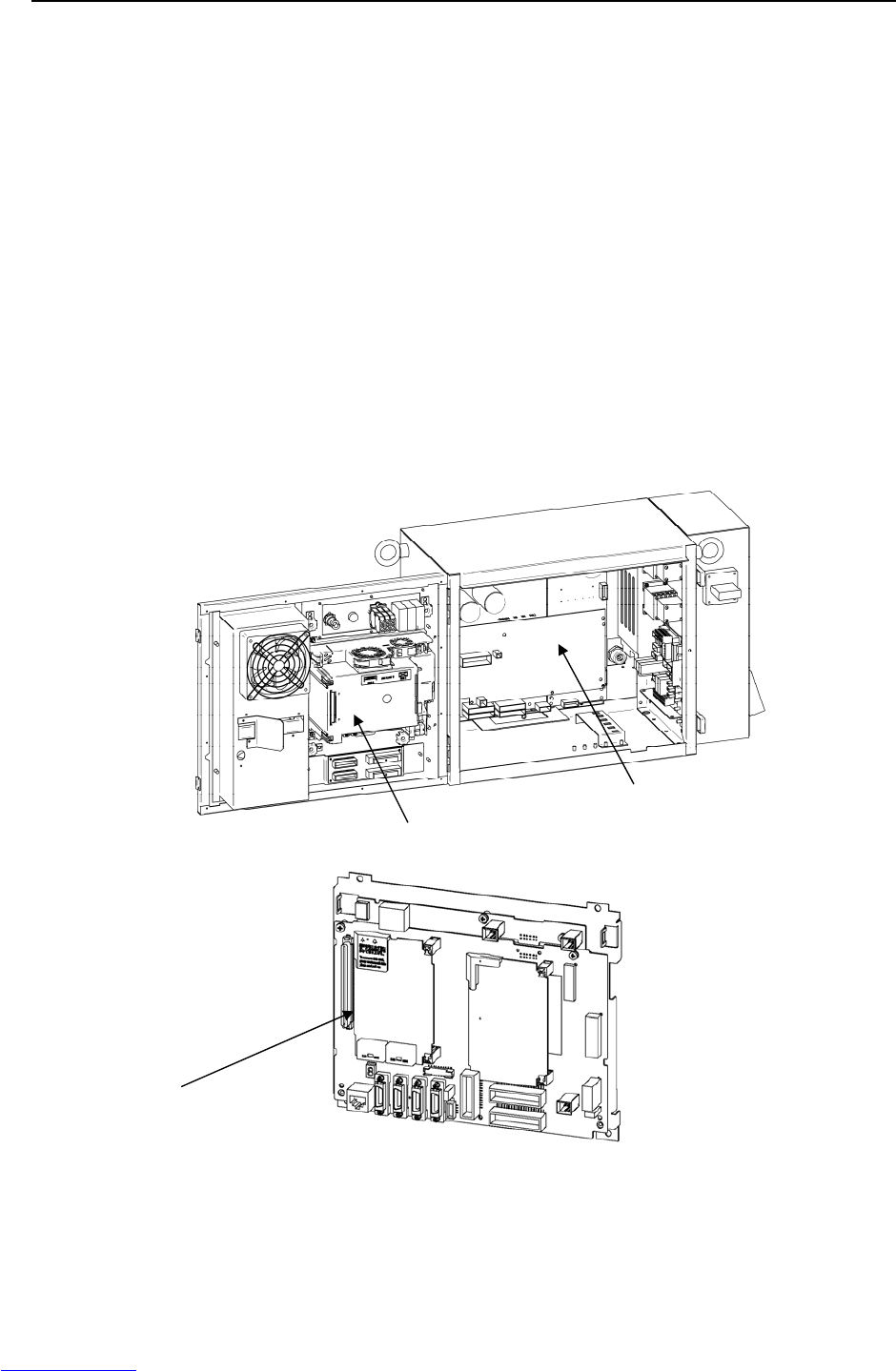
B-82725EN-1/07 MAINTENANCE 3.TROUBLESHOOTING
- 39 -
If this alarm does not occur, the RMP cable of the robot connection cable or the
internal cable of the robot may be short-circuited to the ground. Check the cables
and replace it if necessary.
(Action 3) Check whether the LED (P5V and P3.3V) on the servo amplifier is lit. If they are
not lit, the DC power is not supplied to the servo amplifier.
Make sure the connector CRP24 and CRM96 on the E-stop unit and the connector
CRM96 on the servo amplifier are connected tightly. If they are connected tightly,
replace the servo amplifier.
(Action 4) Check the communication cable (optical fiber) between the axis control board and
servo amplifier. Replace it if it is faulty.
(Action 5) Replace the servo card on the main board.
(Action 6) Replace the servo amplifier.
(Action 7) If the other units (the servo amplifier for the auxiliary axis and the line tracking
interface) are connected in the FSSB optical communication, disconnect these
units and connect only servo amplifier for the robot. Then turn on the power. If
this alarm does not occur, search the failed unit and replace it.
Before executing the (Action 8), perform a complete controller back-up to save all
your programs and settings.
(Action 8) Replace the main board.
Fig.3.5 (q) SRVO-055 FSSB com error 1
SRVO-056 FSSB com error 2
SRVO-057 FSSB disconnect
SRVO-058 FSSB init error
Axis control card
Main board
Servo amplifier
Downloaded from www.Manualslib.com manuals search engine
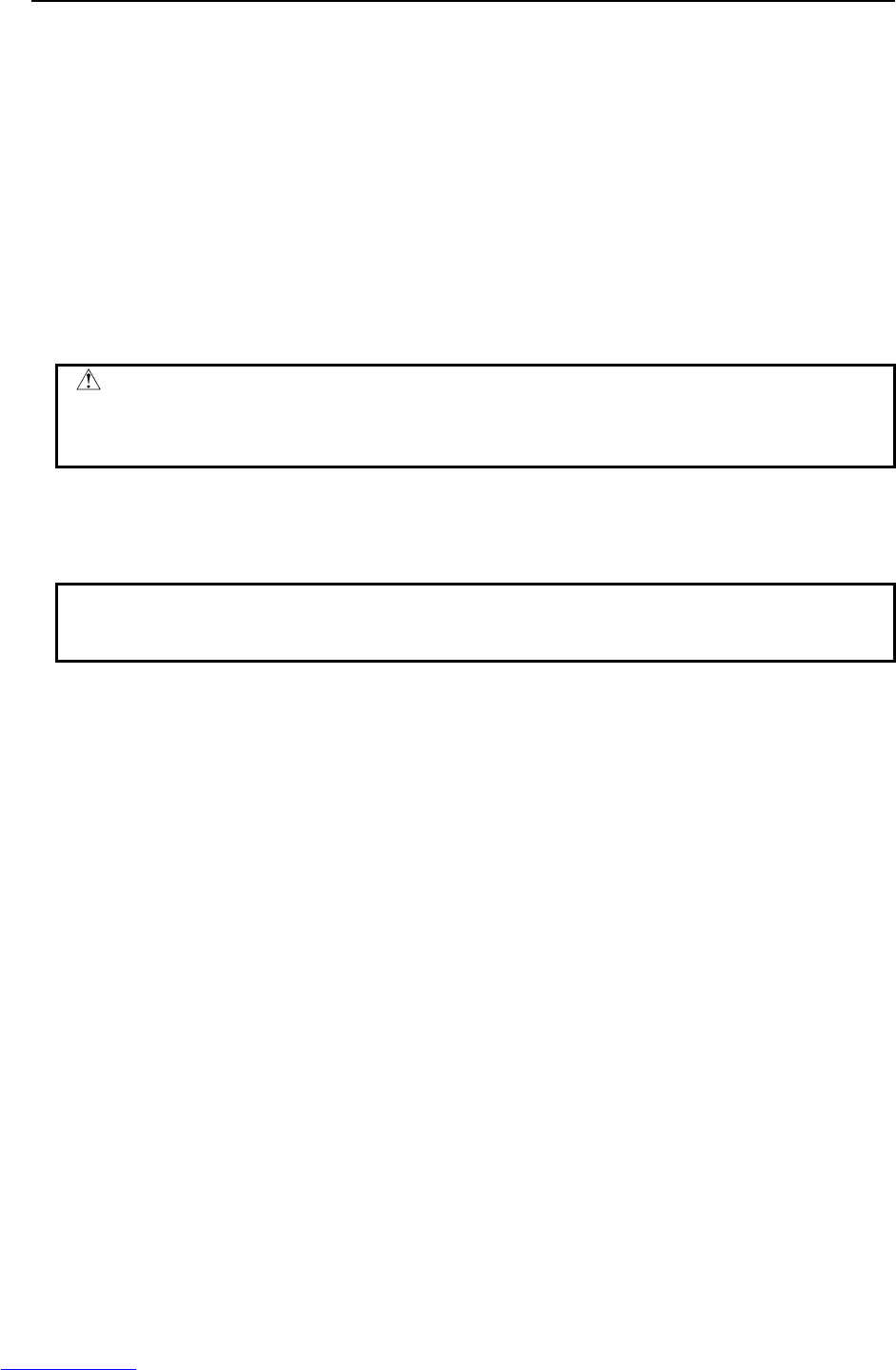
3.TROUBLESHOOTING MAINTENANCE B-82725EN-1/07
- 40 -
(34) SRVO-059 Servo amp init error
(Explanation) Servo amplifier initialization is failed.
(Action 1) Check the wiring of the servo amplifier.
(Action 2) Replace the servo amplifier.
(Action 3) Replace the line tracking board.
(35) SRVO-062 BZAL alarm (Group: i Axis : j)
(Explanation) This alarm occurs if battery for Pulsecoder absolute-position backup is empty.
A probable cause is a broken battery cable or no batteries in the robot.
(Action 1) Replace the battery in the battery box of the robot base.
(Action 2) Replace the Pulsecoder with which an alarm has been issued.
(Action 3) Check whether the robot internal cable for feeding power from the battery to the
Pulsecoder is not disconnected and grounded. If an abnormality is found, replace
the cable.
CAUTION
After correcting the cause of this alarm, set the system variable
($MCR.$SPC_RESET) to TRUE then turn on the power again. Mastering is
needed.
(36) SRVO-064 PHAL alarm (Group : i Axis : j)
(Explanation) This alarm occurs if the phase of the pulses generated in the Pulsecoder is
abnormal.
(Action) Replace the Pulsecoder.
NOTE
This alarm might accompany the DTERR, CRCERR, or STBERR alarm. In this
case, however, there is no actual condition for this alarm.
(37) SRVO-065 BLAL alarm (Group : i Axis : j)
(Explanation) The battery voltage for the Pulsecoder is lower than the rating.
(Action) Replace the battery.
(If this alarm occurs, turn on the power and replace the battery as soon as possible.
A delay in battery replacement may result in the BZAL alarm being detected. In
this case, the position data will be lost. Once the position data is lost, mastering
will become necessary.
(38) SRVO-067 OHAL2 alarm (Group : i Axis : j)
(Explanation) The temperature inside the Pulsecoder or motor is abnormally high, and the
built-in thermostat has operated.
(Action 1) Check the robot operating conditions. If a condition such as the duty cycle and
load weight has exceeded the rating, relax the robot load condition to meet the
allowable range.
(Action 2) When power is supplied to the motor after it has become sufficiently cool, if the
alarm still occurs, replace the motor.
(39) SRVO-068 DTERR alarm (Group : i Axis : j)
(Explanation) The serial Pulsecoder does not return serial data in response to a request signal.
(Action 1) Make sure that the RMP connector of servo amplifier (motor side) is connected
tightly.
(Action 2) Check that the shielding of the RMP cable is grounded securely in the cabinet.
(Action 3) Replace the Pulsecoder.
(Action 4) Replace the servo amplifier.
(Action 5) Replace the RMP cable.
(Action 6) Replace the robot interconnection cable (for the Pulsecoder).
Downloaded from www.Manualslib.com manuals search engine
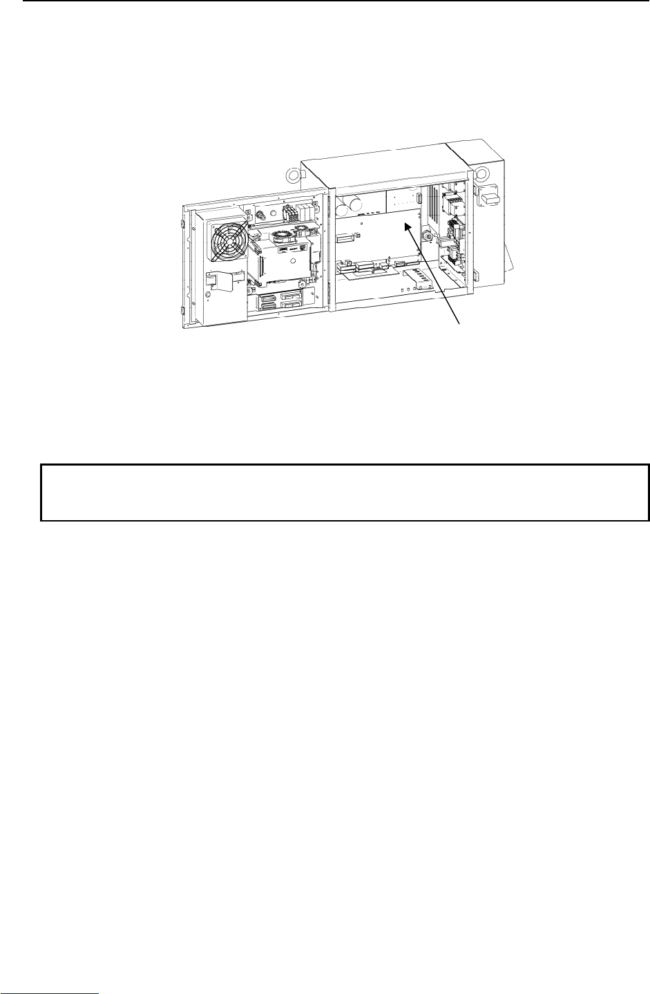
B-82725EN-1/07 MAINTENANCE 3.TROUBLESHOOTING
- 41 -
(40) SRVO-069 CRCERR alarm (Group : i Axis : j)
(Explanation) The serial data has disturbed during communication.
(Action) See actions on SRVO-068.
(41) SRVO-070 STBERR alarm (Group : i Axis : j)
(Explanation) The start and stop bits of the serial data are abnormal.
(Action) See actions on SRVO-068.
Fig.3.5 (r) SRVO-059 Servo amp init error
SRVO-070 STBERR alarm
(42) SRVO-071 SPHAL alarm (Group : i Axis : j)
(Explanation) The feedback speed is abnormally high.
(Action) Action as same as the SRVO-068.
NOTE
If this alarm occurs together with the PHAL alarm (SRVO-064), this alarm does
not correspond to the major cause of the failure.
(43) SRVO-072 PMAL alarm (Group : i Axis : j)
(Explanation) It is likely that the Pulsecoder is abnormal.
(Action) Replace the Pulsecoder and remaster the robot.
(44) SRVO-073 CMAL alarm (Group : i Axis : j)
(Explanation) It is likely that the Pulsecoder is abnormal or the Pulsecoder has malfunctioned
due to noise.
(Action 1) Check whether the connection of the controller earth is good. Check the earth
cable connection between controller and robot. Check whether the shielding of the
robot connection cables is connected securely to the grounding plate.
(Action 2) Reinforce the earth of the motor flange.(In case of Auxiliary axis)
(Action 3) Replace the Pulsecoder.
(45) SRVO-074 LDAL alarm (Group : i Axis : j)
(Explanation) The LED in the Pulsecoder is broken.
(Action) Replace the Pulsecoder, and remaster the robot.
(46) SRVO-075 Pulse not established (Group : i Axis : j)
(Explanation) The absolute position of the Pulsecoder cannot be established.
(Action) Reset the alarm, and jog the axis on which the alarm has occurred until the same
alarm will not occur again.
(47) SRVO-076 Tip Stick Detection (Group : i Axis : j)
Servo amplifier
Downloaded from www.Manualslib.com manuals search engine
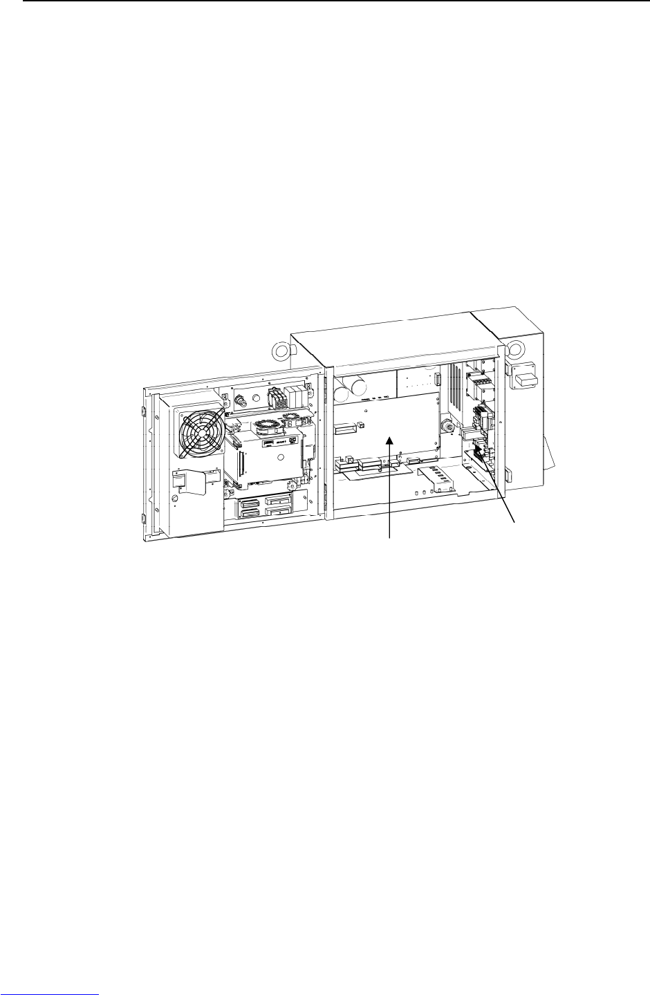
3.TROUBLESHOOTING MAINTENANCE B-82725EN-1/07
- 42 -
(Explanation) An excessive disturbance was assumed in servo software at the start of operation.
(An abnormal load was detected. The cause may be welding.)
(Action 1) Check whether the robot has collided. Or check whether the machinery load of the
corresponding axis is increased.
(Action 2) Check whether the load settings are valid.
(Action 3) Check whether the brake of the corresponding axis is released.
(Action 4) Check whether the load weight is within the rated range. If the weight exceeds the
upper limit, decrease it to the limit.
(Action 5) Check whether the voltage input to the controller is within the rated voltage and
check whether the voltage set for the transformer of the controller is correct.
(Action 6) Replace the servo amplifier.
(Action 7) Replace the corresponding servo motor.
(Action 8) Replace the E-stop unit.
(Action 9) Replace the power cable of the robot connection cable in which the corresponding
axis is connected.
(Action 10) Replace the power cable of the robot interconnection cable in which the
corresponding axis is connected.
Fig.3.5 (s) SRVO-076 Tip Stick Detection
(48) SRVO-081 EROFL alarm (Track enc : i)
(Explanation) The pulse counter for line tracking has overflowed.
(Action 1) Check whether the condition of the line tracking exceeds the limitation.
(Action 2) Replace the Pulsecoder.
(Action 3) Replace the line tracking interface board.
(49) SRVO-082 DAL alarm (Track ebc : i)
(Explanation) The line tracking Pulsecoder has not been connected.
(Action 1) Check the connection cable at each end (the line tracking interface board and the
motor side)
(Action 2) Check whether the shielding of the connection cable is connected securely to the
grounding plate.
(Action 3) Replace the line tracking cable.
(Action 4) Replace the Pulsecoder.
(Action 5) Replace the line tracking interface board.
(50) SRVO-084 BZAL alarm (Track enc : i)
(Explanation) This alarm occurs if the backup battery for the absolute position of the Pulsecoder
has not been connected. See the description about the BZAL alarm (SRVO-062).
E-stop unit
Servo amplifier
Downloaded from www.Manualslib.com manuals search engine

B-82725EN-1/07 MAINTENANCE 3.TROUBLESHOOTING
- 43 -
(51) SRVO-087 BLAL alarm (Track enc : i)
(Explanation) This alarm occurs if the voltage of the backup battery for the absolute position of
the Pulsecoder is low. See the description about the BLAL alarm (SRVO-065).
(52) SRVO-089 OHAL2 alarm (Track enc : i)
(Explanation) The motor has overheated. When power is supplied to the Pulsecoder after it has
become sufficiently cool, if the alarm still occurs. See the description about the
OHAL2 alarm (SRVO-067).
(53) SRVO-090 DTERR alarm (Track ebc : i)
(Explanation) Communication between the Pulsecoder and line tracking interface board is
abnormal. See the SRVO-068 DTERR alarm.
(Action 1) Check the connection cable at each end (the line tracking interface board and the
Pulsecoder)
(Action 2) Check whether the shielding of the connection cable is connected securely to the
grounding plate.
(Action 3) Replace the Pulsecoder.
(Action 4) Replace the line tracking cable.
(Action 5) Replace the line tracking interface board.
(54) SRVO-091 CRCERR alarm (Track enc : i)
(Explanation) Communication between the Pulsecoder and line tracking interface board is
abnormal.
(Action) Action as same as the SRVO-090.
(55) SRVO-092 STBERR alarm (Track enc : i)
(Explanation) Communication between the Pulsecoder and line tracking interface board is
abnormal.
(Action) Action as same as the SRVO-090.
(56) SRVO-093 SPHAL alarm (Track enc : i)
(Explanation) This alarm occurs if the current position data from the Pulsecoder is higher than
the previous position data.
(Action) Action as same as the SRVO-090.
(57) SRVO-094 PMAL alarm (Track enc : i)
(Explanation) It is likely that the Pulsecoder is abnormal. See the description about the PMAL
alarm (SRVO-072).
(58) SRVO-095 CMAL alarm (Track enc : i)
(Explanation) It is likely that the Pulsecoder is abnormal or the Pulsecoder has malfunctioned
due to noise. See the description about the CMAL alarm (SRVO-073).
(Action 1) Reinforce the earth of the flange of the Pulsecoder.
(Action 2) Replace the Pulsecoder.
(59) SRVO-096 LDAL alarm (Track enc : i)
(Explanation) The LED in the Pulsecoder is broken. See the description about the LDAL alarm
(SRVO-074).
(60) SRVO-097 Pulse not established (enc : i)
(Explanation) The absolute position of the Pulsecoder cannot be established. See the
description about (SRVO-075). Pulse not established.
(Action 1) Reset the alarm, and jog the axis on which the alarm has occurred until the same
alarm does not occur again. (Jog one motor revolution)
Downloaded from www.Manualslib.com manuals search engine

3.TROUBLESHOOTING MAINTENANCE B-82725EN-1/07
- 44 -
(61) SRVO-105 Door open or E-stop
(Explanation) The cabinet door is open.
- When the door switch is mounted.
(Action 1) When the door is open, close it.
(Action 2) Check the door switch and door switch connection cable. If the switch or cable is
faulty, replace it.
- When the door switch is not mounted.
(Action 3) Check that the CRMA31, CRMA43, and CRM90 connectors on the E-STOP unit
are connected securely.
(Action 4) Replace the E-stop unit.
(Action 5) Replace the servo amplifier.
Fig.3.5 (t) SRVO-105 Door open or E-stop
(62) SRVO-136 DCLVAL alarm (Group : i Axis : j)
(Explanation) The servo the DC current of amplifier (DC link voltage) of the main power supply
is abnormally low.
- This alarm occurred during robot operation.
(Action 1) Check the input voltage to the controller is within the rated voltage and no phase is
lack. In addition, check the setting of the transformer is correct.
(Action 2) It is possible that an instant disconnection of power source causes this alarm.
Check whether an instant disconnection occurred.
(Action 3) Modify the program in order that robot and the auxiliary axis do not accelerate
simultaneously in the system with the auxiliary axis.
(Action 4) Replace the E-stop unit.
(Action 5) Replace the servo amplifier.
- If this alarm occurred before the magnetic contactor is turned on:
(Action 1) Check whether the circuit breaker in the E-stop unit is OFF. If it is OFF, check the
servo amplifier and the wiring between the servo amplifier and the E-stop unit. If
anything is abnormal, replace it. Else, turn on the breaker.
(Action 2) Check the input voltage to the controller is within the rated voltage and no phase is
lack. In addition, check the setting of the transformer is correct.
(Action 3) Replace the E-stop unit.
(Action 4) Replace the servo amplifier.
E-stop unit
Servo amplifier Door switch
Downloaded from www.Manualslib.com manuals search engine
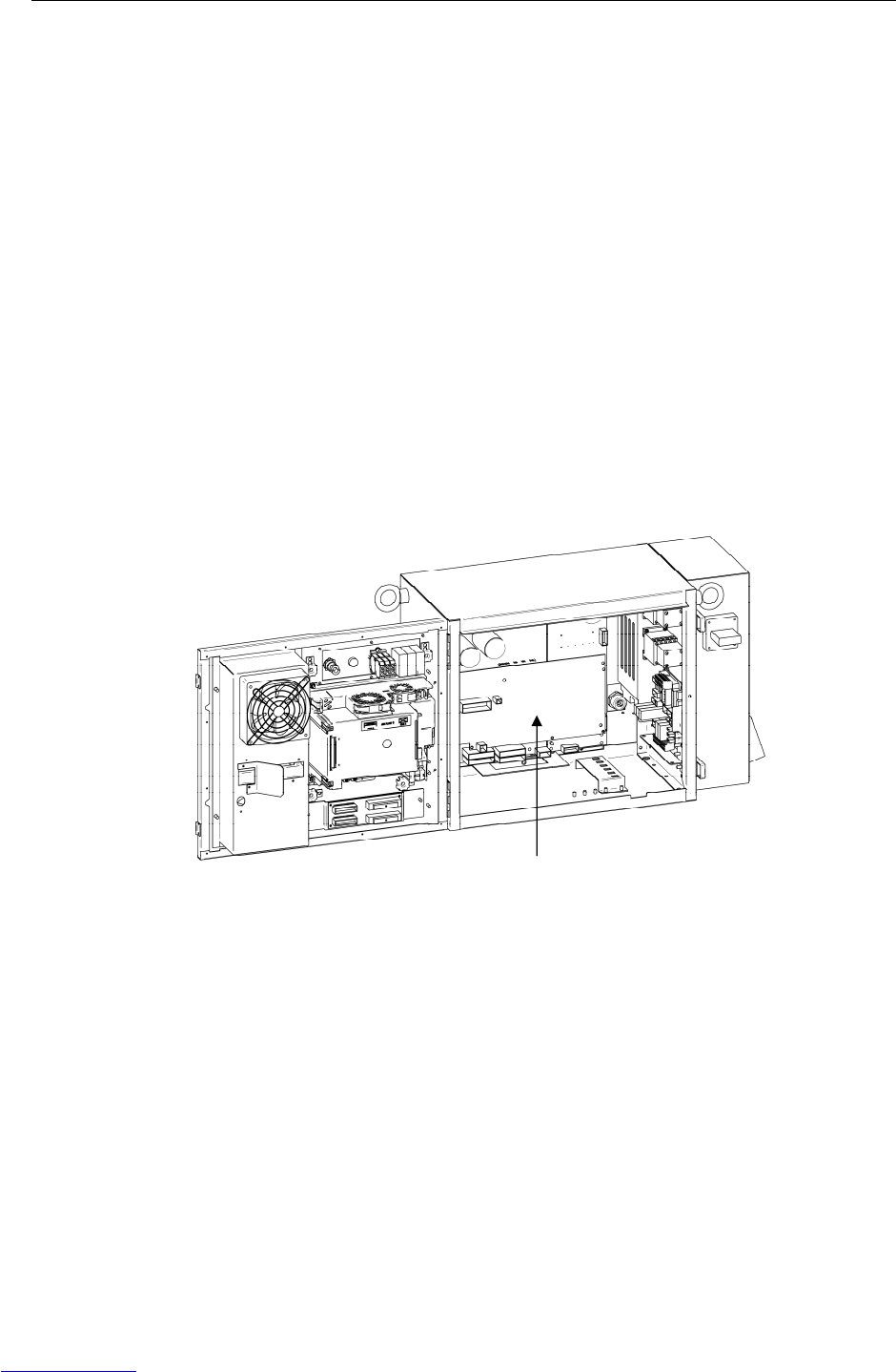
B-82725EN-1/07 MAINTENANCE 3.TROUBLESHOOTING
- 45 -
(63) SRVO-156 IPMAL alarm (Group: i Axis: j)
(Explanation) Abnormally high current flowed through the main circuit of the servo amplifier.
(Action 1) Turn off the power, and disconnect the power cable from the servo amplifier
indicated by the alarm message. (And disconnect the brake cable (CRR88) on the
servo amplifier to avoid the axis falling unexpectedly.) Turn on the power, and if
the alarm occurs again, replace the servo amplifier.
(Action 2) Turn off the power and disconnect the power cable from the servo amplifier
indicated by the alarm message, and check the insulation of their U, V, W and the
GND lines each other. If there is a short-circuit, replace the power cable.
(Action 3) Turn off the power and disconnect the power cable from the servo amplifier by the
alarm message, and measure the resistance between their U and V, V and W and
W and U with an ohmmeter that has a very low resistance range. If the resistances
at the three places are different from each other, the motor, the power cable is
defective. Check each item in detail and replace it if necessary.
(64) SRVO-157 CHGAL alarm (Group : i Axis : j)
(Explanation) The capacitor for the condenser voltage of the servo amplifier was not charged
within the specified time when the servo power is on.
(Action 1) Replace the E-stop unit.
(Action 2) Replace the servo amplifier.
(Action 3) Replace the auxiliary amplifier for system of the auxiliary axis.
Fig.3.5 (u) SRVO-136 DCLVAL alarm
SRVO-156 IPMAL alarm
SRVO-157 CHGAL alarm
Servo amplifier
Downloaded from www.Manualslib.com manuals search engine
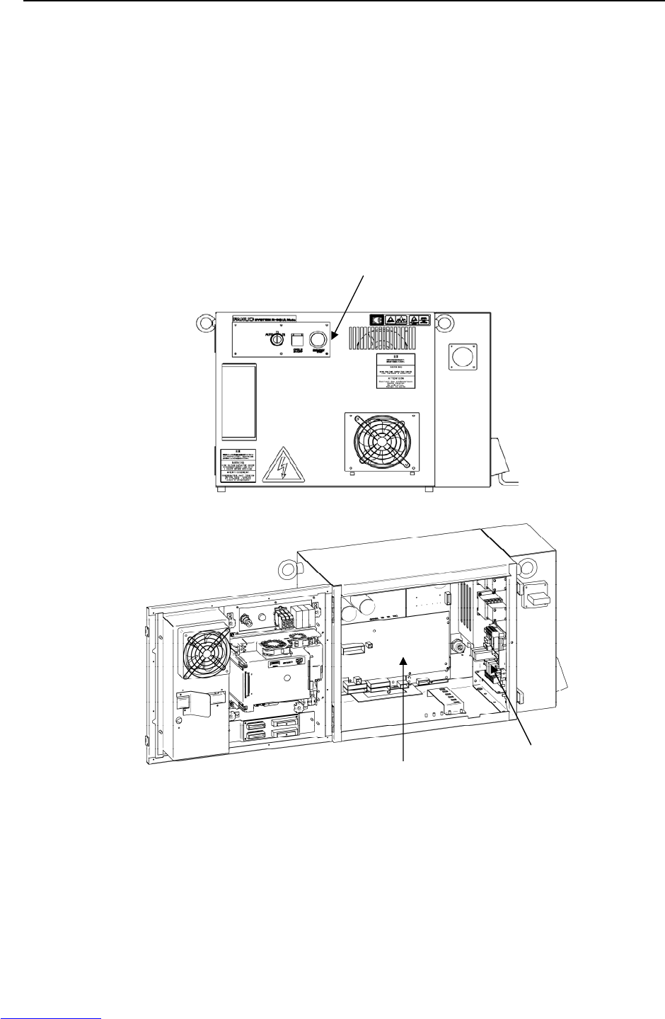
3.TROUBLESHOOTING MAINTENANCE B-82725EN-1/07
- 46 -
(65) SRVO-201 Panel E-stop or SVEMG abnormal
(Explanation) The EMERGENCY STOP button on the operator’s panel was pressed, but the
EMERGENCY STOP line was not disconnected.
(Action 1) With the E-stop in the released position, check for continuity across the terminals
of the switch. If continuity is not found, the emergency stop button is broken.
Replace the switch unit or the operator's panel.
Before executing the (Action 2), perform a complete controller back-up to save all
your programs and settings.
(Action 2) Replace the main board.
(Action 3) Replace the Servo amplifier.
(Action 4) Replace the E-stop board.
Fig.3.5 (v) SRVO-201 Panel E-stop or SVEMG abnormal
Emergency stop button
E-stop unit
Servo amplifier
Downloaded from www.Manualslib.com manuals search engine
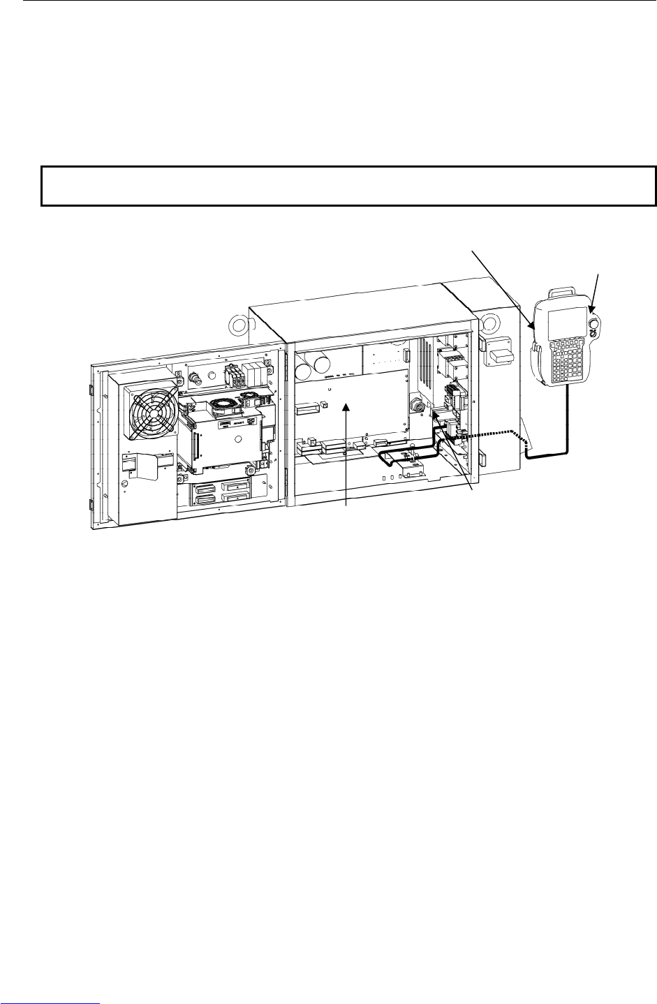
B-82725EN-1/07 MAINTENANCE 3.TROUBLESHOOTING
- 47 -
(66) SRVO-202 TP E-stop or SVEMG abnormal
(Explanation) The EMERGENCY STOP button on the teach pendant was pressed, but the
EMERGENCY STOP line was not disconnected.
(Action 1) Replace the teach pendant.
(Action 2) Check the teach pendant cable. If this inferior, replace the cable.
(Action 3) Replace the operator's panel.
(Action 4) Replace the E-stop unit.
(Action 5) Replace the servo amplifier.
NOTE
This alarm might occur if the EMERGENCY STOP button is pressed slowly.
Fig.3.5 (w) SRVO-202 TP E-stop or SVEMG abnormal
E-stop unit
Servo amplifier
Emergency stop button
Teach pendant
Downloaded from www.Manualslib.com manuals search engine
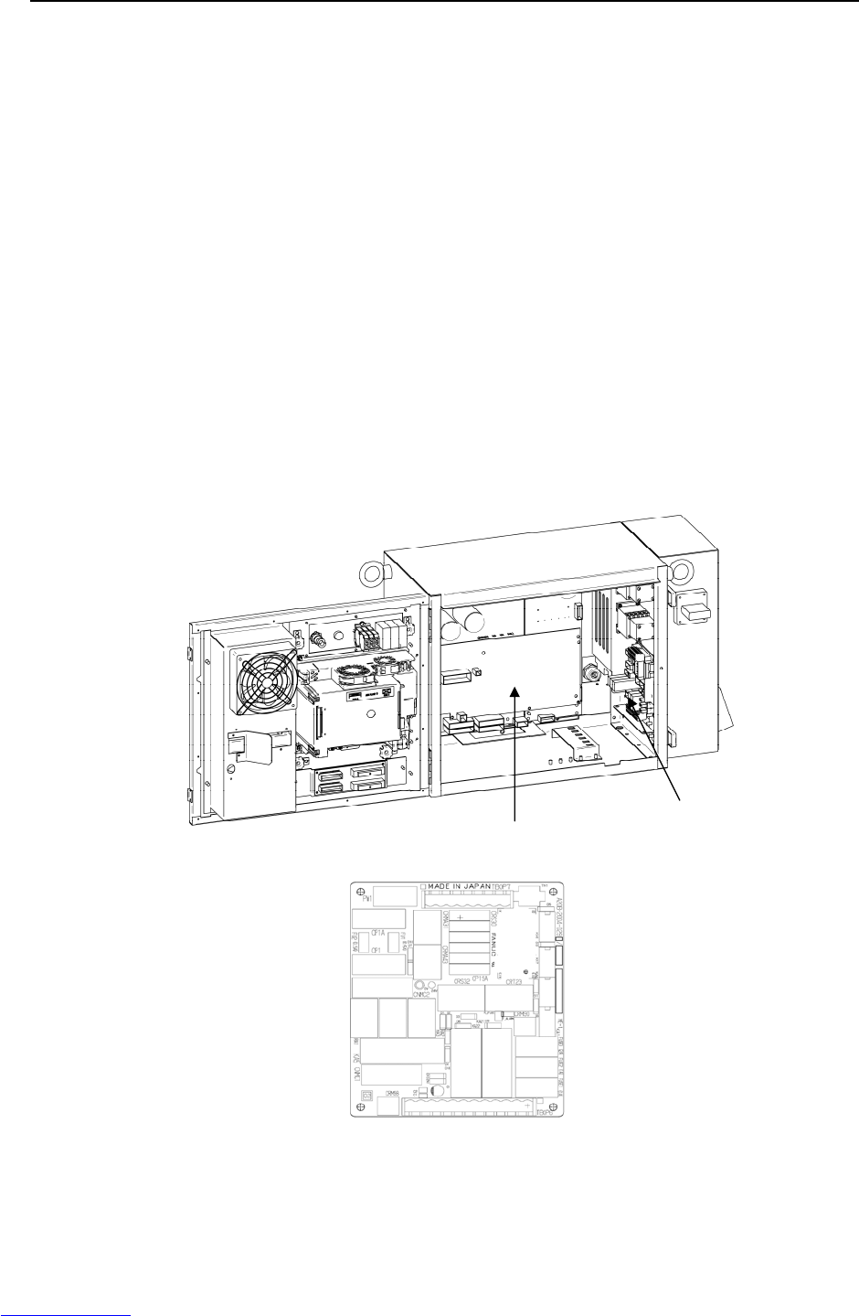
3.TROUBLESHOOTING MAINTENANCE B-82725EN-1/07
- 48 -
(67) SRVO-204 External (SVEMG abnormal) E-stop
(Explanation) The emergency stop line was not disconnected when the switch connected to the
external emergency stop contacts on the E-stop board was pressed.
Terminal connection: Between EES1 and EES11 and between EES2 and EES21
on the TBOP7 terminal board.
(Action 1) Check the switches and cables connected between terminals on the E-stop board
(between EES1 and EES11 and between EES2 and EES21 on TBOP7). If a
defective cable or switch is found, replace it.
(Action 2) Replace the E-stop unit.
(Action 3) Replace the servo amplifier.
(68) SRVO-205 Fence open (SVEMG abnormal)
(Explanation) The emergency stop line was not disconnected when the switch connected to the
safety fence contacts on the E-stop board was pressed.
Terminal connection: Between EAS1 and EAS11 and between EAS2 and EAS21
on the TBOP7 terminal board.
(Action 1) Check the switches and cables connected between terminals on the E-stop board
(between EAS1 and EAS11 and between EAS2 and EAS21 on TBOP7). If a
defective cable or switch is found, replace it.
(Action 2) Replace the E-stop unit.
(Action 3) Replace the servo amplifier.
(E-stop board)
Fig.3.5 (x) SRVO-204 External (SVEMG abnormal) E-stop
SRVO-205 Fence open (SVEMG abnormal)
E-stop unit
Servo amplifier
Downloaded from www.Manualslib.com manuals search engine
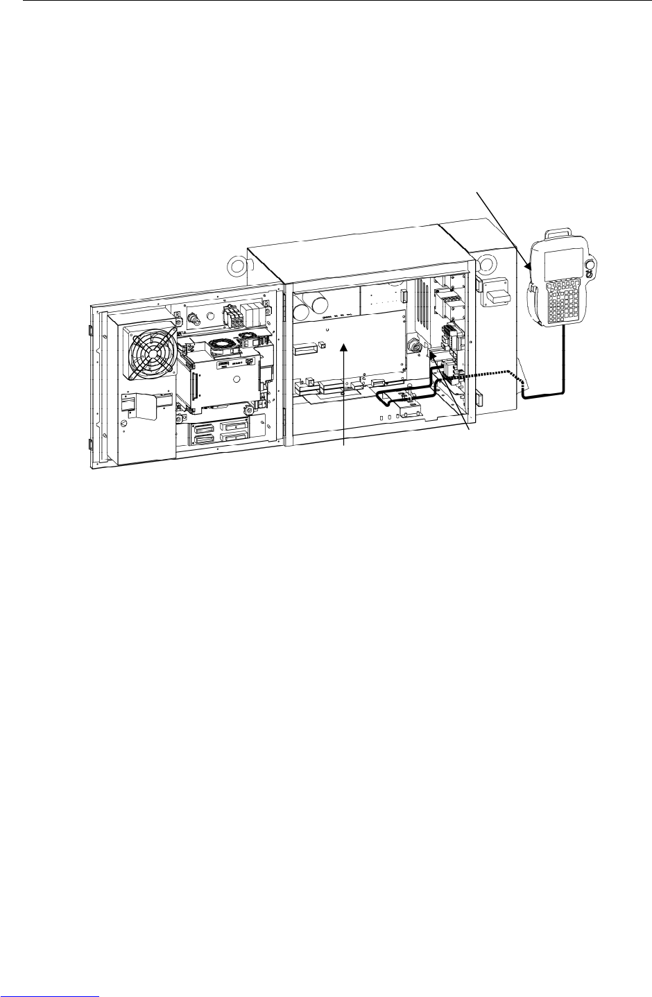
B-82725EN-1/07 MAINTENANCE 3.TROUBLESHOOTING
- 49 -
(69) SRVO-206 DEADMAN switch (SVEMG abnormal)
(Explanation) When the teach pendant was enabled, the DEADMAN switch was released or
pressed strongly, but the emergency stop line was not disconnected.
(Action 1) Replace the teach pendant.
(Action 2) Check the teach pendant cable. If it is inferior, replace the cable.
(Action 3) Replace the E-stop unit.
(Action 4) Replace the servo amplifier.
Fig.3.5 (y) SRVO-206 DEADMAN switch (SVEMG abnormal)
E-stop unit
Servo amplifier
Teach pendant
Downloaded from www.Manualslib.com manuals search engine

3.TROUBLESHOOTING MAINTENANCE B-82725EN-1/07
- 50 -
(70) SRVO-214 Fuse blown (Servo amplifier)
(Explanation) A fuse in the servo amplifier has blown.
In case that FS1 is blown
(Action 1) Replace the servo amplifier.
In case that FS2 or FS3 is blown
(Action 1) A fuse is blown, eliminate the cause, and then replace the fuse. (See Section 3.6 in
the Part II, “MAINTENANCE”.)
(Action 2) Replace the servo amplifier.
(71) SRVO-216 OVC (total) (Robot : i)
(Explanation) The current (total current for six axes) flowing through the motor is too large.
(Action 1) Slow the motion of the robot where possible. Check the robot operation conditions.
If the robot is used with a condition exceeding the duty or load weight robot rating,
reduce the load condition value to the specification range.
(Action 2) Check the input voltage to the controller is within the rated voltage and no phase is
lack. In addition, check the setting of the transformer is correct.
(Action 3) Replace the servo amplifier.
Fig.3.5 (z) SRVO-214 Fuse blown (servo amplifier)
SRVO-216 OVC (total)
Servo amplifier
Downloaded from www.Manualslib.com manuals search engine
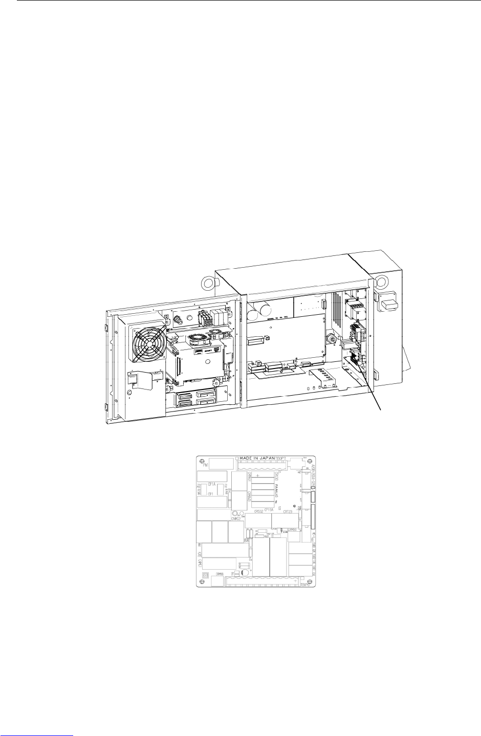
B-82725EN-1/07 MAINTENANCE 3.TROUBLESHOOTING
- 51 -
(72) SRVO-218 Ext.E-stop/ServoDisconnect
(Explanation) The switch connected across EES1 – EES11 and EES2 – EES21 on the TBOP7
terminal board on the E-stop board was pressed.
(Action 1) When the external emergency stop button is connected, release the button.
(Action 2) Check the switch and cable connected to EES1 – EES11 and EES2 – EES21 on
TBOP7 terminal board. If the cable is abnormal, replace it.
(Action 3) When this signal is not used, establish the short circuits between the contacts
(between EES1 – EES11 and between EES2 – EES21) on the terminal block of the
E-stop unit.
(Action 4) Replace the teach pendant.
(Action 5) Check the teach pendant cable. If this inferior, replace the cable.
(Action 6) Replace the E-stop unit.
Before executing the (Action 7), perform a complete controller back-up to save all
your programs and settings.
(Action 7) Replace the main board.
(E-stop board)
Fig.3.5 (aa) SRVO-218 Ext.E-stop/ServoDisconnect
E-stop unit
Downloaded from www.Manualslib.com manuals search engine
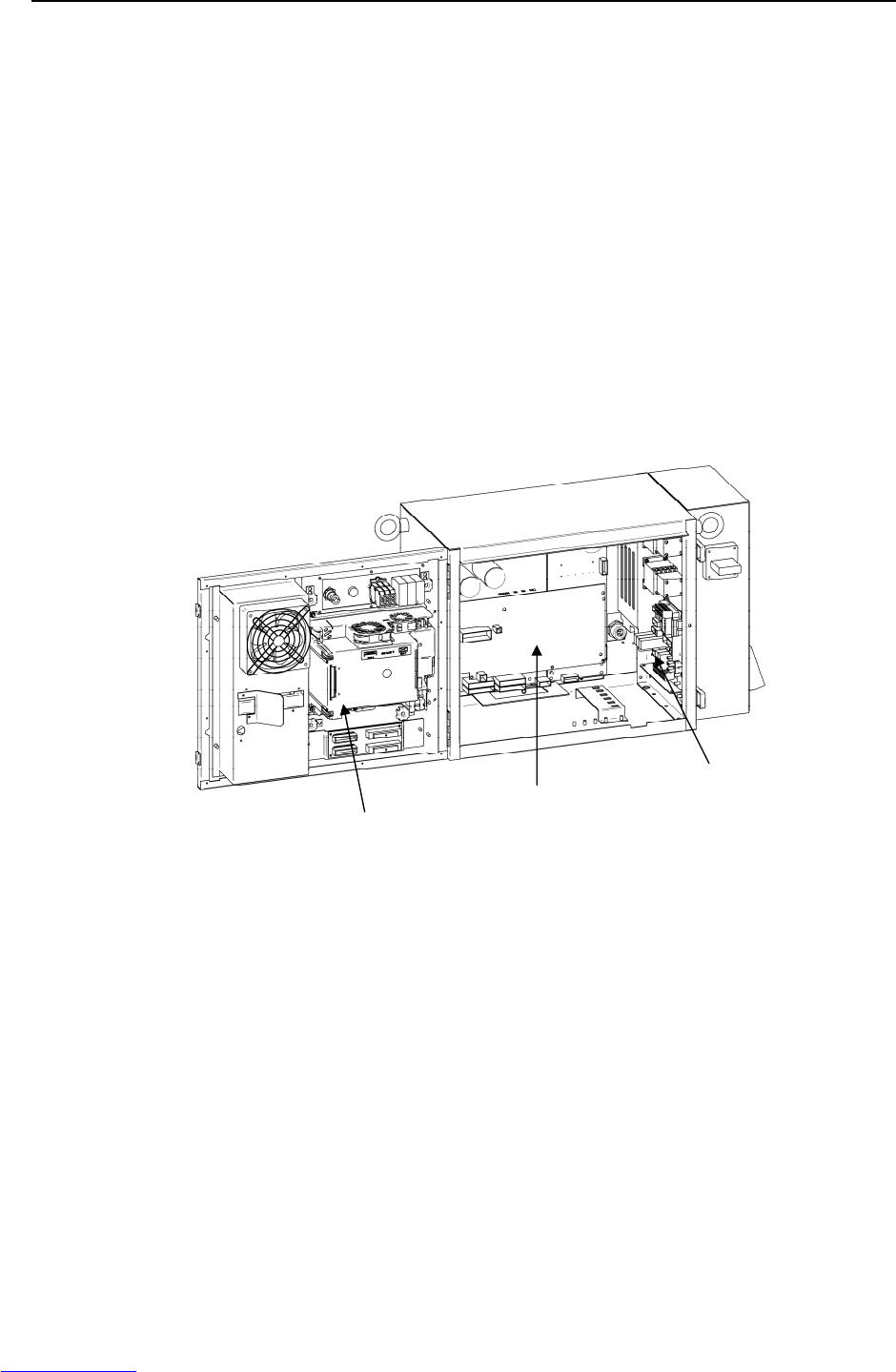
3.TROUBLESHOOTING MAINTENANCE B-82725EN-1/07
- 52 -
(73) SRVO-220 SDI fuse blown
(Explanation) A fuse (FUSE3) on the main board has blown.
(Action 1) Check whether the fuse (FUSE3) on the main board has blown. If the fuse has
blown, 24SDI may be short-circuited to 0V. Take Action 2.
(Action 2) Remove the cause of the 24SDI ground-fault, then check that FUSE3 does not
blow. Disconnect the following on the main board, then turn on the power.
- CRMA15
- CRMA16
If FUSE3 does not blow in this state, 24SDI and 0V may be short-circuited at any
of the above locations. Determine the faulty location, then take appropriate
action.
If FUSE3 still blows after the above are disconnected, take Action 3.
(Action 3) Disconnect CRS30. If FUSE3 still blows, replace the main board.
(Action 4) Replace the cable between the E-stop unit and servo amplifier.
(Action 5) Replace the cable between the main board and the E-stop unit.
(Action 6) Replace the E-stop unit.
(Action 7) Replace the servo amplifier
Fig.3.5 (ab) SRVO-220 SDI fuse blown
E-stop unit
Servo amplifier
Main board
Downloaded from www.Manualslib.com manuals search engine
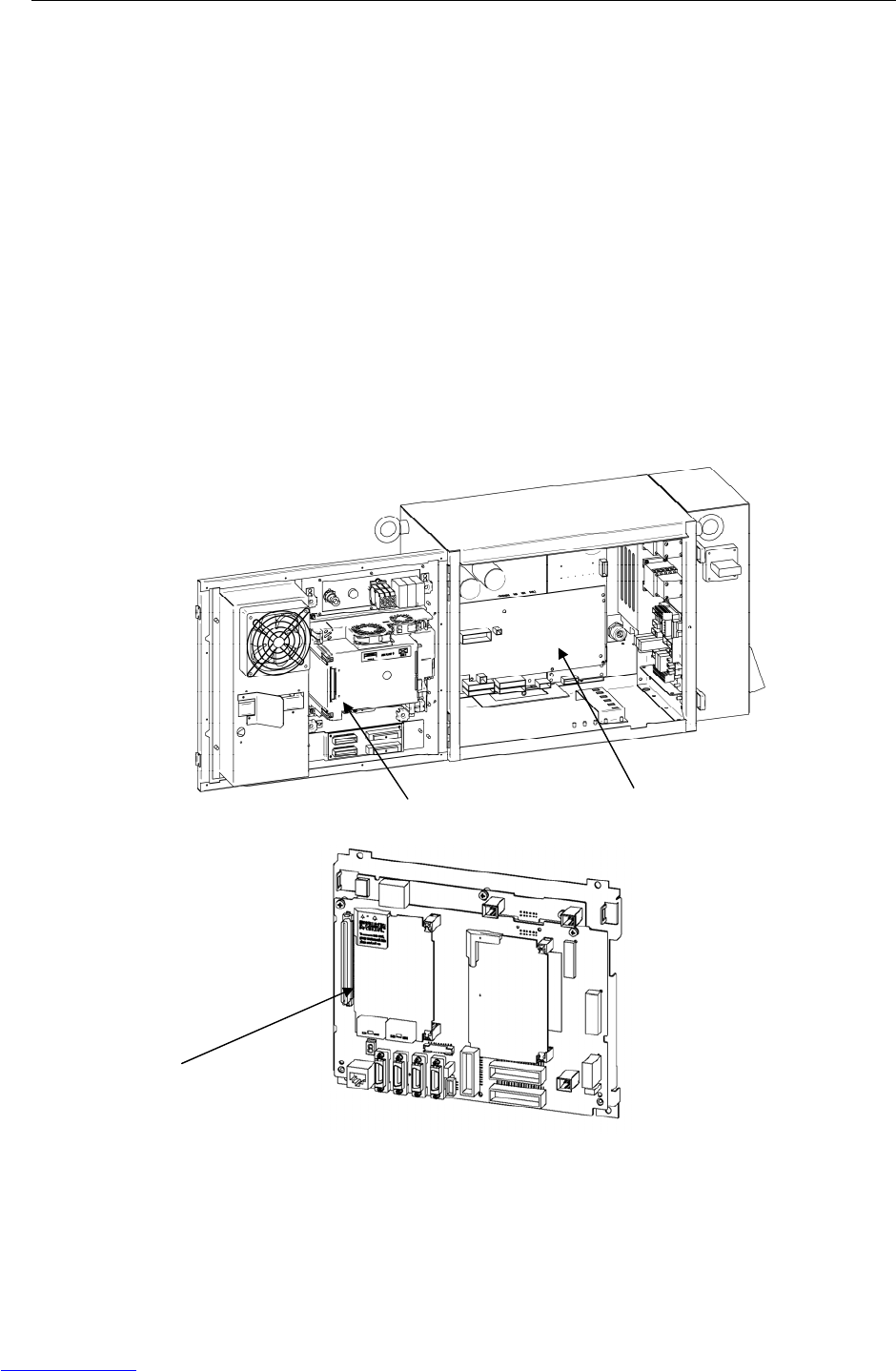
B-82725EN-1/07 MAINTENANCE 3.TROUBLESHOOTING
- 53 -
(74) SRVO-221 Lack of DSP (Group : i Axis : j)
(Explanation) A controlled axis card corresponding to the set number of axes is not mounted.
(Action 1) Check whether the set number of axes is valid. If the number is invalid, set the
correct number.
(Action 2) Replace the axis control card with a card corresponding to the set number of axes.
(75) SRVO-223 DSP dry run(a b)
(Explanation) Servo system initialization was stopped because of a hardware failure or improver
software setting. The controller has been started in the DSP dry run mode.
(Action 1) When the value is 1, 5, or 6: An incorrect setting is made. Check whether the
dry run mode is set and also check whether the setting of the hard start axis is
correct.
(Action 2) When the value is 2, 3, 4, or 7: Replace the servo card.
(Action 3) When the value is 8 or 10: Take action for an FSSB initialization error that has
occurred at the same time.
(Action 4) When the value is 9: Take the following action:
Check whether the servo amplifier is connected.
Replace the optical cable used for servo amplifier connection.
Replace the servo amplifier
(Main board)
Fig.3.5 (ac) SRVO-221 Lack of DSP
SRVO-223 DSP dry run(a b)
Main board
Axis control card
Servo amplifier
Downloaded from www.Manualslib.com manuals search engine
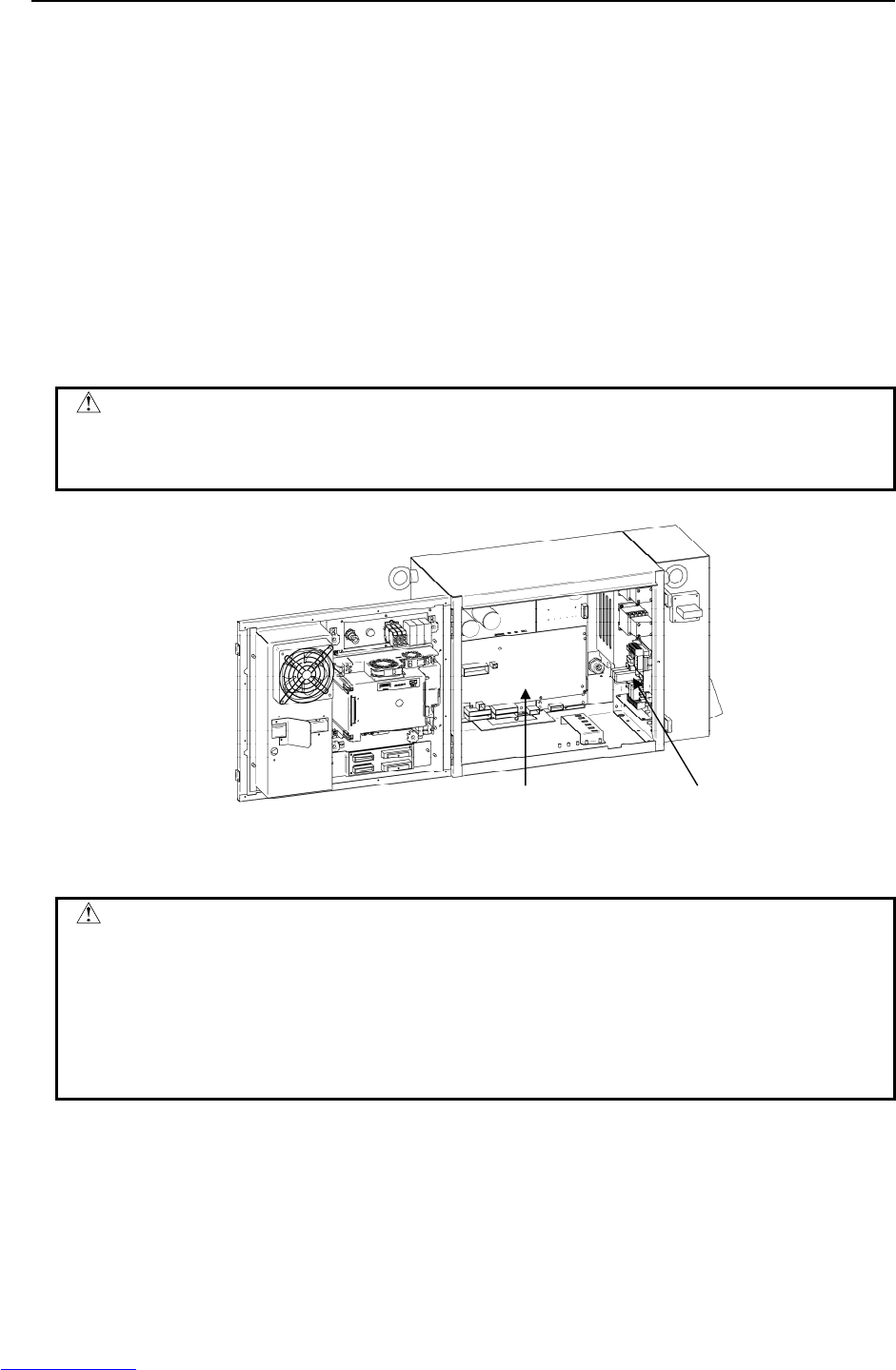
3.TROUBLESHOOTING MAINTENANCE B-82725EN-1/07
- 54 -
(76) SRVO-230 Chain 1 abnormal a,b
SRVO-231 Chain 2 abnormal a,b
(Explanation) A mismatch occurred between duplicate safety signals.
SRVO-230 is issued if such a mismatch that a contact connected on the chain 1
side (between EES1 and EES11, between EAS1 and EAS11, between SD4 and
SD41, and so forth) is closed, and a contact on the chain 2 side (between EES2 and
EES21, between EAS2 and EAS21, between SD5 and SD51, and so forth) is open
occurs. SRVO-231 is issued if such a mismatch that a contact on the chain 1 side
is open, and a contact on the chain 2 side is closed occurs.
If a chain error is detected, correct the cause of the alarm then reset the alarm
according to the method described later.
(Action) Check the alarms issued at the same time in order to identify with which signal the
mismatch occurred.
SRVO-266 through SRVO-275 and SRVO-370 through SRVO-385 are issued at
the same time. Take the action(s) described for each item.
WARNING
If this alarm is issued, do not reset the chain error alarm until the failure is
identified and repaired. If robot use is continued with one of the duplicate
circuits being faulty, safety may not be guaranteed when the other circuit fails.
Fig.3.5 (ad) SRVO-230 Chain 1 abnormal
SRVO-231 Chain 2 abnormal
CAUTION
1 The state of this alarm is preserved by software. After correcting the cause of the
alarm, reset the chain error alarm according to the chain error reset procedure
described later.
2 Until a chain error is reset, no ordinary reset operation must be performed. If
an ordinary reset operation is performed before chain error resetting, the
message "SRVO-237 Chain error cannot be reset" is displayed on the teach
pendant.
Alarm history display method
1. Press the screen selection key on the teach pendant.
2. Select [4 ALARM] on the teach pendant.
3. Press F3 [HIST] on the teach pendant.
E-stop unit Servo amplifier
Downloaded from www.Manualslib.com manuals search engine

B-82725EN-1/07 MAINTENANCE 3.TROUBLESHOOTING
- 55 -
Chain error reset procedure
CAUTION
Do not perform this operation until the cause of the alarm is corrected.
<Method 1>
1. Press the emergency stop button.
2. Press the screen selection key on the teach pendant.
3. Select [0 NEXT PAGE] on the teach pendant.
4. Press [6 SYSTEM] on the teach pendant.
5. Press [7 SYSTEM SETTING] on the teach pendant.
6. Find "28" Chain Error Reset Execution.
7. Press F3 on the teach pendant to reset "Chain Error".
<Method 2>
1. Press the screen selection key on the teach pendant.
2. Select [4 ALARM] on the teach pendant.
3. Press F4 [CHAIN RESET] on the teach pendant.
(77) SRVO-233 TP disabled in T1, T2/Door open
(Explanation) Teach pendant is disabled when the mode switch is T1 or T2.
(Action 1) Enable the teach pendant in teaching operation. In other case the mode switch
should be AUTO mode.
(Action 2) Replace the teach pendant.
(Action 3) Replace the teach pendant cable.
(Action 4) Replace the mode switch.
(Action 5) Replace the E-stop unit.
(Action 6) Replace the servo amplifier.
(78) SRVO-235 Short term Chain abnormal
(Explanation) Short term single chain failure condition is detected.
• Cause of this alarm is ;
- Half release of DEADMAN switch
- Half operation of emergency stop switch.
(Action 1) Cause the same error to occur again, then perform resetting.
(Action 2) Replace the E-stop unit.
(Action 3) Replace the servo amplifier.
E-stop unit
Servo amplifier
Emergency stop button
Teach pendant
Downloaded from www.Manualslib.com manuals search engine
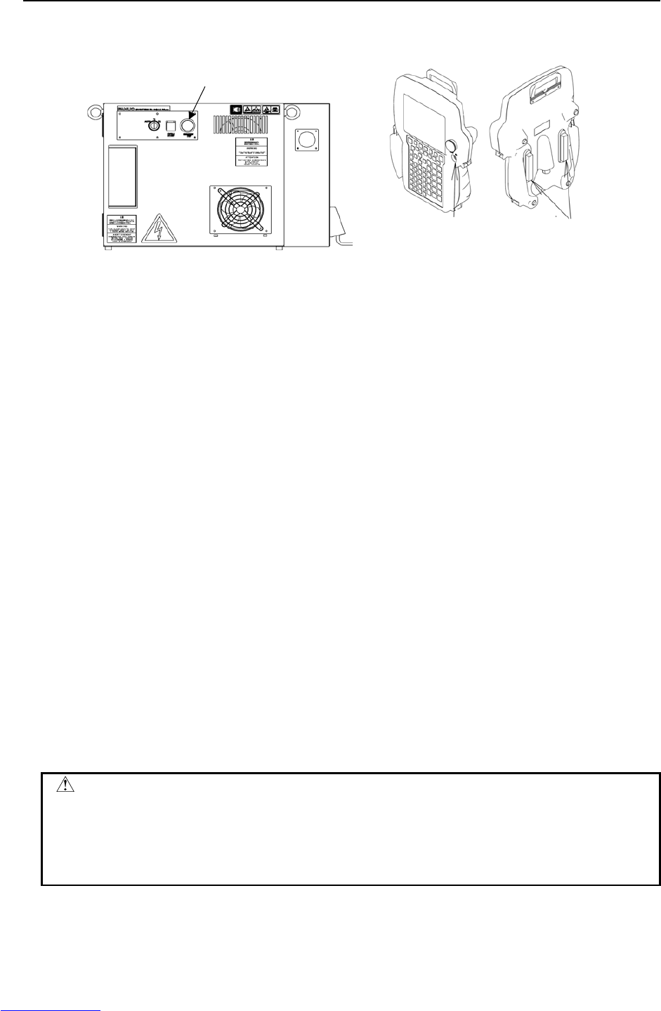
3.TROUBLESHOOTING MAINTENANCE B-82725EN-1/07
- 56 -
Emergency stop button
Enable switch Deadman switch
(Teach pendant)
Fig.3.5 (ae) SRVO-233 TP disabled in T1, T2/Door open
SRVO-235 Short term Chain abnormal
(79) SRVO-251 DB relay abnormal
(Explanation) An abnormality was detected in the internal relay (DB relay) of the servo
amplifier.
(Action) Replace the servo amplifier.
(80) SRVO-252 Current detect abnl
(Explanation) An abnormality was detected in the current detection circuit inside the servo
amplifier.
(Action) Replace the servo amplifier.
(81) SRVO-253 Amp internal over heat
(Explanation) An overheat was detected inside the servo amplifier.
(Action) Replace the servo amplifier.
(82) SRVO-266 FENCE1 status abnormal
SRVO-267 FENCE2 status abnormal
(Explanation) A chain alarm was detected with the EAS (FENCE) signal.
(Action 1) Check whether the circuitry connected to the dual input signal (EAS) is faulty.
(Action 2) Check whether the timing of the dual input signal (EAS) satisfies the timing
specification (See Section 3.2.5, Table 3.2.5 of Part III CONNECTIONS).
Before executing the (Action 3), perform a complete controller back-up to save all
your programs and settings.
(Action 3) Replace the main board.
(Action 4) Replace the E-stop unit.
CAUTION
1 For the procedure of recovery from this alarm, see the descriptions of SRVO-230
and SRVO-231.
2 If this alarm is issued, do not reset the chain error alarm until the failure is
checked and corrected. If robot use is continued with one of the duplicate
circuits being faulty, safety may not be guaranteed when the other circuit fails.
Downloaded from www.Manualslib.com manuals search engine

B-82725EN-1/07 MAINTENANCE 3.TROUBLESHOOTING
- 57 -
(83) SRVO-270 EXEMG1 status abnormal
SRVO-271 EXEMG2 status abnormal
(Explanation) A chain alarm was detected with the EES (EXEMG) signal.
(Action 1) Check whether the circuitry connected to the dual input signal (EES) is faulty.
(Action 2) Check whether the timing of the dual input signal (EES) satisfies the timing
specification
(See Section 3.2.5, Table 3.2.5 of Part III CONNECTIONS).
(Action 3) Check the teach pendant cable. If this inferior, replace the cable.
(Action 4) Replace the teach pendant.
(Action 5) Check the emergency stop button connection and operation. If trouble is found,
replace the emergency stop button.
(Action 6) Replace the E-stop unit.
Before executing the (Action 7), perform a complete controller back-up to save all
your programs and settings.
(Action 7) Replace the main board.
CAUTION
1 For the procedure of recovery from this alarm, see the descriptions of SRVO-230
and SRVO-231.
2 If this alarm is issued, do not reset the chain error alarm until the failure is
checked and corrected. If robot use is continued with one of the duplicate
circuits being faulty, safety may not be guaranteed when the other circuit fails.
Downloaded from www.Manualslib.com manuals search engine
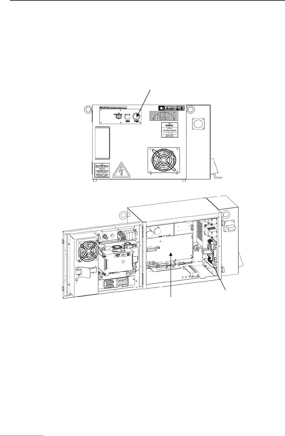
3.TROUBLESHOOTING MAINTENANCE B-82725EN-1/07
- 58 -
(84) SRVO-277 Panel E-stop(SVEMG abnormal)
(Explanation) The E-stop line was not disconnected although the emergency stop button on the
operator's panel was pressed.
Before executing the (Action 1), perform a complete controller back-up to save all
your programs and settings.
(Action 1) Replace the main board.
(Action 2) Replace the E-stop unit
(Action 3) Replace the servo amplifier.
Fig.3.5 (af) SRVO-251 DB relay abnormal
SRVO-252 Current detect abnl
SRVO-253 Amp internal over heat
SRVO-266 FENCE1 status abnormal
SRVO-267 FENCE2 status abnormal
SRVO-270 EXEMG1 status abnormal
SRVO-271 EXEMG2 status abnormal
SRVO-277 Panel E-stop(SVEMG abnormal)
E-stop unit
Servo amplifier
Emergency stop button
Downloaded from www.Manualslib.com manuals search engine
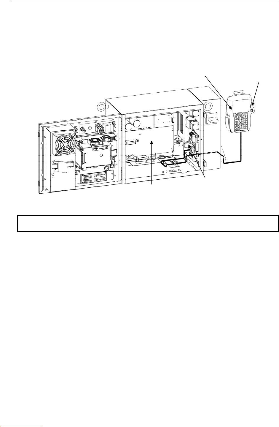
B-82725EN-1/07 MAINTENANCE 3.TROUBLESHOOTING
- 59 -
(85) SRVO-278 TP E-stop(SVEMG abnormal)
(Explanation) The emergency stop line was not disconnected although the emergency stop button
on the teach pendant was pressed.
(Action 1) Replace the teach pendant.
(Action 2) Replace the teach pendant cable.
(Action 3) Replace the E-stop unit.
(Action 4) Replace the servo amplifier.
NOTE
This alarm may be issued if the emergency stop button is pressed very slowly.
Fig.3.5 (ag) SRVO-278 TP E-stop(SVEMG abnormal)
E-stop unit
Servo amplifier
Emergency stop button
Teach pendant
Downloaded from www.Manualslib.com manuals search engine
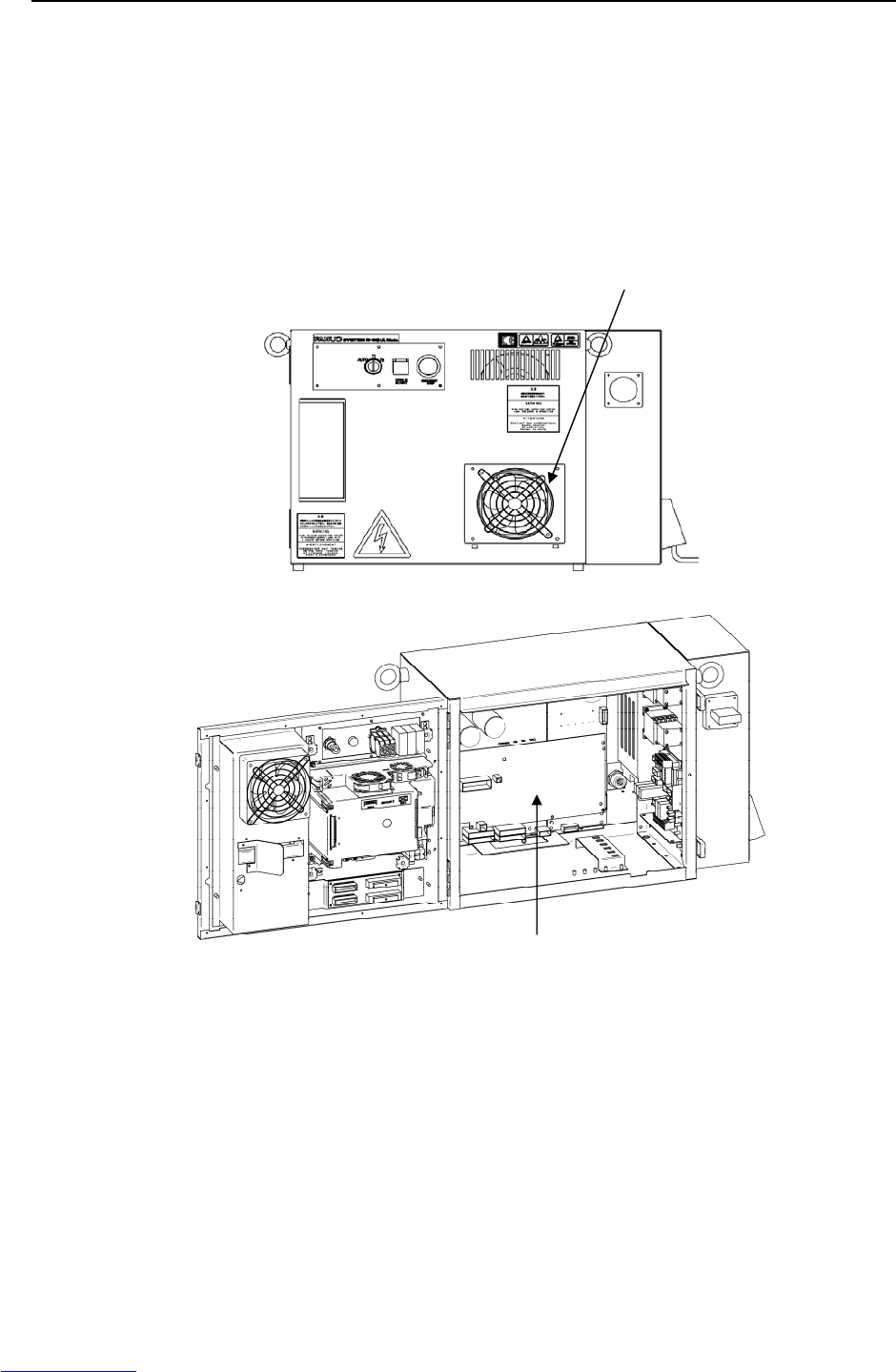
3.TROUBLESHOOTING MAINTENANCE B-82725EN-1/07
- 60 -
(86) SRVO-291 IPM over heat (G:i A:j)
(Explanation) IPM on the servo amplifier is overheated.
(Action 1) Check whether the fan for cabinet ventilation is stopped and also check whether
the vent hole is clogged. If necessary, clean or replace them.
(Action 2) If SRVO-291 is issued when the robot operating condition is severe, check the
robot operating condition then relax the condition when possible.
(Action 3) If SRVO-291 is issued frequently, replace the servo amplifier.
Fig.3.5 (ah) SRVO-291 IPM over heat
(87) SRVO-300 Hand broken/HBK disabled
SRVO-302 Set Hand broken to ENABLE
(Explanation) Although HBK was disabled, the HBK signal was input.
(Action 1) Press RESET on the teach pendant to release the alarm.
(Action 2) Check whether the hand broken signal is connected to the robot. When the hand
broken signal circuit is connected, enable hand broken. (See Subsection 5.6.4 in
Part III, “CONNECTIONS”.)
Servo amplifier
Fan unit
Downloaded from www.Manualslib.com manuals search engine
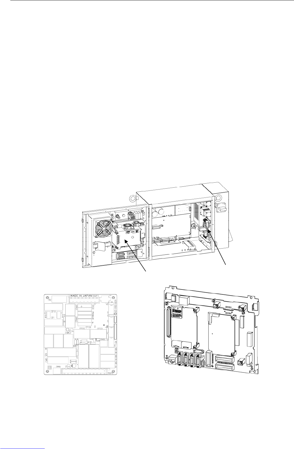
B-82725EN-1/07 MAINTENANCE 3.TROUBLESHOOTING
- 61 -
(88) SRVO-335 DCS OFFCHK alarm a,b
(Explanation) A failure was detected in the safety signal input circuit.
(Action 1) Replace the E-stop board.
(Action 2) Replace the main board.
(89) SRVO-348 DCS MCC OFF alarm a,b
(Explanation) A command was issued to turn off the magnetic contactor, but the magnetic
contactor was not turned off.
(Action 1) Replace the E-stop unit.
Before executing the (Action 2), perform a complete controller back-up to save all
your programs and settings.
(Action 2) Replace the main board.
(90) SRVO-349 DCS MCC ON alarm a,b
(Explanation) A command was issued to turn on the magnetic contactor, but the magnetic
contactor was not turned on.
(Action 1) Replace the E-stop unit.
Before executing the (Action 2), perform a complete controller back-up to save all
your programs and settings.
(Action 2) Replace the main board.
(Action 3) Replace the servo amplifier.
(E-stop board) (Main board)
Fig.3.5 (ai) SRVO-335 DCS OFFCHK alarm a,b
SRVO-348 DCS MCC OFF alarm a,b
SRVO-349 DCS MCC ON alarm a,b
Main board E-stop unit
Downloaded from www.Manualslib.com manuals search engine
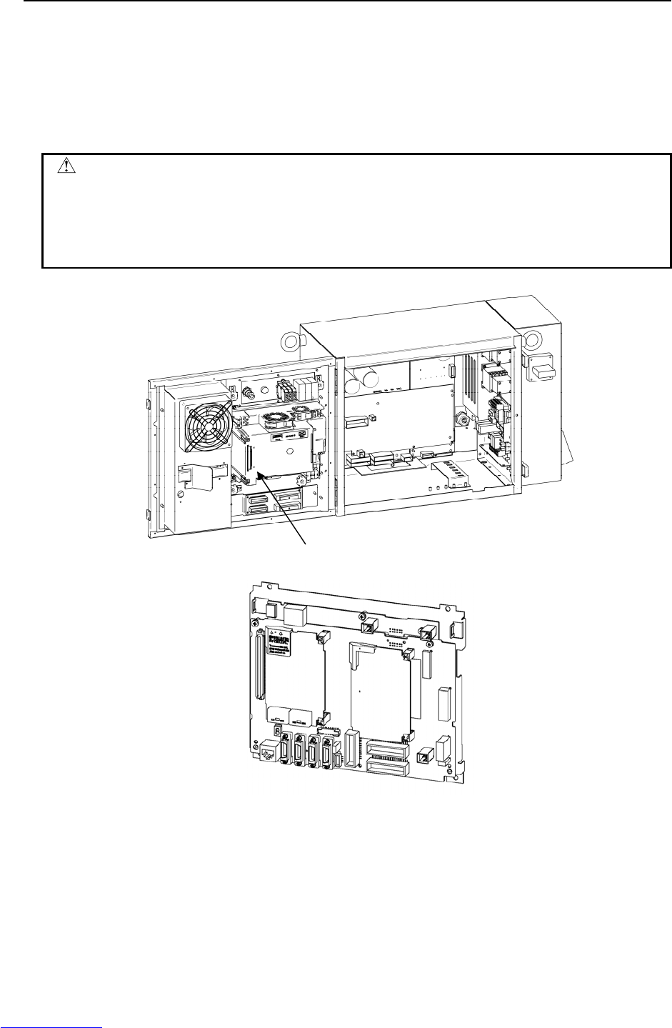
3.TROUBLESHOOTING MAINTENANCE B-82725EN-1/07
- 62 -
(91) SRVO-370 SVON1 status abnormal a,b
SRVO-371 SVON2 status abnormal a,b
(Explanation) A chain alarm was detected with the main board internal signal (SVON).
Before executing the (Action), perform a complete controller back-up to save all
your programs and settings.
(Action) Replace the main board.
CAUTION
1 For the procedure of recovery from this alarm, see the descriptions of SRVO-230
and SRVO-231.
2 If this alarm is issued, do not reset the chain error alarm until the failure is
checked and corrected. If robot use is continued with one of the duplicate
circuits being faulty, safety may not be guaranteed when the other circuit fails.
(Main board)
Fig.3.5 (aj) SRVO-370 SVON1 status abnormal a,b
SRVO-371 SVON2 status abnormal a,b
Main board
Downloaded from www.Manualslib.com manuals search engine

B-82725EN-1/07 MAINTENANCE 3.TROUBLESHOOTING
- 63 -
(92) SRVO-372 OPEMG1 status abnormal a, b
SRVO-373 OPEMG2 status abnormal a, b
(Explanation) A chain alarm was detected with the E-stop switch on the operator's panel.
(Action 1) Check the emergency stop button connection and operation. If trouble is found,
replace the emergency stop button.
(Action 2) Replace the E-stop board.
Before executing the (Action 3), perform a complete controller back-up to save all
your programs and settings.
(Action 3) Replace the main board.
CAUTION
1 For the procedure of recovery from this alarm, see the descriptions of SRVO-230
and SRVO-231.
2 If this alarm is issued, do not reset the chain error alarm until the failure is
checked and corrected. If robot use is continued with one of the duplicate
circuits being faulty, safety may not be guaranteed when the other circuit fails.
(E-stop board)
Fig.3.5 (ak) SRVO-372 OPEMG1 status abnormal a,b
E-stop board
Teach pendant
Emergency stop button
Downloaded from www.Manualslib.com manuals search engine
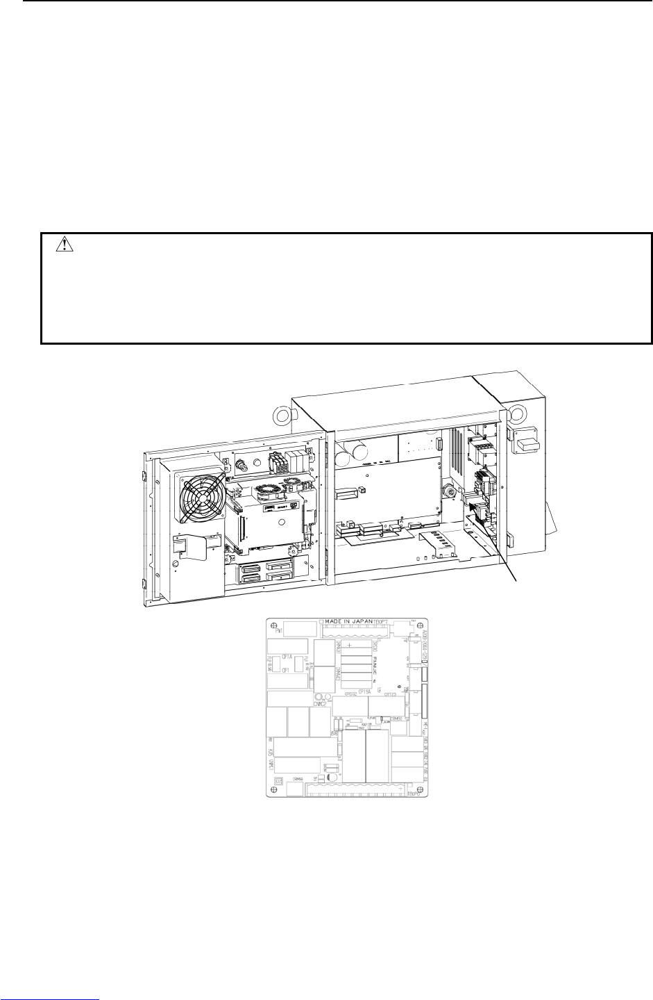
3.TROUBLESHOOTING MAINTENANCE B-82725EN-1/07
- 64 -
(93) SRVO-374 MODE11 status abnormal a,b
SRVO-375 MODE12 status abnormal a,b
SRVO-376 MODE21 status abnormal a,b
SRVO-377 MODE22 status abnormal a,b
(Explanation) A chain alarm was detected with the mode switch signal.
(Action 1) Check the mode switch connection and operation. If trouble is found, replace the
mode switch.
Before executing the (Action 2), perform a complete controller back-up to save all
your programs and settings.
(Action 2) Replace the main board.
(Action 3) Replace the E-stop board.
CAUTION
1 For the procedure of recovery from this alarm, see the descriptions of SRVO-230
and SRVO-231.
2 If this alarm is issued, do not reset the chain error alarm until the failure is
checked and corrected. If robot use is continued with one of the duplicate
circuits being faulty, safety may not be guaranteed when the other circuit fails.
(E-stop board)
Fig.3.5 (al) SRVO-374 MODE11 status abnormal a,b
SRVO-375 MODE12 status abnormal a,b
SRVO-376 MODE21 status abnormal a,b
SRVO-377 MODE22 status abnormal a,b
E-stop board
Downloaded from www.Manualslib.com manuals search engine
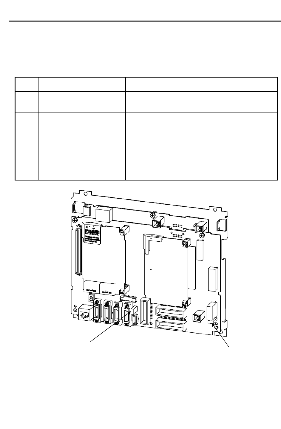
B-82725EN-1/07 MAINTENANCE 3.TROUBLESHOOTING
- 65 -
3.6 FUSE-BASED TROUBLESHOOTING
This section describes the alarms and symptoms generated and actions required when the fuses installed
on the printed circuit boards and units have blown.
(1) Fuses on the main board
FUSE1: For protecting the +24V output
FUSE3: For protecting the +24V output of the peripheral device interface
Name Symptom observed when fuse
has blown Action
FUSE1 The teach pendant becomes
inoperative, and all LEDs on the main
board go off.
1. Replace the backplane board.
2. Replace the main board.
FUSE3 An alarm (SRVO-220) is displayed on
the teach pendant.
1. 24SDI and 0 V may be short-circuited. Check the peripheral
device cable for any abnormality, and replace it if necessary.
2. Disconnect CRS30. If FUSE3 still blows, replace the main
board.
3. Replace the cable between the emergency stop unit and the
servo amplifier.
4. Replace the cable between the main board and the
emergency stop unit.
5. Replace the emergency stop unit.
6. Replace the servo amplifier.
Fig.3.6 (a) Fuses on the main board
FUSE1 (5A)
FUSE3 (1A)
Downloaded from www.Manualslib.com manuals search engine
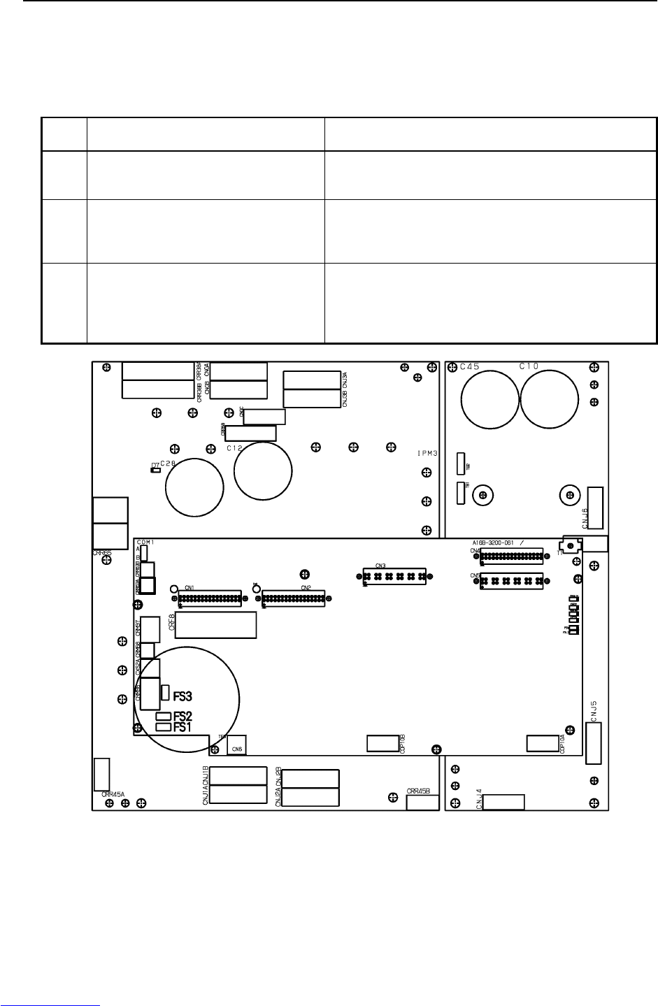
3.TROUBLESHOOTING MAINTENANCE B-82725EN-1/07
- 66 -
(2) Fuses on the Servo amplifier
FS1: For generation of the power to the amplifier control circuit
FS2: For protection of the 24V output to the end effector, ROT, and HBK
FS3: For protection of the 24V output to the regenerative resistance and the additional
axis amplifier
Name Symptom observed when fuse has
blown Action
FS1 All LEDs on the servo amplifier go out.
The FSSB disconnection or initialization
alarm is displayed on the teach pendant.
Replace the servo amplifier.
FS2 The Fuse Blown (Amp) alarm
(SRVO-214), Hand broken (SRVO-006),
and ROBOT OVER TRAVEL are displayed
on the teach pendant.
1 Check +24VF used by the end effector for a ground fault.
2 Check the robot connection cable and the robot’s internal
cable.
3 Replace the servo amplifier.
FS3 The Fuse Blown (Amp) alarm (SRVO-214)
and DCAL are displayed on the teach
pendant.
1 Check the regenerative resistance, and replace it if
required.
2 Check the additional axis amplifier and its wiring, and
replace them if required.
3 Replace the servo amplifier.
5A
3.2A
3.2A
CRR88
Fig.3.6 (b) Fuses on the servo amplifier
Downloaded from www.Manualslib.com manuals search engine
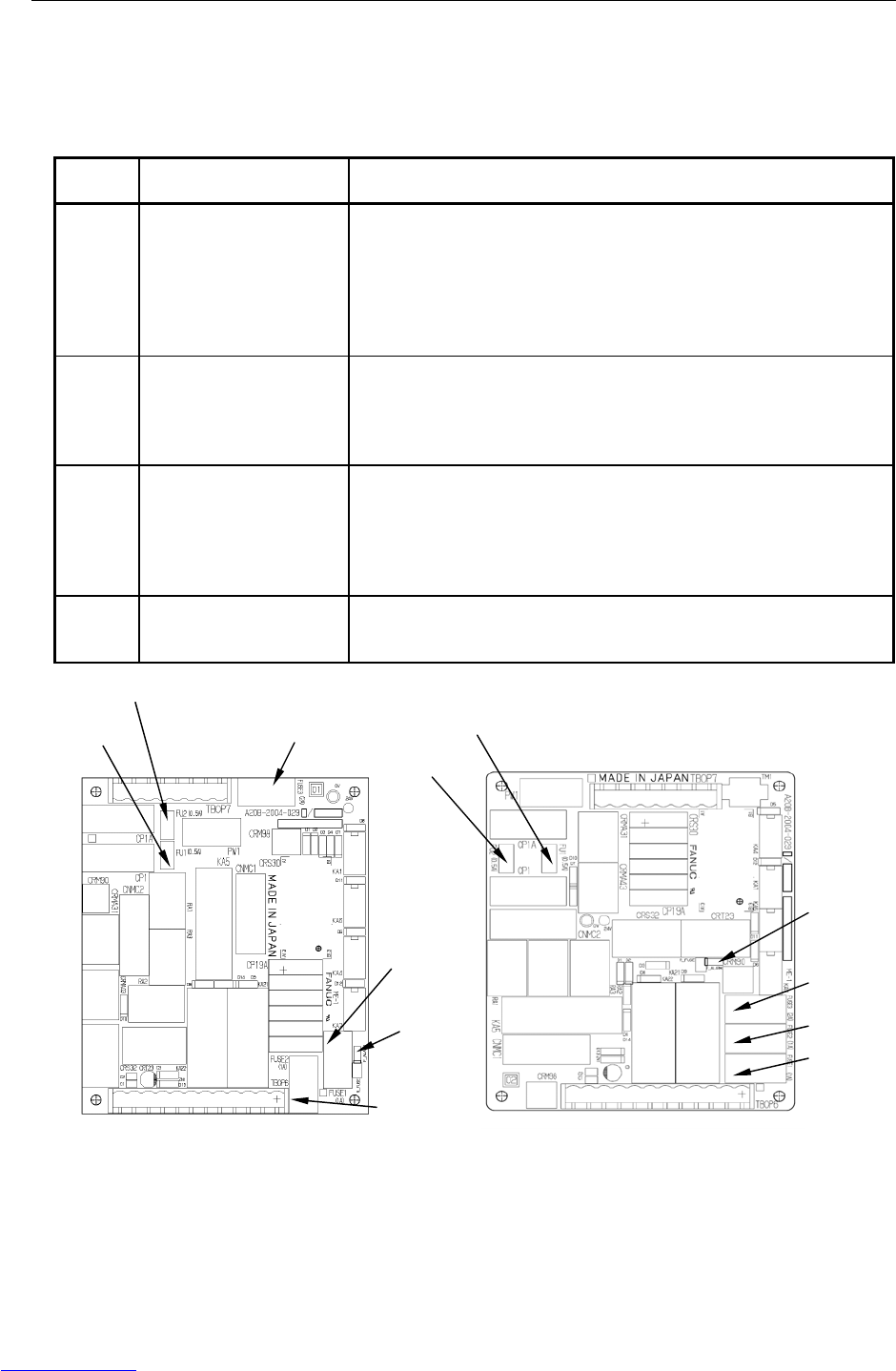
B-82725EN-1/07 MAINTENANCE 3.TROUBLESHOOTING
- 67 -
(3) Fuses on the E-stop board
FUSE1: For protecting +24EXT for the emergency stop circuit
FUSE2: For protecting +24V for the teach pendant
FUSE3: For protecting +24V
FU1 and FU2: For protecting input for the door fan
Name Symptom observed when
fuse has blown Action
FUSE1 Alarm (SRVO-218) is
displayed on the teach
pendant, and the LED (red)
on the emergency stop
board lights.
1. If an alarm is issued when the fuse has not blown, check the voltages of
EXT24V and EXT0V (TBOP6). If external 24V or 0V is not used,
check the jumper pin between EXT24V and INT24V or between EXT0V
and INT0V.
2. Check the +24EXT line (emergency stop line) for a short circuit or
connection to ground.
3. Replace the emergency stop board.
FUSE2 The display on the teach
pendant disappears, and
the LED (red) on the
emergency stop board
lights.
1. Check the teach pendant cable for any abnormality, and replace it if
necessary.
2. Check the teach pendant for any abnormality, and replace it if
necessary.
3. Replace the emergency stop board.
FUSE3 An alarm relating to an
input signal that causes an
emergency stop is issued,
and the LED (red) on the
emergency stop board
lights.
1. Check the connections on TBOP7.
2. Check the cable between the emergency stop board and the main
board for any abnormality, and replace it if necessary.
3. Replace the main board.
4. Replace the emergency stop board.
FU1, FU2 The fan stops.
The teach pendant cannot
be operated.
1. Check the fan cable for any abnormality, and replace it if necessary.
2. Replace the fan unit.
3. Replace the emergency stop board.
(Edition 01A) (Edition 02A or later)
Fig.3.6 (c) Fuses on the emergency stop board
FU1 (0.5A) FUSE3 (2A)
FUSE1 (1A)
FUSE2 (1A)
FU2 (0.5A)
LED (Red)
FU1 (0.5A)
FU2 (0.5A)
FUSE1 (1A)
FUSE2 (1A)
FUSE3 (2A)
LED (Red)
Downloaded from www.Manualslib.com manuals search engine
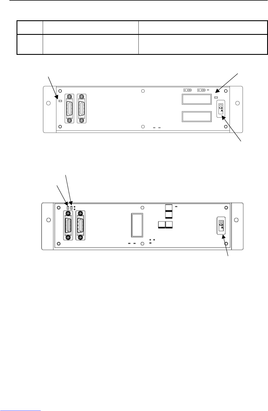
3.TROUBLESHOOTING MAINTENANCE B-82725EN-1/07
- 68 -
(4) Fuse FUSE1 on the process I/O board (for +24E)
Name Symptom observed when fuse has
blown Action
FUSE1 The LED (ALM1 or FALM) the process I/O
board lights.
1. Check if the cables and peripheral devices connected
to the process I/O board are normal.
2. Replace the process I/O board.
FUSE1 (1A)
LED:FALM(Red)
LED:ALM1(Red)
Fig.3.6 (d) Fuse on the process I/O board MA
LED:ALM1 (Red)
LED:FALM (Red)
FUSE1 (1A)
Fig.3.6 (e) Fuse on the process I/O board MB
Downloaded from www.Manualslib.com manuals search engine
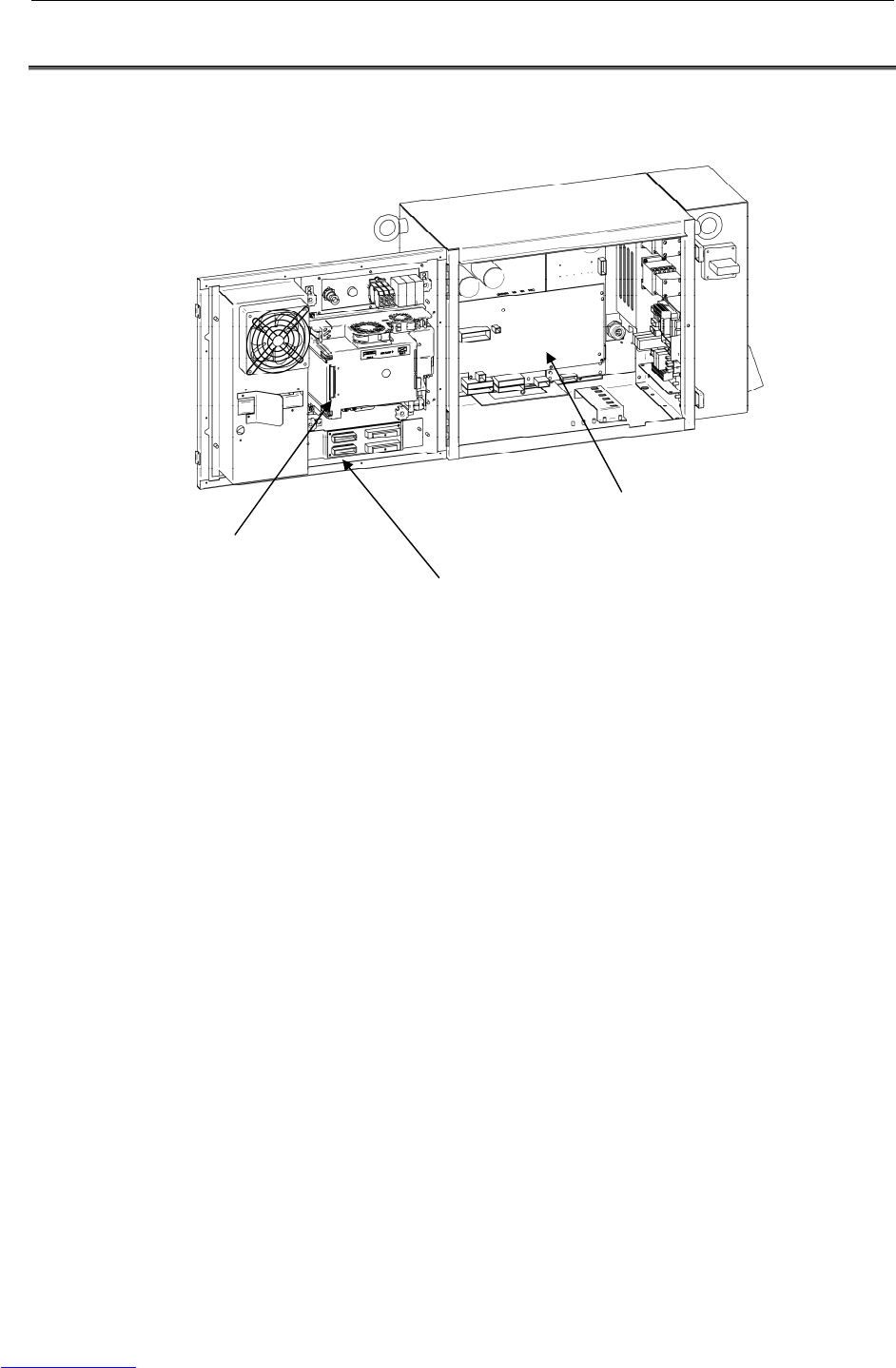
B-82725EN-1/07 MAINTENANCE 3.TROUBLESHOOTING
- 69 -
3.7 TROUBLESHOOTING BASED ON LED INDICATIONS
The main board and servo amplifier are provided with alarm LEDs and status LEDs. The LED status
and corresponding troubleshooting procedures are described below.
Fig.3.7 (a) Location of status LEDs
Main board
Servo am
p
lifie
r
Process I/O board
Downloaded from www.Manualslib.com manuals search engine

3.TROUBLESHOOTING MAINTENANCE B-82725EN-1/07
- 70 -
TROUBLESHOOTING USING THE LEDS ON THE MAIN BOARD
(1) Troubleshooting using the status display LED
To troubleshoot an alarm that arises before the teach pendant is ready to display, check the status
LEDs (green) on the main board at power-on. After power-on, the LEDs light as described in steps
1 to end, in the order described. If an alarm is detected, the step in which the alarm occurred can be
determined from which LEDs are lit.
■:On
□:Off
☆:Blink
Step LED Action to be taken
1: After power-on, all
LEDs are lit.
[Action1] Replace the CPU card.
* [Action2] Replace the main board.
2: Software operation
start-up.
[Action1] Replace the CPU card.
* [Action2] Replace the main board.
3: The initialization of
dram on the CPU
card is completed.
[Action1] Replace the CPU card.
* [Action2] Replace the main board.
4: The initialization of
DPRAM on the
communication IC is
completed.
[Action1] Replace the CPU card.
* [Action2] Replace the main board.
* [Action3] Replace the FROM/SRAM module.
5: The initialization of
the communication
IC is completed.
[Action1] Replace the CPU card.
* [Action2] Replace the main board.
* [Action3] Replace the FROM/SRAM module.
6: The loading of the
basic software is
completed.
* [Action1] Replace the main board.
* [Action2] Replace the FROM/SRAM module.
7: Basic software
start-up.
[Action1] Check the fuse (FU1) on the emergency stop
board.
[Action2] Check the connection of CP1 connector on the
emergency stop board.
[Action3] Replace the emergency stop board.
* [Action4] Replace the main board.
* [Action5] Replace the FROM/SRAM module.
8: Start-up of
communication with
the teach pendant.
* [Action1] Replace the main board.
* [Action2] Replace the FROM/SRAM module.
Downloaded from www.Manualslib.com manuals search engine
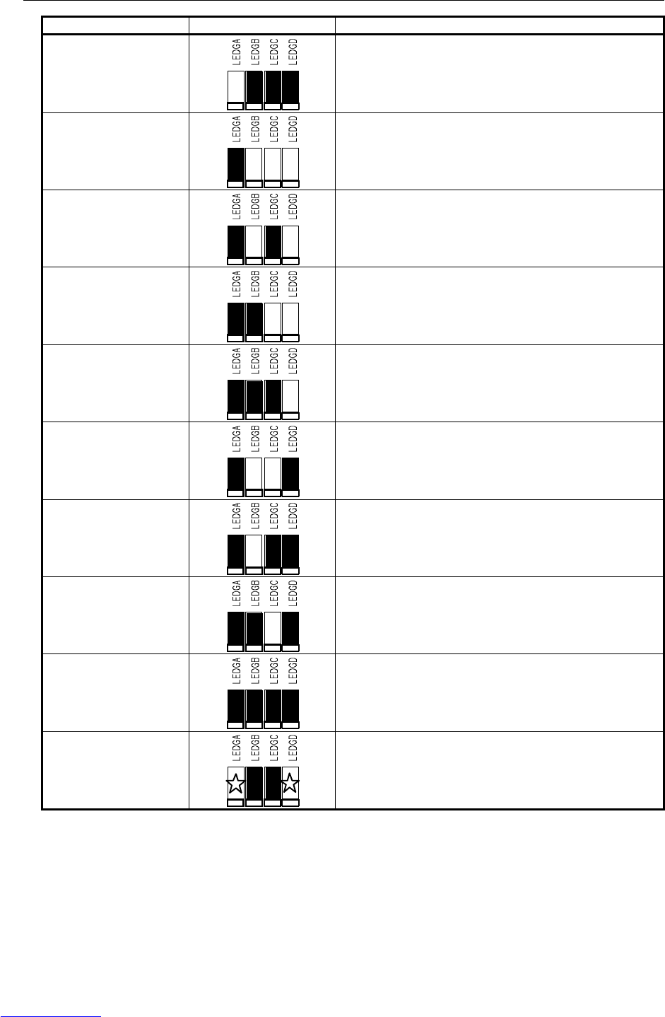
B-82725EN-1/07 MAINTENANCE 3.TROUBLESHOOTING
- 71 -
Step LED Action to be taken
9: The loading of
optional software is
completed.
* [Action1] Replace the main board.
[Action2] Replace the process I/O board.
10: DI/DO initialization
* [Action1] Replace the FROM/SRAM module.
* [Action2] Replace the main board.
11: The preparation of
the SRAM module is
completed.
[Action1] Replace the axis control card.
* [Action2] Replace the main board.
[Action3] Replace the servo amplifier.
12: Axis control card
initialization
[Action1] Replace the axis control card.
* [Action2] Replace the main board.
[Action3] Replace the servo amplifier.
13: Calibration is
completed.
[Action1] Replace the axis control card.
* [Action2] Replace the main board.
[Action3] Replace the servo amplifier.
14: Start-up of power
application for the
servo system
* [Action1] Replace the main board.
15: Program execution
* [Action1] Replace the main board.
[Action2] Replace the process I/O board.
16: DI/DO output
start-up.
* [Action1] Replace the main board.
17: Initialization is
terminated.
Initialization has ended normally.
18: Normal status
Status LEDs 1 and 2 blink when the system is operating
normally.
* If the main board or FROM/SRAM module is replaced, the contents of memory (parameters,
specified data, etc.) will be lost. Before you replace the unit, therefore, make a backup copy of the
data.
If an alarm is issued, data backup may be disabled. So, back up the contents of memory routinely.
Downloaded from www.Manualslib.com manuals search engine


B-82725EN-1/07 MAINTENANCE 3.TROUBLESHOOTING
- 73 -
(2) TROUBLESHOOTING BY 7-SEGMENT LED INDICATOR
7-segment LED
indicator Description
[Description] A parity alarm condition has occurred in DRAM on the CPU card installed on
the main board.
[Action1] Replace the CPU card.
* [Action2] Replace the main board.
[Description] A parity alarm condition has occurred in SRAM on the FROM/SRAM module
installed on the main board.
[Action1] Replace the FROM/SRAM module.
* [Action2] Replace the main board.
[Description] A bus error has occurred in the communication controller.
* [Action] Replace the main board.
[Description] A parity alarm condition has occurred in DRAM controlled by the
communication controller.
* [Action] Replace the main board.
[Description] A servo alarm condition has occurred on the main board.
[Action1] Replace the axis control card.
* [Action2] Replace the main board.
[Action3] Replace the option board that is connected to the backplane.
[Description] The SYSEMG alarm has occurred.
[Action1] Replace the axis control card.
[Action2] Replace the CPU card.
* [Action3] Replace the main board.
[Description] The SYSFAIL alarm has occurred.
[Action1] Replace the axis control card.
[Action2] Replace the CPU card.
* [Action3] Replace the main board.
[Action4] Replace the option board that is connected to the backplane.
[Description] 5V is supplied to Main board. Above alarms do not occur.
* If the main board or FROM/SRAM module is replaced, the contents of memory (parameters,
specified data, etc.) will be lost. Before you replace the unit, therefore, make a backup copy of the
data.
If an alarm is issued, data backup may be disabled. So, back up the contents of memory routinely.
Downloaded from www.Manualslib.com manuals search engine
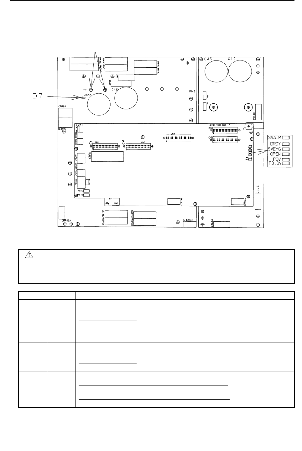
3.TROUBLESHOOTING MAINTENANCE B-82725EN-1/07
- 74 -
Troubleshooting by LEDs on servo amplifier
The servo amplifier has alarm LEDs. Troubleshoot the alarm indicated by the LEDs, referring also to
the alarm indication on the teach pendant.
Check that the voltage is not higher than 50V.
Fig.3.7 (c) LED status on the servo amplifier
CAUTION
Before touching the servo amplifier, check the DC link voltage with the screws
located above the LED "D7". By using a DC voltage tester, check that the
voltage is 50 V or less.
LED Color Description
P5V Green Lights when the power supply circuit inside the servo amplifier outputs a voltage of +5 V
normally.
If the LED does not light:
[Measure 1] Check the robot connection cable (RMP) to see if there is a ground fault in
the +5V wire.
[Measure 2] Replace the servo amplifier.
P3.3V Green Lights when the power supply circuit inside the servo amplifier outputs a voltage of +3.3 V
normally.
If the LED does not light:
[Measure] Replace the servo amplifier.
SVEMG Red Lights when an emergency stop signal is input to the servo amplifier.
If the LED lights when the machine is not at an emergency stop:
[Measure] Replace the servo amplifier.
If the LED does light when the machine is at an emergency stop:
[Measure] Replace the servo amplifier.
Downloaded from www.Manualslib.com manuals search engine

B-82725EN-1/07 MAINTENANCE 3.TROUBLESHOOTING
- 75 -
LED Color Description
ALM Red Lights when the servo amplifier detects an alarm.
If the LED lights when there is no alarm condition in the machine:
[Measure] Replace the servo amplifier.
If the LED does not light when there is an alarm condition in the machine:
[Measure] Replace the servo amplifier.
DRDY Green Lights when the servo amplifier is ready to drive the servo motor.
If the LED does not light when the motor is activated:
[Measure] Replace the servo amplifier.
OPEN Green Lights when the communication between the servo amplifier and the main board is normal.
If the LED does not light:
[Measure 1] Check for the connection of the FSSB optical cable.
[Measure 2] Replace the servo card.
[Measure 3] Replace the servo amplifier.
D7 Red Lights when the DCLINK circuit inside the servo amplifier is charged to reach the specified
voltage.
If the LED does not light after pre-charge is finished:
[Measure 1] It is likely that the DC Link may be short-circuited. Check for connection.
[Measure 2] It is likely that the charge current control resistor may be defective. Replace
the emergency stop unit.
[Measure 3] Replace the servo amplifier.
Troubleshooting by LEDs on Process I/O board
LED Color Description
ALM1 Red
[Explanation] An alarm was issued during communication between the main board
and the process I/O board.
[Measure 1] Replace the process I/O board.
[Measure 2] Replace the I/O link connection cable.
[Measure 3] Replace the main board.
FALM Red
[Explanation] The fuse on the process I/O board was blown.
[Measure 1] Replace the fuse on the process I/O board.
[Measure 2] Check the cables and peripheral units connected to the process I/O
board and replace the defective units.
[Measure 3] Replace the process I/O board.
FUSE1 (1A)
LED:FALM(Red)
LED:ALM1(Red)
Fig.3.7 (d) LED status on the process I/O board MA
Downloaded from www.Manualslib.com manuals search engine
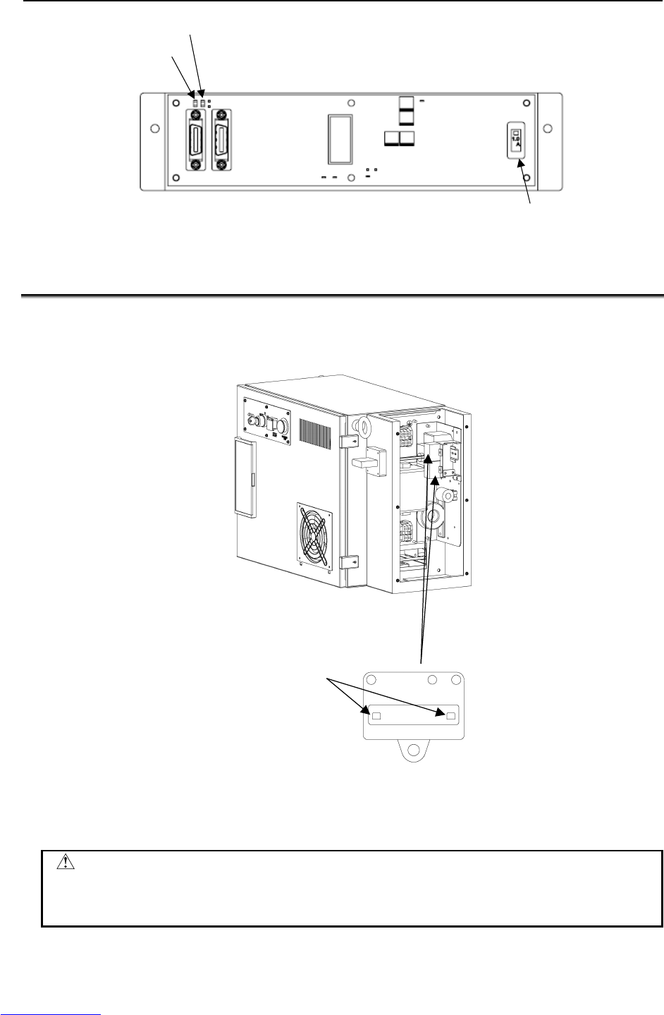
3.TROUBLESHOOTING MAINTENANCE B-82725EN-1/07
- 76 -
LED:ALM1 (Red)
LED:FALM (Red)
FUSE1 (1A)
Fig.3.7 (e) Fuse on the process I/O board MB
3.8 CHECK AND REPLACEMENT SURGE ABSORBER
The surge absorber is mounted at primary power supply of controller.
It is necessary to check the surge absorber as following procedure.
SURGE ABSORBER
Status indicator
Green : Normal
Red : Damaged
Fig.3.8 Status indicator of the surge absorber
The surge absorber has the status indicator. Check the status indicator every six months. In addition, if
surge absorber has been damaged, replace the surge absorber.
CAUTION
In case of lightning surge attack, the performance of surge absorber may be
possibility of damage. In this case, check the status indicator of surge absorber.
In addition, if surge absorber has been damaged, replace the surge absorber.
Downloaded from www.Manualslib.com manuals search engine

B-82725EN-1/07 MAINTENANCE 3.TROUBLESHOOTING
- 77 -
3.9 POSITION DEVIATION FOUND IN RETURN TO THE
REFERENCE POSITION (POSITIONING)
(Check 1) On the status screen, check the position deviation in the stopped state. To display
the position deviation, press the screen selection key, and select STATUS from the
menu. Press F1, [TYPE], select AXIS from the menu, then press the F4, PULSE.
(Corrective action)
Correct the parameters related to return to the reference position (positioning).
(Check 2) Check whether the motor axis can be positioned normally.
(Corrective action)
If the motor axis can be positioned normally, check the mechanical unit.
(Check 3) Check the mechanical unit for backlash.
(Corrective action)
Replace a faulty key of motor shaft or other faulty parts.
(Check 4) If checks 1 to 3 show normal results
(Corrective action)
Replace the Pulsecoder and main board.
* If the main board or FROM/SRAM module is replaced, the contents of memory (parameters,
specified data, etc.) will be lost. Before you replace the unit, therefore, make a backup copy of the
data.
3.10 MANUAL OPERATION IMPOSSIBLE
The following explains checking and corrective action required if the robot cannot be operated manually
after the controller is turned on:
(1) Check and corrective action to be made if manual operation is impossible
(Check 1) Check whether the teach pendant is enabled.
(Corrective action)
Turn on the teach pendant "enable".
(Check 2) Check whether the teach pendant is handled correctly.
(Corrective action)
To move an axis by manual operation, press the axis selection key and shift key at
the same time.
Set the override for manual feed to a position other than the FINE and VFINE
positions.
(Check 3) Check whether the ENBL signal of the peripheral device control interface is on.
(Corrective action)
Place the peripheral device control interface in the ENBL status.
(Check 4) Check whether the HOLD signal of the peripheral device control interface (hold
status). (Check whether the hold lamp on the teach pendant is on.)
(Corrective action)
Turn off the HOLD signal of the peripheral device control interface.
(Check 5) Check whether the previous manual operation has been completed.
(Corrective action)
If the robot cannot be placed in the effective area because of the offset of the speed
command voltage preventing the previous operation from being completed, check
the position deviation on the status screen, and change the setting.
(Check 6) Check whether the controller is in the alarm status.
(Corrective action)
Release the alarm.
Downloaded from www.Manualslib.com manuals search engine

3.TROUBLESHOOTING MAINTENANCE B-82725EN-1/07
- 78 -
(2) Check and corrective action to be taken if the program cannot be executed
(Check 1) Check whether the ENBL signal for the peripheral-device control interface is on.
(Corrective action)
Put the peripheral-device control interface in the ENBL state.
(Check 2) Check whether the HOLD signal for the peripheral-device control interface is on.
Also check whether the HOLD lamp on the teach pendant is on.
(Corrective action)
If the HOLD signal of the peripheral device control interface is on, turn it off.
(Check 3) Check whether the previous manual operation has been completed.
(Corrective action)
If the robot cannot be placed in the effective area because of the offset of the speed
command voltage, which prevents the previous operation from being completed,
check the position deviation on the status screen, then change the setting.
(Check 4) Check whether the controller is in the alarm status.
(Corrective action)
Release the alarm.
Downloaded from www.Manualslib.com manuals search engine
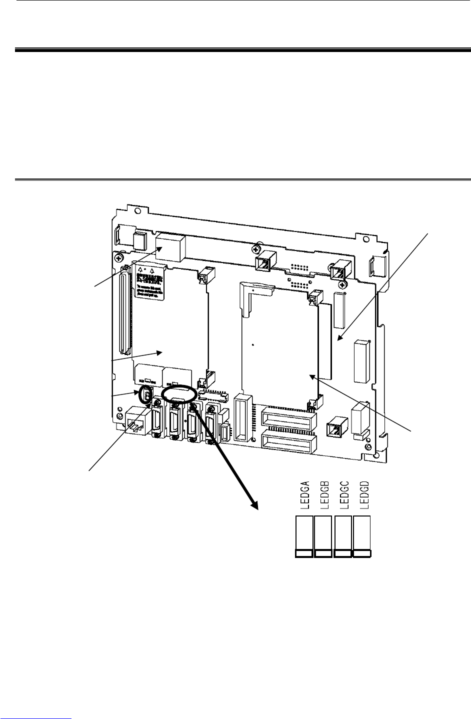
B-82725EN-1/07 MAINTENANCE 4.PRINTED CIRCUIT BOARDS
- 79 -
4 PRINTED CIRCUIT BOARDS
The printed circuit boards are factory-set for operation. Usually, you do not need to set or adjust them.
This chapter describes the standard settings and adjustment required if a defective printed circuit board is
replaced. It also describes the test pins and the LED indications.
The control unit printed circuit board includes the main unit printed circuit board and one or more cards
or modules installed horizontally to the main-unit printed-circuit board.
These PC boards have interface connectors, LED indicators, and a plastic panel at the front. At the rear,
there is a backplane connector.
4.1 MAIN BOARD (A20B-8200-0470)
Fig.4.1 Main board
Axis control card
CPU card
Status LED
7 segment LED
FROM/SRAM module
(
Behind the axis control card
)
FAN board
ETHERNET
LEDs
Downloaded from www.Manualslib.com manuals search engine
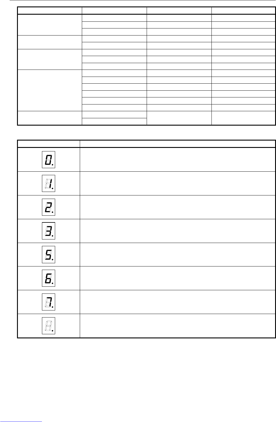
4.PRINTED CIRCUIT BOARDS MAINTENANCE B-82725EN-1/07
- 80 -
Name Ordering Specification Board Specification Note
A05B-2550-H001 A20B-8200-0470 Standard
A05B-2550-H002 A20B-8200-0471 Vision
Main board
A05B-2550-H003 A20B-8200-0472 Vision, Force sensor
A05B-2550-H020 A20B-3400-0020 DRAM 32M CPU card
A05B-2550-H021 A20B-3400-0021 DRAM 64M
A05B-2550-H040 A20B-3300-0448 8-axis
A05B-2550-H041 A20B-3300-0447 12-axis
Axis control card
A05B-2550-H042 A20B-3300-0442 16-axis
A05B-2550-H060 A20B-3900-0223 FROM 32M/ SRAM 1M
A05B-2550-H061 A20B-3900-0224 FROM 32M/ SRAM 2M
A05B-2550-H062 A20B-3900-0225 FROM 32M/ SRAM 3M
A05B-2550-H063 A20B-3900-0226 FROM 64M/ SRAM 1M
A05B-2550-H064 A20B-3900-0227 FROM 64M/ SRAM 2M
FROM/SRAM module
A05B-2550-H065 A20B-3900-0228 FROM 64M/ SRAM 3M
A05B-2550-H001 FAN board
A05B-2550-H002 A20B-8002-0639
(1) LEDs
Seven segment LED Description
A parity alarm occurred in a DRAM of the CPU card on the main board.
A parity alarm occurred in a SRAM of the FROM/SRAM module on the main board.
Bus error occurred on the communication controller.
A parity alarm occurred in DRAM controlled by communication controller.
A servo alarm occurred on the main board.
SYSEMG occurred.
SYSFAIL occurred.
5V is supplied to Main board.
Above 0-7 alarms do not occur.
Downloaded from www.Manualslib.com manuals search engine
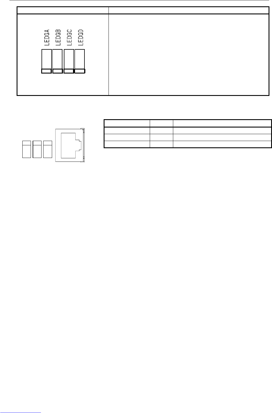
B-82725EN-1/07 MAINTENANCE 4.PRINTED CIRCUIT BOARDS
- 81 -
Status LED Description
Operating status of the system.
RECEIVE
TRANS
LINK
ETHERNET LED Color Description
RECEIVE Green Blinks when data is received.
TRANS Green Flashes during data transmission.
LINK Green Lights when a link is established.
Downloaded from www.Manualslib.com manuals search engine
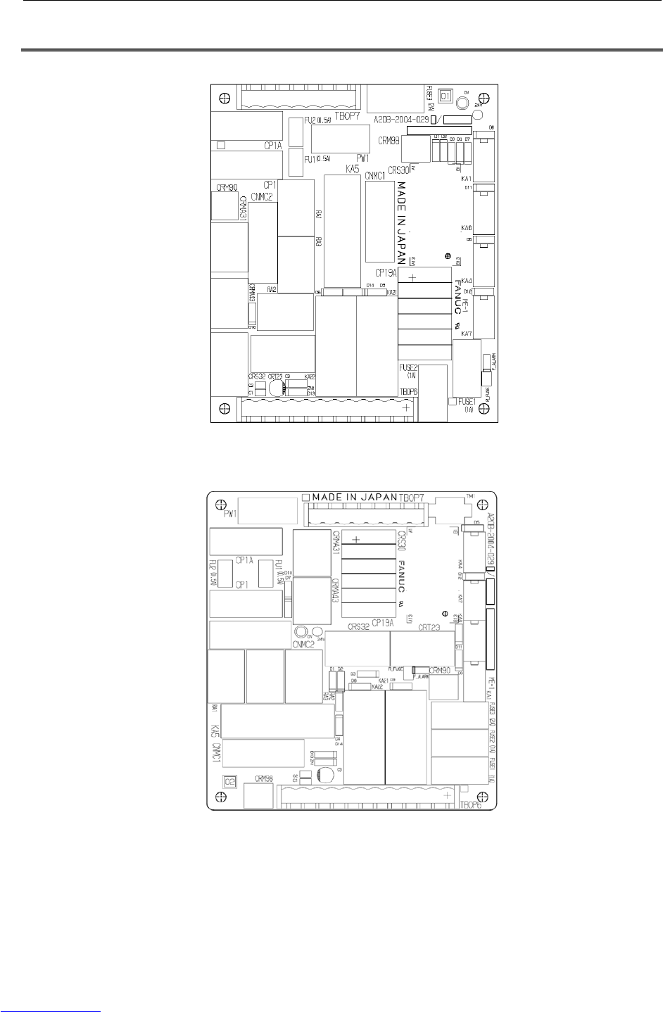
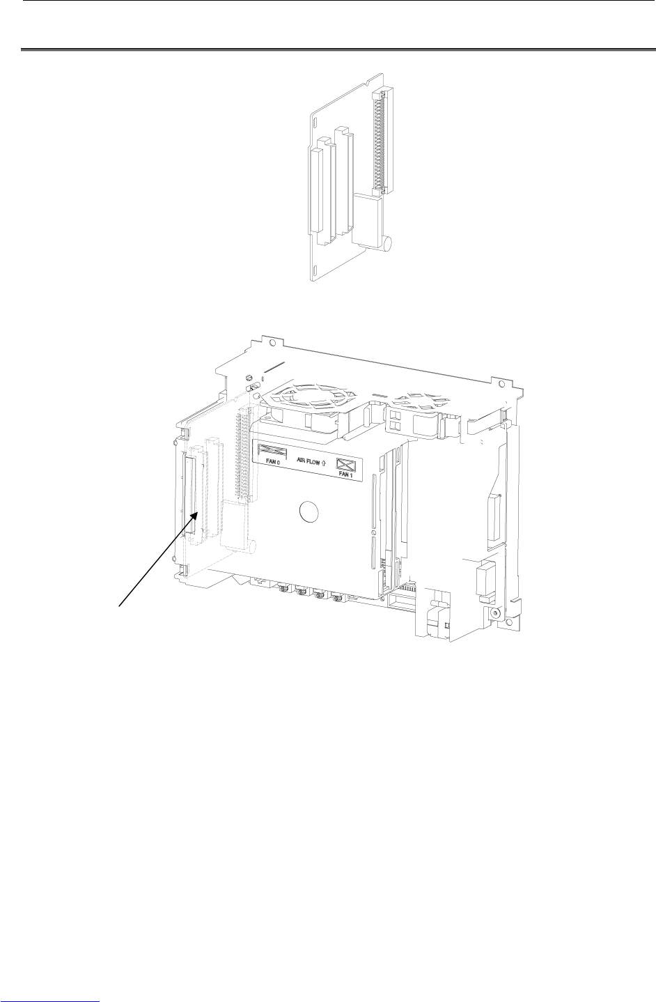
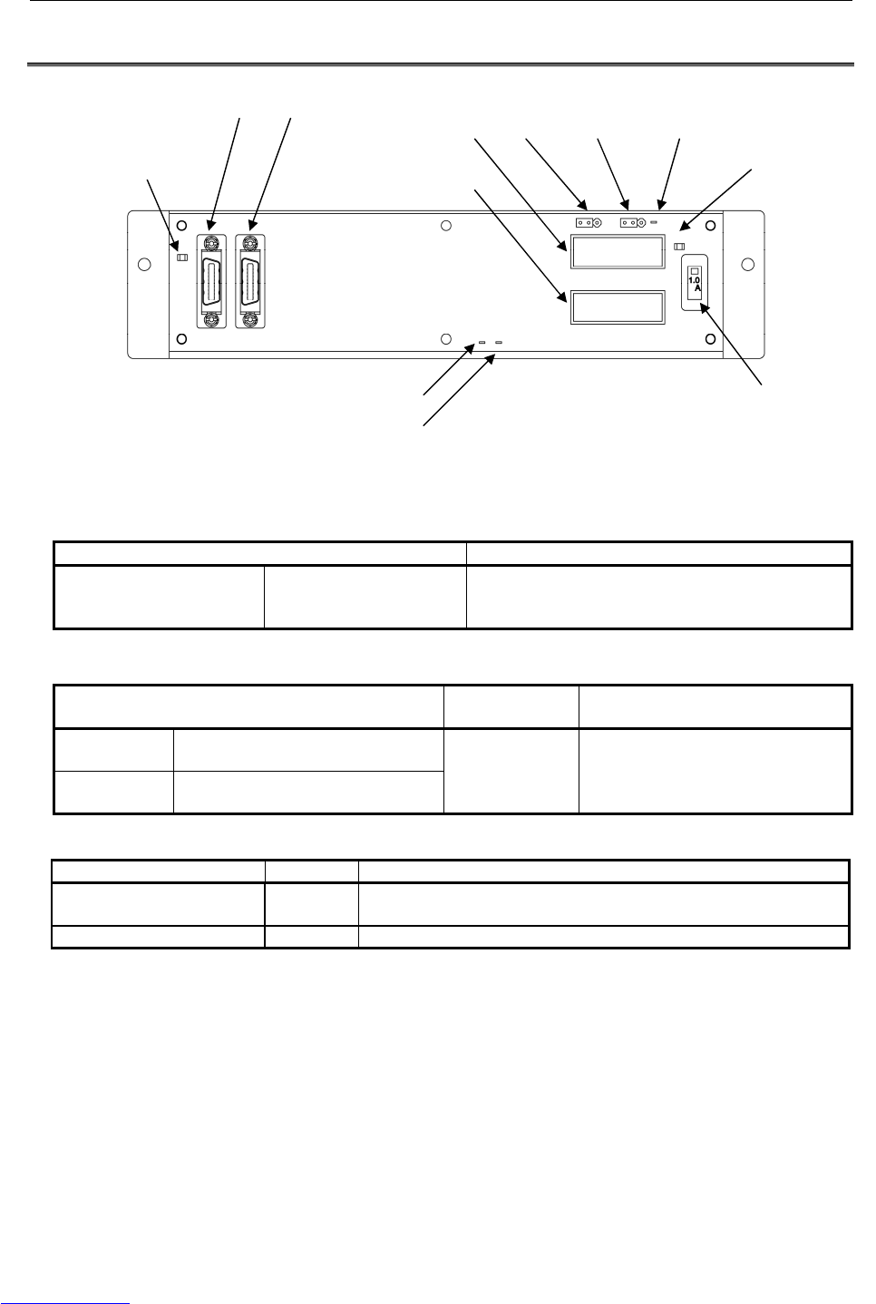
4.PRINTED CIRCUIT BOARDS MAINTENANCE B-82725EN-1/07
- 84 -
4.4 PROCESS I/O BOARD MA (A20B-2004-0380)
Fig.4.4 Process I/O board MA
(1) Test pins
Name Use
P24V
P5V
GND
+24V
+5V
GND
For measuring the DC supply voltage
(2) Settings
Name Standard
setting Description
ICOM1 UDI1- 10
(Connector CRMA52A)
ICOM2 UDI11- 20
(Connector CRMA52B)
Side A For common voltage setting
Side A: +24V common
Side B: 0V common
(3) LEDs
Name Color Description
ALM1 Red
A communication alarm occurred between the main CPU and process
I/O board.
FALM Red The fuse (FUSE1) on the process I/O board has blown.
FUSE1 (1A)
LED:FALM(Red)
LED:ALM1(Red)
JD1B JD1A
GND
P5V
CRMA52B
CRMA52A P24V ICOM2 ICOM1
Downloaded from www.Manualslib.com manuals search engine
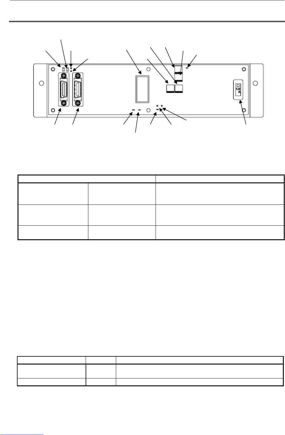
B-82725EN-1/07 MAINTENANCE 4.PRINTED CIRCUIT BOARDS
- 85 -
4.5 PROCESS I/O BOARD MB (A20B-2101-0730)
Fig.4.5 Process I/O board MB
(1) Test pins and pads
Name Use
24V
5V
GND
+24V
+5V
GND
For measuring the DC supply voltage
P24VF
P5VF
GNDF
+24V
+5V
GND
D/A converter power supply
AOUT1
AOUT2
Channel 1
Channel 2
For analog output signal (D/A) voltage measurement
(2) Adjustment
VR1/VR2 Channel 1 gain and offset adjustment
Connect the “+” and “-” terminals of a digital voltmeter, respectively, to the AOUT1
check pin and the GNDF check pin (not a general ground point). From the teach pendant,
execute AOUT[1]=3413, using a robot program. While observing the voltage at the
AOUT1 check pin with the digital voltmeter, adjust potentiometers VR1 and VR2 for
15.0V.
VR3/VR4 Channel 2 gain and offset adjustment
Connect the “+” and “-” terminals of a digital voltmeter, respectively, to the AOUT2
check pin and the GNDF check pin (not a general ground point). From the teach pendant,
execute AOUT[2]=3413, using a robot program. While observing the voltage at the
AOUT2 check pin with the digital voltmeter, adjust potentiometers VR3 and VR4 for
15.0V.
(3) LEDs
Name Color Description
ALM1 Red
A communication alarm occurred between the main CPU and process
I/O board.
FALM Red The fuse (FUSE1) on the process I/O board has blown.
JD1B JD1A
LED:ALM1 (Red)
LED:FALM (Red)
GND
AOUT2
24V
5V
CRW11
GNDF P5VF
P24VF
VR1
VR2 VR3 VR4 AOUT1
FUSE1 (1A)
Downloaded from www.Manualslib.com manuals search engine
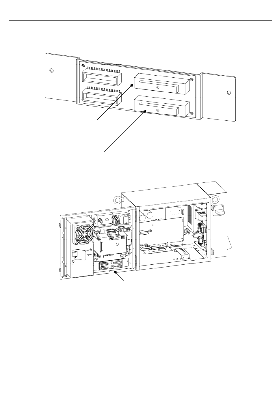

B-82725EN-1/07 MAINTENANCE 5.SERVO AMPLIFIERS
- 87 -
5 SERVO AMPLIFIERS
The servo amplifiers are factory-set for operation. Usually, you do not need to set or adjust them.
This chapter describes the standard settings and adjustment required if a defective servo amplifier is
replaced. It also describes the use of test pins and meanings of the LED indications.
Table 5 Servo amplifier specifications
Robot Servo amplifier Regenerative resistor
LR Mate 200iC A06B-6107-H005 A05B-2550-C050
M-1iA A06B-6107-H005 A05B-2550-C050
ARC Mate 100iC, M-10iA, ARC Mate 0iA A06B-6107-H004 A05B-2550-C051
ARC Mate 100iCe, M-10iAe A06B-6107-H004 A05B-2550-C053
ARC Mate 120iC, M-20iA A06B-6107-H002 A05B-2550-C052
ARC Mate 50iC A06B-6107-H005 A05B-2550-C051
Check that the voltage is not higher than 50V.
Fig.5 Servo amplifier
WARNING
Before touching the servo amplifier, check the DC link voltage with the screws
located above the LED "D7". By using a DC voltage tester, check that the
voltage is 50 V or less.
Downloaded from www.Manualslib.com manuals search engine
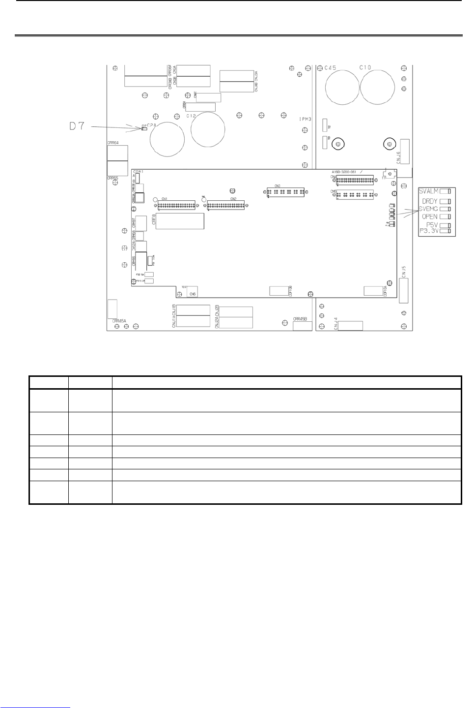
5.SERVO AMPLIFIERS MAINTENANCE B-82725EN-1/07
- 88 -
5.1 LED OF SERVO AMPLIFIER
Fig.5.1 LED of servo amplifier
LED Color Description
P5V Green Lights when the power supply circuit inside the servo amplifier outputs a voltage of +5 V
normally.
P3.3V Green Lights when the power supply circuit inside the servo amplifier outputs a voltage of +3.3 V
normally.
SVEMG Red Lights when an emergency stop signal is input to the servo amplifier.
SVALM Red Lights when the servo amplifier detects an alarm.
DRDY Green Lights when the servo amplifier is ready to drive the servo motor.
OPEN Green Lights when the communication between the servo amplifier and the main board is normal.
D7 Red Lights when the DCLINK circuit inside the servo amplifier is charged to reach a specific
voltage.
Downloaded from www.Manualslib.com manuals search engine
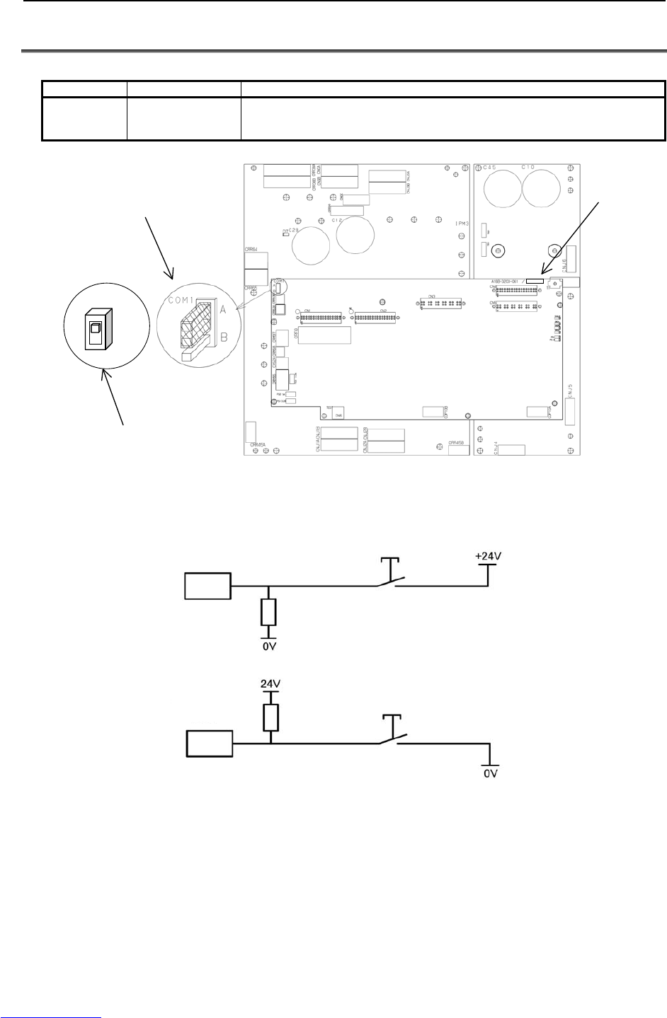
B-82725EN-1/07 MAINTENANCE 5.SERVO AMPLIFIERS
- 89 -
5.2 SETTING OF SERVO AMPLIFIER
Table 5.2 Settings
Name Standard setting Description
COM1 Side A
Robot Digital Input (RI) device common voltage.
Side A: +24V common
Side B: 0V common
COM1
A
B
Total edition of
servo amplifier
control board
When total edition of servo amplifier
control board is 12F or later
When total edition of servo amplifier
control board is 11E or earlier
Fig.5.2 (a) Setting of servo amplifier
A side
B side
RI
RI
Fig.5.2 (b) Circuit based on jumper pin location or setting of switch
Downloaded from www.Manualslib.com manuals search engine
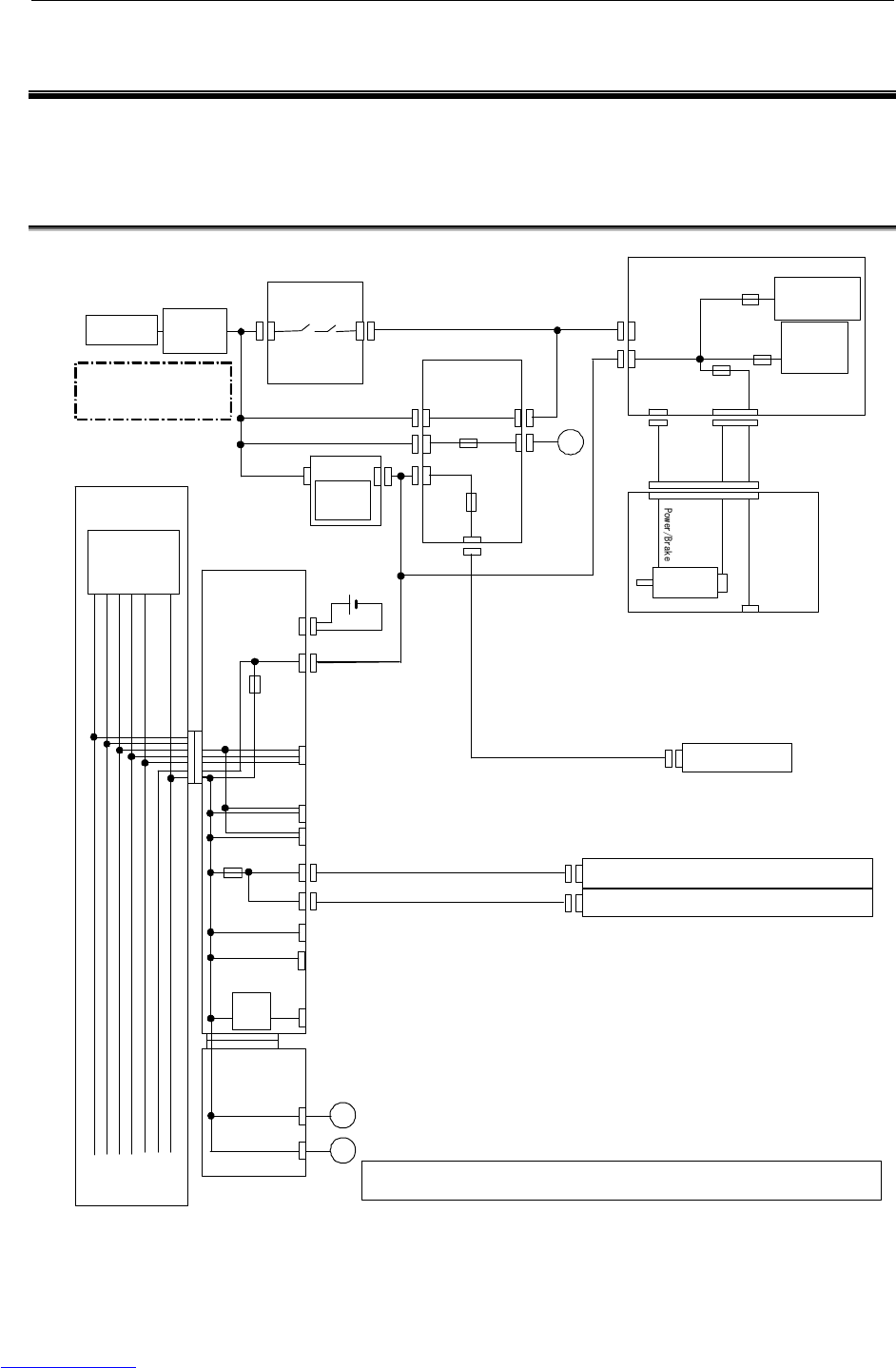
6.SETTING THE POWER SUPPLY MAINTENANCE B-82725EN-1/07
- 90 -
6 SETTING THE POWER SUPPLY
Setting and adjustment of the power supply is factory-set for operation. Usually, you do not need to set
or adjust it.
6.1 BLOCK DIAGRAM OF THE POWER SUPPLY
Robot
AC power supply
AC 200 ~ 230 V
1φ or 3φ
MCC
Breaker
E-stop unit
200VAC
Servo amplifier
(6-axis amplifier)
CNJ
CRF8
CRR38A
CRM96
+24V
Pulsecorder +5V
+24VF
End effector
Motor
CRS32
Teach pendant
+24T
FUSE2
DC/DC
+5V, +3.3V
+15V, -15V
FS1
FS3 Regenerative
res, aux, axis
FS2
PSU
200VAC
AC/DC
+24V
CP1
CNMC1
CNMC2
FU1
FU2
CP1A
CP19A
Fan
1φ
1φ
Noise
filter
Backplane
Main board
CRMA16
Batte ry
Fan board
Peripheral device (general-purpose signals)
+3.3V
+5V
+15V
-15V
+24E
+24V
CA114
M-JD1A/S-JD1B
JD17
CRS31
CA54
I/O LINK(1ch)
RS-232-C/RS-485
FORCE SENSOR
SERVO CHECK I/F
24V→
12V
JRL6 VIDEO IN PUT
CP19
+24V
+2.5V
DC/DC (IN+24V)
+5V,+3.3V
+2.5V
+15V,-15V
Fan
CRMA15
Peripheral device (dedicated signals)
Fan
FUSE1
FUSE3
I/O LINK(2ch)
S-JD1A
No fuse is existed in the grounding line(Neutral of 200VAC, 1φ and 0V).
Fig.6.1 Block diagram of the power supply
Downloaded from www.Manualslib.com manuals search engine

B-82725EN-1/07 MAINTENANCE 6.SETTING THE POWER SUPPLY
- 91 -
6.2 CHECKING THE POWER SUPPLY
The power supply need not be set or adjusted.
Table 6.2 Rating of the power supply
Output Rated voltage Tolerance
+5V +5.1V ±3%
+3.3V +3.3V ±3%
+2.5V +2.5V ±3%
+24V +24V ±5%
+24E +24V ±5%
+15V +15V ±10%
-15V -15V ±10%
Downloaded from www.Manualslib.com manuals search engine
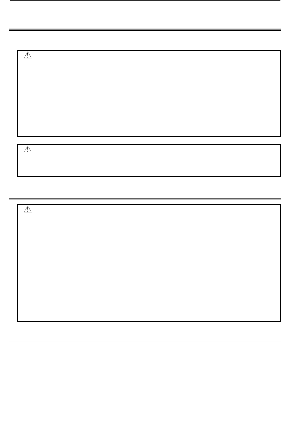
7.REPLACING A UNIT MAINTENANCE B-82725EN-1/07
- 92 -
7 REPLACING A UNIT
This section explains how to replace each unit in the control section.
WARNING
1 Before you start to replace a unit, turn off the control unit main power. Also, keep
all machines in the area of the control unit switched. Otherwise, you could injure
personnel or damage equipment.
2 Before replacing components, read the maintenance manual to understand the
replacement procedure. Performing an incorrect replacement procedure can
lead to an unpredictable accident, resulting in breakage in the robot or personal
injury.
3 When a heavy component or unit is to be handled, support the workers with a
crane or the like not to apply excessive loads to the workers. Note that
incorrect handling can cause serious injury to the workers.
CAUTION
Components in the control unit heat up, so care should be taken. When you
have to touch a heated component, prepare a protector such as heat-resistant
gloves.
7.1 REPLACING THE PRINTED-CIRCUIT BOARDS
CAUTION
When you replace printed-circuit boards, observe the following cautions:
1 Keep the controller power switched off.
2 When you remove a printed-circuit board, do not touch the semiconductor
devices on the board with your hand or make them touch other components.
3 Make sure that the replacement printed-circuit board has been set up
appropriately. (Setting plug etc.)
4 After replacing a printed-circuit board, make adjustments correctly if the board
needs to be adjusted.
5 If the backplane board, power supply unit, or main board (including cards and
modules) is replaced, it is likely that robot parameters and taught data are
lost. Before you start to replace these components, save a backup copy of the
robot parameters and taught data to an external memory device.
6 Before you disconnect a cable, note its location. If a cable is detached for
replacement, reconnect it exactly as before.
7.1.1 Replacing the Backplane Board (Unit)
Replace the backplane board together with the plastic case.
(1) Remove the two screws fastening the case. (When cables are connected to option boards, detach
the cables.)
(2) Release the latches in the upper part on each side of the case from the base metal plate, and pull out
the case. The case can be pulled out with the backplane board, fan, and battery installed in the
case.
Downloaded from www.Manualslib.com manuals search engine
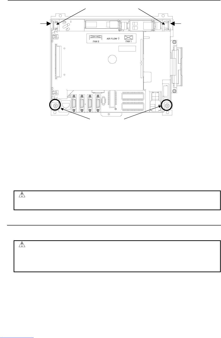
B-82725EN-1/07 MAINTENANCE 7.REPLACING A UNIT
- 93 -
Fig.7.1.1 Replacing the backplane board
(3) Replace the backplane unit with a new one.
(4) Confirm that the screw and latch positions of the case are in place, and slowly set the case. When
the case is attached, the backplane board installed in the case is connected to the main board with the
connectors. When setting the case, check that the connectors are connected properly, and be
careful not to apply excessive force.
(5) After confirming that the case is surely latched, tighten the screws of the case. Lightly press the
fan and battery, and make sure that the connectors are connected securely. (If the cables of option
boards have been detached, connect the cables again.)
CAUTION
Be sure to back up all programs and a possibility of data loss when a backplane-
mounted printed circuit board is replaced.
7.1.2 Replacing the Main board
The backplane unit incorporates the backplane board, main board, and option boards.
CAUTION
Before starting replacement, turn off the main power of the controller. The main
board is equipped with battery-backed memory devices for holding robot
parameters and taught data. When the main board is replaced, the memory
contents are lost.
(1) Remove the case. (See Subsection 7.1.1.)
(2) Detach cables from the connectors on the main board, and remove the three screws fastening the
main board. The main board and fan board are connected directly with connector CA115A.
Detach the main board by sliding the main board downward.
(1) Remove the screws
(2) Unlatch and pull out the case.
(2) (2)
Downloaded from www.Manualslib.com manuals search engine

7.REPLACING A UNIT MAINTENANCE B-82725EN-1/07
- 94 -
Fig.7.1.2 Replacing the main board
(3) Replace the main board with a new one.
(4) Install the case. (See Subsection 7.1.1.)
7.2 REPLACING CARDS AND MODULES ON THE MAIN
BOARD
CAUTION
Before you start to replace a card or module, make a backup copy of robot
parameters and taught data. If the FROM/SRAM module is replaced, SRAM
memory contents are lost.
Demounting a Card
(1) Pull up the spacer metal fitting.
(2) A molded cover is attached to a corner of the servo card and CPU card although the shapes of the
covers attached to the cards differ from each other. Insert a finger into the rear of the cover and pull
up the cover slowly in the arrow direction shown in the figure below. (Note: At this time, hold the
neighborhood of the main board on the opposite side with the other hand whenever possible. A force
of 7 to 8 kgf is required for extraction. Be careful not to drop the card board due to the momentum of
extraction.)
(3) When one side of the card board is raised slightly by pulling up the cover, do not fully extract the
card board, but push back the cover softly.
(4) When the card board is pushed back to be parallel with the main board, pinch two sides of the card
board and pull up the card board. This completes the extraction of the card board.
(2) Remove the screws.
CA115A
Downloaded from www.Manualslib.com manuals search engine
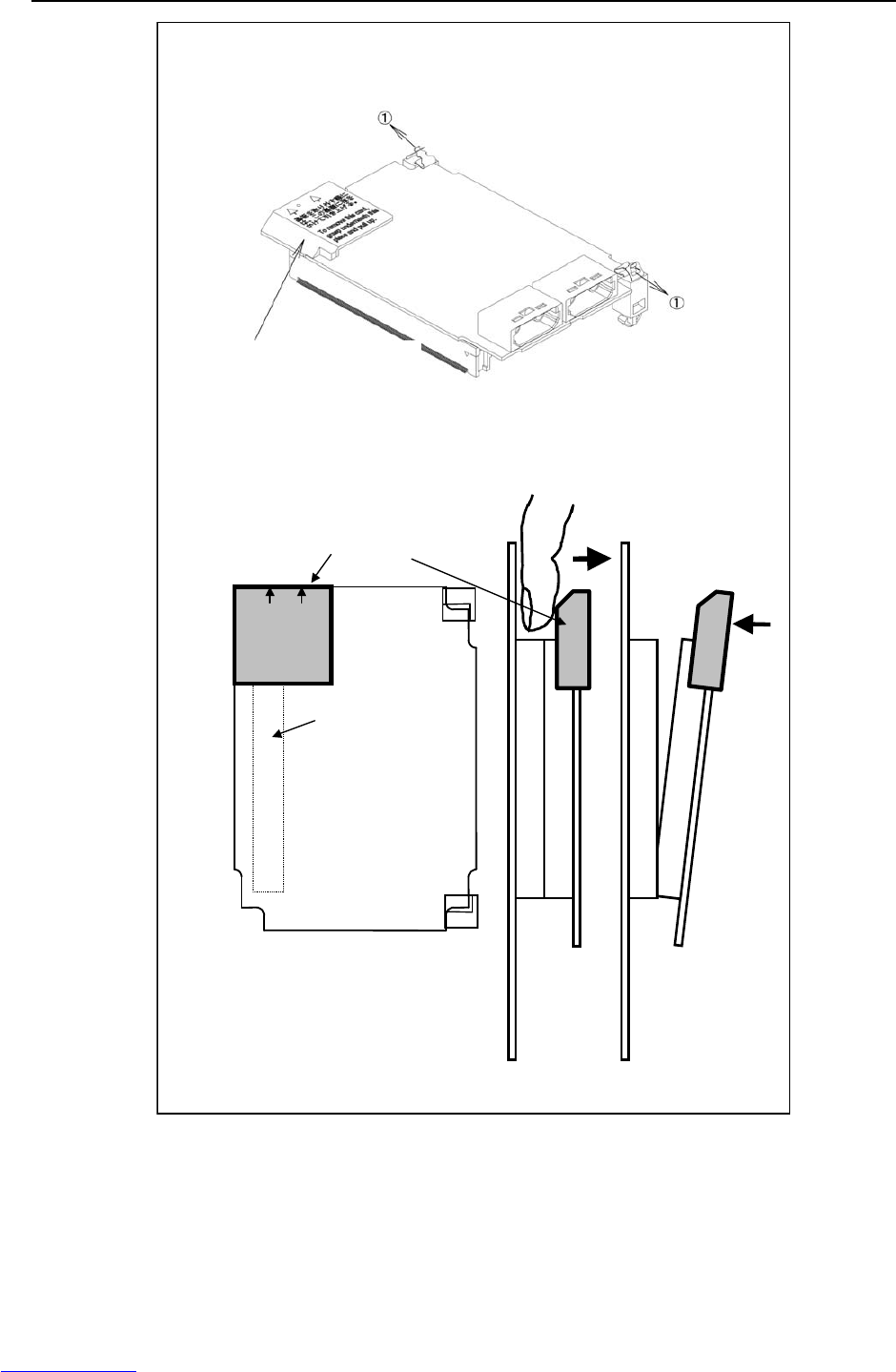
B-82725EN-1/07 MAINTENANCE 7.REPLACING A UNIT
- 95 -
基板を取り外す際に
はこの裏側に指を
かけて引き上げる。
Please put a finge
r
in the reverse o
f
this part and pul
l
up this part whe
n
removing this PCB.
Be sure to hold this part
to pull out the card.
240-pin
connector on
the back
Connector side
Spacer side
For extraction, insert a finger into the rea
r
of this cover, then pull up the cover in the
arrow direction.
Side view
Step 2 Step 3
Push back the
cover softly.
Fig.7.2 (a) Demounting the card on the main board
Mounting a Card
(1) Check that the metal fittings of the spacers are raised.
(2) To align the board insertion position, touch the spacer end faces of the board with the spacer as
shown in the figure below. (At this time, the board is touching the spacers only).
Downloaded from www.Manualslib.com manuals search engine
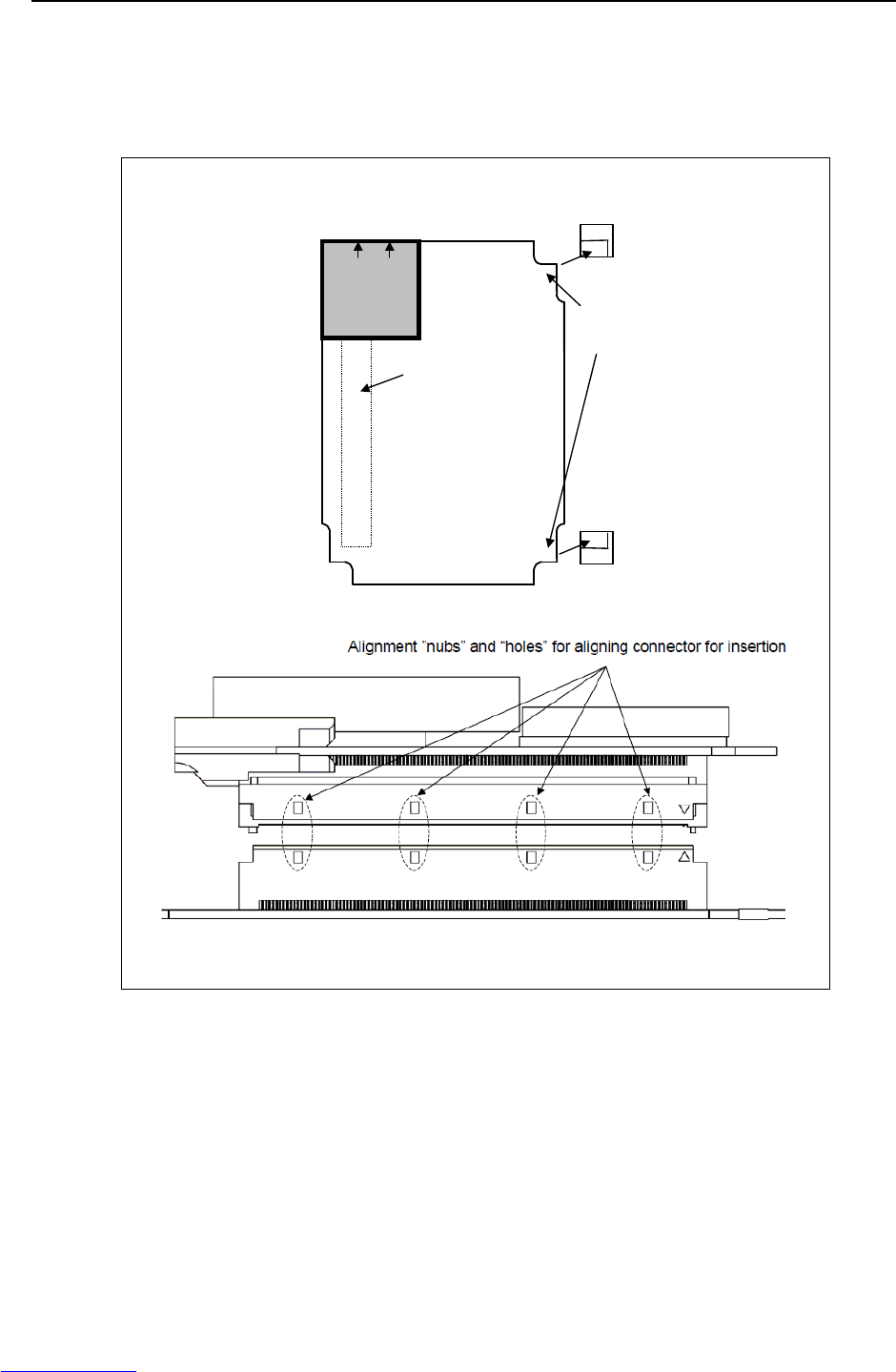
7.REPLACING A UNIT MAINTENANCE B-82725EN-1/07
- 96 -
(3) While aligning the board with the spacers, lower the connector side slowly until the connectors
touch each other (do no press until aligned).
(4) The mating position can be determined more easily by moving the card back and forth until the
alignment “nubs” and “holes” are aligned on the connectors. The board must be turned to view the
board connectors on the side.
基板を取り外す際に
はこの裏側に指を
かけて引き上げる。
Pl
ease put a
fi
nge
r
in the reverse of this
part and pull up this
part when removing
this PCB.
240-pin
connector
on the back
Spacer
Spacer
Spacer fixing
end face
Connector side
Spacer side
Fig.7.2 (b) Mounting the card on the main board
(5) At this time, push on the back of the board over the connector. The force required for connector
insertion is about 10 kgf. If the connector will not insert easily, re-check the alignment of the
connector to prevent damaging the connector(s). Do not press the radiation fin installed on the CPU
and LSI chip. Otherwise, the CPU or LSI chip can be damaged.
(6) Push in the spacer metal fitting to lock the board in place.
Downloaded from www.Manualslib.com manuals search engine
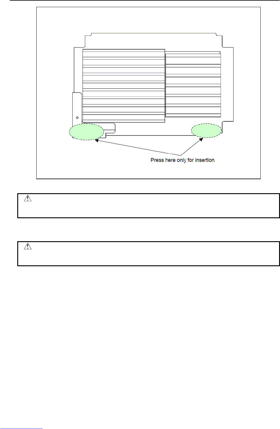
B-82725EN-1/07 MAINTENANCE 7.REPLACING A UNIT
- 97 -
Fig.7.2 (c) Pushing location when mounting the board (top view of MAIN CPU board).
WARNING
Do not press the radiation fins installed on a CPU and LSI chip. Otherwise, CPU
card may be broken.
Demounting a module
CAUTION
When replacing the module, be careful not to touch the module contact. If you
touch the contact inadvertently, wipe out dirt on the contact with a clean cloth.
(1) Move the clip of the socket outward. (a)
(2) Extract the module by raising it at a 30 degree slant and pulling outward.
Downloaded from www.Manualslib.com manuals search engine
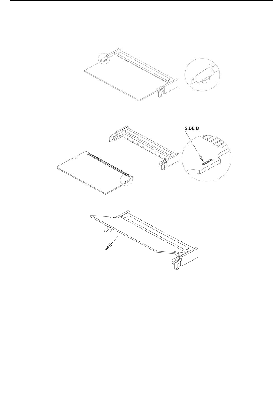
7.REPLACING A UNIT MAINTENANCE B-82725EN-1/07
- 98 -
Mounting a module
(1) Insert the module at a 30-degree slant into the module socket, with side B facing upward. (b)
(2) Push the module inward and downward until it is locked. (c)
(a)
A
Details of section A
(b)
A
Details of section A
(c)
Fig.7.2 (d) Demounting/mounting a module
Downloaded from www.Manualslib.com manuals search engine
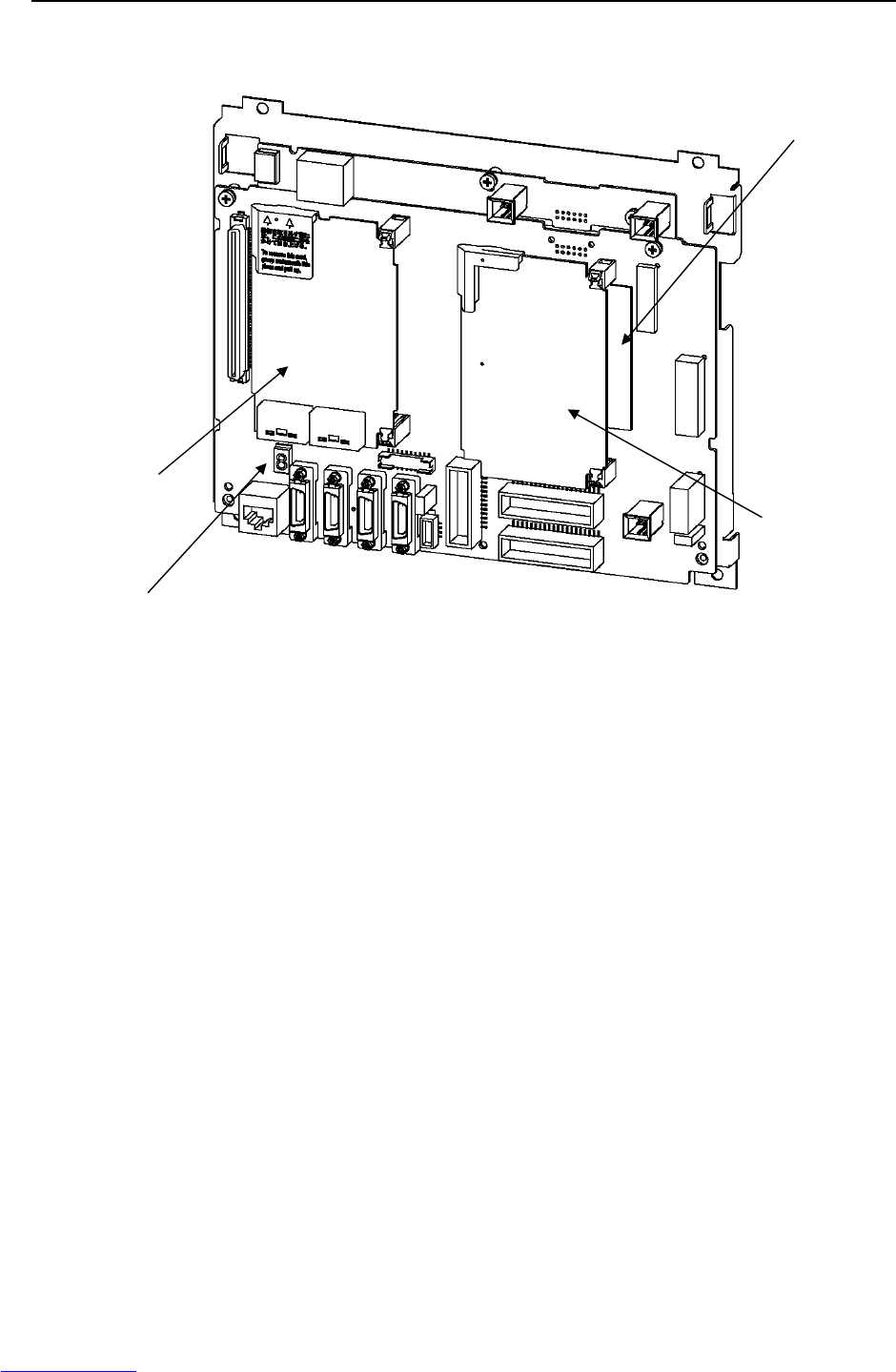
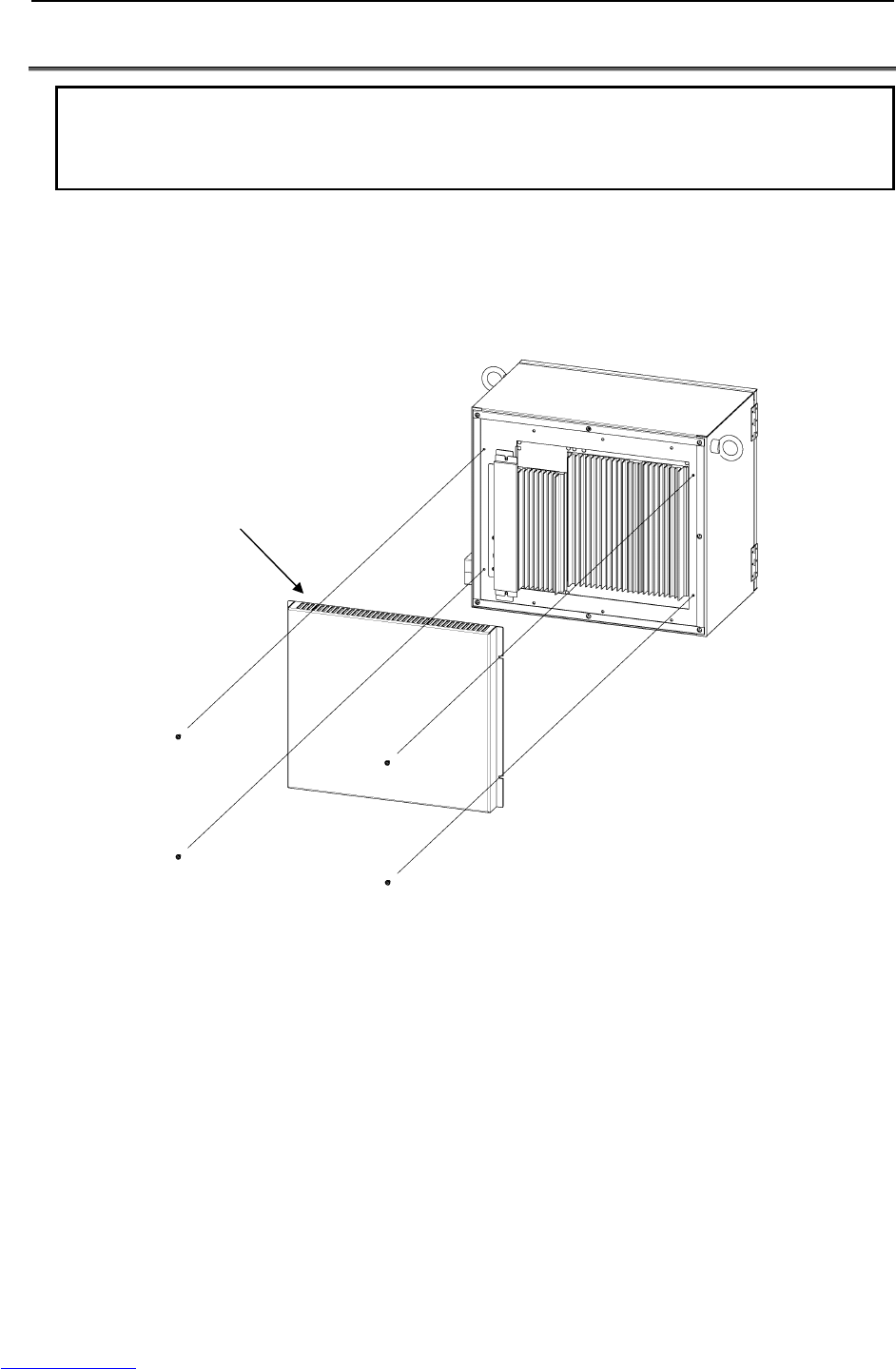
7.REPLACING A UNIT MAINTENANCE B-82725EN-1/07
- 100 -
7.3 REPLACING THE REGENERATIVE RESISTOR UNIT
WARNING
Before you start, turn off the controller main power. Be careful not to get
burned, because the regenerative resistor unit is very hot immediately after
operation.
In case of LR Mate 200iC, M-1iA
(1) Remove the four screws fastening the rear plate of the cabinet, and remove the rear plate.
(2) Unplug connector CRR45 and CRR63 at the Servo amplifier.
(3) Unscrew the retaining screws on the regenerative resistor unit and remove it.
(4) Install the replacement unit by reversing this procedure (1) to (3).
Rear plate
Downloaded from www.Manualslib.com manuals search engine
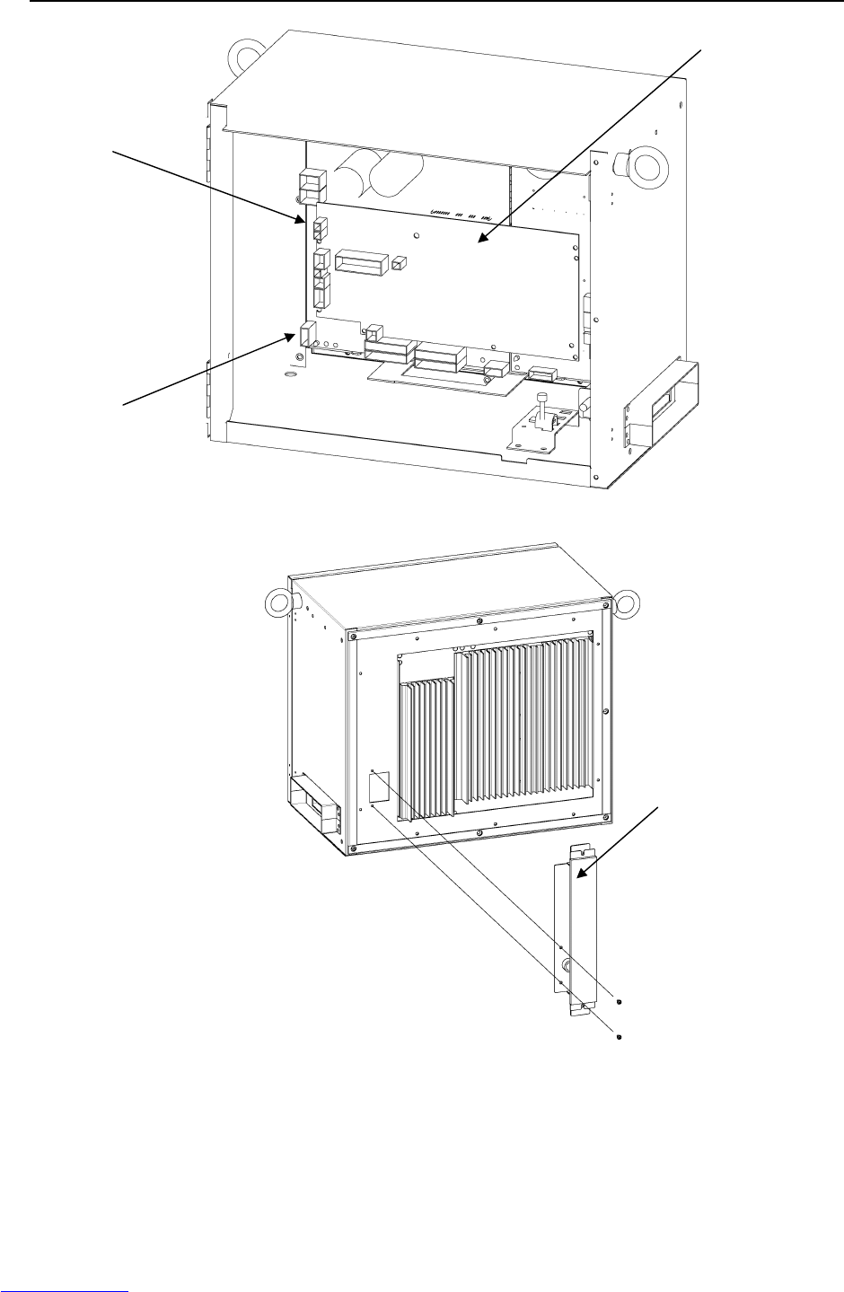

7.REPLACING A UNIT MAINTENANCE B-82725EN-1/07
- 102 -
In case of ARC Mate 100iC, M-10iA, ARC Mate 120iC, M-20iA, ARC Mate 50iC,
ARC Mate 0iA
(1) Remove the servo amplifier from the front of the cabinet. For details, see Section 7.5.
(2) Remove the metal plate securing the cable of the regenerative resistor unit.
(3) Of the two nuts securing the regenerative resistor unit, remove the upper nut, loosen the lower nut,
and remove the regenerative resistor unit.
(4) Install a new regenerative unit by reversing steps (1) to (3) above.
Regenerative resistance unit (Two M4 nuts)
Securing position of
regenerative resistor unit cable
(Two M4 screws)
Fig.7.3 (b) Replacing the regenerative resistor unit
(ARC Mate 100iC, M-10iA, ARC Mate 120iC, M-20iA, ARC Mate 50iC, ARC Mate 0iA)
Downloaded from www.Manualslib.com manuals search engine

B-82725EN-1/07 MAINTENANCE 7.REPLACING A UNIT
- 103 -
7.4 REPLACING THE E-STOP UNIT
(1) Detach the cables from the emergency stop unit.
(2) Remove the three nuts fastening the E-stop unit, and replace the E-stop unit.
(3) Reconnect the cables.
Fig.7.4 Replacing the E-stop unit
E-stop unit
Downloaded from www.Manualslib.com manuals search engine
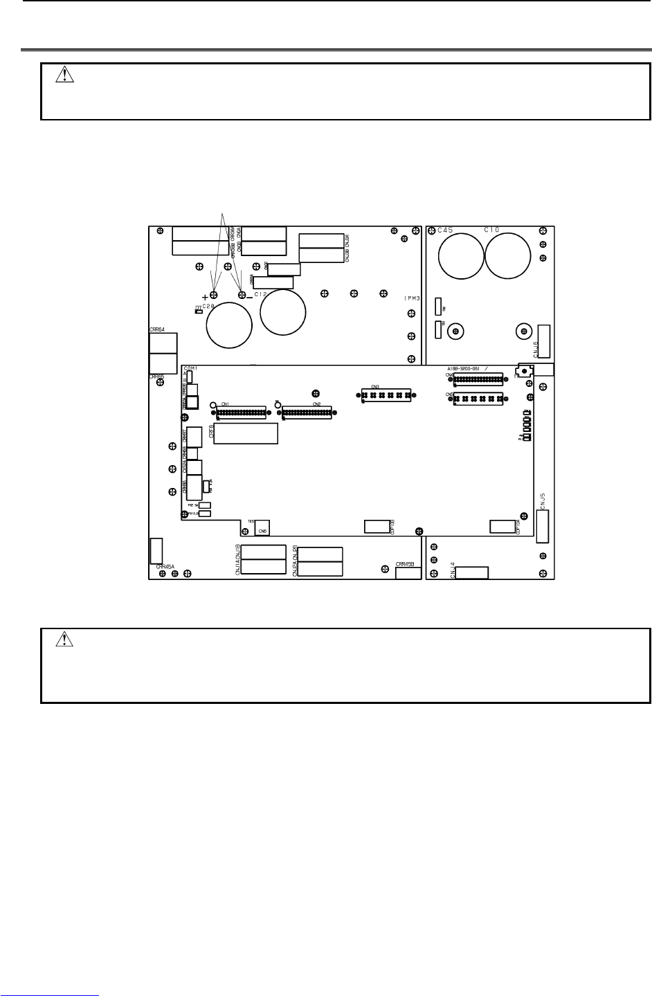
7.REPLACING A UNIT MAINTENANCE B-82725EN-1/07
- 104 -
7.5 REPLACING SERVO AMPLIFIERS
CAUTION
Because the servo amplifier is heated immediately after operation, leave the
servo amplifier until it cools down thoroughly, before replacing it.
(1) Open the door, and check the DC link voltage at the screws above the LED "D7", using a DC power
supply voltmeter. The voltage reading must be 50 V or lower.
Check that the voltage is not higher than 50V.
Fig.7.5 (a) Servo amplifier
WARNING
Before touching the servo amplifier, check the DC link voltage with the screws
located above the LED "D7". By using a DC voltage tester, check that the
voltage is 50 V or less.
Downloaded from www.Manualslib.com manuals search engine
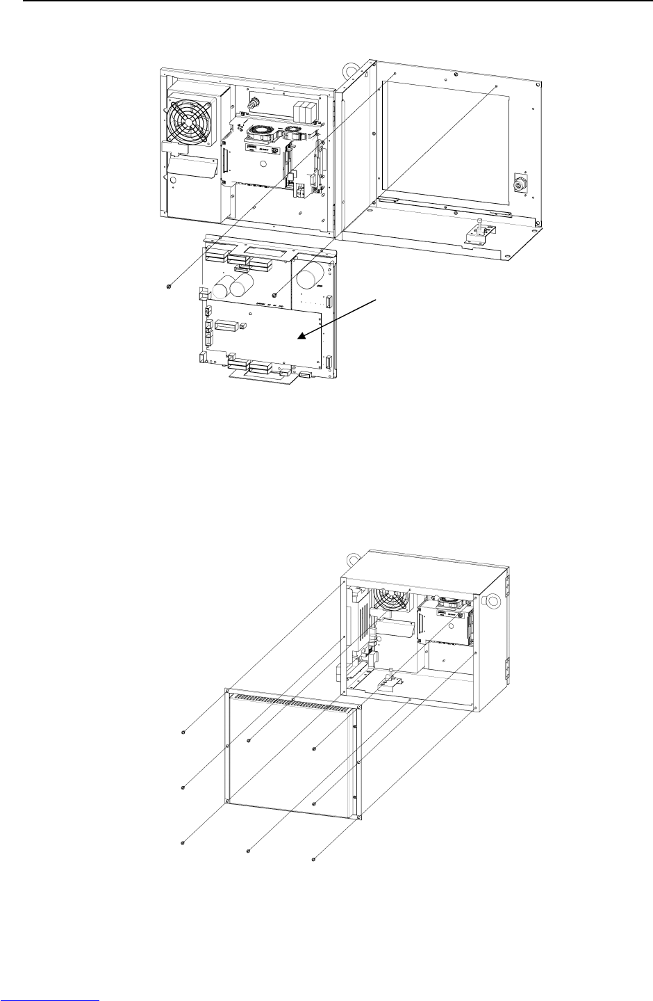
B-82725EN-1/07 MAINTENANCE 7.REPLACING A UNIT
- 105 -
(2) Detach the cables from the servo amplifier.
(3) Remove the two screws fastening the servo amplifier.
Fig.7.5 (b) Replacing the servo amplifier
(4) Hold the handles located in the upper and lower parts of the servo amplifier, and remove the servo
amplifier.
(5) Reverse steps (2) to (4) above to install a new servo amplifier.
The servo amplifier can also be removed together with the metal plate of the rear of the cabinet.
(6) Remove the eight screws fastening the metal plate, and remove the metal plate and the servo
amplifier at a time.
Fig.7.5 (c) Replacing the servo amplifier from rear side
Servo amplifier
Downloaded from www.Manualslib.com manuals search engine

7.REPLACING A UNIT MAINTENANCE B-82725EN-1/07
- 106 -
7.6 REPLACING THE TEACH PENDANT and i PENDANT
The specifications of the teach pendant vary with its use. When you replace the teach pendant, check its
specifications carefully.
(1) Be sure that the power of a robot controller is off.
(2) Detach the cable from the teach pendant.
(3) Replace the teach pendant.
Detach or attach the cable by rotating the connecto
r
retaining ring.
Fig.7.6 Replacing the teach pendant
Downloaded from www.Manualslib.com manuals search engine
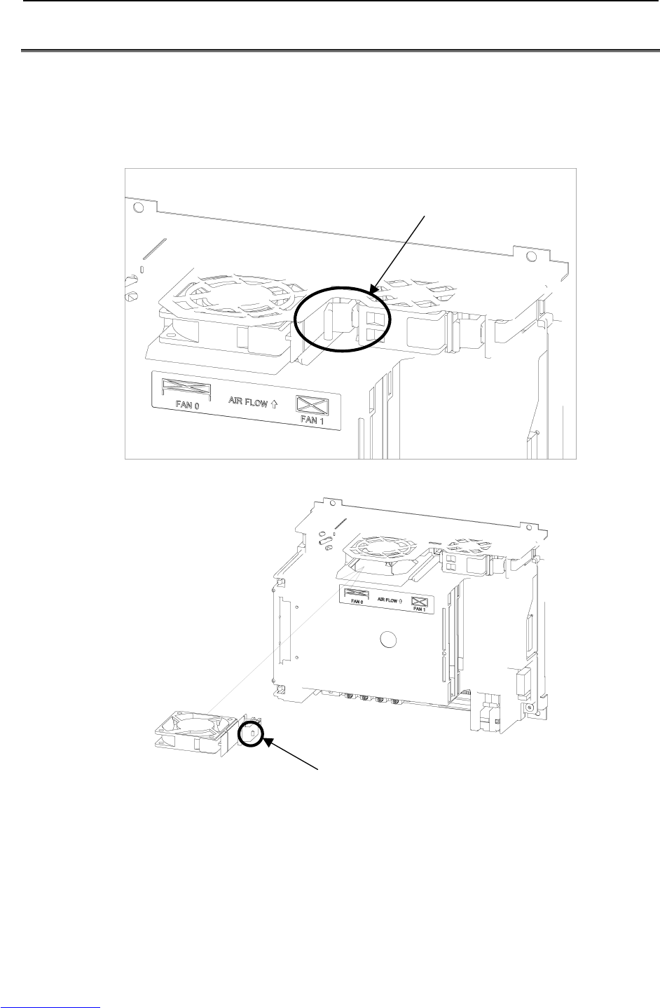
B-82725EN-1/07 MAINTENANCE 7.REPLACING A UNIT
- 107 -
7.7 REPLACING THE CONTROL SECTION FAN MOTOR
The control section fan motor can be replaced without using a tool. The fan motor is mounted on the fan
unit rack.
(1) Be sure that the power to the robot controller is turned off.
(2) Pull out the fan motor to be replaced. (When pulling out the fan motor, hold the latch of the fan
unit, and unlatch the unit from the case.)
Hold this part and pull out the motor.
(3) Install a new fan unit. (Insert the unit until the latch of the unit snaps into the case.)
Insert the unit until the latch
snaps into the case.
Fig.7.7 Replacing the control section fan motor
Downloaded from www.Manualslib.com manuals search engine

7.REPLACING A UNIT MAINTENANCE B-82725EN-1/07
- 108 -
7.8 REPLACING THE AC FAN MOTOR
WARNING
Do not touch the fan motor when it is rotating, or you could be injured.
7.8.1 Replacing External Air Fan Unit and Door Fan
The cabinet has a heat exchanger inside the door.
Before replacing the heat exchanger, you must detach the door fan unit.
Door fan unit
(1) Remove the four M4 retaining screws.
(2) Remove the cables connected to the heat exchanger.
(3) Mount a spare fan unit by reversing the removal procedure.
Heat exchanger
(1) Remove the door fan unit (see the descriptions above).
(2) Open the door of the cabinet, and remove the cables.
(3) Remove the four M5 retaining nuts, and detach the heat exchanger.
(4) Mount a spare heat exchanger by reversing the removal procedure.
Fig.7.8.1 (a) Replacing the door fan unit Fig.7.8.1 (b) Replacing the heat exchanger
Rear fan unit (for the ARC Mate 100iC/M-10iA, ARC Mate 120iC, M-20iA, ARC Mate 0iA)
(1) Remove the six securing screws (M4) and remove the unit.
(2) Remove the connected cables.
(3) Mount a spare fan unit by reversing the removal procedure.
Screws
4-M4
Door fan unit
Heat exchanger
Nuts
4-M5
Downloaded from www.Manualslib.com manuals search engine
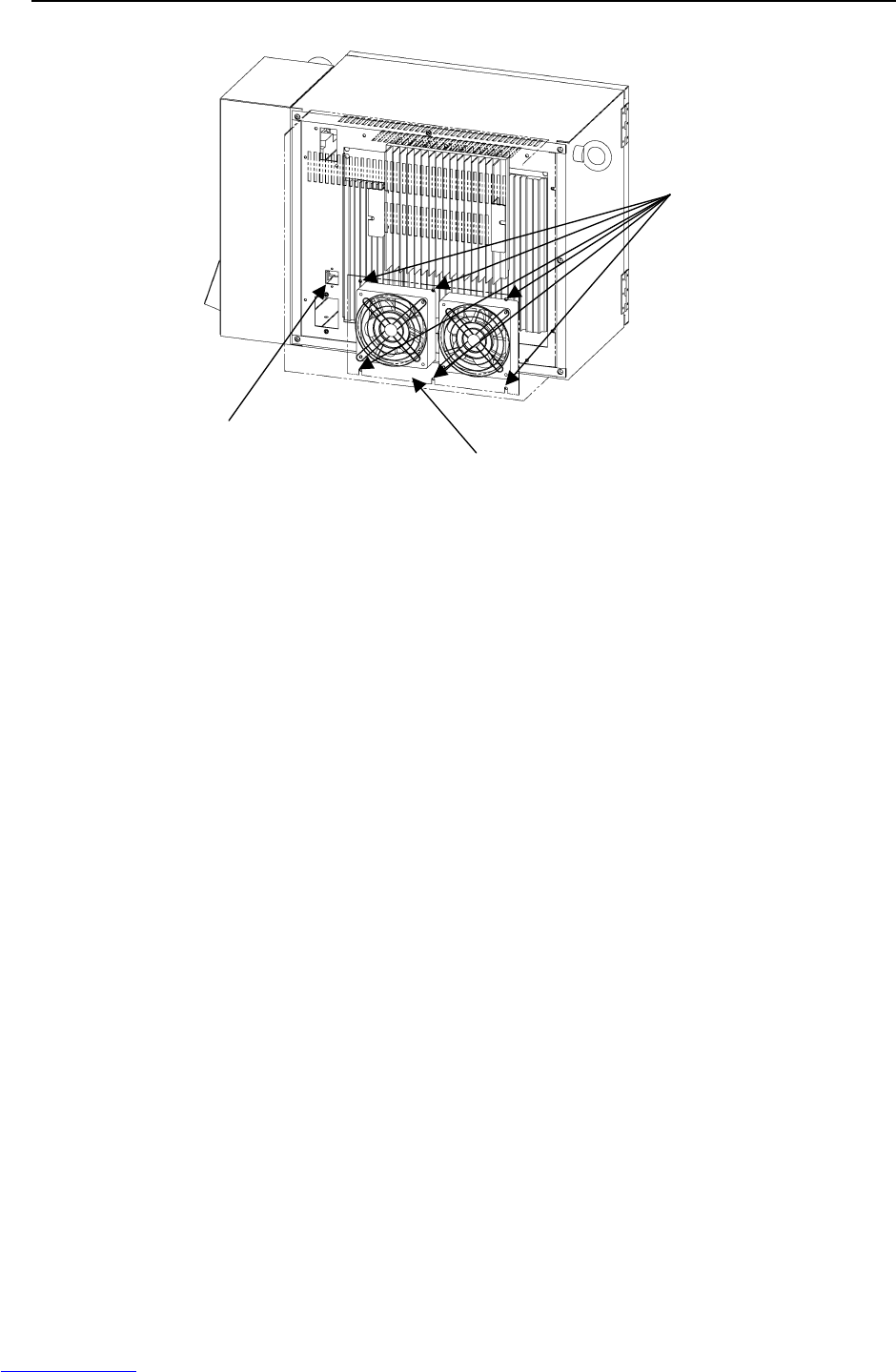
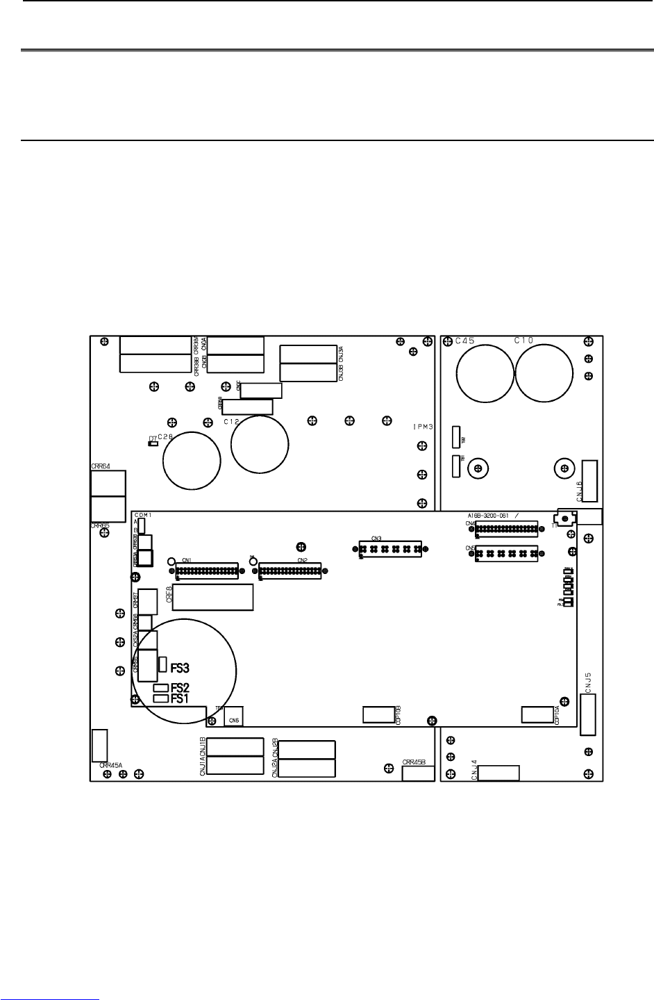
7.REPLACING A UNIT MAINTENANCE B-82725EN-1/07
- 110 -
7.9 REPLACING FUSES
If a fuse in the control unit has blown, find the cause and take an appropriate measure before replacing the
fuse.
7.9.1 Replacing Fuses in the Servo Amplifier
The following fuses are in the servo amplifier.
F1, F2: Fuses for detection of the circuits failure in the servo amplifier, (A60L-0001-0245#GP20)
If either of these fuses has blown, it is likely that the servo amplifier is defective. Replace the
servo amplifier.
FS1: For generation of the power to the amplifier control circuit (A60L-0001-0290#LM32C)
FS2: For protection of the 24 V output to the end effector, ROT, and HBK
(A60L-0001-0290#LM32C)
FS3: For protection of the 24 V output to the regenerative resistor and the additional axis amplifier
(A60L-0001-0290#LM50C)
5A
3.2A
3.2A
Fig.7.9.1 Replacing fuses in the servo amplifier
Downloaded from www.Manualslib.com manuals search engine
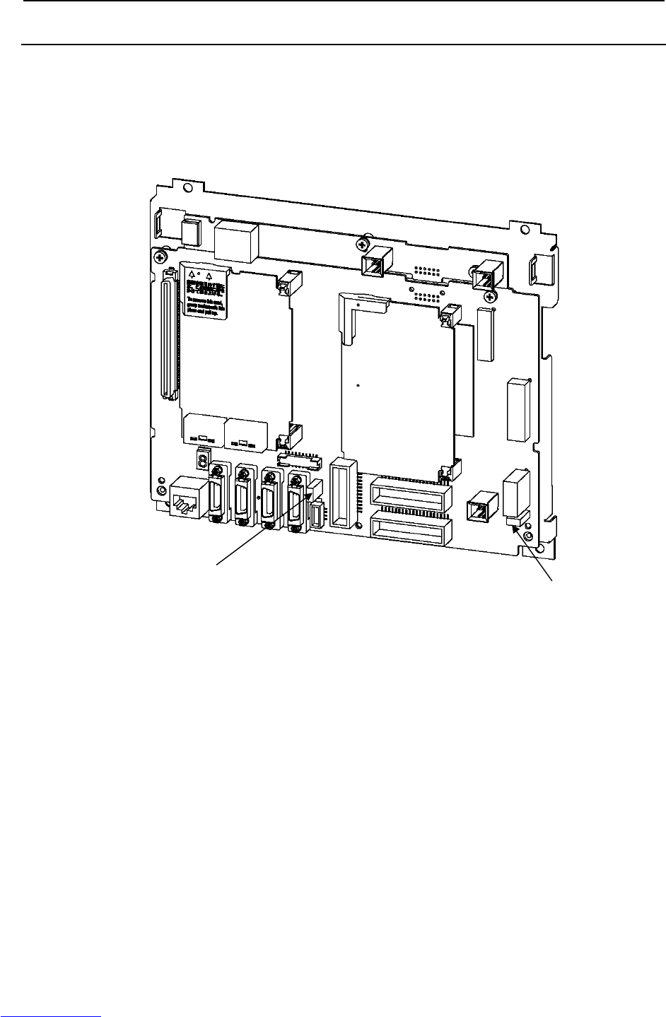
B-82725EN-1/07 MAINTENANCE 7.REPLACING A UNIT
- 111 -
7.9.2 Replacing Fuses in the Main Board
The following fuses are in the main board.
FUSE1: Fuse for protecting the +24V output:
A60L-0001-0290#LM50C
FUSE3: Fuse for protecting the +24V output for peripheral equipment interfaces:
A60L-0001-0290#LM10C
Fig.7.9.2 Replacing fuses in the main board
FUSE1 (5A)
FUSE3 (1A)
Downloaded from www.Manualslib.com manuals search engine
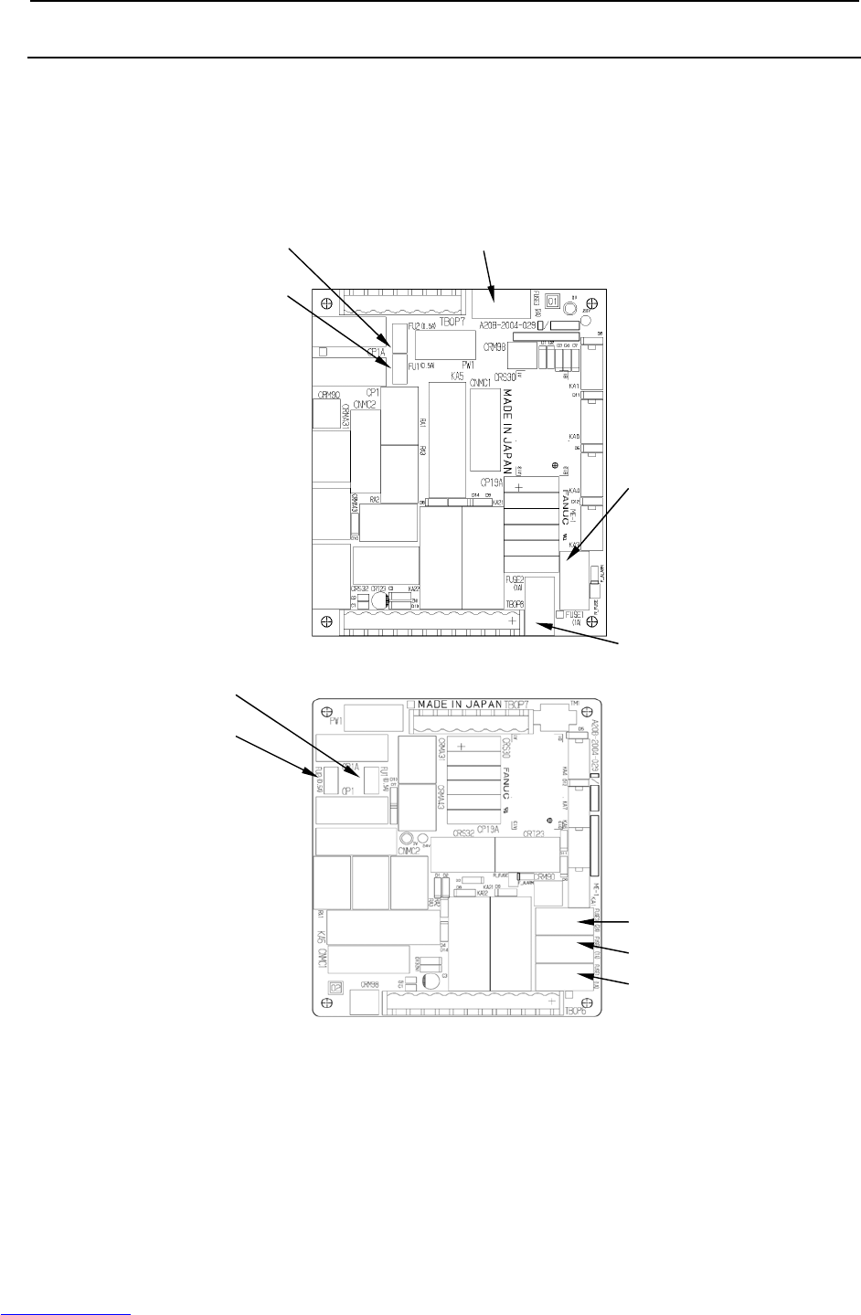
7.REPLACING A UNIT MAINTENANCE B-82725EN-1/07
- 112 -
7.9.3 Replacing the Fuse on the E-stop Boards
The emergency stop board has the following fuses:
FUSE1 For protecting +24EXT to the emergency stop circuit: A60L-0001-0046#1.0
FUSE2: For protecting +24V to the teach pendant: A60L-0001-0046#1.0
FUSE3: For protection of the +24V: A60L-0001-0046#2.0
FU1 and FU2: For door fan input protection: A60L-0001-0175#0.5A
(Edition 01A)
(Edition 02B or later)
Fig.7.9.3 Emergency stop board
FU2 (0.5A)
FU1 (0.5A)
FUSE3 (2A)
FUSE1 (1A)
FUSE2 (1A)
FUSE1 (1A)
FUSE2 (1A)
FUSE3 (2A)
FU2 (0.5A)
FU1 (0.5A)
Downloaded from www.Manualslib.com manuals search engine
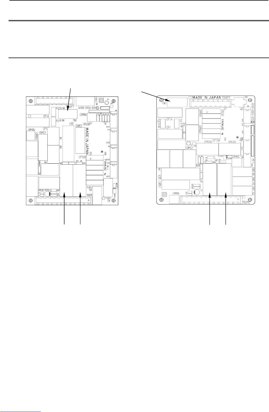
B-82725EN-1/07 MAINTENANCE 7.REPLACING A UNIT
- 113 -
7.10 REPLACING RELAYS
Prolonged use of a relay might result in its contacts failing to make a secure connection or sticking to
each other permanently. If such a failure occurs, replace the relay.
7.10.1 Replacing Relays on the E-stop Board
KA21, KA22 For the emergency stop circuit: A58L-0001-0192#1997R
PW1 For the 200-V power supply: A58L-0001-0548#AQC145
(Edition 01A) (Edition 02B or later)
Fig.7.10.1 Replacing relays on the emergency stop board
KA22 KA21
PW1
PW1
KA22 KA21
Downloaded from www.Manualslib.com manuals search engine
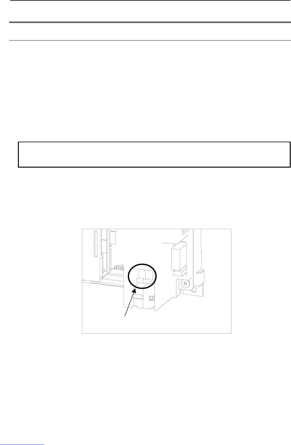
7.REPLACING A UNIT MAINTENANCE B-82725EN-1/07
- 114 -
7.11 REPLACING BATTERY
7.11.1 Battery for Memory Backup (3 VDC)
The programs, and system variables are stored in the SRAM in the main board. The power to the
SRAM memory is backed up by a lithium battery mounted on the front panel of the main board. The
above data is not lost even when the main power of controller is turned off. A new battery can maintain
the contents of memory for about 4 years (Note).
When the voltage of the battery becomes low, the low-voltage battery alarm (system-035) is displayed on
the teach pendant. When this alarm is displayed, replace the battery as soon as possible. In general, the
battery can be replaced within one or two weeks, however, this depends on the system configuration.
If the battery voltage gets lower, it becomes impossible to back up the content of the SRAM. Cycling
power to the controller in this state causes system not to start, and LED located on the main board
displays "1" because the contents of memory have been lost. Clear the entire SRAM memory and
reenter data after replacing the battery. Important data should be saved to the memory card or other
external device beforehand in case of emergency.
NOTE
In a newly introduced robot, the battery is factory-installed. Battery replacement
may, therefore, be needed within 4 years after the introduction of the robot.
Replacing the lithium battery
(1) Prepare a new lithium battery (ordering drawing number: A05B-2550-K030).
(2) Turn the robot controller on for about 30 seconds.
(3) Turn the robot controller off.
(4) Pull out the battery unit located in the lower right part of the backplane unit. (Hold the latch of the
battery unit, unlatch the battery unit from the case, and pull out the unit.).
Hold this part and pull out the battery unit.
(5) Install a new battery unit. (Insert the battery unit until the latch of the unit snaps into the case.)
Check that the battery unit is latched securely.
Downloaded from www.Manualslib.com manuals search engine
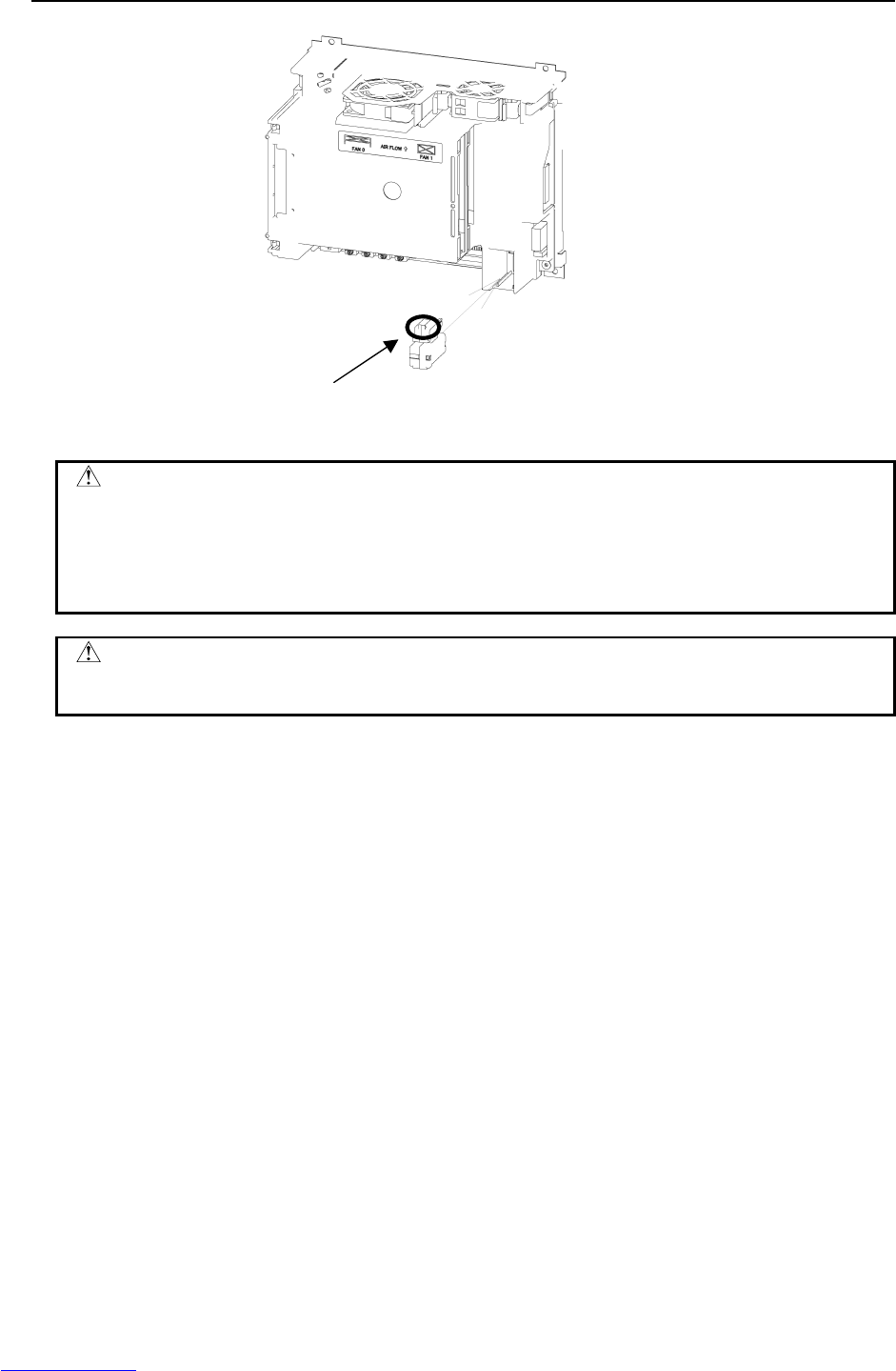
B-82725EN-1/07 MAINTENANCE 7.REPLACING A UNIT
- 115 -
Insert the unit until the latch snaps into the case.
Fig.7.11.1 Replacing the battery
CAUTION
Complete the steps (c) to (e) within 30 minutes.
If the battery is left disconnected for a long time, the contents of memory will be
lost.
To prevent possible data loss, it is recommended that the robot data such as
programs and system variables be backed up before battery replacement.
WARNING
Using other than the recommended battery may result in the battery explosion.
Replace the battery only with the specified battery (A05B-2550-K030).
Dispose of the replaced battery as an industrial waste, according to the laws and other rules in the country
where the controller is installed and those established by the municipality and other organizations that
have jurisdiction over the area where the controller is installed.
Downloaded from www.Manualslib.com manuals search engine


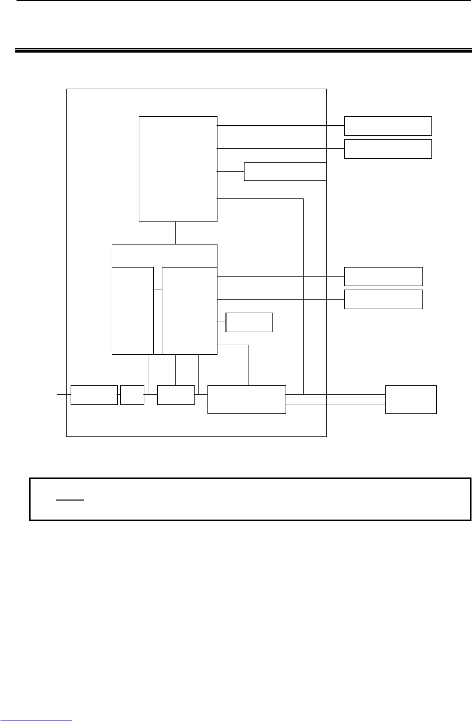
2.BLOCK DIAGRAM CONNECTIONS B-82725EN-1/07
- 120 -
2 BLOCK DIAGRAM
Fig.2 is a block diagram of electrical interface connections with the R-30iA Mate.
R-30iA Mate
Main board
E-stop unit
Teach pendant
RS-232-C
E-stop
board
Peripheral device
Robot
PSU
E-stop signal
Servo amp. MCC Breaker
200VAC Pulsecoder
Power
Operator panel
Fan
NF
NF: Noise Filter
Fig.2 Block diagram of electrical interface connection
NOTE
1 : Indicates electrical connection.
2 For more information, contact our service section.
Downloaded from www.Manualslib.com manuals search engine
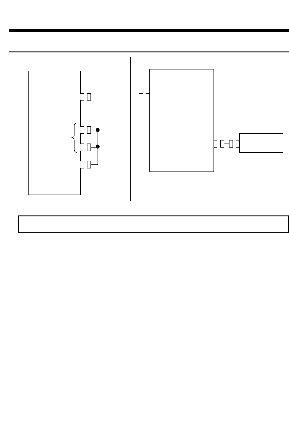
B-82725EN-1/07 CONNECTIONS 3.ELECTRICAL CONNECTIONS
- 121 -
3 ELECTRICAL CONNECTIONS
3.1 CONNECTION DIAGRAM BETWEEN MECHANICAL UNITS
R-30iA Mate
Robot
RMP
(Pulsecoder, RI/RO
, HBK, ROT)
(Motor power/brake)
Servo amplifier
CRF8
(Pulsecoder, RI/RO,
HBK, ROT)
CNJx
(Motor power)
CNGx
(Ground)
CRR88
(Brake control)
(Note1)
EE End effector
Fig.3.1 (a) Mechanical connection diagram
NOTE1
This cable is not included. It must be supplied by the customer.
Downloaded from www.Manualslib.com manuals search engine

3.ELECTRICAL CONNECTIONS CONNECTIONS B-82725EN-1/07
- 122 -
, ARC Mate 0iA
R-30iA Mate
CRS32
(Emergency stop board)
CRMA15, CRMA16
(Main board)
M-JD1A/S-JD1B
(Main board)
S-JD1A
(Main board)
JD17
(Main board)
CD38A
(Main board)
Breaker L
N
PE
L1
L2
L3
PE
Emergency stop board
(TBOP7)
EES1
EES11
EES2
EES21
EAS1
EAS11
EAS2
EAS21
Teach pendant
Peripheral device
External device
Ethernet
Input power
External emergency
stop switch
Fence
(Note 1)
(Note 2)
(Note 2)
(Note 2)
(Note 2)
Process I/O (Master setting)
CNC, etc. (Slave setting)
Process I/O, etc.
(slave setting)
In case of
LR Mate 200iC,M-1iA
In case of
ARC Mate 100iC,ARC Mate 120iC
M-10iA, M-20iA, ARC Mate 50iC
Fig.3.1 (b) Mechanical connection unit
NOTE
1 For detail of the peripheral device connection, see the section of Peripheral
device interface.
2 This cable is not included. It must be supplied by the customer.
Downloaded from www.Manualslib.com manuals search engine
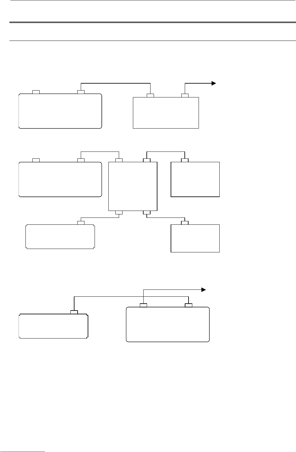
B-82725EN-1/07 CONNECTIONS 3.ELECTRICAL CONNECTIONS
- 123 -
3.2 FANUC I/O LINK
3.2.1 Connection of I/O Link
The connection of I/O links in the R-30iA Mate is shown below.
1. When the R-30iA Mate control unit is used as the I/O link master (default)
(When the R-30iA Mate control unit controls the process I/O board etc.)
To another I/O link
R-30iA Mate
M-JD1A/S-JD1B*
Process I/O board
etc.
JD1B JD1A
S-JD1A*
2. When the R-30iA Mate control unit is connected to a CNC etc. via the I/O link connection unit
R-30iA Mate
M-JD1A/S-JD1B*
FANUC I/O
unit etc.
JD1B
S-JD1A*
FANUC I/O
link connection
unit
JD1B1 JD1A1
JD1B2 JD1A2
FANUC I/O
unit etc.
JD1B
CNC, PLC
JD1A
3. When the R-30iA Mate control unit is used as an I/O link slave
(When a CNC or PLC is the I/O link master)
R-30iA Mate
M-JD1A/S-JD1B*
S-JD1A*
To another I/O link
CNC, PLC
JD1A
* M-JD1A/S-JD1B: For main board general versions equal to or earlier than 04A, the connector name
is JD1A.
S-JD1A: For main board general versions equal to or earlier than 04A, the connector
name is JD1B.
Fig.3.2.1 Connection of I/O links
Downloaded from www.Manualslib.com manuals search engine
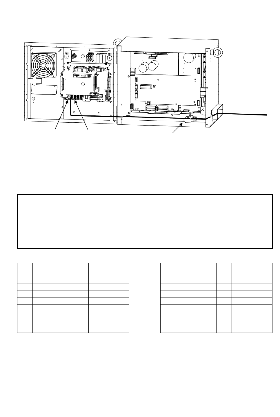
3.ELECTRICAL CONNECTIONS CONNECTIONS B-82725EN-1/07
- 124 -
3.2.2 Connection of I/O the Link Cable
Fig.3.2.2 (a) Path of the I/O link cable
1. Connect the cable according to the system. Be sure to perform shielding.
2. Before connection, turn off the power.
NOTE
For connection with the CNC with I/O links, turn on or off the power of the CNC
and the robot control unit at the following timing.
a) A slave unit must be powered on as soon as or before the master is powered on.
b) If the CNC or robot control unit is powered off after startup of the system, an I/O
link error occurs. To successfully make connection with I/O links again, power
off all of the units and then power them on at the timing indicated in a).
M-JD1A/S-JD1B interface S-JD1A interface
11 0V 01 RXSLC1 11 0V 01 RXSLC2
12 0V 02 *RXSLC1 12 0V 02 *RXSLC2
13 0V 03 TXSLC1 13 0V 03 TXSLC2
14 0V 04 *TXSLC1 14 0V 04 *TXSLC2
15 0V 05 15 0V 05
16 0V 06 16 0V 06
17 07 17 07
18 (+5V) 08 18 (+5V) 08
19 09 (+5V) 19 09 (+5V)
20 (+5V) 10 20 (+5V) 10
Note: +5V is connected when the optical
I/O link adapter is used.
Note: +5V is connected when the optical
I/O link adapter is used.
(1) Use a twisted-pair cable in which wires 1 and 2 are paired and wires 3 and 4 are paired.
(2) Shield the cable collectively and ground the shield on the CNC side.
M-JD1A/S-JD1B S-JD1A Grounding plate
Remove the insulation of the shield cable and
ground it here (see Section 4.7.1).
To another I/O link
Downloaded from www.Manualslib.com manuals search engine
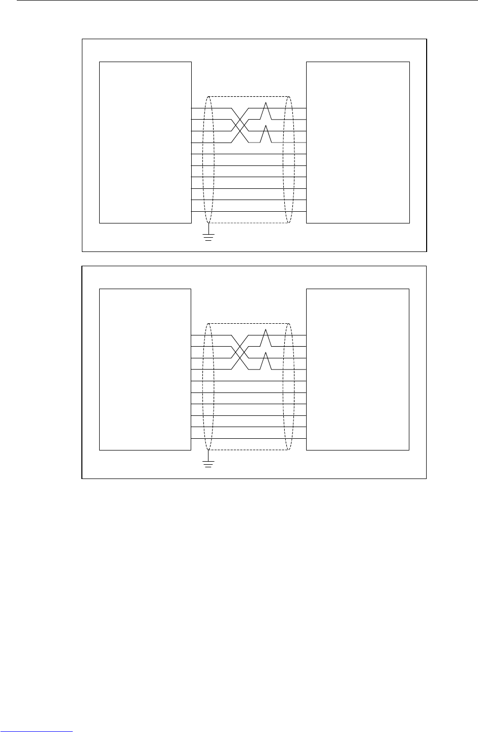
B-82725EN-1/07 CONNECTIONS 3.ELECTRICAL CONNECTIONS
- 125 -
Cable connection diagram
When the master is set
R-30iA Mate
M-JD1A/S-JD1B
RXSLC1 (1)
XRXSLC1 (2)
TXSLC1 (3)
XTXSLC1 (4)
0V (11)
0V (12)
0V (13)
0V (14)
0V (15)
0V (16)
I/O unit etc.
JD1B
(1) SIN [RX]
(2) XSIN [XRX]
(3) SOUT [TX]
(4) XSOUT [XTX]
(11) 0V
(12) 0V
(13) 0V
(14) 0V
(15) 0V
(16) 0V
When the slave is set
CNC、PLC etc.
JD1A
[RX] SIN (1)
[XRX] XSIN (2)
[TX] SOUT (3)
[XTX] XSOUT (4)
0V (11)
0V (12)
0V (13)
0V (14)
0V (15)
0V (16)
R-30iA Mate
M-JD1A/S-JD1B
(1) RXSLC1
(2) XRXSLC1
(3) TXSLC1
(4) XTXSLC1
(11) 0V
(12) 0V
(13) 0V
(14) 0V
(15) 0V
(16) 0V
Fig.3.2.2 (b) Connection diagram of I/O Link cable
Downloaded from www.Manualslib.com manuals search engine
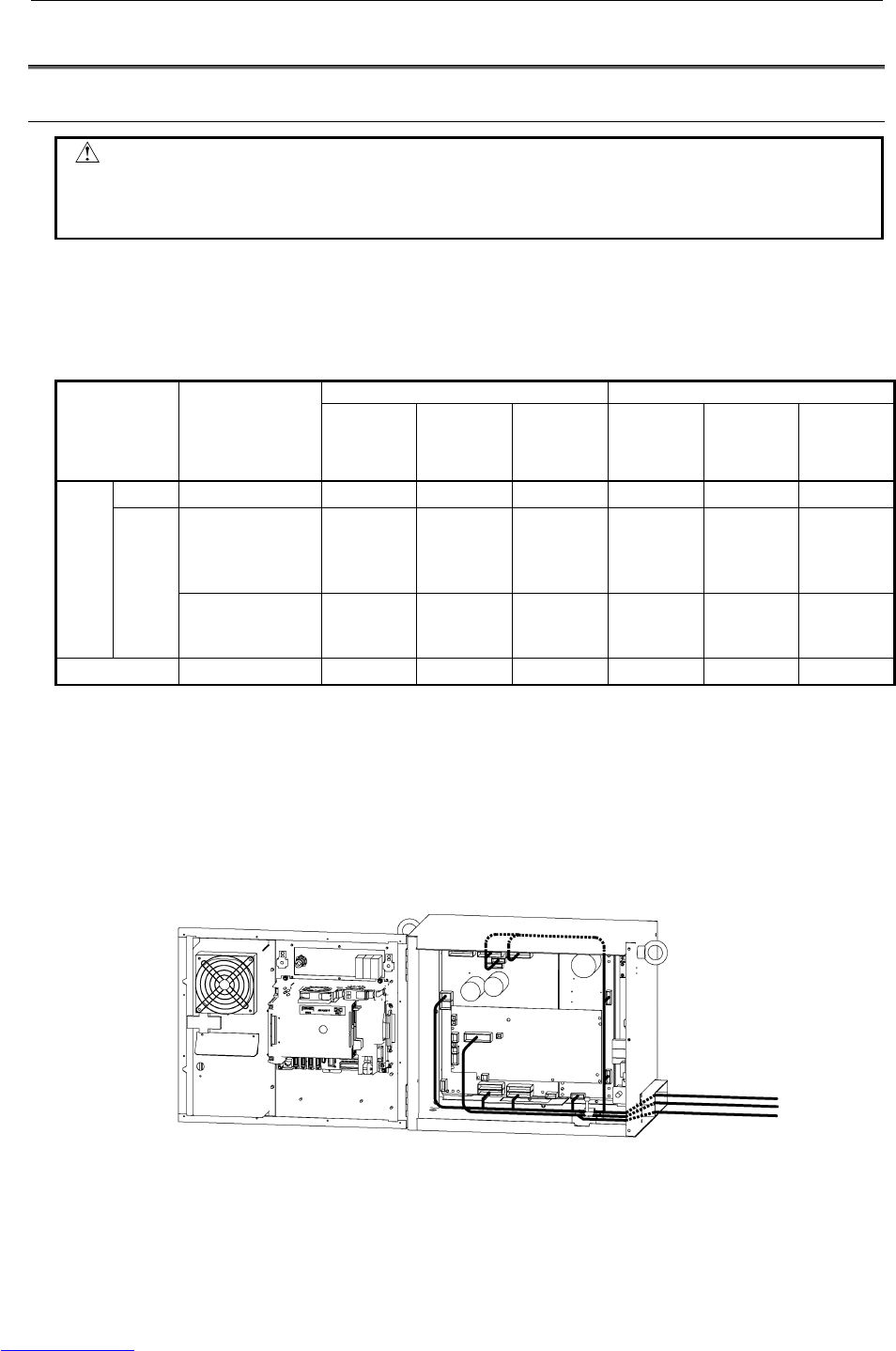
3.ELECTRICAL CONNECTIONS CONNECTIONS B-82725EN-1/07
- 126 -
3.3 EXTERNAL CABLE WIRING DIAGRAM
3.3.1 Robot Connection Cables
CAUTION
Before operating the robot, uncoil the interconnection cables from their shipping
position to prevent excessive heat, which may damage the cables.
(Coiled part should be shorter than 10 meter.)
There are two types of the robot connection cable;
Non-flex type: usage is restricted to fixed laying
Flex type: possible to use in the cable track
Specification of cable
Non-flex type Flex type
Robot Diameter
(mm) Weight
(kg/m) Minimum
bending
radius
(mm)
Diameter
(mm) Weight
(kg/m) Minimum
bending
radius
(mm)
Signal All models 14.2 0.31 200 - - -
ARC Mate 100iC
ARC Mate 120iC
M-10iA, M-20iA
ARC Mate 0iA
20.6 1.22 200 - - -
RMP
Power
LR Mate 200iC
M-1iA
ARC Mate 50iC
16.1 0.75 200 - - -
Earth All models 4.7 0.065 200 - - -
Using condition of flex type cable
(1) When routing cables in movable places, use a cable bearer.
(2) The bending radius (R) of the cable track is more than 200mm.
(3) The cable should be fixed to the cable track by using the clamp. (e.g. rubber packing)
(4) The size of the hole to support a cable in the cable track should be more than 110% of the cable size
and should have the gap more than 3mm.
(5) When cables are laid in the cable track, pay attention for the cable not to be twisted.
RMP
(Pulsecoder)
(Power)
Earth
Downloaded from www.Manualslib.com manuals search engine
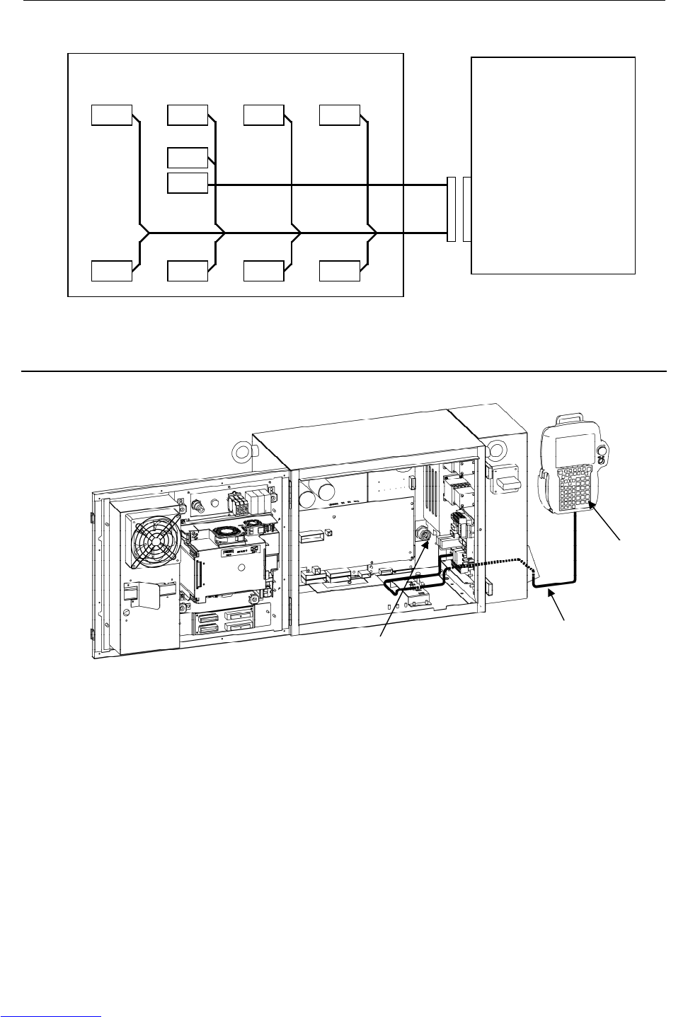
B-82725EN-1/07 CONNECTIONS 3.ELECTRICAL CONNECTIONS
- 127 -
- Detail of cable connection to servo amplifier.
R-30iA Mate (Servo amplifier)
Robot
RMP
(Pulsecoder, RI/RO, HBK, ROT)
(Motor power/brake)
(J1M, J2M, J3M, J4M, J5M, J6M, BK)
CNJ2A CNJ4 CNJ5CNJ1A
CRR88 CNGA CNJ3A
CNGC
CRF8
CNJ6
Fig.3.3.1 Robot connection cable
3.3.2 Teach Pendant Cable
Fig.3.3.2 Teach pendant cable
Teach pendant
E-stop board(CRS32)
Teach pendant cable
Downloaded from www.Manualslib.com manuals search engine
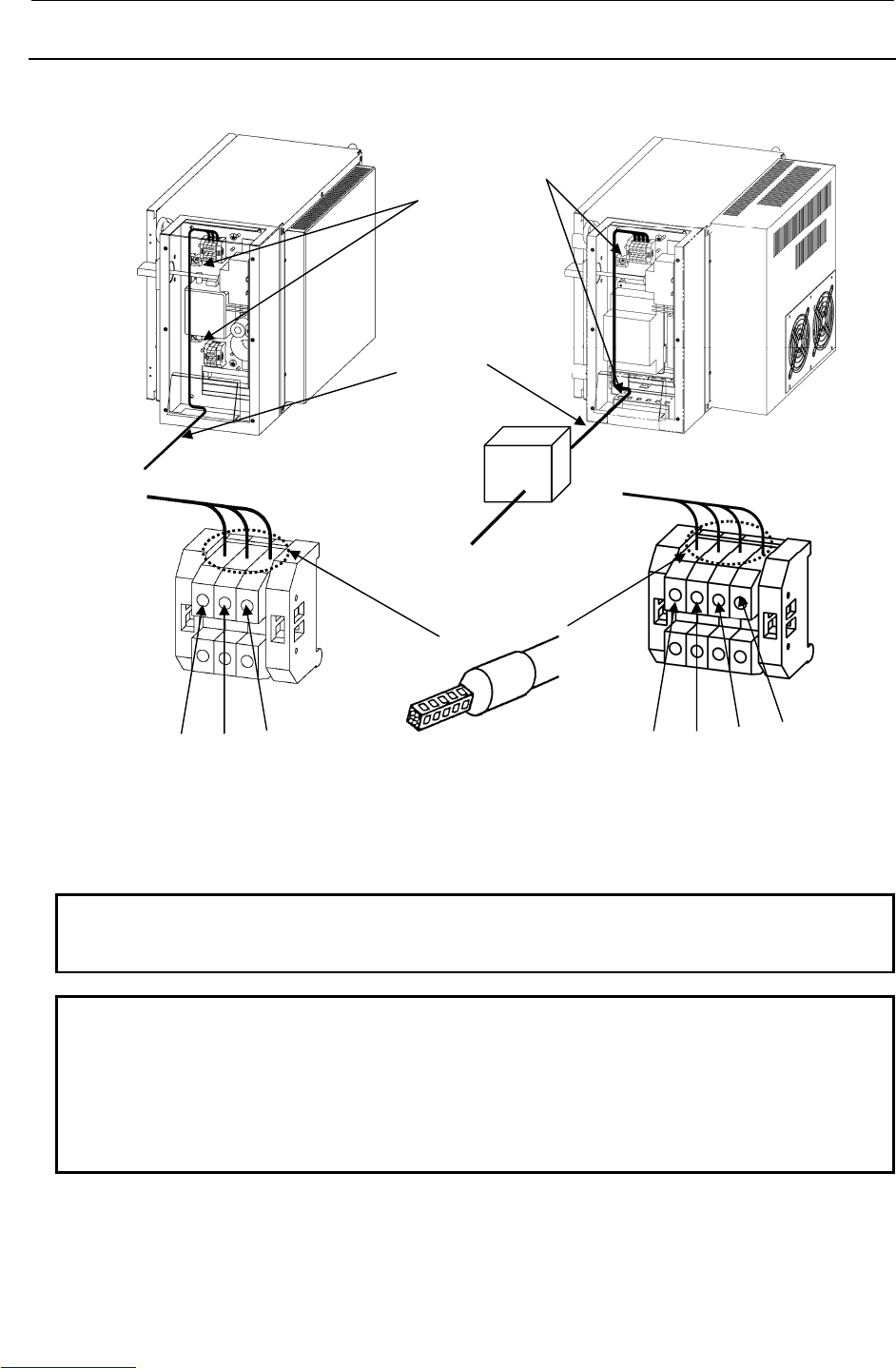
3.ELECTRICAL CONNECTIONS CONNECTIONS B-82725EN-1/07
- 128 -
3.3.3 Connecting the Input Power Supply
The input power cable should be supplied by the customer.
(LR Mate 200iC, M-1iA) (ARC Mate 100iC, M-10iA, ARC Mate 120iC, M-20iA
, ARC Mate 50iC, ARC Mate 0iA)
Fig.3.3.3 Input power cable
NOTE1
Use the wire which size is from AWG14 to AWG10 for input power supply cable
and earth cable.
NOTE2
Example of Isolated transformer
Manufacture RIST Transformatorenbau GmbH
Specification 25065LK
Capacity 3kVA
Output AC200V
Refer to the subsection 5.4 in CONNECTIONS.
Isolated transformer
(NOTE2)
Fix the power cable
at these cable holders.
(2 points)
Input power supply cable
(Earth cable)
L N PE Use ferrule to the terminal of power cable L1 L2 PE L3
A
C200V, 1φ
A
C200V, 3φ
Customer provided
Downloaded from www.Manualslib.com manuals search engine
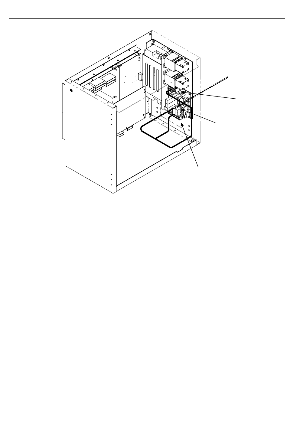
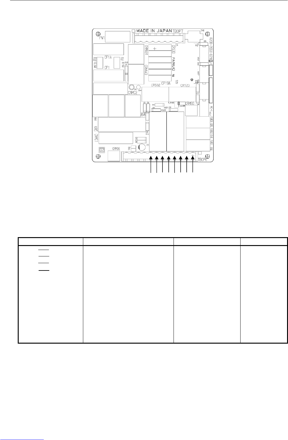
3.ELECTRICAL CONNECTIONS CONNECTIONS B-82725EN-1/07
- 130 -
External emergency stop output
Fig.3.3.4 (b) E-stop board
For the circuit, see Figure A (b) in Appendix A, "TOTAL CONNECTION DIAGRAM".
Signal Description Current, voltage Min. load
ESPB1 ESPB11
ESPB2 ESPB21
ESPB3 ESPB31
ESPB4 ESPB41
The contact is open when one of the
TP emergency stop button or the
Operator panel emergency stop
button is pressed. The contact is
also open while the controller is
powered off regardless of status of
emergency stop buttons. By
connecting external power supply to
the emergency stop circuit, the
contact works even while the robot
controller is powered off. (See
“External power connection” of this
section) The contact is closed during
normal operation.
Rated contact:
250 VAC, 5-A resistor
load
300 VDC, 5-A resistor
load
(Reference value)
DC5V 10mA
ESPB1
ESPB11
ESPB2
ESPB21
ESPB3
ESPB31
ESPB4
ESPB41
Downloaded from www.Manualslib.com manuals search engine
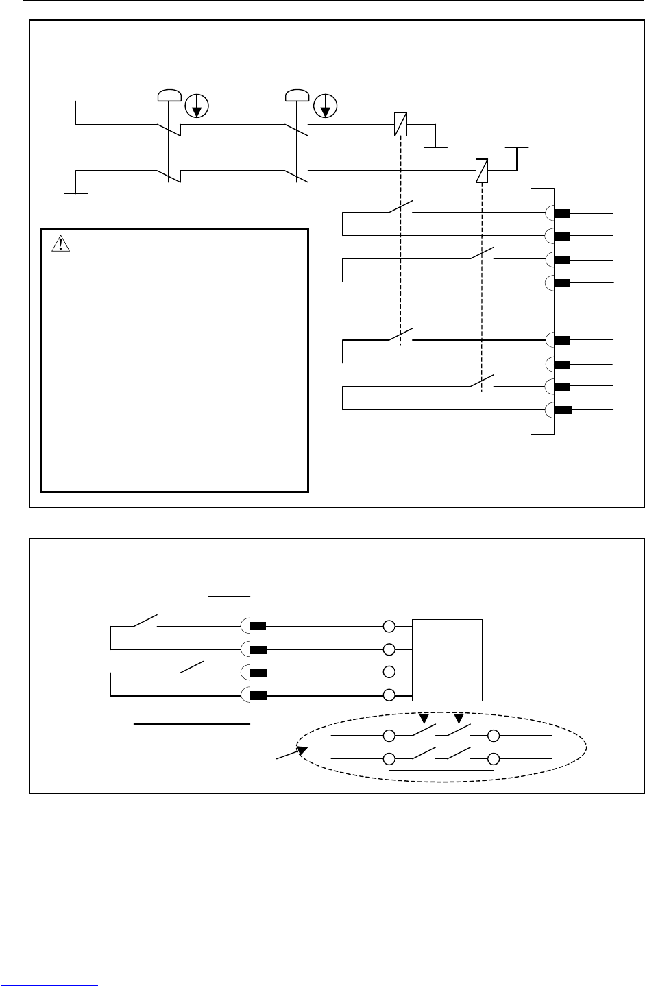
B-82725EN-1/07 CONNECTIONS 3.ELECTRICAL CONNECTIONS
- 131 -
ESPB1
ESPB11
ESPB2
ESPB21
ESPB3
ESPB31
ESPB4
ESPB41
Internal
circuit
+24EXT
0EXT
0EXT
+24EXT
TP emergency
stop button
KA21
KA22
Control
circuit
ESPB1
ESPB11
ESPB2
ESPB21
Example of the connection with the safety relay unit
Robot controller Safety relay unit
Contact output signal ensured safety
WARNING
In case of using the contact of the
emergency stop output signal, be
sure to pair ESPB1 with ESPB2,
and ESPB3 with ESPB4.
Robot controller does not detec
t
the breakdown of the contact o
f
the emergency stop output signal.
Take countermeasures such as
inspecting the duplicated
contacts, or using a safety rela
y
circuit that can detect the
breakdown.
Operator panel
emergency stop button
Connector
panel
Downloaded from www.Manualslib.com manuals search engine
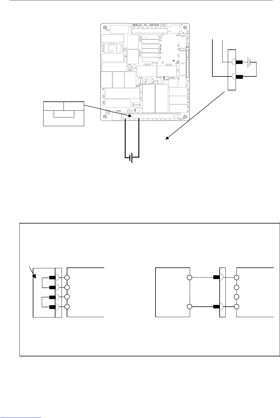
3.ELECTRICAL CONNECTIONS CONNECTIONS B-82725EN-1/07
- 132 -
External power connection
Fig.3.3.4 (d) External power connection
The relays for emergency stop input and output can be separated from controller’s power. Please connect
external +24V instead of internal +24V,if emergency stop output must not be effected controller’s power.
EXT24V
INT24V
INT0V
EXT0V
Example of the connection
In case of not using the external
power source
In case of using the external power source
EXT24V
INT24V
INT0V
EXT0V
24
V
0
V
External power source
+24V(±10%)
More than 300mA
EMC compliant
Connector
panel
Jumper
connector
Connector
panel
EXT0V EXT24V External power source
• +24V(±10%)
• More than 300mA
• EMC compliant
EXT
0V 24V
INT
Connector
panel
Downloaded from www.Manualslib.com manuals search engine
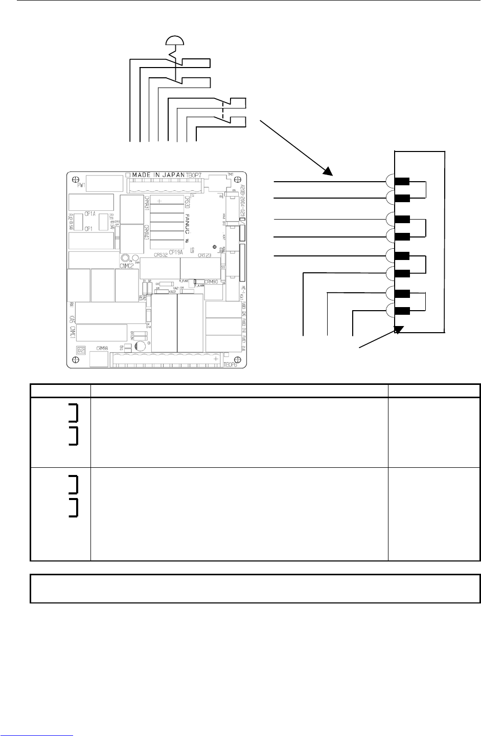
B-82725EN-1/07 CONNECTIONS 3.ELECTRICAL CONNECTIONS
- 133 -
External emergency stop input
External emergency stop switch
Fence
These terminals are
factory-jumpered. When using
external emergency stop inputs,
remove the Jumper connector.
EAS21
EAS2
EAS11
EAS1
EES21
EES2
EES11
EES1
Jumper connector
Connector
panel
Signal Description Current, voltage
EES1
EES11
EES2
EES21
Connect the contacts of the external emergency stop switch to these
terminals. When a contact is open, the servo power supply is turned off,
and the robot is immediately placed in the emergency stop state. When
using the contacts of a relay or contactor instead of the switch, connect a
spark killer to the coil of the relay or contactor, to suppress noise. When
these terminals are not used, jumper them.
Open and close of
24VDC 0.1A
(Note 1)
EAS1
EAS11
EAS2
EAS21
These signals are used to stop the robot safely when the safety fence gate
is opened during operation in the AUTO mode. When a contact is open,
the robot decelerates then stops, and the servo power supply is turned off.
In the T1 or T2 mode and the DEADMAN switch is held correct position,
the robot can be operated even when the safety fence gate is open.
When using the contacts of a relay or contactor instead of the switch,
connect a spark killer to the coil of the relay or contactor, to suppress
noise. When these terminals are not used, jumper them.
Open and close of
24VDC 0.1A
(Note 1)
NOTE
1 Use a contact which minimum load is 5 mA less.
Downloaded from www.Manualslib.com manuals search engine
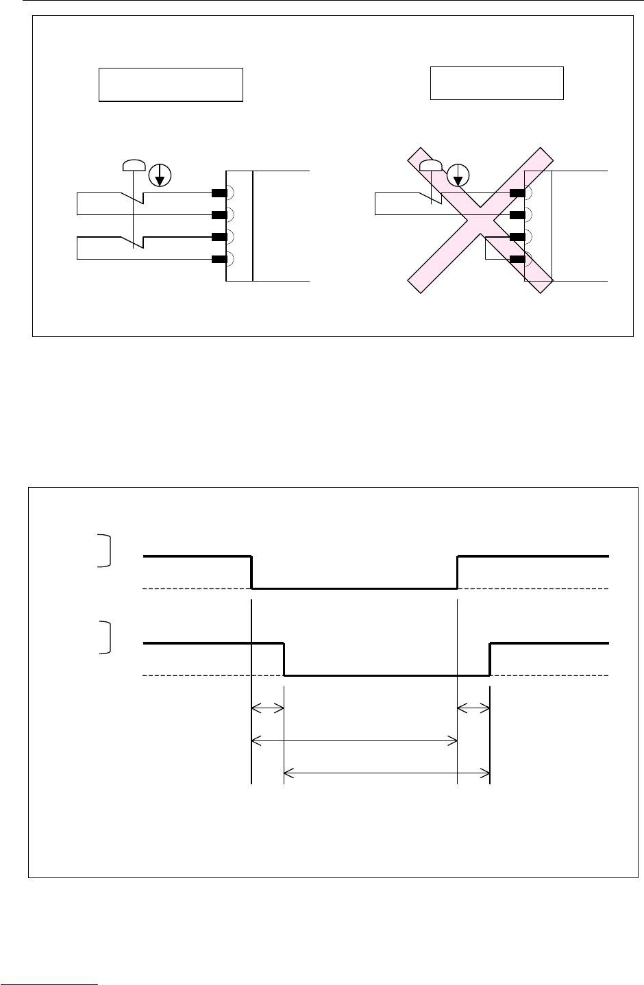
3.ELECTRICAL CONNECTIONS CONNECTIONS B-82725EN-1/07
- 134 -
EES1
EES11
EES2
EES21
Examples of connection of duplicate safety signals
External emergency stop switch
EES1
EES11
EES2
EES21
External emergency stop switch
Correct connection
Discrepancy in duplicate inputs results in an alarm.
Wrong connection
Connector
panel
Connector
panel
Input timing of duplicate safety signals
Duplicate inputs are used for signals such as the external emergency stop signal, safety fence signal, and
servo off signal so that a response is made even when a single failure occurs. The statuses of these
duplicate input signals must always be changed at the same timing according to the timing specifications
provided in this section. The robot control unit always checks that the statuses of the duplicate inputs
are the same, and if the control unit finds a discrepancy, it issues an alarm. If the timing specifications
are not satisfied, an alarm may be issued because of a signal discrepancy.
Open
Close
EES1
EAS1
EES2
EAS2
TDIF
TOPEN
TOPEN
TDIF
TDIF (input time difference)< 200msec
Open
Close
TOPEN (input hold period) > 2sec
Fig.3.3.4 (c) Input timing of duplicate safety signals
Downloaded from www.Manualslib.com manuals search engine

B-82725EN-1/07 CONNECTIONS 3.ELECTRICAL CONNECTIONS
- 135 -
Connecting external on/off and external emergency stop signal input/output
wires
FANUC's specification Manufacturer's
specification (WAGO) Remark
8-pole terminal block
(TBOP7)
A63L-0001-0783#308 231-308/026-000 External emergency stop
12-pole terminal block
(TBOP6)
A63L-0001-0783#312 231-312/026-000 External emergency stop
Jumper pin A63L-0001-0783#902 231-902
Operation lever A63L-0001-0783#131-M 231-131 2 pieces of 231-131 and operation
manual are included in FANUC's
specification
1. Detach the plug connector block from the panel board.
2. Insert the tip of a flat-blade screwdriver into the manipulation slot and push down its handle.
3. Insert the end of the signal wire into the wire slot.
4. Pull out the screwdriver.
5. Attach the plug connector block to the panel board.
Do not insert a wire into the wire hole of a plug connector or pull it out with the plug connector
block mounted on the panel board; otherwise, the panel board may be damaged.
FANUC recommends the lever (A05B-2400-K030) for connecting the signal wire to the plug connector
block instead of Flat-blade screwdriver.
Signal wire
Flat-blade screwdriver
Downloaded from www.Manualslib.com manuals search engine
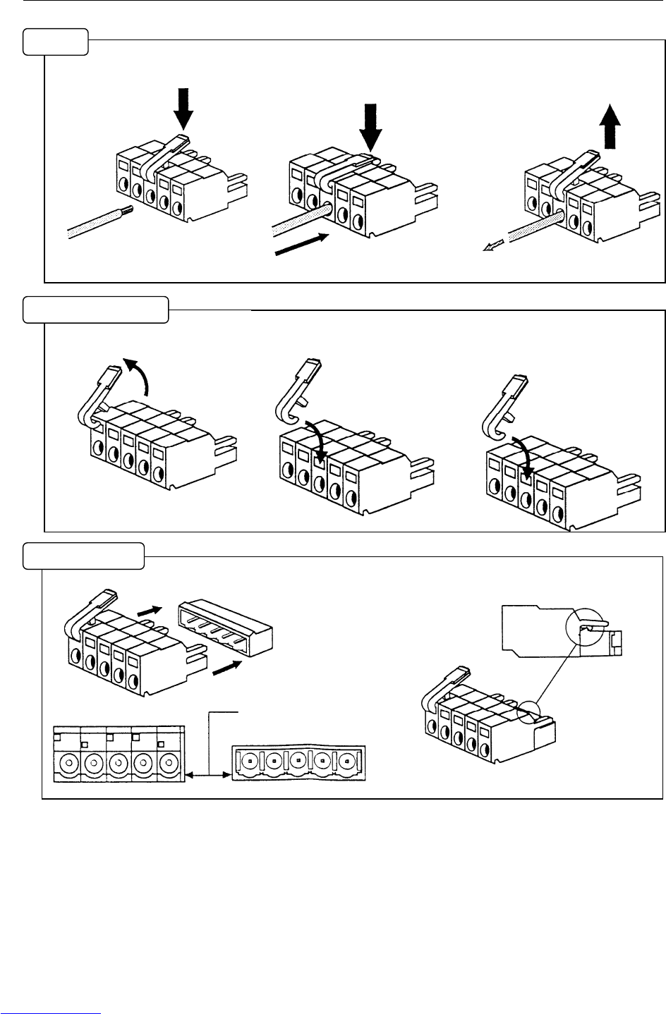
3.ELECTRICAL CONNECTIONS CONNECTIONS B-82725EN-1/07
- 136 -
(1) Pull down the lever.
(2) Push in the conductor while
holding the lever.
(3) Set the lever free.
* In addition, pull the conductor
softly to check the clamping.
* Don't pull strongly.
(1) Pull off the lever. Be careful
not to lose the lever.
(2) Hook the lever to the rectangle
hole.
(3) Push down the lever until click
in.
(1) Push in the connector to header.
* Be careful to fit the
shape of each other.
(2) Please check if the latch is hooked to header.
Wirin
g
Re
p
lace the leve
r
Fit to heade
r
Downloaded from www.Manualslib.com manuals search engine
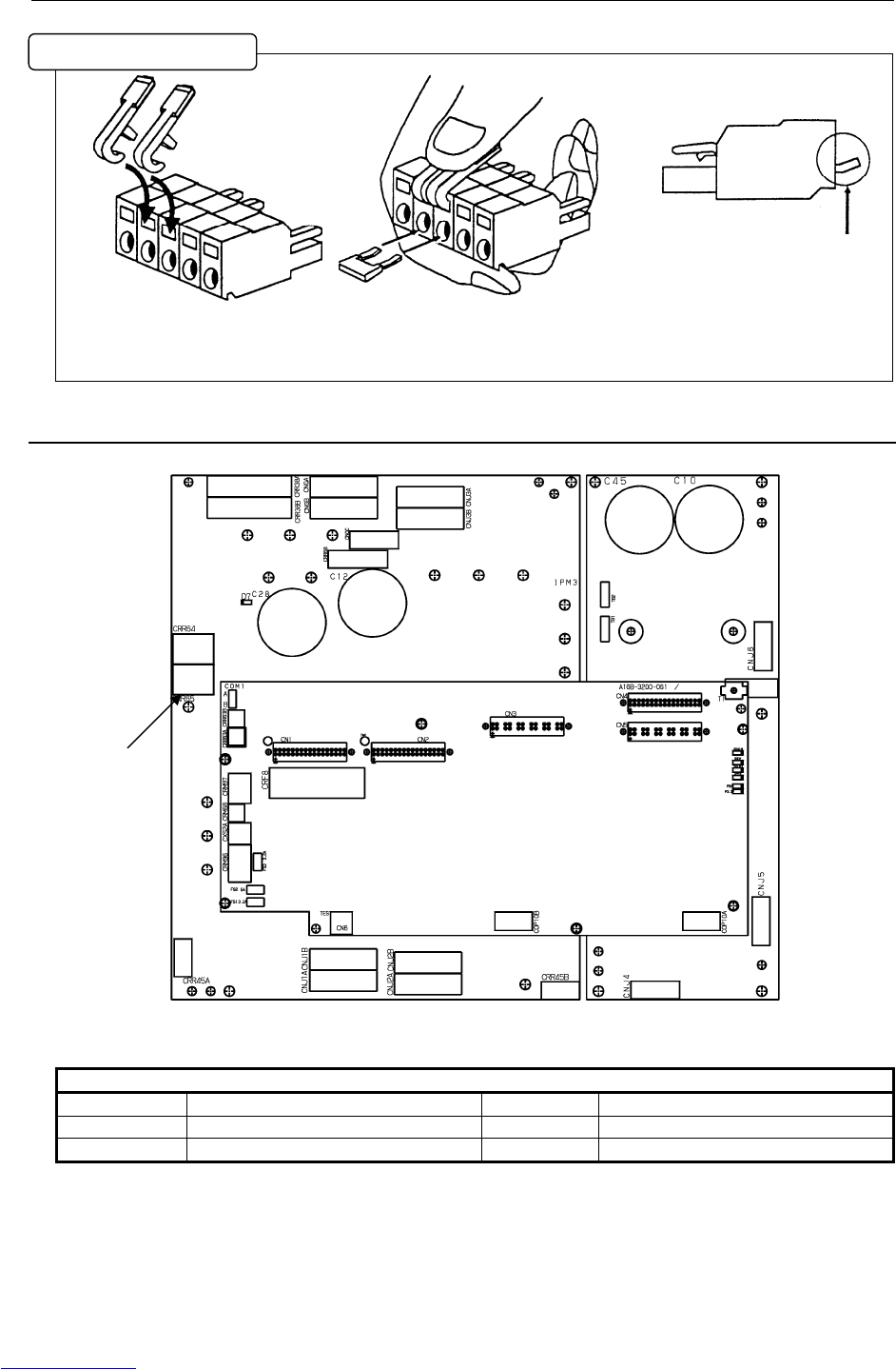
B-82725EN-1/07 CONNECTIONS 3.ELECTRICAL CONNECTIONS
- 137 -
(1) Attach levers to connector.
(2) Hold down levers at the same
time, then put the jumper into
connector.
* Please check the direction of the
jumper.
3.3.5 Connecting the Auxiliary Axis Brake (CRR65 A/B)
Fig.3.3.5 6-axis servo amplifier
Table 3.3.5 CRR65 A/B connector manufactured by Tyco Electronics AMP k.k.
CRR65 A/B
A1 BKA1 B1 BKA2
A2 B2
A3 COMMON B3 COMMON
Specification:
Rece-housing 1-178129-6 : A63L-0001-0460#062KMXX
Rece-contact 175218-2 : A63L-0001-0456#ASL
Installation of "Jum
p
er"
CRR65
Downloaded from www.Manualslib.com manuals search engine

3.ELECTRICAL CONNECTIONS CONNECTIONS B-82725EN-1/07
- 138 -
3.3.6 Connecting the Auxiliary Axis Over Travel (CRM68)
Fig.3.3.6 6-axis servo amplifier
Table 3.3.6 CRM68 connector manufactured by Tyco Electronics AMP k.k.
CRM68
A1 AUXOT1
A2 AUXOT2
A3
Specification:
Rece-housing 1-1318120-3 : A63L-0001-0812#R03SX
Rece-contact 1318107-1 : A63L-0001-0812#CRM
CRM68
Downloaded from www.Manualslib.com manuals search engine
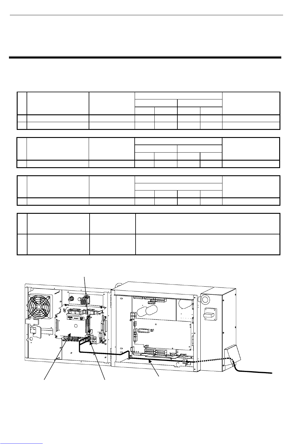
B-82725EN-1/07 CONNECTIONS
- 139 -
4. PERIPHERAL DEVICE AND
END EFFECTOR INTERFACES
4 PERIPHERAL DEVICE AND END
EFFECTOR INTERFACES
Table 4 lists the peripheral device interfaces of the R-30iA Mate. Fig. 4 shows a peripheral device cable
routing diagram.
Table 4 Peripheral device interface types
Peripheral device interface
CRMA15 CRMA16
No. Name Drawing number
DI DO DI DO
Remarks
1a Main board A A20B-8200-0470 20 8 8 16 Standard
1b Main board B A20B-8200-0471 20 8 8 16 With Vision I/F
Peripheral device interface
CRMA52A CRMA52B
No. Name Drawing number
DI DO DI DO
Remarks
2 Process I/O board MA A20B-2004-0380 10 8 10 8 Option
Peripheral device interface
CRW11
No. Name Drawing number
WI WO D/A A/D
Remarks
3 Process I/O board MB A20B-2101-0730 5 4 2 0 Option
No. Name Drawing number Remarks
4 Connector converter
board
A20B-2004-0410 This option board converts peripheral device interfaces
CRMA15 and CRMA16 of the main board to the MR connector
manufactured by Honda Tsushin Kogyo Co., LTD.
Fig.4 (a) Connecting the peripheral device cable
Main board
CRMA16
CRMA15
To Peripheral
device
Peripheral device cable
Downloaded from www.Manualslib.com manuals search engine
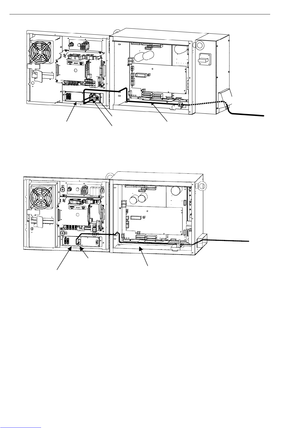
CONNECTIONS B-82725EN-1/07
- 140 -
4. PERIPHERAL DEVICE AND
END EFFECTOR INTERFACES
Fig. 4 (b) Connecting the peripheral device cable (Process I/O board MA)
Process I/O board MB
CRW11
Welding machine cable (For Process I/O)
To Welding machine
Fig.4 (c) Connecting the welding machine cable (Process I/O board MB)
Process I/O board MA
CRMA52A
CRMA52B
To Peripheral
device
Peripheral device cable (For Process I/O)
Downloaded from www.Manualslib.com manuals search engine
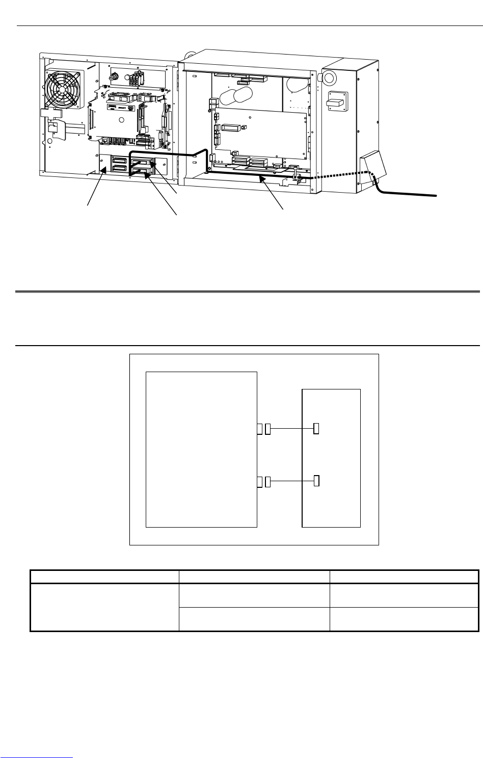
B-82725EN-1/07 CONNECTIONS
- 141 -
4. PERIPHERAL DEVICE AND
END EFFECTOR INTERFACES
Connector converter board
CRMA58
CRMA59
To Peripheral device
Peripheral device cable
Fig.4 (d) Connecting the peripheral device cable (Connector converter board)
4.1 PERIPHERAL DEVICE INTERFACE BLOCK DIAGRAM
Following are a block diagram of the peripheral device interface and the specifications.
4.1.1 In Case of Main Board (CRMA15, CRMA16)
Main board
CRMA15
CRMA16
Peripheral
Device
Fig.4.1.1 Block diagram of connecting peripheral device cable
Name Drawing number Remarks
A05B-2550-J100 Length: 10m (CRMA15)
Length: 10m (CRMA16)
Peripheral device connection cable
(For main board)
A05B-2550-J101 Length: 20m (CRMA15)
Length: 20m (CRMA16)
Downloaded from www.Manualslib.com manuals search engine
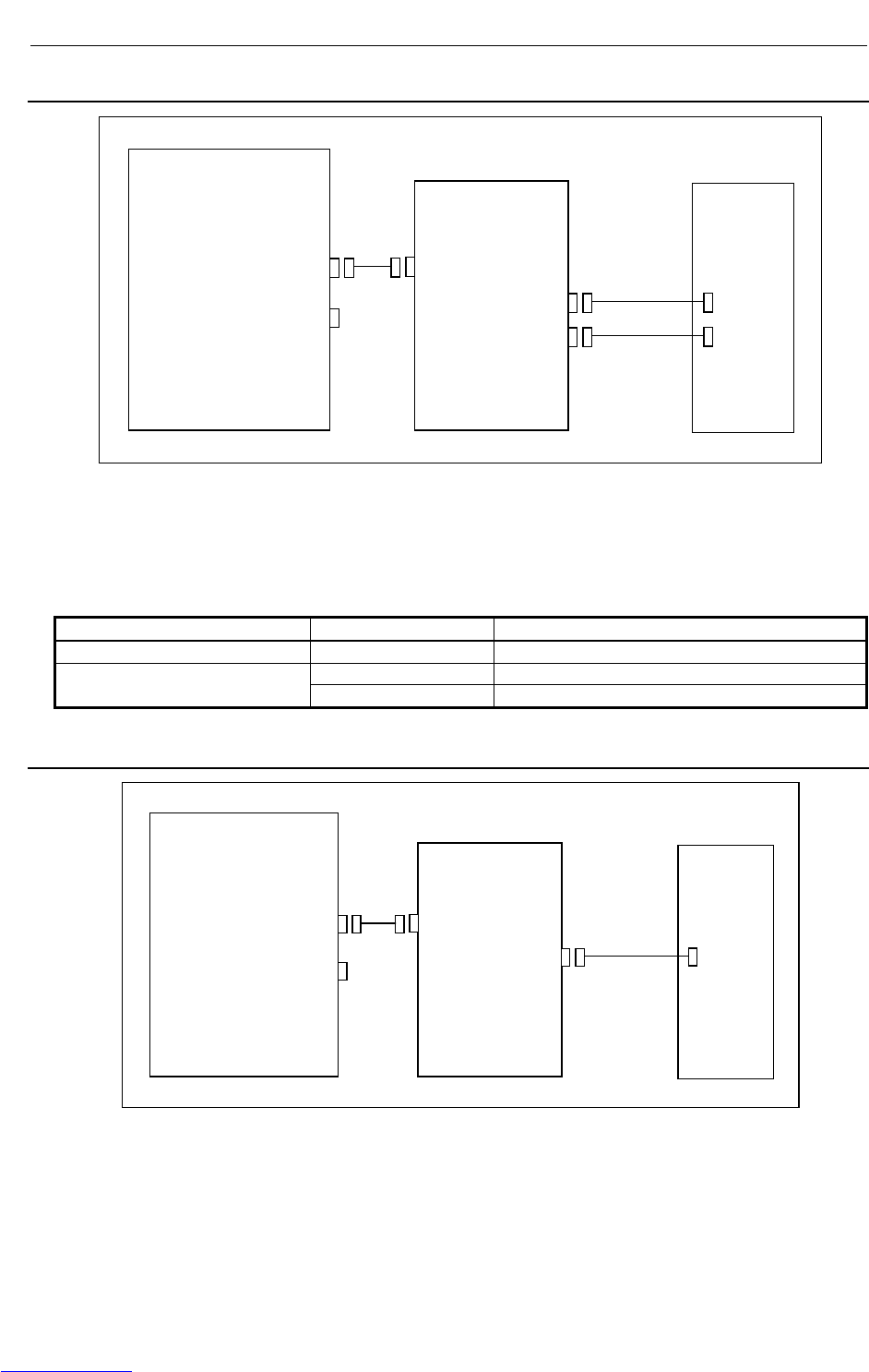
CONNECTIONS B-82725EN-1/07
- 142 -
4. PERIPHERAL DEVICE AND
END EFFECTOR INTERFACES
4.1.2 In the Case of the Process I/O Board MA
Main board
M-JD1A/S-JD1B
S-JD1A
Process I/O
board MA
Note)
Peripheral
unit
JD1B
CRMA52A
CRMA52B
(Note) The connection depends on whether the R-30i
A
Mate is
the I/O link master or an I/O link slave.
For details, see Section 3.2.1.
②
②
①
Fig.4.1.2 Block diagram of the process I/O MA
Component Drawing number Remark
<1> I/O link cable - Included in the process I/O board MA
A05B-2550-J220 Connection length 10m (one): CRMA52 <2> Peripheral device cable
(For process I/O MA) A05B-2550-J221 Connection length 20m (one): CRMA52
4.1.3 In the Case of the Process I/O Board MB
Main board
M-JD1A/S-JD1B
S-JD1A
Process I/O
board MB
Note)
Welding
machine
JD1B
CRW11
(Note) The connection depends on whether the R-30iA Mate is
the I/O link master or an I/O link slave.
For details
,
see Section 3.2.1.
②
①
Fig.4.1.3 Block diagram of the process I/O MB
Downloaded from www.Manualslib.com manuals search engine
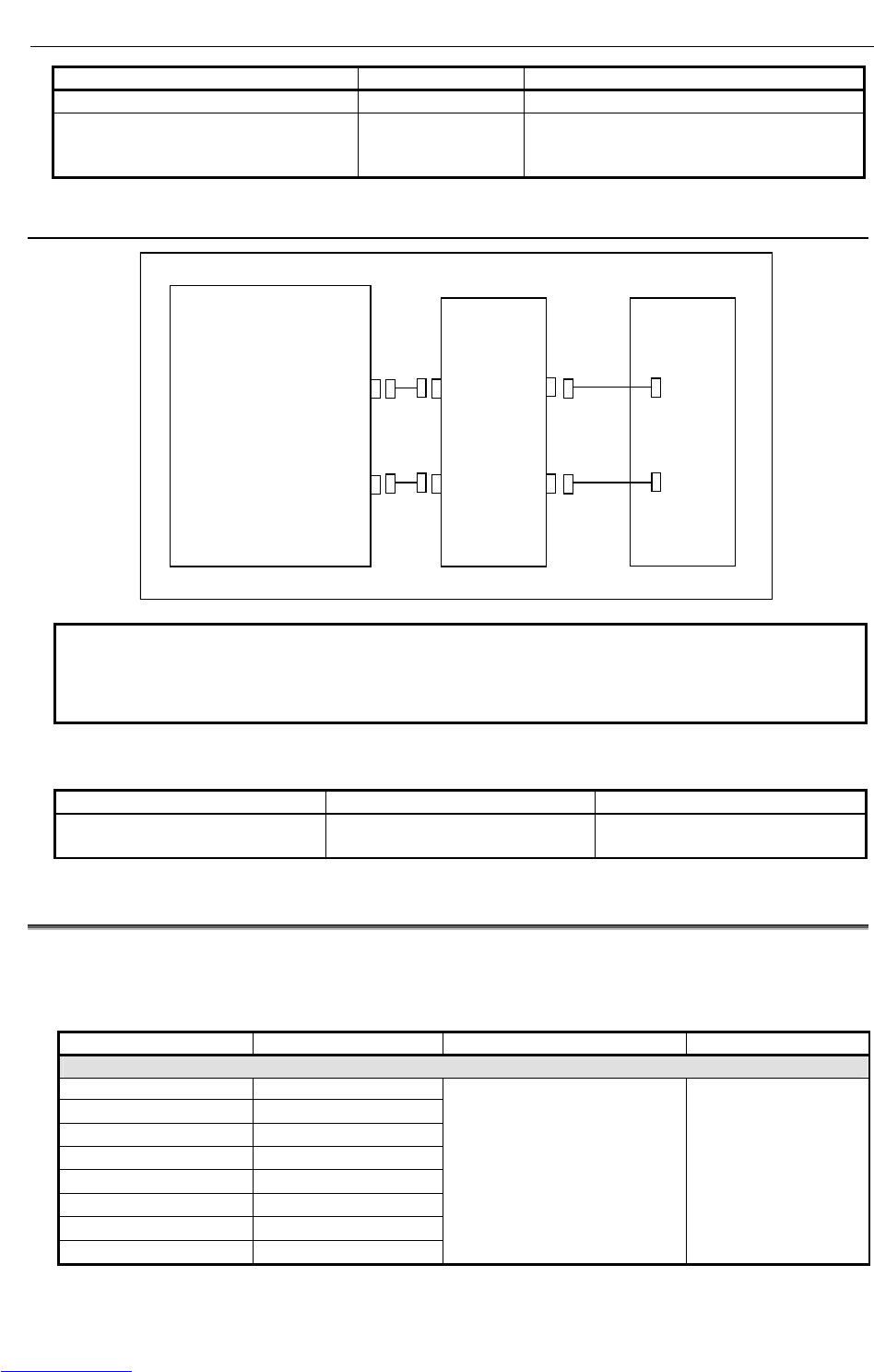
B-82725EN-1/07 CONNECTIONS
- 143 -
4. PERIPHERAL DEVICE AND
END EFFECTOR INTERFACES
Component Drawing number Remark
<1> I/O link cable - Included in the process I/O board MB
<2> Welding machine connection cable
(For process I/O MB)
(FANUC interface/elbow type)
A05B-2552-J204 Connection length 7m (one): CRW11
4.1.4 In the Case of the Connector Conversion Board
Main board
CRMA15
CRMA16
Connector
conversion
board
Peripheral
unit
CRMA58
CRMA59
(Note 1)
(Note 1)
①
①
NOTE
This component is not provided by FANUC. The customer needs to obtain it.
For details on the connection method, see "Connection between the peripheral
devices and the control unit".
Fig.4.1.4 Connection diagram of the connector conversion board
Component Drawing number Remark
<1> Connection cable - Included in the I/O connector
conversion board.
4.2 I/O SIGNALS OF MAIN BOARD
There are 28 data inputs (DI) and 24 data outputs (DO) on main board.
Table 4.2 shows I/O signals of main board.
Table 4.2 I/O Signals of main board
Connector number Signal name Description Remarks
(DI signals)
CRMA15-A5 DI101
CRMA15-B5 DI102
CRMA15-A6 DI103
CRMA15-B6 DI104
CRMA15-A7 DI105
CRMA15-B7 DI106
CRMA15-A8 DI107
CRMA15-B8 DI108
Peripheral device status General signal
Downloaded from www.Manualslib.com manuals search engine
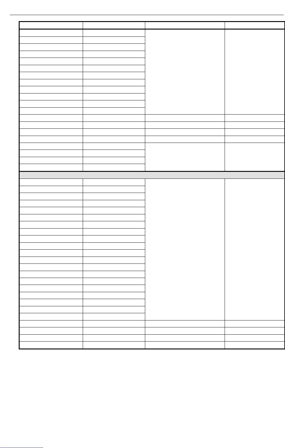
CONNECTIONS B-82725EN-1/07
- 144 -
4. PERIPHERAL DEVICE AND
END EFFECTOR INTERFACES
Connector number Signal name Description Remarks
CRMA15-A9 DI109
CRMA15-B9 DI110
CRMA15-A10 DI111
CRMA15-B10 DI112
CRMA15-A11 DI113
CRMA15-B11 DI114
CRMA15-A12 DI115
CRMA15-B12 DI116
CRMA15-A13 DI117
CRMA15-B13 DI118
CRMA15-A14 DI119
CRMA15-B14 DI120
Peripheral device status General signal
CRMA16-A5 XHOLD Temporary stop
CRMA16-B5 FAULT RESET External reset
CRMA16-A6 START Start
CRMA16-B6 ENBL Operation enabled
CRMA16-A7 PNS1
CRMA16-B7 PNS2
CRMA16-A8 PNS3
CRMA16-B8 PNS4
Robot service request
(DO signals)
CRMA15-A15 DO101
CRMA15-B15 DO102
CRMA15-A16 DO103
CRMA15-B16 DO104
CRMA15-A17 DO105
CRMA15-B17 DO106
CRMA15-A18 DO107
CRMA15-B18 DO108
CRMA16-A10 DO109
CRMA16-B10 DO110
CRMA16-A11 DO111
CRMA16-B11 DO112
CRMA16-A12 DO113
CRMA16-B12 DO114
CRMA16-A13 DO115
CRMA16-B13 DO116
CRMA16-A14 DO117
CRMA16-B14 DO118
CRMA16-A15 DO119
CRMA16-B15 DO120
Peripheral device control signal General signal
CRMA16-A16 CMDENBL During automatic operation
CRMA16-B16 FAULT Alarm
CRMA16-A17 BATALM Battery voltage drop
CRMA16-B17 BUSY During operation
Downloaded from www.Manualslib.com manuals search engine
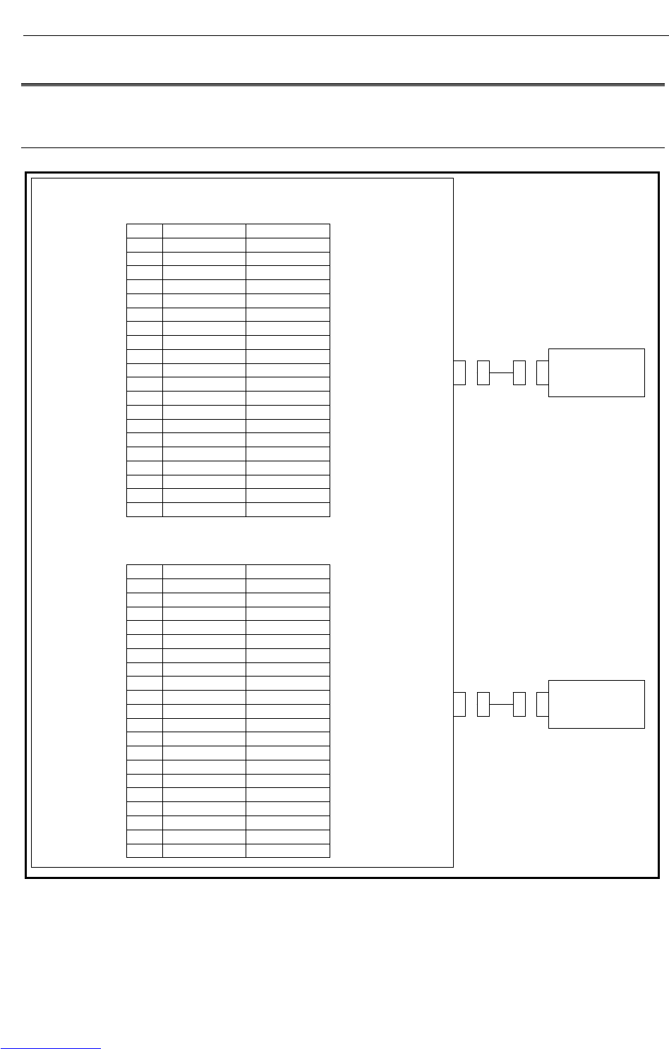
B-82725EN-1/07 CONNECTIONS
- 145 -
4. PERIPHERAL DEVICE AND
END EFFECTOR INTERFACES
4.3 INTERFACE FOR PERIPHERAL DEVICES
4.3.1 Connection between the Main Board (CRMA15, CRMA16) and
Peripheral Devices
Peripheral device control interface A1 (source type DO)
CRMA15
A B
01 24F 24F
02 24F 24F
03 SDICOM1 SDICOM2
04 0V 0V
05 DI101 DI102
06 DI103 DI104
07 DI105 DI106
08 DI107 DI108
09 DI109 DI110
10 DI111 DI112
11 DI113 DI114
12 DI115 DI116
13 DI117 DI118
14 DI119 DI120
15 DO101 DO102
16 DO103 DO104
17 DO105 DO106
18 DO107 DO108
19 0V 0V
20 DOSRC1 DOSRC1
Peripheral device control interface A2 (source type DO)
CRMA16
A B
01 24F 24F
02 24F 24F
03 SDICOM3
04 0V 0V
05 XHOLD RESET
06 START ENBL
07 PNS1 PNS2
08 PNS3 PNS4
09
10 DO109 DO110
11 DO111 DO112
12 DO113 DO114
13 DO115 DO116
14 DO117 DO118
15 DO119 DO120
16 CMDENBL FAULT
17 BATALM BUSY
18
19 0V 0V
20 DOSRC2 DOSRC2
Peripheral
device A1
Peripheral
device A2
Downloaded from www.Manualslib.com manuals search engine

CONNECTIONS B-82725EN-1/07
- 146 -
4. PERIPHERAL DEVICE AND
END EFFECTOR INTERFACES
SDICOM1~3 signal are common selection signal for SDI.
When +24F common is used, connect to 0V.
When 0V common is used, connect to +24F.
SDICOM1 → Selects a common for DI101~DI108.
SDICOM2 → Selects a common for DI109~DI120.
SDICOM3 → Selects a common for XHOLD、RESET、START、ENBL、PNS1~PNS4.
NOTE
1 The peripheral device connection cables are optional.
2 The DOSRC1 and DOSRC2 pins of the CRMA15 and CRMA16 are pins for
supplying power to drivers. (None of these pins can be left open.)
Downloaded from www.Manualslib.com manuals search engine
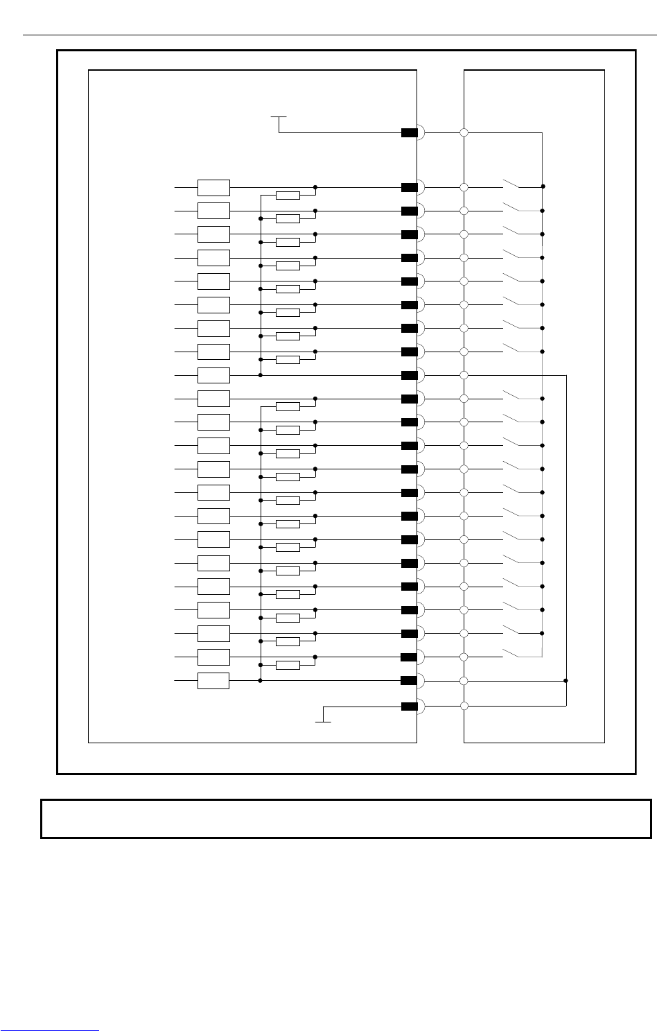
B-82725EN-1/07 CONNECTIONS
- 147 -
4. PERIPHERAL DEVICE AND
END EFFECTOR INTERFACES
Set this jumper according
to the common voltage of
input devices. (ICOM1)
Control unit (peripheral device control interface A1)
Peripheral device
DI101 CRMA15 (A5)
CRMA15 (A1,A2,B1,B2)
Connector pin No.
+24F
Receiver circuit
DI108 CRMA15 (B8)
DI119 CRMA15 (A14)
DI120
CRMA15 (A4,B4,A19,B19)
0V
DI102 CRMA15 (B5)
DI103 CRMA15 (A6)
DI104 CRMA15 (B6)
DI105 CRMA15 (A7)
DI106 CRMA15 (B7)
DI107 CRMA15 (A8)
SDICOM1 CRMA15 (A3)
CRMA15 (A9)
CRMA15 (B9)
CRMA15 (A10)
CRMA15 (B10)
CRMA15 (A11)
CRMA15 (B11)
CRMA15 (A12)
DI116 CRMA15 (B12)
DI117 CRMA15 (A13)
DI118 CRMA15 (B13)
3.3k
RV
RV
RV
RV
RV
RV
RV
RV
RV
RV
RV
RV
RV
RV
RV
RV
RV
RV
RV
RV
RV
DI109
DI110
DI111
DI112
DI113
DI114
DI115
CRMA15 (B14)
SDICOM2 CRMA15 (B3)
RV
NOTE
In this diagram, common voltage of input devices is +24V.
Downloaded from www.Manualslib.com manuals search engine
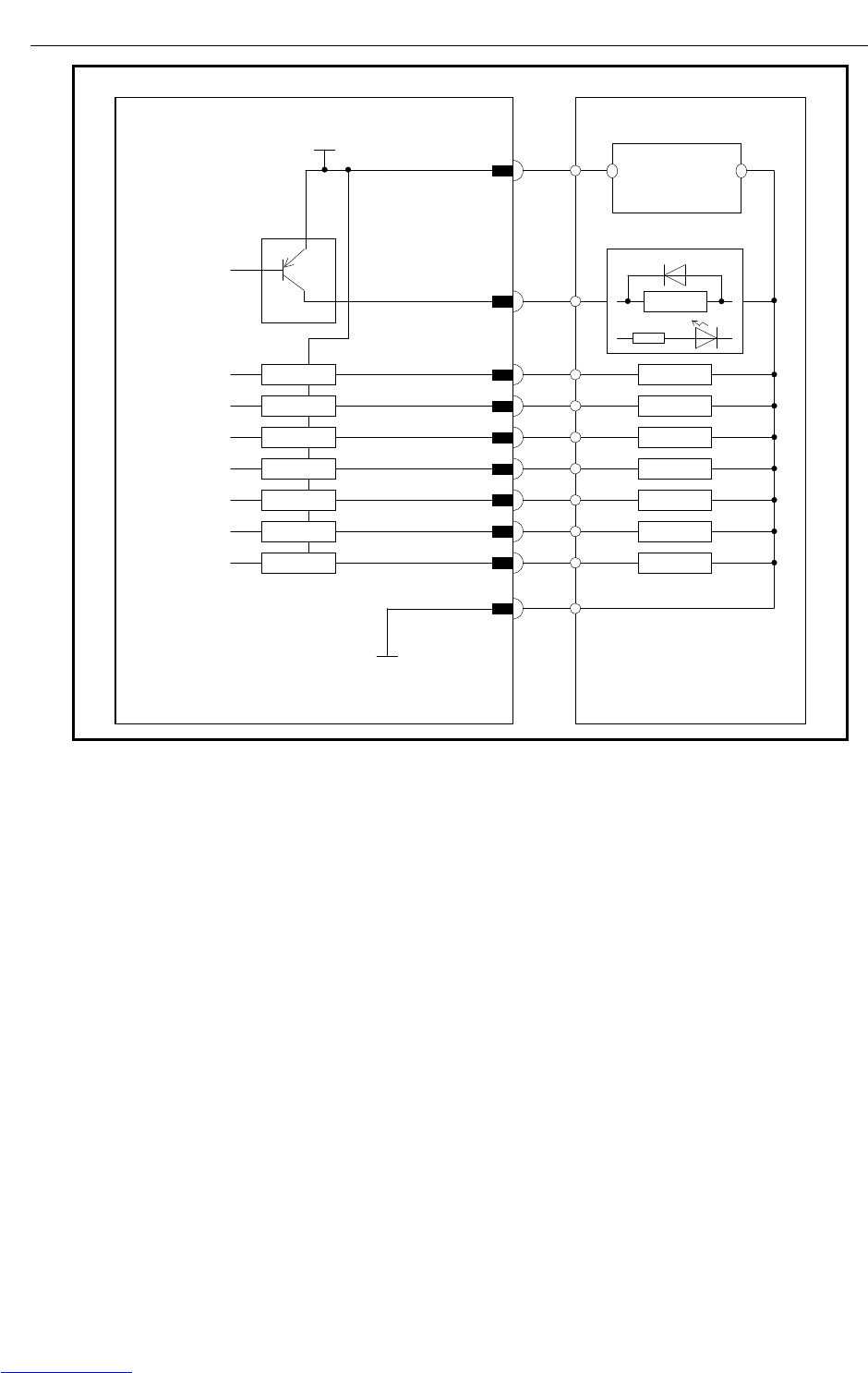
CONNECTIONS B-82725EN-1/07
- 148 -
4. PERIPHERAL DEVICE AND
END EFFECTOR INTERFACES
Control unit (peripheral device control interface A1)
Peripheral device
DO101
CRMA15 (B15)
CRMA15 (A15)
Connector pin No.
Driver circuit
DO108
DO102
CRMA15 (A16)
DO103
CRMA15 (B16)
DO104
CRMA15 (A17)
DO105
CRMA15 (B17)
DO106
CRMA15 (A18)
DO107
CRMA15 (B18)
DV
LOAD
RELA
Y
A
maximum output current per DO point is 0.2 A.
LOAD
LOAD
LOAD
LOAD
LOAD
LOAD
LOAD
CRMA15 (A20,B20)
DOSRC1
+24V 0V
+24V regulated
power supply
DV
DV
DV
DV
DV
DV
DV
CRMA15 (A4,B4,A19,B19)
0V
Downloaded from www.Manualslib.com manuals search engine
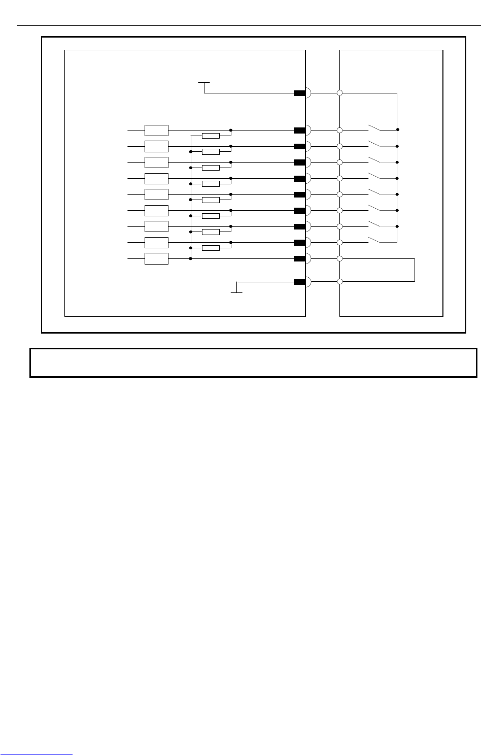
B-82725EN-1/07 CONNECTIONS
- 149 -
4. PERIPHERAL DEVICE AND
END EFFECTOR INTERFACES
Set this jumper according
to the common voltage of
input devices. (ICOM1)
Control unit (peripheral device control interface A2)
Peripheral device
XHOLD CRMA16 (A5)
CRMA16 (A1,A2,B1,B2)
Connector pin No.
+24F
Receiver circuit
PNS4 CRMA16 (B8)
CRMA16 (A4,B4,A19,B19)
0V
RESET CRMA16 (B5)
START CRMA16 (A6)
ENBL CRMA16 (B6)
PNS1 CRMA16 (A7)
PNS2 CRMA16 (B7)
PNS3 CRMA16 (A8)
SDICOM3 CRMA16 (A3)
3.3k
RV
RV
RV
RV
RV
RV
RV
RV
RV
NOTE
In this diagram, common voltage of input devices is +24V.
Downloaded from www.Manualslib.com manuals search engine
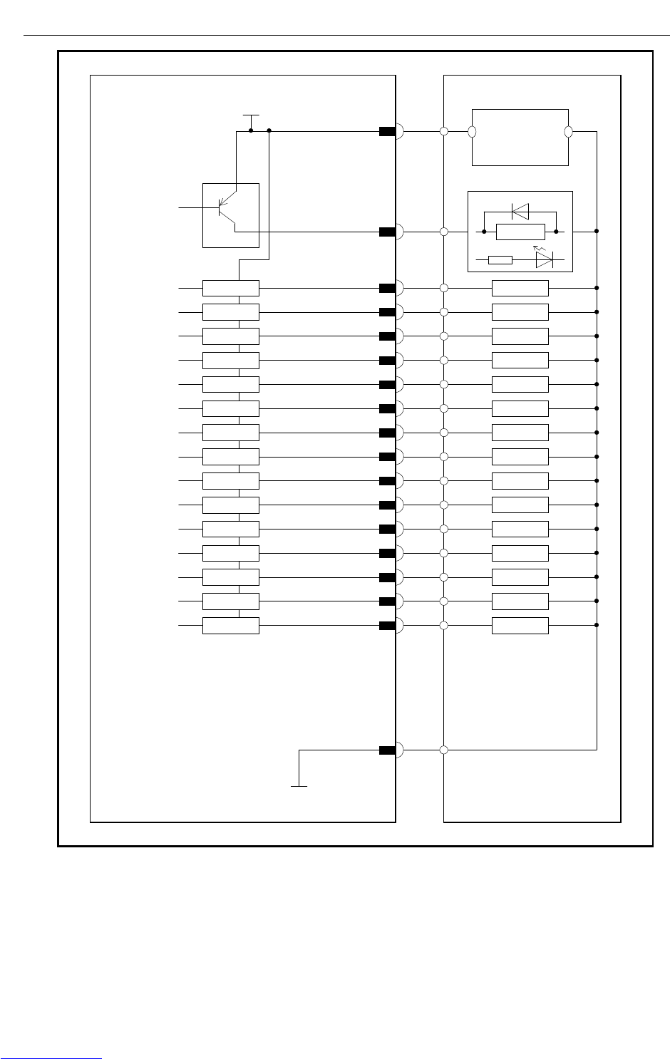
CONNECTIONS B-82725EN-1/07
- 150 -
4. PERIPHERAL DEVICE AND
END EFFECTOR INTERFACES
Control unit (peripheral device control interface A2)
Peripheral device
DO109
CRMA16 (B10)
CRMA16 (A10)
Connector pin No.
Driver circuit
DO116
CRMA16 (A14)
DO110
CRMA16 (A11)
DO111
CRMA16 (B11)
DO112
CRMA16 (A12)
DO113
CRMA16 (B12)
DO114
CRMA16 (A13)
DO115
CRMA16 (B13)
DO117
CRMA16 (B14)
DO118
CRMA16 (A15)
DO119
CRMA16 (B15)
DV
LOAD
RELA
Y
A
maximum output current per DO point is 0.2 A.
LOAD
LOAD
LOAD
LOAD
LOAD
LOAD
LOAD
LOAD
LOAD
LOAD
LOAD
CRMA16 (A20,B20)
DOSRC2
+24V 0V
+24V regulated
power supply
DV
DV
DV
DV
DV
DV
DV
DV
DV
DV
DV
CRMA16 (A4,B4,A19,B19)
0V
DO120
CRMA16 (A16)
CMDENBL
CRMA16 (B16)
FAULT
CRMA16 (A17)
BATALM
CRMA16 (B17)
LOAD
LOAD
LOAD
LOAD
DV
DV
DV
DV
BUS
Y
Downloaded from www.Manualslib.com manuals search engine
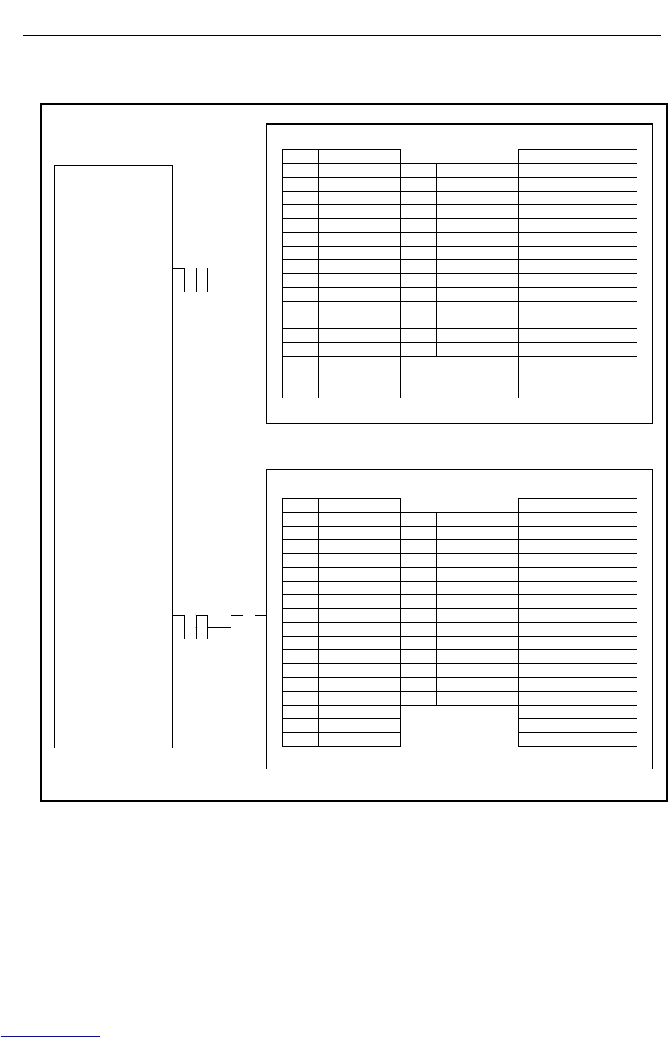
B-82725EN-1/07 CONNECTIONS
- 151 -
4. PERIPHERAL DEVICE AND
END EFFECTOR INTERFACES
The following shows the connector interface of the optional peripheral device cables on the peripheral
device side.
Peripheral device A1
01 DI101 33 DO101
02 DI102 19 SDICOM1 34 DO102
03 DI103 20 SDICOM2 35 DO103
04 DI104 21 36 DO104
05 DI105 22 DI117 37 DO105
06 DI106 23 DI118 38 DO106
07 DI107 24 DI119 39 DO107
08 DI108 25 DI120 40 DO108
09 DI109 26 41
10 DI110 27 42
11 DI111 28 43
12 DI112 29 0V 44
13 DI113 30 0V 45
14 DI114 31 DOSRC1 46
15 DI115 32 DOSRC1 47
16 DI116 48
17 0V 49 24F
18 0V
50 24F
Peripheral device A2
01 XHOLD 33 CMDENBL
02 RESET 19 SDICOM3 34 FAULT
03 START 20 35 BATALM
04 ENBL 21 DO120 36 BUSY
05 PNS1 22 37
06 PNS2 23 38
07 PNS3 24 39
08 PNS4 25 40
09 26 DO117 41 DO109
10 27 DO118 42 DO110
11 28 DO119 43 DO111
12 29 0V 44 DO112
13 30 0V 45 DO113
14 31 DOSRC2 46 DO114
15 32 DOSRC2 47 DO115
16 48 DO116
17 0V 49 24F
18 0V
50 24F
Controller
CRMA15
CRMA16
Downloaded from www.Manualslib.com manuals search engine
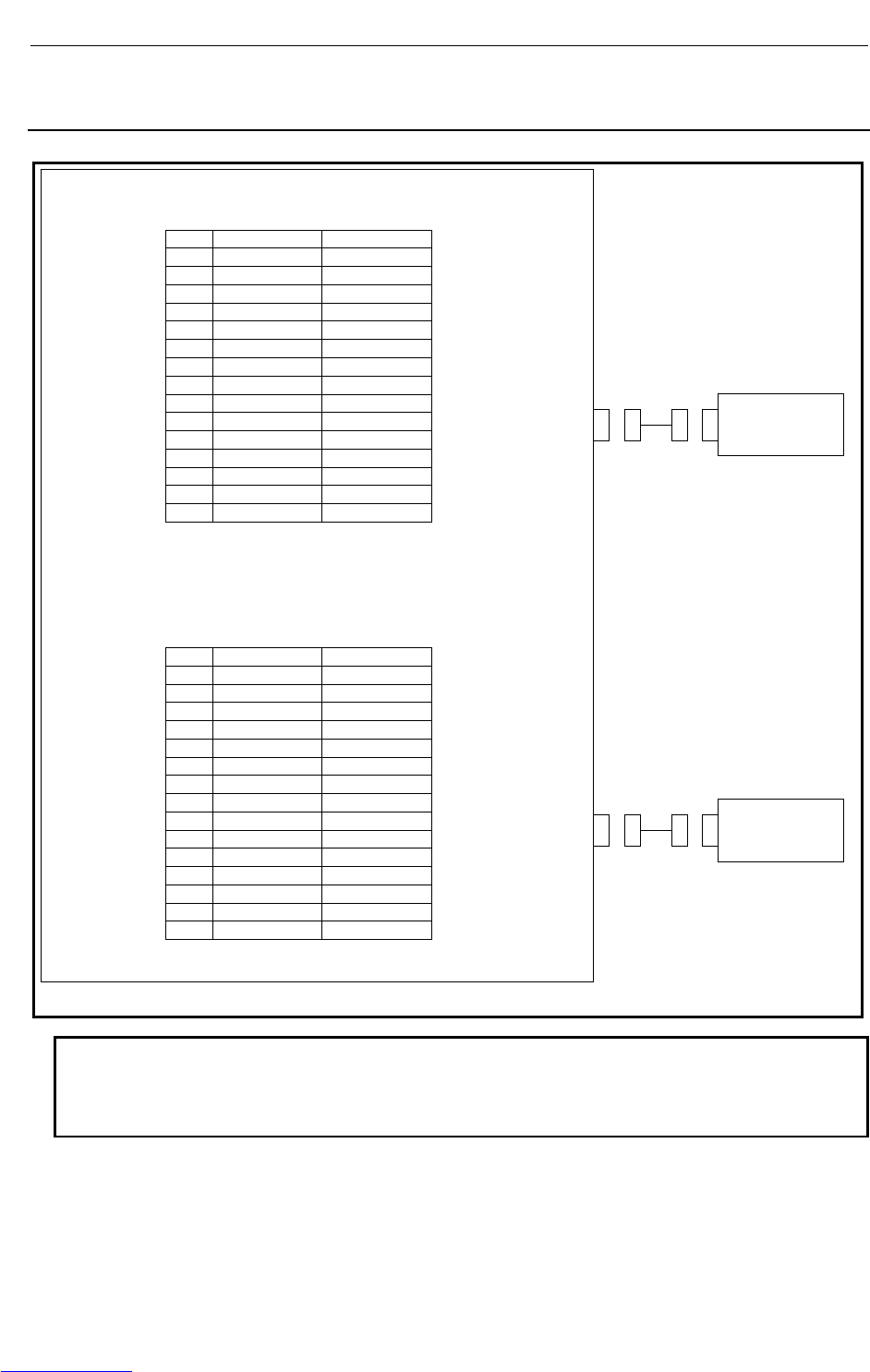
CONNECTIONS B-82725EN-1/07
- 152 -
4. PERIPHERAL DEVICE AND
END EFFECTOR INTERFACES
4.3.2 Connection between the Process I/O Board MA and
Peripheral Devices
Peripheral device control interface B1 (source type DO)
CRMA52A
A B
01 24F 24F
02 DI121 DI122
03 DI123 DI124
04 DI125 DI126
05 DI127 DI128
06 DI129 DI130
07
08 DO121 DO122
09 DO123 DO124
10 DO125 DO126
11 DO127 DO128
12
13 0V 0V
14 0V 0V
15 DOSRC3 DOSRC3
Peripheral device control interface B2 (source type DO)
CRMA52B
A B
01 24F 24F
02 DI131 DI132
03 DI133 DI134
04 DI135 DI136
05 DI137 DI138
06 DI139 DI140
07
08 DO129 DO130
09 DO131 DO132
10 DO133 DO134
11 DO135 DO136
12
13 0V 0V
14 0V 0V
15 DOSRC3 DOSRC3
NOTE
1 The peripheral device connection cable is optional.
2 The DOSRC3 pin of CRMA52A and CRMA52B supply power to the drivers
(connect all pins).
Control unit
Peripheral
Device B1
Peripheral
Device B2
Downloaded from www.Manualslib.com manuals search engine
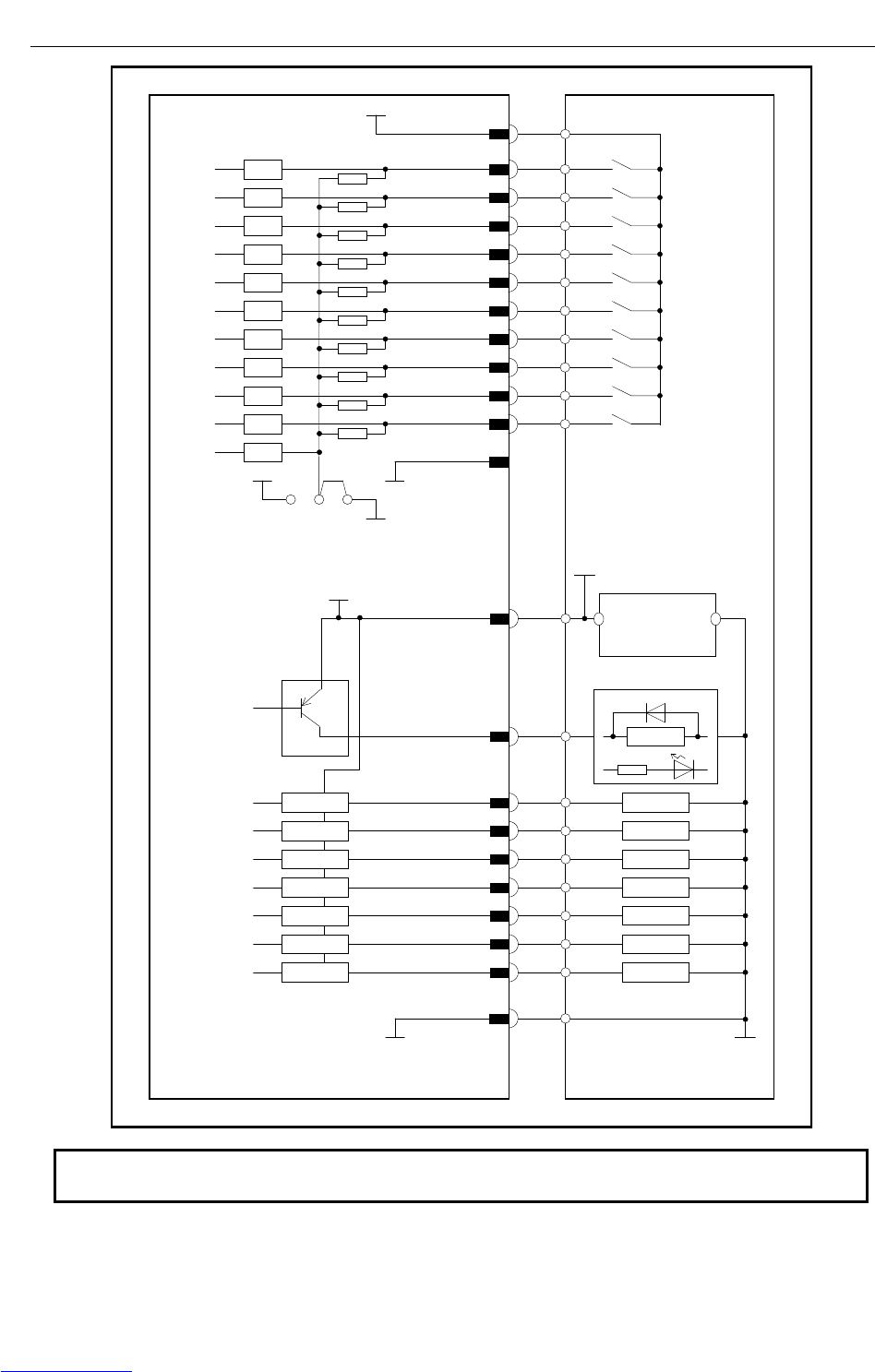
B-82725EN-1/07 CONNECTIONS
- 153 -
4. PERIPHERAL DEVICE AND
END EFFECTOR INTERFACES
Control unit
(Peripheral device control
interface:B1)
Peripheral device
DO121
CRMA52A (B8)
CRMA52A (A8)
Connector pin No.
Driver circuit
DO128
DO122
CRMA52A (A9)
DO123
CRMA52A (B9)
DO124
CRMA52A (A10)
DO125
CRMA52A (B10)
DO126
CRMA52A (A11)
DO127
CRMA52A (B11)
DV
LOAD
RELAY
LOAD
LOAD
LOAD
LOAD
LOAD
LOAD
LOAD
CRMA52A (A15,B15)
DOSRC3
+24V 0V
+24Vregulaated
power supply
DV
DV
DV
DV
DV
DV
DV
CRMA52A (A14,B14)
0V
DI130 CRMA52A (B6)
COM1 CRMA52A (A13,B13)
0V
CRMA52A (A2)
CRMA52A (B2)
CRMA52A (A3)
CRMA52A (B3)
CRMA52A (A4)
CRMA52A (B4)
DI127 CRMA52A (A5)
DI128 CRMA52A (B5)
DI129 CRMA52A (A6)
+24E
0V
B
A
RV
RV
RV
RV
RV
RV
RV
RV
RV
RV
RV
DI121
DI122
DI123
DI124
DI125
DI126
CRMA52A (A1,B1)
Connector pin No.
+24F
EXT24V
EXT0V
Common-level change-over
setting pin (ICOM1)
(This common voltage is
for 24V.)
NOTE
In this diagram, common voltage of input device is 24V.
Downloaded from www.Manualslib.com manuals search engine
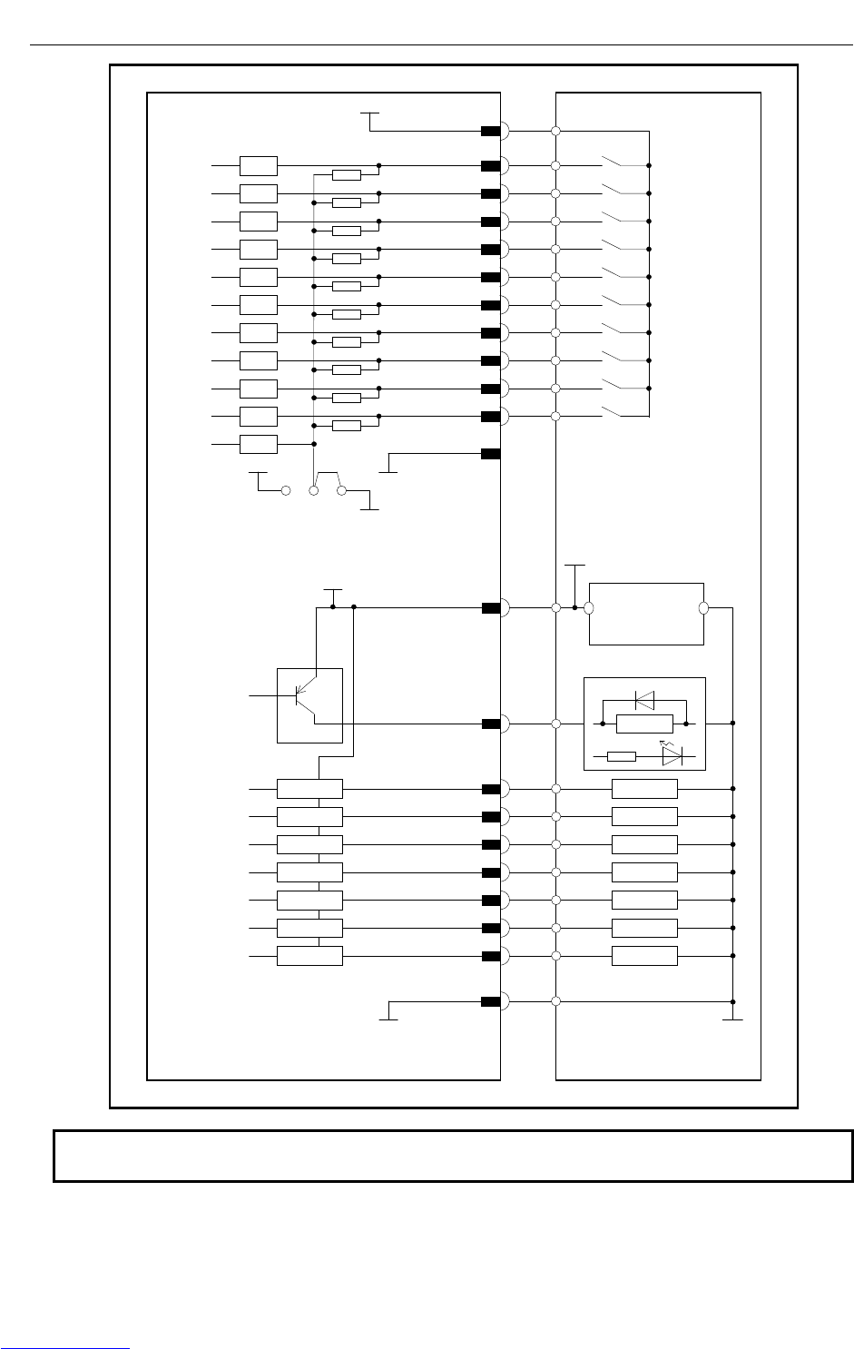
CONNECTIONS B-82725EN-1/07
- 154 -
4. PERIPHERAL DEVICE AND
END EFFECTOR INTERFACES
Control unit
(Peripheral device control
interface :B1)
Peripheral device
DO129
CRMA52B (B8)
CRMA52B (A8)
Connector pin No.
Driver circuit
DO136
DO130
CRMA52B (A9)
DO131
CRMA52B (B9)
DO132
CRMA52B (A10)
DO133
CRMA52B (B10)
DO134
CRMA52B (A11)
DO135
CRMA52B (B11)
DV
LOAD
RELAY
LOAD
LOAD
LOAD
LOAD
LOAD
LOAD
LOAD
CRMA52B (A15,B15)
DOSRC3
+24V 0V
+24V regulated
power su
DV
DV
DV
DV
DV
DV
DV
CRMA52B (A14,B14)
0V
DI140 CRMA52B (B6)
COM1 CRMA52B (A13,B13)
0V
CRMA52B (A2)
CRMA52B (B2)
CRMA52B (A3)
CRMA52B (B3)
CRMA52B (A4)
CRMA52B (B4)
DI137 CRMA52B (A5)
DI138 CRMA52B (B5)
DI139 CRMA52B (A6)
+24E
0V
B
A
RV
RV
RV
RV
RV
RV
RV
RV
RV
RV
RV
DI131
DI132
DI133
DI134
DI135
DI136
CRMA52B (A1,B1)
Connector pin No.
+24F
EXT24V
EXT0V
Common-level change-over
setting pin (ICOM2)
(This common voltage is
for 24V.)
NOTE
In this diagram, common voltage of input device is +24V.
Downloaded from www.Manualslib.com manuals search engine
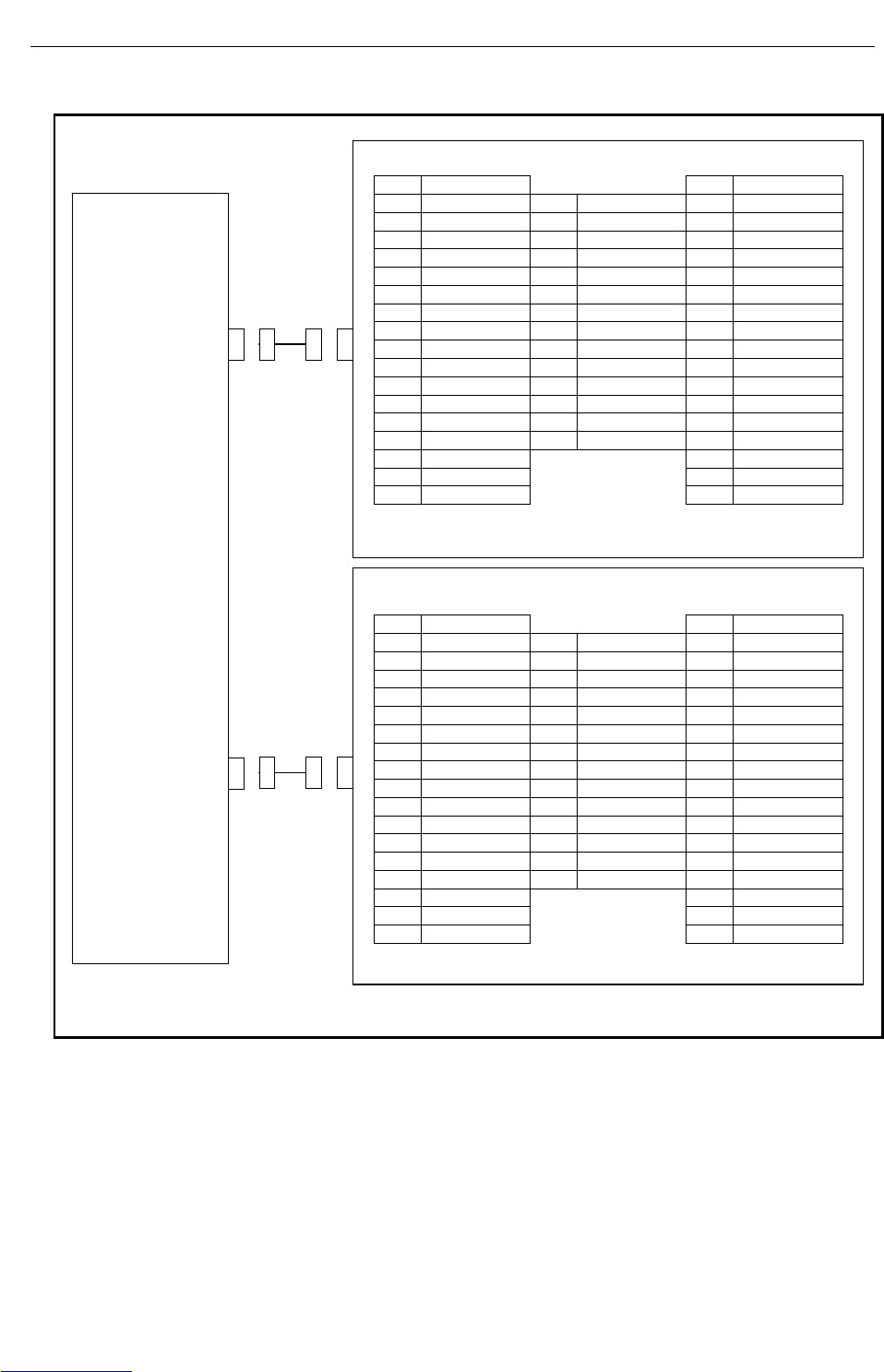
B-82725EN-1/07 CONNECTIONS
- 155 -
4. PERIPHERAL DEVICE AND
END EFFECTOR INTERFACES
The following shows the connector interface of the optional peripheral device cables on the peripheral
device side.
Peripheral device A3
01 DI121 33 DO121
02 DI122 19 34 DO122
03 DI123 20 35 DO123
04 DI124 21 36 DO124
05 DI125 22 37 DO125
06 DI126 23 38 DO126
07 DI127 24 39 DO127
08 DI128 25 40 DO128
09 DI129 26 41
10 DI130 27 42
11 28 43
12 29 0V 44
13 30 0V 45
14 31 DOSRC3 46
15 32 DOSRC3 47
16 48
17 0V 49 +24F
18 0V 50 +24F
Peripheral device A4
01 DI131 33 DO129
02 DI132 19 34 DO130
03 DI133 20 35 DO131
04 DI134 21 36 DO132
05 DI135 22 37 DO133
06 DI136 23 38 DO134
07 DI137 24 39 DO135
08 DI138 25 40 DO136
09 DI139 26 41
10 DI140 27 42
11 28 43
12 29 0V 44
13 30 0V 45
14 31 DOSRC3 46
15 32 DOSRC3 47
16 48
17 0V 49 +24F
18 0V 50 +24F
CRMA52B
I/O board
CRMA52A
Downloaded from www.Manualslib.com manuals search engine
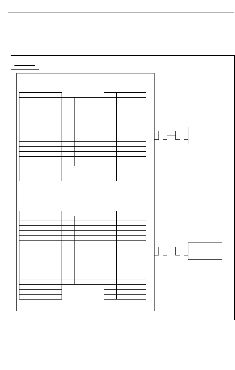
CONNECTIONS B-82725EN-1/07
- 156 -
4. PERIPHERAL DEVICE AND
END EFFECTOR INTERFACES
4.3.3 Connection between the Connector Conversion Board and
Peripheral Devices
The connector interface of the optional connector conversion board is shown below. For electrical
connection, see Section 4.3.1.
Peripheral device control interface C1
(Honda Tsushin Kogyo MR-50RFD)
CRMA58
01 DI101 33 DO101
02 DI102 19 SDICOM1 34 DO102
03 DI103 20 SDICOM2 35 DO103
04 DI104 21 36 DO104
05 DI105 22 DI117 37 DO105
06 DI106 23 DI118 38 DO106
07 DI107 24 DI119 39 DO107
08 DI108 25 DI120 40 DO108
09 DI109 26 41
10 DI110 27 42
11 DI111 28 43
12 DI112 29 0V 44
13 DI113 30 0V 45
14 DI114 31 DOSRC1 46
15 DI115 32 DOSRC1 47
16 DI116 48
17 0V 49 24F
18 0V
50 24F
Peripheral device control interface C2
(Honda Tsushin Kogyo MR-50RFD)
CRMA59
01 XHOLD 33 CMDENBL
02 RESET 19 SDICOM3 34 FAULT
03 START 20 35 BATALM
04 ENBL 21 DO120 36 BUSY
05 PNS1 22 37
06 PNS2 23 38
07 PNS3 24 39
08 PNS4 25 40
09 26 DO117 41 DO109
10 27 DO118 42 DO110
11 28 DO119 43 DO111
12 29 0V 44 DO112
13 30 0V 45 DO113
14 31 DOSRC2 46 DO114
15 32 DOSRC2 47 DO115
16 48 DO116
17 0V 49 24F
18 0V
50 24F
Peripheral
deviceC1
Controller
Peripheral
deviceC2
Downloaded from www.Manualslib.com manuals search engine

B-82725EN-1/07 CONNECTIONS
- 157 -
4. PERIPHERAL DEVICE AND
END EFFECTOR INTERFACES
4.3.4 Connection between the Process I/O Board MB and Welding
Machines
Welding machine interface
CRW11
A B
01 WI02 24F
02 WI03 24F
03 WI04 0V
04 WI05 0V
05 WI06 WDI+
06 WO01 WDI-
07 WO02 DACH1
08 WO04 COMDA
09 WO05 DACH2
10 COMDA
NOTE
1 The welding machine connection cable is optional.
Control unit
Welding
machine
Downloaded from www.Manualslib.com manuals search engine

CONNECTIONS B-82725EN-1/07
- 158 -
4. PERIPHERAL DEVICE AND
END EFFECTOR INTERFACES
Control unit(welding machine interface)
Process I/O board MB Welding machine
DACH1 CRW11 (B7)
Connector pin No.
R=100Ω or
higher
COMD
A
CRW11 (B8)
DACH2 CRW11 (B9)
COMD
A
CRW11 (B10)
+
Welding voltag
e
specification signal
Wire spee
d
specification signal
A
B
E
F
MS connector pin No.
WDI+ CRW11 (B5)
WDI- CRW11 (B6)
Wire deposition
detection signal
N
P
-
Welding
power
WI02 CRW11 (A1)
CRW11 (B3,B4)
Connector pin No.
Receiver circuit
(Photocoupler)
WI06
WI03 CRW11 (A2)
WI04 CRW11 (A3)
WI05 CRW11 (A4)
3.0
k
+24F
RV
RV
RV
RV
h
d
e
f
g
Arc detection signal
Out-of-gus
detection signal
Broken-wire
detection signal
Arc-off detection
signal (power supply
abnormal)
m
Welding start signal
Wire inching (+)
CRW11 (A6) R
WO01
WO02 CRW11 (A7) S
CRW11 (A8) U WO04
WO05 CRW11 (A9) V
Wire inching (-)
+
-
Welding machine frame ground
Cabinet ground (shield clamped)
Gas signal
RV CRW11 (A5)
DV
0V
DV
DV
DV
Out-of-cooling-
water detection signal
0V
CRW11 (B1,B2) r
0V
24V
Pin-to-pin connection between CRW11 connector and welding machine connector (FANUC interface)
(Analog output, welding wire deposition detection, WI/WO connection)
Downloaded from www.Manualslib.com manuals search engine

B-82725EN-1/07 CONNECTIONS
- 159 -
4. PERIPHERAL DEVICE AND
END EFFECTOR INTERFACES
4.4 INTERFACE FOR END EFFECTOR
4.4.1 Connection between the LR Mate 200iC, ARC Mate 50iC and
End Effector
End effector
8 24V 9 24V 1 RI1
7 XHBK 12 0V 10 24V 2 RI2
6 RI6
(XPPABN) 11 0V 3 RI3
5 RI5 4 RI4
Robot
EE
Note) For end effector figures other than the above (eight RI/RO signals for each), refer to
the operator's manual of each robot.
Fig.4.4.1 End effector interface
NOTE
RO1 to RO6 are used as the on/off signals of the solenoid valve option.
The RI and XHBK signals can be used for the end effector.
For RO, refer to the operator’s manual of the mechanical unit.
Wrist breakage
detection signal XHBK Peripheral device
Wrist breakage
detection si
g
nal XHBK
EE (7)
EE(8,9,10)
Connector pin No.
+24V
Receiver circuit
RI1 EE (1)
RI2 EE (2)
RI3 EE (3)
RI4
EE (5)
RI5
EE (4)
RI6 EE (6)
3.3k
+24V
0V
B
A
Set this jumper or switch according to
the common voltage of input devices.
(COM1)
RV
RV
RV
RV
RV
RV
RV
(Pneumatic pressure
abnormal signal XPPABN)
0
V
(XPPABN)
NOTE
1 In this diagram, common voltage of input devices is +24V.
2 The common-level change-over setting pin or switch (COM1) is in the 6-axis
servo amplifier.
Downloaded from www.Manualslib.com manuals search engine
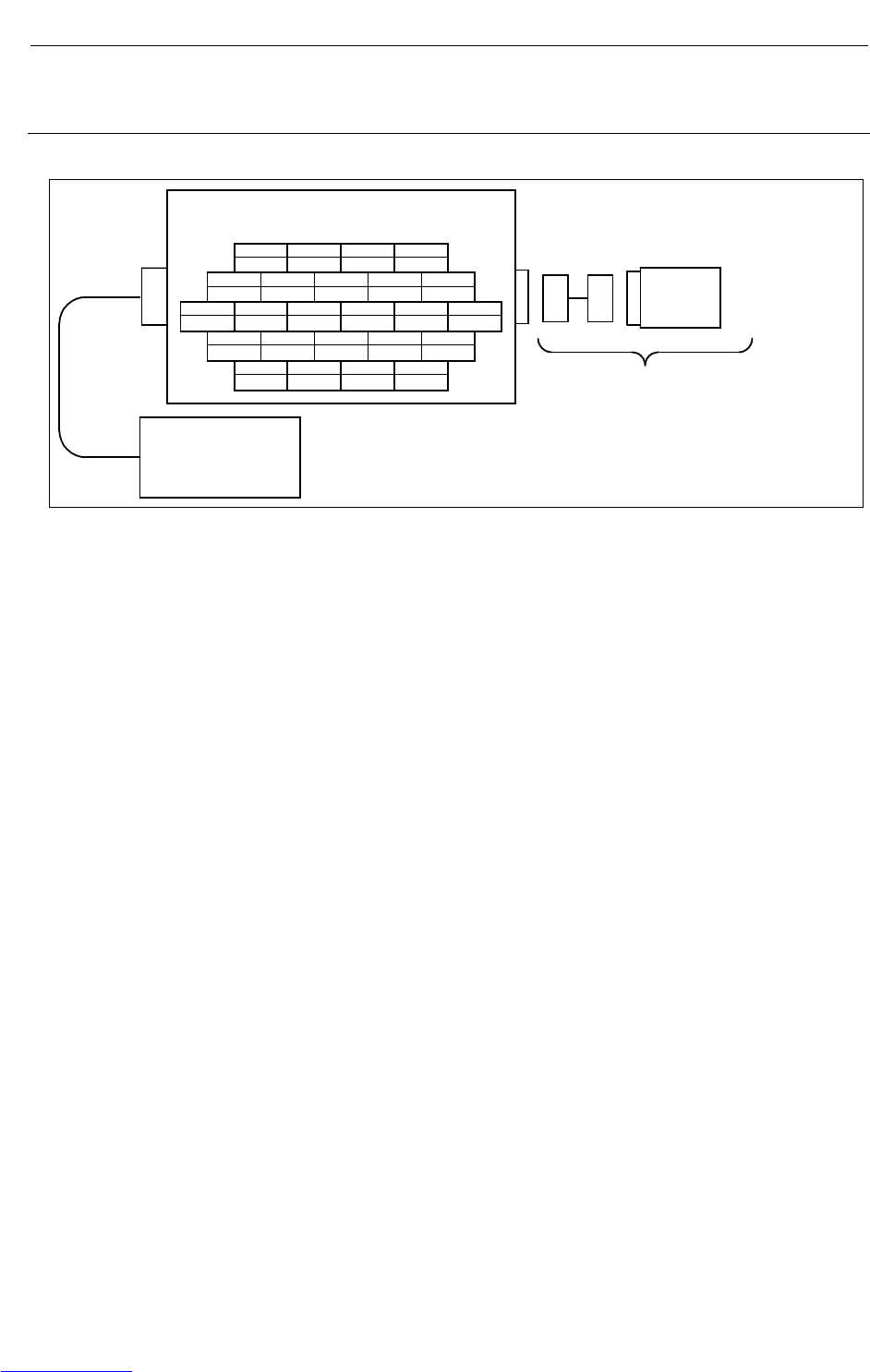
CONNECTIONS B-82725EN-1/07
- 160 -
4. PERIPHERAL DEVICE AND
END EFFECTOR INTERFACES
4.4.2 Connection between the ARC Mate 100iC/M-10iA, ARC Mate
120iC/M-20iA, ARC Mate 0iA and End Effector
4
RO4
RI3
RI8
321
RO3 RO2 RO1
9
RI1
8
0V(A1)
7
XHBK
6
RO6
5
RO5
15
RI5
14 13 12 11 10
XPPABN RI4 RI2
20
24VF(A1)
19 18 17 16
24VF(A1) 24VF(A1) 24VF(A1) RI6
24 23 22 21
RI7 0V(A2) RO8 RO7
Controller
Please prepare by user.
EE interface (RI/RO) (Output)
XHBK : Hand broken
XPPABN : Pneumatic pressure abnormal
End
effector
W2524F(Fujikura.Ltd)
Fig.4.4.2 Connection between the ARC Mate 100iC/M-10iA, ARC Mate 120iC/M-20iA, ARC Mate 0iA and end
effector
Note) For end effector figures other than the above (eight RI/RO signals for each), refer to the operator's
manual of each robot.
Downloaded from www.Manualslib.com manuals search engine
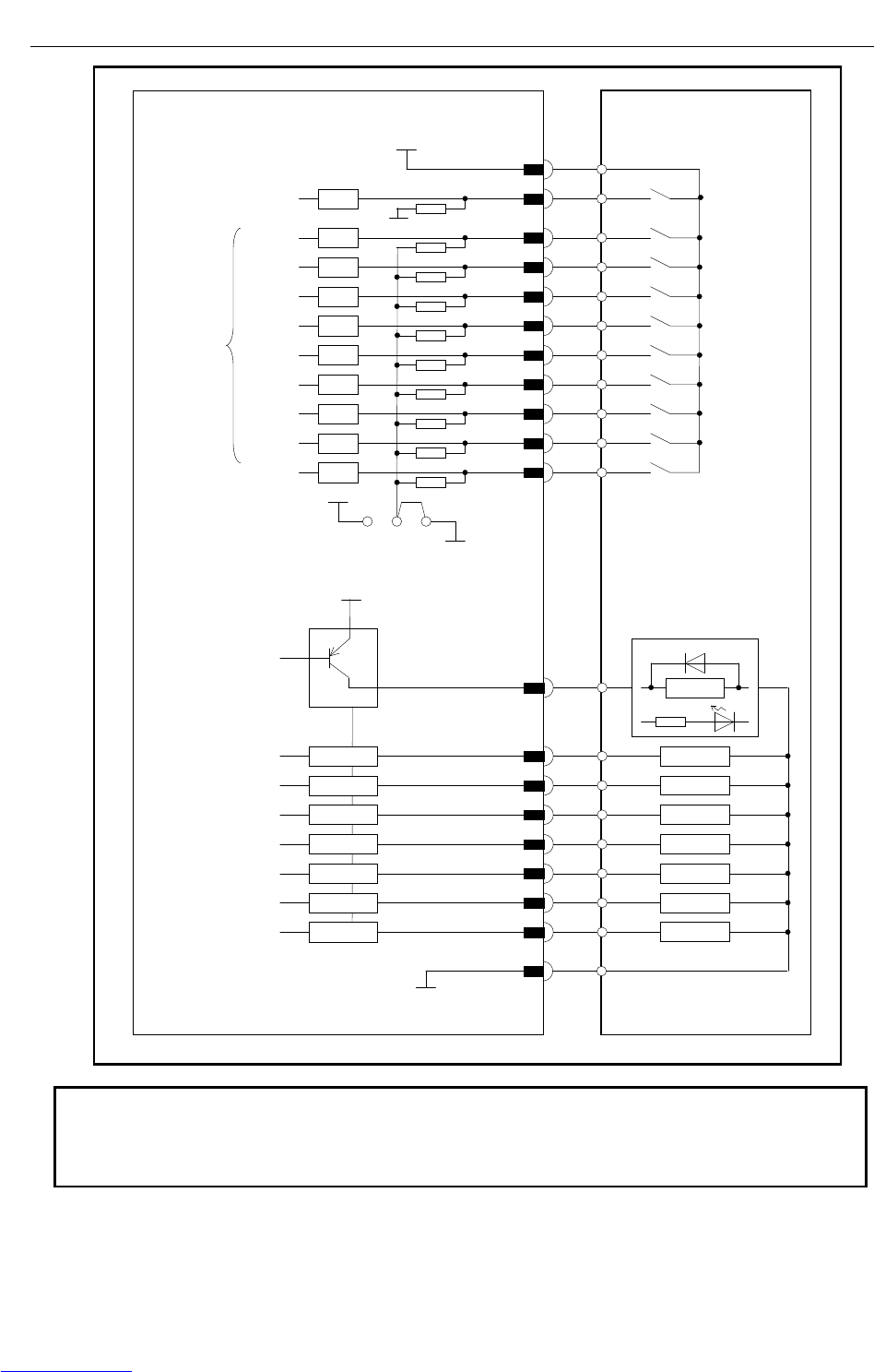
B-82725EN-1/07 CONNECTIONS
- 161 -
4. PERIPHERAL DEVICE AND
END EFFECTOR INTERFACES
Mechanical unit (end-effector interface:EE) Peripheral device
Wrist breakage XHBK
detection signal
EE (7)
EE(17,18,19,20)
Connector pin No.
+24VF
Receiver circuit
RI7 EE (24)
RI9
RI1 EE (9)
RI2 EE (10)
RI3 EE (11)
RI4
EE (15)
RI5
EE (12)
RI6 EE (16)
3.3k
+24E
0V
BA
Set this jumper or switch
according to the common voltage
of input devices. (COM1)
RV
RV
RV
RV
RV
RV
RV
RV
RV
RO1
EE (2)
EE (1)
Driver circuit
RO8
RO2
EE (3)
RO3
EE (4)
RO4
EE (5)
RO5
EE (6)
RO6
EE (21)
RO7
EE (22)
DV
LOAD
RELAY
LOAD
LOAD
LOAD
LOAD
LOAD
LOAD
LOAD
+24VF
A maximum output current per RO point is 0.2A.
EE (8,23)
0V
DV
DV
DV
DV
DV
DV
DV
RI8 EE (13)
RV
(Pneumatic pressure
abnormal signal XPPABN)
0
V
EE (14)
NOTE
1 In this diagram, common voltage of input device is +24V.
2 The common-level change-over setting pin or switch (COM1) is in the 6-axis
servo amplifier.
Downloaded from www.Manualslib.com manuals search engine

CONNECTIONS B-82725EN-1/07
- 162 -
4. PERIPHERAL DEVICE AND
END EFFECTOR INTERFACES
4.5 DIGITAL I/O SIGNAL SPECIFICATIONS
This section describes the specifications of the digital I/O signals interfaced with the peripheral device,
end effector, and arc welder.
4.5.1 Peripheral Device Interface
(1) Output signals in peripheral device interface (Source type DO)
(a) Example of connection
Spark killer diode
0.2A or less
(b) Electrical specifications
Maximum load current when driver is on: 200 mA (including momentary level)
Saturation voltage when driver is on: 1.0 V max.
Dielectric strength: 24 V ±20% (including momentary level)
Leakage current when driver is off: 100 μA
(c) The external power supply to output signals must satisfy the following:
Power supply voltage: +24 V ±10%
Power supply current:
For each printed circuit board of this type
(Total sum of maximum load currents including momentary levels + 100 mA or more)
Power-on timing:
At the same time when the control unit is turned on or earlier
Power-off timing:
At the same time when the control unit is turned off or later
(d) Spark killer diode
Rated peak reverse voltage: 100 V or more
Rated effective forward current: 1 A or more
(e) Driver for output signals
In the driver device, the current of each output signal is monitored, and when an overcurrent is
detected, the relevant output is turned off. After an output has been turned off by overcurrent,
the overcurrent state is released because the output is off, so the output on state is restored.
Therefore, in the ground fault or overcurrent state, the output is turned on and off repeatedly.
Such a condition is found also when a load with a high surge current is connected.
The driver device also includes an overheat detection circuit, which turns off all outputs of the
device when the internal temperature of the device has increased as a result of a continued
overcurrent state due to a ground fault of an output and so on. The outputs are held off, but
their normal states can be restored by turning the power to the controller on and off after the
internal temperature of the device has lowered.
(f) Note on use
When adding a relay, solenoid, or the like directly to the circuit, connect a diode for counter
electromotive voltage protection in parallel to the load.
(g) Applicable signals
Output signals of main board I/O board CRMA15 and CRMA16
CMDENBL, FAULT, BATALM, BUSY,
DO101 to DO120
Downloaded from www.Manualslib.com manuals search engine
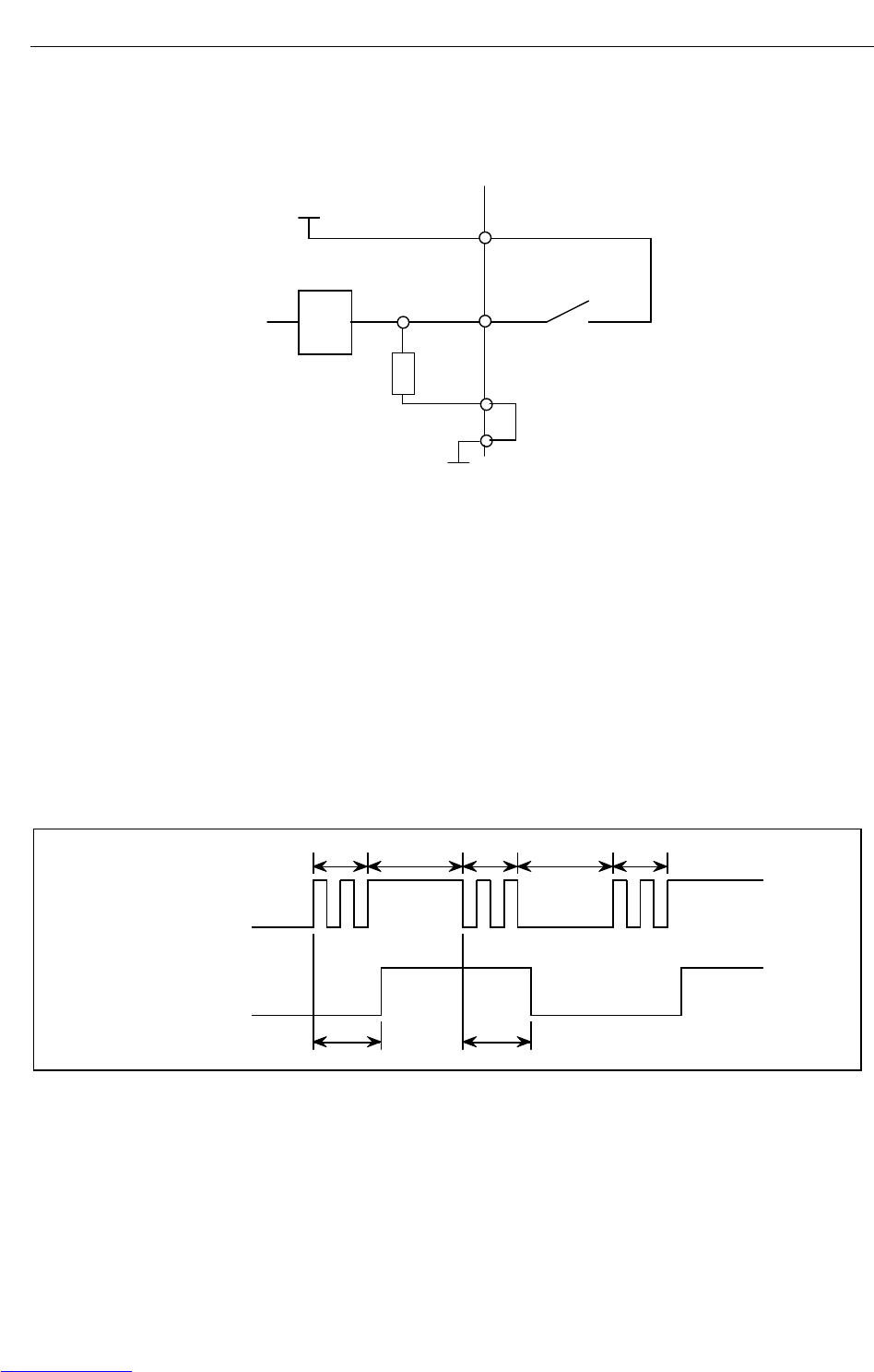
B-82725EN-1/07 CONNECTIONS
- 163 -
4. PERIPHERAL DEVICE AND
END EFFECTOR INTERFACES
Output signals of Process I/O board CRMA52A and CRMA52B
DO121 to DO136
(2) Input signals in peripheral device interface A
(a) Example of connection
+24V
3.3kΩ
RV
0V
SDICOM
(b) Electrical specifications of the receiver
Type: Grounded voltage receiver
Rated input voltage: Contact close +20V to +28V
Contact open 0V to +4V
Maximum applied input voltage: +28VDC
Input impedance: 3.3kΩ(approx.)
Response time: 5ms to 20ms
(c) Specifications of the peripheral device contact
Voltage and Current: DC24V, 0.1A
(Use a contact which minimum load is 5mA less.)
Input signal width: 200ms or more (on/off)
Chattering time: 5ms or less
Closed circuit resistance: 100Ω or less
Opened circuit resistance: 100kΩ or more
(Signal)(Signal)
TCTC
TBTBTB
Peripheral device
contact signal
Robot receiver signal
TB ; Chattering 5 ms or less
TC ; 5 to 20 ms
(d) Note on use
Apply the +24 V power at the robot to the receiver.
However, the above signal specifications must be satisfied at the robot receiver.
(e) Applicable signals
Input signals of main board CRMA15 and CRMA16
XHOLD, FAULT RESET, START, HOME, ENBL
DI101 to DI120
Input signals of Process I/O board CRMA52A and CRMA52B
DI121 to DI140
Downloaded from www.Manualslib.com manuals search engine

CONNECTIONS B-82725EN-1/07
- 164 -
4. PERIPHERAL DEVICE AND
END EFFECTOR INTERFACES
4.5.2 End Effector Control Interface
(1) Output signals in end effector interface
(a) Example of connection
0V
+24V
0.2A or less
Spark killer diode
(b) Electrical specifications
Maximum load current when driver is on: 200 mA (including momentary level)
Saturation voltage when driver is on: 1.0 V max.
Dielectric strength: 24 V ±20% (including momentary level)
Leakage current when driver is off: 100 μA
(c) Power supply to output signals
The +24 V power supply on the robot side can be used if the total current level, including the
current of the welding interface, is 0.7 A or less.
(d) Driver for output signals
In the driver device, the current of each output signal is monitored, and when an overcurrent is
detected, the relevant output is turned off. After an output has been turned off by overcurrent,
the overcurrent state is released because the output is off, so the output on state is restored.
Therefore, in the ground fault or overcurrent state, the output is turned on and off repeatedly.
Such a condition is found also when a load with a high surge current is connected.
The driver device also includes an overheat detection circuit, which turns off all outputs of the
device when the internal temperature of the device has increased as a result of a continued
overcurrent state due to a ground fault of an output and so on. The outputs are held off, but
their normal states can be restored by turning the power to the control unit on and off after the
internal temperature of the device has lowered.
(e) Note on use
When adding a relay, solenoid, or the like directly to the circuit, connect a diode for counter
electromotive voltage protection in parallel to the load.
(f) Applicable signals
RO1 to RO8
(2) Input signal in peripheral device interface
The input signals are the same as those of other I/O boards. (Refer to Subsection 4.5.1 in
CONNECTIONS.)
(a) Applicable signals
RI1 to RI8, XHBN, XPPABN
Downloaded from www.Manualslib.com manuals search engine
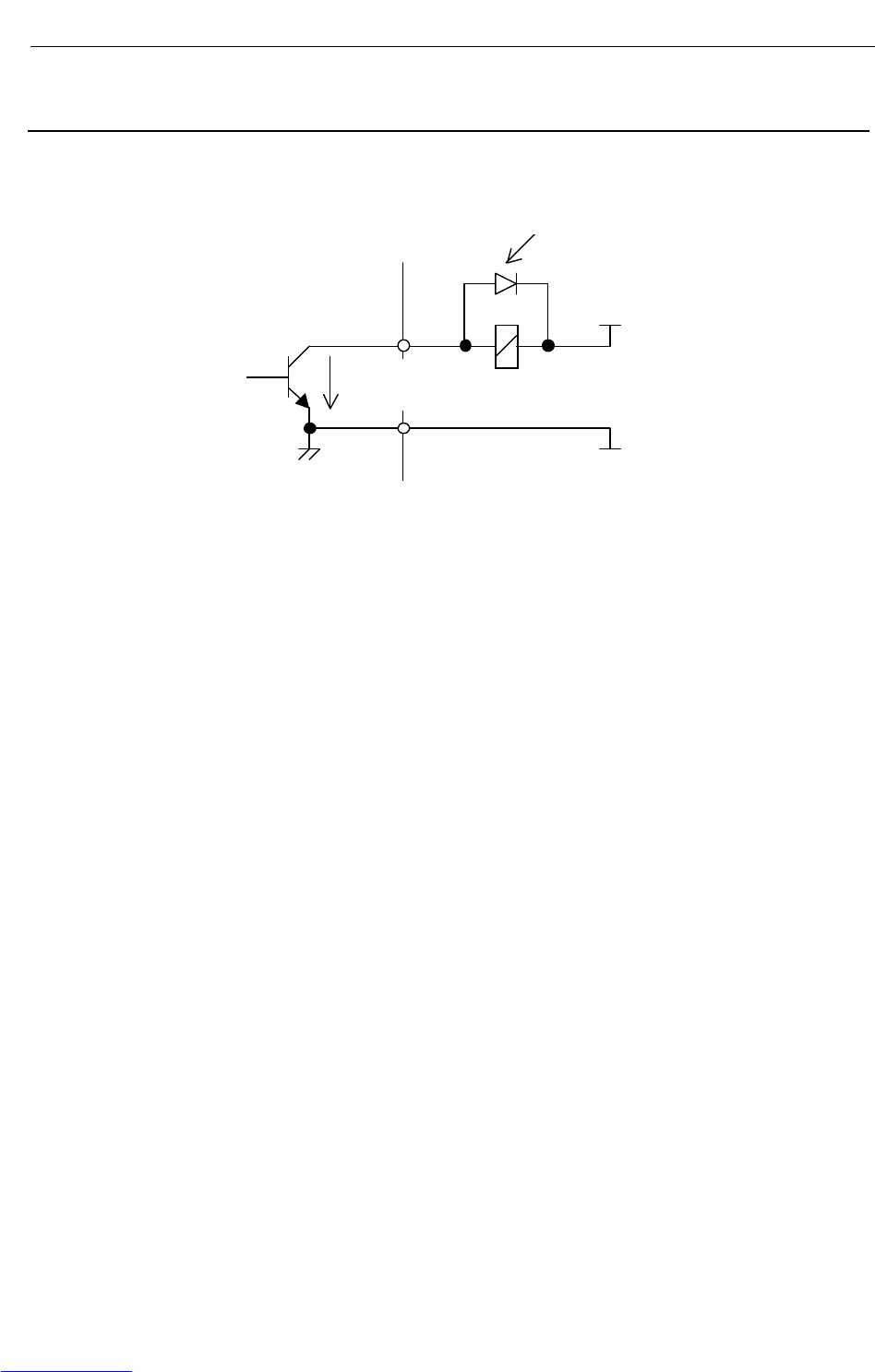
B-82725EN-1/07 CONNECTIONS
- 165 -
4. PERIPHERAL DEVICE AND
END EFFECTOR INTERFACES
4.5.3 Specification for Arc Welding Machine Interface Input/Output
Signals
(1) Specification for arc welding machine interface digital output signals
(a) Example of connection
0V
+24V
0.2A
以下
スパークキラーダイオード
(b) Electrical specifications
Rated voltage: 24VDC
Maximum applicable voltage: 30VDC
Maximum load current: 0.2A
Transistor type: Open-collector NPN
Saturation voltage when the circuit is on: Approximately 1.0V
(c) Spark killer diode
Rated peak-to-peak reverse withstand voltage: 100 V or higher
Rated effective forward current: 1 A or more
(d) Caution for use
The arc welding machine interface can use the +24V power supply of the robot unless the sum
of its sink current and that of the end effector control interface exceeds 0.7A. When using a
relay or solenoid directly as a load, connect the load and a back electromotive force voltage
prevention diode in parallel.
When using a load, such as a lamp, that generates surge current when it is turned on, install a
protection resistor.
(e) Applicable signals
Arc welding machine interface output signals
[WO1, 2,4,5]
S
p
ark killer diode
0.2 A or less
Downloaded from www.Manualslib.com manuals search engine
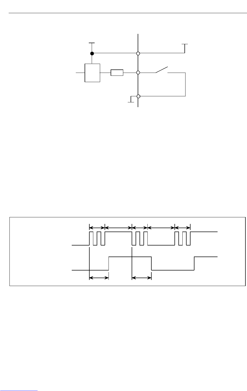
CONNECTIONS B-82725EN-1/07
- 166 -
4. PERIPHERAL DEVICE AND
END EFFECTOR INTERFACES
(2) Specification for arc welding machine interface digital output signals
(a) Example of connection
+24F
3.0kΩ
RV
0V
24V
(Photocoupler)
(b) Electrical specifications of the receiver
Type: Grounded voltage receiver
Rated input voltage: Contact close +20V to +28V
Contact open 0V to +4V
Maximum applied input voltage: +28VDC
Input impedance: 3.0kΩ(approx.)
Response time: 5ms to 20ms
(c) Specifications of the peripheral device contact
Voltage and Current: DC24V, 0.1A
(Use a contact which minimum load is 5mA less.)
Input signal width: 200ms or more (on/off)
Chattering time: 5ms or less
Closed circuit resistance: 100Ω or less
Opened circuit resistance: 100kΩ or more
(Signal)(Signal)
TCTC
TBTBTB
Peripheral device
contact signal
Robot receiver signal
TB ; Chattering 5 ms or less
TC ; 5 to 20 ms
(d) Note on use
Apply the +24 V power at the robot to the receiver.
However, the above signal specifications must be satisfied at the robot receiver.
(e) Applicable signals
Arc welding machine interface input signals
[WI2~6]
Downloaded from www.Manualslib.com manuals search engine
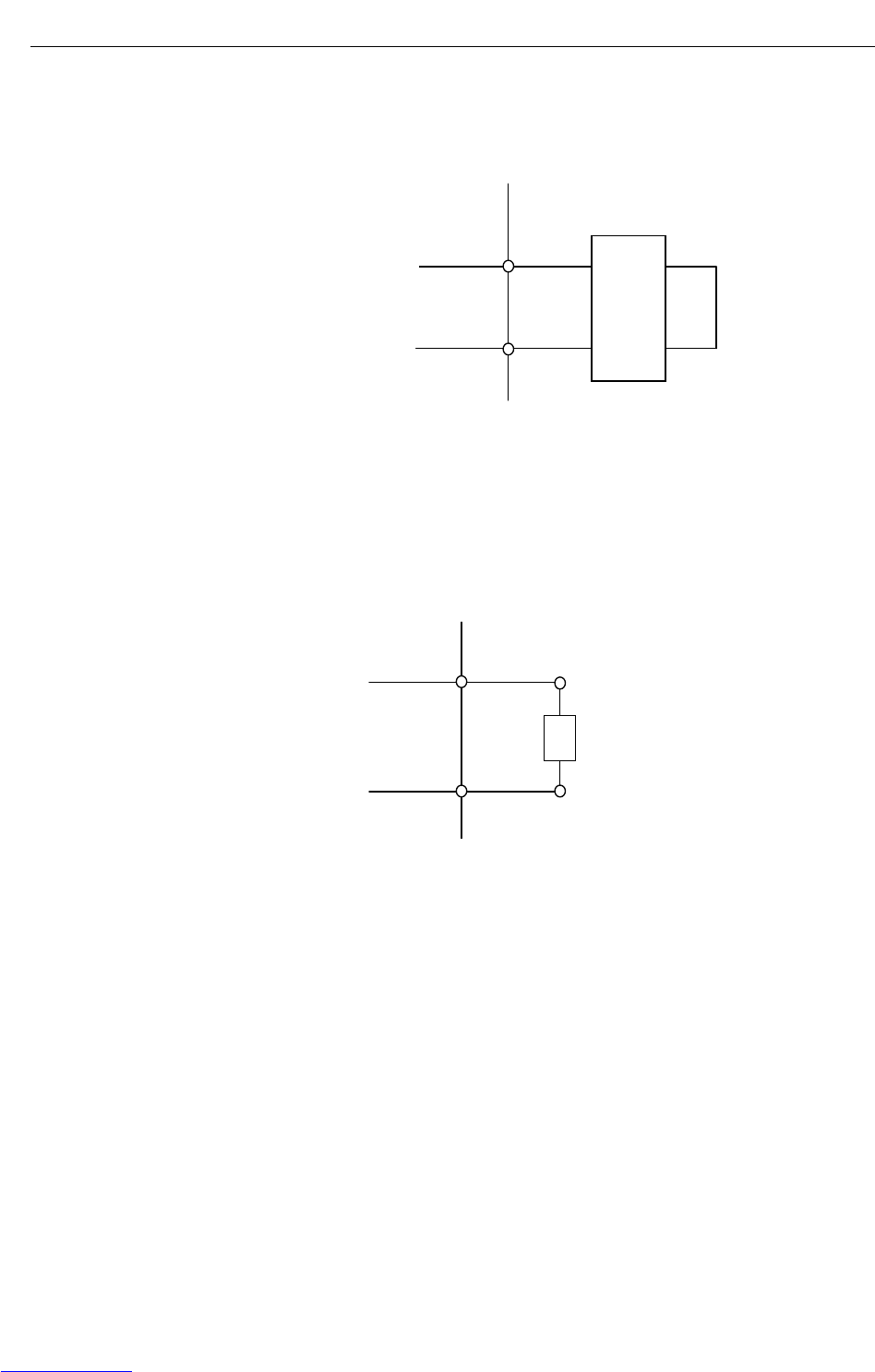
B-82725EN-1/07 CONNECTIONS
- 167 -
4. PERIPHERAL DEVICE AND
END EFFECTOR INTERFACES
(3) Specification for arc welding machine interface analog output signals (welding voltage and wire feed
speed specification signals)
(a) Example of connection
0V
溶接機側
0V~+15V
(b) Caution for use
Input impedance: 3.3 kΩ or higher
Install a high-frequency filter.
(Wire deposit detection: WDI+ and WDI-)
(a) Example of connection
溶接機側
max.
+15V 85mA
溶接電極
+
‐
(Wire deposition detection: WDI+, WDI-)
(b) Caution for use
The resistance between the + and - terminals of the welding machine must be 100 Ω or
higher.
The TIG welding deposition detection circuit must be isolated from the welding circuit
(high frequency).
This circuit can withstand up to 80 V.
Welding machine
Weldin
g
machine
Welding electrode
Downloaded from www.Manualslib.com manuals search engine
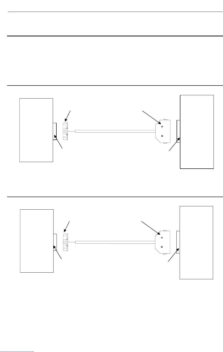
CONNECTIONS B-82725EN-1/07
- 168 -
4. PERIPHERAL DEVICE AND
END EFFECTOR INTERFACES
4.6 SPECIFICATIONS OF THE CABLES USED FOR
PERIPHERAL DEVICES AND WELDERS
If the customer manufactures cables, make sure they conform to the FANUC standard cables described in
this section.
(See the description in "Peripheral Device Interface" in this manual for the specifications of the FANUC
standard cables.)
4.6.1 Peripheral Device Interface A1 Cable
(CRMA15: Tyco Electronics AMP, D-1000 series, 40 pins)
Peripheral
device
CRMA15
Main board
4.6.2 Peripheral Device Interface A2 Cable
(CRMA16: Tyco Electronics AMP, D-1000 series, 40 pins)
Peripheral
device
CRMA16
Main board
Tyco Electronics AMP
1-1827863-0(Housing)
1939991-2(Contact)
Honda Tsushin
MR50LF01 (Connector)
MRP-F112 (Contact)
Honda Tsushin
MR50RMH
Tyco Electronics AMP
1-1939995-0
Tyco Electronics AMP
2-1827863-0(Housing)
1939991-2(Contact)
Honda Tsushin
MR50LF01 (Connector)
MRP-F112 (Contact)
Honda Tsushin
MR50RMH
Tyco Electronics AMP
2-1939995-0
Downloaded from www.Manualslib.com manuals search engine

B-82725EN-1/07 CONNECTIONS
- 169 -
4. PERIPHERAL DEVICE AND
END EFFECTOR INTERFACES
4.6.3 Peripheral Device Interface B1 and B2 Cables
(CRMA52; Tyco Electronics AMP K.K. 30 pin)
Peripheral
device
CRMA52
Process I/O
board MA
4.6.4 ARC Weld Connection Cables
(CRW11; Tyco Electronics AMP K.K. 20 pin)
CRW11
Process I/O
Tyco Electronics AMP K.K.
1-1318118-9(connector)
1318106-1(contact)
Tyco Electronics AMP K.K.
D-2100 series 20pin X key
Japan Aviation Electronics
Industry Ltd.
A
RC Welde
r
Japan Aviation Electronics
Industry Ltd.
Standard position of guide
key
Tyco Electronics AMP K.K.
1-1827863-5(connector)
1939991-2(contact)
Honda Tsushin Kogyo
MR50LF01 (connector)
MRP-F112 (contact)
Tyco Electronics AMP K.K.
D-1100 series 30 pin X key Honda Tsushin Kogyo
MR50RMH
Downloaded from www.Manualslib.com manuals search engine
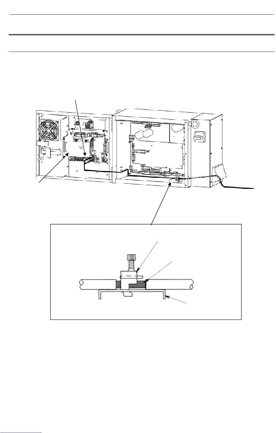
CONNECTIONS B-82725EN-1/07
- 170 -
4. PERIPHERAL DEVICE AND
END EFFECTOR INTERFACES
4.7 CABLE CONNECTION FOR THE PERIPHERAL DEVICES
4.7.1 Peripheral Device Connection Cable
Fig.4.7.1 shows the connection of the peripheral device cable in the cabinet.
For noise protection, cut part of the jacket of the peripheral device cable to expose the shield sheath, and
fasten this part to the shield plate with the clamp.
Fig.4.7.1 Peripheral device cable connection
Main board
Clamp
CRMA15, CRMA16
To peripheral device
Shield sheath
Shield plate
Downloaded from www.Manualslib.com manuals search engine
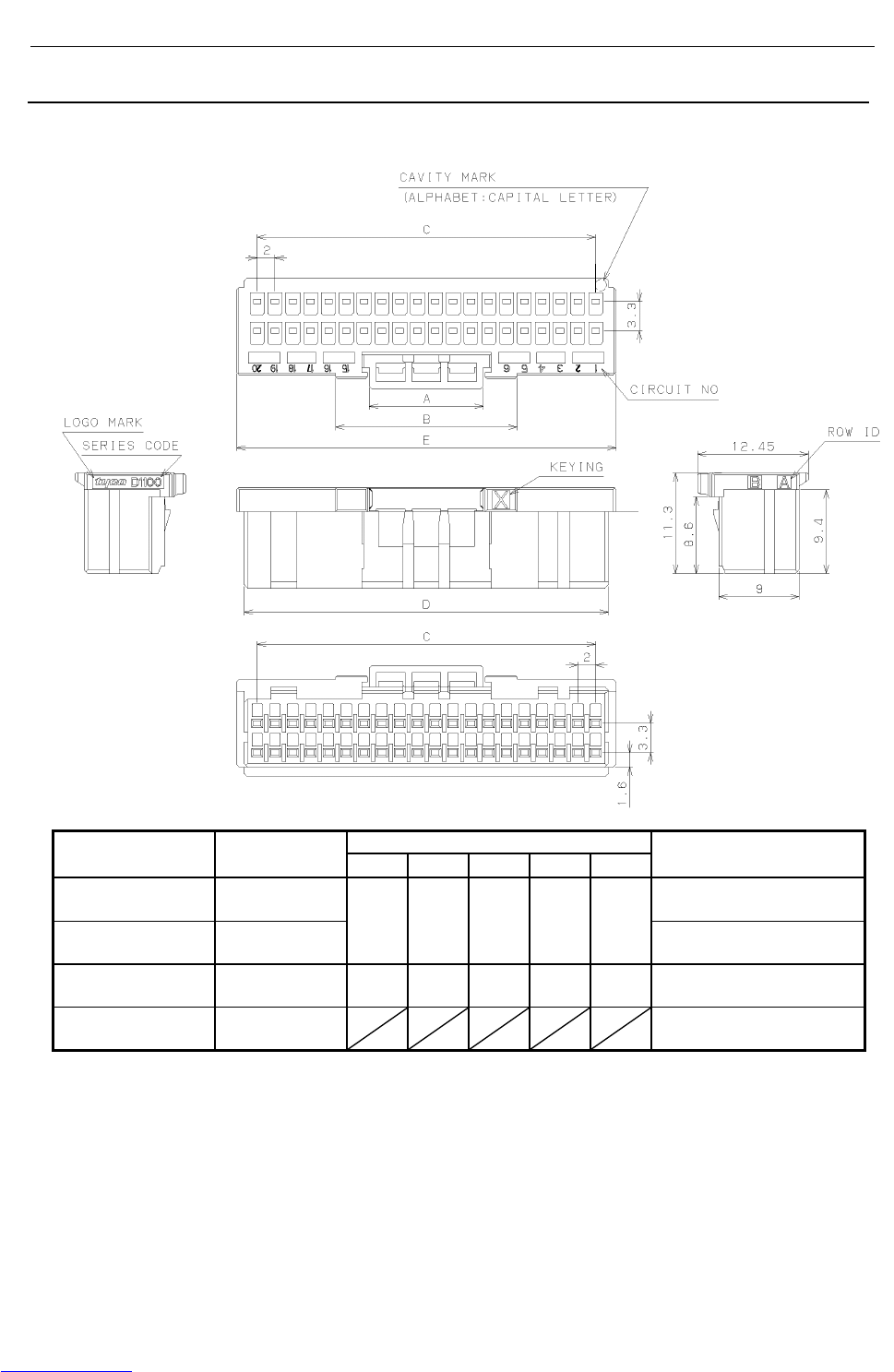
B-82725EN-1/07 CONNECTIONS
- 171 -
4. PERIPHERAL DEVICE AND
END EFFECTOR INTERFACES
4.7.2 Peripheral Device Cable Connector
(1) Fig.4.7.2 shows the connector for peripheral device cables A1 and A2.
Dimensions Connector
specifications Applicable
interface A B C D E Remark
1-1827863-0
(Housing) CRMA15 Tyco Electronics AMP
D-1000 series 40pin (X-key)
2-1827863-0
(Housing) CRMA16
12.8 20.4 38.0 40.9 42.6 Tyco Electronics AMP
D-1000 series 40pin (Y-key)
1-1827863-5
(Housing) CRMA52 12.8 20.4 28.0 30.9 32.6 Tyco Electronics AMP
D-1000 series 30pin (X-key)
1939991-2
(Contact)
CRMA15
CRMA16
Tyco Electronics AMP
D-1000 series
Maintenance tool
Hand tool (for crimping contact) 1762846-1:A05B-2550-K060
Extraction tool 1891526-1:A05B-2550-K061
Fig.4.7.2 (a) Peripheral device cable connector (Tyco Electronics AMP)
Downloaded from www.Manualslib.com manuals search engine
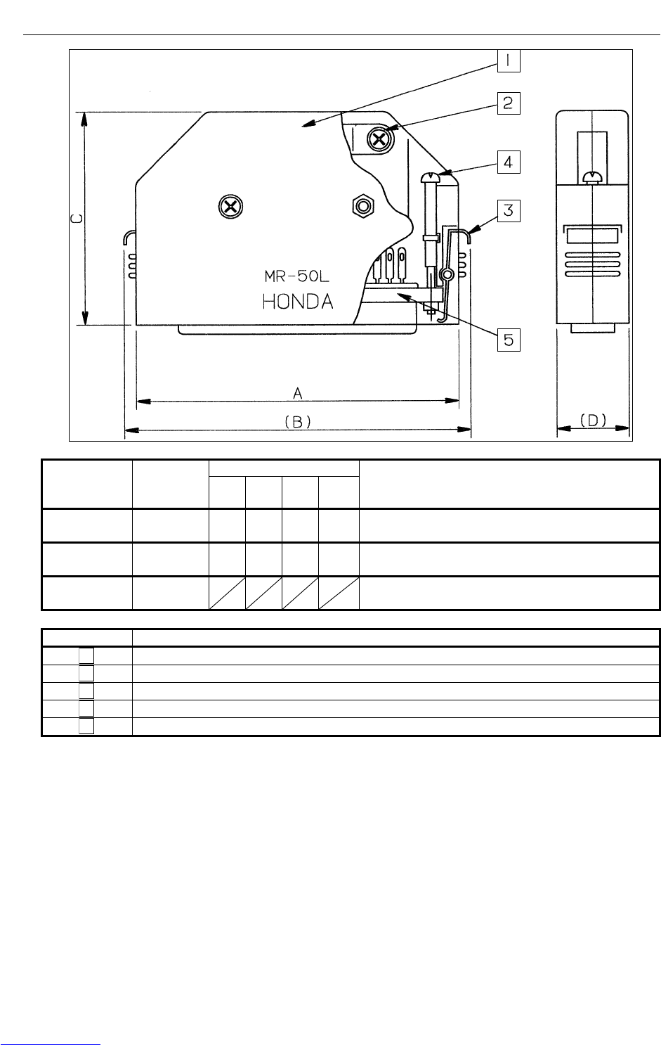
CONNECTIONS B-82725EN-1/07
- 172 -
4. PERIPHERAL DEVICE AND
END EFFECTOR INTERFACES
Dimensions Connector
specification
s
Applicable
interface A (B) C (D) Remark
MR50LF
(Connector)
CRMA15
CRMA16 67.9 73.5 44.8 18 Honda Tsushin Kogyo, 50 pins, female
MR50LM
(Connector)
CRMA58
CRMA59 67.9 73.5 44.8 18 Honda Tsushin Kogyo, 50 pins, male
MRP-F112
(Contact)
CRMA15
CRMA16 Honda Tsushin Kogyo
Symbol Name
1 Connector cover
2 Cable clamp screw
3 Connector clamp spring
4 Connector clamp screw
5 Connector 50 pins (female) MR50LF
Fig.4.7.2 (b) Peripheral device cable connector (Honda Tsushin Kogyo)
Downloaded from www.Manualslib.com manuals search engine
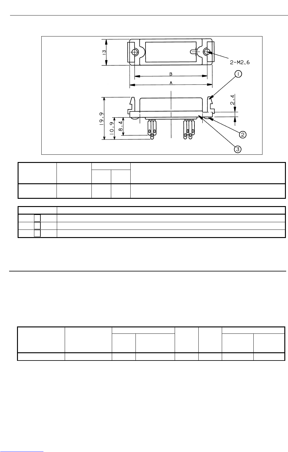
B-82725EN-1/07 CONNECTIONS
- 173 -
4. PERIPHERAL DEVICE AND
END EFFECTOR INTERFACES
(2) Peripheral device connector
DimensionsConnector
specification
s
Applicable
interface A B Remark
MR50RM (CRMA15)
(CRMA16)
61.4 56.4 Honda Tsushin Kogyo, 50 pins
Symbol Name
1 Connector clamp screw
2 Screw M2.6 8
3 Connector (MR50RM)
Fig.4.7.2 (c) Peripheral device connector (Honda Tsushin Kogyo)
4.7.3 Recommended Cables
(1) Peripheral device connection cable
Connect a peripheral device using a completely shielded, heavily protected cable conforming to the
specifications in Table 4.7.3 (a).
Allow an extra 50 cm for routing the cable in the control unit.
The maximum cable length is 30 m.
Table 4.7.3 (a) Recommended cable (for peripheral device connection)
Conductor Electrical characteristics
Number of wires Wire specifications
(FANUC
specifications) Diameter
(mm) Configuration
Sheath
thicknes
s (mm)
Effective
outside
diameter
(mm)
Conductor
resistance
(Ω/km)
Allowable
current (A)
50 A66L-0001-0042 φ1.05 7/0.18 AWG24 1.5 φ12.5 106 1.6A
(2) End effector connection cable
Connect an end effector using a heavily protected cable with a movable wire conforming to the
specifications in Table 4.7.3(b).
The cable length is determined so that the cable will not interfere with the end effector and the wrist
can move through its full stroke.
Downloaded from www.Manualslib.com manuals search engine
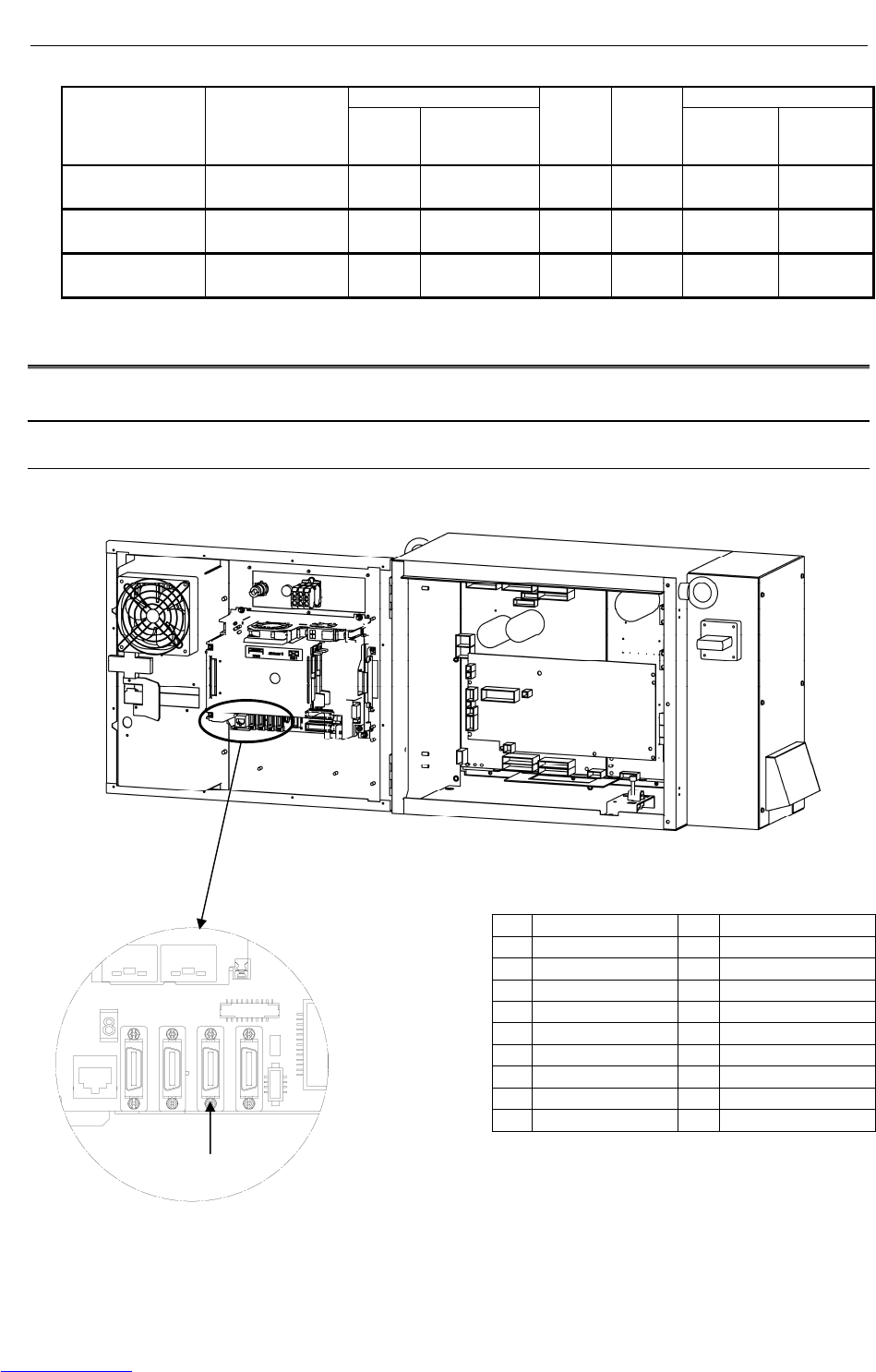
CONNECTIONS B-82725EN-1/07
- 174 -
4. PERIPHERAL DEVICE AND
END EFFECTOR INTERFACES
Table 4.7.3 (b) Recommended cable (for end effector connection)
Conductor Electrical characteristics
Number of wires Wire specifications
(FANUC
specifications) Diameter
(mm) Configuration
Sheath
thicknes
s (mm)
Effective
outside
diameter
(mm)
Conductor
resistance
(Ω/km)
Allowable
current (A)
6 A66L-0001-0143
φ1.1 40/0.08
AWG24 1.0 φ5.3 91 3.7
20 A66L-0001-0144
φ1.1 40/0.08
AWG24 1.0 φ8.6 91 2.3
24 A66L-0001-0459
φ0.58 40/0.08
AWG24 1.0 φ8.3 93 2.3
4.8 CONNECTING THE COMMUNICATION UNIT
4.8.1 RS-232-C Interface
4.8.1.1 Interface
This interface can be connected to a communication unit from FANUC.
Fig.4.8.1.1 RS-232-C interface
JD17
1 RD 11 SD
2 SG 12 SG
3 DR 13 ER
4 SG 14 SG
5 CS 15 RS
6 SG 16 SG
7 17
8 18
9 19 +24V
10 +24V 20
JD17
JD17 : Honda Tsushin Kogyo
CONNECTOR : PCR-E20FS
COVER : PCR-V20LA,
or compatible connector
Downloaded from www.Manualslib.com manuals search engine
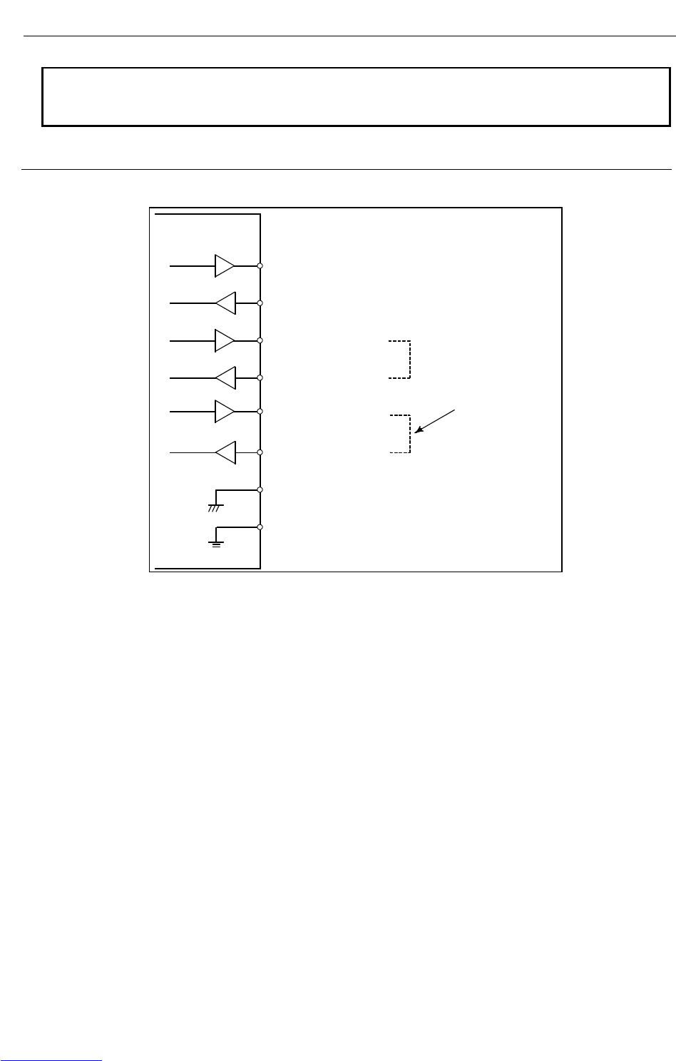
B-82725EN-1/07 CONNECTIONS
- 175 -
4. PERIPHERAL DEVICE AND
END EFFECTOR INTERFACES
NOTE
1 +24V can be used as the power supply for FANUC RS-232-C equipment.
2 Do not connect anything to those pins for which signal names are not indicated.
4.8.1.2 RS-232-C interface signals
Generally signals as follows are used in RS-232-C interface.
R-30iA Mate
SD (Send data)
RD (Receive data)
RS (Request to Send)
CS (Enable to send)
ER (Ready)
DR (Data set ready)
SG (Signal ground)
FG (Frame ground)
When CS is not used short
CS and RS.
When DR is not
used short DR and
ER.
Output
Input
Downloaded from www.Manualslib.com manuals search engine
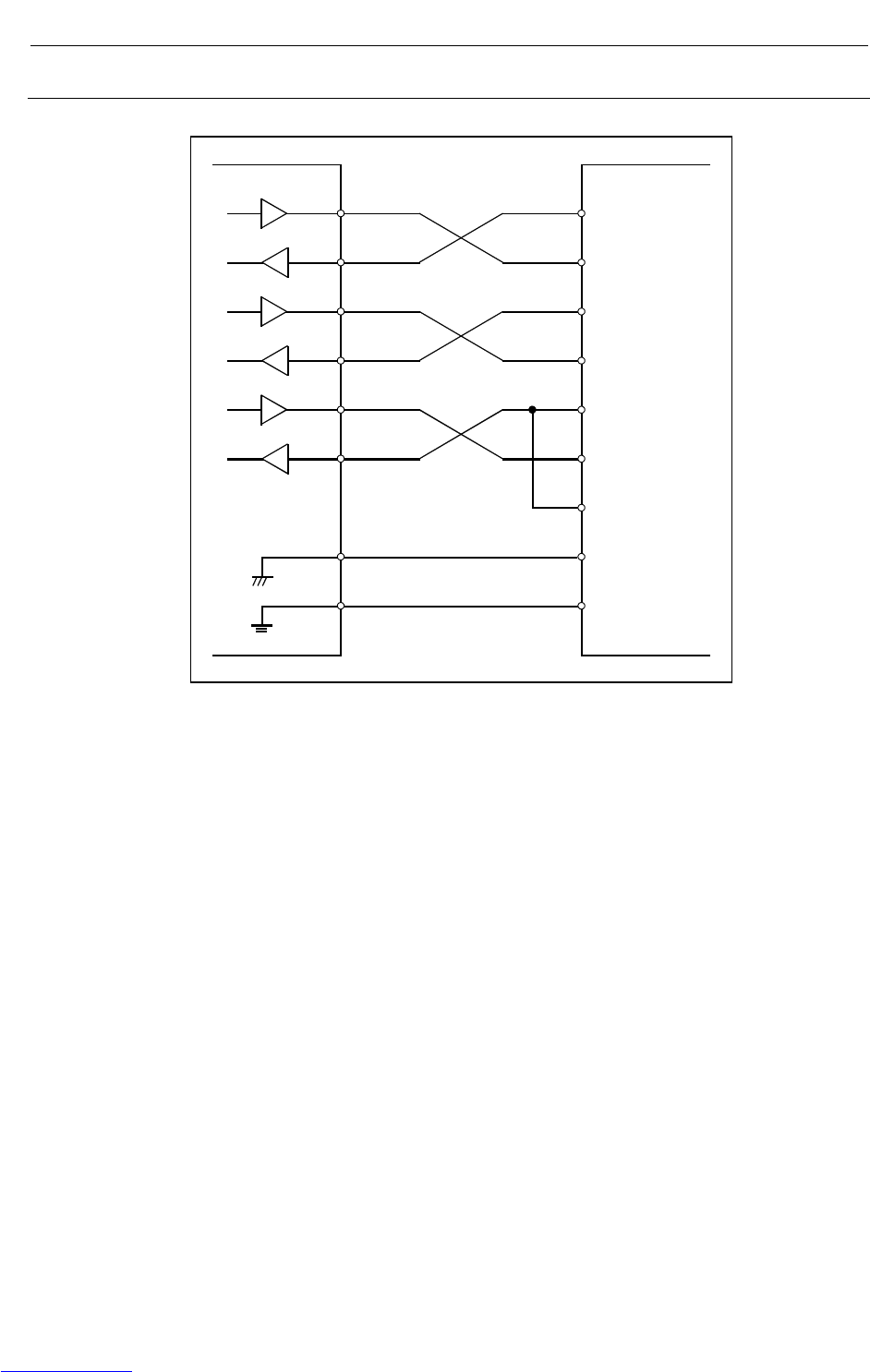
CONNECTIONS B-82725EN-1/07
- 176 -
4. PERIPHERAL DEVICE AND
END EFFECTOR INTERFACES
4.8.1.3 Connection between RS-232-C interface and I/O device
The figure below shows a connection with the handshaking of the ER/DR, RS/CS signals.
R-30iA Mate I/O 機器側
SD
RD
RS
CS
ER
DR
SG
FG
SD
RD
RS
CS
ER
DR
CD
SG
FG
FG (Frame ground)
Downloaded from www.Manualslib.com manuals search engine
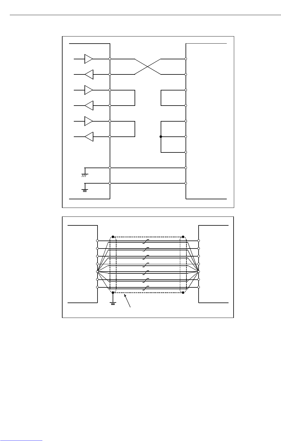
B-82725EN-1/07 CONNECTIONS
- 177 -
4. PERIPHERAL DEVICE AND
END EFFECTOR INTERFACES
• The figure below shows a connection without the handshaking of the RS/CS, ER/DR signals.
External device
side
SD
RD
RS
CS
ER
DR
SG
FG
SD
RD
RS
CS
ER
DR
CD
SG
FG
R-30iA Mate
FG (Frame ground)
DR
R-30iA Mate
Cable : twist 10 pairs 0.18mm
2
, with shield
SD
RD
RS
CS
SG
ER
Cable connection
Pair each signal with SG.
Downloaded from www.Manualslib.com manuals search engine
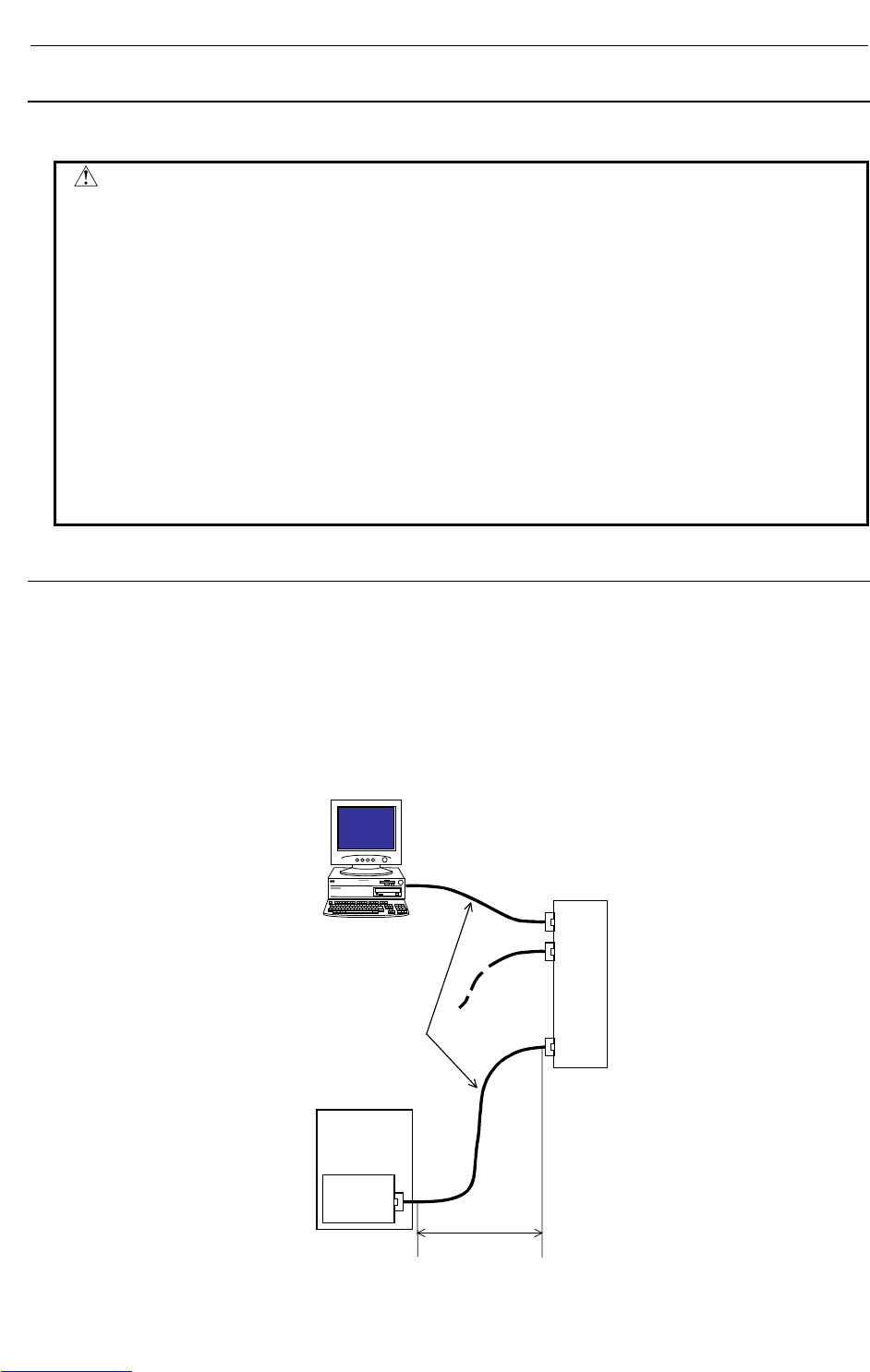
CONNECTIONS B-82725EN-1/07
- 178 -
4. PERIPHERAL DEVICE AND
END EFFECTOR INTERFACES
4.8.2 Ethernet Interface
This section describes information relating to the physical Ethernet connection.
CAUTION
1 Before connecting or disconnecting the cable to or from the FAST
Ethernet/FAST Data Server, make sure that the power to the CNC is turned off.
2 Please inquire of each manufacturer about the construction of network or the
condition of using the equipment except the FAST Ethernet/FAST Data Server
(hub, transceiver, cable etc.). When configuring your network, you must take
other sources of electrical noise into consideration to prevent your network from
being influenced by electrical noise. Make sure that network wiring is sufficiently
separated from power lines and other sources of electrical noise such as motors,
and ground each of the devices as necessary. Also, high and insufficient ground
impedance may cause interference during communications. After installing the
machine, conduct a communications test before you actually start operating the
machine.
We cannot ensure operation that is influenced by network trouble caused by a
device other than the FAST Ethernet or FAST Data Server.
4.8.2.1 Connection to Ethernet
The FAST Ethernet or FAST Data Server is provided with a 100BASE-TX interface.
Prepare a hub for connecting the FAST Ethernet board to the Ethernet trunk. The following shows an
example of a general connection.
Some devices (hub, transceiver, etc.) that are needed for building a network do not come in a dust-proof
construction. Using such devices in an atmosphere where they are subjected to dust or oil mist will
interfere with communications or damage the FAST Ethernet or FAST Data Server. Be sure to install
such devices in a dust-proof cabinet.
HUB
Controller
FAST
Ethernet or
FAST Data
Server
:
:
:
Max. 100m
Twisted pai
r
cable
Downloaded from www.Manualslib.com manuals search engine
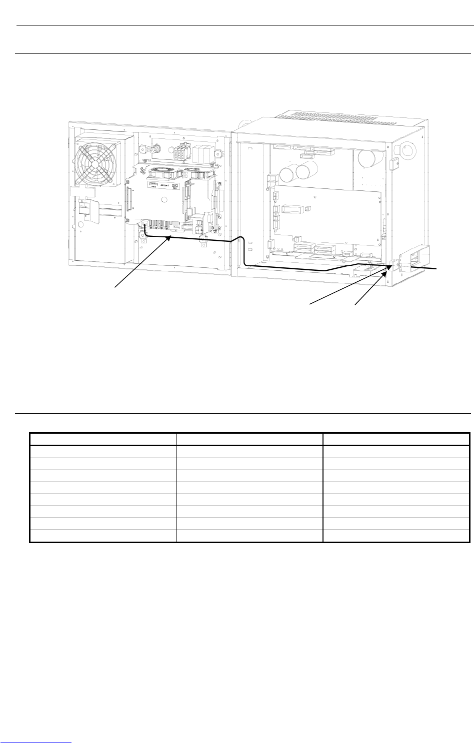
B-82725EN-1/07 CONNECTIONS
- 179 -
4. PERIPHERAL DEVICE AND
END EFFECTOR INTERFACES
4.8.2.2 Leading out the Ethernet cable
For this type of control unit, the cable is drawn out only from the front of the control unit. See the
outline drawing of each type of board for the location of the connector.
The Ethernet cable must be fastened by a cable clamp to prevent tension being applied to the
modular connector (RJ-45) that connects the cable to the control unit even if the Ethernet cable is
pulled directly. This clamp is also used to ground the cable shield.
4.8.2.3 100BASE-TX connector (CD38R) pin assignments
Table 4.8.2.3 CD38R
Pin No. Signal name Description
1 TX+ Send +
2 TX- Send -
3 RX+ Receive +
4 Not used
5 Not used
6 RX- Receive -
7 Not used
8 Not used
Twisted-pair cable.
The radius of the cable
must be 70mm or less. Clamp Ground plate
Downloaded from www.Manualslib.com manuals search engine
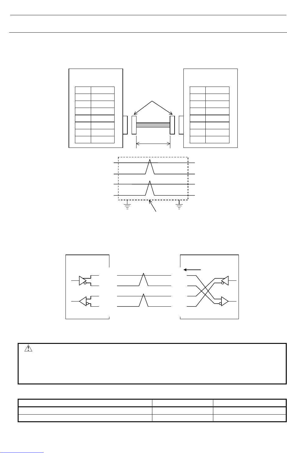
CONNECTIONS B-82725EN-1/07
- 180 -
4. PERIPHERAL DEVICE AND
END EFFECTOR INTERFACES
4.8.2.4 Twisted-pair cable specification
Cable Connection
The cable used for connection between the 100BASE-TX interface, CD38, of the controller and the hub is
connected as follows:
1 TX+
2 TX-
3 RX+
4
5
6 RX-
7
8
R-30+A Mate
CD38A,CD38B
1 TX+
2 TX-
3 RX+
4
5
6 RX-
7
8
HUB
TX+ (1)
TX- (2)
RX+ (3)
RX- (6)
(1) TX+
(2) TX-
(3) RX+
(6) RX-
Shielded cable
RJ-45
modular connector
MAX.100m
• Keep the total cable length within 100 m.
Do not extend the cable more than is necessary.
• The figure above shows the cable connection when cables are crossed in the hub.
"X" is usually indicated at the port of the hub to signify that cables are crossed in the hub.
1 TX+
2 TX-
3 RX+
6 RX-
TX+ 1
TX- 2
RX+ 3
RX- 6
HUB
X
R-30+iA/
R-30+A Mate Cross-connected
cables
Cable Materials
CAUTION
Unshielded cable (UTP cable) is commercially available as 100BASE-TX
twisted-pair cable: You should, however, use shielded Category 5 twisted-pair
cable (STP cable) to improve the resistance to electrical noise in an FA
environment.
Table 4.8.2.4(a) Recommended cables
Manufacturer Specification Remarks
FURUKAWA ELECTRIC CO., LTD. DTS5087C-4P Twisted-pair cable
NISSEI ELECTRIC CO., LTD. F-4PFWMF Single-conductor cable
Downloaded from www.Manualslib.com manuals search engine
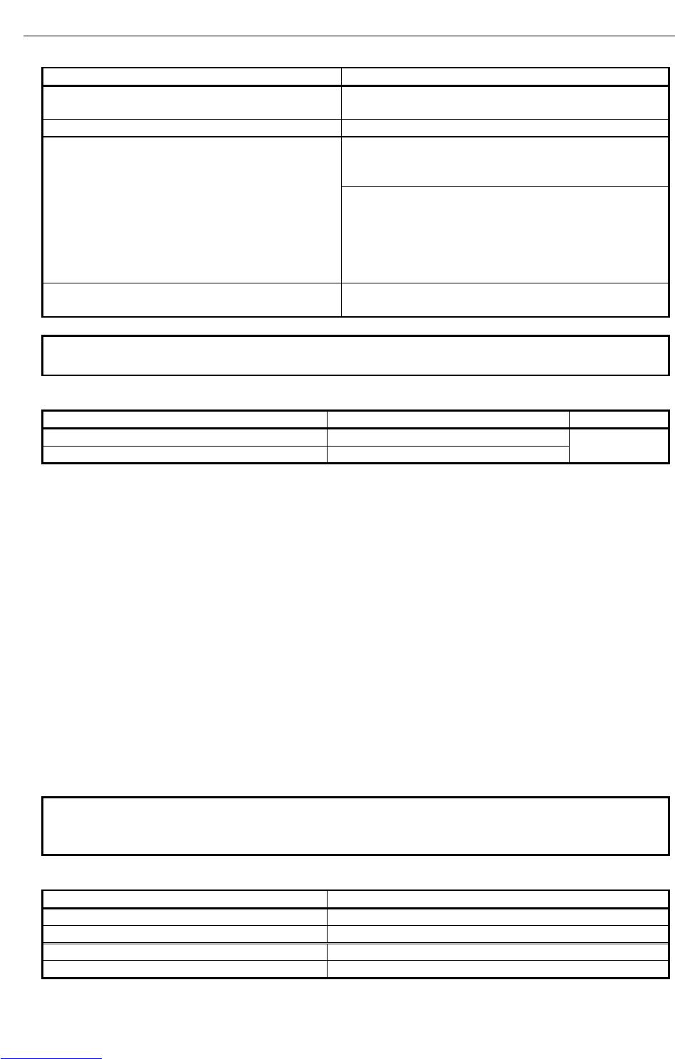
B-82725EN-1/07 CONNECTIONS
- 181 -
4. PERIPHERAL DEVICE AND
END EFFECTOR INTERFACES
Table 4.8.2.4(b) Inquiries
Manufacturer Contact address
FURUKAWA ELECTRIC CO., LTD.
Sales Headquarters
2-6-1 Marunouchi, Chiyoda-ku. Tokyo 100-8322
TEL: 03-3286-3126 FAX: 03-3286-3979
Remarks
NISSEI ELECTRIC CO., LTD.
Machida Branch
3F MU Bldg., 1-9-1 Minami-narise,
Machida City, Tokyo 194-0045
TEL: 0427-29-2531 FAX: 0427-29-3375
Overseas Sales Office IWATANI International Corporation
Tokyo Head Office
21-8 Nishi-shinbashi 3-chome, Minato-ku, TOKYO,
105-8458, JAPAN
TEL: 03-5405-5810 FAX: 03-5405-5666
Telex: 2524256 IWATYO J
Remarks A finished cable with connectors at both ends can be
offered.
NOTE
The recommended cables cannot be connected to moving parts.
Table 4.8.2.4(c) Recommended cable (for movable parts)
Manufacturer Specification Remarks
Oki Electric Cable Co., Ltd. AWG26 4P TPMC-C5-F (SB)
Shinko Electric Industrial Co., Ltd. FNC-118
Dedicated to
FANUC
Specification
• Electric characteristics:
Conforms to EIA/TIA 568A Category 3 and Category 5.
From the viewpoint of attenuation performance, ensure that the length to the hub is 50 m or less.
• Structure:
Group shielded (braided shield). A drain wire is available.
The conductor is an AWG26 annealed copper twisted wire, with a sheath thickness of 0.8 mm and
an outer diameter of 6.7 mm ±0.3 mm.
• Fire retardancy
UL1581 VW-1
• Oil resistance
Conforms to the FANUC internal standards (equivalent to the conventional oil-resistant electric
cables).
• Flexing resistance:
1,000,000 times or more with a bending radius of 50 mm (U-shaped flex test)
• UL style No.
AWM 20276 (80°C/30V/VW-1)
NOTE
Be sure to use the connector TM21CP-88P (03) manufactured by HIROSE
ELECTRIC CO., LTD. for this cable.
Table 4.8.2.4(d) Inquiries
Manufacturer Contact address
Oki Electric Cable Co., Ltd. Nagano Sales Office TEL:0266-27-1597
Remarks
Shinko Electric Industrial Co., Ltd. Tokyo Sales Office TEL:03-3492-0073
Remarks
Downloaded from www.Manualslib.com manuals search engine
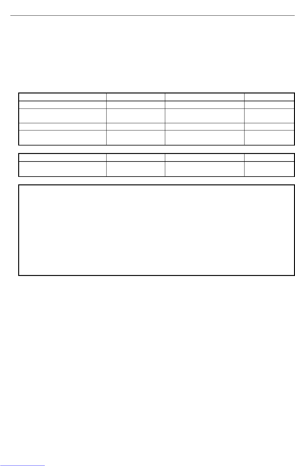
CONNECTIONS B-82725EN-1/07
- 182 -
4. PERIPHERAL DEVICE AND
END EFFECTOR INTERFACES
Cable assembly
Oki Electric Cable Co., Ltd. can also supply the cable assembly mentioned above.
Contact Oki Electric directly to determine the specifications (length, factory test, packing, and so forth)
for purchase.
Connector Specification
Use an 8-pin modular connector (RJ-45) with the twisted-pair cable for the Ethernet connection. The
following connectors or equivalents must be used.
For general use Specification Manufacturer Remarks
Solid wire 5-569530-3 Tyco Electronics AMP K.K..
Solid wire MS8-RSZT-EMC SK KOHKI CO., LTD. Special tools
required
Twisted-pair cable 5-569552-3 Tyco Electronics AMP K.K..
Twisted-pair cable TM11AP-88P HIROSE ELECTRIC CO., LTD. Special tools
required
For movable parts Specification Manufacturer Remarks
For cable AWG26 4P TPMC-C5-F
(SB) or FNC-118 TM21CP-88P (03) HIROSE ELECTRIC CO., LTD. Note
NOTE
Information about TM21CP-88P (03):
Connector (standard product of the manufacturer)
Drawing number: A63L-0001-0823#P
Manufacturer: HIROSE ELECTRIC CO., LTD.
Manufacturer type number: TM21CP-88P (03)
Conforms to EIA/TIA 568A Category 3 and Category 5.
For assembly with a cable, contact HIROSE ELECTRIC CO., LTD. directly.
(From HIROSE ELECTRIC CO., LTD., "TM21CP-88P (03) Connection
Procedure Manual (Technical Specification No. ATAD-E2367)" is available as a
technical document.)
Downloaded from www.Manualslib.com manuals search engine

B-82725EN-1/07 CONNECTIONS
- 183 -
4. PERIPHERAL DEVICE AND
END EFFECTOR INTERFACES
4.8.2.5 Electrical noise countermeasures
Clamping and Shielding Cables
Clamp an Ethernet twisted pair cable according to the method described below, as with cables that need
to be shielded. Clamping cables provides support and shielding and is extremely important to the safe
operation of the system. Never overlook cable clamping.
Peel off part of the jacket as shown in the figure to expose the outer coating of the shield, and press this outer
coating against the ground plate with the clamp fixture.
The machine manufacturer must prepare the ground plate and install it as follows:
Shield
Peel off jacket
Ground plate
Ground plate
Cable
Cable clamp
NOTE
To ensure the safe operation of the system, clamp and shield the cables.
Connect the Ethernet board and hub with a twisted-pair cable. Shield the cable with clamp fixtures.
Downloaded from www.Manualslib.com manuals search engine
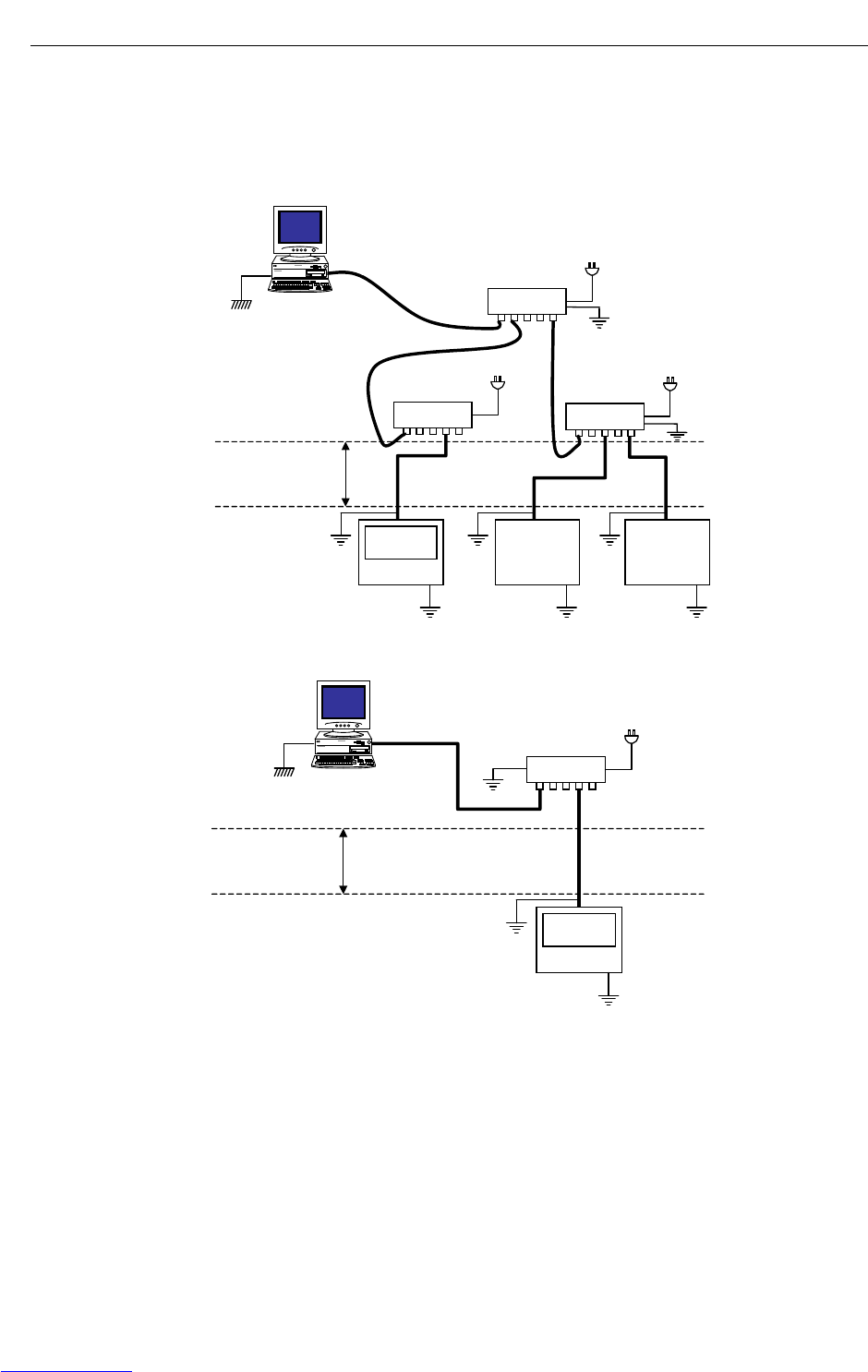
CONNECTIONS B-82725EN-1/07
- 184 -
4. PERIPHERAL DEVICE AND
END EFFECTOR INTERFACES
Grounding the Network
Even if the grounding condition on the machine side is satisfied, the communication line can pick up
noise from the machine, depending on the machine installation condition and environment, thus resulting
in a communication error. To protect against such noise, the machine should be separated and insulated
from the Ethernet trunk cable and personal computer. Examples of connection are given below.
Ethernet
Machine
Machine Machine
STP cable STP
cable
Electrically separated
by 100BASE-TX cable
connection
Personal computer
Personal computer /
HUB side
Machine system
Note 1
Hub power supply
Note 1 Note 1
Note 1
HUB
Note 2
Note 1 Note 1 Note 1
HUB
Note 2
Note 2
Switching HUB
Large-Scale Network
Note 1
HUB
STP cable
Electrically separated
by 100BASE-TX
cable connection
Personal computer
Note 1
Personal computer/Ethernet trunk side
Machine system
Hub power supply
Ethernet
Machine
Note 2
Note 1
Note 1
Small-Scale Network
Downloaded from www.Manualslib.com manuals search engine
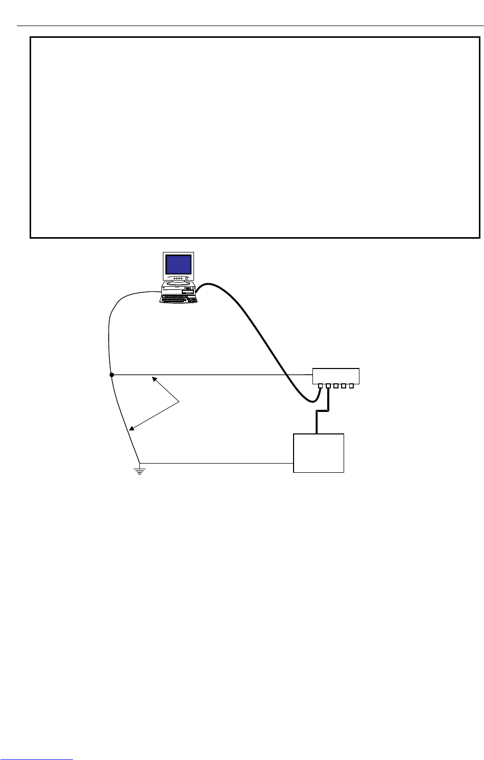
B-82725EN-1/07 CONNECTIONS
- 185 -
4. PERIPHERAL DEVICE AND
END EFFECTOR INTERFACES
NOTE
1 The ground between PC/HUB side and machine system side must be separated.
If it is impossible to separate the ground because there is only one grounding
point, connect the ground cable for each system to the grounding point
independently. (See figure below.)
The resistance for grounding must be less than 100-ohm (Class D). The
thickness of the ground cable is the same as the thickness of AC power cable or
more. At least thickness of 5.5mm2 is necessary.
2 Note that the number of allowable hub-to-hub connections depends on the type
of hub.
3 There is possibility that noise makes the obstacle of communication even if the
ground is separated using the 100BASE-TX. In the case of using the FAST
Ethernet/FAST Data Server under the worst environment, please separate
between the PC/Trunk line side and machine system side completely using the
100BASE-FX (Optical fiber media).
HUB
FG
Ground wire on personal
computer and trunk sides
Ground wire on machine system
FG
Ground point
Note 2
Ground wire on
machine system
Wiring on a single ground point
Downloaded from www.Manualslib.com manuals search engine

CONNECTIONS B-82725EN-1/07
- 186 -
4. PERIPHERAL DEVICE AND
END EFFECTOR INTERFACES
4.8.2.6 Check items at installation
The following table lists check items at installation.
Check item Description Check
Ethernet cable
Use cables which satisfies all the following conditions:
1) With shielding
2) Twisted-pair cable
Type
3) Category 5
Length The cable length shall be within 100 m (50 m for a movable cable recommended
by FANUC).
For a twisted-pair cable, the following pins shall be paired:
1) Pin No. 1 (TX+) – pin No. 2 (TX-)
Connection
2) Pin No. 3 (RX+) – pin No. 6 (RX-)
The Ethernet cables shall be bound separately from the following cables or
covered with an electromagnetic shield:
1) Group A: AC power lines, power lines for motors, and others
Separation
2) Group B: Current DC (24 VDC) and others
Shielding For a shielded cable, the part of which outer coating is peeled off and exposed
shall be fixed to the ground plate with a clamp fixture.
Clamping The ground plate shall be located as nearest to the CNC as possible (to make the
cable between the ground plate and CNC hard to be affected by noise).
Connectors Any cable connector shall not be pulled (to prevent poor contact of the connector).
Wiring No cable shall be laid under a heavy object.
Bending radius The bending radius shall be at least four times as long as the diameter of the
cable.
For movable
part For a movable part, a cable for a movable part shall be used.
CNC and cabinet
CNC grounding The CNC ground (frame ground) shall be connected properly and the length of the
ground wire shall be within 300 mm.
Ground plate The ground plate shall be connected to the AC ground of the cabinet with wire.
Mounting The Ethernet board shall be inserted in a CNC slot properly.
HUB
Use conditions The "cautions on use" of the hub shall be observed (A terminating resistor shall be
mounted properly if required).
Grounding The hub shall be grounded.
Cabinet The hub shall be installed in an enclosed cabinet.
Vibration The hub shall be installed so that it is not affected by vibration.
Bending radius The bending radius shall be at least four times as long as the diameter of the
cable.
Downloaded from www.Manualslib.com manuals search engine
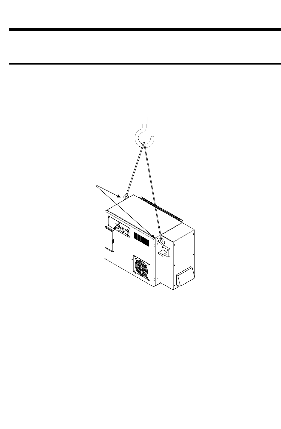
B-82725EN-1/07 CONNECTIONS
- 187 -
5.TRANSPORTATION
AND INSTALLATION
5 TRANSPORTATION AND INSTALLATION
This chapter describes the transportation and installation for the controller.
5.1 TRANSPORTATION
The controller is transported by a crane. Attach a strap to eyebolts at the top of the control unit.
Fig.5.1 Transportation
E
y
ebolt
(
M10
)
Crane capacity: Minimum 150kg
Sling capacity: Minimum 150kg
Downloaded from www.Manualslib.com manuals search engine
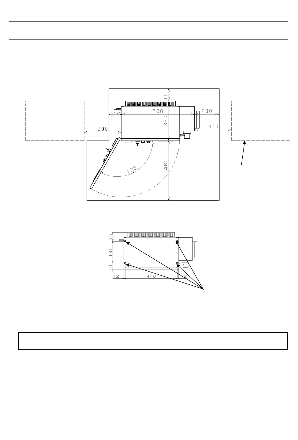
CONNECTIONS B-82725EN-1/07
- 188 -
5.TRANSPORTATION
AND INSTALLATION
5.2 INSTALLATION
5.2.1 Installation Method
Following is the installation method for cabinet.
When installing the controller, allow the space for maintenance shown in the following figure.
Fig.5.2.1 (a) Installation dimension (LR Mate 200iC, M-1iA)
NOTE
Keep this area for maintenance and the radiation of heat.
Location of fixing bolts.
(M10: 4 places)
(
To
p
View
)
When more than one
controller is installed
Downloaded from www.Manualslib.com manuals search engine
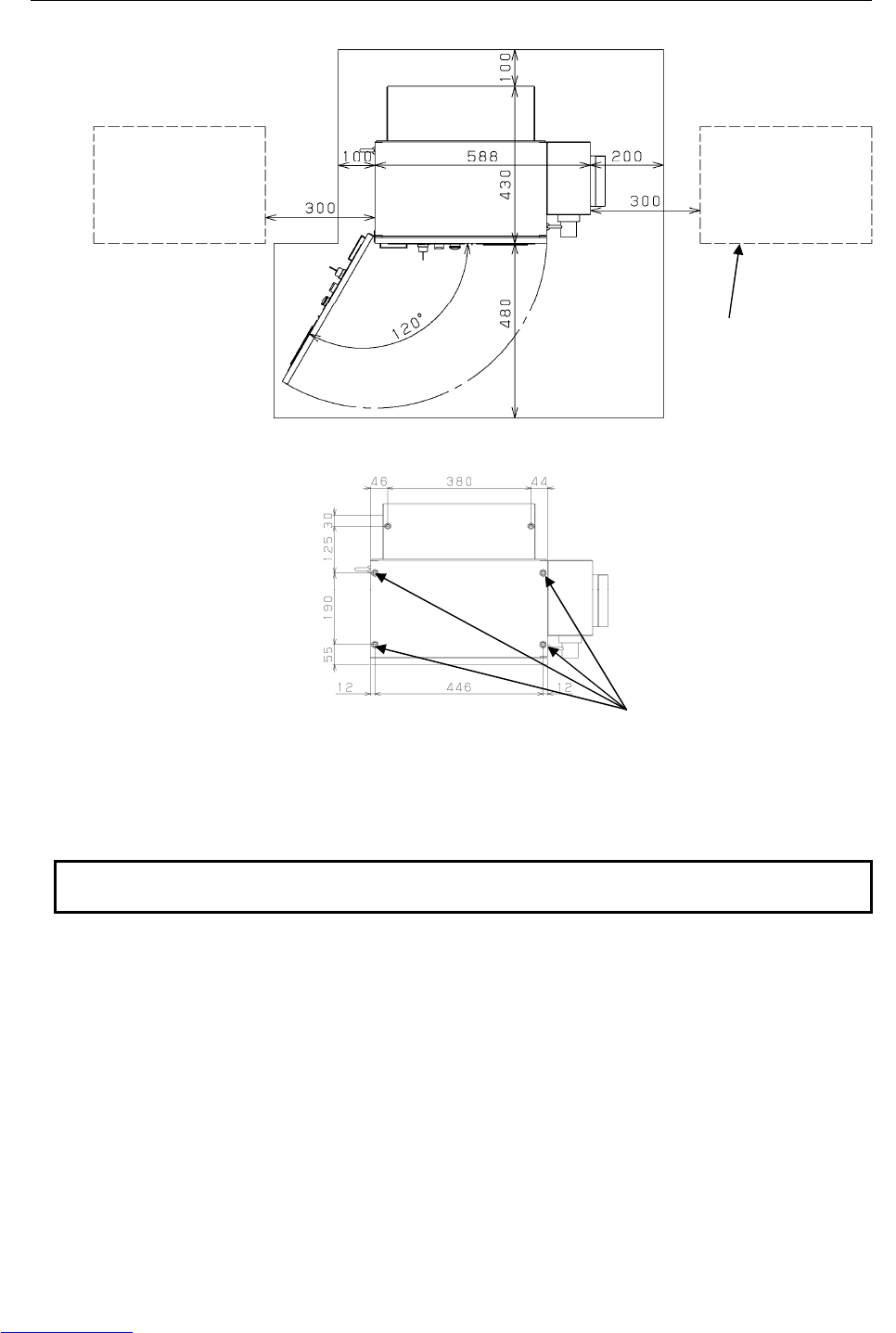
B-82725EN-1/07 CONNECTIONS
- 189 -
5.TRANSPORTATION
AND INSTALLATION
Fig.5.2.1 (b) Installation dimension (ARC Mate 100iC, M-10iA, ARC Mate 120iC, M-20iA, ARC Mate 50iC,
ARC Mate 0iA)
NOTE
Keep this area for maintenance and the radiation of heat.
When more than one
controller is installed
Location of fixing bolts.
(M10: 4 places)
(
To
p
View
)
Downloaded from www.Manualslib.com manuals search engine
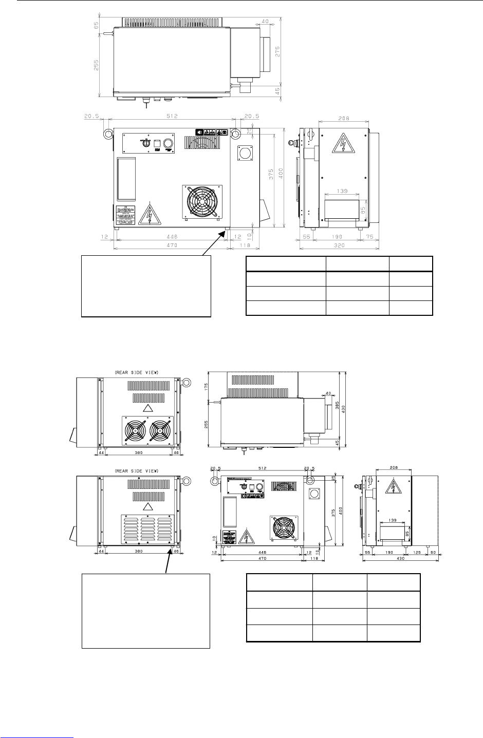
CONNECTIONS B-82725EN-1/07
- 190 -
5.TRANSPORTATION
AND INSTALLATION
MUNSELL Color
Body 5GY3.5/0.5 Gray
Door 3.0GY8.2/0.9 White
Operator’s Panel N1.5 Black
M10 weld nut (4 positions)
Before shipment, M10 bolts are
screwed into the weld nuts to form
a leg portion with a size of 10 mm.
If the M10 bolts are removed, the
weld nuts can be used to secure
the control unit.
Fig.5.2.1(c) External dimension (LR Mate 200iC, M-1iA)
In case of ARC Mate 100
i
C,
M
-10iA,
ARC Mate 120iC, M-20iA,
ARC Mate 0iA
In case of ARC Mate 50
i
C
M10 weld nut (6 positions)
Before shipment, M10 bolts are
screwed into the weld nuts to form a
leg portion with a size of 10 mm.
If the M10 bolts are removed, the
weld nuts can be used to secure
the control unit.
MUNSELL Color
Body 5GY3.5/0.5 Gray
Door 3.0GY8.2/0.9 Wh i te
Operator’s Panel N1.5 Black
Fig.5.2.1(d) External dimension
(ARC Mate 100iC,M-10iA, ARC Mate 120iC,M-20iA, ARC Mate 50iC, ARC Mate 0iA)
Downloaded from www.Manualslib.com manuals search engine
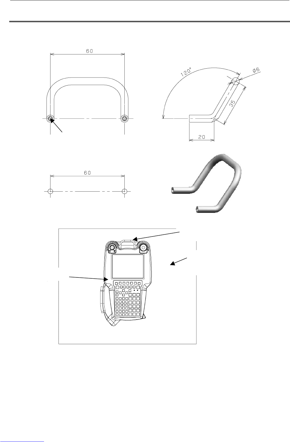
B-82725EN-1/07 CONNECTIONS
- 191 -
5.TRANSPORTATION
AND INSTALLATION
5.3 MOUNTING METHOD OF TEACH PENDANT HOOK
Following is external dimension for Teach Pendant HOOK (Ordering specification: A05B-2550-K050).
Screw(M3)
Mounting hole
Teach Pendant HOOK
Mounting plate for Teach Pendant
(Provided by customer.)
Teach Pendant
Fig.5.3 External dimension of Teach Pendant HOOK
Downloaded from www.Manualslib.com manuals search engine

CONNECTIONS B-82725EN-1/07
- 192 -
5.TRANSPORTATION
AND INSTALLATION
5.4 INSTALLATION CONDITION
Item Model Specification/condition
LR Mate 200iC,
M-1iA
200-230VAC +10% -15%
50/60Hz ±1Hz Single phase
Rated Voltage
ARC Mate 100iC, M-10iA
ARC Mate 120iC, M-20iA
ARC Mate 50iC
ARC Mate 0iA
200-230VAC +10% -15%
50/60Hz ±1Hz 3 phase
Tolerant fluctuation All models Tolerant voltage fluctuation: +10% -15%
Tolerant frequency fluctuation: ±1Hz
M-1iA, 1.0KVA
LR Mate 200iC,
ARC Mate 50iC
1.2KVA
ARC Mate 100iC,M-10iA
ARC Mate 0iA
2.0KVA
Input power source capacity
ARC Mate 120iC,M-20iA3.0KVA
M-1iA, 0.2KW
LR Mate 200iC,
ARC Mate 50iC
0.5KW
Average power consumption
ARC Mate 100iC,M-10iA
ARC Mate 120iC,M-20iA
ARC Mate 0iA
1.0KW
Permissible ambient
temperature
All models Operating 0℃ to 45℃
Storage, Transport -20℃ to 60℃
Temperature change 0.3℃/minute or less
Permissible ambient humidity All models Normal: 75%RH or less, no condensation
Short period (less than 1 month): 95%RH or less, no
condensation
Surrounding gas All models An additional protective provision is necessary if the
machine is installed in an environment in which there
are relatively large amounts of contaminants (dust,
dielectric fluid, organic solvent, acid, corrosive gas,
salt, etc.).
LR Mate 200iC,
M-1iA
Installation Category Ⅲ, Pollution Degree 3,
IEC60664-1 and IEC61010-1
Installation Category
ARC Mate 100iC, M-10iA
ARC Mate 120iC, M-20iA
ARC Mate 50iC
ARC Mate 0iA
Installation Category Ⅱ, Pollution Degree 3,
IEC60664-1 and IEC61010-1 (NOTE2)
Vibration All models 0.5G or less
When using the robot in a location subject to serious
vibration, consult with your FANUC sales
representative.
Altitude All models Operating: Up to 1000m
Non-operating: Up to 12000m
Ionized and non-ionized
radiation
All models A shielding provision is necessary if the machine is
installed in an environment in which it is exposed to
radiation (microwave, ultraviolet rays, laser beams,
and/or X-rays).
Mass of control unit All models 50kg
Downloaded from www.Manualslib.com manuals search engine

B-82725EN-1/07 CONNECTIONS
- 193 -
5.TRANSPORTATION
AND INSTALLATION
NOTE
1 The power rating indicated above is sufficient as the continuous rating. However,
when the robot is rapidly accelerating, the instantaneous requirement may
increase to several times the continuous rating.
If the acceleration/deceleration override (ACC) greater than 100% is set in the
robot program, the extreme current may flow to the robot controller
instantaneously and the input voltage of robot controller will drop.
In this case, if the supply voltage is decreased 10% or more per rated voltage,
Power supply alarm, Move error excess alarm, DCLV alarm of servo amplifier
may occur.
2 In case of connected with Input power source of Installation category Ⅲ, set up
isolated transformer between Input power source and controller.
5.5 ADJUSTMENT AND CHECKS AT INSTALLATION
Adjust the robot according to the following procedure at installation.
No. Description
1 Visually check the inside and outside of the control unit.
2 Check the screw terminals for proper connection.
3 Check that the connectors and printed circuit boards are firmly connected.
4 Connect control unit and mechanical unit cables.
5 The breaker off and connect the input power cable.
6 Check the input power voltage.
7 Press the EMERGENCY STOP button on the operator panel and turn on the control unit.
8 Check the interface signals between control unit and robot mechanical unit.
9 Check the parameters. If necessary, set them.
10 Release the EMERGENCY STOP button on the operator panel. Turn on the controller.
11 Check the movement along each axis in manual jog mode.
12 Check the end effector interface signals.
13 Check the peripheral device control interface signals.
5.6 RESETTING OVERTRAVEL AND EMERGENCY STOP AT
INSTALLATION
An overtravel and emergency stop occur when the robot is operated for the first time after it is installed
and the mechanical and control units are wired. This section describes how to reset the overtravel and
emergency stop.
Remove the red plate fastening the swiveling axis beforehand.
The J2 and J3 axes are pressed against the hard stops at shipment. Therefore, an overtravel alarm occurs
when the power is turned on after installation.
The robot can also be in an emergency stop state if the peripheral device control interface is not
connected.
Downloaded from www.Manualslib.com manuals search engine
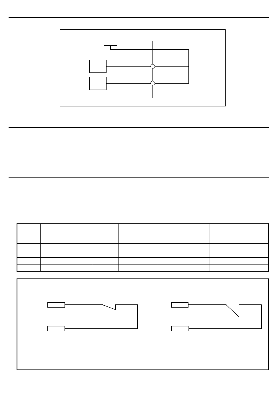
CONNECTIONS B-82725EN-1/07
- 194 -
5.TRANSPORTATION
AND INSTALLATION
5.6.1 Peripheral Device Interface Processing
Take the following actions if signals *HOLD and ENBL are not used.
A
1, A2, B1, B2
+24F
A
5
RV
B6
XHOLD
RV ENBL
CRMA16
5.6.2 Resetting Overtravel
1) Select [OT release] on the overtravel release screen to release each robot axis from the overtravel
state.
2) Hold down the shift key, and press the alarm release button to reset the alarm condition.
3) Still hold down the shift key, and jog to bring all axes into the movable range.
5.6.3 How to Disable/Enable HBK
1) Press [MENUS] on the teach pendant.
2) Select [NEXT].
3) Select [SYSTEM].
4) Press "F1" (TYPE) on the teach pendant.
5) Select "Config" to disable/enable HBK.
Status Hand Broken
enable/disable
setting HBK (*1) HBK
detection Robot operation Message
1 Enable CLOSE Yes Possible None
2 Enable OPEN Yes Impossible SRVO-006
3 Disable CLOSE Yes (*2) Possible None
4 Disable OPEN No Possible At cold start, SRVO-300
NOTE
1 Robot end effector connector
24V
XHBK
24V
XHBK
CLOSE OPEN
2 The moment the HBK circuit is closed, HBK detection becomes enabled.
When the HBK circuit is opened again, alarm "Servo 300" or "Servo 302" occurs,
causing the robot to stop.
3 If the power is turned off and on again under the condition stated in *2, status 4
is entered, so the alarm condition is removed.
Downloaded from www.Manualslib.com manuals search engine

B-82725EN-1/07 CONNECTIONS
- 195 -
5.TRANSPORTATION
AND INSTALLATION
5.6.4 How to Disable/Enable Pneumatic Pressure Alarm (PPABN)
1) Press [MENUS] on the teach pendant.
2) Select [NEXT].
3) Select [SYSTEM].
4) Press "F1" (TYPE) on the teach pendant.
5) Select "Config" to disable/enable PPABN.
Downloaded from www.Manualslib.com manuals search engine


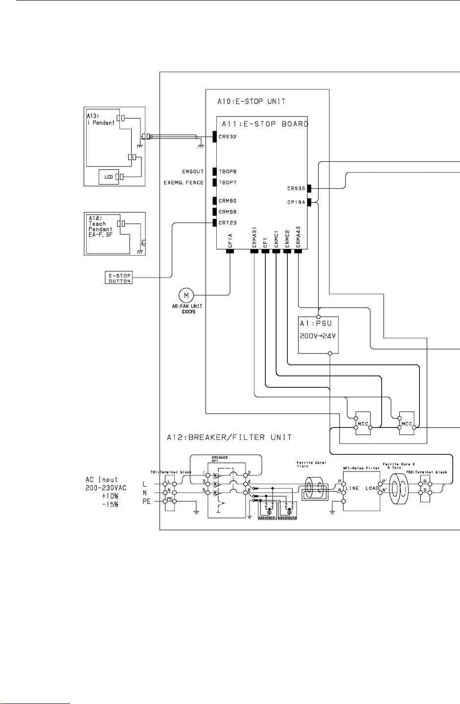
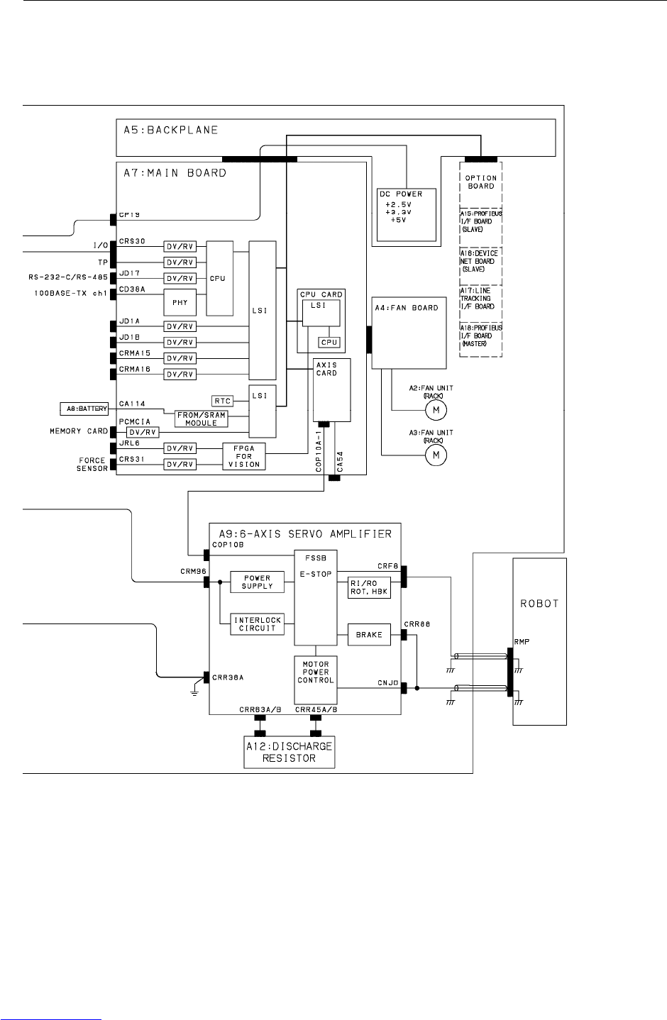
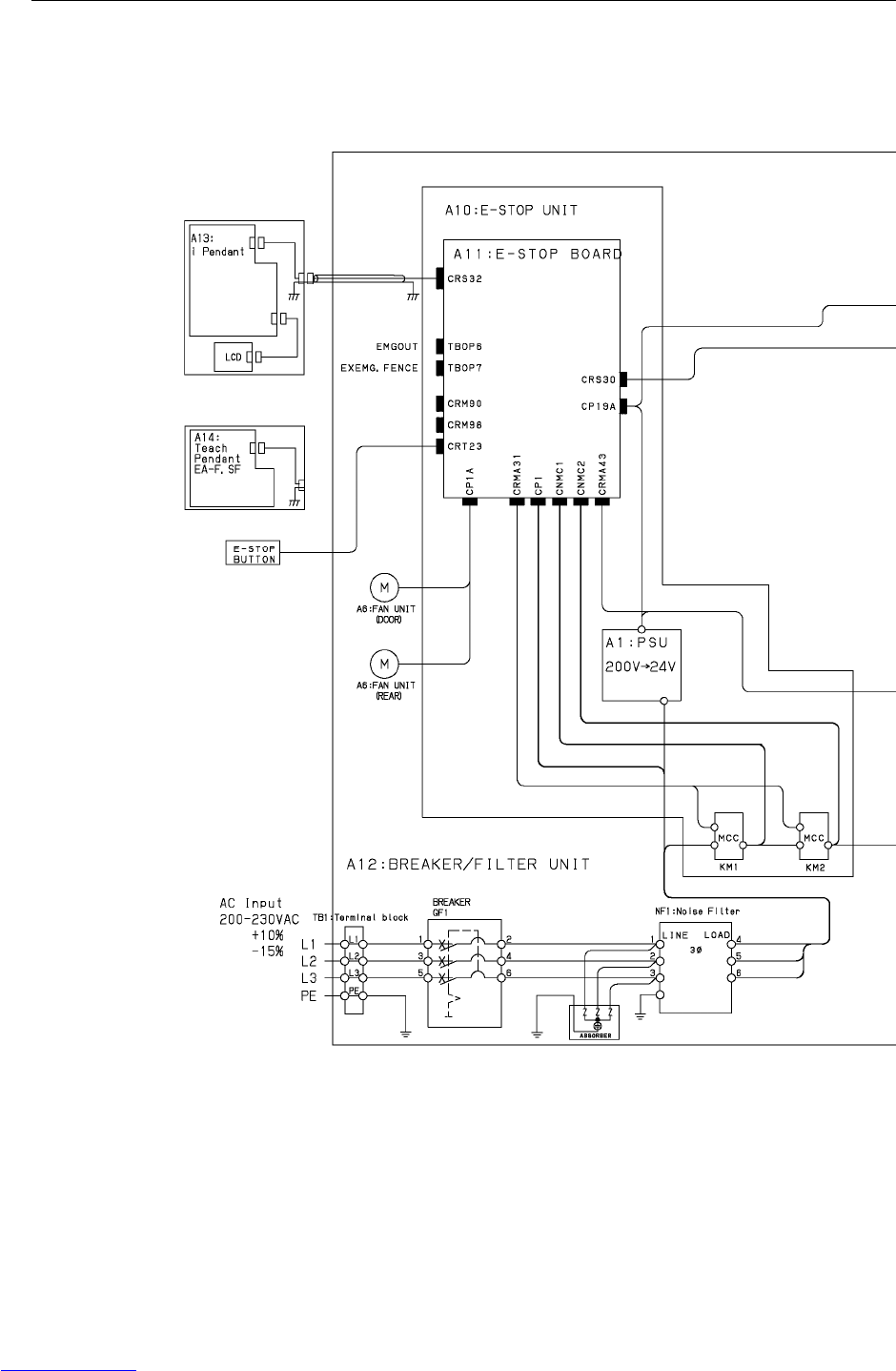
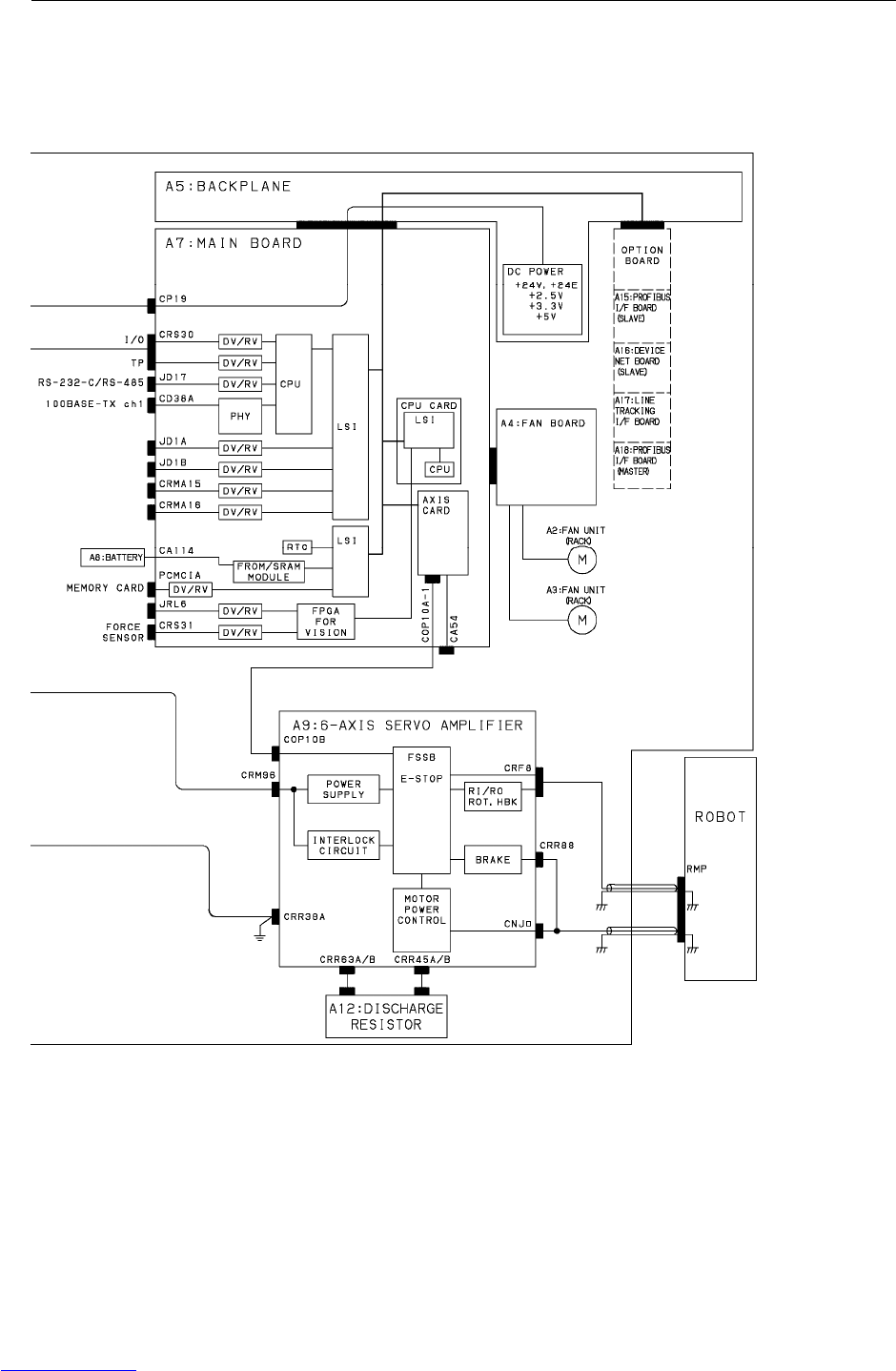
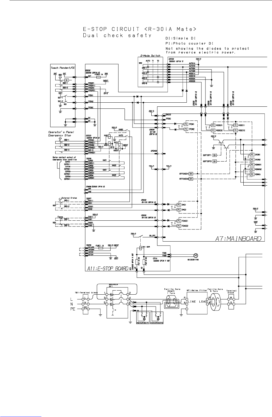

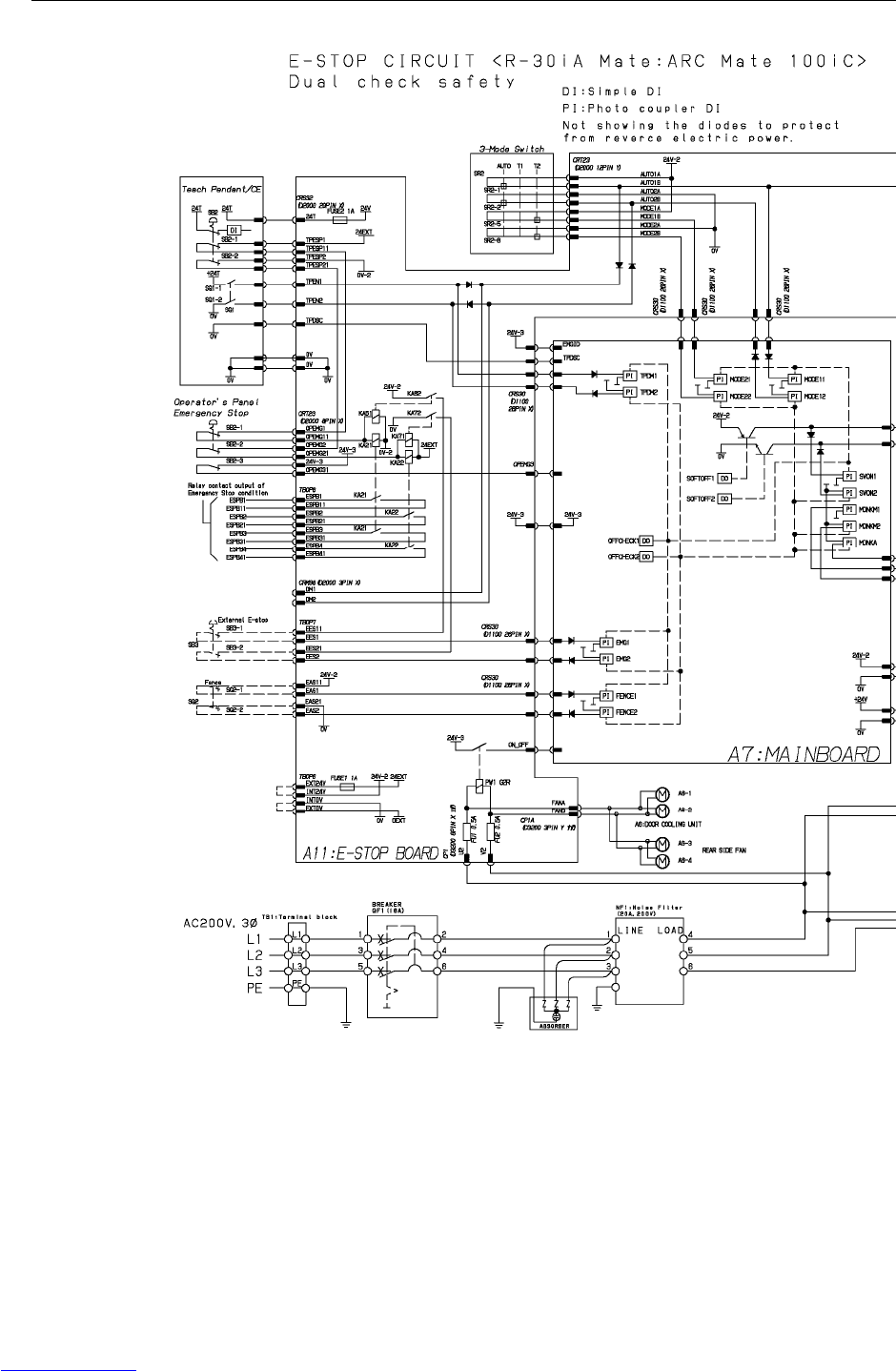
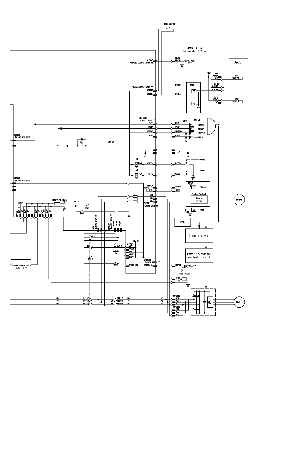
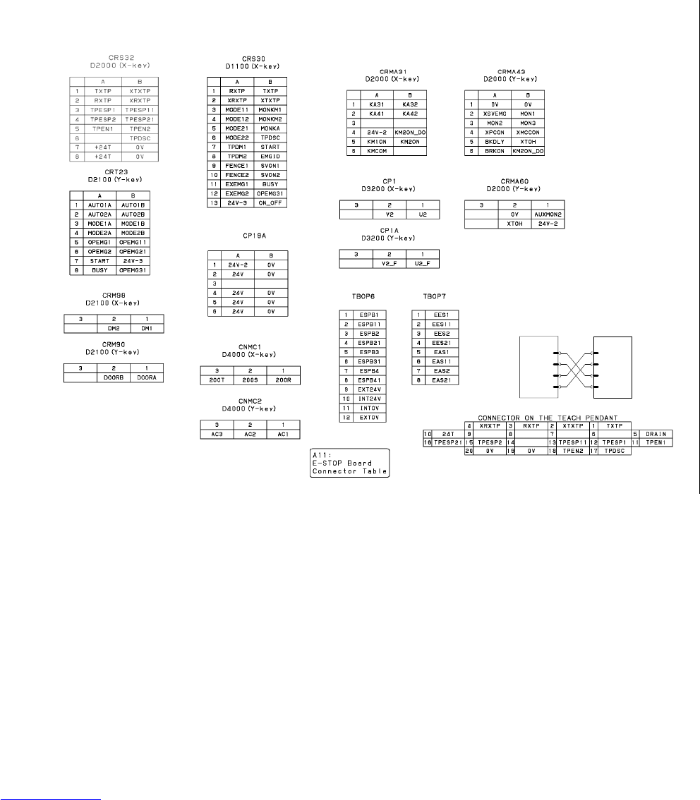
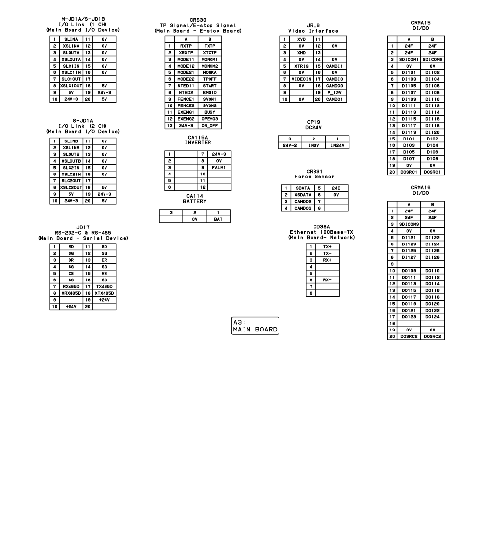
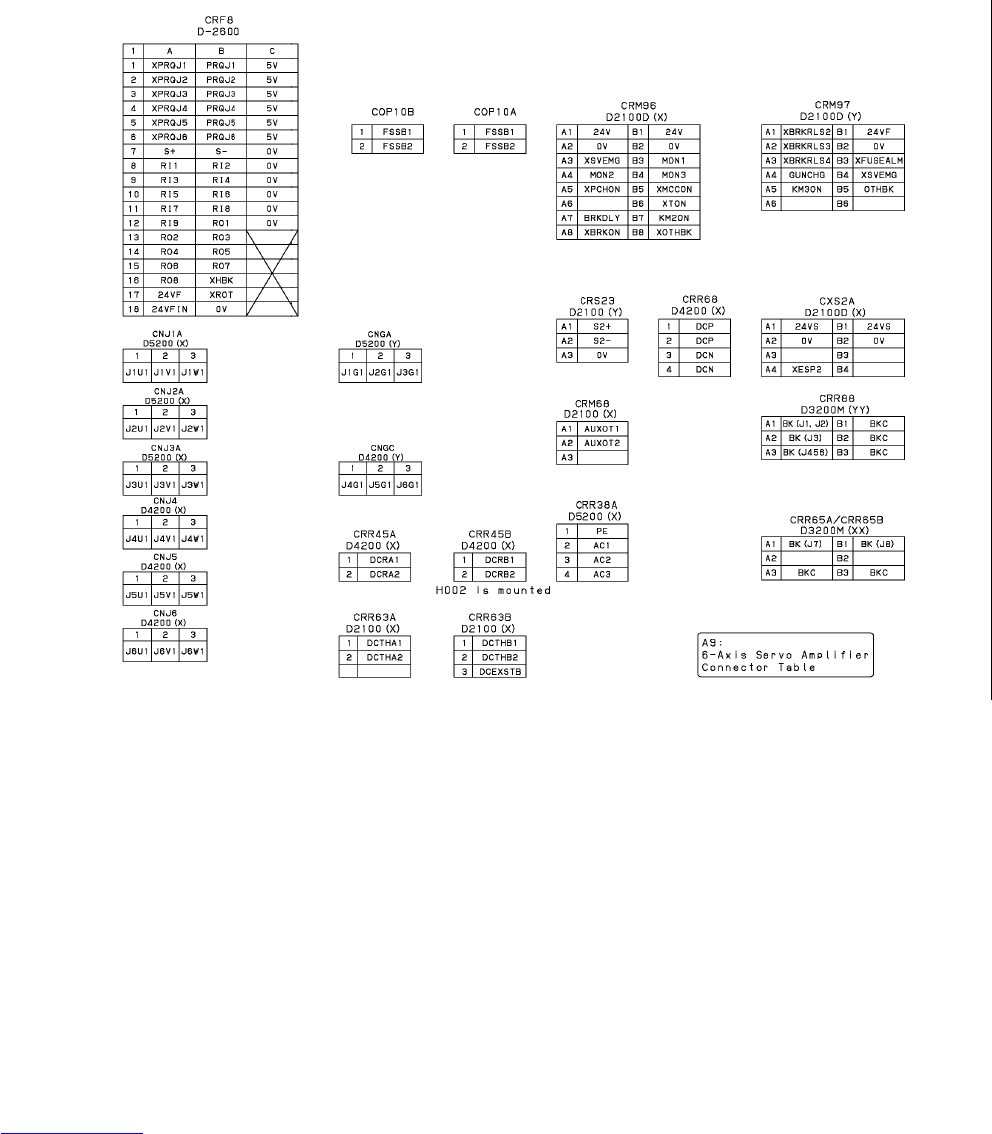
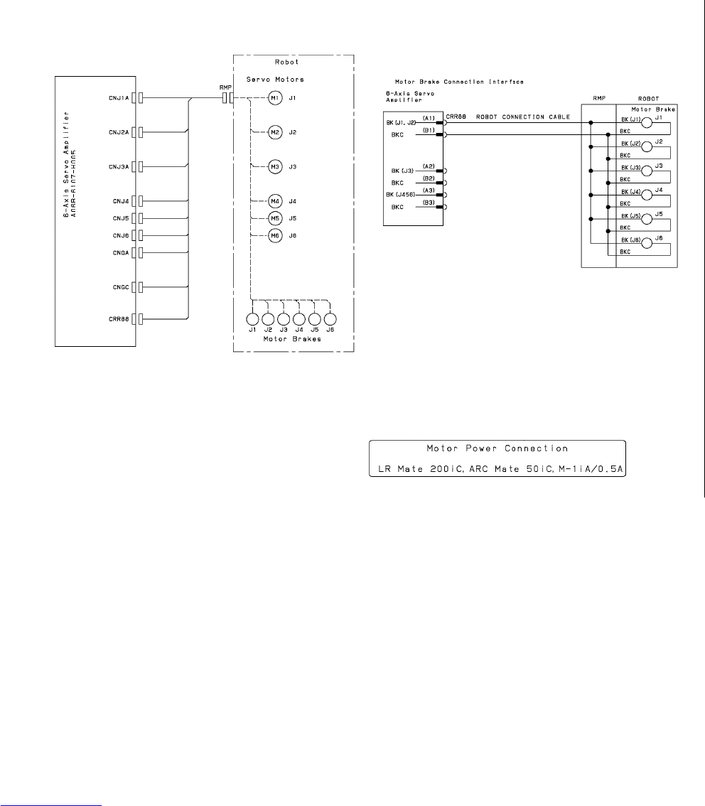


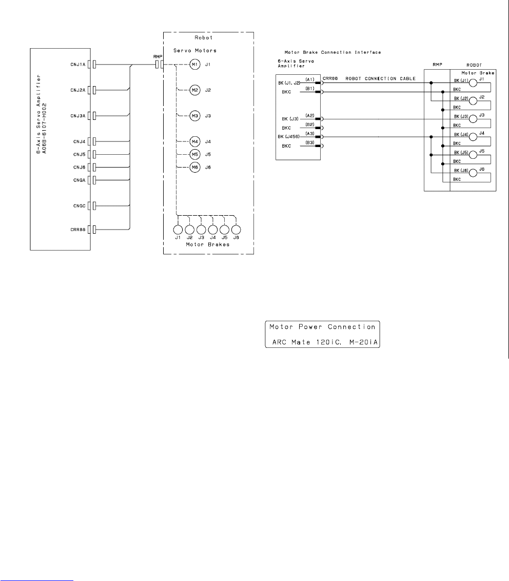
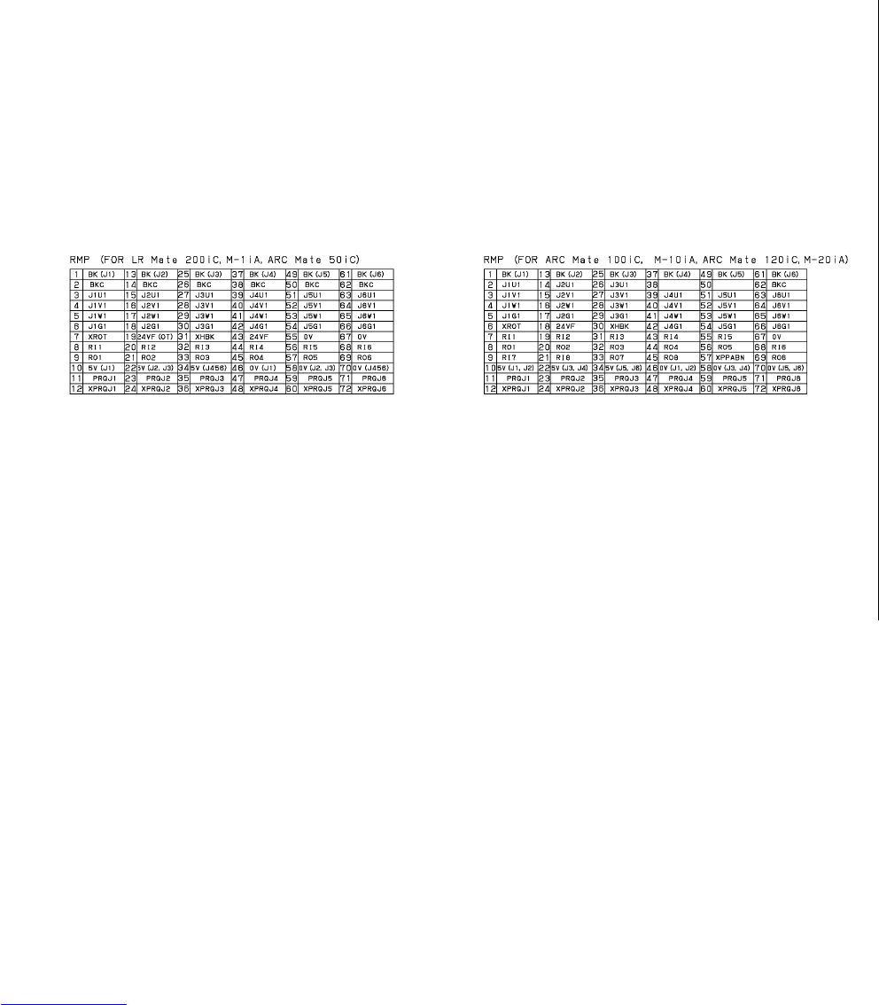
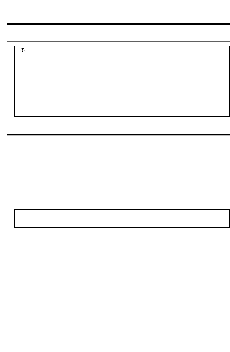
B-82725EN-1/07 APPENDIX B.BRAKE RELEASE UNIT
- 217 -
B BRAKE RELEASE UNIT
B.1 SAFETY PRECAUTIONS
WARNING
Support the robot arm by mechanical means to prevent it from falling down or
rising up when brake is released. Before using the brake release unit, read the
Operator’s manual of the robot that tries to release the brake.
Confirm that the robot is fixed tightly to the floor to prevent the falling down and
unexpected movement of robot.
Confirm that the outlet with earth is used for the power supply of brake release
unit and earth of brake release unit is surely connected to earth of power supply.
There is danger of getting an electric shock if earth is not connected.
B.2 CONFIRMATIONS BEFORE OPERATION
Confirm the followings before operation.
(1) Confirm the exterior of the brake release unit and the power cable. Do not use it when there are
damages in the unit and the cable.
(2) Confirm that the power supply of the robot controller is disconnected.
(3) There are two types of brake release units according to the input voltage as shown in Table B.2 (a).
Confirm the input voltage of the unit to refer to the input voltage label put to the unit (Fig. B.5 (a)).
(4) Confirm that the voltage of power supply before connecting the power supply to the brake release
unit. There is possibility to give the damaging to the brake or the brake release unit when the
incorrect power supply is connected to the unit.
Table B.2 (a) Specification of brake release unit
Brake release unit Remarks
Brake release unit (AC 100V) Input voltage AC100-115V, single phase
Brake release unit (AC 200V) Input voltage AC200-240V, single phase
(5) The brake release unit connection cable is different in each robot. Confirm the cable specification
corresponding to the robot referring to Table B.2 (b).
Downloaded from www.Manualslib.com manuals search engine
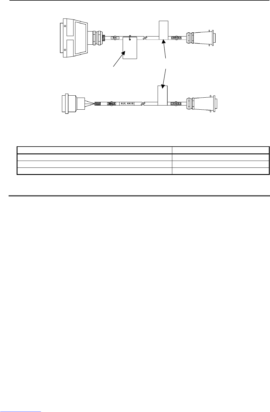
B.BRAKE RELEASE UNIT APPENDIX B-82725EN-1/07
- 218 -
Brake release
unit side(CRR56A)
Robot side
RMP
Inside robot
controller
(CRR65A/B)
Robot
A
uxiliary Axis
Cable specification
The applicable robot
types are shown.
Brake release
unit side(CRR56A)
Fig.B.2 Brake release unit connection cable
Table B.2 (b) Specification of brake release unit connection cable
Applicable robot types Specification of cable
LR Mate 200iC, ARC Mate 50iC, M-1iA A660-2006-T474
ARC Mate 100iC, M-10iA, ARC Mate 120iC, M-20iA, ARC Mate 0iA A660-2006-T881
Auxiliary AXIS A660-2005-T711
B.3 OPERATION
In case of operating to the robot
Operate the brake release unit according to the following procedures.
(1) Support the robot arm by mechanical means to prevent it from falling down or rising up when brake
is released. Refer to the Operator’s manual for each robot.
(2) Connect the Brake Release Unit connection cable to Brake Release Unit.
(3) Disconnect the RMP connector from Robot, and connect the Brake Release Unit connection cable to
the Robot. Keep the connection of Robot connection cable except RMP cable.
(4) Connect the power cable of Brake release unit to power supply.
(5) Press and hold the deadman switch in the middle position.
(6) Press the brake switch ‘1’..’6’ according to the axis that tries to release the brake, then brake will be
released. (Refer to Table B.3) Two axes or more cannot be operated at the same time.
Downloaded from www.Manualslib.com manuals search engine
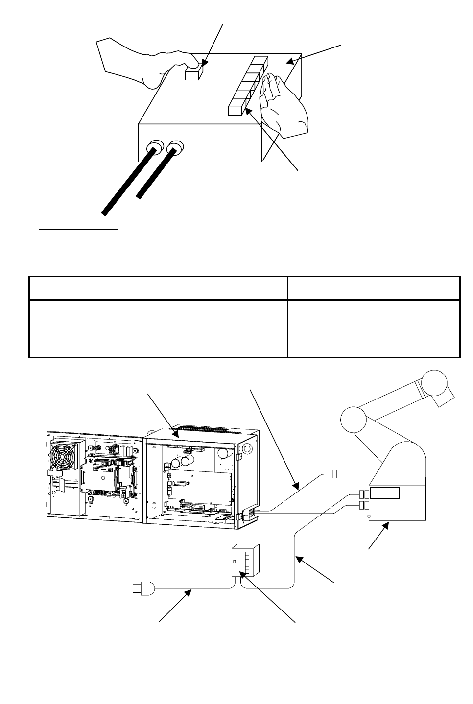
B-82725EN-1/07 APPENDIX B.BRAKE RELEASE UNIT
- 219 -
1
Power cable
Brake Release Unit
connection cable
2
3
4
5
6
Deadman switch
Brake Release Unit
Brake switch
1
2
3
4
5
6
Fig.B.3 (a) Brake release unit
Table B.3 The relation between brake switch and robot axis
Brake switch
Robot 1 2 3 4 5 6
LR Mate 200iC(6 axes), ARC Mate 0iA,
ARC Mate 100iC, M-10iA, ARC Mate 50iC
ARC Mate 120iC, M-20iA, M-1iA/0.5A(6 axes)
J1 J2 J3 J4 J5 J6
LR Mate 200iC(5 axes) J1 J2 J3 - J4 J5
M-1iA/0.5S(4 axes) J1 J2 J3 J4 - -
Brake Release Unit
connection cable
Robot
RMP
Remove RMP connector
Brake Release Unit
Power cable
Robot controller
Fig.B.3 (b) How to connect brake release unit (In case of operating the Robot)
Downloaded from www.Manualslib.com manuals search engine
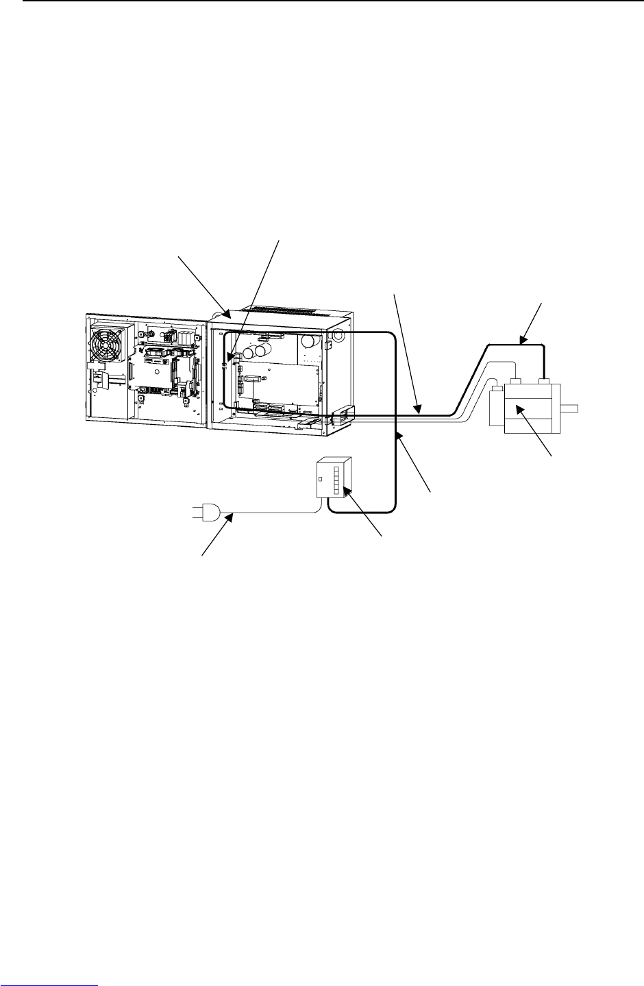
B.BRAKE RELEASE UNIT APPENDIX B-82725EN-1/07
- 220 -
In case of operating to the auxiliary Axis
Operate the brake release unit according to the following procedures.
(1) Support the auxiliary Axis by mechanical means to prevent it from falling down or rising up when
the brake is released.
(2) Connect the Brake Release Unit connection cable to Brake Release Unit.
(3) Disconnect the aux. axis brake connector (CRR65A/B), and connect the CRR65A/B connector to the
Brake Release Unit connection cable. Keep the connection of all cables of aux. axis motor (power,
Pulsecoder, brake).
(4) Connect the power cable of Brake release unit to power supply.
(5) Press and hold the deadman switch in the middle position.
(6) Press the brake switch‘1’, then brake will be released.
Disconnect the brake
connection cable(CRR65A/B)
Brake Release Unit
Power cable
Brake Release Unit
connection cable
Robot controller
Motor for Aux. Axis
Do not disconnect
motor cables.
Brake cable for Aux. Axis
Fig.B.3 (c) How to connect brake release unit (In case of operating the Aux. Axis)
Downloaded from www.Manualslib.com manuals search engine
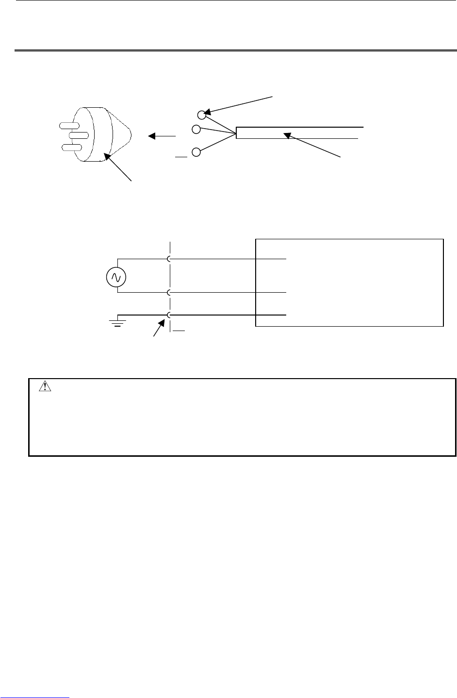
B-82725EN-1/07 APPENDIX B.BRAKE RELEASE UNIT
- 221 -
B.4 HOW TO CONNECT THE PLUG TO THE POWER CABLE
(IN CASE OF NO POWER PLUG)
Connect the plug to the power cable as follows. This plug is provided by customer.
Power plug
(Provided by customer)
Cable
(Provided by FANUC)
Terminal (M4 Size)
1(R)
2(S)
PE
Earth(Yellow/Green spiral)
1(R)
2(S)
PE
Brake Release Unit
AC200-240V
+10%/-15%
or
AC100-115V
+10%/-15%
Outlet
Fig.B.4 How to connect the plug to the power cable
WARNING
Only a specialist having the relevant expertise knowledge is permitted to connect
the plug to the power cable.
In the EU area, only plug complying with the relevant European product standard
can be used.
Do not install the plugs without protective earth pin.
Downloaded from www.Manualslib.com manuals search engine
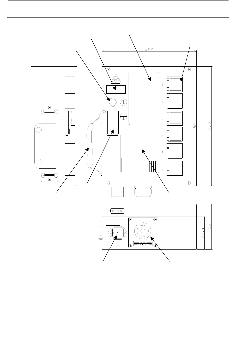
B.BRAKE RELEASE UNIT APPENDIX B-82725EN-1/07
- 222 -
B.5 DIMENSION
Input voltage label
Pilot lamp
Brake switch
Warning label
Belt Deadman switch Caution label
The connector(CRR56A) for Brake
Release Unit connection cable
Power cable
Fig.B.5 (a) Dimension of brake release unit (Front view)
Downloaded from www.Manualslib.com manuals search engine
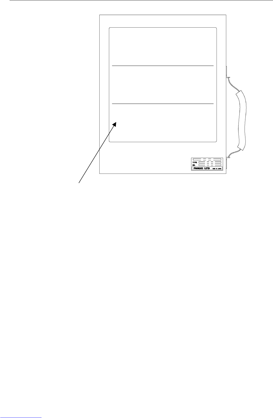
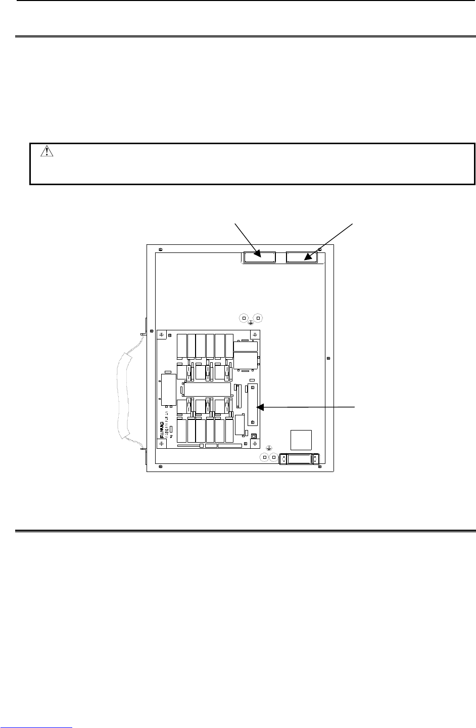
B.BRAKE RELEASE UNIT APPENDIX B-82725EN-1/07
- 224 -
B.6 FUSE
The fuses are mounted inside this unit. Please check the fuse when the pilot lamp doesn't light even if
deadman switch is pressed. When the fuse is blown, exchange the fuse after finding the root cause of
failure, and taking the appropriate countermeasures.
Manufacturer: Daito Communication Co.
Specification: P420H
Rating: 2A
WARNING
When the fuse is replaced, the power cable of brake release unit must be
disconnected.
FU011 FU012
FU001
Fig.B.6 The location of fuses
B.7 SPECIFICATIONS
Input power supply
AC100-115V, 50/60Hz±1Hz, single phase, +10%/-15%, 1A
AC200-240V, 50/60Hz±1Hz, single phase, +10%/-15%, 1A
Weight
Brake Release Unit (AC 100V); 2.3 kg
Brake Release Unit (AC 200V); 3.5 kg
Downloaded from www.Manualslib.com manuals search engine

B-82725EN-1/07 INDEX
i-1
INDEX
<Number>
100BASE-TX connector (CD38R) pin assignments ....179
<A>
ADJUSTMENT AND CHECKS AT INSTALLATION193
ALARM OCCURRENCE SCREEN..............................15
ARC Weld Connection Cables (CRW11; Tyco
Electronics AMP K.K. 20 pin) .................................169
<B>
BACKPLANE BOARD (A20B-8101-0580) .................83
Battery for Memory Backup (3 VDC) .........................114
BLOCK DIAGRAM ....................................................120
BLOCK DIAGRAM OF THE POWER SUPPLY.........90
BRAKE RELEASE UNIT ...........................................217
<C>
CABLE CONNECTION FOR THE PERIPHERAL
DEVICES.................................................................170
CHECK AND REPLACEMENT SURGE ABSORBER
....................................................................................76
Check items at installation ...........................................186
CHECKING THE POWER SUPPLY............................91
COMPONENT FUNCTIONS........................................11
CONFIGURATION.........................................................4
CONFIRMATIONS BEFORE OPERATION..............217
Connecting the Auxiliary Axis Brake (CRR65 A/B) ...137
Connecting the Auxiliary Axis over Travel (CRM68).138
CONNECTING THE COMMUNICATION UNIT .....174
Connecting the External Emergency Stop....................129
Connecting the Input Power Supply.............................128
Connection between RS-232-C interface and I/O device
..................................................................................176
Connection between the ARC Mate 100iC/M-10iA,
ARC Mate 120iC/M-20iA, ARC Mate 0iA and End
Effector.....................................................................160
Connection between the Connector Conversion Board
and Peripheral Devices.............................................156
Connection between the LR Mate 200iC, ARC Mate
50iC and End Effector..............................................159
Connection between the Main Board (CRMA15,
CRMA16) and Peripheral Devices...........................145
Connection between the Process I/O Board MA and
Peripheral Devices....................................................152
Connection between the Process I/O Board MB and
Welding Machines....................................................157
CONNECTION DIAGRAM BETWEEN
MECHANICAL UNITS...........................................121
Connection of I/O Link................................................123
Connection of I/O the Link Cable................................124
Connection to Ethernet.................................................178
CONNECTOR CONVERTER BOARD
(A20B-2004-0410) .....................................................86
<D>
DIGITAL I/O SIGNAL SPECIFICATIONS ...............162
DIMENSION...............................................................222
<E>
ELECTRICAL CONNECTIONS ................................121
Electrical noise countermeasures.................................183
EMERGENCY STOP CONTROL BOARD
(A20B-2004-0290).....................................................82
End Effector Control Interface.....................................164
Ethernet Interface.........................................................178
EXTERNAL CABLE WIRING DIAGRAM...............126
EXTERNAL VIEW OF THE CONTROLLER ...............4
<F>
FANUC I/O LINK .......................................................123
FUSE............................................................................224
FUSE-BASED TROUBLESHOOTING........................65
<G>
GENERAL...................................................................119
<H>
HOW TO CONNECT THE PLUG TO THE POWER
CABLE (IN CASE OF NO POWER PLUG)...........221
How to Disable/Enable HBK.......................................194
How to Disable/Enable Pneumatic Pressure Alarm
(PPABN) ..................................................................195
<I>
I/O SIGNALS OF MAIN BOARD..............................143
In Case of Main Board (CRMA15, CRMA16) ............141
In the Case of the Connector Conversion Board..........143
In the Case of the Process I/O Board MA....................142
In the Case of the Process I/O Board MB ....................142
INSTALLATION.........................................................188
INSTALLATION CONDITION..................................192
Installation Method ......................................................188
Interface .......................................................................174
INTERFACE FOR END EFFECTOR.........................159
INTERFACE FOR PERIPHERAL DEVICES ............145
<L>
Leading out the Ethernet cable.....................................179
LED OF SERVO AMPLIFIER......................................88
<M>
MAIN BOARD (A20B-8200-0470)...............................79
MANUAL OPERATION IMPOSSIBLE.......................77
MASTERING ................................................................19
MOUNTING METHOD OF TEACH PENDANT
HOOK ......................................................................191
<O>
OPERATION...............................................................218
Downloaded from www.Manualslib.com manuals search engine

INDEX B-82725EN-1/07
i-2
OVERVIEW ....................................................................3
<P>
PERIPHERAL DEVICE AND END EFFECTOR
INTERFACES..........................................................139
Peripheral Device Cable Connector .............................171
Peripheral Device Connection Cable ...........................170
Peripheral Device Interface..........................................162
Peripheral Device Interface A1 Cable (CRMA15: Tyco
Electronics AMP, D-1000 series, 40 pins) ...............168
Peripheral Device Interface A2 Cable (CRMA16: Tyco
Electronics AMP, D-1000 series, 40 pins) ...............168
Peripheral Device Interface B1 and B2 Cables
(CRMA52; Tyco Electronics AMP K.K. 30 pin) .....169
PERIPHERAL DEVICE INTERFACE BLOCK
DIAGRAM...............................................................141
Peripheral Device Interface Processing........................194
POSITION DEVIATION FOUND IN RETURN TO
THE REFERENCE POSITION (POSITIONING).....77
POWER CANNOT BE TURNED ON ..........................13
PREFACE.................................................................... p-1
PREVENTIVE MAINTENANCE.................................11
PRINTED CIRCUIT BOARDS.....................................79
PROCESS I/O BOARD MA (A20B-2004-0380) ..........84
PROCESS I/O BOARD MB (A20B-2101-0730)...........85
<R>
Recommended Cables..................................................173
REPLACING A UNIT...................................................92
REPLACING BATTERY............................................114
REPLACING CARDS AND MODULES ON THE
MAIN BOARD ..........................................................94
Replacing External Air Fan Unit and Door Fan...........108
REPLACING FUSES ..................................................110
Replacing Fuses in the Main board..............................111
Replacing Fuses in the Servo Amplifier.......................110
REPLACING RELAYS...............................................113
Replacing Relays on the E-stop Board.........................113
REPLACING SERVO AMPLIFIERS .........................104
REPLACING THE AC FAN MOTOR........................108
Replacing the Backplane Board (Unit) ..........................92
REPLACING THE CONTROL SECTION FAN
MOTOR ...................................................................107
REPLACING THE E-STOP UNIT..............................103
Replacing the Fuse on the E-stop Boards.....................112
Replacing the Main board..............................................93
REPLACING THE PRINTED-CIRCUIT BOARDS.....92
REPLACING THE REGENERATIVE RESISTOR
UNIT ........................................................................100
REPLACING THE TEACH PENDANT and i
PENDANT ...............................................................106
Resetting Overtravel.....................................................194
RESETTING OVERTRAVEL AND EMERGENCY
STOP AT INSTALLATION....................................193
Robot Connection Cables.............................................126
RS-232-C Interface ......................................................174
RS-232-C interface signals...........................................175
<S>
SAFETY PRECAUTIONS ....................................s-1,217
SAFETY SIGNALS.......................................................18
SERVO AMPLIFIERS ..................................................87
SETTING OF SERVO AMPLIFIER.............................89
SETTING THE POWER SUPPLY................................90
Specification for Arc Welding Machine Interface
Input/Output Signals.................................................165
SPECIFICATIONS......................................................224
SPECIFICATIONS OF THE CABLES USED FOR
PERIPHERAL DEVICES AND WELDERS...........168
<T>
Teach Pendant Cable....................................................127
TOTAL CONNECTION DIAGRAM..........................199
TRANSPORTATION..................................................187
TRANSPORTATION AND INSTALLATION...........187
TROUBLESHOOTING.................................................13
TROUBLESHOOTING BASED ON LED
INDICATIONS..........................................................69
TROUBLESHOOTING USING THE ERROR CODE .21
Twisted-pair cable specification ..................................180
<W>
When the Teach Pendant Cannot be Powered on...........13
When the Teach Pendant Does Not Change from the
Initial Screen ..............................................................14
Downloaded from www.Manualslib.com manuals search engine

B-82725EN-1/07 REVISION RECORD
r-1
REVISION RECORD
Edition Date Contents
07 July.2012
• Addition of ARC Mate 0iA
• Error correction
06 May.2011
• Addition of ARC Mate 100iCe, M-10iAe, ROBOWELD
• Error correction
05 May.2009
• Addition of ARC Mate 120iC, M-20iA, M-1iA
04 Nov.2008
• Addition of ARC Mate 50iC
03 Jul.,2008
• Addition of ARC Mate 100iC
02 Dec.,2007 • Addition of I/O Link and Process I/O
01 Jun.,2007
Downloaded from www.Manualslib.com manuals search engine

