Rsc_594 7 Rsc 594
rsc_92159400 rsc_92159400
rsc_478-20 rsc_478-20
User Manual: Pdf rsc_594-7
Open the PDF directly: View PDF ![]() .
.
Page Count: 10

08-10 F250 4.5 OR 6” SUSPENSION KIT
92159400A
Tools Needed:
8mm Wrench 1 1/8” Wrench
10mm Wrench 1 13/16” Wrench
12mm Wrench Jack Stands
15mm Wrench Jack
17mm Wrench Drill
17mm Socket Drill Bits– for the 6”
18mm Wrench kit 13/16-7/8
18mm Socket
19mm Wrench
21mm Wrench
24mm Socket
30mm Socket
Thank you for choosing Rough Country for your suspension needs.
Rough Country recommends a certified technician installs this system. In addition to these instructions, professional
knowledge of disassemble/reassembly procedures as well as post installation checks must be known. Attempts to install
this system without this knowledge and expertise may jeopardize the integrity and/or operating safety of the vehicle.
Please read all the instructions before beginning the installation. Check the kit hardware against the parts list. Be sure
you have all the needed parts and understand where they go. Also please review the tools needed list and make sure
you have needed tools.
PRODUCT USE INFORMATION
As a general rule, the taller a vehicle is the easier it will roll. We strongly recommend seat belts and
shoulder harnesses should be worn at all times. Avoid situations where a side rollover may occur.
Braking performance and capabilities are decreased when significantly larger/heaver tires and wheels are used. Take
this into consideration while driving. Also, speedometer recalibration is necessary when larger tires are installed.
Do no add, alter, or fabricate any factory or after-market parts which increase vehicle height over the intended height of
the Rough Country product purchased. Mixing component brands, lifts, and/or combining body lift with suspension lifts
voids all warranties. Rough Country makes no claims regarding lifting devices and excludes any and all implied claims.
We will not be responsible for any product that is altered.
This kit is packaged as a leveling kit—raising the front 6” and the back 5”. If you desire a different look or if the vehicle
has a tool box or added weight in the rear, please consult with your sales representative about block / u-bolt options.
This 6” suspension system was developed for 37x12.50x17 tire on an after market wheel w/ 4.5” back spacing.
If equipped with factory rear contact overload springs, please note that they will need to be removed with the
addition of the block /add-a-leaf combination on this kit.
NOTICE TO DEALER AND VECHICLE OWNER
Any vehicle equipped with any Rough country product must have the “Warning to Driver” decal installed on the sun visor
or dash. The decal is to act as a constant reminder for whoever is operating the vehicle of its unique handling character-
istics. INSTALLING DEALER—It is your responsibility to install the warning decal and to forward these installation in-
structions on too the vehicle owner for review and to be kept in the vehicle for its service life.
Kit Contents:
9295 Diesel Coil Springs
OR
9296 6” Gas Coil Springs
4.5” Diesel Coil Springs
1594Box1 Track Bar Bracket
Radius arm Drop Brkts
Sway Bar links
Pass Sway Bar Bracket
Driver Shim Plate
Carrier Drop Bracket
Pitman Arm
Bumpstop spacer
Dr & Pass Brake Lines
1580Box4 Shock Box
6” Kit
6111 Add-a-leaf
6578 3” Block and U-Bolt Kit
4.5” Kit
1563BOX3 6.5” Block and U-Bolt Kit
Torque Specs:
Size Grade 5 Grade 8
5/16” 15 ft/lbs 20 ft/lbs
3/8” 30 ft/lbs 35 ft/lbs
7/16” 45 ft/lbs 60 ft/lbs
1/2” 65 ft/lbs 90 ft/lbs
9/16” 95 ft/lbs 130 ft/lbs
5/8” 135 ft/lbs 175 ft/lbs
3/4” 185 ft/lbs 280 ft/lbs
Class 8.8 Class 10.9
6MM 5 ft/lbs 9 ft/lbs
8MM 18ft/lbs 23 ft/lbs
10MM 32ft/lbs 45ft/lbs
12MM 55ft/lbs 75ft/lbs
14MM 85ft/lbs 120ft/lbs
16MM 130ft/lbs 165ft/lbs
18MM 170ft/lbs 240ft/lbs
*1594BAG3*
1594BAG3
FRONT INSTALLTION INSTRUCTIONS
1. Block the rear wheels of the vehicle. Raise the front of the vehicle and support the frame with jack stands. Remove
the front wheels and tires and set aside. Position a hydraulic jack under the front axle and raise the jack until the
front suspension begins to compress.
2. Disconnect the track bar from the driver side frame bracket, using a 30mm wrench.
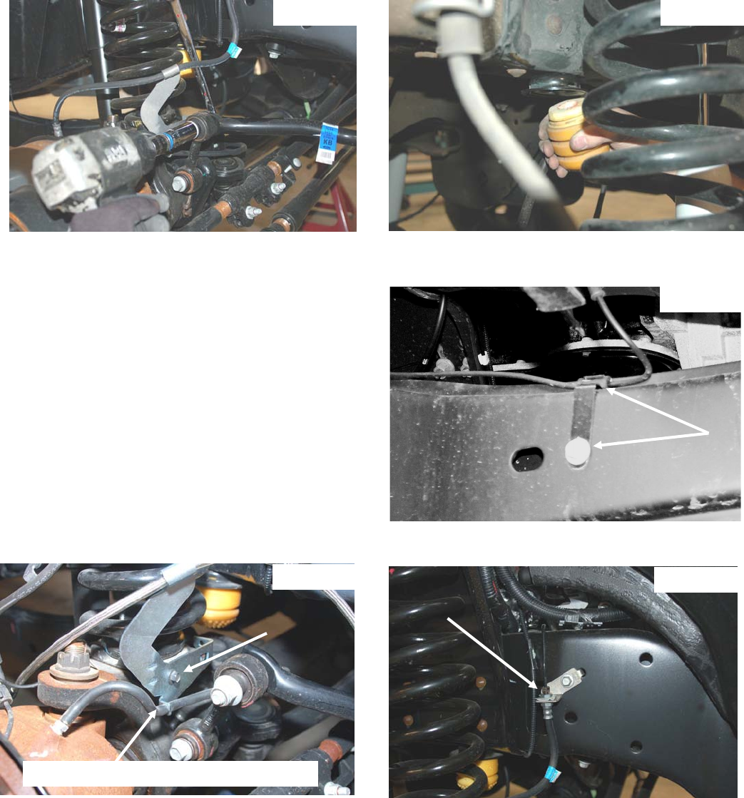
3. Disconnect the sway bar end links from the axle and the sway bar using a 18mm wrench. Remove end links and
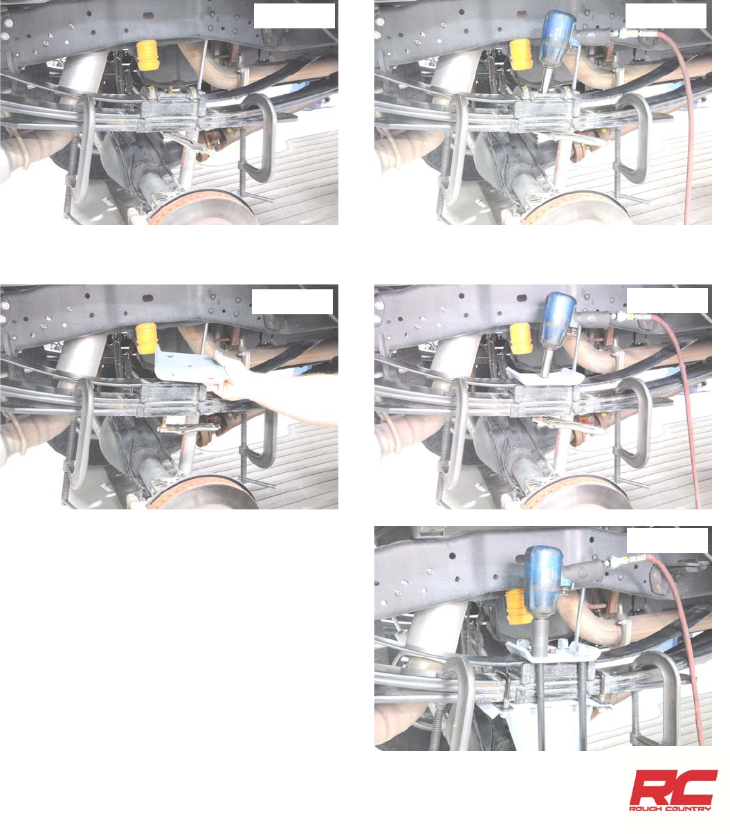
retain the hardware for reuse. See Photo 1.
4. Remove the bump stop from the cup shaped bracket. Remove the bracket from the frame rail. See Photo 2.
5. Disconnect the ABS sensor wire from the lower spring seat and the radius arm, using a 8mm wrench. See Photo 3.
6. Unbolt the brake line brackets from the spring seat, using a 10mm wrench. Remove the center disconnect vacuum
lines from the clamp on the axle.( If equipped with automatic hubs). See Photo 4.
7. Remove the stock brake line from the stock steel line on
the frame. See Photo 5.
8. Remove the stock line from the caliper and install the sup-
plied braided brake lines in the factory location with the
factory hardware. To ease the removal of the coil springs,
do not install the brake line bracket to the spring seat.
Please note there is a driver and passenger side brake
hose .
9. Using a 19mm wrench, remove the nut, retaining washer
and rubber bushing from the both upper shock mounts.
Using a 18mm wrench remove the lower shock bolts. Re-
tain hardware for re-use.
10. Carefully lower the jack until the coil springs are free. Re-
move the coil springs from the vehicle. Note: use of a coil
spring compressor may be required for spring removal.
Disconnect Vacuum Line (Auto Hubs only)
Photo 1 Photo 2
Photo 3
Photo 4 Photo 5
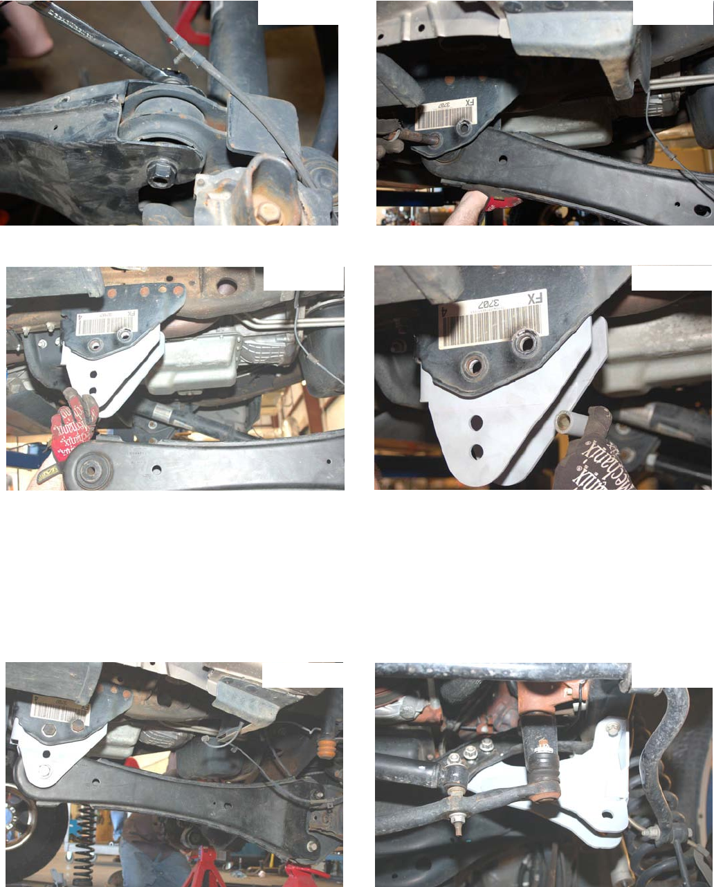
12. Insert the radius arm drop bracket into the stock location. See Photo 8. Bolt into place using the supplied spacer
sleeves and 3/4” x 4 3/4” bolts, nuts and washers provided in the kit bag. See Photo 9. Do not tighten at this time.
13. Install the radius arms to the new drop bracket with factory hardware. See Photo 10.
14. Attach the arm to the axle using the stock hardware. Note: it may be necessary to raise or lower the truck to align
the holes.
15. Reattach the ABS wire to the radius arm using a 8MM wrench.
16. Using a 21mm wrench and 19mm wrench socket remove the factory track bar bracket. Retain stock hardware for re-
use.
17. Position the Rough Country track bar bracket on the frame in the same position as the original and secure using the
factory hardware. Tighten hardware. See Photo 11.
18. Using the nylon bump stop extension provided, place the extension between the frame and the bump stop cup. Bolt
back into the original location using the 8mmx95mm bolt supplied. Torque to 15 ft. lbs.
11. Support both radius arms with jack stands. Using a 1 1/8” wrench, and socket remove the bolt holding the upper
control arm to the frame. Using a 24mm wrench, and socket remove the bolt holding the upper control arm to the
axle. Retain stock hardware for reuse. See Photo 6 & 7.
Photo 6
Photo 8
Photo 10
Photo 9
Photo 11
Photo 7
25. Install tires and wheels and lower the vehicle to the
ground.
26. Line up the track bar with the hole in the new track bar
bracket. You may have to start the truck and turn the
wheels in the direction the track bar needs to go to help
align the track bar with the hole. Install using the stock
track bar bolt. Tighten bolt.
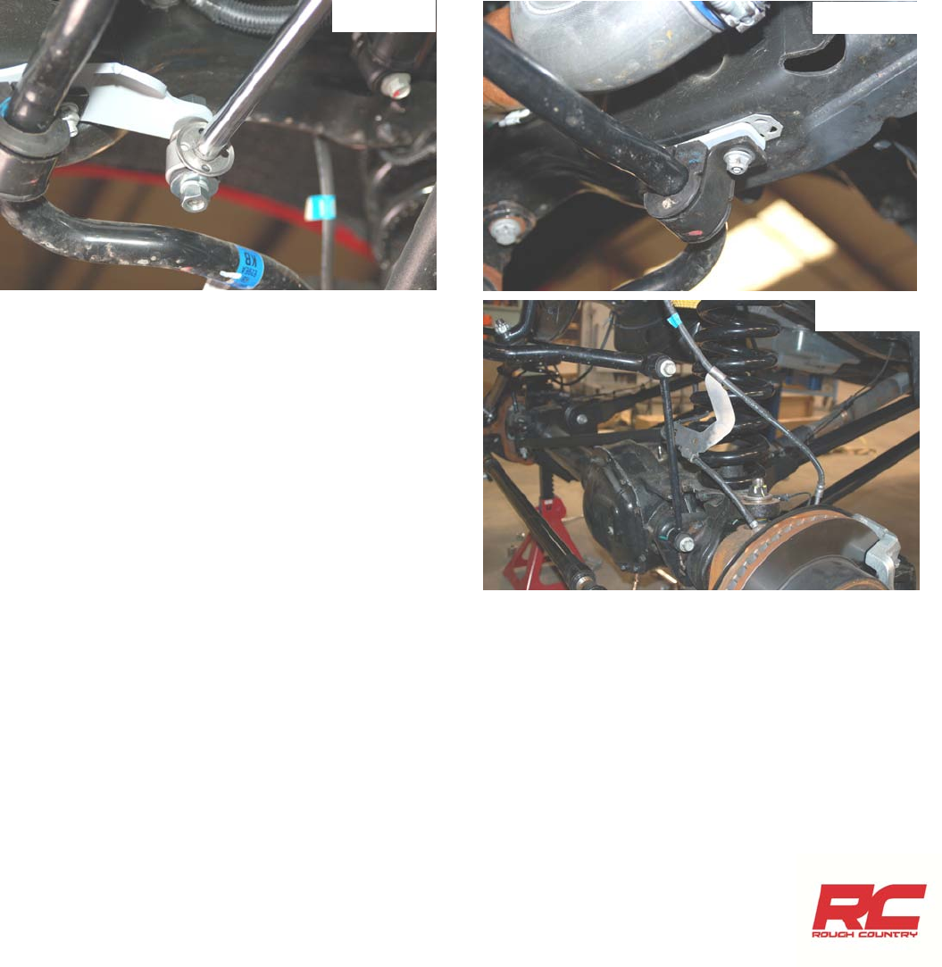
27. Install the new sway bar links in the factory location with
the factory hardware and using a 18mm wrench. See
Photo 14.
19. Lower the front axle enough to install the new coil springs. Position the coil springs in the lower coil buckets on the
axle and rotate as necessary to be sure that the pigtail of the coil in indexed properly in the bucket. Position the fac-
tory rubber isolator on top of each coil, then raise the axle enough to seat the coil springs in the upper spring buck-
ets.
20. Install the bushings and sleeves on the front gas shock absorbers part # 658459.
21. Compress the front springs enough to install the front shocks. Bolt the lower end of the shock to the axle using the
stock hardware using a 18mm wrench. Attach the upper end of the shock with the stock hardware, using a 19mm
wrench. Tighten only enough to bulge the bushing.
22. Remove the factory steering stabilizer from the factory frame mount using a 19mm wrench. Remove the passenger
side sway bar bracket from the frame using a 15mm wrench.
23. On the passenger side, install the new stabilizer bracket in between the frame and the factory sway bar mount with
the factory hardware and install the stabilizer on the mount with factory hardware. Tighten using a 19mm wrench.
See Photo 12.
24. On the driver side, remove the sway bar bracket from the frame using a 15mm wrench and install the supplied
spacer as shown in Photo 13 with factory hardware.
Photo 12 Photo 13
Photo 14
29. Remove the cotter pin and nut using a 21mm wrench, from the drag link end where it attaches to the pitman arm.
Dislodge link with a tie rod end puller, or a pickle fork. Note: replace the link if any stud looseness is detected, or if
you can twist the studs in its socket with your fingers. Using a 34mm socket, remove the nut from the steering sector
and remove the pitman arm with a puller tool. Inspect the splines on the shaft for excessive wear, repair if needed.
30. Install new arm, lock washer, and nut. Using a 34mm socket, tighten bolt.
31. Attach the drag link stud to the pitman arm. Torque nut to factory specs, and install cotter pin. Check for adequate
linkage clearances while turning steering wheel full lock in both positions.
32. Install the brake line bracket to the spring seat with factory hardware and using a 10mm wrench.
33. Install the wheels/tires.
34. Jack up the vehicle and remove the jack stands.
35. Lower the vehicle to the ground and tighten the radius arm bolts.
Photo 1
1. For vehicles with 2 piece drive shafts, support the driveshaft, using a 17mm socket remove the bolts from the carrier
bearing bracket. Insert the carrier bearing spacer between the bearing bracket and body mount. Reattach the carrier
bearing using the supplied 7/16”x 3 1/4” bolts and washers. Torque to 60 ft/lbs. See Photo 1. Install bracket with
flat part on the stock mount thicker part of the bracket toward the rear and the taper towards the front.
CARRIER BEARING INSTRUCTIONS
REAR INSTALLATION (for 4.5” Kit)
1. Chock front wheels and jack up the rear of the vehicle. Secure with jack stands on the frame rail.
2. Place a floor jack under the rear differential on the rear axle. Using a 18mm wrench for the upper, and 19mm and
15mm wrench for the lower, remove the stock shock absorbers, retain the stock hardware for reuse.
3. Using a 24mm socket, remove the stock u-bolts. Use the floor jack to lower the axle assembly to allow for lifted block
installation.
4. Using C-clamps, clamp the spring pack on each side of the center pin.
5. Using locking pliers, lock onto the bottom of the center pin. See Photo 1.
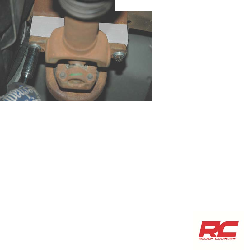
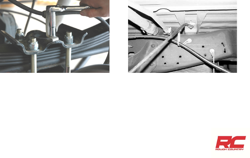
10. Using a 9/16” socket, remove the nut from the center pin. See Photo 2.
11. Remove the factory ubolt plate. See Photo 3.
12. Using the stock hardware, attach the supplied ubolt plate and tighten the center pin using a 9/16” socket. See
Photo 4.
13. Install the supplied shim plates between the block and the
leaf spring. Install the supplied 7/16” square ubolts and
hardware. Tighten using a 5/8” socket.
14. Install the new supplied 3/4” ubolts from the bottom. Use
the supplied 3/4” hardware and tighten using a 1-1/8”
socket. See Photo 5.
15. Locate shock part number 658601 gas shock and assem-
ble poly bushings and sleeve in shock. Using a 18mm
wrench, for the upper, and a 19mm and 15mm wrench for
the lower. Install using factory hardware on upper and
lower shock mount
16. Install the tires and wheels.
17. Jack up the rear of the vehicle and remove the jack
stands. Lower the vehicle to the floor.
18. With the weight of the vehicle on the axle, torque the u-
bolts to 130-150 ft-lbs.
19. Check all hardware for proper torque.
Photo 1 Photo 2
Photo 3 Photo 4
Photo 5
REAR INSTALLATION (6” Kit)
1. Chock front wheels and jack up the rear of the vehicle. Secure with jack stands on the frame rail.
2. Place a floor jack under the rear differential on the rear axle. Using a 18mm wrench for the upper, and 19mm and
15mm wrench for the lower, remove the stock shock absorbers, retain the stock hardware for reuse.
3. Using a 24mm socket, remove the stock u-bolts. Use the floor jack to lower the axle assembly to allow for lifted block
installation. Retain the factory axle block if equipped.
4. 6” Kit—Remove the spring eye bolts and nuts and remove the spring. If equipped with factory overloads, the top
mounted spacer block and top mounted overload spring must be removed. The top spring plate may need to be
drilled out to accept the nut for the new spring center pin. Make sure before starting that you have access to a drill
and a 13/16” to 7/8” drill bit. Have c-clamps in place on either side of each strap before center bolt is removed.
5. Unbolt center pin and remove. Un-clamp leaf spring. CAUTION -Take care when releasing the c-clamps since the
springs are under load and will “spring” apart when released.
6. Position add-a-leaf under the next longest leaf of the spring pack. Replace the shorter spring leafs under the helper
leaf and clamp together, being careful to align the center pin holes in the spring leafs. If less lift is desired the leaf
under the new add-a-leaf can be removed.
7. Insert the new center pin supplied with the kit through the spring assembly with the head of the center pin in the
same location as the stock pin. Re-compress the pack with the c-clamps, not center pin, to avoid stripping of nut/bolt
threads. Bolt together, being sure to align leafs. Cut off excess threads on the center pin with a hack saw. If applica-
ble, re-form straps or install new bend straps. If heat is used on the straps, allow them to cool naturally and thor-
oughly before removing the c-clamps.
8. Replace spring on vehicle. Torque to 86-110 ft./lbs.
9. Install the Rough Country block in between the factory block /leaf spring and the axle. Jack up the axle and align the
pins in the blocks and axle seat. Secure with new u-bolts and torque evenly to 85 ft/lbs. On Driver side disconnect
the parking brake cable bracket from the spring plate and retain hardware See Photo 1. Take care not to over ex-
tend the brake lines.
10. Reattach parking brake cable bracket to the spring plate. If more slack is needed remove the cable from the rearmost cable
ring on the frame rail See Photo 2.
11. Locate shock part number 658601 gas shock and assemble poly bushings and sleeve in shock. Using a 18mm
wrench, for the upper, and a 19mm and 15mm wrench for the lower. Install using factory hardware on upper and
lower shock mount
12. Install the tires and wheels.
13. Jack up the rear of the vehicle and remove the jack stands. Lower the vehicle to the floor.
14. With the weight of the vehicle on the axle, torque the u-bolts to 130-150 ft-lbs.
15. On the leaf spring to front spring hanger torque bolts to 222 ft.lbs. and on rear leaf spring to shackle and shackle to
frame mount torque bolts to 185 ft.lbs.
16. Check all hardware for proper torque.
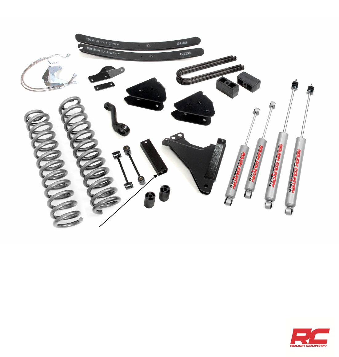
6” Kit Shown
BUMPSTOP EXT
FR RADIUS ARM
BRKTS
FR TRACK ROD BRACKET
FR BRAKE BRKTS
FR SWAY BAR LINKS
PITMAN ARM
COIL SPRINGS
REAR U-BOLTS
RR BLOCKS
SHOCK ABSORBERS
RR ADD-A-LEAFS
CARRIER BEARING DROP
POST INSTALLTION INSTRUCTIONS
1. Adjust steering wheel to re-center prior to driving.
2. Check all fasteners for proper torque. Check to ensure for adequate clearance between all rotating, mobile, fixed,
and heated members. Verify clearance between exhaust and brake lines, fuel lines, fuel tank, floor boards and wiring
harness. Check steering gear for clearance. Test and inspect brake system.
3. Perform steering sweep to ensure front brake hoses have adequate slack and do not contact any rotating, mobile or
heated members. Inspect rear brake hoses at full extension for adequate slack. Failure to perform hose check/ re-
placement may result in component failure. Longer replacement hoses, if needed can be purchased from a local
parts supplier.
4. Have a qualified alignment center realign front end to Caster min– 4.0 degree
Camber –0.6—.09 degree
Toe –.10– .15 degree
5. Install Warning to Driver decal on sun visor.
6. Re-torque all nuts, bolts, and especially u-bolts after the first 100 miles, again after another 100 miles and then check
periodically thereafter.
7. All components must be retightened after 500 miles, and every three thousand miles after installation
8. Adjust headlights to proper settings.
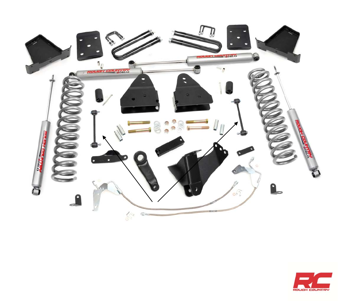
FR SWAY BAR LINKS
COIL SPRINGS
FR TRACK ROD BRACKET
PITMAN ARM
FR RADIUS ARM
BRKTS
BUMPSTOP EXT
REAR U-BOLTS RR BLOCKS
FR STABILIZER BRKTS
RR SHOCK ABSORBERS
Thank you for choosing Rough Country for your suspension needs.
FR SHOCK ABSORBERS
FR BRAKE BRKTS
By purchasing any item sold by Rough Country, LLC, the buyer expressly warrants that he/she is in compliance with all
applicable Federal, State, and Local laws and regulations regarding the purchase, ownership, and
use of the item. It shall be the buyers responsibility to comply with all Federal, State and Local laws
governing the sales of any items listed, illustrated or sold. The buyer expressly agrees to indemnify
and hold harmless Rough Country, LLC for all claims resulting directly or indirectly from the purchase,
ownership, or use of the items.
SPRING
PLATES(2)
4.5” Kit Shown
