S7 1200 Programmable Controller S71200 System Manual En US
User Manual: Pdf
Open the PDF directly: View PDF ![]() .
.
Page Count: 1614 [warning: Documents this large are best viewed by clicking the View PDF Link!]
- S7-1200 Programmable controller
- Preface
- Table of contents
- 1 Product overview
- 2 New features
- 3 STEP 7 programming software
- 3.1 System requirements
- 3.2 Different views to make the work easier
- 3.3 Easy-to-use tools
- 3.3.1 Inserting instructions into your user program
- 3.3.2 Accessing instructions from the "Favorites" toolbar
- 3.3.3 Creating a complex equation with a simple instruction
- 3.3.4 Adding inputs or outputs to a LAD or FBD instruction
- 3.3.5 Expandable instructions
- 3.3.6 Selecting a version for an instruction
- 3.3.7 Modifying the appearance and configuration of STEP 7
- 3.3.8 Dragging and dropping between editors
- 3.3.9 Changing the operating mode of the CPU
- 3.3.10 Changing the call type for a DB
- 3.3.11 Temporarily disconnecting devices from a network
- 3.3.12 Virtual unplugging of devices from the configuration
- 3.4 Backward compatibility
- 4 Installation
- 4.1 Guidelines for installing S7-1200 devices
- 4.2 Power budget
- 4.3 Installation and removal procedures
- 4.3.1 Mounting dimensions for the S7-1200 devices
- 4.3.2 Installing and removing the CPU
- 4.3.3 Installing and removing an SB, CB, or BB
- 4.3.4 Installing and removing an SM
- 4.3.5 Installing and removing a CM or CP
- 4.3.6 Removing and reinstalling the S7-1200 terminal block connector
- 4.3.7 Installing and removing the expansion cable
- 4.3.8 TS (TeleService) adapter
- 4.4 Wiring guidelines
- 5 PLC concepts
- 5.1 Execution of the user program
- 5.1.1 Operating modes of the CPU
- 5.1.2 Processing the scan cycle in RUN mode
- 5.1.3 Organization blocks (OBs)
- 5.1.3.1 Program cycle OB
- 5.1.3.2 Startup OB
- 5.1.3.3 Time delay interrupt OB
- 5.1.3.4 Cyclic interrupt OB
- 5.1.3.5 Hardware interrupt OB
- 5.1.3.6 Time error interrupt OB
- 5.1.3.7 Diagnostic error interrupt OB
- 5.1.3.8 Pull or plug of modules OB
- 5.1.3.9 Rack or station failure OB
- 5.1.3.10 Time of day OB
- 5.1.3.11 Status OB
- 5.1.3.12 Update OB
- 5.1.3.13 Profile OB
- 5.1.3.14 MC-Servo and MC-Interpolator OB
- 5.1.3.15 MC-PreServo
- 5.1.3.16 MC-PostServo
- 5.1.3.17 Event execution priorities and queuing
- 5.1.4 Monitoring and configuring the cycle time
- 5.1.5 CPU memory
- 5.1.6 Diagnostics buffer
- 5.1.7 Time of day clock
- 5.1.8 Configuring the outputs on a RUN-to-STOP transition
- 5.2 Data storage, memory areas, I/O and addressing
- 5.3 Processing of analog values
- 5.4 Data types
- 5.4.1 Bool, Byte, Word, and DWord data types
- 5.4.2 Integer data types
- 5.4.3 Floating-point real data types
- 5.4.4 Time and Date data types
- 5.4.5 Character and String data types
- 5.4.6 Array data type
- 5.4.7 Data structure data type
- 5.4.8 PLC data type
- 5.4.9 Variant pointer data type
- 5.4.10 Accessing a "slice" of a tagged data type
- 5.4.11 Accessing a tag with an AT overlay
- 5.5 Using a memory card
- 5.6 Recovery from a lost password
- 5.1 Execution of the user program
- 6 Device configuration
- 6.1 Inserting a CPU
- 6.2 Uploading the configuration of a connected CPU
- 6.3 Adding modules to the configuration
- 6.4 Configuration control
- 6.5 Changing a device
- 6.6 Configuring the operation of the CPU
- 6.7 Configuring multilingual support
- 6.8 Configuring the parameters of the modules
- 6.9 Configuring the CPU for communication
- 6.10 Time synchronization
- 7 Programming concepts
- 7.1 Guidelines for designing a PLC system
- 7.2 Structuring your user program
- 7.3 Using blocks to structure your program
- 7.4 Understanding data consistency
- 7.5 Programming language
- 7.6 Protection
- 7.7 Downloading the elements of your program
- 7.8 Synchronizing the online CPU and offline project
- 7.9 Uploading from the online CPU
- 7.10 Debugging and testing the program
- 8 Basic instructions
- 8.1 Bit logic operations
- 8.2 Timer operations
- 8.3 Counter operations
- 8.4 Comparator operations
- 8.5 Math functions
- 8.5.1 CALCULATE (Calculate)
- 8.5.2 Add, subtract, multiply and divide instructions
- 8.5.3 MOD (return remainder of division)
- 8.5.4 NEG (Create twos complement)
- 8.5.5 INC (Increment) and DEC (Decrement)
- 8.5.6 ABS (Form absolute value)
- 8.5.7 MIN (Get minimum) and MAX (Get maximum)
- 8.5.8 LIMIT (Set limit value)
- 8.5.9 Exponent, logarithm, and trigonometry instructions
- 8.6 Move operations
- 8.6.1 MOVE (Move value), MOVE_BLK (Move block), UMOVE_BLK (Move block uninterruptible), and MOVE_BLK_VARIANT (Move block)
- 8.6.2 Deserialize
- 8.6.3 Serialize
- 8.6.4 FILL_BLK (Fill block) and UFILL_BLK (Fill block uninterruptible)
- 8.6.5 SWAP (Swap bytes)
- 8.6.6 LOWER_BOUND: (Read out ARRAY low limit)
- 8.6.7 UPPER_BOUND: (Read out ARRAY high limit)
- 8.6.8 Read / Write memory instructions
- 8.6.9 Variant instructions
- 8.6.10 Legacy instructions
- 8.7 Conversion operations
- 8.7.1 CONV (Convert value)
- 8.7.2 Conversion instructions for SCL
- 8.7.3 ROUND (Round numerical value) and TRUNC (Truncate numerical value)
- 8.7.4 CEIL and FLOOR (Generate next higher and lower integer from floating-point number)
- 8.7.5 SCALE_X (Scale) and NORM_X (Normalize)
- 8.7.6 Variant conversion instructions
- 8.8 Program control operations
- 8.8.1 JMP (Jump if RLO = 1), JMPN (Jump if RLO = 0), and Label (Jump label) instructions
- 8.8.2 JMP_LIST (Define jump list)
- 8.8.3 SWITCH (Jump distributor)
- 8.8.4 RET (Return)
- 8.8.5 ENDIS_PW (Enable/disable CPU passwords)
- 8.8.6 RE_TRIGR (Restart cycle monitoring time)
- 8.8.7 STP (Exit program)
- 8.8.8 GET_ERROR and GET_ERROR_ID (Get error and error ID locally) instructions
- 8.8.9 RUNTIME (Measure program runtime)
- 8.8.10 SCL program control statements
- 8.9 Word logic operations
- 8.10 Shift and rotate
- 9 Extended instructions
- 9.1 Date, time-of-day, and clock functions
- 9.2 String and character
- 9.2.1 String data overview
- 9.2.2 S_MOVE (Move character string)
- 9.2.3 String conversion instructions
- 9.2.4 String operation instructions
- 9.2.4.1 MAX_LEN (Maximum length of a character string)
- 9.2.4.2 LEN (Determine the length of a character string)
- 9.2.4.3 CONCAT (Combine character strings)
- 9.2.4.4 LEFT, RIGHT, and MID (Read substrings in a character string) instructions
- 9.2.4.5 DELETE (Delete characters in a character string)
- 9.2.4.6 INSERT (Insert characters in a character string)
- 9.2.4.7 REPLACE (Replace characters in a character string)
- 9.2.4.8 FIND (Find characters in a character string)
- 9.2.5 Runtime information
- 9.2.5.1 GetSymbolName (Read out a tag on the input parameter)
- 9.2.5.2 GetSymbolPath (Query composite global name of the input parameter assignment)
- 9.2.5.3 GetInstanceName (Read out name of the block instance)
- 9.2.5.4 GetInstancePath (Query composite global name of the block instance)
- 9.2.5.5 GetBlockName (Read out name of the block)
- 9.3 Distributed I/O (PROFINET, PROFIBUS, or AS-i)
- 9.3.1 Distributed I/O Instructions
- 9.3.2 RDREC and WRREC (Read/write data record)
- 9.3.3 GETIO (Read process image)
- 9.3.4 SETIO (Transfer process image)
- 9.3.5 GETIO_PART (Read process image area)
- 9.3.6 SETIO_PART (Transfer process image area)
- 9.3.7 RALRM (Receive interrupt)
- 9.3.8 D_ACT_DP (Enable/disable PROFINET IO devices)
- 9.3.9 STATUS parameter for RDREC, WRREC, and RALRM
- 9.3.10 Others
- 9.4 PROFIenergy
- 9.5 Interrupts
- 9.6 Alarms
- 9.7 Diagnostics (PROFINET or PROFIBUS)
- 9.7.1 Diagnostic instructions
- 9.7.2 RD_SINFO (Read current OB start information)
- 9.7.3 LED (Read LED status)
- 9.7.4 Get_IM_Data (Read the identification and maintenance data)
- 9.7.5 Get_Name (Read the name of a PROFINET IO device)
- 9.7.6 GetStationInfo (Read the IP or MAC address of a PROFINET IO device)
- 9.7.7 DeviceStates instruction
- 9.7.8 ModuleStates instruction
- 9.7.9 GET_DIAG (Read diagnostic information)
- 9.7.10 Diagnostic events for distributed I/O
- 9.8 Pulse
- 9.9 Recipes and Data logs
- 9.10 Data block control
- 9.11 Address handling
- 9.11.1 GEO2LOG (Determine the hardware identifier from the slot)
- 9.11.2 LOG2GEO (Determine the slot from the hardware identifier)
- 9.11.3 IO2MOD (Determine the hardware identifier from an I/O address)
- 9.11.4 RD_ADDR (Determine the IO addresses from the hardware identifier)
- 9.11.5 GEOADDR system data type
- 9.12 Common error codes for the Extended instructions
- 10 Technology instructions
- 10.1 Counting (High-speed counters)
- 10.2 PID control
- 10.2.1 Inserting the PID instruction and technology object
- 10.2.2 PID_Compact
- 10.2.3 PID_3Step
- 10.2.4 PID_Temp
- 10.2.5 Configuring the PID_Compact and PID_3Step controllers
- 10.2.6 Configuring the PID_Temp controller
- 10.2.7 Commissioning the PID_Compact and PID_3Step controllers
- 10.2.8 Commissioning the PID_Temp controller
- 10.3 Motion control
- 10.3.1 Phasing
- 10.3.2 Configuring a pulse generator
- 10.3.3 Open loop motion control
- 10.3.4 Closed loop motion control
- 10.3.5 Configuring the TO_CommandTable_PTO
- 10.3.6 Operation of motion control for S7-1200
- 10.3.7 Motion control instructions
- 10.3.7.1 MC instruction overview
- 10.3.7.2 MC_Power (Release/block axis)
- 10.3.7.3 MC_Reset (Confirm error)
- 10.3.7.4 MC_Home (Home axis)
- 10.3.7.5 MC_Halt (Pause axis)
- 10.3.7.6 MC_MoveAbsolute (Position axis absolutely)
- 10.3.7.7 MC_MoveRelative (Position axis relatively)
- 10.3.7.8 MC_MoveVelocity (Move axis at predefined velocity)
- 10.3.7.9 MC_MoveJog (Move axis in jog mode)
- 10.3.7.10 MC_CommandTable (Run axis commans as movement sequence)
- 10.3.7.11 MC_ChangeDynamic (Change dynamc settings for the axis)
- 10.3.7.12 MC_WriteParam (write parameters of a technology object)
- 10.3.7.13 MC_ReadParam instruction (read parameters of a technology object)
- 10.3.8 Monitoring active commands
- 10.3.9 ErrorIDs and ErrorInfos for motion control
- 11 Communication
- 11.1 Asynchronous communication connections
- 11.2 PROFINET
- 11.2.1 Creating a network connection
- 11.2.2 Configuring the Local/Partner connection path
- 11.2.3 Assigning Internet Protocol (IP) addresses
- 11.2.4 Testing the PROFINET network
- 11.2.5 Locating the Ethernet (MAC) address on the CPU
- 11.2.6 Configuring Network Time Protocol (NTP) synchronization
- 11.2.7 PROFINET device start-up time, naming, and address assignment
- 11.2.8 Open user communication
- 11.2.8.1 Protocols
- 11.2.8.2 TCP and ISO on TCP
- 11.2.8.3 Communication services and used port numbers
- 11.2.8.4 Ad hoc mode
- 11.2.8.5 Connection IDs for the Open user communication instructions
- 11.2.8.6 Parameters for the PROFINET connection
- 11.2.8.7 TSEND_C and TRCV_C instructions
- 11.2.8.8 Legacy TSEND_C and TRCV_C instructions
- 11.2.8.9 TCON, TDISCON, TSEND, and TRCV instructions
- 11.2.8.10 Legacy TCON, TDISCON, TSEND, and TRCV instructions
- 11.2.8.11 T_RESET (Terminate and re-establish an existing connection) instruction
- 11.2.8.12 T_DIAG (Checks the status of connection and reads information) instruction
- 11.2.8.13 TMAIL_C (Send an email using the Ethernet interface of the CPU) instruction
- 11.2.8.14 UDP
- 11.2.8.15 TUSEND and TURCV
- 11.2.8.16 T_CONFIG
- 11.2.8.17 Common parameters for instructions
- 11.2.9 Communication with a programming device
- 11.2.10 HMI-to-PLC communication
- 11.2.11 PLC-to-PLC communication
- 11.2.12 Configuring a CPU and PROFINET IO device
- 11.2.13 Configuring a CPU and PROFINET I-device
- 11.2.14 Shared devices
- 11.2.15 Media Redundancy Protocol (MRP)
- 11.2.16 S7 routing
- 11.2.17 Disabling SNMP
- 11.2.18 Diagnostics
- 11.2.19 Distributed I/O instructions
- 11.2.20 Diagnostic instructions
- 11.2.21 Diagnostic events for distributed I/O
- 11.3 PROFIBUS
- 11.4 AS-i
- 11.5 S7 communication
- 12 Web server
- 12.1 Enabling the Web server
- 12.2 Configuring Web server users
- 12.3 Accessing the Web pages from a PC
- 12.4 Accessing the Web pages from a mobile device
- 12.5 Using a CP module to access Web pages
- 12.6 Standard Web pages
- 12.7 User-defined Web pages
- 12.7.1 Creating HTML pages
- 12.7.2 AWP commands supported by the S7-1200 Web server
- 12.7.2.1 Reading variables
- 12.7.2.2 Writing variables
- 12.7.2.3 Reading special variables
- 12.7.2.4 Writing special variables
- 12.7.2.5 Using an alias for a variable reference
- 12.7.2.6 Defining enum types
- 12.7.2.7 Referencing CPU variables with an enum type
- 12.7.2.8 Creating fragments
- 12.7.2.9 Importing fragments
- 12.7.2.10 Combining definitions
- 12.7.2.11 Handling tag names that contain special characters
- 12.7.3 Configuring use of user-defined Web pages
- 12.7.4 Configuring the entry page
- 12.7.5 Programming the WWW instruction for user-defined web pages
- 12.7.6 Downloading the program blocks to the CPU
- 12.7.7 Accessing the user-defined Web pages
- 12.7.8 Constraints specific to user-defined Web pages
- 12.7.9 Example of a user-defined web page
- 12.7.9.1 Web page for monitoring and controlling a wind turbine
- 12.7.9.2 Reading and displaying controller data
- 12.7.9.3 Using an enum type
- 12.7.9.4 Writing user input to the controller
- 12.7.9.5 Writing a special variable
- 12.7.9.6 Reference: HTML listing of remote wind turbine monitor Web page
- 12.7.9.7 Configuration in STEP 7 of the example Web page
- 12.7.10 Setting up user-defined Web pages in multiple languages
- 12.7.11 Advanced user-defined Web page control
- 12.8 Constraints
- 13 Communication processor and Modbus TCP
- 13.1 Using the serial communication interfaces
- 13.2 Biasing and terminating an RS485 network connector
- 13.3 Point-to-point (PtP) communication
- 13.3.1 PtP, Freeport communication
- 13.3.2 3964(R) communication
- 13.3.3 Configuring the PtP Freeport communication
- 13.3.4 Configuring 3964(R) communication
- 13.3.5 Point-to-point instructions
- 13.3.5.1 Common parameters for Point-to-Point instructions
- 13.3.5.2 Port_Config (Configure communication parameters dynamically)
- 13.3.5.3 Send_Config (Configure serial transmission parameters dynamically)
- 13.3.5.4 Receive_Config (Configure serial receive parameters dynamically)
- 13.3.5.5 P3964_Config (Configuring the 3964(R) protocol)
- 13.3.5.6 Send_P2P (Transmit send buffer data)
- 13.3.5.7 Receive_P2P (Enable receive messages)
- 13.3.5.8 Receive_Reset (Delete receive buffer)
- 13.3.5.9 Signal_Get (Query RS-232 signals)
- 13.3.5.10 Signal_Set (Set RS-232 signals)
- 13.3.5.11 Get_Features
- 13.3.5.12 Set_Features
- 13.3.6 Programming the PtP communications
- 13.3.7 Example: Point-to-Point communication
- 13.4 Universal serial interface (USS) communication
- 13.5 Modbus communication
- 13.6 Legacy PtP communication (CM/CB 1241 only)
- 13.6.1 Legacy point-to-point instructions
- 13.6.1.1 PORT_CFG (Configure communication parameters dynamically)
- 13.6.1.2 SEND_CFG (Configure serial transmission parameters dynamically)
- 13.6.1.3 RCV_CFG (Configure serial receive parameters dynamically)
- 13.6.1.4 SEND_PTP (Transmit send buffer data)
- 13.6.1.5 RCV_PTP (Enable receive messages)
- 13.6.1.6 RCV_RST (Delete receive buffer)
- 13.6.1.7 SGN_GET (Query RS-232 signals)
- 13.6.1.8 SGN_SET (Set RS-232 signals)
- 13.6.1 Legacy point-to-point instructions
- 13.7 Legacy USS communication (CM/CB 1241 only)
- 13.8 Legacy Modbus TCP communication
- 13.8.1 Overview
- 13.8.2 Selecting the version of the Modbus TCP instructions
- 13.8.3 Legacy Modbus TCP instructions
- 13.8.4 Legacy Modbus TCP examples
- 13.8.4.1 Example: Legacy MB_SERVER Multiple TCP connections
- 13.8.4.2 Example: Legacy MB_CLIENT 1: Multiple requests with common TCP connection
- 13.8.4.3 Example: Legacy MB_CLIENT 2: Multiple requests with different TCP connections
- 13.8.4.4 Example: Legacy MB_CLIENT 3: Output image write request
- 13.8.4.5 Example: Legacy MB_CLIENT 4: Coordinating multiple requests
- 13.9 Legacy Modbus RTU communication (CM/CB 1241 only)
- 13.10 Industrial Remote Communication (IRC)
- 14 TeleService communication (SMTP email)
- 15 Online and diagnostic tools
- 15.1 Status LEDs
- 15.2 Going online and connecting to a CPU
- 15.3 Assigning a name to a PROFINET IO device online
- 15.4 Setting the IP address and time of day
- 15.5 Resetting to factory settings
- 15.6 Updating firmware
- 15.7 Formatting a SIMATIC memory card from STEP 7
- 15.8 CPU operator panel for the online CPU
- 15.9 Monitoring the cycle time and memory usage
- 15.10 Displaying diagnostic events in the CPU
- 15.11 Comparing offline and online CPUs
- 15.12 Performing an online/offline topology comparison
- 15.13 Monitoring and modifying values in the CPU
- 15.14 Downloading in RUN mode
- 15.14.1 Prerequisites for "Download in RUN mode"
- 15.14.2 Changing your program in RUN mode
- 15.14.3 Downloading selected blocks
- 15.14.4 Downloading a single selected block with a compile error in another block
- 15.14.5 Modifying and downloading existing blocks in RUN mode
- 15.14.6 System reaction if the download process fails
- 15.14.7 Considerations when downloading in RUN mode
- 15.15 Tracing and recording CPU data on trigger conditions
- 15.16 Determining the type of wire break condition from an SM 1231 module
- 15.17 Backing up and restoring a CPU
- A Technical specifications
- A.1 Siemens Online Support website
- A.2 General technical specifications
- A.3 PROFINET interface X1 port pinouts
- A.4 CPU 1211C
- A.5 CPU 1212C
- A.6 CPU 1214C
- A.7 CPU 1215C
- A.8 CPU 1217C
- A.8.1 General specifications and features
- A.8.2 Timers, counters and code blocks supported by CPU 1217C
- A.8.3 Digital inputs and outputs
- A.8.4 Analog inputs and outputs
- A.8.5 CPU 1217C wiring diagrams
- A.8.6 CPU 1217C Differential Input (DI) detail and application example
- A.8.7 CPU 1217C Differential Output (DQ) detail and application example
- A.9 Digital signal modules (SMs)
- A.10 Analog signal modules (SMs)
- A.10.1 SM 1231 analog input module specifications
- A.10.2 SM 1232 analog output module specifications
- A.10.3 SM 1234 analog input/output module specifications
- A.10.4 Step response of the analog inputs
- A.10.5 Sample time and update times for the analog inputs
- A.10.6 Measurement ranges of the analog inputs for voltage and current (SB and SM)
- A.10.7 Measurement ranges of the analog outputs for voltage and current (SB and SM)
- A.11 Thermocouple and RTD signal modules (SMs)
- A.12 Technology modules
- A.13 Digital signal boards (SBs)
- A.14 Analog signal boards (SBs)
- A.15 BB 1297 Battery board
- A.16 Communication interfaces
- A.17 TeleService (TS Adapter and TS Adapter modular)
- A.18 SIMATIC memory cards
- A.19 Input simulators
- A.20 S7-1200 Potentiometer module
- A.21 I/O expansion cable
- A.22 Companion products
- B Calculating a power budget
- C Ordering Information
- D Device exchange and spare parts compatibility
- Index

S7-1200 Programmable controller
___________________
___________________
___________________
___________________
___________________
___________________
___________________
___________________
___________________
___________________
___________________
___________________
___________________
___________________
___________________
___________________
___________________
___________________
___________________
___________________
SIMATIC
S7
S7-1200 Programmable controller
System Manual
V4.2, 09/2016
A5E02486680
-AK
Preface
Product overview
1
New features
2
STEP 7 programming
software
3
Installation
4
PLC concepts
5
Device configuration
6
Programming concepts
7
Basic instructions
8
Extended instructions
9
Technology instructions
10
Communication
11
Web server
12
Communication processor
and Modbus TCP
13
TeleService communication
(SMTP email)
14
Online and diagnostic tools
15
Technical specifications
A
Calculating a power budget
B
Ordering Information
C
Device exchange and spare
parts compatibility
D

Siemens AG
Division Digital Factory
Postfach 48 48
90026 NÜRNBERG
GERMANY
A5E02486680-AK
Ⓟ
08/2016 Subject to change
Copyright © Siemens AG 2016.
All rights reserved
Legal information
Warning notice system
This manual contains notices you have to observe in order to ensure your personal safety, as well as to prevent
damage to property. The notices referring to your personal safety are highlighted in the manual by a safety alert
symbol, notices referring only to property damage have no safety alert symbol. These notices shown below are
graded according to the degree of danger.
DANGER
indicates that death or severe personal injury will result if proper precautions are not taken.
WARNING
indicates that death or severe personal injury may result if proper precautions are not taken.
CAUTION
indicates that minor personal injury can result if proper precautions are not taken.
NOTICE
indicates that property damage can result if proper precautions are not taken.
If more than one degree of danger is present, the warning notice representing the highest degree of danger will
be used. A notice warning of injury to persons with a safety alert symbol may also include a warning relating to
property damage.
Qualified Personnel
The product/system described in this documentation may be operated only by
personnel qualified
for the specific
task in accordance with the relevant documentation, in particular its warning notices and safety instructions.
Qualified personnel are those who, based on their training and experience, are capable of identifying risks and
avoiding potential hazards when working with these products/systems.
Proper use of Siemens products
Note the following:
WARNING
Siemens products may only be used for the applications described in the catalog and in the relevant technical
documentation. If products and components from other manufacturers are used, these must be recommended
or approved by Siemens. Proper transport, storage, installation, assembly, commissioning, operation and
maintenance are required to ensure that the products operate safely and without any problems. The permissible
ambient conditions must be complied with. The information in the relevant documentation must be observed.
Trademarks
All names identified by ® are registered trademarks of Siemens AG. The remaining trademarks in this publication
may be trademarks whose use by third parties for their own purposes could violate the rights of the owner.
Disclaimer of Liability
We have reviewed the contents of this publication to ensure consistency with the hardware and software
described. Since variance cannot be precluded entirely, we cannot guarantee full consistency. However, the
information in this publication is reviewed regularly and any necessary corrections are included in subsequent
editions.

S7-1200 Programmable controller
System Manual, V4.2, 09/2016, A5E02486680-AK 3
Preface
Purpose of the manual
The S7-1200 series is a line of programmable logic controllers (PLCs) that can control a
variety of automation applications. Compact design, low cost, and a powerful instruction set
make the S7-1200 a perfect solution for controlling a wide variety of applications. The S7-
1200 models and the Windows-based STEP 7 programming tool (Page 37) give you the
flexibility you need to solve your automation problems.
This manual provides information about installing and programming the S7-1200 PLCs and
is designed for engineers, programmers, installers, and electricians who have a general
knowledge of programmable logic controllers.
Required basic knowledge
To understand this manual, it is necessary to have a general knowledge of automation and
programmable logic controllers.
Scope of the manual
This manual describes the following products:
● STEP 7 V14 Basic and Professional (Page 37)
● S7-1200 CPU firmware release V4.2
For a complete list of the S7-1200 products described in this manual, refer to the technical
specifications (Page 1359).
Certification, CE label, C-Tick, and other approvals
Refer to the technical specifications (Page 1359) for more information.
Service and support
In addition to our documentation, Siemens offers technical expertise on the Internet and on
the customer support web site (http://support.industry.siemens.com).
Contact your Siemens distributor or sales office for assistance in answering any technical
questions, for training, or for ordering S7 products. Because your sales representatives are
technically trained and have the most specific knowledge about your operations, process
and industry, as well as about the individual Siemens products that you are using, they can
provide the fastest and most efficient answers to any problems you might encounter.

Preface
S7-1200 Programmable controller
4 System Manual, V4.2, 09/2016, A5E02486680-AK
Documentation and information
S7-1200 and STEP 7 provide a variety of documentation and other resources for finding the
technical information that you require.
● The S7-1200 Programmable Controller System Manual provides specific information
about the operation, programming, and the specifications for the complete S7-1200
product family. In addition to the system manual, the S7-1200 Easy Book provides a
more general overview to the capabilities of the S7-1200 family.
Both the system manual and the Easy Book are available as electronic (PDF) manuals.
You can download or view the electronic manuals from the Siemens Industry Online
Support Web site (http://support.industry.siemens.com). The system manual is also
available on the Documents Disk that ships with every S7-1200 CPU.
● The online STEP 7 information system provides immediate access to the conceptual
information and specific instructions that describe the operation and functionality of the
programming package and basic operation of SIMATIC CPUs.
● The Siemens Industry Online Support Web site (http://support.industry.siemens.com)
provides access to the electronic (PDF) versions of the SIMATIC documentation set,
including the system manual, the Easy Book, and the STEP 7 information system.
Existing documents are available from the Product Support link. With this online
documentation access, you can also drag and drop topics from various documents to
create your own custom manual.
You can access online documentation by clicking "mySupport" from the left side of the
page and selecting "Documentation" from the navigation choices. To use the mySupport
Documentation features, you must sign up as a registered user.
● The Update to the S7-1200 System Manual, edition 07/2016
(https://support.industry.siemens.com/cs/ww/en/view/108168658) has updates to the S7-
1200 Programmable Controller System Manual that occurred after publication.
● The Siemens Industry Online Support Web site also provides FAQs and other helpful
documents for S7-1200 and STEP 7.
● You can also follow or join product discussions on the Service & Support technical forum
(https://support.industry.siemens.com/tf/ww/en/?Language=en&siteid=csius&treeLang=e
n&groupid=4000002&extranet=standard&viewreg=WW&nodeid0=34612486). These
forums allow you to interact with various product experts.
– Forum for S7-1200
(https://support.industry.siemens.com/tf/ww/en/threads/237?title=simatic-s7-
1200&skip=0&take=10&orderBy=LastPostDate+desc)
– Forum for STEP 7 Basic
(https://support.industry.siemens.com/tf/ww/en/threads/243?title=step-7-tia-
portal&skip=0&take=10&orderBy=LastPostDate+desc)

Preface
S7-1200 Programmable controller
System Manual, V4.2, 09/2016, A5E02486680-AK 5
Security information
Siemens provides products and solutions with industrial security functions that support the
secure operation of plants, systems, machines and networks.
In order to protect plants, systems, machines and networks against cyber threats, it is
necessary to implement – and continuously maintain – a holistic, state-of-the-art industrial
security concept. Siemens’ products and solutions only form one element of such a concept.
Customer is responsible to prevent unauthorized access to its plants, systems, machines
and networks. Systems, machines and components should only be connected to the
enterprise network or the internet if and to the extent necessary and with appropriate security
measures (e.g. use of firewalls and network segmentation) in place.
Additionally, Siemens’ guidance on appropriate security measures should be taken into
account. For more information about industrial security, please visit
(http://www.industry.siemens.com/topics/global/en/industrial-security/Pages/default.aspx).
Siemens’ products and solutions undergo continuous development to make them more
secure. Siemens strongly recommends to apply product updates as soon as available and to
always use the latest product versions. Use of product versions that are no longer supported,
and failure to apply latest updates may increase customer’s exposure to cyber threats.
To stay informed about product updates, subscribe to the Siemens Industrial Security RSS
Feed under (https://support.industry.siemens.com/cs/us/en/).

Preface
S7-1200 Programmable controller
6 System Manual, V4.2, 09/2016, A5E02486680-AK
S7-1200 Programmable controller
System Manual, V4.2, 09/2016, A5E02486680-AK 7
Table of contents
Preface ................................................................................................................................................... 3
1 Product overview .................................................................................................................................. 27
1.1 Introducing the S7-1200 PLC ................................................................................................. 27
1.2 Expansion capability of the CPU ............................................................................................ 30
1.3 Basic HMI panels .................................................................................................................... 32
2 New features ......................................................................................................................................... 33
3 STEP 7 programming software ............................................................................................................. 37
3.1 System requirements .............................................................................................................. 38
3.2 Different views to make the work easier ................................................................................. 39
3.3 Easy-to-use tools .................................................................................................................... 41
3.3.1 Inserting instructions into your user program ......................................................................... 41
3.3.2 Accessing instructions from the "Favorites" toolbar ............................................................... 41
3.3.3 Creating a complex equation with a simple instruction ........................................................... 42
3.3.4 Adding inputs or outputs to a LAD or FBD instruction ............................................................ 44
3.3.5 Expandable instructions .......................................................................................................... 44
3.3.6 Selecting a version for an instruction ...................................................................................... 45
3.3.7 Modifying the appearance and configuration of STEP 7 ........................................................ 45
3.3.8 Dragging and dropping between editors ................................................................................. 46
3.3.9 Changing the operating mode of the CPU .............................................................................. 47
3.3.10 Changing the call type for a DB .............................................................................................. 48
3.3.11 Temporarily disconnecting devices from a network ................................................................ 49
3.3.12 Virtual unplugging of devices from the configuration .............................................................. 50
3.4 Backward compatibility ........................................................................................................... 51
4 Installation ............................................................................................................................................ 53
4.1 Guidelines for installing S7-1200 devices ............................................................................... 53
4.2 Power budget .......................................................................................................................... 56
4.3 Installation and removal procedures ....................................................................................... 57
4.3.1 Mounting dimensions for the S7-1200 devices ....................................................................... 57
4.3.2 Installing and removing the CPU ............................................................................................ 61
4.3.3 Installing and removing an SB, CB, or BB .............................................................................. 63
4.3.4 Installing and removing an SM ............................................................................................... 65
4.3.5 Installing and removing a CM or CP ....................................................................................... 67
4.3.6 Removing and reinstalling the S7-1200 terminal block connector ......................................... 68
4.3.7 Installing and removing the expansion cable .......................................................................... 69
4.3.8 TS (TeleService) adapter ........................................................................................................ 71
4.3.8.1 Connecting the TeleService adapter ...................................................................................... 71
4.3.8.2 Installing the SIM card ............................................................................................................ 73
4.3.8.3 Installing the TS adapter unit on a DIN rail ............................................................................. 74
4.3.8.4 Installing the TS adapter on a panel ....................................................................................... 75

Table of contents
S7-1200 Programmable controller
8 System Manual, V4.2, 09/2016, A5E02486680-AK
4.4 Wiring guidelines .................................................................................................................... 76
5 PLC concepts ....................................................................................................................................... 83
5.1 Execution of the user program ............................................................................................... 83
5.1.1 Operating modes of the CPU ................................................................................................. 87
5.1.2 Processing the scan cycle in RUN mode ............................................................................... 91
5.1.3 Organization blocks (OBs) ..................................................................................................... 92
5.1.3.1 Program cycle OB .................................................................................................................. 92
5.1.3.2 Startup OB ............................................................................................................................. 93
5.1.3.3 Time delay interrupt OB ......................................................................................................... 93
5.1.3.4 Cyclic interrupt OB ................................................................................................................. 94
5.1.3.5 Hardware interrupt OB ........................................................................................................... 95
5.1.3.6 Time error interrupt OB .......................................................................................................... 96
5.1.3.7 Diagnostic error interrupt OB ................................................................................................. 97
5.1.3.8 Pull or plug of modules OB .................................................................................................. 100
5.1.3.9 Rack or station failure OB .................................................................................................... 101
5.1.3.10 Time of day OB .................................................................................................................... 102
5.1.3.11 Status OB ............................................................................................................................. 102
5.1.3.12 Update OB ........................................................................................................................... 103
5.1.3.13 Profile OB ............................................................................................................................. 103
5.1.3.14 MC-Servo and MC-Interpolator OB...................................................................................... 103
5.1.3.15 MC-PreServo ....................................................................................................................... 104
5.1.3.16 MC-PostServo ...................................................................................................................... 105
5.1.3.17 Event execution priorities and queuing ................................................................................ 105
5.1.4 Monitoring and configuring the cycle time ........................................................................... 109
5.1.5 CPU memory ........................................................................................................................ 110
5.1.5.1 System and clock memory ................................................................................................... 112
5.1.6 Diagnostics buffer ................................................................................................................ 114
5.1.7 Time of day clock ................................................................................................................. 115
5.1.8 Configuring the outputs on a RUN-to-STOP transition ........................................................ 116
5.2 Data storage, memory areas, I/O and addressing ............................................................... 117
5.2.1 Accessing the data of the S7-1200 ...................................................................................... 117
5.3 Processing of analog values ................................................................................................ 123
5.4 Data types ............................................................................................................................ 125
5.4.1 Bool, Byte, Word, and DWord data types ............................................................................ 126
5.4.2 Integer data types ................................................................................................................ 127
5.4.3 Floating-point real data types ............................................................................................... 127
5.4.4 Time and Date data types .................................................................................................... 128
5.4.5 Character and String data types .......................................................................................... 130
5.4.6 Array data type ..................................................................................................................... 132
5.4.7 Data structure data type ....................................................................................................... 133
5.4.8 PLC data type ...................................................................................................................... 133
5.4.9 Variant pointer data type ...................................................................................................... 134
5.4.10 Accessing a "slice" of a tagged data type ............................................................................ 134
5.4.11 Accessing a tag with an AT overlay ..................................................................................... 135
5.5 Using a memory card ........................................................................................................... 138
5.5.1 Inserting a memory card in the CPU .................................................................................... 139
5.5.2 Configuring the startup parameter of the CPU before copying the project to the
memory card ........................................................................................................................ 142
5.5.3 Transfer card ........................................................................................................................ 142

Table of contents
S7-1200 Programmable controller
System Manual, V4.2, 09/2016, A5E02486680-AK 9
5.5.4 Program card ........................................................................................................................ 145
5.5.5 Firmware update ................................................................................................................... 148
5.6 Recovery from a lost password ............................................................................................ 151
6 Device configuration............................................................................................................................ 153
6.1 Inserting a CPU ..................................................................................................................... 154
6.2 Uploading the configuration of a connected CPU ................................................................. 156
6.3 Adding modules to the configuration .................................................................................... 158
6.4 Configuration control ............................................................................................................. 159
6.4.1 Advantages and applications of configuration control .......................................................... 159
6.4.2 Configuring the central installation and optional modules .................................................... 159
6.4.3 Example of configuration control .......................................................................................... 166
6.5 Changing a device ................................................................................................................ 170
6.6 Configuring the operation of the CPU ................................................................................... 170
6.6.1 Overview ............................................................................................................................... 170
6.6.2 Configuring digital input filter times ....................................................................................... 172
6.6.3 Pulse catch ........................................................................................................................... 174
6.7 Configuring multilingual support ........................................................................................... 175
6.8 Configuring the parameters of the modules ......................................................................... 177
6.9 Configuring the CPU for communication .............................................................................. 179
6.10 Time synchronization ............................................................................................................ 181
7 Programming concepts ....................................................................................................................... 183
7.1 Guidelines for designing a PLC system ................................................................................ 183
7.2 Structuring your user program .............................................................................................. 185
7.3 Using blocks to structure your program ................................................................................ 187
7.3.1 Organization block (OB)........................................................................................................ 188
7.3.2 Function (FC) ........................................................................................................................ 190
7.3.3 Function block (FB) ............................................................................................................... 190
7.3.4 Data block (DB) ..................................................................................................................... 192
7.3.5 Creating reusable code blocks ............................................................................................. 194
7.3.6 Passing parameters to blocks ............................................................................................... 195
7.4 Understanding data consistency ........................................................................................... 198
7.5 Programming language......................................................................................................... 199
7.5.1 Ladder logic (LAD) ................................................................................................................ 199
7.5.2 Function Block Diagram (FBD) ............................................................................................. 200
7.5.3 SCL ....................................................................................................................................... 201
7.5.3.1 SCL program editor ............................................................................................................... 201
7.5.3.2 SCL expressions and operations .......................................................................................... 202
7.5.3.3 Indexed addressing with PEEK and POKE instructions ....................................................... 206
7.5.4 EN and ENO for LAD, FBD and SCL .................................................................................... 208
7.6 Protection .............................................................................................................................. 210
7.6.1 Access protection for the CPU .............................................................................................. 210
7.6.2 External load memory ........................................................................................................... 212
7.6.3 Know-how protection ............................................................................................................ 213

Table of contents
S7-1200 Programmable controller
10 System Manual, V4.2, 09/2016, A5E02486680-AK
7.6.4 Copy protection .................................................................................................................... 214
7.7 Downloading the elements of your program ........................................................................ 216
7.8 Synchronizing the online CPU and offline project ................................................................ 219
7.9 Uploading from the online CPU ........................................................................................... 221
7.9.1 Comparing the online CPU to the offline CPU ..................................................................... 221
7.10 Debugging and testing the program..................................................................................... 222
7.10.1 Monitor and modify data in the CPU .................................................................................... 222
7.10.2 Watch tables and force tables .............................................................................................. 223
7.10.3 Cross reference to show usage ........................................................................................... 223
7.10.4 Call structure to examine the calling hierarchy .................................................................... 225
8 Basic instructions ................................................................................................................................. 227
8.1 Bit logic operations ............................................................................................................... 227
8.1.1 Bit logic instructions ............................................................................................................. 227
8.1.2 Set and reset instructions .................................................................................................... 230
8.1.3 Positive and negative edge instructions .............................................................................. 233
8.2 Timer operations .................................................................................................................. 236
8.3 Counter operations .............................................................................................................. 244
8.4 Comparator operations ........................................................................................................ 250
8.4.1 Compare values instructions ................................................................................................ 250
8.4.2 IN_Range (Value within range) and OUT_Range (Value outside range) ............................ 251
8.4.3 OK (Check validity) and NOT_OK (Check invalidity) ........................................................... 252
8.4.4 Variant and array comparison instructions .......................................................................... 253
8.4.4.1 Equality and non-equality comparison instructions.............................................................. 253
8.4.4.2 Null comparsion instructions ................................................................................................ 254
8.4.4.3 IS_ARRAY (Check for ARRAY) ........................................................................................... 254
8.5 Math functions ...................................................................................................................... 255
8.5.1 CALCULATE (Calculate) ..................................................................................................... 255
8.5.2 Add, subtract, multiply and divide instructions ..................................................................... 257
8.5.3 MOD (return remainder of division)...................................................................................... 258
8.5.4 NEG (Create twos complement) .......................................................................................... 259
8.5.5 INC (Increment) and DEC (Decrement) ............................................................................... 259
8.5.6 ABS (Form absolute value) .................................................................................................. 260
8.5.7 MIN (Get minimum) and MAX (Get maximum) .................................................................... 261
8.5.8 LIMIT (Set limit value) .......................................................................................................... 262
8.5.9 Exponent, logarithm, and trigonometry instructions ............................................................. 263
8.6 Move operations................................................................................................................... 265
8.6.1 MOVE (Move value), MOVE_BLK (Move block), UMOVE_BLK (Move block
uninterruptible), and MOVE_BLK_VARIANT (Move block) ................................................. 265
8.6.2 Deserialize ........................................................................................................................... 269
8.6.3 Serialize ............................................................................................................................... 272
8.6.4 FILL_BLK (Fill block) and UFILL_BLK (Fill block uninterruptible) ........................................ 275
8.6.5 SWAP (Swap bytes) ............................................................................................................ 276
8.6.6 LOWER_BOUND: (Read out ARRAY low limit) ................................................................... 277
8.6.7 UPPER_BOUND: (Read out ARRAY high limit) .................................................................. 279
8.6.8 Read / Write memory instructions ........................................................................................ 281
8.6.8.1 PEEK and POKE (SCL only) ............................................................................................... 281
8.6.8.2 Read and write big and little Endian instructions (SCL)....................................................... 283

Table of contents
S7-1200 Programmable controller
System Manual, V4.2, 09/2016, A5E02486680-AK 11
8.6.9 Variant instructions ............................................................................................................... 285
8.6.9.1 VariantGet (Read VARIANT tag value) ................................................................................ 285
8.6.9.2 VariantPut (Write VARIANT tag value) ................................................................................. 286
8.6.9.3 CountOfElements (Get number of ARRAY elements) .......................................................... 287
8.6.10 Legacy instructions ............................................................................................................... 288
8.6.10.1 FieldRead (Read field) and FieldWrite (Write field) instructions ........................................... 288
8.7 Conversion operations .......................................................................................................... 290
8.7.1 CONV (Convert value) .......................................................................................................... 290
8.7.2 Conversion instructions for SCL ........................................................................................... 291
8.7.3 ROUND (Round numerical value) and TRUNC (Truncate numerical value) ........................ 294
8.7.4 CEIL and FLOOR (Generate next higher and lower integer from floating-point number) .... 295
8.7.5 SCALE_X (Scale) and NORM_X (Normalize) ...................................................................... 296
8.7.6 Variant conversion instructions ............................................................................................. 299
8.7.6.1 VARIANT_TO_DB_ANY (Convert VARIANT to DB_ANY) ................................................... 299
8.7.6.2 DB_ANY_TO_VARIANT (Convert DB_ANY to VARIANT) ................................................... 300
8.8 Program control operations .................................................................................................. 302
8.8.1 JMP (Jump if RLO = 1), JMPN (Jump if RLO = 0), and Label (Jump label) instructions ..... 302
8.8.2 JMP_LIST (Define jump list) ................................................................................................. 303
8.8.3 SWITCH (Jump distributor) ................................................................................................... 304
8.8.4 RET (Return) ......................................................................................................................... 306
8.8.5 ENDIS_PW (Enable/disable CPU passwords) ..................................................................... 307
8.8.6 RE_TRIGR (Restart cycle monitoring time) .......................................................................... 309
8.8.7 STP (Exit program) ............................................................................................................... 310
8.8.8 GET_ERROR and GET_ERROR_ID (Get error and error ID locally) instructions ............... 311
8.8.9 RUNTIME (Measure program runtime) ................................................................................. 314
8.8.10 SCL program control statements .......................................................................................... 316
8.8.10.1 Overview of SCL program control statements ...................................................................... 316
8.8.10.2 IF-THEN statement ............................................................................................................... 317
8.8.10.3 CASE statement ................................................................................................................... 318
8.8.10.4 FOR statement ...................................................................................................................... 320
8.8.10.5 WHILE-DO statement ........................................................................................................... 321
8.8.10.6 REPEAT-UNTIL statement ................................................................................................... 322
8.8.10.7 CONTINUE statement .......................................................................................................... 323
8.8.10.8 EXIT statement ..................................................................................................................... 324
8.8.10.9 GOTO statement ................................................................................................................... 325
8.8.10.10 RETURN statement .............................................................................................................. 325
8.9 Word logic operations ........................................................................................................... 326
8.9.1 AND, OR, and XOR logic operation instructions .................................................................. 326
8.9.2 INV (Create ones complement) ............................................................................................ 327
8.9.3 DECO (Decode) and ENCO (Encode) instructions .............................................................. 327
8.9.4 SEL (Select), MUX (Multiplex), and DEMUX (Demultiplex) instructions .............................. 329
8.10 Shift and rotate ...................................................................................................................... 332
8.10.1 SHR (Shift right) and SHL (Shift left) instructions ................................................................. 332
8.10.2 ROR (Rotate right) and ROL (Rotate left) instructions ......................................................... 333

Table of contents
S7-1200 Programmable controller
12 System Manual, V4.2, 09/2016, A5E02486680-AK
9 Extended instructions ........................................................................................................................... 335
9.1 Date, time-of-day, and clock functions ................................................................................. 335
9.1.1 Date and time-of-day instructions ........................................................................................ 335
9.1.2 Clock functions ..................................................................................................................... 338
9.1.3 TimeTransformationRule data structure .............................................................................. 342
9.1.4 SET_TIMEZONE (Set timezone) ......................................................................................... 343
9.1.5 RTM (Runtime meters) ........................................................................................................ 344
9.2 String and character ............................................................................................................. 346
9.2.1 String data overview ............................................................................................................ 346
9.2.2 S_MOVE (Move character string) ........................................................................................ 346
9.2.3 String conversion instructions .............................................................................................. 347
9.2.3.1 S_CONV, STRG_VAL, and VAL_STRG (Convert to/from character string and number)
instructions ........................................................................................................................... 347
9.2.3.2 Strg_TO_Chars and Chars_TO_Strg (Convert to/from character string and array of
CHAR) instructions .............................................................................................................. 357
9.2.3.3 ATH and HTA (Convert to/from ASCII string and hexadecimal number) instructions ......... 359
9.2.4 String operation instructions ................................................................................................ 361
9.2.4.1 MAX_LEN (Maximum length of a character string) .............................................................. 361
9.2.4.2 LEN (Determine the length of a character string) ................................................................ 362
9.2.4.3 CONCAT (Combine character strings) ................................................................................ 363
9.2.4.4 LEFT, RIGHT, and MID (Read substrings in a character string) instructions ...................... 364
9.2.4.5 DELETE (Delete characters in a character string) ............................................................... 365
9.2.4.6 INSERT (Insert characters in a character string) ................................................................. 366
9.2.4.7 REPLACE (Replace characters in a character string) ......................................................... 367
9.2.4.8 FIND (Find characters in a character string) ........................................................................ 369
9.2.5 Runtime information ............................................................................................................. 370
9.2.5.1 GetSymbolName (Read out a tag on the input parameter) ................................................. 370
9.2.5.2 GetSymbolPath (Query composite global name of the input parameter assignment) ........ 373
9.2.5.3 GetInstanceName (Read out name of the block instance) .................................................. 376
9.2.5.4 GetInstancePath (Query composite global name of the block instance) ............................. 379
9.2.5.5 GetBlockName (Read out name of the block) ..................................................................... 381
9.3 Distributed I/O (PROFINET, PROFIBUS, or AS-i) ............................................................... 384
9.3.1 Distributed I/O Instructions ................................................................................................... 384
9.3.2 RDREC and WRREC (Read/write data record) ................................................................... 385
9.3.3 GETIO (Read process image) ............................................................................................. 388
9.3.4 SETIO (Transfer process image) ......................................................................................... 389
9.3.5 GETIO_PART (Read process image area) .......................................................................... 390
9.3.6 SETIO_PART (Transfer process image area) ..................................................................... 392
9.3.7 RALRM (Receive interrupt) .................................................................................................. 394
9.3.8 D_ACT_DP (Enable/disable PROFINET IO devices) .......................................................... 398
9.3.9 STATUS parameter for RDREC, WRREC, and RALRM ..................................................... 403
9.3.10 Others .................................................................................................................................. 408
9.3.10.1 DPRD_DAT and DPWR_DAT (Read/write consistent data) ................................................ 408
9.3.10.2 RCVREC (I-device/I-slave receive data record) .................................................................. 411
9.3.10.3 PRVREC (I-device/I-slave make data record available) ...................................................... 413
9.3.10.4 DPNRM_DG (Read diagnostic data from a PROFIBUS DP slave) ..................................... 416
9.4 PROFIenergy ....................................................................................................................... 419
9.5 Interrupts .............................................................................................................................. 420
9.5.1 ATTACH and DETACH (Attach/detach an OB and an interrupt event) instructions ........... 420
9.5.2 Cyclic interrupts.................................................................................................................... 424

Table of contents
S7-1200 Programmable controller
System Manual, V4.2, 09/2016, A5E02486680-AK 13
9.5.2.1 SET_CINT (Set cyclic interrupt parameters)......................................................................... 424
9.5.2.2 QRY_CINT (Query cyclic interrupt parameters) ................................................................... 426
9.5.3 Time of day interrupts ........................................................................................................... 427
9.5.3.1 SET_TINTL (Set time of day interrupt) ................................................................................. 428
9.5.3.2 CAN_TINT (Cancel time of day interrupt) ............................................................................. 429
9.5.3.3 ACT_TINT (Activate time of day interrupt) ............................................................................ 430
9.5.3.4 QRY_TINT (Query status of time of day interrupt) ............................................................... 431
9.5.4 Time delay interrupts ............................................................................................................ 432
9.5.5 DIS_AIRT and EN_AIRT (Delay/enable execution of higher priority interrupts and
asynchronous error events) instructions ............................................................................... 435
9.6 Alarms ................................................................................................................................... 436
9.6.1 Gen_UsrMsg (Generate user diagnostic alarms) ................................................................. 436
9.7 Diagnostics (PROFINET or PROFIBUS) .............................................................................. 439
9.7.1 Diagnostic instructions .......................................................................................................... 439
9.7.2 RD_SINFO (Read current OB start information) .................................................................. 440
9.7.3 LED (Read LED status) ........................................................................................................ 450
9.7.4 Get_IM_Data (Read the identification and maintenance data) ............................................. 451
9.7.5 Get_Name (Read the name of a PROFINET IO device) ...................................................... 453
9.7.6 GetStationInfo (Read the IP or MAC address of a PROFINET IO device) ........................... 460
9.7.7 DeviceStates instruction ....................................................................................................... 468
9.7.7.1 DeviceStates example configurations ................................................................................... 469
9.7.8 ModuleStates instruction ...................................................................................................... 474
9.7.8.1 ModuleStates example configurations .................................................................................. 476
9.7.9 GET_DIAG (Read diagnostic information) ............................................................................ 480
9.7.10 Diagnostic events for distributed I/O ..................................................................................... 486
9.8 Pulse ..................................................................................................................................... 487
9.8.1 CTRL_PWM (Pulse width modulation) ................................................................................. 487
9.8.2 CTRL_PTO (Pulse train output) ............................................................................................ 488
9.8.3 Operation of the pulse outputs .............................................................................................. 492
9.8.4 Configuring a pulse channel for PWM or PTO ..................................................................... 494
9.9 Recipes and Data logs .......................................................................................................... 498
9.9.1 Recipes ................................................................................................................................. 498
9.9.1.1 Recipe overview .................................................................................................................... 498
9.9.1.2 Recipe example .................................................................................................................... 499
9.9.1.3 Program instructions that transfer recipe data ...................................................................... 502
9.9.1.4 Recipe example program ...................................................................................................... 506
9.9.2 Data logs ............................................................................................................................... 509
9.9.2.1 Data log record structure ...................................................................................................... 509
9.9.2.2 Program instructions that control data logs .......................................................................... 510
9.9.2.3 Working with data logs .......................................................................................................... 525
9.9.2.4 Limit to the size of data log files ............................................................................................ 526
9.9.2.5 Data log example program ................................................................................................... 529
9.10 Data block control ................................................................................................................. 534
9.10.1 CREATE_DB (Create data block) ......................................................................................... 534
9.10.2 READ_DBL and WRIT_DBL (Read/write a data block in load memory) instructions ........... 538
9.10.3 ATTR_DB (Read data block attribute) .................................................................................. 541
9.10.4 DELETE_DB (Delete data block) .......................................................................................... 542
9.11 Address handling .................................................................................................................. 544
9.11.1 GEO2LOG (Determine the hardware identifier from the slot)............................................... 544

Table of contents
S7-1200 Programmable controller
14 System Manual, V4.2, 09/2016, A5E02486680-AK
9.11.2 LOG2GEO (Determine the slot from the hardware identifier) .............................................. 546
9.11.3 IO2MOD (Determine the hardware identifier from an I/O address) ..................................... 548
9.11.4 RD_ADDR (Determine the IO addresses from the hardware identifier) .............................. 550
9.11.5 GEOADDR system data type ............................................................................................... 551
9.12 Common error codes for the Extended instructions ............................................................ 553
10 Technology instructions ....................................................................................................................... 555
10.1 Counting (High-speed counters) .......................................................................................... 555
10.1.1 CTRL_HSC_EXT (Control high-speed counter) instruction ................................................. 556
10.1.1.1 Instruction overview ............................................................................................................. 556
10.1.1.2 Example ............................................................................................................................... 557
10.1.1.3 CTRL_HSC_EXT Instruction System Data Types (SDT)..................................................... 561
10.1.2 Operating the high-speed counter ....................................................................................... 566
10.1.2.1 Synchronization function ...................................................................................................... 566
10.1.2.2 Gate function ........................................................................................................................ 567
10.1.2.3 Capture function ................................................................................................................... 569
10.1.2.4 Compare function ................................................................................................................. 570
10.1.2.5 Applications .......................................................................................................................... 571
10.1.3 Configuring a high-speed counter ........................................................................................ 572
10.1.3.1 Type of Counting .................................................................................................................. 573
10.1.3.2 Operating phase................................................................................................................... 574
10.1.3.3 Initial values ......................................................................................................................... 578
10.1.3.4 Input functions ...................................................................................................................... 578
10.1.3.5 Output function ..................................................................................................................... 579
10.1.3.6 Interrupt events .................................................................................................................... 580
10.1.3.7 Hardware input pin assignment ........................................................................................... 580
10.1.3.8 Hardware output pin assignment ......................................................................................... 582
10.1.3.9 HSC input memory addresses ............................................................................................. 583
10.1.3.10 Hardware identifier ............................................................................................................... 583
10.1.4 Legacy CTRL_HSC (Control high-speed counter) instruction ............................................. 584
10.1.4.1 Instruction overview ............................................................................................................. 584
10.1.4.2 Using CTRL_HSC ................................................................................................................ 586
10.1.4.3 HSC current count value ...................................................................................................... 587
10.2 PID control ........................................................................................................................... 588
10.2.1 Inserting the PID instruction and technology object ............................................................. 590
10.2.2 PID_Compact ....................................................................................................................... 592
10.2.2.1 PID_Compact instruction ..................................................................................................... 592
10.2.2.2 PID_Compact instruction Process value limits .................................................................... 596
10.2.2.3 PID_Compact instruction ErrorBit parameters ..................................................................... 597
10.2.2.4 PID_Compact instruction Warning parameters .................................................................... 599
10.2.3 PID_3Step ............................................................................................................................ 600
10.2.3.1 PID_3Step instruction .......................................................................................................... 600
10.2.3.2 PID_3Step instruction ErrorBit parameters .......................................................................... 607
10.2.3.3 PID_3Step instruction Warning parameters ......................................................................... 609
10.2.4 PID_Temp ............................................................................................................................ 610
10.2.4.1 PID_Temp instruction ........................................................................................................... 610
10.2.4.2 PID_Temp ErrorBit parameters ............................................................................................ 619
10.2.4.3 PID_Temp Warning parameters .......................................................................................... 621
10.2.5 Configuring the PID_Compact and PID_3Step controllers .................................................. 622
10.2.6 Configuring the PID_Temp controller ................................................................................... 625
10.2.7 Commissioning the PID_Compact and PID_3Step controllers ............................................ 640

Table of contents
S7-1200 Programmable controller
System Manual, V4.2, 09/2016, A5E02486680-AK 15
10.2.8 Commissioning the PID_Temp controller ............................................................................. 642
10.3 Motion control ....................................................................................................................... 653
10.3.1 Phasing ................................................................................................................................. 658
10.3.2 Configuring a pulse generator .............................................................................................. 661
10.3.3 Open loop motion control ...................................................................................................... 662
10.3.3.1 Configuring the axis .............................................................................................................. 662
10.3.3.2 Commissioning ..................................................................................................................... 666
10.3.4 Closed loop motion control ................................................................................................... 672
10.3.4.1 Configuring the axis .............................................................................................................. 672
10.3.4.2 ServoOBs .............................................................................................................................. 679
10.3.4.3 Speed controlled operation ................................................................................................... 681
10.3.4.4 Telegram 4 support ............................................................................................................... 684
10.3.4.5 Simulation axis ...................................................................................................................... 689
10.3.4.6 Data adaptation ..................................................................................................................... 691
10.3.4.7 Axis control using the TM Pulse module ............................................................................... 702
10.3.5 Configuring the TO_CommandTable_PTO ........................................................................... 708
10.3.6 Operation of motion control for S7-1200............................................................................... 711
10.3.6.1 CPU outputs used for motion control .................................................................................... 711
10.3.6.2 Hardware and software limit switches for motion control ..................................................... 713
10.3.6.3 Homing .................................................................................................................................. 723
10.3.6.4 Jerk limit ................................................................................................................................ 730
10.3.7 Motion control instructions .................................................................................................... 731
10.3.7.1 MC instruction overview ........................................................................................................ 731
10.3.7.2 MC_Power (Release/block axis) ........................................................................................... 733
10.3.7.3 MC_Reset (Confirm error)..................................................................................................... 736
10.3.7.4 MC_Home (Home axis)......................................................................................................... 737
10.3.7.5 MC_Halt (Pause axis) ........................................................................................................... 740
10.3.7.6 MC_MoveAbsolute (Position axis absolutely) ....................................................................... 742
10.3.7.7 MC_MoveRelative (Position axis relatively) .......................................................................... 745
10.3.7.8 MC_MoveVelocity (Move axis at predefined velocity) .......................................................... 747
10.3.7.9 MC_MoveJog (Move axis in jog mode) ................................................................................. 749
10.3.7.10 MC_CommandTable (Run axis commans as movement sequence) ................................... 751
10.3.7.11 MC_ChangeDynamic (Change dynamc settings for the axis) .............................................. 754
10.3.7.12 MC_WriteParam (write parameters of a technology object) ................................................. 756
10.3.7.13 MC_ReadParam instruction (read parameters of a technology object) ................................ 758
10.3.8 Monitoring active commands ................................................................................................ 760
10.3.8.1 Monitoring MC instructions with a "Done" output parameter ................................................ 760
10.3.8.2 Monitoring the MC_Velocity .................................................................................................. 764
10.3.8.3 Monitoring the MC_MoveJog ................................................................................................ 768
10.3.9 ErrorIDs and ErrorInfos for motion control ............................................................................ 772
11 Communication ................................................................................................................................... 799
11.1 Asynchronous communication connections ......................................................................... 801
11.2 PROFINET ............................................................................................................................ 804
11.2.1 Creating a network connection ............................................................................................. 806
11.2.2 Configuring the Local/Partner connection path .................................................................... 807
11.2.3 Assigning Internet Protocol (IP) addresses .......................................................................... 810
11.2.3.1 Assigning IP addresses to programming and network devices ............................................ 810
11.2.3.2 Checking the IP address of your programming device ......................................................... 812
11.2.3.3 Assigning an IP address to a CPU online ............................................................................. 813
11.2.3.4 Configuring an IP address for a CPU in your project ............................................................ 814

Table of contents
S7-1200 Programmable controller
16 System Manual, V4.2, 09/2016, A5E02486680-AK
11.2.4 Testing the PROFINET network .......................................................................................... 819
11.2.5 Locating the Ethernet (MAC) address on the CPU .............................................................. 820
11.2.6 Configuring Network Time Protocol (NTP) synchronization ................................................ 822
11.2.7 PROFINET device start-up time, naming, and address assignment ................................... 824
11.2.8 Open user communication ................................................................................................... 825
11.2.8.1 Protocols .............................................................................................................................. 825
11.2.8.2 TCP and ISO on TCP .......................................................................................................... 826
11.2.8.3 Communication services and used port numbers ................................................................ 827
11.2.8.4 Ad hoc mode ........................................................................................................................ 828
11.2.8.5 Connection IDs for the Open user communication instructions ........................................... 828
11.2.8.6 Parameters for the PROFINET connection ......................................................................... 832
11.2.8.7 TSEND_C and TRCV_C instructions ................................................................................... 836
11.2.8.8 Legacy TSEND_C and TRCV_C instructions ...................................................................... 848
11.2.8.9 TCON, TDISCON, TSEND, and TRCV instructions ............................................................ 856
11.2.8.10 Legacy TCON, TDISCON, TSEND, and TRCV instructions ............................................... 867
11.2.8.11 T_RESET (Terminate and re-establish an existing connection) instruction ........................ 878
11.2.8.12 T_DIAG (Checks the status of connection and reads information) instruction .................... 880
11.2.8.13 TMAIL_C (Send an email using the Ethernet interface of the CPU) instruction .................. 885
11.2.8.14 UDP ...................................................................................................................................... 894
11.2.8.15 TUSEND and TURCV .......................................................................................................... 895
11.2.8.16 T_CONFIG ........................................................................................................................... 901
11.2.8.17 Common parameters for instructions ................................................................................... 912
11.2.9 Communication with a programming device ........................................................................ 913
11.2.9.1 Establishing the hardware communications connection ...................................................... 914
11.2.9.2 Configuring the devices ....................................................................................................... 914
11.2.9.3 Assigning Internet Protocol (IP) addresses ......................................................................... 915
11.2.9.4 Testing your PROFINET network ........................................................................................ 915
11.2.10 HMI-to-PLC communication ................................................................................................. 916
11.2.10.1 Configuring logical network connections between two devices ........................................... 917
11.2.11 PLC-to-PLC communication ................................................................................................ 918
11.2.11.1 Configuring logical network connections between two devices ........................................... 919
11.2.11.2 Configuring the Local/Partner connection path between two devices ................................. 919
11.2.11.3 Configuring transmit (send) and receive parameters........................................................... 919
11.2.12 Configuring a CPU and PROFINET IO device .................................................................... 922
11.2.12.1 Adding a PROFINET IO device ........................................................................................... 922
11.2.12.2 Assigning CPUs and device names ..................................................................................... 923
11.2.12.3 Assigning Internet Protocol (IP) addresses ......................................................................... 924
11.2.12.4 Configuring the IO cycle time ............................................................................................... 924
11.2.13 Configuring a CPU and PROFINET I-device ....................................................................... 926
11.2.13.1 I-device functionality ............................................................................................................ 926
11.2.13.2 Properties and advantages of the I-device .......................................................................... 927
11.2.13.3 Characteristics of an I-device ............................................................................................... 928
11.2.13.4 Data exchange between higher- and lower-level IO system ............................................... 931
11.2.13.5 Configuring the I-device ....................................................................................................... 933
11.2.14 Shared devices .................................................................................................................... 936
11.2.14.1 Shared device functionality .................................................................................................. 936
11.2.14.2 Example: Configuring a shared device (GSD configuration) ............................................... 939
11.2.14.3 Example: Configuring an I-device as a shared device ........................................................ 945
11.2.15 Media Redundancy Protocol (MRP) .................................................................................... 954
11.2.15.1 Media redundancy with ring topologies ............................................................................... 954
11.2.15.2 Using Media Redundancy Protocol (MRP) .......................................................................... 956
11.2.15.3 Configuring media redundancy ............................................................................................ 959

Table of contents
S7-1200 Programmable controller
System Manual, V4.2, 09/2016, A5E02486680-AK 17
11.2.16 S7 routing .............................................................................................................................. 962
11.2.16.1 S7 routing between CPU and CP interfaces ........................................................................ 963
11.2.16.2 S7 routing between two CP interfaces .................................................................................. 963
11.2.17 Disabling SNMP .................................................................................................................... 964
11.2.17.1 Disabling SNMP .................................................................................................................... 965
11.2.18 Diagnostics ........................................................................................................................... 967
11.2.19 Distributed I/O instructions .................................................................................................... 967
11.2.20 Diagnostic instructions .......................................................................................................... 967
11.2.21 Diagnostic events for distributed I/O ..................................................................................... 967
11.3 PROFIBUS ............................................................................................................................ 968
11.3.1 Communications services of the PROFIBUS CMs ............................................................... 970
11.3.2 Reference to the PROFIBUS CM user manuals .................................................................. 971
11.3.3 Configuring a DP master and slave device........................................................................... 971
11.3.3.1 Adding the CM 1243-5 (DP master) module and a DP slave ............................................... 971
11.3.3.2 Configuring logical network connections between two PROFIBUS devices ........................ 972
11.3.3.3 Assigning PROFIBUS addresses to the CM 1243-5 module and DP slave ......................... 972
11.3.4 Distributed I/O instructions .................................................................................................... 974
11.3.5 Diagnostic instructions .......................................................................................................... 974
11.3.6 Diagnostic events for distributed ........................................................................................... 974
11.4 AS-i ....................................................................................................................................... 975
11.4.1 Configuring an AS-i master and slave device ....................................................................... 976
11.4.1.1 Adding the AS-i master CM 1243-2 and AS-i slave .............................................................. 976
11.4.1.2 Configuring logical network connections between two AS-i devices .................................... 977
11.4.1.3 Configuring the properties of the AS-i master CM1243-2 ..................................................... 977
11.4.1.4 Assigning an AS-i address to an AS-i slave ......................................................................... 978
11.4.2 Exchanging data between the user program and AS-i slaves .............................................. 981
11.4.2.1 STEP 7 basic configuration .................................................................................................. 981
11.4.2.2 Configuring slaves with STEP 7 ........................................................................................... 982
11.4.3 Distributed I/O instructions .................................................................................................... 984
11.4.4 Working with AS-i online tools .............................................................................................. 984
11.5 S7 communication ................................................................................................................ 986
11.5.1 GET and PUT (Read and write from a remote CPU) ........................................................... 986
11.5.2 Creating an S7 connection ................................................................................................... 991
11.5.3 Configuring the Local/Partner connection path between two devices .................................. 992
11.5.4 GET/PUT connection parameter assignment .......................................................................
992
11.5.4.1 Connection parameters......................................................................................................... 993
11.5.4.2 Configuring a CPU-to-CPU S7 connection ........................................................................... 995
12 Web server ........................................................................................................................................1001
12.1 Enabling the Web server .................................................................................................... 1003
12.2 Configuring Web server users ............................................................................................ 1005
12.3 Accessing the Web pages from a PC ................................................................................. 1007
12.4 Accessing the Web pages from a mobile device ................................................................ 1009
12.5 Using a CP module to access Web pages ......................................................................... 1010
12.6 Standard Web pages .......................................................................................................... 1011
12.6.1 Layout of the standard Web pages ..................................................................................... 1011
12.6.2 Basic pages ........................................................................................................................ 1012
12.6.3 Logging in and user privileges ............................................................................................ 1013

Table of contents
S7-1200 Programmable controller
18 System Manual, V4.2, 09/2016, A5E02486680-AK
12.6.4 Introduction ........................................................................................................................ 1017
12.6.5 Start .................................................................................................................................... 1018
12.6.6 Diagnostics ......................................................................................................................... 1019
12.6.7 Diagnostic Buffer ................................................................................................................ 1022
12.6.8 Module Information ............................................................................................................ 1023
12.6.9 Communication .................................................................................................................. 1027
12.6.10 Tag status .......................................................................................................................... 1031
12.6.11 Watch tables ...................................................................................................................... 1033
12.6.12 Online backup .................................................................................................................... 1035
12.6.13 File Browser ....................................................................................................................... 1037
12.7 User-defined Web pages ................................................................................................... 1040
12.7.1 Creating HTML pages ........................................................................................................ 1041
12.7.2 AWP commands supported by the S7-1200 Web server .................................................. 1042
12.7.2.1 Reading variables .............................................................................................................. 1044
12.7.2.2 Writing variables................................................................................................................. 1045
12.7.2.3 Reading special variables .................................................................................................. 1047
12.7.2.4 Writing special variables .................................................................................................... 1048
12.7.2.5 Using an alias for a variable reference .............................................................................. 1049
12.7.2.6 Defining enum types .......................................................................................................... 1050
12.7.2.7 Referencing CPU variables with an enum type ................................................................. 1051
12.7.2.8 Creating fragments ............................................................................................................ 1052
12.7.2.9 Importing fragments ........................................................................................................... 1053
12.7.2.10 Combining definitions ......................................................................................................... 1054
12.7.2.11 Handling tag names that contain special characters ......................................................... 1055
12.7.3 Configuring use of user-defined Web pages ..................................................................... 1057
12.7.4 Configuring the entry page ................................................................................................. 1058
12.7.5 Programming the WWW instruction for user-defined web pages ...................................... 1059
12.7.6 Downloading the program blocks to the CPU .................................................................... 1060
12.7.7 Accessing the user-defined Web pages ............................................................................ 1061
12.7.8 Constraints specific to user-defined Web pages ............................................................... 1062
12.7.9 Example of a user-defined web page ................................................................................ 1063
12.7.9.1 Web page for monitoring and controlling a wind turbine.................................................... 1063
12.7.9.2 Reading and displaying controller data .............................................................................. 1065
12.7.9.3 Using an enum type ........................................................................................................... 1066
12.7.9.4 Writing user input to the controller ..................................................................................... 1067
12.7.9.5 Writing a special variable ................................................................................................... 1068
12.7.9.6 Reference: HTML listing of remote wind turbine monitor Web page ................................. 1068
12.7.9.7 Configuration in STEP 7 of the example Web page .......................................................... 1073
12.7.10 Setting up user-defined Web pages in multiple languages ............................................... 1074
12.7.10.1 Creating the folder structure .............................................................................................. 1074
12.7.10.2 Programming the language switch..................................................................................... 1075
12.7.10.3 Configuring STEP 7 to use a multi-language page structure ............................................ 1078
12.7.11 Advanced user-defined Web page control ......................................................................... 1078
12.8 Constraints ......................................................................................................................... 1082
12.8.1 Use of JavaScript ............................................................................................................... 1083
12.8.2 Feature restrictions when the Internet options do not allow cookies ................................. 1083
12.8.3 Rules for entering tag names and values .......................................................................... 1084
12.8.4 Importing the Siemens security certificate ......................................................................... 1085
12.8.5 Importing CSV format data logs to non-USA/UK versions of Microsoft Excel ................... 1086

Table of contents
S7-1200 Programmable controller
System Manual, V4.2, 09/2016, A5E02486680-AK 19
13 Communication processor and Modbus TCP ......................................................................................1087
13.1 Using the serial communication interfaces ......................................................................... 1087
13.2 Biasing and terminating an RS485 network connector ....................................................... 1088
13.3 Point-to-point (PtP) communication .................................................................................... 1090
13.3.1 PtP, Freeport communication ............................................................................................. 1090
13.3.2 3964(R) communication ...................................................................................................... 1092
13.3.3 Configuring the PtP Freeport communication ..................................................................... 1093
13.3.3.1 Managing flow control ......................................................................................................... 1095
13.3.3.2 Configuring transmit (send) parameters ............................................................................. 1096
13.3.3.3 Configuring receive parameters .......................................................................................... 1097
13.3.4 Configuring 3964(R) communication .................................................................................. 1105
13.3.4.1 Configuring the 3964(R) communication ports ................................................................... 1105
13.3.4.2 Configuring the 3964(R) priority and protocol parameters ................................................. 1106
13.3.5 Point-to-point instructions ................................................................................................... 1108
13.3.5.1 Common parameters for Point-to-Point instructions ........................................................... 1108
13.3.5.2 Port_Config (Configure communication parameters dynamically) ..................................... 1110
13.3.5.3 Send_Config (Configure serial transmission parameters dynamically) .............................. 1112
13.3.5.4 Receive_Config (Configure serial receive parameters dynamically) .................................. 1115
13.3.5.5 P3964_Config (Configuring the 3964(R) protocol) ............................................................. 1120
13.3.5.6 Send_P2P (Transmit send buffer data) .............................................................................. 1122
13.3.5.7 Receive_P2P (Enable receive messages).......................................................................... 1126
13.3.5.8 Receive_Reset (Delete receive buffer) ............................................................................... 1128
13.3.5.9 Signal_Get (Query RS-232 signals) .................................................................................... 1129
13.3.5.10 Signal_Set (Set RS-232 signals) ........................................................................................ 1130
13.3.5.11 Get_Features ...................................................................................................................... 1131
13.3.5.12 Set_Features ....................................................................................................................... 1132
13.3.6 Programming the PtP communications .............................................................................. 1134
13.3.6.1 Polling architecture ............................................................................................................. 1135
13.3.7 Example: Point-to-Point communication ............................................................................. 1136
13.3.7.1 Configuring the communication module ............................................................................. 1137
13.3.7.2 RS422 and RS485 operating modes .................................................................................. 1140
13.3.7.3 Programming the STEP 7 program .................................................................................... 1143
13.3.7.4 Configuring the terminal emulator ....................................................................................... 1145
13.3.7.5 Running the example program ........................................................................................... 1145
13.4 Universal serial interface (USS) communication ................................................................ 1146
13.4.1 Selecting the version of the USS instructions ..................................................................... 1149
13.4.2 Requirements for using the USS protocol .......................................................................... 1150
13.4.3 USS instructions ................................................................................................................. 1153
13.4.3.1 USS_Port_Scan (Edit communication using USS network) ............................................... 1153
13.4.3.2 USS_Drive_Control (Swap data with drive) ........................................................................ 1154
13.4.3.3 USS_Read_Param (Readout parameters from the drive) .................................................. 1157
13.4.3.4 USS_Write_Param (Change parameters in the drive) ........................................................ 1158
13.4.4 USS status codes ............................................................................................................... 1160
13.4.5 USS general drive setup requirements ............................................................................... 1162
13.4.6 Example: USS general drive connection and setup ........................................................... 1162
13.5 Modbus communication ...................................................................................................... 1166
13.5.1 Overview of Modbus RTU and Modbus TCP communication ............................................ 1166
13.5.2 Modbus TCP ....................................................................................................................... 1169
13.5.2.1 Overview ............................................................................................................................. 1169
13.5.2.2 Selecting the version of the Modbus TCP instructions ....................................................... 1170

Table of contents
S7-1200 Programmable controller
20 System Manual, V4.2, 09/2016, A5E02486680-AK
13.5.2.3 Modbus TCP instructions ................................................................................................... 1171
13.5.2.4 Modbus TCP examples ...................................................................................................... 1185
13.5.3 Modbus RTU ...................................................................................................................... 1191
13.5.3.1 Overview ............................................................................................................................ 1191
13.5.3.2 Selecting the version of the Modbus RTU instructions ...................................................... 1193
13.5.3.3 Maximum number of supported Modbus slaves ................................................................ 1193
13.5.3.4 Modbus RTU instructions ................................................................................................... 1194
13.5.3.5 Modbus RTU examples ..................................................................................................... 1213
13.6 Legacy PtP communication (CM/CB 1241 only) ................................................................ 1217
13.6.1 Legacy point-to-point instructions ...................................................................................... 1218
13.6.1.1 PORT_CFG (Configure communication parameters dynamically) .................................... 1218
13.6.1.2 SEND_CFG (Configure serial transmission parameters dynamically) .............................. 1220
13.6.1.3 RCV_CFG (Configure serial receive parameters dynamically) ......................................... 1221
13.6.1.4 SEND_PTP (Transmit send buffer data) ............................................................................ 1226
13.6.1.5 RCV_PTP (Enable receive messages) .............................................................................. 1229
13.6.1.6 RCV_RST (Delete receive buffer) ...................................................................................... 1231
13.6.1.7 SGN_GET (Query RS-232 signals) ................................................................................... 1232
13.6.1.8 SGN_SET (Set RS-232 signals) ........................................................................................ 1233
13.7 Legacy USS communication (CM/CB 1241 only) .............................................................. 1234
13.7.1 Selecting the version of the USS instructions .................................................................... 1235
13.7.2 Requirements for using the USS protocol ......................................................................... 1236
13.7.3 Legacy USS instructions .................................................................................................... 1239
13.7.3.1 USS_PORT (Edit communication using USS network) instruction .................................... 1239
13.7.3.2 USS_DRV (Swap data with drive) instruction .................................................................... 1240
13.7.3.3 USS_RPM (Readout parameters from the drive) instruction ............................................. 1243
13.7.3.4 USS_WPM (Change parameters in the drive) instruction.................................................. 1244
13.7.4 Legacy USS status codes .................................................................................................. 1246
13.7.5 Legacy USS general drive setup requirements ................................................................. 1248
13.8 Legacy Modbus TCP communication ................................................................................ 1249
13.8.1 Overview ............................................................................................................................ 1249
13.8.2 Selecting the version of the Modbus TCP instructions ...................................................... 1249
13.8.3 Legacy Modbus TCP instructions ...................................................................................... 1250
13.8.3.1 MB_CLIENT (Communicate using PROFINET as Modbus TCP client) ............................ 1250
13.8.3.2 MB_SERVER (Communicate using PROFINET as Modbus TCP server) ........................ 1257
13.8.4 Legacy Modbus TCP examples ......................................................................................... 1264
13.8.4.1 Example: Legacy MB_SERVER Multiple TCP connections .............................................. 1264
13.8.4.2 Example: Legacy MB_CLIENT 1: Multiple requests with common TCP connection ......... 1265
13.8.4.3 Example: Legacy MB_CLIENT 2: Multiple requests with different TCP connections ........ 1266
13.8.4.4 Example: Legacy MB_CLIENT 3: Output image write request .......................................... 1267
13.8.4.5 Example: Legacy MB_CLIENT 4: Coordinating multiple requests .................................... 1268
13.9 Legacy Modbus RTU communication (CM/CB 1241 only) ................................................ 1269
13.9.1 Overview ............................................................................................................................ 1269
13.9.2 Selecting the version of the Modbus RTU instructions ...................................................... 1269
13.9.3 Legacy Modbus RTU instructions ...................................................................................... 1270
13.9.3.1 MB_COMM_LOAD (Configure port on the PtP module for Modbus RTU) ........................ 1270
13.9.3.2 MB_MASTER (Communicate using the PtP port as Modbus RTU master) ...................... 1272
13.9.3.3 MB_SLAVE (Communicate using the PtP port as Modbus RTU slave) ............................ 1278
13.9.4 Legacy Modbus RTU examples ......................................................................................... 1285
13.9.4.1 Example: Legacy Modbus RTU master program ............................................................... 1285
13.9.4.2 Example: Legacy Modbus RTU slave program ................................................................. 1287

Table of contents
S7-1200 Programmable controller
System Manual, V4.2, 09/2016, A5E02486680-AK 21
13.10 Industrial Remote Communication (IRC) ............................................................................ 1288
13.10.1 Telecontrol CPs overview ................................................................................................... 1288
13.10.2 Connection to a GSM network ............................................................................................ 1291
13.10.3 Applications of the CP 1242-7 ............................................................................................ 1293
13.10.4 Other properties of the CP 1242-7 ...................................................................................... 1294
13.10.5 Further information .............................................................................................................. 1294
13.10.6 Accessories ......................................................................................................................... 1295
13.10.7 Configuration examples for telecontrol ............................................................................... 1296
14 TeleService communication (SMTP email) .........................................................................................1301
14.1 TM_Mail (Send email) instruction ....................................................................................... 1301
15 Online and diagnostic tools ................................................................................................................1309
15.1 Status LEDs ........................................................................................................................ 1309
15.2 Going online and connecting to a CPU............................................................................... 1313
15.3 Assigning a name to a PROFINET IO device online .......................................................... 1314
15.4 Setting the IP address and time of day ............................................................................... 1316
15.5 Resetting to factory settings ............................................................................................... 1317
15.6 Updating firmware ............................................................................................................... 1318
15.7 Formatting a SIMATIC memory card from STEP 7 ............................................................ 1320
15.8 CPU operator panel for the online CPU.............................................................................. 1321
15.9 Monitoring the cycle time and memory usage .................................................................... 1321
15.10 Displaying diagnostic events in the CPU ............................................................................ 1322
15.11 Comparing offline and online CPUs .................................................................................... 1323
15.12 Performing an online/offline topology comparison .............................................................. 1324
15.13 Monitoring and modifying values in the CPU ...................................................................... 1325
15.13.1 Going online to monitor the values in the CPU ................................................................... 1326
15.13.2 Displaying status in the program editor .............................................................................. 1327
15.13.3 Capturing a snapshot of the online values of a DB for restoring values ............................. 1327
15.13.4 Using a watch table to monitor and modify values in the CPU ........................................... 1329
15.13.4.1 Using a trigger when monitoring or modifying PLC tags .................................................... 1330
15.13.4.2 Enabling outputs in STOP mode ........................................................................................ 1331
15.13.5 Forcing values in the CPU .................................................................................................. 1332
15.13.5.1 Using the force table ........................................................................................................... 1332
15.13.5.2 Operation of the Force function .......................................................................................... 1333
15.14 Downloading in RUN mode ................................................................................................ 1335
15.14.1 Prerequisites for "Download in RUN mode" ....................................................................... 1336
15.14.2 Changing your program in RUN mode ............................................................................... 1337
15.14.3 Downloading selected blocks ............................................................................................. 1338
15.14.4 Downloading a single selected block with a compile error in another block....................... 1340
15.14.5 Modifying and downloading existing blocks in RUN mode ................................................. 1341
15.14.6 System reaction if the download process fails .................................................................... 1344
15.14.7 Considerations when downloading in RUN mode .............................................................. 1345
15.15 Tracing and recording CPU data on trigger conditions ....................................................... 1347
15.16 Determining the type of wire break condition from an SM 1231 module ............................ 1349

Table of contents
S7-1200 Programmable controller
22 System Manual, V4.2, 09/2016, A5E02486680-AK
15.17 Backing up and restoring a CPU........................................................................................ 1352
15.17.1 Backup and restore options ............................................................................................... 1352
15.17.2 Backing up an online CPU ................................................................................................. 1354
15.17.3 Restoring a CPU ................................................................................................................ 1356
A Technical specifications ..................................................................................................................... 1359
A.1 Siemens Online Support website ....................................................................................... 1359
A.2 General technical specifications ........................................................................................ 1359
A.3 PROFINET interface X1 port pinouts ................................................................................. 1369
A.4 CPU 1211C ........................................................................................................................ 1370
A.4.1 General specifications and features................................................................................... 1370
A.4.2 Timers, counters, and code blocks supported by CPU 1211C .......................................... 1372
A.4.3 Digital inputs and outputs ................................................................................................... 1376
A.4.4 Analog inputs ..................................................................................................................... 1377
A.4.4.1 Step response of the built-in analog inputs of the CPU ..................................................... 1378
A.4.4.2 Sample time for the built-in analog ports of the CPU ......................................................... 1378
A.4.4.3 Measurement ranges of the analog inputs for voltage (CPUs) .......................................... 1378
A.4.5 CPU 1211C wiring diagrams .............................................................................................. 1379
A.5 CPU 1212C ........................................................................................................................ 1382
A.5.1 General specifications and features................................................................................... 1382
A.5.2 Timers, counters, and code blocks supported by CPU 1212C .......................................... 1384
A.5.3 Digital inputs and outputs ................................................................................................... 1388
A.5.4 Analog inputs ..................................................................................................................... 1390
A.5.4.1 Step response of the built-in analog inputs of the CPU ..................................................... 1390
A.5.4.2 Sample time for the built-in analog ports of the CPU ......................................................... 1391
A.5.4.3 Measurement ranges of the analog inputs for voltage (CPUs) .......................................... 1391
A.5.5 CPU 1212C wiring diagrams .............................................................................................. 1392
A.6 CPU 1214C ........................................................................................................................ 1395
A.6.1 General specifications and features................................................................................... 1395
A.6.2 Timers, counters and code blocks supported by CPU 1214C ........................................... 1397
A.6.3 Digital inputs and outputs ................................................................................................... 1401
A.6.4 Analog inputs ..................................................................................................................... 1403
A.6.4.1 Step response of the built-in analog inputs of the CPU ..................................................... 1403
A.6.4.2 Sample time for the built-in analog ports of the CPU ......................................................... 1404
A.6.4.3 Measurement ranges of the analog inputs for voltage (CPUs) .......................................... 1404
A.6.5 CPU 1214C wiring diagrams .............................................................................................. 1405
A.7 CPU 1215C ........................................................................................................................ 1409
A.7.1 General specifications and features................................................................................... 1409
A.7.2 Timers, counters and code blocks supported by CPU 1215C ........................................... 1411
A.7.3 Digital inputs and outputs ................................................................................................... 1415
A.7.4 Analog inputs and outputs ................................................................................................. 1417
A.7.4.1 Step response of built-in analog inputs of the CPU ........................................................... 1417
A.7.4.2 Sample time for the built-in analog ports of the CPU ......................................................... 1418
A.7.4.3 Measurement ranges of the analog inputs for voltage (CPUs) .......................................... 1418
A.7.4.4 Analog output specifications .............................................................................................. 1419
A.7.5 CPU 1215C wiring diagrams .............................................................................................. 1420
A.8 CPU 1217C ........................................................................................................................ 1425
A.8.1 General specifications and features................................................................................... 1425
A.8.2 Timers, counters and code blocks supported by CPU 1217C ........................................... 1427

Table of contents
S7-1200 Programmable controller
System Manual, V4.2, 09/2016, A5E02486680-AK 23
A.8.3 Digital inputs and outputs ................................................................................................... 1430
A.8.4 Analog inputs and outputs .................................................................................................. 1435
A.8.4.1 Analog input specifications ................................................................................................. 1435
A.8.4.2 Step response of built-in analog inputs of the CPU ............................................................ 1435
A.8.4.3 Sample time for the built-in analog ports of the CPU ......................................................... 1436
A.8.4.4 Measurement ranges of the analog inputs for voltage (CPUs)........................................... 1436
A.8.4.5 Analog output specifications ............................................................................................... 1436
A.8.5 CPU 1217C wiring diagrams .............................................................................................. 1438
A.8.6 CPU 1217C Differential Input (DI) detail and application example ..................................... 1440
A.8.7 CPU 1217C Differential Output (DQ) detail and application example ................................ 1441
A.9 Digital signal modules (SMs) .............................................................................................. 1442
A.9.1 SM 1221 digital input specifications .................................................................................... 1442
A.9.2 SM 1222 8-point digital output specifications ..................................................................... 1444
A.9.3 SM 1222 16-point digital output specifications ................................................................... 1446
A.9.4 SM 1223 digital input/output V DC specifications ............................................................... 1451
A.9.5 SM 1223 digital input/output V AC specifications ............................................................... 1456
A.10 Analog signal modules (SMs) ............................................................................................. 1459
A.10.1 SM 1231 analog input module specifications ..................................................................... 1459
A.10.2 SM 1232 analog output module specifications ................................................................... 1464
A.10.3 SM 1234 analog input/output module specifications .......................................................... 1466
A.10.4 Step response of the analog inputs .................................................................................... 1470
A.10.5 Sample time and update times for the analog inputs ......................................................... 1470
A.10.6 Measurement ranges of the analog inputs for voltage and current (SB and SM) .............. 1471
A.10.7 Measurement ranges of the analog outputs for voltage and current (SB and SM) ............ 1472
A.11 Thermocouple and RTD signal modules (SMs) .................................................................. 1473
A.11.1 SM 1231 Thermocouple...................................................................................................... 1473
A.11.1.1 Basic operation for a thermocouple .................................................................................... 1476
A.11.1.2 Selection tables for the SM 1231 thermocouple ................................................................. 1477
A.11.2 SM 1231 RTD ..................................................................................................................... 1479
A.11.2.1 Selection tables for the SM 1231 RTD ............................................................................... 1482
A.12 Technology modules ........................................................................................................... 1485
A.12.1 SM 1278 4xIO-Link Master SM ........................................................................................... 1485
A.12.1.1 SM 1278 4xIO-Link Master overview .................................................................................. 1488
A.12.1.2 Connecting .......................................................................................................................... 1491
A.12.1.3 Parameters/address space ................................................................................................. 1493
A.12.1.4 Interrupt, error, and system alarms ..................................................................................... 1496
A.13 Digital signal boards (SBs) ................................................................................................. 1500
A.13.1 SB 1221 200 kHz digital input specifications ...................................................................... 1500
A.13.2 SB 1222 200 kHz digital output specifications .................................................................... 1502
A.13.3 SB 1223 200 kHz digital input / output specifications ......................................................... 1505
A.13.4 SB 1223 2 X 24 V DC input / 2 X 24 V DC output specifications ....................................... 1508
A.14 Analog signal boards (SBs) ................................................................................................ 1511
A.14.1 SB 1231 1 analog input specifications ................................................................................ 1511
A.14.2 SB 1232 1 analog output specifications.............................................................................. 1514
A.14.3 Measurement ranges for analog inputs and outputs .......................................................... 1516
A.14.3.1 Step response of the analog inputs .................................................................................... 1516
A.14.3.2 Sample time and update times for the analog inputs ......................................................... 1516
A.14.3.3 Measurement ranges of the analog inputs for voltage and current (SB and SM) .............. 1516
A.14.3.4 Measurement ranges of the analog outputs for voltage and current (SB and SM) ............ 1517

Table of contents
S7-1200 Programmable controller
24 System Manual, V4.2, 09/2016, A5E02486680-AK
A.14.4 Thermocouple signal boards (SBs).................................................................................... 1519
A.14.4.1 SB 1231 1 analog thermocouple input specifications ........................................................ 1519
A.14.4.2 Basic operation for a thermocouple ................................................................................... 1520
A.14.5 RTD signal boards (SBs) ................................................................................................... 1523
A.14.5.1 SB 1231 1 analog RTD input specifications ...................................................................... 1523
A.14.5.2 Selection tables for the SB 1231 RTD ............................................................................... 1526
A.15 BB 1297 Battery board ....................................................................................................... 1528
A.16 Communication interfaces ................................................................................................. 1530
A.16.1 PROFIBUS ......................................................................................................................... 1530
A.16.1.1 CM 1242-5 PROFIBUS DP SLAVE ................................................................................... 1530
A.16.1.2 Pinout of the D-sub socket of the CM 1242-5 .................................................................... 1531
A.16.1.3 CM 1243-5 PROFIBUS DP Master .................................................................................... 1532
A.16.1.4 Pinout of the D-sub socket of the CM 1243-5 .................................................................... 1533
A.16.2 CP 1242-7 .......................................................................................................................... 1534
A.16.2.1 CP 1242-7 GPRS ............................................................................................................... 1534
A.16.2.2 GSM/GPRS antenna ANT794-4MR................................................................................... 1536
A.16.2.3 Flat antenna ANT794-3M ................................................................................................... 1537
A.16.3 CM 1243-2 AS-i master ..................................................................................................... 1538
A.16.3.1 Technical data for the AS-i master CM 1243-2 .................................................................. 1538
A.16.3.2 Electrical connections of the AS-i master .......................................................................... 1539
A.16.4 RS232, RS422, and RS485 ............................................................................................... 1541
A.16.4.1 CB 1241 RS485 specifications .......................................................................................... 1541
A.16.4.2 CM 1241 RS232 specifications .......................................................................................... 1543
A.16.4.3 CM 1241 RS422/485 specifications ................................................................................... 1544
A.17 TeleService (TS Adapter and TS Adapter modular) .......................................................... 1546
A.18 SIMATIC memory cards ..................................................................................................... 1546
A.19 Input simulators .................................................................................................................. 1547
A.20 S7-1200 Potentiometer module ......................................................................................... 1549
A.21 I/O expansion cable ........................................................................................................... 1550
A.22 Companion products .......................................................................................................... 1551
A.22.1 PM 1207 power module ..................................................................................................... 1551
A.22.2 CSM 1277 compact switch module.................................................................................... 1551
A.22.3 CM CANopen module ........................................................................................................ 1552
A.22.4 RF120C communications module ...................................................................................... 1552
A.22.5 SM 1238 Energy meter module ......................................................................................... 1553
A.22.6 SIWAREX electronic weighing systems ............................................................................ 1553
B Calculating a power budget ................................................................................................................ 1555
C Ordering Information .......................................................................................................................... 1559
C.1 CPU modules ..................................................................................................................... 1559
C.2 Signal modules (SMs), signal boards (SBs), and battery boards (BBs) ............................ 1560
C.3 Communication .................................................................................................................. 1561
C.4 Fail-Safe CPUs and signal modules .................................................................................. 1563
C.5 Other modules.................................................................................................................... 1563
C.6 Memory cards .................................................................................................................... 1563

Table of contents
S7-1200 Programmable controller
System Manual, V4.2, 09/2016, A5E02486680-AK 25
C.7 Basic HMI devices .............................................................................................................. 1564
C.8 Spare parts and other hardware ......................................................................................... 1564
C.9 Programming software ........................................................................................................ 1569
D Device exchange and spare parts compatibility ..................................................................................1571
D.1 Exchanging a V3.0 CPU for a V4.2 CPU ............................................................................ 1571
D.2 S7-1200 V3.0 and earlier terminal block spare kits ............................................................ 1578
Index..................................................................................................................................................1581

Table of contents
S7-1200 Programmable controller
26 System Manual, V4.2, 09/2016, A5E02486680-AK
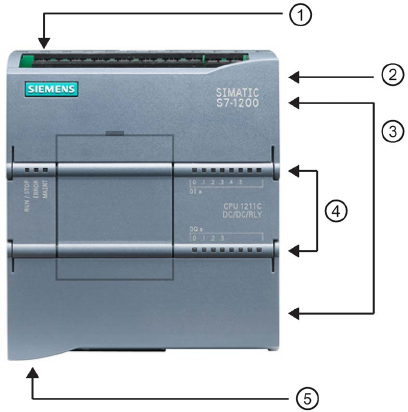
S7-1200 Programmable controller
System Manual, V4.2, 09/2016, A5E02486680-AK 27
Product overview
1
1.1
Introducing the S7-1200 PLC
The S7-1200 controller provides the flexibility and power to control a wide variety of devices
in support of your automation needs. The compact design, flexible configuration, and
powerful instruction set combine to make the S7-1200 a perfect solution for controlling a
wide variety of applications.
The CPU combines a microprocessor, an integrated power supply, input and output circuits,
built-in PROFINET, high-speed motion control I/O, and on-board analog inputs in a compact
housing to create a powerful controller. After you download your program, the CPU contains
the logic required to monitor and control the devices in your application. The CPU monitors
the inputs and changes the outputs according to the logic of your user program, which can
include Boolean logic, counting, timing, complex math operations, motion control, and
communications with other intelligent devices.
The CPU provides a PROFINET port for communication over a PROFINET network.
Additional modules are available for communicating over PROFIBUS, GPRS, RS485,
RS232, RS422, IEC, DNP3, and WDC (Wideband Data Communication) networks.
①
Power connector
②
Memory card slot under top
door
③
Removable user wiring co
n-
nectors (behind the doors)
④
Status LEDs for the on
-
board I/O
⑤
PROFINET connector (on
the bottom of the CPU)
Several security features help protect access to both the CPU and the control program:
● Every CPU provides password protection (Page 210) that allows you to configure access
to the CPU functions.
● You can use "know-how protection" (Page 213) to hide the code within a specific block.
● You can use copy protection (Page 214) to bind your program to a specific memory card
or CPU.

Product overview
1.1 Introducing the S7-1200 PLC
S7-1200 Programmable controller
28 System Manual, V4.2, 09/2016, A5E02486680-AK
Table 1- 1 Comparing the CPU models
Feature
CPU 1211C
CPU 1212C
CPU 1214C
CPU 1215C
CPU 1217C
Physical size (mm)
90 x 100 x 75
110 x 100 x 75
130 x 100 x 75
150 x 100 x 75
User memory Work 50 Kbytes 75 Kbytes 100 Kbytes 125 Kbytes 150 Kbytes
Load
1 Mbyte
2 Mbytes
4 Mbytes
Retentive 10 Kbytes
Local on-board I/O Digital 6 inputs/
4 outputs
8 inputs/
6 outputs
14 inputs/
10 output
Analog
2 inputs
2 inputs/2 output
Process image size
Inputs (I)
1024 bytes
Outputs (Q)
1024 bytes
Bit memory (M)
4096 bytes
8192 bytes
Signal module (SM) expansion
None
2
8
Signal board (SB), Battery board
(BB), or communication board
(CB)
1
Communication module (CM)
(left-side expansion)
3
High-speed coun-
ters
Total
Up to 6 configured to use any built-in or SB inputs
1 MHz
-
Ib.2 to Ib.5
100/180
kHz
Ia.0 to Ia.5
30/
1
20 kHz
--
Ia.6 to Ia.7
Ia.6 to Ib.5
Ia.6 to Ib.1
200 kHz3
Pulse outputs2
Total
Up to 4 configured to use any built-in or SB outputs
1 MHz
--
Qa.0 to Qa.3
100 kHz
Qa.0 to Qa.3
Qa.4 to Qb.1
20 kHz
--
Qa.4 to Qa.5
Qa.4 to Qb.1
--
Memory card
SIMATIC memory card (optional)
Data logs
Number
Maximum 8 open at one time
Size
500 MB per data log or as limited by maximum available load memory
Real time clock retention time
20 days, typ./12 day min. at 40 degrees C (maintenance-free Super Capacitor)
PROFINET
Ethernet communication port
1 2
Real math execution speed
2.3 μs/instruction
Boolean execution speed
0.08 μs/instruction
1
The slower speed is applicable when the HSC is configured for quadrature mode of operation.
2
For CPU models with relay outputs, you must install a digital signal (SB) to use the pulse outputs.
3 Up to 200 kHz are available with the SB 1221 DI x 24 V DC 200 kHz and SB 1221 DI 4 x 5 V DC 200 kHz.
The different CPU models provide a diversity of features and capabilities that help you create
effective solutions for your varied applications. For detailed information about a specific
CPU, see the technical specifications (Page 1359).

Product overview
1.1 Introducing the S7-1200 PLC
S7-1200 Programmable controller
System Manual, V4.2, 09/2016, A5E02486680-AK 29
Table 1- 2 Blocks, timers, and counters supported by S7-1200
Element
Description
Blocks
Type
OB, FB, FC, DB
Size
CPU Model
CPU 1211C
CPU 1212C
CPU 1214C
CPU 1215C
CPU 1217C
Code blocks
50KB
64KB
64KB
64KB
64KB
Linked1 data blocks 50KB 75KB 100KB 125KB 150KB
Unlinked
2
data blocks
256KB
256KB
256KB
256KB
256KB
Quantity
Up to 1024 blocks total (OBs + FBs + FCs + DBs)
Nesting depth 16 from the program cycle or startup OB;
6 from any interrupt event OB
Monitoring
Status of 2 code blocks can be monitored simultaneously
OBs
Program cycle
Multiple
Startup
Multiple
Time-delay interrupts
4 (1 per event)
Cyclic interrupts
4 (1 per event)
Hardware interrupts
50 (1 per event)
Time error interrupts
1
Diagnostic error interrupts
1
Pull or plug of modules
1
Rack or station failure
1
Time of day
Multiple
Status
1
Update
1
Profile
1
Timers
Type
IEC
Quantity Limited only by memory size
Storage
Structure in DB, 16 bytes per timer
Counters
Type
IEC
Quantity
Limited only by memory size
Storage Structure in DB, size dependent upon count type
• SInt, USInt: 3 bytes
• Int, UInt: 6 bytes
• DInt, UDInt: 12 bytes
1
Stored in work memory and load memory
2 Stored only in load memory

Product overview
1.2 Expansion capability of the CPU
S7-1200 Programmable controller
30 System Manual, V4.2, 09/2016, A5E02486680-AK
1.2
Expansion capability of the CPU
The S7-1200 family provides a variety of modules and plug-in boards for expanding the
capabilities of the CPU with additional I/O or other communication protocols. For detailed
information about a specific module, see the technical specifications (Page 1359).
①
Communication module (CM) or communication processor (CP) (Page 1530)
②
CPU (CPU 1211C (Page 1370), CPU 1212C (Page 1382), CPU 1214C (Page 1395),
CPU 1215C (Page 1409), CPU 1217C (Page 1425))
③
Signal board (SB) (digital SB (Page 1500), analog SB (Page 1511)), communication board
(CB) (Page 1541), or Battery Board (BB) CPU (CPU 1211C, CPU 1212C, CPU 1214C, CPU
1215C, CPU 1217C) (Page 1528)
④
Signal module (SM) (digital SM (Page 1442), analog SM (Page 1459), thermocouple SM
(Page 1473), RTD SM (Page 1479), technology SM) (Page 1485)
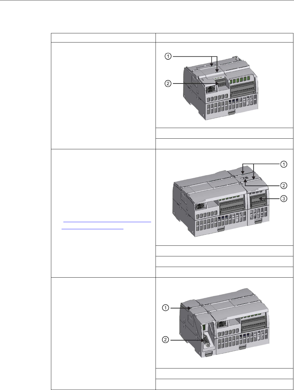
Product overview
1.2 Expansion capability of the CPU
S7-1200 Programmable controller
System Manual, V4.2, 09/2016, A5E02486680-AK 31
Table 1- 3 S7-1200 expansion modules
Type of module
Description
The CPU supports one plug-in expansion
board:
• A signal board (SB) provides additional
I/O for your CPU. The SB connects on
the front of the CPU.
• A communication board (CB) allows
you to add another communication port
to your CPU.
• A battery board (BB) allows you to
provide long term backup of the
realtime clock.
①
Status LEDs on the SB
②
Removable user wiring connector
Signal modules (SMs) add additional func-
tionality to the CPU. SMs connect to the
right side of the CPU.
• Digital I/O
• Analog I/O
• RTD and thermocouple
• SM 1278 IO-Link Master
• SM 1238 Energy Meter
(https://support.industry.siemens.com/
cs/ww/en/view/109483435)
①
Status LEDs
②
Bus connector slide tab
③ Removable user wiring connector
Communication modules (CMs) and
communications processors (CPs) add
communication options to the CPU, such
as for PROFIBUS or RS232/RS485 con-
nectivity (for PtP, Modbus or USS), or the
AS-i master.
A CP provides capabilities for other types
of communication, such as connecting to
the CPU over a GPRS, LTE, IEC, DNP3,
or WDC network.
• The CPU supports up to three CMs or
CPs
• Each CM or CP connects to the left
side of the CPU (or to the left side of
another CM or CP)
①
Status LEDs
②
Communication connector

Product overview
1.3 Basic HMI panels
S7-1200 Programmable controller
32 System Manual, V4.2, 09/2016, A5E02486680-AK
1.3
Basic HMI panels
The SIMATIC HMI Basic Panels provide touch-screen devices for basic operator control and
monitoring tasks. All panels have a protection rating for IP65 and have CE, UL, cULus, and
NEMA 4x certification.
The available Basic HMI panels (Page 1564)are described below:
● KTP400 Basic: 4" Touch screen with 4 configurable keys, a resolution of 480 x 272 and
800 tags
● KTP700 Basic: 7" Touch screen with 8 configurable keys, a resolution of 800 x 480 and
800 tags
● KTP700 Basic DP: 7" Touch screen with 8 configurable keys, a resolution of 800 x 480
and 800 tags
● KTP900 Basic: 9" Touch screen with 8 configurable keys, a resolution of 800 x 480 and
800 tags
● KTP1200 Basic: 12" Touch screen with 10 configurable keys, a resolution of 800 x 480
and 800 tags
● KTP 1200 Basic DP: 12" Touch screen with 10 configurable keys, a resolution of 800 x
400 and 800 tags
S7-1200 Programmable controller
System Manual, V4.2, 09/2016, A5E02486680-AK 33
New features
2
The following features are new in the V4.2 release:
● Enhancements to the Web server (Page 1001):
– More shared functionality with the S7-1500 Web server
– Ability to define user-defined Web page as start page
– New or improved standard Web pages:
Watch tables (Page 1033)
Online backup (Page 1035)
Communication (Page 1027): inclusion of communication statistics
● New programming instructions:
– Basic instructions:
LOWER_BOUND: (Read out ARRAY low limit) (Page 277)
UPPER_BOUND: (Read out ARRAY high limit) (Page 279)
– Extended instructions
GetSymbolName (Read out a tag on the input parameter) (Page 370)
GetSymbolPath (Query composite global name of the input parameter assignment)
(Page 373)
GetInstanceName (Read out name of the block instance) (Page 376)
GetInstancePath (Query composite global name of the block instance) (Page 379)
GetBlockName (Read out name of the block) (Page 381)
GETIO (Read process image) (Page 388)
SETIO (Transfer process image) (Page 389)
GETIO_PART (Read process image area) (Page 390)
SETIO_PART (Transfer process image area) (Page 392)
D_ACT_DP (Enable/disable PROFINET IO devices) (Page 398)
RCVREC (I-device/I-slave receive data record) (Page 411)
PRVREC (I-device/I-slave make data record available) (Page 413)
PROFIenergy (Page 419) instructions for energy management
Gen_UsrMsg (Generate user diagnostic alarms) (Page 436)
RD_SINFO (Read current OB start information) (Page 440)

New features
S7-1200 Programmable controller
34 System Manual, V4.2, 09/2016, A5E02486680-AK
Get_Name (Read the name of a PROFINET IO device) (Page 453)
GetStationInfo (Read the IP or MAC address of a PROFINET IO device) (Page 460)
CTRL_PTO (Pulse train output) (Page 488)
DataLogClear (Empty data log) (Page 518)
DataLogDelete (Delete data log) (Page 520)
CREATE_DB (Create data block) (Page 534)
ATTR_DB (Read data block attribute) (Page 541)
DELETE_DB (Delete data block) (Page 542)
● New communication capabilities:
– Time synchronization (Page 181)
– Media Redundancy Protocol (MRP) (Page 954) (client-only)
– S7-routing (Page 962)
– Autonegotiation (Page 814)
– PROFINET interface X1 port pinouts (Page 1369)
● New High-Speed Counter (HSC) capabilities:
– Added support to the CTRL_HSC_EXT (Control high-speed counter) instruction for
Count and Frequency mode (Page 556)
– Enable and disable the HSC with the Gate input (Page 567)
– Capture the HSC’s count value with Capture input (Page 569)
– Generate an output pulse on HSC events with the Compare output (Page 570)
– Ability to change HSC counting limits and an additional reference value (Page 578)
– Improved accuracy of frequency measurement (Page 573)
● New motion control capabilities:
– Speed controlled operation (Page 681)
– Telegram 4 support (Page 684)
– Simulation axis (Page 689)
– Data adaptation (Page 691)
– Axis control using the TM Pulse module (Page 702)
– Homing reference point switch level (Page 726)
– Hardware limit switch edge detection configuration on address change (Page 716)
● Backup and restore of an online S7-1200 CPU from STEP 7 (Page 1352)
● Enhancements to capturing and loading an online DB snapshot (Page 1327)
● Opportunity to synchronize the online CPU with the offline project (Page 219) under
certain conditions
● Reduction of repeated security event entries in the Diagnostics Buffer (Page 114)
● Ability to format a SIMATIC memory card from STEP 7 (Page 1320)

New features
S7-1200 Programmable controller
System Manual, V4.2, 09/2016, A5E02486680-AK 35
● Ability to prevent copies from internal load memory to external load memory (SIMATIC
memory card) (Page 212)
● Support for the 3964R protocol (Page 1092) in point-to-point communications
● Ability to declare a tag in I or Q memory using a PLC data type (Page 133) (user-defined
data type or UDT)
● Ability to save trace job measurements (Page 1347) to external load memory
● Maximum size of 256KB for unlinked (load memory) data blocks, regardless of CPU
model (Page 27)
New modules for the S7-1200
New modules expand the power of the S7-1200 CPU and provide the flexibility to meet your
automation needs:
● New Fail-safe CPUs (https://support.industry.siemens.com/cs/ww/en/view/104547552):
There are two new fail-safe CPUs in conjunction with the S7-1200 V4.2 or later release:
– CPU 1212FC DC/DC/DC (6ES7212-1AF40-0XB0)
– CPU 1212FC DC/DC/Rly (6ES7212-1HF40-0XB0)
● The SM 1238 Energy Meter 480 V AC (6ES7238-5XA32-0XB0)
(https://support.industry.siemens.com/cs/ww/en/view/109483435) supports machine-level
deployment with an S7-1200 CPU V4.1 or later, including the Fail-safe CPUs. It records
over 200 different electrical measurement and energy values and lets you create
transparency about the energy requirements of individual components of a production
plant down to the machine level. Using the measured values provided by the SM 1238
Energy meter module, you can determine energy consumption and power demand.
Exchanging your V3.0 CPU for a V4.2 CPU
If you are replacing an S7-1200 V3.0 CPU with an S7-1200 V4.2 CPU, take note of the
documented differences (Page 1571) in the versions and the required user actions.

New features
S7-1200 Programmable controller
36 System Manual, V4.2, 09/2016, A5E02486680-AK

S7-1200 Programmable controller
System Manual, V4.2, 09/2016, A5E02486680-AK 37
STEP 7 programming software
3
STEP 7 provides a user-friendly environment to develop, edit, and monitor the logic needed
to control your application, including the tools for managing and configuring all of the devices
in your project, such as controllers and HMI devices. To help you find the information you
need, STEP 7 provides an extensive online help system.
STEP 7 provides standard programming languages for convenience and efficiency in
developing the control program for your application.
● LAD (ladder logic) (Page 199) is a graphical programming language. The representation
is based on circuit diagrams.
● FBD (Function Block Diagram) (Page 200) is a programming language that is based on
the graphical logic symbols used in Boolean algebra.
● SCL (structured control language) (Page 201) is a text-based, high-level programming
language.
When you create a code block, you select the programming language to be used by that
block. Your user program can utilize code blocks created in any or all of the programming
languages.
Note
STEP
7 is the programming and configuration software component of the TIA Portal. The
TIA Portal, in addition t
o STEP 7, also includes WinCC for designing and executing runtime
process visualization, and includes online help for WinCC as well as STEP
7.

STEP 7 programming software
3.1 System requirements
S7-1200 Programmable controller
38 System Manual, V4.2, 09/2016, A5E02486680-AK
3.1
System requirements
You must install STEP 7 with Administrator privileges.
Table 3- 1 System requirements
Hardware/software
Requirements
Processor type
Intel® Core™ i5-3320M 3.3 GHz or better
RAM 8 GB
Available hard disk space
2 GB on system drive C:\
Operating systems You can use STEP 7 with the following operating systems (64-
bit only):
• Microsoft Windows 7 Home Premium SP1 or higher (STEP 7
Basic only, not supported for STEP 7 Professional)
• Microsoft Windows 7 or higher (Professional SP1, Enterprise
SP1, Ultimate SP1)
• Microsoft Windows 8.1 (STEP 7 Basic only, not supported
for STEP 7 Professional)
• Microsoft Windows 8.1 (Professional, Enterprise)
• Microsoft Server 2008 R2 StdE SP1 (STEP 7 Professional
only)
• Microsoft Server 2012 R2 StdE
Graphics card 32 MB RAM
24-bit color depth
Screen resolution
1920 x 1080 (recommended)
Network 10 Mbit/s Ethernet or faster, for communication between STEP 7
and the CPU
Optical drive
DVD-ROM
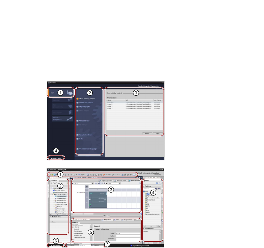
STEP 7 programming software
3.2 Different views to make the work easier
S7-1200 Programmable controller
System Manual, V4.2, 09/2016, A5E02486680-AK 39
3.2
Different views to make the work easier
STEP 7 provides a user-friendly environment to develop controller logic, configure HMI
visualization, and setup network communication. To help increase your productivity, STEP 7
provides two different views of the project: a task-oriented set of portals that are organized
on the functionality of the tools (Portal view), or a project-oriented view of the elements within
the project (Project view). Choose which view helps you work most efficiently. With a single
click, you can toggle between the Portal view and the Project view.
Portal view
①
Porta
ls for the different tasks
②
Tasks for the selected portal
③
Selection panel for the selected
action
④
Changes to the Project view
Project view
①
Menus and toolbar
②
Project navigator
③
Work area
④
Task cards
⑤
Insp
ector window
⑥
Changes to the Portal view
⑦
Editor bar
With all of these components in one place, you have easy access to every aspect of your
project. The work area consists of three tabbed views:
● Device view: Displays the device that you have added or selected and its associated
modules
● Network view: Displays the CPUs and network connections in your network
● Topology view: Displays the PROFINET topology of the network including devices,
passive components, ports, interconnections, and port diagnostics

STEP 7 programming software
3.2 Different views to make the work easier
S7-1200 Programmable controller
40 System Manual, V4.2, 09/2016, A5E02486680-AK
Each view also enables you to perform configuration tasks. The inspector window shows the
properties and information for the object that you have selected in the work area. As you
select different objects, the inspector window displays the properties that you can configure.
The inspector window includes tabs that allow you to see diagnostic information and other
messages.
By showing all of the editors that are open, the editor bar helps you work more quickly and
efficiently. To toggle between the open editors, simply click the different editor. You can also
arrange two editors to appear together, arranged either vertically or horizontally. This feature
allows you to drag and drop between editors.
The STEP 7 Information System provides extensive online help for all of the configuration,
programming, and monitoring tools of STEP 7. You can refer to it for detailed explanations
beyond what this manual provides.
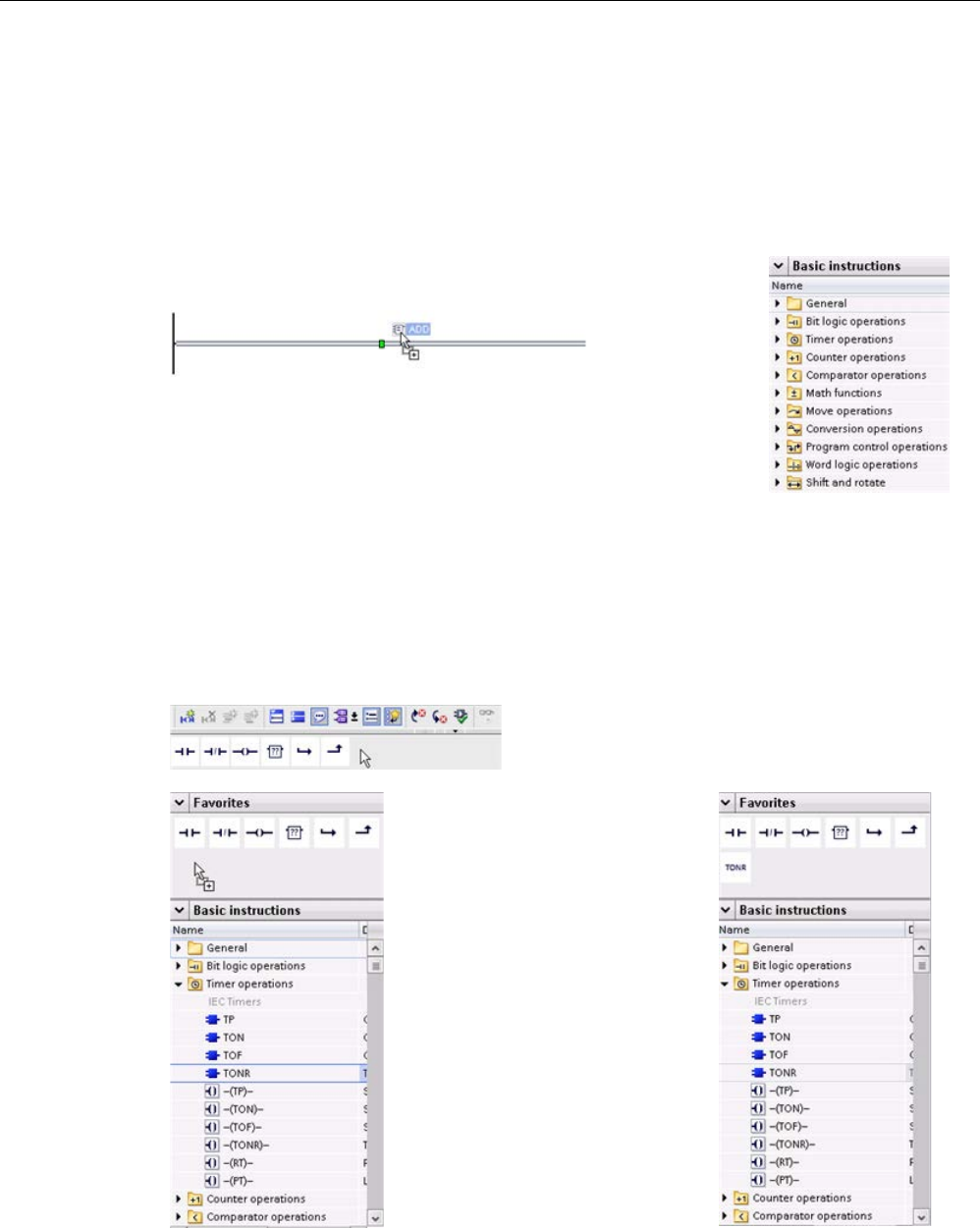
STEP 7 programming software
3.3 Easy-to-use tools
S7-1200 Programmable controller
System Manual, V4.2, 09/2016, A5E02486680-AK 41
3.3
Easy-to-use tools
3.3.1
Inserting instructions into your user program
STEP 7 provides task cards that contain the instructions for your
program. The instructions are grouped according to function.
To create your program, you drag instructions from the task card
onto a network.
3.3.2
Accessing instructions from the "Favorites" toolbar
STEP 7 provides a "Favorites" toolbar to give you quick access to the instructions that you
frequently use. Simply click the icon for the instruction to insert it into your network!
(For the "Favorites" in the instruction tree, double
-
click the icon.)
You ca
n easily customize the
"Favorites" by adding new i
n-
stru
ctions.
Simply drag and drop an instru
c-
tion to the "Favorites".
The instruction is now just a click
away!
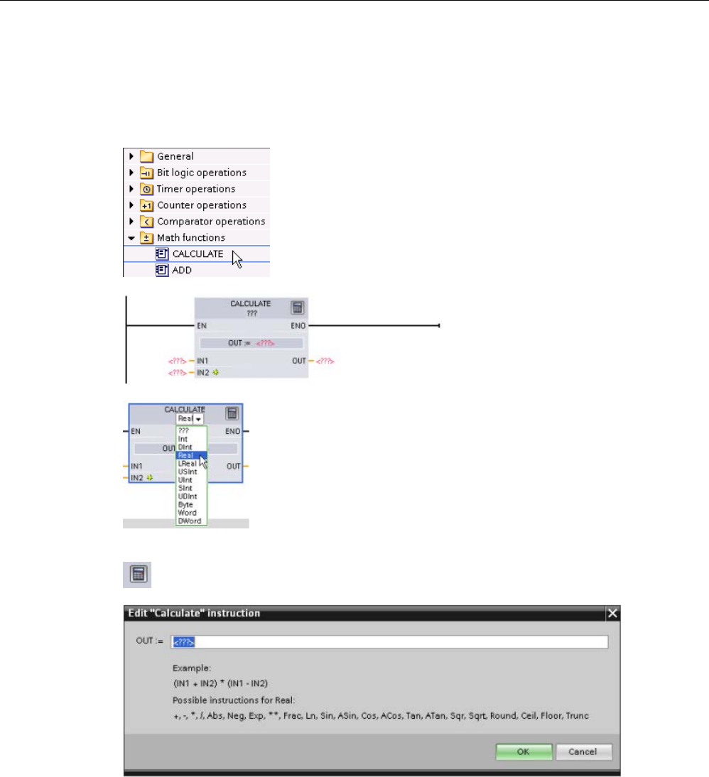
STEP 7 programming software
3.3 Easy-to-use tools
S7-1200 Programmable controller
42 System Manual, V4.2, 09/2016, A5E02486680-AK
3.3.3
Creating a complex equation with a simple instruction
The
Calculate instruction (Page 255) lets you create a math function that operates on multi-
ple input parameters to produce the result, according to the equation t
hat you define.
In the Basic instruction tree, expand the Math functions folder.
Double
-click the Calculate instruction to insert the instruction
into your user program.
The unconfigured Calculate instru
c-
tion provides two input parameters
and an output parameter.
Click the "???" and select the data
types for the input and output pa-
rameters. (The input and output parameters must all be the same data
type.)
For this example, select the "Real" data type.
Click the "Edit equation" icon to enter the equation.
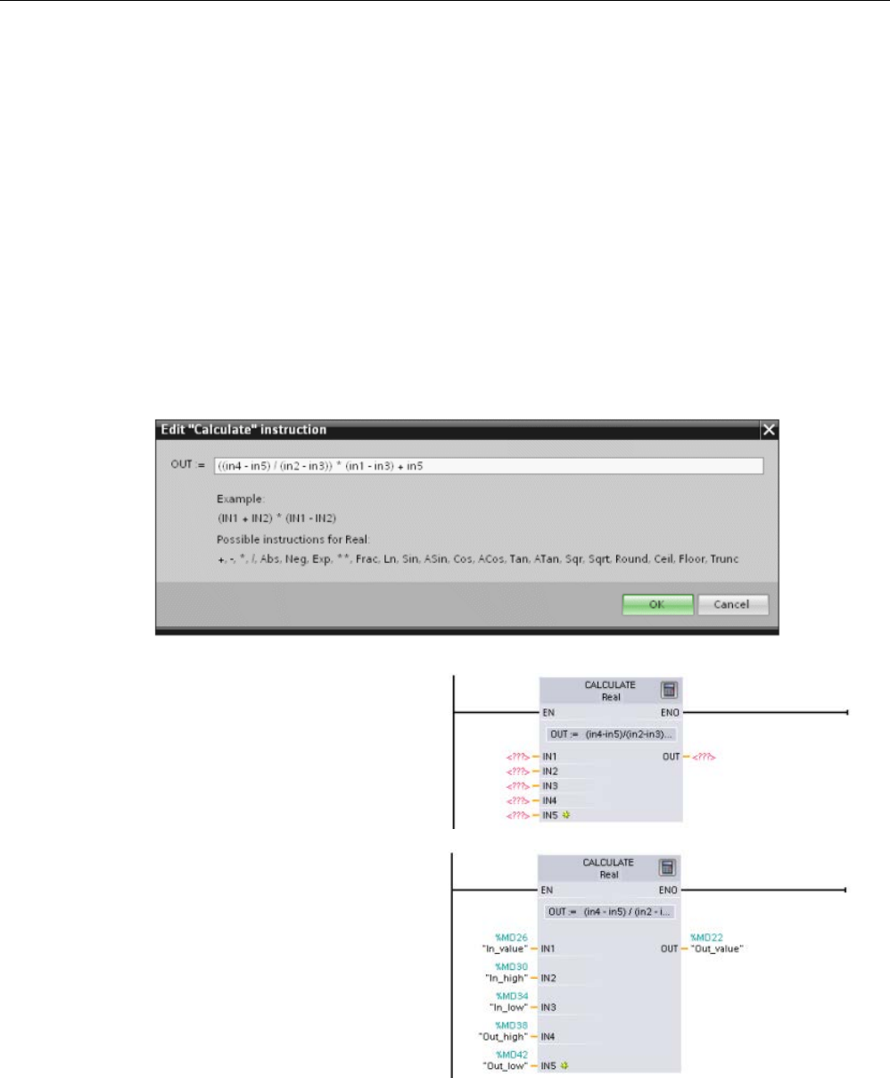
STEP 7 programming software
3.3 Easy-to-use tools
S7-1200 Programmable controller
System Manual, V4.2, 09/2016, A5E02486680-AK 43
For this example, enter the following equation for scaling a raw analog value. (The "In" and
"Out" designations correspond to the parameters of the Calculate instruction.)
Out
value
= ((Out
high
- Out
low
) / (In
high
- In
low
)) * (In
value
- In
low
) + Out
low
Out
= ((in4 - in5) / (in2 - in3)) * (in1 - in3) + in5
Where:
Out
value
(Out)
Scaled output value
In value
(in1)
Analog input value
In high
(in2)
Upper limit for the scaled input value
In
low
(in3)
Lower limit for the scaled input value
Out
high
(in4)
Upper limit for the scaled output value
Out
low
(in5)
Lower limit for the scaled output value
In the "Edit Calculate" box, enter the equation with the parameter names:
OUT = ((in4 - in5) / (in2 - in3)) * (in1 - in3) + in5
When you click "OK", the Calculate
instruction creates the inputs r
e-
quired for the inst
ruction.
Enter the tag names for the values
that correspond to the parameters.
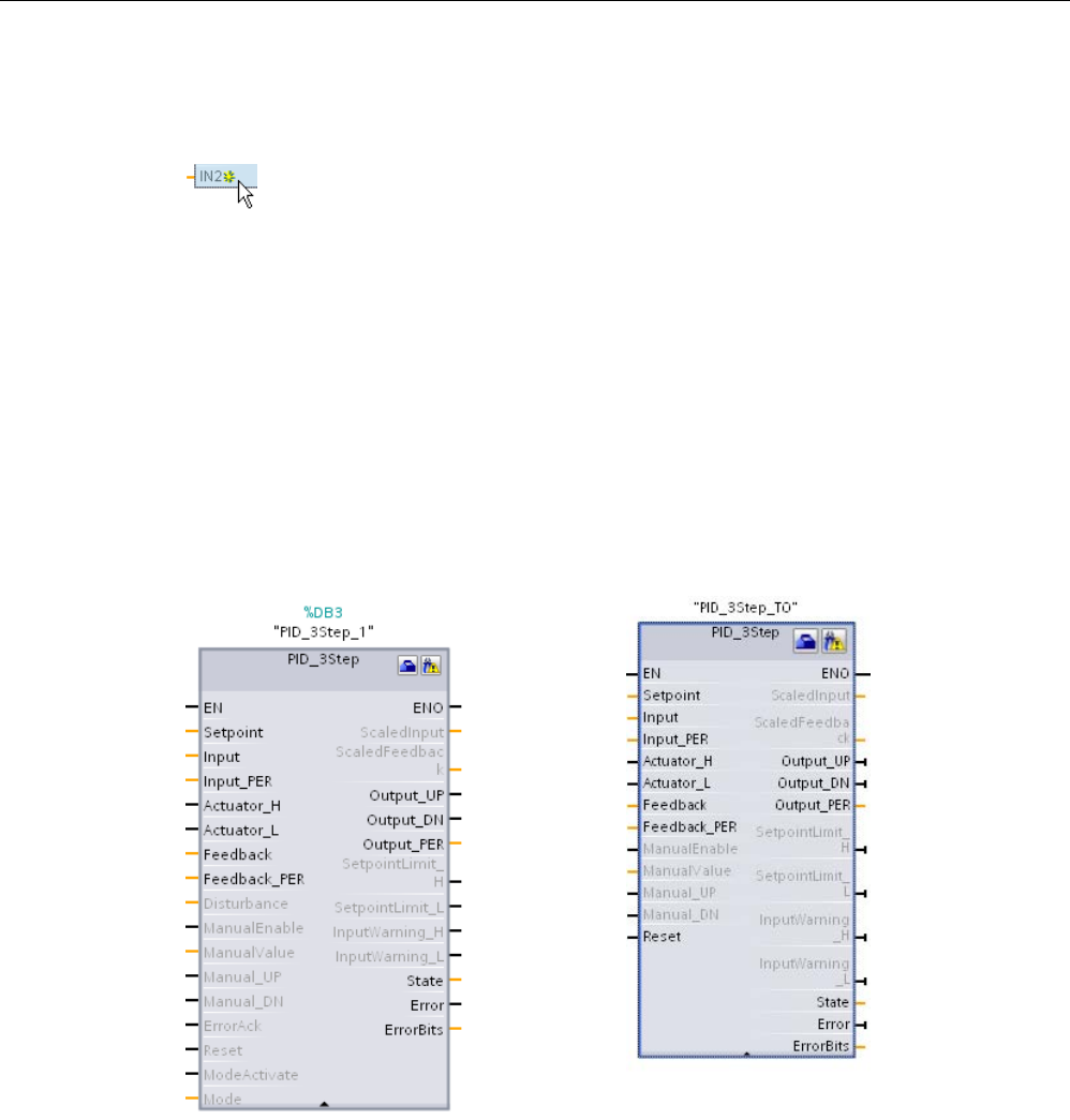
STEP 7 programming software
3.3 Easy-to-use tools
S7-1200 Programmable controller
44 System Manual, V4.2, 09/2016, A5E02486680-AK
3.3.4
Adding inputs or outputs to a LAD or FBD instruction
Some of the instructions allow you to create addi
tional inputs or outputs.
● To add an input or output, click the "Create" icon or right-click on an input stub for one of
the existing IN or OUT parameters and select the "Insert input" command.
● To remove an input or output, right-click on the stub for one of the existing IN or OUT
parameters (when there are more than the original two inputs) and select the "Delete"
command.
3.3.5
Expandable instructions
Some of the more complex inst
ructions are expandable, displaying only the key inputs and
outputs. To display all the inputs and outputs, click the arrow at the bottom of the instruction.
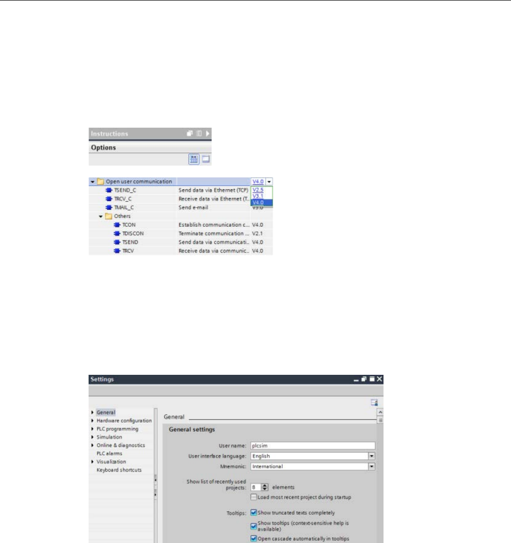
STEP 7 programming software
3.3 Easy-to-use tools
S7-1200 Programmable controller
System Manual, V4.2, 09/2016, A5E02486680-AK 45
3.3.6
Selecting a version for an instruction
The development and release cycles for certain sets of instructions (such as Modbus, PID
and motion) have created multiple released versions for these instructions. To help ensure
compatibility and migration with older projects, STEP 7 allows you to choose which version
of instruction to insert into your user program.
Click the icon on
the instruction tree task card
to enable the headers and columns of the
instruction tree.
To change the version of the instruction, s
e-
lect the appropriate version from the drop
-
down list.
3.3.7
Modifying the appearance and configuration of STEP 7
You can select a variety of settings, such as the appearance of the interface, language, or
the folder for saving your work.
Select the "Settings" command from the "Options" menu to change these settings.
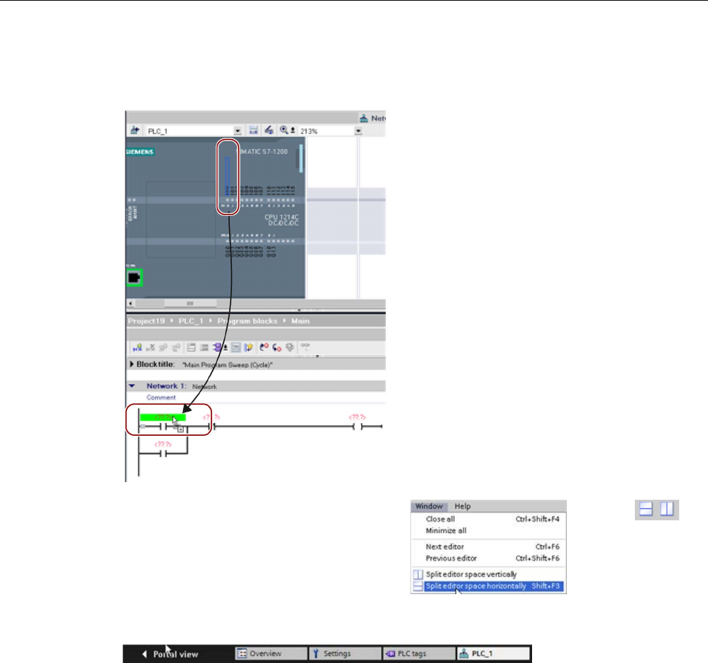
STEP 7 programming software
3.3 Easy-to-use tools
S7-1200 Programmable controller
46 System Manual, V4.2, 09/2016, A5E02486680-AK
3.3.8
Dragging and dropping between editors
To help you perform tasks quickly and easily,
STEP
7 allows you to drag and drop elements
from one editor to another. For
example, you
can drag an input from the CPU to the address
of an instruction in your user program.
You must zoom in at least 200% to select the
inputs or outputs of
the CPU.
Notice that the tag names are displayed not
only in the PLC tag table, but also are di
s-
played on the CPU.
To display two editors at one time, use the
"Split editor" menu commands or buttons in
the toolbar.
To toggle between the editors that have been opened, click the icons in the editor bar.
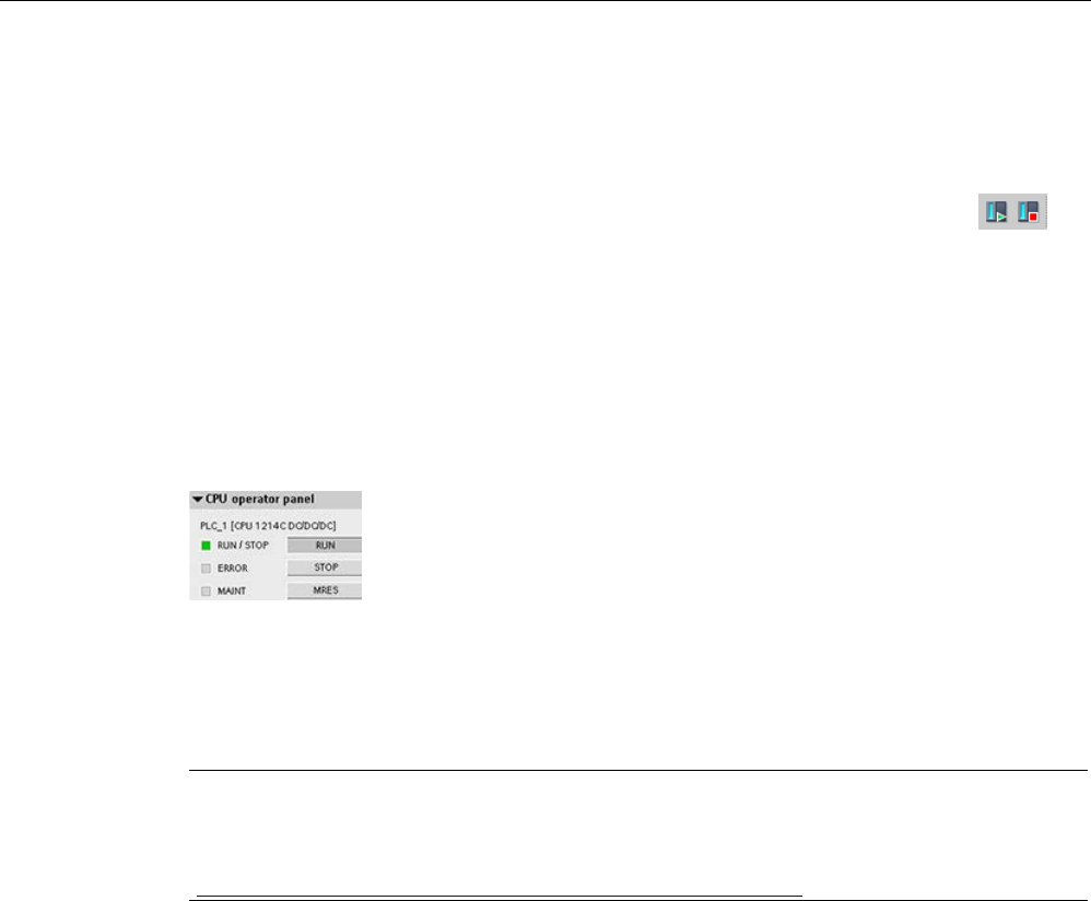
STEP 7 programming software
3.3 Easy-to-use tools
S7-1200 Programmable controller
System Manual, V4.2, 09/2016, A5E02486680-AK 47
3.3.9
Changing the operating mode of the CPU
The CPU does not have a physical switch for changing the operating mode (STOP or RUN).
Use the "Start CPU" and "Stop CPU" toolbar buttons to change the operating
mode of the CPU.
When you configure the CPU in the device configuration (Page 153), you configure the start-
up behavior in the properties of the CPU (Page 170).
The "Online and diagnostics" portal also provides an operator panel for changing the
operating mode of the online CPU. To use the CPU operator panel, you must be connected
online to the CPU. The "Online tools" task card displays an operator panel that shows the
operating mode of the online CPU. The operator panel also allows you to change the
operating mode of the online CPU.
Use the button on the operator panel to change the operating mode
(STOP or RUN). The operator panel also provides an MRES button for
resetting the memory.
The color of the RUN/STOP indicator shows the current operating mode of the CPU. Yellow
indicates STOP mode, and green indicates RUN mode.
From the device configuration in STEP 7 (Page 153) you can also configure the default
operating mode on power up of the CPU (Page 87).
Note
You can also change the operating mode of the CPU from the
Web server (Page 1001) or
the SIMATIC Automation Tool
(
https://support.industry.siemens.com/cs/ww/en/view/98161300).
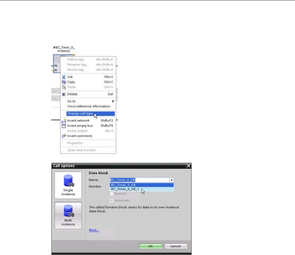
STEP 7 programming software
3.3 Easy-to-use tools
S7-1200 Programmable controller
48 System Manual, V4.2, 09/2016, A5E02486680-AK
3.3.10
Changing the call type for a DB
STEP
7 allows you to easily create or change the associ-
ation of a DB for an instruction or an FB that is in an FB.
•
You can switch the association between different DBs.
•
You can switch the association between a single-
instance DB and a multi-instance DB.
•
You can create an instance DB (if an instance DB is
missing or not available).
You can access the "Change call type" command either
by right
-clicking the instruction or FB in the program edi-
tor or
by selecting the "Block call" command from the
"Options" menu.
The "Call options" dialog allows
you to select a single
-instance
or multi
-instance DB. You can
also select specific DBs from a
drop
-down list of available DBs.
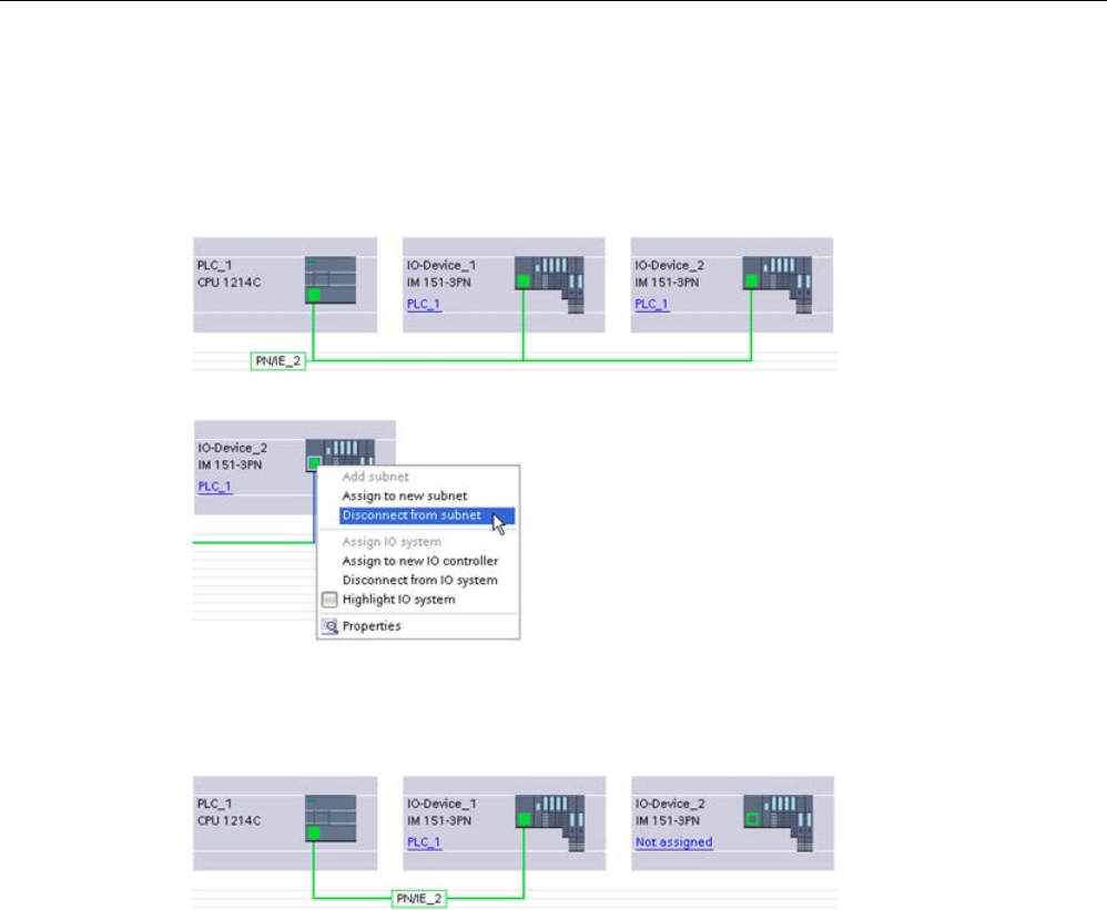
STEP 7 programming software
3.3 Easy-to-use tools
S7-1200 Programmable controller
System Manual, V4.2, 09/2016, A5E02486680-AK 49
3.3.11
Temporarily disconnecting devices from a network
From the network view, you can disconnect individual network devices from the subnet.
Because the configuration of the device is not removed from the project, you can easily
restore the connection to the device.
Right
-click the interface port of the network
device and select the "Disconnect from su
b-
net" command from the context menu.
STEP 7 reconfigures the network connections, but does not remove the disconnected device
from the project. While the network connection is deleted, the interface addresses are not
changed.
When you download the new network connections, the CPU must be set to STOP mode.
To reconnect the device, simply create a new network connection to the port of the device.
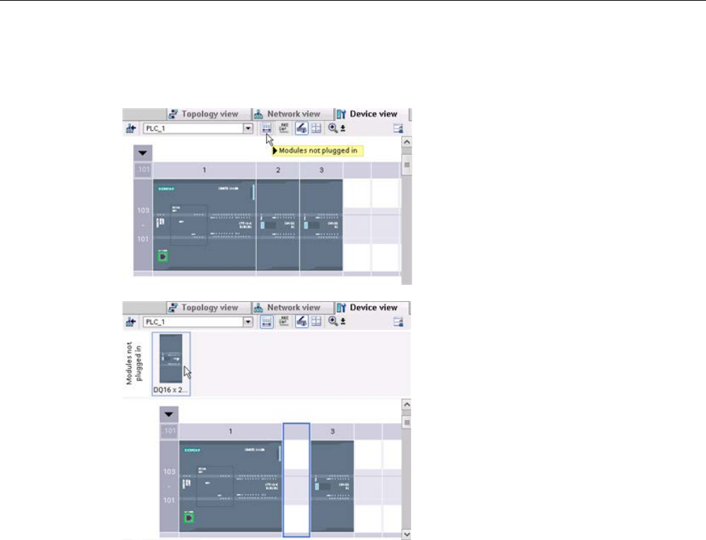
STEP 7 programming software
3.3 Easy-to-use tools
S7-1200 Programmable controller
50 System Manual, V4.2, 09/2016, A5E02486680-AK
3.3.12
Virtual unplugging of devices from the configuration
STEP 7 provides a storage area for "u
n-
plugged" modules. You can drag a module
from the rack to save the configuration of
that module.
These unplugged modules
are saved with your project, allowing you
to reinsert the module in the future without
having to reconfigure the parameters.
One use of this feature is for temporary
maintenance. Consider a scenario where
you might be waiting for a replacement
module and plan to temporarily use a di
f-
ferent module as a short
-term replace-
ment.
You could drag the configured
module from the rack to the "Unplugged
modules" and then insert the temporary
module.

STEP 7 programming software
3.4 Backward compatibility
S7-1200 Programmable controller
System Manual, V4.2, 09/2016, A5E02486680-AK 51
3.4
Backward compatibility
STEP 7 V14 supports configuration and programming of the S7-1200 V4.2 CPU and
provides for all of the new features (Page 33).
You can download projects for S7-1200 V4.0 and V4.1 CPUs from STEP 7 (V12 or later) to
an S7-1200 V4.2 CPU. Your configuration and program will be limited to the set of features
and instructions that the previous version of the S7-1200 CPU and your version of STEP 7
supported.
This backwards compatibility makes it possible for you to run programs on the new
S7-1200 V4.2 CPU models that you have previously designed and programmed for older
versions.
WARNING
Risks with copying and pasting program logic from older versions of STEP 7
Copying program logic from an older version of STEP 7 such as STEP 7 V12 into STEP 7
V14 can cause unpredictable behavior in program execution or failures to compile. Different
versions of STEP 7 implement program elements differently. The compiler does not always
detect the differences if you made the changes by pasting from an older version into
STEP 7 V14. Executing unpredictable program logic could result in death or severe
personal injury if you do not correct the program.
When using program logic from a release of STEP 7 earlier than STEP 7 V14, always
upgrade the entire project to STEP 7 14. Then you can copy, cut, paste, and edit program
logic as necessary. In STEP 7 V14, you can open a project from STEP 7 V13 SP1 or later.
STEP 7 then performs the necessary compatibility conversions and upgrades the program
correctly. Such upgrade conversions and corrections are necessary for proper program
compilation and execution. If your project is older than STEP 7 V13 SP1, you must upgrade
the project incrementally to STEP 7 V14 (Page 1571).
You cannot download projects for V1.0, V2.0, or V3.0 S7-1200 CPUs to an S7-1200 V4.2
CPU. See the Device exchange and spare parts compatibility (Page 1571) topic for
guidelines on upgrading older projects to a project that you can download.
Note
Projects with S7-1200 V1.x CPU versions
You cannot open a STEP
7 project that contains S7-1200 V1.x CPUs in STEP 7 V14. In
order to use your existing project, you must use STEP
7 V13 SP1 (with any update) to open
your project and convert the S7
-1200 V1.x CPUs to V2.0 or later. You can then use STEP 7
V14 to open the saved project with the converted CPUs.

STEP 7 programming software
3.4 Backward compatibility
S7-1200 Programmable controller
52 System Manual, V4.2, 09/2016, A5E02486680-AK

S7-1200 Programmable controller
System Manual, V4.2, 09/2016, A5E02486680-AK 53
Installation
4
4.1
Guidelines for installing S7-1200 devices
The S7-1200 equipment is designed to be easy to install. You can install an S7-1200 either
on a panel or on a standard rail, and you can orient the S7-1200 either horizontally or
vertically. The small size of the S7-1200 allows you to make efficient use of space.
Electrical equipment standards classify the SIMATIC S7-1200 system as Open Equipment.
You must install the S7-1200 in a housing, cabinet, or electric control room. You should limit
entry to the housing, cabinet, or electric control room to authorized personnel.
The installation should provide a dry environment for the S7-1200. SELV/PELV circuits are
considered to provide protection against electric shock in dry locations.
The installation should provide the appropriate mechanical strength, flammability protection,
and stability protection that is approved for open equipment in your particular location
category according to applicable electrical and building codes.
Conductive contamination due to dust, moisture, and airborne pollution can cause
operational and electrical faults in the PLC.
If you locate the PLC in an area where conductive contamination may be present, the PLC
must be protected by an enclosure with appropriate protection rating. IP54 is one rating that
is generally used for electronic equipment enclosures in dirty environments and may be
appropriate for your application.
WARNING
Improper installation of the S7-1200 can result in electrical faults or unexpected operation
of machinery.
Electrical faults or unexpected machine operation can result in death, severe personal
injury, and/or property damage.
All instructions for installation and maintenance of a proper operating environment must be
followed to ensure the equipment operates safely.

Installation
4.1 Guidelines for installing S7-1200 devices
S7-1200 Programmable controller
54 System Manual, V4.2, 09/2016, A5E02486680-AK
Separate the S7-1200 devices from heat, high voltage, and electrical noise
As a general rule for laying out the devices of your system, always separate the devices that
generate high voltage and high electrical noise from the low-voltage, logic-type devices such
as the S7-1200.
When configuring the layout of the S7-1200 inside your panel, consider the heat-generating
devices and locate the electronic-type devices in the cooler areas of your cabinet. Reducing
the exposure to a high-temperature environment will extend the operating life of any
electronic device.
Consider also the routing of the wiring for the devices in the panel. Avoid placing low-voltage
signal wires and communications cables in the same tray with AC power wiring and high-
energy, rapidly-switched DC wiring.
Provide adequate clearance for cooling and wiring
S7-1200 devices are designed for natural convection cooling. For proper cooling, you must
provide a clearance of at least 25 mm above and below the devices. Also, allow at least 25
mm of depth between the front of the modules and the inside of the enclosure.
CAUTION
For vertical mounting, the maximum allowable ambient temperature is reduced by 10
degrees C.
Orient a vertically mounted S7-1200 system as shown in the following figure.
Ensure that the S7-1200 system is mounted correctly.

Installation
4.1 Guidelines for installing S7-1200 devices
S7-1200 Programmable controller
System Manual, V4.2, 09/2016, A5E02486680-AK 55
When planning your layout for the S7-1200 system, allow enough clearance for the wiring
and communications cable connections.
①
Side view
③
Vertical installation
②
Horizontal installation
④
Clearance area

Installation
4.2 Power budget
S7-1200 Programmable controller
56 System Manual, V4.2, 09/2016, A5E02486680-AK
4.2
Power budget
Your CPU has an internal power supply that provides power for the CPU, the signal
modules, signal board and communication modules and for other 24 V DC user power
requirements.
Refer to the technical specifications (Page 1359) for information about the 5 V DC logic
budget supplied by your CPU and the 5 V DC power requirements of the signal modules,
signal boards, and communication modules. Refer to "Calculating a power budget"
(Page 1555) to determine how much power (or current) the CPU can provide for your
configuration.
The CPU provides a 24 V DC sensor supply that can supply 24 V DC for input points, for
relay coil power on the signal modules, or for other requirements. If your 24 V DC power
requirements exceed the budget of the sensor supply, then you must add an external 24 V
DC power supply to your system. Refer to the technical specifications (Page 1359) for the
24 V DC sensor supply power budget for your particular CPU.
If you require an external 24 V DC power supply, ensure that the power supply is not
connected in parallel with the sensor supply of the CPU. For improved electrical noise
protection, it is recommended that the commons (M) of the different power supplies be
connected.
WARNING
Connecting an external 24 V DC power supply in parallel with the 24 V DC sensor supply
can result in a conflict between the two supplies as each seeks to establish its own
preferred output voltage level
The result of this conflict can be shortened lifetime or immediate failure of one or both
power supplies, with consequent unpredictable operation of the PLC system. Unpredictable
operation could result in death, severe personal injury and/or property damage.
The DC sensor supply and any external power supply should provide power to different
points.
Some of the 24 V DC power input ports in the S7-1200 system are interconnected, with a
common logic circuit connecting multiple M terminals. For example, the following circuits are
interconnected when designated as "not isolated" in the data sheets: the 24 V DC power
supply of the CPU, the power input for the relay coil of an SM, or the power supply for a non-
isolated analog input. All non-isolated M terminals must connect to the same external
reference potential.
WARNING
Connecting non-isolated M terminals to different reference potentials will cause unintended
current flows that may cause damage or unpredictable operation in the PLC and any
connected equipment.
Failure to comply with these guidelines could cause damage or unpredictable operation
which could result in death or severe personal injury and/or property damage.
Always ensure that all non-isolated M terminals in an S7-1200 system are connected to the
same reference potential.
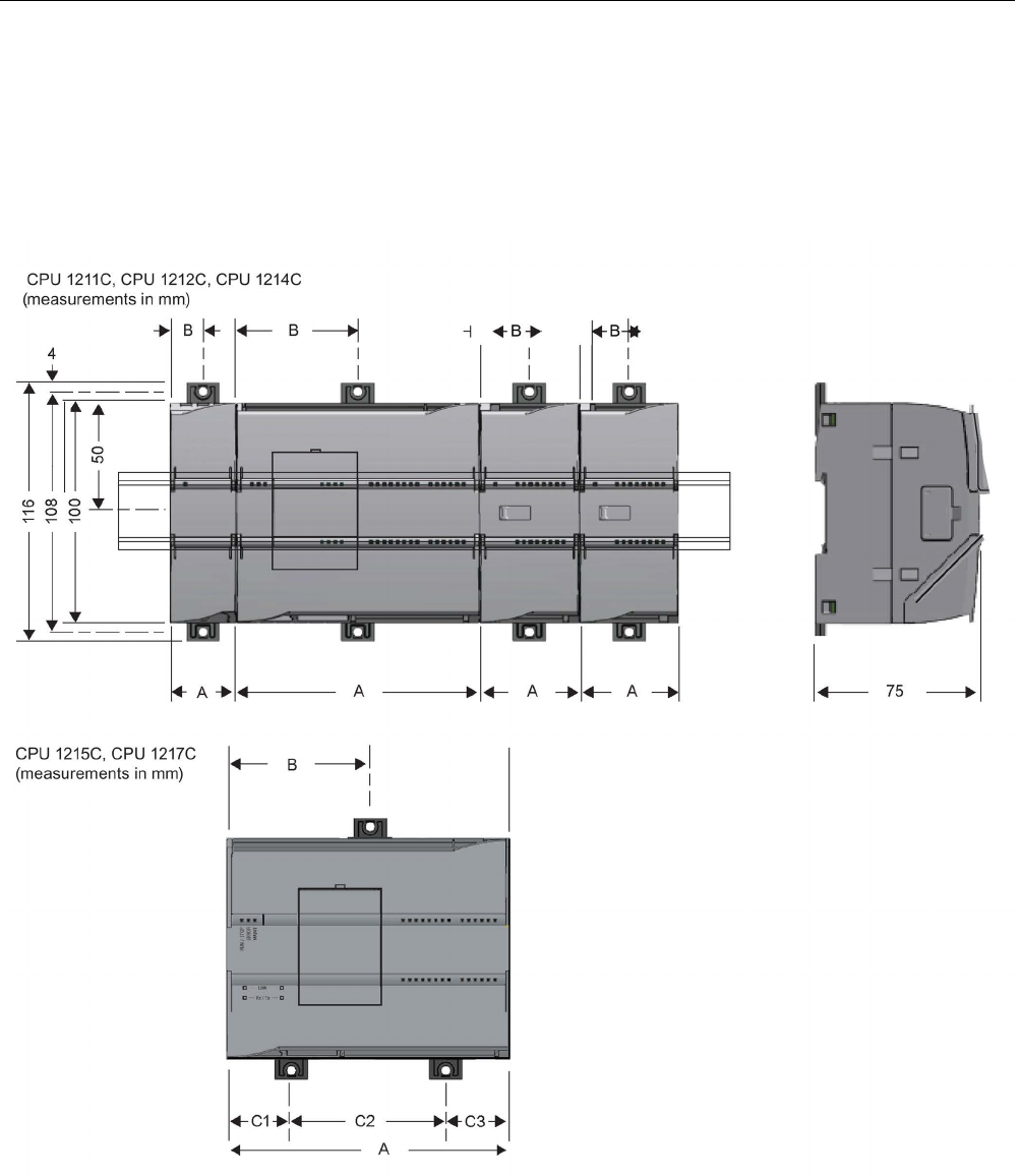
Installation
4.3 Installation and removal procedures
S7-1200 Programmable controller
System Manual, V4.2, 09/2016, A5E02486680-AK 57
4.3
Installation and removal procedures
4.3.1
Mounting dimensions for the S7-1200 devices

Installation
4.3 Installation and removal procedures
S7-1200 Programmable controller
58 System Manual, V4.2, 09/2016, A5E02486680-AK
Table 4- 1 Mounting dimensions (mm)
S7-1200 Devices
Width A
(mm)
Width B
(mm)
Width C
(mm)
CPU
CPU 1211C and CPU 1212C
90
45
--
CPU 1214C 110 55 --
CPU 1215C 130 65 (top) Bottom:
C1: 32.5
C2: 65
C3: 32.5
CPU 1217C 150 75 Bottom:
C1: 37.5
C2: 75
C3: 37.5
Signal modules Digital 8 and 16 point
Analog 2, 4, and 8 point
Thermocouple 4 and 8 point
RTD 4 point
SM 1278 IO Link-Master
45 22.5 --
Digital DQ 8 x Relay (Changeover)
70
35
--
Analog 16 point
RTD 8 point
70 35 --
SM 1238 Energy Meter module
45
22.5
--
Communication
interfaces
CM 1241 RS232, and
CM 1241 RS422/485
CM 1243-5 PROFIBUS master and
CM 1242-5 PROFIBUS slave
CM 1242-2 AS-i Master
CP 1242-7 GPRS V2
CP 1243-7 LTE-EU
CP 1243-1 DNP3
CP 1243-1 IEC
CP 1243-1
CP1243-1 PCC
CP 1243-8 IRC
RF120C
30 15 --
TS (TeleService) Adapter IE Advanced 1
TS (Teleservice) Adapter IE Basic 1
TS Adapter
TS Module
30
30
15
15
--
--
1
Before installing the TS (TeleService) Adapter IE Advanced or IE Basic, you must first connect the
TS Adapter and a TS module. The total width ("width A") is 60 mm.
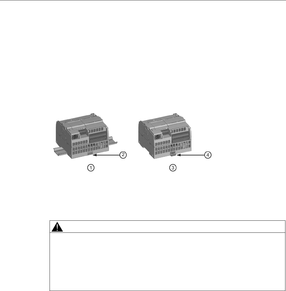
Installation
4.3 Installation and removal procedures
S7-1200 Programmable controller
System Manual, V4.2, 09/2016, A5E02486680-AK 59
Each CPU, SM, CM, and CP supports mounting on either a DIN rail or on a panel. Use the
DIN rail clips on the module to secure the device on the rail. These clips also snap into an
extended position to provide screw mounting positions to mount the unit directly on a panel.
The interior dimension of the hole for the DIN clips on the device is 4.3 mm.
A 25 mm thermal zone must be provided above and below the unit for free air circulation.
Installing and removing the S7-1200 devices
The CPU can be easily installed on a standard DIN rail or on a panel. DIN rail clips are
provided to secure the device on the DIN rail. The clips also snap into an extended position
to provide a screw mounting position for panel-mounting the unit.
①
DIN rail installation
③
Panel installation
②
DIN rail clip in latched position
④
Clip in extended position for panel mounting
Before you install or remove any electrical device, ensure that the power to that equipment
has been turned off. Also, ensure that the power to any related equipment has been turned
off.
WARNING
Installation or removal of S7-1200 or related equipment with the power applied could cause
electric shock or unexpected operation of equipment.
Failure to disable all power to the S7-1200 and related equipment during installation or
removal procedures could result in death, severe personal injury and/or property damage
due to electric shock or unexpected equipment operation.
Always follow appropriate safety precautions and ensure that power to the S7-1200 is
disabled before attempting to install or remove S7-1200 CPUs or related equipment.

Installation
4.3 Installation and removal procedures
S7-1200 Programmable controller
60 System Manual, V4.2, 09/2016, A5E02486680-AK
Always ensure that whenever you replace or install an S7-1200 device you use the correct
module or equivalent device.
WARNING
Incorrect installation of an S7-1200 module may cause the program in the S7-1200 to
function unpredictably.
Failure to replace an S7-1200 device with the same model, orientation, or order could result
in death, severe personal injury and/or property damage due to unexpected equipment
operation.
Replace an S7-1200 device with the same model, and be sure to orient and position it
correctly.
WARNING
Do not disconnect equipment when a flammable or combustible atmosphere is present.
Disconnection of equipment when a flammable or combustible atmosphere is present may
cause a fire or explosion which could result in death, serious injury and/or property
damage.
Always follow appropriate safety precautions when a flammable or combustible atmosphere
is present.
Note
Electrostatic discharge can damage the device or the receptacle on the CPU.
Make contact with a grounded conductive pad and/or wear a grounded wrist strap whenever
you handle the device.

Installation
4.3 Installation and removal procedures
S7-1200 Programmable controller
System Manual, V4.2, 09/2016, A5E02486680-AK 61
4.3.2
Installing and removing the CPU
You can install the CPU on a panel or on a DIN rail.
Note
Attach any communication modules to the CPU and install the assembly as a unit. Install
signal
modules separately after the CPU has been installed.
Consider the following when installing the units on the DIN rail or on a panel:
● For DIN rail mounting, make sure the upper DIN rail clip is in the latched (inner) position
and that the lower DIN rail clip is in the extended position for the CPU and attached CMs.
● After installing the devices on the DIN rail, move the lower DIN rail clips to the latched
position to lock the devices on the DIN rail.
● For panel mounting, make sure the DIN rail clips are pushed to the extended position.
To install the CPU on a panel, follow these steps:
1. Locate, drill, and tap the mounting holes (M4), using the dimensions shown in table,
Mounting dimensions (mm) (Page 57).
2. Ensure that the CPU and all S7-1200 equipment are disconnected from electrical power.
3. Extend the mounting clips from the module. Make sure the DIN rail clips on the top and
bottom of the CPU are in the extended position.
4. Secure the module to the panel, using a Pan Head M4 screw with spring and flat washer.
Do not use a flat head screw.
Note
The type of screw will be determined by the material upon which it is mounted. You
should apply appropriate t
orque until the spring washer becomes flat. Avoid applying
excessive torque to the mounting screws. Do not use a flat head screw.
Note
Using DIN rail stops could be helpful if your CPU is in an environment with high vibration
potential or if the CPU h
as been installed vertically. Use an end bracket (8WA1808 or
8WA1805) on the DIN rail to ensure that the modules remain connected. If your system is
in a high
-vibration environment, then panel-mounting the CPU will provide a greater level
of vibration prot
ection.
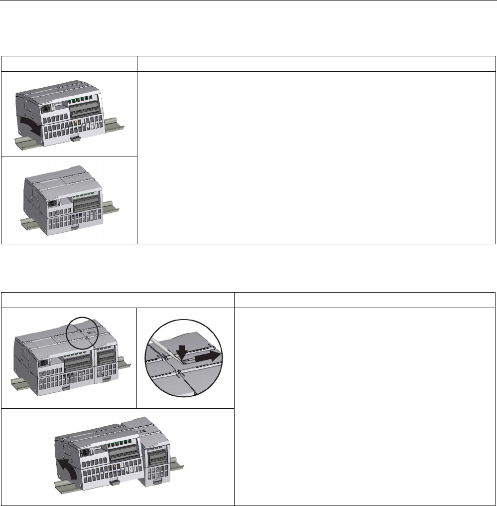
Installation
4.3 Installation and removal procedures
S7-1200 Programmable controller
62 System Manual, V4.2, 09/2016, A5E02486680-AK
Table 4- 2 Installing the CPU on a DIN rail
Task
Procedure
1. Install the DIN rail. Secure the rail to the mounting panel every 75 mm.
2. Ensure that the CPU and all S7-1200 equipment are disconnected from electrical
power.
3. Hook the CPU over the top of the DIN rail.
4. Pull out the DIN rail clip on the bottom of the CPU to allow the CPU to fit over the rail.
5. Rotate the CPU down into position on the rail.
6. Push in the clips to latch the CPU to the rail.
Table 4- 3 Removing the CPU from a DIN rail
Task
Procedure
1. Ensure that the CPU and all S7-1200 equipment are dis-
connected from electrical power.
2. Disconnect the I/O connectors, wiring, and cables from the
CPU (Page 68).
3.
Remove the CPU and any attached communication modules
as a unit. All signal modules should remain installed.
4. If an SM is connected to the CPU, retract the bus connector:
– Place a screwdriver beside the tab on the top of the sig-
nal module.
– Press down to disengage the connector from the CPU.
– Slide the tab fully to the right.
5. Remove the CPU:
– Pull out the DIN rail clip to release the CPU from the rail.
– Rotate the CPU up and off the rail, and remove the CPU
from the system.
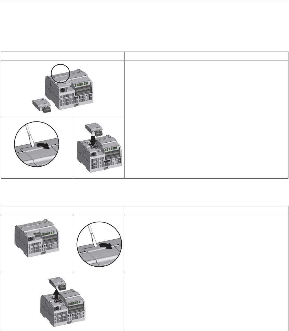
Installation
4.3 Installation and removal procedures
S7-1200 Programmable controller
System Manual, V4.2, 09/2016, A5E02486680-AK 63
4.3.3
Installing and removing an SB, CB, or BB
Table 4- 4 Installing an SB, CB, or BB 1297
Task
Procedure
1. Ensure that the CPU and all S7-1200 equipment are disconnect-
ed from electrical power.
2. Remove the top and bottom terminal block covers from the CPU.
3. Place a screwdriver into the slot on top of the CPU at the rear of
the cover.
4. Gently pry the cover straight up and remove it from the CPU.
5. Place the module straight down into its mounting position in the
top of the CPU.
6. Firmly press the module into position until it snaps into place.
7. Replace the terminal block covers.
Table 4- 5 Removing an SB, CB or BB 1297
Task
Procedure
1. Ensure that the CPU and all S7-1200 equipment are disconnect-
ed from electrical power.
2. Remove the top and bottom terminal block covers from the CPU.
3. Remove the signal board connector (if installed) by gently disen-
gaging with a screwdriver.
4. Place a screwdriver into the slot on top of the module.
5. Gently pry the module up to disengage it from the CPU.
6. Without using a screwdriver, remove the module straight up from
its mounting position in the top of the CPU.
7. Replace the cover onto the CPU.
8. Replace the terminal block covers.

Installation
4.3 Installation and removal procedures
S7-1200 Programmable controller
64 System Manual, V4.2, 09/2016, A5E02486680-AK
Installing or replacing the battery in the BB 1297 battery board
The BB 1297 requires battery type CR1025. The battery is not included with the BB 1297
and must be purchased. To install or replace the battery, follow these steps:
1. In the BB 1297, install a new battery with the positive side of the battery on top, and the
negative side next to the printed wiring board.
2. The BB 1297 is ready to be installed in the CPU. Follow the installation directions above
to install the BB 1297.
To replace the battery in the BB 1297:
1. Remove the BB 1297 from the CPU following the removal directions above.
2. Carefully remove the old battery using a small screwdriver. Push the battery out from
under the clip.
3. Install a new CR1025 replacement battery with the positive side of the battery on top and
the negative side next to the printed wiring board.
4. Re-install the BB 1297 battery board following the installation directions above.
WARNING
Installing an unspecified battery in the BB 1297, or otherwise connecting an unspecified
battery to the circuit can result in fire or component damage and unpredictable operation of
machinery.
Fire or unpredictable operation of machinery can result in death, severe personal injury, or
property damage.
Use only the specified CR1025 battery for backup of the Real-time clock.
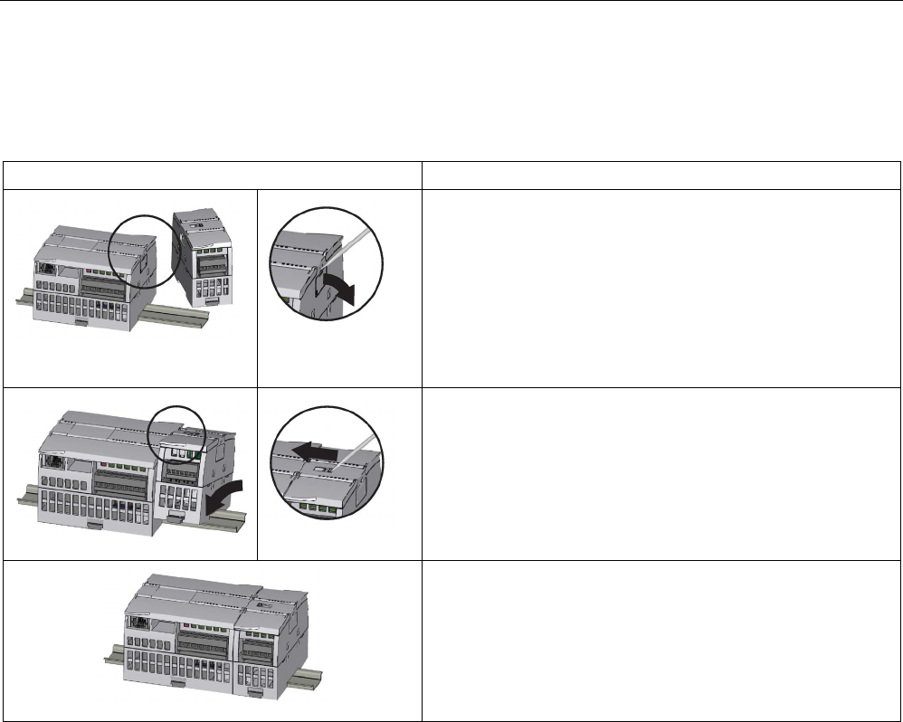
Installation
4.3 Installation and removal procedures
S7-1200 Programmable controller
System Manual, V4.2, 09/2016, A5E02486680-AK 65
4.3.4
Installing and removing an SM
Table 4- 6 Installing an SM
Task
Procedure
Install your SM after installing the CPU.
1. Ensure that the CPU and all S7-1200 equipment are discon-
nected from electrical power.
2.
Remove the cover for the connector from the right side of the
CPU:
– Insert a screwdriver into the slot above the cover.
– Gently pry the cover out at its top and remove the cover.
3. Retain the cover for reuse.
Connect the SM to the CPU:
1. Position the SM beside the CPU.
2. Hook the SM over the top of the DIN rail.
3.
Pull out the bottom DIN rail clip to allow the SM to fit over the
rail.
4. Rotate the SM down into position beside the CPU and push
the bottom clip in to latch the SM onto the rail.
Extending the bus connector makes both mechanical and elec-
trical connections for the SM.
1. Place a screwdriver beside the tab on the top of the SM.
2. Slide the tab fully to the left to extend the bus connector into
the CPU.
Follow the same procedure to install a signal module to a signal
module.
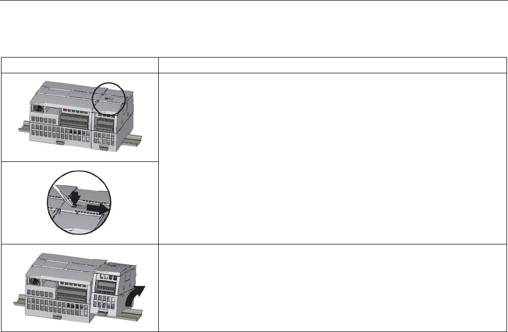
Installation
4.3 Installation and removal procedures
S7-1200 Programmable controller
66 System Manual, V4.2, 09/2016, A5E02486680-AK
Table 4- 7 Removing an SM
Task
Procedure
You can remove any SM without removing the CPU or other SMs in place.
1. Ensure that the CPU and all S7-1200 equipment are disconnected from electri-
cal power.
2. Remove the I/O connectors and wiring from the SM (Page 68).
3. Retract the bus connector.
– Place a screwdriver beside the tab on the top of the SM.
– Press down to disengage the connector from the CPU.
– Slide the tab fully to the right.
If there is another SM to the right, repeat this procedure for that SM.
Remove the SM:
1. Pull out the bottom DIN rail clip to release the SM from the rail.
2. Rotate the SM up and off the rail. Remove the SM from the system.
3. If required, cover the bus connector on the CPU to avoid contamination.
Follow the same procedure to remove a signal module from a signal module.
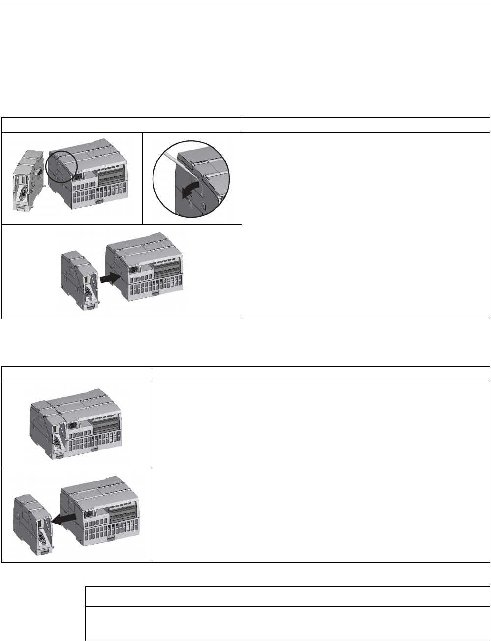
Installation
4.3 Installation and removal procedures
S7-1200 Programmable controller
System Manual, V4.2, 09/2016, A5E02486680-AK 67
4.3.5
Installing and removing a CM or CP
Attach any communication modules to the CPU and install the assembly as a unit, as shown
in Installing and removing the CPU (Page 61).
Table 4- 8 Installing a CM or CP
Task
Procedure
1. Ensure that the CPU and all S7-1200 equipment are
disconnected from electrical power.
2. Attach the CM to the CPU before installing the assembly
as a unit to the DIN rail or panel.
3. Remove the bus cover from the left side of the CPU:
– Insert a screwdriver into the slot above the bus cover.
– Gently pry out the cover at its top.
4. Remove the bus cover. Retain the cover for reuse.
5. Connect the CM or CP to the CPU:
– Align the bus connector and the posts of the CM with
the holes of the CPU
– Firmly press the units together until the posts snap in-
to place.
6. Install the CPU and CP on a DIN rail or panel.
Table 4- 9 Removing a CM or CP
Task
Procedure
Remove the CPU and CM as a unit from the DIN rail or panel.
1. Ensure that the CPU and all S7-1200 equipment ar
e disconnected from electrical
power.
2. Remove the I/O connectors and all wiring and cables from the CPU and CMs.
3. For DIN rail mounting, move the lower DIN rail clips on the CPU and CMs to the
extended position.
4. Remove the CPU and CMs from the DIN rail or panel.
5. Grasp the CPU and CMs firmly and pull apart.
NOTICE
Separate modules without using a tool.
Do not use a tool to separate the modules because this can damage the units.

Installation
4.3 Installation and removal procedures
S7-1200 Programmable controller
68 System Manual, V4.2, 09/2016, A5E02486680-AK
4.3.6
Removing and reinstalling the S7-1200 terminal block connector
The CPU, SB and SM modules provide removable connectors to make connecting the wiring
easy.
Table 4- 10 Removing the connector
Task
Procedure
Prepare the system for terminal block connector removal by removing the power from
the CPU and opening the cover above the connector.
1. Ensure that the CPU and all S7-1200 equipment are disconnected from electrical
power.
2. Inspect the top of the connector and locate the slot for the tip of the screwdriver.
3. Insert a screwdriver into the slot.
4. Gently pry the top of the connector away from the CPU. The connector will release
with a snap.
5. Grasp the connector and remove it from the CPU.
Table 4- 11 Installing the connector
Task
Procedure
Prepare the components for terminal block installation by removing power from the
CPU and opening the cover for connector.
1. Ensure that the CPU and all S7-1200 equipment are disconnected from electrical
power.
2. Align the connector with the pins on the unit.
3. Align the wiring edge of the connector inside the rim of the connector base.
4. Press firmly down and rotate the connector until it snaps into place.
Check carefully to ensure that the connector is properly aligned and fully engaged.
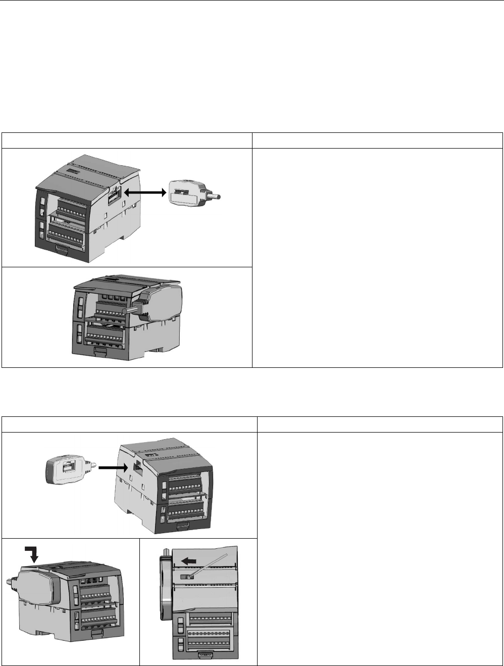
Installation
4.3 Installation and removal procedures
S7-1200 Programmable controller
System Manual, V4.2, 09/2016, A5E02486680-AK 69
4.3.7
Installing and removing the expansion cable
The S7-1200 expansion cable provides additional flexibility in configuring the layout of your
S7-1200 system. Only one expansion cable is allowed per CPU system. You install the
expansion cable either between the CPU and the first SM, or between any two SMs.
Table 4- 12 Installing and removing the male connector of the expansion cable
Task
Procedure
To install the male connector:
1. Ensure that the CPU and all S7-1200 equipment are
disconnected from electrical power.
2. Push the connector into the bus connector on the right
side of the signal module or CPU.
To remove the male connector:
1. Ensure that the CPU and all S7-1200 equipment are
disconnected from electrical power.
2. Pull out the male connector to release it from the signal
module or CPU.
Table 4- 13 Installing the female connector of the expansion cable
Task
Procedure
1. Ensure that the CPU and all S7-1200 equipment are
disconnected from electrical power.
2.
Place the female connector to the bus connector on the
left side of the signal module.
3.
Slip the hook extension of the female connector into the
housing at the bus connector and press down slightly
to engage the hook.
4. Lock the connector into place:
– Place a screwdriver beside the tab on the top of the
signal module.
– Slide the tab fully to the left.
To engage the connector, you must slide the connector tab
all the way to the left. The connector tab must be locked
into place.
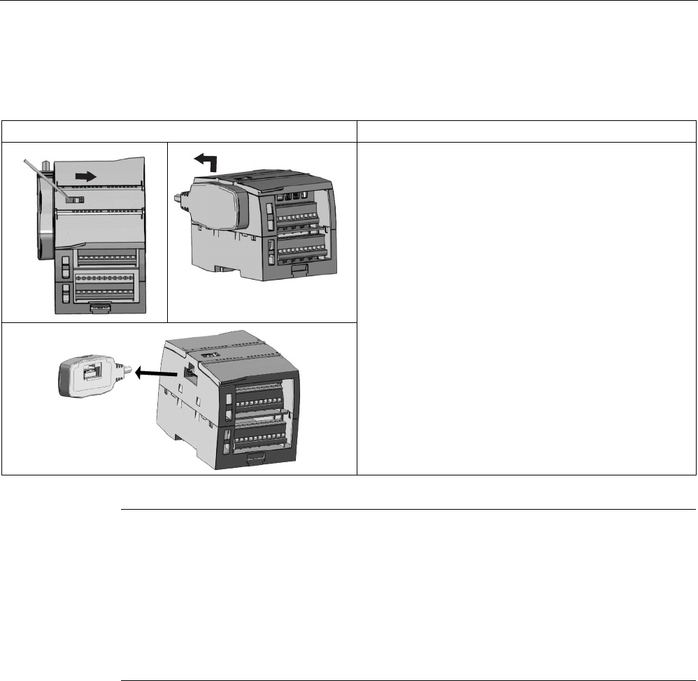
Installation
4.3 Installation and removal procedures
S7-1200 Programmable controller
70 System Manual, V4.2, 09/2016, A5E02486680-AK
Table 4- 14 Removing the female connector of the expansion cable
Task
Procedure
1. Ensure that the CPU and all S7-1200 equipment are
disconnected from electrical power.
2. Unlock the connector:
– Place a screwdriver beside the tab on the top of the
signal module.
– Press down slightly and slide the tab fully to the
right.
3. Lift the connector up slightly to disengage the hook
extension.
4. Remove the female connector.
Note
Installing the expansion cable in a vibration environment
If the expansion cable is connected to modules that move
, or are not firmly fixed, the cable
male end snap
-on connection can gradually become loose.
Use a cable tie to fix the male end cable on the DIN
-rail (or other place) to provide extra
strain relief.
Avoid using excessive force when you pull the cable duri
ng installation. Ensure the cable-
module connection is in the correct position once installation is complete.
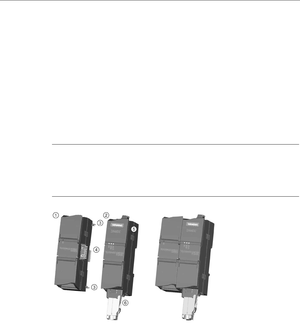
Installation
4.3 Installation and removal procedures
S7-1200 Programmable controller
System Manual, V4.2, 09/2016, A5E02486680-AK 71
4.3.8
TS (TeleService) adapter
4.3.8.1
Connecting the TeleService adapter
Before installing the TS (TeleService) Adapter IE Basic or TS (TeleService) Adapter IE
Advanced, you must first connect the TS Adapter and a TS module.
Available TS modules:
● TS module RS232
● TS module Modem
● TS module GSM
● TS module ISDN
Note
The TS module can be damaged if you touch the contacts of the plug connector ④ of the
TS module.
Follow ESD guidelines in order to avoid damaging the TS
module through electrostatic
discharge. Before connecting a TS
module and TS Adapter, make sure that both are in an
idle state.
①
TS module
④
Plug connector from the TS module
②
TS Adapter
⑤
Cannot be opened
③
Elements
⑥
Ethernet port

Installation
4.3 Installation and removal procedures
S7-1200 Programmable controller
72 System Manual, V4.2, 09/2016, A5E02486680-AK
Note
Before connecting a TS module and TS adapter basic unit, ensure that the contact pins ④
are not bent.
When connecting, ensure that the mal
e connector and guide pins are positioned correctly.
Only connect a TS
module into the TS adapter. Do not force a connection of the TS adapter
to a different device, such as an S7
-1200 CPU. Do not change the mechanical construction
of the connector, and do
not remove or damage the guide pins.
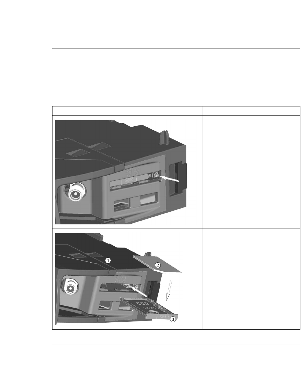
Installation
4.3 Installation and removal procedures
S7-1200 Programmable controller
System Manual, V4.2, 09/2016, A5E02486680-AK 73
4.3.8.2
Installing the SIM card
Locate the SIM card slot on the underside of the TS module GSM.
Note
The SIM card may only be removed or inserted if the T
S module GSM is de-energized.
Table 4- 15 Installing the SIM card
Task
Procedure
Use a sharp object to press the eject
button of the SIM card tray (in the
direction of the arrow) and remove the
SIM card tray.
Place the SIM card in the SIM card
tray as shown and put the SIM card
tray back into its slot.
① TS Module GSM
②
SIM card
③ SIM card tray
Note
Ensure that the SIM card is correctly oriented in the card tray. Otherwise, the SIM card will
not make connection with the module, and the eject button may not remove the card tray.
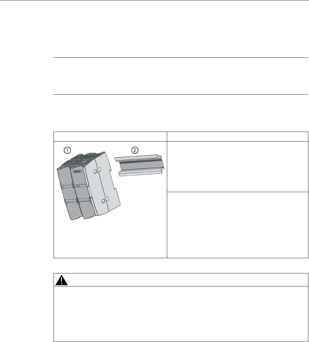
Installation
4.3 Installation and removal procedures
S7-1200 Programmable controller
74 System Manual, V4.2, 09/2016, A5E02486680-AK
4.3.8.3
Installing the TS adapter unit on a DIN rail
Prerequisites: You must have connected the TS Adapter and a TS module together, and the
DIN rail must have been installed.
Note
If you
install the TS unit vertically or in high-vibration environment, the TS module can
become disconnected from the TS
Adapter. Use an end bracket 8WA1808 on the DIN rail to
ensure that the modules remain connected.
Table 4- 16 Installing and removing the TS Adapter
Task
Procedure
Installation:
1. Hook the TS Adapter with attached TS module ①
on the DIN rail ②.
2. Rotate the unit back until it engages.
3. Push in the DIN rail clip on each module to attach
each module to the rail.
Removal:
1. Remove the analog cable and Ethernet cable from
the underside of the TS Adapter.
2. Remove power from the TS Adapter.
3. Use a screwdriver to disengage the rail clips on
both modules.
4. Rotate the unit upwards to remove the unit from the
DIN rail.
WARNING
Safety requirements for installing or removing the TS Adapter.
Before you remove power from the unit, disconnect the grounding of the TS Adapter by
removing the analog cable and Ethernet cable. Failure to observe this precaution could
result in death, severe personal injury and/or property damage due to unexpected
equipment operation.
Always follow these requirements when installing or removing the TS Adapter.
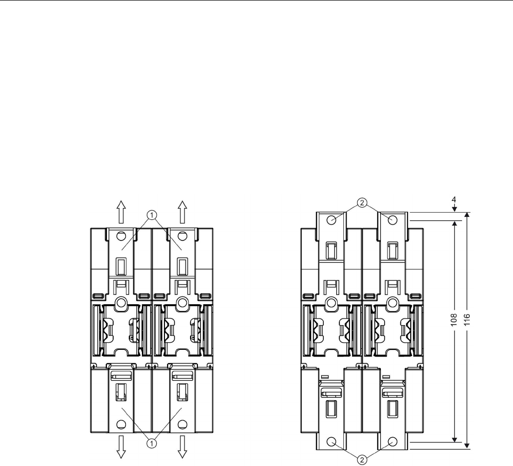
Installation
4.3 Installation and removal procedures
S7-1200 Programmable controller
System Manual, V4.2, 09/2016, A5E02486680-AK 75
4.3.8.4
Installing the TS adapter on a panel
Prerequisites: You must have connected the TS Adapter and TS module.
1. Move the attachment slider ① to the backside of the TS Adapter and TS module in the
direction of the arrow until it engages.
2. Screw the TS Adapter and TS module to the position marked with ② to the designated
assembly wall.
The following illustration shows the TS Adapter from behind, with the attachment sliders ①
in both positions:
①
Attachment slider
②
Drill holes for wall mounting

Installation
4.4 Wiring guidelines
S7-1200 Programmable controller
76 System Manual, V4.2, 09/2016, A5E02486680-AK
4.4
Wiring guidelines
Proper grounding and wiring of all electrical equipment is important to help ensure the
optimum operation of your system and to provide additional electrical noise protection for
your application and the S7-1200. Refer to the technical specifications (Page 1359) for the
S7-1200 wiring diagrams.
Prerequisites
Before you ground or install wiring to any electrical device, ensure that the power to that
equipment has been turned off. Also, ensure that the power to any related equipment has
been turned off.
Ensure that you follow all applicable electrical codes when wiring the S7-1200 and related
equipment. Install and operate all equipment according to all applicable national and local
standards. Contact your local authorities to determine which codes and standards apply to
your specific case.
WARNING
Installation or wiring the S7-1200 or related equipment with power applied could cause
electric shock or unexpected operation of equipment.
Failure to disable all power to the S7-1200 and related equipment during installation or
removal procedures could result in death, severe personal injury, and/or damage due to
electric shock or unexpected equipment operation.
Always follow appropriate safety precautions and ensure that power to the S7-1200 is
disabled before attempting to install or remove the S7-1200 or related equipment.
Always take safety into consideration as you design the grounding and wiring of your S7-
1200 system. Electronic control devices, such as the S7-1200, can fail and can cause
unexpected operation of the equipment that is being controlled or monitored. For this reason,
you should implement safeguards that are independent of the S7-1200 to protect against
possible personal injury or equipment damage.
WARNING
Control devices can fail in an unsafe condition, resulting in unexpected operation of
controlled equipment.
Such unexpected operations could result in death, severe personal injury and/or property
damage.
Use an emergency stop function, electromechanical overrides, or other redundant
safeguards that are independent of the S7-1200.

Installation
4.4 Wiring guidelines
S7-1200 Programmable controller
System Manual, V4.2, 09/2016, A5E02486680-AK 77
Guidelines for isolation
S7-1200 AC power supply boundaries and I/O boundaries to AC circuits have been designed
and approved to provide safe separation between AC line voltages and low voltage circuits.
These boundaries include double or reinforced insulation, or basic plus supplementary
insulation, according to various standards. Components which cross these boundaries such
as optical couplers, capacitors, transformers, and relays have been approved as providing
safe separation. Only circuits rated for AC line voltage include safety isolation to other
circuits. Isolation boundaries between 24 V DC circuits are functional only, and you should
not depend on these boundaries for safety.
The sensor supply output, communications circuits, and internal logic circuits of an S7-1200
with included AC power supply are sourced as SELV (safety extra-low voltage) according to
EN 61131-2.
To maintain the safe character of the S7-1200 low voltage circuits, external connections to
communications ports, analog circuits, and all 24 V DC nominal power supply and I/O
circuits must be powered from approved sources that meet the requirements of SELV,
PELV, Class 2, Limited Voltage, or Limited Power according to various standards.
WARNING
Use of non-isolated or single insulation supplies to supply low voltage circuits from an AC
line can result in hazardous voltages appearing on circuits that are expected to be touch
safe, such as communications circuits and low voltage sensor wiring.
Such unexpected high voltages could cause electric shock resulting in death, severe
personal injury and/or property damage.
Only use high voltage to low voltage power converters that are approved as sources of
touch safe, limited voltage circuits.
Guidelines for grounding the S7-1200
The best way to ground your application is to ensure that all the common and ground
connections of your S7-1200 and related equipment are grounded to a single point. This
single point should be connected directly to the earth ground for your system.
All ground wires should be as short as possible and should use a large wire size, such as 2
mm2 (14 AWG).
When locating grounds, consider safety-grounding requirements and the proper operation of
protective interrupting devices.

Installation
4.4 Wiring guidelines
S7-1200 Programmable controller
78 System Manual, V4.2, 09/2016, A5E02486680-AK
Guidelines for wiring the S7-1200
When designing the wiring for your S7-1200, provide a single disconnect switch that
simultaneously removes power from the S7-1200 CPU power supply, from all input circuits,
and from all output circuits. Provide over-current protection, such as a fuse or circuit breaker,
to limit fault currents on supply wiring. Consider providing additional protection by placing a
fuse or other current limit in each output circuit.
Install appropriate surge suppression devices for any wiring that could be subject to lightning
surges. For more information, see Surge immunity (Page 1359) in the General technical
specifications section.
Avoid placing low-voltage signal wires and communications cables in the same wire tray with
AC wires and high-energy, rapidly switched DC wires. Always route wires in pairs, with the
neutral or common wire paired with the hot or signal-carrying wire.
Use the shortest wire possible and ensure that the wire is sized properly to carry the required
current.
Wire and cable should have a temperature rating 30 °C higher than the ambient temperature
around the S7-1200 (for example, a minimum of 85 °C-rated conductors for 55 °C ambient
temperature). You should determine other wiring type and material requirements from the
specific electrical circuit ratings and your installation environment.
Use shielded wires for optimum protection against electrical noise. Typically, grounding the
shield at the S7-1200 gives the best results. You should ground communication cable
shields to S7-1200 communication connector shells using connectors that engage the cable
shield, or by bonding the communication cable shields to a separate ground. You should
ground other cable shields using clamps or copper tape around the shield to provide a high
surface area connection to the grounding point.
When wiring input circuits that are powered by an external power supply, include an
overcurrent protection device in that circuit. External protection is not necessary for circuits
that are powered by the 24 V DC sensor supply from the S7-1200 because the sensor
supply is already current-limited.
All S7-1200 modules have removable connectors for user wiring. To prevent loose
connections, ensure that the connector is seated securely and that the wire is installed
securely into the connector.
To help prevent unwanted current flows in your installation, the S7-1200 provides isolation
boundaries at certain points. When you plan the wiring for your system, you should consider
these isolation boundaries. Refer to the technical specifications (Page 1425) for the amount
of isolation provided and the location of the isolation boundaries. Circuits rated for AC line
voltage include safety isolation to other circuits. Isolation boundaries between 24 V DC
circuits are functional only, and you should not depend on these boundaries for safety.

Installation
4.4 Wiring guidelines
S7-1200 Programmable controller
System Manual, V4.2, 09/2016, A5E02486680-AK 79
A summary of Wiring rules for the S7-1200 CPUs, SMs and SBs is shown below:
Table 4- 17 Wiring rules for S7-1200 CPUs, SMs, and SBs
Wiring rules for...
CPU and SM connector
SB connector
Connectible conductor
cross-sections for stand-
ard wires
2 mm2 to 0.3 mm2 (14 AWG to 22
AWG)
1.3 mm2 to 0.3 mm2 (16 AWG to 22
AWG)
Number of wires per con-
nection
1 or combination of 2 wires up to
2 mm
2
(total)
1 or combination of 2 wires up to 1.3
mm
2
(total)
Wire strip length
6.4 mm
6.3 to 7 mm
Tightening torque* (maxi-
mum)
0.56 N-m (5 inch-pounds) 0.33 N-m (3 inch-pounds)
Tool 2.5 to 3.0 mm flathead screw-
driver
2.0 to 2.5 mm flathead screwdriver
* To avoid damaging the connector, be careful that you do not over-tighten the screws.
Note
Ferrules or end sleeves on stranded conductors reduce the risk of stray strands causing
short ci
rcuits. Ferrules longer than the recommended strip length should include an
insulating collar to prevent shorts due to side movement of conductors. Cross
-sectional area
limits for bare conductors also apply to ferrules.
See also
Technical specifications (Page 1359)
Guidelines for lamp loads
Lamp loads are damaging to relay contacts because of the high turn-on surge current. This
surge current will nominally be 10 to 15 times the steady state current for a Tungsten lamp.
A replaceable interposing relay or surge limiter is recommended for lamp loads that will be
switched a large number of times during the lifetime of the application.

Installation
4.4 Wiring guidelines
S7-1200 Programmable controller
80 System Manual, V4.2, 09/2016, A5E02486680-AK
Guidelines for inductive loads
Use suppressor circuits with inductive loads to limit the voltage rise when a control output
turns off. Suppressor circuits protect your outputs from premature failure caused by the high
voltage transient that occurs when current flow through an inductive load is interrupted.
In addition, suppressor circuits limit the electrical noise generated when switching inductive
loads. High frequency noise from poorly suppressed inductive loads can disrupt the
operation of the PLC. Placing an external suppressor circuit so that it is electrically across
the load and physically located near the load is the most effective way to reduce electrical
noise.
S7-1200 DC outputs include internal suppressor circuits that are adequate for inductive
loads in most applications. Since S7-1200 relay output contacts can be used to switch either
a DC or an AC load, internal protection is not provided.
A good suppressor solution is to use contactors and other inductive loads for which the
manufacturer provides suppressor circuits integrated in the load device, or as an optional
accessory. However, some manufacturer provided suppressor circuits may be inadequate
for your application. An additional suppressor circuit may be necessary for optimal noise
reduction and contact life.
For AC loads, a metal oxide varistor (MOV) or other voltage clamping device may be used
with a parallel RC circuit, but is not as effective when used alone. An MOV suppressor with
no parallel RC circuit often results in significant high frequency noise up to the clamp
voltage.
A well-controlled turn-off transient will have a ring frequency of no more than 10 kHz, with
less than 1 kHz preferred. Peak voltage for AC lines should be within +/- 1200 V of ground.
Negative peak voltage for DC loads using the PLC internal suppression will be ~40 V below
the 24 V DC supply voltage. External suppression should limit the transient to within 36 V of
the supply to unload the internal suppression.
Note
The effectiveness of a suppressor circuit depends on the application and must be verified for
your particular usage. Ensure that all components are correctly rated
and use an
oscilloscope to observe the turn
-off transient.
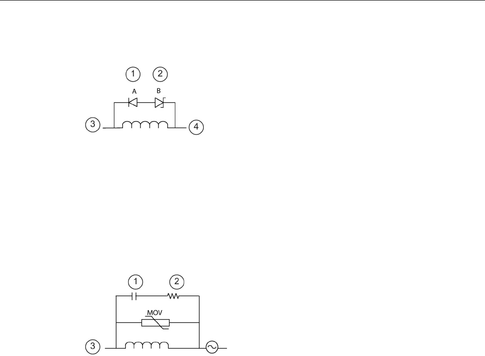
Installation
4.4 Wiring guidelines
S7-1200 Programmable controller
System Manual, V4.2, 09/2016, A5E02486680-AK 81
Typical suppressor circuit for DC or relay outputs that switch DC inductive loads
In most applications, the addition of a diode (A)
across a DC inductive load is suitab
le, but if your
application requires faster turn
-off times, then the
addition of a zener diode (B) is recommended. Be
sure to size your zener diode properly for the amount
of current in your output circuit.
①
1N4001 diode or equivalent
②
8.2 V Zener (DC
outputs),
36 V Zener (Relay outputs)
③
Output point
④
M, 24 V reference
Typical suppressor circuit for relay outputs that switch AC inductive loads
Ensure that the working voltage of the metal oxide
varistor (MOV) is at lea
st 20% greater than the nomi-
nal line voltage.
Choose pulse
-rated, non-inductive resistors, and
capacitors recommended for pulse applications (typ
i-
cally metal film). Verify the components meet ave
r-
age power, peak power, and peak voltage
requirements.
①
See table for C value
②
See table for R value
③
Output point

Installation
4.4 Wiring guidelines
S7-1200 Programmable controller
82 System Manual, V4.2, 09/2016, A5E02486680-AK
If you design your own suppressor circuit, the following table suggests resistor and capacitor
values for a range of AC loads. These values are based on calculations with ideal
component parameters. I rms in the table refers to the steady-state current of the load when
fully ON.
Table 4- 18 AC suppressor circuit resistor and capacitor values
Inductive load
Suppressor values
I rms
230 V AC
120 V AC
Resistor
Capacitor
Amps VA VA Ω W (power rating) nF
0.02
4.6
2.4
15000
0.1
15
0.05
11.5
6
5600
0.25
470
0.1
23
12
2700
0.5
100
0.2
46
24
1500
1
150
0.5
115
60
560
2.5
470
1
230
120
270
5
1000
2
460
240
150
10
1500
Conditions satisfied by the table values:
Maximum turn-off transition step < 500 V
Resistor peak voltage < 500 V
Capacitor peak voltage < 1250 V
Suppressor current < 8% of load current (50 Hz)
Suppressor current < 11% of load current (60 Hz)
Capacitor dV/dt < 2 V/μs
Capacitor pulse dissipation : ∫(dv/dt)2 dt < 10000 V2/μs
Resonant frequency < 300 Hz
Resistor power for 2 Hz max switching frequency
Power factor of 0.3 assumed for typical inductive load
Guidelines for differential inputs and outputs
Differential inputs and outputs behave differently than standard inputs and outputs. There
are two pins per differential input and output. Determining whether a differential input or
output is on or off requires that you measure the voltage difference between these two pins.
See the detailed specifications for the CPU 1217C in Appendix A (Page 1425).
S7-1200 Programmable controller
System Manual, V4.2, 09/2016, A5E02486680-AK 83
PLC concepts
5
5.1
Execution of the user program
The CPU supports the following types of code blocks that allow you to create an efficient
structure for your user program:
● Organization blocks (OBs) define the structure of the program. Some OBs have
predefined behavior and start events, but you can also create OBs with custom start
events.
● Functions (FCs) and function blocks (FBs) contain the program code that corresponds to
specific tasks or combinations of parameters. Each FC or FB provides a set of input and
output parameters for sharing data with the calling block. An FB also uses an associated
data block (called an instance DB) to maintain the data values for that instance of the FB
call. You can call an FB multiple times, each time with a unique instance DB. Calls to the
same FB with different instance DBs do not affect the data values in any of the other
instance DBs.
● Data blocks (DBs) store data that can be used by the program blocks.
Execution of the user program begins with one or more optional startup organization blocks
(OBs) which execute once upon entering RUN mode, followed by one or more program cycle
OBs that execute cyclically. You can also associate an OB with an interrupt event, which can
be either a standard event or an error event. These OBs execute whenever the
corresponding standard or error event occurs.
A function (FC) or a function block (FB) is a block of program code that can be called from
an OB or from another FC or FB, down to the following nesting depths:
● 16 from the program cycle or startup OB
● 6 from any interrupt event OB
FCs are not associated with any particular data block (DB). FBs are tied directly to a DB and
use the DB for passing parameters and storing interim values and results.
The size of the user program, data, and configuration is limited by the available load memory
and work memory in the CPU. There is no specific limit to the number of each individual OB,
FC, FB and DB block. However, the total number of blocks is limited to 1024.
Each cycle includes writing the outputs, reading the inputs, executing the user program
instructions, and performing background processing. The cycle is referred to as a scan cycle
or scan.

PLC concepts
5.1 Execution of the user program
S7-1200 Programmable controller
84 System Manual, V4.2, 09/2016, A5E02486680-AK
Your S7-1200 automation solution can consist of a central rack with the S7-1200 CPU and
additional modules. The term "central rack" refers to either the rail or panel installation of the
CPU and associated modules. The modules (SM, SB, BB, CB, CM or CP) are detected and
logged in only upon powerup.
● Inserting or removing a module in the central rack under power (hot) is not supported.
Never insert or remove a module from the central rack when the CPU has power.
WARNING
Safety requirements for inserting or removing modules
Insertion or removal of a module (SM, SB, BB, CD, CM or CP) from the central rack
when the CPU has power could cause unpredictable behavior, resulting in damage to
equipment and/or injury to personnel.
Always remove power from the CPU and central rack and follow appropriate safety
precautions before inserting or removing a module from the central rack.
● You can insert or remove a SIMATIC memory card while the CPU is under power.
However, inserting or removing a memory card when the CPU is in RUN mode causes
the CPU to go to STOP mode.
NOTICE
Risks with removing memory card when CPU is in RUN mode.
Insertion or removal of a memory card when the CPU is in RUN mode causes the CPU
to go to STOP, which might result in damage to the equipment or the process being
controlled.
Whenever you insert or remove a memory card, the CPU immediately goes to STOP
mode. Before inserting or removing a memory card, always ensure that the CPU is not
actively controlling a machine or process. Always install an emergency stop circuit for
your application or process.
● If you insert or remove a module in a distributed I/O rack (AS-i, PROFINET, or
PROFIBUS) when the CPU is in RUN mode, the CPU generates an entry in the
diagnostics buffer, executes the pull or plug of modules OB if present, and by default
remains in RUN mode.

PLC concepts
5.1 Execution of the user program
S7-1200 Programmable controller
System Manual, V4.2, 09/2016, A5E02486680-AK 85
Process image update and process image partitions
The CPU updates local digital and analog I/O points synchronously with the scan cycle using
an internal memory area called the process image. The process image contains a snapshot
of the physical inputs and outputs (the physical I/O points on the CPU, signal board, and
signal modules).
You can configure I/O points to be updated in the process image every scan cycle or when a
specific event interrupt occurs. You can also configure an I/O point to be excluded from
process image updates. For example, your process might only need certain data values
when an event such as a hardware interrupt occurs. By configuring the process image
update for these I/O points to be associated with a partition that you assign to a hardware
interrupt OB, you avoid having the CPU update data values unnecessarily every scan cycle
when your process does not need a continual update.
For I/O that is updated every scan cycle, the CPU performs the following tasks during each
scan cycle:
● The CPU writes the outputs from the process image output area to the physical outputs.
● The CPU reads the physical inputs just prior to the execution of the user program and
stores the input values in the process image input area. These values thus remain
consistent throughout the execution of the user instructions.
● The CPU executes the logic of the user instructions and updates the output values in the
process image output area instead of writing to the actual physical outputs.
This process provides consistent logic through the execution of the user instructions for a
given cycle and prevents the flickering of physical output points that might change state
multiple times in the process image output area.
For controlling whether your process updates I/O points automatically on every scan cycle,
or upon the triggering of events, the S7-1200 provides five process image partitions. The first
process image partition, PIP0, is designated for I/O that is to be automatically updated every
scan cycle, and is the default assignment. You can use the remaining four partitions, PIP1,
PIP2, PIP3, and PIP4 for assigning I/O process image updates to various interrupt events.
You assign I/O to process image partitions in Device Configuration and you assign process
image partitions to interrupt events when you create interrupt OBs (Page 188) or edit OB
properties (Page 188).
By default, when you insert a module in the device view, STEP 7 sets its I/O process image
update to "Automatic update". For I/O configured for "Automatic update", the CPU handles
the data exchange between the module and the process image area automatically during
every scan cycle.
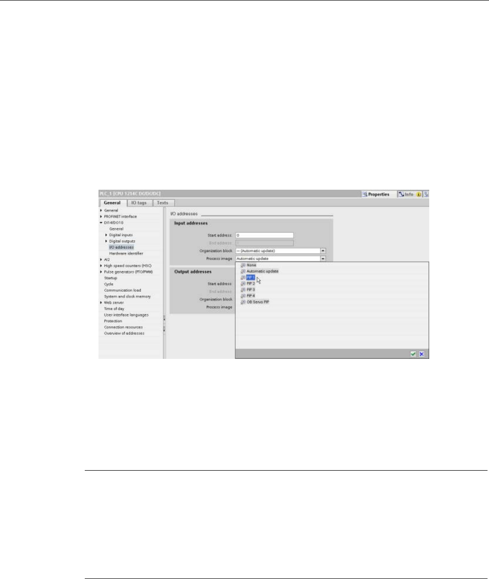
PLC concepts
5.1 Execution of the user program
S7-1200 Programmable controller
86 System Manual, V4.2, 09/2016, A5E02486680-AK
To assign digital or analog points to a process image partition, or to exclude I/O points from
process image updates, follow these steps:
1. View the Properties tab for the appropriate device in Device configuration.
2. Expand the selections under "General" as necessary to locate the desired I/O points.
3. Select "I/O addresses".
4. Optionally select a specific OB from the "Organization block" drop-down list.
5. From the "Process image" drop-down list, change "Automatic update" to "PIP1", "PIP2",
"PIP3", "PIP4" or "None". A selection of "None" means that you can only read from and
write to this I/O using immediate instructions. To add the points back to the process
image automatic update, change this selection back to "Automatic update".
You can immediately read physical input values and immediately write physical output
values when an instruction executes. An immediate read accesses the current state of the
physical input and does not update the process image input area, regardless of whether the
point is configured to be stored in the process image. An immediate write to the physical
output updates both the process image output area (if the point is configured to be stored in
the process image) and the physical output point. Append the suffix ":P" to the I/O address if
you want the program to immediately access I/O data directly from the physical point instead
of using the process image.
Note
Use of process image partitions
If you assign I/O to one of the process image partitions PIP1
- PIP4, and do not assign an
OB to that partition, then the CPU never updates th
at I/O to or from the process image.
Assigning I/O to a PIP that does not have a corresponding OB assignment, is the same as
assigning the process image to "None". You can read the I/O directly from the physical I/O
with an immediate read instruction, or w
rite to the physical I/O with an immediate write
instruction. The CPU does not update the process image.
The CPU supports distributed I/O for PROFINET, PROFIBUS, and AS-i networks
(Page 799).

PLC concepts
5.1 Execution of the user program
S7-1200 Programmable controller
System Manual, V4.2, 09/2016, A5E02486680-AK 87
5.1.1
Operating modes of the CPU
The CPU has three modes of operation: STOP mode, STARTUP mode, and RUN mode.
Status LEDs on the front of the CPU indicate the current mode of operation.
● In STOP mode, the CPU is not executing the program. You can download a project.
● In STARTUP mode, the startup OBs (if present) execute once. The CPU does not
process interrupt events during the startup mode.
● In RUN mode, the program cycle OBs execute repeatedly. Interrupt events can occur and
the corresponding interrupt event OBs can execute at any point within the RUN mode.
You can download some parts of a project in RUN mode (Page 1335).
The CPU supports a warm restart for entering the RUN mode. Warm restart does not include
a memory reset. The CPU initializes all non-retentive system and user data at warm restart,
and retains the values of all retentive user data.
A memory reset clears all work memory, clears retentive and non-retentive memory areas,
copies load memory to work memory, and sets outputs to the configured "Reaction to CPU
STOP". A memory reset does not clear the diagnostics buffer or the permanently saved
values of the IP address.
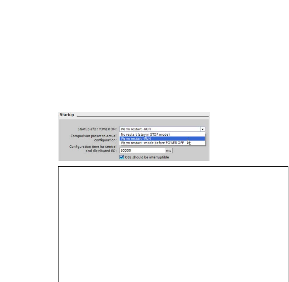
PLC concepts
5.1 Execution of the user program
S7-1200 Programmable controller
88 System Manual, V4.2, 09/2016, A5E02486680-AK
You can configure the "startup after POWER ON" setting of the CPU. This configuration item
appears under the "Device configuration" for the CPU under "Startup". Upon powering up,
the CPU performs a sequence of power-up diagnostic checks and system initialization.
During system initialization the CPU deletes all non-retentive bit (M) memory and resets all
non-retentive DB contents to the initial values from load memory. The CPU retains retentive
bit (M) memory and retentive DB contents and then enters the appropriate operating mode.
Certain detected errors prevent the CPU from entering the RUN mode. The CPU supports
the following configuration choices:
● No restart (stay in STOP mode)
● Warm restart - RUN
● Warm restart - mode prior to POWER OFF
NOTICE
Repairable faults can cause the CPU to enter STOP mode.
The CPU can enter STOP mode due to repairable faults, such as failure of a
replaceable signal module, or temporary faults, such as power line disturbance or erratic
power up event. Such conditions could result in property damage.
If you have configured the CPU to "Warm restart - mode prior to POWER OFF", the
CPU goes to the operating mode it was in prior to the loss of power or fault. If the CPU
was in STOP mode at the time of power loss or fault, the CPU goes to STOP mode on
power up and stays in STOP mode until it receives a command to go to RUN mode. If
the CPU was in RUN mode at the time of power loss or fault, the CPU goes to RUN
mode on the next power up providing it detects no errors that would inhibit a transition to
RUN mode.
Configure CPUs that are intended to operate independently of a STEP 7 connection to
"Warm restart - RUN" so that the CPU can return to RUN mode on the next power cycle.
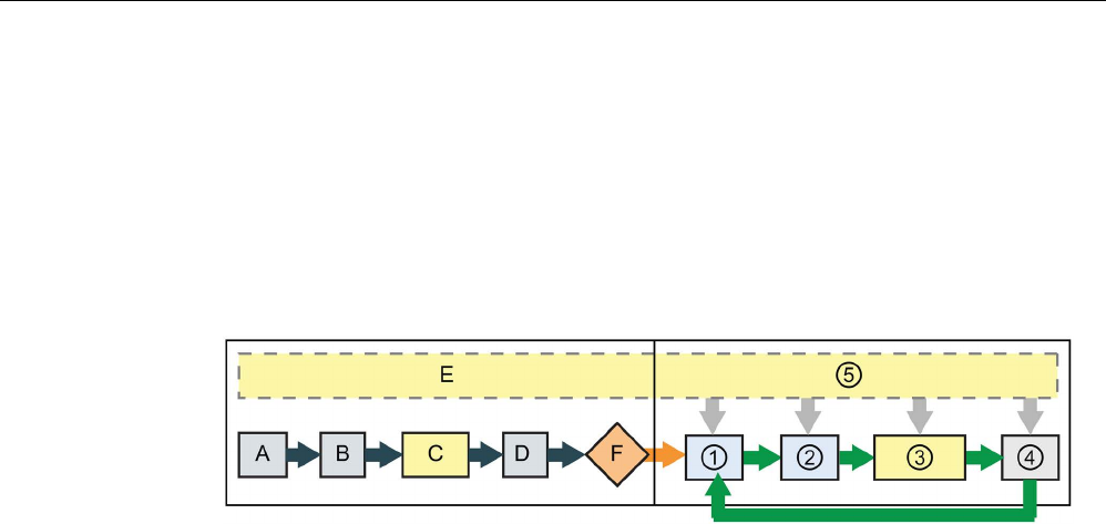
PLC concepts
5.1 Execution of the user program
S7-1200 Programmable controller
System Manual, V4.2, 09/2016, A5E02486680-AK 89
You can change the current operating mode using the "STOP" or "RUN" commands
(Page 1321) from the online tools of the programming software. You can also include a STP
instruction (Page 310) in your program to change the CPU to STOP mode. This allows you
to stop the execution of your program based on the program logic.
● In STOP mode, the CPU handles any communication requests (as appropriate) and
performs self-diagnostics. The CPU does not execute the user program, and the
automatic updates of the process image do not occur.
● In STARTUP and RUN modes, the CPU performs the tasks shown in the following figure:
STARTUP
RUN
A
Clears the I (image) memory area
①
Writes Q memory to the physical outputs
B Initializes the Q output (image)
memory area with either zero, the last
value, or the substitute value, as con-
figured, and zeroes PB, PN, and AS-i
outputs
②
Copies the state of the physical inputs to I
memory
C Initializes non-retentive M memory and
data blocks to their initial value and
enables configured cyclic interrupt and
time of day events.
Executes the startup OBs.
③
Executes the program cycle OBs
D Copies the state of the physical inputs
to I memory
④
Performs self-test diagnostics
E Stores any interrupt events into the
queue to be processed after entering
RUN mode
⑤
Processes interrupts and communications
during any part of the scan cycle
F Enables the writing of Q memory to the
physical outputs

PLC concepts
5.1 Execution of the user program
S7-1200 Programmable controller
90 System Manual, V4.2, 09/2016, A5E02486680-AK
STARTUP processing
Whenever the operating mode changes from STOP to RUN, the CPU clears the process
image inputs, initializes the process image outputs and processes the startup OBs. Any read
accesses to the process-image inputs by instructions in the startup OBs read zero rather
than the current physical input value. Therefore, to read the current state of a physical input
during the startup mode, you must perform an immediate read. The startup OBs and any
associated FCs and FBs are executed next. If more than one startup OB exists, each is
executed in order according to the OB number, with the lowest OB number executing first.
Each startup OB includes startup information that helps you determine the validity of
retentive data and the time-of-day clock. You can program instructions inside the startup
OBs to examine these startup values and to take appropriate action. The following startup
locations are supported by the Startup OBs:
Table 5- 1 Startup locations supported by the startup OB
Input
Data Type
Description
LostRetentive
Bool
This bit is true if the retentive data storage areas have been lost
LostRTC Bool This bit is true if the time-of-day clock (Real time Clock) has been
lost
The CPU also performs the following tasks during the startup processing:
● Interrupts are queued but not processed during the startup phase
● No cycle time monitoring is performed during the startup phase
● Configuration changes to HSC (high-speed counter), PWM (pulse-width modulation), and
PtP (point-to-point communication) modules can be made in startup
● Actual operation of HSC, PWM and point-to-point communication modules only occurs in
RUN
After the execution of the startup OBs finishes, the CPU goes to RUN mode and processes
the control tasks in a continuous scan cycle.

PLC concepts
5.1 Execution of the user program
S7-1200 Programmable controller
System Manual, V4.2, 09/2016, A5E02486680-AK 91
5.1.2
Processing the scan cycle in RUN mode
For each scan cycle, the CPU writes the outputs, reads the inputs, executes the user
program, updates communication modules, and responds to user interrupt events and
communication requests. Communication requests are handled periodically throughout the
scan.
These actions (except for user interrupt events) are serviced regularly and in sequential
order. User interrupt events that are enabled are serviced according to priority in the order in
which they occur. For interrupt events, the CPU reads the inputs, executes the OB, and then
writes the outputs, using the associated process image partition (PIP), if applicable.
The system guarantees that the scan cycle will be completed in a time period called the
maximum cycle time; otherwise a time error event is generated.
● Each scan cycle begins by retrieving the current values of the digital and analog outputs
from the process image and then writing them to the physical outputs of the CPU, SB,
and SM modules configured for automatic I/O update (default configuration). When a
physical output is accessed by an instruction, both the output process image and the
physical output itself are updated.
● The scan cycle continues by reading the current values of the digital and analog inputs
from the CPU, SB, and SMs configured for automatic I/O update (default configuration),
and then writing these values to the process image. When a physical input is accessed
by an instruction, the value of the physical input is accessed by the instruction, but the
input process image is not updated.
● After reading the inputs, the user program is executed from the first instruction through
the end instruction. This includes all the program cycle OBs plus all their associated FCs
and FBs. The program cycle OBs are executed in order according to the OB number with
the lowest OB number executing first.
Communications processing occurs periodically throughout the scan, possibly interrupting
user program execution.
Self-diagnostic checks include periodic checks of the system and the I/O module status
checks.
Interrupts can occur during any part of the scan cycle, and are event-driven. When an event
occurs, the CPU interrupts the scan cycle and calls the OB that was configured to process
that event. After the OB finishes processing the event, the CPU resumes execution of the
user program at the point of interruption.

PLC concepts
5.1 Execution of the user program
S7-1200 Programmable controller
92 System Manual, V4.2, 09/2016, A5E02486680-AK
5.1.3
Organization blocks (OBs)
OBs control the execution of the user program. Specific events in the CPU trigger the
execution of an organization block. OBs cannot call each other or be called from an FC or
FB. Only an event such as a diagnostic interrupt or a time interval can start the execution of
an OB. The CPU handles OBs according to their respective priority classes, with higher
priority OBs executing before lower priority OBs. The lowest priority class is 1 (for the main
program cycle), and the highest priority class is 26.
5.1.3.1
Program cycle OB
Program cycle OBs execute cyclically while the CPU is in RUN mode. The main block of the
program is a program cycle OB. This is where you place the instructions that control your
program and where you call additional user blocks. You can have multiple program cycle
OBs, which the CPU executes in numerical order. Main (OB 1) is the default.
Program cycle events
The program cycle event happens once during each program cycle (or scan). During the
program cycle, the CPU writes the outputs, reads the inputs and executes program cycle
OBs. The program cycle event is required and is always enabled. You might have no
program cycle OBs, or you might have multiple OBs selected for the program cycle event.
After the program cycle event occurs, the CPU executes the lowest numbered program cycle
OB (usually "Main" OB 1). The CPU executes the other program cycle OBs sequentially (in
numerical order) within the program cycle. Program execution is cyclical such that the
program cycle event occurs at the following times:
● When the last startup OB finishes execution
● When the last program cycle OB finishes execution
Table 5- 2 Start information for a program cycle OB
Input
Data type
Description
Initial_Call
Bool
True for initial call of the OB
Remanence
Bool
True if retentive data are available

PLC concepts
5.1 Execution of the user program
S7-1200 Programmable controller
System Manual, V4.2, 09/2016, A5E02486680-AK 93
5.1.3.2
Startup OB
Startup OBs execute one time when the operating mode of the CPU changes from STOP to
RUN, including powering up in the RUN mode and in commanded STOP-to-RUN transitions.
After completion, the main "Program cycle" begins executing.
Startup events
The startup event happens one time on a STOP to RUN transition and causes the CPU to
execute the startup OBs. You can configure multiple OBs for the startup event. The startup
OBs execute in numerical order.
Table 5- 3 Start information for a startup OB
Input
Data type
Description
LostRetentive
Bool
True if retentive data are lost
LostRTC
Bool
True if date and time are lost
5.1.3.3
Time delay interrupt OB
Time delay interrupt OBs execute after a time delay that you configure.
Time delay interrupt events
You configure time delay interrupt events to occur after a specified delay time has expired.
You assign the delay time with the SRT_DINT instruction. The time delay events interrupt the
program cycle to execute the corresponding time delay interrupt OB. You can attach only
one time delay interrupt OB to a time delay event. The CPU supports four time delay events.
Table 5- 4 Start information for a time delay interrupt OB
Input
Data type
Description
Sign
Word
Identifier passed to triggering call of SRT_DINT

PLC concepts
5.1 Execution of the user program
S7-1200 Programmable controller
94 System Manual, V4.2, 09/2016, A5E02486680-AK
5.1.3.4
Cyclic interrupt OB
Cyclic interrupt OBs execute at a specified interval. You can configure up to a total of four
cyclic interrupt events, with one OB corresponding to each cyclic interrupt event.
Cyclic interrupt events
The cyclic interrupt events allow you to configure the execution of an interrupt OB at a
configured cycle time. You configure the initial cycle time when you create the cyclic interrupt
OB. A cyclic event interrupts the program cycle and executes the corresponding cyclic
interrupt OB. Note that the cyclic interrupt event is at a higher priority class than the program
cycle event.
You can attach only one cyclic interrupt OB to a cyclic event.
You can assign a phase shift to each cyclic interrupt so that the execution of cyclic interrupts
can be offset from one another by the phase offset amount. For example, if you have a 5 ms
cyclic event and a 10 ms cyclic event, every ten milliseconds both events occur at the same
moment. If you phase shift the 5 ms event by 1 to 4 ms and the 10 ms event by 0 ms, then
the two events do not occur at the same moment.
The default phase offset is 0. To change the initial phase shift, or to change the cyclic time
for a cyclic event, follow these steps:
1. Right-click the cyclic interrupt OB in the project tree.
2. Select "Properties" from the context menu.
3. Click "Cyclic interrupt" from the "Cyclic interrupt [OB 30]" dialog, and enter the new initial
values.
The maximum phase offset is 6000 ms (6 seconds) or the maximum Cyclic time, whichever
is smaller.
You can also query and change the scan time and the phase shift from your program using
the Query cyclic interrupt (QRY_CINT) and Set cyclic interrupt (SET_CINT) instructions.
Scan time and phase shift values set by the SET_CINT instruction do not persist through a
power cycle or a transition to STOP mode; scan time and phase shift values return to the
initial values following a power cycle or a transition to STOP. The CPU supports a total of
four cyclic interrupt events.

PLC concepts
5.1 Execution of the user program
S7-1200 Programmable controller
System Manual, V4.2, 09/2016, A5E02486680-AK 95
5.1.3.5
Hardware interrupt OB
Hardware interrupt OBs execute when the relevant hardware event occurs. A hardware
interrupt OB interrupts normal cyclic program execution in reaction to a signal from a
hardware event.
Hardware interrupt events
Changes in the hardware, such as a rising or falling edge on an input point, or an HSC (High
Speed Counter) event trigger hardware interrupt events. The S7-1200 supports one interrupt
OB for each hardware interrupt event. You enable the hardware events in the device
configuration, and assign an OB for an event in the device configuration or with an ATTACH
instruction in the user program. The CPU supports several hardware interrupt events. The
CPU model and the number of input points determine the exact events that are available.
Limits on hardware interrupt events are as follows:
Edges:
● Rising edge events: maximum of 16
● Falling edge events: maximum of 16
HSC events:
● CV=PV: maximum of 6
● Direction changed: maximum of 6
● External reset: maximum of 6
Table 5- 5 Start information for a hardware interrupt OB
Input
Data type
Description
LADDR HW_IO Hardware identifier of the module that triggered the hardware inter-
rupt
USI WORD User structure identifier (16#0001 to 16#FFFF), reserved for future
use
IChannel
USINT
Number of the channel that triggered the interrupt
EventType BYTE Identifier for the module-specific event type associated with the
event triggering the interrupt, for example falling edge or rising
edge.
The bits in EventType depend on the triggering module as shown below:
Module / Sub-
module
Value
Process event
Onboard I/O
from
CPU or SB
16#0
Rising edge
16#1 Falling edge
HSC
16#0
HSC CV=RV1
16#1
HSC direction changed
16#2
HSC reset
16#3
HSC CV=RV2

PLC concepts
5.1 Execution of the user program
S7-1200 Programmable controller
96 System Manual, V4.2, 09/2016, A5E02486680-AK
5.1.3.6
Time error interrupt OB
If configured, the time error interrupt OB (OB 80) executes when either the scan cycle
exceeds the maximum cycle time or a time error event occurs. If triggered, it executes,
interrupting normal cyclic program execution or any other event OB.
The occurrence of either of these events generates a diagnostic buffer entry describing the
event. The diagnostic buffer entry is generated regardless of the existence of the time error
interrupt OB.
Time error interrupt events
The occurrence of any of several different time error conditions results in a time error event:
● Scan cycle exceeds maximum cycle time
The "maximum cycle time exceeded" condition results if the program cycle does not
complete within the specified maximum scan cycle time. See the section on "Monitoring
the cycle time in the S7-1200 System Manual" (Page 109) for more information regarding
the maximum cycle time condition, how to configure the maximum scan cycle time in the
properties of the CPU, and how to reset the cycle timer.
● CPU cannot start requested OB because a second time interrupt (cyclic or time-delay)
starts before the CPU finishes execution of the first interrupt OB
● Queue overflow occurred
The "queue overflow occurred" condition results if the interrupts are occurring faster than
the CPU can process them. The CPU limits the number of pending (queued) events by
using a different queue for each event type. If an event occurs when the corresponding
queue is full, the CPU generates a time error event.
All time error events trigger the execution of the time error interrupt OB if it exists. If the time
error interrupt OB does not exist, then the device configuration of the CPU determines the
CPU reaction to the time error:
● The default configuration for time errors, such as starting a second cyclic interrupt before
the CPU has finished the execution of the first, is for the CPU to stay in RUN.
● The default configuration for exceeding the maximum time is for the CPU to change to
STOP.
The user program can extend the program cycle execution time up to ten times the
configured maximum cycle time by executing the RE_TRIGR instruction (Page 309) to
restart the cycle time monitor. However, if two "maximum cycle time exceeded" conditions
occur within the same program cycle without resetting the cycle timer, then the CPU
transitions to STOP, regardless of whether the time error interrupt OB exists. See the section
on "Monitoring the cycle time in the S7-1200 System Manual" (Page 109).

PLC concepts
5.1 Execution of the user program
S7-1200 Programmable controller
System Manual, V4.2, 09/2016, A5E02486680-AK 97
Time error interrupt OB includes start information that helps you determine which event and
OB generated the time error. You can program instructions inside the OB to examine these
start values and to take appropriate action.
Table 5- 6 Start information for the time error OB (OB 80)
Input
Data type
Description
fault_id BYTE 16#01 - maximum cycle time exceeded
16#02 - requested OB cannot be started
16#07 and 16#09 - queue overflow occurred
csg_OBnr OB_ANY Number of the OB which was being executed when the error oc-
curred
csg_prio
UINT
Priority of the OB causing the error
To include a time error interrupt OB in your project, you must add a time error interrupt by
double-clicking "Add new block" under "Program blocks" in the tree, then choose
"Organization block", and then "Time error interrupt".
The priority for a new V4.0 CPU is 22. If you exchange a V3.0 CPU for a V4.0 CPU
(Page 1571), the priority is 26, the priority that was in effect for V3.0. In either case, the
priority field is editable and you can set the priority to any value in the range 22 to 26.
5.1.3.7
Diagnostic error interrupt OB
The diagnostic error interrupt OB executes when the CPU detects a diagnostic error, or if a
diagnostics-capable module recognizes an error and you have enabled the diagnostic error
interrupt for the module. The diagnostic error interrupt OB interrupts the normal cyclic
program execution. You can include an STP instruction in the diagnostic error interrupt OB to
put the CPU in STOP mode if you desire your CPU to enter STOP mode upon receiving this
type of error.
If you do not include a diagnostic error interrupt OB in your program, the CPU ignores the
error and stays in RUN mode.
Diagnostic error events
Analog (local), PROFINET, PROFIBUS, and some digital (local) devices are capable of
detecting and reporting diagnostic errors. The occurrence or removal of any of several
different diagnostic error conditions results in a diagnostic error event. The following
diagnostic errors are supported:
● No user power
● High limit exceeded
● Low limit exceeded
● Wire break
● Short circuit
Diagnostic error events trigger the execution of the diagnostic error interrupt OB (OB 82) if it
exists. If it does not exist, then the CPU ignores the error.

PLC concepts
5.1 Execution of the user program
S7-1200 Programmable controller
98 System Manual, V4.2, 09/2016, A5E02486680-AK
To include a diagnostic error interrupt OB in your project, you must add a diagnostic error
interrupt by double-clicking "Add new block" under "Program blocks" in the tree, then choose
"Organization block", and then "Diagnostic error interrupt".
Note
Diagnostic errors for multi-channel local analog devices (I/O, RTD, and Thermocouple)
The diagnostic error interrupt OB can process only one channel's diagnostic
error at a time.
If two channels of a multi
-channel device have an error, then the second error only triggers
the diagnostic error interrupt OB under the following conditions: the first channel error clears,
the execution of the diagnostic error interrupt
OB that the first error triggered is complete,
and the second error still exists.
The diagnostic error interrupt OB includes startup information that helps you determine
whether the event is due to the occurrence or removal of an error, and the device and
channel which reported the error. You can program instructions inside the diagnostic error
interrupt OB to examine these startup values and to take appropriate action.
Note
Diagnostic error OB Start information references the submodule as a whole if no diagnostic
event is pending
In V3.0, the start information for an outgoing diagnostic error event always indicated the
source of the event. In V4.0, if the outgoing event leaves the submodule with no pending
diagnostics, the start information references the submodule as a whole (16#8000) even if the
source of the event was a specific channel.
For example, if a wire break triggers a diagnostic error event on channel 2, the fault is then
corrected, and the diagnostic error event is cleared, the Start info
rmation will not reference
channel 2, but the submodule (16#8000).

PLC concepts
5.1 Execution of the user program
S7-1200 Programmable controller
System Manual, V4.2, 09/2016, A5E02486680-AK 99
Table 5- 7 Startup information for the diagnostic error interrupt OB
Input
Data type
Description
IOstate WORD IO state of the device:
• Bit 0 = 1 if the configuration is correct, and = 0 if the configura-
tion is no longer correct.
• Bit 4 = 1 if an error is present (such as a wire break). (Bit 4 = 0 if
there is no error.)
• Bit 5 = 1 if the configuration is
not
correct, and = 0 if the configu-
ration is correct again.
•
Bit 7 = 1 if an I/O access error has occurred. Refer to LADDR for
the hardware identifier of the I/O with the access error. (Bit 6 = 0
if there is no error.)
LADDR HW_ANY Hardware identifier of the device or functional unit that reported the
error
1
Channel
UINT
Channel number
MultiError BOOL TRUE if more than one error is present
1
The LADDR input contains the hardware identifier of the device or functional unit which returned
the error. The hardware identifier is assigned automatically when components are inserted in the
device or network view and appears in the Constants tab of PLC tags. A name is also assigned
automatically for the hardware identifier. These entries in the Constants tab of the PLC tags can-
not be changed.

PLC concepts
5.1 Execution of the user program
S7-1200 Programmable controller
100 System Manual, V4.2, 09/2016, A5E02486680-AK
5.1.3.8
Pull or plug of modules OB
The "Pull or plug of modules" OB executes when a configured and non-disabled distributed
I/O module or submodule (PROFIBUS, PROFINET, AS-i) generates an event related to
inserting or removing a module.
Pull or plug of modules event
The following conditions generate a pull of plug of modules event:
● Someone removes or inserts a configured module
● A configured module is not physically present in an expansion rack
● An incompatible module is in an expansion rack that does not correspond to the
configured module
● A compatible module for a configured module is in an expansion rack, but the
configuration does not allow substitutes
● A module or submodule has parameterization errors
If you have not programmed this OB, the CPU remains in RUN mode when any of these
conditions occur with a configured and non-disabled distributed I/O module.
Regardless of whether you have programmed this OB, the CPU changes to STOP mode
when any of these conditions occur with a module in the central rack.
Table 5- 8 Start information for pull or plug of modules OB
Input
Data type
Description
LADDR
HW_IO
Hardware identifier
Event_Class Byte 16#38: module inserted
16#29: module removed
Fault_ID
Byte
Fault identifier

PLC concepts
5.1 Execution of the user program
S7-1200 Programmable controller
System Manual, V4.2, 09/2016, A5E02486680-AK 101
5.1.3.9
Rack or station failure OB
The "Rack or station failure" OB executes when the CPU detects the failure or
communication loss of a distributed rack or station.
Rack or station failure event
The CPU generates a rack or station failure event when it detects one of the following:
● The failure of a DP master system or of a PROFINET IO system (in the case of either an
incoming or an outgoing event).
● The failure of a DP slave or of an IO device (in the case of either an incoming or an
outgoing event)
● Failure of some of the submodules of a PROFINET I-device
If you have not programmed this OB, the CPU remains in RUN mode when any of these
conditions occur.
Table 5- 9 Start information for rack or station failure OB
Input
Data type
Description
LADDR
HW_IO
Hardware identifier
Event_Class Byte 16#32: Activation of a DP slave or an IO device
16#33: Deactivation of a DP slave or an IO device
16#38: outgoing event
16#39: incoming event
Fault_ID
Byte
Fault identifier

PLC concepts
5.1 Execution of the user program
S7-1200 Programmable controller
102 System Manual, V4.2, 09/2016, A5E02486680-AK
5.1.3.10
Time of day OB
Time of day OBs execute based on configured clock time conditions. The CPU supports two
time of day OBs.
Time of day events
You can configure a time of day interrupt event to occur once on a specified date or time or
cyclically with one of the following cycles:
● Every minute: The interrupt occurs every minute.
● Hourly: The interrupt occurs every hour.
● Daily: The interrupt occurs every day at a specified time (hour and minute).
● Weekly: The interrupt occurs every week at a specified time on a specified day of the
week (for example, every Tuesday at 4:30 in the afternoon).
● Monthly: The interrupt occurs every month at a specified time on a specified day of the
month. The day number must be between 1 and 28, inclusive.
● Every end of month: The interrupt occurs on the last day of every month at a specified
time.
● Yearly: The interrupt occurs every year on the specified date (month and day). You
cannot specify a date of February 29.
Table 5- 10 Start information for a time of day event OB
Input
Data type
Description
CaughtUp
Bool
OB call is caught up because time was set forward
SecondTimes
Bool
OB call is started a second time because time was set backward
5.1.3.11
Status OB
Status OBs execute if a DPV1 or PNIO slave triggers a status interrupt. This might be the
case if a component (module or rack) of a DPV1 or PNIO slave changes its operating mode,
for example from RUN to STOP.
Status events
For detailed information on events that trigger a status interrupt, refer to the manufacturer's
documentation for the DPV1 or PNIO slave.
Table 5- 11 Start information for status OB
Input
Data type
Description
LADDR
HW_IO
Hardware identifier
Slot
UInt
Slot number
Specifier
Word
Alarm specifier

PLC concepts
5.1 Execution of the user program
S7-1200 Programmable controller
System Manual, V4.2, 09/2016, A5E02486680-AK 103
5.1.3.12
Update OB
Update OBs
execute if a DPV1 or PNIO slave triggers an update interrupt.
Update events
For detailed information on events that trigger an update interrupt, refer to the manufacturer's
documentation for the DPV1 or PNIO slave.
Table 5- 12 Start information for update OB
Input
Data type
Description
LADDR
HW_IO
Hardware identifier
Slot
UInt
Slot number
Specifier
Word
Alarm specifier
5.1.3.13
Profile OB
Profile OBs execute if a DPV1 or PNIO slave triggers a profile-specific interrupt.
Profile events
For detailed information on events that trigger a profile interrupt, refer to the manufacturer's
documentation for the DPV1 or PNIO slave.
Table 5- 13 Start information for profile OB
Input
Data type
Description
LADDR HW_IO Hardware identifier
Slot
UInt
Slot number
Specifier
Word
Alarm specifier
5.1.3.14
MC-Servo and MC-Interpolator OB
STEP 7 creates the read-only MC-Servo and MC-Interpolator OBs automatically when you
create a motion technology object and set the drive interface to be "Analog drive connection"
or "PROFIDrive". You do not need to edit any OB properties or create this OB directly. The
CPU uses these OBs for closed loop control. Refer to the STEP 7 Information System for
further details.

PLC concepts
5.1 Execution of the user program
S7-1200 Programmable controller
104 System Manual, V4.2, 09/2016, A5E02486680-AK
5.1.3.15
MC-PreServo
You can program the MC-PreServo OB to contain program logic for the STEP 7 program to
execute directly before the MC-Servo OB executes.
MC-PreServo events
The MC-PreServo OB allows you to read out the configured application cycle information in
microseconds.
Table 5- 14 Start information for MC-PreServo OB
Input
Data type
Description
Initial_Call
BOOL
TRUE indicates first call of this OB on transition from STOP to RUN
PIP_Input
BOOL
TRUE indicates the associated process image input is up to date.
PIP_Output BOOL TRUE indicates that the CPU transferred the associated process
image output to the outpus in good time after the last cycle.
IO_System
USINT
Number of the distributed I/O system triggering the interrupt
Event_Count INT n: number of lost cycles
-1: unknown number of cycles lost (for example, because cycle has
changed)
Synchronous
BOOL
Reserved
CycleTime UDINT Display of the application cycle configured for the MC-Servo OB in
microseconds

PLC concepts
5.1 Execution of the user program
S7-1200 Programmable controller
System Manual, V4.2, 09/2016, A5E02486680-AK 105
5.1.3.16
MC-PostServo
You can program the MC-PreServo OB to contain program logic for the STEP 7 program to
execute directly after the MC-Servo OB executes.
MC-PostServo events
The MC-PreServo OB allows you to read out the configured application cycle information in
microseconds.
Table 5- 15 Start information for MC-PostServo OB
Input
Data type
Description
Initial_Call
BOOL
TRUE indicates first call of this OB on transition from STOP to RUN
PIP_Input
BOOL
TRUE indicates the associated process image input is up to date.
PIP_Output BOOL TRUE indicates that the CPU transferred the associated process
image output to the outpus in good time after the last cycle.
IO_System
USINT
Number of the distributed I/O system triggering the interrupt
Event_Count INT n: number of lost cycles
-1: unknown number of cycles lost (for example, because cycle has
changed)
Synchronous
BOOL
Reserved
CycleTime UDINT Display of the application cycle configured for the MC-Servo OB in
microseconds
5.1.3.17
Event execution priorities and queuing
The CPU processing is controlled by events. An event triggers an interrupt OB to be
executed. You can specify the interrupt OB for an event during the creation of the block,
during the device configuration, or with an ATTACH or DETACH instruction. Some events
happen on a regular basis like the program cycle or cyclic events. Other events happen only
a single time, like the startup event and time delay events. Some events happen when the
hardware triggers an event, such as an edge event on an input point or a high speed counter
event. Events like the diagnostic error and time error event only happen when an error
occurs. The event priorities and queues are used to determine the processing order for the
event interrupt OBs.
The CPU processes events in order of priority where 1 is the lowest priority and 26 is the
highest priority. Prior to V4.0 of the S7-1200 CPU, each type of OB belonged to a fixed
priority class (1 to 26). From V4.0 forward, you can assign a priority class to each OB that
you configure. You configure the priority number in the attributes of the OB properties.
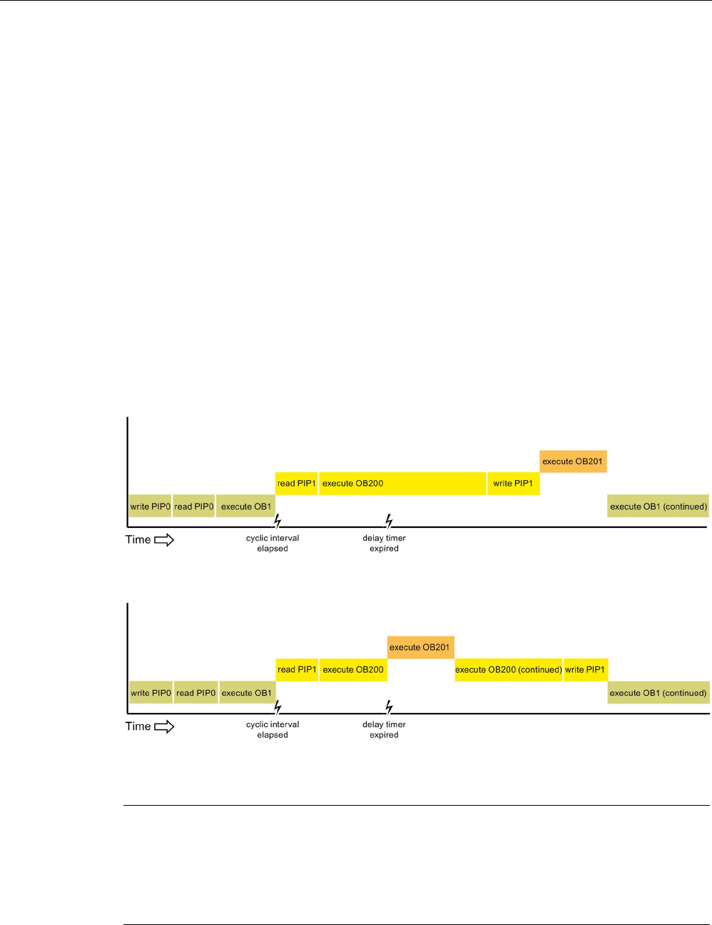
PLC concepts
5.1 Execution of the user program
S7-1200 Programmable controller
106 System Manual, V4.2, 09/2016, A5E02486680-AK
Interruptible and non-interruptible execution modes
OBs (Page 92) execute in priority order of the events that trigger them. In the Startup
properties of the device configuration of the CPU (Page 170), you can configure OB
execution to be interruptible or non-interruptible. Note that program cycle OBs are always
interruptible, but you can configure all other OBs to be either interruptible or non-
interruptible.
If you set interruptible mode, then if an OB is executing and a higher priority event occurs
before the OB completes its execution, the running OB is interrupted to allow the higher-
priority event OB to run. The higher-priority event runs, and at its completion, the OB that
was interrupted continues. When multiple events occur while an interruptible OB is
executing, the CPU processes those events in priority order.
If you do not set interruptible mode, then an OB runs to completion when triggered
regardless of any other events that trigger during the time that it is running.
Consider the following two cases where interrupt events trigger a cyclic OB and a time delay
OB. In both cases, the time delay OB (OB201) has no process image partition assignment
(Page 83) and executes at priority 4. The cyclic OB (OB200) has a process image partition
assignment of PIP1 and executes at priority 2. The following illustrations show the difference
in execution between non-interruptible and interruptible execution modes:
Figure 5-1 Case 1: Non-interruptible OB execution
Figure 5-2 Case 2: Interruptible OB execution
Note
If you configure the OB execution mode to be non
-interruptible, then a time error OB cannot
interrupt OBs other than program cycle OBs. Prior to V4.0 of the S7
-1200 CPU, a time error
OB could interrupt any executing OB. From V4.0
forward, you must configure OB execution
to be interruptible if you want a time error OB (or any other higher priority OB) to be able to
interrupt executing OBs that are not program cycle OBs.
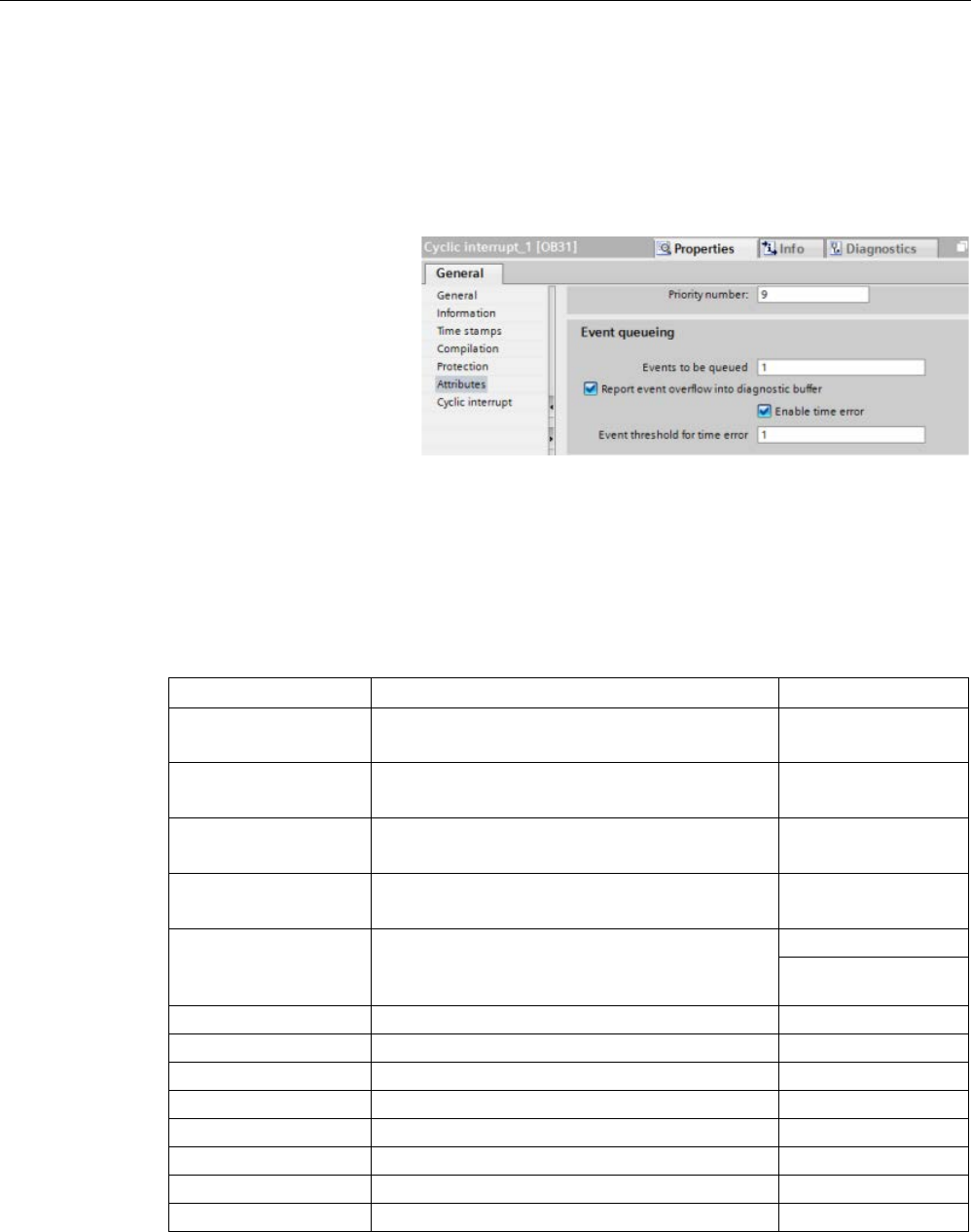
PLC concepts
5.1 Execution of the user program
S7-1200 Programmable controller
System Manual, V4.2, 09/2016, A5E02486680-AK 107
Understanding event execution priorities and queuing
The CPU limits the number of pending (queued) events from a single source, using a
different queue for each event type. Upon reaching the limit of pending events for a given
event type, the next event is lost. You can use a time error interrupt OB (Page 96) to
respond to queue overflows.
Note that STEP
7 allows you
to configure some specific
event queueing parameters
for the Cycl
ic interrupt OB
and the Time of day OB.
For further information on CPU overload behavior and event queueing, refer to the STEP 7
Information System.
Each CPU event has an associated priority. In general, the CPU services events in order of
priority (highest priority first). The CPU services events of the same priority on a "first-come,
first-served" basis.
Table 5- 16 OB events
Event
Quantity allowed
Default OB priority
Program cycle 1 program cycle event
Multiple OBs allowed
14
Startup 1 startup event 1
Multiple OBs allowed
14
Time delay Up to 4 time events
1 OB per event
3
Cyclic interrupt Up to 4 events
1 OB per event
8
Hardware interrupt Up to 50 hardware interrupt events2
1 OB per event, but you can use the same OB for
multiple events
18
18
Time error
1 event (only if configured)
3
22 or 26
4
Diagnostic error
1 event (only if configured)
5
Pull or plug of modules
1 event
6
Rack or station failure
1 event
6
Time of day
Up to 2 events
2
Status
1 event
4
Update
1 event
4
Profile
1 event
4

PLC concepts
5.1 Execution of the user program
S7-1200 Programmable controller
108 System Manual, V4.2, 09/2016, A5E02486680-AK
Event
Quantity allowed
Default OB priority
MC-Servo
1 event
25
MC-Interpolator 1 event 24
1
The startup event and the program cycle event never occur at the same time because the startup
event runs to completion before the program cycle event starts.
2
You can have more than 50 hardware interrupt event OBs if you use the DETACH and ATTACH
instructions.
3
You can configure the CPU to stay in RUN if the scan cycle exceeds the maximum scan cycle time
or you can use the RE_TRIGR instruction to reset the cycle time. However, the CPU goes to
STOP mode the second time that one scan cycle exceeds the maximum scan cycle time.
4
The priority for a new V4.0 or V4.1 CPU is 22. If you exchange a V3.0 CPU for a V4.0 or V4.1
CPU, the priority is 26: the priority that was in effect for V3.0. In either case, the priority field is ed-
itable and you can set the priority to any value in the range 22 to 26.
Refer to the topic "Exchanging a V3.0 CPU for a V4.1 CPU (Page 1571)" for more details.
In addition, the CPU recognizes other events that do not have associated OBs. The following
table describes these events and the corresponding CPU actions:
Table 5- 17 Additional events
Event
Description
CPU action
I/O access error Direct I/O read/write error The CPU logs the first occurrence in the
diagnostic buffer and stays in RUN mode.
You can access the error cause using the
GET_ERROR_ID (Page 311) instruction.
Max cycle time error CPU exceeds the configured
cycle time twice
The CPU logs the error in the diagnostic
buffer and transitions to STOP mode.
Peripheral access error I/O error during process im-
age update
The CPU logs the first occurrence in the
diagnostic buffer and stays in RUN mode.
Programming error program execution error • If block-local error handling is enabled,
the system enters an error cause in the
error structure. You can access the er-
ror cause using the GET_ERROR_ID
(Page 311) instruction.
• If global error handling is enabled, the
system enters an access error start
event into the diagnostic buffer and
stays in RUN mode.
Interrupt latency
The interrupt event latency (the time from notification of the CPU that an event has occurred
until the CPU begins execution of the first instruction in the OB that services the event) is
approximately 175 µsec, provided that a program cycle OB is the only event service routine
active at the time of the interrupt event.

PLC concepts
5.1 Execution of the user program
S7-1200 Programmable controller
System Manual, V4.2, 09/2016, A5E02486680-AK 109
5.1.4
Monitoring and configuring the cycle time
The cycle time is the time that the CPU operating system requires to execute the cyclic
phase of the RUN mode. The CPU provides two methods of monitoring the cycle time:
● Maximum scan cycle time
● Minimum scan cycle time
Scan cycle monitoring begins after the startup event is complete. Configuration for this
feature appears under the "Device Configuration" for the CPU under "Cycle time".
The CPU always monitors the scan cycle and reacts if the maximum scan cycle time is
exceeded. If the configured maximum scan cycle time is exceeded, an error is generated
and is handled one of two ways:
● If the user program does not include a time error interrupt OB, then the timer error event
generates a diagnostic buffer entry, but the CPU remains in RUN mode. (You can change
the configuration of the CPU to go to STOP mode when it detects a time error, but the
default configuration is to remain in RUN mode.)
● If the user program includes a time error interrupt OB, then the CPU executes it.
The RE_TRIGR instruction (Page 309) (re-trigger cycle time monitoring) allows you to reset
the timer that measures the cycle time. If the elapsed time for the current program cycle
execution is less than ten times the configured maximum scan cycle time, the RE_TRIGR
instruction retriggers the cycle time monitoring and returns with ENO = TRUE. If not, the
RE_TRIGR instruction does not retrigger the cycle time monitoring. It returns ENO = FALSE.
Typically, the scan cycle executes as fast as it can be executed and the next scan cycle
begins as soon as the current one completes. Depending upon the user program and
communication tasks, the time period for a scan cycle can vary from scan to scan. To
eliminate this variation, the CPU supports an optional minimum scan cycle time. If you
enable this optional feature and provide a minimum scan cycle time in ms, then the CPU
delays after the execution of the program cycle OBs until the minimum scan cycle time
elapses before repeating the program cycle.
In the event that the CPU completes the normal scan cycle in less time than the specified
minimum cycle time, the CPU spends the additional time of the scan cycle performing
runtime diagnostics and/or processing communication requests.
In the event that the CPU does not complete the scan cycle in the specified minimum cycle
time, the CPU completes the scan normally (including communication processing) and does
not create any system reaction as a result of exceeding the minimum scan time. The
following table defines the ranges and defaults for the cycle time monitoring functions:
Table 5- 18 Range for the cycle time
Cycle time
Range (ms)
Default
Maximum scan cycle time
1
1 to 6000
150 ms
Minimum scan cycle time2 1 to maximum scan cycle time Disabled
1
The maximum scan cycle time is always enabled. Configure a cycle time between 1 ms to 6000
ms. The default is 150 ms.
2
The minimum scan cycle time is optional, and is disabled by default. If required, configure a cycle
time between 1 ms and the maximum scan cycle time.
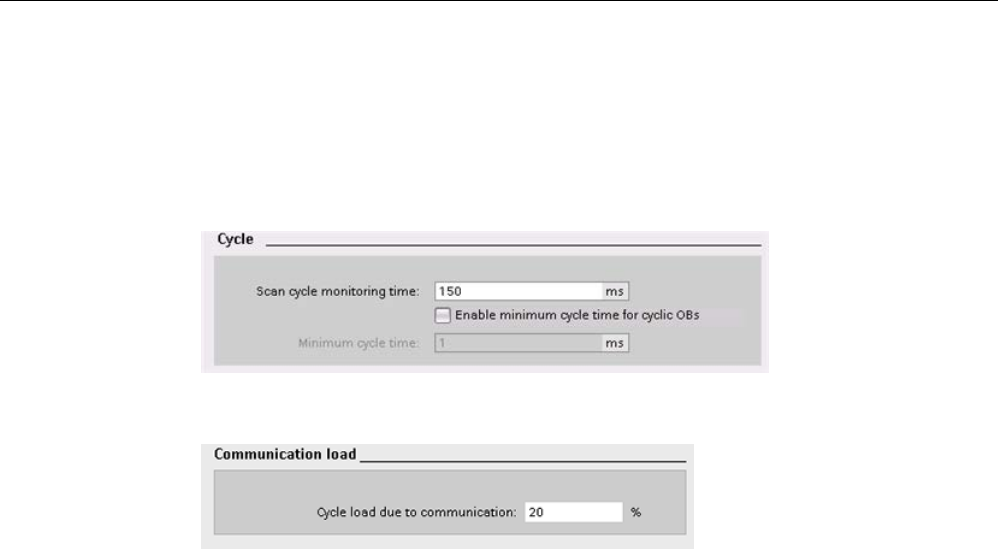
PLC concepts
5.1 Execution of the user program
S7-1200 Programmable controller
110 System Manual, V4.2, 09/2016, A5E02486680-AK
Configuring the cycle time and communication load
You use the CPU properties in the Device configuration to configure the following
parameters:
● Cycle: You can enter a maximum scan cycle monitoring time. You can also enable and
enter a minimum scan cycle time.
● Communication load: You can configure a percentage of the time to be dedicated for
communication tasks.
For more information about the scan cycle, see "Monitoring the cycle time". (Page 109)
5.1.5
CPU memory
Memory management
The CPU provides the following memory areas to store the user program, data, and
configuration:
● Load memory is non-volatile storage for the user program, data and configuration. When
you download a project to the CPU, the CPU first stores the program in the Load memory
area. This area is located either in a memory card (if present) or in the CPU. The CPU
maintains this non-volatile memory area through a power loss. The memory card
supports a larger storage space than that built-in to the CPU.
● Work memory is volatile storage for some elements of the user project while executing
the user program. The CPU copies some elements of the project from load memory into
work memory. This volatile area is lost when power is removed, and is restored by the
CPU when power is restored.
● Retentive memory is non-volatile storage for a limited quantity of work memory values.
The CPU uses the retentive memory area to store the values of selected user memory
locations during power loss. When a power down or power loss occurs, the CPU restores
these retentive values upon power up.
To display the memory usage for a compiled program block, right-click the block in the
"Program blocks" folder in the STEP 7 project tree and select "Resources" from the context
menu. The Compiliation properties display the load memory and work memory for the
compiled block.
To display the memory usage for the online CPU, double-click "Online and diagnostics" in
STEP 7, expand "Diagnostics", and select "Memory".

PLC concepts
5.1 Execution of the user program
S7-1200 Programmable controller
System Manual, V4.2, 09/2016, A5E02486680-AK 111
Retentive memory
You can avoid data loss after power failure by marking certain data as retentive. The CPU
allows you to configure the following data as retentive:
● Bit memory (M): You can define the size of retentive memory for bit memory in the PLC
tag table or in the assignment list. Retentive bit memory always starts at MB0 and runs
consecutively up through a specified number of bytes. Specify this value from the PLC
tag table or in the assignment list by clicking the "Retain" toolbar icon. Enter the number
of M bytes to retain starting at MB0.
Note: For any block, you can display the assignment list by selecting a block in the
Program Blocks folder and then selecting he
Tools > Assignment list
menu command.
● Tags of a function block (FB): If an FB is of type "Optimized block access", then the
interface editor for this FB includes a "Retain" column. In this column, you can select
either "Retain", "Non-retain", or "Set in IDB" individually for each tag. When you place
such an FB in the program, the instance DB that corresponds to the FB includes this
"Retain" column as well. You can only change the retentive state of a tag from within the
instance DB interface editor if you selected "Set in IDB" (Set in instance data block) in the
Retain selection for the tag in the optimized FB.
If an FB is
not
of type "Optimized block access", then the interface editor for this FB does
not include a "Retain" column. When you place such an FB in the program, the instance
DB that corresponds to the FB does, however, include a "Retain" column that is available
for edit. In this case, selecting the "Retain" option for any tag results in the selection of
all
tags. Similarly, deselecting the option for any tag results in the deselection of
all
tags.
To view or modify whether an FB is optimized, open the properties of the FB and select
the attributes.
● Tags of a global data block: The behavior of a global DB with regard to retentive state
assignment is similar to that of an FB. Depending on the block access setting you can
define the retentive state either for individual tags or for all tags of a global data block.
– If you select "Optimized" when you create the DB, you can set the retentive state for
each individual tag.
– If you select "Standard - compatible with S7-300/400" when you create the DB, the
retentive-state setting applies to all tags of the DB; either all tags are retentive or no
tag is retentive.
The CPU supports a total of 10240 bytes of retentive data. To see how much is available,
from the PLC tag table or the assignment list, click the "Retain" toolbar icon. Although this is
where the retentive range is specified for M memory, the second row indicates the total
remaining memory available for M and DB combined. Note that for this value to be accurate,
you must compile all data blocks with retentive tags.
Note
Downloading a program does not clear or make any changes to existing values in retentive
memory. If you want to clear retentive memory before a download, then reset your CPU
to
factory settings prior to downloading the program.

PLC concepts
5.1 Execution of the user program
S7-1200 Programmable controller
112 System Manual, V4.2, 09/2016, A5E02486680-AK
5.1.5.1
System and clock memory
You use the CPU properties to enable bytes for "system memory" and "clock memory". Your
program logic can reference the individual bits of these functions by their tag names.
● You can assign one byte in M memory for system memory. The byte of system memory
provides the following four bits that can be referenced by your user program by the
following tag names:
– First cycle: (Tag name "FirstScan") bit is set to1 for the duration of the first scan after
the startup OB finishes. (After the execution of the first scan, the "first scan" bit is set
to 0.)
– Diagnostics status changed: (Tag name: "DiagStatusUpdate") is set to 1 for one scan
after the CPU logs a diagnostic event. Because the CPU does not set the
"DiagStatusUpdate" bit until the end of the first execution of the program cycle OBs,
your user program cannot detect if there has been a diagnostic change either during
the execution of the startup OBs or the first execution of the program cycle OBs.
– Always 1 (high): (Tag name "AlwaysTRUE") bit is always set to 1.
– Always 0 (low): (Tag name "AlwaysFALSE") bit is always set to 0.
● You can assign one byte in M memory for clock memory. Each bit of the byte configured
as clock memory generates a square wave pulse. The byte of clock memory provides 8
different frequencies, from 0.5 Hz (slow) to 10 Hz (fast). You can use these bits as control
bits, especially when combined with edge instructions, to trigger actions in the user
program on a cyclic basis.
The CPU initializes these bytes on the transition from STOP mode to STARTUP mode. The
bits of the clock memory change synchronously to the CPU clock throughout the STARTUP
and RUN modes.
CAUTION
Risks with overwriting the system memory or clock memory bits
Overwriting the system memory or clock memory bits can corrupt the data in these
functions and cause your user program to operate incorrectly, which can cause damage to
equipment and injury to personnel.
Because both the clock memory and system memory are unreserved in M memory,
instructions or communications can write to these locations and corrupt the data.
Avoid writing data to these locations to ensure the proper operation of these functions, and
always implement an emergency stop circuit for your process or machine.
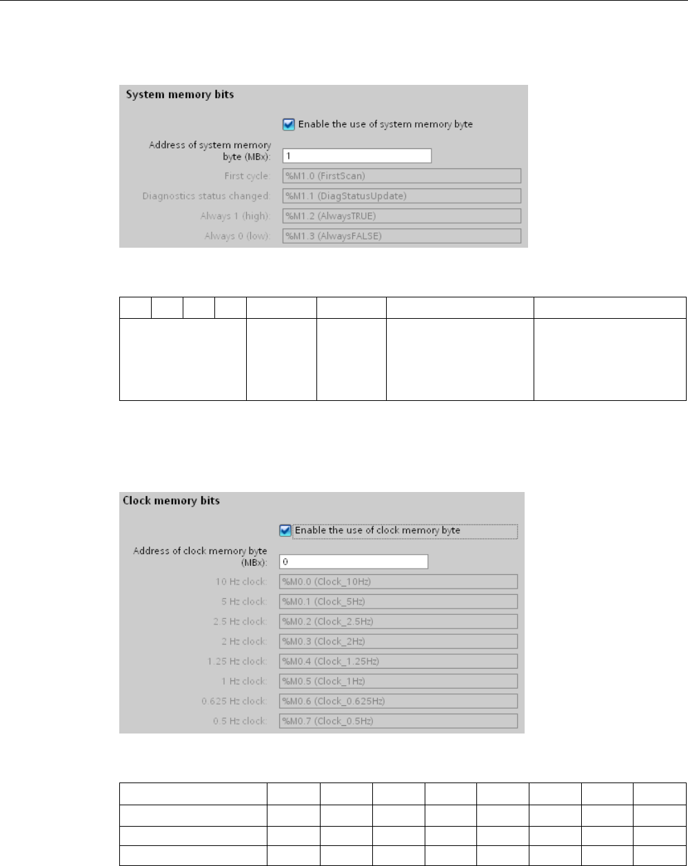
PLC concepts
5.1 Execution of the user program
S7-1200 Programmable controller
System Manual, V4.2, 09/2016, A5E02486680-AK 113
System memory configures a byte with bits that turn on (value = 1) for a specific event.
Table 5- 19 System memory
7
6
5
4
3
2
1
0
Reserved
Value 0
Always off
Value 0
Always on
Value 1
Diagnostic status indica-
tor
• 1: Change
• 0: No change
First scan indicator
• 1: First scan after
startup
• 0: Not first scan
Clock memory configures a byte that cycles the individual bits on and off at fixed intervals.
Each clock bit generates a square wave pulse on the corresponding M memory bit. These
bits can be used as control bits, especially when combined with edge instructions, to trigger
actions in the user code on a cyclic basis.
Table 5- 20 Clock memory
Bit number
7
6
5
4
3
2
1
0
Tag name
Period (s)
2.0
1.6
1.0
0.8
0.5
0.4
0.2
0.1
Frequency (Hz)
0.5
0.625
1
1.25
2
2.5
5
10
Because clock memory runs asynchronously to the CPU cycle, the status of the clock memory can
change several times during a long cycle.
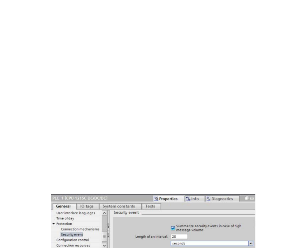
PLC concepts
5.1 Execution of the user program
S7-1200 Programmable controller
114 System Manual, V4.2, 09/2016, A5E02486680-AK
5.1.6
Diagnostics buffer
The CPU supports a diagnostics buffer that contains an entry for each diagnostic event.
Each entry includes a date and time the event occurred, an event category, and an event
description. The entries are displayed in chronological order with the most recent event at
the top. Up to 50 most recent events are available in this log. When the log is full, a new
event replaces the oldest event in the log. When power is lost, the events are saved.
The following types of events are recorded in the diagnostics buffer:
● Each system diagnostic event; for example, CPU errors and module errors
● Each state change of the CPU (each power up, each transition to STOP, each transition
to RUN)
To access the diagnostics buffer (Page 1322), you must be online. From the "Online &
diagnostics" view, locate the diagnostics buffer under "Diagnostics > Diagnostics buffer".
Reducing the number of security diagnostic events
Some security events generate repeated entries in the diagnostics buffer. These messages
can fill up the diagnostics buffer and potentially obscure other event messages. You can
configure the PLC to limit the number of diagnostic messages from security events. You
make selections in the device configuration of the CPU based on the time interval in which
you want to suppress recurring messages:
If you choose to summarize security events within a time interval, you have the choice of
setting a time interval in seconds, minutes, or hours, and a numerical value in the range 1 ..
255.
If you choose to restrict security events, you will be restricting these types of events:
● Going online with the correct or incorrect password
● Manipulated communications data detected
● Manipulated data detected on memory card
● Manipulated firmware update file detected
● Changed protection level (access protection) downloaded to the CPU
● Password legitimization restricted or enabled (by instruction or CPU display)
● Online access denied due to the possible number of simultaneous access attempts being
exceeded
● Timeout when an existing online connection is inactive
● Logging in to the Web server with the correct or incorrect password

PLC concepts
5.1 Execution of the user program
S7-1200 Programmable controller
System Manual, V4.2, 09/2016, A5E02486680-AK 115
● Creating a backup of the CPU
● Restoring the CPU configuration
5.1.7
Time of day clock
The CPU supports a time-of-day clock. A super-capacitor supplies the energy required to
keep the clock running during times when the CPU is powered down. The super-capacitor
charges while the CPU has power. After the CPU has been powered up at least 24 hours,
then the super-capacitor has sufficient charge to keep the clock running for typically 20 days.
STEP 7 sets the time-of-day clock to system time, which has a default value out of the box or
following a factory reset. To utilize the time-of-day clock, you must set it. Timestamps such
as those for diagnostic buffer entries, data log files, and data log entries are based on the
system time. You set the time of day from the "Set time of day" function (Page 1316) in the
"Online & diagnostics" view of the online CPU. STEP 7 then calculates the system time from
the time you set plus or minus the Windows operating system offset from UTC (Coordinated
Universal Time). Setting the time of day to the current local time produces a system time of
UTC if your Windows operating system settings for time zone and daylight savings time
correspond to your locale.
STEP 7 includes instructions (Page 338) to read and write the system time (RD_SYS_T and
WR_SYS_T), to read the local time (RD_LOC_T), and to set the time zone
(SET_TIMEZONE). The RD_LOC_T instruction calculates local time using the time zone and
daylight saving time offsets that you set in the "Time of day" configuration in the general
properties of the CPU (Page 170). These settings enable you to set your time zone for local
time, optionally enable daylight saving time, and specify the start and end dates and times
for daylight saving time. You can also use the SET_TIMEZONE instructions to configure
these settings.

PLC concepts
5.1 Execution of the user program
S7-1200 Programmable controller
116 System Manual, V4.2, 09/2016, A5E02486680-AK
5.1.8
Configuring the outputs on a RUN-to-STOP transition
You can configure the behavior of the digital and analog outputs when the CPU is in STOP
mode. For any output of a CPU, SB or SM, you can set the outputs to either freeze the value
or use a substitute value:
● Substituting a specified output value (default): You enter a substitute value for each
output (channel) of that CPU, SB, or SM device.
The default substitute value for digital output channels is OFF, and the default substitute
value for analog output channels is 0.
● Freezing the outputs to remain in last state: The outputs retain their current value at the
time of the transition from RUN to STOP. After power up, the outputs are set to the
default substitute value.
You configure the behavior of the outputs in Device Configuration. Select the individual
devices and use the "Properties" tab to configure the outputs for each device.
Note
Some distibuted I/O modules offer additional settings for the reaction to CPU stop mode.
Select from the list of choices in
Device Configuration for those modules.
When the CPU changes from RUN to STOP, the CPU retains the process image and writes
the appropriate values for both the digital and analog outputs, based upon the configuration.

PLC concepts
5.2 Data storage, memory areas, I/O and addressing
S7-1200 Programmable controller
System Manual, V4.2, 09/2016, A5E02486680-AK 117
5.2
Data storage, memory areas, I/O and addressing
5.2.1
Accessing the data of the S7-1200
STEP 7 facilitates symbolic programming. You create symbolic names or "tags" for the
addresses of the data, whether as PLC tags relating to memory addresses and I/O points or
as local variables used within a code block. To use these tags in your user program, simply
enter the tag name for the instruction parameter.
For a better understanding of how the CPU structures and addresses the memory areas, the
following paragraphs explain the "absolute" addressing that is referenced by the PLC tags.
The CPU provides several options for storing data during the execution of the user program:
● Global memory: The CPU provides a variety of specialized memory areas, including
inputs (I), outputs (Q) and bit memory (M). This memory is accessible by all code blocks
without restriction.
● PLC tag table: You can enter symbolic names in the STEP 7 PLC tag table for specific
memory locations. These tags are global to the STEP 7 program and allow programming
with names that are meaningful for your application.
● Data block (DB): You can include DBs in your user program to store data for the code
blocks. The data stored persists when the execution of the associated code block comes
to an end. A "global" DB stores data that can be used by all code blocks, while an
instance DB stores data for a specific FB and is structured by the parameters for the FB.
● Temp memory: Whenever a code block is called, the operating system of the CPU
allocates the temporary, or local, memory (L) to be used during the execution of the
block. When the execution of the code block finishes, the CPU reallocates the local
memory for the execution of other code blocks.

PLC concepts
5.2 Data storage, memory areas, I/O and addressing
S7-1200 Programmable controller
118 System Manual, V4.2, 09/2016, A5E02486680-AK
Each different memory location has a unique address. Your user program uses these
addresses to access the information in the memory location. References to the input (I) or
output (Q) memory areas, such as I0.3 or Q1.7, access the process image. To immediately
access the physical input or output, append the reference with ":P" (such as I0.3:P, Q1.7:P,
or "Stop:P").
Table 5- 21 Memory areas
Memory area
Description
Force
Retentive
I
Process image input
I_:P 1
(Physical input)
Copied from physical inputs at the beginning of
the scan cycle
No No
Immediate read of the physical input points on
the CPU, SB, and SM
Yes No
Q
Process image output
Q_:P 1
(Physical output)
Copied to physical outputs at the beginning of
the scan cycle
No No
Immediate write to the physical output points
on the CPU, SB, and SM
Yes No
M
Bit memory
Control and data memory No Yes
(optional)
L
Temp memory
Temporary data for a block local to that block No No
DB
Data block
Data memory and also parameter memory for
FBs
No Yes
(optional)
1
To immediately access (read or write) the physical inputs and physical outputs, append a ":P" to
the address or tag (such as I0.3:P, Q1.7:P, or "Stop:P").
Each different memory location has a unique address. Your user program uses these
addresses to access the information in the memory location. The absolute address consists
of the following elements:
● Memory area identifier (such as I, Q, or M)
● Size of the data to be accessed ("B' for Byte, "W" for Word, or "D" for DWord)
● Starting address of the data (such as byte 3 or word 3)
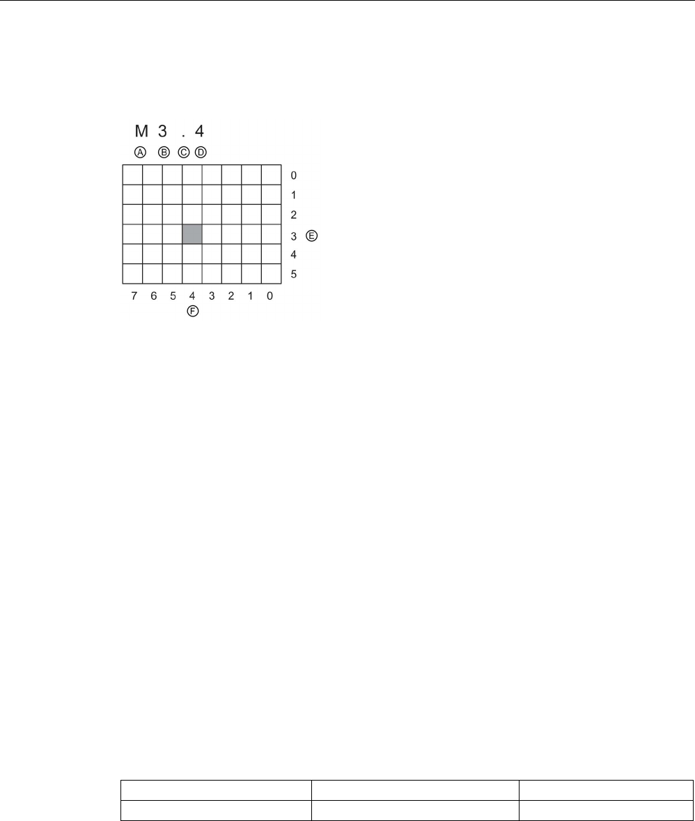
PLC concepts
5.2 Data storage, memory areas, I/O and addressing
S7-1200 Programmable controller
System Manual, V4.2, 09/2016, A5E02486680-AK 119
When accessing a bit in the address for a Boolean value, you do not enter a mnemonic for
the size. You enter only the memory area, the byte location, and the bit location for the data
(such as I0.0, Q0.1, or M3.4).
A
Memory area identifier
E
Bytes of the memory area
B
Byte address: byte 3
F
Bits of the selected byte
C
Separator ("byte.bit")
D
Bit location of the byte (bit 4 of 8)
In the example, the memory area and byte address (M = bit memory area, and 3 = Byte 3)
are followed by a period (".") to separate the bit address (bit 4).
Accessing the data in the memory areas of the CPU
STEP 7 facilitates symbolic programming. Typically, you create tags either in the PLC tag
table, a data block, or in the interface of an OB, FC, or FB. These tags include a name, data
type, offset, and comment. Additionally, in a data block, you can specify a start value. You
can use these tags when programming by entering the tag name at the instruction
parameter. Optionally you can enter the absolute operand (memory area, size and offset) at
the instruction parameter. The examples in the following sections show how to enter
absolute operands. The % character is inserted automatically in front of the absolute
operand by the program editor. You can toggle the view in the program editor to one of
these: symbolic, symbolic and absolute, or absolute.
I (process image input):
The CPU samples the peripheral (physical) input points just prior to
the cyclic OB execution of each scan cycle and writes these values to the input process
image. You can access the input process image as bits, bytes, words, or double words. Both
read and write access is permitted, but typically, process image inputs are only read.
Table 5- 22 Absolute addressing for I memory
Bit
I[byte address].[bit address]
I0.1
Byte, Word, or Double Word
I[size][starting byte address]
IB4, IW5, or ID12
By appending a ":P" to the address, you can immediately read the digital and analog inputs
of the CPU, SB, SM or distributed module. The difference between an access using I_:P
instead of I is that the data comes directly from the points being accessed rather than from
the input process image. This I_:P access is referred to as an "immediate read" access
because the data is retrieved immediately from the source instead of from a copy that was
made the last time the input process image was updated.

PLC concepts
5.2 Data storage, memory areas, I/O and addressing
S7-1200 Programmable controller
120 System Manual, V4.2, 09/2016, A5E02486680-AK
Because the physical input points receive their values directly from the field devices
connected to these points, writing to these points is prohibited. That is, I_:P accesses are
read-only, as opposed to I accesses which can be read or write.
I_:P accesses are also restricted to the size of inputs supported by a single CPU, SB, or SM,
rounded up to the nearest byte. For example, if the inputs of a 2 DI / 2 DQ SB are configured
to start at I4.0, then the input points can be accessed as I4.0:P and I4.1:P or as IB4:P.
Accesses to I4.2:P through I4.7:P are not rejected, but make no sense since these points are
not used. Accesses to IW4:P and ID4:P are prohibited since they exceed the byte offset
associated with the SB.
Accesses using I_:P do not affect the corresponding value stored in the input process image.
Table 5- 23 Absolute addressing for I memory (immediate)
Bit
I[byte address].[bit address]:P
I0.1:P
Byte, Word, or Double word
I[size][starting byte address]:P
IB4:P, IW5:P, or ID12:P
Q (process image output):
The CPU copies the values stored in the output process image to
the physical output points. You can access the output process image in bits, bytes, words, or
double words. Both read and write access is permitted for process image outputs.
Table 5- 24 Absolute addressing for Q memory
Bit
Q[byte address].[bit address]
Q1.1
Byte, Word, or Double word
Q[size][starting byte address]
QB5, QW10, QD40
By appending a ":P" to the address, you can immediately write to the physical digital and
analog outputs of the CPU, SB, SM or distributed module. The difference between an access
using Q_:P instead of Q is that the data goes directly to the points being accessed in addition
to the output process image (writes to both places). This Q_:P access is sometimes referred
to as an "immediate write" access because the data is sent immediately to the target point;
the target point does not have to wait for the next update from the output process image.
Because the physical output points directly control field devices that are connected to these
points, reading from these points is prohibited. That is, Q_:P accesses are write-only, as
opposed to Q accesses which can be read or write.
Q_:P accesses are also restricted to the size of outputs supported by a single CPU, SB, or
SM, rounded up to the nearest byte. For example, if the outputs of a 2 DI / 2 DQ SB are
configured to start at Q4.0, then the output points can be accessed as Q4.0:P and Q4.1:P or
as QB4:P. Accesses to Q4.2:P through Q4.7:P are not rejected, but make no sense since
these points are not used. Accesses to QW4:P and QD4:P are prohibited since they exceed
the byte offset associated with the SB.
Accesses using Q_:P affect both the physical output as well as the corresponding value
stored in the output process image.
Table 5- 25 Absolute addressing for Q memory (immediate)
Bit
Q[byte address].[bit address]:P
Q1.1:P
Byte, Word, or Double word
Q[size][starting byte address]:P
QB5:P, QW10:P or QD40:P

PLC concepts
5.2 Data storage, memory areas, I/O and addressing
S7-1200 Programmable controller
System Manual, V4.2, 09/2016, A5E02486680-AK 121
M (bit memory area):
Use the bit memory area (M memory) for both control relays and data
to store the intermediate status of an operation or other control information. You can access
the bit memory area in bits, bytes, words, or double words. Both read and write access is
permitted for M memory.
Table 5- 26 Absolute addressing for M memory
Bit
M[byte address].[bit address]
M26.7
Byte, Word, or Double Word
M[size][starting byte address]
MB20, MW30, MD50
Temp (temporary memory):
The CPU allocates the temp memory on an as-needed basis.
The CPU allocates the temp memory for the code block and initializes the memory locations
to 0 at the time when it starts the code block (for an OB) or calls the code block (for an FC or
FB).
Temp memory is similar to M memory with one major exception: M memory has a "global"
scope, and temp memory has a "local" scope:
● M memory: Any OB, FC, or FB can access the data in M memory, meaning that the data
is available globally for all of the elements of the user program.
● Temp memory: The CPU restricts access to the data in temp memory to the OB, FC, or
FB that created or declared the temp memory location. Temp memory locations remain
local and different code blocks do not share temp memory, even when the code block
calls another code block. For example: When an OB calls an FC, the FC cannot access
the temp memory of the OB that called it.
The CPU provides temp (local) memory for each OB priority level:
● 16 Kbytes for startup and program cycle, including associated FBs and FCs
● 6 Kbytes for each additional interrupt event thread, including associated FBs and FCs
You access temp memory by symbolic addressing only.
You can find out the amount of temp (local) memory that the blocks in your program use
through the call structure in STEP 7. From the project tree select Program info and then
select the Call structure tab. You will see all of the OBs in your program and you can drill
down to see the blocks that they call. For each block, you can see the local data allocation.
You can also access the Call structure display from the STEP 7
Tools > Call structure
menu
command.
DB (data block):
Use the DB memory for storing various types of data, including intermediate
status of an operation or other control information parameters for FBs, and data structures
required for many instructions such as timers and counters. You can access data block
memory in bits, bytes, words, or double words. Both read and write access is permitted for
read/write data blocks. Only read access is permitted for read-only data blocks.
Table 5- 27 Absolute addressing for DB memory
Bit DB[data block number].DBX[byte ad-
dress].[bit address]
DB1.DBX2.3
Byte, Word, or Double
Word
DB[data block number].DB [size][starting
byte address]
DB1.DBB4, DB10.DBW2,
DB20.DBD8
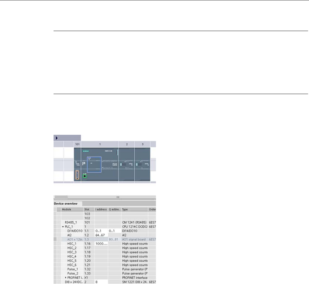
PLC concepts
5.2 Data storage, memory areas, I/O and addressing
S7-1200 Programmable controller
122 System Manual, V4.2, 09/2016, A5E02486680-AK
Note
When you specify an absolute address in LAD or FBD, STEP 7 precedes this address with a
"%" character to indicate that it is an absolute address.
While programming, you can enter
an absolute address either with or without the "%" character (for example %I0.0 or I.0). If
omitted, STEP
7 supplies the "%" character.
In SCL, you must enter the "%" before the address to indicate that it is an absolute a
ddress.
Without the "%", STEP
7 generates an undefined tag error at compile time
Configuring the I/O in the CPU and I/O modules
When you add a CPU and I/O modules to your
device configuration, STEP
7 automatically assigns
I and
Q addresses. You can change the default
addressing by selecting the address field in the
device configuration and entering new numbers.
•
STEP 7 assigns digital inputs and outputs in
groups of 8 points (1 byte), whether the module
uses all the points or not.
•
STEP 7 allocates analog inputs and outputs in
groups of 2, where each analog poing occupies
2 bytes (16 bits).
The figure shows an example of a CPU 1214C with two SMs and one SB. In this example,
you could change the address of the DI8 module to 2 instead of 8. The tool assists you by
changing address ranges that are the wrong size or conflict with other addresses.

PLC concepts
5.3 Processing of analog values
S7-1200 Programmable controller
System Manual, V4.2, 09/2016, A5E02486680-AK 123
5.3
Processing of analog values
Analog signal modules provide input signals or expect output values that represent either a
voltage range or a current range. These ranges are ±10 V, ±5 V, ±2.5 V, or 0 - 20 mA. The
values returned by the modules are integer values where 0 to 27648 represents the rated
range for current, and -27648 to 27648 for voltage. Anything outside the range represents
either an overflow or underflow. See the tables for analog input representation (Page 1471)
and analog output representation (Page 1472) for details about the types of out-of-range
values.
In your control program, you probably need to use these values in engineering units, for
example to represent a volume, temperature, weight or other quantitative value. To do this
for an analog input, you must first normalize the analog value to a real (floating point) value
from 0.0 to 1.0. Then you must scale it to the minimum and maximum values of the
engineering units that it represents. For values that are in engineering units that you need to
convert to an analog output value, you first normalize the value in engineering units to a
value between 0.0 and 1.0, and then scale it between 0 and 27648 or -27648 to 27648,
depending on the range of the analog module. STEP 7 provides the NORM_X and SCALE_X
instructions (Page 296) for this purpose. You can also use the CALCULATE instruction
(Page 255) to scale the analog values (Page 42).
Example: analog value processing
Consider, for example, an analog input that has a current range of 0 - 20 mA. The analog
input module returns values in the range 0 to 24768 for measured values. For this example,
consider that you are using this analog input value to measure a temperature range from
50 °C to 100 °C. A few sample values would have the following meanings:
Analog input value
Engineering units
0
50 °C
6192 62.5 °C
12384
75 °C
18576
87.5 °C
24768
100 °C
The calculation for determining engineering units from the analog input value in this example
is as follows:
Engineering units value = 50 + (Analog input value) * (100 - 50) / (24768 - 0)
For the general case, the equation would be:
Englineering units value = (Low range of engineering units) +
(Analog input value) *
(High range of engineering units
- Low range of engineering units) /
(Maximum analog input range - Minimum analog input range)
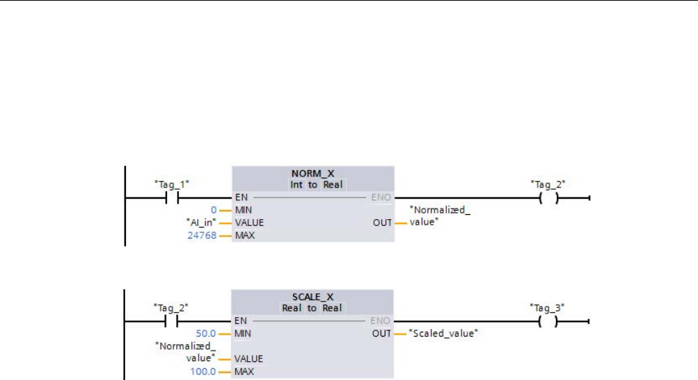
PLC concepts
5.3 Processing of analog values
S7-1200 Programmable controller
124 System Manual, V4.2, 09/2016, A5E02486680-AK
In PLC applications, the typical method is to normalize the analog input value to a floating
point value between 0.0 and 1.0. Then, you would scale the resulting value to a floating point
value in the range of your engineering units. For simplicity, the following LAD instructions
use constant values for the ranges; you might actually choose to use tags:
Network 1
Network 2

PLC concepts
5.4 Data types
S7-1200 Programmable controller
System Manual, V4.2, 09/2016, A5E02486680-AK 125
5.4
Data types
Data types are used to specify both the size of a data element as well as how the data are to
be interpreted. Each instruction parameter supports at least one data type, and some
parameters support multiple data types. Hold the cursor over the parameter field of an
instruction to see which data types are supported for a given parameter.
A formal parameter is the identifier on an instruction that marks the location of data to be
used by that instruction (example: the IN1 input of an ADD instruction). An actual parameter
is the memory location (preceded by a "%" character) or constant containing the data to be
used by the instruction (example %MD400 "Number_of_Widgets"). The data type of the
actual parameter specified by you must match one of the supported data types of the formal
parameter specified by the instruction.
When specifying an actual parameter, you must specify either a tag (symbol) or an absolute
(direct) memory address. Tags associate a symbolic name (tag name) with a data type,
memory area, memory offset, and comment, and can be created either in the PLC tags
editor or in the Interface editor for a block (OB, FC, FB and DB). If you enter an absolute
address that has no associated tag, you must use an appropriate size that matches a
supported data type, and a default tag will be created upon entry.
All data types except String, Struct, Array, and DTL are available in the PLC tags editor and
the block Interface editors. String, Struct, Array, and DTL are available only in the block
Interface editors. You can also enter a constant value for many of the input parameters.
● Bit and Bit sequences (Page 126): Bool (Boolean or bit value), Byte (8-bit byte value),
Word (16-bit value), DWord (32-bit double word value)
● Integer (Page 127)
– USInt (unsigned 8-bit integer), SInt (signed 8-bit integer),
– UInt (unsigned 16-bit integer), Int (signed 16-bit integer)
– UDInt (unsigned 32-bit integer), DInt (signed 32-bit integer)
● Floating-point Real (Page 127): Real (32-bit Real or floating-point value), LReal (64-bit
Real or floating-point value)
● Time and Date (Page 128): Time (32-bit IEC time value), Date (16-bit date value), TOD
(32-bit time-of-day value), DTL (12-byte date-and-time structure)
● Character and String (Page 130): Char (8-bit single character), String (variable-length
string of up to 254 characters)
● Array (Page 132)
● Data structure (Page 133): Struct
● PLC data type (Page 133)
● Variant data type (Page 134)

PLC concepts
5.4 Data types
S7-1200 Programmable controller
126 System Manual, V4.2, 09/2016, A5E02486680-AK
Although not available as data types, the following BCD numeric format is supported by the
conversion instructions:
Table 5- 28 Size and range of the BCD format
Format
Size (bits)
Numeric Range
Constant Entry Examples
BCD16
16
-999 to 999
123, -123
BCD32 32 -9999999 to 9999999 1234567, -1234567
5.4.1
Bool, Byte, Word, and DWord data types
Table 5- 29 Bit and bit sequence data types
Data
type
Bit
size
Number
type
Number
range
Constant
examples
Address
examples
Bool 1
Boolean
FALSE or TRUE
TRUE
I1.0
Q0.1
M50.7
DB1.DBX2.3
Tag_name
Binary 2#0 or 2#1 2#0
Unsigned integer
0 or 1
1
Octal
8#0 or 8#1
8#1
Hexadecimal
16#0 or 16#1
16#1
Byte 8
Binary
2#0 to 2#1111_1111
2#1000_1001
IB2
MB10
DB1.DBB4
Tag_name
Unsigned integer
0 to 255
15
Signed integer
-128 to 127
-63
Octal
8#0 to 8#377
8#17
Hexadecimal B#16#0 to B#16#FF, 16#0 to
16#FF
B#16#F, 16#F
Word 16
Binary
2#0 to 2#1111_1111_1111_1111
2#1101_0010_1001_0110
MW10
DB1.DBW2
Tag_name
Unsigned integer
0 to 65535
61680
Signed integer
-32768 to 32767
72
Octal
8#0 to 8#177_777
8#170_362
Hexadecimal W#16#0 to W#16#FFFF,
16#0 to 16#FFFF
W#16#F1C0, 16#A67B
DWord 32 Binary 2#0 to
2#1111_1111_1111_1111_1111
_1111_1111_1111
2#1101_0100_1111_1110
_1000_1100
MD10
DB1.DBD8
Tag_name
Unsigned integer* 0 to 4_294_967_295 15_793_935
Signed integer* -2_147_483_648 to
2_147_483_647
-400000
Octal 8#0 to 8#37_777_777_777 8#74_177_417
Hexadecimal DW#16#0000_0000 to
DW#16#FFFF_FFFF,
16#0000_0000 to
16#FFFF_FFFF
DW#16#20_F30A,
16#B_01F6
* The underscore "_" is a thousands separator to enhance readability for numbers greater than eight digits.

PLC concepts
5.4 Data types
S7-1200 Programmable controller
System Manual, V4.2, 09/2016, A5E02486680-AK 127
5.4.2
Integer data types
Table 5- 30 Integer data types (U = unsigned, S = short, D= double)
Data
type
Bit size
Number Range
Constant examples
Address
examples
USInt
8
0 to 255
78, 2#01001110
MB0, DB1.DBB4,
Tag_name
SInt 8 -128 to 127 +50, 16#50
UInt
16
0 to 65,535
65295, 0
MW2, DB1.DBW2,
Tag_name
Int
16
-32,768 to 32,767
30000, +30000
UDInt
32
0 to 4,294,967,295
4042322160
MD6, DB1.DBD8,
Tag_name
DInt
32
-2,147,483,648 to 2,147,483,647
-2131754992
5.4.3
Floating-point real data types
Real (or floating-point) numbers are represented as 32-bit single-precision numbers (Real),
or 64-bit double-precision numbers (LReal) as described in the ANSI/IEEE 754-1985
standard. Single-precision floating-point numbers are accurate up to 6 significant digits and
double-precision floating point numbers are accurate up to 15 significant digits. You can
specify a maximum of 6 significant digits (Real) or 15 (LReal) when entering a floating-point
constant to maintain precision.
Table 5- 31 Floating-point real data types (L=Long)
Data
type
Bit size
Number range
Constant Examples
Address examples
Real 32 -3.402823e+38 to -1.175 495e-38,
±0,
+1.175 495e-38 to
+3.402823e+38
123.456, -3.4, 1.0e-5 MD100,
DB1.DBD8,
Tag_name
LReal 64 -1.7976931348623158e+308 to
-2.2250738585072014e-308,
±0,
+2.2250738585072014e-308 to
+1.7976931348623158e+308
12345.123456789e40,
1.2E+40
DB_name.var_nam
e
Rules:
• No direct ad-
dressing sup-
port
• Can be as-
signed in an
OB, FB, or FC
block interface
table
Calculations that involve a long series of values including very large and very small numbers
can produce inaccurate results. This can occur if the numbers differ by 10 to the power of x,
where x > 6 (Real), or 15 (LReal). For example (Real): 100 000 000 + 1 = 100 000 000.

PLC concepts
5.4 Data types
S7-1200 Programmable controller
128 System Manual, V4.2, 09/2016, A5E02486680-AK
5.4.4
Time and Date data types
Table 5- 32 Time and date data types
Data type
Size
Range
Constant Entry Examples
Time 32 bits T#-24d_20h_31m_23s_648ms to
T#24d_20h_31m_23s_647ms
Stored as: -2,147,483,648 ms to
+2,147,483,647 ms
T#5m_30s
T#1d_2h_15m_30s_45ms
TIME#10d20h30m20s630ms
500h10000ms
10d20h30m20s630ms
Date 16 bits D#1990-1-1 to D#2168-12-31 D#2009-12-31
DATE#2009-12-31
2009-12-31
Time_of_Day
32 bits TOD#0:0:0.0 to TOD#23:59:59.999 TOD#10:20:30.400
TIME_OF_DAY#10:20:30.400
23:10:1
DTL
(Date and
Time Long)
12
bytes
Min.: DTL#1970-01-01-00:00:00.0
Max.: DTL#2262-04-11:23:47:16.854 775
807
DTL#2008-12-16-
20:30:20.250
Time
TIME data is stored as a signed double integer interpreted as milliseconds. The editor format
can use information for day (d), hours (h), minutes (m), seconds (s) and milliseconds (ms).
It is not necessary to specify all units of time. For example T#5h10s and 500h are valid.
The combined value of all specified unit values cannot exceed the upper or lower limits in
milliseconds for the Time data type (-2,147,483,648 ms to +2,147,483,647 ms).
Date
DATE data is stored as an unsigned integer value which is interpreted as the number of days
added to the base date 01/01/1990, to obtain the specified date. The editor format must
specify a year, month and day.
TOD
TOD (TIME_OF_DAY) data is stored as an unsigned double integer which is interpreted as
the number of milliseconds since midnight for the specified time of day (Midnight = 0 ms).
The hour (24hr/day), minute, and second must be specified. The fractional second
specification is optional.

PLC concepts
5.4 Data types
S7-1200 Programmable controller
System Manual, V4.2, 09/2016, A5E02486680-AK 129
DTL
DTL (Date and Time Long) data type uses a12 byte structure that saves information on date
and time. You can define DTL data in either the Temp memory of a block or in a DB. A value
for all components must be entered in the "Start value" column of the DB editor.
Table 5- 33 Size and range for DTL
Length
(bytes)
Format
Value range
Example of value
input
12 Clock and calendar
Year-Month-
Day:Hour:Minute:
Second.Nanoseconds
Min.: DTL#1970-01-01-00:00:00.0
Max.: DTL#2554-12-31-23:59:59.999 999
999
DTL#2008-12-16-
20:30:20.250
Each component of the DTL contains a different data type and range of values. The data
type of a specified value must match the data type of the corresponding components.
Table 5- 34 Elements of the DTL structure
Byte
Component
Data type
Value range
0 Year UINT 1970 to 2554
1
2
Month
USINT
1 to 12
3
Day
USINT
1 to 31
4
Weekday
1
USINT
1(Sunday) to 7(Saturday)
1
5
Hour
USINT
0 to 23
6
Minute
USINT
0 to 59
7
Second
USINT
0 to 59
8
Nanoseconds UDINT 0 to 999 999 999
9
10
11
1
The format Year-Month-Day:Hour:Minute:
Second.Nanosecond does not include the weekday.

PLC concepts
5.4 Data types
S7-1200 Programmable controller
130 System Manual, V4.2, 09/2016, A5E02486680-AK
5.4.5
Character and String data types
Table 5- 35 Character and String data types
Data type
Size
Range
Constant Entry Examples
Char
8 bits
16#00 to 16#FF
'A', 't', '@', 'ä', '∑'
WChar 16 bits 16#0000 to 16#FFFF 'A', 't', '@', 'ä', '∑', Asian characters, Cyrillic
characters, and others
String
n+ 2 bytes
n = (0 to 254 bytes)
"ABC"
WString n+ 2 words n = (0 to 65534 words) "ä123@XYZ.COM"
Char and WChar
A Char occupies one byte in memory and stores a single character coded in ASCII format,
including the extended ASCII character codes. A WChar occupies one word in memory and
can contain any double-byte character representation.
The editor syntax uses a single quote character before and after the character. You can use
visible characters and control characters.
String and WString
The CPU supports the String data type for storing a sequence of single-byte characters. The
String data type contains a total character count (number of characters in the string) and the
current character count. The String type provides up to 256 bytes for storing the maximum
total character count (1 byte), the current character count (1 byte), and up to 254 bytes in the
string. Each byte in a String data type can be any value from 16#00 - 16#FF.
The WString data type provides for longer strings of one-word (double-byte) values. The first
word contains the maximum total character count; the next word contains the total character
count, and the following string can contain up to 65534 words. Each word in a WString data
type can be any value from 16#0000 - 16#FFFF.
You can use literal strings (constants) for instruction parameters of type IN using single
quotes. For example, ‘ABC’ is a three-character string that could be used as input for
parameter IN of the S_CONV instruction. You can also create string variables by selecting
data type "String" or "WString" in the block interface editors for OB, FC, FB, and DB. You
cannot create a string in the PLC tags editor.
You can specify the maximum string size in bytes (String) or words (WString) by entering
square brackets after the keyword "String" or "WString" after you select one of those data
types from the data type drop-down list. For example, "MyString String[10]" would specify a
10-byte maximum size for MyString. If you do not include the square brackets with a
maximum size, then 254 is assumed for a string and 65534 for a WString. "MyWString
WString[1000]" would specify a 1000-word WString.

PLC concepts
5.4 Data types
S7-1200 Programmable controller
System Manual, V4.2, 09/2016, A5E02486680-AK 131
The following example defines a String with maximum character count of 10 and current
character count of 3. This means the String currently contains 3 one-byte characters, but
could be expanded to contain up to 10 one-byte characters.
Table 5- 36 Example of a String data type
Total Charac-
ter Count
Current Char-
acter Count
Character 1
Character 2
Character 3
...
Character 10
10
3
'C' (16#43)
'A' (16#41)
'T' (16#54)
...
-
Byte 0 Byte 1 Byte 2 Byte 3 Byte 4 ... Byte 11
The following example defines a WString with maximum character count of 500 and current
character count of 300. This means the String currently contains 300 one-word characters,
but could be expanded to contain up to 500 one-word characters.
Table 5- 37 Example of a WString data type
Total Charac-
ter Count
Current Char-
acter Count
Character 1
Characters
2 to 299
Character
300
...
Character 500
500 300 'ä' (16#0084) ASCII charac-
ter words
'M' (16#004D) ... -
Word 0 Word 1 Word 2 Words 3 to
300
Word 301 ... Word 501
ASCII control characters can be used in Char, Wchar, String and WString data. The
following table shows examples of control character syntax.
Table 5- 38 Valid ASCII control characters
Control char-
acters
ASCII Hex
value (Char)
ASCII Hex
value (WChar)
Control function
Examples
$L or $l
16#0A
16#000A
Line feed
'$LText', '$0AText'
$N or $n 16#0A and
16#0D
16#000A and
16#000D
Line break
The new line shows two
characters in the string.
'$NText',
'$0A$0DText'
$P or $p
16#0C
16#000C
Form feed
'$PText', '$0CText'
$R or $r
16#0D
16#000D
Carriage return (CR)
'$RText','$0DText'
$T or $t
16#09
16#0009
Tab
'$TText', '$09Text'
$$
16#24
16#0024
Dollar sign
'100$$', '100$24'
$' 16#27 16#0027 Single quote '$'Text$'','$27Text$
27'

PLC concepts
5.4 Data types
S7-1200 Programmable controller
132 System Manual, V4.2, 09/2016, A5E02486680-AK
5.4.6
Array data type
Arrays
You can create an array that contains multiple elements of the same data type. Arrays can
be created in the block interface editors for OB, FC, FB, and DB. You cannot create an array
in the PLC tags editor.
To create an array from the block interface editor, name the array and choose data type
"Array [lo .. hi] of type", then edit "lo", "hi", and "type" as follows:
● lo - the starting (lowest) index for your array
● hi - the ending (highest) index for your array
● type - one of the data types, such as BOOL, SINT, UDINT
Table 5- 39 ARRAY data type rules
Data Type
Array syntax
ARRAY Name [index1_min..index1_max, index2_min..index2_max] of <data type>
• All array elements must be the same data type.
• The index can be negative, but the lower limit must be less than or equal to the upper limit.
• Arrays can have one to six dimensions.
• Multi-dimensional index min..max declarations are separated by comma characters.
• Nested arrays, or arrays of arrays, are not allowed.
• The memory size of an array = (size of one element * total number of elements in array)
Array index
Valid index data types
Array index rules
Constant or varia-
ble
USInt, SInt, UInt, Int, UDInt,
DInt
• Value limits: -32768 to +32767
• Valid: Mixed constants and variables
• Valid: Constant expressions
• Not valid: Variable expressions
Example: array
declarations
ARRAY[1..20] of REAL
One dimension, 20 elements
ARRAY[-5..5] of INT
One dimension, 11 elements
ARRAY[1..2, 3..4] of CHAR
Two dimensions, 4 elements
Example: array
addresses
ARRAY1[0]
ARRAY1 element 0
ARRAY2[1,2]
ARRAY2 element [1,2]
ARRAY3[i,j]
If i =3 and j=4, then ARRAY3 element
[3, 4] is addressed

PLC concepts
5.4 Data types
S7-1200 Programmable controller
System Manual, V4.2, 09/2016, A5E02486680-AK 133
5.4.7
Data structure data type
You can use the data type "Struct" to define a structure of data consisting of other data
types. The struct data type can be used to handle a group of related process data as a single
data unit. A Struct data type is named and the internal data structure declared in the data
block editor or a block interface editor.
Arrays and structures can also be assembled into a larger structure. A structure can be
nested up to eight levels deep. For example, you can create a structure of structures that
contain arrays.
5.4.8
PLC data type
The PLC data type editor lets you define data structures that you can use multiple times in
your program. You create a PLC data type by opening the "PLC data types" branch of the
project tree and double-clicking the "Add new data type" item. On the newly created PLC
data type item, use two single-clicks to rename the default name and double-click to open
the PLC data type editor.
You create a custom PLC data type structure using the same editing methods that are used
in the data block editor. Add new rows for any data types that are necessary to create the
data structure that you want.
If a new PLC data type is created, then the new PLC type name will appear in the data type
selector drop-down lists in the DB editor and code block interface editor.
You can potentially use PLC data types in the following ways:
● As a data type in a code block interface or in data blocks
● As a template for the creation of multiple global data blocks that use the same data
structure
● As a data type for PLC tag declarations the I and Q memory areas of the CPU
For example, a PLC data type could be a recipe for mixing colors. You can then assign this
PLC data type to multiple data blocks. You can adjust the variables within each data block to
create a specific color.
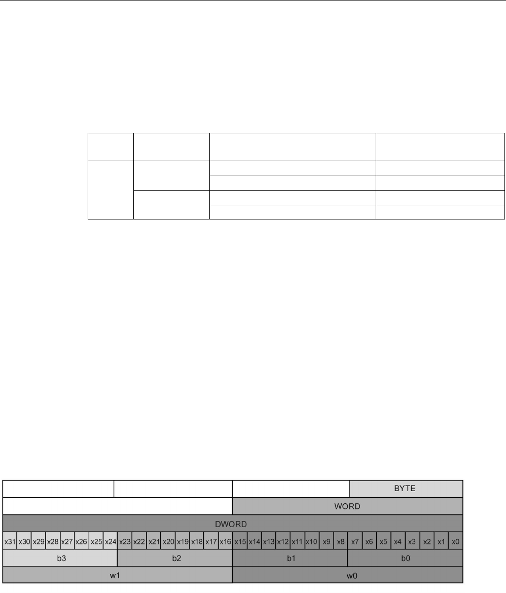
PLC concepts
5.4 Data types
S7-1200 Programmable controller
134 System Manual, V4.2, 09/2016, A5E02486680-AK
5.4.9
Variant pointer data type
The data type Variant can point to variables of different data types or parameters. The
Variant pointer can point to structures and individual structural components. The Variant
pointer does not occupy any space in memory.
Table 5- 40 Properties of the Variant pointer
Length
(Byte)
Representation
Format
Example entry
0 Symbolic
Operand
MyTag
DB_name.Struct_name.element_name MyDB.Struct1.pressure1
Absolute
Operand
%MW10
DB_number.Operand Type Length
P#DB10.DBX10.0 INT 12
5.4.10
Accessing a "slice" of a tagged data type
PLC tags and data block tags can be accessed at the bit, byte, or word level depending on
their size. The syntax for accessing such a data slice is as follows:
● "<PLC tag name>".xn (bit access)
● "<PLC tag name>".bn (byte access)
● "<PLC tag name>".wn (word access)
● "<Data block name>".<tag name>.xn (bit access)
● "<Data block name>".<tag name>.bn (byte access)
● "<Data block name>".<tag name>.wn (word access)
A double word-sized tag can be accessed by bits 0 - 31, bytes 0 - 3, or word 0 - 1. A word-
sized tag can be accessed by bits 0 - 15, bytes 0 - 1, or word 0. A byte-sized tag can be
accessed by bits 0 - 7, or byte 0. Bit, byte, and word slices can be used anywhere that bits,
bytes, or words are expected operands.
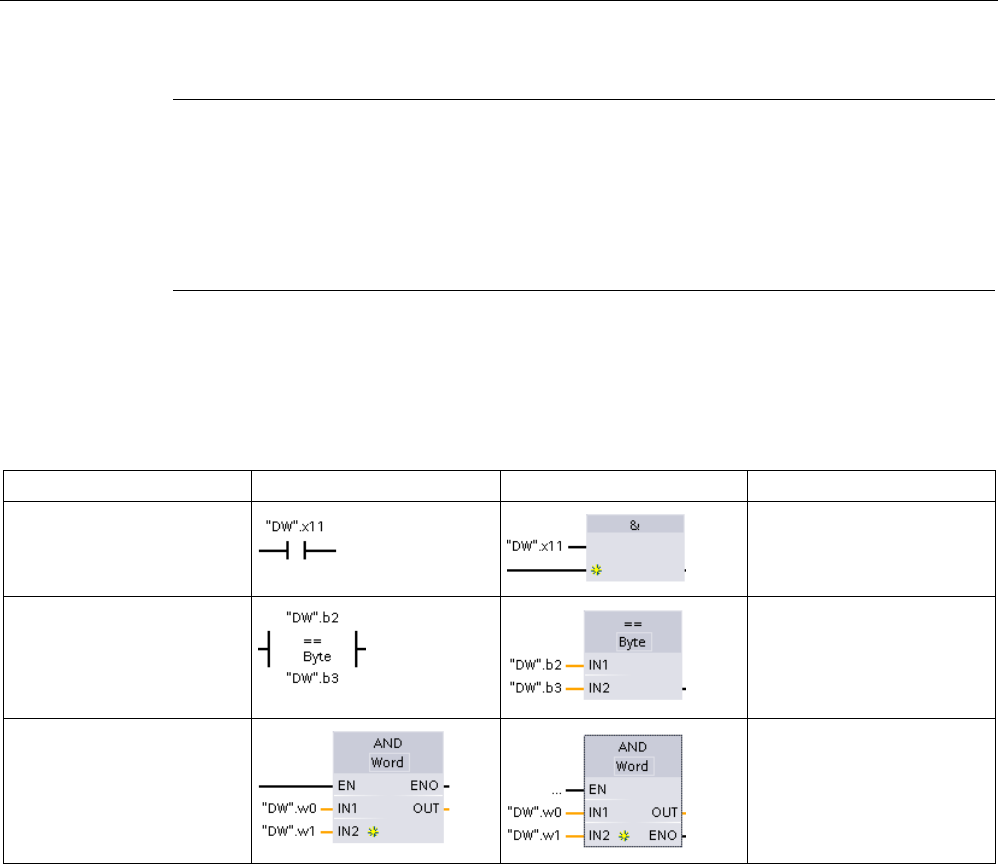
PLC concepts
5.4 Data types
S7-1200 Programmable controller
System Manual, V4.2, 09/2016, A5E02486680-AK 135
Note
Valid data types that can be accessed by slice are Byte, Char, Conn_Any, Date, DInt,
DWord, Event_Any, Event_
Att, Hw_Any, Hw_Device, HW_Interface, Hw_Io, Hw_Pwm,
Hw_SubModule, Int, OB_Any, OB_Att, OB_Cyclic, OB_Delay, OB_WHINT, OB_PCYCLE,
OB_STARTUP, OB_TIMEERROR, OB_Tod, Port, Rtm, SInt, Time, Time_Of_Day, UDInt,
UInt, USInt, and Word. PLC Tags of type Real can
be accessed by slice, but data block tags
of type Real cannot.
Examples
In the PLC tag table, "DW" is a declared tag of type DWORD. The examples show bit, byte,
and word slice access:
LAD
FBD
SCL
Bit access
IF "DW".x11 THEN
...
END_IF;
Byte access
IF "DW".b2 = "DW".b3
THEN
...
END_IF;
Word access
out:= "DW".w0 AND
"DW".w1;
5.4.11
Accessing a tag with an AT overlay
The AT tag overlay allows you to access an already-declared tag of a standard access block
with an overlaid declaration of a different data type. You can, for example, address the
individual bits of a tag of a Byte, Word, or DWord data type with an Array of Bool.
Declaration
To overlay a parameter, declare an additional parameter directly after the parameter that is
to be overlaid and select the data type "AT". The editor creates the overlay, and you can
then choose the data type, struct, or array that you wish to use for the overlay.

PLC concepts
5.4 Data types
S7-1200 Programmable controller
136 System Manual, V4.2, 09/2016, A5E02486680-AK
Example
This example shows the input parameters of a standard-access FB. The byte tag B1 is
overlaid with an array of Booleans:
Another example is a DWord tag overlaid with a Struct, which includes a Word, Byte, and
two Booleans:
The Offset column of the block interface shows the location of the overlaid data types
relative to the original tag.
You can address the overlay types directly in the program logic:
LAD
FBD
SCL
IF #OV[1] THEN
...
END_IF;
IF #DW1_Struct.W1 = W#16#000C THEN
...
END_IF;
out1 := #DW1_Struct.B1;
IF #OV[4] AND #DW1_Struct.BO2 THEN
...
END_IF;

PLC concepts
5.4 Data types
S7-1200 Programmable controller
System Manual, V4.2, 09/2016, A5E02486680-AK 137
Rules
● Overlaying of tags is only possible in FB and FC blocks with standard (not optimized)
access.
● You can overlay parameters for all block types and all declaration sections.
● You can use an overlaid parameter like any other block parameter.
● You cannot overlay parameters of type VARIANT.
● The size of the overlaying parameter must be less than or equal to the size of the overlaid
parameter.
● You must declare the overlaying variable immediately after the variable that it overlays
and select the keyword "AT" as the initial data type selection.

PLC concepts
5.5 Using a memory card
S7-1200 Programmable controller
138 System Manual, V4.2, 09/2016, A5E02486680-AK
5.5
Using a memory card
Note
The CPU supports only the pre
-formatted SIMATIC memory cards (Page 1546).
Before you copy any program to the formatted memory card, del
ete any previously saved
program from the memory card.
Use the memory card either as a transfer card or as a program card. Any program that you
copy to the memory card contains all of the code blocks and data blocks, any technology
objects, and the device configuration. A copied program does
not
contain force values. The
force values are not part of the program, but are stored in the load memory, whether the
internal load memory of the CPU, or the external load memory (a program card). If you insert
a program card in the CPU, STEP 7 then applies the force values only to the external load
memory on the program card.
● Use a transfer card (Page 142) to copy a program to the internal load memory of the CPU
without using STEP 7. After you insert the transfer card, the CPU first erases the user
program and any force values from the internal load memory, and then copies the
program from the transfer card to the internal load memory. When the transfer process is
complete, you must remove the transfer card.
You can use an empty transfer card to access a password-protected CPU when the
password has been lost or forgotten (Page 151). Inserting the empty transfer card deletes
the password-protected program in the internal load memory of the CPU. You can then
download a new program to the CPU.
● Use a program card (Page 145) as external load memory for the CPU. Inserting a
program card in the CPU erases all of the CPU internal load memory (the user program
and any force values). The CPU then executes the program in external load memory (the
program card). Downloading to a CPU that has a program card updates only the external
load memory (the program card).
Because the internal load memory of the CPU was erased when you inserted the
program card, the program card
must
remain in the CPU. If you remove the program
card, the CPU goes to STOP mode. (The error LED flashes to indicate that program card
has been removed.)
You also use a memory card when downloading firmware updates (Page 148).
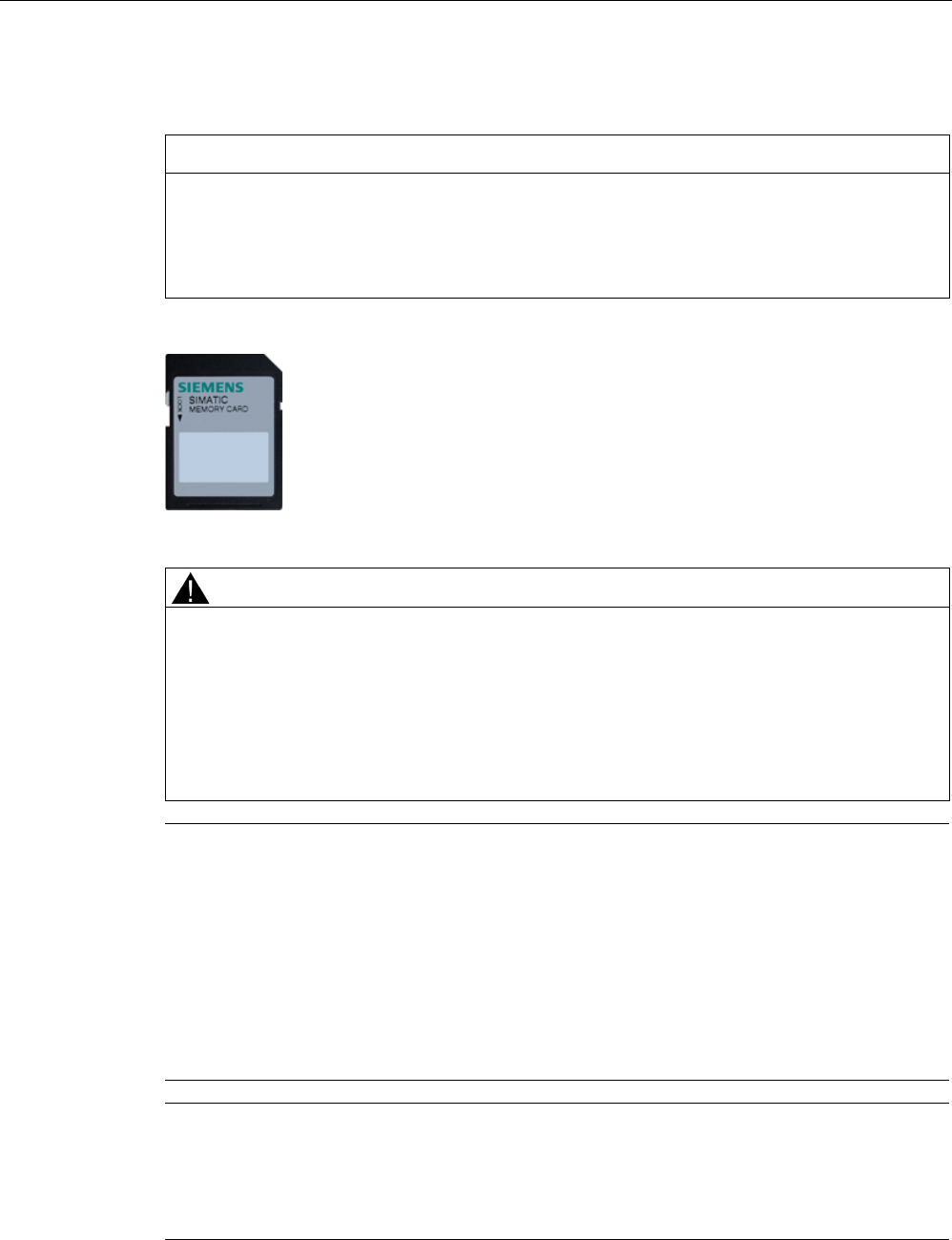
PLC concepts
5.5 Using a memory card
S7-1200 Programmable controller
System Manual, V4.2, 09/2016, A5E02486680-AK 139
5.5.1
Inserting a memory card in the CPU
NOTICE
Protect memory card and receptacle from electrostatic discharge
Electrostatic discharge can damage the memory card or the receptacle on the CPU.
Make contact with a grounded conductive pad and/or wear a grounded wrist strap when
you handle the memory card. Store the memory card in a conductive container.
Check that the memory card is not write
-protected. Slide the protection
switch away from the "Lock" position.
Note that if you do insert a write
-protected memory card into the CPU,
STEP
7 will display a diagnostic message on the next power up alerting you
to that fact. The CPU will power up without failure, but instructions involving
recipes or data logs, for example, will return errors if the card is write
-
protected.
WARNING
Verify that the CPU is not running a process before inserting the memory card.
If you insert a memory card (whether configured as a program card, transfer card, or
firmware update card) into a running CPU, the CPU goes immediately to STOP mode,
which might cause process disruption that could result in death or severe personal injury.
Before inserting or removing a memory card, always ensure that the CPU is not actively
controlling a machine or process. Always install an emergency stop circuit for your
application or process.
Note
Do not insert V3.0 program transfer cards into S7-1200 V4.0 CPUs.
Version 3.0 program transfer cards are not compatible with version S7
-1200 V4.0 CPUs.
Inserting a memory card that contains a V3.0 program causes a CPU error.
If you do insert an invalid version
program transfer card (Page 142), you should remove the
card, and perform a STOP to RUN transition, a memory reset (MRES), or cycle power. After
you recover the CPU from the error condition, you can downlo
ad a valid V4.0 CPU program.
To transfer a V3.0 program to a V4.0 program, you must use the TIA Portal to Change
Device in the Hardware Configuration.
Note
If you insert a memory card with the CPU in STOP mode, the diagnostic buffer displays a
message
that the memory card evaluation has been initiated. The CPU will evaluate the
memory card the next time you either change the CPU to RUN mode, reset the CPU
memory with an MRES, or power
-cycle the CPU.
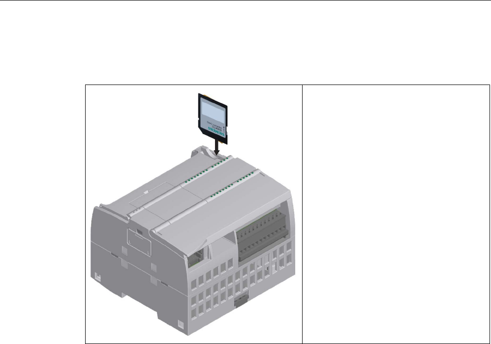
PLC concepts
5.5 Using a memory card
S7-1200 Programmable controller
140 System Manual, V4.2, 09/2016, A5E02486680-AK
Table 5- 41 Inserting a memory card
To insert a memory card, open the top CPU
door and insert the memory card in the slot. A
push-push type connector allows for easy
insertion and removal.
The memory card is keyed for proper installa-
tion.
CPU behavior when you insert a memory card
When you insert a memory card in the CPU, the CPU peforms the following steps:
1. Transitions to STOP mode (if not already in STOP mode)
2. Prompts for one of the following choices:
– Power cycle
– Transition to RUN mode
– Perform a memory reset
3. Evaluates the card

PLC concepts
5.5 Using a memory card
S7-1200 Programmable controller
System Manual, V4.2, 09/2016, A5E02486680-AK 141
How the CPU evaluates the memory card
If you do not configure the CPU to "Disable copy from internal load memory to external load
memory" in the Protection properties of the device configuration (Page 212), the CPU
determines what type of memory card you inserted:
●
Empty memory card
: A blank memory card does not have a job file (S7_JOB.S7S). If you
insert a blank memory card, the CPU adds a program job file. It then copies internal load
memory to external load memory (the program file on the memory card) and erases
internal load memory.
●
Blank program card
: A blank program card has a program job file that is empty. In this
case, the CPU copies internal load memory to external load memory (the program file on
the memory card) and erases internal load memory.
If you configured the CPU to "Disable copy from internal load memory to external load
memory" in the Protection properties of the device configuration, the CPU behaves as
follows:
●
Empty memory card
: A blank memory card does not have a job file (S7_JOB.S7S). If you
insert a blank memory card, the CPU does nothing. It does not create a program job file
and it does not copy internal load memory to external load memory (the program file on
the memory card). It does not erase internal load memory.
●
Blank program card
: A blank program card has a program job file that is empty. In this
case, the CPU performs no action. It does not
copy internal load memory to external load
memory (the program file on the memory card). It does not erase internal load memory.
If you insert a program card (Page 145), transfer card (Page 142), or card that contains a
firmware update (Page 148)into the CPU, the configuration setting for "Disable copy from
internal load memory to external load memory" has no effect on how the CPU evaluates the
memory card.
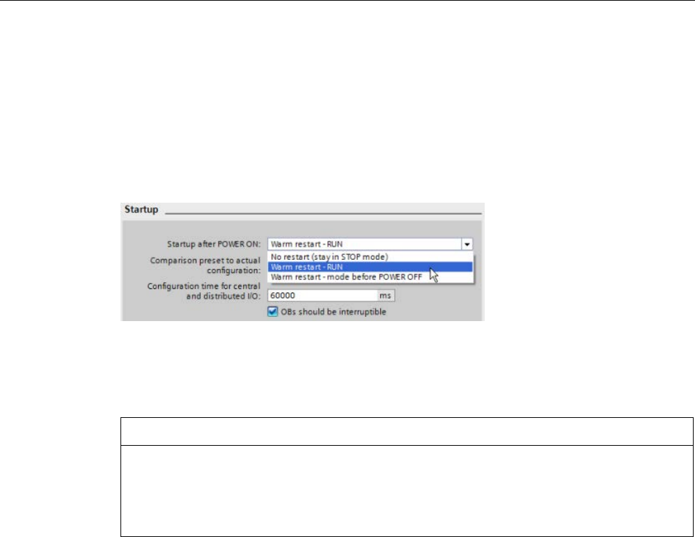
PLC concepts
5.5 Using a memory card
S7-1200 Programmable controller
142 System Manual, V4.2, 09/2016, A5E02486680-AK
5.5.2
Configuring the startup parameter of the CPU before copying the project to the
memory card
When you copy a program to a transfer card or a program card, the program includes the
startup parameter for the CPU. Before copying the program to the memory card, always
ensure that you have configured the operating mode for the CPU following a power-cycle.
Select whether the CPU starts in STOP mode, RUN mode, or in the previous mode (prior to
the power cycle).
5.5.3
Transfer card
NOTICE
Protect memory card and receptacle from electrostatic discharge
Electrostatic discharge can damage the memory card or the receptacle on the CPU.
Make contact with a grounded conductive pad and/or wear a grounded wrist strap
whenever you handle the memory card. Store the memory card in a conductive container.
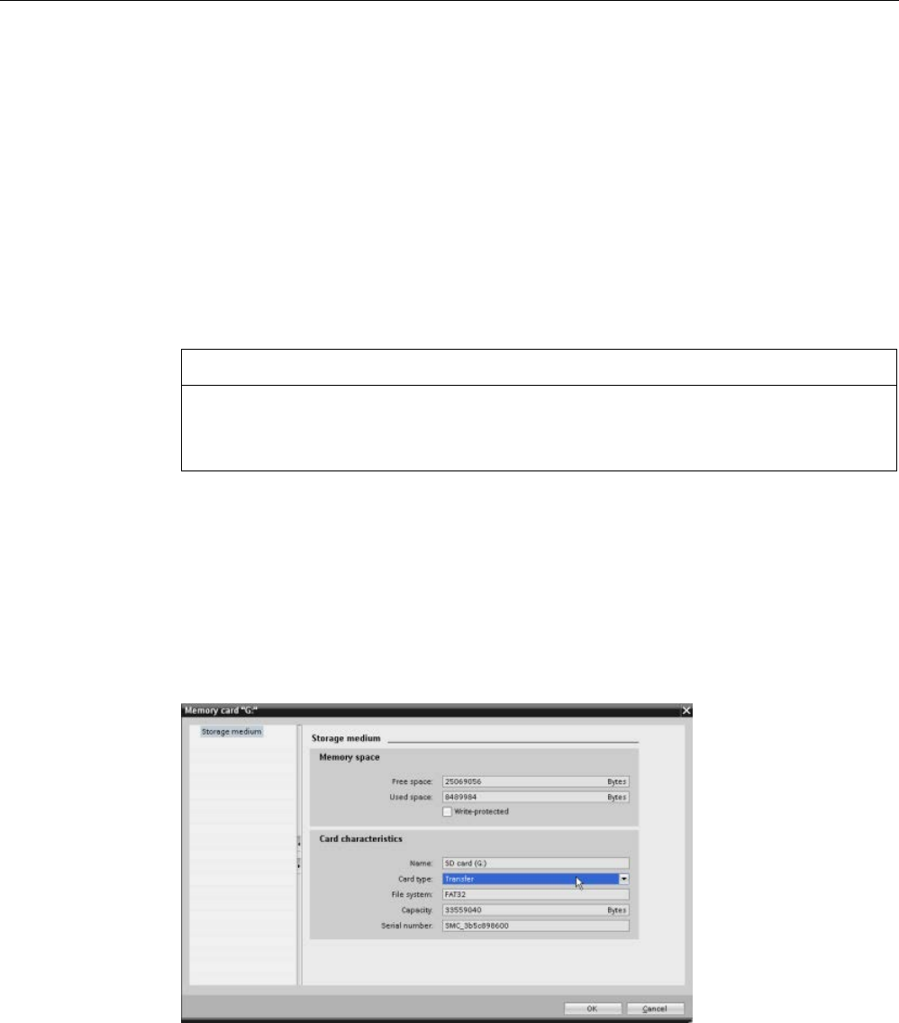
PLC concepts
5.5 Using a memory card
S7-1200 Programmable controller
System Manual, V4.2, 09/2016, A5E02486680-AK 143
Creating a transfer card
Always remember to configure the startup parameter of the CPU (Page 142) before copying
a program to the transfer card. To create a transfer card, follow these steps:
1. Insert a blank SIMATIC memory card that is not write-protected into an SD card
reader/writer attached to your computer. (If the card is write-protected, slide the
protection switch away from the "Lock" position.)
If you are reusing a SIMATIC memory card that contains a user program, data logs,
recipes, or a firmware update, you
must
delete the files before reusing the card. Use
Windows Explorer to display the contents of the memory card and delete the
"S7_JOB.S7S" file and also delete any existing folders (such as
"SIMATIC.S7S","FWUPDATE.S7S", "DataLogs", and "Recipes").
NOTICE
Do NOT delete the hidden files "__LOG__" and "crdinfo.bin" from the memory card.
The "__LOG__" and "crdinfo.bin" files are required for the memory card. If you delete
these files, you cannot use the memory card with the CPU.
2. In the Project tree (Project view), expand the "SIMATIC Card Reader" folder and select
your card reader.
3. Display the "Memory card" dialog by right-clicking the drive letter corresponding to the
memory card in the card reader and selecting "Properties" from the context menu.
4. In the "Memory card" dialog, select "Transfer" from the "Card type" drop-down menu.
At this point, STEP 7 creates the empty transfer card. If you are creating an empty
transfer card, such as to recover from a lost CPU password (Page 151), remove the
transfer card from the card reader.
5. Add the program by selecting the CPU device (such as PLC_1 [CPU 1214C DC/DC/DC])
in the Project tree and dragging the CPU device to the memory card. (Another method is
to copy the CPU device and paste it to the memory card.) Copying the CPU device to the
memory card opens the "Load preview" dialog.

PLC concepts
5.5 Using a memory card
S7-1200 Programmable controller
144 System Manual, V4.2, 09/2016, A5E02486680-AK
6. In the "Load preview" dialog, click the "Load" button to copy the CPU device to the
memory card.
7. When the dialog displays a message that the CPU device (program) has been loaded
without errors, click the "Finish" button.
Using a transfer card
WARNING
Verify that the CPU is not actively running a process before inserting the memory card.
Inserting a memory card will cause the CPU to go to STOP mode, which could affect the
operation of an online process or machine. Unexpected operation of a process or machine
could result in death or injury to personnel and/or property damage.
Before inserting a transfer card, always ensure that the CPU is in STOP mode and your
process is in a safe state.
Note
Do not insert V3.0 program transfer cards into later model CPUs.
Version 3.0 program transf
er cards are not compatible with later model S7-1200 CPUs.
Inserting a memory card that contains a V3.0 program causes a CPU error.
If you do insert an invalid version program transfer card, then remove the card, perform a
STOP to RUN transition, a memory
reset (MRES), or cycle power. After you recover the
CPU from the error condition, you can download a valid CPU program
To transfer the program to a CPU, follow these steps:
1. Insert the transfer card into the CPU (Page 139). If the CPU is in RUN, the CPU will go to
STOP mode. The maintenance (MAINT) LED flashes to indicate that the memory card
needs to be evaluated.
2. Power-cycle the CPU to evaluate the memory card. Alternative methods for rebooting the
CPU are to perform either a STOP-to-RUN transition or a memory reset (MRES) from
STEP 7.
3. After the rebooting and evaluating the memory card, the CPU copies the program to the
internal load memory of the CPU.
The RUN/STOP LED alternately flashes green and yellow to indicate that the program is
being copied. When the RUN/STOP LED turns on (solid yellow) and the MAINT LED
flashes, the copy process has finished. You can then remove the memory card.
4. Reboot the CPU (either by restoring power or by the alternative methods for rebooting) to
evaluate the new program that was transferred to internal load memory.
The CPU then goes to the start-up mode (RUN or STOP) that you configured for the project.
Note
You
must remove the transfer card before setting the CPU to RUN mode.

PLC concepts
5.5 Using a memory card
S7-1200 Programmable controller
System Manual, V4.2, 09/2016, A5E02486680-AK 145
5.5.4
Program card
NOTICE
Electrostatic discharge can damage the memory card or the receptacle on the CPU.
Make contact with a grounded conductive pad and/or wear a grounded wrist strap when
you handle the memory card. Store the memory card in a conductive container.
Check that the memory card is not write
-protected. Slide the protection
switch away from the "Lock" position.
Before you copy any program elements t
o the program card, delete any
previously saved programs from the memory card.
Creating a program card
When used as a program card, the memory card is the external load memory of the CPU. If
you remove the program card, the internal load memory of the CPU is empty.
Note
If you insert a blank memory card into the CPU and perform a memory card evaluation by
either power cycling the CPU, performing a STOP to RUN transition, or performing a
memory reset (MRES), the program and force values in internal load
memory of the CPU are
copied to the memory card. (The memory card is now a program card.) After the copy has
been completed, the program in internal load memory of the CPU is then erased. The CPU
then goes to the configured startup mode (RUN or STOP).
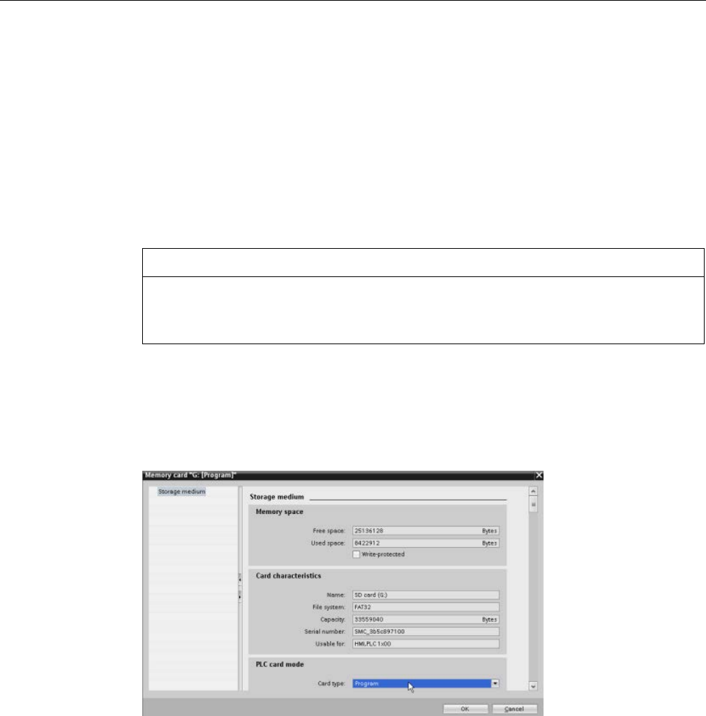
PLC concepts
5.5 Using a memory card
S7-1200 Programmable controller
146 System Manual, V4.2, 09/2016, A5E02486680-AK
Always remember to configure the startup parameter of the CPU (Page 142) before copying
a project to the program card. To create a program card, follow these steps:
1. Insert a blank SIMATIC memory card that is not write-protected into an SD card
reader/writer attached to your computer. (If the card is write-protected, slide the
protection switch away from the "Lock" position.)
If you are reusing a SIMATIC memory card that contains a user program, data logs,
recipes, or a firmware update, you
must
delete the files before reusing the card. Use
Windows Explorer to display the contents of the memory card and delete the
"S7_JOB.S7S" file and also delete any existing folders (such as
"SIMATIC.S7S","FWUPDATE.S7S", "DataLogs", and "Recipes").
NOTICE
Do NOT delete the hidden files "__LOG__" and "crdinfo.bin" from the memory card.
The "__LOG__" and "crdinfo.bin" files are required for the memory card. If you delete
these files, you cannot use the memory card with the CPU.
2. In the Project tree (Project view), expand the "SIMATIC Card Reader" folder and select
your card reader.
3. Display the "Memory card" dialog by right-clicking the drive letter corresponding to the
memory card in the card reader and selecting "Properties" from the context menu.
4. In the "Memory card" dialog, select "Program" from the drop-down menu.
5. Add the program by selecting the CPU device (such as PLC_1 [CPU 1214C DC/DC/DC])
in the Project tree and dragging the CPU device to the memory card. (Another method is
to copy the CPU device and paste it to the memory card.) Copying the CPU device to the
memory card opens the "Load preview" dialog.
6. In the "Load preview" dialog, click the "Load" button to copy the CPU device to the
memory card.
7. When the dialog displays a message that the CPU device (program) has been loaded
without errors, click the "Finish" button.

PLC concepts
5.5 Using a memory card
S7-1200 Programmable controller
System Manual, V4.2, 09/2016, A5E02486680-AK 147
Using a program card as the load memory for your CPU
WARNING
Risks associated with inserting a program card
Verify that the CPU is not actively running a process before inserting the memory card.
Inserting a memory card will cause the CPU to go to STOP mode, which could affect the
operation of an online process or machine. Unexpected operation of a process or machine
could result in death or injury to personnel and/or property damage.
Before inserting a memory card, always ensure that the CPU is offline and in a safe state.
To use a program card with your CPU, follow these steps:
1. Insert the program card into the CPU. If the CPU is in RUN mode, the CPU goes to STOP
mode. The maintenance (MAINT) LED flashes to indicate that the memory card needs to
be evaluated.
2. Power-cycle the CPU to evaluate the memory card. Alternative methods for rebooting the
CPU are to perform either a STOP-to-RUN transition or a memory reset (MRES) from
STEP 7.
3. After the CPU reboots and evaluates the program card, the CPU erases the internal load
memory of the CPU.
The CPU then goes to the start-up mode (RUN or STOP) that you configured for the CPU.
The program card must remain in the CPU. Removing the program card leaves the CPU with
no program in internal load memory.
WARNING
Risks associated with removing a program card
If you remove the program card, the CPU loses its external load memory and generates an
error. The CPU goes to STOP mode and flashes the error LED.
Control devices can fail in an unsafe condition, resulting in unexpected operation of
controlled equipment. Such unexpected operations could result in death or serious injury to
personnel, and/or damage to equipment.
Do not remove the program card without understanding that you are removing the program
from CPU.

PLC concepts
5.5 Using a memory card
S7-1200 Programmable controller
148 System Manual, V4.2, 09/2016, A5E02486680-AK
5.5.5
Firmware update
You can use a SIMATIC memory card for performing a firmware update.
NOTICE
Protect memory card and receptacle from electrostatic discharge
Electrostatic discharge can damage the memory card or the receptacle on the CPU.
Make contact with a grounded conductive pad and/or wear a grounded wrist strap
whenever you handle the memory card. Store the memory card in a conductive container.
You use a SIMATIC memory card when downloading firmware updates from Siemens
Industry Online Support (http://support.industry.siemens.com). From this Web site, navigate
to "Downloads". From there search for the specific type of module that you need to update.
Alternatively, you can access the S7-1200 downloads Web page
(https://support.industry.siemens.com/cs/ww/en/ps/13683/dl) directly.
Note
You cannot update an S7
-1200 CPU V3.0 or earlier to S7-1200 V4.0 or V4.1 by firmware
update.
You can also perform a firmware update by one of these methods:
● Using the online and diagnostic tools of STEP 7 (Page 1318)
● Using the Web server "Module Information" standard Web page (Page 1023)
● Using the SIMATIC Automation Tool
(https://support.industry.siemens.com/cs/ww/en/view/98161300)
NOTICE
Do not use the Windows formatter utility or any other formatting utility to reformat the
memory card.
If a Siemens memory card is reformatted using the Microsoft Windows formatter utility, then
the memory card will no longer be usable by a S7-1200 CPU.

PLC concepts
5.5 Using a memory card
S7-1200 Programmable controller
System Manual, V4.2, 09/2016, A5E02486680-AK 149
To download the firmware update to your memory card, follow these steps:
1. Insert a blank SIMATIC memory card that is not write-protected into an SD card
reader/writer attached to your computer. (If the card is write-protected, slide the
protection switch away from the "Lock" position.)
You can reuse a SIMATIC memory card that contains a user program or another firmware
update, but you must delete some of the files on the memory card.
To reuse a memory card, you
must
delete the "S7_JOB.S7S" file and any existing "Data
Logs" folders or any folder (such as "SIMATIC.S7S" or "FWUPDATE.S7S") before
downloading the firmware update. Use Windows Explorer to display the contents of the
memory card and to delete the file and folders.
NOTICE
Do NOT delete the hidden files "__LOG__" and "crdinfo.bin" from the memory card.
The "__LOG__" and "crdinfo.bin" files are required for the memory card. If you delete
these files, you cannot use the memory card with the CPU.
2. Select the zip file for the firmware update that corresponds to your module, and download
it to your computer. Double-click the file, set the file destination path to be the root
directory of the SIMATIC memory card, and start the extraction process. After the
extraction is complete, the root directory (folder) of the memory card will contain a
"FWUPDATE.S7S" directory and the "S7_JOB.S7S" file.
3. Safely eject the card from the card reader/writer.
To install the firmware update, follow these steps:
WARNING
Verify that the CPU is not actively running a process before installing the firmware update.
Installing the firmware update will cause the CPU to go to STOP mode, which could affect
the operation of an online process or machine. Unexpected operation of a process or
machine could result in death or injury to personnel and/or property damage.
Before inserting the memory card, always ensure that the CPU is offline and in a safe state.
1. Insert the memory card into the CPU. If the CPU is in RUN mode, the CPU then goes to
STOP mode. The maintenance (MAINT) LED flashes to indicate that the memory card
needs to be evaluated.
2. Power-cycle the CPU to start the firmware update. Alternative methods for rebooting the
CPU are to perform either a STOP-to-RUN transition or a memory reset (MRES) from
STEP 7.
Note
To complete the firmware upgrade for the module, you must ensure that the external 24
V
DC power to the module remains on.

PLC concepts
5.5 Using a memory card
S7-1200 Programmable controller
150 System Manual, V4.2, 09/2016, A5E02486680-AK
After the CPU reboots, the firmware update starts. The RUN/STOP LED alternately
flashes green and yellow to indicate that the update is being copied. When the
RUN/STOP LED turns on (solid yellow) and the MAINT LED flashes, the copy process
has finished. You must then remove the memory card.
3. After removing the memory card, reboot the CPU again (either by restoring power or by
the alternative methods for rebooting) to load the new firmware.
The user program and hardware configuration are not affected by the firmware update.
When the CPU is powered up, the CPU enters the configured start-up state. (If the startup
mode for your CPU was configured to "Warm restart - mode before POWER OFF", the CPU
will be in STOP mode because the last state of the CPU was STOP.)
Note
Updating multiple modules connected to CPU
If your hardware configuration contains multiple modules that correspond to a single
firmware update file on the memory card, the CPU applies the updates to all applicable
modules (CM, SM, and SB) in configuration order, that is, by increasing orde
r of the module
position in Device Configuration in STEP
7.
If you have downloaded multiple firmware updates to the memory card for multiple modules,
the CPU applies the updates in the order in which you downloaded them to the memory
card.

PLC concepts
5.6 Recovery from a lost password
S7-1200 Programmable controller
System Manual, V4.2, 09/2016, A5E02486680-AK 151
5.6
Recovery from a lost password
If you have lost the password for a password-protected CPU, use an empty transfer card to
delete the password-protected program. The empty transfer card erases the internal load
memory of the CPU. You can then download a new user program from STEP 7 to the CPU.
For information about the creation and use of an empty transfer card, see the section of
transfer cards (Page 142).
WARNING
Verify that the CPU is not actively running a process before inserting the memory card
If you insert a transfer card in a running CPU, the CPU goes to STOP. Control devices can
fail in an unsafe condition, resulting in unexpected operation of controlled equipment. Such
unexpected operations could result in death or serious injury to personnel, and/or damage
to equipment.
Before inserting a transfer card, always ensure that the CPU is in STOP mode and your
process is in a safe state.
You must remove the transfer card before setting the CPU to RUN mode.

PLC concepts
5.6 Recovery from a lost password
S7-1200 Programmable controller
152 System Manual, V4.2, 09/2016, A5E02486680-AK
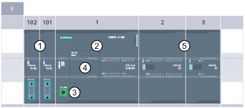
S7-1200 Programmable controller
System Manual, V4.2, 09/2016, A5E02486680-AK 153
Device configuration
6
You create the device configuration for your PLC by adding a CPU and additional modules to
your project.
①
Communication module (CM) or communication processor (CP): Up to 3, inserted in slots 101,
102, and 103
②
CPU: Slot 1
③
PROFINET port of CPU
④
Signal board (SB), communication board (CB) or battery board (BB): up to 1, inserted in the
CPU
⑤
Signal module (SM) for digital or analog I/O: up to 8, inserted in slots 2 through 9
(CPU 1214C, CPU 1215C and CPU 1217C allow 8, CPU 1212C allows 2, CPU 1211C does not
allow any)
Configuration control
Device configuration for the S7-1200 also supports "configuration control (Page 159)" where
you can configure a maximum configuration for a project including modules that you might
not actually use. This feature, sometimes also called "option handling", allows you to
configure a maximum configuration that you might use with variations in the installed
modules in multiple applications.
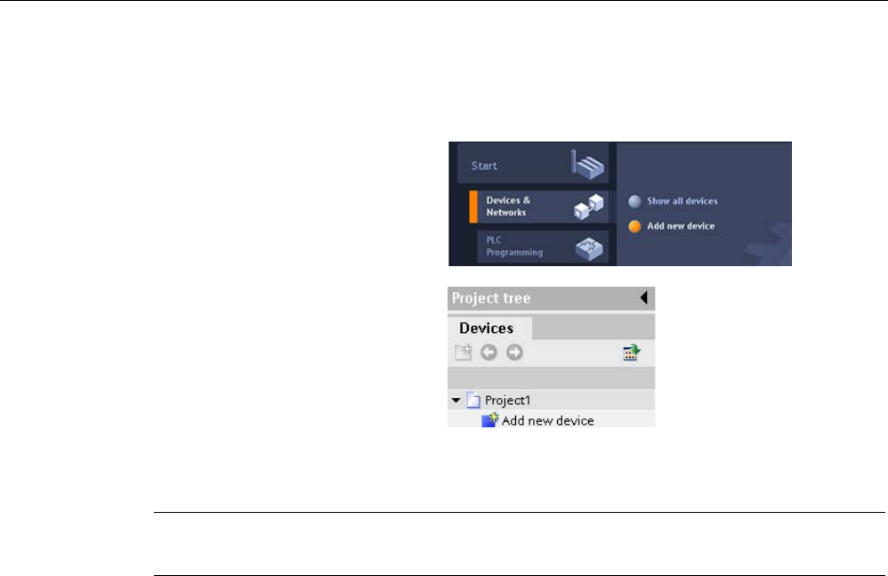
Device configuration
6.1 Inserting a CPU
S7-1200 Programmable controller
154 System Manual, V4.2, 09/2016, A5E02486680-AK
6.1
Inserting a CPU
You can insert a CPU into your pr
o-
ject from either the Portal view or the
Project view of STEP
7:
•
In the Porta
l view, select "Devices
& Networks" and click "Add new
device".
•
In the Project view, under the
project name, double-click "Add
new device".
Be sure you insert the correct model and firmware version from the list. Selecting the CPU
from the "Add new device" dialog creates the rack and CPU.
Note
With STEP
7 V14, you cannot add a V1.0 S7-1200 CPU to your project.
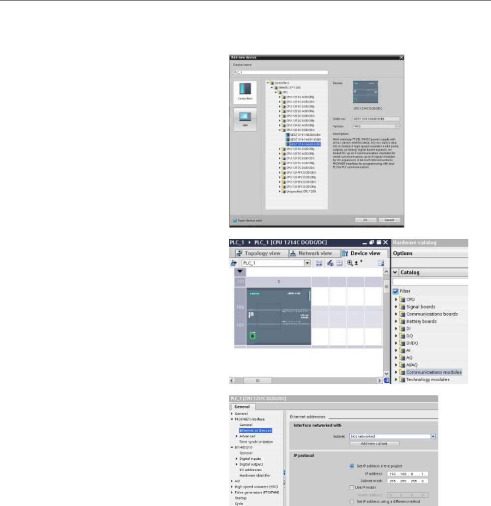
Device configuration
6.1 Inserting a CPU
S7-1200 Programmable controller
System Manual, V4.2, 09/2016, A5E02486680-AK 155
"Add new device" dialog
Device view of the hardware
configuration
Selecting the CPU in the Device
view d
isplays the CPU proper-
ties in the inspector window.
The CPU does not have a pre
-
configured IP address. You must
manually assign an IP address
for the CPU during the device
configuration. If your CPU is
connected to a router on the
network, you also enter t
he IP
address for a router.
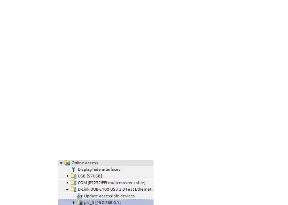
Device configuration
6.2 Uploading the configuration of a connected CPU
S7-1200 Programmable controller
156 System Manual, V4.2, 09/2016, A5E02486680-AK
6.2
Uploading the configuration of a connected CPU
STEP 7 provides two methods for uploading the hardware configuration of a connected
CPU:
● Uploading the connected device as a new station
● Configuring an unspecified CPU and detecting the hardware configuration of the
connected CPU
Note, however, that the first method uploads both the hardware configuration and the
software of the connected CPU.
Uploading a device as a new station
To upload a connected device as a new station, follow these steps:
1. Expand your communications interface from the "Online access" node of the project tree.
2. Double-click "Update accessible devices".
3. Select the PLC from the detected devices.
4. From the Online menu of STEP 7, select the "Upload device as new station (hardware
and software)" menu command.
STEP 7 uploads both the hardware configuration and the program blocks.
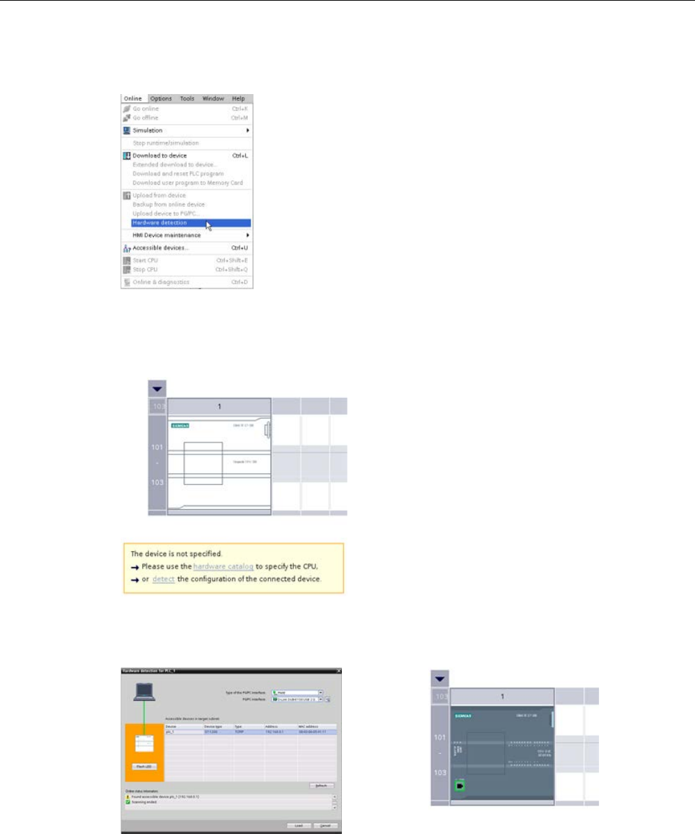
Device configuration
6.2 Uploading the configuration of a connected CPU
S7-1200 Programmable controller
System Manual, V4.2, 09/2016, A5E02486680-AK 157
Detecting the hardware configuration of an unspecified CPU
If you are c
onnected to a CPU, you can upload the
configuration of that CPU, including any modules, to
your project. Simply create a new project and select
the "unspecified CPU" instead of selecting a specific
CPU. (You can also skip the device configuration e
n-
tirely by selecting the "Create a PLC program" from the
"First steps". STEP 7 then automatically creates an
unspecified CPU.)
From the program editor, you select the "Hardware
detection" command from the "Online" menu.
From the device configuration editor, you select the option for detecting the configuration of
the connected device.
After you select the CPU from the online dialog and click the Load
button, STEP 7 uploads
the hardware configuration from the CPU, including any modules (SM, SB, or CM). You can
then configure the parameters for the CPU and the modules (Page 170).
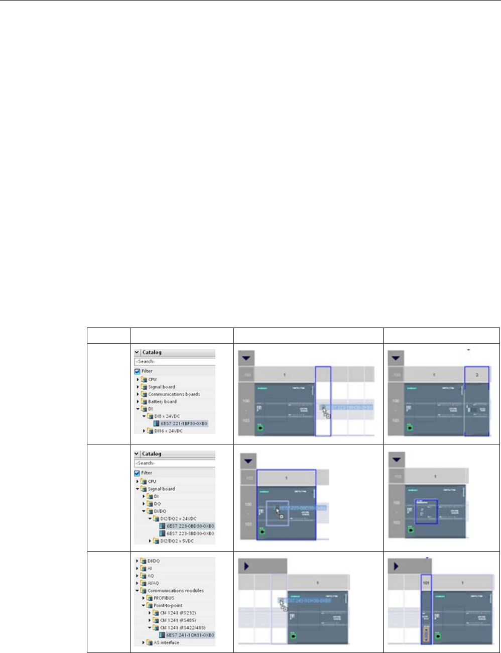
Device configuration
6.3 Adding modules to the configuration
S7-1200 Programmable controller
158 System Manual, V4.2, 09/2016, A5E02486680-AK
6.3
Adding modules to the configuration
Use the hardware catalog to add modules to the CPU:
● Signal module (SM) provides additional digital or analog I/O points. These modules are
connected to the right side of the CPU.
● Signal board (SB) provides just a few additional I/O points for the CPU. The SB is
installed on the front of the CPU.
● Battery Board 1297 (BB) provides long-term backup of the realtime clock. The BB is
installed on the front of the CPU.
● Communication board (CB) provides an additional communication port (such as RS485).
The CB is installed on the front of the CPU.
● Communication module (CM) and communication processor (CP) provide an additional
communication port, such as for PROFIBUS or GPRS. These modules are connected to
the left side of the CPU.
To insert a module into the device configuration, select the module in the hardware catalog
and either double-click or drag the module to the highlighted slot. You must add the modules
to the device configuration and download the hardware configuration to the CPU for the
modules to be functional.
Table 6- 1 Adding a module to the device configuration
Module
Select the module
Insert the module
Result
SM
SB, BB
or CB
CM or
CP

Device configuration
6.4 Configuration control
S7-1200 Programmable controller
System Manual, V4.2, 09/2016, A5E02486680-AK 159
With the "configuration control" feature (Page 159), you can add signal modules and signal
boards to your device configuration that might not correspond to the actual hardware for a
specific application, but that will be used in related applications that share a common user
program, CPU model, and perhaps some of the configured modules.
6.4
Configuration control
6.4.1
Advantages and applications of configuration control
Configuration control can be a useful solution when you create an automation solution
(machine) that you intend to use with variations in multiple installations.
You can load a STEP 7 device configuration and user program to different installed PLC
configurations. You only need to make a few easy adaptations to make the STEP 7 project
correspond to the actual installation.
6.4.2
Configuring the central installation and optional modules
Configuration control with STEP 7 and the S7-1200 enables you to configure a maximum
configuration for a standard machine and to operate versions (options) that use a subset of
this configuration. The PROFINET with STEP 7 manual
(http://support.automation.siemens.com/WW/view/en/49948856) refers to these types of
projects as "standard machine projects".
A control data record that you program in the startup program block notifies the CPU as to
which modules are missing in the real installation as compared to the configuration or which
modules are located in different slots as compared to the configuration. Configuration control
does not have an impact on the parameter assignment of the modules.
Configuration control gives you the flexibility to vary the installation as long as you can derive
the real configuration from the maximum device configuration in STEP 7.
To activate configuration control and structure the required control data record, follow these
steps:
1. Optionally, reset the CPU to factory settings to ensure that an incompatible control data
record is not present in the CPU.
2. Select the CPU in device configuration in STEP 7.
3. From the Configuration control node in the CPU properties, select the "Enable
reconfiguration of device with user program" check box.
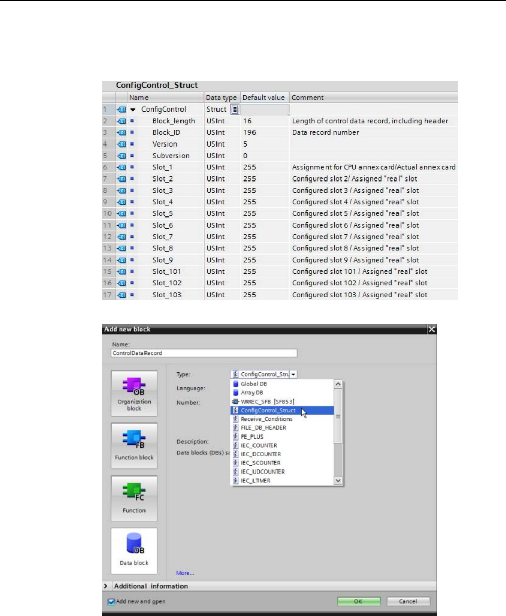
Device configuration
6.4 Configuration control
S7-1200 Programmable controller
160 System Manual, V4.2, 09/2016, A5E02486680-AK
4. Create a PLC data type to contain the control data record. Configure it as a struct that
includes four USints for configuration control information and additional USints to
correspond to the slots of a maximum S7-1200 device configuration, as follows:
5. Create a data block of the PLC data type that you created.
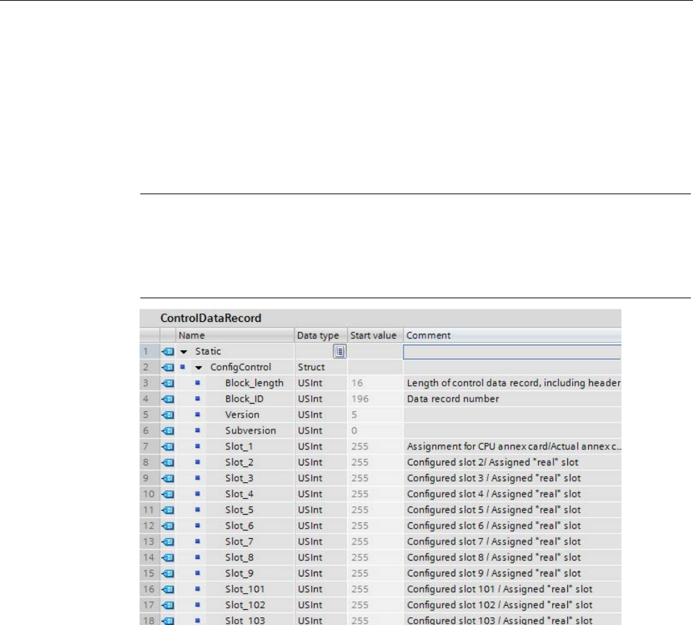
Device configuration
6.4 Configuration control
S7-1200 Programmable controller
System Manual, V4.2, 09/2016, A5E02486680-AK 161
6. In this data block, configure the Block_length, Block_ID, Version, and Subversion as
shown below. Configure the values for the slots based on their presence or absence and
position in your actual installation:
– 0: Configured module is not present in the actual configuration. (The slot is empty.)
– 1 to 9, 101 to 103: The actual slot position for the configured slot
– 255: The STEP 7 device configuration does not include a module in this slot.
Note
Configuration control not available for HSCs and PTOs on the signal board
If you have a signal board in the CPU that you configure for HSCs or PTOs, you must not
disable it with a "0" in Slot_1 of the configuration control data record. Configured HSC and
PTO devices of the CPU are mandatory regarding configurati
on control.
See Example of configuration control (Page 166) for an explanation of how to assign the
slot values.
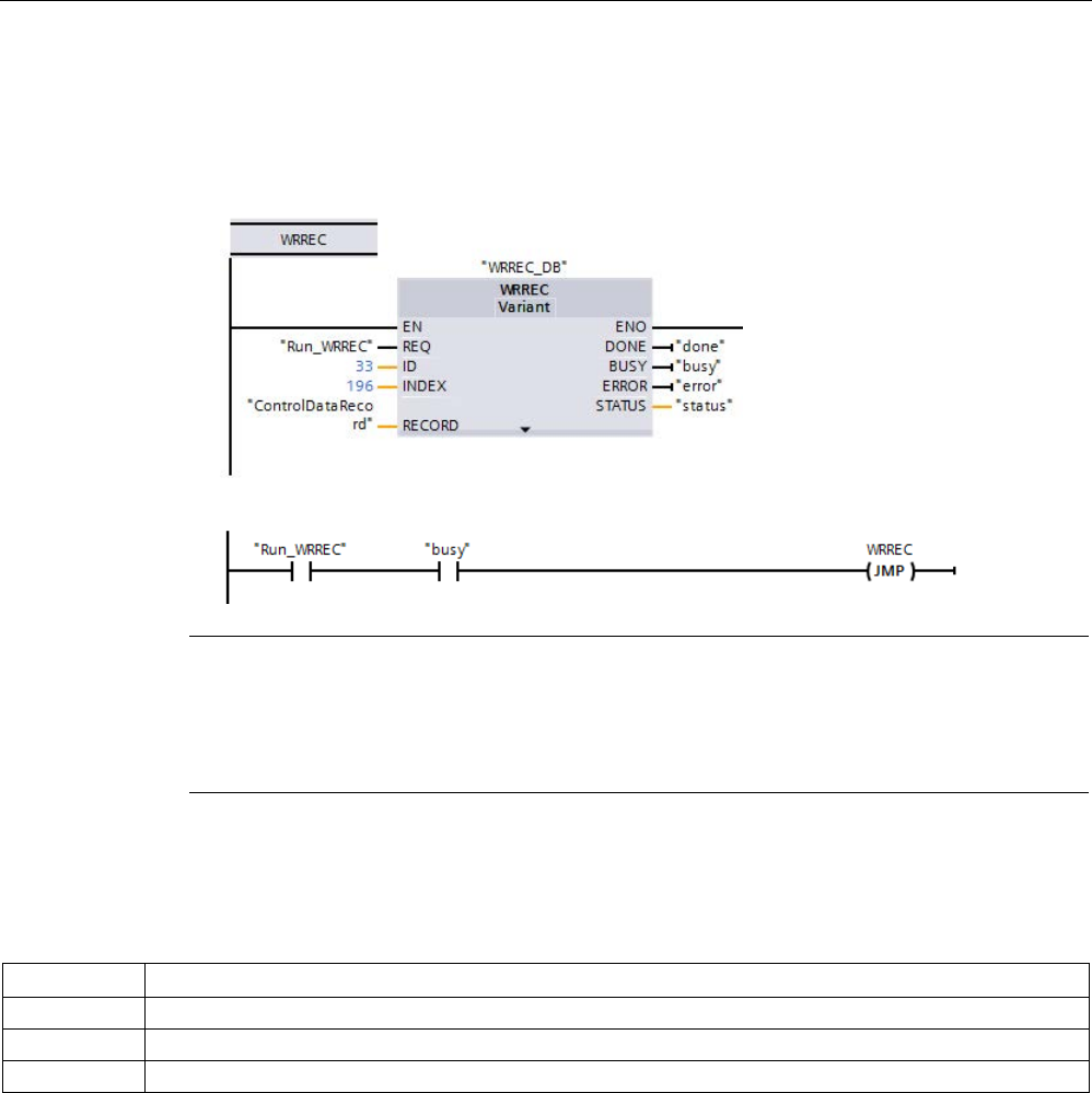
Device configuration
6.4 Configuration control
S7-1200 Programmable controller
162 System Manual, V4.2, 09/2016, A5E02486680-AK
7. In the startup OB, call the extended WRREC (Write data record) instruction to transfer the
control data record that you created to index 196 of hardware ID 33. Use a label and JMP
(jump) instruction to wait for the WRREC instruction to complete.
Network 1:
Network 2:
Note
Configuration control is not in effect until the WRREC instruction transfers the control data
record in the startup OB. If you have enabled configuration control and the CPU does not
have the con
trol data record, it will go to STOP mode when it exits STARTUP mode. Be sure
that you program the startup OB to transfer the control data record.
Module arrangement
The following table shows the slot number assignment:
Slot
Modules
1
Signal board or communication board (CPU annex card)
2 to 9
Signal modules
101 to 103
Communication modules

Device configuration
6.4 Configuration control
S7-1200 Programmable controller
System Manual, V4.2, 09/2016, A5E02486680-AK 163
Control data record
A control data record 196 contains the slot assignment and represents the actual
configuration, as shown below:
Byte
Element
Value
Explanation
0
Block length
16
Header
1 Block ID 196
2
Version
5
3 Subversion 0
4
Assignment of CPU annex card
Actual annex card, 0, or 255*
Control element
Describes in each element which
re
al slot in the device is assigned to
the configured slot.
5
Assignment of configured slot 2
Actual slot, 0, or 255*
...
...
...
12
Assignment of configured slot 9
Actual slot, 0, or 255*
13
Assignment of configured slot 101
Actual slot or 255*
Unlike signal modules, the actual
slot for physically-present commu-
nication modules must be the same
as the configured slot.
14
Assignment of configured slot 102
Actual slot or 255*
15 Assignment of configured slot 103 Actual slot or 255*
*Slot values:
0
: Configured module is not present in the actual configuration. (The slot is empty.)
1 to 9, 101 to 103: The actual slot position for the configured slot
255: The STEP 7 device configuration does not include a module in this slot.
Note
Alternative to creating a PLC tag type
As an alternative to creating a custom PLC tag type, you can create a data block directly with
all of the structure elements of a control data record. You could even configure multiple
structs in this data block to serve as multiple
control data record configurations. Either
implementation is an effective way to transfer the control data record during startup.

Device configuration
6.4 Configuration control
S7-1200 Programmable controller
164 System Manual, V4.2, 09/2016, A5E02486680-AK
Rules
Observe the following rules:
● Configuration control does not support position changes for communication modules. The
control data record slot positions for slots 101 to 103 must correspond to the actual
installation. If you have not configured a module for the slot in your device configuration,
enter 255 for that slot position in the control data record. If you have configured a module
for the slot, enter the configured slot as the actual slot for that slot position.
● F-I/O modules do not support configuration control. The control data record slot positions
for an F-I/O module must equal the configured slot position for the F-I/O module. If you
attempt to move or delete a configured F-I/O module using the control data record, then
all actually-installed F-I/O modules will raise a "parameter assignment" error and disallow
exchange.
● You cannot have embedded empty (unused) slots between filled (used) slots. For
example, if the actual configuration has a module in slot 4, then the actual configuration
must also have modules in slots 2 and 3. Correspondingly, if the actual configuration has
a communication module in slot 102, then the actual configuration must also have a
module in slot 101.
● If you have enabled configuration control, the CPU is not ready for operation without a
control data record. The CPU returns from startup to STOP if a startup OB does not
transfer a valid control data record. The CPU does not initialize the central I/O in this case
and enters the cause for the STOP mode in the diagnostics buffer.
● The CPU saves a successfully-transferred control data record in retentive memory, which
means that it is not necessary to write the control data record 196 again at a restart if you
have not changed the configuration.
● Each real slot must be present only once in the control data record.
● You can only assign a real slot to one configured slot.
Note
Modifying a configuration
The writing of a control data record with a modified configuration triggers the following
automatic reaction by the CPU: Memory reset with subsequent startup with this modified
configuration.
As a result of this reaction, the CPU deletes the original
control data record and saves the
new control data record retentively.

Device configuration
6.4 Configuration control
S7-1200 Programmable controller
System Manual, V4.2, 09/2016, A5E02486680-AK 165
Behavior during operation
For the online display and for the display in the diagnostics buffer (module OK or module
faulty), STEP 7 uses the device configuration and not the differing real configuration.
Example:
A module outputs diagnostics data. This module is configured in slot 4, but is
actually inserted in slot 3. The online view indicates that configured slot 4 is faulty. In the real
configuration, the module at slot 3 indicates an error by its LED display.
If you have configured modules as missing in the control data record (0 entry), the
automation system behaves as follows:
● Modules designated as not present in the control data record do not supply diagnostics
and their status is always OK. The value status is OK.
● Direct writing access to the outputs or writing access to the process image of outputs that
are not present proceeds with no effect; the CPU reports no access error.
● Direct read access to the inputs or read access to the process image of inputs that are
not present results in a value "0" for each input; the CPU reports no access error.
● Writing a data record to a module that is not present proceeds with no effect; the CPU
reports no error.
● Attempting to read a data record from module that is not present resuls in an error
because the CPU cannot return a valid data record.
Error messages
The CPU returns the following error messages if an error occurs during writing of the control
data record:
Error code
Meaning
16#80B1
Invalid length; the length information in the control data record is not correct.
16#80B5 Configuration control parameters not assigned
16#80E2 Data record was transferred in the wrong OB context. The data record must be transferred in the
startup OB.
16#80B0 Block type (byte 2) of control data record is not equal to 196.
16#80B8 Parameter error; module signals invalid parameters, for example:
• The control data record attempts to modify the configuration of a communication module or a
communication annex card. The real configuration for communication modules and a communica-
tion annex card must equal the STEP 7 configuration.
• The assigned value for an unconfigured slot in the STEP 7 project is not equal to 255.
• The assigned value for a configured slot is out of range.
• The assigned configuration has an "internal" empty slot, for example, slot n is assigned and slot
n-1 is not assigned.
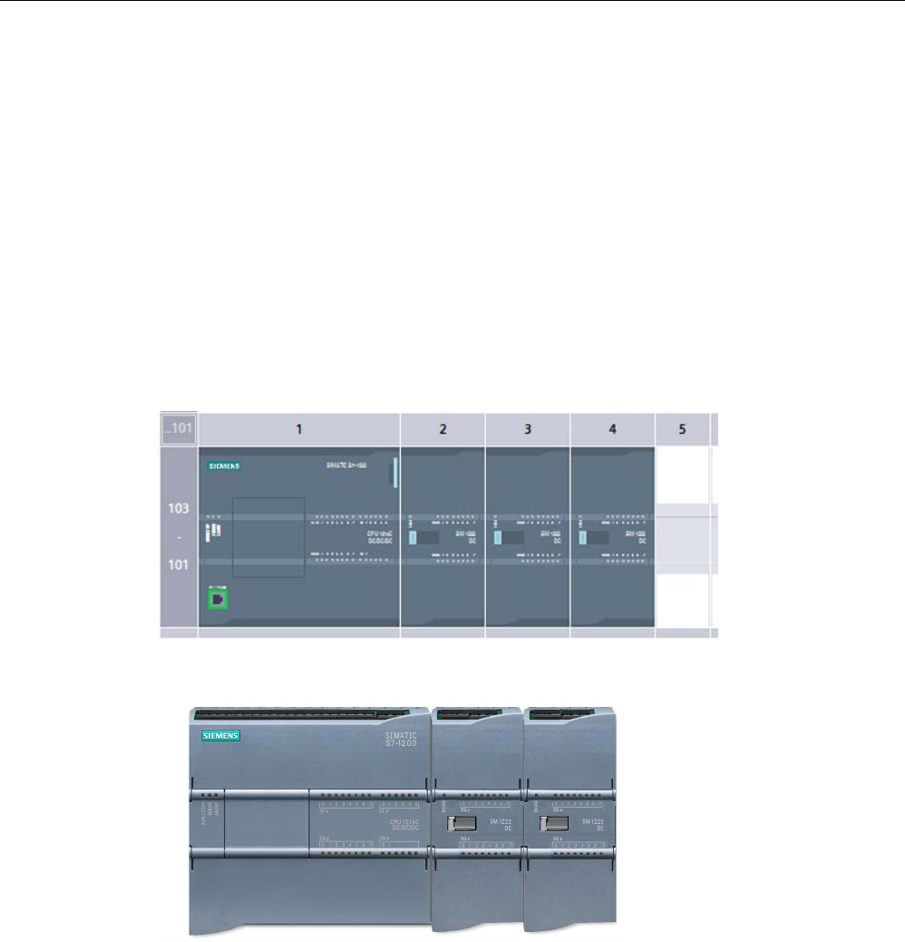
Device configuration
6.4 Configuration control
S7-1200 Programmable controller
166 System Manual, V4.2, 09/2016, A5E02486680-AK
6.4.3
Example of configuration control
This example describes a configuration consisting of a CPU and three I/O modules.The
module at slot 3 is not present in the first actual installation, so you use configuration control
to "hide" it.
In the second installation, the application includes the module that was initially hidden but
now includes it in the last slot. A modified control data record provides the information about
the slot assignments of the modules.
Example: Actual installation with configured but unused module
The device configuration contains all modules that can be present in an actual installation
(maximum configuration). In this case, the module that is in slot 3 in the device configuration
is not present in the real installation.
Figure 6-1 Device configuration of maximum installation with three signal modules
Figure 6-2 Actual installation with module configured in slot 3 absent, and module configured for slot
4 in actual slot 3
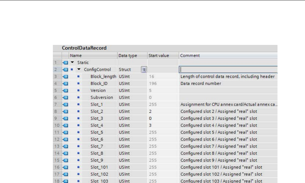
Device configuration
6.4 Configuration control
S7-1200 Programmable controller
System Manual, V4.2, 09/2016, A5E02486680-AK 167
To indicate the absence of the missing module, you must configure slot 3 in the control data
record with 0.
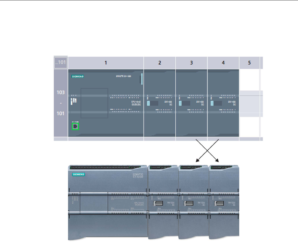
Device configuration
6.4 Configuration control
S7-1200 Programmable controller
168 System Manual, V4.2, 09/2016, A5E02486680-AK
Example: Actual installation with module subsequently added to a different slot
In the second example, the module in slot 3 of the device configuration is present in the
actual installation but is in slot 4.
Figure 6-3 Device configuration compared to actual installation with modules in slots 3 and 4
swapped
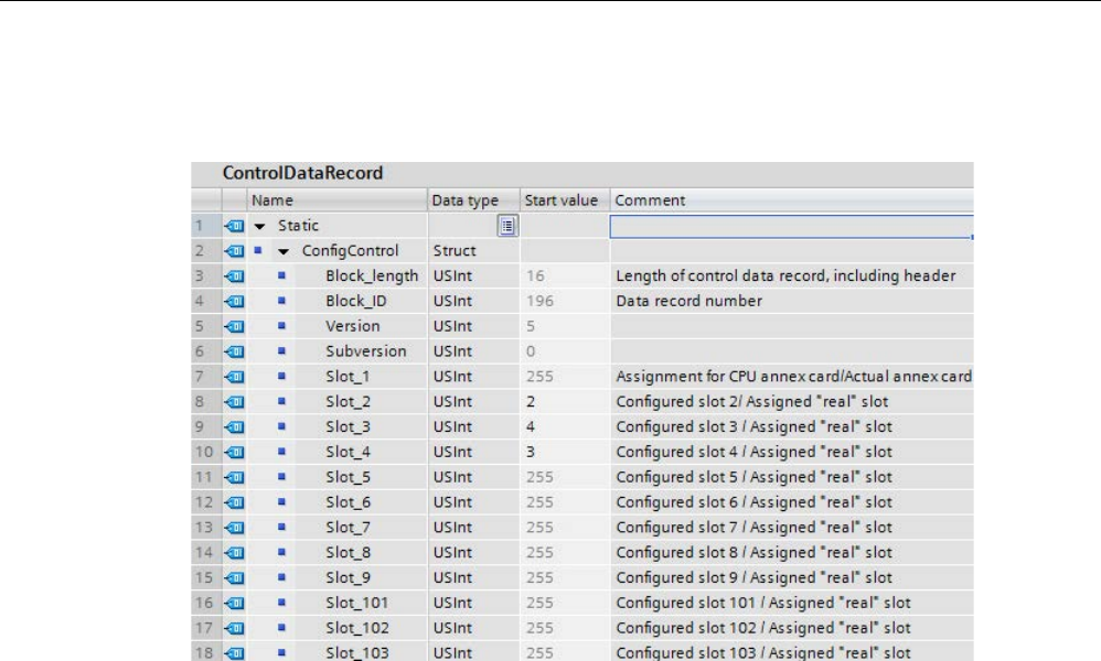
Device configuration
6.4 Configuration control
S7-1200 Programmable controller
System Manual, V4.2, 09/2016, A5E02486680-AK 169
To correlate the device configuration to the actual installation, edit the control data record to
assign the modules to the correct slot positions.
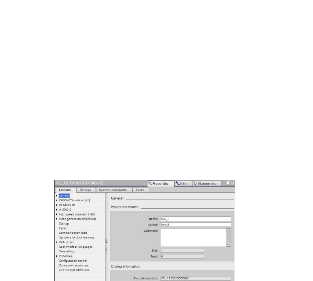
Device configuration
6.5 Changing a device
S7-1200 Programmable controller
170 System Manual, V4.2, 09/2016, A5E02486680-AK
6.5
Changing a device
You can change the device type of a configured CPU or module. From Device configuration,
right-click the device and select "Change device" from the context menu. From the dialog,
navigate to and select the CPU or module that you want to replace. The Change device
dialog shows you compatibility information between the two devices.
For considerations on changing devices between different CPU versions, refer to
Exchanging a V3.0 CPU for a V4.2 CPU (Page 1571).
6.6
Configuring the operation of the CPU
6.6.1
Overview
To configure the operational parameters for the CPU, select the CPU in the Device view
(blue outline around whole CPU), and use the "Properties" tab of the inspector window.

Device configuration
6.6 Configuring the operation of the CPU
S7-1200 Programmable controller
System Manual, V4.2, 09/2016, A5E02486680-AK 171
Table 6- 2 CPU properties
Property
Description
PROFINET interface
Sets the IP address for the CPU and time synchronization
DI, DO, and AI Configures the behavior of the local (on-board) digital and analog I/O (for example, digital
input filter times and digital output reaction to a CPU stop).
High-speed counters
(Page 555) and pulse gen-
erators (Page 492)
Enables and configures the high-speed counters (HSC) and the pulse generators used for
pulse-train operations (PTO) and pulse-width modulation (PWM)
When you configure the outputs of the C
PU or signal board as pulse generators (for use with
the PWM or motion control instructions), the corresponding output addresses are removed
from the Q memory and cannot be used for other purposes in your user program. If your
user program writes a value to an output used as a pulse generator, the CPU does not write
that value to the physical output.
Startup (Page 87)
Startup after POWER ON:
Selects the behavior of the CPU following an off-to-on transition,
such as to start in STOP mode or to go to RUN mode after a warm restart
Supported hardware compatibility:
Configures the substitution strategy for all system com-
ponents (SM, SB, CM, CP and CPU):
• Allow acceptable substitute
• Allow any substitute (default)
Each module internally contains substitution compatibility requirements based on the num-
ber of I/O, electrical compatibility, and other corresponding points of comparison. For exam-
ple, a 16-channel SM could be an acceptable substitute for an 8-channel SM, but an 8-
channel SM could not be an acceptable substitute for a 16-channel SM. If you select "Allow
acceptable substitute", STEP 7 enforces the substitution rules; otherwise, STEP 7 allows
any substitution.
Parameter assignment time for distributed I/O:
Configures a maximum amount of time (de-
fault: 60000 ms) for the distributed I/O to be brought online. (The CMs and CPs receive
power and communication parameters from the CPU during startup. This assignment time
allows time for the I/O connected to the CM or CP to be brought online.)
The CPU goes to RUN as soon as the distributed I/O is online, regardless of the assignment
time. If the distributed I/O has not been brought online within this time, the CPU still goes to
RUN--without the distributed I/O.
Note:
If your configuration uses a CM 1243-
5 (PROFIBUS master), do not set this parameter
below 15 seconds (15000 ms) to ensure that the module can be brought online.
OBs should be interruptible
: Configures whether OB execution (for all OBs) in the CPU is
interruptible or non-interruptible (Page 105)
Cycle (Page 109)
Defines a maximum cycle time or a fixed minimum cycle time
Communication load
Allocates a percentage of the CPU time to be dedicated to communication tasks
System and clock memory
(Page 112)
Enables a byte for "system memory" functions and enables a byte for "clock memory" func-
tions (where each bit toggles on and off at a predefined frequency)
Web server (Page 1001)
Enables and configures the Web server feature
Time of day
Selects the time zone and configures daylight saving time
Multilingual support
(Page 175)
Assigns a project language for the Web server to use for displaying diagnostic buffer entry
texts for each of the possible Web server user interface display languages.
Protection (Page 210)
Sets the read/write protection and passwords for accessing the CPU
Configuration control
(Page 159)
Enables configuring a master device configuration that you can control for different actual
device configurations
Connection resources
(Page 801)
Provides a summary of the communication connection resources that are available for the
CPU and the number of connection resources that have been configured
Overview of addresses
Provides a summary of the I/O addresses that have been configured for the CPU
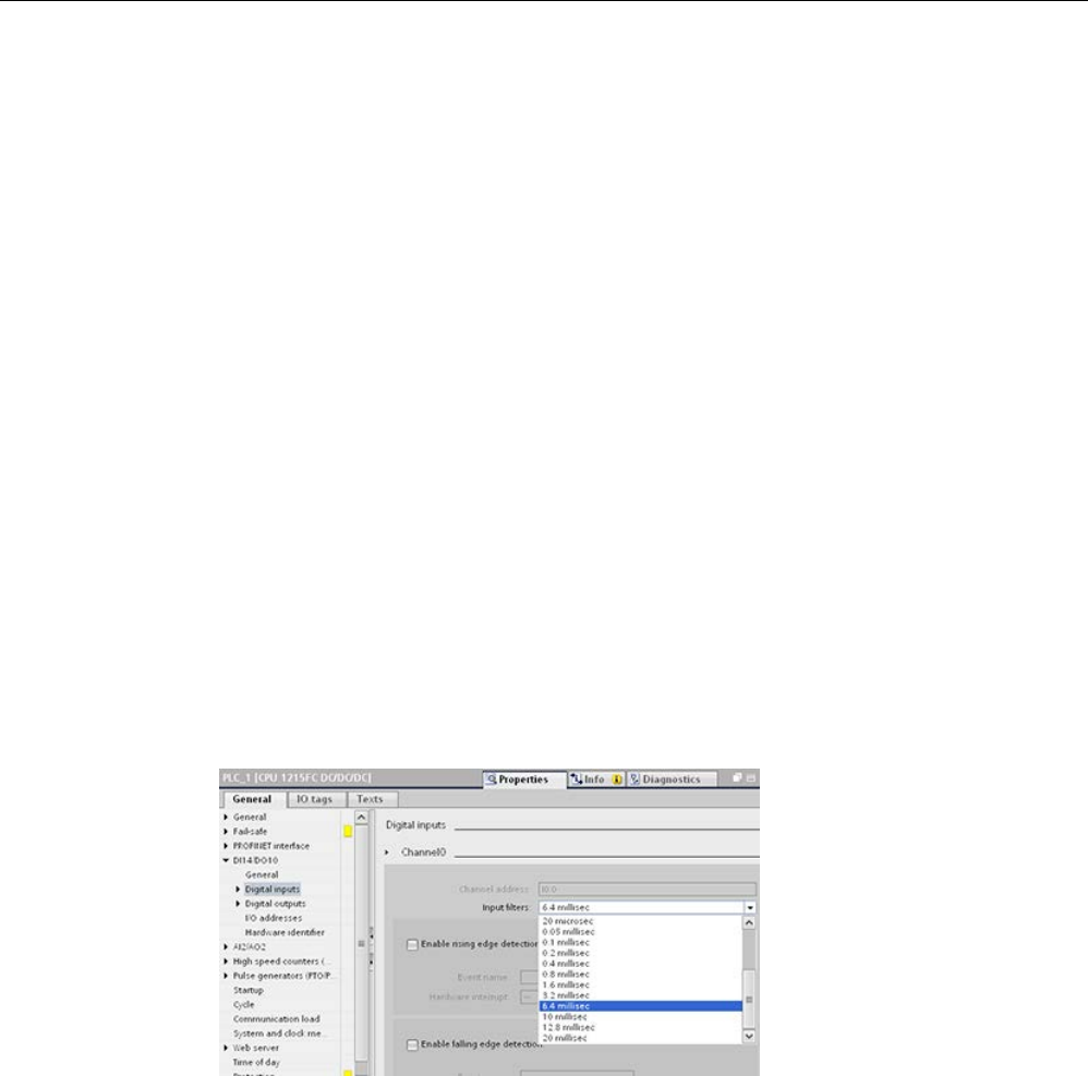
Device configuration
6.6 Configuring the operation of the CPU
S7-1200 Programmable controller
172 System Manual, V4.2, 09/2016, A5E02486680-AK
6.6.2
Configuring digital input filter times
The digital input filters protect your program from responding to unwanted fast changes in
the input signals, as may result from switch contact bounce or electrical noise. The default
filter time of 6.4 ms blocks unwanted transitions from typical mechanical contacts. Different
points in your application can require shorter filter times to detect and respond to inputs from
fast sensors, or longer filter times to block slow contact bounce or longer impulse noise.
An input filter time of 6.4 ms means that a single signal change, from ‘0’ to ‘1’ or from ‘1’ to
‘0’, must continue for approximately 6.4 ms to be detected, and a single high or low pulse
shorter than approximately 6.4 ms is not detected. If an input signal switches between ‘0’
and ‘1’ more rapidly than the filter time, the input point value can change in the user program
when the accumulated duration of new value pulses over old value pulses exceeds the filter
time.
The digital input filter works this way:
● When a "1" is input, it counts up, stopping at the filter time. The image register point
changes from "0" to "1" when the count reaches the filter time.
● When a "0" is input, it counts down, stopping at "0". The image register point changes
from "1" to "0" when the count reaches "0".
● If the input is changing back and forth, the counter will count up some and count down
some. The image register will change when the net accumulation of counts reaches
either the filter time or "0".
● A rapidly-changing signal with more "0’s" than "1’s" will eventually go to "0", and if there
are more "1’s" than "0’s", the image register will eventually change to "1".
Each input point has a single filter configuration that applies to all uses: process inputs,
interrupts, pulse catch, and HSC inputs. To configure input filter times, select "Digital Inputs".
Device configuration
6.6 Configuring the operation of the CPU
S7-1200 Programmable controller
System Manual, V4.2, 09/2016, A5E02486680-AK 173
The default filter time for the digital inputs is 6.4 ms. You can select a filter time from the
Input filters drop-down list. Valid filter times range from 0.1 us to 20.0 ms.
WARNING
Risks with changes to filter time for digital input channel
If you change the filter time for a digital input channel from a previous setting, a new "0"
level input value may need to stay at "0" for up to 20.0 ms before the filter becomes fully
responsive to new inputs. During this time, short "0" pulse events of duration less than 20.0
ms may not be detected or counted.
This changing of filter times can result in unexpected machine or process operation, which
may cause death or serious injury to personnel, and/or damage to equipment.
To ensure that a new filter time goes immediately into effect, a power cycle of the CPU
must be applied.
Configuring filter times for digital inputs used as HSCs
For inputs that you use as high-speed counters (HSCs), change the input filter time to an
appropriate value to avoid missing counts.
Siemens recommends the following settings:
Type of HSC
Recommended input filter time
1 MHz
0.1 microseconds
100 kHz
0.8 microseconds
30 kHz
3.2 microseconds
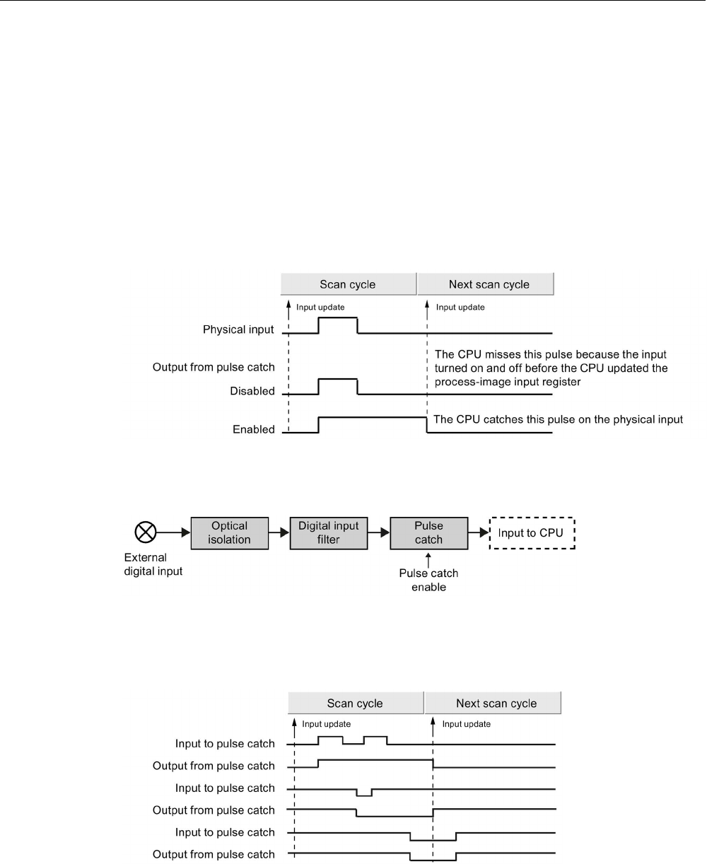
Device configuration
6.6 Configuring the operation of the CPU
S7-1200 Programmable controller
174 System Manual, V4.2, 09/2016, A5E02486680-AK
6.6.3
Pulse catch
The S7-1200 CPU provides a pulse catch feature for digital input points. The pulse catch
feature allows you to capture high-going pulses or low-going pulses that are of such a short
duration that they would not always be seen when the CPU reads the digital inputs at the
beginning of the scan cycle.
When pulse catch is enabled for an input, a change in state of the input is latched and held
until the next input cycle update. This ensures that a pulse which lasts for a short period of
time will be caught and held until the CPU reads the inputs.
The figure below shows the basic operation of the S7-1200 CPU with and without pulse
catch enabled:
Because the pulse catch function operates on the input after it passes through the input filter,
you must adjust the input filter time so that the pulse is not removed by the filter. The figure
below shows a block diagram of the digital input circuit:
The figure below shows the response of an enabled pulse catch function to various input
conditions. If you have more than one pulse in a given scan, only the first pulse is read. If
you have multiple pulses in a given scan, you should use the rising/falling edge interrupt
events:

Device configuration
6.7 Configuring multilingual support
S7-1200 Programmable controller
System Manual, V4.2, 09/2016, A5E02486680-AK 175
6.7
Configuring multilingual support
The Multilingual support settings allow you to assign one of two project languages for each
user interface language for the S7-1200 Web server (Page 1001). You can also configure no
project language for a user interface language.
What is a project language?
The project language is the language that the TIA Portal uses to display user-defined project
texts as network comments and block comments.
You select project languages in the TIA Portal from the
Tools > Project languages
menu
command for the selected project in the project tree.
You can then configure user texts such as network comments and block comments in each
project language from the
Tools > Project texts
menu command. Then when you change the
TIA Portal user interface language, the network comments, block comments, and other
multilingual project texts display in the corresponding project language. You set the TIA
Portal user interface language from the
Options > Settings
project language menu
command.
Project languages and project texts are also configurable from the
Languages & resources
node of the project tree.
The Web server can use one or two of the STEP 7 project languages for the display of
diagnostic buffer messages.
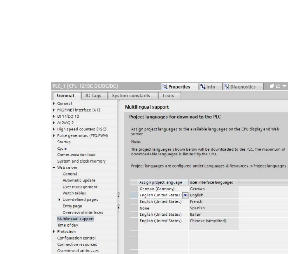
Device configuration
6.8 Configuring the parameters of the modules
S7-1200 Programmable controller
176 System Manual, V4.2, 09/2016, A5E02486680-AK
Project language correspondence to user interface language in the Web server
The Web server supports the same user interface languages as the TIA Portal; however, it
only supports up to two project languages. You can configure the Web server to use one of
two project languages for diagnostic buffer text entries depending on the user interface
language of the Web server. You configure these settings in the "Multilingual support"
properties in the device configuration of the CPU. (Network comments and block comments
and other multilingual texts are not visible from the Web server.)
In the Multilingual support properties, the user interface languages on the right are not
editable. They are the pre-defined languages that are available for both the TIA Portal and
for the Web server user interfaces. The "Assign project language" setting is configurable and
can be one of two of your configured project languages, or it can be "None". Because the
S7-1200 CPU only supports two project languages, you cannot configure the project
language to be the same as the user interface language for all of the supported user
interface languages.
In the configuration below, the Web server displays diagnostic buffer entries (Page 1022) in
German when the Web server user interface is German, displays no texts for diagnostic
buffer events when the Web server user interface is Spanish, and displays diagnostic buffer
entries in English for all other languages.
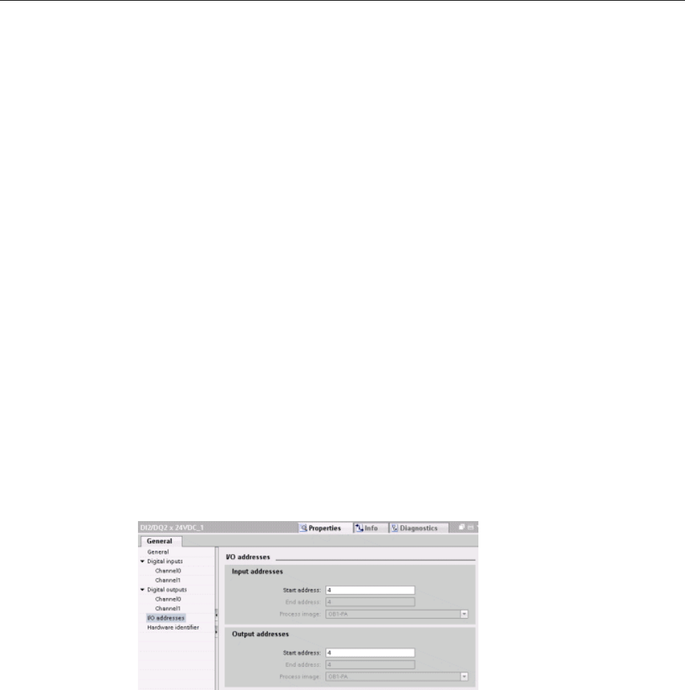
Device configuration
6.8 Configuring the parameters of the modules
S7-1200 Programmable controller
System Manual, V4.2, 09/2016, A5E02486680-AK 177
6.8
Configuring the parameters of the modules
To configure the operational parameters for the modules, select the module in the Device
view and use the "Properties" tab of the inspector window to configure the parameters for the
module.
Configuring a signal module (SM) or a signal board (SB)
The device configuration for signal modules and signal boards provides the means to
configure the following:
● Digital I/O: You can configure inputs for rising-edge detection or falling-edge detection
(associating each with an event and hardware interrupt) or for "pulse catch" (to stay on
after a momentary pulse) through the next update of the input process image. Outputs
can use a freeze or substitute value.
● Analog I/O: For individual inputs, configure parameters, such as measurement type
(voltage or current), range and smoothing, and to enable underflow or overflow
diagnostics. Analog outputs provide parameters such as output type (voltage or current)
and for diagnostics, such as short circuit (for voltage outputs) or upper/lower limit
diagnostics. You do not configure ranges of analog inputs and outputs in engineering
units on the Properties dialog. You must handle this in your program logic as described in
the topic "Processing of analog values (Page 123)".
● I/O addresses: You configure the start address for the set of inputs and outputs of the
module. You can also assign the inputs and outputs to a process image partition (PIP0,
PIP1, PIP2, PIP3, PIP4) or to automatically update, or to use no process image partition.
See "Execution of the user program" (Page 83) for an explanation of the process image
and process image partitions.
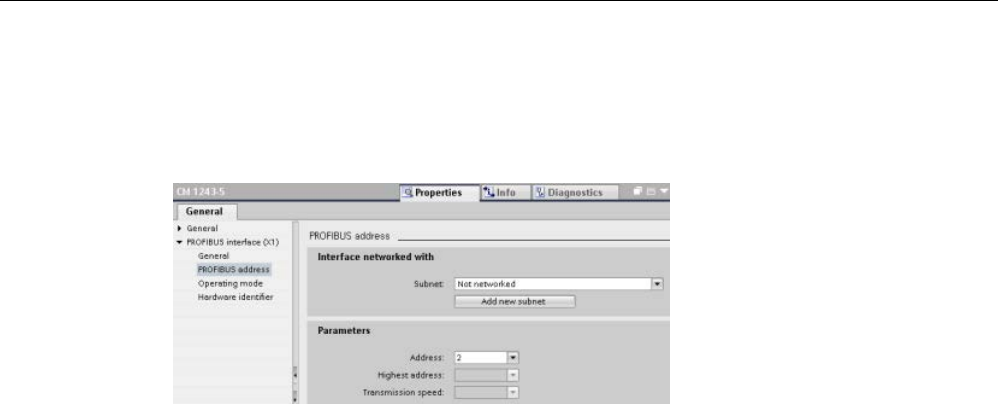
Device configuration
6.8 Configuring the parameters of the modules
S7-1200 Programmable controller
178 System Manual, V4.2, 09/2016, A5E02486680-AK
Configuring a communication interface (CM, CP or CB)
Depending on the type of communication interface, you configure the parameters for the
network.
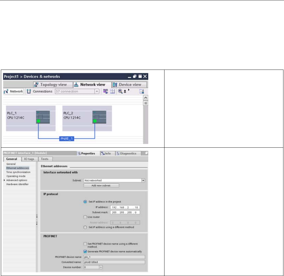
Device configuration
6.9 Configuring the CPU for communication
S7-1200 Programmable controller
System Manual, V4.2, 09/2016, A5E02486680-AK 179
6.9
Configuring the CPU for communication
The S7-1200 is designed to solve your communications and networking needs by supporting
not only the simplest of networks but also supporting more complex networks. The S7-1200
also provides tools that allow you to communicate with other devices, such as printers and
weigh scales which use their own communications protocols.
Use the "Network view" of Device configuration to
create the network connections between the de-
vices in your project. After creating the network
connection, use the "Properties" tab of the inspec-
tor window to configure the parameters of the
network.
Refer to "Creating a network connection"
(Page 806) for further information.
In the Properties window, select the "Ethernet
addresses" configuration entry. STEP 7 displays
the Ethernet address configuration dialog, which
associates the software project with the IP ad-
dress of the CPU that will receive that project.
Note: The S7-1200 CPU does not have a pre-
configured IP address. You must manually assign
an IP address for the CPU.
Refer to "Assigning Internet Protocol (IP) address-
es" (Page 810) for further information.
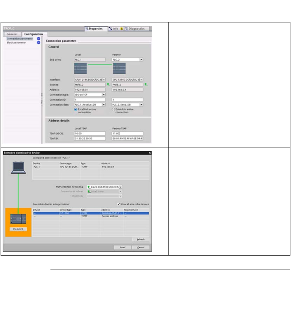
Device configuration
6.10 Time synchronization
S7-1200 Programmable controller
180 System Manual, V4.2, 09/2016, A5E02486680-AK
For the TCP, ISO-on-TCP, and UDP Ethernet
protocols, use the "Properties" of the instruction
(TSEND_C, TRCV_C, or TCON) to configure the
"Local/Partner" connections.
The figure shows the "Connection properties" of
the "Configuration tab" for an ISO-on-TCP con-
nection.
Refer to
"Configuring the Local/Partner connection
path" (Page 807) for further information.
After completing the configuration, download the
project to the CPU. All IP addresses are config-
ured when you download the project.
Refer to "Testing the PROFINET network"
(Page 819) for further information.
Note
To make a connection to your CPU, your network interface card (NIC) and the CPU must be
on the same class of network and on the same subnet. You can either set up your network
interface card to
match the default IP address of the CPU, or you can change the IP address
of the CPU to match the network class and subnet of your network interface card.
Refer to
"Assigning Internet Protocol (IP) addresses" (Page 810) for information about how
to accomplish this.
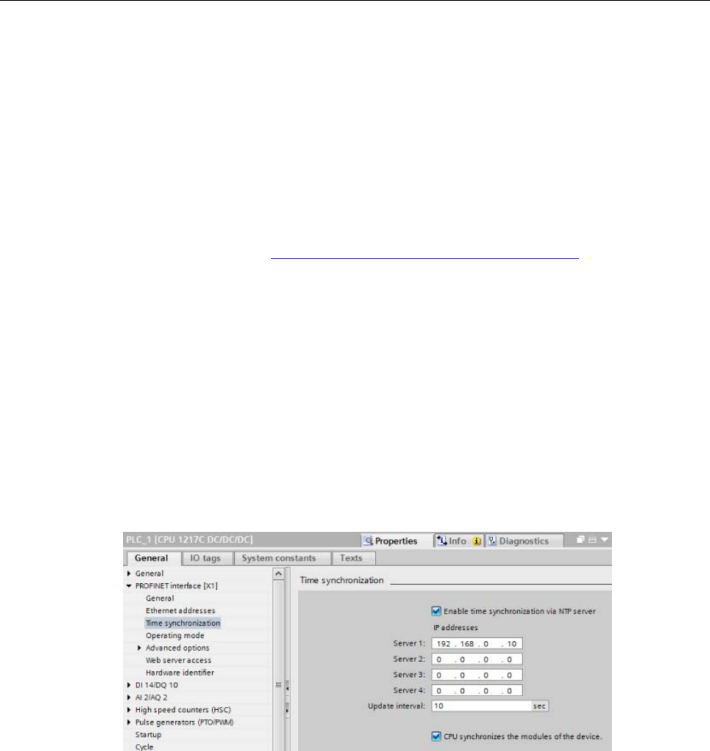
Device configuration
6.10 Time synchronization
S7-1200 Programmable controller
System Manual, V4.2, 09/2016, A5E02486680-AK 181
6.10
Time synchronization
The objective of time synchronization of the time-of-day clocks is to have one master clock to
which all other local clocks are synchronized. Not only are the clocks synchronized initially,
but they are re-synchronized periodically to avoid the effects of drift over time.
In the case of the S7-1200 and its local base components, only the CPU and some of the CP
modules have time-of-day clocks that may need to be synchronized. In general, the CPU’s
time-of-day clock can be synchronized to an external master clock. The external master
clock might supply the time of day using an NTP server or through a CP in the local rack of
the S7-1200 that is connected to a SCADA system which includes a master clock.
Refer to S7-1200 CPs (https://support.industry.siemens.com/cs/us/en/ps) at Siemens
Industry Online Support, Product Support for further information on all S7-1200 CPs that
support the Time sychronization function.
Setting the time-of-day clock
There are three ways to set the time-of-day clock in the S7-1200 CPU:
● Using the NTP server (Page 822)
● Using the Engineering System (ES)
● From the user program
● Using an HMI panel
You configure time synchronization of the CP modules to the CPU’s clock by selecting the
"CPU synchronizes the modules of the device." check box as shown in the following figure:
By default, neither time synchronization using the NTP server nor time synchronization of the
CP clocks to the CPU’s clock is enabled.
You configure time synchronization of the CPU’s clock and time synchronization of the CP
clocks independently. Consequently, you can enable time synchronization of the CP clocks
by the CPU when the CPU’s clock is set by any internal or external method.
You can select the update interval using the NTP server. The update interval of the NTP
server is set to 10 seconds by default.

Device configuration
6.10 Time synchronization
S7-1200 Programmable controller
182 System Manual, V4.2, 09/2016, A5E02486680-AK
When you activate time synchronization in a module, the Engineering Station (ES) prompts
you to select the "CPU synchronizes the modules of the device." if you have not already
selected the check box in the CPU’s "Time synchronization" dialog. The ES also warns you if
you configured more than one master clock source for time synchronization (for example,
you activated time synchronization on more than one CP or on both the CPU and a module).
Note
Activating time synchronization on a CP causes the CP to set the CPU’s clock. Selecting the
"CPU synchronizes the modules of the device" check box in the CPU’s "Time
synchronization" dialog causes the CP modules to automatically synchronize to the CPU’s
clock.
Note
You should assign only one time source for the control system.

S7-1200 Programmable controller
System Manual, V4.2, 09/2016, A5E02486680-AK 183
Programming concepts
7
7.1
Guidelines for designing a PLC system
When designing a PLC system, you can choose from a variety of methods and criteria. The
following general guidelines can apply to many design projects. Of course, you must follow
the directives of your own company's procedures and the accepted practices of your own
training and location.
Table 7- 1 Guidelines for designing a PLC system
Recommended steps
Tasks
Partition your process
or machine
Divide your process or machine into sections that have a level of independence from each other.
These partitions determine the boundaries between controllers and influence the functional de-
scription specifications and the assignment of resources.
Create the functional
specifications
Write the descriptions of operation for each section of the process or machine, such as the I/O
points, the functional description of the operation, the states that must be achieved before allow-
ing action for each actuator (such as a solenoid, a motor,
or a drive), a description of the operator
interface, and any interfaces with other sections of the process or machine.
Design the safety cir-
cuits
Identify any equipment that might require hard-wired logic for safety. Remember that control
devices can fail in an unsafe manner, which can produce unexpected startup or change in the
operation of machinery. Where unexpected or incorrect operation of the machinery could result in
physical injury to people or significant property damage, consider the implementation of electro-
mechanical overrides (which operate independently of the PLC) to prevent unsafe operations.
The following tasks should be included in the design of safety circuits:
• Identify any improper or unexpected operation of actuators that could be hazardous.
• Identify the conditions that would assure the operation is not hazardous, and determine how
to detect these conditions independently of the PLC.
• Identify how the PLC affects the process when power is applied and removed, and also iden-
tify how and w
hen errors are detected. Use this information only for designing the normal and
expected abnormal operation. You should not rely on this "best case" scenario for safety pur-
poses.
• Design the manual or electromechanical safety overrides that block the hazardous operation
independent of the PLC.
• Provide the appropriate status information from the independent circuits to the PLC so that
the program and any operator interfaces have necessary information.
• Identify any other safety-related requirements for safe operation of the process.
Plan system security Determine what level of protection (Page 210) you require for access to your process. You can
password-protect CPUs and program blocks from unauthorized access.

Programming concepts
7.1 Guidelines for designing a PLC system
S7-1200 Programmable controller
184 System Manual, V4.2, 09/2016, A5E02486680-AK
Recommended steps
Tasks
Specify the operator
stations
Based on the requirements of the functional specifications, create the following drawings of the
operator stations:
• Overview drawing that shows the location of each operator station in relation to the process
or machine.
• Mechanical layout drawing of the devices for the operator station, such as display, switches,
and lights.
• Electrical drawings with the associated I/O of the PLC and signal modules.
Create the configura-
tion drawings
Based on the requirements of the functional specification, create configuration drawings of the
control equipment:
• Overview drawing that shows the location of each PLC in relation to the process or machine.
• Mechanical layout drawing of each PLC and any I/O modules, including any cabinets and
other equipment.
• Electrical drawings for each PLC and any I/O modules, including the device model numbers,
communications addresses, and I/O addresses.
Create a list of symbol-
ic names
Create a list of symbolic names for the absolute addresses. Include not only the physical I/O
signals, but also the other elements (such as tag names) to be used in your program.

Programming concepts
7.2 Structuring your user program
S7-1200 Programmable controller
System Manual, V4.2, 09/2016, A5E02486680-AK 185
7.2
Structuring your user program
When you create a user program for the automation tasks, you insert the instructions for the
program into code blocks:
● An organization block (OB) responds to a specific event in the CPU and can interrupt the
execution of the user program. The default for the cyclic execution of the user program
(OB 1) provides the base structure for your user program. If you include other OBs in your
program, these OBs interrupt the execution of OB 1. The other OBs perform specific
functions, such as for startup tasks, for handling interrupts and errors, or for executing
specific program code at specific time intervals.
● A function block (FB) is a subroutine that is executed when called from another code
block (OB, FB, or FC). The calling block passes parameters to the FB and also identifies
a specific data block (DB) that stores the data for the specific call or instance of that FB.
Changing the instance DB allows a generic FB to control the operation of a set of
devices. For example, one FB can control several pumps or valves, with different
instance DBs containing the specific operational parameters for each pump or valve.
● A function (FC) is a subroutine that is executed when called from another code block (OB,
FB, or FC). The FC does not have an associated instance DB. The calling block passes
parameters to the FC. The output values from the FC must be written to a memory
address or to a global DB.
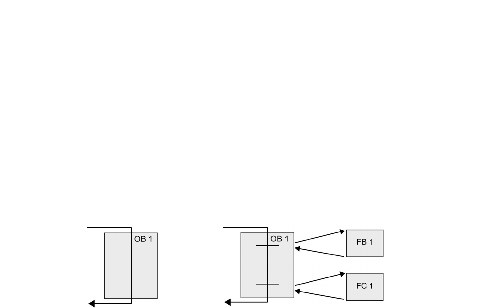
Programming concepts
7.2 Structuring your user program
S7-1200 Programmable controller
186 System Manual, V4.2, 09/2016, A5E02486680-AK
Choosing the type of structure for your user program
Based on the requirements of your application, you can choose either a linear structure or a
modular structure for creating your user program:
● A linear program executes all of the instructions for your automation tasks in sequence,
one after the other. Typically, the linear program puts all of the program instructions into
the OB for the cyclic execution of the program (OB 1).
● A modular program calls specific code blocks that perform specific tasks. To create a
modular structure, you divide the complex automation task into smaller subordinate tasks
that correspond to the technological functions of the process. Each code block provides
the program segment for each subordinate task. You structure your program by calling
one of the code blocks from another block.
Linear structure:
Modular structure:
By creating generic code blocks that can be reused within the user program, you can simplify
the design and implementation of the user program. Using generic code blocks has a
number of benefits:
● You can create reusable blocks of code for standard tasks, such as for controlling a pump
or a motor. You can also store these generic code blocks in a library that can be used by
different applications or solutions.
● When you structure the user program into modular components that relate to functional
tasks, the design of your program can be easier to understand and to manage. The
modular components not only help to standardize the program design, but can also help
to make updating or modifying the program code quicker and easier.
● Creating modular components simplifies the debugging of your program. By structuring
the complete program as a set of modular program segments, you can test the
functionality of each code block as it is developed.
● Creating modular components that relate to specific technological functions can help to
simplify and reduce the time involved with commissioning the completed application.
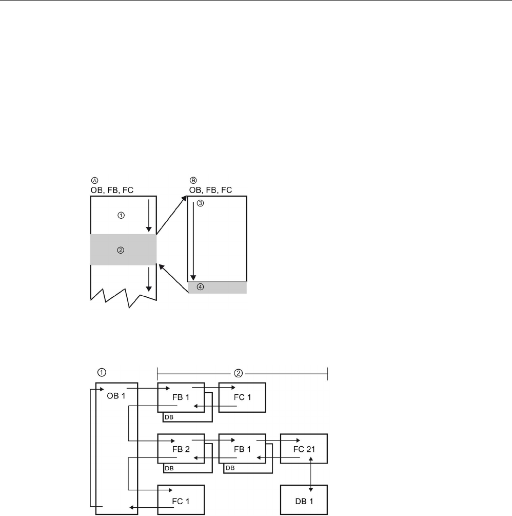
Programming concepts
7.3 Using blocks to structure your program
S7-1200 Programmable controller
System Manual, V4.2, 09/2016, A5E02486680-AK 187
7.3
Using blocks to structure your program
By designing FBs and FCs to perform generic tasks, you create modular code blocks. You
then structure your program by having other code blocks call these reusable modules. The
calling block passes device-specific parameters to the called block.
When a code block calls another code block, the CPU executes the program code in the
called block. After execution of the called block is complete, the CPU resumes the execution
of the calling block. Processing continues with execution of the instruction that follows after
the block call.
A
Calling block
B
Called (or interrupting) block
①
Program execution
②
Instruction or event that initiates the execution of
another block
③
Program execution
④
Block end (returns to calling block)
You can nest the block calls for a more modular structure. In the following example, the
nesting depth is 3: the program cycle OB plus 3 layers of calls to code blocks.
①
Start of cycle
②
Nesting depth
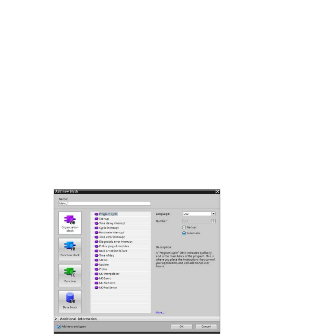
Programming concepts
7.3 Using blocks to structure your program
S7-1200 Programmable controller
188 System Manual, V4.2, 09/2016, A5E02486680-AK
7.3.1
Organization block (OB)
Organization blocks provide structure for your program. They serve as the interface between
the operating system and the user program. OBs are event driven. An event, such as a
diagnostic interrupt or a time interval, causes the CPU to execute an OB. Some OBs have
predefined start events and behavior.
The program cycle OB contains your main program. You can include more than one program
cycle OB in your user program. During RUN mode, the program cycle OBs execute at the
lowest priority level and can be interrupted by all other event types. The startup OB does not
interrupt the program cycle OB because the CPU executes the startup OB before going to
RUN mode.
After finishing the processing of the program cycle OBs, the CPU immediately executes the
program cycle OBs again. This cyclic processing is the "normal" type of processing used for
programmable logic controllers. For many applications, the entire user program is located in
a single program cycle OB.
You can create other OBs to perform specific functions, such as for handling interrupts and
errors, or for executing specific program code at specific time intervals. These OBs interrupt
the execution of the program cycle OBs.
Use the "Add new block" dialog to create new OBs in your user program.
Interrupt handling is always
event
-driven. When such
an event occurs, the CPU
interrupts the execution of
the user program and calls
the OB that was configured
to ha
ndle that event. After
finishing the execution of
the interrupting OB, the
CPU resumes the exec
u-
tion of the user program at
the point of interruption.
The CPU determines the order for handling interrupt events by priority. You can assign
multiple interrupt events to the same priority class. For more information, refer to the topics
on organization blocks (Page 92) and execution of the user program (Page 83).
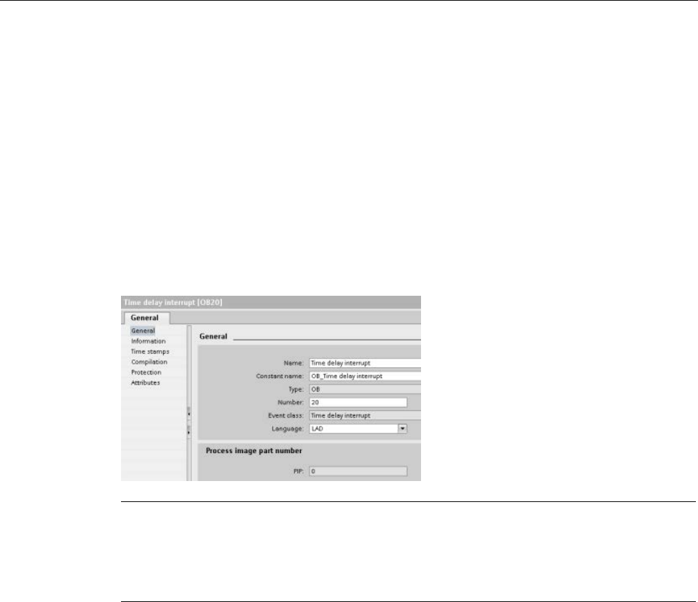
Programming concepts
7.3 Using blocks to structure your program
S7-1200 Programmable controller
System Manual, V4.2, 09/2016, A5E02486680-AK 189
Creating additional OBs
You can create multiple OBs for your user program, even for the program cycle and startup
OB events. Use the "Add new block" dialog to create an OB and enter a name for your OB.
If you create multiple program cycle OBs for your user program, the CPU executes each
program cycle OB in numerical sequence, starting with the program cycle OB with the lowest
number (such as OB 1). For example: after the first program cycle OB (such as OB 1)
finishes, the CPU executes the program cycle OB with the next higher number.
Configuring the properties of an OB
You can modify the properties of an OB. For example, you can configure the OB number or
programming language.
Note
Note that you can assign a process image part number to an OB
that corresponds to PIP0,
PIP1, PIP2, PIP3, or PIP4. If you enter a number for the process image part number, the
CPU creates that process image partition. See the topic "
Execution of the user program
(Page
83)" for an explanation of the process image partitions.

Programming concepts
7.3 Using blocks to structure your program
S7-1200 Programmable controller
190 System Manual, V4.2, 09/2016, A5E02486680-AK
7.3.2
Function (FC)
A function (FC) is a code block that typically performs a specific operation on a set of input
values. The FC stores the results of this operation in memory locations. For example, use
FCs to perform standard and reusable operations (such as for mathematical calculations) or
technological functions (such as for individual controls using bit logic operations). An FC can
also be called several times at different points in a program. This reuse simplifies the
programming of frequently recurring tasks.
An FC does not have an associated instance data block (DB). The FC uses the local data
stack for the temporary data used to calculate the operation. The temporary data is not
saved. To store data permanently, assign the output value to a global memory location, such
as M memory or to a global DB.
7.3.3
Function block (FB)
A function block (FB) is a code block that uses an instance data block for its parameters and
static data. FBs have variable memory that is located in a data block (DB), or "instance" DB.
The instance DB provides a block of memory that is associated with that instance (or call) of
the FB and stores data after the FB finishes. You can associate different instance DBs with
different calls of the FB. The instance DBs allow you to use one generic FB to control
multiple devices. You structure your program by having one code block make a call to an FB
and an instance DB. The CPU then executes the program code in that FB, and stores the
block parameters and the static local data in the instance DB. When the execution of the FB
finishes, the CPU returns to the code block that called the FB. The instance DB retains the
values for that instance of the FB. These values are available to subsequent calls to the
function block either in the same scan cycle or other scan cycles.
Reusable code blocks with associated memory
You typically use an FB to control the operation for tasks or devices that do not finish their
operation within one scan cycle. To store the operating parameters so that they can be
quickly accessed from one scan to the next, each FB in your user program has one or more
instance DBs. When you call an FB, you also specify an instance DB that contains the block
parameters and the static local data for that call or "instance" of the FB. The instance DB
maintains these values after the FB finishes execution.
By designing the FB for generic control tasks, you can reuse the FB for multiple devices by
selecting different instance DBs for different calls of the FB.
An FB stores the Input, Output, and InOut, and Static parameters in an instance DB.
You can also modify and download the function block interface in RUN mode (Page 1341).
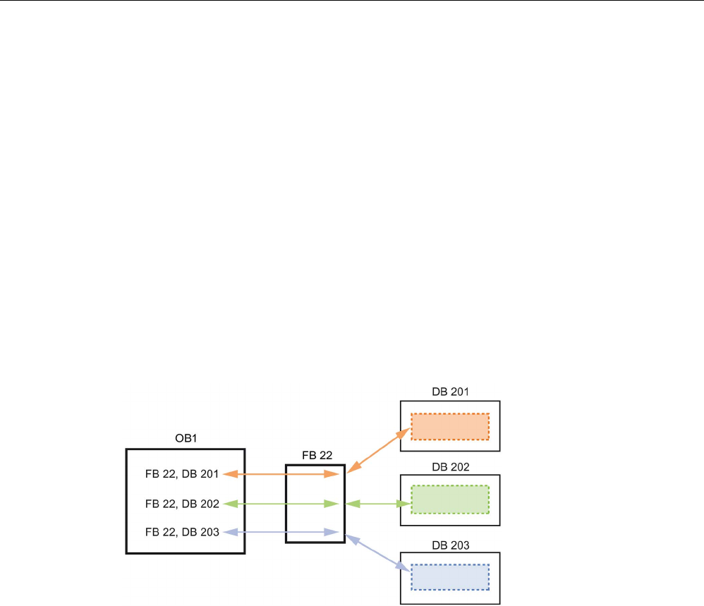
Programming concepts
7.3 Using blocks to structure your program
S7-1200 Programmable controller
System Manual, V4.2, 09/2016, A5E02486680-AK 191
Assigning the start value in the instance DB
The instance DB stores both a default value and a start value for each parameter. The start
value provides the value to be used when the FB is executed. The start value can then be
modified during the execution of your user program.
The FB interface also provides a "Default value" column that allows you to assign a new start
value for the parameter as you are writing the program code. This default value in the FB is
then transferred to the start value in the associated instance DB. If you do not assign a new
start value for a parameter in the FB interface, the default value from instance DB is copied
to start value.
Using a single FB with DBs
The following figure shows an OB that calls one FB three times, using a different data block
for each call. This structure allows one generic FB to control several similar devices, such as
motors, by assigning a different instance data block for each call for the different devices.
Each instance DB stores the data (such as speed, ramp-up time, and total operating time)
for an individual device.
In this example, FB 22 controls three separate devices, with DB 201 storing the operational
data for the first device, DB 202 storing the operational data for the second device, and DB
203 storing the operational data for the third device.

Programming concepts
7.3 Using blocks to structure your program
S7-1200 Programmable controller
192 System Manual, V4.2, 09/2016, A5E02486680-AK
7.3.4
Data block (DB)
You create data blocks (DB) in your user program to store data for the code blocks. All of the
program blocks in the user program can access the data in a global DB, but an instance DB
stores data for a specific function block (FB).
The data stored in a DB is not deleted when the execution of the associated code block
comes to an end. There are two types of DBs:
● A global DB stores data for the code blocks in your program. Any OB, FB, or FC can
access the data in a global DB.
● An instance DB stores the data for a specific FB. The structure of the data in an instance
DB reflects the parameters (Input, Output, and InOut) and the static data for the FB. (The
Temp memory for the FB is not stored in the instance DB.)
Note
Although the instance DB reflects the data for a specific FB, any code block can access
the data in an instance DB.
You can also modify and download data blocks in RUN mode (Page 1341).
Read-only data blocks
You can configure a DB as being read-only:
1. Right-click the DB in the project navigator and select "Properties" from the context menu.
2. In the "Properties" dialog, select "Attributes".
3. Select the "Data block write-protected in the device" option and click "OK".

Programming concepts
7.3 Using blocks to structure your program
S7-1200 Programmable controller
System Manual, V4.2, 09/2016, A5E02486680-AK 193
Optimized and standard data blocks
You can also configure a data block to be either standard or optimized. A standard DB is
compatible with STEP 7 Classic programming tools and the classic S7-300 and S7-400
CPUs. Data blocks with optimized access have no fixed defined structure. The data
elements contain only a symbolic name in the declaration and no fixed address within the
block. The CPU stores the elements automatically in the available memory area of the block
so that there are no gaps in the memory. This makes for optimal use of the memory
capacity.
To set optimized access for a data block, follow these steps:
1. Expand the program blocks folder in the STEP 7 project tree.
2. Right-click the data block and select "Properties" from the context menu.
3. For the attributes, select "Optimized block access".
Note that optimized block access is the default for new data blocks. If you deselect
"Optimized block access", the block uses standard access.
Note
Block access type for an FB and its instance DB
Be sure that if your FB setting is "Optimized block access" then the setting of the instance
DB for that FB is also "Optimized block access". Similarly if you have not selected
"Optimized block access" for the FB such that the FB is of type
standard access, then be
sure that the instance DB is also standard, or not optimized block access.
If you do not have compatible block access types, then changes to the IN/OUT parameter
values of the FB from an HMI during execution of the FB could be lo
st.
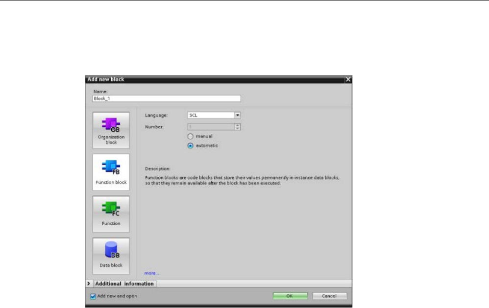
Programming concepts
7.3 Using blocks to structure your program
S7-1200 Programmable controller
194 System Manual, V4.2, 09/2016, A5E02486680-AK
7.3.5
Creating reusable code blocks
Use the "Add new block"
dialog under "Program
blocks" in the Project nav
i-
gator to create OBs, FBs,
FCs, and global DBs.
When you create a code
block, you select the pr
o-
gramming language for the
block. You do not select a
language for a DB because
it only stores data.
Selecting the "Add new
and open" check box (d
e-
fault) opens the code block
in the Project view.
You can store objects you want to reuse in libraries. For each project, there is a project
library that is connected to the project. In addition to the project library, you can create any
number of global libraries that can be used over several projects. Since the libraries are
compatible with each other, library elements can be copied and moved from one library to
another.
Libraries are used, for example, to create templates for blocks that you first paste into the
project library and then further develop there. Finally, you copy the blocks from the project
library to a global library. You make the global library available to other colleagues working
on your project. They use the blocks and further adapt them to their individual requirements,
where necessary.
For details about library operations, refer to the STEP 7 online Help library topics.
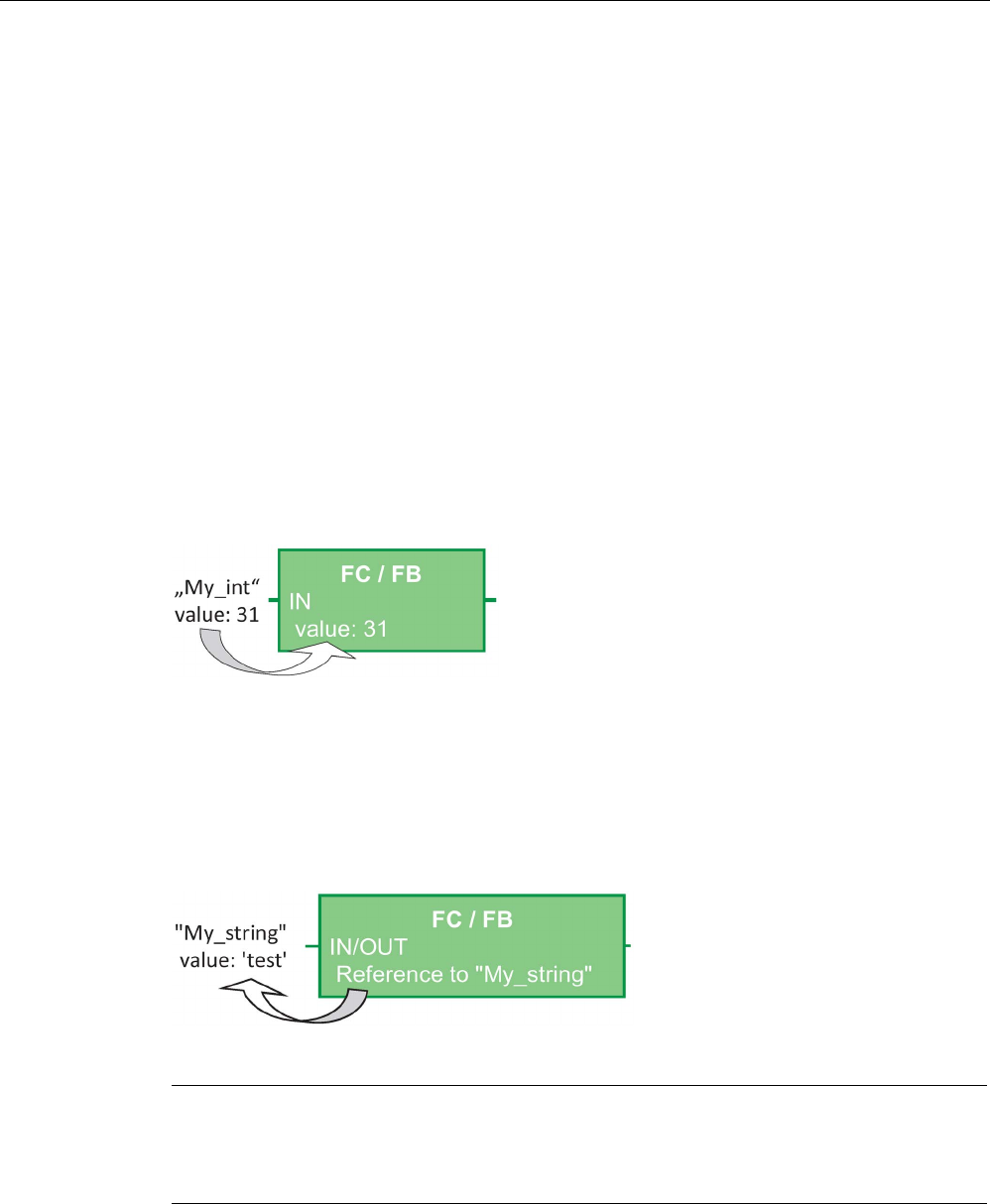
Programming concepts
7.3 Using blocks to structure your program
S7-1200 Programmable controller
System Manual, V4.2, 09/2016, A5E02486680-AK 195
7.3.6
Passing parameters to blocks
Function Blocks (FB) and Functions (FC) have three different interface types:
● IN
● IN/OUT
● OUT
FBs and FCs receive parameters through the IN and IN/OUT interface types. The blocks
process the parameters and return values to the caller through the IN/OUT and OUT
interface types.
The user program transfers parameters using one of two methods.
Call-by-value
When the user program passes a parameter to a function as "call-by-value", the user
program copies the actual parameter value into the input parameter of the block for the IN
interface type. This operation requires additional memory for the copied value.
When the user program calls the block, it copies the values.
Call-by-reference
When the user program passes a parameter to a function as "call-by-reference", the user
program references the address of the actual parameter for the IN/OUT interface type and
does not copy the value. This operation does not require additional memory.
When the user program calls the block, it references the address of the actual parameters.
Note
Generally, use the IN/OUT interface type for structured tags (for example, ARRAY,
STRUCT, and STRING) in order to avoid increasing the required data memory
unnecessarily.

Programming concepts
7.3 Using blocks to structure your program
S7-1200 Programmable controller
196 System Manual, V4.2, 09/2016, A5E02486680-AK
Block optimization and passing parameters
The user program passes FC parameters as "call-by-value" for simple data types (for
example, INT, DINT, and REAL). It passes complex data types (for example, STRUCT,
ARRAY, and STRING) as "call-by-reference".
The user program normally passes FB parameters in the instance Data block (DB)
associated with the FB:
● The user program passes simple data types (for example, INT, DINT, and REAL) as "call-
by-value" by copying the parameters to/from the instance DB.
● The user program copies complex data types (for example, STRUCT, ARRAY, and
STRING) to and from the instance DB for IN and OUT parameter types.
● The user program passes complex data types as "call-by-reference" for the IN/OUT
interface type.
DBs can be created as either "Optimized" or "Standard" (non-optimized). The optimized data
blocks are more compact than the non-optimized data blocks. Also, the ordering of the data
elements within the DB is different for optimized versus non-optimized DBs. Refer to the
"Optimized blocks" section of the S7-Programming Guideline for S7-1200/1500, STEP 7 (TIA
Portal), 03/2014 (http://support.automation.siemens.com/WW/view/en/81318674) for a
discussion of optimized blocks.
You create FBs and FCs to process either optimized or non-optimized data. You can select
the "Optimized block access" check box as one of the attributes for the block. The user
program optimizes program blocks by default, and the program blocks expect data passed to
the block to be in the optimized format.
When the user program passes a complex parameter (for example, a STRUCT) to a
function, the system checks the optimization setting of the data block containing the structure
and the optimization setting of the program block. If you optimize both the data block and the
function, then the user program passes the STRUCT as a "call-by-reference". The same is
true if you select non-optimized for both the data block and the function.
However, if you make the function and data block optimization different (meaning that you
optimized one block and not the other block), the STRUCT must be converted to the format
expected by the function. For example, if you select non-optimized for the data block and
optimized for the function, then a STRUCT in the data block must be converted to an
optimized format before the function can process the STRUCT. The system does this
conversion by making a "copy" of the STRUCT and converting it to the optimized format that
the function expects.
In summary, when the user program passes a complex data type (for example, a STRUCT)
to a function as an IN/OUT parameter, the function expects the user program to pass the
STRUCT as a "call-by-reference":
● If you select optimized or non-optimized for both the data block containing the STRUCT
and the function, the user program passes the data as "call-by-reference".
● If you do not configure the data block and the function with the same optimization settings
(one is optimized and the other is non-optimized), the system must make a copy of the
STRUCT before passing it to the function. Because the system has to make this copy of
the structure, this converts the "call-by-reference", effectively, into a "call-by-value".

Programming concepts
7.3 Using blocks to structure your program
S7-1200 Programmable controller
System Manual, V4.2, 09/2016, A5E02486680-AK 197
Effect of optimization settings on user programs
The copying of the parameter can cause an issue in a user program if an HMI or interrupt
OB modifies elements of the structure. For example, there is an IN/OUT parameter of a
function (normally passed as "call-by-reference"), but the optimization settings of the data
block and function are different:
1. When the user program is ready to call the function, the system must make a "copy" of
the structure to change the format of the data to match the function.
2. The user program calls the function with a reference to the "copy" of the structure.
3. An interrupt OB occurs while the function is executing, and the interrupt OB changes a
value in the original structure.
4. The function completes and, since the structure is an IN/OUT parameter, the system
copies the values back to the original structure in the original format.
The effect of making the copy of the structure to change the format is that the data written by
the interrupt OB is lost. The same can happen when writing a value with an HMI. The HMI
can interrupt the user program and write a value in the same manner as an interrupt OB.
There are multiple ways to correct this issue:
● The best solution for this this issue is to match the optimization settings of the program
block and the data block when using complex data types (for example, a STRUCT). This
ensures that the user program always passes the parameters as "call-by-reference".
● Another solution is that an interrupt OB or HMI does not directly modify an element in the
structure. The OB or HMI can modify another variable, and then you can copy this
variable into the structure at a specific point in the user program.

Programming concepts
7.4 Understanding data consistency
S7-1200 Programmable controller
198 System Manual, V4.2, 09/2016, A5E02486680-AK
7.4
Understanding data consistency
The CPU maintains the data consistency for all of the elementary data types (such as Words
or DWords) and all of the system-defined structures (for example, IEC_TIMERS or DTL).
The reading or writing of the value cannot be interrupted. (For example, the CPU protects
the access to a DWord value until the four bytes of the DWord have been read or written.) To
ensure that the program cycle OBs and the interrupt OBs cannot write to the same memory
location at the same time, the CPU does not execute an interrupt OB until the read or write
operation in the program cycle OB has been completed.
If your user program shares multiple values in memory between a program cycle OB and an
interrupt OB, your user program must also ensure that these values are modified or read
consistently. You can use the DIS_AIRT (disable alarm interrupt) and EN_AIRT (enable
alarm interrupt) instructions in your program cycle OB to protect any access to the shared
values.
● Insert a DIS_AIRT instruction in the code block to ensure that an interrupt OB cannot be
executed during the read or write operation.
● Insert the instructions that read or write the values that could be altered by an interrupt
OB.
● Insert an EN_AIRT instruction at the end of the sequence to cancel the DIS_AIRT and
allow the execution of the interrupt OB.
A communication request from an HMI device or another CPU can also interrupt execution of
the program cycle OB. The communication requests can also cause problems with data
consistency. The CPU ensures that the elementary data types are always read and written
consistently by the user program instructions. Because the user program is interrupted
periodically by communications, it is not possible to guarantee that multiple values in the
CPU will all be updated at the same time by the HMI. For example, the values displayed on a
given HMI screen could be from different scan cycles of the CPU.
The PtP (Point-to-Point) instructions, PROFINET instructions (such as TSEND_C and
TRCV_C), PROFINET Distributed I/O instructions (Page 384), and PROFIBUS Distributed
I/O Instructions (Page 384) transfer buffers of data that could be interrupted. Ensure the data
consistency for the buffers of data by avoiding any read or write operation to the buffers in
both the program cycle OB and an interrupt OB. If it is necessary to modify the buffer values
for these instructions in an interrupt OB, use a DIS_AIRT instruction to delay any interruption
(an interrupt OB or a communication interrupt from an HMI or another CPU) until an
EN_AIRT instruction is executed.
Note
The use of the DIS_AIRT instruction delays the processing of interrupt OBs until the
EN_AIRT instr
uction is executed, affecting the interrupt latency (time from an event to the
time when the interrupt OB is executed) of your user program.
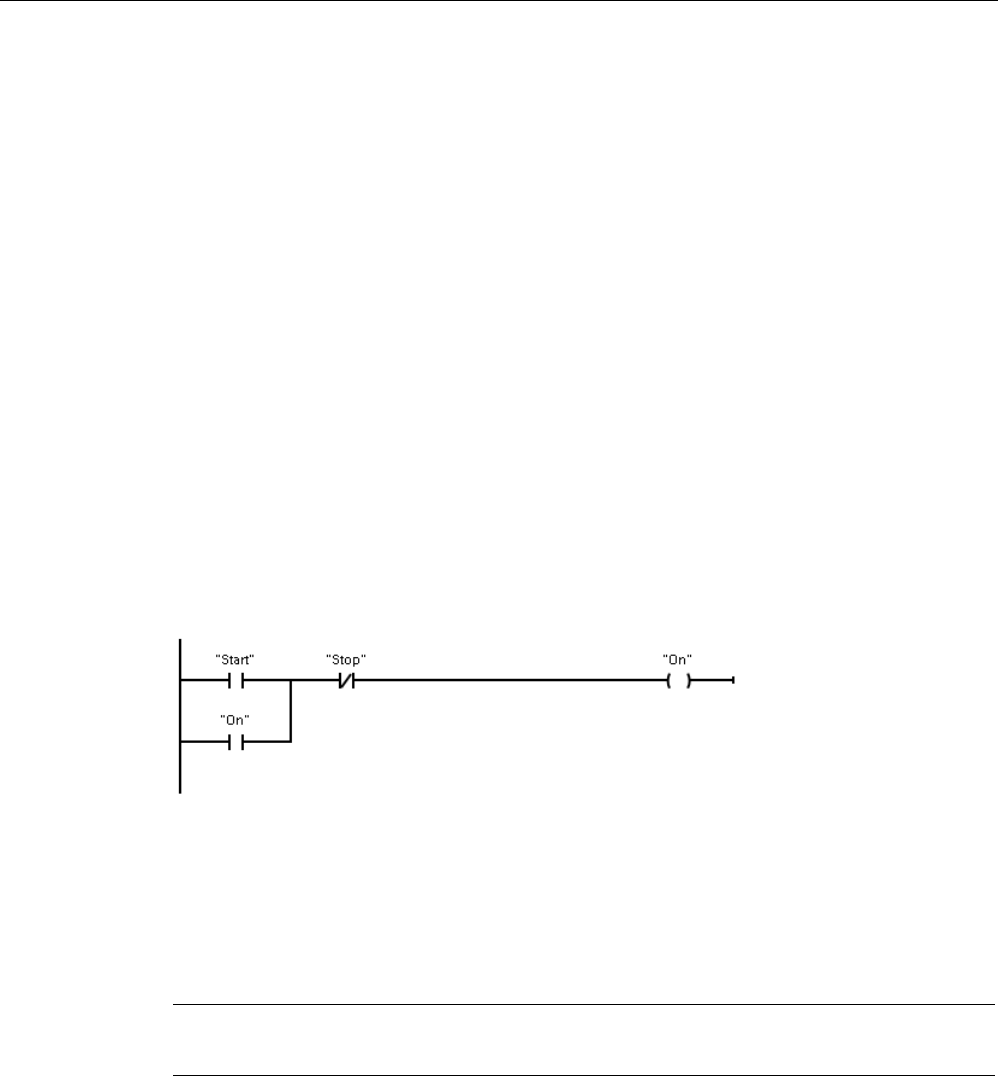
Programming concepts
7.5 Programming language
S7-1200 Programmable controller
System Manual, V4.2, 09/2016, A5E02486680-AK 199
7.5
Programming language
STEP 7 provides the following standard programming languages for S7-1200:
● LAD (ladder logic) is a graphical programming language. The representation is based on
circuit diagrams (Page 199).
● FBD (Function Block Diagram) is a programming language that is based on the graphical
logic symbols used in Boolean algebra (Page 200).
● SCL (structured control language) is a text-based, high-level programming language
(Page 201).
When you create a code block, you select the programming language to be used by that
block.
Your user program can utilize code blocks created in any or all of the programming
languages.
7.5.1
Ladder logic (LAD)
The elements of a circuit diagram, such as normally closed and normally open contacts, and
coils are linked to form networks.
To create the logic for complex operations, you can insert branches to create the logic for
parallel circuits. Parallel branches are opened downwards or are connected directly to the
power rail. You terminate the branches upwards.
LAD provides "box" instructions for a variety of functions, such as math, timer, counter, and
move.
STEP 7 does not limit the number of instructions (rows and columns) in a LAD network.
Note
Every LAD network must term
inate with a coil or a box instruction.

Programming concepts
7.5 Programming language
S7-1200 Programmable controller
200 System Manual, V4.2, 09/2016, A5E02486680-AK
Consider the following rules when creating a LAD network:
● You cannot create a branch that could result in a power flow in the reverse direction.
● You cannot create a branch that would cause a short circuit.
7.5.2
Function Block Diagram (FBD)
Like LAD, FBD is also a graphical programming language. The representation of the logic is
based on the graphical logic symbols used in Boolean algebra.
To create the logic for complex operations,
insert parallel branches between the boxes.
Mathematical functions and other complex functions can be represented directly in
conjunction with the logic boxes.
STEP 7 does not limit the number of instructions (rows and columns) in an FBD network.
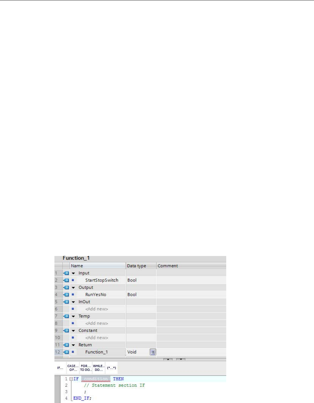
Programming concepts
7.5 Programming language
S7-1200 Programmable controller
System Manual, V4.2, 09/2016, A5E02486680-AK 201
7.5.3
SCL
Structured Control Language (SCL) is a high-level, PASCAL-based programming language
for the SIMATIC S7 CPUs. SCL supports the block structure of STEP 7 (Page 187). Your
project can include program blocks in any of the three programming languages: SCL, LAD,
and FBD.
SCL instructions use standard programming operators, such as for assignment (:=),
mathematical functions (+ for addition, - for subtraction, * for multiplication, and / for division).
SCL also uses standard PASCAL program control operations, such as IF-THEN-ELSE,
CASE, REPEAT-UNTIL, GOTO and RETURN. You can use any PASCAL reference for
syntactical elements of the SCL programming language. Many of the other instructions for
SCL, such as timers and counters, match the LAD and FBD instructions. For more
information about specific instructions, refer to the specific instructions in the chapters for
Basic instructions (Page 227) and Extended instructions (Page 335).
7.5.3.1
SCL program editor
You can designate any type of block (OB, FB, or FC) to use the SCL programming language
at the time you create the block. STEP 7 provides an SCL program editor that includes the
following elements:
● Interface section for defining the parameters of the code block
● Code section for the program code
● Instruction tree that contains the SCL instructions supported by the CPU
You enter the SCL code for your instruction directly in the code section. The editor includes
buttons for common code constructs and comments. For more complex instructions, simply
drag the SCL instructions from the instruction tree and drop them into your program. You can
also use any text editor to create an SCL program and then import that file into STEP 7.

Programming concepts
7.5 Programming language
S7-1200 Programmable controller
202 System Manual, V4.2, 09/2016, A5E02486680-AK
In the Interface section of the SCL code block you can declare the following types of
parameters:
● Input, Output, InOut, and Ret_Val: These parameters define the input tags, output tags,
and return value for the code block. The tag name that you enter here is used locally
during the execution of the code block. You typically would not use the global tag name in
the tag table.
● Static (FBs only; the illustration above is for an FC): The code block uses static tags for
storage of static intermediate results in the instance data block. The block retains static
data until overwritten, which can be after several cycles. The names of the blocks, which
this block calls as multi-instance, are also stored in the static local data.
● Temp: These parameters are the temporary tags that are used during the execution of
the code block.
● Constant: These are named constant values for your code block.
If you call the SCL code block from another code block, the parameters of the SCL code
block appear as inputs or outputs.
In this example, the tags for "Start" and "On" (from the project tag table) correspond to
"StartStopSwitch" and "RunYesNo" in the declaration table of the SCL program.
7.5.3.2
SCL expressions and operations
Constructing an SCL expression
An SCL expression is a formula for calculating a value. The expression consists of operands
and operators (such as *, /, + or -). The operands can be tags, constants, or expressions.
The evaluation of the expression occurs in a certain order, which is defined by the following
factors:
● Every operator has a pre-defined priority, with the highest-priority operation performed
first.
● For operators with equal priority, the operators are processed in a left-to-right sequence.
● You use parentheses to designate a series of operators to be evaluated together.

Programming concepts
7.5 Programming language
S7-1200 Programmable controller
System Manual, V4.2, 09/2016, A5E02486680-AK 203
The result of an expression can be used either for assigning a value to a tag used by your
program, as a condition to be used by a control statement, or as parameters for another SCL
instruction or for calling a code block.
Table 7- 2 Operators in SCL
Type
Operation
Operator
Priority
Parentheses
(
Expression
)
( , )
1
Math Power ** 2
Sign (unary plus)
+
3
Sign (unary minus) - 3
Multiplication
*
4
Division
/
4
Modulo
MOD
4
Addition
+
5
Subtraction
-
5
Comparison
Less than
<
6
Less than or equal to
<=
6
Greater than
>
6
Greater than or equal to
>=
6
Equal to
=
7
Not equal to
<>
7
Bit logic
Negation (unary)
NOT
3
AND logic operation
AND or &
8
Exclusive OR logic operation
XOR
9
OR logic operation
OR
10
Assignment
Assignment
:=
11
As a high-level programming language, SCL uses standard statements for basic tasks:
● Assignment statement: :=
● Mathematical functions: +, -, *, and /
● Addressing of global variables (tags): "<tag name>" (Tag name or data block name
enclosed in double quotes)
● Addressing of local variables: #<variable name> (Variable name preceded by "#" symbol)
The following examples show different expressions for different uses:
"C" := #A+#B;
Assigns the sum of two local variables to a tag
"Data_block_1".Tag := #A;
Assignment to a data block tag
IF #A > #B THEN "C" := #A;
Condition for the IF-THEN statement
"C" := SQRT (SQR (#A) + SQR (#B));
Parameters for the SQRT instruction
Arithmetic operators can process various numeric data types. The data type of the result is
determined by the data type of the most-significant operands. For example, a multiplication
operation that uses an INT operand and a REAL operand yields a REAL value for the result.

Programming concepts
7.5 Programming language
S7-1200 Programmable controller
204 System Manual, V4.2, 09/2016, A5E02486680-AK
Control statements
A control statement is a specialized type of SCL expression that performs the following
tasks:
● Program branching
● Repeating sections of the SCL program code
● Jumping to other parts of the SCL program
● Conditional execution
The SCL control statements include IF-THEN, CASE-OF, FOR-TO-DO, WHILE-DO,
REPEAT-UNTIL, CONTINUE, GOTO, and RETURN.
A single statement typically occupies one line of code. You can enter multiple statements on
one line, or you can break a statement into several lines of code to make the code easier to
read. Separators (such as tabs, line breaks and extra spaces) are ignored during the syntax
check. An END statement terminates the control statement.
The following examples show a FOR-TO-DO control statement. (Both forms of coding are
syntactically valid.)
FOR x := 0 TO max DO sum := sum + value(x); END_FOR;
FOR x := 0 TO max DO
sum := sum + value(x);
END_FOR;
A control statement can also be provided with a label. A label is set off by a colon at the
beginning of the statement:
Label: <Statement>;
The STEP 7 online help provides a complete SCL programming language reference.
Conditions
A condition is a comparison expression or a logical expression whose result is of type BOOL
(with the value of either TRUE or FALSE). The following example shows conditions of
various types:
#Temperature > 50
#Counter <= 100
#CHAR1 < 'S'
Relational expression
(#Alpha <> 12) AND NOT #Beta
Comparison and logical expression
5 + #Alpha
Arithmetic expression
A condition can use arithmetic expressions:
● The condition of the expression is TRUE if the result is any value other than zero.
● The condition of the expression is FALSE if the result equals zero.

Programming concepts
7.5 Programming language
S7-1200 Programmable controller
System Manual, V4.2, 09/2016, A5E02486680-AK 205
Calling other code blocks from your SCL program
To call another code block in your user program, simply enter the name (or absolute
address) of the FB or FC with the parameters. For an FB, you must provide the instance DB
to be called with the FB.
<DB name> (Parameter list)
Call as a single instance
<#Instance name> (Parameter list)
Call as multi
-instance
"MyDB"(MyInput:=10, MyInOut:="Tag1");
<FC name> (Parameter list)
Standard call
<Operand>:=<FC name> (Parameter list)
Call in an expression
"MyFC"(MyInput:=10, MyInOut:="Tag1");
You can also drag blocks from the navigation tree to the SCL program editor, and complete
the parameter assignment.
Adding block comments to SCL code
You can include a block comment in your SCL code by including the comment text between
(* and *). You can have any number of comment lines between the (* and the *). Your SCL
program block can include many block comments. For programming convenience, the SCL
editor includes a block comment button along with common control statements:
Addressing
As with LAD and FBD, SCL allows you to use either tags (symbolic addressing) or absolute
addresses in your user program. SCL also allows you to use a variable as an array index.
Absolute addressing
%I0.0
Precede absolute ad
dresses with the "%" symbol.
Without the "%", STEP
7 generates an undefined
tag error at compile time.
%MB100
Symbolic addressing
"PLC_Tag_1"
Tag in PLC tag table
"Data_block_1".Tag_1
Tag in a data block
"Data_block_1".MyArray[#i]
Array element in a data block array

Programming concepts
7.5 Programming language
S7-1200 Programmable controller
206 System Manual, V4.2, 09/2016, A5E02486680-AK
7.5.3.3
Indexed addressing with PEEK and POKE instructions
SCL provides PEEK and POKE instructions that allow you to read from or write to data
blocks, I/O, or memory. You provide parameters for specific byte offsets or bit offsets for the
operation.
Note
To use the PEEK and POKE instructions with data blocks, you must use standard (not
optimized) data blocks. Also note that the PEEK and POKE instructions merely transfer data.
They have no knowledge of data types at the addresses.
PEEK(area:=_in_,
dbNumber:=_in_,
byteOffset:=_in_);
Reads the byte referenced by byteOffset of
the referenced data block, I/O or memory
area.
Example referencing data block:
%MB100 := PEEK(area:=16#84,
dbNumber:=1, byteOffset:=#i);
Exam
ple referencing IB3 input:
%MB100 := PEEK(area:=16#81,
dbNumber:=0, byteOffset:=#i); // when
#i = 3
PEEK_WORD(area:=_in_,
dbNumber:=_in_,
byteOffset:=_in_);
Reads the word referenced by byteOffset of
the referenced data block, I/O or m
emory
area.
Example:
%MW200 := PEEK_WORD(area:=16#84,
dbNumber:=1, byteOffset:=#i);
PEEK_DWORD(area:=_in_,
dbNumber:=_in_,
byteOffset:=_in_);
Reads the double word referenced by
byteOffset of the referenced data block, I/O or
memory ar
ea.
Example:
%MD300 := PEEK_DWORD(area:=16#84,
dbNumber:=1, byteOffset:=#i);
PEEK_BOOL(area:=_in_,
dbNumber:=_in_,
byteOffset:=_in_,
bitOffset:=_in_);
Reads a Boolean referenced by the bitOffset
and byteOffset of the referen
ced data block,
I/O or memory area
Example:
%MB100.0 := PEEK_BOOL(area:=16#84,
dbNumber:=1, byteOffset:=#ii,
bitOffset:=#j);

Programming concepts
7.5 Programming language
S7-1200 Programmable controller
System Manual, V4.2, 09/2016, A5E02486680-AK 207
POKE(area:=_in_,
dbNumber:=_in_,
byteOffset:=_in_,
value:=_in_);
Writes the value (Byte, Word, or DW
ord) to
the referenced byteOffset of the referenced
data block, I/O or memory area
Example referencing data block:
POKE(area:=16#84, dbNumber:=2,
byteOffset:=3, value:="Tag_1");
Example referencing QB3 output:
POKE(area:=16#82, dbNumber:=0,
byteOffset:=3, value:="Tag_1");
POKE_BOOL(area:=_in_,
dbNumber:=_in_,
byteOffset:=_in_,
bitOffset:=_in_,
value:=_in_);
Writes the Boolean value to the referenced
bitOffset and byteOffset of the referenced
data block, I/O or memory
area
Example:
POKE_BOOL(area:=16#84, dbNumber:=2,
byteOffset:=3, bitOffset:=5, va
l-
ue:=0);
POKE_BLK(area_src:=_in_,
dbNumber_src:=_in_,
byteOffset_src:=_in_,
area_dest:=_in_,
dbNumber_dest:=_in_,
byteOffset_dest:=_in_,
count:=_in_);
Writes "count" number of bytes starting at the
referenced byte Offset of the referenced
source data block, I/O or memory area to the
referenced byteOffset of the referenced dest
i-
nation data block, I/O or memory area
Ex
ample:
POKE_BLK(area_src:=16#84,
dbNumber_src:=#src_db, byteOf
f-
set_src:=#src_byte, area_dest:=16#84,
dbNumber_dest:=#src_db, byteOf
f-
set_dest:=#src_byte, count:=10);
For PEEK and POKE instructions, the following values for the "area", "area_src" and
"area_dest" parameters are applicable. For areas other than data blocks, the dbNumber
parameter must be 0.
16#81 I
16#82
Q
16#83
M
16#84
DB

Programming concepts
7.5 Programming language
S7-1200 Programmable controller
208 System Manual, V4.2, 09/2016, A5E02486680-AK
7.5.4
EN and ENO for LAD, FBD and SCL
Determining "power flow" (EN and ENO) for an instruction
Certain instructions (such as the Math and the Move instructions) provide parameters for EN
and ENO. These parameters relate to power flow in LAD or FBD and determine whether the
instruction is executed during that scan. SCL also allows you to set the ENO parameter for a
code block.
● EN (Enable In) is a Boolean input. Power flow (EN = 1) must be present at this input for
the box instruction to be executed. If the EN input of a LAD box is connected directly to
the left power rail, the instruction will always be executed.
● ENO (Enable Out) is a Boolean output. If the box has power flow at the EN input and the
box executes its function without error, then the ENO output passes power flow
(ENO = 1) to the next element. If an error is detected in the execution of the box
instruction, then power flow is terminated (ENO = 0) at the box instruction that generated
the error.
Table 7- 3 Operands for EN and ENO
Program editor
Inputs/outputs
Operands
Data type
LAD
EN, ENO
Power flow
Bool
FBD EN I, I:P, Q, M, DB, Temp, Power Flow Bool
ENO
Power Flow
Bool
SCL
EN
1
TRUE, FALSE
Bool
ENO
2
TRUE, FALSE
Bool
1
The use of EN is only available for FBs.
2
The use of ENO with the SCL code block is optional. You must configure the SCL compiler to set
ENO when the code block finishes.
Configuring SCL to set ENO
To configure the SCL compiler for setting ENO, follow these steps:
1. Select the "Settings" command from the "Options" menu.
2. Expand the "PLC programming" properties and select "SCL (Structured Control
Language)".
3. Select the "Set ENO automatically" option.

Programming concepts
7.5 Programming language
S7-1200 Programmable controller
System Manual, V4.2, 09/2016, A5E02486680-AK 209
Using ENO in program code
You can also use ENO in your program code, for example by assigning ENO to a PLC tag,
or by evaluating ENO in a local block.
Examples:
“MyFunction”
( IN1 := … ,
IN2 := … ,
OUT1 => #myOut,
ENO => #statusFlag ); // PLC tag statusFlag holds the value of E
NO
“MyFunction”
( IN1 := …
IN2 := … ,
OUT1 => #myOut,
ENO => ENO ); // block status flag of "MyFunction"
// is stored in the local block
IF ENO = TRUE THEN
// execute code only if MyFunction returns true ENO
Effect of Ret_Val or Status parameters on ENO
Some instructions, such as the communication instructions or the string conversion
instructions, provide an output parameter that contains information about the processing of
the instruction. For example, some instructions provide a Ret_Val (return value) parameter,
which is typically an Int data type that contains status information in a range from -32768 to
+32767. Other instructions provide a Status parameter, which is typically a Word data type
that stores status information in a range of hexadecimal values from 16#0000 to 16#FFFF.
The numerical value stored in a Ret_Val or a Status parameter determines the state of ENO
for that instruction.
● Ret_Val: A value from 0 to 32767 typically sets ENO = 1 (or TRUE). A value from -32768
to -1 typically sets ENO = 0 (or FALSE). To evaluate Ret_Val, change the representation
to hexadecimal.
● Status: A value from 16#0000 16#7FFF typically sets ENO = 1 (or TRUE). A value from
16#8000 to 16#FFFF typically sets ENO = 0 (or FALSE).
Instructions that take more than one scan to execute often provide a Busy parameter (Bool)
to signal that the instruction is active but has not completed execution. These instructions
often also provide a Done parameter (Bool) and an Error parameter (Bool). Done signals that
the instruction was completed without error, and Error signals that the instruction was
completed with an error condition.
● When Busy = 1 (or TRUE), ENO = 1 (or TRUE).
● When Done = 1 (or TRUE), ENO = 1 (or TRUE).
● When Error = 1 (or TRUE), ENO = 0 (or FALSE).
See also
OK (Check validity) and NOT_OK (Check invalidity) (Page 252)

Programming concepts
7.6 Protection
S7-1200 Programmable controller
210 System Manual, V4.2, 09/2016, A5E02486680-AK
7.6
Protection
7.6.1
Access protection for the CPU
The CPU provides four levels of security for restricting access to specific functions. When
you configure the security level and password for a CPU, you limit the functions and memory
areas that can be accessed without entering a password.
Each level allows certain functions to be accessible without a password. The default
condition for the CPU is to have no restriction and no password-protection. To restrict access
to a CPU, you configure the properties of the CPU and enter the password.
Entering the password over a network does not compromise the password protection for the
CPU. Password protection does not apply to the execution of user program instructions
including communication functions. Entering the correct password provides access to all of
the functions at that level.
PLC-to-PLC communications (using communication instructions in the code blocks) are not
restricted by the security level in the CPU.
Table 7- 4 Security levels for the CPU
Security level
Access restrictions
Full access (no
protection)
Allows full access without password protection.
Read access Allows HMI access, comparing Offline/Online code blocks, and all forms of PLC-
to-PLC communications without password protection.
Password is required for modifying (writing to) the CPU. Password is not re-
quired for changing the CPU mode (RUN/STOP).
HMI access Allows HMI access and all forms of PLC-to-PLC communications without pass-
word protection.
Password is required for reading the data in the CPU, for comparing Of-
fline/Online code blocks, for modifying (writing to) the CPU, and for changing the
CPU mode (RUN/STOP).
No access (com-
plete protection)
Allows no access without password protection.
Password is required for HMI access, reading the data in the CPU, comparing
Offline/Online code blocks, and for modifying (writing to) the CPU.
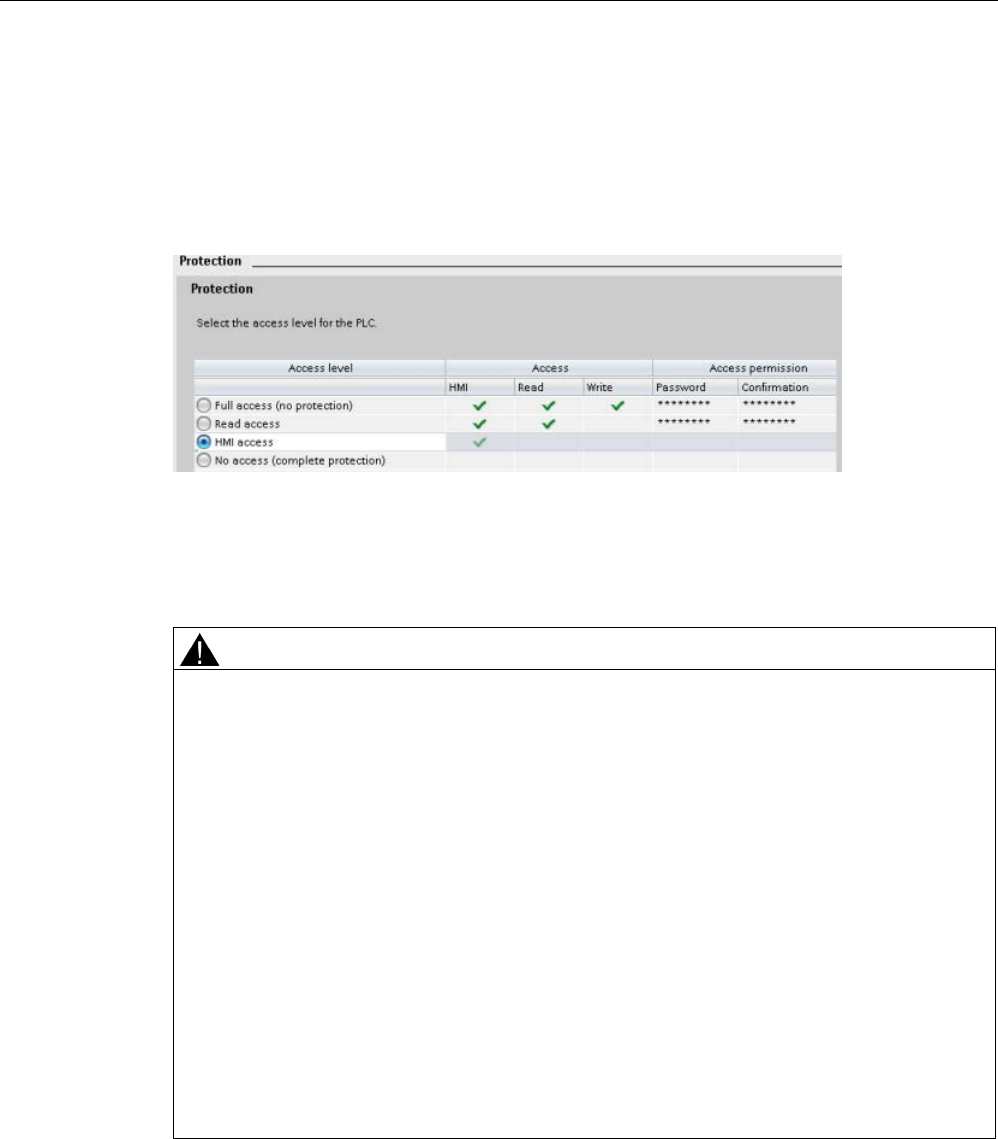
Programming concepts
7.6 Protection
S7-1200 Programmable controller
System Manual, V4.2, 09/2016, A5E02486680-AK 211
Passwords are case-sensitive. To configure the protection level and passwords, follow these
steps:
1. In the "Device configuration", select the CPU.
2. In the inspector window, select the "Properties" tab.
3. Select the "Protection" property to select the protection level and to enter passwords.
When you download this configuration to the CPU, the user has HMI access and can access
HMI functions without a password. To read data or compare Offline/Online code blocks, the
user must enter the configured password for "Read access" or the password for "Full access
(no protection)". To write data, the user must enter the configured password for "Full access
(no protection)".
WARNING
Unauthorized access to a protected CPU
Users with CPU full access privileges have privileges to read and write PLC variables.
Regardless of the access level for the CPU, Web server users can have privileges to read
and write PLC variables. Unauthorized access to the CPU or changing PLC variables to
invalid values could disrupt process operation and could result in death, severe personal
injury and/or property damage.
Authorized users can perform operating mode changes, writes to PLC data, and firmware
updates. Siemens recommends that you observe the following security practices:
• Password protect CPU access levels and Web server user IDs (Page 1005) with strong
passwords. Strong passwords are at least ten characters in length, mix letters, numbers,
and special characters, are not words that can be found in a dictionary, and are not
names or identifiers that can be derived from personal information. Keep the password
secret and change it frequently.
• Enable access to the Web server only with the HTTPS protocol.
• Do not extend the default minimum privileges of the Web server "Everybody" user.
• Perform error-checking and range-checking on your variables in your program logic
because Web page users can change PLC variables to invalid values.
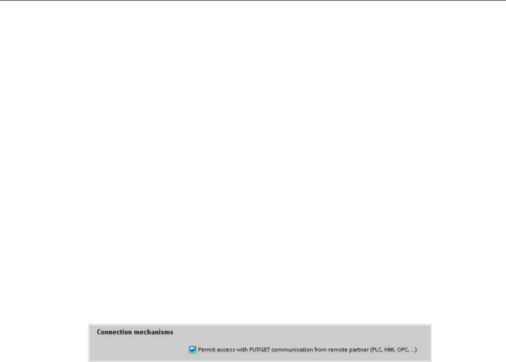
Programming concepts
7.6 Protection
S7-1200 Programmable controller
212 System Manual, V4.2, 09/2016, A5E02486680-AK
Connection mechanisms
To access remote connection partners with PUT/GET instructions, the user must also have
permission.
By default, the "Permit access with PUT/GET communication" option is not enabled. In this
case, read and write access to CPU data is only possible for communication connections
that require configuration or programming both for the local CPU and for the communication
partner. Access through BSEND/BRCV instructions is possible, for example.
Connections for which the local CPU is only a server (meaning that no
configuration/programming of the communication with the communication partner exists at
the local CPU), are therefore not possible during operation of the CPU, for example:
● PUT/GET, FETCH/WRITE or FTP access through communication modules
● PUT/GET access from other S7 CPUs
● HMI access through PUT/GET communication
If you want to allow access to CPU data from the client side, that is, you do not want to
restrict the communication services of the CPU, follow these steps:
1. Configure the protection access level to be any level other than "No access (complete
protection)".
2. Select the "Permit access with PUT/GET communication" check box.
When you download this configuration to the CPU, the CPU permits PUT/GET
communication from remote partners
7.6.2
External load memory
You can also protect the external load memory (memory card) from copies. To prevent the
copying of internal load memory to external load memory follow these steps:
1. From the device configuration of the CPU in STEP 7, select "Protection" from the General
properties.
2. In the "External Load Memory" section, select "Disable copy from internal load memory to
external load memory".
See also the topic Inserting a memory card in the CPU (Page 139) for a description of how
this property affects the insertion of a memory card into the CPU.
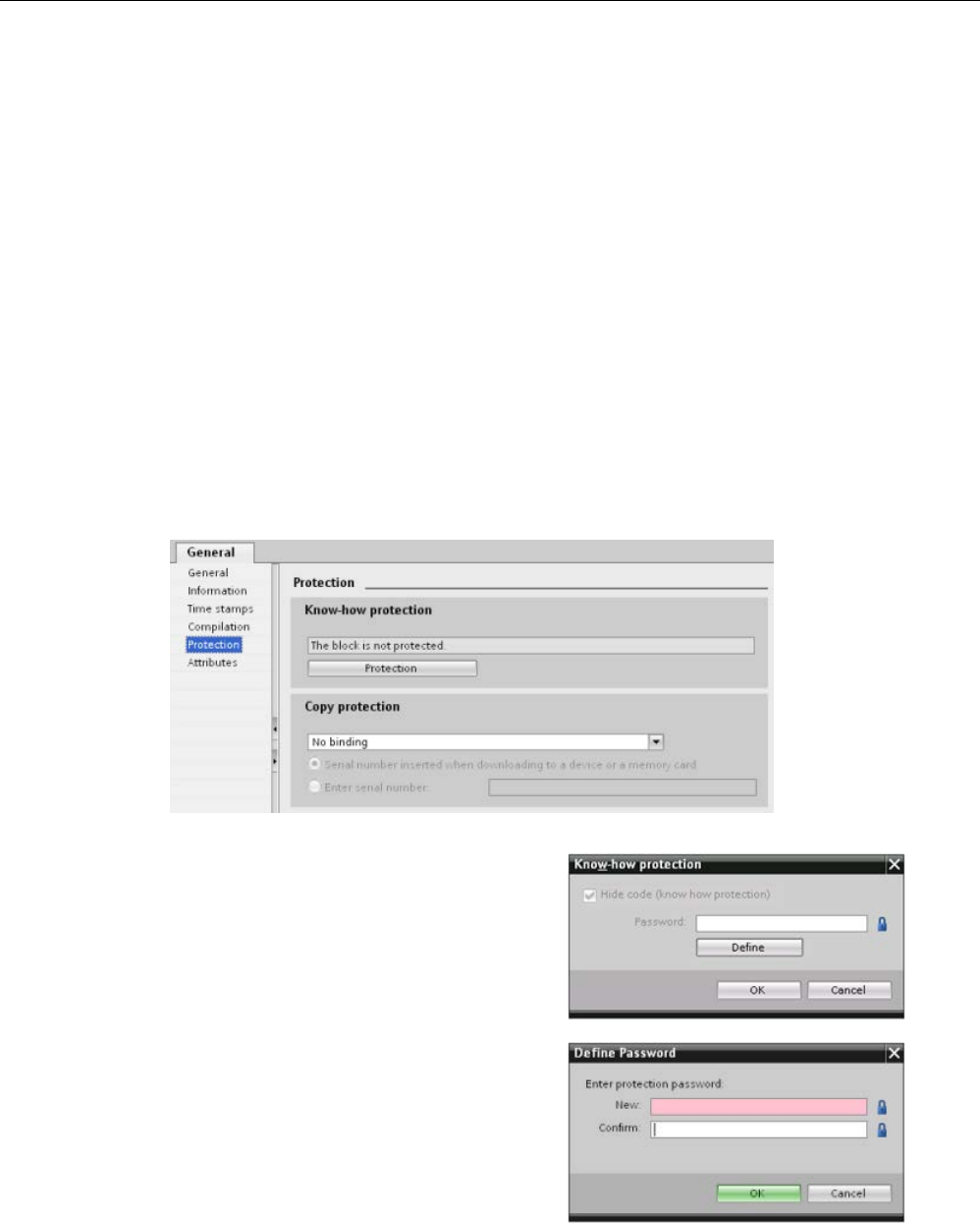
Programming concepts
7.6 Protection
S7-1200 Programmable controller
System Manual, V4.2, 09/2016, A5E02486680-AK 213
7.6.3
Know-how protection
Know-how protection allows you to prevent one or more code blocks (OB, FB, FC, or DB) in
your program from unauthorized access. You create a password to limit access to the code
block. The password-protection prevents unauthorized reading or modification of the code
block. Without the password, you can read only the following information about the code
block:
● Block title, block comment, and block properties
● Transfer parameters (IN, OUT, IN_OUT, Return)
● Call structure of the program
● Global tags in the cross references (without information on the point of use), but local
tags are hidden
When you configure a block for "know-how" protection, the code within the block cannot be
accessed except after entering the password.
Use the "Properties" task card of the code block to configure the know-how protection for
that block. After opening the code block, select "Protection" from Properties.
1.
In the Properties for the code block, click
the "Protection" button to display the
"Know-how protection" dialog.
2.
Click the "Define" button to enter the
password.
After entering and confirming the password,
click "OK".

Programming concepts
7.6 Protection
S7-1200 Programmable controller
214 System Manual, V4.2, 09/2016, A5E02486680-AK
7.6.4
Copy protection
An additional security feature allows you to bind program blocks for use with a specific
memory card or CPU. This feature is especially useful for protecting your intellectual
property. When you bind a program block to a specific device, you restrict the program or
code block for use only with a specific memory card or CPU. This feature allows you to
distribute a program or code block electronically (such as over the Internet or through email)
or by sending a memory card. Copy protection is available for OBs (Page 188), FBs
(Page 190), and FCs (Page 190). The S7-1200 CPU supports three types of block
protection:
● Binding to the serial number of a CPU
● Binding to the serial number of a memory card
● Dynamic binding with mandatory password
Use the "Properties" task card of the code block to bind the block to a specific CPU or
memory card.
1. After opening the code block, select "Protection".
2. From the drop-down list under "Copy protection" task, select the type of copy protection
that you want to use.

Programming concepts
7.6 Protection
S7-1200 Programmable controller
System Manual, V4.2, 09/2016, A5E02486680-AK 215
3. For binding to the serial number of a CPU or memory card, select either to insert the
serial number when downloading, or enter the serial number for the memory card or
CPU.
Note
The serial number is case
-sensitive.
For dynamic binding with mandatory password, define the password that you must use to
download or copy the block.
When you subsequently download (Page 216) a block with dynamic binding, you must
enter the password to be able to download the block. Note that the copy protection
password and the know-how protection (Page 213) password are two separate
passwords.
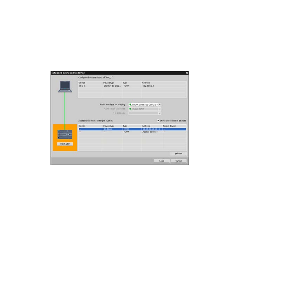
Programming concepts
7.7 Downloading the elements of your program
S7-1200 Programmable controller
216 System Manual, V4.2, 09/2016, A5E02486680-AK
7.7
Downloading the elements of your program
You can download the elements of your project from the programming device to the CPU.
When you download a project, the CPU stores the user program (OBs, FCs, FBs and DBs)
in internal load memory or if a SIMATIC memory card is present in external load memory
(the card).
You can download your project from the programming device to your CPU from any of the
following locations:
● Project tree: Right-click the program element, and then click the context-sensitive
"Download" selection.
● Online menu: Click the "Download to device" selection.
● Toolbar: Click the "Download to device" icon.
● Device configuration: Right-click the CPU and select the elements to download.
Note that if you have applied dynamic binding with mandatory password (Page 214) to any
of the program blocks, you must enter the password for the protected blocks in order to
download them. If you have configured this type of copy protection for multiple blocks, you
must enter the password for each of the protected blocks in order to download them.
Note
Downloading a progra
m does not clear or make any changes to existing values in retentive
memory. If you want to clear retentive memory before a download, then reset your CPU to
factory settings prior to downloading the program.
You can also download a panel project for the Basic HMI panels (Page 32) from the
TIA Portal to a memory card in the S7-1200 CPU.
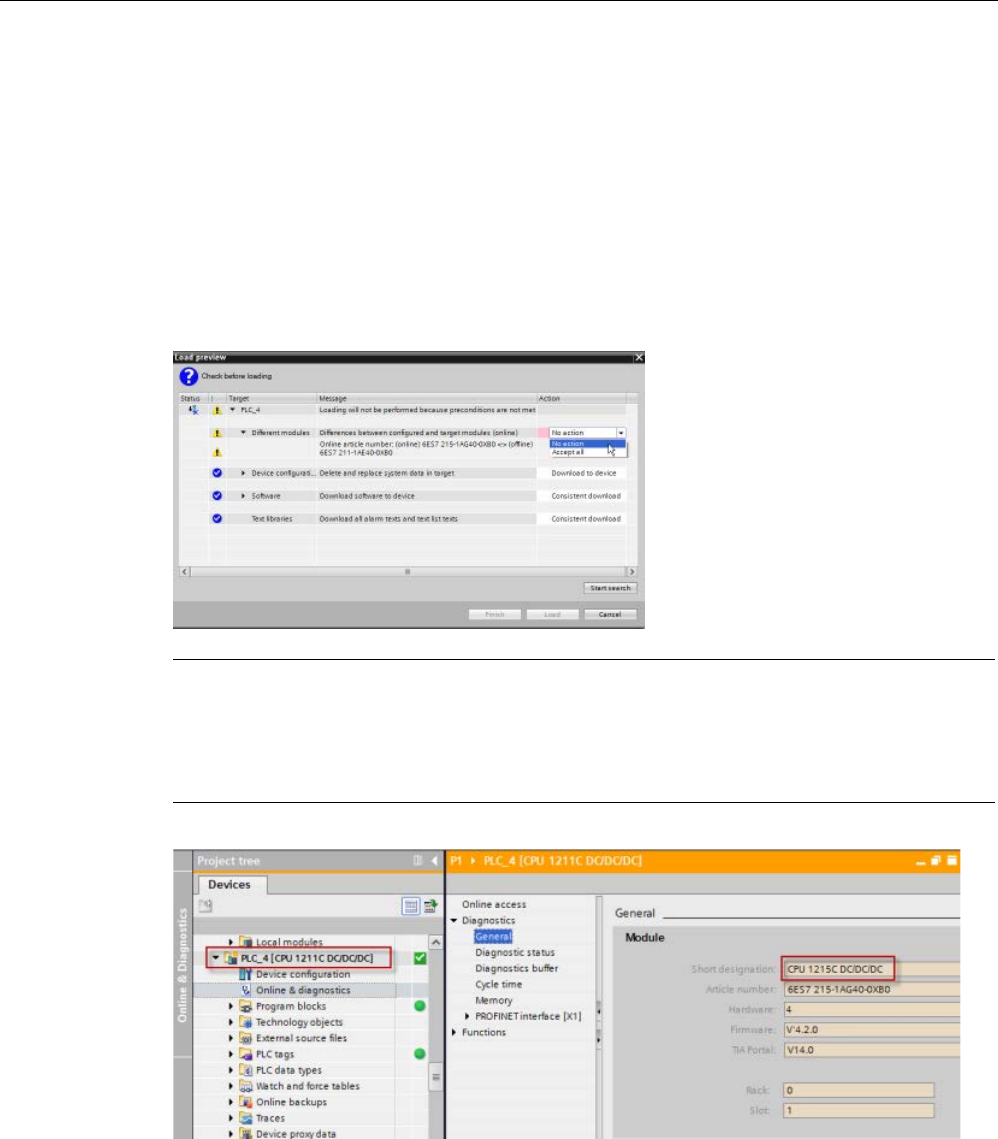
Programming concepts
7.7 Downloading the elements of your program
S7-1200 Programmable controller
System Manual, V4.2, 09/2016, A5E02486680-AK 217
Downloading when the configured CPU is different from the connected CPU
STEP 7 and the S7-1200 permit a download if the connected CPU has the capacity to store
a download from the configured CPU, based on the memory requirements of the project and
the compatibility of the I/O. You can download the configuration and program from a CPU to
a larger CPU, for example, from a CPU 1211C DC/DC/DC to a CPU 1215C DC/DC/DC
because the I/O is compatible and the memory is sufficient. In this case, the download
operation displays a warning, "Differences between configured and target modules (online)"
along with the article numbers and firmware versions in the "Load preview" dialog. You must
choose either "No action" if you do not want the download to proceed or "Accept all" if you
do want the download to proceed:
Note
When you
go online (Page 1313) after downloading the configured CPU to a different
connected CPU, you see the project for the configur
ed CPU with online status indicators in
the project tree. In the online and diagnostics view, however, you see the actual connected
CPU module type.
Figure 7-1 Online view when configured CPU is different from connected CPU
You can, of course, change your device (Page 170) in the device configuration so that the
configured CPU is the same module type as the connected CPU. The "Change device"
dialog provides complete compatibility details when you try to change a device.
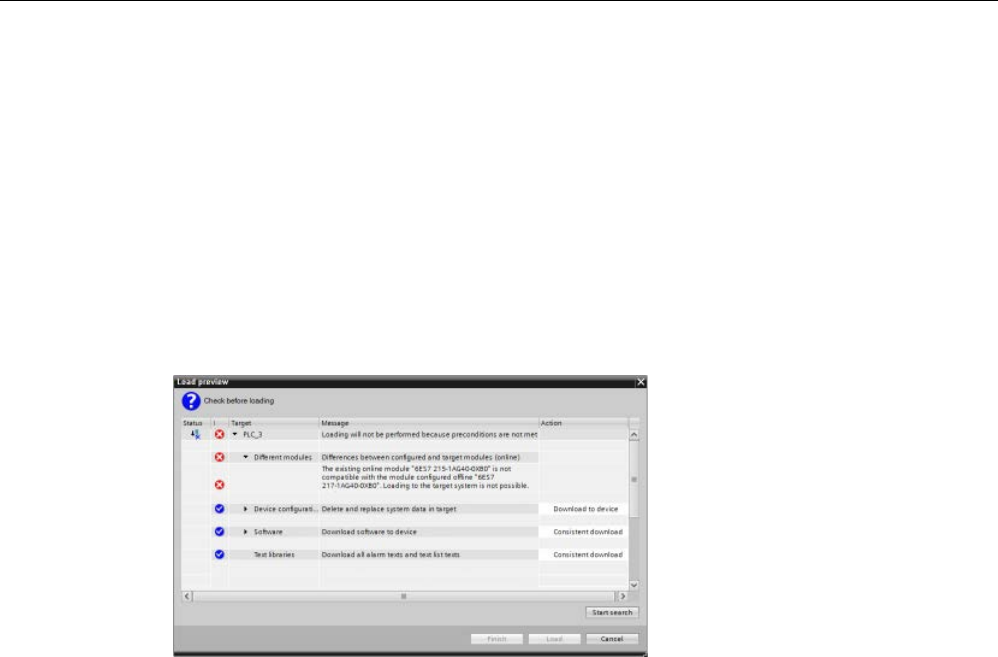
Programming concepts
7.7 Downloading the elements of your program
S7-1200 Programmable controller
218 System Manual, V4.2, 09/2016, A5E02486680-AK
STEP 7 and the S7-1200 prohibit a download if the connected CPU does not have the
capacity to store a download from the configured CPU; for example, you cannot download
the hardware configuration and program for the following cases:
● CPU 1215C DC/DC/DC to a CPU 1212C DC/DC/DC due to insufficient work memory
● CPU 1211C DC/DC/Relay to a CPU 1211C DC/DC/DC due to I/O differences
● CPU 1217C DC/DC/DC to any CPU 1211C, CPU 1212C, CPU 1214C, or CPU 1215C
due to the 1.5 V DC outputs in the CPU 1217C.
● CPU 1214C V4.2 to CPU 1214C V4.0, due to firmware version incompatibility
The "Load preview" dialog displays an error in such cases:
Recovering from a failed download
If the download fails, the Info tab of the Inspector Window displays the reason. The
diagnostic buffer also provides information. After a failed download, follow these steps to be
able to download successfully:
1. Correct the problem as described in the error message.
2. Reattempt the download.
In rare cases, the download succeeds but a subsequent power cycle of the CPU fails. In this
case you may see an error in the diagnostic buffer such as:
● 16# 02:4175 -- CPU error: Memory card evaluation error: Unknown or incompatible
version of CPU configuration description current card type: No memory card Function
finished/aborted, new startup inhibit set: ..- Memory card missing, wrong type, wrong
content or protected
If this occurs and additional attempts to download fail, you must clear the internal load
memory or external load memory:
1. If using internal load memory, reset the CPU to factory settings.
2. If using a SIMATIC memory card, remove it and delete the contents of the memory card
(Page 145) before reinserting.
3. Download the hardware configuration and software.

Programming concepts
7.8 Synchronizing the online CPU and offline project
S7-1200 Programmable controller
System Manual, V4.2, 09/2016, A5E02486680-AK 219
See also
Synchronizing the online CPU and offline project (Page 219)
7.8
Synchronizing the online CPU and offline project
When you download project blocks to the CPU, the CPU can detect whether blocks or tags
have changed in the online CPU since the last download. In such cases, the CPU offers you
the choice to synchronize the changes. This means that you can upload the online CPU
changes to the project before downloading the project to the CPU. Changes in the online
CPU can be due to a variety of factors:
● Changes to the start values of data block tags during runtime, for example by the
WRIT_DBL instruction (Page 538) or by loading a recipe
● A download from a "secondary" project (a project other than the one that originated the
last download) where one or more of the following conditions exist:
– The online CPU includes program blocks that do not exist in the project.
– Data block tags or block attributes differ between the offline project and online CPU.
– PLC tags exist in the online CPU that do not exist in the offline project.
Note
If you edit blocks or tags in the project that you used for the last download, you do not have
to make any choices about synchronization. STEP 7 and the CPU detect that the offline
project changes are newer than the o
nline CPU and proceeds with a normal download
operation.
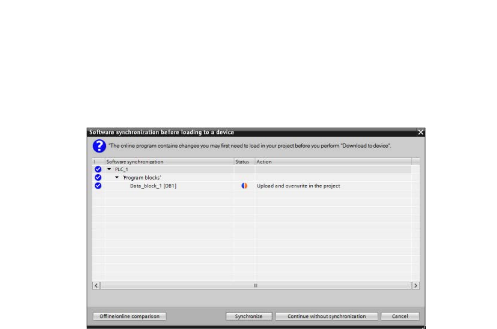
Programming concepts
7.8 Synchronizing the online CPU and offline project
S7-1200 Programmable controller
220 System Manual, V4.2, 09/2016, A5E02486680-AK
Synchronization choices
When you download a project to the CPU, you see the synchronization dialog if STEP 7
detects that data blocks or tags in the online CPU are newer than the project values. For
example, if the STEP 7 program has executed WRIT_DBL and changed a start value for a
tag in Data_block_1, STEP 7 displays the following synchronization dialog when you initiate
a download:
This dialog lists the program blocks where differences exist. From this dialog, you have the
following choices:
● Online/offline comparison: If you click this button, STEP 7 displays the program blocks,
system blocks, technology objects, PLC tags, and PLC data types for the project as
compared to the online CPU (Page 1323). For each object, you can click to see a
detailed analysis of the differences including time stamps. You can use this information to
decide what to do about the differences between the online CPU and the project.
● Synchronize: If you click this button, STEP 7 uploads the data blocks, tags, and other
objects from the online CPU to the project. You can then continue with the program
download, unless program execution has again caused the project to be out of sync with
the CPU.
● Continue without synchronization: If you click this button, STEP 7 downloads the project
to the CPU.
● Cancel: If you click this button, you cancel the download operation.
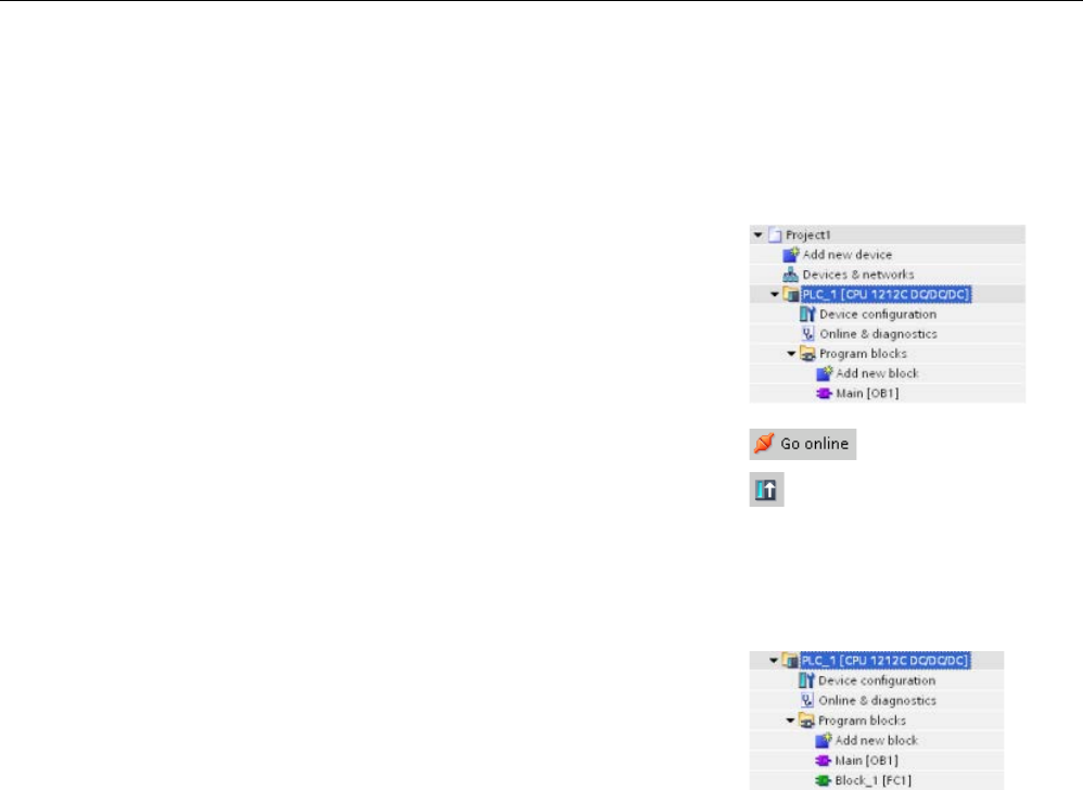
Programming concepts
7.9 Uploading from the online CPU
S7-1200 Programmable controller
System Manual, V4.2, 09/2016, A5E02486680-AK 221
7.9
Uploading from the online CPU
You can also copy the program blocks from an online CPU or a memory card attached to
your programming device.
Prepare the offline project for the copied program blocks:
1.
Add a CPU device that matches the online CPU.
2.
Expand the CPU node once so that the "Program
blocks" folder is visible.
To
upload the program blocks from the online CPU to the
offline project, follow these steps:
1.
Click the "Program blocks" folder in the offline project.
2.
Click the "Go online" button.
3.
Click the "Upload" button.
4.
Confirm your decision from the Upload dialog
(Page 1313).
When the upload is complete, STEP
7 displays all of the
uploaded program blocks in the proj
ect.
7.9.1
Comparing the online CPU to the offline CPU
You can use the "Compare" editor (Page 1323) in STEP 7 to find differences between the
online and offline projects. You might find this useful prior to uploading from the CPU.
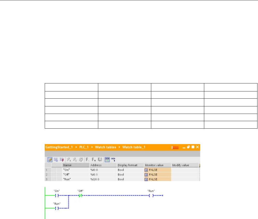
Programming concepts
7.10 Debugging and testing the program
S7-1200 Programmable controller
222 System Manual, V4.2, 09/2016, A5E02486680-AK
7.10
Debugging and testing the program
7.10.1
Monitor and modify data in the CPU
As shown in the following table, you can monitor and modify values in the online CPU.
Table 7- 5 Monitoring and modifying data with STEP 7
Editor
Monitor
Modify
Force
Watch table
Yes
Yes
No
Force table Yes No Yes
Program editor
Yes
Yes
No
Tag table
Yes
No
No
DB editor
Yes
No
No
Monitoring with a
watch table
Monitoring with the LAD editor
Refer to the "Online and diagnostics" chapter for more information about monitoring and
modifying data in the CPU (Page 1325).

Programming concepts
7.10 Debugging and testing the program
S7-1200 Programmable controller
System Manual, V4.2, 09/2016, A5E02486680-AK 223
7.10.2
Watch tables and force tables
You use "watch tables" for monitoring and modifying the values of a user program being
executed by the online CPU. You can create and save different watch tables in your project
to support a variety of test environments. This allows you to reproduce tests during
commissioning or for service and maintenance purposes.
With a watch table, you can monitor and interact with the CPU as it executes the user
program. You can display or change values not only for the tags of the code blocks and data
blocks, but also for the memory areas of the CPU, including the inputs and outputs (I and Q),
peripheral inputs (I:P), bit memory (M), and data blocks (DB).
With the watch table, you can enable the physical outputs (Q:P) of a CPU in STOP mode.
For example, you can assign specific values to the outputs when testing the wiring for the
CPU.
STEP 7 also provides a force table for "forcing" a tag to a specific value. For more
information about forcing, see the section on forcing values in the CPU (Page 1333) in the
"Online and Diagnostics" chapter.
Note
The force values are stored in the CPU and not in the watch table.
You cannot force an input (or "I" address). However, you can force a peripheral input. To
force a peripheral input, app
end a ":P" to the address (for example: "On:P").
STEP 7 also provides the capability of tracing and recording program variables based on
trigger conditions (Page 1347).
7.10.3
Cross reference to show usage
The Inspector window displays cross-reference information about how a selected object is
used throughout the complete project, such as the user program, the CPU and any HMI
devices. The "Cross-reference" tab displays the instances where a selected object is being
used and the other objects using it. The Inspector window also includes blocks which are
only available online in the cross-references. To display the cross-references, select the
"Show cross-references" command. (In the Project view, find the cross references in the
"Tools" menu.)
Note
You do not have to close the editor to see the cross
-reference information.

Programming concepts
7.10 Debugging and testing the program
S7-1200 Programmable controller
224 System Manual, V4.2, 09/2016, A5E02486680-AK
You can sort the entries in the cross-reference. The cross-reference list provides an
overview of the use of memory addresses and tags within the user program.
● When creating and changing a program, you retain an overview of the operands, tags
and block calls you have used.
● From the cross-references, you can jump directly to the point of use of operands and
tags.
● During a program test or when troubleshooting, you are notified about which memory
location is being processed by which command in which block, which tag is being used in
which screen, and which block is called by which other block.
Table 7- 6 Elements of the cross reference
Column
Description
Object Name of the object that uses the lower-level objects or that is being used by the
lower-level objects
Number Number of uses
Point of use
Each location of use, for example, network
Property Special properties of referenced objects, for example, the tag names in multi-
instance declarations
as Shows additional information about the object, such as whether an instance DB is
used as template or as a multiple instance
Access Type of access, whether access to the operand is read access (R) and/or write
access (W)
Address
Address of the operand
Type
Information on the type and language used to create the object
Path
Path of object in project tree
Depending on the installed products, the cross-reference table displays additional or different
columns.

Programming concepts
7.10 Debugging and testing the program
S7-1200 Programmable controller
System Manual, V4.2, 09/2016, A5E02486680-AK 225
7.10.4
Call structure to examine the calling hierarchy
The call structure describes the call hierarchy of the block within your user program. It
provides an overview of the blocks used, calls to other blocks, the relationships between
blocks, the data requirements for each block, and the status of the blocks. You can open the
program editor and edit blocks from the call structure.
Displaying the call structure provides you with a list of the blocks used in the user program.
STEP 7 highlights the first level of the call structure and displays any blocks that are not
called by any other block in the program. The first level of the call structure displays the OBs
and any FCs, FBs, and DBs that are not called by an OB. If a code block calls another block,
the called block is shown as an indentation under the calling block. The call structure only
displays those blocks that are called by a code block.
You can selectively display only the blocks causing conflicts within the call structure. The
following conditions cause conflicts:
● Blocks that execute any calls with older or newer code time stamps
● Blocks that call a block with modified interface
● Blocks that use a tag with modified address and/or data type
● Blocks that are called neither directly nor indirectly by an OB
● Blocks that call a non-existent or missing block
You can group several block calls and data blocks as a group. You use a drop-down list to
see the links to the various call locations.
You can also perform a consistency check to show time stamp conflicts. Changing the time
stamp of a block during or after the program is generated can lead to time stamp conflicts,
which in turn cause inconsistencies among the blocks that are calling and being called.
● Most time stamp and interface conflicts can be corrected by recompiling the code blocks.
● If compilation fails to clear up inconsistencies, use the link in the "Details" column to go to
the source of the problem in the program editor. You can then manually eliminate any
inconsistencies.
● Any blocks marked in red must be recompiled.

Programming concepts
7.10 Debugging and testing the program
S7-1200 Programmable controller
226 System Manual, V4.2, 09/2016, A5E02486680-AK

S7-1200 Programmable controller
System Manual, V4.2, 09/2016, A5E02486680-AK 227
Basic instructions
8
8.1
Bit logic operations
8.1.1
Bit logic instructions
LAD and FBD are very effective for handling Boolean logic. While SCL is especially effective
for complex mathematical computation and for project control structures, you can use SCL
for Boolean logic.
LAD contacts
Table 8- 1 Normally open and normally closed contacts
LAD
SCL
Description
IF in THEN
Statement;
ELSE
Statement;
END_IF;
Normally open and normally closed contacts: You can connect contacts
to other contacts and create your own combination logic. If the input bit
you specify uses memory identifier I (input) or Q (output), then the bit
value is read from the process-image register. The physical contact sig-
nals in your control process are wired to I terminals on the PLC. The CPU
scans the wired input signals and continuously updates the correspond-
ing state values in the process-image input register.
You can perform an immediate read of a physical input using ":P" follow-
ing the I offset (example: "%I3.4:P"). For an immediate read, the bit data
values are read directly from the physical input instead of the process
image. An immediate read does not update the process image.
IF NOT (in) THEN
Statement;
ELSE
Statement;
END_IF;
Table 8- 2 Data types for the parameters
Parameter
Data type
Description
IN
Bool
Assigned bit
● The Normally Open contact is closed (ON) when the assigned bit value is equal to 1.
● The Normally Closed contact is closed (ON) when the assigned bit value is equal to 0.
● Contacts connected in series create AND logic networks.
● Contacts connected in parallel create OR logic networks.

Basic instructions
8.1 Bit logic operations
S7-1200 Programmable controller
228 System Manual, V4.2, 09/2016, A5E02486680-AK
FBD AND, OR, and XOR boxes
In FBD programming, LAD contact networks are transformed into AND (&), OR (>=1), and
EXCLUSIVE OR (x) box networks where you can specify bit values for the box inputs and
outputs. You may also connect to other logic boxes and create your own logic combinations.
After the box is placed in your network, you can drag the "Insert input" tool from the
"Favorites" toolbar or instruction tree and then drop it onto the input side of the box to add
more inputs. You can also right-click on the box input connector and select "Insert input".
Box inputs and outputs can be connected to another logic box, or you can enter a bit
address or bit symbol name for an unconnected input. When the box instruction is executed,
the current input states are applied to the binary box logic and, if true, the box output will be
true.
Table 8- 3 AND, OR, and XOR boxes
FBD
SCL1
Description
out := in1 AND
in2;
All inputs of an AND box must be TRUE for the output to be
TRUE.
out := in1 OR in2;
Any input of an OR box must be TRUE for the output to be
TRUE.
out := in1 XOR
in2;
An odd number of the inputs of an XOR box must be TRUE for
the output to be TRUE.
1 For SCL: You must assign the result of the operation to a variable to be used for another statement.
Table 8- 4 Data types for the parameters
Parameter
Data type
Description
IN1, IN2
Bool
Input bit
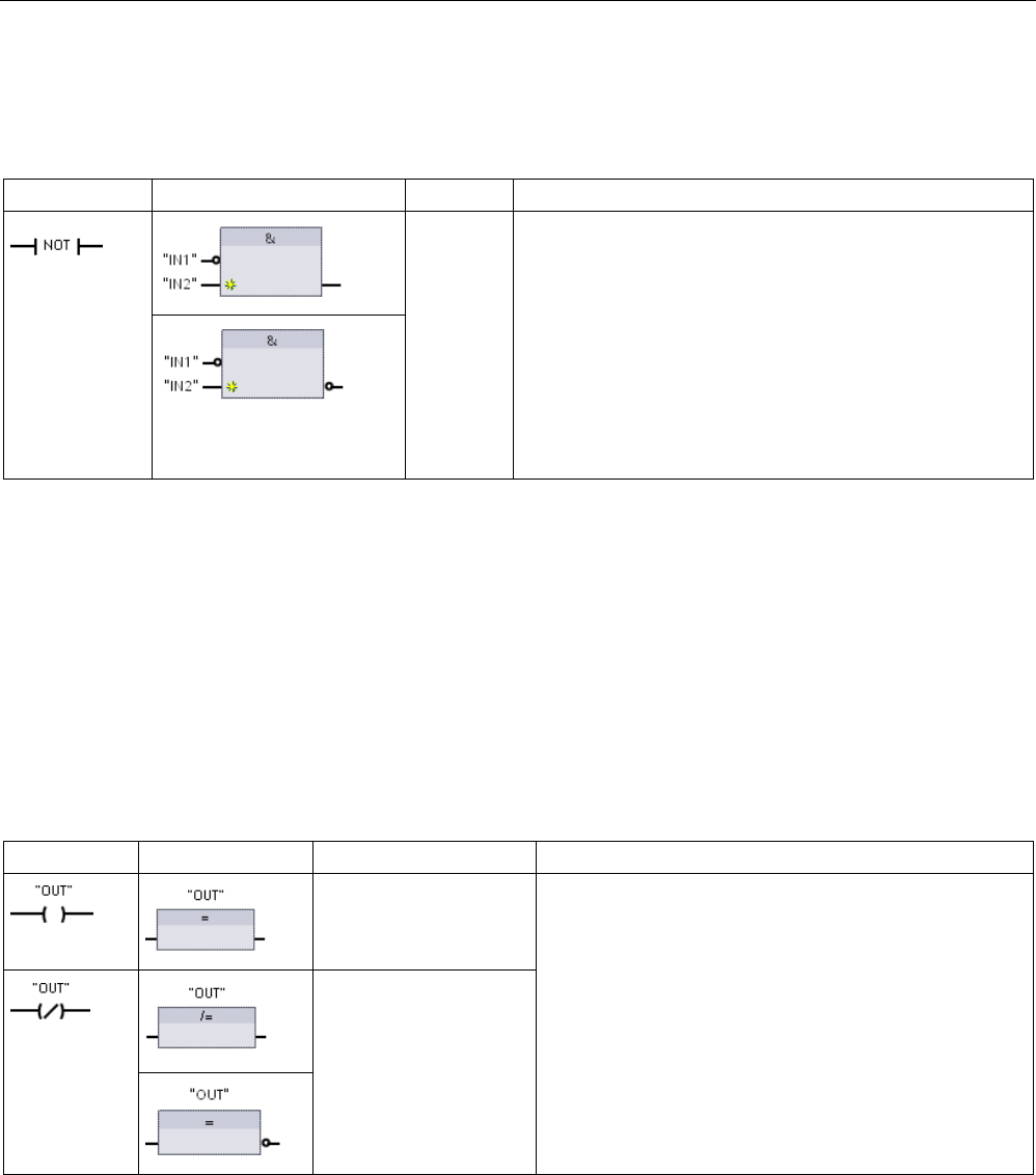
Basic instructions
8.1 Bit logic operations
S7-1200 Programmable controller
System Manual, V4.2, 09/2016, A5E02486680-AK 229
NOT logic inverter
Table 8- 5 Invert RLO (Result of Logic Operation)
LAD
FBD
SCL
Description
NOT
For FBD programming, you can drag the "Invert RLO" tool
from the "Favorites" toolbar or instruction tree and then drop
it on an input or output to create a logic inverter on that box
connector.
The LAD NOT contact inverts the logical state of power flow
input.
• If there is no power flow into the NOT contact, then there
is power flow out.
• If there is power flow into the NOT contact, then there is
no power flow out.
Output coil and assignment box
The coil output instruction writes a value for an output bit. If the output bit you specify uses
memory identifier Q, then the CPU turns the output bit in the process-image register on or
off, setting the specified bit equal to power flow status. The output signals for your control
actuators are wired to the Q terminals of the CPU. In RUN mode, the CPU system
continuously scans your input signals, processes the input states according to your program
logic, and then reacts by setting new output state values in the process-image output
register. The CPU system transfers the new output state reaction that is stored in the
process-image register, to the wired output terminals.
Table 8- 6 Assignment and negate assignment
LAD
FBD
SCL
Description
out := <Boolean
expression>;
In FBD programming, LAD coils are transformed into
assignment (= and /=) boxes where you specify a bit ad-
dress for the box output. Box inputs and outputs can be
connected to other box logic or you can enter a bit ad-
dress.
You can specify an immediate write of a physical output
using ":P" following the Q offset (example: "%Q3.4:P").
For an immediate write, the bit data values are written to
the process image output and directly to physical output.
out := NOT <Boole-
an expression>;
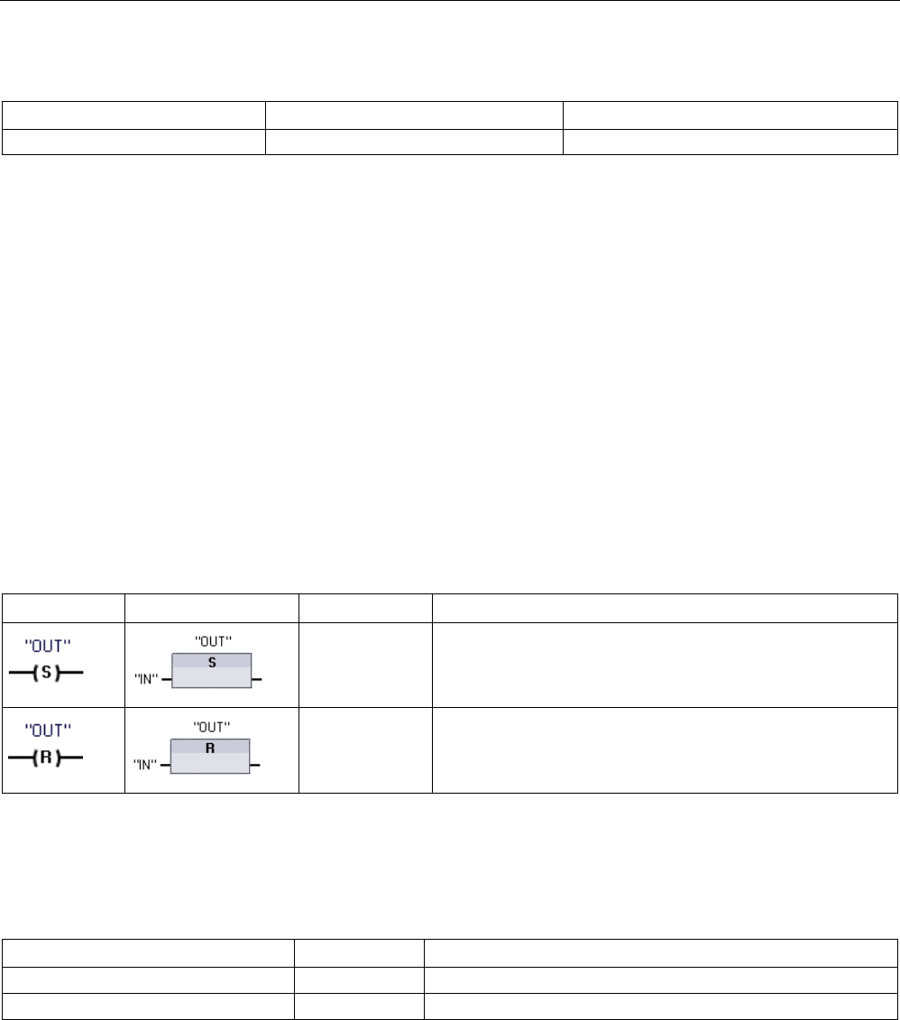
Basic instructions
8.1 Bit logic operations
S7-1200 Programmable controller
230 System Manual, V4.2, 09/2016, A5E02486680-AK
Table 8- 7 Data types for the parameters
Parameter
Data type
Description
OUT
Bool
Assigned bit
● If there is power flow through an output coil or an FBD "=" box is enabled, then the output
bit is set to 1.
● If there is no power flow through an output coil or an FBD "=" assignment box is not
enabled, then the output bit is set to 0.
● If there is power flow through an inverted output coil or an FBD "/=" box is enabled, then
the output bit is set to 0.
● If there is no power flow through an inverted output coil or an FBD "/=" box is not enabled,
then the output bit is set to 1.
8.1.2
Set and reset instructions
Set and Reset 1 bit
Table 8- 8 S and R instructions
LAD
FBD
SCL
Description
Not available Set output:
When S (Set) is activated, then the data value at the OUT
address is set to 1. When S is not activated, OUT is not
changed.
Not available Reset output:
When R (Reset) is activated, then the data value at the OUT
address is set to 0. When R is not activated, OUT is not
changed.
1
For LAD and FBD: These instructions can be placed anywhere in the network.
2 For SCL: You must write code to replicate this function within your application.
Table 8- 9 Data types for the parameters
Parameter
Data type
Description
IN (or connect to contact/gate logic)
Bool
Bit tag of location to be monitored
OUT
Bool
Bit tag of location to be set or reset
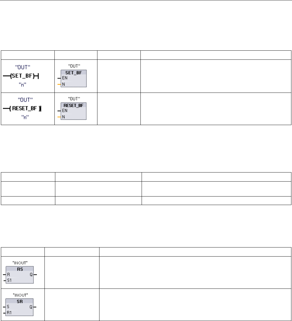
Basic instructions
8.1 Bit logic operations
S7-1200 Programmable controller
System Manual, V4.2, 09/2016, A5E02486680-AK 231
Set and Reset Bit Field
Table 8- 10 SET_BF and RESET_BF instructions
LAD1
FBD
SCL
Description
Not available Set bit field:
Wh
en SET_BF is activated, a data value of 1 is assigned to "n"
bits starting at address tag OUT. When SET_BF is not activat-
ed, OUT is not changed.
Not available Reset bit field:
RESET_BF writes a data value of 0 to "n" bits starting at ad-
dress tag OUT. When RESET_BF is not activated, OUT is not
changed.
1
For LAD and FBD: These instructions must be the right-most instruction in a branch.
2 For SCL: You must write code to replicate this function within your application.
Table 8- 11 Data types for the parameters
Parameter
Data type
Description
OUT Bool Starting element of a bit field to be set or reset (Example:
#MyArray[3])
n
Constant (UInt)
Number of bits to write
Set-dominant and Reset-dominant flip-flops
Table 8- 12 RS and SR instructions
LAD / FBD
SCL
Description
Not available Reset/set flip-flop:
RS is a set dominant latch where the set dominates. If the set (S1) and reset (R)
signals are both true, the value at address INOUT will be 1.
Not available Set/reset flip-flop:
SR is a reset dominant latch where the reset dominates. If the set (S) and reset
(R1) signals are both true, the value at address INOUT will be 0.
1
For LAD and FBD: These instructions must be the right-most instruction in a branch.
2 For SCL: You must write code to replicate this function within your application.

Basic instructions
8.1 Bit logic operations
S7-1200 Programmable controller
232 System Manual, V4.2, 09/2016, A5E02486680-AK
Table 8- 13 Data types for the parameters
Parameter
Data type
Description
S, S1
Bool
Set input; 1 indicates dominance
R, R1 Bool Reset input; 1 indicates dominance
INOUT
Bool
Assigned bit tag "INOUT"
Q Bool Follows state of "INOUT" bit
The "INOUT" tag assigns the bit address that is set or reset. The optional output Q follows
the signal state of the "INOUT" address.
Instruction
S1
R
"INOUT" bit
RS
0
0
Previous state
0
1
0
1
0
1
1
1
1
S
R1
SR
0
0
Previous state
0
1
0
1
0
1
1
1
0
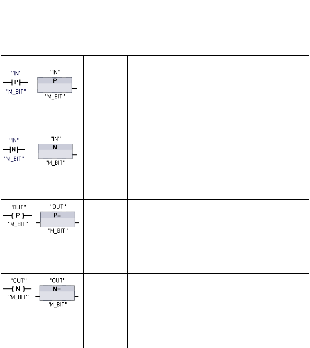
Basic instructions
8.1 Bit logic operations
S7-1200 Programmable controller
System Manual, V4.2, 09/2016, A5E02486680-AK 233
8.1.3
Positive and negative edge instructions
Table 8- 14 Positive and negative transition detection
LAD
FBD
SCL
Description
Not available 1 Scan operand for positive signal edge.
LAD: The state of this contact is TRUE when a positive transition (OFF-
to-ON) is detected on the assigned "IN" bit. The contact logic state is
then combined with the power flow in state to set the power flow out
state. The P contact can be located anywhere in the network except the
end of a branch.
FBD: The output logic state is TRUE when a positive transition (OFF-
to-ON) is detected on the assigned input bit. The P box can only be
located at the beginning of a branch.
Not available 1 Scan operand for negative signal edge.
LAD: The state of this contact is TRUE when a negative transition (ON-
to-OFF) is detected on the assigned input bit. The contact logic state is
then combined with the power flow in state to set the power flow out
state. The N contact can be located anywhere in the network except
the end of a branch.
FBD: The output logic state is TRUE when a negative transition (ON-to-
OFF) is detected on the assigned input bit. The N box can only be
located at the beginning of a branch.
Not available 1 Set operand on positve signal edge.
LAD: The assigned bit "OUT" is TRUE when a positive transition (OFF-
to-ON) is detected on the power flow entering the coil. The power flow
in state always passes through the coil as the power flow out state. The
P coil can be located anywhere in the network.
FBD: The assigned bit "OUT" is TRUE when a positive transition (OFF-
to-ON) is detected on the logic state at the box input connection or on
the input bit assignment if the box is located at the start of a branch.
The input logic state always passes through the box as the output logic
state. The P= box can be located anywhere in the branch.
Not available 1 Set operand on negative signal edge.
LAD: The assigned bit "OUT" is TRUE when a negative transition (ON-
to-OFF) is detected on the power flow entering the coil. The power flow
in state always passes through the coil as the power flow out state. The
N coil can be located anywhere in the network.
FBD: The assigned bit "OUT" is TRUE when a negative transition (ON-
to-OFF) is detected on the logic state at the box input connection or on
the input bit assignment if the box is located at the start of a branch.
The input logic state always passes through the box as the output logic
state. The N= box can be located anywhere in the branch.
1 For SCL: You must write code to replicate this function within your application.
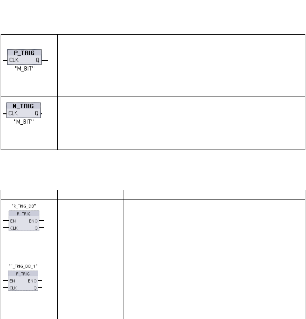
Basic instructions
8.1 Bit logic operations
S7-1200 Programmable controller
234 System Manual, V4.2, 09/2016, A5E02486680-AK
Table 8- 15 P_TRIG and N_TRIG
LAD / FBD
SCL
Description
Not available 1 Scan RLO (result of logic operation) for positve signal edge.
The Q output power flow or logic state is TRUE when a positive transi-
tion (OFF-to-ON) is detected on the CLK input state (FBD) or CLK pow-
er flow in (LAD).
In LAD, the P_TRIG instruction cannot be located at the beginning or
end of a network. In FBD, the P_TRIG instruction can be located any-
where except the end of a branch.
Not available 1 Scan RLO for negative signal edge.
The Q output power flow or logic state is TRUE when a negative transi-
tion (ON-to-OFF) is detected on the CLK input state (FBD) or CLK pow-
er flow in (LAD).
In LAD, the N_TRIG instruction cannot be located at the beginning or
end of a network. In FBD, the N_TRIG instruction can be located any-
where except the end of a branch.
1 For SCL: You must write code to replicate this function within your application.
Table 8- 16 R_TRIG and F_TRIG instructions
LAD / FBD
SCL
Description
"R_TRIG_DB"(
CLK:=_in_,
Q=> _bool_out_);
Set tag on positive signal edge.
The assigned instance DB is used to store the previous state of the CLK
input. The Q output power flow or logic state is TRUE when a positive
transition (OFF-to-ON) is detected on the CLK input state (FBD) or CLK
power flow in (LAD).
In LAD, the R_TRIG instruction cannot be located at the beginning or
end of a network. In FBD, the R_TRIG instruction can be located any-
where except the end of a branch.
"F_TRIG_DB"(
CLK:=_in_,
Q=> _bool_out_);
Set tag on negative signal edge.
The assigned instance DB is used to store the previous state of the CLK
input. The Q output power flow or logic state is TRUE when a negative
transition (ON-to-OFF) is detected on the CLK input state (FBD) or CLK
power flow in (LAD).
In LAD, the F_TRIG instruction cannot be located at the beginning or
end of a network. In FBD, the F_TRIG instruction can be located any-
where except the end of a branch.

Basic instructions
8.1 Bit logic operations
S7-1200 Programmable controller
System Manual, V4.2, 09/2016, A5E02486680-AK 235
For R_TRIG and F_TRIG, when you insert the instruction in the program, the "Call options"
dialog opens automatically. In this dialog you can assign
whether the edge memory bit is stored in its own data block (single instance) or as a local
tag (multiple instance) in the
block interface. If you create a separate data block, you will find it in the project tree in the
"Program resources" folder
under "Program blocks > System blocks".
Table 8- 17 Data types for the parameters (P and N contacts/coils, P=, N=, P_TRIG and N_TRIG)
Parameter
Data type
Description
M_BIT
Bool
Memory bit in which the previous state of the input is saved
IN Bool Input bit whose transition edge is detected
OUT
Bool
Output bit which indicates a transition edge was detected
CLK
Bool
Power flow or input bit whose transition edge is detected
Q
Bool
Output which indicates an edge was detected
All edge instructions use a memory bit (M_BIT: P/N contacts/coils, P_TRIG/N_TRIG) or
(instance DB bit: R_TRIG, F_TRIG) to store the previous state of the monitored input signal.
An edge is detected by comparing the state of the input with the previous state. If the states
indicate a change of the input in the direction of interest, then an edge is reported by writing
the output TRUE. Otherwise, the output is written to FALSE.
Note
Edge instructions evaluate the input and memory
-bit values each time they are executed,
including the first execution. You must account for the initial states of the input and memory
bit in your program design either to allo
w or to avoid edge detection on the first scan.
Because the memory bit must be maintained from one execution to the next, you should use
a unique bit for each edge instruction, and you should not use this bit any other place in your
program. You should als
o avoid temporary memory and memory that can be affected by
other system functions, such as an I/O update. Use only M, global DB, or Static memory (in
an instance DB) for M_BIT memory assignments.
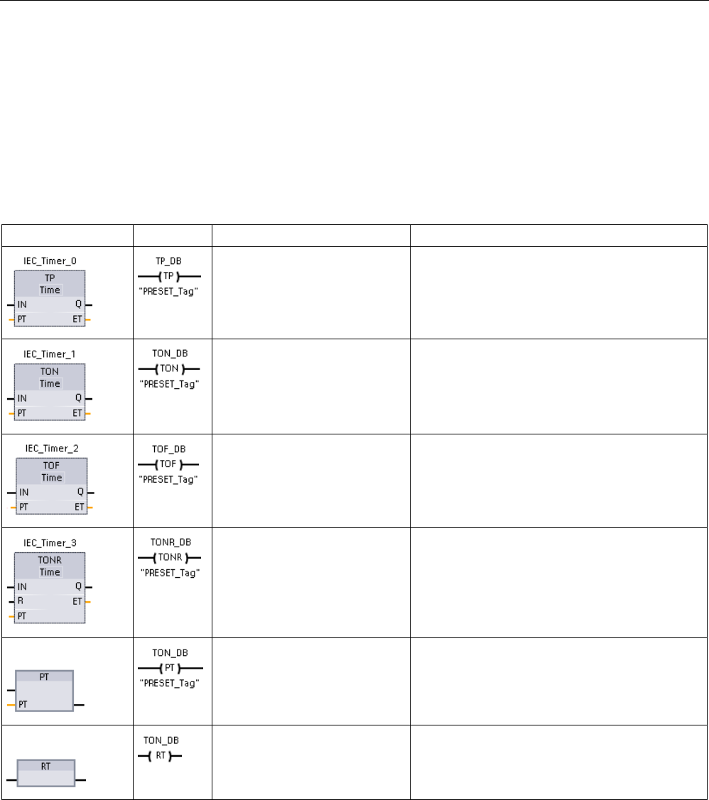
Basic instructions
8.2 Timer operations
S7-1200 Programmable controller
236 System Manual, V4.2, 09/2016, A5E02486680-AK
8.2
Timer operations
You use the timer instructions to create programmed time delays. The number of timers that
you can use in your user program is limited only by the amount of memory in the CPU. Each
timer uses a 16 byte IEC_Timer data type DB structure to store timer data that is specified at
the top of the box or coil instruction. STEP 7 automatically creates the DB when you insert
the instruction.
Table 8- 18 Timer instructions
LAD / FBD boxes
LAD coils
SCL
Description
"IEC_Timer_0_DB".TP(
IN:=_bool_in_,
PT:=_time_in_,
Q=>_bool_out_,
ET=>_time_out_);
The TP timer generates a pulse with a preset
width time.
"IEC_Timer_0_DB".TON (
IN:=_bool_in_,
PT:=_time_in_,
Q=>_bool_out_,
ET=>_time_out_);
The TON timer sets output Q to ON after a preset
time delay.
"IEC_Timer_0_DB".TOF (
IN:=_bool_in_,
PT:=_time_in_,
Q=>_bool_out_,
ET=>_time_out_);
The TOF timer resets output Q to OFF after a
preset time delay.
"IEC_Timer_0_DB".TONR (
IN:=_bool_in_,
R:=_bool_in_,
PT:=_time_in_,
Q=>_bool_out_,
ET=>_time_out_);
The TONR timer sets output Q to ON after a pre-
set time delay. Elapsed time is accumulated over
multiple timing periods until the R input is used to
reset the elapsed time.
FBD only:
PRESET_TIMER(
PT:=_time_in_,
TIMER:=_iec_timer_in_);
The PT (Preset timer) coil loads a new PRESET
time value in the specified IEC_Timer.
FBD only:
RESET_TIMER(
_iec_timer_in_);
The RT (Reset timer) coil resets the specified
IEC_Timer.
1
STEP 7 automatically creates the DB when you insert the instruction.
2 In the SCL examples, "IEC_Timer_0_DB" is the name of the instance DB.

Basic instructions
8.2 Timer operations
S7-1200 Programmable controller
System Manual, V4.2, 09/2016, A5E02486680-AK 237
Table 8- 19 Data types for the parameters
Parameter
Data type
Description
Box: IN
Coil: Power flow
Bool TP, TON, and TONR:
Box: 0=Disable timer, 1=Enable timer
Coil: No power flow=Disable timer, Power flow=Enable timer
TOF:
Box: 0=Enable timer, 1=Disable timer
Coil: No power flow=Enable timer, Power flow=Disable timer
R Bool TONR box only:
0=No reset
1= Reset elapsed time and Q bit to 0
Box: PT
Coil: "PRESET_Tag"
Time Timer box or coil: Preset time input
Box: Q
Coil: DBdata.Q
Bool Timer box: Q box output or Q bit in the timer DB data
Timer coil: you can only address the Q bit in the timer DB data
Box: ET
Coil: DBdata.ET
Time Timer box: ET (elapsed time) box output or ET time value in the timer DB
data
Timer coil: you can only address the ET time value in the timer DB data.
Table 8- 20 Effect of value changes in the PT and IN parameters
Timer
Changes in the PT and IN box parameters and the corresponding coil parameters
TP • Changing PT has no effect while the timer runs.
• Changing IN has no effect while the timer runs.
TON • Changing PT has no effect while the timer runs.
• Changing IN to FALSE, while the timer runs, resets and stops the timer.
TOF • Changing PT has no effect while the timer runs.
• Changing IN to TRUE, while the timer runs, resets and stops the timer.
TONR • Changing PT has no effect while the timer runs, but has an effect when the timer resumes.
• Changing IN to FALSE, while the timer runs, stops the timer but does not reset the timer. Changing
IN back to TRUE will cause the timer to start timing from the accumulated time value.
PT (preset time) and ET (elapsed time) values are stored in the specified IEC_TIMER DB
data as signed double integers that represent milliseconds of time. TIME data uses the T#
identifier and can be entered as a simple time unit (T#200ms or 200) and as compound time
units like T#2s_200ms.
Table 8- 21 Size and range of the TIME data type
Data type
Size
Valid number ranges1
TIME 32 bits, stored
as DInt data
T#
-
24d_20h_31m_23s_648ms to T#24d_20h_31m_23s_647ms
Stored as -2,147,483,648 ms to +2,147,483,647 ms
1
The negative range of the TIME data type shown above cannot be used with the timer instructions. Negative PT (preset
time) values are set to zero when the timer instruction is executed. ET (elapsed time) is always a positive value.
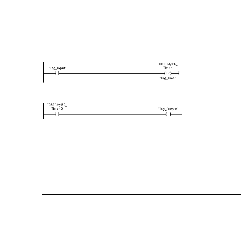
Basic instructions
8.2 Timer operations
S7-1200 Programmable controller
238 System Manual, V4.2, 09/2016, A5E02486680-AK
Timer coil example
The -(TP)-, -(TON)-, -(TOF)-, and -(TONR)- timer coils must be the last instruction in a LAD
network. As shown in the timer example, a contact instruction in a subsequent network
evaluates the Q bit in a timer coil's IEC_Timer DB data. Likewise, you must address the
ELAPSED element in the IEC_timer DB data if you want to use the elapsed time value in
your program.
The pulse timer is started on a 0 to 1 transition of the Tag_Input bit value. The timer runs for
the time specified by Tag_Time time value.
As long as the timer runs, the state of DB1.MyIEC_Timer.Q=1 and the Tag_Output value=1.
When the Tag_Time value has elapsed, then DB1.MyIEC_Timer.Q=0 and the Tag_Output
value=0.
Reset timer -(RT)- and Preset timer -(PT)- coils
These coil instructions can be used with box or coil timers and can be placed in a mid-line
position. The coil output power flow status is always the same as the coil input status. When
the -(RT)- coil is activated, the ELAPSED time element of the specified IEC_Timer DB data
is reset to 0. When the -(PT)- coil is activated, the PRESET time element of the specified
IEC_Timer DB data is loaded with the assigned time-duration value..
Note
When you place timer instructions in an FB, you can select the "Multi
-instance data block"
option. The timer st
ructure names can be different with separate data structures, but the
timer data is contained in a single data block and does not require a separate data block for
each timer. This reduces the processing time and data storage necessary for handling the
tim
ers. There is no interaction between the timer data structures in the shared multi-instance
DB.

Basic instructions
8.2 Timer operations
S7-1200 Programmable controller
System Manual, V4.2, 09/2016, A5E02486680-AK 239
Operation of the timers
Table 8- 22 Types of IEC timers
Timer
Timing diagram
TP
: Generate pulse
The TP timer generates a pulse with a preset width
time.
TON
: Generate ON-delay
The TON timer sets output Q to ON after a preset time
delay.
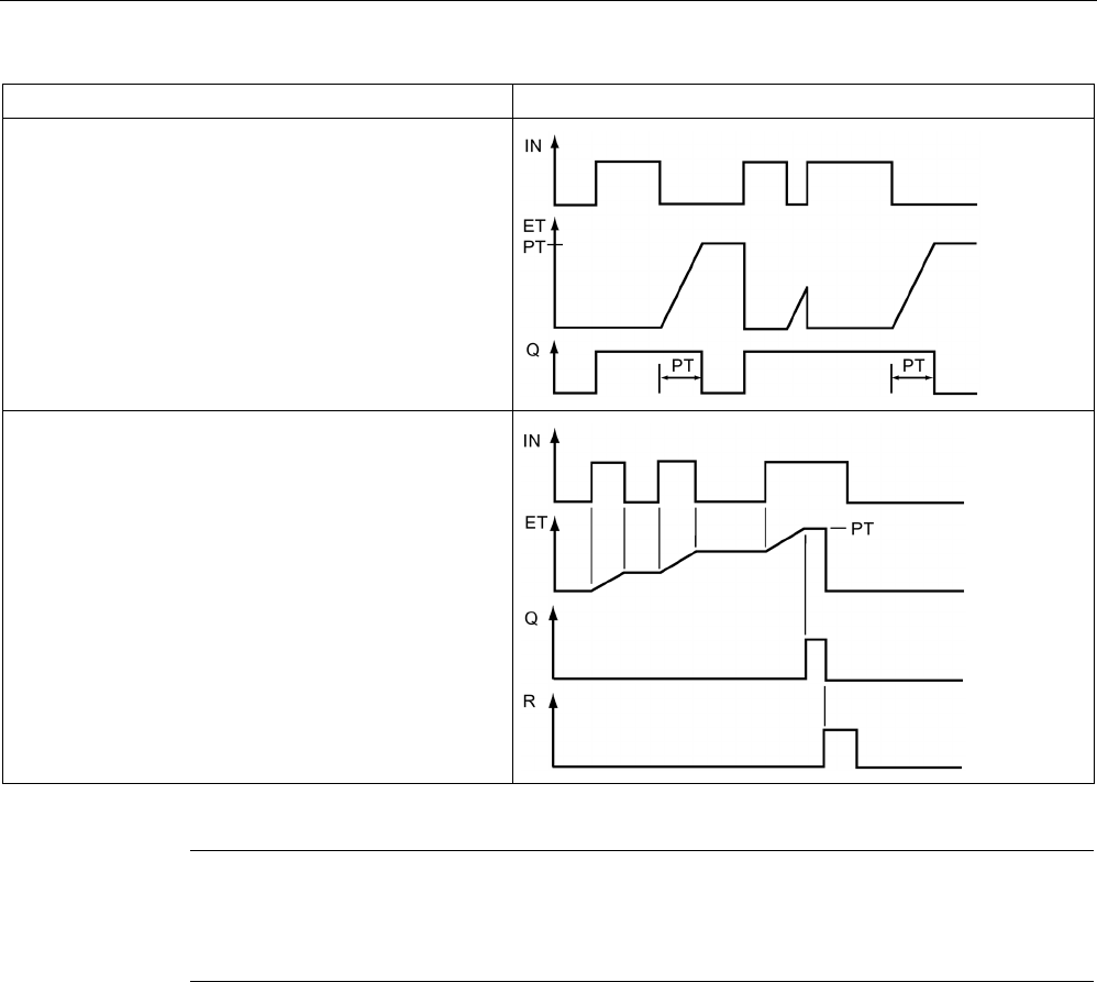
Basic instructions
8.2 Timer operations
S7-1200 Programmable controller
240 System Manual, V4.2, 09/2016, A5E02486680-AK
Timer
Timing diagram
TOF
: Generate OFF-delay
The TOF timer resets output Q to OFF after a preset
time delay.
TONR
: Time accumulator
The TONR timer sets output Q to ON after a preset time
delay. Elapsed time is accumulated over multiple timing
periods until the R input is used to reset the elapsed
time.
Note
In the CPU, no dedicated resource is allocated to any specific timer instruction. Instead,
each timer utilizes its own timer structure in DB memory and a continuously
-running internal
CPU timer to perform timing.
When a timer is started due to an edge change on the input of a TP, TON, TOF, or TONR
instruction, the value of the continuously-running internal CPU timer is copied into the
START member of the DB structure allocated for this timer instruction. This start value
remains unchanged while the timer continues to run, and is used later each time the timer is
updated. Each time the timer is started, a new start value is loaded into the timer structure
from the internal CPU timer.
When a timer is updated, the start value described above is subtracted from the current
value of the internal CPU timer to determine the elapsed time. The elapsed time is then
compared with the preset to determine the state of the timer Q bit. The ELAPSED and Q
members are then updated in the DB structure allocated for this timer. Note that the elapsed
time is clamped at the preset value (the timer does not continue to accumulate elapsed time
after the preset is reached).

Basic instructions
8.2 Timer operations
S7-1200 Programmable controller
System Manual, V4.2, 09/2016, A5E02486680-AK 241
A timer update is performed when and only when:
● A timer instruction (TP, TON, TOF, or TONR) is executed
● The "ELAPSED" member of the timer structure in DB is referenced directly by an
instruction
● The "Q" member of the timer structure in DB is referenced directly by an instruction
Timer programming
The following consequences of timer operation should be considered when planning and
creating your user program:
● You can have multiple updates of a timer in the same scan. The timer is updated each
time the timer instruction (TP, TON, TOF, TONR) is executed and each time the
ELAPSED or Q member of the timer structure is used as a parameter of another
executed instruction. This is an advantage if you want the latest time data (essentially an
immediate read of the timer). However, if you desire to have consistent values throughout
a program scan, then place your timer instruction prior to all other instructions that need
these values, and use tags from the Q and ET outputs of the timer instruction instead of
the ELAPSED and Q members of the timer DB structure.
● You can have scans during which no update of a timer occurs. It is possible to start your
timer in a function, and then cease to call that function again for one or more scans. If no
other instructions are executed which reference the ELAPSED or Q members of the timer
structure, then the timer will not be updated. A new update will not occur until either the
timer instruction is executed again or some other instruction is executed using ELAPSED
or Q from the timer structure as a parameter.
● Although not typical, you can assign the same DB timer structure to multiple timer
instructions. In general, to avoid unexpected interaction, you should only use one timer
instruction (TP, TON, TOF, TONR) per DB timer structure.
● Self-resetting timers are useful to trigger actions that need to occur periodically. Typically,
self-resetting timers are created by placing a normally-closed contact which references
the timer bit in front of the timer instruction. This timer network is typically located above
one or more dependent networks that use the timer bit to trigger actions. When the timer
expires (elapsed time reaches preset value), the timer bit is ON for one scan, allowing the
dependent network logic controlled by the timer bit to execute. Upon the next execution of
the timer network, the normally closed contact is OFF, thus resetting the timer and
clearing the timer bit. The next scan, the normally closed contact is ON, thus restarting
the timer. When creating self-resetting timers such as this, do not use the "Q" member of
the timer DB structure as the parameter for the normally-closed contact in front of the
timer instruction. Instead, use the tag connected to the "Q" output of the timer instruction
for this purpose. The reason to avoid accessing the Q member of the timer DB structure
is because this causes an update to the timer and if the timer is updated due to the
normally closed contact, then the contact will reset the timer instruction immediately. The
Q output of the timer instruction will not be ON for the one scan and the dependent
networks will not execute.

Basic instructions
8.2 Timer operations
S7-1200 Programmable controller
242 System Manual, V4.2, 09/2016, A5E02486680-AK
Time data retention after a RUN-STOP-RUN transition or a CPU power cycle
If a run mode session is ended with stop mode or a CPU power cycle and a new run mode
session is started, then the timer data stored in the previous run mode session is lost, unless
the timer data structure is specified as retentive (TP, TON, TOF, and TONR timers).
When you accept the defaults in the call options dialog after you place a timer instruction in
the program editor, you are automatically assigned an instance DB which
cannot be made
retentive
. To make your timer data retentive, you must either use a global DB or a Multi-
instance DB.
Assign a global DB to store timer data as retentive data
This option works regardless of where the timer is placed (OB, FC, or FB).
1. Create a global DB:
– Double-click "Add new block" from the Project tree
– Click the data block (DB) icon
– For the Type, choose global DB
– If you want to be able to select individual data elements in this DB as retentive, be
sure the DB type "Optimized" box is checked. The other DB type option "Standard -
compatible with S7-300/400" only allows setting all DB data elements retentive or
none retentive.
– Click OK
2. Add timer structure(s) to the DB:
– In the new global DB, add a new static tag using data type IEC_Timer.
– In the "Retain" column, check the box so that this structure will be retentive.
– Repeat this process to create structures for all the timers that you want to store in this
DB. You can either place each timer structure in a unique global DB, or you can place
multiple timer structures into the same global DB. You can also place other static tags
besides timers in this global DB. Placing multiple timer structures into the same global
DB allows you to reduce your overall number of blocks.
– Rename the timer structures if desired.
3. Open the program block for editing where you want to place a retentive timer (OB, FC, or
FB).
4. Place the timer instruction at the desired location.
5. When the call options dialog appears, click the cancel button.
6. On the top of the new timer instruction, type the name (do not use the helper to browse)
of the global DB and timer structure that you created above (example:
"Data_block_3.Static_1").

Basic instructions
8.2 Timer operations
S7-1200 Programmable controller
System Manual, V4.2, 09/2016, A5E02486680-AK 243
Assign a multi-instance DB to store timer data as retentive data
This option only works if you place the timer in an FB.
This option depends upon whether the FB properties specify "Optimized block access"
(allows symbolic access only). To verify how the access attribute is configured for an existing
FB, right-click on the FB in the Project tree, choose properties, and then choose Attributes.
If the FB specifies "Optimized block access" (allows symbolic access only):
1. Open the FB for edit.
2. Place the timer instruction at the desired location in the FB.
3. When the Call options dialog appears, click the Multi instance icon. The Multi Instance
option is only available if the instruction is being placed into an FB.
4. In the Call options dialog, rename the timer if desired.
5. Click OK. The timer instruction appears in the editor, and the IEC_TIMER structure
appears in the FB Interface under Static.
6. If necessary, open the FB interface editor (may have to click on the small arrow to expand
the view).
7. Under Static, locate the timer structure that was just created for you.
8. In the Retain column for this timer structure, change the selection to "Retain". Whenever
this FB is called later from another program block, an instance DB will be created with this
interface definition which contains the timer structure marked as retentive.
If the FB does not specify "Optimized block access", then the block access type is standard,
which is compatible with S7-300/400 classic configurations and allows symbolic and direct
access. To assign a multi-instance to a standard block access FB, follow these steps:
1. Open the FB for edit.
2. Place the timer instruction at the desired location in the FB.
3. When the Call options dialog appears, click on the multi instance icon. The multi instance
option is only available if the instruction is being placed into an FB.
4. In the Call options dialog, rename the timer if desired.
5. Click OK. The timer instruction appears in the editor, and the IEC_TIMER structure
appears in the FB Interface under Static.
6. Open the block that will use this FB.
7. Place this FB at the desired location. Doing so results in the creation of an instance data
block for this FB.
8. Open the instance data block created when you placed the FB in the editor.
9. Under Static, locate the timer structure of interest. In the Retain column for this timer
structure, check the box to make this structure retentive.

Basic instructions
8.3 Counter operations
S7-1200 Programmable controller
244 System Manual, V4.2, 09/2016, A5E02486680-AK
8.3
Counter operations
Table 8- 23 Counter instructions
LAD / FBD
SCL
Description
"IEC_Counter_0_DB".CTU
(
CU:=_bool_in,
R:=_bool_in,
PV:=_in,
Q=>_bool_out,
CV=>_out);
Use the counter instructions to count internal program events and
external process events. Each counter uses a structure stored in a
data block to maintain counter data. You assign the data block when
the counter instruction is placed in the editor.
• CTU is a count-up counter
• CTD is a count-down counter
• CTUD is a count-up-and-down counter
"IEC_Counter_0_DB".CTD
(
CD:=_bool_in,
LD:=_bool_in,
PV:=_in,
Q=>_bool_out,
CV=>_out);
"IEC_Counter_0_DB".CTU
D(
CU:=_bool_in,
CD:=_bool_in,
R:=_bool_in,
LD:=_bool_in,
PV:=_in_,
QU=>_bool_out,
QD=>_bool_out,
CV=>_out_);
1
For LAD and FBD: Select the count value data type from the drop-down list below the instruction name.
2
STEP 7 automatically creates the DB when you insert the instruction.
3 In the SCL examples, "IEC_Counter_0_DB" is the name of the instance DB.
Table 8- 24 Data types for the parameters
Parameter
Data type1
Description
CU, CD
Bool
Count up or count down, by one count
R (CTU, CTUD)
Bool
Reset count value to zero
LD (CTD, CTUD)
Bool
Load control for preset value
PV
SInt, Int, DInt, USInt, UInt, UDInt
Preset count value
Q, QU Bool True if CV >= PV
QD
Bool
True if CV <= 0
CV
SInt, Int, DInt, USInt, UInt, UDInt
Current count value
1
The numerical range of count values depends on the data type you select. If the count value is an unsigned integer
type, you can count down to zero or count up to the range limit. If the count value is a signed integer, you can count
down to the negative integer limit and count up to the positive integer limit.
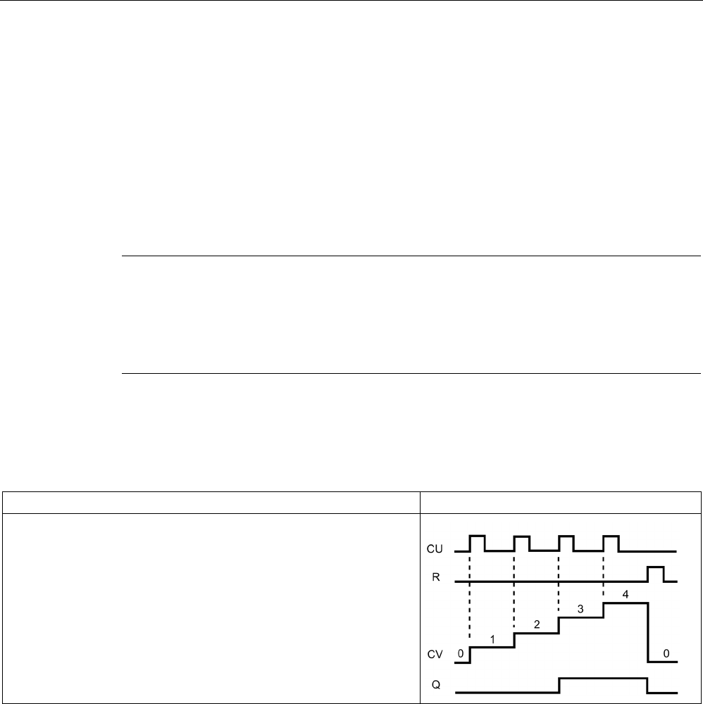
Basic instructions
8.3 Counter operations
S7-1200 Programmable controller
System Manual, V4.2, 09/2016, A5E02486680-AK 245
The number of counters that you can use in your user program is limited only by the amount
of memory in the CPU. Counters use the following amount of memory:
● For SInt or USInt data types, the counter instruction uses 3 bytes.
● For Int or UInt data types, the counter instruction uses 6 bytes.
● For DInt or UDInt data types, the counter instruction uses 12 bytes.
These instructions use software counters whose maximum counting rate is limited by the
execution rate of the OB in which they are placed. The OB that the instructions are placed in
must be executed often enough to detect all transitions of the CU or CD inputs. For faster
counting operations, see the CTRL_HSC instruction (Page 555).
Note
When you place counter instruc
tions in an FB, you can select the multi-instance DB option,
the counter structure names can be different with separate data structures, but the counter
data is contained in a single DB and does not require a separate DB for each counter. This
reduces the
processing time and data storage necessary for the counters. There is no
interaction between the counter data structures in the shared multi
-instance DB.
Operation of the counters
Table 8- 25 Operation of CTU (count up)
Counter
Operation
The CTU counter counts up by 1 when the value of parameter CU
changes from 0 to 1. The CTU timing diagram shows the operation for
an unsigned integer count value (where PV = 3).
• If the value of parameter CV (current count value) is greater than or
equal to the value of parameter PV (preset count value), then the
counter output parameter Q = 1.
• If the value of the reset parameter R changes from 0 to 1, then the
current count value is reset to 0.
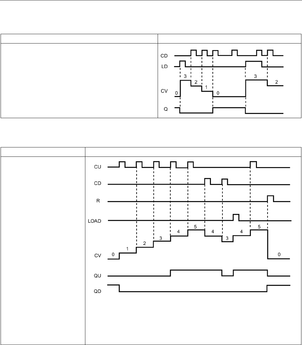
Basic instructions
8.3 Counter operations
S7-1200 Programmable controller
246 System Manual, V4.2, 09/2016, A5E02486680-AK
Table 8- 26 Operation of CTD (count down)
Counter
Operation
The CTD counter counts down by 1 when the value of parame-
ter CD changes from 0 to 1. The CTD timing diagram shows
the operation for an unsigned integer count value (where PV =
3).
• If the value of parameter CV (current count value) is equal
to or less than 0, the counter output parameter Q = 1.
• If the value of parameter LOAD changes from 0 to 1, the
value at parameter PV (preset value) is loaded to the coun-
ter as the new CV (current count value).
Table 8- 27 Operation of CTUD (count up and down)
Counter
Operation
The CTUD counter counts up or
down by 1 on the 0 to 1 transi-
tion of the count up (CU) or
count down (CD) inputs. The
CTUD timing diagram shows the
operation for an unsigned inte-
ger count value (where PV = 4).
• If the value of parameter CV
is equal to or greater than the
value of parameter PV, then
the counter output parameter
QU = 1.
• If the value of parameter CV
is less than or equal to zero,
then the counter output pa-
rameter QD = 1.
• If the value of parameter
LOAD changes from 0 to 1,
then the value at parameter
PV is loaded to the counter
as the new CV.
• If the value of the reset pa-
rameter R is changes from 0
to 1, the current count value
is reset to 0.

Basic instructions
8.3 Counter operations
S7-1200 Programmable controller
System Manual, V4.2, 09/2016, A5E02486680-AK 247
Counter data retention after a RUN-STOP-RUN transition or a CPU power cycle
If a run mode session is ended with stop mode or a CPU power cycle and a new run mode
session is started, then the counter data stored in the previous run mode session is lost,
unless the counter data structure is specified as retentive (CTU, CTD, and CTUD counters).
When you accept the defaults in the call options dialog after you place a counter instruction
in the program editor, you are automatically assigned an instance DB which
cannot be made
retentive
. To make your counter data retentive, you must either use a global DB or a Multi-
instance DB.
Assign a global DB to store counter data as retentive data
This option works regardless of where the counter is placed (OB, FC, or FB).
1. Create a global DB:
– Double-click "Add new block" from the Project tree
– Click the data block (DB) icon
– For the Type, choose global DB
– If you want to be able to select individual items in this DB as retentive, be sure the
symbolic-access-only box is checked.
– Click OK
2. Add counter structure(s) to the DB:
– In the new global DB, add a new static tag using one of the counter data types. Be
sure to consider the Type you want to use for your Preset and Count values.
– In the "Retain" column, check the box so that this structure will be retentive.
– Repeat this process to create structures for all the counters that you want to store in
this DB. You can either place each counter structure in a unique global DB, or you can
place multiple counter structures into the same global DB. You can also place other
static tags besides counters in this global DB. Placing multiple counter structures into
the same global DB allows you to reduce your overall number of blocks.
– Rename the counter structures if desired.
3. Open the program block for editing where you want to place a retentive counter (OB, FC,
or FB).
4. Place the counter instruction at the desired location.

Basic instructions
8.3 Counter operations
S7-1200 Programmable controller
248 System Manual, V4.2, 09/2016, A5E02486680-AK
5. When the call options dialog appears, click the cancel button. You should now see a new
counter instruction which has "???" both just above and just below the instruction name.
6. On the top of the new counter instruction, type the name (do not use the helper to
browse) of the global DB and counter structure that you created above (example:
"Data_block_3.Static_1"). This causes the corresponding preset and count value type to
be filled in (example: UInt for an IEC_UCounter structure).
Counter Data Type
Corresponding Type for the Preset and Count Values
IEC_Counter
INT
IEC_SCounter
SINT
IEC_DCounter
DINT
IEC_UCounter
UINT
IEC_USCounter
USINT
IEC_UDCounter
UDINT
Assign a multi-instance DB to store counter data as retentive data
This option only works if you place the counter in an FB.
This option depends upon whether the FB properties specify "Optimized block access"
(allows symbolic access only). To verify how the access attribute is configured for an existing
FB, right-click on the FB in the Project tree, choose properties, and then choose Attributes.
If the FB specifies "Optimized block access" (allows symbolic access only):
1. Open the FB for edit.
2. Place the counter instruction at the desired location in the FB.
3. When the Call options dialog appears, click on the Multi instance icon. The Multi Instance
option is only available if the instruction is being placed into an FB.
4. In the Call options dialog, rename the counter if desired.
5. Click OK. The counter instruction appears in the editor with type INT for the preset and
count values, and the IEC_COUNTER structure appears in the FB Interface under Static.
6. If desired, change the type in the counter instruction from INT to one of the other types.
The counter structure will change correspondingly.
7. If necessary, open the FB interface editor (may have to click on the small arrow to expand
the view).
8. Under Static, locate the counter structure that was just created for you.
9. In the Retain column for this counter structure, change the selection to "Retain".
Whenever this FB is called later from another program block, an instance DB will be
created with this interface definition which contains the counter structure marked as
retentive.

Basic instructions
8.3 Counter operations
S7-1200 Programmable controller
System Manual, V4.2, 09/2016, A5E02486680-AK 249
If the FB does not specify "Optimized block access", then the block access type is standard,
which is compatible with S7-300/400 classic configurations and allows symbolic and direct
access. To assign a multi-instance to a standard block access FB, follow these steps:
1. Open the FB for edit.
2. Place the counter instruction at the desired location in the FB.
3. When the Call options dialog appears, click on the multi instance icon. The multi instance
option is only available if the instruction is being placed into an FB.
4. In the Call options dialog, rename the counter if desired.
5. Click OK. The counter instruction appears in the editor with type INT for the preset and
count value, and the IEC_COUNTER structure appears in the FB Interface under Static.
6. If desired, change the type in the counter instruction from INT to one of the other types.
The counter structure will change correspondingly.
7. Open the block that will use this FB.
8. Place this FB at the desired location. Doing so results in the creation of an instance data
block for this FB.
9. Open the instance data block created when you placed the FB in the editor.
10.Under Static, locate the counter structure of interest. In the Retain column for this counter
structure, check the box to make this structure retentive.
Type shown in counter instruction (for preset
and count values)
Corresponding structure Type s
hown in FB
interface
INT
IEC_Counter
SINT
IEC_SCounter
DINT
IEC_DCounter
UINT
IEC_UCounter
USINT
IEC_USCounter
UDINT
IEC_UDCounter
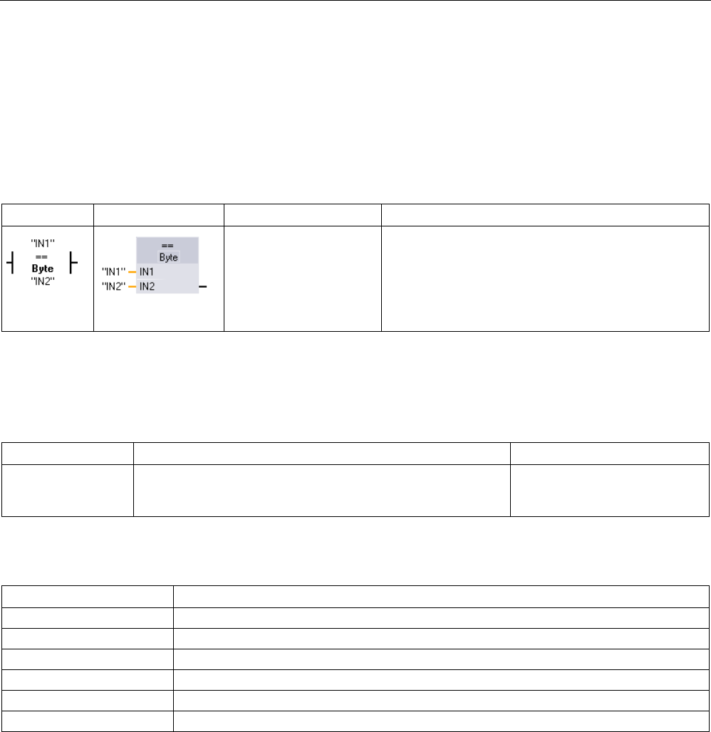
Basic instructions
8.4 Comparator operations
S7-1200 Programmable controller
250 System Manual, V4.2, 09/2016, A5E02486680-AK
8.4
Comparator operations
8.4.1
Compare values instructions
Table 8- 28 Compare instructions
LAD
FBD
SCL
Description
out := in1 = in2;
or
IF in1 = in2
THEN out := 1;
ELSE out := 0;
END_IF;
Compares two values of the same data type. When the
LAD contact comparison is TRUE, then the contact is
activated. When the FBD box comparison is TRUE,
then the box output is TRUE.
1
For LAD and FBD: Click the instruction name (such as "==") to change the comparison type from the drop-down list.
Click the "???" and select data type from the drop-down list.
Table 8- 29 Data types for the parameters
Parameter
Data type
Description
IN1, IN2 Byte, Word, DWord, SInt, Int, DInt, USInt, UInt, UDInt, Real,
LReal, String, WString, Char, Char, Time, Date, TOD, DTL,
Constant
Values to compare
Table 8- 30 Comparison descriptions
Relation type
The comparison is true if ...
=
IN1 is equal to IN2
<>
IN1 is not equal to IN2
>=
IN1 is greater than or equal to IN2
<=
IN1 is less than or equal to IN2
>
IN1 is greater than IN2
<
IN1 is less than IN2

Basic instructions
8.4 Comparator operations
S7-1200 Programmable controller
System Manual, V4.2, 09/2016, A5E02486680-AK 251
8.4.2
IN_Range (Value within range) and OUT_Range (Value outside range)
Table 8- 31 Value within Range and value outside range instructions
LAD / FBD
SCL
Description
out := IN_RANGE(min,
val, max);
Tests whether an input value is in or out of a specified value range.
If the comparison is TRUE, then the box output is TRUE.
out := OUT_RANGE(min,
val, max);
1 For LAD and FBD: Click the "???" and select the data type from the drop-down list.
Table 8- 32 Data types for the parameters
Parameter
Data type1
Description
MIN, VAL, MAX SInt, Int, DInt, USInt, UInt, UDInt, Real, LReal,
Constant
Comparator inputs
1 The input parameters MIN, VAL, and MAX must be the same data type.
● The IN_RANGE comparison is true if: MIN <= VAL <= MAX
● The OUT_RANGE comparison is true if: VAL < MIN or VAL > MAX
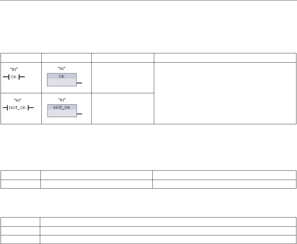
Basic instructions
8.4 Comparator operations
S7-1200 Programmable controller
252 System Manual, V4.2, 09/2016, A5E02486680-AK
8.4.3
OK (Check validity) and NOT_OK (Check invalidity)
Table 8- 33 OK (check validity) and Not OK (check invalidity) instructions
LAD
FBD
SCL
Description
Not available Tests whether an input data reference is a valid real num-
ber according to IEEE specification 754.
Not available
1
For LAD and FBD: When the LAD contact is TRUE, the contact is activated and passes power flow. When the FBD box
is TRUE, then the box output is TRUE.
Table 8- 34 Data types for the parameter
Parameter
Data type
Description
IN
Real, LReal
Input data
Table 8- 35 Operation
Instruction
The Real number test is TRUE if:
OK
The input value is a valid real number
1
NOT_OK
The input value is not a valid real number
1
1
A Real or LReal value is invalid if it is +/- INF (infinity), NaN (Not a Number), or if it is a denormalized value. A denormal-
ized value is a number very close to zero. The CPU substitutes a zero for a denormalized value in calculations.
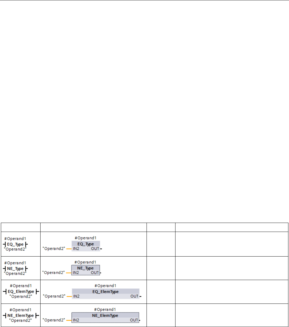
Basic instructions
8.4 Comparator operations
S7-1200 Programmable controller
System Manual, V4.2, 09/2016, A5E02486680-AK 253
8.4.4
Variant and array comparison instructions
8.4.4.1
Equality and non-equality comparison instructions
The S7-1200 CPU provides instructions for querying the data type of a tag to which a Variant
operand points for either equality or non-equality to the data type of the other operand.
In addition, the S7-1200 CPU provides instructions for querying the data type of an array
element for either equality or non-equality to the data type of the other operand.
In these instructions, you are comparing <Operand1> to <Operand2>. <Operand1> must
have the Variant data type. <Operand2> can be an elementary data type of a PLC data type.
In LAD and FBD, <Operand1> is the operand above the instruction. In LAD, <Operand2> is
the operand below the instruction.
For all instructions, the result of logic operation (RLO) is 1 (true) if the equality or non-
equality test passes, and is 0 (false) if not.
The equality and non-equality type comparison instructions are as follows:
● EQ_Type (Compare data type for EQUAL with the data type of a tag)
● NE_Type (Compare data type for UNEQUAL with the data type of a tag)
● EQ_ElemType (Compare data type of an ARRAY element for EQUAL with the data type
of a tag)
● NE_ElemType (Compare data type of an ARRAY element for UNEQUAL with the data
type of a tag)
Table 8- 36 EQ and NE instructions
LAD
FBD
SCL
Description
Not avail-
able
Tests whether the tag pointed to by the Variant
at Operand1 is of the same data type as the
tag at Operand2.
Not avail-
able
Tests whether the tag pointed to by the Variant
at Operand1 is of a different data type as the
tag at Operand2.
Not avail-
able
Tests whether the array element pointed to by
the Variant at Operand1 is of the same data
type as the tag at Operand2.
Not avail-
able
Tests whether the array element pointed to by
the Variant at Operand1 is of a different data
type as the tag at Operand2.

Basic instructions
8.4 Comparator operations
S7-1200 Programmable controller
254 System Manual, V4.2, 09/2016, A5E02486680-AK
Table 8- 37 Data types for the parameters
Parameter
Data type
Description
Operand1
Variant
First operand
Operand2 Bit strings, integers, floating-point numbers,
timers, date and time, character strings,
ARRAY, PLC data types
Second operand
8.4.4.2
Null comparsion instructions
You can use the instructions IS_NULL and NOT_NULL to determine whether or not the input
actually points to an object or not.
For both instructions, <Operand> must have the Variant data type.
Table 8- 38 IS_NULL (Query for EQUALS ZERO pointer) and NOT_NULL (Query for EQUALS ZERO pointer) instructions
LAD
FBD
SCL
Description
Not avail-
able
Tests whether the tag pointed to by the Variant
at Operand is null and therefore not an object.
Not avail-
able
Tests whether the tag pointed to by the Variant
at Operand is not null and therefore does point
to an object.
Table 8- 39 Data types for the parameters
Parameter
Data type
Description
Operand
Variant
Operand to evaluate for null or not null.
8.4.4.3
IS_ARRAY (Check for ARRAY)
You can use the "Check for ARRAY" instruction to query whether the Variant points to a tag
of the Array data type.
The <Operand> must have the Variant data type.
The instructions returns 1 (true) if the operand is an array.
Table 8- 40 IS_ARRAY (Check for ARRAY)
LAD
FBD
SCL
Description
IS_ARRAY(_variant_in_) Tests whether the tag pointed to by the Variant
at Operand is an array.
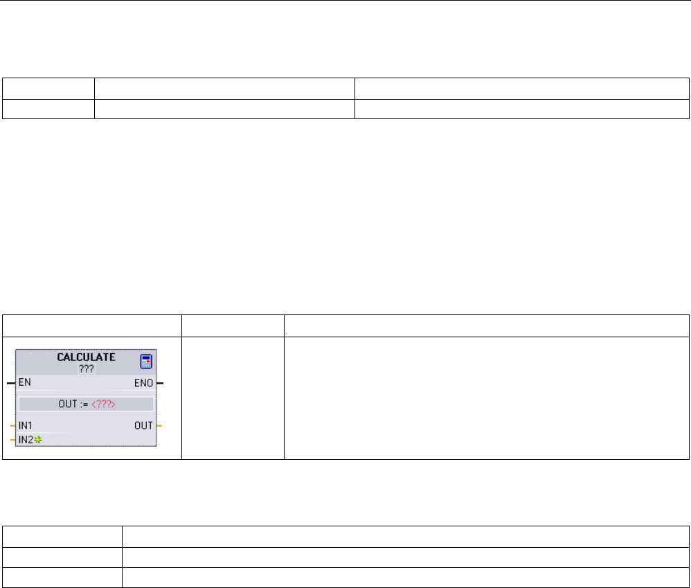
Basic instructions
8.5 Math functions
S7-1200 Programmable controller
System Manual, V4.2, 09/2016, A5E02486680-AK 255
Table 8- 41 Data types for the parameters
Parameter
Data type
Description
Operand
Variant
Operand to evaluate for whether it is an array.
8.5
Math functions
8.5.1
CALCULATE (Calculate)
Table 8- 42 CALCULATE instruction
LAD / FBD
SCL
Description
Use the stand-
ard SCL math
expressions to
create the equa-
tion.
The CALCULATE instruction lets you create a math function that oper-
ates on inputs (IN1, IN2, .. INn) and produces the result at OUT, ac-
cording to the equation that you define.
• Select a data type first. All inputs and the output must be the same
data type.
• To add another input, click the icon at the last input.
Table 8- 43 Data types for the parameters
Parameter
Data type1
IN1, IN2, ..INn
SInt, Int, DInt, USInt, UInt, UDInt, Real, LReal, Byte, Word, DWord
OUT
SInt, Int, DInt, USInt, UInt, UDInt, Real, LReal, Byte, Word, DWord
1
The IN and OUT parameters must be the same data type (with implicit conversions of the input parameters). For exam-
ple: A SINT value for an input would be converted to an INT or a REAL value if OUT is an INT or REAL
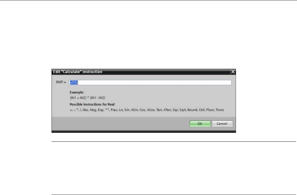
Basic instructions
8.5 Math functions
S7-1200 Programmable controller
256 System Manual, V4.2, 09/2016, A5E02486680-AK
Click the calculator icon to open the dialog and define your math function. You enter your
equation as inputs (such as IN1 and IN2) and operations. When you click "OK" to save the
function, the dialog automatically creates the inputs for the CALCULATE instruction.
The dialog shows an example and a list of possible instructions that you can include based
on the data type of the OUT parameter:
Note
You also must create an input for any constants in your function. The constant value would
then be entered in the associated input for the CALCULATE instruction.
By entering constants as
inputs, you can copy the CALCULATE instruction to other locations
in your user program without having to change the function. You then can change the values
or tags of the inputs for the instruction without modifying the function.
When CALCULATE is executed and all the individual operations in the calculation complete
successfully, then the ENO = 1. Otherwise, ENO = 0.
For an example of the CALCULATE instruction, see "Creating a complex equation with a
simple instruction (Page 42)".
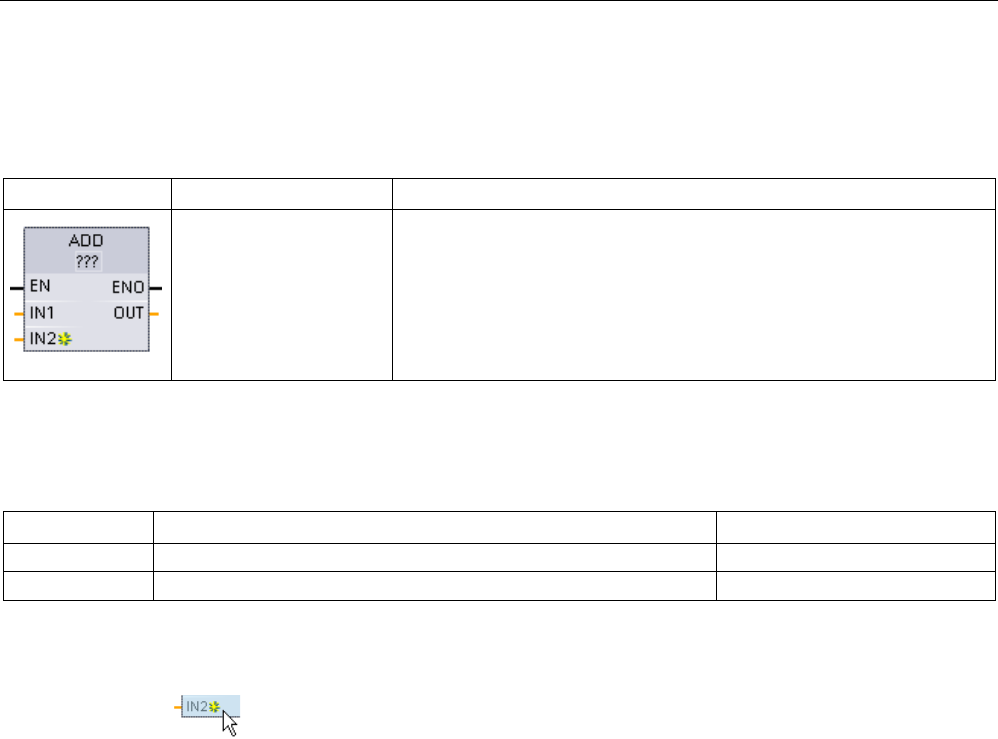
Basic instructions
8.5 Math functions
S7-1200 Programmable controller
System Manual, V4.2, 09/2016, A5E02486680-AK 257
8.5.2
Add, subtract, multiply and divide instructions
Table 8- 44 Add, subtract, multiply and divide instructions
LAD / FBD
SCL
Description
out := in1 + in2;
out := in1 - in2;
out := in1 * in2;
out := in1 / in2;
• ADD: Addition (IN1 + IN2 = OUT)
• SUB: Subtraction (IN1 - IN2 = OUT)
• MUL: Multiplication (IN1 * IN2 = OUT)
• DIV: Division (IN1 / IN2 = OUT)
An Integer division operation truncates the fractional part of the quotient
to produce an integer output.
1 For LAD and FBD: Click the "???" and select a data type from the drop-down menu.
Table 8- 45 Data types for the parameters (LAD and FBD)
Parameter
Data type1
Description
IN1, IN2
SInt, Int, DInt, USInt, UInt, UDInt, Real, LReal, Constant
Math operation inputs
OUT SInt, Int, DInt, USInt, UInt, UDInt, Real, LReal Math operation output
1 Parameters IN1, IN2, and OUT must be the same data type.
To add an ADD or MUL input, click the "Create" icon or right
-click on an input
stub for one of the existing IN parameters and select the "Insert input" command.
To remove an input, right-click on an input stub for one of the existing IN parameters (when
there are more than the original two inputs) and select the "Delete" command.
When enabled (EN = 1), the math instruction performs the specified operation on the input
values (IN1 and IN2) and stores the result in the memory address specified by the output
parameter (OUT). After the successful completion of the operation, the instruction sets ENO
= 1.
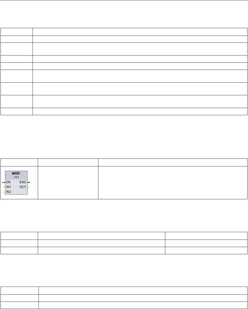
Basic instructions
8.5 Math functions
S7-1200 Programmable controller
258 System Manual, V4.2, 09/2016, A5E02486680-AK
Table 8- 46 ENO status
ENO
Description
1
No error
0 The Math operation result value would be outside the valid number range of the data type selected. The
least significant part of the result that fits in the destination size is returned.
0
Division by 0 (IN2 = 0): The result is undefined and zero is returned.
0 Real/LReal: If one of the input values is NaN (not a number) then NaN is returned.
0 ADD Real/LReal: If both IN values are INF with different signs, this is an illegal operation and NaN is re-
turned.
0 SUB Real/LReal: If both IN values are INF with the same sign, this is an illegal operation and NaN is re-
turned.
0 MUL Real/LReal: If one IN value is zero and the other is INF, this is an illegal operation and NaN is re-
turned.
0
DIV Real/LReal: If both IN values are zero or INF, this is an illegal operation and NaN is returned.
8.5.3
MOD (return remainder of division)
Table 8- 47 Modulo (return remainder of division) instruction
LAD / FBD
SCL
Description
out := in1 MOD in2;
You can use the MOD instruction to return the remainder of an integer
division operation. The value at the IN1 input is divided by the value at
the IN2 input and the remainder is returned at the OUT output.
1 For LAD and FBD: Click the "???" and select a data type from the drop-down menu.
Table 8- 48 Data types for parameters
Parameter
Data type1
Description
IN1 and IN2
SInt, Int, DInt, USInt, UInt, UDInt, Constant
Modulo inputs
OUT SInt, Int, DInt, USInt, UInt, UDInt Modulo output
1 The IN1, IN2, and OUT parameters must be the same data type.
Table 8- 49 ENO values
ENO
Description
1 No error
0
Value IN2 = 0, OUT is assigned the value zero
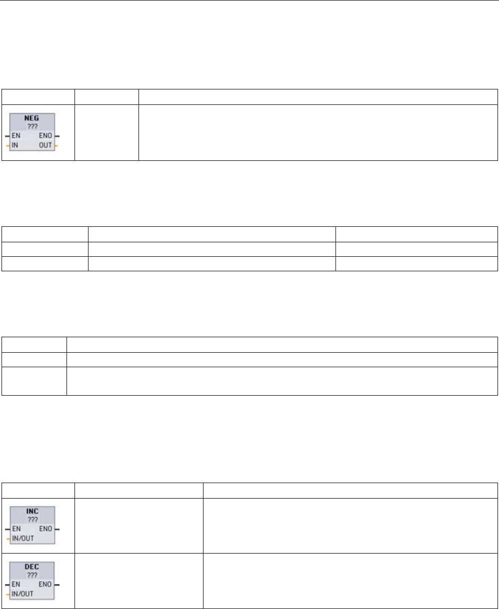
Basic instructions
8.5 Math functions
S7-1200 Programmable controller
System Manual, V4.2, 09/2016, A5E02486680-AK 259
8.5.4
NEG (Create twos complement)
Table 8- 50 NEG (create twos complement) instruction
LAD / FBD
SCL
Description
-(in);
The NEG instruction inverts the arithmetic sign of the value at parameter IN and stores
the result in parameter OUT.
1 For LAD and FBD: Click the "???" and select a data type from the drop-down menu.
Table 8- 51 Data types for parameters
Parameter
Data type1
Description
IN
SInt, Int, DInt, Real, LReal, Constant
Math operation input
OUT
SInt, Int, DInt, Real, LReal
Math operation output
1 The IN and OUT parameters must be the same data type.
Table 8- 52 ENO status
ENO
Description
1
No error
0 The resulting value is outside the valid number range of the selected data type.
Example for SInt: NEG (-128) results in +128 which exceeds the data type maximum.
8.5.5
INC (Increment) and DEC (Decrement)
Table 8- 53 INC and DEC instructions
LAD / FBD
SCL
Description
in_out := in_out + 1;
Increments a signed or unsigned integer number value:
IN_OUT value +1 = IN_OUT value
in_out := in_out - 1;
Decrements a signed or unsigned integer number value:
IN_OUT value - 1 = IN_OUT value
1 For LAD and FBD: Click the "???" and select a data type from the drop-down menu.
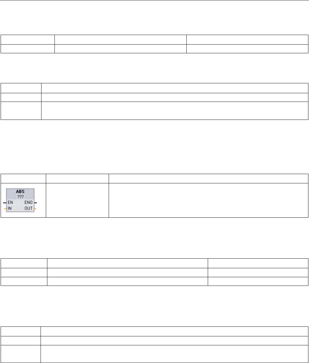
Basic instructions
8.5 Math functions
S7-1200 Programmable controller
260 System Manual, V4.2, 09/2016, A5E02486680-AK
Table 8- 54 Data types for parameters
Parameter
Data type
Description
IN/OUT
SInt, Int, DInt, USInt, UInt, UDInt
Math operation input and output
Table 8- 55 ENO status
ENO
Description
1
No error
0 The resulting value is outside the valid number range of the selected data type.
Example for SInt: INC (+127) results in +128, which exceeds the data type maximum.
8.5.6
ABS (Form absolute value)
Table 8- 56 ABS (absolute value) instruction
LAD / FBD
SCL
Description
out := ABS(in);
Calculates the absolute value of a signed integer or real number at parameter
IN and stores the result in parameter OUT.
1 For LAD and FBD: Click the "???" and select a data type from the drop-down menu.
Table 8- 57 Data types for parameters
Parameter
Data type1
Description
IN
SInt, Int, DInt, Real, LReal
Math operation input
OUT
SInt, Int, DInt, Real, LReal
Math operation output
1 The IN and OUT parameters must be the same data type.
Table 8- 58 ENO status
ENO
Description
1 No error
0 The math operation result value is outside the valid number range of the selected data type.
Example for SInt: ABS (-128) results in +128 which exceeds the data type maximum.
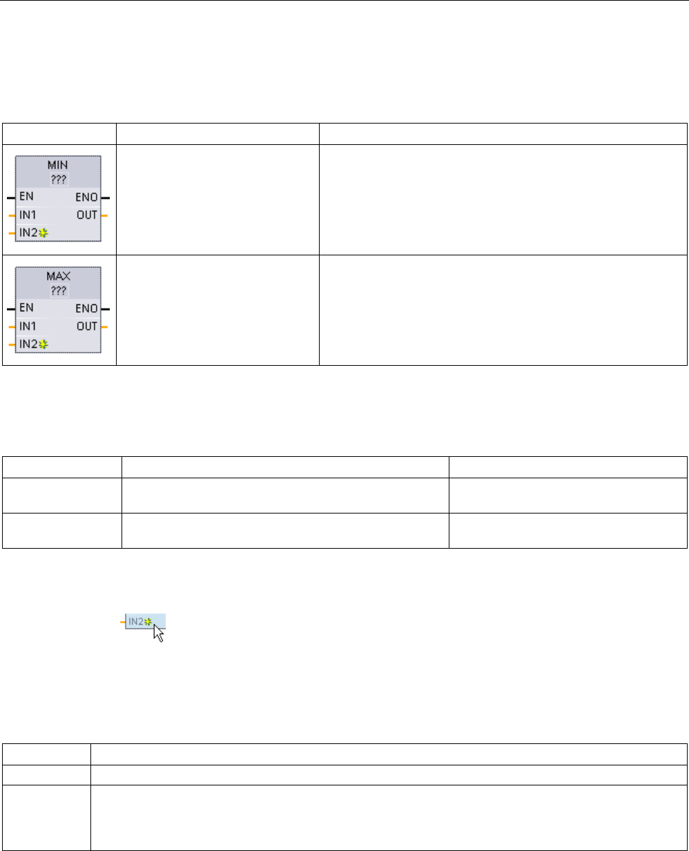
Basic instructions
8.5 Math functions
S7-1200 Programmable controller
System Manual, V4.2, 09/2016, A5E02486680-AK 261
8.5.7
MIN (Get minimum) and MAX (Get maximum)
Table 8- 59 MIN (get minimum) and MAX (get maximum) instructions
LAD / FBD
SCL
Description
out:= MIN(
in1:=_variant_in_,
in2:=_variant_in_
[,...in32]);
The MIN instruction compares the value of two parameters IN1
and IN2 and assigns the minimum (lesser) value to parameter
OUT.
out:= MAX(
in1:=_variant_in_,
in2:=_variant_in_
[,...in32]);
The MAX instruction compares the value of two parameters IN1
and IN2 and assigns the maximum (greater) value to parameter
OUT.
1 For LAD and FBD: Click the "???" and select a data type from the drop-down menu.
Table 8- 60 Data types for the parameters
Parameter
Data type1
Description
IN1, IN2
[...IN32]
SInt, Int, DInt, USInt, UInt, UDInt, Real, LReal, Time,
Date, TOD, Constant
Math operation inputs (up to 32 inputs)
OUT SInt, Int, DInt, USInt, UInt, UDInt, Real, LReal, Time,
Date, TOD
Math operation output
1 The IN1, IN2, and OUT parameters must be the same data type.
To add an input, click the "Create"
icon or right-click on an input stub for one of
the existing IN parameters and select the "Insert input" command.
To remove an input, right-click on an input stub for one of the existing IN parameters (when
there are more than the original two inputs) and select the "Delete" command.
Table 8- 61 ENO status
ENO
Description
1
No error
0 For Real data type only:
• At least one input is not a real number (NaN).
• The resulting OUT is +/- INF (infinity).
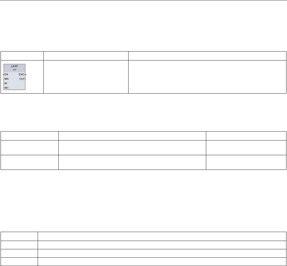
Basic instructions
8.5 Math functions
S7-1200 Programmable controller
262 System Manual, V4.2, 09/2016, A5E02486680-AK
8.5.8
LIMIT (Set limit value)
Table 8- 62 LIMIT (set limit value) instruction
LAD / FBD
SCL
Description
LIMIT(MN:=_variant_in_,
IN:=_variant_in_,
MX:=_variant_in_,
OUT:=_variant_out_);
The Limit instruction tests if the value of parameter IN is inside the
value range specified by parameters MIN and MAX and if not,
clamps the value at MIN or MAX.
1 For LAD and FBD: Click the "???" and select a data type from the drop-down menu.
Table 8- 63 Data types for the parameters
Parameter
Data type1
Description
MN, IN, and MX SInt, Int, DInt, USInt, UInt, UDInt, Real, LReal, Time, Date,
TOD·Constant
Math operation inputs
OUT SInt, Int, DInt, USInt, UInt, UDInt, Real, LReal, Time, Date,
TOD
Math operation output
1 The MN, IN, MX, and OUT parameters must be the same data type.
If the value of parameter IN is within the specified range, then the value of IN is stored in
parameter OUT. If the value of parameter IN is outside of the specified range, then the OUT
value is the value of parameter MIN (if the IN value is less than the MIN value) or the value
of parameter MAX (if the IN value is greater than the MAX value).
Table 8- 64 ENO status
ENO
Description
1
No error
0
Real: If one or more of the values for MIN, IN and MAX is NaN (Not a Number), then NaN is returned.
0
If MIN is greater than MAX, the value IN is assigned to OUT.
SCL examples:
● MyVal := LIMIT(MN:=10,IN:=53, MX:=40); //Result: MyVal = 40
● MyVal := LIMIT(MN:=10,IN:=37, MX:=40); //Result: MyVal = 37
● MyVal := LIMIT(MN:=10,IN:=8, MX:=40); //Result: MyVal = 10

Basic instructions
8.5 Math functions
S7-1200 Programmable controller
System Manual, V4.2, 09/2016, A5E02486680-AK 263
8.5.9
Exponent, logarithm, and trigonometry instructions
You use the floating point instructions to program mathematical operations using a Real or
LReal data type:
● SQR: Form square (IN 2 = OUT)
● SQRT: Form square root (√IN = OUT)
● LN: Form natural logarithm (LN(IN) = OUT)
● EXP: Form exponential value (e IN =OUT), where base e = 2.71828182845904523536
● EXPT: exponentiate (IN1 IN2 = OUT)
EXPT parameters IN1 and OUT are always the same data type, for which you must
select Real or LReal. You can select the data type for the exponent parameter IN2 from
among many data types.
● FRAC: Return fraction (fractional part of floating point number IN = OUT)
● SIN: Form sine value (sin(IN radians) = OUT)
● ASIN: Form arcsine value (arcsine(IN) = OUT radians), where the sin(OUT radians) = IN
● COS: Form cosine (cos(IN radians) = OUT)
● ACOS: Form arccosine value (arccos(IN) = OUT radians), where the cos(OUT radians) =
IN
● TAN: Form tangent value (tan(IN radians) = OUT)
● ATAN: Form arctangent value (arctan(IN) = OUT radians), where the tan(OUT radians) =
IN
Table 8- 65 Examples of floating-point math instructions
LAD / FBD
SCL
Description
out := SQR(in);
or
out := in * in;
Square: IN 2 = OUT
For example: If IN = 9, then OUT = 81.
out := in1 ** in2;
General exponential: IN1 IN2 = OUT
For example: If IN1 = 3 and IN2 = 2, then OUT = 9.
1
For LAD and FBD: Click the "???" (by the instruction name) and select a data type from the drop-down menu.
2 For SCL: You can also use the basic SCL math operators to create the mathematical expressions.

Basic instructions
8.5 Math functions
S7-1200 Programmable controller
264 System Manual, V4.2, 09/2016, A5E02486680-AK
Table 8- 66 Data types for parameters
Parameter
Data type
Description
IN, IN1
Real, LReal, Constant
Inputs
IN2 SInt, Int, DInt, USInt, UInt,UDInt, Real, LReal, Constant EXPT exponent input
OUT
Real, LReal
Outputs
Table 8- 67 ENO status
ENO
Instruction
Condition
Result (OUT)
1 All No error Valid result
0 SQR
Result exceeds valid Real/LReal range
+INF
IN is +/- NaN (not a number)
+NaN
SQRT
IN is negative
-NaN
IN is +/- INF (infinity) or +/- NaN
+/- INF or +/- NaN
LN
IN is 0.0, negative, -INF, or -NaN
-NaN
IN is +INF or +NaN
+INF or +NaN
EXP
Result exceeds valid Real/LReal range
+INF
IN is +/- NaN
+/- NaN
SIN, COS, TAN
IN is +/- INF or +/- NaN
+/- INF or +/- NaN
ASIN, ACOS
IN is outside valid range of -1.0 to +1.0
+NaN
IN is +/- NaN
+/- NaN
ATAN
IN is +/- NaN
+/- NaN
FRAC
IN is +/- INF or +/- NaN
+NaN
EXPT
IN1 is +INF and IN2 is not -INF
+INF
IN1 is negative or -INF +NaN if IN2 is Real/LReal,
-INF otherwise
IN1 or IN2 is +/- NaN
+NaN
IN1 is 0.0 and IN2 is Real/LReal (only) +NaN
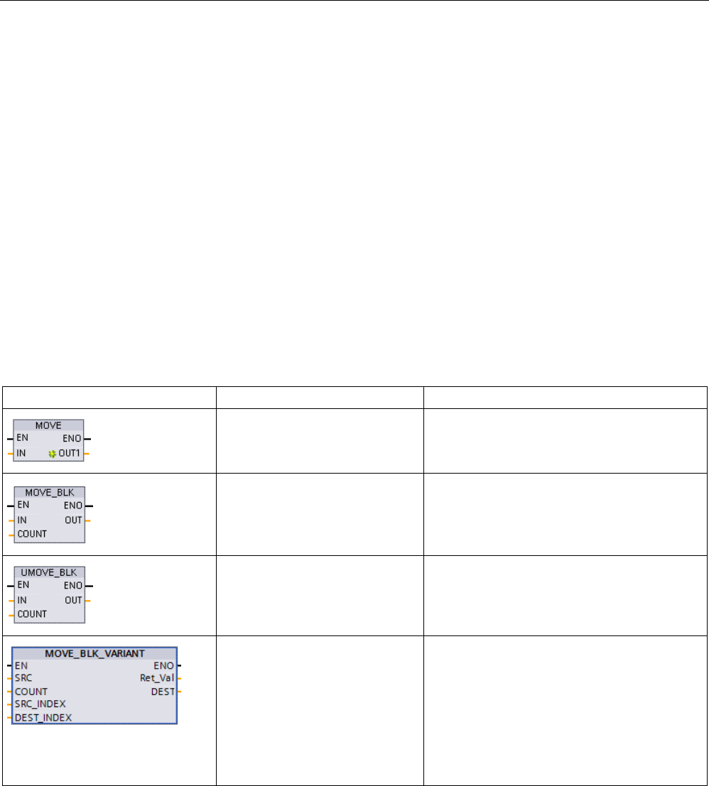
Basic instructions
8.6 Move operations
S7-1200 Programmable controller
System Manual, V4.2, 09/2016, A5E02486680-AK 265
8.6
Move operations
8.6.1
MOVE (Move value), MOVE_BLK (Move block), UMOVE_BLK (Move block
uninterruptible), and MOVE_BLK_VARIANT (Move block)
Use the Move instructions to copy data elements to a new memory address and convert
from one data type to another. The source data is not changed by the move process.
● The MOVE instruction copies a single data element from the source address specified by
the IN parameter to the destination addresses specified by the OUT parameter.
● The MOVE_BLK and UMOVE_BLK instructions have an additional COUNT parameter.
The COUNT specifies how many data elements are copied. The number of bytes per
element copied depends on the data type assigned to the IN and OUT parameter tag
names in the PLC tag table.
Table 8- 68 MOVE, MOVE_BLK, UMOVE_BLK, and MOVE_BLK_VARIANT instructions
LAD / FBD
SCL
Description
out1 := in;
Copies a data element stored at a specified
address to a new address or multiple address-
es.1
MOVE_BLK(
in:=_variant_in,
count:=_uint_in,
out=>_variant_out);
Interruptible move that copies a block of data
elements to a new address.
UMOVE_BLK(
in:=_variant_in,
count:=_uint_in,
out=>_variant_out);
Uninterruptible move that copies a block of data
elements to a new address.
MOVE_BLK(
SRC:=_variant_in,
COUNT:=_udint_in,
SRC_INDEX:=_dint_in,
DEST_INDEX:=_dint_in,
DEST=>_variant_out);
Moves the contents of a source memory area to
a destination memory area.
You can copy a complete array or elements of
an array to another array of the same data type.
The size (number of elements) of source and
destination array may be different. You can
copy mult
iple or single elements within an array.
You use Variant data types to point to both the
source and destination arrays.
1
MOVE instruction: To add another output in LAD or FBD, click the "Create" icon by the output parameter. For SCL, use
multiple assignment statements. You might also use one of the loop constructions.

Basic instructions
8.6 Move operations
S7-1200 Programmable controller
266 System Manual, V4.2, 09/2016, A5E02486680-AK
Table 8- 69 Data types for the MOVE instruction
Parameter
Data type
Description
IN SInt, Int, DInt, USInt, UInt, UDInt, Real, LReal, Byte, Word,
DWord, Char, WChar, Array, Struct, DTL, Time, Date, TOD,
IEC data types, PLC data types
Source address
OUT SInt, Int, DInt, USInt, UInt, UDInt, Real, LReal, Byte, Word,
DWord, Char, WChar, Array, Struct, DTL, Time, Date, TOD,
IEC data types, PLC data types
Destination address
To add MOVE outputs, click the "Create" icon or right
-click on an output stub for
one of the existing OUT parameters and select the "Insert output" command.
To remove an output, right-click on an output stub for one of the existing OUT parameters
(when there are more than the original two outputs) and select the "Delete" command.
Table 8- 70 Data types for the MOVE_BLK and UMOVE_BLK instructions
Parameter
Data type
Description
IN SInt, Int, DInt, USInt, UInt, UDInt, Real, LReal Byte, Word,
DWord, Time, Date, TOD, WChar
Source start address
COUNT
UInt
Number of data elements to copy
OUT SInt, Int, DInt, USInt, UInt, UDInt, Real, LReal, Byte, Word,
DWord, Time, Date, TOD, WChar
Destination start address
Table 8- 71 Data types for the MOVE_BLK_VARIANT instruction
Parameter
Data type
Description
SRC
Variant (which points to an array or individual array element)
Source block from which to copy
COUNT
UDInt
Number of data elements to copy
SRC_INDEX
DInt
Zero-based index into the SRC array
DEST_INDEX DInt Zero-based index into the DEST
array
RET_VAL
Int
Error information
DEST Variant (which points to an array or individualt array element) Destination area into which to copy
the contents of the source block

Basic instructions
8.6 Move operations
S7-1200 Programmable controller
System Manual, V4.2, 09/2016, A5E02486680-AK 267
Note
Rules for data copy operations
•
To copy the Bool data type, use SET_BF, RESET_BF, R, S, or output coil (LAD)
(Page 230)
•
To copy a single elementary data type, use MOVE
•
To copy an array of an elementary data type, use MOVE_BLK or UMOVE_BLK
•
To copy a structure, use MOVE
•
To copy a string, use S_MOVE (Page 346)
•
To copy a single character in a string, use MOVE
•
The MOVE_BLK and UMOVE_BLK instructions cannot be used to copy arrays or
structures to the I, Q, or M memory areas.
MOVE_BLK and UMOVE_BLK instructions differ in how interrupts are handled:
● Interrupt events are
queued and processed
during MOVE_BLK execution. Use the
MOVE_BLK instruction when the data at the move destination address is not used within
an interrupt OB subprogram or, if used, the destination data does not have to be
consistent. If a MOVE_BLK operation is interrupted, then the last data element moved is
complete and consistent at the destination address. The MOVE_BLK operation is
resumed after the interrupt OB execution is complete.
● Interrupt events are
queued but not processed
until UMOVE_BLK execution is complete.
Use the UMOVE_BLK instruction when the move operation must be completed and the
destination data consistent, before the execution of an interrupt OB subprogram. For
more information, see the section on data consistency (Page 198).
ENO is always true following execution of the MOVE instruction.
Table 8- 72 ENO status
ENO
Condition
Result
1
No error
All COUNT elements were successfully copied.
0 Either the source (IN) range or the destination (OUT)
range exceeds the available memory area.
Elements that fit are copied. No partial ele-
ments are copied.

Basic instructions
8.6 Move operations
S7-1200 Programmable controller
268 System Manual, V4.2, 09/2016, A5E02486680-AK
Table 8- 73 Condition codes for the MOVE_BLK_VARIANT instruction
RET_VAL
(W#16#...)
Description
0000
No error
80B4 Data types do not correspond.
8151
Access to the SRC parameter is not possible.
8152
The operand at the SRC parameter is an invalid type.
8153
Code generation error at the SRC parameter
8154
The operand at the SRC parameter has the data type Bool.
8281
The COUNT parameter has an invalid value.
8382 The value at the SRC_INDEX parameter is outside the limits of the
Variant.
8383 The value at parameter SRC_INDEX is outside the high limit of the
array.
8482 The value at the DEST_INDEX parameter is outside the limits of
the Variant.
8483 The value at parameter DEST_INDEX is outside the high limit of
the array.
8534
The DEST parameter is write-protected.
8551
Access to the DEST parameter is not possible.
8552
The operand at the DEST parameter is an invalid type.
8553
Code generation error at the DEST parameter
8554
The operand at the DEST parameter has the data type Bool.
*You can display error codes in the program editor as integer or hexadecimal values.
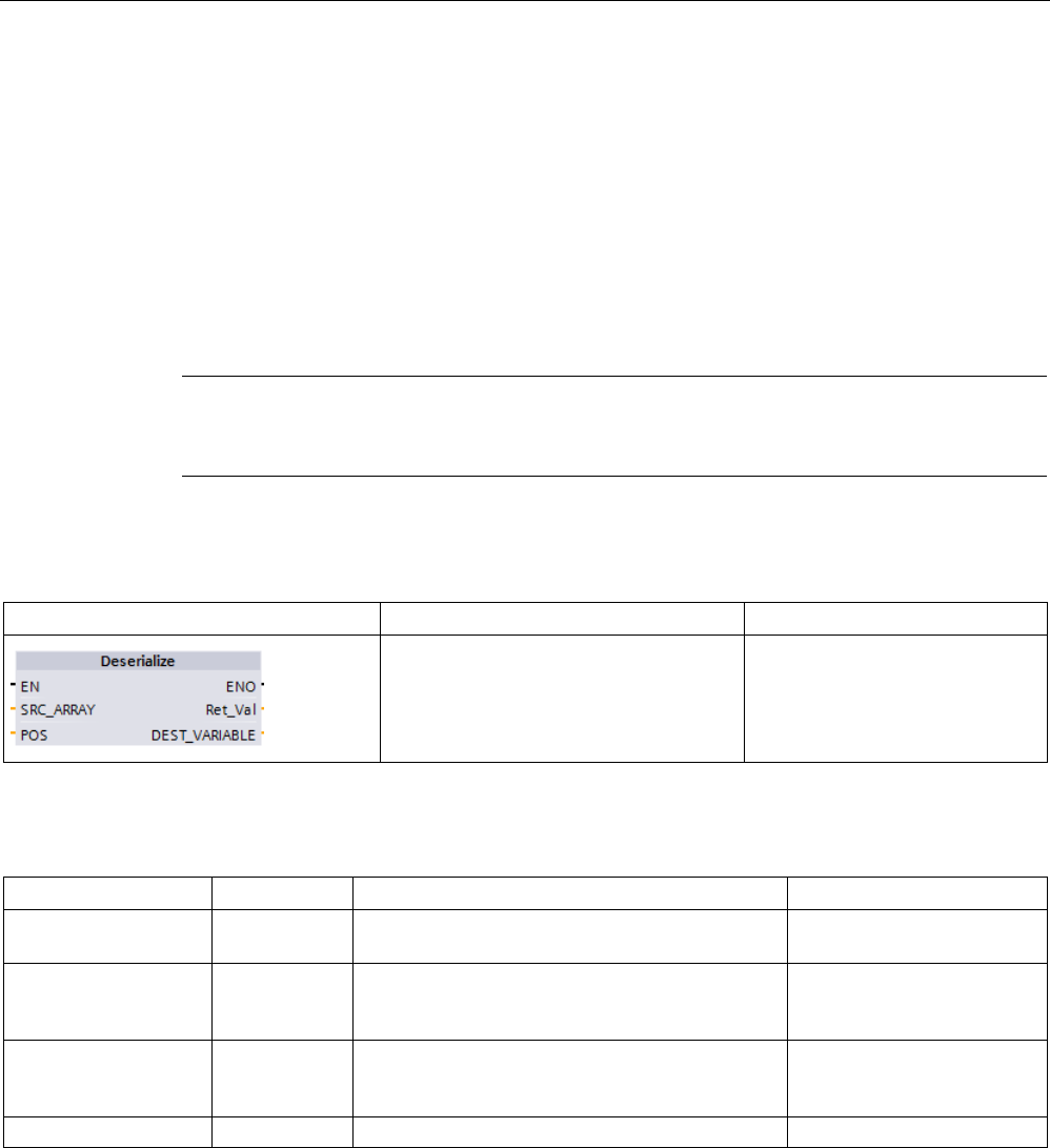
Basic instructions
8.6 Move operations
S7-1200 Programmable controller
System Manual, V4.2, 09/2016, A5E02486680-AK 269
8.6.2
Deserialize
You can use the "Deserialize" instruction to convert the sequential representation of a PLC
data type (UDT) back to a PLC data type and to fill its entire contents. If the comparison is
TRUE, then the box output is TRUE.
The memory area which holds the sequential representation of a PLC data type must have
the Array of Byte data type and you must declare the data block to have standard (not
optimized) access. Make sure that there is enough memory space prior to the conversion.
The instruction enables you to convert multiple sequential representations of converted PLC
data types back to their original data types.
Note
If you only want to convert back a single sequential representation of a PLC data type (UDT),
you can also use the instruction "TRCV: Receive data via communication connect
ion".
Table 8- 74 DESERIALIZE instruction
LAD / FBD
SCL
Description
ret_val := Deserialize(
SRC_ARRAY:=_variant_in_,
DEST_VARIABLE=>_variant_out
_,
POS:=_dint_inout_);
Converts the sequential represen-
tation of a PLC data type (UDT)
back to a PLC data type and fills
its entire contents
Table 8- 75 Parameters for the DESERIALIZE instruction
Parameter
Type
Data type
Description
SRC_ARRAY IN Variant Global data block that con-
tains the data stream
DEST_VARIABLE INOUT Variant Tag in which to store the
converted PLC data type
(UDT)
POS INOUT DInt Number of bytes that the
converted PLC data type
uses
RET_VAL
OUT
Int
Error information
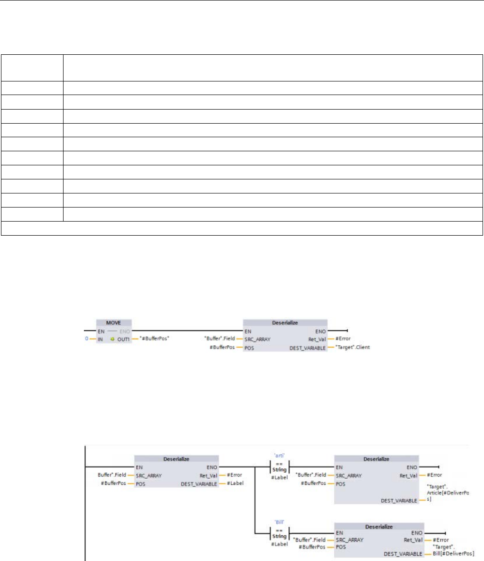
Basic instructions
8.6 Move operations
S7-1200 Programmable controller
270 System Manual, V4.2, 09/2016, A5E02486680-AK
Table 8- 76 RET_VAL parameter
RET_VAL*
(W#16#...)
Description
0000
No error
80B0 The memory areas for the SRC_ARRAY and DEST_VARIABLE parameters overlap.
8136
The data block at the DEST_VARIABLE parameter is not a block with standard access.
8150
The Variant data type at the SRC_ARRAY parameter contains no value.
8151
Code generation error at the SRC_ARRAY parameter.
8153
There is not enough free memory available at the SRC_ARRAY parameter.
8250
The Variant data type at the DEST_VARIABLE parameter contains no value.
8251
Code generation error at the DEST_VARIABLE parameter.
8254
Invalid data type at the DEST_VARIABLE parameter.
8382
The value at parameter POS is outside the limits of the array.
*
You can view the error codes as either integer or hexadecimal in the program editor.
Example: Deserialize instruction
The following example shows how the instruction works:
Network 1:
The "MOVE" instruction moves the value "0" to the "#BufferPos" data block tag. The
Deserialize instruction then deserializes the sequential representation of the customer data
from the "Buffer" data block and writes it to the "Target" data block. The Deserialize
instruction calculates the number of bytes that the converted data uses and stores it in the
"#BufferPos" data block tag.
Network 2:
The "Deserialize" instruction deserializes the sequential representation of the data stream
pointed to by "Buffer" and writes the characters to the "#Label" operand. The logic compares
the characters using the comparison instructions "arti" and "Bill". If the comparison for "arti" =
TRUE, the data is article data that is to be deserialized and written to the "Article" data
structure of the "Target" data block. If the comparison for "Bill" = TRUE, the data is billing
data that is to be deserialized and written to the "Bill" data structure of the "Target" data
block.
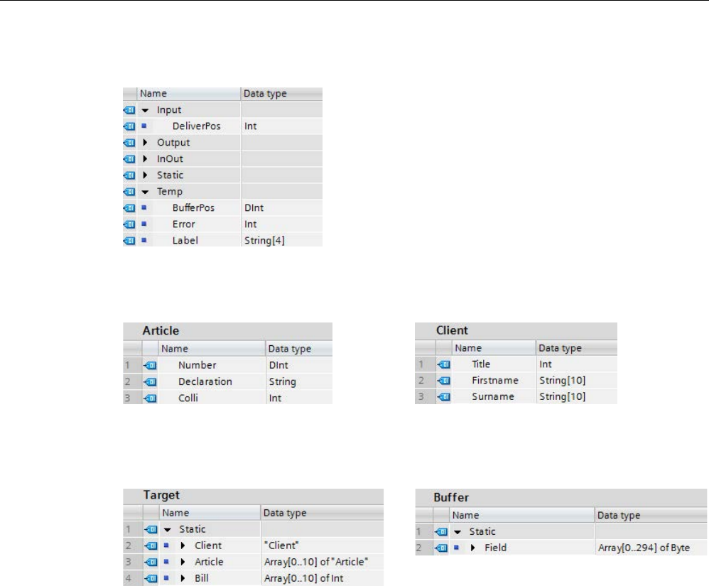
Basic instructions
8.6 Move operations
S7-1200 Programmable controller
System Manual, V4.2, 09/2016, A5E02486680-AK 271
Function block (or Function) interface:
Custom PLC data types:
The structure of the two PLC data types (UDTs) for this example are as follows:
Data blocks:
The two data blocks for this example are as follows:
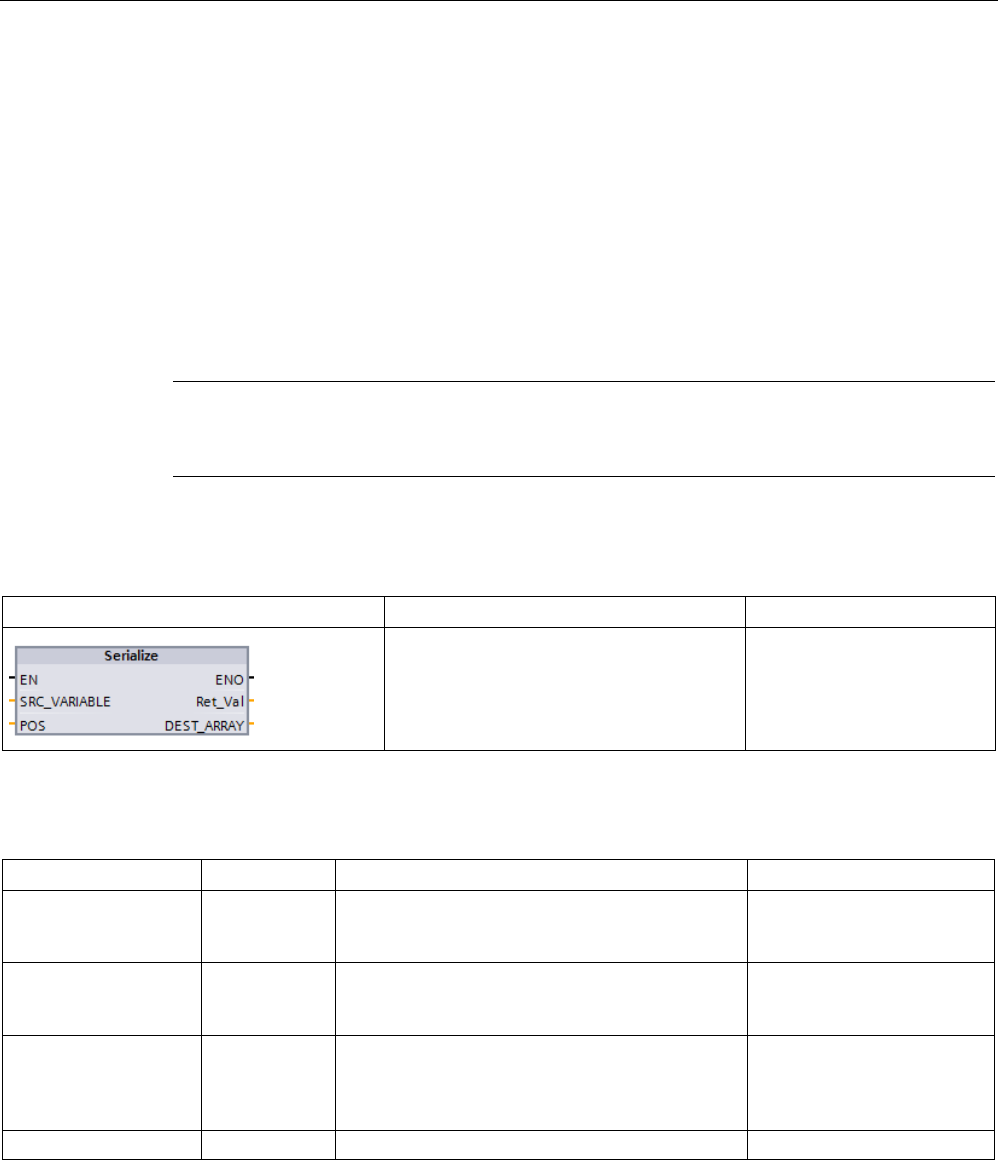
Basic instructions
8.6 Move operations
S7-1200 Programmable controller
272 System Manual, V4.2, 09/2016, A5E02486680-AK
8.6.3
Serialize
You can use the "Serialize" instruction to convert several PLC data types (UDTs) to a
sequential representation without any loss of structure.
You can use the instruction to temporarily save multiple structured data items from your
program to a buffer, for example to a global data block, and send them to another CPU. The
memory area in which the converted PLC data types are stored must have the ARRAY of
BYTE data type and be declared with standard access. Make sure that there is enough
memory space prior to the conversion.
The POS parameter contains information about the number of bytes that the converted PLC
data types use.
Note
If you only want to send a single PLC data type (UDT), you can us
e the instruction "TSEND:
Send data via communication connection".
Table 8- 77 SERIALIZE instruction
LAD / FBD
SCL
Description
ret_val := Serialize(
SRC_VARIABLE=>_variant_in_,
DEST_ARRAY:=_variant_out_,
POS:=_dint_inout_);
Converts a PLC data type
(UDT) to a sequential repre-
sentation.
Table 8- 78 Parameters for the SERIALIZE instruction
Parameter
Type
Data type
Description
SRC_VARIABLE IN Variant PLC data type (UDT) that is
to be converted to a serial
representation
DEST_ARRAY INOUT Variant Data block in which the gen-
erated data stream is to be
stored
POS INOUT DInt Number of bytes that the
converted PLC data types
use. The calculated POS
parameter is zero-based.
RET_VAL
OUT
Int
Error information
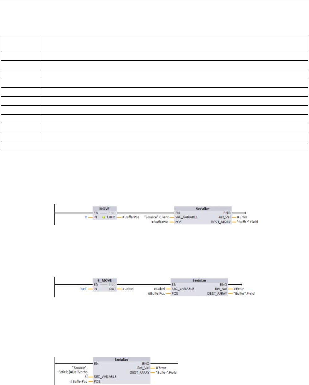
Basic instructions
8.6 Move operations
S7-1200 Programmable controller
System Manual, V4.2, 09/2016, A5E02486680-AK 273
Table 8- 79 RET_VAL parameter
RET_VAL*
(W#16#...)
Description
0000
No error
80B0 The memory areas for the SRC_VARIABLE and DEST_ARRAY parameters overlap.
8150
The Variant data type at the SRC_VARIABLE parameter contains no value.
8152
Code generation error at the SRC_VARIABLE parameter.
8236
The data block at the DEST_ARRAY parameter is not a block with standard access.
8250
The Variant data type at the DEST_ARRAY parameter contains no value.
8252
Code generation error at the DEST_ARRAY parameter.
8253
There is not enough free memory available at the DEST_ARRAY parameter.
8254
Invalid data type at the DEST_VARIABLE parameter.
8382
The value at parameter POS is outside the limits of the array.
*
You can view the error codes as either integer or hexadecimal in the program editor.
Example: Serialize instruction
The following example shows how the instruction works:
Network 1:
The "MOVE" instruction moves the value "0" to the "#BufferPos" parameter. The "Serialize"
instruction serializes the customer data from the "Source" data block and writes it in
sequential representation to the "Buffer" data block. The instruction stores the number of
bytes used by the sequential representation in the "#BufferPos" parameter.
Network 2:
The logic now inserts some separator text to make it easier to deserialize the sequential
representation later. The "S_MOVE" instruction moves the text string "arti" to the "#Label"
parameter. The "Serialize" instruction writes these characters after the source client data to
the "Buffer" data block. The instruction adds the number of bytes in the text string "arti" to the
number already stored in the "#BufferPos" parameter.
Network 3:
The "Serialize" instruction serializes the data of a specific article, which is calculated in
runtime, from the "Source" data block and writes it in sequential representation to the
"Buffer" data block after the "arti" characters

Basic instructions
8.6 Move operations
S7-1200 Programmable controller
274 System Manual, V4.2, 09/2016, A5E02486680-AK
Block Interface:
Custom PLC data types:
The structure of the two PLC data types (UDTs) for this example are as follows:
Data blocks:
The two data blocks for this example are as follows:

Basic instructions
8.6 Move operations
S7-1200 Programmable controller
System Manual, V4.2, 09/2016, A5E02486680-AK 275
8.6.4
FILL_BLK (Fill block) and UFILL_BLK (Fill block uninterruptible)
Table 8- 80 FILL_BLK and UFILL_BLK instructions
LAD / FBD
SCL
Description
FILL_BLK(
in:=_variant_in,
count:=int,
out=>_variant_out);
Interruptible fill instruction: Fills an address range with copies of a
specified data element
UFILL_BLK(
in:=_variant_in,
count:=int,
out=>_variant_out);
Uninterruptible fill instruction: Fills an address range with copies of
a specified data element
Table 8- 81 Data types for parameters
Parameter
Data type
Description
IN SInt, Int, DInt, USInt, UInt, UDInt, Real, LReal, Byte, Word,
DWord, Time, Date, TOD, Char, WChar
Data source address
COUNT
UDint, USInt, UInt
Number of data elements to copy
OUT SInt, Int, DInt, USInt, UInt, UDInt, Real, LReal, Byte, Word,
DWord, Time, Date, TOD, Char, WChar
Data destination address
Note
Rules for data fill operations
•
To fill with the BOOL data type, use SET_BF, RESET_BF, R, S, or output coil (LAD)
•
To fill with a single elementary data type, use MOVE
•
To fill an array with an elementary data type, use FILL_BLK or UFILL_BLK
•
To fill a single character in a string, use MOVE
•
The FILL_BLK and UFILL_BLK instructions cannot be used to fill arrays in the I, Q, or M
memory areas.
The FILL_BLK and UFILL_BLK instructions copy the source data element IN to the
destination where the initial address is specified by the parameter OUT. The copy process
repeats and a block of adjacent addresses is filled until the number of copies is equal to the
COUNT parameter.
FILL_BLK and UFILL_BLK instructions differ in how interrupts are handled:
● Interrupt events are
queued and processed
during FILL_BLK execution. Use the
FILL_BLK instruction when the data at the move destination address is not used within an
interrupt OB subprogram or, if used, the destination data does not have to be consistent.
● Interrupt events are
queued but not processed
until UFILL_BLK execution is complete.
Use the UFILL_BLK instruction when the move operation must be completed and the
destination data consistent, before the execution of an interrupt OB subprogram.
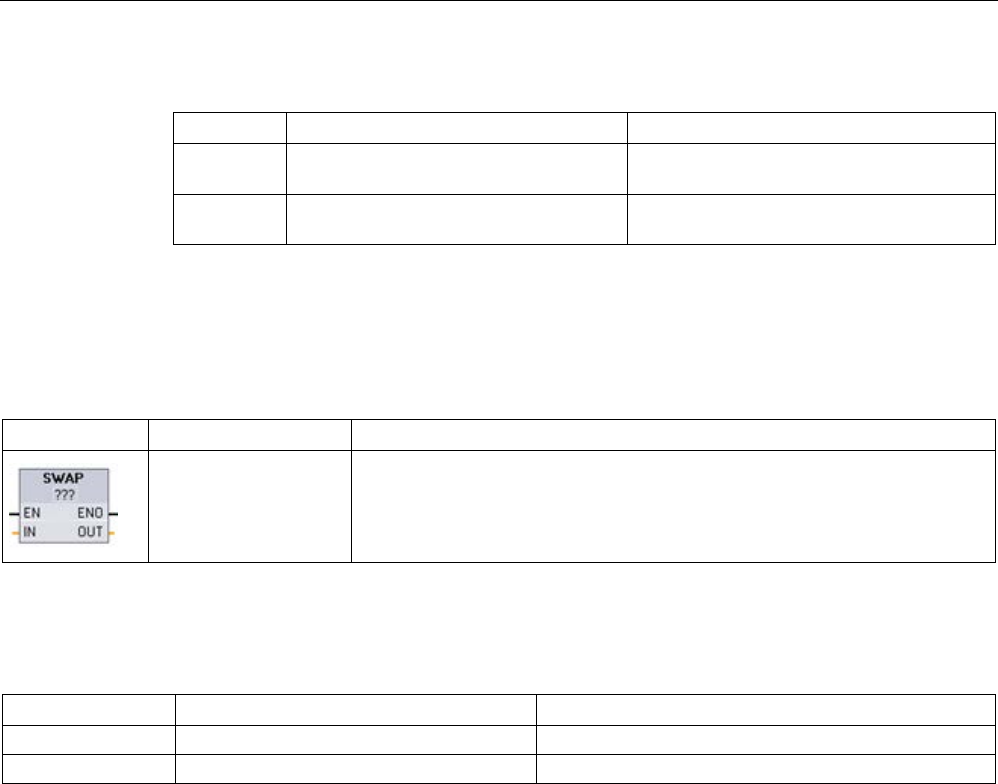
Basic instructions
8.6 Move operations
S7-1200 Programmable controller
276 System Manual, V4.2, 09/2016, A5E02486680-AK
Table 8- 82 ENO status
ENO
Condition
Result
1 No error The IN element was successfully copied to
all COUNT destinations.
0 The destination (OUT) range exceeds
the available memory area
Elements that fit are copied. No partial ele-
ments are copied.
8.6.5
SWAP (Swap bytes)
Table 8- 83 SWAP instruction
LAD / FBD
SCL
Description
out := SWAP(in);
Reverses the byte order for two-byte and four-byte data elements. No change
is made to the bit order within each byte. ENO is always TRUE following exe-
cution of the SWAP instruction.
1 For LAD and FBD: Click the "???" and select a data type from the drop-down menu.
Table 8- 84 Data types for the parameters
Parameter
Data type
Description
IN
Word, DWord
Ordered data bytes IN
OUT
Word, DWord
Reverse ordered data bytes OUT
Example 1
Parameter IN = MB0
(before execution)
Parameter OUT = MB4,
(after execution)
Address
MW0
MB1
MW4
MB5
W#16#1234
WORD
12
MSB
34
LSB
34
MSB
12
LSB
Example 2
Parameter IN = MB0
(before execution)
Parameter OUT = MB4,
(after execution)
Address
MD0
MB1
MB2
MB3
MD4
MB5
MB6
MB7
DW#16#
12345678
DWORD
12
MSB
34
56
78
LSB
78
MSB
56
34
12
LSB
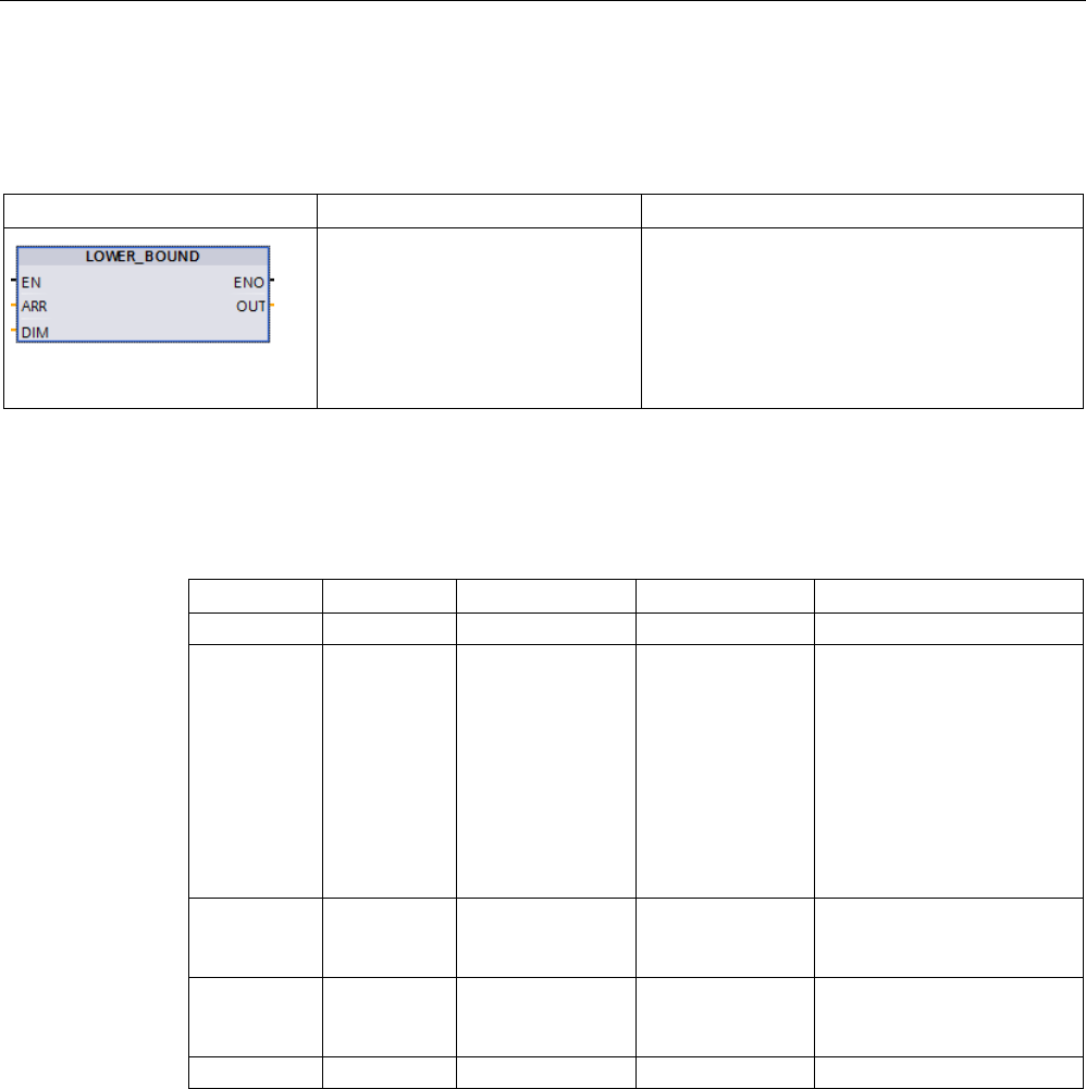
Basic instructions
8.6 Move operations
S7-1200 Programmable controller
System Manual, V4.2, 09/2016, A5E02486680-AK 277
8.6.6
LOWER_BOUND: (Read out ARRAY low limit)
Table 8- 85 LOWER_BOUND instruction
LAD / FBD
SCL
Description
out := LOWER_BOUND(
ARR:=_variant_in_,
DIM:=_udint_in_);
You can declare tags with ARRAY[*] in the block
interface. For these local tags, you can read out
the limits of the ARRAY. You will need to specify
the required dimension at the DIM parameter.
The LOWER_BOUND (Read out ARRAY low
limit). instruction lets you read out the variable
low limit of the ARRAY.
Parameters
The following table shows the parameters of the instruction "LOWER_BOUND: Read out
ARRAY low limit":
Parameters
Declaration
Data type
Memory area
Description
EN
Input
BOOL
I, Q, M, D, L
Enable input
ENO Output BOOL I, Q, M, D, L Enable output ENO has the
signal state "0" if one of the
following conditions applies:
• The EN enable input has
the signal state "0".
• The dimension specified
at input DIM does not ex-
ist.
ARR Input ARRAY [*] FB: Section InOut
FC: Sections Input
and InOut
ARRAY of which the variable
low limit is to be read.
DIM Input UDINT I, Q, M, D, L or
constant
Dimension of the ARRAY of
which the variable low limit is
to be read.
OUT
Output
DINT
I, Q, M, D, L
Result
You can find additional information on valid data types under "Data types (Page 125)":
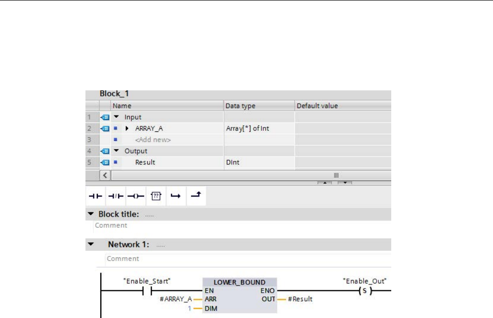
Basic instructions
8.6 Move operations
S7-1200 Programmable controller
278 System Manual, V4.2, 09/2016, A5E02486680-AK
Example
In the function (FC) block interface, the input parameter ARRAY_A is a one-dimensional
array with variable dimensions.
If the "Enable_Start" operand returns signal state "1", the CPU executes the
LOWER_BOUND instruction. It reads out the variable low limit of the ARRAY #ARRAY_A
from the one-dimensional array. If the instruction executes without errors, it sets operand
"Enable_Out" and sets the "Result" operand to the low limit of the array.

Basic instructions
8.6 Move operations
S7-1200 Programmable controller
System Manual, V4.2, 09/2016, A5E02486680-AK 279
8.6.7
UPPER_BOUND: (Read out ARRAY high limit)
Table 8- 86 LOWER_BOUND instruction
LAD / FBD
SCL
Description
out := UPPER_BOUND(
ARR:=_variant_in_,
DIM:=_udint_in_);
You can declare tags with ARRAY[*] in the block
interface. For these local tags, you can read out
the limits of the ARRAY. You will need to specify
the required dimension at the DIM parameter.
The UPPER_BOUND (Read out ARRAY high
limit) instruction lets you read out the variable
high limit of the ARRAY.
Parameters
The following table shows the parameters of the instruction "UPPER_BOUND: Read out
ARRAY high limit":
Parameters
Declaration
Data type
Memory area
Description
EN
Input
BOOL
I, Q, M, D, L
Enable input
ENO
Output
BOOL
I, Q, M, D, L
Enable output
ARR Input ARRAY [*] FB: Section InOut
FC: Sections Input
and InOut
ARRAY of which the variable
high limit is to be read.
DIM Input UDINT I, Q, M, D, L or
constant
Dimension of the ARRAY of
which the variable high limit
is to be read.
OUT
Output
DINT
I, Q, M, D, L
Result
You can find additional information on valid data types under "Data types (Page 125)":
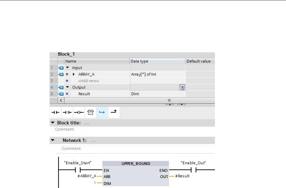
Basic instructions
8.6 Move operations
S7-1200 Programmable controller
280 System Manual, V4.2, 09/2016, A5E02486680-AK
Example
In the function (FC) block interface, the input parameter ARRAY_A is a one-dimensional
array with variable dimensions.
If the "Enable_Start" operand returns signal state "1", the CPU executes the instruction. It
reads out the variable high limit of the ARRAY #ARRAY_A from the one-dimensional array. If
the instruction executes without errors, it sets operand "Enable_Out" and sets the "Result"
operand.

Basic instructions
8.6 Move operations
S7-1200 Programmable controller
System Manual, V4.2, 09/2016, A5E02486680-AK 281
8.6.8
Read / Write memory instructions
8.6.8.1
PEEK and POKE (SCL only)
SCL provides PEEK and POKE instructions that allow you to read from or write to data
blocks, I/O, or memory. You provide parameters for specific byte offsets or bit offsets for the
operation.
Note
To use the PEEK and POKE instructions with data blocks, you mu
st use standard (not
optimized) data blocks. Also note that the PEEK and POKE instructions merely transfer data.
They have no knowledge of data types at the addresses.
PEEK(area:=_in_,
dbNumber:=_in_,
byteOffset:=_in_);
Reads the b
yte referenced by byteOffset of
the referenced data block, I/O or memory
area.
Example referencing data block:
%MB100 := PEEK(area:=16#84,
dbNumber:=1, byteOffset:=#i);
Example referencing IB3 input:
%MB100 := PEEK(area:=16#81,
dbNumber:=0, byteOffset:=#i); // when
#i = 3
PEEK_WORD(area:=_in_,
dbNumber:=_in_,
byteOffset:=_in_);
Reads the word referenced by byteOffset of
the referenced data block, I/O or memory
area.
Example:
%MW200 := PEEK_WORD(area:=16#84,
dbNumber:=1, byteOffset:=#i);
PEEK_DWORD(area:=_in_,
dbNumber:=_in_,
byteOffset:=_in_);
Reads the double word referenced by
byteOffset of the referenced data block, I/O or
memory area.
Example:
%MD300 := PEEK_DWORD(area:=16#84,
dbNumber:=1, byteOffset:=#i);
PEEK_BOOL(area:=_in_,
dbNumber:=_in_,
byteOffset:=_in_,
bitOffset:=_in_);
Reads a Boolean referenced by the bitOffset
and byteOffset of the referenced data block,
I/O or memory area
Example:
%MB100.0 := PEEK_BOOL(area:=16#84,
dbNu
mber:=1, byteOffset:=#ii,
bitOffset:=#j);

Basic instructions
8.6 Move operations
S7-1200 Programmable controller
282 System Manual, V4.2, 09/2016, A5E02486680-AK
POKE(area:=_in_,
dbNumber:=_in_,
byteOffset:=_in_,
value:=_in_);
Writes the value (Byte, Word, or DWord) to
the referenced byteOffset of the referenced
data block, I/O or memory area
Example referencing data block:
POKE(area:=16#84, dbNumber:=2,
byteOffset:=3, value:="Tag_1");
Example referencing QB3 output:
POKE(area:=16#82, dbNumber:=0,
byteOffset:=3, value:="Tag_1");
POKE_BOOL(area:=_in_,
dbNumber:=_in_,
byteOffset:=_in_,
bitOffset:=_in_,
value:=_in_);
Writes the Boolean value to the referenced
bitOffset and byteOffset of the referenced
data block, I/O or memory area
Example:
POKE_BOOL(area:=16#84, dbNumber:=2,
byteOffset:=3, bitOffset:=5, va
l-
ue:=0);
POKE_BLK(area_src:=_in_,
dbNumber_src:=_in_,
byteOffset_src:=_in_,
area_dest:=_in_,
dbNumber_dest:=_in_,
byteOffset_dest:=_in_,
count:=_in_);
Writes "count" number of bytes starting at th
e
referenced byte Offset of the referenced
source data block, I/O or memory area to the
referenced byteOffset of the referenced dest
i-
nation data block, I/O or memory area
Example:
POKE_BLK(area_src:=16#84,
dbNumber_src:=#src_db, byteOf
f-
set_src:=#src_byte,
area_dest:=16#84,
dbNumber_dest:=#src_db, byteOf
f-
set_dest:=#src_byte, count:=10);
For PEEK and POKE instructions, the following values for the "area", "area_src" and
"area_dest" parameters are applicable. For areas other than data blocks, the dbNumber
parameter must be 0.
16#81 I
16#82
Q
16#83
M
16#84
DB

Basic instructions
8.6 Move operations
S7-1200 Programmable controller
System Manual, V4.2, 09/2016, A5E02486680-AK 283
8.6.8.2
Read and write big and little Endian instructions (SCL)
The S7-1200 CPU provides SCL instructions for reading and writing data in little endian
format and in big endian format. Little endian format means that the byte with the least
significant bit is in the lowest memory address. Big endian format means that the byte with
the most significant bit is in the lowest memory address.
The four SCL instructions for reading and writing data in little endian and big endian format
are as follows:
● READ_LITTLE (Read data in little endian format)
● WRITE_LITTLE (Write data in little endian format)
● READ_BIG (Read data in big endian format)
● WRITE_BIG (Write data in big endian format)
Table 8- 87 Read and write big and little endian instructions
LAD / FBD
SCL
Description
Not available
READ_LITTLE(
src_array:=_variant_in_,
dest_Variable =>_out_,
pos:=_dint_inout)
Reads data from a memory area and writes it to a
single tag in little endian byte format.
Not available
WRITE_LITTLE(
src_variable:=_in_,
dest_array =>_variant_inout_,
pos:=_dint_inout)
Writes data from a single tag to a memory area in little
endian byte format.
Not available
READ_BIG(
src_array:=_variant_in_,
dest_Variable =>_out_,
pos:=_dint_inout)
Reads data from a memory area and writes it to a
single tag in big endian byte format.
Not available
WRITE_BIG(
src_variable:=_in_,
dest_array =>_variant_inout_,
pos:=_dint_inout)
Writes data from a single tag to a memory area in big
endian byte format.
Table 8- 88 Parameters for the READ_LITTLE and READ_BIG instructions
Parameter
Data type
Description
src_array Array of Byte Memory area from which to read
data
dest_Variable Bit strings, integers, floating-point numbers, timers, date and
time, character strings
Destination variable at which to
write data
pos DINT Zero-based position from which to
start reading data from the
src_array input.

Basic instructions
8.6 Move operations
S7-1200 Programmable controller
284 System Manual, V4.2, 09/2016, A5E02486680-AK
Table 8- 89 Parameters for the WRITE_LITTLE and WRITE_BIG instructions
Parameter
Data type
Description
src_variable Bit strings, integers, floating-point numbers, LDT, TOD, LTOD,
DATA, Char, WChar
Source data from tag
dest_array Array of Byte Memory area at which to write data
pos DINT Zero-based position at which to
start writing data into the dest_array
output.
Table 8- 90 RET_VAL parameter
RET_VAL*
(W#16#...)
Description
0000
No error
80B4
The SRC_ARRAY or DEST_ARRAY is not an Array of Byte
8382
The value at parameter POS is outside the limits of the array.
8383 The value at parameter POS is within the limits of the Array but the size of the memory area exceeds the
high limit of the array.
*
You can view the error codes as either integer or hexadecimal in the program editor.
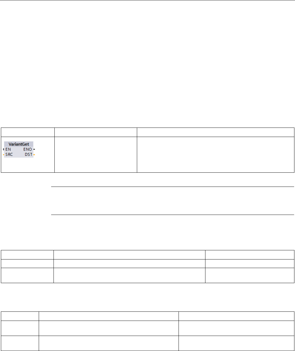
Basic instructions
8.6 Move operations
S7-1200 Programmable controller
System Manual, V4.2, 09/2016, A5E02486680-AK 285
8.6.9
Variant instructions
8.6.9.1
VariantGet (Read VARIANT tag value)
You can use the "Read out Variant tag value" instruction to read the value of the tag to which
the Variant pointer at the SRC parameter points and write it in the tag at the DST parameter.
The SRC parameter has the Variant data type. Any data type except for Variant can be
specified at the DST parameter.
The data type of the tag at the DST parameter must match the data type to which the Variant
points.
Table 8- 91 VariantGet instruction
LAD / FBD
SCL
Description
VariantGet(
SRC:=_variant_in_,
DST=>_variant_out_);
Reads the tag pointed to by the SRC parameter and writes it to
the tag at the DST parameter
Note
To copy structures and arrays, you can use the "MOVE_BLK_VARIANT: Move block"
instruction.
Table 8- 92 Parameters for the VariantGet instruction
Parameter
Data type
Description
SRC
Variant
Pointer to source data
DST Bit strings, integers, floating-point numbers, timers, date and
time, character strings, ARRAY elements, PLC data types
Destination at which to write data
Table 8- 93 ENO status
ENO
Condition
Result
1 No error Instruction copied the tag data pointed to by
SRC to the DST tag.
0 Enable input EN has the signal state "0" or the data types
do not correspond.
Instruction copied no data.
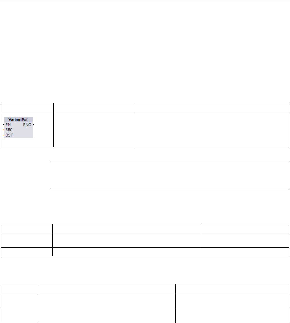
Basic instructions
8.6 Move operations
S7-1200 Programmable controller
286 System Manual, V4.2, 09/2016, A5E02486680-AK
8.6.9.2
VariantPut (Write VARIANT tag value)
You can use the "Write VARIANT tag value" instruction to write the value of the tag at the
SRC parameter to the tag at the DST parameter to which the VARIANT points.
The DST parameter has the VARIANT data type. Any data type except for VARIANT can be
specified at the SRC parameter.
The data type of the tag at the SRC parameter must match the data type to which the
VARIANT points.
Table 8- 94 VariantPut instruction
LAD / FBD
SCL
Description
VariantPut(
SRC:=_variant_in_,
DST=>_variant_in_);
Writes the tag referenced by the SRC parameter to the variant
pointed to by the DST parameter
Note
To copy structures and ARRAYs, you can use the "MOVE_BLK_VARIANT: Move block"
instruction.
Table 8- 95 Parameters for the VariantPut instruction
Parameter
Data type
Description
SRC Bit strings, integers, floating-point numbers, timers, date and
time, character strings, ARRAY elements, PLC data types
Pointer to source data
DST
Variant
Destination at which to write data
Table 8- 96 ENO status
ENO
Condition
Result
1 No error
Instruction copied the SRC tag data to the DST
tag.
0
Enable input EN has the signal state "0" or the data types
do not correspond.
Instruction copied no data.
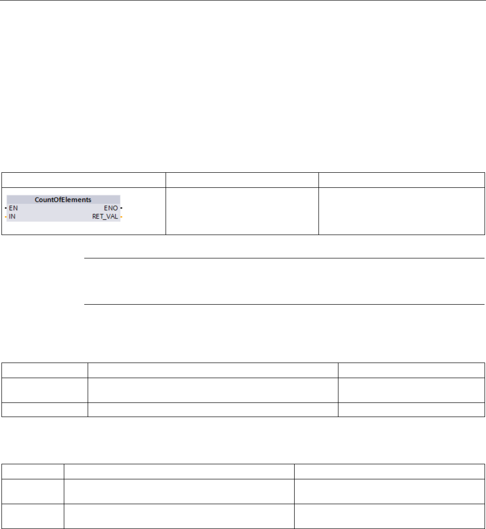
Basic instructions
8.6 Move operations
S7-1200 Programmable controller
System Manual, V4.2, 09/2016, A5E02486680-AK 287
8.6.9.3
CountOfElements (Get number of ARRAY elements)
You can use the "Get number of ARRAY elements" instruction to query how many Array
elements are in a tag pointed to by a Variant.
If it is a one-dimensional ARRAY, the instruction returns the difference between the high and
low limit +1 is output. If it is a multi-dimensional ARRAY, the instruction returns the product of
all dimensions.
Table 8- 97 CountOfElements instruction
LAD / FBD
SCL
Description
Result := CountOfElements(
_variant_in_);
Counts the number of array elements at
the array pointed to by the IN parameter.
Note
If the Variant points to an Array of Bool, the instruction counts the fill elements to the nearest
byte boundary. For example, the instruction returns 8 as the count for an Array[0..1] of Bool.
Table 8- 98 Parameters for the CountOfElements instruction
Parameter
Data type
Description
IN Variant Tag with array elements to be
counted
RET_VAL
UDint
Instruction result
Table 8- 99 ENO status
ENO
Condition
Result
1 No error Instruction returns the number of array ele-
ments.
0 Enable input EN has the signal state "0" or the Variant
does not point to an array.
Instruction returns 0.
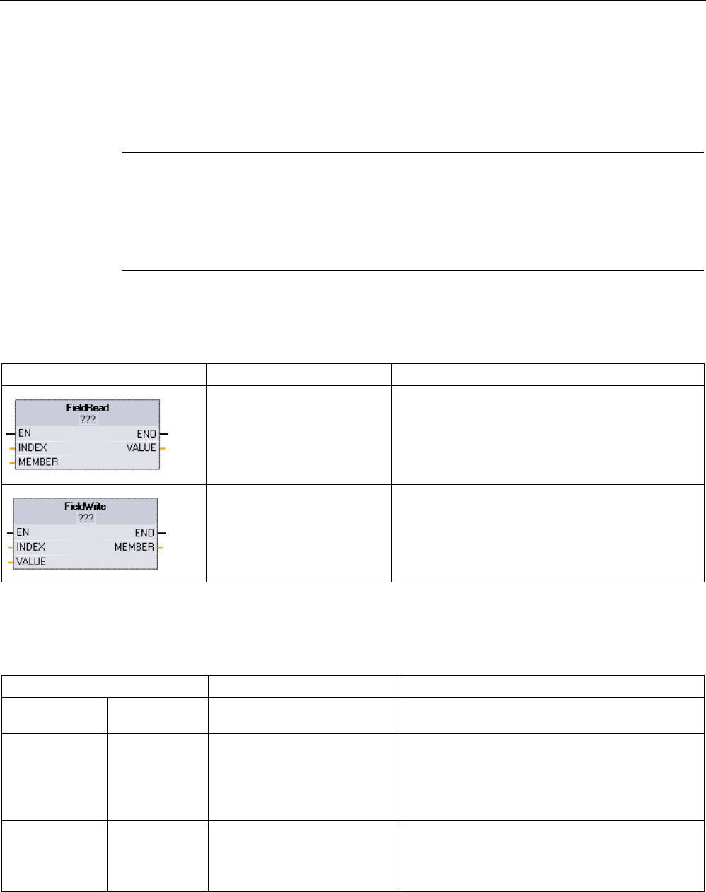
Basic instructions
8.6 Move operations
S7-1200 Programmable controller
288 System Manual, V4.2, 09/2016, A5E02486680-AK
8.6.10
Legacy instructions
8.6.10.1
FieldRead (Read field) and FieldWrite (Write field) instructions
Note
STEP 7 V10.5 did not support
a variable reference as an array index or multi-dimensional
arrays. The FieldRead and FieldWrite instructions were used to provide variable array index
operations for a one
-dimensional array. STEP 7 V11 and greater
do support
a variable as an
array index and multi
-dimensional arrays. FieldRead and FieldWrite are included in STEP 7
V11 and greater for backward compatibility with programs that have used these instructions.
Table 8- 100 FieldRead and FieldWrite instructions
LAD / FBD
SCL
Description
value := mem-
ber[index];
FieldRead reads the array element with the index
value INDEX from the array whose first element in
specified by the MEMBER parameter. The value of
the array element is transferred to the location speci-
fied at the VALUE parameter.
member[index] := val-
ue;
WriteField transfers the value at the location specified
by the VALUE parameter to the array whose first
element is specified by the MEMBER parameter. The
value is transferred to the array element whose array
index is specified by the INDEX parameter.
1 For LAD and FBD: Click the "???" and select a data type from the drop-down menu.
Table 8- 101 Data types for parameters
Parameter and type
Data type
Description
Index Input DInt The index numb
er of the array element to be read or
written to
Member 1 Input Binary numbers, integers, float-
ing-point numbers, timers,
DATE, TOD, CHAR and
WCHAR as components of an
ARRAY tag
Location of the first element in a one- dimension
array defined in a global data block or block inter-
face.
For example: If the array index is specified as [-2..4],
then the index of the first element is -2 and not 0.
Value 1 Out Binary numbers, integers, float-
ing-point numbers, timers,
DATE, TOD, CHAR, WCHAR
Location to which the specified array element is
copied (FieldRead)
Location of the value that is copied to the specified
array element (FieldWrite)
1
The data type of the array element specified by the MEMBER parameter and the VALUE parameter must have the
same data type.
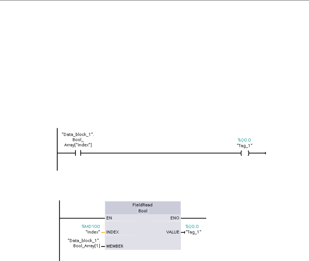
Basic instructions
8.6 Move operations
S7-1200 Programmable controller
System Manual, V4.2, 09/2016, A5E02486680-AK 289
The enable output ENO = 0, if one of the following conditions applies:
● The EN input has signal state "0"
● The array element specified at the INDEX parameter is not defined in the array
referenced at MEMBER parameter
● Errors such as an overflow occur during processing
Example: Accessing data by array indexing
To access elements of an array with a variable, simply use the variable as an array index in
your program logic. For example, the network below sets an output based on the Boolean
value of an array of Booleans in "Data_block_1" referenced by the PLC tag "Index".
The logic with the variable array index is equivalent to the former method using the
FieldRead instruction:
FieldWrite and FieldRead instructions can be replaced with variable array indexing logic.
SCL has no FieldRead or FieldWrite instructions, but supports indirect addressing of an
array with a variable:
#Tag_1 := "Data_block_1".Bool_Array[#Index];
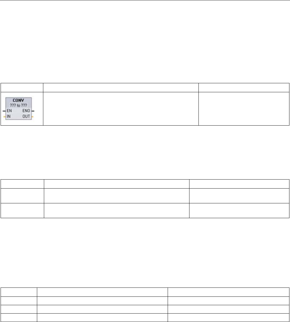
Basic instructions
8.7 Conversion operations
S7-1200 Programmable controller
290 System Manual, V4.2, 09/2016, A5E02486680-AK
8.7
Conversion operations
8.7.1
CONV (Convert value)
Table 8- 102 Convert (CONV) instruction
LAD / FBD
SCL
Description
out := <data type in>_TO_<data type out>(in);
Converts a data element from one
data type to another data type.
1
For LAD and FBD: Click the "???" and select the data types from the drop-down menu.
2
For SCL: Construct the conversion instruction by identifying the data type for the input parameter (in) and output pa-
rameter (out). For example, DWORD_TO_REAL converts a DWord value to a Real value.
Table 8- 103 Data types for the parameters
Parameter
Data type
Description
IN Bit string1, SInt, USInt, Int, UInt, DInt, UDInt, Real, LReal,
BCD16, BCD32, Char, WChar
Input value
OUT Bit string1, SInt, USInt, Int, UInt, DInt, UDInt, Real, LReal,
BCD16, BCD32, Char, WChar
Input value converted to a new data type
1
The instruction does not allow you to select Bit strings (Byte, Word, DWord). To enter an operand of data type Byte,
Word, or DWord for a parameter of the instruction, select an unsigned integer with the same bit length. For example, se-
lect USInt for a Byte, UInt for a Word, or UDInt for a DWord.
After you select the (convert from) data type, a list of possible conversions is shown in the
(convert to) dropdown list. Conversions from and to BCD16 are restricted to the Int data
type. Conversions from and to BCD32 are restricted to the DInt data type.
Table 8- 104 ENO status
ENO
Description
Result OUT
1
No error
Valid result
0
IN is +/- INF or +/- NaN
+/- INF or +/- NaN
0
Result exceeds valid range for OUT data type
OUT is set to the IN value

Basic instructions
8.7 Conversion operations
S7-1200 Programmable controller
System Manual, V4.2, 09/2016, A5E02486680-AK 291
8.7.2
Conversion instructions for SCL
Conversion instructions for SCL
Table 8- 105 Conversion from a Bool, Byte, Word, or DWord
Data type
Instruction
Result
Bool
BOOL_TO_BYTE, BOOL_TO_WORD,
BOOL_TO_DWORD, BOOL_TO_INT,
BOOL_TO_DINT
The value is transferred to the least significant bit of the
target data type.
Byte
BYTE_TO_BOOL
The least significant bit is transferred into the destination
data type.
BYTE_TO_WORD, BYTE_TO_DWORD
The value is transferred to the least significant byte of the
target data type.
BYTE_TO_SINT, BYTE_TO_USINT
The value is transferred to the target data type.
BYTE_TO_INT, BYTE_TO_UINT,
BYTE_TO_DINT, BYTE_TO_UDINT
The value is transferred to the least significant byte of the
target data type.
Word
WORD_TO_BOOL
The least significant bit is transferred into the destination
data type.
WORD_TO_BYTE
The least significant byte of the source value is trans-
ferred to the target data type
WORD_TO_DWORD
The value is transferred to the least significant word of
the target data type.
WORD_TO_SINT, WORD_TO_USINT
The least significant byte of the source value is trans-
ferred to the target data type.
WORD_TO_INT, WORD_TO_UINT
The value is transferred to the target data type.
WORD_TO_DINT, WORD_TO_UDINT
The value is transferred to the least significant word of
the target data type.
DWord
DWORD_TO_BOOL
The least significant bit is transferred into the destination
data type.
DWORD_TO_BYTE, DWORD_TO_WORD,
DWORD_TO_SINT
The least significant byte of the source value is trans-
ferred to the target data type.
DWORD_TO_USINT, DWORD_TO_INT,
DWORD_TO_UINT
The least significant word of the source value is trans-
ferred to the target data type.
DWORD_TO_DINT, DWORD_TO_UDINT,
DWORD_TO_REAL
The value is transferred to the target data type.

Basic instructions
8.7 Conversion operations
S7-1200 Programmable controller
292 System Manual, V4.2, 09/2016, A5E02486680-AK
Table 8- 106 Conversion from a short integer (SInt or USInt)
Data type
Instruction
Result
SInt
SINT_TO_BOOL
The least significant bit is transferred into the destination
data type.
SINT_TO_BYTE
The value is transferred to the target data type
SINT_TO_WORD, SINT_TO_DWORD
The value is transferred to the least significant byte of the
target data type.
SINT_TO_INT, SINT_TO_DINT,
SINT_TO_USINT, SINT_TO_UINT,
SINT_TO_UDINT, SINT_TO_REAL,
SINT_TO_LREAL, SINT_TO_CHAR,
SINT_TO_STRING
The value is converted.
USInt
USINT_TO_BOOL
The least significant bit is transferred into the destination
data type.
USINT_TO_BYTE
The value is transferred to the target data type
USINT_TO_WORD, USINT_TO_DWORD,
USINT_TO_INT, USINT_TO_UINT,
USINT_TO_DINT, USINT_TO_UDINT
The value is transferred to the least significant byte of the
target data type.
USINT_TO_SINT, USINT_TO_REAL,
USINT_TO_LREAL, USINT_TO_CHAR,
USINT_TO_STRING
The value is converted.
Table 8- 107 Conversion from an integer (Int or UInt)
Data type
instruction
Result
Int
INT_TO_BOOL
The least significant bit is transferred into the destination
data type.
INT_TO_BYTE, INT_TO_DWORD,
INT_TO_SINT, INT_TO_USINT,
INT_TO_UINT, INT_TO_UDINT,
INT_TO_REAL, INT_TO_LREAL,
INT_TO_CHAR, INT_TO_STRING
The value is converted.
INT_TO_WORD
The value is transferred to the target data type.
INT_TO_DINT
The value is transferred to the least significant byte of the
target data type.
UInt
UINT_TO_BOOL
The least significant bit is transferred into the destination
data type.
UINT_TO_BYTE, UINT_TO_SINT,
UINT_TO_USINT, UINT_TO_INT,
UINT_TO_REAL, UINT_TO_LREAL,
UINT_TO_CHAR, UINT_TO_STRING
The value is converted.
UINT_TO_WORD, UINT_TO_DATE
The value is transferred to the target data type.
UINT_TO_DWORD, UINT_TO_DINT,
UINT_TO_UDINT
The value is transferred to the least significant byte of the
target data type.

Basic instructions
8.7 Conversion operations
S7-1200 Programmable controller
System Manual, V4.2, 09/2016, A5E02486680-AK 293
Table 8- 108 Conversion from a double integer (Dint or UDInt)
Data type
Instruction
Result
DInt
DINT_TO_BOOL
The least significant bit is transferred
into the destination data type.
DINT_TO_BYTE, DINT_TO_WORD, DINT_TO_SINT,
DINT_TO_USINT, DINT_TO_INT, DINT_TO_UINT,
DINT_TO_UDINT, DINT_TO_REAL, DINT_TO_LREAL,
DINT_TO_CHAR, DINT_TO_STRING
The value is converted.
DINT_TO_DWORD, DINT_TO_TIME
The value is transferred to the target
data type.
UDInt
UDINT_TO_BOOL
The least significant bit is transferred
into the destination data type.
UDINT_TO_BYTE, UDINT_TO_WORD, UDINT_TO_SINT,
UDINT_TO_USINT, UDINT_TO_INT, UDINT_TO_UINT,
UDINT_TO_DINT, UDINT_TO_REAL, UDINT_TO_LREAL,
UDINT_TO_CHAR, UDINT_TO_STRING
The value is converted.
UDINT_TO_DWORD, UDINT_TO_TOD
The value is transferred to the target
data type.
Table 8- 109 Conversion from a Real number (Real or LReal)
Data type
Instruction
Result
Real
REAL_TO_DWORD, REAL_TO_LREAL
The value is transferred to the target
data type.
REAL_TO_SINT, REAL_TO_USINT, REAL_TO_INT,
REAL_TO_UINT, REAL_TO_DINT, REAL_TO_UDINT,
REAL_TO_STRING
The value is converted.
LReal
LREAL_TO_SINT, LREAL_TO_USINT, LREAL_TO_INT,
LREAL_TO_UINT, LREAL_TO_DINT, LREAL_TO_UDINT,
LREAL_TO_REAL, LREAL_TO_STRING
The value is converted.
Table 8- 110 Conversion from Time, DTL, TOD or Date
Data type
Instruction
Result
Time
TIME_TO_DINT
The value is transferred to the target data type.
DTL
DTL_TO_DATE, DTL_TO_TOD
The value is converted.
TOD
TOD_TO_UDINT
The value is converted.
Date
DATE_TO_UINT
The value is converted.

Basic instructions
8.7 Conversion operations
S7-1200 Programmable controller
294 System Manual, V4.2, 09/2016, A5E02486680-AK
Table 8- 111 Conversion from a Char or String
Data type
Instruction
Result
Char
CHAR_TO_SINT, CHAR_TO_USINT,
CHAR_TO_INT, CHAR_TO_UINT,
CHAR_TO_DINT, CHAR_TO_UDINT
The value is converted.
CHAR_TO_STRING
The value is transferred to the first character of
the string.
String
STRING_TO_SINT, STRING_TO_USINT,
STRING_TO_INT, STRING_TO_UINT,
STRING_TO_DINT, STRING_TO_UDINT,
STRING_TO_REAL, STRING_TO_LREAL
The value is converted.
STRING_TO_CHAR
The first character of the string is copied to the
Char.
8.7.3
ROUND (Round numerical value) and TRUNC (Truncate numerical value)
Table 8- 112 ROUND and TRUNC instructions
LAD / FBD
SCL
Description
out := ROUND (in);
Converts a real number to an integer. For LAD/FBD, you click the "???" in
the instruction box to select the data type for the output, for example "DInt".
For SCL, the default data type for the output of the ROUND instruction is
DINT. To round to another output data type, enter the instruction name with
the explicit name of the data type, for example, ROUND_REAL or
ROUND_LREAL.
The real number fraction is rounded to the nearest integer value (IEEE -
round to nearest). If the number is exactly one-half the span between two
integers (for example, 10.5), then the number is rounded to the even inte-
ger. For example:
• ROUND (10.5) = 10
• ROUND (11.5) = 12
out := TRUNC(in);
TRUNC converts a real number to an integer. The fractional part of the real
number is truncated to zero (IEEE - round to zero).
1 For LAD and FBD: Click the "???" (by the instruction name) and select a data type from the drop-down menu.
Table 8- 113 Data types for the parameters
Parameter
Data type
Description
IN
Real, LReal
Floating point input
OUT
SInt, Int, DInt, USInt, UInt, UDInt, Real, LReal
Rounded or truncated output
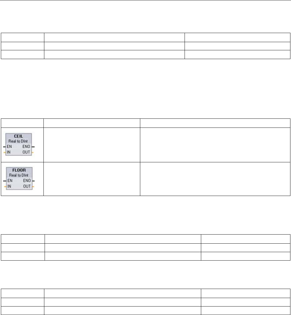
Basic instructions
8.7 Conversion operations
S7-1200 Programmable controller
System Manual, V4.2, 09/2016, A5E02486680-AK 295
Table 8- 114 ENO status
ENO
Description
Result OUT
1
No error
Valid result
0 IN is +/- INF or +/- NaN +/- INF or +/- NaN
8.7.4
CEIL and FLOOR (Generate next higher and lower integer from floating-point
number)
Table 8- 115 CEIL and FLOOR instructions
LAD / FBD
SCL
Description
out := CEIL(in);
Converts a real number (Real or LReal) to the closest integer
greater than or equal to the selected real number (IEEE "round
to +infinity").
out := FLOOR(in);
Converts a real number (Real or LReal) to the closest integer
smaller than or equal to the selected real number (IEEE "round
to -infinity").
1 For LAD and FBD: Click the "???" (by the instruction name) and select a data type from the drop-down menu.
Table 8- 116 Data types for the parameters
Parameter
Data type
Description
IN
Real, LReal
Floating point input
OUT
SInt, Int, DInt, USInt, UInt, UDInt, Real, LReal
Converted output
Table 8- 117 ENO status
ENO
Description
Result OUT
1
No error
Valid result
0
IN is +/- INF or +/- NaN
+/- INF or +/- NaN

Basic instructions
8.7 Conversion operations
S7-1200 Programmable controller
296 System Manual, V4.2, 09/2016, A5E02486680-AK
8.7.5
SCALE_X (Scale) and NORM_X (Normalize)
Table 8- 118 SCALE_X and NORM_X instructions
LAD / FBD
SCL
Description
out :=SCALE_X(min:=_in_,
value:=_in_,
max:=_in_);
Scales the normalized real parameter VALUE
where ( 0.0 <= VALUE <= 1.0 ) in the data type
and value range specified by the MIN and MAX
parameters:
OUT = VALUE (MAX - MIN) + MIN
out :=NORM_X(min:=_in_,
value:=_in_,
max:=_in_);
Normalizes the parameter VALUE inside the
value range specified by the MIN and MAX pa-
rameters:
OUT = (VALUE - MIN) / (MAX - MIN),
where ( 0.0 <= OUT <= 1.0 )
1 For LAD and FBD: Click the "???" and select a data type from the drop-down menu.
Table 8- 119 Data types for the parameters
Parameter
Data type1
Description
MIN
SInt, Int, DInt, USInt, UInt, UDInt, Real, LReal
Input minimum value for range
VALUE SCALE_X: Real, LReal
NORM_X: SInt, Int, DInt, USInt, UInt, UDInt, Real, LReal
Input value to scale or normalize
MAX
SInt, Int, DInt, USInt, UInt, UDInt, Real, LReal
Input maximum value for range
OUT SCALE_X: SInt, Int, DInt, USInt, UInt, UDInt, Real, LReal
NORM_X: Real, LReal
Scaled or normalized output value
1
For SCALE_X: Parameters MIN, MAX, and OUT must be the same data type.
For NORM_X: Parameters MIN, VALUE, and MAX must be the same data type.

Basic instructions
8.7 Conversion operations
S7-1200 Programmable controller
System Manual, V4.2, 09/2016, A5E02486680-AK 297
Note
SCALE_X parameter VALUE should be restricted to ( 0.0 <= VALUE <= 1.0 )
If parameter VALUE is less than 0.0 or greater than 1.0:
•
The linear scaling operation can produce OUT values that are less than the parameter
MIN value or above the parameter MAX value for OUT values that fit within the value
range of the OUT data type. SCALE_X execution sets ENO = TRUE for these cases.
•
It is possible to generate scaled numbers that are not within the range of the OUT data
type. For these cases, the parameter OUT value is set to an intermediate value equal to
the least-significant portion of the scaled real number prior to final conversion to the OUT
data type. SCALE_X execution sets ENO = FALSE in this case.
NORM_X parameter VALUE should be restricted to ( MIN <= VALUE <= MAX )
If parameter VALUE is less than MIN or greater than MAX, the linear scaling operation can
produce normalized OUT values that are les
s than 0.0 or greater than 1.0. NORM_X
execution sets ENO = TRUE in this case.
Table 8- 120 ENO status
ENO
Condition
Result OUT
1
No error
Valid result
0 Result exceeds valid range for the OUT data
type
Intermediate result: The least-significant portion of a real
number prior to final conversion to the OUT data type.
0 Parameters MAX <= MIN SCALE_X: The least-significant portion of the Real number
VALUE to fill up the OUT size.
NORM_X: VALUE in VALUE data type extended to fill a
double word size.
0
Parameter VALUE = +/- INF or +/- NaN
VALUE is written to OUT
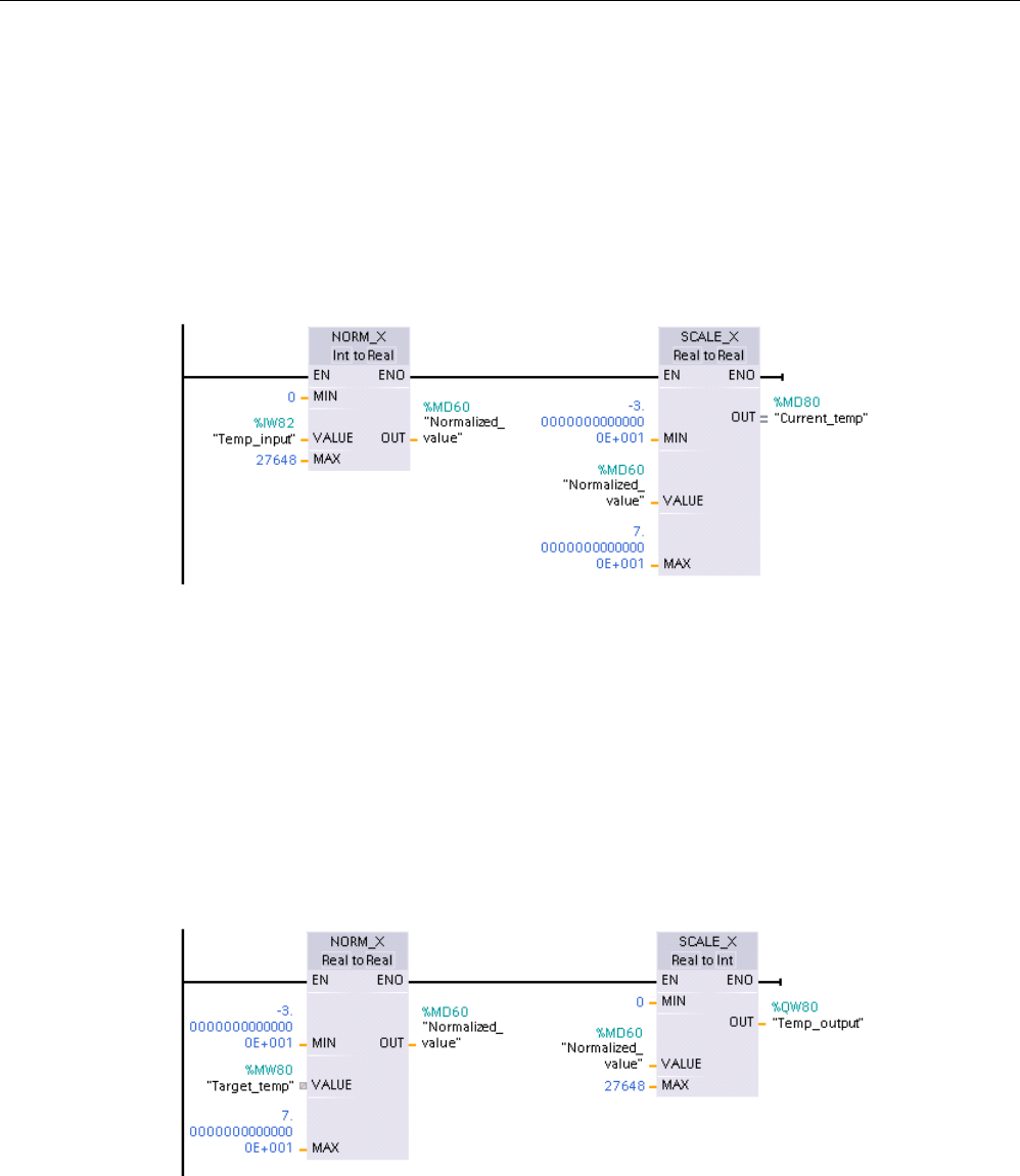
Basic instructions
8.7 Conversion operations
S7-1200 Programmable controller
298 System Manual, V4.2, 09/2016, A5E02486680-AK
Example (LAD): normalizing and scaling an analog input value
An analog input from an analog signal module or signal board using input in current is in the
range 0 to 27648 for valid values. Suppose an analog input represents a temperature where
the 0 value of the analog input represents -30.0 degrees C and 27648 represents 70.0
degrees C.
To transform the analog value to the corresponding engineering units, normalize the input to
a value between 0.0 and 1.0, and then scale it between -30.0 and 70.0. The resulting value
is the temperature represented by the analog input in degrees C:
Note that if the analog input was from an analog signal module or signal board using voltage,
the MIN value for the NORM_X instruction would be -27648 instead of 0.
Example (LAD): normalizing and scaling an analog output value
An analog output to be set in an analog signal module or signal board using output in current
must be in the range 0 to 27648 for valid values. Suppose an analog output represents a
temperature setting where the 0 value of the analog input represents -30.0 degrees C and
27648 represents 70.0 degrees C. To convert a temperature value in memory that is
between -30.0 and 70.0 to a value for the analog output in the range 0 to 27648, you must
normalize the value in engineering units to a value between 0.0 and 1.0, and then scale it to
the range of the analog output, 0 to 27648:
Note that if the analog output was for an analog signal module or signal board using voltage,
the MIN value for the SCALE_X instruction would be -27648 instead of 0.
Additional information on analog input representations (Page 1471) and analog output
representations (Page 1472) in both voltage and current can be found in the Technical
Specifications.

Basic instructions
8.7 Conversion operations
S7-1200 Programmable controller
System Manual, V4.2, 09/2016, A5E02486680-AK 299
8.7.6
Variant conversion instructions
8.7.6.1
VARIANT_TO_DB_ANY (Convert VARIANT to DB_ANY)
You use the "VARIANT to DB_ANY" instruction to read the operand at the IN parameter and
convert it to the data type DB_ANY. The IN parameter is of the Variant data type and
represents either an instance data block or an ARRAY data block. When you create the
program, you do not need to know which data block corresponds to the IN parameter. The
instruction reads the data block number during runtime and writes it to the operand at the
RET_VAL parameter.
Table 8- 121 VARIANT_TO_DB_ANY instruction
LAD / FBD
SCL
Description
Not available
RET_VAL :=
VARIANT_TO_DB_ANY(
in := _variant_in_,
err => _int_out_);
Reads the operand from the Variant IN parameter and stores it
in the function result, which is of the type DB_ANY
Table 8- 122 Parameters for the VARIANT_TO_DB_ANY instruction
Parameter
Data type
Description
IN Variant Variant that represents and instance data
block or an array data block
RET_VAL DB_ANY Output DB_ANY data type that contains the
converted data block number
ERR
Int
Error information
Table 8- 123 ENO status
ENO
Condition
Result
1 No error Instruction converts the input Variant and
stores it in the DB_ANY function output
0 Enable input EN has the signal state "0" or the IN param-
eter is invalid.
Instruction does nothing.
Table 8- 124 Error output codes for the VARIANT_TO_DB_ANY instruction
Err
(W#16#...)
Description
0000
No error
252C The Variant data type at IN parameter has the value 0. The CPU
changes to STOP mode.
8131
The data block does not exist or is too short (first access).

Basic instructions
8.7 Conversion operations
S7-1200 Programmable controller
300 System Manual, V4.2, 09/2016, A5E02486680-AK
Err
(W#16#...)
Description
8132 The data block is too short and not an Array data block (second
access).
8134
The data block is write-protected
8150 The data type Variant at parameter IN provides the value "0". To
receive this error message, the "Handle errors within block" block
property must be activated. Otherwise the CPU changes to STOP
mode and sends the error code 16#252C
8154
The data block has the incorrect data type.
*You can display error codes in the program editor as integer or hexadecimal values.
8.7.6.2
DB_ANY_TO_VARIANT (Convert DB_ANY to VARIANT)
You use the "DB_ANY to VARIANT" instruction to read the number of a data block that
meets the requirements listed below. The operand at the IN parameter has the data type
DB_ANY, which means you do not need to know during program creation which data block is
to be read. The instruction reads the data block number during runtime and writes it to the
function result RET_VAL by means of a VARIANT pointer.
Table 8- 125 DB_ANY_TO_VARIANT instruction
LAD / FBD
SCL
Description
Not available
RET_VAL :=
DB_ANY_TO_VARIANT(
in := _db_any_in_,
err => _int_out_);
Reads the data block number from the Variant IN parameter and
stores it in the function result, which is of the type Variant
Table 8- 126 Parameters for the DB_ANY_TO_VARIANT instruction
Parameter
Data type
Description
IN
DB_ANY
Variant that contains the data block number
RET_VAL Variant Output DB_ANY data type that contains the
converted data block number
ERR
Int
Error information
Table 8- 127 ENO status
ENO
Condition
Result
1 No error Instruction converts the data block number in
the variant and stores it in the function DB_ANY
output
0 Enable input EN has the signal state "0" or the IN
parameter is invalid.
Instruction does nothing.

Basic instructions
8.7 Conversion operations
S7-1200 Programmable controller
System Manual, V4.2, 09/2016, A5E02486680-AK 301
Table 8- 128 Error output codes for the DB_ANY_TO_VARIANT instruction
Err
(W#16#...)
Description
0000
No error
8130 The number of the data block is 0.
8131
The data block does not exist or is too short.
8132
The data block is too short and not an Array data block.
8134
The data block is write-protected.
8154
The data block has the incorrect data type.
8155
Unknown type code
*You can display error codes in the program editor as integer or hexadecimal values.
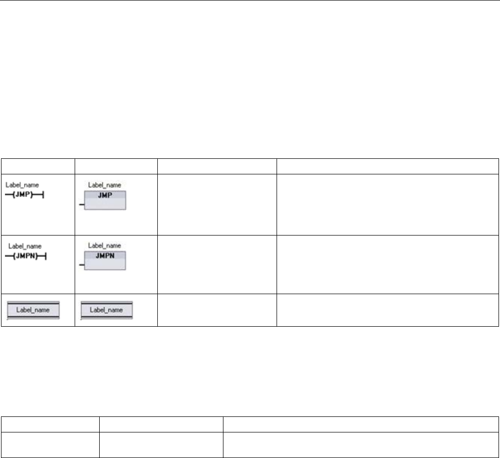
Basic instructions
8.8 Program control operations
S7-1200 Programmable controller
302 System Manual, V4.2, 09/2016, A5E02486680-AK
8.8
Program control operations
8.8.1
JMP (Jump if RLO = 1), JMPN (Jump if RLO = 0), and Label (Jump label)
instructions
Table 8- 129 JMP, JMPN, and LABEL instruction
LAD
FBD
SCL
Description
See the GOTO (Page 325)
statement.
Jump if RLO (result of logic operation) = 1:
If there is power flow to a JMP coil (LAD), or if the
JMP box input is true (FBD), then program execution
continues with the first instruction following the speci-
fied label.
Jump if RLO = 0:
If there is no power flow to a JMPN coil (LAD), or if
the JMPN box input is false (FBD), then program
execution continues with the first instruction following
the specified label.
Destination label for a JMP or JMPN jump instruction.
1
You create your label names by typing in the LABEL instruction directly. Use the parameter helper icon to select the
available label names for the JMP and JMPN label name field. You can also type a label name directly into the JMP or
JMPN instruction.
Table 8- 130 Data types for the parameters
Parameter
Data type
Description
Label_name Label identifier Identifier for Jump instructions and the corresponding jump desti-
nation program label
● Each label must be unique within a code block.
● You can jump within a code block, but you cannot jump from one code block to another
code block.
● You can jump forward or backward.
● You can jump to the same label from more than one place in the same code block.
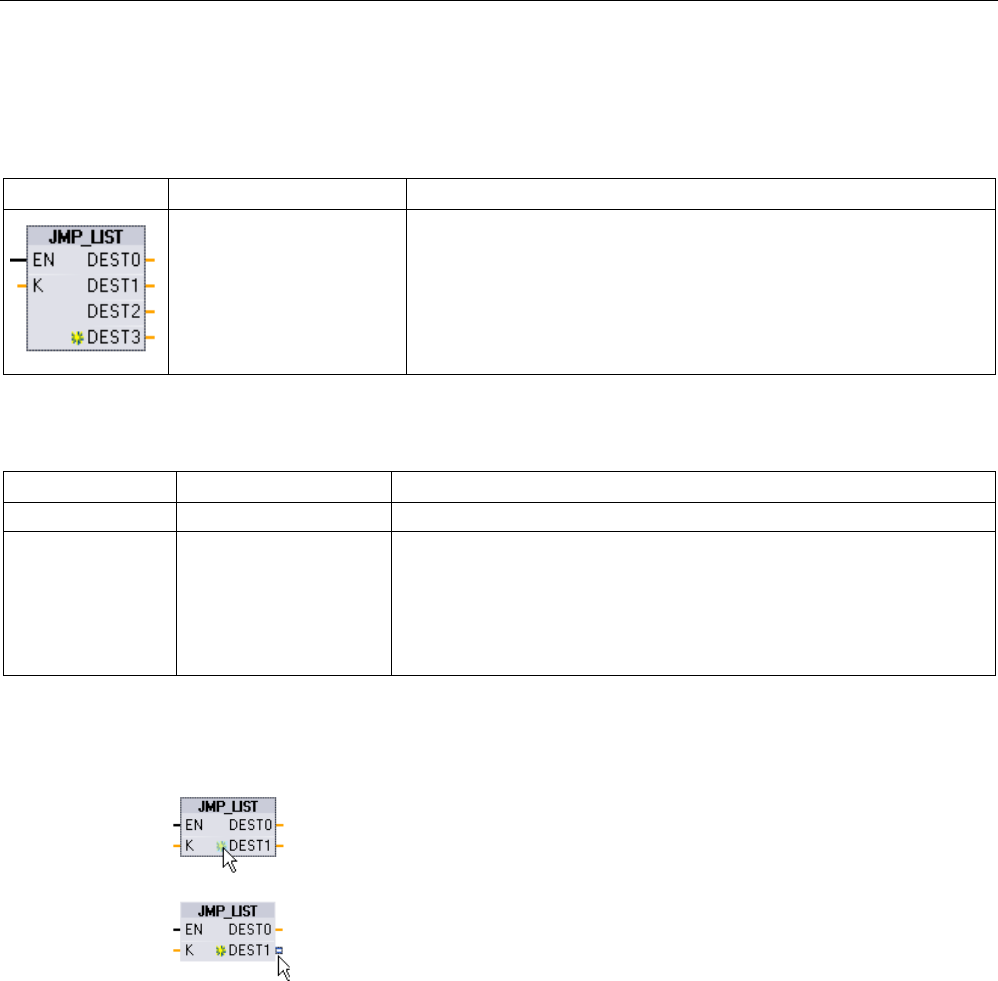
Basic instructions
8.8 Program control operations
S7-1200 Programmable controller
System Manual, V4.2, 09/2016, A5E02486680-AK 303
8.8.2
JMP_LIST (Define jump list)
Table 8- 131 JMP_LIST instruction
LAD / FBD
SCL
Description
CASE k OF
0: GOTO dest0;
1: GOTO dest1;
2: GOTO dest2;
[n: GOTO destn;]
END_CASE;
The JMP_LIST instruction acts as a program jump distributor to control
the execution of program sections. Depending on the value of the K
input, a jump occurs to the corresponding program label. Program exe-
cution continues with the program instructions that follow the destination
jump label. If the value of the K input exceeds the number of labels - 1,
then no jump occurs and processing continues with the next program
network.
Table 8- 132 Data types for parameters
Parameter
Data type
Description
K
UInt
Jump distributor control value
DEST0, DEST1, ..,
DESTn.
Program Labels Jump destination labels corresponding to specific K parameter values:
If the value of K equals 0, then a jump occurs to the program label as-
signed to the DEST0 output. If the value of K equals 1, then a jump oc-
curs to the program label assigned to the DEST1 output, and so on. If the
value of the K input exceeds the (number of labels - 1), then no jump
occurs and processing continues with the next program network.
For LAD and FBD: When the JMP_LIST
box is first placed in your program, there are two
jump label outputs. You can add or delete jump destinations.
Click the create icon inside the box (on the left of the last DEST parameter)
to add new outputs for jump labels.
•
Right-click on an output stub and select the "Insert output" command.
•
Right-click on an output stub and select the "Delete" command.
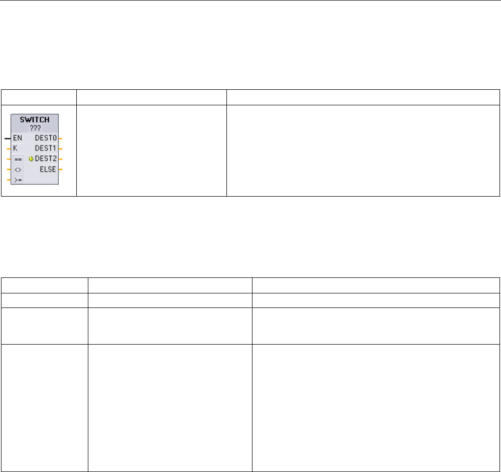
Basic instructions
8.8 Program control operations
S7-1200 Programmable controller
304 System Manual, V4.2, 09/2016, A5E02486680-AK
8.8.3
SWITCH (Jump distributor)
Table 8- 133 SWITCH instruction
LAD / FBD
SCL
Description
Not available
The SWITCH instruction acts as a program jump distributor to
control the execution of program sections. Depending on the re-
sult of comparisons between the value of the K input and the
values assigne
d to the specified comparison inputs, a jump occurs
to the program label that corresponds to the first comparison test
that is true. If none of the comparisons is true, then a jump to the
label assigned to ELSE occurs. Program execution continues with
the program instructions that follow the destination jump label.
1
For LAD and FBD: Click below the box name and select a data type from the drop-down menu.
2 For SCL: Use an IF-THEN set of comparisons.
Table 8- 134 Data types for parameters
Parameter
Data type1
Description
K
UInt
Common comparison value input
==, <>, <, <=, >. >=
SInt, Int, DInt, USInt, UInt, UDInt, Real,
LReal, Byte, Word, DWord, Time,
TOD, Date
Separate comparison value inputs for specific comparison
types
DEST0, DEST1, ..,
DESTn, ELSE
Program Labels Jump destination labels corresponding to specific compari-
sons:
The comparison input below and next to the K input is pro-
cessed first and causes a jump to the label assigned to
DEST0, if the comparison between the K value and this
input is true. The next comparison test uses the next input
below and causes a jump to the label assigned to DEST1, if
the comparison is true, The remaining comparisons are
processed similarly and if none of the comparisons are true,
then a jump to the label assigned to the ELSE output oc-
curs.
1 The K input and comparison inputs (==, <>, <, <=, >, >=) must be the same data type.
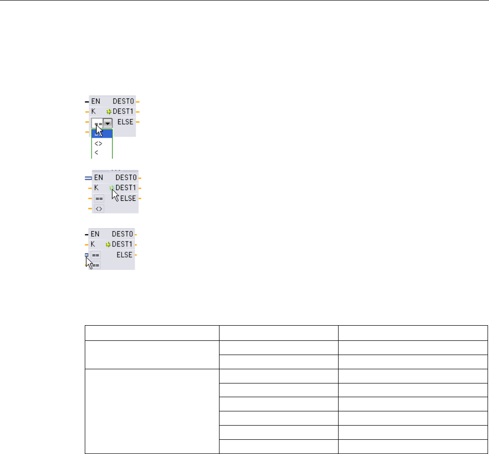
Basic instructions
8.8 Program control operations
S7-1200 Programmable controller
System Manual, V4.2, 09/2016, A5E02486680-AK 305
Adding inputs, deleting inputs, and specifying comparison types
When the LAD or FBD SWITCH box is first placed in your program there are two comparison
inputs. You can assign comparison types and add inputs/jump destinations, as shown below.
Click a
comparison operator inside the box and select a new operator
from the drop
-down list.
Click the create icon inside the box (to the left of the last DEST p
a-
rameter) to add new comparison
-destination parameters.
•
Right-click on an input stub and select the "Insert input" command.
•
Right-click on an input stub and select the "Delete" command.
Table 8- 135 SWITCH box data type selection and allowed comparison operations
Data type
Comparison
Operator syntax
Byte, Word, DWord
Equal
==
Not equal
<>
SInt, Int, DInt, USInt, UInt,
UDInt, Real, LReal, Time, TOD,
Date
Equal
==
Not equal
<>
Greater than or equal
>=
Less than or equal <=
Greater than
>
Less than
<
SWITCH box placement rules
● No LAD/FBD instruction connection in front of the compare input is allowed.
● There is no ENO output, so only one SWITCH instruction is allowed in a network and the
SWITCH instruction must be the last operation in a network.

Basic instructions
8.8 Program control operations
S7-1200 Programmable controller
306 System Manual, V4.2, 09/2016, A5E02486680-AK
8.8.4
RET (Return)
The optional RET instruction is used to terminate the execution of the current block. If and
only if there is power flow to the RET coil (LAD) or if the RET box input is true (FBD), then
program execution of the current block will end at that point and instructions beyond the RET
instruction will not be executed. If the current block is an OB, the "Return_Value" parameter
is ignored. If the current block is a FC or FB, the value of the "Return_Value" parameter is
passed back to the calling routine as the ENO value of the called box.
You are not required to use a RET instruction as the last instruction in a block; this is done
automatically for you. You can have multiple RET instructions within a single block.
For SCL, see the RETURN (Page 325) statement.
Table 8- 136 Return_Value (RET) execution control instruction
LAD
FBD
SCL
Description
RETURN;
Terminates the execution of the current block
Table 8- 137 Data types for the parameters
Parameter
Data type
Description
Return_Value Bool The "Return_value" parameter of the RET instruction is assigned to the ENO output
of the block call box in the calling block.
Sample steps for using the RET instruction inside an FC code block:
1. Create a new project and add an FC:
2. Edit the FC:
– Add instructions from the instruction tree.
– Add a RET instruction, including one of the following for the "Return_Value"
parameter:
TRUE, FALSE, or a memory location that specifies the required return value.
– Add more instructions.
3. Call the FC from MAIN [OB1].
The EN input on the FC box in the MAIN code block must be true to begin execution of the
FC.
The value specified by the RET instruction in the FC will be present on the ENO output of the
FC box in the MAIN code block following execution of the FC for which power flow to the
RET instruction is true.
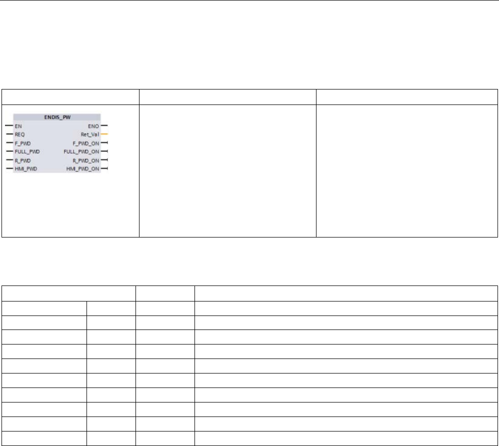
Basic instructions
8.8 Program control operations
S7-1200 Programmable controller
System Manual, V4.2, 09/2016, A5E02486680-AK 307
8.8.5
ENDIS_PW (Enable/disable CPU passwords)
Table 8- 138 ENDIS_PW instruction
LAD / FBD
SCL
Description
ENDIS_PW(
req:=_bool_in_,
f_pwd:=_bool_in_,
full_pwd:=_bool_in_,
r_pwd:=_bool_in_,
hmi_pwd:=_bool_in_,
f_pwd_on=>_bool_out_,
full_pwd_on=>_bool_out_,
r_pwd_on=>_bool_out_,
hmi_pwd_on=>_bool_out_);
The ENDIS_PW instruction can allow and
disallow client connections to a S7-1200
CPU, even when the client can provide the
correct password.
This instruction does not disallow Web
server passwords.
Table 8- 139 Data types for the parameters
Parameter and type
Data type
Description
REQ IN Bool Perform function if REQ=1
F_PWD
IN
Bool
Fail-safe password: Allow (=1) or disallow (=0)
FULL_PWD
IN
Bool
Full access password: Allow (=1) or disallow (=0) full access password
R_PWD
IN
Bool
Read access password: Allow (=1) or disallow (=0)
HMI_PWD
IN
Bool
HMI password: Allow (=1) or disallow (=0)
F_PWD_ON
OUT
Bool
Fail-safe password status: Allowed (=1) or disallowed (=0)
FULL_PWD_ON
OUT
Bool
Full access password status: Allowed (=1) or disallowed (=0)
R_PWD_ON
OUT
Bool
Read only password status: Allowed (=1) or disallowed (=0)
HMI_PWD_ON
OUT
Bool
HMI password status: Allowed (=1) or disallowed (=0)
Ret_Val
OUT
Word
Function result

Basic instructions
8.8 Program control operations
S7-1200 Programmable controller
308 System Manual, V4.2, 09/2016, A5E02486680-AK
Calling ENDIS_PW with REQ=1 disallows password types where the corresponding
password input parameter is FALSE. Each password type can be allowed or disallowed
independently. For example, if the fail-safe password is allowed and all other passwords
disallowed, then you can restrict CPU access to a small group of employees.
ENDIS_PW is executed synchronously in a program scan and the password output
parameters always show the current state of password allowance independent of the input
parameter REQ. All passwords that you set to allow must be changeable to
disallowed/allowed. Otherwise, an error is returned and all passwords are allowed that were
allowed before ENDIS_PW execution. This means that in a standard CPU (where the fail-
safe password is not configured) F_PWD must always be set to 1, to result in a return value
of 0. In this case, F_PWD_ON is always 1.
Note
•
ENDIS_PW execution can block the access of HMI devices, if the HMI password is
disallowed.
•
Client sessions that were authorized prior to ENDIS_PW execution remain unchanged by
ENDIS_PW execution.
After a power-up, CPU access is restricted by passwords previously defined in the regular
CPU protection configuration. The ability to disallow a valid password must be re-established
with a new ENDIS_PW execution. However, if ENDIS_PW is immediately executed and
necessary passwords are disallowed, then TIA portal access can be locked out. You can use
a timer instruction to delay ENDIS_PW execution and allow time to enter passwords, before
the passwords become disallowed.
Note
Restoring a CPU that locks out TIA portal communication
Refer to the "
Recovery from a lost password (Page 151
)" topic for details about how to erase
the internal load memory of a PLC using a memory card.
An operating mode change to STOP caused by errors, STP execution or STEP 7 does not
abolish the protection. The protection is valid until the CPU is power cycled. See the
following table for details.
Action
Operating mode
ENDIS_PW password control
After memory reset from
STEP 7
STOP Active: Disallowed passwords
remain disallowed.
After powering on, or changing
a memory card
STOP Off: No passwords are disal-
lowed.
After ENDIS_PW execution in a
program cycle or startup OB
STARTUP, RUN Active: Passwords are disal-
lowed according to ENDIS_PW
parameters
After change of the operating
mode from RUN or STARTUP
to STOP through STP instruc-
tion, error, or STEP 7
STOP Active: Disallowed passwords
remain disallowed

Basic instructions
8.8 Program control operations
S7-1200 Programmable controller
System Manual, V4.2, 09/2016, A5E02486680-AK 309
Note
Password protect CPU access levels with strong passwords. Strong passwords are at least
ten characters in length, mix letters, numbers, and special characters, are not words that can
be found in a dictionary, and are not names or identifiers that can be derived from personal
information. Keep the password secret and change it frequently.
Table 8- 140 Condition codes
RET_VAL
(W#16#...)
Description
0000
No error
8090
The instruction is not supported.
80D0
The password for fail-safe is not configured.
80D1
The password for read/write access is not configured.
80D2
The password for read access is not configured.
80D3
The password for HMI access is not configured.
8.8.6
RE_TRIGR (Restart cycle monitoring time)
Table 8- 141 RE_TRIGR instruction
LAD / FBD
SCL
Description
RE_TRIGR();
RE_TRIGR (Re-trigger scan time watchdog) is used to extend the maximum
time allowed before the scan cycle watchdog timer generates an error.
Use the RE_TRIGR instruction to restart the scan cycle monitoring timer during a single scan
cycle. This has the effect of extending the allowed maximum scan cycle time by one
maximum cycle time period, from the last execution of the RE_TRIGR function.
Note
Prior to S7
-1200 CPU firmware version 2.2, RE_TRIGR was restricted to execution from a
program cycle OB and could be used to extend the PLC scan time indefinitely. ENO =
FALSE and the watchdog timer is not reset when RE_TRIGR was executed from a start up
OB, an interr
upt OB, or an error OB.
For firmware version 2.2 and later, RE_TRIGR can be executed from any OB (including start
up, interrupt, and error OBs). However, the PLC scan can only be extended by a maximum
of 10x the configured maximum cycle time.

Basic instructions
8.8 Program control operations
S7-1200 Programmable controller
310 System Manual, V4.2, 09/2016, A5E02486680-AK
Setting the PLC maximum cycle time
Configure the value for maximum scan cycle time in the Device configuration for "Cycle
time".
Table 8- 142 Cycle time values
Cycle time monitor
Minimum value
Maximum value
Default value
Maximum cycle time
1 ms
6000 ms
150 ms
Watchdog timeout
If the maximum scan cycle timer expires before the scan cycle has been completed, an error
is generated. If the user program includes a time error interrupt OB (OB 80), the CPU
executes the time error interrupt OB, which can include program logic to create a special
reaction.
If the user program does not include a time error interrupt OB, the first timeout condition is
ignored and the CPU remains in RUN mode. If a second maximum scan time timeout occurs
in the same program scan (2 times the maximum cycle time value), then an error is triggered
that causes a transition to STOP mode.
In STOP mode, your program execution stops while CPU system communications and
system diagnostics continue.
8.8.7
STP (Exit program)
Table 8- 143 STP instruction
LAD / FBD
SCL
Description
STP();
STP puts the CPU in STOP mode. When the CPU is in STOP mode, the
execution of your program and physical updates from the process image are
stopped.
For more information see: Configuring the outputs on a RUN-to-STOP transition (Page 116).
If EN = TRUE, then the CPU goes to STOP mode, the program execution stops, and the
ENO state is meaningless. Otherwise, EN = ENO = 0.
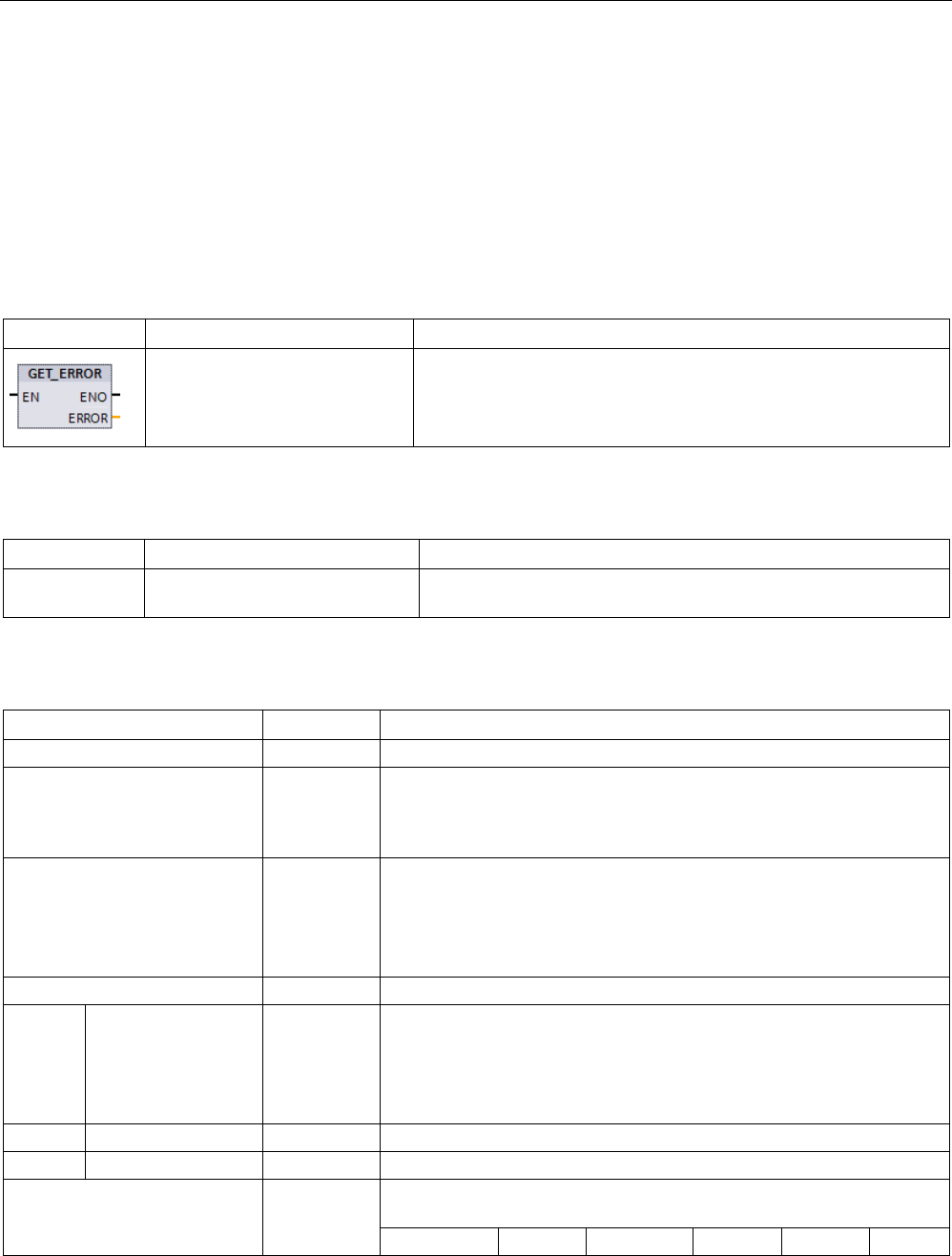
Basic instructions
8.8 Program control operations
S7-1200 Programmable controller
System Manual, V4.2, 09/2016, A5E02486680-AK 311
8.8.8
GET_ERROR and GET_ERROR_ID (Get error and error ID locally) instructions
The get error instructions provide information about program block execution errors. If you
add a GET_ERROR or GET_ERROR_ID instruction to your code block, you can handle
program errors within your program block.
GET_ERROR
Table 8- 144 GET_ERROR instruction
LAD / FBD
SCL
Description
GET_ERROR(_out_);
Indicates that a local program block execution error has occurred
and fills a predefined error data structure with detailed error infor-
mation.
Table 8- 145 Data types for the parameters
Parameter
Data type
Description
ERROR ErrorStruct Error data structure: You can rename the structure, but not the
members within the structure.
Table 8- 146 Elements of the ErrorStruct data structure
Structure components
Data type
Description
ERROR_ID
Word
Error ID
FLAGS Byte Shows if an error occurred during a block call.
• 16#01: Error during a block call.
• 16#00: No error during a block call.
REACTION Byte Default reaction:
• 0: Ignore (write error),
• 1: Continue with substitute value "0" (read error),
• 2: Skip instruction (system error)
CODE_ADDRESS
CREF
Information about the address and type of block
BLOCK_TYPE Byte Type of block where the error occurred:
• 1: OB
• 2: FC
• 3: FB
CB_NUMBER
UInt
Number of the code block
OFFSET
UDInt
Reference to the internal memory
MODE Byte Access mode: Depending on the type of access, the following infor-
mation can be output:
Mode
(A)
(B)
(C)
(D)
(E)
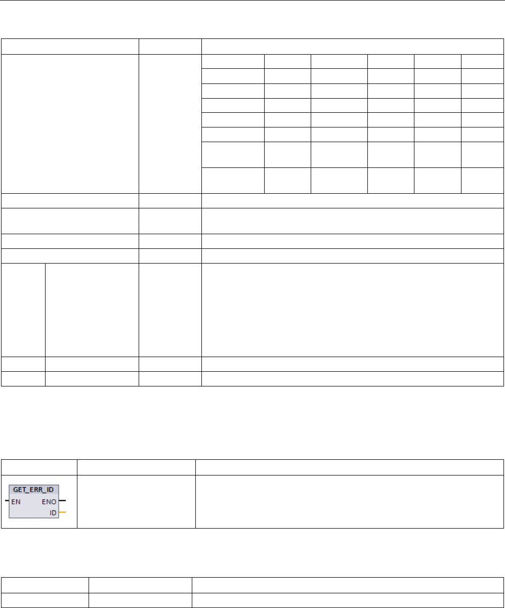
Basic instructions
8.8 Program control operations
S7-1200 Programmable controller
312 System Manual, V4.2, 09/2016, A5E02486680-AK
Structure components
Data type
Description
0
1 Offset
2
Area
3 Location Scope Number
4
Area
Offset
5
Area
DB no.
Offset
6 PtrNo.
/Acc
Area DB no. Offset
7 PtrNo. /
Acc
Slot No. /
Scope
Area DB no. Offset
OPERAND_NUMBER
UInt
Operand number of the machine command
POINTER_NUMBER_
LOCATION
UInt (A) Internal pointer
SLOT_NUMBER_SCOPE
UInt
(B) Storage area in internal memory
DATA_ADDRESS
NREF
Information about the address of an operand
AREA Byte (C) Memory area:
• L: 16#40 – 4E, 86, 87, 8E, 8F, C0 – CE
• I: 16#81
• Q: 16#82
• M: 16#83
• DB: 16#84, 85, 8A, 8B
DB_NUMBER
UInt
(D) Number of the data block
OFFSET
UDInt
(E) Relative address of the operand
GET_ERROR_ID
Table 8- 147 GetErrorID instruction
LAD / FBD
SCL
Description
GET_ERR_ID();
Indicates that a program block execution error has occurred and reports
the ID (identifier code) of the error.
Table 8- 148 Data types for the parameters
Parameter
Data type
Description
ID
Word
Error identifier values for the ErrorStruct ERROR_ID member

Basic instructions
8.8 Program control operations
S7-1200 Programmable controller
System Manual, V4.2, 09/2016, A5E02486680-AK 313
Table 8- 149 Error_ID values
ERROR_ID hexa-
decimal
ERROR_ID decimal
Program block execution error
0
0
No error
2520 9504 Corrupted string
2522
9506
Operand out of range read error
2523
9507
Operand out of range write error
2524
9508
Invalid area read error
2525
9509
Invalid area write error
2528
9512
Data alignment read error (incorrect bit alignment)
2529
9513
Data alignment write error (incorrect bit alignment)
252C
9516
Uninitialized pointer error
2530
9520
DB write protected
2533
9523
Invalid pointer used
2538
9528
Access error: DB does not exist
2539
9529
Access error: Wrong DB used
253A
9530
Global DB does not exist
253C
9532
Wrong version or FC does not exist
253D
9533
Instruction does not exist
253E
9534
Wrong version or FB does not exist
253F
9535
Instruction does not exist
2550
9552
Access error: DB does not exist
2575
9589
Program nesting depth error
2576 9590 Local data allocation error
2942
10562
Physical input point does not exist
2943
10563
Physical output point does not exist
Operation
By default, the CPU responds to a block execution error by logging an error in the
diagnostics buffer. However, if you place one or more GET_ERROR or GET_ERROR_ID
instructions within a code block, this block is now set to handle errors within the block. In this
case, the CPU does not log an error in the diagnostics buffer. Instead, the error information
is reported in the output of the GET_ERROR or GET_ERROR_ID instruction. You can read
the detailed error information with the GET_ERROR instruction, or read just the error
identifier with GET_ERROR_ID instruction. Normally the first error is the most important, with
the following errors only consequences of the first error.
The first execution of a GET_ERROR or GET_ERROR_ID instruction within a block returns
the first error detected during block execution. This error could have occurred anywhere
between the start of the block and the execution of either GET_ERROR or GET_ERROR_ID.
Subsequent executions of either GET_ERROR or GET_ERROR_ID return the first error
since the previous execution of GET_ERROR or GET_ERROR_ID. The history of errors is
not saved, and execution of either instruction will re-arm the PLC system to catch the next
error.

Basic instructions
8.8 Program control operations
S7-1200 Programmable controller
314 System Manual, V4.2, 09/2016, A5E02486680-AK
The ErrorStruct data type used by the GET_ERROR instruction can be added in the data
block editor and block interface editors, so your program logic can access these values.
Select ErrorStruct from the data type drop-down list to add this structure. You can create
multiple ErrorStruct elements by using unique names. The members of an ErrorStruct cannot
be renamed.
Error condition indicated by ENO
If EN = TRUE and GET_ERROR or GET_ERROR_ID executes, then:
● ENO = TRUE indicates a code block execution error occurred and error data is present
● ENO = FALSE indicates no code block execution error occurred
You can connect error reaction program logic to ENO which activates after an error occurs. If
an error exists, then the output parameter stores the error data where your program has
access to it.
GET_ERROR and GET_ERROR_ID can be used to send error information from the currently
executing block (called block) to a calling block. Place the instruction in the last network of
the called block program to report the final execution status of the called block.
8.8.9
RUNTIME (Measure program runtime)
Table 8- 150 RUNTIME instruction
LAD / FBD
SCL
Description
Ret_Val := RUNTIME(
_lread_inout_);
Measures the runtime of the entire program, individual blocks, or
command sequences.
If you want to measure the runtime of your entire program, call the instruction "Measure
program runtime" in OB 1. Measurement of the runtime is started with the first call and the
output RET_VAL returns the runtime of the program after the second call. The measured
runtime includes all CPU processes that can occur during the program execution, for
example, interruptions caused by higher-level events or communication. The instruction
"Measure program runtime" reads an internal counter of the CPU and write the value to the
IN-OUT parameter MEM. The instruction calculates the current program runtime according
to the internal counter frequency and writes it to output RET_VAL.
If you want to measure the runtime of individual blocks or individual command sequences,
you need three separate networks. Call the instruction "Measure program runtime" in an
individual network within your program. You set the starting point of the runtime
measurement with this first call of the instruction. Then you call the required program block
or the command sequence in the next network. In another network, call the "Measure
program runtime" instruction a second time and assign the same memory to the IN-OUT
parameter MEM as you did during the first call of the instruction. The "Measure program
runtime" instruction in the third network reads an internal CPU counter and calculates the
current runtime of the program block or the command sequence according to the internal
counter frequency and writes it to the output RET_VAL.
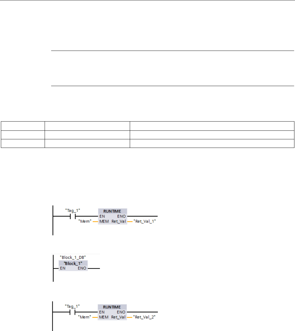
Basic instructions
8.8 Program control operations
S7-1200 Programmable controller
System Manual, V4.2, 09/2016, A5E02486680-AK 315
The Measure program runtime" instruction uses an internal high-frequency counter to
calculate the time. If the counter overruns, the instruction returns values <= 0.0. Ignore these
runtime values.
Note
The CPU cannot exactly determine the runtime of a command sequence, because the
sequence of instructions within a command sequence changes during optimized compilation
of the program.
Table 8- 151 Data types for the parameters
Parameter
Data type
Description
MEM
LReal
Starting poing of the runtime measurement
RET_VAL
LReal
Measured runtime in seconds
Example: RUNTIME instruction
The following example shows the use of the RUNTIME instruction to measure the execution
time of a function block:
Network 1:
Network 2:
Network 3:

Basic instructions
8.8 Program control operations
S7-1200 Programmable controller
316 System Manual, V4.2, 09/2016, A5E02486680-AK
When the "Tag_1" operand in network 1 has the signal state "1", the RUNTIME instruction
executes. The starting point for the runtime measurement is set with the first call of the
instruction and buffered as reference for the second call of the instruction in the "Mem"
operand.
The function block FB1 executes in network 2.
When the FB1 program block completes and the "Tag_1" operand has the signal state "1",
the RUNTIME instruction in network 3 executes. The second call of the instruction calculates
the runtime of the program block and writes the result to the output RET_VAL_2.
8.8.10
SCL program control statements
8.8.10.1
Overview of SCL program control statements
Structured Control Language (SCL) provides three types of program control statements for
structuring your user program:
● Selective statements: A selective statement enables you to direct program execution into
alternative sequences of statements.
● Loops: You can control loop execution using iteration statements. An iteration statement
specifies which parts of a program should be iterated depending on certain conditions.
● Program jumps: A program jump means an immediate jump to a specified jump
destination and therefore to a different statement within the same block.
These program control statements use the syntax of the PASCAL programming language.
Table 8- 152 Types of SCL program control statements
Program control statement
Description
Selective IF-THEN statement
(Page 317)
Enables you to direct program execution into one of two alternative
branches, depending on a condition being TRUE or FALSE
CASE statement
(Page 318)
Enables the selective execution into 1 of
n
alternative branches, based
on the value of a variable
Loop FOR statement
(Page 320)
Repeats a sequence of statements for as long as the control variable
remains within the specified value range
WHILE-DO statement
(Page 321)
Repeats a sequence of statements while an execution condition con-
tinues to be satisfied
REPEAT-UNTIL state-
ment (Page 322)
Repeats a sequence of statements until a terminate condition is met
Program jump CONTINUE statement
(Page 323)
Stops the execution of the current loop iteration
EXIT statement
(Page 324)
Exits a loop at any point regardless of whether the terminate condition
is satisfied or not
GOTO statement
(Page 325)
Causes the program to jump immediately to a specified label
RETURN statement
(Page 325)
Causes the program to exit the block currently being executed and to
return to the calling block

Basic instructions
8.8 Program control operations
S7-1200 Programmable controller
System Manual, V4.2, 09/2016, A5E02486680-AK 317
8.8.10.2
IF-THEN statement
The IF-THEN statement is a conditional statement that controls program flow by executing a
group of statements, based on the evaluation of a Bool value of a logical expression. You
can also use brackets to nest or structure the execution of multiple IF-THEN statements.
Table 8- 153 Elements of the IF-THEN statement
SCL
Description
IF "condition" THEN
statement_A;
statement_B;
statement_C;
;
If "condition" is TRUE or 1, then execute the following statements until en-
countering the END_IF statement.
If "condition" is FALSE or 0, then skip to END_IF statement (unless the
program includes optional ELSIF or ELSE statements).
[ELSIF "condition-n" THEN
statement_N;
;]
The optional ELSEIF1 statement provides additional conditions to be evalu-
ated. For example: If "condition" in the IF-THEN statement is FALSE, then
the program evaluates "condition-n". If "condition-n" is TRUE, then execute
"statement_N".
[ELSE
statement_X;
;]
The optional ELSE statement provides statements to be executed when the
"condition" of the IF-THEN statement is FALSE.
END_IF;
The END_IF statement terminates the IF-THEN instruction.
1 You can include multiple ELSIF statements within one IF-THEN statement.
Table 8- 154 Variables for the IF-THEN statement
Variables
Description
"condition"
Required. The logical expression is either TRUE (1) or FALSE (0).
"statement_A"
Optional. One or more statements to be executed when "condition" is TRUE.
"condition-n"
Optional. The logical expression to be evaluated by the optional ELSIF statement.
"statement_N" Optional. One or more statements to be executed when "condition-
n" of the ELSIF statement is
TRUE.
"statement_X" Optional. One or more statements to be executed when "condition" of the IF-THEN statement
is FALSE.
An IF statement is executed according to the following rules:
● The first sequence of statements whose logical expression = TRUE is executed. The
remaining sequences of statements are not executed.
● If no Boolean expression = TRUE, the sequence of statements introduced by ELSE is
executed (or no sequence of statements if the ELSE branch does not exist).
● Any number of ELSIF statements can exist.
Note
Using one or more ELSIF branches has the advantage that the logical expressio
ns
following a valid expression are no longer evaluated in contrast to a sequence of IF
statements. The runtime of a program can therefore be reduced.

Basic instructions
8.8 Program control operations
S7-1200 Programmable controller
318 System Manual, V4.2, 09/2016, A5E02486680-AK
8.8.10.3
CASE statement
Table 8- 155 Elements of the CASE statement
SCL
Description
CASE "Test_Value" OF
"ValueList": Statement[; Statement, ...]
"ValueList": Statement[; Statement, ...]
[ELSE
Else-statement[; Else-statement, ...]]
END_CASE;
The CASE statement executes one of several
groups of statements, depending on the value
of an expression.
Table 8- 156 Parameters
Parameter
Description
"Test_Value"
Required. Any numeric expression of data type Int
"ValueList" Required. A single value or a comma-separated list of values or ranges of values. (Use two
periods to define a range of values: 2..8) The following example illustrates the different vari-
ants of the value list:
1: Statement_A;
2, 4: Statement _B;
3, 5..7,9: Statement _C;
Statement Required. One or more statements that are executed when "Test_Value" matches any value
in the value list
Else-statement Optional. One or more statements that are executed if no match with a value of the "Val-
ueList" stated matches

Basic instructions
8.8 Program control operations
S7-1200 Programmable controller
System Manual, V4.2, 09/2016, A5E02486680-AK 319
The CASE statement is executed according to the following rules:
● The Test_value expression must return a value of the type Int.
● When a CASE statement is processed, the program checks whether the value of the
Test_value expression is contained within a specified list of values. If a match is found,
the statement component assigned to the list is executed.
● If no match is found, the program section following ELSE is executed or no statement is
executed if the ELSE branch does not exist.
Example: Nested CASE statements
CASE statements can be nested. Each nested case statement must have an associated
END_CASE statement.
CASE "var1" OF
1 : #var2 := 'A';
2 : #var2 := 'B';
ELSE
CASE "var3" OF
65..90: #var2 := 'UpperCase';
97..122: #var2 := 'LowerCase';
ELSE
#var2:= 'SpecialCharacter';
END_CASE;
END_CASE;

Basic instructions
8.8 Program control operations
S7-1200 Programmable controller
320 System Manual, V4.2, 09/2016, A5E02486680-AK
8.8.10.4
FOR statement
Table 8- 157 Elements of the FOR statement
SCL
Description
FOR "control_variable" := "begin" TO "end"
[BY "increment"] DO
statement;
;
END_FOR;
A FOR statement is used to repeat a sequence of
statements as long as a control variable is within
the specified range of values. The definition of a
loop with FOR includes the specification of an
initial and an end value. Both values must be the
same type as the control variable.
You can nest FOR loops. The END_FOR state-
ment refers to the last executed FOR instruction.
Table 8- 158 Parameters
Parameter
Description
"control_variable"
Required. An integer (Int or DInt) that serves as a loop counter
"begin"
Required. Simple expression that specifies the initial value of the control variables
"end"
Required. Simple expression that determines the final value of the control variables
"increment" Optional. Amount by which a "control variable" is changed after each loop. The "increment"
has the same data type as "control variable". If the "increment" value is not specified, then
the value of the run tags will be increased by 1 after each loop. You cannot change "incre-
ment" during the execution of the FOR statement.
The FOR statement executes as follows:
● At the start of the loop, the control variable is set to the initial value (initial assignment)
and each time the loop iterates, it is incremented by the specified increment (positive
increment) or decremented (negative increment) until the final value is reached.
● Following each run through of the loop, the condition is checked (final value reached) to
establish whether or not it is satisfied. If the end condition is not satisfied, the sequence of
statements is executed again, otherwise the loop terminates and execution continues
with the statement immediately following the loop.
Rules for formulating FOR statements:
● The control variable may only be of the data type Int or DInt.
● You can omit the statement BY [increment]. If no increment is specified, it is automatically
assumed to be +1.
To end the loop regardless of the state of the "condition" expression, use the EXIT statement
(Page 324). The EXIT statement executes the statement immediately following the
END_FOR statement.
Use the CONTINUE statement (Page 323) to skip the subsequent statements of a FOR loop
and to continue the loop with the examination of whether the condition is met for termination.

Basic instructions
8.8 Program control operations
S7-1200 Programmable controller
System Manual, V4.2, 09/2016, A5E02486680-AK 321
8.8.10.5
WHILE-DO statement
Table 8- 159 WHILE statement
SCL
Description
WHILE "condition" DO
Statement;
Statement;
...;
END_WHILE;
The WHILE statement performs a series of statements until a given condition is
TRUE.
You can nest WHILE loops. The END_WHILE statement refers to the last executed
WHILE instruction.
Table 8- 160 Parameters
Parameter
Description
"condition" Required. A logical expression that evaluates to TRUE or FALSE. (A "null" condition is inter-
preted as FALSE.)
Statement
Optional. One or more statements that are executed until the condition evaluates to TRUE.
Note
The WHILE statement evaluates the state of "condition" before executing any of the
statements. To execute the statements at least one time regardless of the state of
"condition",
use the REPEAT statement (Page 322).
The WHILE statement executes according to the following rules:
● Prior to each iteration of the loop body, the execution condition is evaluated.
● The loop body following DO iterates as long as the execution condition has the value
TRUE.
● Once the value FALSE occurs, the loop is skipped and the statement following the loop is
executed.
To end the loop regardless of the state of the "condition" expression, use the EXIT statement
(Page 324). The EXIT statement executes the statement immediately following the
END_WHILE statement.
Use the CONTINUE statement to skip the subsequent statements of a WHILE loop and to
continue the loop with the examination of whether the condition is met for termination.

Basic instructions
8.8 Program control operations
S7-1200 Programmable controller
322 System Manual, V4.2, 09/2016, A5E02486680-AK
8.8.10.6
REPEAT-UNTIL statement
Table 8- 161 REPEAT instruction
SCL
Description
REPEAT
Statement;
;
UNTIL "condition"
END_REPEAT;
The REPEAT statement executes a group of statements until a given condition is
TRUE.
You can nest REPEAT loops. The END_REPEAT statement always refers to the last
executed Repeat instruction.
Table 8- 162 Parameters
Parameter
Description
Statement
Optional. One or more statements that are executed until the condition is TRUE.
"condition" Required. One or more expressions of the two following ways: A numeric expression or string
expression that evaluates to TRUE or FALSE. A "null" condition is interpreted as FALSE.
Note
Before e
valuating the state of "condition", the REPEAT statement executes the statements
during the first iteration of the loop (even if "condition" is FALSE). To review the state of
"condition" before executing the statements, use the
WHILE statement (Page 321).
To end the loop regardless of the state of the "condition" expression, use the EXIT statement
(Page 324). The EXIT statement executes the statement immediately following the
END_REPEAT statement.
Use the CONTINUE statement (Page 323) to skip the subsequent statements of a REPEAT
loop and to continue the loop with the examination of whether the condition is met for
termination.

Basic instructions
8.8 Program control operations
S7-1200 Programmable controller
System Manual, V4.2, 09/2016, A5E02486680-AK 323
8.8.10.7
CONTINUE statement
Table 8- 163 CONTINUE statement
SCL
Description
CONTINUE
Statement;
;
The CONTINUE statement skips the subsequent statements of a program loop (FOR,
WHILE, REPEAT) and continues the loop with the examination of whether the condition is
met for termination. If this is not the case, the loop continues.
The CONTINUE statement executes according to the following rules:
● This statement immediately terminates execution of a loop body.
● Depending on whether the condition for repeating the loop is satisfied or not the body is
executed again or the iteration statement is exited and the statement immediately
following is executed.
● In a FOR statement, the control variable is incremented by the specified increment
immediately after a CONTINUE statement.
Use the CONTINUE statement only within a loop. In nested loops CONTINUE always refers
to the loop that includes it immediately. CONTINUE is typically used in conjunction with an IF
statement.
If the loop is to exit regardless of the termination test, use the EXIT statement.
Example: CONTINUE statement
The following example shows the use of the CONTINUE statement to avoid a division-by-0
error when calculating the percentage of a value:
FOR i := 0 TO 10 DO
IF value[i] = 0 THEN CONTINUE; END_IF;
p := part / value[i] * 100;
s := INT_TO_STRING(p);
percent := CONCAT(IN1:=s, IN2:="%");
END_FOR;

Basic instructions
8.8 Program control operations
S7-1200 Programmable controller
324 System Manual, V4.2, 09/2016, A5E02486680-AK
8.8.10.8
EXIT statement
Table 8- 164 EXIT instruction
SCL
Description
EXIT;
An EXIT statement is used to exit a loop (FOR, WHILE or REPEAT) at any point, regardless of whether
the terminate condition is satisfied.
The EXIT statement executes according to the following rules:
● This statement causes the repetition statement immediately surrounding the exit
statement to be exited immediately.
● Execution of the program is continued after the end of the loop (for example after
END_FOR).
Use the EXIT statement within a loop. In nested loops, the EXIT statement returns the
processing to the next higher nesting level.
Example: EXIT statement
FOR i := 0 TO 10 DO
CASE value[i, 0] OF
1..10: value [i, 1]:="A";
11..40: value [i, 1]:="B";
41..100: value [i, 1]:="C";
ELSE
EXIT;
END_CASE;
END_FOR;

Basic instructions
8.8 Program control operations
S7-1200 Programmable controller
System Manual, V4.2, 09/2016, A5E02486680-AK 325
8.8.10.9
GOTO statement
Table 8- 165 GOTO statement
SCL
Description
GOTO JumpLabel;
Statement;
... ;
JumpLabel: Statement;
The GOTO statement skips over statements by jumping to a label in the same
block.
The jump label ("JumpLabel") and the GOTO statement
must be in the same block.
The name of a jump label can only be assigned once within a block. Each jump
label can be the target of several GOTO statements.
It is not possible to jump to a loop section (FOR, WHILE or REPEAT). It is possible to jump
from within a loop.
Example: GOTO statement
In the following example: Depending on the value of the "Tag_value" operand, the execution
of the program resumes at the point defined by the corresponding jump label. If "Tag_value"
equals 2, the program execution resumes at the jump label "MyLabel2" and skips
"MyLabel1".
CASE "Tag_value" OF
1 : GOTO MyLabel1;
2 : GOTO MyLabel2;
ELSE GOTO MyLabel3;
END_CASE;
MyLabel1: "Tag_1" := 1;
MyLabel2: "Tag_2" := 1;
MyLabel3: "Tag_4" := 1;
8.8.10.10
RETURN statement
Table 8- 166 RETURN instruction
SCL
Description
RETURN;
The Return instruction exits the code block being executed without conditions. Program execu-
tion returns to the calling block or to the operating system (when exiting an OB).
Example: RETURN instruction:
IF "Error" <> 0 THEN
RETURN;
END_IF;
Note
After executing the
last instruction, the code block automatically returns to the calling block.
Do not insert a RETURN instruction at the end of the code block.
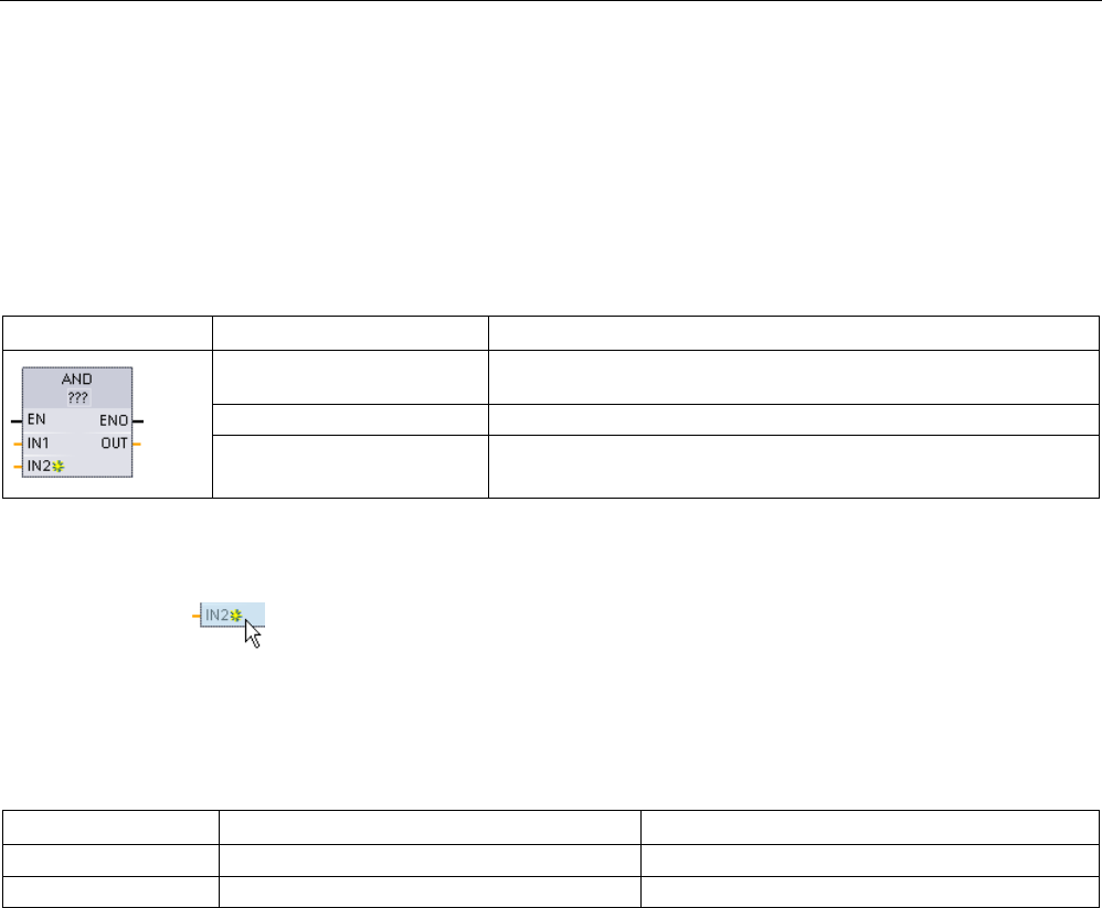
Basic instructions
8.9 Word logic operations
S7-1200 Programmable controller
326 System Manual, V4.2, 09/2016, A5E02486680-AK
8.9
Word logic operations
8.9.1
AND, OR, and XOR logic operation instructions
Table 8- 167 AND, OR, and XOR logic operation instructions
LAD / FBD
SCL
Description
out := in1 AND in2;
AND: Logical AND
out := in1 OR in2;
OR: Logical OR
out := in1 XOR in2;
XOR: Logical EXCLUSIVE OR
1 For LAD and FBD: Click the "???" and select a data type from the drop-down menu.
To add an input, click the "Create" icon or right
-click on an input stub for one of the
existing IN parameters and select the "Insert input" command.
To remove an input, right-click on an input stub for one of the existing IN parameters (when
there are more than the original two inputs) and select the "Delete" command.
Table 8- 168 Data types for the parameters
Parameter
Data type
Description
IN1, IN2
Byte, Word, DWord
Logical inputs
OUT
Byte, Word, DWord
Logical output
1 The data type selection sets parameters IN1, IN2, and OUT to the same data type.
The corresponding bit values of IN1 and IN2 are combined to produce a binary logic result at
parameter OUT. ENO is always TRUE following the execution of these instructions.
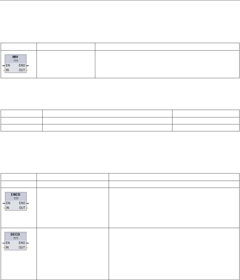
Basic instructions
8.9 Word logic operations
S7-1200 Programmable controller
System Manual, V4.2, 09/2016, A5E02486680-AK 327
8.9.2
INV (Create ones complement)
Table 8- 169 INV instruction
LAD / FBD
SCL
Description
Not available
Calculates the binary one's complement of the parameter IN. The one's
complement is formed by inverting each bit value of the IN parameter
(changing each 0 to 1 and each 1 to 0). ENO is always TRUE following
the execution of this instruction.
1 For LAD and FBD: Click the "???" and select a data type from the drop-down menu.
Table 8- 170 Data types for the parameters
Parameter
Data type
Description
IN
SInt, Int, DInt, USInt, UInt, UDInt, Byte, Word, DWord
Data element to invert
OUT
SInt, Int, DInt, USInt, UInt, UDInt, Byte, Word, DWord
Inverted output
8.9.3
DECO (Decode) and ENCO (Encode) instructions
Table 8- 171 ENCO and DECO instruction
LAD / FBD
SCL
Description
out := ENCO(_in_);
Encodes a bit pattern to a binary number
The ENCO instruction converts parameter IN to the binary number
corresponding to the bit position of the least-significant set bit of
parameter IN and returns the result to parameter OUT. If parame-
ter IN is either 0000 0001 or 0000 0000, then a value of 0 is re-
turned to parameter OUT. If the parameter IN value is 0000 0000,
then ENO is set to FALSE.
out := DECO(_in_);
Decodes a binary number to a bit pattern
The DECO instruction decodes a binary number from parameter
IN, by setting the corresponding bit position in parameter OUT to
a 1 (all other bits are set to 0). ENO is always TRUE following
execution of the DECO instruction.
Note: The default data type for the DECO instruction is DWORD.
In SCL, change the instruction name to DECO_BYTE or
DECO_WORD to decode a byte or word value, and assign to a
byte or word tag or address.
1 For LAD and FBD: Click the "???" and select a data type from the drop-down menu.

Basic instructions
8.9 Word logic operations
S7-1200 Programmable controller
328 System Manual, V4.2, 09/2016, A5E02486680-AK
Table 8- 172 Data types for the parameters
Parameter
Data type
Description
IN ENCO: Byte, Word, DWord
DECO: UInt
ENCO: Bit pattern to encode
DECO: Value to decode
OUT ENCO: Int
DECO: Byte, Word, DWord
ENCO: Encoded value
DECO: Decoded bit pattern
Table 8- 173 ENO status
ENO
Condition
Result (OUT)
1
No error
Valid bit number
0
IN is zero
OUT is set to zero
The DECO parameter OUT data type selection of a Byte, Word, or DWord restricts the
useful range of parameter IN. If the value of parameter IN exceeds the useful range, then a
modulo operation is performed to extract the least significant bits shown below.
DECO parameter IN range:
● 3 bits (values 0-7) IN are used to set 1 bit position in a Byte OUT
● 4-bits (values 0-15) IN are used to set 1 bit position in a Word OUT
● 5 bits (values 0-31) IN are used to set 1 bit position in a DWord OUT
Table 8- 174 Examples
DECO IN value
DECO OUT value ( Decode single bit position)
Byte OUT
8 bits
Min. IN
0
00000001
Max. IN
7
10000000
Word OUT
16 bits
Min. IN
0
0000000000000001
Max. IN
15
1000000000000000
DWord OUT
32 bits
Min. IN
0
00000000000000000000000000000001
Max. IN
31
10000000000000000000000000000000
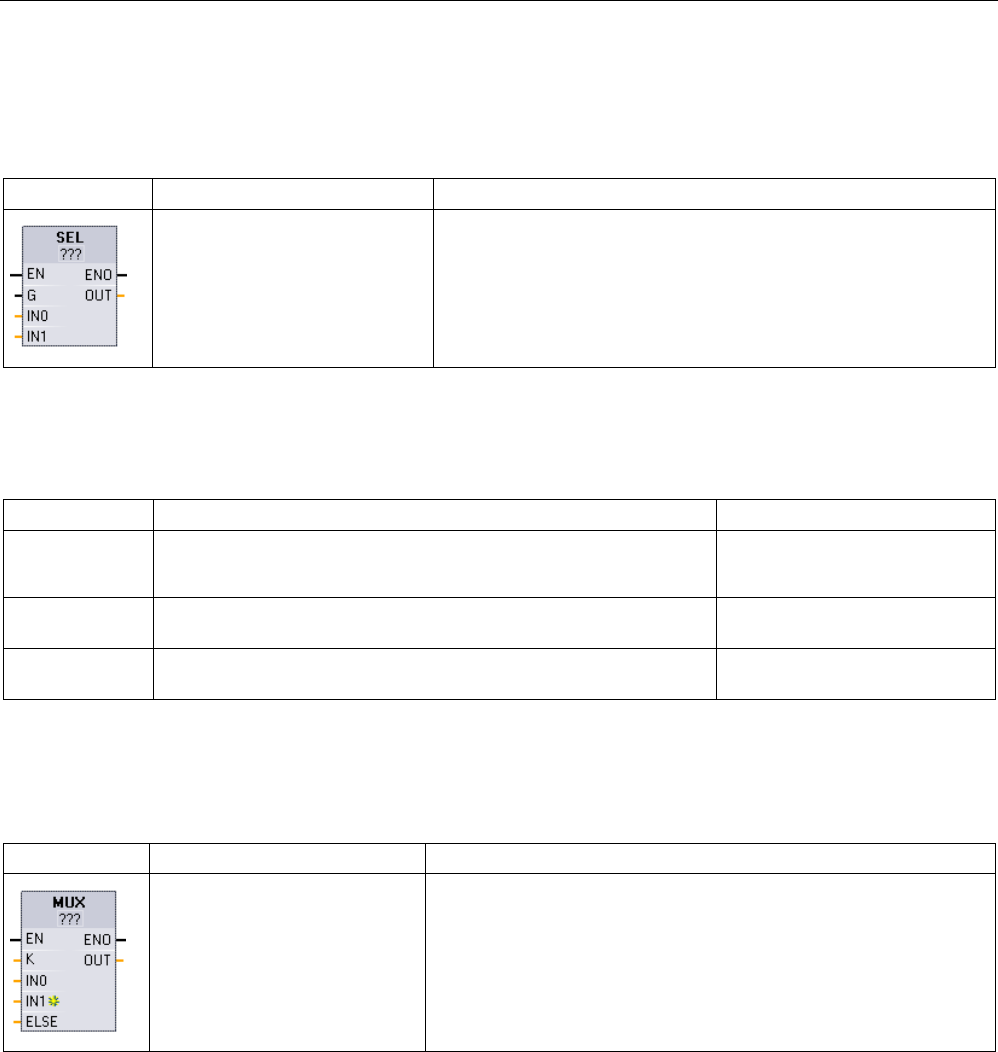
Basic instructions
8.9 Word logic operations
S7-1200 Programmable controller
System Manual, V4.2, 09/2016, A5E02486680-AK 329
8.9.4
SEL (Select), MUX (Multiplex), and DEMUX (Demultiplex) instructions
Table 8- 175 SEL (select) instruction
LAD / FBD
SCL
Description
out := SEL(
g:=_bool_in,
in0:-_variant_in,
in1:=_variant_in);
SEL assigns one of two input values to parameter OUT, depending
on the parameter G value.
1 For LAD and FBD: Click the "???" and select a data type from the drop-down menu.
Table 8- 176 Data types for the SEL instruction
Parameter
Data type 1
Description
G Bool • 0 selects IN0
• 1 selects IN1
IN0, IN1 SInt, Int, DInt, USInt, UInt, UDInt, Real, LReal, Byte, Word, DWord,
Time, Date, TOD, Char, WChar
Inputs
OUT SInt, Int, DInt, USInt, UInt, UDInt, Real, LReal, Byte, Word, DWord,
Time, Date, TOD, Char, WChar
Output
1 Input variables and the output variable must be of the same data type.
Condition codes:
ENO is always TRUE following execution of the SEL instruction.
Table 8- 177 MUX (multiplex) instruction
LAD / FBD
SCL
Description
out := MUX(
k:=_unit_in,
in1:=variant_in,
in2:=variant_in,
[...in32:=variant_in,]
inelse:=variant_in);
MUX copies one of many input values to parameter OUT, depending
on the parameter K value. If the parameter K value exceeds (IN
n
- 1),
then the parameter ELSE value is copied to parameter OUT.
1 For LAD and FBD: Click the "???" and select a data type from the drop-down menu.
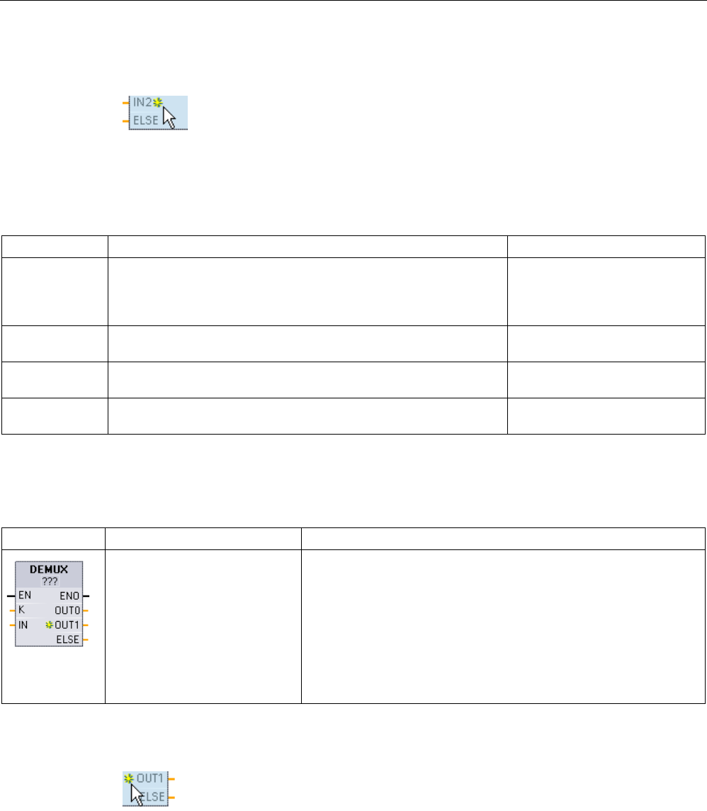
Basic instructions
8.9 Word logic operations
S7-1200 Programmable controller
330 System Manual, V4.2, 09/2016, A5E02486680-AK
To add an input, click the "Create" icon or right
-
click on an input stub for one of
the existing IN parameters and select the "Insert input" command.
To remove an input, right-click on an input stub for one of the existing IN parameters (when
there are more than the original two inputs) and select the "Delete" command.
Table 8- 178 Data types for the MUX instruction
Parameter
Data type
Description
K UInt • 0 selects IN1
• 1 selects IN2
•
n
selects IN
n
IN0, IN1, .. INn SInt, Int, DInt, USInt, UInt, UDInt, Real, LReal, Byte, Word, DWord,
Time, Date, TOD, Char, WChar
Inputs
ELSE SInt, Int, DInt, USInt, UInt, UDInt, Real, LReal, Byte, Word, DWord,
Time, Date, TOD, Char, WChar
Input substitute value (optional)
OUT SInt, Int, DInt, USInt, UInt, UDInt, Real, LReal, Byte, Word, DWord,
Time, Date, TOD, Char, WChar
Output
1 Input variables and the output variable must be of the same data type.
Table 8- 179 DEMUX (Demultiplex) instruction
LAD / FBD
SCL
Description
DEMUX(
k:=_unit_in,
in:=variant_in,
out1:=variant_in,
out2:=variant_in,
[...out32:=variant_in,]
outelse:=variant_in);
DEMUX copies the value of the location assigned to parameter IN to
one of many outputs. The value of the K parameter selects which
output selected as the destination of the IN value. If the value of K is
greater than the number (OUT
n
- 1) then the IN value is copied to
location assigned to the ELSE parameter.
1 For LAD and FBD: Click the "???" and select a data type from the drop-down menu.
To add an output, click the "Create" icon or right
-click on an output stub for one
of the existing OUT parameters and select the "Insert output" command.
To remove an output, right-click on an output stub for one of the existing OUT parameters
(when there are more than the original two outputs) and select the "Delete" command.

Basic instructions
8.9 Word logic operations
S7-1200 Programmable controller
System Manual, V4.2, 09/2016, A5E02486680-AK 331
Table 8- 180 Data types for the DEMUX instruction
Parameter
Data type 1
Description
K UInt Selector value:
• 0 selects OUT1
• 1 selects OUT2
• n selects OUTn
IN SInt, Int, DInt, USInt, UInt, UDInt, Real, LReal, Byte, Word,
DWord, Time, Date, TOD, Char, WChar
Input
OUT0, OUT1, ..
OUTn
SInt, Int, DInt, USInt, UInt, UDInt, Real, LReal, Byte, Word,
DWord, Time, Date, TOD, Char, WChar
Outputs
ELSE SInt, Int, DInt, USInt, UInt, UDInt, Real, LReal, Byte, Word,
DWord, Time, Date, TOD, Char, WChar
Substitute output when K is greater than
(OUTn - 1)
1 The input variable and the output variables must be of the same data type.
Table 8- 181 ENO status for the MUX and DEMUX instructions
ENO
Condition
Result OUT
1 No error MUX: Selected IN value is copied to
OUT
DEMUX: IN value is copied to selected
OUT
0 MUX: K is greater than the number of inputs -1 • No ELSE provided: OUT is un-
changed,
•
ELSE provided, ELSE value assigned
to OUT
DEMUX: K is greater than the number of outputs -1 • No ELSE provided: outputs are un-
changed,
• ELSE provided, IN value copied to
ELSE
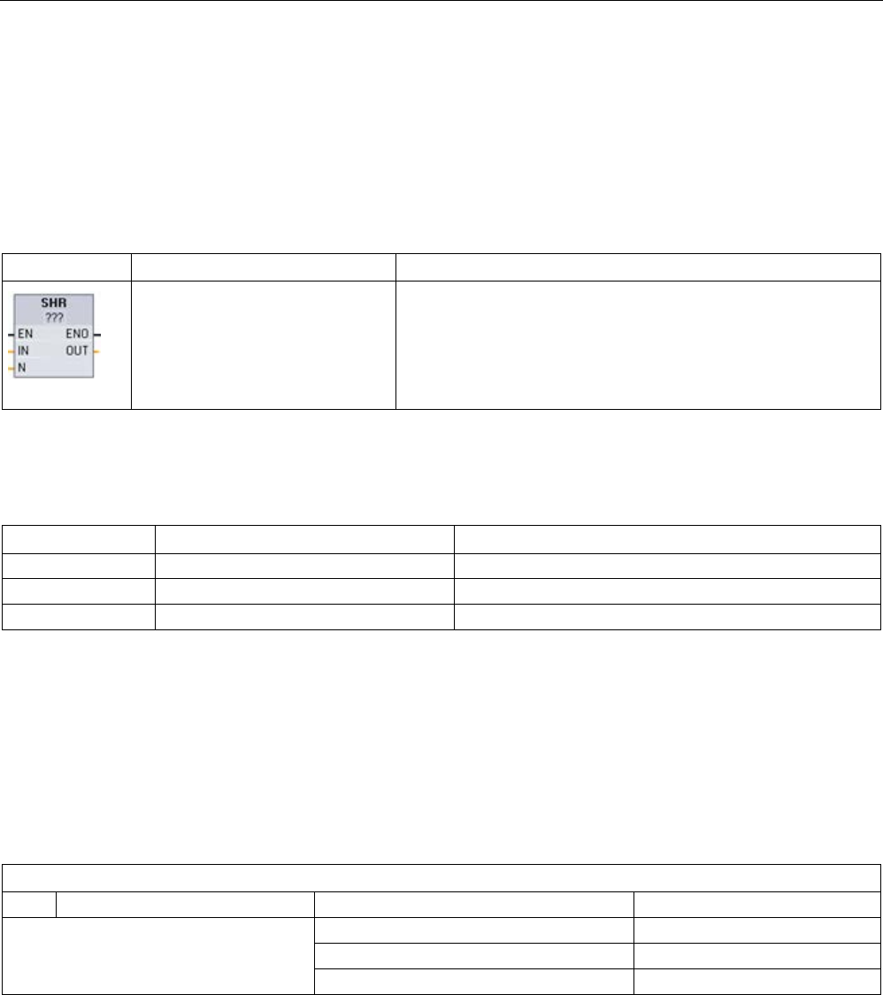
Basic instructions
8.10 Shift and rotate
S7-1200 Programmable controller
332 System Manual, V4.2, 09/2016, A5E02486680-AK
8.10
Shift and rotate
8.10.1
SHR (Shift right) and SHL (Shift left) instructions
Table 8- 182 SHR and SHL instructions
LAD / FBD
SCL
Description
out := SHR(
in:=_variant_in_,
n:=_uint_in);
out := SHL(
in:=_variant_in_,
n:=_uint_in);
Use the shift instructions (SHL and SHR) to shift the bit pattern of
parameter IN. The result is assigned to parameter OUT. Parame-
ter N specifies the number of bit positions shifted:
• SHR: Shift bit pattern right
• SHL: Shift bit pattern left
1 For LAD and FBD: Click the "???" and select the data types from the drop-down menu.
Table 8- 183 Data types for the parameters
Parameter
Data type
Description
IN
Integers
Bit pattern to shift
N USInt, UDint Number of bit positions to shift
OUT
Integers
Bit pattern after shift operation
● For N=0, no shift occurs. The IN value is assigned to OUT.
● Zeros are shifted into the bit positions emptied by the shift operation.
● If the number of positions to shift (N) exceeds the number of bits in the target value (8 for
Byte, 16 for Word, 32 for DWord), then all original bit values will be shifted out and
replaced with zeros (zero is assigned to OUT).
● ENO is always TRUE for the shift operations.
Table 8- 184 Example: SHL for Word data
Shift the bits of a Word to the left by inserting zeroes from the right (N = 1)
IN
1110 0010 1010 1101
OUT value before first shift:
1110 0010 1010 1101
After first shift left:
1100 0101 0101 1010
After second shift left:
1000 1010 1011 0100
After third shift left:
0001 0101 0110 1000
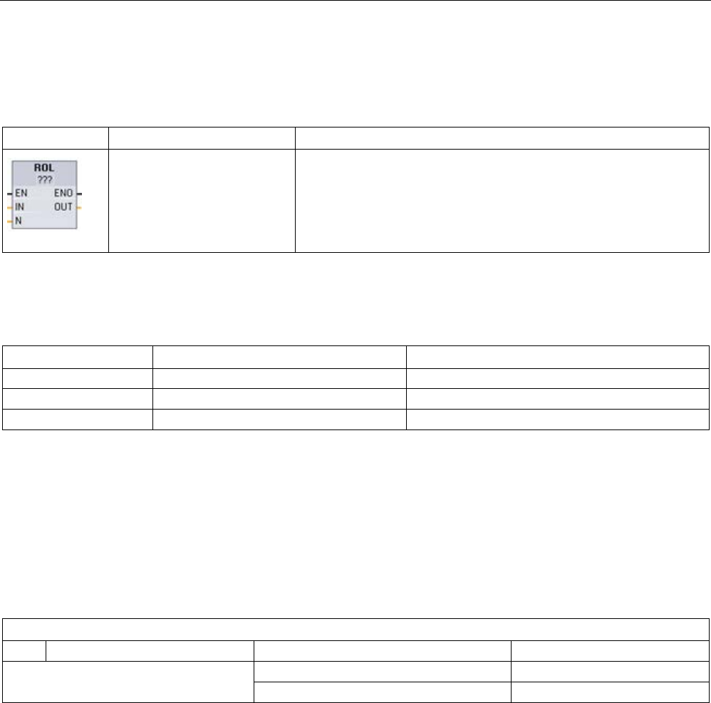
Basic instructions
8.10 Shift and rotate
S7-1200 Programmable controller
System Manual, V4.2, 09/2016, A5E02486680-AK 333
8.10.2
ROR (Rotate right) and ROL (Rotate left) instructions
Table 8- 185 ROR and ROL instructions
LAD / FBD
SCL
Description
out := ROL(
in:=_variant_in_,
n:=_uint_in);
out := ROR(
in:=_variant_in_,
n:=_uint_in);
Use the rotate instructions (ROR and ROL) to rotate the bit pattern of
parameter IN. The result is assigned to parameter OUT. Parameter N
defines the number of bit positions rotated.
• ROR: Rotate bit pattern right
• ROL: Rotate bit pattern left
1 For LAD and FBD: Click the "???" and select the data types from the drop-down menu.
Table 8- 186 Data types for the parameters
Parameter
Data type
Description
IN
Integers
Bit pattern to rotate
N USInt, UDint Number of bit positions to rotate
OUT
Integers
Bit pattern after rotate operation
● For N=0, no rotate occurs. The IN value is assigned to OUT.
● Bit data rotated out one side of the target value is rotated into the other side of the target
value, so no original bit values are lost.
● If the number of bit positions to rotate (N) exceeds the number of bits in the target value
(8 for Byte, 16 for Word, 32 for DWord), then the rotation is still performed.
● ENO is always TRUE following execution of the rotate instructions.
Table 8- 187 Example: ROR for Word data
Rotate bits out the right -side into the left -side (N = 1)
IN
0100 0000 0000 0001
OUT value before first rotate:
0100 0000 0000 0001
After first rotate right:
1010 0000 0000 0000
After second rotate right:
0101 0000 0000 0000

Basic instructions
8.10 Shift and rotate
S7-1200 Programmable controller
334 System Manual, V4.2, 09/2016, A5E02486680-AK

S7-1200 Programmable controller
System Manual, V4.2, 09/2016, A5E02486680-AK 335
Extended instructions
9
9.1
Date, time-of-day, and clock functions
9.1.1
Date and time-of-day instructions
Use the date and time instructions for calendar and time calculations.
● T_CONV converts a value to or from (date and time data types) and (byte, word, and
dword size data types)
● T_ADD adds Time and DTL values: (Time + Time = Time) or (DTL + Time = DTL)
● T_SUB subtracts Time and DTL values: (Time - Time = Time) or (DTL - Time = DTL)
● T_DIFF provides the difference between two DTL values as a Time value: DTL - DTL =
Time
● T_COMBINE combines a Date value and a Time_and_Date value to create a DTL value
For information about the format of DTL and Time data, refer to the section on the Time and
Date data types (Page 128).
Table 9- 1 T_CONV (Convert times and extract) instruction
LAD / FBD
SCL example
Description
out := DINT_TO_TIME(
in:=_variant_in);
out := TIME_TO_DINT(
in:=_variant_in);
T_CONV converts a value to or from (date and time data types) and
(byte, word, and dword size data types).
1
For LAD and FBD boxes: Click "???" and select the source/target data types from the drop-down menu.
2 For SCL: Drag T_CONV from instruction tree and drop into the program editor, then select the source/target data types.
Table 9- 2 Valid data types for T_CONV conversions
Data type IN (or OUT)
Data types OUT (or IN)
TIME (milliseconds) DInt, Int, SInt, UDInt, UInt, USInt, TOD
SCL only: Byte, Word, Dword
DATE (number of days since Jan. 1 1990) DInt, Int, SInt, UDInt, UInt, USInt, DTL
SCL only: Byte, Word, Dword
TOD (milliseconds since midnight- 24:00:00.000) DInt, Int, SInt, UDInt, UInt, USInt, TIME, DTL
SCL only: Byte, Word, Dword
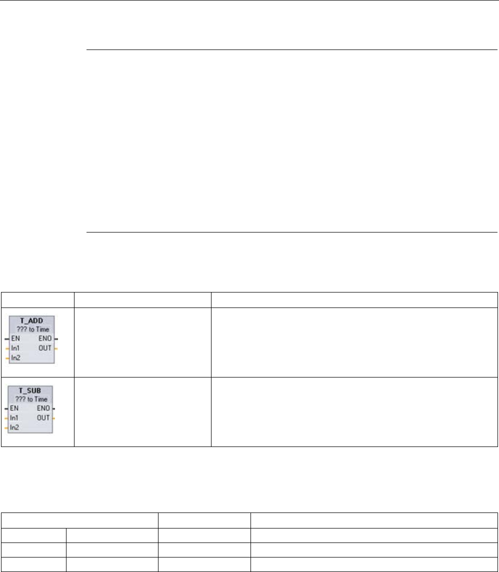
Extended instructions
9.1 Date, time-of-day, and clock functions
S7-1200 Programmable controller
336 System Manual, V4.2, 09/2016, A5E02486680-AK
Note
Using T_CONV to convert a larger data size to a smaller data size
Data values can be truncated when you convert a larger data type with more bytes to a
smaller data type with less bytes. If this error occurs, then ENO is set to 0.
Conversion to/from DTL data type
DT
L (Date and Time Long) contains year, month, date, and time data. DTL data can be
converted to/from DATE and TOD data types.
However, DTL conversion with DATE data only affects the year, month, and day values. DTL
conversion with TOD data only affects the
hour, minutes, and seconds values.
When T_CONV converts to DTL, the unaffected data elements in the DTL format are left
unchanged.
Table 9- 3 T_ADD (Add times) and T_SUB (Subtract times) instructions
LAD / FBD
SCL
Description
out := T_ADD(
in1:=_variant_in,
in2:=_time_in);
T_ADD adds the input IN1 value (DTL or Time data types) with the
input IN2 Time value. Parameter OUT provides the DTL or Time value
result. Two data type operations are possible:
• Time + Time = Time
• DTL + Time = DTL
out := T_SUB(
in1:=_variant_in,
in2:=_time_in);
T_SUB subtracts the IN2 Time value from IN1 (DTL or Time value).
Parameter OUT provides the difference value as a DTL or Time data
type. Two data type operations are possible.
• Time - Time = Time
• DTL - Time = DTL
1 For LAD and FBD: Click the "???" and select the data types from the drop-down menu.
Table 9- 4 Data types for the T_ADD and T_SUB parameters
Parameter and type
Data type
Description
IN1
1
IN
DTL, Time
DTL or Time value
IN2
IN
Time
Time value to add or subtract
OUT
OUT
DTL, Time
DTL or Time sum or difference
1
Select the IN1 data type from the drop-down list available below the instruction name. The IN1 data type selection also
sets the data type of parameter OUT.
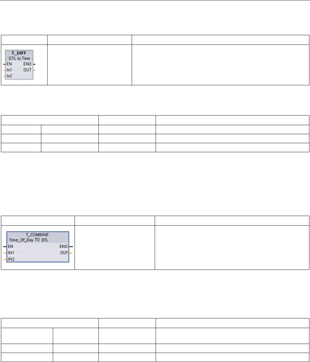
Extended instructions
9.1 Date, time-of-day, and clock functions
S7-1200 Programmable controller
System Manual, V4.2, 09/2016, A5E02486680-AK 337
Table 9- 5 T_DIFF (Time difference) instruction
LAD / FBD
SCL
Description
out := T_DIFF(
in1:=_DTL_in,
in2:=_DTL_in);
T_DIFF subtracts the DTL value (IN2) from the DTL value (IN1). Pa-
rameter OUT provides the difference value as a Time data type.
• DTL - DTL = Time
Table 9- 6 Data types for the T_DIFF parameters
Parameter and type
Data type
Description
IN1
IN
DTL
DTL value
IN2
IN
DTL
DTL value to subtract
OUT
OUT
Time
Time difference
Condition codes:
ENO = 1 means no error occurred. ENO = 0 and parameter OUT = 0
errors:
● Invalid DTL value
● Invalid Time value
Table 9- 7 T_COMBINE (Combine times) instruction
LAD / FBD
SCL
Description
out :=
CONCAT_DATE_TOD(
In1 := _date_in,
In2 := _tod_in);
T_COMBINE combines a Date value and a Time_of_Day
value to create a DTL value.
1
Note that the T_COMBINE instruction in the Extended Instructions equates to the CONCAT_DATE_TOD function in
SCL.
Table 9- 8 Data types for the T_COMBINE parameters
Parameter and type
Data type
Description
IN1 IN Date Date value to be combined must be between DATE#1990-
01-01 and DATE#2089-12-31
IN2
IN
Time_of_Day
Time_of_Day values to be combined
OUT
OUT
DTL
DTL value

Extended instructions
9.1 Date, time-of-day, and clock functions
S7-1200 Programmable controller
338 System Manual, V4.2, 09/2016, A5E02486680-AK
9.1.2
Clock functions
WARNING
If an attacker can access your networks through Network Time Protocol (NTP)
synchronization, the attacker can possibly take limited control of your process by shifting
the CPU system time.
The NTP client feature of the S7-1200 CPU is disabled by default, and, when enabled, only
allows configured IP addresses to act as an NTP server. The CPU disables this feature by
default, and you must configure this feature to allow remotely-controlled CPU system time
corrections.
The S7-1200 CPU supports "time of day" interrupts and clock instructions that depend upon
accurate CPU system time. If you configure NTP and accept time synchronization from a
server, you must ensure that the server is a trusted source. Failure to do so can cause a
security breach that allows an unknown user to take limited control of your process by
shifting the CPU system time.
For security information and recommendations, please see our "Operational Guidelines for
Industrial Security" (http://www.industry.siemens.com/topics/global/en/industrial-
security/Documents/operational_guidelines_industrial_security_en.pdf) on the Siemens
Service and Support site.

Extended instructions
9.1 Date, time-of-day, and clock functions
S7-1200 Programmable controller
System Manual, V4.2, 09/2016, A5E02486680-AK 339
Use the clock instructions to set and read the CPU system clock. The data type DTL
(Page 128) is used to provide date and time values.
Table 9- 9 System time instructions
LAD / FBD
SCL
Description
ret_val :=
WR_SYS_T(
in:=_DTL_in_);
WR_SYS_T (Set time-of-day) sets the CPU time of day clock
with a DTL value at parameter IN. This time value does not in-
clude local time zone or daylight saving time offsets.
ret_val :=
RD_SYS_T(
out=>_DTL_out);
RD_SYS_T (Read time-of-day) reads the current system time
from the CPU. This time value does not include local time zone
or daylight saving time offsets.
ret_val :=
RD_LOC_T(
out=>_DTL_out);
RD_LOC_T (Read local time) provides the current local time of
the CPU as a DTL data type. This time value reflects the local
time zone adjusted appropriately for daylight saving time (if con-
figured).
ret_val :=
WR_LOC_T(
LOCTIME:=DTL_in_,
DST:_in_;
WR_LOC_T (Write local time) sets the date and time of the CPU
clock. You assign the date and time information as local time at
LOCTIME with DTL data type. The instruction uses the
"TimeTransformationRule (Page 342)" DB structure to calculate
the system time. The granularity of the time information for local
time and system time is product-specific and is at least one milli-
second. Input values at the LOCTIME parameter which are less
than those supported by the CPU are rounded up during system
time calculation.
Note
: You must use the CPU device configuration to set the
"Time of day" properties (time zone, DST activation, DST start,
and DST stop). Otherwise, WR_LOC_T cannot interpret the DST
time change.

Extended instructions
9.1 Date, time-of-day, and clock functions
S7-1200 Programmable controller
340 System Manual, V4.2, 09/2016, A5E02486680-AK
Table 9- 10 Data types for the parameters
Parameter and type
Data type
Description
IN
IN
DTL
Time of day to set in the CPU system clock
OUT OUT DTL RD_SYS_T: Current CPU system time
RD_LOC_T: Current local time, including any adjustment for
daylight saving time, if configured
LOCTIME
IN
DTL
WR_LOC_T: Local time
DST IN BOOL WR_LOC_T:
D
aylight
S
aving
T
ime only evaluated during the
"double hour" when the clocks change to daylight saving time.
• TRUE = daylight saving time (first hour)
• FALSE = standard time (second hour)
RET_VAL
OUT
Int
Execution condition code
● The local time is calculated by using the time zone and daylight saving time offsets that
you set in the device configuration general tab "Time of day" parameters.
● Time zone configuration is an offset to UTC or GMT time.
● Daylight saving time configuration specifies the month, week, day, and hour when
daylight saving time begins.
● Standard time configuration also specifies the month, week, day, and hour when standard
time begins.
● The time zone offset is always applied to the system time value. The daylight saving time
offset is only applied when daylight saving time is in effect.
Note
Daylight saving and standard start time configuration
The "Time of day" properties for "Start for daylight saving time" of the CPU device
configuration must be your local time.

Extended instructions
9.1 Date, time-of-day, and clock functions
S7-1200 Programmable controller
System Manual, V4.2, 09/2016, A5E02486680-AK 341
Condition codes:
ENO = 1 means no error occurred. ENO = 0 means an execution error
occurred, and a condition code is provided at the RET_VAL output.
RET_VAL (W#16#....)
Description
0000
The current local time is in standard time.
0001 Daylight saving time has been configured, and the current local time is in daylight saving time.
8080
Local time not available or LOCTIME value is invalid.
8081 Illegal year value or time value assigned by the LOCTIME parameter is invalid
8082
Illegal month value (byte 2 in DTL format)
8083
Illegal day value (byte 3 in DTL format)
8084
Illegal hour value (byte 5 in DTL format)
8085
Illegal minute value (byte 6 in DTL format)
8086
Illegal second value (byte 7 in DTL format)
8087
Illegal nanosecond value (bytes 8 to 11 in DTL format)
8089
Time value does not exist (hour already passed upon changeover to daylight saving time)
80B0
The real-time clock has failed
80B1
The "TimeTransformationRule" structure has not been defined.

Extended instructions
9.1 Date, time-of-day, and clock functions
S7-1200 Programmable controller
342 System Manual, V4.2, 09/2016, A5E02486680-AK
9.1.3
TimeTransformationRule data structure
Description
The changeover rules for standard and daylight saving time are defined in the
TimeTransformationRule structure. The structure is as follows:
Name
Data type
Description
TimeTransformationRule
STRUCT
Bias INT Time difference between local time and UTC [minutes]
Range: -1439 to 1439
DaylightBias INT Time difference between daylight saving and standard time [minutes]
Range: 0 to 60
DaylightStartMonth USINT Month of conversion to daylight saving time
Range: 1 to 12
DaylightStartWeek USINT Week of conversion to daylight saving time
1 = First occurrence of the weekday in the month, ...,
5 = Last occurrence of the weekday in the month
DaylightStartWeekday USINT Weekday of daylight saving time changeover:
1 = Sunday
DaylightStartHour USINT Hour of daylight saving time changeover:
Range: 0 to 23
DaylightStartMinute USINT Minute of daylight saving time changeover
Range: 0 to 59
StandardStartMonth USINT Month of conversion to standard time
Range: 1 to 12
StandardStartWeek USINT Week of conversion to standard time
1 = First occurrence of the weekday in the month, ...,
5 = Last occurrence of the weekday in the month
StandardStartWeekday USINT Weekday of standard time changeover:
1 = Sunday
StandardStartHour USINT Hour of standard time changeover
Range: 0 to 23
StandardStartMinute USINT Minute of standard time changeover
Range: 0 to 59
TimeZoneName STRING[80] Name of time zone: "(GMT+01:00) Amsterdam, Berlin, Bern, Rome,
Stockholm, Vienna"
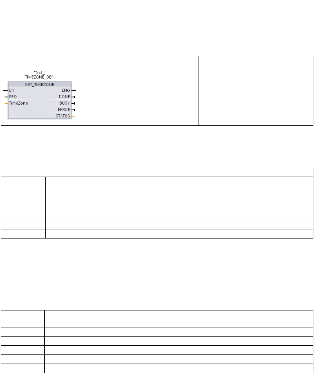
Extended instructions
9.1 Date, time-of-day, and clock functions
S7-1200 Programmable controller
System Manual, V4.2, 09/2016, A5E02486680-AK 343
9.1.4
SET_TIMEZONE (Set timezone)
Table 9- 11 SET_TIMEZONE instruction
LAD / FBD
SCL
Description
"SET_TIMEZONE_DB"(
REQ:=_bool_in,
Timezone:=_struct_in,
DONE=>_bool_out_,
BUSY=>_bool_out_,
ERROR=>_bool_out_,
STATUS=>_word_out_);
Sets the local time zone and daylight sav-
ing parameters that are used to transform
the CPU system time to local time.
1 In the SCL example, "SET_TIMEZONE_DB" is the name of the instance DB.
Table 9- 12 Data types for the parameters
Parameter and type
Data type
Description
REQ
IN
Bool
REQ=1: execute function
Timezone IN TimeTransformationRule Rules for the transformation from system time to
local time
DONE
OUT
Bool
Function complete
BUSY
OUT
Bool
Function busy
ERROR OUT Bool Error detected
STATUS
OUT
Word
Function result / error message
To manually configure the time zone parameters for the CPU, use the "Time of day"
properties of the "General" tab of the device configuration.
Use the SET_TIMEZONE instruction to set the local time configuration. The parameters of
the "TimeTransformationRule (Page 342)" structure assign the local time zone and timing for
automatic switching between standard time and daylight saving time.
Condition codes:
ENO = 1 means no error occurred. ENO = 0 means an execution error
occurred, and a condition code is provided at the STATUS output.
STATUS
(W#16#....)
Description
0
No error
7000
No job processing active
7001
Start of job processing. Parameter BUSY = 1, DONE = 0
7002
Intermediate call (REQ irrelevant): Instruction already active; BUSY has the value "1".
808x
Error at x-th component: For example 8084 indicates that DaylightStartWeekif is not a value from 1to 5.
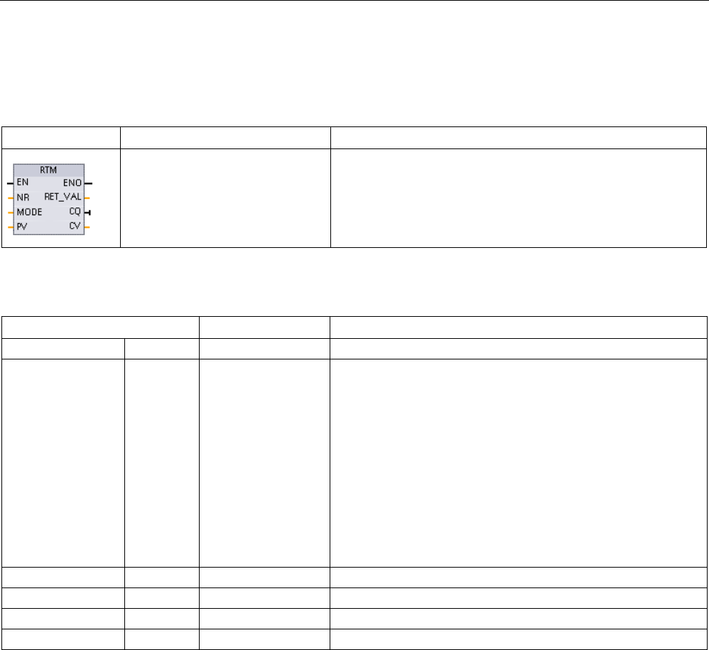
Extended instructions
9.1 Date, time-of-day, and clock functions
S7-1200 Programmable controller
344 System Manual, V4.2, 09/2016, A5E02486680-AK
9.1.5
RTM (Runtime meters)
Table 9- 13 RTM instruction
LAD / FBD
SCL
Description
RTM(NR:=_uint_in_,
MODE:=_byte_in_,
PV:=_dint_in_,
CQ=>_bool_out_,
CV=>_dint_out_);
The RTM (Runtime Meters) instruction can set, start, stop, and
read the runtime hour meters in the CPU.
Table 9- 14 Data types for the parameters
Parameter and type
Data type
Description
NR
IN
UInt
Runtime meter number: (possible values: 0..9)
MODE IN Byte RTM Execution mode number:
• 0 = Fetch values (the status is then written to CQ and the
current value to CV)
• 1 = Start (at the last counter value)
• 2 = Stop
• 4 = Set (to the value specified in PV)
• 5 = Set (to the value specified in PV) and then start
• 6 = Set (to the value specified in PV) and then stop
• 7 = Save all RTM values in the CPU to the MC (memory
card)
PV
IN
DInt
Preset hours value for the specified runtime meter
RET_VAL
OUT
Int
Function result / error message
CQ
OUT
Bool
Runtime meter status (1 = running)
CV
OUT
DInt
Current runtime hours value for the specified meter
The CPU operates up to 10 runtime hour meters to track the runtime hours of critical control
subsystems. You must start the individual hour meters with one RTM execution for each
timer. All runtime hour meters are stopped when the CPU makes a run-to-stop transition.
You can also stop individual timers with RTM execution mode 2.
When a CPU makes a stop-to-run transition, you must restart the hour timers with one RTM
execution for each timer that is started. After a runtime meter value is greater than
2147483647 hours, counting stops and the "Overflow" error is sent. You must execute the
RTM instruction once for each timer to reset or modify the timer.
A CPU power failure or power cycle causes a power-down process that saves the current
runtime meter values in retentive memory. Upon CPU power-up, the stored runtime meter
values are reloaded to the timers and the previous runtime hour totals are not lost. The
runtime meters must be restarted to accumulate additional runtime.

Extended instructions
9.1 Date, time-of-day, and clock functions
S7-1200 Programmable controller
System Manual, V4.2, 09/2016, A5E02486680-AK 345
Your program can also use RTM execution mode 7 to save the runtime meter values in a
memory card. The states of all timers at the instant RTM mode 7 is executed are stored in
the memory card. These stored values can become incorrect over time as the hour timers
are started and stopped during a program run session. You must periodically update the
memory card values to capture important runtime events. The advantage that you get from
storing the RTM values in the memory card is that you can insert the memory card in a
substitute CPU where your program and saved RTM values will be available. If you did not
save the RTM values in the memory card, then the timer values would be lost (in a substitute
CPU).
Note
Avoid excessive program calls for memory card write operations
Minimize flash memory card write operations to extend the life of the memory card.
Table 9- 15 Condition codes
RET_VAL (W#16#....)
Description
0
No error
8080
Incorrect runtime meter number
8081
A negative value was passed to the parameter PV
8082
Overflow of the operating hours counter
8091
The input parameter MODE contains an illegal value
80B1
Value cannot be saved to MC (MODE=7)

Extended instructions
9.2 String and character
S7-1200 Programmable controller
346 System Manual, V4.2, 09/2016, A5E02486680-AK
9.2
String and character
9.2.1
String data overview
String data type
String data is stored as a 2-byte header followed by up to 254 character bytes of ASCII
character codes. A String header contains two lengths. The first byte is the maximum length
that is given in square brackets when you initialize a string, or 254 by default. The second
header byte is the current length that is the number of valid characters in the string. The
current length must be smaller than or equal to the maximum length. The number of stored
bytes occupied by the String format is 2 bytes greater than the maximum length.
Initialize your String data
String input and output data must be initialized as valid strings in memory, before execution
of any string instructions.
Valid String data
A valid string has a maximum length that must be greater than zero but less than 255. The
current length must be less than or equal to the maximum length.
Strings cannot be assigned to I or Q memory areas.
For more information see: Format of the String data type (Page 130).
9.2.2
S_MOVE (Move character string)
Table 9- 16 String move instruction
LAD / FBD
SCL
Description
out := in;
Copy the source IN string to the OUT location. S_MOVE execution does not affect
the contents of the source string.
Table 9- 17 Data types for the parameters
Parameter
Data type
Description
IN
String
Source string
OUT
String
Target address
If the actual length of the string at the input IN exceeds the maximum length of a string
stored at output OUT, then the part of the IN string which can fit in the OUT string is copied.
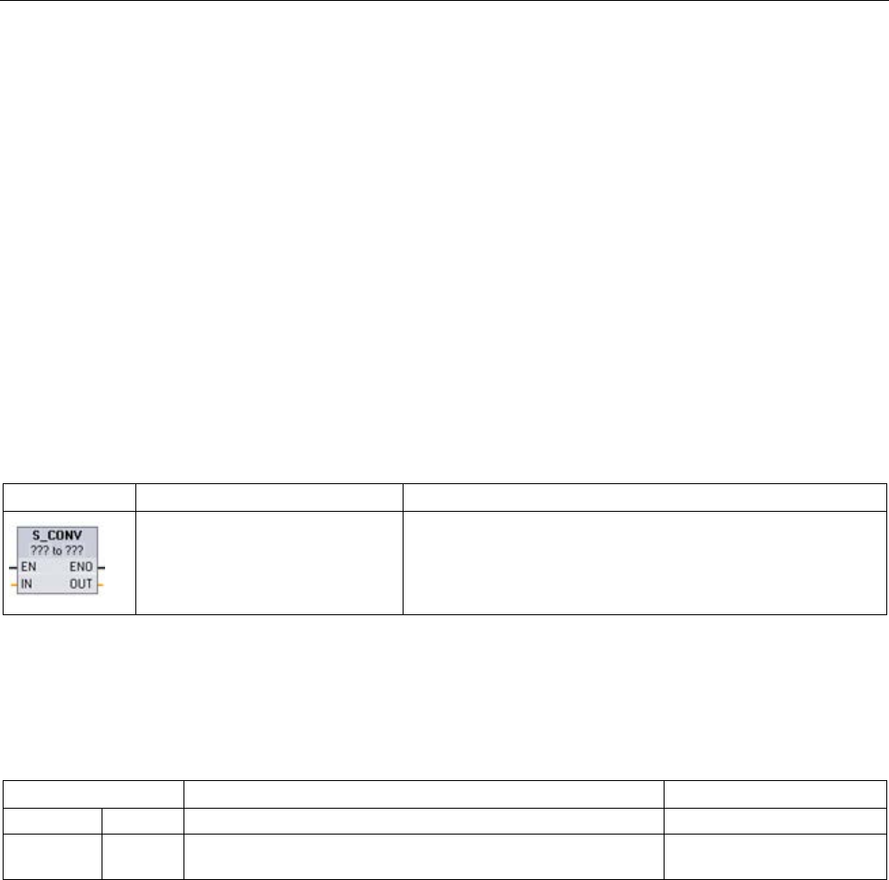
Extended instructions
9.2 String and character
S7-1200 Programmable controller
System Manual, V4.2, 09/2016, A5E02486680-AK 347
9.2.3
String conversion instructions
9.2.3.1
S_CONV, STRG_VAL, and VAL_STRG (Convert to/from character string and number)
instructions
You can convert number character strings to number values or number values to number
character strings with these instructions:
● S_CONV converts (number string to a number value) or (number value to a number
string)
● STRG_VAL converts a number string to a number value with format options
● VAL_STRG converts a number value to a number string with format options
S_CONV (convert character string)
Table 9- 18 String conversion instruction
LAD / FBD
SCL
Description
out :=
<Type>_TO_<Type>(in);
Converts a character string to the corresponding value, or a value
to the corresponding character string. The S_CONV instruction
has no output formatting options. This makes the S_CONV in-
struction simpler, but less flexible than the STRG_VAL and
VAL_STRG instructions.
1
For LAD / FBD: Click the "???" and select the data type from the drop-down list.
2
For SCL: Select S_CONV from the Extended I
nstructions, and answer the prompts for the data types for the conversion.
STEP 7 then provides the appropriate conversion instruction.
Table 9- 19 Data types (string to value)
Parameter and type
Data type
Description
IN
IN
String, WString
Input character string
OUT OUT String, WString, Char, WChar, SInt, Int, DInt, USInt, UInt, UDInt,
Real, LReal
Output number value
Conversion of the string parameter IN starts at the first character and continues until the end
of the string, or until the first character is encountered that is not "0" through "9", "+", "-", or
".". The result value is provided at the location specified in parameter OUT. If the output
number value does not fit in the range of the OUT data type, then parameter OUT is set to 0
and ENO is set to FALSE. Otherwise, parameter OUT contains a valid result and ENO is set
to TRUE.
Input String format rules:
● If a decimal point is used in the IN string, you must use the "." character.
● Comma characters "," used as a thousands separator to the left of the decimal point are
allowed and ignored.
● Leading spaces are ignored.

Extended instructions
9.2 String and character
S7-1200 Programmable controller
348 System Manual, V4.2, 09/2016, A5E02486680-AK
S_CONV (value to string conversion)
Table 9- 20 Data types (value to string)
Parameter and type
Data type
Description
IN IN String, WString, Char, WChar, SInt, Int, DInt, USInt, UInt, UDInt,
Real, LReal
Input number value
OUT
OUT
String, WString
Output character string
An integer, unsigned integer, or floating point value IN is converted to the corresponding
character string at OUT. The parameter OUT must reference a valid string before the
conversion is executed. A valid string consists of a maximum string length in the first byte,
the current string length in the second byte, and the current string characters in the next
bytes. The converted string replaces characters in the OUT string starting at the first
character and adjusts the current length byte of the OUT string. The maximum length byte of
the OUT string is not changed.
How many characters are replaced depends on the parameter IN data type and number
value. The number of characters replaced must fit within the parameter OUT string length.
The maximum string length (first byte) of the OUT string should be greater than or equal to
the maximum expected number of converted characters. The following table shows S_CONV
value to string conversion examples:
Output String format rules:
● Values written to parameter OUT do not use a leading "+" sign.
● Fixed-point representation is used (no exponential notation).
● The period character "." is used to represent the decimal point when parameter IN is the
Real data type.
● Values are right-justified in the output string and are preceded by space characters that
fill empty character positions.
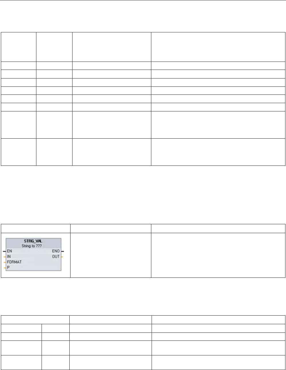
Extended instructions
9.2 String and character
S7-1200 Programmable controller
System Manual, V4.2, 09/2016, A5E02486680-AK 349
Table 9- 21 Maximum string lengths for each data type
IN data type
Character
positions
allocated by
S_CONV
Converted string example1
Total string length including maximum and current length
bytes
USInt
4
"x255"
6
SInt 4 "-128" 6
UInt
6
"x65535"
8
Int 6 "-32768" 8
UDInt
11
"x4294967295"
13
DInt
11
"-2147483648"
13
Real 14 "x-3.402823E+38"
"x-1.175495E-38"
"x+1.175495E-38"
"x+3.402823E+38"
16
LReal 21 "-1.7976931348623E+308"
"-2.2250738585072E-308"
"+2.2250738585072E-308"
"+1.7976931348623E+308"
23
1
The "x" characters represent space characters that fill empty positions in the right-justified field that is allocated for the
converted value.
STRG_VAL (convert characer string to numerical value)
Table 9- 22 String-to-value instruction
LAD / FBD
SCL
Description
"STRG_VAL"(
in:=_string_in,
format:=_word_in,
p:=uint_in,
out=>_variant_out);
Converts a number character string to the corresponding
integer or floating point representation.
1 For LAD / FBD: Click the "???" and select the data type from the drop-down list.
Table 9- 23 Data types for the STRG_VAL instruction
Parameter and type
Data type
Description
IN IN String, WString The ASCII character string to convert
FORMAT
IN
Word
Output format options
P IN UInt, Byte, USInt IN: Index to the first character to be converted (first
character = 1)
OUT OUT SInt, Int, DInt, USInt, UInt, UDInt,
Real, LReal
Converted number value

Extended instructions
9.2 String and character
S7-1200 Programmable controller
350 System Manual, V4.2, 09/2016, A5E02486680-AK
Conversion begins in the string IN at character offset P and continues until the end of the
string, or until the first character is encountered that is not "+", "-", ".", ",", "e", "E", or "0" to
"9". The result is placed at the location specified in parameter OUT.
String data must be initialized before execution as a valid string in memory.
The FORMAT parameter for the STRG_VAL instruction is defined below. The unused bit
positions must be set to zero.
Table 9- 24 Format of the STRG_VAL instruction
Bit
16
Bit 8
Bit 7
Bit 0
0
0
0
0
0
0
0
0
0
0
0
0
0
0
f
r
f = Notation format
1= Exponential notation
0 = Fixed point notation
r = Decimal point format
1 = "," (comma character)
0 = "." (period character)
Table 9- 25 Values of the FORMAT parameter
FORMAT (W#16#)
Notation format
Decimal point representation
0000 (default)
Fixed point
"."
0001
","
0002
Exponential
"."
0003
","
0004 to FFFF
Illegal values
Rules for STRG_VAL conversion:
● If the period character "." is used for the decimal point, then commas "," to the left of the
decimal point are interpreted as thousands separator characters. The comma characters
are allowed and ignored.
● If the comma character "," is used for the decimal point, then periods "." to the left of the
decimal point are interpreted as thousands separator characters. These period
characters are allowed and ignored.
● Leading spaces are ignored.
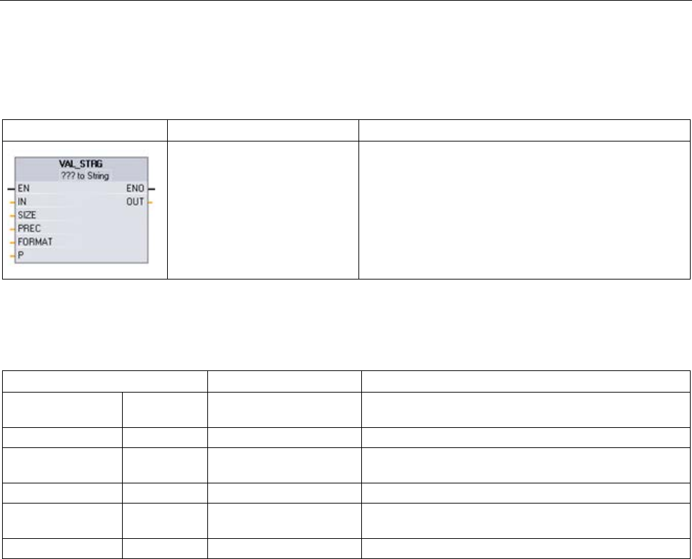
Extended instructions
9.2 String and character
S7-1200 Programmable controller
System Manual, V4.2, 09/2016, A5E02486680-AK 351
VAL_STRG (convert numerical value to string)
Table 9- 26 Value-to-string operation
LAD / FBD
SCL
Description
"VAL_STRG"(
in:=_variant_in,
size:=_usint_in,
prec:=_usint_in,
format:=_word_in,
p:=uint_in,
out=>_string_out);
Converts an integer, unsigned integer, or floating point
value to the corresponding character string representa-
tion.
1 For LAD / FBD: Click the "???" and select the data type from the drop-down list.
Table 9- 27 Data types for the VAL_STRG instruction
Parameter and type
Data type
Description
IN IN
SInt, Int, DInt, USInt, UInt,
UDInt, Real, LReal
Value to convert
SIZE
IN
USInt
Number of characters to be written to the OUT string
PREC IN USInt The precision or size of the fractional portion. This does
not include the decimal point.
FORMAT
IN
Word
Output format options
P IN UInt, Byte, USInt IN: Index to the first OUT string character to be replaced
(first character = 1)
OUT
OUT
String, WString
The converted string
This instruction converts the value represented by parameter IN to a string referenced by
parameter OUT. The parameter OUT must be a valid string before the conversion is
executed.
The converted string replaces characters in the OUT string starting at character offset count
P to the number of characters specified by parameter SIZE. The number of characters in
SIZE must fit within the OUT string length, counting from character position P. If the SIZE
parameter is zero, then the characters overwrite at position P in the OUT string without
limitation. This instruction is useful for embedding number characters into a text string. For
example, you can put the numbers "120" into the string "Pump pressure = 120 psi".
Parameter PREC specifies the precision or number of digits for the fractional part of the
string. If the parameter IN value is an integer, then PREC specifies the location of the
decimal point. For example, if the data value is 123 and PREC = 1, then the result is "12.3".
The maximum supported precision for the Real data type is 7 digits.
If parameter P is greater than the current size of the OUT string, then spaces are added, up
to position P, and the result is appended to the end of the string. The conversion ends if the
maximum OUT string length is reached.

Extended instructions
9.2 String and character
S7-1200 Programmable controller
352 System Manual, V4.2, 09/2016, A5E02486680-AK
The FORMAT parameter for the VAL_STRG instruction is defined below. The unused bit
positions must be set to zero.
Table 9- 28 Format of the VAL_STRG instruction
Bit
16
Bit 8
Bit 7
Bit 0
0
0
0
0
0
0
0
0
0
0
0
0
0
s
f
r
s = Number sign character
1= use sign character "+" and "
-"
0 = use sign character "-" only
f = Notation format
1= Exponential notation
0 = Fixed point notation
r = Decimal point format
1 = "," (comma character)
0 = "." (period character)
Table 9- 29 Values of the FORMAT parameter
FORMAT (WORD)
Number sign character
Notation format
Decimal point representation
W#16#0000
"-" only Fixed point
"."
W#16#0001
","
W#16#0002
Exponential
"."
W#16#0003
","
W#16#0004
"+" and "-" Fixed Point
"."
W#16#0005
","
W#16#0006 Exponential "."
W#16#0007
","
W#16#0008 to W#16#FFFF Illegal values
Parameter OUT string format rules:
● Leading space characters are added to the leftmost part of the string when the converted
string is smaller than the specified size.
● When the FORMAT parameter sign bit is FALSE, unsigned and signed integer data type
values are written to the output buffer without the leading "+" sign. The "-" sign is used if
required.
<leading spaces><digits without leading zeroes>'.'<PREC digits>
● When the sign bit is TRUE, unsigned and signed integer data type values are written to
the output buffer always with a leading sign character.
<leading spaces><sign><digits without leading zeroes>'.'<PREC digits>
● When the FORMAT is set to exponential notation, Real data type values are written to the
output buffer as:
<leading spaces><sign><digit> '.' <PREC digits>'E' <sign><digits without leading zero>

Extended instructions
9.2 String and character
S7-1200 Programmable controller
System Manual, V4.2, 09/2016, A5E02486680-AK 353
● When the FORMAT is set to fixed point notation, integer, unsigned integer, and real data
type values are written to the output buffer as:
<leading spaces><sign><digits without leading zeroes>'.'<PREC digits>
● Leading zeros to the left of the decimal point (except the digit adjacent to the decimal
point) are suppressed.
● Values to the right of the decimal point are rounded to fit in the number of digits to the
right of the decimal point specified by the PREC parameter.
● The size of the output string must be a minimum of three bytes more than the number of
digits to the right of the decimal point.
● Values are right-justified in the output string.
Conditions reported by ENO
When the conversion operation encounters an error, the instruction returns the following
results:
● ENO is set to 0.
● OUT is set to 0, or as shown in the examples for string to value conversion.
● OUT is unchanged, or as shown in the examples when OUT is a string.
Table 9- 30 ENO status
ENO
Description
1
No error
0 Illegal or invalid parameter; for example, an access to a DB that does not exist
0
Illegal string where the maximum length of the string is 0 or 255
0 Illegal string where the current length is greater than the maximum length
0
The converted number value is too large for the specified OUT data type.
0 The OUT parameter maximum string size must be large enough to accept the number of characters
specified by parameter SIZE, starting at the character position parameter P.
0
Illegal P value where P=0 or P is greater than the current string length
0
Parameter SIZE must be greater than parameter PREC.

Extended instructions
9.2 String and character
S7-1200 Programmable controller
354 System Manual, V4.2, 09/2016, A5E02486680-AK
Table 9- 31 Example of S_CONV string to value conversion
IN string
OUT data type
OUT value
ENO
"123"
Int or DInt
123
TRUE
"-00456" Int or DInt -456 TRUE
"123.45"
Int or DInt
123
TRUE
"+2345" Int or DInt 2345 TRUE
"00123AB"
Int or DInt
123
TRUE
"123"
Real
123.0
TRUE
"123.45"
Real
123.45
TRUE
"1.23e-4"
Real
1.23
TRUE
"1.23E-4"
Real
1.23
TRUE
"12,345.67"
Real
12345.67
TRUE
"3.4e39"
Real
3.4
TRUE
"-3.4e39"
Real
-3.4
TRUE
"1.17549e-38"
Real
1.17549
TRUE
"12345"
SInt
0
FALSE
"A123"
N/A
0
FALSE
""
N/A
0
FALSE
"++123"
N/A
0
FALSE
"+-123"
N/A
0
FALSE
Table 9- 32 Examples of S_CONV value to string conversion
Data type
IN value
OUT string 1
ENO
UInt
123
"xxx123"
TRUE
UInt
0
"xxxxx0"
TRUE
UDInt
12345678
"xxx12345678"
TRUE
Real
+9123.456
"xx+9.123456E+3"
TRUE
LReal +9123.4567890123 "xx+9.1234567890123
E+3"
TRUE
Real
-INF
"xxxxxxxxxxxINF"
FALSE
Real
+INF
"xxxxxxxxxxxINF"
FALSE
Real
NaN
"xxxxxxxxxxxNaN"
FALSE
1
The "x" characters represent space characters that fill empty positions in the right-justified field
that is allocated for the converted value.

Extended instructions
9.2 String and character
S7-1200 Programmable controller
System Manual, V4.2, 09/2016, A5E02486680-AK 355
Table 9- 33 Example: STRG_VAL conversion
IN string
FORMAT
(W#16#....)
OUT data type
OUT value
ENO
"123"
0000
Int or DInt
123
TRUE
"-00456" 0000 Int or DInt -456 TRUE
"123.45"
0000
Int or DInt
123
TRUE
"+2345"
0000
Int or DInt
2345
TRUE
"00123AB"
0000
Int or DInt
123
TRUE
"123"
0000
Real
123.0
TRUE
"-00456"
0001
Real
-456.0
TRUE
"+00456"
0001
Real
456.0
TRUE
"123.45"
0000
Real
123.45
TRUE
"123.45"
0001
Real
12345.0
TRUE
"123.45"
0000
Real
12345.0
TRUE
"123.45"
0001
Real
123.45
TRUE
".00123AB"
0001
Real
123.0
TRUE
"1.23e-4"
0000
Real
1.23
TRUE
"1.23E-4"
0000
Real
1.23
TRUE
"1.23E-4"
0002
Real
1.23E-4
TRUE
"12,345.67"
0000
Real
12345.67
TRUE
"12,345.67"
0001
Real
12.345
TRUE
"3.4e39"
0002
Real
+INF
TRUE
"-3.4e39"
0002
Real
-INF
TRUE
"1.1754943e-38"
(and smaller)
0002 Real 0.0 TRUE
"12345"
N/A
SInt
0
FALSE
"A123" N/A N/A 0 FALSE
""
N/A
N/A
0
FALSE
"++123"
N/A
N/A
0
FALSE
"+-123"
N/A
N/A
0
FALSE

Extended instructions
9.2 String and character
S7-1200 Programmable controller
356 System Manual, V4.2, 09/2016, A5E02486680-AK
The following examples of VAL_STRG conversions are based on an OUT string initialized as
follows:
"Current Temp = xxxxxxxxxx C"
where the "x" character represents space characters allocated for the converted value.
Table 9- 34 Example: VAL_STRG conversion
Data type
IN value
P
SIZE
FORMAT
(W#16#....)
PREC
OUT string
ENO
UInt 123 16 10 0000 0
Current Temp =
xxxxxxx123 C
TRUE
UInt 0 16 10 0000 2
Current Temp =
xxxxxx0.00 C
TRUE
UDInt 12345678 16 10 0000 3
Current Temp =
x12345.678 C
TRUE
UDInt 12345678 16 10 0001 3
Current Temp =
x12345,678 C
TRUE
Int 123 16 10 0004 0
Current Temp =
xxxxxx+123 C
TRUE
Int -123 16 10 0004 0
Current Temp =
xxxxxx-123 C
TRUE
Real -0.00123 16 10 0004 4
Current Temp = xxx-
0.0012 C
TRUE
Real -0.00123 16 10 0006 4
Current Temp = -
1.2300E-3 C
TRUE
Real -INF 16 10 N/A 4
Current Temp =
xxxxxx-INF C
FALSE
Real +INF 16 10 N/A 4
Current Temp =
xxxxxx+INF C
FALSE
Real NaN 16 10 N/A 4
Current Temp =
xxxxxxxNaN C
FALSE
UDInt 12345678 16 6 N/A 3
Current Temp =
xxxxxxxxxx C
FALSE
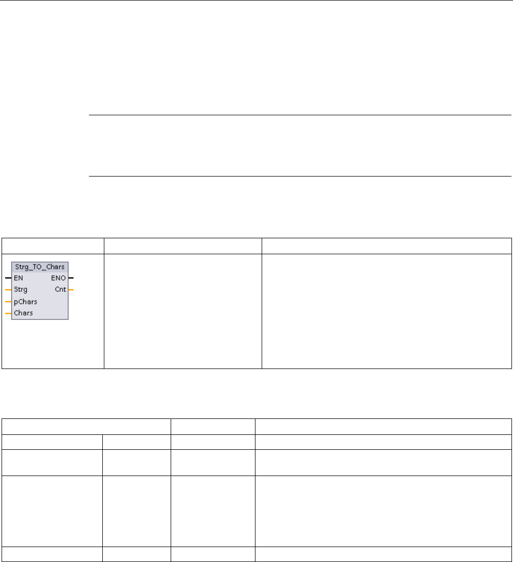
Extended instructions
9.2 String and character
S7-1200 Programmable controller
System Manual, V4.2, 09/2016, A5E02486680-AK 357
9.2.3.2
Strg_TO_Chars and Chars_TO_Strg (Convert to/from character string and array of
CHAR) instructions
Strg_TO_Chars copies an ASCII character string into an array of character bytes.
Chars_TO_Strg copies an array of ASCII character bytes into a character string.
Note
Only the zero based array types (Array [0..n] of Char) or (Array [0..n] of Byte) are allow
ed as
the input parameter Chars for the Chars_TO_Strg instruction, or as the IN_OUT parameter
Chars for the Strg_TO_Chars instruction.
Table 9- 35 Strg_TO_Chars instruction
LAD / FBD
SCL
Description
Strg_TO_Chars(
Strg:=_string_in_,
pChars:=_dint_in_,
Cnt=>_uint_out_,
Chars:=_variant_inout_);
The complete input string Strg is copied to an array of
characters at IN_OUT parameter Chars.
The operation overwrites bytes starting at array element
number specified by the pChars parameter.
Strings of all supported max lengths (1..254) may be used.
An end delimiter is not written; this is your responsibility.
To set an end delimiter just after the last written array
character, use the next array element number
[pChars+Cnt].
Table 9- 36 Data types for the parameters (Strg_TO_Chars)
Parameter and type
Data type
Description
Strg
IN
String, WString
Source string
pChars IN DInt Array element number for the first string character written to
the target array
Chars IN_OUT Variant The Chars parameter is a pointer to a zero-based array
[0..n] of characters copied from the input string. The array
can be declared in a DB or as local variables in the block
interface.
Example: "DB1".MyArray points to MyArray [0..10] of Char
element values in DB1.
Cnt
OUT
UInt
Count of characters copied
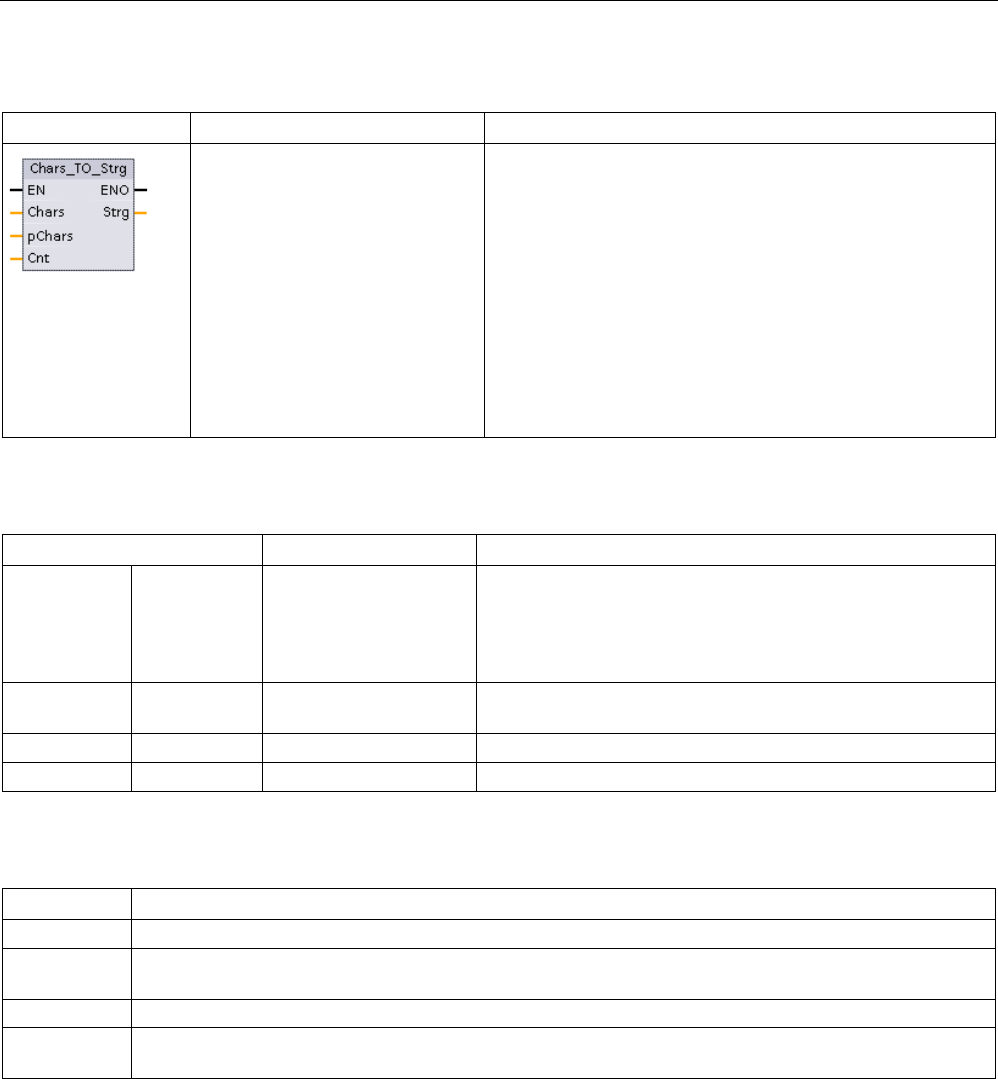
Extended instructions
9.2 String and character
S7-1200 Programmable controller
358 System Manual, V4.2, 09/2016, A5E02486680-AK
Table 9- 37 Chars_TO_Strg instruction
LAD / FBD
SCL
Description
Chars_TO_Strg(
Chars:=_variant_in_,
pChars:=_dint_in_,
Cnt:=_uint_in_,
Strg=>_string_out_);
All or part of an array of characters is copied to a string.
The output string must be declared before Chars_TO_Strg is
executed. The string is then overwritten by the
Chars_TO_Strg operation.
Strings of all supported maximum lengths (1..254) may be
used.
The string maximum length value is not changed by
Chars_TO_Strg operation. Copying from array to string stops
when the maximum string length is reached.
A nul character '$00' or 16#00 value in the character array
works as a delimiter and ends copying of characters into the
string.
Table 9- 38 Data types for the parameters (Chars_TO_Strg)
Parameter and type
Data type
Description
Chars IN Variant The Chars parameter is a pointer to zero based array [0..n] of
characters to be converted into a string. The array can be de-
clared in a DB or as local variables in the block interface.
Example: "DB1".MyArray points to MyArray [0..10] of Char
element values in DB1.
pChars IN Dint Element number for the first character in the array to copy.
Array element [0] is the default value.
Cnt
IN
UInt
Count of characters to copy: 0 means all
Strg
OUT
String, WString
Target string
Table 9- 39 ENO status
ENO
Description
1
No error
0 Chars_TO_Strg: Attempt to copy more character bytes to the output string than allowed by the maximum
length byte in the string declaration
0
Chars_TO_Strg: The nul character (16#00) value was found in the input character byte array.
0
Strg_TO_Chars: Attempt to copy more character bytes to the output array than are allowed by the element
number limit
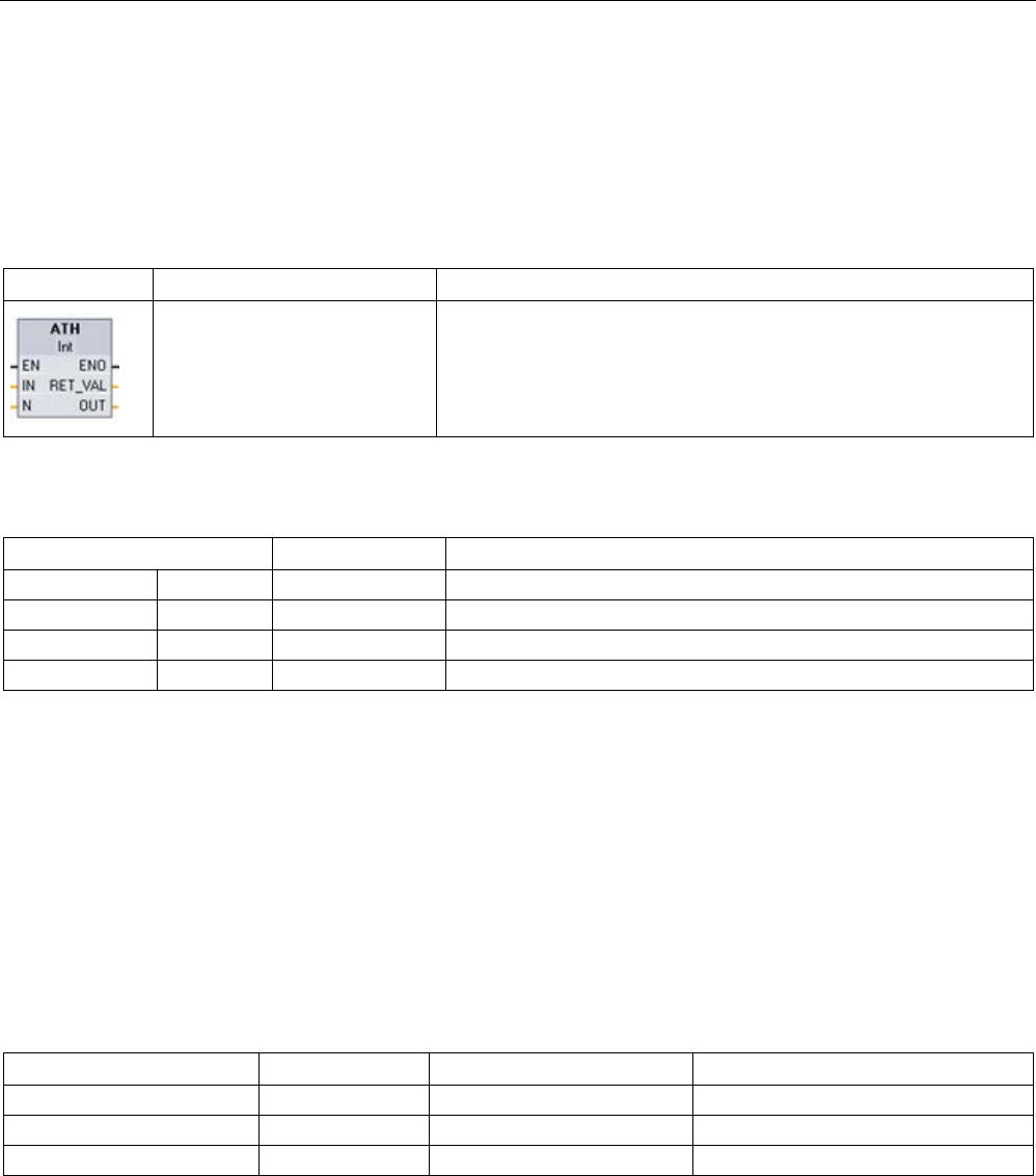
Extended instructions
9.2 String and character
S7-1200 Programmable controller
System Manual, V4.2, 09/2016, A5E02486680-AK 359
9.2.3.3
ATH and HTA (Convert to/from ASCII string and hexadecimal number) instructions
Use the ATH (ASCII to hexadecimal) and HTA (hexadecimal to ASCII) instructions for
conversions between ASCII character bytes (characters 0 to 9 and uppercase A to F only)
and the corresponding 4-bit hexadecimal nibbles.
Table 9- 40 ATH instruction
LAD / FBD
SCL
Description
ret_val := ATH(
in:=_variant_in_,
n:=_int_in_,
out=>_variant_out_);
Converts ASCII characters into packed hexadecimal digits.
Table 9- 41 Data types for the ATH instruction
Parameter type
Data Type
Description
IN
IN
Variant
Pointer to ASCII character byte array
N
IN
UInt
Number of ASCII character bytes to convert
RET_VAL
OUT
Word
Execution condition code
OUT
OUT
Variant
Pointer to the converted hexadecimal byte array
Conversion begins at the location specified by parameter IN and continues for N bytes. The
result is placed at the location specified by OUT. Only valid ASCII characters 0 to 9, lower
case a to f, and uppercase A to F can be converted. Any other character will be converted to
zero.
8-bit ASCII coded characters are converted to 4-bit hexadecimal nibbles. Two ASCII
characters can converted into a single byte containing two 4-bit hexadecimal nibbles.
The IN and OUT parameters specify byte arrays and not hexadecimal String data. ASCII
characters are converted and placed in the hexadecimal output in the same order as they
are read. If there are an odd number of ASCII characters, then zeros are put in the right-
most nibble of the last converted hexadecimal digit.
Table 9- 42 Examples: ASCII-to-hexadecimal (ATH) conversion
IN character bytes
N
OUT value
ENO
'0a23'
4
W#16#0A23
TRUE
'123AFx1a23'
10
16#123AF01023
FALSE
'a23'
3
W#16#A230
TRUE
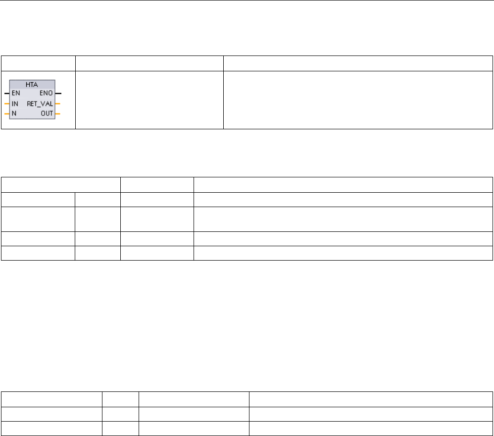
Extended instructions
9.2 String and character
S7-1200 Programmable controller
360 System Manual, V4.2, 09/2016, A5E02486680-AK
Table 9- 43 HTA instruction
LAD / FBD
SCL
Description
ret_val := HTA(
in:=_variant_in_,
n:=_uint_in_,
out=>_variant_out_);
Converts packed hexadecimal digits to their corresponding ASCII
character bytes.
Table 9- 44 Data types for the HTA instruction
Parameter and type
Data Type
Description
IN
IN
Variant
Pointer to input byte array
N IN UInt Number of bytes to convert (each input byte has two 4-bit nibbles and
produces 2N ASCII characters)
RET_VAL
OUT
Word
Execution condition code
OUT
OUT
Variant
Pointer to ASCII character byte array
Conversion begins at the location specified by parameter IN and continues for N bytes. Each
4-bit nibble converts to a single 8-bit ASCII character and produces 2N ASCII character
bytes of output. All 2N bytes of the output are written as ASCII characters 0 to 9 through
uppercase A to F. The parameter OUT specifies a byte array and not a string.
Each nibble of the hexadecimal byte is converted into a character in the same order as they
are read in (left-most nibble of a hexadecimal digit is converted first, followed by the right-
most nibble of that same byte).
Table 9- 45 Examples: Hexadecimal -to- ASCII (HTA) conversion
IN value
N
OUT character bytes
ENO (ENO always TRUE after HTA execution)
W#16#0123 2 '0123' TRUE
DW#16#123AF012
4
'123AF012'
TRUE

Extended instructions
9.2 String and character
S7-1200 Programmable controller
System Manual, V4.2, 09/2016, A5E02486680-AK 361
Table 9- 46 ATH and HTA condition codes
RET_VAL
(W#16#....)
Description
ENO
0000
No error
TRUE
0007 Invalid ATH input character: A character was found that was not an ASCII character 0-
9, lowercase a to f, or uppercase A to F
FALSE
8101
Illegal or invalid input pointer, for example, an access to a DB that does not exist.
FALSE
8120 Input string is an invalid format, i.e., max= 0, max=255, current>max, or grant length in
pointer < max
FALSE
8182
Input buffer is too small for N
FALSE
8151
Data type not allowed for input buffer
FALSE
8301
Illegal or invalid output pointer, for example, an access to a DB that does not exist.
FALSE
8320 Output string is an invalid format, i.e., max= 0, max=255, current>max, or grant length
in pointer < max
FALSE
8382
Output buffer is too small for N
FALSE
8351
Data type not allowed for output buffer
FALSE
9.2.4
String operation instructions
Your control program can use the following string and character instructions to create
messages for operator display and process logs.
9.2.4.1
MAX_LEN (Maximum length of a character string)
Table 9- 47 Maximum length instruction
LAD / FBD
SCL
Description
out :=
MAX_LEN(in);
MAX_LEN (Maximum length of string) provides the maximum length value
assigned to string IN at output OUT. If errors occur during processing of the
instruction, then an empty string length will be output.
The String and WString data types contain two lengths: the first byte (or word)
gives the maximum length and the second byte (or word) gives the current
length (this is the current number of valid characters).
• The maximum length of the character string is assigned for each String or
WString declaration in square brackets. The number of bytes occupied by a
String is 2 bytes greater than the maximum length. The number of words
occupied by a WString is 2 words greater than the maximum length.
• The current length represents the number of the characters actually used.
The current length must be less than or equal to the maximum length. The
current length is in bytes for a String and in words for a WString.
Use the MAX_LEN instruction to get the maximum length of the character
string and the LEN instruction to get the current length of a string.
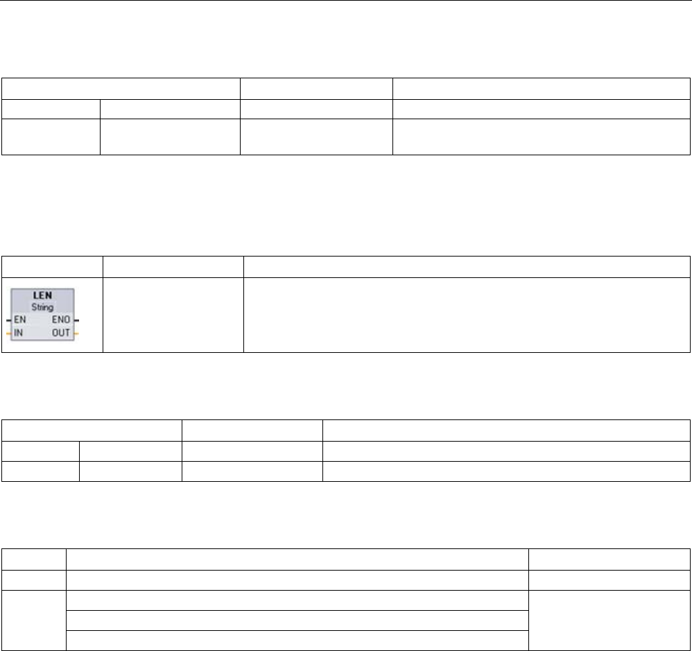
Extended instructions
9.2 String and character
S7-1200 Programmable controller
362 System Manual, V4.2, 09/2016, A5E02486680-AK
Table 9- 48 Data types for the parameters
Parameter and type
Data type
Description
IN
IN
String, WString
Input string
OUT OUT DInt Maximum number of characters allowed for IN
string
9.2.4.2
LEN (Determine the length of a character string)
Table 9- 49 Length instruction
LAD / FBD
SCL
Description
out := LEN(in);
LEN (length) provides the current length of the string IN at output OUT. An
empty string has a length of zero.
Table 9- 50 Data types for the parameters
Parameter and type
Data type
Description
IN
IN
String, WString
Input string
OUT
OUT
Int, DInt, Real, LReal
Number of valid characters of IN string
Table 9- 51 ENO status
ENO
Condition
OUT
1
No invalid string condition
Valid string length
0
Current length of IN exceeds maximum length of IN
Current length is set to 0
Maximum length of IN does not fit within allocated memory range
Maximum length of IN is 255 (illegal length)
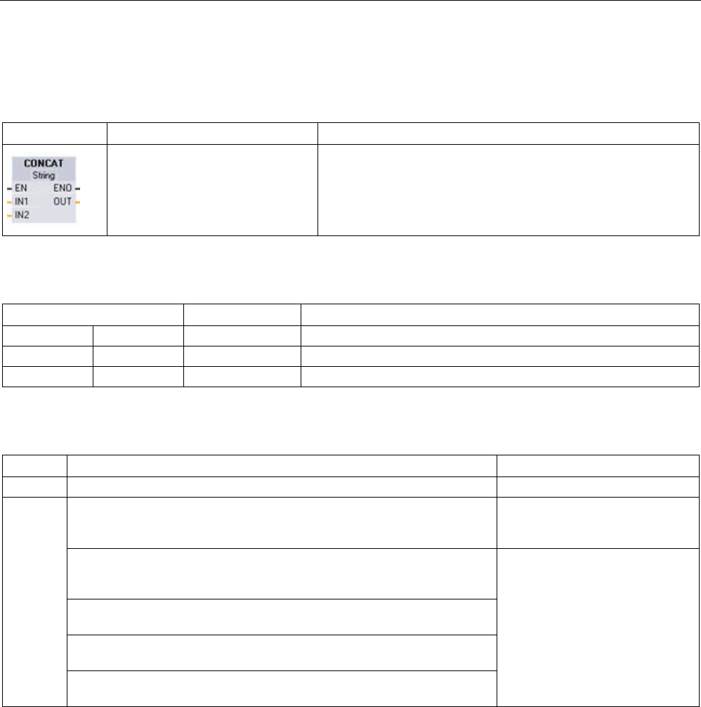
Extended instructions
9.2 String and character
S7-1200 Programmable controller
System Manual, V4.2, 09/2016, A5E02486680-AK 363
9.2.4.3
CONCAT (Combine character strings)
Table 9- 52 Concatenate strings instruction
LAD / FBD
SCL
Description
out := CONCAT(in1, in2);
CONCAT (concatenate strings) joins string parameters IN1 and
IN2 to form one string provided at OUT. After concatenation,
String IN1 is the left part and String IN2 is the right part of the
combined string.
Table 9- 53 Data types for the parameters
Parameter and type
Data type
Description
IN1
IN
String, WString
Input string 1
IN2
IN
String, WString
Input string 2
OUT
OUT
String, WString
Combined string (string 1 + string 2)
Table 9- 54 ENO status
ENO
Condition
OUT
1
No errors detected
Valid characters
0 Resulting string after concatenation is larger than maximum length of OUT
string
Resulting string characters are
copied until the maximum length
of the OUT is reached
Current length of IN1 exceeds maximum length of IN1, current length of
IN2 exceeds maximum length of IN2, or current length of OUT exceeds
maximum length of OUT (invalid string)
Current length is set to 0
Maximum length of IN1, IN2 or OUT does not fit within allocated memory
range
Maximum length of IN1 or IN2 is 255, or the maximum length of OUT is 0
or 255 (String data type)
Maximum length of IN1 or IN2 is 65534, or the maximum length of OUT is
0 or 65534 (WString data type)
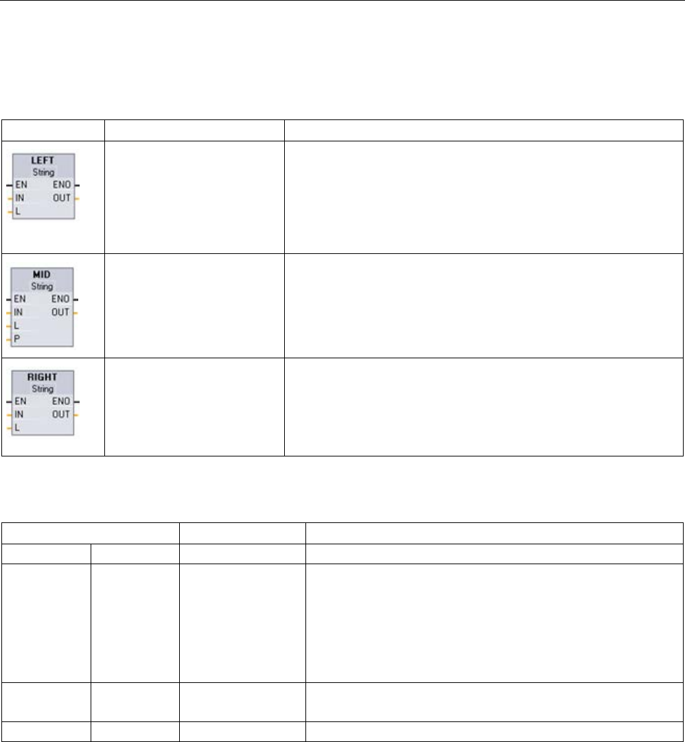
Extended instructions
9.2 String and character
S7-1200 Programmable controller
364 System Manual, V4.2, 09/2016, A5E02486680-AK
9.2.4.4
LEFT, RIGHT, and MID (Read substrings in a character string) instructions
Table 9- 55 Left, right and middle substring operations
LAD / FBD
SCL
Description
out := LEFT(in, L);
LEFT (Left substring) provides a substring made of the first L charac-
ters of string parameter IN.
•
If L is greater than the current length of the IN string, then the entire
IN string is returned in OUT.
• If an empty string is the input, then an empty string is returned in
OUT.
out := MID(in, L, p);
MID (Middle substring) provides the middle part of a string. The middle
substring is L characters long and starts at character position P (inclu-
sive)
If the sum of L and P exceeds the current length of the string parame-
ter IN, then a substring is returned that starts at character position P
and continues to the end of the IN string.
out := RIGHT(in, L);
RIGHT (Right substring) provides the last L characters of a string.
•
If L is greater than the current length of the IN string, then the entire
IN string is returned in parameter OUT.
• If an empty string is the input, then an empty string is returned in
OUT.
Table 9- 56 Data types for the parameters
Parameter and type
Data type
Description
IN
IN
String, WString
Input string
L IN Int Length of the substring to be created:
• LEFT uses the left-most characters number of characters in the
string
• RIGHT uses the right-most number of characters in the string
• MID uses the number of characters starting at position P within
the string
P IN Int MID only: Position of first substring character to be copied
P= 1, for the initial character position of the IN string
OUT
OUT
String, WString
Output string

Extended instructions
9.2 String and character
S7-1200 Programmable controller
System Manual, V4.2, 09/2016, A5E02486680-AK 365
Table 9- 57 ENO status
ENO
Condition
OUT
1
No errors detected
Valid characters
0 • L or P is less than or equal to 0
• P is greater than maximum length of IN
• Current length of IN exceeds maximum length of IN, or current length
of OUT exceeds maximum length of OUT
• Maximum length of IN or OUT does not fit within allocated memory
• Maximum length of IN or OUT is 0 or 255 (String data type) or 0 or
65534 (WString data type)
Current length is set to 0
Substring length (L) to be copied is larger than maximum length of OUT
string.
Characters are copied until the
maximum length of OUT is
reached
MID only: L or P is less than or equal to 0 Current length is set to 0
MID only: P is greater than maximum length of IN
Current length of IN1 exceeds maximum length of IN1, or current length of
IN2 exceeds maximum length of IN2 (invalid string)
Current length is set to 0
Maximum length of IN1, IN2 or OUT does not fit within allocated memory
range
Maximum length of IN1, IN2 or OUT is illegal length: 0 or 255 (String data
type) or 0 or 65534 (WString data type)
9.2.4.5
DELETE (Delete characters in a character string)
Table 9- 58 Delete substring instruction
LAD / FBD
SCL
Description
out := DELETE(in, L, p);
Deletes L characters from string IN. Character deletion starts at
character position P (inclusive), and the remaining substring is
provided at parameter OUT.
• If L is equal to zero, then the input string is returned in OUT.
• If the sum of L and P is greater than the length of the input
string, then the string is deleted to the end.
Table 9- 59 Data types for the parameters
Parameter and type
Data type
Description
IN
IN
String, WString
Input string
L
IN
Int
Number of characters to be deleted
P IN Int Position of the first character to be deleted: The first character of
the IN string is position number 1
OUT
OUT
String, WString
Output string
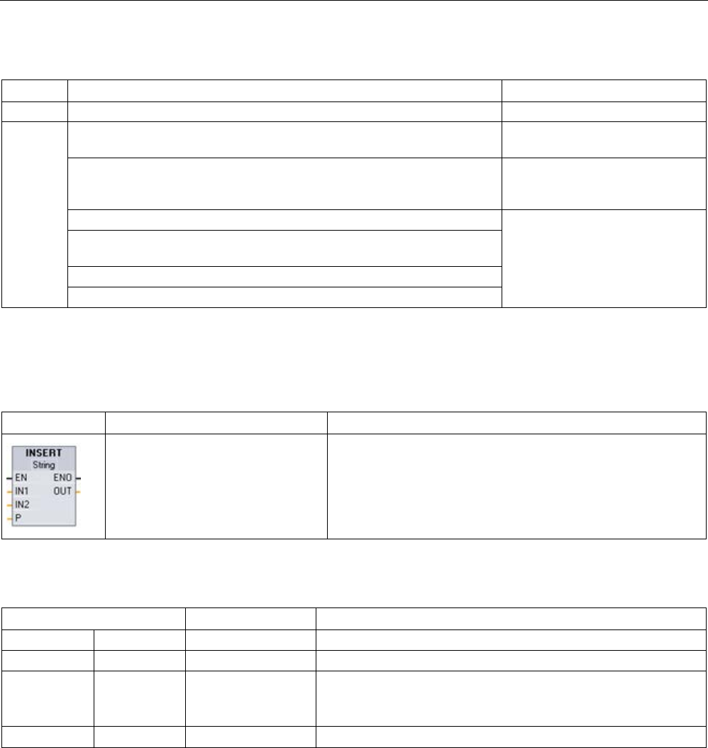
Extended instructions
9.2 String and character
S7-1200 Programmable controller
366 System Manual, V4.2, 09/2016, A5E02486680-AK
Table 9- 60 ENO status
ENO
Condition
OUT
1
No errors detected
Valid characters
0 P is greater than current length of IN IN is copied to OUT with no char-
acters deleted
Resulting string after characters are deleted is larger than maximum length
of OUT string
Resulting string characters are
copied until the maximum length
of OUT is reached
L is less than 0, or P is less than or equal to 0
Current length is set to 0
Current length of IN exceeds maximum length of IN, or current length of
OUT exceeds maximum length of OUT
Maximum length of IN or OUT does not fit within allocated memory
Maximum length of IN or OUT is 0 or 255
9.2.4.6
INSERT (Insert characters in a character string)
Table 9- 61 Insert substring instruction
LAD / FBD
SCL
Description
out := INSERT(in1, in2, p);
Inserts string IN2 into string IN1. Insertion begins after the char-
acter at position P.
Table 9- 62 Data types for the parameters
Parameter and type
Data type
Description
IN1
IN
String, WString
Input string 1
IN2
IN
String, WString
Input string 2
P IN Int Last character position in string IN1 before the insertion point for
string IN2
The first character of string IN1 is position number 1.
OUT
OUT
String, WString
Result string

Extended instructions
9.2 String and character
S7-1200 Programmable controller
System Manual, V4.2, 09/2016, A5E02486680-AK 367
Table 9- 63 ENO status
ENO
Condition
OUT
1
No errors detected
Valid characters
0 P is greater than length of IN1 IN2 is concatenated with IN1 immediate-
ly following the last IN1 character
P is less than 0
Current length is set to 0
Resulting string after insertion is larger than maximum length of
OUT string
Resulting string characters are copied
until the maximum length of OUT is
reached
Current length of IN1 exceeds maximum length of IN1, current
length of IN2 exceeds maximum length of IN2, or current length of
OUT exceeds maximum length of OUT (invalid string)
Current length is set to 0
Maximum length of IN1, IN2 or OUT does not fit within allocated
memory range
Maximum length of IN1 or IN2 is 255, or maximum length of OUT is
0 or 255 (String data type)
Maximum length of IN1 or IN2 is 65534, or maximum length of OUT
is 0 or 65534 (WString data type)
9.2.4.7
REPLACE (Replace characters in a character string)
Table 9- 64 Replace substring instruction
LAD / FBD
SCL
Description
out := REPLACE(
in1:=_string_in_,
in2:=_string_in_,
L:=_int_in_,
p:=_int_in);
Replaces L characters in the string parameter IN1. Replacement
starts at string IN1 character position P (inclusive), with replace-
ment characters coming from the string parameter IN2.

Extended instructions
9.2 String and character
S7-1200 Programmable controller
368 System Manual, V4.2, 09/2016, A5E02486680-AK
Table 9- 65 Data types for the parameters
Parameter and type
Data type
Description
IN1
IN
String, WString
Input string
IN2 IN String, WString String of replacement characters
L
IN
Int
Number of characters to replace
P IN Int Position of first character to be replaced
OUT
OUT
String, WString
Result string
If parameter L is equal to zero, then the string IN2 is inserted at position P of string IN1
without deleting any characters from string IN1.
If P is equal to one, then the first L characters of string IN1 are replaced with string IN2
characters.
Table 9- 66 ENO status
ENO
Condition
OUT
1
No errors detected
Valid characters
0 P is greater than length of IN1 IN2 is concatenated with IN1 immediate-
ly following the last IN1 character
P points within IN1, but fewer than L characters remain in IN1 IN2 replaces the end characters of IN1
beginning at position P
Resulting string after replacement is larger than maximum length of
OUT string
Resulting string characters are copied
until the maximum length of OUT is
reached
Maximum length of IN1 is 0
IN2 characters are copied to OUT
L is less than 0, or P is less than or equal to 0
Current length is set to 0
Current length of IN1 exceeds maximum length of IN1, current
length of IN2 exceeds maximum length of IN2, or current length of
OUT exceeds maximum length of OUT
Maximum length of IN1, IN2 or OUT does not fit within allocated
memory range
Maximum length of IN1 or IN2 is 255, or maximum length of OUT is
0 or 255 (String data type)
Maximum length of IN1 or IN2 is 65534, or maximum length of OUT
is 0 or 65534 (WString data type)

Extended instructions
9.2 String and character
S7-1200 Programmable controller
System Manual, V4.2, 09/2016, A5E02486680-AK 369
9.2.4.8
FIND (Find characters in a character string)
Table 9- 67 Find substring instruction
LAD / FBD
SCL
Description
out := FIND(
in1:=_string_in_,
in2:=_string_in);
Provides the character position of the substring specified by IN2 within
the string IN1. The search starts on the left. The character position of
the first occurrence of IN2 string is returned at OUT. If the string IN2 is
not found in the string IN1, then zero is returned.
Table 9- 68 Data types for the parameters
Parameter and type
Data type
Description
IN1
IN
String, WString
Search inside this string
IN2
IN
String, WString
Search for this string
OUT
OUT
Int
Character position in string IN1 of the first search match
Table 9- 69 ENO status
ENO
Condition
OUT
1
No errors detected
Valid character position
0
IN2 is larger than IN1
Character position is set to 0
Current length of IN1 exceeds maximum length of IN1, or current length
of IN2 exceeds maximum length of IN2 (invalid string)
Maximum length of IN1 or IN2 does not fit within allocated memory
range
Maximum length of IN1 or IN2 is 255 (String data type) or 65535
(WString data type)
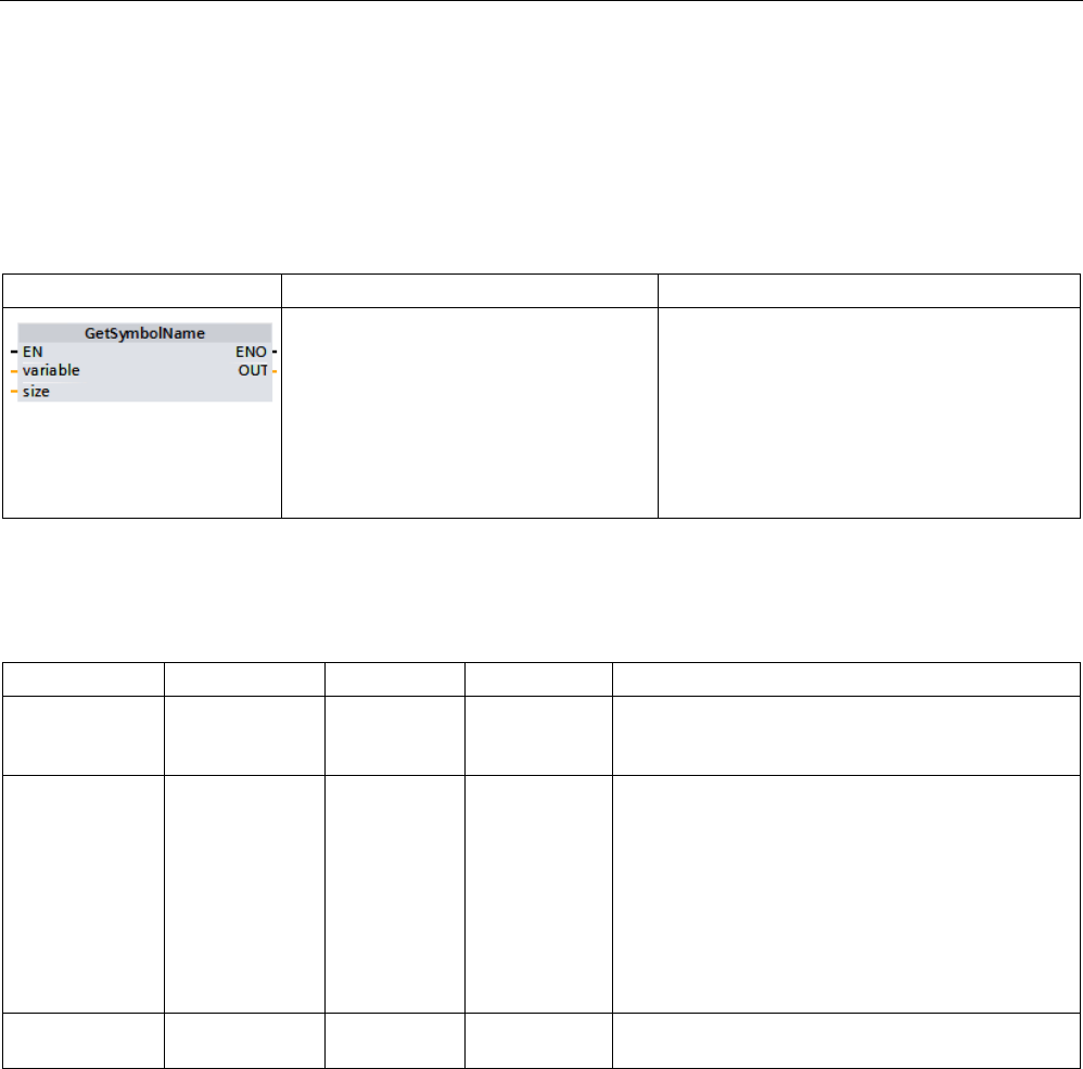
Extended instructions
9.2 String and character
S7-1200 Programmable controller
370 System Manual, V4.2, 09/2016, A5E02486680-AK
9.2.5
Runtime information
9.2.5.1
GetSymbolName (Read out a tag on the input parameter)
Table 9- 70 GetSymbolName instruction
LAD / FBD
SCL
Description
OUT := GetSymbolName(
variable:=_parameter_in_,
size:=_dint_in_);
The GetSymbolName instruction returns a
string corresponding to the name of a variable
from the block interface.
Your program can call the instruction multiple
times with different tags. The process value of
the tag is irrelevant.
The instruction returns the name read at the
OUT parameter.
Parameter
The following table shows the parameters of the GetSymbolName instruction:
Parameter
Declaration
Data type
Memory area
Description
VARIABLE Input PARAMETER Parameter
sections Input,
Output, InOut
Variable from the local block interface for which you
want a string value of the name returned
SIZE Input DINT I, Q, M, D, L Limits the number of characters output at the OUT
parameter:
•
SIZE > 0: GetSymbolName returns the first SIZE
characters of the name.
• SIZE = 0: GetSymbolName returns the entire
name.
•
SIZE < 0: GetSymbolName returns the last SIZE
characters of the name.
OUT Return WSTRING I, Q, M, D, L Output of the tag name supplied by the input pa-
rameter
You specify the input parameters of the block interface at the VARIABLE parameter. Use
only an interface parameter for this parameter and not a PLC or data block tag.
To limit the length of the read tag name, use the SIZE parameter. If the instruction truncates
the name, it indicates the truncation by the characters "..." (Unicode character 16#2026)
appears at the end of the name. Note that this character has the length 1.
You can find additional information on valid data types under "Data types (Page 125)".

Extended instructions
9.2 String and character
S7-1200 Programmable controller
System Manual, V4.2, 09/2016, A5E02486680-AK 371
Example: Meaning of SIZE parameter
The following example illustrates the meaning of the SIZE parameter. The following tag
name is read from the block interface: "MyPLCTag" (The double quotes at the start and end
belong to the name.)
SIZE
GetSymbolName returns
Explanation
1 '...' • First character of WSTRING:'
• Identifier that the name was truncated: ...
• Last character of WSTRING:'
2 '"...' • First character of WSTRING:'
• The first character of the name and identifier that the
name was truncated:"...
• Last character of WSTRING:'
3 '"M...' • First character of WSTRING:'
• The first two characters of the name and identifier that
the name was truncated:"... "M...
• Last character of WSTRING:'
6 '"MyPL...' • First character of WSTRING:'
• The first five characters of the name and identifier that
the name was truncated: "MyPL...
• Last character of WSTRING:'
0 '"MyPLCTag"' • First character of WSTRING:'
• All characters of the name: "MyPLCTag"
• Last character of WSTRING:'
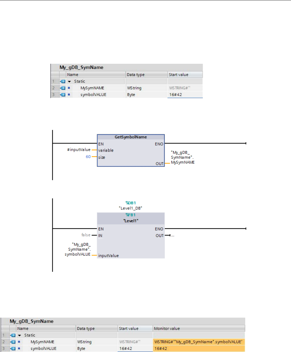
Extended instructions
9.2 String and character
S7-1200 Programmable controller
372 System Manual, V4.2, 09/2016, A5E02486680-AK
Example: Reading a symbol name
In the following example, you read out the name of a tag that is interconnected via the input
parameter of a block.
Create two tags in a global data block for storing the data.
Create an input parameter inputValue with the BYTE data type in the Level1 block. Call the
GetSymbolName instruction in the Level1 block. Interconnect the parameters of the
instruction as follows.
Interconnect the inputValue parameter of the Level1 block as follows.
The GetSymbolName instruction is executed in the Level1 block. Input parameter inputValue
of the Level1 block is examined for its interconnection using input parameter VARIABLE of
the instruction. In doing so, the symbolVALUE tag is read out and output as a character
string at output parameter OUT ("MySymNAME"). According to the value of input parameter
SIZE, the length of the character string is limited to 60 characters.
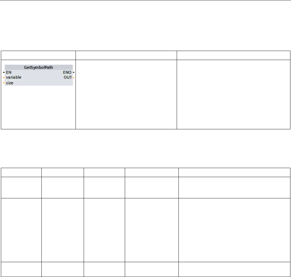
Extended instructions
9.2 String and character
S7-1200 Programmable controller
System Manual, V4.2, 09/2016, A5E02486680-AK 373
9.2.5.2
GetSymbolPath (Query composite global name of the input parameter assignment)
Table 9- 71 GetSymbolPath instruction
LAD / FBD
SCL
Description
OUT := GetSymbolPath(
variable:=_parameter_in_,
size:=_dint_in_);
The GetSymbolPath instruction reads the
composite global name of an input parameter
at the local interface of a block (FB or FC). The
name consists of the storage path and the tag
name.
Your program can call the instruction multiple
times with different tags. The process value of
the tag is irrelevant.
The instruction returns the name read at the
OUT parameter.
Parameter
The following table shows the parameters of the GetSymbolPath instruction:
Parameter
Declaration
Data type
Memory area
Description
VARIABLE Input PARAMETER Parameter sections
Input, Output, InOut
Selection of the local interface to which you
want to read the global name of the input
parameter supply.
SIZE Input DINT I, Q, M, D, L or con-
stant
Limits the number of characters output at the
OUT parameter.
• SIZE > 0: GetSymbolPath returns the first
SIZE characters of the name.
• SIZE = 0: GetSymbolPath returns the
entire name.
• SIZE < 0: GetSymbolPath returns the last
SIZE characters of the name.
OUT Output WSTRING I, Q, M, D, L Output of the tag name of the input parame-
ters supply.
You can find additional information on valid data types under "Data types (Page 125)".

Extended instructions
9.2 String and character
S7-1200 Programmable controller
374 System Manual, V4.2, 09/2016, A5E02486680-AK
Usage
Note the following tips on using the GetSymbolPath instruction:
● Specify the block interface through which the name of the input tag is read at the
VARIABLE parameter of the instruction:
– If a data block tag supplies the input parameter, GetSymbolPath outputs the name of
the DB, contained structures and the name of the tag.
– If a PLC tag supplies the input parameters GetSymbolPath outputs the name of the
PLC tag.
– If a constant supplies the input parameter, GetSymbolPath outputs the constant value.
● To limit the length of the read tag name, use the SIZE parameter. If the name has been
truncated, this is indicated by the character "..." (Unicode character 16#2026) at the end
of the name. Note that this character has the length 1.
Example: Meaning of the SIZE parameter
The following example illustrates the meaning of the SIZE parameter. GetSymbolPath has
read out the following tag name is read out from the block interface: "MyPLCTag" (The
double quotes at the start and end belong to the name.)
SIZE
GetSymbolPath returns
Explanation
1 '...' • First character of WSTRING:'
• Identifier that the name was truncated: ...
• Last character of WSTRING:'
2 '"...' • First character of WSTRING:'
• The first character of the name and identifier that the
name was truncated:"...
• Last character of WSTRING:'
3 '"M...' • First character of WSTRING:'
• The first two characters of the name and identifier that
the name was truncated:"... "M...
• Last character of WSTRING:'
6 '"MyPL...' • First character of WSTRING:'
• The first five characters of the name and identifier that
the name was truncated: "MyPL...
• Last character of WSTRING:'
0 '"MyPLCTag"' • First character of WSTRING:'
• All characters of the name: "MyPLCTag"
• Last character of WSTRING:'
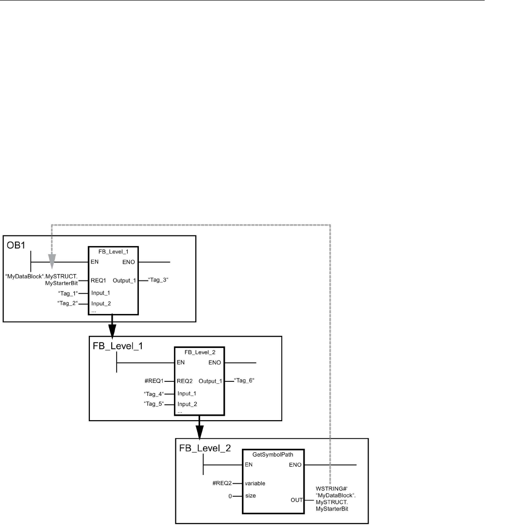
Extended instructions
9.2 String and character
S7-1200 Programmable controller
System Manual, V4.2, 09/2016, A5E02486680-AK 375
Example: Calling GetSymbolPath over mutiple block call levels
The following example shows the use of GetSymbolPath over several call levels:
● Organization block OB1 calls the FB_Level_1 block, which in turn calls the FB_Level_2
block.
● The FB_Level_2 block executes GetSymbolPath to read the path of the parameter at the
REQ2 interface.
● Since the REQ1 interface supplies REQ2, the instruction determines the path of the input
parameter of REQ1.
● The MyStarterBit tag is the REQ1 input parameter. The bit is located in the MySTRUCT
structure in the MyDatablock data block.
GetSymbolPath reads this information and outputs the path
("MyDataBlock".MySTRUCT.MyStarterBit) at the OUT parameter.
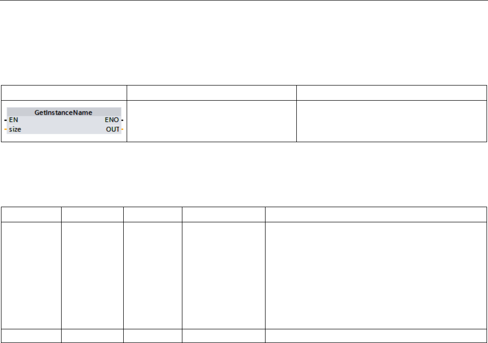
Extended instructions
9.2 String and character
S7-1200 Programmable controller
376 System Manual, V4.2, 09/2016, A5E02486680-AK
9.2.5.3
GetInstanceName (Read out name of the block instance)
Table 9- 72 GetInstanceName instruction
LAD / FBD
SCL
Description
OUT := GetInstanceName(
size:=_dint_in_);
You can use the GetInstanceName instruction
to read the name of the instance data block
within a function block.
Parameter
The following table shows the parameters of the GetInstanceName instruction:
Parameter
Declaration
Data type
Memory area
Description
SIZE Input DINT I, Q, M, D, L or
constant
Limits the number of characters output at the OUT
parameter.
• SIZE > 0: GetInstanceName returns the first SIZE
characters of the name.
• SIZE = 0: GetInstanceName returns the entire
name.
• SIZE < 0: GetInstanceName returns the last SIZE
characters of the name.
OUT
Output
WSTRING
I, Q, M, D, L
Read name of the instance data block
You can find additional information on valid data types under "Data types (Page 125)".

Extended instructions
9.2 String and character
S7-1200 Programmable controller
System Manual, V4.2, 09/2016, A5E02486680-AK 377
Example: Meaning of SIZE parameter
To limit the length of the read instance name, use the SIZE parameter. If the instruction has
truncated the name, it indicates the truncation by the character "..." (Unicode character
16#2026) at the end of the name. Note that this character has the length 1.
The following example illustrates the meaning of the SIZE parameter. GetInstanceName has
read out the following instance name from the block interface: "Level1_DB" (The double
quotes at the start and end belong to the name.)
SIZE
GetSymbolPath returns
Explanation
1 '...' • First character of WSTRING:'
• Identifier that the name was truncated: ...
• Last character of WSTRING:'
2 '"...' • First character of WSTRING:'
• The first character of the name and identifier that the
name was truncated:"...
• Last character of WSTRING:'
3 '"L...' • First character of WSTRING:'
• The first two characters of the name and identifier that
the name was truncated:"... "L...
• Last character of WSTRING:'
6 '"Leve...' • First character of WSTRING:'
• The first five characters of the name and identifier that
the name was truncated: "Leve...
• Last character of WSTRING:'
0 '"Level1_DB"' • First character of WSTRING:'
• All characters of the name: "Level1_DB"
• Last character of WSTRING:'
GetInstanceName writes out the name of the instance data block to the OUT parameter. The
instruction truncates the name if the name of the instance data block is longer than the
maximum length of WSTRING.
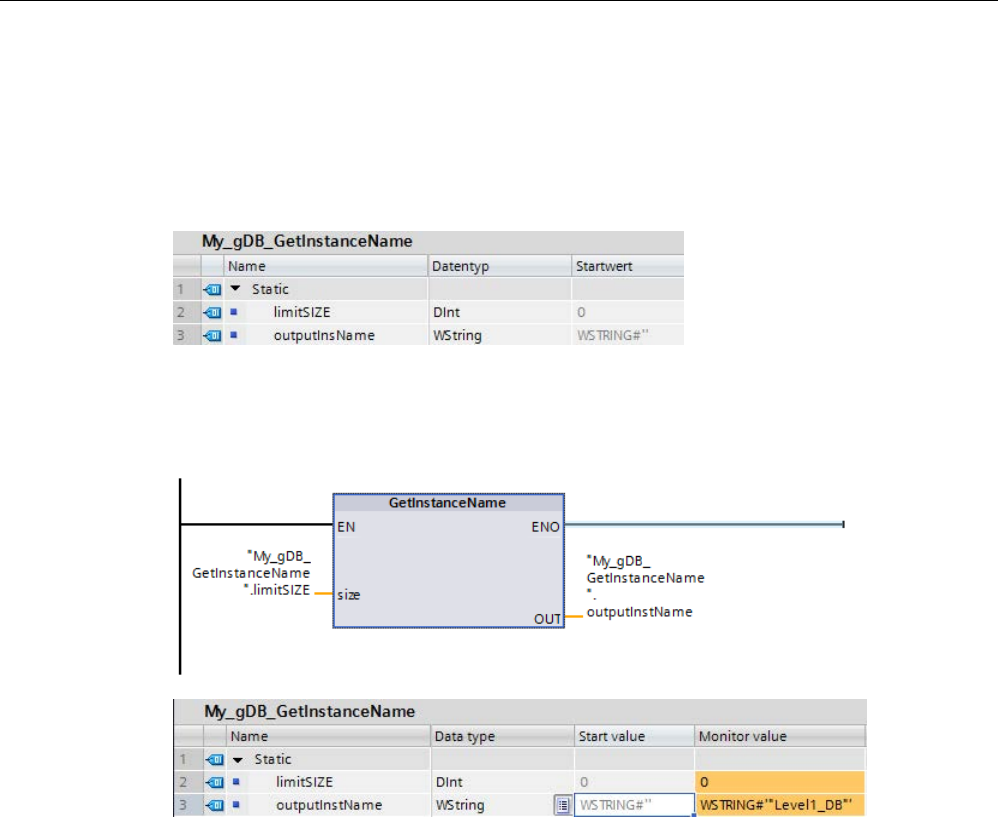
Extended instructions
9.2 String and character
S7-1200 Programmable controller
378 System Manual, V4.2, 09/2016, A5E02486680-AK
Example: Reading the name of an instance data block
The following example shows how to read out the name of an instance data block.
Create two tags in a global data block for storing the data.
Define the parameters of the instruction as follows.
The Level1_gin block executes the GetInstanceName instruction, which determines the
associated instance data block of the Level1_gin block and outputs the name as a character
string at output parameter OUT (outputInstName). According to the value 0 of parameter
SIZE (limitSIZE), the length of the character string is unlimited.

Extended instructions
9.2 String and character
S7-1200 Programmable controller
System Manual, V4.2, 09/2016, A5E02486680-AK 379
9.2.5.4
GetInstancePath (Query composite global name of the block instance)
Table 9- 73 GetInstancePath instruction
LAD / FBD
SCL
Description
OUT := GetInstancePath(
size:=_dint_in_);
You use the GetInstancePath instruction to
read the composed global name of the block
instance within a function block. The com-
posed global name of the block instance is the
path of the complete call hierarchy when the
program calls multiple instances.
Parameter
The following table shows the parameters of the GetInstancePath instruction:
Parameter
Declaration
Data type
Memory area
Description
SIZE Input DINT I, Q, M, D, L or con-
stant
Limits the number of characters output at the
OUT parameter.
• SIZE > 0: GetInstancePath returns the first
SIZE characters of the name.
• SIZE = 0: GeInstancePath returns the
entire name.
•
SIZE < 0: GetInstancePath returns the last
SIZE characters of the name.
OUT Output WSTRING I, Q, M, D, L Read global name of the block instance.
If the global name of the block instance is
longer than the maximum length of WSTRING
(254 characters), GetInstancePath truncates
the name.
You can find additional information on valid data types under "Data types (Page 125)".
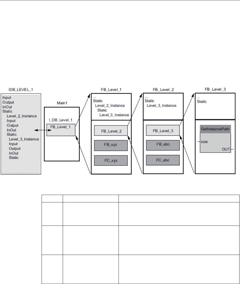
Extended instructions
9.2 String and character
S7-1200 Programmable controller
380 System Manual, V4.2, 09/2016, A5E02486680-AK
Example: Calling GetInstancePath to get the path of a multi-instance FB call
In the following example, the FB_Level_3 function block calls the GetInstancePath
instruction.
● The FB_Level_3 function block stores its data in the calling FB_Level_2 function block.
● The FB_Level_2 function block in turn stores its data in the calling FB_Level_1 function
block.
● The FB_Level_1 function block in turn stores its data in its instance data block
IDB_LEVEL_1. Through the use of multi-instances, the instance data block of FB_Level_1
contains all data of the three function blocks.
The GetInstancePath instruction returns the following values for this example, depending on
the value of the SIZE parameter:
SIZE
GetInstancePath returns
Explanation
1 '...' • First character of WSTRING:'
• Identifier that the name was truncated: ...
• Last character of WSTRING:'
2 '"...' • First character of WSTRING:'
• The first character of the name and identifier that the
name was truncated:"...
• Last character of WSTRING:'
3 '"I...' • First character of WSTRING:'
• The first two characters of the name and identifier that
the name was truncated:"... "I...
• Last character of WSTRING:'
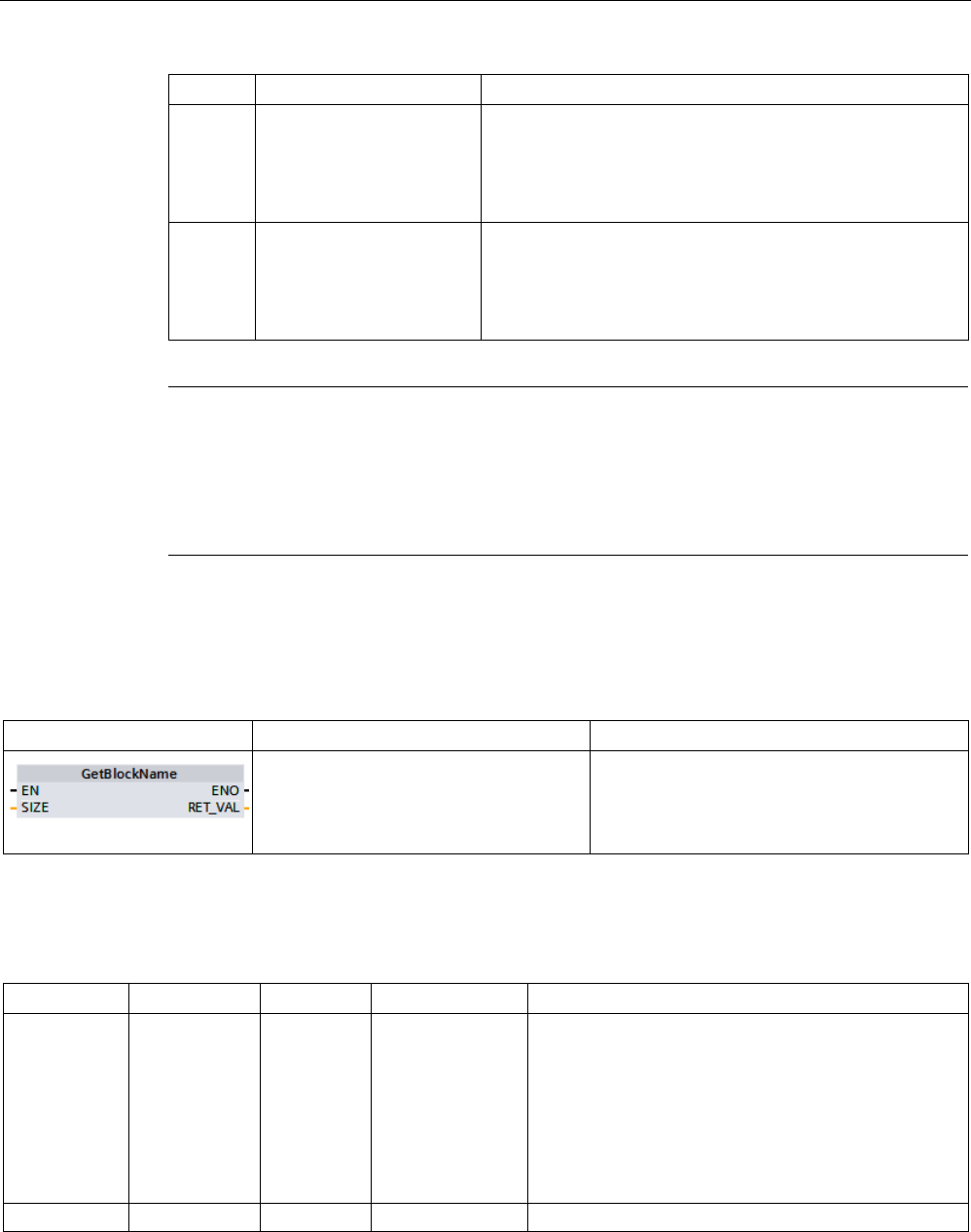
Extended instructions
9.2 String and character
S7-1200 Programmable controller
System Manual, V4.2, 09/2016, A5E02486680-AK 381
SIZE
GetInstancePath returns
Explanation
6 '"IDB_...' • First character of WSTRING:'
• The first five characters of the name and identifier that
the name was truncated: "IDB_...
• Last character of WSTRING:'
0 '"IDB_LEVEL_1".Level_2_
Instance.Level_3_Instance'
• First character of WSTRING:'
• All characters of the name:
"IDB_LEVEL_1".Level_2_Instance.Level_3_Instance
• Last character of WSTRING:'
Note
Use of GetInstancePath in function blocks with single instance
If the function block in which you call GetInstancePath saves data in
its own instance data
block, GetInstancePath outputs the name of the single instance as the global name. The
result at parameter OUT corresponds in this case to the
GetInstanceName (Page 376)
instruction.
9.2.5.5
GetBlockName (Read out name of the block)
Table 9- 74 GetBlockName instruction
LAD / FBD
SCL
Description
RET_VAL := GetBlockName(
size:=_dint_in_);
You use the GetBlockName instruction to read
the name of the block in which the instruction
is called.
Parameter
The following table shows the parameters of the GetBlockName instruction:
Parameter
Declaration
Data type
Memory area
Description
SIZE Input UINT I, Q, M, D, L or
constant
Limits the number of characters output at the
RET_VAL parameter.
• SIZE > 0: GetBlockName returns the first SIZE
characters of the name.
• SIZE = 0: GetBlockName returns the entire name.
• SIZE < 0: GetBlockName returns the last SIZE
characters of the name.
RET_VAL
Output
WSTRING
I, Q, M, D, L
Read name of the instance data block
You can find additional information on valid data types under "Data types (Page 125)".

Extended instructions
9.2 String and character
S7-1200 Programmable controller
382 System Manual, V4.2, 09/2016, A5E02486680-AK
Example: Meaning of the SIZE parameter
To limit the length of the block name to a certain number of characters, specify the maximum
length at the SIZE parameter. If GetBlockName truncates the name, it indicates the
truncation by the character "..." (Unicode character 16#2026) at the end of the name. Note
that this character has the length 1.
The following example illustrates the meaning of the SIZE parameter. GetBlockName has
read out the following block name: Level1_gbn (The double quotes at the start and end
belong to the name.)
SIZE
GetBlockName returns
Explanation
1 '...' • First character of WSTRING:'
• Identifier that the name was truncated: ...
• Last character of WSTRING:'
2 '"...' • First character of WSTRING:'
• The first character of the name and identifier that the
name was truncated:"...
• Last character of WSTRING:'
3 '"L...' • First character of WSTRING:'
• The first two characters of the name and identifier that
the name was truncated:"... "L...
• Last character of WSTRING:'
6 '"Leve...' • First character of WSTRING:'
• The first five characters of the name and identifier that
the name was truncated: "Leve...
• Last character of WSTRING:'
0 '"Level1_gbn"' • First character of WSTRING:'
• All characters of the name: "Level1_gbn"
• Last character of WSTRING:'
GetBlockName writes the name of the block at the RET_VAL parameter. If the name of the
block is longer than the maximum length of WSTRING, it truncates the name.
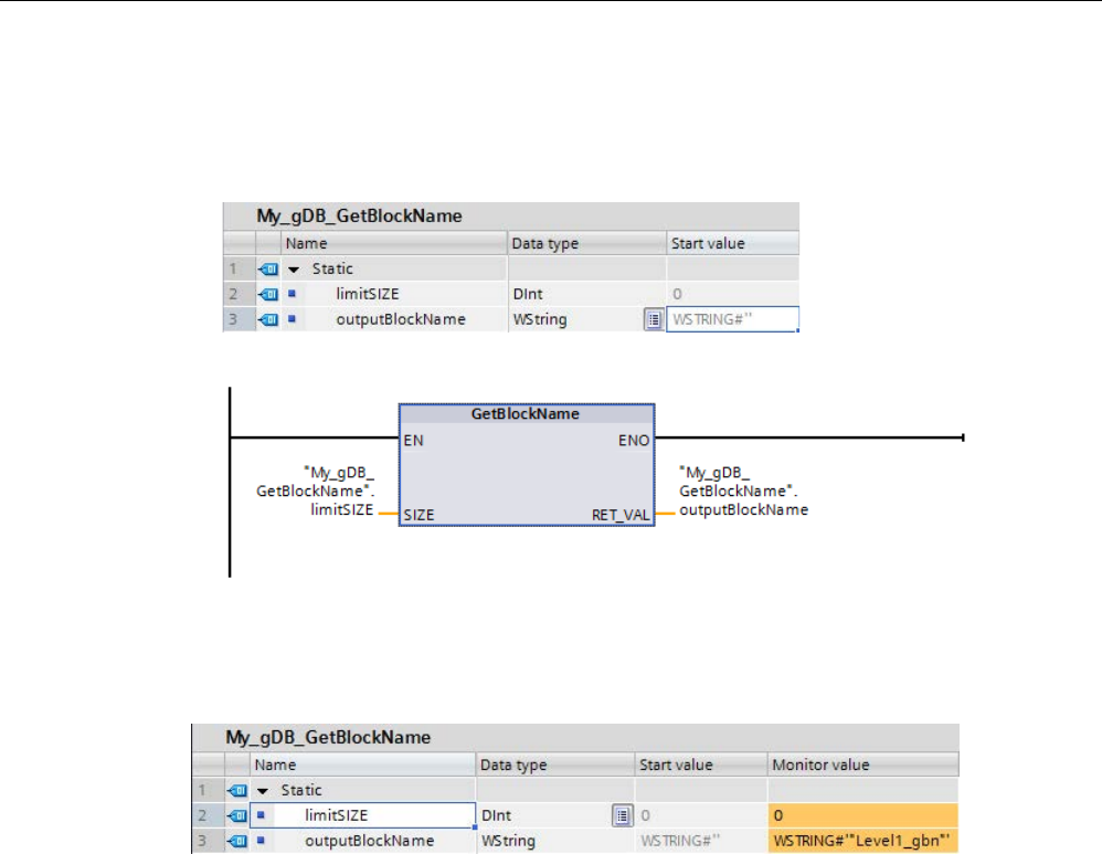
Extended instructions
9.2 String and character
S7-1200 Programmable controller
System Manual, V4.2, 09/2016, A5E02486680-AK 383
Example: Reading a block name
The following example shows how to read out a block name.
1. Create two tags in a global data block for storing the data.
2. Define the parameters of the instruction as follows:
The Level1_gbn block executes the GetBlockName instruction. GetBlockName reads out the
name of the Level1_gbn block and outputs the name as a character string at output
parameter RET_VAL(outputBlockName). Because the SIZE parameter is 0 (limitSIZE), the
length of the character string is unlimited.

Extended instructions
9.3 Distributed I/O (PROFINET, PROFIBUS, or AS-i)
S7-1200 Programmable controller
384 System Manual, V4.2, 09/2016, A5E02486680-AK
9.3
Distributed I/O (PROFINET, PROFIBUS, or AS-i)
9.3.1
Distributed I/O Instructions
The following Distributed I/O instructions can be used with PROFINET, PROFIBUS, or AS-i:
● RDREC instruction (Page 385): Reads a data record with the number INDEX from a
module or device.
● WRREC instruction (Page 385): Transfers a data record with the number INDEX to a
module or device defined by ID.
● GETIO instruction (Page 388): Consistently reads out all inputs of a DP standard slave /
PROFINET IO device.
● SETIO instruction (Page 389): Consistently transfers data from the source range defined
by the OUTPUTS parameter to the addressed DP standard slave / PROFINET IO device.
● GETIO_PART instruction (Page 390): Consistently reads out a related part of the inputs
of an IO module.
● SETIO_PART instruction (Page 392): Consistently writes data from the source area
spanned by the OUTPUTS parameter to the outputs of an IO module.
● RALRM instruction (Page 394): Allows you to receive an interrupt with all corresponding
information from a module or device and supply this information to its output parameters.
● DPRD_DAT instruction (Page 408): Allows you to read consistent data areas greater than
64 bytes from a module or device with the DPRD_DAT instruction.
● DPWR_DAT instruction (Page 408): Allows you to write consistent data areas greater
than 64 bytes to a module or device with the DPWR_DAT instruction.
The D_ACT_DP instruction (Page 398) allows you to disable and enable configured
PROFINET IO devices in a targeted manner. You can also determine whether each
assigned PROFINET IO device is currently activated or deactivated.
Note
Note: You can only use the D_ACT_DP instruction with PROFINET IO devices. You cannot
use the instruction with PROFIBUS DP slaves.
The DPNRM_DG instruction (Page 416) allows you to read the current diagnostic data of a
DP slave in the format specified by EN 50 170 Volume 2, PROFIBUS.
Note
You can only use the DPNRM_D
G instruction with PROFIBUS.

Extended instructions
9.3 Distributed I/O (PROFINET, PROFIBUS, or AS-i)
S7-1200 Programmable controller
System Manual, V4.2, 09/2016, A5E02486680-AK 385
9.3.2
RDREC and WRREC (Read/write data record)
You can use the RDREC (Read data record) and WRREC (Write data record) instructions
with PROFINET, PROFIBUS, and AS-i.
Table 9- 75 RDREC and WRREC instructions
LAD / FBD
SCL
Description
"RDREC_DB"(
req:=_bool_in_,
ID:=_word_in_,
index:=_dint_in_,
mlen:=_uint_in_,
valid=>_bool_out_,
busy=>_bool_out_,
error=>_bool_out_,
status=>_dword_out_,
len=>_uint_out_,
rec-
ord:=_variant_inout_);
Use the RDREC instruction to read a data
record with the number INDEX from the
component addressed by the ID, such as
a central rack or a distributed component
(PROFIBUS DP or PROFINET IO). As-
sign the maximum number of bytes to
read in MLEN. The selected length of the
target area RECORD should have at
least the length of MLEN bytes.
"WRREC_DB"(
req:=_bool_in_,
ID:=_word_in_,
index:=_dint_in_,
len:=_uint_in_,
done=>_bool_out_,
busy=>_bool_out_,
error=>_bool_out_,
status=>_dword_out_,
rec-
ord:=_variant_inout_);
Use the WRREC instruction to transfer a
data RECORD with the record number
INDEX to a DP slave/PROFINET IO de-
vice component addressed by ID, such as
a module in the central rack or a distrib-
uted component (PROFIBUS DP or
PROFINET IO).
Assign the byte length of the data record
to be transmitted. The selected length of
the source area RECORD should, there-
fore, have at least the length of LEN
bytes.
1
STEP 7 automatically creates the DB when you insert the instruction.
2 In the SCL examples, "RDREC_DB" and "WRREC_DB" are the names of the instance DBs.

Extended instructions
9.3 Distributed I/O (PROFINET, PROFIBUS, or AS-i)
S7-1200 Programmable controller
386 System Manual, V4.2, 09/2016, A5E02486680-AK
Table 9- 76 RDREC and WRREC data types for the parameters
Parameter and type
Data type
Description
REQ
IN
Bool
REQ = 1: Transfer data record
ID IN HW_IO (Word) Logical address of the DP slave/PROFINET IO component
(module or submodule):
• For an output module, bit 15 must be set (for example, for
address 5: ID:= DW#16#8005).
• For a combination module, the smaller of the two addresses
should be specified.
Note
: In V3.0, the device ID can be determined in one of two
ways:
• By making the following "Network view" selections:
– Device (gray box)
– "Properties" of the device
– "Hardware identifier"
Note
: Not all devices display their Hardware identifiers,
however.
• By making the following "Project tree" menu selections:
– PLC tags
– Default tag table
– System constants tab
All configured device Hardware identifiers are displayed.
Note
: In V4.0, the device ID (hardware identifier) for the interface
module is determined by going to the tag table and locating the
"Device Name [HEAD]" parameter under System Constants.
INDEX IN Byte, Word, USInt,
UInt, SInt, Int, DInt
Data record number
MLEN IN Byte, USInt, UInt Maximum length in bytes of the data record information to be
fetched (RDREC)
VALID OUT Bool New data record was received and valid (RDREC). The VALID
bit is TRUE for one scan, after the last request was completed
with no error.
DONE OUT Bool Data record was transferred (WRREC). The DONE bit is TRUE
for one scan, after the last request was completed with no error.
BUSY OUT Bool • BUSY = 1: The read (RDREC) or write (WRREC) process is
not yet terminated.
• BUSY = 0: Data record transmission is completed.
ERROR OUT Bool ERROR = 1: A read (RDREC) or write (WRREC) error has oc-
curred. The ERROR bit is TRUE for one scan, after the last
request was terminated with an error. The error code value at
the STATUS parameter is valid only during the single scan
where ERROR = TRUE.
STATUS
OUT
DWord
Block status (Page 403) or error information (Page 553)

Extended instructions
9.3 Distributed I/O (PROFINET, PROFIBUS, or AS-i)
S7-1200 Programmable controller
System Manual, V4.2, 09/2016, A5E02486680-AK 387
Parameter and type
Data type
Description
LEN OUT (RDREC)
IN (WRREC)
UInt • Length of the fetched data record information (RDREC)
• Maximum byte length of the data record to be transferred
(WRREC)
RECORD IN_OUT Variant • Target area for the fetched data record (RDREC)
• Data record (WRREC)
The RDREC and WRREC instructions operate asynchronously, that is, processing covers
multiple instruction calls. Start the job by calling RDREC or WRREC with REQ = 1.
The job status is displayed via output parameter BUSY and the two central bytes of output
parameter STATUS. The transfer of the data record is complete when the output parameter
BUSY has been set to FALSE
A value of TRUE (only for one scan) on the output parameter VALID (RDREC) or DONE
(WRREC) verifies that the data record has been successfully transferred into the target area
RECORD (RDREC) or to the target device (WRREC). In the case of the RDREC, the output
parameter LEN contains the length of the fetched data in bytes.
The output parameter ERROR (only for one scan when ERROR = TRUE) indicates that a
data record transmission error has occurred. In this case, the output parameter STATUS
(only for the one scan when ERROR = TRUE) contains the error information.
Data records are defined by the hardware device manufacturer. Refer to the hardware
manufacturer's device documentation for details about a data record.
You can have up to four RDREC instructions and four WRREC instructions in use at the
same time.
Note
If you configure a DPV1 slave with a GSD file (GSD rev. 3 and higher) and
the DP interface
of the DP master is set to "S7 compatible", then you might not read any data records from
the I/O modules in the user program with "RDREC" or write to the I/O modules with
"WRREC". In this case, the DP master addresses the wrong slot (con
figured slot + 3).
Remedy: set the interface of the DP master to "DPV1".
Note
The interfaces of the "RDREC" and "WRREC" instructions are identical to the "RDREC" and
"WRREC" FBs defined in "PROFIBUS Guideline PROFIBUS Communication and Proxy
Function B
locks according to IEC 61131-3".
Note
If you use "RDREC" or "WRREC" to read or write a data record for PROFINET IO, then the
CPU interprets negative values in the INDEX, MLEN, and LEN parameters as unsigned 16
-
bit integers.
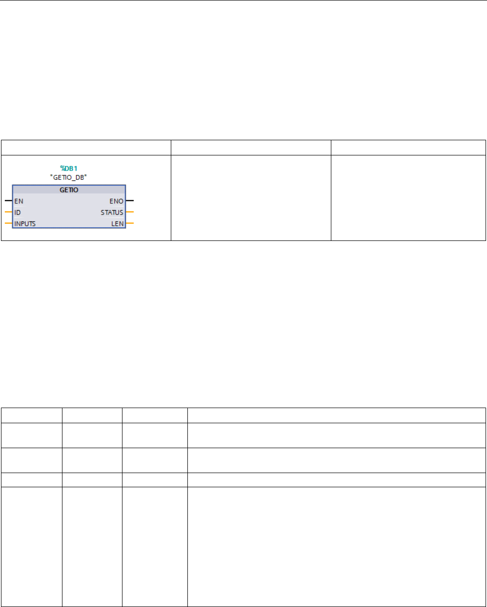
Extended instructions
9.3 Distributed I/O (PROFINET, PROFIBUS, or AS-i)
S7-1200 Programmable controller
388 System Manual, V4.2, 09/2016, A5E02486680-AK
9.3.3
GETIO (Read process image)
You use the instruction "GETIO" to consistently read inputs of modules or submodules of
DP slaves and PROFINET IO devices. The instruction "GETIO" calls the instruction
"DPRD_DAT (Page 408)". If there is no error during the data transmission, the data that has
been read is entered in the destination area indicated by INPUTS.
Table 9- 77 GETIO (Read process image) instruction
LAD / FBD
SCL
Description
"GETIO_DB"(
id:=_uint_in_,
status=>_dword_out_,
len=>_int_out_,
inputs:=_variant_inout_);
Use the instruction "GETIO" to con-
sistently read out all inputs of a
DP standard slave /
PROFINET IO device.
1
STEP 7 automatically creates the DB when you insert the instruction.
2 In the SCL example, "GETIO_DB" is the name of the instance DB.
The destination area must have a length that is greater than or equal to the length of the
selected component.
If you read from a DP standard slave with a modular configuration or with several DP
identifiers, you only access the data of one component / DP identifier at the configured start
address with a "GETIO" call.
Parameters
The following table shows the parameters of the "GETIO" instruction:
Parameter
Declaration
Data type
Description
ID IN HW_SUBMOD
ULE
Hardware ID of the DP standard slave / PROFINET IO device
STATUS1 OUT DWord Contains the error information of "DPRD_DAT (Page 408)" in the form
DW#16#40xxxx00
LEN
OUT
Int
Amount of data read in bytes
INPUTS IN_OUT Variant Destination area for the read data: The destination area must have a
length that is greater than or equal to the length of the selected
DP standard slave / PROFINET IO device.
You can use the following data types:
• System data types and array of system data types: BYTE, CHAR,
SINT, USINT, WORD, INT, UINT, DWORD, DINT, UDINT, REAL,
LREAL, LWORD, LINT, ULINT
• User Defined Types (UDT)
• Structures (STRUCT), but only in non-optimized data blocks (DB)
1 When displaying the "GETIO" error codes, use the DWord data type.
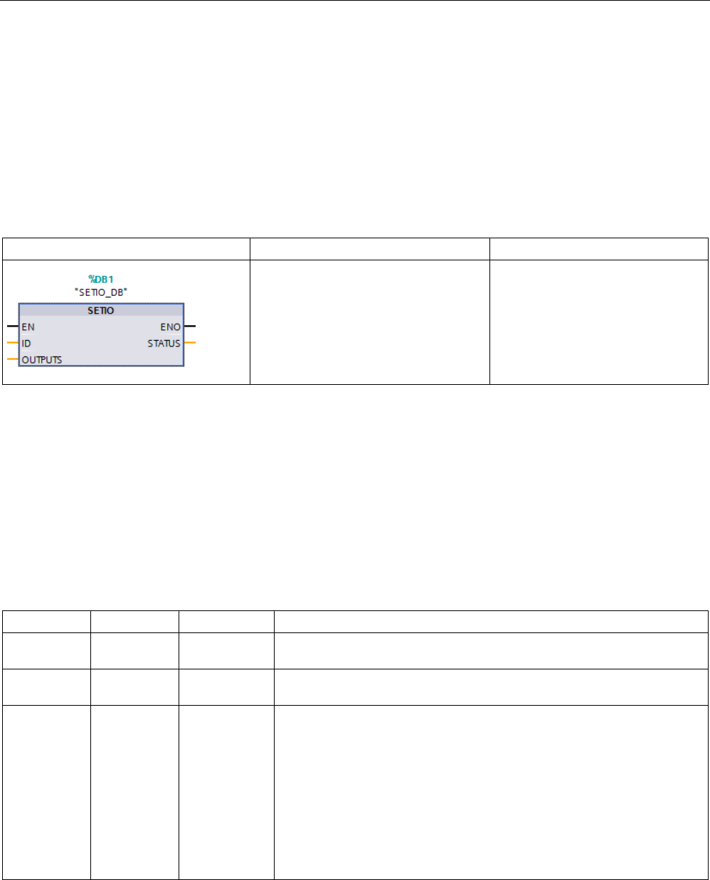
Extended instructions
9.3 Distributed I/O (PROFINET, PROFIBUS, or AS-i)
S7-1200 Programmable controller
System Manual, V4.2, 09/2016, A5E02486680-AK 389
9.3.4
SETIO (Transfer process image)
You use the instruction "SETIO" to consistently transfer data from the source range defined
by the OUTPUTS parameter to the addressed modules or submodules of DP slaves and
PROFINET IO devices. If you have configured the relevant address area of the
DP standard slave / PROFINET IO device as a consistent range in a process image, the
data is transferred to the process image. "SETIO" calls the "DPWR_DAT (Page 408)"
instruction during this transfer.
Table 9- 78 SETIO (Read process image) instruction
LAD / FBD
SCL
Description
"SETIO_DB"(
id:=_uint_in_,
status=>_dword_out_,
outputs:=_variant_inout_);
Use the instruction "SETIO" to con-
sistently transfer data from the
source range defined by the param-
eter OUTPUTS to the addressed
DP standard slave /
PROFINET IO device.
1
STEP 7 automatically creates the DB when you insert the instruction.
2 In the SCL example, "SETIO_DB" is the name of the instance DB.
The source range must have a length that is greater than or equal to the length of the
selected component.
In the case of a DP standard slave / PROFINET IO device with modular configuration or with
several DP identifiers, you can only access one DP identifier / component per "SETIO" call.
Parameters
The following table shows the parameters of the "SETIO" instruction:
Parameter
Declaration
Data type
Description
ID IN HW_SUBMOD
ULE
Hardware ID of the DP standard slave / PROFINET IO device
STATUS1 OUT DWord Contains the error information of "DPWR_DAT (Page 408)" in the form
DW#16#40xxxx00
OUTPUTS IN_OUT Variant Source range for the data to be written: The source range must have a
length that is greater than or equal to the length of the selected DP stand-
ard slave / PROFINET IO device.
You can use the following data types:
• System data types and array of system data types: BYTE, CHAR,
SINT, USINT, WORD, INT, UINT, DWORD, DINT, UDINT, REAL,
LREAL, LWORD, LINT, ULINT
• User Defined Types (UDT)
• Structures (STRUCT), but only in non-optimized data blocks (DB)
1 When displaying the "SETIO"error codes, use the DWord data type.

Extended instructions
9.3 Distributed I/O (PROFINET, PROFIBUS, or AS-i)
S7-1200 Programmable controller
390 System Manual, V4.2, 09/2016, A5E02486680-AK
9.3.5
GETIO_PART (Read process image area)
You use the instruction "GETIO_PART" to consistently read a related part of the inputs of
modules or submodules of DP slaves and PROFINET IO devices. GETIO_PART calls the
instruction "DPRD_DAT (Page 408)".
Table 9- 79 GETIO_PART (Read process image area) instruction
LAD / FBD
SCL
Description
"GETIO_PART_DB"(
id:=_uint_in_,
offset:=_int_in_,
len:=_int_in_,
status=>_dword_out_,
error=>_bool_out_,
inputs:=_variant_inout_);
Use the instruction GETIO_PART to
consistently read out a related part of
the inputs of an IO module.
1
STEP 7 automatically creates the DB when you insert the instruction.
2 In the SCL example, "GETIO_PART_DB" is the name of the instance DB.
Use the ID input parameter to select the IO module by means of the hardware ID.
Use the OFFSET and LEN parameters to specify the portion of the process image area to be
read. If the input area spanned by OFFSET and LEN is not completely covered by the
module, the block returns the error code DW#16#40
80B7
00.
The length of the destination area must be larger than or equal to the amount of bytes to be
read:
● If there is no error during the data transmission, ERROR receives the value FALSE. The
data that is read is written to the destination area defined at the INPUTS parameter.
● If there is an error during the data transmission, ERROR receives the value TRUE. The
STATUS parameter receives the error information from DPRD_DAT.
● If the destination area is greater than LEN, the instruction writes to the first LEN bytes of
the destination area. ERROR receives the value FALSE.

Extended instructions
9.3 Distributed I/O (PROFINET, PROFIBUS, or AS-i)
S7-1200 Programmable controller
System Manual, V4.2, 09/2016, A5E02486680-AK 391
Parameters
The following table shows the parameters of the GETIO_PART instruction:
Parameter
Declaration
Data type
Description
ID IN HW_SUBMO
DULE
Hardware identifier of the module
OFFSET IN Int Number of the first byte to be read in the process image for the component
(smallest possible value: 0)
LEN
IN
Int
Number of bytes to be read
STATUS1 OUT DWord Contains the error information of DPRD_DAT (Page 408) in the form
DW#16#40xxxx00, if ERROR = TRUE
ERROR OUT Bool Error display: ERROR = TRUE if an error occurs when DPRD_DAT
(Page 408) is called
INPUTS IN_OUT Variant Destination area for read data: If the destination area is greater than LEN,
the instruction writes to the first LEN bytes of the destination area.
You can use the following data types:
• System data types and array of system data types: BYTE, CHAR,
SINT, USINT, WORD, INT, UINT, DWORD, DINT, UDINT, REAL,
LREAL, LWORD, LINT, ULINT
• User Defined Types (UDT)
• Structures (STRUCT), but only in non-optimized data blocks (DB)
1 When displaying the GETIO_PART error codes, use the DWord data type.
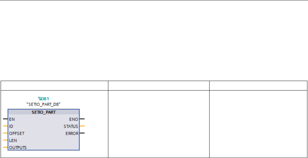
Extended instructions
9.3 Distributed I/O (PROFINET, PROFIBUS, or AS-i)
S7-1200 Programmable controller
392 System Manual, V4.2, 09/2016, A5E02486680-AK
9.3.6
SETIO_PART (Transfer process image area)
You can use the "SETIO_PART" instruction to consistently write data from the source area
spanned by OUTPUTS to the outputs of modules or submodules of DP slaves and
PROFINET IO devices. SETIO_PART calls the instruction "DPWR_DAT (Page 408)".
Table 9- 80 SETIO_PART (Transfer process image area) instruction
LAD / FBD
SCL
Description
"SETIO_PART_DB"(
id:=_uint_in_,
offset:=_int_in_,
len:=_int_in_,
status=>_dword_out_,
error=>_bool_out_,
outputs:=_variant_inout_);
Use the instruction SETIO_PART to
consistently write data from the
source area spanned by OUTPUTS
to the outputs of an IO module.
1
STEP 7 automatically creates the DB when you insert the instruction.
2 In the SCL example, "SETIO_PART_DB" is the name of the instance DB.
With the input parameter ID, you select the I/O module based on the hardware identified.
With the parameters OFFSET and LEN, you assign the portion of the process image area to
be written for the component addressed by ID. If the output area spanned by OFFSET and
LEN is not completely covered by the module, the block returns the error code
DW#16#40
80B7
00.
The length of the destination area must be larger than or equal to the amount of bytes to be
read:
● If there is no error during the data transmission, ERROR receives the value FALSE.
● If there is an error during the data transmission, ERROR receives the value TRUE, and
STATUS receives the error information of DPWR_DAT.
● If the source area is greater than LEN, the instruction transfers the first LEN bytes from
OUTPUTS. ERROR receives the value FALSE.

Extended instructions
9.3 Distributed I/O (PROFINET, PROFIBUS, or AS-i)
S7-1200 Programmable controller
System Manual, V4.2, 09/2016, A5E02486680-AK 393
Parameters
The following table shows the parameters of the SETIO_PART instruction:
Parameter
Declaration
Data type
Description
ID IN HW_SUBMO
DULE
Hardware identifier of the IO module
OFFSET IN Int Number of the first byte to be written in the process image for the compo-
nent (smallest possible value: 0)
LEN
IN
Int
Number of bytes to be written
STATUS1 OUT DWord Contains the error information of DPWR_DAT (Page 408) in the form
DW#16#40xxxx00, if ERROR = TRUE
ERROR OUT Bool Error display: ERROR = TRUE if an error occurs when DPWR_DAT
(Page 408) is called
OUTPUTS IN_OUT Variant Source range for the data to be written: If the source area is greater than
LEN, the first LEN bytes are transferred from OUTPUTS.
You can use the following data types:
• System data types and array of system data types: BYTE, CHAR,
SINT, USINT, WORD, INT, UINT, DWORD, DINT, UDINT, REAL,
LREAL, LWORD, LINT, ULINT
• User Defined Types (UDT)
• Structures (STRUCT), but only in non-optimized data blocks (DB)
1 When displaying the SETIO_PART error codes, use the DWord data type.

Extended instructions
9.3 Distributed I/O (PROFINET, PROFIBUS, or AS-i)
S7-1200 Programmable controller
394 System Manual, V4.2, 09/2016, A5E02486680-AK
9.3.7
RALRM (Receive interrupt)
You can use the RALRM (Read alarm) instruction with PROFINET and PROFIBUS.
Table 9- 81 RALRM instruction
LAD / FBD
SCL
Description
"RALRM_DB"(
mode:=_int_in_,
f_ID:=_word_in_,
mlen:=_uint_in_,
new=>_bool_out_,
status=>_dword_out_,
ID=>_word_out_,
len=>_uint_out_,
tinfo:=_variant_inout_,
ainfo:=_variant_inout_);
Use the RALRM (read alarm) instruction to read diagnostic
interrupt information from PROFIBUS or PROFINET I/O mod-
ules/devices.
The information in the output parameters contains the start
information of the called OB as well as information of the inter-
rupt source.
Call RALRM in an interrupt OB to return information regarding
the event(s) that caused the interrupt. In the S7-1200. The fol-
lowing Diagnostic OB interrupts are supported: Status, Update,
Profile, Diagnostic error interrupt, Pull or plug of modules, Rack
or station failure.
1
STEP 7 automatically creates the DB when you insert the instruction.
2 In the SCL example, "RALRM_DB" is the name of the instance DB.
Table 9- 82 Data types for the parameters
Parameter and type
Data type
Description
MODE
IN
Byte, USInt, SInt, Int
Operating mode
F_ID IN HW_IO (Word) Logical start address of the component (module) from which interrupts
are to be received
Note
: The device ID can be determined in one of two ways:
• By making the following "Network view" selections:
– Device (gray box)
– "Properties" of the device
– "Hardware identifier"
Note
: Not all devices display their Hardware identifiers.
• By making the following "Project tree" menu selections:
– PLC tags
– Default tag table
– System constants tab
– All configured device Hardware identifiers are displayed.
MLEN IN Byte, USInt, UInt Maximum length in bytes of the data interrupt information to be re-
ceived. MLEN of 0 will allow receipt of as much data interrupt infor-
mation as is available in the AINFO Target Area.
NEW
OUT
Bool
A new interrupt was received.
STATUS OUT DWord Status of the RALRM instruction. Refer to "STATUS parameter for
RDREC, WRREC, and RALRM" (Page 403) for more information.

Extended instructions
9.3 Distributed I/O (PROFINET, PROFIBUS, or AS-i)
S7-1200 Programmable controller
System Manual, V4.2, 09/2016, A5E02486680-AK 395
Parameter and type
Data type
Description
ID OUT HW_IO (Word) Hardware identifier of the I/O module that caused the diagnostic inter-
rupt
Note
: Refer to the F_ID parameter for an explanation of how to deter-
mine the device ID.
LEN OUT DWord, UInt, UDInt,
DInt, Real, LReal
Length of the received AINFO interrupt information
TINFO IN_OUT Variant Task information: Target range for OB start and management infor-
mation. The TINFO length is always 32 bytes.
AINFO IN_OUT Variant Interrupt information: Target area for header information and additional
interrupt information. For AINFO, provide a length of at least the MLEN
bytes, if MLEN is greater than 0. The AINFO length is variable.
Note
If you call "RALRM" in an OB whose start event is not an I/O interrupt, the instruction will
provide correspondingly reduced information in its outputs.
Make sure to use different instance DBs when you call "RALRM" in diffe
rent OBs. If you
evaluate data from an "RALRM" call outside of the associated interrupt OB, use a separate
instance DB per OB start event.
Note
The interface of the "RALRM" instruction is identical to the "RALRM" FB defined in
"PROFIBUS Guideline PROFI
BUS Communication and Proxy Function Blocks according to
IEC 61131
-3".

Extended instructions
9.3 Distributed I/O (PROFINET, PROFIBUS, or AS-i)
S7-1200 Programmable controller
396 System Manual, V4.2, 09/2016, A5E02486680-AK
Calling RALRM
You can call the RALRM instruction in three different operating modes (MODE).
Table 9- 83 RALRM instruction operating modes
MODE
Description
0 • ID contains the hardware identifier of the I/O module that triggered the interrupt.
• Output parameter NEW is set to TRUE.
• LEN produces an output of 0.
• AINFO and TINFO are not updated with any information.
1 • ID contains the hardware identifier of the I/O module that triggered the interrupt.
• Output parameter NEW is set to TRUE.
• LEN produces an output of the amount in bytes of AINFO data that is returned.
• AINFO and TINFO are updated with interrupt-related information.
2 If the hardware identifier assigned to input parameter F_ID has triggered the interrupt then:
• ID contains the hardware identifier of the I/O module that triggered the interrupt. Should be the same
as the value at F_ID.
• Output parameter NEW is set to TRUE.
• LEN produces an output of the amount in bytes of AINFO data that is returned.
• AINFO and TINFO are updated with interrupt-related information.
Note
If you assign a destination area for TINFO or AINFO that is too short, RALRM cannot return
the full information.
MLEN can limit th
e amount of AINFO data that is returned.
Refer to the AINFO parameters and TINFO parameters of the online information system of
STEP
7 for information on how to interpret the TINFO and AINFO data.

Extended instructions
9.3 Distributed I/O (PROFINET, PROFIBUS, or AS-i)
S7-1200 Programmable controller
System Manual, V4.2, 09/2016, A5E02486680-AK 397
TInfo organization block data
The table below shows how the TInfo data is arranged for the RALRM instruction:
Same for OBs: Status, Update, Profile,
Diagnostic error interrupt, Pull or plug of
modules, Rack or station failure
0 SI_Format OB_Class OB_Nr
4
LADDR
TI_Submodule - OBs: Status, Update,
Profile
4 Slot
8
Specifier
0
TI_DiagnosticInterrupt - OB: Diagnostic
error interrupt
4 IO_State
8
Channel
MultiError
0
TI_PlugPullModule - OB: Pull or plug of
modules
4 Event_Class Fault_ID
8
0
0
TI_StationFailure - OB: Rack or station
failure
4 Event_Class Fault_ID
8
0
0
Same for OBs: Status, Update, Profile,
Diagnostic error interrupt, Pull or plug of
modules, Rack or station failure
12 0
16
20 address slv_prfl intr_type
24
flags1
flags2
id
28
1
manufacturer
instance
1 Bytes 28 - 31 (manufacturer and instance) are not used with PROFIBUS.
Note
Refer to the online information system of STEP
7 for more detailed information on TINFO
data.
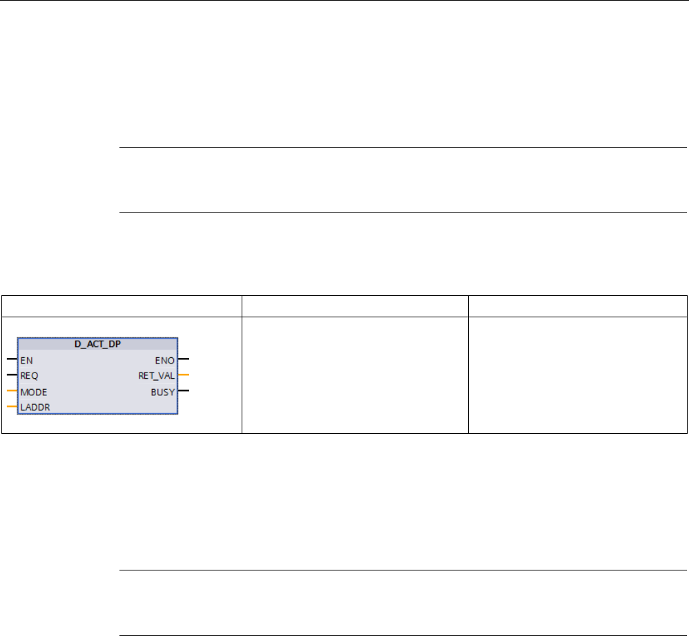
Extended instructions
9.3 Distributed I/O (PROFINET, PROFIBUS, or AS-i)
S7-1200 Programmable controller
398 System Manual, V4.2, 09/2016, A5E02486680-AK
9.3.8
D_ACT_DP (Enable/disable PROFINET IO devices)
With the "D_ACT_DP" instruction, you can disable and enable configured PROFINET IO
devices in a targeted manner. In addition, you can determine whether each assigned
PROFINET IO device is currently activated or deactivated.
Note
You can only use the D_ACT_DP instruction with PROFINET IO devices. You cannot use
the instruction with PROFIBUS DP slaves.
Table 9- 84 D_ACT_DP instruction
LAD / FBD
SCL
Description
"D_ACT_DP_DB"(
req:=_bool_in_,
mode:=_usint_in_,
laddr:=_uint_in_,
ret_val=>_int_out_,
busy=>_bool_out_);
Use the D_ACT_DP instruction to
disable and enable configured
PROFINET IO devices and determine
whether each assigned PROFINET
IO device is currently activated or
deactivated.
1
STEP 7 automatically creates the DB when you insert the instruction.
2 In the SCL example, "D_ACT_DP_SFB_DB" is the name of the instance DB.
You cannot disable/enable an IE/PB Link PN IO type of gateway using the D_ACT_DP
instruction. If you nevertheless use D_ACT_DP on the gateway named, the CPU returns the
value W#16#8093 (there is no hardware object that can be activated or deactivated for the
address specified in LADDR).
Note
The disabling or enabling
job requires several runs through the cycle control point.
Therefore, you cannot wait for the end of such a job in a programmed loop.
Functional description
D_ACT_DP is an asynchronous instruction, which means that the job processing extends
over multiple D_ACT_DP instruction executions. You start the job by calling D_ACT_DP with
REQ = 1.
The output parameters RET_VAL and BUSY indicate the status of the job.
Application
If you configure PROFINET IO devices in a CPU which are not actually present or not
currently required, the CPU nevertheless continues to access these PROFINET IO devices
at regular intervals. After the devices are deactivated, further CPU accessing stops. The
corresponding error events no longer occur.

Extended instructions
9.3 Distributed I/O (PROFINET, PROFIBUS, or AS-i)
S7-1200 Programmable controller
System Manual, V4.2, 09/2016, A5E02486680-AK 399
Examples
From a machine OEM's point of view, there are numerous device options possible in series
production of machines. However, each delivered machine includes only one combination of
selected options.
The manufacturer configures every one of these possible machine options as a PROFINET
IO device. The manufacturer does this in order to create and maintain a common user
program having all possible options. Use D_ACT_DP to deactivate all PROFINET IO devices
not present at machine startup.
A similar situation exists for machine tools having numerous tooling options available, but
actually using only a few of them at any given time. These tools are implemented as
PROFINET IO devices. With D_ACT_DP, the user program activates the tools currently
needed and deactivates those required later.
Identification of a job
If you have started a deactivation or activation job and you call D_ACT_DP again before the
job is complete, the behavior of the instruction depends on whether or not the new call
involves the same job. If the input parameter LADDR matches, the call is interpreted as a
follow-on call.
Deactivating PROFINET IO devices
When you deactivate a PROFINET IO device with D_ACT_DP, its process outputs are set to
the configured substitute values or to "0" (safe state). The assigned PROFINET IO controller
does not continue to address this component. The error LEDs on the PROFINET IO
controller or CPU do not identify the deactivated PROFINET IO devices as faulty or missing.
The CPU updates the process image inputs of deactivated PROFINET IO devices with "0".
Therefore, the CPU treats the deactivated PROFINET IO devices just like failed PROFINET
IO devices.
If you directly access the user data of a previously deactivated PROFINET IO device from
your program, the system behavior depends on the block’s error handling selection:
● If global error handling is enabled, the system enters an access error start event into the
diagnostic buffer and stays in RUN.
● If block-local error handling is enabled, the system enters an error cause in the error
structure. You can access the error cause using the GET_ERROR_ID (Page 311)
instruction.
An error for a read access returns "0". Refer to "Event execution priorities and queuing"
(Page 105) for further information on error handling.
If you attempt to access a deactivated PROFINET IO device using an instruction (such as
"RD_REC (Page 385)"), you receive the same error information in RET_VAL as for an
unavailable PROFINET IO device.
If a PROFINET IO station fails after you have deactivated it with D_ACT_DP, the operating
system does not detect the failure.

Extended instructions
9.3 Distributed I/O (PROFINET, PROFIBUS, or AS-i)
S7-1200 Programmable controller
400 System Manual, V4.2, 09/2016, A5E02486680-AK
Activating PROFINET IO devices
When you reactivate a PROFINET IO device with D_ACT_DP, the associated PROFINET IO
controller configures the component and assigns parameters (as with the return of a failed
PROFINET IO station). This activation is complete when the component is able to transfer
user data.
If you try to activate a PROFINET IO device that cannot be accessed (for example, because
it was physically separated from the bus) with a D_ACT_DP instruction, the instruction
returns the error code W#16#80A7 after expiration of the configured parameter assignment
time for distributed I/O. The PROFINET IO device is activated and the fact that the activated
PROFINET IO device cannot be accessed results in a corresponding display in the system
diagnostics.
If the PROFINET IO device is accessible again afterwards, this results in standard system
behavior.
Note
Activating a PROFINET IO device can be time
-consuming. If you want to cancel a currently
running activation job, start D_ACT_DP with the same value for LADDR and MODE
= 2. You
repeat the call for D_ACT_DP with MODE = 2 until the successful cancellation of the
activation job is displayed with RET_VAL
= 0.
Parameters
The following table shows the parameters of the D_ACT_DP instruction:
Parameter
Declara-
tion
Data type
Description
REQ IN Bool Level-triggered control parameter
REQ = 1: Run activation or deactivation
MODE IN USInt Job identifier
Possible values:
• 0: Request information on whether the addressed component
is activated or deactivated (output using RET_VAL parameter)
• 1: Activate the PROFINET IO device
• 2: Deactivate the PROFINET IO device
LADDR IN HW_DEVICE Hardware identifier of the PROFINET IO device (HW_Device)
The number can be taken from the properties of the PROFINET IO
device in the Network view or from the "System constants" tab of
the standard tag table.
If both the identifier for the device diagnostics as well as the ID for
operating state transitions are specified there, you must use the
code for the device diagnostics.

Extended instructions
9.3 Distributed I/O (PROFINET, PROFIBUS, or AS-i)
S7-1200 Programmable controller
System Manual, V4.2, 09/2016, A5E02486680-AK 401
Parameter
Declara-
tion
Data type
Description
RET_VAL OUT Int If an error occurs while the program executes the instruction, the
return value contains an error code.
BUSY OUT Bool Active code:
• BUSY = 1: The job is still active.
• BUSY = 0: The job was terminated.
Parameter RET_VAL
Error code*
(W#16#...)
Explanation
0000
Job completed without error.
0001 The PROFINET IO device is active (this error code is only possible with MODE = 0.)
0002 The PROFINET IO device is deactivated (this error code is only possible with
MODE = 0.)
7000
First call with REQ = 0: The job specified in LADDR is not active; BUSY has the value
"0".
7001
First call with REQ = 1. The program triggered the job specified in LADDR. BUSY has
the value "1".
7002 Intermediate call (REQ irrelevant). The activated job is still active; BUSY has the val-
ue "1".
8090 • You have not configured a module with the address specified in LADDR.
• You operate your CPU as I-slave / I-device, and you have specified an address of
this I-slave/I-device in LADDR.
8092
The deactivation of the currently addressed PROFINET IO device (MODE = 2) cannot
be canceled by being activated (MODE = 1). Activate the component at a later time.
8093 The address specified in LADDR does not belong to any PROFINET IO device that
can be activated or deactivated, or the MODE parameter is unknown.
8094 You have attempted to activate a device which is a potential partner for a tool change
port. However, another device is already activated on this tool change port at this
time. The activated device remains activated.
80A0 Error during the communication between the CPU and the IO controller.
80A1 Parameters cannot be assigned for the addressed component. (This error code is
only possible when MODE = 1.)
Note: If this component fails again during parameter assignment of the activated de-
vice, the D_ACT_DP instruction supplies the error information. If the parameter as-
signment of a single module is unsuccessful, D_ACT_DP returns the error information
W#16#0000.
80A3
The PROFINET IO controller concerned does not support this function.
80A4
The CPU does not support this function for an external PROFINET IO controller.

Extended instructions
9.3 Distributed I/O (PROFINET, PROFIBUS, or AS-i)
S7-1200 Programmable controller
402 System Manual, V4.2, 09/2016, A5E02486680-AK
Error code*
(W#16#...)
Explanation
80A6 Slot error in the PROFINET IO device; not all user data can be accessed (this error
code is only available when MODE = 1).
Note: D_ACT_DP returns this error information only if the activated component fails
again after parameter assignment and before the end of the D_ACT_DP instruction
execution. If only a single module is unavailable, D_ACT_DP returns the error infor-
mation W#16#0000.
80A7 A timeout occurred during activation: The remote device is unreachable, or you have
set the parameter assignment time for central and distributed I/O too short. The status
of the remote device is "activated", but it is not accessible.
80AA
Activation with errors in the PROFINET IO device: Differences in the configuration
80AB
Activation with errors in the PROFINET IO device: Parameter assignment error
80AC
Activation with errors in the PROFINET IO device: Maintenance required
80C1 D_ACT_DP has started and is being continued with another address (this error code
is possible when MODE = 1 and MODE = 2).
80C3 •
Temporary resource error: The CPU is currently processing the maximum possible
activation and deactivation jobs (8). (This error code is only possible when
MODE = 1 and MODE = 2.)
• The CPU is busy receiving a modified configuration. Currently, you cannot ena-
ble/disable PROFINET IO devices.
80C6
PROFINET: Jobs not collected by the user are discarded at restart.
General error
information
See the GET_ERROR_ID (Page 311) instruction for information on how to access the
error.
* The error codes in the program editor can be displayed as integer or hexadecimal values.

Extended instructions
9.3 Distributed I/O (PROFINET, PROFIBUS, or AS-i)
S7-1200 Programmable controller
System Manual, V4.2, 09/2016, A5E02486680-AK 403
9.3.9
STATUS parameter for RDREC, WRREC, and RALRM
The output parameter STATUS contains error information that is interpreted as ARRAY[1...4]
OF BYTE, with the following structure:
Table 9- 85 STATUS output array
Array element
Name
Description
STATUS[1] Function_Num • B#16#00, if no error
• Function ID from DPV1-PDU: If an error occurs, B#16#80 is OR'ed (for read
data record: B#16#DE; for write data record: B#16#DF). If no DPV1 protocol
element is used, then B#16#C0 will be output.
STATUS[2]
Error_Decode
Location of the error ID
STATUS[3]
Error_Code_1
Error ID
STATUS[4] Error_Code_2 Manufacturer-specific error ID expansion
Table 9- 86 STATUS[2] values
Error_decode
(B#16#....)
Source
Description
00 to 7F
CPU
No error or no warning
80
DPV1
Error according to IEC 61158-6
81 to 8F
CPU
B#16#8x shows an error in the "xth" call parameter of the instruction.
FE, FF
DP Profile
Profile-specific error

Extended instructions
9.3 Distributed I/O (PROFINET, PROFIBUS, or AS-i)
S7-1200 Programmable controller
404 System Manual, V4.2, 09/2016, A5E02486680-AK
Table 9- 87 STATUS[3] values
Error_decode
(B#16#....)
Error_code_1
(B#16#....)
Explanation (DVP1)
Description
00
00
No error, no warning
70 00 Reserved, reject Initial call; no active data record transfer
01
Reserved, reject
Initial call; data record transfer has started
02
Reserved, reject
Intermediate call; data record transfer already active
80
90
Reserved, pass
Invalid logical start address
92
Reserved, pass
Illegal type for Variant pointer
93 Reserved, pass The DP component addressed via ID or F_ID is not con-
figured.
96 The "RALRM (Page 394)" cannot supply the OB start
information, management information, header infor-
mation, or additional interrupt information.
For the following OBs, you can use the "DPNRM_DG
(Page 416)" instruction to read the current diagnostics
message frame of the relevant DP slave asynchronously
(address information from OB start information):
• Hardware interrupt (Page 95)
• Status (Page 102), Update (Page 103) or Profile
(Page 103)
• Diagnostic error interrupt (Page 97)
• Pull or plug of modules (Page 100)
A0 Read error Negative acknowledgement while reading from the mod-
ule
A1
Write error
Negative acknowledgement while writing to the module
A2 Module failure DP protocol error at layer 2 (for example, slave failure or
bus problems)
A3 Reserved, pass • PROFIBUS DP: DP protocol error with Direct-Data-
Link-Mapper or User-Interface/User
• PROFINET IO: General CM error
A4
Reserved, pass
Communication on the communication bus disrupted
A5
Reserved, pass
-
A7 Reserved, pass DP slave or modules is occupied (temporary error).
A8
Version conflict
DP slave or module reports non-compatible versions.
A9 Feature not supported Feature not supported by DP slave or module
AA to AF User specific DP slave or module reports a manufacturer-specific error
in its application. Please check the documentation from
the manufacturer of the DP slave or module.
B0 Invalid index Data record not known in module; illegal data record
number ≥ 256

Extended instructions
9.3 Distributed I/O (PROFINET, PROFIBUS, or AS-i)
S7-1200 Programmable controller
System Manual, V4.2, 09/2016, A5E02486680-AK 405
Error_decode
(B#16#....)
Error_code_1
(B#16#....)
Explanation (DVP1)
Description
B1 Write length error The length information in the RECORD parameter is
incorrect.
• With "RALRM": Length error in AINFO
Note
: Refer to the online information system of
STEP 7 for immediate access to information on how
to interpret the "AINFO" returned buffers.
• With "RDREC (Page 385)" and "WRREC
(Page 385)": Length error in "MLEN"
B2 Invalid slot The configured slot is not occupied.
B3 Type conflict Actual module type does not match specified module
type.
B4
Invalid area
DP slave or module reports access to an invalid area.
B5
Status conflict
DP slave or module not ready
B6
Access denied
DP slave or module denies access.
B7 Invalid range DP slave or module reports an invalid range for a param-
eter or value.
B8
Invalid parameter
DP slave or module reports an invalid parameter.
B9 Invalid type DP slave or module reports an invalid type:
• With "RDREC (Page 385)": Buffer too small (subsets
cannot be read)
• With "WRREC (Page 385)": Buffer too small (subsets
cannot be written)
BA to BF User specific DP slave or module reports a manufacturer-specific error
when accessing. Please check the documentation from
the manufacturer of the DP slave or module.
C0 Read constraint conflict • With "WRREC (Page 385)": The data can only be
written when the CPU is in STOP mode.
Note
: This means that data cannot be written by the
user program. You can only write the data online with
a PG/PC.
• With "RDREC (Page 385)": The module routes the
data record, but either no data is present or the data
can only be read when the CPU is in STOP mode.
Note
: If data can only be read when the CPU is in
STOP mode, no evaluation by the user program is
possible. In this case, you can only read the data
online with a PG/PC.
C1 Write constraint conflict The data of the previous write request to the module for
the same data record has not yet been processed by the
module.
C2 Resource busy The module is currently processing the maximum possi-
ble number of jobs for a CPU.
C3
Resource unavailable
The required operating resources are currently occupied.

Extended instructions
9.3 Distributed I/O (PROFINET, PROFIBUS, or AS-i)
S7-1200 Programmable controller
406 System Manual, V4.2, 09/2016, A5E02486680-AK
Error_decode
(B#16#....)
Error_code_1
(B#16#....)
Explanation (DVP1)
Description
C4 Internal temporary error. Job could not be carried out.
Repeat the job. If this error occurs often, check your
installation for sources of electrical interference.
C5 DP slave or module not available
C6 Data record transfer was cancelled due to priority class
cancellation.
C7 Job aborted due to warm or cold restart on the DP mas-
ter.
C8 to CF DP slave or module reports a manufacturer-specific re-
source error. Please check the documentation from the
manufacturer of the DP slave or module.
Dx User specific DP Slave specific. Refer to the description of the DP
Slave.
81 00 to FF Error in the initial call parameter (with "RALRM
(Page 394)": MODE)
00
Illegal operating mode
82
00 to FF
Error in the second call parameter
88 00 to FF Error in the eighth call parameter (with "RALRM
(Page 394)": TINFO)
Note
: Refer to the online information system of STEP 7
for immediate access to information on how to interpret
the "TINFO" returned buffers.
01
Wrong syntax ID
23
Quantity structure exceeded or destination area too small
24
Wrong range ID
32
DB/DI number out of user range
3A DB/DI number is NULL for area ID DB/DI, or specified
DB/DI does not exist.
89 00 to FF Error in the ninth call parameter (with "RALRM
(Page 394)": AINFO)
Note
: Refer to the online information system of STEP 7
for immediate access to information on how to interpret
the "AINFO" returned buffers.
01
Wrong syntax ID
23
Quantity structure exceeded or destination area too small
24
Wrong range ID
32
DB/DI number out of user range
3A DB/DI number is NULL for area ID DB/DI, or specified
DB/DI does not exist.
8A
00 to FF
Error in the 10th call parameter
8F
00 to FF
Error in the 15th call parameter
FE, FF
00 to FF
Profile-specific error

Extended instructions
9.3 Distributed I/O (PROFINET, PROFIBUS, or AS-i)
S7-1200 Programmable controller
System Manual, V4.2, 09/2016, A5E02486680-AK 407
Array element STATUS[4]
With DPV1 errors, the DP Master passes on STATUS[4] to the CPU and to the instruction.
Without a DPV1 error, this value is set to 0, with the following exceptions for the RDREC:
● STATUS[4] contains the target area length from RECORD, if MLEN > the destination
area length from RECORD.
● STATUS[4]=MLEN, if the actual data record length < MLEN < the destination area length
from RECORD.
● STATUS[4]=0, if STATUS[4] > 255; would have to be set
In PROFINET IO, STATUS[4] has the value 0.

Extended instructions
9.3 Distributed I/O (PROFINET, PROFIBUS, or AS-i)
S7-1200 Programmable controller
408 System Manual, V4.2, 09/2016, A5E02486680-AK
9.3.10
Others
9.3.10.1
DPRD_DAT and DPWR_DAT (Read/write consistent data)
Use the DPRD_DAT (Read consistent data) instruction to read one or more bytes of data
consistently, and use the DPWR_DAT (Write consistent data) instruction to transfer one or
more bytes of data consistently. You can use the DPRD_DAT and DPWR_DAT instructions
with PROFINET and PROFIBUS.
Table 9- 88 DPRD_DAT and DPWR_DAT instructions
LAD / FBD
SCL
Description
ret_val := DPRD_DAT(
laddr:=_word_in_,
record=>_variant_out_);
Use the DPRD_DAT instruction to read one or more
bytes of data from modules or submodules of one of
the following locations:
• Local base I/O
• DP slave
• PROFINET I/O device
The CPU transfers the data read consistently. If no
errors occur during the data transfer, the CPU enters
the read data into the target area set up by the
RECORD parameter. The target area must have the
same length as you configured with STEP 7 for the
selected module. When you execute the DPRD_DAT
instruction, you can only access the data of one
module or submodule. The transfer starts at the
configured start address.
ret_val := DPWR_DAT(
laddr:=_word_in_,
record:=_variant_in_);
Use the DPWR_DAT instruction to transfer the data
in RECORD consistently to the following locations:
• Addressed module or submodule in the local
base
• DP standard slave
• PROFINET I/O device
The source area must have the same length as you
configured with STEP 7 for the selected module or
submodule.
● The S7-1200 CPU supports consistent peripheral I/O read or write of 1, 2, or 4 bytes. Use
the DPRD_DAT instruction to consistently read and the DPWR_DAT instruction to
consistently write data of lengths other than 1, 2, or 4 bytes.
● You can use these instructions for data areas of 1 or more bytes. If the access is rejected,
error code W#16#8090 results.
● PROFINET supports up to 1024 bytes of consistent data. You do not need to use these
instructions for consistent transfers between the S7-1200 and PROFINET devices.

Extended instructions
9.3 Distributed I/O (PROFINET, PROFIBUS, or AS-i)
S7-1200 Programmable controller
System Manual, V4.2, 09/2016, A5E02486680-AK 409
Note
If you are using the DPRD_DAT and DPWR_DAT instructions with consistent data, you must
remove this consistent data from the process
-image automatic update. Refer to "PLC
concepts: Execution of the user program"
(Page 83) for more information.
Table 9- 89 Parameters
Parameter
Declaration
Data type
Description
LADDR IN HW_IO (Word) Hardware ID of the module from which the data is to be read.
(DPRD_DAT)
Hardware ID of the module to which the data is to be written.
(DPWR_DAT)
The hardware ID ca
n be found in the properties of the module in the device
view or system constants.
RECORD OUT Variant Destination area for the user data that were read (DPRD_DAT) or source
area for the user data to be written (DPWR_DAT). This must be exactly as
large as you configured for the selected module with STEP 7.
RET_VAL OUT Int If an error occurs while the function is active, the return value contains an
error code.
DPRD_DAT operations
Use the parameter LADDR to select the module of the DP standard slave / PROFINET IO
device. If an access error occurs on the addressed module, the error code W#16#8090 is
output.
Use the parameter RECORD to define the target range of the read data:
● The target range has to be at least as long as the inputs of the selected module. Only the
inputs are transferred; the other bytes are not considered. If you read from a DP standard
slave with a modular configuration or with several DP identifiers, you can only access the
data of a module of the configured hardware identifier for each DPRD_DAT instruction
call. If you select a target range that is too small, the error code W#16#80B1 is output at
the RET_VAL parameter.
● The following data types can be used: Byte, Char, Word, DWord, Int, UInt, USInt, SInt,
DInt, UDInt. The use of these data types in a User Defined Type (UDT) data structure of
the type ARRAY or STRUCT is permissible.
● The data type STRING is not supported.
● If there was no error during the data transmission, the data that have been read are
entered in the target range defined at the parameter RECORD.

Extended instructions
9.3 Distributed I/O (PROFINET, PROFIBUS, or AS-i)
S7-1200 Programmable controller
410 System Manual, V4.2, 09/2016, A5E02486680-AK
DPWR_DAT operations
Use the parameter LADDR to select the module of the DP standard slave / PROFINET IO
device. If an access error occurs on the addressed module, the error code W#16#8090 is
output.
Use the parameter RECORD to define the source range of the data to be written:
● The source range has to be at least as long as the outputs of the selected module. Only
the outputs are transferred; the other bytes are not considered. If the source range at the
parameter RECORD is longer than the outputs of the configured module, only the data up
to the maximum length of the outputs is transferred. If the source range at the parameter
RECORD is shorter than the outputs of the configured module, the error code
W#16#80B1 is output at the RET_VAL parameter.
● The following data types can be used: Byte, Char, Word, DWord, Int, UInt, USInt, SInt,
DInt, UDInt. The use of these data types in a User Defined Type (UDT) data structure of
the type ARRAY or STRUCT is permissible.
● The data type STRING is not supported.
● The data is transferred synchronously, that is, the write process is completed when the
instruction is completed.
Error codes
Table 9- 90 DPRD_DAT and DPWR_DAT error codes
Error code 1
Description
0000
No error occurred
8090 One of the following cases apply:
• You have not configured a module for the specified logical base address.
• You have ignored the restriction concerning the length of consistent data.
• You have not entered the start address in the LADDR parameter in hexadecimal format.
8092 The RECORD parameter supports the following data types: Byte, Char, Word, DWord, Int, UInt,
USInt, SInt, DInt, UDInt, and arrays of these types.
8093 No DP module/PROFINET IO device from which you can read (DPRD_DAT) or to which you can
write (DPWR_DAT) consistent data exists at the logical address specified in LADDR.
80A0
Access error detected while the I/O devices were being accessed (DPRD_DAT).
80B1 The length of the specified destination (DPRD_DAT) or source (DPWR_D
AT) area is not identical to
the user data length configured with STEP 7 Basic.
80B2
System error with external DP interface module (DPRD_DAT) and (DPWR_DAT)
1 When displaying the DPRD_DAT and DPWR_DAT error codes, use the Word data type.
Note
If
you access DPV1 slaves, error information from these slaves can be forwarded from the
DP master to the instruction.
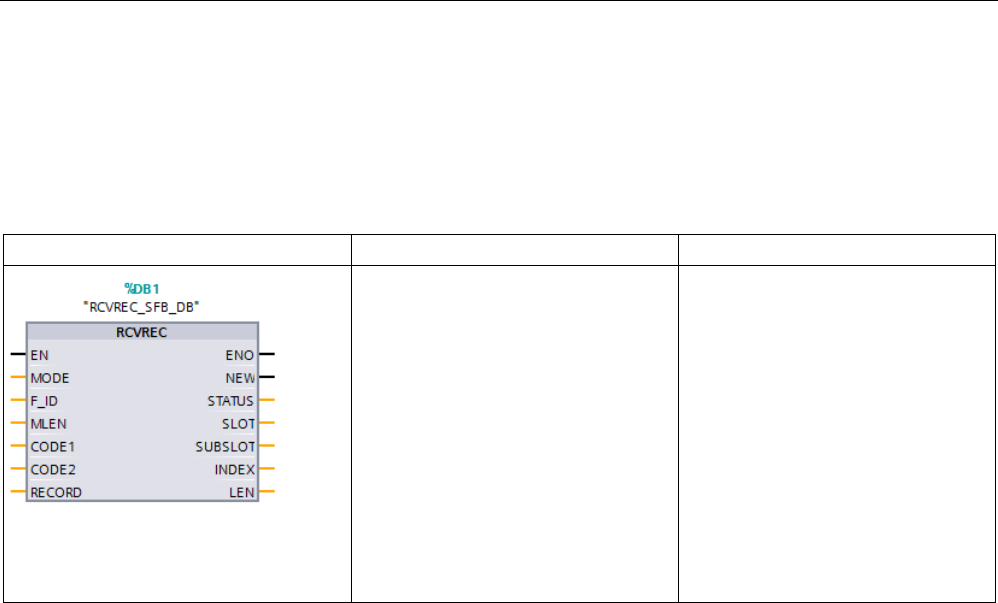
Extended instructions
9.3 Distributed I/O (PROFINET, PROFIBUS, or AS-i)
S7-1200 Programmable controller
System Manual, V4.2, 09/2016, A5E02486680-AK 411
9.3.10.2
RCVREC (I-device/I-slave receive data record)
An I-device can receive a data record from a higher-level controller. The receipt takes place
in the user program with the RCVREC instruction (receive data record).
Table 9- 91 RCVREC instruction
LAD / FBD
SCL
Description
"RCVREC_SFB_DB"(
mode:=_int_in_,
F_ID:=_uint_in_,
mlen:=_uint_in_,
code1:=_byte_in_,
code2:=_byte_in_,
new=>_bool_out_,
status=>_dword_out_,
slot=>_uint_out_,
subslot=>_uint_out_,
index=>_uint_out_
len=>_uint_out_,
rec-
ord:=_variant_inout_);
Use the RCVREC instruction to re-
ceive a data record from a higher-
level controller.
1
STEP 7 automatically creates the DB when you insert the instruction.
2 In the SCL example, "RCVREC_SFB_DB" is the name of the instance DB.
The instruction has the following operating modes:
● Check whether the I-device has a request for a data record receipt
● Make the data record available to the output parameters
● Send an answer to the higher-level controller
You can determine the operating mode executed by the instruction using the input parameter
MODE (see below).
The I-device must be in the RUN or STARTUP mode.
With MLEN, you specify the maximum number of bytes you want to receive. The selected
length of the target range RECORD should have at least the length of MLEN bytes.
If a data record is received (MODE = 1 or MODE = 2), the output parameter NEW indicates
that the data record is stored in RECORD. Note that RECORD has a sufficient length. The
output parameter LEN contains the actual length of the data record received in bytes.

Extended instructions
9.3 Distributed I/O (PROFINET, PROFIBUS, or AS-i)
S7-1200 Programmable controller
412 System Manual, V4.2, 09/2016, A5E02486680-AK
Set CODE1 and CODE2 to zero for the positive answer to the higher-level controller. If the
received data record is to be rejected, enter the negative answer to the higher-level
controller in Error Code 1 of the CODE1 and in Error Code 2 of the CODE2.
Note
If the I
-device has received a request for a data record receipt, you must recognize the
delivery of this request within
a certain duration. After recognition, you must send an answer
to the higher
-level controller within this time period. Otherwise, the I-device experiences a
timeout error which causes the operating system of the I
-device to send a negative answer
to the h
igher-level controller. For information on the value for the time period, refer to the
specifications of your CPU.
The STATUS output parameter receives the error information after the occurrence of an
error.
Operating modes
You can determine the operating mode of the RCVREC instruction with the input parameter
MODE. This step is explained in the following table:
MODE
Meaning
0 Check whether a request for a data record receipt exists
If a data record from a higher-level controller exists on the I-device, the instruction only writes to the NEW,
SLOT, SUBSLOT, INDEX, and LEN output parameters. If you call the instruction several times with MODE =
0, then the output parameter only refers to one and the same request.
1 Receiving a data record for any subslot of the I-device
If a data record from a higher-level controller exists on the I-device for any subslot of the I-device, the instruc-
tion writes to the output parameter and transfers the data record to the parameter RECORD.
2 Receiving a data record for a specific subslot of the I-device
If a data record from a higher-level controller exists on the I-device for a specific subslot of the I-device, the
instruction writes to the output parameter and transfers the data record to the parameter RECORD.
3 Sending a positive answer to the higher-level controller
The instruction checks the request of the higher-level controller to receive a data record, accepts the existing
data record, and sends a positive acknowledgment to the higher-level controller.
4 Sending a negative answer to the higher-level controller
The instruction checks the request of the higher-level controller to receive a data record, rejects the existing
data record, and sends a negative acknowledgment to the higher-level controller. Enter the reason for the
rejection in the input parameters CODE1 and CODE2.
Note
After the receipt of a data record (NEW = 1), you must call the RCVREC instruction twice to
ensure complete processing. You must do this in the following order:
•
First call with MODE = 1 or MODE = 2
•
Second call with MODE = 3 or MODE = 4

Extended instructions
9.3 Distributed I/O (PROFINET, PROFIBUS, or AS-i)
S7-1200 Programmable controller
System Manual, V4.2, 09/2016, A5E02486680-AK 413
Parameters
The following table shows the parameters of the RCVREC instruction:
Parameter
Declara-
tion
Data type
Description
MODE
IN
Int
Mode
F_ID IN HW_SUBMODULE Subslot in the transfer area of the I-device for the data record to
be received (only relevant for MODE = 2). The high word is always
set to zero.
MLEN
IN
Int
Maximum length of the data record to be received in bytes
CODE1
IN
Byte
Zero (for MODE = 3) and/or Error Code 1 (for MODE = 4)
CODE2
IN
Byte
Zero (for MODE = 3) and/or Error Code 2 (for MODE = 4)
NEW OUT Bool • MODE = 0: New data record was received
• MODE = 1 or 2: Data record was transferred to RECORD
STATUS OUT DWord Error information. Refer to "STATUS parameter" (Page 403) for
more information.
SLOT
OUT
HW_SUBMODULE
Identical to F_ID
SUBSLOT
OUT
HW_SUBMODULE
Identical to F_ID
INDEX
OUT
UInt
Number of the data record received
LEN
OUT
UInt
Length of the data record received
RECORD
IN_OUT
Variant
Target range for the data record received
9.3.10.3
PRVREC (I-device/I-slave make data record available)
An I-device can receive a request from a higher-level controller to make a data record
available. The I-device makes the data record available in the user program with the
PRVREC instruction (make data record available).
Table 9- 92 PRVREC instruction
LAD / FBD
SCL
Description
"PRVREC_SFB_DB"(
mode:=_int_in_,
F_ID:=_uint_in_,
code1:=_byte_in_,
code2:=_byte_in_,
len:=_uint_in_,
new=>_bool_out_,
status=>_dword_out_,
slot=>_uint_out_,
subslot=>_uint_out_,
index=>_uint_out_
rlen=>_uint_out_,
rec-
ord:=_variant_inout_);
Use the PRVREC instruction to re-
ceive a request from a higher-level
controller to make a data record
available.
1
STEP 7 automatically creates the DB when you insert the instruction.
2 In the SCL example, "PRVREC_SFB_DB" is the name of the instance DB.

Extended instructions
9.3 Distributed I/O (PROFINET, PROFIBUS, or AS-i)
S7-1200 Programmable controller
414 System Manual, V4.2, 09/2016, A5E02486680-AK
The instruction has the following operating modes:
● Check whether the I-device has a request for making a data record available
● Transfer the requested data record to the higher-level controller
● Sending an answer to the higher-level controller
You can determine the operating mode executed by the instruction using the input parameter
MODE (see below).
The I-device must be in the RUN or STARTUP mode.
Enter the maximum number of bytes the data record to be sent should have with LEN. The
selected length of the target range RECORD should have at least the length of LEN bytes.
If a request to make a data record available exists, (MODE = 0), the output parameter NEW
is set to TRUE.
If the request for making a data record available is accepted, write RECORD for the positive
answer to the higher-level controller with the requested data record and write zero for
CODE1 and CODE2. If the request for making a data record available is to be rejected, enter
the negative answer to the higher-level controller in Error Code 1 of the CODE1 and in Error
Code 2 of the CODE2.
Note
If the I
-device has received a request for making a data record available, you must recognize
the delivery of this request within a certain time period. After recognition, you must send an
answer to the higher
-level controller within this time period. Otherwise, the I-device
experiences a timeout error which causes the operating system of the I
-device to send a
negative answer to the higher
-level controller. For information on the value for the time
period, refer to the specifications of your CPU.
The STATUS output parameter receives the error information after the occurrence of an
error.

Extended instructions
9.3 Distributed I/O (PROFINET, PROFIBUS, or AS-i)
S7-1200 Programmable controller
System Manual, V4.2, 09/2016, A5E02486680-AK 415
Operating modes
You can determine the operating mode of the PRVREC instruction with the input parameter
MODE. This step is explained in the following table:
MODE
Meaning
0 Check whether a request for making a data record available exists
If a request from a higher-level controller for making a data record available exists on the I-device, the instruc-
tion only writes to the NEW, SLOT, SUBSLOT, INDEX, and RLEN outp
ut parameters. If you call the instruction
several times with MODE = 0, then the output parameter only refers to one and the same request.
1 Receiving a request for making a data record available for any subslot of the I-device
If such a request from a higher-level controller for any subslot of the I-device exists on the I-device, the instruc-
tion writes to the output parameter.
2 Receiving a request for making a data record available for a specific subslot of the I-device
If such a request from a higher-level controller for a specific subslot of the I-device exists on the I-device, the
instruction writes to the output parameter.
3 Make the data record available and send a positive answer to the higher-level controller
The instruction checks the request of the higher-level controller to make a data record available, makes the
request data record available to RECORD, and sends a positive acknowledgement to the higher-level control-
ler.
4 Sending a negative answer to the higher-level controller
The instruction checks the request of the higher-level controller to make a data record available, rejects this
request, and sends a negative acknowledgement to the higher-level controller. Enter the reason for the rejec-
tion in the input parameters CODE1 and CODE2.
Note
After the receipt of a request (NEW = 1), you must call the PRVREC instruction twice to
ensure complete processing. You must do this in the following order:
•
First call with MODE = 1 or MODE = 2
•
Second call with MODE = 3 or MODE = 4
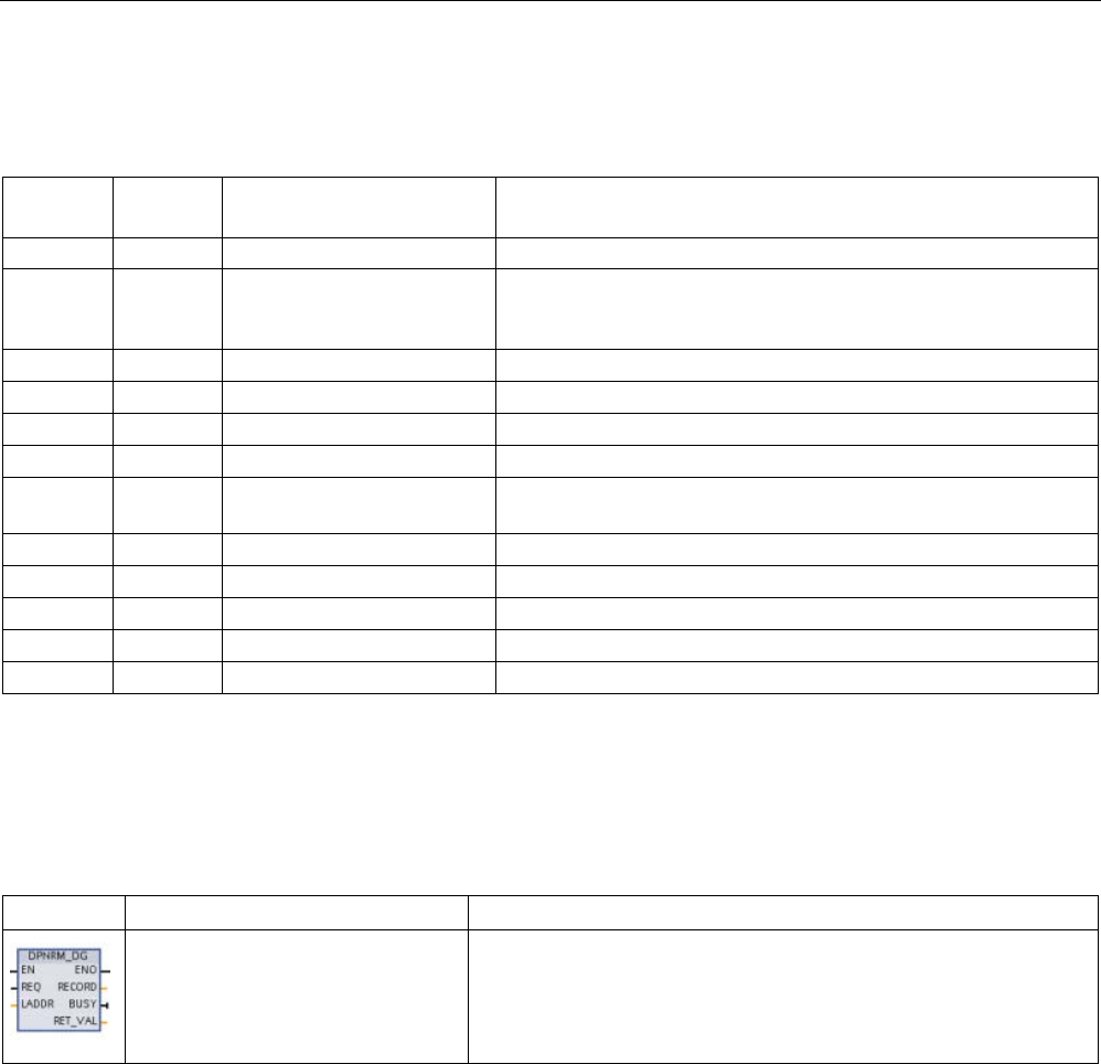
Extended instructions
9.3 Distributed I/O (PROFINET, PROFIBUS, or AS-i)
S7-1200 Programmable controller
416 System Manual, V4.2, 09/2016, A5E02486680-AK
Parameters
The following table shows the parameters of the PRVREC instruction:
Parameter
Declara-
tion
Data type
Description
MODE
IN
Int
Mode
F_ID IN HW_SUBMODULE Subslot in the transfer area of the I-
device for the data record to be
sent (only relevant for MODE = 2). The high word is always set to
zero.
CODE1
IN
Byte
Zero (for MODE = 3) and/or Error Code 1 (for MODE = 4)
CODE2
IN
Byte
Zero (for MODE = 3) and/or Error Code 2 (for MODE = 4)
LEN
IN
UInt
Maximum length of the data record to be sent in bytes
NEW
OUT
Bool
The new data record was requested by the higher-level controller.
STATUS OUT DWord Error information. Refer to "STATUS parameter" (Page 403) for
more information.
SLOT
OUT
HW_SUBMODULE
Identical to F_ID
SUBSLOT
OUT
HW_SUBMODULE
Identical to F_ID
INDEX
OUT
UInt
Number of the data record to be sent
RLEN
OUT
UInt
Length of the data record to be sent
RECORD
IN_OUT
Variant
Data record made available
9.3.10.4
DPNRM_DG (Read diagnostic data from a PROFIBUS DP slave)
You can use the DPNRM_DG (Read diagnostic data) instruction with PROFIBUS.
Table 9- 93 DPNRM_DG instruction
LAD / FBD
SCL
Description
ret_val := DPNRM_DG(
req:=_bool_in_,
laddr:=_word_in_,
record=>_variant_out_,
busy=>_bool_out_);
Use the DPNRM_DG instruction to read the current diagnostic data of
a DP slave in the format specified by EN 50 170 Volume 2,
PROFIBUS. The data that has been read is entered in the destination
area indicated by RECORD following error-free data transfer.

Extended instructions
9.3 Distributed I/O (PROFINET, PROFIBUS, or AS-i)
S7-1200 Programmable controller
System Manual, V4.2, 09/2016, A5E02486680-AK 417
Table 9- 94 DPNRM_DG instruction data types for the parameters
Parameter and type
Data type
Description
REQ
IN
Bool
REQ=1: Read request
LADDR IN HW_DPSLAVE Configured diagnostic address of the DP slave: Must be the address of
the station and not for the I/O device. Select the station (and not the
image of the device) in the "Network" view of the "Device configuration"
to determine the diagnostic address.
Enter the addresses in hexadecimal format. For example, diagnostic
address 1022 means LADDR:=W#16#3FE.
RET_VAL OUT Int If an error occurs while the function is active, the return value contains
an error code. If no error occurs, the length of the data actually trans-
ferred is entered in RET_VAL.
RECORD OUT Variant Destination area for the diagnostic data that were read. The minimum
length of the data record to be read (or the destination area) is 6 bytes.
The maximum length of the data record to be sent is 240 bytes.
Standard slaves can provide more than 240 bytes of diagnostic data up
to a maximum of 244 bytes. In this case, the first 240 bytes are trans-
ferred to the destination area, and the overflow bit is set in the data.
BUSY
OUT
Bool
BUSY=1: The read job is not yet completed
You start the read job by assigning 1 to the input parameter REQ in the DPNRM_DG
instruction call. The read job is executed asynchronously, in other words, it requires several
DPNRM_DG instruction calls. The status of the job is indicated by the output parameters
RET_VAL and BUSY.
Table 9- 95 Slave diagnostic data structure
Byte
Description
0
Station status 1
1
Station status 2
2
Station status 3
3
Master station number
4
Vendor ID (high byte)
5 Vendor ID (low byte)
6 ...
Additional slave-specific diagnostic information

Extended instructions
9.3 Distributed I/O (PROFINET, PROFIBUS, or AS-i)
S7-1200 Programmable controller
418 System Manual, V4.2, 09/2016, A5E02486680-AK
Table 9- 96 DPNRM_DG instruction error codes
Error code
Description
Restriction
0000
No error
-
7000 First call with REQ=0: No data transfer active; BUSY has the value 0. -
7001
First call with REQ =1: No data transfer active; BUSY has the value 1.
Distributed I/Os
7002 Interim call (REQ irrelevant): Data transfer already active; BUSY has the
value 1.
Distributed I/Os
8090
Specified logical base address invalid: There is no base address.
-
8092 The RECORD parameter supports the following data types: Byte, Char,
Word, DWord, Int, UInt, USInt, SInt, DInt, UDInt, and arrays of these types.
-
8093 • This instruction is not permitted for the module specified by LADDR
(S7-DP modules for S7-1200 are permitted).
•
LADDR specifies the I/O device instead of specifying the station. Select
the station (and not the image of the device) in the "Network" view of
the "Device configuration" to determine the diagnostic address for
LADDR.
-
80A2 • DP protocol error at layer 2 (for example, slave failure or bus problems)
• For ET200S, data record cannot be read in DPV0 mode.
Distributed I/Os
80A3
DP protocol error with user interface/user
Distributed I/Os
80A4 Communication problem on the communication bus
The error occurs between the
CPU and the external DP
interface module.
80B0 • The instruction is not possible for module type.
• The module does not recognize the data record.
• Data record number 241 is not permitted.
-
80B1 The length specified in the RECORD parameter is incorrect. Specified length > record
length
80B2
The configured slot is not occupied.
-
80B3
Actual module type does not match the required module type.
-
80C0
There is no diagnostic information.
-
80C1 The data of the previous write job for the same data record on the module
have not yet been processed by the module.
-
80C2 The module is currently processing the maximum possible number of jobs
for a CPU.
-
80C3
The required resources (memory, etc.) are currently occupied.
-
80C4 Internal temporary error. The job could not be processed.
Repeat the job. If this error occurs frequently, check your system for elec-
trical disturbance sources.
-
80C5
Distributed I/Os not available
Distributed I/Os
80C6 Data record transfer was stopped due to a priority class abort (restart or
background)
Distributed I/Os
8xyy
1
General error codes
Refer to "Extended instructions, Distributed I/O: Error information for RDREC, WRREC, and
RALRM" (Page 403) for more information on general error codes.

Extended instructions
9.4 PROFIenergy
S7-1200 Programmable controller
System Manual, V4.2, 09/2016, A5E02486680-AK 419
9.4
PROFIenergy
PROFIenergy is a manufacturer- and device-neutral profile for energy management with
PROFINET. To reduce electricity consumption during breaks in production and unplanned
interruptions, it is possible to shut down equipment in a coordinated and centralized manner
using PROFIenergy.
The PROFINET IO controller switches off the PROFINET devices/power modules using
special commands in the user program. You require no additional hardware. The PROFINET
devices interpret the PROFIenergy commands directly.
The S7-1200 CPU does not support the PE controller functionality. The S7-1200 CPU can
only act as a PROFIenergy entity (with I-device functionality).
PROFIenergy controller (PE controller)
The PE controller is a higher-level CPU (for example, an S7-1500) that activates or
deactivates the idle state of lower-level devices. The PE controller deactivates and
reactivates specific production components or complete production lines using the user
program. Lower-level devices receive commands from the user program through
corresponding instructions (function blocks).
The user program sends the commands using the PROFINET communication protocol. The
PE command can be either a control command to switch a PE entity to the energy-saving
mode, or a command to read a status or measured value.
You use the PE_I_DEV instruction to request data from a module. The user program has to
determine what information is being requested by the PE controller and retrieve it from the
energy module using data records. The module itself does not directly support the PE
commands. The module stores the energy measurement information in a shared area, and
the lower-level CPU (for example, an S7-1200) triggers the PE_I_DEV instruction to return it
to the PE controller.
PROFIenergy entity (PE entity)
The PE entity (for example, an S7-1200) receives the PROFIenergy commands of the PE
controller (for example, an S7-1200) and executes these accordingly (for example, by
returning a measured value or activating an energy saving mode). Implementation of the PE
entity in a PROFIenergy-capable device is device- and manufacturer-specific.
Reference information
You can find further information on PROFIenergy in the TIA Portal STEP 7 online help. You
can find examples that use the PROFIenergy instructions in the Industry Online Support in
the entry "PROFIenergy - Saving Energy with SIMATIC S7
(http://support.automation.siemens.com/WW/view/en/41986454)".
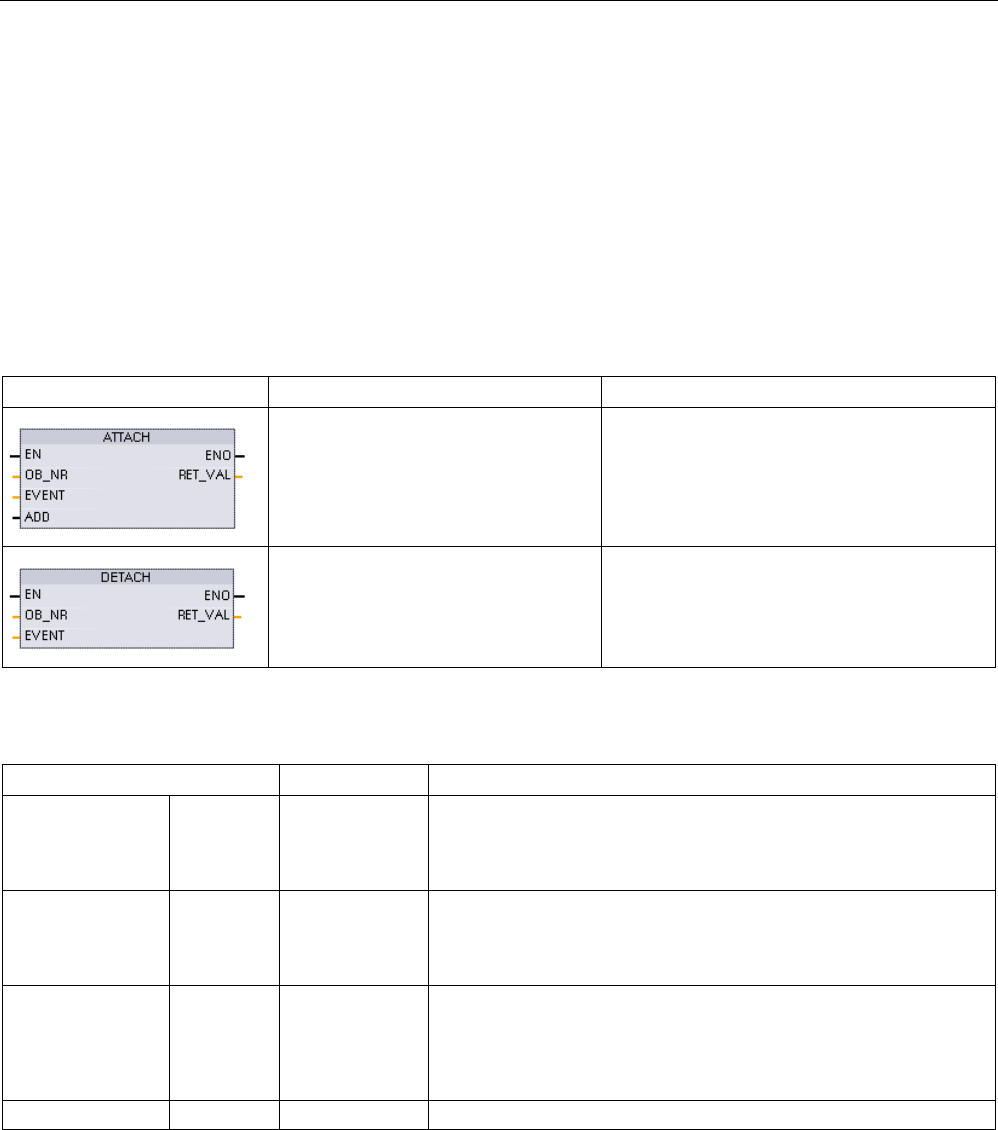
Extended instructions
9.5 Interrupts
S7-1200 Programmable controller
420 System Manual, V4.2, 09/2016, A5E02486680-AK
9.5
Interrupts
9.5.1
ATTACH and DETACH (Attach/detach an OB and an interrupt event)
instructions
You can activate and deactivate interrupt event-driven subprograms with the ATTACH and
DETACH instructions.
Table 9- 97 ATTACH and DETACH instructions
LAD / FBD
SCL
Description
ret_val := ATTACH(
ob_nr:=_int_in_,
event:=_event_att_in_,
add:=_bool_in_);
ATTACH enables interrupt OB subprogram
execution for a hardware interrupt event.
ret_val := DETACH(
ob_nr:=_int_in_,
event:=_event_att_ in);
DETACH disables interrupt OB subprogram
execution for a hardware interrupt event.
Table 9- 98 Data types for the parameters
Parameter and type
Data type
Description
OB_NR IN OB_ATT Organization block identifier: Select from the available hardware
interrupt OBs that were created using the "Add new block" feature.
Double-click on the parameter field, then click on the helper icon to
see the available OBs.
EVENT IN EVENT_ATT Event identifier: Select from the available hardware interrupt events
that were enabled in PLC device configuration for digital inputs or
high-speed counters. Double-click on the parameter field, then click
on the helper icon to see the available events.
ADD
(ATTACH only)
IN Bool • ADD = 0 (default): This event replaces all previous event attach-
ments for this OB.
• ADD = 1: This event is added to previous event attachments for
this OB.
RET_VAL
OUT
Int
Execution condition code

Extended instructions
9.5 Interrupts
S7-1200 Programmable controller
System Manual, V4.2, 09/2016, A5E02486680-AK 421
Hardware interrupt events
The following hardware interrupt events are supported by the CPU:
● Rising edge events: first 12 built-in CPU digital inputs (DIa.0 to DIb.3) and all SB digital
inputs
– A rising edge occurs when the digital input transitions from OFF to ON as a response
to a change in the signal from a field device connected to the input.
● Falling edge events: first 12 built-in CPU digital inputs (DIa.0 to DIb.3) and all SB digital
inputs
– A falling edge occurs when the digital input transitions from ON to OFF.
● High-speed counter (HSC) current value = reference value (CV = RV) events (HSC 1
through 6)
– A CV = RV interrupt for a HSC is generated when the current count transitions from an
adjacent value to the value that exactly matches a reference value that was previously
established.
● HSC direction changed events (HSC 1 through 6)
– A direction changed event occurs when the HSC is detected to change from
increasing to decreasing, or from decreasing to increasing.
● HSC external reset events (HSC 1 through 6)
– Certain HSC modes allow the assignment of a digital input as an external reset that is
used to reset the HSC count value to zero. An external reset event occurs for such a
HSC, when this input transitions from OFF to ON.
Enabling hardware interrupt events in the device configuration
Hardware interrupts must be enabled during the device configuration. You must check the
enable-event box in the device configuration for a digital input channel or a HSC, if you want
to attach this event during configuration or run time.
Check box options within the PLC device configuration:
● Digital input
– Enable rising edge detection
– Enable falling edge detection
● High-speed counter (HSC)
– Enable this high-speed counter for use
– Generate interrupt for counter value equals reference value count
– Generate interrupt for external reset event
– Generate interrupt for direction change event

Extended instructions
9.5 Interrupts
S7-1200 Programmable controller
422 System Manual, V4.2, 09/2016, A5E02486680-AK
Adding new hardware interrupt OB code blocks to your program
By default, no OB is attached to an event when the event is first enabled. This is indicated by
the "HW interrupt:" device configuration "<not connected>" label. Only hardware-interrupt
OBs can be attached to a hardware interrupt event. All existing hardware-interrupt OBs
appear in the "HW interrupt:" drop-down list. If no OB is listed, then you must create an OB
of type "Hardware interrupt" as follows. Under the project tree "Program blocks" branch:
1. Double-click "Add new block", select "Organization block (OB)" and choose "Hardware
interrupt".
2. Optionally, you can rename the OB, select the programming language (LAD, FBD or
SCL), and select the block number (switch to manual and choose a different block
number than that suggested).
3. Edit the OB and add the programmed reaction that you want to execute when the event
occurs. You can call FCs and FBs from this OB, to a nesting depth of six.
OB_NR parameter
All existing hardware-interrupt OB names appear in the device configuration "HW interrupt:"
drop-down list and in the ATTACH / DETACH parameter OB_NR drop-list.
EVENT parameter
When a hardware interrupt event is enabled, a unique default event name is assigned to this
particular event. You can change this event name by editing the "Event name:" edit box, but
it must be a unique name. These event names become tag names in the "Constants" tag
table, and appear on the EVENT parameter drop-down list for the ATTACH and DETACH
instruction boxes. The value of the tag is an internal number used to identify the event.
General operation
Each hardware event can be attached to a hardware-interrupt OB which will be queued for
execution when the hardware interrupt event occurs. The OB-event attachment can occur at
configuration time or at run time.
You have the option to attach or detach an OB to an enabled event at configuration time. To
attach an OB to an event at configuration time, you must use the "HW interrupt:" drop-down
list (click on the down arrow on the right) and select an OB from the list of available
hardware-interrupt OBs. Select the appropriate OB name from this list, or select "<not
connected>" to remove the attachment.
You can also attach or detach an enabled hardware interrupt event during run time. Use the
ATTACH or DETACH program instructions during run time (multiple times if you wish) to
attach or detach an enabled interrupt event to the appropriate OB. If no OB is currently
attached (either from a "<not connected>" selection in device configuration, or as a result of
executing a DETACH instruction), the enabled hardware interrupt event is ignored.

Extended instructions
9.5 Interrupts
S7-1200 Programmable controller
System Manual, V4.2, 09/2016, A5E02486680-AK 423
DETACH operation
Use the DETACH instruction to detach either a particular event or all events from a particular
OB. If an EVENT is specified, then only this one event is detached from the specified
OB_NR; any other events currently attached to this OB_NR will remain attached. If no
EVENT is specified, then all events currently attached to OB_NR will be detached.
Condition codes
Table 9- 99 Condition codes
RET_VAL (W#16#....)
ENO
Description
0000
1
No error
0001 1 Nothing to Detach (DETACH only)
8090
0
OB does not exist
8091
0
OB is wrong type
8093
0
Event does not exist
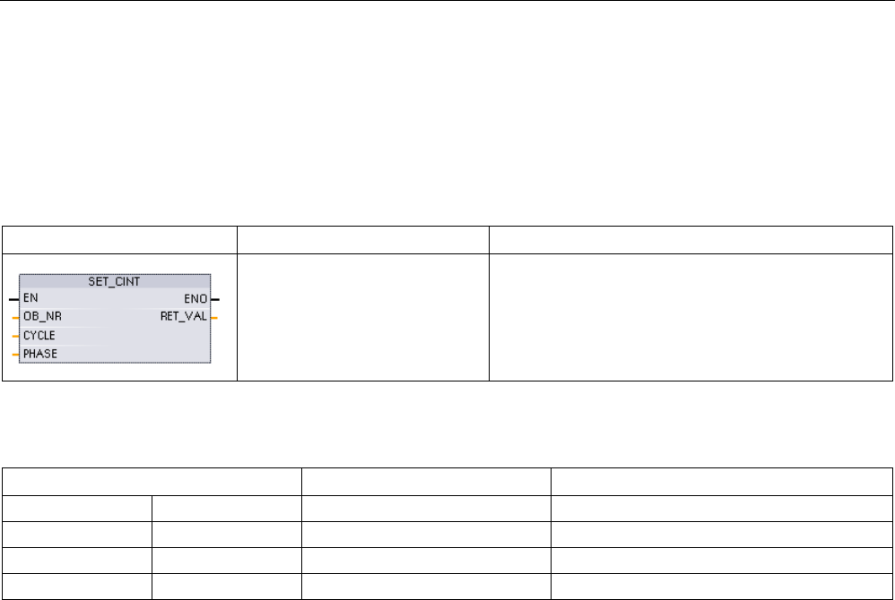
Extended instructions
9.5 Interrupts
S7-1200 Programmable controller
424 System Manual, V4.2, 09/2016, A5E02486680-AK
9.5.2
Cyclic interrupts
9.5.2.1
SET_CINT (Set cyclic interrupt parameters)
Table 9- 100 SET_CINT (Set cyclic interrupt parameters)
LAD / FBD
SCL
Description
ret_val := SET_CINT(
ob_nr:=_int_in_,
cycle:=_udint_in_,
phase:=_udint_in_);
Set the specified interrupt OB to begin cyclic execution
that interrupts the program scan.
Table 9- 101 Data types for the parameters
Parameter and type
Data type
Description
OB_NR
IN
OB_CYCLIC
OB number (accepts symbolic name)
CYCLE
IN
UDInt
Time interval, in microseconds
PHASE
IN
UDInt
Phase shift, in microseconds
RET_VAL
OUT
Int
Execution condition code
Examples: time parameter
● If the CYCLE time = 100 us, then the interrupt OB referenced by OB_NR interrupts the
cyclic program scan every 100 us. The interrupt OB executes and then returns execution
control to the program scan, at the point of interruption.
● If the CYCLE time = 0, then the interrupt event is deactivated and the interrupt OB is not
executed.
● The PHASE (phase shift) time is a specified delay time that occurs before the CYCLE
time interval begins. You can use the phase shift to control the execution timing of lower
priority OBs.
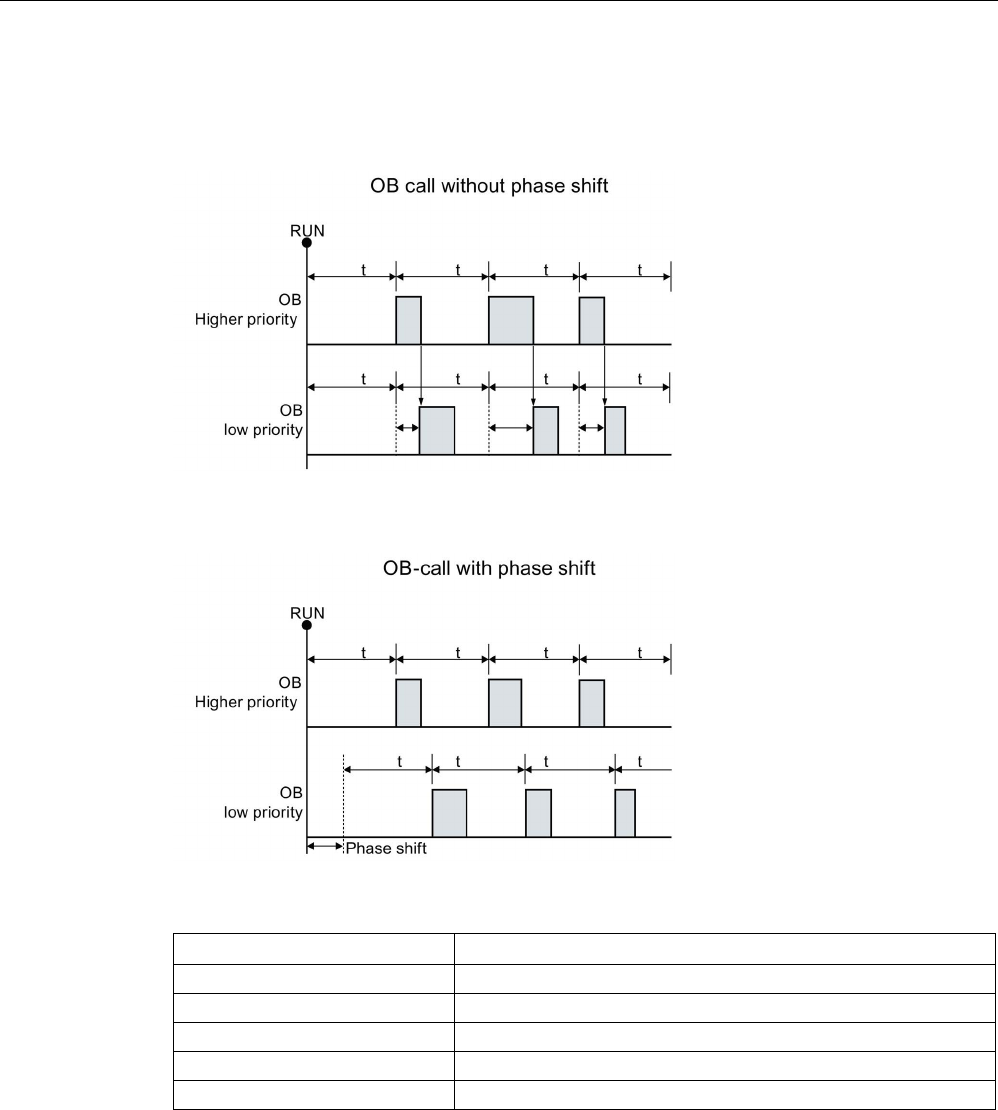
Extended instructions
9.5 Interrupts
S7-1200 Programmable controller
System Manual, V4.2, 09/2016, A5E02486680-AK 425
If lower and higher priority OBs are called in the same time interval, the lower priority OB is
only called after the higher priority OB has finished processing. The execution start time for
the low priority OB can shift depending on the processing time of higher priority OBs.
If you want to start the execution of a lower priority OB on a fixed time cycle, then phase shift
time should be greater then the processing time of higher priority OBs.
Table 9- 102 Condition codes
RET_VAL (W#16#....)
Description
0000
No error
8090
OB does not exist or is of wrong type
8091
Invalid cycle time
8092
Invalid phase shift time
80B2
OB has no attached event
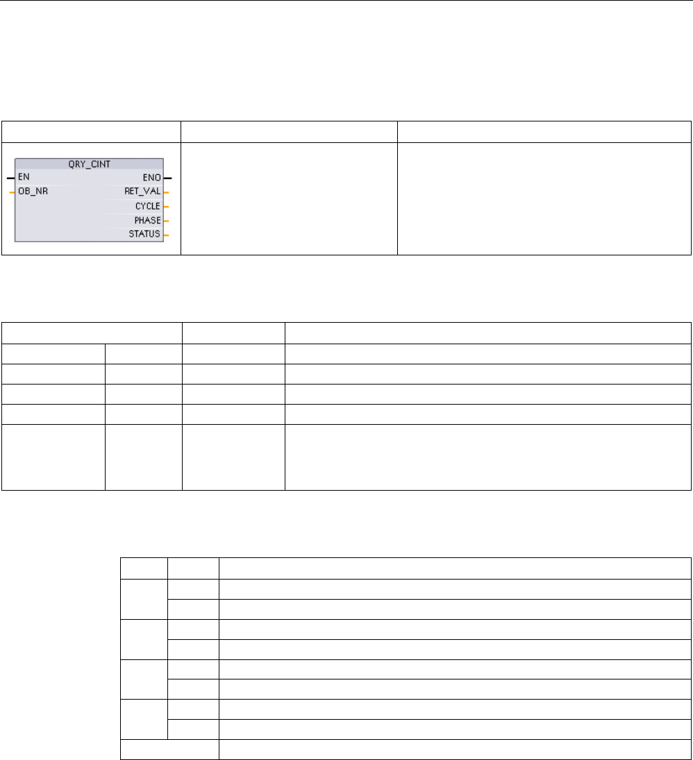
Extended instructions
9.5 Interrupts
S7-1200 Programmable controller
426 System Manual, V4.2, 09/2016, A5E02486680-AK
9.5.2.2
QRY_CINT (Query cyclic interrupt parameters)
Table 9- 103
QRY_CINT (Query cyclic interrupt)
LAD / FBD
SCL
Description
ret_val := QRY_CINT(
ob_nr:=_int_in_,
cycle=>_udint_out_,
phase=>_udint_out__,
status=>_word_out_);
Get parameter and execution status from a cyclic
interrupt OB. The values that are returned existed
at the time QRY_CINT was executed.
Table 9- 104 Data types for the parameters
Parameter and type
Data type
Description
OB_NR
IN
OB_CYCLIC
OB number (accepts symbolic name like OB_MyOBName)
RET_VAL
OUT
Int
Execution condition code
CYCLE
OUT
UDInt
Time interval, in microseconds
PHASE
OUT
UDInt
Phase shift, in microseconds
STATUS OUT Word Cyclic interrupt status code:
• Bits 0 to 4, see the STATUS table below
• Other bits, always 0
Table 9- 105 STATUS parameter
Bit
Value
Description
0
0
During CPU RUN
1
During startup
1
0
The interrupt is enabled.
1
Interrupt is disabled via the DIS_IRT instruction.
2 0 The interrupt is not active or has elapsed.
1
The interrupt is active.
4 0 The OB identified by OB_NR does not exist.
1
The OB identified by OB_NR exists.
Other Bits
Always 0
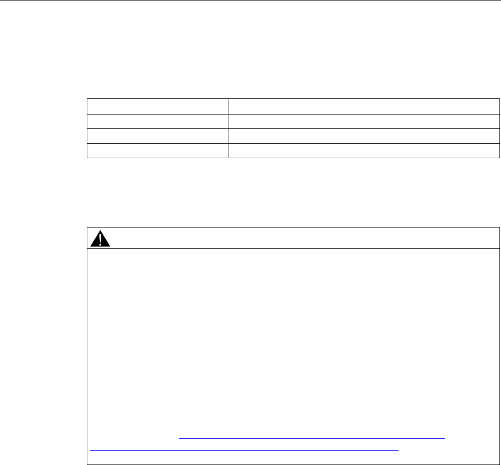
Extended instructions
9.5 Interrupts
S7-1200 Programmable controller
System Manual, V4.2, 09/2016, A5E02486680-AK 427
If an error occurs, RET_VAL displays the appropriate error code and the parameter STATUS
= 0.
Table 9- 106 RET_VAL parameter
RET_VAL (W#16#....)
Description
0000
No error
8090 OB does not exist or is of wrong type.
80B2
OB has no attached event.
9.5.3
Time of day interrupts
WARNING
If an attacker can access your networks through Network Time Protocol (NTP)
synchronization, the attacker can possibly take limited control of your process by shifting
the CPU system time.
The NTP client feature of the S7-1200 CPU is disabled by default, and, when enabled, only
allows configured IP addresses to act as an NTP server. The CPU disables this feature by
default, and you must configure this feature to allow remotely-controlled CPU system time
corrections.
The S7-1200 CPU supports "time of day" interrupts and clock instructions that depend upon
accurate CPU system time. If you configure NTP and accept time synchronization from a
server, you must ensure that the server is a trusted source. Failure to do so can cause a
security breach that allows an unknown user to take limited control of your process by
shifting the CPU system time.
For security information and recommendations, please see our "Operational Guidelines for
Industrial Security" (http://www.industry.siemens.com/topics/global/en/industrial-
security/Documents/operational_guidelines_industrial_security_en.pdf) on the Siemens
Service and Support site.
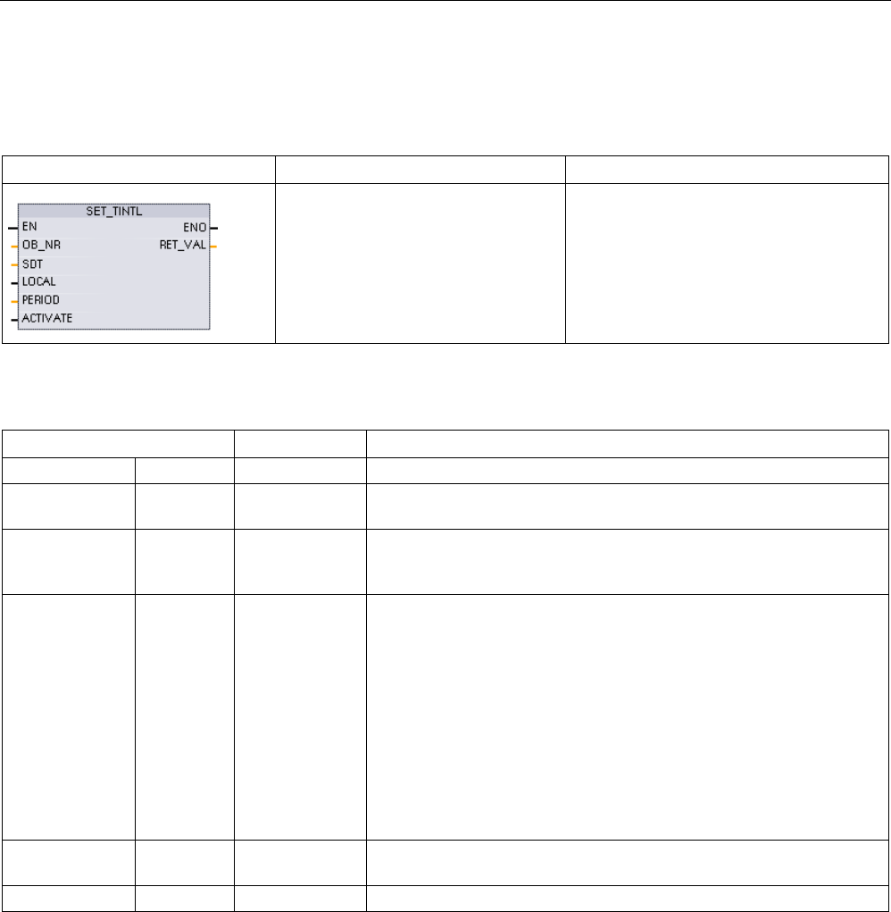
Extended instructions
9.5 Interrupts
S7-1200 Programmable controller
428 System Manual, V4.2, 09/2016, A5E02486680-AK
9.5.3.1
SET_TINTL (Set time of day interrupt)
Table 9- 107 SET_TINTL (Set date and time of day interrupt with DTL data type)
LAD / FBD
SCL
Description
ret_val := SET_TINTL(
OB_NR:=_int_in_,
SDT:=_dtl_in_,
LOCAL:=_bool_in_
PERIOD:=_word_in_
ACTIVATE:=_bool_in_);
Set a date and time of day interrupt. The
program interrupt OB can be set for one
execution, or for recurring execution with
an assigned time period.
Table 9- 108 Data types for the parameters
Parameter and type
Data type
Description
OB_NR
IN
OB_TOD (INT)
OB number (accepts symbolic name)
SDT IN DTL Start date and time: Seconds and milliseconds are ignored and can be
set to 0.
LOCAL IN Bool 0 = Use system time
1 = Use local time (if the CPU is configured for local time, otherwise
use system time)
PERIOD IN Word The period from the starting date and time for recurring interrupt event.
• W#16#0000 = Once
• W#16#0201 = Every minute
• W#16#0401 = Every hour
• W#16#1001 = Daily
• W#16#1201 = Weekly
• W#16#1401 = Monthly
• W#16#1801 = yearly
• W#16#2001 = End of month
ACTIVATE IN Bool 0 = ACT_TINT must be executed to activate the interrupt event.
1 = The interrupt event is activated.
RET_VAL
OUT
Int
Execution condition code
Your program can use SET_TINTL to set a date and time of day interrupt event that will
execute the assigned interrupt OB. The start date and time is set by parameter SDT and the
time period for recurring interrupts (for example, daily or weekly) is set by parameter
PERIOD. If you set the repetition period to monthly, then you must set the start date to a day
from 1 to 28. The days 29 to 31 may not be used because they do not occur in February. If
you want an interrupt event at the end of each month, then use end of month for parameter
PERIOD.
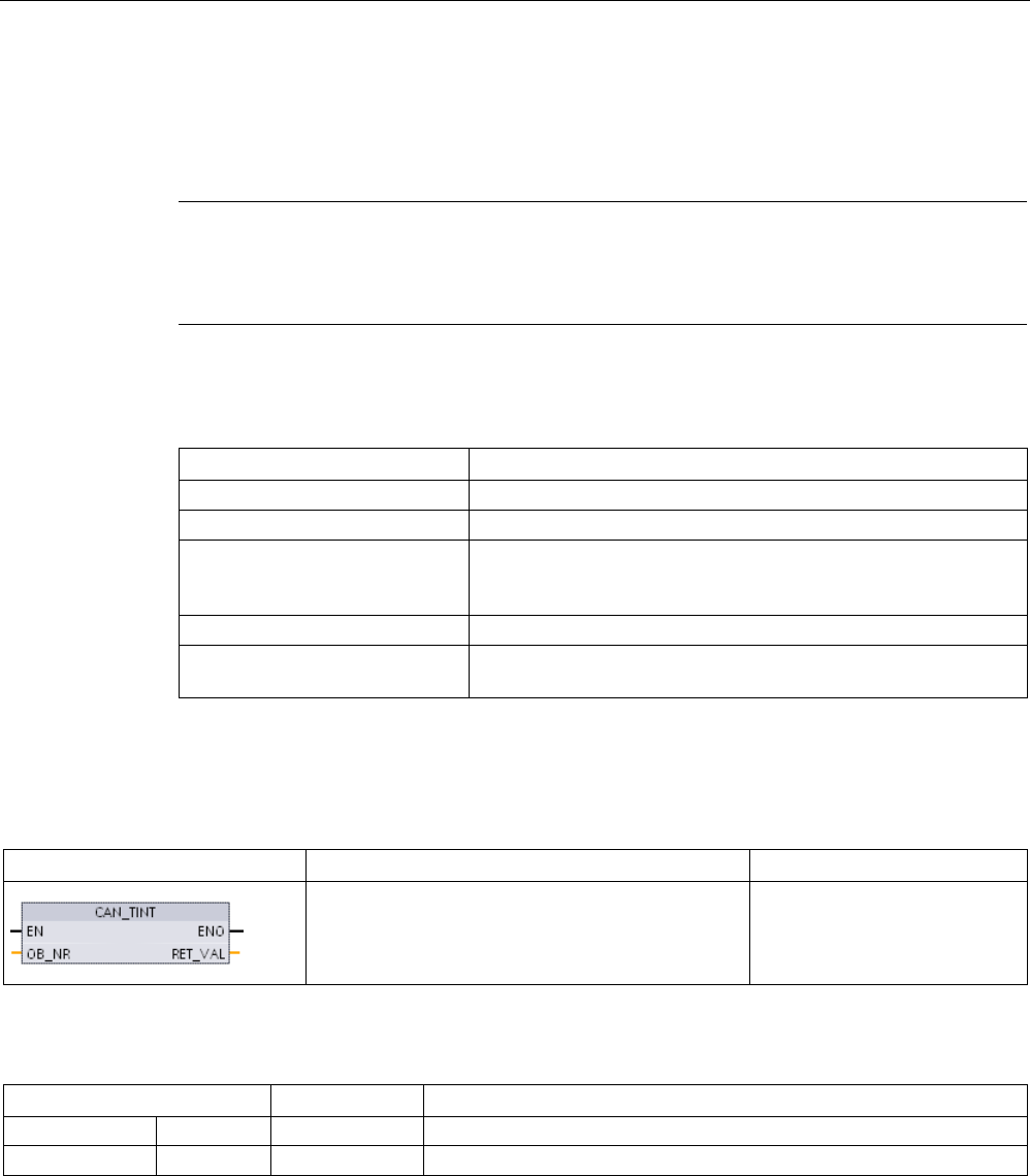
Extended instructions
9.5 Interrupts
S7-1200 Programmable controller
System Manual, V4.2, 09/2016, A5E02486680-AK 429
The DTL data weekday value in parameter SDT is ignored. Set a CPU's current date and
time using the "Set time of day" function in the "Online & diagnostics" view of an online CPU.
You must set the month, day of month, and year. STEP 7 calculates the interrupt period
based on the CPU date and time clock.
Note
The first hour of the day does not exist when changing from summer to winter (daylight
saving time). Use a start time within the second hour or use an additional time delay interrupt
within the first hour.
Table 9- 109 Condition code
RET_VAL (W#16#....)
Description
0000
No error
8090
Invalid OB_NR parameter
8091 Invalid SDT start time parameter:
(for example, a start time within the skipped hour at the start of
daylight savings time)
8092
Invalid PERIOD parameter
80A1 The start time is in the past.
(This error code only occurs with PERIOD = W #16#0000.)
9.5.3.2
CAN_TINT (Cancel time of day interrupt)
Table 9- 110 CAN_TINT (Cancel date and time of day interrupt)
LAD / FBD
SCL
Description
ret_val:=CAN_TINT(_int_in);
Cancels the start date and time
of day interrupt event for the
specified interrupt OB.
Table 9- 111 Data types for the parameters
Parameter and type
Data type
Description
OB_NR
IN
OB_TOD (INT)
OB number (accepts symbolic name)
RET_VAL
OUT
Int
Execution condition code
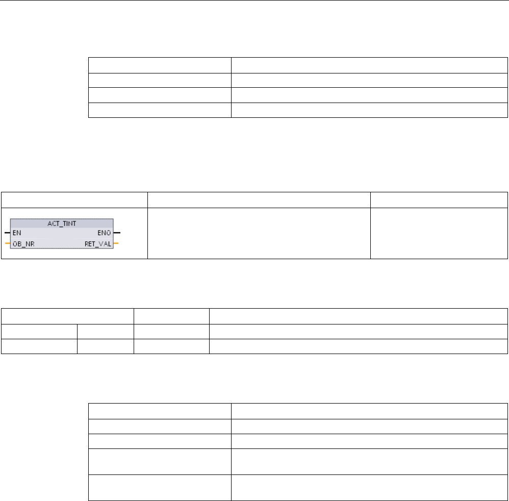
Extended instructions
9.5 Interrupts
S7-1200 Programmable controller
430 System Manual, V4.2, 09/2016, A5E02486680-AK
Table 9- 112 Condition codes
RET_VAL (W#16#....)
Description
0000
No error
8090 Invalid OB_NR parameter
80A0
No start date / time set for that interrupt OB
9.5.3.3
ACT_TINT (Activate time of day interrupt)
Table 9- 113 ACT_TINT (Activate date and time of day interrupt)
LAD / FBD
SCL
Description
ret_val:=ACT_TINT(_int_in_);
Activates the start date and
time of day interrupt event for
the specified interrupt OB.
Table 9- 114 Data types for the parameters
Parameter and type
Data type
Description
OB_NR
IN
OB_TOD (INT)
OB number (accepts symbolic name)
RET_VAL
OUT
Int
Execution condition code
Table 9- 115 Condition codes
RET_VAL (W#16#....)
Description
0000
No error
8090
Invalid OB_NR parameter
80A0 Start date and time-of day not set, for the relevant time-of-day
interrupt OB
80A1 The activated time is in the past. The error only occurs when the
interrupt OB is set to execute once only.
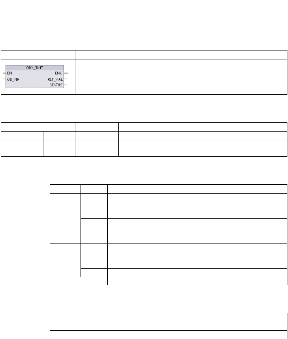
Extended instructions
9.5 Interrupts
S7-1200 Programmable controller
System Manual, V4.2, 09/2016, A5E02486680-AK 431
9.5.3.4
QRY_TINT (Query status of time of day interrupt)
Table 9- 116 QRY_TINT (Query date and time of day interrupt)
LAD / FBD
SCL
Description
ret_val:=QRY_TINT(
OB_NR:=_int_in_,
STATUS=>_word_out_);
Queries the date and time of day interrupt status for
the specified interrupt OB.
Table 9- 117 Data types for the parameters
Parameter and type
Data type
Description
OB_NR
IN
OB_TOD (INT)
OB number (accepts symbolic name) of the interrupt OB to query
RET_VAL
OUT
Int
Execution condition code
STATUS
OUT
Word
Status of the specified interrupt OB
Table 9- 118 STATUS parameter
Bit
Value
Description
0
0
In Run
1
In Startup
1
0
The interrupt is enabled.
1
The interrupt is disabled.
2
0
The interrupt is not active or has expired.
1
The interrupt is active.
4 0 The assigned OB_NR does not exist.
1
An OB with the assigned OB_NR exists.
6
1
The date and time of day interrupt uses local time.
0
The date and time of day interrupt uses system time.
Others
Always 0
Table 9- 119 Condition code
RET_VAL (W#16#....)
Description
0000
No error
8090
Invalid OB_NR parameter
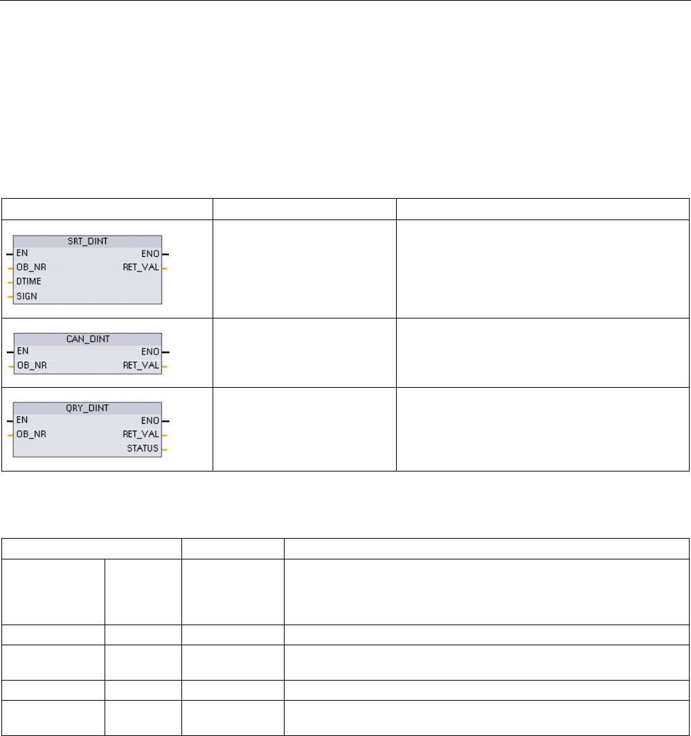
Extended instructions
9.5 Interrupts
S7-1200 Programmable controller
432 System Manual, V4.2, 09/2016, A5E02486680-AK
9.5.4
Time delay interrupts
You can start and cancel time delay interrupt processing with the SRT_DINT and CAN_DINT
instructions, or query the interrupt status with the QRY_DINT instruction. Each time delay
interrupt is a one-time event that occurs after the specified delay time. If the time delay event
is cancelled before the time delay expires, the program interrupt does not occur.
Table 9- 120 SRT_DINT, CAN_DINT, and QRY_DINT instructions
LAD / FBD
SCL
Description
ret_val := SRT_DINT(
ob_nr:=_int_in_,
dtime:=_time_in_,
sign:=_word_in_);
SRT_DINT starts a time delay interrupt that exe-
cutes an OB when the delay time specified by
parameter DTIME has elapsed.
ret_val := CAN_DINT(
ob_nr:=_int_in_);
CAN_DINT cancels a time delay interrupt that has
already started. The time delay interrupt OB is not
executed in this case.
ret_val := QRY_DINT(
ob_nr:=_int_in_,
sta-
tus=>_word_out_);
QRY_DINT queries the status of the time delay
interrupt specified by the OB_NR parameter.
Table 9- 121 Data types for the parameters
Parameter and type
Data type
Description
OB_NR IN OB_DELAY Organization block (OB) to be started after a time-delay: Select from
the available time-delay interrupt OBs that were created using the "Add
new block" project tree feature. Double-click on the parameter field,
then click on the helper icon to see the available OBs.
DTIME
1
IN
Time
Time delay value (1 to 60000 ms)
SIGN 1 IN Word Not used by the S7-1200: Any value is accepted. A value must be as-
signed to prevent errors.
RET_VAL
OUT
Int
Execution condition code
STATUS OUT Word QRY_DINT instruction: Status of the specified time-delay interrupt OB,
see the table below
1 Only for SRT_DINT
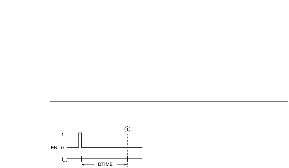
Extended instructions
9.5 Interrupts
S7-1200 Programmable controller
System Manual, V4.2, 09/2016, A5E02486680-AK 433
Operation
When EN=1, the SRT_DINT instruction starts the internal time delay timer (DTIME). When
the time delay elapses, the CPU generates a program interrupt that triggers the execution of
the associated time delay interrupt OB. You can cancel an in-process time delay interrupt
before the specified time delay occurs by executing the CAN_DINT instruction. The total
number of active time delay interrupt events must not exceed four.
Note
The SRT_DINT starts the time delay timer on every scan when EN=1. Assert EN=1 as a
one
-shot rather than just setting EN=1 to begin your time delay.
Timing diagram for the SRT_DINT instruction:
①
Time delay interrupt executes
Adding time delay interrupt OBs to your project
You can only assign time delay interrupt OBs to the SRT_DINT and CAN_DINT instructions.
No time delay interrupt OB exists in a new project. You must add time delay interrupt OBs to
your project. To create a time-delay interrupt OB, follow these steps:
1. Double-click the "Add new block" item in the "Program blocks" branch of the project tree,
select "Organization block (OB)", and choose "Time delay interrupt".
2. You have the option to rename the OB, select the programming language, or select the
block number. Switch to manual numbering if you want to assign a different block number
than the number that was assigned automatically.
3. Edit the time delay interrupt OB subprogram and create programmed reaction that you
want to execute when the time delay timeout event occurs. You can call other FC and FB
code blocks from the time delay interrupt OB, with a maximum nesting depth of six.
4. The newly assigned time delay interrupt OB names will be available when you edit the
OB_NR parameter of the SRT_DINT and CAN_DINT instructions.

Extended instructions
9.5 Interrupts
S7-1200 Programmable controller
434 System Manual, V4.2, 09/2016, A5E02486680-AK
QRY_DINT parameter STATUS
Table 9- 122 If there is an error (REL_VAL <> 0), then STATUS = 0.
Bit
Value
Description
0
0
In RUN
1 In startup
1
0
The interrupt is enabled.
1
The interrupt is disabled.
2
0
The interrupt is not active or has elapsed.
1
The interrupt is active.
4
0
An OB with an OB number given in OB_NR does not exist.
1
An OB with an OB number given in OB_NR exists.
Other bits
Always 0
Condition codes
Table 9- 123 Condition codes for SRT_DINT, CAN_DINT, and QRY_DINT
RET_VAL (W#16#...)
Description
0000
No error occurred
8090
Incorrect parameter OB_NR
8091
Incorrect parameter DTIME
80A0
Time delay interrupt has not started.
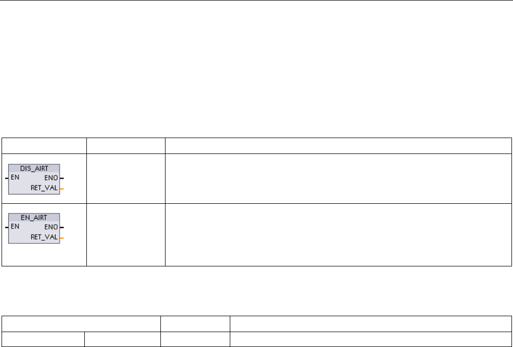
Extended instructions
9.5 Interrupts
S7-1200 Programmable controller
System Manual, V4.2, 09/2016, A5E02486680-AK 435
9.5.5
DIS_AIRT and EN_AIRT (Delay/enable execution of higher priority interrupts
and asynchronous error events) instructions
Use the DIS_AIRT and EN_AIRT instructions to disable and enable alarm interrupt
processing.
Table 9- 124 DIS_AIRT and EN_AIRT instructions
LAD / FBD
SCL
Description
DIS_AIRT();
DIS_AIRT delays the processing of new interrupt events. You can execute
DIS_AIRT more than once in an OB.
EN_AIRT();
EN_AIRT enables the processing of interrupt events that you previously disabled
with the DIS_AIRT instruction. Each DIS_AIRT execution must be cancelled by an
EN_AIRT execution.
The EN_AIRT executions must occur within the same OB, or any FC or FB called
from the same OB, before interrupts are enabled again for this OB.
Table 9- 125 Data types for the parameters
Parameter and type
Data type
Description
RET_VAL
OUT
Int
Number of delays = number of DIS_AIRT executions in the queue.
The DIS_AIRT executions are counted by the operating system. Each of these remains in
effect until it is cancelled again specifically by an EN_AIRT instruction, or until the current OB
has been completely processed. For example: if you disabled interrupts five times with five
DIS_AIRT executions, you must cancel these with five EN_AIRT executions before interrupts
become enabled again.
After the interrupt events are enabled again, the interrupts that occurred while DIS_AIRT was
in effect are processed, or the interrupts are processed as soon as the current OB has been
executed.
Parameter RET_VAL indicates the number of times that interrupt processing was disabled,
which is the number of queued DIS_AIRT executions. Interrupt processing is only enabled
again when parameter RET_VAL = 0.

Extended instructions
9.6 Alarms
S7-1200 Programmable controller
436 System Manual, V4.2, 09/2016, A5E02486680-AK
9.6
Alarms
9.6.1
Gen_UsrMsg (Generate user diagnostic alarms)
Table 9- 126 Gen_UsrMsg instruction
LAD / FBD
SCL
Description
ret_val :=Gen_UsrMsg(
Mode:=_uint_in_,
TextID:=_uint_in_,
TextListID:=_uint_in_,
As-
socValues:=_struct_inout_);
You use the "Gen_UsrMsg" instruction to
generate a user diagnostic alarm that can be
either an incoming or outgoing alarm. By
means of user diagnostic alarms, you can
write a user entry to the diagnostics buffer and
send a corresponding alarm.
The entry in the diagnostic buffer is created
synchronously. Alarm transmission is asyn-
chronous.
If an error occurs during the execution of an
instruction, it is output via the parameter
RET_VAL.
Content of the alarm
A text list defines the content of the alarm:
● Define the text list you want to use with the parameter TextListID. For this purpose open
the dialog "Text lists" in the project navigation. Show the column "ID" in the dialog "Text
lists". Apply the ID at the parameter TextListID.
● Use the parameter TextID to select the text list entry you want to write in the diagnostic
buffer. For this purpose select an entry from the "Text lists entries" dialog by applying a
number from the columns "Range from / range to" at the parameter TextID. You must use
the same number from both the "Range from" and "Range to" columns for the text list
entry.
Refer to the STEP 7 Information System for detailed information about text lists.
Defining associated values
The text list entry defines new associated values to be added to the alarm:
● Add the following information to the text list entry to define associated values:
@<No. of the associated value><Element type><Format specification>@
● Use the system data type AssocValues to specify which associated value to add when
generating the alarm.
Refer to the STEP 7 Information System for detailed information about the structure of
associated values.

Extended instructions
9.6 Alarms
S7-1200 Programmable controller
System Manual, V4.2, 09/2016, A5E02486680-AK 437
Parameters
The following table shows the parameters of the "Gen_UsrMsg" instruction:
Parameter
Declaration
Data type
Memory area
Description
Mode Input UInt I, Q, M, D, L or
constant
Parameters for selecting the
status of the alarm:
• 1: incoming alarm
• 2: outgoing alarm
TextID Input UInt I, Q, M, D, L or
constant
ID of the text list entry that
should be used for the alarm
text.
TextListID Input UInt I, Q, M, D, L or
constant
ID of the text list that con-
tains text list entry.
Ret_Val
Return
Int
I, Q, M, D, L
Error code of the instruction.
AssocValues InOut VARIANT D, L Pointer to the system data
type AssocValues that al-
lows you to define the asso-
ciated values.
For additional information on valid data types, refer to "Data types (Page 125)".
Parameter AssocValues
Use the system data type AssocValues to define which associated values will be sent. A
maximum of eight associated values are possible. Enter the data type "AssocValues" as a
data block to create the structure.
You select associated values by entering the numbers of the associated values for the
parameters Value[x]. Note the following:
● The Gen_UsrMsg instruction treats the values for TextID and TextListID as associated
values to be sent. As a result, "1" and "2" are pre-assigned as numbers for addressing
associated values. Do not use the numbers "1" or "2" to address associated values.
● Address the associated value at parameter Value [1] as number "3", at parameter Value
[2] as number "4", and so forth.
Byte
Parameter
Data type
Start value
Description
Number of
the associ-
ated value
0..1 Value[1] UINT 0 First associated
value of the
alarm.
3
2..3 Value[2] UINT 0 Second asso-
ciated value of
the alarm.
4
4..5
Value[3]
UINT
0
...
5
6..7
Value[4]
UINT
0
...
6
8..9
Value[5]
UINT
0
...
7
10..11
Value[6]
UINT
0
...
8

Extended instructions
9.6 Alarms
S7-1200 Programmable controller
438 System Manual, V4.2, 09/2016, A5E02486680-AK
Byte
Parameter
Data type
Start value
Description
Number of
the associ-
ated value
12..13
Value[7]
UINT
0
...
9
14..15 Value[8] UINT 0 Eighth associ-
ated value of
the alarm.
10
Parameter RET_VAL
The following table defines output values for the RET_VAL parameter. See also Common
error codes for the Extended instructions (Page 553).
Error code*
(W#16#...)
Explanation
0000
No error
8080
Value in the MODE parameter is not supported.
80C1
Resource bottleneck due to too many parallel calls.
8528
Parameter 5 (AssocValues) is not byte-aligned.
853A
Parameter 5 (AssocValues) references an invalid point.
* You can display the error code as either integer or hexadecimal in the program editor.

Extended instructions
9.7 Diagnostics (PROFINET or PROFIBUS)
S7-1200 Programmable controller
System Manual, V4.2, 09/2016, A5E02486680-AK 439
9.7
Diagnostics (PROFINET or PROFIBUS)
9.7.1
Diagnostic instructions
The following diagnostic instructions can be used with either PROFINET or PROFIBUS:
● RD_SINFO instruction (Page 440): Reads the current OB's start information
● LED instruction (Page 450): Reads the state of the LEDs for a distributed I/O device.
● Get_IM_Data instruction (Page 451): Checks the identification and maintenance (I&M)
data for a specified module or sub-module.
● Get_Name instruction (Page 453): Reads the name of a PROFINET IO device,
PROFIBUS slave, or AS-i slave.
● GetStationInfo instruction (Page 460): Reads the IP or MAC address of a PROFINET IO
device in the local IO system or a PROFINET IO device located in a lower-level IO
system (connected using CP/CM modules).
● DeviceStates instruction (Page 468): Retrieves the operational states for a distributed I/O
device within an I/O subsystem.
● ModuleStates instruction (Page 474): Retrieves the operational states for the modules in
a distributed I/O device.
● GET_DIAG instruction (Page 480): Reads the diagnostic information from a specified
device.
Note
You can only use the GetStationInfo instruction with PROFINET IO devices. You cannot use
the instruction with PROFIBUS DP slaves.
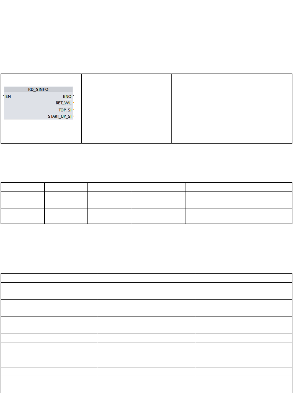
Extended instructions
9.7 Diagnostics (PROFINET or PROFIBUS)
S7-1200 Programmable controller
440 System Manual, V4.2, 09/2016, A5E02486680-AK
9.7.2
RD_SINFO (Read current OB start information)
Description
Table 9- 127 RD_SINFO instruction
LAD / FBD
SCL
Description
ret_val := RD_SINFO(
TOP_SI=>_variant_out_,
START_UP_SI=>_variant_out_)
;
You use the instruction "RD_SINFO" to read the
start information of the following OBs:
• Last OB called that has not yet been com-
pletely executed
• Last startup OB that the CPU started
There is no time stamp in either case. If the call is
in OB 100, OB 101 or OB 102, two identical start
information messages will be returned.
Parameter
The following table shows the parameters of the "RD_SINFO" instruction:
Parameter
Declaration
Data type
Memory area
Description
RET_VAL
Return
INT
I, Q, M, D, L
Error information
TOP_SI
Output
VARIANT
D, L
Start information of the current OB
START_UP_SI Output VARIANT D, L Start information of the startup OB last
started
You will find more detailed information on valid data types in "Data types (Page 125)".
SDTs of the TOP_SI parameter
The following table shows the possible SDTs for the TOP_SI parameter:
Organization blocks (OB)
System data types (SDT)
System data type numbers
Any
SI_classic*
592*
SI_none
593
ProgramCycleOB
SI_ProgramCycle
594
TimeOfDayOB
SI_TimeOfDay
595
TimeDelayOB
SI_Delay
596
CyclicOB
SI_Cyclic
597
ProcessEventOB
SI_HWInterrupt
598
ProfileEventOB
StatusEventOB
UpdateEventOB
SI_Submodule 601
SynchronousCycleOB
SI_SynchCycle
602
IOredundancyErrorOB
SI_IORedundancyError
604
CPUredundancyErrorOB
SI_CPURedundancyError
605

Extended instructions
9.7 Diagnostics (PROFINET or PROFIBUS)
S7-1200 Programmable controller
System Manual, V4.2, 09/2016, A5E02486680-AK 441
Organization blocks (OB)
System data types (SDT)
System data type numbers
TimeErrorOB
SI_TimeError
606
DiagnosticErrorOB SI_DiagnosticInterrupt 607
PullPlugEventOB
SI_PlugPullModule
608
PeripheralAccessErrorOB SI_AccessError 609
RackStationFailureOB
SI_StationFailure
610
ServoOB
SI_Servo
611
IpoOB
SI_Ipo
612
StartupOB
SI_Startup
613
ProgrammingErrorOB
IOaccessErrorOB
SI_ProgIOAccessError 614
*The SI_classic SDT is not applicable for the S7
-1200. The S7-1200 CPU returns a RET_VAL of #16#8081 if the TOP_SI
parameter is of type SI_classic.
SDTs of the START_UP_SI parameter
The following table shows the possible SDTs for the START_UP_SI parameter:
System data types (SDT)
System data type numbers
SI_classic*
592
SI_none
593
SI_Startup
613
*The SI_classic SDT is not applicable for th
e S7-1200. The S7-1200 CPU returns a RET_VAL of
#16#8083 if the START_UP_SI parameter is of type SI_classic.

Extended instructions
9.7 Diagnostics (PROFINET or PROFIBUS)
S7-1200 Programmable controller
442 System Manual, V4.2, 09/2016, A5E02486680-AK
Structures
The following tables define the structure elements of the individual structures:
Table 9- 128 SI_classic structure
Structure element
Data type
Description
EV_CLASS BYTE • Bits 0 to 3: Event ID
• Bits 4 to 7: Event class
EV_NUM
BYTE
Event number
PRIORITY BYTE Priority class number
(Meaning of B#16#FE: OB not available or disabled or cannot be started in
current operating mode)
NUM BYTE OB number
TYP2_3 BYTE Data ID 2_3:
Identifies the information entered in ZI2_3
TYP1 BYTE Data ID 1:
Identifies the information entered in ZI1
ZI1
WORD
Additional information 1
ZI2_3
DWORD
Additional information 2_3
Table 9- 129 SI_none structure
Structure element
Data type
Description
SI_Format USINT • 16#FF = No information
• 16#FE = Optimized start information
OB_Class
USINT
OB class for "No information" or "Optimized start information"
OB_Nr
UINT
OB number (1 ... 32767)
Table 9- 130 SI_ProgramCycle structure
Structure element
Data type
Description
SI_Format USINT • 16#FF = No information
• 16#FE = Optimized start information
OB_Class
USINT := 1
OB class for "No information" or "Optimized start information"
OB_Nr
UINT
OB number (1 ... 32767)
Initial_Call
BOOL
For OB_Class = 1, 30, 52, 61, 65
Remanence
BOOL
For OB_Class = 1

Extended instructions
9.7 Diagnostics (PROFINET or PROFIBUS)
S7-1200 Programmable controller
System Manual, V4.2, 09/2016, A5E02486680-AK 443
Table 9- 131 SI_TimeOfDay structure
Structure element
Data type
Description
SI_Format USINT • 16#FF = No information
• 16#FE = Optimized start information
OB_Class
USINT := 10
OB class for "No information" or "Optimized start information"
OB_Nr
UINT
OB number (1 ... 32767)
CaughtUp BOOL For OB_Class = 10
SecondTime
BOOL
For OB_Class = 10
Table 9- 132 SI_Delay structure
Structure element
Data type
Description
SI_Format USINT • 16#FF = No information
• 16#FE = Optimized start information
OB_Class
USINT := 20
OB class for "No information" or "Optimized start information"
OB_Nr
UINT
OB number (1 ... 32767)
Sign
WORD
For OB_Class = 20
Table 9- 133 SI_Cyclic structure
Structure element
Data type
Description
SI_Format USINT • 16#FF = No information
• 16#FE = Optimized start information
OB_Class
USINT := 30
OB class for "No information" or "Optimized start information"
OB_Nr
UINT
OB number (1 ... 32767)
Initial_Call
BOOL
For OB_Class = 1, 30, 52, 61, 65
Event_Count
INT
For OB_Class = 30, 51, 52, 61, 65, 91, 92
Table 9- 134 SI_HWInterrupt structure
Structure element
Data type
Description
SI_Format USINT • 16#FF = No information
• 16#FE = Optimized start information
OB_Class
USINT := 40
OB class for "No information" or "Optimized start information"
OB_Nr
UINT
OB number (1 ... 32767)
LADDR
HW_IO
For OB_Class = 40, 51, 55, 56, 57, 70, 82, 83, 85, 86, 91, 92
USI
WORD
For OB_Class = 40
IChannel
USINT
For OB_Class = 40
EventType
BYTE
For OB_Class = 40

Extended instructions
9.7 Diagnostics (PROFINET or PROFIBUS)
S7-1200 Programmable controller
444 System Manual, V4.2, 09/2016, A5E02486680-AK
Table 9- 135 SI_Submodule structure
Structure element
Data type
Description
SI_Format USINT • 16#FF = No information
• 16#FE = Optimized start information
OB_Class
USINT
OB class for "No information" or "Optimized start information"
OB_Nr
UINT
OB number (1 ... 32767)
LADDR HW_IO For OB_Class = 40, 51, 55, 56, 57, 70, 82, 83, 85, 86, 91, 92
Slot
UINT
For OB_Class = 55, 56, 57
Specifier
WORD
For OB_Class = 55, 56, 57
Table 9- 136 SI_SynchCycle structure
Structure element
Data type
Description
SI_Format USINT • 16#FF = No information
• 16#FE = Optimized start information
OB_Class
USINT := 61
OB class for "No information" or "Optimized start information"
OB_Nr
UINT
OB number (1 ... 32767)
Initial_Call
BOOL
For OB_Class = 1, 30, 52, 61, 65
PIP_Input
BOOL
For OB_Class = 61, 91, 92
PIP_Output
BOOL
For OB_Class = 61, 91, 92
IO_System
USINT
For OB_Class = 61, 91, 92
Event_Count
INT
For OB_Class = 30, 51, 52, 61, 65, 91, 92
SyncCycleTime
LTIME
Calculated cycle time
Table 9- 137 SI_IORedundancyError structure
Structure element
Data type
Description
SI_Format USINT • 16#FF = No information
• 16#FE = Optimized start information
OB_Class
USINT := 70
OB class for "No information" or "Optimized start information"
OB_Nr
UINT
OB number (1 ... 32767)
LADDR
HW_ANY
For OB_Class = 40, 51, 55, 56, 57, 70, 82, 83, 85, 86, 91, 92
Event_Class
BYTE
For OB_Class = 70, 83, 85, 86
Fault_ID
BYTE
For OB_Class = 70, 80, 83, 85, 86

Extended instructions
9.7 Diagnostics (PROFINET or PROFIBUS)
S7-1200 Programmable controller
System Manual, V4.2, 09/2016, A5E02486680-AK 445
Table 9- 138 SI_CPURedundancyError structure
Structure element
Data type
Description
SI_Format USINT • 16#FF = No information
• 16#FE = Optimized start information
OB_Class
USINT := 72
OB class for "No information" or "Optimized start information"
OB_Nr
UINT
OB number (1 ... 32767)
Switch_Over BOOL For OB_Class = 72
Table 9- 139 SI_TimeError structure
Structure element
Data type
Description
SI_Format USINT • 16#FF = No information
• 16#FE = Optimized start information
OB_Class USINT := 80 OB class for "No information" or "Optimized start information"
OB_Nr
UINT
OB number (1 ... 32767)
Fault_ID
BYTE
For OB_Class = 70, 80, 83, 85, 86
Csg_OBnr
OB_ANY
For OB_Class = 80
Csg_Prio
UINT
For OB_Class = 80
Table 9- 140 SI_DiagnosticInterrupt structure
Structure element
Data type
Description
SI_Format USINT • 16#FF = No information
• 16#FE = Optimized start information
OB_Class
USINT := 82
OB class for "No information" or "Optimized start information"
OB_Nr
UINT
OB number (1 ... 32767)
IO_State
WORD
For OB_Class = 82
LADDR
HW_ANY
For OB_Class = 40, 51, 55, 56, 57, 70, 82, 83, 85, 86, 91, 92
Channel
UINT
For OB_Class = 82
MultiError
BOOL
For OB_Class = 82

Extended instructions
9.7 Diagnostics (PROFINET or PROFIBUS)
S7-1200 Programmable controller
446 System Manual, V4.2, 09/2016, A5E02486680-AK
Table 9- 141 SI_PlugPullModule structure
Structure element
Data type
Description
SI_Format USINT • 16#FF = No information
• 16#FE = Optimized start information
OB_Class
USINT := 83
OB class for "No information" or "Optimized start information"
OB_Nr
UINT
OB number (1 ... 32767)
LADDR HW_IO For OB_Class = 40, 51, 55, 56, 57, 70, 82, 83, 85, 86, 91, 92
Event_Class
BYTE
For OB_Class = 70, 83, 85, 86
Fault_ID
BYTE
For OB_Class = 70, 80, 83, 85, 86
Table 9- 142 SI_AccessError structure
Structure element
Data type
Description
SI_Format USINT • 16#FF = No information
• 16#FE = Optimized start information
OB_Class
USINT := 85
OB class for "No information" or "Optimized start information"
OB_Nr
UINT
OB number (1 ... 32767)
LADDR
HW_IO
For OB_Class = 40, 51, 55, 56, 57, 70, 82, 83, 85, 86, 91, 92
Event_Class
BYTE
For OB_Class = 70, 83, 85, 86
Fault_ID
BYTE
For OB_Class = 70, 80, 83, 85, 86
IO_Addr
UINT
For OB_Class = 85
IO_LEN
UINT
For OB_Class = 85
Table 9- 143 SI_StationFailure structure
Structure element
Data type
Description
SI_Format USINT • 16#FF = No information
• 16#FE = Optimized start information
OB_Class
USINT := 86
OB class for "No information" or "Optimized start information"
OB_Nr
UINT
OB number (1 ... 32767)
LADDR
HW_IO
For OB_Class = 40, 51, 55, 56, 57, 70, 82, 83, 85, 86, 91, 92
Event_Class
BYTE
For OB_Class = 70, 83, 85, 86
Fault_ID
BYTE
For OB_Class = 70, 80, 83, 85, 86

Extended instructions
9.7 Diagnostics (PROFINET or PROFIBUS)
S7-1200 Programmable controller
System Manual, V4.2, 09/2016, A5E02486680-AK 447
Table 9- 144 SI_Servo structure
Structure element
Data type
Description
SI_Format USINT • 16#FF = No information
• 16#FE = Optimized start information
OB_Class
USINT := 91
OB class for "No information" or "Optimized start information"
OB_Nr
UINT
OB number (1 ... 32767)
Initial_Call BOOL For OB_Class = 1, 30, 52, 61, 65
PIP_Input
BOOL
For OB_Class = 61, 91, 92
PIP_Output
BOOL
For OB_Class = 61, 91, 92
IO_System
USINT
For OB_Class = 61, 91, 92
Event_Count
INT
For OB_Class = 30, 51, 52, 61, 65, 91, 92
Synchronous
BOOL
Table 9- 145 SI_Ipo structure
Structure element
Data type
Description
SI_Format USINT • 16#FF = No information
• 16#FE = Optimized start information
OB_Class
USINT := 92
OB class for "No information" or "Optimized start information"
OB_Nr
UINT
OB number (1 ... 32767)
Initial_Call
BOOL
For OB_Class = 1, 30, 52, 61, 65
PIP_Input
BOOL
For OB_Class = 61, 91, 92
PIP_Output
BOOL
For OB_Class = 61, 91, 92
IO_System
USINT
For OB_Class = 61, 91, 92
Event_Count
INT
For OB_Class = 30, 51, 52, 61, 65, 91, 92
Reduction
UINT
For OB_Class = 92
Table 9- 146 SI_Startup structure
Structure element
Data type
Description
SI_Format USINT • 16#FF = No information
• 16#FE = Optimized start information
OB_Class
USINT := 100
OB class for "No information" or "Optimized start information"
OB_Nr
UINT
OB number (1 ... 32767)
LostRetentive
BOOL
For OB_Class = 100
LostRTC
BOOL
For OB_Class = 100

Extended instructions
9.7 Diagnostics (PROFINET or PROFIBUS)
S7-1200 Programmable controller
448 System Manual, V4.2, 09/2016, A5E02486680-AK
Table 9- 147 SI_ProgIOAcessError structure
Structure element
Data type
Description
SI_Format USINT • 16#FF = No information
• 16#FE = Optimized start information
OB_Class
USINT
OB class for "No information" or "Optimized start information"
OB_Nr
UINT
OB number (1 ... 32767)
BlockNr UINT For OB_Class = 121, 122
Reaction
USINT
For OB_Class = 121, 122
Fault_ID
BYTE
For OB_Class = 121, 122
BlockType
USINT
For OB_Class = 121, 122
Area
USINT
For OB_Class = 121, 122
DBNr
DB_ANY
For OB_Class = 121, 122
Csg_OBNr
OB_ANY
For OB_Class = 121, 122
Csg_Prio
USINT
For OB_Class = 121, 122
Width
USINT
For OB_Class = 121, 122
Note
If this was created with the block property "Standard", the structure elements specified for
the SI_c
lassic structure are identical in content to the temporary tags of an OB.
Note, however, that temporary tags of the individual OBs can have different names and
different data types. Also note that the call interface of each OB includes additional
informat
ion regarding the date and the time of the OB request.
Bits 4 to 7 of the EV_CLASS structure element contain the event class. The following values
are possible here:
● 1: Start events from standard OBs
● 2: Start events from synchronous error OBs
● 3: Start events from asynchronous error OBs
The PRIORITY structure element supplies the priority class belonging to the current OB.
Apart from these two elements, NUM is also relevant. NUM contains the number of the
current OB or the startup OB that was started last.
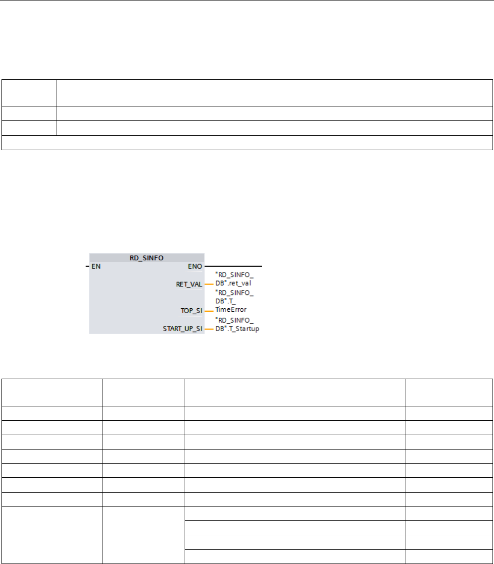
Extended instructions
9.7 Diagnostics (PROFINET or PROFIBUS)
S7-1200 Programmable controller
System Manual, V4.2, 09/2016, A5E02486680-AK 449
RET_VAL parameter
The following table shows the meaning of the values of the RET_VAL parameter:
Error code*
(W#16#...)
Explanation
8081
Start information of the current OB does not correspond to the specified system data type
8083 Start information of the last startup OB started does not correspond to the specified system data type
* You can display the error code as either integer or hexadecimal values in the program editor.
Example
A time error interrupt OB (OB 80) is the OB that was called last and that has not yet been
completely processed. Startup OB (OB 100) is the startup OB that was started last. The
instruction call to read the startup information is as follows, where RD_SINFO_DB is the data
block that contains tags of the SDTs for types of OBs:
The following table shows the assignment between the structure elements of the TOP_SI
parameter of the "RD_SINFO" instruction and the associated local tags of OB 80.
TOP_SI
structure element
Data type
OB 80 - Associated local tag
Data type
EV_CLASS
BYTE
OB80_EV_CLASS
BYTE
EV_NUM
BYTE
OB80_FLT_ID
BYTE
PRIORITY
BYTE
OB80_PRIORITY
BYTE
NUM
BYTE
OB80_OB_NUMBR
BYTE
TYP2_3
BYTE
OB80_RESERVED_1
BYTE
TYP1 BYTE OB80_RESERVED_2 BYTE
ZI1
WORD
OB80_ERROR_INFO
WORD
ZI2_3 DWORD OB80_ERR_EV_CLASS BYTE
OB80_ERR_EV_NUM
BYTE
OB80_OB_PRIORITY
BYTE
OB80_OB_NUM
BYTE
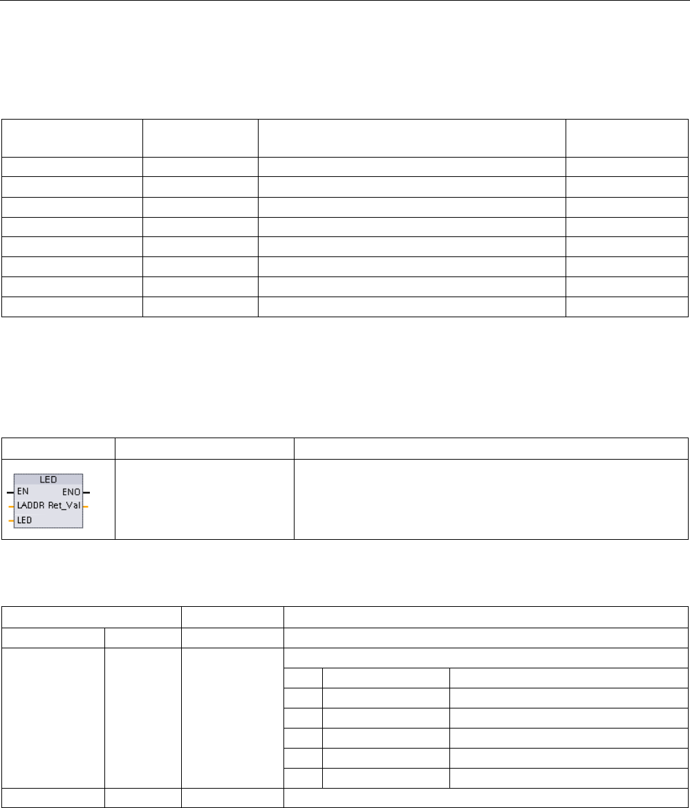
Extended instructions
9.7 Diagnostics (PROFINET or PROFIBUS)
S7-1200 Programmable controller
450 System Manual, V4.2, 09/2016, A5E02486680-AK
The following table shows the assignment between the structure elements of the
START_UP_SI parameter of the "RD_SINFO" instruction and the associated local tags of
OB 100.
START_UP_SI
structure element
Data type
OB 100 - Local tag
Data type
EV_CLASS
BYTE
OB100_EV_CLASS
BYTE
EV_NUM BYTE OB100_STRTUP BYTE
PRIORITY
BYTE
OB100_PRIORITY
BYTE
NUM
BYTE
OB100_OB_NUMBR
BYTE
TYP2_3
BYTE
OB100_RESERVED_1
BYTE
TYP1
BYTE
OB100_RESERVED_2
BYTE
ZI1
WORD
OB100_STOP
WORD
ZI2_3
DWORD
OB100_STRT_INFO
DWORD
9.7.3
LED (Read LED status)
Table 9- 148 LED instruction
LAD / FBD
SCL
Description
ret_val := LED(
laddr:=_word_in_,
LED:=_uint_in_);
Use the LED instruction to read the state of the LEDs on a CPU or
interface. The specified LED state is returned by the RET_VAL out-
put.
Table 9- 149 Data types for the parameters
Parameter and type
Data type
Description
LADDR
IN
HW_IO
Identification number of the CPU or interface
1
LED IN UInt
LED identifier number
1
RUN/STOP
Color 1 = green, color 2 = yellow
2
Error
Color 1 = red
3
Maintenance
Color 1 = yellow
4
Redundancy
Not applicable
5
Link
Color 1 = green
6
Tx/Rx
Color 1 = yellow
RET_VAL
OUT
Int
Status of the LED
1
For example, you can select the CPU (such as "PLC_1") or the PROFINET interface from the drop-down list of the
parameter.
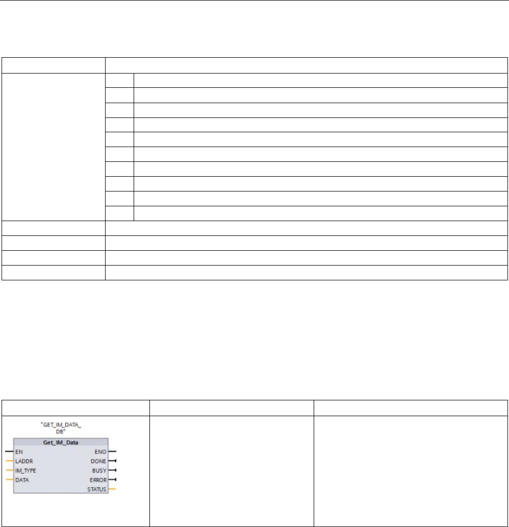
Extended instructions
9.7 Diagnostics (PROFINET or PROFIBUS)
S7-1200 Programmable controller
System Manual, V4.2, 09/2016, A5E02486680-AK 451
Table 9- 150 Status of RET_VAL
RET_VAL (W#16#...)
Description
0 to 9 LED state
0
LED does not exist
1 Off
2
Color 1 On (solid)
3 Color 2 On (Solid)
4
Color 1 flashing at 2 Hz
5
Color 2 flashing 2 Hz
6
Color 1 & 2 flashing alternatively at 2 Hz
7
Color 1 on (Tx/Rx)
8
Color 2 on (Tx/Rx)
9
State of the LED is not available
8091
Device identified by LADDR does not exist
8092
Device identified by LADDR does not support LEDs
8093
LED identifier not defined
80Bx
CPU identified by LADDR does not support the LED instruction
9.7.4
Get_IM_Data (Read the identification and maintenance data)
You use the Get_IM_Data instruction to check the identification and maintenance (I&M) data
for the specified module or sub-module.
Table 9- 151 Get_IM_Data instruction
LAD / FBD
SCL
Description
"GET_IM_DATA_DB"(LADDR:=16#0
,
IM_TYPE:=0,
DONE=>_bool_out_,
BUSY=>_bool_out_,
ERROR=>_bool_out_,
STATUS=>_word_out_,
DATA:=_variant_inout_);
Use the Get_IM_Data instruction to check the
identification and maintenance (I&M) data for
the specified module or sub-module.

Extended instructions
9.7 Diagnostics (PROFINET or PROFIBUS)
S7-1200 Programmable controller
452 System Manual, V4.2, 09/2016, A5E02486680-AK
Table 9- 152 Data types for the parameters
Parameter and type
Data type
Description
LADDR
Input
HW_IO
Identifier of the module
IM_TYPE Input UInt Identification and maintenance (I&M) data number:
• 0: I&M0 (MLFB, serial number, version, and other information)
• 1: I&M1 (Designators)
• 2: I&M2 (Installation date)
• 3: I&M3 (Descriptor)
• 4: I&M4 (Signature)
RET_VAL
Output
Int
Status (condition code)
DATA InOut Variant I&M data (STRING or an array of BYTE); recommend use of the SDT
"IM0_Data" for IM_TYPE = 0.
Identification and maintenance (I&M) data can help you to check the system configuration,
detect hardware changes, or view maintenance data. Module identification data (I data) is
read only. Module maintenance data (M data) depends on system information, such as the
installation date. M data are created during maintenance planning and written to the module:
● If the data type used at the parameter DATA is a string, then the current length of the
string is set according to the length of the I&M data.
● If the data type used at the parameter DATA is an array of Byte or Char, then the I&M
data are copied in as a sequence of bytes.
● If the data type used at the parameter DATA is a structure, then the I&M data are copied
in as a sequence of bytes.
● If the given array of byte/char at DATA is longer than the requested I&M data, then the
byte value 16#00 is appended.
● Other data types are not supported and error 8093 is returned.
Table 9- 153 Condition codes
RET_VAL (W#16#...)
Description
0
No error
8091
LADDR does not exist
8092
LADDR does not address a HW object which supports I&M data
8093
Data type given at parameter DATA is not supported
80B1
DATA instruction not supported by the CPU for this LADDR
80B2
IM_TYPE not supported by the CPU
8452 The complete I&M information does not fit into the variable given at the DATA parameter. A par-
tial result up to the byte length of the variable is returned.
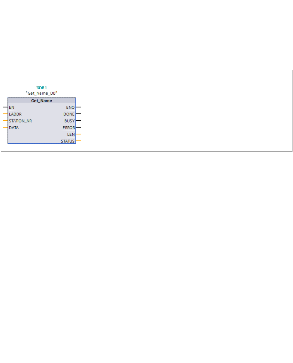
Extended instructions
9.7 Diagnostics (PROFINET or PROFIBUS)
S7-1200 Programmable controller
System Manual, V4.2, 09/2016, A5E02486680-AK 453
9.7.5
Get_Name (Read the name of a PROFINET IO device)
The "Get_Name" instruction reads the name of a PROFINET IO device, PROFIBUS slave, or
AS-i slave. The name is displayed in the network view and in the properties of the IO device.
Table 9- 154 Get_Name instruction
LAD / FBD
SCL
Description
"Get_Name_DB"(
LADDR:=_uint_in_,
STATION_NR:=_uint_in_,
DONE=>_bool_out_,
BUSY=>_bool_out_,
ERROR=>_bool_out_,
LEN=>_dint_out_,
STATUS=>_word_out_,
DATA:=_variant_inout_);
Use the Get_Name instruction to read
the name of a PROFINET IO device
or PROFIBUS slave.
1
STEP 7 automatically creates the DB when you insert the instruction.
2 In the SCL example, "Get_Name_DB" is the name of the instance DB.
You select the IO device by using the hardware identifier of the distributed IO system (at the
LADDR parameter) and the device number of the PROFINET IO device or the PROFIBUS
address of the PROFIBUS slave (at the STATION_NR parameter).
Once the instruction has been executed, the program writes the name of the IO device to the
area addressed with the DATA parameter.
The name that is read depends on the type of IO device:
● DP slave or IO device: Name of the head module
● I-slave or I-device: Name of the interface module
● HMI panel: Name of the interface
● PC station: Name of the interface module
● GSD devices: Displays the name of the Device Access Point (DAP) (name of the
interface or head module)
The instruction writes the length of the name at the LEN parameter. If the name is longer
than the area specified at the DATA parameter, the program writes only that section which
corresponds to the maximum length of the addressed area.
The maximum length for a name is 128 characters.
Note
Name of the CPU readout (Version 1.1)
If you assign a "0" at each of the parameters LADDR and STATION_NR, the ins
truction
writes the name of the CPU.

Extended instructions
9.7 Diagnostics (PROFINET or PROFIBUS)
S7-1200 Programmable controller
454 System Manual, V4.2, 09/2016, A5E02486680-AK
Parameters
The following table shows the parameters of the Get_Name instruction:
Parameter
Declaration
Data type
Description
LADDR IN HW_IOSYSTEM Hardware identifier (HW-IoSystem) of the distributed IO sys-
tem. The number is taken from the system constants or the
properties of the IO system.
STATION_NR IN UInt • PROFINET IO device: Device number is applied in the
Network view from the properties of the IO device under
"Ethernet addresses".
• PROFIBUS slave: PROFIBUS address is applied in the
Network view from the properties of the PROFIBUS slave
under "PROFIBUS address".
DATA
IN_OUT
Variant
Pointer to the area where the name is written.
DONE OUT Bool The instruction executes successfully. Name of the module
transfers to the area at the DATA parameter.
BUSY OUT Bool Status parameter:
• 0: Execution of the instruction complete.
• 1: Execution of the instruction not yet complete.
ERROR OUT Bool Status parameter:
• 0: No error
• 1: An error occurred during execution of the instruction.
The STATUS parameter contains detailed information.
LEN
OUT
DInt
Length of the name of the IO device (number of characters).
STATUS OUT Word Status parameter: The parameter is only set for the duration of
one call. To display the status, you should therefore copy
STATUS to a free data area.

Extended instructions
9.7 Diagnostics (PROFINET or PROFIBUS)
S7-1200 Programmable controller
System Manual, V4.2, 09/2016, A5E02486680-AK 455
STATUS parameter
Error code*
(W#16#...)
Explanation
0
No error
7000 No job in progress
7001 First call of the asynchronous Get_Name instruction. Execution of the instruction not yet complete (BUSY
= 1, DONE = 0).
7002 Additional call of the asynchronous Get_Name instruction. Execution of the instruction not yet complete
(BUSY = 1, DONE = 0).
8090
The hardware identifier specified at the LADDR parameter does not exist in the project.
8092
The value at the LADDR parameter does not address a PROFINET IO system.
8093
Instruction does not support data type at the DATA parameter.
8095 Device number (STATION_NR parameter) does not exist in the selected PROFINET IO system or does
not address an IO device.
80B1
The CPU used does not support the instruction.
80C3 Temporary resource error: The CPU is currently processing the maximum possible number of simultane-
ous block calls. Get_Name cannot be executed until at least one of the block calls is finished.
8852 Th
e area specified at the DATA parameter is too short for the full name of the IO device. The name can be
written up to the maximum possible length.
To read the full name, use a longer data area at the DATA parameter. The area must have at least as
many characters as there are at the LEN parameter.
* The error codes in the program editor can be displayed as integer or hexadecimal values.
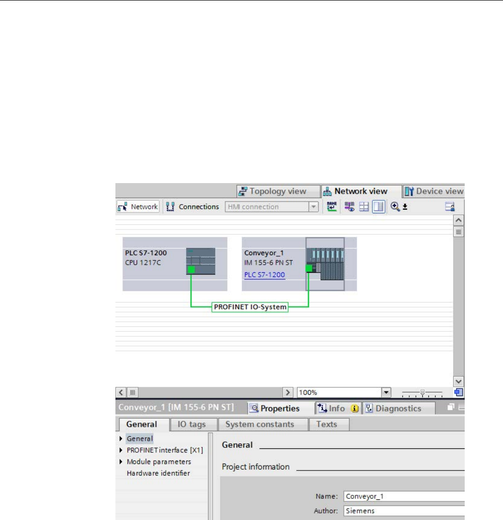
Extended instructions
9.7 Diagnostics (PROFINET or PROFIBUS)
S7-1200 Programmable controller
456 System Manual, V4.2, 09/2016, A5E02486680-AK
Example
The following example shows how you can read the station name of an ET 200SP
PROFINET IO device:
1. Configuring the ET 200SP:
– Create the ET 200SP with the station name "Conveyor_1" in the network view and
assign it to the same PROFINET IO system as the CPU.
– Assign the CPU as the IO controller for the ET 200SP.
– Use the default device number "1" located in the Properties under "Ethernet
addresses".
2. Assigning parameters for the Get_Name instruction:
– Enter the hardware ID of the IO system at the LADDR parameter. In this example, the
hardware ID is "269". You can find the hardware ID at the following location:
PLC tags > Show all tags > System constants tab > Local-PROFINET_IO-System
– Enter the device number of the ET 200SP at the STATION_NR parameter. In this
example, the device number is "1".
– Connect a tag with the data type STRING of a data block at the DATA parameter.
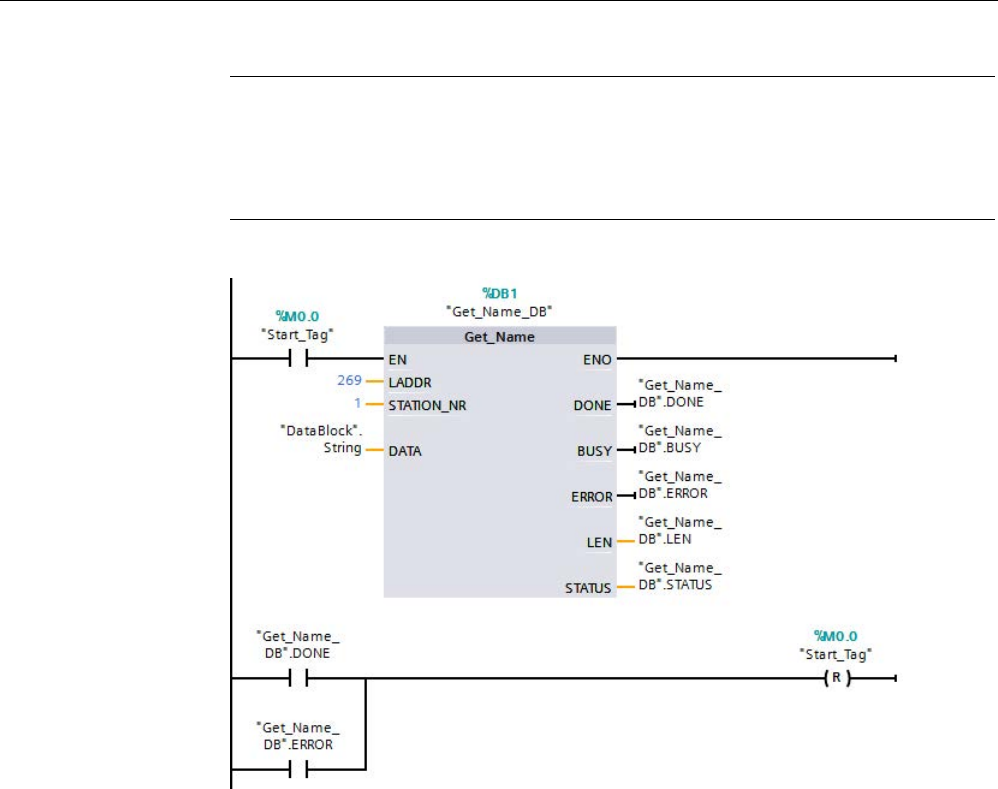
Extended instructions
9.7 Diagnostics (PROFINET or PROFIBUS)
S7-1200 Programmable controller
System Manual, V4.2, 09/2016, A5E02486680-AK 457
Note
When using the dropdown to make your selections for configuring the tag to the DATA
parameter, select the DB (in the example, "Datablock") and the tag (in the example,
"String[ ]"). In order to read the entire String data type,
you must delete the brackets
so that the final result is: "Datablock".String
– Define PLC tags (memory area, flags) for the output parameters of the instruction.
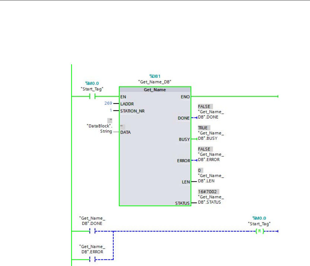
Extended instructions
9.7 Diagnostics (PROFINET or PROFIBUS)
S7-1200 Programmable controller
458 System Manual, V4.2, 09/2016, A5E02486680-AK
3. Executing the Get_Name instruction:
– As the instruction executes, the BUSY output parameter may get set to "1", and the
DONE parameter is then set to "0".
– Error code information is displayed at the STATUS output parameter.
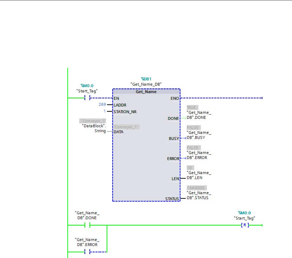
Extended instructions
9.7 Diagnostics (PROFINET or PROFIBUS)
S7-1200 Programmable controller
System Manual, V4.2, 09/2016, A5E02486680-AK 459
4. Completing execution of the Get_Name instruction:
– After execution of the instruction, the program writes "Conveyor_1", the station name
of the ET 200SP, into the data block at the DATA parameter.
– The program writes "10", the number of characters in the station name, to the LEN
parameter.
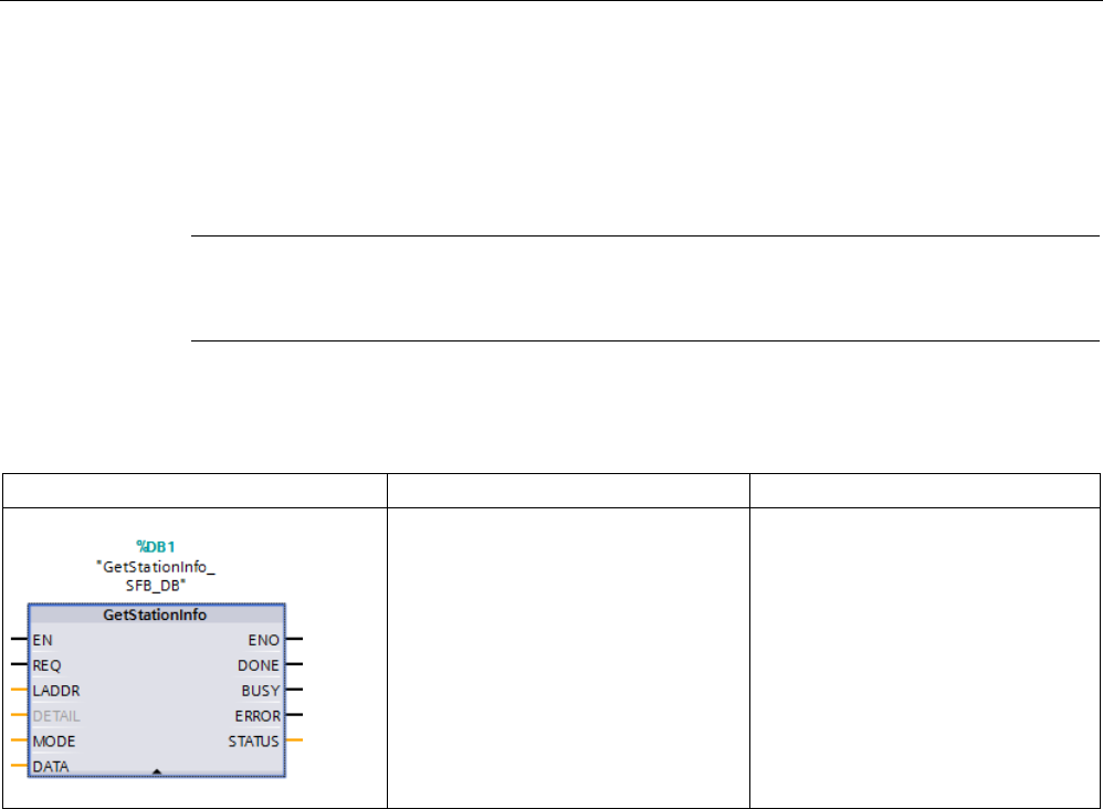
Extended instructions
9.7 Diagnostics (PROFINET or PROFIBUS)
S7-1200 Programmable controller
460 System Manual, V4.2, 09/2016, A5E02486680-AK
9.7.6
GetStationInfo (Read the IP or MAC address of a PROFINET IO device)
The "GetStationInfo" instruction reads the IP or MAC address of a PROFINET IO device in
the local IO system or a PROFINET IO device located in a lower-level IO system (connected
using CP/CM modules).
Note
You can only use the GetStationInfo instruction with PROFINET IO
devices. You cannot use
the instruction with PROFIBUS DP slaves.
Table 9- 155 GetStationInfo instruction
LAD / FBD
SCL
Description
"GetStationInfo_SFB_DB"(
REQ:=_bool_in_,
LADDR:=_uint_in_,
DETAIL:=_uint_in_,
MODE:=_uint_in_,
DONE=>_bool_out_,
BUSY=>_bool_out_,
ERROR=>_bool_out_,
STATUS=>_word_out_,
DATA:=_variant_inout_);
Use the GetStationInfo instruction to
read the IP or MAC address of a
PROFINET IO device. The instruction
also enables you to read the IP or
MAC address of an IO device located
in a lower-level IO system (connected
using CP/CM modules).
1
STEP 7 automatically creates the DB when you insert the instruction.
2 In the SCL example, "GetStationInfo_SFB_DB" is the name of the instance DB.
You address the IO device using the hardware identifier of the station at the LADDR
parameter. You can find the hardware ID at the following location:
PLC tags > Show all tags > System constants tab. Search for the "IODevice" in the Name
column and for "Hw_Device" in the Data type column.
Use the MODE parameter to select the information to be read.
At the DATA parameter, assign the data area to which the instruction writes the read
address data. For storing the IP address, use the "IF_CONF_v4" structure. For storing the
MAC address, use the "IF_CONF_MAC" structure.
Enable reading of the address data using the REQ control parameter. This requires the IO
device to be accessible.

Extended instructions
9.7 Diagnostics (PROFINET or PROFIBUS)
S7-1200 Programmable controller
System Manual, V4.2, 09/2016, A5E02486680-AK 461
The instruction displays the execution status of the read job using the BUSY, DONE, and
ERROR output parameters and the STATUS output parameter.
Note
Address the IO device using only the hardware identifier of the station
The station, the IO device, and PROFINET interface have their own hardware identifi
er. Use
only the hardware identifier of the station for the GetStationInfo instruction.
If a PROFINET interface is addressed using the LADDR parameter, for example, the
address data is not read and the CPU generates a "8092" error code.
To read the address
data of an integrated PROFINET interface or a CM/CP module in the
central configuration, use the "RDREC" instruction.
Parameters
The following table shows the parameters of the GetStationInfo instruction:
Parameter
Declaration
Data type
Description
REQ IN Bool Control parameter request
Activates the reading of the information with REQ = "1".
LADDR IN HW_DEVICE Hardware identifier of the station of the IO device
The number is taken from the properties of the station in the
Network view or from the "System constants" tab of the default
tag table.
DETAIL IN HW_SUBMODUL
E
The DETAIL parameter is not used. Leave the parameter un-
connected.
MODE IN UNIT Selection of address data to be read:
• MODE = 1: Address parameter according to IPv4 (S7-1200
CPUs as of firmware version V4.2)
• MODE = 2: MAC address (S7-1200 CPUs as of firmware
version V4.2)
DATA IN_OUT Variant Pointer to the area to which the program writes the address
data of the IO device. Use the "IF_CONF_v4" structure for
MODE = 1, and the "IF_CONF_MAC" structure for MODE = 2.
DONE OUT Bool The program executed the instruction successfully. The pro-
gram transferred the address data to the DATA parameter.
BUSY OUT Bool STATUS parameter:
• 0: Execution of the instruction complete.
• 1: Execution of the instruction not yet complete.

Extended instructions
9.7 Diagnostics (PROFINET or PROFIBUS)
S7-1200 Programmable controller
462 System Manual, V4.2, 09/2016, A5E02486680-AK
Parameter
Declaration
Data type
Description
ERROR OUT Bool STATUS parameter:
• 0: No error.
• 1: An error occurred during execution of the instruction.
Detailed information is output using the STATUS parameter.
STATUS OUT Word STATUS parameter:
The parameter is only set for the duration of one call. To dis-
play the status, you should therefore copy STATUS to a free
data area.
DATA parameter
● Use the "IF_CONF_v4" structure at the DATA parameter to store the address parameter
according to IPv4:
Byte
Parameter
Data type
Start value
Description
0 … 1
Id
UINT
30
ID of the "IF_CONF_v4" structure
2 … 3
Length
UNIT
18
Length of data read in BYTE
4 ... 5 Mode UNIT 0 Not relevant for the "GetStationInfo" instruction (left at
"0")
6 ... 9 InterfaceAddress ARRAY [1..4] of
BYTE
- IP address of the IO device in the format IP_V4 (for
example, 192.168.3.10):
• addr[1] = 192
• addr[2] = 168
• addr[3] = 3
• addr[4] = 10
10 …
13
SubnetMask ARRAY [1..4] of
BYTE
- Subnet mask of the IO device in the format IP_V4 (for
example, 255.255.255.0):
• addr[1] = 255
• addr[2] = 255
• addr[3] = 255
• addr[4] = 0
14 ...
17
DefaultRouter ARRAY [1..4] of
BYTE
- IP address of the router in the format IP_V4 (for ex-
ample, 192.168.3.1):
• addr[1] = 192
• addr[2] = 168
• addr[3] = 3
• addr[4] = 1

Extended instructions
9.7 Diagnostics (PROFINET or PROFIBUS)
S7-1200 Programmable controller
System Manual, V4.2, 09/2016, A5E02486680-AK 463
● Use the "IF_CONF_MAC" structure at parameter DATA for storing the MAC address:
Byte
Parameter
Data type
Start value
Description
0 … 1
Id
UINT
3
ID of the "IF_CONF_MAC" structure
2 … 3 Length UNIT 12 Length of data read in BYTE
4 ... 5 Mode UNIT 0 Not relevant for the "GetStationInfo" instruction (left at
"0")
6 ... 11 MACAddress ARRAY [1..6] of
BYTE
- MAC address of the IO device (for example, 08-00-06-
12-34-56):
• Mac[1] = 8
• Mac[2] = 0
• Mac[3] = 6
• Mac[4] = 12
• Mac[5] = 34
• Mac[6] = 56
STATUS parameter
Error code*
(W#16#...)
Explanation
0
No error
7000
No job in progress
7001 First call of the asynchronous instruction GetStationInfo. Execution of the instruction not yet complete
(BUSY = 1, DONE = 0).
7002 Additional call of the asynchronous instruction GetStationInfo. Execution of the instruction not yet com-
plete (BUSY = 1, DONE = 0).
8080
Value at the MODE parameter is not supported.
8090
The hardware identifier specified at the LADDR parameter is not configured.
8092
The LADDR parameter does not address a PROFINET IO device.
8093
Invalid data type at the DATA parameter.
80A0
Requested information is not read.
80C0
Addressed IO device is not reachable.
80C3 The maximum number of simultaneous calls of the GetStationInfo instruction (10 instances) has been
reached.
* The error codes in the program editor are displayed as integer or hexadecimal values.
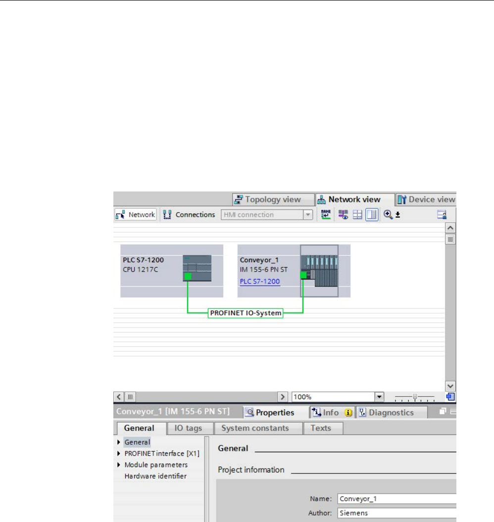
Extended instructions
9.7 Diagnostics (PROFINET or PROFIBUS)
S7-1200 Programmable controller
464 System Manual, V4.2, 09/2016, A5E02486680-AK
Example
In the example below, you use the GetStationInfo instruction to read the IP address data of
an IO device and write the information to a data block. The IP address data includes the
IP address, subnet mask, and (if used) the address data of the router.
The IO controller executes the GetStationInfo instruction, and the instruction reads the
IP address information of a lower-level IO device (in this example, an ET200SP):
1. Configuring the ET 200SP:
– Create the ET 200SP with the station name "Conveyor_1" in the network view, and
assign it to the same PROFINET IO system as the CPU.
– Assign the CPU as the IO controller for the ET 200SP.
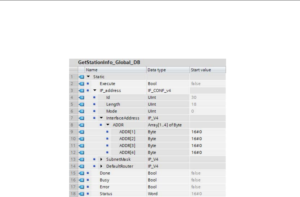
Extended instructions
9.7 Diagnostics (PROFINET or PROFIBUS)
S7-1200 Programmable controller
System Manual, V4.2, 09/2016, A5E02486680-AK 465
2. Assigning parameters for the GetStationInfo instruction:
– Create five tags and a structure with the IF_CONF_v4 data type in a global data block
for storing the IP address data. Assign any name to the structure. (In the example, the
structure name is "IP_Address".)
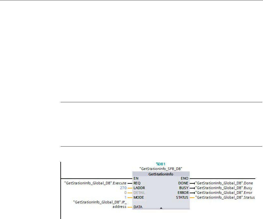
Extended instructions
9.7 Diagnostics (PROFINET or PROFIBUS)
S7-1200 Programmable controller
466 System Manual, V4.2, 09/2016, A5E02486680-AK
3. Assigning parameters for the GetStationInfo instruction:
– Enter the hardware ID of the IO device at the LADDR parameter. The hardware
identifier uniquely identifies the product, and, in this example, the hardware ID is
"270". You can find the hardware ID at the following location: PLC tags > Show all
tags > System constants tab
Search for the IO device in the Name column and for the "Hw_Device" in the Data
type column. The associated value is the hardware ID that you enter at the LADDR
parameter.
– Select "1" (read address parameters according to IPv4) for the MODE parameter.
– Connect the IF_CONF_v4 structure at the DATA parameter.
Note
When using the dropdown list to make your selections for configuring the tag to the
DATA parameter, select the DB (in
the example, "GetStationInfo_Global_DB") and the
tag (in the example, "IP
address"). In order to read the entire IF_CONF_v4 data type,
you must delete the period that appears following "IP
address" so that the final result
is: "GetStationInfo_Global_DB".IP
address
– Define PLC tags from your global DB for the output parameters of the instruction.
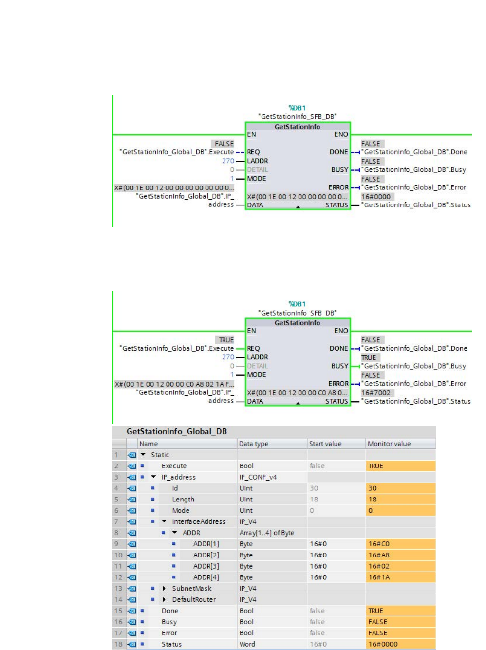
Extended instructions
9.7 Diagnostics (PROFINET or PROFIBUS)
S7-1200 Programmable controller
System Manual, V4.2, 09/2016, A5E02486680-AK 467
4. Executing the GetStationInfo instruction:
– When the REQ input = 1 (FALSE), the instruction displays no IP address information
at the DATA input/output parameter or error code information at the STATUS output
parameter.
5. Completing execution of the GetStationInfo instruction:
– When the REQ input = 1 (TRUE), the program executes the instruction and writes the
IP address to the data block. The program writes the IP address, "C0 A8 02 1A"
(decimal value of "192.168.2.26"), to the DATA input/output parameter.
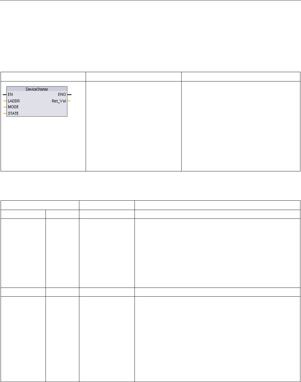
Extended instructions
9.7 Diagnostics (PROFINET or PROFIBUS)
S7-1200 Programmable controller
468 System Manual, V4.2, 09/2016, A5E02486680-AK
9.7.7
DeviceStates instruction
You can use the DeviceStates instruction to return the states of all distributed I/O slave
devices connected to a specified distributed I/O Master.
Table 9- 156 DeviceStates instruction
LAD / FBD
SCL
Description
ret_val := DeviceStates(
laddr:=_word_in_,
mode:=_uint_in_,
state:=_variant_inout_);
DeviceStates retrieves the I/O device opera-
tional states of an I/O subsystem. After execu-
tion, the STATE parameter contains the error
state of each I/O device in a bit list (for the
assigned LADDR and MODE). This information
corresponds with the device status seen in the
STEP 7 diagnostics view.
The LADDR input of DeviceStates uses the
hardware identifier of a distributed I/O interface.
In the TIA portal, the hardware identifiers for a
PLC can be found by looking for
"HW_IOSYSTEM" data types in the system
constants tab in the PLC tag table.
Table 9- 157 Data types for the parameters
Parameter and type
Data type
Description
LADDR
IN
HW_IOSYSTEM
Logical address: (Identifier for the I/O system)
MODE IN UInt Supports five modes of operation. The MODE input determines
which data will be returned to the location specified for STATE
information. The modes are as follows:
• 1: Device configuration active
• 2: Device defective
• 3: Device disabled
• 4: Device exists
• 5: Problem in Device
RET_VAL
OUT
Int
Execution condition code
STATE1 InOut Variant Buffer that receives the error status of each device: The data type
that you choose for the STATE parameter can be any bit type
(Bool, Byte, Word, or DWord) or an array of a bit type
• Bit 0 of the first byte of the returned STATE data is a summary
bit. When it is set to TRUE, it indicates that other data is avail-
able.
• The data returned by the STATE parameter shows a one-to-
one correlation between a bit location and a distributed I/O ad-
dress. This device addressing is TRUE for PROFIBUS and
PROFINET. For example, Bit 4 in the first Byte correlates to
PROFIBUS address 4 or PROFINET device number 4.
1 For PROFIBUS-DP, the length of the status information is 128 bits. For PROFINET I/O, the length is 1024 bits.

Extended instructions
9.7 Diagnostics (PROFINET or PROFIBUS)
S7-1200 Programmable controller
System Manual, V4.2, 09/2016, A5E02486680-AK 469
After execution, the STATE parameter contains the error state of each I/O device as a bit list
(for the assigned LADDR and MODE).
Table 9- 158 Condition codes
RET_VAL (W#16#...)
Description
0
No error
8091 LADDR does not exist.
8092
LADDR does not address an I/O system.
8093 Invalid data type assigned for STATE parameter: Valid data types are (Bool, Byte, Word, or
Dword), or an array of (Bools, Bytes, Words, or Dwords)
80Bx
DeviceStates instruction not supported by the CPU for this LADDR.
8452 The complete state data is too large for the assigned STATE parameter. The STATE buffer
contains a partial result.
9.7.7.1
DeviceStates example configurations
PROFIBUS example
The PROFIBUS example consists of the following:
● 16 PROFIBUS devices named "DPSlave_10" through "DPSlave_25"
● The 16 PROFIBUS devices use PROFIBUS addresses 10 through 25, respectively.
● Each slave device is configured with multiple I/O modules.
● The first four bytes of the returned STATE parameter information is displayed.
MODE
Example 1:
Normal operation with
no errors
Example 2:
PROFIBUS slave de-
vice DPSlave_12 with
single module pulled
Example 3:
PROFIBUS slave
device DPSlave_12
disconnected
1: Device configuration
active
0x01FC_FF03 0x01FC_FF03 0x01FC_FF03
2: Device defective
0x0000_0000
0x0110_0000
0x0110_0000
3: Device disabled
0x0000_0000
0x0000_0000
0x0000_0000
4: Device exists
0x01FC_FF03
0x01FC_FF03
0x01EC_FF03
5: Problem in device
0x0000_0000
0x0110_0000
0x0110_0000
The following four tables show a binary breakdown of the four bytes of data that are being
analyzed:

Extended instructions
9.7 Diagnostics (PROFINET or PROFIBUS)
S7-1200 Programmable controller
470 System Manual, V4.2, 09/2016, A5E02486680-AK
Table 9- 159 Example 1: No errors: A value of 0x01FC_FF03 is returned for MODE 1 (Device configu-
ration active).
Byte with value
Bit pattern with value
Notes
Byte 1 0x01
Bit 7 0000-0001 Bit 0
Bit 0 is true; data is available.
Byte 2 0xFC Bit 15 1111-1100 Bit 8
Byte 3 0xFF
Bit 23 1111-1111 Bit 16
Byte 4 0x03
Bit 31 0000-0011 Bit 24
The devices are configured in addresses 10 (Bit 10) through 25 (Bit 25).
No devices are configured in addresses 1 through 9.
MODE 4 (Device exists) data matches MODE 1 (Device configuration active), so the configured
devices match the existing devices.
Table 9- 160 Example 2: A module has been pulled from PROFIBUS slave device "DPSlave_12". A
value of 0x0110_0000 is returned for MODE 2 (Device defective).
Byte with value
Bit pattern with value
Notes
Byte 1 0x01
Bit 7 0000-0001 Bit 0
Bit 0 is true; data is available.
Byte 2 0x10
Bit 15 0001-0000 Bit 8
Byte 3 0x00
Bit 23 0000-0000 Bit 16
Byte 4 0x00
Bit 31 0000-0000 Bit 24
Device 12 (Bit 12) is marked as defective.
MODE 5 (Problem in device) returns the same information as MODE 2 (Device defective).

Extended instructions
9.7 Diagnostics (PROFINET or PROFIBUS)
S7-1200 Programmable controller
System Manual, V4.2, 09/2016, A5E02486680-AK 471
Table 9- 161 Example 2 (continued): A module has been pulled from PROFIBUS slave device
"DPSlave_12". A value of 0x01FC_FF03 is returned for MODE 4 (Device exists).
Byte with value
Bit pattern with value
Notes
Byte 1 0x01
Bit 7 0000-0001 Bit 0
Bit 0 is true; data is available.
Byte 2 0xFC Bit 15 111
1
-1100 Bit 8
Byte 3 0xFF
Bit 23 1111-1111 Bit 16
Byte 4 0x03
Bit 31 0000-0011 Bit 24
Even though device 12 (Bit 12) has an error as shown in MODE 2 (Device defective) above, the d
e-
vice is still functioning on the network which causes MODE 4 (Device exists) to show the device as
an "existing device".
Table 9- 162 Example 3: PROFIBUS slave device "DPSlave_12" is disconnected (cable disconnected
or power loss) from the PROFIBUS network. "DPSlave_12" is still detected as a defec-
tive device as well as an error in the device. The difference is that "DPSlave_12" is no
longer detected as a device that exists. A value of 0x01EC_FF03 is returned for MODE 4
(Device exists).
Byte with value
Bit pattern with value
Notes
Byte 1 0x01 Bit 7 0000-0001 Bit 0 Bit 0 is true; data is available.
Byte 2 0xEC
Bit 15 1110-1100 Bit 8
Byte 3 0xFF
Bit 23 1111-1111 Bit 16
Byte 4 0x03
Bit 31 0000-0011 Bit 24
Device 12 (Bit 12) is marked as not existing. With this exception, devices 10 through 25 still report as
existing.

Extended instructions
9.7 Diagnostics (PROFINET or PROFIBUS)
S7-1200 Programmable controller
472 System Manual, V4.2, 09/2016, A5E02486680-AK
PROFINET example
The PROFINET example consists of the following:
● 16 PROFINET slave devices named "et200s_1" through "et200s_16"
● The 16 PROFINET devices use PROFINET device numbers 1 through 16, respectively.
● Each slave device is configured with multiple I/O modules.
● The first four bytes of the returned STATE parameter information is displayed.
MODE
Example 1:
Normal operation with
no errors
Example 2:
PROFINET slave
et200s_1 module
pulled
Example 3:
PROFINET slave
et200s_1 disconnect-
ed
1: Device configuration
active
0xFFFF_0100 0xFFFF_0100 0xFFFF_0100
2 - Device defective
0x0000_0000
0x0300_0000
0x0300_0000
3 - Device disabled
0x0000_0000
0x0000_0000
0x0000_0000
4 - Device exists 0xFFFF_0100 0xFFFF_0100 0xFDFF_0100
5 - Problem in device
0x0000_0000
0x0300_0000
0x0300_0000
The following four tables show a binary breakdown of the four bytes of data that are being
analyzed:
Table 9- 163 Example 1: No errors: A value of 0xFFFF_0100 is returned for MODE 1 (Device configu-
ration active).
Byte with value
Bit pattern with value
Notes
Byte 1 0xFF
Bit 7 1111-1111 Bit 0
Bit 0 is true; data is available.
Byte 2 0xFF
Bit 15 1111-1111 Bit 8
Byte 3 0x01
Bit 23 0000-0001 Bit 16
Byte 4 0x00
Bit 31 0000-0000 Bit 24
The devices are configured in addresses 1 (Bit 1) through 16 (Bit 16).
No devices are configured in addresses 1 through 9.
MODE 4 (Device exists) data matches MODE 1 (Device configuration active), so the configured
devices match the existing devices.

Extended instructions
9.7 Diagnostics (PROFINET or PROFIBUS)
S7-1200 Programmable controller
System Manual, V4.2, 09/2016, A5E02486680-AK 473
Table 9- 164 Example 2: A module has been pulled from PROFINET slave device "et200s_1". A value
of 0x0300_0000 is returned for MODE 2 (Device defective).
Byte with value
Bit pattern with value
Notes
Byte 1 0x03
Bit 7 0000-0011 Bit 0
Bit 0 is true; data is available.
Byte 2 0x00 Bit 15 0000-0000 Bit 8
Byte 3 0x00
Bit 23 0000-0000 Bit 16
Byte 4 0x00
Bit 31 0000-0000 Bit 24
Device 1 (Bit 1) is marked as defective. Since the device still exists, MODE 4 (Device exist
s) shows
the same data as when operating normally.
MODE 5 (Problem in device) returns the same information as MODE 2 (Device defective).
Table 9- 165 Example 2 (continued): A module has been pulled from PROFIBUS slave device
"et200s_1". A value of 0xFFFF_0100 is returned for MODE 4 (Device exists).
Byte with value
Bit pattern with value
Notes
Byte 1 0xFF Bit 7 1111-11
1
1 Bit 0 Bit 0 is true; data is available.
Byte 2 0xFF
Bit 15 1111-1111 Bit 8
Byte 3 0x01
Bit 23 0000-0001 Bit 16
Byte 4 0x00
Bit 31 0000-0000 Bit 24
Even though device 1 (Bit 1) has an error as shown in MODE 2 (Device defective) above, the device
is still functioning on the network which causes MODE 4 (Device exists) to show the device as an
"existing device".
Table 9- 166 Example 3: PROFINET slave device "et200s_1" is disconnected (cable disconnected or
power loss) from the PROFINET network. A value of 0xFDFF_0100 is returned for
MODE 4 (Device exists).
Byte with value
Bit pattern with value
Notes
Byte 1 0xFD
Bit 7 1111-1101 Bit 0
Bit 0 is true; data is available.
Byte 2 0xFF
Bit 15 1111-1111 Bit 8
Byte 3 0x01
Bit 23 0000-0001 Bit 16
Byte 4 0x00
Bit 31 0000-0000 Bit 24
Device 1 (Bit 1) does not exist. Devices 2 (Bit 2) through 16 (Bit 16) do exist.

Extended instructions
9.7 Diagnostics (PROFINET or PROFIBUS)
S7-1200 Programmable controller
474 System Manual, V4.2, 09/2016, A5E02486680-AK
9.7.8
ModuleStates instruction
You can use the ModuleStates instruction to return the status of all of the modules in a
PROFIBUS or PROFINET station.
Table 9- 167 ModuleStates instruction
LAD / FBD
SCL
Description
ret_val := ModuleStates(
laddr:=_word_in_,
mode:=_uint_in,
state:=_variant_inout);
ModuleStates retrieves the operational states
of I/O modules. After execution, the STATE
parameter contains the error state of each I/O
module in a bit list (for the assigned LADDR
and MODE). This information corresponds
with the module status seen in the STEP 7
diagnostics view.
The LADDR input of ModuleStates uses is a
hardware identifier of a distributed I/O station
and not of the head module itself. The hard-
ware identifier can be found by selecting the
entire station in the network view and then
looking in the hardware identifier section un-
der properties. It can also be found by looking
for "Hw_Device" and "Hw_DpSlave" data
types in the system constants tab in the PLC
tag table.

Extended instructions
9.7 Diagnostics (PROFINET or PROFIBUS)
S7-1200 Programmable controller
System Manual, V4.2, 09/2016, A5E02486680-AK 475
Table 9- 168 Data types for the parameters
Parameter and type
Data type
Description
LADDR
IN
HW_DEVICE
Logical address (Identifier for the I/O modules)
MODE IN UInt Supports five modes of operation. The MODE input determines
which data will be returned to the location specified for STATE
information. The modes are as follows:
• 1: Module configuration active
• 2: Module defective
• 3: Module disabled
• 4: Module exists
• 5: Problem in Module
RET_VAL
OUT
Int
Status (condition code)
STATE1 InOut Variant Buffer that receives the error status of each module: The data type
you use for the STATE parameter can be any bit type (Bool, Byte,
Word, or DWord) or an array of a bit type.
• Bit 0 of the first byte of the returned STATE data is a summary
bit. When it is set to TRUE, it indicates that other data is avail-
able.
• The data returned by the STATE parameter shows a one-to-
one correlation between a bit location and a module position.
This slot addressing is TRUE for PROFIBUS and PROFINET.
For example, for an ET 200SP with a head module, power
module, and a pair of I/O modules, Bit 1 in the first Byte corre-
lates to the head module, Bit 2 to the power module, and Bits 3
and 4 to the I/O modules, respectively.
1 A maximum of 128 bits can be assigned. The number of bits required is dependent on your I/O module usage.
Table 9- 169 Condition codes
RET_VAL ( W#16#...)
Description
0
No error
8091
Module identified by LADDR does not exist.
8092
Module identified by LADDR does not address an I/O device.
8093 Invalid data type for STATE parameter: Valid data types are (Bool, Byte, Word, or Dword), or
an array of (Bools, Bytes, Words, or Dwords).
80Bx
ModuleStates instruction not supported by this CPU for this LADDR.
8452 The complete state data is too large for the assigned STATE parameter. The STATE buffer
contains a partial result.

Extended instructions
9.7 Diagnostics (PROFINET or PROFIBUS)
S7-1200 Programmable controller
476 System Manual, V4.2, 09/2016, A5E02486680-AK
9.7.8.1
ModuleStates example configurations
PROFIBUS example
The PROFIBUS example consists of the following:
● 16 PROFIBUS devices named "DPSlave_10" through "DPSlave_25"
● The 16 PROFIBUS devices use PROFIBUS addresses 10 through 25, respectively.
● Each slave device is configured with multiple I/O modules.
● The example uses the LADDR parameter of PROFIBUS slave "DPSlave_12" which
contains a head module, a power module, and two I/O modules.
● The first four bytes of the returned STATE parameter information is displayed.
MODE
Example 1:
Normal operation with
no errors
Example 2:
PROFIBUS slave de-
vice DPSlave_12 mod-
ule pulled
Example 3:
PROFIBUS slave
device DPSlave_12
disconnected
1: Module configuration
active
0x1F00_0000 0x1F00_0000 0x1F00_0000
2: Module defective 0x0000_0000 0x0900_0000 0x1F00_0000
3: Module disabled
0x0000_0000
0x0000_0000
0x0000_0000
4: Module exists 0x1F00_0000 0x1700_0000 0x0000_0000
5: Problem in module
0x0000_0000
0x0900_0000
0x1F00_0000
The following four tables show a binary breakdown of the four bytes of data that are being
analyzed:
Table 9- 170 Example 1: No errors: A value of 0x1F00_0000 is returned for MODE 1 (Module configu-
ration active).
Byte with value
Bit pattern with value
Notes
Byte 1 0x1F
Bit 7 0001-1111 Bit 0
Bit 0 is true; data is available.
Byte 2 0x00
Bit 15 0000-0000 Bit 8
Byte 3 0x00
Bit 23 0000-0000 Bit 16
Byte 4 0x00
Bit 31 0000-0000 Bit 24
Slots 1 (Bit 1) through 4 (Bit 4) contain modules. Slots 5 (Bit 5) an
d beyond do not contain modules.
MODE 4 (Module exists) data matches MODE 1 (Module configuration active), so the configured
modules match the existing modules.

Extended instructions
9.7 Diagnostics (PROFINET or PROFIBUS)
S7-1200 Programmable controller
System Manual, V4.2, 09/2016, A5E02486680-AK 477
Table 9- 171 Example 2: A module has been pulled from PROFIBUS slave device "DPSlave_12". A
value of 0x0900_0000 is returned for MODE 2 (Module defective).
Byte with value
Bit pattern with value
Notes
Byte 1 0x09
Bit 7 0000-1001 Bit 0
Bit 0 is true; data is available.
Byte 2 0x00 Bit 15 0000-0000 Bit 8
Byte 3 0x00
Bit 23 0000-0000 Bit 16
Byte 4 0x00
Bit 31 0000-0000 Bit 24
Only module 3 (Bit 3) is marked as defective. All other modules are functional.
Table 9- 172 Example 2 (continued): A module has been pulled from PROFIBUS slave device
"DPSlave_12". A value of 0x1700_0000 is returned for MODE 4 (Module exists).
Byte with value
Bit pattern with value
Notes
Byte 1 0x17
Bit 7 0001-0111 Bit 0
Bit 0 is true; data is available.
Byte 2 0x00
Bit 15 0000-0000 Bit 8
Byte 3 0x00
Bit 23 0000-0000 Bit 16
Byte 4 0x00
Bit 31 0000-0000 Bit 24
Module 3 (Bit 3) is shown as missing. Modules 1, 2, and 4 (Bits 1, 2, and 4) are shown as existing.
Table 9- 173 Example 3: PROFIBUS slave device "DPSlave_12" is disconnected (cable disconnected
or power loss) from the PROFIBUS network. A value of 0x1F00_0000 is returned for
MODE 2 (Module defective).
Byte with value
Bit pattern with value
Notes
Byte 1 0x1F
Bit 7 0001-1111 Bit 0
Bit 0 is true; data is available.
Byte 2 0x00
Bit 15 0000-0000 Bit 8
Byte 3 0x00
Bit 23 0000-0000 Bit 16
Byte 4 0x00
Bit 31 0000-0000 Bit 24
The modules in slots 1 through 4 (Bits 1 through 4) are all marked as defective since the device is
missing.
MODE 5 (Problem in module) shows the same information as MODE 2 (Module defective).

Extended instructions
9.7 Diagnostics (PROFINET or PROFIBUS)
S7-1200 Programmable controller
478 System Manual, V4.2, 09/2016, A5E02486680-AK
PROFINET example
The PROFINET example consists of the following:
● 16 PROFINET slave devices named "et200s_1" through "et200s_16"
● The 16 PROFINET devices use PROFINET device numbers 1 through 16, respectively.
● Each slave device is configured with multiple I/O modules.
● The example uses PROFINET slave "et200s_1" which contains a head module, a power
module, and 18 I/O modules.
● The first four bytes of the returned STATE parameter information is displayed.
MODE
Example 1:
Normal operation with
no errors
Example 2:
PROFINET et200s_1
slave module pulled
Example 3:
PROFINET et200s_1
slave disconnected
1: Module configuration
active
0xFFFF_1F00 0xFFFF_1F00 0xFFFF_1F00
2: Module defective
0x0000_0000
0x0180_0000
0xFFFF_1F00
3: Module disabled
0x0000_0000
0x0000_0000
0x0000_0000
4: Module exists 0xFFFF_1F00 0xFF7F_1F00 0x0000_0000
5: Problem in module
0x0000_0000
0x0180_0000
0xFFFF_1F00
The following four tables show a binary breakdown of the four bytes of data that are being
analyzed:
Table 9- 174 Example 1: No errors: A value of 0xFFFF_1F00 is returned for MODE 1 (Module configu-
ration active).
Byte with value
Bit pattern with value
Notes
Byte 1 0xFF
Bit 7 1111-1111 Bit 0
Bit 0 is true; data is available.
Byte 2 0xFF
Bit 15 1111-1111 Bit 8
Byte 3 0x1F
Bit 23 0001-1111 Bit 16
Byte 4 0x00
Bit 31 0000-0000 Bit 24
Slots 1 (Bit 1) through 20 (Bit 20) contain modules. Slot 21 (Bit 21) and beyond do not
contain mod-
ules.
MODE 4 (Module exists) data matches MODE 1 (Module configuration active), so the configured
modules match the existing modules.
Table 9- 175 Example 2: A module has been pulled from PROFINET slave device "et200s_1". A value
of 0x0180_0000 is returned for MODE 2 (Module defective).
Byte with value
Bit pattern with value
Notes
Byte 1 0x01
Bit 7 0000-0001 Bit 0
Bit 0 is true; data is available.
Byte 2 0x80
Bit 15 1000-0000 Bit 8
Byte 3 0x00
Bit 23 0000-0000 Bit 16
Byte 4 0x00
Bit 31 0000-0000 Bit 24
Only module 15 (Bit 15) is marked as defective. All other modules are functional.

Extended instructions
9.7 Diagnostics (PROFINET or PROFIBUS)
S7-1200 Programmable controller
System Manual, V4.2, 09/2016, A5E02486680-AK 479
Table 9- 176 Example 2 (continued): A module has been pulled from PROFIBUS slave device
"et200s_1". A value of 0xFF7F_1F00 is returned for MODE 4 (Module exists).
Byte with value
Bit pattern with value
Notes
Byte 1 0xFF
Bit 7 1111-1111 Bit 0
Bit 0 is true; data is available.
Byte 2 0x7F Bit 15
0
111-1111 Bit 8
Byte 3 0x1F
Bit 23 0001-1111 Bit 16
Byte 4 0x00
Bit 31 0000-0000 Bit 24
Module 15 (Bit 15) is shown as missing. Modules 1 through 14 (Bits 1 through 14) and 16 through 20
(Bits 16 through 20) are shown as existing.
Table 9- 177 Example 3: PROFINET slave device "et200s_1" is disconnected (cable disconnected or
power loss) from the PROFINET network. A value of 0xFFFF_1F00 is returned for
MODE 2 (Module defective).
Byte with value
Bit pattern with value
Notes
Byte 1 0xFF
Bit 7 1111-1111 Bit 0
Bit 0 is true; data is available.
Byte 2 0xFF
Bit 15 1111-1111 Bit 8
Byte 3 0x1F
Bit 23 0001-1111 Bit 16
Byte 4 0x00
Bit 31 0000-0000 Bit 24
The modules in slots 1 through 20 (Bits 1 through 20) are all marked as defective since the devi
ce is
missing.
MODE 5 (Problem in module) shows the same information as MODE 2 (Module defective).
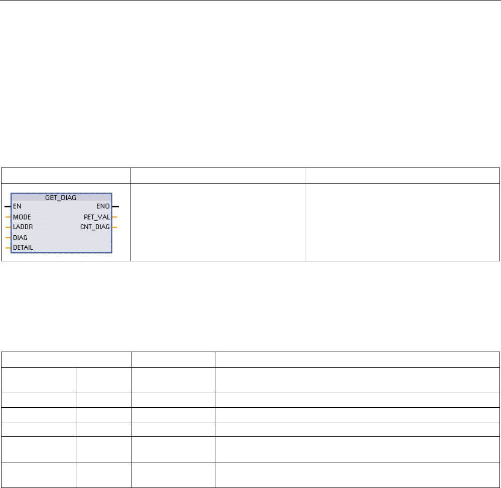
Extended instructions
9.7 Diagnostics (PROFINET or PROFIBUS)
S7-1200 Programmable controller
480 System Manual, V4.2, 09/2016, A5E02486680-AK
9.7.9
GET_DIAG (Read diagnostic information)
Description
You can use the "GET_DIAG" instruction to read out the diagnostic information of a
hardware device. The hardware device is selected with the LADDR parameter. With the
MODE parameter, you select which diagnostic information to read.
Table 9- 178 GET_DIAG instruction
LAD / FBD
SCL
Description
ret_val := GET_DIAG(
mode:=_uint_in_,
laddr:=_word_in_,
cnt_diag=>_uint_out_,
diag:=_variant_inout_,
detail:=_variant_inout_);
Reads the diagnostic information from an
assigned hardware device.
Parameters
The following table shows the parameters of the "GET_DIAG" instruction:
Table 9- 179 Data types for the parameters
Parameter and type
Data type
Description
MODE IN UInt Use the MODE parameter to select which diagnostic data is to be
output.
LADDR
IN
HW_ANY (Word)
Hardware ID of the device
RET_VAL
OUT
Int
Status of the instruction
CNT_DIAG
OUT
UInt
Number of output diagnostic details
DIAG InOut Variant Pointer to data area for storage of diagnostic information of the se-
lected mode
DETAILS InOut Variant Pointer to data area for storage of diagnostic details in accordance
with the selected mode

Extended instructions
9.7 Diagnostics (PROFINET or PROFIBUS)
S7-1200 Programmable controller
System Manual, V4.2, 09/2016, A5E02486680-AK 481
MODE parameter
Depending on the value at the MODE parameter, different diagnostics data is output at the
DIAG, CNT_DIAG and DETAILS output parameters:
Table 9- 180 MODE parameter
MODE
Description
DIAG
CNT_DIAG
DETAILS
0 Output of all supported diag-
nostic information for a mod-
ule as DWord, where Bit X=1
indicates that mode X is sup-
ported.
Bit string of the supported
modes as DWord, where Bit
X=1 indicates that mode X
is supported.
0 -
1 Output of the inherent status
of the addressed hardware
object.
Diagnostics status: Output
in accordance with the DIS
structure. (Note: Refer to
the "DIS structure" infor-
mation below and
GET_DIAG instruction ex-
ample at the end of the
section.)
0 -
2 Output of the status of all
subordinate modules of the
addressed hardware object.
Output of diagnostics data
in accordance with the DNN
structure. (Note: Refer to
the "DNN structure" infor-
mation below and
GET_DIAG instruction ex-
ample at the end of the
section.)
0 -

Extended instructions
9.7 Diagnostics (PROFINET or PROFIBUS)
S7-1200 Programmable controller
482 System Manual, V4.2, 09/2016, A5E02486680-AK
DIS structure
With the MODE parameter = 1, the diagnostics information is output in accordance with the
DIS structure. The following table shows the meaning of the individual parameter values:
Table 9- 181 Structure of the Diagnostic Information Source (DIS)
Parameter
Data type
Value
Description
MaintenanceState DWord
Enum
0 No maintenance required
1
The module or device is disabled.
2
-
3
-
4
-
5
Maintenance required
6
Maintenance demanded
7
Error
8
Status unknown / error in subordinate module
9
-
10
Inputs/outputs are not available.
Componentstate
Detail
DWord Bit array Status of the module submodules:
• Bit 0 to 15: Status message of the module
• Bit 16 to 31: Status message of the CPU
0 to 2
(enum)
Additional information:
• Bit 0: No additional information
• Bit 1: Transfer not permitted
3
Bit 3 = 1: At least one channel supports qualifiers for diagnostics.
4 Bit 4 = 1: Maintenance required for at least one channel or one compo-
nent
5 Bit 5 = 1: Maintenance demanded for at least one channel or one com-
ponent
6
Bit 6 = 1: Error in at least one channel or one component
7 to 10
Reserved (always = 0)
11 to 14 Bit 11 = 1: PNIO - submodule correct
Bit 12 = 1: PNIO - replacement module
Bit 13 = 1: PNIO - incorrect module
Bit 14 = 1: PNIO - module disconnected
15
Reserved (always = 0)

Extended instructions
9.7 Diagnostics (PROFINET or PROFIBUS)
S7-1200 Programmable controller
System Manual, V4.2, 09/2016, A5E02486680-AK 483
Parameter
Data type
Value
Description
16 to 31 Status information for modules generated by the CPU:
Bit 16 = 1: Module disabled
Bit 17 = 1: CiR operation active
Bit 18 = 1: Input not available
Bit 19 = 1: Output not available
Bit 20 = 1: Overflow diagnostics buffer
Bit 21 = 1: Diagnostics not available
Bit 22 - 31: Reserved (always 0)
OwnState Uint16 Enum The value of the OwnState parameter describes the maintenance sta-
tus of the module.
0
No fault
1
The module or device is disabled.
2
Maintenance required
3
Maintenance demanded
4
Error
5 The module or the device cannot be reached from the CPU (valid for
modules and devices below a CPU).
6
Inputs/outputs are not available.
7
-
IO State Uint16
Bit array
I/O status of the module
0
Bit 0 = 1: No maintenance required
1
Bit 1 = 1: The module or device is disabled.
2
Bit 2 = 1: Maintenance required
3 Bit 3 = 1: Maintenance demanded
4
Bit 4 = 1: Error
5 Bit 5 = 1: The module or the device cannot be reached from the CPU
(valid for modules and devices below a CPU).
6
Qualifier; bit 7 = 1, if bit 0, 2, or 3 are set
7
Inputs/outputs are not available.
8 to 15
Reserved (always = 0)
OperatingState UInt16
Enum
0
-
1
In STOP / firmware update
2
In STOP / reset memory
3
In STOP / self start
4
In STOP
5
Memory reset
6
In START
7
In RUN
8
-
9
In HOLD
10
-
11
-

Extended instructions
9.7 Diagnostics (PROFINET or PROFIBUS)
S7-1200 Programmable controller
484 System Manual, V4.2, 09/2016, A5E02486680-AK
Parameter
Data type
Value
Description
12
Module defective
13 -
14
No power
15 CiR
16
In STOP / without DIS
17
In
18
19
20
DNN structure
With the MODE parameter = 2, the diagnostics information details are output in accordance
with the DNN structure. The following table shows the meaning of the individual parameter
values:
Table 9- 182 Structure of the Diagnostic Navigation Node (DNN)
Parameter
Data type
Value
Description
SubordinateState UINT Enum Status of the subordinate module (See parameter OwnState of
the DIS structure.)
SubordinateIOState WORD Bitarray Status of the inputs and outputs of the subordinate module (See
parameter IO State of the DIS structure.)
DNNmode WORD Bitarray • Bit 0 = 0: Diagnostics enabled
• Bit 0 = 1: Diagnostics disabled
• Bit 1 to 15: Reserved
RET_VAL parameter
Table 9- 183 Error codes of the RET_VAL parameter
Error code
(W#16#...)
Description
0
No error
8080
Value in the MODE parameter is not supported.
8081
Type in the DIAG parameter is not supported with the selected mode (parameter MODE).
8082
Type in the DETAILS parameter is not supported with the selected mode (parameter MODE).
8090
LADDR does not exist.
8091
The selected channel in the CHANNEL parameter does not exist.
80C1
Insufficient resources for parallel execution
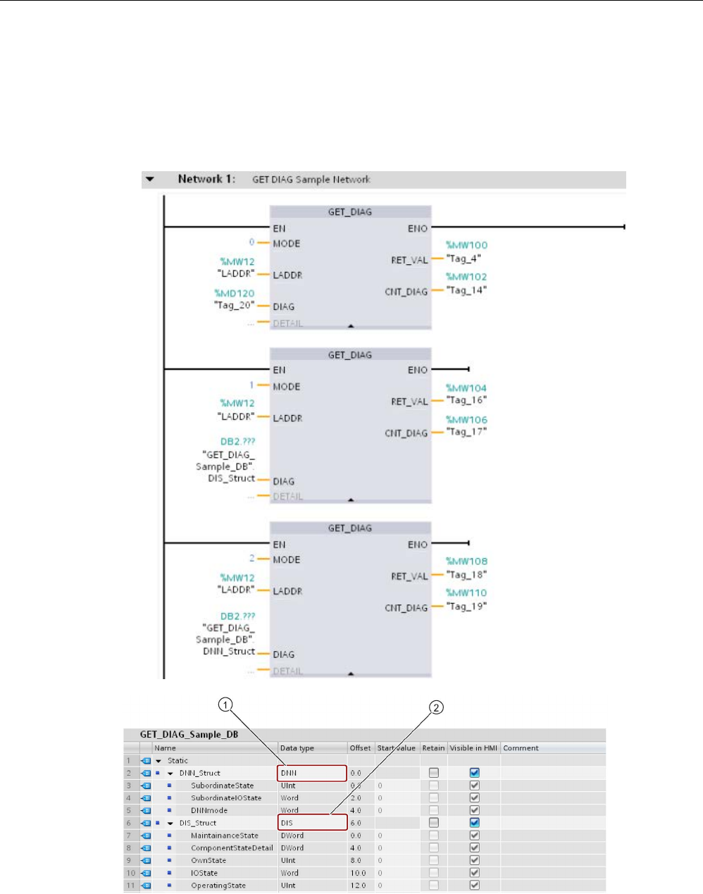
Extended instructions
9.7 Diagnostics (PROFINET or PROFIBUS)
S7-1200 Programmable controller
System Manual, V4.2, 09/2016, A5E02486680-AK 485
Example
The following ladder logic network and DB show how to use the three modes with the three
structures:
● DIS
● DNN
①
DNN
②
DIS

Extended instructions
9.7 Diagnostics (PROFINET or PROFIBUS)
S7-1200 Programmable controller
486 System Manual, V4.2, 09/2016, A5E02486680-AK
Note
In the DB, you must manually type in the data type to access each of the three structures;
there is no dropdown list selection. Type in the data types exactly as shown below:
•
DNN
•
DIS
9.7.10
Diagnostic events for distributed I/O
Note
Wi
th a PROFIBUS IO system, after a download or power cycle, the CPU will go to RUN
mode unless the hardware compatibility is set to allow
acceptable substitute modules
(Page
170) and one or more modules is missing or is not an acceptable substitute for the
configured module.
As shown in the following table, the CPU supports diagnostics that can be configured for the
components of the distributed I/O system. Each of these errors generates a log entry in the
diagnostic buffer.
Table 9- 184 Handling of diagnostic events for PROFINET and PROFIBUS
Type of error
Diagnostic information for
the station?
Entry in the diagnostic buff-
er?
CPU operating mode
Diagnostic error
Yes
Yes
Stays in RUN mode
Rack or station failure
Yes
Yes
Stays in RUN mode
I/O access error
1
No
Yes
Stays in RUN mode
Peripheral access error
2
No
Yes
Stays in RUN mode
Pull / plug event
Yes
Yes
Stays in RUN mode
1
I/O access error example cause: A module that has been removed.
2 Peripheral access error example cause: Acyclic communication to a submodule that is not communicating.
Use the GET_DIAG instruction (Page 480) for each station to obtain the diagnostic
information. This will allow you to programmatically handle the errors encountered on the
device and if desired take the CPU to STOP mode. This method requires you to specify the
hardware device from which to read the status information.
The GET_DIAG instruction uses the "L address" (LADDR) of the station to obtain the health
of the entire station. This L Address can be found within the Network Configuration view and
by selecting the entire station rack (entire gray area), the L Address is shown in the
Properties Tab of the station. You can find the LADDR for each individual module either in
the properties for the module (in the device configuration) or in the default tag table for the
CPU.

Extended instructions
9.8 Pulse
S7-1200 Programmable controller
System Manual, V4.2, 09/2016, A5E02486680-AK 487
9.8
Pulse
9.8.1
CTRL_PWM (Pulse width modulation)
Table 9- 185 CTRL_PWM (Pulse Width Modulation) instruction
LAD / FBD
SCL
Description
"CTRL_PWM_DB"(
PWM:=_uint_in_,
ENABLE:=_bool_in_,
BUSY=>_bool_out_,
STATUS=>_word_out_);
Provides a fixed cycle time output with a variable duty
cycle. The PWM output runs continuously after being
started at the specified frequency (cycle time). The
pulse width is varied as required to affect the desired
control.
1
When you insert the instruction, STEP 7 displays the "Call Options" dialog for creating the associated DB.
2 In the SCL example, "CTRL_PWM_DB" is the name of the instance DB.
Table 9- 186 Data types for the parameters
Parameter and type
Data type
Description
PWM IN HW_PWM
(Word)
PWM identifier: Names of enabled pulse generators will become tags in
the "constant" tag table, and will be available for use as the PWM pa-
rameter. (Default value: 0)
ENABLE IN Bool 1=start pulse generator
0 = stop pulse generator
BUSY OUT Bool Function busy (Default value: 0)
STATUS
OUT
Word
Execution condition code (Default value: 0)
The CTRL_PWM instruction stores the parameter information in the DB. The data block
parameters are not separately changed by the user, but are controlled by the CTRL_PWM
instruction.
Specify the enabled pulse generator to use, by using its tag name for the PWM parameter.
When the EN input is TRUE, the PWM_CTRL instruction starts or stops the identified PWM
based on the value at the ENABLE input. Pulse width is specified by the value in the
associated Q word output address.
Because the CPU processes the request when the CTRL_PWM instruction is executed,
parameter BUSY will always report FALSE. If an error is detected, then ENO is set to
FALSE, and parameter STATUS contains a condition code.
The pulse width will be set to the initial value configured in device configuration when the
CPU first enters RUN mode. You write values to the Q-word location specified in device
configuration ("Output addresses" / "Start address:") as needed to change the pulse width.
You use an instruction such as a move, convert, math, or PID box to write the desired pulse
width to the appropriate Q word. You must use the valid range for the Q-word value (percent,
thousandths, ten-thousandths, or S7 analog format).
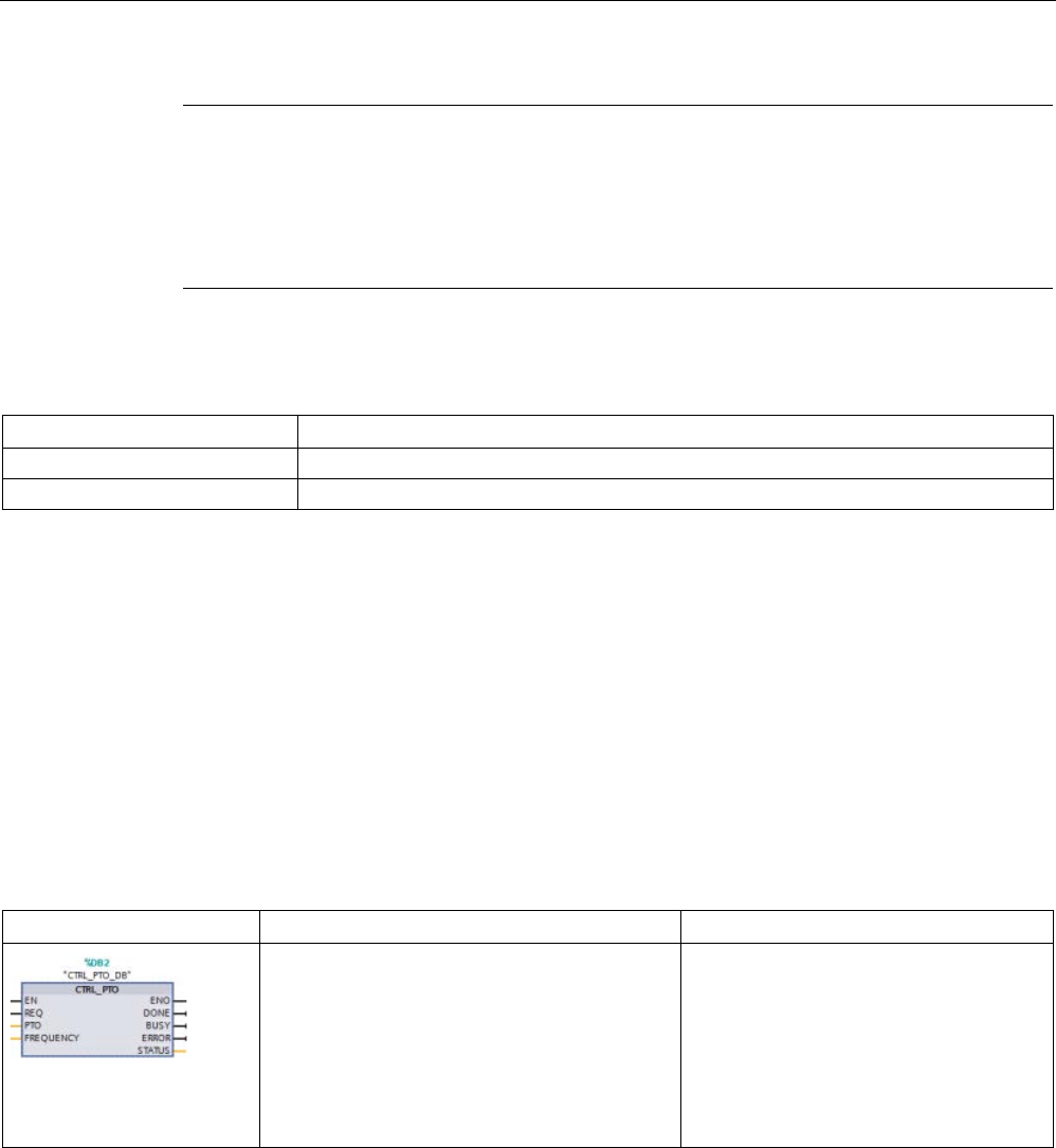
Extended instructions
9.8 Pulse
S7-1200 Programmable controller
488 System Manual, V4.2, 09/2016, A5E02486680-AK
Note
Digital I/O points assigned to PWM and PTO cannot be forced
The digital I/O points used by the pulse
-width modulation (PWM) and pulse-train output
(PTO) devices are assigned during dev
ice configuration. When digital I/O point addresses
are assigned to these devices, the values of the assigned I/O point addresses cannot be
modified by the Watch table force function.
Table 9- 187 Value of the STATUS parameter
STATUS
Description
0
No error
80A1
PWM identifier does not address a valid PWM.
9.8.2
CTRL_PTO (Pulse train output)
The PTO instruction provides a square wave with a 50% duty cycle output at a specified
frequency. You can use the CTRL_PTO instruction to assign the frequency without a
Technology objects (TO) axis data block (DB).
This instruction requires a pulse generator. You must activate the pulse generator and select
a signal type in the hardware configuration. Refer to "Configuring a pulse channel for PWM
or PTO" (Page 494) for further information.
You can access the CTRL_PTO instruction in the Task Cards, Extended instructions.
Table 9- 188 CTRL_PTO (Pulse Train Output) instruction
LAD / FBD1
SCL2
Description
"CTRL_PTO_DB"(
REQ:=_bool_in_,
PTO:=_uint_in_,
FREQUENCY:=_udint_in_,
DONE=>_bool_out_,
BUSY=>_bool_out_,
ERROR=>_bool_out_,
STATUS=>_word_out_);
The PTO instruction allows the user to
control the frequency for a square wave
(50% duty cycle) output.
1
When you insert the instruction, STEP 7 displays the "Call Options" dialog for creating the associated DB.
2 In the SCL example, "CTRL_PTO_DB" is the name of the instance DB.

Extended instructions
9.8 Pulse
S7-1200 Programmable controller
System Manual, V4.2, 09/2016, A5E02486680-AK 489
Table 9- 189 Data types for the parameters
Parameter and type
Data type
Description
EN IN Bool 1 = Instruction enabled
0 = Instruction disabled
REQ IN Bool 1 = Set PTO output frequency to value in FREQUENCY input
0 = No change to PTO
PTO IN HW_PTO
(Word)
PTO identifier: Hardware ID of the pulse generator:
• Names of the enabled pulse generators become tags in the "con-
stant" tag table, and are available for use as the PTO parameter.
(Default value = 0)
• You can find the hardware ID in the Properties of the pulse genera-
tor in the Device view. The system constants also list the hardware
IDs of the pulse generators. (Default value = 0)
FREQUENCY IN UDInt Desired frequency (in Hz) of the PTO. This value is applied only when
REQ = 1 (Default value is 0 Hz)
DONE
OUT
Bool
Function completed without error (Default value: 0)
BUSY
OUT
Bool
Function busy (Default value: 0)
ERROR
OUT
Word
Error detected (Default value: 0)
STATUS
OUT
Word
Execution condition code (Default value: 0)
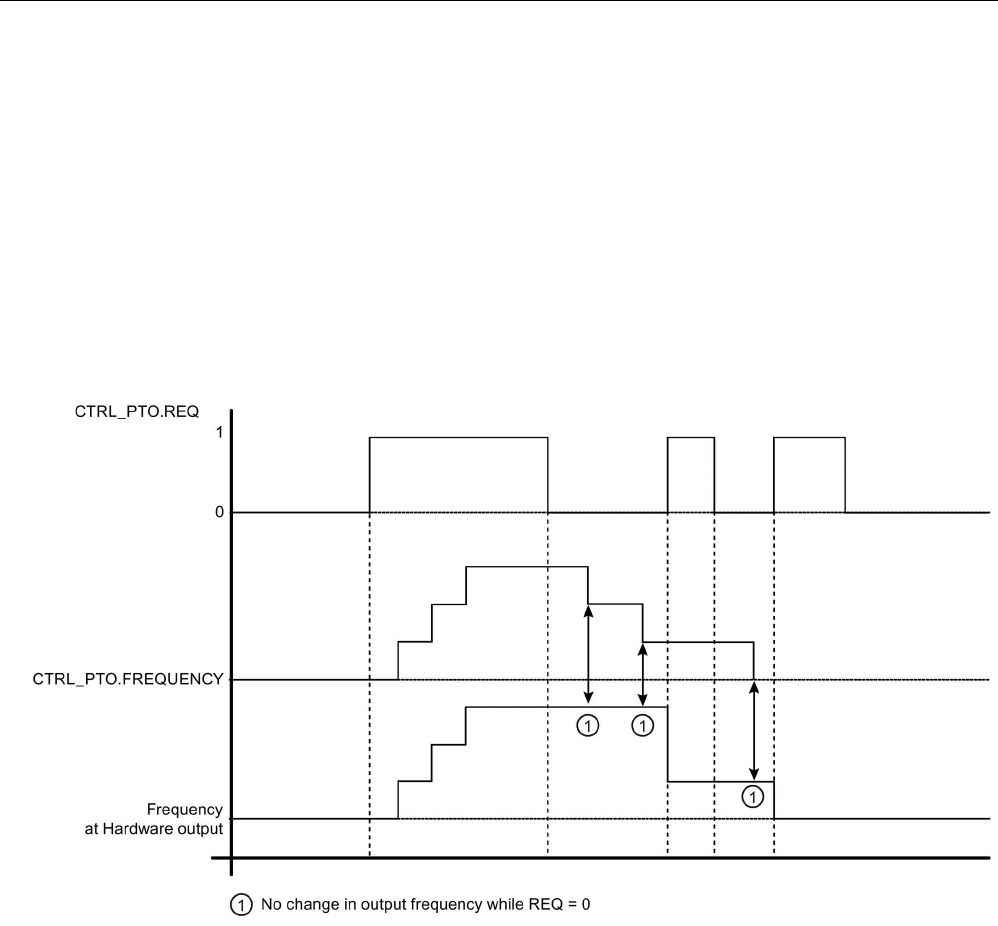
Extended instructions
9.8 Pulse
S7-1200 Programmable controller
490 System Manual, V4.2, 09/2016, A5E02486680-AK
The CTRL_PTO instruction stores the parameter information in the DB. The data block
parameters are not separately changed by the user, but are controlled by the CTRL_PTO
instruction.
Specify the enabled pulse generator to use, by using its tag name or hardware identifier for
the PTO parameter.
When the EN input is TRUE, the CTRL_PTO instruction starts or stops the identified PTO.
When the EN input is FALSE, the CTRL_PTO instruction does not execute and the PTO
maintains its current state.
When you set the REQ input to TRUE, the FREQUENCY value takes effect. If REQ is
FALSE, the PTO's output frequency cannot be changed, and the PTO continues to output
pulses.
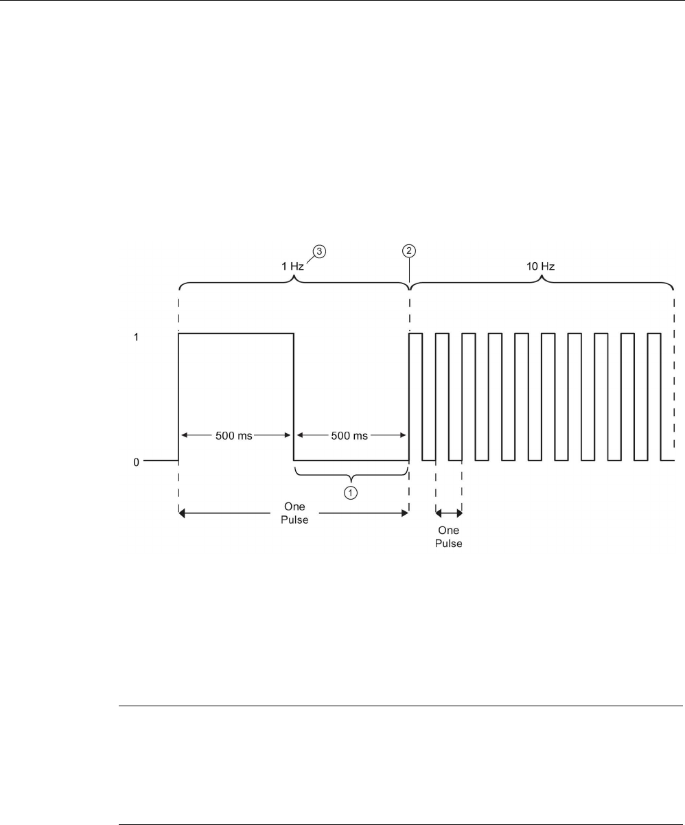
Extended instructions
9.8 Pulse
S7-1200 Programmable controller
System Manual, V4.2, 09/2016, A5E02486680-AK 491
Since the CTRL_PTO instruction only starts the PTO, the CTRL_PTO instruction finishes
immediately. As a result, the BUSY output never turns on. The DONE output comes on as
long as no error occurs. If an error is detected, the ERROR parameter is set to TRUE, and
the STATUS parameter contains a condition code.
When the user enables the CTRL_PTO instruction with a given frequency, the S7-1200
outputs a pulse train at that given frequency. The user can change the desired frequency at
any time. When the frequency is changed, the S7-1200 finishes the current pulse prior to
changing frequency to the new desired frequency. For example, if the desired frequency is 1
Hz (which takes 1000ms to complete) and the user changes the frequency to 10 Hz after
500ms, the frequency changes at the end of the 1000ms time period.
①
The user changes the frequency to 10 Hz after 500 ms.
②
The 1 Hz pulse must finish before the frequency can change to the new 10 Hz frequency.
③
1 Hz corresponds to 1000 ms
The pulse generator hardware object has the following restriction: Only one instruction can
use the pulse generator as PTO, and the hardware configuration editor manages the use of
the pulse generator. Other instructions that try to access that PTO return an error: "0x8090"
(Pulse generator with the specified hardware ID is in use).
Note
Digital I/O points assigned to PWM and PTO cannot be forced
The digital I/O points used by the pulse width modulation (PWM) and pulse train output
(PTO) devices are assigned during device configuration. When digital I/O point addresses
are assigne
d to these devices, the values of the assigned I/O point addresses cannot be
modified by the Watch table force function.
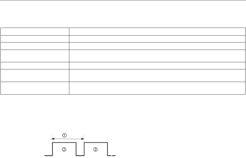
Extended instructions
9.8 Pulse
S7-1200 Programmable controller
492 System Manual, V4.2, 09/2016, A5E02486680-AK
Table 9- 190 STATUS parameter error code value
Error code (W#16#...)
Description
0
No errors
0x8090 Pulse generator with the specified hardware ID is in use.
0x8091 Frequency out-of-range. The desired frequency exceeds the maximum frequency of the
pulse output selected.
0x80A1 PTO identifier (hardware ID) does not address a valid PTO.
0x80D0 Pulse generator with the specified hardware ID is not activated. Activate the pulse gen-
erator in the CPU properties under "Pulse generators (PTO/PWM)".
0x80D1 Pulse generator with the specified hardware ID has no PTO selection. Select PTO in
Hardware Configuration.
9.8.3
Operation of the pulse outputs
Pulse width can be expressed as hundredths of the
cycle time (0 to 100), as thousandths (0 to 1000), as
ten thousandths (0 to 10000), or as S7 analog format.
The pulse width can vary from 0
(no pulse, always off)
to full scale (no pulse, always on).
①
Cycle time
②
Pulse width
Since the PWM output can be varied from 0 to full scale, it provides a digital output that in
many ways is the same as an analog output. For example, the PWM output can be used to
control the speed of a motor from stop to full speed, or it can be used to control position of a
valve from closed to fully opened.
You configure frequency in the hardware configuration. You control pulse width from the user
program.
Four pulse generators are available for controlling high-speed pulse output functions: PWM
and Pulse train output (PTO). PTO is used by the motion control instructions. You can assign
each pulse generator to either PWM or PTO, but not both at the same time.
You can use onboard CPU outputs, or you can use the optional signal board outputs. The
output point numbers are shown in the following table (assuming the default output
configuration). If you have changed the output point numbering, then the output point
numbers will be those you assigned. Note that PWM requires only one output, while PTO
can optionally use two outputs per channel. If an output is not required for a pulse function, it
is available for other uses. Refer to the table below for I/O assignment.

Extended instructions
9.8 Pulse
S7-1200 Programmable controller
System Manual, V4.2, 09/2016, A5E02486680-AK 493
The table below shows the default I/O assignments; however, the four pulse generators can
be configured to any CPU built-in or SB digital output. Different output points support
different voltages and speeds, so take that into account when assigning PWM/PTO
locations.
Note
Pulse-train outputs cannot be used by other instructions in the user program.
When you configure the
outputs of the CPU or signal board as pulse generators (for use with
the PWM or motion control PTO instructions), the corresponding outputs addresses are
removed from the Q memory and cannot be used for other purposes in your user program. If
your user pr
ogram writes a value to an output used as a pulse generator, the CPU does not
write that value to the physical output.
Note
PTO direction outputs can be freed for use elsewhere in your program.
Each PTO requires the assignment of two outputs: one as a
pulse output and one as a
direction output. You can use just the pulse output and not the direction output. You can then
free the direction output for other purposes in your user program.
Table 9- 191 Default output assignments for the pulse generators3
Description
Pulse
Direction
PTO1
Built-in I/O
Q0.0
Q0.1
SB I/O
Q4.0
Q4.1
PWM1
Built-in outputs
Q0.0
-
SB outputs
Q4.0
-
PTO2
Built-in I/O
Q0.2
Q0.3
SB I/O
Q4.2
Q4.3
PWM2
Built-in outputs Q0.2 -
SB outputs
Q4.2
-
PTO3
Built-in I/O
Q0.4
1
Q0.5
1
SB I/O
Q4.0
Q4.1
PWM3
Built-in outputs
Q0.4
1
-
SB outputs
Q4.1
-
PTO4
Built-in I/O
Q0.6
2
Q0.7
2
SB I/O
Q4.2
Q4.3

Extended instructions
9.8 Pulse
S7-1200 Programmable controller
494 System Manual, V4.2, 09/2016, A5E02486680-AK
Description
Pulse
Direction
PWM4
Built-in outputs Q0.62 -
SB outputs
Q4.3
-
1
The CPU 1211C does not have outputs Q0.4, Q0.5, Q0.6, or Q0.7. Therefore, these outputs can-
not be used in the CPU 1211C.
2
The CPU 1212C does not have outputs Q0.6 or Q0.7. Therefore, these outputs cannot be used in
the CPU 1212C.
3
This table applies to the CPU 1211C, CPU 1212C, CPU 1214C, CPU 1215C, and CPU 1217C
PTO/PWM functions.
9.8.4
Configuring a pulse channel for PWM or PTO
To prepare for PWM or PTO operation, first configure a pulse channel in the device
configuration by selecting the CPU, then Pulse Generator (PTO/PWM), and choose
PWM1/PTO1 through PWM4/PTO4. Enable the pulse generator (check box). If a pulse
generator is enabled, a unique default name is assigned to this particular pulse generator.
You can change this name by editing it in the "Name:" edit box, but it must be a unique
name. Names of enabled pulse generators will become tags in the "constant" tag table and
will be available for use as one of the following:
● PWM parameter of the CTRL_PWM instruction
● PTO parameter of the CTRL_PTO instruction
You can also write a comment about this specific pulse generator in the "Comment:" edit
box.
Table 9- 192 CPU output: Maximum frequency (PTO) and minimum cycle time (PWM)
CPU
CPU output channel
PTO maximum fre-
quency
PWM minimum cycle
time
1211C
Qa.0 to Qa.3
100 kHz
10 µs
1212C Qa.0 to Qa.3 100 kHz 10 µs
Qa.4, Qa.5
20 kHz
50 µs
1214C and 1215C
Qa.0 to Qa.3
100kHz
10 µs
Qa.4 to Qb.1
20 kHz
50 µs
1217C DQa.0 to DQa.3
(.0+, .0- to .3+, .3-)
1 MHz 1 µs
DQa.4 to DQb.1
100 kHz
10 µs

Extended instructions
9.8 Pulse
S7-1200 Programmable controller
System Manual, V4.2, 09/2016, A5E02486680-AK 495
Table 9- 193 SB signal board output: Maximum frequency (PTO) and minimum cycle time (PWM)
SB signal board
SB output channel
PTO maximum fre-
quency
PWM minimum cycle
time
SB 1222, 200 kHz
DQe.0 to DQe.3
200kHz
5 µs
SB 1223, 200 kHz DQe.0, DQe.1 200kHz 5 µs
SB 1223
DQe.0, DQe.1
20 kHz
50 µs
Note
The minimum cycle time of each of the CPU and Signal Board outputs is given in the tables
above. However, TIA Portal does not alert you when you configure a PWM pulse generator
with
a cycle time that exceeds this hardware limitation. Problems can result with your
application, so always ensure that you do not exceed the minimum cycle time of the
hardware.
Parameter assignment
The Parameter assignment section allows the user to configure the parameters of the output
pulse. The following options are available, depending on whether PWM or PTO is selected:
● Signal type: Configure the pulse output as PWM or PTO. For PTO selections, refer to
"Phasing" (Page 658) for further information:
– PWM
– PTO (pulse A and direction B)
– PTO (pulse up A and pulse down B)
– PTO (A/B phase-shifted)
– PTO (A/B phase-shifted - fourfold)
● Time base (only applies to PWM): Select which units of time to use:
– Milliseconds
– Microseconds
● Pulse duration format (only applies to PWM): Assign the resolution of the pulse duration
(width):
– Hundredths (0 to 100)
– Thousandths (0 to 1000)
– Ten-thousandths (0 to 10000)
– S7 analog format (0 to 27648)
● Cycle time (only applies to PWM): Assign the time duration it takes to complete one pulse
(pulse high time plus pulse low time equals cycle time). You can change the cycle time at
runtime by selecting the check box "Allow runtime modification of the cycle time". Refer to
the "I/O addresses" section below for further information. Range is 1 to 16,777,215 units
of time.

Extended instructions
9.8 Pulse
S7-1200 Programmable controller
496 System Manual, V4.2, 09/2016, A5E02486680-AK
● Initial pulse duration (only applies to PWM): Assign the pulse duration of the first pulse.
You can change this value at runtime using the Q word address configured in I/O
addresses. Range is based upon the Pulse duration format.
● Allow runtime modification of the cycle time (only applies to PWM): Selecting this option
allows your program to modify the cycle time of the PWM signal while the program is
running. Refer to the "I/O addresses" section below for further information.
Note
When setting the pulse duration of a PWM signal, b
e sure to consider the switching delay of
the output channel as specified in Appendix A. The actual pulse duration measured at the
output may be greater than the selected pulse duration. The increase of the pulse duration is
more pronounced for small pulse
duration and higher frequencies. Be sure to verify that the
pulse duration measured at the output matches your requirements.
Determining the Pulse duration value
"Pulse duration" is derived by multiplying the "Initial pulse duration" by the "Cycle time".
When you select a "Time base", "Pulse duration format", "Cycle time", and "Initial pulse
duration", you must keep in mind that the overall "Pulse duration" cannot be a fractional
value. If your resulting "Pulse duration" is a fractional value, you should adjust your "Initial
pulse duration" or change your "Time base" to generate an integer value.
Here are two examples:
● Example 1: If you select the following values:
– Time base = Milliseconds (ms)
– Pulse duration format = Hundredths (0 to 100)
– Cycle time = 3 ms
– Initial pulse duration = 75
The resulting "Pulse duration" = .75 x 3 ms = 2.25 ms
This "Pulse duration" value is fractional and causes an error when you operate the
CTRL_PWM instruction. The "Pulse duration" value must be an integer value.
● Example 2: If you select the following values:
– Time base = Microseconds (µs)
– Pulse duration format = Hundredths (0 to 100)
– Cycle time = 3000 µs
– Initial pulse duration = 75
The resulting "Pulse duration" = .75 x 3000 µs = 2250 µs
This "Pulse duration" value is an integer value, and the CTRL_PWM instruction functions
properly with this value.

Extended instructions
9.8 Pulse
S7-1200 Programmable controller
System Manual, V4.2, 09/2016, A5E02486680-AK 497
Hardware outputs
In the hardware outputs section, select the output channel from the dropdown menu.
Depending on the configuration, there may be one or two outputs to select. If you do assign
an output channel to a pulse generator, the output channel cannot be used by another pulse
generator, HSC, or the process image register.
Note
Pulse generator outputs cannot be used by other instructions in the user program
When you configure the outputs of the CPU or signal board as pulse generators (for use with
the PWM, PTO, or motion control instructions), the corresponding outputs addresses are
removed from the Q memory and cannot be used for other p
urposes in your program. If your
program writes a value to an output used as a pulse generator, the CPU does not write that
value to the physical output.
I/O addresses
The PWM has two bytes of Q memory designated for "Pulse duration". While the PWM is
running, you can modify the value in the assigned Q memory and change the Pulse duration.
In the I/O Address section, enter the Q word address where you want to store the Pulse
duration value.
The default addresses for the PWM Pulse duration values are as follows:
● PWM1: QW1000
● PWM2: QW1002
● PWM3: QW1004
● PWM4: QW1006
For the PWM, the value at this location controls the duration of the pulse and is initialized to
the "Initial pulse duration:" value (assigned above) each time the CPU transitions from STOP
to RUN mode. You change this Q-word value during runtime to cause a change in the pulse
duration. The range of this value is dependent on the Pulse duration format configured under
Parameter assignment.
You can also allocate an additional four bytes of Q memory for the "Cycle time" of the PWM
signal. Refer to "Operation of the pulse outputs" (Page 492) for a diagram of the PWM
signal. When you select the "Allow runtime modification of the cycle time" check box, the first
two bytes hold the Pulse duration value and the last four bytes hold the Cycle time value.
While the PWM is running, you can modify the value of the double word at the end of the Q
memory that is allocated to that PWM. This changes the Cycle time of the PWM signal. For
example, you enable this option so that the CPU allocates six bytes for PWM1, and you
decide to use QB1008 to QB1013. Once you download the program and start the PWM, you
can modify the Pulse duration using QW1008 and the Cycle time using QD1010.
Each time the CPU transitions from STOP to RUN mode, the CPU initializes the Cycle time
value in Q memory to the "Cycle time" value assigned above in the "Parameter assignment"
section. The units and range of values for the Cycle time value in Q memory are the same as
the configuration in the "Parameter assignment" section.

Extended instructions
9.9 Recipes and Data logs
S7-1200 Programmable controller
498 System Manual, V4.2, 09/2016, A5E02486680-AK
When you select the "Allow runtime modification of the cycle time" check box, the TIA Portal
automatically selects a new address for the output address. The new output address cannot
be the same as the default address for that pulse generator. The TIA Portal uses the next
available block of six consecutive bytes. If the search does not find an available block of Q
memory before it reaches the end of Q memory, the search starts over at address "0" of Q
memory and continues searching for an available block.
A pulse generator configured for PTO does not use the Q-word address.
9.9
Recipes and Data logs
9.9.1
Recipes
9.9.1.1
Recipe overview
Recipe data storage
● A recipe data block that you create in your project must be stored in CPU
load
memory.
Internal CPU memory or an external memory "Program" card can be used.
● Another DB that you must create is the active recipe data block. This DB must be in
work
memory, where one active recipe record is read or written with your program logic.
Recipe data management
The recipe DB uses an array of product recipe records. Each element of the recipe array
represents a different recipe flavor that is based on a common set of components.
● You create a PLC data type or struct that defines all the components in one recipe record.
This data type template is reused for all recipe records. Product recipes vary according to
the start values that are assigned to the recipe components.
● One of the recipes can be transferred at any time from the recipe DB (all recipes in load
memory) to the active recipe DB (one recipe in work memory) using the READ_DBL
instruction. After a recipe record is moved to work memory, then your program logic can
read the component values and begin a production run. This transfer minimizes the
amount of CPU work memory that is required for recipe data.
● If the active recipe component values are adjusted by an HMI device during a production
run, you can write the modified values back to the recipe DB, using the WRIT_DBL
instruction.
Recipe export (from recipe DB to CSV file)
The complete set of recipe records can be generated as a CSV file using the RecipeExport
instruction. Unused recipe records are also exported.

Extended instructions
9.9 Recipes and Data logs
S7-1200 Programmable controller
System Manual, V4.2, 09/2016, A5E02486680-AK 499
Recipe import (from CSV file to recipe DB)
Once a recipe export operation is completed, then you can use the generated CSV file as a
data structure template.
1. Use the file browser page in the CPU web server to download an existing recipe CSV file
from the CPU to a PC
2. Modify the recipe CSV with an ASCII text editor. You can modify the start values
assigned to components, but not the data types or data structure
3. Upload the modified CSV file from PC back to the CPU. However, the old CSV file in CPU
load memory (with the same name) must be deleted or renamed before the CPU Web
server allows the upload operation.
4. After the modified CSV file is uploaded to the CPU, then you can use the RecipeImport
instruction to transfer the new start values from the modified CSV file (in CPU load
memory) to the recipe DB (in CPU load memory).
9.9.1.2
Recipe example
Example recipes
The table below shows how to prepare recipe information for use in a recipe DB. The
example recipe DB stores five records, three of which are used. The fourth and fifth records
are free for later expansions. Each table row represents one record that stores the recipe
name, component data types, and component values.
productname
water
barley
wheat
hops
yeast
waterTmp
mashTmp
mashTime
QTest
Pils
10
9
3
280
39
40
30
100
0
Lager
10
9
3
150
33
50
30
120
0
BlackBeer
10
9
3
410
47
60
30
90
1
Not_used 0 0 0
0 0
0 0 0
0
Not_used
0
0
0
0
0
0
0
0
0
Creating a recipe data block
Note
Rules for recipe data blocks
•
The recipe DB must contain a single dimension array of either a PLC data type or a
struct. The recipe example shows how to create a recipe DB with a PLC data type.
•
In the example, the data type of the component ingredients are all the UINT data type.
The component data types may also be a mix of any data type except for structs. In a
recipe DB array element, a struct in a PLC data type or a struct in a struct is not allowed.
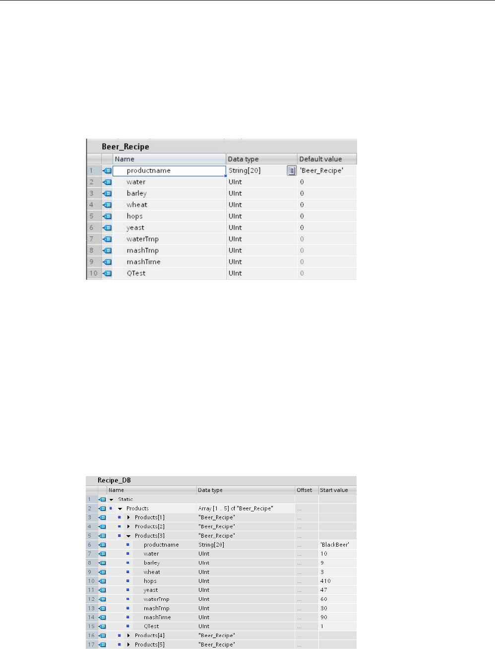
Extended instructions
9.9 Recipes and Data logs
S7-1200 Programmable controller
500 System Manual, V4.2, 09/2016, A5E02486680-AK
First, create a new PLC data type
Add a new PLC data type whose name is the recipe type. In the following image,
"Beer_Recipe" is the new complex PLC data type that stores a sequence of simple data
types. The "Beer_Recipe" PLC data type is a data template that is reused in each recipe DB
record and also in the active recipe DB. Enter the component names and data types that are
common to all the example recipes. The individual component values are added later in the
recipe DB.
Second, create a recipe data block
● Create your recipe DB as a global data block with the DB property "Only store in load
memory" enabled.
● The name of a recipe data block is used as file name of the corresponding CSV file. The
DB name characters you assign must follow the Windows file system naming restrictions.
Characters \ / : * ? " < > | and the space character are not allowed.
● The recipe array assignment is "Products" as Array [1.. 5] of "Beer_Recipe". The array
size 5 is the maximum number of recipe flavors that are possible.
● The values for recipe components are added as DB start values.
In the following image, the "BlackBeer" recipe is expanded to show all the components of a
recipe record.

Extended instructions
9.9 Recipes and Data logs
S7-1200 Programmable controller
System Manual, V4.2, 09/2016, A5E02486680-AK 501
Recipe export (from recipe DB to CSV file)
"RecipeExport (Page 502)" execution transfers recipe DB data to a CSV file, as shown in the
following text file.
Recipe_DB.csv
index,productname,water,barley,wheat,hops,yeast,waterTmp,
mashTmp,mashTime,QTest
1,”Pils”,10,9,3,280,39,40,30,100,0
2,”Lager”,10,9,3,150,33
,50,30,120,0
3,”BlackBeer”,10,9,3,410,47,60,30,90,1
4 ”Not_used”,0,0,0,0,0,0,0,0,0
5 ”Not_used”,0,0,0,0,0,0,0,0,0
Recipe import (from CSV file to recipe DB)
1. Use the file browser page in the CPU web server to download an existing recipe CSV file
from CPU load memory to a PC
2. Modify the recipe CSV with an ASCII text editor. You can modify the start values
assigned to components, but not the data types or data structure
3. Upload the modified CSV file from PC back to the CPU. However, the old CSV file in CPU
load memory (with the same name) must be deleted or renamed before the CPU Web
server allows the upload operation.
4. After the modified CSV file is uploaded to the CPU, then you can use the RecipeImport
instruction to transfer the new start values from the modified CSV file (in CPU load
memory) to the recipe DB (in CPU load memory).
CSV files must exactly match the corresponding recipe DB structure
● The values in the CSV file can be changed, but changing the structure is not allowed. The
RecipeImport instruction requires that the exact number of records and components
matches the destination recipe DB structure. Otherwise, RecipeImport execution fails. For
example, if 10 recipes are defined in the recipe DB but only 6 are in use, then line 7 to 10
in the CSV file are also transferred to the DB. You must coordinate whether this data is
valid or not. For example, you can assign a variable “Not_used” for the product name in
unused recipe records.
● If you add data records to the text file and import the modified file, make sure the recipe
DB array limit you assign has enough elements for all the recipe records.
● An index number is automatically generated during export to the CSV file. If you create
additional data records, add consecutive index numbers accordingly.
● RecipeImport execution checks the CSV file data for correct structure and whether the
values fit in the data types assigned in the associated recipe DB. For example, a Bool
data type cannot store an integer value and the RecipeImport execution fails.
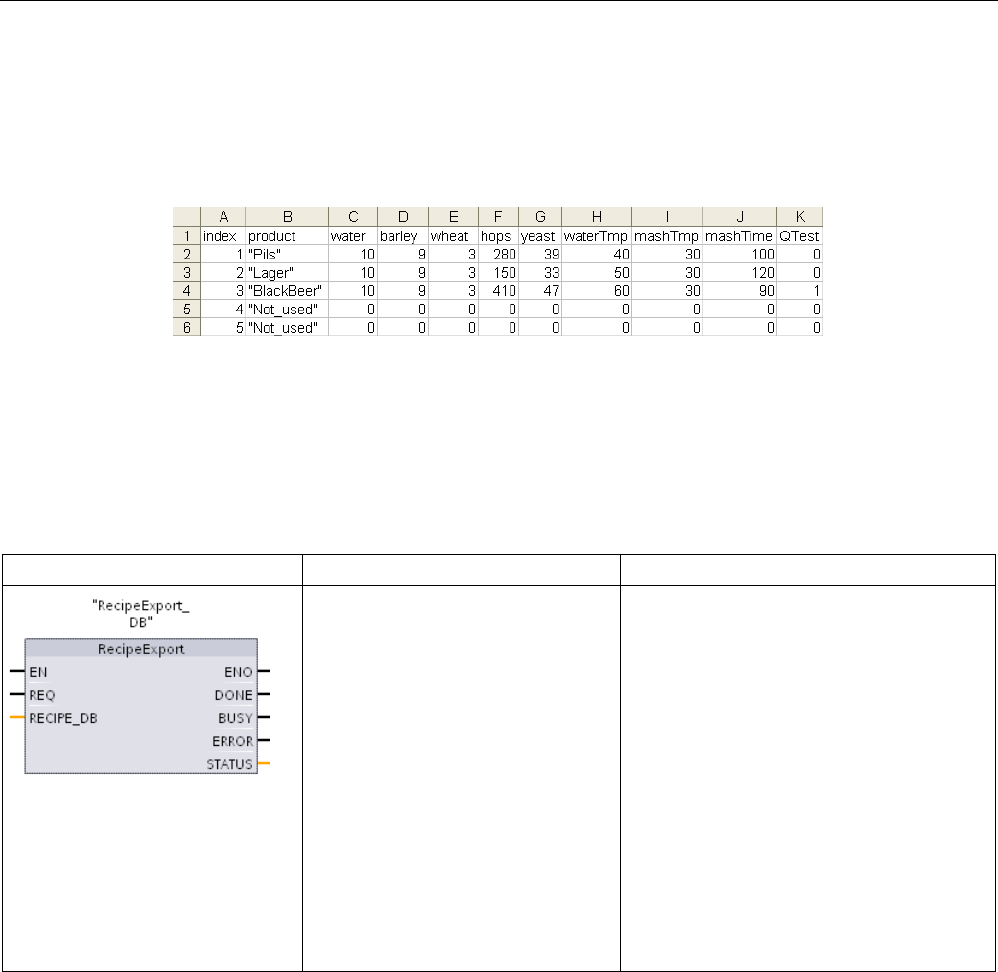
Extended instructions
9.9 Recipes and Data logs
S7-1200 Programmable controller
502 System Manual, V4.2, 09/2016, A5E02486680-AK
Display CSV recipe data in Excel
The CSV file can be opened in Excel to make reading and editing easier. If the commas are
not recognized as decimal separators, use the Excel import function to output the data in
structured form
9.9.1.3
Program instructions that transfer recipe data
RecipeExport (Recipe export)
Table 9- 194 RecipeExport instruction
LAD/FBD
SCL
Description
"RecipeExport_DB"(
req:=_bool_in_,
done=>_bool_out_,
busy=>_bool_out_,
error=>_bool_out_,
status=>_word_out_,
Reci-
pe_DB:=_variant_inout_);
The "RecipeExport" instruction exports all
recipe records from a recipe data block to
the CSV file format. The CSV file contains
product names, component names, and start
values. The CSV file is stored in internal load
memory or external load memory, if an op-
tional external "program" memory card is
installed.
The export operation is triggered by the
"REQ" parameter. The BUSY parameter is
set to "1" during export processing. After the
execution of RecipeExport stops, BUSY is
reset to "0" and the completion of the opera-
tion is indicated with "1" at the DONE pa-
rameter. If an error occurs during execution,
then parameters ERROR and STATUS indi-
cate the result.
A recipe DB must be created before a recipe export is possible. The name of a recipe data
block is used as the file name of the new CSV file. If a CSV file with an identical name
already exists, then it is overwritten during the export operation.
You can use the File Browser page (Page 1037) of the CPU's built-in Web server to access
the recipe CSV file. The file is put in the recipe folder in the root directory of CPU load
memory.

Extended instructions
9.9 Recipes and Data logs
S7-1200 Programmable controller
System Manual, V4.2, 09/2016, A5E02486680-AK 503
Table 9- 195 Data types for the parameters
Parameter and type
Data type
Description
REQ IN Bool Control parameter REQUEST: Activates the export on a positive
edge.
RECIPE_DB In/Out Variant Pointer to the recipe data block. Refer to the "Recipe DB example
(Page 499)" for details. The DB name characters must follow the
Windows file system naming restrictions. Characters \ / : * ? " < > |
and the space character are not allowed.
DONE OUT Bool The DONE bit is TRUE for one scan, after the last request was com-
pleted with no error. (Default value: False)
BUSY OUT Bool RecipeExport execution
• 0: No operation in progress
• 1: Operation on progress
ERROR OUT Bool The ERROR bit is TRUE for one scan, after the last request was
terminated with an error. The error code value at the STATUS pa-
rameter is valid only during the single scan where ERROR = TRUE.
• 0: No warning or error
• 1: An error has occurred. The STATUS parameter provides in-
formation on the type of error.
STATUS
OUT
Word
Execution condition code
Table 9- 196 Values of ERROR and STATUS
ERROR
STATUS
(W#16#....)
Description
0
0000
No error
0
7000
Call with no REQ edge: BUSY = 0, DONE = 0
0
7001
First call with REQ edge (working): BUSY = 1, DONE = 0
0
7002
N
th
call (working): BUSY = 1, DONE = 0
1
8070
All instance memory is in use.
1
8090
File name contains invalid characters
1
8091
The data structure referenced with RECIPE_DB cannot be processed.
1
8092
Data structure specified in RECIPE_DB exceeds 5000 bytes
1 80B3 Not enough space in on MC or in internal load memory
1
80B4
MC is write protected
1
80B6
Recipe DB attribute "Only store in load memory" is not enabled.
1
80C0
CSV file is temporarily locked
1
80C1
DB is temporarily locked
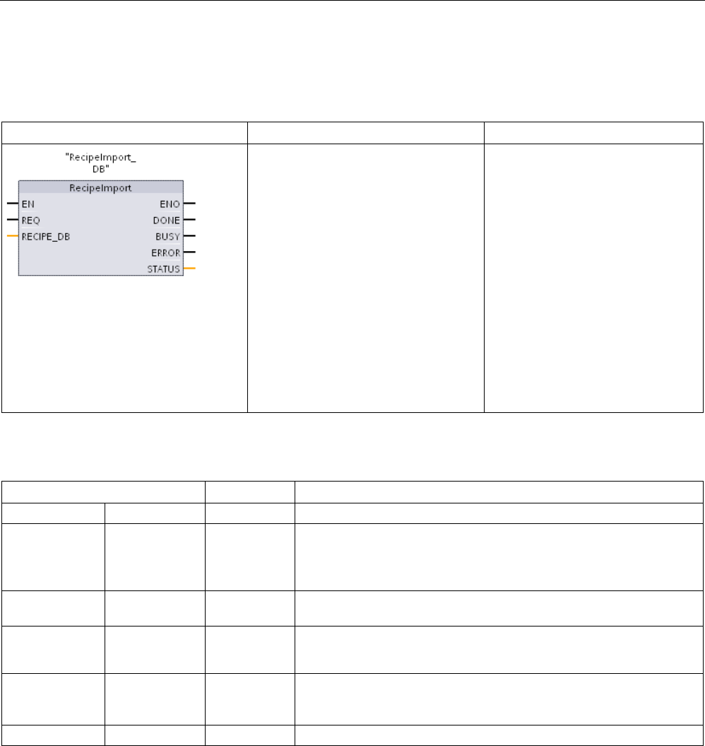
Extended instructions
9.9 Recipes and Data logs
S7-1200 Programmable controller
504 System Manual, V4.2, 09/2016, A5E02486680-AK
RecipeImport (Recipe import)
Table 9- 197 RecipeImport instruction
LAD/FBD
SCL
Description
"RecipeImport_DB"(
req:=_bool_in_,
done=>_bool_out_,
busy=>_bool_out_,
error=>_bool_out_,
status=>_word_out_,
Reci-
pe_DB:=_variant_inout_);
The "RecipeImport" instruction im-
ports recipe data from a CSV file, in
CPU load memory, to a recipe data
block referenced by the RECIPE_DB
parameter. Start values in the recipe
data block are overwritten by the
import process. The import operation
is triggered by the "REQ" parameter.
The BUSY parameter is set to "1"
during import processing. After the
execution of RecipeImport stops,
BUSY is reset to "0" and the comple-
tion of the operation is indicated with
"1" at the DONE parameter. If an
error occurs during execution, then
parameters ERROR and STATUS
indicate the result.
Table 9- 198 Data types for the parameters
Parameter and type
Data type
Description
REQ
IN
Bool
Control parameter REQUEST: Activates the import on a positive edge.
RECIPE_DB In/Out Variant Pointer to the recipe data block. Refer to "Recipe DB example
(Page 499)" for details. The DB name characters must follow the Win-
dows file system naming restrictions. Characters \ / : * ? " < > | and the
space character are not allowed.
DONE OUT Bool The DONE bit is TRUE for one scan, after the last request was com-
pleted with no error. (Default value: False)
BUSY OUT Bool • 0 - No operation in progress
• 1 - Operation on progress
ERROR OUT Bool The ERROR bit is TRUE for one scan, after the last request was ter-
minated with an error. The error code value at the STATUS parameter
is valid only during the single scan where ERROR = TRUE.
STATUS
OUT
Word
Execution condition code (Default value: 0)

Extended instructions
9.9 Recipes and Data logs
S7-1200 Programmable controller
System Manual, V4.2, 09/2016, A5E02486680-AK 505
A recipe DB that contains a structure which is consistent with the CSV file data structure
must exist, before a recipe import operation is possible.
CSV file rules:
● The CSV file must be located in the root directory "Recipes" folder of internal load
memory or external load memory, if an optional external "program" memory card is
installed.
● The name of the CSV file must match the name of the data block at the RECIPE_DB
parameter.
● The first line (header) of the CSV file contains the name of the recipe components. The
first line is ignored during import. The names of the recipe components in the CSV file
and the data block are not reconciled during the import process.
● In each case the first value in each line of the CSV file is the index number of the recipe.
The individual recipes are imported in the order of the index. For this, the index in the
CSV file has to be in ascending order and may contain no gaps (if this is not the case, the
error message 80B0 is output at the STATUS parameter).
● The CSV file may not contain more recipe data records than provided for in the recipe
data block. The maximum number of data records is indicated by the array limits in the
data block.
Table 9- 199 Values of ERROR and STATUS
ERROR
STATUS
(W#16#....)
Description
0
0000
No error
0 7000 Call with no REQ edge: BUSY = 0, DONE = 0
0
7001
First call with REQ edge (working): BUSY = 1, DONE = 0
0
7002
N
th
call (working): BUSY = 1, DONE = 0
1
8070
All instance memory is in use.
1
8090
The file name contains invalid characters.
1 8092 No matching CSV file found for the import. Possible cause: The name of the CSV file
does not match the name of the recipe DB.
1
80C0
CSV file is temporarily locked.
1
80C1
Data block is temporarily locked.
1 80B0 Numbering in the index of the CSV file is not c
ontinuous, not ascending or exceeds the
maximum number (array limit) in the data block.
1 80B1
Structure of the recipe data block and the CSV file do not match: The CSV file contains
too many fields.
1 80B2 Structure of the recipe data block and the CSV
file do not match: The CSV file contains
too few fields.
1
80B6
Recipe DB attribute "Only store in load memory" is not enabled.
1 80D0 +n Structure of the recipe data block and the CSV file do not match: Data type in field n
does not match (n<=46).
1 80FF Structure of the recipe data block and the CSV file do not match: Data type in field n
does not match (n>46).
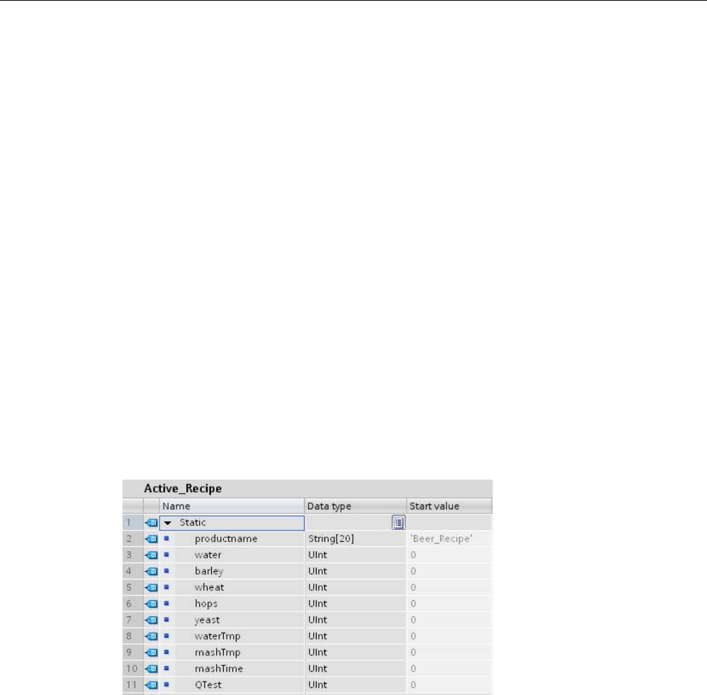
Extended instructions
9.9 Recipes and Data logs
S7-1200 Programmable controller
506 System Manual, V4.2, 09/2016, A5E02486680-AK
9.9.1.4
Recipe example program
Prerequisites for the recipe example program
The prerequisites for the recipe example program are as follows:
● A recipe DB that stores all recipe records. The recipe DB is stored in load memory.
● An active recipe DB that stores a copy of one recipe in work memory.
Refer to the "Recipe DB example (Page 499)" for details about the recipe DB and the
corresponding CSV file.
Create the active recipe DB
On the "Add new block" window:
● Select the "Data block" button on the "Add new block" window
● On the "Type" drop-down menu, select the "Beer_recipe" PLC data type that you created
previously.
Start values are not required. The DB data values are set when one recipe is transferred
from the recipe DB to the active recipe DB. In the example, the active recipe DB is the
destination for READ_DBL data and provides source data for WRITE_DBL. The following
image shows the Active_Recipe DB.
Instance DBs
The instance DBs used by instructions RecipeExport ("RecipeExport_DB") and RecipeImport
("RecipeImport_DB") are created automatically when you place the instructions in your
program. The instance DBs are used to control instruction execution and are not referenced
in the program logic.
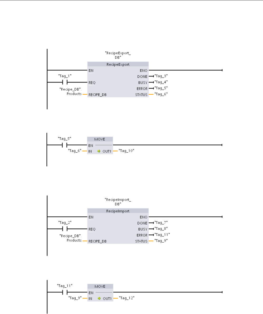
Extended instructions
9.9 Recipes and Data logs
S7-1200 Programmable controller
System Manual, V4.2, 09/2016, A5E02486680-AK 507
Example recipe program
Network 1
A rising edge on REQ starts the export process. A CSV file is generated from the
recipe DB data and placed in the CPU memory recipes folder.
Network 2
Capture the STATUS output from RecipeExport execution, because it is only valid
for one scan.
Network 3
A rising edge on REQ starts the import process. The existing recipe DB is loaded
with all recipe data read from the corresponding CSV file that is located in the CPU memory
recipes folder.
Network 4
Capture the STATUS output from RecipeImport execution, because it is only valid
for one scan.
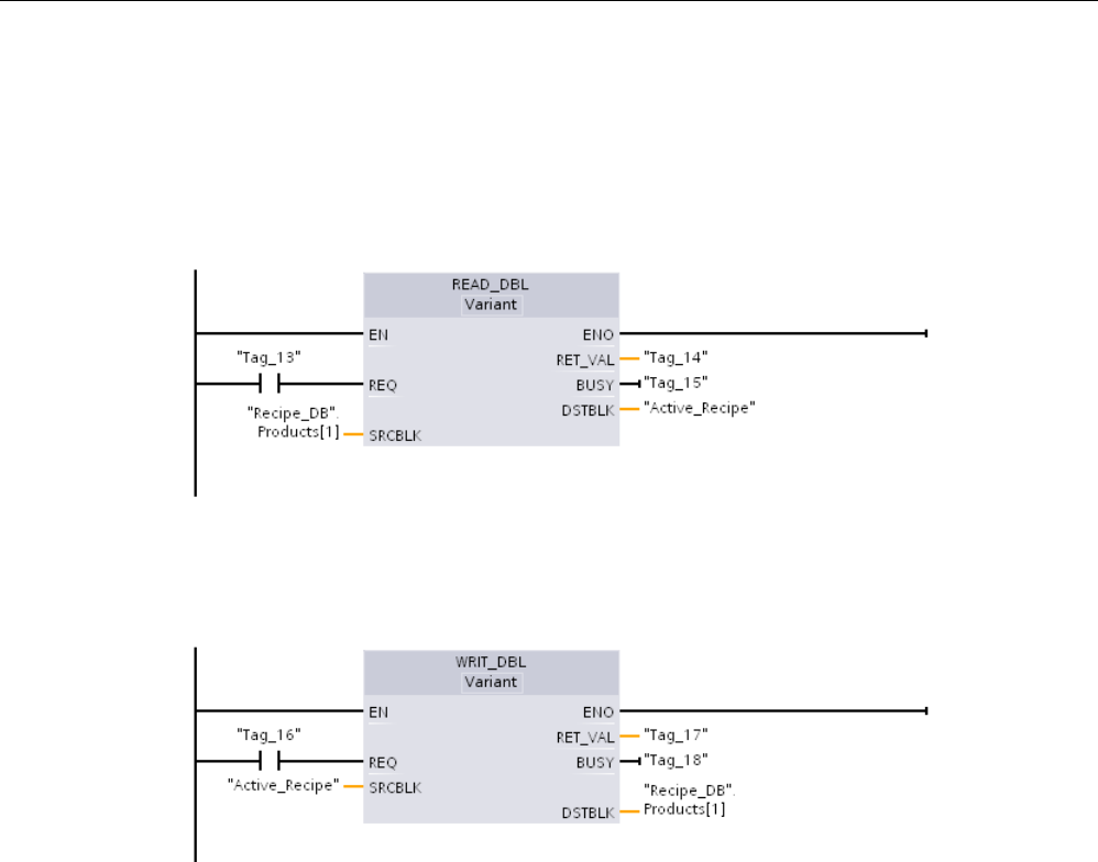
Extended instructions
9.9 Recipes and Data logs
S7-1200 Programmable controller
508 System Manual, V4.2, 09/2016, A5E02486680-AK
Network 5
READ_DBL copies the start values from one recipe "Recipe_DB". Products[1] (in
CPU load memory) to the Active_Recipe DB current values (in CPU work memory). After
READ_DBL execution, your program logic can access the recipe component values by
addressing locations in the Active_Recipe DB. For example, the symbolic addresses (
"Active_Recipe".productname) and ("Active_Recipe.water) provide your program logic with
the current recipe name and quantity of water.
Network 6
During run time, An HMI device could modify a component value stored in the
Active_Recipe DB. Improved recipe data can be stored by executing WRIT_DBL. In the
example, all Recipe_DB start values for the single recipe "Recipe_DB". Products[1] are
overwritten by the current values from the "Active_Recipe" DB.

Extended instructions
9.9 Recipes and Data logs
S7-1200 Programmable controller
System Manual, V4.2, 09/2016, A5E02486680-AK 509
9.9.2
Data logs
Your control program can use the Data log instructions to store run-time data values in
persistent log files. The CPU stores data log files in flash memory (CPU or memory card) in
standard CSV (Comma Separated Value) format. The CPU organizes the data records as a
circular log file of a pre-determined size.
You use the Data log instructions in your program to create, open, write a record to, and
close the log files. You decide which program values to log by creating a data buffer that
defines a single log record. The CPU uses your data buffer as temporary storage for a new
log record. Your control program moves new current values into the buffer during runtime.
When the program has updated all of the current data values, it can then execute the
DataLogWrite instruction to transfer data from the buffer to a data log record.
You can open, edit, save, rename, and delete data log files from the File Browser page of
the Web Server. You must have read privileges to view the file browser and you must have
modify privileges to edit, delete, or rename data log files.
9.9.2.1
Data log record structure
The DATA and HEADER parameters of the DataLogCreate instruction assign the data type
and the column header description of all data elements in a log record.
DATA parameter for the DataLogCreate instruction
The DATA parameter points to memory used as a temporary buffer for a new log record and
must be assigned to an M or DB location.
You can assign an entire DB (derived from a PLC data type that you assign when the DB is
created) or part of a DB (the specified DB element can be any data type, data type structure,
PLC data type, or data array).
Structure data types are limited to a single nesting level. The total number of data elements
declared should correspond to the number of columns specified in the header parameter.
The maximum number of data elements you can assign is 253 (with a timestamp) or 255
(without a timestamp). This restriction keeps your record inside the 256 column limit of an
Excel sheet.
The DATA parameter can assign either retentive or non-retentive data elements in a
"Standard" (compatible with S7-300/400) or "Optimized" DB type.
In order to write a Data log record you must first load the temporary DATA record with new
process values and then execute the DataLogWrite instruction that saves new record values
in the Datalog file.
HEADER parameter for the DataLogCreate instruction
The HEADER parameter points to column header names for the top row of the data matrix
encoded in the CSV file. HEADER data must be located in DB or M memory and the
characters must follow standard CSV format rules with commas separating each column
name. The data type may be a string, byte array, or character array. Character/byte arrays
allow increased size, where strings are limited to a maximum of 255 bytes. The HEADER
parameter is optional. If the HEADER is not assigned, then no header row is created in the
Data log file.
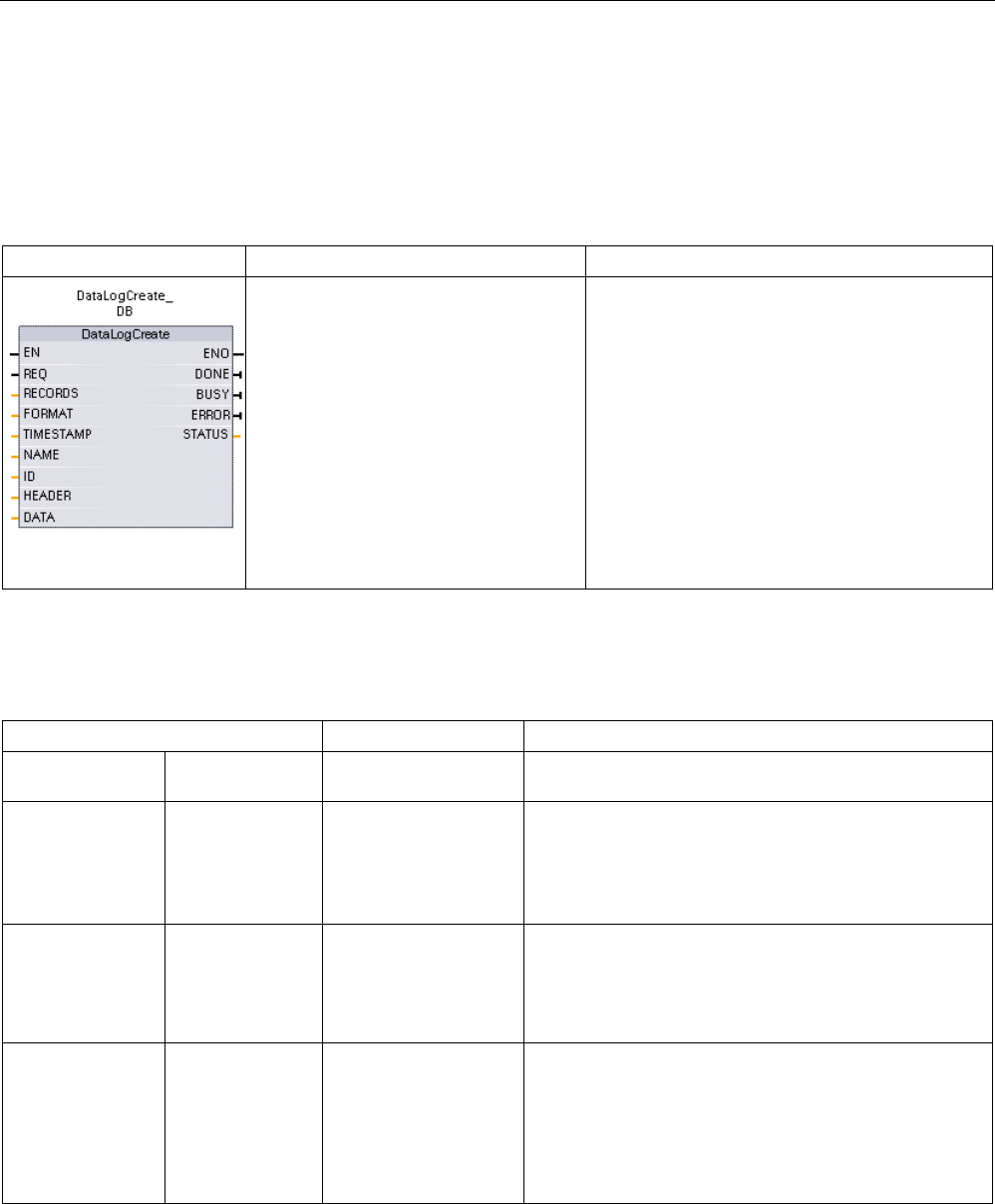
Extended instructions
9.9 Recipes and Data logs
S7-1200 Programmable controller
510 System Manual, V4.2, 09/2016, A5E02486680-AK
9.9.2.2
Program instructions that control data logs
DataLogCreate (Create data log)
Table 9- 200 DataLogCreate instruction
LAD/FBD
SCL
Description
"DataLogCreate_DB"(
req:=_bool_in_,
records:=_udint_in_,
format:=_uint_in_,
timestamp:=_uint_in_,
done=>_bool_out_,
busy=>_bool_out_,
error=>_bool_out_,
status=>_word_out_,
name:=_string_inout_,
ID:=_dword_inout_,
header:=_variant_inout_,
data:=_variant_inout_);
Creates and initializes a data log file. The CPU
creates the file in the \DataLogs folder, using the
name in the NAME parameter, and implicitly
opens the file for write operations. You can use
the Data log instructions in your program to store
runtime process data in the flash memory of the
CPU or on the memory card.
STEP 7 automatically creates the associated
instance DB when you insert the instruction.
1 In the SCL example, "DataLogCreate_DB" is the name of the instance DB.
Table 9- 201 Data types for the parameters
Parameter and type
Data type
Description
REQ IN Bool A low to high (positive edge) signal starts the operation.
(Default value: False)
RECORDS IN UDint The maximum number of data records the circular data
log can contain before overwriting the oldest entry:
The header record is not included. Sufficient available
PLC load memory must exist in order to successfully
create the data log. (Default value - 1)
FORMAT IN UInt Data log format:
• 0 - Internal format (not supported)
• 1 - Comma separated values "csv-eng" (Default val-
ue)
TIMESTAMP IN UInt Data time stamp format: Column headers for date and
time fields are not required. The time stamp uses the
system time (Coordinated Universal Time - UTC) and not
the local time.
• 0 - No time stamp
• 1 - Date and time stamp (Default value)

Extended instructions
9.9 Recipes and Data logs
S7-1200 Programmable controller
System Manual, V4.2, 09/2016, A5E02486680-AK 511
Parameter and type
Data type
Description
NAME IN Variant Data log name: You provide the name. This variant only
supports a String data type and can only be located in
local, DB, or M memory. (Default value: ' ')
The string reference is also used as the name of the data
log file. The name characters must follow the Windows
file system naming restrictions. Characters \ / : * ? " < > |
and the space character are not allowed.
ID In/Out DWord Data log numeric identifier: You store this generated
value for use with other Data log instructions. The ID
parameter is only used as an output with the DataLog-
Create instruction. (Default value: 0)
Symbolic name access for this parameter is not allowed.
HEADER In/Out Variant Pointer to data log column header names for the top row
of the data matrix encoded in the CSV file. (Default val-
ue: null).
HEADER data must be located in DB or M memory.
The characters must follow standard CSV format rules
with commas separating each column name. The data
type may be a string, byte array, or character array.
Character/byte arrays allow increased size, where
strings are limited to a maximum of 255 bytes.
The HEADER parameter is optional. If the HEADER is
not parameterized, then no header row is created in the
Data log file.
DATA In/Out Variant Pointer to the record data structure, user defined type
(UDT), or array. Record data must be located in DB or M
memory.
The DATA parameter specifies the individual data ele-
ments (columns) of a data log record and their data type.
Structure data types are limited to a single nesting level.
The number of data elements declared should corre-
spond to the number of columns specified in the header
parameter. The maximum number of data elements you
can assign is 253 (with a timestamp) or 255 (without a
timestamp). This restriction keeps your record inside the
256 column limit of an Excel sheet.
DONE OUT Bool The DONE bit is TRUE for one scan, after the last re-
quest was completed with no error. (Default value: False)
BUSY OUT Bool • 0 - No operation in progress
• 1 - Operation on progress
ERROR OUT Bool The ERROR bit is TRUE for one scan, after the last
request was terminated with an error. The error code
value at the STATUS parameter is valid only during the
single scan where ERROR = TRUE.
STATUS
OUT
Word
Execution condition code (Default value: 0)

Extended instructions
9.9 Recipes and Data logs
S7-1200 Programmable controller
512 System Manual, V4.2, 09/2016, A5E02486680-AK
The CPU creates a data log file with a pre-determined fixed sized based on the RECORDS
and DATA parameters and organizes the data records as a circular log file. The
DataLogWrite instruction appends new records to the data log file until it stores the
maximum number of records that is specified by the RECORDS parameter. The next record
written will overwrite the oldest record. Another DataLogWrite operation will overwrite the
next oldest data record and so on.
Memory resource usage:
● The data logs consume only load memory.
● The size of all data logs combined is limited by the available resources of load memory.
Only eight data logs can be open at one time. You can manage your data logs from the
File Browser (Page 1037) standard Web page. See the description of this standard Web
page for guidelines on how many data logs to maintain at a time.
● The maximum possible number for the RECORDS parameter is the limit for an UDint
number (4,294,967,295). The actual limit for the RECORD parameter depends on the
size of a single record, the size of other data logs, and the available resources of load
memory. In addition, Excel limits the number of rows allowed in an Excel sheet.
Note
Data log creation execution must be complete before starting a data log write operation
•
DataLogCreate and DataLogNewFile log file creation operations extend over many
program scan cycles. The actual time required for the log file creation depends on the
record structure and number of records. Your program logic must monitor and catch the
DONE bit's transition t
o the TRUE state that signals the completion of a log file creation. If
the user program executes a DataLogWrite instruction before a data log creation
operation is complete, then the write operation will fail to write a new data log record as
expected.
•
In certain situations when a very fast program scan is running, data log creation can take
an extended time. If the long creation time is too slow, you should ensure that the
checkbox for the Enable minimum cycle time for cyclic OBs is active, and the minimum
cycle time is set to one ms or greater. Refer to Configuring the cycle time and
communication load (Page 109) for more information.
Note
The DataLogNewFile instruction copies an existing data log's record structure
If you want to prevent overwriting any data records, then you can use the DataLogNewFile
instruction to create a new data log based on the current data log, after the current data lo
g
has stored the maximum number of records. New data records are stored in the new data
log file. The old data log file and record data remain stored in flash memory.

Extended instructions
9.9 Recipes and Data logs
S7-1200 Programmable controller
System Manual, V4.2, 09/2016, A5E02486680-AK 513
Table 9- 202 Values of ERROR and STATUS
ERROR
STATUS
(W#16#....)
Description
0
0000
No error
0 7000 Call with no REQ edge: BUSY = 0, DONE = 0
0
7001
First call with REQ edge (working): BUSY = 1, DONE = 0
0
7002
N
th
call (working): BUSY = 1, DONE = 0
1
8070
All internal instance memory is in use.
1
807F
Internal error
1
8090
Invalid file name
1
8091
Name parameter is not a String reference.
1 8093
A data log already exists with that name. Use a different name, make sure the existing
data log's .csv file is not open, and then use the File Browser (Page 1037) page of the
Web Server to delete the existing data log.
1
8097
Requested file length exceeds file system maximum.
1 80B2 Out of resource IDs
Note: Delete some existing data logs or decrease the number of columns in the data
record structure to avoid this error.
1
80B3
Insufficient load memory available.
1
80B4
MC (memory card) is write-protected.
1
80C0
Archive file is locked
1
80C1
Too many open files: No more than eight opened data log files are allowed.
1
8253
Invalid record count
1
8353
Invalid format selection
1
8453
Invalid timestamp selection
1 8B24 Invalid HEADER area assignment: For example, pointing to local memory
1
8B51
Invalid HEADER parameter data type
1 8B52 Too many HEADER parameter data elements
1
8C24
Invalid DATA area assignment: For example, pointing to local memory
1
8C51
Invalid DATA parameter data type
1
8C52
Too many DATA parameter data elements

Extended instructions
9.9 Recipes and Data logs
S7-1200 Programmable controller
514 System Manual, V4.2, 09/2016, A5E02486680-AK
DataLogOpen (Open data log)
Table 9- 203 DataLogOpen instruction
LAD / FBD
SCL
Description
"DataLogOpen_DB"(
req:=_bool_in_,
mode:=_uint_in_,
done=>_bool_out_,
busy=>_bool_out_,
error=>_bool_out_,
status=>_word_out_,
name:=_string_inout_,
ID:=_dword_inout_);
Opens a pre-existing data log file. You must open a data log before
you can write (Page 516
) new records to the log. You can open and
close data logs individually. A maximum of eight data logs can be
open at the same time.
STEP 7 automatically creates the associated instance DB when
you insert the instruction.
2 In the SCL example, "DataLogOpen_DB" is the name of the instance DB.
Table 9- 204 Data types for the parameters
Parameter and type
Data type
Description
REQ IN Bool A low to high (positive edge) signal starts the operation. (Default
value: False)
MODE IN UInt Operation mode:
• 0 - Append to existing data (Default value)
• 1 - Clear all existing records
NAME IN Variant Name of an existing data log: This variant only supports a String
data type and can only be located in local, DB, or M memory. (De-
fault value: ' ')
ID In/Out DWord Numeric identifier of a data log. (Default value: 0)
Note: Symbolic name access for this parameter is not allowed.
DONE OUT Bool The DONE bit is TRUE for one scan, after the last request was
completed with no error. (Default value: False)
BUSY OUT Bool • 0 - No operation in progress
• 1 - Operation in progress
ERROR OUT Bool The ERROR bit is TRUE for one scan, after the last request was
terminated with an error. The error code value at the STATUS
parameter is valid only during the single scan where ERROR =
TRUE.
STATUS
OUT
Word
Execution condition code (Default value: 0)

Extended instructions
9.9 Recipes and Data logs
S7-1200 Programmable controller
System Manual, V4.2, 09/2016, A5E02486680-AK 515
You can provide either the NAME or an ID (ID parameter as an input) of a pre-existing data
log. If you provide both parameters and a valid ID does correspond to the NAME data log,
then the ID is used, and the NAME ignored.
The NAME must be the name of a data log created by the DataLogCreate instruction. If only
the NAME is provided and the NAME specifies a valid data log, then the corresponding ID
will be returned (ID parameter as an output).
Note
General usage of data log files
•
Data log files are automatically opened after the DataLogCreate and DataLogNewFile
operations.
•
Data log files are automatically closed after a PLC run to stop transition or a PLC power
cycle.
•
A Data log file must be open before a new DataLogWrite operation is possible.
•
A maximum of eight data log files may be open at one time. More than eight data log files
may exist, but some of them must be closed so no more than eight are open.
Table 9- 205 Values of ERROR and STATUS
ERROR
STATUS (W#16#)
Description
0
0000
No error
0
0002
Warning: Data log file already open by this application program
0
7000
Call with no REQ edge: BUSY = 0, DONE = 0
0
7001
First call with REQ edge (working): BUSY = 1, DONE = 0
0
7002
N
th
call (working): BUSY = 1, DONE = 0
1
8070
All internal instance memory is in use.
1
8090
Data log definition is inconsistent with existing data log file.
1
8091
Name parameter is not a String reference.
1
8092
Data log does not exist.
1
80C0
Data log file is locked.
1
80C1
Too many open files: No more than eight opened data log files are allowed.

Extended instructions
9.9 Recipes and Data logs
S7-1200 Programmable controller
516 System Manual, V4.2, 09/2016, A5E02486680-AK
DataLogWrite (Write data log)
Table 9- 206 DataLogWrite instruction
LAD / FBD
SCL
Description
"DataLogWrite_DB"(
req:=_bool_in_,
done=>_bool_out_,
busy=>_bool_out_,
error=>_bool_out_,
status=>_word_out_,
ID:=_dword_inout_);
Writes a data record into the specified data log. The pre-existing target
data log must be open (Page 514) before you can write to it with a Dat-
aLogWrite instruction.
STEP 7 automatically creates the associated instance DB when you
insert the instruction.
2 In the SCL example, "DataLogWrite_DB" is the name of the instance DB.
Table 9- 207 Data types for the parameters
Parameter and type
Data type
Description
REQ IN Bool A low to high (positive edge) signal starts the operation. (Default value:
False)
ID In/Out DWord Numeric data log identifier. Only used as an input for the DataLogWrite
instruction. (Default value: 0)
Note: Symbolic name access for this parameter is not allowed.
DONE OUT Bool The DONE bit is TRUE for one scan, after the last request was com-
pleted with no error.
BUSY OUT Bool • 0 - No operation in progress
• 1 - Operation on progress
ERROR OUT Bool The ERROR bit is TRUE for one scan, after the last request was termi-
nated with an error. The error code value at the STATUS parameter is
valid only during the single scan where ERROR = TRUE.
STATUS
OUT
Word
Execution condition code (Default value: 0)
The DATA parameter of a DataLogCreate instruction defines the memory address and data
structure of the record buffer. The control program must load the record buffer with current
runtime process values and then execute the DataLogWrite instruction to move new record
data from the buffer to the data log.
The ID parameter identifies a data log and data record configuration. The DataLogCreate
instruction generates the ID number.
If there are empty records in the circular data log file, then the DataLogWrite instruction
writes the next available empty record. If all records are full, then the DataLogWrite
instruction overwrites the oldest record.

Extended instructions
9.9 Recipes and Data logs
S7-1200 Programmable controller
System Manual, V4.2, 09/2016, A5E02486680-AK 517
NOTICE
Data log creation operations must be complete, before starting a data log write operation
DataLogCreate and DataLogNewFile log file creation operations extend over many
program scan cycles. The actual time required for the log file creation depends on the
record structure and number of records. Your program logic must monitor and catch the
DONE bit's transition to the TRUE state that signals the completion of a log file creation. If a
DataLogWrite instruction executes before a data log creation operation is complete, then
the write operation does not write a new data log record.
Note
Effect of data logs on internal CPU memory
Each data log write consumes at a m
inimum 2 KB of memory. If your program writes small
amounts of data frequently, it is consuming at least 2 KB of memory on each write. A better
implementation would be to accumulate the small data items in a data block (DB), and to
write the data block to
the data log at less frequent intervals.
If your program writes many data log entries at a high frequency, consider using a
replaceable SD memory card.
NOTICE
Potential for data log data loss during a CPU power failure
If there is a power failure during an incomplete DataLogWrite operation, then the data
record being transferred to the data log could be lost.
Table 9- 208 Values of ERROR and STATUS
ERROR
STATUS (W#16#)
Description
0
0000
No error
0 0001 Indicates that the data log is full: Each data log is created with a specified maxi-
mum number of records. The last record of the maximum number has been
written. The next write operation will overwrite the oldest record.
0
7000
Call with no REQ edge: BUSY = 0, DONE = 0
0
7001
First call with REQ edge (working): BUSY = 1, DONE = 0
0
7002
N
th
call (working): BUSY = 1, DONE = 0
1
8070
All internal instance memory is in use.
1
8092
Data log does not exist.
1
80B0
Data log file is not open (for explicit open mode only).
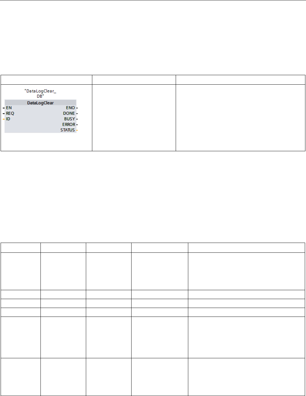
Extended instructions
9.9 Recipes and Data logs
S7-1200 Programmable controller
518 System Manual, V4.2, 09/2016, A5E02486680-AK
DataLogClear (Empty data log)
Description
Table 9- 209 DataLogClear instruction
LAD / FBD
SCL
Description
"DataLogClear_DB"(
REQ:=_bool_in_,
DONE=>_bool_out_,
BUSY=>_bool_out_,
ERROR=>_bool_out_,
STATUS=>_word_out_,
ID:=_dword_inout_);
The "DataLogClear" instruction deletes all data
records in an existing data log. The instruction
does not delete the optional header of the CSV file
(see the description of the HEADER parameter of
the instruction "DataLogCreate (Page 510)").
You use the ID parameter to select the data log
whose data records are to be deleted.
"DataLogClear_DB" is the name of the instance DB.
Requirement
Before you can delete data records, the data log must be open (see "DataLogOpen
(Page 514) instruction").
Parameters
The following table shows the parameters of the "DataLogClear" instruction:
Parameter
Declaration
Data type
Memory area
Description
REQ Input BOOL I, Q, M, L, D, T, C or
constant
(T and C are only
available in LAD and
FBD with S7-1500)
Execution of the instruction upon a rising
edge.
ID
InOut
DWORD
I, Q, M, D, L
Numeric data log identifier
DONE
Output
BOOL
I, Q, M, D, L
Instruction was executed successfully.
BUSY
Output
BOOL
I, Q, M, D, L
Execution of the instruction not yet complete.
ERROR Output BOOL I, Q, M, D, L • 0: No error.
• 1: An error occurred during execution of
the instruction.
Detailed information is output at the STATUS
parameter.
STATUS Output WORD I, Q, M, D, L Status parameter
The parameter is only set for the duration of
one call. To display the status, you should
therefore copy the STATUS parameter to a
free data area.
You can find additional information on valid data types under "Data types (Page 125)".

Extended instructions
9.9 Recipes and Data logs
S7-1200 Programmable controller
System Manual, V4.2, 09/2016, A5E02486680-AK 519
Parameter STATUS
Error code*
(W#16#...)
Explanation
0000
No error.
7000 No job processing active.
7001
Start of job processing. Parameter BUSY = 1, DONE = 0
7002 Intermediate call (REQ irrelevant): Instruction already active; BUSY has the value "1".
8080
The data log file selected with the ID parameter cannot be processed with the "DataLogClear" instruction.
8092
Data log does not exist.
80A2
Write error signaled back by the file system.
80B0
Data log is not open.
80B4
The memory card is write-protected.
* The error codes can be displayed as integer or hexadecimal values in the program editor. For information on switching
the display formats, refer to "See also".
DataLogClose (Close data log)
Table 9- 210 DataLogClose instruction
LAD / FBD
SCL
Description
"DataLogClose_DB"(
req:=_bool_in_,
done=>_bool_out_,
busy=>_bool_out_,
error=>_bool_out_,
status=>_word_out_,
ID:=_dword_inout_);
Closes an open data log file. DataLogWrite operations to
a closed data log result in an error. No write operations
are allowed to this data log until another DataLogOpen
operation is performed.
A transition to STOP mode will close all open data log
files.
STEP 7 automatically creates the associated instance
DB when you insert the instruction.
2 In the SCL example, "DataLogClose_DB" is the name of the instance DB.
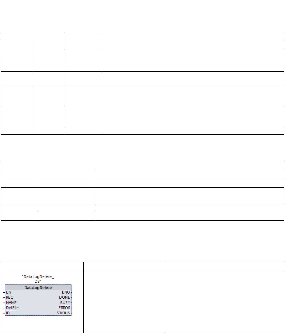
Extended instructions
9.9 Recipes and Data logs
S7-1200 Programmable controller
520 System Manual, V4.2, 09/2016, A5E02486680-AK
Table 9- 211 Data types for the parameters
Parameter and type
Data type
Description
REQ
IN
Bool
A low to high (positive edge) signal starts the operation. (Default value: False)
ID In/Out DWord Numeric identifier of a data log. Only used as an input for the DataLogClose
instruction. (Default value: 0)
Note:
Symbolic name access for this parameter is not allowed.
DONE OUT Bool The DONE bit is TRUE for one scan after the last request was completed with
no error.
BUSY OUT Bool • 0 - No operation in progress
• 1- Operation in progress
ERROR OUT Bool The ERROR bit is TRUE for one scan, after the last request was terminated
with an error. The error code value at the STATUS parameter is valid only
during the single scan where ERROR = TRUE.
STATUS
OUT
Word
Execution condition code (Default value: 0)
Table 9- 212 Values of ERROR and STATUS
ERROR
STATUS (W#16#)
Description
0
0000
No error
0
0001
Data log not open
0
7000
Call with no REQ edge: BUSY = 0, DONE = 0
0
7001
First call with REQ edge (working): BUSY = 1, DONE = 0
0
7002
N
th
call (working): BUSY = 1, DONE = 0
1
8092
Data log does not exist.
DataLogDelete (Delete data log)
Table 9- 213 DataLogDelete instruction
LAD / FBD
SCL
Description
"DataLogDelete_DB"(
REQ:=_bool_in_,
NAME:=_variant_in_,
DelFile:=_bool_in_,
DONE=>_bool_out_,
BUSY=>_bool_out_,
ERROR=>_bool_out_,
STATUS=>_word_out_,
ID:=_dword_inout_);
You use the "DataLogDelete" instruction to delete
a data log file. The data log and the data records
it contains can only be deleted if it was created
with the "DataLogCreate" or "DataLogNewFile"
instruction.
"DataLogDelete_DB" is the name of the instance DB.

Extended instructions
9.9 Recipes and Data logs
S7-1200 Programmable controller
System Manual, V4.2, 09/2016, A5E02486680-AK 521
Parameters
The following table shows the parameters of the "DataLogDelete" instruction:
Parameter
Declaration
Data type
Memory area
Description
REQ Input BOOL I, Q, M, L, D, T, C or
constant
(T and C are only
available in LAD and
FBD with S7-1500)
Execution of the instruction upon a rising
edge.
NAME
Input
VARIANT
L, D
File name of the data log
DELFILE Input BOOL I, Q, M, D, L or con-
stant
• 0: Data log is retained.
• 1: Data log is deleted.
ID InOut DWORD I, Q, M, D, L Numeric data log identifier
DONE
Output
BOOL
I, Q, M, D, L
Instruction executed successfully.
BUSY
Output
BOOL
I, Q, M, D, L
Deletion of the data log is not yet complete.
ERROR Output BOOL I, Q, M, D, L • 0: No error.
• 1: An error occurred during execution of
the instruction.
Detailed information is output at the STATUS
parameter.
STATUS Output WORD I, Q, M, D, L Status parameter
The parameter is only set for the duration of
one call. To display the status, you should
therefore copy the STATUS parameter to a
free data area.
You can find additional information on valid data types under "Data types (Page 125)".
Parameters NAME and ID
Select the data log to be deleted using the NAME and ID parameters. The ID parameter is
evaluated first. If there is a data log with the relevant ID, the NAME parameter will not be
evaluated. If the value "0" is used at the ID parameter, a value with the data type STRING
must be used at the NAME parameter.
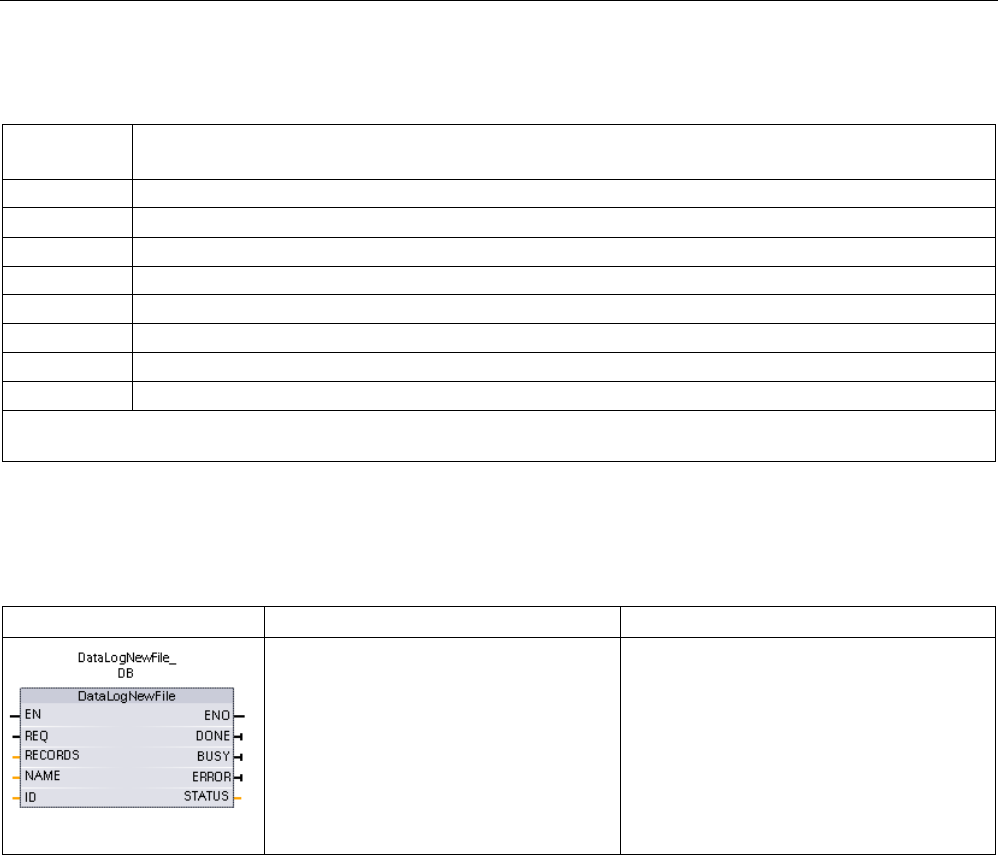
Extended instructions
9.9 Recipes and Data logs
S7-1200 Programmable controller
522 System Manual, V4.2, 09/2016, A5E02486680-AK
Parameter RET_VAL
Error code*
(W#16#...)
Explanation
0
No error.
7000 No job processing active.
7001
Start of job processing. Parameter BUSY = 1, DONE = 0
7002 Intermediate call (REQ irrelevant): Instruction already active; BUSY has the value "1".
8091
A data type other than STRING is being used at the NAME parameter.
8092
Data log does not exist.
80A2
Write error signaled back by the file system.
80B4
The memory card is write-protected.
* The error codes can be displayed as integer or hexadecimal values in the program editor. For information on switching
the display formats, refer to "See also".
DataLogNewFile (Data log in new file)
Table 9- 214 DataLogNewFile instruction
LAD / FBD
SCL
Description
"DataLogNewFile_DB"(
req:=_bool_in_,
records=:_udint_in_,
done=>_bool_out_,
busy=>_bool_out_,
error=>_bool_out_,
status=>_word_out_,
name=:_DataLog_out_,
ID:=_dword_inout_);
Allows your program to create a new data
log file based upon an existing data log file.
STEP 7 automatically creates the associated
instance DB when you insert the instruction.
2 In the SCL example, "DataLogNewFile_DB" is the name of the instance DB.

Extended instructions
9.9 Recipes and Data logs
S7-1200 Programmable controller
System Manual, V4.2, 09/2016, A5E02486680-AK 523
Table 9- 215 Data types for the parameters
Parameter and type
Data type
Description
REQ IN Bool A low to high (positive edge) signal starts the operation. (Default value:
False)
RECORDS IN UDInt The maximum number of data records the circular data log can contain
before overwriting the oldest entry. (Default value: 1)
The header record is not included. Sufficient available CPU load memory
must exist in order to successfully create the data log.
NAME IN Variant Data log name: You provide the name. This variant only supports a String
data type and can only be located in local, DB, or M memory. (Default value:
' ')
The string reference is also used as the name of the data log file. The name
characters must follow the Windows file system naming restrictions. Charac-
ters \ / : * ? " < > | and the space character are not allowed.)
ID In/Out DWord Numeric data log identifier(Default value: 0):
• At execution, the ID input identifies a valid data log. The new data log
configuration is copied from this data log.
• After execution, the ID parameter becomes an output that returns the ID
of the newly created data log file.
Note: Symbolic name access for this parameter is not allowed.
DONE OUT Bool The DONE bit is TRUE for one scan, after the last request was completed
with no error.
BUSY OUT Bool • 0 - No operation in progress
• 1 - Operation in progress
ERROR OUT Bool The ERROR bit is TRUE for one scan, after the last request was terminated
with an error. The error code value at the STATUS parameter is valid only
during the single scan where ERROR = TRUE.
STATUS
OUT
Word
Execution condition code (Default value: 0)
You can execute the DataLogNewFile instruction when a data log becomes full or is deemed
completed and you do not want to lose any data that is stored in the data log. A new empty
data log file can be created based on the structure of the full Data log file. The header record
will be duplicated from the original data log with the original data log properties (DATA record
buffer, data format, and timestamp settings). The original Data log file is implicitly closed and
the new Data log file is implicitly opened.
DataLogWrite parameter trigger: Your program must monitor the ERROR and STATUS
parameters of each DataLogWrite operation. When the final record is written and a data log
is full, the DataLogWrite ERROR bit = 1 and the DataLogWrite STATUS word = 1. These
ERROR and STATUS values are valid for one scan only, so your monitoring logic must use
ERROR = 1 as a time gate to capture the STATUS value and then test for STATUS = 1 (the
data log is full).

Extended instructions
9.9 Recipes and Data logs
S7-1200 Programmable controller
524 System Manual, V4.2, 09/2016, A5E02486680-AK
DataLogNewFile operation: When your program logic gets the data log is full signal, this
state is used to activate a DataLogNewFile operation. You must execute DataLogNewFile
with the ID of an existing (usually full) and open data log, but a new unique NAME
parameter. After the DataLogNewFile operation is done, a new data log ID value is returned
(as an output parameter) that corresponds to the new data log name. The new data log file is
implicitly opened and is ready to store new records. New DataLogWrite operations that are
directed to the new data log file, must use the ID value returned by the DataLogNewFile
operation.
NOTICE
Data log creation operations must be complete, before starting a data log write operation
DataLogCreate and DataLogNewFile log file creation operations extend over many
program scan cycles. The actual time required for the log file creation depends on the
record structure and number of records. Your program logic must monitor and catch the
DONE bit's transition to the TRUE state that signals the completion of a log file creation. If a
DataLogWrite instruction is executed before a data log creation operation is complete, then
the write operation will fail to write a new data log record as expected.
Table 9- 216 Values of ERROR and STATUS
ERROR
STATUS (W#16#)
Description
0
0000
No error
0
7000
Call with no REQ edge: BUSY = 0, DONE = 0
0
7001
First call with REQ edge (working): BUSY = 1, DONE = 0
0
7002
N
th
call (working): BUSY = 1, DONE = 0
1
8070
All internal instance memory is in use.
1
8090
Invalid file name
1
8091
Name parameter is not a String reference.
1
8092
Data log does not exist.
1
8093
Data log already exists.
1
8097
Requested file length exceeds file system maximum.
1 80B2 Out of resource IDs
Note: Delete some existing data logs to create resources for a new data log.
1 80B3 Insufficient load memory available.
1
80B4
MC is write-protected.
1
80C1
Too many open files.

Extended instructions
9.9 Recipes and Data logs
S7-1200 Programmable controller
System Manual, V4.2, 09/2016, A5E02486680-AK 525
9.9.2.3
Working with data logs
The data log files are stored as comma separated value format (*.csv) in persistent flash
memory. You can view the data logs by using the PLC Web server feature or by removing
the PLC memory card and inserting it in a standard PC card reader.
Viewing data logs with the PLC Web server feature
If the PLC PROFINET port and a PC are connected to a network, then you can use a PC
web browser like Microsoft Internet Explorer or Mozilla Firefox to access the built-in PLC
Web server. The PLC may be in run mode or stop mode when you operate the PLC Web
server. If the PLC is in run mode, then your control program continues to execute while the
PLC Web server is transferring log data through the network.
Web server access:
1. Enable the Web server in the Device Configuration for the target CPU (Page 1003).
2. Connect your PC to the PLC through the PROFINET network (Page 1007).
3. Access the CPU through the built-in Web server (Page 1011).
4. Download, edit, and delete data log files with the "File Browser" standard Web page
(Page 1037).
5. Open the .csv file with a spreadsheet application like Microsoft Excel.
Note
Data log management
Keep no more than 1000 data logs in a file system. Exceeding this number can prevent the
Web server from having enough CPU resources to display the data logs.
If you find that the Fi
le Browser Web page is not able to display the data logs, then you must
place the CPU in STOP mode in order to display and delete data logs.
Manage your data logs to ensure that you only keep the number that you need to maintain,
and do not exceed 1000 dat
a logs.
Viewing data logs on a PLC memory card
If the S7-1200 CPU has a "Program" type S7-1200 memory card inserted, then you can
remove the memory card and insert the card into a standard SD (Secure Digital) or MMC
(MultiMediaCard) card slot on a PC or PG. The PLC is in stop mode when the memory card
is removed and your control program is not executed.
Use the Windows file explorer and navigate to the \DataLog directory on the memory card.
All your \*.csv data log files are located in this directory.

Extended instructions
9.9 Recipes and Data logs
S7-1200 Programmable controller
526 System Manual, V4.2, 09/2016, A5E02486680-AK
Make a copy of the data log files and put the copies on a local drive of your PC. Then, you
can use Excel to open a local copy of a *.csv file and not the original file that is stored on the
memory card.
NOTICE
You can copy, but do not modify or delete data log files on a S7-1200 memory card using a
PC card reader
The standard Web server File Browser page is the recommended tool for viewing,
downloading (copying), and deleting data log files.
Direct browsing of the memory card file system by the Windows Explorer has the risk that
you can accidentally delete/modify data log or other system files which can corrupt a file or
make the memory card unusable.
NOTICE
Effect of data logs on memory cards
To ensure the overall performance and robustness of your system, limit the data log rate to
no faster than every 200 ms.
9.9.2.4
Limit to the size of data log files
Data log files share PLC load memory space with the program, program data, configuration
data, user-defined Web pages, and PLC system data. A large program using internal load
memory requires a large amount of load memory. There might be insufficient free space for
data log files. In this case, you can use a "Program card" (Page 145) to increase the size of
load memory. S7-1200 CPUs can use either internal or external load memory, but not both
at once.
Maximum size rule for Data log files
The maximum size of one data log file cannot exceed the free load memory size or 500
megabytes, whichever is smaller. The size of 500 megabytes in this case refers to the
decimal definition of megabyte, such that the maximum data log file size is 500,000,000
bytes or 500 x 10002 bytes.
Table 9- 217 Load memory size
Data area
CPU 1211C
CPU 1212C
CPU 1214C
CPU 1215C,
CPU 1217C
Data storage
Internal load memory
flash memory
1 MB
2 MB
4 MB
4 MB
User program and
program data, con-
figuration data, Data
logs, user-defined
Web pages, and
PLC system data
External load memory
Optional "Program card"
flash memory
4 MB, 12 MB, 24 MB, 256 MB, 2 GB, or 32 GB depending on the SD
card size

Extended instructions
9.9 Recipes and Data logs
S7-1200 Programmable controller
System Manual, V4.2, 09/2016, A5E02486680-AK 527
Determining load memory free space
The amount of load memory free space varies during normal operations as the operating
system uses and releases memory. Use the following steps to view the load memory
memory size.
1. Establish an online connection between STEP 7 and the target S7-1200 PLC.
2. Download the program that controls your data log operations.
3. Create any optional user-defined Web pages that you need. The standard Web pages
that access data logs are stored in PLC firmware and do not use load memory.
4. Use the Online and diagnostic tools (Page 1309) or the Web server Diagnostics page
(Page 1019)to view total load memory size and free space.
Calculating the size of a data log file (all data records)
When the data log file is created the CPU allocates the maximum memory size. In addition to
the size required for all the data records, you must include storage space for a data log
header (if used), time stamp header (if used), record index header, and the minimum block
size for memory allocation.
Use the following formula to determine the size of your data log files and ensure you do not
violate the maximum size rule.
Data log data bytes = ((data bytes in one record + time stamp bytes + 12 bytes) * number of
records)
Header
Data log header bytes = header character bytes + 2 bytes
Header character bytes
● No data header and no timestamps = 7 bytes
● No data header and timestamps (has a timestamp header) = 21 bytes
● Data headers and no timestamps = number of character bytes in all column head text
including separator commas
● Data headers and timestamps (has a timestamp header) = number of character bytes in
all column head text including separator commas +21 bytes
Data
Data log data bytes = ((data bytes in one record + time stamp bytes + 12 bytes) * number of
records)
Data bytes in one data record
The DataLogCreate DATA parameter points to a structure that assigns the number of data
fields and the data type of each data field for one data log record.
Multiply the number of occurrences for a given data type by the number of bytes required.
Repeat the process for each data type in a record and sum all the data bytes to get the total
of all data elements in one record.

Extended instructions
9.9 Recipes and Data logs
S7-1200 Programmable controller
528 System Manual, V4.2, 09/2016, A5E02486680-AK
Size of individual data elements
Log data is stored as character bytes in the CSV (comma separated values) file format. The
following table shows the number of bytes that are required to store each data element.
Data type
Number of bytes (includes data plus one comma byte)
Bool
2
Byte
5
Word
7
DWord
12
Char
4
String
Example 1
: MyString String[10]
The maximum string size is assigned as 10 characters.
Text characters + automatic padding with bla
nk characters = 10 bytes
Opening and closing double quote + comma characters = 3 bytes
10 + 3 = 13 total bytes
Example 2
: Mystring2 String
If no size is assigned with square brackets, then 254 bytes is allocated by d
e-
fault.
Text characters + automatic padd
ing with blank characters = 254 bytes
Opening and closing double quote + comma characters = 3 bytes
254 + 3 = 257 total bytes
USInt
5
UInt
7
UDInt
12
SInt
5
Int
7
DInt
12
Real
16
LReal
25
Time
15
DTL
24
Number of records in a data log file
The RECORDS parameter of the DataLogCreate instruction sets the maximum number of
records in a data log file.
Time stamp bytes in one data record
● No time stamp = 0 bytes
● Time stamp = 20 bytes
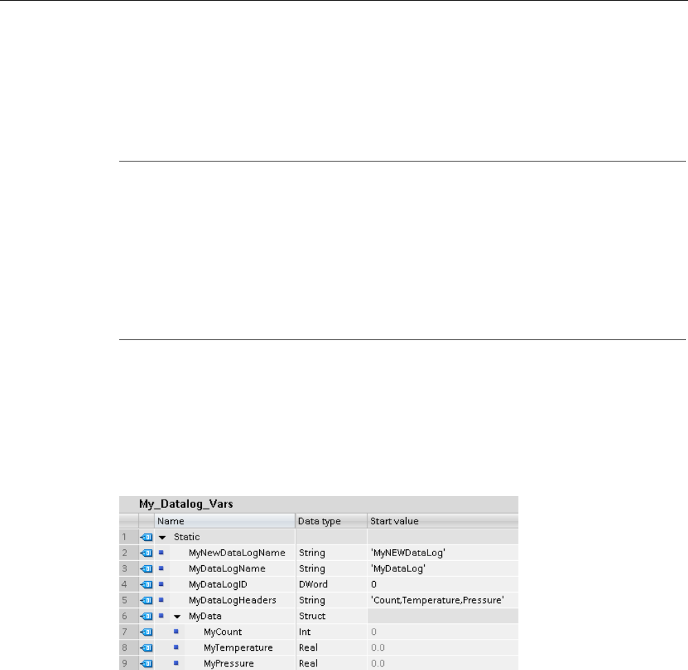
Extended instructions
9.9 Recipes and Data logs
S7-1200 Programmable controller
System Manual, V4.2, 09/2016, A5E02486680-AK 529
9.9.2.5
Data log example program
This Data log example program does not show all the program logic necessary to get sample
values from a dynamic process, but does show the key operations of the Data log
instructions. The structure and number of log files that you use depends on your process
control requirements.
Note
General usage of Data log files
•
Data log files are automatically opened after the DataLogCreate and DataLogNew File
operations.
•
Data log files are automatically closed after a PLC run to stop transition or a PLC power
cycle.
•
A Data log file must be open before a DataLogWrite operation is possible.
•
A maximum of eight data log files may be open at one time. More than eight data log files
may exist, but some of them must be closed so no more than eight are open.
Example Data log program
Example data log names, header text, and the MyData structure are created in a data block.
The three MyData variables temporarily store new sample values. The process sample
values at these DB locations are transferred to a data log file by executing the DataLogWrite
instruction.
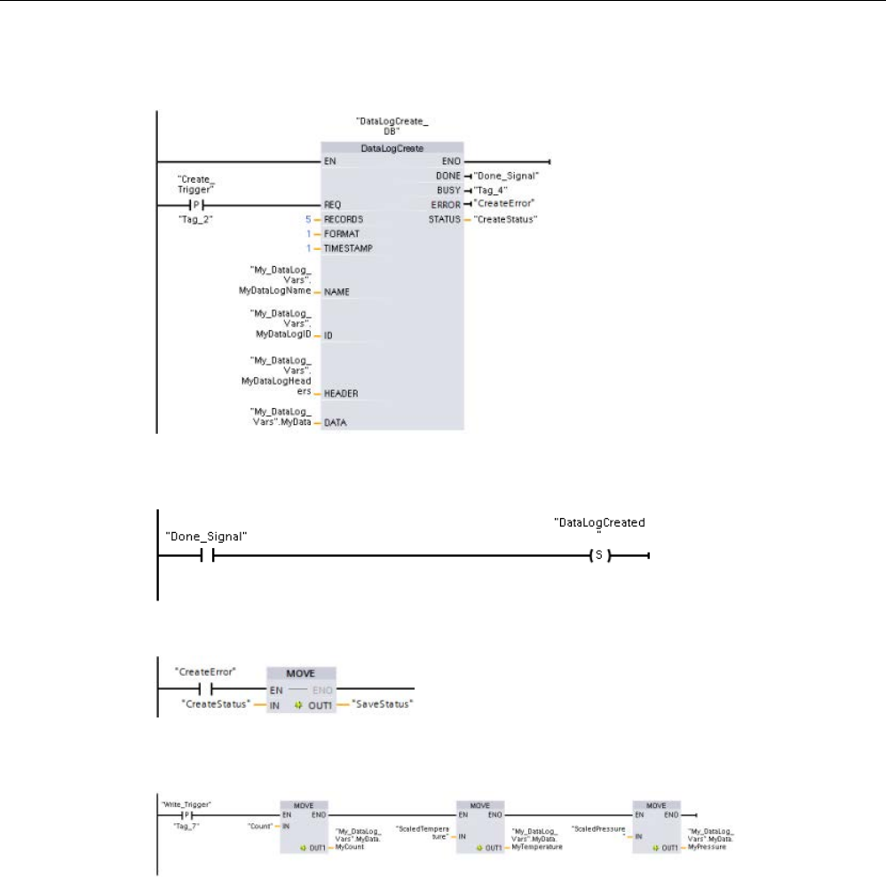
Extended instructions
9.9 Recipes and Data logs
S7-1200 Programmable controller
530 System Manual, V4.2, 09/2016, A5E02486680-AK
Network 1
REQ rising edge starts the data log creation process.
Network 2
Capture the DONE output from DataLogCreate because it is only valid for one
scan.
Network 3
If an error exists save the status output
Network 4
A positive edge signal triggers when to store new process values in the MyData
structure.
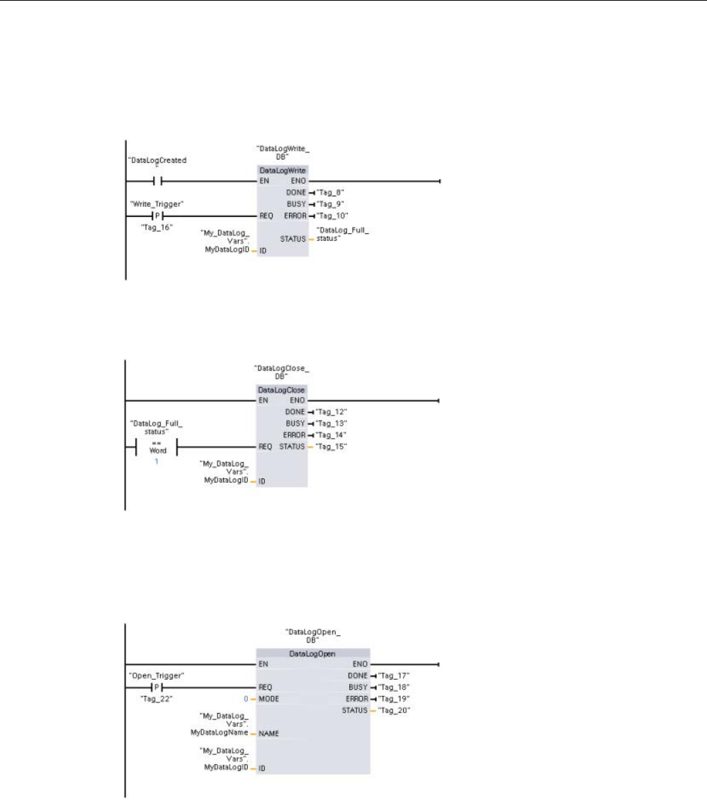
Extended instructions
9.9 Recipes and Data logs
S7-1200 Programmable controller
System Manual, V4.2, 09/2016, A5E02486680-AK 531
Network 5
The EN input state is based upon when the DataLogCreate operation is complete.
A create operation extends over many scan cycles and must be complete before executing a
write operation. The positive edge signal on the REQ input is the event that triggers an
enabled write operation.
Network 6
Close the data log once the last record has been written. After executing the
DataLogWrite operation that writes the last record, the log file full status is signaled when
DataLogWrite STATUS output = 1.
Network 7
A positive signal edge DataLogOpen REQ input simulates the user pushing a
button on an HMI that opens a data log file. If you open a Data log file that has all records
filled with process data, then the next DataLogWrite operation will overwrite the oldest
record. You may want to preserve the old Data log and instead create a new data log, as
shown in network 7.
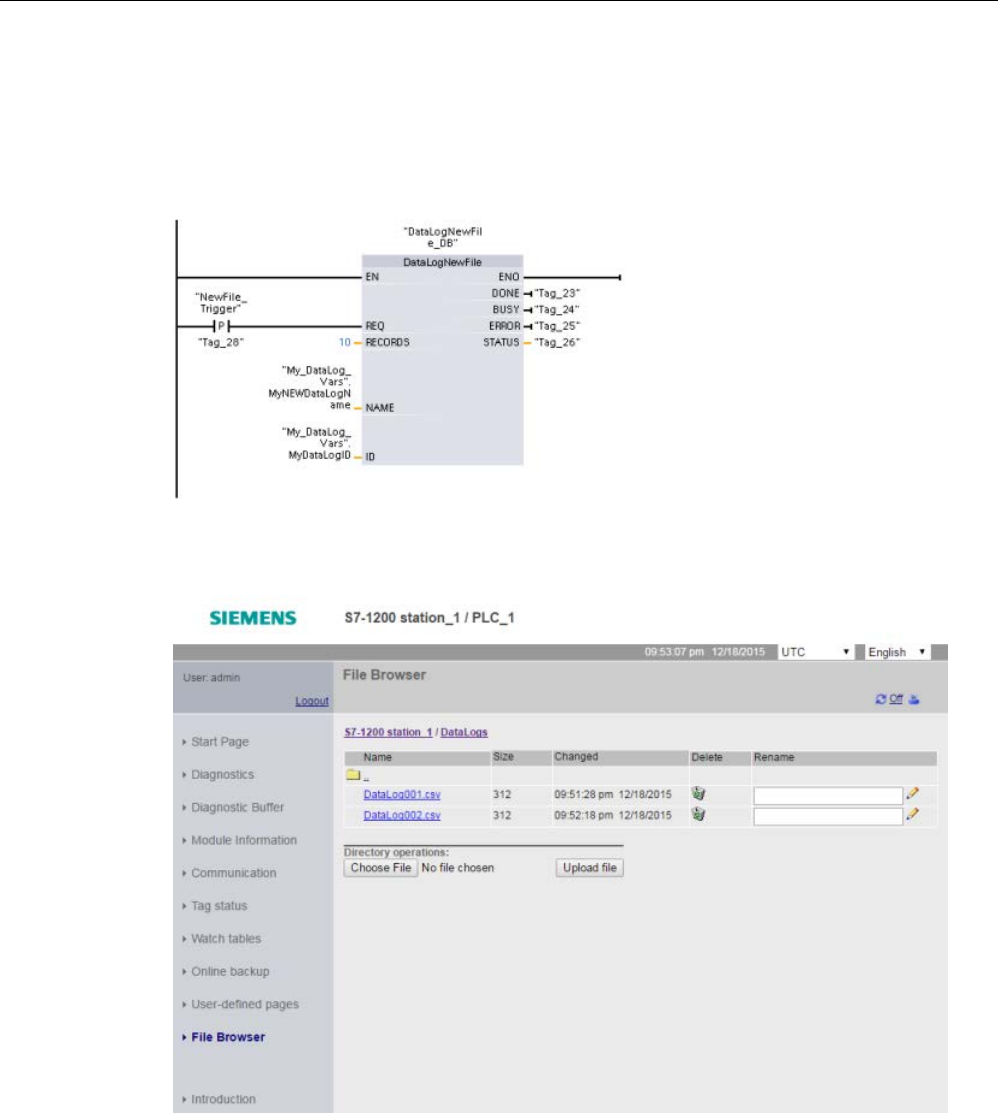
Extended instructions
9.9 Recipes and Data logs
S7-1200 Programmable controller
532 System Manual, V4.2, 09/2016, A5E02486680-AK
Network 8
The ID parameter is an IN/OUT type. First, you supply the ID value of the existing
Data log whose structure you want to copy. After the DataLogNewFile operation is complete,
a new and unique ID value for the new Data log is written back to the ID reference location.
The required DONE bit = TRUE capture is not shown, refer to networks 1, 2, and 4 for an
example of DONE bit logic.
Data log files created by the example program viewed with the S7-1200 CPU Web server
①
The "Delete" option is not available if you are not logged in with modify privileges.
②
The "Rename" option is not available if you are not logged in with modify privileges.

Extended instructions
9.9 Recipes and Data logs
S7-1200 Programmable controller
System Manual, V4.2, 09/2016, A5E02486680-AK 533
Table 9- 218 Downloaded .csv file examples viewed with Excel
Two records written in a five record max-
imum file
Five records in a Data log file with a five
record maximum
After one additional record is written to the
file above which is full, the sixth write
operation overwrites the oldest record one
with record six. Another write operation
will overwrite record two with record sev-
en and so on.
Note
Data logs no longer use an //END marker to mark the end of a data log fi
le that is not full.
Prior to V4.1 of the S7
-1200 CPU, data logs that were not full included an //END marker.

Extended instructions
9.10 Data block control
S7-1200 Programmable controller
534 System Manual, V4.2, 09/2016, A5E02486680-AK
9.10
Data block control
9.10.1
CREATE_DB (Create data block)
Table 9- 219 CREATE_DB instruction
LAD / FBD
SCL
Description
ret_val := CREATE_DB(
REQ:=_bool_in_,
LOW_LIMIT:=_uint_in_,
UP_LIMIT:=_uint_in_,
COUNT:=_udint_in_,
ATTRIB:=_byte_in_,
BUSY=>_bool_out_,
DB_NUM=>_uint_out_);
Use the instruction "CREATE_DB" to create a
new data block in the load and/or work memory.
The instruction "CREATE_DB" does not change
the checksum of the user program.
A data block that you create only in work memory
has the following properties:
• After a memory reset or POWER OFF /
POWER ON this block no longer exists.
• When loading or when there is a STOP-RUN
transition, its content remains unchanged.
Number of the data block
The data block created is assigned a number from the range defined at the LOW_LIMIT (low
limit) and UP_LIMIT (high limit) parameters. "CREATE_DB" assigns the smallest possible
number from the specified range to the DB. You cannot assign the numbers of the DBs
already contained in the user program.
To create a DB with a specific number, enter the same number for the high and low limit of
the range to be specified. If a DB with the same number already exists in the work memory
and/or load memory, or if the DB exists as a copied version, the instruction will be terminated
and an error message will be generated at the RET_VAL parameter.
Start values of the data block
The SRCBLK parameter is used to define start values for the DB that is to be created. The
SRCBLK parameter is a pointer to a DB or a DB area from which you apply the start values.
The DB addressed at the SRCBLK parameter must have been generated with standard
access ("Optimized block access" attribute disabled).
● If the area specified at the SRCBLK parameter is larger than the DB generated, the
values up to the length of the DB generated will be applied as start values.
● If the area specified at the SRCBLK parameter is smaller than the DB generated, the
remaining values will be filled with "0".
To ensure data consistency, you must not change this data area while "CREATE_DB" is
being executed (which means as long as the BUSY parameter has the value TRUE).

Extended instructions
9.10 Data block control
S7-1200 Programmable controller
System Manual, V4.2, 09/2016, A5E02486680-AK 535
Functional description
The "CREATE_DB" instruction works asynchronously. Processing takes place across
several calls. You start the job by calling "CREATE_DB" with REQ = 1.
The output parameters RET_VAL and BUSY indicate the status of the job.
See also: DELETE_DB (Delete data block) (Page 542)
Parameters
The following table shows the parameters of the "CREATE_DB" instruction:
Parameter
Declara-
tion
Data
type
Memory area
Description
REQ Input BOOL I, Q, M, D, L or con-
stant
Level-triggered control parameter "request to activate"
REQ = 1: Request to generate the data block
LOW_LIMIT Input UINT I, Q, M, D, L or con-
stant
Low limit of the range for the assignment of a DB number. The
smallest possible number is 60000.
UP_LIMIT Input UINT I, Q, M, D, L or con-
stant
High limit of the area used by "CREATE_DB" to assign a num-
ber to your DB (largest possible DB number: 60999)
COUNT Input UDINT I, Q, M, D, L or con-
stant
The count value specifies the number of bytes which you want
to reserve for the DB generated. The number of bytes must be
an even number. The maximum length is 65534 bytes.
ATTRIB Input BYTE I, Q, M, D, L or con-
stant
You use the first 4 bits of the byte at parameter ATTRIB to
define the properties of the data block *:
• Bit 0 = 0: Attribute "Only store in load memory" is not set.
• Bit 0 = 1: Attribute "Only store in load memory" is set. With
this setting, the DB takes up no space in the work memory
and is not included in the program. The DB cannot be ac-
cessed with bit commands. When bit 0 = 1, the selection for
bit 2 is irrelevant.
To ensure compatibility with STEP 7 V5.x, bits 0 and 3 must be
considered together (see below).
• Bit 1 = 0: Attribute "Data block write-protected in the device"
is not set.
• Bit 1 = 1: Attribute "Data block write-protected in the device"
is set.
•
Bit 2 = 0: DB is retentive (only for DBs generated in the load
and in the work memory). The DB is regarded as retentive if
at least one value has been set as retentive.
• Bit 2 = 1: DB is not retentive
Retentivity is not supported with DBs that are only stored in
load memory or only in the work memory. If you call the
"CREATE_DB" instruction with one of the two combinations
"retentive and only load memory" or "retentive and only work
memory" the DB to be generated will not be marked as reten-
tive.

Extended instructions
9.10 Data block control
S7-1200 Programmable controller
536 System Manual, V4.2, 09/2016, A5E02486680-AK
Parameter
Declara-
tion
Data
type
Memory area
Description
• Bit 3 = 0: Creation of the DB either in the load memory or in
the work memory (selection using bit 0, see above)
•
Bit 3 = 1: Creation of the DB both in the load memory and in
the work memory (bit 0 irrelevant)
To ensure compatibility with STEP 7 V5.x, bits 0 and 3 must be
used in combination. When bit 3 = 1, bit 0 is irrelevant.
Bit 0
Bit 3
DB generation
0
0
In work memory only
1 0 In load memory only
Irrele-
vant
1 Work and load memory
• Bit 4 = 0 - No start values specified (input values at the
SRCBLK parameter will be ignored).
• Bit 4 = 1 -
Specify start values (values correspond to the DB
addressed by the SRCBLK parameter).
SRCBLK Input VARIAN
T
D Pointer to the data block whose values will be used to initialize
the data block to be generated.
RET_VAL
Return
INT
I, Q, M, D, L
Error information
BUSY
Output
BOOL
I, Q, M, D, L
BUSY = 1: The process is not yet complete.
DB_NUM Output DB_DY
N
(UINT)
I, Q, M, D, L Number of the DB created.
* The properties selected here correspond to the attributes in the properties of a data block.
You can find additional information on valid data types under "Data types (Page 125)".

Extended instructions
9.10 Data block control
S7-1200 Programmable controller
System Manual, V4.2, 09/2016, A5E02486680-AK 537
Parameter RET_VAL
Error code*
(W#16#...)
Description
0000
No error
0081 The destination area is greater than the source area.
The source area is written completely to the destination area. The remaining bytes of the destination area
remain unchanged.
7000
First call with REQ = 0: No data transfer active; BUSY has the value "0".
7001
First call with REQ = 1: Data transfer triggered; BUSY has the value "1".
7002
Intermediate call (REQ irrelevant): Data transfer already active; BUSY has the value "1".
8081 The source area is larger than the destination area.
The complete destination area is written. The remaining bytes of the source area are ignored.
8092 The "Create data block" function is currently unavailable because
• The "Compress user memory" function is currently active.
• The maximum number of blocks on your CPU has already been reached.
8093
No data block or a data block that is not in the work memory is specified for the SRCBLK parameter.
8094
An invalid value was specified at parameter ATTRIB.
80A1 DB number error:
• The number is "0"
• The number exceeds the CPU-specific high limit for DB numbers
• Low limit > high limit
80A2 DB length error:
• The length is "0"
• The length is an odd number
• The length is greater than permitted by the CPU
80A3
The data block at the SRCBLK parameter was not created with standard access.
80B1
There is no DB number free.
80B2
Not enough work memory.
80B4
The memory card is write-protected.
80BB
Not enough load memory.
80C3
The maximum number of simultaneously active "CREATE_DB" instructions has already been reached.
General error
information
See also: Common error codes for the Extended instructions (Page 553)
* You can display the error code as either integer or hexadecimal values in the program editor.
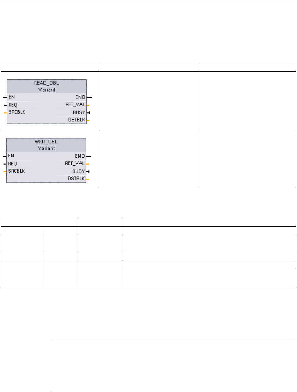
Extended instructions
9.10 Data block control
S7-1200 Programmable controller
538 System Manual, V4.2, 09/2016, A5E02486680-AK
9.10.2
READ_DBL and WRIT_DBL (Read/write a data block in load memory)
instructions
Table 9- 220 READ_DBL and WRIT_DBL instructions
LAD / FBD
SCL
Description
READ_DBL(
req:=_bool_in_,
srcblk:=_variant_in_,
busy=>_bool_out_,
dstblk=>_variant_out_);
Copies DB start values or part of the
values, from load memory to a target
DB in the work memory.
The content of load memory is not
changed during the copy process.
WRIT_DBL(
req:=_bool_in_,
srcblk:=_variant_in_,
busy=>_bool_out_,
dstblk=>_variant_out_);
Copies DB current values or part of the
values from work memory to a target
DB in load memory.
The content of work memory is not
changed during the copy process.
Table 9- 221 Data types for the parameters
Parameter and type
Data type
Description
REQ
IN
BOOL
A high signal starts the operation, if BUSY = 0.
SRCBLK IN VARIANT READ_DBL: Pointer to the source data block in load memory
WRIT_DBL: Pointer to the source data block in work memory
RET_VAL
OUT
INT
Execution condition code
BUSY
OUT
BOOL
BUSY = 1 signals that the reading/writing process is not complete.
DSTBLK OUT VARIANT READ_DBL: Pointer to the destination data block in work memory
WRIT_DBL: Pointer to the destination data block in load memory
Typically, a DB is stored in both load memory (flash) and work memory (RAM). The start
values (initial values) are always stored in load memory, and the current values are always
stored in work memory. READ_DBL can be used to copy a set of start values from load
memory to the current values of a DB in work memory that is referenced by your program.
You can use WRIT_DBL to update the start values stored in internal load memory or
memory card from current values in work memory.
Note
Effect of WRIT_DBL and READ_DBL instruction on flash memory
The WRIT_DBL instruction performs write operations in flash memory (internal load
memory
or memory card). To avoid reducing the lifetime of the flash memory, use the WRIT_DBL
instruction for infrequent updates such as recording changes to a production process. For
similar reasons, avoid frequent calls to READ_DBL for read operations.

Extended instructions
9.10 Data block control
S7-1200 Programmable controller
System Manual, V4.2, 09/2016, A5E02486680-AK 539
You must create the data blocks for READ_DBL and WRIT_DBL prior to calling these
instructions in the STEP 7 program. If you created the source DB as a "standard" type then
the destination DB must also be the "standard" type. If you created the source data block as
an "optimized" type then the destination data block must also be the "optimized" type.
If the DBs are standard, then you can specify either a tag name or a P# value. The P# value
allows you to specify and copy any number of elements of the specified size (Byte, Word, or
DWord). Thus, you can copy part or all of a DB. If the DBs are optimized, you can only
specify a tag name; you cannot use the P# operator. If you specify a tag name for either
standard or optimized DBs (or for other work-memory types), then the instruction copies the
data that this tag name references. This could be a user-defined type, an array, or a basic
element. You can only use type Struct with these instructions if the DB is standard, not
optimized. You must use a user-defined type (UDT) if it is a structure in optimized memory.
Only a user-defined type ensures that the "data types" are exactly the same for both the
source and destination structures.
Note
Using a structure (data type Struct) in an "optimized" DB
When using a
Struct data type with "optimized" DBs, you must first create a user-defined
data type (UDT) for the Struct. You then configure both the source and destination DBs with
the UDT. The UDT ensures that the data types within the Struct remain consistent for bo
th
DBs.
For "standard" DBs, you use the Struct without creating a UDT.
READ_DBL and WRIT_DBL execute asynchronously to the cyclic program scan. The
processing extends over multiple READ_DBL and WRIT_DBL calls. You start the DB
transfer job by calling with REQ = 1 and then monitor the BUSY and RET_VAL outputs to
determine when the data transfer is complete and correct.
Note
Effect of WRIT_DBL and READ_DBL instruction on communication load
When the WRIT_DBL or READ_DBL instruction is continually active,
it can consume
communication resources to the point that STEP
7 loses communication with the CPU. For
this reason, use a
positive edge input (Page 233) for the REQ parameter rather than a
normally open or closed input
(Page 227
) that would remain on (signal level high) for multiple
scans.
To ensure data consistency, do not modify the destination area during the processing of
READ_DBL or the source area during the processing of WRIT_DBL (that is, as long as the
BUSY parameter is TRUE).
SRCBLK and DSTBLK parameter restrictions:
● A data block must have been previously created before it can be referenced.
● The length of a VARIANT pointer of type BOOL must be divisible by 8.
● The length of a VARIANT pointer of type STRING must be the same in the source and
destination pointers.

Extended instructions
9.10 Data block control
S7-1200 Programmable controller
540 System Manual, V4.2, 09/2016, A5E02486680-AK
Recipes and machine setup information
You can use the READ_DBL and WRIT_DBL instructions to manage recipes or machine
setup information. This essentially becomes another method of achieving retentive data for
values that do not change often, although you would want to limit the number of writes to
prevent wearing out the flash prematurely. This effectively allows you to increase the amount
of retentive memory beyond that supported for the normal power-down retentive data, at
least for values that do not change often. You could save recipe information or machine-
setup information from work memory to load memory using the WRIT_DBL instruction, and
you could retrieve such information from load memory into work memory using the
READ_DBL instruction.
Table 9- 222 Condition codes
RET_VAL
(W#16#...)
Description
0000
No error
0081 Warning: that the source area is smaller than the destination area. The source data is copied complete-
ly with the extra bytes in the destination area unchanged.
7000
Call with REQ = 0: BUSY = 0
7001 First call with REQ = 1 (working): BUSY = 1
7002
N
th
call (working): BUSY = 1
8051
Data block type error
8081 The source area is larger than the destination area. The destination area is completely filled and the
remaining bytes of the source are ignored.
8251
Source data block type error
82B1
Missing source data block
82C0
The source DB is being edited by another statement or a communication function.
8551
Destination data block type error
85B1
Missing destination data block
85C0
The destination DB is being edited by another statement or a communication function.
80C3
More than 50 READ_DBL or 50 WRIT_DBL statements are currently queued for execution.
See also
Recipes (Page 498)
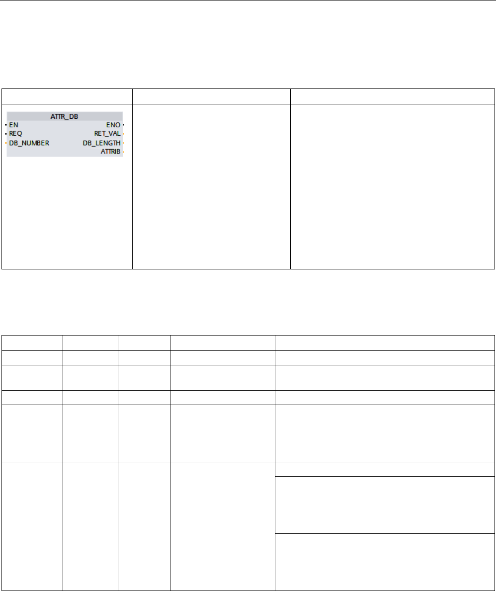
Extended instructions
9.10 Data block control
S7-1200 Programmable controller
System Manual, V4.2, 09/2016, A5E02486680-AK 541
9.10.3
ATTR_DB (Read data block attribute)
Table 9- 223 ATTR_DB instruction
LAD / FBD
SCL
Description
ret_val := ATTR_DB(
REQ:=_bool_in_,
DB_NUMBER:=_uint_in_,
DB_LENGTH=>_udint_out_,
ATTRIB=>_byte_out_);
You use the instruction "ATTR_DB" to obtain
information about a data block (DB) located in the
work memory of the CPU. The instruction deter-
mines the attributes set at the ATTRIB parameter
for the DB selected.
The length cannot be read out for data blocks
with optimized access and data blocks that are
only in load memory. In these cases, the
DB_LENGH parameter has the value "0".
Do not apply ATTR_DB to data blocks with opti-
mized access and activated memory reserve.
Do not read out the data blocks for motion control
with the "ATTR_DB" instruction. The error code
80B2 is output for this.
Parameters
The following table shows the parameters of the "ATTR_DB" instruction:
Parameter
Declaration
Data type
Memory area
Description
REQ
Input
BOOL
I, Q, M, D, L or constant
REQ = 1: Request to read block attributes
DB_NUMBE
R
Input DB_ANY I, Q, M, D, L or constant Number of the DB to be tested
RET_VAL
Output
INT
I, Q, M, D, L
Error information
DB_LENGTH Output UDINT I, Q, M, D, L • Number of data bytes that the selected DB con-
tains.
• "0" for data blocks with optimized access and
data blocks that are only in load memory.
ATTRIB Output BYTE I, Q, M, D, L
DB properties:
• Bit 0*= 0: Attribute "Only store in load memory" is
not set.
• Bit 0*= 1: Attribute "Only store in load memory" is
set.
• Bit 1 = 0: Attribute "Data block write-protected in
the device" is not set.
• Bit 1 = 1: Attribute "Data block write-protected in
the device" is set.

Extended instructions
9.10 Data block control
S7-1200 Programmable controller
542 System Manual, V4.2, 09/2016, A5E02486680-AK
Parameter
Declaration
Data type
Memory area
Description
If bit 0 = 1, then bit 2 is irrelevant and gets the value
1.
• Bit 2 = 0: Retentive - The DB is regarded as re-
tentive if at least one value has been set as reten-
tive.
• Bit 2 = 1: Not retentive - The complete DB is not
retentive.
• Bit 3*= 0: The DB is either in the load memory (bit
0 = 1) or in the work memory (bit 0 = 0).
• Bit 3*= 1: The DB is generated in both the load
and the work memory
* The relationship between bit 0 and bit 3 is explained in the parameters of the instruction "CREATE_DB (Create data
block) (Page 534)".
You can find additional information on valid data types under "Data types (Page 125)".
Parameter RET_VAL
Error code*
(W#16#...)
Explanation
0000
No error occurred.
80A1 Error in input parameter DB_NUMBER: the actual parameter selected
• Is "0"
• Is greater than the maximum permitted DB number for the CPU used.
80B1
The DB with the specified number does not exist on the CPU.
80B2
Data blocks of motion control technology objects cannot be read with the "ATTR_DB" instruction.
General error
information
See also: Common error codes for the Extended instructions (Page 553)
* You can display the error code as either integer or hexadecimal values in the program editor.
9.10.4
DELETE_DB (Delete data block)
Table 9- 224 DELETE_DB instruction
LAD / FBD
SCL
Description
ret_val := DELETE_DB(
REQ := _bool_in_,
DB_NUMBER :=
_uint_in_,
BUSY => _bool_out_);
You use the instruction "DELETE_DB" to delete a
data block (DB) that the user program created by
calling the instruction "CREATE_DB (Page 534)".
If the data block was not created with
"CREATE_DB", DELETE_DB returns the error
code W#16#80B5 at the RET_VAL parameter.
The DELETE_DB call does not delete the select-
ed data block immediately, but rather at the cycle
control point after execution of the cycle OB.

Extended instructions
9.10 Data block control
S7-1200 Programmable controller
System Manual, V4.2, 09/2016, A5E02486680-AK 543
Functional description
The "DELETE_DB" instruction works asynchronously, that is, its execution extends over
multiple calls. You start the interrupt transfer by calling the instruction with REQ = 1.
Output parameter BUSY and bytes 2 and 3 of output parameter RET_VAL show the status of
the job.
The deletion of the data block is complete when output parameter BUSY has the value
FALSE.
Parameters
The following table shows the parameters of the "DELETE_DB" instruction:
Parameter
Declaration
Data type
Memory area
Description
REQ Input BOOL I, Q, M, D, L or constant REQ =1: Request to delete the DB with the num-
ber in parameter DB_NUMBER
DB_NUMBER
Input
UINT
I, Q, M, D, L or constant
Number of the DB to be deleted
RET_VAL
Output
INT
I, Q, M, D, L
Error information (see "RET_VAL parameter")
BUSY Output BOOL I, Q, M, D, L BUSY= 1: The process is not yet complete.
You can find additional information on valid data types under "Data types (Page 125)".
Parameter RET_VAL
Error code*
(W#16#...)
Explanation
0000
No error occurred.
7000
First call with REQ = 0: No data transfer active; BUSY has the value "0".
7001
First call with REQ = 1: Data transfer triggered; BUSY has the value "1".
7002
Intermediate call (REQ irrelevant): Data transfer already active; BUSY has the value "1".
80A1 Error in input parameter DB_NUMBER:
• The value at the parameter is "0".
• The value at the parameter is greater than the maximum permitted DB number for the CPU used.
80B1
The DB with the specified number does not exist on the CPU.
80B4
The DB cannot be deleted because the memory card of the CPU is write-protected.
80B5
The DB was not created using "CREATE_DB".
80BB
Not enough load memory.
80C3
The "Delete a DB" function cannot be executed at this time due to a temporary resource bottleneck.
General error
information
See also: Common error codes for the Extended instructions (Page 553)
* You can display the error code as either integer or hexadecimal values in the program editor.

Extended instructions
9.11 Address handling
S7-1200 Programmable controller
544 System Manual, V4.2, 09/2016, A5E02486680-AK
9.11
Address handling
9.11.1
GEO2LOG (Determine the hardware identifier from the slot)
You use the GEO2LOG instruction to determine the hardware identifier based upon slot
information.
Table 9- 225 GEO2LOG instruction
LAD / FBD
SCL
Description
ret_val := GEO2LOG(
GEOADDR:=_variant_in_out_,
laddr:=_word_out_);
You use the GEO2LOG instruction to
determine the hardware identifier based
upon slot information.
The GEO2LOG instruction determines the hardware identifier based upon slot information
that you define using the GEOADDR system data type:
Depending on the type of hardware you define at the parameter HWTYPE, the following
information is evaluated from the other GEOADDR parameters:
● With HWTYPE = 1 (PROFINET IO system):
– Only IOSYSTEM is evaluated. The other parameters of GEOADDR are not taken into
consideration.
– The hardware identifier of the PROFINET IO system is output.
● With HWTYPE = 2 (PROFINET IO device):
– IOSYSTEM and STATION are evaluated. The other parameters of GEOADDR are not
taken into consideration.
– The hardware identifier of the PROFINET IO device is output.
● With HWTYPE = 3 (rack):
– Only IOSYSTEM and STATION are evaluated. The other parameters of GEOADDR
are not taken into consideration.
– The hardware identifier of the rack is output.
● With HWTYPE = 4 (module):
– IOSYSTEM, STATION, and SLOT are evaluated. The SUBSLOT parameter of
GEOADDR is not taken into consideration.
– The hardware identifier of the module is output.

Extended instructions
9.11 Address handling
S7-1200 Programmable controller
System Manual, V4.2, 09/2016, A5E02486680-AK 545
● With HWTYPE = 5 (submodule):
– All parameters of GEOADDR are evaluated.
– The hardware identifier of the submodule is output.
The AREA parameter of the GEOADDR system data type is not evaluated.
Table 9- 226 Data types for the parameters
Parameter and type
Data type
Description
GEOADDR IN/OUT or
IN ?
Variant Pointer to the structure of the GEOADDR system data type. The
GEOADDR system data type contains the slot information from which the
hardware ID is determined.
Refer to the "GEOADDR system data type (Page 551)" for further infor-
mation.
RET_VAL OUT or
RETURN
?
Int Output of error information.
LADDR OUT HW_ANY Hardware identifier of the assembly or the module.
The number is automatically assigned and is stored in the properties in
the hardware configuration.
For further information on valid data types, refer to "Overview of the valid data types" in the
STEP 7 online help.
Table 9- 227 Condition codes
RET_VAL*
(W#16#...)
Explanation
0
No error occurred.
8091
Invalid value for in GEOADDR for HWTYPE.
8094
Invalid value for in GEOADDR for IOSYSTEM.
8095
Invalid value for in GEOADDR for STATION.
8096
Invalid value for in GEOADDR for SLOT.
8097
Invalid value for in GEOADDR for SUBSLOT.
* The error codes can be displayed as integer or hexadecimal values in the program editor.
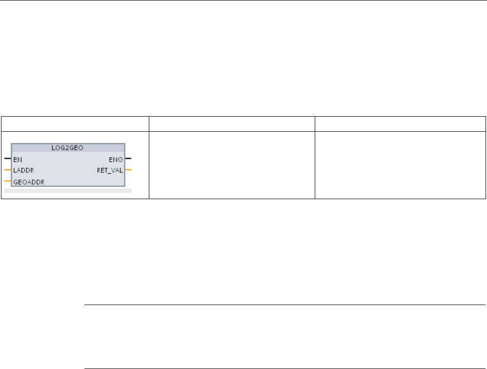
Extended instructions
9.11 Address handling
S7-1200 Programmable controller
546 System Manual, V4.2, 09/2016, A5E02486680-AK
9.11.2
LOG2GEO (Determine the slot from the hardware identifier)
You use the LOG2GEO instruction to determine the geographical address (module slot) from
the logical address belonging to a hardware identifier.
Table 9- 228 LOG2GEO instruction
LAD / FBD
SCL
Description
ret_val := LOG2GEO(
laddr:=_word_in_,
GEOADDR:=_variant_in_out_);
You use the LOG2GEO instruction to
determine the module slot belonging to a
hardware identifier.
The LOG2GEO instruction determines the geographic address of a logical address based
upon the hardware identifier:
● Use the LADDR parameter to select the logical address based upon the hardware
identifier.
● The GEOADDR contains the geographic address of the logical address given at the
LADDR input.
Note
In the cases where the HW type does not support a component, a subslot number for a
module 0 is returned.
An error is provid
ed if the LADDR input does not address a HW object.

Extended instructions
9.11 Address handling
S7-1200 Programmable controller
System Manual, V4.2, 09/2016, A5E02486680-AK 547
Table 9- 229 Data types for the parameters
Parameter and type
Data type
Description
LADDR IN HW_ANY Hardware identifier of the IO system or the module. The number is as-
signed automatically and is stored in the properties of the CPU or the
interface of the hardware configuration.
RET_VAL OUT Int Error code of the instruction
GEOADDR IN_OUT Variant Pointer to the GEOADDR system data type. The GEOADDR system data
type contains the slot information.
Refer to the "GEOADDR system data type (Page 551)" for further infor-
mation.
For further information on valid data types, refer to "Overview of the valid data types" in the
STEP 7 online help.
Table 9- 230 Condition codes
RET_VAL
(W#16#...)
Description
0000
No error
8090
The address specified at the LADDR parameter is invalid.
* The error codes can be displayed as integer or hexadecimal values in the program editor.
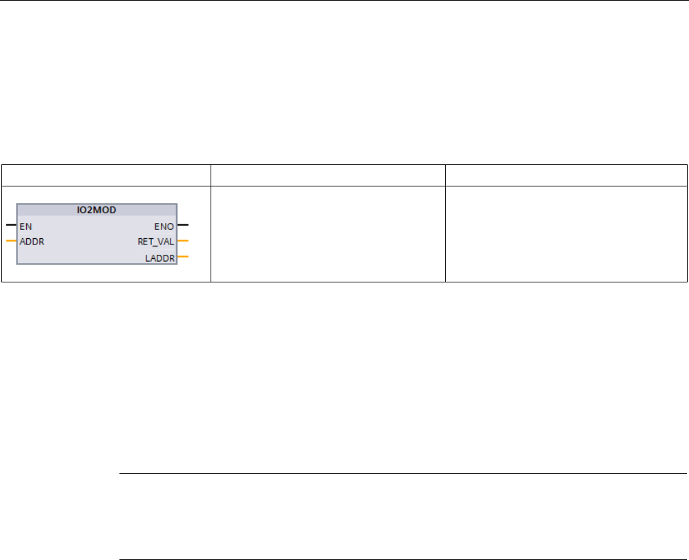
Extended instructions
9.11 Address handling
S7-1200 Programmable controller
548 System Manual, V4.2, 09/2016, A5E02486680-AK
9.11.3
IO2MOD (Determine the hardware identifier from an I/O address)
You use the IO2MOD instruction to determine the hardware identifier of the module from an
I/O address of a (sub)module.
Table 9- 231 IO2MOD instruction
LAD / FBD
SCL
Description
ret_val := IO2MOD(
ADDR:=_word_in_,
LADDR:=_word_out_);
You use the IO2MOD instruction to de-
termine the module slot belonging to a
hardware identifier.
The IO2MOD instruction determines the hardware identifier of the module from an IO
address (I, Q, PI, PQ) of a (sub)module.
Enter the IO address at the ADDR parameter. If a series of IO addresses is used at this
parameter, only the first address is evaluated to determine the hardware identifier. If the first
address is correctly specified, the length for the address specification at the ADDR is of no
significance. If an address area is used that encompasses several modules or non-used
addresses, the hardware identifier of the first module can also be determined.
If no IO address of a (sub)module is specified at the ADDR parameter, the error code "8090"
is output at the RET_VAL parameter.
Note
Input of IO address in SCL
You cannot program using the IO access ID "%QWx:P" in SCL. In this case, use the
symbolic tag name or
the absolute address in the process image.

Extended instructions
9.11 Address handling
S7-1200 Programmable controller
System Manual, V4.2, 09/2016, A5E02486680-AK 549
Table 9- 232 Data types for the parameters
Parameter
Declaration
Data type
Memory area
Description
ADDR IN or IN/OUT ? Variant I, Q, M, D, L IO address (I, Q, PI, PQ) within a
(sub)module.
Make sure that slice access is not used for
the parameter ADDR. If this is the case, incor-
rect values are output at the LADDR parame-
ter.
RET_VAL OUT or
RETURN ?
Int I, Q, M, D, L Error code of the instruction.
LADDR OUT HW_IO I, Q, M, D, L Determined hardware identifier (logical ad-
dress) of the IO (sub)module.
For further information on valid data types, refer to "Overview of the valid data types" in the
STEP 7 online help.
Table 9- 233 Condition codes
RET_VAL*
(W#16#...)
Explanation
0
No error occurred.
8090
IO address specified at ADDR parameter is not used by any hardware component.
* The error codes can be displayed as integer or hexadecimal values in the program editor.
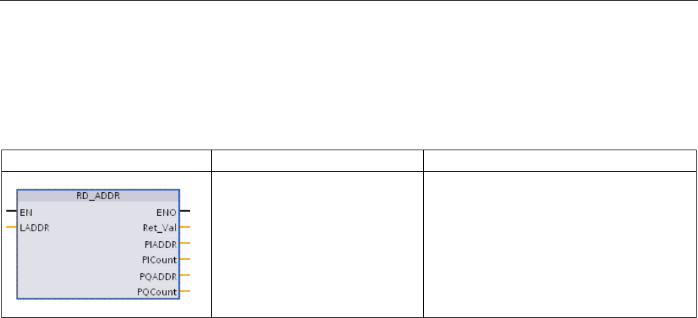
Extended instructions
9.11 Address handling
S7-1200 Programmable controller
550 System Manual, V4.2, 09/2016, A5E02486680-AK
9.11.4
RD_ADDR (Determine the IO addresses from the hardware identifier)
You use the RD_ADDR instruction to get the I/O addresses of a submodule.
Table 9- 234 RD_ADDR instruction
LAD / FBD
SCL
Description
ret_val := RD_ADDR(
laddr:=_word_in_,
PIADDR=>_udint_out_,
PICount=>_uint_out_,
PQADDR=>_udint_out_,
PQCount=>_uint_out_,);
You use the RD_ADDR instruction to get the
I/O addresses of a submodule.
The RD_ADDR instruction determines the length and the start address of the inputs or
outputs based on the hardware identifier of a submodule:
● Use the LADDR parameter to select the input or output module based upon the hardware
identifier.
● The following output parameters are used depending on whether it is an input module or
output module:
– In the case of an input module, the determined values are output at the PIADDR and
PICOUNT parameters.
– In the case of an output module, the determined values are output at the PQADDR
and PQCOUNT parameters.
● The PIADDR and PQADDR parameters each contain the start address of the I/O
addresses of the module.
● The PICOUNT and PQCOUNT parameters each contain the number of bytes of the
inputs or outputs (1 byte for 8 inputs/outputs, 2 bytes for 16 inputs/outputs).

Extended instructions
9.11 Address handling
S7-1200 Programmable controller
System Manual, V4.2, 09/2016, A5E02486680-AK 551
Table 9- 235 Data types for the parameters
Parameter and type
Data type
Description
LADDR
IN
HW_IO
Hardware identifier of the (sub)module
RET_VAL OUT Int Error code of the instruction
PIADDR
OUT
UDInt
Start address of the input module
PICOUNT OUT UInt Number of bytes of the inputs
PQADDR
OUT
UDInt
Start address of the output module
PQCOUNT
OUT
UInt
Number of bytes of the outputs
For further information on valid data types, refer to "Overview of the valid data types" in the
STEP 7 online help.
Table 9- 236 Condition codes
RET_VAL
(W#16#...)
Description
0000
No error
8090
Hardware identifier of the module at the LADDR parameter is invalid.
* The error codes can be displayed as integer or hexadecimal values in the program editor.
9.11.5
GEOADDR system data type
Geographical address
The system data type GEOADDR contains the geographical address of a module (or the slot
information).
● Geographical address for PROFINET IO:
For PROFINET IO, the geographical address is composed of the ID of the PROFINET IO
system, the device number, the slot number, and the submodule (if a sub-module is
used).
● Geographical address for PROFIBUS DP:
For PROFIBUS DP, the geographical address consists of the ID of the DP master
system, the station number, and the slot number.
The slot information of the modules can be found in the hardware configuration of each
module.

Extended instructions
9.11 Address handling
S7-1200 Programmable controller
552 System Manual, V4.2, 09/2016, A5E02486680-AK
Structure of the GEOADDR system data type
The structure GEOADDR is automatically created if you enter "GEOADDR" as the data type
in a data block.
Parameter name
Data type
Description
GEOADDR
STRUCT
HWTYPE UINT Hardware type:
• 1: IO system (PROFINET/PROFIBUS)
• 2: IO device/DP slave
• 3: Rack
• 4: Module
• 5: Submodule
If a hardware type is not supported by the instruction, a HWTYPE "0" is output.
AREA UINT Area ID:
• 0 = CPU
• 1 = PROFINET IO
• 2 = PROFIBUS DP
• 3 = AS-i
IOSYSTEM UINT PROFINET IO system (0=central unit in the rack)
STATION UINT • Number of the rack if area identifier AREA = 0 (central module).
• Station number if area identifier AREA > 0.
SLOT
UINT
Slot number
SUBSLOT UINT Number of the submodule. This parameter has the value "0" if no submodule is
available or can be plugged.

Extended instructions
9.12 Common error codes for the Extended instructions
S7-1200 Programmable controller
System Manual, V4.2, 09/2016, A5E02486680-AK 553
9.12
Common error codes for the Extended instructions
Table 9- 237 Common condition codes for the extended instructions
Condition code (W#16#....)1
Description
8x22
2
Area too small for input
8x23 Area too small for output
8x24
Illegal input area
8x25 Illegal output area
8x28
Illegal input bit assignment
8x29
Illegal output bit assignment
8x30
Output area is a read-only DB.
8x3A
DB does not exist.
1
If one of these errors occurs when a code block is executed, then the CPU remains in RUN (default) or can be config-
ured to go to STOP. Optionally, you can use the GetError or GetErorID instructions within that code block to handle the
error locally (CPU remains in RUN), and create a programmed reaction to the error.
2 The "x" represents the parameter number with the error. Parameter numbers start with 1.

Extended instructions
9.12 Common error codes for the Extended instructions
S7-1200 Programmable controller
554 System Manual, V4.2, 09/2016, A5E02486680-AK

S7-1200 Programmable controller
System Manual, V4.2, 09/2016, A5E02486680-AK 555
Technology instructions
10
10.1
Counting (High-speed counters)
The basic counter instructions, described in
"Counter operations" (Page 244)
,
are limited to
counting events that occur at a rate slower than the scan cycle of the S7-1200 CPU. The
High-speed counter (HSC) function provides the ability to count pulses occurring at a higher
rate than the PLC scan cycle. In addition, you can configure the HSC to measure the
frequency and period of the occurring pulses, or be setup such that motion control can use
the HSC to read a motor encoder signal.
To use the HSC function, the HSC must first be enabled and configured using the CPU’s
Properties tab in the Device Configuration screen. To get started configuring the HSC, refer
to "Configuring a high-speed counter" (Page 572).
After you download the hardware configuration, the HSC can count pulses or measure
frequency without the need for any instructions to be called. When the HSC is in Count or
Period mode, the count value is automatically captured and updated in the process image (I
memory) each scan cycle. If the HSC is in Frequency mode, the process image value is the
frequency in Hz.
In addition to counting and measuring, the HSC can generate hardware interrupt events,
operate dependent on the state of physical input points, and produce an output pulse
according to a specified counter event (V4.2 or above CPUs only). Technology instruction
CTRL_HSC_EXT allows the user program to control the HSC programmatically.
CTRL_HSC_EXT updates HSC parameters and returns the most up-to-date values when
executed. You can use the CTRL_HSC_EXT instruction while the HSC is in Count, Period,
or Frequency mode.
Note
The CTRL_HSC_EXT instruction replaces the legacy CTRL_HSC instruction for projects
targeting V4.2 CPUs and later. All of the functionality of the CTRL_HSC instructi
on, plus
several additional features, is available with the CTRL_HSC_EXT instruction. The legacy
CTRL_HSC instruction is only available for compatibility with older S7
-1200 projects and
should not be used in new projects.
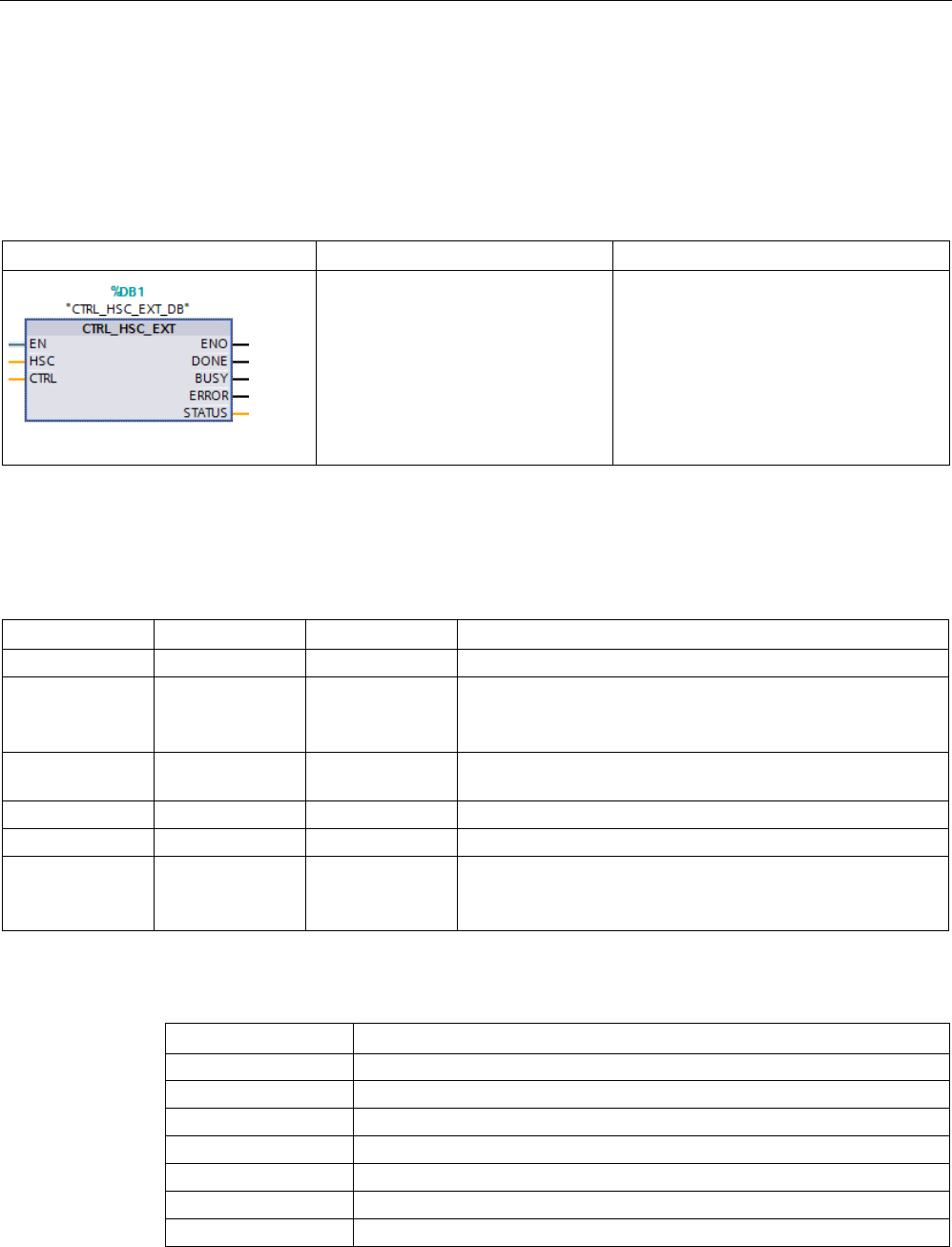
Technology instructions
10.1 Counting (High-speed counters)
S7-1200 Programmable controller
556 System Manual, V4.2, 09/2016, A5E02486680-AK
10.1.1
CTRL_HSC_EXT (Control high-speed counter) instruction
10.1.1.1
Instruction overview
Table 10- 1 CTRL_HSC_EXT instruction
LAD / FBD
SCL
Description
"CTRL_HSC_1_DB" (
hsc:=_hw_hsc_in_,
done:=_done_out_,
busy:=_busy_ out_,
error:=_error_out_,
status:=_status_out_,
ctrl:=_variant_in_);
Each CTRL_HSC_EXT (Control high-
speed counter (extended)) instruction
uses a system-defined data structure
stored in a user-defined Global DB to
store counter data. You assign the
HSC_Count, HSC_Period, or
HSC_Frequency data types as an input
parameter to the CTRL_HSC_EXT in-
struction.
1
STEP 7 automatically creates the DB when you insert the instruction.
2 In the SCL example, "CTRL_HSC_1_DB" is the name of the instance DB.
Table 10- 2 Data types for the parameters
Parameter
Declaration
Data type
Description
HSC
IN
HW_HSC
HSC identifier
CTRL IN_OUT Variant SFB input and return data.
Note: Refer to "CTRL_HSC_EXT instruction System Data
Types (SDT) (Page 561)" for further information.
DONE OUT Bool 1= Indicates SFB is finished. Always 1 because SFB is syn-
chronous
BUSY
OUT
Bool
Always 0, function is never busy
ERROR
OUT
Bool
1 = Indicates an error
STATUS OUT Word Execution condition code
Note: Refer to the "Execution condition codes" table below for
further information.
Table 10- 3 Execution condition codes
STATUS (W#16#)
Description
0
No error
80A1
HSC identifier does not address an HSC
80B1
Illegal value in NewDirection
80B4
Illegal value in NewPeriod
80B5 Illegal value in NewOpModeBehavior
80B6
Illegal value in NewLimitBehavior
80D0
SFB 124 not available
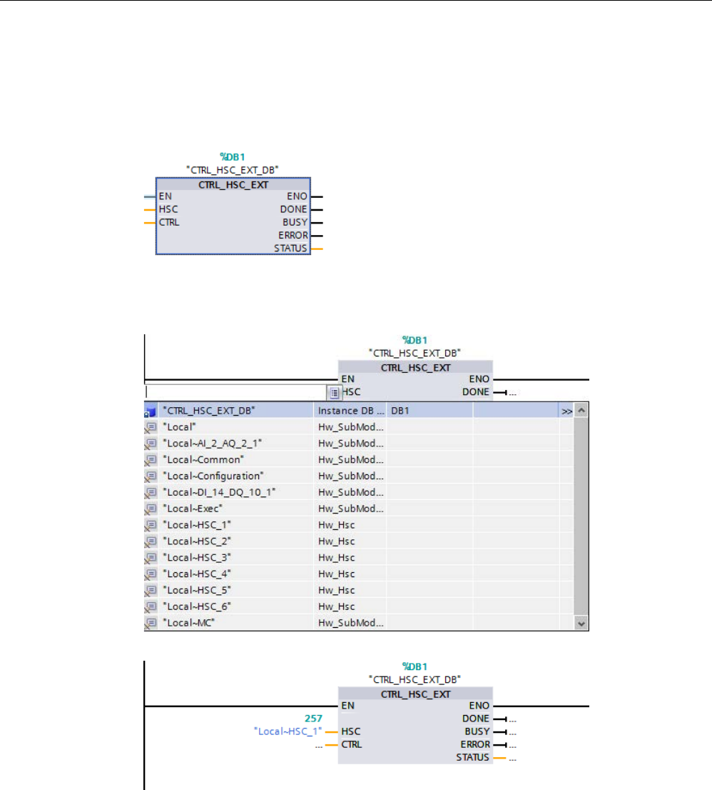
Technology instructions
10.1 Counting (High-speed counters)
S7-1200 Programmable controller
System Manual, V4.2, 09/2016, A5E02486680-AK 557
10.1.1.2
Example
To use the CTRL_HSC_EXT instruction, follow the steps below:
1. Place the CTRL_HSC_EXT instruction in the ladder network, which also creates the
following instance data block: "CTRL_HSC_EXT_DB":
2. Attach the HSC’s hardware identifier, found in the HSC’s properties, to the "HSC" pin of
the ladder instruction. You can also select one of the six "Hw_Hsc" objects from the
dropdown menu of this input pin. The default tag name for HSC1 is "Local~HSC_1":

Technology instructions
10.1 Counting (High-speed counters)
S7-1200 Programmable controller
558 System Manual, V4.2, 09/2016, A5E02486680-AK
3. Create a global data block named "Data_block_1" (You can also use an existing global
data block.):
– Within "Data_block_1", locate an empty row and add a variable named "MyHSC".
– In the "Data type" column, add one of the following System Data Types (SDT). Select
the SDT that corresponds to the HSC’s configured type of counting. More HSC SDT
information can be found later in this section. The dropdown list does not contain
these types so ensure that you enter the SDT name exactly as shown: HSC_Count,
HSC_Period, or HSC_Frequency
– After you enter the data type, you can expand the "MyHSC" variable to see all the
fields contained in the data structure. Here, you can find the data type of each of the
fields and change the default starting values:
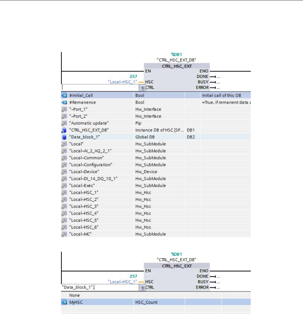
Technology instructions
10.1 Counting (High-speed counters)
S7-1200 Programmable controller
System Manual, V4.2, 09/2016, A5E02486680-AK 559
4. Assign the variable "'Data_block_1'. MyHSC" to the CTRL input pin of the
CTRL_HSC_EXT instruction:
– Select "Data_Block_1".
– Select "MyHSC".
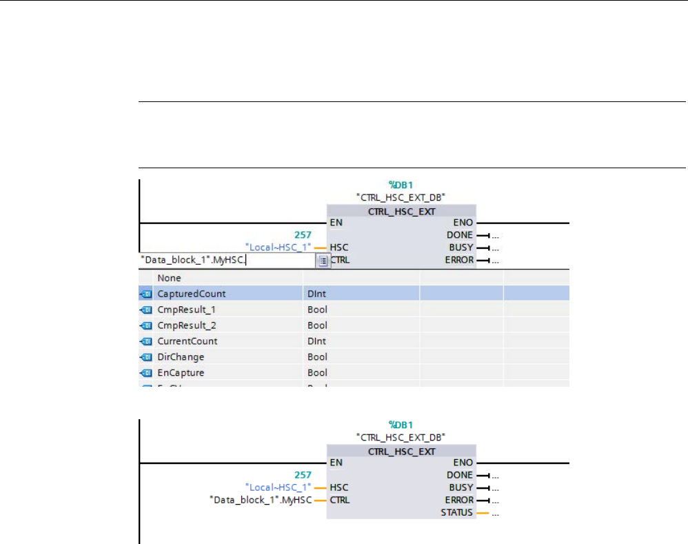
Technology instructions
10.1 Counting (High-speed counters)
S7-1200 Programmable controller
560 System Manual, V4.2, 09/2016, A5E02486680-AK
– Delete the period (".") following: "'Data_Block_1'.MyHSC". Then, either click outside
the box or press the ESC key once and then press the Enter key.
Note
After deleting the period (".") following: "'Data_Block_1'.MyHSC", do not press only the
Enter key. This action places the period (".") bac
k into the box.
– The completed CTRL input is shown below.
After you configure the HSC in the PLC, you can execute the CTRL_HSC_EXT instruction. If
an error occurs, ENO is set to "0" and the STATUS output indicates the condition code.
See also
CTRL_HSC_EXT Instruction System Data Types (SDT) (Page 561)

Technology instructions
10.1 Counting (High-speed counters)
S7-1200 Programmable controller
System Manual, V4.2, 09/2016, A5E02486680-AK 561
10.1.1.3
CTRL_HSC_EXT Instruction System Data Types (SDT)
The following System Data Types (SDTs) are only used with the CTRL_HSC_EXT
instruction’s CTRL pin. To use them, create a user data block and add an object with the
data type of the SDT that corresponds to the HSC’s configured mode (type of counting). TIA
Portal V14 does not show these data types in the dropdown menu so the name of the SDT
must be typed exactly as shown.
Inputs of the HSC’s SDT are denoted by the prefix "En" or "New". Inputs prefixed with "En"
either enables an HSC function or updates the corresponding parameter. The prefix "New"
identifies the update value. In order for the new value to take effect, the corresponding "En"
bit must be true, and the "New" value must be valid. When the CTRL_HSC_EXT instruction
is executed, the program applies input changes and updates the outputs with the appropriate
SDT reference attached.
SDT: HSC_Count
The "HSC_Count" data type corresponds to an HSC configured for "Count" mode. The
Count mode provides the following capabilities:
● Access the current pulse count
● Latch the current pulse count on an input event
● Reset the current pulse count to the starting value on an input event
● Access status bits, indicating certain HSC events have occurred
● Disable the HSC using a software or hardware input
● Change the counting direction using a software or hardware input
● Change the current pulse count
● Change the starting value (used when CPU transitions to RUN state or when Sync
function is triggered)
● Changing two independent reference (or preset) values used for comparison
● Change the upper and lower counting limits
● Change how the HSC operates when the pulse count reaches those limits
● Generate a hardware interrupt event when the current pulse count reaches a reference
(preset) value
● Generate a hardware interrupt event when the Synchronization (reset) input activates
● Generate a hardware interrupt event when the counting direction changes based upon an
external input
● Generate a single output pulse on a specified counting event
When an event occurs and the CTRL_HSC_EXT instruction executes, the instruction sets a
status bit. On the following CTRL_HSC_EXT instruction execution, the instruction clears the
status bit, unless the event occurs again before the instruction executes.

Technology instructions
10.1 Counting (High-speed counters)
S7-1200 Programmable controller
562 System Manual, V4.2, 09/2016, A5E02486680-AK
Table 10- 4 HSC_Count structure
Structure element
Declaration
Data type
Description
CurrentCount
OUT
Dint
Returns the HSC’s current count value
CapturedCount OUT Dint Returns the counter value captured on the specified input
event
SyncActive
OUT
Bool
Status bit: Sync input was activated
DirChange OUT Bool Status bit: Counting direction has changed
CmpResult1
OUT
Bool
Status bit: CurrentCount equals Reference1 event occured
CmpResult2
OUT
Bool
Status bit: CurrentCount equals Reference2 event occured
OverflowNeg
OUT
Bool
Status bit: CurrentCount reached the LowerLimit
OverflowPos
OUT
Bool
Status bit: CurrentCount reached the UpperLimit
EnHSC IN Bool Enables the HSC to count pulses when true; disables counting
when false
EnCapture IN Bool Enables the Capture input when true, Capture input has no
effect when false
EnSync IN Bool Enables the Sync input when true; Sync input has no effect
when false
EnDir
IN
Bool
Enables the NewDirection value to take effect
EnCV
IN
Bool
Enables the NewCurrentCount value to take effect
EnSV
IN
Bool
Enables the NewStartValue value to take effect
EnReference1
IN
Bool
Enables the NewReference1 value to take effect
EnReference2
IN
Bool
Enables the NewReference2 value to take effect
EnUpperLmt
IN
Bool
Enables the NewUpperLimit value to take effect
EnLowerLmt
IN
Bool
Enables the New_Lower_Limit value to take effect
EnOpMode IN Bool Enables the NewOpModeBehavior value to take effect
EnLmtBehavior
IN
Bool
Enables the NewLimitBehavior value to take effect
EnSyncBehavior IN Bool This value is not used.
NewDirection IN Int Counting direction: 1 = count up; -1 = count down; all other
values are reserved.
NewOpModeBe-
havior
IN Int HSC’s operation on overflow: 1 = HSC stops counting (HSC
must be disabled and re-enabled to continue counting); 2 =
HSC continues to operate; all other values are reserved.
NewLimitBehav-
ior
IN Int Result of the CurrentCount value on overflow: 1 = set Cur-
rentCount to opposite limit; 2 = set CurrentCount to StartValue;
all other values are reserved.
NewSyncBehav-
ior
IN Int This value is not used.
NewCurrentCount
IN
Dint
CurrentCount Value
NewStartValue
IN
Dint
StartValue: Initial value of the HSC
NewReference1
IN
Dint
Reference1 Value
NewReference2
IN
Dint
Reference2 Value
NewUpperLimit
IN
Dint
Upper counting limit value
New_Lower_Limit
IN
Dint
Lower counting limit value

Technology instructions
10.1 Counting (High-speed counters)
S7-1200 Programmable controller
System Manual, V4.2, 09/2016, A5E02486680-AK 563
SDT: HSC_Period
The "HSC_Period" data type corresponds to an HSC configured for "Period" mode. The
CTRL_HSC_EXT instruction provides program access to the number of input pulses over a
specified measurement interval. This instruction allows for the time period between input
pulses to be calculated with a fine nanosecond resolution.
Table 10- 5 HSC_Period structure
Structure element
Declaration
Data type
Description
ElapsedTime
OUT
UDInt
See description below.
EdgeCount OUT UDInt See description below.
EnHSC IN Bool Enables the HSC for Period measurement when true; disables
Period measurement when false.
EnPeriod IN Bool Enables NewPeriod value to take effect.
NewPeriod IN Int Specifies the measurement interval time in milliseconds. The
only allowed values are 10, 100 or 1000 ms.
ElapsedTime returns the time, in nanoseconds, between the last counting events of
sequential measurement intervals. If no counting events occurred during a measurement
interval, ElapsedTime returns the cumulative time since the last counting event.
ElapsedTime has a range from "0" to 4,294,967,280 nanoseconds (0x0000 0000 to 0xFFFF
FFF0). The return value 4,294,967,295 (0xFFFF FFFF) indicates that period overflow has
occurred. Overflow indicates that the time between pulse edges is greater than 4.295
seconds and the period cannot be calculated using this instruction. The values from 0xFFFF
FFF1 to 0xFFFF FFFE are reserved.
EdgeCount returns the number of counting events received during the measurement interval.
The period can only be calculated when the value of EdgeCount is greater than zero. If
ElapsedTime is either "0" (no input pulses received) or 0xFFFF FFFF (Period overflow), then
EdgeCount is not valid.
When EdgeCount is valid, use the following formula to calculate the period in nanoseconds:
Period = ElapsedTime/EdgeCount
The calculated time period value is an average of the time periods of all of the pulses that
occur during the measurement interval. If the period of an incoming pulse is greater than the
measurement interval (10, 100, or 1000 ms), then the period calculation requires multiple
measurement intervals.
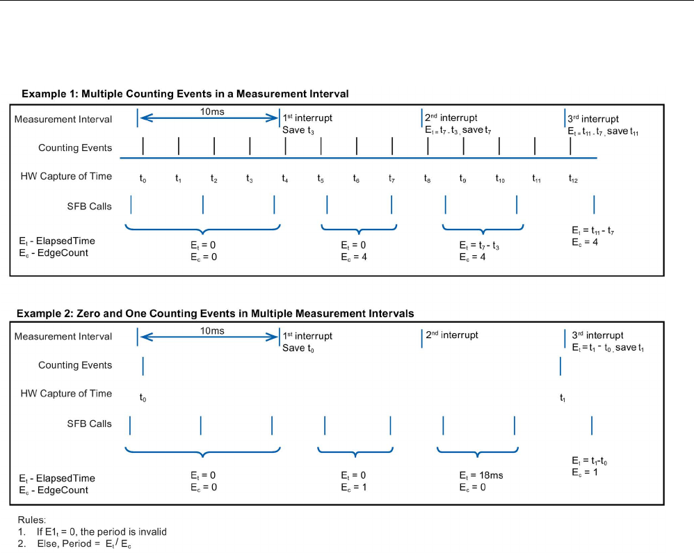
Technology instructions
10.1 Counting (High-speed counters)
S7-1200 Programmable controller
564 System Manual, V4.2, 09/2016, A5E02486680-AK
The following examples show how the instruction makes period measurements:

Technology instructions
10.1 Counting (High-speed counters)
S7-1200 Programmable controller
System Manual, V4.2, 09/2016, A5E02486680-AK 565
SDT: HSC_Frequency
The "HSC_Frequency" data type corresponds to an HSC configured for "Frequency" mode.
The instruction CTRL_HSC_EXT provides program access to the frequency of input pulses,
measured over a specified time period.
Using the CTRL_HSC_EXT instruction in Frequency mode provides the following
capabilities:
Table 10- 6 HSC_Frequency structure
Structure element
Declaration
Data type
Description
Frequency OUT DInt Returns a frequency in Hz, measured over the measurement
interval time. When the HSC counts down, the instruction
returns a negative frequency.
EnHSC IN Bool Enables the HSC for Frequency measurement when true;
disables Frequency measurement when false.
EnPeriod
IN
Bool
Enables NewPeriod value to take effect.
NewPeriod IN Int Specifies the measurement interval time in milliseconds. The
only allowed values are 10, 100, or 1000 ms.
The CTRL_HSC_EXT instruction measures the Frequency using the same measurement
technique as Period mode to find the ElapsedTime and EdgeCount. The instruction
calculates the frequency as a signed integer value in Hz using the formula: Frequency =
EdgeCount/ElapsedTime
If you require a floating-point value for frequency, you can use the above formula for
frequency when the HSC is in Period mode. Note that in Period mode, ElapsedTime is
returned in nanoseconds and can require scaling of the value.
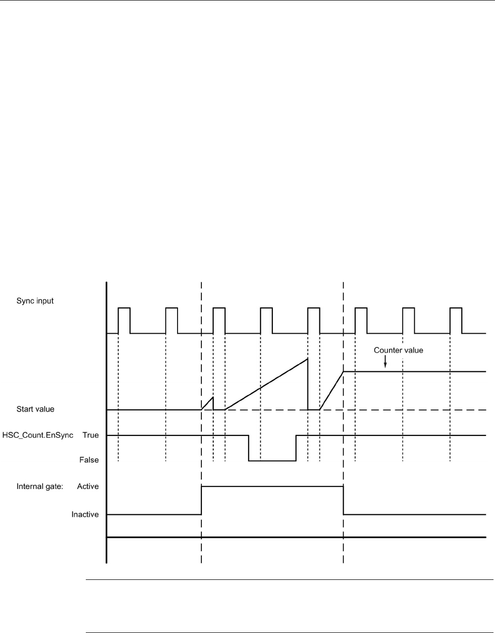
Technology instructions
10.1 Counting (High-speed counters)
S7-1200 Programmable controller
566 System Manual, V4.2, 09/2016, A5E02486680-AK
10.1.2
Operating the high-speed counter
10.1.2.1
Synchronization function
You use the Sync (synchronization) function to set the counter to the start value with an
external input signal. You can modify the start value by executing the CTRL_HSC_EXT
instruction. This allows the user to synchronize the current count value to a desired value on
occurrence of an external input signal.
Synchronization always takes place at the occurrence of the input signal and is effective
regardless of the status of the internal gate. You must set the "HSC_Count.EnSync" bit to
true in order to enable the Sync function.
The CTRL_HSC_EXT instruction sets the HSC_Count.SyncActive status bit to true after
completion of synchronization. The CTRL_HSC_EXT instruction sets the
HSC_Count.SyncActive status bit to false if synchronization has not occurred since the last
instruction execution.
The figure below shows an example of synchronization when the input signal is configured
for an active high level:
Note
The configured input filters delay the control signal of the digital input.
This input function is only available to be use
d when the HSC is configured for Count mode.

Technology instructions
10.1 Counting (High-speed counters)
S7-1200 Programmable controller
System Manual, V4.2, 09/2016, A5E02486680-AK 567
Refer to Input functions (Page 578) for information on how to configure the Synchronization
function.
10.1.2.2
Gate function
Many applications require counting processes to be started or stopped in accordance with
other events. In such cases, counting is started and stopped using the internal gate function.
Each HSC channel has two gates: a software gate and a hardware gate. The state of these
gates determines the state of the internal gate. See the table below.
The internal gate is open if the software gate is open and the hardware gate is open or has
not been configured. If the internal gate is open, counting is started. If the internal gate is
closed, all other count pulses are ignored and counting is stopped.
Table 10- 7 Gate function states
Hardware gate
Software gate
Internal gate
Open/not configured
Open
Open
Open/not configured
Closed
Closed
Closed
Open
Closed
Closed Closed Closed
The term "open" is defined to be the active state of the gate. Similarly, the term "closed" is defined to
be the inactive state of the gate.
You control the software gate with the "HSC_Count.EnHSC" enable bit in the SDT attached
to the CTRL_HSC_EXT instruction. To open the software gate, set the "HSC_Count.EnHSC"
bit true; to close the software gate, set the "HSC_Count.EnHSC" bit false. Execute the
CTRL_HSC_EXT instruction to update the software gate’s state.
The hardware gate is optional, and you can enable or disable it in the HSC properties
section. To control a counting process with only the hardware gate, the software gate must
remain open. If you do not configure a hardware gate, the hardware gate is considered to be
always open and the internal gate state is the same as the software gate state.
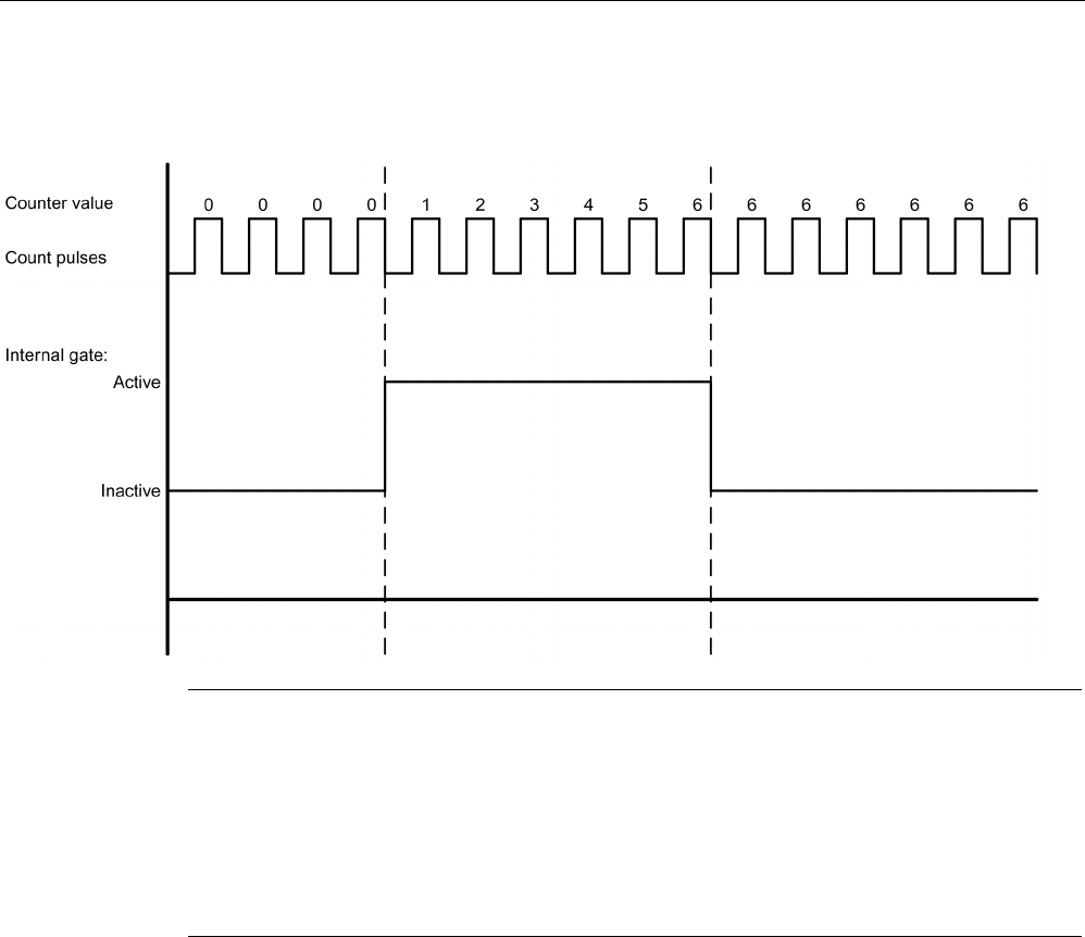
Technology instructions
10.1 Counting (High-speed counters)
S7-1200 Programmable controller
568 System Manual, V4.2, 09/2016, A5E02486680-AK
The figure below shows an example of the hardware gate opening and closing with a digital
input. The digital input is configured for an active high level:
Note
The configured input filters delay the control signal of the digital input.
The hardware gate function is only available to be used when the HSC is configured for
Count mode. In Period and Frequency modes, the
internal gate state is the same as the
software gate state.
In Period mode, the software gate is controlled by "HSC_Period.EnHSC".
In Frequency mode, the software gate is controlled by "HSC_Frequency.EnHSC".
Refer to Input functions (Page 578) for information on how to configure the Gate function.
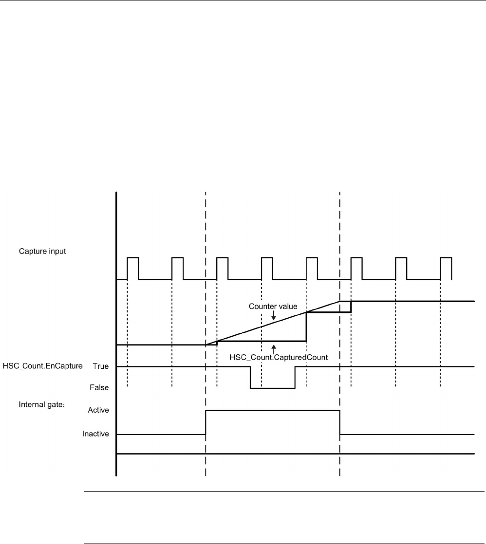
Technology instructions
10.1 Counting (High-speed counters)
S7-1200 Programmable controller
System Manual, V4.2, 09/2016, A5E02486680-AK 569
10.1.2.3
Capture function
You use the Capture function to save the current counter value with an external reference
signal. When configured and enabled by the "HSC_Count.EnCapture" bit, the Capture
function causes the current count to be captured on the occurrence of an external input
edge. The Capture function is effective regardless of the status of the internal gate. The
program saves the unchanged counter value when the gate is closed. After executing the
CTRL_HSC_EXT instruction, the program stores the captured value in
"HSC_Count.CapturedCount".
The figure below shows an example of the Capture function configured to capture on a rising
edge. The Capture input does not trigger a capture of the current count when the
"HSC_Count.EnCapture" bit is set false through the CTRL_HSC_EXT instruction.
Note
The configured input filters delay the
control signal of the digital input.
This input function can only be used when the HSC is configured for Count mode.
Refer to Input functions (Page 578) for information on how to configure the Capture function.

Technology instructions
10.1 Counting (High-speed counters)
S7-1200 Programmable controller
570 System Manual, V4.2, 09/2016, A5E02486680-AK
10.1.2.4
Compare function
When enabled, the Compare output function generates a single, configurable pulse that
occurs every time the configured event occurs. The events include count equal to one of the
reference values or the counter overflows. If a pulse is in progress and the event occurs
again, a pulse is not produced for that event.
Note
This output function can only be used when the HSC is configured for Count mode.
Refer to Output function (Page 579) for information on how to configure the Compare
function.

Technology instructions
10.1 Counting (High-speed counters)
S7-1200 Programmable controller
System Manual, V4.2, 09/2016, A5E02486680-AK 571
10.1.2.5
Applications
A typical application uses the HSC to monitor feedback from an incremental shaft encoder.
The shaft encoder provides a specified number of counts per revolution that you can use as
the clock generator input to the HSC. There is also a reset pulse that occurs once per
revolution that you can use as the sync input to the HSC.
To start, the program loads the first reference value into the HSC and sets the outputs to
their initial states. The outputs remain in this state for the time period that the current count is
less than the reference value. The HSC provides an interrupt when the current count is equal
to the reference value, when the sync event (reset) occurs, and also when there is a
direction change.
As each counter value equals the reference value, an interrupt event occurs, and the
program loads a new reference value into the HSC and sets the outputs to their next state.
When the sync interrupt event occurs, the program sets the first reference value and the first
output states and repeats the cycle.
Since the interrupts occur at a much slower rate than the counting rate of the HSC, you can
implement precise control of high-speed operations with relatively minor impact to the scan
cycle of the CPU. The method of interrupt attachment allows each load of a new preset to be
performed in a separate interrupt routine for easy state control. Alternatively, you can
process all interrupt events in a single interrupt routine.
The Gate function, triggered either by the user program or an external input signal, can
disable counting of the encoder pulses. You can ignore any movement of the shaft by
deactivating the gate. This means that while the encoder continues to send pulses to the
HSC, the count value is held at the last value before the gate goes inactive. When the gate
goes active, counting resumes from the last value before the gate went inactive.
When enabled, the Capture function causes the current count to be captured on the
occurrence of an external input. A process (for example, a calibration routine) can use this
function to determine how many pulses occur between events.
When enabled, the Compare output function generates a single, configurable pulse that
occurs every time the current count reaches one of the reference values or overflows
(exceeds the counting limits). You can use this pulse as a signal to start another process
whenever a certain HSC event occurs.
The counting direction is controlled by either the user program or an external input signal.
To obtain the speed of the rotating shaft, you can configure the HSC for Frequency mode.
This function provides a signed integer value in units of Hz. Because the reset signal occurs
once per revolution, measuring the frequency of the reset signal provides a quick indication
of the shaft’s speed, in revolutions per second.
If you desire a floating point value of the frequency, configure the HSC for Period mode. You
can use the ElapsedTime and EdgeCount values returned in Period mode to calculate the
frequency.
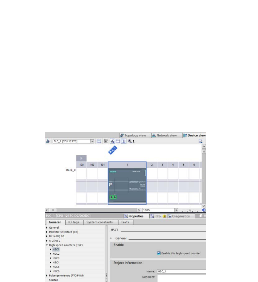
Technology instructions
10.1 Counting (High-speed counters)
S7-1200 Programmable controller
572 System Manual, V4.2, 09/2016, A5E02486680-AK
10.1.3
Configuring a high-speed counter
To setup the high-speed counter (HSC):
● Select Device Configuration from the Project navigator.
● Select the CPU you wish to configure.
● Click the Properties tab, located in the Inspector window (see figure below).
● Select the HSC you want to enable from the list shown under the General tab (see figure
below).
You may configure up to six high-speed counters (HSC1 through HSC6). Enable an HSC by
selecting the "Enable this high speed counter" option. If enabled, STEP 7 assigns a unique
default name to this HSC. You can change this name by editing it in the "Name:" edit field;
however, it must be a unique name. Names of enabled HSCs become tags with the Data
type "HW_Hsc" in the "System constant" tag table and are available for use as the "HSC"
parameter of the CTRL_HSC_EXT instructions. Refer to "Configuring the operation of the
CPU (Page 170)" for further information:
After enabling the HSC, STEP 7 sets single phase counting as the default configuration.
Once you set the digital input filter for the HSC clock generator input, the program can be
downloaded to the PLC, and the CPU is ready to count. To change the HSC’s configuration,
proceed to the next section, "Type of Counting".

Technology instructions
10.1 Counting (High-speed counters)
S7-1200 Programmable controller
System Manual, V4.2, 09/2016, A5E02486680-AK 573
The following table provides an overview of what inputs and outputs are available for each
configuration:
Table 10- 8 Counting modes for HSC
Type
Input 1
Input 2
Input 3
Input 4
Input 5
Output 1
Function
Single-phase
with internal
direction
control
Clock - - - - - Count, Fre-
quency, or
Period
Sync Gate Capture Compare Count
Single-phase
with external
direction
control
Clock Direction - - - - Count, Fre-
quency, or
Period
Sync
Gate
Capture
Compare
Count
Two-phase Clock up Clock down - - - - Count, Fre-
quency, or
Period
Sync
Gate
Capture
Compare
Count
A/B counter Phase A Phase B - - - - Count, Fre-
quency, or
Period
Sync
1
Gate
Capture
Compare
Count
A/B counter
fourfold
Phase A Phase B - - - - Count, Fre-
quency, or
Period
Sync
1
Gate
Capture
Compare
Count
1 For an encoder: Phase Z, Home
10.1.3.1
Type of Counting
There are four types of counting or modes. When you change the mode, the available
configuration options for that HSC also change:
● Count: Counts the number of pulses and increments or decrements the count value,
depending on the state of the direction control. External I/O can reset the count, disable
counting, initiate a capture of the current count, and produce a single pulse on a specified
event. The output values are the current count value and the count value at the moment a
capture event occurs.
● Period: Counts the number of input pulses over a specified time period. Returns the pulse
count and time duration in nanoseconds (ns). Values are captured and calculated at the
end of the time period specified by Frequency measuring period.
● Frequency: Measures the input pulses and time duration and calculates the frequency of
the pulses. The program returns the frequency as a signed double integer in units of Hz.
The value is negative if the counting direction is down. Values are captured and
calculated at the end of the time period specified by the Frequency measuring period.
● Motion control: Used by the motion control technology object and not available to the
HSC instructions. Refer to "Motion control (Page 653)" for further information.
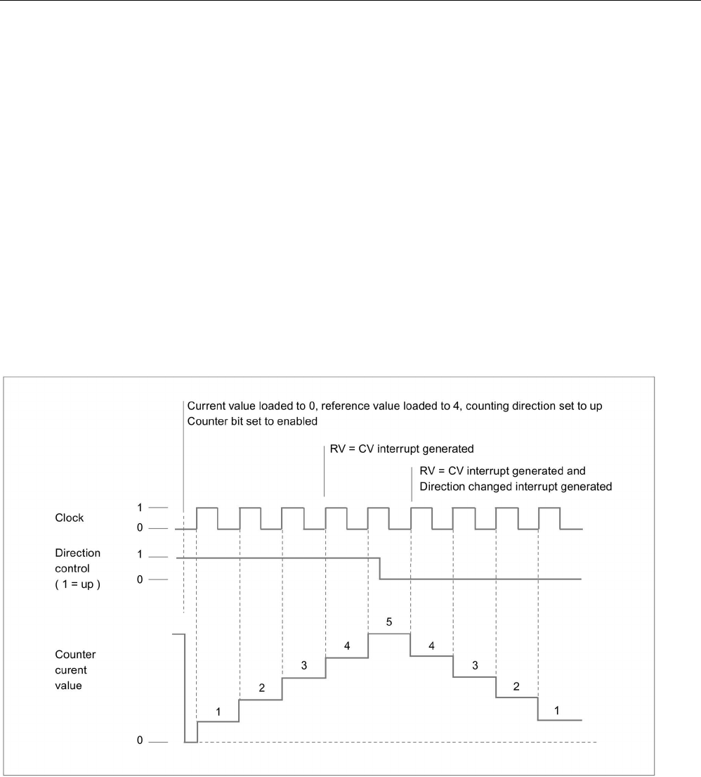
Technology instructions
10.1 Counting (High-speed counters)
S7-1200 Programmable controller
574 System Manual, V4.2, 09/2016, A5E02486680-AK
10.1.3.2
Operating phase
Select the desired operating phase of the HSC. The four figures below show when the
counter value changes, when the current value (CV) equals the reference value (RV) event
occurs, and when the direction change event occurs.
Single phase
Single-phase (not available with motion control) counts pulses:
● User program (internal direction control):
– 1 is up
– -1 is down
● Hardware input (external direction control):
– High level is up.
– Low level is down.
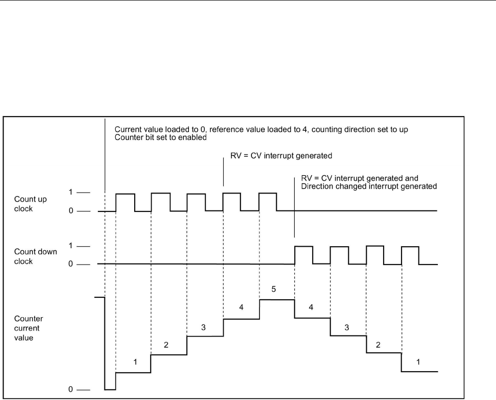
Technology instructions
10.1 Counting (High-speed counters)
S7-1200 Programmable controller
System Manual, V4.2, 09/2016, A5E02486680-AK 575
Two phase
Two phase counts:
● Up on the clock up input
● Down on the clock down input
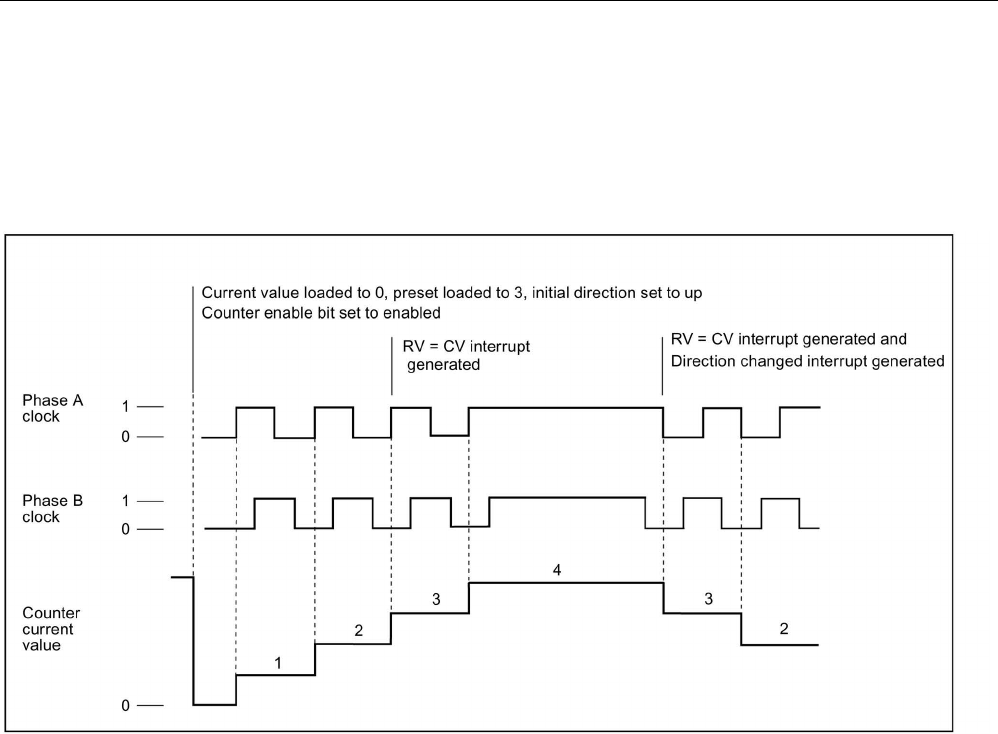
Technology instructions
10.1 Counting (High-speed counters)
S7-1200 Programmable controller
576 System Manual, V4.2, 09/2016, A5E02486680-AK
A/B counter
A/B phase quadrature counts:
● Up on the rising edge of the clock A input when the clock B input is low
● Down on the falling edge of the clock A input when the clock B input is low
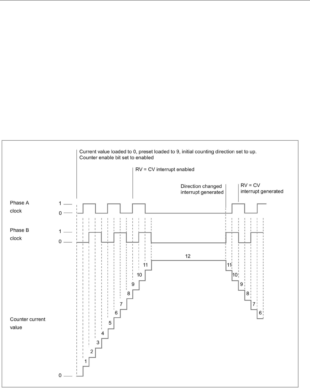
Technology instructions
10.1 Counting (High-speed counters)
S7-1200 Programmable controller
System Manual, V4.2, 09/2016, A5E02486680-AK 577
A/B counter fourfold
A/B phase quadrature fourfold counts:
● Up on the rising edge of the clock A input when the clock B input is low
● Up on the falling edge of the clock A input when the clock B input is high
● Up on the rising edge of the clock B input when the clock A input is high
● Up on the falling edge of the clock B input when the clock A input is low
● Down on the rising edge of the clock B input when the clock A input is low
● Down on the falling edge of the clock B input when the clock A input is high
● Down on the rising edge of the clock A input when the clock B input is high
● Down on the falling edge of the clock A input when the clock B input is low

Technology instructions
10.1 Counting (High-speed counters)
S7-1200 Programmable controller
578 System Manual, V4.2, 09/2016, A5E02486680-AK
10.1.3.3
Initial values
Each time the CPU goes to RUN, it loads initial values. The initial values are only used in
count mode:
● Initial counter value: The program sets the current count value to the initial counter value
when the CPU goes from STOP to RUN mode or when the program triggers the sync
input.
● Initial reference value: When the current count reaches the reference value, if the
respective functions are set up, the program generates an interrupt and/or an output
pulse.
● Initial reference value 2: When the current count reaches the reference value 2, if the
function is set up, the program generates an output pulse.
● Initial upper limit value: Maximum counting value. The default is the largest possible value
of +2,147,483,647 pulses.
● Initial lower limit value: Minimum counting value. The default is the smallest possible
value of -2,147,483,648 pulses.
The values above and the behavior of the counter when it reaches a limit are only available
in Count mode. You can adjust the values and the behavior with the CTRL_HSC_EXT
instruction using the HSC_Count SDT.
10.1.3.4
Input functions
The Clock and direction inputs determine count events and direction, based upon the
operating phase. You can only use the Sync, Capture, and Gate inputs in Count mode and
can individually enable and configure the inputs for different types of triggers.
Synchronization input
The Sync (synchronization) input sets the current count value to the starting (or initial
counter) value. You typically use the Sync input to reset the counter to "0". You can trigger
the Sync when the input pin is in one of the following states:
● High
● Low
● Goes from low to high
● Goes from high to low
● Goes from high to low or from low to high

Technology instructions
10.1 Counting (High-speed counters)
S7-1200 Programmable controller
System Manual, V4.2, 09/2016, A5E02486680-AK 579
Capture input
The Capture input sets the captured count value to the count value saved at the moment you
triggered the Capture input. You can trigger the capture when the input pin is in one of the
following states:
● Goes from low to high
● Goes from high to low
● Goes from high to low or from low to high
Gate input
The Gate input stops HSC counting. You can trigger the Gate when the input pin is in one of
the following states:
● High
● Low
10.1.3.5
Output function
The compare output function is the only output for the HSC and is only available in Count
mode.
Compare output
You can configure the Compare output to generate a single pulse on the occurrence of one
of the following events:
● Counter equals reference value (count direction is up)
● Counter equals reference value (count direction is down)
● Counter equals reference value (count direction is up or down)
● Counter equals reference value 2 (count direction is up)
● Counter equals reference value 2 (count direction is down)
● Counter equals reference value 2 (count direction is up or down)
● Positive overflow
● Negative overflow
You can configure the output pulse with a cycle time ranging from 1 to 500 ms; the default
cycle time is 10 ms. You can set the pulse width, or duty cycle, anywhere from 1 to 100%;
the default pulse width is 50%.
If multiple compare output events occur within the specified cycle time, the output pulses
from those events are lost due to the fact that the current pulse has not completed its cycle
yet. Once the pulse has finished (the configured cycle time has passed), the pulse generator
is available to produce a new pulse.

Technology instructions
10.1 Counting (High-speed counters)
S7-1200 Programmable controller
580 System Manual, V4.2, 09/2016, A5E02486680-AK
10.1.3.6
Interrupt events
Under the Event configuration section, you can select a hardware interrupt OB from the
dropdown menu (or you can create a new OB) and attach it to an HSC event. The priority of
the interrupt is in a range from 2 to 26, where 2 is the lowest priority and 26 is the highest
priority. Depending on the HSC’s configuration, the following events are available:
● Counter value equals reference value event: A counter value equals reference value
event occurs when the HSC’s count value reaches the reference value. You can set the
reference value during configuration under the Initial reference value section, or by
updating "NewReference1" using the CTRL_HSC_EXT instruction. Refer to the
"Operating phase (Page 574)" section for further information.
● Synchronization event: A Sync (synchronization) occurs whenever you enable and trigger
the Sync input.
● Change of direction event: A change of direction event occurs when the counting
direction changes. Refer to the "Operating phase (Page 574)" section for further
information.
10.1.3.7
Hardware input pin assignment
For each HSC input that you enable, select the desired input point, located either on the
CPU or optional signal board (communication and signal modules do not support HSC
inputs). When you select a point, STEP 7 displays the maximum frequency value next to the
selection. The digital input filter settings may need to be adjusted so that all valid signal
frequencies can pass through the filter. To set up the HSC input filters, refer to "Configuring
digital input filter times (Page 172)".
Note
CPU and SB input channels (V4 or later firmware) have configurable input filter times
Earlier firmware versions had fixed HSC input channels and fixed filter times that you could
not change.
With V4 or later versions, you can assign input channels and filter times. The default input
filter setting is 6
.4 ms, which limits the maximum counting rate to 78 Hz. You can change the
filter settings to count higher or lower frequencies depending on the design of your system.
WARNING
Risks with changes to filter time setting for digital input channels
If the filter time for a digital input channel is changed from a previous setting, a new "0"
level input value might need to be presented for up to a 20.0 ms accumulated duration
before the filter becomes fully responsive to new inputs. During this time, short "0" pulse
events of duration less than 20.0 ms may not be detected or counted.
The changing of filter times can result in unexpected machine or process operation, which
can cause death or serious injury to personnel, and/or damage to equipment.
To ensure that a new filter time goes immediately into effect, power cycle the CPU.

Technology instructions
10.1 Counting (High-speed counters)
S7-1200 Programmable controller
System Manual, V4.2, 09/2016, A5E02486680-AK 581
Use the following table and ensure that the CPU and SB input channels that you connect
can support the maximum pulse rates in your process signals:
Table 10- 9 CPU input: maximum frequency
CPU
CPU Input channel
Operating phase: Single
phase or Two phase
Operating phase: A/B
counter or A/B Counter
fourfold
1211C
Ia.0 to Ia.5
100 kHz
80 kHz
1212C Ia.0 to Ia.5 100 kHz 80 kHz
Ia.6, Ia.7
30 kHz
20 kHz
1214C and 1215C
Ia.0 to Ia.5
100kHz
80kHz
Ia.6 to Ib.5
30 kHz
20 kHz
1217C
Ia.0 to Ia.5
100 kHz
80 kHz
Ia.6 to Ib.1
30 kHz
20 kHz
Ib.2 to Ib.5
(.2+, .2- to .5+, .5-)
1 MHz 1 MHz
Table 10- 10 SB signal board input: maximum frequency (optional board)
SB signal board
SB input channel
Operating phase: Single
phase or Two phase
Operating phase: A/B
counter or A/B Counter
fourfold
SB 1221, 200 kHz
Ie.0 to Ie.3
200kHz
160 kHz
SB 1223, 200 kHz
Ie.0, Ie.1
200kHz
160 kHz
SB 1223
Ie.0, Ie.1
30 kHz
20 kHz
When assigning an input point to an HSC function, you can assign the same input point to
multiple HSC functions. For example, assigning I0.3 to the Sync input of HSC1 and the Sync
input of HSC2 to synchronize the count of both HSCs at the same time is a valid
configuration; however, it generates a compiler warning.

Technology instructions
10.1 Counting (High-speed counters)
S7-1200 Programmable controller
582 System Manual, V4.2, 09/2016, A5E02486680-AK
When possible, avoid assigning multiple input functions of the same HSC to the same input
point. For example, assigning I0.3 to the Sync input and the Gate input of HSC 1 to
synchronize the count and disable counting at the same time is also a valid configuration.
You can make this configuration, but it could produce unintended results. Refer to the
Warning below for further information.
WARNING
Risks with assigning multiple functions to a single digital input channel
Assigning multiple input functions of the same HSC to a common input point may produce
unpredictable results. When a trigger occurs on a point with multiple functions assigned to
that trigger, the order in which the functions are executed by the PLC cannot be known.
This is known as a race condition and is often an undesirable situation.
This race condition can result in unexpected machine or process operation, which can
cause death or serious injury to personnel, and/or damage to equipment.
To avoid a race condition, do not assign more than two input functions, of the same HSC,
to the same input pin. If an HSC has two input functions assigned to the same pin, set the
triggers such that they could never occur at the same time. Remember that a falling edge
occurs at the same instance that a low level begins and that a rising edge occurs at the
same instance that a high level begins.
Note
You assign the digita
l input and output points used by high-speed counter (HSC) devices
during CPU device configuration. When you assign input and output points to HSC devices,
you cannot modify the values of these points using the force function in a watch table. The
HSC has
full control of these input and output points.
10.1.3.8
Hardware output pin assignment
If you enable the Compare output, select an available output point. Once you configure an
output point for use by an HSC (or other technology objects such as a pulse generator), that
output point is owned exclusively by that object. No other component can use the output
point, and the output point cannot be forced to a value. If you configure a single output
channel for multiple HSCs or for use in an HSC and a pulse output, the program generates a
compile error.

Technology instructions
10.1 Counting (High-speed counters)
S7-1200 Programmable controller
System Manual, V4.2, 09/2016, A5E02486680-AK 583
10.1.3.9
HSC input memory addresses
Each HSC uses a double word section of I-memory that stores the current count. If you
configure the HSC for frequency, then the frequency is stored in that input memory location.
The available input address range is I0.0 to I1023.7 (maximum start address is I1020.0). The
HSC cannot use an input address that overlaps with an input address mapped to another
component. For further information on the process image, refer to "Execution of the user
program (Page 83)".
The following table shows the default addresses assigned for each HSC:
Table 10- 11 HSC default addresses
High-speed counter (HSC)
Current value data type
Default current value address
HSC1
DInt
ID 1000
HSC2
DInt
ID 1004
HSC3
DInt
ID 1008
HSC4 DInt ID 1012
HSC5
DInt
ID 1016
HSC6
DInt
ID 1020
10.1.3.10
Hardware identifier
Each HSC has a unique hardware identifier, which is used by the HSC_CTRL and
HSC_CTRL_EXT instructions. You can find the PLC tag for the hardware identifier under
"System Constants". An HSC with the name "HSC_1" has the tag "Local~HSC_1" and data
type "Hw_Hsc". This tag is also shown in the dropdown menu when selecting the HSC input
of the CTRL_HSC_EXT instructions.
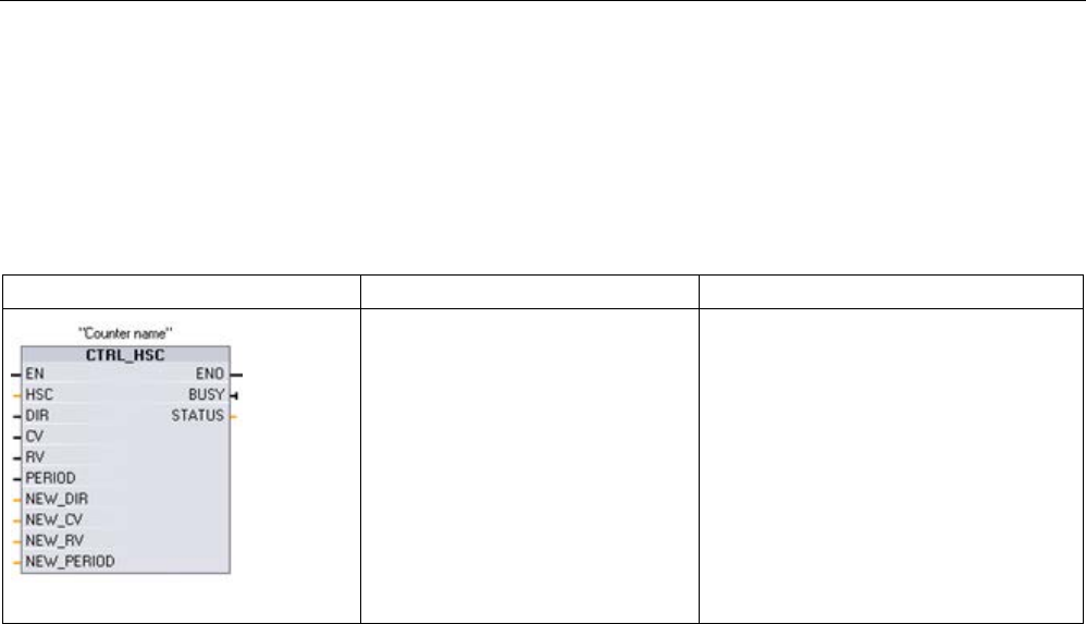
Technology instructions
10.1 Counting (High-speed counters)
S7-1200 Programmable controller
584 System Manual, V4.2, 09/2016, A5E02486680-AK
10.1.4
Legacy CTRL_HSC (Control high-speed counter) instruction
10.1.4.1
Instruction overview
Table 10- 12 CTRL_HSC instruction (For general purpose counting)
LAD / FBD
SCL
Description
"CTRL_HSC_1_DB" (
hsc:=W#16#0,
dir:=False,
cv:=False,
rv:=False,
period:=False,
new_dir:=0,
new_cv:=L#0,
new_rv:=L#0,
new_period:=0,
busy=>_bool_out_,
status=>_word_out_);
Each CTRL_HSC (Control high-speed
counter) instruction uses a structure
stored in a DB to maintain counter data.
You assign the DB when the CTRL_HSC
instruction is placed in the editor.
1
When you insert the instruction, STEP 7 displays the "Call Options" dialog for creating the associated DB.
2 In the SCL example, "CTRL_HSC_1_DB" is the name of the instance DB.

Technology instructions
10.1 Counting (High-speed counters)
S7-1200 Programmable controller
System Manual, V4.2, 09/2016, A5E02486680-AK 585
Table 10- 13 Data types for the parameters
Parameter
Declaration
Data type
Description
HSC
IN
HW_HSC
HSC identifier
DIR1, 2 IN Bool 1 = Request new direction
CV
1
IN
Bool
1 = Request to set new counter value
RV1 IN Bool 1= Request to set new reference value
PERIOD1 IN Bool 1 = Request to set new period value
(only for frequency measurement mode)
NEW_DIR
IN
Int
New direction: 1= forward, -1= backward
NEW_CV
IN
DInt
New counter value
NEW_RV
IN
DInt
New reference value
NEW_PERIOD IN Int New period value is in milliseconds (only for frequency meas-
urement mode). The only allowed values are 10, 100, or 1000
milliseconds:
1000 = 1 second
100 = 0.1 second
10 = 0.01 second
BUSY
3
OUT
Bool
Function is busy
STATUS
OUT
Word
Execution condition code
1
If an update of a parameter value is not requested, then the corresponding input values are ignored.
2
The DIR parameter is only valid if the configured counting direction is set to "User program (internal direction control)".
You determine how to use this parameter in the HSC device configuration.
3 For an HSC on the CPU or on the SB, the BUSY parameter always has a value of 0.
You configure the parameters for each HSC in the device configuration for the CPU for
counting/frequency function, reset options, interrupt event configuration, hardware I/O, and
count value address.
Some of the parameters for the HSC can be modified by your user program to provide
program control of the counting process:
● Set the counting direction to a NEW_DIR value
● Set the current count value to a NEW_CV value
● Set the reference value to a NEW_RV value
● Set the period value (for frequency measurement mode) to a NEW_PERIOD value
If the following Boolean flag values are set to 1 when the CTRL_HSC instruction is executed,
the corresponding NEW_xxx value is loaded to the counter. Multiple requests (more than
one flag is set at the same time) are processed in a single execution of the CTRL_HSC
instruction.
● DIR = 1 is a request to load a NEW_DIR value, 0 = no change
● CV = 1 is a request to load a NEW_CV value, 0 = no change
● RV = 1 is a request to load a NEW_RV value, 0 = no change
● PERIOD = 1 is a request to load a NEW_PERIOD value, 0 = no change
If an error occurs, ENO is set to "0" and the STATUS output indicates a condition code:

Technology instructions
10.1 Counting (High-speed counters)
S7-1200 Programmable controller
586 System Manual, V4.2, 09/2016, A5E02486680-AK
Table 10- 14 Execution condition codes
STATUS (W#16#)
Description
0
No error
80A1 HSC identifier does not address a HSC
80B1
Illegal value in NEW_DIR
80B2 Illegal value in NEW_CV
80B3
Illegal value in NEW_RV
80B4
Illegal value in NEW_PERIOD
80C0
Multiple access to the high-speed counter
80D0
High-speed counter (HSC) not enabled in CPU hardware configuration
10.1.4.2
Using CTRL_HSC
The CTRL_HSC instruction is typically placed in a hardware interrupt OB that is executed
when the counter hardware interrupt event is triggered. For example, if a CV=RV event
triggers the counter interrupt, then a hardware interrupt OB code block executes the
CTRL_HSC instruction and can change the reference value by loading a NEW_RV value.
The current count value is not available in the CTRL_HSC parameters. The process image
address that stores the current count value is assigned during the hardware configuration of
the high-speed counter. You may use program logic to directly read the count value. The
value returned to your program will be a correct count for the instant in which the counter
was read. The counter will continue to count high-speed events. Therefore, the actual count
value could change before your program completes a process using an old count value.

Technology instructions
10.1 Counting (High-speed counters)
S7-1200 Programmable controller
System Manual, V4.2, 09/2016, A5E02486680-AK 587
10.1.4.3
HSC current count value
The CPU stores the current value of each HSC in an input (I) address. The following table
shows the default addresses assigned to the current value for each HSC. You can change
the I address for the current value by modifying the properties of the CPU in the Device
Configuration.
High-speed counters use a DInt value to store the current count value. A DInt count value
has a range of -2147483648 to +2147483647. As of CPU firmware V4.2, you can configure
the range limits. Refer to "Initial values (Page 578)" for further information.
The counter rolls over from the maximum positive value to the maximum negative value
when counting up, and from the maximum negative value to the maximum positive value
when counting down. Frequency is returned in units of Hertz (for example, 123.4 Hz is
returned as 123).
Table 10- 15 HSC default addresses
HSC
Current value data type
Default current value address
HSC1
DInt
ID1000
HSC2
DInt
ID1004
HSC3
DInt
ID1008
HSC4 DInt ID1012
HSC5
DInt
ID1016
HSC6
DInt
ID1020

Technology instructions
10.2 PID control
S7-1200 Programmable controller
588 System Manual, V4.2, 09/2016, A5E02486680-AK
10.2
PID control
STEP 7 provides the following PID instructions for the S7-1200 CPU:
● The PID_Compact instruction is used to control technical processes with continuous
input- and output variables.
● The PID_3Step instruction is used to control motor-actuated devices, such as valves that
require discrete signals for open- and close actuation.
● The PID_Temp instruction provides a universal PID controller that allows handling of the
specific requirements of temperature control.
Note
C
hanges that you make to the PID configuration and download in RUN do not take effect
until the CPU transitions from STOP to RUN mode. Changes that you make in the "PID
parameters" dialog using the "Start value control" take effect immediately.
All three PID instructions (PID_Compact, PID_3Step, and PID_Temp) can calculate the P-, I-
, and D-components during startup (if configured for "pre-tuning"). You can also configure
the instruction for "fine tuning" to allow you to optimize the parameters. You do not need to
manually determine the parameters.
Note
Execute the PID instruction at constant intervals of the sampling time (preferably in a cyclic
OB).
Because the PID loop needs a certain time to respond to changes of the control value, do
not calculate
the output value in every cycle. Do not execute the PID instruction in the main
program cycle OB (such as OB
1).
The sampling time of the PID algorithm represents the time between two calculations of the
output value (control value). The output value is calculated during self-tuning and rounded to
a multiple of the cycle time. All other functions of PID instruction are executed at every call.

Technology instructions
10.2 PID control
S7-1200 Programmable controller
System Manual, V4.2, 09/2016, A5E02486680-AK 589
PID algorithm
The PID (Proportional/Integral/Derivative) controller measures the time interval between two
calls and then evaluates the results for monitoring the sampling time. A mean value of the
sampling time is generated at each mode changeover and during initial startup. This value is
used as reference for the monitoring function and is used for calculation. Monitoring includes
the current measuring time between two calls and the mean value of the defined controller
sampling time.
The output value for the PID controller consists of three components:
● P (proportional): When calculated with the "P" component, the output value is proportional
to the difference between the setpoint and the process value (input value).
● I (integral): When calculated with the "I" component, the output value increases in
proportion to the duration of the difference between the setpoint and the process value
(input value) to finally correct the difference.
● D (derivative): When calculated with the "D" component, the output value increases as a
function of the increasing rate of change of the difference between the setpoint and the
process value (input value). The output value is corrected to the setpoint as quickly as
possible.
The PID controller uses the following formula to calculate the output value for the
PID_Compact instruction.
y
Output value
x
Process value
w
Setpoint value
s
Laplace operator
Kp Proportional gain
(P component)
a Derivative delay coefficient
(D component)
T1 Integral action time
(I component)
b Proportional action weighting
(P component)
TD Derivative action time
(D component)
c Derivative action weighting
(D component)
The PID controller uses the following formula to calculate the output value for the PID_3Step
instruction.
y
Output value
x
Process value
w
Setpoint value
s
Laplace operator
Kp Proportional gain
(P component)
a Derivative delay coefficient
(D component)
T1 Integral action time
(I component)
b Proportional action weighting
(P component)
TD Derivative action time
(D component)
c Derivative action weighting
(D component)
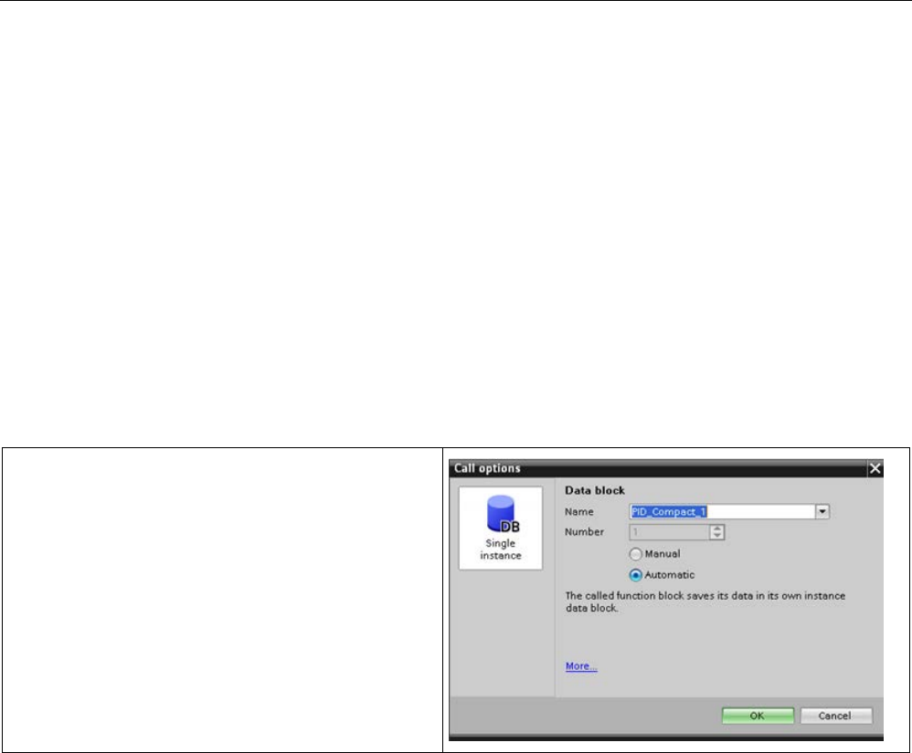
Technology instructions
10.2 PID control
S7-1200 Programmable controller
590 System Manual, V4.2, 09/2016, A5E02486680-AK
10.2.1
Inserting the PID instruction and technology object
STEP 7 provides two instructions for PID control:
● The PID_Compact instruction and its associated technology object provide a universal
PID controller with tuning. The technology object contains all of the settings for the control
loop.
● The PID_3Step instruction and its associated technology object provide a PID controller
with specific settings for motor-activated valves. The technology object contains all of the
settings for the control loop. The PID_3Step controller provides two additional Boolean
outputs.
After creating the technology object, you must configure the parameters (Page 622). You
also adjust the autotuning parameters ("pre-tuning" during startup or manual "fine tuning") to
commission the operation of the PID controller (Page 640).
Table 10- 16 Inserting the PID instruction and the technology object
When you insert a PID instruction into your user program,
STEP 7 automatically creates a technology object and an
instance DB for the instruction. The instance DB contains
all of the parameters that are used by the PID instruction.
Each PID instruction must have its own unique instance
DB to operate properly.
After inserting the PID instruction and creating the tech-
nology object and instance DB, you configure the parame-
ters for the technology object (Page 622).
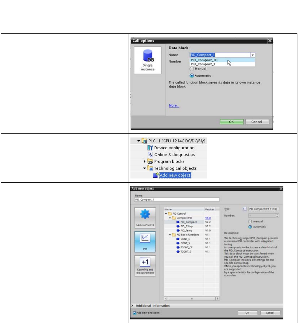
Technology instructions
10.2 PID control
S7-1200 Programmable controller
System Manual, V4.2, 09/2016, A5E02486680-AK 591
Table 10- 17 (Optional) Creating a technology object from the project navigator
You can also create technology objects for your
project
before
inserting the PID instruction. By
creating the technology object before inserting a
PID instruction into your user program, you can
then select the technology object when you insert
the PID instruction.
To create a technology object, double-click the
"Add new object" icon in the project navigator.
Click the "Control" icon and select the technology
object for the type of PID controller (PID_Compact
or PID_3Step). You can create an optional name
for the technology object.
Click "OK" to create the technology object.
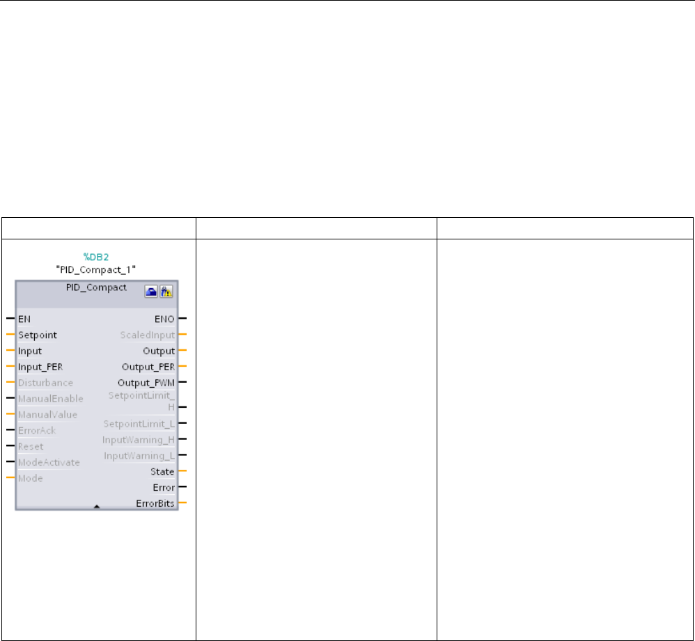
Technology instructions
10.2 PID control
S7-1200 Programmable controller
592 System Manual, V4.2, 09/2016, A5E02486680-AK
10.2.2
PID_Compact
10.2.2.1
PID_Compact instruction
The PID_Compact instruction provides a universal PID controller with integrated self-tuning
for automatic and manual mode.
Table 10- 18 PID_Compact instruction
LAD / FBD
SCL
Description
"PID_Compact_1"(
Setpoint:=_real_in_,
Input:=_real_in_,
Input_PER:=_word_in_,
Disturbance:=_real_in_,
ManualEnable:=_bool_in_,
ManualValue:=_real_in_,
ErrorAck:=_bool_in_,
Reset:=_bool_in_,
ModeActivate:=_bool_in_,
Mode:=_int_in_,
ScaledInput=>_real_out_,
Output=>_real_out_,
Output_PER=>_word_out_,
Output_PWM=>_bool_out_,
SetpointLimit_H=>_bool_out_,
SetpointLimit_L=>_bool_out_,
InputWarn-
ing_H=>_bool_out_,
InputWarn-
ing_L=>_bool_out_,
State=>_int_out_,
Error=>_bool_out_,
ErrorBits=>_dword_out_);
PID_Compact provides a PID controller with
self-tuning for automatic and manual mode.
PID_Compact is a PID T1 controller with
anti-windup and weighting of the P- and D-
component.
1
STEP 7 automatically creates the technology object and instance DB when you insert the instruction. The instance DB
contains the parameters of the technology object.
2 In the SCL example, "PID_Compact_1" is the name of the instance DB.

Technology instructions
10.2 PID control
S7-1200 Programmable controller
System Manual, V4.2, 09/2016, A5E02486680-AK 593
Table 10- 19 Data types for the parameters
Parameter and type
Data type
Description
Setpoint
IN
Real
Setpoint of the PID controller in automatic mode. (Default value: 0.0)
Input IN Real A tag of the user program is used as the source of the process value.
(Default value: 0.0)
If you are using the Input parameter, you must set Con-
fig.InputPerOn = FALSE.
Input_PER IN Word An Analog input is used as the source of the process value. (Default
value: W#16#0)
If you are using the Input_PER parameter, you must set Con-
fig.InputPerOn = TRUE.
Disturbance
IN
Real
Disturbance variable or pre-control value
ManualEnable IN Bool Enables or disables the manual operation mode. (Default value:
FALSE):
• A FALSE to TRUE edge activates "manual mode", while State = 4,
Mode remains unchanged.
As long as ManualEnable = TRUE, you cannot change the operat-
ing mode using a rising edge at ModeActivate or use the commis-
sioning dialog.
• A TRUE to FALSE edge activates the operating mode that is as-
signed by Mode.
Note: We recommend that you change the operating mode using
ModeActivate only.
ManualValue IN Real Output value for manual operation. (Default value: 0.0)
You can use values from Config.OutputLowerLimit to Con-
fig.OutputUpperLimit.
ErrorAck
IN
Bool
Resets the ErrorBits and warning outputs. FALSE to TRUE edge
Reset IN Bool Restarts the controller. (Default value: FALSE):
• FALSE to TRUE edge:
– Switches to "inactive" mode
– Resets the ErrorBits and warning outputs
– Clears Integral action
– Maintains PID parameters
• As long as Reset = TRUE, PID_Compact remains in "Inactive"
mode (State = 0).
• TRUE to FALSE edge:
– PID_Compact switches to the operating mode that is saved in
the Mode parameter.
ModeActivate IN Bool The PID_Compact switches to the operating mode that is saved in the
Mode parameter. FALSE to TRUE edge:
Mode IN Int The desired PID mode; Activated on the leading edge of the Mode
Activate input.
ScaledInput OUT Real Scaled process value. (Default value: 0.0)
Output
1
OUT
Real
Output value in REAL format. (Default value: 0.0)
Output_PER1 OUT Word Analog output value. (Default value: W#16#0)

Technology instructions
10.2 PID control
S7-1200 Programmable controller
594 System Manual, V4.2, 09/2016, A5E02486680-AK
Parameter and type
Data type
Description
Output_PWM1 OUT Bool Output value for pulse width modulation. (Default value: FALSE)
On and Off times form the output value.
SetpointLimit_H OUT Bool Setpoint high limit. (Default value: FALSE)
If SetpointLimit_H = TRUE, the absolute setpoint upper limit is reached
(Setpoint ≥ Config.SetpointUpperLimit).
The setpoint is limited to Config.SetpointUpperLimit.
SetpointLimit_L OUT Bool Setpoint low limit. (Default value: FALSE)
If SetpointLimit_L = TRUE, the absolute setpoint lower limit is reached
(Setpoint ≤ Config.SetpointLowerLimit).
The setpoint is limited to Config.SetpointLowerLimit.
InputWarning_H OUT Bool If InputWarning_H = TRUE, the process value has reached or exceed-
ed the warning high limit. (Default value: FALSE)
InputWarning_L OUT Bool If InputWarning_L = TRUE, the process value has reached or fallen
below the warning low limit. (Default value: FALSE)
State OUT Int Current operating mode of the PID controller. (Default value: 0)
You can change the operating mode using the Mode input parameter
and a rising edge at ModeActivate:
• State = 0: Inactive
• State = 1: Pre-tuning
• State = 2: Manual fine tuning
• State = 3: Automatic mode
• State = 4: Manual mode
• State = 5: Substitute output value with error monitoring
Error OUT Bool If Error = TRUE, at least one error message is pending in this cycle.
(Default value: FALSE)
Note: The Error parameter in V1.x PID was the ErrorBits field that con-
tained the error codes. It is now a Boolean flag indicating that an error
has occurred.
ErrorBits OUT DWord The PID_Compact instruction ErrorBits parameters table (Page 597)
defines the error messages that are pending. (Default value:
DW#16#0000 (no error)). ErrorBits is retentive and is reset upon a
rising edge at Reset or ErrorAck.
Note: In V1.x, the ErrorBits parameter was defined as the Error param-
eter and did not exist.
1 You can use the outputs of the Output, Output_PER, and Output_PWM parameters in parallel.
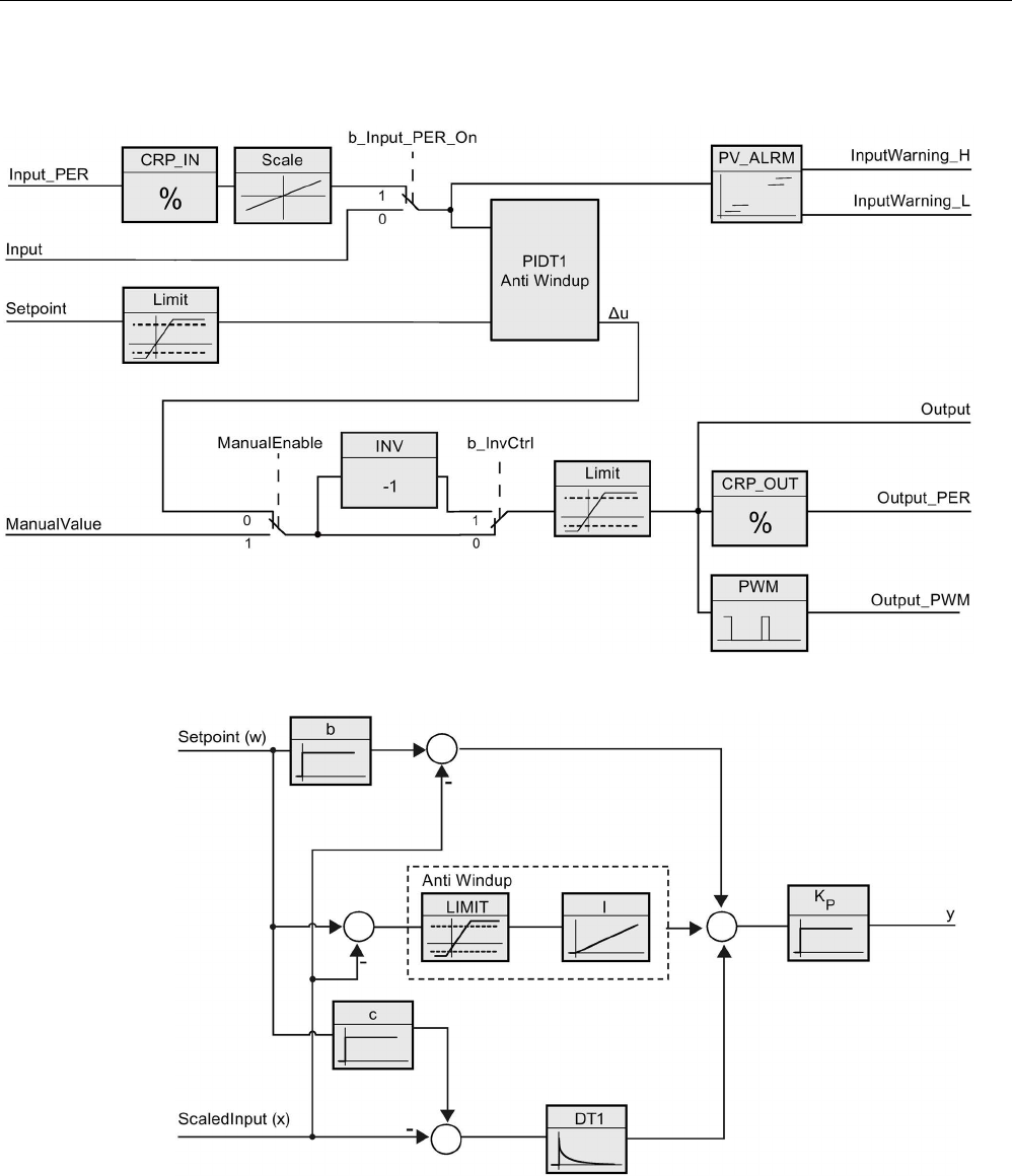
Technology instructions
10.2 PID control
S7-1200 Programmable controller
System Manual, V4.2, 09/2016, A5E02486680-AK 595
Operation of the PID_Compact controller
Figure 10-1 Operation of the PID_Compact controller
Figure 10-2 Operation of the PID_Compact controller as a PIDT1 controller with anti-windup
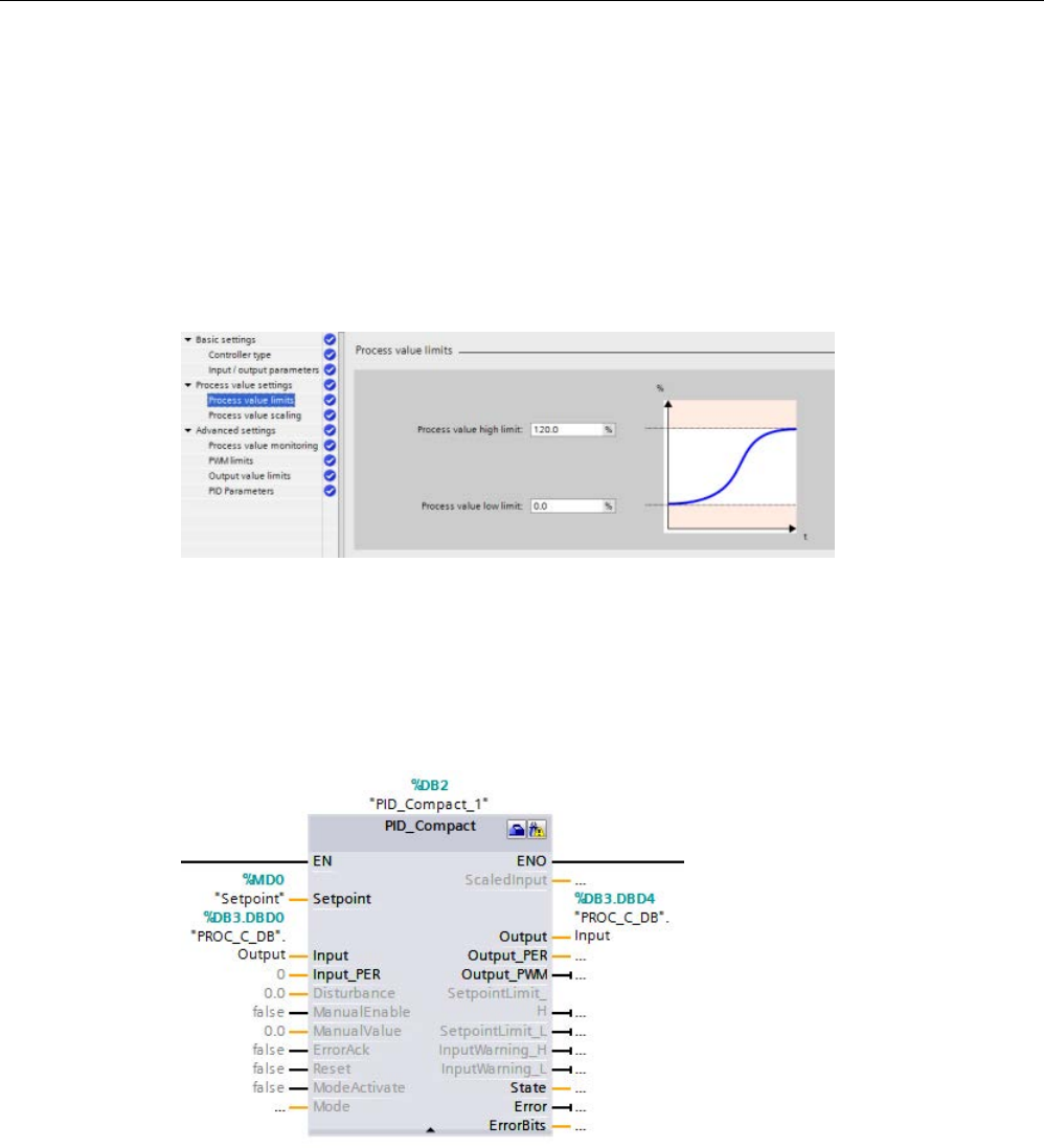
Technology instructions
10.2 PID control
S7-1200 Programmable controller
596 System Manual, V4.2, 09/2016, A5E02486680-AK
10.2.2.2
PID_Compact instruction Process value limits
"Process value limits" are normally used in conjunction with the analog input; however, you
can use them for other purposes.
The Process value limits configuration serves two functions:
● Sets the upper and lower limits for the Setpoint High/Low alarm outputs on the PID block
● Sets a limit so that the process variable cannot exceed or go below those limits
regardless of the setpoint. This configuration defines fixed limits for the process.
On the PID block, you can use four alarm outputs:
● SetpointLimit_H: Setpoint exceeds the High Limit.
● SetpointLimit_L: Setpoint exceeds the Low Limit.
● InputWarning_H: Process Variable exceeds the input high limit.
● InputWarning_L: Process Variable exceeds the input low limit.
When you set the Process value limits, the points that trigger the Setpoint high and low
alarm outputs to go true are set to the same value. For example, with the settings shown
above, if you enter a setpoint that is greater than 120%, the "SetpointLimit_H" output goes
true. This action is the same for the low limit. If you enter a setpoint that is lower than 0%,
then the "SetpointLimit_L" goes true. This gives your program an indication that the entered
setpoint is out-of-range. This alarm can prompt you to re-enter the setpoint.

Technology instructions
10.2 PID control
S7-1200 Programmable controller
System Manual, V4.2, 09/2016, A5E02486680-AK 597
If you enter a setpoint that is out-of-range, the Compact_PID automatically limits the process
variable to the configured range. For example, if the Process value high limit is set to 120%
(as shown in the figure above), you can still enter a setpoint higher than 120%. As the
process variable approaches 120%, the PID reduces the output and controls the process at
the high limit of 120%. Conversely, the same action occurs if the setpoint is lower than the
Process value low limit. The PID does not let the process variable go below the low limit.
This feature allows you to define the acceptable process operation during normal automatic
PID control. However, this feature does not apply to startup and shutdown unless the PID is
in automatic mode. If the PID is in automatic mode and the setpoint and process variable are
less than the lower limit, the PID tries to control the process at the configured lower limit.
10.2.2.3
PID_Compact instruction ErrorBit parameters
If several errors are pending, the values of the error codes are displayed by means of binary
addition. The display of error code 0003, for example, indicates that the errors 0001 and
0002 are also pending.
Table 10- 20 PID_Compact instruction ErrorBit parameters
ErrorBit (DW#16#...)
Description
0000
No error
0001 1, 2 The Input parameter is outside the process value limits.
Input > Config.InputUpperLimit
Input < Config.InputLowerLimit
0002 2, 3 Invalid value at the Input_PER parameter. Check whether an error is pend-
ing at the analog input.
0004 4 Error during fine tuning. Oscillation of the process value could not be main-
tained.
0008 4 Error at start of pre-tuning. The process value is too close to the setpoint.
Start fine tuning.
0010 4 The setpoint was changed during tuning.
Note: You can set the permitted fluctuation on the setpoint at the Cancel-
TuningLevel tag.
0020 Pre-tuning is not permitted during fine tuning.
Note: If ActivateRecoverMode = TRUE before the error occurred,
PID_Compact remains in fine tuning mode.
0080 4 Error during pre-tuning. Incorrect configuration of output value limits.
Check whether the limits of the output value are configured correctly and
match the control logic.
0100
4
Error during fine tuning resulted in invalid parameters.
0200
2, 3
Invalid value at the Input parameter: Value has an invalid number format.
0400
2, 3
Calculation of the output value failed. Check the PID parameters.
0800 1, 2 Sampling time error: PID_Compact is not called within the sampling time of
the cyclic interrupt OB.
1000 2, 3 Invalid value at the Setpoint parameter: Value has an invalid number format.

Technology instructions
10.2 PID control
S7-1200 Programmable controller
598 System Manual, V4.2, 09/2016, A5E02486680-AK
ErrorBit (DW#16#...)
Description
10000 Invalid value at the ManualValue parameter: Value has an invalid number
format.
Note: If ActivateRecoverMode = TRUE before the error occurred,
PID_Compact uses SubstituteOutput as the output value. As soon as you
assign a valid value in the ManualValue parameter, PID_Compact uses it as
the output value.
20000 Invalid value at the SubstituteValue tag: Value has an invalid number for-
mat.
PID_Compact uses the output value low limit as the output value.
Note: If automatic mode was active before the error occurred, Acti-
vateRecoverMode = TRUE, and the error is no longer pending,
PID_Compact switches back to automatic mode.
40000 Invalid value at the Disturbance parameter: Value has an invalid number
format.
Note: If automatic mode was active and ActivateRecoverMode = FALSE
before the error occurred, Disturbance is set to zero. PID_Compact remains
in automatic mode.
Note: If pre-tuning or fine tuning mode was ac
tive and ActivateRecoverMode
= TRUE before the error occurred, PID_Compact switches to the operating
mode that is saved in the Mode parameter. If Disturbance in the current
phase has no effect on the output value, tuning is not canceled.
1
Note: If automatic mode was active before the error occurred and ActivateRecoverMode = TRUE,
PID_Compact remains in automatic mode.
2
Note: If pre-tuning or fine tuning mode was active before the error occurred and ActivateRecover-
Mode = TRUE, PID_Compact switches to the operating mode that is saved in the
Mode parameter.
3
Note: If automatic mode was active before the error occurred and ActivateRecoverMode = TRUE,
PID_Compact outputs the configured substitute output value. As soon as the error is no longer
pending, PID_Compact switches back to automatic mode.
4
Note: If ActivateRecoverMode = TRUE before the error occurred, PID_Compact cancels the tuning
and switches to the operating mode that is saved in the Mode parameter.

Technology instructions
10.2 PID control
S7-1200 Programmable controller
System Manual, V4.2, 09/2016, A5E02486680-AK 599
10.2.2.4
PID_Compact instruction Warning parameters
If the PID controller has several warnings pending, it displays the values of the error codes
by means of binary addition. The display of error code 0003, for example, indicates that the
errors 0001 and 0002 are pending.
Table 10- 21 PID_Compact instruction Warning parameters
Warning (DW#16#...)
Description
0000
No warning pending.
0001
1
The point of inflection was not found during pretuning.
0002 Oscillation was enforced during “tuning in run”. (The "Warning" parameter suppresses this
warning and is only visible in the “WarningInternal” parameter for diagnostic purposes.)
0004
1
The setpoint was limited to the configured limits.
0008 1 Not all the necessary controlled system properties were defined for the selected method of
calculation. Instead, the PID parameters were calculated using the TIR.TuneRuleHeat /
TIR.TuneRuleCool = 3 method.
0010 The operating mode could not be changed because Reset = TRUE or ManualEnable =
TRUE.
0020 The cycle time of the calling OB limits the sampling time of the PID algorithm. Improve re-
sults by using shorter OB cycle times.
0040
1
The process value exceeded one of its warning limits.
0080
Invalid value at Mode. The operating mode is not switched.
0100
1
The manual value was limited to the limits of the controller output.
0200
The specified rule for tuning is not supported. No PID parameters are calculated.
1000
The substitute output value cannot be reached because it is outside the output value limits.
1
Note: The PID controller deleted the following warnings automatically as soon as the cause is eliminated or the user
action repeated with valid parameters: 0001, 0004, 0008, 0040, and 0100.
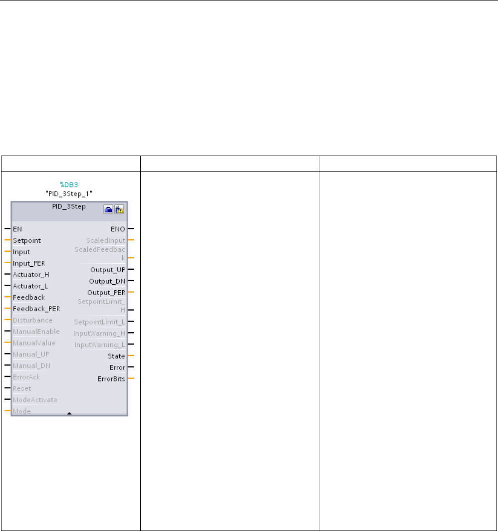
Technology instructions
10.2 PID control
S7-1200 Programmable controller
600 System Manual, V4.2, 09/2016, A5E02486680-AK
10.2.3
PID_3Step
10.2.3.1
PID_3Step instruction
The PID_3Step instruction configures a PID controller with self-tuning capabilities that has
been optimized for motor-controlled valves and actuators.
Table 10- 22 PID_3Step instruction
LAD / FBD
SCL
Description
"PID_3Step_1"(
SetpoInt:=_real_in_,
Input:=_real_in_,
ManualValue:=_real_in_,
Feedback:=_real_in_,
InputPer:=_word_in_,
FeedbackPer:=_word_in_,
Disturbance:=_real_in_,
ManualEnable:=_bool_in_,
ManualUP:=_bool_in_,
ManualDN:=_bool_in_,
ActuatorH:=_bool_in_,
ActuatorL:=_bool_in_,
ErrorAck:=_bool_in_,
Reset:=_bool_in_,
ModeActivate:=_bool_in_,
Mode:=_int_in_,
ScaledInput=>_real_out_,
ScaledFeedback=>_real_out_,
ErrorBits=>_dword_out_,
OutputPer=>_word_out_,
State=>_int_out_,
OutputUP=>_bool_out_,
OutputDN=>_bool_out_,
SetpoIntLimitH=>_bool_out_,
SetpoIntLimitL=>_bool_out_,
InputWarningH=>_bool_out_,
InputWarningL=>_bool_out_,
Error=>_bool_out_,
ErrorBits=>_dword_out_);
PID_3Step configures a PID controller with
self-tuning capabilities that has been opti-
mized for motor-controlled valves and
actuators. It provides two Boolean outputs.
PID_3Step is a PID T1controller with anti-
windup and weighting of the P- and D-
components.
1
STEP 7 automatically creates the technology object and instance DB when you insert the instruction. The instance DB
contains the parameters of the technology object.
2 In the SCL example, "PID_3Step_1" is the name of the instance DB.

Technology instructions
10.2 PID control
S7-1200 Programmable controller
System Manual, V4.2, 09/2016, A5E02486680-AK 601
Table 10- 23 Data types for the parameters
Parameter and type
Data type
Description
Setpoint
IN
Real
Setpoint of the PID controller in automatic mode. (Default value: 0.0)
Input IN Real A tag of the user program is used as the source of the process value.
(Default value: 0.0)
If you are using the Input parameter, you must set Con-
fig.InputPerOn = FALSE.
Input_PER IN Word An Analog input is used as the source of the process value. (Default
value: W#16#0)
If you are using the Input_PER parameter, you must set Con-
fig.InputPerOn = TRUE.
Actuator_H IN Bool Digital position feedback of the valve for the high end stop
If Actuator_H =
TRUE, the valve is at the high end stop and is no longer
moved in this direction. (Default value: FALSE)
Actuator_L IN Bool Digital position feedback of the valve for the low end stop
If Actuator_L = TRUE, the valve is at the low end stop and is no longer
moved in this direction. (Default value: FALSE)
Feedback IN Real Position feedback of the valve. (Default value: 0.0)
If you are using the Feedback parameter, you must set Con-
fig.FeedbackPerOn = FALSE.
Feedback_PER IN Int Analog feedback of the valve position. (Default value: W#16#0)
If you are using the Feedback_PER parameter, you must set Con-
fig.FeedbackPerOn = TRUE. Feedback_PER is scaled, based upon the
following tags:
• Config.FeedbackScaling.LowerPointIn
• Config.FeedbackScaling.UpperPointIn
• Config.FeedbackScaling.LowerPointOut
• Config.FeedbackScaling.UpperPointOut
Disturbance
IN
Real
Disturbance variable or pre-control value
ManualEnable IN Bool Enables or disables the manual operation mode. (Default value:
FALSE):
• A FALSE to TRUE edge activates "manual mode", while State = 4,
Mode remains unchanged.
As long as ManualEnable = TRUE, you cannot change the operat-
ing mode using a rising edge at ModeActivate or use the commis-
sioning dialog.
• A TRUE to FALSE edge activates the operating mode that is as-
signed by Mode.
Note: We recommend that you change the operating mode using
ModeActivate only.
ManualValue IN Real Process value for manual operation. (Default value: 0.0)
In manual mode, you specify the absolute position of the valve. Manu-
alValue is evaluated only if you are using OutputPer,
or
if position feed-
back is available.

Technology instructions
10.2 PID control
S7-1200 Programmable controller
602 System Manual, V4.2, 09/2016, A5E02486680-AK
Parameter and type
Data type
Description
ManualUP IN Bool • Manual_UP = TRUE:
– The valve is opened even if you use Output_PER or a position
feedback. The valve is no longer moved if the high end stop has
been reached.
– See also Config.VirtualActuatorLimit
• Manual_UP = FALSE:
– If you use Output_PER or a position feedback, the valve is
moved to ManualValue. Otherwise, the valve is no longer
moved.
Note: If Manual_UP and Manual_DN are set to TRUE simultaneously,
the valve is not moved.
ManualDN IN Bool • Manual_DN = TRUE:
– The valve is opened even if you use Output_PER or a position
feedback. The valve is no longer moved if the high end stop has
been reached.
– See also Config.VirtualActuatorLimit
• Manual_DN = FALSE:
– If you use Output_PER or a position feedback, the valve is
moved to ManualValue. Otherwise, the valve is no longer
moved.
ErrorAck
IN
Bool
Resets the ErrorBits and warning outputs. FALSE to TRUE edge
Reset IN Bool Restarts the controller. (Default value: FALSE):
• FALSE to TRUE edge:
– Switches to "inactive" mode
– Resets the ErrorBits and warning outputs
– Clears Integral action
– Maintains PID parameters
• As long as Reset = TRUE, PID_3Step remains in "Inactive" mode
(State = 0).
• TRUE to FALSE edge:
– PID_3Step switches to the operating mode that is saved in the
Mode parameter.
ModeActivate IN Bool The PID_3Step switches to the mode that is saved in the Mode param-
eter. FALSE to TRUE edge:
Mode IN Int The desired PID mode; Activated on the leading edge of the Mode
Activate input.
ScaledInput
OUT
Real
Scaled process value
ScaledFeedback OUT Real Scaled valve position feedback
Note: For an actuator without position feedback, the position of the
actuator indicated by ScaledFeedback is very imprecise. ScaledFeed-
back can only be used for rough estimation of the current position in
this case.
Output_UP OUT Bool Digital output value for opening the valve. (Default value: FALSE)
If Config.OutputPerOn = FALSE, the parameter Output_UP is used.
Output_DN OUT Bool Digital output value for closing the valve. (Default value: FALSE)
If Config.OutputPerOn = FALSE, the parameter Output_DN is used.

Technology instructions
10.2 PID control
S7-1200 Programmable controller
System Manual, V4.2, 09/2016, A5E02486680-AK 603
Parameter and type
Data type
Description
Output_PER OUT Word Analog output value.
If Config.OutputPerOn = TRUE, the parameter Output_PER is used.
SetpointLimitH OUT Bool Setpoint high limit. (Default value: FALSE)
If SetpointLimitH = TRUE, the absolute upper limit of the setpoint is
reached (Setpoint ≥ Config.SetpointUpperLimit).
Note: The setpoint is limited to (Setpoint ≥ Config.SetpointUpperLimit).
SetpointLimitL OUT Bool Setpoint low limit. (Default value: FALSE)
If SetpointLimitL = TRUE, the absolute lower limit of the setpoint is
reached (Setpoint ≥ Config.SetpointLowerLimit).
Note: The setpoint is limited to (Setpoint ≥ Config.SetpointLowerLimit).
InputWarningH OUT Bool If InputWarningH =
TRUE, the input value has reached or exceeded the
warning high limit. (Default value: FALSE)
InputWarningL OUT Bool If InputWarningL = TRUE, the input value has reached or exceeded the
warning low limit. (Default value: FALSE)
State OUT Int Current operating mode of the PID controller. (Default value: 0)
You can change the operating mode using the Mode input parameter
and a rising edge at ModeActivate:
• State = 0: Inactive
• State = 1: Pre-tuning
• State = 2: Manual fine tuning
• State = 3: Automatic mode
• State = 4: Manual mode
• State = 5: Substitute output value approach
• State = 6: Transition time measurement
• State = 7: Error monitoring
• State = 8: Substitute output value approach with error monitoring\
• State = 10: Manual mode without end stop signals
Error OUT Bool If Error = TRUE, at least one error message is pending. (Default value:
FALSE)
Note: The Error parameter in V1.x PID was the ErrorBits field that con-
tained the error codes. It is now a Boolean flag indicating that an error
has occurred.
ErrorBits OUT DWord The PID_3Step instruction ErrorBits parameters table (Page 607) de-
fines the error messages that are pending. (Default value:
DW#16#0000 (no error)). ErrorBits is retentive and is reset upon a
rising edge at Reset or ErrorAck.
Note: In V1.x, the ErrorBits parameter was defined as the Error param-
eter and did not exist.
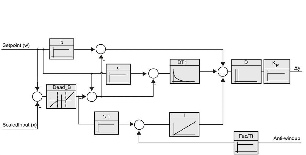
Technology instructions
10.2 PID control
S7-1200 Programmable controller
604 System Manual, V4.2, 09/2016, A5E02486680-AK
Operation of the PID_3Step controller
Figure 10-3 Operation of the PID_3Step controller as a PID T1 controller with anti-windup
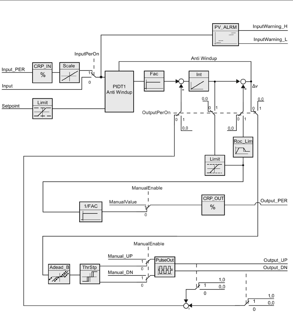
Technology instructions
10.2 PID control
S7-1200 Programmable controller
System Manual, V4.2, 09/2016, A5E02486680-AK 605
Figure 10-4 Operation of the PID_3Step controller without position feedback
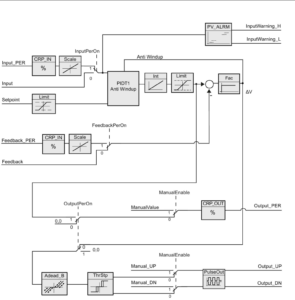
Technology instructions
10.2 PID control
S7-1200 Programmable controller
606 System Manual, V4.2, 09/2016, A5E02486680-AK
Figure 10-5 Operation of the PID_3Step controller with position feedback enabled

Technology instructions
10.2 PID control
S7-1200 Programmable controller
System Manual, V4.2, 09/2016, A5E02486680-AK 607
10.2.3.2
PID_3Step instruction ErrorBit parameters
If several errors are pending, the values of the error codes are displayed by means of binary
addition. The display of error code 0003, for example, indicates that the errors 0001 and
0002 are also pending.
Table 10- 24 PID_3STEP instruction ErrorBit parameters
ErrorBit (DW#16#...)
Description
0000
No error
0001 1, 2 The Input parameter is outside the process value limits.
Input > Config.InputUpperLimit
Input < Config.InputLowerLimit
0002 2, 3 Invalid value at the Input_PER parameter. Check whether an error is pend-
ing at the analog input.
0004 4 Error during fine tuning. Oscillation of the process value could not be main-
tained.
0010 4 The setpoint was changed during tuning.
Note: You can set the permitted fluctuation on the setpoint at the Cancel-
TuningLevel tag.
0020 Pre-tuning is not permitted during fine tuning.
Note: If ActivateRecoverMode = TRUE before the error occurred, PID_3Step
remains in fine tuning mode.
0080 4 Error during pre-tuning. Incorrect configuration of output value limits.
Check whether the limits of the output value are configured correctly and
match the control logic.
0100
4
Error during fine tuning resulted in invalid parameters.
0200
2, 3
Invalid value at the Input parameter: Value has an invalid number format.
0400
2, 3
Calculating the output value failed. Check the PID parameters.
0800 1, 2 Sampling time error: PID_3Step is not called within the sampling time of the
cyclic interrupt OB.
1000
2, 3
Invalid value at the Setpoint parameter: Value has an invalid number format.
2000 1, 2, 5 Invalid value at the Feedback_PER parameter.
Check whether an error is pending at the analog input.
4000 1, 2, 5 Invalid value at the Feedback parameter: Value has an invalid number for-
mat.
8000 1, 2 Error during digital position feedback. Actuator_H = TRUE and Actuator_L =
TRUE.
The actuator cannot be moved to the substitute output value and remains in
its current position. Manual mode is not possible in this state.
In order to move the actuator from this state, you must deactivate the "Actu-
ator end stop" (Config.ActuatorEndStopOn = FALSE) or switch to manual
mode without end stop signals (Mode = 10).

Technology instructions
10.2 PID control
S7-1200 Programmable controller
608 System Manual, V4.2, 09/2016, A5E02486680-AK
ErrorBit (DW#16#...)
Description
10000 Invalid value at the ManualValue parameter: Value has an invalid number
format.
The actuator cannot be moved to the manual value and remains in its cur-
rent position.
Assign a valid value in ManualValue or move the actuator in manual mode
with Manual_UP and Manual_DN.
20000 Invalid value at the SavePosition tag: Value has an invalid number format.
The actuator cannot be moved to the substitute output value and remains in
its current position.
40000 Invalid value at the Disturbance parameter: Value has an invalid number
format.
Note: If automatic mode was active and ActivateRecoverMode = FALSE
before the error occurred, Disturbance is set to zero. PID_3Step remains in
automatic mode.
Note: If pre-
tuning or fine tuning mode was active and ActivateRecoverMode
= TRUE before the error occurred, PID_3Step switches to the operating
mode that is saved in the Mode parameter. If Disturbance in the current
phase has no effect on the output value, tuning is not canceled.
The error has no effect during transition time measurement.
1
Note: If automatic mode was active before the error occurred and ActivateRecoverMode = TRUE,
PID_3Step remains in automatic mode.
2
Note: If pre-tuning, fine tuning, or transition time measurement mode were active and Acti-
vateRecoverMode = TRUE before the error occurred, PID_3Step switches to the operating mode
that is saved in the Mode parameter.
3
Note: If automatic mode was active before the error occurred and ActivateRecoverMode = TRUE,
PID_3Step switches to "Approach substitute output value with error monitoring" or "Error monitor-
ing" mode. As soon as the error is no longer pending, PID_3Step switches back to automatic
mode.
4
Note: If ActivateRecoverMode = TRUE before the error occurred, PID_3Step cancels the tuning
and switches to the operating mode that is saved in the Mode parameter.
5
The actuator cannot be moved to the substitute output value and remains in its current position. In
manual mode, you can change the position of the actuator only with Manual_UP and Manual_DN,
and not with ManualValue.

Technology instructions
10.2 PID control
S7-1200 Programmable controller
System Manual, V4.2, 09/2016, A5E02486680-AK 609
10.2.3.3
PID_3Step instruction Warning parameters
If the PID controller has several warnings pending, it displays the values of the error codes
by means of binary addition. The display of error code 0003, for example, indicates that the
errors 0001 and 0002 are pending.
Table 10- 25 PID_Compact instruction Warning parameters
Warning (DW#16#...)
Description
0000
No warning pending.
0001
1
The point of inflection was not found during pretuning.
0002 Oscillation was enforced during “tuning in run”. (The "Warning" parameter suppresses this
warning and is only visible in the “WarningInternal” parameter for diagnostic purposes.)
0004
1
The setpoint was limited to the configured limits.
0008 1 Not all the necessary controlled system properties were defined for the selected method of
calculation. Instead, the PID parameters were calculated using the TIR.TuneRuleHeat /
TIR.TuneRuleCool = 3 method.
0010 The operating mode could not be changed because Reset = TRUE or ManualEnable =
TRUE.
0020 The cycle time of the calling OB limits the sampling time of the PID algorithm. Improve re-
sults by using shorter OB cycle times.
0040
1
The process value exceeded one of its warning limits.
0080
Invalid value at Mode. The operating mode is not switched.
0100
1
The manual value was limited to the limits of the controller output.
0200
The specified rule for tuning is not supported. No PID parameters are calculated.
1000
The substitute output value cannot be reached because it is outside the output value limits.
1
Note: The PID controller deleted the following warnings automatically as soon as the cause is eliminated or the user
action repeated with valid parameters: 0001, 0004, 0008, 0040, and 0100.
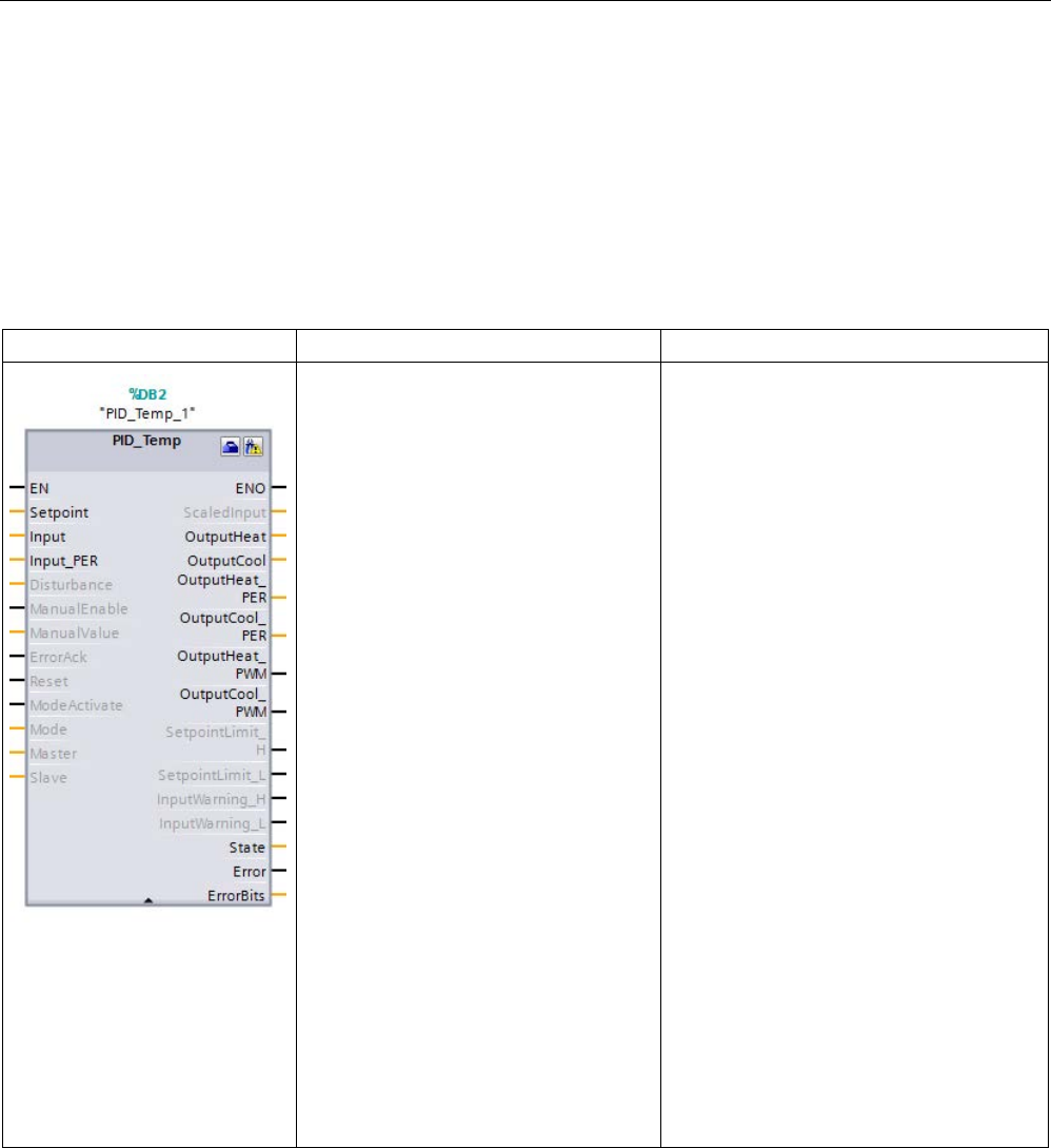
Technology instructions
10.2 PID control
S7-1200 Programmable controller
610 System Manual, V4.2, 09/2016, A5E02486680-AK
10.2.4
PID_Temp
10.2.4.1
PID_Temp instruction
The PID_Temp instruction provides a universal PID controller that allows handling of the
specific requirements of temperature control.
Table 10- 26 PID_Temp instruction
LAD / FBD
SCL
Description
"PID_Temp_1"(
Setpoint:=_real_in_,
Input:=_real_in_,
Input_PER:=_int_in_,
Disturbance:=_real_in_,
ManualEnable:=_bool_in_,
ManualValue:=_real_in_,
ErrorAck:=_bool_in_,
Reset:=_bool_in_,
ModeActivate:=_bool_in_,
Mode:=_int_in_,
Master:=_dword_in
Save:=_dword_in
ScaledInput=>_real_out_,
OutputHeat=>_real_out_,
OutputCool=>_real_out_,
OutputHeat_PER=>_int_out_,
OutputCool_PER=>_int_out_,
Out-
putHeat_PWM=>_bool_out_,
Out-
putCool_PWM=>_bool_out_,
SetpointLimit_H=>_bool_out_,
SetpointLimit_L=>_bool_out_,
InputWarn-
ing_H=>_bool_out_,
InputWarn-
ing_L=>_bool_out_,
State=>_int_out_,
Error=>_bool_out_,
ErrorBits=>_dword_out_);
PID_Temp provides these capabilities:
• Heating and cooling of the process with
different actuators
• Integrated autotuning to handle temper-
ature processes
• Cascading to process more than one
temperature that depends on the same
actuator
1
STEP 7 automatically creates the technology object and instance DB when you insert the instruction. The instance DB
contains the parameters of the technology object.
2 In the SCL example, "PID_Temp_1" is the name of the instance DB.

Technology instructions
10.2 PID control
S7-1200 Programmable controller
System Manual, V4.2, 09/2016, A5E02486680-AK 611
Table 10- 27 Data types for the parameters
Parameter and type
Data type
Description
Setpoint
IN
Real
Setpoint of the PID controller in automatic mode. (Default value: 0.0)
Input IN Real A tag of the user program is used as the source of the process value.
(Default value: 0.0)
If you are using the Input parameter, you must set Con-
fig.InputPerOn = FALSE.
Input_PER IN Int An Analog input is used as the source of the process value. (Default
value: 0)
If you are using the Input_PER parameter, you must set Con-
fig.InputPerOn = TRUE.
Disturbance
IN
Real
Disturbance variable or pre-control value
ManualEnable IN Bool Enables or disables the manual operation mode. (Default value:
FALSE):
• A FALSE to TRUE edge activates Manual mode, while State = 4,
Mode remains unchanged.
As long as ManualEnable = TRUE, you cannot change the operat-
ing mode using a rising edge at ModeActivate or use the commis-
sioning dialog.
• A TRUE to FALSE edge activates the operating mode that is as-
signed by Mode.
Note: We recommend that you change the operating mode using
ModeActivate only.
ManualValue IN Real Output value for manual operation. (Default value: 0.0)
You can use values from Config.OutputLowerLimit to Con-
fig.OutputUpperLimit.
ErrorAck IN Bool Resets the ErrorBits and warning outputs with a FALSE to TRUE edge.
(Default value: FALSE)
Reset IN Bool Restarts the controller. (Default value: FALSE):
• FALSE to TRUE edge:
– Switches to "inactive" mode
– Resets the ErrorBits and warning outputs
– Clears Integral action
– Maintains PID parameters
• As long as Reset = TRUE, PID_Temp remains in Inactive mode
(State = 0).
• TRUE to FALSE edge:
– PID_Temp switches to the operating mode that is saved in the
Mode parameter.
ModeActivate IN Bool The PID_Temp switches to the operating mode that is saved in the
Mode parameter with a FALSE to TRUE edge. (Default value: FALSE)

Technology instructions
10.2 PID control
S7-1200 Programmable controller
612 System Manual, V4.2, 09/2016, A5E02486680-AK
Parameter and type
Data type
Description
Mode IN/OUT Int Activated on the leading edge of the Mode Activate input.
Operating mode selection (Default value: 0.0):
• Mode = 0: Inactive
• Mode = 1: Pretuning
• Mode = 2: Fine tuning
• Mode = 3: Automatic mode
• Mode = 4: Manual mode
“Substitute output value with error monitoring” (State = 5). This cannot
be activated by the user; it is only an automatic error reaction.
Master
IN/OUT
DWord
Cascade connection to master (AntiWindUp and tuning conditions).
(Default value: DW#16#0000)
• Bits 0 - 15: Not used in PID_Temp instruction
• Bits 16 - 23: Limit counter: A slave increments this value if it reach-
es its limitation. The number of slaves in limitation is processed for
Anti-Windup-functionality (Refer to the Con-
fig.Cascade.AntiWindUpMode parameter.
• Bit 24: IsAutomatic: This bit is set to "1" if all slaves of this controller
are in Automatic mode and are processed to check conditions for
tuning in a cascade. This bit is identical to the AllSlaveAutomat-
icState parameter.
• Bit 25: "IsReplacement-Setpoint": This bit is set to "1" if a slave of
this controller has the "Replacement Setpoint" activated and is pro-
cessed to check conditions for tuning in a cascade. The inverted
value is stored in the NoSlaveReplacementSetpoint parameter.
Slave IN/OUT DWord
ScaledInput
OUT
Real
Scaled process value. (Default value: 0.0)
OutputHeat1 OUT Real Output value for heating in REAL format. (Default value: 0.0)
This output value is calculated, independent from the output selection,
using the Config.Output.Heat.Select parameter.
OutputCool1 OUT Real Output value for cooling in REAL format. (Default value: 0.0)
This output value is calculated, independent from the output selection,
using the Config.Output.Cool.Select parameter.
OutputHeat_PER1 OUT Int Output value for heating in peripheral format (Default value: 0)
This output value is only calculated if selected using the Con-
fig.Output.Heat.Select = 2 parameter. If not selected, this output is
always "0".
OutputCool_PER1 OUT Int Output value for cooling in peripheral format (Default value: 0)
This output value is only calculated if selected using the Con-
fig.Output.Cool.Select = 2 parameter. If not selected, this output is
always "0".
OutputHeat_PWM1 OUT Bool Pulse-width-modulated output value for heating. (Default value: FALSE)
This output value is only calculated if selected using the Con-
fig.Output.Heat.Select = 1 (default value) parameter. If not selected,
this output is always FALSE.

Technology instructions
10.2 PID control
S7-1200 Programmable controller
System Manual, V4.2, 09/2016, A5E02486680-AK 613
Parameter and type
Data type
Description
OutputCool_PWM1 OUT Bool Pulse-width-modulated output value for cooling. (Default value: FALSE)
This output value is only calculated if selected using the Con-
fig.Output.Cool.Select = 1 (default value)
parameter. If not selected, this
output is always FALSE.
SetpointLimit_H OUT Bool Setpoint high limit. (Default value: FALSE)
If SetpointLimit_H = TRUE, the absolute setpoint upper limit is reached
(Setpoint ≥ Config.SetpointUpperLimit).
The setpoint is limited to Config.SetpointUpperLimit.
SetpointLimit_L OUT Bool Setpoint low limit. (Default value: FALSE)
If SetpointLimit_L = TRUE, the absolute setpoint lower limit is reached
(Setpoint ≤ Config.SetpointLowerLimit).
The setpoint is limited to Config.SetpointLowerLimit.
InputWarning_H OUT Bool If InputWarning_H = TRUE, the process value has reached or exceed-
ed the warning high limit. (Default value: FALSE)
InputWarning_L OUT Bool If InputWarning_L = TRUE, the process value has reached or fallen
below the warning low limit. (Default value: FALSE)
State OUT Int Current operating mode of the PID controller. (Default value: 0)
You can change the operating mode using the Mode input parameter
and a rising edge at ModeActivate:
• State = 0: Inactive
• State = 1: Pre-tuning
• State = 2: Fine tuning
• State = 3: Automatic mode
• State = 4: Manual mode
• State = 5: Substitute output value with error monitoring
Error OUT Bool If Error = TRUE, at least one error message is pending in this cycle.
(Default value: FALSE)
Note: The Error parameter in V1.x PID was the ErrorBits field that con-
tained the error codes. It is now a Boolean flag indicating that an error
has occurred.
ErrorBits OUT DWord The PID_Temp instruction, ErrorBits parameters table
(Page 619)defines the error messages that are pending. (Default value:
DW#16#0000 (no error)). ErrorBits is retentive and is reset upon a
rising edge at Reset or ErrorAck.
Note: In V1.x, the ErrorBits parameter was defined as the Error pa-
rameter and did not exist.
Warning OUT DWord The PID_Temp instruction, Warning parameters table (Page 621) de-
fines the user-relevant warning messages that are pending. (Default
value: DW#16#0000 (no warning)).
WarningInternal OUT DWord The PID_Temp instruction, WarningInternal parameters table defines
the warning internal messages that are pending (includes all warnings).
(Default value: DW#16#0000 (no warning internal)).
1 You can use the outputs of the Output, Output_PER, and Output_PWM parameters in parallel.

Technology instructions
10.2 PID control
S7-1200 Programmable controller
614 System Manual, V4.2, 09/2016, A5E02486680-AK
Operation of the PID_Temp controller
Selecting heating and/or cooling control
You must first select if you need a cooling device in addition to the heating output at
parameter "ActivateCooling". Afterwards, you must define if you want to use two PID-
parameter-sets (advanced mode) or only one PID-parameter-set with an additional
heating/cooling-factor at parameter "AdvancedCooling".
Using CoolFactor
In case you want to apply a heating/cooling-factor, you must define the value manually. You
have to identify the value from the technical data of your application (ratio of proportional
gain of the actuators (for example, the ratio of maximum heating- and cooling-power of the
actuators) and assign it to parameter "CoolFactor". A heating/cooling-factor of 2.0 means
that the heating device is two times more effective than the cooling device. If you use cooling
factor, PID_Temp calculates the output signal and, depending on its sign, multiply the output
signal with the heating/cooling-factor (when sign is negative) or not (when sign is positive).
Using two PID-parameter-sets
Different PID-parameter-sets for heating and cooling can be automatically detected during
commissioning. You can expect a better control performance compared to heating/cooling-
factor because, in addition to different proportional gains, you can consider different delay
times with two parameters-sets. However, the disadvantage is that this can take more time
for the tuning process. If PID-parameter switchover is activated (Config.AdvancedCooling =
TRUE), the PID_Temp controller detects in "Automatic mode" (controlling is active) if heating
or cooling is necessary at that time and uses PID-parameter-sets for control.
ControlZone
With the PID_Temp controller, you can define a control zone for each parameter-set at
parameter "ControlZone". If the control deviation (setpoint – input) is within the control zone,
PID_Temp uses the PID-algorithm to calculate the output signals. However, if the control
deviation leaves the defined range, the output is set to the maximum heating or maximum
cooling output value (cooling output activated) / minimum heating output value (cooling
output deactivated). You can use this functionality to reach the desired setpoint faster,
especially for initial heating-up of slow temperature processes.
DeadZone
In the "DeadZone" parameter, you can define a width of control deviation for heating and
cooling that is neglected by the PID-algorithm. This means a control deviation within this
range is suppressed, and the PID_Temp controller behaves like the setpoint and process
values are identical. Thus, you can reduce unnecessary intervention by the controller around
the setpoint and conserve the actuator. If you want to apply a DeadZone, you must define
the value manually. Auto tuning does not automatically set the DeadZone value. DeadZone
is symmetric (between -Retain.CtrlParams.Heat.DeadZone and
+Retain.CtrlParams.Heat.DeadZone) for heating controllers without cooling or
heating/cooling controllers using CoolFactor. DeadZone can be asymmetric (between -
Retain.CtrlParams.Cool.DeadZone and +Retain.CtrlParams.Heat.DeadZone) for
heating/cooling controllers using two PID-parameter sets.
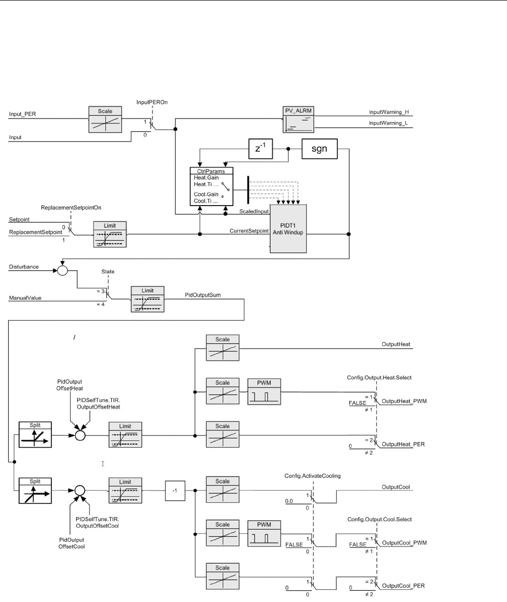
Technology instructions
10.2 PID control
S7-1200 Programmable controller
System Manual, V4.2, 09/2016, A5E02486680-AK 615
PID_Temp controller operations
The following block diagrams illustrate the PID_Temp instruction standard and cascade
operations:
Figure 10-6 PID_Temp_Operation_Block_Diagram

Technology instructions
10.2 PID control
S7-1200 Programmable controller
616 System Manual, V4.2, 09/2016, A5E02486680-AK
Figure 10-7 PID_Temp_Cascade_Operation_Block_Diagram
Cascading controllers
You can cascade temperature PID controllers to process more than one temperature that
depend on the same actuator.
Call order
You must call cascaded PID controllers in the same OB cycle. First, you must call the
master, then, the next slave(s) in the control signal flow, and finally on to the last slave in the
cascade. The PID_Temp instruction does not make an automatic check of call order.

Technology instructions
10.2 PID control
S7-1200 Programmable controller
System Manual, V4.2, 09/2016, A5E02486680-AK 617
Communication connections
When cascading controllers, you must connect the master and slave so that they can share
information with each other. You must connect a slave’s “Master” IN/OUT parameter to its
master’s “Slave” IN/OUT parameter in the signal flow direction.
This shows a connection of PID_Temp controllers in a cascade with two sub-cascades:
"PID_Temp1" provides the setpoint. The configuration connects the outputs of "PID_Temp2",
"PID_Temp3", "PID_Temp5", "PID_Temp6", and "PID_Temp8" to the process:
Figure 10-8 PID_Temp_Cascading_communication_connection
Replacement setpoint
The PID_Temp instruction provides a second setpoint input at the “ReplacementSetpoint”
parameter that you can activate by setting the parameter “ReplacementSetpointOn” = TRUE.
You can use “ReplacementSetpoint” as your setpoint input during commissioning or tuning of
a slave controller without having to disconnect the output-to-setpoint connection between
master and slave. This connection is necessary for normal operation of the cascade.
In this way, you do not have to change your program and download it if you want to
temporarily separate a slave from its master. You only have to activate the
"ReplacementSetpoint" and deactivate it again when you finish.The setpoint value is
effective for the PID algorithm when you can see the value at the “CurrentSetpoint”
parameter.

Technology instructions
10.2 PID control
S7-1200 Programmable controller
618 System Manual, V4.2, 09/2016, A5E02486680-AK
Autotuning
An autotuning for a cascaded master controller must meet these requirements:
● Be commissioned from its inner slave to the first master.
● All slaves of the master have to be in “Automatic mode".
● The output of the master must be the setpoint for the slaves.
PID_Temp instruction will provide the following support for autotuning in the cascade:
● If you start autotuning for a master controller, the master checks to see if all slaves are in
“Automatic mode” and for the deactivation of the Replacement-Setpoint-functionality for
all slaves (“ReplacementSetpointOn” = FALSE). If you do not meet these conditions, you
cannot autotune the master. The master cancels the tuning, goes to “Inactive” mode" (if
“ActivateRecoverMode” = FALSE), or back to the mode stored in the “Mode” parameter (if
“ActivateRecoverMode” = TRUE). The master displays the error message 200000hex
("Error with master in the cascade. Slaves are not in automatic mode or have a substitute
setpoint enabled and are preventing tuning of the master.").
● When all slaves are in “Automatic mode”, the system sets the parameter
“AllSlaveAutomaticState” = TRUE. You can apply this parameter in your programs or
localize the cause of error 200000hex.
● When the "ReplacementSetpoint" is deactivated for all slaves, the system sets the
parameter “NoSlaveReplacementSetpoint” = TRUE. You can apply this parameter in their
programs or localize the cause of error 200000hex.
When the PID_Temp instruction commissioning dialog is used, you have further support for
cascade tuning (Page 642).
Operation modes and error handling
The PID_Temp controller does not allow switching of the operating mode by its master or
slaves. This means that a master inside the cascade stays in its current mode when a slave
raises an error. This is an advantage if two or more parallel slaves operate with this master
controller; an error in one chain does not shut down the parallel chain.
Similarly, a slave inside the cascade stays in its current operation mode, if its master has an
error. However, further operation of the slave then depends on the configuration of the
master because the slave’s setpoint is the master’s output. This means that if you configure
the master with “ActivateRecoverMode” = TRUE and an error occurs, the master outputs the
last valid or a substitute output value as setpoint for the slave. If you configure the master
with “ActivateRecoverMode” = FALSE, the master switchs to “Inactive mode" and sets all
outputs to "0.0" so that the slave uses "0.0" as its setpoint.
Because only the slave controllers have direct access to the actuators and these stay in their
operating mode in case of a master error, you can avoid damage to the process. For
example, for plastics processing devices, it is fatal for the slaves to stop working, shut down
the actuators, and allow the plastic to harden inside the device solely because the master
controller had an error.

Technology instructions
10.2 PID control
S7-1200 Programmable controller
System Manual, V4.2, 09/2016, A5E02486680-AK 619
Anti-windup
A slave in a cascade gets its setpoint from the output of his master. If the slave reaches its
own output limits while the master still sees a control deviation (setpoint – input), the master
freezes or reduces its integration contribution to prevent a so-called "WindUp". In case of a
"WindUp", the master increases its integration contribution to a very large value and must
reduce it first, before the controller can again have a normal reaction. Such a "WindUp"
affects the dynamic of the control negatively. The PID_Temp provides ways to prevent this
effect in a cascade by configuring the parameter “Config.Cascade.AntiWindUpMode” of the
master controller:
Value
Description
0
Deactivates Anti-Windup functionality.
1 Reduces the integration contribution of the master controller at the ratio “slaves
in limitation” to “existing slaves” (parameter “CountSlaves”).
2 Freezes the integration contribution of the master as soon as one slave reaches
its limitation. Only relevant if "Config.Cascade.IsMaster" = TRUE.
10.2.4.2
PID_Temp ErrorBit parameters
If the PID controller has several warnings pending, it displays the values of the error codes
by means of binary addition. The display of error code 0003, for example, indicates that the
errors 0001 and 0002 are pending.
Table 10- 28 PID_Temp instruction ErrorBit parameters
ErrorBit (DW#16#...)
Description
0000 No error
0001 1, 2 The Input parameter is outside the process value limits.
Input > Config.InputUpperLimit
Input < Config.InputLowerLimit
0002 2, 3 Invalid value at the Input_PER parameter. Check whether an error is pend-
ing at the analog input.
0004 4 Error during fine tuning. Oscillation of the process value could not be main-
tained.
0008 4 Error at start of pre-tuning. The process value is too close to the setpoint.
Start fine tuning.
0010 4 The setpoint was changed during tuning.
Note: You can set the permitted fluctuation on the setpoint at the Cancel-
TuningLevel tag.
0020 Pre-tuning is not permitted during fine tuning.
Note: If ActivateRecoverMode = TRUE before the error occurred,
PID_Temp remains in fine tuning mode.
0040
4
Error during pretuning. The cooling could not reduce the process value.
0080 4 Error during pre-tuning. Incorrect configuration of output value limits.
Check whether the limits of the output value are configured correctly and
match the control logic.
0100 4 Error during fine tuning resulted in invalid parameters.

Technology instructions
10.2 PID control
S7-1200 Programmable controller
620 System Manual, V4.2, 09/2016, A5E02486680-AK
ErrorBit (DW#16#...)
Description
0200
2, 3
Invalid value at the Input parameter: Value has an invalid number format.
0400 2, 3 Calculation of the output value failed. Check the PID parameters.
0800 1, 2 Sampling time error: PID_Temp is not called within the sampling time of the
cyclic interrupt OB.
1000 2, 3 Invalid value at the Setpoint parameter: Value has an invalid number format.
10000 Invalid value at the ManualValue parameter: Value has an invalid number
format.
Note: If ActivateRecoverMode = TRUE before the error occurred,
PID_Temp uses SubstituteOutput as the output value. As soon as you as-
sign a valid value in the ManualValue parameter, PID_Temp uses it as the
output value.
20000 Invalid value at the SubstituteValue tag: Value has an invalid number for-
mat.
PID_Temp uses the output value low limit as the output value.
Note: If automatic mode was active before the error occurred, Acti-
vateRecoverMode = TRUE, and the error is no longer pending, PID_Temp
switches back to automatic mode.
40000 Invalid value at the Disturbance parameter: Value has an invalid number
format.
Note: If automatic mode was active and ActivateRecoverMode = FALSE
before the error occurred, Disturbance is set to zero. PID_Temp remains in
automatic mode.
Note: If pre-tuning or fine tuning mode was active and ActivateRecover-
Mode = TRUE before the error occurred, PID_Temp switches to the operat-
ing mode that is saved in the Mode parameter. If Disturbance in the current
phase has no effect on the output value, tuning is not canceled.
200000 Error with master in the cascade. Slaves are not in automatic mode or have
a substitute setpoint enabled, preventing tuning of the master.
400000 The PID controller does not permit pretuning for heating while cooling is
active.
800000 The process value must be close to the setpoint in order to start pretuning
for cooling.
1000000 Error starting tuning. “Heat.EnableTuning” and “Cool.EnableTuning” are not
set or do not match the configuration.
2000000
Pretuning for cooling requires successful pretuning for heating.

Technology instructions
10.2 PID control
S7-1200 Programmable controller
System Manual, V4.2, 09/2016, A5E02486680-AK 621
ErrorBit (DW#16#...)
Description
4000000 Error starting fine tuning. “Heat.EnableTuning” and “Cool.EnableTuning”
cannot be set at the same time.
8000000 Error during PID parameter calculation resulted in invalid parameters (for
example, negative Gain; the current PID parameters remain unchanged and
tuning has no effect).
1
Note: If automatic mode was active before the error occurred and ActivateRecoverMode = TRUE,
PID_Temp remains in automatic mode.
2
Note: If pre-tuning or fine tuning mode was active before the error occurred and ActivateRecover-
Mode = TRUE, PID_Temp switches to the operating mode that is saved in the Mode parameter.
3
Note: If automatic mode was active before the error occurred and ActivateRecoverMode = TRUE,
PID_Compact outputs the configured substitute output value. As soon as the error is no longer
pending, PID_Temp switches back to automatic mode.
4
Note: If ActivateRecoverMode = TRUE before the error occurred, PID_Temp cancels the tuning
and switches to the operating mode that is saved in the Mode parameter.
10.2.4.3
PID_Temp Warning parameters
If the PID controller has several warnings pending, it displays the values of the error codes
by means of binary addition. The display of error code 0003, for example, indicates that the
errors 0001 and 0002 are pending.
Table 10- 29 PID_Temp instruction Warning parameters
Warning (DW#16#...)
Description
0000
No warning pending.
0001
1
The point of inflection was not found during pretuning.
0002 Oscillation was enforced during “tuning in run”. (The "Warning" parameter
suppresses this warning and is only visible in the “WarningInternal” parame-
ter for diagnostic purposes.)
0004
1
The setpoint was limited to the configured limits.
0008 1 Not all the necessary controlled system properties were defined for the
selected method of calculation. Instead, th
e PID parameters were calculated
using the TIR.TuneRuleHeat / TIR.TuneRuleCool = 3 method.
0010 The operating mode could not be changed because Reset = TRUE or Man-
ualEnable = TRUE.
0020 The cycle time of the calling OB limits the sampling time of the PID algo-
rithm. Improve results by using shorter OB cycle times.
0040
1
The process value exceeded one of its warning limits.
0080
Invalid value at Mode. The operating mode is not switched.
0100 1 The manual value was limited to the limits of the controller output.
0200 The specified rule for tuning is not supported. No PID parameters are calcu-
lated.
1000 The substitute output value cannot be reached because it is outside the
output value limits.
4000 The specified output selection for heating and/or cooling is not supported.
Only OutputHeat and OutputCool are active.
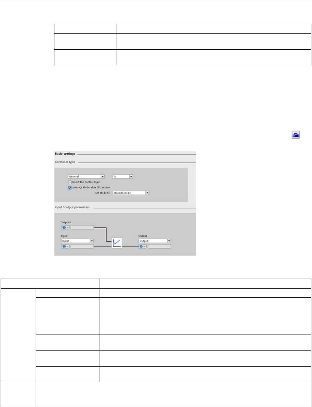
Technology instructions
10.2 PID control
S7-1200 Programmable controller
622 System Manual, V4.2, 09/2016, A5E02486680-AK
Warning (DW#16#...)
Description
8000 The specified value for the PIDSelfTune.SUT.AdaptDelayTime parameter is
not supported, so the default value "0" is used.
10000 The specified value for the PIDSelfTune.SUT.CoolingMode parameter is not
supported, so the default value "0" is used.
1
Note: The PID controller deleted the following warnings automatically as soon as the cause is
eliminated or the user action repeated with valid parameters: 0001, 0004, 0008, 0040, and 0100.
10.2.5
Configuring the PID_Compact and PID_3Step controllers
The parameters of the technology object determine the operation of the PID contro
l-
ler. Use the icon to open the configuration editor.
Table 10- 30 Example configuration settings for the PID_Compact instruction
Settings
Description
Basic
Controller type
Selects the engineering units.
Invert the control logic Allows selection of a reverse-acting PID loop.
• If not selected, the PID loop is in direct-acting mode and the output of PID loop
increases if input value < setpoint.
• If selected, the output of the PID loop increases if the input value > setpoint.
Enable last mode after
CPU restart
Restarts the PID loop after it is reset or if an input limit has been exceeded and
returned to the valid range.
Input Selects either the Input parameter or the Input_PER parameter (for analog) for the
process value. Input_PER can come directly from an analog input module.
Output Selects either the Output parameter or the Output_PER parameter (for analog) for
the output value. Output_PER can go directly to an analog output module.
Process
value
Scales both the range and the limits for the process value. If the process value goes below the low limit or
above the high limit, the PID loop goes to inactive mode and sets the output value to 0.
To use Input_PER, you
must
scale the analog process value (input value).
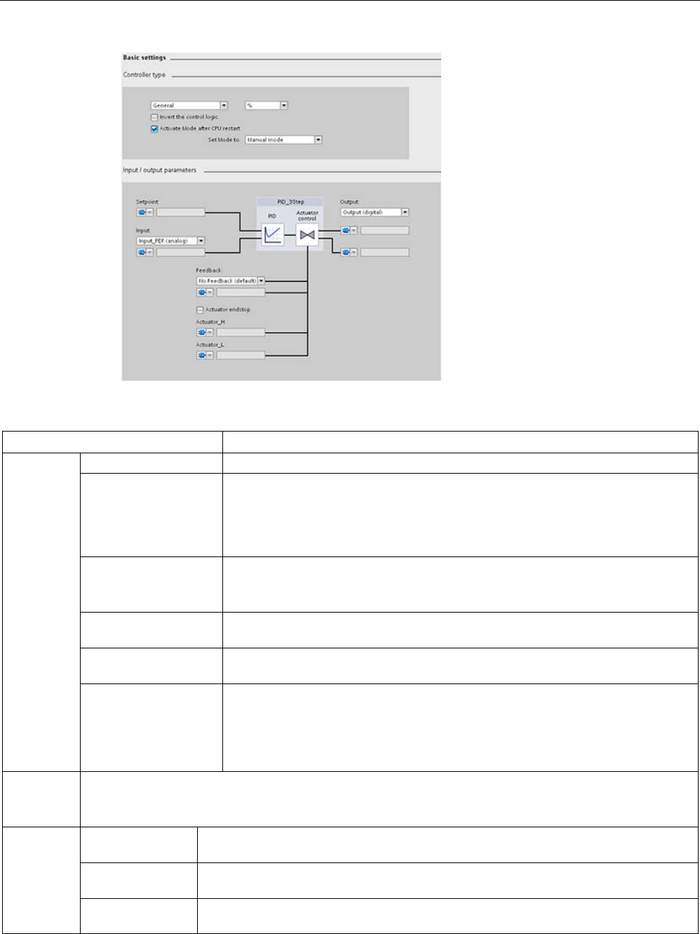
Technology instructions
10.2 PID control
S7-1200 Programmable controller
System Manual, V4.2, 09/2016, A5E02486680-AK 623
Table 10- 31 Example configuration settings for the PID_3Step instruction
Settings
Description
Basic
Controller type
Selects the engineering units.
Invert the control logic Allows selection of a reverse-acting PID loop.
• If not selected, the PID loop is in direct-acting mode, and the output of PID loop
increases if the input value < setpoint).
• If selected, the output of the PID loop increases if the input value > setpoint.
Activate mode after
CPU restart
Restarts the PID loop after it is reset or if an input limit has been exceeded and
returned to the valid range.
Set Mode to: Defines the mode that the user wants the PID to go to after restart.
Input Selects either the Input parameter or the Input_PER parameter (for analog) for the
process value. Input_PER can come directly from an analog input module.
Output Selects either to use the digital outputs (Output_UP and Output_DN) or to use the
analog output (Output_PER) for the output value.
Feedback Selects the type of device status returned to the PID loop:
• No feedback (default)
• Feedback
• Feedback_PER
Process
value
Scales both the range and the limits for the process value. If the process value goes below the low limit or
above the high limit, the PID loop goes to inactive mode and sets the output value to 0.
To use Input_PER, you must scale the analog process value (input value).
Actuator Motor transition
time
Sets the time from open to close for the valve. (Locate this value on the data sheet or
the faceplate of the valve.)
Minimum ON time Sets the minimum movement time for the valve. (Locate this value on the data sheet or
the faceplate of the valve.)
Minimum OFF
time
Sets the minimum pause time for the valve. (Locate this value on the data sheet or the
faceplate of the valve.)

Technology instructions
10.2 PID control
S7-1200 Programmable controller
624 System Manual, V4.2, 09/2016, A5E02486680-AK
Settings
Description
Reaction to error Defines the behavior of the valve when an error is detected or when the PID loop is
reset. If you select to use a substitute position, enter the "Safety position". For analog
feedback or analog output, select a value between the upper or lower limit for the out-
put. For digital outputs, you can choose only 0% (off) or 100% (on).
Scale Position
Feedback1
• "High end stop" and "Lower end stop" define the maximum positive position (full-
open) and the maximum negative position (full-closed). "High end stop" must be
greater than "Lower end stop".
• "High limit process value" and "Low limit process value" define the upper and lower
positions of the valve during tuning and automatic mode.
• "FeedbackPER" ("Low" and "High") defines the analog feedback of the valve posi-
tion. "FeedbackPER High" must be greater than "FeedbackPER Low".
Advanced Monitoring process
value
Sets the warning high and low limits for the process value.
PID parameters If the user wishes, he can enter his own PID tuning parameters in this window. The
“Enable Manual Entry” check box must be checked to allow this.
1 "Scale Position Feedback" is editable only if you enabled "Feedback" in the "Basic" settings.
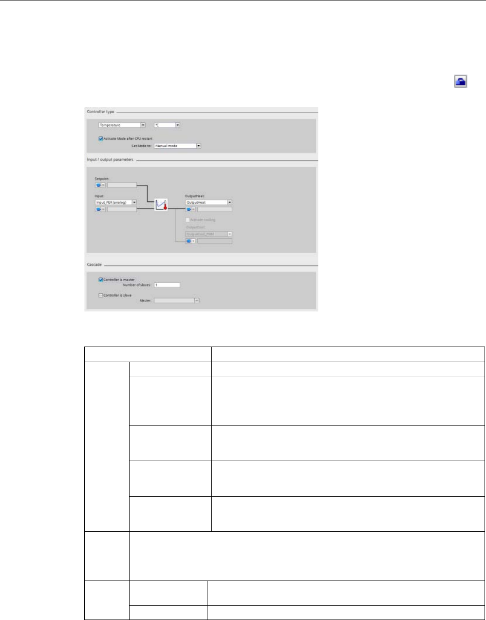
Technology instructions
10.2 PID control
S7-1200 Programmable controller
System Manual, V4.2, 09/2016, A5E02486680-AK 625
10.2.6
Configuring the PID_Temp controller
The parameters of the technology object determine the operation of the PID contro
l-
ler. Use the icon to open the configuration editor.
Table 10- 32 Example configuration settings for the PID_Temp instruction
Settings
Description
Basic
Controller type
Selects the engineering units.
Activate mode
after CPU restart
Restarts the PID loop after it is reset or if an input limit has been
exceeded and returned to the valid range.
Set Mode to: Defines the mode that the user wants the PID to go to
after restart.
Input Selects either the Input parameter or the Input_PER parameter (for
analog) for the process value. Input_PER can come directly from an
analog input module.
Output Heat Selects either to use the digital outputs (OutputHeat and Out-
putHeat_PWM) or to use the analog output (OutputHeat_PER (ana-
log)) for the output value.
Output Cool Selects either to use the digital outputs (OutputCool and Out-
putCool_PWM) or to use the analog output (OutputCool_PER (ana-
log)) for the output value.
Process
value
Scales both the range and the limits for the process value. If the process value goes be-
low the low limit or above the high limit, the PID loop goes to inactive mode and sets the
output value to 0.
To use Input_PER, you must scale the analog process value (input value).
Cascade Controller is mas-
ter
Sets the controller as a master and selects the number of slaves.
Controller is slave
Sets the controller as a slave and selects the number of masters.

Technology instructions
10.2 PID control
S7-1200 Programmable controller
626 System Manual, V4.2, 09/2016, A5E02486680-AK
Controller type
Setting
TO-DB parameter
Data
type
Value range
Description
Physical
quantity
"PhysicalQuantity" Int
(Enu
m)
• General
• Temperature
(=default)
Pre-selection for physical
unit value
No multi-value control
and not editable in online
mode of functional view.
Unit of
meas-
urement
"PhysicalUnit Int
(Enu
m)
• General: Units =
%
• Temperature:
Units (possible
selections) =
– °C (=default)
– °F
– K
User unit selection is set
back to “0” if you change
the physical quantity.
Activate
mode
after
CPU
restart
"RunModeByStartup" Bool Checkbox If set to TRUE (=default),
the controller switches to
the state that is stored in
the “Mode” variable after
a powercycle (Power on -
off - on) or PLC STOP-to-
RUN transition. Other-
wise, the PID_Temp
remains in “Inactive”
mode.
Set
mode to
"Mode" Int
(Enu
m)
Modes (possible
selections):
• 0: Inactive
• 1: Pretuning
• 2: Fine tuning
• 3: Automatic
mode
• 4: Manual mode
(=default)
The engineering station
(ES) sets the start value
of the“Mode” variable
according to user selec-
tion.The default value of
Mode (stored inTO-DB) is
Manual Mode.

Technology instructions
10.2 PID control
S7-1200 Programmable controller
System Manual, V4.2, 09/2016, A5E02486680-AK 627
Input / output parameters
Setting
TO-DB parameter
Data
type
Value range
Description
Setpoint Setpoint Real) Real
Only accessible in Prop-
erty Page.
No multi value control in
online mode of function-
al view.
Selection
input
"Config.InputPerOn" Bool
(Enu
m)
Bool Selects which kind of
input to use.
Possible selections:
• FALSE: “Input” (Re-
al)
• TRUE: “Input_PER
(analog)”
Input Input or Input_PER Real
or Int
Real or Int Only accessible in Prop-
erties page.
No multi value control in
online mode of function-
al view.
Selection
Output
(heating)
"Config.Output.Heat.Select" Int
(Enu
m)
2 >= Config.Output.
Heat.Select
>= 0
Selects which kind of
output to use for heating.
Possible selections:
• “OutputHeat” (Real)
• “OutputHeat_PWM”
(Bool) (=default)
• “OutputHeat_PER
(analog)” (Word)
Is set to “OutputHeat”
once, if “This controller
is a master” checkbox in
the “Cascade” section is
activated by user.
Output
(heating)
OutputHeat, OutputHeat_PER,
or OutputHeat_PWM
Real
or Int
or
Bool
Real, Int, or Bool Only accessible in Prop-
erties page.
No multi value control in
online mode of function-
al view.

Technology instructions
10.2 PID control
S7-1200 Programmable controller
628 System Manual, V4.2, 09/2016, A5E02486680-AK
Setting
TO-DB parameter
Data
type
Value range
Description
Activate
output
(cooling)
"Config.ActivateCooling" Bool Bool Checking this checkbox:
• Sets the "Con-
fig.Output.
Heat.PidLowerLimit
= 0.0 once.
• Sets the
"Con-
fig.ActivateCooling"
parameter to TRUE,
instead of FALSE if
unchecked
(=default).
• Activates all other
“Output (cooling)”
controls (in “Basic
settings” and other
views).
• Changes the line
from the PID symbol
to the controls from
gray to black.
• “This controller is a
master” checkbox in
the “Cascade” sec-
tion is disabled.
Note: Only available if
you do not configure the
controller as a master for
a cascade (“This control-
ler is a master”checkbox
in the “Cascade” section
is deactivated;
"Con-
fig.Cascade.IsMaster" =
FALSE).

Technology instructions
10.2 PID control
S7-1200 Programmable controller
System Manual, V4.2, 09/2016, A5E02486680-AK 629
Setting
TO-DB parameter
Data
type
Value range
Description
Selection
Output
(cooling)
"Config.Output.Cool.Select" Int
(Enu
m)
2 >= Config.Output.
Heat.Select
>= 0
Selects which kind of
output to use for cooling.
Possible selections:
• “OutputCool” (Real)
• “OutputCool_PWM”
(Bool) (=default)
• “OutputCool_PER
(analog)” (Word)
Only available if you
check “Activate output
(cooling)”;
(Config.ActivateCooling
= TRUE).
Output
(cooling)
OutputCool, OutputCool_PER,
or OutputCool_PWM
Real
or Int
or
Bool
Real, Int, or Bool Only accessible in Prop-
erties page.
No multi value control in
online mode of function-
al view.

Technology instructions
10.2 PID control
S7-1200 Programmable controller
630 System Manual, V4.2, 09/2016, A5E02486680-AK
Cascade parameters
The following parameters enable you to select controllers as masters or slaves and to
determine the number of slave controllers that receive their setpoint directly from the master
controller:
Setting
TO-DB parameter
Data
type
Value range
Description
This
controller
is a
master
"Config.Cascade.IsMaster" Bool Bool Shows if this controller is
a master in a cascade.
When you check this
checkbox, you perform
the following:
• Set the parameter
"Con-
fig.Cascade.IsMaster
" to TRUE, instead of
FALSE if unchecked
(=default).
• Set “Selection Output
(heating)” in “Input /
output parameters”
section to “Out-
putHeat” once (Con-
fig.Output.Heat.Selec
t = 0).
• Enable “Number of
Slaves” input field.
• Disable “Activate
output (cooling)”
checkbox in “Input /
output parameters”
section.
Note: Only available if
cooling output of this
controller is deactivated
(“Activate output (cool-
ing)” checkbox in “Input /
output parameters” sec-
tion deactivated (Con-
fig.ActivateCooling =
FALSE).

Technology instructions
10.2 PID control
S7-1200 Programmable controller
System Manual, V4.2, 09/2016, A5E02486680-AK 631
Setting
TO-DB parameter
Data
type
Value range
Description
Number
of slaves
"Config.Cascade.CountSlaves" Int 255 >= Con-
fig.Cascade.
CountSlaves
>= 1
Number of slave control-
lers that get their set-
point directly from this
master controller. The
PID_Temp instruction
processes this value,
along with others, for
anti-windup-
handling."Number of
slaves is only available if
“This controller is a mas-
ter” checkbox is activat-
ed (Con-
(Con-
fig.Cascade.IsMaster =
TRUE).
This
controller
is a
slave
"Config.Cascade.IsSlave" Bool Bool Shows if this controller is
a slave in a cascade.
When you check this
checkbox, you set the
parameter "Con-
fig.Cascade.IsSlave" to
TRUE, instead of FALSE
if unchecked (=default).
You must check this
checkbox in the property
page to enable the “Se-
lectionMaster” dropdown
list.
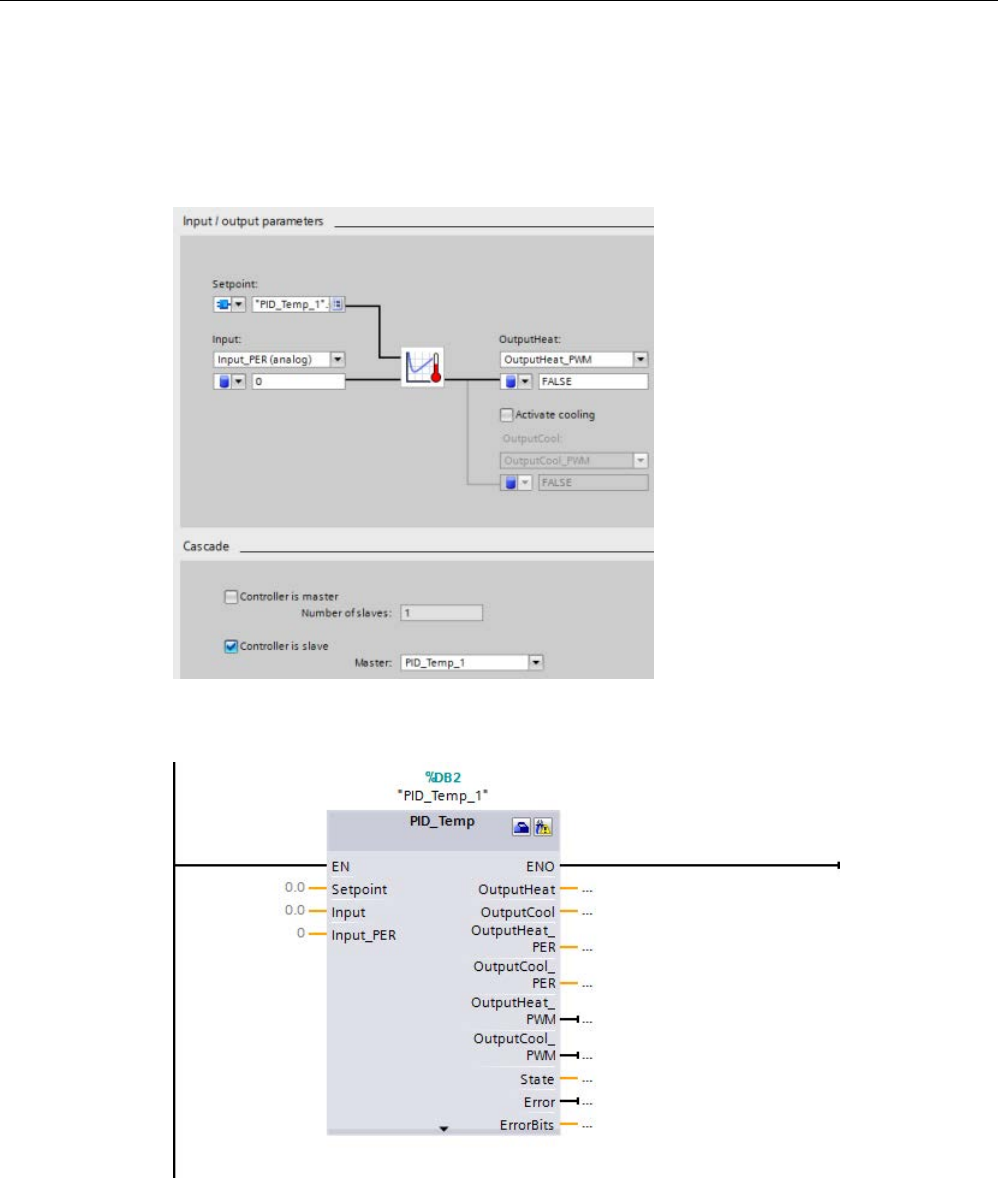
Technology instructions
10.2 PID control
S7-1200 Programmable controller
632 System Manual, V4.2, 09/2016, A5E02486680-AK
Example: Cascading controllers
In the “Basic settings” dialog below, you see the “Input / output parameters” section and the
“Cascade” section for slave controller "PID_Temp_2" after selecting "PID_Temp_1" as
master. You make the connections between master and slave controller:
Network 1: In these networks, you make the connection between the "PID_Temp_1" master
and the "PID_Temp_2" slave in the programming editor:
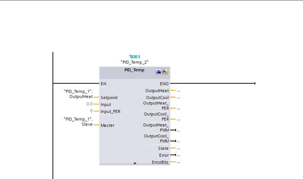
Technology instructions
10.2 PID control
S7-1200 Programmable controller
System Manual, V4.2, 09/2016, A5E02486680-AK 633
Network 2: You make the connection between the "PID_Temp_1" master’s “OutputHeat” and
"Slave" parameters to the "PID_Temp_2" slave’s “Setpoint” and "Master" parameters,
respectively:

Technology instructions
10.2 PID control
S7-1200 Programmable controller
634 System Manual, V4.2, 09/2016, A5E02486680-AK
Autotuning of temperature processes
The PID_Temp instruction provides two modes for auto tuning:
● “Pretuning” (parameter “Mode” = 1)
● “Finetuning” (parameter “Mode” = 2)
Depending on the controller configuration, different variants of these tuning methods are
available:
Configuration
Controller with heating
output
Controller with heating and
cooling output using cool-
ing factor
Controller with heating and
cooling output using two
sets of PID parameters
Associated
TO-DB values
• Config.ActivateCooling
= FALSE
• Con-
fig.AdvancedCooling
= irrelevant
• Config.ActivateCooling
= TRUE
• Con-
fig.AdvancedCooling =
FALSE
• Config.ActivateCooling
= TRUE
• Con-
fig.AdvancedCooling =
TRUE
Available tun-
ing methods
• “Pretuning heating”
• “Fine tuning heating"
(cooling offset cannot
be used)
• “Pretuning heating”
• “Fine tuning heating"
(cooling offset can be
used)
• “Pretuning heating and
cooling”
• "Pretuning heating”
• “Pretuning cooling”
• “Fine tuning heating”
(cooling offset can be
used)
• “Fine tuning cooling”
(heating offset can be
used)
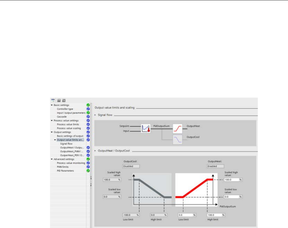
Technology instructions
10.2 PID control
S7-1200 Programmable controller
System Manual, V4.2, 09/2016, A5E02486680-AK 635
Output value limits and scaling
Cooling activation disabled
If you configure the PID_Temp instruction as master for a cascade “Activate output (cooling)”
checkbox in “Basic settings” view is unchecked and disabled, all settings in the “Output
settings” view that depend on cooling activation are disabled, too.
The figure below shows the "Output value limits and scaling” section in the “Output settings”
view with cooling deactivated (OutputHeat_PWM selected in “Input / output parameters” view
and OutputHeat always enabled):
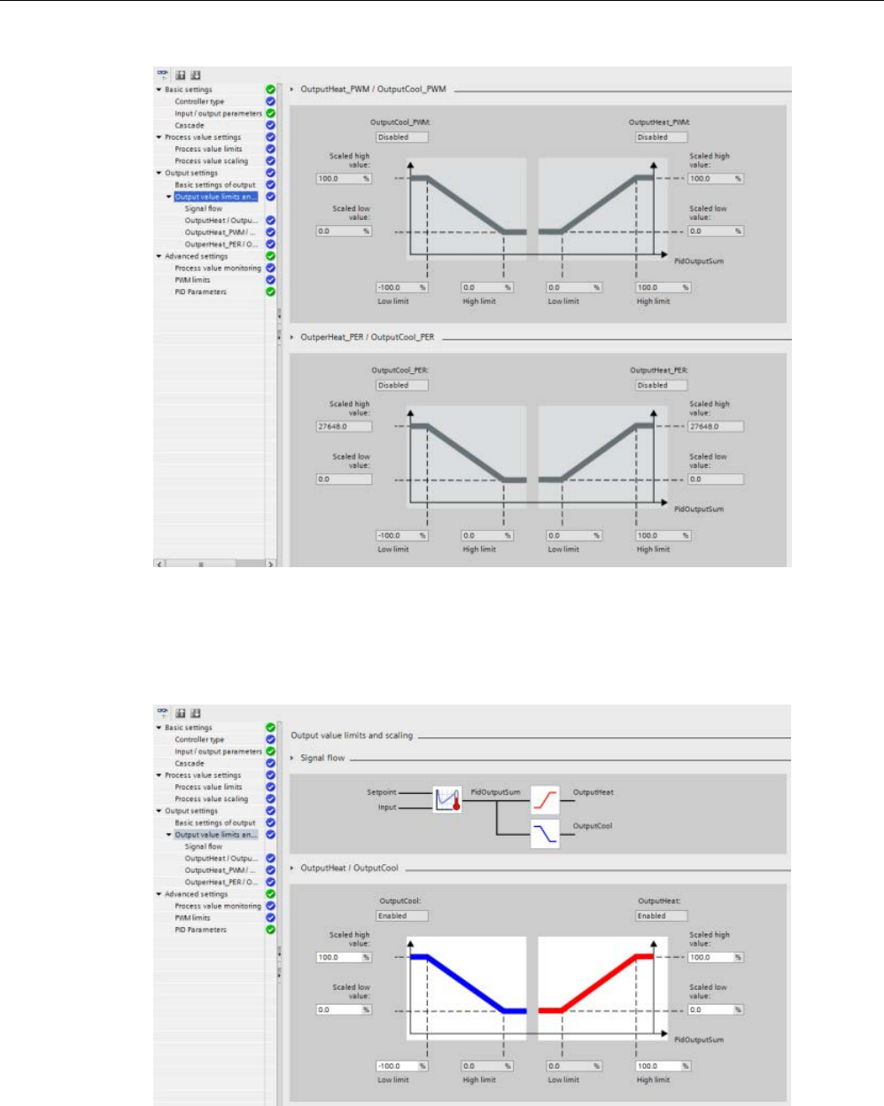
Technology instructions
10.2 PID control
S7-1200 Programmable controller
636 System Manual, V4.2, 09/2016, A5E02486680-AK
Cooling activation enabled
The figure below shows the ”Output value limits and scaling” section in “Output settings”
view with cooling activated (OutputCool_PER and OutputHeat_PWM selected in “Input /
output parameters” view; OutputCool and OutputHeat always enabled):
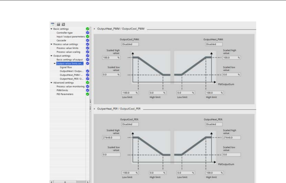
Technology instructions
10.2 PID control
S7-1200 Programmable controller
System Manual, V4.2, 09/2016, A5E02486680-AK 637

Technology instructions
10.2 PID control
S7-1200 Programmable controller
638 System Manual, V4.2, 09/2016, A5E02486680-AK
Operation modes
To change the mode of operation manually, the user needs to set the “Mode” in-out
parameter of the controller and activate it by setting “ModeActivate” from FALSE to TRUE
(rising edge triggered). You must reset “ModeActivate” before the next mode change; it does
not reset automatically.
Output parameter “State” shows the current operating mode and is set to the requested
“Mode” if possible. The “State” parameter cannot be changed directly; it is only changed
through the “Mode” parameter or automatic operating mode changes by the controller.
"Mode" /
"State"
Name
Description
0 Inactive The PID_Temp instruction:
• Deactivates the PID-algorithm and pulse width modulation
• Sets to "0" (FALSE) all controller outputs (OutputHeat, OutputCool, Out-
putHeat_PWM,OutputCool_PWM, OutputHeat_PER, OutputCool_PER), regardless of
configured output limits or offsets. You can reach this mode by setting “Mode” = 0,
“Reset” = TRUE, or by error.
1 Pretuning
(startup tun-
ing / SUT)
This mode determines the parameters during first start up of the controller.
Un
like the PID_Compact, for the PID_Temp, you must select if you require heating tuning,
cooling tuning, or both with the “Heat.EnableTuning” and “Cool.EnableTuning” parame-
ters.
You can activate "Pretuning" from Inactive, Automatic mode, or Manual mode.
If tuning is successful, PID_Temp switches to Automatic mode. If tuning is unsuccessful,
the switchover of the operating mode depends on “ActivateRecoverMode”.
2 Fine tuning
(tuning in run
/ TIR)
This mode determines the optimum parameterization of the PID controller at the setpoint.
Unlike the PID_Compact, for the PID_Temp, you must select if you require heating tuning
or cooling tuning with the “Heat.EnableTuning” and “Cool.EnableTuning” parameters.
You can activate "Finetuning" from Inactive, Automatic mode, or Manual mode.
If tuning is successful, PID_Temp switches to Automatic mode. If tuning is not successful,
the switchover of the operating mode depends on “ActivateRecoverMode”.
3 Automatic
mode
In Automatic mode (the standard PID control mode), the result of the PID-algorithm de-
termines the output values.
PID_Temp switches to Inactive if an error occurs and “ActivateRecoverMode” = FALSE. If
an error occurs and “ActivateRecoverMode” = TRUE, the switchover of the operating
mode depends on the error. Refer to PID_Temp instruction ErrorBit parameters
(Page 619) for further information.

Technology instructions
10.2 PID control
S7-1200 Programmable controller
System Manual, V4.2, 09/2016, A5E02486680-AK 639
"Mode" /
"State"
Name
Description
4 Manual mode In this mode, the PID controller scales, limits, and transfers the value of parameter “Man-
ualValue” to the outputs.
The PID controller assigns “ManualValue” in the scaling of the PID-algorithm
(like“PidOutputSum”), so its value decides if it is effective at the heating or cooling out-
puts.
You can reach this mode by setting “Mode” = 4 or “ManualEnable”= TRUE.
5 Substitute
output value
with error
monitoring
(Recover
mode)
You can activate this mode by setting "Mode" = 5. The mode is an automatic error reac-
tion of the controller if Automatic mode is active at the moment the error occurs:
• SetSubstituteOutput = FALSE (Last valid output value)
• SetSubstituteOutput = TRUE (Value stored in parameter "SubstituteOutput")
When PID_Temp is in “Automatic mode” and the “ActivateRecoverMode” parameter =
TRUE, PID_Temp changes to this
mode in the case of the following errors:
• “Invalid value at "Input_PER" parameter. Check for an error at the analog input (for
example, wire broken)." (ErrorBits = DW#16#0002)
• “Invalid value at "Input" parameter. Value is not a number.” (ErrorBits = DW#16#0200)
• “Calculation of output value failed. Check the PID parameters.” (ErrorBits =
DW#16#0400)
• “Invalid value at "Setpoint" parameter. Value is not a number.” (ErrorBits =
DW#16#1000)
If the error is no longer pending, PID_Temp will switch back to Automatic mode automati-
cally.
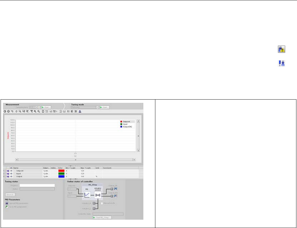
Technology instructions
10.2 PID control
S7-1200 Programmable controller
640 System Manual, V4.2, 09/2016, A5E02486680-AK
10.2.7
Commissioning the PID_Compact and PID_3Step controllers
Use the commissioning editor to configure the PID controller for autotuning at startup
and for autotuning during operation. To open the commissioning editor, click
the icon
on either the instruction or the project navigator.
Table 10- 33 Sample commissioning screen (PID_3Step)
• Measurement: To display the setpoint, the pro-
cess value (input value) and the output value in a re-
al-time trend, enter the sample time and click the
"Start" button.
• Tuning mode: To tune the PID loop, select either
"Pre-tuning" or "Fine tuning" (manual) and click the
"Start" button. The PID controller runs through multi-
ple phases to calculate system response and update
times. The appropriate tuning parameters are calcu-
lated from these values.
After the completion of the tuning process, you can
store the new parameters by clicking the "Upload PID
parameters" button in the "PID Parameters" section of
the commissioning editor.
If an error occurs during tuning, the output value of the
PID goes to 0. The PID mode then is set to "inactive"
mode. The status indicates the error.

Technology instructions
10.2 PID control
S7-1200 Programmable controller
System Manual, V4.2, 09/2016, A5E02486680-AK 641
PID start value control
You can edit the actual values of the PID configuration parameters so that the behavior of
the PID controller can be optimized in online mode.
Open the "Technology objects" for your PID controller and its "Configuration" object. To
access the start value control, click the "eyeglasses icon" in the upper left corner of the
dialog:
You can now change the value of any of your PID controller configuration parameters as
shown in the figure below.
You can compare the actual value to the project (offline) start value and the PLC (online)
start value of each parameter. This is necessary to compare online/offline differences of the
Technology object data block (TO-DB) and to be informed about the values that will be used
as current values on the next Stop-to-Start transition of the PLC. In addition, a compare icon
gives a visual indication to help easily identify online/offline differences:
The figure above shows the PID parameter screen with compare icons showing which
values are different between online and offline projects. A green icon indicates that the
values are the same; a blue/orange icon indicates that the values are different.
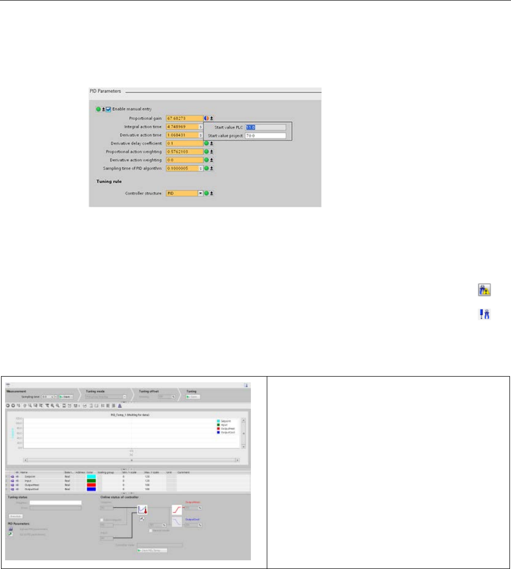
Technology instructions
10.2 PID control
S7-1200 Programmable controller
642 System Manual, V4.2, 09/2016, A5E02486680-AK
Additionally, click the parameter button with the downward arrow to open a small window
that shows the project (offline) start value and the PLC (online) start value of each
parameter:
10.2.8
Commissioning the PID_Temp controller
Use the commissioning edit
or to configure the PID controller for autotuning at startup
and for autotuning during operation. To open the commissioning editor, click the icon
on either the instruction or the project navigator.
Table 10- 34 Sample commissioning screen (PID_Temp)
Measurement: To display the setpoint, the process value
(input value) and the output value in a real-time trend,
enter the sample time and click the "Start" button.
Tuning mode: To tune the PID_Temp loop, select either
"Pretuning" or "Finetuning" (manual) and click the "Start"
button. The PID controller runs through multiple phases
to calculate system response and update times. The
appropriate tuning parameters are calculated from these
values.
After the completion of the tuning process, you can store
the new parameters by clicking the "Upload PID parame-
ters" button in the "PID Parameters" section of the com-
missioning editor.
If an error occurs during tuning, the output value of the
PID goes to "0". The PID mode then is set to "inactive"
mode. The status indicates the error.
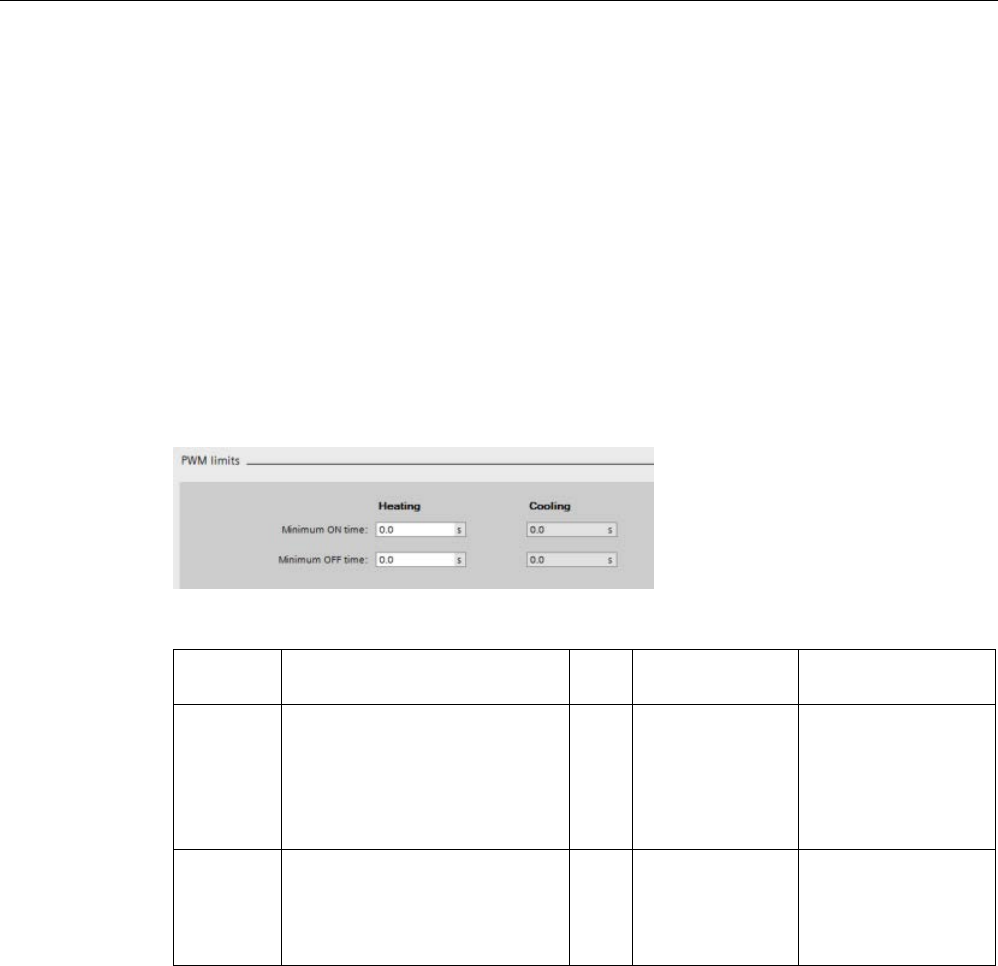
Technology instructions
10.2 PID control
S7-1200 Programmable controller
System Manual, V4.2, 09/2016, A5E02486680-AK 643
PWM limits
Actuators that are controlled with the software PWM function of the PID_Temp may need to
be protected from too short pulse durations (for example, a thyristor relay needs to be turned
on for more than 20 ms before it can react at all); you assign a minimum on time. The
actuator can also neglect short impulses and therefore corrupt the control quality. A
minimum off time can be necessary (for example, to prevent overheating).
To show up the PWM limits view, you must open the functional view in the Technology
objects (TO) configuration and select “PWM limits” from the “Advanced settings” node in the
navigation tree.
If you open the “PWM limits” view in the functional view and activate monitoring (“glasses”
button), all controls show the online monitor value from TO-DB with orange background color
and multi-value control, and you can edit the values (if configuration conditions are fulfilled;
refer to the table below).
Setting
TO-DB parameter
Data
type
Value range
Description
Minimum
on
time (heat-
ing) 1,2
"Config.Output.Heat.
MinimumOnTime"
Real 100000.0
>= "Config.Output.
Heat.
MinimumOnTime
>= 0.0
A pulse at Out-
putHeat_PWM" is
never shorter than this
value.
Minimum
off
time (heat-
ing) 1,2
"Config.Output.Heat.
MinimumOffTime"
Real 100000.0
>= "Config.Output.
Heat.
MinimumOffTime
>= 0.0
A break at Out-
putHeat_PWM is nev-
er shorter than this
value.

Technology instructions
10.2 PID control
S7-1200 Programmable controller
644 System Manual, V4.2, 09/2016, A5E02486680-AK
Setting
TO-DB parameter
Data
type
Value range
Description
Minimum
on
time (cool-
ing) 1,3,4
"Config.Output.Cool.
MinimumOnTime"
Real 100000.0
>= Config.Output.
Cool.
MinimumOnTime
>= 0.0
A pulse at Out-
putCool_PWM is nev-
er shorter than this
value.
Minimum
off
time (cool-
ing) 1,3,4
"Config.Output.Cool.
MinimumOffTime"
Real 100000.0
>= Config.Output.
Cool.
MinimumOffTime
>= 0.0
A break at Out-
putCool_PWM is nev-
er shorter than this
value.
1
The field displays "s" (seconds) as the time units.
2
If the·selection Output (heating) in “Basic settings” view is not “OutputHeat_PWM” (Con-
fig.Output.Heat.Select = TRUE), you should set this value to "0.0".
3
If selection Output (cooling) in “Basic settings” view is not “OutputCool_PWM” (Con-
fig.Output.Cool.Select = TRUE), you should set this value to "0.0".
4
Only available if you check “Activate output (cooling)” in “Basic settings” view (Con-
fig.ActivateCooling = TRUE).
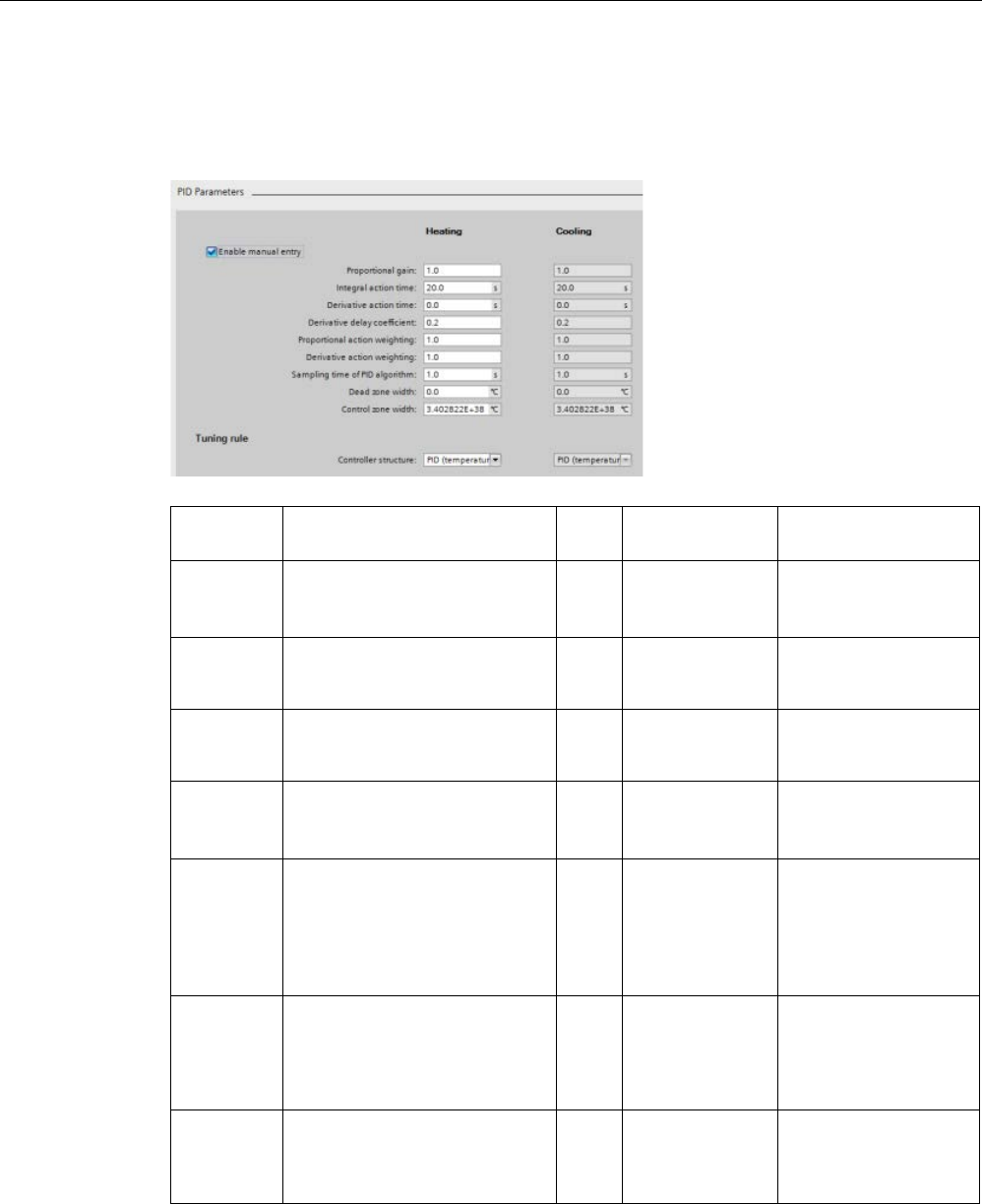
Technology instructions
10.2 PID control
S7-1200 Programmable controller
System Manual, V4.2, 09/2016, A5E02486680-AK 645
PID parameters
The “Advanced settings” view, "PID Parameters” section is shown below with the cooling
and/or “PID parameterswitchover” feature deactivated.
Setting
TO-DB parameter
Data
type
Value range
Description
Enable
manual
entry
"Retain.CtrlParams.
SetByUser"
Bool Bool
You must check this
checkbox to enter PID
parameters manually.
Proportional
gain (heat-
ing)
2
"Retain.CtrlParams.
Heat.Gain"
Real Gain >= 0.0 PID proportional gain
for heating
Integral
action time
(heating)
1,2
"Retain.CtrlParams.
Heat.Ti"
Real 100000.0 >=
Ti >= 0.0
PID integral action for
heating.
Derivative
action time
(heating) 1,2
"Retain.CtrlParams.
Heat.Td"
Real 100000.0 >=
Td >= 0.0
PID derivative action
time for heating.
Derivative
delay coeffi-
cient(heatin
g) 2
"Retain.CtrlParams.
Heat.TdFiltRatio"
Real TdFiltRatio >=
0.0
PID derivative delay
coefficient for heating
that defines the deriva-
tive lag time as coeffi-
cient from the PID
derivative time.
Proportional
action
weighting(h
eating) 2
"Retain.CtrlParams.
Heat.PWeighting"
Real 1.0 >=PWeighting
>= 0.0
Weighting of the PID
proportional gain for
heating in either direct-
or loopback- control
path.
Derivative
action
weighting
(heating)
2
"Retain.CtrlParams.
Heat.DWeighting"
Real 1.0 >=DWeighting
>= 0.0
Weighting of the PID
derivative part for heat-
ing in either direct- or
loopback- control path.

Technology instructions
10.2 PID control
S7-1200 Programmable controller
646 System Manual, V4.2, 09/2016, A5E02486680-AK
Setting
TO-DB parameter
Data
type
Value range
Description
Sampling
time of PID
algorithm
(heating) 1,2
"Retain.CtrlParams.
Heat.Cycle"
Real 100000.0
>=Cycle
> 0.0
Internal call cycle of the
PID controller for heat-
ing.
Rounded to an integer
multiple of the FB call
cycle time.
Deadband
width(heatin
g)
2,3
"Retain.CtrlParams.
Heat.DeadZone"
Real DeadZone>= 0.0 Width of the deadband
for heating control
deviation.
Control
Zone (heat-
ing)2,3
"Retain.CtrlParams.
Heat.ControlZone"
Real ControlZone> 0.0 Width of the control
deviation zone for heat-
ing where PID control is
active. If control devia-
tion leaves this range,
output is switched to
maximum output val-
ues.
Default value is
"MaxReal" so control
zone is deactivated as
long as autotuning is
not executed.
Value "0.0" is prohibit-
ed for Control Zone;
with the value "0.0",
PID_Temp behaves like
a two-position controller
that is always heating
or cooling at full power.

Technology instructions
10.2 PID control
S7-1200 Programmable controller
System Manual, V4.2, 09/2016, A5E02486680-AK 647
Setting
TO-DB parameter
Data
type
Value range
Description
Controller
structure
(heating)
"PIDSelfTune.SUT.
TuneRuleHeat",
"PIDSelfTune.TIR.
TuneRuleHeat"
Int "PIDSelf-
Tune.SUT.
TuneRuleHeat"
= 0..2,
"PIDSelf-
Tune.TIR.
TuneRuleHeat"
= 0..5
You can select the
tuning algorithm for
heating.
Possible selections:
• PID (Temperature)
(=default)
("PIDSelfTune.SUT.
TuneRuleHeat" = 2)
("PIDSelfTune.TIR.
TuneRuleHeat" = 0)
• PID
("PIDSelfTune.SUT.
TuneRuleHeat" = 0)
("PIDSelfTune.TIR.
TuneRuleHeat" = 0)
• PI
("PIDSelfTune.SUT.
TuneRuleHeat" = 1)
("PIDSelfTune.TIR.
TuneRuleHeat" = 4)
Any other combination
shows “User defined”,
but “User defined” is
not provided by default.
“PID (Temperature)” is
new for PID_Temp,
with a specific pretun-
ing (SUT) method for
temperature processes.
Proportional
gain (cool-
ing)
4
"Retain.CtrlParams.
Cool.Gain"
Real Gain >= 0.0 PID proportional gain
for cooling
Integral
action time
(cooling)
1,4
"Retain.CtrlParams.
Cool.Ti"
Real 100000.0 >=Ti
>= 0.0
PID integral action for
cooling
Derivative
action time
(cooling)
1,4
"Retain.CtrlParams.
Cool.Td"
Real 100000.0 >=Td
>= 0.0
PID derivative action
time for cooling
Derivative
delay coeffi-
cient (cool-
ing) 4
Retain.CtrlParams.
Cool.TdFiltRatio"
Real TdFiltRatio>= 0.0 PID derivative delay
coefficient for cooling
that defines the deriva-
tive lag time as a coef-
ficient from the PID
derivative time.

Technology instructions
10.2 PID control
S7-1200 Programmable controller
648 System Manual, V4.2, 09/2016, A5E02486680-AK
Setting
TO-DB parameter
Data
type
Value range
Description
Proportional
action
weighting
(cooling) 4
"Retain.CtrlParams.
Cool.PWeighting"
Real 1.0 >=PWeighting
>= 0.0
Weighting of the PID
proportional gain for
cooling in either the
direct- or loopback-
control path.
Derivative
action
weighting
(cooling) 4
Retain.CtrlParams.
Cool.DWeighting"
Real 1.0 >=DWeighting
>= 0.0
Weighting of the PID
derivative part for cool-
ing in either the direct-
or loopback- control
path.
Sampling
time of PID
algorithm
(cooling) 1,4
"Retain.CtrlParams.
Cool.Cycle"
Real 100000.0
>=Cycle
> 0.0
Internal call cycle of the
PID controller for cool-
ing.
Rounded to an integer
multiple of the FB call
cycle time.
Deadband
width (cool-
ing)
3,4
"Retain.CtrlParams.
Cool.DeadZone"
Real DeadZone>= 0.0 Width of the deadband
for cooling control devi-
ation

Technology instructions
10.2 PID control
S7-1200 Programmable controller
System Manual, V4.2, 09/2016, A5E02486680-AK 649
Setting
TO-DB parameter
Data
type
Value range
Description
Control
Zone (cool-
ing) 3,4
"Retain.CtrlParams.
Cool.ControlZone"
Real ControlZone> 0.0 Width of the control
deviation zone for cool-
ing where PID control is
active. If control devia-
tion leaves this range,
output is switched to
maximum output val-
ues.
Default value is
"MaxReal" so control
zone is deactivated as
long as autotuning is
not executed.
Value "0.0" is prohibit-
ed for Control Zone;
with the value "0.0",
PID_Temp behaves like
a two-
position controller
that is always heating
or cooling at full power.

Technology instructions
10.2 PID control
S7-1200 Programmable controller
650 System Manual, V4.2, 09/2016, A5E02486680-AK
Setting
TO-DB parameter
Data
type
Value range
Description
Controller
structure
(cooling)
"PIDSelfTune.SUT.
TuneRuleCool",
"PIDSelfTune.TIR.
TuneRuleCool"
Int "PIDSelf-
Tune.SUT.
TuneRuleHeat"
= 0..2,
"PIDSelf-
Tune.TIR.
TuneRuleHeat"
= 0..5
You can select the
tuning algorithm for
cooling.
Possible selections:
• PID (Temperature)
(=default)
("PIDSelfTune.SUT.
TuneRuleCool" = 2)
("PIDSelfTune.TIR.
TuneRuleCool = 0)
• PID
("PIDSelfTune.SUT.
TuneRuleCool" = 0)
("PIDSelfTune.TIR.
TuneRuleCool" = 0)
• PI
("PIDSelfTune.SUT.
TuneRuleCool" = 1)
("PIDSelfTune.TIR.
TuneRuleCool" = 4)
Any other combination
shows “User defined”,
but “User defined” is
not provided by default.
“PID (Temperature)” is
new for PID_Temp,
with a specific pretun-
ing (SUT) method for
temperature processes.
Only available if you
check/select the follow-
ing items: “Activate
output (cooling)” in
“Basic settings” view
("Con-
fig.ActivateCooling" =
TRUE), and “PID pa-
rameter switchover” in
“Output settings” view
(Con-
fig.AdvancedCooling =
TRUE).
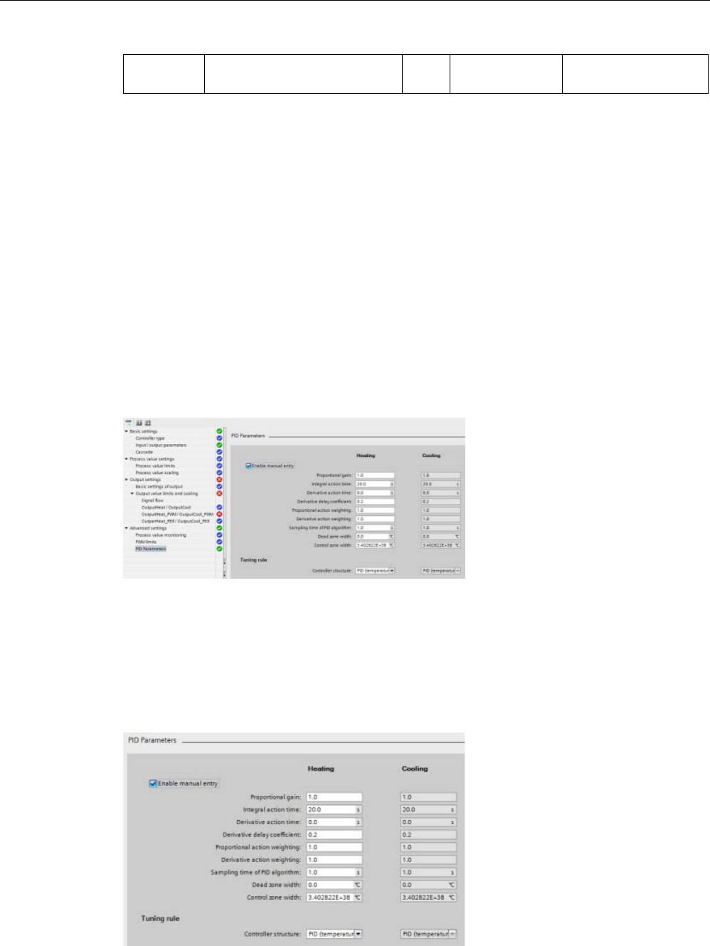
Technology instructions
10.2 PID control
S7-1200 Programmable controller
System Manual, V4.2, 09/2016, A5E02486680-AK 651
Setting
TO-DB parameter
Data
type
Value range
Description
1
The field displays "s" (seconds) as the time units.
2
Only available if you check "Enable manual entry” in PID parameters ("Re-
tain.CtrlParams.SetByUser" = TRUE).
3
Unit of measurement is displayed at the end of the field as selected in “Basic settings” view.
4
Only available if you check/select the following items: "Enable manual entry” in PID parameters
("Retain.CtrlParams.SetByUser" = TRUE), “Activate output (cooling)” in “Basic settings” view
("Config.ActivateCooling" = TRUE), and “PID parameter switchover” in “Output settings” view
(Config.AdvancedCooling = TRUE).
PID start value control
You can edit the actual values of the PID configuration parameters so that the behavior of
the PID controller can be optimized in online mode.
Open the "Technology objects" for your PID controller and its "Configuration" object. To
access the start value control, click the "eyeglasses icon" in the upper left corner of the
dialog:
You can now change the value of any of your PID controller configuration parameters as
shown in the figure below.
You can compare the actual value to the project (offline) start value and the PLC (online)
start value of each parameter. This is necessary to compare online/offline differences of the
Technology object data block (TO-DB) and to be informed about the values that will be used
as current values on the next Stop-to-Start transition of the PLC. In addition, a compare icon
gives a visual indication to help easily identify online/offline differences:
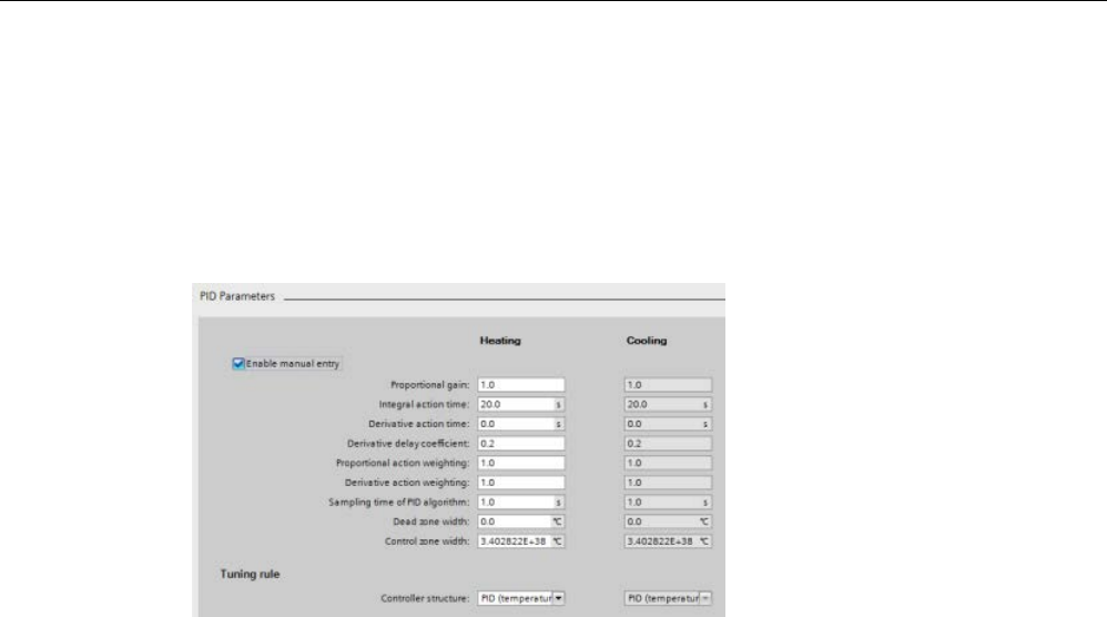
Technology instructions
10.2 PID control
S7-1200 Programmable controller
652 System Manual, V4.2, 09/2016, A5E02486680-AK
The figure above shows the PID parameter screen with compare icons showing which
values are different between online and offline projects. A green icon indicates that the
values are the same; a blue/orange icon indicates that the values are different.
Additionally, click the parameter button with the downward arrow to open a small window
that shows the project (offline) start value and the PLC (online) start value of each
parameter:
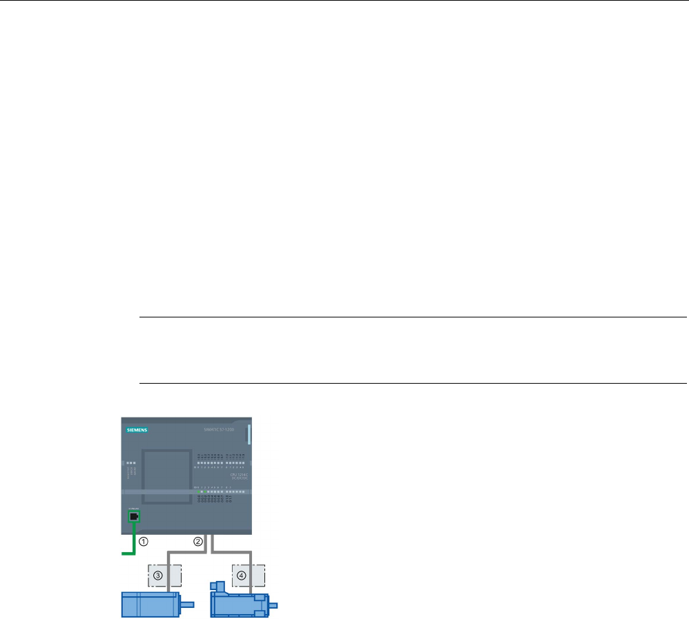
Technology instructions
10.3 Motion control
S7-1200 Programmable controller
System Manual, V4.2, 09/2016, A5E02486680-AK 653
10.3
Motion control
The CPU provides motion control functionality for the operation of stepper motors and servo
motors with pulse interface. The motion control functionality takes over the control and
monitoring of the drives.
● The "Axis" technology object configures the mechanical drive data, drive interface,
dynamic parameters, and other drive properties.
● You configure the pulse and direction outputs of the CPU for controlling the drive.
● Your user program uses the motion control instructions to control the axis and to initiate
motion tasks.
● Use the PROFINET interface to establish the online connection between the CPU and the
programming device. In addition to the online functions of the CPU, additional
commissioning and diagnostic functions are available for motion control.
Note
Changes that you make to the motion control configuration and download in RUN mode
do not take effect until the CPU transitions from STOP to RUN mode.
①
PROFINET
②
Pulse and directi
on outputs
③
Power section for stepper motor
④
Power section for servo motor
The DC/DC/DC variants of the CPU S7
-1200 have onboard
outputs for direct control of drives. The relay variants of the
CPU require the signal board with DC outputs for drive
con-
trol.
A signal board (SB) expands the onboard I/O to include a few additional I/O points. An SB
with two digital outputs can be used as pulse and direction outputs to control one motor. An
SB with four digital outputs can be used as pulse and direction outputs to control two motors.
Built-in relay outputs cannot be used as pulse outputs to control motors. Whether you use
onboard I/O or SB I/O or a combination of both, you can have a maximum number of four
pulse generators.

Technology instructions
10.3 Motion control
S7-1200 Programmable controller
654 System Manual, V4.2, 09/2016, A5E02486680-AK
The four pulse generators have default I/O assignments; however, they can be configured to
any digital output on the CPU or SB. Pulse generators on the CPU cannot be assigned to
SMs or to distributed I/O.
Note
Pulse-train outputs cannot be used by other instructions in the user program
When you configure the outputs of the CPU or signal board as pulse generators (for use with
the PWM or motion control instructions), the corresponding output addresses no longer
control the outputs. If your user program writes a value to an output used
as a pulse
generator, the CPU does not write that value to the physical output.
Table 10- 35 Maximum number of controllable drives
Type of CPU
Onboard I/O;
No SB installed
With an SB
(2 x DC outputs)
With an SB
(4 x DC outputs)
With direc-
tion
Without
direction
With direc-
tion
Without
direction
With direc-
tion
Without
direction
CPU 1211C
DC/DC/DC
2
4
3
4
4
4
AC/DC/Relay
0
0
1
2
2
4
DC/DC/Relay
0
0
1
2
2
4
CPU 1212C
DC/DC/DC
3
4
3
4
4
4
AC/DC/Relay
0
0
1
2
2
4
DC/DC/Relay
0
0
1
2
2
4
CPU 1214C
DC/DC/DC
4
4
4
4
4
4
AC/DC/Relay
0
0
1
2
2
4
DC/DC/Relay
0
0
1
2
2
4
CPU 1215C
DC/DC/DC
4
4
4
4
4
4
AC/DC/Relay
0
0
1
2
2
4
DC/DC/Relay
0
0
1
2
2
4
CPU 1217C
DC/DC/DC
4
4
4
4
4
4
Note
The maximum number of pulse generators is four.
Whether you use onboard I/O, SB I/O, or a combination of both, you can have a maximum
number of four pulse generators.

Technology instructions
10.3 Motion control
S7-1200 Programmable controller
System Manual, V4.2, 09/2016, A5E02486680-AK 655
Table 10- 36 CPU output: maximum frequency
CPU
CPU output channel
Pulse and direction
output
A/B, quadrature, up/down,
and pulse/direction
1211C
Qa.0 to Qa.3
100 kHz
100 kHz
1212C Qa.0 to Qa.3 100 kHz 100 kHz
Qa.4, Qa.5
20 kHz
20 kHz
1214C and 1215C
Qa.0 to Qa.3
100kHz
100kHz
Qa.4 to Qb.1
20 kHz
20 kHz
1217C DQa.0 to DQa.3
(.0+, .0- to .3+, .3-)
1 MHz 1 MHz
DQa.4 to DQb.1
100 kHz
100 kHz
Table 10- 37 SB signal board output: maximum frequency (optional board)
SB signal board
SB output channel
Pulse and direction
output
A/B, quadrature, up/down,
and pulse/direction
SB 1222, 200 kHz
DQe.0 to DQe.3
200kHz
200 kHz
SB 1223, 200 kHz
DQe.0, DQe.1
200kHz
200 kHz
SB 1223
DQe.0, DQe.1
20 kHz
20 kHz
Table 10- 38 Limit frequencies of pulse outputs
Pulse output
Frequency
Onboard 4 PTO: 2 Hz ≤ f ≤ 1 MHz, 4 PTO: 2 Hz ≤ f ≤ 100 kHz, or any
combination of these values for 4 PTOs.
1 2
Standard SB
2 Hz ≤ f ≤ 20 kHz
High-speed SBs
2 Hz ≤ f ≤ 200 kHz
1
See the table below for four possible CPU 1217C output speed combinations.
2
See t
he table below for four possible CPU 1211C, CPU 1212C, CPU 1214C, or CPU 1215C output
speed combinations.

Technology instructions
10.3 Motion control
S7-1200 Programmable controller
656 System Manual, V4.2, 09/2016, A5E02486680-AK
Example: CPU 1217C pulse output speed configurations
Note
The CPU 1217C can generate pulse outputs up to 1 MHz, using the onboard differential
out
puts.
The examples below show four possible output speed combinations:
● Example 1: 4 - 1 MHz PTOs, no direction output
● Example 2: 1 - 1 MHz, 2 - 100 kHz, and 1 - 20 kHz PTOs, all with direction output
● Example 3: 4 - 200 kHz PTOs, no direction output
● Example 4: 2 - 100 kHz PTOs and 2 - 200 kHz PTOs, all with direction output
P = Pulse
D = Direction
CPU on-board outputs
High-speed SB outputs
Standard
SB out-
puts
1 MHz Outputs (Q) 100 kHz Outputs (Q) 200 kHz Outputs (Q) 20 kHz
Outputs
(Q)
0.0+
0.1+
0.2+
0.3+
0.4
0.5
0.6
0.7
1.0
1.1
4.0
4.1
4.2
4.3
4.0
4.1
0.0-
0.1-
0.2-
0.3-
Ex. 1:
4 - 1
MHz
(no
direction
output)
PTO1
P
PTO2
P
PTO3
P
PTO4 P
Ex. 2: 1 -
1 MHz; 2
- 100
and 1 -
20 kHz
(all with
direction
output)
PTO1
P
D
PTO2 P D
PTO3
P
D
PTO4 P D
Ex. 3:
4 - 200
kHz (no
direction
output)
PTO1
P
PTO2
P
PTO3
P
PTO4
P
Ex. 4:
2 - 100
kHz;
2 - 200
kHz (all
with
direction
output)
PTO1
P
D
PTO2
P
D
PTO3
P
D
PTO4 P D

Technology instructions
10.3 Motion control
S7-1200 Programmable controller
System Manual, V4.2, 09/2016, A5E02486680-AK 657
Example: CPU 1211C, CPU 1212C, CPU 1214C, and CPU 1215C pulse output speed configurations
The examples below show four possible output speed combinations:
● Example 1: 4 - 100 kHz PTOs, no direction output
● Example 2: 2 - 100 kHz PTOs and 2 - 20 kHz PTOs, all with direction output
● Example 3: 4 - 200 kHz PTOs, no direction output
● Example 4: 2 - 100 kHz PTOs and 2 - 200 kHz PTOs, all with direction output
P = Pulse
D = Direction
CPU on-board outputs
High-speed SB outputs
Low-speed
SB outputs
100 kHz Outputs (Q) 20 kHz Outputs (Q) 200 kHz Outputs (Q) 20 kHz
Outputs
(Q)
0.0 0.1 0.2 0.3 0.4 0.5 0.6 0.7 1.0 1.1 4.0 4.1 4.2 4.3 4.0 4.1
CPU 1211C
CPU 1212C CPU
1212C
CPU 1214C CPU
1214C
CPU 1214C
CPU 1215C CPU
1215C
CPU 1215C
Ex. 1:
4 - 100
kHz (no
direction
output)
PTO1
P
PTO2
P
PTO3
P
PTO4 P
Ex. 2:
2 - 100
kHz;
2 - 20
kHz (all
with direc-
tion out-
put)
PTO1
P
D
PTO2
P
D
PTO3
P
D
PTO4 P D
Ex. 3:
4 - 200
kHz (no
direction
output)
PTO1 P
PTO2
P
PTO3
P
PTO4
P
Ex. 4:
2 - 100
kHz;
2 - 200
kHz (all
with direc-
tion out-
put)
PTO1
P
D
PTO2
P
D
PTO3
P
D
PTO4 P D
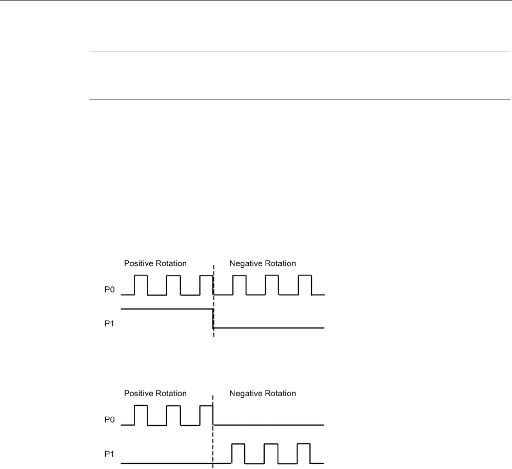
Technology instructions
10.3 Motion control
S7-1200 Programmable controller
658 System Manual, V4.2, 09/2016, A5E02486680-AK
Note
Refer to the
SIMATIC STEP 7 S7-1200 Motion Control V14 Function Manual
for further
information.
10.3.1
Phasing
You have four options for the "Phasing" interface to the stepper/servo drive. These options
are as follows:
● PTO (pulse A and direction B): If you select a PTO (pulse A and direction B) option, then
one output (P0) controls the pulsing and one output (P1) controls the direction. P1 is high
(active) if pulsing is in the positive direction. P1 is low (inactive) if pulsing is in the
negative direction:
● PTO (pulse up A and pulse down B): If you select a PTO (pulse up A and pulse down B)
option, then one output (P0) pulses for positive directions and a different output (P1)
pulses for negative directions:
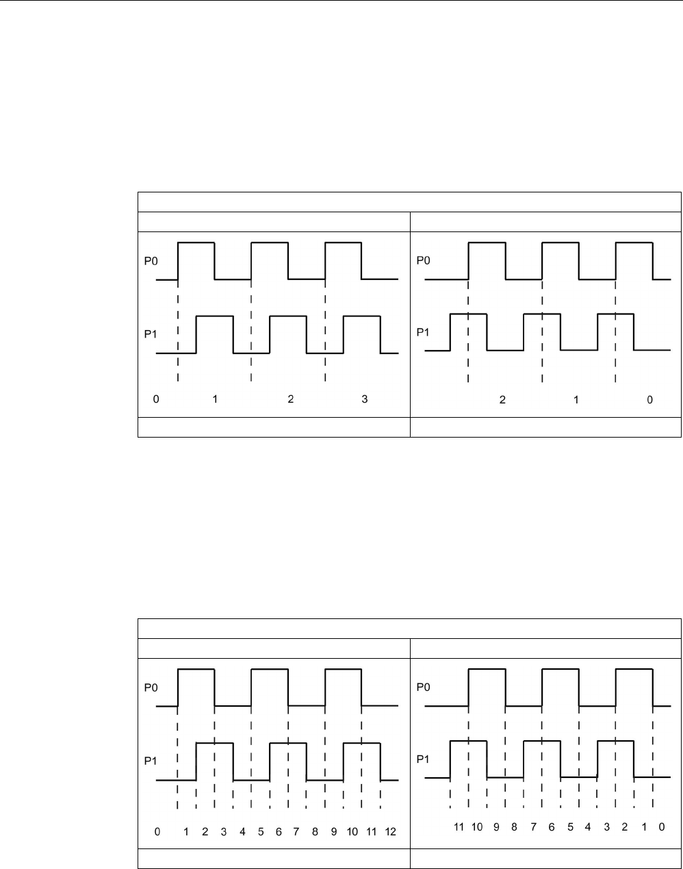
Technology instructions
10.3 Motion control
S7-1200 Programmable controller
System Manual, V4.2, 09/2016, A5E02486680-AK 659
● PTO (A/B phase-shifted): If you select a PTO (A/B phase-shifted) option, then both
outputs pulse at the speed specified, but 90 degrees out-of-phase. It is a 1X
configuration, meaning one pulse is the amount of time between positive transitions of
P0. In this case, the direction is determined by which output transitions high first. P0
leads P1 for the positive direction. P1 leads P0 for the negative direction.
The number of pulses generated is based upon the number of 0 to 1 transitions of Phase
A. The phase relationship determines the direction of movement:
PTO (A/B phase-shifted)
Phase A leads phase B (positive movement)
Phase A lags phase B (negative movement)
Number of pulses
Number of pulses
● PTO (A/B phase-shifted - fourfold): If you select a PTO (A/B phase-shifted - fourfold)
option, then both outputs pulse at the speed specified, but 90 degrees out-of-phase. The
fourfold is a 4X configuration, meaning one pulse is the transition of each output (both
positive and negative). In this case, the direction is determined by which output
transitions high first. P0 leads P1 for the positive direction. P1 leads P0 for the negative
direction.
Fourfold is based upon positive and negative transitions of both Phase A and Phase B.
You configure the number of transitions. The phase relationship (A leading B or B leading
A) determines the direction of movement.
PTO (A/B phase-shifted - fourfold)
Phase A leads phase B (positive movement)
Phase A lags phase B (negative movement)
Number of pulses
Number of pulses

Technology instructions
10.3 Motion control
S7-1200 Programmable controller
660 System Manual, V4.2, 09/2016, A5E02486680-AK
● PTO (pulse and direction (direction de-selected)): If you de-select the direction output in a
PTO (pulse and direction (direction de-selected)), then output (P0) controls the pulsing.
Output P1 is not used and is available for other program uses. Only positive motion
commands are accepted by the CPU in this mode. Motion control restricts you from
making illegal negative configurations when you select this mode. You can save an
output if your motion application is in one direction only. Single phase (one output) is
shown in the figure below (assuming positive polarity):

Technology instructions
10.3 Motion control
S7-1200 Programmable controller
System Manual, V4.2, 09/2016, A5E02486680-AK 661
10.3.2
Configuring a pulse generator
1. Add a Technology object:
– In the Project tree, expand the node "Technology Objects" and select "Add new
object".
– Select the "Axis" icon (rename if required) and click "OK" to open the configuration
editor for the axis object.
Note
To ensure the consistency of your project af
ter you rename the technology objects,
download the project to the CPU while it is in STOP. A name change occurs when you
delete a technolology object and create a new technology object with a new name and
data block number.
– Display the "Select PTO for Axis Control" properties under the "Basic parameters" and
select the desired pulse.
Note
If the PTO has not been previously configured in the CPU Properties, the PTO is
configured to use one of the onboard outputs.
If you use an output signal board, t
hen select the "Device configuration" button to go
to the CPU Properties. Under "Parameter assignment", in the "Pulse options",
configure the output source to a signal board output.
– Configure the remaining Basic and Extended parameters.
2. Program your application: Insert the MC_Power instruction in a code block.
– For the Axis input, select the axis technology object that you created and configured.
– Setting the Enable input to TRUE allows the other motion instructions to function.
– Setting the Enable input FALSE cancels the other motion instructions.
Note
Include only one MC_Power instruction per axis.
3. Insert the other motion instructions to produce the required motion.
Note
Configuring a pulse generator to signal board outputs: Select the "Pulse ge
nerators
(PTO/PWM)" properties for a CPU (in Device configuration) and enable a pulse generator.
Two pulse generators are available for each S7
-1200 CPU V1.0, V2.0, V2.1, and V2.2.
S7
-1200 CPU V3.0 and V4.0 CPUs have four pulse generators available. In this same
configuration area under "Pulse options", select Pulse generator used as: "PTO".
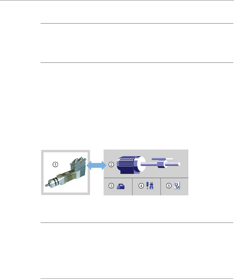
Technology instructions
10.3 Motion control
S7-1200 Programmable controller
662 System Manual, V4.2, 09/2016, A5E02486680-AK
Note
The CPU calculates motion tasks in "slices" or segments of 10
ms. As one slice is being
executed, the next slice is waiting in the queue to be executed. If y
ou interrupt the motion
task on an axis (by executing another new motion task for that axis), the new motion task
cannot be executed for a maximum of 20
ms (the remainder of the current slice plus the
queued slice).
10.3.3
Open loop motion control
10.3.3.1
Configuring the axis
You connect the open loop axis on the PLC and the drive through a PTO (Pulse Train
Output). For motion applications using PTO, the CPU requires onboard or signal board (SB)
digital I/O. This limits the number of axes that are available on the smaller PLCs.
STEP 7 provides the configuration tools, the commissioning tools, and the diagnostic tools
for the "Axis" technology object.
①
Drive
④
Commissioning
②
Technology object
⑤
Diagnostics
③
Configuration
Note
For CPU firmware releases V2.2 and earlier, the PTO requires the internal functionality of a
high
-speed counter (HSC). This means the corresponding HSC cannot be used elsewhere.
The assignment between PTO and HSC is fixed. If PTO1 is activated, it will be connected to
HSC1. If PTO2 is activated, it will be connected to HSC2. You cannot monitor the current
value (for example, in ID1000) when pulses are occurring.
S7
-1200 V3.0 and later CPUs do not have this restriction; all HSCs remain available for
program use when pulse outputs are configured in these CPUs.

Technology instructions
10.3 Motion control
S7-1200 Programmable controller
System Manual, V4.2, 09/2016, A5E02486680-AK 663
Table 10- 39 STEP 7 tools for motion control
Tool
Description
Configuration Configures the following properties of the "Axis" technology object:
• Selection of the PTO to be used and configuration of the drive interface
• Properties of the mechanics and the transmission ratio of the drive (or machine or system)
• Properties for position limits, dynamics, and homing
Save the configuration in the data block of the technology object.
Commissioning Tests the function of your axis without having to create a user program. When the tool is started,
the control panel will be displayed. The following commands are available on the control panel:
• Enable and disable axis
• Move axis in jog mode
• Position axis in absolute and relative terms
• Home axis
• Acknowledge errors
The velocity and the acceleration / deceleration can be specified for the motion commands. The
control panel also shows the current axis status.
Diagnostics
Monitors of the current status and error information for the axis and drive.
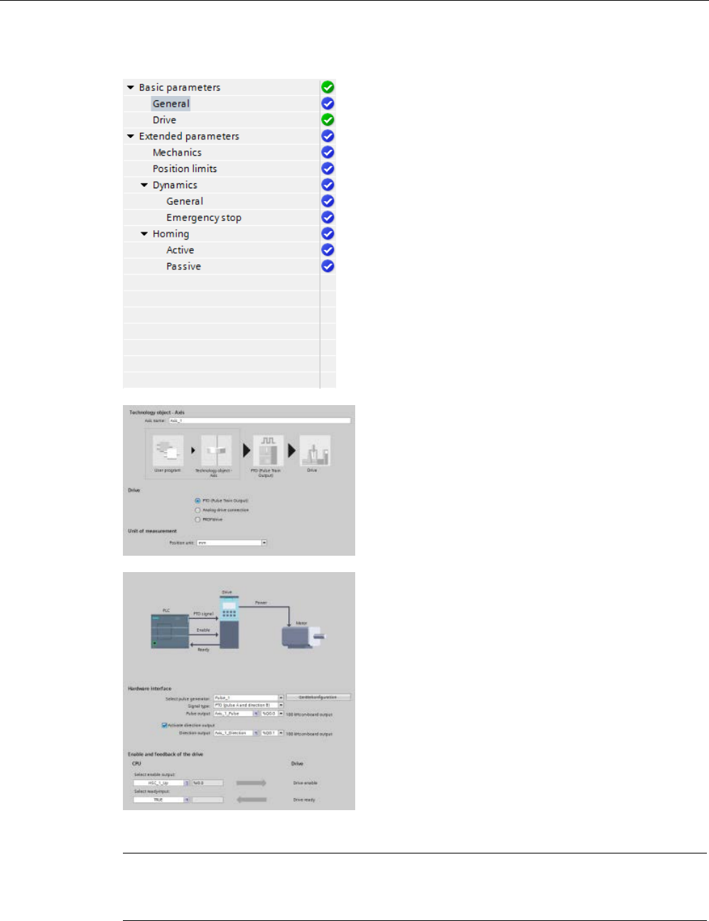
Technology instructions
10.3 Motion control
S7-1200 Programmable controller
664 System Manual, V4.2, 09/2016, A5E02486680-AK
The tree selector for the PTO axis does not include
the Encoder, Modulo, Posi
tion monitoring, and
Control loop configuration menus.
After you create the technology object for the axis,
you configure the axis by defining the basic p
a-
rameters, such as the PTO and the configuration of
the drive interface. You
also configure the other
properties of the axis, such as position limits, d
y-
namics, and homing.
Note
You may have to adapt the values of the input parameters of motion control instructions to
the new dimension unit in the use
r program.
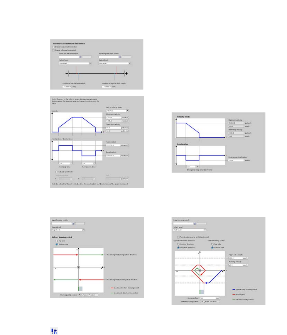
Technology instructions
10.3 Motion control
S7-1200 Programmable controller
System Manual, V4.2, 09/2016, A5E02486680-AK 665
Configure the properties for the drive signals, drive
mechanics, and position monitoring (hardware and
software limit switches).
You configure the motion dynamics and the beha
v-
ior of the emergency stop command.
You also configure the homing behavior (passive and active).
Use the "Commissioning" control panel to test the functionality independently from your user
program.
Click the "Startup" icon to commission the axis.
The control panel shows the current status of the axis. Not only can you enable and disable
the axis, but you can also test the positioning of the axis (both in absolute and relative terms)
and can specify the velocity, acceleration and deceleration. You can also test the homing
and jogging tasks. The control panel also allows you to acknowledge errors.

Technology instructions
10.3 Motion control
S7-1200 Programmable controller
666 System Manual, V4.2, 09/2016, A5E02486680-AK
10.3.3.2
Commissioning
"Status and error bits" diagnostic function
Use the "Status and error bits" diagnostic function to monitor the most important status and
error messages for the axis. The diagnostic function display is available in online mode in
"Manual control" mode and in "Automatic control" when the axis is active.
Table 10- 40 Status of the axis
Status
Description
Enabled The axis is enabled and ready to be controlled via motion control tasks.
(Tag of technology object: <Axis name>.StatusBits.Enable)
Homed The axis is homed and is capable of executing absolute positioning tasks of motion control instruc-
tion "MC_MoveAbsolute". The axis does not have to be homed for relative homing. Special situa-
tions:
• During active homing, the status is FALSE.
• If a homed axis undergoes passive homing, the status is set to TRUE during passive homing.
(Tag of technology object: <Axis name>.StatusBits.HomingDone)
Error An error has occurred in the "Axis" technology object. More information about the error is available
in automatic control at the ErrorID and ErrorInfo parameters of the motion control instructions. In
manual mode, the "Last error" field of the control panel displays detailed information about the
cause of error.
(Tag of technology object: <Axis name>.StatusBits.Error)
Control panel active The "Manual control" mode was enabled in the control panel. The control panel has control priority
over the "Axis" technology object. The axis cannot be controlled from the user program.
(Tag of technology object: <Axis name>.StatusBits.ControlPanelActive)
Table 10- 41 Drive status
Status
Description
Drive ready The drive is ready for operation.
(Tag of technology object: <Axis name>.StatusBits.DriveReady)
Error The drive has reported an error after failure of its ready signal.
(Tag of technology object: <Axis name>.ErrorBits.DriveFault)

Technology instructions
10.3 Motion control
S7-1200 Programmable controller
System Manual, V4.2, 09/2016, A5E02486680-AK 667
Table 10- 42 Status of the axis motion
Status
Description
Standstill The axis is at a standstill.
(Tag of technology object: <Axis name>.StatusBits.StandStill)
Accelerating The axis accelerates.
(Tag of technology object: <Axis name>.StatusBits.Acceleration)
Constant velocity The axis travels at constant velocity.
(Tag of technology object: <Axis name>.StatusBits.ConstantVelocity)
Decelerating The axis decelerates (slows down).
(Tag of technology object: <Axis name>.StatusBits.Deceleration)
Table 10- 43 Status of the motion mode
Status
Description
Positioning The axis executes a positioning task of motion control instruction "MC_MoveAbsolute" or
"MC_MoveRelative" or of the control panel.
(Tag of technology object: <Axis name>.StatusBits.PositioningCommand)
Speed Command The axis executes a task at set speed of motion control instruction "MC_MoveVelocity" or
"MC_MoveJog" or of the control panel.
(Tag of technology object: <Axis name>.StatusBits.SpeedCommand)
Homing The axis executes a homing task of motion control instruction "MC_Home" or the control
panel.
(Tag of technology object: <Axis name>.StatusBits.Homing)
Table 10- 44 Error bits
Error
Description
Min software limit reached The lower software limit switch has been reached.
(Tag of technology object: <Axis name>.ErrorBits.SwLimitMinReached)
Min software limit exceeded The lower software limit switch has been exceeded.
(Tag of technology object: <Axis name>.ErrorBits.SwLimitMinExceeded)
Max software limit reached The upper software limit switch has been reached.
(Tag of technology object: <Axis name>.ErrorBits.SwLimitMaxReached)
Max software limit exceeded The upper software limit switch has been exceeded.
(Tag of technology object: <Axis name>.ErrorBits.SwLimitMaxExceeded)
Negative hardware limit The lower hardware limit switch has been approached.
(Tag of technology object: <Axis name>.ErrorBits.HwLimitMin)
Positive hardware limit The upper hardware limit switch has been approached.
(Tag of technology object: <Axis name>.ErrorBits.HwLimitMax)
PTO already used A second axis is using the same PTO and is enabled with "MC_Power".
(Tag of technology object: <Axis name>.ErrorBits.HwUsed)

Technology instructions
10.3 Motion control
S7-1200 Programmable controller
668 System Manual, V4.2, 09/2016, A5E02486680-AK
Error
Description
Configuration error The "Axis" technology object was incorrectly configured or editable configuration data
were modified incorrectly during runtime of the user program.
(Tag of technology object: <Axis name>.ErrorBits.ConfigFault)
General Error An internal error has occurred.
(Tag of technology object: <Axis name>.ErrorBits.SystemFault)
"Motion status" diagnostic function
Use the "Motion status" diagnostic function to monitor the motion status of the axis. The
diagnostic function display is available in online mode in "Manual control" mode and in
"Automatic control" when the axis is active.
Table 10- 45 Motion status
Status
Description
Target position The "Target position" field indicates the current target position of an active positioning task of
motion control instruction "MC_MoveAbsolute" or "MC_MoveRelative" or of the control panel.
The value of the "Target position" is only valid during execution of a positioning task.
(Tag of technology object: <Axis name>.MotionStatus.TargetPosition)
Current position The "Current position" field indicates the current axis position. If the axis is not homed, the
value indicates the position value relative to the enable position of the axis.
(Tag of technology object: <Axis name>.MotionStatus.Position)
Current velocity The "Current velocity" field indicates the actual axis velocity.
(Tag of technology object: <Axis name>.MotionStatus.Velocity)
Table 10- 46 Dynamic limits
Dynamic limit
Description
Velocity The "Velocity" field indicates the configured maximum velocity of the axis.
(Tag of technology object: <Axis name>.Config.DynamicLimits.MaxVelocity)
Acceleration The "Acceleration" field indicates the currently configured acceleration of the axis.
(Tag of technology object: <Axis name>.Config.DynamicDefaults.Acceleration)
Deceleration The "Deceleration" field indicates the currently configured deceleration of the axis.
(Tag of technology object: <Axis name>.Config.DynamicDefaults.Deceleration)
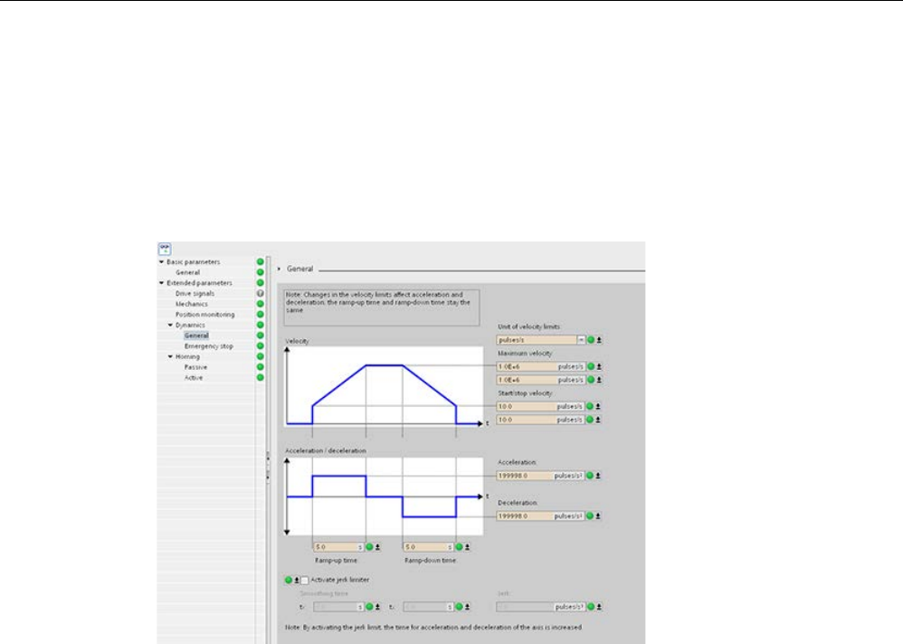
Technology instructions
10.3 Motion control
S7-1200 Programmable controller
System Manual, V4.2, 09/2016, A5E02486680-AK 669
Motion start value control
You can edit the actual values of the Motion configuration parameters so that the behavior of
the process can be optimized in online mode.
Open the "Technology objects" for your motion control and its "Configuration" object. To
access the start value control, click the "eyeglasses icon" in the upper left corner of the
dialog:

Technology instructions
10.3 Motion control
S7-1200 Programmable controller
670 System Manual, V4.2, 09/2016, A5E02486680-AK
You can now change the value of any of your motion control configuration parameters as
shown in the figure below.
You can compare the actual value to the project (offline) start value and the PLC (online)
start value of each parameter. This is necessary to compare online/offline differences of the
Technology object data block (TO-DB) and to be informed about the values that will be used
as current values on the next Stop-to-Start transition of the PLC. In addition, a compare icon
gives a visual indication to help easily identify online/offline differences.
The figure above shows the Motion parameter screen with compare icons showing which
values are different between online and offline projects. A green icon indicates that the
values are the same; a blue/orange icon indicates that the values are different.
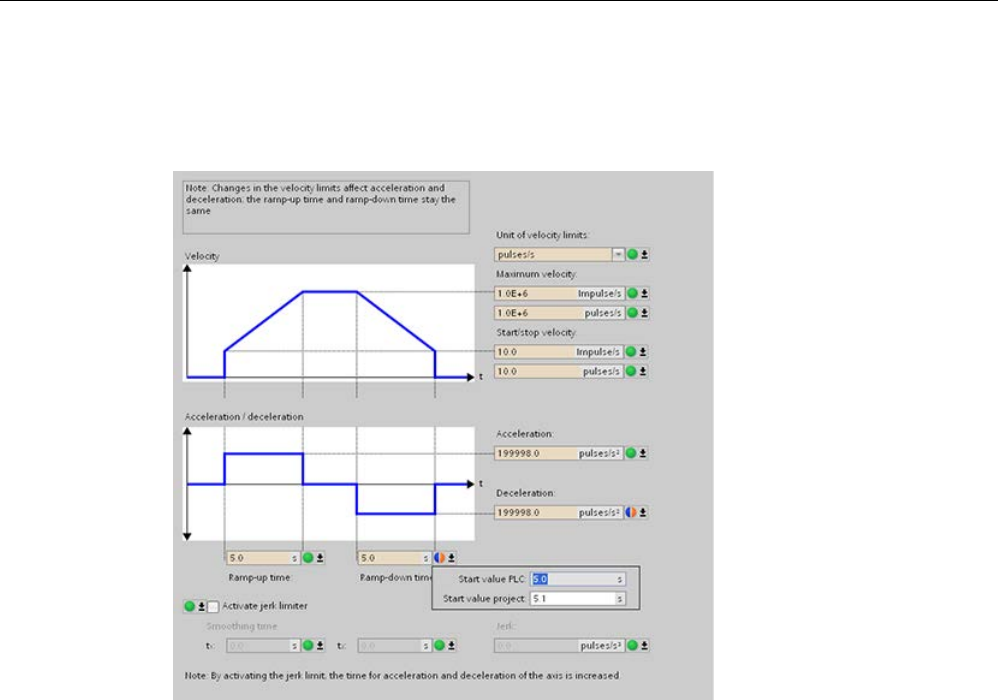
Technology instructions
10.3 Motion control
S7-1200 Programmable controller
System Manual, V4.2, 09/2016, A5E02486680-AK 671
Additionally, click the parameter button with the downward arrow to open a small window
that shows the project (offline) start value and the PLC (online) start value of each
parameter.
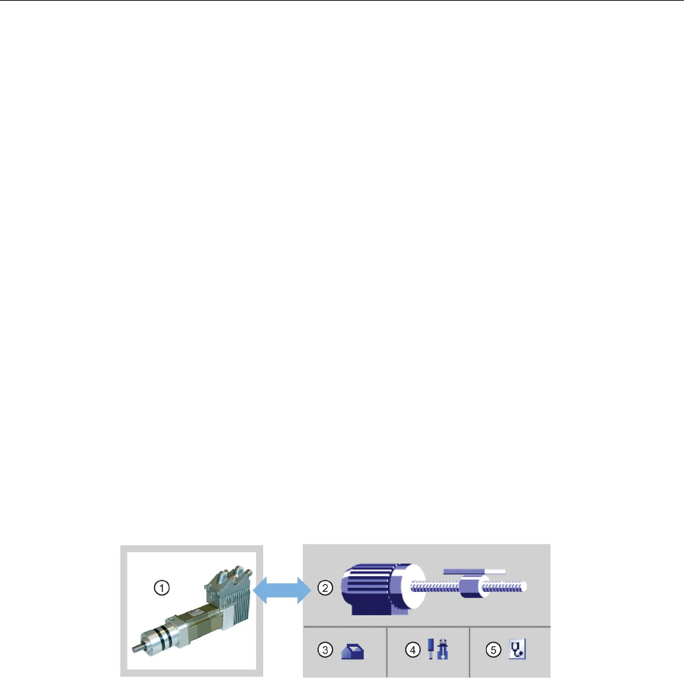
Technology instructions
10.3 Motion control
S7-1200 Programmable controller
672 System Manual, V4.2, 09/2016, A5E02486680-AK
10.3.4
Closed loop motion control
10.3.4.1
Configuring the axis
You connect the closed loop axis on the PLC and the drive through one of two connections:
● Analog drive: This connection can use onboard, SB, or signal module (SM) analog I/O; it
does not use PTOs. You have the following analog I/O resolution available for your
application:
– Onboard I/O: 10 bit (lowest I/O resolution)
– Signal board (SB) I/O: 12 bit
– SM I/O: 14 bit (highest I/O resolution)
● PROFIdrive: This connection is a network solution and does not use PTOs.
The closed loop axis requires an encoder as well. You can connect encoders to the following
items:
● Encoder interface on the drive
● High-speed counters (HSC)
● Technology modules (TM)
● PROFIdrive encoder on PROFINET / PROFIBUS
You can have a maximum number of eight drives (or axes) for the PROFIdrive or analog
drive connection.
STEP 7 provides the configuration tools, the commissioning tools, and the diagnostic tools
for the "Axis" technology object.
①
Drive
④
Commissioning
②
Technology object
⑤
Diagnostics
③
Configuration

Technology instructions
10.3 Motion control
S7-1200 Programmable controller
System Manual, V4.2, 09/2016, A5E02486680-AK 673
Table 10- 47 STEP 7 tools for closed loop motion control
Tool
Description
Configuration Configures the following properties of the "Axis" technology object:
• Selection of the analog drive connection or PROFIdrive to be used and configuration of the
drive and encoder interface
• Properties of the mechanics and the transmission ratio of the drive and encoder (or machine
or system)
• Properties for position limits, dynamics, and homing
Save the configuration in the data block of the technology object.
Commissioning Tests the function of your axis without having to create a user program. When the tool is started,
the control panel will be displayed. The following commands are available on the control panel:
• Enable and disable axis
• Move axis in jog mode
• Position axis in absolute and relative terms
• Home axis
• Acknowledge errors
The velocity and the acceleration / deceleration can be specified for the motion commands. The
control panel also shows the current axis status.
Diagnostics
Monitors of the current status and error information for the axis and drive.
Note
You may have to adapt the values of the input parameters of motion control instructions t
o
the new dimension unit in the user program.
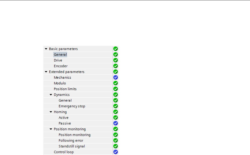
Technology instructions
10.3 Motion control
S7-1200 Programmable controller
674 System Manual, V4.2, 09/2016, A5E02486680-AK
After you create the technology object for the axis, you configure the axis by defining the
basic parameters, either the Analog drive or the PROFIdrive connection and the
configuration of the drive and encoder.
The tree selector for the analog drive or
PROFIdrive connection includes the Encoder,
Modulo, Position monitoring, and Control loop co
n-
figuration menus.
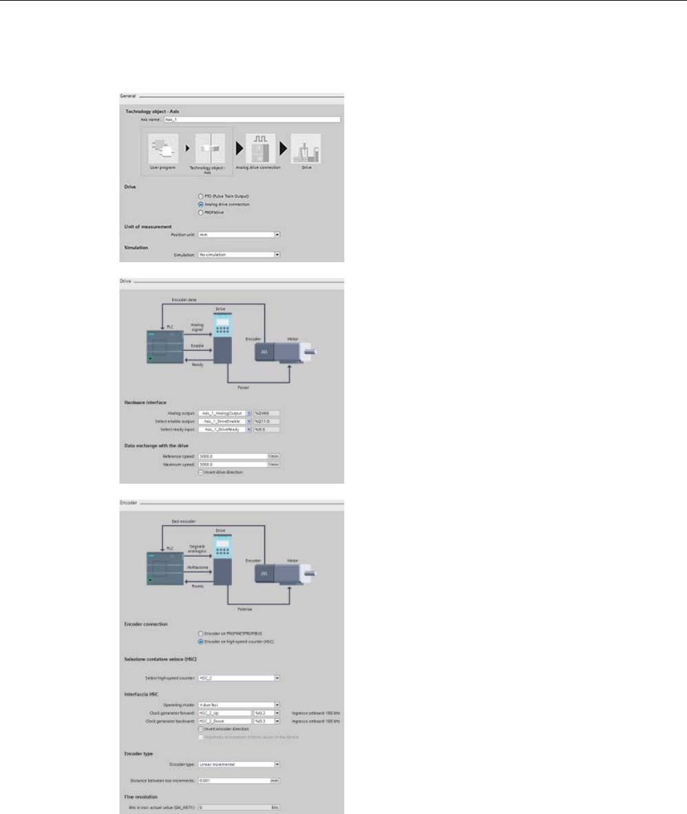
Technology instructions
10.3 Motion control
S7-1200 Programmable controller
System Manual, V4.2, 09/2016, A5E02486680-AK 675
Analog drive connection configuration
In the Gen
eral configuration dialog, you select the
following parameters:
•
"Analog drive connection" radio button
•
Unit of measurement
In the Drive configuration dialog, you select the
following parameters:
•
Analog drive hardware outputs
•
Data exchange drive velocities
Note: The Maximum speed must be greater
than or equal to the Reference (nominal) speed.
In the Encoder configuration dialog, you select the
following parameters:
•
Analog drive encoder coupling (for example, a
high-speed counter (HSC))
•
HSC interface
•
Encoder type
•
Fine resolution
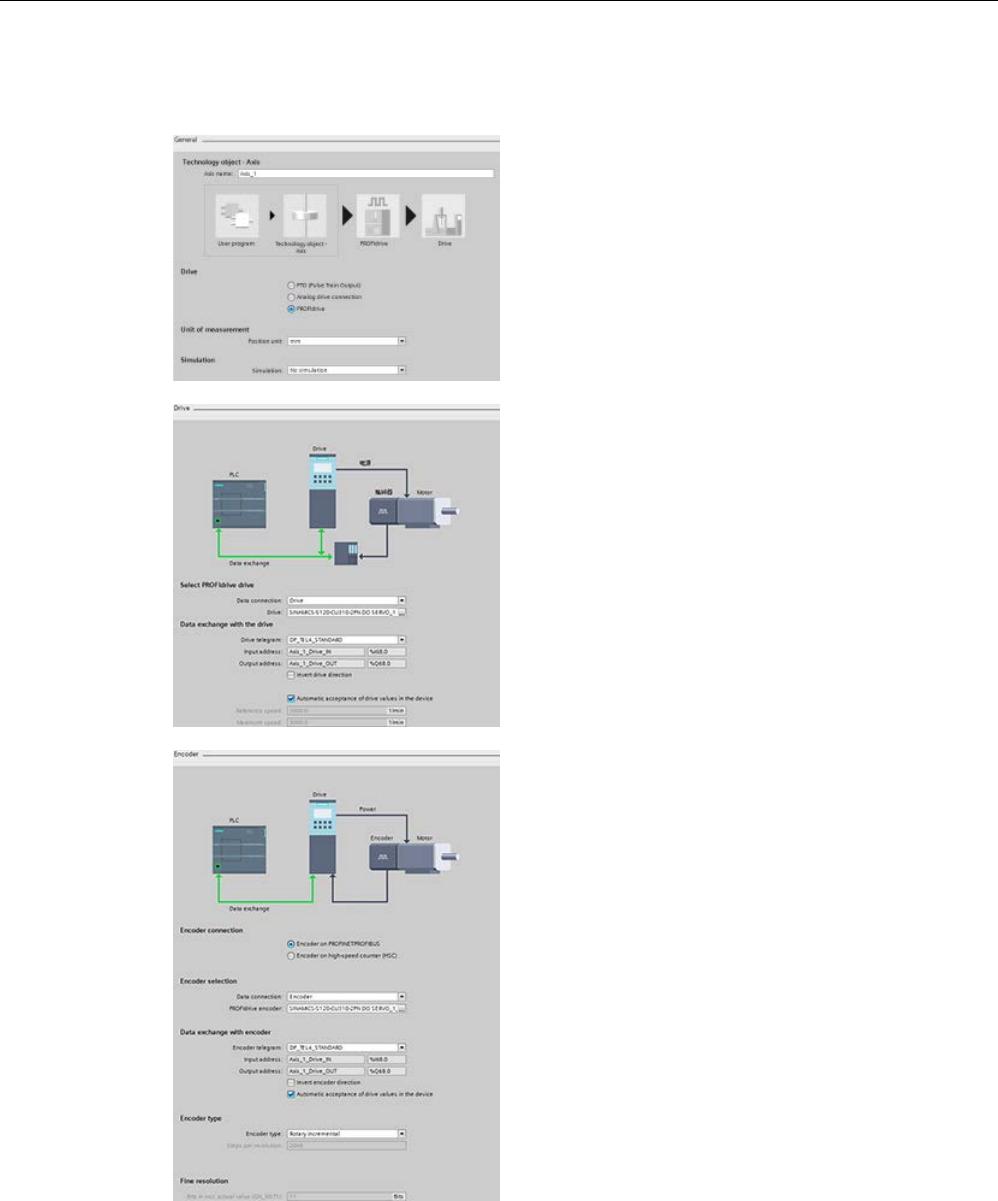
Technology instructions
10.3 Motion control
S7-1200 Programmable controller
676 System Manual, V4.2, 09/2016, A5E02486680-AK
PROFIdrive configuration
In the General configuration dialog, you select the
following parameters:
•
"PROFIdrive" radio button
•
Unit of measurement
In the Drive configuration dialog, you select the
following parameters:
•
PROFIdrive drive
•
Data exchange with the drive
Note: The Maximum speed must be greater
than or equal to the Reference (nominal) speed.
In the Encod
er configuration dialog, you select the
following parameters:
•
PROFIdrive encoder coupling (for example, a
PROFIdrive encoder on PROFINET)
•
PROFIdrive encoder
•
Data exchange with the encoder
•
Encoder type
•
Fine resolution
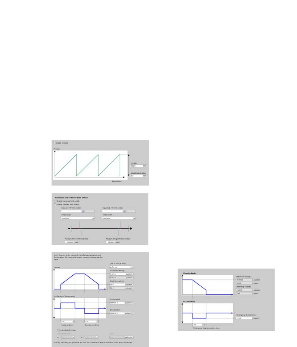
Technology instructions
10.3 Motion control
S7-1200 Programmable controller
System Manual, V4.2, 09/2016, A5E02486680-AK 677
Extended parameters
You can also configure the following properties of the closed loop axis:
● Modulo
● Position limits
● Dynamics
● Homing
● Position monitoring
● Following error
● Standstill signal
● Control loop
Modulo: You can configure a "Modulo" axis to
move the load in a cyclic
area which has a start
value/start position and a given length. If the pos
i-
tion of the load reaches the end of this area, it is
automatically set to the start value again. You en
a-
ble the "Length" and "Modulo start value" fields
when you check the "Enable
Modulo" check box.
Position limits: You can configure the properties for
the drive signals, drive mechanics, and position
monitoring (hardware and software limit switches).
Dynamics: You can configure the m
otion dynamics
and the behavior of the emergency stop command.
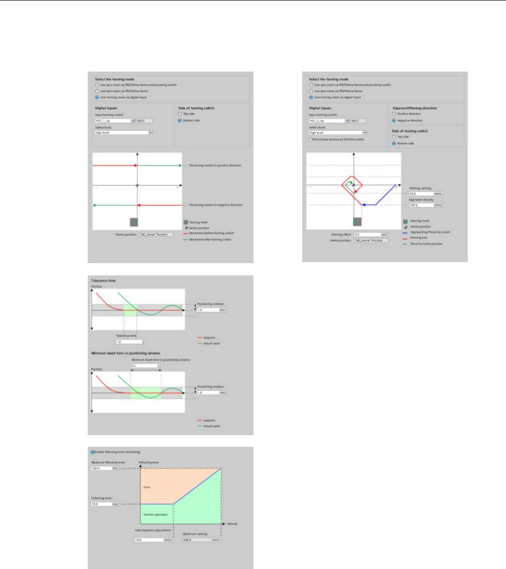
Technology instructions
10.3 Motion control
S7-1200 Programmable controller
678 System Manual, V4.2, 09/2016, A5E02486680-AK
Homing: You can configure the homing behavior (passive and active).
"Positioning monitori
ng": You can configure
tolerance time as well as minimum dwell
time for the positioning window.
The system connects the following three
parameters directly with the axis TO
-DB:
•
Positioning window
•
Tolerance time
•
Minimum dwell time in positioning window
Note
: The "Positioning window" field's mini-
mum value is "0.001" and its maximum value
is "1 E+12".
"Following error": You can configure the
difference of the allowed error distance over
a velocity range. You check the "Enable
following
error monitoring" check box to acti-
vate following error. You can configure the
following parameters:
•
Maximum following error
•
Following error
•
Start dynamic adjustment
•
Maximum velocity

Technology instructions
10.3 Motion control
S7-1200 Programmable controller
System Manual, V4.2, 09/2016, A5E02486680-AK 679
"Standstill signal": You can configure the
foll
owing parameters:
•
Minimum dwell time in standstill window
•
Standstill window.
"Control loop": You can configure the veloc
i-
ty gain known as "Precontrol (Kv factor)".
Use the "Commissioning" control panel to test the functionality in
dependently from your user
program.
Click the "Startup" icon to commission the axis.
The control panel shows the current status of the axis. Not only can you enable and disable
the axis, but you can also test the positioning of the axis (both in absolute and relative terms)
and can specify the velocity, acceleration and deceleration. You can also test the homing
and jogging tasks. The control panel also allows you to acknowledge errors.
10.3.4.2
ServoOBs
When you create a technology object for S7-1200 motion control, the CPU automatically
creates the organization block "MC-Servo (OB 91)" for processing the technology objects.
The motion control functionality of the technology objects creates its own priority class, and
the SIMATIC S7-1200 execution system calls the OB according to the application cycle.
The MC-Servo OB is write-protected. You cannot change the contents.
The position control algorithms of all technology objects configured for motion control on the
CPU are calculated within the MC-Servo OB.
You can set the application cycle and the priority of the organization block in accordance
with your requirements for control quality and system load. Multiple ServoOBs can link to a
"CyclicServoEvent". The Property page of the MC-Servo OB shows the two changeable
values of the CyclicServoEvent:
● Priority number
● Cycle time

Technology instructions
10.3 Motion control
S7-1200 Programmable controller
680 System Manual, V4.2, 09/2016, A5E02486680-AK
The MC-PreServo OB and MC-PostServo OB are instances of the ServoOB, and they are of
type ServoOB. These OBs are optional, can only exist if MC-Servo OB is present, and
contain user code. All three OBs (MC-PreServo, MC-Servo, and MC-PostServo) have to run
in the same runtime level, and the same CyclicServoEvent triggers them. The PLC firmware
executes the OBs sequencially, based upon their block number:
OB instance
OB number
Automation System
Object Model (ASOM)
event
Engineering System
Object Model (ESOM)
event
MC-PreServo
67
ServoOB
-
MC-Servo 91 ServoOB ServoOB
MC-PostServo
95
ServoOB
-
Compared to the ASOM, the Engineering System Object Model (ESOM) only links the event
to the MC-Servo OB. The ESOM does not link the event to the MC-PreServo OB or MC-
PostServo OB.
Configuring the axis with an application cycle MC-Servo (OB 91)
Application cycle MC-Servo (OB 91)
You can set the application cycle in which the MC-Servo OB is called in the properties of the
organization block:
● Synchronous to the BUS: You call the MC-Servo OB synchronously with a bus system.
You set the send clock in the properties of the selected bus system.
● Cyclical: You call the MC-Servo OB cyclically with the assigned application cycle.
To avoid disruptions in the program execution on the CPU, set the application cycle
depending on the number of used axes as follows:
Application cycle = number of axes x 2 ms
Number of axes
Application cycle
1 2 ms
2
4 ms
4
8 ms
8
16 ms
The SINAMICS G120 drive updates the drive process image every 4 ms. To improve control,
set the application cycle of the MC-Servo (OB 91) to 4 ms or to a multiple of 4 ms.

Technology instructions
10.3 Motion control
S7-1200 Programmable controller
System Manual, V4.2, 09/2016, A5E02486680-AK 681
Overflow MC-Servo (OB 91)
The selected application cycle must be long enough to allow all the technology objects for
motion control to be processed in one cycle. If the application cycle is not observed,
overflows occur.
The CPU does not go into STOP at overflow of the MC-Servo (OB 91). (The TIA Portal
online help statement concerning STOP at overflow of the MC-Servo (OB 91) is incorrect.)
If necessary, you can set the CPU to STOP at overflow of the MC-Servo (OB 91) using a
time-error OB (OB 80).
Process image partition OB Servo PIP
For optimal control of all I/O modules (for example, hardware limit switches) used by motion
control, assign them to the process image partition "OB Servo PIP". The assignment causes
the I/O modules to be processed simultaneously with the technology object.
When motion control uses a high-speed counter (HSC), motion control automatically assigns
the HSC to the process image partition "OB Servo PIP".
10.3.4.3
Speed controlled operation
With speed controlled operation, you can move a positioning axis with "speed controlled".
Using the MC_Power instruction, you can enable the axis. With the MC_MoveVelocity and
MC_MoveJog instructions, you can move the axis with velocity setpoints. You can move the
axis in spite of a sensor error even if no valid actual values are available. "Speed controlled"
mode sets the following conditions:
● Disables the positioning controller of the axis
● Sets velocity setpoints to the drive directly
● Sets the axis position setpoint to zero
● Updates the actual position of the axis in case of valid sensor values
● Does not define the following error and controller error and sets them to zero
You can activate and deactivate the "speed controlled" mode with the following three
instructions and these parameters:
● MC_Power.StartMode (Int)
● MC_MoveVelocity.PositionControlled (Bool)
● MC_MoveJog.PositionControlled (Bool)

Technology instructions
10.3 Motion control
S7-1200 Programmable controller
682 System Manual, V4.2, 09/2016, A5E02486680-AK
MC_Power
With the MC_Power instruction, you can enable the axis with the "speed controlled" mode.
You can do this if no valid sensor values are available or the axis cannot change to "position
controlled" mode.
You can only use StartModes "0" and "1". Other values show an error:
StartMode
PTO axis
Servo axis
0
Ignored
Speed controlled
1 Ignored Positioning controlled
Other Invalid mode
MC_Power.ErrorID = 0x8412
MC_Power.ErrorID = 0x0011
Invalid mode
MC_Power.ErrorID = 0x8412
MC_Power.ErrorID = 0x0011
During disabling of the TO axis with "MC_Power.Enable = FALSE", you obtain the operation
mode. Depending on the operation mode, the axis reacts with a different behavior:
StartMode
Mode: Position controlled
Mode: Speed controlled
0: Emergency stop The axis decelerates positioning
controlled with "Dynam-
icDefaults.
EmergencyDeceleration" based
upon the ActualPosition and
ActualVelocity.
The axis decelerates speed
controlled with "Dynam-
icDefaults.
EmergencyDeceleration" based
upon the ActualVelocity if avail-
able.
1: Immediate stop The drive stops with the "AUS3"
ramp within the connected drive.
The drive stops with the "AUS3"
ramp within the connected drive.
2: Emergency stop with jerk
control
Axis brakes are positioning
controlled at the configured
emergency deceleration based
upon the setpoint position. If the
jerk control is activated, the
configured jerk is taken into
account.
Axis brakes are speed con-
trolled at the configured emer-
gency deceleration based upon
the setpoint velocity. If the jerk
control is activated, the config-
ured jerk is taken into account.
During drive switch off, the operation mode cannot be changed because new motion
commands are not accepted until the drive is stopped. After standstill of the drive, the axis
can be enabled again.
MC_MoveVelocity/MC_MoveJog
Independent of operation mode (Speed controlled / Positioning controlled), the blocks
change the axis to the configured mode. This can happen during closed loop motion or
during standstill.
MC_Halt
The MC_Halt instruction does not change the operation mode. In speed controlled mode, the
calculated deceleration ramp depends on the setpoint velocity with the configured
deceleration.
If the Standstill window is reached, the command is finished and shows "Done = TRUE".

Technology instructions
10.3 Motion control
S7-1200 Programmable controller
System Manual, V4.2, 09/2016, A5E02486680-AK 683
Other motion commands
The speed controlled mode remains active until one of the following commands becomes
active:
● MC_MoveAbsolute
● MC_MoveRelative
● MC_MoveVelocity (PositionControlled = TRUE)
● MC_MoveJog (PositionControlled = TRUE)
● MC_Home:
– Active homing (Mode 3)
– Other modes (passive, direct, adjustment of absolute value sensor) are refused with
ErrorId:
ErrorId 8207: "Command rejected" / "Auftrag abgewiesen"
ErrorInfo 006B: "Aufruf im Speed controlled Mode unzulässig".
Axis TODB
The axis TODB displays the operation mode if one of the three motion instructions,
MC_Power, MC_MoveVelocity, or MC_MoveJog, are executed with the speed controlled
operation mode:
● Axis.Statusbit.NonPositionControlled = TRUE
● Axis.Position = 0.0
Calculation of new setpoint position
The setpoint position must be recalculated after a mode change from speed-controlled to
closed loop during motion:
● With Precontrol (kpc > 0): Position = ActualPosition + ActualVelocity * vtc
● Without Precontrol (kpc = 0): Position = ActualPosition + ActualVelocity / kv (vtc =
substitute time constate of precontrol; kv = gain of position control)
Software limit switches
During speed controlled mode, the software limit switches are not active.
Hardware limit switches
Hardware limit switches are supported during speed controlled mode.

Technology instructions
10.3 Motion control
S7-1200 Programmable controller
684 System Manual, V4.2, 09/2016, A5E02486680-AK
10.3.4.4
Telegram 4 support
The PROFdrive Telegram 4 contains actor values and two values from different encoders.
The first sensor value comes from the encoder on the motor. The second sensor value is
provided by an additional encoder on the machine.
The machine encoder is connected directly to a SINAMICS CU, and the CU provides both
sensor values within the Telegram 4.
Axis Drive configuration dialog
You configure Telegram 4 in the hardware configuration, and you can select it in the axis
Drive configuration dialog.
Axis Encoder configuration dialog
In the axis Encoder configuration dialog, you have two options:
● Encoder on PROFINET/PROFIBUS
● Encoder on high-speed counter (HSC)
"Encoder on PROFINET/PROFIBUS" is the default selection; however, both options are
available.
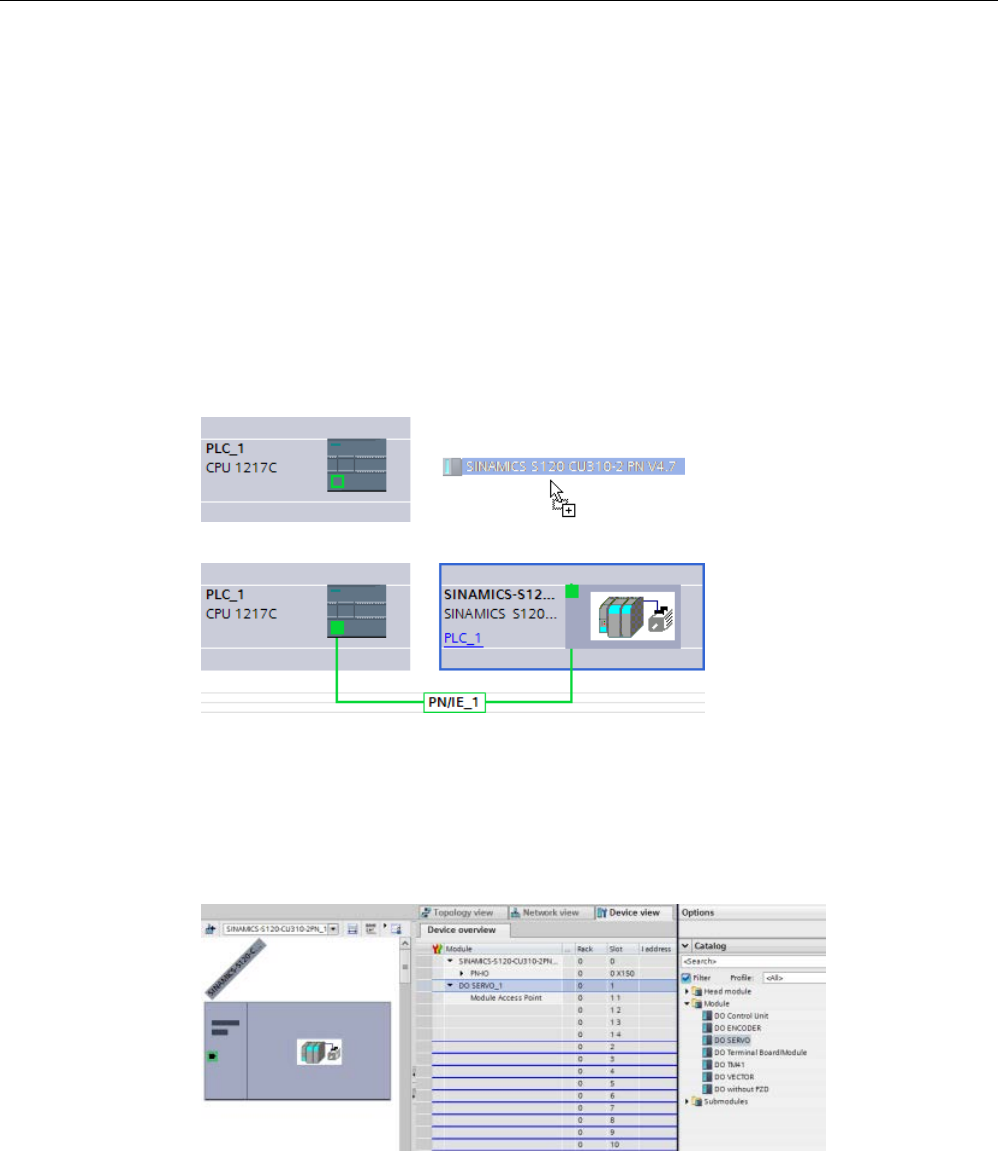
Technology instructions
10.3 Motion control
S7-1200 Programmable controller
System Manual, V4.2, 09/2016, A5E02486680-AK 685
Example: Configuring the SINAMICS S120 and encoder with Telegram 4
1. Selecting the SINAMICS drive:
Use the hardware catalog to add a SINAMICS S120 CU310-2 PN V4.7 drive. To do so,
expand the following containers:
– Other field devices
– PROFINET IO
– Drives
– SIEMENS AG
– SINAMICS
Insert the drive as shown in the figures below:
Configure your PROFINET network.
2. Selecting the DO SERVO:
– From the Network view, double-click the SINAMICS S120 CU310-2 PN V4.7 drive.
– Open the Device overview.
– In the hardware catalog, expand the Module container.
– Double-click or drag the DO SERVO drive object to insert it in the first blank row:
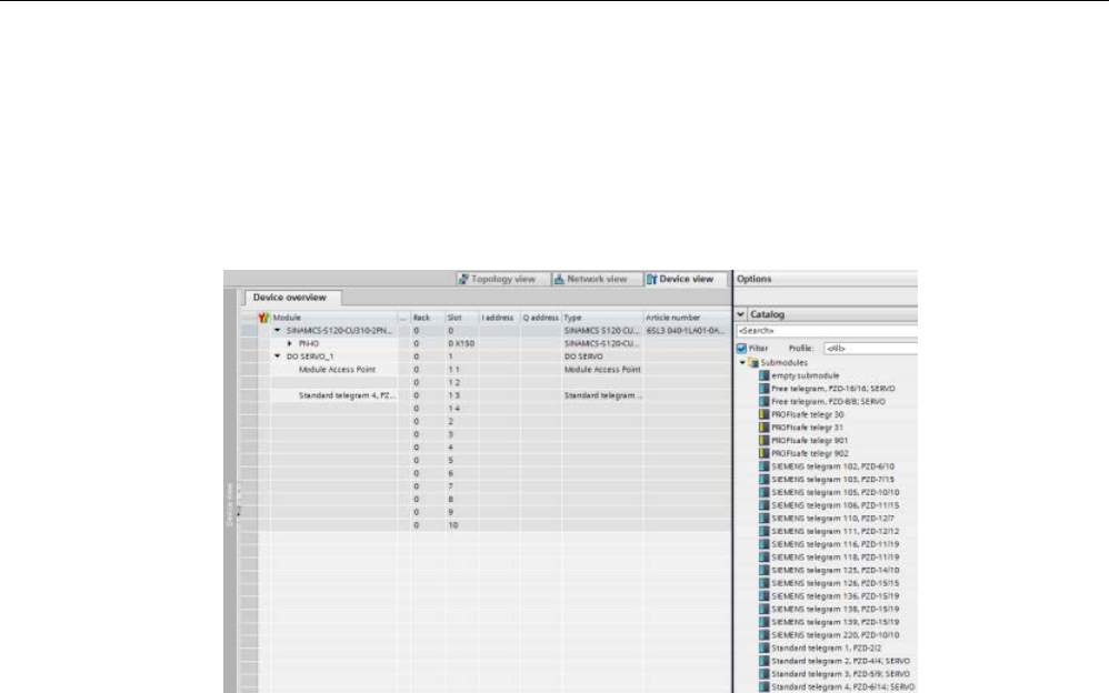
Technology instructions
10.3 Motion control
S7-1200 Programmable controller
686 System Manual, V4.2, 09/2016, A5E02486680-AK
3. Selecting the Telegram 4:
– In the hardware catalog, expand the Submodules container.
– Double-click or drag the "Standard telegram 4, PZD-6/15;SERVO" to insert it in the
second blank row.
– You must skip a blank row to insert the Telegram 4, as shown in the figure below:
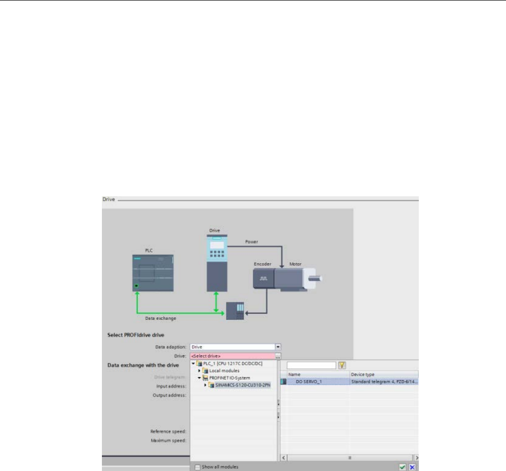
Technology instructions
10.3 Motion control
S7-1200 Programmable controller
System Manual, V4.2, 09/2016, A5E02486680-AK 687
4. Selecting the encoder in the Drive configuration dialog:
– Navigate to the axis configuration dialog, and the Basic parameters, Drive
configuration dialog.
– Move to the Select PROFIdrive drive, Drive: field.
– Click the ellipsis button.
– Double-click "PROFINET IO-System" to open its folder.
– Click "SINAMICS-S120-CU310-2PN".
– In the right pane, "DO SERVO_1: Standard telegam 4, PZD-6/14; SERVO" displays.
– Click the green check mark button to enter the configuration.
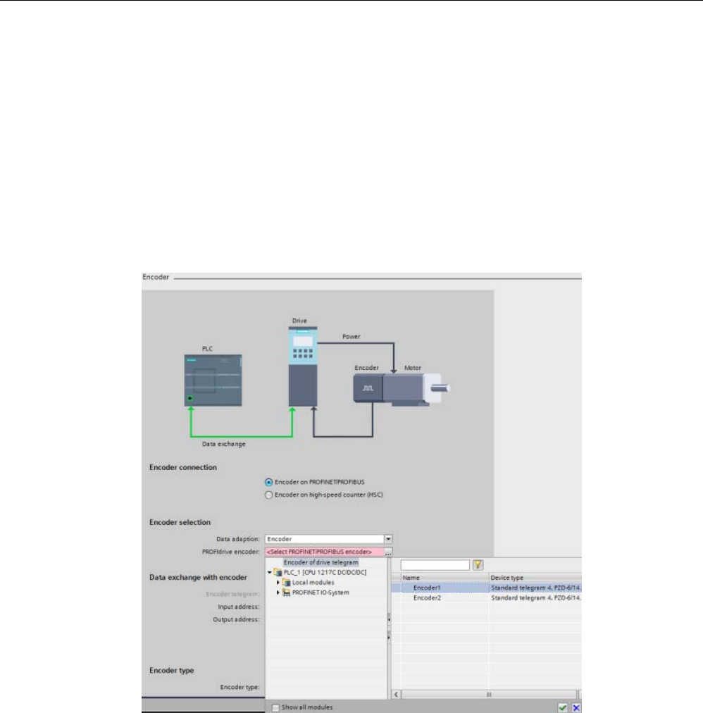
Technology instructions
10.3 Motion control
S7-1200 Programmable controller
688 System Manual, V4.2, 09/2016, A5E02486680-AK
5. Configuring the encoder:
– Since you selected Telegram 4 in the axis Drive configuration dialog, the Encoder
drive configuration dialog provides a new "Encoder in telegram" entry in the navigation
tree. When you select the "Encoder in telegram" entry, the right pane displays two
entries, Encoder 1 and Encoder 2, with encoder values.
– Motion control assigns one of the encoders as the drive encoder and the other
encoder as the machine encoder. When you select either Encoder 1 or Encoder 2,
you determine which encoder is assigned as the drive encoder. The encoder that you
do not select is assigned as the machine encoder.
– After you select the drive encoder, click the green check mark button to enter the
configuration:
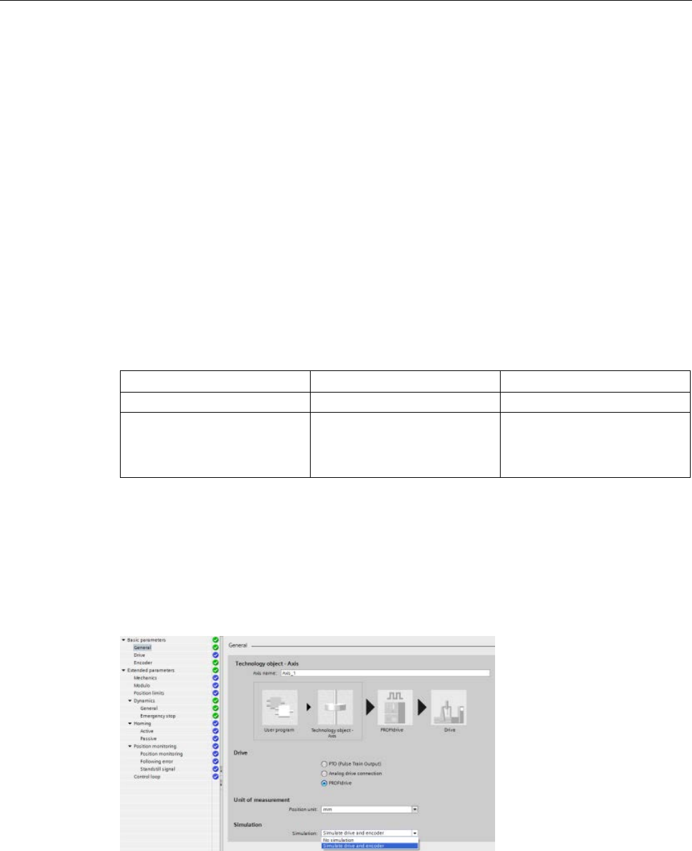
Technology instructions
10.3 Motion control
S7-1200 Programmable controller
System Manual, V4.2, 09/2016, A5E02486680-AK 689
10.3.4.5
Simulation axis
You use Simulation Mode when you want to work with the PROFIdrive or the Analog drive
axis on a PLC without a connected drive.
Simulation Mode is required when you want to do one of the following tasks:
● Commisioning of program sequence without a drive
● Testing of user program without moving an axis
● Simulation of behavior of the axis using a process model without a real movement.
● Drive and encoder must not be connected: Testing is also possible without a projected
drive; drive will be added and configured later.
Configuring Simulation Mode
The following options are available:
TODB value
Dialog entries
Comment
0
No simulation
No simulation
1 Simulate drive and encoder Simulation with and without
correct configured addresses of
the axis and configured I/O in
hardware configuration
You can only use Simulation Mode with Servo Axis, and, therefore, only with PROFIdrive
and Analog drive. In the case of a PTO axis, the simulation mode is "0".
The TIA Portal has to implement the remainder of the Simulation Mode in case of switching
the type of the axis to PTO. Also, with "Data adaptation", check that in the case of PTO that
simulation mode is "0", and, if not, it is set automatically.
The user selects the different simulation modes in the Basic parameters dialog > General
section > Simulation field as shown in the following figure:

Technology instructions
10.3 Motion control
S7-1200 Programmable controller
690 System Manual, V4.2, 09/2016, A5E02486680-AK
Mode 1: "Simulate drive and encoder":
● In this mode, the axis in your program executes and works on a PLC without real
connected hardware regarding a PROFIdrive drive and sensor.
● You do not require the logical I/O addresses in the Technology Objects data block
(TODB). This means that you do not have to configure the sensor and drive configuration
and additional digital signals (hardware limit switches and reference point switches) in the
TO and in hardware configuration. The axis does not supply data to the logical addresses
of sensor and drive.
● Simulates TODB ActualSpeed.
● Does not use the PROFIdrive telegram in the case of PROFIdrive.
● In the case of PROFIdrive, the PLC shows a diagnostic error that the configured
hardware (peripheral devices or drives) is missing, but this has no influence on the
applicability of the axis.
● Creates homing reports in all homing modes directly. Sets positions and status,
accordingly. Does not detect hardware inputs.
● All connections can be empty.
● Axis Control Panel \ Tuning Panel works as usual.
● Supports Speed Controlled axis.
● Does not support a virtual axis (like defined by SMC); however, you can use a simulated
axis with no hardware connections like a virtual axis.
Download case:
You can download the axis with changed simulation mode during PLC in RUN. In this case,
the PLC sets the StatusBit RestartRequired". After restart of the axis, the PLC transfers the
changes to the working memory. The following table shows all axis parameters that are
connected to hardware configuration (Actor, Sensor, and PositionLimits) and required or
optional for simulation:
TODB parameter
Mode 1: Simulate PROFIdrive
Actor.Interface.AddressIn
Optional
Actor.Interface.AddressOut Optional
Actor.Interface.EnableDriveOutput
Optional
Actor.Interface.DriveReadyInput Optional
Sensor.Interface.AddressIn
Optional
Sensor.Interface.AddressOut
Optional
Sensor.ActiveHoming.DigitalInputAddress
Optional
Sensor.PassiveHoming.DigitalInputAddress
Optional
PositionLimits_HW.MinSwitchAddress
Optional
PositionLimits_HW.MaxSwitchAddress
Optional
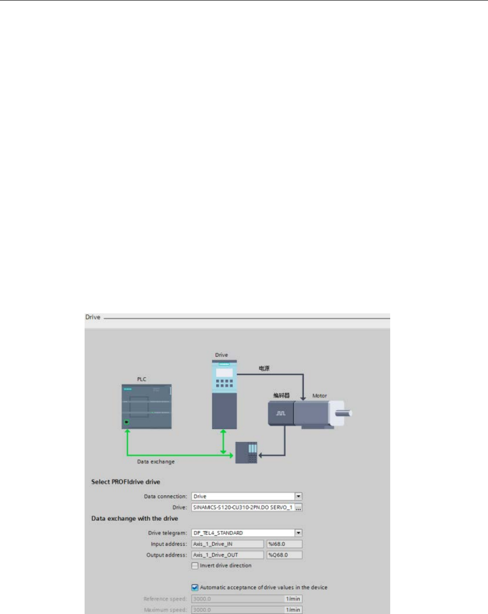
Technology instructions
10.3 Motion control
S7-1200 Programmable controller
System Manual, V4.2, 09/2016, A5E02486680-AK 691
10.3.4.6
Data adaptation
Overview
You can adapt actor and sensor data that are readable from the drive or sensor module and
have been configured the same in both the PLC and the drive/sensor device.
Configuring Adaptation RT
The CPU configures the Adaptation RT in the TO-DB for the specific actor and sensor:
● <axis>.Sensor[i].DataAdaptation: DINT [ 0:NO | 1:YES ]
● <axis>.Actor.DataAdaptation: DINT [ 0:NO | 1:YES ]
You can change the Adaptation RT configuration during run with the axis configuration
dialog, Basic parameters, Drive and Encoder configuration dialogs. The adaptation is
effective with TO startup or restart or loss of communication to the drive.
In the TIA Portal, you select "Data adaptation" using the "Automatic acceptance of drive
values in the device" check box found in both of the axis configuration dialog, Basic
parameters, Drive and Encoder dialogs.
The following figure shows the axis configuration Drive dialog:

Technology instructions
10.3 Motion control
S7-1200 Programmable controller
692 System Manual, V4.2, 09/2016, A5E02486680-AK
● If a SINAMICS drive is connected:
– The check box is selected by default.
– The controls following the check box, "Reference speed’ and "Maximum speed", are
grayed out.
– Adaptation RT for actor data is activated.
– If you manually deselect the check box, you can change the values of both of the
controls following the check box.
● If no SINAMICS drive or another drive is connected:
– The check box is deselected and grayed out by default.
– The controls following the check box, "Reference speed’ and "Maximum speed", are
active and editable.
– Adaptation RT for actor data is not activated.
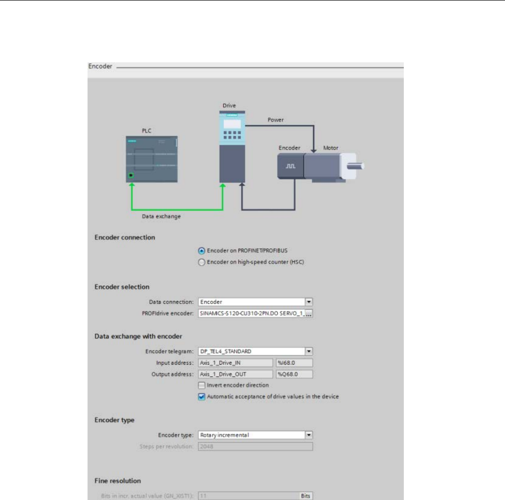
Technology instructions
10.3 Motion control
S7-1200 Programmable controller
System Manual, V4.2, 09/2016, A5E02486680-AK 693
The following figure shows the axis configuration Encoder dialog:

Technology instructions
10.3 Motion control
S7-1200 Programmable controller
694 System Manual, V4.2, 09/2016, A5E02486680-AK
● If a PROFIdrive encoder is connected:
– The check box is selected by default.
– The controls following the check box, "Encoder type" ("Steps per revolution" only) and
"Fine resolution", are grayed out.
– Adaptation RT for encoder data is activated.
– If you manually deselect the check box, you can change the values of both of the
controls following the check box.
● If no PROFIdrive encoder is connected (HSC or TM modules):
– The check box is deselected and grayed out by default.
– The controls following the check box, "Encoder type" and "Fine resolution", are active
and editable.
– Adaptation RT for actor data is not activated.
Executing Adaptation RT
You execute the adaptation with Adaptation RT activated:
● During startup of the Technology objects (TO) (or PLC startup) or creation of the TO (on
download of the TO-DB)
● After the drive or encoder blackout (or communication loss) and startup again
● Restart of TO (after every restart data are adapted)
During active communication of Adaptation RT, motion control refuses communication
orders from the user program regarding this drive and displays a resource error in the user
program.
A drop out of the drive breaks the adaptation during communication of Adaptation RT. If the
drive answers again, the adaptation starts again.
If the device makes a negative confirmation, motion control does not overwrite the TO axis
configuration. If Adaptation RT is selected, but the system does not operate an adaptation
successfully, motion control displays an error and the device cannot be enabled.

Technology instructions
10.3 Motion control
S7-1200 Programmable controller
System Manual, V4.2, 09/2016, A5E02486680-AK 695
Displaying adaptation status and adaption errors
Motion control displays the Adaptation RT status and errors in parameters and
ErrorIDs/ErrorInfos:
● Motion control displays the adaptation status at the axis: If the adaptation does not
operate or operates with errors, motion control displays an error at the axis and the
ErrorID / ErrorInfo of the MC_Power instruction.
● General adaptation parameter: Manufacturer, device, version, and date are readout from
the P964[7] parameter. The P964 parameter is a PROFIdrive parameter and available at
the actor and encoder.
● Performance: Motion control executes the Adaptation RT after startup or restart. If the
configuration does not change afterwards, it is reasonable to deactivate the data
adaptation because of performance reasons. There are two solutions:
– Save the values by application in the RT after adaptation and deactivate the
adaptation.
– Upload of the values after adaptation, transfer these values to the project, and
deactivate the adaptation.
● Adaptation behavior:
– During startup / restart all configured devices (actor and sensor) to be adapted are
adapted.
– If a device is not adaptable during this step, motion control displays an error and the
status changes to "ADAPTATION_ERROR".
– With errors of an encoder, an enabling of the axis in the speed controlled mode is
possible because this mode usually works without an encoder.
Refer to "ErrorIDs and ErrorInfos for motion control" for a listing of the data adaptation
ErrorIDs and ErrorInfos.
Adapting actor data
The adaptation of actor data is device specific and supported only for SINAMICS drives.
SINAMICS drives support data adaptation and show an error if Adaptation RT is activated.
Units
Adaptation of actor data considers the configured units in the drive. Values and units depend
on the DO-Type, DO-Function module, and units system.
Adaptation of actor data only supports rotary drives (no linear drives) and units of 1/min.
The following parameters are read and evaluated:
● p107 (DO-Typ)
● p108 (DO-Function module)
● p505 (SI units or US units)

Technology instructions
10.3 Motion control
S7-1200 Programmable controller
696 System Manual, V4.2, 09/2016, A5E02486680-AK
Selected current data record from the drive
A SINAMICS drive supports different data sets for the encoder and actor. The SINAMICS
drive adapts the current data record at the moment of adaptation. Therefore, "p51" (current
data record of drive) is readout:
● The reference speed is equal to all data records: "p2000" (reference speed) is
independent of the data record.
● The maximum speed is independent of the data record: "p1082"
● The SINAMICS drive does not check the different maximum values of the different data
records if they are consistent regarding their control value in the current data record. For
example, this happens after a data adaptation to another data record.
Motor type
SINAMICS supports two motor types:
● Linear motor
● Default motor (rotary motor)
With Basic Motion Control (BMC), SINAMICS only supports rotary motors.
If the SINAMICS drive has a linear motor configured (parameter "r108, bit 12"), motion
control displays an ErrorID after a consistency check or a data adaptation abort.
Parameters
Motion control supports "DO-Servo" and "DO-Vector". The following parameters of the drive
are adapted:
TO-DB actor parameter
SINAMICS parameter
Actor.DriveParameter.ReferenceSpeed
p2000
Actor.DriveParameter.MaxSpeed p1082
Three TO DB parameters of the actor are not adapted but checked on plausibility:
TO-DB sensor parameter
SINAMICS/PROFIdrive parameter
Actor.type
r108, bit12
Actor.Interface.AddressIn.RID p922 or p2079
Actor.Interface.AddressOut.RID
p922 or p2079

Technology instructions
10.3 Motion control
S7-1200 Programmable controller
System Manual, V4.2, 09/2016, A5E02486680-AK 697
The values of each parameter are listed in the following tables:
TO-DB actor parameter
Value
Actor.type • 0 = Analog
• 1 = PROFIdrive
• 2 = PTO
Note: The TIA Portal only supports the rotary
drive. This means that only a "1" value is valid.
Actor.Interface.AddressIn.RID • 0208_0708 = Telegram 1
• 0208_070A = Telegram 2
• 0208_070C = Telegram 3
• 0208_0720 = Telegram 4
• 0208_070E = Telegram 81
• 0208_0710 = Telegram 83
Actor.Interface.AddressOut.RID • 0208_0709 = Telegram 1
• 0208_070B = Telegram 2
• 0208_070D = Telegram 3
• 0208_0721 = Telegram 4
• 0208_070F = Telegram 81
• 0208_0711 = Telegram 83
SINAMICS/PROFIdrive parameter
Value
r108, bit12 • 0 = Linear drive
• 1 = Rotary drive
Note: The TIA Portal only supports the rotary
drive.
p922 or p2079 • 1 = Telegram 1
• 2 = Telegram 2
• 3 = Telegram 3
• 4 = Telegram 4
• 81 = Telegram 81
• 83 = Telegram 83
Check of the maximum velocity
The TIA Portal verifies the validity of the TO-DB "DynamicLimits.MaxVelocity" parameter.
However, with data adaptation, the check is only possible when the system is in RUN and
does not perform the TIA Portal verification.

Technology instructions
10.3 Motion control
S7-1200 Programmable controller
698 System Manual, V4.2, 09/2016, A5E02486680-AK
Consistency check
Motion control executes a consistency check during the first startup or restart of the TO axis.
Motion control also displays an ErrorID if the data adaptation of the actor is activated. A
consistency check involves the telegram, motor type, and maximum speed:
● Telegram in "p922" or "p2079": If there is an inconsistency between the TO and drive
configuration, motion control displays an error.
● Motor type in "r108, bit12" of DO-Servo: If there is an inconsistency between the TO and
drive configuration, motion control displays an error.
● The maximum speed is not reachable with the configured axis parameters, and motion
control displays an error. (Note: Motion control does not display this error again after
confirmation if the axis configuration is not changed.)
Special case:
● Maximum speed (p1082) > 2 x reference speed (p2000)
● Motion control reduces the maximum speed to "2x" reference speed internally. The entry
in the axis configuration is not limited. However, motion control adapts the value of
"p1082" and displays an error.
Adapting sensor data
Only data adaptation with an active encoder is supported (p0979).
Amount of adapted data
Motion control adapts the actual value description of "p0979" (including the rotary or linear
encoder configuration) and checks the TIA Portal encoder type parameter, "incremental or
absolute". Motion control does not adapt or evaluate the NIST reference value in Telegram
83.
Correlating the encoder in the telegram to the encoder in the PLC and drive
● Motion control configures the mapping of an encoder in the PLC to the actual value in the
telegram (actual value 1 or actual value 2) in the VREF.RID of two TO-DB parameters:
– <axis>.Sensor[i].Interface.AddressIn
– <axis>.Sensor[i].Interface.AddressOut
● The mapping in the drive occurs with the index setting in "p979" (encoder modeling in
SINAMICS).

Technology instructions
10.3 Motion control
S7-1200 Programmable controller
System Manual, V4.2, 09/2016, A5E02486680-AK 699
Parameters
Motion control adapts the following prarmeters:
TO-DB sensor parameter
SINAMICS/PROFIdrive parameter
Sensor[i].System • P979.[1] or P979.[11]
• Bit 0 = 0: rotary encoder
• Bit 0 = 1: linear encoder
Incremental rotary sensor
Sensor[i].Parameter.StepsPerRevolution
P979.[2] or P979.[12]
Sensor[i].Parameter.FineResolutionXist1 P979.[3] or P979.[13]
Incremental linear sensor
Sensor[i].Parameter.Resolution
P979.[2] or P979.[12]
Sensor[i].Parameter.FineResolutionXist1
P979.[3] or P979.[13]
Absolute rotary sensor
Sensor[i].Parameter.StepsPerRevolution
P979.[2] or P979.[12]
Sensor[i].Parameter.FineResolutionXist1
P979.[3] or P979.[13]
Sensor[i].Parameter.DeterminableRevolutions
P979.[5] or P979.[15]
Sensor[i].Parameter.FineResolutionXist2
P979.[4], bzw.P979.[14]
Absolute linear sensor
Sensor[i].Parameter.Resolution
P979.[2] or P979.[12]
Sensor[i].Parameter.FineResolutionXist1
P979.[3] or P979.[13]
Sensor[i].Parameter.FineResolutionXist2
P979.[4], bzw. P979.[14]
Motion control does not adapt one TO-DB sensor parameter, but checks it on consistency:
TO-DB sensor parameter
SINAMICS/PROFIdrive parameter
Sensor[i].Type • P979.[5], bzw. P979.[15]
• Bit 0 = 0: incremental encoder
• Bit 0 > 1: absolute encoder
Sensor[i].Interface.AddressIn
Sensor[i].Interface.AddressOut
p922 or p2079
You can use an absolute encoder as an incremental encoder, but not an incremental
encoder as an absolute encoder. Motion control displays an incompatibility of the encoder
type at the TO and its related actual value in the PROFIdrive telegram in an error. Note: With
SINAMICS FW V2.6, the PROFIdrive interface has a sensor zero mark.

Technology instructions
10.3 Motion control
S7-1200 Programmable controller
700 System Manual, V4.2, 09/2016, A5E02486680-AK
Consistency check
Motion control executes a consistency check during the first startup or restart of the TO axis.
Motion control also displays an ErrorID if the data adaptation of the sensor is activated. A
consistency check involves the telegram and sensor type:
● Telegram in "p922" or "p2079": If there is an inconsistency between the TO and sensor
configuration, motion control displays an error.
● Sensor type in "P979.[5]" or "P979.[15]": You can use an absolute encoder as an
incremental encoder, but not an incremental encoder as an absolute encoder. If there is
no consistency, motion control displays an error.
Parameters that must be uploaded
The following list shows all the parameters that you have to upload from the drive into the
TIA portal. To manage this data adaptation, you must expand the TO-DB. You use the
following structs of the TO-DB to perform this expansion:
Actor
Type
Default
Changeable
Comment
Ac-
tor.DataAdaptation
DINT 0 R (with restart) Adaptation acti-
vate:
• 0: NO
• 1: YES
StatusDrive
Type
Comment
StatusDrive.AdaptationState DINT Adaptation status:
• 0: NOT_ADAPTED: Cannot take
over data.
• 1: IN_ADAPTATION: Data adapta-
tion has just started.
• 2: ADAPTED: Data are adapted
• 3:NOT_APPLICABLE: Adaptation
not selected or not available for this
drive
• 4:ADAPTATION_ERROR: Error
during adaptation:
– Axis cannot be enabled.
– Motion control displays a con-
figuration error.

Technology instructions
10.3 Motion control
S7-1200 Programmable controller
System Manual, V4.2, 09/2016, A5E02486680-AK 701
Sensor
Type
Default
Changeable
Comment
Sen-
sor.DataAdaptation
DINT 0 R (with restart) Adaptation acti-
vate:
• 0: NO
• 1: YES
StatusSensor
Type
Comment
StatusSensor.AdaptationState DINT Adaptation status:
• 0: NOT_ADAPTED: Cannot take
over data.
• 1: IN_ADAPTATION: Data adapta-
tion has just started.
• 2: ADAPTED: Data are adapted.
• 3: NOT_APPLICABLE: Adaptation
not selected or not available for this
drive.
• 4: ADAPTATION_ERROR: Error
during adaptation:
– Axis cannot be enabled.
– Motion control displays a con-
figuration error.
ErrorWord
Type
Comment
...
Bool
Bit 15: Adaptation Error
Bool
ErrorID:
...
Bool

Technology instructions
10.3 Motion control
S7-1200 Programmable controller
702 System Manual, V4.2, 09/2016, A5E02486680-AK
10.3.4.7
Axis control using the TM Pulse module
The TM Pulse Module is an ET 200SP two-channel pulse output module for use with valves
and motors. The module can support either two 24 V DC channels at 2 A or one 24 V DC
channel at 4 A.
Using the "DC motor" operating mode of the TM Pulse 2x24V output module, you can drive a
motor in both directions with a bipolar PWM output. You can assign a digital input as an
"External stop" signal for the motor.
The TM Pulse module can perform the following functions to support motion control:
● Programmable output response to CPU/master STOP condition
● Error detection and diagnostics:
– Missing or under voltage L+ supply voltage
– Short-circuit/overload of a digital output
– Short-circuit/under voltage of a sensor power supply
– Over temperature error
– Parameterization fault
– Module/firmware error
Example
Some applications require the ability to move easily to a specific location, but do not require
the absolute accuracy and adherence to a specific profile. The use of a common DC motor in
conjunction with the Closed Loop Servo control is possible using the ET 200SP TM Pulse
module to control the motor. This application example covers one mode of the ET 200SP TM
Pulse module: "PWM with DC Motor". Refer to the
ET 200SP Technology module TM Pulse
2x24V Manual
for further information on the other ET 200SP TM Pulse modes.
In order to use true closed loop control, you require a method of position feedback. You must
connect an encoder to the motor to provide feedback to the control system. This example
shows three methods of achieving this:
● High Speed Counter (HSC) that is built into the S7-1200
● ET 200SP TM Count Module
● ET 200SP TM Position module
In some cases, where moving at various velocities is a requirement, the Closed Loop control
can operate in Speed Control mode. If you use this mode, you do not require position
feedback.
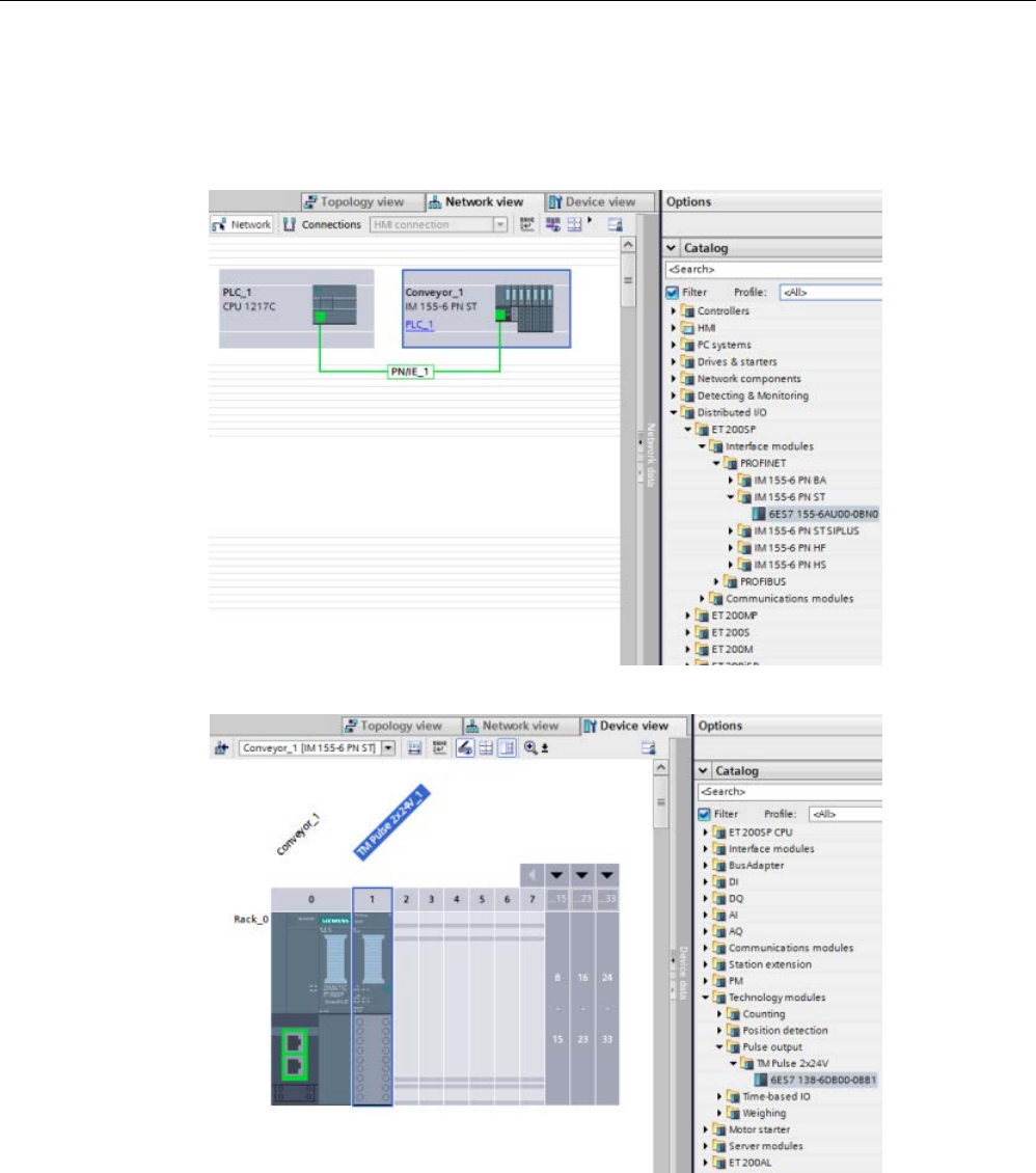
Technology instructions
10.3 Motion control
S7-1200 Programmable controller
System Manual, V4.2, 09/2016, A5E02486680-AK 703
Follow these steps to configure the TM Pulse module:
1. Configure your S7-1200 CPU.
2. Select the required ET 200SP Interface module and place it in the Device View:
3. Add the ET 200SP TM Pulse module:
4. In the Channel configuration, select "2 channels (2A)".
5. Set the Operating mode to "PWM with DC Motor".
6. Set the Diagnostics and Channel parameters as required.
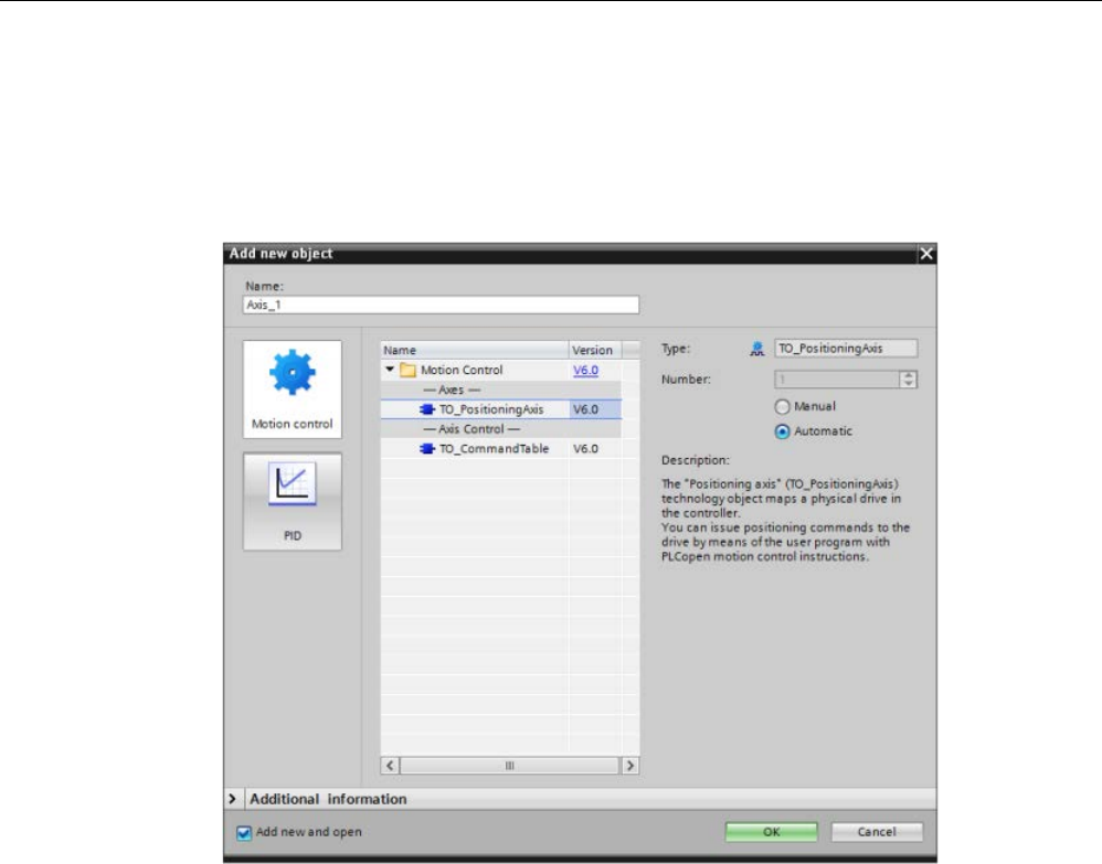
Technology instructions
10.3 Motion control
S7-1200 Programmable controller
704 System Manual, V4.2, 09/2016, A5E02486680-AK
Follow these steps to configure the Axis of Motion with position feedback:
1. When configuring your interface with a Closed Loop Motion Control System, you use
analog control, not PROFIdrive or PTO. You configure the axis to be controlled in the
same way that you configure an axis that uses an analog output as the input to a servo
drive. Add a "TO PositioningAxis" as shown in the figure below:
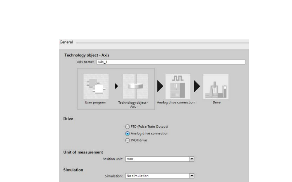
Technology instructions
10.3 Motion control
S7-1200 Programmable controller
System Manual, V4.2, 09/2016, A5E02486680-AK 705
2. In the General configuration dialog for the axis configuration, select "Analog drive
connection":
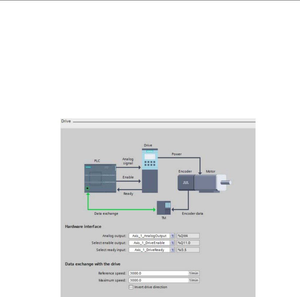
Technology instructions
10.3 Motion control
S7-1200 Programmable controller
706 System Manual, V4.2, 09/2016, A5E02486680-AK
3. You now need analog outputs and a drive enable for your drive configuration. Go to the
Device View of the ET 200SP interface module and the Device Overview entry for the TM
Pulse module. Using the starting Q address for the TM Pulse module and the Control
interface and Feedback interface tables in the
SIMATIC ET 200SP Technology module
TM Pulse 2x24V (6ES7138-6DB00-0BB1) Manual
, you can determine the following
analog outputs and drive enable required for your drive:
– Analog output
– Select enable output
– Select ready input
In the Drive configuration dialog for the axis configuration, select your hardware interface
I/O and data exchange values:
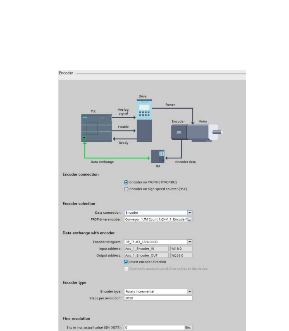
Technology instructions
10.3 Motion control
S7-1200 Programmable controller
System Manual, V4.2, 09/2016, A5E02486680-AK 707
4. In the Encoder configuration dialog for the axis configuration, complete the configuration
by selecting one of the following encoders:
● TM Count module
● TM Pulse module
● High-Speed Counter (HSC)
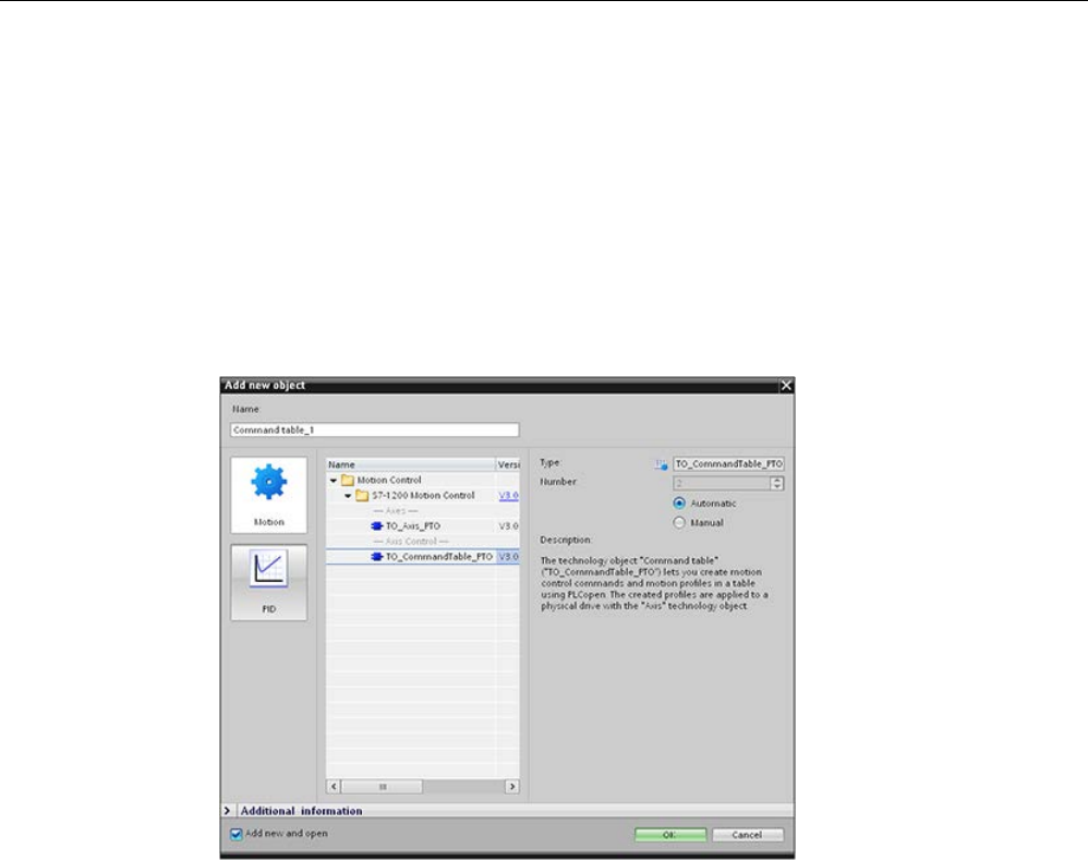
Technology instructions
10.3 Motion control
S7-1200 Programmable controller
708 System Manual, V4.2, 09/2016, A5E02486680-AK
10.3.5
Configuring the TO_CommandTable_PTO
You can configure a MC_CommandTable instruction using the Technology objects. The
following example demonstrates how this is done.
Adding a Technology object
1. In the Project tree, expand the node "Technology Objects" and select "Add new object".
2. Select the "CommandTable" icon (rename if required), and click "OK" to open the
configuration editor for the CommandTable object.
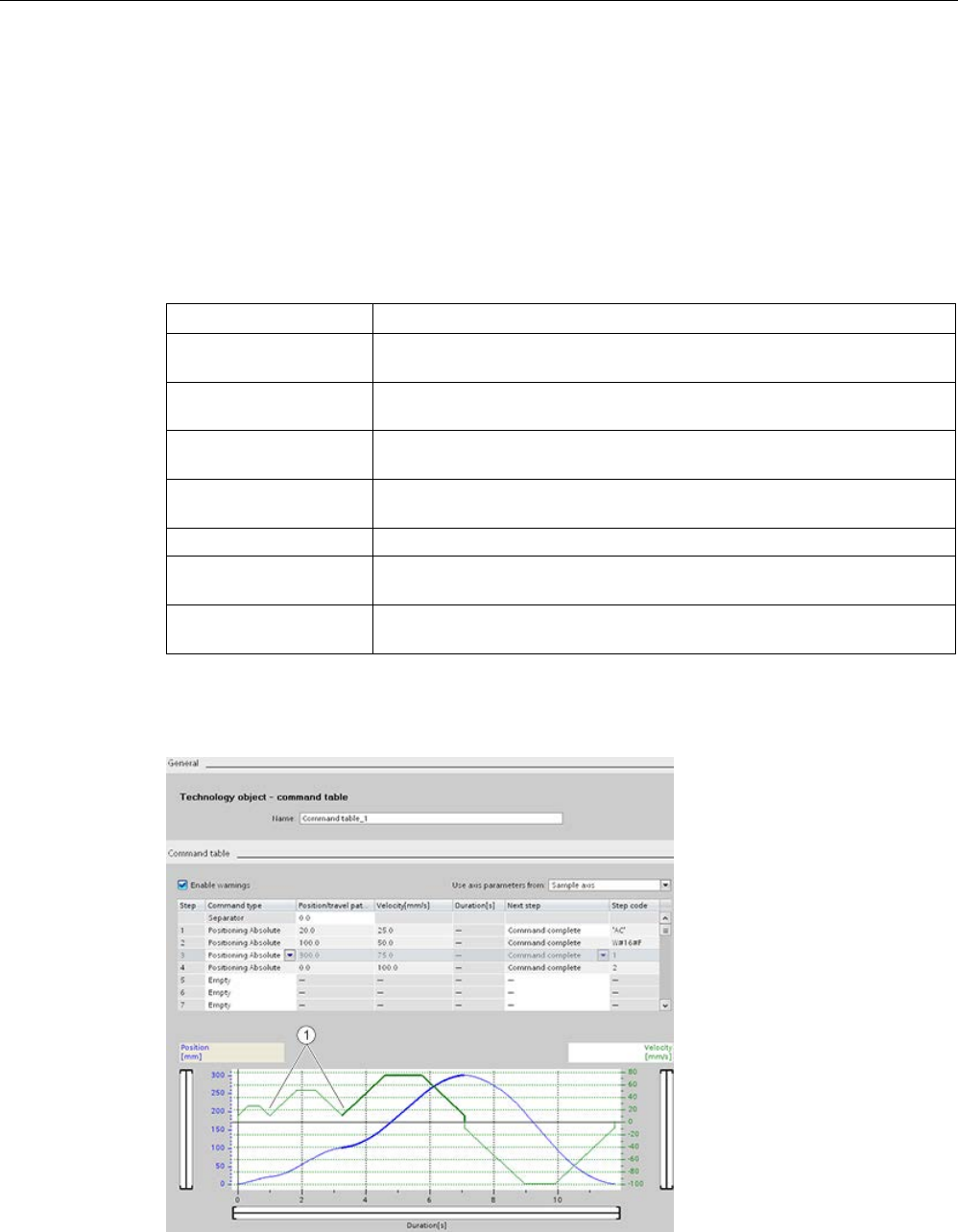
Technology instructions
10.3 Motion control
S7-1200 Programmable controller
System Manual, V4.2, 09/2016, A5E02486680-AK 709
Planning the steps for your application
You can create the desired movement sequence in the "Command Table" configuration
window, and check the result against the graphic view in the trend diagram.
You can select the command types that are to be used for processing the command table.
Up to 32 steps can be entered. The commands are processed in sequence, easily producing
a complex motion profile.
Table 10- 48 MC_CommandTable command types
Command type
Description
Empty The empty serves as a placeholder for any commands to be added. The
empty entry is ignored when the command table is processed
Halt Pause axis.
Note: The command only takes place after a "Velocity setpoint" command.
Positioning Relative Positions the axis based upon distance. The command moves the axis by
the given distance and velocity.
Positioning Absolute Positions the axis based upon location. The command moves the axis to
the given location, using the velocity specified.
Velocity setpoint
Moves the axis at the given velocity.
Wait Waits until the given period is over. "Wait" does not stop an active travers-
ing motion.
Separator Adds a "Separator" line above the selected line. The separator line allows
more than one profile to be defined in a single command table.
In the figure below, "Command complete" is used as the transition to the next step. This type
of transition allows your device to decelerate to the start/stop speed and then accelerate
once again at the start of the next step.
①
Axis decelerates to the start/stop speed between steps.
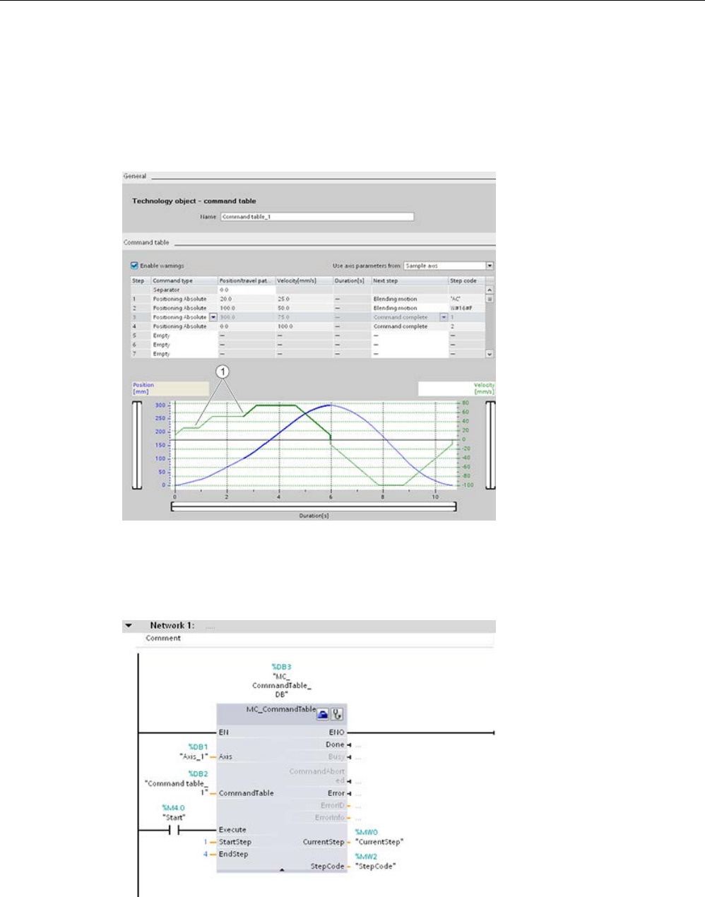
Technology instructions
10.3 Motion control
S7-1200 Programmable controller
710 System Manual, V4.2, 09/2016, A5E02486680-AK
In the figure below, "Blending motion" is used as the transition to the next step. This type of
transition allows your device to maintain its velocity into the start of the next step, resulting in
a smooth transition for the device from one step to the next. Using blending can shorten the
total time required for a profile to execute completely. Without blending, this example takes
seven seconds to run. With blending, the execution time is reduced by one second to a total
of six seconds.
①
Axis continues to move and accelerates or decelerates to the next step velocity, saving time and
mechanical wear.
The operation of your CommandTable is controlled by an MC_CommandTable instruction,
as shown below:

Technology instructions
10.3 Motion control
S7-1200 Programmable controller
System Manual, V4.2, 09/2016, A5E02486680-AK 711
10.3.6
Operation of motion control for S7-1200
10.3.6.1
CPU outputs used for motion control
The CPU provides four pulse output generators. Each pulse output generator provides one
pulse output and one direction output for controlling a stepper motor drive or a servo motor
drive with pulse interface. The pulse output provides the drive with the pulses required for
motor motion. The direction output controls the travel direction of the drive.
The PTO output generates a square wave output of variable frequency. Pulse generation is
controlled by configuration and execution information supplied through H/W configuration
and/or SFCs/SFBs.
Based upon the user’s selection while the CPU is in RUN mode, either the values stored in
the image register or the pulse generator outputs drive the digital outputs. In STOP mode,
the PTO generator does not control the outputs.
Onboard CPU outputs and outputs of a signal board can be used as pulse and direction
outputs. You select between onboard CPU outputs and outputs of the signal board during
device configuration under Pulse generators (PTO/PWM) on the "Properties" tab. Only PTO
(Pulse Train Output) applies to motion control.
The table below shows the default I/O assignments; however, the four pulse generators can
be configured to any digital output.
Note
Pulse-train outputs cannot be used by other instructions in the user program.
When you configure the outputs of the CPU or signal board as pulse generators (for use with
the PWM or motion con
trol instructions), the corresponding output addresses no longer
control the outputs. If your user program writes a value to an output used as a pulse
generator, the CPU does not write that value to the physical output.
Note
PTO direction outputs can be freed for use elsewhere in your program.
Each PTO requires the assignment of two outputs: one as a pulse output and one as a
direction output. You can use just the pulse output and not the direction output. You can then
free the direction output for othe
r purposes in your user program. The output cannot be used
for both the PTO direction output and in the user program, simultaneously.

Technology instructions
10.3 Motion control
S7-1200 Programmable controller
712 System Manual, V4.2, 09/2016, A5E02486680-AK
Table 10- 49 Default address assignments of the pulse and direction outputs
Usage of outputs for motion control
Pulse
Direction
PTO1
Built-in I/O
Q0.0
Q0.1
SB I/O Q4.0 Q4.1
PTO2
Built-in I/O
Q0.2
Q0.3
SB I/O
Q4.2
1
Q4.3
1
PTO3
Built-in I/O
Q0.4
2
Q0.5
2
SB I/O
Q4.0
Q4.1
PTO4
Built-in I/O
Q0.6
3
Q0.7
3
SB I/O
Q4.2
Q4.3
1
Outputs Q4.2 and Q4.3 are only available on the SB 1222 DQ4.
2
The CPU 1211C does not have outputs Q0.4, Q0.5, Q0.6, or Q0.7. Therefore, these outputs can-
not be used in the CPU 1211C.
3
The CPU 1212C does not have outputs Q0.6 or Q0.7. Therefore, these outputs cannot be used in
the CPU 1212C.
4
This table applies to the CPU 1211C, CPU 1212C, CPU 1214C, CPU 1215C, and CPU 1217C
PTO functions.
Drive interface
For motion control, you can optionally configure a drive interface for "Drive enabled" and
"Drive ready". When using the drive interface, the digital output for the drive enable and the
digital input for "drive ready" can be freely selected.
Note
The firmware will take control through the corresponding pulse and direction outputs if the
PTO (Pul
se Train Output) has been selected and assigned to an axis.
With this takeover of the control function, the connection between the process image and I/O
output is also disconnected. While the user has the possibility of writing the process image of
pulse a
nd direction outputs via the user program or watch table, this is never transferred to
the I/O output. Accordingly, it is also not possible to monitor the I/O output via the user
program or watch table. The information read merely reflects the value of the
process image
and does not match the actual status of the I/O output in any respect.
For all other CPU outputs that are not used permanently by the CPU firmware, the status of
the I/O output can be controlled or monitored via the process image, as usual.
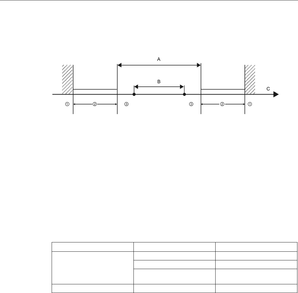
Technology instructions
10.3 Motion control
S7-1200 Programmable controller
System Manual, V4.2, 09/2016, A5E02486680-AK 713
10.3.6.2
Hardware and software limit switches for motion control
Use the hardware and software limit switches to limit the "allowed travel range" and the
"working range" of your axis.
①
Mechanical stop
A
Allowed travel range for the axis
②
Lower and upper hardware limits
B
Working range of the axis
③
Lower and upper software limits
C
Distance
Hardware and software limit switches must be activated prior to use in the configuration or in
the user program. Software limit switches are only active after homing the axis.
Hardware limit switches
Hardware limit switches determine the maximum travel range of the axis. Hardware limit
switches are physical switching elements that must be connected to interrupt-capable inputs
of the CPU. Use only hardware limit switches that remain permanently switched after being
approached. This switching status can only be revoked after a return to the allowed travel
range.
Table 10- 50 Available inputs for hardware limits
Description
CPU
RPS, LIM-, and LIM+ 1
Built-in I/O
CPU 1211C
I0.0 - I0.5
CPU 1212C
I0.0 - I0.7
CPU 1214C, CPU 1215C, and
CPU 1217C
I0.0 - I01.3
SB I/O
All S7-1200 CPUs
I4.0 - I4.3
1
Reference Point Switch input (RPS), Negative Travel Limit input (LIM-), and Positive Travel Limit
input (LIM+)
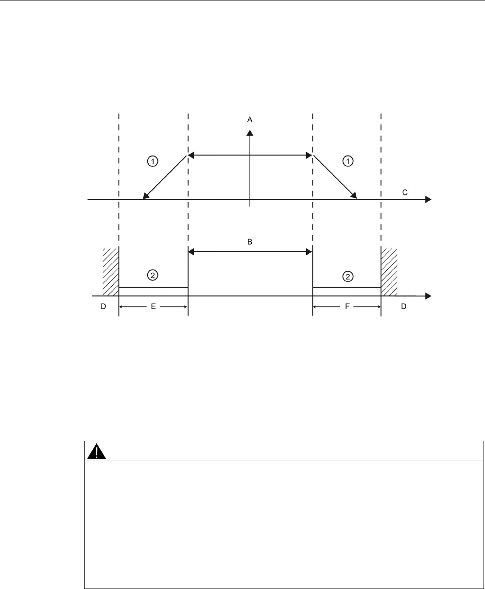
Technology instructions
10.3 Motion control
S7-1200 Programmable controller
714 System Manual, V4.2, 09/2016, A5E02486680-AK
When the hardware limit switches are approached, the axis brakes to a standstill at the
configured emergency deceleration. The specified emergency deceleration must be
sufficient to reliably stop the axis before the mechanical stop. The following diagram
presents the behavior of the axis after it approaches the hardware limit switches.
①
The axis brakes to a standstill at the configured emergency deceleration.
②
Range in which the hardware limit switches signal the stats "approached".
A
[Velocity]
B
Allowed travel range
C
Distance
D
Mechanical stop
E
Lower hardware limit switch
F
Upper hardware limit switch
WARNING
Risks with changes to filter time for digital input channel
If the filter time for a digital input channel is changed from a previous setting, a new "0"
level input value needs to be presented for up to 20.0 ms accumulated duration before the
filter becomes fully responsive to new inputs. During this time, short "0" pulse events of
duration less than 20.0 ms cannot be detected or counted.
This changing of filter times can result in unexpected machine or process operation, which
can cause death or serious injury to personnel, and/or damage to equipment.
To ensure that a new filter time goes immediately into effect, a power cycle of the CPU
must be applied.
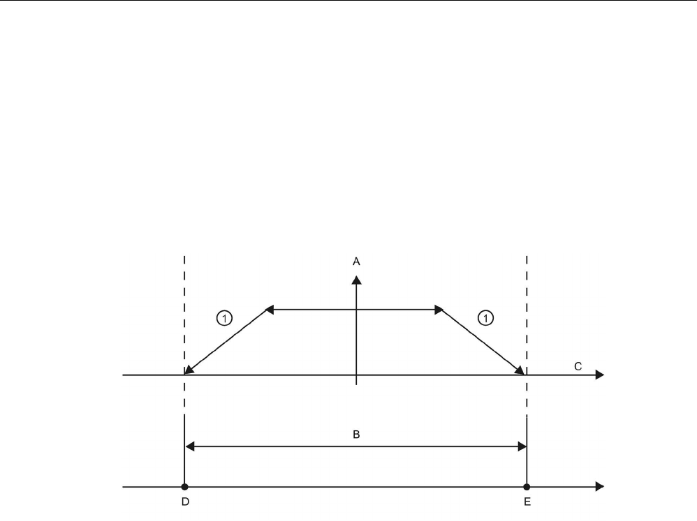
Technology instructions
10.3 Motion control
S7-1200 Programmable controller
System Manual, V4.2, 09/2016, A5E02486680-AK 715
Software limit switches
Software limit switches limit the "working range" of the axis. They must fall inside the
hardware limit switches relative to the travel range. Because the positions of the software
limit switches can be set flexibly, the working range of the axis can be restricted on an
individual basis depending on the current traversing profile. In contrast to hardware limit
switches, software limit switches are implemented exclusively by means of the software and
do not require their own switching elements.
If software limit switches are activated, an active motion is stopped at the position of the
software limit switch. The axis is braked at the configured deceleration. The following
diagram presents the behavior of the axis until it reaches the software limit switches.
①
The axis brakes to a standstill at the configured deceleration.
A
[Velocity]
B
Working range
C
Distance
D
Lower software limit switch
E
Upper software limit switch
Use additional hardware limit switches if a mechanical endstop is located after the software
limit switches and there is a risk of mechanical damage.

Technology instructions
10.3 Motion control
S7-1200 Programmable controller
716 System Manual, V4.2, 09/2016, A5E02486680-AK
Edge detection configuration on address change
If you configure a position limit or input homing switch to an input address in a TO
PositionAxis, motion control configures it with edge interrupts automatically. If, then, you
change the position limit or input homing switch to another address, the configuration with
edge detection for the old address remains active.
In the axis configuration, Extended parameters, Position limits dialog, you can add hardware
and software limit switches. When you add a hardware limit switch input, an edge detection
is automatically activated. Later, if you decide to change an input address, an edge detection
dialog displays which offers the following choices:
● Yes: Changes to the new address, activates edge detection on the new address, and
deactivates edge detection on the old address (default selection)
● No: Changes to the new address, activates edge detection on the new address, and
maintains edge detection on the old address
● Cancel: Does not change to a new address and maintains current edge detection state
Edge detection dialog
selection
Changes to new ad-
dress
Activates edge dectec-
tion on new address
Deactivates edge de-
tection on old address
Yes (default)
Yes
Yes
Yes
No Yes Yes No
Cancel
No
N/A
No
Note
For Servo configurations that require no edge detection, no dialog displays.
Note
If an OB is linked to the input, motion control does not perform operations with edge
detection as described above.
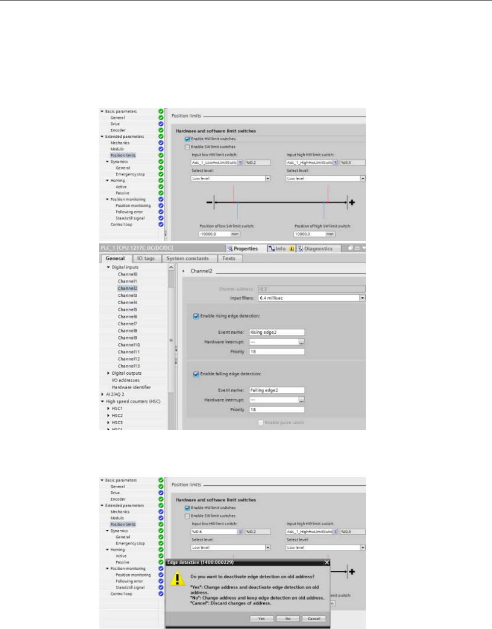
Technology instructions
10.3 Motion control
S7-1200 Programmable controller
System Manual, V4.2, 09/2016, A5E02486680-AK 717
Example: Changing to a new HW limit switch address with edge detection and deactivating edge
detection on the old address
1. Current state: You have connected an "Input low HW limit switch" to I0.2. This
configuration automatically enabled edge detection on I0.2. This configuration is also
shown in the CPU Properties, Digital Inputs:
2. You change "Input low HW limit switch" to I0.6 and confirm. The edge detection dialog
displays. You select: "Yes: Change address and deactivate edge detection on old
address.":
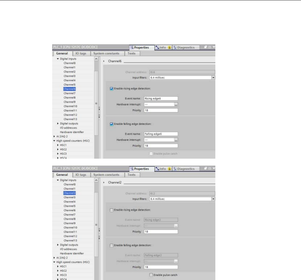
Technology instructions
10.3 Motion control
S7-1200 Programmable controller
718 System Manual, V4.2, 09/2016, A5E02486680-AK
3. The CPU accepts the new I0.6 address and activates edge detection on the I0.6. The
edge detection of I0.2 in the CPU Properties, Digital Inputs is automatically deactivated:
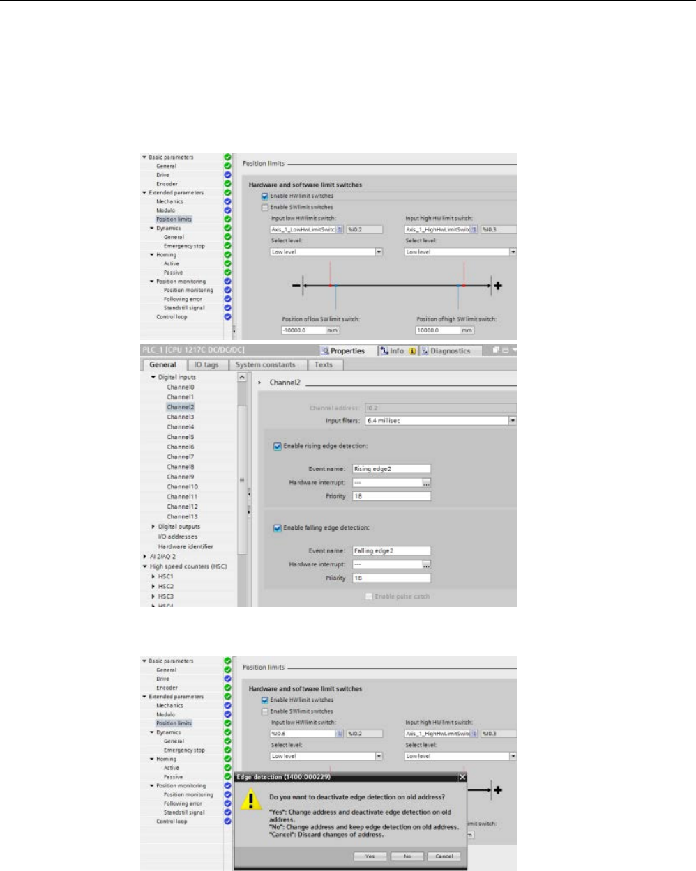
Technology instructions
10.3 Motion control
S7-1200 Programmable controller
System Manual, V4.2, 09/2016, A5E02486680-AK 719
Example: Changing to a new HW limit switch address with edge detection and maintaining edge
detection on the old address
1. Current state: You have connected an "Input low HW limit switch" to I0.2. This
configuration automatically enabled edge detection on I0.2. This configuration is also
shown in the CPU Properties, Digital Inputs:
2. You change "Input low HW limit switch" to I0.6 and confirm. The edge detection dialog
displays. You select: "No: Change address and keep edge detection on old address.":
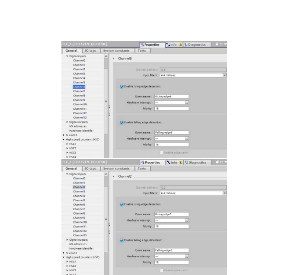
Technology instructions
10.3 Motion control
S7-1200 Programmable controller
720 System Manual, V4.2, 09/2016, A5E02486680-AK
3. The CPU accepts the new I0.6 address and activates edge detection on the I0.6. The
edge detection of I0.2 in the CPU Properties, Digital Inputs is kept activated:

Technology instructions
10.3 Motion control
S7-1200 Programmable controller
System Manual, V4.2, 09/2016, A5E02486680-AK 721
Example: Canceling change to a new HW limit switch address with edge detection
1. Current state: You have connected an "Input low HW limit switch" to I0.2. This
configuration automatically enabled edge detection on I0.2. This configuration is also
shown in the CPU Properties, Digital Inputs:
2. You change "Input low HW limit switch" to I0.6 and confirm. The edge detection dialog
displays. You select: "Cancel.":
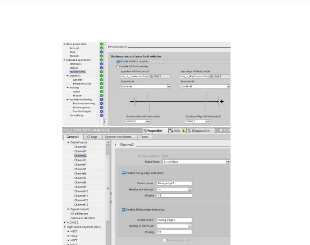
Technology instructions
10.3 Motion control
S7-1200 Programmable controller
722 System Manual, V4.2, 09/2016, A5E02486680-AK
3. The "Input low HW limit switch" remains configured to I0.2 and edge detection on I0.2
remains activated:
Additional information
Your user program can override the hardware or software position limits by enabling or
disabling both hardware and software limits functionality. The selection is made from the
Axis DB.
● To enable or disable the hardware limit functionality, access the "Active" tag (Bool) in the
DB path "<axis name>/Config/
PositonLimits_HW
". The state of the "Active" tag enables
or disables the use of hardware position limits.
● To enable or disable software position limit functionality, access "Active" tag (Bool) in the
DB path "<axis name>/Config/
Position Limits_SW
". The state of this "Active" tag enables
or disables the software position limits.
You can also modify the software position limits with your user program (for example, to add
flexibility for machine setup or to shorten machine change-over time). Your user program can
write new values to the " MinPosition " and " MaxPosition " tags (engineering units in Real
format) in the DB "<axis name>/Config/
PositionLimits_SW
".

Technology instructions
10.3 Motion control
S7-1200 Programmable controller
System Manual, V4.2, 09/2016, A5E02486680-AK 723
10.3.6.3
Homing
Homing refers to the matching of the axis coordinates to the real, physical drive position. (If
the drive is currently at position x, the axis will be adjusted to be in position x.) For position-
controlled axes, the entries and displays for the position refer exactly to these axis
coordinates.
Note
The agreement between the axis coordinates and the real situation is extremely important.
This step is necessary to ensure that the absolute target position of the axis is also achieved
e
xactly with the drive.
The MC_Home instruction initiates the homing of the axis.
There are 4 different homing functions. The first two functions allow the user to set the
current position of the axis and the second two position the axis with respect to a Home
reference Sensor.
● Mode 0 - Direct Referencing Absolute: When executed this mode tells the axis exactly
where it is. It sets the internal position variable to the value of the Position input of the
Homing instruction. This is used for machine calibration and setup.
The axis position is set regardless of the reference point switch. Active traversing motions
are not aborted. The value of the Position input parameter of the MC_Home instruction is
set immediately as the reference point of the axis. To assign the reference point to an
exact mechanical position, the axis must be at a standstill at this position at the time of
the homing operation.
● Mode 1 - Direct Referencing Relative: When executed this mode uses the internal
position variable and adds the value of the Position input on the Homing instruction to it.
This is typically used to account for machine offset.
The axis position is set regardless of the reference point switch. Active traversing motions
are not aborted. The following statement applies to the axis position after homing: New
axis position = current axis position + value of the Position parameter of the MC_Home
instruction.
● Mode 2 - Passive Referencing: When the axis is moving and passes the Reference Point
Switch the current position is set as the home position. This feature will help account for
normal machine wear and gear backlash and prevent the need for manual compensation
for wear. The Position input on the Homing instruction, as before, adds to the location
indicated by the Reference Point Switch allowing easy offset of the Home position.
During passive homing, the MC_Home instruction does not carry out any homing motion.
The traversing motion required for this step must be implemented by the user via other
motion control instructions. When the reference point switch is detected, the axis is
homed according to the configuration. Active traversing motions are not aborted upon
start of passive homing.

Technology instructions
10.3 Motion control
S7-1200 Programmable controller
724 System Manual, V4.2, 09/2016, A5E02486680-AK
● Mode 3 - Active Referencing: This mode is the most precise method of Homing the Axis.
The initial direction and velocity of movement is configured in the Technology Object
Configuration Extended Parameters-Homing. This is dependent upon machine
configuration. There is also the ability to determine if the leading edge or falling edge of
the Reference Point Switch signal is the Home position. Virtually all sensors have an
active range and if the Steady State On position was used as the Home signal then there
would be a possibility for error in the Homing position since the On signal active range
would cover a range of distance. By using either the leading or falling edge of that signal
a much more precise Home position results. As with all other modes the value of the
Position input on the Homing instruction is added to the Hardware referenced position.
In active homing mode, the MC_Home instruction performs the required reference point
approach. When the reference point switch is detected, the axis is homed according to
the configuration. Active traversing motions are aborted.
Modes 0 and 1 do not require that the axis be moved at all. They are typically used in setup
and calibration. Modes 2 and 3 require that the axis move and pass a sensor that is
configured in the "Axis" technology object as the Reference Point Switch. The reference
point can be placed in the work area of the axis or outside of the normal work area but within
movement range.
Configuration of homing parameters
You configure the parameters for active and passive homing in the "Homing" configuration
window. The homing method is set using the "Mode" input parameter of the motion control
instruction. Here, Mode = 2 means passive homing and Mode = 3 means active homing.
Note
Use one of the following measures to ensure that t
he machine does not travel to a
mechanical endstop in the event of a direction reversal:
•
Keep the approach velocity low
•
Increase the configured acceleration/deceleration
•
Increase the distance between hardware limit switch and mechanical stop

Technology instructions
10.3 Motion control
S7-1200 Programmable controller
System Manual, V4.2, 09/2016, A5E02486680-AK 725
Table 10- 51 Configuration parameters for homing the axis
Parameter
Description
Input reference point switch
(Active and passive homing)
Select the digital input for the reference point switch from the drop-down list box. The
input must be interrupt-capable. The onboard CPU inputs and inputs of an inserted
signal board can be selected as inputs for the reference point switch.
The default filter time for the digital inputs is 6.4 ms. When the digital inputs are used
as a reference point switch, this can result in undesired decelerations and thus inac-
curacies. Depending on the homing velocity and extent of the reference point switch,
the reference point may not be detected. The filter time can be set under "Input filter"
in the device configuration of the digital inputs.
The specified filter time must be less than the duration of the input signal at the refer-
ence point switch.
Reference point switch
(Active and passive homing)
• Active homing: Select whether the axis is to be referenced on the bottom or top
side of the reference point switch. Depending on the start position of the axis and
the configuration of the homing parameters, the reference point approach se-
quence can differ from the diagram in the configuration window.
• Passive homing: With passive homing, the traversing motions for purposes of
homing must be implemented by the user via motion commands. The side of the
reference point switch on which homing occurs depends on the following factors:
– "Reference point switch" configuration
– Current travel direction during passive homing
Auto reverse after reaching the
hardware limit switches
(Active homing only)
Activate the check box to use the hardware limit switch as a reversing cam for the
reference point approach. The hardware limit switches must be configured and acti-
vated for direction reversal.
If the hardware limit switch is reached during active homing, the axis brakes at the
configured deceleration (not with the emergency deceleration) and reverses direction.
The reference point switch is then sensed in reverse direction.
If the direction reversal is not active and the axis reaches the hardware limit switch
during active homing, the reference point approach is aborted with an error and the
axis is braked at the emergency deceleration.
Approach direction
(Active and passive homing)
With the direction selection, you determine the "approach direction" used during ac-
tive homing to search for the reference point switch, as well as the homing direction.
The homing direction specifies the travel direction the axis uses to approach the
configured side of the reference point switch to carry out the homing operation.
Approach velocity
(Active homing only)
Specify the velocity at which the reference point switch is to be searched for during
the reference point approach.
Limit values (independent of the selected user unit):
Start/stop velocity ≤ approach velocity ≤ maximum velocity

Technology instructions
10.3 Motion control
S7-1200 Programmable controller
726 System Manual, V4.2, 09/2016, A5E02486680-AK
Parameter
Description
Homing velocity
(Active homing only)
Specify the velocity at which the axis approaches the reference point switch for hom-
ing.
Limit values (independent of the selected user unit):
Start/stop velocity ≤ homing velocity ≤ maximum velocity
Home position offset
(Active homing only)
If the desired reference position deviates from the position of the reference point
switch, the home position offset can be specified in this field.
If the value does not equal 0, the axis executes the following actions following homing
at the reference point switch:
1. Move the axis at homing velocity by the value of the home position offset.
2. When the position of the home position offset is reached, the axis position is set
to the absolute reference position. The absolute reference position is specified via
parameter "Position" of motion control instruction "MC_Home".
Limit values (independent of the selected user unit):
-1.0e12 ≤ home position offset ≤ 1.0e12
Table 10- 52 Factors that affect homing
Influencing factors:
Result:
Configuration
Approach direction
Configuration
Reference point switch
Current travel direction
Homing on
Reference point switch
Positive "Bottom (negative) side"
Positive direction
Bottom
Negative direction
Top
Positive "Top (positive) side"
Positive direction
Top
Negative direction
Bottom
Negative "Bottom (negative) side"
Positive direction
Top
Negative direction
Bottom
Negative "Top (positive) side"
Positive direction
Bottom
Negative direction
Top
Homing reference point switch level
In the axis configuration Homing dialog, Passive or Active, you configure your "Digital input
homing switch". As part of this configuration, you can also change the levels (high or low) of
the closed loop axes (PROFIdrive and analog) reference point switches. The default value is
high level.
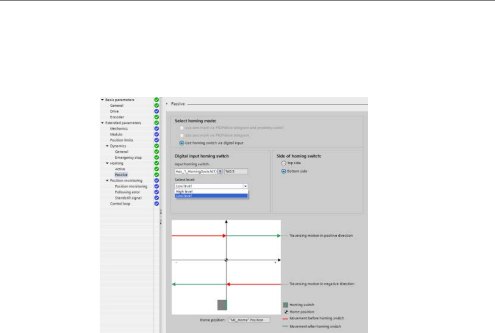
Technology instructions
10.3 Motion control
S7-1200 Programmable controller
System Manual, V4.2, 09/2016, A5E02486680-AK 727
Example:
Selecting the passive reference point switch level
1. You have configured an S7-1200 project with an Analog/PROFIdrive axis using passive
homing. Depending on your application, you select "High level" or "Low level" for the
passive homing switch level:
2. The program executes a passive homing.
3. After finishing the passive homing, the axis is homed.
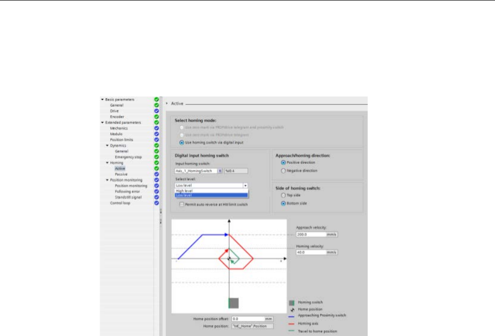
Technology instructions
10.3 Motion control
S7-1200 Programmable controller
728 System Manual, V4.2, 09/2016, A5E02486680-AK
Example: Selecting the active reference point switch level
1. You have configured an S7-1200 project with an Analog/PROFIdrive axis using active
homing. Depending on your application, you select "High level" or "Low level" for the
active homing switch level:
2. The program executes an active homing.
3. After finishing the active homing, the axis is homed.
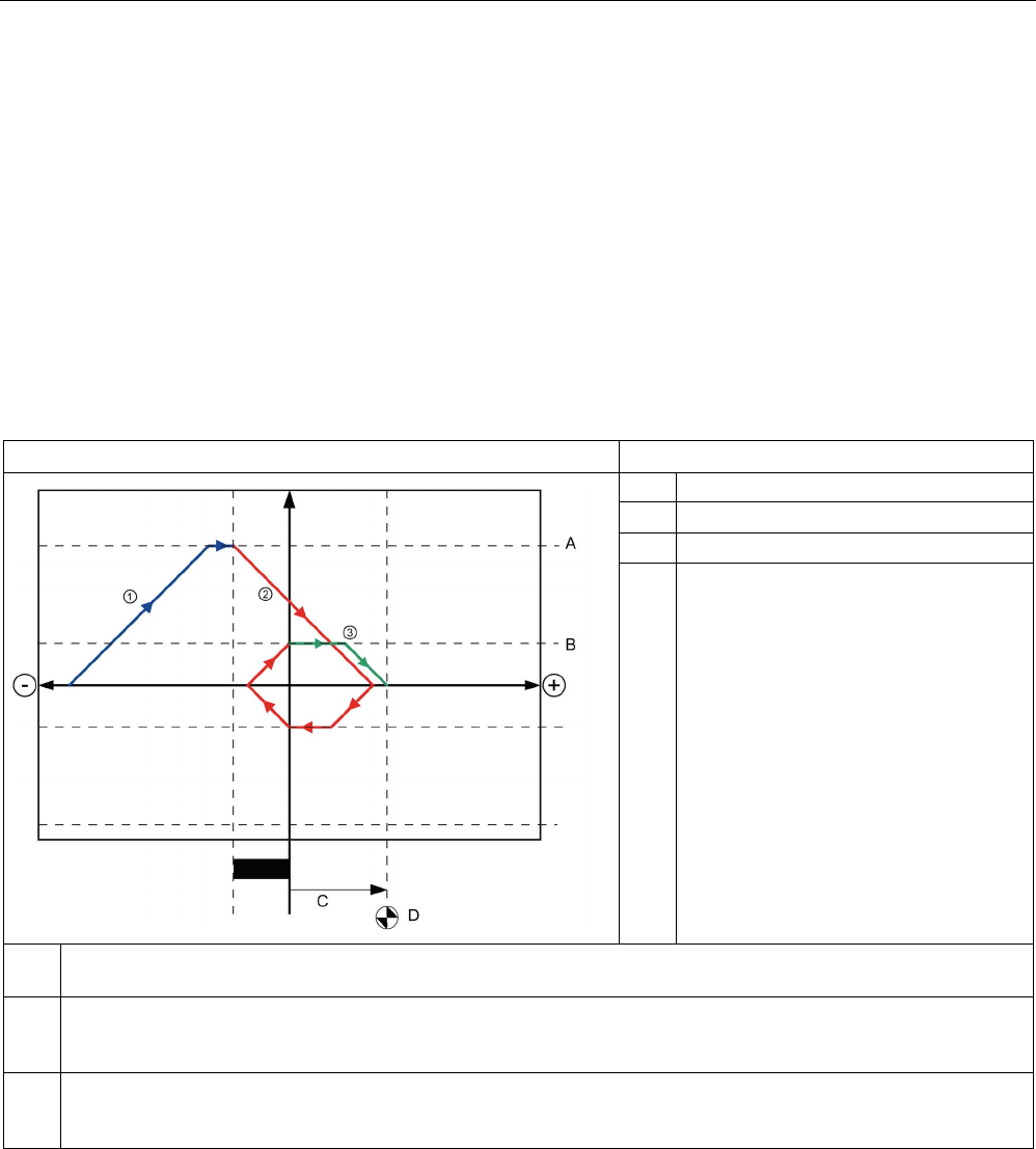
Technology instructions
10.3 Motion control
S7-1200 Programmable controller
System Manual, V4.2, 09/2016, A5E02486680-AK 729
Sequence for active homing
You start active homing with motion control instruction "MC_Home" (input parameter
Mode = 3). Input parameter "Position" specifies the absolute reference point coordinates in
this case. Alternatively, you can start active homing on the control panel for test purposes.
The following diagram shows an example of a characteristic curve for an active reference
point approach with the following configuration parameters:
● "Approach direction" = "Positive approach direction"
● "Reference point switch" = "Top (positive) side"
● Value of "home position offset" > 0
Table 10- 53 Velocity characteristics of MC homing
Operation
Notes
A
Approach velocity
B Homing velocity
C
Home position coordinate
D Home position offset
① Search phase (blue curve segment): When active homing starts, the axis accelerates to the configured "approach
velocity" and searches at this velocity for the reference point switch.
②
Reference point approach (red curve section): When the reference point switch is detected, the axis in this example
brakes and reverses, to be homed on the configured side of the reference point switch at the configured "homing
velocity".
③ Travel to reference point position (green curve segment): After homing at the refe
rence point switch, the axis travels
to the "Reference point coordinates" at the "homing velocity". On reaching the "Reference point coordinates", the
axis is stopped at the position value that was specified in the Position input parameter of the MC_Home instruction".

Technology instructions
10.3 Motion control
S7-1200 Programmable controller
730 System Manual, V4.2, 09/2016, A5E02486680-AK
Note
If the homing search does not function as you expected, check the inputs assigned to the
hardware limits or to the reference point. These inputs may have had their edge interrupts
disabled in device configuration.
Examine the configu
ration data for the axis technology object of concern to see which inputs
(if any) are assigned for "HW Low Limit Switch Input", "HW High Limit Switch Input", and
"Input reference point switch". Then open the Device configuration for the CPU and examine
ea
ch of the assigned inputs. Verify the "Enable rising edge detection" and "Enable falling
edge detection" are both selected. If these properties are not selected, delete the specified
inputs in the axis configuration and select them again.
10.3.6.4
Jerk limit
With the jerk limit you can reduce the stresses on your mechanics during an acceleration
and deceleration ramp. The value for the acceleration and deceleration is not changed
abruptly when the step limiter is active; it is adapted in a transition phase. The figure below
shows the velocity and acceleration curve without and with jerk limit.
Table 10- 54 Jerk limit
Travel without step limiter
Travel with step limiter
The jerk limit gives a "smoothed" velocity profile of the axis motion. This ensures soft starting
and braking of a conveyor belt for example.

Technology instructions
10.3 Motion control
S7-1200 Programmable controller
System Manual, V4.2, 09/2016, A5E02486680-AK 731
10.3.7
Motion control instructions
10.3.7.1
MC instruction overview
The motion control instructions use an associated technology data block and the dedicated
PTO (pulse train outputs) of the CPU to control the motion on an axis.
● MC_Power (Page 733) enables and disables a motion control axis.
● MC_Reset (Page 736) resets all motion control errors. All motion control errors that can
be acknowledged are acknowledged.
● MC_Home (Page 737) establishes the relationship between the axis control program and
the axis mechanical positioning system.
● MC_Halt (Page 740) cancels all motion processes and causes the axis motion to stop.
The stop position is not defined.
● MC_MoveAbsolute (Page 742) starts motion to an absolute position. The job ends when
the target position is reached.
● MC_MoveRelative (Page 745) starts a positioning motion relative to the start position.
● MC_MoveVelocity (Page 747) causes the axis to travel with the specified speed.
● MC_MoveJog (Page 749) executes jog mode for testing and startup purposes.
● MC_CommandTable (Page 751) runs axis commands as a movement sequence.
● MC_ChangeDynamic (Page 754) changes Dynamics settings for the axis.
● MC_WriteParam (Page 756) writes a select number of parameters to change the
functionality of the axis from the user program.
● MC_ReadParam (Page 758) reads a select number of parameters that indicate the
current position, velocity, and so forth of the axis defined in the Axis input.

Technology instructions
10.3 Motion control
S7-1200 Programmable controller
732 System Manual, V4.2, 09/2016, A5E02486680-AK
CPU firmware levels
If you have an S7-1200 CPU with V4.1 or later firmware, select the V5.0 version of each
motion instruction.
If you have an S7-1200 CPU with V4.0 or earlier firmware, select the applicable V4.0, V3.0,
V2.0, or V1.0 version of each motion instruction.
Note
Instructions in motion control V1.0 to V3.0 actively control t
he ENO output of the instruction.
When an error occurs within the block, the ENO output is turned to the OFF state. An error is
indicated by the ERROR, ErrorID, and ErrorInfo outputs on the block. Using the ENO output,
it is possible to evaluate the status
of the instruction and execute subsequent instructions
after it in a serial manner.
With instructions in motion control V4.0 and V5.0, the ENO output stays true as long as the
instruction executes regardless of its error state. This could cause a program
that used V3.0
or earlier motion control that depends on the ENO status to function incorrectly. To remedy
this situation, use the DONE and ERROR outputs to evaluate the status of the instruction
rather than the ENO output when using motion control V4.0 or
later.
Note
The CPU calculates motion tasks in "slices" or segments of 10
ms. As one slice is being
executed, the next slice is waiting in the queue to be executed. If you interrupt the motion
task on an axis (by executing another new motion task fo
r that axis), the new motion task
cannot be executed for a maximum of 20
ms (the remainder of the current slice plus the
queued slice).
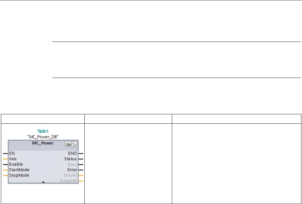
Technology instructions
10.3 Motion control
S7-1200 Programmable controller
System Manual, V4.2, 09/2016, A5E02486680-AK 733
10.3.7.2
MC_Power (Release/block axis)
Note
If the axis is switched off due to an error, it will be enabled again automati
cally after the error
has been eliminated and acknowledged. This requires that the Enable input parameter has
retained the value TRUE during this process.
Table 10- 55 MC_Power instruction
LAD / FBD
SCL
Description
"MC_Power_DB"(
Axis:=_multi_fb_in_,
Enable:=_bool_in_,
StartMode:=_int_in_,
StopMode:=_int_in_,
Status=>_bool_out_,
Busy=>_bool_out_,
Error=>_bool_out_,
ErrorID=>_word_out_,
ErrorIn-
fo=>_word_out_);
The MC_Power motion control instruction enables
or disables an axis. Before you can enable or disa-
ble the axis, ensure the following conditions:
• The technology object has been configured
correctly.
• There is no pending enable-inhibiting error.
The execution of MC_Power cannot be aborted by
a motion control task. Disabling the axis (input
parameter Enable = FALSE) aborts all motion con-
trol tasks for the associated technology object.
1
STEP 7 automatically creates the DB when you insert the instruction.
2 In the SCL example, "MC_Power_DB" is the name of the instance DB.

Technology instructions
10.3 Motion control
S7-1200 Programmable controller
734 System Manual, V4.2, 09/2016, A5E02486680-AK
Table 10- 56 Parameters for the MC_Power instruction
Parameter and type
Data type
Description
Axis
IN_OUT
TO_Axis
Axis technology object
Enable IN Bool • FALSE (default): All active tasks are aborted according to the pa-
rameterized "StopMode" and the axis is stopped.
• TRUE: Motion control attempts to enable the axis.
StartMode IN Int • 0: Speed controlled
Note: The StartMode parameter is only evaluated during edge detec-
tion (false to true).
• 1: Position controlled (default)
StopMode IN Int • 0: Emergency stop: If a request to disable the axis is pending, the
axis brakes at the configured emergency deceleration. The axis is
disabled after reaching standstill.
• 1: Immediate stop: If a request to disable the axis is pending, this
axis is disabled without deceleration. Pulse output is stopped imme-
diately.
•
2: Emergency stop with jerk control: If a request to disable the axis is
pending, the axis brakes at the configured emergency stop decelera-
tion. If the jerk control is activated, the configured jerk is taken into
account. The axis is disabled after reaching standstill.
Status OUT Bool Status of axis enable:
• FALSE: The axis is disabled:
– The axis does not execute motion control tasks and does not ac-
cept any new tasks (exception: MC_Reset task).
– The axis is not homed.
– Upon disabling, the status does not change to FALSE until the
axis reaches a standstill.
• TRUE: The axis is enabled:
– The axis is ready to execute motion control tasks.
– Upon axis enabling, the status does not change to TRUE until
the signal "Drive ready" is pending. If the "Drive ready" drive in-
terface was not configured in the axis configuration, the status
changes to TRUE immediately.
Busy OUT Bool FALSE: MC_Power is not active.
TRUE: MC_Power is active.
Error OUT Bool FALSE: No error
TRUE: An error has occurred in motion control instruction "MC_Power"
or in the associated technology object. The cause of the error can be
found in parameters "ErrorID" and "ErrorInfo".
ErrorID
OUT
Word
Error ID for parameter "Error""
ErrorInfo
OUT
Word
Error info ID for parameter "ErrorID"
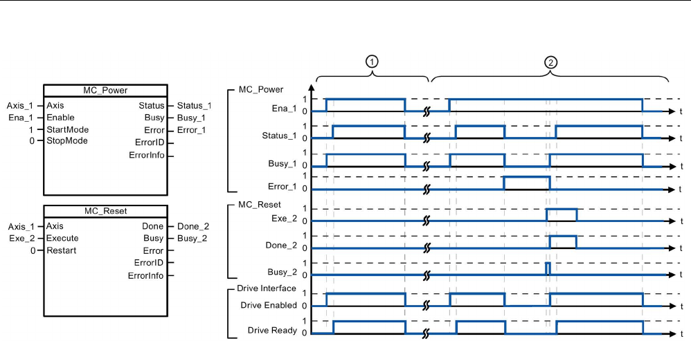
Technology instructions
10.3 Motion control
S7-1200 Programmable controller
System Manual, V4.2, 09/2016, A5E02486680-AK 735
①
An axis is enabled and then disabled again. After the drive has signaled "Drive ready" back to the CPU, the suc-
cessful enable can be read out via "Status_1".
②
Following an axis enable, an error has occurred that caused the axis to be disabled. The error is eliminated and
acknowledged with "MC_Reset". The axis is then enabled again.
To enable an axis with configured drive interface, follow these steps:
1. Check the requirements indicated above.
2. Initialize input parameter "StopMode" with the desired value. Set input parameter
"Enable" to TRUE.
The enable output for "Drive enabled" changes to TRUE to enable the power to the drive.
The CPU waits for the "Drive ready" signal of the drive.
When the "Drive ready" signal is available at the configured ready input of the CPU, the
axis becomes enabled. Output parameter "Status" and technology object tag <Axis
name>.StatusBits.Enable indicates the value TRUE.
To enable an axis without configured drive interface, follow these steps:
1. Check the requirements indicated above.
2. Initialize input parameter "StopMode" with the desired value. Set input parameter
"Enable" to TRUE. The axis is enabled. Output parameter "Status" and technology object
tag <Axis name>.StatusBits.Enable indicate the value TRUE.
To disable an axis, follow these steps:
1. Bring the axis to a standstill.
You can identify when the axis is at a standstill in technology object tag <Axis
name>.StatusBits.StandStill.
2. Set input parameter "Enable" to FALSE after standstill is reached.
3. If output parameters "Busy" and "Status" and technology object tag <Axis
name>.StatusBits.Enable indicate the value FALSE, disabling of the axis is complete.
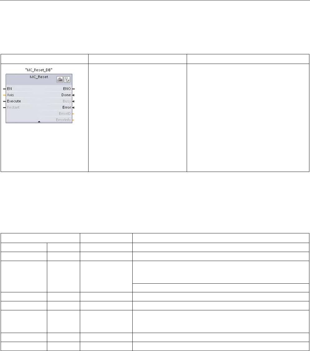
Technology instructions
10.3 Motion control
S7-1200 Programmable controller
736 System Manual, V4.2, 09/2016, A5E02486680-AK
10.3.7.3
MC_Reset (Confirm error)
Table 10- 57 MC_Reset instruction
LAD / FBD
SCL
Description
"MC_Reset_DB"(
Axis:=_multi_fb_in_,
Execute:=_bool_in_,
Restart:=_bool_in_,
Done=>_bool_out_,
Busy=>_bool_out_,
Error=>_bool_out_,
ErrorID=>_word_out_,
ErrorInfo=>_word_out_);
Use the MC_Reset instruction to acknowledge
"Operating error with axis stop" and "Configura-
tion error". The errors that require acknowl-
edgement can be found in the "List of ErrorIDs
and ErrorInfos" under "Remedy".
Before using the MC_Reset instruction, you
must have eliminated the cause of a pending
configuration error requiring acknowledgement
(for example, by changing an invalid accelera-
tion value in "Axis" technology object to a valid
value).
As of V3.0 and later, the Restart command
allows the axis configuration to be downloaded
to the work memory in the RUN operating
mode.
1
STEP 7 automatically creates the DB when you insert the instruction.
2 In the SCL example, "MC_Reset_DB" is the name of the instance DB.
The MC_Reset task cannot be aborted by any other motion control task. The new MC_Reset
task does not abort any other active motion control tasks.
Table 10- 58 Parameters of the MC_Reset instruction
Parameter and type
Data type
Description
Axis
IN
TO_Axis_1
Axis technology object
Execute
IN
Bool
Start of the task with a positive edge
Restart IN Bool
TRUE = Download the axis configuration from the load memory to the
work memory. The command can only be executed when the axis is
disabled.
FALSE = Acknowledges pending errors
Done
OUT
Bool
TRUE = Error has been acknowledged.
Busy
OUT
Bool
TRUE = The task is being executed.
Error OUT Bool TRUE = An error has occurred during execution of the task. The
cause of the error can be found in parameters "ErrorID" and "ErrorIn-
fo".
ErrorID
OUTP
Word
Error ID for parameter "Error""
ErrorInfo
OUT
Word
Error info ID for parameter "ErrorID"
To acknowledge an error with MC_Reset, follow these steps:
1. Check the requirements indicated above.
2. Start the acknowledgement of the error with a rising edge at the Execute input parameter.
3. The error has been acknowledged when Done equals TRUE and the technology object
tag <Axis name>.StatusBits.Error equals FALSE.
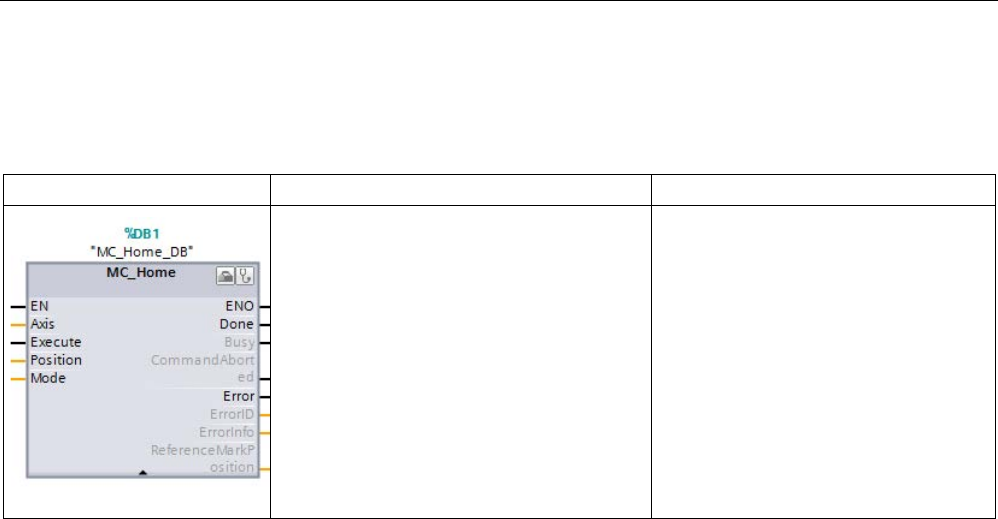
Technology instructions
10.3 Motion control
S7-1200 Programmable controller
System Manual, V4.2, 09/2016, A5E02486680-AK 737
10.3.7.4
MC_Home (Home axis)
Table 10- 59 MC_Home instruction
LAD / FBD
SCL
Description
"MC_Home_DB"(
Axis:=_multi_fb_in_,
Execute:=_bool_in_,
Position:=_real_in_,
Mode:=_int_in_,
Done=>_bool_out_,
Busy=>_bool_out_,
CommandAborted=>_bool_out_,
Error=>_bool_out_,
ErrorID=>_word_out_,
ErrorInfo=>_word_out_,
ReferenceMarkPosi-
tion=>_real_out_);
Use the MC_Home instruction to match
the axis coordinates to the real, physical
drive position. Homing is required for
absolute positioning of the axis:
In order to use the MC_Home instruction,
the axis must first be enabled.
1
STEP 7 automatically creates the DB when you insert the instruction.
2 In the SCL example, "MC_Home_DB" is the name of the instance DB.
The following types of homing are available:
● Direct homing absolute (Mode = 0): The current axis position is set to the value of
parameter "Position".
● Direct homing relative (Mode = 1): The current axis position is offset by the value of
parameter "Position".
● Passive homing (Mode = 2): During passive homing, the MC_Home instruction does not
carry out any homing motion. The traversing motion required for this step must be
implemented by the user via other motion control instructions. When the reference point
switch is detected, the axis is homed.
● Active homing (Mode = 3): The homing procedure is executed automatically.
● Absolute encoder adjustment (relative) (Mode = 6): The current position is shifted by the
value of the parameter "MC_Home.Position".
● Absolute encoder adjustment (absolute) (Mode = 7): The current position is set to the
value of the parameter "MC_Home.Position".

Technology instructions
10.3 Motion control
S7-1200 Programmable controller
738 System Manual, V4.2, 09/2016, A5E02486680-AK
Table 10- 60 Parameters for the MC_Home instruction
Parameter and type
Data type
Description
Axis
IN_OUT
TO_Axis
Axis technology object
Execute IN Bool Start of the task with a positive edge
Position IN Real • Mode = 0, 2, and 3 (Absolute position of axis after comple-
tion of the homing operation)
• Mode = 1 (Correction value for the current axis position)
• Mode = 6 (The current position is shifted by the value of
the parameter "MC_Home.Position".)
• Mode = 7 (The current position is set to the value of the
parameter "MC_Home.Position".)
Limit values: -1.0e
12
≤ Position ≤ 1.0e
12
Mode IN Int Homing mode:
• 0: Direct homing absolute
New axis position is the position value of parameter "Posi-
tion".
• 1: Direct homing relative
New axis position is the current axis position + position
value of parameter "Position".
• 2: Passive homing
Homing according to the axis configuration. Following
homing, the value of parameter "Position" is set as the
new axis position.
• 3: Active homing
Reference point approach in accordance with the axis
configuration. Following homing, the value of parameter
"Position" is set as the new axis position.
• 6: The current position is shifted by the value of the pa-
rameter "MC_Home.Position". The calculated absolute
value offset is stored retentively in the CPU.
(<Axis name>.StatusSensor.AbsEncoderOffset)
• 7: The current position is set to the value of the parameter
"MC_Home.Position". The calculated absolute value offset
is stored retentively in the CPU.
(<Axis name>.StatusSensor.AbsEncoderOffset)
Done
OUT
Bool
TRUE = Task completed
Busy
OUT
Bool
TRUE = The task is being executed.
CommandAborted OUT Bool TRUE = During execution, the task was aborted by another
task.
Error OUT Bool TRUE = An error has occurred during execution of the task.
The cause of the error can be found in parameters "ErrorID"
and "ErrorInfo".
ErrorID
OUT
Word
Error ID for parameter "Error""

Technology instructions
10.3 Motion control
S7-1200 Programmable controller
System Manual, V4.2, 09/2016, A5E02486680-AK 739
Parameter and type
Data type
Description
ErrorInfo
OUT
Word
Error info ID for parameter "ErrorID"
ReferenceMarkPosition OUT Real Position of the axis at the reference mark in the previous co-
ordinate system.
"ReferenceMarkPosition" output parameter: The homing function saves the old position
before execution and provides this value in the ReferenceMarkPosition output parameter.
The output displays the following values during the different homing modes:
● Active/Passive homing: Displays the position of the axis at the zero/reference mark of the
previous coordinate system during and after active/passive homing.
● Absolute encoder adjustment: Displays the previous axis position during and after
absolute encoder adjustment.
● Direct homing: Displays the previous axis position during and after direct homing.
During homing, motion control sets the axis position to the new value of input
"MC_Home.Position". The values of "MC_Home.ReferenceMarkPosition" are valid when
"MC_Home.Done" = TRUE.
Note
Axis homing is lost under the following conditions
•
Disabling of axis by the MC_Power instruction
•
Switchover between automatic control and manual control
•
Upon start of active homing (After successful completion of the homing operation, axis
homing is available again.)
•
After power-cycling the CPU
•
After CPU restart (RUN-to-STOP or STOP-to-RUN)
To home the axis, follow these steps:
1. Check the requirements indicated above.
2. Initialize the necessary input parameters with values, and start the homing operation with
a rising edge at input parameter "Execute".
3. If output parameter "Done" and technology object tag <Axis
name>.StatusBits.HomingDone indicate the value TRUE, homing is complete.

Technology instructions
10.3 Motion control
S7-1200 Programmable controller
740 System Manual, V4.2, 09/2016, A5E02486680-AK
Table 10- 61 Override response
Mode
Description
0 or 1 The MC_Home task cannot be aborted by any other motion control task. The new MC_Home task does not
abort any active motion control tasks. Position-related motion tasks are resumed after homing according to
the new homing position (value at the Position input parameter).
2 The MC_Home task can be aborted by the following motion control tasks:
MC_Home task Mode = 2, 3: The new MC_Home task aborts the following active motion control task.
MC_Home task Mode = 2: Position-related motion tasks are resumed after homing according to the new
homing position (value at the Position input parameter).
3 The MC_Home task can be aborted by the following
motion control tasks:
• MC_Home Mode = 3
• MC_Halt
• MC_MoveAbsolute
• MC_MoveRelative
• MC_MoveVelocity
• MC_MoveJog
The new MC_Home task aborts the following active
motion control tasks:
• MC_Home Mode = 2, 3
• MC_Halt
• MC_MoveAbsolute
• MC_MoveRelative
• MC_MoveVelocity
• MC_MoveJog
10.3.7.5
MC_Halt (Pause axis)
Table 10- 62 MC_Halt instruction
LAD / FBD
SCL
Description
"MC_Halt_DB"(
Axis:=_multi_fb_in_,
Execute:=_bool_in_,
Done=>_bool_out_,
Busy=>_bool_out_,
CommandAborted=>_bool_out_,
Error=>_bool_out_,
ErrorID=>_word_out_,
ErrorInfo=>_word_out_);
Use the MC_Halt instruction to stop all
motion and to bring the axis to a stand-
still. The stand-still position is not defined.
In order to use the MC_Halt instruction,
the axis must first be enabled.
1
STEP 7 automatically creates the DB when you insert the instruction.
2 In the SCL example, "MC_Halt_DB" is the name of the instance DB.
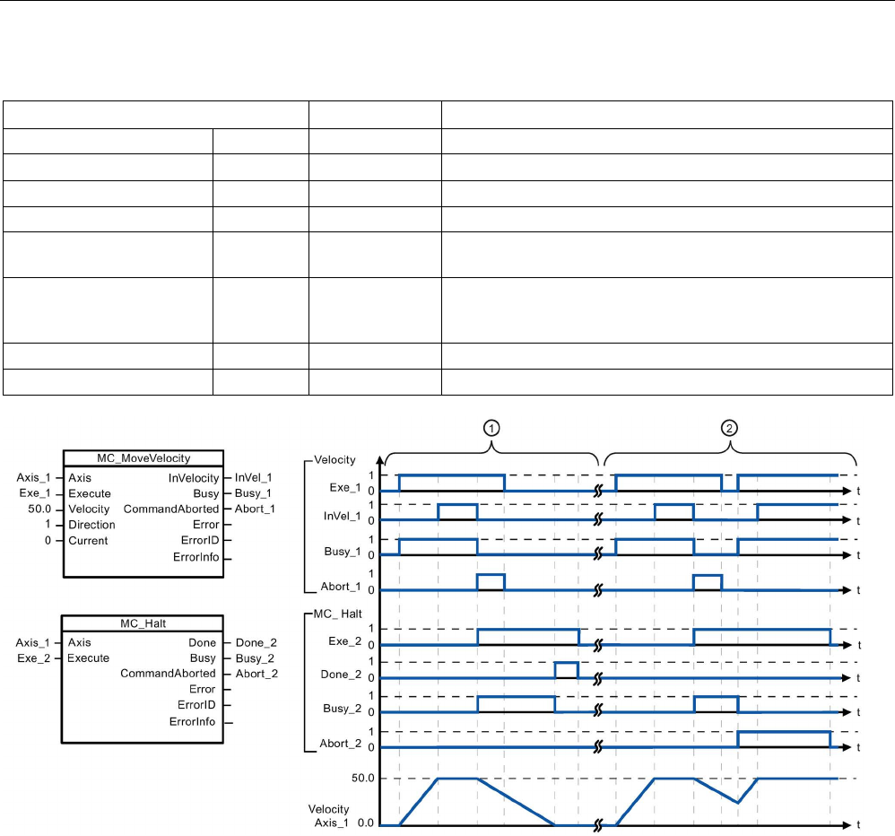
Technology instructions
10.3 Motion control
S7-1200 Programmable controller
System Manual, V4.2, 09/2016, A5E02486680-AK 741
Table 10- 63 Parameters for the MC_Halt instruction
Parameter and type
Data type
Description
Axis
IN
TO_Axis_1
Axis technology object
Execute IN Bool Start of the task with a positive edge
Done
OUT
Bool
TRUE = Zero velocity reached
Busy OUT Bool TRUE = The task is being executed.
CommandAborted OUT Bool TRUE = During execution the task was aborted by another
task.
Error OUT Bool TRUE = An error has occurred during execution of the task.
The cause of the error can be found in parameters "ErrorID"
and "ErrorInfo".
ErrorID
OUT
Word
Error ID for parameter "Error"
ErrorInfo
OUT
Word
Error info ID for parameter "ErrorID"
The following values were configured in the "Dynamics > General" configuration window: Acceleration = 10.0 and Decelera-
tion = 5.0
①
The axis is braked by an MC_Halt task until it comes to a standstill. The axis standstill is signaled via "Done_2".
②
While an MC_Halt task is braking the axis, this task is aborted by another motion task. The abort is signaled via
"Abort_2".

Technology instructions
10.3 Motion control
S7-1200 Programmable controller
742 System Manual, V4.2, 09/2016, A5E02486680-AK
Override response
The MC_Halt task can be aborted by the
following motion control tasks:
•
MC_Home Mode = 3
•
MC_Halt
•
MC_MoveAbsolute
•
MC_MoveRelative
•
MC_MoveVelocity
•
MC_MoveJog
The new MC_Halt task aborts the following
active motion control tasks:
•
MC_Home Mode = 3
•
MC_Halt
•
MC_MoveAbsolute
•
MC_MoveRelative
•
MC_MoveVelocity
•
MC_MoveJog
10.3.7.6
MC_MoveAbsolute (Position axis absolutely)
Table 10- 64 MC_MoveAbsolute instruction
LAD / FBD
SCL
Description
"MC_MoveAbsolute_DB"(
Axis:=_multi_fb_in_,
Execute:=_bool_in_,
Position:=_real_in_,
Velocity:=_real_in_,
Direction:=_int_in_,
Done=>_bool_out_,
Busy=>_bool_out_,
CommandAborted=>_bool_out_,
Error=>_bool_out_,
ErrorID=>_word_out_,
ErrorInfo=>_word_out_);
Use the MC_MoveAbsolute in-
struction to start a positioning
motion of the axis to an absolute
position.
In order to use the
MC_MoveAbsolute instruction, the
axis must first be enabled and also
must be homed.
1
STEP 7 automatically creates the DB when you insert the instruction.
2 In the SCL example, "MC_MoveAbsolute_DB" is the name of the instance DB.

Technology instructions
10.3 Motion control
S7-1200 Programmable controller
System Manual, V4.2, 09/2016, A5E02486680-AK 743
Table 10- 65 Parameters for the MC_MoveAbsolute instruction
Parameter and type
Data type
Description
Axis
IN
TO_Axis_1
Axis technology object
Execute IN Bool Start of the task with a positive edge (Default value: False)
Position IN Real Absolute target position (Default value: 0.0)
Limit values: -1.0e
12
≤ Position ≤ 1.0e
12
Velocity IN Real Velocity of axis (Default value: 10.0)
This velocity is not always reached because of the configured accel-
eration and deceleration and the target position to be approached.
Limit values: Start/stop velocity ≤ Velocity ≤ maximum velocity
Direction
IN
Int
Direction of rotation (Default value: 0)
Done
OUT
Bool
TRUE = Absolute target position reached
Busy
OUT
Bool
TRUE = The task is being executed.
CommandAborted
OUT
Bool
TRUE = During execution the task was aborted by another task.
Error OUT Bool TRUE = An error has occurred during execution of the task. The
cause of the error can be found in parameters "ErrorID" and "ErrorIn-
fo".
ErrorID
OUT
Word
Error ID for parameter "Error" (Default value: 0000)
ErrorInfo
OUT
Word
Error info ID for parameter "ErrorID" (Default value: 0000)
You can configure the positioning axis as a Modulo axis. When using a modulo axis, you can
select the motion direction with the "Direction" input parameter. Motion control ignores the
"Direction" input if the axis is not a Modulo axis.
The following table shows the valid values for the Direction input:
Value
Enumeration
Comment
0
SIGN_OF_VELOCITY
Sign of velocity defines the motion direction
1
POSITIVE
Motion with positive velocity
2
NEGATIVE
Motion with negative velocity
3
SHORTEST_WAY
Motion with shortest distance to the destination
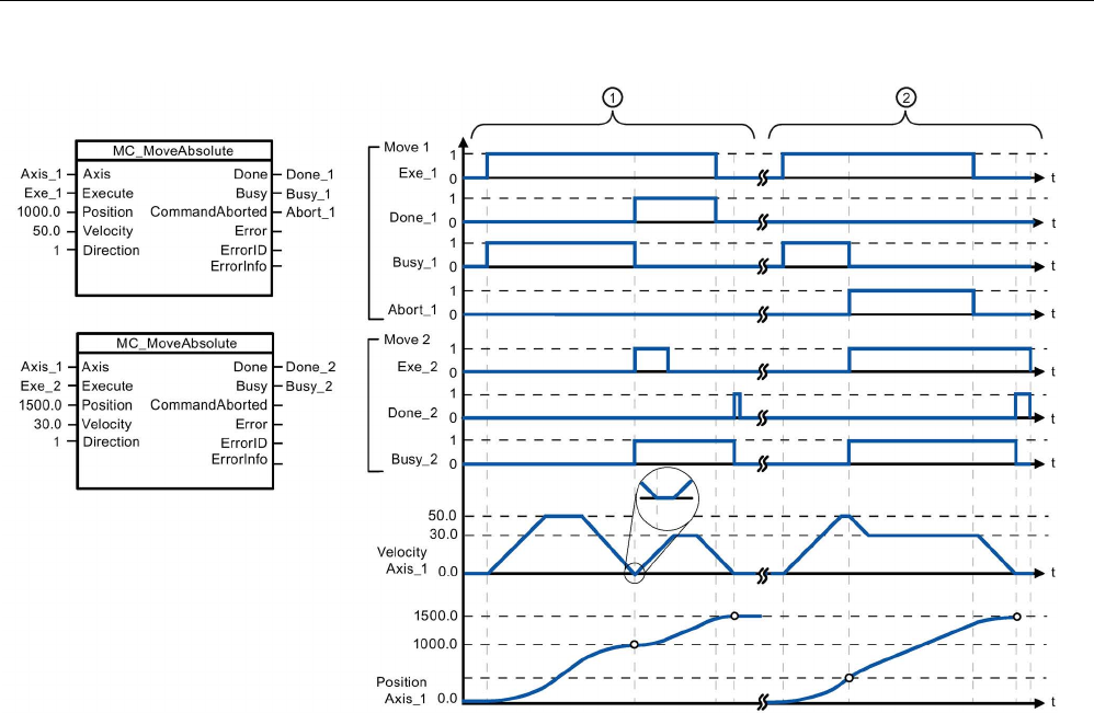
Technology instructions
10.3 Motion control
S7-1200 Programmable controller
744 System Manual, V4.2, 09/2016, A5E02486680-AK
The following values were configured in the "Dynamics > General" configuration window: Acceleration = 10.0 and Decelera-
tion = 10.0
①
An axis is moved to absolute position 1000.0 with a MC_MoveAbsolute task. When the axis reaches the target
position, this is signaled via "Done_1". When "Done_1" = TRUE, another MC_MoveAbsolute task, with target posi-
tion 1500.0, is started. Because of the response times (e.g., cycle time of user program, etc.), the axis comes to a
standstill briefly (see zoomed-in detail). When the axis reaches the new target position, this is signaled via
"Done_2".
②
An active MC_MoveAbsolute task is aborted by another MC_MoveAbsolute task. The abort is signaled via
"Abort_1". The axis is then moved at the new velocity to the new target position 1500.0. When the new target posi-
tion is reached, this is signaled via "Done_2".
Override response
The MC_MoveAbsolute task can be abor
t-
ed by the following motion control tasks:
•
MC_Home Mode = 3
•
MC_Halt
•
MC_MoveAbsolute
•
MC_MoveRelative
•
MC_MoveVelocity
•
MC_MoveJog
The new MC_MoveAbsolute task aborts
the following active motion
control tasks:
•
MC_Home Mode = 3
•
MC_Halt
•
MC_MoveAbsolute
•
MC_MoveRelative
•
MC_MoveVelocity
•
MC_MoveJog
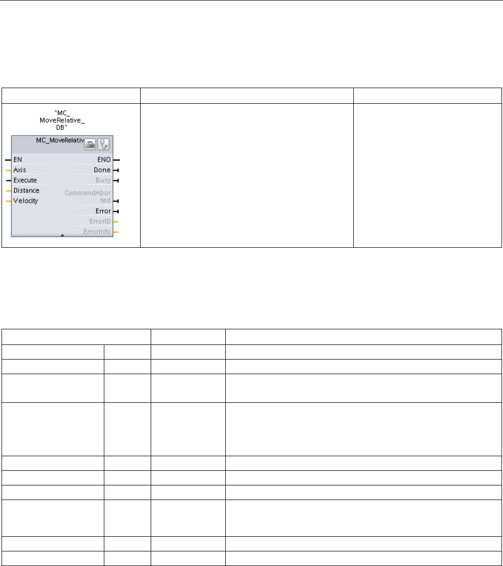
Technology instructions
10.3 Motion control
S7-1200 Programmable controller
System Manual, V4.2, 09/2016, A5E02486680-AK 745
10.3.7.7
MC_MoveRelative (Position axis relatively)
Table 10- 66 MC_MoveRelative instruction
LAD / FBD
SCL
Description
"MC_MoveRelative_DB"(
Axis:=_multi_fb_in_,
Execute:=_bool_in_,
Distance:=_real_in_,
Velocity:=_real_in_,
Done=>_bool_out_,
Busy=>_bool_out_,
CommandAborted=>_bool_out_,
Error=>_bool_out_,
ErrorID=>_word_out_,
ErrorInfo=>_word_out_);
Use the MC_MoveRelative instruc-
tion to start a positioning motion
relative to the start position.
In order to use the
MC_MoveRelative instruction, the
axis must first be enabled.
1
STEP 7 automatically creates the DB when you insert the instruction.
2 In the SCL example, "MC_MoveRelative_DB " is the name of the instance DB.
Table 10- 67 Parameters for the MC_MoveRelative instruction
Parameter and type
Data type
Description
Axis
IN
TO_Axis_1
Axis technology object
Execute
IN
Bool
Start of the task with a positive edge (Default value: False)
Distance IN Real Travel distance for the positioning operation (Default value: 0.0)
Limit values: -1.0e
12
≤ Distance ≤ 1.0e
12
Velocity IN Real Velocity of axis (Default value: 10.0)
This velocity is not always reached on account of the configured
acceleration and deceleration and the distance to be traveled.
Limit values: Start/stop velocity ≤ Velocity ≤ maximum velocity
Done OUT Bool TRUE = Target position reached
Busy
OUT
Bool
TRUE = The task is being executed.
CommandAborted
OUT
Bool
TRUE = During execution the task was aborted by another task.
Error OUT Bool TRUE = An error has occurred during execution of the task. The
cause of the error can be found in parameters "ErrorID" and "Error-
Info".
ErrorID
OUT
Word
Error ID for parameter "Error" (Default value: 0000)
ErrorInfo
OUT
Word
Error info ID for parameter "ErrorID" (Default value: 0000)
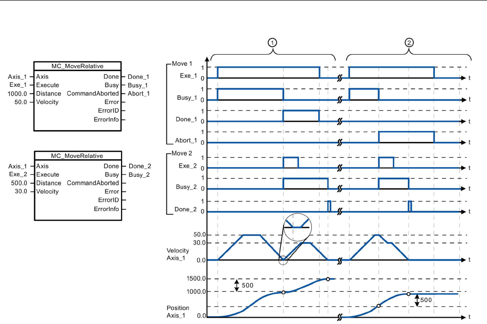
Technology instructions
10.3 Motion control
S7-1200 Programmable controller
746 System Manual, V4.2, 09/2016, A5E02486680-AK
The following values were configured in the "Dynamics > General" configuration window: Acceleration = 10.0 and Decelera-
tion = 10.0
①
The axis is moved by an MC_MoveRelative task by the distance ("Distance") 1000.0. When the axis reaches the
target position, this is signaled via "Done_1". When "Done_1" = TRUE, another MC_MoveRelative task, with travel
distance 500.0, is started. Because of the response times (for example, cycle time of user program), the axis
comes to a standstill briefly (see zoomed-in detail). When the axis reaches the new target position, this is signaled
via "Done_2".
②
An active MC_MoveRelative task is aborted by another MC_MoveRelative task. The abort is signaled via
"Abort_1". The axis is then moved at the new velocity by the new distance ("Distance") 500.0. When the new target
position is reached, this is signaled via "Done_2".
Override response
The MC_MoveRelative task can be aborted
by the following motion control tasks:
•
MC_Home Mode = 3
•
MC_Halt
•
MC_MoveAbsolute
•
MC_MoveRelative
•
MC_MoveVelocity
•
MC_MoveJog
The new MC_MoveRelative task aborts the
following active motion control tasks:
•
MC_Home Mode = 3
•
MC_Halt
•
MC_MoveAbsolute
•
MC_MoveRelative
•
MC_MoveVelocity
•
MC_MoveJog
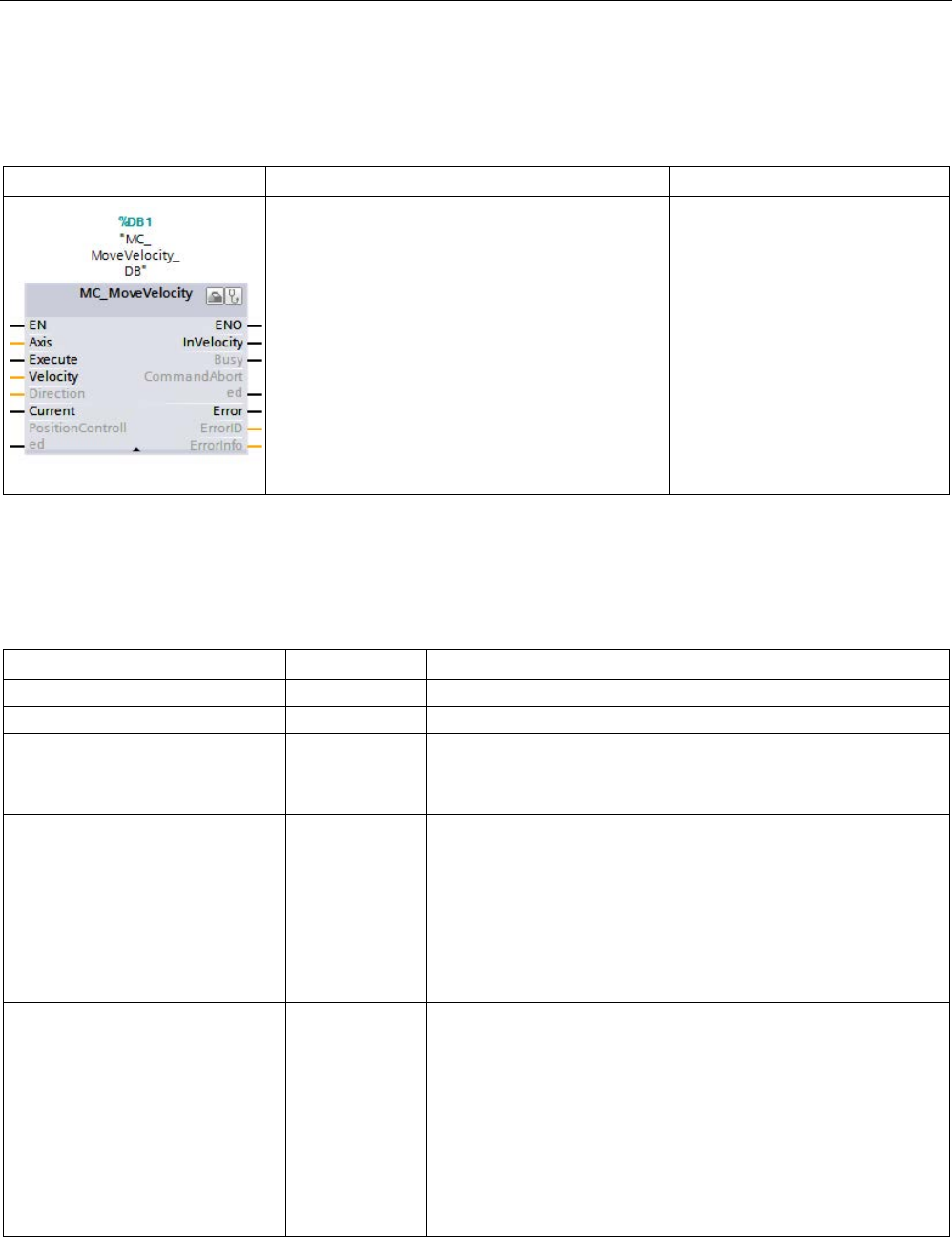
Technology instructions
10.3 Motion control
S7-1200 Programmable controller
System Manual, V4.2, 09/2016, A5E02486680-AK 747
10.3.7.8
MC_MoveVelocity (Move axis at predefined velocity)
Table 10- 68 MC_MoveVelocity instruction
LAD / FBD
SCL
Description
"MC_MoveVelocity_DB"(
Axis:=_multi_fb_in_,
Execute:=_bool_in_,
Velocity:=_real_in_,
Direction:=_int_in_,
Current:=_bool_in_,
PositionControlled:=_bool_in_,
InVelocity=>_bool_out_,
Busy=>_bool_out_,
CommandAborted=>_bool_out_,
Error=>_bool_out_,
ErrorID=>_word_out_,
ErrorInfo=>_word_out_);
Use the MC_MoveVelocity instruc-
tion to move the axis constantly at
the specified velocity.
In order to use the
MC_MoveVelocity instruction, the
axis must first be enabled.
1
STEP 7 automatically creates the DB when you insert the instruction.
2 In the SCL example, "MC_MoveVelocity_DB " is the name of the instance DB.
Table 10- 69 Parameters for the MC_MoveVelocity instruction
Parameter and type
Data type
Description
Axis
IN
TO_SpeedAxis
Axis technology object
Execute
IN
Bool
Start of the task with a positive edge (Default value: False)
Velocity IN Real Velocity specification for axis motion (Default value: 100.0)
Limit values: Start/stop velocity ≤ |Velocity| ≤ maximum velocity
(Velocity = 0.0 is allowed)
Direction IN Int Direction specification:
• 0: Direction of rotation corresponds to the sign of the value in
parameter "Velocity" (Default value)
• 1: Positive direction of rotation (The sign of the value in param-
eter "Velocity" is ignored.)
• 2: Negative direction of rotation (The sign of the value in pa-
rameter "Velocity" is ignored.)
Current IN Bool Maintain current velocity:
• FALSE: "Maintain current velocity" is deactivated. The values
of parameters "Velocity" and "Direction" are used. (Default val-
ue)
• TRUE: "Maintain current velocity" is activated. The values in
parameters "Velocity" and "Direction" are not taken into ac-
count.
When the axis resumes motion at the current velocity, the "In-
Velocity" parameter returns the value TRUE
.
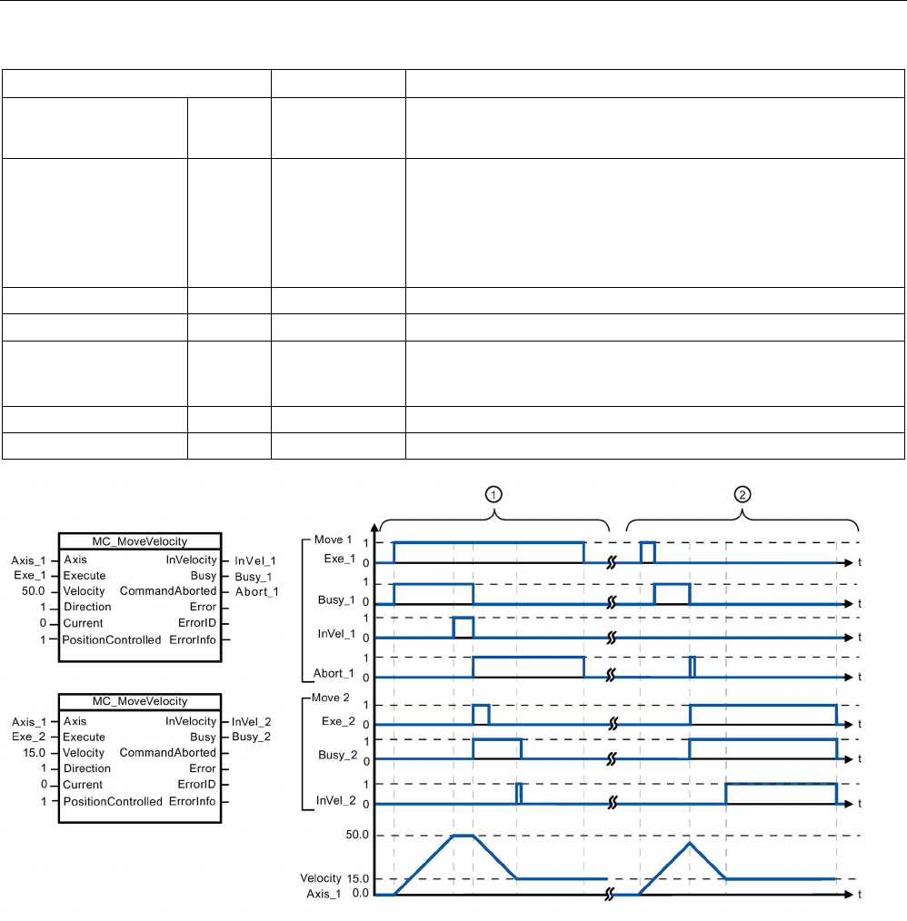
Technology instructions
10.3 Motion control
S7-1200 Programmable controller
748 System Manual, V4.2, 09/2016, A5E02486680-AK
Parameter and type
Data type
Description
PositionControlled IN Bool • 0: speed controlled
• 1: position controlled (Default value: True)
InVelocity OUT Bool TRUE:
• If "Current" = FALSE: The velocity specified in parameter "Ve-
locity" was reached.
• If "Current" = TRUE: The axis travels at the current velocity at
the start time.
Busy
OUT
Bool
TRUE = The task is being executed.
CommandAborted OUT Bool TRUE = During execution the task was aborted by another task.
Error OUT Bool TRUE = An error has occurred during execution of the task. The
cause of the error can be found in parameters "ErrorID" and "Error-
Info".
ErrorID
OUT
Word
Error ID for parameter "Error" (Default value: 0000)
ErrorInfo
OUT
Word
Error info ID for parameter "ErrorID" (Default value: 0000)
The following values were configured in the "Dynamics > General" configuration window: Acceleration = 10.0 and Decelera-
tion = 10.0
①
An active MC_MoveVelocity task signals via "InVel_1" that its target velocity has been reached. It is then aborted
by another MC_MoveVelocity task. The abort is signaled via "Abort_1". When the new target velocity 15.0 is
reached, this is signaled via "InVel_2". The axis then continues moving at the new constant velocity.
②
An active MC_MoveVelocity task is aborted by another MC_MoveVelocity task prior to reaching its target velocity.
The abort is signaled via "Abort_1". When the new target velocity 15.0 is reached, this is signaled via "InVel_2".
The axis then continues moving at the new constant velocity.

Technology instructions
10.3 Motion control
S7-1200 Programmable controller
System Manual, V4.2, 09/2016, A5E02486680-AK 749
Override response
The MC_MoveVelocity task can be aborted
by the following motion control tasks:
•
MC_Home Mode = 3
•
MC_Halt
•
MC_MoveAbsolute
•
MC_MoveRelative
•
MC_MoveVelocity
•
MC_MoveJog
The new MC_MoveVelocity task aborts the
following active motion control tasks:
•
MC_Home Mode = 3
•
MC_Halt
•
MC_MoveAbsolute
•
MC_MoveRelative
•
MC_MoveVelocity
•
MC_MoveJog
Note
Behavior with zero set velocity (Velocity = 0.0)
An MC_MoveVelocity task with "Velocity" = 0.0 (such as an MC_Halt task) aborts active
motion tasks and stops the axis with the configured deceleration. When the axis comes to a
standstill, output parameter "InVelocity" indicates TRUE for at least one prog
ram cycle.
"Busy" indicates the value TRUE during the deceleration operation and changes to FALSE
together with "InVelocity". If parameter "Execute" = TRUE is set, "InVelocity" and "Busy" are
latched.
When the MC_MoveVelocity task is started, status bit "S
peedCommand" is set in the
technology object. Status bit "ConstantVelocity" is set upon axis standstill. Both bits are
adapted to the new situation when a new motion task is started.
10.3.7.9
MC_MoveJog (Move axis in jog mode)
Table 10- 70 MC_MoveJog instruction
LAD / FBD
SCL
Description
"MC_MoveJog_DB"(
Axis:=_multi_fb_in_,
JogForward:=_bool_in_,
JogBackward:=_bool_in_,
Velocity:=_real_in_,
PositionControlled:=_bool_in_,
InVelocity=>_bool_out_,
Busy=>_bool_out_,
CommandAborted=>_bool_out_,
Error=>_bool_out_,
ErrorID=>_word_out_,
ErrorInfo=>_word_out_);
Use the MC_MoveJog instruction to move
the axis constantly at the specified veloci-
ty in jog mode. This instruction is typically
used for testing and commissioning pur-
poses.
In order to use the MC_MoveJog instruc-
tion, the axis must first be enabled.
1
STEP 7 automatically creates the DB when you insert the instruction.
2 In the SCL example, "MC_MoveJog_DB " is the name of the instance DB.
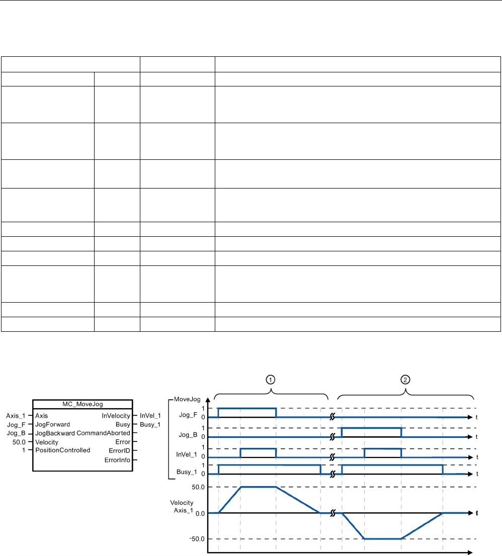
Technology instructions
10.3 Motion control
S7-1200 Programmable controller
750 System Manual, V4.2, 09/2016, A5E02486680-AK
Table 10- 71 Parameters for the MC_MoveJog instruction
Parameter and type
Data type
Description
Axis
IN
TO_SpeedAxis
Axis technology object
JogForward1 IN Bool As long as the parameter is TRUE, the axis moves in the positive
direction at the velocity specified in parameter "Velocity". The sign of
the value in parameter "Velocity" is ignored. (Default value: False)
JogBackward1 IN Bool As long as the parameter is TRUE, the axis moves in the negative
direction at the velocity specified in parameter "Velocity". The sign of
the value in parameter "Velocity" is ignored. (Default value: False)
Velocity IN Real Preset velocity for jog mode (Default value: 100.0)
Limit values: Start/stop velocity ≤ |Velocity| ≤ maximum velocity
PositionControlled IN Bool • 0: speed controlled
• 1: position controlled (Default value: True)
InVelocity
OUT
Bool
TRUE = The velocity specified in parameter "Velocity" was reached.
Busy
OUT
Bool
TRUE = The task is being executed.
CommandAborted
OUT
Bool
TRUE = During execution the task was aborted by another task.
Error OUT Bool TRUE = An error has occurred during execution of the task. The
cause of the error can be found in parameters "ErrorID" and "ErrorIn-
fo".
ErrorID
OUT
Word
Error ID for parameter "Error" (Default value: 0000)
ErrorInfo
OUT
Word
Error info ID for parameter "ErrorID" (Default value: 0000)
1
If both the JogForward and JogBackward parameters are simultaneously TRUE, the axis stops with the configured
deceleration. An error is indicated in parameters "Error", "ErrorID", and "ErrorInfo".
The following values were configured in the "Dynamics > General" configuration window: Acceleration = 10.0 and Decelera-
tion = 5.0
①
The axis is moved in the positive direction in jog mode via "Jog_F". When the target velocity 50.0 is reached, this is
signaled via "InVelo_1". The axis brakes to a standstill again after Jog_F is reset.
②
The axis is moved in the negative direction in jog mode via "Jog_B". When the target velocity 50.0 is reached, this
is signaled via "InVelo_1". The axis brakes to a standstill again after Jog_B is reset.

Technology instructions
10.3 Motion control
S7-1200 Programmable controller
System Manual, V4.2, 09/2016, A5E02486680-AK 751
Override response
The MC_MoveJog task can be aborted by
the following motion control tasks:
•
MC_Home Mode = 3
•
MC_Halt
•
MC_MoveAbsolute
•
MC_MoveRelative
•
MC_MoveVelocity
•
MC_MoveJog
The new MC_MoveJog task aborts the
fol
lowing active motion control tasks:
•
MC_Home Mode = 3
•
MC_Halt
•
MC_MoveAbsolute
•
MC_MoveRelative
•
MC_MoveVelocity
•
MC_MoveJog
10.3.7.10
MC_CommandTable (Run axis commans as movement sequence)
Table 10- 72 MC_CommandTable instruction
LAD / FBD
SCL
Description
"MC_CommandTable_DB"(
Axis:=_multi_fb_in_,
CommandTable:=_multi_fb_in_,
Execute:=_bool_in_,
StartIndex:=_uint_in_,
EndIndex:=_uint_in_,
Done=>_bool_out_,
Busy=>_bool_out_,
CommandAborted=>_bool_out_,
Error=>_bool_out_,
ErrorID=>_word_out_,
ErrorInfo=>_word_out_,
CurrentIndex=>_uint_out_,
Code=>_word_out_);
Executes a series of individual
motions for a motor control axis
that can combine into a move-
ment sequence.
Individual motions are configured
in a technology object command
table for pulse train output
(TO_CommandTable_PTO).
1
STEP 7 automatically creates the DB when you insert the instruction.
2 In the SCL example, "MC_CommandTable_DB " is the name of the instance DB.
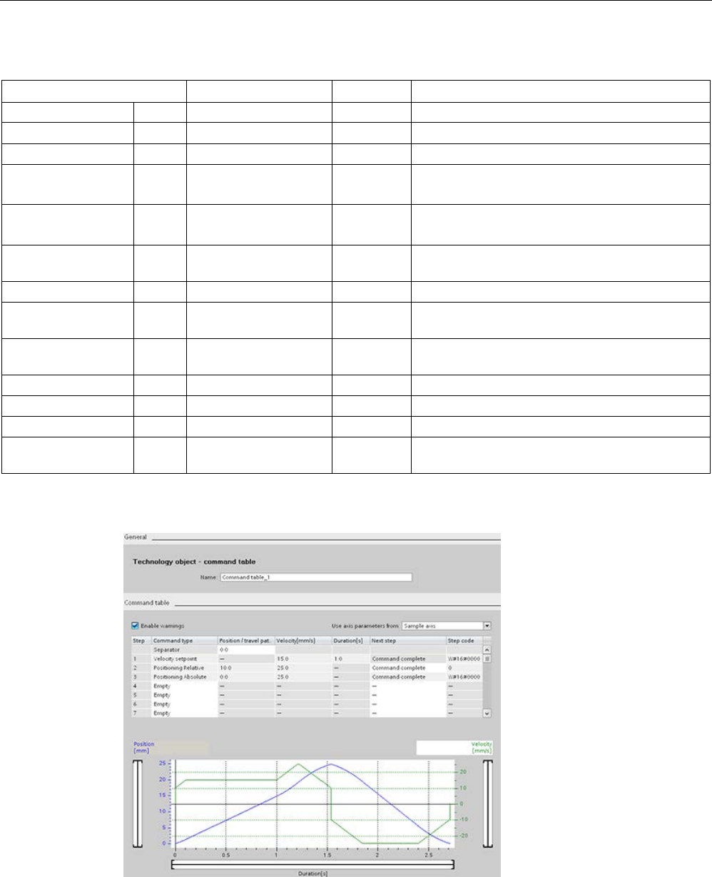
Technology instructions
10.3 Motion control
S7-1200 Programmable controller
752 System Manual, V4.2, 09/2016, A5E02486680-AK
Table 10- 73 Parameters for the MC_CommandTable instruction
Parameter and type
Data type
Initial value
Description
Axis
IN
TO_Axis_1
-
Axis technology object
Table IN TO_CommandTable_1 - Command table technology object
Execute
IN
Bool
FALSE
Start job with rising edge
StartIndex IN Int 1 Start command table processing with this step
Limits: 1 ≤
StartIndex
≤ EndIndex
EndIndex IN Int 32 End command table processing with this step
Limits: StartIndex ≤ EndIndex ≤ 32
Done OUT Bool FALSE MC_CommandTable processing completed suc-
cessfully
Busy
OUT
Bool
FALSE
Operation in progress
CommandAborted OUT Bool FALSE The task was aborted during processing by anoth-
er task.
Error OUT Bool FALSE An error occurred during processing. The cause is
indicated by the parameters ErrorID and ErrorInfo.
ErrorID
OUT
Word
16#0000
Error identifier
ErrorInfo
OUT
Word
16#0000
Error information
Step
OUT
Int
0
Step currently in process
Code OUT Word 16#0000 User defined identifier of the step currently in pro-
cess
You can create the desired movement sequence in the "Command Table" configuration
window and check the result against the graphic view in the trend diagram.
You can select the command types that are to be used for processing the command table.
Up to 32 jobs can be entered. The commands are processed in sequence.

Technology instructions
10.3 Motion control
S7-1200 Programmable controller
System Manual, V4.2, 09/2016, A5E02486680-AK 753
Table 10- 74 MC_CommandTable command types
Command type
Description
Empty The empty serves as a placeholder for any commands to be added. The empty entry is
ignored when the command table is processed
Halt Pause axis.
Note: The command only takes place after a "Velocity setpoint" command.
Positioning Relative Positions the axis based upon distance. The command moves the axis by the given dis-
tance and velocity.
Positioning Absolute Positions the axis based upon location. The command moves the axis to the given loca-
tion, using the velocity specified.
Velocity setpoint
Moves the axis at the given velocity.
Wait
Waits until the given period is over. "Wait" does not stop an active traversing motion.
Separator Adds a "Separator" line above the selected line. The separator line allows more than one
profile to be defined in a single command table.
Prerequisites for MC_CommandTable execution:
● The technology object TO_Axis_PTO V2.0 must be correctly configured.
● The technology object TO_CommandTable_PTO must be correctly configured.
● The axis must be released.
Override response
The MC_CommandTable task can be
aborted by the following motion control
tasks:
•
MC_Home Mode = 3
•
MC_Halt
•
MC_MoveAbsolute
•
MC_MoveRelative
•
MC_MoveVelocity
•
MC_MoveJog
•
MC_CommandTable
The new MC_CommandTable task aborts the
following active motion control tasks:
•
MC_Home Mode = 3
•
MC_Halt
•
MC_MoveAbsolute
•
MC_MoveRelative
•
MC_MoveVelocity
•
MC_MoveJog
•
MC_CommandTable
•
The current motion control job with the
launch of the first "Positioning Relative",
"Positioning Absolute", "Velocity setpoint"
or "Halt" command
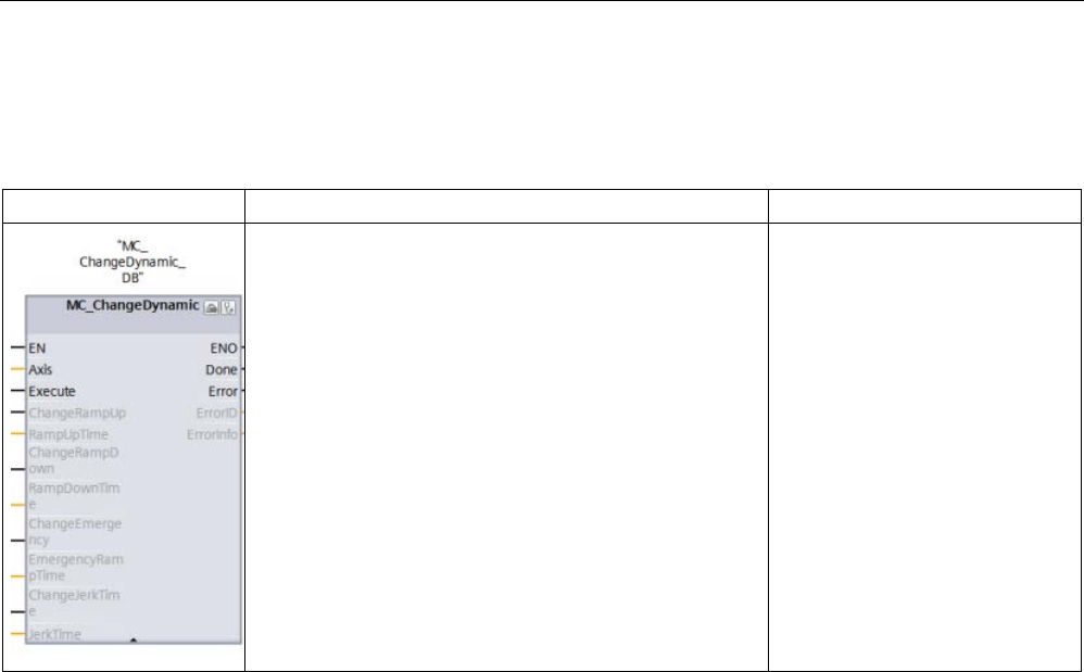
Technology instructions
10.3 Motion control
S7-1200 Programmable controller
754 System Manual, V4.2, 09/2016, A5E02486680-AK
10.3.7.11
MC_ChangeDynamic (Change dynamc settings for the axis)
Table 10- 75 MC_ChangeDynamic instruction
LAD / FBD
SCL
Description
"MC_ChangeDynamic_DB"(
Execute:=_bool_in_,
ChangeRampUp:=_bool_in_,
RampUpTime:=_real_in_,
ChangeRampDown:=_bool_in_,
RampDownTime:=_real_in_,
ChangeEmergency:=_bool_in_,
EmergencyRampTime:=_real_in_,
ChangeJerkTime:=_bool_in_,
JerkTime:=_real_in_,
Done=>_bool_out_,
Error=>_bool_out_,
ErrorID=>_word_out_,
ErrorInfo=>_word_out_);
Changes the dynamic settings of
a motion control axis:
• Change the ramp-up time
(acceleration) value
• Change the ramp-down time
(deceleration) value
• Change the emergency stop
ramp-down time (emergency
stop deceleration) value
• Change the smoothing time
(jerk) value
1
STEP 7 automatically creates the DB when you insert the instruction.
2 In the SCL example, "MC_ChangeDynamic_DB " is the name of the instance DB.

Technology instructions
10.3 Motion control
S7-1200 Programmable controller
System Manual, V4.2, 09/2016, A5E02486680-AK 755
Table 10- 76 Parameters for the MC_ChangeDynamic instruction
Parameter and type
Data type
Description
Axis
IN
TO_Axis_1
Axis technology object
Execute IN Bool Start of the command with a positive edge. Default value:
FALSE
ChangeRampUp IN Bool TRUE = Change ramp-up time in line with input parameter
"RampUpTime". Default value: FALSE
RampUpTime IN Real Time (in seconds) to accelerate from standstill to the configured
maximum velocity without jerk limit. Default value: 5.00
The change will influence the tag <Axis name>. Con-
fig.DynamicDefaults.Acceleration. The effectiveness of the
change is shown in the description of this tag.
ChangeRampDown IN Bool TRUE = Change ramp-down time in line with input parameter
"RampDownTime". Default value: FALSE
RampDownTime IN Real Time (in seconds) to decelerate axis from the configured maxi-
mum velocity to standstill without jerk limiter. Default value: 5.00
The change will influence the tag <Axis name>. Con-
fig.DynamicDefaults.Deceleration. The effectiveness of the
change is shown in the description of this tag.
ChangeEmergency IN Bool TRUE = Change emergency stop ramp-down time in line with
input parameter "EmergencyRampTime" Default value: FALSE
EmergencyRampTime IN Real Time (in seconds) to decelerate the axis from configured maxi-
mum velocity to standstill without jerk limiter in emergency stop
mode. Default value: 2.00
The change will influence the tag <Axis name>. Con-
fig.DynamicDefaults.EmergencyDeceleration. The effectiveness
of the change is shown in the description of this tag.
ChangeJerkTime IN Bool TRUE = Change smoothing time according to the input parame-
ter "JerkTime". Default value: FALSE
JerkTime IN Real Smoothing time (in seconds) used for the axis acceleration and
deceleration ramps. Default value: 0.25
The change will influence the tag <Axis name>. Con-
fig.DynamicDefaults.Jerk. The effectiveness of the change is
shown in the description of this tag.
Done OUT Bool TRUE = The changed values have been written to the technolo-
gy data block. The description of the tags will show when the
change becomes effective. Default value: FALSE
Error OUT Bool TRUE = An error occurred during execution of the command.
The cause of the error can be found in parameters "ErrorID" and
"ErrorInfo". Default value: FALSE
ErrorID
OUT
Word
Error identifier. Default value: 16#0000
ErrorInfo
IN
Word
Error information. Default value: 16#0000
Prerequisites for MC_ ChangeDynamic execution:
● The technology object TO_Axis_PTO V2.0 must be correctly configured.
● The axis must be released.
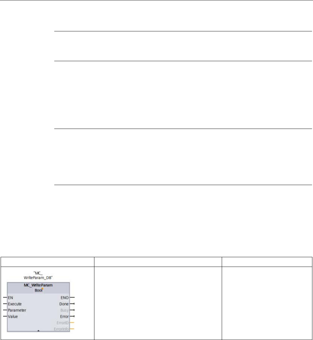
Technology instructions
10.3 Motion control
S7-1200 Programmable controller
756 System Manual, V4.2, 09/2016, A5E02486680-AK
Note
You can only use the MC_ChangeDynamic instruction for a drive connection using PTO
(Pulse Train Output).
Override response
An MC_ChangeDynamic command cannot be aborted by any other motion control
command.
A new MC_ChangeDynamic command does not abort any active motion control jobs.
Note
The input parameters "RampUpTime", "RampDownTime", "EmergencyRampTime" and
"RoundingOf
fTime" can be specified with values that makes the resultant axis parameters
"acceleration", "delay", "emergency stop
-delay" and "jerk" outside the permissible limits.
Make sure you keep the MC_ChangeDynamic parameters within the limits of the dynamic
conf
iguration settings for the axis technology object.
10.3.7.12
MC_WriteParam (write parameters of a technology object)
You use the MC_WriteParam instruction to write a select number of parameters to change
the functionality of the axis from the user program.
Table 10- 77 MC_WriteParam instruction
LAD / FBD
SCL
Description
"MC_WriteParam_DB"(
Parameter:=_variant_in_,
Value:=_variant_in_,
Execute:=_bool_in_,
Done:=_bool_out_,
Error:=_real_out_,
ErrorID:=_word_out_,
ErrorInfo:=_word_out_);
You use the MC_WriteParam
instruction to write to public pa-
rameters (for example, accelera-
tion and user DB values).
1
STEP 7 automatically creates the DB when you insert the instruction.
2 In the SCL example, "MC_WriteParam_DB" is the name of the instance DB.

Technology instructions
10.3 Motion control
S7-1200 Programmable controller
System Manual, V4.2, 09/2016, A5E02486680-AK 757
You can write to the parameters that are public. You cannot write to "MotionStatus" and
"StatusBits". The valid parameters are listed in the table below:
Writeable parameter name
Writeable parameter name
Actor.InverseDirection
DynamicDefaults.Acceleration
Actor.DirectionMode DynamicDefaults.Deceleration
Actor.DriveParameter.PulsesPerDriveRevolution
DynamicDefaults.Jerk
Sensor[1].ActiveHoming.Mode DynamicDefaults.EmergencyDeceleration
Sensor[1].ActiveHoming.SideInput
PositionLimitsHW.Active
Sensor[1].ActiveHoming.Offset
PositionLimitsHW.MaxSwitchedLevel
Sensor[1].ActiveHoming.SwitchedLevel
PositionLimitsHW.MinSwitchedLevel
Sensor[1].PassiveHoming.Mode
PositionLimitsSW.Active
Sensor[1].PassiveHoming.SideInput
PositionLimitsSW.MinPosition
Sensor[1].PassiveHoming.SwitchedLevel
PositionLimitsSW.MaxPosition
Units.LengthUnit
Homing.AutoReversal
Mechanics.LeadScrew
Homing.ApproachDirection
DynamicLimits.MinVelocity
Homing.ApproachVelocity
DynamicLimits.MaxVelocity
Homing.ReferencingVelocity
Table 10- 78 Parameters for the MC_WriteParam instruction
Parameter and type
Data type
Description
PARAMNAME
IN
Variant
Name of parameter where value is written
VALUE
IN
Variant
Value to write to assigned parameter
EXECUTE
IN
Bool
Start the instruction. Default value: FALSE
DONE
OUT
Bool
Value has been written. Default value: FALSE
BUSY
OUT
Bool
If TRUE, the instruction is operating. Default value: FALSE
ERROR
OUT
Real
If TRUE, an error occurred. Default value: FALSE
ERRORID
OUT
Word
ID of the error
ERRORINFO
OUT
Word
Related information to the ERRORID

Technology instructions
10.3 Motion control
S7-1200 Programmable controller
758 System Manual, V4.2, 09/2016, A5E02486680-AK
Table 10- 79 Condition codes for ERRORID and ERRORINFO
ERRORID
(W#16#...)
ERRORINFO
(W#16#...)
Description
0
0
Successful change of an Axis TO-DB parameter
8410[1] 0028[1] Set an invalid parameter (Axis TO-DB parameter with incorrect length)
8410
[1]
0029
[1]
Set an invalid parameter (no Axis TO-DB parameter)
8410[1]
002B[1]
Set an Invalid parameter (read-only Axis TO-DB parameter)
8410
[1]
002C
[1]
Set a valid parameter, but axis is not disabled
Config
Error[2]
Config
Error[2]
Set a valid parameter (public read-only Axis TO-DB parameter) out-of-range
Config
Error
[3]
Config
Error
[3]
Set a valid parameter (public Axis TO-DB parameter) out-of-range
[1] Error at MC_WriteParam
[2] Error at MC_Power
[3] Error at MC_Power and MC_MoveXXX or MC_CommandTable
Note
For a drive connection using a PROFIdrive/analog output, you cannot write parameters with
M
C_WriteParam that require a restart of the technology object. The TIA Portal online help
statement concerning this instruction is incorrect.
10.3.7.13
MC_ReadParam instruction (read parameters of a technology object)
You use the MC_ReadParam instruction to read a select number of parameters that indicate
the current position, velocity, and so forth of the axis defined in the Axis input.
Table 10- 80 MC_ReadParam instruction
LAD / FBD
SCL
Description
"MC_ReadParam_DB"(
Enable:=_bool_in_,
Parameter:=_variant_in_,
Value:=_variant_in_out_,
Valid:=_bool_out_,
Busy:=_bool_out_,
Error:=_real_out_,
ErrorID:=_word_out_,
ErrorInfo:=_word_out_);
You use the MC_ReadParam
instruction to read single status
values, independent of the cycle
control point.
1
STEP 7 automatically creates the DB when you insert the instruction.
2 In the SCL example, "MC_ReadParam_DB " is the name of the instance DB.

Technology instructions
10.3 Motion control
S7-1200 Programmable controller
System Manual, V4.2, 09/2016, A5E02486680-AK 759
The MC_ReadParam instruction works on an enable behavior. As long as the input "Enable"
is true the instruction reads the specified "Parameter" to the "Value" storage location.
The "MotionStatus" "Position" value updates at each Cycle Control Point (CCP) based upon
the current HSC value.
The "MotionStatus" "Velocity" value is the command velocity at the end of the current
segment (updated ~10ms). The MC_ReadParam can also read this value.
If an error occurs, the instruction switches to an error state that can only be reset by a new
rising edge at the input "Enable".
Table 10- 81 Parameters for the MC_ReadParam instruction
Parameter and type
Data type
Description
ENABLE
IN
Bool
Start the instruction. Default value: FALSE
PARAMETER IN Variant Pointer to the TO-parameter that is to be read
VALID
OUT
Bool
If TRUE, the value has been read. Default value: FALSE
BUSY
OUT
Bool
If TRUE, the instruction is operating. Default value: FALSE
ERROR
OUT
Real
If TRUE, an error occurred. Default value: FALSE
ERRORID
OUT
Word
ID of the error. Default value: 0
ERRORINFO
OUT
Word
Related information to the ERRORID. Default value: 0
VALUE
INOUT
Variant
Pointer to the location where the read value is stored
Table 10- 82 Condition codes for ERRORID and ERRORINFO
ERRORID
(W#16#...)
ERRORINFO
(W#16#...)
Description
0
0
Successful read of a parameter
8410
0028
Invalid parameter (incorrect length)
8410
0029
Invalid parameter (no TO-DB)
8410
0030
Invalid parameter (not readable)
8411
0032
Invalid parameter (wrong value)
TO parameters
The axis "MotionStatus" consists of four values. You will want to monitor changes in these
values, which can be read while the program is running:
Variable name
Data type
Readable through
MC_ReadParam
MotionStatus:
Structure
No
• Position REAL Yes
• Velocity REAL Yes
• Distance REAL Yes
• TargetPosition REAL Yes

Technology instructions
10.3 Motion control
S7-1200 Programmable controller
760 System Manual, V4.2, 09/2016, A5E02486680-AK
10.3.8
Monitoring active commands
10.3.8.1
Monitoring MC instructions with a "Done" output parameter
Motion control instructions with the output parameter "Done" are started by the input
parameter "Execute" and have a defined conclusion (for example, with motion control
instruction "MC_Home": Homing was successful). The task is complete and the axis is at a
standstill.
● The output parameter "Done" indicates the value TRUE, if the task has been successfully
completed.
● The output parameters "Busy", "CommandAborted", and "Error" signal that the task is still
being processed, has been aborted or an error is pending. The motion control instruction
"MC_Reset" cannot be aborted and thus has no "CommandAborted" output parameter.
– During processing of the motion control task, the output parameter "Busy" indicates
the value TRUE. If the task has been completed, aborted, or stopped by an error, the
output parameter "Busy" changes its value to FALSE. This change occurs regardless
of the signal at input parameter "Execute".
– Output parameters "Done", "CommandAborted", and "Error" indicate the value TRUE
for at least one cycle. These status messages are latched while input parameter
"Execute" is set to TRUE.
The tasks of the following motion control instructions have a defined conclusion:
● MC_Reset
● MC_Home
● MC_Halt
● MC_MoveAbsolute
● MC_MoveRelative
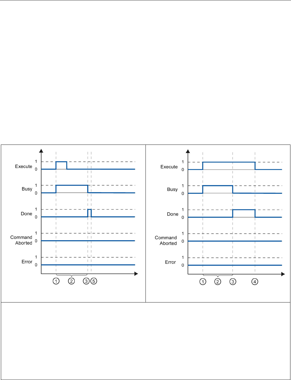
Technology instructions
10.3 Motion control
S7-1200 Programmable controller
System Manual, V4.2, 09/2016, A5E02486680-AK 761
The behavior of the status bits is presented below for various example situations.
● The first example shows the behavior of the axis for a completed task. If the motion
control task has been completely executed by the time of its conclusion, this is indicated
by the value TRUE in output parameter "Done". The signal status of input parameter
"Execute" influences the display duration in the output parameter "Done".
● The second example shows the behavior of the axis for an aborted task. If the motion
control task is aborted during execution, this is indicated by the value TRUE in output
parameter "CommandAborted". The signal status of the input parameter "Execute"
influences the display duration in the output parameter "CommandAborted".
● The third example shows the behavior of the axis if an error occurs. If an error occurs
during execution of the motion control task, this is indicated by the value TRUE in the
output parameter "Error". The signal status of the input parameter "Execute" influences
the display duration in the output parameter "Error".
Table 10- 83 Example 1 - Complete execution of task
If "Execute" = FALSE during the processing of the task
If "Execute" = FALSE after completion of the task
①
The task is started with a positive edge at the input parameter "Execute". Depending on the programming, "Execute"
can still be reset to the value FALSE during the task, or the value TRUE can be retained until after completion of the task.
② While the task is active, the output parameter "Busy" indicates the value TRUE.
③ With conclusion of the task (for example, for motion control instruction "MC_Home": Homing was successful), output
parameter "Busy" changes to FALSE and "Done" to TRUE.
④ If "Execute" retains the value TRUE until after completion of the task, then "Done" also remains TRUE and changes its
value to FALSE together with "Execute".
⑤ If "Execute" has been set to FALSE before the task is complete, "Done" indicates the value TRUE for only one execu-
tion cycle.
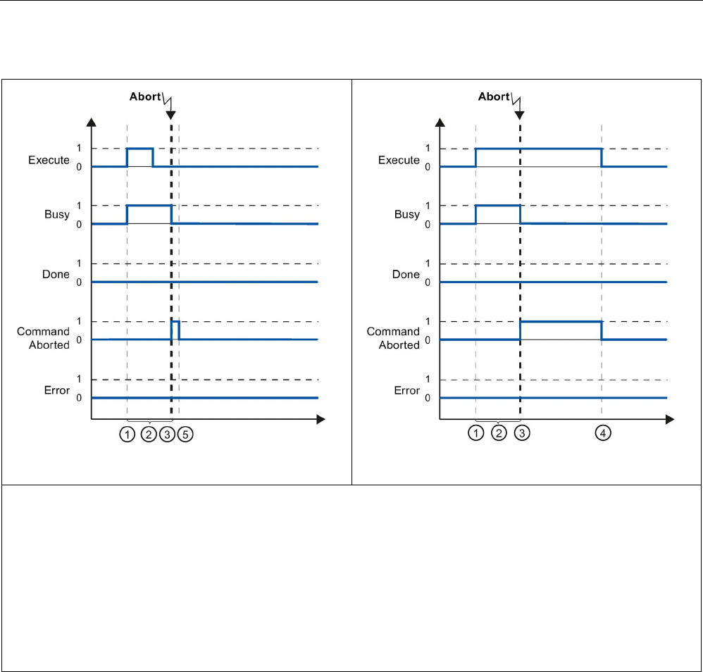
Technology instructions
10.3 Motion control
S7-1200 Programmable controller
762 System Manual, V4.2, 09/2016, A5E02486680-AK
Table 10- 84 Example 2 - Aborting the task
If "Execute" = FALSE before the task is aborted
If "Execute" = FALSE after the task is aborted
①
The task is started with a positive edge at the input parameter "Execute". Depending on the programming, "Execute"
can still be reset to the value FALSE during the task, or the value TRUE can be retained until after completion of the task.
② While the task is active, the output parameter "Busy" indicates the value TRUE.
③ During task execution, the task is aborted by another motion control task. If the task is aborted, output parameter
"Busy" changes to FALSE and "CommandAborted" to TRUE.
④ If "Execute" retains the value TRUE until after the task is aborted, then "CommandAborted" also remains TRUE and
changes its value to FALSE together with "Execute".
⑤ If "Execute" has been set to FALSE before the task is aborted, "CommandAborted" indicates the value TRUE for only
one execution cycle.
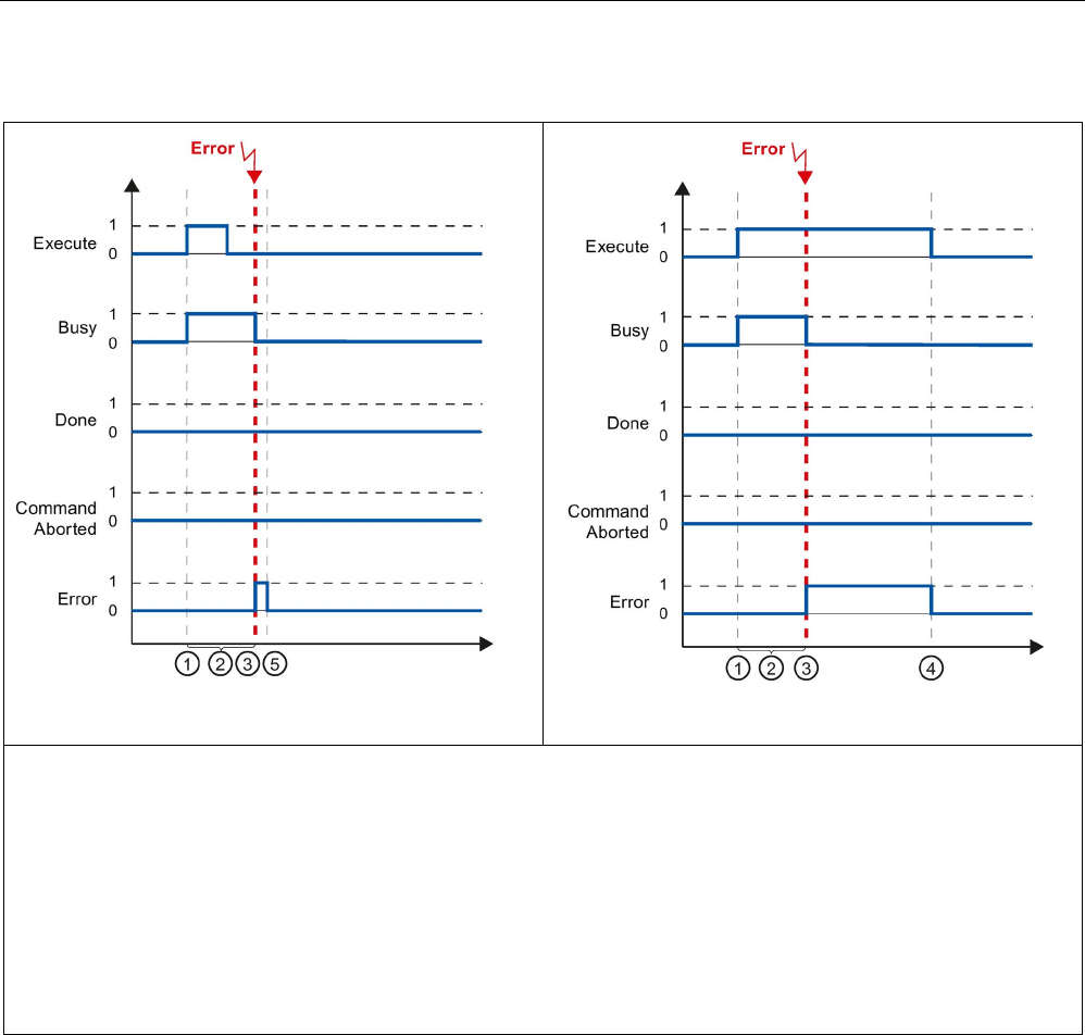
Technology instructions
10.3 Motion control
S7-1200 Programmable controller
System Manual, V4.2, 09/2016, A5E02486680-AK 763
Table 10- 85 Example 3 - Error during task execution
If "Execute" = FALSE before the error occurs
If "Execute" = FALSE after the error occurs
① The task is started with a positive edge at the input parameter "Execute". Depending on the programming, "Execute"
can still be reset to the value FALSE during the task, or the value TRUE can be retained until after completion of the task.
② While the task is active, the output parameter "Busy" indicates the value TRUE.
③ An error occurred during task execution. When the error occurs, the output parameter "Busy" changes to FALSE and
"Error" to TRUE.
④ If "Execute" retains the value TRUE until after the error occurs, then "Error" also remains TRUE and only changes its
value to FALSE together with "Execute".
⑤ If "Execute" has been set to FALSE before the error occurs, "Error" indicates the value TRUE for only one execution
cycle.

Technology instructions
10.3 Motion control
S7-1200 Programmable controller
764 System Manual, V4.2, 09/2016, A5E02486680-AK
10.3.8.2
Monitoring the MC_Velocity
The tasks of the motion control instruction "MC_MoveVelocity" implement a move at the
specified velocity:
● The tasks of motion control instruction "MC_MoveVelocity" do not have a defined end.
The task objective is fulfilled when the parameterized velocity is reached for the first time
and the axis travels at constant velocity. When the parameterized velocity is reached, this
is indicated by the value TRUE in output parameter "InVelocity".
● The task is complete when the parameterized velocity has been reached and input
parameter "Execute" has been set to the value FALSE. However, the axis motion is not
yet complete upon completion of the task. For example, the axis motion can be stopped
with motion control task "MC_Halt".
● The output parameters "Busy", "CommandAborted", and "Error" signal that the task is still
being processed, has been aborted or an error is pending.
– During execution of the motion control task, output parameter "Busy" indicates the
value TRUE. If the task has been completed, aborted, or stopped by an error, the
output parameter "Busy" changes its value to FALSE. This change occurs regardless
of the signal at input parameter "Execute".
– The output parameters "InVelocity", "CommandAborted", and "Error" indicate the
value TRUE for at least one cycle, when their conditions are met. These status
messages are latched while input parameter "Execute" is set to TRUE.
The behavior of the status bits is presented below for various example situations:
● The first example shows the behavior when the axis reaches the parameterized velocity.
If the motion control task has been executed by the time the parameterized velocity is
reached, this is indicated by the value TRUE in output parameter "InVelocity". The signal
status of the input parameter "Execute" influences the display duration in the output
parameter "InVelocity".
● The second example shows the behavior if the task is aborted before achieving the
parameterized velocity. If the motion control task is aborted before the parameterized
velocity is reached, this is indicated by the value TRUE in output parameter
"CommandAborted". The signal status of input parameter "Execute" influences the
display duration in output parameter "CommandAborted".
● The third example shows the behavior of the axis if an error occurs before achieving the
parameterized velocity. If an error occurs during execution of the motion control task
before the parameterized velocity has been reached, this is indicated by the value TRUE
in the output parameter "Error". The signal status of the input parameter "Execute"
influences the display duration in the output parameter "Error".
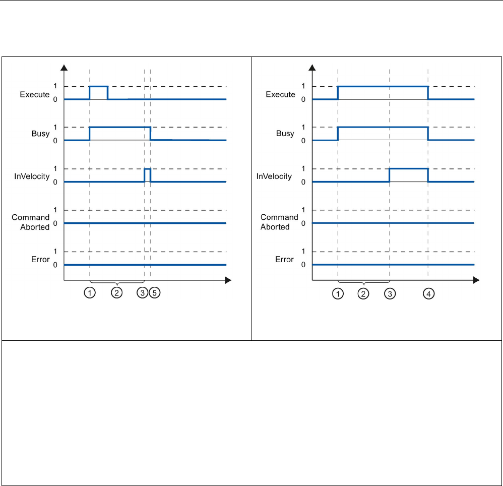
Technology instructions
10.3 Motion control
S7-1200 Programmable controller
System Manual, V4.2, 09/2016, A5E02486680-AK 765
Table 10- 86 Example 1 - If the parameterized velocity is reached
If "Execute" = FALSE before the configured velocity is
reached
If "Execute" = FALSE after the configured velocity is
reached
①
The task is started with a positive edge at the input parameter "Execute". Depending on the programming, "Execute"
can be reset to the value FALSE event before the parameterized velocity is reached, or alternatively only after it has been
reached.
② While the task is active, the output parameter "Busy" indicates the value TRUE.
③ When the parameterized velocity is reached, the output parameter "InVelocity" changes to TRUE.
④ If "Execute" retains the value TRUE even after the parameterized velocity has been reached, the task remains active.
"InVelocity" and "Busy" retain the value TRUE and only change their status to FALSE together with "Execute".
⑤ If "Execute" has been reset to FALSE before the parameterized velocity is reached, the task is complete when the
parameterized velocity is reached. "InVelocity" indicates the value TRUE for one execution cycle and changes to FALSE
together with "Busy".
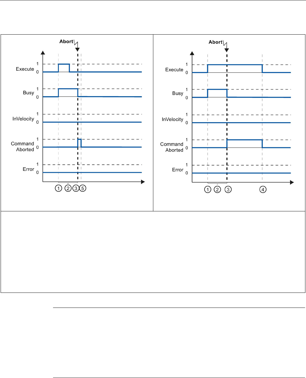
Technology instructions
10.3 Motion control
S7-1200 Programmable controller
766 System Manual, V4.2, 09/2016, A5E02486680-AK
Table 10- 87 Example 2 - If the task is aborted prior to reaching the parameterized velocity
If "Execute" = FALSE before the task is aborted
If "Execute" = FALSE after the task is aborted
①
The task is started with a positive edge at the input parameter "Execute". Depending on the programming, "Execute"
can still be reset to the value FALSE during the task, or the value TRUE can be retained until after the task is aborted.
② While the task is active, the output parameter "Busy" indicates the value TRUE.
③ During task execution, the task is aborted by another motion control task. If the task is aborted, output parameter
"Busy" changes to FALSE and "CommandAborted" to TRUE.
④ If "Execute" retains the value TRUE until after the task is aborted, then "CommandAborted" also remains TRUE and
changes its status to FALSE together with "Execute".
⑤ If "Execute" has been reset to FALSE before the task is aborted, "CommandAborted" indicates the value TRUE for only
one execution cycle.
Note
Under the following conditions, an abort is not indicated in output parameter
"CommandAborted":
•
The parameterized velocity has been reached, input parameter "Execute" has the value
FALSE, and a new motion control task is initiated.
•
When the parameterized velocity is reached and input parameter "Execute" has the value
FALSE, the task is complete. Therefore, the start of a new task is not indicated as an
abort.
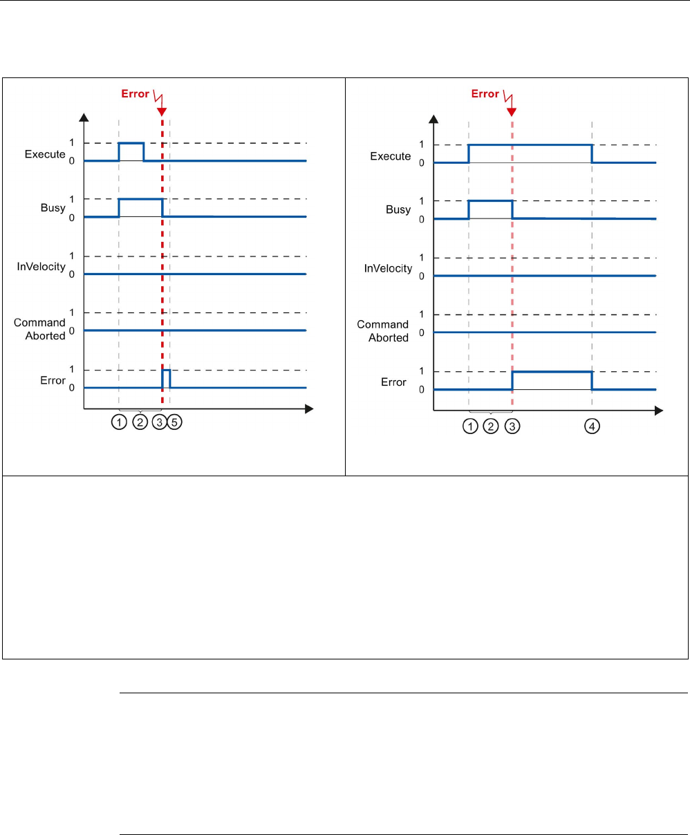
Technology instructions
10.3 Motion control
S7-1200 Programmable controller
System Manual, V4.2, 09/2016, A5E02486680-AK 767
Table 10- 88 Example 3 - If an error occurs prior to reaching the parameterized velocity
If "Execute" = FALSE before the error occurs
If "Execute" = FALSE after the error occurs
①
The task is started with a positive edge at the input parameter "Execute". Depending on the programming, "Execute"
can still be reset to the value FALSE during the task, or the value TRUE can be retained until after the error has occurred.
② While the task is active, the output parameter "Busy" indicates the value TRUE.
③ An error occurred during task execution. When the error occurs, the output parameter "Busy" changes to FALSE and
"Error" to TRUE.
④ If "Execute" retains the value TRUE until after the error has occurred, then "Error" also remains TRUE and only chang-
es its status to FALSE together with "Execute".
⑤ If "Execute" has been reset to FALSE before the error occurs, "Error" indicates the value TRUE for only one execution
cycle.
Note
Under the following conditions, an error is not indic
ated in output parameter "Error":
•
The parameterized velocity has been reached, input parameter "Execute" has the value
FALSE, and an axis error occurs (software limit switch is approached, for example).
•
When the parameterized velocity is reached and input
parameter "Execute" has the value
FALSE, the task is complete. After completion of the task, the axis error is only indicated
in the motion control instruction "MC_Power".

Technology instructions
10.3 Motion control
S7-1200 Programmable controller
768 System Manual, V4.2, 09/2016, A5E02486680-AK
10.3.8.3
Monitoring the MC_MoveJog
The tasks of motion control instruction "MC_MoveJog" implement a jog operation.
● The motion control tasks "MC_MoveJog" do not have a defined end. The task objective is
fulfilled when the parameterized velocity is reached for the first time and the axis travels
at constant velocity. When the parameterized velocity is reached, this is indicated by the
value TRUE in output parameter "InVelocity".
● The order is complete when input parameter "JogForward" or "JogBackward" has been
set to the value FALSE and the axis has come to a standstill.
● The output parameters "Busy", "CommandAborted", and "Error" signal that the task is still
being processed, has been aborted or an error is pending.
– During processing of the motion control task, the output parameter "Busy" indicates
the value TRUE. If the task has been completed, aborted, or stopped by an error, the
output parameter "Busy" changes its value to FALSE.
– The output parameter "InVelocity" indicates the status TRUE, as long as the axis is
moving at the parameterized velocity. The output parameters "CommandAborted" and
"Error" indicate the status for at least one cycle. These status messages are latched
as long as either input parameter "JogForward" or "JogBackward" is set to TRUE.
The behavior of the status bits is presented below for various example situations.
● The first example shows the behavior or the axis if the parameterized velocity is reached
and maintained. If the motion control task has been executed by the time the
parameterized velocity is reached, this is indicated by the value TRUE in output
parameter "InVelocity".
● The second example shows the behavior of the axis if the task is aborted. If the motion
control task is aborted during execution, this is indicated by the value TRUE in output
parameter "CommandAborted". The behavior is independent of whether or not the
parameterized velocity has been reached.
● The third example shows the behavior of the axis if an error occurs. If an error occurs
during execution of the motion control task, this is indicated by the value TRUE in output
parameter "Error". The behavior is independent of whether or not the parameterized
velocity has been reached.
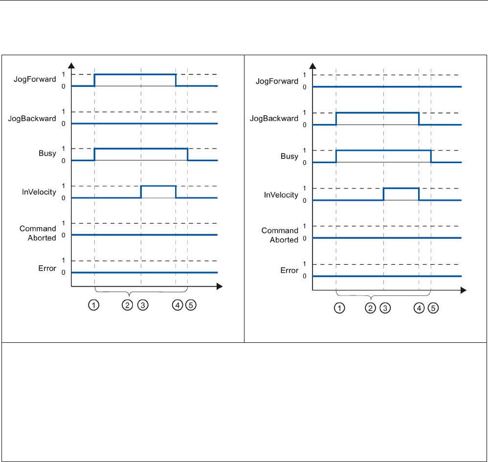
Technology instructions
10.3 Motion control
S7-1200 Programmable controller
System Manual, V4.2, 09/2016, A5E02486680-AK 769
Table 10- 89 Example 1 - If the parameterized velocity is reached and maintained
JogForward
JogBackward
①
The task is started with a positive edge at the input parameter "JogForward" or "JogBackward".
② While the task is active, the output parameter "Busy" indicates the value TRUE.
③ When the parameterized velocity is reached, the output parameter "InVelocity" changes to TRUE.
④
When the input parameter "JogForward" or "JogBackward" is reset to the value FALSE, the axis motion ends. The axis
starts to decelerate. As a result, the axis no longer moves at constant velocity and the output parameter "InVelocity"
changes its status to FALSE.
⑤ If the axis has come to a standstill, the motion control task is complete and the output parameter "Busy" changes its
value to FALSE.
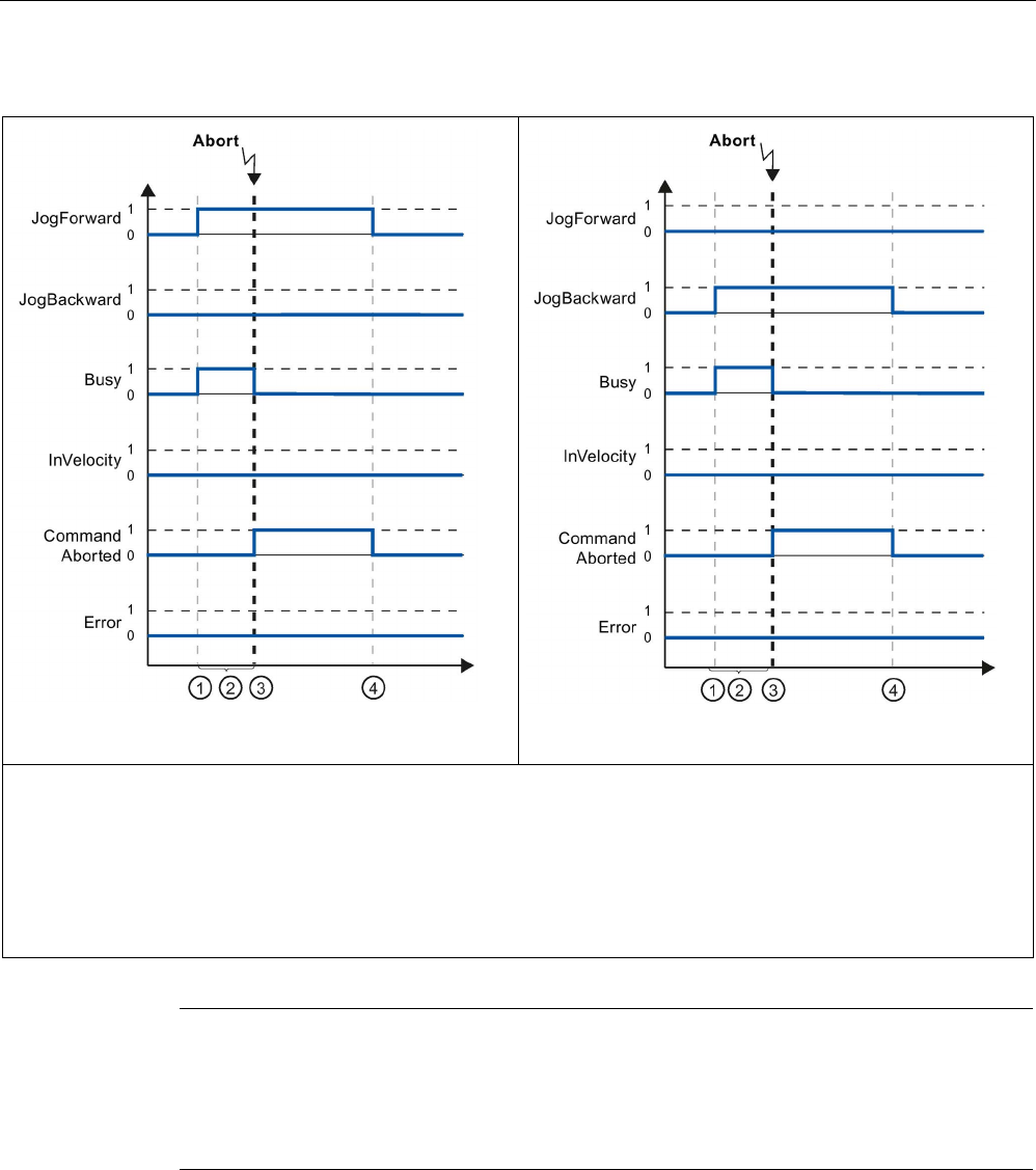
Technology instructions
10.3 Motion control
S7-1200 Programmable controller
770 System Manual, V4.2, 09/2016, A5E02486680-AK
Table 10- 90 Example 2 - If the task is aborted during execution
JogForward
JogBackward
①
The task is started with a positive edge at the input parameter "JogForward" or "JogBackward".
② While the task is active, the output parameter "Busy" indicates the value TRUE.
③ During task execution, the task is aborted by another motion control task. If the task is aborted, output parameter
"Busy" changes to FALSE and "CommandAborted" to TRUE.
④ When the input parameter "JogForward" or "JogBackward" is reset to the value FALSE, the output parameter "Com-
mandAborted" changes its value to FALSE.
Note
The task abort is indicated in the output parameter "CommandAborted" for only one
execution cycle, if all conditions below are met:
The input parameters "JogForward" and "
JogBackward" have the value FALSE (but the axis
is still decelerating) and a new motion control task is initiated.
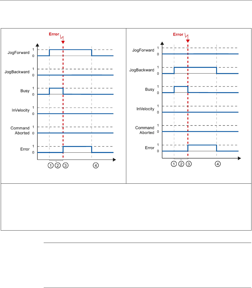
Technology instructions
10.3 Motion control
S7-1200 Programmable controller
System Manual, V4.2, 09/2016, A5E02486680-AK 771
Table 10- 91 Example 3 - If an error has occurred during task execution
JogForward
JogBackward
①
The task is started with a positive edge at the input parameter "JogForward" or "JogBackward".
② While the task is active, the output parameter "Busy" indicates the value TRUE.
③ An error occurred during task execution. When the error occurs, the output parameter "Busy" changes to FALSE and
"Error" to TRUE.
④ When the input parameter "JogForward" or "JogBackward" is reset to the value FALSE, the output parameter "Error"
changes its value to FALSE.
Note
An er
ror occurrence is indicated in the output parameter "Error" for only one execution cycle,
if all the conditions below are met:
The input parameters "JogForward" and "JogBackward" have the value FALSE (but the axis
is still decelerating) and a new error occ
urs (software limit switch is approached, for
example).

Technology instructions
10.3 Motion control
S7-1200 Programmable controller
772 System Manual, V4.2, 09/2016, A5E02486680-AK
10.3.9
ErrorIDs and ErrorInfos for motion control
The following table lists all ErrorIDs and ErrorInfos that can be indicated in motion control
instructions and data adaptation. In addition to the cause of the error, remedies for
eliminating the error are also listed.
Depending on the error reaction, the axis is stopped in the case of operating errors with stop
of axis. The following error reactions are possible:
●
Remove enable
The setpoint zero is output and the enable is removed. The axis is braked depending on
the configuration in the drive, and is brought to a standstill.
●
Stop with emergency stop ramp
Active motion commands are aborted. The axis is braked with the emergency stop
deceleration configured under "Technology object > Extended parameters > Dynamics >
Emergency stop ramp" without any jerk limit and brought to a standstill.
Operating error with axis stop
ErrorID
ErrorInfo
Description
Remedy
Error reaction
16#8000
Drive error, loss of "Drive ready"
-
16#0001 - Acknowledge error with instruction
"MC_Reset"; provide drive signal; re-
start command, if necessary
16#8001
Low SW limit switch has been tripped
Stop with emer-
gency stop ramp.
16#000E The position of the low SW limit
switch was reached with the currently
configured deceleration
Acknowledge the error with instruction
"MC_Reset"; use a motion command to
move the axis in the positive direction
out of the range of the SW limit switch
16#000F The position of the low SW limit
switch was reached with the emer-
gency stop deceleration
16#0010 The position of the low SW limit
switch was exceeded with the emer-
gency stop deceleration
16#8002
High SW limit switch has been tripped
Stop with emer-
gency stop ramp.
16#000E The position of the high SW limit
switch was reached with the currently
configured deceleration
Acknowledge the error with instruction
"MC_Reset"; use a motion command to
move the axis in the negative direction
out of the range of the SW limit switch
16#000F The position of the high SW limit
switch was reached with the emer-
gency stop deceleration
16#0010 The position of the high SW limit
switch was exceeded with the emer-
gency stop deceleration

Technology instructions
10.3 Motion control
S7-1200 Programmable controller
System Manual, V4.2, 09/2016, A5E02486680-AK 773
ErrorID
ErrorInfo
Description
Remedy
Error reaction
16#8003
Low HW limit switch was reached
For drive connec-
tion via PTO
(Pulse Train Out-
put):
Stop with emer-
gency stop ramp.
For drive connec-
tion via
PROFIdrive/analo
g output:
Remove enable.
16#000E The low HW limit switch was
reached. The axis was stopped with
the emergency stop deceleration.
(During an active homing procedure,
the homing switch was not found)
Acknowledge the error for an enabled
axis with instruction "MC_Reset"; use a
motion command to move the axis in
the positive direction out of the range of
the HW limit switch.
16#8004
High HW limit switch was reached
For drive connec-
tion via PTO
(Pulse Train Out-
put):
Stop with emer-
gency stop ramp.
For drive connec-
tion via
PROFIdrive/analo
g output:
Remove enable.
16#000E The high HW limit switch has been
reached. The axis was stopped with
the emergency stop deceleration.
(During an active homing procedure,
the homing switch was not found)
Acknowledge the error for an enabled
axis with instruction "MC_Reset"; use a
motion command to move the axis in
the negative direction out of the range
of the HW limit switch.
16#8005
PTO/HSC are already being used by another axis
-
16#0001 -
The axis was configured incorrectly:
Correct the configuration of the PTO
(Pulse Train Output) / HSC (High
Speed Counter) and download it to the
controller
More than one axis is to run with one
PTO:
Another axis is using the PTO / HSC. If
the current axis is to assume the con-
trol, the other axis must be disabled
with "MC_Power" Enable = FALSE.
16#8006
A communication error in the control panel has occurred
Remove enable.
16#0012 A timeout has occurred Check the cable connection and press
the "Manual control" button again
16#8007
The axis cannot be enabled
-
16#0025
Restarting
Wait until the axis restart is complete.
16#0026 Executing loading process in RUN
mode
Wait until the loading process is com-
plete.

Technology instructions
10.3 Motion control
S7-1200 Programmable controller
774 System Manual, V4.2, 09/2016, A5E02486680-AK
ErrorID
ErrorInfo
Description
Remedy
Error reaction
16#8008
Invalid direction of motion
-
16#002E The selected motion direction is not
allowed.
• Adjust the motion direction and
restart the command.
• Adjust the allowed direction of rota-
tion in the technology object config-
uration under "Extended parameters
> Mechanics". Restart the com-
mand.
16#002F A reversing motion is not possible
with the selected motion direction.
16#8009
Reference switch/encoder zero mark not found
Stop with emer-
gency stop ramp.
16#0033 Error in the configuration, hardware
or installation of the encoder or at the
homing switch.
• Connect a suitable device.
• Check the device (I/Os).
• Compare the configuration of HW
Config and the technology object.
16#800A
Alarm message from encoder
Remove enable.
16#0001 - Check the device with regard to func-
tion, connections and I/Os.
16#0034
Hardware error at encoder
16#0035
Encoder dirty
16#0036 Error during reading of encoder abso-
lute value
Compare the encoder type in the drive
or encoder parameter P979 with the
configuration data of the technology
object.
16#0037 Zero mark monitoring of the encoder Encoder reports error in zero mark
monitoring (fault code 0x0002 in
Gx_XIST2, see PROFIdrive profile).
Check the plant for electromagnetic
compatibility (EMC).
16#0038 Encoder is in "Parking" state • Search for the cause of the error in
the connected drive or encoder.
• Check whether the error message
was possibly triggered by a com-
missioning action at the drive or en-
coder.
16#0040 PROFIdrive: Encoder at bus failed
(station failure)
Check the device with regard to func-
tion, connections and I/Os.
16#0041 PROFIdrive: Signs of life of encoder
faulty
16#800B
Range violation of the position
Remove enable.
16#0039 Range violation in positive direction Home the axis to a valid actual value
range.
16#003A
Range violation in negative direction
16#003B
The change of the actual position in a
position control clock cycle is greater
than the modulo length.
Adjust the modulo length of the em-
ployed encoder.

Technology instructions
10.3 Motion control
S7-1200 Programmable controller
System Manual, V4.2, 09/2016, A5E02486680-AK 775
ErrorID
ErrorInfo
Description
Remedy
Error reaction
16#800C
Alarm message from drive
Remove enable.
16#0001 - Check the device with regard to func-
tion, connections and I/Os.
16#003C PROFIdrive: Drive signal "Control
requested" failed
16#003D PROFIdrive: Drive has shut down
16#003E PROFIdrive: Drive at bus failed (sta-
tion failure)
16#003F PROFIdrive: Signs of life of drive
faulty
• Check the device with regard to
function, connections and I/Os.
• Compare the clock parameters of
HW Config (PROFIBUS line, slave
OM for drive or encoder) and the
execution system. Tmapc and servo
must be configured with the same
clock cycle time.
16#800D
The permitted following error was exceeded
Remove enable.
16#0001 - • Check the configuration of the con-
trol loop.
• Check the direction signal of the
encoder.
• Check the configuration of following
error monitoring.
16#800E
Error at the hardware limit switch
Remove enable.
16#0042 Illegal free travel direction with active
hardware limit switch
The programmed direction of move-
ment is disabled due to the active
hardware limit switch.
Retract the axis in the opposite direc-
tion.
16#0043 Hardware limit switch polarity is re-
versed, axis cannot be freed
Check the mechanical configuration of
the hardware limit switch.
16#0044 Both hardware limit switches are
active, axis cannot be freed
16#800F
Error in target range
Remove enable.
16#0045 Target range not reached Target range was not reached within
the positioning tolerance time.
• Check the configuration of the posi-
tion monitoring.
• Check the configuration of the con-
trol loop.
16#0046 Exit target range again The target range was exited within the
minimum dwell time.
• Check the configuration of the posi-
tion monitoring.
• Check the configuration of the con-
trol loop.

Technology instructions
10.3 Motion control
S7-1200 Programmable controller
776 System Manual, V4.2, 09/2016, A5E02486680-AK
ErrorID
ErrorInfo
Description
Remedy
Error reaction
16#8010
Position of the low SW limit switch is greater than that of the high SW limit
switch when the axis is not a modulo axis
Remove enable.
16#0001 - Change the position of the software
limit switches.
Operating error without axis stop
ErrorID
ErrorInfo
Description
Remedy
16#8200
Axis is not enabled
16#0001
-
Enable the axis; restart the command.
16#003D Displayed if a drive with an analog drive con-
nection has turned off.
Enable the axis; restart the command.
16#8201
Axis has already been enabled by another "MC_Power" instance
16#0001 - Enable the axis with only one "MC_Power" in-
stance.
16#8202
The maximum number of simultaneous motion control commands has been exceeded (max. 200
commands for drive connection via PTO (Pulse Train Output), max. 100 commands for drive con-
nection via PROFIdrive/analog output)
16#0001 - Reduce the number of simultaneously active
commands; restart the command
A command is active if parameter "Busy" = TRUE
in the motion control instruction.
16#8203
Axis is currently operated in "Manual control" (axis control panel)
16#0001
-
Exit "Manual control"; restart the command.
16#8204
Axis is not homed
16#0001 -
Home the axis with instruction "MC_Home"; restart
the command.
16#8205
The axis is currently controlled by the user program (the error is only displayed in the axis control
panel)
16#0013 The axis is enabled in the user program Disable axis with instruction "MC_Power" and
select "Manual control" again in the axis control
panel
16#8206
Technology object not activated yet
16#0001 - Enable the axis with instruction "MC_Power" Ena-
ble = TRUE or enable the axis in the axis control
panel.
16#8207
Command rejected
16#0016 Active homing is running; another homing
method cannot be started.
Wait for active homing to finish or abort the active
homing with a motion command, for example,
"MC_Halt".
16#0018 The axis cannot be moved with a command
table while it is being actively or passively
homed.
Wait until direct or passive homing is complete.
16#0019 The axis cannot be actively or passively
homed while a command table is being pro-
cessed.
Wait for command table to finish or abort the
command table with a motion command, for ex-
ample, "MC_Halt".

Technology instructions
10.3 Motion control
S7-1200 Programmable controller
System Manual, V4.2, 09/2016, A5E02486680-AK 777
ErrorID
ErrorInfo
Description
Remedy
16#0052 The specified position exceeds the numerical
limit.
Enter a valid position value at the motion control
instruction.
16#0053 The axis is ramping up. Wait until the axis is ready for operation.
16#0054 Actual value is invalid To execute a "MC_Home" command, the actual
values must be valid.
Check the status of the actual values. The tag of
the technology object <Axis
name>."StatusSensor.State" must show the value
2 (valid).
16#8208
Difference between maximum and start/stop velocity is invalid
16#0002
Value is not a valid number
Correct the value; restart the command.
16#000A
Value is less than or equal to 0.
16#8209
Invalid acceleration for technology object "Axis"
16#0002
Value is not a valid number
Correct the value; restart the command.
16#000A
Value is less than or equal to 0.
16#820A
It is not possible to restart the axis
16#0013 The axis is enabled in the user program Disable the axis with the "MC_Power" instruction;
restart again.
16#0027
The axis is currently being operated in "Manual
control" (axis control panel)
Exit "Manual control"; restart again.
16#002C
The axis is not disabled.
Disable the axis; restart the command.
16#0047
The technology object is not ready for restart.
Download the project again.
16#0048 Condition for restart of the technology object is
not satisfied.
Disable the technology object.
16#820B
It is not possible to execute the command table
16#0026 Executing loading process in RUN mode Wait until the loading process is complete.
16#820C
No configuration available
16#0001 - Internal error
Contact the hotline.

Technology instructions
10.3 Motion control
S7-1200 Programmable controller
778 System Manual, V4.2, 09/2016, A5E02486680-AK
Block parameter error
ErrorID
ErrorInfo
Description
Remedy
16#8400
Invalid value at parameter "Position" of the motion control instruction
16#0002 Value is not a valid number Correct the value; restart the command.
16#0005 Value is outside the number range (greater
than 1E+12)
16#0006 Value is outside the number range (less than
1E+12)
16#8401
Invalid value at parameter "Distance" of the motion control instruction
16#0002
Value is not a valid number
Correct the value; restart the command.
16#0005 Value is outside the number range (greater
than 1E+12)
16#0006 Value is outside the number range (less than
1E+12)
16#8402
Invalid value at parameter "Velocity" of the motion control instruction
16#0002
Value is not a valid number
Correct the value; restart the command.
16#0008 Value is greater than the configured maximum
velocity
16#0009 Value is less than the configured start/stop
velocity
16#0024
Value is less than 0
16#8403
Invalid value at parameter "Direction" of the motion control instruction
16#0011 The selection value is invalid Correct the selection value; restart the command.
16#8404
Invalid value at parameter "Mode" of the motion control instruction
16#0011
The selection value is invalid
Correct the selection value; restart the command.
16#0015 Active/passive homing is not configured Correct the configuration and download it to the
controller; enable the axis and restart the com-
mand.
16#0017 The direction reversal is activated at the hard-
ware limit switch, despite the fact that the
hardware limit switches are disabled
• Activate the HW limit switch using the tag
<Axis name>.PositionLimitsHW.Active =
TRUE, restart the command.
• Correct the configuration and download it to
the controller; enable the axis and restart the
command.
16#0055 Invalid mode at incremental encoder Start a homing process for an incremental encod-
er using parameter "Mode" = 0, 1, 2, 3.
16#0056 Invalid mode at absolute encoder Passive and active homing ("Mode" = 2, 3) are not
possible for an absolute value encoder.
Start a homing process for an absolute encoder
using parameter "Mode" = 0, 1.
16#8405
Invalid value at parameter "StopMode" of the motion control instruction
16#0011
The selection value is invalid
Correct the selection value; enable the axis again.

Technology instructions
10.3 Motion control
S7-1200 Programmable controller
System Manual, V4.2, 09/2016, A5E02486680-AK 779
ErrorID
ErrorInfo
Description
Remedy
16#8406
Simultaneous forward and backward jogging is not allowed
16#0001 - Take steps to ensure that parameters "JogFor-
ward" and "JogBackward" do not have signal
status TRUE simultaneously; restart the com-
mand.
16#8407
Switching to another axis with instruction "MC_Power" is only permitted after disabling the active
axis.
16#0001 - Disable the active axis; it is then possible to switch
to the other axis and enable it.
16#8408
Invalid value at parameter "Axis" of the motion control instruction
16#001A The specified value does not match the re-
quired technology object version
Correct the value; restart the command.
16#001B The specified value does not match the re-
quired technology object type
16#001C The specified value is not a motion control
technology data block
16#8409
Invalid value at parameter "CommandTable" of the motion control instruction
16#001A The specified value does not match the re-
quired technology object version
Correct the value; restart the command.
16#001B The specified value does not match the re-
quired technology object type
16#001C The specified value is not a motion control
technology data block
16#840A
Invalid value at parameter "StartStep" of the motion control instruction
16#000A
Value is less than or equal to 0.
Correct the value; restart the command.
16#001D
The start step is greater than the end step
16#001E
Value is greater than 32
16#840B
Invalid value at parameter "EndStep" of the motion control instruction
16#000A
Value is less than or equal to 0.
Correct the value; restart the command.
16#001E
Value is greater than 32
16#840C
Invalid value at parameter "RampUpTime" of the motion control instruction
16#0002
Value is not a valid number
Correct the value; restart the command.
16#000A
Value is less than or equal to 0.
16#840D
Invalid value at parameter "RampDownTime" of the motion control instruction
16#0002
Value is not a valid number
Correct the value; restart the command.
16#000A
Value is less than or equal to 0.
16#840E
Invalid value at parameter "EmergencyRampTime" of the motion control instruction
16#0002
Value is not a valid number
Correct the value; restart the command.
16#000A
Value is less than or equal to 0.
16#840F
Invalid value at parameter "JerkTime" of the motion control instruction
16#0002
Value is not a valid number
Correct the value; restart the command.
16#000A
Value is less than or equal to 0.

Technology instructions
10.3 Motion control
S7-1200 Programmable controller
780 System Manual, V4.2, 09/2016, A5E02486680-AK
ErrorID
ErrorInfo
Description
Remedy
16#8410
Invalid value at parameter "Parameter" of the motion control instruction
16#0002 Value is not a valid number Correct the value; restart the command.
16#000B Address is invalid Download error-
free configuration to the controller;
enable the axis again with instruction
"MC_Power".
16#0028 Data type of VARIANT pointer "Parameter"
and "Value" do not match.
Use a suitable data type; restart command.
16#0029 VARIANT pointer "Parameter" does not point
to a data block of the technology object.
Correct the VARIANT pointer; restart the com-
mand.
16#002A The value at the VARIANT pointer "Parameter"
cannot be read.
Correct the VARIANT pointer; restart the com-
mand.
16#002B
The value at the VARIANT pointer "Parameter"
cannot be written.
Correct the VARIANT pointer or value; restart the
command.
16#002C
The axis is not disabled.
Disable the axis; restart the command.
16#8411
Invalid value at parameter "Value" of the motion control instruction
16#0002
Value is not a valid number
Correct the value; restart the command.
Configuration error of the axis
ErrorID
ErrorInfo
Description
Remedy
16#8600
Parameter assignment of pulse generator (PTO is invalid
16#000B
The address is invalid
Download error-
free configuration to the controller;
enable the axis again with instruction
"MC_Power".
16#0014 The selected hardware is used by another
application
16#8601
Parameter assignment of the high-speed counter (HSC) is invalid
16#000B The address is invalid Download error-
free configuration to the controller;
enable the axis again with instruction
"MC_Power".
16#0014 The selected hardware is used by another
application
16#8602
Invalid parameter assignment of "Enable output"
16#000B The address is invalid Download error-
free configuration to the controller;
enable the axis again with instruction
"MC_Power".
16#8603
Invalid parameter assignment of "Ready input"
16#000B The address is invalid Download error-
free configuration to the controller;
enable the axis again with instruction
"MC_Power".
16#8604
Invalid "Pulses per motor revolution" value
16#000A Value is less than or equal to zero Download error-
free configuration to the controller;
enable the axis again with instruction
"MC_Power".

Technology instructions
10.3 Motion control
S7-1200 Programmable controller
System Manual, V4.2, 09/2016, A5E02486680-AK 781
ErrorID
ErrorInfo
Description
Remedy
16#8605
Invalid "Distance per revolution" value
16#0002 Value is not a valid number Download error-free configuration to the controller;
enable the axis again with instruction
"MC_Power".
16#0005 Value is outside the number range (greater
than 1E+12)
16#000A Value is less than or equal to zero
16#0030 Value has an incorrect number format or is
outside the valid number range
• Download error-free configuration to the con-
troller; enable the axis again with instruction
"MC_Power".
• Correct the incorrect value online;
acknowledge error with instruction "MC_Reset"
and restart the command, if necessary.
16#8606
Invalid "Start/stop velocity" value
16#0002
Value is not a valid number
Download error-
free configuration to the controller;
enable the axis again with instruction
"MC_Power".
16#0003
Value is higher than the high hardware limit
16#0004
Value is lower than the low hardware limit
16#0007 The start/stop velocity is greater than the max-
imum velocity
16#8607
Invalid "maximum velocity" value
16#0002
Value is not a valid number
Download error-
free configuration to the controller;
enable the axis again with instruction
"MC_Power".
16#0003
Value is higher than the high hardware limit
16#0004
Value is lower than the low hardware limit
16#0030 Value has an incorrect number format or is
outside the valid number range
• Download error-free configuration to the con-
troller; enable the axis again with instruction
"MC_Power".
• Correct the incorrect value online;
acknowledge error with instruction "MC_Reset"
and restart the command, if necessary.
16#8608
Invalid "Acceleration" value
16#0002
Value is not a valid number
• Download error-free configuration to the con-
troller; enable the axis again with instruction
"MC_Power".
• Correct the incorrect value online;
acknowledge error with instruction "MC_Reset"
and restart the command, if necessary.
16#0003
Value is higher than the high hardware limit
16#0004 Value is lower than the low hardware limit
16#0030 Value has an incorrect number format or is
outside the valid number range
• Download error-free configuration to the con-
troller; enable the axis again with instruction
"MC_Power".
• Correct the incorrect value online;
acknowledge error with instruction "MC_Reset"
and restart the command, if necessary.

Technology instructions
10.3 Motion control
S7-1200 Programmable controller
782 System Manual, V4.2, 09/2016, A5E02486680-AK
ErrorID
ErrorInfo
Description
Remedy
16#8609
Invalid "Deceleration" value
16#0002 Value is not a valid number • Download error-free configuration to the con-
troller; enable the axis again with instruction
"MC_Power".
• Correct the incorrect value online;
acknowledge error with instruction "MC_Reset"
and restart the command, if necessary.
16#0003
Value is higher than the high hardware limit
16#0004 Value is lower than the low hardware limit
16#0030 Value has an incorrect number format or is
outside the valid number range
• Download error-free configuration to the con-
troller; enable the axis again with instruction
"MC_Power".
• Correct the incorrect value online;
acknowledge error with instruction "MC_Reset"
and restart the command, if necessary.
16#860A
Invalid "Emergency stop deceleration" value
16#0002
Value is not a valid number
• Download error-free configuration to the con-
troller; enable the axis again with instruction
"MC_Power".
• Correct the incorrect value online;
acknowledge error with instruction "MC_Reset"
and restart the command, if necessary.
16#0003 Value is higher than the high hardware limit
16#0004 Value is lower than the low hardware limit
16#0030 Value has an incorrect number format or is
outside the valid number range
• Download error-free configuration to the con-
troller; enable the axis again with instruction
"MC_Power".
• Correct the incorrect value online;
acknowledge error with instruction "MC_Reset"
and restart the command, if necessary.
16#860B
Value for position of the low SW limit switch is invalid
16#0002 Value is not a valid number • Download error-free configuration to the con-
troller; enable the axis again with instruction
"MC_Power".
• Correct the incorrect value online;
acknowledge error with instruction "MC_Reset"
and restart the command, if necessary.
16#0005 Value is outside the number range (greater
than 1E+12)
16#0006 Value is outside the number range (less than
1E+12)
16#0030 The position value of the low software limit
switch is greater than that of the high software
limit switch

Technology instructions
10.3 Motion control
S7-1200 Programmable controller
System Manual, V4.2, 09/2016, A5E02486680-AK 783
ErrorID
ErrorInfo
Description
Remedy
16#860C
Value for position of the high SW limit switch is invalid
16#0002 Value is not a valid number • Download error-free configuration to the con-
troller; enable the axis again with instruction
"MC_Power".
• Correct the incorrect value online;
acknowledge error with instruction "MC_Reset"
and restart the command, if necessary.
16#0005 Value is outside the number range (greater
than 1E+12)
16#0006 Value is outside the number range (less than
1E+12)
16#0030 Value has an incorrect number format or is
outside the valid number range
• Download error-free configuration to the con-
troller; enable the axis again with instruction
"MC_Power".
• Correct the incorrect value online;
acknowledge error with instruction "MC_Reset"
and restart the command, if necessary.
16#860D
Invalid address of the low HW limit switch
16#000B
Invalid address
Download error-free configuration to the controller;
enable the axis again with instruction
"MC_Power".
16#000C The address of the falling edge is invalid
16#000D
The address of the rising edge is invalid
16#860E
Invalid address of the high HW limit switch
16#000B
Invalid address
Download error-fr
ee configuration to the controller;
enable the axis again with instruction
"MC_Power".
16#000C
The address of the falling edge is invalid
16#000D
The address of the rising edge is invalid
16#860F
Invalid "home position offset" value
16#0002
Value is not a valid number
• Download error-free configuration to the con-
troller; enable the axis again with instruction
"MC_Power".
• Correct the incorrect value online;
acknowledge error with instruction "MC_Reset"
and restart the command, if necessary.
16#0005 Value is outside the number range (greater
than 1E+12)
16#0006 Value is outside the number range (less than
1E+12)
16#0030 Value has an incorrect number format or is
outside the valid number range
• Download error-free configuration to the con-
troller; enable the axis again with instruction
"MC_Power".
• Correct the incorrect value online;
acknowledge error with instruction "MC_Reset"
and restart the command, if necessary.

Technology instructions
10.3 Motion control
S7-1200 Programmable controller
784 System Manual, V4.2, 09/2016, A5E02486680-AK
ErrorID
ErrorInfo
Description
Remedy
16#8610
Invalid "approach velocity" value
16#0002 Value is not a valid number • Download error-free configuration to the con-
troller; enable the axis again with instruction
"MC_Power".
• Correct the incorrect value online;
acknowledge error with instruction "MC_Reset"
and restart the command, if necessary.
16#0008 The velocity is greater than the maximum
velocity
16#0009 The velocity is less than the start/stop velocity
16#0030 Value has an incorrect number format or is
outside the valid number range
• Download error-free configuration to the con-
troller; enable the axis again with instruction
"MC_Power".
• Correct the incorrect value online;
acknowledge error with instruction "MC_Reset"
and restart the command, if necessary.
16#8611
Invalid "Homing velocity" value
16#0002
Value is not a valid number
• Download error-free configuration to the con-
troller; enable the axis again with instruction
"MC_Power".
• Correct the incorrect value online;
acknowledge error with instruction "MC_Reset"
and restart the command, if necessary.
16#0008 The velocity is greater than the maximum
velocity
16#0009 The velocity is less than the start/stop velocity
16#0030 Value has an incorrect number format or is
outside the valid number range
• Download error-free configuration to the con-
troller; enable the axis again with instruction
"MC_Power".
• Correct the incorrect value online;
acknowledge error with instruction "MC_Reset"
and restart the command, if necessary.
16#8612
Invalid address of the homing switch
16#000B Invalid address Download error-
free configuration to the controller;
enable the axis again with instruction
"MC_Power".
16#000C
The address of the falling edge is invalid
16#000D
The address of the rising edge is invalid
16#8613
During active homing, direction reversal at the hardware limit switch is activated although the hard-
ware limit switches are not configured
16#0001 - • Download error-free configuration to the con-
troller; enable the axis again with instruction
"MC_Power".
• Correct the incorrect value online;
acknowledge error with instruction "MC_Reset"
and restart the command, if necessary.

Technology instructions
10.3 Motion control
S7-1200 Programmable controller
System Manual, V4.2, 09/2016, A5E02486680-AK 785
ErrorID
ErrorInfo
Description
Remedy
16#8614
Invalid "Jerk" value
16#0002 Value is not a valid number • Download error-free configuration to the con-
troller; enable the axis again with instruction
"MC_Power".
• Correct the incorrect value online;
acknowledge error with instruction "MC_Reset"
and restart the command, if necessary.
16#001F
Value is greater than the maximum jerk
16#0020 Value is less than the minimum jerk
16#0030 Value has an incorrect number format or is
outside the valid number range
• Download error-free configuration to the con-
troller; enable the axis again with instruction
"MC_Power".
• Correct the incorrect value online;
acknowledge error with instruction "MC_Reset"
and restart the command, if necessary.
16#8615
Value for "Unit of measurement" is invalid
16#0011 The selection value is invalid Download error-
free configuration to the controller;
enable the axis again with instruction
"MC_Power".
16#8616
Address of homing switch is invalid (passive homing as of V4)
16#0011 The selection value is invalid • Download error-free configuration to the con-
troller; enable the axis again with instruction
"MC_Power".
• Correct the incorrect value online;
acknowledge error with instruction "MC_Reset"
and restart the command, if necessary.
16#0030 Value has an incorrect number format or is
outside the valid number range
• Download error-free configuration to the con-
troller; enable the axis again with instruction
"MC_Power".
• Correct the incorrect value online;
acknowledge error with instruction "MC_Reset"
and restart the command, if necessary.
16#8617
Value of tag <Axis name>.Sensor.Sensor[1].ActiveHoming.Mode is invalid
16#0011 The selection value is invalid
(Valid value: 2 = Homing via digital input)
• Download error-free configuration to the con-
troller; enable the axis again with instruction
"MC_Power".
• Correct the incorrect value online;
acknowledge error with instruction "MC_Reset"
and restart the command, if necessary.
16#8618
Value of tag <Axis name>.Sensor.Sensor[1].PassiveHoming.Mode is invalid
16#0011 The selection value is invalid
(Valid value: 2 = Homing via digital input)
• Download error-free configuration to the con-
troller; enable the axis again with instruction
"MC_Power".
• Correct the incorrect value online;
acknowledge error with instruction "MC_Reset"
and restart the command, if necessary.

Technology instructions
10.3 Motion control
S7-1200 Programmable controller
786 System Manual, V4.2, 09/2016, A5E02486680-AK
ErrorID
ErrorInfo
Description
Remedy
16#8619
Value of tag <Axis name>.Actor.Type is invalid
16#0011 The selection value is invalid
(Valid value: 2 = Connection via pulse inter-
face)
• Download error-free configuration to the con-
troller; enable the axis again with instruction
"MC_Power".
• Correct the incorrect value online;
acknowledge error with instruction "MC_Reset"
and restart the command, if necessary.
16#861A
Value for "Permitted direction of rotation" is invalid
16#0011 The selection value is invalid • Download error-free configuration to the con-
troller; enable the axis again with instruction
"MC_Power".
• Correct the incorrect value online;
acknowledge error with instruction "MC_Reset"
and restart the command, if necessary.
16#002D "Both directions" not allowed when direction
output is deactivated
16#861B
Faulty load gear factors
16#0031 Value is invalid. Download error-
free configuration to the controller;
enable the axis again with instruction
"MC_Power".
16#861C
Illegal combination of data for homing with incremental encoder
16#0031 Value is invalid. • Download error-free configuration to the con-
troller; enable the axis again with instruction
"MC_Power".
• Correct the incorrect value online;
acknowledge error with instruction "MC_Reset"
and restart the command, if necessary.
16#861D
The set encoder mounting type is invalid. Invalid value in <Axis
name>.Sensor.Sensor[1].MountingMode
16#0011 The selection value is invalid • Download error-free configuration to the con-
troller; enable the axis again with instruction
"MC_Power".
• Correct the incorrect value online;
acknowledge error with instruction "MC_Reset"
and restart the command, if necessary.
16#861E
The configuration of the measuring wheel circumference of the encoder is invalid. Invalid value in
<Axis name>.Sensor.Sensor[1].Parameter.DistancePerRevolution
16#0030 Value has an incorrect number format or is
outside the valid number range
• Download error-free configuration to the con-
troller; enable the axis again with instruction
"MC_Power".
• Correct the incorrect value online;
acknowledge error with instruction "MC_Reset"
and restart the command, if necessary.

Technology instructions
10.3 Motion control
S7-1200 Programmable controller
System Manual, V4.2, 09/2016, A5E02486680-AK 787
ErrorID
ErrorInfo
Description
Remedy
16#861F
The configuration for the resolution of the linear encoder is faulty. Invalid value in <Axis
name>.Sensor.Sensor[1].Parameter.Resolution
16#0030 Value has an incorrect number format or is
outside the valid number range
• Download error-free configuration to the con-
troller; enable the axis again with instruction
"MC_Power".
• Correct the incorrect value online;
acknowledge error with instruction "MC_Reset"
and restart the command, if necessary.
16#8620
The set fine resolution for Gn_XIST1 is invalid. Invalid value in <Axis
name>.Sensor.Sensor[1].Parameter.FineResolutionXist1
16#0030 Value has an incorrect number format or is
outside the valid number range
• Download error-free configuration to the con-
troller; enable the axis again with instruction
"MC_Power".
• Correct the incorrect value online;
acknowledge error with instruction "MC_Reset"
and restart the command, if necessary.
16#8621
The set fine resolution for Gn_XIST1 in <Axis
name>.Sensor.Sensor[1].Parameter.FineResolutionXist1 is not consistent with the setting in
PROFIdrive parameter P979
16#0030 Value has an incorrect number format or is
outside the valid number range
• Download error-free configuration to the con-
troller; enable the axis again with instruction
"MC_Power".
• Correct the incorrect value online;
acknowledge error with instruction "MC_Reset"
and restart the command, if necessary.
16#8622
Invalid value for the configuration date <Axis name>.Actor.Interface.AddressIn or <Axis
name>.Actor.Interface.AddressOut
16#0011 The selection value is invalid Download error-
free configuration to the controller;
enable the axis again with instruction
"MC_Power".
16#8623
The value set in the tag <Axis name>.Sensor.Sensor[1].Type is invalid.
16#0011 The selection value is invalid Download error-
free configuration to the controller;
enable the axis again with instruction
"MC_Power".
16#8624
The set encoder system is invalid. Invalid value in <Axis name>.Sensor.Sensor[1].System
16#0011 The selection value is invalid • Download error-free configuration to the con-
troller; enable the axis again with instruction
"MC_Power".
• Correct the incorrect value online;
acknowledge error with instruction "MC_Reset"
and restart the command, if necessary.

Technology instructions
10.3 Motion control
S7-1200 Programmable controller
788 System Manual, V4.2, 09/2016, A5E02486680-AK
ErrorID
ErrorInfo
Description
Remedy
16#8625
Parameter of position monitoring is faulty. Invalid value in <Axis
name>.PositioningMonitoring.MinDwellTime
16#0030 Value has an incorrect number format or is
outside the valid number range
• Download error-free configuration to the con-
troller; enable the axis again with instruction
"MC_Power".
• Correct the incorrect value online;
acknowledge error with instruction "MC_Reset"
and restart the command, if necessary.
16#8626
Parameter of position monitoring is faulty. Invalid value in <Axis
name>.PositioningMonitoring.Window
16#0030 Value has an incorrect number format or is
outside the valid number range
• Download error-free configuration to the con-
troller; enable the axis again with instruction
"MC_Power".
• Correct the incorrect value online;
acknowledge error with instruction "MC_Reset"
and restart the command, if necessary.
16#8627
The configuration of the PROFIdrive interface of the actual value is faulty. Invalid value in <Axis
name>.Sensor.Sensor[1].Interface.AddressIn or <Axis
name>.Sensor.Sensor[1].Interface.AddressOut
16#0011 The selection value is invalid Download error-
free configuration to the controller;
enable the axis again with instruction
"MC_Power".
16#8628
Faulty controller factors
16#0030 Value has an incorrect number format or is
outside the valid number range
The value for the gain or the precontrol of the
control loop is faulty.
• Download error-free configuration to the con-
troller; enable the axis again with instruction
"MC_Power".
• Correct the incorrect value online;
acknowledge error with instruction "MC_Reset"
and restart the command, if necessary. (<Axis
name>.PositionControl.Kv, <Axis
name>.PositionControl.Kpc)
16#8629
Limit for standstill signal is faulty. Invalid value in <Axis name>.StandStillSignal.VelocityThreshold
16#0030 Value has an incorrect number format or is
outside the valid number range
• Download error-free configuration to the con-
troller; enable the axis again with instruction
"MC_Power".
• Correct the incorrect value online;
acknowledge error with instruction "MC_Reset"
and restart the command, if necessary.

Technology instructions
10.3 Motion control
S7-1200 Programmable controller
System Manual, V4.2, 09/2016, A5E02486680-AK 789
ErrorID
ErrorInfo
Description
Remedy
16#862A
Parameter of position monitoring is faulty. Invalid value in <Axis
name>.PositioningMonitoring.ToleranceTime
16#0030 Value has an incorrect number format or is
outside the valid number range
• Download error-free configuration to the con-
troller; enable the axis again with instruction
"MC_Power".
• Correct the incorrect value online;
acknowledge error with instruction "MC_Reset"
and restart the command, if necessary.
16#862B
Inconsistent PROFIBUS parameterization; the sum of Ti and To is greater than one DP cycle
16#0030 Value has an incorrect number format or is
outside the valid number range
Download error-
free configuration to the controller;
enable the axis again with instruction
"MC_Power".
16#862C
Parameter of standstill monitoring is faulty. Invalid value in <Axis
name>.StandStillSignal.MinDwellTime
16#0030 Value has an incorrect number format or is
outside the valid number range
• Download error-free configuration to the con-
troller; enable the axis again with instruction
"MC_Power".
• Correct the incorrect value online;
acknowledge error with instruction "MC_Reset"
and restart the command, if necessary.
16#862D
Parameter of following error monitoring is faulty. Invalid value in <Axis
name>.FollowingError.MinValue
16#0030 Value has an incorrect number format or is
outside the valid number range
• Download error-free configuration to the con-
troller; enable the axis again with instruction
"MC_Power".
• Correct the incorrect value online;
acknowledge error with instruction "MC_Reset"
and restart the command, if necessary.
16#862E
Invalid value for the configuration date <Axis name>.Modulo.Length
16#0030 Value has an incorrect number format or is
outside the valid number range
• Download error-free configuration to the con-
troller; enable the axis again with instruction
"MC_Power".
• Correct the incorrect value online;
acknowledge error with instruction "MC_Reset"
and restart the command, if necessary.
16#862F
Invalid value for the configuration date <Axis name>.Modulo.StartValue
16#0030 Value has an incorrect number format or is
outside the valid number range
• Download error-free configuration to the con-
troller; enable the axis again with instruction
"MC_Power".
• Correct the incorrect value online;
acknowledge error with instruction "MC_Reset"
and restart the command, if necessary.

Technology instructions
10.3 Motion control
S7-1200 Programmable controller
790 System Manual, V4.2, 09/2016, A5E02486680-AK
ErrorID
ErrorInfo
Description
Remedy
16#8630
Invalid value for the configuration date <Axis name>.Actor.DriveParameter.ReferenceSpeed
16#0030 Value has an incorrect number format or is
outside the valid number range
• Download error-free configuration to the con-
troller; enable the axis again with instruction
"MC_Power".
• Correct the incorrect value online;
acknowledge error with instruction "MC_Reset"
and restart the command, if necessary.
16#8631
The set fine resolution for Gn_XIST2 is invalid. Invalid value in <Axis
name>.Sensor.Sensor[1].Parameter.FineResolutionXist2
16#0030 Value has an incorrect number format or is
outside the valid number range
• Download error-free configuration to the con-
troller; enable the axis again with instruction
"MC_Power".
• Correct the incorrect value online;
acknowledge error with instruction "MC_Reset"
and restart the command, if necessary.
16#8632
The number of determinable encoder revolutions is invalid. Invalid value in <Axis
name>.Sensor.Sensor[1].Parameter.DeterminableRevolutions
16#0030 Value has an incorrect number format or is
outside the valid number range
• Download error-free configuration to the con-
troller; enable the axis again with instruction
"MC_Power".
• Correct the incorrect value online;
acknowledge error with instruction "MC_Reset"
and restart the command, if necessary.
16#8633
The specified approach direction of the homing switch for passive homing is invalid. Invalid value in
<Axis name>.Sensor.Sensor[1].PassiveHoming.Direction
16#8634
Parameter of the following error monitoring is faulty. Invalid value in <Axis
name>.FollowingError.MaxValue
16#0030 Value has an incorrect number format or is
outside the valid number range
• Download error-free configuration to the con-
troller; enable the axis again with instruction
"MC_Power".
• Correct the incorrect value online;
acknowledge error with instruction "MC_Reset"
and restart the command, if necessary.
16#8635
Parameter of the following error monitoring is faulty. Invalid value in <Axis
name>.FollowingError.MinVelocity
16#0030 Value has an incorrect number format or is
outside the valid number range
• Download error-free configuration to the con-
troller; enable the axis again with instruction
"MC_Power".
• Correct the incorrect value online;
acknowledge error with instruction "MC_Reset"
and restart the command, if necessary.

Technology instructions
10.3 Motion control
S7-1200 Programmable controller
System Manual, V4.2, 09/2016, A5E02486680-AK 791
ErrorID
ErrorInfo
Description
Remedy
16#8636
Controller factor is incorrect. Invalid value of the precontrol factor <Axis name>.PositionControl.Kpc
16#0030 Value has an incorrect number format or is
outside the valid number range
• Download error-free configuration to the con-
troller; enable the axis again with instruction
"MC_Power".
• Correct the incorrect value online;
acknowledge erro
r with instruction "MC_Reset"
and restart the command, if necessary.
16#8637
Invalid value for the configuration date <Axis name>.Sensor.Sensor[1].Interface.Type
16#0011 The selection value is invalid Download error-free configuration to the controller;
enable the axis again with instruction
"MC_Power".
16#8638
Invalid value for the configuration date <Axis name>.Sensor.Sensor[1].Interface.HSC
16#0011 The selection value is invalid Download error-
free configuration to the controller;
enable the axis again with instruction
"MC_Power".
16#8639
Error at the drive
16#0049 Configuration error at device Download error-
free configuration to the controller;
enable the axis again with instruction
"MC_Power".
16#004A The technology needs a smaller servo clock. Internal system error.
Check the project for consistency and reload it into
the controller.
16#004B Device driver not initialized during ramp-up. To enable a technology object, the actuator driver
must be initialized.
Execute the command again later.
16#863A
Communication to the drive is faulty
16#004C Configuration error at device • Connect a suitable device.
• Check the device (I/Os).
• Compare the configuration of HW Config and
the technology object.
16#004D The device driver needs a smaller servo clock. • Connect a suitable device.
• Check the device (I/Os).
• Compare the configuration of HW Config and
the technology object.
16#004E Error in internal communication with the device
Check the project for consistency and reload it into
the controller.

Technology instructions
10.3 Motion control
S7-1200 Programmable controller
792 System Manual, V4.2, 09/2016, A5E02486680-AK
ErrorID
ErrorInfo
Description
Remedy
16#863B
Error at encoder
16#0049 Configuration error at device Download error-
free configuration to the controller;
enable the axis again with instruction
"MC_Power".
16#004A The technology needs a smaller servo clock. Internal system error.
Check the project for consistency and reload it into
the controller.
16#004B Device driver not initialized during ramp-up. To enable a technology object, the actuator driver
must be initialized.
Execute the command again later.
16#863C
Communication with encoder is faulty
16#004C Configuration error at device • Connect a suitable device.
• Check the device (I/Os).
• Compare the configuration of HW Config and
the technology object.
16#004D The device driver needs a smaller servo clock. • Connect a suitable device.
• Check the device (I/Os).
• Compare the configuration of HW Config and
the technology object.
16#004E Error in internal communication with the device Check the project for consistency and reload it into
the controller.
16#863D
Communication to the device (drive or encoder) is faulty
16#0030 Value has an incorrect number format or is
outside the valid number range
• Download error-free configuration to the con-
troller; enable the axis again with instruction
"MC_Power".
• Correct the incorrect value online;
acknowledge error with instruction "MC_Reset"
and restart the command, if necessary.
16#0055
The requested logical address is invalid.
• Connect a suitable device.
• Check the device (I/Os).
• Check the topological configuration in HW
Config.
• Compare the configuration of HW Config and
the technology object.
16#0056
The requested logical output address is invalid.
16#0057 The requested logical output address is invalid.
16#863E
Value of tag "ControlPanel.Input.TimeOut" is invalid (axis control panel)
16#0030 Value has an incorrect number format or is
outside the valid number range
Correct the value in the tags of the technology
object <Axis name>.ControlPanel.Input.TimeOut.
The value is specified in milliseconds (ms).
16#863F
Invalid value for the configuration date <Axis name>.Actor.DriveParameter.MaxSpeed
16#0030 Value has an incorrect number format or is
outside the valid number range
Correct the reference value in the drive and in the
configuration of the technology object to Actua-
tor.MaxSpeed/2.
With analog drive connection, correct the refer-
ence value in the drive and in the configuration of
the technology object to Actuator.MaxSpeed/1.17.

Technology instructions
10.3 Motion control
S7-1200 Programmable controller
System Manual, V4.2, 09/2016, A5E02486680-AK 793
Data adaptation errors
ErrorID
ErrorInfo
Description
Remedy
Error reaction
16#8640
Errors when adapting actuator configuration
16#0030 Value has the wrong numerical for-
mat or is outside the valid number
range.
Restart Adaptation Error
16#0059 The device is not assigned to any
SINAMICS drive unit or does not
support the services necessary for
adaptation.
Restart Adaptation Error
16#005A Adaptation was cancelled because of
the lack of resources.
Restart Adaptation Error
16#005B Adaptation is possible only if the
device was wired directly to an IO
area.
Restart Adaptation Error
16#005C Maximum speed (p1082): Parameter
does not exist or its value cannot be
read or is outside the permitted limits.
Reading the parameters was can-
celled because of an error indicated
by the hardware.
Restart Adaptation Error
16#005D Maximum torque/force (p1520): Pa-
rameter does not exist or its value
cannot be read or is outside the per-
mitted limits. Reading the parameters
was cancelled because of an error
indicated by the hardware.
Restart Adaptation Error
16#005E Maximum torque/force (p1521): Pa-
rameter does not exist or its value
cannot be read or is outside the per-
mitted limits. Reading the parameters
was cancelled because of an error
indicated by the hardware.
Restart Adaptation Error
16#005F Fine resolution torque/force limit
(p1544): Parameter does not exist or
its value cannot be read or is outside
the permitted limits. Reading the
parameters was cancelled because
of an error indicated by the hardware.
Restart Adaptation Error
16#0060 Basic speed/rated speed (p2000):
Parameter does not exist or its value
cannot be read or is outside the per-
mitted limits. Reading the parameters
was cancelled because of an error
indicated by the hardware.
Restart Adaptation Error
16#0061 Rated torque/rated force (p2003):
Parameter does not exist or its value
cannot be read or is outside the per-
mitted limits. Reading the parameters
was cancelled because of an error
indicated by the hardware.
Restart Adaptation Error

Technology instructions
10.3 Motion control
S7-1200 Programmable controller
794 System Manual, V4.2, 09/2016, A5E02486680-AK
ErrorID
ErrorInfo
Description
Remedy
Error reaction
16#8041
Errors when adapting the encoder configuration
16#0030 Value has the wrong numerical for-
mat or is outside the valid number
range.
Restart Adaptation Error
16#005A Adaptation was cancelled because of
a lack of resources.
Restart Adaptation Error
16#005B Adaptation is possible only if the
device was wired directly to an IO
area.
Restart Adaptation Error
16#0059 The device is not assigned to any
SINAMICS drive unit or does not
support the services necessary for
adaptation.
Restart Adaptation Error
16#0062 Encoder System (r0979[1/11].0): A
parameter does not exist or its value
cannot be read or is outside the per-
mitted limits. Reading the parameters
was cancelled because of an error
indicated by the hardware.
Restart Adaptation Error
16#0063 Encoder resolution (r0979[2/12]): A
parameter does not exist or its value
cannot be read or is outside the per-
mitted limits. Reading the parameters
was cancelled because of an error
indicated by the hardware.
Restart Adaptation Error
16#0064 Encoder resolution Gx_XIST1
(r0979[3/13]): A parameter does not
exist or its value cannot be read or is
outside the permitted limits. Reading
the parameters was cancelled be-
cause of an error indicated by the
hardware.
Restart Adaptation Error
16#0065 Encoder resolution Gx_XIST2
(r0979[4/14]): A parameter does not
exist or its value cannot be read or is
outside the permitted limits. Reading
the parameters was cancelled be-
cause of an error indicated by the
hardware.
Restart Adaptation Error
16#0066 Number of resolvable encoder revolu-
tions (r0979[5/15]): A parameter does
not exist or its value cannot be read
or is outside the permitted limits.
Reading the parameters was can-
celled because of an error indicated
by the hardware.
Restart Adaptation Error

Technology instructions
10.3 Motion control
S7-1200 Programmable controller
System Manual, V4.2, 09/2016, A5E02486680-AK 795
ErrorID
ErrorInfo
Description
Remedy
Error reaction
16#8642
Configuration is adapted internally
16#0067 1: Impermissible value for Ac-
tor.MaxSpeed (Actor.MaxSpeed
larger than 2*Actor.ReferenceSpeed);
Remedy: in drive, set P2000 = P1082
for example.
Reset Configuration
error
16#8643
Inconsistency between TO and drive configuration
16#0068 The configured telegram type is not
compatible with the device’s telegram
type (P922 or P2079).
Reset Configuration
error
16#0069 The torque resolution is not compati-
ble.
Reset Configuration
error
16#006A The elementary period time of the
master application cycle is not identi-
cal with that of the servo clock.
Reset Configuration
error
16#006B The processing clock of the technol-
ogy object is not identical with the
drive’s application cycle.
Reset Configuration
error
16#006C In the drive, a function module with
linear motor is set.
Reset Configuration
error
16#8644
Inconsistency between TO and encoder configuration
16#0068 The configured telegram type is not
compatible with the device’s telegram
type (P922 or P2079).
Reset Configuration
error
16#006A The elementary period time of the
master application cycle is not identi-
cal with that of the servo clock.
Reset Configuration
error
16#006B The processing clock of the technol-
ogy object is not identical with the
drive’s application cycle.
Reset Configuration
error
16#006D The encoder at the drive is not an
absolute value encoder (P979).
Reset Configuration
error
16#8645
Maximum velocity cannot be attained with the drive and axis parameters that were set
16#0001 General Reset Configuration
error

Technology instructions
10.3 Motion control
S7-1200 Programmable controller
796 System Manual, V4.2, 09/2016, A5E02486680-AK
Configuration error of the command table
ErrorID
ErrorInfo
Description
Remedy
16#8700
Value for "Command type" in the command table is invalid
16#0001 - • Download error-free configuration to the con-
troller; enable the axis again with instruction
"MC_Power".
• Correct the incorrect value online and restart
the command, if necessary.
16#8701
Value for "Position / travel path" in the command table is invalid
16#0002 Value is not a valid number • Download error-free configuration to the con-
troller; enable the axis again with instruction
"MC_Power".
• Correct the incorrect value online and restart
the command, if necessary.
16#0005 Value is outside the number range (greater
than 1E+12)
16#0006 Value is outside the number range (less than
1E+12)
16#8702
Value for "Velocity" in the command table is invalid
16#0002 Value is not a valid number • Download error-free configuration to the con-
troller; enable the axis again with instruction
"MC_Power".
• Correct the incorrect value online and restart
the command, if necessary.
16#0008 Value is greater than the configured maximum
velocity
16#0009 Value is less than the configured start/stop
velocity
16#8703
Value for "Duration" in the command table is invalid
16#0002
Value is not a valid number
• Download error-free configuration to the con-
troller; enable the axis again with instruction
"MC_Power".
• Correct the incorrect value online and restart
the command, if necessary.
16#0021
Value is greater than 64800 s
16#0022 Value is less than 0.001 s
16#8704
Value for "Next step" in the command table is invalid
16#0011
The selection value is invalid
• Download error-free configuration to the con-
troller; enable the axis again with instruction
"MC_Power".
• Correct the incorrect value online and restart
the command, if necessary.
16#0023 The command transition is not permitted for
this command

Technology instructions
10.3 Motion control
S7-1200 Programmable controller
System Manual, V4.2, 09/2016, A5E02486680-AK 797
Internal errors
ErrorID
ErrorInfo
Description
Remedy
16#8FFF
Internal error
16#F0** - POWER OFF and POWER ON the CPU
If this does not work, contact Customer Support.
Have the following information ready:
• ErrorID
• ErrorInfo
• Diagnostic buffer entries

Technology instructions
10.3 Motion control
S7-1200 Programmable controller
798 System Manual, V4.2, 09/2016, A5E02486680-AK

S7-1200 Programmable controller
System Manual, V4.2, 09/2016, A5E02486680-AK 799
Communication
11
The S7-1200 offers several types of communication between CPUs and programming
devices, HMIs, and other CPUs.
WARNING
If an attacker can physically access your networks, the attacker can possibly read and write
data.
The TIA Portal, the CPU, and HMIs (except HMIs using GET/PUT) use secure
communication that protects against replay and "man-in-the-middle" attacks. Once
communication is enabled, the exchange of signed messages takes place in clear text
which allows an attacker to read data, but protects against unauthorized writing of data.
The TIA Portal, not the communication process, encrypts the data of know-how protected
blocks.
All other forms of communication (I/O exchange through PROFIBUS, PROFINET, AS-i, or
other I/O bus, GET/PUT, T-Block, and communication modules (CM)) have no security
features. You must protect these forms of communication by limiting physical access. If an
attacker can physically access your networks utilizing these forms of communication, the
attacker can possibly read and write data.
For security information and recommendations, please see our "Operational Guidelines for
Industrial Security" (http://www.industry.siemens.com/topics/global/en/industrial-
security/Documents/operational_guidelines_industrial_security_en.pdf) on the Siemens
Service and Support site.
PROFINET
PROFINET is used for exchanging data through the user program with other
communications partners through Ethernet:
● In the S7-1200, PROFINET supports 16 IO devices with a maximum of 256 submodules,
and PROFIBUS allows 3 independent PROFIBUS DP Masters, supporting 32 slaves per
DP master, with a maximum of 512 modules per DP master.
● S7 communication
● User Datagram Protocol (UDP) protocol
● ISO on TCP (RFC 1006)
● Transport Control Protocol (TCP)
PROFINET IO controller
As an IO controller using PROFINET IO, the CPU communicates with up to 16 PN devices
on the local PN network or through a PN/PN coupler (link). Refer to PROFIBUS and
PROFINET International, PI (www.us.profinet.com) for more information.

Communication
S7-1200 Programmable controller
800 System Manual, V4.2, 09/2016, A5E02486680-AK
PROFIBUS
PROFIBUS is used for exchanging data through the user program with other
communications partners through the PROFIBUS network:
● With CM 1242-5, the CPU operates as a PROFIBUS DP slave.
● With CM 1243-5, the CPU operates as a PROFIBUS DP master class1.
● PROFIBUS DP Slaves, PROFIBUS DP Masters, and AS-i (the 3 left-side communication
modules) and PROFINET are separate communications networks that do not limit each
other.
AS-i
The S7-1200 CM 1243-2 AS-i Master allows the attachment of an AS-i network to an S7-
1200 CPU.
CPU-to-CPU S7 communication
You can create a communication connection to a partner station and use the GET and PUT
instructions to communicate with S7 CPUs.
TeleService communication
In TeleService via GPRS, an engineering station on which STEP 7 is installed communicates
via the GSM network and the Internet with a SIMATIC S7-1200 station with a CP 1242-7.
The connection runs via a telecontrol server that serves as an intermediary and is connected
to the Internet.
IO-Link
The S7-1200 SM 1278 4xIO-Link Master enables IO-Link devices to connect to an S7-1200
CPU.

Communication
11.1 Asynchronous communication connections
S7-1200 Programmable controller
System Manual, V4.2, 09/2016, A5E02486680-AK 801
11.1
Asynchronous communication connections
Overview of communication services
The CPU supports the following communication services:
Communication ser-
vice
Functionality
Using PROFIBUS DP
Using
Ethernet
CM 1243-5
DP master
module
CM 1242-5
DP slave
module
PG communication Commissioning, testing, diagnos-
tics
Yes No Yes
HMI communication
Operator control and monitoring
Yes
No
Yes
S7 communication Data exchange using configured
connections
Yes No Yes
Routing of PG func-
tions
For example, testing and diagnos-
tics beyond network boundaries
No No No
PROFIBUS DP Data exchange between master
and slave
Yes Yes No
PROFINET IO Data exchange between I/O con-
trollers and I/O devices
No No Yes
Web server
Diagnostics
No
No
Yes
SNMP 1
(Simple Network Man-
agement Protocol)
Standard protocol for network
diagnostics and parameterization
No No Yes
S7 routing Using routing tables, communica-
tion partners can communicate
with each device even though the
devices are on different S7 sub-
nets.
No No Yes
Open communication
over TCP/IP
Data exchange over Industrial
Ethernet with TCP/IP protocol (with
loadable FBs)
No No Yes
Open communication
over ISO on TCP
Data exchange over Industrial
Ethernet with ISO on TCP protocol
(with loadable FBs)
No No Yes
Open communication
over UDP
Data exchange over Industrial
Ethernet with UDP protocol (with
loadable FBs)
No No Yes
1 The CPU supports SNMP V1 without TRAPs.
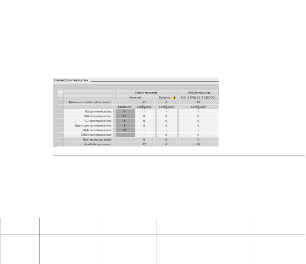
Communication
11.1 Asynchronous communication connections
S7-1200 Programmable controller
802 System Manual, V4.2, 09/2016, A5E02486680-AK
Available connections
The CPU supports the following number of maximum simultaneous, asynchronous
communication connections for PROFINET and PROFIBUS. The maximum number of
connection resources allocated to each category are fixed; you cannot change these values.
However, you can configure the 6 "Free available connections" to increase the number of
any category as required by your application.
Note
The total number of S7
-1200 communication connections does not increase when you add
CM/CP modules.
Based upon the allocated connection resources, the following number of connections per
device are available:
Programming
terminal (PG)
Human Machine
Interface (HMI)
GET/PUT
client/server
Open User
Communications
Web browser
Maximum
number of
connection
resources
3
(guaranteed to
support
1 PG device)
12
(guaranteed to
support
4 HMI devices)
8 8 30
(guaranteed to
support
3 web browsers)
For an example, a PG has 3 available connection resources. Depending on the current PG
functions in use, the PG might actually use 1, 2, or 3 of its available connection resources. In
the S7-1200, you are always guaranteed at least 1 PG; however, no more than 1 PG is
allowed.
Another example is the number of HMIs, as shown in the figure below. HMIs have 12
available connection resources. Depending on what HMI type or model that you have and
the HMI functions that you use, each HMI might actually use 1, 2, or 3 of its available
connection resources. Given the number of available connection resources being used, it
may be possible to use more than 4 HMIs at one time. However, you are always guaranteed
at least 4 HMIs. An HMI can use its available connection resources (1 each for a total of 3)
for the following functions:
● Reading
● Writing
● Alarming plus diagnostics

Communication
11.1 Asynchronous communication connections
S7-1200 Programmable controller
System Manual, V4.2, 09/2016, A5E02486680-AK 803
This is only an example. The actual number of connections used can vary by HMI type and
version.
Example
HMI 1
HMI 2
HMI 3
HMI 4
HMI 5
Total con-
nection
resources
available
Connection
resources
used
2 2 2 3 3 12
Note
Web server (HTTP) connections: The CPU provides connections for multiple web browsers.
The number of browsers that the CPU can simult
aneously support depends upon how many
connections a given web browser requests/utilizes.
Note
The Open User Communications, S7 connection, HMI, programming device, and Web server
(HTTP) communication connections may utilize multiple connection resourc
es based upon
the features currently being used.
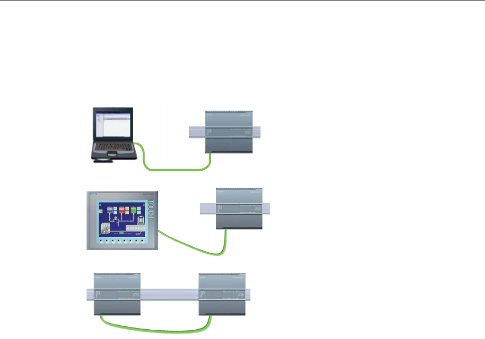
Communication
11.2 PROFINET
S7-1200 Programmable controller
804 System Manual, V4.2, 09/2016, A5E02486680-AK
11.2
PROFINET
The CPU can communicate with other CPUs, with programming devices, with HMI devices,
and with non-Siemens devices using standard TCP communications protocols.
Programming device connected to the
CPU
HMI connected to the CPU
A CPU connected to another CPU
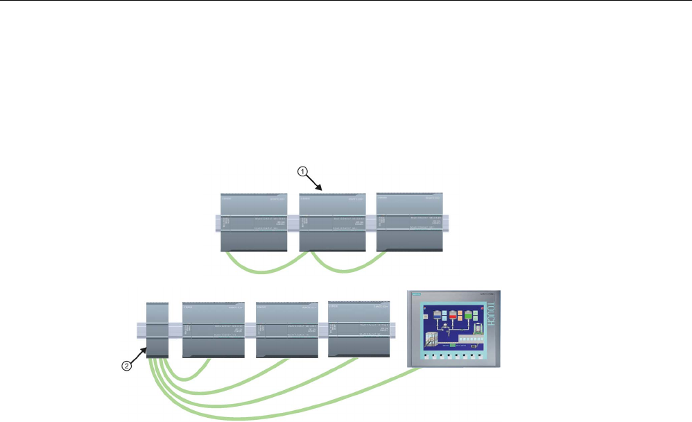
Communication
11.2 PROFINET
S7-1200 Programmable controller
System Manual, V4.2, 09/2016, A5E02486680-AK 805
Ethernet switching
The CPU 1211C, 1212C, and 1214C have a single Ethernet port and do not include a
integrated Ethernet Switch. A direct connection between a programming device or HMI and a
CPU does not require an Ethernet switch. However, a network with more than two CPUs or
HMI devices requires an Ethernet switch.
①
CPU 1215C
②
CSM1277 Ethe
r-
net switch
The CPU 1215C and the CPU 1217C have a built-in 2-port Ethernet switch. You can have a
network with a CPU 1215C and two other S7-1200 CPUs. You can also use the rack-
mounted CSM1277 4-port Ethernet switch for connecting multiple CPUs and HMI devices.
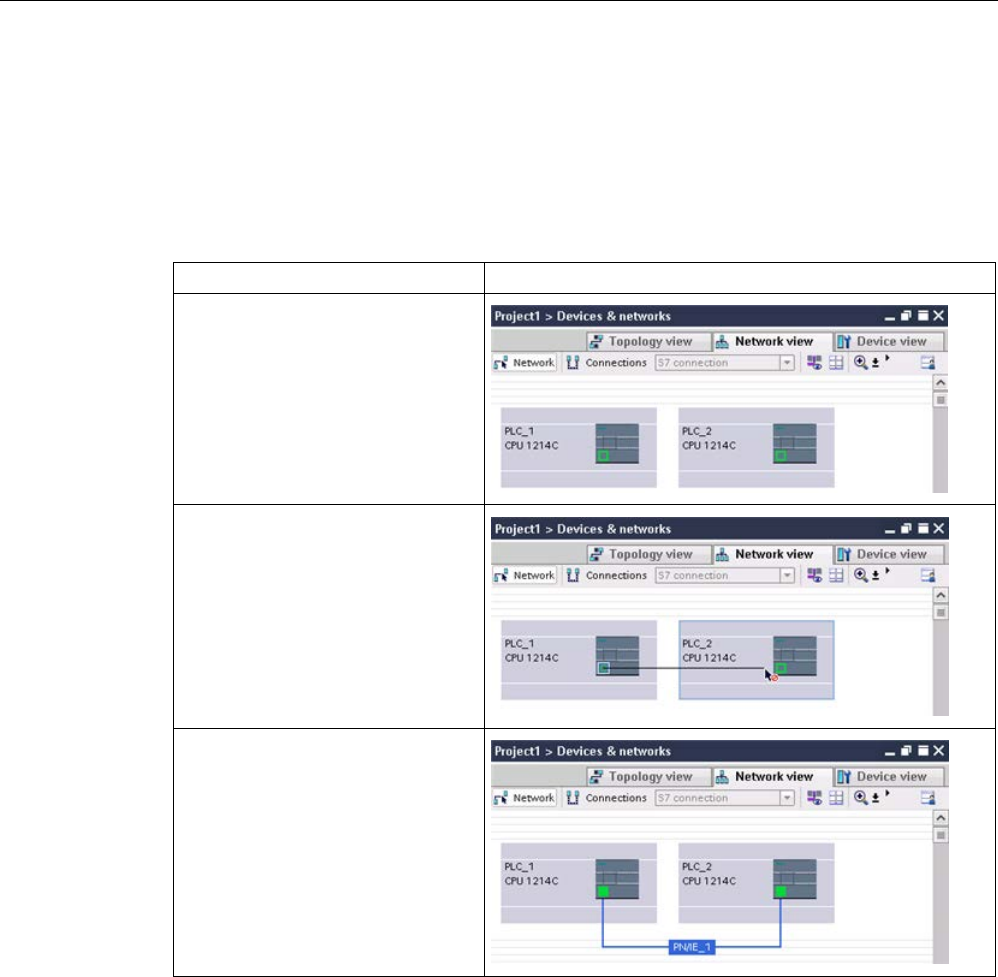
Communication
11.2 PROFINET
S7-1200 Programmable controller
806 System Manual, V4.2, 09/2016, A5E02486680-AK
11.2.1
Creating a network connection
Use the "Network view" of Device configuration to create the network connections between
the devices in your project. After creating the network connection, use the "Properties" tab of
the inspector window to configure the parameters of the network.
Table 11- 1 Creating a network connection
Action
Result
Select "Network view" to display the
devices to be connected.
Select the port on one device and
drag the connection to the port on
the second device.
Release the mouse button to create
the network connection.
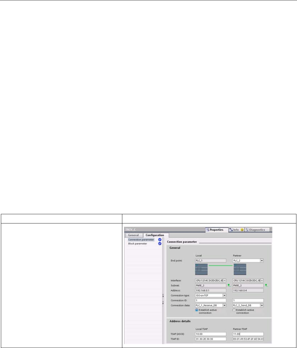
Communication
11.2 PROFINET
S7-1200 Programmable controller
System Manual, V4.2, 09/2016, A5E02486680-AK 807
11.2.2
Configuring the Local/Partner connection path
A Local / Partner (remote) connection defines a logical assignment of two communication
partners to establish communication services. A connection defines the following:
● Communication partners involved (One active, one passive)
● Type of connection (for example, a PLC, HMI, or device connection)
● Connection path
Communication partners execute the instructions to set up and establish the communication
connection. You use parameters to specify the active and passive communication end point
partners. After the connection is set up and established, it is automatically maintained and
monitored by the CPU.
If the connection is terminated (for example, due to a line break), the active partner attempts
to re-establish the configured connection. You do not have to execute the communication
instruction again.
Connection paths
After inserting a TSEND_C, TRCV_C or TCON instruction into the user program, the
inspector window displays the properties of the connection whenever you have selected any
part of the instruction. Specify the communication parameters in the "Configuration" tab of
the "Properties" for the communication instruction.
Table 11- 2 Configuring the connection path (using the properties of the instruction)
TCP, ISO-on-TCP, and UDP
Connection properties
For the TCP, ISO-on-TCP, and UDP Ethernet
protocols, use the "Properties" of the instruction
(TSEND_C, TRCV_C, or TCON) to configure the
"Local/Partner" connections.
The illustration shows the "Connection proper-
ties" of the "Configuration tab" for an ISO-on-
TCP connection.
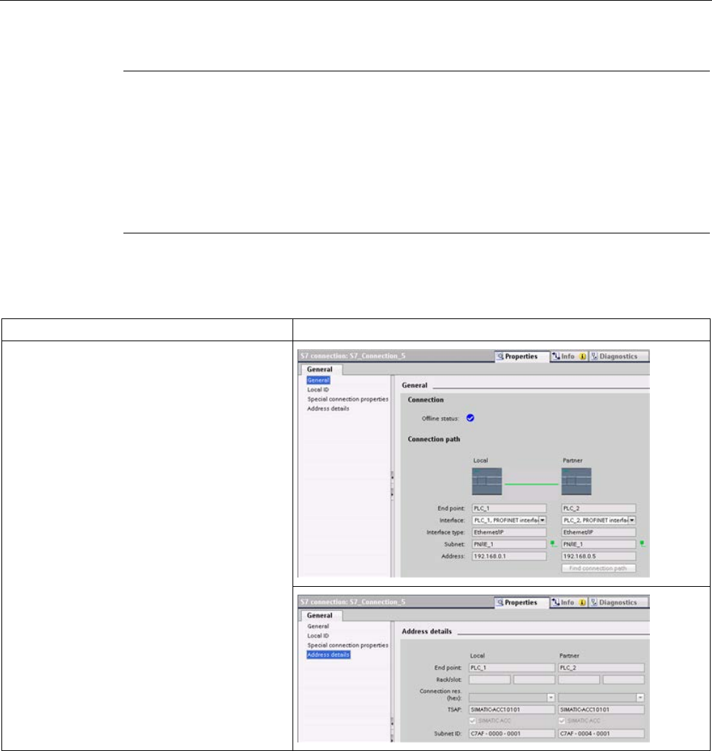
Communication
11.2 PROFINET
S7-1200 Programmable controller
808 System Manual, V4.2, 09/2016, A5E02486680-AK
Note
When you
configure the connection properties for one CPU, STEP 7 allows you either to
select a specific connection DB in the partner CPU (if one exists), or to create the connection
DB for the partner CPU. The partner CPU must already have been created for the proj
ect
and cannot be an "unspecified" CPU.
You must still insert a TSEND_C, TRCV_C or TCON instruction into the user program of the
partner CPU. When you insert the instruction, select the connection DB that was created by
the configuration.
Table 11- 3 Configuring the connection path for S7 communication (Device configuration)
S7 communication (GET and PUT)
Connection properties
For S7 communication, use the "Devices & net-
works" editor of the network to configure the
Local/Partner connections. You can click the
"Highlighted: Connection" button to access the
"Properties".
The "General" tab provides several properties:
• "General" (shown)
• "Local ID"
• "Special connection properties"
• "Address details" (shown)
Refer to "Protocols" (Page 825) in the "PROFINET" section or to "Creating an S7
connection" (Page 991) in the "S7 communication" section for more information and a list of
available communication instructions.

Communication
11.2 PROFINET
S7-1200 Programmable controller
System Manual, V4.2, 09/2016, A5E02486680-AK 809
Table 11- 4 Parameters for the multiple CPU connection
Parameter
Definition
Address
Assigned IP addresses
General End point Name assigned to the partner (receiving) CPU
Interface
Name assigned to the interfaces
Subnet Name assigned to the subnets
Interface type
S7 communication only
: Type of interface
Connection type
Type of Ethernet protocol
Connection ID
ID number
Connection data
Local and Partner CPU data storage location
Establish active connec-
tion
Radio button to select Local or Partner CPU as the active connection
Address de-
tails
End point
S7 communication only
: Name assigned to the partner (receiving) CPU
Rack/slot
S7 communication only
: Rack and slot location
Connection resource
S7 communication only
: Component of the TSAP used when configuring an
S7 connection with an S7-300 or S7-400 CPU
Port (decimal):
TCP and UPD: Partner CPU port in decimal format
TSAP 1 and Subnet ID: ISO on TCP (RFC 1006) and S7 communication: Local and partner CPU
TSAPs in ASCII and hexadecimal formats
1
When configuring a connection with an S7-1200 CPU for ISO-on-TCP, use only ASCII characters in the TSAP extension
for the passive communication partners.
Transport Service Access Points (TSAPs)
Using TSAPs, ISO on TCP protocol and S7 communication allows multiple connections to a
single IP address. TSAPs uniquely identify these communication end point connections to an
IP address.
In the "Address Details" section of the Connection Parameters dialog, you define the TSAPs
to be used. The TSAP of a connection in the CPU is entered in the "Local TSAP" field. The
TSAP assigned for the connection in your partner CPU is entered under the "Partner TSAP"
field.
Port Numbers
With TCP and UDP protocols, the connection parameter configuration of the Local (active)
connection CPU must specify the remote IP address and port number of the Partner
(passive) connection CPU.
In the "Address Details" section of the Connection Parameters dialog, you define the ports to
be used. The port of a connection in the CPU is entered in the "Local Port" field. The port
assigned for the connection in your partner CPU is entered under the "Partner Port" field.

Communication
11.2 PROFINET
S7-1200 Programmable controller
810 System Manual, V4.2, 09/2016, A5E02486680-AK
11.2.3
Assigning Internet Protocol (IP) addresses
11.2.3.1
Assigning IP addresses to programming and network devices
If your programming device is using an on-board adapter card connected to your plant LAN
(and possibly the world-wide web), both the programming device and the CPU must exist on
the same subnet. You assign the subnet as a combination of the IP address and subnet
mask for the device. Please see your local network administrator for help.
The Network ID is the first part of the IP address (first three octets) (for example,
211.154.184
.16) that determines what IP network you are on. The subnet mask normally has
a value of
255.255.255.0
; however, since your computer is on a plant LAN, the subnet mask
may have various values (for example,
255.255.254.0
) in order to set up unique subnets.
The subnet mask, when combined with the device IP address in a logical AND operation,
defines the boundaries of an IP subnet.
Note
In a World Wide Web scenario, where your programming devices, network devices, and IP
routers communicate with the world, you must assign unique IP addresses to avoid conflict
with other network users. Contact your company IT depart
ment personnel, who are familiar
with your plant networks, for assignment of your IP addresses.
WARNING
Unauthorized access to the CPU through the Web server
Unauthorized access to the CPU or changing PLC variables to invalid values could disrupt
process operation and could result in death, severe personal injury and/or property
damage.
Enabling the Web server allows authorized users to perform operating mode changes,
writes to PLC data, and firmware updates, Siemens recommends that you observe the
following security practices:
• Enable access to the Web server only with the HTTPS protocol.
• Password-protect Web server user IDs (Page 1005) with a strong password. Strong
passwords are at least ten characters in length, mix letters, numbers, and special
characters, are not words that can be found in a dictionary, and are not names or
identifiers that can be derived from personal information. Keep the password secret and
change it frequently.
• Do not extend the default minimum privileges of the "Everybody" user.
• Perform error-checking and range-checking on your variables in your program logic
because Web page users can change PLC variables to invalid values.
Note
A secondary network adapter card is useful when you do not want your CPU on your
company LAN. During initial testing or commissioning tests, this arrangement is particularly
useful.

Communication
11.2 PROFINET
S7-1200 Programmable controller
System Manual, V4.2, 09/2016, A5E02486680-AK 811
Assigning or checking the IP address of your programming device using "My Network Places" (on
your desktop)
If you are using Windows 7, you can assign or check your programming device's IP address
with the following menu selections:
● "Start"
● "Control Panel"
● "Network and Sharing Center"
● "Local Area Connection" for the network adapter connected to your CPU
● "Properties"
● In the "Local Area Connection Properties" dialog, in the "This connection uses the
following items:" field:
– Scroll down to "Internet Protocol Version 4 (TCP/IPv4)"
– Click "Internet Protocol Version 4 (TCP/IPv4)".
– Click the "Properties" button.
– Select "Obtain an IP address automatically (DCP)" or "Use the following IP address"
(to enter a static IP address).
● If you have the "Obtain an IP address automatically" selected you may want to change
the selection to "Use the following IP address" to connect to the S7-1200 CPU:
– Select an IP address on the same subnet as the CPU (
192.168.0
.1).
– Set the IP address to an address with the same Network ID (for example,
192.168.0
.200).
– Select a subnet mask of
255.255.255
.0.
– Leave the default gateway blank.
– This will allow you to connect to the CPU.
Note
The Network Interface Card and the CPU must be on the same subnet to allow STEP
7 to
find and communicate with the CPU.
Consult your IT personnel to help you set up a network configuration to allow you to connect
to the S7-1200 CPU.
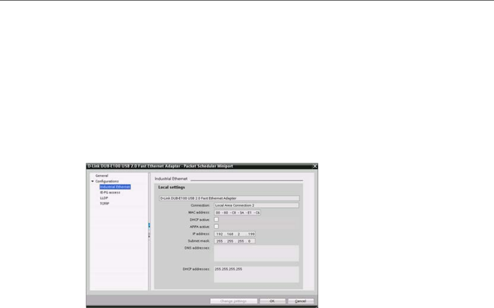
Communication
11.2 PROFINET
S7-1200 Programmable controller
812 System Manual, V4.2, 09/2016, A5E02486680-AK
11.2.3.2
Checking the IP address of your programming device
You can check the MAC and IP addresses of your programming device with the following
menu selections:
1. In the "Project tree", expand "Online access".
2. Right-click the required network, and select "Properties".
3. In the network dialog, expand "Configurations", and select "Industrial Ethernet".
The MAC and IP addresses of the programming device are displayed.
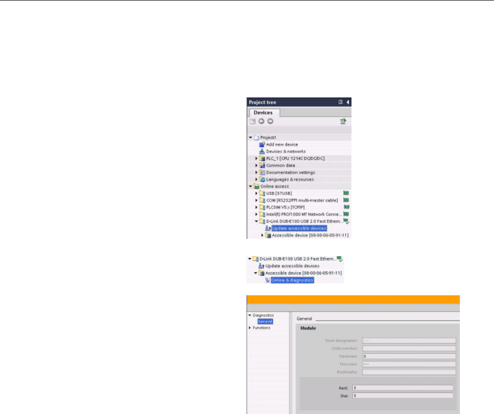
Communication
11.2 PROFINET
S7-1200 Programmable controller
System Manual, V4.2, 09/2016, A5E02486680-AK 813
11.2.3.3
Assigning an IP address to a CPU online
You can assign an IP address to a network device online. This is particularly useful in an
initial device configuration.
1. In the "Project tree," verify that
no IP address is assigned to the
CPU, with the following menu
selections:
•
"Online access"
•
<Adapter card for the network
in which the device is located>
•
"Update accessible devices"
NOTE: If STEP
7 displays a MAC
address instead of an IP address,
then no IP address has been a
s-
signed.
2. Under the required accessible
device, double
-click "Online &
diagnostics".
3. In the "Online & diagnostics"
dialog, make the following menu
selections:
•
"Functions"
•
"Assign IP address"
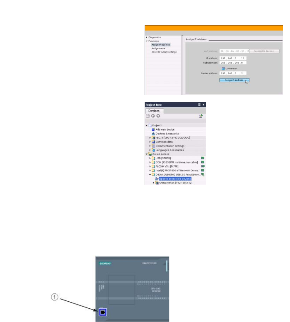
Communication
11.2 PROFINET
S7-1200 Programmable controller
814 System Manual, V4.2, 09/2016, A5E02486680-AK
4. In the "IP address" field, enter
your new IP address, and click the
"Assign IP address" button.
5. In the "Project tree," verify that
your new IP address has been
assigned to the CPU, with the
following menu selections:
•
"Online access"
•
<Adapter for the network in
which the device is located>
•
"Update accessible devices"
11.2.3.4
Configuring an IP address for a CPU in your project
Configuring the PROFINET interface
To configure parameters for the PROFINET interface, select the green PROFINET box on
the CPU. The "Properties" tab in the inspector window displays the PROFINET port.
①
PROFINET port
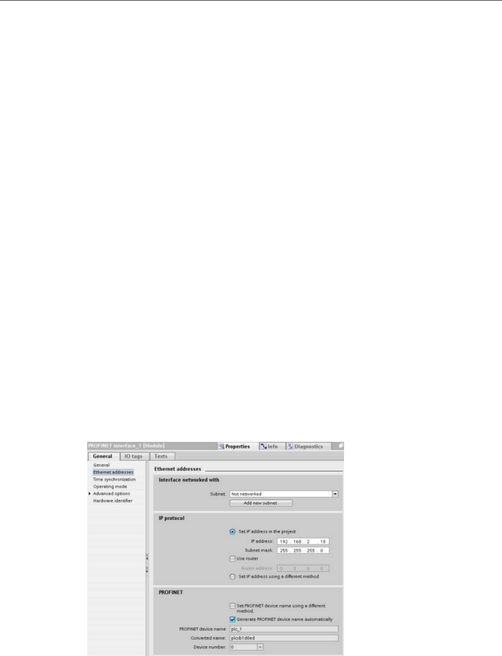
Communication
11.2 PROFINET
S7-1200 Programmable controller
System Manual, V4.2, 09/2016, A5E02486680-AK 815
Configuring the IP address
Ethernet (MAC) address:
In a PROFINET network, each device is assigned a Media Access
Control address (MAC address) by the manufacturer for identification. A MAC address
consists of six groups of two hexadecimal digits, separated by hyphens (-) or colons (:), in
transmission order, (for example, 01-23-45-67-89-AB or 01:23:45:67:89:AB).
IP address:
Each device must also have an Internet Protocol (IP) address. This address
allows the device to deliver data on a more complex, routed network.
Each IP address is divided into four 8-bit segments and is expressed in a dotted, decimal
format (for example, 211.154.184.16). The first part of the IP address is used for the Network
ID (What network are you on?), and the second part of the address is for the Host ID (unique
for each device on the network). An IP address of 192.168.x.y is a standard designation
recognized as part of a private network that is not routed on the Internet.
Subnet mask:
A subnet is a logical grouping of connected network devices. Nodes on a
subnet tend to be located in close physical proximity to each other on a Local Area Network
(LAN). A mask (known as the subnet mask or network mask) defines the boundaries of an IP
subnet.
A subnet mask of 255.255.255.0 is generally suitable for a small local network. This means
that all IP addresses on this network should have the same first 3 octets, and the various
devices on this network are identified by the last octet (8-bit field). An example of this is to
assign a subnet mask of 255.255.255.0 and an IP addresses of 192.168.2.0 through
192.168.2.255 to the devices on a small local network.
The only connection between different subnets is via a router. If subnets are used, an IP
router must be employed.
IP router:
Routers are the link between LANs. Using a router, a computer in a LAN can send
messages to any other networks, which might have other LANs behind them. If the
destination of the data is not within the LAN, the router forwards the data to another network
or group of networks where it can be delivered to its destination.
Routers rely on IP addresses to deliver and receive data packets.
IP addresses properties:
In
the Properties window,
select the "Ethernet a
d-
dresses" configuration e
n-
try. STEP
7 displays the
Ethernet address configur
a-
tion dialog, which assoc
i-
ates the software project
with the IP address of the
CPU that will receive that
proje
ct.

Communication
11.2 PROFINET
S7-1200 Programmable controller
816 System Manual, V4.2, 09/2016, A5E02486680-AK
Table 11- 5 Parameters for the IP address
Parameter
Description
Subnet Name of the Subnet to which the device is connected. Click the "Add new subnet" button to create a
new subnet. "Not connected" is the default. Two connection types are possible:
• The "Not connected" default provides a local connection.
• A subnet is required when your network has two or more devices.
IP protocol IP address Assigned IP address for the CPU
Subnet mask
Assigned subnet mask
Use IP router Click the checkbox to indicate the use of an IP router
Router address
Assigned IP address for the router, if applicable
Note
All IP addresses are configured
when you download the project. If the CPU does not have a
pre
-configured IP address, you must associate the project with the MAC address of the
target device. If your CPU is connected to a router on a network, you must also enter the IP
address of the rou
ter.
The "Set IP address using a different method" radio button allows you to change the IP
address online or by using the "
T_CONFIG (Page 901)" instruction after the program is
downloaded. This IP address assignment method is for the CPU only.
WARNING
Downloading a hardware configuration with "Set IP address using different method"
After downloading a hardware configuration with the "Set IP address using a different
method" option enabled, it is not possible to transition the CPU operating mode from RUN
to STOP or from STOP to RUN.
User equipment continues to run under these conditions and can result in unexpected
machine or process operations, which could cause death, severe personal injury, or
property damage if proper precautions are not taken.
Ensure that your CPU IP address(es) are set before using the CPU in an actual automation
environment. This can be done by using your STEP 7 programming package, the SIMATIC
Automation Tool, or an attached HMI device in conjunction with the T_CONFIG instruction.

Communication
11.2 PROFINET
S7-1200 Programmable controller
System Manual, V4.2, 09/2016, A5E02486680-AK 817
WARNING
Condition in which PROFINET network might stop
When changing the IP address of a CPU online or from the user program, it is possible to
create a condition in which the PROFINET network might stop.
If the IP address of a CPU is changed to an IP address outside the subnet, the PROFINET
network will lose communication, and all data exchange will stop. User equipment may be
configured to keep running under these conditions. Loss of PROFINET communication may
result in unexpected machine or process operations, causing death, severe personal injury,
or property damage if proper precautions are not taken.
If an IP address must be changed manually, ensure that the new IP address lies within the
subnet.
Configuring the PROFINET port
By default, the CPU configures port(s) of the PROFINET interface for autonegotiation. For
autonegotiation to function properly, you must configure both stations to autonegotiate. If one
station has a fixed configuration (for example, full-duplex at 100 Mbps) and the other station
is set to autonegotiate, then autonegotiation fails, resulting in half-duplex operation.
To overcome this limitation of autonegotiation, the S7-1200 provides an option to disable
autonegotiation. When you disable autonegotiation, the S7-1200 is automatically configured
for full-duplex operation at 100 Mbps.
You can set the transmission rate and duplex to a fixed value for each port:
1. Select Advanced options and the port you need to configure. Then, select Port options.
2. In the Connection, Transmission rate / duplex field, select one of the following:
– Automatic: The CPU and the peer device determine the port’s transmission rate and
duplex by autonegotiation.
– TP 100 Mbps full-duplex: If you disable autonegotiation, the port operates at 100 Mbps
full-duplex. If you enable autonegotiation, the port can operate at 100 Mbps full-duplex
or another transmission rate / duplex that is autonegotiated between the CPU and the
peer device (which places a message in the diagnostic buffer if "Monitor" is selected
(see below)).

Communication
11.2 PROFINET
S7-1200 Programmable controller
818 System Manual, V4.2, 09/2016, A5E02486680-AK
3. Monitor: When you select this check box, a message is placed in the diagnostic buffer if
any of the following occur at the port:
– A link cannot be established at the port
– An established link fails
– You select "TP 100 Mbps full-duplex" as the Transmission rate / duplex, and the CPU
establishes a link using autonegotiation with the negotiated transmission rate not
equal to 100 Mbps or the negotiated duplex equal to half-duplex.
4. Enable autonegotiation: Once you set the Transmission rate / duplex field to full-duplex at
100 Mbps, you can then disable autonegotiation. Deselect the "Enable autonegotiation"
check box to disable autonegotiation.
Note
If you do not disable autonegotiation, the CPU and the peer device negotiate the port’s
transmission rate and duplex.
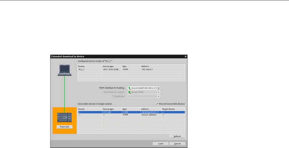
Communication
11.2 PROFINET
S7-1200 Programmable controller
System Manual, V4.2, 09/2016, A5E02486680-AK 819
11.2.4
Testing the PROFINET network
After completing the configuration, download the project (Page 216) to the CPU. All IP
addresses are configured when you download the project.
Assigning an IP address to a device online
The S7-1200 CPU does not have a pre-configured IP address. You must manually assign an
IP address for the CPU:
● To assign an IP address to a device online, refer to "Device configuration: Assigning an
IP address to a CPU online" (Page 813) for this step-by-step procedure.
● To assign an IP address in your project, you must configure the IP address in the Device
configuration, save the configuration, and download it to the PLC. Refer to "Device
configuration: Configuring an IP address for a CPU in your project" (Page 814) for more
information.
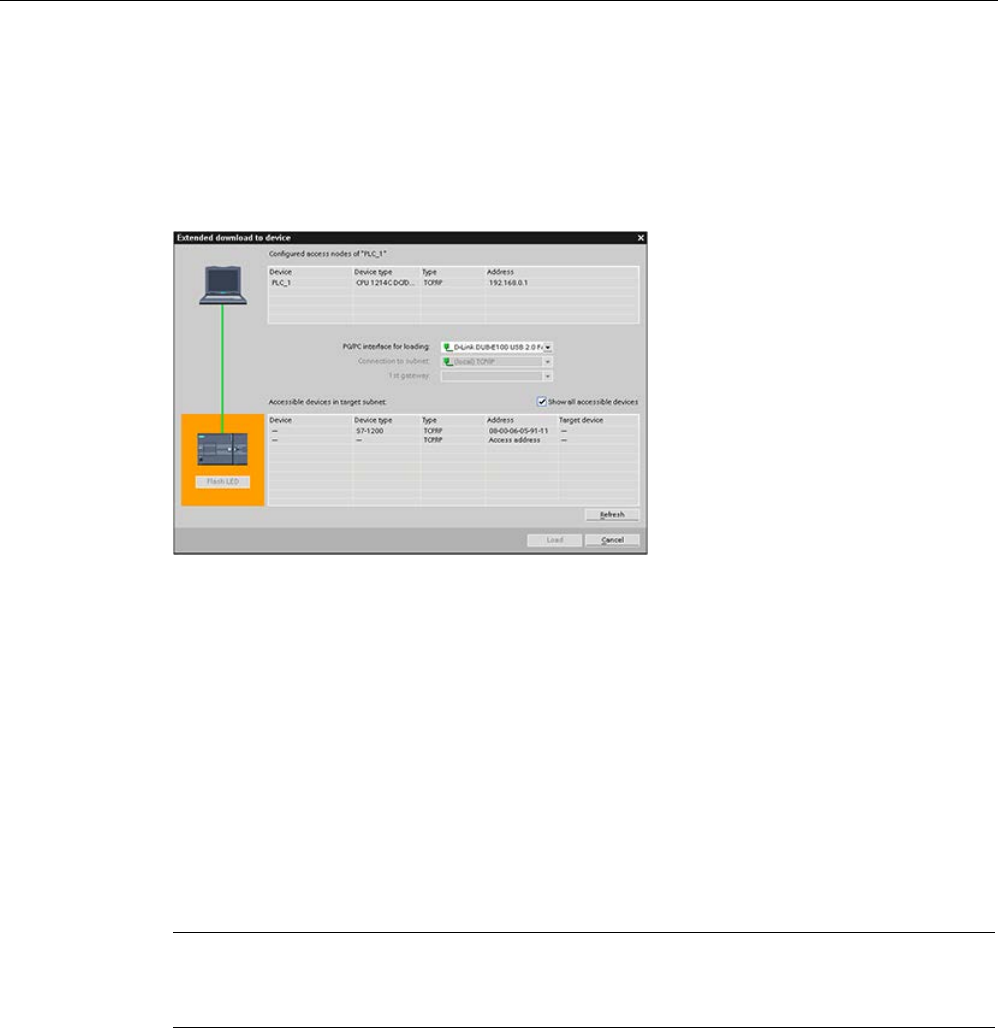
Communication
11.2 PROFINET
S7-1200 Programmable controller
820 System Manual, V4.2, 09/2016, A5E02486680-AK
Using the "Extended download to device" dialog to test for connected network devices
The S7-1200 CPU "Download to device" function and its "Extended download to device"
dialog can show all accessible network devices and whether or not unique IP addresses
have been assigned to all devices. To display all accessible and available devices with their
assigned MAC or IP addresses, check the "Show all accessible devices" checkbox.
If the required network device is not in this list, communications to that device have been
interrupted for some reason. The device and network must be investigated for hardware
and/or configuration errors.
11.2.5
Locating the Ethernet (MAC) address on the CPU
In PROFINET networking, a Media Access Control address (MAC address) is an identifier
assigned to the network interface by the manufacturer for identification. A MAC address
usually encodes the manufacturer's registered identification number.
The standard (IEEE 802.3) format for printing MAC addresses in human-friendly form is six
groups of two hexadecimal digits, separated by hyphens (-) or colons (:), in transmission
order, (for example, 01-23-45-67-89-ab or 01:23:45:67:89:ab).
Note
Each CPU is loaded at the factory with a permanent, unique MAC address. You cannot
change the MAC address of a CPU.
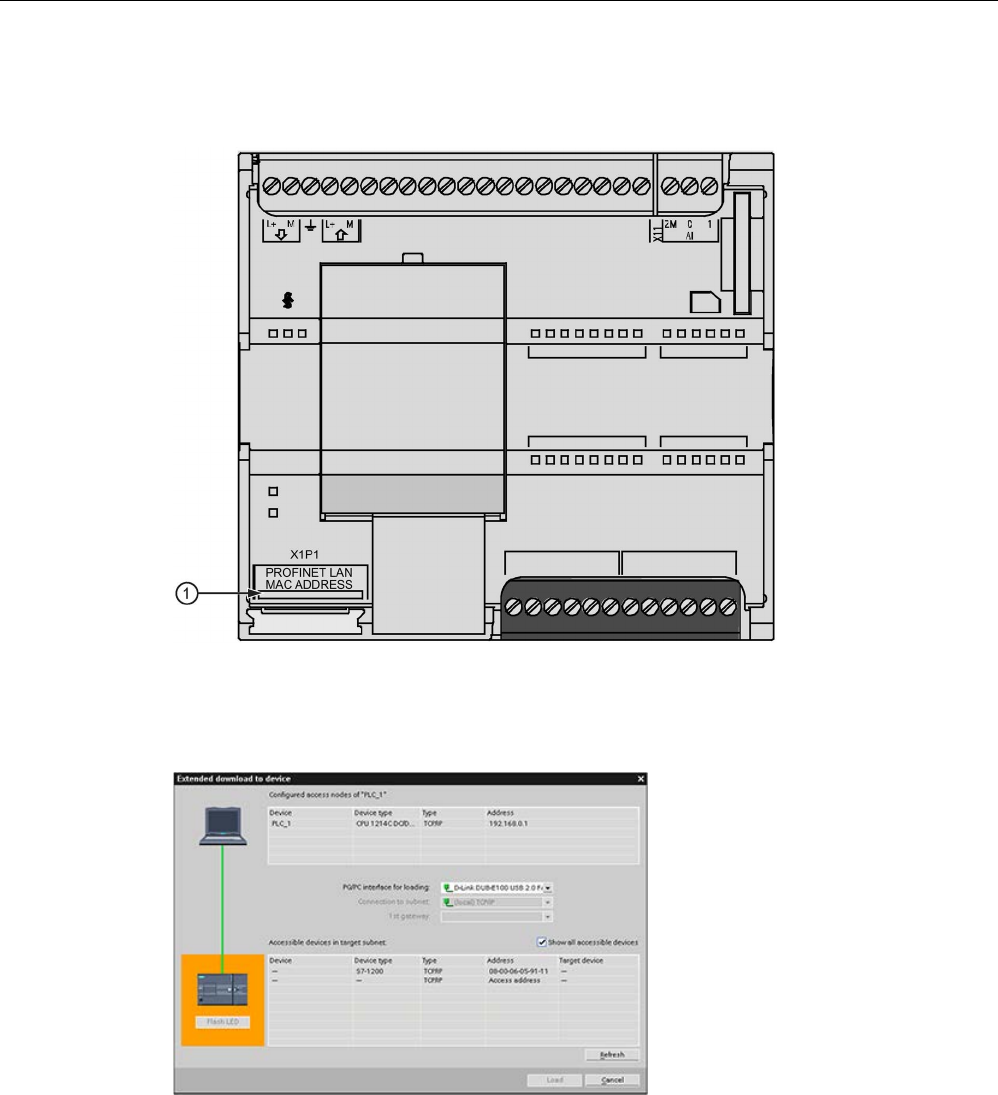
Communication
11.2 PROFINET
S7-1200 Programmable controller
System Manual, V4.2, 09/2016, A5E02486680-AK 821
The MAC address is printed on the front, lower-left corner of the CPU. Note that you have to
lift the lower door to see the MAC address information.
①
MAC address
Initially, the CPU has no IP address, only a factory-installed MAC address. PROFINET
communications requires that all devices be assigned a unique IP address.
Use the CPU "Download to d
e-
vice" function and the "Extend
ed
download to device" dialog to
show all accessible network d
e-
vices and ensure that unique IP
addresses have been assigned to
all devices. This dialog displays all
accessible and available devices
with their assigned MAC or IP
addresses. MAC addresses are
all
-important in identifying devices
that are missing the required
unique IP address.

Communication
11.2 PROFINET
S7-1200 Programmable controller
822 System Manual, V4.2, 09/2016, A5E02486680-AK
11.2.6
Configuring Network Time Protocol (NTP) synchronization
WARNING
If an attacker can access your networks through Network Time Protocol (NTP)
synchronization, the attacker can possibly take limited control of your process by shifting
the CPU system time.
The NTP client feature of the S7-1200 CPU is disabled by default, and, when enabled, only
allows configured IP addresses to act as an NTP server. The CPU disables this feature by
default, and you must configure this feature to allow remotely-controlled CPU system time
corrections.
The S7-1200 CPU supports "time of day" interrupts and clock instructions that depend upon
accurate CPU system time. If you configure NTP and accept time synchronization from a
server, you must ensure that the server is a trusted source. Failure to do so can cause a
security breach that allows an unknown user to take limited control of your process by
shifting the CPU system time.
For security information and recommendations, please see our "Operational Guidelines for
Industrial Security" (http://www.industry.siemens.com/topics/global/en/industrial-
security/Documents/operational_guidelines_industrial_security_en.pdf) on the Siemens
Service and Support site.
The Network Time Protocol (NTP) is widely used to synchronize the clocks of computer
systems to Internet time servers. In NTP mode, the CPU sends time-of-day queries at
regular intervals (in the client mode) to the NTP server in the subnet (LAN). Based on the
replies from the server, the most reliable and most accurate time is calculated and the time
of day on the station is synchronized.
The advantage of this mode is that it allows the time to be synchronized across subnets.
The IP addresses of up to four NTP servers need to be configured. The update interval
defines the interval between the time queries (in seconds). The value of the interval ranges
between 10 seconds and one day.
In NTP mode, it is generally UTC (Universal Time Coordinated) that is transferred; this
corresponds to GMT (Greenwich Mean Time).
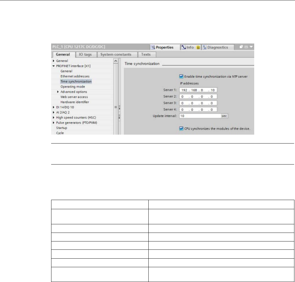
Communication
11.2 PROFINET
S7-1200 Programmable controller
System Manual, V4.2, 09/2016, A5E02486680-AK 823
In the Properties window, select the "Time synchronization" configuration entry. STEP 7
displays the Time synchronization configuration dialog:
Note
All IP addresses are configured when you download the project.
Table 11- 6 Parameters for time synchronization
Parameter
Definition
Enable time synchronization via NTP
server
Select the checkbox to enable time synchronization via NTP
server.
Server 1
Assigned IP Address for network time server 1
Server 2
Assigned IP Address for network time server 2
Server 3
Assigned IP Address for network time server 3
Server 4 Assigned IP Address for network time server 4
Time synchronization update interval
Interval value (sec)
CPU synchronizes the modules of the
device.
Select the checkbox to synchronize the CP clock with the
CPU clock.

Communication
11.2 PROFINET
S7-1200 Programmable controller
824 System Manual, V4.2, 09/2016, A5E02486680-AK
11.2.7
PROFINET device start-up time, naming, and address assignment
PROFINET IO can extend the start-up time for your system (configurable time-out). More
devices and slow devices impact the amount of time it takes to switch to RUN.
In V4.0 and later, you can have a maximum of 16 PROFINET IO devices on your S7-1200
PROFINET network.
Each station (or IO device) starts up independently on start-up, and this affects the overall
CPU start-up time. If you set the configurable time-out too low, there may not be a sufficient
overall CPU start-up time for all stations to complete start-up. If this situation occurs, false
station errors will result.
In the CPU Properties under "Startup", you can find the "Parameter assignment time for
distributed I/O" (time-out). The default configurable time-out is 60,000 ms (1 minute); the
user can configure this time.
PROFINET device naming and addressing in STEP 7
All PROFINET devices
must
have a Device Name and an IP Address. Use STEP 7 to define
the Device Names and to configure the IP addresses. Device names are downloaded to the
IO devices using PROFINET DCP (Discovery and Configuration Protocol).
PROFINET address assignment at system start-up
The controller broadcasts the names of the devices to the network, and the devices respond
with their MAC addresses. The controller then assigns an IP address to the device using
PROFINET DCP protocol:
● If the MAC address has a configured IP address, then the station performs start-up.
● If the MAC address does not have a configured IP address, STEP 7 assigns the address
that is configured in the project, and the station then performs start-up.
● If there is a problem with this process, a station error occurs and no start-up takes place.
This situation causes the configurable time-out value to be exceeded.

Communication
11.2 PROFINET
S7-1200 Programmable controller
System Manual, V4.2, 09/2016, A5E02486680-AK 825
11.2.8
Open user communication
11.2.8.1
Protocols
The integrated PROFINET port of the CPU supports multiple communications standards
over an Ethernet network:
● Transport Control Protocol (TCP)
● ISO on TCP (RFC 1006)
● User Datagram Protocol (UDP)
Table 11- 7 Protocols and communication instructions for each
Protocol
Usage examples
Entering data in the
receive area
Communication instruc-
tions
Addressing type
TCP CPU-to-CPU com-
munication
Transport of frames
Ad hoc mode Only TRCV_C and
TRCV
Assigns port numbers to
the Local (active) and
Partner (passive) devic-
es
Data reception with
specified length
TSEND_C, TRCV_C,
TCON, TDISCON,
TSEND, and TRCV
ISO on TCP CPU-to-CPU com-
munication
Message fragmenta-
tion and re-assembly
Ad hoc mode Only TRCV_C and
TRCV
Assigns TSAPs to the
Local (active) and Part-
ner (passive) devices
Protocol-controlled TSEND_C, TRCV_C,
TCON, TDISCON,
TSEND, and TRCV
UDP CPU-to-CPU com-
munication
User program com-
munications
User Datagram Protocol TUSEND and TURCV Assigns port numbers to
the Local (active) and
Partner (passive) devic-
es, but is not a dedicat-
ed connection
S7 communication CPU-to-CPU com-
munication
Read/write data
from/to a CPU
Data transmission and
reception with specified
length
GET and PUT Assigns TSAPs to the
Local (active) and Part-
ner (passive) devices
PROFINET IO CPU-to-PROFINET
IO device communi-
cation
Data transmission and
reception with specified
length
Built-in Built-in

Communication
11.2 PROFINET
S7-1200 Programmable controller
826 System Manual, V4.2, 09/2016, A5E02486680-AK
11.2.8.2
TCP and ISO on TCP
Transport Control Protocol (TCP) is a standard protocol described by RFC 793:
Transmission Control Protocol. The primary purpose of TCP is to provide reliable, secure
connection service between pairs of processes. This protocol has the following features:
● An efficient communications protocol since it is closely tied to the hardware
● Suitable for medium-sized to large data amounts (up to 8192 bytes)
● Provides considerably more facilities for applications, notably error recovery, flow control,
and reliability
● A connection-oriented protocol
● Can be used very flexibly with third-party systems which exclusively support TCP
● Routing-capable
● Only static data lengths are applicable.
● Messages are acknowledged.
● Applications are addressed using port numbers.
● Most of the user application protocols, such as TELNET and FTP, use TCP.
● Programming effort is required for data management due to the SEND / RECEIVE
programming interface.
International Standards Organization (ISO) on Transport Control Protocol (TCP) (RFC 1006)
(ISO on TCP) is a mechanism that enables ISO applications to be ported to the TCP/IP
network. This protocol has the following features:
● An efficient communications protocol closely tied to the hardware
● Suitable for medium-sized to large data amounts (up to 8192 bytes)
● In contrast to TCP, the messages feature an end-of-data identification and are message-
oriented.
● Routing-capable; can be used in WAN
● Dynamic data lengths are possible.
● Programming effort is required for data management due to the SEND / RECEIVE
programming interface.
Using Transport Service Access Points (TSAPs), TCP protocol allows multiple connections
to a single IP address (up to 64K connections). With RFC 1006, TSAPs uniquely identify
these communication end point connections to an IP address.

Communication
11.2 PROFINET
S7-1200 Programmable controller
System Manual, V4.2, 09/2016, A5E02486680-AK 827
11.2.8.3
Communication services and used port numbers
The S7-1200 CPU supports the protocols listed in the table below. For each protocol, the
CPU assigns the address parameters, the respective communications layer as well as the
communications role, and the communications direction.
This information makes it possible to match the security measures for protection of the
automation system to the used protocols (for example, firewall). Only the Ethernet or
PROFINET networks have security measures. Since PROFIBUS does not have any security
measures, the table does not include any PROFIBUS protocols.
The table below shows the different layers and protocols that the CPU uses:
Protocol
Port number
(2) Link layer
(4) Transport layer
Function
Description
PROFINET protocols
DCP
(Discovery and
Configuration
Protocol)
Not relevant (2) Ethernet II and
IEEE 802.1Q and
Ethertype 0x8892
(PROFINET)
Accessible devic-
es PROFINET
Discovery and
configuration
PROFINET uses
DCP to discover
devices and pro-
vide basic set-
tings.
DCP uses the
special multicast
MAC address: xx-
xx-xx-01-0E-CF,
xx-xx-xx = Organi-
zationally Unique
Indentifier
LLDP
(Link Layer Dis-
covery Protocol)
Not relevant (2) Ethernet II and
IEEE 802.1Q and
Ethertype 0x88CC
(PROFINET)
PROFINET Link
Layer Discovery
protocol
PROFINET uses
LLDP to discover
and manage
neighbor relation-
ships between
PROFINET devic-
es.
LLDP uses the
special multicast
MAC address: 01-
80-C2-00-00-0E

Communication
11.2 PROFINET
S7-1200 Programmable controller
828 System Manual, V4.2, 09/2016, A5E02486680-AK
11.2.8.4
Ad hoc mode
Typically, TCP and ISO-on-TCP receive data packets of a specified length, ranging from 1 to
8192 bytes. However, the TRCV_C and TRCV communication instructions also provide an
"ad hoc" communications mode that can receive data packets of a variable length from 1 to
1472 bytes.
Note
If you store the data in an "optimized" DB (symbolic only), you can receive data only in
arrays of Byte, Char, USInt, and SInt data types.
To configure the TRCV_C or TRCV instruction for ad hoc mode, set the ADHOC instruction
input parameter.
If you do not call the TRCV_C or TRCV instruction in ad hoc mode frequently, you could
receive more than one packet in one call. For example: If you were to receive five 100-byte
packets with one call, TCP would deliver these five packets as one 500-byte packet, while
ISO-on-TCP would restructure the packets into five 100-byte packets.
11.2.8.5
Connection IDs for the Open user communication instructions
When you insert the TSEND_C, TRCV_C or TCON PROFINET instructions into your user
program, STEP 7 creates an instance DB to configure the communications channel (or
connection) between the devices. Use the "Properties" (Page 807) of the instruction to
configure the parameters for the connection. Among the parameters is the connection ID for
that connection.
● The connection ID must be unique for the CPU. Each connection that you create must
have a different DB and connection ID.
● Both the local CPU and the partner CPU can use the same connection ID number for the
same connection, but the connection ID numbers are not required to match. The
connection ID number is relevant only for the PROFINET instructions within the user
program of the individual CPU.
● You can use any number for the connection ID of the CPU. However, configuring the
connection IDs sequentially from "1" provides an easy method for tracking the number of
connections in use for a specific CPU.
Note
Each TSEND_C, TRCV_C or TCON instruction in your user program creates a new
connection. It is important to use the correct connection ID for each connection.
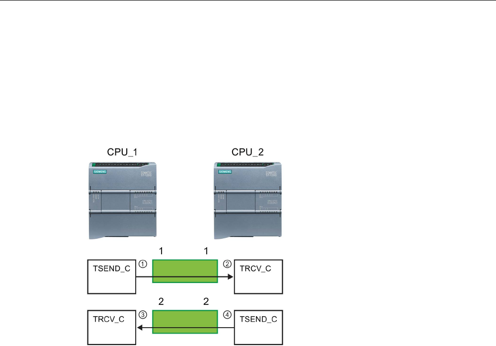
Communication
11.2 PROFINET
S7-1200 Programmable controller
System Manual, V4.2, 09/2016, A5E02486680-AK 829
The following example shows the communication between two CPUs that utilize two
separate connections for sending and receiving the data.
● The TSEND_C instruction in CPU_1 links to the TRCV_C in CPU_2 over the first
connection ("connection ID 1" on both CPU_1 and CPU_2).
● The TRCV_C instruction in CPU_1 links to the TSEND_C in CPU_2 over the second
connection ("connection ID 2" on both CPU_1 and CPU_2).
①
TSEND_C on CPU_1 creates a co
n-
nection and assigns a connection ID
to that connection (connection ID
1 for
CPU_1).
②
TRCV_C on CPU_2 creates the co
n-
nection for CPU_2 and assigns the
connection ID (connection ID 1 for
CPU_2).
③
TRCV_C on CPU_1 creates a second
connection for CPU_1 and assigns a
different connection ID
for that con-
nection (connection ID 2 for CPU_1).
④
TSEND_C on CPU_2 creates a se
c-
ond connection and assigns a different
connection ID for that connection
(connection ID
2 for CPU_2).
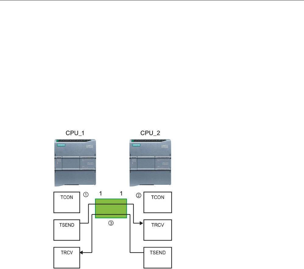
Communication
11.2 PROFINET
S7-1200 Programmable controller
830 System Manual, V4.2, 09/2016, A5E02486680-AK
The following example shows the communication between two CPUs that utilize 1
connection for both sending and receiving the data.
● Each CPU uses a TCON instruction to configure the connection between the two CPUs.
● The TSEND instruction in CPU_1 links to the TRCV instruction in CPU_2 by using the
connection ID ("connection ID 1") that was configured by the TCON instruction in CPU_1.
The TRCV instruction in CPU_2 links to the TSEND instruction in CPU_1 by using the
connection ID ("connection ID 1") that was configured by the TCON instruction in CPU_2.
● The TSEND instruction in CPU_2 links to the TRCV instruction in CPU_1 by using the
connection ID ("connection ID 1") that was configured by the TCON instruction in CPU_2.
The TRCV instruction in CPU_1 links to the TSEND instruction in CPU_2 by using the
connection ID ("connection ID 1") that was configured by the TCON instruction in CPU_1.
①
TCON on CPU_1 creates a conne
c-
tion and assigns a connection ID for
that connection on CPU_1 (ID=1).
②
TCON on CPU_2 creates a conne
c-
tion and assigns a connection ID for
that connection on CPU_2 (ID=1).
③
TSEND and TRCV on CPU_1 use the
connection ID created by the TCON
on CPU_1 (ID=1).
TSEND and TRCV on CPU_2 use the
connection
ID created by the TCON
on CPU_2 (ID=1).
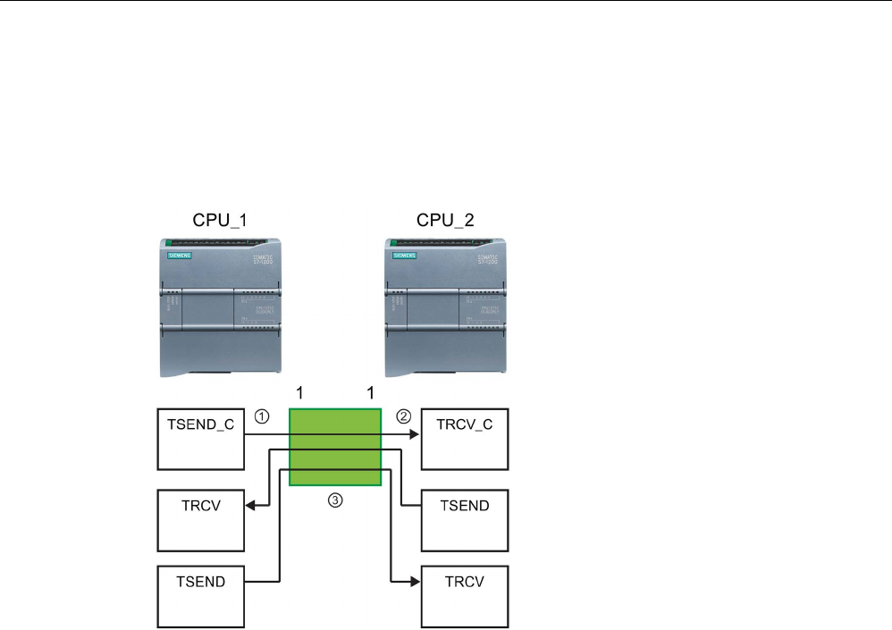
Communication
11.2 PROFINET
S7-1200 Programmable controller
System Manual, V4.2, 09/2016, A5E02486680-AK 831
As shown in the following example, you can also use individual TSEND and TRCV
instruction to communication over a connection created by a TSEND_C or TRCV_C
instruction. The TSEND and TRCV instructions do not themselves create a new connection,
so you must use the DB and connection ID that was created by a TSEND_C, TRCV_C or
TCON instruction.
①
TSEND_C on CPU_1
creates a con-
nection and assigns a connection ID
to that connection (ID=1).
②
TRCV_C on CPU_2 creates a conne
c-
tion and assigns the connection ID to
that connection on CPU_2 (ID=1).
③
TSEND and TRCV on CPU_1 use the
connection ID created by the
TSEND_C
on CPU_1 (ID=1).
TSEND and TRCV on CPU_2 use the
connection ID created by the TRCV_C
on CPU_2 (ID=1).

Communication
11.2 PROFINET
S7-1200 Programmable controller
832 System Manual, V4.2, 09/2016, A5E02486680-AK
11.2.8.6
Parameters for the PROFINET connection
The TSEND_C, TRCV_C and TCON instructions require connection-related parameters in
order to connect to the partner device. The TCON_Param structure assigns these
parameters for the TCP, ISO-on-TCP, and UDP protocols. Typically, you use the
"Configuration" (Page 807) tab of the "Properties" of the instruction to specify these
parameters. If the "Configuration" tab is not accessible, then you must provide the
TCON_Param structure in the instruction parameters.
With V4.1, the TCON_IP_V4 structure assigns parameters for the TCP protocol, and the
TCON_IP_RFC structure assigns parameters for the ISO-on-TCP protocol.
TCON_Param
Table 11- 8 Structure of the connection description (TCON_Param)
Byte
Parameter and data type
Description
0 … 1
block_length
UInt
Length: 64 bytes (fixed)
2 … 3 id CONN_OUC
(Word)
Reference to this connection: Range of values: 1 (default) to 4095.
Specify the value of this parameter for the TSEND_C, TRCV_C or
TCON instruction under ID.
4 connection_type USInt Connection type:
• 17: TCP (default)
• 18: ISO-on-TCP
• 19: UDP
5 active_est Bool ID for the type of connection:
• TCP and ISO-on-TCP:
– FALSE: Passive connection
– TRUE: Active connection (default)
• UDP: FALSE
6 local_device_id USInt ID for the local PROFINET or Industrial Ethernet interface:
1 (default)
7 local_tsap_id_len USInt Length of parameter local_tsap_id used, in bytes; possible values:
• TCP: 0 (active, default) or 2 (passive)
• ISO-on-TCP: 2 to 16
• UDP: 2
8
rem_subnet_id_len
USInt
This parameter is not used.
9 rem_staddr_len USInt Length of address of partner end point, in bytes:
• 0: unspecified (parameter rem_staddr is irrelevant)
• 4 (default): Valid IP address in parameter rem_staddr (only for
TCP and ISO-on-TCP)
10 rem_tsap_id_len USInt Length of parameter rem_tsap_id used, in bytes; possible values:
• TCP: 0 (passive) or 2 (active, default)
• ISO-on-TCP: 2 to 16
• UDP: 0

Communication
11.2 PROFINET
S7-1200 Programmable controller
System Manual, V4.2, 09/2016, A5E02486680-AK 833
Byte
Parameter and data type
Description
11
next_staddr_len
USInt
This parameter is not used.
12 … 27 local_tsap_id Array [1..16] of
Byte
Local address component of connection:
• TCP and ISO-on-TCP: local port no. (possible values: 1 to
49151; recommended values: 2000...5000):
– local_tsap_id[1] = high byte of port number in hexadecimal
notation;
– local_tsap_id[2] = low byte of port number in hexadecimal
notation;
– local_tsap_id[3-16] = irrelevant
• ISO-on-TCP: local TSAP-ID:
– local_tsap_id[1] = B#16#E0;
– local_tsap_id[2] = rack and slot of local end points (bits 0 to
4: slot number, bits 5 to 7: rack number);
– local_tsap_id[3-16] = TSAP extension, optional
• UDP: This parameter is not used.
Note: Make sure that every value of local_tsap_id is unique within
the CPU.
28 … 33 rem_subnet_id Array [1..6] of
USInt
This parameter is not used.
34 … 39 rem_staddr Array [1..6] of
USInt
TCP and ISO-on-TCP only: IP address of the partner end point.
(Not relevant for passive connections.) For example, IP address
192.168.002.003 is stored in the following elements of the array:
rem_staddr[1] = 192
rem_staddr[2] = 168
rem_staddr[3] = 002
rem_staddr[4] = 003
rem_staddr[5-6]= irrelevant
40 … 55 rem_tsap_id Array [1..16] of
Byte
Partner address component of connection
• TCP: partner port number. Range: 1 to 49151; Recommended
values: 2000 to 5000):
– rem_tsap_id[1] = high byte of the port number in hexadeci-
mal notation
– rem_tsap_id[2] = low byte of the port number in hexadeci-
mal notation;
– rem_tsap_id[3-16] = irrelevant
• ISO-on-TCP: partner TSAP-ID:
– rem_tsap_id[1] = B#16#E0
– rem_tsap_id[2] = rack and slot of partner end point (bits 0
to 4: Slot number, bits 5 to 7: rack number)
– rem_tsap_id[3-16] = TSAP extension, optional
• UDP: This parameter is not used.
56 … 61 next_staddr Array [1..6] of
Byte
This parameter is not used.
62 … 63
spare
Word
Reserved: W#16#0000

Communication
11.2 PROFINET
S7-1200 Programmable controller
834 System Manual, V4.2, 09/2016, A5E02486680-AK
TCON_IP_V4
Table 11- 9 Structure of the connection description (TCON_IP_V4): For use with TCP
Byte
Parameter and data type
Description
0 … 1 InterfaceId
HW_ANY
HW-identifier of the IE-interface submodule
2 … 3 ID CONN_OUC
(Word)
Referen
ce to this connection: Range of values: 1 (default) to 4095.
Specify the value of this parameter for the TSEND_C, TRCV_C, or
TCON instruction under ID.
4 ConnectionType Byte Connection type:
• 11: TCP/IP (default)
• 17: TCP/IP (This connection type is included for legacy rea-
sons. It is recommended that you use "11: TCP/IP (default)".)
• 19: UDP
5 ActiveEstablished Bool Active/passive connection establishment:
• TRUE: Active connection (default)
• FALSE: Passive connection
V4 IP address
6
ADDR[1]
Byte
Octet 1
7
ADDR[1]
Byte
Octet 2
8
ADDR[1]
Byte
Octet 3
9
ADDR[1]
Byte
Octet 4
10 ... 11
RemotePort
UInt
Remote UDP/TCP port number
12 ... 13
LocalPort
UInt
Local UDP/TCP port number

Communication
11.2 PROFINET
S7-1200 Programmable controller
System Manual, V4.2, 09/2016, A5E02486680-AK 835
TCON_IP_RFC
Table 11- 10 Structure of the connection description (TCON_IP_RFC): For use with ISO on TCP
Byte
Parameter and data type
Description
0 … 1 InterfaceId
HW_ANY
HW-identifier of the IE-interface submodule
2 … 3 ID CONN_OUC
(Word)
Reference to this connection: Range of values: 1 (default) to 4095.
Specify the value of this parameter for the TSEND_C, TRCV_C, or
TCON instruction under ID.
4 ConnectionType Byte Connection type:
• 12: ISO-on-TCP (default)
• 17: ISO-on-TCP (This connection type is included for legacy
reasons. It is recommended that you use "12: ISO-on-TCP
(default)".)
5 ActiveEstablished Bool Active/passive connection establishment:
• TRUE: Active connection (default)
• FALSE: Passive connection
6 ... 7
Spare
Not used
V4 IP address
8
ADDR[1]
Byte
Octet 1
9
ADDR[1]
Byte
Octet 2
10
ADDR[1]
Byte
Octet 3
11
ADDR[1]
Byte
Octet 4
Remote transport selector
12 ... 13
TSelLength
UInt
Length of TSelector
14 ... 45 TSel array [1..32] of
Byte
Character array for TSAP name
Local transport selector
46 ... 47
TSelLength
UInt
Length of TSelector
48 ... 79 TSel array [1..32] of
Byte
Character array for TSAP name
See also
S7-1200 CM/CPs (https://support.industry.siemens.com/cs/us/en/ps)
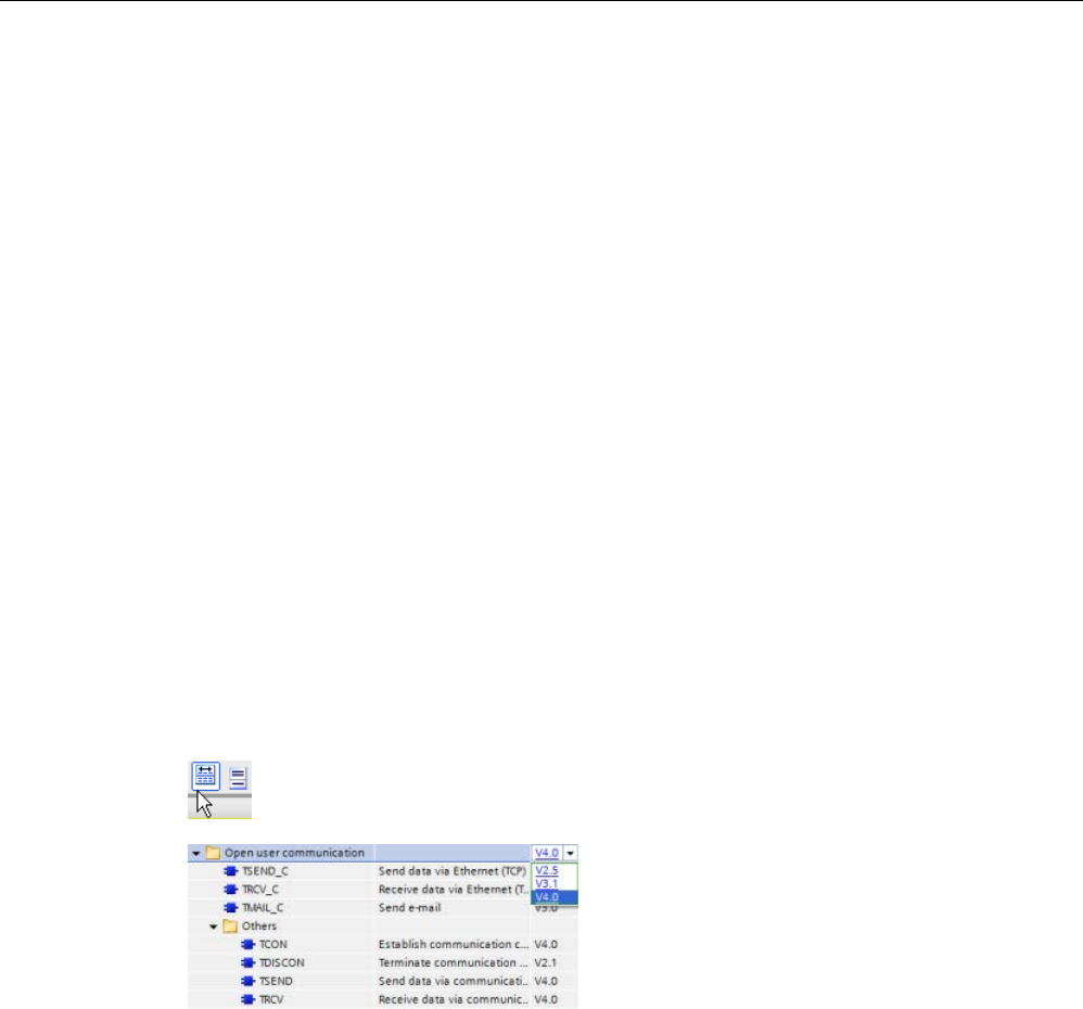
Communication
11.2 PROFINET
S7-1200 Programmable controller
836 System Manual, V4.2, 09/2016, A5E02486680-AK
11.2.8.7
TSEND_C and TRCV_C instructions
As of version V4.1 of the S7-1200 CPU together with STEP 7 V13 SP1, the CPU extends the
capability of the TSEND_C and TRCV_C instructions to use connection parameters with
structures according to "TCON_IP_v4" and "TCON_IP_RFC".
For this reason, the S7-1200 supports two sets of TSEND_C and TRCV_C instructions:
● Legacy TSEND_C and TRCV_C instructions (Page 848): These TSEND_C and TRCV_C
instructions existed prior to version V4.0 of the S7-1200 and only work with connection
parameters with structures according to "TCON_Param".
● TSEND_C and TRCV_C instructions (Page 837): These TSEND_C and TRCV_C
instructions provide all of the functionality of the legacy instructions, plus the ability to use
connection parameters with structures according to "TCON_IP_v4" and "TCON_IP_RFC".
Selecting the version of the TSEND_C and TRCV_C instructions
There are two versions of the TSEND_C and TRCV_C instructions available in STEP 7:
● Versions 2.5 and 3.1 were available in STEP 7 Basic/Professional V13 or earlier.
● Version 4.0 is available in STEP 7 Basic/Professional V13 SP1 or later.
For compatibility and ease of migration, you can choose which instruction version to insert
into your user program.
Do not use different instruction versions in the same CPU program.
Click the icon on the instruction tree task card to enable the headers and columns
of the instruction tree.
To change the version of the TSEND_C and
TRCV_C instructions, select the version from
the drop
-down list. You can select the group
or individual instructions.
When you use the instruction tree to place a TSEND_C or TRCV_C instruction in your
program, a new FB or FC instance, depending on the TSEND_C or TRCV_C instruction
selected, is created in the project tree. You can see new FB or FC instance in the project
tree under PLC_x > Program blocks > System blocks > Program resources.
To verify the version of a TSEND_C or TRCV_C instruction in a program, you must inspect
project tree properties and not the properties of a box displayed in the program editor. Select
a project tree TSEND_C or TRCV_C FB or FC instance, right-click, select "Properties", and
select the "Information" page to see the TSEND_C or TRCV_C instruction version number.

Communication
11.2 PROFINET
S7-1200 Programmable controller
System Manual, V4.2, 09/2016, A5E02486680-AK 837
TSEND_C and TRCV_C (Send and receive data using Ethernet)
The TSEND_C instruction combines the functions of the TCON, TDISCON and TSEND
instructions. The TRCV_C instruction combines the functions of the TCON, TDISCON, and
TRCV instructions. (Refer to "TCON, TDISCON, TSEND, AND TRCV (Page 857)" for more
information on these instructions.)
The minimum size of data that you can transmit (TSEND_C) or receive (TRCV_C) is one
byte; the maximum size is 8192 bytes. TSEND_C does not support the transmission of data
from Boolean locations, and TRCV_C will not receive data into Boolean locations. For
information on transferring data with these instructions, see the section on data consistency
(Page 198).
Note
Initializing the communication parameters
After you insert the TSEND_C or TRCV_C instruction, use the "Properties"
of the instruction
(Page
807) to configure the communication parameters (Page 832). As you enter the
parameters for the communication partners in the inspector window, STEP
7 enters the
c
orresponding data in the DB for the instruction.
If you want to use a multi
-instance DB, you must manually configure the DB on both CPUs.
Table 11- 11 TSEND_C and TRCV_C instructions
LAD / FBD
SCL
Description
"TSEND_C_DB"(
req:=_bool_in_,
cont:=_bool_in_,
len:=_uint_in_,
done=>_bool_out_,
busy=>_bool_out_,
error=>_bool_out_,
status=>_word_out_,
connect:=_struct_inout_,
data:=_variant_inout_,
com_rst:=_bool_inout_);
TSEND_C establishes a TCP or ISO on TCP
communication connection to a partner station,
sends data, and can terminate the connection.
After the connection is set up and established, it
is automatically maintained and monitored by
the CPU.
"TRCV_C_DB"(
en_r:=_bool_in_,
cont:=_bool_in_,
len:=_uint_in_,
adhoc:=_bool_in_,
done=>_bool_out_,
busy=>_bool_out_,
error=>_bool_out_,
status=>_word_out_,
rcvd_len=>_uint_out_,
connect:=_struct_inout_,
data:=_variant_inout_,
com_rst:=_bool_inout_);
TRCV_C establishes a TCP or ISO on TCP
communication connection to a partner CPU,
receives data, and can terminate the connection.
After the connection is set up and established, it
is automatically maintained and monitored by
the CPU.
1 STEP 7 automatically creates the DB when you insert the instruction.

Communication
11.2 PROFINET
S7-1200 Programmable controller
838 System Manual, V4.2, 09/2016, A5E02486680-AK
Table 11- 12 TSEND_C and TRCV_C data types for the parameters
Parameter and type
Data type
Description
REQ
(TSEND_C)
IN Bool Starts the send job on a rising edge
EN_R
(TRCV_C)
IN Bool Receive enable
CONT IN Bool Controls the communication connection:
• 0: Disconnect the communication connection after data is
sent.
• 1: Establish and maintain the communication connection.
When sending data (TSEND_C) (rising edge at the REQ pa-
rameter) or receiving data (TRCV_C) (rising edge at the EN_R
parameter), the CONT parameter must have the value TRUE in
order to establish or maintain a connection.
LEN IN UDInt Optional parameter (hidden)
Maximum number of bytes to be sent (TSEND_C) or received
(TRCV_C) with the job. If you use purely symbolic values at the
DATA parameter, the LEN parameter must have the value "0".
ADHOC
(TRCV_C)
IN Bool Optional parameter (hidden)
Ad hoc mode request for connection type TCP.
CONNECT IN_OUT TCON_Param Pointer to the connection description corresponding to the struc-
ture of connection to be described:
• For TCP or UDP, use the structure TCON_IP_v4
• For further information on TCON_IP_v4, refer to: "Parame-
ters for the PROFINET connection" (Page 832).
• For ISO-on-TCP, use the structure TCON_IP_RFC
• For further information on TCON_IP_RFC, refer to: "Parame-
ters for the PROFINET connection" (Page 832).
The CONNECT parameter is only evaluated upon a positive
edge at REQ (TSEND_C), when connection establishment
starts (TRCV_C), or when COM_RST = 1.
DATA IN_OUT Variant Pointer to the send area containing:
• Address and length of data to be sent (TSEND_C)
• Address and maximum length of received data (TRCV_C)
ADDR IN_OUT Variant Optional parameter (hidden)
Pointer to the address of the recipient with the connection type
UDP. The address information is mapped in the structure
TADDR_Param ###.

Communication
11.2 PROFINET
S7-1200 Programmable controller
System Manual, V4.2, 09/2016, A5E02486680-AK 839
Parameter and type
Data type
Description
COM_RST IN_OUT Bool Optional parameter (hidden)
Restarts the instruction:
• 0: Irrelevant
• 1: Completely restarts the instruction; the existing connec-
tion is either terminated or reset and established again in
accordance with CONT.
The COM_RST parameter is reset after evaluation by the
TSEND_C or TRCV_C instruction and should not, therefore, be
switched statically.
DONE OUT Bool Status parameter with the following values:
• 0: Send job not yet started or is still executing.
• 1: Send job executed without errors. This state is only dis-
played for one cycle.
BUSY OUT Bool Status parameter with the following values:
• 0: Send job not yet started or already completed.
• 1: Send job not yet completed. A new send job cannot be
started.
ERROR OUT Bool Status parameters with the following values:
• 0: No error
• 1: Error occurred during connection establishment, data
transmission, or connection termination.
STATUS OUT Word Status of instruction (see the ERROR and STATUS parameters
description).
RCVD_LEN
(TRCV_C)
OUT Int Amount of data actually received (in bytes).
Note
The TSEND_C instruction requires a low
-to-high transition at the REQ input parameter to
start a send job. The BUSY parameter is then set to 1 during processing. Completion of the
send job is indicated by either the DONE or ERROR parameters being set to 1 for one scan.
During this time, any low
-to-high transition at the REQ input parameter is ignored.

Communication
11.2 PROFINET
S7-1200 Programmable controller
840 System Manual, V4.2, 09/2016, A5E02486680-AK
Note
The default setting of the LEN parameter (LEN = 0) uses the DATA parameter to determine
the length of the data being transmitted. It is recommended that the data transmitted by the
TSEND_C instruction be the
same size as the DATA parameter of the TRCV_C instruction.
If using the default setting of the LEN parameter and it is necessary to send the data in
segments smaller than the DATA parameter size, the following applies. If the size of the data
transmitted f
rom TSEND_C does not equal the TRCV_C DATA parameter size, TRCV_C
remains in a busy status (status code: 7006) until the overall size of the data transmitted
from TSEND_C equals the TRCV_C DATA parameter size.
The TRCV_C DATA parameter buffer does not disp
lay the new data received until the data
size equals the DATA parameter buffer size.

Communication
11.2 PROFINET
S7-1200 Programmable controller
System Manual, V4.2, 09/2016, A5E02486680-AK 841
TSEND_C operations
The TSEND_C instruction is executed asynchronously and implements the following
functions in sequence:
1. Setting up and establishing a communications connection:
TSEND_C sets up a communication connection and establishes this connection if a rising
edge is detected at the REQ parameter and no communication connection is in place yet.
Once the connection has been set up and established, it is automatically maintained and
monitored by the CPU. The connection description specified at the CONNECT parameter
is used to set up the communications connection. The following connection types can be
used:
– TCON_Param structure for the TCP, ISO-on-TCP, and UDP protocols
– WIth V4.1, TCP/UDP: Connection description using the structure TCON_IP_v4 at the
parameter CONNECT
– WIth V4.1, ISO-on-TCP: Connection description using the structure TCON_IP_RFC at
the parameter CONNECT
An existing connection is terminated and the connection which has been set up is
removed when the CPU goes into STOP mode. To set up and establish the connection
again, you must execute TSEND_C again. For information on the number of possible
communication connections, please refer to the technical specifications for your CPU.
2. Sending data via an existing communications connection:
The send job is executed when a rising edge is detected at the REQ parameter. As
described above, the communications connection is established first. You specify the
send area with the DATA parameter. This includes the address and the length of the data
to be sent. Do not use a data area with the data type BOOL or Array of BOOL at the
DATA parameter. With the LEN parameter, you specify the maximum number of bytes
sent with a send job. If using a symbolic name at the DATA parameter, the LEN
parameter should have the value "0".
The data to be sent must not be edited until the send job is completed.
3. Terminating the communications connection:
The communications connection is terminated after the data has been sent if the CONT
parameter had the value "0" at the time of the rising edge at the REQ parameter.
Otherwise, the communications connection will be maintained.
If the send job executes successfully, the DONE parameter is set to "1". The
communications connection may be terminated before this (see the above description of the
dependency on the CONT parameter). Signal state "1" at the DONE parameter is not
confirmation that the data sent has already been read by the communications partner.
TSEND_C is reset when the COM_RST parameter is set to "1". Data loss may occur if data
is being transferred at this point.

Communication
11.2 PROFINET
S7-1200 Programmable controller
842 System Manual, V4.2, 09/2016, A5E02486680-AK
The following scenarios are possible depending on the CONT parameter:
● CONT = "0":
An existing communications connection is established.
● CONT = "1" and a communications connection was established:
An existing communications connection is reset and established again.
● CONT = "1" and no communications connection was established.
No communications connection is established.
The COM_RST parameter is reset following evaluation by the instruction T_SEND. To
enable TSEND_C again after the execution (DONE = 1), call the instruction once with REQ =
0

Communication
11.2 PROFINET
S7-1200 Programmable controller
System Manual, V4.2, 09/2016, A5E02486680-AK 843
TRCV_C operations
The TRCV_C instruction is executed asynchronously and implements the following functions
in sequence:
1. Setting up and establishing a communications connection:
TRCV_C sets up a communication connection and establishes this connection if the
EN_R parameter = "1" and there is no communication connection. Once the connection
has been set up and established, it is automatically maintained and monitored by the
CPU.
The connection description specified at the CONNECT parameter is used to set up the
communications connection. The following connection types can be used:
– TCON_Param structure for the TCP, ISO-on-TCP, and UDP protocols
– With V4.1, TCP / UDP: Connection description via the structure TCON_IP_v4 at the
parameter CONNECT
– With V4.1, ISO-on-TCP: Connection description via the structure TCON_IP_RFC at
the parameter CONNECT
An existing connection is terminated and the connection which has been set up is
removed when the CPU goes into STOP mode. To set up and establish the connection
again, you must execute TRCV_C again with EN_R = "1".
If EN_R is set to "0" before the communications connection has been established, the
connection will be established and remain in place even if CONT = "0". However, no data
will be received (DONE will remain "0").
For information on the number of possible communication connections, please refer to
the technical specifications for your CPU.
2. Receiving data via an existing communications connection:
Receipt of data is enabled when the EN_R parameter is set to the value "1". As described
above, the communications connection is established first. The received data is entered
in a receive area. You specify the length of the receive area either with the LEN
parameter (if LEN <> 0) or with the length information of the DATA parameter (if LEN =
0), depending on the protocol variant being used. If you use purely symbolic values at the
DATA parameter, the LEN parameter must have the value "0".
If EN_R is set to "0" before data is received for the first time, the communication
connection will remain in place even if CONT = 0. However, no data will be received
(DONE will remain "0").
3. Terminating the communications connection:
The communications connection is terminated after data has been received if the CONT
parameter had the value "0" when connection established was started. Otherwise, the
communications connection will be maintained.
If the receive job executes successfully, the DONE parameter is set to "1". The
communications connection may be terminated before this (see the above description of the
dependency on the CONT parameter).

Communication
11.2 PROFINET
S7-1200 Programmable controller
844 System Manual, V4.2, 09/2016, A5E02486680-AK
TRCV_C is reset when the COM_RST parameter is set. If data is being received when it
executes again, this can lead to a loss of data. The following scenarios are possible
depending on the CONT parameter:
● CONT = "0":
An existing communications connection is established.
● CONT = "1" and a communications connection was established:
An existing communications connection is reset and established again.
● CONT = "1" and no communications connection was established:
No communications connection is established.
The COM_RST parameter is reset following evaluation by the instruction TRCV_".
TRCV_C handles the same receive modes as the TRCV instruction. The following table
shows how data is entered in the receive area:
Protocol variant
Availability of data in the receive
area
Connection_type parameter of
the connection description
LEN
parameter
RCVD_LEN
parameter
TCP
(Ad hoc mode)
The data is immediately availa-
ble.
B#16#11 Selected with
the TRCV_C
instruction
ADHOC input
1 to 1472
TCP (data receipt
with specified
length)
The data is available as soon as
the data length specified at the
LEN parameter has been fully
received.
B#16#11 1 to 8192 Identical to the
value at the
LEN parameter
ISO on TCP (pro-
tocol-controlled
data transfer)
The data is available as soon as
the data length specified at the
LEN parameter has been fully
received.
B#16#12 1 to 8192 Identical to the
value at the
LEN parameter
Note
Ad hoc mode
The "ad hoc mode" is only available with the TCP protocol variant. To configure the TRCV_C
instruction for ad hoc mode, set the ADHOC instructi
on input parameter. The length of the
receive area is defined by the pointer at the DATA parameter. The data length actually
received is output at the RCVD_LEN parameter. A maximum of 1460 bytes can be received.
Note
Importing of S7-300/400 STEP 7 projects containing "ad hoc mode" into the S7-1200
In S7
-300/400 STEP 7 projects, "ad hoc mode" is selected by assigning "0" to the LEN
parameter. In the S7
-1200, you configure the TRCV_C instruction for ad hoc mode by setting
the ADHOC instruction input param
eter..
If you import an S7
-300/400 STEP 7 project containing "ad hoc mode" into the S7-1200, you
must change the LEN parameter to "65535".

Communication
11.2 PROFINET
S7-1200 Programmable controller
System Manual, V4.2, 09/2016, A5E02486680-AK 845
Note
TCP (data receipt with specified length)
You use the value of the LEN parameter to specify the length for th
e data receipt. The data
specified at the DATA parameter is available in the receive area as soon as the length
specified at the LEN parameter has been completely received.
Note
ISO on TCP (protocol-controlled data transfer)
With the ISO on TCP protoco
l variant, data is transferred protocol-controlled. The receive
area is defined by the LEN and DATA parameters.
BUSY, DONE, and ERROR parameters
Note
Due to the asynchronous processing of TSEND_C, you must keep the data in the sender
area consistent
until the DONE parameter or the ERROR parameter assumes the value
TRUE.
For TSEND_C, a TRUE state at the parameter DONE means that the data was sent
successfully. It does not mean that the connection partner CPU actually read the receive
buffer.
Due to the
asynchronous processing of TRCV_C, the data in the receiver area are only
consistent when parameter DONE = 1.
Table 11- 13 TSEND_C and TRCV_C instructions BUSY, DONE, and ERROR parameters
BUSY
DONE
ERROR
Description
1
0
0
The send job is being processed.
0
1
0
The send job was completed successfully.
0 0 1 The connection establishment or the send job was completed with an error. The cause
of the error is specified in the STATUS parameter.
0 0 0 No new send job was assigned.
You can check the status of the execution with the BUSY, DONE, ERROR, and STATUS
parameters. The BUSY parameter indicates the processing status. With the DONE
parameter, you can check whether or not a send job executed successfully. The ERROR
parameter is set when errors occurred during execution of TSEND_C or TRCV_C. The error
information is output at the STATUS parameter.

Communication
11.2 PROFINET
S7-1200 Programmable controller
846 System Manual, V4.2, 09/2016, A5E02486680-AK
Error and Status parameters
Table 11- 14 TSEND_C and TRCV_C condition codes for ERROR and STATUS
ERROR
STATUS
(W#16#...)
Description
0
0000
Send (TSEND_C) or receive (TRCV_C) job executed without errors.
0 7000 No active send job execution; no communications connection established.
0 7001 • Start send (TSEND_C) or receive (TRCV_C) job execution.
• Establish connection.
• Wait for connection partner.
0 7002 Data is being sent (TSEND_C) or received (TRCV_C).
0
7003
Communications connection is being terminated.
0 7004 Communications connection established and monitored; no send (TSEND_C) or receive
(TRCV_C) job execution active.
0
7005
Communications connection is being reset.
1
80A0
Group error for error codes W#16#80A1 and W#16#80A2.
1 80A1 • Connection or port already being used by user.
• Communication error:
– The specified connection has not yet been established.
– The specified connection is being terminated. Transfer through this connection is not
possible.
– The interface is being re-initialized.
1
80A2
Local or remote port is being used by the system.
1 80A3 • Attempt being made to re-establish an existing connection.
• Attempt being made to terminate a non-existent connection.
1 80A4 IP address of the remote endpoint of the connection is invalid, which means it corresponds to
the IP address of the local partner.
1 80A7 Communication error: You called the instruction with COM_RST = 1 before the send job was
complete.
1 80B2 The CONNECT parameter points to a data block that was generated with the attribute "Only
store in load memory".
1 80B3 Inconsistent parameter assignment: Group error for error codes W#16#80A0 to W#16#80A2,
W#16#80A4, W#16#80B4 to W#16#80B9.
1 80B4 You have violated one or both of the following conditions for passive connection establishment
(active_est = FALSE) when using the ISO on TCP protocol variant (connection_type =
B#16#12):
• local_tsap_id_len >= B#16#02
• local_tsap_id[1] = B#16#E0
1 80B5 Only passive connection establishment is permitted for connection type 13 = UDP.
1 80B6 Parameter assignment error in the connection_type parameter of the data block for connection
description.
1 80B7 Error in one of the following parameters of the data block for connection description:
block_length, local_tsap_id_len, rem_subnet_id_len, rem_staddr_len, rem_tsap_id_len,
next_staddr_len.

Communication
11.2 PROFINET
S7-1200 Programmable controller
System Manual, V4.2, 09/2016, A5E02486680-AK 847
ERROR
STATUS
(W#16#...)
Description
1 8085 • The LEN parameter is larger than the highest permitted value.
• The value at the LEN or DATA parameter was changed after the first call.
1
8086
The ID parameter within the CONNECT parameter is outside the permitted range.
1
8087
Maximum number of connections reached; no additional connection possible.
1 8088 The value at the LEN parameter does not correspond to the receive area set at the DATA
parameter.
1
8089
The CONNECT parameter does not point to a data block.
1
8091
Maximum nesting depth exceeded.
1 809A The CONNECT parameter points to a field that does not correspond to the length of the con-
nection description.
1
809B
The ID of the local device in the connection description does not correspond to the CPU.
1 80C3 • All connection (Page 828) resources are in use.
• A block with this ID is already being processed in a different priority group.
1 80C4 Temporary communication error:
• The connection cannot be established at this time.
• The interface is receiving new parameters or the connection is being established.
• The configured connection is being removed by a "TDISCON (Page 857)" instruction.
• The connection used is being terminated by a call with COM_RST = 1.
1
8722
Error in the CONNECT parameter: Invalid source area (area not declared in data block).
1 873A Error in the CONNECT parameter: Access to connection description is not possible (no access
to data block).
1
877F
Error in the CONNECT parameter: Internal error
1
8822
TSEND_C: DATA parameter: Invalid source area, the area does not exist in the DB.
1
8824
TSEND_C: DATA parameter: Area error in the VARIANT pointer.
1
8832
TSEND_C: DATA parameter: The DB number is too high.
1 883A TSEND_C: CONNECT parameter: Access to specified connection data not possible (for ex-
ample, because the DB does not exist).
1
887F
TSEND_C: DATA parameter: Internal error (for example, invalid VARIANT reference)
1 893A TSEND_C: DATA parameter: Access to send area not possible (for example, because the DB
does not exist).
1
8922
TRCV_C: DATA parameter: Invalid target area; the area does not exist in the DB.
1
8924
TRCV_C: DATA parameter: Area error in the VARIANT pointer.
1
8932
TRCV_C: DATA parameter: The DB number is too high.
1 893A TRCV_C: CONNECT parameter: Access to specified connection data not possible (for exam-
ple, because the DB does not exist).
1
897F
TRCV_C: DATA parameter: Internal error (for example, invalid VARIANT reference).
1 8A3A TRCV_C: DATA parameter: No access to the data area (for example because the data block
does not exist).

Communication
11.2 PROFINET
S7-1200 Programmable controller
848 System Manual, V4.2, 09/2016, A5E02486680-AK
Note
Error messages of the instructions TCON, TSEND, TRCV, and TDISCON
Internally, the
TSEND_C instruction uses the TCON, TSEND, and TDISCON instructions;
and the TRCV_C instruction uses the TCON, TRCV, and TDISCON instructions. Refer to
"
TCON, TDISCON, TSEND, AND TRCV (Page 857)" for more information on error
messages of these instructions.
Connection Ethernet protocols
Every CPU has an integrated PROFINET port, which supports standard PROFINET
communications. The TSEND_C and TRCV_C and TSEND and TRCV instructions all
support the TCP and ISO on TCP Ethernet protocols.
Refer to "Device Configuration: Configuring the Local/Partner connection path (Page 807)"
for more information.
11.2.8.8
Legacy TSEND_C and TRCV_C instructions
Prior to the release of STEP 7 V13 SP1 and the S7-1200 V4.1 CPUs, the TSEND_C and
TRCV_C instructions could only work with connection parameters with structures according
to "TCON_Param". The general concepts apply to both sets of instructions. Refer to the
individual legacy TSEND_C and TRCV_C instructions for programming information.
Selecting the version of the TSEND_C and TRCV_C instructions
There are two versions of the TSEND_C and TRCV_C instructions available in STEP 7:
● Versions 2.5 and 3.1 were available in STEP 7 Basic/Professional V13 or earlier.
● Version 4.0 is available in STEP 7 Basic/Professional V13 SP1 or later.
For compatibility and ease of migration, you can choose which instruction version to insert
into your user program.
Do not use different instruction versions in the same CPU program.
Click the icon on the instruction tree task card to enable the headers and columns
of the instruction tree.
To change the ve
rsion of the TSEND_C and
TRCV_C instructions, select the version from
the drop
-down list. You can select the group
or individual instructions.

Communication
11.2 PROFINET
S7-1200 Programmable controller
System Manual, V4.2, 09/2016, A5E02486680-AK 849
When you use the instruction tree to place a TSEND_C or TRCV_C instruction in your
program, a new FB or FC instance, depending on the TSEND_C or TRCV_C instruction
selected, is created in the project tree. You can see new FB or FC instance in the project
tree under PLC_x > Program blocks > System blocks > Program resources.
To verify the version of a TSEND_C or TRCV_C instruction in a program, you must inspect
project tree properties and not the properties of a box displayed in the program editor. Select
a project tree TSEND_C or TRCV_C FB or FC instance, right-click, select "Properties", and
select the "Information" page to see the TSEND_C or TRCV_C instruction version number.
Legacy TSEND_C and TRCV_C (Send and receive data using Ethernet)
The legacy TSEND_C instruction combines the functions of the legacy TCON, TDISCON
and TSEND instructions. The TRCV_C instruction combines the functions of the TCON,
TDISCON, and TRCV instructions. (Refer to "Legacy TCON, TDISCON, TSEND, and TRCV
(TCP communication) instructions (Page 868)" for more information on these instructions.)
The minimum size of data that you can transmit (TSEND_C) or receive (TRCV_C) is one
byte; the maximum size is 8192 bytes. TSEND_C does not support the transmission of data
from Boolean locations, and TRCV_C will not receive data into Boolean locations. For
information on transferring data with these instructions, see the section on data consistency
(Page 198).
Note
Initializing the communication parameters
After you insert the TSEND_C or TRCV_C instruction, use the "Properties"
of the instruction
(Page
807) to configure the communication parameters (Page 832). As you enter the
parameters for the communication partners in the inspector window, STEP
7 enters the
corresponding data in the DB f
or the instruction.
If you want to use a multi
-instance DB, you must manually configure the DB on both CPUs.

Communication
11.2 PROFINET
S7-1200 Programmable controller
850 System Manual, V4.2, 09/2016, A5E02486680-AK
Table 11- 15 TSEND_C and TRCV_C instructions
LAD / FBD
SCL
Description
"TSEND_C_DB"(
req:=_bool_in_,
cont:=_bool_in_,
len:=_uint_in_,
done=>_bool_out_,
busy=>_bool_out_,
error=>_bool_out_,
status=>_word_out_,
connect:=_struct_inout_,
data:=_variant_inout_,
com_rst:=_bool_inout_);
TSEND_C establishes a TCP or ISO on TCP
communication connection to a partner station,
sends data, and can terminate the connection.
After the connection is set up and established, it
is automatically maintained and monitored by
the CPU.
"TRCV_C_DB"(
en_r:=_bool_in_,
cont:=_bool_in_,
len:=_uint_in_,
adhoc:=_bool_in_,
done=>_bool_out_,
busy=>_bool_out_,
error=>_bool_out_,
status=>_word_out_,
rcvd_len=>_uint_out_,
connect:=_struct_inout_,
data:=_variant_inout_,
com_rst:=_bool_inout_);
TRCV_C establishes a TCP or ISO on TCP
communication connection to a partner CPU,
receives data, and can terminate the connection.
After the connection is set up and established, it
is automatically maintained and monitored by
the CPU.
1 STEP 7 automatically creates the DB when you insert the instruction.

Communication
11.2 PROFINET
S7-1200 Programmable controller
System Manual, V4.2, 09/2016, A5E02486680-AK 851
Table 11- 16 TSEND_C and TRCV_C data types for the parameters
Parameter and type
Data type
Description
REQ
(TSEND_C)
IN Bool REQ = 1 starts the TSEND_C send job on a rising edge with the
connection descricribed in CONNECT parameter. (CONT = 1 is
also required to establish and maintain the communication con-
nection.
EN_R
(TRCV_C)
IN Bool When EN_R = 1, TRCV_C is ready to receive. The receive job is
processed. (CONT = 1 is also required to establish and maintain
the communication connection.)
CONT IN Bool Controls the communication connection:
• 0: Disconnect the communication connection
• 1: Establish and maintain the communication connection
When sending data (TSEND_C) (rising edge at the REQ pa-
rameter), the CONT parameter must have the value TRUE in
order to establish or maintain a connection.
When receiving data (TRCV_C) (rising edge at the EN_R pa-
rameter), the CONT parameter must have the value TRUE in
order to establish or maintain a connection.
LEN IN UInt Maximum number of bytes to be sent (TSEND_C) or received
(TRCV_C):
• Default = 0: The DATA parameter determines the length of
the data to be sent (TSEND_C) or received (TRCV_C).
• Ad hoc mode = 65535: A variable length of data is set for
reception (TRCV_C).
CONNECT
IN_OUT
TCON_Param
Pointer to the connection description (Page 832)
DATA IN_OUT Variant • Contains address and length of data to be sent (TSEND_C)
•
Contains start address and maximum length of received data
(TRCV_C).
COM_RST IN_OUT Bool Allows restart of the instruction:
• 0: Irrelevant
• 1: Complete restart of the function block, existing connection
will be terminated.
DONE OUT Bool • 0: Job is not yet started or still running.
• 1: Job completed without error.
BUSY OUT Bool • 0: Job is completed.
• 1: Job is not yet completed. A new job cannot be triggered.
ERROR OUT Bool Status parameters with the following values:
• 0: No error
• 1: Error occurred during processing. STATUS provides de-
tailed information on the type of error.
STATUS OUT Word Status information including error information. (Refer to the
"Error and Status Parameters" table below.)
RCVD_LEN
(TRCV_C)
OUT Int Amount of data actually received, in bytes

Communication
11.2 PROFINET
S7-1200 Programmable controller
852 System Manual, V4.2, 09/2016, A5E02486680-AK
Note
The TSEND_C instruction requires a low
-to-high transition at the REQ input parameter to
start a send job. The BUSY parameter is then set to 1 during processing. Comp
letion of the
send job is indicated by either the DONE or ERROR parameters being set to 1 for one scan.
During this time, any low
-to-high transition at the REQ input parameter is ignored.
Note
The default setting of the LEN parameter (LEN = 0) uses the
DATA parameter to determine
the length of the data being transmitted. It is recommended that the data transmitted by the
TSEND_C instruction be the same size as the DATA parameter of the TRCV_C instruction.
If using the default setting of the LEN paramete
r and it is necessary to send the data in
segments smaller than the DATA parameter size, the following applies. If the size of the data
transmitted from TSEND_C does not equal the TRCV_C DATA parameter size, TRCV_C
remains in a busy status (status code: 70
06) until the overall size of the data transmitted
from TSEND_C equals the TRCV_C DATA parameter size.
The TRCV_C DATA parameter buffer does not display the new data received until the data
size equals the DATA parameter buffer size.
TSEND_C operations
The following functions describe the operation of the TSEND_C instruction:
● To establish a connection, execute TSEND_C with CONT = 1.
● After successful establishing of the connection, TSEND_C sets the DONE parameter for
one cycle.
● To terminate the communication connection, execute TSEND_C with CONT = 0. The
connection will be aborted immediately. This also affects the receiving station. The
connection will be closed there and data inside the receive buffer could be lost.
● To send data over an established connection, execute TSEND_C with a rising edge on
REQ. After a successful send operation, TSEND_C sets the DONE parameter for one
cycle.
● To establish a connection and send data, execute TSEND_C with CONT =1 and REQ =
1. After a successful send operation, TSEND_C sets the DONE parameter for one cycle.

Communication
11.2 PROFINET
S7-1200 Programmable controller
System Manual, V4.2, 09/2016, A5E02486680-AK 853
TRCV_C operations
The following functions describe the operation of the TRCV_C instruction:
● To establish a connection, execute TRCV_C with parameter CONT = 1.
● To receive data, execute TRCV_C with parameter EN_R = 1. TRCV_C receives the data
continuously when parameters EN_R = 1 and CONT = 1.
● To terminate the connection, execute TRCV_C with parameter CONT = 0. The
connection will be aborted immediately, and data could be lost.
TRCV_C handles the same receive modes as the TRCV instruction. The following table
shows how data is entered in the receive area:
Table 11- 17 Entering the data into the receive area
Protocol vari-
ant
Entering the data in the
receive area
Parameter
"connection_type"
Value of the LEN parameter
Value of the RCVD_LEN
parameter (bytes)
TCP
Ad hoc mode
B#16#11
65535
1 to 1472
TCP Data reception with
specified length
B#16#11 0 (recommended) or 1 to
8192, except 65535
1 to 8192
ISO on TCP
Ad hoc mode
B#16#12
65535
1 to 1472
ISO on TCP Protocol-controlled B#16#12 0 (recommended) or 1 to
8192, except 65535
1 to 8192
Note
Ad hoc mode
The "ad hoc mode" exists with the TCP and ISO on TCP protocol variants. You set "ad hoc
mode" by assigning "65535" to the LEN param
eter. The receive area is identical to the area
formed by DATA. The length of the received data will be output to the parameter
RCVD_LEN.
If you store the data in an "optimized" DB (symbolic only), you can receive data only in
arrays of Byte, Char, USInt,
and SInt data types.
Note
Importing of S7-300/400 STEP 7 projects containing "ad hoc mode" into the S7-1200
In S7
-300/400 STEP 7 projects, "ad hoc mode" is selected by assigning "0" to the LEN
parameter. In the S7
-1200, you set "ad hoc mode" by assigning "65535" to the LEN
parameter.
If you import an S7
-300/400 STEP 7 project containing "ad hoc mode" into the S7-1200, you
must change the LEN parameter to "65535".

Communication
11.2 PROFINET
S7-1200 Programmable controller
854 System Manual, V4.2, 09/2016, A5E02486680-AK
Note
Must keep the data in the sender area consistent until the DONE parameter or the ERROR
parameter assumes the value TRUE
Due to the asynchronous processing of TSEND_C, you must keep the data in the sender
area consistent until the DONE parameter or the ERROR parameter assumes the value
TRUE.
For TSEND_C, a TRUE state at the parameter DON
E means that the data was sent
successfully. It does not mean that the connection partner CPU actually read the receive
buffer.
Due to the asynchronous processing of TRCV_C, the data in the receiver area are only
consistent when parameter DONE = 1.
Table 11- 18 TSEND_C and TRCV_C instructions BUSY, DONE, and ERROR parameters
BUSY
DONE
ERROR
Description
TRUE
irrelevant
irrelevant
The job is being processed.
FALSE
TRUE
FALSE
The job is successfully completed.
FALSE FALSE TRUE The job was ended with an error. The cause of the error can be found
in the STATUS parameter.
FALSE
FALSE
FALSE
A new job was not assigned.
TSEND_C and TRCV_C Error and Status condition codes
ERROR
STATUS
Description
0
0000
Job executed without error
0
7000
No job processing active
0
7001
Start job processing, establishing connection, waiting for connection partner
0
7002
Data being sent or received
0
7003
Connection being terminated
0
7004
Connection established and monitored, no job processing active
1
8085
LEN parameter is greater than the largest permitted value.
1
8086
The CONNECT parameter is outside the permitted range.
1
8087
Maximum number of connections reached; no additional connection possible.
1
8088
LEN parameter is not valid for the memory area specified in DATA.
1
8089
The CONNECT parameter does not point to a data block.
1
8091
Maximum nesting depth exceeded.
1 809A The CONNECT parameter points to a field that does not match the length of the con-
nection description.
1
809B
The local_device_id in the connection description does not match the CPU.

Communication
11.2 PROFINET
S7-1200 Programmable controller
System Manual, V4.2, 09/2016, A5E02486680-AK 855
ERROR
STATUS
Description
1 80A1 Communications error:
• The specified connection was not yet established
• The specified connection is currently being terminated; transmission over this con-
nection is not possible
• The interface is being reinitialized
1 80A3 Attempt being made to terminate a nonexistent connection
1 80A4 IP address of the remote partner connection is invalid. For example, the remote partner
IP address is the same as the local partner IP address.
1 80A5 Connection ID (Page 828) is already in use.
1
80A7
Communications error: You called TDISCON before TSEND_C was complete.
1 80B2 The CONNECT parameter points to a data block that was generated with the keyword
UNLINKED.
1 80B3 Inconsistent parameters:
• Error in the connection description
• Local port (parameter local_tsap_id) is already present in another connection de-
scription.
• ID in the connection description different from the ID specified as parameter
1 80B4 When using the ISO on TCP (connection_type = B#16#12) to establish a passive con-
nection, condition code 80B4 alerts you that the TSAP entered did not conform to one
of the following address requirements:
• For a local TSAP length of 2 and a TSAP ID value of either E0 or E1 (hexadecimal)
for the first byte, the second byte must be either 00 or 01.
• For a local TSAP length of 3 or greater and a TSAP ID value of either E0 or E1
(hexadecimal) for the first byte, the second byte must be either 00 or 01 and all oth-
er bytes must be valid ASCII characters.
• For a local TSAP length of 3 or greater and the first byte of the TSAP ID does not
have a value of either E0 or E1 (hexadecimal), then all bytes of the TSAP ID must
be valid ASCII characters.
Valid ASCII characters are byte values from 20 to 7E (hexadecimal).
1 80B7 Data type and/or length of the transmitted data does not fit in the area in the partner
CPU in which it is to be written.
1
80C3
All connection resources are in use.
1 80C4 Temporary communications error:
• The connection cannot be established at this time
• The interface is receiving new parameters
• The configured connection is currently being removed by a TDISCON.
1
8722
CONNECT parameter: Source area invalid: area does not exist in DB.
1 873A CONNECT parameter: Access to connection description is not possible (for example,
DB not available)
1
877F
CONNECT parameter: Internal error such as an invalid ANY reference
1
893A
Parameter contains the number of a DB that is not loaded.

Communication
11.2 PROFINET
S7-1200 Programmable controller
856 System Manual, V4.2, 09/2016, A5E02486680-AK
Connection Ethernet protocols
Every CPU has an integrated PROFINET port, which supports standard PROFINET
communications. The TSEND_C and TRCV_C and TSEND and TRCV instructions all
support the TCP and ISO on TCP Ethernet protocols.
Refer to "Device Configuration: Configuring the Local/Partner connection path (Page 807)"
for more information.
11.2.8.9
TCON, TDISCON, TSEND, and TRCV instructions
As of version V4.1 of the S7-1200 CPU together with STEP 7 V13 SP1, the CPU extends the
capability of the TCON, TDISCON, TSEND, and TRCV instructions to use connection
parameters with structures according to "TCON_IP_v4" and "TCON_IP_RFC".
For this reason, the S7-1200 supports two sets of TCON, TDISCON, TSEND, and TRCV
instructions:
● Legacy TCON, TDISCON, TSEND, and TRCV instructions (Page 868): These TCON,
TDISCON, TSEND, and TRCV instructions existed prior to version V4.0 of the S7-1200
and only work with connection parameters with structures according to "TCON_Param".
● TCON, TDISCON, TSEND, and TRCV instructions (Page 857): These TCON, TDISCON,
TSEND, and TRCV instructions provide all of the functionality of the legacy instructions,
plus the ability to use connection parameters with structures according to "TCON_IP_v4"
and "TCON_IP_RFC".
Selecting the version of the TCON, TDISCON, TSEND, and TRCV instructions
There are two versions of the TCON, TDISCON, TSEND, or TRCV instructions available in
STEP 7:
● Versions 2.5 and 3.1 were available in STEP 7 Basic/Professional V13 or earlier.
● Version 4.0 is available in STEP 7 Basic/Professional V13 SP1 or later.
For compatibility and ease of migration, you can choose which instruction version to insert
into your user program.
Do not use different instruction versions in the same CPU program.
Click the icon on the instruction tree task card to enable the headers and columns
of the instruction tree.
To change
the version of the TCON,
TDISCON, TSEND, or TRCV instructions,
select the version from the drop
-down list.
You can select the group or individual i
n-
structions.
When you use the instruction tree to place a TCON, TDISCON, TSEND, or TRCV instruction
in your program, a new FB or FC instance, depending on the TCON, TDISCON, TSEND, or
TRCV instruction selected, is created in the project tree. You can see new FB or FC instance
in the project tree under PLC_x > Program blocks > System blocks > Program resources.

Communication
11.2 PROFINET
S7-1200 Programmable controller
System Manual, V4.2, 09/2016, A5E02486680-AK 857
To verify the version of a TCON, TDISCON, TSEND, or TRCV instruction in a program, you
must inspect project tree properties and not the properties of a box displayed in the program
editor. Select a project tree TCON, TDISCON, TSEND, or TRCV FB or FC instance, right-
click, select "Properties", and select the "Information" page to see the TCON, TDISCON,
TSEND, or TRCV instruction version number.
TCON, TDISCON, TSEND, and TRCV (TCP communication) instructions
Ethernet communication using TCP and ISO on TCP protocols
Note
TSEND_C and TRCV_C instructions
To help simplify the programming of PROFINET/Ethernet communication, the TSEND_C
instruction and the TRCV_C instruction combine the functionality of the TCON, TDISCON.
TSEND and TRCV instructions:
•
TSEND_C combines the TCON, TDISCON and TSEND instructions.
•
TRCV_C combines the TCON, TDISCON and TRCV instructions.
The following instructions control the communication process:
● TCON establishes the TCP/IP connection between the client and server (CPU) PC.
● TSEND and TRCV send and receive data.
● TDISCON breaks the connection.
The minimum size of data that you can transmit (TSEND) or receive (TRCV) is one byte; the
maximum size is 8192 bytes. TSEND does not support the transmission of data from
Boolean locations, and TRCV will not receive data into Boolean locations. For information
transferring data with these instructions, see the section on data consistency (Page 198).
TCON, TDISCON, TSEND, and TRCV operate asynchronously, which means that the job
processing extends over multiple instruction executions. For example, you start a job for
setting up and establishing a connection by executing an instruction TCON with parameter
REQ = 1. Then you use additional TCON executions to monitor the job progress and test for
job completion with parameter DONE.
The following table shows the relationships between BUSY, DONE, and ERROR. Use the
table to determine the current job status:
Table 11- 19 Interactions between the BUSY, DONE, and ERROR parameters
BUSY
DONE
ERROR
Description
1
0
0
The job is being processed.
0
1
0
The job successfully completed.
0 0 1 The job ended with an error. The cause of the error is output at the STATUS parame-
ter.
0
0
0
No new job assigned.
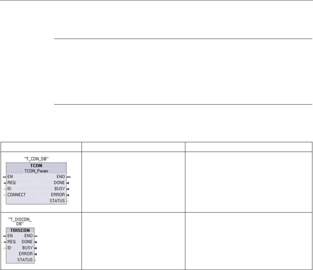
Communication
11.2 PROFINET
S7-1200 Programmable controller
858 System Manual, V4.2, 09/2016, A5E02486680-AK
TCON and TDISCON
Note
Initializing the communication parameters
After you insert the TCON instruction, use the "Properties"
of the instruction (Page 807) to
configure the
communication parameters (Page 832). As you enter the parameters for the
communication partners in the inspector window, STEP
7 enters the corresponding data in
the instanc
e DB for the instruction.
If you want to use a multi
-instance DB, you must manually configure the DB on both CPUs.
Table 11- 20 TCON and TDISCON instructions
LAD / FBD
Description
"TCON_DB"(
req:=_bool_in_,
ID:=_undef_in_,
done=>_bool_out_,
busy=>_bool_out_,
error=>_bool_out_,
status=>_word_out_,
connect:=_struct_inout_);
TCP and ISO on TCP: TCON initiates a commu-
nications connection from the CPU to a commu-
nication partner.
"TDISCON_DB"(
req:=_bool_in_,
ID:=_word_in_,
done=>_bool_out_,
busy=>_bool_out_,
error=>_bool_out_,
status=>_word_out_);
TCP and ISO on TCP: TDISCON terminates a
communications connection from the CPU to a
communication partner.
1 STEP 7 automatically creates the DB when you insert the instruction.

Communication
11.2 PROFINET
S7-1200 Programmable controller
System Manual, V4.2, 09/2016, A5E02486680-AK 859
Table 11- 21 Data types for the parameters of TCON and TDISCON
Parameter
Declaration
Data type
Description
REQ IN Bool Starts the job to establish the connection specified in the ID
upon a rising edge.
ID IN CONN_OUC (Word) Reference to the assigned connection.
Range of values: W#16#0001 to W#16#0FFF
CONNECT
(TCON)
IN_OUT VARIANT Pointer to the connection description
• For TCP or UDP, use the structure TCON_IP_v4
For further information on TCON_IP_v4, refer to: "Pa-
rameters for the PROFINET connection" (Page 832).
• For ISO-on-TCP, use the structure TCON_IP_RFC
For further information on TCON_IP_RFC, refer to: "Pa-
rameters for the PROFINET connection" (Page 832).
DONE OUT Bool Status parameter with the following values:
• 0: Job not yet started or still in progress
• 1: Job executed without errors
BUSY OUT Bool Status parameter with the following values:
• 0: Job not yet started or already completed
• 1: Job not yet completed. A new job cannot be started
ERROR OUT Bool Status parameter ERROR:
• 0: No error
• 1: Error occurred
STATUS
OUT
Word
Status of the instruction
Both communication partners execute the TCON instruction to set up and establish the
communication connection. You use parameters to specify the active and passive
communication end point partners. After the connection is set up and established, it is
automatically maintained and monitored by the CPU.
If the connection is terminated due to a line break or due to the remote communications
partner, for example, the active partner attempts to re-establish the configured connection.
You do not have to execute TCON again.
An existing connection is terminated and the set-up connection is removed when the
TDISCON instruction is executed or when the CPU has gone into STOP mode. To set up
and re-establish the connection, you must execute TCON again.

Communication
11.2 PROFINET
S7-1200 Programmable controller
860 System Manual, V4.2, 09/2016, A5E02486680-AK
Table 11- 22 ERROR and STATUS condition codes for TCON and TDISCON
ERROR
STATUS
(W#16#...)
Explanation
0
0000
Connection successfully established.
0 7000 No job processing active
0
7001
Start job execution; establish connection (TCON) or terminate connection (TDISCON).
0 7002 Connection is being established (REQ irrelevant); establish connection (TCON) or terminate
connection (TDISCON).
1
8085
TCON: Connection ID is already in use.
1
8086
TCON: The ID parameter is outside the valid range.
1
8087
TCON: Maximum number of connections reached; no additional connection possible
1 8089
TCON: The CONNECT parameter does not point to a connection description or the connection
description was created manually.
1
809A
TCON: The structure at the CONNECT parameter is not supported or the length is invalid.
1 809B TCON: The ID of the local device in the connection description does not correspond to the
CPU or the CP, or it is "0".
1
80A0
Group error for error codes W#16#80A1 and W#16#80A2.
1
80A1
TCON: For TCP/UDP (TCON_IP_v4): Connection or port is already in use.
1
80A2
TCON: Local or remote port is being used by the system.
1 80A3 TCON: Value at the ID parameter is already being used by a connection (TCON) that was
created using the user program. The connection uses the identical ID, but different connection
settings at the parameter CONNECT.
1 80A4 TCON: IP address of the remote endpoint of the connection is invalid or it corresponds to the
IP address of the local partner.
1
80A5
TCON: Connection ID is already in use.
1
80A7
TCON: Communication error: You executed "TDISCON" before "TCON" had completed.
1 80B2 TCON: The CONNECT parameter points to a data block that was generated with the attribute
"Only store in load memory".
1 80B3 Inconsistent parameter assignment: Group error for error codes W#16#80A0 to W#16#80A2,
W#16#80A4, W#16#80B4 to W#16#80B9.
1 80B4 TCON: Only with TCON_IP_RFC The local T selector was not specified or the first byte does
not contain the value 0x0E or the local T selector starts with "SIMATIC-".
1 80B5 TCON: Only passive connection establishment is permitted for connection type 13 = UDP
(Parameter active_est of the structure TCON_IP_v4 has the value TRUE)..
1 80B6 TCON: Parameter assignment error in the connection_type parameter of the data block for
connection description.
• Only valid with TCON_IP_v4: 0x11, 0x0B and 0x13.
• Only valid with TCON_IP_RFC: 0x0C and 0x12

Communication
11.2 PROFINET
S7-1200 Programmable controller
System Manual, V4.2, 09/2016, A5E02486680-AK 861
ERROR
STATUS
(W#16#...)
Explanation
1 80B7 TCON: With TCON_IP_v4:
• TCP (active connection establishment): Remote port is "0".
• TCP (passive connection establishment): Local port is "0".
• UDP: Local port is "0".
TCON: With TCON_IP_RFC:
• Local (local_tselector) or remote (remote_tselector) T selector was specified with a length
of more than 32 bytes.
• For TSelLength of the T selector (local or remote), a length greater than 32 was entered.
• Error in the length of the IP address of the specific connection partner.
1 80B8 TCON: Parameter ID in the local connection description (structure at parameter CONNECT)
and parameter ID of the instruction are different.
1
80C3
TCON: All connection (Page 828) resources are in use.
1 80C4 Temporary communication error:
• The connection cannot be established at this time (TCON).
• The interface is currently receiving new parameters (TCON and TDISCON).
• The configured connection is currently being removed by a "TDISCON" instruction (TCON).
1 80C5 TCON: The remote partner refuses to establish the connection, has terminated the connection
or actively ended it.
1
80C6
TCON: The remote partner cannot be reached (network error).
1
80C7
TCON: Execution timeout.
1 80C8 TCON: ID is used by a connection created by the user program, which uses the same connec-
tion description at the CONNECT parameter.
1 80C9 TCON: Validation of the remote partner failed. The remote partner that wants to establish the
connection does not match the defined partner of the structure at the CONNECT parameter.
1
80CE
TCON: The IP address of the local interface is 0.0.0.0.

Communication
11.2 PROFINET
S7-1200 Programmable controller
862 System Manual, V4.2, 09/2016, A5E02486680-AK
TSEND and TRCV
Note
When using PROFINET Open User commun
ication, if you execute a TSEND instruction
without a corresponding TRCV instruction executing on the remote device, then the TSEND
instruction may reside indefinitely in a "Busy State", waiting for the TRCV instruction to
receive the data. In this state,
the TSEND instruction "Busy" output is set, and the "Status"
output has a value of "0x7002". This condition may occur if you are transferring more than
4096 bytes of data. The issue is resolved at the next execution of the TRCV instruction.
Table 11- 23 TSEND and TRCV instructions
LAD / FBD
SCL
Description
"TSEND_DB"(
req:=_bool_in_,
ID:=_word_in_,
len:=_udint_in_,
done=>_bool_out_,
busy=>_bool_out_,
error=>_bool_out_,
status=>_word_out_,
data:=_variant_inout_);
TCP and ISO on TCP: TSEND sends data
through a communication connection from the
CPU to a partner station.
"TRCV_DB"(
en_r:=_bool_in_,
ID:=_word_in_,
len:=_udint_in_,
adhoc:=_bool_in_,
ndr=>_bool_out_,
busy=>_bool_out_,
error=>_bool_out_,
status=>_word_out_,
rcvd_len=>_udint_out_,
data:=_variant_inout_);
TCP and ISO on TCP: TRCV receives data
through a communication connection from a
partner station to the CPU.
1 STEP 7 automatically creates the DB when you insert the instruction.

Communication
11.2 PROFINET
S7-1200 Programmable controller
System Manual, V4.2, 09/2016, A5E02486680-AK 863
Table 11- 24 Data types for the parameters of TSEND and TRCV
Parameter and type
Data type
Description
REQ IN Bool TSEND: Starts the send job on a rising edge. The data is trans-
ferred from the area specified by DATA and LEN.
EN_R
IN Bool TRCV: Enables the CPU to receive; with EN_R = 1, the TRCV is
ready to receive. The receive job is processed.
ID IN CONN_OUC
(Word)
Reference to the associated connection. ID must be identical to
the associated parameter ID in the local connection description.
Value range: W#16#0001 to W#16#0FFF
LEN IN UDInt Maximum number of bytes to be sent (TSEND) or received
(TRCV):
• Default = 0: The DATA parameter determines the length of the
data to be sent (TSEND) or received (TRCV).
• Ad hoc mode = 65535: A variable length of data is set for re-
ception (TRCV).
ADHOC
IN Bool TRCV: Optional parameter (hidden)
Ad hoc mode request for connection type TCP.
DATA IN_OUT Variant Pointer to send (TSEND) or receive (TRCV) data area; data area
contains the address and length. The address refers to I memory,
Q memory, M memory, or a DB.
DONE OUT Bool TSEND:
• 0: Job not yet started or still running.
• 1: Job executed without error.
NDR OUT Bool TRCV:
• NDR = 0: Job not yet started or still running.
• NDR = 1: Job successfully completed.
BUSY OUT Bool • BUSY = 1: The job is not yet complete. A new job cannot be
triggered.
• BUSY = 0: Job is complete.
ERROR OUT Bool ERROR = 1: Error occurred during processing. STATUS provides
detailed information on the type of error
STATUS OUT Word Status information including error information. (Refer to the Error
and Status condition codes in the table below.)
RCVD_LEN
OUT
UDInt
TRCV: Amount of data actually received in bytes
Note
The TSEND instruction requires a low
-to-high transition at the REQ input parameter to start
a send job. The BUSY parameter is then set to 1 during processing. Completion of the send
job is indicated by either t
he DONE or ERROR parameters being set to 1 for one scan.
During this time, any low
-to-high transition at the REQ input parameter is ignored.

Communication
11.2 PROFINET
S7-1200 Programmable controller
864 System Manual, V4.2, 09/2016, A5E02486680-AK
TRCV Operations
The TRCV instruction writes the received data to a receive area that is specified by the
following two variables:
● Pointer to the start of the area
● Length of the area or the value supplied at the LEN input if not 0
Note
The default setting of the LEN parameter (LEN = 0) uses the DATA parameter to
determine the length of the data being transmitted.
It is recommended that the data
transmitted by the TSEND instruction be the same size as the DATA parameter of the
TRCV instruction.
If using the default setting of the LEN parameter and it is necessary to send the data in
segments smaller than the DATA p
arameter size, the following applies. It is
recommended to keep the EN_R bit high until the corresponding TSEND transfers the
appropriate amount of data to fill the TRCV DATA parameter. If the size of the data
transmitted from TSEND does not equal the TRCV
DATA parameter size, TRCV remains
in a busy status (status code: 7002) while the EN_R bit is high until the overall size of the
data transmitted from TSEND equals the TRCV DATA parameter size. If the EN_R bit of
TRCV is pulsed, it needs to be pulsed the s
ame number of times as TSEND is executed
to receive the data.
The TRCV DATA parameter buffer does not display the new data received until the data
size equals the DATA parameter buffer size.
As soon as all the job data has been received, TRCV transfers it to the receive area and sets
NDR to 1.
Table 11- 25 Entering the data into the receive area
Protocol vari-
ant
Entering the data in the
receive area
Parameter
"connection_type"
Value of the LEN parameter
Value of the RCVD_LEN
parameter (bytes)
TCP Ad hoc mode B#16#11 Selected with the TRCV in-
struction ADHOC input
1 to 1472
TCP Data reception with
specified length
B#16#11 0 (recommended) or 1 to
8192, except 65535
1 to 8192
ISO on TCP
Ad hoc mode
B#16#12
65535
1 to 1472
ISO on TCP protocol-controlled B#16#12 0 (recommended) or 1 to
8192, except 65535
1 to 8192

Communication
11.2 PROFINET
S7-1200 Programmable controller
System Manual, V4.2, 09/2016, A5E02486680-AK 865
Note
Ad hoc mode
The "ad hoc mode" exists with the TCP and ISO on TCP protocol variants. To configure the
TRCV instruction for ad hoc mode, set the ADHOC
instruction input parameter. The receive
area is identical to the area formed by DATA. The length of the received data will be output
to the parameter RCVD_LEN. Immediately after receiving a block of data, TRCV enters the
data in the receive area and sets
NDR to 1.
If you store the data in an "optimized" DB (symbolic only), you can receive data only in
arrays of Byte, Char, USInt, and SInt data types.
Note
Importing of S7-300/400 STEP 7 projects containing "ad hoc mode" into the S7-1200
In S7
-300/400 STEP 7 projects, "ad hoc mode" is selected by assigning "0" to the LEN
parameter. In the S7
-1200, you configure the TRCV instruction for ad hoc mode by setting
the ADHOC instruction input parameter.
If you import an S7
-300/400 STEP 7 project containing "ad hoc mode" into the S7-1200, you
must change the LEN parameter to "65535".
Table 11- 26 ERROR and STATUS condition codes for TSEND and TRCV
ERROR
STATUS
Description
0 0000 • Send job completed without error (TSEND)
• New
data accepted: The current length of the received data is shown in RCVD_LEN
(TRCV).
0 7000 • No job processing active (TSEND)
• Block not ready to receive (TRCV)
0 7001 • Start of job processing, data being sent: During this processing the operating sys-
tem accesses the data in the DATA send area (TSEND).
• Block is ready to receive, receive job was activated (TRCV).
0 7002 • Follow-on instruction execution (REQ irrelevant), job being processed: The operat-
ing system accesses the data in the DATA send area during this processing
(TSEND).
• Follow-on instruction execution, receive job being processed: Data is written to the
receive area during this processing. For this reason, an error could result in incon-
sistent data in the receive area (TRCV).
1 8085 • LEN parameter is greater than the largest permitted value (TSEND) and (TRCV).
• LEN or DATA parameter changed since the first instruction execution (TRCV).
1
8086
The ID parameter is not in the permitted address range.
1
8088
The LEN parameter is larger than the memory area specified in DATA.

Communication
11.2 PROFINET
S7-1200 Programmable controller
866 System Manual, V4.2, 09/2016, A5E02486680-AK
ERROR
STATUS
Description
1 80A1 Communications error:
• The specified connection has not yet established (TSEND and TRCV).
• The specified connection is currently being terminated. Transmission or a receive
job over this connection is not possible (TSEND and TRCV).
• The interface is being reinitialized (TSEND).
• The interface is receiving new parameters (TRCV).
1 80C3 Internal lack of connection (Page 828) resources: A block with this ID is already being
processed in a different priority class.
1 80C4 Temporary communications error:
• The connection to the communications partner cannot be established at this time.
• The interface is receiving new parameter settings, or the connection is currently
being established.
Connection Ethernet protocols
Every CPU has an integrated PROFINET port, which supports standard PROFINET
communications. The TSEND_C, TRCV_C, TSEND and TRCV instructions all support the
TCP and ISO on TCP Ethernet protocols.
Refer to "Device Configuration: Configuring the Local/Partner connection path (Page 807)"
for more information.
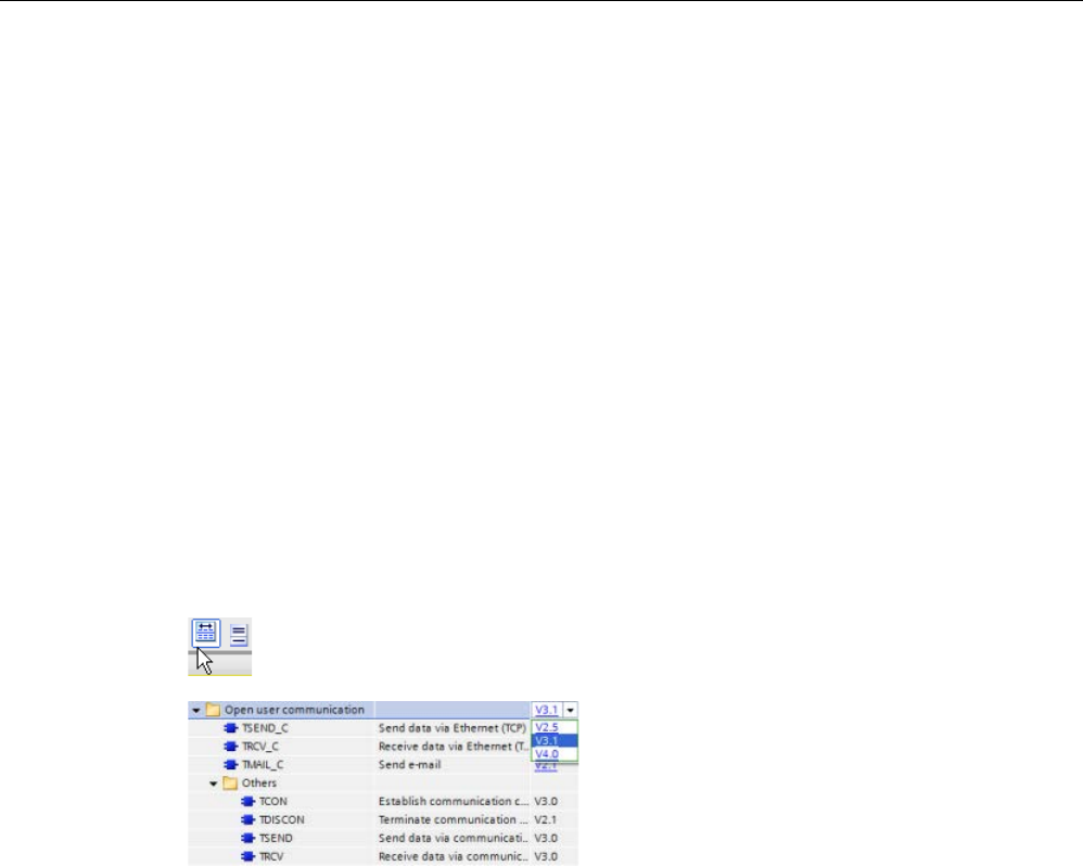
Communication
11.2 PROFINET
S7-1200 Programmable controller
System Manual, V4.2, 09/2016, A5E02486680-AK 867
11.2.8.10
Legacy TCON, TDISCON, TSEND, and TRCV instructions
Prior to the release of STEP 7 V13 SP1 and the S7-1200 V4.1 CPUs, the TCON, TDISCON,
TSEND, and TRCV instructions could only work with connection parameters with structures
according to "TCON_Param". The general concepts apply to both sets of instructions. Refer
to the individual legacy TCON, TDISCON, TSEND, and TRCV instructions for programming
information.
Selecting the version of the TCON, TDISCON, TSEND, and TRCV instructions
There are two versions of the TCON, TDISCON, TSEND, or TRCV instructions available in
STEP 7:
● Versions 2.5 and 3.1 were available in STEP 7 Basic/Professional V13 or earlier.
● Version 4.0 is available in STEP 7 Basic/Professional V13 SP1 or later.
For compatibility and ease of migration, you can choose which instruction version to insert
into your user program.
Do not use different instruction versions in the same CPU program.
Click the icon on the instruction tree task card to enable the headers and columns
of the instruction tree.
To change th
e version of the TCON,
TDISCON, TSEND, or TRCV instructions,
select the version from the drop
-down list.
You can select the group or individual i
n-
structions.
When you use the instruction tree to place a TCON, TDISCON, TSEND, or TRCV instruction
in your program, a new FB or FC instance, depending on the TCON, TDISCON, TSEND, or
TRCV instruction selected, is created in the project tree. You can see new FB or FC instance
in the project tree under PLC_x > Program blocks > System blocks > Program resources.
To verify the version of a TCON, TDISCON, TSEND, or TRCV instruction in a program, you
must inspect project tree properties and not the properties of a box displayed in the program
editor. Select a project tree TCON, TDISCON, TSEND, or TRCV FB or FC instance, right-
click, select "Properties", and select the "Information" page to see the TCON, TDISCON,
TSEND, or TRCV instruction version number.

Communication
11.2 PROFINET
S7-1200 Programmable controller
868 System Manual, V4.2, 09/2016, A5E02486680-AK
Legacy TCON, TDISCON, TSEND, and TRCV (TCP communication) instructions
Ethernet communication using TCP and ISO on TCP protocols
Note
TSEND_C and TRCV_C instructions
To help simplify the programming of PROFINET/Ethernet communication, the TSEND_C
instruction and the TRCV_C instruction combine the functionality of the TCON, TDISCON.
TSEND and TRCV instructions:
•
TSEND_C combines the TCON, TDISCON and TSEND instructions.
•
TRCV_C combines the TCON, TDISCON and TRCV instructions.
The following instructions control the communication process:
● TCON establishes the TCP/IP connection between the client and server (CPU) PC.
● TSEND and TRCV send and receive data.
● TDISCON breaks the connection.
The minimum size of data that you can transmit (TSEND) or receive (TRCV) is one byte; the
maximum size is 8192 bytes. TSEND does not support the transmission of data from
Boolean locations, and TRCV will not receive data into Boolean locations. For information
transferring data with these instructions, see the section on data consistency (Page 198).
TCON, TDISCON, TSEND, and TRCV operate asynchronously, which means that the job
processing extends over multiple instruction executions. For example, you start a job for
setting up and establishing a connection by executing an instruction TCON with parameter
REQ = 1. Then you use additional TCON executions to monitor the job progress and test for
job completion with parameter DONE.
The following table shows the relationships between BUSY, DONE, and ERROR. Use the
table to determine the current job status:
Table 11- 27 Interactions between the BUSY, DONE, and ERROR parameters
BUSY
DONE
ERROR
Description
TRUE
irrelevant
irrelevant
The job is being processed.
FALSE
TRUE
FALSE
The job successfully completed.
FALSE FALSE TRUE The job was ended with an error. The cause of the error can be found in the
STATUS parameter.
FALSE
FALSE
FALSE
A new job was not assigned.

Communication
11.2 PROFINET
S7-1200 Programmable controller
System Manual, V4.2, 09/2016, A5E02486680-AK 869
TCON and TDISCON
Note
Initializing the communication parameters
After yo
u insert the TCON instruction, use the "Properties" of the instruction (Page 807) to
configure the
communication parameters (Page 832). As you enter the parameters for the
communication partners in the inspector window, STEP
7 enters the corresponding data in
the instance DB for the instructio
n.
If you want to use a multi
-instance DB, you must manually configure the DB on both CPUs.
Table 11- 28 TCON and TDISCON instructions
LAD / FBD
Description
"TCON_DB"(
req:=_bool_in_,
ID:=_undef_in_,
done=>_bool_out_,
busy=>_bool_out_,
error=>_bool_out_,
status=>_word_out_,
connect:=_struct_inout_);
TCP and ISO on TCP: TCON initiates a commu-
nications connection from the CPU to a commu-
nication partner.
"TDISCON_DB"(
req:=_bool_in_,
ID:=_word_in_,
done=>_bool_out_,
busy=>_bool_out_,
error=>_bool_out_,
status=>_word_out_);
TCP and ISO on TCP: TDISCON terminates a
communications connection from the CPU to a
communication partner.
1 STEP 7 automatically creates the DB when you insert the instruction.

Communication
11.2 PROFINET
S7-1200 Programmable controller
870 System Manual, V4.2, 09/2016, A5E02486680-AK
Table 11- 29 Data types for the parameters of TCON and TDISCON
Parameter and type
Data type
Description
REQ IN Bool Control parameter REQ starts the job by establishing the
connection specified by ID. The job starts at rising edge.
ID IN CONN_OUC (Word) Reference to the connection to be established (TCON) or
terminated (TDISCON) to the remote partner, or between
the user program and the communication layer of the oper-
ating system. The ID must be identical to the associated
parameter ID in the local connection description.
Value range: W#16#0001 to W#16#0FFF
CONNECT
(TCON)
IN_OUT TCON_Param Pointer to the connection description (Page 832)
DONE OUT Bool • 0: Job is not yet started or still running.
• 1: Job completed without error.
BUSY OUT Bool • 0: Job is completed.
• 1: Job is not yet completed. A new job cannot be trig-
gered.
ERROR OUT Bool Status parameters with the following values:
• 0: No error
• 1: Error occurred during processing. STATUS provides
detailed information on the type of error.
STATUS OUT Word Status information including error information. (Refer to the
Error and Status condition codes in the table below.)
Both communication partners execute the TCON instruction to set up and establish the
communication connection. You use parameters to specify the active and passive
communication end point partners. After the connection is set up and established, it is
automatically maintained and monitored by the CPU.
If the connection is terminated due to a line break or due to the remote communications
partner, for example, the active partner attempts to re-establish the configured connection.
You do not have to execute TCON again.
An existing connection is terminated and the set-up connection is removed when the
TDISCON instruction is executed or when the CPU has gone into STOP mode. To set up
and re-establish the connection, you must execute TCON again.

Communication
11.2 PROFINET
S7-1200 Programmable controller
System Manual, V4.2, 09/2016, A5E02486680-AK 871
Table 11- 30 ERROR and STATUS condition codes for TCON and TDISCON
ERROR
STATUS
Description
0
0000
Connection was established successfully.
0 7000 No job processing active
0 7001 Start job processing; establishing connection (TCON) or terminating connection
(TDISCON)
0 7002 Follow-on call (REQ irrelevant); establishing connection (TCON) or terminating connec-
tion (TDISCON)
1
8086
The ID parameter is outside the permitted address range.
1
8087
TCON: Maximum number of connections reached; no additional connection possible.
1
809B
TCON: The local_device_id in the connection description does not match the CPU.
1
80A1
TCON: Connection or port is already occupied by user.
1
80A2
TCON: Local or remote port is occupied by the system.
1 80A3 Attempt being made to re-establish an existing connection (TCON) or terminate a non-
existent connection (TDISCON).
1 80A4 TCON: IP address of the remote connection end point is invalid; it matches the local
partner IP address.
1
80A5
TCON: Connection ID (Page 828) is already in use.
1 80A7 TCON: Communications error: You executed a TDISCON before the TCON complet-
ed.The TDISCON must first completely terminate the connection referenced by the ID.
1 80B2 TCON: The CONNECT parameter points to a data block that was generated with the
attribute "Only store in load memory".
1 80B4 TCON: When using the ISO on TCP (connection_type = B#16#12) to establish a pas-
sive connection, condition code 80B4 alerts you that the TSAP entered did not conform
to one of the following address requirements:
• For a local TSAP length of 2 and a TSAP ID value of either E0 or E1 (hexadecimal)
for the first byte, the second byte must be either 00 or 01.
• For a local TSAP length of 3 or greater and a TSAP ID value of either E0 or E1
(hexadecimal) for the first byte, the second byte must be either 00 or 01 and all oth-
er bytes must be valid ASCII characters.
• For a local TSAP length of 3 or greater and the first byte of the TSAP ID does not
have a value of either E0 or E1 (hexadecimal), then all bytes of the TSAP ID must
be valid ASCII characters.
Valid ASCII characters are byte values from 20 to 7E (hexadecimal).
1
80B5
TCON: Connection type "13 = UDP" permits only passive connection establishment.
1 80B6 TCON: Parameter assignment error in CONNECTION_TYPE parameter of the SDT
TCON_Param.

Communication
11.2 PROFINET
S7-1200 Programmable controller
872 System Manual, V4.2, 09/2016, A5E02486680-AK
ERROR
STATUS
Description
1 80B7 TCON: Error in one of the following parameters of the data block for connection de-
scription:
• block_length
• local_tsap_id_len
• rem_subnet_id_len
• rem_staddr_len
• rem_tsap_id_len
• next_staddr_len
Note: When operating TCON in TCP passive mode, the LOCAL_TSAP_ID_LEN must
be "2" and the REM_TSAP_ID_LEN must be "0".
1
80B8
TCON: Parameter in the local connection description and Parameter ID are different.
1
80C3
TCON: All connection resources are in use.
1 80C4 Temporary communications error:
• The connection cannot be established at this time (TCON).
• The configured connection is currently being removed by TDISCON (TCON).
• The connection is currently being established (TDISCON).
• The interface is receiving new parameters (TCON and TDISCON).

Communication
11.2 PROFINET
S7-1200 Programmable controller
System Manual, V4.2, 09/2016, A5E02486680-AK 873
TSEND and TRCV
Note
W
hen using PROFINET Open User communication, if you execute a TSEND instruction
without a corresponding TRCV instruction executing on the remote device, then the TSEND
instruction may reside indefinitely in a "Busy State", waiting for the TRCV instruction t
o
receive the data. In this state, the TSEND instruction "Busy" output is set, and the "Status"
output has a value of "0x7002". This condition may occur if you are transferring more than
4096 bytes of data. The issue is resolved at the next execution of th
e TRCV instruction.
Table 11- 31 TSEND and TRCV instructions
LAD / FBD
SCL
Description
"TSEND_DB"(
req:=_bool_in_,
ID:=_word_in_,
len:=_udint_in_,
done=>_bool_out_,
busy=>_bool_out_,
error=>_bool_out_,
status=>_word_out_,
data:=_variant_inout_);
TCP and ISO on TCP: TSEND sends data
through a communication connection from the
CPU to a partner station.
"TRCV_DB"(
en_r:=_bool_in_,
ID:=_word_in_,
len:=_udint_in_,
ndr=>_bool_out_,
busy=>_bool_out_,
error=>_bool_out_,
status=>_word_out_,
rcvd_len=>_udint_out_,
data:=_variant_inout_);
TCP and ISO on TCP: TRCV receives data
through a communication connection from a
partner station to the CPU.
1 STEP 7 automatically creates the DB when you insert the instruction.

Communication
11.2 PROFINET
S7-1200 Programmable controller
874 System Manual, V4.2, 09/2016, A5E02486680-AK
Table 11- 32 Data types for the parameters of TSEND and TRCV
Parameter and type
Data type
Description
REQ IN Bool TSEND: Starts the send job on a rising edge. The data is trans-
ferred from the area specified by DATA and LEN.
EN_R
IN Bool TRCV: Enables the CPU to receive; with EN_R = 1, the TRCV is
ready to receive. The receive job is processed.
ID IN CONN_OUC
(Word)
Reference to the associated connection. ID must be identical to
the associated parameter ID in the local connection description.
Value range: W#16#0001 to W#16#0FFF
LEN IN UInt Maximum number of bytes to be sent (TSEND) or received
(TRCV):
• Default = 0: The DATA parameter determines the length of the
data to be sent (TSEND) or received (TRCV).
• Ad hoc mode = 65535: A variable length of data is set for re-
ception (TRCV).
DATA IN_OUT Variant Pointer to send (TSEND) or receive (TRCV) data area; data area
contains the address and length. The address refers to I memory,
Q memory, M memory, or a DB.
DONE OUT Bool TSEND:
• 0: Job not yet started or still running.
• 1: Job executed without error.
NDR OUT Bool TRCV:
• NDR = 0: Job not yet started or still running.
• NDR = 1: Job successfully completed.
BUSY OUT Bool • BUSY = 1: The job is not yet complete. A new job cannot be
triggered.
• BUSY = 0: Job is complete.
ERROR OUT Bool ERROR = 1: Error occurred during processing. STATUS provides
detailed information on the type of error
STATUS OUT Word Status information including error information. (Refer to the Error
and Status condition codes in the table below.)
RCVD_LEN
OUT
Int
TRCV: Amount of data actually received in bytes
Note
The TSEND instruction requires a low
-to-high transition at the REQ input parameter to start
a send job. The BUSY parameter is then set to 1 during processing. Completion of the send
job is indicated by either the DONE or ERROR parameters being set to 1 for one scan.
During this time, any low
-to-high transition at the REQ input parameter is ignored.

Communication
11.2 PROFINET
S7-1200 Programmable controller
System Manual, V4.2, 09/2016, A5E02486680-AK 875
TRCV Operations
The TRCV instruction writes the received data to a receive area that is specified by the
following two variables:
● Pointer to the start of the area
● Length of the area or the value supplied at the LEN input if not 0
Note
The default setting of the LEN parameter (LEN = 0) uses the DATA parameter to
determine the length of the data being transmitted. It is recommended that the data
transmitted by the TSEND instruction be the same
size as the DATA parameter of the
TRCV instruction.
If using the default setting of the LEN parameter and it is necessary to send the data in
segments smaller than the DATA parameter size, the following applies. It is
recommended to keep the EN_R bit high
until the corresponding TSEND transfers the
appropriate amount of data to fill the TRCV DATA parameter. If the size of the data
transmitted from TSEND does not equal the TRCV DATA parameter size, TRCV remains
in a busy status (status code: 7002) while the
EN_R bit is high until the overall size of the
data transmitted from TSEND equals the TRCV DATA parameter size. If the EN_R bit of
TRCV is pulsed, it needs to be pulsed the same number of times as TSEND is executed
to receive the data.
The TRCV DATA parame
ter buffer does not display the new data received until the data
size equals the DATA parameter buffer size.
As soon as all the job data has been received, TRCV transfers it to the receive area and sets
NDR to 1.
Table 11- 33 Entering the data into the receive area
Protocol vari-
ant
Entering the data in the
receive area
Parameter
"connection_type"
Value of the LEN parameter
Value of the RCVD_LEN
parameter (bytes)
TCP
Ad hoc mode
B#16#11
65535
1 to 1472
TCP Data reception with
specified length
B#16#11 0 (recommended) or 1 to
8192, except 65535
1 to 8192
ISO on TCP
Ad hoc mode
B#16#12
65535
1 to 1472
ISO on TCP protocol-controlled B#16#12 0 (recommended) or 1 to
8192, except 65535
1 to 8192

Communication
11.2 PROFINET
S7-1200 Programmable controller
876 System Manual, V4.2, 09/2016, A5E02486680-AK
Note
Ad hoc mode
The
"ad hoc mode" exists with the TCP and ISO on TCP protocol variants. You set "ad hoc
mode" by assigning "65535" to the LEN parameter. The receive area is identical to the area
formed by DATA. The length of the received data will be output to the parameter
R
CVD_LEN. Immediately after receiving a block of data, TRCV enters the data in the receive
area and sets NDR to 1.
If you store the data in an "optimized" DB (symbolic only), you can receive data only in
arrays of Byte, Char, USInt, and SInt data types.
Note
Importing of S7-300/400 STEP 7 projects containing "ad hoc mode" into the S7-1200
In S7
-300/400 STEP 7 projects, "ad hoc mode" is selected by assigning "0" to the LEN
parameter. In the S7
-1200, you set "ad hoc mode" by assigning "65535" to the LEN
pa
rameter.
If you import an S7
-300/400 STEP 7 project containing "ad hoc mode" into the S7-1200, you
must change the LEN parameter to "65535".
TSEND and TRCV Error and Status condition codes
ERROR
STATUS
Description
0 0000 • Send job completed without error (TSEND)
• New data accepted: The current length of the received data is shown in RCVD_LEN
(TRCV).
0 7000 • No job processing active (TSEND)
• Block not ready to receive (TRCV)
0 7001 • Start of job processing, data being sent: During this processing the operating sys-
tem accesses the data in the DATA send area (TSEND).
• Block is ready to receive, receive job was activated (TRCV).
0 7002 • Follow-on instruction execution (REQ irrelevant), job being processed: The operat-
ing system accesses the data in the DATA send area during this processing
(TSEND).
• Follow-on instruction execution, receive job being processed: Data is written to the
receive area during this processing. For this reason, an error could result in incon-
sistent data in the receive area (TRCV).
1 8085 • LEN parameter is greater than the largest permitted value (TSEND) and (TRCV).
• LEN or DATA parameter changed since the first instruction execution (TRCV).
1
8086
The ID parameter is not in the permitted address range.
1
8088
The LEN parameter is larger than the memory area specified in DATA.

Communication
11.2 PROFINET
S7-1200 Programmable controller
System Manual, V4.2, 09/2016, A5E02486680-AK 877
ERROR
STATUS
Description
1 80A1 Communications error:
• The specified connection has not yet established (TSEND and TRCV).
• The specified connection is currently being terminated. Transmission or a receive
job over this connection is not possible (TSEND and TRCV).
• The interface is being reinitialized (TSEND).
• The interface is receiving new parameters (TRCV).
1 80C3 Internal lack of resources: A block with this ID is already being processed in a different
priority class.
1 80C4 Temporary communications error:
• The connection to the communications partner cannot be established at this time.
• The interface is receiving new parameter settings, or the connection is currently
being established.
Connection Ethernet protocols
Every CPU has an integrated PROFINET port, which supports standard PROFINET
communications. The TSEND_C, TRCV_C, TSEND and TRCV instructions all support the
TCP and ISO on TCP Ethernet protocols.
Refer to "Device Configuration: Configuring the Local/Partner connection path (Page 807)"
for more information.
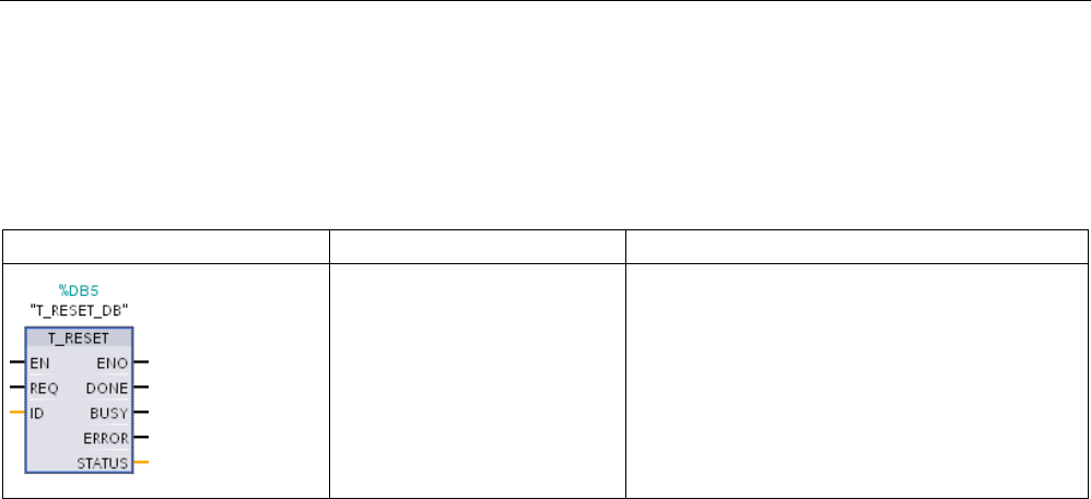
Communication
11.2 PROFINET
S7-1200 Programmable controller
878 System Manual, V4.2, 09/2016, A5E02486680-AK
11.2.8.11
T_RESET (Terminate and re-establish an existing connection) instruction
The "T_RESET" instruction terminates and then re-establishes an existing connection:
Table 11- 34 T_RESET instruction
LAD / FBD
SCL
Description
"T_RESET_DB"(
req:=_bool_in_,
id:=_word_in_,
done=>_bool_out_,
error=>_bool_out_,
sta-
tus=>_word_out_);
Use the T_RESET instruction to terminate and
then re-establish an existing connection.
The local end points of the connection are retained. They are generated automatically:
● If a connection has been configured and loaded to the CPU.
● If a connection has been generated by the user program, for example, by calling the
instruction "TCON (Page 857)".
The "T_RESET" instruction can be executed for all connection types regardless of whether
the local interface of the CPU or the interface of a CM/CP was used for the connection. An
exception to this is connections for data transfer in ad-hoc mode with TCP, as such
connections cannot be referenced with a connection ID.
Once the instruction "T_RESET" has been called using the REQ parameter, the connection
specified with the ID parameter is terminated and, if necessary, the data send and receive
buffer cleared. Canceling the connection also cancels any data transfer in progress. There is
therefore a risk of losing data if data transfer is in progress. The CPU defined as the active
connection partner will then automatically attempt to restore the interrupted communication
connection. You therefore do not need to call the "TCON (Page 857)" instruction to re-
establish the communication connection.
The output parameters DONE, BUSY, and STATUS indicate the status of the job.

Communication
11.2 PROFINET
S7-1200 Programmable controller
System Manual, V4.2, 09/2016, A5E02486680-AK 879
Data types for the parameters
The following table shows the parameters of the "T_RESET" instruction:
Parameter
Declaration
Data type
Memory area
Description
REQ Input BOOL I, Q, M, D, L, T, C or
constant
Control parameter REQUEST starts the job
for terminating the connection specified by ID.
The job starts on a rising edge.
ID Input CONN_OUC
(WORD)
L, D or constant Reference to the connection to the passive
partner which is to be terminated. ID must be
identical to the corresponding parameter ID in
the local connection description.
Range of values: W#16#0001 to W#16#0FFF
DONE Output BOOL I, Q, M, D, L Status parameter DONE
• 0: Job not yet started or still executing.
• 1: Job executed without errors.
BUSY Output BOOL I, Q, M, D, L Status parameter BUSY
• 0: Job is complete.
• 1: Job is not yet complete.
ERROR Output BOOL I, Q, M, D, L Status parameter ERROR
• 0: No error occurred.
• 1: Error occurred during processing. The
STATUS parameter supplies detailed in-
formation on the type of error
STATUS Output WORD I, Q, M, D, L Status parameter STATUS
Error information (see "STATUS parameter"
table).
STATUS parameter
Error bit
STATUS*
(W#16#...)
Description
0
0000
No error.
0
0001
Connection has not been established.
0
7001
Connection termination launched.
0
7002
Connection being terminated.
1
8081
Unknown connection specified at the ID parameter.
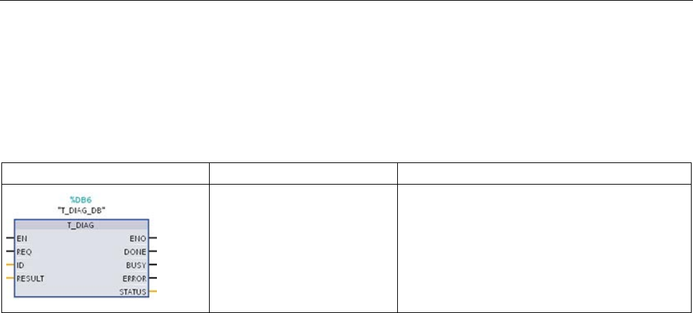
Communication
11.2 PROFINET
S7-1200 Programmable controller
880 System Manual, V4.2, 09/2016, A5E02486680-AK
11.2.8.12
T_DIAG (Checks the status of connection and reads information) instruction
The "T_DIAG" instruction checks the status of a connection and reads further information on
the local end point of this connection:
Table 11- 35 T_DIAG instruction
LAD / FBD
SCL
Description
"T_DIAG_DB"(
req:=_bool_in_,
id:=_word_in_,
done=>_bool_out_,
error=>_bool_out_,
sta-
tus=>_dword_out_);
Use the T_DIAG instruction to check the status of a
connection and read further information on the
local end point of this connection.
The "T_DIAG" instruction operates as follows:
● The connection is referenced by the ID parameter. You can read both connection end
points configured in the connection editor and programmed connection end points (e.g.
with the "TCON" instruction).
Temporary connection end points (for example end points created when you connect to
an engineering station) cannot be diagnosed, as no connection ID is generated in this
process.
● The connection information read is stored in a structure referenced by the RESULT
parameter.
● The output parameter STATUS indicates whether it was possible to read the connection
information. The connection information in the structure at the RESULT parameter is only
valid if the "T_DIAG" instruction has been completed with STATUS = W#16#0000 and
ERROR = FALSE.
Connection information cannot be evaluated if an error occurs.
Possible connection information
The "TDiag_Status" structure can be used to read the connection information at the RESULT
parameter. The TDiag_Status structure only contains the most important information about a
connection end point (for example, the protocol used, the connection status, and the number
of data bytes sent or received).
The structure and parameters of the TDiag_Status structure are described below (see the
"TDIAG_Status structure" table).

Communication
11.2 PROFINET
S7-1200 Programmable controller
System Manual, V4.2, 09/2016, A5E02486680-AK 881
Data types for the parameters
The following table shows the parameters of the "T_DIAG" instruction:
Parameter
Declaration
Data type
Memory area
Description
REQ Input BOOL I, Q, M, D, L, T, C or
constant
Starts the instruction to check the connection
specified in the ID parameter when there is a
positive edge.
ID Input CONN_OUC
(WORD)
L, D or constant Reference to the assigned connection.
Range of values: W#16#0001 to W#16#0FFF
RESULT InOut VARIANT D Pointer to the structure in which the connec-
tion information is stored. The structure TDi-
ag_Status can be used at the RESULT
parameter (for a description, see the
"TDIAG_Status structure" table).
DONE Output BOOL I, Q, M, D, L Status parameter:
• 0: Instruction not yet started or still in pro-
gress.
• 1: Instruction executed without errors.
BUSY Output BOOL I, Q, M, D, L Status parameter:
• 0: Instruction not yet started or already
completed.
•
1: Instruction not yet completed. A new job
cannot be started.
ERROR Output BOOL I, Q, M, D, L Status parameter:
• 0: No error.
• 1: Error occurred.
STATUS
Output
WORD
I, Q, M, D, L
Status of the instruction
Parameters BUSY, DONE, and ERROR
You can check the status of "T_DIAG" instruction execution with the BUSY, DONE, ERROR
and STATUS parameters. The BUSY parameter indicates the processing status. You use
the DONE parameter to check whether or not an instruction has been executed successfully.
The ERROR parameter is set if errors occur during execution of "T_DIAG".
The following table shows the relationship between the BUSY, DONE, and ERROR
parameters:
BUSY
DONE
ERROR
Description
1
-
-
The instruction is being processed.
0 1 0 The instruction has been executed successfully. The data in the structure referenced by
RESULT are only valid if this is the case.
0 0 1 Instruction completed with an error. The cause of the error is output at the STATUS pa-
rameter.
0
0
0
No new instruction has been assigned.

Communication
11.2 PROFINET
S7-1200 Programmable controller
882 System Manual, V4.2, 09/2016, A5E02486680-AK
STATUS parameter
The following table shows the meaning of the values at the STATUS parameter:
Error bit
STATUS*
(W#16#...)
Description
0 0000 The instruction "T_DIAG" has been executed successfully. The data in the structure referenced at
the RESULT parameter can be evaluated.
0 7000 No instruction processing active.
0
7001
Instruction processing launched.
0 7002 Connection information is being read (REQ parameter irrelevant).
1
8086
The value at the ID parameter is outside the valid range (W#16#0001 ... W#16#0FFF).
1 8089 The RESULT parameter points to an invalid data type (structures TDIAG_Status and
TDIAG_StatusExt only).
1 80A3 The ID parameter references a connection end point which does not exist. With programmed
connections, this error can also occur after the "TDISCON" instruction is called.
1
80C4
Internal error. Access to the connection end point is temporarily unavailable.

Communication
11.2 PROFINET
S7-1200 Programmable controller
System Manual, V4.2, 09/2016, A5E02486680-AK 883
TDIAG_Status Structure
The table below details the form of the TDIAG_Status structure. The value of each element
is only valid if the instruction has been executed without errors. If an error occurs, the
content of the parameters will not change:
Name
Data type
Description
The following parameters are in the TDIAG_Status structure:
InterfaceID HW_ANY Interface ID (LADDR) of the CPU or the CM/CP.
ID CONN_OUC ID of the connection diagnosed. Following a successful call, the value of this ele-
ment is identical to the parameter ID of the "T_DIAG" instruction.
ConnectionType BYTE Protocol type used for connection:
• 0x01: Not used.
• ...
• 0x0B: TCP protocol (IP_v4)
• 0x0C: ISO-on-TCP protocol (RFC1006)
• 0x0D: TCP protocol (DNS)
• 0x0E: Dial-in protocol
• 0x0F: WDC protocol
• 0x10: SMTP protocol
• 0x11: TCP protocol
• 0x12: TCP and ISO-on-TCP protocol (RFC1006)
• 0x13: UDP protocol
• 0x14: Reserved
• 0x15: PROFIBUS bus access protocol (FDL)
• 0x16: ISO 8073 transport protocol (ISO native)
• ...
• 0x20: SMTP or SMTPS protocol - based on IPv4
• 0x21: SMTP or SMTPS protocol - based on IPv6
• 0x22: SMTP or SMTPS protocol - based on FQDN (
F
ully
Q
ualified
D
omain
N
ame)
• ...
• 0x70: S7 connection
• Other: Reserved
ActiveEstablished BOOL • FALSE: Locally, the passive connection end point
• TRUE: Locally, the active connection end point

Communication
11.2 PROFINET
S7-1200 Programmable controller
884 System Manual, V4.2, 09/2016, A5E02486680-AK
Name
Data type
Description
State BYTE Current status of the connection end point
• 0x00: Not used.
• 0x01: Connection terminated. Temporary status, for example, after the
"T_RESET" instruction is called. The system then automatically attempts to re-
establish the connection.
• 0x02: The active connection end point is attempting to establish a connection to
the remote communication partner.
• 0x03: The passive connection end point is waiting for establishment of the con-
nection to the remote communication partner.
• 0x04: Connection established.
• 0x05: The connection is being terminated. This may be because the "T_RESET"
or "T_DISCON" instruction has been called. Other possible reasons are protocol
errors and line breaks.
• 0x06..0xFF: Not used.
Kind BYTE Mode of the connection end point:
• 0x00: Not used.
• 0x01: Configured, static connection which has been configured and loaded to
the CPU.
•
0x02: Configured, dynamic connection which has been configured and loaded to
the CPU (not currently supported).
• 0x03: Programmed connection generated in the user program with the instruc-
tion "TCON". A call of the instruction "TDISCON" or a transition to CPU STOP
status has destroyed the connection end point.
• 0x04: Temporary, dynamic connection established by the engineering station
(ES) or operator station (OS), for example. (this connection type cannot current-
ly be diagnosed as there is no ID).
• 0x05..0xFF: Not used.
SentBytes
UDINT
Number of data bytes sent.
ReceivedBytes
UDINT
Number of data bytes received.

Communication
11.2 PROFINET
S7-1200 Programmable controller
System Manual, V4.2, 09/2016, A5E02486680-AK 885
11.2.8.13
TMAIL_C (Send an email using the Ethernet interface of the CPU) instruction
Overview
You use the "TMAIL_C" instruction to send an e-mail using the Ethernet interface of the S7-
1200 CPU.
The TMAIL_C instruction has two functionalities:
● Email over the CPU Interface (only SMTP without SSL)
● Email over a CP Interface (either SMTP without SSL or SMTP with SSL) If you want to
use the SSL functionality, you must set the TMAIL_C input parameter CERTINDEX = 1
and use the CP Interface. Also, the correct certificate must be stored in CP cert storage.
The instruction can only be used once the hardware has been configured and if the network
infrastructure allows for a communication connection to the mail server.
Table 11- 36 TMAIL_C instruction
LAD / FBD
SCL
Description
"TMAIL_C_DB"(
req:=_bool_in_,
to_s:=_string_in_,
cc:=_string_in_,
subject:=_string_in_,
text:=_string_in_,
attachment:=_variant_in_,
attachment_name:=_string_in_,
mail_addr_param:=_string_in_,
done=>_bool_out_,
busy=>_bool_out_,
error=>_bool_out_,
status=>_word_out_);
The TMAIL_C instruction sends
an e-mail using the Ethernet
interface of the S7-1200 CPU.
1 STEP 7 automatically creates the DB when you insert the instruction.

Communication
11.2 PROFINET
S7-1200 Programmable controller
886 System Manual, V4.2, 09/2016, A5E02486680-AK
You define the content of the e-mail, and the connection data, using the following
parameters:
● You define the recipient addresses with the parameters TO_S and CC.
● You define the content of the e-mail with the parameters SUBJECT and TEXT.
● You can define an attachment using VARIANT pointers at the ATTACHMENT and
ATTACHMENT_NAME parameters.
● The connection data are defined, and addressing and authentication for the mail server
executed, using the system data type Tmail_v4 or Tmail_FQDN at the
MAIL_ADDR_PARAM parameter. If you are using the interface of the S7-1200 CPU, the
system data type Tmail_v4 must be used. In this case, the e-mail can only be sent using
SMTP.
● You start the sending of an e-mail with an edge change from "0" to "1" for the REQ
parameter.
● The job status is indicated by the output parameters "BUSY", "DONE", "ERROR" and
"STATUS".
You cannot send an SMS directly with the "TMAIL_C" instruction. Whether or not the e-mail
can be forwarded by the mail server as an SMS depends on your telecommunications
provider.
Operation of the instruction
The "TMAIL_C" instruction works asynchronously, which means its execution extends over
multiple calls. You must specify an instance when you call the instruction "TMAIL_C".
In the following cases, the connection to the mail server will be lost:
● If the CPU switches to STOP while "TMAIL_C" is active.
● If communication problems occur at the Industrial Ethernet bus. In this case, the transfer
of the e-mail will be interrupted and it will not reach its recipient.
The connection is also canceled once the instruction has been successfully executed and
the e-mail sent.
NOTICE
Changing user programs
You can change the parts of your user program that directly affect calls of "TMAIL_C" only
when:
• The CPU is in "STOP" mode.
• No e-mail is being sent (REQ = 0 and BUSY = 0).
This relates, in particular, to deleting and replacing program blocks that contain "TMAIL_C"
calls or calls for the instance of "TMAIL_C".
Ignoring this restriction can tie up connection resources. The automation system can
change to an undefined status with the TCP/IP communication functions via Industrial
Ethernet.
A warm or cold restart of the CPU is required after the changes are transferred.

Communication
11.2 PROFINET
S7-1200 Programmable controller
System Manual, V4.2, 09/2016, A5E02486680-AK 887
Data consistency
The TO_S, CC, SUBJECT, TEXT, ATTACHMENT and MAIL_ADDR_PARAM parameters
are applied by the "TMAIL_C" instruction while it is running, which means that they may only
be changed after the job has been completed (BUSY = 0).
SMTP authentication
Authentication refers here to a procedure for verifying identity, for example, with a password
query.
If you are using the S7-1200 CPU interface, the instruction "TMAIL_C" supports the SMTP
authentication procedure AUTH-LOGIN which is required by most mail servers. For
information about the authentication procedure of your mail server, please refer to your mail
server manual or the website of your Internet service provider.
● Before you can use the AUTH-LOGIN authentication procedure, the "TMAIL_C"
instruction requires the user name with which it is to log on to the mail server. This user
name corresponds to the user name with which you set up a mail account on your mail
server. It is transferred via the UserName parameter to the structure at parameter
MAIL_ADDR_PARAM.
If no user name is specified at the MAIL_ADDR_PARAM parameter, the AUTH-LOGIN
authentication procedure is not used. The e-mail is then sent without authentication.
● To log on, the "TMAIL_C" instruction also requires the associated password. This
password corresponds to the password you specified when you set up your mail account.
It is transferred via the PassWord parameter to the structure at parameter
MAIL_ADDR_PARAM.

Communication
11.2 PROFINET
S7-1200 Programmable controller
888 System Manual, V4.2, 09/2016, A5E02486680-AK
Data types for the parameters
The following table shows the parameters of the "TMAIL_C" instruction:
Parameter
Declaration
Data type
Memory
area
Description
REQ Input BOOL I, Q, M, D,
L, T, C or
constant
Control parameter REQUEST: Acti-
vates the sending of an e-mail upon a
rising edge.
TO_S
(Page 891)
Input STRING D Recipient addresses
STRING with a maximum length of 180
characters (bytes).
For the e-mail address format, please
see the example in the parameter
description.
CC
(Page 891)
Input STRING D CC recipient addresses (optional)
STRING with a maximum length of 180
characters (bytes).
Same e-mail address format as for the
TO_S parameter. If an empty string is
assigned here, the e-mail is not sent to
a CC recipient.
SUBJECT Input STRING D Subject of the e-mail
STRING with a maximum length of 180
characters (bytes).
TEXT Input STRING D Text of the e-mail (optional)
STRING with a maximum length of 180
characters (bytes). If an empty string is
assigned at this parameter, the e-mail
is sent without text.
ATTACHMEN
T
Input VARIANT D E-mail attachment (optional)
Reference to a byte/word/double word
field (ArrayOfByte, ArrayOfWord or
ArrayOfDWord) with a maximum length
of 64 bytes. If no value is assigned, the
e-mail is sent without an attachment.
ATTACHMEN
T_NAME
Input VARIANT D E-mail attachment name (optional)
Reference to a character string with a
maximum length of 50 characters
(bytes) to define the file name of the
attachment. If an empty string is as-
signed at this parameter, the e-mail
attachment will be sent with the file
name "attachment.bin".
MAIL_ADDR_
PARAM
(Page 890)
Input VARIANT D Connection parameter and address of
the e-mail server
To define the connection parameters,
use the structure Tmail_v4 or
Tmail_FQDN (see parameter descrip-
tion).

Communication
11.2 PROFINET
S7-1200 Programmable controller
System Manual, V4.2, 09/2016, A5E02486680-AK 889
Parameter
Declaration
Data type
Memory
area
Description
DONE
(Page 892)
Output BOOL I, Q, M, D, L Status parameter
• DONE = 0: Job not yet started or
still executing.
• DONE = 1: Job was executed with-
out errors.
BUSY
(Page 892)
Output BOOL I, Q, M, D, L Status parameter
• BUSY=0: The processing of
"TMAIL_C" was stopped.
• BUSY = 1: E-mail transmission is
not yet complete.
ERROR
(Page 892)
Output BOOL I, Q, M, D, L Status parameter
• ERROR = 0: No error has occu-
rred.
• ERROR = 1: An error occurred
during processing. STATUS sup-
plies detailed information on the
type of error.
STATUS
(Page 892)
Output WORD I, Q, M, D, L Status parameter
Return value or error information of the
"TMAIL_C" instruction (see parameter
description).
You will find more detailed information on valid data types in "Overview of valid data types".
Note
Optional parameters
The optional parameters CC, TEXT, and ATTACHMENT are only sent with the e
-mail if the
corresponding parameters contain a string of length >
0.

Communication
11.2 PROFINET
S7-1200 Programmable controller
890 System Manual, V4.2, 09/2016, A5E02486680-AK
MAIL_ADDR_PARAM parameter
At the MAIL_ADDR_PARAM parameter, you define the connection for sending the e-mail in
the structure Tmail_v4 or Tmail_FQDN, and save the e-mail server address and login details.
The structure you use at the MAIL_ADDR_PARAM parameter depends on the format in
which the e-mail server is to be addressed:
● Tmail_v4: Addressing by IP address (IPv4).
● Tmail_FQDN: Addressing by fully qualified domain name (FQDN).
Which structure you can use depends on the interface addressed at the InterfaceId
parameter. If you want to use the "TMAIL_C" instruction with the internal interface, the
structure Tmail_v4 must be used at the MAIL_ADDR_PARAM parameter.
Table 11- 37
Tmail_v4: Addressing the mail server by IP address (IPv4)
Parameter
Data type
Description
Tmail_v4
Struct
InterfaceId LADDR Hardware identifier of the interface
ID
CONN_OUC
Connection ID
ConnectionType BYTE Connection type. Select 16#20 as the connection type for
IPv4.
ActiveEstablished
BOOL
Status bit. Set to "1" once the connection is established.
CertIndex BYTE =0: SMTP used (
S
imple
M
ail
T
ransfer
P
rotocol). SMTP
must be used if the e-mail is being sent via the interface of
an S7-1200 CPU.
WatchDogTime TIME Execution watchdog. Use this parameter to define the
maximum execution time for the send operation.
Note: Connection establishment can take longer (approx.
one minute) if the connection is slow. When you specify the
WATCH_DOG_TIME parameter, remember to allow for the
time required to establish the connection.
The connection is terminated once the specified time has
elapsed.
MailServerAddress IP_v4 IP address of the mail server. IPv4 in the following format:
XXX.XXX.XXX.XXX (decimal).
Example: 192.142.131.237.
UserName STRING[254] Mail server login name
PassWord
STRING[254]
Mail server password
From EMAIL_ADDR E-
mail sender address, which is defined using the following
two STRING parameters. For example: "my-
name@mymailserver.com".
Local-
PartPlusAtSign
STRING[64] Local part of sender address, including @ sign. Example:
"myname@".
FullQualified-
DomainName
STRING[254] Fully Qualified Domain Name ( FQDN for short) of the mail
server. Example: "mymailserver.com".

Communication
11.2 PROFINET
S7-1200 Programmable controller
System Manual, V4.2, 09/2016, A5E02486680-AK 891
Table 11- 38
Tmail_FQDN: Addressing the mail server by FQDN
Parameter
Data type
Description
Tmail_v6
Struct
Tmail_FQDN LADDR Hardware identifier of the interface
ID
CONN_OUC
Connection ID
ConnectionType BYTE Connection type. Select 16#22 as the connection type for
FQDN.
ActiveEstablished
BOOL
Status bit. Set to "1" once the connection is established.
CertIndex BYTE =0: SMTP used (
S
imple
M
ail
T
ransfer
P
rotocol). SMTP
must be used if the e-mail is being sent via the interface of
an S7-1200 CPU.
WatchDogTime TIME Execution watchdog. Use this parameter to define the max-
imum execution time for the send operation.
Note: Connection establishment can take longer (approx.
one minute) if the connection is slow. When you specify the
WATCH_DOG_TIME parameter, remember to allow for the
time required to establish the connection.
The connection is terminated once the specified time has
elapsed.
MailServerAddress STRING[254] FQDN (
F
ully
Q
ualified
D
omain
N
ame) of the mail server.
The mail server is addressed using the fully qualified do-
main name.
Example: "www.mymailserver.com.".
UserName
STRING[254]
Mail server login name
PassWord
STRING[254]
Mail server password
From Struct E-mail sender address, which is defined using the following
two STRING parameters. For example: "my-
name@mymailserver.com".
Local-
PartPlusAtSign
STRING[64] Local part of sender address, including @ sign. Example:
"myname@".
FullQualified-
DomainName
STRING[254] Fully Qualified Domain Name (FQDN for short) of the mail
server. Example: "mymailserver.com".
TO_S and CC parameters
The TO_S and CC parameters are strings, for example, with the following content:
● <wenna@mydomain.com>, <ruby@mydomain.com>
● <admin@mydomain.com>, <judy@mydomain.com>
Note the following rules when entering the parameters:
● A space and an opening pointed bracket "<" must be entered before each address.
● A closing pointed bracket ">" must be entered after each address.
● A comma must be entered between the addresses in TO and CC.
For runtime and memory space reasons, the "TMAIL_C" instruction does not perform a
syntax check of parameter TO_S or CC

Communication
11.2 PROFINET
S7-1200 Programmable controller
892 System Manual, V4.2, 09/2016, A5E02486680-AK
DONE, BUSY and ERROR parameters
The output parameters DONE, BUSY and ERROR are each displayed for only one cycle if
the status of the BUSY output parameter changes from "1" to "0".
The following table shows the relationship between DONE, BUSY, and ERROR. Using this
table, you can determine the current status of the instruction "TMAIL_C and when the
sending of the e-mail is complete.
DONE
BUSY
ERROR
Description
0
1
0
The job is being processed.
1 0 0 Job successfully completed.
0 0 1 The job ended with an error. The cause of the error can be
found in the STATUS (Page 892) parameter.
0 0 0 The "TMAIL_C" instruction was not assigned a (new) job.
STATUS parameter
The following table shows the return values of TMAIL_C at the STATUS parameter:
Return val-
ue
STATUS*
(W#16#...):
Explanation
Notes
0000 The processing of TMAIL_C was
completed without errors.
Error-free completion of TMAIL_C does not
mean that the e-mail sent will necessarily
arrive.
Incorrectly entering the recipient addresses
does not generate a status error of the
TMAIL_C instruction. In this case, there is no
guarantee that the e-mail will be sent to other
recipients, even if these were entered correct-
ly.
7001
TMAIL_C is active (BUSY = 1).
First call: Job triggered.
7002
TMAIL_C is active (BUSY = 1).
Intermediate call: Job already active.
8xxx The processing of TMAIL_C was
completed with an error code of the
communication instructions called
internally.
For detailed information, refer to the STATUS
parameter descriptions for the TCON,
TDISCON, TSEND and TRCV (Page 857)
communication instructions.
8010 Error during connection establishment You will find further information on evaluation
in the SFB_STATUS parameter of the instance
data block. The error code displayed at the
SFB_STATUS parameter is explained in the
STATUS parameter description for the TCON
(Page 857) instruction.
8011 Error sending the data You will find further information on evaluation
in the SFB_STATUS parameter of the instance
data block. The error code displayed at the
SFB_STATUS parameter is explained in the
STATUS parameter description for the TSEND
(Page 857) instruction.

Communication
11.2 PROFINET
S7-1200 Programmable controller
System Manual, V4.2, 09/2016, A5E02486680-AK 893
Return val-
ue
STATUS*
(W#16#...):
Explanation
Notes
8012 Error receiving the data You will find further information on evaluation
in the SFB_STATUS parameter of the instance
data block. The error code displayed at the
SFB_STATUS parameter is explained in the
STATUS parameter description for the TRCV
(Page 857) instruction.
8013 Error during connection establishment You will find further information on evaluation
in the SFB_STATUS parameter of the instance
data block. The error code displayed at the
SFB_STATUS parameter is explained in the
STATUS parameter description for the TCON
(Page 857) and TDISCON (Page 857) instruc-
tions.
8014 Establishment of a connection is not
possible.
You may have entered an incorrect mail server
IP address (MailServerAddress (Page 890)) or
too short a time span (WatchDogTime
(Page 890)) for connection establishment. It is
also possible that the CPU has no connection
to the network or that the CPU configuration is
incorrect.
8015 Incorrect data type for
MAIL_ADDR_PARAM
The only valid data types are the system data
types (structures) Tmail_v4 and TMail_FQDN.
8016 Incorrect data type for the
ATTACHMENT parameter
The only valid data types are ArrayOfByte,
ArrayOfWord and ArrayOfDWord.
8017 Incorrect data length for the
ATTACHMENT parameter
Data length must be <= 65534 bytes.
82xx, 84xx,
or 85xx
The error message originates from
the mail server and corresponds,
except for the "8", to the error number
of the SMTP protocol.
The following lines list several error
codes that can occur.
You will find more detailed information on the
SMTP error code and other error codes in the
SMTP protocol on the Internet or in the error
documentation of the mail server. You can
also view the most recent error message from
the mail server in your instance DB in the
BUFFER1 parameter. You will find the last
data sent by the TMAIL_C instruction under
DATEN in the instance DB.
8450 Action not executed: Mailbox not
available/cannot be reached
Try again later.
8451
Action aborted: Local processing error
Try again later.
8500 Syntax error: Error not recognized.
This also includes the error when a
command string is too long. This can
also occur when the e-mail server
does not support the LOGIN authenti-
cation procedure.
Check the parameters of TMAIL_C. Try to
send an e-mail without authentication. To do
this, replace the content of the UserName
parameter with an empty string. If no user
name is specified, the LOGIN authentication
procedure is not used.
8501 Syntax error: Incorrect input at a pa-
rameter
Possible cause: Incorrect address at the TO_S
or CC parameter (see also: TO_S and CC
parameters (Page 891)).

Communication
11.2 PROFINET
S7-1200 Programmable controller
894 System Manual, V4.2, 09/2016, A5E02486680-AK
Return val-
ue
STATUS*
(W#16#...):
Explanation
Notes
8502 Command unknown or not imple-
mented
Check your entries, in particular the FROM
parameter. It may be incomplete and you may
have forgotten the "@" or "." (see also: TO_S
and CC parameters (Page 891)).
8535 SMTP authentication incomplete You have possibly entered an incorrect user
name or incorrect password.
8550 Mail server cannot be reached. You
have no access rights.
You may have entered an incorrect user name
or password, or the mail server may not sup-
port your login. Another cause of error could
be a mistake in the domain name after the "@"
at the TO_S or CC parameter (see also: TO_S
and CC parameters (Page 891)).
8552 Action aborted: Assigned memory
size has been exceeded
Try again later.
8554
Transfer failed
Try again later.
* You can display error codes as integer or hexadecimal values in the program editor.
11.2.8.14
UDP
UDP is a standard protocol described by RFC 768: User Datagram Protocol. UDP provides a
mechanism for one application to send a datagram to another; however, delivery of data is
not guaranteed. This protocol has the following features:
● A quick communications protocol
● Suitable for small-sized to medium data amounts (up to 1472 bytes)
● UDP is a simpler transport control protocol than TCP, with a thin layer that yields low
overheads
● Can be used very flexibly with many third-party systems
● Routing-capable
● Uses port numbers to direct the datagrams
● Messages are unacknowledged: The application is required to take responsibility for error
recovery and security
● Programming effort is required for data management due to the SEND / RECEIVE
programming interface
UDP supports broadcast communication. To use broadcast, you must configure the IP
address portion of the ADDR configuration. For example: A CPU with an IP address of
192.168.2.10 and subnet mask of 255.255.255.0 would use a broadcast address of
192.168.2.255.

Communication
11.2 PROFINET
S7-1200 Programmable controller
System Manual, V4.2, 09/2016, A5E02486680-AK 895
11.2.8.15
TUSEND and TURCV
The following instructions control the UDP communication process:
● TCON establishes the communication between the client and server (CPU) PC.
● TUSEND and TURCV send and receive data.
● TDISCON disconnects the communication between the client and server.
Refer to TCON, TDISCON, TSEND, and TRCV (Page 857) in the "TCP and ISO-on-TCP"
section for more information on the TCON and TDISCON communication instructions.
Table 11- 39 TUSEND and TURCV instructions
LAD / FBD
SCL
Description
"TUSEND_DB"(
req:=_bool_in_,
ID:=_word_in_,
len:=_udint_in_,
done=>_bool_out_,
busy=>_bool_out_,
error=>_bool_out_,
status=>_word_out_,
data:=_variant_inout_);
The TUSEND instruction sends data via UDP to
the remote partner specified by the parameter
ADDR.
To start the job for sending data, call the TUSEND
instruction with REQ = 1.
"TURCV_DB"(
en_r:=_bool_in_,
ID:=_word_in_,
len:=_udint_in_,
ndr=>_bool_out_,
busy=>_bool_out_,
error=>_bool_out_,
status=>_word_out_,
rcvd_len=>_udint_out_,
data:=_variant_inout_);
The TURCV instruction receives data via UDP.
The parameter ADDR shows the address of the
sender. After successful completion of TURCV, the
parameter ADDR contains the address of the re-
mote partner (the sender).
TURCV does not support ad hoc mode.
To start the job for receiving data, call the TURCV
instruction with EN_R = 1.
1 STEP 7 automatically creates the DB when you insert the instruction.
TCON, TDISCON, TUSEND, and TURCV operate asynchronously, which means that the job
processing extends over multiple instruction executions.

Communication
11.2 PROFINET
S7-1200 Programmable controller
896 System Manual, V4.2, 09/2016, A5E02486680-AK
Table 11- 40 TUSEND and TURCV data types for the parameters
Parameter and type
Data type
Description
REQ
(TUSEND)
IN Bool
Starts the send job on a rising edge. The data is transferred from
the area specified by DATA and LEN.
EN_R
(TURCV)
IN Bool • 0: CPU cannot receive.
• 1: Enables the CPU to receive. The TURCV instruction is
ready to receive, and the receive job is processed.
ID IN Word Reference to the associated connection between the user pro-
gram and the communication level of the operating system. ID
must be identical to the associated parameter ID in the local
connection description.
Range of values: W#16#0001 to W#16#0FFF.
LEN IN UDInt Number of bytes to be sent (TUSEND) or received (TURCV).
• Default = 0. The DATA parameter determines the length of
the data to be sent or received.
• Otherwise, range of values: 1 to 1472
DONE
(TUSEND)
IN Bool Status parameter DONE (TUSEND):
• 0: Job is not yet started or still running.
• 1: Job completed without error.
NDR
(TURCV)
OUT Bool Status parameter NDR (TURCV):
• 0: Job not yet started or still running.
• 1: Job has successfully completed.
BUSY OUT Bool • 1: Job is not yet completed. A new job cannot be triggered.
• 0: Job has completed.
ERROR OUT Bool Status parameters with the following values:
• 0: No error
• 1: Error occurred during processing. STATUS provides de-
tailed information on the type of error.
STATUS OUT Word
Status information including error information. (Refer to the Error
and Status condition codes in the table below.)
RCVD_LEN
OUT
UDInt
Number of bytes received (TURCV)

Communication
11.2 PROFINET
S7-1200 Programmable controller
System Manual, V4.2, 09/2016, A5E02486680-AK 897
Parameter and type
Data type
Description
DATA IN_OUT Variant Address of the sender area (TUSEND) or receive area
(TURCV):
• The process image input table
• The process image output table
• A memory bit
• A data block
ADDR IN_OUT Variant Pointer to the address of the receiver (for TUSEND) or sender
(for TURCV) (for example, P#DB100.DBX0.0 byte 8). The point-
er may point to any memory area.
A structure of 8 bytes is required as follows:
• First 4 bytes contain the remote IP address.
• Next 2 bytes specify the remote port number.
• Last 2 bytes are reserved.
The job status is indicated at the output parameters BUSY and STATUS. STATUS
corresponds to the RET_VAL output parameter of asynchronously functioning instructions.
The following table shows the relationships between BUSY, DONE (TUSEND), NDR
(TURCV), and ERROR. Using this table, you can determine the current status of the
instruction (TUSEND or TURCV) or when the sending (transmission) / receiving process is
complete.
Table 11- 41 Status of BUSY, DONE (TUSEND) / NDR (TURCV), and ERROR parameters
BUSY
DONE / NDR
ERROR
Description
TRUE
irrelevant
irrelevant
The job is being processed.
FALSE
TRUE
FALSE
The job was completed successfully.
FALSE FALSE TRUE The job was ended with an error. The cause of the error can be
found in the STATUS parameter.
FALSE
FALSE
FALSE
The instruction was not assigned a (new) job.
1
Due to the asynchronous function of the instructions: For TUSEND, you must keep the data in the sender area con-
sistent until the DONE parameter or the ERROR parameter assumes the value TRUE. For TURCV, the data in the re-
ceiver area are only consistent when the NDR parameter assumes the value TRUE.

Communication
11.2 PROFINET
S7-1200 Programmable controller
898 System Manual, V4.2, 09/2016, A5E02486680-AK
Table 11- 42 TUSEND and TURCV condition codes for ERROR and STATUS
ERROR
STATUS
Description
0 0000 • Send job completed without error (TUSEND).
• New data were accepted. The current length of the received data is shown in
RCVD_LEN (TURCV).
0 7000 • No job processing active (TUSEND)
• Block not ready to receive (TURCV)
0 7001 • Start of job processing, data being sent (TUSEND): During this processing, the
operating system accesses the data in the DATA send area.
• Block is ready to receive, receive job was activated (TURCV).
0 7002 • Follow-on instruction execution (REQ irrelevant), job being processed (TUSEND):
During this processing, the operating system accesses the data in the DATA send
area.
• Follow-on instruction execution, job being processed: During this processing, the
TURCV instruction writes data to the receive area. For this reason, an error could
result in inconsistent data in the receive area.
1 8085 LEN parameter is greater than the largest permitted value, has the value 0 (TUSEND),
or you changed the value of the LEN or DATA parameter since the first instruction exe-
cution (TURCV).
1 8086 The ID parameter is not in the permitted address range.
1 8088 • LEN parameter is larger than the memory area (TUSEND) or receive area (TURCV)
specified in DATA.
• Receive area is too small (TURCV).
1
8089
ADDR parameter does not point to a data block.
1 80A1 Communications error:
• The specified connection between user program and communications layer of the
operating system has not yet been established.
• The specified connection between the user program and the communication layer of
the operating system is currently being terminated. Transmission (TUSEND) or a re-
ceive job (TURCV) over this connection is not possible.
• The interface is being reinitialized.
1 80A4 IP address of the remote connection end point is invalid; it is possible that it matches
the local IP address (TUSEND).
1 80B3 • The set protocol variant (connection_type parameter in the connection description)
is not UDP. Please use the TSEND or TRCV instruction.
• ADDR parameter: Invalid settings for port number (TUSEND)
1 80C3 • A block with this ID is already being processed in a different priority class.
• Internal lack of resources
1 80C4 Temporary communications error:
• The connection between the user program and the communication level of the oper-
ating system cannot be established at this time (TUSEND).
• The interface is receiving new parameters (TUSEND).
• The connection is currently being reinitiated (TURCV).
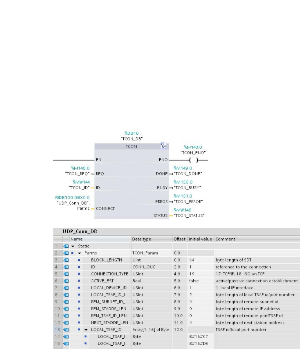
Communication
11.2 PROFINET
S7-1200 Programmable controller
System Manual, V4.2, 09/2016, A5E02486680-AK 899
Connection Ethernet protocols
Every CPU has an integrated PROFINET port, which supports standard PROFINET
communications. The TUSEND and TURCV instructions support the UDP Ethernet protocol.
Refer to "Configuring the Local/Partner connection path" (Page 807)" in the "Device
configuration" chapter for more information.
Operations
Both partners are passive in UDP communication. Typical parameter start values for the
"TCON_Param" data type are shown in the following figures. Port numbers
(LOCAL_TSAP_ID) are written in a 2-byte format. All ports except for 161, 34962, 34963,
and 34964 are allowed.
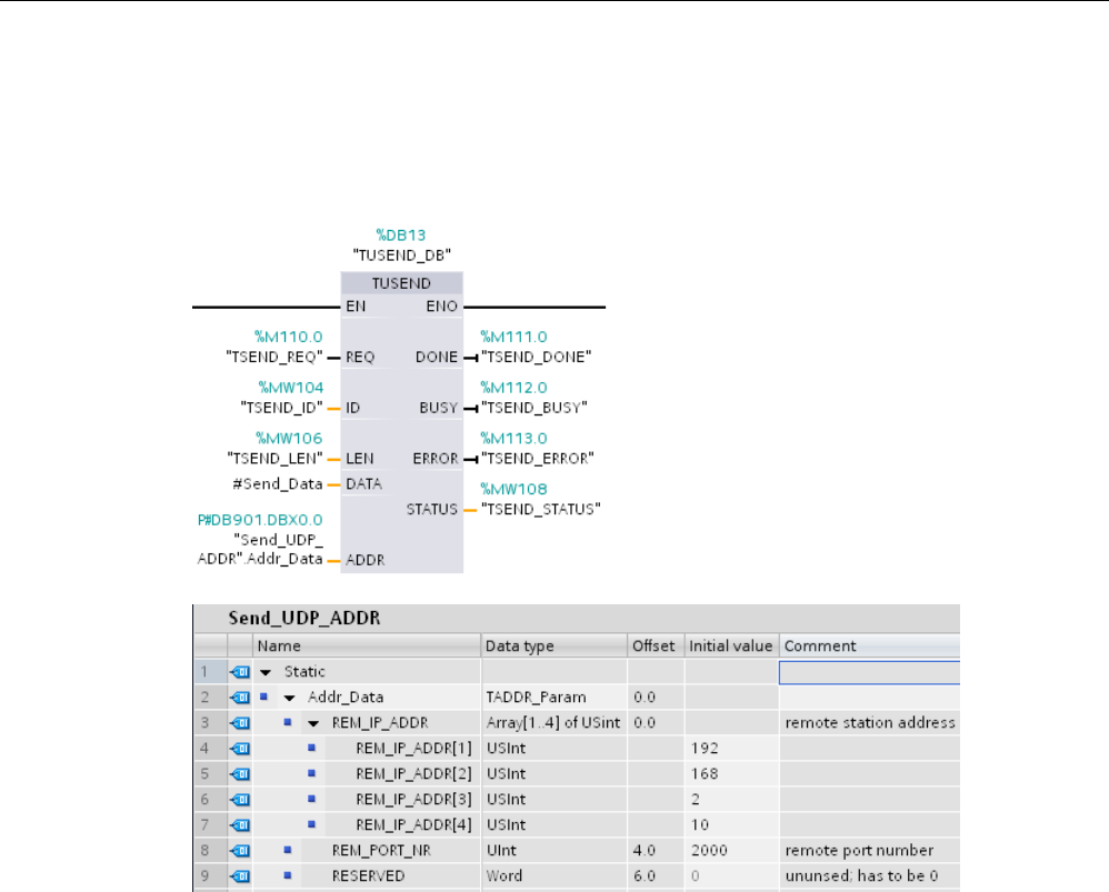
Communication
11.2 PROFINET
S7-1200 Programmable controller
900 System Manual, V4.2, 09/2016, A5E02486680-AK
The TUSEND instruction sends data through UDP to the remote partner specified in the
"TADDR_Param" data type. The TURCV instruction receives data through UDP. After a
successful execution of the TURCV instruction, the "TADDR_Param" data type shows the
address of the remote partner (the sender), as shown in the figures below.

Communication
11.2 PROFINET
S7-1200 Programmable controller
System Manual, V4.2, 09/2016, A5E02486680-AK 901
11.2.8.16
T_CONFIG
The T_CONFIG instruction can change the Ethernet address, the PROFINET device name,
or the IP addresses of the NTP servers for time-of-day synchronization from within the user
program. The following features can be adjusted permanently or temporarily:
● IP address
● Subnet mask
● Router address
● Station name
● IP addresses of up to four NTP servers
Note
Located in the CPU "Properties", "Ethernet address" page, the
"IP address is set directly
at the device"
(Page 908) radio button allows you to change the IP address online or by
using the "T_CONFIG" instruction after the program is downloaded.
Located in the CPU "Properties", "Ethernet address" page, the
"PROFINET device name
is set directly at the device"
(Page 910) radio button allows you to change the PROFINET
device name online or by using the "T_CONFIG" instruction after the
program is
downloaded.
Located in the CPU "Properties", "Time synchronization" page, the
"Enable time
synchronization via NTP server"
(Page 911) box allows you to change the IP addresses
of up to four NTP servers.
Note
You cannot execute more than one T_CONFIG instruction at a time.
Note
Changes to the IP address or name of station of the CPU can be temporary or
permanent. Changes to the NT
P server IP addresses can only be temporary:
•
A permanent change indicates that the change is retentive, meaning that the change
persists through a power failure.
•
A temporary change indicates that the change is volatile and reverts to the original
value after a power loss.
Table 11- 43 T_CONFIG instruction
LAD / FBD
SCL
Description
"T_CONFIG_DB"(
Req:=_bool_in_,
Interface:=_uint_in_,
Conf_Data:=_variant_in_,
Done=>_bool_out_,
Busy=>_bool_out_,
Error=>_bool_out_,
Status=>_dword_out_,
Err_Loc=>_dword_out_);
Use the T_CONFIG instruction to change the IP
configuration parameters from your user program.
T_CONFIG works asynchronously. The execution
extends over multiple calls.

Communication
11.2 PROFINET
S7-1200 Programmable controller
902 System Manual, V4.2, 09/2016, A5E02486680-AK
Table 11- 44 T_CONFIG data types for the parameters
Parameter and type
Data type
Description
REQ
Input
Bool
Starts the instruction on the rising edge.
INTERFACE Input HW_Interface ID of network interface
CONF_DATA Input Variant Reference to the structure of the configuration data;
CONF_DATA is defined by a struct containing up to four
System Data Types (SDT).
DONE Output Bool • 0: Job has not yet started or is still running.
• 1: Job was executed without error.
BUSY Output Bool • 0: The job is complete.
• 1: The job is not yet complete. A new job cannot be
triggered.
ERROR Output Bool Status parameters with the following values:
• 0: No error
• 1: Error occurred during processing. STATUS provides
detailed information on the type of error.
STATUS Output DWord Status information including error information. (Refer to
the Error and Status condition codes in the table below.)
ERR_LOC Output DWord Fault location (field ID and subfield location within the
CONF_DATA structure)
The IP configuration information is placed in the CONF_DATA data block, along with a
Variant pointer on parameter CONF_DATA referenced above. The successful execution of
the T_CONFIG instruction ends with the handover of the IP configuration data to the network
interface.
The status and error messages of the instruction "T_CONFIG" are output at the parameters
STATUS and ERR_LOC:
● The cause of the error is output at the parameter STATUS.
● The location of the error that occurred is output at the parameter ERR_LOC. The
following options are available here:
– 16#0000_0000: No error or error when calling the instruction (for example, errors
when assigning parameters to the instruction or in communication with the PROFINET
interface).
– 16#0001_0000: Error with the configuration data in the parameters of the system data
type IF_CONF_HEADER.
– 16#0001_000x: Error in the configuration data in the parameters of system data type
IF_CONF_V4 or IF_CONF_NOS or IF_CONF_NTP (x specifies the position of the bad
sub-block in the T_CONFIG structure. If the T_CONFIG structure contains, for
example, a sub-block for the IP address and a sub-block for the station name, and the
error is located in the sub-block for the station name, ERR_LOC has the value
0001_0002.)

Communication
11.2 PROFINET
S7-1200 Programmable controller
System Manual, V4.2, 09/2016, A5E02486680-AK 903
The following table shows the possible values for the parameters STATUS and ERR_LOC:
STATUS*
ERR_LOC*
Explanation
0000_0000
0000_0000
Order processing completed without errors.
0070_0000 0000_0000 No job processing active.
0070_0100
0000_0000
Start of the order processing.
0070_0200
0000_0000
Intermediate call (REQ irrelevant).
C08x_yy00
0000_0000
General error information.
C080_8000 0000_0000 Error at call of the instruction:
The hardware ID at the parameter Interface is invalid.
C080_8100 0000_0000 Error at call of the instruction:
The hardware ID at the parameter Interface does not address a PROFINET interface.
C080_8700 0000_0000 Error at call of the instruction:
Incorrect length of the data block at the parameter CONF_DATA.
C080_8800 0001_0000 Error in the system data type IF_CONF_HEADER:
The parameter FieldType has an invalid value. Use the value "0" for FieldType.
C080_8900 0001_0000 Error in the system data type IF_CONF_HEADER:
The parameter FieldId has an invalid value or was used several times. Use the value "0" for
FieldId.
C080_8A00 0001_0000 Error in the system data type IF_CONF_HEADER:
Incorrect number at the parameter SubfieldCount. Enter the correct number of system data
types IF_CONF_V4, IF_CONF_NOS, or IF_CONF_NTP being used.
C080_8B00 0001_000x Error in the system data type IF_CONF_V4, IF_CONF_NOS, or IF_CONF_NTP:
The parameter Id has an invalid value. For IF_CONF_V4 use "30", for IF_CONF_NOS "40",
for IF_CONF_NTP "17".
C080_8C00 0001_000x Error in the system data type IF_CONF_V4, IF_CONF_NOS, or IF_CONF_NTP:
Incorrect data type system used, wrong order or multiple use of a system data type.
C080_8D00 0001_000x Error in the system data type IF_CONF_V4, IF_CONF_NOS, or IF_CONF_NTP:
The parameter Length has an incorrect or invalid value.
C080_8E00 0001_000x Error in the system data type IF_CONF_V4, IF_CONF_NOS, or IF_CONF_NTP:
The parameter Mode has an incorrect or invalid value.
• With IF_CONF_V4 and IF_CONF_NOS only the values "1" (permanent) or "2" (tempo-
rary) are permitted.
• With IF_CONF_NTP only the value "2" (temporary) is permitted.
C080_9000 0001_000x Error in the system data type IF_CONF_V4, IF_CONF_NOS, or IF_CONF_NTP:
Configuration data cannot be applied. Possible cause:
• With IF_CONF_V4: In the hardware configuration, the setting "Set IP address on the
device" was not selected..
• With IF_CONF_NOS: In the hardware configuration, the setting "Set PROFINET device
name on the device" was not selected..
• With IF_CONF_NTP: In the hardware configuration, the setting "Enable time synchroni-
zation via NTP server " was not selected and no IP address was set for NTP servers..
C080_9400 0001_000x Error in the system data type IF_CONF_V4, IF_CONF_NOS, or IF_CONF_NTP:
A parameter value is undefined or invalid.
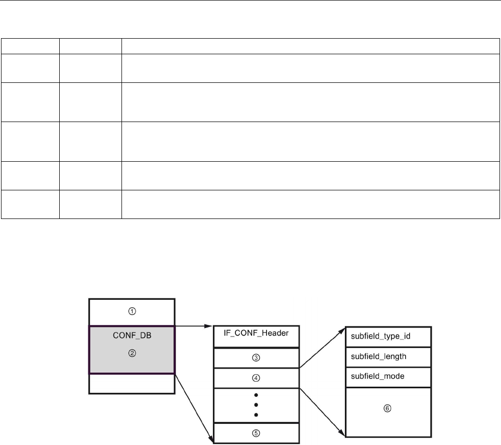
Communication
11.2 PROFINET
S7-1200 Programmable controller
904 System Manual, V4.2, 09/2016, A5E02486680-AK
STATUS*
ERR_LOC*
Explanation
C080_9500 0001_000x Error in the system data type IF_CONF_V4, IF_CONF_NOS, or IF_CONF_NTP:
The values of two parameters are inconsistent.
C080_C200 0000_0000 Error at call of the instruction:
The configuration data cannot be transferred. Possible cause: The PROFINET interface is
not accessible.
C080_C300 0000_0000 Error at call of the instruction:
Insufficient resources (for example, multiple calling of "T_CONFIG" with different parame-
ters).
C080_C400 0000_0000 Error at call of the instruction:
Temporary communication error. Time indication for change to daylight saving time.
C080_D200 0000_0000 Error at call of the instruction:
Call not possible. Instruction is not supported by the selected PROFINET interface.
CONF_DATA Data block
The following diagram shows how the configuration data to be transferred is stored in the
configuration DB.
①
Configuration DB
④
Subfield 2
②
Configuration data
⑤
Subfield
n
③
Subfield 1
⑥
Subfield-specific parameters
The configuration data of CONF_DB consists of a field that contains a header
(IF_CONF_Header) and several subfields. IF_CONF_Header provides the following
elements:
● field_type_id (data type UInt): Zero
● field_id (data type UInt): Zero
● subfield_cnt (data type UInt): Number of subfields

Communication
11.2 PROFINET
S7-1200 Programmable controller
System Manual, V4.2, 09/2016, A5E02486680-AK 905
Each subfield consists of a header (subfield_type_id, subfield_length, subfield_mode) and
the subfield-specific parameters. Each subfield must consist of an even number of bytes.
The subfield_mode can support a value of 1 or 2. Please refer to the tables below.
Note
Only one field (IF_CONF_Header) is currently allowed. Its parameters field_type_id and
field_id must
have the value zero. Other fields with different values for field_type_id and
field_id are subject to future extensions.
Table 11- 45 Subfields supported
subfield_type_id
Data type
Explanation
30
IF_CONF_V4
IP parameters: IP address, subnet mask, router address
40
IF_CONF_NOS
PROFINET IO device name (Name of station)
17
IF_CONF_NTP
Network Time Protocol (NTP)
Table 11- 46 Elements of the IF_CONF_V4 data type
Name
Data type
Start value
Description
Id
UInt
30
subfield_type_id
Length
UInt
18
subfield_length
Mode
UInt
0
subfield_mode (1: permanent or 2: temporary)
InterfaceAddress
IP_V4
- Interface address
ADDR
Array [1..4] of Byte
ADDR[1]
Byte
0
IP address high byte: 200
ADDR[2]
Byte
0
IP address high byte: 12
ADDR[3]
Byte
0
IP address low byte: 1
ADDR[4]
Byte
0
IP address low byte: 144
SubnetMask
IP_V4
- Subnet mask
ADDR
Array [1..4] of Byte
ADDR[1]
Byte
0
Subnet mask high byte: 255
ADDR[2] Byte 0 Subnet mask high byte: 255
ADDR[3]
Byte
0
Subnet mask low byte: 255
ADDR[4] Byte 0 Subnet mask low byte: 0
DefaultRouter
IP_V4
- Default router
ADDR
Array [1..4] of Byte
ADDR[1]
Byte
0
Router high byte: 200
ADDR[2]
Byte
0
Router high byte: 12
ADDR[3]
Byte
0
Router low byte: 1
ADDR[4]
Byte
0
Router low byte: 1

Communication
11.2 PROFINET
S7-1200 Programmable controller
906 System Manual, V4.2, 09/2016, A5E02486680-AK
Table 11- 47 Elements of the IF_CONF_NOS data type
Name
Data type
Start value
Description
Id
UInt
40
subfield_type_id
Length UInt 246 subfield_length
Mode
UInt
0
subfield_mode (1: permanent or 2: temporary)
NOS (Name of
station)
Array[1..240] of Byte 0 Station name: You must occupy the ARRAY from the first
byte. If the ARRAY is longer than the station name to be as-
signed, you must enter a zero byte after the actual station
name (in conformity with IEC 61158-6-10). Otherwise, NOS is
rejected and the "T_CONFIG (Page 901)" instruction enters
the error code DW#16#C0809400 in STATUS. If you occupy
the first byte with zero, the station name is deleted.
The station name is subject to the following limitations:
● A name component within the station name, i.e., a character string between two dots,
must not exceed 63 characters.
● No special characters such as umlauts, brackets, underscore, slash, blank space, etc.
The only special character permitted is the dash.
● The station name must not begin or end with the "-" character.
● The station name must not begin with a number.
● The station name form n.n.n.n (n = 0, ... 999) is not permitted.
● The station name must not begin with the string "port-xyz" or "port-xyz-abcde" (a, b, c, d,
e, x, y, z = 0, ... 9).
Note
You can also create an ARRAY "NOS" that is shorter then 24
0 bytes, but not less than 2
bytes. In this case, you must adjust the "Length" (length of subfield) tag accordingly.

Communication
11.2 PROFINET
S7-1200 Programmable controller
System Manual, V4.2, 09/2016, A5E02486680-AK 907
Table 11- 48 Elements of the IF_CONF_NTP data type
Name
Data type
Start value
Description
Id
UInt
17
subfield_type_id
Length UInt 22 subfield_length
Mode
UInt
0
subfield_mode (2: temporary)
NTP_IP Array[1...4] of IP_V4 - IP addresses of NTP servers
NTP_IP[1]
IP_V4
IP addresses of NTP server 1
ADDR
Array[1...4] of Byte
0
ADDR[1]
Byte
0
IP address high byte
ADDR[2]
Byte
0
IP address high byte
ADDR[3]
Byte
0
IP address low byte
ADDR[4]
Byte
0
IP address low byte
NTP_IP[2]
IP_V4
IP addresses of NTP server 2
ADDR
Array[1...4] of Byte
0
ADDR[1]
Byte
0
IP address high byte
ADDR[2]
Byte
0
IP address high byte
ADDR[3]
Byte
0
IP address low byte
ADDR[4]
Byte
0
IP address low byte
NTP_IP[3]
IP_V4
IP addresses of NTP server 3
ADDR
Array[1...4] of Byte
0
ADDR[1]
Byte
0
IP address high byte
ADDR[2]
Byte
0
IP address high byte
ADDR[3] Byte 0 IP address low byte
ADDR[4]
Byte
0
IP address low byte
NTP_IP[4]
IP_V4
IP addresses of NTP server 4
ADDR
Array[1...4] of Byte
0
ADDR[1]
Byte
0
IP address high byte
ADDR[2]
Byte
0
IP address high byte
ADDR[3] Byte 0 IP address low byte
ADDR[4]
Byte
0
IP address low byte

Communication
11.2 PROFINET
S7-1200 Programmable controller
908 System Manual, V4.2, 09/2016, A5E02486680-AK
Example: Using the T_CONFIG instruction to change IP parameters
In the following example, in the "addr" subfield, the "InterfaceAddress" (IP address),
"SubnetMask", and "DefaultRouter" (IP router) are changed. In the CPU "Properties",
"Ethernet address" page, you must select the "IP address is set directly at the device" radio
button to enable you to change the IP parameters using the "T_CONFIG" instruction after the
program is downloaded.
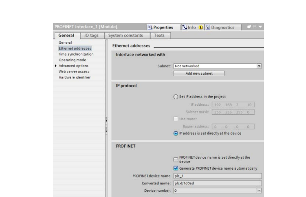
Communication
11.2 PROFINET
S7-1200 Programmable controller
System Manual, V4.2, 09/2016, A5E02486680-AK 909
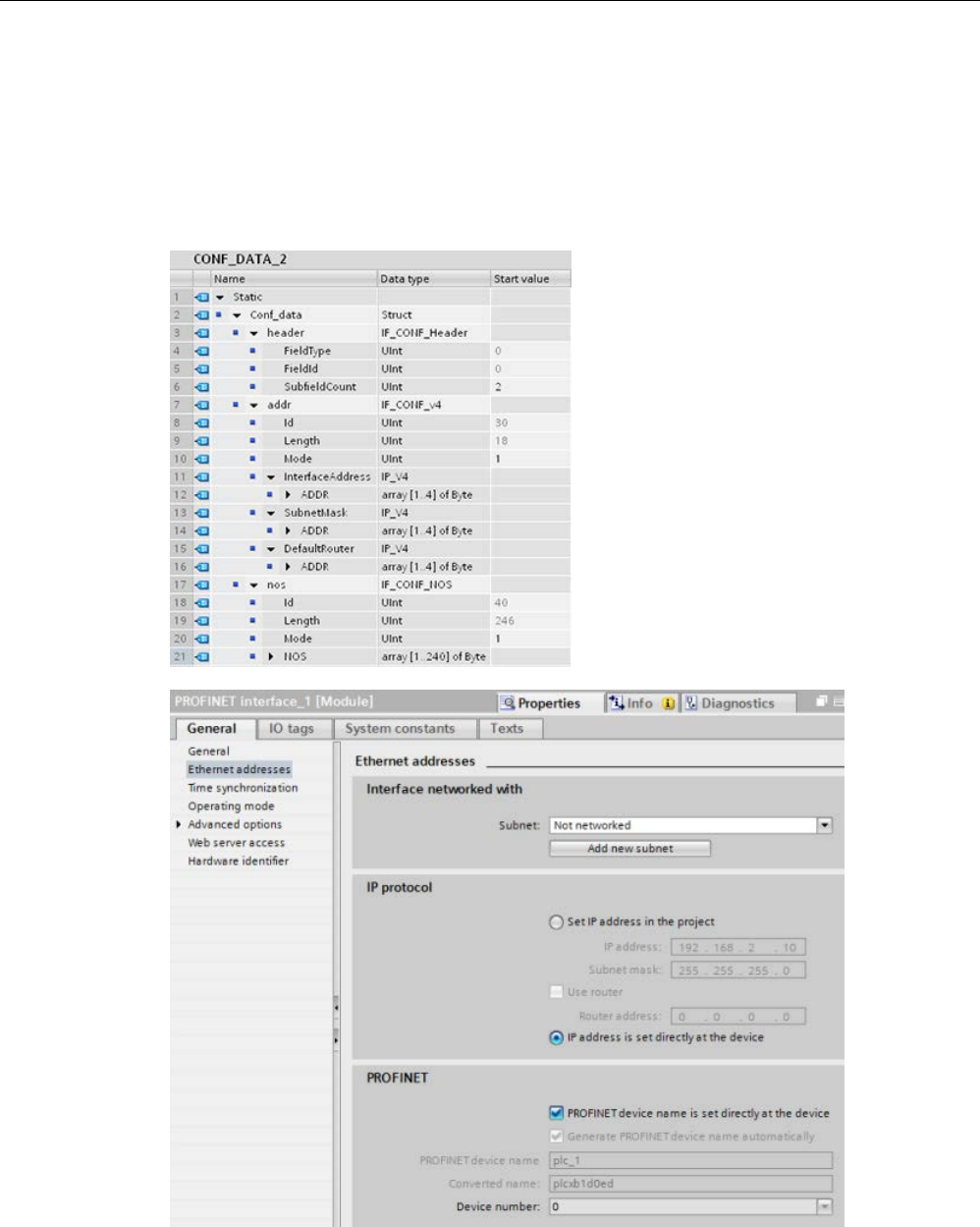
Communication
11.2 PROFINET
S7-1200 Programmable controller
910 System Manual, V4.2, 09/2016, A5E02486680-AK
Example: Using the T_CONFIG instruction to change IP parameters and PROFINET IO device
names
In the following example, both the "addr" and "nos" (Name of station) subfields are changed.
In the CPU "Properties", "Ethernet address" page, you must select the "PROFINET device
name is set directly at the device" check box to enable you to change the PROFINET device
name using the "T_CONFIG" instruction after the program is downloaded.

Communication
11.2 PROFINET
S7-1200 Programmable controller
System Manual, V4.2, 09/2016, A5E02486680-AK 911
Example: Using the T_CONFIG instruction to change IP addresses in the NTP servers
In the following example, in the "ntp" (Network Time Protocol (NTP) server) subfield, the
T_CONFIG instruction changes the IP addresses of up to four NTP servers.
In the CPU Properties, PROFINET interface [X1], Time synchronization page, you configure
NTP synchronization by selecting the "Enable time synchronization via NTP server" check
box as shown in the figure below. You can then change the IP addresses in the NTP servers
using the "T_CONFIG" instruction after the program is downloaded.

Communication
11.2 PROFINET
S7-1200 Programmable controller
912 System Manual, V4.2, 09/2016, A5E02486680-AK
11.2.8.17
Common parameters for instructions
REQ input parameter
Many of the Open User Communication instructions use the REQ input to initiate the
operation on a low to high transition. The REQ input must be high (TRUE) for one execution
of an instruction, but the REQ input can remain TRUE for as long as desired. The instruction
does not initiate another operation until it has been executed with the REQ input FALSE so
that the instruction can reset the history state of the REQ input. This is required so that the
instruction can detect the low to high transition to initiate the next operation.
When you place one of these instructions in your program, STEP 7 prompts you to identify
the instance DB. Use a unique DB for each instruction call. This ensures that each
instruction properly handles inputs such as REQ.
ID input parameter
This is a reference to the "Local ID (hex)" on the "Network view" of "Devices and networks"
in STEP 7 and is the ID of the network that you want to use for this communication block.
The ID must be identical to the associated parameter ID in the local connection description.
DONE, NDR, ERROR, and STATUS output parameters
These instructions provide outputs describing the completion status:
Table 11- 49 Open User Communication instruction output parameters
Parameter
Data type
Default
Description
DONE Bool FALSE Is set TRUE for one execution to indicate that the last request
completed without errors; otherwise, FALSE.
NDR Bool FALSE Is set TRUE for one execution to indicate that the requested action
has completed without error and new data has been received;
otherwise, FALSE.
BUSY Bool FALSE Is set TRUE when active to indicate that:
• The job is not yet complete.
• A new job cannot be triggered.
Is set FALSE when job is complete.
ERROR Bool FALSE Is set TRUE for one execution to indicate that the last request
completed with errors, with the applicable error code in STATUS;
otherwise, FALSE.
STATUS Word 0 Result status:
• If the DONE or NDR bit is set, then STATUS is set to 0 or to an
informational code.
• If the ERROR bit is set, then STATUS is set to an error code.
• If none of the above bits are set, then the instruction returns
status results that describe the current state of the function.
STATUS retains its value for the duration of the execution of the
function.

Communication
11.2 PROFINET
S7-1200 Programmable controller
System Manual, V4.2, 09/2016, A5E02486680-AK 913
Note
Note that DONE, NDR, and ERROR are set for one execution only.
Restricted TSAPs and port numbers for passive ISO and TCP communication
If you use the "TCON" instruction to set up and establish a passive communications
connection, the following port addresses are restricted and should not be used:
● ISO TSAP (passive):
– 01.00, 01.01, 02.00, 02.01, 03.00, 03.01
– 10.00, 10.01, 11.00, 11.01, ... BF.00, BF.01
● TCP port (passive): 5001, 102, 123, 20, 21, 25, 34962, 34963, 34964, 80
● UDP port (passive): 161, 34962, 34963, 34964
11.2.9
Communication with a programming device
A CPU can communicate with a STEP 7 pr
o-
gramming device on a network.
Consider the following when setting up communications between a CPU and a programming
device:
● Configuration/Setup: Hardware configuration is required.
● No Ethernet switch is required for one-to-one communications; an Ethernet switch is
required for more than two devices in a network.
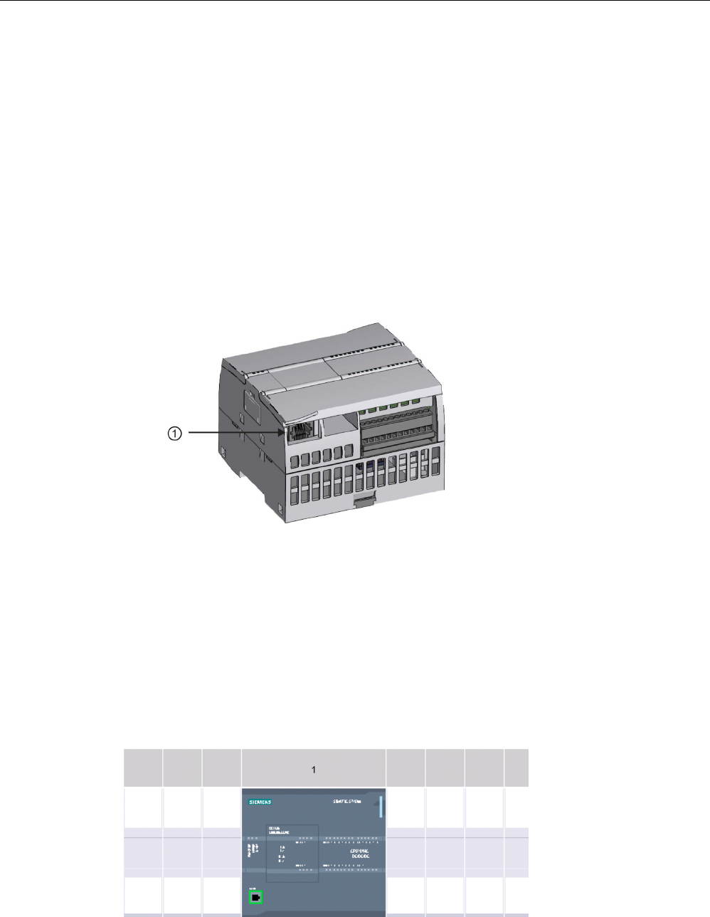
Communication
11.2 PROFINET
S7-1200 Programmable controller
914 System Manual, V4.2, 09/2016, A5E02486680-AK
11.2.9.1
Establishing the hardware communications connection
The PROFINET interfaces establish the physical connections between a programming
device and a CPU. Since Auto-Cross-Over functionality is built into the CPU, either a
standard or crossover Ethernet cable can be used for the interface. An Ethernet switch is not
required to connect a programming device directly to a CPU.
Follow the steps below to create the hardware connection between a programming device
and a CPU:
1. Install the CPU (Page 61).
2. Plug the Ethernet cable into the PROFINET port shown below.
3. Connect the Ethernet cable to the programming device.
①
PROFINET port
An optional strain relief is available to strengthen the PROFINET connection. For ordering
information, see Spare parts and other hardware (Page 1564).
11.2.9.2
Configuring the devices
If you have already created a project with a CPU, open your project in STEP 7.
If not, create a project and insert a CPU (Page 154) into the rack. In the project below, a
CPU is shown in the "Device View".

Communication
11.2 PROFINET
S7-1200 Programmable controller
System Manual, V4.2, 09/2016, A5E02486680-AK 915
11.2.9.3
Assigning Internet Protocol (IP) addresses
Assigning the IP addresses
In a PROFINET network, each device must also have an Internet Protocol (IP) address. This
address allows the device to deliver data on a more complex, routed network:
● If you have programming or other network devices that use an on-board adapter card
connected to your plant LAN or an Ethernet-to-USB adapter card connected to an
isolated network, you must assign IP addresses to them. Refer to "Assigning IP
addresses to programming and network devices" (Page 810) for more information.
● You can also assign an IP address to a CPU or network device online. This is particularly
useful in an initial device configuration. Refer to "Assigning an IP address to a CPU
online" (Page 810) for more information.
● After you have configured your CPU or network device in your project, you can configure
parameters for the PROFINET interface, to include its IP address. Refer to "Configuring
an IP address for a CPU in your project" (Page 813) for more information.
11.2.9.4
Testing your PROFINET network
After completing the configuration, you must download your project to the CPU. All IP
addresses are configured when you download the project.
The CPU "Download to device" function and its "Extended download to device" dialog can
show all accessible network devices and whether or not unique IP addresses have been
assigned to all devices. Refer to "Testing the PROFINET network" (Page 819) for more
information.
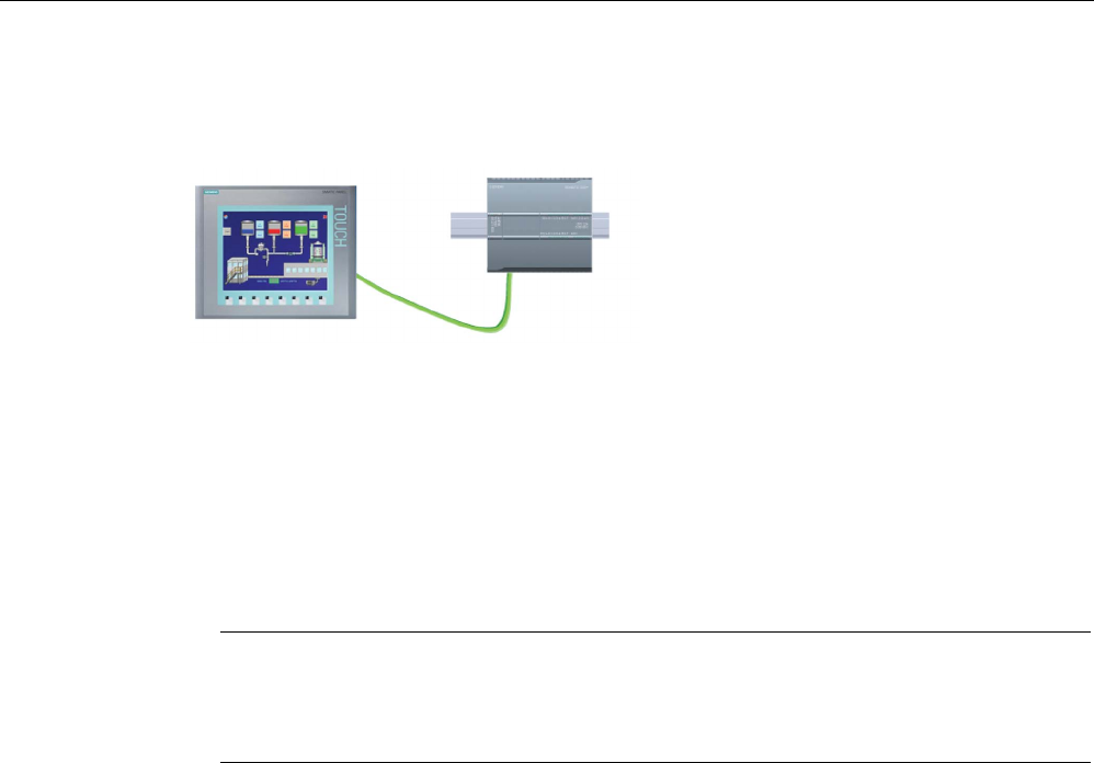
Communication
11.2 PROFINET
S7-1200 Programmable controller
916 System Manual, V4.2, 09/2016, A5E02486680-AK
11.2.10
HMI-to-PLC communication
The CPU supports PROFINET communic
a-
tions connections to
HMIs (Page 32). The
fo
llowing requirements must be considered
when setting up communica
tions between
CPUs and HMIs:
Configuration/Setup:
● The PROFINET port of the CPU must be configured to connect with the HMI.
● The HMI must be setup and configured.
● The HMI configuration information is part of the CPU project and can be configured and
downloaded from within the project.
● No Ethernet switch is required for one-to-one communications; an Ethernet switch is
required for more than two devices in a network.
Note
The rack
-mounted CSM1277 4-port Ethernet switch can be used to connect your CPUs
and HMI devices. The PROFINET port on the CPU does not contain an Ethernet
switching device.
Supported functions:
● The HMI can read/write data to the CPU.
● Messages can be triggered, based upon information retrieved from the CPU.
● System diagnostics

Communication
11.2 PROFINET
S7-1200 Programmable controller
System Manual, V4.2, 09/2016, A5E02486680-AK 917
Table 11- 50 Required steps in configuring communications between an HMI and a CPU
Step
Task
1 Establishing the hardware communications connection
A PROFINET interface establishes the physical connection between an HMI and a CPU. Since Auto-
Cross-Over functionality is built into the CPU, you can use either a standard or crossover Ethernet cable
for the interface. An Ethernet switch is not required to connect an HMI and a CPU.
Refer to "Communication with a programming device: Establishing the hardware communications connec-
tion" (Page 914) for more information.
2 Configuring the devices
Refer to "Communication with a programming device: Configuring the devices" (Page 914) for more in-
formation.
3 Configuring the logical network connections between an HMI and a CPU
Refer to "HMI-to-PLC communication: Configuring the logical network connections between two devices"
(Page 917) for more information.
4 Configuring an IP address in your project
Use the same configuration process; however, you must configure IP addresses for the HMI and the CPU.
Refer to "Device configuration: Configuring an IP address for a CPU in your project" (Page 814) for more
information.
5 Testing the PROFINET network
You must download the configuration for each CPU and HMI device.
Refer to "Device configuration: Testing the PROFINET network" (Page 819) for more information.
11.2.10.1
Configuring logical network connections between two devices
After you configure the rack with the CPU, you are now ready to configure your network
connections.
In the Devices and Networks portal, use the "Network view" to create the network
connections between the devices in your project. First, click the "Connections" tab, and then
select the connection type with the dropdown, just to the right (for example, an ISO on TCP
connection).
To create a PROFINET connection, click the green (PROFINET) box on the first device, and
drag a line to the PROFINET box on the second device. Release the mouse button and your
PROFINET connection is joined.
Refer to "Device Configuration: Creating a network connection" (Page 806) for more
information.

Communication
11.2 PROFINET
S7-1200 Programmable controller
918 System Manual, V4.2, 09/2016, A5E02486680-AK
11.2.11
PLC-to-PLC communication
A CPU can communicate with another CPU on a
network by using the TSEND_C and TRCV_C i
n-
structions.
Consider the following when setting up communications between two CPUs:
● Configuration/Setup: Hardware configuration is required.
● Supported functions: Reading/Writing data to a peer CPU
● No Ethernet switch is required for one-to-one communications; an Ethernet switch is
required for more than two devices in a network.
Table 11- 51 Required steps in configuring communications between two CPUs
Step
Task
1 Establishing the hardware communications connection
A PROFINET interface establishes the physical connection between two CPUs. Since Auto-Cross-Over
functionality is built into the CPU, you can use either a standard or crossover Ethernet cable for the inter-
face. An Ethernet switch is not required to connect the two CPUs.
Refer to "Communication with a programming device: Establishing the hardware communications connec-
tion" (Page 914) for more information.
2 Configuring the devices
You must configure two CPUs in your project.
Refer to "Communication with a programming device: Configuring the devices" (Page 914) for more in-
formation.
3 Configuring the logical network connections between two CPUs
Refer to "PLC-to-PLC communication: Configuring logical network connections between two devices"
(Page 919) for more information.
4 Configuring an IP address in your project
Use the same configuration process; however, you must configure IP addresses for two CPUs (for exam-
ple, PLC_1 and PLC_2).
Refer to "Device configuration: Configuring an IP address for a CPU in your project" (Page 814) for more
information.
5 Configuring transmit (send) and receive parameters
You must configure TSEND_C and TRCV_C instructions in both CPUs to enable communications between
them.
Refer to "Configuring communications between two CPUs: Configuring transmit (send) and receive pa-
rameters" (Page 919) for more information.
6 Testing the PROFINET network
You must download the configuration for each CPU.
Refer to "Device configuration: Testing the PROFINET network" (Page 819) for more information.

Communication
11.2 PROFINET
S7-1200 Programmable controller
System Manual, V4.2, 09/2016, A5E02486680-AK 919
11.2.11.1
Configuring logical network connections between two devices
After you configure the rack with the CPU, you are now ready to configure your network
connections.
In the Devices and Networks portal, use the "Network view" to create the network
connections between the devices in your project. First, click the "Connections" tab, and then
select the connection type with the dropdown, just to the right (for example, an ISO on TCP
connection).
To create a PROFINET connection, click the green (PROFINET) box on the first device, and
drag a line to the PROFINET box on the second device. Release the mouse button and your
PROFINET connection is joined.
Refer to "Device Configuration: Creating a network connection" (Page 806) for more
information.
11.2.11.2
Configuring the Local/Partner connection path between two devices
Configuring General parameters
You specify the communication parameters in the "Properties" configuration dialog of the
communication instruction. This dialog appears near the bottom of the page whenever you
have selected any part of the instruction.
Refer to "Device configuration: Configuring the Local/Partner connection path (Page 807)"
for more information.
In the "Address Details" section of the Connection parameters dialog, you define the TSAPs
or ports to be used. The TSAP or port of a connection in the CPU is entered in the "Local
TSAP" field. The TSAP or port assigned for the connection in your partner CPU is entered
under the "Partner TSAP" field.
11.2.11.3
Configuring transmit (send) and receive parameters
Communication blocks (for example, TSEND_C and TRCV_C) are used to establish
connections between two CPUs. Before the CPUs can engage in PROFINET
communications, you must configure parameters for transmitting (or sending) messages and
receiving messages. These parameters dictate how communications operate when
messages are being transmitted to or received from a target device.
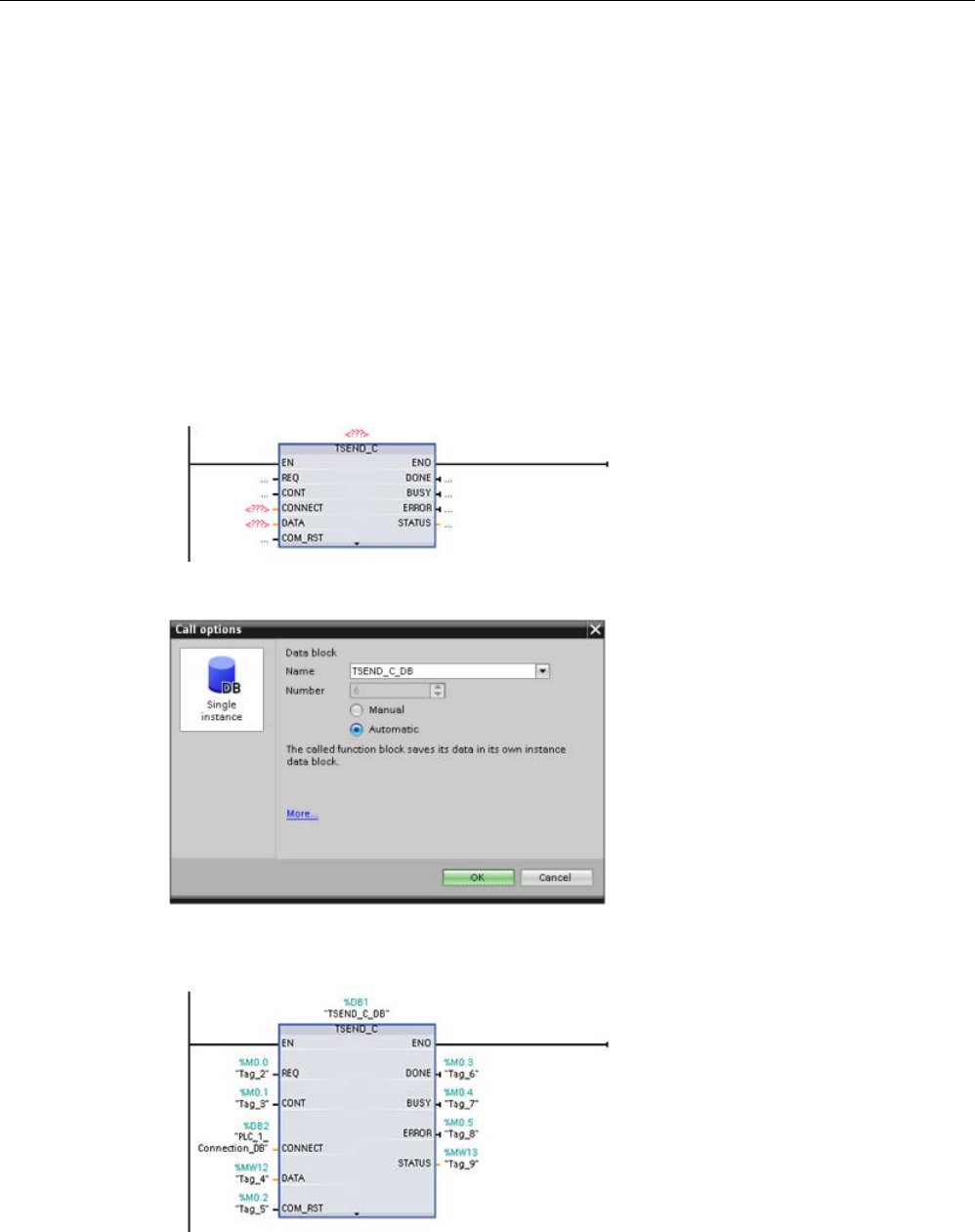
Communication
11.2 PROFINET
S7-1200 Programmable controller
920 System Manual, V4.2, 09/2016, A5E02486680-AK
Configuring the TSEND_C instruction transmit (send) parameters
TSEND_C instruction
The TSEND_C instruction (Page 837) creates a communications connection to a partner
station. The connection is set up, established, and automatically monitored until it is
commanded to disconnect by the instruction. The TSEND_C instruction combines the
functions of the TCON, TDISCON and TSEND instructions.
From the Device configuration in STEP 7, you can configure how a TSEND_C instruction
transmits data. To begin, you insert the instruction into the program from the
"Communications" folder in the "Instructions" task card. The TSEND_C instruction is
displayed, along with the Call options dialog where you assign a DB for storing the
parameters of the instruction.
You can assign tag memory locations to the inputs and outputs, as shown in the following
figure:
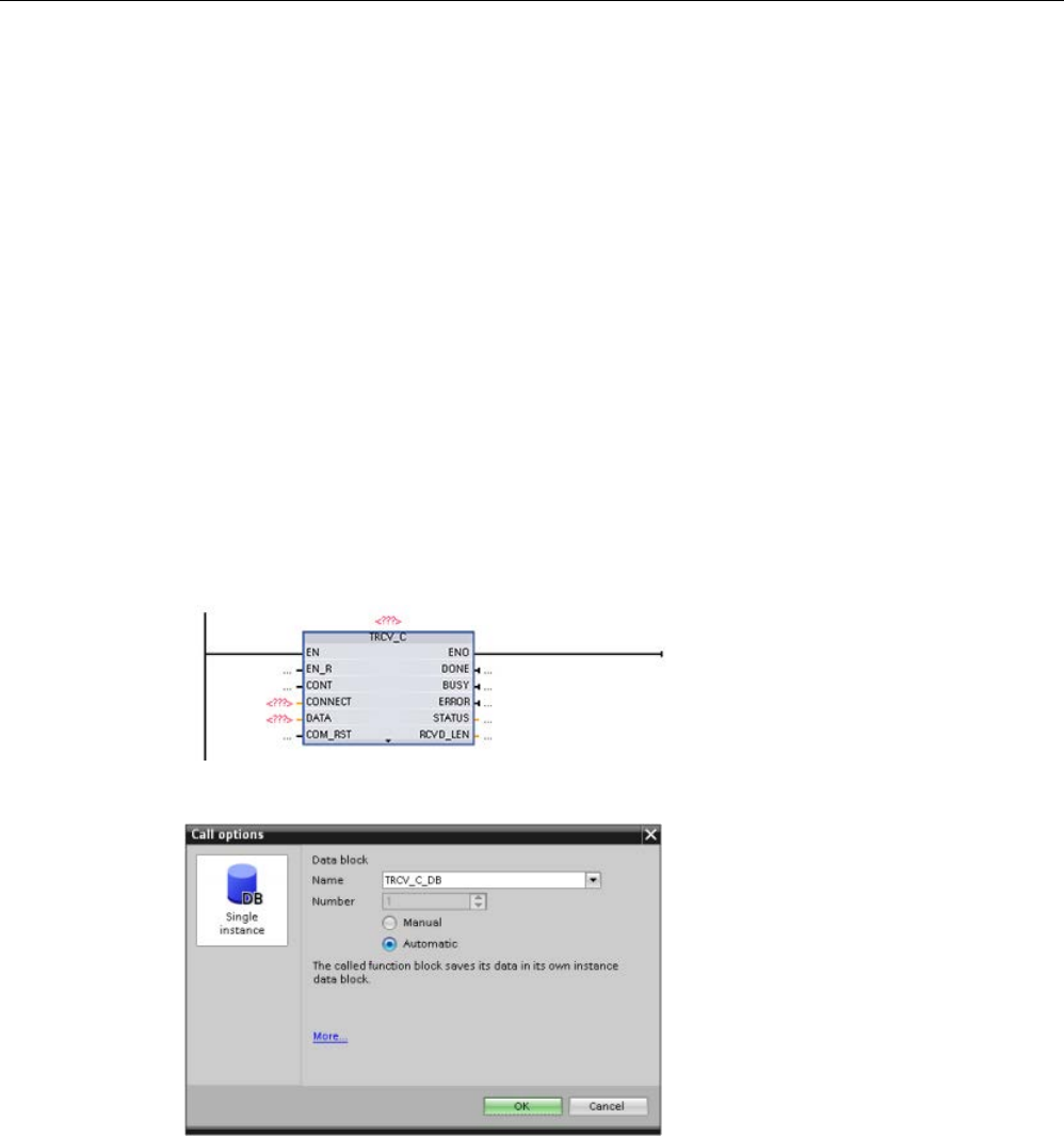
Communication
11.2 PROFINET
S7-1200 Programmable controller
System Manual, V4.2, 09/2016, A5E02486680-AK 921
Configuring General parameters
You specify the parameters in the Properties configuration dialog of the TSEND_C
instruction. This dialog appears near the bottom of the page whenever you have selected
any part of the TSEND_C instruction.
Configuring the TRCV_C instruction receive parameters
TRCV_C instruction
The TRCV_C instruction (Page 837) creates a communications connection to a partner
station. The connection is set up, established, and automatically monitored until it is
commanded to disconnect by the instruction. The TRCV_C instruction combines the
functions of the TCON, TDISCON, and TRCV instructions.
From the CPU configuration in STEP 7, you can configure how a TRCV_C instruction
receives data. To begin, insert the instruction into the program from the "Communications"
folder in the "Instructions" task card. The TRCV_C instruction is displayed, along with the
Call options dialog where you assign a DB for storing the parameters of the instruction.
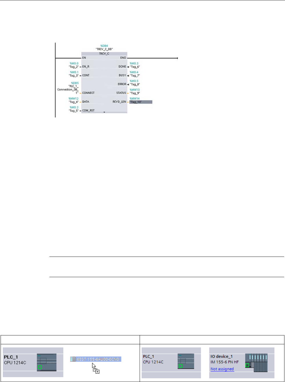
Communication
11.2 PROFINET
S7-1200 Programmable controller
922 System Manual, V4.2, 09/2016, A5E02486680-AK
You can assign tag memory locations to the inputs and outputs, as shown in the following
figure:
Configuring the General parameters
You specify the parameters in the Properties configuration dialog of the TRCV_C instruction.
This dialog appears near the bottom of the page whenever you have selected any part of the
TRCV_C instruction.
11.2.12
Configuring a CPU and PROFINET IO device
11.2.12.1
Adding a PROFINET IO device
Adding a PROFINET IO device
In the "Devices and networks" portal, use the hardware catalog to add PROFINET IO
devices.
Note
To add a PROFINET
IO device, you can use STEP 7 Professional or Basic, V11 or greater.
For example, expand the following containers in the hardware catalog to add an ET 200SP
IO device: Distributed I/O, ET 200SP, Interface modules, and PROFINET. You can then
select the interface module from the list of ET 200SP devices (sorted by part number) and
add the ET 200SP IO device.
Table 11- 52 Adding an ET 200SP IO device to the device configuration
Insert the IO device
Result

Communication
11.2 PROFINET
S7-1200 Programmable controller
System Manual, V4.2, 09/2016, A5E02486680-AK 923
You can now connect the PROFINET IO device to the CPU:
1. Right-click the "Not assigned" link on the device and select "Assign new IO controller"
from the context menu to display the "Select IO controller" dialog.
2. Select your S7-1200 CPU (in this example, "PLC_1") from the list of IO controllers in the
project.
3. Click "OK" to create the network connection.
You can also go to the "Devices and networks" portal and use the "Network view" to create
the network connections between the devices in your project:
1. To create a PROFINET connection, click the green (PROFINET) box on the first device,
and drag a line to the PROFINET box on the second device.
2. Release the mouse button and your PROFINET connection is joined.
Refer to "Device Configuration: Configuring the CPU for communication" (Page 179) for
more information.
11.2.12.2
Assigning CPUs and device names
Assigning CPUs and device names
Network connections between the devices also assign the PROFINET IO device to the CPU,
which is required for that CPU to control the device. To change this assignment, click the
PLC Name shown on the PROFINET IO device. A dialog box opens that allows the
PROFINET IO device to be disconnected from the current CPU and reassigned or left
unassigned, if desired.
The devices on your PROFINET network must have an assigned name before you can
connect with the CPU. Use the "Network view" to assign names to your PROFINET devices
if the devices have not already been assigned a name or if the name of the device is to be
changed. Right-click the PROFINET IO device and select "Assign device name" to do this.
For each PROFINET IO device, you must assign the same name to that device in both the
STEP 7 project and to the PROFINET IO device in the PROFINET network. (You can use
either the STEP 7 "Online & diagnostics" tool or the PRONETA commissioning,
configuration, and diagnostics tool to assign the device name in the PROFINET network.) If
a name is missing or does not match in either location, the PROFINET IO data exchange
mode will not run. Refer to "Online and diagnostic tools: Assigning a name to a PROFINET
device online (Page 1314)" for more information.

Communication
11.2 PROFINET
S7-1200 Programmable controller
924 System Manual, V4.2, 09/2016, A5E02486680-AK
11.2.12.3
Assigning Internet Protocol (IP) addresses
Assigning the IP addresses
In a PROFINET network, each device must also have an Internet Protocol (IP) address. This
address allows the device to deliver data on a more complex, routed network:
● If you have programming or other network devices that use an on-board adapter card
connected to your plant LAN or an Ethernet-to-USB adapter card connected to an
isolated network, you must assign IP addresses to them. Refer to "Assigning IP
addresses to programming and network devices" (Page 810) for more information.
● You can also assign an IP address to a CPU or network device online. This is particularly
useful in an initial device configuration. Refer to "Assigning an IP address to a CPU
online" (Page 813) for more information.
● After you have configured your CPU or network device in your project, you can configure
parameters for the PROFINET interface, to include its IP address. Refer to "Configuring
an IP address for a CPU in your project" (Page 814) for more information.
11.2.12.4
Configuring the IO cycle time
Configuring the IO cycle time
A PROFINET IO device is supplied with new data from the CPU within an "IO cycle" time
period. The update time can be separately configured for each device and determines the
time interval in which data is transmitted from the CPU to and from the device.
STEP 7 calculates the "IO cycle" update time automatically in the default setting for each
device of the PROFINET network, taking into account the volume of data to be exchanged
and the number of devices assigned to this controller. If you do not want to have the update
time calculated automatically, you can change this setting.
You specify the "IO cycle" parameters in the "Properties" configuration dialog of the
PROFINET IO device. This dialog appears near the bottom of the page whenever you have
selected any part of the instruction.
In the "Device view" of the PROFINET IO device, click the PROFINET port. In the
"PROFINET Interface" dialog, access the "IO cycle" parameters with the following menu
selections:
● "Advanced options"
● "Realtime settings"
● "IO cycle"
Define the IO cycle "Update time" with the following selections:
● To have a suitable update time calculated automatically, select "Automatic".
● To set the update yourself, select "Can be set" and enter the required update time in ms.
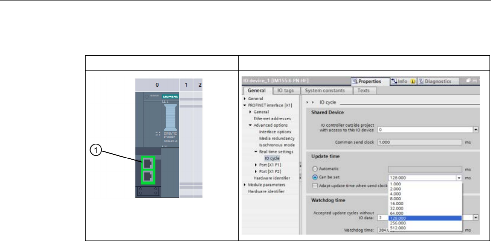
Communication
11.2 PROFINET
S7-1200 Programmable controller
System Manual, V4.2, 09/2016, A5E02486680-AK 925
Table 11- 53 Configuring the ET 200SP PROFINET IO cycle time
ET 200SP PROFINET IO device
ET 200SP PROFINET IO cycle dialog
① PROFINET port
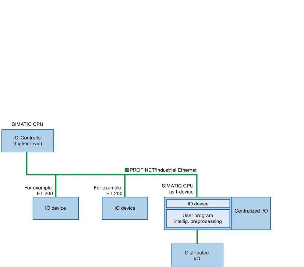
Communication
11.2 PROFINET
S7-1200 Programmable controller
926 System Manual, V4.2, 09/2016, A5E02486680-AK
11.2.13
Configuring a CPU and PROFINET I-device
11.2.13.1
I-device functionality
The "I-device" (intelligent IO device) functionality of a CPU facilitates data exchange with an
IO controller and operation of the CPU as intelligent preprocessing unit of sub processes, for
example. The I-device is linked as an IO device to a "higher-level" IO controller.
The pre-processing is handled by the user program on the CPU. The process values
acquired in the centralized or distributed (PROFINET IO or PROFIBUS DP) I/O are pre-
processed by the user program and made available through a PROFINET IO interface to the
CPU of a higher-level station.
"I-device" naming conventions
In the remainder of this description, a CPU or a CP with I-device functionality is simply called
an "I-device".

Communication
11.2 PROFINET
S7-1200 Programmable controller
System Manual, V4.2, 09/2016, A5E02486680-AK 927
11.2.13.2
Properties and advantages of the I-device
Fields of application
Fields of application of the I-device:
● Distributed processing:
A complex automation task can be divided into smaller units/subprocesses. This results
in manageable processes which lead to simplified subtasks.
● Separating subprocesses:
Complicated, widely distributed and extensive processes can be subdivided into several
subprocesses with manageable interfaces by using I-devices. These subprocesses can
be stored in individual STEP 7 projects if necessary, which can later be merged to form
one master project.
● Know-how protection:
Components can only be delivered with a GSD file for the I-device interface description
instead of with a STEP 7 project. The user can protect his program since it no longer has
to be published.
Properties
Properties of the I-device:
● Unlinking STEP 7 projects:
Creators and users of an I-device can have completely separated STEP 7 automation
projects. The GSD file forms the interface between the STEP 7 projects. This allows a link
to standard IO controllers through a standardized interface.
● Real-time communication:
The I-device is provided with a deterministic PROFINET IO system through a
PROFINET IO interface.
Advantages
The I-device has the following advantages:
● Simple linking of IO controllers
● Real-time communication between IO controllers
● Relieving the IO controller by distributing the computing capacity to I-devices.
● Lower communications load by processing process data locally.
● Manageable, due to processing of subtasks in separate STEP 7 projects
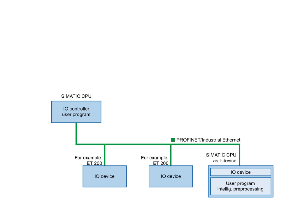
Communication
11.2 PROFINET
S7-1200 Programmable controller
928 System Manual, V4.2, 09/2016, A5E02486680-AK
11.2.13.3
Characteristics of an I-device
An I-device is included in an IO system like a standard IO device.
I-device without lower-level PROFINET IO system
The I-device does not have its own distributed I/O. The configuration and parameter
assignment of the I-devices in the role of an IO device is the same as for a distributed I/O
system (for example, ET 200).
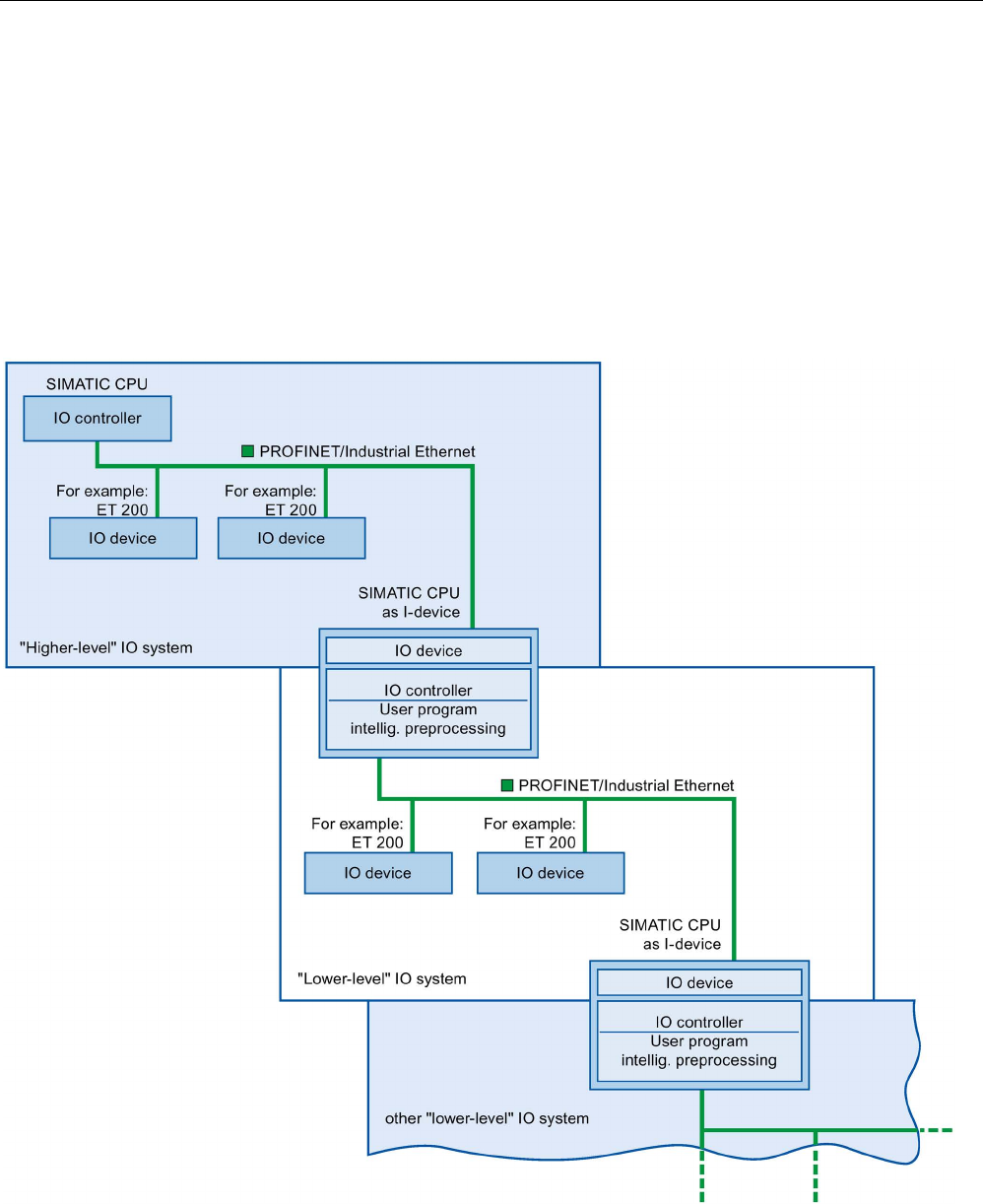
Communication
11.2 PROFINET
S7-1200 Programmable controller
System Manual, V4.2, 09/2016, A5E02486680-AK 929
I-device with lower-level PROFINET IO system
Depending on the configuration, an I-device can also be an IO controller on a PROFINET
interface in addition to having the role of an IO device.
This means that the I-device can be part of a higher-level IO system through its PROFINET
interface and as an IO controller can support its own lower-level IO system.
The lower-level IO system can, in turn, contain I-devices (see figure below). This makes
hierarchically structured IO systems possible.
In addition to its role as IO controller, an I-device can also be used through a PROFIBUS
interface as DP master for a lower-level PROFIBUS system.
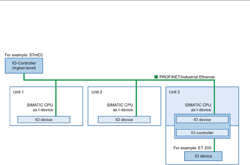
Communication
11.2 PROFINET
S7-1200 Programmable controller
930 System Manual, V4.2, 09/2016, A5E02486680-AK
Example: I-device as IO device and IO controller
The I-device as IO device and IO controller is explained based on the example of a print
process. The I-device controls a unit (a subprocess). One unit is used, for example, to insert
additional sheets such as flyers or brochures in a package of printed material.
Unit 1 and unit 2 each consist of an I-device with centralized I/O. The I-device along with the
distributed I/O system (for example, ET 200) forms unit 3.
The user program on the I-device is responsible for preprocessing the process data. For this
task, the user program of the I-device requires default settings (for example, control data)
from the higher-level IO controller. The I-device provides the higher-level IO controller with
the results (for example, status of its subtask).

Communication
11.2 PROFINET
S7-1200 Programmable controller
System Manual, V4.2, 09/2016, A5E02486680-AK 931
11.2.13.4
Data exchange between higher- and lower-level IO system
Transfer areas are an interface to the user program of the I-device CPU. Inputs are
processed in the user program and outputs are the result of the processing in the user
program.
The data for communication between IO controller and I-device is made available in the
transfer areas. A transfer area contains an information unit that is exchanged consistently
between IO controller and I-device. You can find more information on configuration and use
of transfer areas in the section "Configuring the I-device".
The next figure shows the data exchange between the higher- and lower-level IO system.
The individual communication relations are explained below based upon the numbers:
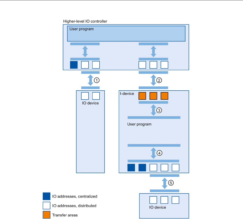
Communication
11.2 PROFINET
S7-1200 Programmable controller
932 System Manual, V4.2, 09/2016, A5E02486680-AK
①
Data exchange between higher-level IO controller and normal IO-device
In this way, the IO controller and IO devices exchange data through PROFINET.
②
Data exchange between higher-level IO controller and I-device
In this way, the IO controller and the I-device exchange data through PROFINET.
The data exchange between a higher-level IO controller and an I-device is based upon the
conventional IO controller / IO device relationship.
For the higher-level IO controller, the transfer areas of the I-devices represent submodules of a
pre-configured station.
The output data of the IO controller is the input data of the I-
device. Analogously, the input data
of the IO controller is the output data of the I-device.
③
Transfer relationship between the user program and the transfer area
In this way, the user program and the transfer area exchange input and output data.
④
Data exchange between the user program and the I/O of the I-device
In this way, the user program and the centralized / distributed I/O exchange input and output
data.

Communication
11.2 PROFINET
S7-1200 Programmable controller
System Manual, V4.2, 09/2016, A5E02486680-AK 933
⑤
Data exchange between the I-device and a lower-level IO device
In this way, the I-device and its IO devices exchange data. The data transfer is through
PROFINET.
11.2.13.5
Configuring the I-device
There are basically two possibilities for configuration:
● Configuration of an I-device within a project
● Configuration of an I-device that is used in another project or in another engineering
system.
STEP 7 allows you to configure an I-device for another project or for another engineering
system by exporting a configured I-device to a GSD file. You import the GSD file in other
projects or engineering systems as with other GSD files. The transfer areas for the data
exchange, among other data, are stored in this GSD file.
Note
When you use the S7
-1200 as a shared I-device and as a controller, ensure that you
increase the PROFINET I
-device and PROFINET IO Update times to alleviate the
communications perfo
rmance impact. The system is very stable and works well when you
select 2 ms for the Update time of a single PROFINET I
-device time and you select 2 ms for
the Update time of a single PROFINET IO time.
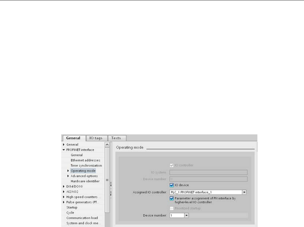
Communication
11.2 PROFINET
S7-1200 Programmable controller
934 System Manual, V4.2, 09/2016, A5E02486680-AK
Configuration of an I-device within a project
1. Drag-and-drop a PROFINET CPU from the hardware catalog into the network view.
2. Drag-and-drop a PROFINET CPU, which can also be configured as an IO device, from
the hardware catalog into the network view. This device is configured as an I-device (for
example, CPU 1215C).
3. Select the PROFINET interface for the I-device.
4. In the Inspector window in the area navigation choose "Operating mode" and select the
check box "IO device".
5. Now you have the option of choosing the IO controller in the "Assigned IO controller"
drop-down list.
Once you have chosen the IO controller, the networking and the IO system between both
devices are displayed in the network view.
6. With the "Parameter assignment of PN interface by higher-level IO controller" check box,
you specify whether the interface parameters will be assigned by the I-device itself or by
a higher-level IO controller.
If you operate the I-device with a lower-level IO system, then the parameters of the I-
device PROFINET interface (for example, port parameter) cannot be assigned with the
higher-level IO controller.
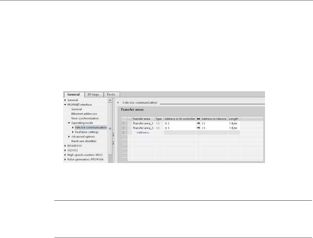
Communication
11.2 PROFINET
S7-1200 Programmable controller
System Manual, V4.2, 09/2016, A5E02486680-AK 935
7. Configure the transfer areas. The transfer areas are found in the area navigation section
"I-device communication":
– Click in the first field of the "Transfer area" column. STEP 7 assigns a default name
which you can change.
– Select the type of communication relation: you can currently only select CD or F-CD.
– Addresses are automatically preset; you can correct addresses if necessary, and
determine the length of the transfer area which is to be consistently transferred.
8. A separate entry is created in the area navigation for each transfer area. If you select one
of these entries, you can adjust the details of the transfer area, or correct them and
comment on them.
Note
If yo
u configure an S7-1200 as an I-device, the maximum size of a transfer area is 1024
input or output bytes. There are possible constraining factors depending on local I/O as well
as address space limitations on the controlling device.
Configuring an I-device with a GSD file
If you use an I-device in another project, or if the I-device is used in another engineering
system, then configure the higher-level IO controller and the I-device as described above.
However, click on the "Export" button after configuring the transfer areas so a new GSD file
is created from the I-device. This GSD file represents the configured I-device in other
projects.
The "Export" button is found in the "I-device communication" section of the Inspector
window.
The hardware configuration is compiled and the export dialog opened.
Assign a name for the I-device proxy as well as a description in the fields provided. Click the
"Export" button to complete your process.
Finally, import the GSD file, for example, in another project.
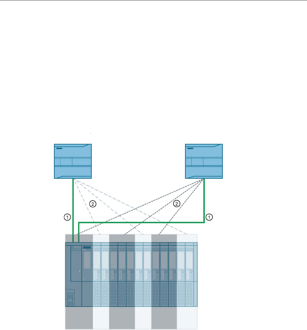
Communication
11.2 PROFINET
S7-1200 Programmable controller
936 System Manual, V4.2, 09/2016, A5E02486680-AK
11.2.14
Shared devices
11.2.14.1
Shared device functionality
Numerous IO controllers are often used in larger or widely distributed systems.
Without the "Shared Device" function, each I/O module of an IO device is assigned to the
same IO controller. If sensors that are physically close to each other must provide data to
different IO controllers, several IO devices are required.
The "Shared Device" function allows the modules or submodules of an IO device to be
divided up among different IO controllers. This allows flexible automation concepts. You
have, for example, the possibility of combining I/O modules lying near each other into an IO
device.
①
PROFINET
②
Logical assignment
Principle
Access to the submodules of the shared device is then divided up among the individual IO
controllers. Each submodule of the shared device is assigned exclusively to one IO
controller.

Communication
11.2 PROFINET
S7-1200 Programmable controller
System Manual, V4.2, 09/2016, A5E02486680-AK 937
Requirement (GSD configuration)
● STEP 7 V12 Service Pack 1 or higher
● S7-1200 CPU with firmware of V4.1 or later as IO controller
● IO device supports the shared device function, e.g. interface module IM 155-5 PN ST
● GSD file for configuring the IO device is installed
● An S7-1200 CPU configured as an I-device supports the Shared Device functionality. You
must export the PROFINET GSD file for the I-device from STEP 7 (as of V5.5) and then
import it into STEP 7 (TIA Portal).
Configuring the access
The IO device must be present in several projects so that the modules or submodules of an
IO device can be assigned to different IO controllers. A separate project is required for each
IO controller.
You use the "Shared device" parameter of the interface module to determine the modules or
submodules to which the IO controller has access:
● If the local IO controller has access to the configured module, select the name of the IO
controller from the list.
● If the IO controller from a different project and not the local IO controller is to have access
to the configured module, select the entry "---".
The configuration is consistent regarding access if each module or submodule in exactly one
project is assigned to an IO controller.
Module or submodule is assigned to another IO controller
The paragraph below describes the consequences of the "---" setting of the "Shared device"
parameter from the point of view of the local IO controller.
In this case, the local IO controller does not have access to the module configured in this
way. Specifically, this means:
● No data exchange with the module or submodule
● No reception of alarms or diagnostics, which means no display of the diagnostics status
in the online view
● No parameter assignment of the module or submodule

Communication
11.2 PROFINET
S7-1200 Programmable controller
938 System Manual, V4.2, 09/2016, A5E02486680-AK
Setting of the real-time properties
STEP 7 calculates the communication load and thus the resulting update times. You must
enter the number of project-external IO controllers in the project in which the PROFINET
interface of the shared device is assigned to the IO controller so that a calculation is possible
with shared device configurations.
The maximum possible number of IO controllers for the shared device depends on the
device. This number is stored in the GSD file of the shared device.
You can set a very short send clock (minimum of 1 ms) with an S7-1200 CPU as IO
controller. The send clock can be shorter than the shortest send clock supported by the
shared device. In this case, the shared device is operated by the IO controller with a send
clock that it supports (send clock adaptation).
Example: A CPU supports send clocks starting from 1 ms. A configured IO device supports
send clocks starting at 1.25 ms; another IO device supports send clocks starting at 1 ms. In
this case, you have the option of setting the short send clock of 1 ms for the CPU. The CPU
operates the "slow" IO device with the send clock of 1.25 ms.
Rules for the configuration
● IO controllers that use the shared device are created in different projects. In each project,
care must be taken that the shared device is configured identically in each station. Only
one IO controller may ever have full access to a submodule. Inconsistencies in the
configuration result in a failure of the shared device.
● I/O addresses of a module or submodule can only be edited if a module or submodule is
assigned to the IO controller in the same project.
● The shared device must have the same IP parameters and the same device name in
each project.
● The send clock must be identical for all IO controllers that have access to the shared
device.
● The S7 subnet ID of the subnet to which the shared device is connected must be identical
in all projects.
● The following functions are only available if the PROFINET interface of the shared device
is assigned to the local IO controller:
– Prioritized startup
– Parameter assignment of the port properties

Communication
11.2 PROFINET
S7-1200 Programmable controller
System Manual, V4.2, 09/2016, A5E02486680-AK 939
Boundary conditions
The following boundary conditions result because a shared device configuration is
distributed across several projects:
● The addresses of modules or submodules that are not assigned to this IO controller are
missing in the address overview of each IO controller that has access to a shared device.
● The modules or submodules that are not assigned are not taken into consideration in the
configuration limit calculation for the shared device during the consistency check. For this
reason, you must verify for yourself that the maximum number of submodules or the
maximum amount of cyclic IO data for the shared device will not be exceeded. For
information on the maximum quantities, refer to the documentation for the devices you
are using.
● Configuration errors such as the assignment of a module or submodule to several IO
controllers are not detected in STEP 7.
● CPUs that are loaded with a shared device configuration do not have any information on
whether the IO device is a shared device. Modules or submodules that are assigned to
other IO controllers and therefore other CPUs are missing in the loaded configuration.
These modules or submodules are therefore displayed neither in the CPU web server nor
in the CPU display.
11.2.14.2
Example: Configuring a shared device (GSD configuration)
This example describes how to configure a distributed I/O system as a shared device with
STEP 7 V13 SP1 or higher.
A "distributed" configuration with different engineering tools for different IO controller families
is possible. The procedure described below is based on STEP 7 as of V13 SP1 and is
limited to configuration with two IO controllers of the S7-1200 series that share one shared
device.
The example creates two projects with one IO controller each:
● Controller1
● Controller2
You must create the shared device in both projects, even though it is physically one and the
same IO device.
Requirements
● STEP 7 V13 SP1 or higher
● IO device supports shared device functionality (for example, ET 200SP IM 155-6 PN HF
V3.1).
● GSD file for configuring the IO device as a shared device is installed.
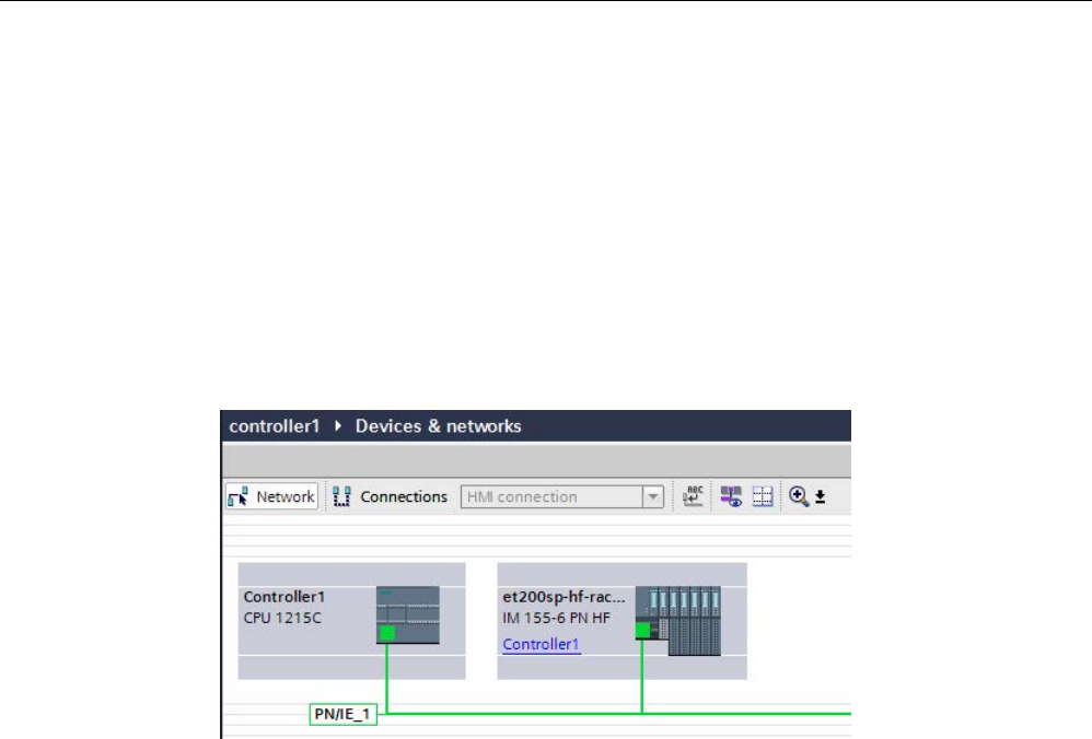
Communication
11.2 PROFINET
S7-1200 Programmable controller
940 System Manual, V4.2, 09/2016, A5E02486680-AK
Procedure: Creating project 1
To create the first project with a shared device, follow these steps:
1. Start STEP 7.
2. Create a new project with the name "Controller1".
3. Insert a CPU 1215C from the hardware catalog in the network view. Name it
"Controller1".
4. Insert an IO device with the "Shared Device" function (for example, an ET 200SP) from
the hardware catalog (hardware catalog: Other field devices > PROFINET IO > I/O).
5. Assign the IO controller "Controller1" to the IO device.
6. Double-click the IO device and insert all required modules and submodules from the
hardware catalog in the device overview table.
7. Assign the module parameters.
8. Save the project.
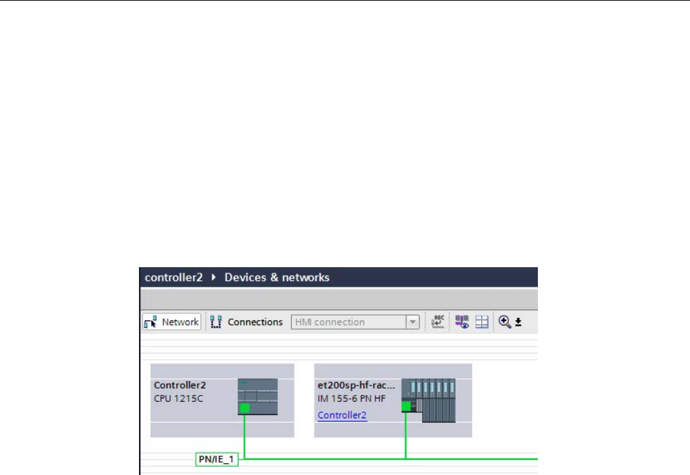
Communication
11.2 PROFINET
S7-1200 Programmable controller
System Manual, V4.2, 09/2016, A5E02486680-AK 941
Procedure: Creating project 2
To create the second project with a shared device, follow these steps:
1. Start STEP 7 once again.
A new instance of STEP 7 opens.
2. In the new instance, create a new project with the name "Controller2".
3. Insert a CPU 1215C in the network view. Name it "Controller2".
4. Copy the IO device from the project "Controller1" and insert it in the network view of
project "Controller2".
5. Assign the IO controller "Controller2" to the IO device.
6. Save the project.
Both projects now have an identically structured IO device that must be configured in the
next step for the different types of IO controller access.
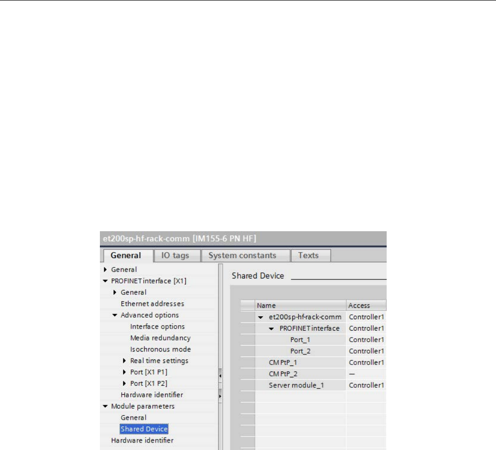
Communication
11.2 PROFINET
S7-1200 Programmable controller
942 System Manual, V4.2, 09/2016, A5E02486680-AK
Procedure: Configuring access to the shared device
The modules and submodules you insert in the shared device are automatically assigned to
the local CPU. To change the assignment, follow these steps:
1. Select the interface module in the network or device view of project "Controller1".
2. Select the "Shared Device" area in the Inspector window.
A table shows which CPU has access to the respective module or submodule for all
configured modules. The default setting is that the local CPU has access to all modules
and submodules.
3. Keep the "Controller1" setting for all modules and submodules that are to remain in the
address range of the local CPU.
Select the setting "---" for all modules and submodules that are to be located in the
address range of the CPU from the "Controller2" project (Controller2). This means that an
IO controller outside the project is to have access to the module or submodule.
4. Select the interface module in the network or device view of project "Controller2".
5. Select the "Shared Device" area in the Inspector window.
A table shows which CPU has access to the respective module or submodule for all
configured modules.
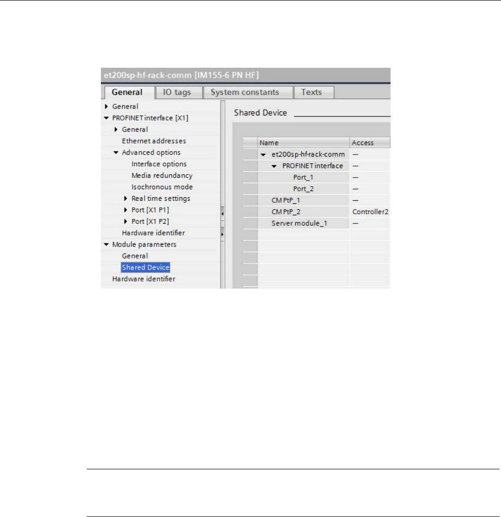
Communication
11.2 PROFINET
S7-1200 Programmable controller
System Manual, V4.2, 09/2016, A5E02486680-AK 943
6. Select the setting "---" for all modules and submodules that are to be located in the
address range of the CPU from the "Controller1" project (Controller1).
7. Finally, check whether the settings for access are "complementary" for each module or
submodule in both projects. This means that if the local CPU has access in one project,
the option "---" must be set in the other project and vice versa.
Note: The option "---" for the PROFINET interface and therefore for the ports makes the
associated parameters read-only and not changeable. Parameters of the PROFINET
interface and port parameters can only be edited in the project in which the PROFINET
interface is assigned to the local CPU. The ports can be interconnected in both projects
regardless of this.
8. Check whether the same IP address parameters and device name are set for the shared
device in all projects.
Check whether the same S7 subnet ID is set in all projects for the subnet to which the
shared device is connected (subnet properties, "General" area in the Inspector window).
Note
If you make changes to the shared device: Make the same changes in each project on the
shared device. Make
sure that only one IO controller has access to a module or submodule.

Communication
11.2 PROFINET
S7-1200 Programmable controller
944 System Manual, V4.2, 09/2016, A5E02486680-AK
Procedure: Adjusting the real-time settings
To ensure that all IO controllers and shared devices are operated with the appropriate send
clock and that the update times are calculated correctly based on the communication load,
you must adjust and check the following settings:
1. Select the project whose IO controllers have access to the PROFINET interface and the
ports of the shared device.
2. Select the interface module of the shared device in the network view.
3. In the Inspector window, navigate to the "PROFINET interface > Advanced options >
Real time settings > IO cycle" area.
4. In the "Shared device" area, set the number of project-external IO controllers. The
maximum number depends on the IO device (specification in GSD file).
5. You must set the same send clock for each IO controller that has access to modules and
submodules of the shared device:
● If you configure the IO controller with STEP 7 (TIA Portal):
– Open the corresponding project.
– Select the PROFINET interface of the IO controller.
– Select the "Advanced options > Real time settings > IO communication" area in the
Inspector window and set the shared send clock.
● If you configure the IO controller with a different engineering tool:
– Select the PROFINET interface of the shared device in STEP 7 (TIA Portal) and read
out the send clock on the shared device ("Advanced options > Real time settings"
area).
– Enter the read send clock in the engineering tool.
Note
If you configure all IO controllers
that have access to the shared device in STEP 7
(TIA
Portal), you can set shorter send clocks on the IO controller than supported by the
shared device (send clock adaptation).
Compiling and loading
You must compile the configurations for the different IO controllers and load them to the
CPUs one after the other.
Due to the distributed configuration with separate projects, STEP 7 does not output
consistency errors in the case of incorrect access parameter assignment. These are
examples of incorrect access parameter assignment:
● Several IO controllers have access to the same module
● IP address parameters or send clocks are not identical
These errors do not show up until controller operation and are output as configuration errors.

Communication
11.2 PROFINET
S7-1200 Programmable controller
System Manual, V4.2, 09/2016, A5E02486680-AK 945
11.2.14.3
Example: Configuring an I-device as a shared device
This example describes how to configure an S7-1200 as an I-device with STEP 7 Version
V13 SP1 or higher and then use it in two projects as a shared device.
A "distributed" configuration with different engineering tools for different IO controller families
is possible. The procedure described below is based on STEP 7 V13 SP1 and is limited to a
configuration with two IO controllers of the S7-1200 family that share the transfer areas of an
I-device as a shared device. The I-device itself is a CPU 1215C.
The example creates three projects with one IO controller each:
● S7-1200-I-Device
● Controller1
● Controller2
You use the S7-1200-I-Device project to configure the I-device. You use the PROFINET
GSD variant of S7-1200-I-Device in the Controller1 and Controller2 projects in order to
assign the transfer areas in the respective higher-level IO controller.
Shared I-device concept
The shared I-device concept requires a minimum of three separate projects:
● I-device project: You configure and program an I-device to perform a particular
automation task. You define transfer areas as the I/O interface for the higher level
controllers and assign these transfer areas to different IO controllers. For the connection
to higher-level IO controllers, you provide a PROFINET GSD file and use the transfer
areas to access the I-device.
● Controllers that share the I-device (two projects): You use the I-device as a PROFINET
GSD variant during configuration of the PROFINET IO system and, in this process,
specify the I/O addresses under which the IO controllers access the transfer areas.
Note
If you configure an S7
-1200 as an I-device, the maximum size of a transfer area is 1024
input or output bytes. There are possible constraining factors depending on local I/O as well
as address space limitations on the controlling device.

Communication
11.2 PROFINET
S7-1200 Programmable controller
946 System Manual, V4.2, 09/2016, A5E02486680-AK
I-device
You assign the following parameters for an S7-1200 CPU as an I-device:
● Centralized and distributed I/O
● Desired transfer areas
● Number of IO controllers having access to this I-device (always greater than 1 for a
shared device)
Note
You configure the I
-device without a higher-level IO controller. As a result, you can only use
the local I/O addresses of the transfer area (corresponds with the "Address in the I
-device")
to create the user program for editing the addresses from the transfer area. You download
the I
-device, completely configured except for the connection to the higher-level IO
controller, to the S7
-1200 CPU.
You export a PROFINET GSD file from the I-device configuration.
Controllers that share the I-device
You must install the PROFINET GSD file created from the I-device configuration in all
engineering systems that you use in configuring a PROFINET IO system with this shared
I-device. If you configure all uses of this I-device with STEP 7 V13 SP1, it is sufficient to
install the GSD file in STEP 7.
You configure the I-device as a GSD variant on the PROFINET IO system in the projects
involved. In STEP 7 V13 SP1, you find this I-device under "Other field devices > PROFINET
IO > PLCs & CPs" following installation.
In each of the projects involved, you assign transfer areas exclusively to the higher-level IO
controllers (default setting: all). You set the other transfer areas to "---" (not assigned). When
you do so, the local IO controller cannot access this transfer area, and you can assign the
transfer area to another IO controller in another project.
Requirements
● STEP 7 V13 SP1 or higher
● IO device supports shared device functionality (for example, ET 200SP IM 155-6 PN HF
V3.1).
● GSD file for configuring the IO device as a shared device is installed.
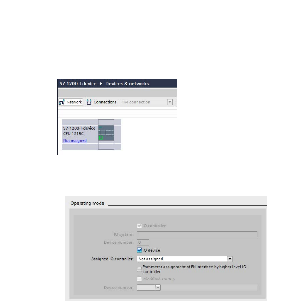
Communication
11.2 PROFINET
S7-1200 Programmable controller
System Manual, V4.2, 09/2016, A5E02486680-AK 947
Procedure: Creating the S7-1200-I-device project
To create the project with a shared I-device, follow these steps:
1. Start STEP 7.
2. Create a new project with the name "S7-1200-I-device".
3. Insert a CPU 1215C from the hardware catalog in the network view. Assign the name
"S7-1200-I-device".
4. Double-click the IO device and configure all required modules and submodules.
5. Assign the module parameters. In particular, you must configure the following settings for
the CPU in the area of the PROFINET interface [X1]:
– Enable the "IO device" option in the "Operating mode" area.
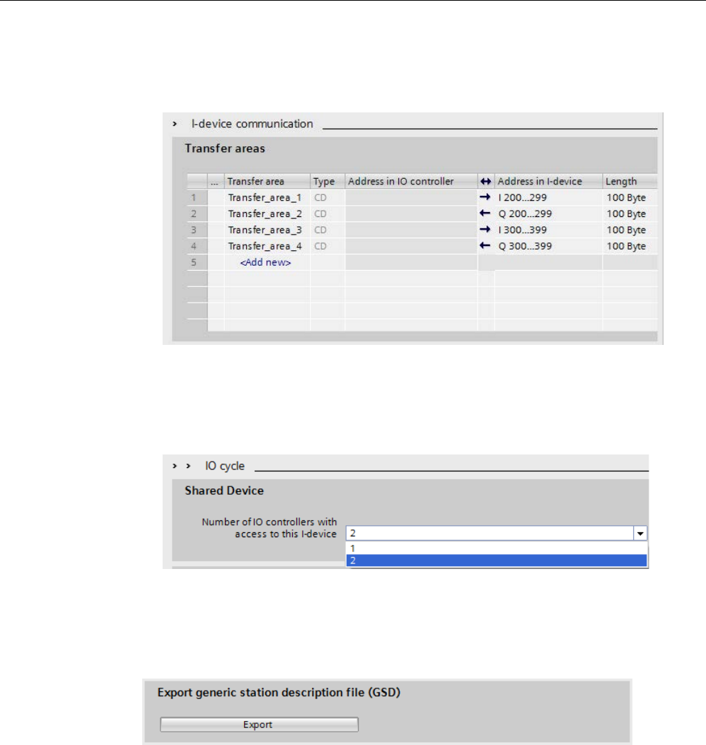
Communication
11.2 PROFINET
S7-1200 Programmable controller
948 System Manual, V4.2, 09/2016, A5E02486680-AK
– Configure the transfer areas in the "Operating mode" > "I-device configuration" area.
The "Address in IO controller" column remains empty because no IO controller is
assigned.
Note: To change an input area to an output area, and vice versa, you must navigate to
the area of the corresponding transfer area.
– Select the number of IO controllers (at least two) that will access the shared I-device
during operation ("Operating mode" > "Real time settings" area, "Shared Device"
area).
6. Save the project.
7. Click the "Export" button ("Mode" > "I-device configuration" area, "Export general station
description file (GSD)" section). If you do not change the name in the Export dialog, the
GSD file uses an assigned format name (for example, "GSDML-V2.31-#Siemens-
PreConf_S7-1200-I-Device-20130925-123456").
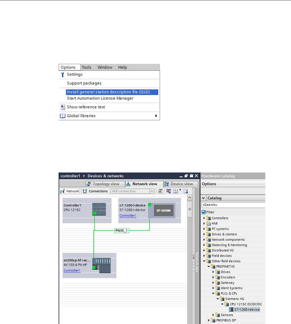
Communication
11.2 PROFINET
S7-1200 Programmable controller
System Manual, V4.2, 09/2016, A5E02486680-AK 949
Procedure: Creating the Controller1 project
To create the first project with a shared I-device, follow these steps:
1. Start STEP 7.
2. Install the PROFINET GSD file from the export of the I-device CPU (S7-1200-I-Device).
3. Create a new project with the name "Controller1".
4. Insert the CPU 1215C in the network view. The name of the CPU should be "Controller1".
5. Insert the I-device from the hardware catalog (Hardware catalog: Other field devices >
PROFINET IO > PLCs & CPs).
6. Assign the IO controller "Controller1" to the I-device.
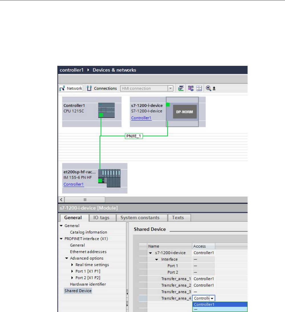
Communication
11.2 PROFINET
S7-1200 Programmable controller
950 System Manual, V4.2, 09/2016, A5E02486680-AK
7. Select the "Shared device" area in the properties of the I-device:
– In the table, all transfer areas and the PROFINET interface are assigned to the local
IO controller (Controller1).
– Define the transfer areas to which the Controller1 CPU should
not
have access. Select
the "---" entry for these areas. These transfer areas are provided for Controller2.
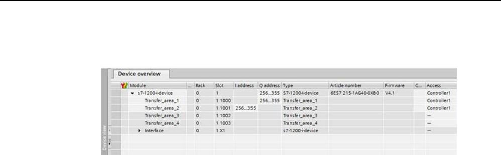
Communication
11.2 PROFINET
S7-1200 Programmable controller
System Manual, V4.2, 09/2016, A5E02486680-AK 951
8. You can adapt the addresses from the Device view of the IO controller in the Device
overview. To open the device overview, double-click the I-device.
9. Save the project.
Procedure - Creating the Controller2 project
To create the second project with a shared device, follow these steps:
1. Start STEP 7 once again.
A new instance of STEP 7 opens.
2. In the new instance, create a new project with the name "Controller2".
3. Insert the CPU 1215C in the network view. Assign the name "Controller2".
4. Insert the I-device from the hardware catalog (Hardware catalog: Other field devices >
PROFINET IO > PLCs & CPs).
5. Assign the IO controller "Controller2" to the I-device.
6. Adapt the access to the transfer areas as in the Controller1 project. Ensure that no
duplicate assignments result.
7. Adapt the parameters of the subnet and PROFINET interface. Because the shared I-
device involves the same device in different projects, these data must match.
8. Save the project.
Both projects now have an identically configured shared I-device. The IO controller access
and the parameters of the PROFINET interface should still be checked in the different
projects during the next step.

Communication
11.2 PROFINET
S7-1200 Programmable controller
952 System Manual, V4.2, 09/2016, A5E02486680-AK
Summary - Assigning parameters for access to the shared device
The transfer areas are automatically assigned to the local IO controller. To change the
assignment, follow these steps:
1. Click the "S7-1200-I-Device" device in the network view of the "Controller1" project, and
select the "Shared device" area.
2. A table shows which CPU has access to each of the configured transfer areas. The
default setting is that the local CPU has access to all modules and submodules.
3. Keep the setting "Controller1" for all transfer areas that are to remain in the address
range of the local CPU.
Select the setting "---" for all transfer areas that are to be located in the address range of
the "Controller2" CPU from the "Controller2" project. This means that an IO controller
outside the project is to have access to the transfer area.
4. Follow the same procedure for the remaining projects.
5. Finally, check whether the settings for access are "complementary" for each module or
submodule in both projects. This means that if the local CPU has access in one project,
the option "---" must be set in the other project and vice versa.
Note: The option "---" for the PROFINET interface and therefore for the ports makes the
associated parameters read-only and not changeable. Parameters of the PROFINET
interface and port parameters can only be edited in the project in which the PROFINET
interface is assigned to the local CPU. The ports can be interconnected in both projects
regardless of this.
6. Check whether the same IP address parameters and device name are set for the shared
device in all projects.
Check whether the same S7 subnet ID is set in all projects for the subnet to which the
shared device is connected (subnet properties, "General" area in the Inspector window).
Note
If you make changes to the I
-device (for example, change the number or length of the
transfer areas), export the I
-device as a GSD file again. Re-install the GSD file in each
project that uses the I
-device as a shared device. Make sure that only one IO controller has
access to a transfer area.
Note
When
you use the S7-1200 as a shared I-device and as a controller, ensure that you
increase the PROFINET I
-device and PROFINET IO Update times to alleviate the
communications performance impact. The system is very stable and works well when you
select 2 ms for
the Update time of a single PROFINET I-device time and you select 2 ms for
the Update time of a single PROFINET IO time.
You specify the "IO cycle" parameters in the "Properties" configuration dialog of the
PROFINET I
-device or IO. Refer to "Configuring the IO cycle time" (Page 924) for further
information.

Communication
11.2 PROFINET
S7-1200 Programmable controller
System Manual, V4.2, 09/2016, A5E02486680-AK 953
Procedure - Adjusting the real-time settings
To ensure that all IO controllers and shared devices are operated with the appropriate send
clock and that the update times are calculated correctly based on the communication load,
you must adjust and check the following settings:
1. You must set the same send clock for each IO controller that has access to modules and
submodules of the shared device:
● If you configure the IO controller with STEP 7 (TIA Portal), perform these steps:
– Open the corresponding project.
– Select the PROFINET interface of the IO controller.
– Select the "Advanced options > Real time settings > IO communication" area in the
Inspector window and set the shared send clock.
● If you configure the IO controller with a different engineering tool, perform these steps:
– Select the PROFINET interface of the shared device in STEP 7 (TIA Portal) and read
out the send clock on the shared device ("Advanced options > Real time settings"
area)
– Enter the read send clock in the engineering tool.
Note
If you configure all
IO controllers that have access to the shared I-device in STEP 7
(TIA
Portal), you can set shorter send clocks on the IO controller than supported by the
shared device (send clock adaptation).
Compiling and downloading
You must compile the configurations for the different IO controllers and download them to
the CPUs one after the other.
Due to the distributed configuration with separate projects, STEP 7 does not output
consistency errors in the case of incorrect access parameter assignment. These are
examples of incorrect access parameter assignment:
● Several IO controllers have access to the same module.
● IP address parameters or send clocks are not identical.
These errors do not show up until controller operation and are output as configuration errors.
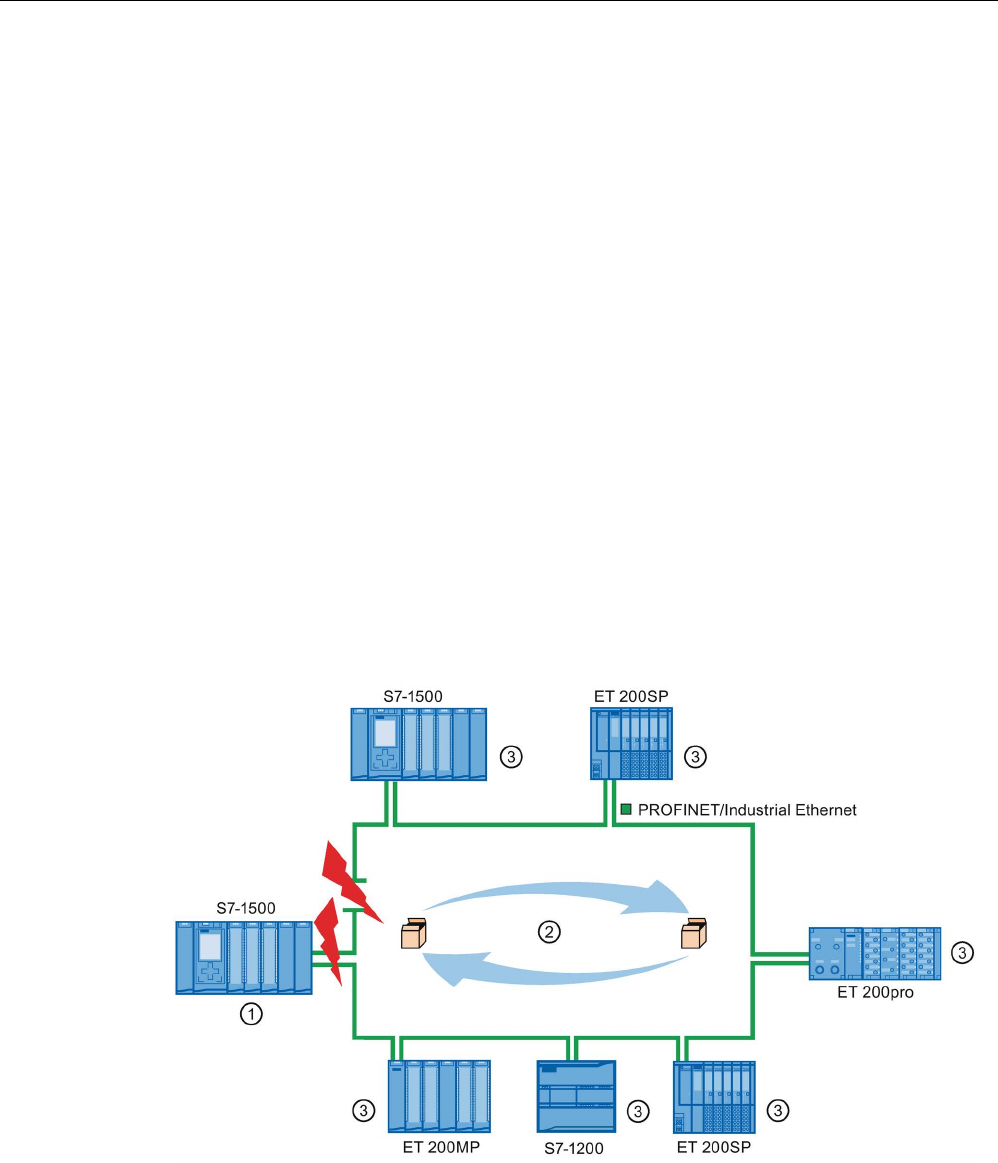
Communication
11.2 PROFINET
S7-1200 Programmable controller
954 System Manual, V4.2, 09/2016, A5E02486680-AK
11.2.15
Media Redundancy Protocol (MRP)
The following V4.2 S7-1200 CPUs support operations as an MRP client, but do not fulfill the
MRP manager role:
● CPU 1215C
● CPU 1217C
● CPU 1215FC
The three S7-1200 CPUs all have two PN ports which are required to support the MRP
protocol and the configuration parameters used to initialize MRP client operation.
11.2.15.1
Media redundancy with ring topologies
In order to increase the network availability of an Industrial Ethernet network with optical or
electrical linear bus topologies, you can convert a linear bus topology to a ring topology by
joining the ends together.
Devices in a ring topology can be IO devices, IO controllers, external switches, and/or the
integrated switches of communication modules.
To set up a ring topology with media redundancy, you need to bring together the two free
ends of a linear bus topology in one device. Closing the linear bus topology to form a ring is
achieved with two ports (ring ports) of a device in the ring. One device of the resulting ring
then takes over the role of the MRP manager. All other devices in the ring are MRP clients.
①
MRP manager
②
Test frames
③
MRP clients
The ring ports of a device are the ports that establish the connection to the two neighboring
devices in the ring topology. The ring ports are selected and set in the configuration of the
relevant device (is also preset, if applicable).

Communication
11.2 PROFINET
S7-1200 Programmable controller
System Manual, V4.2, 09/2016, A5E02486680-AK 955
How media redundancy works in a ring topology
The data paths between the individual devices are automatically reconfigured if the ring is
interrupted at any point. The devices are available again after reconfiguration.
In the MRP manager, one of the two ring ports is blocked in uninterrupted network operation
for normal communication so that no data frames are circulated. In terms of data
transmission, the ring topology is a linear bus topology. The MRP manager monitors the ring
for interruptions. It does this by sending test frames both from ring port 1 and ring port 2. The
test frames run round the ring in both directions until they arrive at the other ring port of the
MRP manager.
An interruption of the ring can be caused by loss of the connection between two devices or
by failure of a device in the ring.
If the test frames of the MRP manager no longer arrive at the other ring port during an
interruption of the ring, the MRP manager connects its two ring ports. This substitute path
once again restores a functioning connection between all remaining devices in the form of a
linear bus topology.
The time between the ring interruption and restoration of a functional linear topology is
known as the reconfiguration time.
As soon as the interruption is eliminated, the original transmission paths are established
again, the two ring ports of the MRP manager are disconnected, and the MRP clients
informed of the change. The MRP clients then use the original paths again to the other
devices.
Media redundancy method
The standard method of media redundancy in SIMATIC is Media Redundancy Protocol
(MRP) with a typical reconfiguration time of 200 ms. Up to 50 devices can participate per
ring.
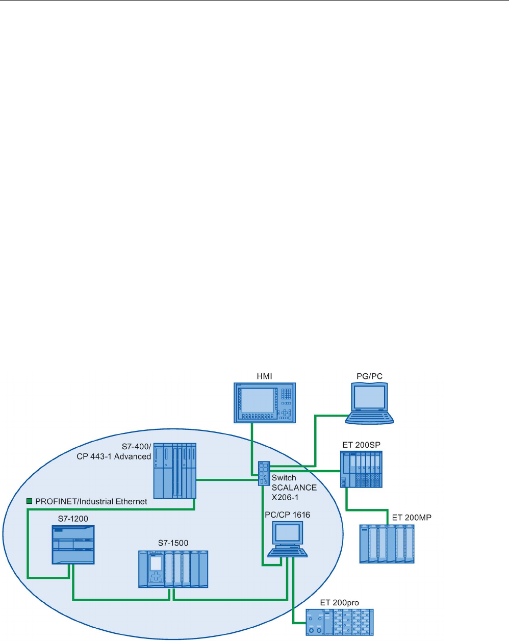
Communication
11.2 PROFINET
S7-1200 Programmable controller
956 System Manual, V4.2, 09/2016, A5E02486680-AK
11.2.15.2
Using Media Redundancy Protocol (MRP)
The "MRP" process works in conformity with Media Redundancy Protocol (MRP), which is
specified in IEC 61158 Type 10 "PROFINET".
Requirements
The following requirements must be met for error-free operation with MRP:
● The ring in which you want to use MRP may only consist of devices that support this
function.
● "MRP" must be activated for all devices in the ring.
● All devices must be interconnected using their ring ports.
● At least one MRP manager (role "Manager (Auto)") must be available.
● The ring must contain not more than 50 devices. Otherwise, reconfiguration times of
greater than or equal to 200 ms can occur.
● All partner ports within the rings must have the identical settings.
Topology
The following schematic shows a possible topology for devices in a ring with MRP. The
devices inside the shaded oval are in the redundancy domain.
This is an example of a ring topology with MRP:

Communication
11.2 PROFINET
S7-1200 Programmable controller
System Manual, V4.2, 09/2016, A5E02486680-AK 957
The following rules apply to a ring topology with media redundancy using MRP:
● All devices in the ring belong to the same redundancy domain.
● One device in the ring has the role of a MRP manager.
● All other devices in the ring are MRP clients.
You can connect non MRP-compliant devices to the network through ports not configured as
ring ports. You can only do this with devices that have more than two ports (for example, a
SCALANCE X switch or a PC with a CP1616).
Boundary conditions
You can have the following communication possibilities:
● MRP and RT: RT operation is possible with the use of MRP.
Note
The RT communication is disrupted (station failure) if the reconfiguration time of the ring
is greater
than the selected watchdog time of the IO device. You must select a watchdog
time greater than 200 ms for your IO devices. Refer to the "Watchdog time" section below
for further information.
● MRP and TCP/IP (TSEND, HTTP, ...): The TCP/IP communication with MRP is possible
because lost data packages are resent, if applicable.
● MRP and prioritized startup:
– If you configure MRP in a ring, you cannot use the "prioritized startup" function in
PROFINET applications on the devices involved.
– If you want to use the "prioritized startup" function, then you must disable MRP in the
configuration (the device cannot be part of the ring).
● MRP on PROFINET devices with more than two ports: If you operate a PROFINET
device with more than two ports in a ring, you should set a sync boundary on the ports
that are not in the ring. By setting the sync boundary, you define a boundary for a sync
domain. You cannot forward sync frames transmitted to synchronize devices within a
sync domain.

Communication
11.2 PROFINET
S7-1200 Programmable controller
958 System Manual, V4.2, 09/2016, A5E02486680-AK
Watchdog time
The watchdog time is the time interval that an IO controller or IO device permits, without
receiving IO data. If the IO device is not supplied by the IO controller with data within the
watchdog time, the device detects the missing frames and outputs substitute values. This is
reported in the IO controller as a station failure.
You can configure the watchdog time for PROFINET IO devices. Do not enter the watchdog
time directly, but as "Accepted number of update cycles when IO data is missing". The
resulting watchdog time is automatically calculated from the number of update cycles.
To assign the watchdog time, follow these steps:
1. Select the PROFINET interface of the IO device in the Network or Device view.
2. In the properties of the interface, navigate to: Advanced options > Realtime settings > IO
cycle
3. Select the required number of cycles from the drop-down list.
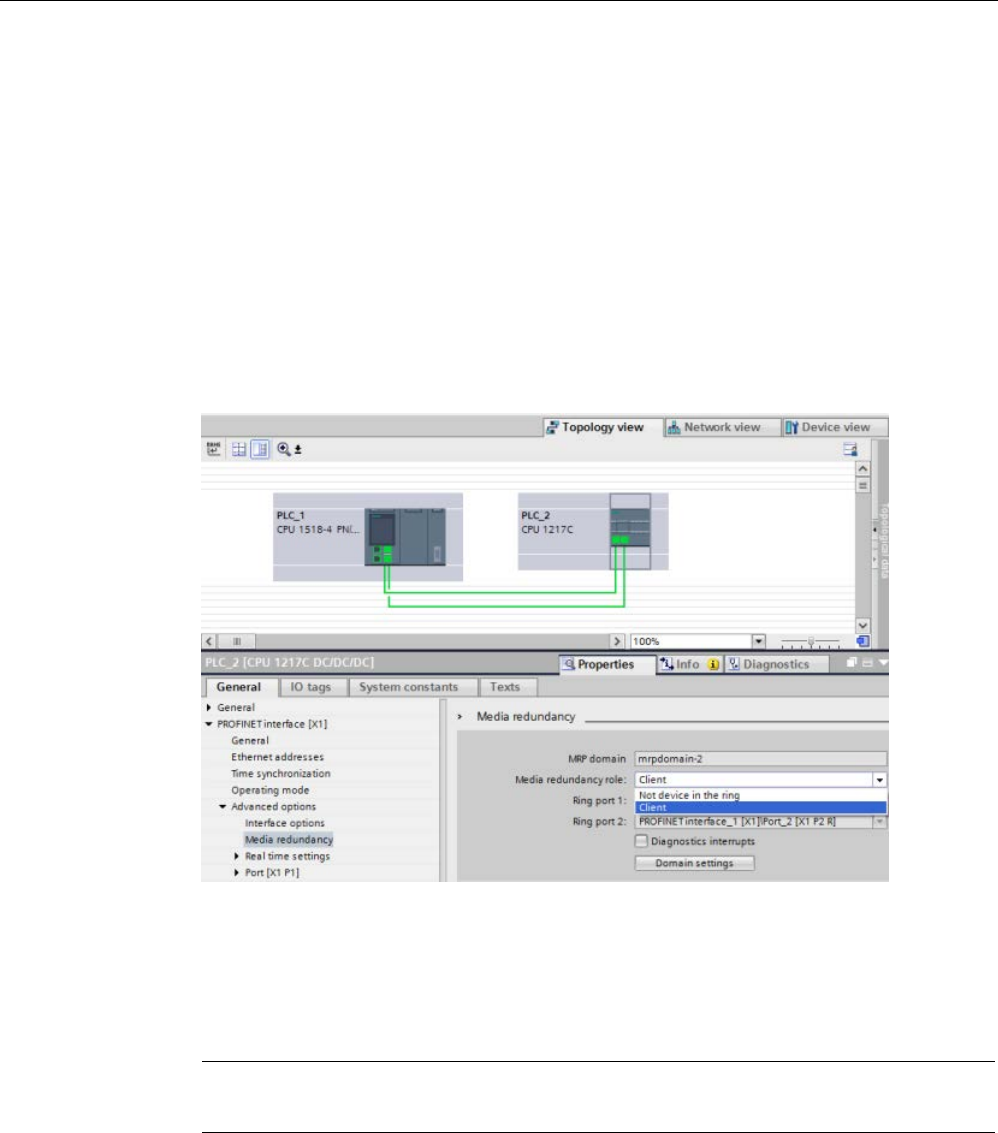
Communication
11.2 PROFINET
S7-1200 Programmable controller
System Manual, V4.2, 09/2016, A5E02486680-AK 959
11.2.15.3
Configuring media redundancy
All of the components in your application must support Media Redundancy Protocol (MRP).
Procedure
To configure media redundancy, proceed as follows:
1. Establish a ring by means of appropriate port interconnections (for example, in the
topology view).
2. Select a PROFINET device for which you want to configure media redundancy.
3. In the Inspector window, navigate to "PROFINET" interface [X1]">"Advanced
options">"Media redundancy".
4. Under "Media redundancy role", assign the "Manager (Auto)", "Client", or "Not device in
the ring" role to the device.
When you configure a ring in the TIA Portal Topology view, the TIA Portal automatically
sets the Media Redundancy role for you. If a device can be a Manager, the TIA Portal
sets the Media redundancy role as "Manager (Auto)". For the S7-1200, the Media
Redundancy role is automatically set to "Client".
Note
You cannot assign the "Manager (Auto)" media redundancy role to the S7
-1200 CPU.
5. Repeat steps 2 to 4 for all PROFINET devices in the ring.
Or:
1. Highlight the PROFINET IO system in the network view.
2. Click on the PROFINET IO system.
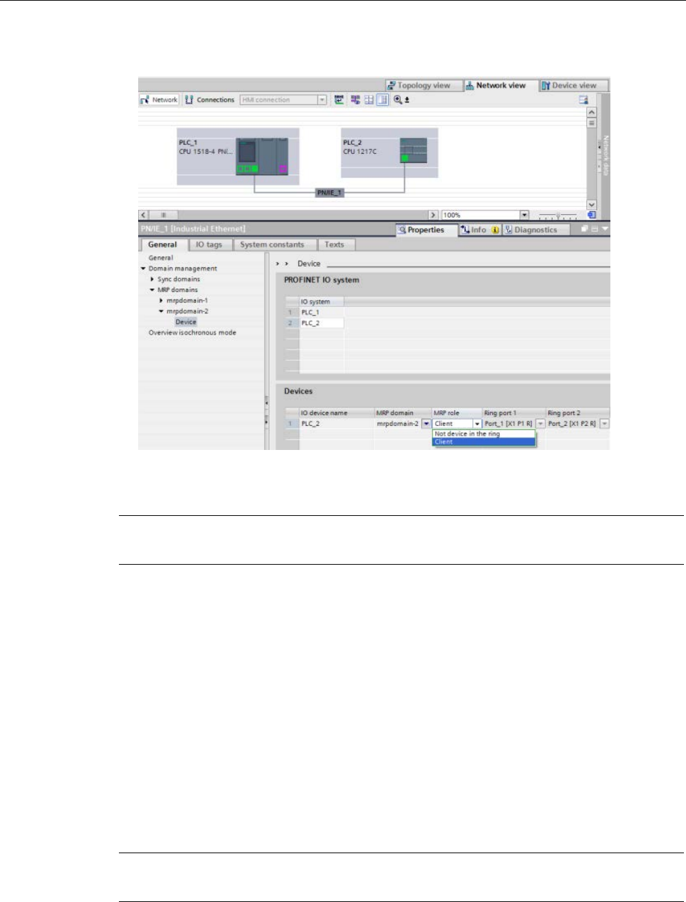
Communication
11.2 PROFINET
S7-1200 Programmable controller
960 System Manual, V4.2, 09/2016, A5E02486680-AK
3. Navigate to the device of the required MRP domain in the inspector window.
4. For the PROFINET devices, set the "Manager (Auto)", "Client", or "Not device in the ring"
role.
Note
You cannot assign the "Manager (Auto)" MRP role to the
S7-1200 CPU.
"Media redundancy" setting option: MRP role
Depending on the device used, the roles "Manager", "Manager (Auto)", "Client", and "Not
device in the ring" are available.
Rules:
● A ring can have only one device with the role of "Manager". No additional devices with the
role of "Manager" or "Manager (Auto)" are permissible. All other devices in the ring can
only have the role of "Client". Devices not in the ring can have the role "Not device in the
ring".
● If a ring has no device with the "Manager" role, the ring must at least have one device
with the role "Manager (Auto)". A ring can have any number of devices with the roles
"Client" and "Manager (Auto)".
Note
You cannot assign the "Manager" or "Manager (Auto)" MRP roles to the S7
-1200 CPU.

Communication
11.2 PROFINET
S7-1200 Programmable controller
System Manual, V4.2, 09/2016, A5E02486680-AK 961
"Media redundancy" setting option: Ring port 1 and Ring port 2
Select one at a time those ports you want to configure as ring port 1 or ring port 2. The drop-
down list box shows the selection of possible ports for each device type. If the ports are set
at the factory, then the fields are unavailable.
Note
Ring port configuration is not necessary in the S7
-1200 because the S7-1200 CPU has only
two ports.
Diagnostic interrupts
If diagnostic interrupts to the MRP state are to be output in the local CPU, select the
"Diagnostic interrupts" check box. The following diagnostic interrupts can be configured:
● Wiring or port error:
The CPU generates diagnostic interrupts for the following errors in the ring ports:
– A neighbor of the ring port does not support MRP.
– A ring port is connected to a non-ring port.
– A ring port is connected to the ring port of another MRP domain.
● Interruption / return (MRP manager only):
If the ring is interrupted and the original configuration is returned, the CPU generates
diagnostic interrupts. If both of these interrupts occur within 0.2 seconds, this indicates an
interruption of the ring.
You can respond to these events in the user program by programming the appropriate
response in the diagnostic error interrupt OB (OB 82).
Note
Third-party devices as MRP manager
To assure error
-free operation when a third party device is used as MRP manager in a ring,
you must assign the fixed role of "Client" to all other devices in the ring before you close the
ring. Otherwise,
circulating data frames and network failure could occur.

Communication
11.2 PROFINET
S7-1200 Programmable controller
962 System Manual, V4.2, 09/2016, A5E02486680-AK
11.2.16
S7 routing
From the STEP 7 Network view, you can create a complex communication topology by
connecting devices in different S7 subnets. You can connect classic CPUs and CPs as well
as the latest S7 CPUs and CPs and can include HMIs and PC stations such as an OPC
server.
Once you decide which devices must communicate and establish the necessary connections
using STEP 7, the Engineering System (ES) can download the corresponding routing tables
to the various S7 routers as part of the hardware configuration. After you download the
routing tables to the various S7 routers, the ES or other communication partners can
communicate with each device even though the devices are on different S7 subnets. This is
possible because the CPUs and/or CPs, in between, act as S7 routers. The CPUs and/or
CPs forward incoming connection requests to the next S7 router until the connection request
reaches the targeted device, and the devices establish the S7 connection.
The CPU uses the write record mechanism to transfer the routing tables required by the CP
devices in the local base. The routing tables establish the route from one device to another
at the time of a connection request, which includes a remote S7 Subnet_ID. The device
receiving the connection request interrogates its routing table, finds the next station in the
path to the target S7 subnet, and forwards the connection request. Eventually, the
connection request reaches the intended target and the response traverses the route in the
reverse direction.
The S7-1200 CPUs have a single PN interface and up to three CP devices connected to the
local communication bus. Therefore, you have two options for routing within the S7-1200
station:
● Routing between the CPU and a CP
● Routing from one CP to another CP
Refer to S7-1200 CPs at Siemens Industry Online Support, Product Support for further
information on all S7-1200 CPs that support the S7 routing function. The CP 1243-1
(https://support.industry.siemens.com/cs/us/en/view/584459) is shown as an example CP
module search for S7 routing capabilities.

Communication
11.2 PROFINET
S7-1200 Programmable controller
System Manual, V4.2, 09/2016, A5E02486680-AK 963
11.2.16.1
S7 routing between CPU and CP interfaces
Since the S7-1200 CPUs are limited to a single PN interface, a stand-alone CPU cannot
serve the function of a router. You can never connect a stand-alone CPU to more than one
S7 subnet at a time. When you install CP modules in the local base of the CPU, you can
connect to multiple S7 subnets and utilize routing.
In the example system below, in order for PLC_1 to communicate with PLC_3, the
Engineering System (ES) must rout messages through PLC_2. The ES must download the
routing table for PLC_2, and PLC_2 must provide the routing table for the CP module in its
local base. With these routing tables in place, PLC_1 and PLC_3 can communicate with
each other, even though not directly connected.
In order to check routing from either S7 subnet to the other S7 subnet, PLC_1 must establish
a transport connection to PLC_3, and PLC_3 must establish a connection to PLC_1. Doing
so, makes sure that routing from the PLC’s PN/IE interface to a CP module is possible as
well as routing from a CP module to the PLC’s PN/IE interface.
11.2.16.2
S7 routing between two CP interfaces
Since the S7-1200 CPUs support up to three CP modules, you can connect all three
modules to different S7 subnets. When you install at least two CP modules in the local base
of the CPU and connect to different S7 subnets, you can utilize routing.
In the example system below, in order for PLC_1 to communicate with PLC_3, the
Engineering System (ES) must rout messages by PLC_2 from the CP module to the CP
module in its local base. The ES must download the routing table for PLC_2, and PLC_2
must provide the routing table for the two CP modules. With these routing tables in place,
PLC_1 and PLC_3 can communicate with each other, even though not directly connected.
Also, you should note that routing takes place from CP module to CP module without
messages being sent over the PN/IE interface of PLC_2.

Communication
11.2 PROFINET
S7-1200 Programmable controller
964 System Manual, V4.2, 09/2016, A5E02486680-AK
11.2.17
Disabling SNMP
Simple Network Management Protocol (SNMP) is an Internet-standard protocol for collecting
and organizing information about managed devices on IP networks and for modifying that
information to change device behavior. Devices that typically support SNMP include routers,
switches, servers, workstations, printers, modem racks, and more.
SNMP is widely used in network management systems to monitor network-attached devices
for conditions that warrant administrative attention. SNMP uses various services and tools
for detection and diagnostics of the network topology. Information about the properties of
devices capable of SNMP is contained in Management Information Base (MIB) files for
which the user needs to have the appropriate rights. SNMP exposes management data in
the form of variables on the managed systems, which describe the system configuration.
These variables can then be queried (and sometimes set) by managing applications.
SNMP uses the UDP transport protocol and has two network components:
● SNMP manager: Monitors the network nodes
● SNMP client: Collects the various network-specific information in the individual network
nodes and stores it in a structured form in the Management Information Base (MIB). With
this data, detailed network diagnostics can be performed.
Under certain conditions, your application may require you to disable SNMP. Examples of
these conditions include the following:
● The security settings in your network do not allow the use of SNMP.
● You use your own SNMP solution (for example, with your own communications
instructions).
If you disable SNMP for a device, you no longer have some options for diagnostics of the
network topology (for example, using the PRONETA tool or the web server of the CPU).
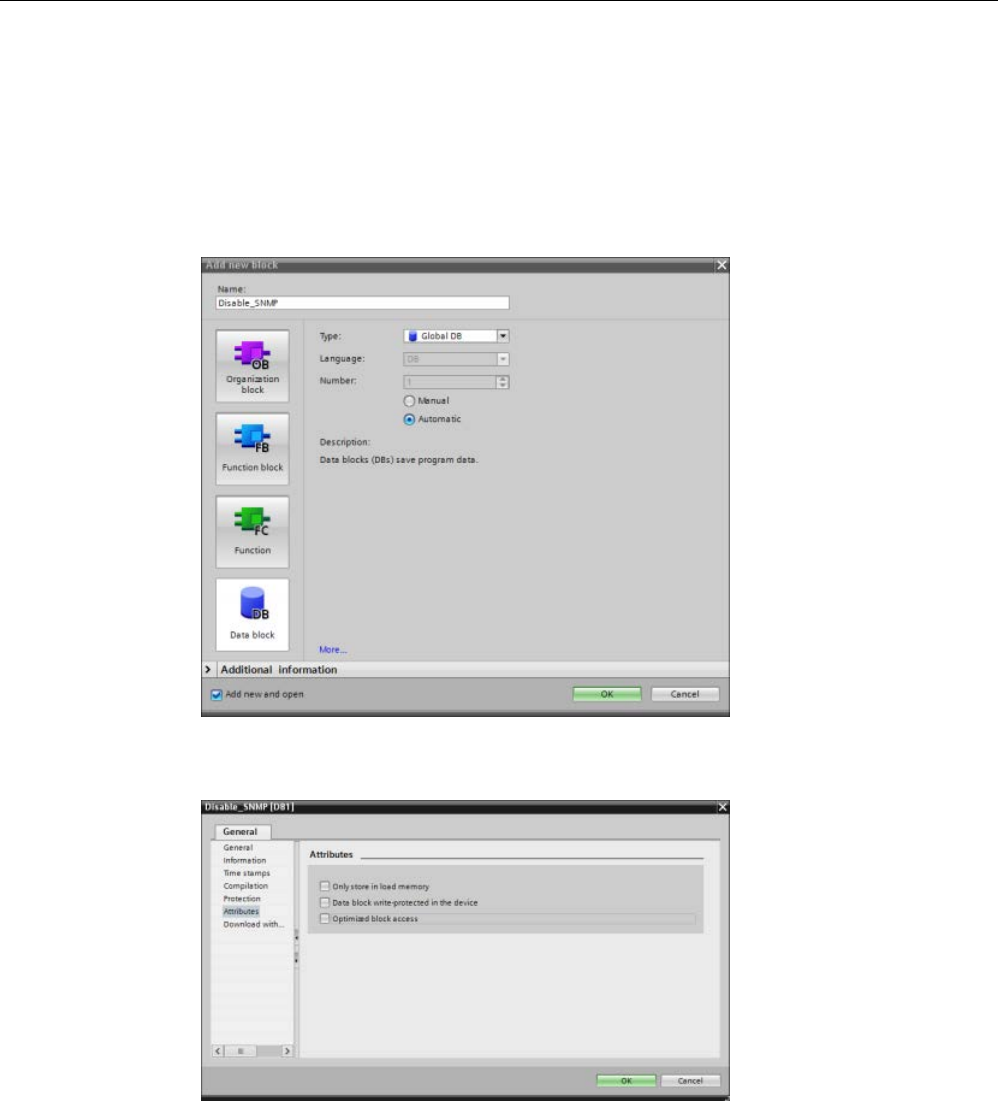
Communication
11.2 PROFINET
S7-1200 Programmable controller
System Manual, V4.2, 09/2016, A5E02486680-AK 965
11.2.17.1
Disabling SNMP
Disabling SNMP
Follow these steps to disable SNMP in the S7-1200 CPU:
1. Create a classic data block (DB):
2. Select the Properties of the newly-created DB.
3. Select the Attributes tab. Deselect the check box for "Optimized block access":
4. Click the OK button.
A message displays advising you to recompile your program. Recompile your program at
this time.
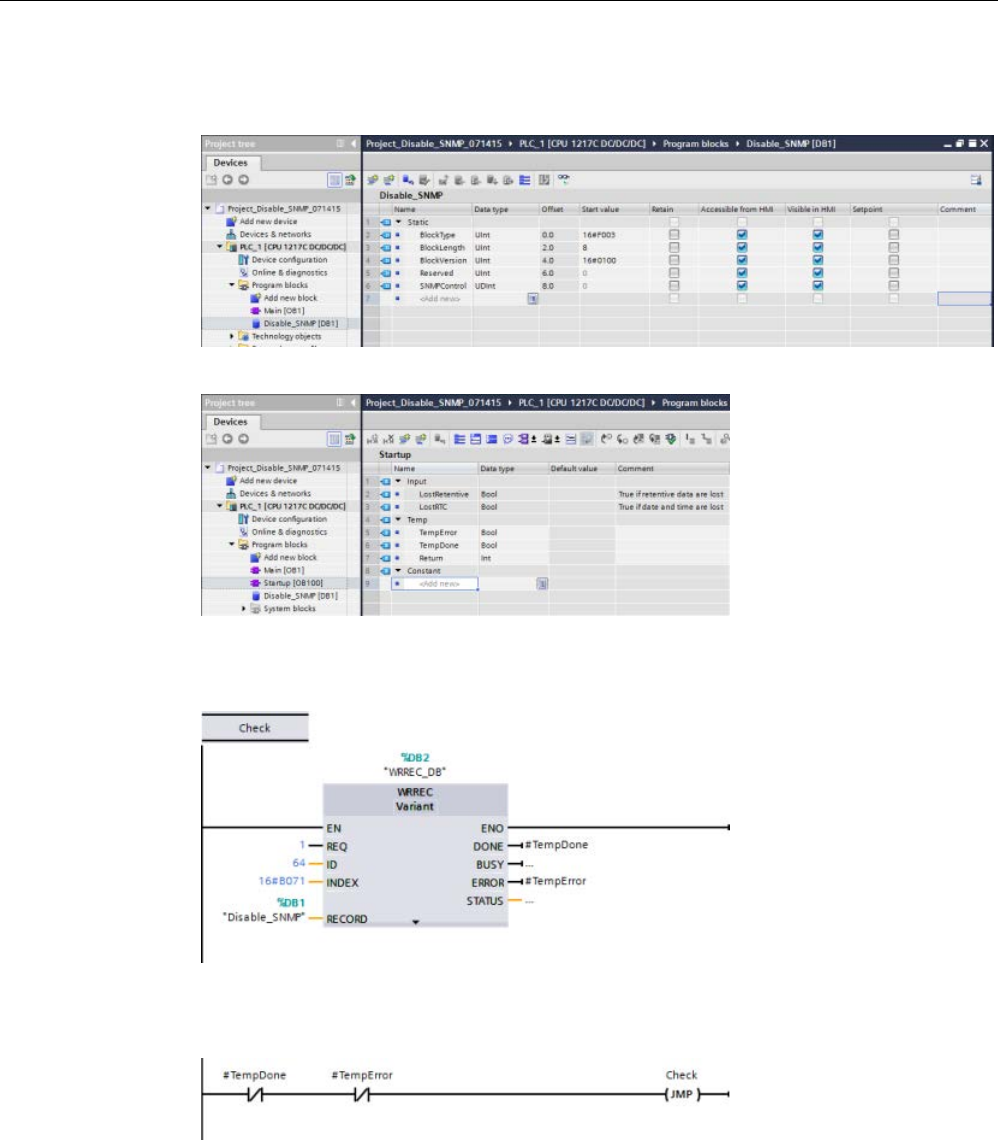
Communication
11.2 PROFINET
S7-1200 Programmable controller
966 System Manual, V4.2, 09/2016, A5E02486680-AK
5. In the classic DB block interface, create the following static tags with the values shown.
You will use these tags in your program to disable the internal SNMP implementation:
6. In the Startup OB (OB100), add the Temporary variables as shown:
7. Using the LAD editor, in the Startup OB (OB100), in Network 1, insert a Label (Jump
label) (in the example below, the Label is named "Check") and a WRREC (Write Record)
instruction with the inputs and outputs shown:
8. Insert the following loop and check code with the Jump to Label (JMP) output. This code
ensures that the call completes and that you disable SNMP before leaving the Startup
OB:

Communication
11.2 PROFINET
S7-1200 Programmable controller
System Manual, V4.2, 09/2016, A5E02486680-AK 967
11.2.18
Diagnostics
Refer to "Organization blocks (OBs)" (Page 92) for information on how to use organization
blocks (OBs) for diagnostics with these communication networks.
11.2.19
Distributed I/O instructions
Refer to "Distributed I/O (PROFINET, PROFIBUS, or AS-i)" (Page 384) for information on
how to use the distributed I/O instructions with these communication networks.
11.2.20
Diagnostic instructions
Refer to the "Diagnostics (PROFINET or PROFIBUS)": "Diagnostics instructions" (Page 439)
for information on how to use these instructions with these communication networks.
11.2.21
Diagnostic events for distributed I/O
Refer to the "Diagnostics (PROFINET or PROFIBUS)": "Diagnostics events for distributed
I/O" (Page 486) for information on how to use this diagnostic information with these
communication networks.
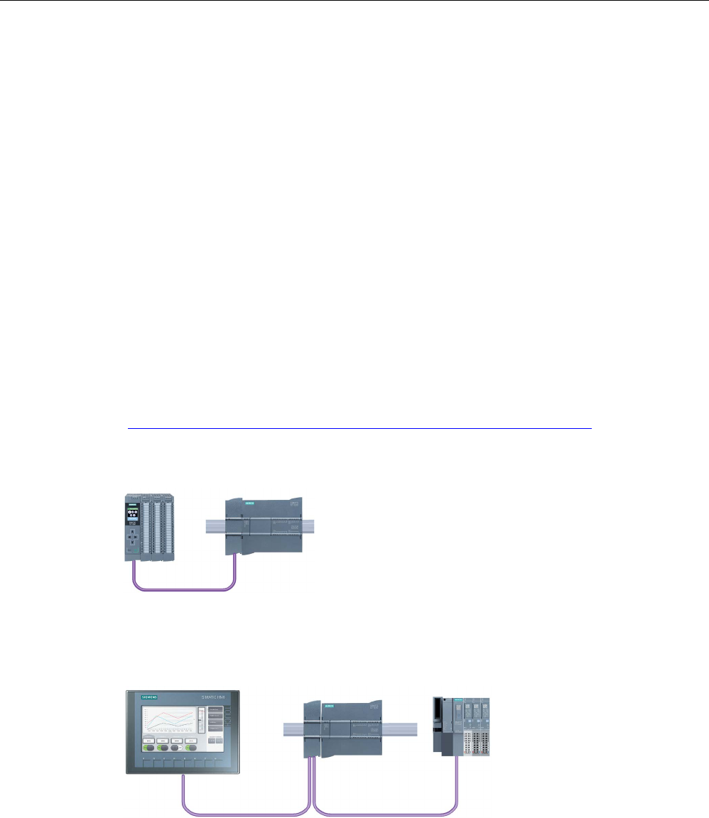
Communication
11.3 PROFIBUS
S7-1200 Programmable controller
968 System Manual, V4.2, 09/2016, A5E02486680-AK
11.3
PROFIBUS
A PROFIBUS system uses a bus master to poll slave devices distributed in a multi-drop
fashion on an RS485 serial bus. A PROFIBUS slave is any peripheral device (I/O
transducer, valve, motor drive, or other measuring device) which processes information and
sends its output to the master. The slave forms a passive station on the network since it
does not have bus access rights, and can only acknowledge received messages, or send
response messages to the master upon request. All PROFIBUS slaves have the same
priority, and all network communication originates from the master.
A PROFIBUS master forms an "active station" on the network. PROFIBUS DP defines two
classes of masters. A class 1 master (normally a central programmable controller (PLC) or a
PC running special software) handles the normal communication or exchange of data with
the slaves assigned to it. A class 2 master (usually a configuration device, such as a laptop
or programming console used for commissioning, maintenance, or diagnostics purposes) is
a special device primarily used for commissioning slaves and for diagnostic purposes.
The S7-1200 is connected to a PROFIBUS network as a DP slave with the CM 1242-5
communication module. The CM 1242-5 (DP slave) module can be the communications
partner of DP V0/V1 masters. If you want to configure the module in a third-party system,
there is a GSD file available for the CM 1242-5 (DP slave) on the CD that ships with the
module and on Siemens Automation Customer Support
(https://support.industry.siemens.com/cs/ww/en/ps/6GK7242-5DX30-0XE0) pages on the
Internet.
In the figure below, the S7-1200 is a DP slave to an S7-300 controller:
The S7-1200 is connected to a PROFIBUS network as a DP master with the CM 1243-5
communication module. The CM 1243-5 (DP master) module can be the communications
partner of DP V0/V1 slaves. In the figure below, the S7-1200 is a master controlling an
ET 200SP DP slave:
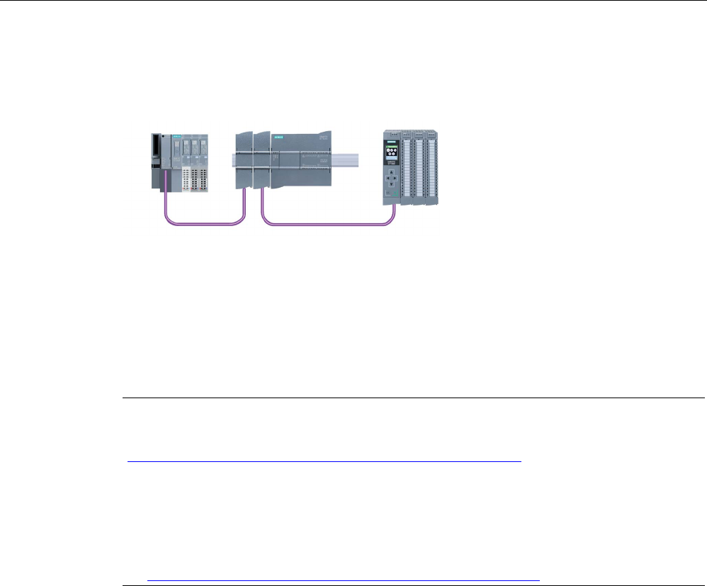
Communication
11.3 PROFIBUS
S7-1200 Programmable controller
System Manual, V4.2, 09/2016, A5E02486680-AK 969
If a CM 1242-5 and a CM 1243-5 are installed together, an S7-1200 can perform as both a
slave of a higher-level DP master system and a master of a lower-level DP slave system,
simultaneously:
As of V3.0, you can configure a maximum of three PROFIBUS CMs per station, in which
there can be any combination of DP master or DP slave CMs. DP masters in a V3.0 or
greater CPU firmware implementation can each control a maximum of 32 slaves.
The configuration data of the PROFIBUS CMs is stored on the local CPU. This allows simple
replacement of these communications modules when necessary.
To use PROFIBUS with S7-1200 V4.0 or later CPUs, you must upgrade the PROFIBUS
Master CM firmware to at least V1.3.
Note
Always up
date the PROFIBUS CM firmware to the latest version available
(
http://support.automation.siemens.com/WW/view/en/42131407). You can perform a
firmware update by any of these methods:
•
Using the online and diagnostic tools of STEP 7 (Page 1318)
•
Using a SIMATIC memory card (Page 148)
•
Using the Web server "Module Information" standard Web page (Page 1023)
•
Using the SIMATIC Automation Tool
(https://support.industry.siemens.com/cs/ww/en/view/98161300)

Communication
11.3 PROFIBUS
S7-1200 Programmable controller
970 System Manual, V4.2, 09/2016, A5E02486680-AK
11.3.1
Communications services of the PROFIBUS CMs
The PROFIBUS CMs use the PROFIBUS DP-V1 protocol.
Types of communication with DP-V1
The following types of communication are available with DP-V1:
● Cyclic communication (CM 1242-5 and CM 1243-5)
Both PROFIBUS modules support cyclic communication for the transfer of process data
between DP slave and DP master.
Cyclic communication is handled by the operating system of the CPU. No software blocks
are required for this. The I/O data is read or written directly from/to the process image of
the CPU.
● Acyclic communication (CM 1243-5 only)
The DP master module also supports acyclic communication using software blocks:
– The "RALRM" instruction is available for interrupt handling.
– The "RDREC" and "WRREC" instructions are available for transferring configuration
and diagnostics data.
Functions not supported by the CM 1243-5: SYNC/FREEZE and Get_Master_Diag
Other communications services of the CM 1243-5
The CM 1243-5 DP master module supports the following additional communications
services:
● S7 communication
– PUT/GET services
The DP master functions as a client and server for queries from other S7 controllers or
PCs via PROFIBUS.
– PG/OP communication
The PG functions allow the downloading of configuration data and user programs from
a PG and the transfer of diagnostics data to a PG.
Possible communications partners for OP communication are HMI panels, SIMATIC
panel PCs with WinCC flexible or SCADA systems that support S7 communication.
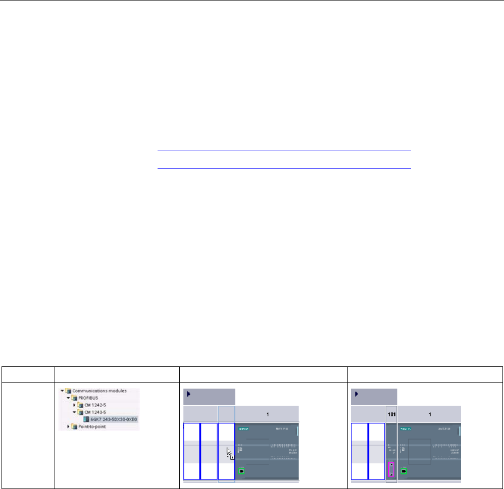
Communication
11.3 PROFIBUS
S7-1200 Programmable controller
System Manual, V4.2, 09/2016, A5E02486680-AK 971
11.3.2
Reference to the PROFIBUS CM user manuals
Further information
You can find detailed information on the PROFIBUS CMs in the manuals for the devices.
You can find these on the Internet in the pages of Siemens Industrial Automation Customer
Support under the following entry IDs:
● CM 1242-5 (https://support.industry.siemens.com/cs/ww/en/ps/15667)
● CM 1243-5 (https://support.industry.siemens.com/cs/ww/en/ps/15669)
11.3.3
Configuring a DP master and slave device
11.3.3.1
Adding the CM 1243-5 (DP master) module and a DP slave
In the "Devices and networks" portal, use the hardware catalog to add PROFIBUS modules
to the CPU. These modules are connected to the left side of the CPU. To insert a module
into the hardware configuration, select the module in the hardware catalog and either
double-click or drag the module to the highlighted slot.
Table 11- 54 Adding a PROFIBUS CM 1243-5 (DP master) module to the device configuration
Module
Select the module
Insert the module
Result
CM 1243-5
(DP mas-
ter)
Use the hardware catalog to add DP slaves as well. For example, to add an ET 200SP DP
slave, in the Hardware Catalog, expand the following containers:
● Distributed I/O
● ET 200SP
● Interface modules
● PROFIBUS
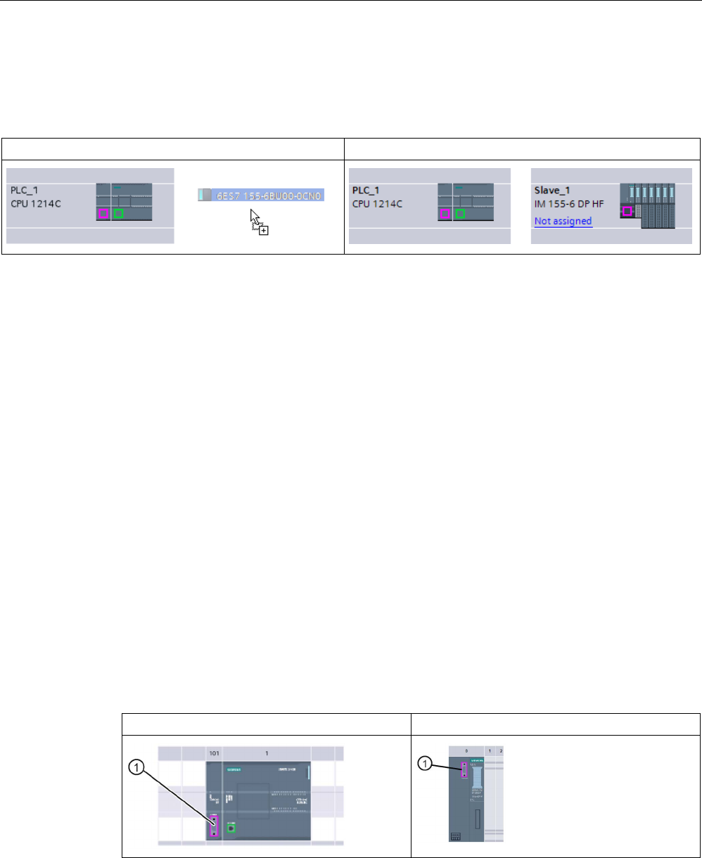
Communication
11.3 PROFIBUS
S7-1200 Programmable controller
972 System Manual, V4.2, 09/2016, A5E02486680-AK
Next, select "6ES7 155-6BU00-0CN0" (IM155-6 DP HF) from the list of part numbers, and
add the ET 200SP DP slave as shown in the figure below.
Table 11- 55 Adding an ET 200SP DP slave to the device configuration
Insert the DP slave
Result
11.3.3.2
Configuring logical network connections between two PROFIBUS devices
After you configure the CM 1243-5 (DP master) module, you are now ready to configure your
network connections.
In the Devices and Networks portal, use the "Network view" to create the network
connections between the devices in your project. To create the PROFIBUS connection,
select the purple (PROFIBUS) box on the first device. Drag a line to the PROFIBUS box on
the second device. Release the mouse button and your PROFIBUS connection is joined.
Refer to "Device Configuration: Creating a network connection" (Page 806) for more
information.
11.3.3.3
Assigning PROFIBUS addresses to the CM 1243-5 module and DP slave
Configuring the PROFIBUS interface
After you configure logical network connections between two PROFIBUS devices, you can
configure parameters for the PROFIBUS interfaces. To do so, click the purple PROFIBUS
box on the CM 1243-5 module, and the "Properties" tab in the inspector window displays the
PROFIBUS interface. The DP slave PROFIBUS interface is configured in the same manner.
Table 11- 56 Configuring the CM 1243-5 (DP master) module and ET 200SP DP slave PROFIBUS in-
terfaces
CM 1243-5 (DP master) module
ET 200SP DP slave
① PROFIBUS port
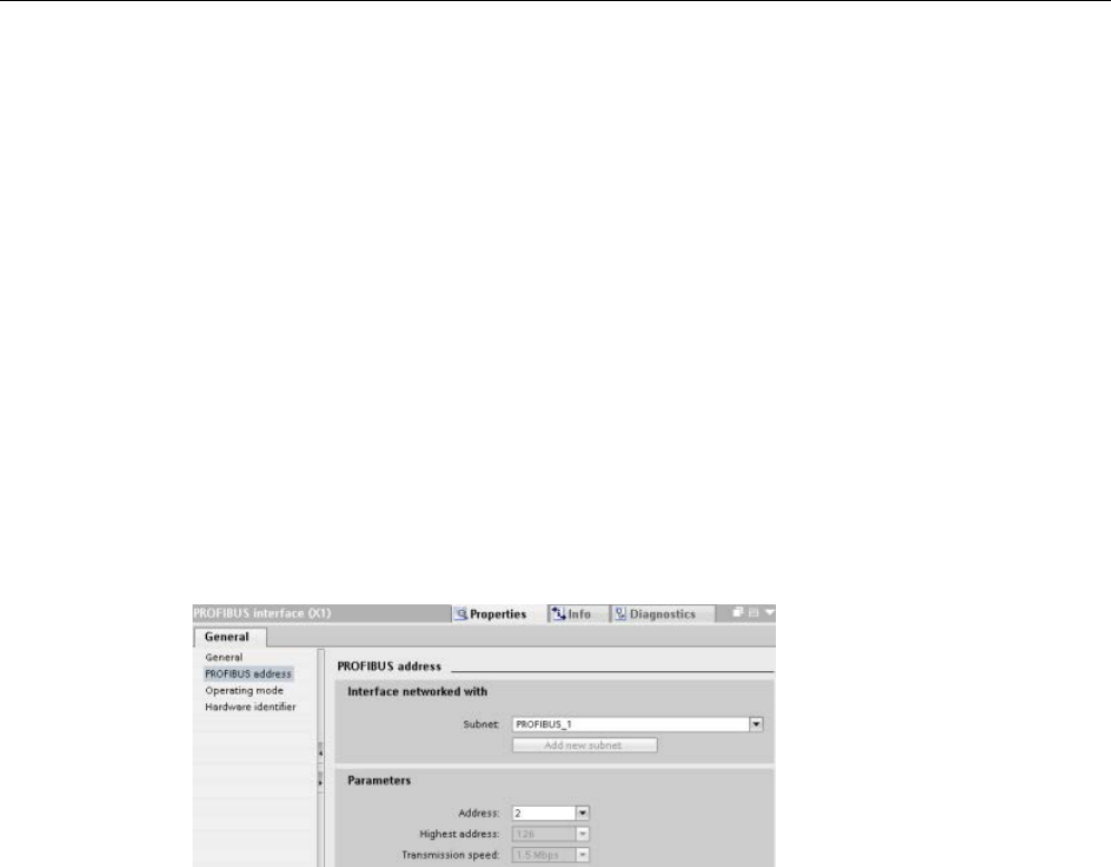
Communication
11.3 PROFIBUS
S7-1200 Programmable controller
System Manual, V4.2, 09/2016, A5E02486680-AK 973
Assigning the PROFIBUS address
In a PROFIBUS network, each device is assigned a PROFIBUS address. This address can
range from 0 through 127, with the following exceptions:
● Address 0: Reserved for network configuration and/or programming tools attached to the
bus
● Address 1: Reserved by Siemens for the first master
● Address 126: Reserved for devices from the factory that do not have a switch setting and
must be re-addressed through the network
● Address 127: Reserved for broadcast messages to all devices on the network and may
not be assigned to operational devices
Thus, the addresses that may be used for PROFIBUS operational devices are 2 through
125.
In the Properties window, select the "PROFIBUS address" configuration entry. STEP 7
displays the PROFIBUS address configuration dialog, which is used to assign the
PROFIBUS address of the device.

Communication
11.3 PROFIBUS
S7-1200 Programmable controller
974 System Manual, V4.2, 09/2016, A5E02486680-AK
Table 11- 57 Parameters for the PROFIBUS address
Parameter
Description
Subnet Name of the Subnet to which the device is connected. Click the "Add new subnet" button to create a
new subnet. "Not connected" is the default. Two connection types are possible:
• The "Not connected" default provides a local connection.
• A subnet is required when your network has two or more devices.
Parameters
Address
Assigned PROFIBUS address for the device
Highest address The highest PROFIBUS address is based on the active stations on the
PROFIBUS (for example, DP master). Passive DP slaves independently
have PROFIBUS addresses from 1 to 125 even if the highest PROFIBUS
address is set to 15, for example. The highest PROFIBUS address is rele-
vant for token forwarding (forwarding of the send rights), and the token is
only forwarded to active stations. Specifying the highest PROFIBUS ad-
dress optimizes the bus.
Transmission rate Transmission rate of the configured PROFIBUS network: The PROFIBUS
transmission rates range from 9.6 Kbits/sec to 12 Mbits/sec. The transmis-
sion rate setting depends on the properties of the PROFIBUS nodes being
used. The transmission rate should not be greater than the rate supported
by the slowest node.
The transmission rate is normally set for the master on the PROFIBUS
network, with all DP slaves automatically using that same transmission rate
(auto-baud).
11.3.4
Distributed I/O instructions
Refer to "Distributed I/O (PROFINET, PROFIBUS, or AS-i)" (Page 384) for information on
how to use the distributed I/O instructions with these communication networks.
11.3.5
Diagnostic instructions
Refer to the "Diagnostics (PROFINET or PROFIBUS)": "Diagnostics instructions" (Page 439)
for information on how to use these instructions with these communication networks.
11.3.6
Diagnostic events for distributed
Refer to the "Diagnostics (PROFINET or PROFIBUS)": "Diagnostics events for distributed
I/O" (Page 486) for information on how to use this diagnostic information with these
communication networks.

Communication
11.4 AS-i
S7-1200 Programmable controller
System Manual, V4.2, 09/2016, A5E02486680-AK 975
11.4
AS-i
The S7-1200 AS-i master CM 1243-2 allows the attachment of an AS-i network to an S7-
1200 CPU.
The actuator/sensor interface, or AS-i, is a single master network connection system for the
lowest level in automation systems. The CM 1243-2 serves as the AS-i master for the
network. Using a single AS-i cable, sensors and actuators (AS-i slave devices) can be
connected to the CPU through the CM 1243-2. The CM 1243-2 handles all AS-i network
coordination and relays data and status information from the actuators and sensors to the
CPU through the I/O addresses assigned to the CM 1243-2. You can access binary or
analog values depending on the slave type. The AS-i slaves are the input and output
channels of the AS-i system and are only active when called by the CM 1243-2.
In the figure below, the S7-1200 is an AS-i master controlling AS-i I/O module digital/analog
slave devices.
To use AS-i with S7-1200 V4.0 CPUs, you must upgrade the AS-i Master CM firmware to
V1.1.
You can make this upgrade using the webserver or a SIMATIC memory card.
Note
For V4.0 S7
-1200 CPUs, if using the web server or a SIMATIC memory card to upgrade
from V1.0 to V1.1 AS
-i firmware, you must update the AS-i firmware in the AS-i Master CM
1243
-2 according to the following procedure:
1.
Download the firmware upgrade to the AS-i Master CM 1243-2.
2.
When the download is complete, power cycle the S7-1200 CPU to complete the firmware
upgrade process in the AS-i Master CM 1243-2.
3.
Repeat steps 1 and 2 for each additional AS-i Master CM 1243-2. The S7-1200 PLC
allows a maximum of three AS-i Master CM 1243-2.
Note
It is recommended that you alw
ays update the AS-i CM firmware to the latest version
available (
http://support.automation.siemens.com/WW/view/en/43416171)at the Siemens
Service and Support web site.
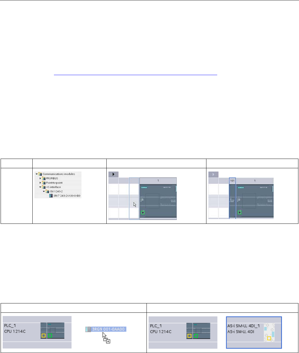
Communication
11.4 AS-i
S7-1200 Programmable controller
976 System Manual, V4.2, 09/2016, A5E02486680-AK
11.4.1
Configuring an AS-i master and slave device
The AS-i master CM 1243-2 is integrated into the S7-1200 automation system as a
communication module.
You can find detailed information on the AS-i master CM 1243-2 in the "AS-i master CM
1243-2 and AS-i data decoupling unit DCM 1271 for SIMATIC S7-1200" Manual
(https://support.industry.siemens.com/cs/ww/en/ps/15750/man).
11.4.1.1
Adding the AS-i master CM 1243-2 and AS-i slave
Use the hardware catalog to add AS-i master CM1243-2 modules to the CPU. These
modules are connected to the left side of the CPU, and a maximum of three AS-i master
CM1243-2 modules can be used. To insert a module into the hardware configuration, select
the module in the hardware catalog and either double-click or drag the module to the
highlighted slot.
Table 11- 58 Adding an AS-i master CM1243-2 module to the device configuration
Module
Select the module
Insert the module
Result
CM 1243-2
AS-i Mas-
ter
Use the hardware catalog to add AS-i slaves as well. For example, to add an "I/O module,
compact, digital, input" slave, in the Hardware Catalog, expand the following containers:
● Field devices
● AS-Interface slaves
Next, select "3RG9 001-0AA00" (AS-i SM-U, 4DI) from the list of part numbers, and add the
"I/O module, compact, digital, input" slave as shown in the figure below.
Table 11- 59 Adding an AS-i slave to the device configuration
Insert the AS-i slave
Result
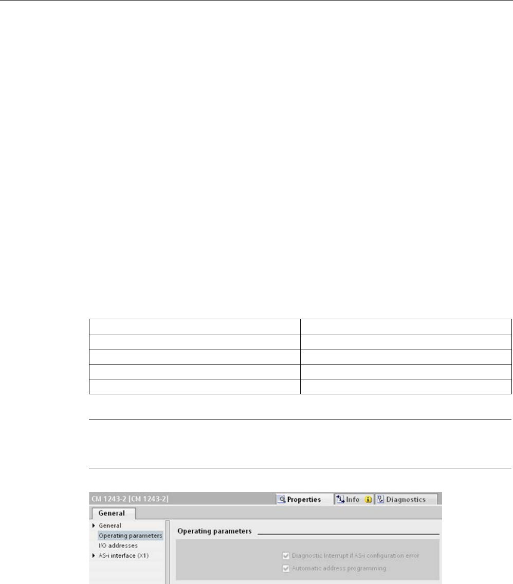
Communication
11.4 AS-i
S7-1200 Programmable controller
System Manual, V4.2, 09/2016, A5E02486680-AK 977
11.4.1.2
Configuring logical network connections between two AS-i devices
After you configure the AS-i master CM1243-2, you are now ready to configure your network
connections.
In the Devices and Networks portal, use the "Network view" to create the network
connections between the devices in your project. To create the AS-i connection, select the
yellow (AS-i) box on the first device. Drag a line to the AS-i box on the second device.
Release the mouse button and your AS-i connection is joined.
Refer to "Device Configuration: Creating a network connection" (Page 806) for more
information.
11.4.1.3
Configuring the properties of the AS-i master CM1243-2
To configure parameters for the AS-i interface, click the yellow AS-i box on the AS-i master
CM1243-2 module, and the "Properties" tab in the inspector window displays the AS-i
interface.
In the STEP 7 inspector window, you can view, configure, and change general information,
addresses and operating parameters:
Table 11- 60 AS-i master CM1243-2 module properties
Property
Description
General
Name of the AS-i master CM 1243-2
Operating parameters Parameters for the response of the AS-i master
I/O addresses
Address area for the slave I/O addresses
AS-i interface (X1) Assigned AS-i network
Note
"Diagnostic interrupt for faults in the AS
-i configuration" and "Automatic address
programming" are always active and are therefore shown in gray.

Communication
11.4 AS-i
S7-1200 Programmable controller
978 System Manual, V4.2, 09/2016, A5E02486680-AK
11.4.1.4
Assigning an AS-i address to an AS-i slave
Configuring the AS-i slave interface
To configure parameters for the AS-i interface, click the yellow AS-i box on the AS-i slave,
and the "Properties" tab in the inspector window displays the AS-i interface.
①
AS-i port
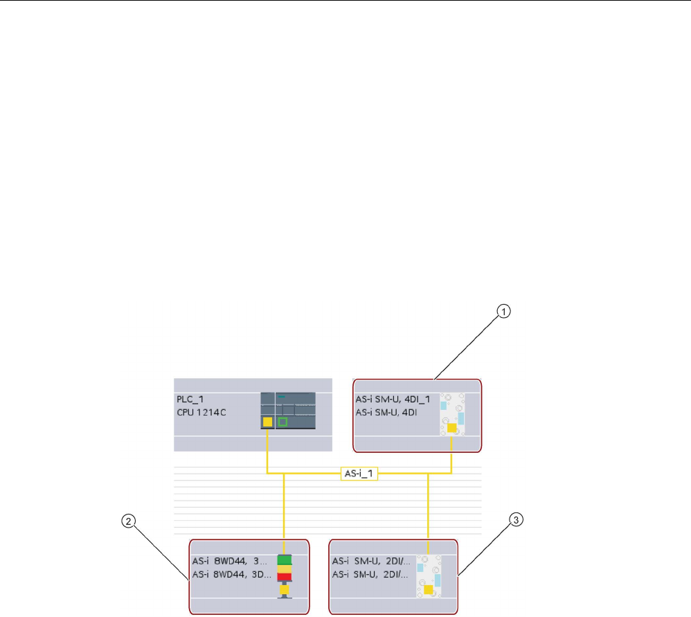
Communication
11.4 AS-i
S7-1200 Programmable controller
System Manual, V4.2, 09/2016, A5E02486680-AK 979
Assigning the AS-i slave address
In an AS-i network, each device is assigned an AS-i slave address. This address can range
from 0 through 31; however, address 0 is reserved only for new slave devices. The slave
addresses are 1(A or B) to 31(A or B) for a total of up to 62 slave devices.
"Standard" AS-i devices use the entire address, having a number address without the A or B
designation. "A/B node" AS-i devices use the A or B portion of each address, enabling each
of the 31 addresses to be used twice. The address space range is 1A to 31A plus 1B to 31B.
Any address in the range of 1 - 31 can be assigned to an AS-i slave device; in other words, it
does not matter whether the slaves begin with address 21 or whether the first slave is
actually given the address 1.
In the example below, three AS-i devices have been addressed as "1" (a standard type
device), "2A" (an A/B node type device), and "3" (a standard type device):
①
AS-i slave address 1; Device: AS-i SM-U, 4DI; article number: 3RG9 001-0AA00
②
AS-i slave address 2A; Device: AS-i 8WD44, 3DO, A/B; article number: 8WD4 428-0BD
③
AS-i slave address 3; Device: AS-i SM-U, 2DI/2DO; article number: 3RG9 001-0AC00
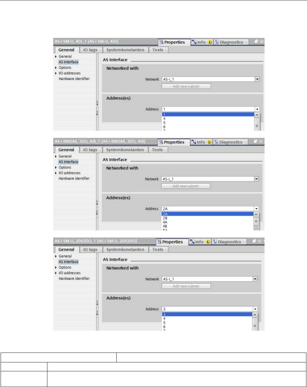
Communication
11.4 AS-i
S7-1200 Programmable controller
980 System Manual, V4.2, 09/2016, A5E02486680-AK
Enter the AS-i slave address here:
Table 11- 61 Parameters for the AS-i interface
Parameter
Description
Network
Name of the network to which the device is connected
Address(es) Assigned AS-i address for the slave device in range of 1(A or B) to 31(A or B) for a total of up to 62
slave devices
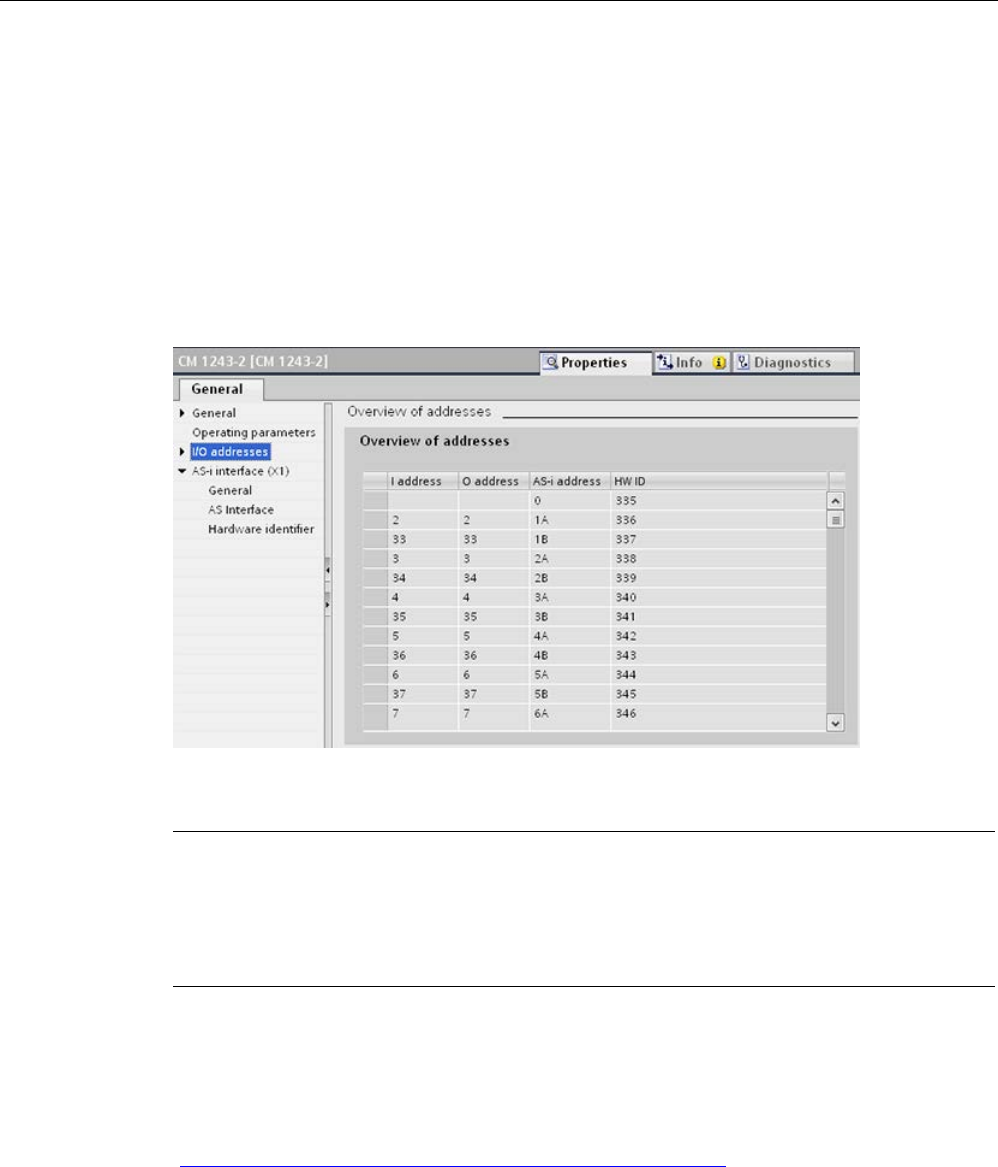
Communication
11.4 AS-i
S7-1200 Programmable controller
System Manual, V4.2, 09/2016, A5E02486680-AK 981
11.4.2
Exchanging data between the user program and AS-i slaves
11.4.2.1
STEP 7 basic configuration
The AS-i master reserves a 62-byte data area in the I/O area of the CPU. Access to the
digital data is performed here in bytes; for each slave, there is one byte of input and one byte
of output data.
The assignment of the AS-i connections of the AS-i digital slaves to the data bits of the
assigned byte is indicated in the inspection window of the AS-i master CM 1243-2.
You can access the data of the AS-i slaves in the user program by using the displayed I/O
addresses with the appropriate bit logic operations (for example, "AND") or bit assignments.
Note
"System assignment" is automatically activated if you do not configure the AS
-i slaves with
STEP
7.
If you do not configure any sl
aves, you must inform the AS-i master CM1243-2 about the
actual bus configuration using the online function "ACTUAL > EXPECTED".
Further information
You can find detailed information on the AS-i master CM 1243-2 in the "AS-i master CM
1243-2 and AS-i data decoupling unit DCM 1271 for SIMATIC S7-1200" Manual
(https://support.industry.siemens.com/cs/ww/en/ps/15750/man).
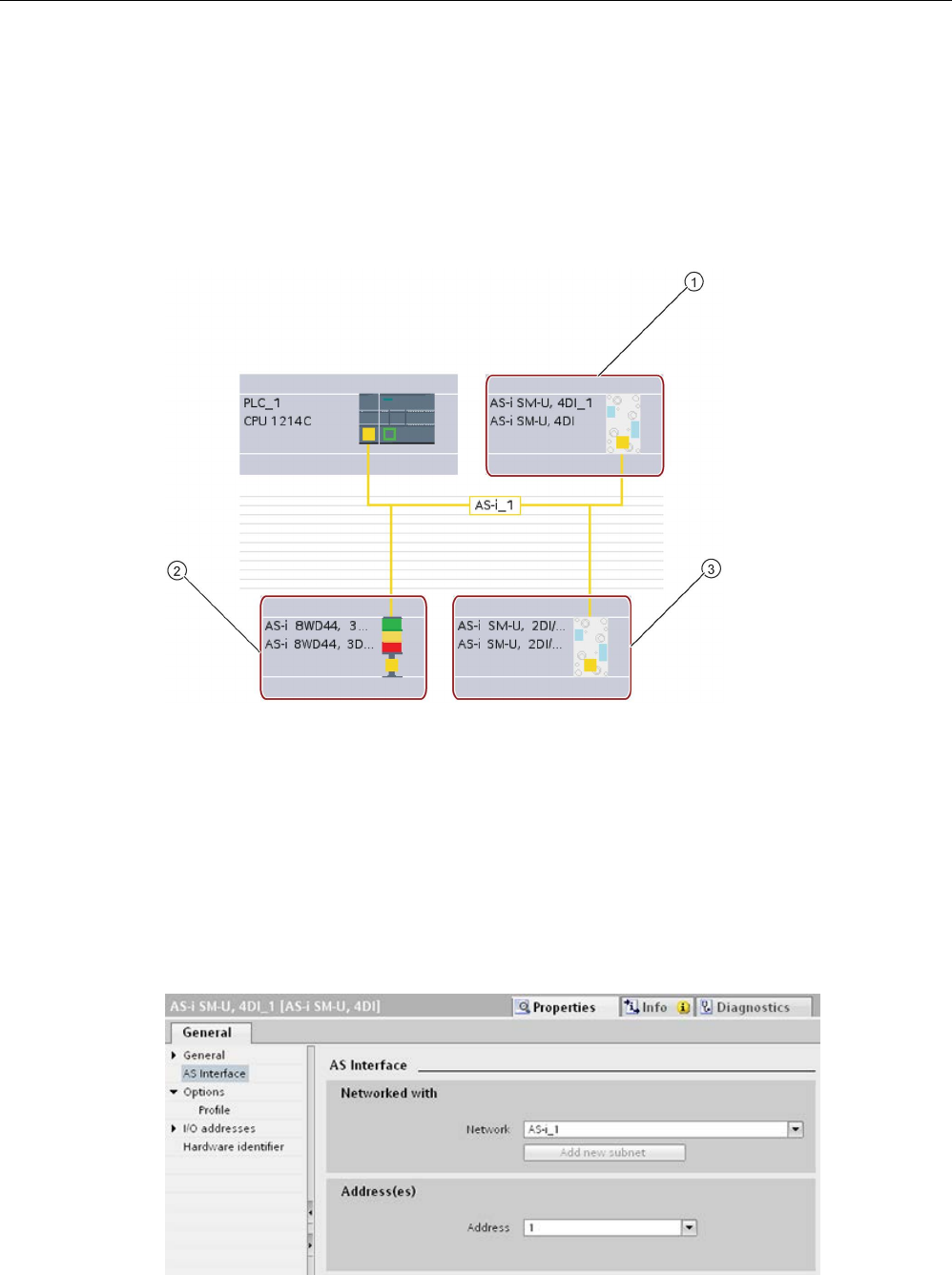
Communication
11.4 AS-i
S7-1200 Programmable controller
982 System Manual, V4.2, 09/2016, A5E02486680-AK
11.4.2.2
Configuring slaves with STEP 7
Transferring AS-i digital values
The CPU accesses the digital inputs and outputs of the AS-i slaves through the AS-i master
CM1243-2 in cyclic operation. The data is accessed through I/O addresses or by means of a
data record transfer.
①
AS-i slave address 1
②
AS-i slave address 2A
③
AS-i slave address 3
Access to the digital data is performed here in bytes (in other words, one byte is assigned to
each AS-i digital slave). When you configure the AS-i slaves in STEP 7, the I/O address for
accessing the data from the user program is displayed in the inspection window for the
respective AS-i slave.
The digital input module (AS-i SM-U, 4DI) in the AS-i network above has been assigned
slave address 1. By clicking on the digital input module, the "AS interface" tab in the device
"Properties" displays the slave address, as shown below:
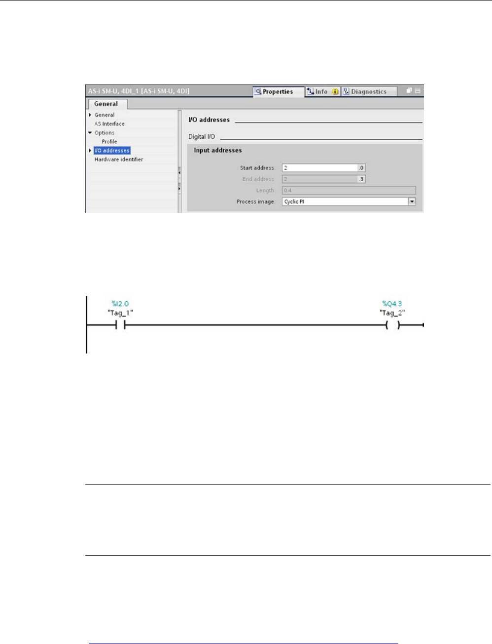
Communication
11.4 AS-i
S7-1200 Programmable controller
System Manual, V4.2, 09/2016, A5E02486680-AK 983
The digital input module (AS-i SM-U, 4DI) in the AS-i network above has been assigned I/O
address 2. By clicking on the digital input module, the "I/O addresses" tab in the device
"Properties" displays the I/O address, as shown below:
You can access the data of the AS-i slaves in the user program by using their I/O addresses
with the appropriate bit logic operations (for example, "AND") or bit assignments. The
following simple program illustrates how the assignment works:
Input 2.0 is polled in this program. In the AS-i system, this input belongs to slave1 (Input byte
2, bit 0). Output 4.3, which is then set, corresponds to AS-i slave 3 (Output byte 4, bit 3)
Transferring AS-i analog values
You can access analog data of an AS-i slave through the process image of the CPU if you
have configured this AS-i slave in STEP 7 as an analog slave.
If you did not configure the analog slave in STEP 7, you can only access the data of the AS-i
slave through the acyclic functions (data record interface). In the user program of the CPU,
AS-i calls are read and written using the RDREC (read data record) and WRREC (write data
record) distributed I/O instructions.
Note
A configuration of the AS
-i slaves specified through STEP 7 and downloaded into the S7
station is transferred by the CPU on the AS
-i master CM1243-2 during S7 station start-up.
Any existing config
uration that was determined through the "System assignment" online
function
(Page 981) ("ACTUAL -> EXPECTED") will be overwritten.
Further information
You can find detailed information on the AS-i master CM 1243-2 in the "AS-i master CM
1243-2 and AS-i data decoupling unit DCM 1271 for SIMATIC S7-1200" Manual
(http://support.automation.siemens.com/WW/view/en/50414115/133300).
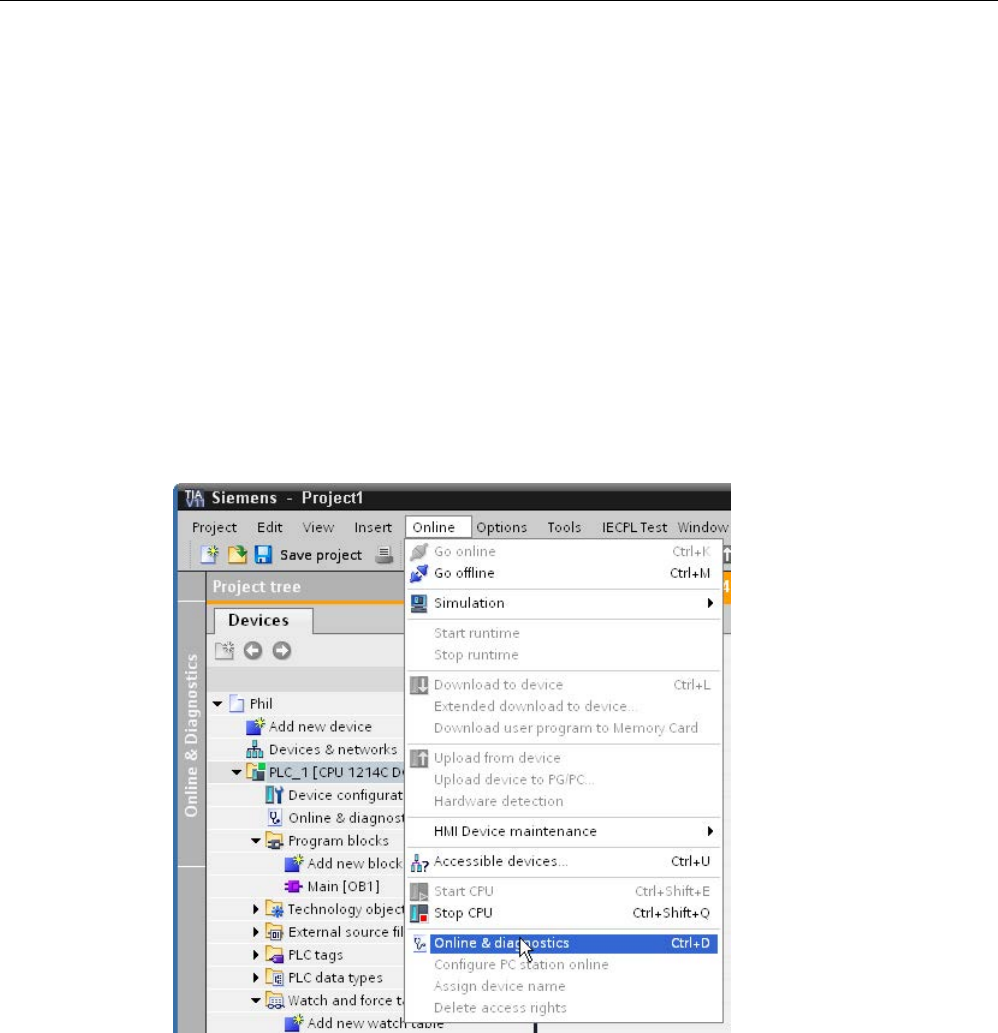
Communication
11.4 AS-i
S7-1200 Programmable controller
984 System Manual, V4.2, 09/2016, A5E02486680-AK
11.4.3
Distributed I/O instructions
Refer to "Distributed I/O (PROFINET, PROFIBUS, or AS-i)" (Page 384) for information on
how to use the distributed I/O instructions with these communication networks.
11.4.4
Working with AS-i online tools
Changing AS-i operational modes online
You must go online to view and change the AS-i operational modes.
In order to go online, your must first be in "Device configuration" with the AS-i master
CM1243-2 module selected, and then click the "Go online" button in the toolbar. Next, select
the "Online and diagnostics" command from the "Online" menu.
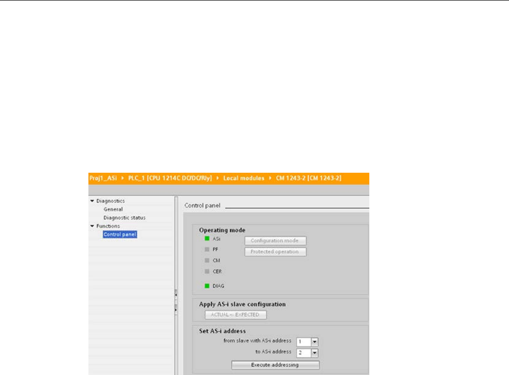
Communication
11.4 AS-i
S7-1200 Programmable controller
System Manual, V4.2, 09/2016, A5E02486680-AK 985
There are two AS-i operational modes:
● Protection mode:
– You cannot change AS-i slave device and CPU I/O addresses.
– The green "CM" LED is OFF.
● Configuration mode:
– You can make required changes in your AS-i slave device and CPU I/O addresses.
– The green "CM" LED is ON.
In the "Set AS-i address" field, you can change the AS-i slave address. A new slave that has
not been assigned an address always has address 0. It is detected by the master as a new
slave without an address assignment and is not included in normal communication until
assigned an address.
Configuration error
When the yellow "CER" LED is ON, there is an error in the AS-i slave device configuration.
Select the "ACTUAL > EXPECTED" button to overwrite the AS-i master CM1243-2 module
slave device configuration with the AS-i field network slave device configuration.

Communication
11.5 S7 communication
S7-1200 Programmable controller
986 System Manual, V4.2, 09/2016, A5E02486680-AK
11.5
S7 communication
11.5.1
GET and PUT (Read and write from a remote CPU)
You can use the GET and PUT instructions to communicate with S7 CPUs through
PROFINET and PROFIBUS connections. This is only possible if the "Permit access with
PUT/GET communication" function is activated for the partner CPU in the "Protection"
property of the local CPU properties:
● Accessing data in a remote CPU: An S7-1200 CPU can only use absolute addresses in
the ADDR_x input field to address variables of remote CPUs (S7-200/300/400/1200).
● Accessing data in a standard DB: An S7-1200 CPU can only use absolute addresses in
the ADDR_x input field to address DB variables in a standard DB of a remote S7 CPU.
● Accessing data in an optimized DB: An S7-1200 CPU cannot access DB variables in an
optimized DB of a remote S7-1200 CPU.
● Accessing data in a local CPU: An S7-1200 CPU can use either absolute or symbolic
addresses as inputs to the RD_x or SD_x input fields of the GET or PUT instruction,
respectively.
Note
V4.0 CPU program GET/PUT operation is not automatically enabled
A V3.0 CPU program GET/PUT operation is automatically enabled in a V4.0 CPU.
However, a V4.0 CPU program GET/PUT operation in a V4.0 CPU is not automatically
enabled. You mu
st go to the CPU "Device configuration", inspector window "Properties"tab,
"Protection" property to enable
GET/PUT access (Page 210).

Communication
11.5 S7 communication
S7-1200 Programmable controller
System Manual, V4.2, 09/2016, A5E02486680-AK 987
Table 11- 62 GET and PUT instructions
LAD / FBD
SCL
Description
"GET_DB"(
req:=_bool_in_,
ID:=_word_in_,
ndr=>_bool_out_,
error=>_bool_out_,
status=>_word_out_,
addr_1:=_remote_inout_,
[...addr_4:=_remote_inout_,]
rd_1:=_variant_inout_
[,...rd_4:=_variant_inout_]);
Use the GET instruction to read data from
a remote S7 CPU. The remote CPU can
be in either RUN or STOP mode.
STEP 7 automatically creates the DB
when you insert the instruction.
"PUT_DB"(
req:=_bool_in_,
ID:=_word_in_,
done=>_bool_out_,
error=>_bool_out_,
status=>_word_out_,
addr_1:=_remote_inout_,
[...addr_4:=_remote_inout_,]
sd_1:=_variant_inout_,
[....sd_4:=_variant_inout_]);
Use the PUT instruction to write data to a
remote S7 CPU. The remote CPU can be
in either RUN or STOP mode.
STEP 7 automatically creates the DB
when you insert the instruction.

Communication
11.5 S7 communication
S7-1200 Programmable controller
988 System Manual, V4.2, 09/2016, A5E02486680-AK
Table 11- 63 Data types for the parameters
Parameter and type
Data type
Description
REQ
Input
Bool
A low to high (positive edge) signal starts the operation.
ID Input CONN_PRG
(Word)
S7 connection ID (Hex)
NDR (GET) Output Bool New Data Ready:
• 0: request has not yet started or is still running
• 1: task was completed successfully
DONE (PUT) Output Bool DONE:
• 0: request has not yet started or is still running
• 1: task was completed successfully
ERROR
STATUS
Output
Output
Bool
Word
• ERROR=0
STATUS value:
– 0000H: neither warning nor error
– <> 0000H: Warning, STATUS supplies detailed information
• ERROR=1
There is an error. STATUS supplies detailed information about
the nature of the error.
ADDR_1 InOut Remote Pointer to the memory areas in the remote CPU that stores the
data to be read (GET) or that is sent (PUT).
ADDR_2
InOut
Remote
ADDR_3
InOut
Remote
ADDR_4
InOut
Remote
RD_1 (GET)
SD_1 (PUT)
InOut Variant Pointer to the memory areas in the local CPU that stores the data
to be read (GET) or sent (PUT).
Data types allowed: Bool (only a single bit allowed), Byte, Char,
Word, Int, DWord, DInt, or Real.
Note: If the pointer accesses a DB, you must specify the absolute
address, such as:
P# DB10.DBX5.0 Byte 10
In this case, 10 represents the number of bytes to GET or PUT.
RD_2 (GET)
SD_2 (PUT)
InOut Variant
RD_3 (GET)
SD_3 (PUT)
InOut Variant
RD_4 (GET)
SD_4 (PUT)
InOut Variant

Communication
11.5 S7 communication
S7-1200 Programmable controller
System Manual, V4.2, 09/2016, A5E02486680-AK 989
You must ensure that the length (number of bytes) and data types for the ADDR_x (remote
CPU) and RD_x or SD_x (local CPU) parameters match. The number after the identifier
"Byte" is the number of bytes referenced by the ADDR_x, RD_x, or SD_x parameter.
Note
The total number of bytes received on a GET instruction or the total number of bytes sent on
a PUT instruction is limited.
The limitations are based on how many of the four possible
address and memory areas you use:
•
If you use only ADDR_1 and RD_1/SD_1, a GET instruction can get 222 bytes and a PUT
instruction can send 212 bytes.
•
If you use ADDR_1, RD_1/SD_1, ADDR_2, and RD_2/SD_2, a GET instruction can get a
total of 218 bytes and a PUT instruction can send a total of 196 bytes.
•
If you use ADDR_1, RD_1/SD_1, ADDR_2, RD_2/SD_2, ADDR_3, and RD_3/SD_3 a
GET instruction can get a total of 214 bytes and a PUT instruction can send
a total of 180
bytes.
•
If you use ADDR_1, RD_1/SD_1, ADDR_2, RD_2/SD_2, ADDR_3, RD_3/SD_3, ADDR_4,
RD_4/SD_4 a GET instruction can get a total of 210 bytes and a PUT instruction can
send a total of 164 bytes.
The sum of the number of bytes of each of your a
ddress and memory area parameters must
be less than or equal to the defined limits. If you exceed these limits, the GET or PUT
instruction returns an error.
On the rising edge of the REQ parameter, the read operation (GET) or write operation (PUT)
loads the ID, ADDR_1, and RD_1 (GET) or SD_1 (PUT) parameters.
● For GET: The remote CPU returns the requested data to the receive areas (RD_x),
starting with the next scan. When the read operation has completed without error, the
NDR parameter is set to 1. A new operation can only be started after the previous
operation has completed.
● For PUT: The local CPU starts sending the data (SD_x) to the memory location (ADDR_x)
in the remote CPU. When the write operation has completed without error, the remote
CPU returns an execution acknowledgement. The DONE parameter of the PUT
instruction is then set to 1. A new write operation can only be started after the previous
operation has completed.
Note
To ensure data consistency, always evaluate when the operation has be
en completed
(NDR
= 1 for GET, or DONE = 1 for PUT) before accessing the data or initiating another
read or write operation.

Communication
11.5 S7 communication
S7-1200 Programmable controller
990 System Manual, V4.2, 09/2016, A5E02486680-AK
The ERROR and STATUS parameters provide information about the status of the read
(GET) or write (PUT) operation.
Table 11- 64 Error information
ERROR
STATUS (deci-
mal)
Description
0 11 • New job cannot take effect since previous job is not yet completed.
• The job is now being processed in a priority class having lower priority.
0
25
Communication has started. The job is being processed.
1 1 Communications problems, such as:
• Connection description not loaded (local or remote)
• Connection interrupted (for example: cable, CPU is turned off, or CM/CB/CP is in
STOP mode)
• Connection to partner not yet established
1 2 Negative acknowledgement from the partner device. The task cannot be executed.
1 4 Errors in the send area pointers (RD_x for GET, or SD_x for PUT) involving the data
length or the data type.
1
8
Access error on the partner CPU
1 10 Access to the local user memory not possible (for example, attempting to access a
deleted DB)
1 12 When the SFB was called:
• An instance DB was specified that does not belong to GET or PUT
• No instance DB was specified, but rather a shared DB
• No instance DB found (loading a new instance DB)
1 20 • Exceeded the maximum number of parallel jobs/instances
• The instances were overloaded at CPU-RUN
This status is possible for first execution of the GET or PUT instruction
1
27
There is no corresponding GET or PUT instruction in the CPU.

Communication
11.5 S7 communication
S7-1200 Programmable controller
System Manual, V4.2, 09/2016, A5E02486680-AK 991
11.5.2
Creating an S7 connection
Connection mechanisms
To access remote connection partners with PUT/GET instructions, the user must also have
permission.
By default, the "Permit access with PUT/GET communication" option is not enabled. In this
case, read and write access to CPU data is only possible for communication connections
that require configuration or programming both for the local CPU and for the communication
partner. Access through BSEND/BRCV instructions is possible, for example.
Connections for which the local CPU is only a server (meaning that no
configuration/programming of the communication with the communication partner exists at
the local CPU), are therefore not possible during operation of the CPU, for example:
● PUT/GET, FETCH/WRITE or FTP access through communication modules
● PUT/GET access from other S7 CPUs
● HMI access through PUT/GET communication
If you want to allow access to CPU data from the client side, that is, you do not want to
restrict the communication services of the CPU, you can configure the access protection for
the S7-1200 CPU (Page 210) for this level of security.
Connection types
The connection type that you select creates a communication connection to a partner
station. The connection is set up, established, and automatically monitored.
In the Devices and Networks portal, use the "Network view" to create the network
connections between the devices in your project. First, click the "Connections" tab, and then
select the connection type with the dropdown, just to the right (for example, an S7
connection). Click the green (PROFINET) box on the first device, and drag a line to the
PROFINET box on the second device. Release the mouse button and your PROFINET
connection is joined.
Refer to "Creating a network connection" (Page 806) for more information.
Click the "Highlighted: Connection" button to access the "Properties" configuration dialog of
the communication instruction.
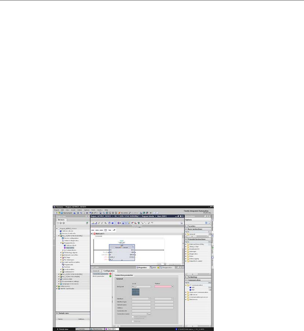
Communication
11.5 S7 communication
S7-1200 Programmable controller
992 System Manual, V4.2, 09/2016, A5E02486680-AK
11.5.3
Configuring the Local/Partner connection path between two devices
Configuring General parameters
You specify the communication parameters in the "Properties" configuration dialog of the
communication instruction. This dialog appears near the bottom of the page whenever you
have selected any part of the instruction.
Refer to "Device configuration: Configuring the Local/Partner connection path (Page 807)"
for more information.
In the "Address Details" section of the Connection parameters dialog, you define the TSAPs
or ports to be used. The TSAP or port of a connection in the CPU is entered in the "Local
TSAP" field. The TSAP or port assigned for the connection in your partner CPU is entered
under the "Partner TSAP" field.
11.5.4
GET/PUT connection parameter assignment
The GET/PUT instructions connection parameter assignment is a user aid for configuring
CPU-to-CPU S7 communication connections.
After inserting a GET or PUT block, STEP 7 displays the connection parameter assignment
dialog for the GET/PUT instructions:
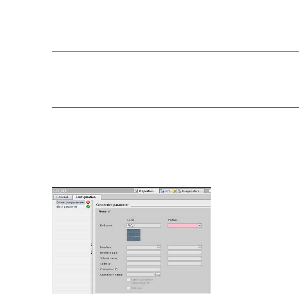
Communication
11.5 S7 communication
S7-1200 Programmable controller
System Manual, V4.2, 09/2016, A5E02486680-AK 993
The inspector window displays the properties of the connection whenever you have selected
any part of the instruction. You can configure the communication parameters in the
"Configuration" tab of the "Properties" for the communication instruction.
Note
V4.1 and later CPU program GET/PUT operation is not automatically enabled
A V3.0 CPU program GE
T/PUT operation is automatically enabled in a V4.1 and later CPU.
However, a V4.1 and later CPU program GET/PUT operation in a V4.1 and later CPU is not
automatically enabled. You must go to the CPU "Device configuration", inspector window
"Properties"tab,
"Protection" property to enable GET/PUT access (Page 210).
11.5.4.1
Connection parameters
The "Connection parameters" page allows you to configure the necessary S7 connection
and to configure the parameter "Connection ID" that is referenced by the GET/PUT block
parameter "ID". The page's content has information about the local endpoint and allows you
to define the local interface. You can also define the partner end point.
The "Block parameters" page allows you to configure the additional block parameters.

Communication
11.5 S7 communication
S7-1200 Programmable controller
994 System Manual, V4.2, 09/2016, A5E02486680-AK
Table 11- 65 Connection parameter: General definitions
Parameter
Definition
Connection
parameter:
General
End point "Local End point": Name assigned to the Local CPU
"Partner End point": Name assigned to the Partner (remote) CPU
Note: In the "Partner End point" dropdown list, the system displays all potential
S7 connection partners of the current project as well as the option "unspeci-
fied". An unspecified partner represents a communication partner which is not
currently in the STEP 7 project (for example, a third party device communica-
tion partner).
Interface Name assigned to the interfaces
Note: You can change the connection by changing the Local and Partner inter-
faces
Interface type
Type of interface
Subnet name
Name assigned to the subnets
Address Assigned IP addresses
Note: You can specify the remote address of a third party device for an "un-
specified" communication partner.
Connection ID ID number: Automatically generated by the GET/PUT connection parameter
assignment
Connection name Local and Partner CPU data storage location: Automatically generated by the
GET/PUT connection parameter assignment
Active connection estab-
lishment
Checkbox to select Local CPU as the active connection
One-way Checkbox to specify a one-way or two-way connection; read-only
Note: In a PROFINET GET/PUT connection, both the local and partner devic-
es can act as a server or a client. This allows a two-way connection, and the
"One-way" checkbox is unchecked.
In a PROFIBUS GET/PUT connection, in some cases, the Partner device can
only act as a server (for example, an S7-300), and the "One-way" checkbox is
checked.
Connection ID parameter
There are three ways to change the system-defined connection IDs:
1. The user can change the current ID directly on the GET/PUT block. If the new ID belongs
to an already existing connection, the connection is changed.
2. The user can change the current ID directly on the GET/PUT block, but the new ID does
not already exist. A new S7 connection is created by the system.
3. The user can change the current ID through the "Connection overview" dialog: The user-
input is synchronized with the ID-parameter on the corresponding GET/PUT block.
Note
The parameter "ID" of the GET/PUT block is not a connection name, but a numerical
expression which is written like the following example: W#16#1
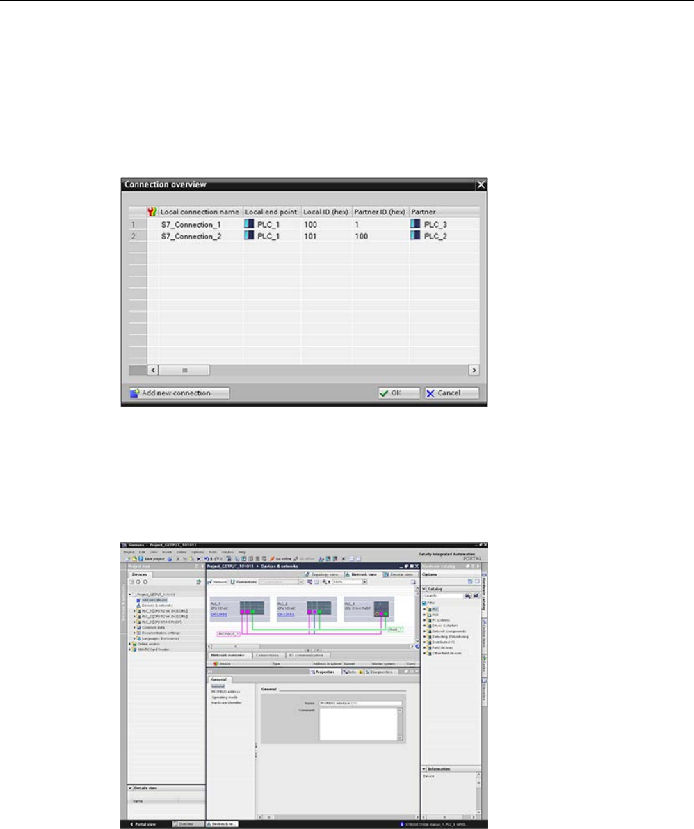
Communication
11.5 S7 communication
S7-1200 Programmable controller
System Manual, V4.2, 09/2016, A5E02486680-AK 995
Connection name parameter
The connection name is editable through a special user control, the "Connection overview"
dialog. This dialog offers all the available S7 connections which could be selected as an
alternative for the current GET/PUT communication. The user can create a completely new
connection in this table. Click the button to the right of the "Connection name" field to start
the "Connection overview" dialog.
11.5.4.2
Configuring a CPU-to-CPU S7 connection
Given the configuration of PLC_1, PLC_2, and PLC_3 as shown in the figure below, insert
GET or PUT blocks for "PLC_1".
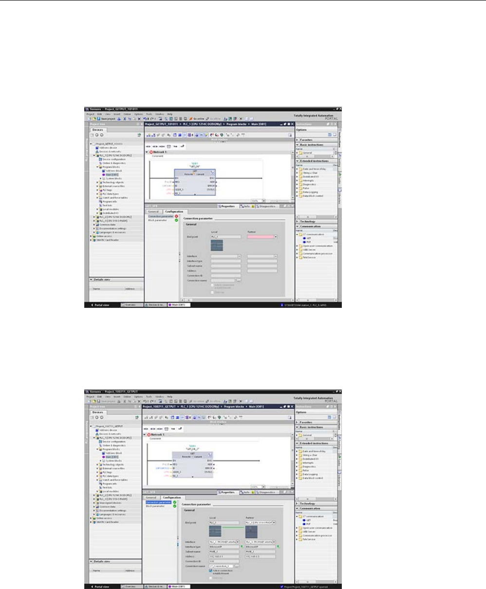
Communication
11.5 S7 communication
S7-1200 Programmable controller
996 System Manual, V4.2, 09/2016, A5E02486680-AK
For the GET or PUT instruction, the "Properties" tab is automatically displayed in the
inspector window with the following menu selections:
● "Configuration"
● "Connection parameters"
Configuring a PROFINET S7 connection
For the "Partner End point", select "PLC_3".

Communication
11.5 S7 communication
S7-1200 Programmable controller
System Manual, V4.2, 09/2016, A5E02486680-AK 997
The system reacts with the following changes:
Table 11- 66 Connection parameter: General values
Parameter
Definition
Connection
parameter:
General
End point "Local End point" contains "PLC_1" as read-only.
"Partner End point" field contains "PLC_3[CPU319-3PN/DP]":
• The color switches from red to white
• The "Partner" device image is shown.
• A connection line appears between the PLC_1- and PLC_3 device images
(green Ethernet line).
Interface "Local Interface" contains "CPU1214C DC/DC/DC, PROFINET interface
(R0/S1)".
"Partner Interface" contains: "CPU319-3PN/DP, PROFINET interface
(R0/S2)".
Interface type "Local Interface type" contains "Ethernet/IP"; control is read-only.
"Partner Interface type" contains "Ethernet/IP"; control is read-only.
Interface type images are shown at the right beside the Local and Partner
"Interface type" (green Ethernet icon).
Subnet name "Local Subnet name" contains "PN/IE_1"; control is read only.
"Partner Subnet name" contains "PN/IE_1"; control is read only.
Address "Local Address" contains the Local IP address; control is read only.
"Partner Address" contains the Partner IP address; control is read only.
Connection ID "Connection ID" contains "100".
In the Program editor, in the Main [OB1], the GET/PUT block "Connection ID"
value also contains "100".
Connection name "Connection name" contains the default connection name (for example,
"S7_Connection_1"); control is enabled.
Active connection estab-
lishment
Checked and enabled to select the Local CPU as the active connection.
One-way Read-only and unchecked.
Note: "PLC_1" (an S7-1200 CPU 1214CDC/DC/Relay) and "PLC_3" (an S7-
300 CPU 319-3PN/DP) can both act as a server and a client in a PROFINET
GET/PUT connection, allowing a two-way connection.
The GET/PUT icon in the Property View tree also changes from red to green.
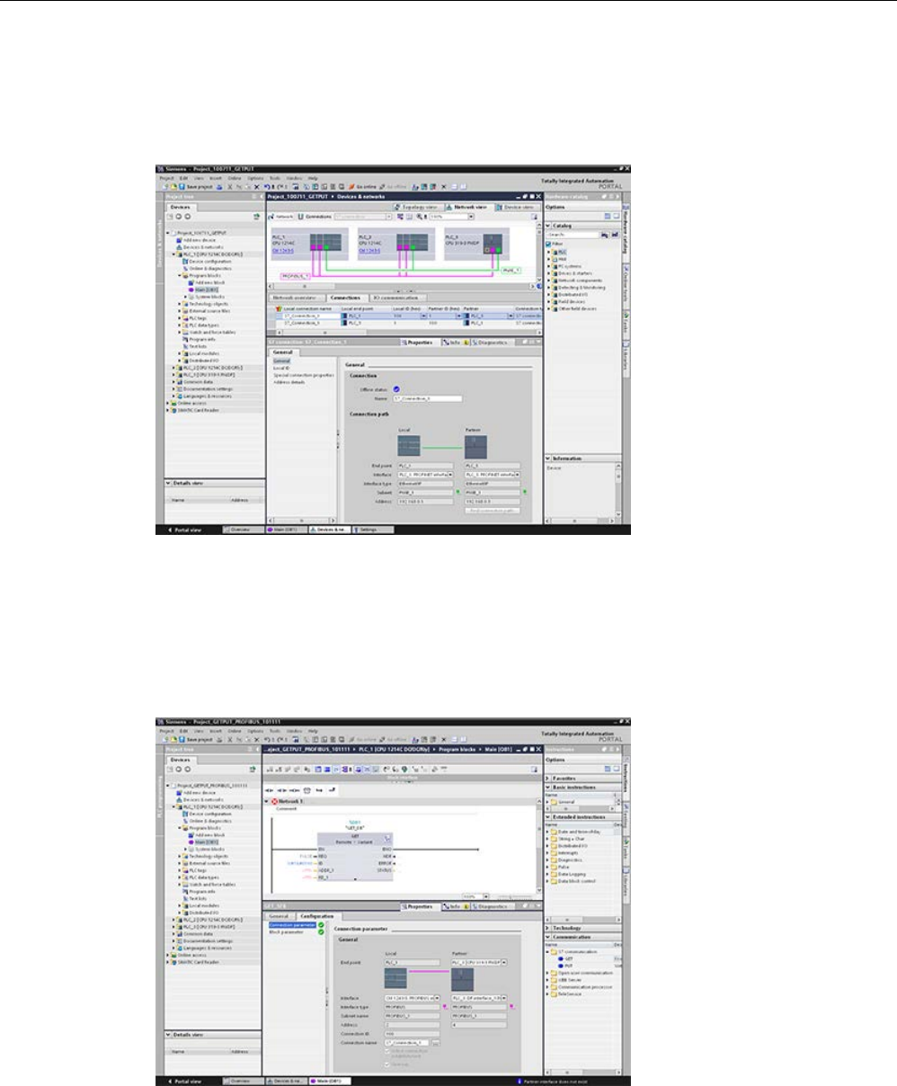
Communication
11.5 S7 communication
S7-1200 Programmable controller
998 System Manual, V4.2, 09/2016, A5E02486680-AK
Completed PROFINET S7 connection
In the "Network view", a two-way S7 connection is shown in the "Connections" table between
"PLC_1" and "PLC_3".
Configuring a PROFIBUS S7 connection
For the "Partner End point", select "PLC_3".

Communication
11.5 S7 communication
S7-1200 Programmable controller
System Manual, V4.2, 09/2016, A5E02486680-AK 999
The system reacts with the following changes:
Table 11- 67 Connection parameter: General values
Parameter
Definition
Connection
parameter:
General
End point "Local End point" contains "PLC_1" as read-only.
"Partner End point" field contains "PLC_3[CPU319-3PN/DP]":
• The color switches from red to white
• The "Partner" device image is shown.
• A connection line appears between the PLC_1- and PLC_3 device images
(purple PROFIBUS line).
Interface "Local Interface" contains "CPU1214C DC/DC/DC, PROFIBUS interface
(R0/S1)".
"Partner Interface" contains: "CPU319-3PN/DP, PROFIBUS interface
(R0/S2)".
Interface type "Local Interface type" contains "PROFIBUS"; control is read-only.
"Partner Interface type" contains " PROFIBUS "; control is read-only.
Interface type images are shown at the right beside the Local and Partner
"Interface type" (purple PROFIBUS icon).
Subnet name "Local Subnet name" contains " PROFIBUS _1"; control is read only.
"Partner Subnet name" contains " PROFIBUS _1"; control is read only.
Address "Local Address" contains the Local IP address; control is read only.
"Partner Address" contains the Partner IP address; control is read only.
Connection ID "Connection ID" contains "100".
In the Program editor, in the Main [OB1], the GET/PUT block "Connection ID"
value also contains "100".
Connection name "Connection name" contains the default connection name (for example,
"S7_Connection_1"); control is enabled.
Active connection estab-
lishment
Read-only, checked, and enabled to select the Local CPU as the active con-
nection.
One-way Read-only and checked.
Note: "PLC_3" (an S7-300 CPU319-3PN/DP) can act only as a server (cannot
also be a client) in a PROFIBUS GET/PUT connection, allowing only a one-
way connection.
The GET/PUT icon in the Property View tree also changes from red to green.
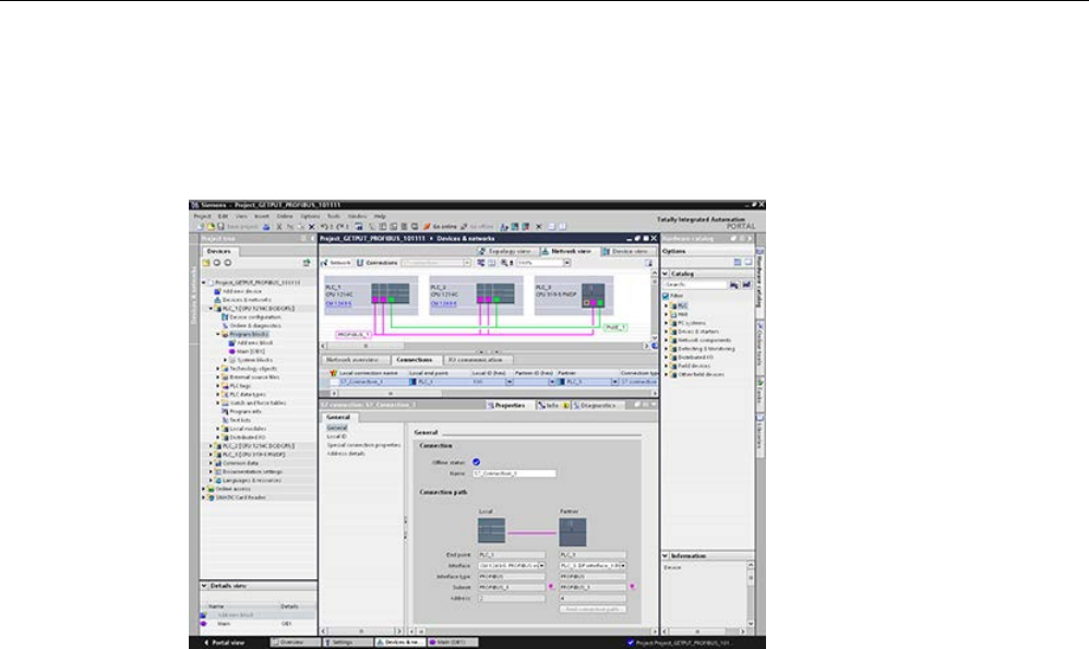
Communication
11.5 S7 communication
S7-1200 Programmable controller
1000 System Manual, V4.2, 09/2016, A5E02486680-AK
Completed PROFIBUS S7 connection
In the "Network view", a one-way S7 connection is shown in the "Connections" table
between "PLC_1" and "PLC_3".
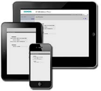
S7-1200 Programmable controller
System Manual, V4.2, 09/2016, A5E02486680-AK 1001
Web server
12
The Web server for the S7-1200 provides Web page access to data about your CPU and
process data.
You can access
the S7-
1200 Web pages from
a PC or from a mobile device. For devices
with small screens, the Web server supports a
collection of
basic pages (Page 1012).
You use a Web browser to access the IP a
d-
dress of the S7
-1200 CPU or the IP address
of a
Web server-
enabled CP (communications
processor) module
(Page 1010) in the local
rack with the CPU to establish the connection.
The S7
-1200 supports multiple concurrent
conne
ctions.
Standard Web pages
The S7-1200 includes standard Web pages (Page 1011) that you can access from the Web
browser of your PC (Page 1007) or from a mobile device (Page 1009):
● Introduction (Page 1017) - entry point to the standard Web pages
● Start Page (Page 1018) - general information about the CPU
● Diagnostics (Page 1019) - detailed information about the CPU including serial, order, and
version numbers, program protection, and memory usage
● Module Information (Page 1023) - information about the local and remote modules and
the ability to update firmware for local modules
● Communication (Page 1027) - information about the network addresses, physical
properties of the communication interfaces, statistics, parameters, as well as a
connection summary and diagnostic information
● Diagnostic Buffer (Page 1022) - the diagnostic buffer
● Tag status (Page 1031) - CPU variables and I/O, accessible by address or PLC tag name
● Watch tables (Page 1033) - watch tables that you configured in STEP 7
● Online backup (Page 1035) - ability to backup an online CPU or restore a previously-
made online backup
● File Browser (Page 1037) - browser for files stored internally in the CPU or on a memory
card, for example, data logs and recipes
● Login (Page 1013) - log in as a different user, or log out.

Web server
S7-1200 Programmable controller
1002 System Manual, V4.2, 09/2016, A5E02486680-AK
These pages are built in to the S7-1200 CPU, and are available in English, German, French,
Spanish, Italian, and Simplified Chinese. All pages except for the Introduction and Start page
require additional user privileges (Page 1005) that you configure in STEP 7 to view the page.
User-defined Web pages
The S7-1200 also provides support for you to create user-defined Web pages that can
access CPU data. You can develop these pages with the HTML authoring software of your
choice, and include pre-defined "AWP" (Automation Web Programming) commands in your
HTML code to access CPU data. Refer to the User-defined Web pages (Page 1040) chapter
for specific information on the development of user-defined Web pages, and the associated
configuration and programming in STEP 7.
You can access the user-defined pages from either a PC or mobile device from the standard
or basic Web pages. You can also configure one of your user-defined Web pages to be the
entry page (Page 1058) for the Web server.
Web browser requirement
The Web server supports the following Web browsers for the standard pages:
● Internet Explorer 8 to 11
● Microsoft Edge
● Mozilla Firefox V22 to V32, V42 to V47
● Google Chrome V33 to V38, V46 to V47
● Mobile Safari and Mobile Chrome for iOS 9 devices
● Android browser for the following versions:
– Jellybean v4.3
– Kitkat v4.4
– Lollipop V5.0 to v5.1
– Marshmellow v6.0
● Mobile Chrome for Google Android
When using the HTML Browser control in a WinCC project, the Web server supports the
following Siemens HMI Panels for the standard pages:
● Basic Panels
– Gen 2 KTP400 to KTP1200
● Comfort Panels
– TP700 to TP2200
– KP400 to KP1500
– KTP400
– TP700 Comfort Outdoor

Web server
12.1 Enabling the Web server
S7-1200 Programmable controller
System Manual, V4.2, 09/2016, A5E02486680-AK 1003
● Mobile Panels
– Gen 2 KTP700[F], KTP900[F]
For browser-related restrictions that can interfere with the display of standard or user-defined
Web pages, see the Constraints (Page 1082) section.
12.1
Enabling the Web server
You enable the Web server in STEP 7 from Device Configuration for the CPU to which you
intend to connect.
To enable the Web server, follow these steps:
1. Select the CPU in the Device Configuration view.
2. In the inspector window, select "Web server" from the CPU properties.
3. Select the check box for "Activate web server on all modules of this device".
4. For increased security, ensure that "Permit access only with HTTPS" is selected to
require secure access to the Web server.
5. If you select "Enable automatic update" for "Automatic update", standard Web pages will
refresh by default every ten seconds. You you can also enter a custom refresh time
period in seconds for the "Update interval" field.
WARNING
Unauthorized access to the CPU through the Web server
Unauthorized access to the CPU or changing PLC variables to invalid values could disrupt
process operation and could result in death, severe personal injury and/or property
damage.
Because enabling the Web server allows authorized users to perform operating mode
changes, writes to PLC data, and firmware updates, Siemens recommends that you
observe the following security practices:
• Enable access to the Web server only with the HTTPS protocol.
• Password-protect Web server user IDs (Page 1005) with a strong password. Strong
passwords are at least ten characters in length, mix letters, numbers, and special
characters, are not words that can be found in a dictionary, and are not names or
identifiers that can be derived from personal information. Keep the password secret and
change it frequently.
• Do not extend the default minimum privileges of the "Everybody" user.
• Perform error-checking and range-checking on your variables in your program logic
because Web page users can change PLC variables to invalid values.
• Use a secure Virtual Private Network (VPN) to connect to the S7-1200 PLC Web server
from a location outside your protected network.

Web server
12.1 Enabling the Web server
S7-1200 Programmable controller
1004 System Manual, V4.2, 09/2016, A5E02486680-AK
After you download the device configuration, you can use the standard Web pages to access
the CPU.
If you created and enabled user-defined Web pages (Page 1040), you can access them from
the standard or basic Web page navigation menu.
Note
Device exchange: Replacing a V3.0 CPU with a V4.x CPU
If you
replace an existing V3.0 CPU with a V4.x CPU (Page 1571) and convert your V3.0
project to a V4.x project, note that STEP
7 and the V4.x CPU retain the Web server settings
for
•
"Activate web server on all modules of this device"
•
"Permit access only with HTTPS"
Note
If a
"Download in RUN" (Page 1335) is in progress, standard and user-defined Web pages
do not update data values or permit you to write data values until the download is complete.
The Web server discards any attempts to write data values while a download is in progress.

Web server
12.2 Configuring Web server users
S7-1200 Programmable controller
System Manual, V4.2, 09/2016, A5E02486680-AK 1005
12.2
Configuring Web server users
You can configure users with various privilege levels for accessing the CPU through the Web
server.
To configure Web server users and their associated privileges, follow these steps:
1. Select the CPU in the Device Configuration view.
2. In the inspector window, select "Web server" from the CPU properties and enable the
Web server (Page 1003).
3. Select "User management" in the Web server properties.
4. Enter user names, access levels, and passwords for the user logins that you want to
provide.
After you download the configuration to the CPU, only authorized users can access Web
server functions for which they have privileges.
Web server access levels
STEP 7 provides a default user named "Everybody" with no password. By default, this user
has no additional privileges and can only view the Start (Page 1018) and Introduction
(Page 1017) standard Web pages. You can, however, configure additional privileges for the
"Everybody" user as well as other users:
● Query diagnostics
● Read tags
● Write tags
● Read tag status
● Write tag status
● Open user-defined web pages
● Write in user-defined web pages
● Read files
● Write/delete files
● Change operating mode
● Flash LEDs
● Perform a firmware update
● Backup CPU
● Restore CPU

Web server
12.2 Configuring Web server users
S7-1200 Programmable controller
1006 System Manual, V4.2, 09/2016, A5E02486680-AK
If you have set a user-defined Web page to be the entry page (Page 1058) for the Web
server, the Everybody user must have the "Open user-defined web pages" privilege.
WARNING
Access to Web server
Granting privileges to the "Everybody" user makes it possible to log in to the Web server
with no password. Unauthorized access to the CPU or changing PLC variables to invalid
values could disrupt process operation and could result in death, severe personal injury
and/or property damage.
Because the "Everybody" user when granted sufficient privileges can perform operating
mode changes, writes to PLC data, and firmware updates with no password, Siemens
recommends that you observe the following security practices
• Enable access to the Web server only with the HTTPS protocol.
• Password-protect Web server user IDs with a strong password. Strong passwords are at
least ten characters in length, mix letters, numbers, and special characters, are not
words that can be found in a dictionary, and are not names or identifiers that can be
derived from personal information. Keep the password secret and change it frequently.
• Do not extend the default minimum privileges of the "Everybody" user.
• Perform error-checking and range-checking on your variables in your program logic
because Web page users can change PLC variables to invalid values.
• Use a secure Virtual Private Network (VPN) to connect to the S7-1200 PLC Web server
from a location outside your protected network.

Web server
12.3 Accessing the Web pages from a PC
S7-1200 Programmable controller
System Manual, V4.2, 09/2016, A5E02486680-AK 1007
12.3
Accessing the Web pages from a PC
You can access the S7-1200 standard Web pages from a PC or from a mobile device
through the IP address of the S7-1200 CPU or the IP address of any Web server-enabled
CP (Page 1010) in the local rack.
To access the S7-1200 standard Web pages from a PC, follow these steps:
1. Ensure that the S7-1200 and the PC are on a common Ethernet network or are
connected directly to each other with a standard Ethernet cable.
2. Open a Web browser and enter the URL "https://ww.xx.yy.zz", where "ww.xx.yy.zz"
corresponds to the IP address of the S7-1200 CPU or the IP address of a CP in the local
rack.
The Web browser opens the Introduction standard Web page (Page 1017) or the Default
HTML page of your user-defined Web pages if you configured it to be the entry page
(Page 1058).
Note
Use a secure Virtual Private Network (VPN) to connect to the S7
-
1200 PLC Web server from
a location outside your protected network. Be aware also of any
constraints (Page 1082
) that
your Web environment or operating system might impose.
Alternatively, you can address your Web browser to a specific standard Web page. To do so,
enter the URL in the form "https://ww.xx.yy.zz/<page>.html", where <page> corresponds to
one of the standard Web pages:
● start (Page 1018) - general information about the CPU
● identification (Page 1019) - detailed information about the CPU including serial, order,
and version numbers, now called the Diagnostics page
● module (Page 1023) - information about the modules in the local rack and the ability to
update firmware
● communication (Page 1027) - information about the network addresses, physical
properties of the communication interfaces, and communication statistics
● diagnostic (Page 1022) - the diagnostic buffer
● variable (Page 1031) - CPU variables (tags) and I/O, accessible by address, PLC tag
name, or data block tag name
● watch (Page 1033) - watch tables
● filebrowser (Page 1037) - browser for accessing data log files or recipe files stored
internally in the CPU or on a memory card
● index (Page 1017) - introduction page to enter the standard Web pages
● login (Page 1013) - page to log in if no user is currently logged in; otherwise, the page is
blank.

Web server
12.3 Accessing the Web pages from a PC
S7-1200 Programmable controller
1008 System Manual, V4.2, 09/2016, A5E02486680-AK
For example, if you enter "https://ww.xx.yy.zz/communication.html", the browser displays the
communication page.
Note
Note that any standard Web page that is not listed spe
cifically above (for example, the
Online backup page
(Page 1035)) does not have a direct access URL.
Secure access
Use a secure Virtual Private Network (VPN) to connect to the S7-1200 PLC Web server from
a location outside your protected network. Require and use https:// instead of http:// for
secure access (Page 1003) to the standard Web pages. When you connect to the S7-1200
with https://, the Web site encrypts the session with a digital certificate. The Web server
transmits the data securely and it is not accessible for anyone to view. You typically get a
security warning that you can confirm with "Yes" to proceed to the standard Web pages. To
avoid the security warning with each secure access, you can import the Siemens software
certificate to your Web browser (Page 1085).
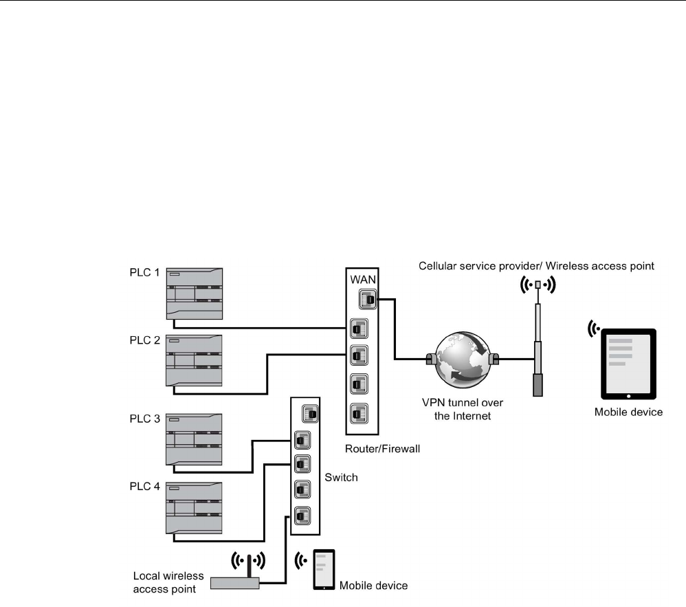
Web server
12.4 Accessing the Web pages from a mobile device
S7-1200 Programmable controller
System Manual, V4.2, 09/2016, A5E02486680-AK 1009
12.4
Accessing the Web pages from a mobile device
To access an S7-1200 from a mobile device, you must connect your PLC to a network that
connects to the Internet or to a local wireless access point. Use a secure Virtual Private
Network (VPN) to connect a mobile device to the S7-1200 PLC Web server. You can use
port forwarding in the wireless router to map the IP address of the PLC to an address by
which a mobile device can access it from the Internet. To configure port forwarding, follow
the instructions for the software configuration of your router. You can connect as many PLCs
and switching devices as your router supports.
Without port forwarding, you can connect to a PLC, but only locally within range of the
wireless signal.
In this example, a mobile device that is within range of the local wireless access point can
connect to PLC 3 and PLC 4 by their IP addresses. From the Internet outside the local
wireless range, a mobile device can connect to PLC 1 and PLC 2 using the port forwarded
address for each PLC.
To access the standard Web pages, you must have access to a cellular service or wireless
access point. To access a PLC from the Internet, enter the port forwarded address in the
Web browser of your mobile device to access the PLC, for example http://ww.xx.yy.zz:pppp
or https:/ww.xx.yy.zz:pppp, where ww.xx.yy.zz is the address of the router and pppp is the
port assignment for a specific PLC.

Web server
12.5 Using a CP module to access Web pages
S7-1200 Programmable controller
1010 System Manual, V4.2, 09/2016, A5E02486680-AK
For local access through a local wireless access point, enter the IP address of the S7-1200
CPU or a Web server-enabled CP (Page 1010) in the local rack:
● http://ww.xx.yy.zz or https::/ww.xx.yy.zz to access the standard Web pages (Page 1011)
● http://ww.xx.yy.zz/basic or https::/ww.xx.yy.zz/basic to access the basic Web pages
(Page 1012)
For increased security, configure the Web server to be accessible only by secure access
(HTTPS) (Page 1003).
12.5
Using a CP module to access Web pages
Regardless of whether you access the Web server from a PC or a mobile device, you can
connect to standard Web pages through one of the following CP modules when you have
configured it in STEP 7 and installed it in the local rack with the S7-1200 CPU:
● CP 1242-7 GPRS V2
● CP 1243-1
● CP 1243-1 PCC
● CP 1243-7 LTE-EU
● CP 1243-7 LTE-US
● CP 1243-8 IRC
You use the Start standard Web page (Page 1018) to access the Web pages through these
CP modules. The Start page displays all configured and installed CP modules that you have
in your local rack, but you can only access Web pages from the ones listed above.
Note
Access to standard Web pages when Web server-enabled CPs are in the local rack
You might observe delays up to one or two minutes when connecting to the S7
-1200
standard Web pages when Web server
-enabled CPs are in the local rack. If the pages do
not appear to be available, or you get errors, just w
ait one or two minutes and refresh the
page.
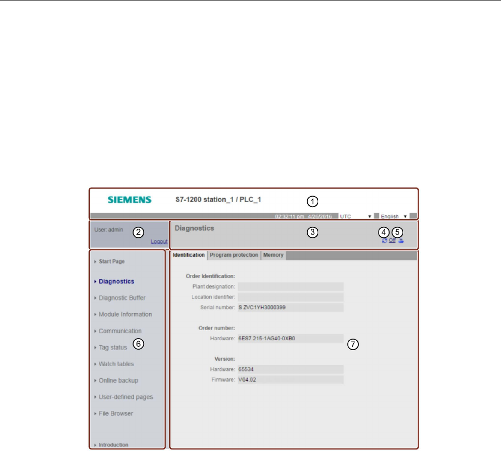
Web server
12.6 Standard Web pages
S7-1200 Programmable controller
System Manual, V4.2, 09/2016, A5E02486680-AK 1011
12.6
Standard Web pages
12.6.1
Layout of the standard Web pages
Each of the S7-1200 standard Web pages has a common layout with navigational links and
page controls. Regardless of whether you are viewing the page on a PC or on a mobile
device, each page has the same content area, but the layout and navigation controls vary
based on the screen size and resolution of the device. On a standard PC or large mobile
device the layout of a standard Web page appears as follows:
①
Web server header with selector to display PLC Local time or UTC time, and a selector for the
display language (Page 170)
②
Log in or log out
③
Standard Web page header with name of the page that you are viewing. This example is the
CPU Identification page. Some of the standard Web pages, such as module information, also
display a navigation path here if multiple screens of that type can be accessed.
④
Refresh icon: for pages with automatic refresh, enables or disables the automatic refresh func-
tion; for pages without automatic refresh, causes the page to update with current data
⑤
Print icon: prepares and displays a printable version of the information available from the dis-
played page
⑥
Navigation area to switch to another page
⑦
Content area for specific standard Web page that you are viewing. This example is the Diag-
nostics page.

Web server
12.6 Standard Web pages
S7-1200 Programmable controller
1012 System Manual, V4.2, 09/2016, A5E02486680-AK
Note
CP module standard Web pages
Certain CP modules
(Page 1010) provide standard Web pages that are similar in
appearance and functionality to the S7
-1200 CPU standard Web pages. Refer to your CP
documentation
for descriptions of the CP standard Web pages.
12.6.2
Basic pages
The Web server provides basic pages intended for use on mobile devices. You access the
basic pages using the IP address of the device and appending "basic" to the URL:
http://ww.xx.yy.zz/basic or https::/ww.xx.yy.zz/basic
The basic pages look similar to the standard pages, but with some differences. The page
omits the navigation area, login area, and the header area, and includes buttons for
advancing backward and forward through the Web pages. Basic pages also include a Home
page button that takes you to a Navigation page. You can also use the navigation controls
provided with your mobile device for navigation. For example, the basic Diagnostics page
appears as follows in the vertical orientation:
The minimum resolution for displaying a basic page is 240 x 240 pixels.
Note that the standard Web page illustrations in this chapter represent the standard PC Web
page appearance. Most of the standard Web pages have equivalent basic pages.

Web server
12.6 Standard Web pages
S7-1200 Programmable controller
System Manual, V4.2, 09/2016, A5E02486680-AK 1013
12.6.3
Logging in and user privileges
Each of the PC standard Web pages provides a login window above the navigation pane.
Due to space considerations, the basic Web pages provide a separate Login page. The S7-
1200 supports multiple user logins with various access levels (privileges):
● Query diagnostics
● Read tags
● Write tags
● Read tag status
● Write tag status
● Open user-defined pages
● Write in user-defined pages
● Read files
● Write/delete files
● Change operating mode
● Flash LEDs
● Perform firmware update
● Backup CPU
● Restore CPU
● Change system parameter
● Change application parameter
You configure user roles, associated access levels (privileges), and passwords (Page 1005)
in the Web server user management properties of the STEP 7 device configuration of the
CPU.

Web server
12.6 Standard Web pages
S7-1200 Programmable controller
1014 System Manual, V4.2, 09/2016, A5E02486680-AK
Logging in
STEP 7 provides a default user named "Everybody" with no password. By default, this user
has no additional privileges and can only view the Start (Page 1018) and Introduction
(Page 1017) standard Web pages. You can, however, grant additional privileges to the
"Everybody" user as well as other users that you configure:
WARNING
Access to Web server
Granting privileges to the "Everybody" user makes it possible to log in to the Web server
with no password. Unauthorized access to the CPU or changing PLC variables to invalid
values could disrupt process operation and could result in death, severe personal injury
and/or property damage.
Because the "Everybody" user when granted sufficient privileges can perform operating
mode changes, writes to PLC data, and firmware updates with no password, Siemens
recommends that you observe the following security practices
• Enable access to the Web server only with the HTTPS protocol.
• Password-protect Web server user IDs (Page 1005) with a strong password. Strong
passwords are at least ten characters in length, mix letters, numbers, and special
characters, are not words that can be found in a dictionary, and are not names or
identifiers that can be derived from personal information. Keep the password secret and
change it frequently.
• Do not extend the default minimum privileges of the "Everybody" user.
• Perform error-checking and range-checking on your variables in your program logic
because Web page users can change PLC variables to invalid values.
• Use a secure Virtual Private Network (VPN) to connect to the S7-1200 PLC Web server
from a location outside your protected network.
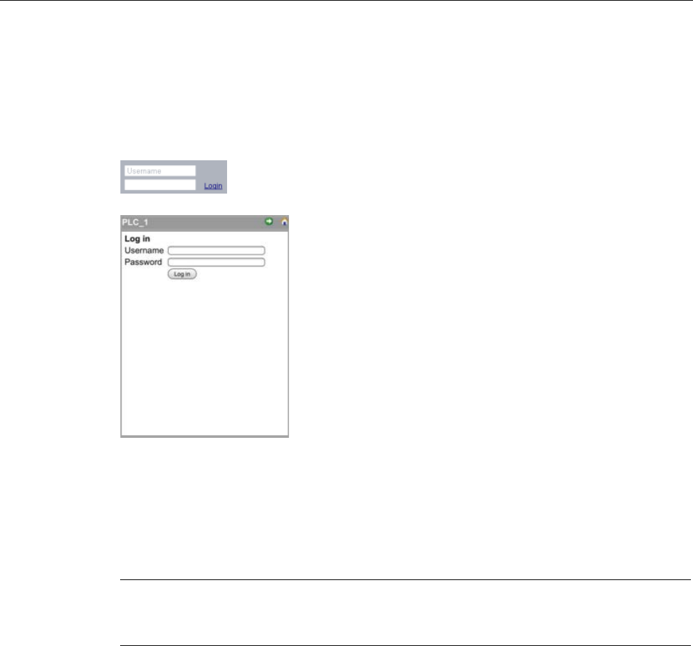
Web server
12.6 Standard Web pages
S7-1200 Programmable controller
System Manual, V4.2, 09/2016, A5E02486680-AK 1015
To perform certain actions such as changing the operating mode of the controller, writing
values to memory, and updating the CPU firmware you must have the required privileges.
Note that if you have set the protection level of the CPU (Page 210) to "Complete protection
(no access)", then the "Everybody" user has no permission to access the Web server,
regardless of the Web server user permission settings.
The log in
frame is near the upper left corner on
each standard Web page when displayed from a
PC or a wide mobile device.
The Log In page is a separate page on small m
o-
bile devices that display the basic pages. It is s
e-
lectable from the Home
page.
To log in, follow these steps:
1. Enter the user name for the Username field.
2. Enter the user password in the Password field.
Your login times out after thirty minutes of inactivity. If the currently-loaded page is
continually refreshing, the login does not time out.
Note
If you encounter any problems logging in,
download the Siemens security certificate
(Page
1085) from the Introduction page (Page 1017). You can then log in with no errors.
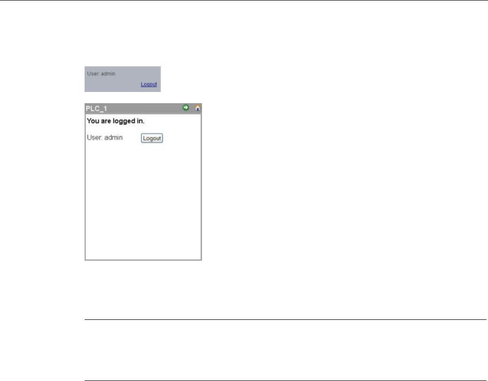
Web server
12.6 Standard Web pages
S7-1200 Programmable controller
1016 System Manual, V4.2, 09/2016, A5E02486680-AK
Logging out
To log out, simply click the "Logout" link from any page
w
hen viewing from a PC or wide mobile device.
From the basic pages, navigate to the Login/Logout
page from the Home page and tap the "Logout" button.
After you log out, you can only access and view standard Web pages according to the
privileges of the "Everybody" user. Each of the standard Web page descriptions defines the
required privileges for that page.
Note
Log off prior to closing Web server
If you have logged in to the Web server, be sure to log off prior to closing your Web browser.
The Web server supports a maximum of seven concurrent logins.
Web server
12.6 Standard Web pages
S7-1200 Programmable controller
System Manual, V4.2, 09/2016, A5E02486680-AK 1017
12.6.4
Introduction
The Introduction page is the welcome screen for entry into the S7-1200 standard Web
pages.
From this page, you click "Enter" to access the S7-1200 standard Web pages. At the top of
the screen are links to useful Siemens Web sites, as well as a link to download the Siemens
security certificate (Page 1085). You can also choose to skip the introduction page on future
accesses to the Web server.
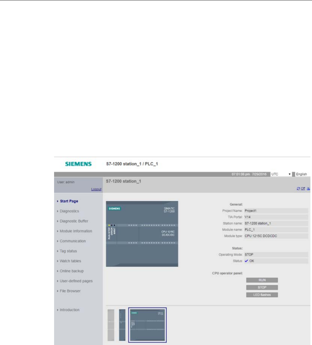
Web server
12.6 Standard Web pages
S7-1200 Programmable controller
1018 System Manual, V4.2, 09/2016, A5E02486680-AK
12.6.5
Start
The Start page displays a representation of the CPU or CP to which you are connected and
lists general information about the device and the TIA Portal version you used to download
the project to the CPU. For the CPU, you can use the buttons to change the operating mode
and flash the LEDs, if you have logged in (Page 1013) with the "change operating mode"
privilege (Page 1005).
The bottom portion of the screen is visible if you have configured and installed Web server-
enabled CP modules (Page 1010) in the local rack with the S7-1200 CPU. You can hover
over and click a Web server-enabled CP module to access the standard Web pages. Refer
to the documentation for your CP module for information about the CP module Web pages.
You see the name of the CP module when you hover over it.
The Web server also displays any other CM and CP modules in the local rack, but you
cannot click them as they do not contain Web pages. The module appearance for these CMs
and CPs are light gray (desensitized) to indicate that they are display-only and not clickable
modules.
Note that the S7-1200 fail-safe CPUs display additional data on this page related to
functional safety.
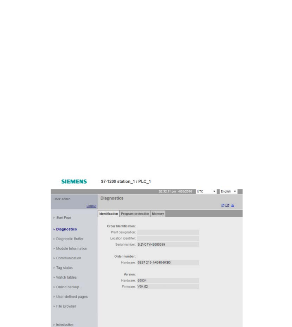
Web server
12.6 Standard Web pages
S7-1200 Programmable controller
System Manual, V4.2, 09/2016, A5E02486680-AK 1019
12.6.6
Diagnostics
The Diagnostics page displays identifying characteristics of the CPU, configuration settings
for know-how protection and memory usage for load memory, work memory, and retentive
memory:
The page consists of three tabs:
● Identification: identifying characteristics of the module and plant and location information
from STEP 7
● Program protection: status of know-how protection and CPU binding, which can be useful
in planning for spare parts as well as STEP 7 configuration setting for allowing or
preventing the copy of internal load memory to external load memory (SIMATIC memory
card).
● Memory: load, work, and retentive memory usage
For F-CPUs, there is an additional Fail-safe tab.
Viewing the Identification page requires the "query diagnostics" privilege (Page 1005).
Identification tab
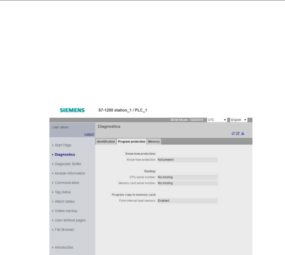
Web server
12.6 Standard Web pages
S7-1200 Programmable controller
1020 System Manual, V4.2, 09/2016, A5E02486680-AK
Program protection tab
The program protection tab includes the following information:
● Know-how protection (Page 213): Displays whether you have configured know-how
protection for any of the program blocks in STEP 7
● Binding (Page 214): Displays whether you have bound the program to either the CPU or
to the SIMATIC memory card
● Program copy to memory card (Page 212): DIsplays whether you have enabled the ability
to copy the program from internal load memory to external load memory (SIMATIC
memory card)
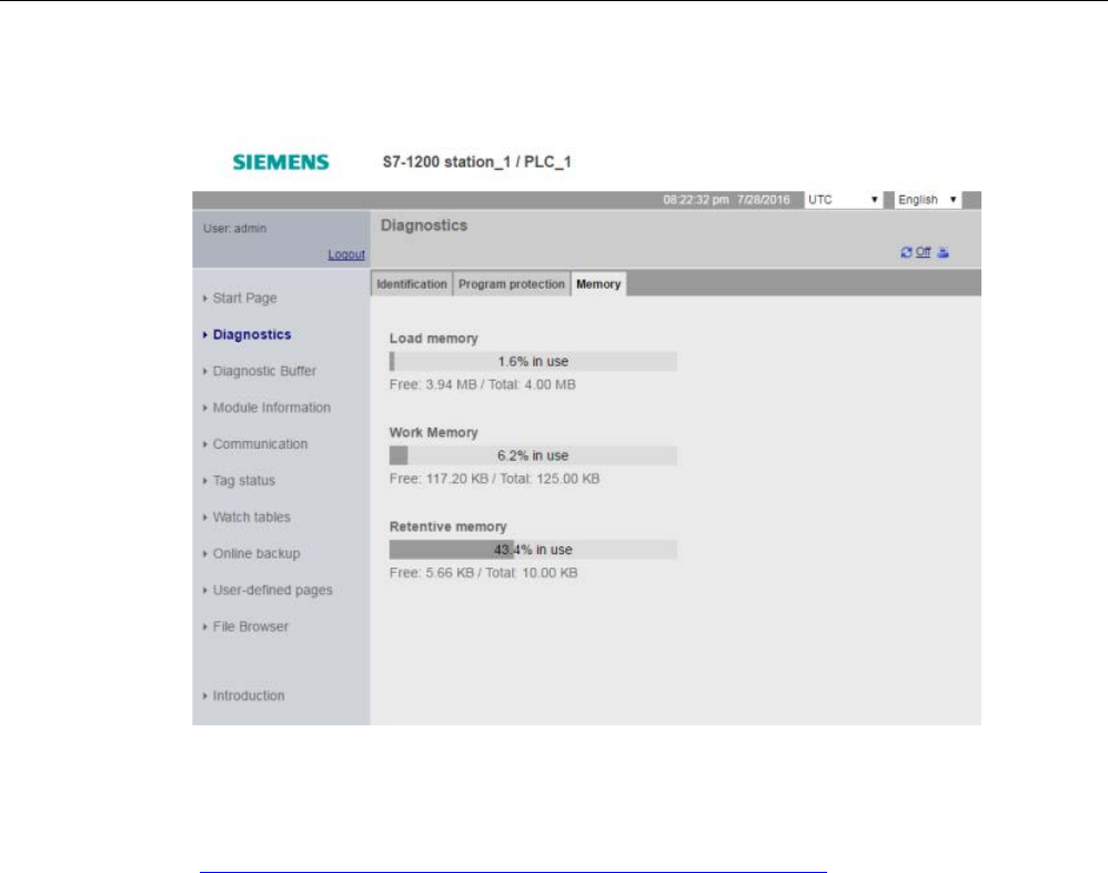
Web server
12.6 Standard Web pages
S7-1200 Programmable controller
System Manual, V4.2, 09/2016, A5E02486680-AK 1021
Memory tab
Fail-safe tab
Refer to the S7-1200 Functional Safety Manual
(https://support.industry.siemens.com/cs/ww/en/view/104547552) for information about the
Diagnostics page Fail-safe tab.
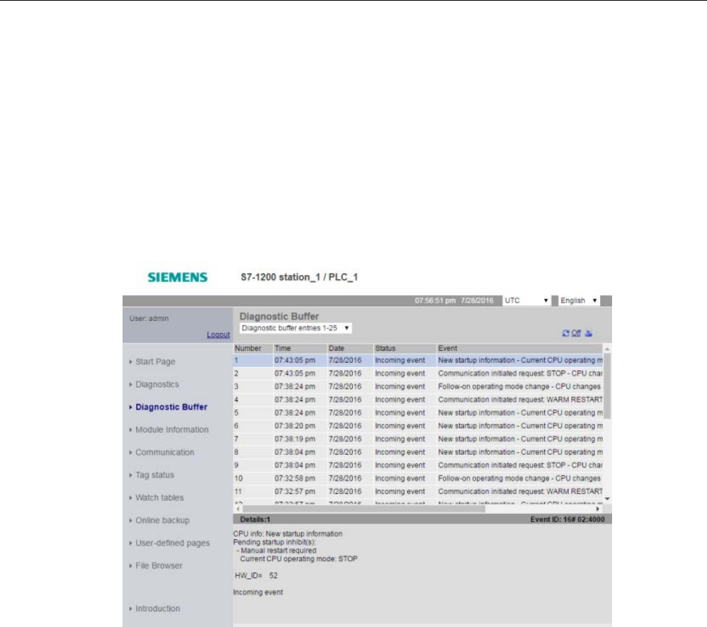
Web server
12.6 Standard Web pages
S7-1200 Programmable controller
1022 System Manual, V4.2, 09/2016, A5E02486680-AK
12.6.7
Diagnostic Buffer
The diagnostic buffer page displays diagnostic events. From the selector on the left, you can
choose what range of diagnostic buffer entries to display, either 1 to 25 or 26 to 50. From the
selector on the right, you can choose whether to display the times in UTC times or PLC local
times. The top part of the page displays the diagnostic entries with the time and date of when
the event occurred.
From the top part of the page, you can select any individual entry to show detailed
information about that entry in the bottom part of the page. Note that the display language of
the diagnostic buffer entries depends upon your device configuration setting for multilingual
support (Page 175).
Viewing the Diagnostic Buffer page requires the "query diagnostics" privilege (Page 1005).
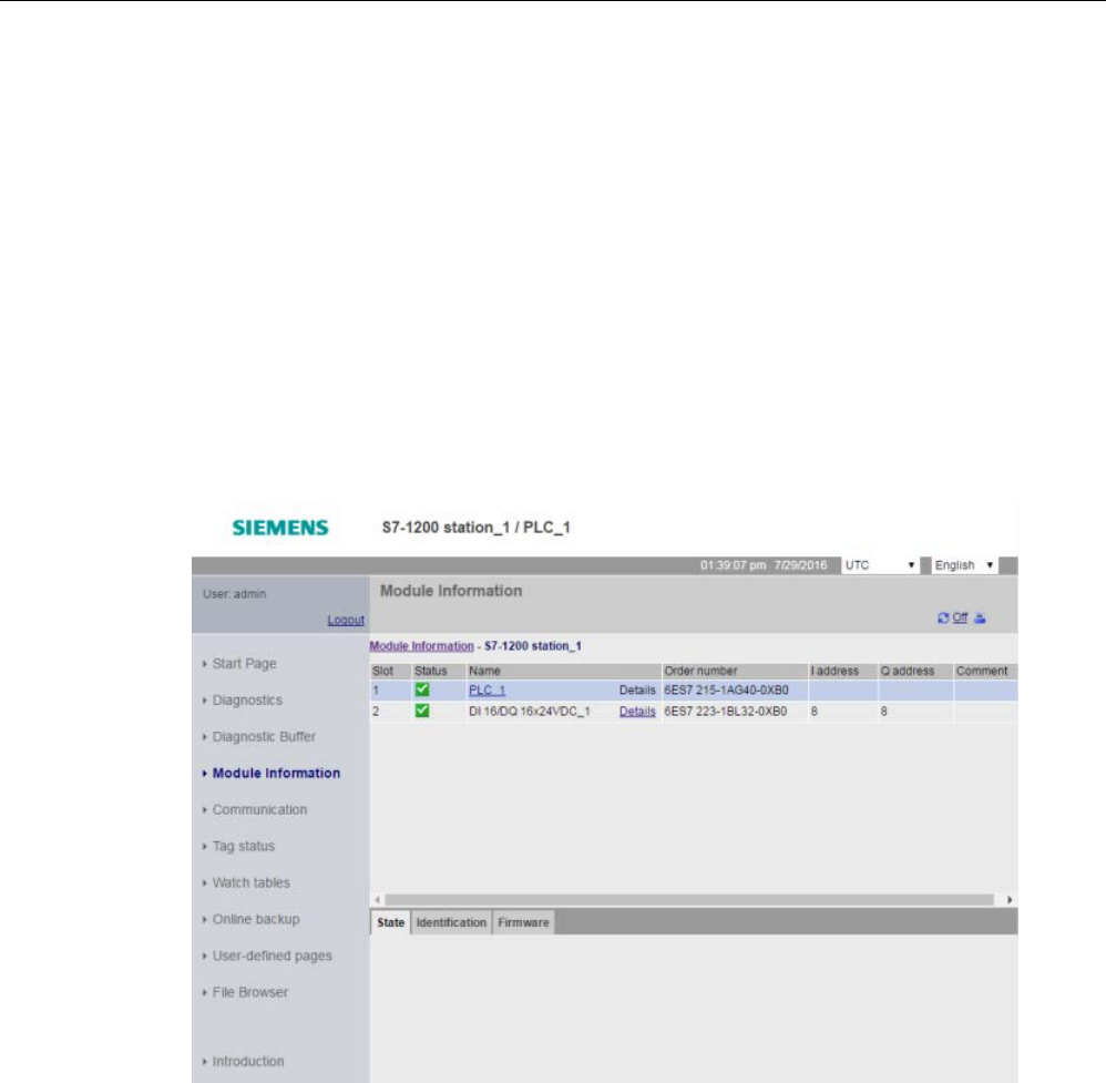
Web server
12.6 Standard Web pages
S7-1200 Programmable controller
System Manual, V4.2, 09/2016, A5E02486680-AK 1023
12.6.8
Module Information
The module information page provides information about all the modules in the local rack.
The top section of the screen shows a summary of the modules based on the device
configuration in STEP 7, and the bottom section shows status, identification and firmware
information for the selected module based on the corresponding connected module. The
module information page also provides the capability to perform a firmware update.
Viewing the Module Information page requires the "query diagnostics" privilege (Page 1005).
Module information: Status tab
The status tab in the bottom section of the module information page displays a description of
the current status of the module that is selected in the top section. If the section is empty,
then the module has no pending diagnostic state.
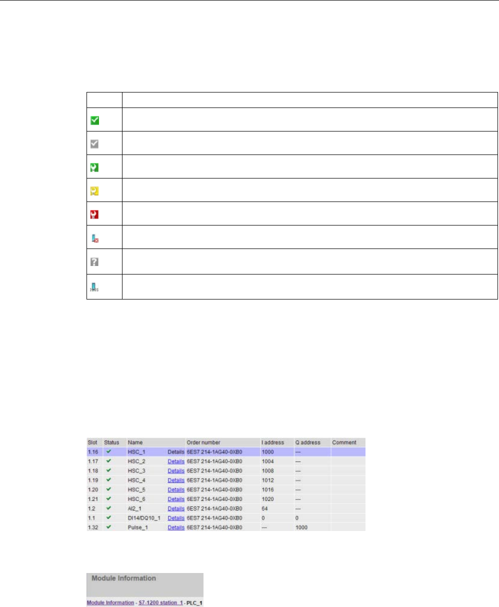
Web server
12.6 Standard Web pages
S7-1200 Programmable controller
1024 System Manual, V4.2, 09/2016, A5E02486680-AK
Status icons for the modules
For each module, the status column of the top section displays an icon that indicates the
status of that module:
Icon
Meaning
No fault
Deactivated
Maintenance required
Maintenance demanded
Error
The CPU cannot reach the module or device (for devices other than the CPU)
The CPU has established a connection to the device, but the module status is unknown (for
devices other than the CPU)
Input and output data are unavailable because the submodule has blocked its I/O channels
(for devices other than the CPU)
Drilling down
You can select a link in the top section to drill down to the module information for that
particular module. Modules with submodules have links for each submodule. The type of
information that is displayed varies with the module selected. For example, the module
information dialog initially displays the name of the S7-1200 station, a status indicator, and a
comment. If you drill down to the CPU, the module information displays the name of the
digital and analog inputs and outputs that the CPU model provides, addressing information
for the I/O, status indicators, slot numbers, and comments.
As you drill down, the module information page shows the path you have followed. You can
click any link in this path to return to a higher level.
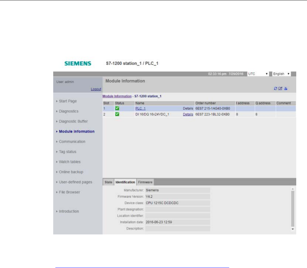
Web server
12.6 Standard Web pages
S7-1200 Programmable controller
System Manual, V4.2, 09/2016, A5E02486680-AK 1025
Module information: Identification tab
The identification tab displays the Identification and Maintenance (I&M) information of the
selected module.
Note that if you click an F-I/O module in the top section, then the bottom section has a Safety
tab. On this tab, you can see specific data related to the selected module as described in the
S7-1200 Functional Safety Manual
(https://support.industry.siemens.com/cs/ww/en/view/104547552).
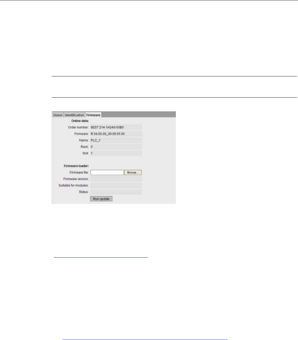
Web server
12.6 Standard Web pages
S7-1200 Programmable controller
1026 System Manual, V4.2, 09/2016, A5E02486680-AK
Module information: Firmware tab
The firmware tab of the module information page displays information about the firmware of
the selected module. If you have the "perform firmware update" privilege (Page 1005), you
can also perform a firmware update of the CPU or other modules in the local rack that
support firmware update. For remote modules, you can view the firmware information, but
not perform a firmware update.
Note
For updating CPU firmware, you can only update S7
-1200 CPUs of version 3.0 and higher.
Performing a firmware update
The CPU must be in STOP mode to perform a firmware update. When the CPU is in STOP
mode, click the Browse button to navigate to and select a firmware file. Firmware updates
are available on the Siemens Industry Online Support Web site
(http://support.industry.siemens.com).
During the update, the page displays a message showing that the update is in progress.
After the update completes, the page displays the article number and version number of the
updated firmware. If you updated the firmware for the CPU or a signal board, the Web server
restarts the CPU.
You can also perform a firmware update by one of these methods:
● Using the online and diagnostic tools of STEP 7 (Page 1318)
● Using a SIMATIC memory card (Page 148)
● Using the SIMATIC Automation Tool
(https://support.industry.siemens.com/cs/ww/en/view/98161300)
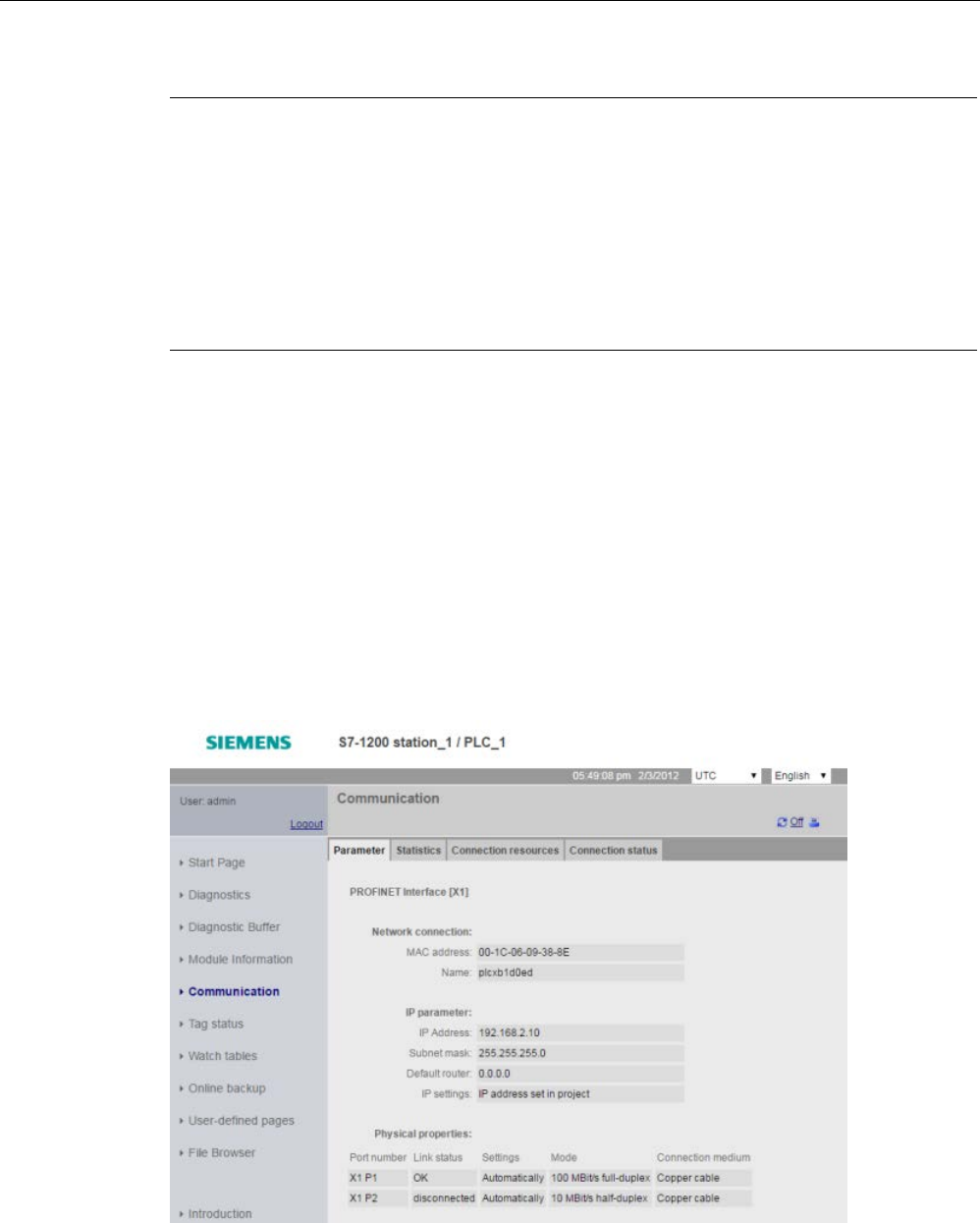
Web server
12.6 Standard Web pages
S7-1200 Programmable controller
System Manual, V4.2, 09/2016, A5E02486680-AK 1027
Note
Potential problems with performing a firmware update from the Web server
In the e
vent of a communications disruption during a firmware update from the Web server,
your Web browser could display a message asking whether you want to leave or stay on the
current page. To avoid potential problems, select the option to stay on the current p
age.
If you close the Web browser while in the process of performing a firmware update from the
Web server, you will be unable to change the operating mode of the CPU to RUN mode. If
this situation happens, you must cycle power to the CPU to be able to cha
nge the CPU to
RUN mode.
12.6.9
Communication
The communication page displays the parameters of the connected CPU, communications
statistics, resources and information about connections.
Viewing the Communication page requires the "query diagnostics" privilege.
Parameter tab
The Parameter tab shows the MAC address of the CPU, the IP address and IP settings of
the CPU, and physical properties:
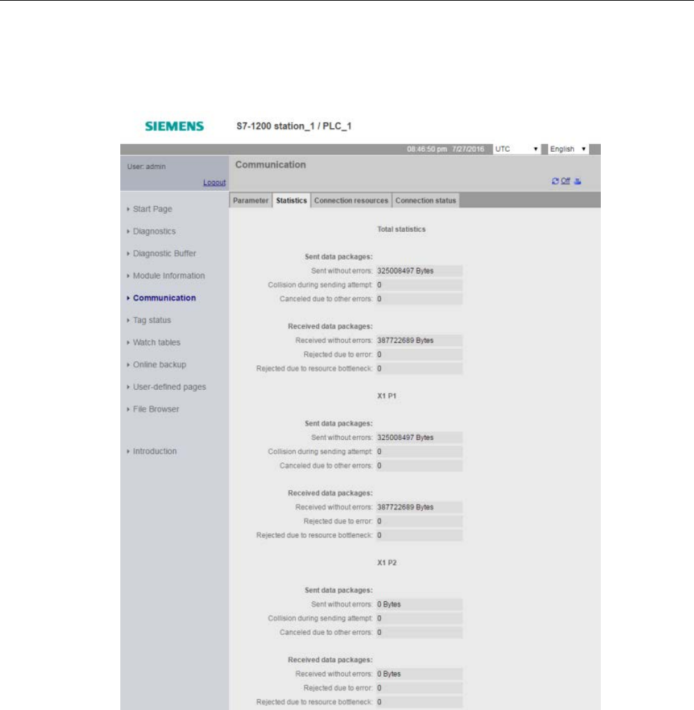
Web server
12.6 Standard Web pages
S7-1200 Programmable controller
1028 System Manual, V4.2, 09/2016, A5E02486680-AK
Statistics tab
The Statistics tab shows send and receive communication statistics:

Web server
12.6 Standard Web pages
S7-1200 Programmable controller
System Manual, V4.2, 09/2016, A5E02486680-AK 1029
Connection resources tab
The Resources tab shows information about the total number of connection resources and
how they are allocated for different types of communication:
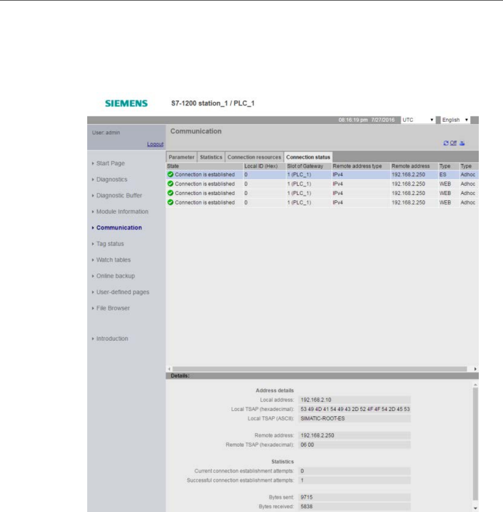
Web server
12.6 Standard Web pages
S7-1200 Programmable controller
1030 System Manual, V4.2, 09/2016, A5E02486680-AK
Connection status tab
The Connections tab shows the connections for the CPU, and connection details for the
selected connection.
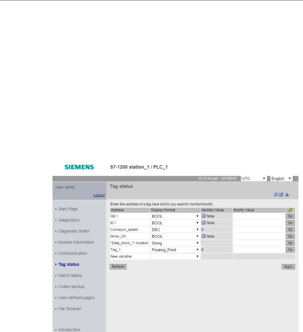
Web server
12.6 Standard Web pages
S7-1200 Programmable controller
System Manual, V4.2, 09/2016, A5E02486680-AK 1031
12.6.10
Tag status
The Tag status page allows you to view any of the I/O or memory data in your CPU. You can
enter a direct address (such as %I0.0), a PLC tag name, or a tag from a specific data block.
For data block tags, you enclose the data block name in double quotation marks. For each
monitor value you can select a display format for the data. You can continue entering and
specifying values until you have as many as you want within the limitations for the page. The
monitor values show up automatically. You can click the "Refresh" button at any time to
refresh all of the monitor values. If you have enabled automatic update in STEP 7
(Page 1003), you can click the "Off" icon in the upper right area of the page to disable it.
When automatic update is disabled, you can click "On" to re-enable it.
Viewing the Tag status page requires the "read tag status" privilege.
If you login as a user with the "write tag status" privilege (Page 1013), you can also modify
data values. Enter any values that you wish to set in the appropriate "Modify Value" field.
Click the "Go" button beside a value to write that value to the CPU. You can also enter
multiple values and click "Apply" to write all of the values to the CPU. The buttons and
column labels for modifying only appear if you have the "write tag status" privilege.
If you leave the Tag status page and return, the Tag status page does not retain your
entries. You can bookmark the page and return to the bookmark to see the same entries. If
you do not bookmark the page, you must re-enter the variables.
For values you frequently monitor or modify, consider using a Watch table (Page 1033)
instead.

Web server
12.6 Standard Web pages
S7-1200 Programmable controller
1032 System Manual, V4.2, 09/2016, A5E02486680-AK
Note
Be aware of the following issues when using the standard Tag status page:
•
Enclose all string modifications in single quotes.
•
The Tag status page can monitor and modify tags that contain any of the following
characters: &, <, (, +, ,(comma), ., [, ], $, or %, providing you enclose the tag name in
double quotation marks, for example, "Clock_2.5Hz".
•
To monitor or modify just one field of a DTL tag, include the field in the Address, for
example, "Data_block_1".DTL_tag.Year. Enter an integer value for the modify value
according to the data type of the specific field of the DTL. For example, the Year field is a
UInt.
•
The maximum number of variable entries per page is 50.
•
If a tag name displays special characters such that it is rejected as an entry on the Tag
status page, you can enclose the tag name in double quotation marks. In most cases, the
page will then recognize the tag name.
See also
Rules for entering tag names and values (Page 1084)
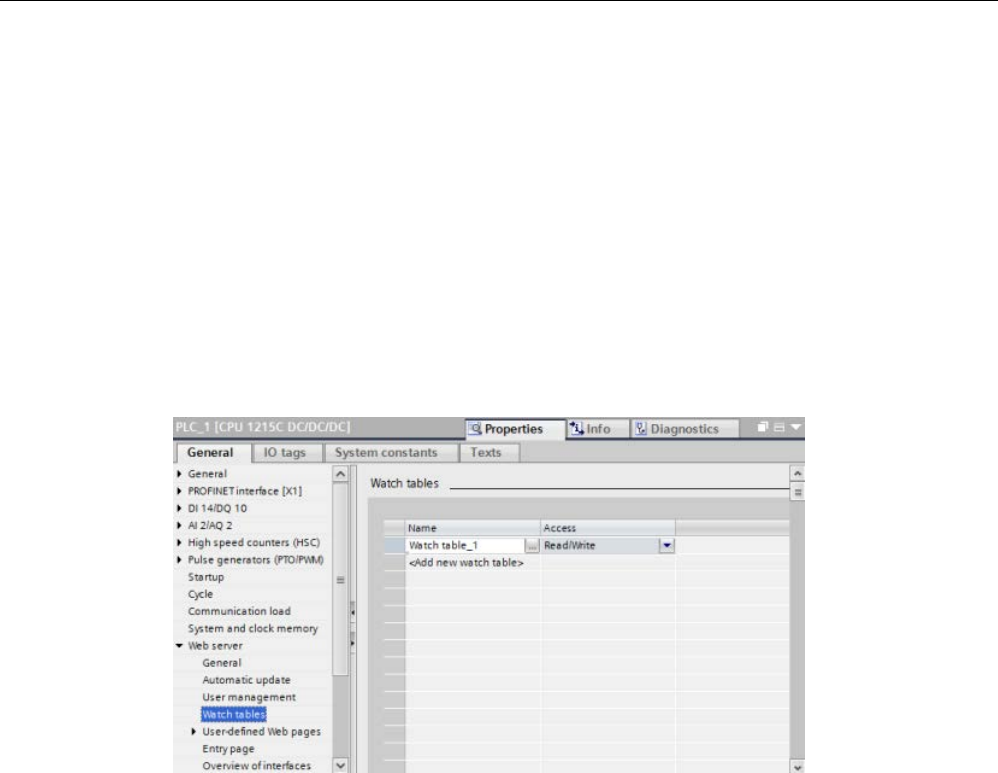
Web server
12.6 Standard Web pages
S7-1200 Programmable controller
System Manual, V4.2, 09/2016, A5E02486680-AK 1033
12.6.11
Watch tables
The Web server allows you to access watch tables that you have configured in STEP 7 and
which you have downloaded to the CPU. Watch tables with 50 or fewer entries offer the best
performance in the Web server.
STEP 7 configuration to select watch tables for the Web server
From the Device Configuration of the CPU in STEP 7, you can add the watch tables that you
want the Web server to be able to display. For each watch table that you select from the list
of existing watch tables, you select Read or Read/Write privileges for it. When downloaded
to the CPU, you can only view the watch tables that have the Read privilege but you can
view and modify watch table tags when you select the Read/Write privilege.
After you complete the watch table configuration in the Web server section of the device
configuration, download your hardware configuration to the CPU.
Viewing watch tables from the Web server
From the Web server, if you have the "read tags" privilege (Page 1005) you can select
"Watch tables" from the navigation menu to access the watch tables that you have
configured and downloaded to the CPU. If you have downloaded more than one watch table,
you can select the one you want to display from the drop-down list. The Web server displays
the watch table that you created in STEP 7 and the current values according to the display
format. You can change the display format if you choose, but when you return to the watch
table page the Web server defaults to the display formats in the STEP 7 watch table.
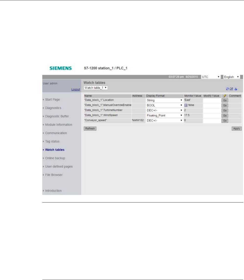
Web server
12.6 Standard Web pages
S7-1200 Programmable controller
1034 System Manual, V4.2, 09/2016, A5E02486680-AK
Modifying watch table tags from the Web server
If you downloaded a watch table with the "Read/Write" access level, and you have logged in
to the Web server with the "write tags" privilege (Page 1005) you can also modify tag values
just like you do in a watch table in STEP 7. You can modify individual tag values and click
"Go" to modify only the one value, or you can enter several values and click "Apply" to
modify them all at once.
Note
Advantages of watch tables for modifying tags
In order for a user to modify tags and data block tags in the CPU from a wat
ch table, you
must configure the watch table in the Web server properties in the STEP
7 device
configuration, and you must make it have Read/Write access. By so doing, you can restrict
the tags to which a user with the "write tags" privilege can modify to
only those tags in the
configured Web server watch tables.
The
Tag Status (Page 1031) page on the other hand allows any user with the "write tag
st
atus" privilege to write to any tag or data block tag in the CPU.
By careful configuration of the Web server
user management privileges (Page 1005), you
can help safeguard access to your PLC data.
See also
Rules for entering tag names and values (Page 1084)

Web server
12.6 Standard Web pages
S7-1200 Programmable controller
System Manual, V4.2, 09/2016, A5E02486680-AK 1035
12.6.12
Online backup
The Online backup standard Web page allows you to make a backup of the STEP 7 project
for the online PLC as well as to restore a previously-made backup of the PLC. Before
creating a backup or restoring a backup, place the PLC in STOP mode and cease all
communication with the PLC such as HMI access and Web server access. If your CPU is not
in STOP mode, the backup and restore functions prompt for confirmation to place the CPU in
STOP mode before continuing.
If you have accessed the Online backup page through one of the Web-enabled CP modules,
you can perform a backup but you cannot restore.
Note
You can also perform
backup and restore operations from STEP 7 (Page 1352). Refer to
these topics for a full description of what data you can back up and restore. The SIMATIC
Automation Tool (SAT) also provides backup and restore capability.
When you back files up from the Web server, your PC or device saves the backup files in
the
default folder for downloads. When you back files up from STEP
7, STEP 7 stores the files
within the STEP
7 project. You cannot restore STEP 7 backup files from the Web server and
you cannot restore Web server backup files from STEP 7. You can, howeve
r, save STEP 7
backup files directly to the download folder of your PC or device. If you do so, then you can
restore these files from the Web server.
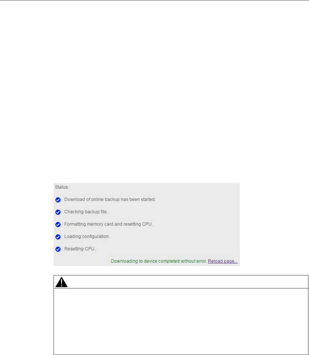
Web server
12.6 Standard Web pages
S7-1200 Programmable controller
1036 System Manual, V4.2, 09/2016, A5E02486680-AK
Backup PLC
From the Backup PLC section of the page, click the "Create online backup" button to make a
backup of the project that is currently stored in the PLC. This function requires the "Backup
CPU" user privilege (Page 1005). If the CPU is in RUN mode and you have to change it to
STOP mode, you also need the "Change operating mode" privilege. The PC or device will
store the backup file at the default location for downloads. Depending on your browser and
device settings, you might be prompted about saving the file.
Restore PLC
From the Restore PLC section of the page, enter the Web server user password and click
the "Browse" or "Choose File" button (depending on your browser) to select a previously-
saved backup file. Click the "Load online backup" button and confirm the prompt to load this
file in the connected PLC. This page requires the "Restore CPU" user privilege (Page 1005).
If the CPU is in RUN mode and you have to change it to STOP mode, you also need the
"Change operating mode" privilege.
As the restore operation proceeds, you see a series of progress messages and you must
reenter your user login and password. After each step of the process completes successfuly,
you see the following completion indicators and a link to reload the page:
WARNING
Restoring backups with unknown content
If you restore a backup with unknown content, you can cause serious damage or injuries in
case of malfunctions or program errors.
In addition, if you restore a backup that does not have the Web server enabled in the
device configuration of the CPU, you will not be able to access the CPU from the Web
server.
Make sure that the backup consists of a configuration with known content.
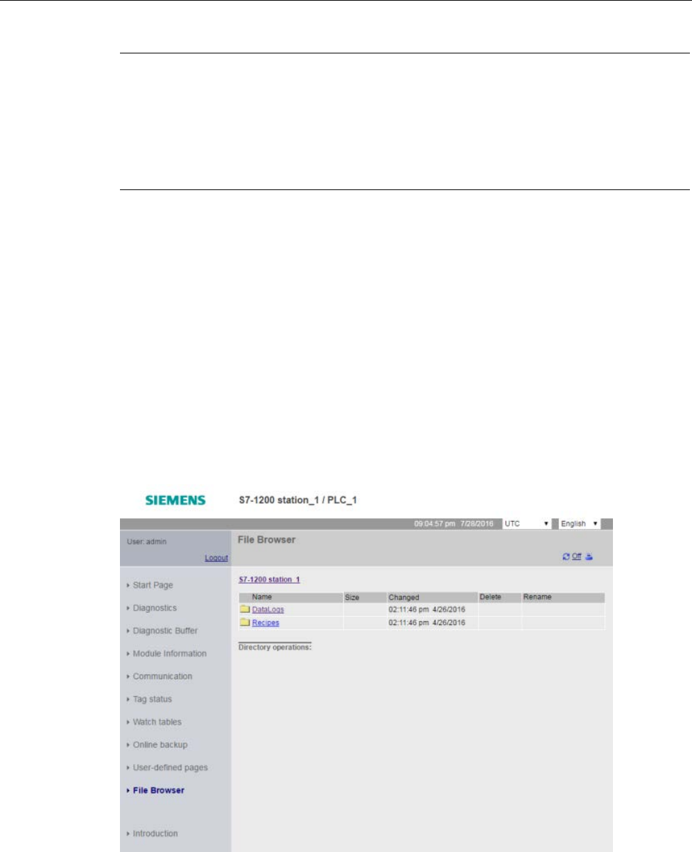
Web server
12.6 Standard Web pages
S7-1200 Programmable controller
System Manual, V4.2, 09/2016, A5E02486680-AK 1037
Note
Restoring a backup where the CPU IP address is different
If you attempt to restore a backup where the CPU IP address in the backup is different from
the IP addres
s of the current CPU, the Web server cannot display the message that the
restore is complete. After you see the "Reset CPU" message for greater than five minutes,
enter the new IP address that corresponds to the address in the backup file. The CPU now
has
this address and you can resume Web server access.
12.6.13
File Browser
The File Browser page provides access to files in the internal load memory of the CPU or on
the memory card (external load memory). The file browser page initially displays the root
folder of the load memory, which contains the "DataLogs" and "Recipes" folders, but also
displays any other folders that you might have created, if using a memory card.
The type of file access you have to the files and folders depends on your user privileges
(Page 1005). Any user with "read files" privileges can view the files and folders with the file
browser. You cannot delete the DataLogs folder or Recipes folder regardless of your login
privileges, but if you had made custom folders on the memory card, you can delete those
folders if you have logged in as a user with "write/delete files" privileges.
Click a folder to access the individual files in the folder.
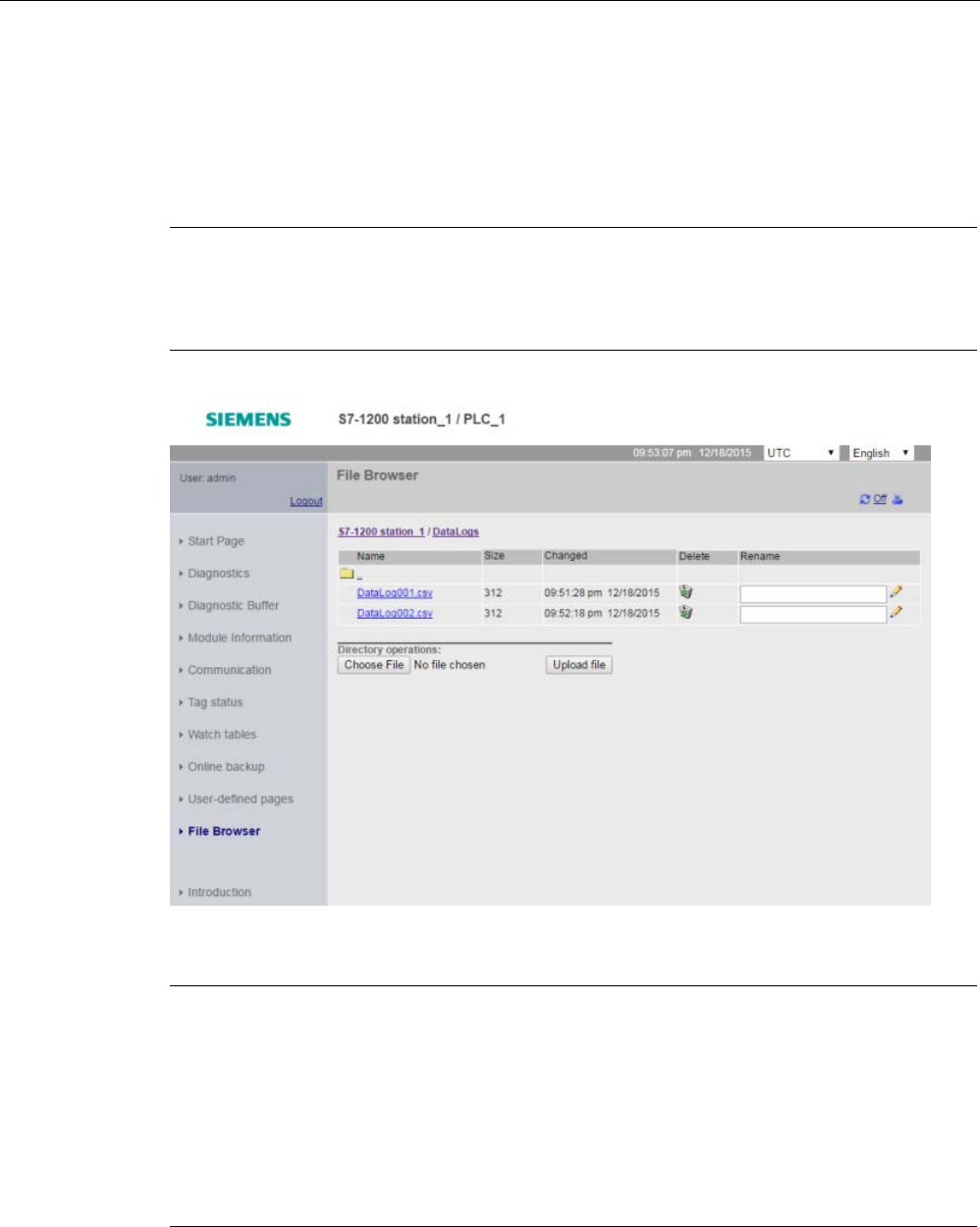
Web server
12.6 Standard Web pages
S7-1200 Programmable controller
1038 System Manual, V4.2, 09/2016, A5E02486680-AK
Data logs
From the "Data Logs" folder, you can open any of the data log files. If you have logged in
with the "write/delete files" privilege (Page 1005), you can also delete, rename, and upload
files. The data log files are in comma-separated values (CSV) file format. You can save them
to your computer or open them in Microsoft Excel (default) or another program.
Note
Time stamps for data logs
The Web server displays the time stamps for the data logs in either UTC time or PLC local
time depending upon your selection
at the top of the page.
Note:
The "Delete" and "Rename" options are not available if you are not logged in with the
"write/delete files" privilege.
Note
Data log management
Keep no more than 1000 data logs in a file system.
Exceeding this number can prevent the
Web server from having enough CPU resources to display the data logs.
If you find that the File Browser Web page is not able to display the data logs, then you must
place the CPU in STOP mode in order to display and de
lete data logs.
Manage your data logs to ensure that you only keep the number that you need to maintain,
and do not exceed 1000 data logs.

Web server
12.6 Standard Web pages
S7-1200 Programmable controller
System Manual, V4.2, 09/2016, A5E02486680-AK 1039
Working with a data log in Excel
The data log file is in USA/UK comma-separated values format (CSV). To open it in Excel on
non-USA/UK systems, you must import it into Excel with specific settings (Page 1086).
Recipe files
Like the data logs folder, the recipe folder displays any recipe files that are present in load
memory. Recipe files are also in CSV format, and you can open them in Microsoft Excel, or
another program. Like data logs, you must have modify privileges in order to delete, modify
and save, rename or upload recipe files.
Uploading files and automatic page refresh
If you begin a file upload, the upload operation continues as long as you remain on the File
Browser Web page. If you enabled automatic update to refresh the Web server pages every
ten seconds, then whenever a page refresh occurs you see the incremental progress of the
file upload operation. For example, if you are uploading a 2 MB file, you might see updates
that show the file size in bytes at 2500, 5000, 10000, 15000, and 20000 as the file upload
progresses.
If you leave the File Browser page before the upload completes, you do not get the complete
file. When you return, the File Browser page displays the file name and the size of the file at
the time that the upload stopped. You see no other indication that it is an incomplete file. To
be sure you upload the complete file, remain on the File Browser page until the displayed file
size reaches the actual size of the file.
Additional information
For information on programming with the data log instructions, and importing (Page 504) and
exporting (Page 502) recipes, see the Recipes and Data logs (Page 498) chapter.
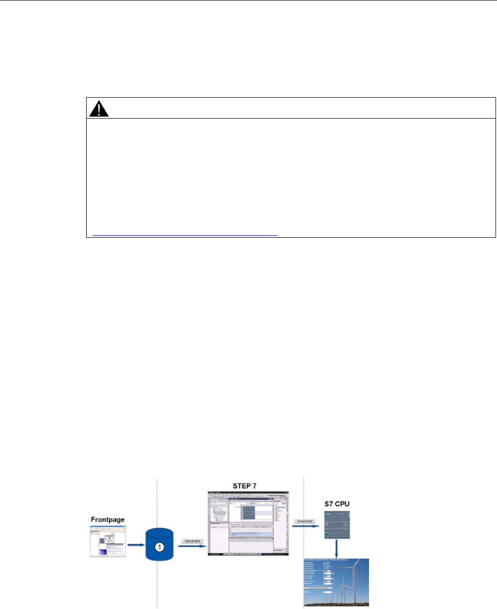
Web server
12.7 User-defined Web pages
S7-1200 Programmable controller
1040 System Manual, V4.2, 09/2016, A5E02486680-AK
12.7
User-defined Web pages
The S7-1200 Web server also provides the means for you to create your own application-
specific HTML pages that incorporate data from the PLC.
WARNING
Unauthorized access to the CPU through user-defined Web pages
Unauthorized access to the CPU through user-defined Web pages could disrupt process
operation, which could result in death, severe personal injury and/or property damage.
Insecure coding of user-defined Web pages introduces security vulnerabilites such as
cross-site scripting (XSS), code injection, and others.
Protect your S7-1200 CPU from unauthorized access by installing it in a secure fashion as
outlined in the Operational Guidelines found on the Industrial Security Web site
(http://www.siemens.com/industrialsecurity).
You create user-defined Web pages using the HTML editor of your choice and download
them to the CPU where they are accessible from the standard Web page menu. This
process involves several tasks:
● Creating HTML pages with an HTML editor, such as Microsoft Frontpage (Page 1041)
● Including AWP commands in HTML comments in the HTML code (Page 1042):The AWP
commands are a fixed set of commands that Siemens provides for accessing CPU
information.
● Configuring STEP 7 to read and process the HTML pages (Page 1057)
● Generating blocks from the HTML pages (Page 1057)
● Programming STEP 7 to control the use of the HTML pages (Page 1059)
● Compiling and downloading the blocks to the CPU (Page 1060)
● Accessing the user-defined Web pages from your PC (Page 1061)
This process is illustrated below:
①
HTML files with embedded AWP commands

Web server
12.7 User-defined Web pages
S7-1200 Programmable controller
System Manual, V4.2, 09/2016, A5E02486680-AK 1041
12.7.1
Creating HTML pages
You can use the software package of your choice to create your own HTML pages for use
with the Web server. Be sure that your HTML code is compliant to the HTML standards of
the W3C (World Wide Web Consortium). STEP 7 does not perform any verification of your
HTML syntax.
You can use a software package that lets you design in WYSIWYG or design layout mode,
but you need to be able to edit your HTML code in pure HTML form. Most Web authoring
tools provide this type of editing; otherwise, you can always use a simple text editor to edit
the HTML code. Include the following line in your HTML page to set the charset for the page
to UTF-8:
<meta http-equiv="content-type" content="text/html; charset=utf-8">
Also be sure to save the file from the editor in UTF-8 character encoding.
You use STEP 7 to compile everything in your HTML pages into STEP 7 data blocks. These
data blocks consist of one control data block that directs the display of the Web pages and
one or more fragment data blocks that contain the compiled Web pages. Be aware that
extensive sets of HTML pages, particularly those with lots of images, require a significant
amount of load memory space (Page 1062) for the fragment DBs. If the internal load
memory of your CPU is not sufficient for your user-defined Web pages, use a memory card
(Page 138) to provide external load memory.
To program your HTML code to use data from the S7-1200, you include AWP commands
(Page 1042) as HTML comments. When finished, save your HTML pages to your PC and
note the folder path where you save them.
Note
The file size limit for HTML files containing AWP command is 64 kilobytes. You must keep
your file size below this limit.
Refreshing user-defined Web pages
User-defined Web pages do not automatically refresh. It is your choice whether to program
the HTML to refresh the page or not. For pages that display PLC data, refreshing periodically
keeps the data current. For HTML pages that serve as forms for data entry, refreshing can
interfere with the user entering data. If you want your entire page to automatically refresh,
you can add this line to your HTML header, where "10" is the number of seconds between
refreshes:
<meta http-equiv="Refresh" content="10">
You can also use JavaScript or other HTML techniques to control page or data refreshing.
For this, refer to documentation on HTML and JavaScript.

Web server
12.7 User-defined Web pages
S7-1200 Programmable controller
1042 System Manual, V4.2, 09/2016, A5E02486680-AK
12.7.2
AWP commands supported by the S7-1200 Web server
The S7-1200 Web server provides AWP commands that you embed in your user-defined
Web pages as HTML comments for the following purposes:
● Reading variables (Page 1044)
● Writing variables (Page 1045)
● Reading special variables (Page 1047)
● Writing special variables (Page 1048)
● Defining enum types (Page 1050)
● Assigning variables to enum types (Page 1051)
● Creating fragment data blocks (Page 1052)
General syntax
Except for the command to read a variable, the AWP commands are of the following syntax:
<!-- AWP_ <command name and parameters> -->
You use the AWP commands in conjunction with typical HTML form commands to write to
variables in the CPU.
The descriptions of the AWP commands in the following pages use the following
conventions:
● Items enclosed in brackets [ ] are optional.
● Items enclosed in angle brackets < > are parameter values to be specified.
● Quotation marks are a literal part of the command. They must be present as indicated.
● Special characters in tag or data block names, depending on usage, must be escaped or
enclosed in quotation marks (Page 1055).
Use a text editor or HTML editing mode to insert AWP commands into your pages.
Note
Expected syntax of AWP commands
The space after "
<!--" and the space before "-->" in the formulation of an AWP command
are essential to proper compiling of the command. Omission of the space characters can
cause the compiler to be unable to generate the proper code. The compiler does not display
an error in this case.

Web server
12.7 User-defined Web pages
S7-1200 Programmable controller
System Manual, V4.2, 09/2016, A5E02486680-AK 1043
AWP command summary
The details for using each AWP command are in the topics to follow, but here is a brief
summary of the commands:
Reading variables
:=<Varname>:
Writing variables
<!-- AWP_In_Variable Name='<Varname1>' [Use='<Varname2>'] ... -->
This AWP command merely declares the variable in the Name clause to be writable. Your
HTML code performs writes to the variable by name from <input>, <select>, or other HTML
statements within an HTML form.
Reading special variables
<!-- AWP_Out_Variable Name='<Type>:<Name>' [Use='<Varname>'] -->
Writing special variables
<!-- AWP_In_Variable Name='<Type>:<Name>' [Use='<Varname>']-->
Defining enum types
<!--
AWP_Enum_Def Name='<Enum type name>' Values='<Value>, <Value>,... '
-->
Referencing enum types
<!-- AWP_In_Variable Name='<Varname>' Enum="<Enum type name>" -->
<!-- AWP_Out_Variable Name='<Varname>' Enum="<Enum type name>" -->
Creating fragments
<!-- AWP_Start_Fragment Name='<Name>' [Type=<Type>][ID=<id>] -->
Importing fragments
<!-- AWP_Import_Fragment Name='<Name>' -->

Web server
12.7 User-defined Web pages
S7-1200 Programmable controller
1044 System Manual, V4.2, 09/2016, A5E02486680-AK
12.7.2.1
Reading variables
User-defined Web pages can read variables (PLC tags) and data block tags from the CPU,
provided that you have configured the tags to be accessible from an HMI.
Syntax
:=<Varname>:
Parameters
<Varname> The variable to be read, which can be a PLC tag name from your STEP 7 program,
a data block tag, I/O, or addressable memory. For memory or I/O addresses or
alias names (Page 1055), do not use quotation marks around the tag name. For
PLC tags, use double quotation marks around the tag name. For data block tags,
en
close the block name only in double quotation marks. The tag name is outside of
the quotation marks. Note that you use the data block name and not a data block
number.
Examples
:="Conveyor_speed"::="My_Data_Block".flag1:
:=I0.0:
:=MW100:
Example reading an aliased variable
<!-- AWP_Out_Variable Name='flag1' Use='"My_Data_Block".flag1' -->
:=flag1:
Note
Defining alias names for PLC tags and data block tags is described in the topic
Using an
alias for a variab
le reference (Page 1049).
If a tag name or data block name includes special characters, you must use additional
quotation marks or escape characters as described in the topic Handling tag names that
contain special characters (Page 1055).

Web server
12.7 User-defined Web pages
S7-1200 Programmable controller
System Manual, V4.2, 09/2016, A5E02486680-AK 1045
12.7.2.2
Writing variables
User-defined pages can write data to the CPU. This is accomplished by using an AWP
command to identify a variable in the CPU to be writable from the HTML page. The variable
must be specified by PLC tag name or data block tag name. You can declare multiple
variable names in one statement. To write the data to the CPU, you use standard HTTP
POST commands.
A typical usage is to design a form in your HTML page with text input fields or select list
choices that correspond to writable CPU variables. As with all user-defined pages, you then
generate the blocks from STEP 7 such that they are included in your STEP 7 program.
When a user with privileges to modify variables subsequently accesses this page and types
data into the input fields or selects a choice from a select list, the Web server converts the
input to the appropriate data type for the variable, and writes the value to the variable in the
CPU. Note that the name clause for HTML input fields and HTML select lists uses syntax
typical for the name clause of the AWP_In_Variable command. Typically enclose the name in
single quotation marks and if you reference a data block, enclose the data block name in
double quotation marks.
For form management details, refer to documentation for HTML.
Syntax
<!-- AWP_In_Variable Name='<Varname1>' [Use='<Varname2>'] ... -->
Parameters
<Varname1> If no Use clause is provided, Varname1 is the variable to be written. It can be a
PLC tag name from your STEP 7 program, a tag from a specific data block, or a
data block name.
If a Use clause is provided, Varname1 is an alternate name for the variable refer-
enced in <Varname2> (Page 1049). It is a local name within the HTML page.
<Varname2> If a Use clause is provided, Varname2 is the variable to be written. It can be a PLC
tag name from your STEP 7 program or a tag from a specific data block.
For both Name clauses and Use clauses, the complete name must be enclosed in single
quotation marks. Within the single quotes, use double quotation marks around a PLC tag
and double quotation marks around a data block name. The data block name is within the
double quotes but not the data block tag name. Note that for data block tags, you use the
name of the block and not a data block number.
If you use an AWP_In_Variable command to make a data block writable, then every tag in
the data block is writable.

Web server
12.7 User-defined Web pages
S7-1200 Programmable controller
1046 System Manual, V4.2, 09/2016, A5E02486680-AK
Examples using HTML input field
<!-- AWP_In_Variable Name='"Target_Level"' -->
<form method="post">
<p>Input Target Level: <input name='"Target_Level"' type="text" />
</p>
</form>
<!-- AWP_In_Variable Name='"Data_block_1".Braking' -->
<form method="post">
<p>Braking: <input name='"Data_block_1".Braking' type="text" />
%</p>
</form>
Example using Use clause
<!-- AWP_In_Variable Name='"Braking"' Use='"Data_block_1".Braking' -
->
<form method="post">
<p>Braking: <input name='"Braking"' type="text" /> %</p>
</form>
Example using writable data block
<!-- AWP_In_Variable Name='"Data_block_1"' -->
<form method="post">
<p>Braking: <input name='"Data_block_1".Braking' type="text" /> %
</p>
<p>Turbine Speed: <input name='"Data_block_1".TurbineSpeed'
size="10" value='"Data_block_1".TurbineSpeed' type="text" />
</p>
</form>
Example using HTML select list
<!-- AWP_In_Variable Name='"Data_block_1".ManualOverrideEnable'-->
<form method="post">
<select name='"Data_block_1".ManualOverrideEnable'>
<option value=:"Data_block_1".ManualOverrideEnable:> </option>
<option value=1>Yes</option>
<option value=0>No</option>
</select><input type="submit" value="Submit setting" /></form>
Note
Only a user with privileges to modify variables can write data to the CPU. The Web server
ignores the commands if
the user does not have modify privileges.
If a tag name or data block name includes special characters, you must use additional
quotation marks or escape characters as described in the topic "Handling tag names that
contain special characters (Page 1055)".

Web server
12.7 User-defined Web pages
S7-1200 Programmable controller
System Manual, V4.2, 09/2016, A5E02486680-AK 1047
12.7.2.3
Reading special variables
The Web server provides the ability to read values from the PLC to store in special variables
in the HTTP response header. You might, for example, want to read a pathname from a PLC
tag to redirect the URL to another location using the HEADER:Location special variable.
Syntax
<!-- AWP_Out_Variable Name='<Type>:<Name>' [Use='<Varname>'] -->
Parameters
<Type> The type of special variable, which is one of the following:
HEADER
COOKIE_VALUE
COOKIE_EXPIRES
<Name> Refer to HTTP documentation for a list of all the names of HEADER variables. A
few examples are listed below:
Status: response code
Location: path for redirection
Retry-After: how long service is expected to be unavailable to the requesting client
For types COOKIE_VALUE and COOKIE_EXPIRES, <Name> is the name of a
specific cookie.
COOKIE_VALUE:name: value of the named cookie
COOKIE_EXPIRES:name: expiration time in seconds of named cookie
The Name clause must be enclosed in single or double quotation marks.
If no Use clause is specified, the special variable name corresponds to a PLC tag
name. Enclose the complete Name clause within single quotation marks and the
PLC tag in double quotation marks. The special variable name and PLC tag name
must match exactly.
<Varname> Name of the PLC tag or data block tag into which the variable is to be read
The Varname must be enclosed in single quotation marks. Within the single
quotes, use double quotation marks around a PLC tag or data block name. The
data block name is within the double quotes but not the data block tag name. Note
that for data block tags, you use the name of the block and not a data block num-
ber.
If a tag name or data block name includes special characters, you must use additional
quotation marks or escape characters as described in the topic Handling tag names that
contain special characters (Page 1055).
Example: Reading a special variable with no Use clause
<!-- AWP_Out_Variable Name='"HEADER:Status"' -->
In this example, the HTTP special variable "HEADER:Status" receives the value of the PLC
tag "HEADER:Status". The name in the PLC tag table must match the name of the special
variable exactly if no Use clause is specified.

Web server
12.7 User-defined Web pages
S7-1200 Programmable controller
1048 System Manual, V4.2, 09/2016, A5E02486680-AK
Example: Reading a special variable with a Use clause
<!-- AWP_Out_Variable Name='HEADER:Status' Use='"Status"' -->
In this example, the HTTP special variable "HEADER:Status" receives the value of the PLC
tag "Status".
12.7.2.4
Writing special variables
The Web server provides the ability to write values to the CPU from special variables in the
HTTP request header. For example, you can store information in STEP 7 about the cookie
associated with a user-defined Web page, the user that is accessing a page, or header
information. The Web server provides access to specific special variables that you can write
to the CPU when logged in as a user with privileges to modify variables.
Syntax
<!-- AWP_In_Variable Name='<Type>:<Name>' [Use='<Varname>']-->
Parameters
<Type> The type of special variable and is one of the following:
HEADER
SERVER
COOKIE_VALUE
<Name> Specific variable within the types defined above, as shown in these examples:
HEADER:Accept: content types that are acceptable
HEADER:User-Agent: information about the user agent originating the request.
SERVER:current_user_id: id of the current user; 0 if no user logged in
SERVER:current_user_name: name of the current user
COOKIE_VALUE:<name>: value of the named cookie
Enclose the Name clause in single quotation marks.
If no Use clause is specified, the special variable name corresponds to a PLC vari-
able name. Enclose the complete Name clause within single quotation marks and
the PLC tag in double quotation marks. The special variable name must match the
PLC tag name exactly.
Refer to HTTP documentation for a list of all the names of HEADER variables.
<Varname> The variable name in your STEP
7 program into which you want to write the special
variable, which can be a PLC tag name, or a data block tag.
The Varname must be enclosed in single quotation marks. Within the single
quotes, use double quotation marks around a PLC tag or data block name. The
data block name is within the double quotes but not the data block tag name. Note
that for data block tags, you use the name of the block and not a data block num-
ber.

Web server
12.7 User-defined Web pages
S7-1200 Programmable controller
System Manual, V4.2, 09/2016, A5E02486680-AK 1049
Examples
<!-- AWP_In_Variable Name='"SERVER:current_user_id"' -->
In this example, the Web page writes the value of the HTTP special variable
"SERVER:current_user_id" to the PLC tag named "SERVER:current_user_id ".
<!-- AWP_In_Variable Name=SERVER:current_user_id' Use='"my_userid"'
-->
In this example, the Web page writes the value of the HTTP special variable
"SERVER:current_user_id" to the PLC tag named "my_userid".
Note
Only a user with privileges to modify
variables can write data to the CPU. The Web server
ignores the commands if the user does not have modify privileges.
If a tag name or data block name includes special characters, you must use additional
quotation marks or escape characters as described in the topic "Handling tag names that
contain special characters (Page 1055)".
12.7.2.5
Using an alias for a variable reference
You can use an alias in your user-defined Web page for an In_Variable or an Out_Variable.
For example, you can use a different symbolic name in your HTML page than the one used
in the CPU, or you can equate a variable in the CPU with a special variable. The AWP Use
clause provides this capability.
Syntax
<-- AWP_In_Variable Name='<Varname1>' Use='<Varname2>' -->
<-- AWP_Out_Variable Name='<Varname1>' Use='<Varname2>' -->
Parameters
<Varname1> The alias name or special variable name
Varname1 must be enclosed in single or double quotation marks.
<Varname2>
Name of the PLC variable for which you want to assign an alias name. The variable
can be a PLC tag, a data block tag, or a special variable. Varname2 must be en-
closed in single quotation marks. Within the single quotes, use double quotation
marks around a PLC tag, special variable, or data block name. The data block
name is within the double quotes but not the data block tag name. Note that for
data block tags, you use the name of the block and not a data block number.

Web server
12.7 User-defined Web pages
S7-1200 Programmable controller
1050 System Manual, V4.2, 09/2016, A5E02486680-AK
Examples
<-- AWP_In_Variable Name='SERVER:current_user_id'
Use='"Data_Block_10".server_user' -->
In this example, the special variable SERVER:current_user_id is written to the tag
"server_user" in data block "Data_Block_10".
<-- AWP_Out_Variable Name='Weight'
Use='"Data_Block_10".Tank_data.Weight' -->
In this example, the value in data block structure member Data_Block_10.Tank_data.Weight
can be referenced simply by "Weight" throughout the rest of the user-defined Web page.
<-- AWP_Out_Variable Name='Weight' Use='"Raw_Milk_Tank_Weight"' -->
In this example, the value in the PLC tag "Raw_Milk_Tank_Weight" can be referenced simply
by "Weight" throughout the rest of the user-defined Web page.
If a tag name or data block name includes special characters, you must use additional
quotation marks or escape characters as described in the topic Handling tag names that
contain special characters (Page 1055).
12.7.2.6
Defining enum types
You can define enum types in your user-defined pages and assign the elements in an AWP
command.
Syntax
<!-- AWP_Enum_Def Name='<Enum type name>' Values='<Value>,
<Value>,... ' -->
Parameters
<Enum type
name>
Name of the enumerated type, enclosed in single or double quotation marks.
<Value> <constant>:<name>
The constant indicates the numerical value for the enum type assignment. The total
number is unbounded.
The name is the value assigned to the enum element.
Note that the entire string of enum value assignments is enclosed in single quotation marks,
and each individual enum type element assignment is enclosed in double quotation marks.
The scope of an enum type definition is global for the user-defined Web pages. If you have
set up your user-defined Web pages in language folders (Page 1074), the enum type
definition is global for all pages in the language folder.
Example
<!-- AWP_Enum_Def Name='AlarmEnum' Values='0:"No alarms", 1:"Tank is
full", 2:"Tank is empty"' -->

Web server
12.7 User-defined Web pages
S7-1200 Programmable controller
System Manual, V4.2, 09/2016, A5E02486680-AK 1051
12.7.2.7
Referencing CPU variables with an enum type
You can assign a variable in the CPU to an enum type. This variable can be used elsewhere
in your user-defined Web page in a read operation (Page 1044) or a write operation
(Page 1045). On a read operation, the Web server will replace the numerical value that is
read from the CPU with the corresponding enum text value. On a write operation, the Web
server will replace the text value with the integer value of the enumeration that corresponds
to the text before writing the value to the CPU.
Syntax
<!-- AWP_In_Variable Name='<Varname>' Enum="<EnumType>" -->
<!-- AWP_Out_Variable Name='<Varname>' Enum="<EnumType>" -->
Parameters
<Varname> Name of PLC tag or data block tag to associate with the enum type, or the name of
the alias name for a PLC tag (Page 1049) if declared.
Varname must be enclosed in single quotation marks. Within the single quotes, use
double quotation marks around a PLC tag or data block name. Note that for data
block tags, you use the name of the block and not a data block number. The data
block name is within the double quotes but not the data block tag name.
<EnumType> Name of the enumerated type, which must be enclosed in single or double quota-
tion marks
The scope of an enum type reference is the current fragment.
Example usage in a variable read
<!-- AWP_Out_Variable Name='"Alarm"' Enum="AlarmEnum" -->...
<p>The current value of "Alarm" is :="Alarm":</p>
If the value of "Alarm" in the CPU is 2, the HTML page displays 'The current value of "Alarm"
is Tank is empty' because the enum type definition (Page 1050) assigns the text string "Tank
is empty" to the numerical value 2.
Example usage in a variable write
<!-- AWP_Enum_Def Name='AlarmEnum' Values='0:"No alarms", 1:"Tank is
full", 2:"Tank is empty"' -->
<!-- AWP_In_Variable Name='"Alarm"' Enum='AlarmEnum' -->...
<form method="POST">
<p><input type="hidden" name='"Alarm"' value="Tank is full" /></p>
<p><input type="submit" value='Set Tank is full' /><p>
</form>
Because the enum type definition (Page 1050) assigns "Tank is full" to the numerical value
1, the value 1 is written to the PLC tag named "Alarm" in the CPU.
Note that the Enum clause in the AWP_In_Variable declaration must correspond exactly to
the Name clause in the AWP_Enum_Def declaration.

Web server
12.7 User-defined Web pages
S7-1200 Programmable controller
1052 System Manual, V4.2, 09/2016, A5E02486680-AK
Example usage in a variable write with use of an alias
<!-- AWP_Enum_Def Name='AlarmEnum' Values='0:"No alarms", 1:"Tank is
full", 2:"Tank is empty"' -->
<!-- AWP_In_Variable Name='"Alarm"' Enum='AlarmEnum'
Use='"Data_block_4".Motor1.Alarm'-->...
<form method="POST">
<p><input type="hidden" name='"Alarm"' value="Tank is full" /></p>
<p><input type="submit" value='Set Tank is full' /><p>
</form>
Because the enum type definition (Page 1050) assigns "Tank is full" to the numerical value
1, the value 1 is written to the alias "Alarm" which corresponds to the PLC tag named
"Motor1.Alarm" in data block "Data_Block_4" in the CPU.
If a tag name or data block name includes special characters, you must use additional
quotation marks or escape characters as described in the topic Handling tag names that
contain special characters (Page 1055).
Note
Previous releases required a separate AWP_Enum_Ref declaration to associate
a variable
with a defined enum type. STEP
7 and the S7-1200 support existing code with
AWP_Enum_Ref declarations; however, this command is no longer needed.
12.7.2.8
Creating fragments
STEP 7 converts and stores user-defined Web pages as a control DB and fragment DBs
when you click "Generate blocks" in the CPU Properties for the Web server. You can set up
specific fragments for specific pages or for sections of specific pages. You can identify these
fragments by a name and number with the "Start_Fragment" AWP command. Everything in
the page following the AWP_Start_Fragment command belongs to that fragment until
another AWP_Start_Command is issued or until end of file is reached.
Syntax
<!-- AWP_Start_Fragment Name='<Name>'
[Type=<Type>][ID=<id>][Mode=<Mode>] -->

Web server
12.7 User-defined Web pages
S7-1200 Programmable controller
System Manual, V4.2, 09/2016, A5E02486680-AK 1053
Parameters
<Name> Text string: name of fragment DB
Fragment names must begin with a letter or underscore and be comprised of let-
ters, numeric digits, and underscores. The fragment name is a regular expression
of the form:
[a-zA-Z_][a-zA-Z_0-9]*
<Type> "manual" or "automatic"
manual: The STEP 7 program must request this fragment and can respond accord-
ingly. Operation of the fragment must be controlled with STEP 7 and the control DB
variables.
automatic: The Web server processes the fragment automatically.
If you do not specify the type parameter, the default is "automatic".
<id> Integer identification number. If you do not specify the ID parameter, the Web serv-
er assigns a number by default. For manual fragments, set the ID to a low number.
The ID is the means by which the STEP 7 program controls a manual fragment.
<Mode> "visible" or "hidden"
visible: Contents of the fragment will display on the user-defined Web page.
hidden: Contents of the fragment will not display on the user-defined Web page.
If you do not specify the type parameter, the default is "visible".
Manual fragments
If you create a manual fragment for a user-defined Web page or portion of a page, then your
STEP 7 program must control when the fragment is sent. The STEP 7 program must set
appropriate parameters in the control DB for a user-defined page under manual control and
then call the WWW instruction with the control DB as modified. For understanding the
structure of the control DB and how to manipulate individual pages and fragments, see the
topic Advanced user-defined Web page control (Page 1078).
12.7.2.9
Importing fragments
You can create a named fragment from a portion of your HTML code and then import that
fragment elsewhere in your set of user-defined Web pages. For example, consider a set of
user-defined Web pages that has a start page and then several other HTML pages
accessible from links on the start page. Suppose each of the separate pages is to display the
company logo on the page. You could implement this by creating a fragment (Page 1052)
that loads the image of the company logo. Each individual HTML page could then import this
fragment to display the company logo. You use the AWP Import_Fragment command for this
purpose. The HTML code for the fragment only exists in one fragment, but you can import
this fragment DB as many times as necessary in as many Web pages as you choose.
Syntax
<!-- AWP_Import_Fragment Name='<Name>' -->

Web server
12.7 User-defined Web pages
S7-1200 Programmable controller
1054 System Manual, V4.2, 09/2016, A5E02486680-AK
Parameters
<Name>
Text string: name of the fragment DB to be imported
Example
Excerpt from HTML code that creates a fragment to display an image:
<!-- AWP_Start_Fragment Name='My_company_logo' --><p><img
src="company_logo.jpg"></p>
Excerpt from HTML code in another .html file that imports the fragment that displays the logo
image:
<!-- AWP_Import_Fragment Name='My_company_logo' -->
Both .html files (the one that creates the fragment and the one that imports it) are in the
folder structure that you define when you configure the user-defined pages in STEP 7
(Page 1057).
12.7.2.10
Combining definitions
When declaring variables for use in your user-defined Web pages, you can combine a
variable declaration and an alias for the variable (Page 1049). You can also declare multiple
In_Variables in one statement and multiple Out_Variables in one statement.
Examples
<!-- AWP_In_Variable Name='"Level'", Name='"Weight"', Name='"Temp"'
-->
<--! AWP_Out_Variable Name='HEADER:Status', Use='"Status"',
Name='HEADER:Location', Use="Location",
Name='COOKIE_VALUE:name', Use="my_cookie" -->
<!-- AWP_In_Variable Name='Alarm' Use='"Data_block_10".Alarm' -->

Web server
12.7 User-defined Web pages
S7-1200 Programmable controller
System Manual, V4.2, 09/2016, A5E02486680-AK 1055
12.7.2.11
Handling tag names that contain special characters
When specifying variable names in user-defined Web pages, you must take special care if
tag names contain characters that have special meanings.
Reading variables
You use the following syntax to read a variable (Page 1044):
:=<Varname>:
The following rules apply to reading variables:
● For variable names from the PLC tag table, enclose the tag name in double quotation
marks.
● For variable names that are data block tags, enclose the data block name in double
quotation marks. The tag is outside of the quotation marks.
● For variable names that are direct I/O addresses, memory addresses, or alias names, do
not use quotation marks around the read variable.
● For tag names or data block tag names that contain a backslash, precede the backslash
with another backslash.
● If a tag name or data block tag name contains a colon, less than sign, greater than sign,
or ampersand define an alias that has no special characters for the read variable, and
read the variable using the alias. Precede colons in tag names in a Use clause with a
backslash.
Table 12- 1 Examples of Read variables
Data block name
Tag name
Read command
n/a ABC:DEF
<!--AWP_Out_Variable Name='special_tag'
Use ='"ABC:DEF"' -->
:=special_tag:
n/a
T\
:="T\\":
n/a A \B 'C :D
<!--AWP_Out_Variable
Name='another_special_tag' Use='"A \\B \'C
:D"' -->
:=another_special_tag:
n/a a<b
<!--AWP_Out_Variable Name='a_less_than_b'
Use='"a<b"' -->
:=a_less_than_b:
Data_block_1
Tag_1
:="Data_block_1".Tag_1:
Data_block_1 ABC:DEF
<!-- AWP_Out_Variable Name='special_tag'
Use='"Data_block_1".ABC\:DEF'-->
:=special_tag:
DB A' B C D$ E
Tag
:="DB A' B C D$ E".Tag:
DB:DB Tag:Tag
<!--AWP_Out_Variable Name='my_tag' Use
='"DB:DB".Tag\:Tag' -->
:=my_tag:

Web server
12.7 User-defined Web pages
S7-1200 Programmable controller
1056 System Manual, V4.2, 09/2016, A5E02486680-AK
Name and Use clauses
The AWP commands AWP_In_Variable, AWP_Out_Variable, AWP_Enum_Def,
AWP_Enum_Ref, AWP_Start_Fragment and AWP_Import_Fragment have Name clauses.
HTML form commands such as <input> and <select> also have name clauses.
AWP_In_Variable and AWP_Out_Variable can additionally have Use clauses. Regardless of
the command, the syntax for Name and Use clauses regarding the handling of special
characters is the same:
● The text you provide for a Name or Use clause must be enclosed within single quotation
marks. If the enclosed name is a PLC tag or Data block name, use single quotation
marks for the full clause.
● Within a Name or Use clause, data block names and PLC tag names must be enclosed
within double quotation marks.
● If a tag name or Data block name includes a single quote character or backslash, escape
that character with a backslash. The backslash is the escape character in the AWP
command compiler.
Table 12- 2 Examples of Name clauses
Data block name
Tag name
Name clause options
n/a
ABC'DEF
Name='"ABC\'DEF"'
n/a A \B 'C :D
Name='"A \\B \'C :D"'
Data_block_1
Tag_1
Name='"Data_block_1".Tag_1'
Data_block_1
ABC'DEF
Name='"Data_block_1".ABC\'DEF'
Data_block_1
A \B 'C :D
Name='"Data_block_1".A \\B \'C :D'
DB A' B C D$ E
Tag
Name='"DB A\' B C D$ E".Tag'
Use clauses follow the same conventions as Name clauses.
Note
Regardless of what characters you use in your HTML page, set the charset of the HTML
page to UTF
-8 and save it from the editor with UTF-8 character encoding.
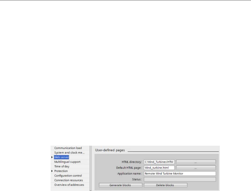
Web server
12.7 User-defined Web pages
S7-1200 Programmable controller
System Manual, V4.2, 09/2016, A5E02486680-AK 1057
12.7.3
Configuring use of user-defined Web pages
To configure user-defined Web pages from STEP 7, follow these steps:
1. Select the CPU in the Device Configuration view.
2. Display the "Web server" properties in the inspector window for the CPU.
3. If not already selected, select the check box for "Activate Web server on this module".
4. Select "Permit access only with HTTPS" to ensure that the Web server uses encrypted
communication and to increase the security of your Web-accessible CPU.
5. Enter or browse to the folder name on your PC where you saved the HTML default page
(start page).
6. Enter the name of the default page.
7. Provide a name for your application (optional). The Web server uses the application
name to further subcategorize or group web pages. When you provide an application
name, the Web server creates an URL for your user-defined page in the following format:
http[s]://ww.xx.yy.zz/awp/<application name>/<pagename>.html.
Avoid special characters in the application name. Some characters can cause the Web
server to be unable to display the user-defined pages.
8. Enter filename extensions of files that include AWP commands. By default, STEP 7
analyzes files with .htm, .html, or .js extensions. If you have additional file extensions,
append them.
9. Keep the default for the Web DB number, or enter a number of your choice. This is the
DB number of the control DB that controls display of the Web pages.
10.Keep the default for the fragment DB start number, or enter a number of your choice. This
is the first of the fragment DBs that contains the Web pages.
Generating program blocks
When you click the "Generate blocks" button, STEP 7 generates data blocks from the HTML
pages in the HTML source directory that you specified and a control data block for the
operation of your Web pages. You can set these attributes as needed for your application
(Page 1059). STEP 7 also generates a set of fragment data blocks to hold the representation
of all of your HTML pages. When you generate the data blocks, STEP 7 updates the
properties to display the control data block number, and the number of the first of the
fragment data blocks. After you generate the data blocks, your user-defined Web pages are
a part of your STEP 7 program. The blocks corresponding to these pages appear in the Web
server folder, which is in the System blocks folder under Program blocks in the project
navigation tree.

Web server
12.7 User-defined Web pages
S7-1200 Programmable controller
1058 System Manual, V4.2, 09/2016, A5E02486680-AK
Deleting program blocks
To delete data blocks that you have previously generated, click the "Delete data blocks"
button. STEP 7 deletes the control data block and all of the fragment data blocks from your
project that correspond to user-defined Web pages.
12.7.4
Configuring the entry page
In the Device Configuration of the CPU, you have the opportunity to designate a user-
defined Web page to be the entry page when you access the Web server from either a PC or
a mobile device. Otherwise, the entry page is the Introduction (Page 1017) standard Web
page.
To select a user-defined Web page to be the entry page, follow these steps:
1. Select the CPU in the Device Configuration view.
2. In the inspector window, select "Web server" from the CPU properties and enable the
Web server (Page 1003).
3. Select "Entry page" in the Web server properties.
4. Select "UP1" from the drop-down list to configure the Web server to display a user-
defined page upon access. (The other selection, "Intro page", sets the Web server to
display the standard Introduction Web page upon access.)
You must also configure the Everybody user to have the "open user-defined Web pages"
privilege (Page 1005) and include a call to the WWW instruction (Page 1059) in your
program.
After you have completed configuration and downloaded the project to the CPU, the Web
server can use the "Default HTML page" that you selected when you configured your user-
defined Web pages (Page 1057) as the entry page.
Note
The CPU must be in RUN mode to display a user
-defined entry page.
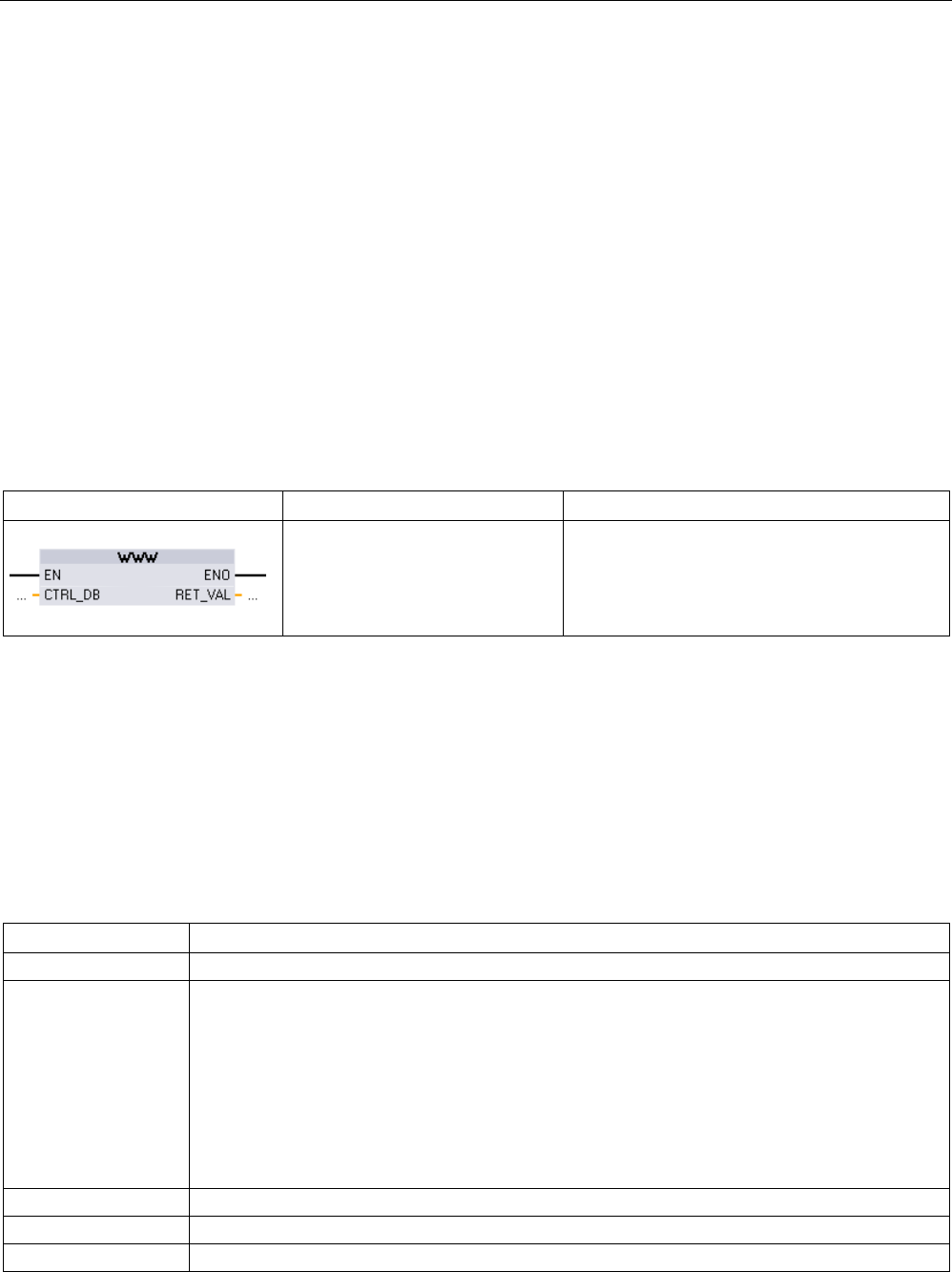
Web server
12.7 User-defined Web pages
S7-1200 Programmable controller
System Manual, V4.2, 09/2016, A5E02486680-AK 1059
12.7.5
Programming the WWW instruction for user-defined web pages
Your STEP 7 user program must include and execute the WWW instruction in order for the
user-defined Web pages to be accessible from the standard Web pages. The control data
block is the input parameter to the WWW instruction and specifies the content of the pages
as represented in the fragment data blocks, as well as state and control information. STEP 7
creates the control data block when you click the "Create blocks" button in the configuration
of user-defined Web pages (Page 1057).
Programming the WWW instruction
The STEP 7 program must execute the WWW instruction for the user-defined Web pages to
be accessible from the standard Web pages. You might want the user-defined Web pages
available only under certain circumstances as dictated by your application requirements and
preferences. In this case, your program logic can control when to call the WWW instruction.
Table 12- 3 WWW instruction
LAD / FBD
SCL
Description
ret_val := WWW(
ctrl_db:=_uint_in_);
Provides access to user-defined Web pages
from standard Web pages
You must provide the control data block input parameter (CTRL_DB) which corresponds to
the integer DB number of the control DB. You can find this control DB block number (called
Web DB Number) in the Web Server properties of the CPU after you create the blocks for
the user-defined Web pages. Enter the integer DB number as the CTRL_DB parameter of
the WWW instruction. The return value (RET_VAL) contains the function result. Note that the
WWW instruction executes asynchronously and that the RET_VAL output might have an
initial value of 0 although an error can occur later. The program can check the state of the
control DB to ensure that the application started successfully, or check RET_VAL with a
subsequent call to WWW.
Table 12- 4 Return value
RET_VAL
Description
0 No error
16#00yx x: The request represented by the respective bit is in the waiting state:
x=1: request 0
x=2: request 1
x=4: request 2
x=8: request 3
The x values can be logically OR-ed to represent waiting states of multiple requests. If x = 6, for
example, requests 1 and 2 are waiting.
y: 0: no error; 1: error exists and "last_error" has been set in the control DB (Page 1078)
16#803a
The control DB is not loaded.
16#8081
The control DB is of the wrong type, format, or version.
16#80C1
No resources are available to initialize the web application.

Web server
12.7 User-defined Web pages
S7-1200 Programmable controller
1060 System Manual, V4.2, 09/2016, A5E02486680-AK
Usage of the Control DB
STEP 7 creates the control data block when you click "Generate blocks" and displays the
control DB number in the User-defined Web pages properties. You can find the control DB
as well in the Program blocks folder in the project navigation tree.
Typically, your STEP 7 program uses the control DB directly as created by the "Generate
blocks" process with no additional manipulation. However, the STEP 7 user program can set
global commands in the control DB to deactivate the web server or to subsequently re-
enable it. Also, for user-defined pages that you create as manual fragment DBs (Page 1057),
the STEP 7 user program must control the behavior of these pages through a request table
in the control DB. For information on these advanced tasks, see the topic Advanced user-
defined Web page control (Page 1078).
12.7.6
Downloading the program blocks to the CPU
After you have generated the blocks for user-defined Web pages, they are part of your STEP
7 program just like any other program blocks. You follow the normal process to download the
program blocks to the CPU. Note that you can only download user-defined Web page
program blocks when the CPU is in STOP mode.
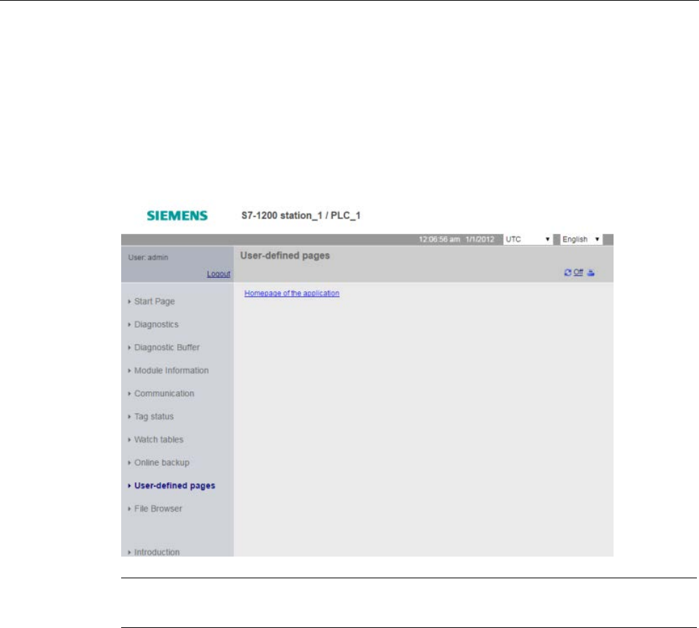
Web server
12.7 User-defined Web pages
S7-1200 Programmable controller
System Manual, V4.2, 09/2016, A5E02486680-AK 1061
12.7.7
Accessing the user-defined Web pages
You access your user-defined Web pages from the standard Web pages (Page 1007). The
standard Web pages display a link for "User-defined pages" on the left side navigation menu.
The basic page navigation also provides a link to "User-defined pages". When you click the
"User-defined pages" link, your Web browser goes to the page that provides a link to your
default page. From within the user-defined pages, navigation is according to how you
designed your specific pages.
Note
You can also
define a user-defined page as the entry page (Page 1058) for the Web server.

Web server
12.7 User-defined Web pages
S7-1200 Programmable controller
1062 System Manual, V4.2, 09/2016, A5E02486680-AK
12.7.8
Constraints specific to user-defined Web pages
The constraints for standard Web pages (Page 1082) also apply to user-defined Web pages.
In addition, user-defined Web pages have some specific considerations.
Load memory space
Your user-defined Web pages become data blocks when you click "Generate blocks", which
require load memory space. If you have a memory card installed, you have up to the
capacity of your memory card as external load memory space for the user-defined Web
pages.
If you do not have a memory card installed, these blocks take up internal load memory
space, which is limited according to your CPU model.
You can check the amount of load memory space that is used and the amount that is
available from the Online and Diagnostic tools in STEP 7. You can also look at the properties
for the individual blocks that STEP 7 generates from your user-defined Web pages and see
the load memory consumption.
Note
If you need to reduce the space required for your user
-defined Web pages, reduce your use
of images if applicable.
Quotation marks in text strings
Avoid using text strings that contain embedded single or double quotation marks in data
block tags that you use for any purpose in user-defined Web pages. Because HTML syntax
often uses single quotes or double quotes as delimiters, quotation marks within text strings
can break the display of user-defined Web pages.
For data block tags of type String that you use in user-defined Web pages, observe the
following rules:
● Do not enter single or double quotation marks in the data block tag string value in
STEP 7.
● Do not let the user program make assignments of strings containing quotes to these data
block tags.
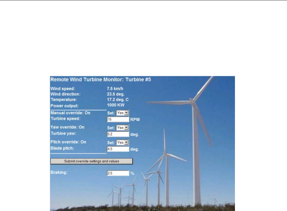
Web server
12.7 User-defined Web pages
S7-1200 Programmable controller
System Manual, V4.2, 09/2016, A5E02486680-AK 1063
12.7.9
Example of a user-defined web page
12.7.9.1
Web page for monitoring and controlling a wind turbine
As an example of a user-defined Web page, consider a Web page that is used to remotely
monitor and control a wind turbine:
Description
In this application, each wind turbine in a wind turbine farm is equipped with an S7-1200 for
control of the turbine. Within the STEP 7 program, each wind turbine has a data block with
data specific to that wind turbine.
The user-defined Web page provides remote turbine access from a PC. A user can connect
to standard web pages of the CPU of a particular wind turbine and access the user-defined
"Remote Wind Turbine Monitor" Web page to see the data for that turbine. A user with
privileges to modify variables can also put the turbine in manual mode and control the
variables for turbine speed, yaw, and pitch from the Web page. A user with privileges to
modify variables can also set a braking value regardless of whether the turbine is under
manual or automatic control.
The STEP 7 program would check the Boolean values for overriding automatic control, and if
set, would use the user-entered values for turbine speed, yaw, and pitch. Otherwise, the
program would ignore these values.
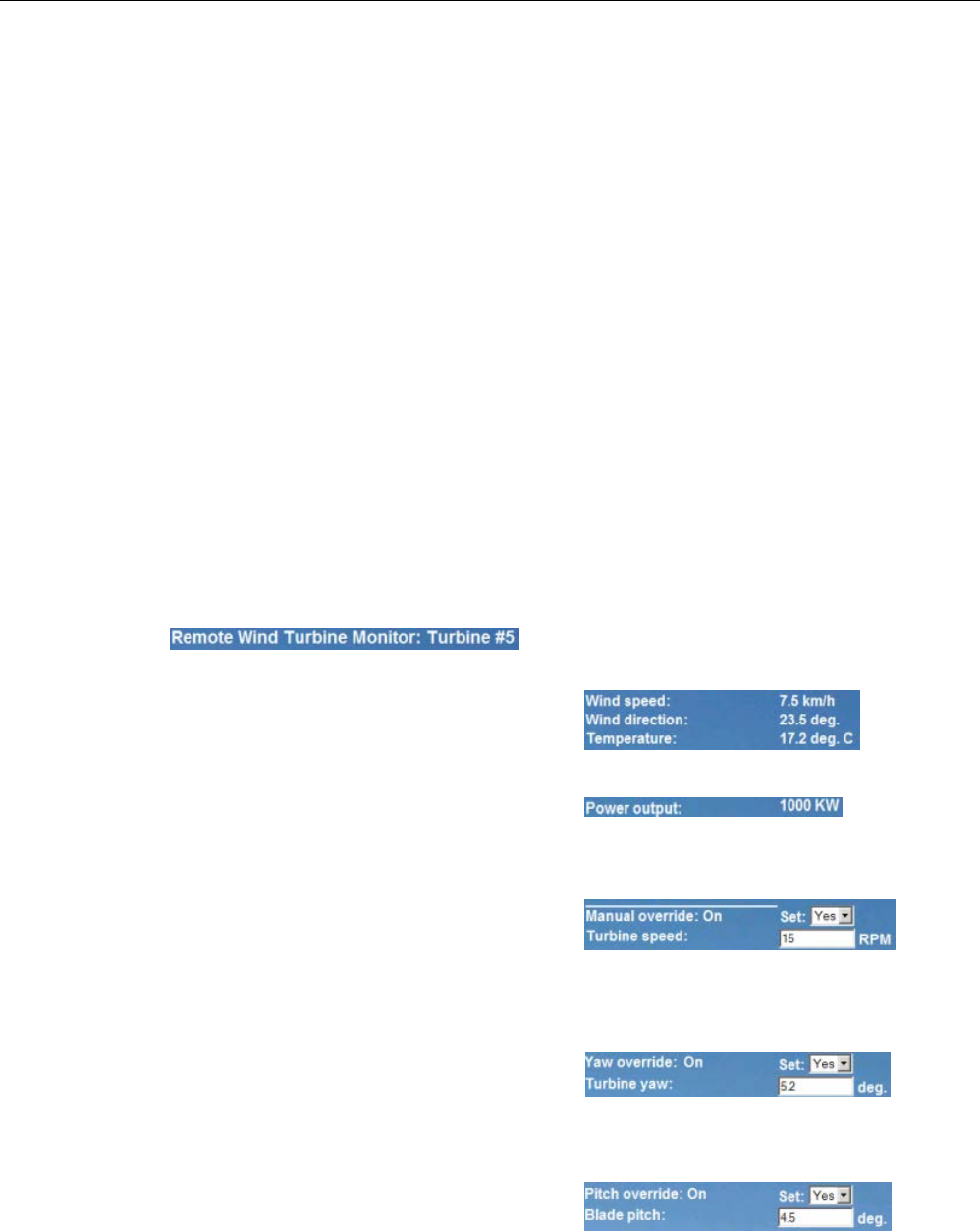
Web server
12.7 User-defined Web pages
S7-1200 Programmable controller
1064 System Manual, V4.2, 09/2016, A5E02486680-AK
Files used
This user-defined Web page example consists of three files:
●
Wind_turbine.html
: This is the HTML page that implements the display shown above,
using AWP commands to access controller data.
●
Wind_turbine.css
: This is the cascading style sheet that contains formatting styles for the
HTML page. Use of a cascading style sheet is optional, but it can simplify the HTML page
development.
●
Wind_turbine.jpg
: This is the background image that the HTML page uses. Use of images
in user-defined Web pages is, of course, optional, and does require additional space in
the CPU.
These files are not provided with your installation, but are described as an example.
Implementation
The HTML page uses AWP commands to read values from the PLC (Page 1044) for the
display fields and to write values to the PLC (Page 1045) for data coming from user input.
This page also uses AWP commands for enum type definition (Page 1050) and reference
(Page 1051) for handling ON/OFF settings.
The first part of the page displays a header line that includes the wind turbine number.
The next part of the page displ
ays atmospheric
conditions at the wind turbine. I/O at the turbine
site provide the wind speed, wind direction, and
current temperature.
Next, the page displays the power output of the
turbine as read from the S7-1200.
The following sections allow for manual control of the turbine, overriding the normal automa
t-
ic control by the S7-1200. These types are as follows:
•
Manual override: enables manual override
of the turbine. The STEP 7 user program
requires that the manual override setting be
true before enabling the use of any of the
manual settings for turbine speed, or yaw or
pitch.
•
Yaw override: enables manual override of
the yaw setting, and a manual setting for the
yaw. The STEP 7 user program requires
that both manual override and yaw override
be true in order to apply the yaw setting.
•
Pitch override: enables manual override of
the pitch of the blades. The STEP 7 user
program requires that both manual override
and pitch override be true in order to apply
the blade pitch setting.
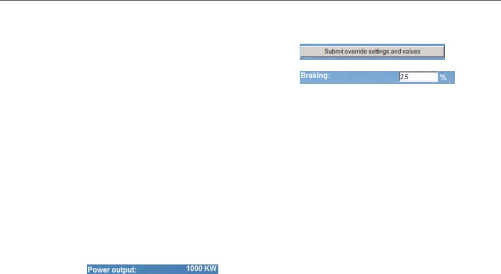
Web server
12.7 User-defined Web pages
S7-1200 Programmable controller
System Manual, V4.2, 09/2016, A5E02486680-AK 1065
The HTML page includes a submit button to
post the override settings to the controller.
The braking user input field provides a manu
al
setting for a braking percentage. The STEP 7
user program does not require manual override
to accept a braking value.
In addition, the HTML page uses an AWP command to write the special variable
(Page 1048) that contains the user ID of the user that is accessing the page to a tag in the
PLC tag table.
12.7.9.2
Reading and displaying controller data
The "Remote Wind Turbine Monitor" HTML page uses numerous AWP commands for
reading data from the controller (Page 1044) and displaying it on the page. For example,
consider the HTML code for displaying the power output as shown in this portion of the
example Web page:
Example HTML code
The following excerpt from the "Remote Wind Turbine Monitor" HTML page displays the text
"Power Output:" in the left cell of a table row and reads the variable for the power output and
displays it in the right cell of the table row along with the text abbreviation for kilowatts, kW.
The AWP command :="Data_block_1".PowerOutput: performs the read operation. Note that
data blocks are referenced by name, not by data block number (that is, "Data_block_1" and
not "DB1").
<tr style="height:2%;">
<td>
<p>Power output:</p>
</td>
<td>
<p style="margin-bottom:5px;"> :="Data_block_1".PowerOutput: kW</p>
</td>
</tr>

Web server
12.7 User-defined Web pages
S7-1200 Programmable controller
1066 System Manual, V4.2, 09/2016, A5E02486680-AK
12.7.9.3
Using an enum type
The "Remote Wind Turbine Monitor" HTML page uses enum types for the three instances
where HTML page displays "ON" or "OFF" for a Boolean value, and for where the user sets
a Boolean value. The enum type for "ON" results in a value of 1, and the enum type for
"OFF" results in a value of 0. For example, consider the HTML code for reading and writing
the Manual Override Enable setting in "Data_block_1".ManualOverrideEnable value using an
enum type:
Example HTML code
The following excerpts from the "Remote Wind Turbine Monitor" HTML page show how to
declare an enum type called "OverrideStatus" with values of "Off" and "On" for 0 and 1, and
then setting an enum type reference to OverrideStatus for the ManualOverrideEnable
Boolean tag in the data block named "Data_block_1".
<!-- AWP_In_Variable Name='"Data_block_1".ManualOverrideEnable'
Enum="OverrideStatus" -->
<!-- AWP_Enum_Def Name="OverrideStatus" Values='0:"Off",1:"On"' -->
Where the HTML page includes a display field in a table cell for the current state of
ManualOverrideEnable, it uses just a normal read variable command, but with the use of the
previously declared and referenced enum type, the page displays "Off" or "On" rather than 0
or 1.
<td style="width:24%; border-top-style: Solid; border-top-width:
2px; border-top-color: #ffffff;">
<p>Manual override: :="Data_block_1".ManualOverrideEnable:</p>
</td>
The HTML page includes a drop-down select list for the user to change the value of
ManualOverrideEnable. The select list uses the text "Yes" and "No" to display in the select
lists. With the use of the enum type, "Yes" is correlated to the value "On" of the enum type,
and "No" is correlated to the value "Off". The empty selection leaves the value of
ManualOverrideEnable as it is.
<select name='"Data_block_1".ManualOverrideEnable'>
<option value=':"Data_block_1".ManualOverrideEnable:'> </option>
<option value="On">Yes</option>
<option selected value="Off">No</option>
</select>
The select list is included within a form on the HTML page. When the user clicks the submit
button, the page posts the form, which writes a value of "1" to the Boolean
ManualOverrideEnable in Data_block_1 if the user had selected "Yes", or "0" if the user had
selected "No".

Web server
12.7 User-defined Web pages
S7-1200 Programmable controller
System Manual, V4.2, 09/2016, A5E02486680-AK 1067
12.7.9.4
Writing user input to the controller
The "Remote Wind Turbine Monitor" HTML page includes several AWP commands for
writing data to the controller (Page 1045). The HTML page declares AWP_In_Variables for
Boolean variables so that a user with privileges to modify variables can put the wind turbine
under manual control and enable manual override for the turbine speed, yaw override,
and/or blade pitch override. The page also uses AWP_In_Variables to allow a user with
privileges to modify variables to subsequently set floating-point values for the turbine speed,
yaw, pitch, and braking percentage. The page uses an HTTP form post command to write
the AWP_In_Variables to the controller.
For example, consider the HTML code for manually setting the braking value:
Example HTML code
The following excerpt from the "Remote Wind Turbine Monitor" HTML page first declares an
AWP_In_Variable for "Data_block_1" that enables the HTML page to write to any tags in the
data block "Data_block_1". The page displays the text "Braking:" in the left cell of a table
row. In the right cell of the table row is the field that accepts user input for the "Braking" tag
of "Data_block_1". This user input value is within an HTML form that uses the HTTP method
"POST" to post the entered text data to the CPU. The page then reads the actual braking
value from the controller and displays it in the data entry field.
A user with privileges to modify variables can subsequently use this page to write a braking
value to the data block in the CPU that controls braking.
<!-- AWP_In_Variable Name='"Data_block_1"' -->
...
<tr style="vertical-align: top; height: 2%;">
<td style="width: 22%;"><p>Braking:</p></td>
<td>
<form method="POST">
<p><input name='"Data_block_1".Braking' size="10" type="text"> %</p>
</form>
</td>
</tr>
Note
Note that if a us
er-defined page has a data entry field for a writable data block tag that is a
string data type, the user must enclose the string in single quotation marks when entering
the string value in the field.
Note
Note that if you declare an entire data block
in an AWP_In_Variable declaration such as <!--
AWP_In_Variable Name='"Data_block_1"' -->, then every tag within that data block can be
written from the user
-
defined Web page. Use this when you intend for all of the tags in a data
block to be writable. Othe
rwise, if you only want specific data block tags to be writable from
the user
-defined Web page, declare it specifically with a declaration such as <!--
AWP_In_Variable Name='"Data_block_1".Braking' -->

Web server
12.7 User-defined Web pages
S7-1200 Programmable controller
1068 System Manual, V4.2, 09/2016, A5E02486680-AK
12.7.9.5
Writing a special variable
The "Remote Wind Turbine Monitor" Web page writes the special variable
SERVER:current_user_id to a PLC tag in the CPU, providing that the user has modify
privileges. In this case, the PLC tag value contains the user ID of the user who is accessing
the "Remote Wind Turbine Monitor" Web page.
The Web page writes the special variable to the PLC and requires no user interface.
Example HTML code
<!-- AWP_In_Variable Name="SERVER:current_user_id" Use="User_ID"-->
12.7.9.6
Reference: HTML listing of remote wind turbine monitor Web page
Wind_turbine.html
<!DOCTYPE HTML PUBLIC "-//W3C//DTD HTML 4.01 Transitional//EN"
"http://www.w3.org/TR/html4/loose.dtd">
<!--
This test program simulates a Web page to monitor and control a Wind
Turbine
Required PLC tags and Data Block Tags in STEP 7:
PLC Tag:
User_ID: Int
Data Blocks:
Data_block_1
Tags in Data_Block_1:
TurbineNumber: Int
WindSpeed: Real
WindDirection: Real
Temperature: Real
PowerOutput: Real
ManualOverrideEnable: Bool
TurbineSpeed: Real
YawOverride: Bool
Yaw: Real
PitchOverride: Bool
Pitch: Real
Braking: Real
The user-defined Web page displays current values for the PLC data,
and provides a select list to set the three Booleans using an
enumerated type assignment. The "Submit" button posts the selected
Boolean values as well as the data entry fields for TurbineSpeed,
Yaw, and Pitch. The value for Braking can be set without use of the
"Submit" button.
No actual STEP 7 program is required to use this page.
Theoretically, the STEP 7 program would only act on the values of
TurbineSpeed, Yaw, and Pitch, if the associated Booleans were set.

Web server
12.7 User-defined Web pages
S7-1200 Programmable controller
System Manual, V4.2, 09/2016, A5E02486680-AK 1069
The only STEP 7 requirement is to call the WWW instruction with the
DB number of the generated data blocks for this page.
-->
<!-- AWP_In_Variable Name='"Data_block_1"' -->
<!-- AWP_In_Variable Name='"Data_block_1".ManualOverrideEnable'
Enum="OverrideStatus" -->
<!-- AWP_In_Variable Name='"Data_block_1".PitchOverride'
Enum="OverrideStatus" -->
<!-- AWP_In_Variable Name='"Data_block_1".YawOverride'
Enum="OverrideStatus" -->
<!-- AWP_In_Variable Name="SERVER:current_user_id" Use="User_ID"-->
<!-- AWP_Enum_Def Name="OverrideStatus" Values='0:"Off",1:"On"' -->
<html>
<head>
<meta http-equiv="content-type" content="text/html; charset=utf-
8"><link rel="stylesheet" href="Wind_turbine.css">
<title>Remote Wind Turbine Monitor</title>
</head>
<body>
<table cellpadding="0" cellspacing="2">
<tr style="height: 2%;">
<td colspan="2">
<h2>Remote Wind Turbine Monitor: Turbine
#:="Data_block_1".TurbineNumber:</h2>
</td>
<tr style="height: 2%;"><td style="width: 25%;"><p>Wind
speed:</p></td>
<td><p> :="Data_block_1".WindSpeed: km/h</p></td>
</tr>
<tr style="height: 2%;">
<td style="width: 25%;"><p>Wind direction:</p></td>
<td><p> :="Data_block_1".WindDirection: deg.</p></td>
</tr>
<tr style="height: 2%;"><td style="width:
25%;"><p>Temperature:</p></td>
<td><p> :="Data_block_1".Temperature: deg. C</p></td>
</tr>
<tr style="height: 2%;">
<td style="width: 25%;"><p>Power output:</p></td>
<td><p style="margin-bottom:5px;"> :="Data_block_1".PowerOutput:
kW</p>
</td>
</tr>
<form method="POST" action="">
<tr style="height: 2%;" >
<td style="width=25%; border-top-style: Solid; border-top-width:
2px; border-top-color: #ffffff;">
<p>Manual override: :="Data_block_1".ManualOverrideEnable:</p>
</td>

Web server
12.7 User-defined Web pages
S7-1200 Programmable controller
1070 System Manual, V4.2, 09/2016, A5E02486680-AK
<td class="Text">Set:
<select name='"Data_block_1".ManualOverrideEnable'>
<option value=':="Data_block_1".ManualOverrideEnable:'> </option>
<option value="On">Yes</option>
<option value="Off">No</option>
</select>
</td>
</tr>
<tr style="vertical-align: top; height: 2%;"><td style="width:
25%;"><p>Turbine speed:</p></td>
<td>
<p style="margin-bottom:5px;"><input
name='"Data_block_1".TurbineSpeed' size="10"
value=':="Data_block_1".TurbineSpeed:' type="text"> RPM</p>
</td>
</tr>
<tr style="vertical-align: top; height: 2%;">
<td style="width: 25%;">
<p>Yaw override: :="Data_block_1".YawOverride: </p>
</td>
<td class="Text">Set:
<select name='"Data_block_1".YawOverride'>
<option value=':="Data_block_1".YawOverride:'> </option>
<option value="On">Yes</option>
<option value="Off">No</option>
</select>
</td>
</tr>
<tr style="vertical-align: top; height: 2%;">
<td style="width: 25%;">
<p>Turbine yaw:</p>
</td>
<td>
<p style="margin-bottom:5px;"><input name='"Data_block_1".Yaw'
size="10" value=':="Data_block_1".Yaw:' type="text"> deg.</p>
</td>
</tr>
<tr style="vertical-align: top; height: 2%;">
<td style="width: 25%;">
<p>Pitch override: :="Data_block_1".PitchOverride: </p>
</td>
<td class="Text">Set:
<select name='"Data_block_1".PitchOverride'>
<option value=':="Data_block_1".PitchOverride:'> </option>
<option value="On">Yes</option>
<option value="Off">No</option>

Web server
12.7 User-defined Web pages
S7-1200 Programmable controller
System Manual, V4.2, 09/2016, A5E02486680-AK 1071
</select>
</td>
</tr>
<tr style="vertical-align: top; height: 2%;">
<td style="width=25%; border-bottom-style: Solid; border-bottom-
width: 2px; border-bottom-color: #ffffff;">
<p>Blade pitch:</p>
</td>
<td>
<p style="margin-bottom:5px;"><input name='"Data_block_1".Pitch'
size="10" value=':="Data_block_1".Pitch:' type="text"> deg.</p>
</td>
</tr>
<tr style="height: 2%;">
<td colspan="2">
<input type="submit" value="Submit override settings and values">
</td>
</tr>
</form>
<tr style="vertical-align: top; height: 2%;">
<td style="width: 25%;"><p>Braking:</p></td>
<td>
<form method="POST" action="">
<p> <input name='"Data_block_1".Braking' size="10"
value=':="Data_block_1".Braking:' type="text"> %</p>
</form>
</td>
</tr>
<tr><td></td></tr>
</table>
</body>
</html>

Web server
12.7 User-defined Web pages
S7-1200 Programmable controller
1072 System Manual, V4.2, 09/2016, A5E02486680-AK
Wind_turbine.css
BODY {
background-image: url('./Wind_turbine.jpg');
background-position: 0% 0%;
background-repeat: no-repeat;
background-size: cover;
}
H2 {
font-family: Arial;
font-weight: bold;
font-size: 14.0pt;
color: #FFFFFF;
margin-top:0px;
margin-bottom:10px;
}
P {
font-family: Arial;
font-weight: bold;
color: #FFFFFF;
font-size: 12.0pt;
margin-top:0px;
margin-bottom:0px;
}
TD.Text {
font-family: Arial;
font-weight: bold;
color: #FFFFFF;
font-size: 12.0pt;
margin-top:0px;
margin-bottom:0px;
}
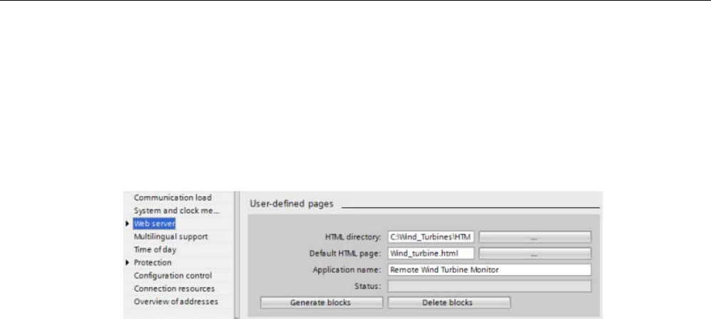
Web server
12.7 User-defined Web pages
S7-1200 Programmable controller
System Manual, V4.2, 09/2016, A5E02486680-AK 1073
12.7.9.7
Configuration in STEP 7 of the example Web page
To include the "Remote Wind Turbine Monitor" HTML page as a user-defined Web page for
the S7-1200, you configure the data about the HTML page in STEP 7 and create data blocks
from the HTML page.
Access the CPU Properties for the S7-1200 that controls the wind turbine, and enter the
configuration information in the User-defined pages properties of the Web Server:
Configuration fields
● HTML directory: This field specifies the fully-qualified pathname to the folder where the
default page (home page or start page) is located on the computer. The "..." button allows
you to browse to the folder that you need.
● Default HTML page: This field specifies the filename of the default page or home page of
the HTML application. The "..." button allows you to select the file that you need. For this
example, WindTurbine.html is the default HTML page. The Remote Wind Turbine Monitor
example only consists of a single page, but in other user-defined applications the default
page can call up additional pages from links on the default page. Within the HTML code,
the default page must reference other pages relative to the HTML source folder.
● Application name: This optional field contains the name that the Web browser includes in
the address field when displaying the page. For this example, it is "Remote Wind Turbine
Monitor", but you can use any name.
No other fields require configuration.
Final steps
To use the Remote Wind Turbine Monitor as configured, generate the blocks, program the
WWW instruction (Page 1059) with the number of the generated control DB as an input
parameter, download the program blocks, and put the CPU in run mode.
When an operator subsequently accesses the standard Web pages for the S7-1200 that
controls the wind turbine, the "Remote Wind Turbine Monitor" Web page is accessible from
the "User-defined pages" link on the navigation bar. This page now provides the means to
monitor and control the wind turbine.

Web server
12.7 User-defined Web pages
S7-1200 Programmable controller
1074 System Manual, V4.2, 09/2016, A5E02486680-AK
12.7.10
Setting up user-defined Web pages in multiple languages
The Web server provides the means for you to provide user-defined Web pages in the
following languages:
● German (de)
● English (en)
● Spanish (es)
● French (fr)
● Italian (it)
● Simplified Chinese (zh)
You do this by setting up your HTML pages in a folder structure (Page 1074) that
corresponds to the languages and by setting a specific cookie named
"siemens_automation_language" from your pages (Page 1075). The Web server responds to
this cookie, and switches to the default page in the corresponding language folder.
12.7.10.1
Creating the folder structure
To provide user-defined Web pages in multiple languages, you set up a folder structure
under your HTML directory. The two-letter folder names are specific and must be named as
shown below:
de: German
en: English
es: Spanish
fr: French
it: Italian
zh: Simplified Chinese
At the same level, you can also include any other folders that your pages need, for example,
folders for images or scripts.
You can include any subset of the language folders. You do not have to include all six
languages. Within the language folders, you create and program your HTML pages in the
appropriate language.

Web server
12.7 User-defined Web pages
S7-1200 Programmable controller
System Manual, V4.2, 09/2016, A5E02486680-AK 1075
12.7.10.2
Programming the language switch
The Web server performs switching between languages through the use of a cookie named
"siemens_automation_language". This is a cookie defined and set in the HTML pages, and
interpreted by the Web server to display a page in the appropriate language from the
language folder of the same name. The HTML page must include a JavaScript to set this
cookie to one of the pre-defined language identifiers: "de", "en", "es", "fr", "it', or "zh".
For example, if the HTML page sets the cookie to "de", the Web server switches to the "de"
folder and displays the page with the default HTML page name as defined in the STEP 7
configuration (Page 1078).
Example
The following example uses a default HTML page named "langswitch.html" in each of the
language folders. Also in the HTML directory is a folder named "script". The script folder
includes a JavaScript file named "lang.js". Each langswitch.html page uses this JavaScript to
set the language cookie, "siemens_automation_language".
HTML for "langswitch.html" in "en" folder
The header of the HTML page sets the language to English, sets the character set to UTF-8,
and sets the path to the JavaScript file lang.js.
<!DOCTYPE HTML PUBLIC "-//W3C//DTD HTML 4.01 Transitional//EN">
<html>
<head>
<meta http-equiv="Content-Language" content="en">
<meta http-equiv="Content-Type" content="text/html; charset=utf-8">
<title>Language switching english page</title>
<script type="text/javascript" src="script/lang.js" ></script>
The body of the file uses a select list for the user to select between German and English.
English ("en") is pre-selected for the language. When the user changes the language, the
page calls the DoLocalLanguageChange() JavaScript function with the value of the selected
option.
<!-- Language Selection -->
<table>
<tr>
<td align="right" valign="top" nowrap>
<!-- change language immediately on selection change -->
<select name="Language"
onchange="DoLocalLanguageChange(this)"
size="1">
<option value="de" >German</option>
<option value="en" selected >English</option>
</select>
</td>
</tr>
</table><!-- Language Selection End-->

Web server
12.7 User-defined Web pages
S7-1200 Programmable controller
1076 System Manual, V4.2, 09/2016, A5E02486680-AK
HTML for "langswitch.html" in "de" folder
The header for the German langswitch.html page is the same as English, except the
language is set to German.
<!DOCTYPE HTML PUBLIC "-//W3C//DTD HTML 4.01 Transitional//EN">
<html>
<head>
<meta http-equiv="Content-Language" content="de"><meta http-
equiv="Content-Type" content="text/html; charset=utf-8">
<title>Sprachumschaltung Deutsche Seite</title>
<script type="text/javascript" src="script/lang.js" ></script>
</head>
The HTML in the German page is identical to that of the English page, except that the default
value of the selected language is German ("de").
<!-- Language Selection -->
<table>
<tr>
<td align="right" valign="top" nowrap>
<!-- change language immediately on change of the selection -
->
<select name="Language"
onchange="DoLocalLanguageChange(this)"
<size="1">
<option value="de" selected >Deutsch</option>
<option value="en" >Englisch</option>
</select>
</td>
</tr>
</table><!-- Language Selection End-->

Web server
12.7 User-defined Web pages
S7-1200 Programmable controller
System Manual, V4.2, 09/2016, A5E02486680-AK 1077
JavaScript "lang.js" in "script" folder
The function "DoLocalLanguageChange()" is in the lang.js file. This function calls the
"SetLangCookie()" function and then reloads the window that is displaying the HTML page.
The function "SetLangCookie()" constructs an assignment that assigns the value from the
select list to the "siemens_automation_language" cookie of the document. It also sets the
path to the application so that the switched page, and not the requesting page, receives the
value of the cookie.
Optionally, in the commented section, the page could set an expiration value for the cookie.
function DoLocalLanguageChange(oSelect) {
SetLangCookie(oSelect.value);
top.window.location.reload();
}
function SetLangCookie(value) {
var strval = "siemens_automation_language=";
// This is the cookie by which the Web server
// detects the desired language
// This name is required by the Web server.
strval = strval + value;
strval = strval + "; path=/ ;";
// Set path to the application, since otherwise
// path would be set to the requesting page
// and this page would not get the cookie.
/* OPTIONAL
use expiration if this cookie should live longer
than the current browser session:
var now = new Date();
var endttime = new Date(now.getTime() + expiration);
strval = strval + "; expires=" +
endttime.toGMTString() + ";";
*/
document.cookie = strval;
}
Note
If your user
-defined Web page implementation includes HTML files within language-specific
folders (en, de, for example) and also HTML files that are not in the language
-specific
folders, not
e that you cannot define enum types with the AWP_Enum_Def command in files
in both locations. If you use enums, you must define them either within files in the language
-
specific folders or within files outside of the language
-specific folders. You cannot make
enum declarations in files in both places.

Web server
12.7 User-defined Web pages
S7-1200 Programmable controller
1078 System Manual, V4.2, 09/2016, A5E02486680-AK
12.7.10.3
Configuring STEP 7 to use a multi-language page structure
The procedure for configuring multi-language user-defined Web pages is similar to the
general process for configuring user-defined Web pages (Page 1057). When you have
folders set up for languages, however, you set your HTML directory setting to the folder that
contains the individual language folders. You do not set the HTML directory to be one of the
language folders.
When you select the default HTML page, you navigate into the language folder and select
the HTML page that is to be the start page. When you subsequently generate blocks and
download the blocks to the CPU, the Web server displays the start page in the language
folder that you configured.
For example, if the folder structure shown here was at C:
\, the set-
ting for HTML directory would be C:
\html, and if English were to be
th
e initial page display, you would navigate to en\langswitch.html for
the default HTML page setting.
12.7.11
Advanced user-defined Web page control
When you generate data blocks for your user-defined Web pages, STEP 7 creates a control
DB that it uses to control display of and interaction with the user-defined pages. STEP 7 also
creates a set of fragment DBs that represent the individual pages. Under normal
circumstances, you do not need to know the structure of the control DB or how to manipulate
it.
If you want to turn a web application on and off, for example, or manipulate individual manual
fragments, you use the control DB tags and the WWW instruction to do so.
Structure of the control DB
The control DB is an extensive data structure, and is accessible when programming your
STEP 7 user program. Only some of the control data block tags are described here.

Web server
12.7 User-defined Web pages
S7-1200 Programmable controller
System Manual, V4.2, 09/2016, A5E02486680-AK 1079
Commandstate structure
"Commandstate" is a structure that contains global commands and global states for the Web
server.
Global commands in the "Commandstate" structure
The global commands apply to the Web server in general. You can deactivate the Web
server or restart it from the control DB parameters.
Block tag
Data type
Description
init BOOL Evaluate the control DB and initialize the Web
application
deactivate
BOOL
Deactivate the Web application
Global states in the Commandstate structure
The global states apply to the Web server in general and contain status information about
the Web application.
Block tag
Data type
Description
initializing
BOOL
Web application is reading control DB
error BOOL Web application could not be initialized
deactivating
BOOL
Web application is terminating
deactivated
BOOL
Web application is terminated
initialized
BOOL
Web application is initialized
last_error INT Last error returned from a WWW instruction
call (Page 1059) when the return code of
WWW is 16#0010:
16#0001: fragment DB structure is inconsistent
16#0002: the application name already exists
16#0003: no resources (memory)
16#0004: control DB structure is inconsistent
16#0005: fragment DB not available
16#0006: fragment DB not for AWP
16#0007: enumeration data is inconsistent
16#000D: conflicting size of the control DB
Request table
The request table is an array of structures containing commands and states that apply to
individual fragment DBs. If you created fragments with the AWP_Start_Fragment
(Page 1052) command of type "manual", the STEP 7 user program must control these pages
through the control DB. The request states are read-only and provide information about the
current fragment. You use the request commands to control the current fragment.
Block tag
Data type
Description
requesttab ARRAY [ 1 .. 4 ] OF STRUCT Array of structures for individual fragment DB
control.
The Web server can process up to four frag-
ments at a time. The array index for a particular
fragment is arbitrary when the Web server is
processing multiple fragments or fragments
from multiple browser sessions.

Web server
12.7 User-defined Web pages
S7-1200 Programmable controller
1080 System Manual, V4.2, 09/2016, A5E02486680-AK
Struct members of requesttab struct
Block tag
Data type
Description
page_index
UINT
Number of the current web page
fragment_index UINT Number of the current fragment - can be set to
a different fragment
// Request Commands
continue BOOL Enables current page/fragment for sending and
continues with the next fragment
repeat BOOL Enables current page/fragment for resending
and continues with the same fragment
abort
BOOL
Close http connection without sending
finish BOOL Send this fragment; page is complete - do not
process any additional fragments
// Request states
The request states are read-only
idle
BOOL
Nothing to do, but active
waiting
BOOL
Fragment is waiting to be enabled
sending
BOOL
Fragment is sending
aborting
BOOL
User has aborted current request
Operation
Whenever your program makes changes to the control DB, it must call the WWW instruction
with the number of the modified control DB as its parameter. The global commands and
request commands take effect when the STEP 7 user program executes the WWW
instruction (Page 1059).
The STEP 7 user program can set the fragment_index explicitly, thus causing the Web
server to process the specified fragment with a request command. Otherwise, the Web
server processes the current fragment for the current page when the WWW instruction
executes.
Possible techniques for using the fragment_index include:
● Processing the current fragment: Leave fragment_index unchanged and set the continue
command.
● Skip the current fragment: Set fragment_index to 0 and set the continue command.
● Replace current fragment with a different fragment: Set the fragment_index to the new
fragment ID and set the continue command.
To check global states or request states that might be changing, the STEP 7 user program
must call the WWW instruction to evaluate the current values of these states. A typical usage
might be to call the WWW instruction periodically until a specific state occurs.
Note
If the STEP
7 user program sets more than one request command, the WWW instruction
processes only one in this order of precedence: abort, finish, repeat, continue. The WWW
instruction clears all of the request commands after processing.
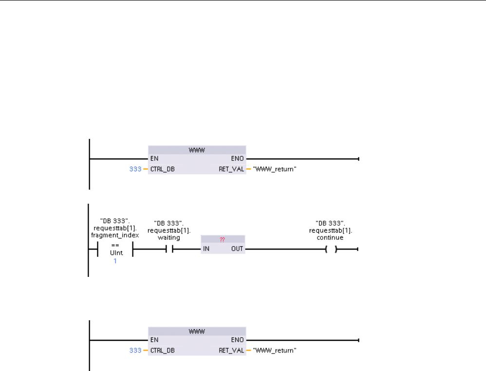
Web server
12.7 User-defined Web pages
S7-1200 Programmable controller
System Manual, V4.2, 09/2016, A5E02486680-AK 1081
Examples
The following example shows a STEP 7 user program that is checking for a fragment with an
ID of 1 to be in the waiting state, following a prior call to the WWW instruction. It might also
wait for other application-specific conditions to occur. Then it performs whatever processing
is necessary for the fragment, such as setting data block tags, performing calculations, or
other application-specific tasks. Afterwards, it sets the continue flag so that the Web server
will execute this fragment.
When the program calls the WWW instruction with this modified control DB, the user-defined
Web page with this fragment can be displayed from the Web browser.
Note that this is a simplified example; the fragment to check could be in any one of the four
requesttab structs in the array.

Web server
12.8 Constraints
S7-1200 Programmable controller
1082 System Manual, V4.2, 09/2016, A5E02486680-AK
12.8
Constraints
The following IT considerations can affect your use of the Web server:
● Typically, you must use the IP address of the CPU to access the standard Web pages or
user-defined Web pages, or the IP address of a wireless router with a port number. If
your Web browser does not allow connecting directly to an IP address, see your IT
administrator. If your local policies support DNS, you can connect to the IP address
through a DNS entry to that address.
● Firewalls, proxy settings, and other site-specific restrictions can also restrict access to the
CPU. See your IT administrator to resolve these issues.
● The standard Web pages use JavaScript and cookies. If your Web browser settings
disable JavaScript or cookies, enable them. If you cannot enable them, some features
are restricted (Page 1083). Use of JavaScript and cookies in user-defined Web pages is
optional. If used, you must enable them in your browser.
● The Web server supports Secure Sockets Layer (SSL). You can access the standard
Web pages and user-defined Web pages with an URL of either http://ww.xx.yy.zz or
https://ww.xx.yy.zz, where "ww.xx.yy.zz" represents the IP address of the CPU.
● Siemens provides a security certificate for secure access to the Web server. From the
Introduction standard Web page (Page 1017), you can download and import the
certificate into the Internet options of your Web browser (Page 1085). If you choose to not
import the certificate, you will get a security verification prompt every time you access the
Web server with https://.
Number of connections
The Web server supports a maximum of 30 active connections. Various actions consume the
30 connections, depending on the Web browser that you use and the number of different
objects per page (.css files, images, additional .html files). Some connections persist while
the Web server is displaying a page; other connections do not persist after the initial
connection.
If, for example, you are using certain versions of Mozilla Firefox, which support a maximum
of six persistent connections, you could use five browser or browser tab instances before the
Web server starts dropping connections. In the case where a page is not using all six
connections, you could have additional browser or browser tab instances.
Also be aware that the number of active connections can affect page performance.
Note
Log off prior to closing Web server
If you have logged in to the Web server, be su
re to log off prior to closing your Web browser.
The Web server supports a maximum of seven concurrent logins.

Web server
12.8 Constraints
S7-1200 Programmable controller
System Manual, V4.2, 09/2016, A5E02486680-AK 1083
12.8.1
Use of JavaScript
The standard Web pages use HTML, JavaScript, and cookies. If your site restricts the use of
JavaScript and cookies, then enable them for the pages to function properly. If you cannot
enable JavaScript for your Web browser, the standard Web pages cannot run. Consider
using the basic pages, which do not use JavaScript.
See also
Layout of the standard Web pages (Page 1011)
12.8.2
Feature restrictions when the Internet options do not allow cookies
If you disable cookies in your Web browser, the following restrictions apply:
● You cannot log in.
● You cannot change the language setting.
● You cannot switch from UTC time to PLC time. Without cookies, all times are in UTC
time.

Web server
12.8 Constraints
S7-1200 Programmable controller
1084 System Manual, V4.2, 09/2016, A5E02486680-AK
12.8.3
Rules for entering tag names and values
Be aware of the following conventions when using the Tag status (Page 1031) and Watch
tables (Page 1033) standard pages:
● If modifying the entire value of a DTL tag, for example, "Data_block_1_.DTL_tag, use the
following DTL syntax for the modify value: DTL#YYYY-MM-DD-HH-MM-SS[.sssssssss]
● When using exponential notation to enter a value for a Real or LReal data type:
– To enter a real-number value (Real or LReal) with a positive exponent (such as
+3.402823e+25), enter the value in either of the following formats:
+3.402823e25
+3.402823e+25
– To enter real-number value (Real or LReal) with a negative exponent (such as
+3.402823e-25), enter the value as follows:
+3.402823e-25
– Be sure that the mantissa portion of the real value in exponential notation includes a
decimal point. Failure to include a decimal point results in the modification of the value
to an unexpected integer value. For example, enter -1.0e8 rather than -1e8.
● LReal values can be only 15 digits (regardless of the location of the decimal point).
Entering more than 15 digits creates a rounding error.
Limitations on the Tag status and Watch Table page:
● The maximum number of characters for the URL is 2083. You can see the URL that
represents your current page in the address bar of your browser.
● For the character display format, if the actual CPU values are not valid ASCII characters
as interpreted by the browser then the page displays the character preceded by a dollar
sign: $.

Web server
12.8 Constraints
S7-1200 Programmable controller
System Manual, V4.2, 09/2016, A5E02486680-AK 1085
12.8.4
Importing the Siemens security certificate
You can import the Siemens security certificate into your Internet options so that you won't
be prompted for security verification when you enter https://ww.xx.yy.zz in your Web
browser, where "ww.xx.yy.zz" is the device IP address. If you use an http:// URL and not an
https:// URL, then you do not need to download and install the certificate.
Downloading the certificate
You use the "download certificate" link from the Introduction page (Page 1017) to download
the Siemens security certificate to your PC. The procedure varies according to which Web
browser you use:
Importing the certificate to Internet Explorer
1. Click the "download certificate" link from the Introduction page. A "File Download -
Security Warning" dialog pops up.
2. From the "File Download - Security Warning" dialog, click "Open" to open the file. A
"Certificate" dialog appears.
3. From the "Certificate" dialog, click the "Install Certificate" button to launch the Certificate
Import Wizard.
4. Follow the dialogs of the "Certificate Import Wizard" to import the certificate, letting the
operating system automatically select the certificate store.
Importing the certificate to Mozilla Firefox
1. Click the "download certificate" link from the Intro page. An "Opening
MiniWebCA_Cer.crt" dialog pops up.
2. Click "Save file" from the "Opening MiniWebCA_Cer.crt" dialog. A "Downloads" dialog
appears.
3. From the "Downloads" dialog, double-click "MiniWebCA_Cer.crt". If you have attempted
the download more than once, multiple copies show up. Just double-click any one of the
"MiniWebCA_Cer.crt" entries.
4. Click "OK" if prompted to open an executable file.
5. Click "Open" on the "Open File - Security Warning" dialog if it appears. A "Certificate"
dialog appears.
6. On the "Certificate" dialog, click the "Install Certificate" button.
7. Follow the dialogs of the "Certificate Import Wizard" to import the certificate, letting the
operating system automatically select the certificate store.
8. If the "Security Warning" dialog appears, click "Yes" to confirm installation of the
certificate.

Web server
12.8 Constraints
S7-1200 Programmable controller
1086 System Manual, V4.2, 09/2016, A5E02486680-AK
Other browsers
Follow the conventions of your Web browser to import and install the Siemens certificate.
After you have installed the Siemens security certificate "S7-1200 Controller Family" in the
Internet options for your Web browser content, you will not be required to verify a security
prompt when you access the Web server with https:// ww.xx.yy.zz.
Note
The security certificate remains constant through reboots of the CPU; however, if you
change the IP address of th
e device you must download a new certificate if you are using a
browser other than Internet Explorer or Mozilla Firefox.
12.8.5
Importing CSV format data logs to non-USA/UK versions of Microsoft Excel
Data log files are in the comma-separated values (CSV) file format. You can open these files
directly in Excel from the Data Logs page when your system is running the USA or UK
version of Excel. In other countries, however, this format is not widely used because
commas occur frequently in numerical notation.
To open a data log file that you have saved, follow these steps for non USA/UK versions of
Excel:
1. Open Excel and create an empty workbook.
2. From the "Data > Import External Data" menu, select the "Import Data" command.
3. Navigate to and select the data log file you want to open. The Text Import Wizard starts.
4. From the Text Import Wizard, change the default option for "Original data type" from
"Fixed width" to "Delimited".
5. Click the Next button.
6. From the Step 2 dialog, select the "Comma" check box to change the delimiter type from
"Tab" to "Comma".
7. Click the Next button.
8. From the Step 3 dialog, you can optionally change the Date format from MDY
(month/day/year) to another format.
9. Complete the remaining steps of the Text Import Wizard to import the file.
S7-1200 Programmable controller
System Manual, V4.2, 09/2016, A5E02486680-AK 1087
Communication processor and Modbus TCP
13
13.1
Using the serial communication interfaces
Two communication modules (CMs) and one communication board (CB) provide the
interface for PtP communications:
● CM 1241 RS232 (Page 1543)
● CM 1241 RS422/485 (Page 1544)
● CB 1241 RS485 (Page 1541)
You can connect up to three CMs (of any type) plus a CB for a total of four communication
interfaces. Install the CM to the left of the CPU or another CM. Install the CB on the front of
the CPU. Refer to the installation guidelines (Page 67)for information on module installation
and removal.
The serial communication interfaces have the following characteristics:
● Have an isolated port
● Support Point-to-Point protocols
● Are configured and programmed through the point-to-point communication processor
instructions
● Display transmit and receive activity by means of LEDs
● Display a diagnostic LED (CMs only)
● Are powered by the CPU: No external power connection is needed.
Refer to the technical specifications for communication interfaces (Page 1530).
LED indicators
The communication modules have three LED indicators:
● Diagnostic LED (DIAG): This LED flashes red until it is addressed by the CPU. After the
CPU powers up, it checks for CMs and addresses them. The diagnostic LED begins to
flash green. This means that the CPU has addressed the CM, but has not yet provided
the configuration to it. The CPU downloads the configuration to the configured CMs when
the program is downloaded to the CPU. After a download to the CPU, the diagnostic LED
on the communication module should be a steady green.
● Transmit LED (Tx): The transmit LED illuminates when data is being transmitted out the
communication port.
● Receive LED (Rx): This LED illuminates when data is being received by the
communication port.
The communication board provides transmit (TxD) and receive (RxD) LEDs. It has no
diagnostic LED.
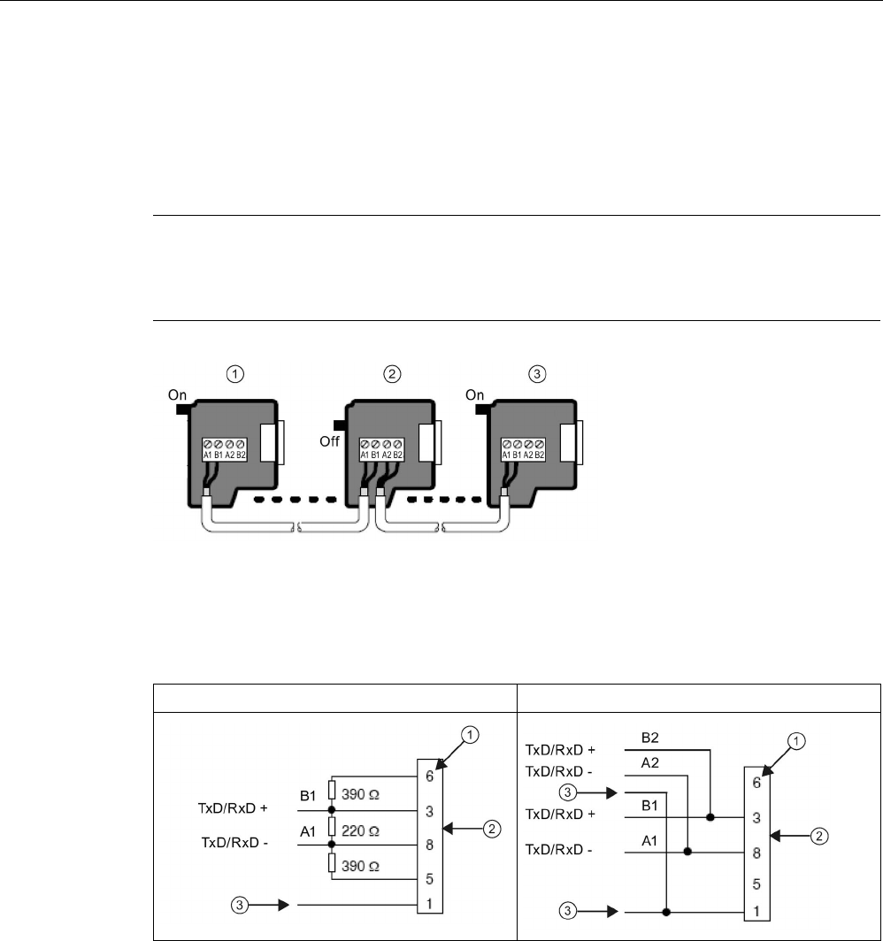
Communication processor and Modbus TCP
13.2 Biasing and terminating an RS485 network connector
S7-1200 Programmable controller
1088 System Manual, V4.2, 09/2016, A5E02486680-AK
13.2
Biasing and terminating an RS485 network connector
Siemens provides an RS485 network connector (Page 1561) that you can use to easily
connect multiple devices to an RS485 network. The connector has two sets of terminals that
allow you to attach the incoming and outgoing network cables. The connector also includes
switches for selectively biasing and terminating the network.
Note
You terminate and bias only the two ends of the RS485 network. The devices in between the
two end devices are not terminated or biased. Bare cable shielding: Approximately 12
mm
(1/2 in) must contact
the metal guides of all locations.
①
Switch position = On: Terminated and biased
②
Switch position = Off: No termination or bias
③
Switch position = On: Terminated and biased
Table 13- 1 Termination and bias for the RS485 connector
Terminating device (bias ON)
Non-terminating device (bias OFF)
①
Pin number
②
Network connector
③ Cable shield
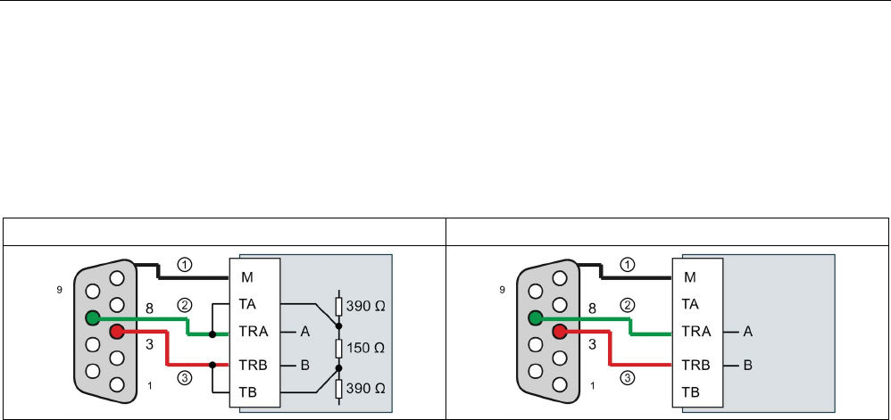
Communication processor and Modbus TCP
13.2 Biasing and terminating an RS485 network connector
S7-1200 Programmable controller
System Manual, V4.2, 09/2016, A5E02486680-AK 1089
The CB 1241 provides internal resistors for terminating and biasing the network. To
terminate and bias the connection, connect TRA to TA and connect TRB to TB to include the
internal resistors to the circuit. CB 1241 does not have a 9-pin connector. The following table
shows the connections to a 9-pin connector on the communications partner.
Table 13- 2 Termination and bias for the CB 1241
Terminating device (bias ON)
Non-terminating device (bias OFF)
①
Connect M to the cable shield
②
A = TxD/RxD - (Green wire / Pin 8)
③ B = TxD/RxD + (Red wire / Pin 3)
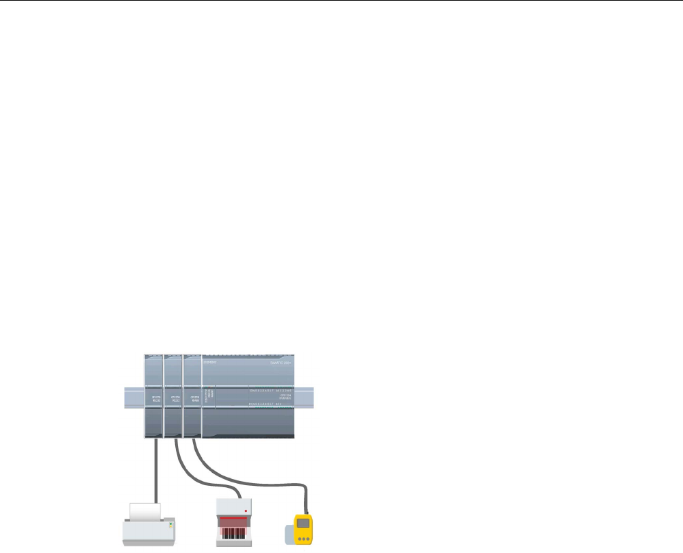
Communication processor and Modbus TCP
13.3 Point-to-point (PtP) communication
S7-1200 Programmable controller
1090 System Manual, V4.2, 09/2016, A5E02486680-AK
13.3
Point-to-point (PtP) communication
The CPU supports the following Point-to-Point communication (PtP) for character-based
serial protocols:
● PtP, Freeport (Page 1090)
● PtP, 3964(R) (Page 1092)
● USS (Page 1146)
● Modbus (Page 1166)
13.3.1
PtP, Freeport communication
PtP with a Freeport, or freely constructed, protocol provides maximum freedom and
flexibility, but requires extensive implementation in the user program.
PtP enables a wide variety of possibilities:
•
The ability to send information directly to an external
device such as a printer
•
The ability to receive information from other devices
such as barcode readers, RFID readers, third-party
camera or vision systems, and many other types of
devices
•
The ability to exchange information, sending and
receiving data, with other devices such as GPS
devices, third-party camera or vision systems, radio
modems, and many more
This type of PtP communication is serial communic
a-
tion that uses standard UARTs to support a variety of
baud rates and parity options. The RS232 and
RS4
22/485 communication modules (CM 1241) and
the RS485 communication board (CB
1241) provide
the electrical interfaces for performing the PtP comm
u-
nications.

Communication processor and Modbus TCP
13.3 Point-to-point (PtP) communication
S7-1200 Programmable controller
System Manual, V4.2, 09/2016, A5E02486680-AK 1091
PtP Freeport over PROFIBUS or PROFINET
PtP enables you to use a PROFINET or PROFIBUS distributed I/O rack to communicate to
various devices (RFID readers, GPS device, and others):
● PROFINET (Page 804): You connect the Ethernet interface of the S7-1200 CPU to a
PROFINET interface module. PtP communication modules in the rack with the interface
module can then provide serial communications to the PtP devices.
● PROFIBUS (Page 968): You insert a PROFIBUS communication module in the left side
of the rack with the S7-1200 CPU. You connect the PROFIBUS communication module
to a rack containing a PROFIBUS interface module. PtP communication modules in the
rack with the interface module can then provide serial communications to the PtP
devices.
For this reason, the S7-1200 supports two sets of PtP instructions:
● Legacy point-to-point instructions (Page 1217): These instructions existed prior to version
V4.0 of the S7-1200 and only work with serial communications using a CM 1241
communication module or CB 1241 communication board.
● Point-to-point instructions (Page 1108): These instructions provide all of the functionality
of the legacy instructions, plus the ability to support PtP communication modules over
PROFINET and PROFIBUS distributed I/O. The point-to-point instructions allow you to
access the communication modules over the distributed I/O rack.
The S7-1200 CM 1241 modules must have a minimum firmware version of V2.1 to use
the point-to-point instructions. These modules are limited to the local rack to the left side
of the S7-1200 CPU.
Communications over distributed I/O use the following modules:
Station
Module
Article number
Interface
ET 200MP
CM PtP RS232 BA
6ES7540-1AD00-0AA0
RS232
CM PtP RS232 HF 6ES7540-1AB00-0AA0 RS232
CM PtP RS422/485 BA
6ES7540-1AD00-0AB0
RS422/RS485
CM PtP RS422/485 HF
6ES7540-1AB00-0AB0
RS232 and RS422/RS485
ET 200SP
CM PtP
6ES7540-6AA00-0BA0
RS232
Note
You can use the point
-to-point instructions to access local (or left side) serial modules, serial
modules over PROFINET and serial modules over PROFIBUS. STEP 7 provides the legacy
point
-to-point instructions only to support existing programs. The legacy instructions still
function, however, with the current S7
-1200 CPUs. You do not have to convert prior
programs from one set of instructions to the other.

Communication processor and Modbus TCP
13.3 Point-to-point (PtP) communication
S7-1200 Programmable controller
1092 System Manual, V4.2, 09/2016, A5E02486680-AK
Station
Module
Article number
Interface
Note
CM module firmware version requirement for Time synchronization and PtP communication
If you
have enabled "CPU synchronizes the modules of the device" in the Time
synchronization
(Page 181) properties for the Profinet interface in the device configuration,
update the firmware versions of the connected communication modules to the latest
available versions. Enabling module time synchronization for communication modules with
old firmware versions can cause communication issues or errors.
13.3.2
3964(R) communication
The S7-1200 CPU supports the 3964(R) protocol to enable communication between a
CM 1241 RS232 module or a CM 1241 (RS422/485) module and a communication partner
that uses the 3964(R) protocol. Unlike the PtP communication described above where you
define specific send (transmit) and receive characteristics for the messages, the 3964(R)
protocol proscribes a strict protocol using the following control characters:
● STX Start of text
Start of character string to be transmitted
● DLE Data Link Escape
Data transmission switchover
● ETX End of Text
End of character string to be transmitted
● BCC Block check character
● NAK Negative Acknowledge
Refer to the chapter describing serial data transmission principles in the S7-300 CP 341
Point-to-Point Communication, Installation, and Parameter Assignment Manual.
(https://support.industry.siemens.com/cs/us/en/view/1117397) manual for a complete
description of the protocol.
Configuring the communication module
To communicate to a partner using the 3964(R) protocol, you must include one of the
following communication modules in your device configuration in STEP 7:
● CM 1241 (RS232)
● CM 1241 (RS422/485)
The firmware version of the CM module must be V2.2.0 or later.
For the communication module, you then configure the communication ports (Page 1093),
priority, and protocol parameters (Page 1106).

Communication processor and Modbus TCP
13.3 Point-to-point (PtP) communication
S7-1200 Programmable controller
System Manual, V4.2, 09/2016, A5E02486680-AK 1093
Communication to a partner with the 3964(R) protocol
When you configure a CM for 3964(R) protocol, you use the standard point-to-point send
and receive instructions to transfer data between the CPU and its communication partner.
The CM embeds your data from the BUFFER parameter of the send instruction into the
3964(R) protocol and sends the data to the communication partner.
The CM receives data from the communication partner by means of the 3964(R) protocol,
removes the protocol information, and returns the data in the BUFFER parameter of the
receive instruction.
Refer to the following point-to-point instructions:
● Send_P2P (Transmit send buffer data) (Page 1122)
● Receive_P2P (Enable receive messages) (Page 1126)
You can also use the legacy point-to-point send and receive instructions:
● SEND_PTP (Transmit send buffer data) (Page 1226)
● RCV_PTP (Enable receive messages) (Page 1229)
13.3.3
Configuring the PtP Freeport communication
You can use either of the following methods to configure the communication interfaces for
PtP Freeport communication:
● Use the device configuration in STEP 7 to configure the port parameters (baud and
parity), the send parameters and the receive parameters. The CPU stores the device
configuration settings and applies the settings after a power cycle and a RUN to STOP
transition.
● Use the Port_Config (Page 1110), Send_Config (Page 1112), and Receive_Config
(Page 1115) instructions to set the parameters. The port settings set by the instructions
are valid while the CPU is in RUN mode. The port settings revert to the device
configuration settings after a STOP transition or power cycle.
After configuring the hardware devices (Page 153), you configure parameters for the
communication interfaces by selecting one of the CMs in your rack or the CB, if configured.
The "Properties" tab of the inspector window di
s-
plays the parameters
of the selected CM or CB.
Select "Port configuration" to edit the following
parameters:
•
Baud rate
•
Parity
•
Data bits per character
•
Number of stop bits
•
Flow control (RS232 only)
•
Wait time
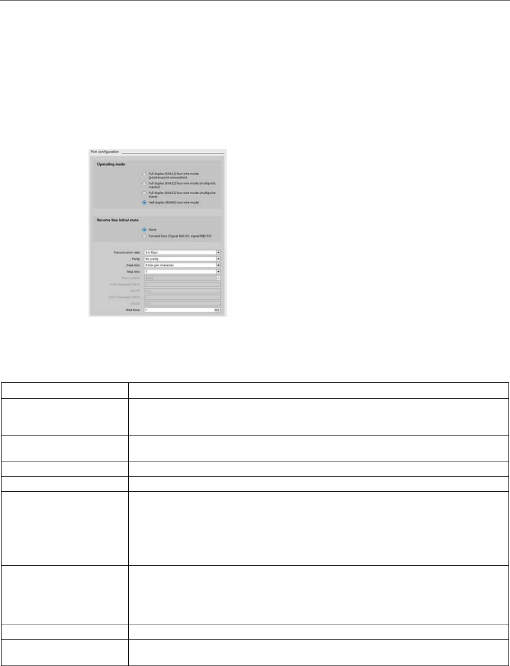
Communication processor and Modbus TCP
13.3 Point-to-point (PtP) communication
S7-1200 Programmable controller
1094 System Manual, V4.2, 09/2016, A5E02486680-AK
For the CM 1241 RS232 and CB RS485 (except for flow control (Page 1095), which only the
CM 1241 RS232 supports), the port configuration parameters are the same regardless of
whether you are configuring an RS232 or an RS485 communication module or the RS485
communication board. The parameter values can differ.
For the CM 1241 RS422/485, you have additional options for port configuration as shown
below. The 422 mode of the CM 1241 RS422/485 module also supports software flow
control.
Select "Port configuration" to edit the following
RS422/485 parameters:
•
"Operating mode":
– Full duplex (RS422) four wire mode (point-to-
point connection)
– Full duplex (RS422) four wire mode (m
ultipoint
master)
– Full duplex (RS422) four wire mode (multipoint
slave)
– Half duplex (RS485) two wire mode
•
"Receive line initial state":
– None
– Forward bias (Signal R(A) 0V, signal R(B) 5V)
The STEP 7 user program can also configure the port or change the existing configuration
with the Port_Config instruction (Page 1110). The instruction topic provides more detail
about the operational mode and initial line state as well as other parameters.
Parameter
Definition
Baud rate The default value for the baud rate is 9.6 Kbits per second. Valid choices are: 300 baud,
600 baud, 1.2 Kbits, 2.4 Kbits, 4.8 Kbits, 9.6 Kbits, 19.2 Kbits, 38.4 Kbits, 57.6 Kbits, 76.8
Kbits, and 115.2 Kbits.
Parity
The default value for parity is no parity. Valid choices are: No parity, even, odd, mark (parity
bit always set to 1), and space (parity bit always set to 0).
Data bits per character
The number of data bits in a character. Valid choices are 7 or 8.
Number of stop bits
The number of stop bits can be either one or two. The default is one.
Flow control For the RS232 communication module, you can select either hardware or software flow
control (Page 1095). If you select hardware flow control, you can select whether the RTS
signal is always on, or RTS is switched. If you select software flow control, you can define
the XON and XOFF characters.
The RS485 communication interfaces do not support flow control. The 422 mode of the CM
1241 RS422/485 module supports software flow control.
Wait time Wait time specifies the time that the CM or CB waits to receive CTS after asserting RTS, or
for receiving an XON after receiving an XOFF, depending on the type of flow control. If the
wait time expires before the communication interface receives an expected CTS or XON,
the CM or CB aborts the transmit operation and returns an error to the user program. You
specify the wait time in milliseconds. The range is 0 to 65535 milliseconds.
Operating mode
This selects the operating mode RS422 or RS485 and network configurations.
Receive line initial state This selects the bias options. Valid values are none, forward bias and reverse bias. Re-
verse bias is used to allow cable break detection.

Communication processor and Modbus TCP
13.3 Point-to-point (PtP) communication
S7-1200 Programmable controller
System Manual, V4.2, 09/2016, A5E02486680-AK 1095
13.3.3.1
Managing flow control
Flow control refers to a mechanism for balancing the sending and receiving of data
transmissions so that no data is lost. Flow control ensures that a transmitting device is not
sending more information than a receiving device can handle. Flow control can be
accomplished through either hardware or software. The RS232 CM supports both hardware
and software flow control. The RS485 CM and CB do not support flow control. The 422
mode of the CM 1241 RS422/485 module supports software flow control. You specify the
type of flow control either when you configure the port (Page 1093) or with the PORT_CFG
instruction (Page 1218).
Hardware flow control works through the Request-to-send (RTS) and Clear-to-send (CTS)
communication signals. With the RS232 CM, the RTS signal is output from pin 7 and the
CTS signal is received through pin 8. The RS232 CM is a DTE (Data Terminal Equipment)
device which asserts RTS as an output and monitors CTS as an input.
Hardware flow control: RTS switched
If you enable RTS switched hardware flow control for an RS232 CM, the module sets the
RTS signal active to send data. It monitors the CTS signal to determine whether the
receiving device can accept data. When the CTS signal is active, the module can transmit
data as long as the CTS signal remains active. If the CTS signal goes inactive, then the
transmission must stop.
Transmission resumes when the CTS signal becomes active. If the CTS signal does not
become active within the configured wait time, the module aborts the transmission and
returns an error to the user program. You specify the wait time in the port configuration
(Page 1093).
The RTS switched flow control is useful for devices that require a signal that the transmit is
active. An example would be a radio modem that uses RTS as a "Key" signal to energize the
radio transmitter. The RTS switched flow control will not function with standard telephone
modems. Use the RTS always on selection for telephone modems.
Hardware flow control: RTS always on
In RTS always on mode, the CM 1241 sets RTS active by default. A device such as a
telephone modem monitors the RTS signal from the CM and utilizes this signal as a clear-to-
send. The modem only transmits to the CM when RTS is active, that is, when the telephone
modem sees an active CTS. If RTS is inactive, the telephone module does not transmit to
the CM.
To allow the modem to send data to the CM at any time, configure "RTS always on"
hardware flow control. The CM thus sets the RTS signal active all the time. The CM will not
set RTS inactive even if the module cannot accept characters. The transmitting device must
ensure that it does not overrun the receive buffer of the CM.
Data Terminal Ready (DTR) and Data Set Ready (DSR) signal utilization
The CM sets DTR active for either type of hardware flow control. The module transmits only
when the DSR signal becomes active. The state of DSR is only evaluated at the start of the
send operation. If DSR becomes inactive after transmission has started, the transmission will
not be paused.

Communication processor and Modbus TCP
13.3 Point-to-point (PtP) communication
S7-1200 Programmable controller
1096 System Manual, V4.2, 09/2016, A5E02486680-AK
Software flow control
Software flow control uses special characters in the messages to provide flow control. You
configure Hex characters that represent XON and XOFF.
XOFF indicates that a transmission must stop. XON indicates that a transmission can
resume. XOFF and XON must not be the same character.
When the transmitting device receives an XOFF character from the receiving device, it stops
transmitting. Transmitting resumes when the transmitting device receives an XON character.
If it does not receive an XON character within the wait time that is specified in the port
configuration (Page 1093), the CM aborts the transmission and returns an error to the user
program.
Software flow control requires full-duplex communication, as the receiving partner must be
able to send XOFF to the transmitting partner while a transmission is in progress. Software
flow control is only possible with messages that contain only ASCII characters. Binary
protocols cannot utilize software flow control.
Before the CPU can engage in PtP Freeport communications, you must configure
parameters for transmitting (or sending) messages and receiving messages. These
parameters dictate how communications operate when messages are being transmitted to or
received from a target device.
13.3.3.2
Configuring transmit (send) parameters
From the device configuration of the CPU, you configure how a communication interface
transmits data by setting the "Transmit message configuration" properties for the selected
interface.
You can also dynamically configure or change the transmit message parameters from the
user program by using the Send_Config (Page 1112) instruction.
Note
Parameter values set from the Send_Config instruction in the user program override the
"Transmit message configuration" propert
ies. Note that the CPU does not retain parameters
set from the Send_Config instruction in the event of power down.
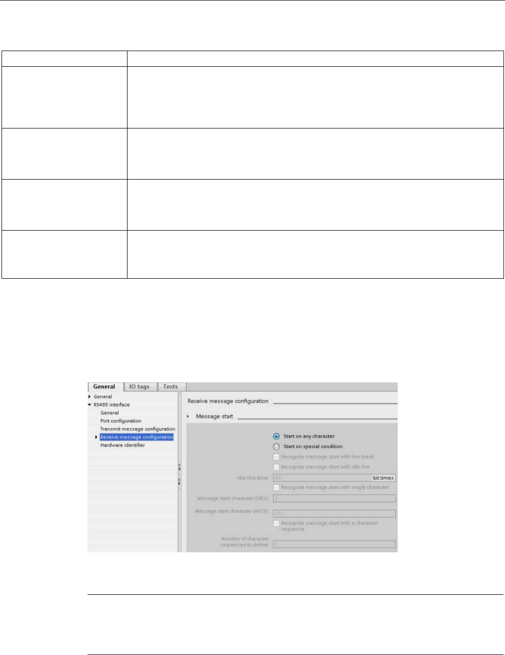
Communication processor and Modbus TCP
13.3 Point-to-point (PtP) communication
S7-1200 Programmable controller
System Manual, V4.2, 09/2016, A5E02486680-AK 1097
Parameter
Definition
RTS On delay Specifies the amount of time to wait after activating RTS before transmission is initiated.
The range is 0 to 65535 ms, with a default value of 0. This parameter is valid only when the
port configuration (Page 1093) specifies hardware flow control. CTS is evaluated after the
RTS On delay time has expired.
This parameter is applicable for RS232 modules only.
RTS Off delay Specifies the amount of time to wait before de-activating RTS after completion of transmis-
sion. The range is 0 to 65535 ms, with a default value of 0. This parameter is valid only
when the port configuration (Page 1093) specifies hardware flow control.
This parameter is applicable for RS232 modules only.
Send break at message start
Number of bit times in a
break
Specifies that upon the start of each message, a break will be sent after the RTS On delay
(if configured) has expired and CTS is active.
You specify how many bit times constitute a break where the line is held in a spacing condi-
tion. The default is 12 and the maximum is 65535, up to a limit of eight seconds.
Send idle line after a break
Idle line after a break
Specifies that an idle line will be sent before message start. It is sent after the break, if a
break is configured. The "Idle line after a break" parameter specifies how many bit times
constitute an idle line where the line is held in a marking condition. The default is 12 and
the maximum is 65535, up to a limit of eight seconds.
13.3.3.3
Configuring receive parameters
From the device configuration of the CPU, you configure how a communication interface
receives data, and how it recognizes both the start of and the end of a message. You set
these parameters in the "Receive message configuration" properties for the selected
interface.
You can also dynamically configure or change the receive message parameters from the
user program by using the Receive_Config instruction (Page 1115).
Note
Parameter values set from the Receive_Config instruction in the user program override the
"Receive message configuration" properties. Note that the CPU does not retain parameters
set from the RCV_CFG instruction
in the event of power down or transition to STOP.
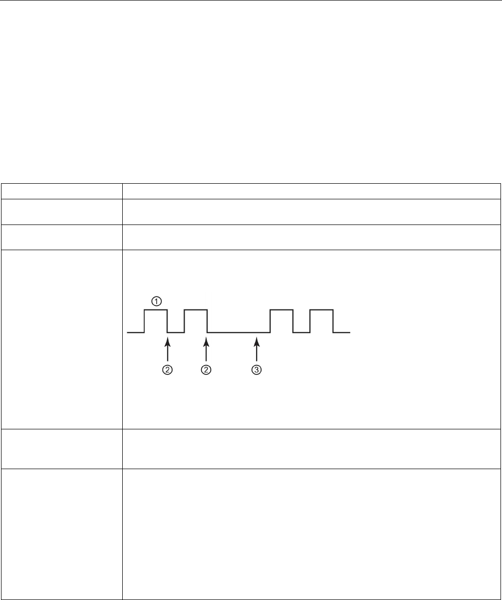
Communication processor and Modbus TCP
13.3 Point-to-point (PtP) communication
S7-1200 Programmable controller
1098 System Manual, V4.2, 09/2016, A5E02486680-AK
Message start conditions
You can determine how the communication interface recognizes the start of a message. The
start characters and the characters comprising the message go into the receive buffer until a
configured end condition is met.
You can specify multiple start conditions. If you specify more than one start condition, all of
the start conditions must be met before the message is considered started. For example, if
you configure an idle line time and a specific start character, the CM or CB will first look for
the idle line time requirement to be met and then the CM will look for the specified start
character. If some other character is received (not the specified start character), the CM or
CB will restart the start of message search by again looking for an idle line time.
Parameter
Definition
Start on Any Character The Any Character condition specifies that any successfully received character indicates the
start of a message. This character is the first character within a message.
Line Break The Line Break condition specifies that a message receive operation starts after a break
character is received.
Idle Line The Idle Line condition specifies that a message reception starts once the receive line has
been idle or quiet for the number of specified bit times. Once this condition occurs, the start
of a message begins.
① Characters
② Restarts the idle line timer
③
Idle line is detected and message receive is started
Special condition:
Recognize message start
with single character
Specifies that a particular character indicates the start of a message. This character is then
the first character within a message. Any character that is received before this specific char-
acter is discarded. The default character is STX.
Special condition:
Recognize message start
with a character sequence
Specifies that a particular character sequence from up to four configured sequences indi-
cates the start of a message. For each sequence, you can specify up to five characters. For
each character position, you specify either a specific hex character, or that the character is
ignored in sequence matching (wild-card character). The last specific character of a charac-
ter sequence terminates that start condition sequence.
Incoming sequences are evaluated against the configured start conditions until a start condi-
tion has been satisfied. Once the start sequence has been satisfied, evaluation of end condi-
tions begins.
You can configure up to four specific character sequences. You use a multiple-sequence
start condition when different sequences of characters can indicate the start of a message. If
any one of the character sequences is matched, the message is started.
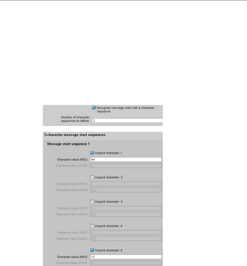
Communication processor and Modbus TCP
13.3 Point-to-point (PtP) communication
S7-1200 Programmable controller
System Manual, V4.2, 09/2016, A5E02486680-AK 1099
The order of checking start conditions is:
● Idle line
● Line break
● Characters or character sequences
While checking for multiple start conditions, if one of the conditions is not met, the CM or CB
will restart the checking with the first required condition. After the CM or CB establishes that
the start conditions have been met, it begins evaluating end conditions.
Example configuration: Start message on one of two character sequences
Consider the following start message condition configuration:
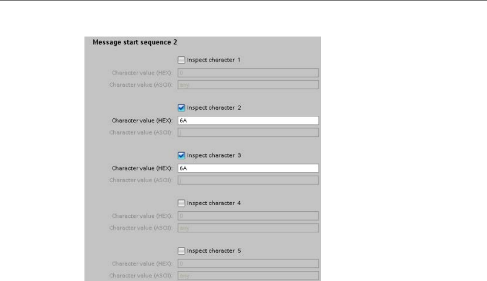
Communication processor and Modbus TCP
13.3 Point-to-point (PtP) communication
S7-1200 Programmable controller
1100 System Manual, V4.2, 09/2016, A5E02486680-AK
With this configuration, the start condition is satisfied when either pattern occurs:
● When a five-character sequence is received where the first character is 0x6A and the fifth
character is 0x1C. The characters at positions 2, 3, and 4 can be any character with this
configuration. After the fifth character is received, evaluation of end conditions begins.
● When two consecutive 0x6A characters are received, preceded by any character. In this
case, evaluation of end conditions begins after the second 0x6A is received (3
characters). The character preceding the first 0x6A is included in the start condition.
Example sequences that would satisfy this start condition are:
● <any character> 6A 6A
● 6A 12 14 18 1C
● 6A 44 A5 D2 1C
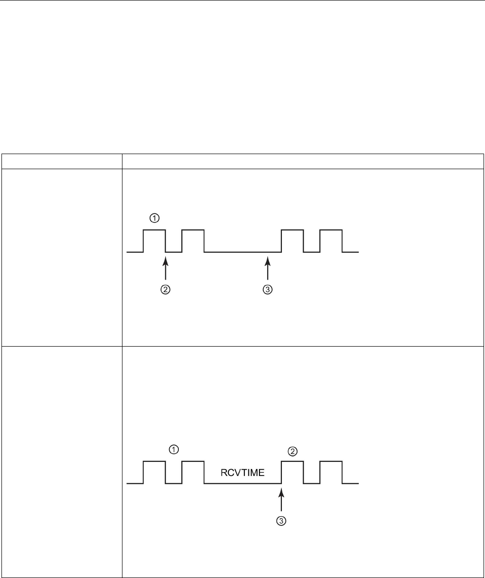
Communication processor and Modbus TCP
13.3 Point-to-point (PtP) communication
S7-1200 Programmable controller
System Manual, V4.2, 09/2016, A5E02486680-AK 1101
Message end conditions
You also configure how the communication interface recognizes the end of a message. You
can configure multiple message end conditions. If any one of the configured conditions
occurs, the message ends.
For example, you could specify an end condition with an end of message timeout of 300
milliseconds, an inter-character timeout of 40 bit times, and a maximum length of 50 bytes.
The message will end if the message takes longer than 300 milliseconds to receive, or if the
gap between any two characters exceeds 40 bit times, or if 50 bytes are received.
Parameter
Definition
Recognize message end by
message timeout
The message end occurs when the configured amount of time to wait for the message end
has expired. The message timeout period begins when a start condition has been satisfied.
The default is 200 ms and the range is 0 to 65535 ms.
① Received characters
②Start Message condition satisfied: message timer starts
③ Message timer expires and terminates the message
Recognize message end by
response timeout
The message end occurs when the configured amount of time to wait for a response ex-
pires before a valid start sequence is received. The response timeout period begins when a
transmission ends and the CM or CB begins the receive operation. The default response
timeout is 200 ms and the range is 0 to 65535 ms. If a character is not received within the
response time period, RCVTIME, then an error is returned to the corresponding RCV_PTP
instruction. The response timeout does not define a specific end condition. It only specifies
that a character must be successfully received within the specified time. You must config-
ure another end condition to indicate the actual end of a message.
① Transmitted characters
② Received characters
③
First character must be successfully received by this time.
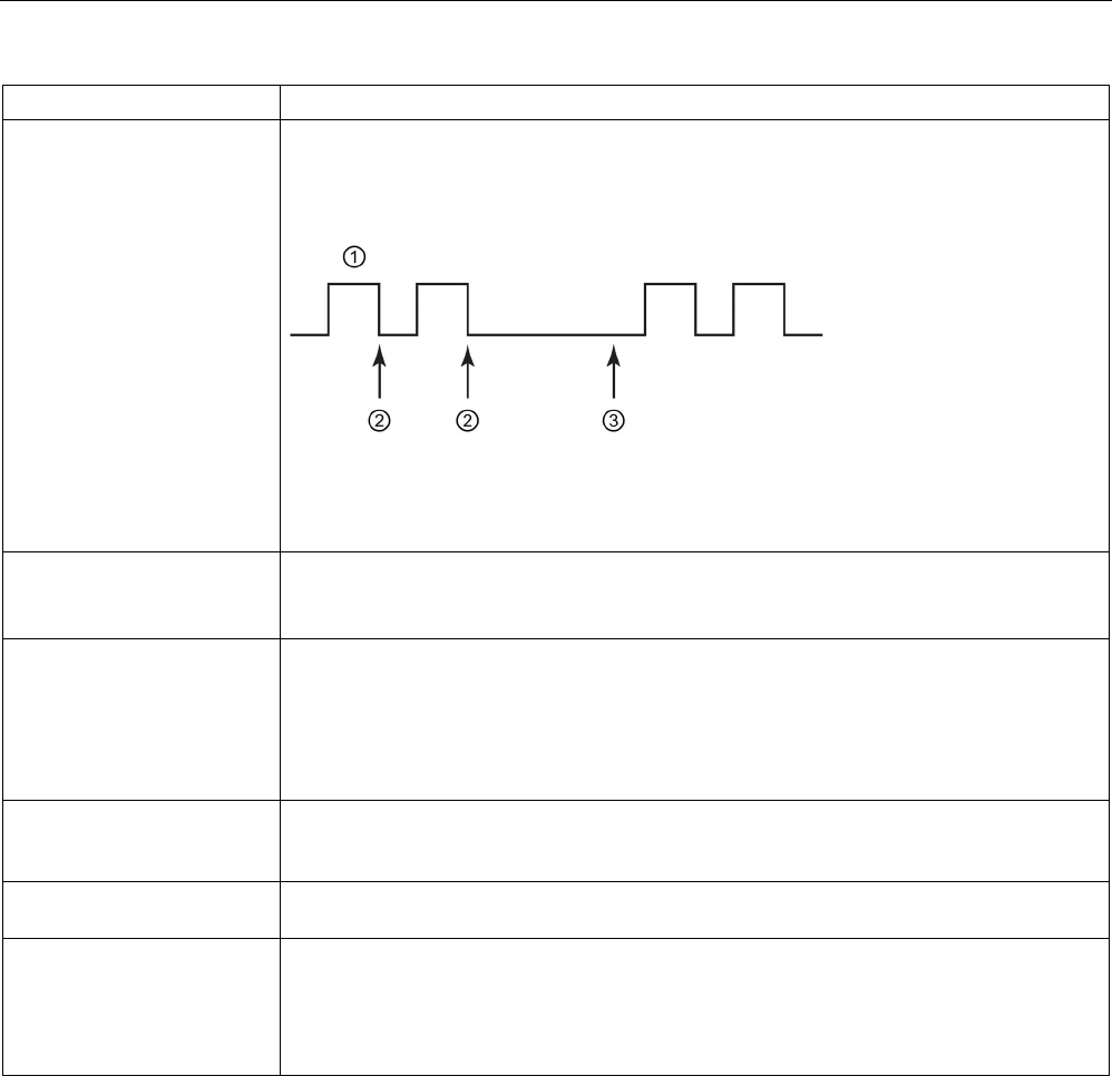
Communication processor and Modbus TCP
13.3 Point-to-point (PtP) communication
S7-1200 Programmable controller
1102 System Manual, V4.2, 09/2016, A5E02486680-AK
Parameter
Definition
Recognize message end by
inter-character gap
The message end occurs when the maximum configured timeout between any two consec-
utive characters of a message has expired. The default value for the inter-character gap is
12 bit times and the maximum number is 65535 bit times, up to a maximum of eight sec-
onds.
① Received characters
② Restarts the intercharacter timer
③ The intercharacter timer expires and terminates the message.
Recognize message end by
receiving a fixed number of
characters
The message end occurs when the specified number of characters has been received. The
valid range for the fixed length is 1 to 4096.
Note that for the S7-1200, this end condition is only valid for V4.0 CPUs or higher.
Recognize message end by
max length
The message end occurs when the configured maximum number of characters has been
received. The valid range for maximum length is 1 to 1023.
This condition can be used to prevent a message buffer overrun error. When this end con-
dition is combined with timeout end conditions and the timeout condition occurs, any valid
received characters are provided even if the maximum length is not reached. This allows
support for varying length protocols when only the maximum length is known.
Read message length from
message
The message itself specifies the length of the message. The message end occurs when a
message of the specified length has been received. The method for specifying and inter-
preting the message length is described below.
Recognize message end
with a character
The message end occurs when a specified character is received.
Recognize message end
with a character sequence
The message end occurs when a specified character sequence is received. You can speci-
fy a sequence of up to five characters. For each character position, you specify either a
specific hex character, or that the character is ignored in sequence matching.
Leading characters that are ignored characters are not part of the end condition. Trailing
characters that are ignored characters are part of the end condition.

Communication processor and Modbus TCP
13.3 Point-to-point (PtP) communication
S7-1200 Programmable controller
System Manual, V4.2, 09/2016, A5E02486680-AK 1103
Example configuration: End message with a character sequence
Consider the following end message condition configuration:
In this case, the end condition is satisfied when two consecutive 0x6A characters are
received, followed by any two characters. The character preceding the 0x6A 0x6A pattern is
not part of the end character sequence. Two characters following the 0x6A 0x6A pattern are
required to terminate the end character sequence. The values received at character
positions 4 and 5 are irrelevant, but they must be received to satisfy the end condition.
Note
If you want your character s
equence to indicate the end of the message, put the sequence in
the last character positions. In the example above, if you wanted 0x6A 0x6A to end the
message with no trailing characters, you would configure 0x6A in character positions 4 and
5.
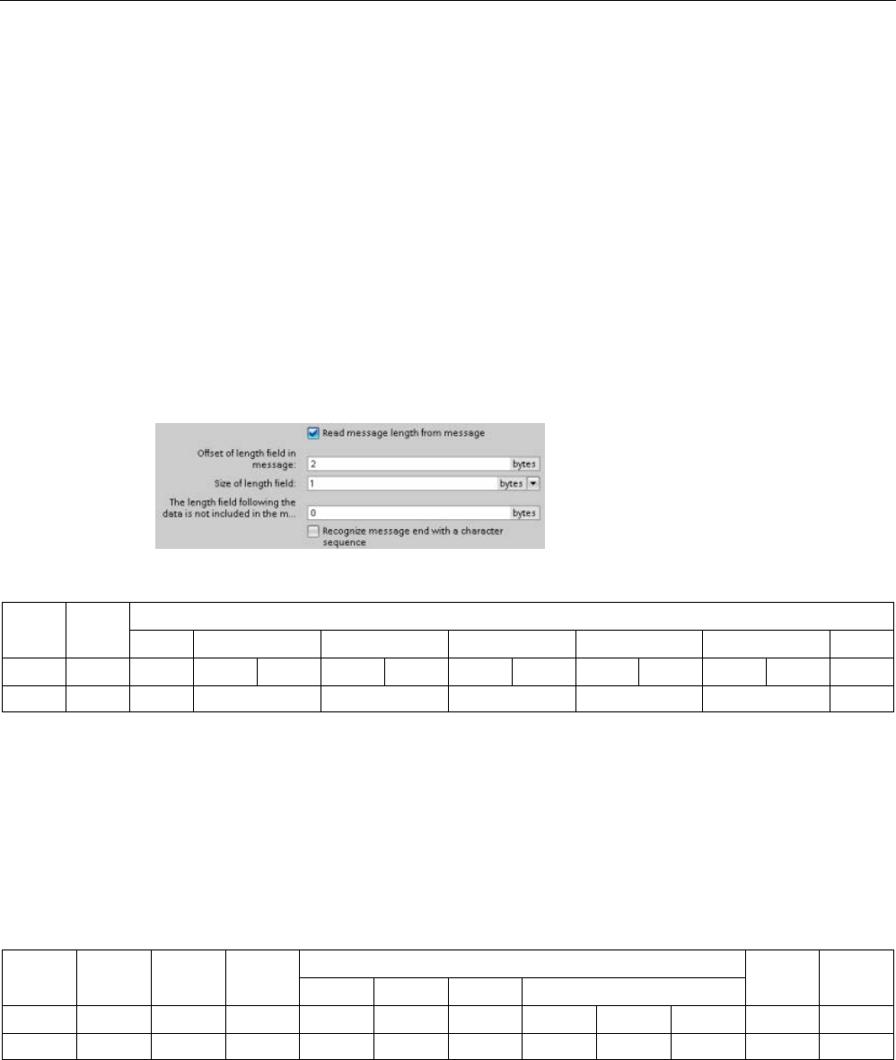
Communication processor and Modbus TCP
13.3 Point-to-point (PtP) communication
S7-1200 Programmable controller
1104 System Manual, V4.2, 09/2016, A5E02486680-AK
Specification of message length within the message
When you select the special condition where the message length is included in the message,
you must provide three parameters that define information about the message length.
The actual message structure varies according to the protocol in use. The three parameters
are as follows:
● n: the character position (1-based) within the message that starts the length specifier
● Length size: The number of bytes (one, two, or four) of the length specifier
● Length m: the number of characters following the length specifier that are not included in
the length count
The ending characters do not need to be contiguous. The "Length m" value can be used to
specify the length of a checksum field whose size is not included in the length field.
These fields appear in the Receive message configuration of the device properties:
Example 1:
Consider a message structured according to the following protocol:
STX
Len
(n)
Characters 3 to 14 counted by the length
ADR
PKE
INDEX
PWD
STW
HSW
BCC
1
2
3
4
5
6
7
8
9
10
11
12
13
14
STX
0x0C
xx
xxxx
xxxx
xxxx
xxxx
xxxx
xx
Configure the receive message length parameters for this message as follows:
● n = 2 (The message length starts with byte 2.)
● Length size = 1 (The message length is defined in one byte.)
● Length m = 0 (There are no additional characters following the length specifier that are
not counted in the length count. Twelve characters follow the length specifier.)
In this example, the characters from 3 to 14 inclusive are the characters counted by Len (n).
Example 2:
Consider another message structured according to the following protocol:
SD1
Len (n)
Len (n)
SD2
Characters 5 to 10 counted by length
FCS
ED
DA
SA
FA
Data unit=3 bytes
1
2
3
4
5
6
7
8
9
10
11
12
xx
0x06
0x06
xx
xx
xx
xx
xx
xx
xx
xx
xx
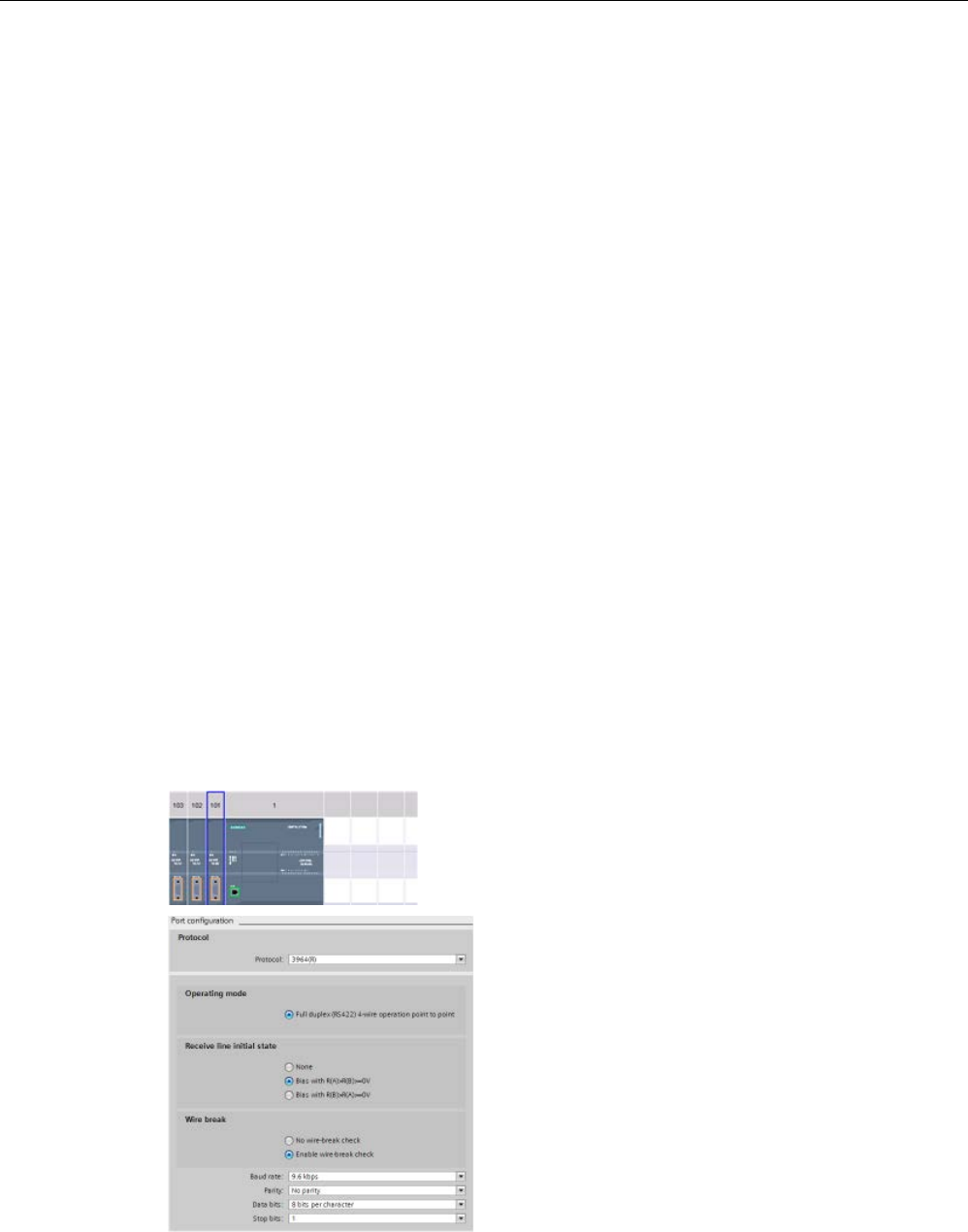
Communication processor and Modbus TCP
13.3 Point-to-point (PtP) communication
S7-1200 Programmable controller
System Manual, V4.2, 09/2016, A5E02486680-AK 1105
Configure the receive message length parameters for this message as follows:
● n = 3 (The message length starts at byte 3.)
● Length size = 1 (The message length is defined in one byte.)
● Length m = 3 (There are three characters following the length specifier that are not
counted in the length. In the protocol of this example, the characters SD2, FCS, and ED
are not counted in the length count. The other six characters are counted in the length
count; therefore the total number of characters following the length specifier is nine.)
In this example, the characters from 5 to 10 inclusive are the characters counted by Len (n).
13.3.4
Configuring 3964(R) communication
13.3.4.1
Configuring the 3964(R) communication ports
You can use either of the following methods to configure the communication interfaces for
3964(R) communication:
● Use the device configuration in STEP 7 to configure the port parameters. The CPU stores
the device configuration settings and applies the settings after a power cycle.
● Use the Port_Config (Page 1110) instruction to set the port parameters. The port settings
set by the instructions are valid while the CPU is in RUN mode. The port settings revert to
the device configuration settings after a power cycle.
After adding the communication interfaces to the device configuration (Page 158), you
configure parameters for the communication interfaces by selecting one of the CMs in your
rack.
The "Properties" tab of the inspector wi
n-
dow displays the parameters of the s
e-
lected CM. Select "Port configuration" to
edit the following parameters:
•
Protocol: 3964(R)
•
Operating mode
(CM 1241 (RS422/485) module only)
•
Receive line initial state
(CM 1241 (RS422/485) module only)
•
Wire break
(CM 1241 (RS422/485) module only)
•
Baud rate
•
Parity
•
Data bits
•
Stop bits

Communication processor and Modbus TCP
13.3 Point-to-point (PtP) communication
S7-1200 Programmable controller
1106 System Manual, V4.2, 09/2016, A5E02486680-AK
Parameter
Definition
Protocol
3964R or Freeport. Select 3964R to configure port for 3964(R) communication
Operating mode* Full duplex (RS422) four-wire operation point-to-point. (Enabled)
Receive line initial state* Enable one of the following choices:
• None
• Bias with R(A)>R(B)>=0V
• Bias with R(B)>R(A)>=0V
Wire break* Enable one of the following choices:
• No wire-break check
• Enable wire-break check
Baud rate The default value for the baud rate is 9.6 Kbits per second. Valid choices are: 300 baud,
600 baud, 1.2 Kbits, 2.4 Kbits, 4.8 Kbits, 9.6 Kbits, 19.2 Kbits, 38.4 Kbits, 57.6 Kbits, 76.8
Kbits, and 115.2 Kbits.
Parity The default value for
parity is no parity. Valid choices are: No parity, even, odd, mark (parity
bit always set to 1), space (parity bit always set to 0), and any parity (set parity bit to 0 for
transmission; ignore parity error when receiving).
Data bits per character
The number of data bits in a character. Valid choices are 7 or 8.
Number of stop bits
The number of stop bits can be either one or two. The default is one.
* CM 1241 (RS422/485) module only
13.3.4.2
Configuring the 3964(R) priority and protocol parameters
You can use either of the following methods to configure the communication interfaces for
3964(R) communication:
● In the device configuration of the communication interface, click "3964(R) configuration"
to set the priority and configure the protocol parameters. The CPU stores the device
configuration settings and applies the settings after a power cycle.
● Use the P3964_Config (Page 1120) instruction to set the priority and protocol
configuration parameters. The values set by the instructions are valid while the CPU is in
RUN mode. The values revert to the device configuration settings after a power cycle.

Communication processor and Modbus TCP
13.3 Point-to-point (PtP) communication
S7-1200 Programmable controller
System Manual, V4.2, 09/2016, A5E02486680-AK 1107
The "Properties" tab of the inspector wi
n-
dow displays the parameters of the s
e-
lected CM. Select "3964(R) configuration"
to e
dit the following parameters:
•
Priority (high or low)
•
Protocol parameters
– With block check (3964R)
– Use default values
Connection attempts
Transmission attempts
Character delay time
Acknowledgement delay
Parameter
Definition
Priority High or low: The CM will be either high or low and the communication partner must be the
opposite.
With block check (3964) If selected, 3964(R) communication employs transmission security by including a block
check character (BCC). If not selected transmission security does not include a block check
character.
Use default values If selected, 3964(R) uses default values for the following protocol parameters:
• Connection attempts
• Transmission attempts
• Character delay time
• Acknowledgement delay
If not selected, you can configure values for each of these parameters.
Connection attempts Number of connection attempts (default value: 6 connection attempts)
1 to 255
Transmission attempts Number of transmission attempts (default value: 6 connection attempts)
1 to 255
Character delay time Character delay time setting (depending on the set data transmission rate) (default value:
220 ms) 1 ms to 65535 ms
Acknowledgement delay Acknowledgment delay time setting (depending on the set data transmission rate) (default
value: 2000 ms when block check is enabled; 550 ms when block check is not enabled) 1
ms to 65535 ms
Note
With the exception of Priority, the protocol settings must be the same for the CM module and
the communication partner.

Communication processor and Modbus TCP
13.3 Point-to-point (PtP) communication
S7-1200 Programmable controller
1108 System Manual, V4.2, 09/2016, A5E02486680-AK
13.3.5
Point-to-point instructions
13.3.5.1
Common parameters for Point-to-Point instructions
Table 13- 3 Common input parameters for the PTP instructions
Parameter
Description
REQ Many of the PtP instructions use the REQ input to initiate the operation on a low to high transi-
tion. The REQ input must be high (TRUE) for one execution of an instruction, but the REQ input
can remain TRUE for as long as desired. The instruction does not initiate another operation until
it has been called with the REQ input FALSE so that the instruction can reset the history state of
the REQ input. This is required so that the instruction can detect the low to high transition to
initiate the next operation.
When you place a PtP instruction in your program, STEP 7 prompts you to identify the instance
DB. Use a unique DB for each PtP instruction call. This ensures that each instruction properly
handles inputs such as REQ.
PORT A port address is assigned during communication device configuration. After configuration, a
default port symbolic name can be selected from the parameter assistant drop-list. The assigned
CM or CB port value is the device configuration property "hardware identifier". The port symbolic
name is assigned in the "Constants" tab of the PLC tag table.
Bit time resolution Several parameters are specified in a number of bit times at the configured baud rate. Specifying
the parameter in bit times allows the parameter to be independent of baud rate. All parameters
that are in units of bit times can be specified to a maximum number of 65535. However, the max-
imum amount of time that a CM or CB can measure is eight seconds.
The DONE, NDR, ERROR, and STATUS output parameters of the PtP instructions provide
execution completion status for the PtP operations.
Table 13- 4 DONE, NDR, ERROR, and STATUS output parameters
Parameter
Data type
Default
Description
DONE Bool FALSE Set TRUE for one execution to indicate that the last request com-
pleted without errors; otherwise, FALSE.
NDR Bool FALSE Set TRUE for one execution to indicate that the requested action
has completed without error and that the new data has been re-
ceived; otherwise, FALSE.
ERROR Bool FALSE Set TRUE for one execution to indicate that the last request com-
pleted with errors, with the applicable error code in STATUS; oth-
erwise, FALSE.
STATUS Word 0 Result status:
•
If the DONE or NDR bit is set, then STATUS is set to 0 or to an
informational code.
• If the ERROR bit is set, then STATUS is set to an error code.
• If none of the above bits are set, then the instruction returns
status results that describe the current state of the function.
STATUS retains its value for the duration of the execution of the
function.

Communication processor and Modbus TCP
13.3 Point-to-point (PtP) communication
S7-1200 Programmable controller
System Manual, V4.2, 09/2016, A5E02486680-AK 1109
Note
The DONE,
NDR, and ERROR parameters are set for one execution only. Your program
logic must save temporary output state values in data latches, so you can detect state
changes in subsequent program scans.
Table 13- 5 Common condition codes
STATUS (W#16#....)
Description
0000
No error
7000
Function is not busy
7001
Function is busy with the first call.
7002
Function is busy with subsequent calls (polls after the first call).
8x3A
Illegal pointer in parameter x
8070
All internal instance memory in use, too many concurrent instructions in progress
8080
Port number is illegal.
8081
Timeout, module error, or other internal error
8082
Parameterization failed because parameterization is in progress in background.
8083 Buffer overflow:
The CM or CB returned a received message with a length greater than the length parameter
allowed.
8090 Internal error: Wrong message length, wrong sub-module, or illegal message
Contact customer support.
8091 Internal error: Wrong version in parameterization message
Contact customer support.
8092 Internal error: Wrong record length in parameterization message
Contact customer support.
Table 13- 6 Common error classes
Class description
Error classes
Description
Port configuration
16#81Ax
Used to define common port configuration errors
Transmit configuration
16#81Bx
Used to define common transmit configuration errors
Receive configuration 16#81Cx
16#82Cx
Used to define common receive configuration errors
Transmission runtime
16#81Dx
Used to define common transmission runtime errors
Reception runtime
16#81Ex
Used to define common reception runtime errors
Signal handling 16#81Fx Used to define common errors associated with all signal han-
dling
Pointer errors 16#8p01 to 16#8p51 Used for ANY pointer errors where "p" is the parameter number
of the instruction
Embedded protocol errors 16#848x
16#858x
Used for embedded protocol errors
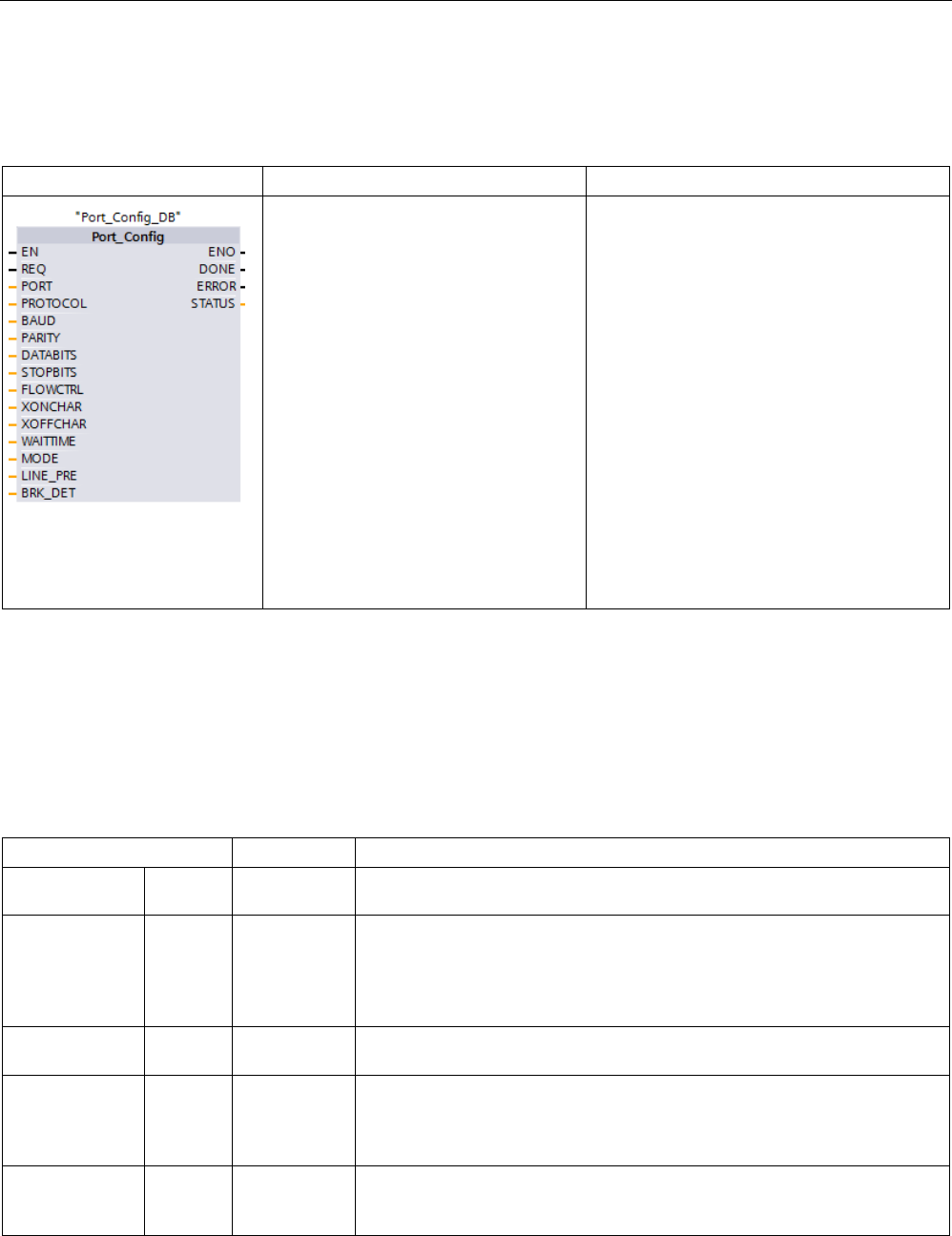
Communication processor and Modbus TCP
13.3 Point-to-point (PtP) communication
S7-1200 Programmable controller
1110 System Manual, V4.2, 09/2016, A5E02486680-AK
13.3.5.2
Port_Config (Configure communication parameters dynamically)
Table 13- 7 Port_Config (Port Configuration) instruction
LAD / FBD
SCL
Description
"Port_Config_DB"(
REQ:=_bool_in_,
PORT:=_word_in_,
PROTOCOL:=_uint_in_,
BAUD:=_uint_in_,
PARITY:=_uint_in_,
DATABITS:=_uint_in_,
STOPBITS:=_uint_in_,
FLOWCTRL:=_uint_in_,
XONCHAR:=_char_in_,
XOFFCHAR:=_char_in_,
WAITTIME:=_uint_in_,
MODE:=_uint_in_,
LINE_PRE:=_uint_in_,
BRK_DET:=_uint_in_,
DONE=>_bool_out_,
ERROR=>_bool_out_,
STATUS=>_word_out_);
Port_Config allows you to change port pa-
rameters such as baud rate from your pro-
gram.
You can set up the initial static configuration
of the port in the device configuration proper-
ties, or just use the default values. You can
execute the Port_Config instruction in your
program to change the configuration.
1 STEP 7 automatically creates the DB when you insert the instruction.
The CPU does not permanently store the values you set with the Port_Config instruction.
The CPU restores the parameters configured in the device configuration when the CPU
transitions from RUN to STOP mode and after a power cycle. See Configuring the
communication ports (Page 1093) and Managing flow control (Page 1095) for more
information.
Table 13- 8 Data types for the parameters
Parameter and type
Data type
Description
REQ IN Bool Activate th
e configuration change on rising edge of this input. (Default value:
False)
PORT IN PORT After you install and configure a CM or CB communication device, the port
identifier appears in the parameter helper drop-list available at the PORT
box connection. The assigned CM or CB port value is the device configura-
tion property "hardware identifier". The port symbolic name is assigned in
the "System constants" tab of the PLC tag table. (Default value: 0)
PROTOCOL IN UInt 0 - Freeport protocol (Default value)
1. 3964(R) protocol
BAUD IN UInt Port baud rate (Default value: 6):
1 = 300 baud, 2 = 600 baud, 3 = 1200 baud, 4 = 2400 baud, 5 = 4800 baud,
6 = 9600 baud, 7 = 19200 baud, 8 = 38400 baud, 9 = 57600 baud,
10 = 76800 baud, 11 = 115200 baud
PARITY IN UInt Port parity (Default value: 1):
1 = No parity, 2 = Even parity, 3 = Odd parity, 4 = Mark parity,
5 = Space parity

Communication processor and Modbus TCP
13.3 Point-to-point (PtP) communication
S7-1200 Programmable controller
System Manual, V4.2, 09/2016, A5E02486680-AK 1111
Parameter and type
Data type
Description
DATABITS IN UInt Bits per character (Default value: 1):
1 = 8 data bits, 2 = 7 data bits
STOPBITS IN UInt Stop bits (Default value: 1):
1 = 1 stop bit, 2 = 2 stop bits
FLOWCTRL* IN UInt Flow control (Default value: 1):
1 = No flow control, 2 = XON/XOFF, 3 = Hardware RTS always ON,
4 = Hardware RTS switched
XONCHAR1 IN Char Specifies the character that is used as the XON character. This is typically a
DC1 character (16#11). This parameter is only evaluated if flow control is
enabled. (Default value: 16#11)
XOFFCHAR1 IN Char Specifies the character that is used as the XOFF character. This is typically
a DC3 character (16#13). This parameter is only evaluated if flow control is
enabled. (Default value: 16#13)
WAITTIME1 IN UInt Specifies how long to wait for a XON character after receiving a XOFF char-
acter, or how long to wait for the CTS signal after enabling RTS (0 to 65535
ms). This parameter is only evaluated if flow control is enabled. (Default
value: 2000)
MODE2 IN UInt Specifies the selection of the module’s operating mode.
• 0 = Full duplex (RS232)
• 1 = Full duplex (RS422) four-wire mode (point-to-point), transmitter al-
ways enabled
• 2 = Full duplex (RS422) four-wire mode (multipoint master), transmitter
always enabled
• 3 = Full duplex (RS422) four-wire modemultipoint slave, transmitter
enabled while sending
• 4 = Half dubplex (RS485) two-wire mode
LINE_PRE IN UInt Specifies the inactive (idle) line condition. For RS422 and RS485 modules
the idle line condition is established by applying a bias voltage to the R(A)
and R(B) signals. The following selections are possible:
• 0 = Not biased (No Presetting) (default)
• 1 = Biased with R(A) > R(B) ≥ 0V; RS422 only
• 2 = Biased with R(B) > R(A) ≥ 0V; RS422 and RS485
BRK_DET IN UInt Enables/disables communications cable break detection. Enabling cable
break detection causes the module to indicate a fault when the communica-
tions cable is not connected to the module.
In RS422 Point-to-Point mode cable break detection is only possible when
Receive Line Presetting is used with bias applied so that R(A) > R(B) ≥ 0V.
• 0 -= No Cable Break Detection (default)
• 1 = Cable Break Detection enabled
DONE
OUT
Bool
TRUE for one execution after the last request was completed with no error
ERROR
OUT
Bool
TRUE for one execution after the last request was completed with an error
STATUS
OUT
Word
Execution condition code (Default value: 0)
1
Not applicable when Protocol=1 (3964(R) protocol)
2
Only modes 0 and 1 are valid when Protocol=1 (3964(R) protocol) depending on whether your CM module is an RS232
module or RS422 module.

Communication processor and Modbus TCP
13.3 Point-to-point (PtP) communication
S7-1200 Programmable controller
1112 System Manual, V4.2, 09/2016, A5E02486680-AK
Table 13- 9 Condition codes
STATUS (W#16#....)
Description
81A0
Specific protocol does not exist.
81A1 Specific baud rate does not exist.
81A2
Specific parity option does not exist.
81A3 Specific number of data bits does not exist.
81A4
Specific number of stop bits does not exist.
80A5
Specific type of flow control does not exist.
81A6
Wait time is 0 and flow control enabled
81A7
XON and XOFF are illegal values (for example, the same value)
81A8
Error in the block header (for example, wrong block type or wrong block length)
81A9
Reconfiguration rejected because a configuration is in progress
81AA
Invalid RS422/RS485 mode of operation
81AB
Invalid presetting of the receive line for break detection
81AC
Invalid RS232 break handling
8280
Negative acknowledgement while reading the module
8281
Negative acknowledgement while writing the module
8282
DP slave or module not available
13.3.5.3
Send_Config (Configure serial transmission parameters dynamically)
Table 13- 10 Send_Config (Send Configuration) instruction
LAD / FBD
SCL
Description
"Send_Config_DB"(
REQ:=_bool_in_,
PORT:=_word_in_,
RTSONDLY:=_uint_in_,
RTSOFFDLY:=_uint_in_,
BREAK:=_uint_in_,
IDLELINE:=_uint_in_,
USR_END:=_string_in_,
APP_END:=_string_in_,
DONE=>_bool_out_,
ERROR=>_bool_out_,
STATUS=>_word_out_);
Send_Config allows the dynamic
configuration of serial transmission
parameters for a PtP communica-
tion port. Any queued messages
within a CM or CB are discarded
when Send_Config is executed.
1 STEP 7 automatically creates the DB when you insert the instruction.

Communication processor and Modbus TCP
13.3 Point-to-point (PtP) communication
S7-1200 Programmable controller
System Manual, V4.2, 09/2016, A5E02486680-AK 1113
You can set up the initial static configuration of the port in the device configuration
properties, or just use the default values. You can execute the Send_Config instruction in
your program to change the configuration.
The CPU does not permanently store the values you set with the Send_Config instruction.
The CPU restores the parameters configured in the device configuration when the CPU
transitions from RUN to STOP mode and after a power cycle. See Configuring transmit
(send) parameters (Page 1096).
Table 13- 11 Data types for the parameters
Parameter and type
Data type
Description
REQ IN Bool Activate the configuration change on the rising edge of this input. (Default
value: False)
PORT IN PORT After you install and configure a CM or CB communication device, the port
identifier appears in the parameter helper drop-list available at the PORT
box connection. The assigned CM or CB port value is the device configura-
tion property "hardware identifier". The port symbolic name is assigned in
the "System constants" tab of the PLC tag table. (Default value: 0)
RTSONDLY IN UInt Number of milliseconds to wait after enabling RTS before any Tx data
transmission occurs. This parameter is only valid when hardware flow con-
trol is enabled. The valid range is 0 - 65535 ms. A value of 0 disables the
feature. (Default value: 0)
RTSOFFDLY IN UInt Number of milliseconds to wait after the Tx data transmission occurs before
RTS is disabled: This parameter is only valid when hardware flow control is
enabled. The valid range is 0 - 65535 ms. A value of 0 disables the feature.
(Default value: 0)
BREAK IN UInt This parameter specifies that a break will be sent upon the start of each
message for the specified number of bit times. The maximum is 65535 bit
times up to an eight second maximum. A value of 0 disables the feature.
(Default value: 12)
IDLELINE IN UInt This parameter specifies that the line will remain idle for the specified num-
ber of bit times before the start of each message. The maximum is 65535 bit
times up to an eight second maximum. A value of 0 disables the feature.
(Default value: 0)
USR_END* IN STRING[2] Specifies the number and the characters in the end delimiter. The end de-
limiter is embedded in the transmit buffer (characters only) and marks the
end of the transmitted message (characters are transmitted until the end
delimiter is encountered). The end delimiter is appended to the end of the
message.
• STRING[2,0,xx,yy] – End delimiter is not used (default)
• STRING[2,1,xx,yy] – End delimiter is a single character
• STRING[2,2,xx,yy] – End delimiter is two characters
Either USR_END or APP_END must have a length of zero.

Communication processor and Modbus TCP
13.3 Point-to-point (PtP) communication
S7-1200 Programmable controller
1114 System Manual, V4.2, 09/2016, A5E02486680-AK
Parameter and type
Data type
Description
APP_END* IN STRING[5] Specifies the number and the characters to be appended to the transmitted
message (only the characters are appended).
STRING[5,0,aa,bb,cc,dd,ee] – End char is not used (default)
• STRING[5,1,aa,bb,cc,dd,ee] – Transmit one end character
• STRING[5,2,aa,bb,cc,dd,ee] – Transmit two end characters
• STRING[5,3,aa,bb,cc,dd,ee]– Transmit three end characters
• STRING[5,4,aa,bb,cc,dd,ee] – Transmit four end characters
• STRING[5,5,aa,bb,cc,dd,ee] – Transmit five end characters
DONE OUT Bool TRUE for one execution after the last request was completed with no error
ERROR
OUT
Bool
TRUE for one execution after the last request was completed with an error
STATUS
OUT
Word
Execution condition code (Default value: 0)
* Not supported for the CM and CB 1241s; you must use an empty string ("") for the parameter.
Table 13- 12 Condition codes
STATUS (W#16#....)
Description
81B0
Transmit interrupt configuration is not allowed. Contact customer suport.
81B1
Break time is greater than the maximum allowed value.
81B2
Idle time is greater than the maximum allowed value.
81B3
Error in the block header, for example, wrong block type or wrong block length
81B4
Reconfiguration rejected because a configuration is in progress
81B5 The number of end delimiters specified is greater than two or the number of end charac-
ters is greater than five
81B6
Send configuration rejected when configured for firmware embedded protocols
8280
Negative acknowledgement while reading the module
8281
Negative acknowledgement while writing the module
8282
DP slave or module not available
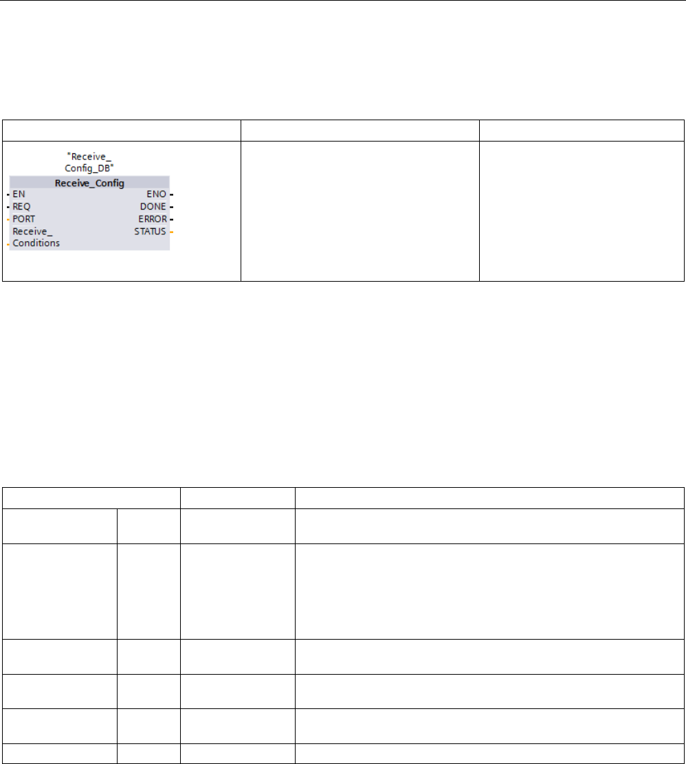
Communication processor and Modbus TCP
13.3 Point-to-point (PtP) communication
S7-1200 Programmable controller
System Manual, V4.2, 09/2016, A5E02486680-AK 1115
13.3.5.4
Receive_Config (Configure serial receive parameters dynamically)
Table 13- 13 Receive_Config (Receive Configuration) instruction
LAD / FBD
SCL
Description
"Receive_Config_DB"(
REQ:=_bool_in_,
PORT:=_uint_in_,
Re-
ceive_Conditions:=_struct_in_,
DONE=>_bool_out_,
ERROR=>_bool_out_,
STATUS=>_word_out_);
Receive_Config performs dynamic
configuration of serial receiver
parameters for a PtP communica-
tion port. This instruction config-
ures the conditions that signal the
start and end of a received mes-
sage. Any queued messages within
a CM or CB are discarded when
Receive_Config is executed.
1 STEP 7 automatically creates the DB when you insert the instruction.
You can set up the initial static configuration of the communication port in the device
configuration properties, or just use the default values. You can execute the Receive_Config
instruction in your program to change the configuration.
The CPU does not permanently store the values you set with the Receive_Config instruction.
The CPU restores the parameters configured in the device configuration when the CPU
transitions from RUN to STOP mode and after a power cycle. See the topic "Configuring
receive parameters (Page 1097)" for more information.
Table 13- 14 Data types for the parameters
Parameter and type
Data type
Description
REQ IN Bool Activate the configuration change on the rising edge of this input.
(Default value: False)
PORT IN PORT After you install and configure a CM or CB communication device,
the port identifier appears in the parameter helper drop-list available
at the PORT box connection. The assigned CM or CB port value is
the device configuration property "hardware identifier". The port sym-
bolic name is assigned in the "System constants" tab of the PLC tag
table. (Default value: 0)
CONDITIONS IN CONDITIONS The Conditions data structure specifies the starting and ending mes-
sage conditions as described below.
DONE OUT Bool TRUE for one scan, after the last request was completed with no
error
ERROR OUT Bool TRUE for one scan, after the last request was completed with an
error
STATUS
OUT
Word
Execution condition code (Default value: 0)

Communication processor and Modbus TCP
13.3 Point-to-point (PtP) communication
S7-1200 Programmable controller
1116 System Manual, V4.2, 09/2016, A5E02486680-AK
Start conditions for the Receive_P2P instruction
The Receive_P2P instruction uses the configuration specified by the Receive_Config
instruction to determine the beginning and ending of point-to-point communication
messages. The start of a message is determined by the start conditions. The start of a
message can be determined by one or a combination of start conditions. If more than one
start condition is specified, all the conditions must be satisfied before the message is started.
See the topic "Configuring receive parameters (Page 1097)" for a description of the message
start conditions.
Parameter CONDITIONS data type structure part 1 (start conditions)
Table 13- 15 CONDITIONS structure for start conditions
Parameter and type
Data type
Description
STARTCOND IN UInt Specifies the start condition (Default value: 1)
• 01H - Start Char
• 02H - Any Char
• 04H - Line Break
• 08H - Idle Line
• 10H - Sequence 1
• 20H - Sequence 2
• 40H - Sequence 3
• 80H - Sequence 4
IDLETIME IN UInt The number of bit times required for idle line timeout. (Default value:
40). Only used with an idle line condition. 0 to 65535
STARTCHAR IN Byte The start character used with the start character condition. (Default
value: B#16#2)
STRSEQ1CTL IN Byte Sequence 1 ignore/compare control for each character: (Default
value: B#16#0)
These are the enabling bits for each character in start sequence
• 01H - Character 1
• 02H - Character 2
• 04H - Character 3
• 08H - Character 4
• 10H - Character 5
Disabling the bit associated with a character means any character
will match, in this sequence position.
STRSEQ1
IN
Char[5]
Sequence 1 start characters (5 characters). Default value: 0
STRSEQ2CTL IN Byte Sequence 2 ignore/compare control for each character. Default val-
ue: B#16#0)
STRSEQ2
IN
Char[5]
Sequence 2 start characters (5 characters). Default value: 0
STRSEQ3CTL IN Byte Sequence 3 ignore/compare control for each character. Default val-
ue: B#16#0
STRSEQ3
IN
Char[5]
Sequence 3 start characters (5 characters). Default value: 0

Communication processor and Modbus TCP
13.3 Point-to-point (PtP) communication
S7-1200 Programmable controller
System Manual, V4.2, 09/2016, A5E02486680-AK 1117
Parameter and type
Data type
Description
STRSEQ4CTL IN Byte Sequence 4 ignore/compare control for each character. Default val-
ue: B#16#0
STRSEQ4 IN Char[5] Sequence 4 start characters (5 characters), Default value: 0
Example
Consider the following received hexadecimal coded message: "
68
10 aa
68
bb 10 aa 16"
and the configured start sequences shown in the table below. Start sequences begin to be
evaluated when the first 68H character is successfully received. Upon successfully receiving
the fourth character (the second 68H), then start condition 1 is satisfied. Once the start
conditions are satisfied, the evaluation of the end conditions begins.
The start sequence processing can be terminated due to various parity, framing, or inter-
character timing errors. These errors result in no received message, because the start
condition was not satisfied.
Table 13- 16 Start conditions
Start condition
First Character
First Character +1
First Character +2
First Character +3
First Character +4
1
68H
xx
xx
68H
xx
2 10H aaH xx xx xx
3
dcH
aaH
xx
xx
xx
4
e5H
xx
xx
xx
xx
End conditions for the Receive_P2P instruction
The end of a message is determined by the specification of end conditions. The end of a
message is determined by the first occurrence of one or more configured end conditions.
The section "Message end conditions" in the topic "Configuring receive parameters
(Page 1097)" describes the end conditions that you can configure in the Receive_Config
instruction.
You can configure the end conditions in either the properties of the communication interface
in the device configuration, or from the Receive_Config instruction. Whenever the CPU
transitions from STOP to RUN, the receive parameters (both start and end conditions) return
to the device configuration settings. If the STEP 7 user program executes Receive_Config,
then the settings are changed to the Receive_Config conditions.

Communication processor and Modbus TCP
13.3 Point-to-point (PtP) communication
S7-1200 Programmable controller
1118 System Manual, V4.2, 09/2016, A5E02486680-AK
Parameter CONDITIONS data type structure part 2 (end conditions)
Table 13- 17 CONDITIONS structure for end conditions
Parameter
Parameter type
Data type
Description
ENDCOND IN UInt
0
This parameter specifies message end condition:
• 01H - Response time
• 02H - Message time
• 04H - Inter-character gap
• 08H - Maximum length
• 10H - N + LEN + M
• 20H - Sequence
MAXLEN IN UInt
1
Maximum message length: Only used when the maxi-
mum length end condition is selected. 1 to 1024 bytes
N IN UInt
0
Byte position within the message of the length field. Only
used with the N + LEN + M end condition. 1 to 1022
bytes
LENGTHSIZE IN UInt
0
Size of the byte field (1, 2, or 4 bytes). Only used with the
N + LEN + M end condition.
LENGTHM IN UInt
0
Specify the number of characters following the length
field that are not included in the value of the length field.
This is only used with the N + LEN + M end condition. 0
to 255 bytes
RCVTIME IN UInt
200
Specify how long to wait for the first character to be re-
ceived. The receive operation will be terminated with an
error if a character is not successfully received within the
specified time. This is only used with the response time
condition. (0 to 65535 bit times with an 8 second maxi-
mum)
This parameter is not a message end condition since
evaluation terminates when the first character of a re-
sponse is received. It is an end condition only in the
sense that it terminates a receiver operation because no
response is received when a response is expected. You
must select a separate end condition.
MSGTIME IN UInt
200
Specify how long to wait for the entire message to be
completely received once the first character has been
received. This parameter is only used when the message
timeout condition is selected. (0 to 65535 milliseconds)
CHARGAP IN UInt
12
Specify the number of bit times between characters. If the
number of bit times between characters exceeds the
specified value, then the end condition will be satisfied.
This is only used with the inter-character gap condition.
(0 to 65535 bit times up to 8 second maximum)

Communication processor and Modbus TCP
13.3 Point-to-point (PtP) communication
S7-1200 Programmable controller
System Manual, V4.2, 09/2016, A5E02486680-AK 1119
Parameter
Parameter type
Data type
Description
ENDSEQ1CTL IN Byte
B#16#0
Sequence 1 ignore/compare control for each character:
These are the enabling bits for each character for the end
sequence. Character 1 is bit 0, character 2 is bit 1, …,
character 5 is bit 4. Disabling the bit associated with a
character means any character will match, in this se-
quence position.
ENDSEQ1 IN Char[5]
0
Sequence 1 start characters (5 characters)
Table 13- 18 Condition codes
STATUS (W#16#....)
Description
81C0
Illegal start condition selected
81C1
Illegal end condition selected, no end condition selected
81C2
Receive interrupt enabled and this is not possible.
81C3
Maximum length end condition is enabled and max length is 0 or > 1024.
81C4
Calculated length is enabled and N is >= 1023.
81C5
Calculated length is enabled and length is not 1, 2 or 4.
81C6
Calculated length is enabled and M value is > 255.
81C7
Calculated length is enabled and calculated length is > 1024.
81C8
Response timeout is enabled and response timeout is zero.
81C9
Inter-character gap timeout is enabled and it is zero.
81CA
Idle line timeout is enabled and it is zero.
81CB
End sequence is enabled but all chars are "don't care".
81CC
Start sequence (any one of 4) is enabled but all characters are "don't care".
81CD
Invalid receive message overwrite protection selection error
81CE Invalid receive message buffer handling on STOP to RUN transition selection error
81CF
Error in the block header, for example, wrong block type or wrong block length
8281 Negative acknowledgement while writing the module
8282
DP slave or module not available
82C0
Reconfiguration rejected because a configuration is in progress
82C1 The specified value for the number of messages that the module can buffer is greater than
the maximum permitted value.
82C2
Receive configuration rejected when configured for firmware embedded protocols
8351
Data type not allowed at this Variant pointer
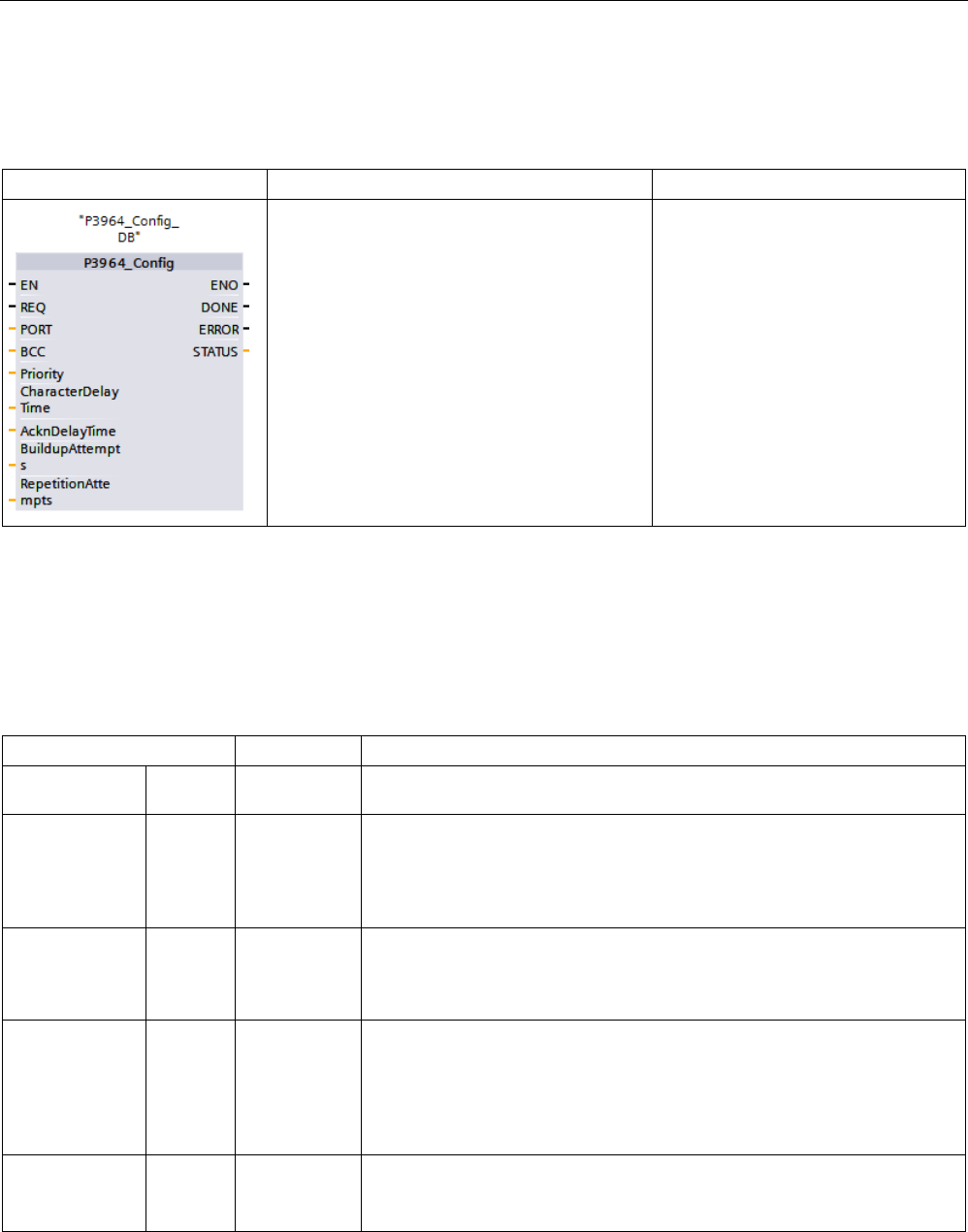
Communication processor and Modbus TCP
13.3 Point-to-point (PtP) communication
S7-1200 Programmable controller
1120 System Manual, V4.2, 09/2016, A5E02486680-AK
13.3.5.5
P3964_Config (Configuring the 3964(R) protocol)
Table 13- 19 P3964_Config (Configuring the 3964(R) protocol) instruction
LAD / FBD
SCL
Description
"P3964_Config_DB"(
REQ:=_bool_in_,
PORT:=_uint_in_,
BCC:=_usint_in,
Priority:= _usint_in,
CharacterDelayTime:=_uint_in,
AcknDelayTime:= _uint_in,
BuildupAttempts:=_usint_in_,
RepetitionAttempts:=_usint_in_,
DONE=>_bool_out_,
ERROR=>_bool_out_,
STATUS=>_word_out_);
P3964_Config allows you to change
priority and protocol parameters dur-
ing runtime.
You can set up the initial static config-
uration of the port in the device con-
figuration properties, or just use the
default values. You can execute the
P3964_Config instruction in your pro-
gram to change the configuration.
1 STEP 7 automatically creates the DB when you insert the instruction.
The CPU does not permanently store the values you set with the P3964_Config instruction.
The CPU restores the parameters configured in the device configuration after a power cycle
of the CPU. See Configuring the 3964(R) communication priority and protocol parameters
(Page 1106) for more information.
Table 13- 20 Data types for the parameters
Parameter and type
Data type
Description
REQ IN Bool Activate the configuration change on rising edge of this input. (Default value:
False)
PORT IN UInt After you install and configure a CM or CB communication device, the port
identifier appears in the parameter helper drop-list available at the PORT
box connection. The assigned CM or CB port value is the device configura-
tion property "hardware identifier". The port symbolic name is assigned in
the "System constants" tab of the PLC tag table. (Default value: 0)
BCC IN USInt Activates/deactivates the use of the block check
• 0 = without block check
• 1 = with block check
Priority IN UInt Selection of the priority
• 0 = low priority
• 1 = high priority
The priority of the CM must be the opposite of the priority of the communica-
tion partner.
CharacterDe-
layTime
IN UInt Character delay time setting (depending on the set data transmission rate)
(default value: 220 ms)
1 ms to 65535 ms

Communication processor and Modbus TCP
13.3 Point-to-point (PtP) communication
S7-1200 Programmable controller
System Manual, V4.2, 09/2016, A5E02486680-AK 1121
Parameter and type
Data type
Description
AcknDelayTime IN UInt
Acknowledgment delay time setting (depending on the set data transmission
rate) (default value: 2000 ms)
1 ms to 65535 ms
BuildupAttempts IN UInt Number of connection attempts (default value: 6 connection attempts)
1 to 255
RepetitionAt-
tempts
IN UInt Number of transmission attempts (default value: 6 connection attempts)
1 to 255
DONE
OUT
Bool
TRUE for one execution after the last request was completed with no error
ERROR
OUT
Bool
TRUE for one execution after the last request was completed with an error
STATUS
OUT
Word
Execution condition code (Default value: 0)
Table 13- 21 Condition codes
STATUS (W#16#....)
Description
16#8380
Parameter assignment error: Invalid value for "Character delay time".
16#8381
Parameter assignment error: Invalid value for "Response timeout".
16#8382
Parameter assignment error: Invalid value for "Priority".
16#8383
Parameter assignment error: Invalid value for "Block check"
16#8384
Parameter assignment error: Invalid value for "Connection attempts".
16#8385
Parameter assignment error: Invalid value for "Transmission attempts".
16#8386
Runtime error: Number of connection attempts exceeded
16#8387
Runtime error: Number of transmission attempts exceeded
16#8388 Runtime error: Error at the "Block check character"
The internally calculated value of the block check character does not correspond to the
block check character received by the partner at the connection end.
16#8389
Runtime error: Invalid character received while waiting for free receive buffer
16#838A Runtime error: Logical error during receiving.
After DLE was received, a further random character (other than DLE or ETX) was re-
ceived.
16#838B
Runtime error: Character delay time exceeded
16#838C Runtime error: Wait time for free receive buffer has started
16#838D
Runtime error: frame repetition does not start within 4 s after NAK
16#838E Runtime error: In idle mode, one or several characters (other than NAK or STX) were
received.
16#838F
Runtime error: Initialization conflict - Both partners have set high priority
16#8391
Parameter assignment error: 3964 configuration data rejected because Freeport is set
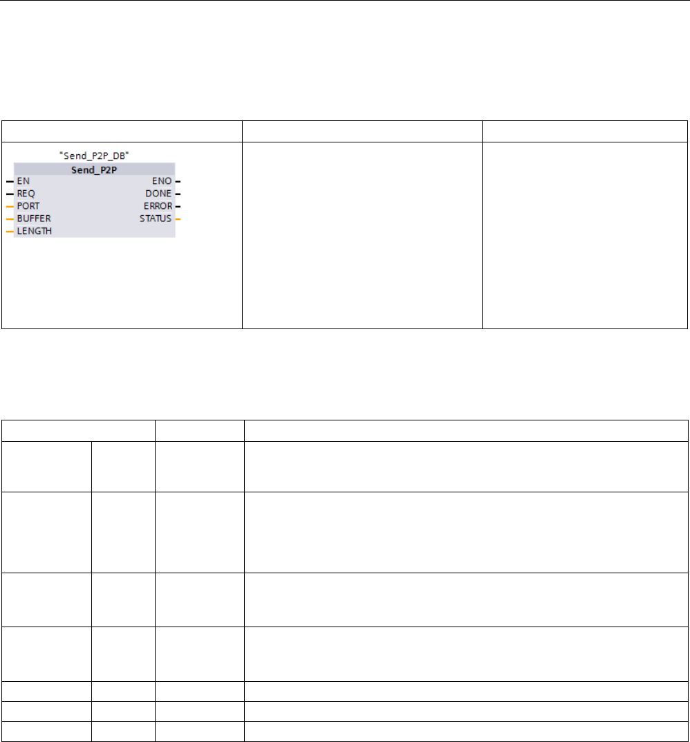
Communication processor and Modbus TCP
13.3 Point-to-point (PtP) communication
S7-1200 Programmable controller
1122 System Manual, V4.2, 09/2016, A5E02486680-AK
13.3.5.6
Send_P2P (Transmit send buffer data)
Table 13- 22 Send_P2P (Send Point-to-Point data) instruction
LAD / FBD
SCL
Description
"Send_P2P_DB"(
REQ:=_bool_in_,
PORT:=_word_in_,
BUFFER:=_variant_in_,
LENGTH:=_uint_in_,
DONE=>_bool_out_,
ERROR=>_bool_out_,
STATUS=>_word_out_);
Send_P2P initiates the transmis-
sion of the data and transfers the
assigned buffer to the communica-
tion interface. The CPU program
continues while the CM or CB
sends the data at the assigned
baud rate. Only one send operation
can be pending at a given time.
The CM or CB returns an error if a
second Send_P2P is executed
while the CM or CB is already
transmitting a message.
1 STEP 7 automatically creates the DB when you insert the instruction.
Table 13- 23 Data types for the parameters
Parameter and type
Data type
Description
REQ IN Bool Activates the requested transmission on the rising edge of this transmission
enable input. This initiates transfer of the contents of the buffer to the Point-to-
Point communication interface. (Default value: False)
PORT IN PORT After you install and configure a CM or CB communication device, the port
identifier appears in the parameter helper drop-list available at the PORT box
connection. The assigned CM or CB port value is the device configuration
property "hardware identifier". The port symbolic name is assigned in the "Sys-
tem constants" tab of the PLC tag table. (Default value: 0)
BUFFER IN Variant This parameter points to the starting location of the transmit buffer. (Default
value: 0)
Note:
Boolean data or Boolean arrays are not supported.
LENGTH IN UInt Transmitted frame length in bytes (Default value: 0)
When transmitting a complex structure, always use a length of 0. When the
length is 0, the instruction transmits the entire frame.
DONE
OUT
Bool
TRUE for one scan, after the last request was completed with no error
ERROR
OUT
Bool
TRUE for one scan, after the last request was completed with an error
STATUS
OUT
Word
Execution condition code (Default value: 0)
While a transmit operation is in progress, the DONE and ERROR outputs are FALSE. When
a transmit operation is complete, either the DONE or the ERROR output will be set TRUE to
show the status of the transmit operation. While DONE or ERROR is TRUE, the STATUS
output is valid.
The instruction returns a status of 16#7001 if the communication interface accepts the
transmit data. Subsequent Send_P2P executions return 16#7002, if the CM or CB is still
busy transmitting. When the transmit operation is complete, the CM or CB returns the status
of the transmit operation as 16#0000 (if no errors occurred). Subsequent executions of
Send_P2P with REQ low return a status of 16#7000 (not busy).
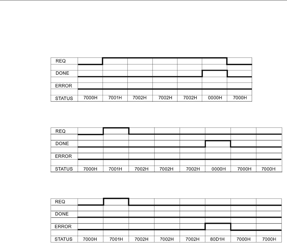
Communication processor and Modbus TCP
13.3 Point-to-point (PtP) communication
S7-1200 Programmable controller
System Manual, V4.2, 09/2016, A5E02486680-AK 1123
The following diagrams show the relationship of the output values to REQ. This assumes
that the instruction is called periodically to check for the status of the transmission process.
In the diagram below, it is assumed that the instruction is called every scan (represented by
the STATUS values).
The following diagram shows how the DONE and STATUS parameters are valid for only one
scan if the REQ line is pulsed (for one scan) to initiate the transmit operation.
The following diagram shows the relationship of DONE, ERROR and STATUS parameters
when there is an error.
The DONE, ERROR and STATUS values are only valid until Send_P2P executes again with
the same instance DB.

Communication processor and Modbus TCP
13.3 Point-to-point (PtP) communication
S7-1200 Programmable controller
1124 System Manual, V4.2, 09/2016, A5E02486680-AK
Table 13- 24 Condition codes
STATUS (W#16#....)
Description
81D0
New request while transmitter active
81D1 Transmit aborted because of no CTS within wait time
81D2
Transmit aborted because of no DSR from the DCE device
81D3 Transmit aborted because of queue overflow (transmit more than 1024 bytes)
81D5
Reverse bias signal (wire break condition)
81D6
Transmission request rejected because end delimiter was not found in the transmit buffer
81D7
Internal error / error in synchronization between FB and CM
81D8
Transmission attempt rejected because the port has not been configured
81DF CM has reset the interface to the FB due to one of the following reasons
• The module has restarted (Power cycle)
• The CPU has reached a breakpoint
• The module has been reparameterized
In each case the module indicates this code in the Status parameter. The module resets
Status and Error to zero after the first received record for SEND_P2P.
8281
Negative acknowledgement while writing the module
8282
DP slave or module not available
8301
Illegal syntax ID at an ANY pointer
8322
Range length error when reading a parameter
8324
Range error when reading a parameter
8328
Alignment error when reading a parameter
8332 The parameter contains a DB number that is higher than the highest permitted number (DB
number error).
833A
The DB for the BUFFER parameter does not exist.
Note
Setting the maximum record length for Profibus communication
When using a CM1243
-5 Profibus Master module to control an ET 200SP or ET 200MP
Profibus device that uses an RS232, RS422, or RS48
5 point-to-point module, you need to
explicitly set the "max_record_len" data block tag to 240 as defined below:
Set "max_record_len" in the instance DB (for example, "Send_P2P_DB".max_record_len) to
240 after running any configuration instruction such as
Port_Config, Send_Config, or
Receive_Config.
Explicitly assigning max_record_len is only necessary with Profibus communication; Profinet
communication already uses a valid max_record_len value.

Communication processor and Modbus TCP
13.3 Point-to-point (PtP) communication
S7-1200 Programmable controller
System Manual, V4.2, 09/2016, A5E02486680-AK 1125
Interaction of the LENGTH and BUFFER parameters
The minimum size of data that can be transmitted by the SEND_P2P instruction is one byte.
The BUFFER parameter determines the size of the data to be transmitted. You cannot use
the data type Bool or arrays of Bool for the BUFFER parameter.
You can always set the LENGTH parameter to 0 and ensure that SEND_P2P sends the
entire data structure represented by the BUFFER parameter. If you only want to send part of
a data structure in the BUFFER parameter, you can set LENGTH as follows:
Table 13- 25 LENGTH and BUFFER parameters
LENGTH
BUFFER
Description
= 0 Not used
The complete data is sent as defined at the BUFFER parameter. You do not
need to specify the number of transmitted bytes when LENGTH = 0.
> 0 Elementary data type The LENGTH value must contain the byte count of this data type. For ex-
ample, for a Word value, the LENGTH must be two. For a Dword or Real,
the LENGTH must be four. Otherwise, nothing is transferred and the error
8088H is returned.
Structure The LENGTH value can contain a byte count less than the complete byte
length of the structure, in which case the instruction sends only the first n
bytes of the structure from the BUFFER, where n = LENGTH. Since the
internal byte organization of a structure cannot always be determined, you
might get unexpected results. In this case, use a LENGTH of 0 to send the
complete structure.
Array The LENGTH value must contain a byte count that is less than or equal to
the complete byte length of the array and which must be a multiple of the
data element byte count. For example, the LENGTH parameter for an array
of Words must be a multiple of two and for an array of Reals, a multiple of
four. When LENGTH is specified, the instruction transfers the number of
array elements that correspond to the LENGTH value in bytes. If your
BUFFER, for example, contains an array of 15 Dwords (60 total bytes), and
you specify a LENGTH of 20, then the first five Dwords in the array are
transferred.
The LENGTH value must be a multiple of the data element byte count. Oth-
erwise, STATUS = 8088H, ERROR = 1, and no transmission occurs.
String The LENGTH parameter contains the number of characters to be transmit-
ted. Only the characters of the String are transmitted. The maximum and
actual length bytes of the String are not transmitted.
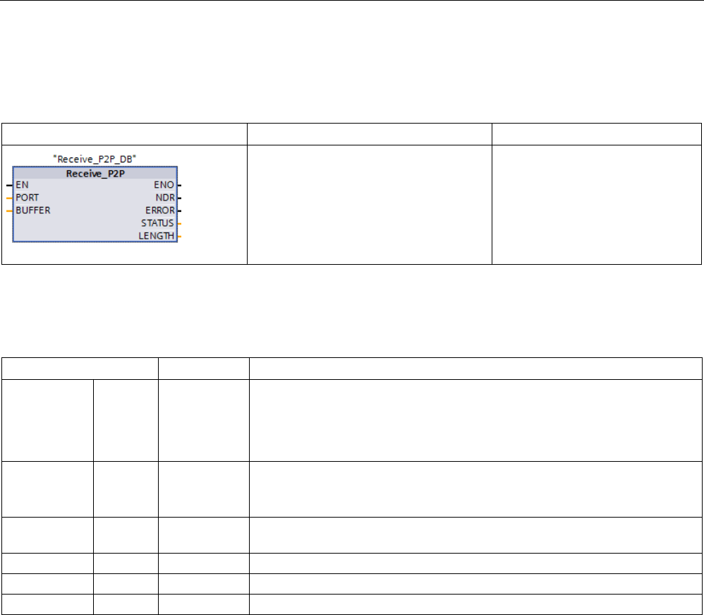
Communication processor and Modbus TCP
13.3 Point-to-point (PtP) communication
S7-1200 Programmable controller
1126 System Manual, V4.2, 09/2016, A5E02486680-AK
13.3.5.7
Receive_P2P (Enable receive messages)
Table 13- 26 Receive_P2P (Receive Point-to-Point) instruction
LAD / FBD
SCL
Description
"Receive_P2P_DB"(
PORT:=_word_in_,
BUFFER:=_variant_in_,
NDR=>_bool_out_,
ERROR=>_bool_out_,
STATUS=>_word_out_,
LENGTH=>_uint_out_);
Receive_P2P checks for messages
that have been received in the CM
or CB. If a message is available, it
will be transferred from the CM or
CB to the CPU. An error returns
the appropriate STATUS value.
1 STEP 7 automatically creates the DB when you insert the instruction.
Table 13- 27 Data types for the parameters
Parameter and type
Data type
Description
PORT IN PORT After you install and configure a CM or CB communication device, the port
identifier appears in the parameter helper drop-list available at the PORT box
connection. The assigned CM or CB port value is the device configuration
property "hardware identifier". The port symbolic name is assigned in the "Sys-
tem constants" tab of the PLC tag table. (Default value: 0)
BUFFER IN Variant This parameter points to the starting location of the receive buffer. This buffer
should be large enough to receive the maximum length message.
Boolean data or Boolean arrays are not supported. (Default value: 0)
NDR OUT Bool TRUE for one execution when new data is ready and operation is complete
with no errors.
ERROR
OUT
Bool
TRUE for one execution after the operation was completed with an error.
STATUS
OUT
Word
Execution condition code (Default value: 0)
LENGTH
OUT
UInt
Length of the returned message in bytes (Default value: 0)
The STATUS value is valid when either NDR or ERROR is TRUE. The STATUS value
provides the reason for termination of the receive operation in the CM or CB. This is typically
a positive value, indicating that the receive operation was successful and that the receive
process terminated normally. If the STATUS value is negative (the Most Significant Bit of the
hexadecimal value is set), the receive operation was terminated for an error condition such
as parity, framing, or overrun errors.
Each PtP communication interface can buffer up to a maximum of 1024 bytes. This could be
one large message or several smaller messages. If more than one message is available in
the CM or CB, the Receive_P2P instruction returns the oldest message available. A
subsequent Receive_P2P instruction execution returns the next oldest message available.

Communication processor and Modbus TCP
13.3 Point-to-point (PtP) communication
S7-1200 Programmable controller
System Manual, V4.2, 09/2016, A5E02486680-AK 1127
Table 13- 28 Condition codes
STATUS (W#16#...)
Description
0000
No buffer present
0094 Message terminated due to received maximum character length
0095
Message terminated because of message timeout
0096 Message terminated because of inter-character timeout
0097
Message terminated because of response timeout
0098
Message terminated because the "N+LEN+M" length condition was satisfied
0099
Message terminated because of end sequence was satisfied
8085
LENGTH parameter has a value of 0 or is greater than 4KB.
8088 The LENGTH parameter or the received length is longer than the area specified in BUFFER or the
received length is longer than the area specified in BUFFER.
8090
Incorrect configuration message, wrong message length, wrong submodule, illegal message
81E0
Message terminated because the receive buffer is full
81E1
Message terminated due to parity error
81E2
Message terminated due to framing error
81E3
Message terminated due to overrun error
81E4
Message terminated because calculated length exceeds buffer size
81E5
Reverse bias signal (wire break condition)
81E6 The message queue is full. This error is reported without data. If it occurs, the module toggles be-
tween an error free data transfer and this error.
81E7 Internal error, error in synchronization between instruction and CM: set wehn a sequence error is
detected
81E8 Message terminated, inter-character timeout expired before the end of message criteria was satis-
fied
81E9 Modbus CRC error detected (Only used by modules that support CRC generation/checking for the
Modbus protocol)
81EA Modbus telegram is too short (Only used by modules that support CRC generation/checking for the
Modbus protocol)
81EB
Message terminated, because maximum message size exceeded
8201
Illegal syntax ID at an ANY pointer
8223 Range length error when writing a parameter. The parameter is located either entirely or partly
outside the range of an address or that the length of a bit range is not a multiple of 8 with an ANY
pointer.
8225 Range error when writing a parameter. The parameter is located in a range that is illegal for the
system function.
8229 Alignment error when writing a parameter. The referenced parameter is located at bit address that
is not equal to 0.
8230
Parameter is located in a read-only global DB
8231
Parameter is located in a read-only instance DB.
8232 Parameter contains a DB number that is higher than the highest block number allowed (DB number
error).
823A
The DB for the BUFFER parameter does not exist.
8280
Negative acknowledgement while reading the module
8282
DP slave or module not available
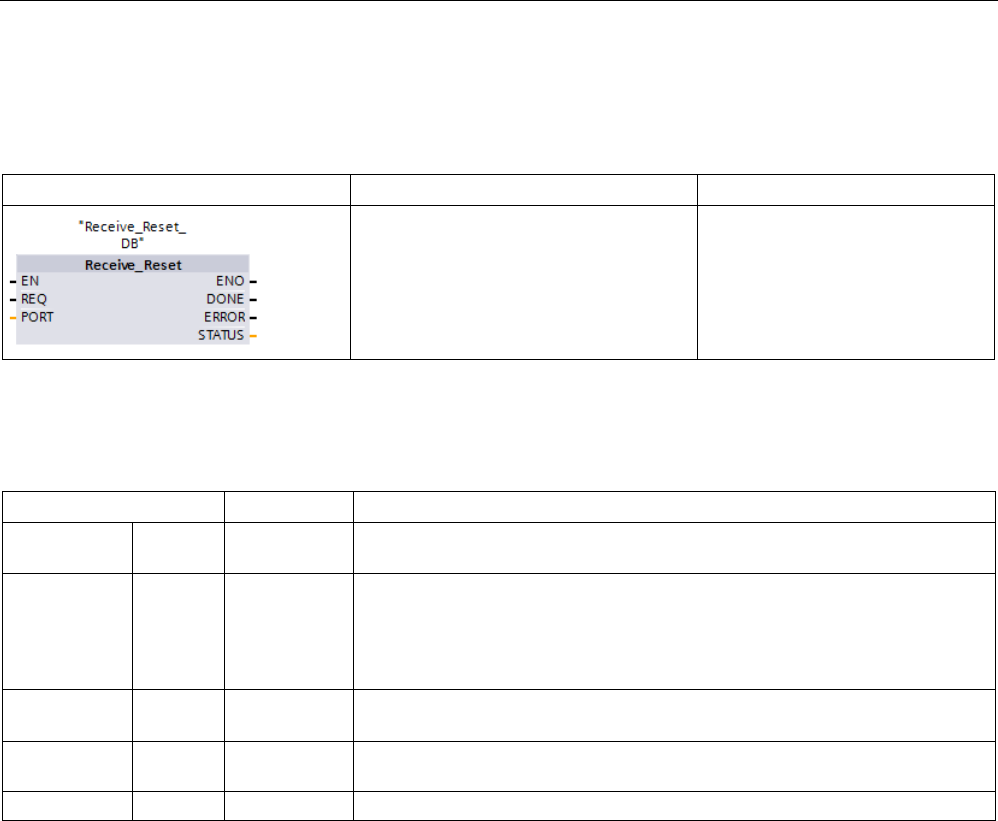
Communication processor and Modbus TCP
13.3 Point-to-point (PtP) communication
S7-1200 Programmable controller
1128 System Manual, V4.2, 09/2016, A5E02486680-AK
13.3.5.8
Receive_Reset (Delete receive buffer)
Table 13- 29 Receive_Reset (Receiver Reset) instruction
LAD / FBD
SCL
Description
"Receive_Reset_DB"(
REQ:=_bool_in_,
PORT:=_word_in_,
DONE=>_bool_out_,
ERROR=>_bool_out_,
STATUS=>_word_out_);
Receive_Reset clears the receive
buffers in the CM or CB.
1 STEP 7 automatically creates the DB when you insert the instruction.
Table 13- 30 Data types for parameters
Parameter and type
Data type
Description
REQ IN Bool Activates the receiver reset on the rising edge of this enable input (Default
value: False)
PORT IN PORT After you install and configure a CM or CB communication device, the port
identifier appears in the parameter helper drop-list available at the PORT box
connection. The assigned CM or CB port value is the device configuration
property "hardware identifier". The port symbolic name is assigned in the "Sys-
tem constants" tab of the PLC tag table. (Default value: 0)
DONE OUT Bool When TRUE for one scan, indicates that the last request was completed with-
out errors.
ERROR OUT Bool When TRUE, shows that the last request was completed with errors. Also,
when this output is TRUE, the STATUS output will contain related error codes.
STATUS
OUT
Word
Error code (Default value: 0)
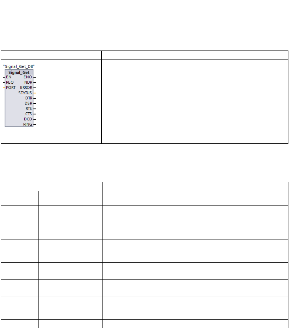
Communication processor and Modbus TCP
13.3 Point-to-point (PtP) communication
S7-1200 Programmable controller
System Manual, V4.2, 09/2016, A5E02486680-AK 1129
13.3.5.9
Signal_Get (Query RS-232 signals)
Table 13- 31 Signal_Get (Get RS232 signals) instruction
LAD / FBD
SCL
Description
"Signal_Get_DB"(
REQ:=_bool_in_,
PORT:=_uint_in_,
NDR=>_bool_out_,
ERROR=>_bool_out_,
STATUS=>_word_out_,
DTR=>_bool_out_,
DSR=>_bool_out_,
RTS=>_bool_out_,
CTS=>_bool_out_,
DCD=>_bool_out_,
RING=>_bool_out_);
Signal_Get reads the current states
of RS232 communication signals.
This function is valid only for the
RS232 CM.
1 STEP 7 automatically creates the DB when you insert the instruction.
Table 13- 32 Data types for the parameters
Parameter and type
Data type
Description
REQ IN Bool Get RS232 signal state values on the rising edge of this input (Default value:
False)
PORT IN PORT After you install and configure a CM or CB communication device, the port
identifier appears in the parameter helper drop-list available at the PORT box
connection. The assigned CM or CB port value is the device configuration
property "hardware identifier". The port symbolic name is assigned in the "Sys-
tem constants" tab of the PLC tag table.
NDR OUT Bool TRUE for one scan, when new data is ready and the operation is complete
with no errors
ERROR
OUT
Bool
TRUE for one scan, after the operation was completed with an error
STATUS
OUT
Word
Execution condition code (Default value: 0)
DTR
OUT
Bool
Data terminal ready, module ready (output). Default value: False
DSR
OUT
Bool
Data set ready, communication partner ready (input). Default value: False
RTS
OUT
Bool
Request to send, module ready to send (output). Default value: False
CTS OUT Bool Clear to send, communication partner can receive data (input). Default value:
False
DCD
OUT
Bool
Data carrier detect, receive signal level (always False, not supported)
RING
OUT
Bool
Ring indicator, indication of incoming call (always False, not supported)
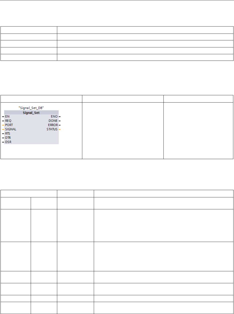
Communication processor and Modbus TCP
13.3 Point-to-point (PtP) communication
S7-1200 Programmable controller
1130 System Manual, V4.2, 09/2016, A5E02486680-AK
Table 13- 33 Condition codes
STATUS (W#16#....)
Description
81F0
CM or CB is RS485 and no signals are available
81F4 Error in the block header, for example, wrong block type or wrong block length
8280
Negative acknowledgement while reading the module
8282 DP slave or module not available
13.3.5.10
Signal_Set (Set RS-232 signals)
Table 13- 34 Signal_Set (Set RS232 signals) instruction
LAD / FBD
SCL
Description
"Signal_Set_DB"(
REQ:=_bool_in_,
PORT:=_word_in_,
SIGNAL:=_byte_in_,
RTS:=_bool_in_,
DTR:=_bool_in_,
DSR:=_bool_in_,
DONE=>_bool_out_,
ERROR=>_bool_out_,
STATUS=>_word_out_);
Signal_Set sets the states of
RS232 communication signals.
This function is valid only for the
RS232 CM.
1 STEP 7 automatically creates the DB when you insert the instruction.
Table 13- 35 Data types for parameters
Parameter and type
Data type
Description
REQ IN Bool Start the set RS232 signals operation, on the rising edge of this input
(Default value: False)
PORT IN PORT After you install and configure a CM or CB communication device, the
port identifier appears in the parameter helper drop-list available at the
PORT box connection. The assigned CM or CB port value is the device
configuration property "hardware identifier". The port symbolic name is
assigned in the "System constants" tab of the PLC tag table. (Default
value: 0)
SIGNAL IN Byte Selects which signal to set: (multiple allowed). Default value: 0
• 01H = Set RTS
• 02H = Set DTR
• 04H = Set DSR
RTS IN Bool Request to send, module ready to send value to set (true or false), De-
fault value: False
DTR IN Bool Data terminal ready, module ready to send value to set (true or false).
Default value: False
DSR
IN
Bool
Data set ready (only applies to DCE type interfaces), not used.
DONE OUT Bool TRUE for one execution after the last request was completed with no
error
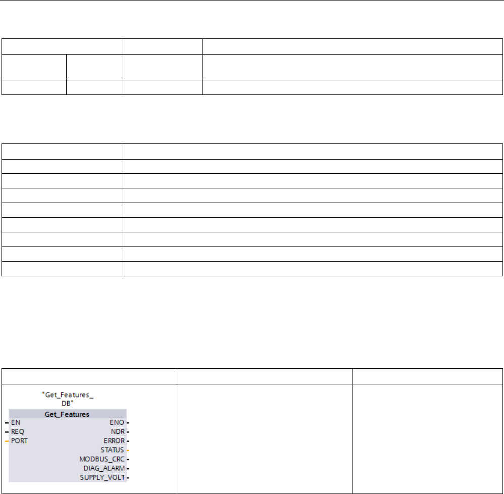
Communication processor and Modbus TCP
13.3 Point-to-point (PtP) communication
S7-1200 Programmable controller
System Manual, V4.2, 09/2016, A5E02486680-AK 1131
Parameter and type
Data type
Description
ERROR OUT Bool TRUE for one execution after the last request was completed with an
error
STATUS OUT Word Execution condition code (Default value: 0)
Table 13- 36 Condition codes
STATUS (W#16#....)
Description
81F0
CM or CB is RS485 and no signals can be set
81F1
Signals cannot be set because of Hardware flow control
81F2
Cannot set DSR because module is DTE
81F3
Cannot set DTR because module is DCE
81F4
Error in the block header, for example, wrong block type or wrong block length
8280
Negative acknowledgement while reading the module
8281
Negative acknowledgement while writing the module
8282
DP slave or module not available
13.3.5.11
Get_Features
Table 13- 37 Get_Features (Get advanced features) instruction
LAD / FBD
SCL
Description
"Get_Features_DB"(
REQ:=_bool_in_,
PORT:=_word_in_,
NDR:=_bool_out_,
ERROR=>_bool_out_,
STATUS=>_word_out_,
MODBUS_CRC=>_bool_out_,
DIAG_ALARM=>_bool_out_,
SUPPLY_VOLT=>_bool_out);
Get_Features performs reads the
advanced feature capabilities of a
moduler.
1 STEP 7 automatically creates the DB when you insert the instruction.
Use the Get_Features instruction to read the advanced feature capabilites of a module.
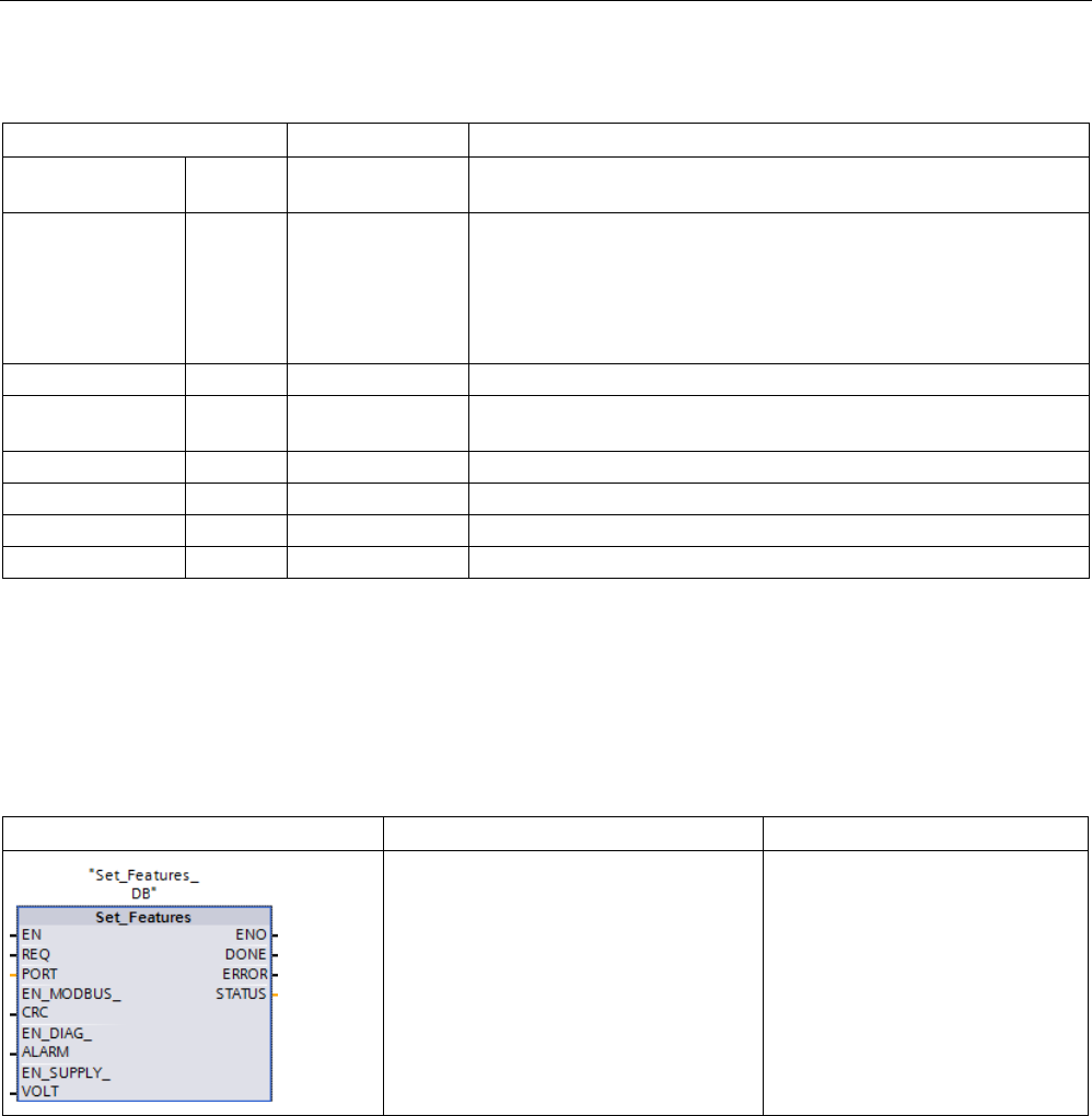
Communication processor and Modbus TCP
13.3 Point-to-point (PtP) communication
S7-1200 Programmable controller
1132 System Manual, V4.2, 09/2016, A5E02486680-AK
Table 13- 38 Data types for the parameters
Parameter and type
Data type
Description
REQ IN Bool Activate the configuration change on the rising edge of this input.
(Default value: False)
PORT IN PORT After you install and configure a CM or CB communication device,
the port identifier appears in the parameter helper drop-list available
at the PORT box connection. The assigned CM or CB port value is
the device configuration property "hardware identifier". The port sym-
bolic name is assigned in the "System constants" tab of the PLC tag
table. (Default value: 0)
NDR
OUT
Bool
Indicates that new data is ready.
ERROR OUT Bool TRUE for one scan, after the last request was completed with an
error
STATUS
OUT
Word
Execution condition code (Default value: 0)
MODBUS_CRC*
OUT
Bool
MODBUS CRC generation and checking
DIAG_ALARM*
OUT
Bool
Diagnostic alarm generation
SUPPLY_VOLT*
OUT
Bool
Diagnostics for missing supply voltage L+ is available
*Get_Features returns TRUE (1) if the feature is available, FALSE (0) if the feature is not available
13.3.5.12
Set_Features
Table 13- 39 Set_Features (Set advanced features) instruction
LAD / FBD
SCL
Description
"Set_Features_DB"(
REQ:=_bool_in_,
PORT:=_word_in_,
EN_MODBUS_CRC:=_bool_in_,
EN_DIAG_ALARM:=_bool_in_,
EN_SUPPLY_VOLT:=_bool_in_,
DONE=>_bool_out_,
ERROR=>_bool_out_,
STATUS=>_word_out_);
Set_Features enables the ad-
vanced features that a module
supports.
1 STEP 7 automatically creates the DB when you insert the instruction.
Use the Set_Features instruction to read the advanced feature capabilites of a module.

Communication processor and Modbus TCP
13.3 Point-to-point (PtP) communication
S7-1200 Programmable controller
System Manual, V4.2, 09/2016, A5E02486680-AK 1133
Table 13- 40 Data types for the parameters
Parameter and type
Data type
Description
REQ IN Bool Activate the configuration change on the rising edge of this input.
(Default value: False)
PORT IN PORT After you install and configure a CM or CB communication device,
the port identifier appears in the parameter helper drop-list available
at the PORT box connection. The assigned CM or CB port value is
the device configuration property "hardware identifier". The port sym-
bolic name is assigned in the "System constants" tab of the PLC tag
table. (Default value: 0)
EN_MODBUS_CRC IN Bool Enable MODBUS CRC generation and checking:
• 0: CRC calculation tuned OFF (default)
• 1: CRC calculation turned ON
Note: Only V2.1 CMs, V4.1 CPUs with CBs, and CM PtP modules for
distributed I/O support this parameter.
EN_DIAG_ALARM IN Bool Enable diagnostic alarm generation:
• 0: Diagnostic alarm turned OFF
• 1: Diagnostic alarm turned ON (default)
EN_SUPPLY_VOLT IN Bool Enable diagnostics for missing supply voltage L+:
• 0: Supply voltage diagnostic disabled (default)
• 1: Supply voltage diagnostic enabled
DONE
OUT
Bool
Indicates that set features is done
ERROR OUT Bool TRUE for one scan, after the last request was completed with an
error
STATUS
OUT
Word
Execution condition code (Default value: 0)

Communication processor and Modbus TCP
13.3 Point-to-point (PtP) communication
S7-1200 Programmable controller
1134 System Manual, V4.2, 09/2016, A5E02486680-AK
13.3.6
Programming the PtP communications
STEP 7 provides extended instructions that enable the user program to perform Point-to-
Point communications with a protocol designed and implemented in the user program. These
instructions fall into two categories:
● Configuration instructions
● Communication instructions
Configuration instructions
Before your user program can engage in PtP communication, you must configure the
communication interface port and the parameters for sending data and receiving data.
You can perform the port configuration and message configuration for each CM or CB
through the device configuration or through these instructions in your user program:
● Port_Config (Page 1110)
● Send_Config (Page 1112)
● Receive_Config (Page 1115)
Communication instructions
The PtP communication instructions enable the user program to send messages to and
receive messages from the communication interfaces. For information about transferring
data with these instructions, see the section on data consistency (Page 198).
All of the PtP functions operate asynchronously. The user program can use a polling
architecture to determine the status of transmissions and receptions. Send_P2P and
Receive_P2P can execute concurrently. The communication modules and communication
board buffer the transmit and receive messages as necessary up to a maximum buffer size
of 1024 bytes.
The CMs and CB send messages to and receive messages from the actual point-to-point
devices. The message protocol is in a buffer that is either received from or sent to a specific
communication port. The buffer and port are parameters of the send and receive
instructions:
● Send_P2P (Page 1122)
● Receive_P2P (Page 1126)
Additional instructions provide the capability to reset the receive buffer, and to get and set
specific RS232 signals:
● Receive_Reset (Page 1128)
● Signal_Get (Page 1129)
● Signal_Set (Page 1130)

Communication processor and Modbus TCP
13.3 Point-to-point (PtP) communication
S7-1200 Programmable controller
System Manual, V4.2, 09/2016, A5E02486680-AK 1135
13.3.6.1
Polling architecture
The STEP 7 user program must call the S7-1200 point-to-point instructions
cyclically/periodically to check for received messages. Polling the send tells the user
program when the transmit has completed.
Polling architecture: master
The typical sequence for a master is as follows:
1. A Send_P2P (Page 1122) instruction initiates a transmission to the CM or CB.
2. The Send_P2P instruction executes on subsequent scans to poll for the transmit
complete status.
3. When the Send_P2P instruction indicates that the transmission is complete, the user
code can prepare to receive the response.
4. The Receive_P2P (Page 1126) instruction executes repeatedly to check for a response.
When the CM or CB has collected a response message, the Receive_P2P instruction
copies the response to the CPU and indicates that new data has been received.
5. The user program can process the response.
6. Go to step 1 and repeat the cycle.
Polling architecture: slave
The typical sequence for a slave is as follows:
1. The user program executes the Receive_P2P instruction every scan.
2. When the CM or CB has received a request, the Receive_P2P instruction indicates that
new data is ready and the request is copied into the CPU.
3. The user program services the request and generates a response.
4. Use a Send_P2P instruction to send the response back to the master.
5. Repeatedly execute Send_P2P to be sure the transmit occurs.
6. Go to step 1 and repeat the cycle.
The slave must be responsible for calling Receive_P2P frequently enough to receive a
transmission from the master before the master times out while waiting for a response. To
accomplish this task, the user program can call RCV_PTP from a cyclic OB, where the cycle
time is sufficient to receive a transmission from the master before the timeout period expires.
If you set the cycle time for the OB to provide for two executions within the timeout period of
the master, the user program can receive transmissions without missing any.
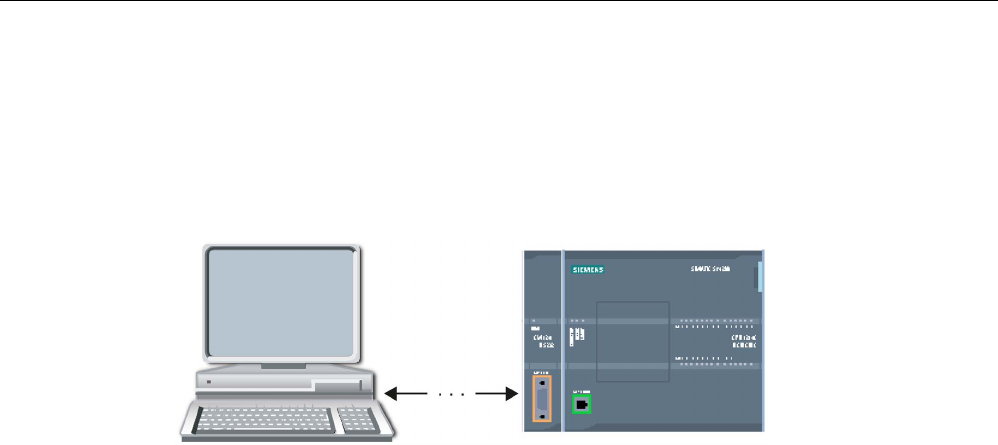
Communication processor and Modbus TCP
13.3 Point-to-point (PtP) communication
S7-1200 Programmable controller
1136 System Manual, V4.2, 09/2016, A5E02486680-AK
13.3.7
Example: Point-to-Point communication
In this example, an S7-1200 CPU communicates to a PC with a terminal emulator through a
CM 1241 RS232 module. The point-to-point configuration and STEP 7 program in this
example illustrate how the CPU can receive a message from the PC and echo the message
back to the PC.
You must connect the communication interface of the CM 1241 RS232 module to the RS232
interface of the PC, which is normally COM1. Because both of these ports are Data Terminal
Equipment (DTE), you must switch the receive and transmit pins (2 and 3) when connecting
the two ports, which you can accomplish by either of the following methods:
● Use a NULL modem adapter to swap pins 2 and 3 together with a standard RS232 cable.
● Use a NULL modem cable, which already has pins 2 and 3 swapped. You can usually
identify a NULL modem cable as one with two female 9-pin D connector ends.
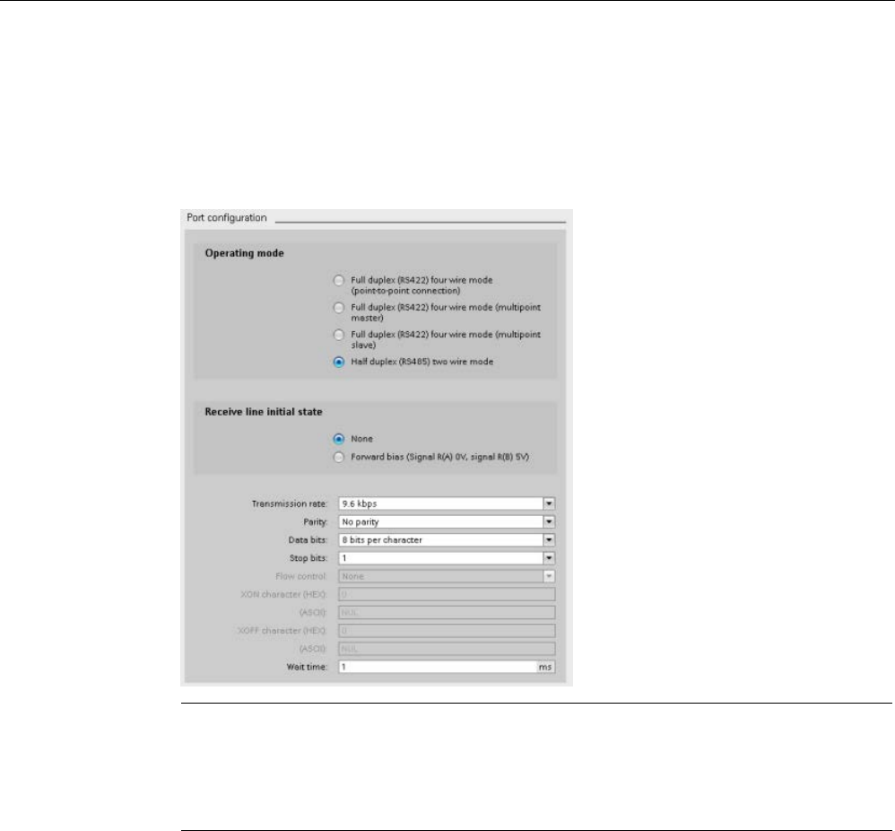
Communication processor and Modbus TCP
13.3 Point-to-point (PtP) communication
S7-1200 Programmable controller
System Manual, V4.2, 09/2016, A5E02486680-AK 1137
13.3.7.1
Configuring the communication module
You can configure the CM 1241 from the Device configuration in STEP 7 or with user
program instructions. This example uses the Device configuration method.
● Port configuration: Click the communication port of the CM module from the Device
configuration, and configure the port as shown:
Note
The configuration settings for "Operating mode" and "Receive line initial state" are only
applicable for the CM
1241 (RS422/RS485) module. The other CM 1241 modules do not
have these port
configuration settings. Refer to Configuring the RS422 and RS485
(Page
1140).
● Transmit message configuration: Accept the default for transmit message configuration.
No break is to be sent at message start.
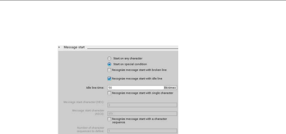
Communication processor and Modbus TCP
13.3 Point-to-point (PtP) communication
S7-1200 Programmable controller
1138 System Manual, V4.2, 09/2016, A5E02486680-AK
● Receive message start configuration: Configure the CM 1241 to start receiving a
message when the communication line is inactive for at least 50 bit times (about 5
milliseconds at 9600 baud = 50 * 1/9600):

Communication processor and Modbus TCP
13.3 Point-to-point (PtP) communication
S7-1200 Programmable controller
System Manual, V4.2, 09/2016, A5E02486680-AK 1139
● Receive message end configuration: Configure the CM 1241 to end a message when it
receives a maximum of 100 bytes or a linefeed character (10 decimal or a hexadecimal).
The end sequence allows up to five end characters in sequence. The fifth character in the
sequence is the linefeed character. The preceding four end sequence characters are
"don’t care" or unselected characters. The CM 1241 does not evaluate the "don’t care"
characters but looks for a linefeed character preceded by zero or more "don’t care"
characters to indicate the message end.

Communication processor and Modbus TCP
13.3 Point-to-point (PtP) communication
S7-1200 Programmable controller
1140 System Manual, V4.2, 09/2016, A5E02486680-AK
13.3.7.2
RS422 and RS485 operating modes
Configuring the RS422
For RS422 mode, there are three operating modes depending on your network configuration.
Select one of these operating modes based on the devices in your network. The different
selections for Receive line initial state reference the cases shown below for more details.
● Full duplex (RS422) four wire mode (point-to-point connection): select this option when
there are two devices on your network. In the Receive line initial state:
– Select none when you supply the bias and termination (Case 3).
– Select forward bias to use internal bias and termination (Case 2).
– Select reverse bias to use internal bias and termination, and enable cable break
detection for both devices (Case 1).
● Full duplex (RS422) four wire mode (multipoint master): select this option for the master
device when you have a network with one master and multiple slaves. In the Receive line
initial state:
– Select none when you supply the bias and termination (Case 3).
– Select forward bias to use internal bias and termination (Case 2).
– Cable break detection is not possible in this mode.
● Full duplex (RS422) four wire mode (multipoint slave): Select this option for all the slave
devices when you have a network with one master and multiple slaves. In the Receive
line initial state:
– Select none when you supply the bias and termination (Case 3).
– Select forward bias to use internal bias and termination (Case 2).
– Select reverse bias to use internal bias and termination, and enable cable break
detection for the slaves (Case 1).
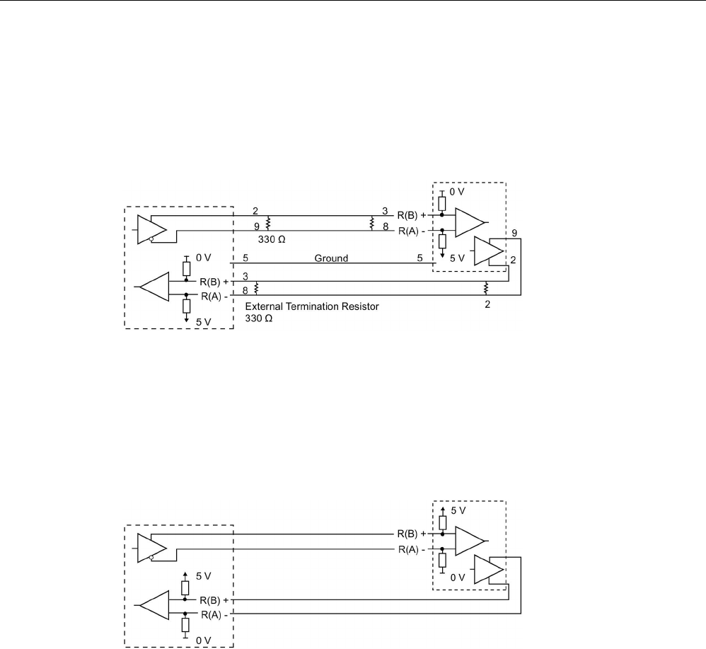
Communication processor and Modbus TCP
13.3 Point-to-point (PtP) communication
S7-1200 Programmable controller
System Manual, V4.2, 09/2016, A5E02486680-AK 1141
Case 1: RS422 with cable break detection
● Mode of operation: RS422
● Receive line initial state: Reverse bias (biased with R(A) > R(B) > 0V)
● Cable break: Cable break detection enabled (transmitter always active)
Case 2: RS422 No cable break detection, forward bias
● Mode of operation: RS422
● Receive line initial state: Forward bias (biased with R(B) > R(A) > 0 V)
● Cable break: No cable break detection (transmitter enabled only while transmitting)
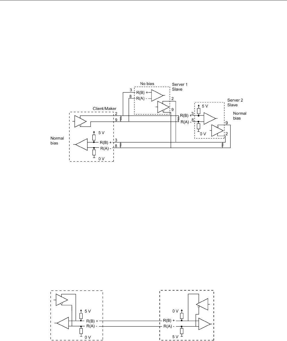
Communication processor and Modbus TCP
13.3 Point-to-point (PtP) communication
S7-1200 Programmable controller
1142 System Manual, V4.2, 09/2016, A5E02486680-AK
Case 3: RS422: No cable break detection, no bias
● Mode of operation: RS422
● Receive line initial state: no bias
● Cable break: No cable break detection (transmitter enabled only while transmitting)
Bias and termination are added by the user at the end nodes of the network.
Configuring the RS485
For RS485 mode, there is only one operating mode. The different selections for Receive line
initial state reference the cases shown below for more details.
● Half duplex (RS485) two wire mode. In the Receive line initial state:
– Select none when you supply the bias and termination (Case 5).
– Select forward bias to use internal bias and termination (Case 4).
Case 4: RS485: Forward bias
● Mode of operation: RS485
● Receive line initial state: Forward bias (biased with R(B) > R(A) > 0 V)
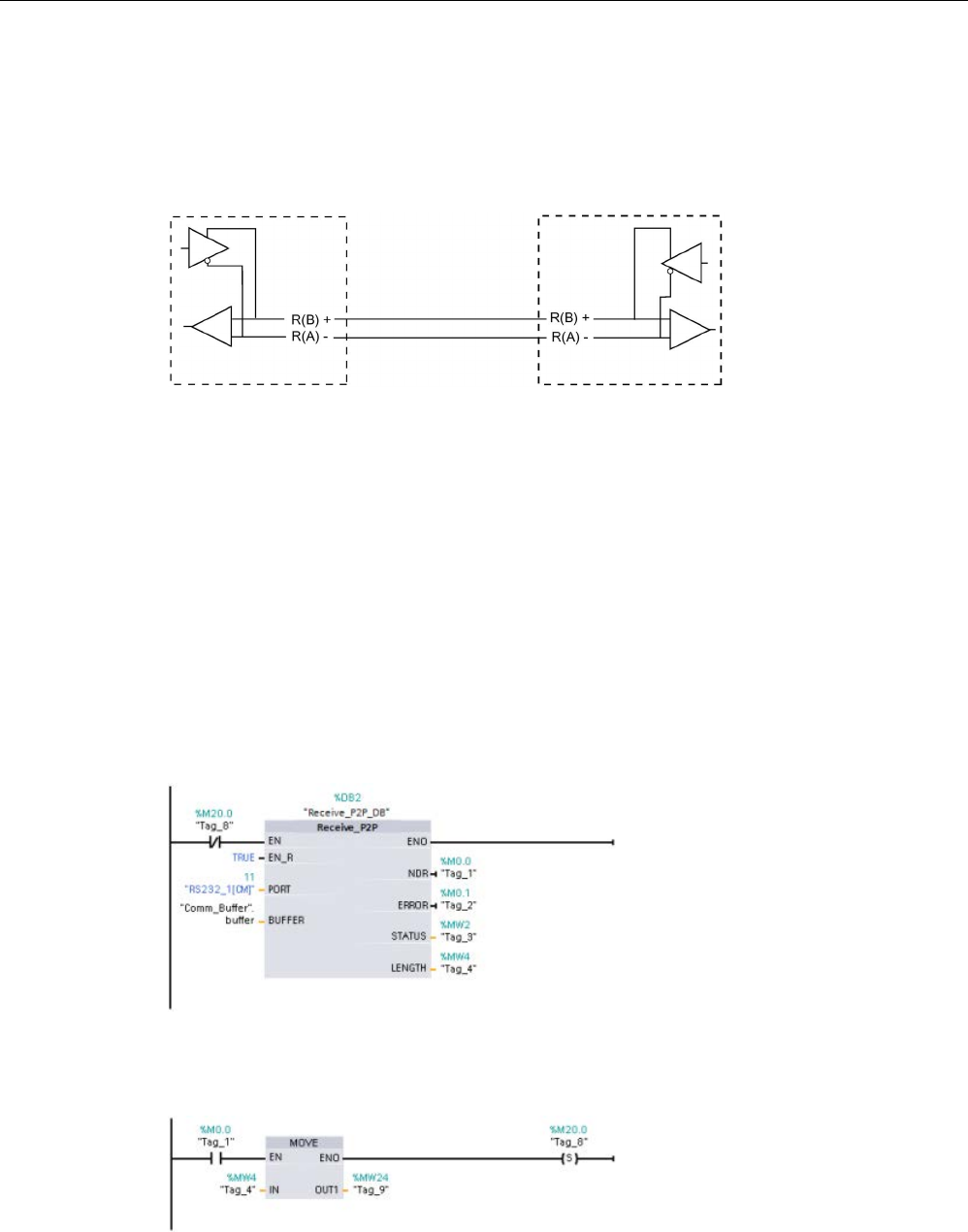
Communication processor and Modbus TCP
13.3 Point-to-point (PtP) communication
S7-1200 Programmable controller
System Manual, V4.2, 09/2016, A5E02486680-AK 1143
Case 5: RS485: No bias (external bias)
● Mode of operation: RS485
● Receive line initial state: No bias (external bias required)
13.3.7.3
Programming the STEP 7 program
The example program uses a global data block for the communication buffer, a RCV_PTP
instruction (Page 1229) to receive data from the terminal emulator, and a SEND_PTP
instruction (Page 1226) to echo the buffer back to the terminal emulator. To program the
example, add the data block configuration and Main program block OB 1 as described
below.
Global data block "Comm_Buffer":
Create a global data block (DB) and name it
"Comm_Buffer". Create one value in the data block called "buffer" with a data type of "array
[0 .. 99] of byte".
Network 1:
Enable the RCV_PTP instruction whenever SEND_PTP is not active. Tag_8 at
MW20.0 indicates when sending is complete in Network 4, and when the communication
module is thus ready to receive a message.
Network 2:
Use the NDR value (Tag_1 at M0.0) set by the RCV_PTP instruction to make a
copy of the number of bytes received and to set a flag (Tag_8 at M20.0) to trigger the
SEND_PTP instruction.
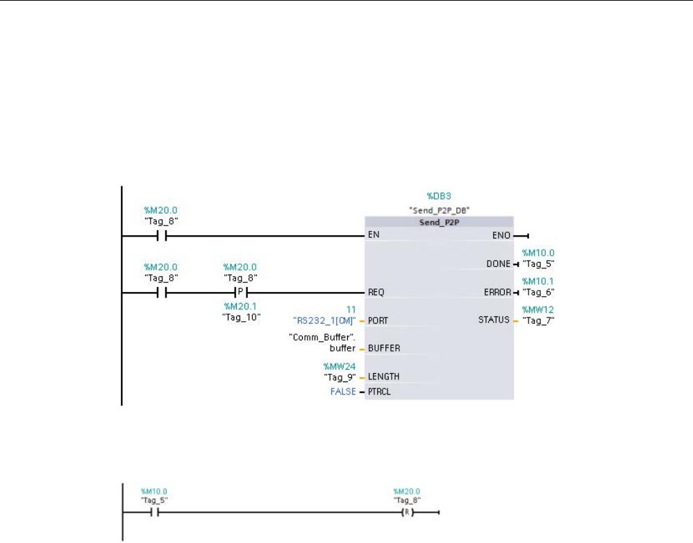
Communication processor and Modbus TCP
13.3 Point-to-point (PtP) communication
S7-1200 Programmable controller
1144 System Manual, V4.2, 09/2016, A5E02486680-AK
Network 3:
Enable the SEND_PTP instruction when the M20.0 flag is set. Also use this flag
to set the REQ input to TRUE for one scan. The REQ input tells the SEND_PTP instruction
that a new request is to be transmitted. The REQ input must only be set to TRUE for one
execution of SEND_PTP. The SEND_PTP instruction is executed every scan until the
transmit completes. The transmit is complete when the last byte of the message has been
transmitted from the CM 1241. When the transmit is complete, the DONE output (Tag_5 at
M10.0) is set TRUE for one execution of SEND_PTP.
Network 4:
monitor the DONE output of SEND_PTP and reset the transmit flag (Tag_8 at
M20.0) when the transmit operation is complete. When the transmit flag is reset, the
RCV_PTP instruction in Network 1 is enabled to receive the next message.

Communication processor and Modbus TCP
13.3 Point-to-point (PtP) communication
S7-1200 Programmable controller
System Manual, V4.2, 09/2016, A5E02486680-AK 1145
13.3.7.4
Configuring the terminal emulator
You must set up the terminal emulator to support the example program. You can use most
any terminal emulator on your PC, such as HyperTerminal. Make sure that the terminal
emulator is in the disconnected mode before editing the settings as follows:
1. Set the terminal emulator to use the RS232 port on the PC (normally COM1).
2. Configure the port for 9600 baud, 8 data bits, no parity (none), 1 stop bit and no flow
control.
3. Change the settings of the terminal emulator to emulate an ANSI terminal.
4. Configure the terminal emulator ASCII setup to send a line feed after every line (after the
user presses the Enter key).
5. Echo the characters locally so that the terminal emulator displays what is typed.
13.3.7.5
Running the example program
To exercise the example program, follow these steps:
1. Download the STEP 7 program to the CPU and ensure that it is in RUN mode.
2. Click the "connect" button on the terminal emulator to apply the configuration changes
and open a terminal session to the CM 1241.
3. Type characters at the PC and press Enter.
The terminal emulator sends the characters to the CM 1241 and to the CPU. The CPU
program then echoes the characters back to the terminal emulator.
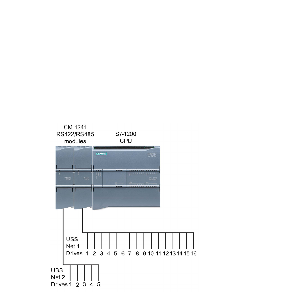
Communication processor and Modbus TCP
13.4 Universal serial interface (USS) communication
S7-1200 Programmable controller
1146 System Manual, V4.2, 09/2016, A5E02486680-AK
13.4
Universal serial interface (USS) communication
The USS instructions control the operation of motor drives which support the universal serial
interface (USS) protocol. You can use the USS instructions to communicate with multiple
drives through RS485 connections to CM 1241 RS485 communication modules or a CB
1241 RS485 communication board. Up to three CM 1241 RS422/RS485 modules and one
CB 1241 RS485 board can be installed in a S7-1200 CPU. Each RS485 port can operate up
to sixteen drives.
The USS protocol uses a master-slave network for communications over a serial bus. The
master uses an address parameter to send a message to a selected slave. A slave itself can
never transmit without first receiving a request to do so. Direct message transfer between
the individual slaves is not possible. USS communication operates in half-duplex mode. The
following USS illustration shows a network diagram for an example drive application.

Communication processor and Modbus TCP
13.4 Universal serial interface (USS) communication
S7-1200 Programmable controller
System Manual, V4.2, 09/2016, A5E02486680-AK 1147
USS communications through PROFIBUS or PROFINET
As of version V4.1 of the S7-1200 CPU together with STEP 7 V13 SP1, the CPU extends the
capability of USS to use a PROFINET or PROFIBUS distributed I/O rack to communicate to
various devices (RFID readers, GPS device, and others):
● PROFINET (Page 804): You connect the Ethernet interface of the S7-1200 CPU to a
PROFINET interface module. PtP communication modules in the rack with the interface
module can then provide serial communications to the PtP devices.
● PROFIBUS (Page 968): You insert a PROFIBUS communication module in the left side
of the rack with the S7-1200 CPU. You connect the PROFIBUS communication module
to a rack containing a PROFIBUS interface module. PtP communication modules in the
rack with the interface module can then provide serial communications to the PtP
devices.
For this reason, the S7-1200 supports two sets of PtP instructions:
● Legacy USS instructions (Page 1239): These USS instructions existed prior to version
V4.0 of the S7-1200 and only work with serial communications using a CM 1241
communication module or CB 1241 communication board.
● USS instructions (Page 1153): These USS instructions provide all of the functionality of
the legacy instructions, plus the ability to connect to PROFINET and PROFIBUS
distributed I/O. These USS instructions allow you to configure the communications
between the PtP communication modules in the distributed I/O rack and the PtP devices.
S7-1200 CM 1241 modules must have a minimum firmware version of V2.1 to use these
USS instructions.
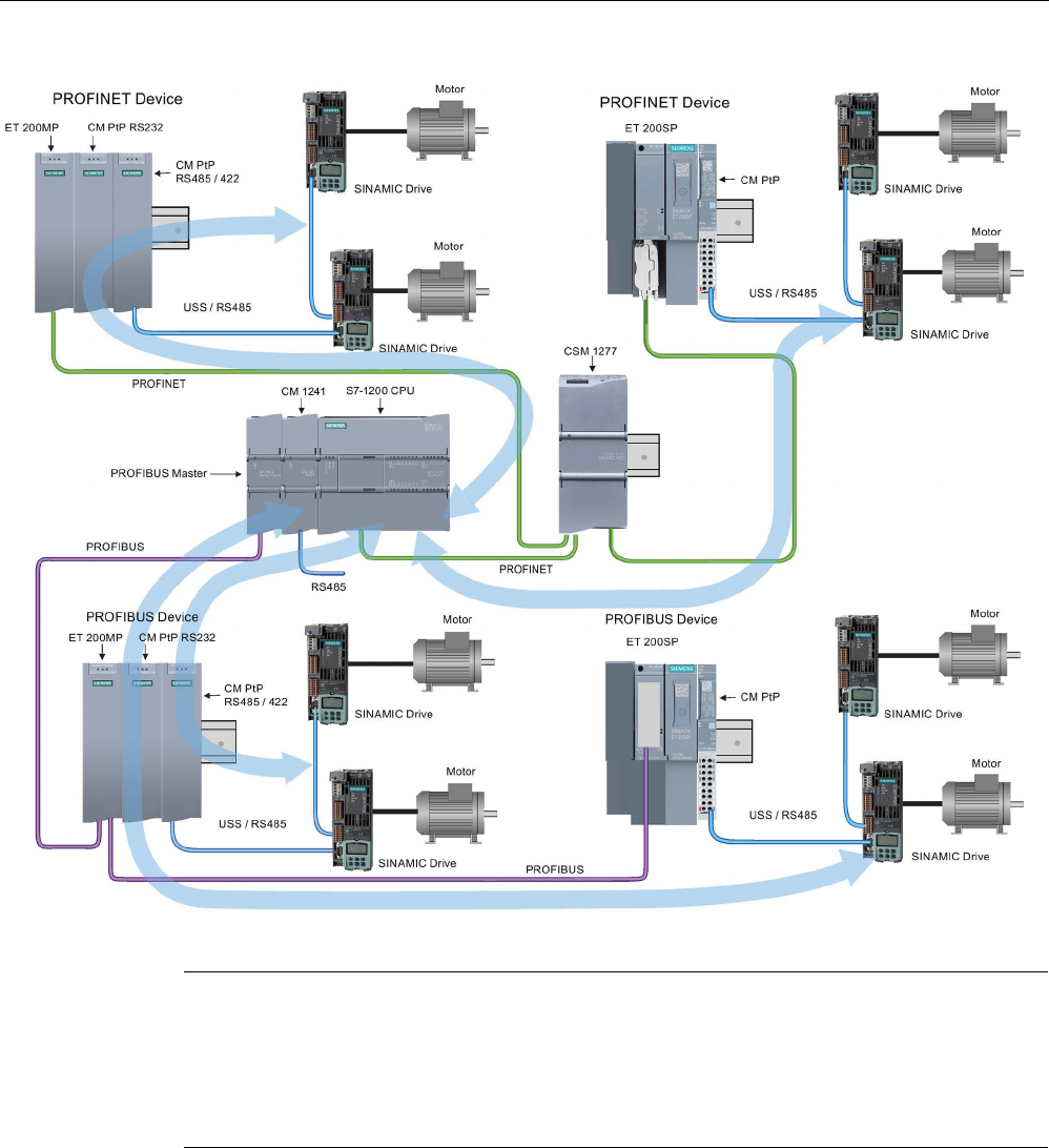
Communication processor and Modbus TCP
13.4 Universal serial interface (USS) communication
S7-1200 Programmable controller
1148 System Manual, V4.2, 09/2016, A5E02486680-AK
The blue arrows indicate the flow of bidirectional communication between devices.
Note
With version V4.1 of the S7
-1200, you can use the point-to-point instructions for all types of
point
-to-point communication: serial, serial over PROFINET, and serial over PROFIBUS.
STEP 7 pro
vides the legacy point-to-
point instructions only to support existing programs. The
legacy instructions still function with all S7
-1200 CPUs. You do not have to convert prior
programs from one set of instructions to the other.
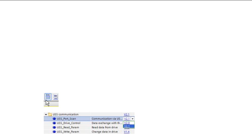
Communication processor and Modbus TCP
13.4 Universal serial interface (USS) communication
S7-1200 Programmable controller
System Manual, V4.2, 09/2016, A5E02486680-AK 1149
13.4.1
Selecting the version of the USS instructions
There are two versions of USS instructions available in STEP 7:
● Version 2.0 (legacy instructions) was initially available in STEP 7 Basic/Professional V13.
● Version 2.1 is available in STEP 7 Basic/Professional V13 SP1 or later.
For compatibility and ease of migration, you can choose which instruction version to insert
into your user program.
You cannot use both versions of the instructions with the same module, but two different
modules can use different versions of the instructions.
Click the icon on the instruction tree task card to enable the headers and columns
of the instruction tree.
To change the version of the USS instru
c-
tions, select the version from the drop
-down
list. You can select the group or individual
instructions.
When you use the instruction tree to place a USS instruction in your program, a new FB or
FC instance, depending on the USS instruction selected, is created in the project tree. You
can see new FB or FC instance in the project tree under PLC_x > Program blocks > System
blocks > Program resources.
To verify the version of a USS instruction in a program, you must inspect project tree
properties and not the properties of a box displayed in the program editor. Select a project
tree USS FB or FC instance, right-click, select "Properties", and select the "Information"
page to see the USS instruction version number.
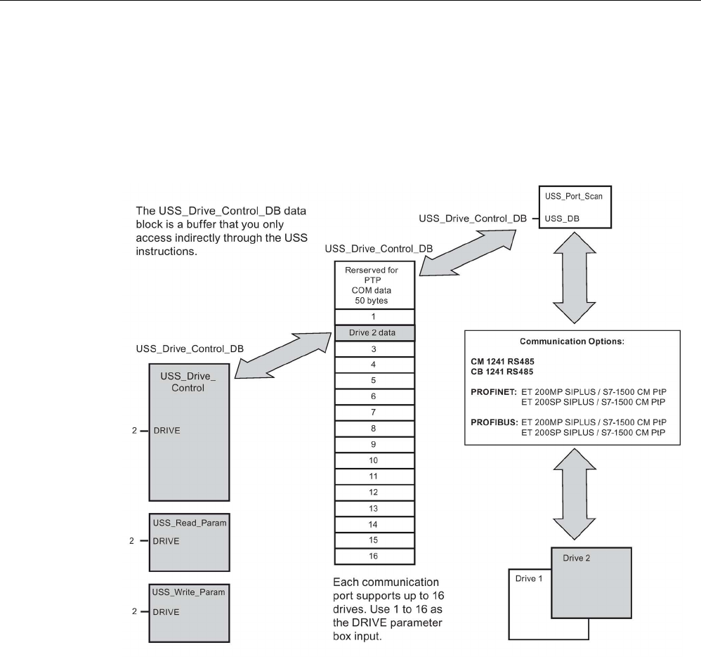
Communication processor and Modbus TCP
13.4 Universal serial interface (USS) communication
S7-1200 Programmable controller
1150 System Manual, V4.2, 09/2016, A5E02486680-AK
13.4.2
Requirements for using the USS protocol
The four USS instructions use two function blocks (FBs) and two functions (FCs) to support
the USS protocol. One USS_Port_Scan instance data block (DB) is used for each USS
network. The USS_Port_Scan instance data block contains temporary storage and buffers
for all drives on that USS network. The USS instructions share the information in this data
block.
All drives (up to 16) connected to a single RS485 port are part of the same USS network. All
drives connected to a different RS485 port are part of a different USS network. Each USS
network is managed using a unique data block. All instructions associated with a single USS
network must share this data block. This includes all USS_Drive_Control, USS_Port_Scan,
USS_Read_Param, and USS_Write_Param instructions used to control all drives on a single
USS network.
The USS_Drive_Control instruction is a Function Block (FB). When you place the
USS_Drive_Control instruction into the program editor, you will be prompted by the "Call
options" dialog to assign a DB for this FB. If this is the first USS_Drive_Control instruction in
this program for this USS network, then you can accept the default DB assignment (or
change the name if you wish) and the new DB is created for you. If however this is not the
first USS_Drive_Control instruction for this channel, then you must use the drop-down list in
the "Call options" dialog to select the DB name that was previously assigned for this USS
network.

Communication processor and Modbus TCP
13.4 Universal serial interface (USS) communication
S7-1200 Programmable controller
System Manual, V4.2, 09/2016, A5E02486680-AK 1151
The USS_Port_Scan instruction is a Function Block (FB) and handles the actual
communication between the CPU and the drives through the Point-to-Point (PtP) RS485
communication port. Each call to this FB handles one communication with one drive. Your
program must call this FB fast enough to prevent a communication timeout by the drives.
You may call this function FB in a main program cycle OB or any interrupt OB.
The USS_Read_Param, and USS_Write_Param instructions are both Functions (FCs). No
DB is assigned when you place these FCs in the editor. Instead, you must assign the
appropriate DB reference to the "USS_DB" input of these instructions. Double-click on the
parameter field and then click on the parameter helper icon to see the available DB names).
Typically, you should call the USS_Port_Scan FB from a cyclic interrupt OB. The cycle time
of the cyclic interrupt OB should be set to about half of the minimum call interval (As an
example, 1200 baud communication should use a cyclic time of 350 ms or less).
The USS_Drive_Control FB provides your program access to a specified drive on the USS
network. Its inputs and outputs are the status and controls for the drive. If there are 16 drives
on the network, your program must have at least 16 USS_Drive_Control calls, one for each
drive. These blocks should be called at the rate that is required to control the operation of the
drive.
You may only call the USS_Drive_Control FB from a main program cycle OB.
CAUTION
Considerations in calling USS instructions from OBs
Only call USS_Drive_Control, USS_Read_Param, and USS_Write_Param from a main
program cycle OB. The USS_Port_Scan FB can be called from any OB, usually from a
cyclic interrupt OB.
Do not use instructions USS_Drive_Control, USS_Read_Param, and USS_Write_Param in
a higher priority OB than the corresponding USS_Port_Scan instruction. For example, do
not place the USS_Port_Scan in the main OB and a USS_Read_Param in a cyclic interrupt
OB. Failure to prevent interruption of USS_Port_Scan execution can produce unexpected
errors, which could result in personal injury.
The USS_Read_Param, and USS_Write_Param FCs read and write the remote drive
operating parameters. These parameters control the internal operation of the drive. See the
drive manual for the definition of these parameters. Your program can contain as many of
these functions as necessary, but only one read or write request can be active per drive, at
any given time. You may only call the USS_Read_Param, and USS_Write_Param FCs from
a main program cycle OB.

Communication processor and Modbus TCP
13.4 Universal serial interface (USS) communication
S7-1200 Programmable controller
1152 System Manual, V4.2, 09/2016, A5E02486680-AK
Calculating the time required for communicating with the drive
Communications with the drive are asynchronous to the S7-1200 scan cycle. The S7-1200
typically completes several scans before one drive communications transaction is
completed.
The USS_Port_Scan interval is the time required for one drive transaction. The table below
shows the minimum USS_Port_Scan interval for each communication baud rate. Calling the
USS_Port_Scan FB more frequently than the USS_Port_Scan interval will not increase the
number of transactions. The drive timeout interval is the amount of time that might be taken
for a transaction, if communications errors caused 3 tries to complete the transaction. By
default, the USS protocol library automatically does up to 2 retries on each transaction.
Table 13- 41 Calculating the time requirements
Baud rate
Calculated minimum USS_Port_Scan call
Interval ( milliseconds )
Drive message interval timeout per
drive ( milliseconds )
1200
790
2370
2400 405 1215
4800
212.5
638
9600 116.3 349
19200
68.2
205
38400
44.1
133
57600
36.1
109
115200
28.1
85
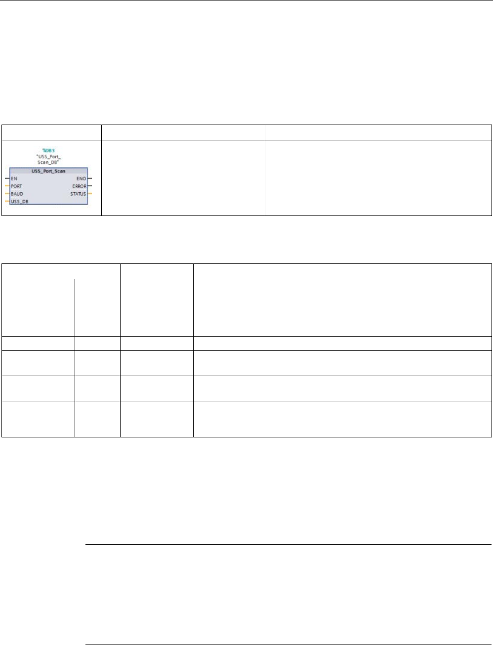
Communication processor and Modbus TCP
13.4 Universal serial interface (USS) communication
S7-1200 Programmable controller
System Manual, V4.2, 09/2016, A5E02486680-AK 1153
13.4.3
USS instructions
13.4.3.1
USS_Port_Scan (Edit communication using USS network)
Table 13- 42 USS_Port_Scan instruction
LAD / FBD
SCL
Description
USS_Port_Scan(
PORT:=_uint_in_,
BAUD:=_dint_in_,
ERROR=>_bool_out_,
STATUS=>_word_out_,
USS_DB:=_fbtref_inout_);
The USS_Port_Scan instruction handles communica-
tion over a USS network.
Table 13- 43 Data types for the parameters
Parameter and type
Data type
Description
PORT IN Port After you install and configure a CM or CB communication device, the
port identifier appears in the parameter helper drop-list available at the
PORT box connection. The assigned CM or CB port value is the device
configuration property "hardware identifier". The port symbolic name is
assigned in the "System constants" tab of the PLC tag table.
BAUD
IN
DInt
The baud rate used for USS communication.
USS_DB INOUT USS_BASE The name of the instance DB that is created and initialized when a
USS_Drive_Control instruction is placed in your program.
ERROR OUT Bool When true, this output indicates that an error has occurred and the
STATUS output is valid.
STATUS OUT Word The status value of the request indicates the result of the scan or initiali-
zation. Additional information is available in the "USS_Extended_Error"
variable for some status codes.
Typically, there is only one USS_Port_Scan instruction per PtP communication port in the
program, and each call of this Function Block (FB) handles a transmission to or from a single
drive. All USS functions associated with one USS network and PtP communication port must
use the same instance DB.
Your program must execute the USS_Port_Scan instruction often enough to prevent drive
timeouts. USS_Port_Scan is usually called from a cyclic interrupt OB to prevent drive
timeouts and keep the most recent USS data updates available for USS_Drive_Control calls.
Note
When using the USS protocol library and the USS_Port_Scan instruction with a CB 1241,
you must set the LINE_PRE data block tag to a value of 0 (No initial state). The default value
of 2 for the LINE_PRE data block tag results
in an error value of 16#81AB being returned by
the USS_Port_Scan instruction. The LINE_PRE data block tag is found in the data block
associated with the USS_Port_Scan instruction (usually named USS_Port_Scan_DB).
Ensure the start value of LINE_PRE is cha
nged to a 0 (zero).

Communication processor and Modbus TCP
13.4 Universal serial interface (USS) communication
S7-1200 Programmable controller
1154 System Manual, V4.2, 09/2016, A5E02486680-AK
13.4.3.2
USS_Drive_Control (Swap data with drive)
Table 13- 44 USS_Drive_Control instruction
LAD / FBD
SCL
Description
"USS_Drive_Control_DB"(
RUN:=_bool_in_,
OFF2:=_bool_in_,
OFF3:=_bool_in_,
F_ACK:=_bool_in_,
DIR:=_bool_in_,
DRIVE:=_usint_in_,
PZD_LEN:=_usint_in_,
SPEED_SP:=_real_in_,
CTRL3:=_word_in_,
CTRL4:=_word_in_,
CTRL5:=_word_in_,
CTRL6:=_word_in_,
CTRL7:=_word_in_,
CTRL8:=_word_in_,
NDR=>_bool_out_,
ERROR=>_bool_out_,
STATUS=>_word_out_,
RUN_EN=>_bool_out_,
D_DIR=>_bool_out_,
INHIBIT=>_bool_out_,
FAULT=>_bool_out_,
SPEED=>_real_out_,
STATUS1=>_word_out_,
STATUS3=>_word_out_,
STATUS4=>_word_out_,
STATUS5=>_word_out_,
STATUS6=>_word_out_,
STATUS7=>_word_out_,
STATUS8=>_word_out_);
The USS_Drive_Control instruction exchanges data
with a drive by creating request messages and inter-
preting the drive response messages. A separate func-
tion block should be used for each drive, but all USS
functions associated with one USS network and PtP
communication port must use the same instance data
block. You must create the DB name when you place
the first USS_Drive_Control instruction and then refer-
ence the DB that was created by the initial instruction
usage.
STEP 7 automatically creates the DB when you insert
the instruction.
1
LAD and FBD: Expand the box to reveal all the parameters by clicking the bottom of the box. The parameter pins that
are grayed are optional and parameter assignment is not required.

Communication processor and Modbus TCP
13.4 Universal serial interface (USS) communication
S7-1200 Programmable controller
System Manual, V4.2, 09/2016, A5E02486680-AK 1155
Table 13- 45 Data types for the parameters
Parameter and type
Data type
Description
RUN IN Bool Drive start bit: When true, this input enables the drive to run at the
preset speed. When RUN goes to false while a drive is running, the
motor will be ramped down to a stop. This behavior differs from the
dropping power (OFF2) or braking the motor (OFF3).
OFF2 IN Bool Electrical stop bit: When false, this bit causes the drive to coast to a
stop with no braking.
OFF3 IN Bool Fast stop bit: When false, this bit causes a fast stop by braking the
drive rather than just allowing the drive to coast to a stop.
F_ACK IN Bool Fault acknowledge bit: This bit is set to reset the fault bit on a drive.
The bit is set after the fault is cleared to indicate to the drive it no longer
needs to indicate the previous fault.
DIR IN Bool Drive direction control: This bit is set to indicate that the direction is
forward (for positive SPEED_SP).
DRIVE IN USInt Drive address: This input is the address of the USS drive. The valid
range is drive 1 to drive 16.
PZD_LEN IN USInt
Word length: This is the number of words of PZD data. The valid values
are 2, 4, 6, or 8 words. The default value is 2.
SPEED_SP IN Real Speed set point: This is the speed of the drive as a percentage of con-
figured frequency. A positive value specifies forward direction (when
DIR is true). Valid range is 200.00 to -200.00.
CTRL3 IN Word Control word 3: A value written to a user-configurable parameter on the
drive. You must configure this on the drive. (optional parameter)
CTRL4 IN Word Control word 4: A value written to a user-configurable parameter on the
drive. You must configure this on the drive. (optional parameter)
CTRL5 IN Word Control word 5: A value written to a user-configurable parameter on the
drive. You must configure this on the drive. (optional parameter)
CTRL6 IN Word Control word 6: A value written to a user-configurable parameter on the
drive. You must configure this on the drive. (optional parameter)
CTRL7 IN Word Control word 7: A value written to a user-configurable parameter on the
drive. You must configure this on the drive. (optional parameter)
CTRL8 IN Word Control word 8: A value written to a user-configurable parameter on the
drive. You must configure this on the drive. (optional parameter)
NDR OUT Bool New data ready: When true, the bit indicates that the outputs contain
data from a new communication request.
ERROR OUT Bool
Error occurred: When true, this indicates that an error has occurred and
the STATUS output is valid. All other outputs are set to zero on an
error. Communication errors are only reported on the USS_Port_Scan
instruction ERROR and STATUS outputs.
STATUS OUT Word The status value of the request indicates the result of the scan. This is
not a status word returned from the drive.
RUN_EN
OUT
Bool
Run enabled: This bit indicates whether the drive is running.
D_DIR
OUT
Bool
Drive direction: This bit indicates whether the drive is running forward.
INHIBIT
OUT
Bool
Drive inhibited: This bit indicates the state of the inhibit bit on the drive.
FAULT OUT Bool Drive fault: This bit indicates that the drive has registered a fault. You
must fix the problem and then set the F_ACK bit to clear this bit when
set.

Communication processor and Modbus TCP
13.4 Universal serial interface (USS) communication
S7-1200 Programmable controller
1156 System Manual, V4.2, 09/2016, A5E02486680-AK
Parameter and type
Data type
Description
SPEED OUT Real Drive Current Speed (scaled value of drive status word 2): The value of
the speed of the drive as a percentage of configured speed.
STATUS1 OUT Word Drive Status Word 1: This value contains fixed status bits of a drive.
STATUS3 OUT Word Drive Status Word 3: This value contains a user-configurable status
word on the drive.
STATUS4 OUT Word Drive Status Word 4: This value contains a user-configurable status
word on the drive.
STATUS5 OUT Word Drive Status Word 5: This value contains a user-configurable status
word on the drive.
STATUS6 OUT Word Drive Status Word 6: This value contains a user-configurable status
word on the drive.
STATUS7 OUT Word Drive Status Word 7: This value contains a user-configurable status
word on the drive.
STATUS8 OUT Word Drive Status Word 8: This value contains a user-configurable status
word on the drive.
When the initial USS_Drive_Control execution occurs, the drive indicated by the USS
address (parameter DRIVE) is initialized in the Instance DB. After this initialization,
subsequent executions of USS_Port_Scan can begin communication to the drive at this drive
number.
Changing the drive number requires a CPU STOP-to-RUN mode transition that initializes the
instance DB. Input parameters are configured into the USS TX message buffer and outputs
are read from a "previous" valid response buffer if any exists. There is no data transmission
during USS_Drive_Control execution. Drives communicate when USS_Port_Scan is
executed. USS_Drive_Control only configures the messages to be sent and interprets data
that might have been received from a previous request.
You can control the drive direction of rotation using either the DIR input (Bool) or using the
sign (positive or negative) with the SPEED_SP input (Real). The following table indicates
how these inputs work together to determine the drive direction, assuming the motor is wired
for forward rotation.
Table 13- 46 Interaction of the SPEED_SP and DIR parameters
SPEED_SP
DIR
Drive rotation direction
Value > 0
0
Reverse
Value > 0
1
Forward
Value < 0
0
Forward
Value < 0
1
Reverse
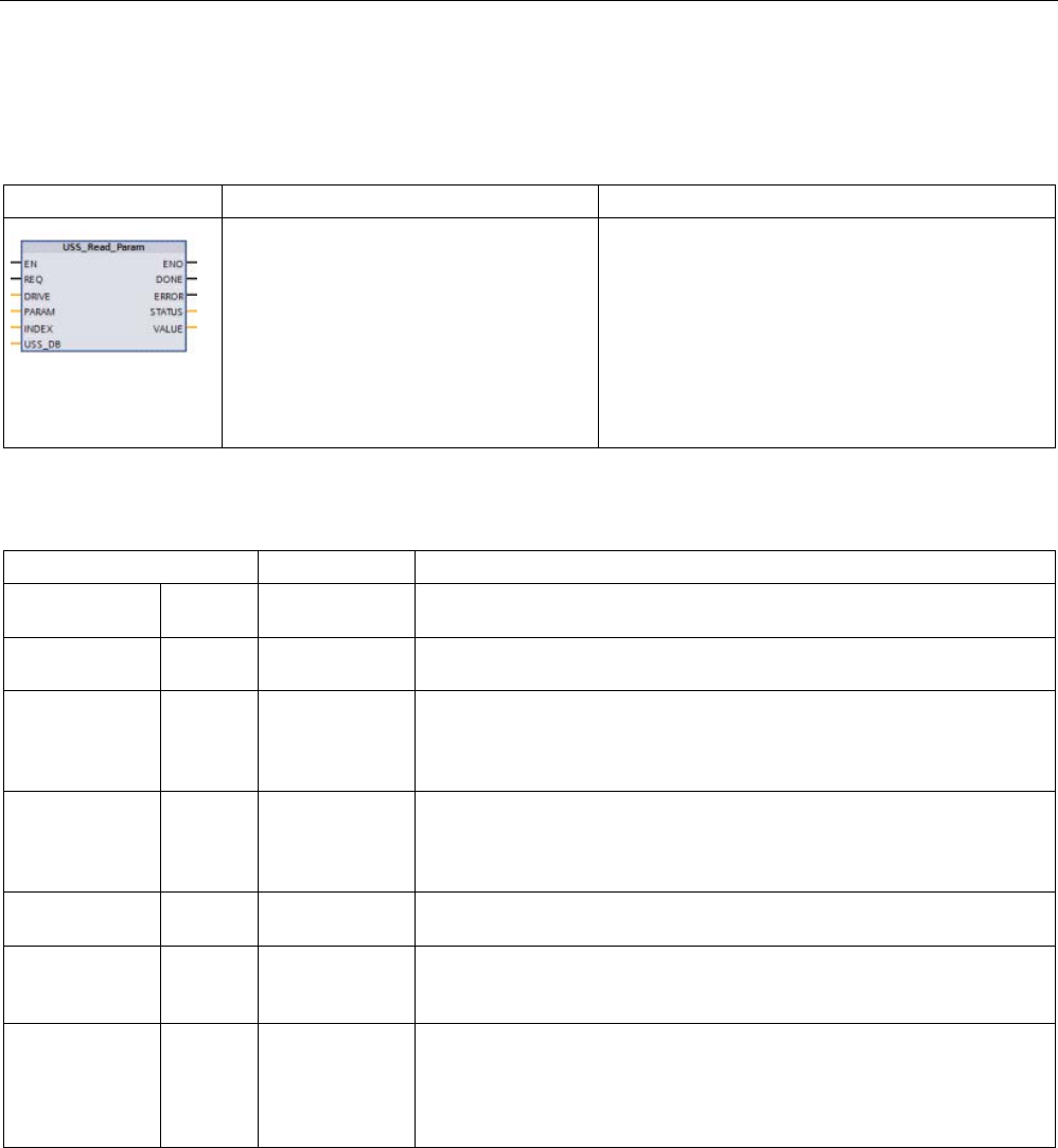
Communication processor and Modbus TCP
13.4 Universal serial interface (USS) communication
S7-1200 Programmable controller
System Manual, V4.2, 09/2016, A5E02486680-AK 1157
13.4.3.3
USS_Read_Param (Readout parameters from the drive)
Table 13- 47 USS_Read_Param instruction
LAD / FBD
SCL
Description
USS_Read_Param(REQ:=_bool_in_,
DRIVE:=_usint_in_,
PARAM:=_uint_in_,
INDEX:=_uint_in_,
DONE=>_bool_out_,
ERROR=>_bool_out_,
STATUS=>_word_out_,
VALUE=>_variant_out_,
USS_DB:=_fbtref_inout_);
The USS_Read_Param instruction reads a parame-
ter from a drive. All USS functions associated with
one USS network and PtP communication port must
use the same data block. USS_Read_Param must
be called from a main program cycle OB.
Table 13- 48 Data types for the parameters
Parameter type
Data type
Description
REQ IN Bool Send request: When true, REQ indicates that a new read request is de-
sired. This is ignored if the request for this parameter is already pending.
DRIVE IN USInt Drive address: DRIVE is the address of the USS drive. The valid range is
drive 1 to drive 16.
PARAM IN UInt Parameter number: PARAM designates which drive parameter is written.
The range of this parameter is 0 to 2047. On some drives, the most signif-
icant byte can access PARAM values greater than 2047. See your drive
manual for details on how to access an extended range.
INDEX IN UInt Parameter index: INDEX designates which Drive Parameter index is to be
written. A 16-bit value where the Least Significant Byte is the actual index
value with a range of (0 to 255). The Most Significant Byte may also be
used by the drive and is drive-specific. See your drive manual for details.
USS_DB INOUT USS_BASE The name of the instance DB that is created and initialized when a
USS_Drive_Control instruction is placed in your program.
VALUE IN Word, Int, UInt,
DWord, DInt,
UDInt, Real
This is the value of the parameter that was read and is valid only when
the DONE bit is true.
DONE1 OUT Bool When true, indicates that the VALUE output holds the previously request-
ed read parameter value. This bit is set when USS_Drive_Control sees
the read response data from the drive. This bit is reset when either: you
request the response data using another USS_Read_Param poll, or on
the second of the next two calls to USS_Drive_Control.
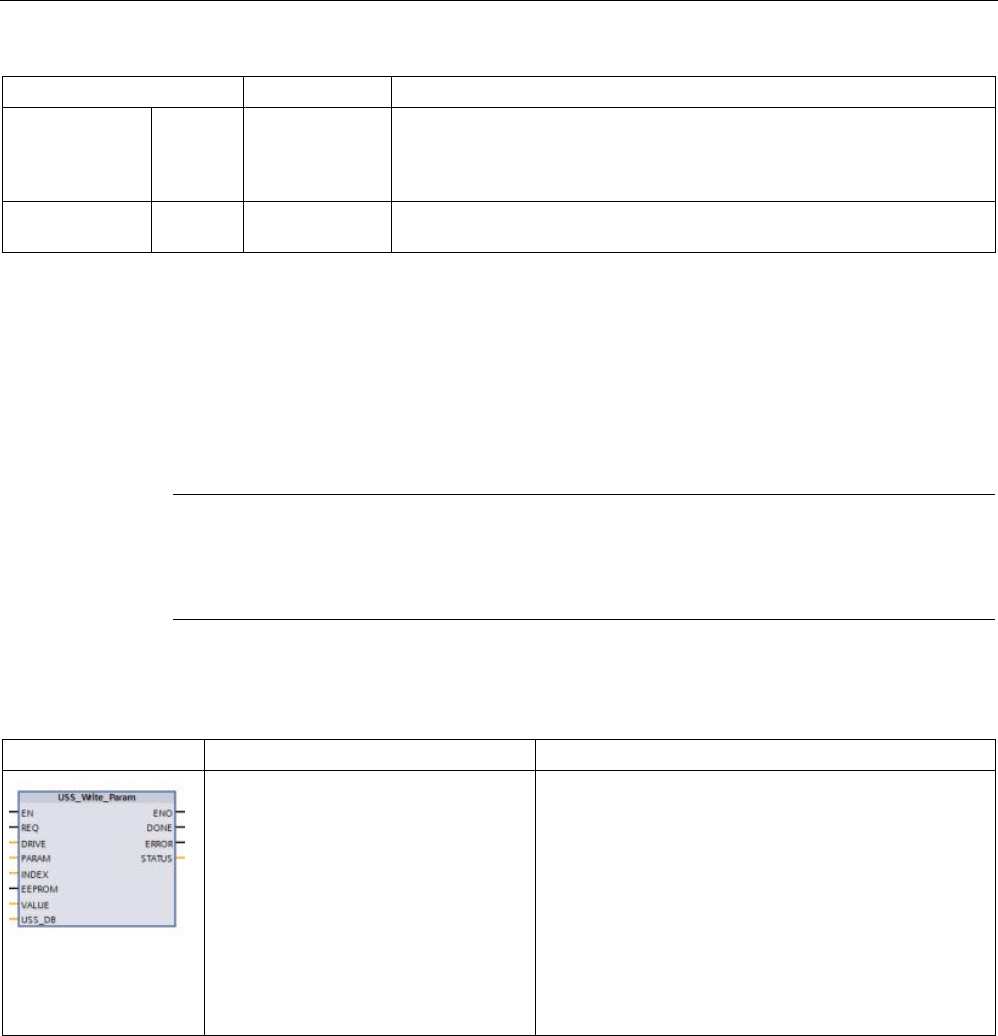
Communication processor and Modbus TCP
13.4 Universal serial interface (USS) communication
S7-1200 Programmable controller
1158 System Manual, V4.2, 09/2016, A5E02486680-AK
Parameter type
Data type
Description
ERROR OUT Bool Error occurred: When true, ERROR indicates that an error has occurred
and the STATUS output is valid. All other outputs are set to zero on an
error. Communication errors are only reported on the USS_Port_Scan
instruction ERROR and STATUS outputs.
STATUS OUT Word STATUS indicates the result of the read request. Additional information is
available in the "USS_Extended_Error" variable for some status codes.
1
The DONE bit indicates that valid data has been read from the referenced motor drive and delivered to the CPU. It does
not indicate that the USS library is capable of immediately reading another parameter. A blank PKW request must be
sent to the motor drive and must also be acknowledged by the instruction before the parameter channel for the specific
drive becomes available for use. Immediately calling a USS_Read_Param or USS_Write_Param FC for the specified
motor drive will result in a "0x818A" error.
13.4.3.4
USS_Write_Param (Change parameters in the drive)
Note
EEPROM write operations (for the EEPROM inside a USS drive)
Do not overuse the EEPROM permanent write operation. Minimize the number of EEPROM
write op
erations to extend the EEPROM life.
Table 13- 49 USS_Write_Param instruction
LAD / FBD
SCL
Description
USS_Write_Param(REQ:=_bool_in
_,
DRIVE:=_usint_in_,
PARAM:=_uint_in_,
INDEX:=_uint_in_,
EEPROM:=_bool_in_,
VALUE:=_variant_in_,
DONE=>_bool_out_,
ERROR=>_bool_out_,
STATUS=>_word_out_,
USS_DB:=_fbtref_inout_);
The USS_Write_Param instruction modifies a parame-
ter in the drive. All USS functions associated with one
USS network and PtP communication port must use the
same data block.
USS_Write_Param must be called from a main program
cycle OB.

Communication processor and Modbus TCP
13.4 Universal serial interface (USS) communication
S7-1200 Programmable controller
System Manual, V4.2, 09/2016, A5E02486680-AK 1159
Table 13- 50 Data types for the parameters
Parameter and type
Data type
Description
REQ IN Bool Send request: When true, REQ indicates that a new write request is de-
sired. This is ignored if the request for this parameter is already pending.
DRIVE IN USInt Drive address: DRIVE is the address of the USS drive. The valid range is
drive 1 to drive 16.
PARAM IN UInt Parameter number: PARAM designates which drive parameter is written.
The range of this parameter is 0 to 2047. On some drives, the most signif-
icant byte can access PARAM values greater than 2047. See your drive
manual for details on how to access an extended range.
INDEX IN UInt Parameter index: INDEX designates which Drive Parameter index is to be
written. A 16-bit value where the least significant byte is the actual index
value with a range of (0 to 255). The most significant byte may also be
used by the drive and is drive-specific. See your drive manual for details.
EEPROM IN Bool Store To Drive EEPROM: When true, a write drive parameter transaction
will be stored in the drive EEPROM. If false, the write is temporary and
will not be retained if the drive is power cycled.
VALUE IN Word, Int, UInt,
DWord, DInt,
UDInt, Real
The value of the parameter that is to be written. It must be valid on the
transition of REQ.
USS_DB INOUT USS_BASE The name of the instance DB that is created and initialized when a
USS_Drive_Control instruction is placed in your program.
DONE1 OUT Bool When true, DONE indicates that the input VALUE has been written to the
drive. This bit is set when USS_Drive_Control sees the write response
data from the drive. This bit is reset when either you request the response
data using another USS_Drive_Control poll, or on the second of the next
two calls to USS_Drive_Control.
ERROR OUT Bool
When true, ERROR indicates that an error has occurred and the STATUS
output is valid. All other outputs are set to zero on an error. Communica-
tion errors are only reported on the USS_Port_Scan instruction ERROR
and STATUS outputs.
STATUS OUT Word
STATUS indicates the result of the write request. Additional information is
available in the "USS_Extended_Error" variable for some status codes.
1
The DONE bit indicates that valid data
has been read from the referenced motor drive and delivered to the CPU. It does
not indicate that the USS library is capable of immediately reading another parameter. A blank PKW request must be
sent to the motor drive and must also be acknowledged by the instruction before the parameter channel for the specific
drive becomes available for use. Immediately calling a USS_Read_Param or USS_Write_Param FC for the specified
motor drive will result in a "0x818A" error.

Communication processor and Modbus TCP
13.4 Universal serial interface (USS) communication
S7-1200 Programmable controller
1160 System Manual, V4.2, 09/2016, A5E02486680-AK
13.4.4
USS status codes
USS instruction status codes are returned at the STATUS output of the USS functions.
Table 13- 51 STATUS codes 1
STATUS
(W#16#....)
Description
0000
No error
8180 Th
e length of the drive response did not match the characters received from the drive. The drive number
where the error occurred is returned in the "USS_Extended_Error" variable. See the extended error
description below this table.
8181
VALUE parameter was not a Word, Real or DWord data type.
8182 The user supplied a Word for a parameter value and received a DWord or Real from the drive in the
response.
8183 The user supplied a DWord or Real for a parameter value and received a Word from the drive in the
response.
8184 The response telegram from drive had a bad checksum. The drive number where the error occurred is
returned in the "USS_Extended_Error" variable. See the extended error description below this table.
8185
Illegal drive address (valid drive address range: 1 to16)
8186
The speed set point is out of the valid range (valid speed SP range: -200% to 200%).
8187 The wrong drive number responded to the request sent. The drive number where the error occurred is
returned in the "USS_Extended_Error" variable. See the extended error description below this table.
8188
Illegal PZD word length specified (valid range = 2, 4, 6 or 8 words)
8189
Illegal Baud Rate was specified.
818A
The parameter request channel is in use by another request for this drive.
818B The drive has not responded to requests and retries. The drive number where the error occurred is
returned in the "USS_Extended_Error" variable. See the extended error description below this table.
818C The drive returned an extended error on a parameter request operation. See the extended error descrip-
tion below this table.
818D The drive returned an illegal access error on a parameter request operation. See your drive manual for
information of why parameter access may be limited.
818E The drive has not been initialized. This error code is returned to USS_Read_Param or
USS_Write_Param when USS_Drive_Control, for that drive, has not been called at least once. This
keeps the initialization on first scan of USS_Drive_Control from overwriting a pending parameter read or
write request, since it initializes the drive as a new entry. To fix this error, call USS_Drive_Control for this
drive number.
80Ax-80Fx Specific errors returned from PtP communication FBs called by the USS Library - These error code
values are not modified by the USS library and are defined in the PtP instruction descriptions.
1 In addition to the USS instruction errors listed above, errors can be returned from the
underlying PtP communication instructions (Page 1108).
For several STATUS codes, additional information is provided in the "USS_Extended_Error"
variable of the USS_Drive_Control Instance DB. For STATUS codes hexadecimal 8180,
8184, 8187, and 818B, USS_Extended_Error contains the drive number where the
communication error occurred. For STATUS code hexadecimal 818C, USS_Extended_Error
contains a drive error code returned from the drive when using a USS_Read_Param or
USS_Write_Param instruction.

Communication processor and Modbus TCP
13.4 Universal serial interface (USS) communication
S7-1200 Programmable controller
System Manual, V4.2, 09/2016, A5E02486680-AK 1161
Example: Communication errors reporting
Communication errors (STATUS = 16#818B) are only reported on the USS_Port_Scan
instruction and not on the USS_Drive_Control instruction. For example, if the network is not
properly terminated, then it is possible for a drive to go to RUN but the USS_Drive_Control
instruction will show all "0's' for the output parameters. In this case, you can only detect the
communication error on the USS_Port_Scan instruction. Since this error is only visible for
one scan, you will need to add some capture logic as illustrated in the following example. In
this example, when the error bit of the USS_Port_Scan instruction is TRUE, then the
STATUS and the USS_Extended_Error values are saved into M memory. The drive number
is placed in the USS_Extended_Error variable when the STATUS code value is hexadecimal
8180, 8184, 8187, or 818B.
Network 1
"PortStatus"port status
and"U
SS_Drive_Control_DB".USS_Ex
tended_Error
extended error code values are only
valid for
one program scan. The values must
be
captured for later processing.
Network 2
The "PortError" contact
triggers the storage of the "PortStatus"
val
ue in "LastPortStatus" and
the"USS_Drive_Control_DB".USS_Ext
ended_Error
value in "LastExtError".
Read and write access to a drive's internal parameters
USS drives support read and write access to a drive's internal parameters. This feature
allows remote control and configuration of the drive. Drive parameter access operations can
fail due to errors such as values out of range or illegal requests for a drive's current mode.
The drive generates an error code value that is returned in the "USS_Extended_Error"
variable. This error code value is only valid for the last execution of a USS_Read_Param or
USS_Write_Param instruction. The drive error code is put into USS_Extended_Error variable
when the STATUS code value is hexadecimal 818C. The error code value of
USS_Extended_Error depends on the drive model. See the drive's manual for a description
of the extended error codes for read and write parameter operations.

Communication processor and Modbus TCP
13.4 Universal serial interface (USS) communication
S7-1200 Programmable controller
1162 System Manual, V4.2, 09/2016, A5E02486680-AK
13.4.5
USS general drive setup requirements
USS general drive setup requirements consist of the following points:
● The drives must be set to use 4 PKW words.
● The drives can be configured for 2, 4, 6, or 8 PZD words.
● The number of PZD word's in the drive must match PZD_LEN input on the
USS_Drive_Control instruction for that drive.
● The baud rate in all the drives must match the BAUD input on the USS_Port_Scan
instruction.
● The drive must be set for remote control.
● The drive must be set for frequency set-point to USS on COM Link.
● The drive address must be set to 1 to 16 and match the DRIVE input on the
USS_Drive_Control block for that drive.
● The drive direction control must be set to use the polarity of the drive set-point.
● The RS485 network must be terminated properly.
13.4.6
Example: USS general drive connection and setup
Connecting a MicroMaster drive
This information about SIEMENS MicroMaster drives is provided as an example. For other
drives, refer to the drive's manual for setup instructions.
To make the connection to a MicroMaster Series 4 (MM4) drive, insert the ends of the
RS485 cable into the two caged-clamp, screw-less terminals provided for USS operation.
Standard PROFIBUS cable and connectors can be used to connect the S7-1200.
CAUTION
Interconnecting equipment with different reference potentials can cause unwanted currents
to flow through the interconnecting cable
These unwanted currents can cause communications errors or damage equipment. Be sure
all equipment that you are about to connect with a communications cable either shares a
common circuit reference or is isolated to prevent unwanted current flows. The shield must
be tied to chassis ground or pin 1 on the 9-pin connector. It is recommended that you tie
wiring terminal 2-0 V on the MicroMaster drive to chassis ground.
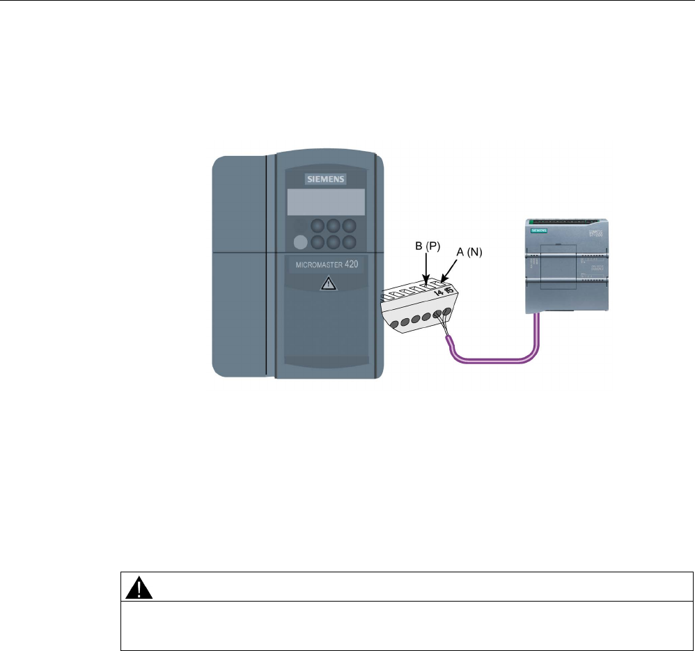
Communication processor and Modbus TCP
13.4 Universal serial interface (USS) communication
S7-1200 Programmable controller
System Manual, V4.2, 09/2016, A5E02486680-AK 1163
The two wires at the opposite end of the RS485 cable must be inserted into the MM4 drive
terminal blocks. To make the cable connection on a MM4 drive, remove the drive cover(s) to
access the terminal blocks. See the MM4 user manual for details about how to remove the
covers(s) of your specific drive.
The terminal block connections are labeled numerically. Using a PROFIBUS connector on
the S7
-
1200 side, connect the A terminal of the cable to the drive terminal 15 (for an MM420)
or terminal 30 (MM440). Connect the B
terminal of B (P) A (N) the cable connector to termi-
nal 14 (MM420) or terminal 29 (MM440).
If the S7
-1200 is a terminating node in the network, or if the connection is point-to-point, it is
necessary to use terminals A1 and B1 (not A2 and B2) of the conne
ctor since they allow the
termination settings to be set (for example, with DP connector type 6ES7972-0BA40-0X40).
CAUTION
Replace drive covers properly before supplying power
Make sure the drive covers are replaced properly before supplying power to the unit.
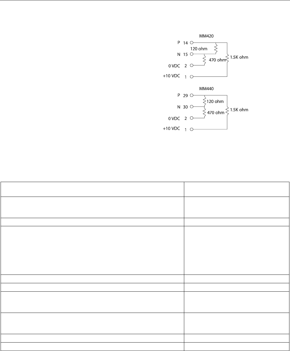
Communication processor and Modbus TCP
13.4 Universal serial interface (USS) communication
S7-1200 Programmable controller
1164 System Manual, V4.2, 09/2016, A5E02486680-AK
If the drive is configured as the terminating
node in the network, then termination and
bias resistors must also be wired to the
appropriate terminal connections. This
diagram shows examples of the MM4 drive
connections necessar
y for termination and
bias.
Setting up the MM4 drive
Before you connect a drive to the S7-1200, you must ensure that the drive has the following
system parameters. Use the keypad on the drive to set the parameters:
1. Reset the drive to factory settings (optional). P0010=30
P0970=1
If you skip step 1, then ensure that these parameters are set to the indicated
values.
USS PZD length = P2012 Index 0=(2, 4, 6,
or 8)
USS PKW length = P2013 Index 0=4
2. Enable the read/write access to all parameters (Expert mode).
P0003=3
3. Check the motor settings for your drive. The settings will vary according to
the motor(s) being used.
To set the parameters P304, P305, P307, P310, and P311, you must first set
parameter P010 to 1 (quick commissioning mode). When you are finished
setting the parameters, set parameter P010 to 0. Parameters P304, P305,
P307, P310, and P311 can only be changed in the quick commissioning
mode.
P0304 = Rated motor voltage (V)
P0305 = Rated motor current (A)
P0307 = Rated motor power (W)
P0310 = Rated motor frequency (Hz)
P0311 = Rated motor speed
4. Set the local/remote control mode.
P0700 Index 0=5
5. Set selection of frequency set-point to USS on COM link.
P1000 Index 0=5
6. Ramp up time (optional)
This is the time in seconds that it takes the motor to accelerate to maximum
frequency.
P1120=(0 to 650.00)
7. Ramp down time (optional)
This the time in seconds that it takes the motor to decelerate to a complete
stop.
P1121=(0 to 650.00)
8. Set the serial link reference frequency:
P2000=(1 to 650 Hz)
9. Set the USS normalization:
P2009 Index 0=0

Communication processor and Modbus TCP
13.4 Universal serial interface (USS) communication
S7-1200 Programmable controller
System Manual, V4.2, 09/2016, A5E02486680-AK 1165
10. Set the baud rate of the RS485 serial interface: P2010 Index 0= 4 (2400 baud)
5 (4800 baud)
6 (9600 baud)
7 (19200 baud
8 (38400 baud)
9 (57600 baud)
12 (115200 baud)
11. Enter the Slave address.
Each drive (a maximum of 31) can be operated over the bus.
P2011 Index 0=(0 to 31)
12. Set the serial link timeout.
This is the maximum permissible period between two incoming data tele-
grams. This feature is used to turn off the inverter in the event of a communi-
cations failure. Timing starts after a valid data telegram has been received. If
a further data telegram is not received within the specified time period, the
inverter will trip and display fault code F0070. Setting the value to zero
switches off the control.
P2014 Index 0=(0 to 65,535 ms)
0=timeout disabled
13. Transfer the data from RAM to EEPROM: P0971=1 (Start transfer) Save the changes
to the parameter settings to EEPROM

Communication processor and Modbus TCP
13.5 Modbus communication
S7-1200 Programmable controller
1166 System Manual, V4.2, 09/2016, A5E02486680-AK
13.5
Modbus communication
13.5.1
Overview of Modbus RTU and Modbus TCP communication
Modbus function codes
● A CPU operating as a Modbus RTU master (or Modbus TCP client) can read/write both
data and I/O states in a remote Modbus RTU slave (or Modbus TCP server). Remote
data can be read and then processed in your program logic.
● A CPU operating as a Modbus RTU slave (or Modbus TCP server) allows a supervisory
device to read/write both data and I/O states in CPU memory. An RTU master (or
Modbus TCP client) can write new values into slave/server CPU memory that is available
to your program logic.
WARNING
If an attacker can physically access your networks, the attacker can possibly read and write
data.
The TIA Portal, the CPU, and HMIs (except HMIs using GET/PUT) use secure
communication that protects against replay and "man-in-the-middle" attacks. Once
communication is enabled, the exchange of signed messages takes place in clear text
which allows an attacker to read data, but protects against unauthorized writing of data.
The TIA Portal, not the communication process, encrypts the data of know-how protected
blocks.
All other forms of communication (I/O exchange through PROFIBUS, PROFINET, AS-i, or
other I/O bus, GET/PUT, T-Block, and communication modules (CM)) have no security
features. You must protect these forms of communication by limiting physical access. If an
attacker can physically access your networks utilizing these forms of communication, the
attacker can possibly read and write data.
For security information and recommendations, refer to the "Operational Guidelines for
Industrial Security" (http://www.industry.siemens.com/topics/global/en/industrial-
security/Documents/operational_guidelines_industrial_security_en.pdf).
Table 13- 52 Read data functions: Read remote I/O and program data
Modbus function code
Read slave (server) functions - standard addressing
01
Read output bits: 1 to 2000 bits per request
02
Read input bits: 1 to 2000 bits per request
03
Read Holding registers: 1 to 125 words per request
04
Read input words: 1 to 125 words per request

Communication processor and Modbus TCP
13.5 Modbus communication
S7-1200 Programmable controller
System Manual, V4.2, 09/2016, A5E02486680-AK 1167
Table 13- 53 Write data functions: Write remote I/O and modify program data
Modbus function code
Write slave (server) functions - standard addressing
05
Write one output bit: 1 bit per request
06 Write one holding register: 1 word per request
15
Write one or more output bits: 1 to 1968 bits per request
16 Write one or more holding registers: 1 to 123 words per request
● Modbus function codes 08 and 11 provide slave device communication diagnostic
information.
● Modbus function code 0 broadcasts a message to all slaves (with no slave response).
The broadcast function is not available for Modbus TCP, because communication is
connection based.
Table 13- 54 Modbus network station addresses
Station
Address
RTU station
Standard station address
1 to 247
Extended station address 1 to 65535
TCP station
Station address
IP address and port number
Modbus memory addresses
The actual number of Modbus memory addresses available depends on the CPU model,
how much work memory exists, and how much CPU memory is used by other program data.
The table below gives the nominal value of the address range.
Table 13- 55 Modbus memory addresses
Station
Address range
RTU station
Standard memory address
10K
Extended memory address
64K
TCP station
Standard memory address
10K
Modbus RTU communication
Modbus RTU (Remote Terminal Unit) is a standard network communication protocol that
uses the RS232 or RS485 electrical connection for serial data transfer between Modbus
network devices. You can add PtP (Point to Point) network ports to a CPU with a RS232 or
RS485 CM or a RS485 CB.
Modbus RTU uses a master/slave network where all communications are initiated by a
single Master device and slaves can only respond to a master’s request. The master sends a
request to one slave address and only that slave address responds to the command.

Communication processor and Modbus TCP
13.5 Modbus communication
S7-1200 Programmable controller
1168 System Manual, V4.2, 09/2016, A5E02486680-AK
Modbus TCP communication
Modbus TCP (Transmission Control Protocol) is a standard network communication protocol
that uses the PROFINET connector on the CPU for TCP/IP communication. No additional
communication hardware module is required.
Modbus TCP uses Open User Communications (OUC) connections as a Modbus
communication path. Multiple client-server connections may exist, in addition to the
connection between STEP 7 and the CPU. Mixed client and server connections are
supported up to the maximum number of connections allowed by the CPU model
(Page 801).
Each MB_SERVER connection must use a unique instance DB and IP port number. Only 1
connection per IP port is supported. Each MB_SERVER (with its unique instance DB and IP
port) must be executed individually for each connection.
A Modbus TCP client (master) must control the client-server connection with the
DISCONNECT parameter. The basic Modbus client actions are shown below.
1. Initiate a connection to a particular server (slave) IP address and IP port number
2. Initiate client transmission of a Modbus message and receive the server responses
3. When desired, initiate the disconnection of client and server to enable connection with a
different server.
Modbus RTU instructions in your program
● Modbus_Comm_Load: One execution of Modbus_Comm_Load is used to set up PtP port
parameters like baud rate, parity, and flow control. After a CPU port is configured for the
Modbus RTU protocol, it can only be used by either the Modbus_Master or
Modbus_Slave instructions.
● Modbus_Master: The Modbus_Master instruction enables the CPU to act as a
Modbus RTU master device and communicate with one or more Modbus slave devices.
● Modbus_Slave: The Modbus_Slave instruction enables the CPU to act as a Modbus RTU
slave device and communicate with a Modbus master device.
Modbus TCP instructions in your program
● MB_CLIENT: Make client-server TCP connection, send command message, receive
response, and control the disconnection from the server
● MB_SERVER: Connect to a Modbus TCP client upon request, receive Modbus message,
and send response
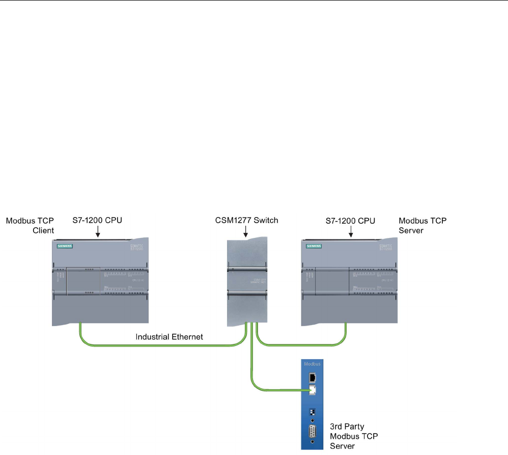
Communication processor and Modbus TCP
13.5 Modbus communication
S7-1200 Programmable controller
System Manual, V4.2, 09/2016, A5E02486680-AK 1169
13.5.2
Modbus TCP
13.5.2.1
Overview
As of version V4.1 of the S7-1200 CPU together with STEP 7 V13 SP1, the CPU extends the
capability of Modbus TCP to use enhanced T-block instructions.
For this reason, the S7-1200 supports two sets of PtP instructions:
● Legacy Modbus TCP instructions (Page 1250): These Modbus TCP instructions existed
prior to version V4.0 of the S7-1200.
● Modbus TCP instructions (Page 1171): These Modbus TCP instructions provide all of the
functionality of the legacy instructions.
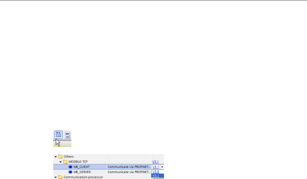
Communication processor and Modbus TCP
13.5 Modbus communication
S7-1200 Programmable controller
1170 System Manual, V4.2, 09/2016, A5E02486680-AK
13.5.2.2
Selecting the version of the Modbus TCP instructions
There are three versions of the Modbus TCP instructions available in STEP 7:
● Legacy version 3.0: Compatible with all CPU and CP versions
● Legacy version 3.1: Compatible with all CPU and CP versions
● Version 4.1: Compatible with V4.0 and later CPUs and V2.1 and later CMs
For compatibility and ease of migration, you can choose which instruction version to insert
into your user program.
Do not use both 3.0 and 3.1 instruction versions in the same CPU program. Your program's
Modbus TCP instructions must have the same major version number (
1
.x,
2
.y, or
V
.z). The
individual instructions within a major version group may have different minor versions (1.
x
).
Click the icon on the instruction tree task card to enable the headers and columns
of the instruction tree.
To change the version of the Modbus TCP
instructions, select t
he version from the drop
-
down list. You can select the group or ind
i-
vidual instructions.
When you use the instruction tree to place a Modbus TCP instruction in your program, a new
FB instance is created in the project tree. You can see new FB instance in the project tree
under PLC_x > Program blocks > System blocks > Program resources.
To verify the version of a Modbus TCP instruction in a program, you must inspect project
tree properties and not the properties of a box displayed in the program editor. Select a
project tree Modbus TCP FB instance, right-click, select "Properties", and select the
"Information" page to see the Modbus TCP instruction version number.
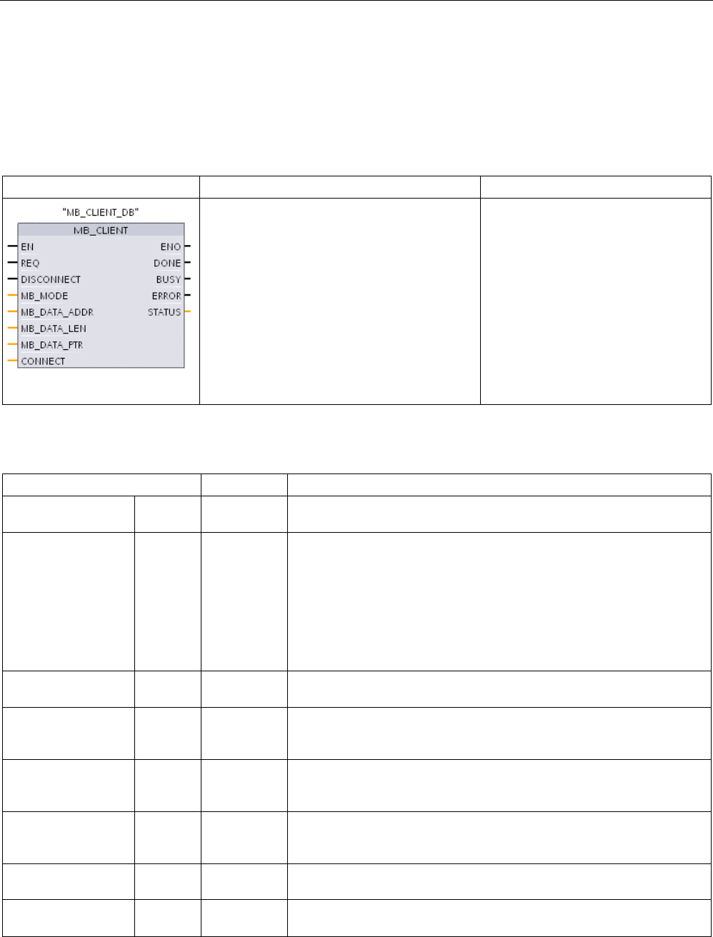
Communication processor and Modbus TCP
13.5 Modbus communication
S7-1200 Programmable controller
System Manual, V4.2, 09/2016, A5E02486680-AK 1171
13.5.2.3
Modbus TCP instructions
MB_CLIENT (Communicate using PROFINET as Modbus TCP client) instruction
Table 13- 56 MB_CLIENT instruction
LAD / FBD
SCL
Description
"MB_CLIENT_DB"(
REQ:=_bool_in_,
DISCONNECT:=_bool_in_,
MB_MODE:=_usint_in_,
MB_DATA_ADDR:=_udint_in_,
MB_DATA_LEN:=_uint_in_,
DONE=>_bool_out_,
BUSY=>_bool_out_,
ERROR=>_bool_out_,
STATUS=>_word_out_,
MB_DATA_PTR:=_variant_inout_,
CONNECT:=_variant_inout_);
MB_CLIENT communicates as a
Modbus TCP client through the
PROFINET port on the S7-1200 CPU.
No additional communication hard-
ware module is required.
MB_CLIENT can make a client-server
connection, send a Modbus function
request, receive a response, and
control the disconnection from a Mod-
bus TCP server.
Table 13- 57 Data types for the parameters
Parameter and type
Data type
Description
REQ In Bool FALSE = No Modbus communication request
TRUE = Request to communicate with a Modbus TCP server
DISCONNECT IN Bool The DISCONNECT parameter allows your program to control connec-
tion and disconnection with a Modbus server device.
If DISCONNECT = 0 and a connection does not exist, then MB_CLIENT
attempts to make a connection to the assigned IP address and port
number.
If DISCONNECT = 1 and a connection exists, then a disconnect opera-
tion is attempted. Whenever this input is enabled, no other operation will
be attempted.
MB_MODE IN USInt Mode selection: Assigns the type of request (read, write, or diagnostic).
See the Modbus functions table below for details.
MB_DATA_ADDR IN UDInt Modbus starting Address: Assigns the starting address of the data to be
accessed by MB_CLIENT. See the following Modbus functions table for
valid addresses.
MB_DATA_LEN IN UInt Modbus data Length: Assigns the number of bits or words to be ac-
cessed in this request. See the following Modbus functions table for
valid lengths
MB_DATA_PTR IN_OUT Variant Pointer to the Modbus data register: The register buffers data going to or
coming from a Modbus server. The pointer must assign a non-optimized
global DB or an M memory address.
CONNECT IN_OUT Variant
Reference to a Data block structure that contains connection parameters
in the system data type "TCON_IP_v4".
DONE OUT Bool The DONE bit is TRUE for one scan, after the last request was complet-
ed with no error.

Communication processor and Modbus TCP
13.5 Modbus communication
S7-1200 Programmable controller
1172 System Manual, V4.2, 09/2016, A5E02486680-AK
Parameter and type
Data type
Description
BUSY OUT Bool • 0 - No MB_CLIENT operation in progress
• 1 - MB_CLIENT operation in progress
ERROR OUT Bool The ERROR bit is TRUE for one scan, after the MB_CLIENT execution
ended with an error. The error code at the STATUS parameter is valid
only during the single cycle where ERROR = TRUE.
STATUS
OUT
Word
Execution condition code
Note
CPU firmware version requirement
The Modbus
TCP instructions described in this section of the manual require firmware
release V4.1 or later.
REQ parameter
FALSE = No Modbus communication request
TRUE = Request to communicate with a Modbus TCP server
If no instance of MB_CLIENT is active and parameter DISCONNECT=0, when REQ=1 a new
Modbus request starts. If the connection is not already established, then a new connection is
made.
If the same instance of MB_CLIENT is executed again with DISCONNECT=0 and REQ=1,
before the completion of the current request, then no subsequent Modbus transmission will
be made. However, as soon as the current request is completed, a new request can be
processed if MB_CLIENT is executed with REQ=1.
When the current MB_CLIENT communication request is complete, the DONE bit is TRUE
for one cycle. The DONE bit can be used as a time gate to sequence multiple MB_CLIENT
requests.
Note
Input data consistency during MB_CLIENT processing
Once a Modbus client initiates a Modbus operation, all the input states are saved internally
and are then compared on each succ
essive call. The comparison is used to determine if this
particular call was the originator of the active client request. More than one MB_CLIENT call
can be performed using a common instance DB.
It is important that the inputs are not changed during the p
eriod of time that an MB_CLIENT
operation is actively being processed. If this rule is not followed, then an MB_CLIENT cannot
determine the active instance.

Communication processor and Modbus TCP
13.5 Modbus communication
S7-1200 Programmable controller
System Manual, V4.2, 09/2016, A5E02486680-AK 1173
MB_MODE and MB_DATA_ADDR parameters select the Modbus communication function
The MB_CLIENT instruction uses an MB_MODE input rather than a function code.
MB_DATA_ADDR assigns the starting Modbus address of the remote data.
The combination of MB_MODE and MB_DATA_ADDR determines the function code that is
used in the actual Modbus message. The following table shows the correspondence
between parameter MB_MODE, MB_DATA_ADDR, and Modbus function:
Table 13- 58 Modbus functions
MB_MOD
E
Modbus function
Data length
Operation and data
MB_DATA_ADDR
0 01 1 to 2000 Read output bits:
1 to 2000 bits per request
1 to 9999
101 01 1 to 2000 Read output bits:
1 to 2000 bits per request
00000 to 65535
0 02 1 to 2000 Read input bits:
1 to 2000 bits per request
10001 to 19999
102 02 1 to 2000 Read input bits:
1 to 2000 bits per request
00000 to 65535
0 03 1 to 125 Read Holding registers:
1 to 125 words per request
40001 to 49999 or
400001 to 465535
103 03 1 to 125 Read Holding registers:
1 to 125 words per request
00000 to 65535
0 04 1 to 125 Read input words:
1 to 125 words per request
30001 to 39999
104 04 1 to 125 Read input words:
1 to 125 words per request
00000 to 65535
1 05 1 Write one output bit:
One bit per request
1 to 9999
105 05 1 Write one output bit:
One bit per request
00000 to 65535
1 06 1 Write one holding register:
1 word per request
40001 to 49999 or
400001 to 465535
106 06 1 Write one holding register:
1 word per request
00000 to 65535
1 15 2 to 1968
Write multiple output bits:
2 to 1968 bits per request
1 to 9999
1 16 2 to 123 Write multiple holding registers:
2 to 123 words per request
40001 to 49999 or
400001 to 465535
2 15 1 to 1968 Write one or more output bits:
1 to 1968 bits per request
1 to 9999
2 15 1 to 1968 Write one or more output bits:
1 to 1968 bits per request
1 to 9999
2 15 1 to 1968 Write one or more output bits:
1 to 1968 bits per request
1 to 9999
115 15 1 to 1968 Write one or more output bits:
1 to 1968 bits per request
00000 to 65535

Communication processor and Modbus TCP
13.5 Modbus communication
S7-1200 Programmable controller
1174 System Manual, V4.2, 09/2016, A5E02486680-AK
MB_MOD
E
Modbus function
Data length
Operation and data
MB_DATA_ADDR
2 16 1 to 123 Write one or more holding registers:
1 to 123 words per request
40001 to 49999 or
400001 to 465535
116 16 1 to 123 Write one or more holding registers:
1 to 123 words per request
00000 to 65535
11 11 0 Read the server communication status word and
event counter. The status word indicates busy (0
= not busy, 0xFFFF = busy). The event counter
is incremented for each successful completion of
a message.
Both the MB_DATA_ADDR and MB_DATA_LEN
parameters of MB_CLIENT are ignored for this
function.
80 08 1
Check server status with diagnostic code 0x0000
(Loopback test, server echoes the request)
1 word per request
81 08 1 Reset server event counter with diagnostic code
0x000A
1 word per request
3 to 10,
12 to 79,
82 to 100,
107 to
114,
117 to 255
Reserved
Note
MB_DATA_PTR assigns a buffer to store data read/written to/from a Modbus TCP server
The data buffer can be located in a non
-optimized global DB or M memory address.
For a buffer in M memory, use the Any Pointer format. This is in the format P#"Bit Address"
"Data Type" "Length", an example would be P#M1000.0 WORD 500.

Communication processor and Modbus TCP
13.5 Modbus communication
S7-1200 Programmable controller
System Manual, V4.2, 09/2016, A5E02486680-AK 1175
MB_DATA_PTR parameter assigns a communication buffer
● MB_CLIENT communication functions:
– Read and write 1-bit data from Modbus server addresses (00001 to 09999)
– Read 1-bit data from Modbus server addresses (10001 to 19999)
– Read 16-bit word data from Modbus server addresses (30001 to 39999) and (40001 to
49999)
– Write 16-bit word data to Modbus server addresses (40001 to 49999)
● Word or bit sized data is transferred to/from the DB or M memory buffer assigned by
MB_DATA_PTR.
● If a DB is assigned as the buffer by MB_DATA_PTR, then you must assign data types to
all DB data elements.
– The 1-bit Bool data type represents one Modbus bit address
– 16-bit single word data types like WORD, UInt, and Int represent one Modbus word
address
– 32-bit double word data types like DWORD, DInt, and Real represent two Modbus
word addresses
● Complex DB elements can be assigned by MB_DATA_PTR, such as
– Arrays
– Named structures where each element is unique.
– Named complex structures where each element has a unique name and a 16 or 32 bit
data type.
● No requirement that the MB_DATA_PTR data areas be in the same global data block (or
M memory area). You can assign one data block for Modbus reads, another data block
for Modbus writes, or one data block for each MB_CLIENT.
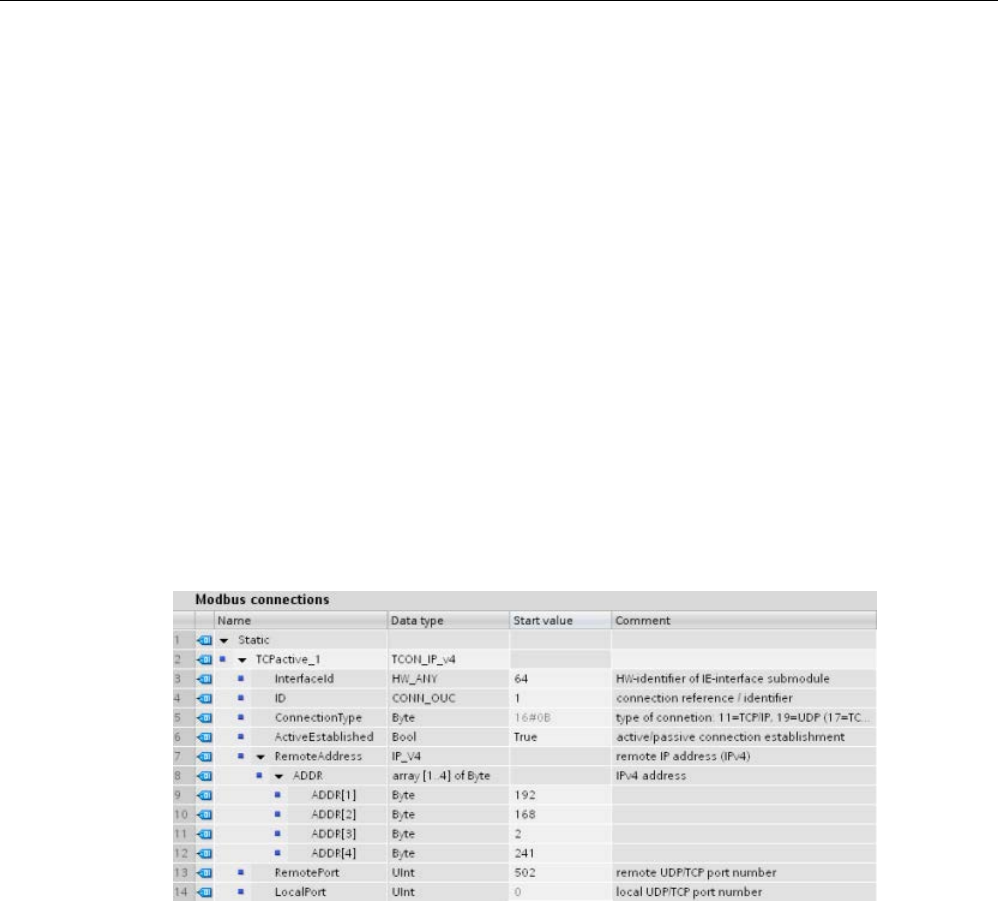
Communication processor and Modbus TCP
13.5 Modbus communication
S7-1200 Programmable controller
1176 System Manual, V4.2, 09/2016, A5E02486680-AK
CONNECT parameter assigns data used to establish a PROFINET connection
You must use a global data block and store the required connection data before you can
reference this DB at the CONNECT parameter.
1. Create a new global DB or use an existing global DB to store the CONNECT data. You
can use one DB to store multiple TCON_IP_v4 data structures. Each Modbus TCP client
or server connection uses a TCON_IP_v4 data structure. You reference the connection
data at the CONNECT parameter.
2. Name the DB and a static variable with a helpful name. For example, name the data
block "Modbus connections" and a static variable "TCPactive_1" (for Modbus TCP client
connection 1).
3. In the DB editor, assign the system data type "TCON_IP_v4" in the Data Type column, for
the example static variable "TCPactive_1".
4. Expand the TCON_IP_v4 structure so you can modify the connection parameters, as
shown in the following image.
5. Modify data in the TCON_IP_v4 structure for an MB_CLIENT connection.
6. Enter the DB structure reference for the CONNECT parameter of MB_CLIENT. For the
example, this would be "Modbus connections".TCPactive_1.
Modify TCP_IP_v4 DB data for each MB_CLIENT connection
●
InterfaceID
: Using the Device configuration window, click on the CPU PROFINET port
image. Then click on the General properties tab and use the Hardware identifier that you
see there.
●
ID
: Enter a connection ID number between 1 and 4095. Modbus TCP communication is
made using underlying TCON, TDISCON, TSEND, and TRCV instructions, for OUC
(Open User Communication).
●
ConnectionType
: For TCP/IP, use the default 16#0B (decimal number = 11).
●
ActiveEstablished
: This value must be 1 or TRUE. The connection is active in that
MB_CLIENT initiates Modbus communication.
●
RemoteAddress
: Enter the IP address of the target Modbus TCP server into the four
ADDR array elements. For example, enter 192.168.2.241, as in the previous image.

Communication processor and Modbus TCP
13.5 Modbus communication
S7-1200 Programmable controller
System Manual, V4.2, 09/2016, A5E02486680-AK 1177
●
RemotePort
: The default is 502. This number is the IP port number of the Modbus server
that MB_CLIENT attempts to connect and communicate with. Some third-party Modbus
servers require that you use another port number.
●
LocalPort
: This value must be 0, for an MB_CLIENT connection.
Multiple client connections
A Modbus TCP client can support concurrent connections up to the maximum number of
Open User Communications connections allowed by the PLC. The total number of
connections for a PLC, including Modbus TCP Clients and Servers, must not exceed the
maximum number of supported Open User Communications connections (Page 801).
Individual concurrent client connections must follow these rules:
● Each MB_CLIENT connection must use a unique instance DB
● Each MB_CLIENT connection must assign a unique server IP address
● Each MB_CLIENT connection must assign a unique connection ID
● Unique IP port numbers may or may not be required depending upon the server
configuration
A different connection ID must be used with each instance DB. In summary, the instance DB
and the connection ID are paired together and must be unique for each connection.
Table 13- 59 MB_CLIENT instance data block: User accessible static variables
Variable
Data type
Default
description
Blocked_Proc_Timeo
ut
Real 3.0 Amount of time (in seconds) to wait upon a blocked Modbus client in-
stance before removing this instance as being ACTIVE. This can occur,
for example, when a client request has been issued and then application
stops executing the client function before completely finishing the re-
quest. The maximum S7-1200 limit is 55 seconds.
MB_Unit_ID Word 255 Modbus unit identifier:
A Modbus TCP server is addressed using its IP address. As a result, the
MB_UNIT_ID parameter is not used for Modbus TCP addressing.
The MB_UNIT_ID parameter corresponds to the slave address in the
Modbus RTU protocol. If a Modbus TCP server is used for a gateway to a
Modbus RTU protocol, the MB_UNIT_ID can be used to identify the slave
device connected on the serial network. The MB_UNIT_ID would be used
to forward the request to the correct Modbus RTU slave address.
Some Modbus TCP devices may require the MB_UNIT_ID parameter to
be within a restricted range.
RCV_TIMEOUT Real 2.0 Time in seconds that the MB_CLIENT waits for a server to respond to a
request.
Connected Bool 0 Indicates whether the connection to the assigned server is connected or
disconnected: 1=connected, 0=disconnected

Communication processor and Modbus TCP
13.5 Modbus communication
S7-1200 Programmable controller
1178 System Manual, V4.2, 09/2016, A5E02486680-AK
Table 13- 60 MB_CLIENT protocol errors
STATUS
(W#16#)
Response code to Modbus
client (B#16#)
Modbus protocol errors
8381
01
Function code not supported
8382 03 Data length error
8383 02 Data address error or access outside the bounds of the MB_HOLD_REG
address area
8384 03 Data value error
8385
03
Data diagnostic code not supported (function code 08)
Table 13- 61 MB_CLIENT execution condition codes 1
STATUS
(W#16#)
MB_CLIENT parameter errors
7001 MB_CLIENT is wait
ing for a Modbus server response to a connect or disconnect request, on the assigned
TCP port. This code is only returned for the first execution of a connect or disconnect operation.
7002 MB_CLIENT is waiting for a Modbus server response to a connect or disconnect request, for the assigned
TCP port. This will be returned for any subsequent executions, while waiting for completion of a connect
or disconnect operation.
7003
A disconnect operation has successfully completed (Only valid for one PLC scan).
80C8 The server has not responded in the assigned time. MB_CLIENT must receive a response using the
transaction ID that was originally transmitted within the assigned time or this error is returned. Check the
connection to the Modbus server device.
This error is only returned after retries (if applicable) have been attempted.
8188
Invalid mode
8189
Invalid data address
818A
Invalid data length
818B Invalid pointer to the DATA_PTR area. This can be the combination of MB_DATA_ADDRESS +
MB_DATA_LEN.
818C Pointer DATA_PTR points to an non-optimized DB area (must be a non-optimized DB area or M memory
area)
8200 The port is busy processing an existing Modbus request.
8380
Received Modbus frame is incorrect or too few bytes have been received.
8387 The a
ssigned Connection ID parameter is different from the ID used for previous requests. There can only
be a single Connection ID used within each MB_CLIENT instance DB.
This code is also returned as an internal error if the Modbus TCP protocol ID received from a server is not
0.
8388 A Modbus server returned a quantity of data that is different than what was requested. This code applies
to Modbus functions 15 or 16 only.
1
In addition to the MB_CLIENT errors listed above, errors can be returned from the underlying T block communication
instructions (TCON, TDISCON, TSEND, and TRCV).
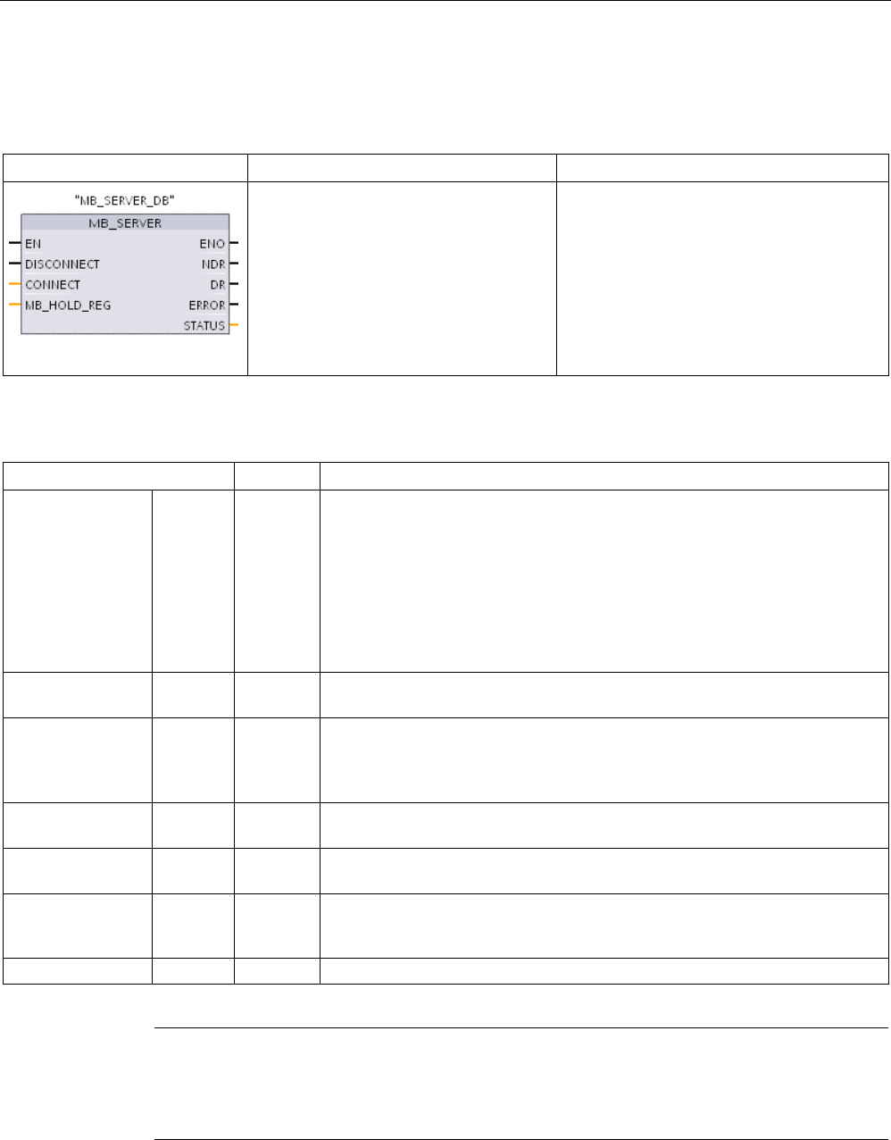
Communication processor and Modbus TCP
13.5 Modbus communication
S7-1200 Programmable controller
System Manual, V4.2, 09/2016, A5E02486680-AK 1179
MB_SERVER (Communicate using PROFINET as Modbus TCP server) instruction
Table 13- 62 MB_SERVER instruction
LAD / FBD
SCL
Description
"MB_SERVER_DB"(
DISCONNECT:=_bool_in_,
CONNECT:=_variant_in_,
NDR=>_bool_out_,
DR=>_bool_out_,
ERROR=>_bool_out_,
STATUS=>_word_out_,
MB_HOLD_REG:=_variant_inout_);
MB_SERVER communicates as a Modbus
TCP server through the PROFINET port on
the S7-1200 CPU. No additional communi-
cation hardware module is required.
MB_SERVER can accept a request to con-
nect with Modbus TCP client, receive a
Modbus function request, and send a re-
sponse message.
Table 13- 63 Data types for the parameters
Parameter and type
Data type
Description
DISCONNECT IN Bool MB_SERVER attempts to make a "passive" connection with a partner device.
This means that the se
rver is passively listening for a TCP connection request
from any requesting IP address.
If DISCONNECT = 0 and a connection does not exist, then a passive connec-
tion can be initiated.
If DISCONNECT = 1 and a connection exists, then a disconnect operation is
initiated. This parameter allows your program to control when a connection is
accepted. Whenever this input is enabled, no other operation will be attempt-
ed.
CONNECT IN Variant Reference to a Data block structure that contains connection parameters in
the system data type "TCON_IP_v4".
MB_HOLD_REG IN_OUT Variant Pointer to the MB_SERVER Modbus holding register: The holding register
must either be a non-optimized global DB or an M memory address. This
memory area is used to hold the data a Modbus client is allowed to access
using Modbus register functions 3 (read), 6 (write), and 16 (write).
NDR OUT Bool New Data Ready: 0 = No new data, 1 = Indicates that new data has been
written by a Modbus client
DR OUT Bool Data Read: 0 = No data read, 1 = Indicates that data has been read by a
Modbus client.
ERROR OUT Bool The ERROR bit is TRUE for one scan, after MB_SERVER execution ended
with an error. The error code at the STATUS parameter is valid only during
the single cycle where ERROR = TRUE.
STATUS
OUT
Word
Execution condition code
Note
CPU firmware version requirement
The Modbus
TCP instructions described in this section of the manual require firmware
release V4.1 or later.

Communication processor and Modbus TCP
13.5 Modbus communication
S7-1200 Programmable controller
1180 System Manual, V4.2, 09/2016, A5E02486680-AK
CONNECT parameter assigns data used to establish a PROFINET connection
You must use a global data block and store the required connection data before you can
reference this DB at the CONNECT parameter.
1. Create a new global DB or use an existing global DB to store the CONNECT data. You
can use one DB to store multiple TCON_IP_v4 data structures. Each Modbus TCP client
or server connection uses a TCON_IP_v4 data structure. You reference the connection
data at the CONNECT parameter.
2. Name the DB and a static variable with a helpful name. For example, name the data
block "Modbus connections" and a static variable "TCPpassive_1" (for Modbus TCP
server connection 1).
3. In the DB editor, assign the system data type "TCON_IP_v4" in the Data Type column, for
the example static variable "TCPactive_1".
4. Expand the TCON_IP_v4 structure so you can modify the connection parameters, as
shown in the following image.
5. Modify data in the TCON_IP_v4 structure for an MB_SERVER connection.
6. Enter the DB structure reference for the CONNECT parameter of MB_SEVER. For the
example, this would be "Modbus connections".TCPpassive_1.
Modify TCP_IP_v4 DB data for each MB_SERVER connection
●
InterfaceID
: Using the Device configuration window, click on the CPU PROFINET port
image. Then click on the General properties tab and use the Hardware identifier that you
see there.
●
ID
: Enter a number between 1 and 4095 that is unique for this connection. Modbus TCP
communication is made using underlying TCON, TDISCON, TSEND, and TRCV
instructions, for OUC (Open User Communication). Up to eight simultaneous OUC
connections are allowed.
●
ConnectionType
: For TCP/IP, use the default 16#0B (decimal value = 11).
●
ActiveEstablished
: This value must be 0 or FALSE. The connection is passive in that
MB_SERVER is waiting for a communication request from a Modbus client.

Communication processor and Modbus TCP
13.5 Modbus communication
S7-1200 Programmable controller
System Manual, V4.2, 09/2016, A5E02486680-AK 1181
●
RemoteAddress
: There are two options.
– Use 0.0.0.0 and MB_CLIENT will respond to a Modbus request from any TCP client
– Enter the IP address of a target Modbus TCP client and MB_CLIENT only responds to
a request originating from this client's IP address. For example, enter 192.168.2.241,
as in the previous image.
●
RemotePort
: This value must be 0, for an MB_SERVER connection.
●
LocalPort
: The default is 502. This number is the IP port number of the Modbus client that
MB_SERVER attempts to connect and communicate with. Some third-party Modbus
clients require another port number.
Modbus and process image addresses
MB_SERVER allows incoming Modbus function codes (1, 2, 4, 5, and 15) to read/write
bits/words directly in the input/output process image. For data transfer function codes (3, 6,
and 16), the MB_HOLD_REG parameter must be defined as a data type larger than a byte.
The following table shows the mapping of Modbus addresses to the process image in the
CPU.
Table 13- 64 Mapping of Modbus addresses to the process image
Modbus functions
S7-1200
Codes
Function
Data area
Address range
Data area
CPU address
01 Read bits Output 1 To 8192 Output Process Image Q0.0 to Q1023.7
02
Read bits
Input
10001
To
18192
Input Process Image
I0.0 to I1023.7
04 Read words Input 30001 To 30512 Input Process Image IW0 to IW1022
05
Write bit
Output
1
To
8192
Output Process Image
Q0.0 to Q1023.7
15
Write bits
Output
1
To
8192
Output Process Image
Q0.0 to Q1023.7
Incoming Modbus message function codes function codes (3, 6, and 16) read/write words in
a Modbus holding register, which can be in M memory or a data block. The type of holding
register is specified by the MB_HOLD_REG parameter.
Note
MB_HOLD_REG parameter assignment
Modbus holding registers defined as arrays of word, integer, wide character, unsigned
integer, byte, short integer, unsigned short integer, character, double word, double integer,
unsigned double integer, or real
can be placed in any memory area.
Modbus holding registers defined as structures must be placed in non
-optimized DBs.
For a Modbus holding register in M memory, use the Any Pointer format. This is in the format
P#"Bit Address" "Data Type" "Length". An exa
mple would be P#M1000.0 WORD 500

Communication processor and Modbus TCP
13.5 Modbus communication
S7-1200 Programmable controller
1182 System Manual, V4.2, 09/2016, A5E02486680-AK
The following table shows examples of Modbus addresses to holding register mapping used
for Modbus function codes 03 (read words), 06 (write word), and 16 (write words). The actual
upper limit of DB addresses is determined by the maximum work memory limit and M
memory limit, for each CPU model.
Table 13- 65 Mapping examples of Modbus address to CPU memory address
Modbus Address
MB_HOLD_REG parameter examples
P#M100.0 Word 5
P#DB10.DBx0.0 Word 5
"Recipe".ingredient
40001
MW100
DB10.DBW0
"Recipe".ingredient[1]
40002
MW102
DB10.DBW2
"Recipe".ingredient[2]
40003 MW104 DB10.DBW4 "Recipe".ingredient[3]
40004
MW106
DB10.DBW6
"Recipe".ingredient[4]
40005
MW108
DB10.DBW8
"Recipe".ingredient[5]
Multiple server connections
Multiple server connections may be created. A single PLC can establish concurrent
connections to multiple Modbus TCP clients.
A Modbus TCP server can support concurrent connections up to the maximum number of
Open User Communications connections allowed by the PLC. The total number of
connections for a PLC, including Modbus TCP Clients and Servers, must not exceed the
maximum number of supported Open User Communications connections (Page 801). The
Modbus TCP connections may be shared between Client and Server type connections.
Individual concurrent server connection must follow these rules:
● Each MB_SERVER connection must use a unique instance DB.
● Each MB_SERVER connection must assign a unique IP port number. Only 1 connection
per port is supported.
● Each MB_SERVER connection must assign a unique connection ID.
● The MB_SERVER must be called individually for each connection (with its respective
instance DB).

Communication processor and Modbus TCP
13.5 Modbus communication
S7-1200 Programmable controller
System Manual, V4.2, 09/2016, A5E02486680-AK 1183
The connection ID must be unique for each individual connection. A single, connection ID
must be used with each individual instance DB. The instance DB and the connection ID are
paired together and must be unique for every connection.
Table 13- 66 Modbus diagnostic function codes
MB_SERVER Modbus diagnostic functions
Codes
Sub-function
Description
08 0x0000 Return query data echo test: The MB_SERVER will echo back to a Modbus client a data word
that is received.
08 0x000A
Clear communication event counter: The MB_SEVER will clear the communication event counter
that is used for Modbus function 11.
11 Get communication event counter: The MB_SERVER uses an internal communication event
counter for recording the number of successful Modbus read and write requests that are sent to
the Modbus server. The counter does not increment on any request for Function 8, Function 11,
or any request that results in a communication error.
The broadcast function is not available for Modbus TCP, because only one client-server connec-
tion exists at any one time.
MB_SERVER variables
This table shows the public static variables that are stored in the MB_SERVER instance data
block and can be used in your program
Table 13- 67 MB_SERVER public static variables
Variable
Data type
Default
Description
HR_Start_Offset
Word
0
Assigns the starting address of the Modbus Holding register
Request_Count
Word
0
The number of all requests received by this server.
Server_Message_Count
Word
0
The number of requests received for this specific server.
Xmt_Rcv_Count Word 0 The number of transmissions or receptions that have encountered an
error. Also, incremented if a message is received that is an invalid
Modbus message.
Exception_Count
Word
0
Modbus specific errors that require a returned exception
Success_Count Word 0 The number of requests received for this specific server that has no
protocol errors.
Connected Bool 0 Indicates whether the connection to the assigned client is connected or
disconnected: 1=connected, 0=disconnected
Your program can write data to the HR_Start_Offset and control Modbus server operations.
The other variables can be read to monitor Modbus status.
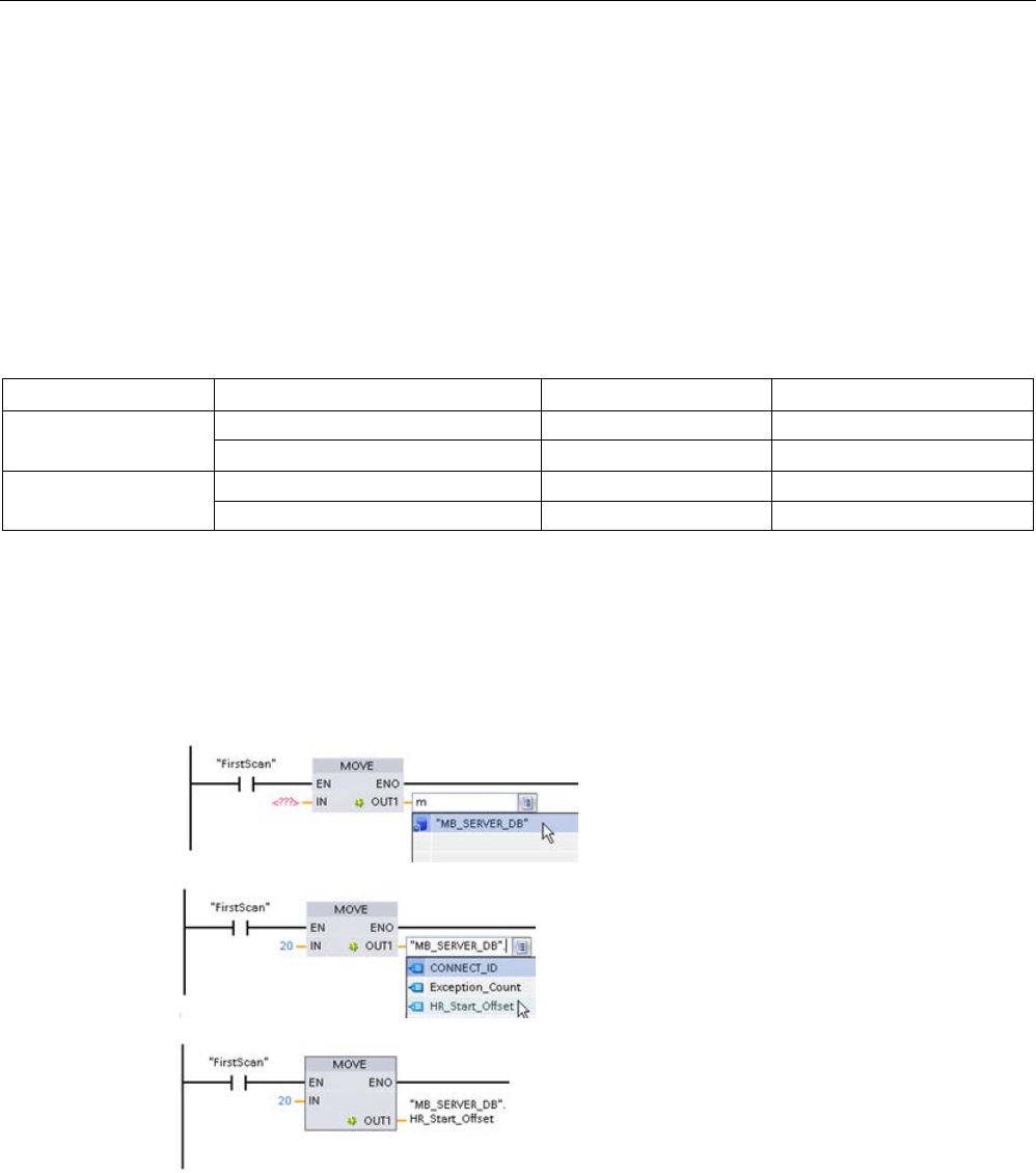
Communication processor and Modbus TCP
13.5 Modbus communication
S7-1200 Programmable controller
1184 System Manual, V4.2, 09/2016, A5E02486680-AK
HR_Start_Offset
Modbus holding register addresses begin at 40001. These addresses correspond to the
beginning PLC memory address of the holding register. However, you can use the
"HR_Start_Offset" variable to start the beginning Modbus holding register address at another
number instead of 40001.
For example, if the holding register starts at MW100 and is 100 words long. An offset of 20
specifies a beginning holding register address of 40021 instead of 40001. Any address less
than 40021 or greater than 40119 results in an addressing error.
Table 13- 68 Example of Modbus holding register addressing
HR_Start_Offset
Address
Minimum
Maximum
0
Modbus address (Word)
40001
40099
S7-1200 address MW100 MW298
20
Modbus address (Word)
40021
40119
S7-1200 address MW100 MW298
HR_Start_Offset is word data in the MB_SERVER instance data block that assigns the
starting address of the Modbus holding register. You can set this public static variable by
using the parameter helper drop list, after MB_SERVER is placed in your program.
For example, after you place MB_SERVER in a LAD network, you can go to a previous
network and assign HR_Start_Offset. The start address must be assigned prior to execution
of MB_SERVER.
Entering a Modbus server
variable using the default DB name:
1.
Set the cursor in the parameter field and
type an m character.
2.
Select "MB_SERVER_DB" from the drop
list of DB names.
3.
Select
"MB_SERVER_DB.HR_Start_Offset" from
the drop list of DB variables.

Communication processor and Modbus TCP
13.5 Modbus communication
S7-1200 Programmable controller
System Manual, V4.2, 09/2016, A5E02486680-AK 1185
Table 13- 69 MB_SERVER execution condition codes 1
STATUS
(W#16#)
Response code
to Modbus serv-
er (B#16#)
Modbus protocol errors
7001 MB_SERVER is waiting for a Modbus client to connect to the assigned TCP port. This
code is returned on the first execution of a connect or disconnect operation.
7002 MB_SERVER is waiting for a Modbus client to connect to the assigned TCP port. This
code is returned for any subsequent executions, while waiting for completion of a connect
or disconnect operation.
7003
A disconnect operation has successfully completed (Only valid for one PLC scan).
8187 MB_HOLD_REG is not valid, could be pointing into an optimized DB, or is pointing to an
area of less than 2 bytes.
818C Pointer MB_HOLD_REG points to a non-optimized DB area (must be a non-optimized
global DB area or M memory area) or Blocked process timeout exceeds the limit of 55
seconds. (S7-1200 specific)
8381
01
Function code not supported
8382
03
Data length error
8383
02
Data address error or access outside the bounds of the MB_HOLD_REG address area
8384
03
Data value error
8385
03
Data diagnostic code not supported (function code 08)
1 In addition to the MB_SERVER errors listed above, errors can be returned from the
underlying T block communication instructions (TCON, TDISCON, TSEND, and TRCV).
13.5.2.4
Modbus TCP examples
Example: MB_SERVER Multiple TCP connections
You can have multiple Modbus TCP server connections. To accomplish this, MB_SERVER
must be independently executed for each connection. Each connection must use an
independent instance DB, connection ID, and IP port. The S7-1200 allows only one
connection per IP port.
For best performance, MB_SERVER should be executed every program cycle, for each
connection.
The CONNECT parameter uses system data type TCP_IP_v4.For the example, these data
structures are in a DB named "Modbus connections". The "Modbus connections" DB
contains two TCP_IP_v4 structures "TCPpassive_1" (for connection 1) and "TCP_passive_2"
(for connection 2).The connection properties ID and LocalPort described in the network
comments are data elements stored in the CONNECT data structure.
The TCP_IP_v4 CONNECT data also contains an IP address in the RemoteAddress ADDR
array. IP address assignments within TCPpassive_1 and TCP_passive_2 do not affect the
establishment of TCP server connections, but determine which Modbus TCP clients are
allowed to communicate though the connections to each MB_SERVER. MB_SERVER
passively listens for a modbus client message and compares the incoming message IP
address with the IP address stored in the corresponding RemoteAddress ADDR array.
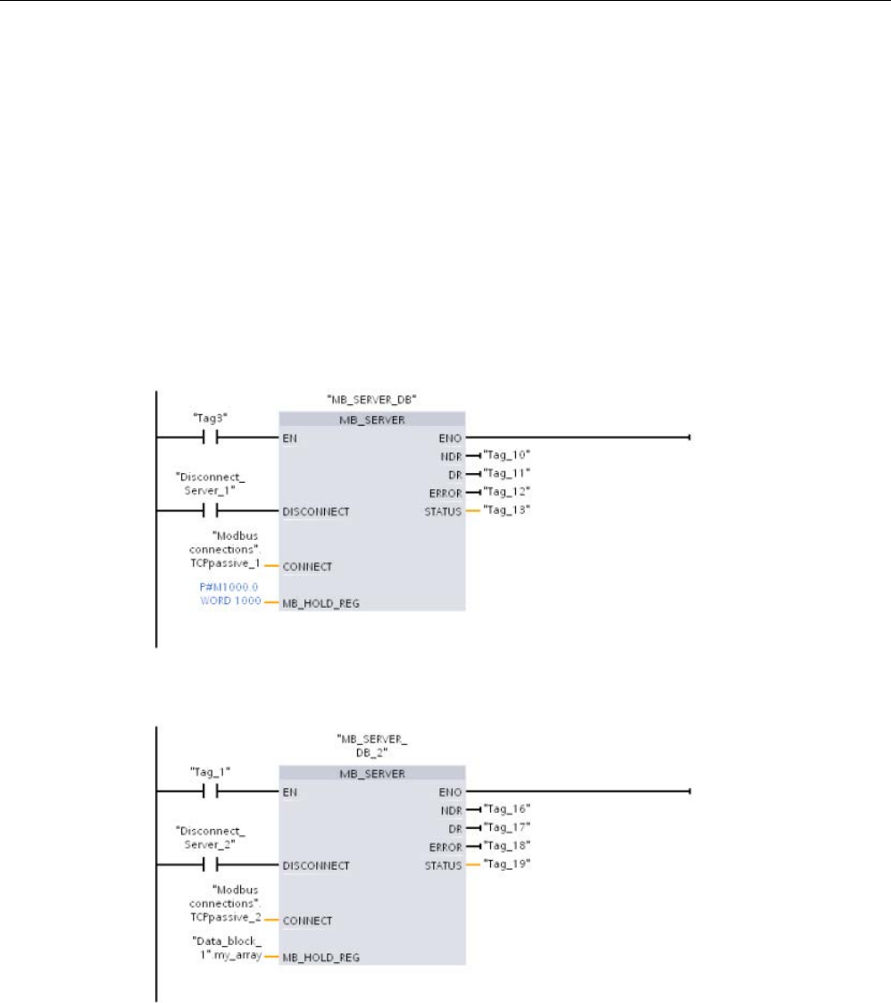
Communication processor and Modbus TCP
13.5 Modbus communication
S7-1200 Programmable controller
1186 System Manual, V4.2, 09/2016, A5E02486680-AK
Three MB_SERVER IP address variations are possible for the two MB_SERVER
instructions:
●
IP address = 0.0.0.0
Each MB_SERVER will respond to all Modbus TCP clients using any IP address.
●
IP address = Same IP address in TCPpassive_1 and TCPpassive_2
Both MB_SERVER connections only respond to Modbus clients originating from this IP
address.
●
IP address = Different IP number in TCP_passive_1 and TCP_passive_2
Each MB_SERVER only responds to Modbus clients that originate from the IP address
stored in their TCP_IP_v4 data.
Network 1:
Connection #1, Instance DB = "MB_SERVER_DB", within "Modbus
connections.TCPpassive_1" (ID = 1 and LocalPort = 502)
Network 2:
Connection #2, Instance DB = "MB_SERVER_DB_1, within "Modbus
connections.TCPpassive_2" (ID = 2 and LocalPort = 503)
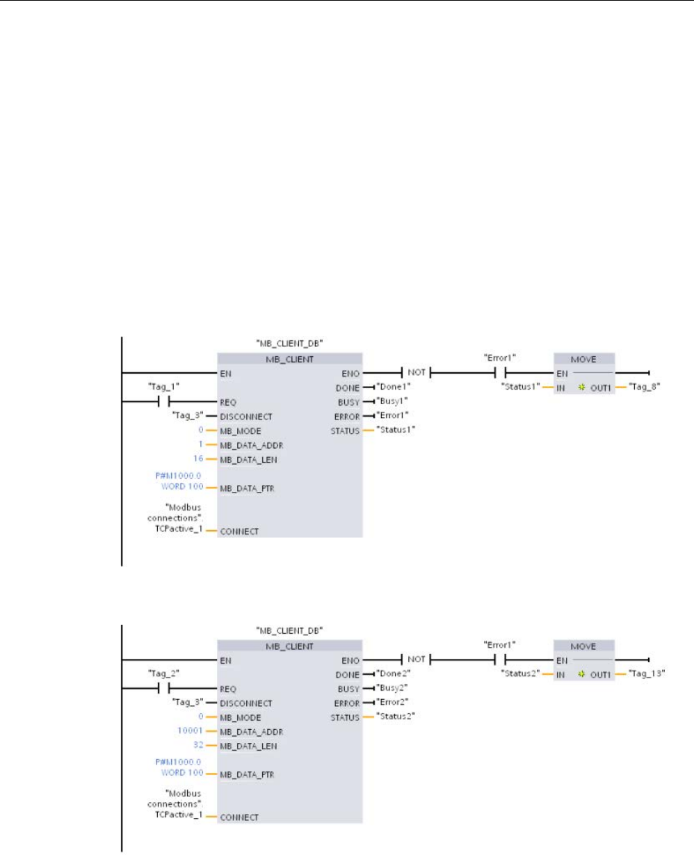
Communication processor and Modbus TCP
13.5 Modbus communication
S7-1200 Programmable controller
System Manual, V4.2, 09/2016, A5E02486680-AK 1187
Example: MB_CLIENT 1: Multiple requests with common TCP connection
Multiple Modbus client requests can be sent over the same connection. To accomplish this,
use the same instance DB, connection ID, and port number.
Because both MB_CLIENT boxes use the same CONNECT parameter TCON_IP_v4 data
structure ("Modbus_connections".TCPactive_1), the connection ID, port number, and IP
address are identical. The CONNECT IP address data assigns the IP address, of the target
Modbus TCP server.
Only one MB_CLIENT can be active at any given time. Once a client completes its
execution, the next client can begin execution. Your program logic is responsible for the
execution sequence logic. The example shows both clients reading remote data from a
single Modbus client and transferring the data to the Modbus client's CPU (M memory
starting at M1000.0). A returned error is captured, which is optional.
Network 1:
Modbus function 1 - Read 16 output bits from a Modbus TCP server with the IP
address assigned in "Modbus connections".TCPactive_1.
Network 2:
Modbus function 2 - Read 32 input bits from a Modbus TCP server with the IP
address assigned in "Modbus connections".TCPactive_1.
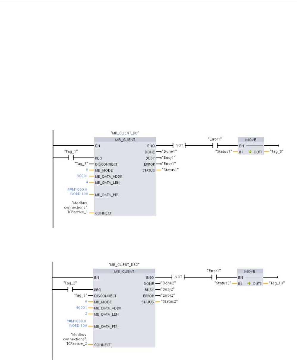
Communication processor and Modbus TCP
13.5 Modbus communication
S7-1200 Programmable controller
1188 System Manual, V4.2, 09/2016, A5E02486680-AK
Example: MB_CLIENT 2: Multiple requests with different TCP connections
Modbus TCP client requests can be sent over different connections. To accomplish this,
different instance DBs and connection IDs must be used.
The RemotePort (IP port) number must be different, if the connections are established to the
same Modbus server. If the connections are on different servers, there is no IP port number
restriction.
The example shows two Modbus TCP clients transferring remote data from two different
Modbus TCP servers to the same local CPU memory area, starting at address M1000.0.
Also, a returned error is captured which is optional.
Network 1:
Modbus function 4 - Read input process image words from a Modbus TCP server
CONNECT parameter = "Modbus connections".TCPactive_1: Connection
ID
= 1,
RemoteAddress
= 192.168.2.241,
RemotePort
= 502
Network 2:
Modbus function 3 - Read holding register words from a Modbus TCP server
CONNECT parameter = "Modbus connections".TCPactive_2: Connection
ID
= 2,
RemoteAddress
= 192.168.2.242,
RemotePort
= 502
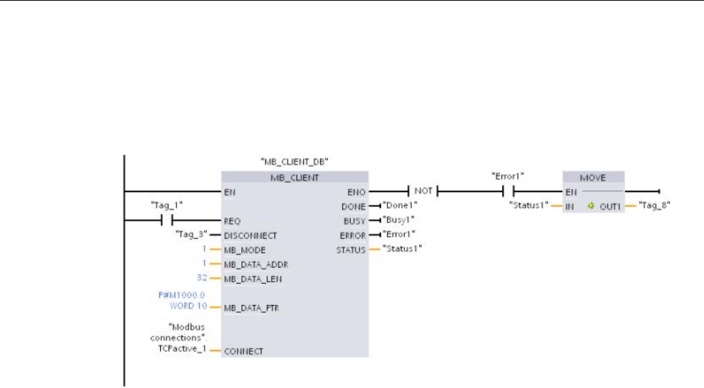
Communication processor and Modbus TCP
13.5 Modbus communication
S7-1200 Programmable controller
System Manual, V4.2, 09/2016, A5E02486680-AK 1189
Example: MB_CLIENT 3: Output image write request
This example shows a Modbus client request that transfers bit data from local CPU memory
(starting at M1000.0) to a remote Modbus TCP server.
Network 1:
Modbus function 15 - Write output bits in a Modbus server
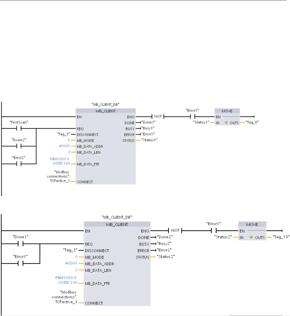
Communication processor and Modbus TCP
13.5 Modbus communication
S7-1200 Programmable controller
1190 System Manual, V4.2, 09/2016, A5E02486680-AK
Example: MB_CLIENT 4: Coordinating multiple requests
You must ensure that each individual Modbus TCP request finishes execution. The
execution sequence must be controlled by your program logic. The example below shows
how the outputs of the first and second client requests can control the execution sequence.
The example shows both clients using the same CONNECT connection data (used at
different times). The clients transfer holding register data from the same remote Modbus
TCP server to the same local CPU memory M address. Also, a returned error is captured
which is optional.
Network 1:
Modbus function 3 - Read Modbus TCP server holding register words
Network 2:
Modbus function 3 - Read Modbus TCP server holding register words

Communication processor and Modbus TCP
13.5 Modbus communication
S7-1200 Programmable controller
System Manual, V4.2, 09/2016, A5E02486680-AK 1191
13.5.3
Modbus RTU
13.5.3.1
Overview
As of version V4.1 of the S7-1200 CPU together with STEP 7 V13 SP1, the CPU extends the
capability of Modbus RTU to use a PROFINET or PROFIBUS distributed I/O rack to
communicate to various devices (RFID readers, GPS device, and others):
● PROFINET (Page 804): You connect the Ethernet interface of the S7-1200 CPU to a
PROFINET interface module. PtP communication modules in the rack with the interface
module can then provide serial communications to the PtP devices.
● PROFIBUS (Page 968): You insert a PROFIBUS communication module in the left side
of the rack with the S7-1200 CPU. You connect the PROFIBUS communication module
to a rack containing a PROFIBUS interface module. PtP communication modules in the
rack with the interface module can then provide serial communications to the PtP
devices.
For this reason, the S7-1200 supports two sets of PtP instructions:
● Legacy Modbus RTU instructions (Page 1270): These Modbus RTU instructions existed
prior to version V4.0 of the S7-1200 and only work with serial communications using a
CM 1241 communication module or CB 1241 communication board.
● Modbus RTU instructions (Page 1194): These Modbus RTU instructions provide all of the
functionality of the legacy instructions, plus the ability to connect to PROFINET and
PROFIBUS distributed I/O. These Modbus RTU instructions allow you to configure the
communications between the PtP communication modules in the distributed I/O rack and
the PtP devices. S7-1200 CM 1241 modules must have a minimum firmware version of
V2.1 to use these Modbus RTU instructions.
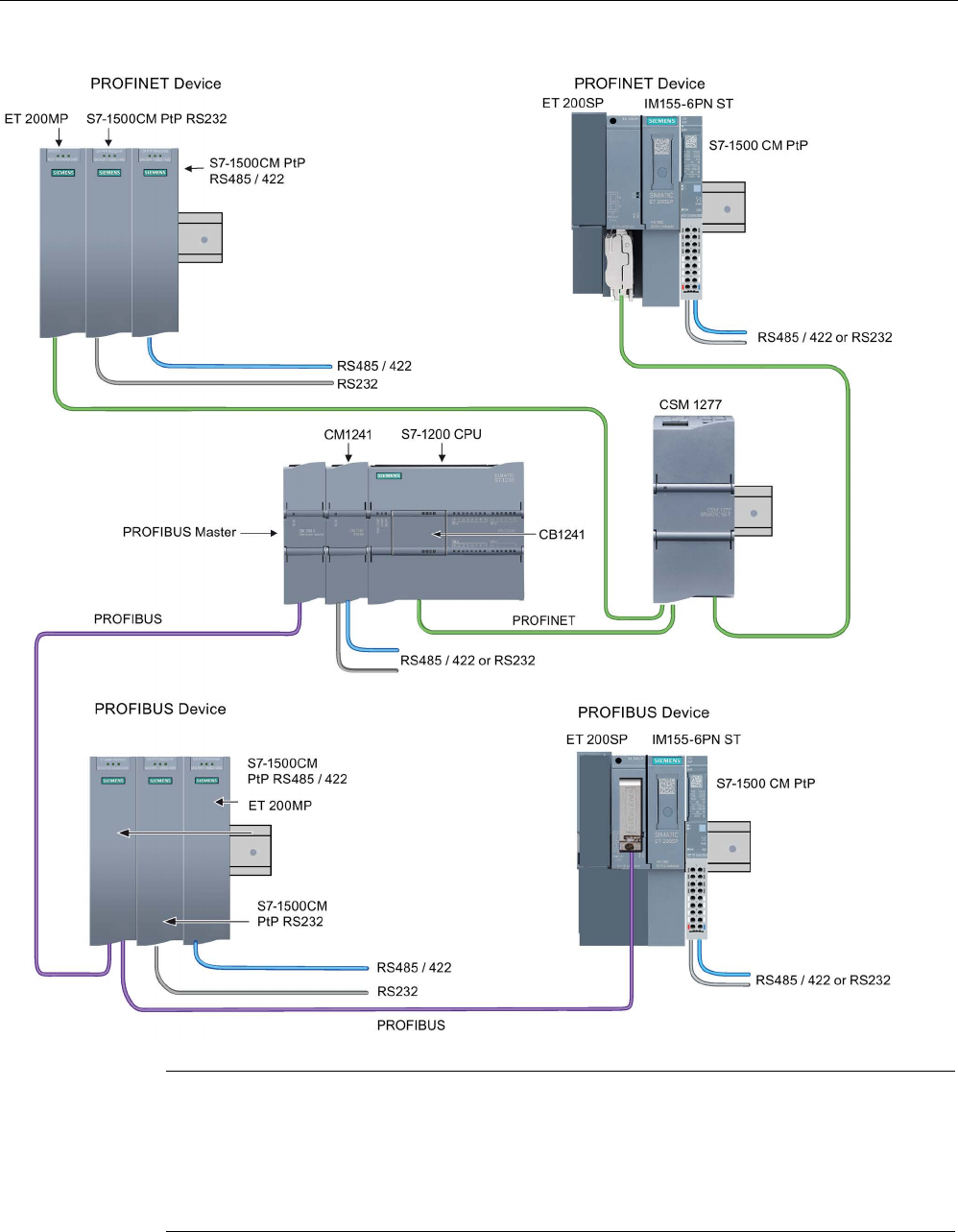
Communication processor and Modbus TCP
13.5 Modbus communication
S7-1200 Programmable controller
1192 System Manual, V4.2, 09/2016, A5E02486680-AK
Note
With version V4.1 of the S7
-1200, you can use the point-to-point instructions for all types of
point
-to-point communication: serial, serial over PROFINET, and serial over PROFIBUS.
STEP 7 provides the legacy point
-to-
point instructions only to support existing programs. The
legacy instructions still function, however, with V4.1 CPUs as well as V4.0 and earlier CPUs.
You do not have to convert prior programs from one set of instru
ctions to the other.
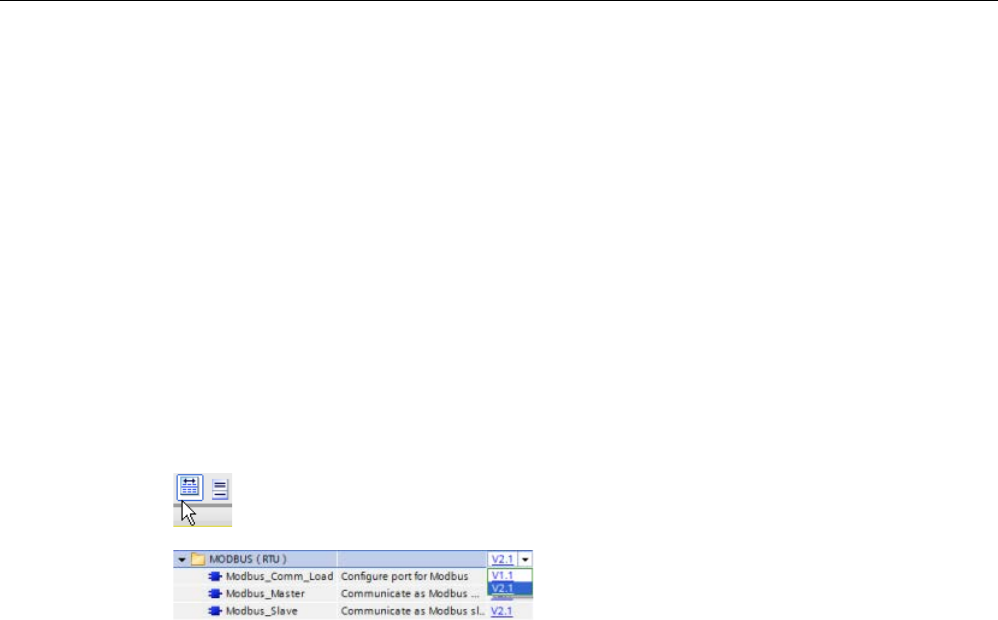
Communication processor and Modbus TCP
13.5 Modbus communication
S7-1200 Programmable controller
System Manual, V4.2, 09/2016, A5E02486680-AK 1193
13.5.3.2
Selecting the version of the Modbus RTU instructions
There are three versions of the Modbus RTU instructions available in STEP 7:
● Version 1.1: Compatible with V4.0 and later CPUs and V2.1 and later CMs
● Version 2.1: Compatible with V4.0 and later CPUs and V2.1 and later CMs
● Version 3.0: Compatible with V4.0 and later CPUs and V2.1 and later CMs
For compatibility and ease of migration, you can choose which instruction version to insert
into your user program.
You cannot use both versions of the instructions with the same module, but two different
modules can use different versions of the instructions. Do not use both 1.x and 2.y
instruction versions in the same CPU program. Your program's Modbus RTU instructions
must have the same major version number (
1
.x,
2
.y, or
V
.z). The individual instructions
within a major version group may have different minor versions (1.
x
).
Click the icon on the instruction tree task card to enable the headers and columns
of the instruction tree.
To change the version of the Modbus RTU
inst
ructions, select the version from the drop
-
down list. You can select the group or ind
i-
vidual instructions.
When you use the instruction tree to place a Modbus RTU instruction in your program, a new
FB instance is created in the project tree. You can see new FB instance in the project tree
under PLC_x > Program blocks > System blocks > Program resources.
To verify the version of a Modbus RTU instruction in a program, you must inspect project
tree properties and not the properties of a box displayed in the program editor. Select a
project tree Modbus RTU FB instance, right-click, select "Properties", and select the
"Information" page to see the Modbus RTU instruction version number.
13.5.3.3
Maximum number of supported Modbus slaves
Modbus addressing supports a maximum of 247 slaves (slave numbers 1 through 247).
Each Modbus network segment can have a maximum of 32 devices, based upon the loading
and drive capabilities of the RS485 interface. When you reach the 32-device limit, you must
use a repeater to expand to the next segment. You need seven repeaters to support the 247
slaves connected to one master for RS485.
Siemens repeaters work only with PROFIBUS; their function is to monitor PROFIBUS token
passing. You cannot use Siemens repeaters with other protocols. Therefore, you require
third party repeaters for Modbus.
Modbus timeouts are long by default; the use of multiple repeaters does not create a time-
delay problem. The Modbus master does not care if a slave is slow to respond or if multiple
repeaters delay the response.

Communication processor and Modbus TCP
13.5 Modbus communication
S7-1200 Programmable controller
1194 System Manual, V4.2, 09/2016, A5E02486680-AK
13.5.3.4
Modbus RTU instructions
Modbus_Comm_Load (Configure SIPLUS I/O or port on the PtP module for Modbus RTU) instruction
Table 13- 70 Modbus_Comm_Load instruction
LAD / FBD
SCL
Description
"Modbus_Comm_Load_DB"(
REQ:=_bool_in,
PORT:=_uint_in_,
BAUD:=_udint_in_,
PARITY:=_uint_in_,
FLOW_CTRL:=_uint_in_,
RTS_ON_DLY:=_uint_in_,
RTS_OFF_DLY:=_uint_in_,
RESP_TO:=_uint_in_,
DONE=>_bool_out,
ERROR=>_bool_out_,
STATUS=>_word_out_,
MB_DB:=_fbtref_inout_);
The Modbus_Comm_Load instruction configures
SIPLUS I/O or a PtP port for Modbus RTU pro-
tocol communications.
Modbus RTU port hardware options: Install up to
three CMs (RS485 or RS232), plus one CB
(R4845).
Modbus RTU SIPLUS I/O options: Install ET
200MP S7-
1500CM PtP (RS485 / 422 or RS232)
or ET 200SP S7-1500 CM PtP (RS485 / 422 or
RS232)
An instance data block is assigned automatically
when you place the Modbus_Comm_Load in-
struction in your program.

Communication processor and Modbus TCP
13.5 Modbus communication
S7-1200 Programmable controller
System Manual, V4.2, 09/2016, A5E02486680-AK 1195
Table 13- 71 Data types for the parameters
Parameter and type
Data type
Description
REQ IN Bool A low to high (positive edge) signal starts the operation.
(Version 2.0 only)
PORT IN Port After you install and configure a CM or CB communication device, the
port identifier appears in the parameter helper drop-list available at the
PORT box connection. The assigned CM or CB port value is the device
configuration property "hardware identifier". The port symbolic name is
assigned in the "System constants" tab of the PLC tag table.
BAUD IN UDInt Baud rate selection:
300, 600, 1200, 2400, 4800, 9600, 19200, 38400, 57600, 76800, 115200,
all other values are invalid
PARITY IN UInt Parity selection:
• 0 – None
• 1 – Odd
• 2 – Even
FLOW_CTRL 1 IN UInt Flow control selection:
• 0 – (default) no flow control
• 1 – Hardware flow control with RTS always ON (does not apply to
RS485 ports)
• 2 – Hardware flow control with RTS switched
RTS_ON_DLY 1 IN UInt RTS ON delay selection:
• 0 – (default) No delay from RTS active until the first character of the
message is transmitted
• 1 to 65535 – Delay in milliseconds from RTS active until the first char-
acter of the message is transmitted (does not apply to RS485 ports).
RTS delays shall be applied independent of the FLOW_CTRL selec-
tion.
RTS_OFF_DLY 1 IN UInt RTS OFF delay selection:
• 0 – (default) No delay from the last character transmitted until RTS
goes inactive
• 1 to 65535 – Delay in milliseconds from the last character transmitted
until RTS goes inactive (does not apply to RS485 ports). RTS delays
shall be applied independent of the FLOW_CTRL selection.
RESP_TO 1 IN UInt Response timeout:
Time in milliseconds allowed by the Modbus_Master for the slave to re-
spond. If the slave does not respond in this time period, the Mod-
bus_Master will retry the request or terminate the request with an error
when the specified number of retries has been sent.
5 ms to 65535 ms (default value = 1000 ms).
MB_DB IN Variant A reference to the instance data block used by the Modbus_Master or
Modbus_Slave instructions. After Modbus_Master or Modbus_Slave is
placed in your program, the DB identifier appears in the parameter helper
drop-list available at the MB_DB box connection.
DONE OUT Bool
The DONE bit is TRUE for one scan, after the last request was completed
with no error. (Version 2.0 only)

Communication processor and Modbus TCP
13.5 Modbus communication
S7-1200 Programmable controller
1196 System Manual, V4.2, 09/2016, A5E02486680-AK
Parameter and type
Data type
Description
ERROR OUT Bool The ERROR bit is TRUE for one scan, after the last request was termi-
nated with an error. The error code value at the STATUS parameter is
valid only during the single scan where ERROR = TRUE.
STATUS OUT Word Execution condition code
1
Optional parameters for Modbus_Comm_Load (V 2.x or later). Click the arrow at the bottom of a LAD/FBD box to ex-
pand the box and include these parameters.
Modbus_Comm_Load is executed to configure a port for the Modbus RTU protocol. Once a
port is configured for the Modbus RTU protocol, it can only be used by either the
Modbus_Master or Modbus_Slave instructions.
One execution of Modbus_Comm_Load must be used to configure each communication port
that is used for Modbus communication. Assign a unique Modbus_Comm_Load instance DB
for each port that you use. You can install up to three communication modules (RS232 or
RS485) and one communication board (RS485) in the CPU. Call Modbus_Comm_Load from
a startup OB and execute it one time or use the first scan system flag (Page 110) to initiate
the call to execute it one time. Only execute Modbus_Comm_Load again if communication
parameters like baud rate or parity must change.
If you use the Modbus library with a module in a distributed rack, the Modbus_Comm_Load
instruction must be executed in a cyclical interrupt routine (for example, once per second or
once every 10 seconds). If power is lost to the distributed rack or the module is pulled, upon
restoration of module operation, only the HWConfig parameter set is sent to the PtP module.
All requests initiated by the Modbus_Master timeout, and the Modbus_Slave goes silent (no
response to any message). Cyclic execution of the Modbus_Comm_Load instruction
resolves these issues.
An instance data block is assigned for Modbus_Master or Modbus_Slave when you place
these instructions in your program. This instance data block is referenced when you specify
the MB_DB parameter for the Modbus_Comm_Load instruction.

Communication processor and Modbus TCP
13.5 Modbus communication
S7-1200 Programmable controller
System Manual, V4.2, 09/2016, A5E02486680-AK 1197
Modbus_Comm_Load instance data block (DB) tags
The following table shows the public static tags stored in the Modbus_Comm_Load instance
DB that can be used in your program:
Table 13- 72 Modbus_Comm_Load instance DB static tags
Tag
Data type
Default
Description
ICHAR_GAP Word 0 Maximum character delay time between characters. This parameter is
specified in milliseconds and increases the anticipated period between
the received characters. The corresponding number of bit times for this
parameter is added to the Modbus default value of 35 bit times (3.5
character times).
RETRIES Word 2 Number of retries that the master executes before the error code
0x80C8 for "No response" is returned.
EN_SUPPLY_VOLT
Bool
0
Enable diagnostics for missing supply voltage L+.
MODE USInt 0 Operating mode
Valid operating modes are as follows:
• 0 = Full duplex (RS232)
• 1 = Full duplex (RS422) four-wire mode (point-to-point)
• 2 = Full duplex (RS422) four-wire mode (multipoint master, CM PtP
(ET 200SP))
• 3 = Full duplex (RS422) four-wire mode (multipoint slave, CM PtP
(ET 200SP))
• 4 = Half duplex (RS485) two-wire mode (See Note below.)
LINE_PRE USInt 0 Receive line initial state
Valid initial states are as follows:
• 0 = "No" initial state (See Note below.)
• 1 = signal R(A) = 5 V DC, signal R(B) = 0 V DC (break detection):
Break detection is possible with this initial state.
Can only be selected with: "Full duplex (RS422) four-wire mode
(point-to-point connection)" and "Full duplex (RS422) four-wire
mode (multipoint slave)".
• 2 = signal R(A) = 0 V DC, signal R(B) = 5 V DC:
This default setting corresponds to the idle state (no active send
operation). No break detection is possible with this initial state.
BRK_DET USInt 0 Break detection
The following selections are valid:
• 0 = break detection deactivated
• 1 = break detection activated
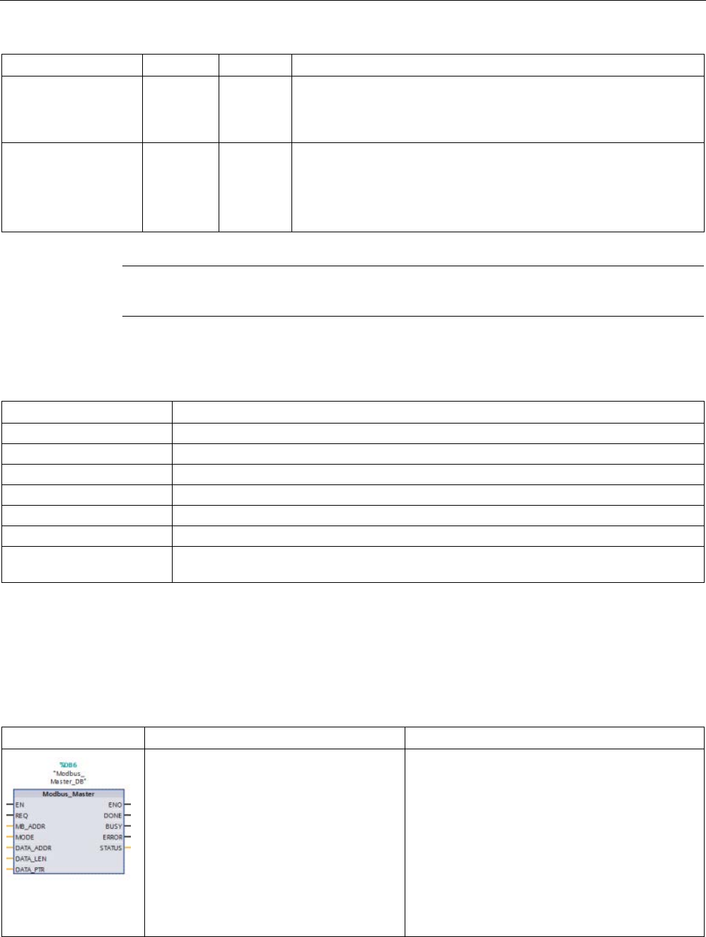
Communication processor and Modbus TCP
13.5 Modbus communication
S7-1200 Programmable controller
1198 System Manual, V4.2, 09/2016, A5E02486680-AK
Tag
Data type
Default
Description
EN_DIAG_ALARM Bool 0 Activate diagnostics interrupt:
• 0 = not activated
• 1 = activated
STOP_BITS USInt 1 Number of stop bits:
• 1 = 1 stop bit
• 2 = 2 stop bits
• 0, 3 to 255 = reserved
Note
Required setting for the use of PROFIBUS cables with CM 1241 for RS485
Table 13- 73 Modbus_Comm_Load execution condition codes 1
STATUS (W#16#)
Description
0000
No error
8180
Invalid port ID value (wrong port/hardware identifier for communication module)
8181
Invalid baud rate value
8182
Invalid parity value
8183
Invalid flow control value
8184
Invalid response timeout value (response timeout less than the 5 ms minimum)
8185 MB_DB parameter is not an instance data block of a Modbus_Master or Modbus_Slave
instruction.
1
In addition to the Modbus_Comm_Load errors listed above, errors can be returned from the underlying PtP communica-
tion instructions.
Modbus_Master (Communicate using SIPLUS I/O or the PtP port as Modbus RTU master) instruction
Table 13- 74 Modbus_Master instruction
LAD / FBD
SCL
Description
"Modbus_Master_DB"(
REQ:=_bool_in_,
MB_ADDR:=_uint_in_,
MODE:=_usint_in_,
DATA_ADDR:=_udint_in_,
DATA_LEN:=_uint_in_,
DONE=>_bool_out_,
BUSY=>_bool_out_,
ERROR=>_bool_out_,
STATUS=>_word_out_,
DATA_PTR:=_variant_inout_);
The Modbus_Master instruction communicates as
a Modbus master using a port that was configured
by a previous execution of the Mod-
bus_Comm_Load instruction. An instance data
blo
ck is assigned automatically when you place the
Modbus_Master instruction in your program. This
Modbus_Master instance data block is used when
you specify the MB_DB parameter for the Mod-
bus_Comm_Load instruction.

Communication processor and Modbus TCP
13.5 Modbus communication
S7-1200 Programmable controller
System Manual, V4.2, 09/2016, A5E02486680-AK 1199
Table 13- 75 Data types for the parameters
Parameter and type
Data type
Description
REQ IN Bool 0=No request
1= Request to transmit data to Modbus slave
MB_ADDR IN V1.0: USInt
V2.0: UInt
Modbus RTU station address:
Standard addressing range (1 to 247)
Extended addressing range (1 to 65535)
The value of 0 is reserved for broadcasting a message to all Modbus
slaves. Modbus function codes 05, 06, 15 and 16 are the only function
codes supported for broadcast.
MODE IN USInt Mode Selection: Specifies the type of request (read, write, or diagnostic).
See the Modbus functions table below for details.
DATA_ADDR IN UDInt
Starting Address in the slave: Specifies the starting address of the data to
be accessed in the Modbus slave. See the Modbus functions table below
for valid addresses.
DATA_LEN IN UInt Data Length: Specifies the number of bits or words to be accessed in this
request. See the Modbus functions table below for valid lengths.
DATA_PTR IN Variant Data Pointer: Points to the M or DB address (non-optimized DB type) for
the data being written or read.
DONE OUT Bool
The DONE bit is TRUE for one scan, after the last request was completed
with no error.
BUSY OUT Bool • 0 – No Modbus_Master operation in progress
• 1 – Modbus_Master operation in progress
ERROR OUT Bool The ERROR bit is TRUE for one scan, after the last request was termi-
nated with an error. The error code value at the STATUS parameter is
valid only during the single scan where ERROR = TRUE.
STATUS
OUT
Word
Execution condition code
Modbus_Master communication rules
● MB_COMM_LOAD must be executed to configure a port before a Modbus_Master
instruction can communicate with that port.
● If a port is to be used to initiate Modbus master requests, that port should not be used by
MB_SLAVE. One or more instances of Modbus_Master execution can be used with that
port, but all Modbus_Master execution must use the same Modbus_Master instance DB
for that port.
● The Modbus instructions do not use communication interrupt events to control the
communication process. Your program must poll the Modbus_Master instruction for
transmit and receive complete conditions.

Communication processor and Modbus TCP
13.5 Modbus communication
S7-1200 Programmable controller
1200 System Manual, V4.2, 09/2016, A5E02486680-AK
● It is recommended that you call all Modbus_Master execution for a given port from a
program cycle OB. Modbus_Master instructions may execute in only one of the program
cycle or cyclic/time delay execution levels. They must not execute in both execution
priority levels. Pre-emption of a Modbus_Master instruction by another Modbus_Master
instruction in a higher priority execution priority level will result in improper operation.
Modbus_Master instructions must not execute in the startup, diagnostic or time error
execution priority levels.
● Once a Modbus_Master instruction initiates a transmission, this instance must be
continually executed with the EN input enabled until a DONE=1 state or ERROR=1 state
is returned. A particular Modbus_Master instance is considered active until one of these
two events occurs. While the original instance is active, any call to any other instance
with the REQ input enabled will result in an error. If the continuous execution of the
original instance stops, the request state remains active for a period of time specified by
the static variable "Blocked_Proc_Timeout". Once this period of time expires, the next
Modbus_Master instruction called with an enabled REQ input will become the active
instance. This prevents a single Modbus_Master instance from monopolizing or locking
access to a port. If the original active instance is not enabled within the period of time
specified by the static variable "Blocked_Proc_Timeout", then the next execution by this
instance (with REQ not set) will clear the active state. If (REQ is set), then this execution
initiates a new Modbus_Master request as if no other instance was active.
REQ parameter
0 = No request; 1 = Request to transmit data to Modbus Slave
You may control this input either through the use of a level or edge triggered contact.
Whenever this input is enabled, a state machine is started to ensure that no other
Modbus_Master using the same instance DB is allowed to issue a request, until the current
request is completed. All other input states are captured and held internally for the current
request, until the response is received or an error detected.
If the same instance of Modbus_Master is executed again with REQ input = 1 before the
completion of the current request, then no subsequent transmissions are made. However,
when the request is completed, a new request is issued whenever a Modbus_Master is
executed again with REQ input = 1.

Communication processor and Modbus TCP
13.5 Modbus communication
S7-1200 Programmable controller
System Manual, V4.2, 09/2016, A5E02486680-AK 1201
DATA_ADDR and MODE parameters select the Modbus function type
DATA_ADDR (starting Modbus address in the slave): Specifies the starting address of the
data to be accessed in the Modbus slave.
The Modbus_Master instruction uses a MODE input rather than a Function Code input. The
combination of MODE and Modbus address determine the Function Code that is used in the
actual Modbus message. The following table shows the correspondence between parameter
MODE, Modbus function code, and Modbus address range.
Table 13- 76 Modbus functions
MODE
Modbus
function
Data length
Operation and data
Modbus
address
0 01 1 to 2000
1 to 1992
1
Read output bits:
1 to (1992 or 2000) bits per request
1 to 9999
0 02 1 to 2000
1 to 1992 1
Read input bits:
1 to (1992 or 2000) bits per request
10001 to 19999
0 03 1 to 125
1 to 124
1
Read Holding registers:
1 to (124 or 125) words per request
40001 to 49999 or
400001 to 465535
0 04 1 to 125
1 to 124
1
Read input words:
1 to (124 or 125) words per request
30001 to 39999
104 04 1 to 125
1 to 124 1
Read input words:
1 to (124 or 125) words per request
00000 to 65535
1 05 1 Write one output bit:
One bit per request
1 to 9999
1 06 1 Write one holding register:
1 word per request
40001 to 49999 or
400001 to 465535
1 15 2 to 1968
2 to 1960
1
Write multiple output bits:
2 to (1960 or 1968) bits per request
1 to 9999
1 16 2 to 123
2 to 122
1
Write multiple holding registers:
2 to (122 or 123) words per request
40001 to 49999 or
400001 to 465535
2 15 1 to 1968
2 to 1960
1
Write one or more output bits:
1 to (1960 or 1968) bits per request
1 to 9999
2 16 1 to 123
1 to 122 1
Write one or more holding registers:
1 to (122 or 123) words per request
40001 to 49999 or
400001 to 465535
11 11 0 Read the slave communication status word and event
counter. The status word indicates busy (0 – not busy,
0xFFFF - busy). The event counter is incremented for
each successful completion of a message.
Both the DATA_ADDR and DATA_LEN operands of the
Modbus_Master instruction are ignored for this function.
80 08 1 Check slave status using data diagnostic code 0x0000
(Loopback test – slave echoes the request)
1 word per request

Communication processor and Modbus TCP
13.5 Modbus communication
S7-1200 Programmable controller
1202 System Manual, V4.2, 09/2016, A5E02486680-AK
MODE
Modbus
function
Data length
Operation and data
Modbus
address
81 08 1 Reset slave event counter using data diagnostic code
0x000A
1 word per request
3 to 10,
12 to 79,
82 to 255
Reserved
1
For "Extended Addressing" mode the maximum data lengths are reduced by 1 byte or 1 word depending upon the data
type used by the function.
DATA_PTR parameter
The DATA_PTR parameter points to the DB or M address that is written to or read from. If
you use a data block, then you must create a global data block that provides data storage for
reads and writes to Modbus slaves.
Note
The DATA_PTR data block type must allow direct addressing
The data
block must allow both direct (absolute) and symbolic addressing. When you create
the data block the "Standard" access attribute must be selected.
Data block structures for the DATA_PTR parameter
● These data types are valid for
word reads
of Modbus addresses 30001 to 39999, 40001
to 49999, and 400001 to 465536 and also for
word writes
to Modbus addresses 40001 to
49999 and 400001 to 465536.
– Standard array of WORD, UINT, or INT data types
– Named WORD, UINT, or INT structure where each element has a unique name and
16 bit data type.
– Named complex structure where each element has a unique name and a 16 or 32 bit
data type.
● For
bit reads
and writes of Modbus addresses 00001 to 09999 and bit reads of 10001 to
19999.
– Standard array of Boolean data types.
– Named Boolean structure of uniquely named Boolean variables.
● Although not required, it is recommended that each Modbus_Master instruction have its
own separate memory area. The reason for this recommendation is that there is a greater
possibility of data corruption if multiple Modbus_Master instructions are reading and
writing to the same memory area.
● There is no requirement that the DATA_PTR data areas be in the same global data block.
You can create one data block with multiple areas for Modbus reads, one data block for
Modbus writes, or one data block for each slave station.

Communication processor and Modbus TCP
13.5 Modbus communication
S7-1200 Programmable controller
System Manual, V4.2, 09/2016, A5E02486680-AK 1203
Modbus_Master instruction data block (DB) tags
The following table shows the public static tags stored in the Modbus_Master instance DB
that you can use in your program:
Table 13- 77 Modbus_Master instance DB static tags
Tag
Data type
Default
Description
Blocked_Proc_Timeout Real 0.5 Duration (in seconds) for which to wait for a blocked Modbus_Master
instance before this instance is removed as ACTIVE. This can occur,
for example, if a Modbus_Master request is issued and the program
then stops to call the Modbus_Master function before it has completely
finished the request. The time value must be greater than 0 and less
than 55 seconds, or an error occurs.
Extended_Addressing Bool FALSE Configures single or double-byte slave station addressing:
• FALSE = One-byte address; 0 to 247
• TRUE = Two-byte address (corresponds to extended addressing);
0 to 65535
MD_DB MB_BASE - The MB_DB parameter of the Modbus_Comm_Load instruction must
be connected to the MB_DB parameter of the Modbus_Master instruc-
tion.
Your program can write values to the Blocked_Proc_Timeout and Extended_Addressing
variables to control the Modbus_Master operations. See the MB_SLAVE topic description of
HR_Start_Offset and Extended_Addressing (Page 1206) for an example of how to use these
variables in the program editor and details about Modbus extended addressing.

Communication processor and Modbus TCP
13.5 Modbus communication
S7-1200 Programmable controller
1204 System Manual, V4.2, 09/2016, A5E02486680-AK
Condition codes
Table 13- 78 Modbus_Master execution condition codes (communication and configuration errors) 1
STATUS (W#16#)
Description
0000
No error
80C8 Slave timeout. The specified slave did not respond in the specified time. Please check the
baud rate, parity, and wiring of the slave device. This error is only reported after any configured
retries have been attempted.
80C9 The Modbus_Master instruction has timed out for one of the following reasons:
• The instruction is waiting for a response from the module that is being used for communica-
tions.
• The Blocked_Proc_Timeout value is set too small.
This error is reported if a PROFIBUS or PROFINET distributed I/O device returns from one of
the following:
• An interruption to power or communication
• A communication module pull/plug event
In these instances, the hardware configuration from the PLC is reloaded, and Mod-
bus_Comm_Load must be executed again to properly configure the communication module.
80D1 The receiver issued a flow control request to suspend an active transmission and never re-
enabled the transmission during the specified wait time.
This error is also generated during hardware flow control when the receiver does not assert
CTS within the specified wait time.
80D2
The transmit request was aborted because no DSR signal is received from the DCE.
80E0
The message was terminated because the receive buffer is full.
80E1
The message was terminated as a result of a parity error.
80E2
The message was terminated as a result of a framing error.
80E3
The message was terminated as a result of an overrun error.
80E4
The message was terminated as a result of the specified length exceeding the total buffer size.
8180
Invalid port ID value or error with Modbus_Comm_Load instruction
8186
Invalid Modbus station address
8188
Invalid Mode specified for broadcast request
8189
Invalid Data Address value
818A Invalid Data Length value
818B
Invalid pointer to the local data source/destination: Size not correct
818C Invalid pointer for DATA_PTR or invalid Blocked_Proc_Timeout. The data area must be one of
the following:
• Classic DB
• Array of elemental data types in a symbolic or retentive DB
• M memory
8200
Port is busy processing a transmit request.

Communication processor and Modbus TCP
13.5 Modbus communication
S7-1200 Programmable controller
System Manual, V4.2, 09/2016, A5E02486680-AK 1205
STATUS (W#16#)
Description
8280 Negative acknowledgement when reading module. Check the input at the PORT parameter.
This can be caused by the loss of a PROFIBUS or PROFINET distributed I/O module, either
by a station power or communication loss or a module pull.
8281 Negative acknowledgement when writing to module. Check the input at the PORT parameter.
This can be caused by the loss of a PROFIBUS or PROFINET distributed I/O module, either
by a station power or communication loss or a module pull.
Table 13- 79 Modbus_Master execution condition codes (Modbus protocol errors) 1
STATUS (W#16#)
Response code from
slave
Modbus protocol errors
8380
-
CRC error
8381
01
Function code not supported
8382
03
Data length error
8383 02 Data address error or address outside the valid range of the
DATA_PTR area
8384
Greater than 03
Data value error
8385
03
Data diagnostic code value not supported (function code 08)
8386
-
Function code in the response does not match the code in the request.
8387
-
Wrong slave responded
8388 - The slave response to a write request is incorrect. The write request
returned by the slave does not match what the master actually sent.
1
In addition to the Modbus_Master errors listed above, errors can be returned from the underlying PtP communication
instructions.
Note
Setting the maximum record length for Profibus communication
When using a CM1243
-5 Profibus Master module to control an ET 200SP or ET 200MP
Profibus device that uses an RS232, RS422, or RS485 point
-to-point module, you need to
explicitly set the "max_record_len" data block tag to 240 as defined below:
Set "max_record_len" in the Send_P2P section of the instance DB (for example,
"Modbus_Master_DB".Send_P2P.max_record_len) to 240 after running
Modbus_Comm_Loa
d.
Explicitly assigning max_record_len is only necessary with Profibus communication; Profinet
communication already uses a valid max_record_len value.
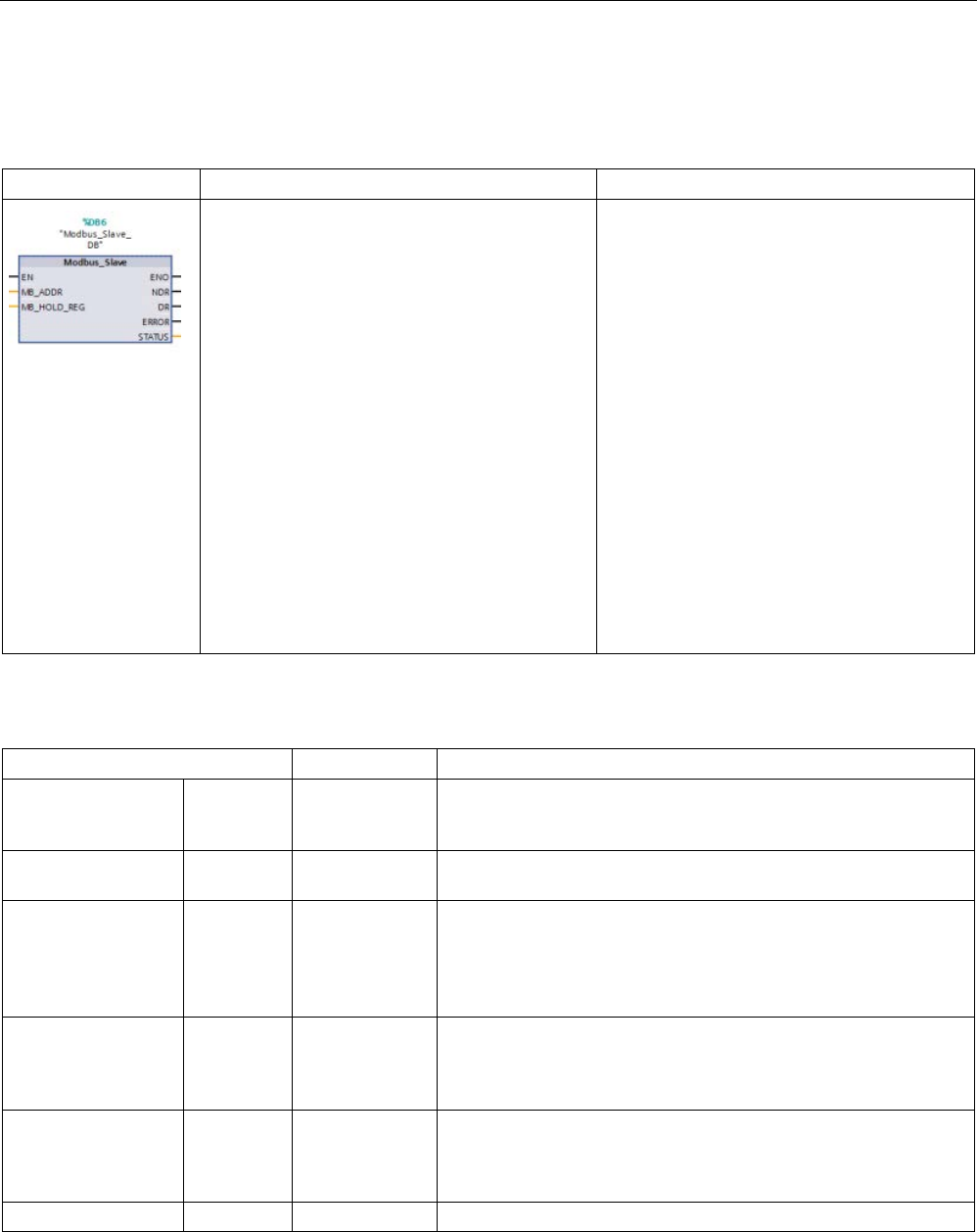
Communication processor and Modbus TCP
13.5 Modbus communication
S7-1200 Programmable controller
1206 System Manual, V4.2, 09/2016, A5E02486680-AK
Modbus_Slave (Communicate using SIPLUS I/O or the PtP port as Modbus RTU slave) instruction
Table 13- 80 Modbus_Slave instruction
LAD / FBD
SCL
Description
"Modbus_Slave_DB"(
MB_ADDR:=_uint_in_,
NDR=>_bool_out_,
DR=>_bool_out_,
ERROR=>_bool_out_,
STATUS=>_word_out_,
MB_HOLD_REG:=_variant_inout_);
The Modbus_Slave instruction allows your
program to communicate in one of two ways:
• As a Modbus RTU slave through a PtP
port on the CM (RS485 or RS232) and CB
(RS485)
• As a Modbus RTU slave through Modbus
RTU SIPLUS I/O options:
– Install ET 200MP S7-1500CM PtP
(RS485 / 422 or RS232).
– Install ET 200SP S7-1500 CM PtP
(RS485 / 422 or RS232).
When a remote Modbus RTU master issues a
request, your user program responds to the
request by Modbus_Slave execution. STEP 7
automatically creates an instance DB when
you insert the instruction. Use this Mod-
bus_Slave_DB name when you specify the
MB_DB parameter for the Mod-
bus_Comm_Load instruction.
Table 13- 81 Data types for the parameters
Parameter and type
Data type
Description
MB_ADDR IN V1.0: USInt
V2.0: UInt
The station address of the Modbus slave:
Standard addressing range (1 to 247)
Extended addressing range (0 to 65535)
MB_HOLD_REG IN Variant Pointer to the Modbus Holding Register DB: The Modbus holding
register can be M memory or a data block.
NDR OUT Bool New Data Ready:
• 0 – No new data
• 1 – Indicates that new data has been written by the Modbus
master
DR OUT Bool Data Read:
• 0 – No data read
• 1 – Indicates that data has been read by the Modbus master
ERROR OUT Bool The ERROR bit is TRUE for one scan, after the last request was
terminated with an error. If execution is terminated with an error,
then the error code value at the STATUS parameter is valid only
during the single scan where ERROR = TRUE.
STATUS
OUT
Word
Execution error code

Communication processor and Modbus TCP
13.5 Modbus communication
S7-1200 Programmable controller
System Manual, V4.2, 09/2016, A5E02486680-AK 1207
Modbus communication function codes (1, 2, 4, 5, and 15) can read and write bits and words
directly in the input process image and output process image of the CPU. For these function
codes, the MB_HOLD_REG parameter must be defined as a data type larger than a byte.
The following table shows the example mapping of Modbus addresses to the process image
in the CPU.
Table 13- 82 Mapping of Modbus addresses to the process image
Modbus functions
S7-1200
Codes
Function
Data area
Address range
Data area
CPU address
01 Read bits Output 1 to 8192 Output Process Image Q0.0 to Q1023.7
02
Read bits
Input
10001
to
18192
Input Process Image
I0.0 to I1023.7
04
Read words
Input
30001
to
30512
Input Process Image
IW0 to IW1022
05
Write bit
Output
1
to
8192
Output Process Image
Q0.0 to Q1023.7
15
Write bits
Output
1
to
8192
Output Process Image
Q0.0 to Q1023.7
Modbus communication function codes (3, 6, 16) use a Modbus holding register which can
be an M memory address range or a data block. The type of holding register is specified by
the MB_HOLD_REG parameter on the Modbus_Slave instruction.
Note
MB_HOLD_REG data block type
A Modbus holding register data block must allow
both direct (absolute) and symbolic
addressing. When you create the data block the "Standard" access attribute must be
selected.
The following table shows examples of Modbus address to holding register mapping that is
used for Modbus function codes 03 (read words), 06 (write word), and 16 (write words). The
actual upper limit of DB addresses is determined by the maximum work memory limit and M
memory limit, for each CPU model.
Table 13- 83 Mapping of Modbus addresses to CPU memory
Modbus master
address
MB_HOLD_REG parameter examples
MW100
DB10.DBw0
MW120
DB10.DBW50
"Recipe".ingredient
40001
MW100
DB10.DBW0
MW120
DB10.DBW50
"Recipe".ingredient[1]
40002
MW102
DB10.DBW2
MW122
DB10.DBW52
"Recipe".ingredient[2]
40003
MW104
DB10.DBW4
MW124
DB10.DBW54
"Recipe".ingredient[3]
40004
MW106
DB10.DBW6
MW126
DB10.DBW56
"Recipe".ingredient[4]
40005
MW108
DB10.DBW8
MW128
DB10.DBW58
"Recipe".ingredient[5]

Communication processor and Modbus TCP
13.5 Modbus communication
S7-1200 Programmable controller
1208 System Manual, V4.2, 09/2016, A5E02486680-AK
Table 13- 84 Diagnostic functions
S7-1200 Modbus_Slave Modbus diagnostic functions
Codes
Sub-function
Description
08 0000H Return query data echo test: The Modbus_Slave will echo back to a Modbus master a
word of data that is received.
08 000AH Clear communication event counter: The Modbus_Slave will clear out the communica-
tion event counter that is used for Modbus function 11.
11 Get communication event counter: The Modbus_Slave uses an internal communication
event counter for recording the number of successful Modbus read and write requests
that are sent to the Modbus_Slave. The counter does not increment on any Function 8,
Function 11, or broadcast requests. It is also not incremented on any requests that
result in a communication error (for example, parity or CRC errors).
The Modbus_Slave instruction supports broadcast write requests from any Modbus master
as long as the request is for accessing valid addresses. Modbus_Slave will produce error
code "0x8188" for function codes not supported in broadcast.
Modbus_Slave communication rules
● Modbus_Comm_Load must be executed to configure a port, before a Modbus_Slave
instruction can communicate through that port.
● If a port is to respond as a slave to a Modbus_Master, then do not program that port with
the Modbus_Master instruction.
● Only one instance of Modbus_Slave can be used with a given port, otherwise erratic
behavior may occur.
● The Modbus instructions do not use communication interrupt events to control the
communication process. Your program must control the communication process by
polling the Modbus_Slave instruction for transmit and receive complete conditions.
● The Modbus_Slaveinstruction must execute periodically at a rate that allows it to make a
timely response to incoming requests from a Modbus_Master. It is recommended that you
execute Modbus_Slave every scan from a program cycle OB. Executing Modbus_Slave
from a cyclic interrupt OB is possible, but is not recommended because of the potential
for excessive time delays in the interrupt routine to temporarily block the execution of
other interrupt routines.
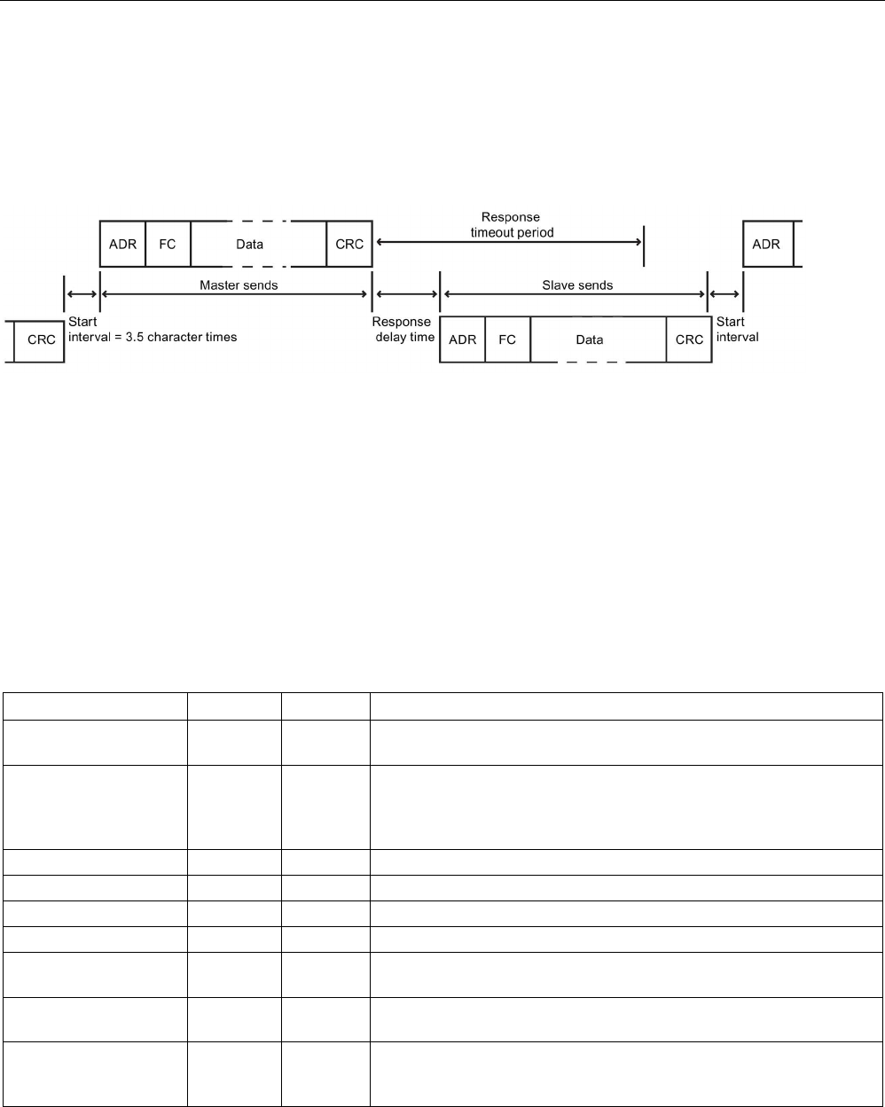
Communication processor and Modbus TCP
13.5 Modbus communication
S7-1200 Programmable controller
System Manual, V4.2, 09/2016, A5E02486680-AK 1209
Modbus signal timing
Modbus_Slave must be executed periodically to receive each request from the
Modbus_Master and then respond as required. The frequency of execution for
Modbus_Slave is dependent upon the response timeout period of the Modbus_Master. This
is illustrated in the following diagram.
The response timeout period RESP_TO is the amount of time a Modbus_Master waits for the
start of a response from a Modbus_Slave. This time period is not defined by the Modbus
protocol, but is a parameter of each Modbus_Master. The frequency of execution (the time
between one execution and the next execution) of Modbus_Slave must be based upon the
particular parameters of your Modbus_Master. At a minimum, you should execute
Modbus_Slave twice within the response timeout period of the Modbus_Master.
Modbus_Slave instruction data block (DB) tags
The following table shows the public static tags stored in the Modbus_Slave instance DB that
you can use in your program:
Table 13- 85 Modbus_Slave instance DB static tags
Tag
Data type
Default
Description
HR_Start_Offset Word 0 Assigns the starting address of the Modbus holding register (default =
0)
Extended_Addressing Bool FALSE Configures single or double-byte slave addressing:
• FALSE = single byte address
• TRUE = double-byte address
Request_Count
Word
0
Total of all requests received by this slave
Slave_Message_Count
Word
0
Number of requests received for this specific slave
Bad_CRC_Count Word 0 Number of requests received that have a CRC error
Broadcast_Count
Word
0
Number of broadcast requests received
Exception_Count Word 0 Modbus-specific errors that require an acknowledgement with a re-
turned exception to the master
Success_Count Word 0 Number of requests received for this specific slave that have no proto-
col errors
MB_DB MB_BASE - The MB_DB parameter of the Modbus_Comm_Load instruction must
be connected to the MB_DB parameter of the Modbus_Slave instruc-
tion.
Your program can write values to the HR_Start_Offset and Extended_Addressing tags and
control the Modbus slave operations. You can read the other tags to monitor the Modbus
status.
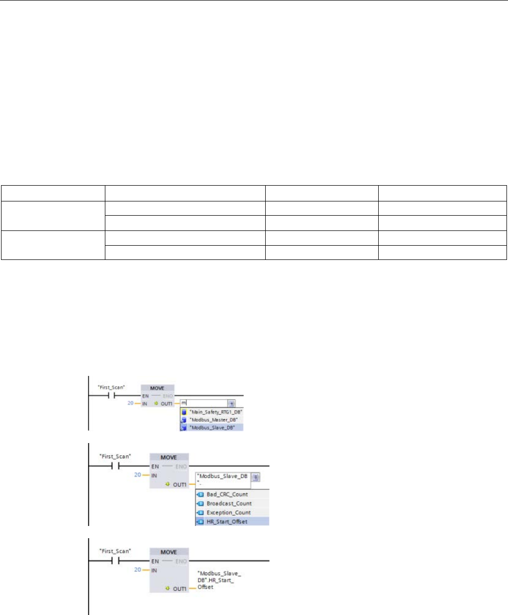
Communication processor and Modbus TCP
13.5 Modbus communication
S7-1200 Programmable controller
1210 System Manual, V4.2, 09/2016, A5E02486680-AK
HR_Start_Offset
Modbus holding register addresses begin at 40001 or 400001. These addresses correspond
to the beginning PLC memory address of the holding register. However, you can configure
the "HR_Start_Offset" variable to start the beginning Modbus holding register address at
another value instead of 40001 or 400001.
For example, if the holding register is configured to start at MW100 and is 100 words long.
An offset of 20 specifies a beginning holding register address of 40021 instead of 40001.
Any address below 40021 and above 400119 will result in an addressing error.
Table 13- 86 Example of Modbus holding register addressing
HR_Start_Offset
Address
Minimum
Maximum
0
Modbus address (Word)
40001
40099
S7-1200 address MW100 MW298
20
Modbus address (Word)
40021
40119
S7-1200 address MW100 MW298
HR_Start_Offset is a word value that specifies the starting address of the Modbus holding
register and is stored in the Modbus_Slave instance data block. You can set this public static
variable value by using the parameter helper drop-list, after Modbus_Slave is placed in your
program.
For example, after Modbus_Slave is placed in a LAD network, you can go to a previous
network and assign the HR_Start_Offset value. The value must be assigned prior to
execution of Modbus_Slave.
Entering a Modb
us slave variable using the
default DB name:
1.
Set the cursor in the parameter field and
type an m character.
2.
Select "Modbus_Slave_DB" from the drop-
list.
3.
Set the cursor at the right side of the DB
name (after the quote character) and enter
a period character.
4.
Select
"Modbus_Slave_DB.HR_Start_Offset" from
the drop list.

Communication processor and Modbus TCP
13.5 Modbus communication
S7-1200 Programmable controller
System Manual, V4.2, 09/2016, A5E02486680-AK 1211
Extended_Addressing
The Extended_Addressing variable is accessed in a similar way as the HR_Start_Offset
reference discussed above except that the Extended_Addressing variable is a Boolean
value. The Boolean value must be written by an output coil and not a move box.
Modbus slave addressing can be configured to be either a single byte (which is the Modbus
standard) or double byte. Extended addressing is used to address more than 247 devices
within a single network. Selecting extended addressing allows you to address a maximum of
64000 addresses. A Modbus function 1 frame is shown below as an example.
Table 13- 87 Single-byte slave address (byte 0)
Function 1
Byte 0
Byte 1
Byte 2
Byte 3
Byte 4
Byte 5
Request
Slave addr.
F code
Start address
Length of coils
Valid Response Slave addr. F code Length Coil data
Error response
Slave addr.
0x81
E code
Table 13- 88 Double-byte slave address (byte 0 and byte 1)
Byte 0
Byte 1
Byte 2
Byte 3
Byte 4
Byte 5
Byte 6
Request Slave address F code Start address Length of coils
Valid Response
Slave address
F code
Length
Coil data
Error response
Slave address
0x81
E code

Communication processor and Modbus TCP
13.5 Modbus communication
S7-1200 Programmable controller
1212 System Manual, V4.2, 09/2016, A5E02486680-AK
Condition codes
Table 13- 89 Modbus_Slave execution condition codes (communication and configuration errors) 1
STATUS (W#16#)
Description
80D1 The receiver issued a flow control request to suspend an active transmission and never re-
enabled the transmission during the specified wait time.
This error is also generated during hardware flow control when the receiver does not assert
CTS within the specified wait time.
80D2
The transmit request was aborted because no DSR signal is received from the DCE.
80E0
The message was terminated because the receive buffer is full.
80E1
The message was terminated as a result of a parity error.
80E2
The message was terminated as a result of a framing error.
80E3
The message was terminated as a result of an overrun error.
80E4 The message was terminated as a result of the specified length exceeding the total buffer
size.
8180
Invalid port ID value or error with Modbus_Comm_Load instruction
8186
Invalid Modbus station address
8187
Invalid pointer to MB_HOLD_REG DB: Area is too small
818C Invalid MB_HOLD_REG pointer. The data area must be one of the following:
• Classic DB
• Array of elemental data types in a symbolic or retentive DB
• M memory
Table 13- 90 Modbus_Slave execution condition codes (Modbus protocol errors) 1
STATUS (W#16#)
Response code from
slave
Modbus protocol errors
8380
No response
CRC error
8381
01
Function code not supported or not supported within broadcasts
8382
03
Data length error
8383 02 Data address error or address outside the valid range of the
DATA_PTR area
8384
03
Data value error
8385 03 Data diagnostic code value not supported (function code 08)
1
In addition to the Modbus_Slave errors listed above, errors can be returned from the underlying PtP communication
instructions.
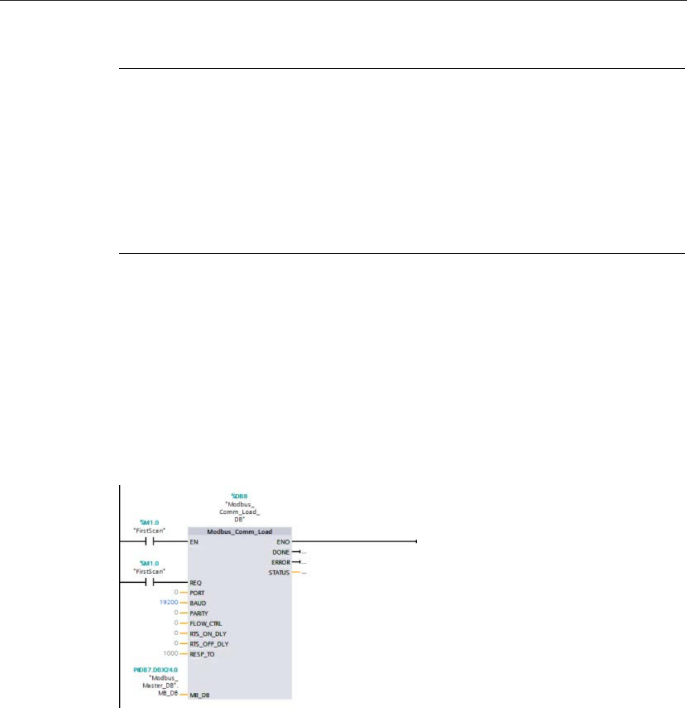
Communication processor and Modbus TCP
13.5 Modbus communication
S7-1200 Programmable controller
System Manual, V4.2, 09/2016, A5E02486680-AK 1213
Note
Setting the maximum record length for PROFIBUS communication
When using a CM1243
-5 PROFIBUS Master module to control an ET 200SP or ET 200MP
PROFIBUS device that uses an RS232, RS422, or RS485 point
-to-point module, you need
to explicitly set the "max_record_len" data block tag to 240 as defined below:
Set "max_record_len" in the Send_P2P section of the instance DB (for example,
"Modbus_
Slave_DB".Send_P2P.max_record_len) to 240 after running Modbus_Comm_Load.
Explicitly assigning max_record_len is only necessary with PROFIBUS communication;
PROFINET communication already uses a valid max_record_len value.
13.5.3.5
Modbus RTU examples
Example: Modbus RTU master program
Modbus_Comm_Load is initialized during start-up by using the first scan flag. Execution of
Modbus_Comm_Load in this manner should only be done when the serial port configuration
will not change at runtime.
Network 1
: Configure/initialize the RS485 module communications port only once during the
first scan.
One Modbus_Master instruction is used in the program cycle OB to communicate with a
single slave. Additional Modbus_Master instructions can be used in the program cycle OB to
communicate with other slaves, or one Modbus_Master FB could be re-used to communicate
with additional slaves.
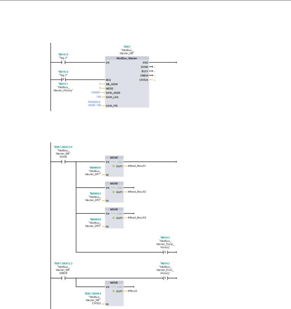
Communication processor and Modbus TCP
13.5 Modbus communication
S7-1200 Programmable controller
1214 System Manual, V4.2, 09/2016, A5E02486680-AK
Network 2
: Read 100 words of holding register data from location 400001 on slave #2 to
memory location MW500-MW698.
Network 3
: Move the first 3 words of the holding register data that has been read to some
other location, and set a DONE history bit. This network also sets an ERROR history bit and
saves the STATUS word to another location in the event of an error.
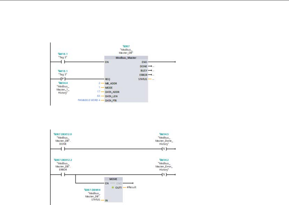
Communication processor and Modbus TCP
13.5 Modbus communication
S7-1200 Programmable controller
System Manual, V4.2, 09/2016, A5E02486680-AK 1215
Network 4
: Write 64 bits of data from MW600-MW607 to output bit locations 00017 to 00081
on slave #2.
Network 5
: Set a DONE history bit when the write is complete. If an error occurs, the
program sets an ERROR history bit and saves the STATUS code.
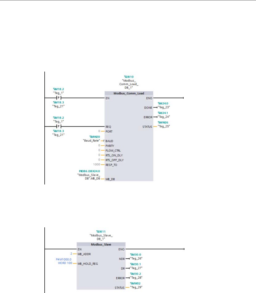
Communication processor and Modbus TCP
13.5 Modbus communication
S7-1200 Programmable controller
1216 System Manual, V4.2, 09/2016, A5E02486680-AK
Example: Modbus RTU slave program
MB_COMM_LOAD shown below is initialized each time "Tag_1" is enabled.
Execution of MB_COMM_LOAD in this manner should only be done when the serial port
configuration will change at runtime, as a result of HMI configuration.
Network 1
: Initialize the RS485 module parameters each time they are changed by an HMI
device.
MB_SLAVE shown below is placed in a cyclic OB that is executed every 10 ms. While this
does not give the absolute fastest response by the slave, it does provide good performance
at 9600 baud for short messages (20 bytes or less in the request).
Network 2
: Check for Modbus master requests during each scan. The Modbus holding
register is configured for 100 words starting at MW1000.

Communication processor and Modbus TCP
13.6 Legacy PtP communication (CM/CB 1241 only)
S7-1200 Programmable controller
System Manual, V4.2, 09/2016, A5E02486680-AK 1217
13.6
Legacy PtP communication (CM/CB 1241 only)
Prior to the release of STEP 7 V13 SP1 and the S7-1200 V4.1 CPUs, the point-to-point
communication instructions existed with different names, and in some cases, slightly
different interfaces. The general concepts about point-to-point communication (Page 1090),
as well as port (Page 1093) and parameter configuration (Page 1108) apply to both sets of
instructions. Refer to the individual legacy point-to-point instructions for programming
information.
Table 13- 91 Common error classes
Class description
Error classes
Description
Port configuration
80Ax
Used to define common port configuration errors
Transmit configuration 80Bx Used to define common transmit configuration errors
Receive configuration
80Cx
Used to define common receive configuration errors
Transmission runtime
80Dx
Used to define common transmission runtime errors
Reception runtime
80Ex
Used to define common reception runtime errors
Signal handling 80Fx Used to define common errors associated with all signal han-
dling

Communication processor and Modbus TCP
13.6 Legacy PtP communication (CM/CB 1241 only)
S7-1200 Programmable controller
1218 System Manual, V4.2, 09/2016, A5E02486680-AK
13.6.1
Legacy point-to-point instructions
13.6.1.1
PORT_CFG (Configure communication parameters dynamically)
Table 13- 92 PORT_CFG (Port Configuration) instruction
LAD / FBD
SCL
Description
"PORT_CFG_DB"(
REQ:=_bool_in_,
PORT:=_uint_in_,
PROTOCOL:=_uint_in_,
BAUD:=_uint_in_,
PARITY:=_uint_in_,
DATABITS:=_uint_in_,
STOPBITS:=_uint_in_,
FLOWCTRL:=_uint_in_,
XONCHAR:=_char_in_,
XOFFCHAR:=_char_in_,
WAITTIME:=_uint_in_,
DONE=>_bool_out_,
ERROR=>_bool_out_,
STATUS=>_word_out_);
PORT_CFG allows you to change port parameters
such as baud rate from your program.
You can set up the initial static configuration of the
port in the device configuration properties, or just use
the default values. You can execute the PORT_CFG
instruction in your program to change the configura-
tion.
1 STEP 7 automatically creates the DB when you insert the instruction.
The PORT_CFG configuration changes are not permanently stored in the CPU. The
parameters configured in the device configuration are restored when the CPU transitions
from RUN to STOP mode and after a power cycle. See Configuring the communication ports
(Page 1093) and Managing flow control (Page 1095) for more information.
Table 13- 93 Data types for the parameters
Parameter and type
Data type
Description
REQ IN Bool
Activate the configuration change on rising edge of this input. (Default value:
False)
PORT IN PORT After you install and configure a CM or CB communication device, the port
identifier appears in the parameter helper drop-list available at the PORT
box connection. The assigned CM or CB port value is the device configura-
tion property "hardware identifier". The port symbolic name is assigned in
the "System constants" tab of the PLC tag table. (Default value: 0)
PROTOCOL IN UInt 0 - Point-to-Point communication protocol (Default value)
1..n - future definition for specific protocols
BAUD IN UInt Port baud rate (Default value: 6):
1 = 300 baud, 2 = 600 baud, 3 = 1200 baud, 4 = 2400 baud, 5 = 4800 baud,
6 = 9600 baud, 7 = 19200 baud, 8 = 38400 baud, 9 = 57600 baud,
10 = 76800 baud, 11 = 115200 baud
PARITY IN UInt Port parity (Default value: 1):
1 = No parity, 2 = Even parity, 3 = Odd parity, 4 = Mark parity,
5 = Space parity
DATABITS IN UInt Bits per character (Default value:1):
1 = 8 data bits, 2 = 7 data bits

Communication processor and Modbus TCP
13.6 Legacy PtP communication (CM/CB 1241 only)
S7-1200 Programmable controller
System Manual, V4.2, 09/2016, A5E02486680-AK 1219
Parameter and type
Data type
Description
STOPBITS IN UInt Stop bits (Default value: 1):
1 = 1 stop bit, 2 = 2 stop bits
FLOWCTRL IN UInt Flow control (Default value: 1):
1 = No flow control, 2 = XON/XOFF, 3 = Hardware RTS always ON,
4 = Hardware RTS switched
XONCHAR IN Char
Specifies the character that is used as the XON character. This is typically a
DC1 character (16#11). This parameter is only evaluated if flow control is
enabled. (Default value: 16#11)
XOFFCHAR IN Char Specifies the character that is used as the XOFF character. This is typically
a DC3 character (116#3). This parameter is only evaluated if flow control is
enabled. (Default value: 16#13)
XWAITIME IN UInt Specifies how long to wait for a XON character after receiving a XOFF char-
acter, or how long to wait for the CTS signal after enabling RTS (0 to 65535
ms). This parameter is only evaluated if flow control is enabled. (Default
value: 2000)
DONE
OUT
Bool
TRUE for one execution after the last request was completed with no error
ERROR
OUT
Bool
TRUE for one execution after the last request was completed with an error
STATUS
OUT
Word
Execution condition code (Default value: 0)
Table 13- 94 Condition codes
STATUS (W#16#....)
Description
80A0
Specific protocol does not exist.
80A1
Specific baud rate does not exist.
80A2
Specific parity option does not exist.
80A3
Specific number of data bits does not exist.
80A4 Specific number of stop bits does not exist.
80A5
Specific type of flow control does not exist.
80A6 Wait time is 0 and flow control enabled
80A7
XON and XOFF are illegal values (for example, the same value)

Communication processor and Modbus TCP
13.6 Legacy PtP communication (CM/CB 1241 only)
S7-1200 Programmable controller
1220 System Manual, V4.2, 09/2016, A5E02486680-AK
13.6.1.2
SEND_CFG (Configure serial transmission parameters dynamically)
Table 13- 95 SEND_CFG (Send Configuration) instruction
LAD / FBD
SCL
Description
"SEND_CFG_DB"(
REQ:=_bool_in_,
PORT:=_uint_in_,
RTSONDLY:=_uint_in_,
RTSOFFDLY:=_uint_in_,
BREAK:=_uint_in_,
IDLELINE:=_uint_in_,
DONE=>_bool_out_,
ERROR=>_bool_out_,
STATUS=>_word_out_);
SEND_CFG allows the dynamic configuration of serial
transmission parameters for a PtP communication port.
Any queued messages within a CM or CB are discard-
ed when SEND_CFG is executed.
1 STEP 7 automatically creates the DB when you insert the instruction.
You can set up the initial static configuration of the port in the device configuration
properties, or just use the default values. You can execute the SEND_CFG instruction in
your program to change the configuration.
The SEND_CFG configuration changes are not permanently stored in the CPU. The
parameters configured in the device configuration are restored when the CPU transitions
from RUN to STOP mode and after a power cycle. See Configuring transmit (send)
parameters.
Table 13- 96 Data types for the parameters
Parameter and type
Data type
Description
REQ IN Bool Activate the configuration change on the rising edge of this input.. (Default
value: False)
PORT IN PORT After you install and configure a CM or CB communication device, the port
identifier appears in the parameter helper drop-list available at the PORT
box connection. The assigned CM or CB port value is the device configura-
tion property "hardware identifier". The port symbolic name is assigned in
the "System constants" tab of the PLC tag table. (Default value: 0)
RTSONDLY IN UInt Number of milliseconds to wait after enabling RTS before any Tx data
transmission occurs. This parameter is only valid when hardware flow con-
trol is enabled. The valid range is 0 - 65535 ms. A value of 0 disables the
feature. (Default value: 0)
RTSOFFDLY IN UInt Number of milliseconds to wait after the Tx data transmission occurs before
RTS is disabled: This parameter is only valid when hardware flow control is
enabled. The valid range is 0 - 65535 ms. A value of 0 disables the feature.
(Default value: 0)
BREAK IN UInt This parameter specifies that a break will be sent upon the start of each
message for the specified number of bit times. The maximum is 65535 bit
times up to an eight second maximum. A value of 0 disables the feature.
(Default value: 12)
IDLELINE IN UInt This parameter specifies that the line will remain idle for the specified num-
ber of bit times before the start of each message. The maximum is 65535 bit
times up to an eight second maximum. A value of 0 disables the feature.
(Default value: 12)
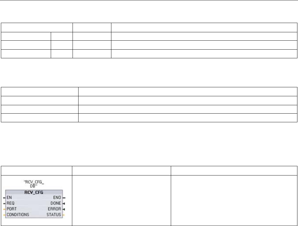
Communication processor and Modbus TCP
13.6 Legacy PtP communication (CM/CB 1241 only)
S7-1200 Programmable controller
System Manual, V4.2, 09/2016, A5E02486680-AK 1221
Parameter and type
Data type
Description
DONE
OUT
Bool
TRUE for one execution after the last request was completed with no error
ERROR OUT Bool TRUE for one execution after the last request was completed with an error
STATUS
OUT
Word
Execution condition code (Default value: 0)
Table 13- 97 Condition codes
STATUS (W#16#....)
Description
80B0 Transmit interrupt configuration is not allowed.
80B1
Break time is greater than the maximum allowed value.
80B2
Idle time is greater than the maximum allowed value.
13.6.1.3
RCV_CFG (Configure serial receive parameters dynamically)
Table 13- 98 RCV_CFG (Receive Configuration) instruction
LAD / FBD
SCL
Description
"RCV_CFG_DB"(
REQ:=_bool_in_,
PORT:=_uint_in_,
CONDITIONS:=_struct_in_,
DONE=>_bool_out_,
ERROR=>_bool_out_,
STATUS=>_word_out_);
RCV_CFG performs dynamic configuration of seri-
al receiver parameters for a PtP communication
port. This instruction configures the conditions that
signal the start and end of a received message.
Any queued messages within a CM or CB are
discarded when RCV_CFG is executed.
1 STEP 7 automatically creates the DB when you insert the instruction.
You can set up the initial static configuration of the communication port in the device
configuration properties, or just use the default values. You can execute the RCV_CFG
instruction in your program to change the configuration.
The RCV_CFG configuration changes are not permanently stored in the CPU. The
parameters configured in the device configuration are restored when the CPU transitions
from RUN to STOP mode and after a power cycle. See Configuring receive parameters
(Page 1097) for more information.

Communication processor and Modbus TCP
13.6 Legacy PtP communication (CM/CB 1241 only)
S7-1200 Programmable controller
1222 System Manual, V4.2, 09/2016, A5E02486680-AK
Table 13- 99 Data types for the parameters
Parameter and type
Data type
Description
REQ IN Bool Activate the configuration change on the rising edge of this input.
(Default value: False)
PORT IN PORT After you install and configure a CM or CB communication device,
the port identifier appears in the parameter helper drop-list available
at the PORT box connection. The assigned CM or CB port value is
the device configuration property "hardware identifier". The port sym-
bolic name is assigned in the "System constants" tab of the PLC tag
table. (Default value: 0)
CONDITIONS IN CONDITIONS The Conditions data structure specifies the starting and ending mes-
sage conditions as described below.
DONE OUT Bool TRUE for one scan, after the last request was completed with no
error
ERROR OUT Bool TRUE for one scan, after the last request was completed with an
error
STATUS
OUT
Word
Execution condition code (Default value: 0)
Start conditions for the RCV_PTP instruction
The RCV_PTP instruction uses the configuration specified by the RCV_CFG instruction to
determine the beginning and ending of point-to-point communication messages. The start of
a message is determined by the start conditions. The start of a message can be determined
by one or a combination of start conditions. If more than one start condition is specified, all
the conditions must be satisfied before the message is started.
See the topic "Configuring receive parameters (Page 1097)" for a description of the message
start conditions.

Communication processor and Modbus TCP
13.6 Legacy PtP communication (CM/CB 1241 only)
S7-1200 Programmable controller
System Manual, V4.2, 09/2016, A5E02486680-AK 1223
Parameter CONDITIONS data type structure part 1 (start conditions)
Table 13- 100 CONDITIONS structure for START conditions
Parameter and type
Data type
Description
STARTCOND IN UInt Specifies the start condition (Default value: 1)
• 01H - Start Char
• 02H - Any Char
• 04H - Line Break
• 08H - Idle Line
• 10H - Sequence 1
• 20H - Sequence 2
• 40H - Sequence 3
• 80H - Sequence 4
IDLETIME IN UInt The number of bit times required for idle line timeout. (Default value:
40). Only used with an idle line condition. 0 to 65535
STARTCHAR IN Byte The start character used with the start character condition. (Default
value: B#16#2)
SEQ[1].CTL IN Byte Sequence 1 ignore/compare control for each character: (Default
value: B#16#0)
These are the enabling bits for each character in start sequence
• 01H - Character 1
• 02H - Character 2
• 04H - Character 3
• 08H - Character 4
• 10H - Character 5
Disabling the bit associated with a character means any character
will match, in this sequence position.
SEQ[1].STR
IN
Char[5]
Sequence 1 start characters (5 characters). Default value: 0
SEQ[2].CTL IN Byte Sequence 2 ignore/compare control for each character. Default val-
ue: B#16#0)
SEQ[2].STR
IN
Char[5]
Sequence 2 start characters (5 characters). Default value: 0
SEQ[3].CTL IN Byte Sequence 3 ignore/compare control for each character. Default val-
ue: B#16#0
SEQ[3].STR
IN
Char[5]
Sequence 3 start characters (5 characters). Default value: 0
SEQ[4].CTL IN Byte Sequence 4 ignore/compare control for each character. Default val-
ue: B#16#0
SEQ[4].STR
IN
Char[5]
Sequence 4 start characters (5 characters), Default value: 0

Communication processor and Modbus TCP
13.6 Legacy PtP communication (CM/CB 1241 only)
S7-1200 Programmable controller
1224 System Manual, V4.2, 09/2016, A5E02486680-AK
Example
Consider the following received hexadecimal coded message: "
68
10 aa
68
bb 10 aa 16"
and the configured start sequences shown in the table below. Start sequences begin to be
evaluated when the first 68H character is successfully received. Upon successfully receiving
the fourth character (the second 68H), then start condition 1 is satisfied. Once the start
conditions are satisfied, the evaluation of the end conditions begins.
The start sequence processing can be terminated due to various parity, framing, or inter-
character timing errors. These errors result in no received message, because the start
condition was not satisfied.
Table 13- 101 Start conditions
Start condition
First Character
First Character +1
First Character +2
First Character +3
First Character +4
1
68H
xx
xx
68H
xx
2 10H aaH xx xx xx
3
dcH
aaH
xx
xx
xx
4
e5H
xx
xx
xx
xx
End conditions for the RCV_PTP instruction
The end of a message is determined by the specification of end conditions. The end of a
message is determined by the first occurrence of one or more configured end conditions.
The section "Message end conditions" in the topic "Configuring receive parameters
(Page 1097)" describes the end conditions that you can configure in the RCV_CFG
instruction.
You can configure the end conditions in either the properties of the communication interface
in the device configuration, or from the RCV_CFG instruction. Whenever the CPU transitions
from STOP to RUN, the receive parameters (both start and end conditions) return to the
device configuration settings. If the STEP 7 user program executes RCV_CFG, then the
settings are changed to the RCV_CFG conditions.

Communication processor and Modbus TCP
13.6 Legacy PtP communication (CM/CB 1241 only)
S7-1200 Programmable controller
System Manual, V4.2, 09/2016, A5E02486680-AK 1225
Parameter CONDITIONS data type structure part 2 (end conditions)
Table 13- 102 CONDITIONS structure for END conditions
Parameter
Parameter type
Data type
Description
ENDCOND IN UInt
0
This parameter specifies message end condition:
• 01H - Response time
• 02H - Message time
• 04H - Inter-character gap
• 08H - Maximum length
• 10H - N + LEN + M
• 20H - Sequence
MAXLEN IN UInt
1
Maximum message length: Only used when the maxi-
mum length end condition is selected. 1 to 1024 bytes
N IN UInt
0
Byte position within the message of the length field. Only
used with the N + LEN + M end condition. 1 to 1022
bytes
LENGTHSIZE IN UInt
0
Size of the length field (1, 2, or 4 bytes). Only used with
the N + LEN + M end condition.
LENGTHM IN UInt
0
Specify the number of characters following the length
field that are not included in the value of the length field.
This is only used with the N + LEN + M end condition. 0
to 255 bytes
RCVTIME IN UInt
200
Specify how long to wait for the first character to be re-
ceived. The receive operation will be terminated with an
error if a character is not successfully received within the
specified time. This is only used with the response time
condition. (0 to 65535 bit times with an 8 second maxi-
mum)
This parameter is not a message end condition since
evaluation terminates when the first character of a re-
sponse is received. It is an end condition only in the
sense that it terminates a receiver operation because no
response is received when a response is expected. You
must select a separate end condition.
MSGTIME IN UInt
200
Specify how long to wait for the entire message to be
completely received once the first character has been
received. This parameter is only used when the message
timeout condition is selected. (0 to 65535 milliseconds)
CHARGAP IN UInt
12
Specify the number of bit times between characters. If the
number of bit times between characters exceeds the
specified value, then the end condition will be satisfied.
This is only used with the inter-character gap condition.
(0 to 65535 bit times up to 8 second maximum)

Communication processor and Modbus TCP
13.6 Legacy PtP communication (CM/CB 1241 only)
S7-1200 Programmable controller
1226 System Manual, V4.2, 09/2016, A5E02486680-AK
Parameter
Parameter type
Data type
Description
SEQ.CTL IN Byte
B#16#0
Sequence 1 ignore/compare control for each character:
These are the enabling bits for each character for the end
sequence. Character 1 is bit 0, character 2 is bit 1, …,
character 5 is bit 4. Disabling the bit associated with a
character means any character will match, in this se-
quence position.
SEQ.STR IN Char[5]
0
Sequence 1 start characters (5 characters)
Table 13- 103 Condition codes
STATUS (W#16#....)
Description
80C0
Illegal start condition selected
80C1
Illegal end condition selected, no end condition selected
80C2
Receive interrupt enabled and this is not possible.
80C3
Maximum length end condition is enabled and max length is 0 or > 1024.
80C4
Calculated length is enabled and N is >= 1023.
80C5
Calculated length is enabled and length is not 1, 2 or 4.
80C6
Calculated length is enabled and M value is > 255.
80C7
Calculated length is enabled and calculated length is > 1024.
80C8
Response timeout is enabled and response timeout is zero.
80C9
Inter-character gap timeout is enabled and it is zero.
80CA
Idle line timeout is enabled and it is zero.
80CB
End sequence is enabled but all chars are "don't care".
80CC
Start sequence (any one of 4) is enabled but all characters are "don't care".
13.6.1.4
SEND_PTP (Transmit send buffer data)
Table 13- 104 SEND_PTP (Send Point-to-Point data) instruction
LAD / FBD
SCL
Description
"SEND_PTP_DB"(
REQ:=_bool_in_,
PORT:=_uint_in_,
BUFFER:=_variant_in_,
LENGTH:=_uint_in_,
PTRCL:=_bool_in_,
DONE=>_bool_out_,
ERROR=>_bool_out_,
STATUS=>_word_out_);
SEND_PTP initiates the transmission of the data
and transfers the assigned buffer to the communica-
tion interface. The CPU program continues while
the CM or CB sends the data at the assigned baud
rate. Only one send operation can be pending at a
given time. The CM or CB returns an error if a sec-
ond SEND_PTP is executed while the CM or CB is
already transmitting a message.
1 STEP 7 automatically creates the DB when you insert the instruction.

Communication processor and Modbus TCP
13.6 Legacy PtP communication (CM/CB 1241 only)
S7-1200 Programmable controller
System Manual, V4.2, 09/2016, A5E02486680-AK 1227
Table 13- 105 Data types for the parameters
Parameter and type
Data type
Description
REQ IN Bool Activates the requested transmission on the rising edge of this transmission
enable input. This initiates transfer of the contents of the buffer to the Point-to-
Point communication interface. (Default value: False)
PORT IN PORT After you install and configure a CM or CB communication device, the port
identifier appears in the parameter helper drop-list available at the PORT box
connection. The assigned CM or CB port value is the device configuration
property "hardware identifier". The port symbolic name is assigned in the "Sys-
tem constants" tab of the PLC tag table. (Default value: 0)
BUFFER IN Variant This parameter points to the starting location of the transmit buffer. (Default
value: 0)
Note: Boolean data or Boolean arrays are not supported.
LENGTH 1 IN UInt Transmitted frame length in bytes (Default value: 0)
When transmitting a complex structure, always use a length of 0.
PTRCL
IN
Bool
Reserved for future use
DONE
OUT
Bool
TRUE for one scan, after the last request was completed with no error
ERROR
OUT
Bool
TRUE for one scan, after the last request was completed with an error
STATUS
OUT
Word
Execution condition code (Default value: 0)
1 Optional parameter: Click the arrow at the bottom of a LAD/FBD box to expand the box and include this parameter.
While a transmit operation is in progress, the DONE and ERROR outputs are FALSE. When
a transmit operation is complete, either the DONE or the ERROR output will be set TRUE to
show the status of the transmit operation. While DONE or ERROR is TRUE, the STATUS
output is valid.
The instruction returns a status of 16#7001 if the communication interface accepts the
transmit data. Subsequent SEND_PTP executions return 16#7002, if the CM or CB is still
busy transmitting. When the transmit operation is complete, the CM or CB returns the status
of the transmit operation as 16#0000 (if no errors occurred). Subsequent executions of
SEND_PTP with REQ low return a status of 16#7000 (not busy).
The following diagrams show the relationship of the output values to REQ. This assumes
that the instruction is called periodically to check for the status of the transmission process.
In the diagram below, it is assumed that the instruction is called every scan (represented by
the STATUS values).
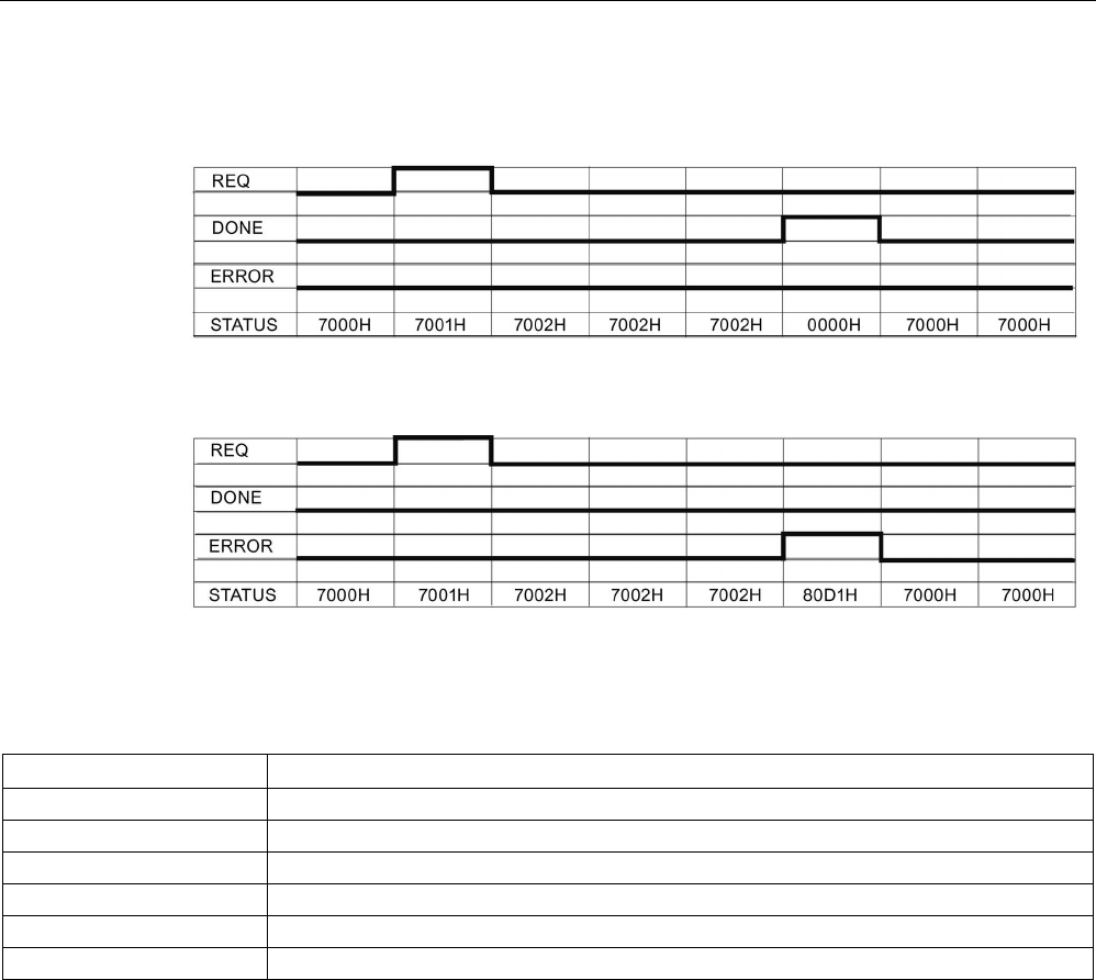
Communication processor and Modbus TCP
13.6 Legacy PtP communication (CM/CB 1241 only)
S7-1200 Programmable controller
1228 System Manual, V4.2, 09/2016, A5E02486680-AK
The following diagram shows how the DONE and STATUS parameters are valid for only one
scan if the REQ line is pulsed (for one scan) to initiate the transmit operation.
The following diagram shows the relationship of DONE, ERROR and STATUS parameters
when there is an error.
The DONE, ERROR and STATUS values are only valid until SEND_PTP executes again
with the same instance DB.
Table 13- 106 Condition codes
STATUS (W#16#....)
Description
80D0
New request while transmitter active
80D1
Transmit aborted because of no CTS within wait time
80D2
Transmit aborted because of no DSR from the DCE device
80D3
Transmit aborted because of queue overflow (transmit more than 1024 bytes)
80D5
Reverse bias signal (wire break condition)
833A
The DB for the BUFFER parameter does not exist.

Communication processor and Modbus TCP
13.6 Legacy PtP communication (CM/CB 1241 only)
S7-1200 Programmable controller
System Manual, V4.2, 09/2016, A5E02486680-AK 1229
13.6.1.5
RCV_PTP (Enable receive messages)
Table 13- 107 RCV_PTP (Receive Point-to-Point) instruction
LAD / FBD
SCL
Description
"RCV_PTP_DB"(
EN_R:=_bool_in_,
PORT:=_uint_in_,
BUFFER:=_variant_in_,
NDR=>_bool_out_,
ERROR=>_bool_out_,
STATUS=>_word_out_,
LENGTH=>_uint_out_);
RCV_PTP checks for messages that have been re-
ceived in the CM or CB. If a message is available, it
will be transferred from the CM or CB to the CPU. An
error returns the appropriate STATUS value.
1 STEP 7 automatically creates the DB when you insert the instruction.
Table 13- 108 Data types for the parameters
Parameter and type
Data type
Description
EN_R IN Bool When this input is TRUE and a message is available, the message is trans-
ferred from the CM or CB to the BUFFER. When EN_R is FALSE, the CM or
CB is checked for messages and NDR, ERROR and STATUS output are up-
dated, but the message is not transferred to the BUFFER. (Default value: 0)
PORT IN PORT After you install and configure a CM or CB communication device, the port
identifier appears in the parameter helper drop-list available at the PORT box
connection. The assigned CM or CB port value is the device configuration
property "hardware identifier". The port symbolic name is assigned in the "Sys-
tem constants" tab of the PLC tag table. (Default value: 0)
BUFFER IN Variant This parameter points to the starting location of the receive buffer. This buffer
should be large enough to receive the maximum length message.
Boolean data or Boolean arrays are not supported. (Default value: 0)
NDR OUT Bool TRUE for one execution when new data is ready and operation is complete
with no errors.
ERROR
OUT
Bool
TRUE for one execution after the operation was completed with an error.
STATUS
OUT
Word
Execution condition code (Default value: 0)
LENGTH
OUT
UInt
Length of the returned message in bytes (Default value: 0)
Note the following correlation between the EN_R input and the message buffer of the
RCV_PTP instruction:
Input EN_R controls the copy of a received message to the BUFFER.
When the EN_R input is TRUE and a message is available, the CPU transfers the message
from the CM or CB to the BUFFER and updates the NDR, ERROR, STATUS, and LENGTH
outputs.
When EN_R is FALSE, the CPU checks the CM or CB for messages and updates the NDR,
ERROR, and STATUS outputs, but does not transfer the message to the BUFFER. (Note
that the default value of EN_R is FALSE.)
The recommended practice is to set EN_R to TRUE and control execution of the RCV_PTP
instruction with the EN input.

Communication processor and Modbus TCP
13.6 Legacy PtP communication (CM/CB 1241 only)
S7-1200 Programmable controller
1230 System Manual, V4.2, 09/2016, A5E02486680-AK
The STATUS value is valid when either NDR or ERROR is TRUE. The STATUS value
provides the reason for termination of the receive operation in the CM or CB. This is typically
a positive value, indicating that the receive operation was successful and that the receive
process terminated normally. If the STATUS value is negative (the Most Significant Bit of the
hexadecimal value is set), the receive operation was terminated for an error condition such
as parity, framing, or overrun errors.
Each PtP communication interface can buffer up to a maximum of 1024 bytes. This could be
one large message or several smaller messages. If more than one message is available in
the CM or CB, the RCV_PTP instruction returns the oldest message available. A subsequent
RCV_PTP instruction execution returns the next oldest message available.
Table 13- 109 Condition codes
STATUS (W#16#...)
Description
0000
No buffer present
0094 Message terminated due to received maximum character length
0095
Message terminated because of message timeout
0096 Message terminated because of inter-character timeout
0097
Message terminated because of response timeout
0098
Message terminated because the "N+LEN+M" length condition was satisfied
0099
Message terminated because of end sequence was satisfied
80E0
Message terminated because the receive buffer is full
80E1
Message terminated due to parity error
80E2
Message terminated due to framing error
80E3
Message terminated due to overrun error
80E4
Message terminated because calculated length exceeds buffer size
80E5
Reverse bias signal (wire break condition)
833A
The DB for the BUFFER parameter does not exist.
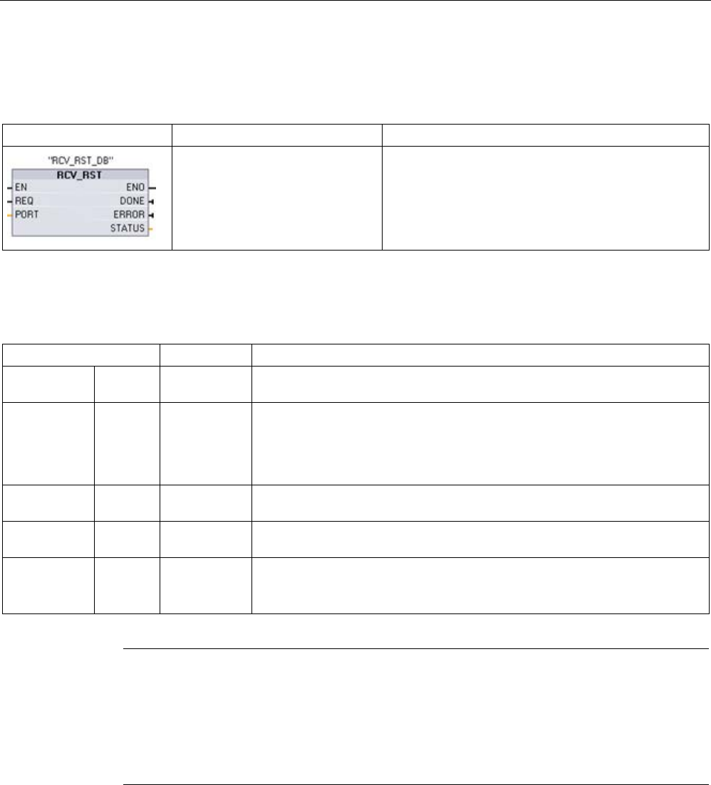
Communication processor and Modbus TCP
13.6 Legacy PtP communication (CM/CB 1241 only)
S7-1200 Programmable controller
System Manual, V4.2, 09/2016, A5E02486680-AK 1231
13.6.1.6
RCV_RST (Delete receive buffer)
Table 13- 110 RCV_RST (Receiver Reset) instruction
LAD / FBD
SCL
Description
"RCV_RST_DB"(
REQ:=_bool_in_,
PORT:=_uint_in_,
DONE=>_bool_out_,
ERROR=>_bool_out_,
STATUS=>_word_out_);
RCV_RST clears the receive buffers in the CM or CB.
1 STEP 7 automatically creates the DB when you insert the instruction.
Table 13- 111 Data types for parameters
Parameter and type
Data type
Description
REQ IN Bool Activates the receiver reset on the rising edge of this enable input (Default
value: False)
PORT IN PORT After you install and configure a CM or CB communication device, the port
identifier appears in the parameter helper drop-list available at the PORT box
connection. The assigned CM or CB port value is the device configuration
property "hardware identifier". The port symbolic name is assigned in the "Sys-
tem constants" tab of the PLC tag table. (Default value: 0)
DONE OUT Bool When TRUE for one scan, indicates that the last request was completed with-
out errors.
ERROR OUT Bool When TRUE, shows that the last request was completed with errors. Also,
when this output is TRUE, the STATUS output will contain related error codes.
STATUS OUT Word Error code (Default value: 0)
See Common parameters for Point-to-Point instructions (Page 1108) for com-
munication status codes.
Note
You might want to use the RCV_RST instruction to be sure the message buffers are clear
following a communications error, or after changing a communication parameter
such as the
baud rate. Executing RCV_RST causes the module to clear all of the internal message
buffers. After clearing the message buffers, you can be assured that when your program
executes a subsequent receive instruction, the messages it returns are ne
w messages and
not old messages from some time prior to the RCV_RST call.

Communication processor and Modbus TCP
13.6 Legacy PtP communication (CM/CB 1241 only)
S7-1200 Programmable controller
1232 System Manual, V4.2, 09/2016, A5E02486680-AK
13.6.1.7
SGN_GET (Query RS-232 signals)
Table 13- 112 SGN_GET (Get RS232 signals) instruction
LAD / FBD
SCL
Description
"SGN_GET_DB"(
REQ:=_bool_in_,
PORT:=_uint_in_,
NDR=>_bool_out_,
ERROR=>_bool_out_,
STATUS=>_word_out_,
DTR=>_bool_out_,
DSR=>_bool_out_,
RTS=>_bool_out_,
CTS=>_bool_out_,
DCD=>_bool_out_,
RING=>_bool_out_);
SGN_GET reads the current states of RS232 communica-
tion signals.
This function is valid only for the RS232 CM.
1 STEP 7 automatically creates the DB when you insert the instruction.
Table 13- 113 Data types for the parameters
Parameter and type
Data type
Description
REQ IN Bool Get RS232 signal state values on the rising edge of this input (Default value:
False)
PORT IN PORT After you install and configure a CM or CB communication device, the port
identifier appears in the parameter helper drop-list available at the PORT box
connection. The assigned CM or CB port value is the device configuration
property "hardware identifier". The port symbolic name is assigned in the "Sys-
tem constants" tab of the PLC tag table.
NDR OUT Bool TRUE for one scan, when new data is ready and the operation is complete
with no errors
ERROR
OUT
Bool
TRUE for one scan, after the operation was completed with an error
STATUS
OUT
Word
Execution condition code (Default value: 0)
DTR
OUT
Bool
Data terminal ready, module ready (output). Default value: False
DSR
OUT
Bool
Data set ready, communication partner ready (input). Default value: False
RTS
OUT
Bool
Request to send, module ready to send (output). Default value: False
CTS OUT Bool Clear to send, communication partner can receive data (input). Default value:
False
DCD
OUT
Bool
Data carrier detect, receive signal level (always False, not supported)
RING
OUT
Bool
Ring indicator, indication of incoming call (always False, not supported)
Table 13- 114 Condition codes
STATUS (W#16#....)
Description
80F0
CM or CB is RS485 and no signals are available

Communication processor and Modbus TCP
13.6 Legacy PtP communication (CM/CB 1241 only)
S7-1200 Programmable controller
System Manual, V4.2, 09/2016, A5E02486680-AK 1233
13.6.1.8
SGN_SET (Set RS-232 signals)
Table 13- 115 SGN_SET (Set RS232 signals) instruction
LAD / FBD
SCL
Description
"SGN_SET_DB"(
REQ:=_bool_in_,
PORT:=_uint_in_,
SIGNAL:=_byte_in_,
RTS:=_bool_in_,
DTR:=_bool_in_,
DSR:=_bool_in_,
DONE=>_bool_out_,
ERROR=>_bool_out_,
STATUS=>_word_out_);
SGN_SET sets the states of RS232 communication
signals.
This function is valid only for the RS232 CM.
1 STEP 7 automatically creates the DB when you insert the instruction.
Table 13- 116 Data types for parameters
Parameter and type
Data type
Description
REQ IN Bool Start the set RS232 signals operation, on the rising edge of this input
(Default value: False)
PORT IN PORT After you install and configure a CM or CB communication device, the
port identifier appears in the parameter helper drop-list available at the
PORT box connection. The assigned CM or CB port value is the device
configuration property "hardware identifier". The port symbolic name is
assigned in the "System constants" tab of the PLC tag table. (Default
value: 0)
SIGNAL IN Byte Selects which signal to set: (multiple allowed). Default value: 0
• 01H = Set RTS
• 02H = Set DTR
• 04H = Set DSR
RTS IN Bool Request to send, module ready to send value to set (true or false), De-
fault value: False
DTR IN Bool Data terminal ready, module ready to send value to set (true or false).
Default value: False
DSR
IN
Bool
Data set ready (only applies to DCE type interfaces), not used.
DONE OUT Bool TRUE for one execution after the last request was completed with no
error
ERROR OUT Bool TRUE for one execution after the last request was completed with an
error
STATUS
OUT
Word
Execution condition code (Default value: 0)
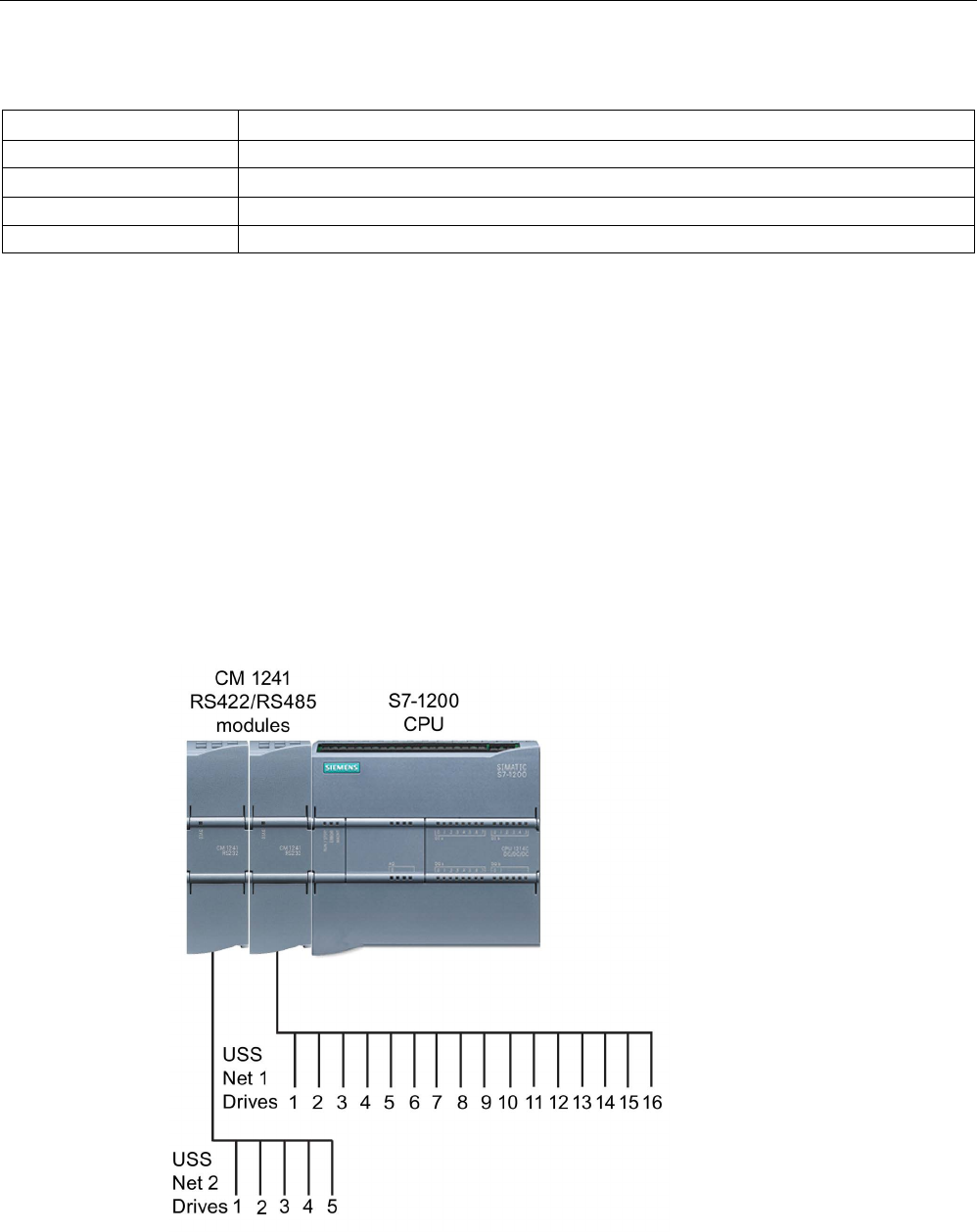
Communication processor and Modbus TCP
13.7 Legacy USS communication (CM/CB 1241 only)
S7-1200 Programmable controller
1234 System Manual, V4.2, 09/2016, A5E02486680-AK
Table 13- 117 Condition codes
STATUS (W#16#....)
Description
80F0
CM or CB is RS485 and no signals can be set
80F1 Signals cannot be set because of Hardware flow control
80F2
Cannot set DSR because module is DTE
80F3 Cannot set DTR because module is DCE
13.7
Legacy USS communication (CM/CB 1241 only)
The USS instructions control the operation of motor drives which support the universal serial
interface (USS) protocol. You can use the USS instructions to communicate with multiple
drives through RS485 connections to CM 1241 RS485 communication modules or a CB
1241 RS485 communication board. Up to three CM 1241 RS422/RS485 modules and one
CB 1241 RS485 board can be installed in a S7-1200 CPU. Each RS485 port can operate up
to sixteen drives.
The USS protocol uses a master-slave network for communications over a serial bus. The
master uses an address parameter to send a message to a selected slave. A slave itself can
never transmit without first receiving a request to do so. Direct message transfer between
the individual slaves is not possible. USS communication operates in half-duplex mode. The
following USS illustration shows a network diagram for an example drive application.
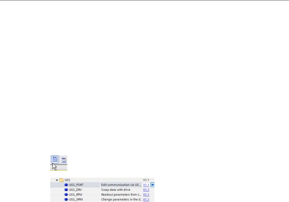
Communication processor and Modbus TCP
13.7 Legacy USS communication (CM/CB 1241 only)
S7-1200 Programmable controller
System Manual, V4.2, 09/2016, A5E02486680-AK 1235
Prior to the release of STEP 7 V13 SP1 and the S7-1200 V4.1 CPUs, the USS
communication instructions existed with different names, and in some cases, slightly
different interfaces. The general concepts apply to both sets of instructions. Refer to the
individual legacy USS instructions for programming information.
13.7.1
Selecting the version of the USS instructions
There are two versions of USS instructions available in STEP 7:
● Version 2.0 was initially available in STEP 7 Basic/Professional V13.
● Version 2.1 is available in STEP 7 Basic/Professional V13 SP1 or later.
For compatibility and ease of migration, you can choose which instruction version to insert
into your user program.
You cannot use both versions of the instructions with the same module, but two different
modules can use different versions of the instructions.
Click the icon on the instruction tree task card to enable the headers and columns
of the instruction tree.
To change the version of the USS instru
c-
tions, select the version from the drop
-down
list. You can select the group or individual
instructio
ns.
When you use the instruction tree to place a USS instruction in your program, a new FB or
FC instance, depending on the USS instruction selected, is created in the project tree. You
can see new FB or FC instance in the project tree under PLC_x > Program blocks > System
blocks > Program resources.
To verify the version of a USS instruction in a program, you must inspect project tree
properties and not the properties of a box displayed in the program editor. Select a project
tree USS FB or FC instance, right-click, select "Properties", and select the "Information"
page to see the USS instruction version number.
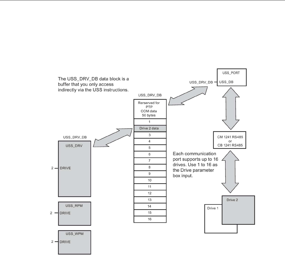
Communication processor and Modbus TCP
13.7 Legacy USS communication (CM/CB 1241 only)
S7-1200 Programmable controller
1236 System Manual, V4.2, 09/2016, A5E02486680-AK
13.7.2
Requirements for using the USS protocol
The four USS instructions use 1 FB and 3 FCs to support the USS protocol. One
USS_PORT instance data block (DB) is used for each USS network. The USS_PORT
instance data block contains temporary storage and buffers for all drives on that USS
network. The USS instructions share the information in this data block.
All drives (up to 16) connected to a single RS485 port are part of the same USS network. All
drives connected to a different RS485 port are part of a different USS network. Each USS
network is managed using a unique data block. All instructions associated with a single USS
network must share this data block. This includes all USS_DRV, USS_PORT, USS_RPM,
and USS_WPM instructions used to control all drives on a single USS network.
The USS_DRV instruction is a Function Block (FB). When you place the USS_DRV
instruction into the program editor, you will be prompted by the "Call options" dialog to assign
a DB for this FB. If this is the first USS_DRV instruction in this program for this USS network,
then you can accept the default DB assignment (or change the name if you wish) and the
new DB is created for you. If however this is not the first USS_DRV instruction for this
channel, then you must use the drop-down list in the "Call options" dialog to select the DB
name that was previously assigned for this USS network.
Instructions USS_PORT, USS_RPM, and USS_WPM are all Functions (FCs). No DB is
assigned when you place these FCs in the editor. Instead, you must assign the appropriate
DB reference to the "USS_DB" input of these instructions. Double-click on the parameter
field and then click on the parameter helper icon to see the available DB names).

Communication processor and Modbus TCP
13.7 Legacy USS communication (CM/CB 1241 only)
S7-1200 Programmable controller
System Manual, V4.2, 09/2016, A5E02486680-AK 1237
The USS_PORT function handles the actual communication between the CPU and the
drives via the Point-to-Point (PtP) RS485 communication port. Each call to this function
handles one communication with one drive. Your program must call this function fast enough
to prevent a communication timeout by the drives. You may call this function in a main
program cycle OB or any interrupt OB.
Typically, you should call the USS_PORT function from a cyclic interrupt OB. The cycle time
of the cyclic interrupt OB should be set to about half of the minimum call interval (As an
example, 1200 baud communication should use a cyclic time of 350 ms or less).
The USS_DRV function block provides your program access to a specified drive on the USS
network. Its inputs and outputs are the status and controls for the drive. If there are 16 drives
on the network, your program must have at least 16 USS_DRV calls, one for each drive.
These blocks should be called at the rate that is required to control the operation of the drive.
You may only call the USS_DRV function block from a main program cycle OB.
CAUTION
Considerations in calling USS instructions from OBs
Only call USS_DRV, USS_RPM, and USS_WPM from a main program cycle OB. The
USS_PORT function can be called from any OB, usually from a cyclic interrupt OB.
Do not use instructions USS_DRV, USS_RPM, or USS_WPM in a higher priority OB than
the corresponding USS_PORT instruction. For example, do not place the USS_PORT in
the main and a USS_RPM in a cyclic interrupt OB. Failure to prevent interruption of
USS_PORT execution can produce unexpected errors, which could result in personal
injury.
The USS_RPM and USS_WPM functions read and write the remote drive operating
parameters. These parameters control the internal operation of the drive. See the drive
manual for the definition of these parameters. Your program can contain as many of these
functions as necessary, but only one read or write request can be active per drive, at any
given time. You may only call the USS_RPM and USS_WPM functions from a main program
cycle OB.

Communication processor and Modbus TCP
13.7 Legacy USS communication (CM/CB 1241 only)
S7-1200 Programmable controller
1238 System Manual, V4.2, 09/2016, A5E02486680-AK
Calculating the time required for communicating with the drive
Communications with the drive are asynchronous to the S7-1200 scan cycle. The S7-1200
typically completes several scans before one drive communications transaction is
completed.
The USS_PORT interval is the time required for one drive transaction. The table below
shows the minimum USS_PORT interval for each communication baud rate. Calling the
USS_PORT function more frequently than the USS_PORT interval will not increase the
number of transactions. The drive timeout interval is the amount of time that might be taken
for a transaction, if communications errors caused 3 tries to complete the transaction. By
default, the USS protocol library automatically does up to 2 retries on each transaction.
Table 13- 118 Calculating the time requirements
Baud rate
Calculated minimum USS_PORT call
Interval ( milliseconds )
Drive message interval timeout per
drive ( milliseconds )
1200
790
2370
2400 405 1215
4800
212.5
638
9600 116.3 349
19200
68.2
205
38400
44.1
133
57600
36.1
109
115200
28.1
85

Communication processor and Modbus TCP
13.7 Legacy USS communication (CM/CB 1241 only)
S7-1200 Programmable controller
System Manual, V4.2, 09/2016, A5E02486680-AK 1239
13.7.3
Legacy USS instructions
13.7.3.1
USS_PORT (Edit communication using USS network) instruction
Table 13- 119 USS_PORT instruction
LAD / FBD
SCL
Description
USS_PORT(
PORT:=_uint_in_,
BAUD:=_dint_in_,
ERROR=>_bool_out_,
STATUS=>_word_out_,
USS_DB:=_fbtref_inout_);
The USS_PORT instruction handles communication
over a USS network.
Table 13- 120 Data types for the parameters
Parameter and type
Data type
Description
PORT IN Port After you install and configure a CM or CB communication device, the
port identifier appears in the parameter helper drop-list available at the
PORT box connection. The assigned CM or CB port value is the device
configuration property "hardware identifier". The port symbolic name is
assigned in the "System constants" tab of the PLC tag table.
BAUD
IN
DInt
The baud rate used for USS communication.
USS_DB INOUT USS_BASE The name of the instance DB that is created and initialized when a
USS_DRV instruction is placed in your program.
ERROR OUT Bool When true, this output indicates that an error has occurred and the
STATUS output is valid.
STATUS OUT Word The status value of the request indicates the result of the scan or initiali-
zation. Additional information is available in the "USS_Extended_Error"
variable for some status codes.
Typically, there is only one USS_PORT instruction per PtP communication port in the
program, and each call of this function handles a transmission to or from a single drive. All
USS functions associated with one USS network and PtP communication port must use the
same instance DB.
Your program must execute the USS_PORT instruction often enough to prevent drive
timeouts. USS_PORT is usually called from a cyclic interrupt OB to prevent drive timeouts
and keep the most recent USS data updates available for USS_DRV calls.

Communication processor and Modbus TCP
13.7 Legacy USS communication (CM/CB 1241 only)
S7-1200 Programmable controller
1240 System Manual, V4.2, 09/2016, A5E02486680-AK
13.7.3.2
USS_DRV (Swap data with drive) instruction
Table 13- 121 USS_DRV instruction
LAD / FBD
SCL
Description
Default view
"USS_DRV_DB"(
RUN:=_bool_in_,
OFF2:=_bool_in_,
OFF3:=_bool_in_,
F_ACK:=_bool_in_,
DIR:=_bool_in_,
DRIVE:=_usint_in_,
PZD_LEN:=_usint_in_,
SPEED_SP:=_real_in_,
CTRL3:=_word_in_,
CTRL4:=_word_in_,
CTRL5:=_word_in_,
CTRL6:=_word_in_,
CTRL7:=_word_in_,
CTRL8:=_word_in_,
NDR=>_bool_out_,
ERROR=>_bool_out_,
STATUS=>_word_out_,
RUN_EN=>_bool_out_,
D_DIR=>_bool_out_,
INHIBIT=>_bool_out_,
FAULT=>_bool_out_,
SPEED=>_real_out_,
STATUS1=>_word_out_,
STATUS3=>_word_out_,
STATUS4=>_word_out_,
STATUS5=>_word_out_,
STATUS6=>_word_out_,
STATUS7=>_word_out_,
STATUS8=>_word_out_);
The USS_DRV instruction exchanges data with a drive
by creating request messages and interpreting the drive
response messages. A separate function block should
be used for each drive, but all USS functions associat-
ed with one USS network and PtP communication port
must use the same instance data block. You must cre-
ate the DB name when you place the first USS_DRV
instruction and then reference the DB that was created
by the initial instruction usage.
STEP 7 automatically creates the DB when you insert
the instruction.
Expanded view
1
LAD and FBD: Expand the box to reveal all the parameters by clicking the bottom of the box. The parameter pins that
are grayed are optional and parameter assignment is not required.

Communication processor and Modbus TCP
13.7 Legacy USS communication (CM/CB 1241 only)
S7-1200 Programmable controller
System Manual, V4.2, 09/2016, A5E02486680-AK 1241
Table 13- 122 Data types for the parameters
Parameter and type
Data type
Description
RUN IN Bool Drive start bit: When true, this input enables the drive to run at the
preset speed. When RUN goes to false while a drive is running, the
motor will be ramped down to a stop. This behavior differs from the
dropping power (OFF2) or braking the motor (OFF3).
OFF2 IN Bool Electrical stop bit: When false, this bit causes the drive to coast to a
stop with no braking.
OFF3 IN Bool Fast stop bit: When false, this bit causes a fast stop by braking the
drive rather than just allowing the drive to coast to a stop.
F_ACK IN Bool Fault acknowledge bit: This bit is set to reset the fault bit on a drive.
The bit is set after the fault is cleared to indicate to the drive it no longer
needs to indicate the previous fault.
DIR IN Bool Drive direction control: This bit is set to indicate that the direction is
forward (for positive SPEED_SP).
DRIVE IN USInt Drive address: This input is the address of the USS drive. The valid
range is drive 1 to drive 16.
PZD_LEN IN USInt
Word length: This is the number of words of PZD data. The valid values
are 2, 4, 6, or 8 words. The default value is 2.
SPEED_SP IN Real Speed set point: This is the speed of the drive as a percentage of con-
figured frequency. A positive value specifies forward direction (when
DIR is true). Valid range is 200.00 to -200.00.
CTRL3 IN Word Control word 3: A value written to a user-configurable parameter on the
drive. You must configure this on the drive. (optional parameter)
CTRL4 IN Word Control word 4: A value written to a user-configurable parameter on the
drive. You must configure this on the drive. (optional parameter)
CTRL5 IN Word Control word 5: A value written to a user-configurable parameter on the
drive. You must configure this on the drive. (optional parameter)
CTRL6 IN Word Control word 6: A value written to a user-configurable parameter on the
drive. You must configure this on the drive. (optional parameter)
CTRL7 IN Word Control word 7: A value written to a user-configurable parameter on the
drive. You must configure this on the drive. (optional parameter)
CTRL8 IN Word Control word 8: A value written to a user-configurable parameter on the
drive. You must configure this on the drive. (optional parameter)
NDR OUT Bool New data ready: When true, the bit indicates that the outputs contain
data from a new communication request.
ERROR OUT Bool
Error occurred: When true, this indicates that an error has occurred and
the STATUS output is valid. All other outputs are set to zero on an
error. Communication errors are only reported on the USS_PORT in-
struction ERROR and STATUS outputs.
STATUS OUT Word The status value of the request indicates the result of the scan. This is
not a status word returned from the drive.
RUN_EN
OUT
Bool
Run enabled: This bit indicates whether the drive is running.
D_DIR
OUT
Bool
Drive direction: This bit indicates whether the drive is running forward.
INHIBIT
OUT
Bool
Drive inhibited: This bit indicates the state of the inhibit bit on the drive.
FAULT OUT Bool Drive fault: This bit indicates that the drive has registered a fault. You
must fix the problem and then set the F_ACK bit to clear this bit when
set.

Communication processor and Modbus TCP
13.7 Legacy USS communication (CM/CB 1241 only)
S7-1200 Programmable controller
1242 System Manual, V4.2, 09/2016, A5E02486680-AK
Parameter and type
Data type
Description
SPEED OUT Real Drive Current Speed (scaled value of drive status word 2): The value of
the speed of the drive as a percentage of configured speed.
STATUS1 OUT Word Drive Status Word 1: This value contains fixed status bits of a drive.
STATUS3 OUT Word Drive Status Word 3: This value contains a user-configurable status
word on the drive.
STATUS4 OUT Word Drive Status Word 4: This value contains a user-configurable status
word on the drive.
STATUS5 OUT Word Drive Status Word 5: This value contains a user-configurable status
word on the drive.
STATUS6 OUT Word Drive Status Word 6: This value contains a user-configurable status
word on the drive.
STATUS7 OUT Word Drive Status Word 7: This value contains a user-configurable status
word on the drive.
STATUS8 OUT Word Drive Status Word 8: This value contains a user-configurable status
word on the drive.
When the initial USS_DRV execution occurs, the drive indicated by the USS address
(parameter DRIVE) is initialized in the Instance DB. After this initialization, subsequent
executions of USS_PORT can begin communication to the drive at this drive number.
Changing the drive number requires a CPU STOP-to-RUN mode transition that initializes the
instance DB. Input parameters are configured into the USS TX message buffer and outputs
are read from a "previous" valid response buffer if any exists. There is no data transmission
during USS_DRV execution. Drives communicate when USS_PORT is executed. USS_DRV
only configures the messages to be sent and interprets data that might have been received
from a previous request.
You can control the drive direction of rotation using either the DIR input (Bool) or using the
sign (positive or negative) with the SPEED_SP input (Real). The following table indicates
how these inputs work together to determine the drive direction, assuming the motor is wired
for forward rotation.
Table 13- 123 Interaction of the SPEED_SP and DIR parameters
SPEED_SP
DIR
Drive rotation direction
Value > 0
0
Reverse
Value > 0
1
Forward
Value < 0
0
Forward
Value < 0
1
Reverse

Communication processor and Modbus TCP
13.7 Legacy USS communication (CM/CB 1241 only)
S7-1200 Programmable controller
System Manual, V4.2, 09/2016, A5E02486680-AK 1243
13.7.3.3
USS_RPM (Readout parameters from the drive) instruction
Table 13- 124 USS_RPM instruction
LAD / FBD
SCL
Description
USS_RPM(REQ:=_bool_in_,
DRIVE:=_usint_in_,
PARAM:=_uint_in_,
INDEX:=_uint_in_,
DONE=>_bool_out_,
ERROR=>_bool_out_,
STATUS=>_word_out_,
VALUE=>_variant_out_,
USS_DB:=_fbtref_inout_);
The USS_RPM instruction reads a parameter from
a drive. All USS functions associated with one USS
network and PtP communication port must use the
same data block. USS_RPM must be called from a
main program cycle OB.
Table 13- 125 Data types for the parameters
Parameter type
Data type
Description
REQ IN Bool Send request: When true, REQ indicates that a new read request is de-
sired. This is ignored if the request for this parameter is already pending.
DRIVE IN USInt Drive address: DRIVE is the address of the USS drive. The valid range is
drive 1 to drive 16.
PARAM IN UInt Parameter number: PARAM designates which drive parameter is written.
The range of this parameter is 0 to 2047. On some drives, the most signif-
icant byte can access PARAM values greater than 2047. See your drive
manual for details on how to access an extended range.
INDEX IN UInt
Parameter index: INDEX designates which Drive Parameter index is to be
written. A 16-bit value where the Least Significant Byte is the actual index
value with a range of (0 to 255). The Most Significant Byte may also be
used by the drive and is drive-specific. See your drive manual for details.
USS_DB INOUT USS_BASE The name of the instance DB that is created and initialized when a
USS_DRV instruction is placed in your program.
VALUE IN Word, Int, UInt,
DWord, DInt,
UDInt, Real
This is the value of the parameter that was read and is valid only when
the DONE bit is true.
DONE1 OUT Bool When true, indicates that the VALUE output holds the previously request-
ed read parameter value. This bit is set when USS_DRV sees the read
response data from the drive. This bit is reset when either: you request
the response data via another USS_RPM poll, or on the second of the
next two calls to USS_DRV

Communication processor and Modbus TCP
13.7 Legacy USS communication (CM/CB 1241 only)
S7-1200 Programmable controller
1244 System Manual, V4.2, 09/2016, A5E02486680-AK
Parameter type
Data type
Description
ERROR OUT Bool Error occurred: When true, ERROR indicates that an error has occurred
and the STATUS output is valid. All other outputs are set to zero on an
error. Communication errors are only reported on the USS_PORT instruc-
tion ERROR and STATUS outputs.
STATUS OUT Word STATUS indicates the result of the read request. Additional information is
available in the "USS_Extended_Error" variable for some status codes.
1
The DONE bit indicates that valid data has been read from the referenced motor drive and delivered to the CPU. It does
not indicate that the USS library is capable of immediately reading another parameter. A blank PKW request must be
sent to the motor drive and must also be acknowledged by the instruction before the parameter channel for the specific
drive becomes available for use. Immediately calling a USS_RPM or USS_WPM FC for the specified motor drive will re-
sult in a 0x818A error.
13.7.3.4
USS_WPM (Change parameters in the drive) instruction
Note
EEPROM write operations (for the EEPROM inside a USS drive)
Do not overuse the EEPROM permanent write operation. Minimize the number of EEPROM
write operations to extend the EEPROM life.
Table 13- 126 USS_WPM instruction
LAD / FBD
SCL
Description
USS_WPM(REQ:=_bool_in_,
DRIVE:=_usint_in_,
PARAM:=_uint_in_,
INDEX:=_uint_in_,
EEPROM:=_bool_in_,
VALUE:=_variant_in_,
DONE=>_bool_out_,
ERROR=>_bool_out_,
STATUS=>_word_out_,
USS_DB:=_fbtref_inout_);
The USS_WPM instruction modifies a parameter in the
drive. All USS functions associated with one USS net-
work and PtP communication port must use the same
data block.
USS_WPM must be called from a main program cycle
OB.

Communication processor and Modbus TCP
13.7 Legacy USS communication (CM/CB 1241 only)
S7-1200 Programmable controller
System Manual, V4.2, 09/2016, A5E02486680-AK 1245
Table 13- 127 Data types for the parameters
Parameter and type
Data type
Description
REQ IN Bool Send request: When true, REQ indicates that a new write request is de-
sired. This is ignored if the request for this parameter is already pending.
DRIVE IN USInt Drive address: DRIVE is the address of the USS drive. The valid range is
drive 1 to drive 16.
PARAM IN UInt Parameter number: PARAM designates which drive parameter is written.
The range of this parameter is 0 to 2047. On some drives, the most signif-
icant byte can access PARAM values greater than 2047. See your drive
manual for details on how to access an extended range.
INDEX IN UInt
Parameter index: INDEX designates which Drive Parameter index is to be
written. A 16-bit value where the least significant byte is the actual index
value with a range of (0 to 255). The most significant byte may also be
used by the drive and is drive-specific. See your drive manual for details.
EEPROM IN Bool Store To Drive EEPROM: When true, a write drive parameter transaction
will be stored in the drive EEPROM. If false, the write is temporary and
will not be retained if the drive is power cycled.
VALUE IN Word, Int, UInt,
DWord, DInt,
UDInt, Real
The value of the parameter that is to be written. It must be valid on the
transition of REQ.
USS_DB INOUT USS_BASE The name of the instance DB that is created and initialized when a
USS_DRV instruction is placed in your program.
DONE1 OUT Bool When true, DONE indicates that the input VALUE has been written to the
drive. This bit is set when USS_DRV sees the write response data from
the drive. This bit is reset when either you request the response data via
another USS_WPM poll, or on the second of the next two calls to
USS_DRV
ERROR OUT Bool
When true, ERROR indicates that an error has occurred and the STATUS
output is valid. All other outputs are set to zero on an error. Communica-
tion errors are only reported on the USS_PORT instruction ERROR and
STATUS outputs.
STATUS OUT Word
STATUS indicates the result of the write request. Additional information is
available in the "USS_Extended_Error" variable for some status codes.
1
The DONE bit indicates that valid data has been read from the referenced motor drive and delivered to the CPU. It does
not indicate that the USS library is capable of immediately reading another parameter. A blank PKW request must be
sent to the motor drive and must also be acknowledged by the instruction before the parameter channel for the specific
drive becomes available for use. Immediately calling a USS_RPM or USS_WPM FC for the specified motor drive will re-
sult in a 0x818A error.

Communication processor and Modbus TCP
13.7 Legacy USS communication (CM/CB 1241 only)
S7-1200 Programmable controller
1246 System Manual, V4.2, 09/2016, A5E02486680-AK
13.7.4
Legacy USS status codes
USS instruction status codes are returned at the STATUS output of the USS functions.
Table 13- 128 STATUS codes 1
STATUS
(W#16#....)
Description
0000
No error
8180
The length of the drive response did not match the characters received from the drive. The drive number
where the error occurred is returned in the "USS_Extended_Error" variable. See the extended error
description below this table.
8181
VALUE parameter was not a Word, Real or DWord data type.
8182 The user supplied a Word for a parameter value and received a DWord or Real from the drive in the
response.
8183 The user supplied a DWord or Real for a parameter value and received a Word from the drive in the
response.
8184 The response telegram from drive had a bad checksum. The drive number where the error occurred is
returned in the "USS_Extended_Error" variable. See the extended error description below this table.
8185
Illegal drive address (valid drive address range: 1 to16)
8186
The speed set point is out of the valid range (valid speed SP range: -200% to 200%).
8187 The wrong drive number responded to the request sent. The drive number where the error occurred is
returned in the "USS_Extended_Error" variable. See the extended error description below this table.
8188
Illegal PZD word length specified (valid range = 2, 4, 6 or 8 words)
8189
Illegal Baud Rate was specified.
818A
The parameter request channel is in use by another request for this drive.
818B The drive has not responded to requests and retries. The drive number where the error occurred is
returned in the "USS_Extended_Error" variable. See the extended error description below this table.
818C The drive returned an extended error on a parameter request operation. See the extended error descrip-
tion below this table.
818D The drive returned an illegal access error on a parameter request operation. See your drive manual for
information of why parameter access may be limited.
818E The drive has not been initialized. This error code is returned to USS_RPM or USS_WPM when
USS_DRV, for that drive, has not been called at least once. This keeps the initialization on first scan of
USS_DRV from overwriting a pending parameter read or write request, since it initializes the drive as a
new entry. To fix this error, call USS_DRV for this drive number.
80Ax-80Fx Specific errors returned from PtP communication FBs called by the USS Library - These error code
values are not modified by the USS library and are defined in the PtP instruction descriptions.
1 In addition to the USS instruction errors listed above, errors can be returned from the
underlying PtP communication instructions.
For several STATUS codes, additional information is provided in the "USS_Extended_Error"
variable of the USS_DRV Instance DB. For STATUS codes hexadecimal 8180, 8184, 8187,
and 818B, USS_Extended_Error contains the drive number where the communication error
occurred. For STATUS code hexadecimal 818C, USS_Extended_Error contains a drive error
code returned from the drive when using a USS_RPM or USS_WPM instruction.
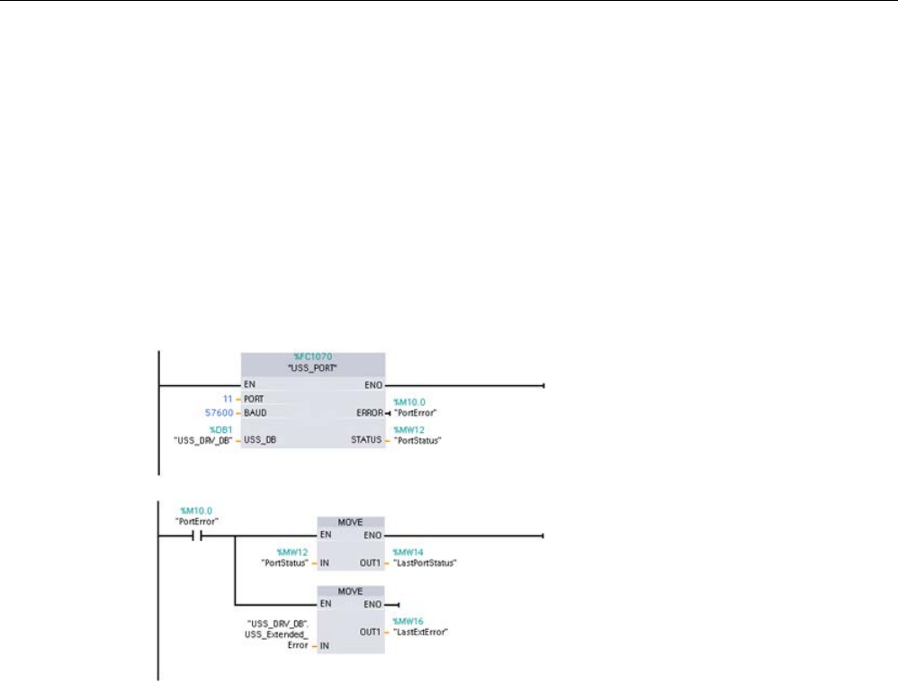
Communication processor and Modbus TCP
13.7 Legacy USS communication (CM/CB 1241 only)
S7-1200 Programmable controller
System Manual, V4.2, 09/2016, A5E02486680-AK 1247
Example: communication errors reporting
Communication errors (STATUS = 16#818B) are only reported on the USS_PORT
instruction and not on the USS_DRV instruction. For example, if the network is not properly
terminated then it is possible for a drive to go to RUN but the USS_DRV instruction will show
all 0's for the output parameters. In this case, you can only detect the communication error
on the USS_PORT instruction. Since this error is only visible for one scan, you will need to
add some capture logic as illustrated in the following example. In this example, when the
error bit of the USS_PORT instruction is TRUE, then the STATUS and the
USS_Extended_Error values are saved into M memory. The drive number is placed in
USS_Extended_Error variable when the STATUS code value is hexadecimal 8180, 8184,
8187, or 818B.
Network 1
"PortStatus"port status
and"USS_DRV_DB".USS_Extended_
Errorextended error code values are
only valid for one program scan. The
values must be captured for later pr
o-
cessing.
Network 2
The "PortError" contact
triggers the storage of the "PortStatus"
value in "LastPortStatus" and
the"USS_DRV_DB".USS_Extended_E
rrorvalue in "LastExtError".
Read and write access to drive internal parameters
USS drives support read and write access to a drive's internal parameters. This feature
allows remote control and configuration of the drive. Drive parameter access operations can
fail due to errors such as values out of range or illegal requests for a drive's current mode.
The drive generates an error code value that is returned in the "USS_Extended_Error"
variable. This error code value is only valid for the last execution of a USS_RPM or
USS_WPM instruction. The drive error code is put into USS_Extended_Error variable when
the STATUS code value is hexadecimal 818C. The error code value of
"USS_Extended_Error" depends on the drive model. See the drive's manual for a description
of the extended error codes for read and write parameter operations.

Communication processor and Modbus TCP
13.7 Legacy USS communication (CM/CB 1241 only)
S7-1200 Programmable controller
1248 System Manual, V4.2, 09/2016, A5E02486680-AK
13.7.5
Legacy USS general drive setup requirements
Legacy USS general drive setup requirements consist of the following points:
● The drives must be set to use 4 PKW words.
● The drives can be configured for 2, 4, 6, or 8 PZD words.
● The number of PZD word's in the drive must match PZD_LEN input on the USS_DRV
instruction for that drive.
● The baud rate in all the drives must match the BAUD input on the USS_PORT instruction.
● The drive must be set for remote control.
● The drive must be set for frequency set-point to USS on COM Link.
● The drive address must be set to 1 to 16 and match the DRIVE input on the USS_DRV
block for that drive.
● The drive direction control must be set to use the polarity of the drive set-point.
● The RS485 network must be terminated properly.
USS general drive connection and setup is the same for USS instructions (V4.1) and legacy
USS instructions (V4.0 and earlier). Refer to the Example: USS general drive connection and
setup (Page 1162) for further information.
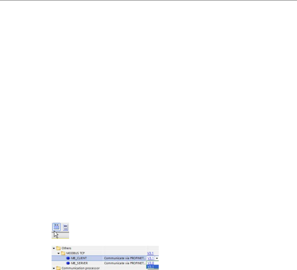
Communication processor and Modbus TCP
13.8 Legacy Modbus TCP communication
S7-1200 Programmable controller
System Manual, V4.2, 09/2016, A5E02486680-AK 1249
13.8
Legacy Modbus TCP communication
13.8.1
Overview
Prior to the release of STEP 7 V13 SP1 and the S7-1200 V4.1 CPUs, the Modbus TCP
communication instructions existed with different names, and in some cases, slightly
different interfaces. The general concepts apply to both sets of instructions. Refer to the
individual legacy Modbus TCP instructions for programming information.
13.8.2
Selecting the version of the Modbus TCP instructions
There are three versions of the Modbus TCP instructions available in STEP 7:
● Legacy version 3.0: Compatible with all CPU and CP versions
● Legacy version 3.1: Compatible with all CPU and CP versions
● Version 4.1: Compatible with V4.0 and later CPUs and V2.1 and later CMs
For compatibility and ease of migration, you can choose which instruction version to insert
into your user program.
Do not use both 3.0 and 3.1 instruction versions in the same CPU program. Your program's
Modbus TCP instructions must have the same major version number (
1
.x,
2
.y, or
V
.z). The
individual instructions within a major version group may have different minor versions (1.
x
).
Click the icon on the instruction tree task card to enable the headers and columns
of the instruction tree.
To change the version of the Modbus TCP
instructions, select the version from the drop-
down list. Y
ou can select the group or indi-
vidual instructions.
When you use the instruction tree to place a Modbus TCP instruction in your program, a new
FB instance is created in the project tree. You can see new FB instance in the project tree
under PLC_x > Program blocks > System blocks > Program resources.
To verify the version of a Modbus TCP instruction in a program, you must inspect project
tree properties and not the properties of a box displayed in the program editor. Select a
project tree Modbus TCP FB instance, right-click, select "Properties", and select the
"Information" page to see the Modbus TCP instruction version number.
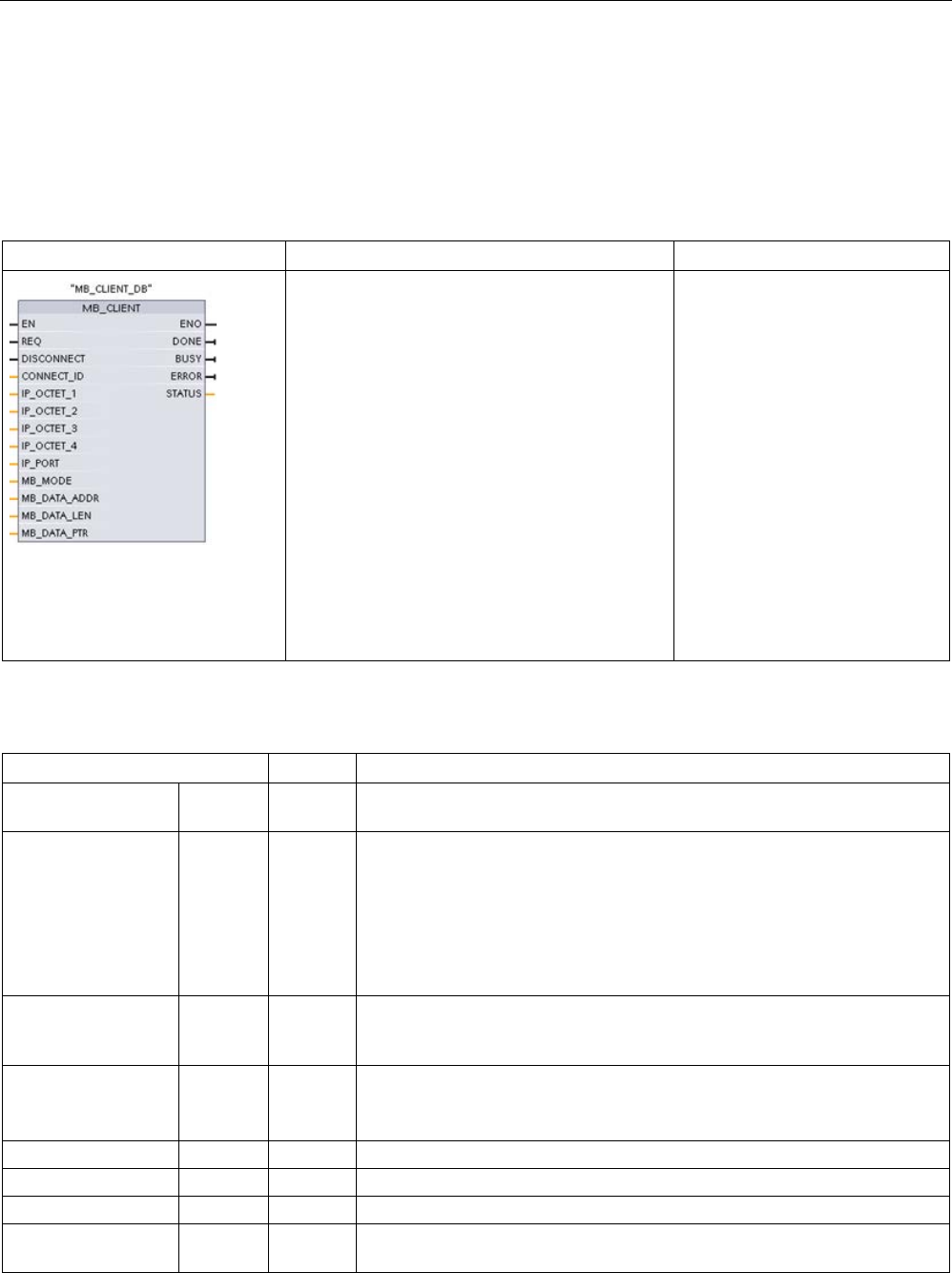
Communication processor and Modbus TCP
13.8 Legacy Modbus TCP communication
S7-1200 Programmable controller
1250 System Manual, V4.2, 09/2016, A5E02486680-AK
13.8.3
Legacy Modbus TCP instructions
13.8.3.1
MB_CLIENT (Communicate using PROFINET as Modbus TCP client)
Table 13- 129 MB_CLIENT instruction
LAD / FBD
SCL
Description
"MB_CLIENT_DB"(
REQ:=_bool_in_,
DISCONNECT:=_bool_in_,
CONNECT_ID=_uint_in_,
IP_OCTET_1:=_byte_in_,
IP_OCTET_2:=_byte_in_,
IP_OCTET_3:=_byte_in_,
IP_OCTET_4:=_byte_in_,
IP_PORT:=_uint_in_,
MB_MODE:=_usint_in_,
MB_DATA_ADDR:=_udint_in_,
MB_DATA_LEN:=_uint_in_,
DONE=>_bool_out_,
BUSY=>_bool_out_,
ERROR=>_bool_out_,
STATUS=>_word_out_,
MB_DATA_PTR:=_variant_inout_);
MB_CLIENT communicates as a
Modbus TCP client through the
PROFINET connector on the S7-
1200 CPU. No additional commu-
nication hardware module is re-
quired.
MB_CLIENT can make a client-
server connection, send a Mod-
bus function request, receive a
response, and control the discon-
nection from a Modbus TCP serv-
er.
Table 13- 130 Data types for the parameters
Parameter and type
Data type
Description
REQ In Bool FALSE = No Modbus communication request
TRUE = Request to communicate with a Modbus TCP server
DISCONNECT IN Bool The DISCONNECT parameter allows your program to control connection
and disconnection with a Modbus server device.
If DISCONNECT = 0 and a connection does not exist, then MB_CLIENT
attempts to make a connection to the assigned IP address and port number.
If DISCONNECT = 1 and a connection exists, then a disconnect operation is
attempted. Whenever this input is enabled, no other operation will be at-
tempted.
CONNECT_ID IN UInt The CONNECT_ID parameter must uniquely identify each connection within
the PLC. Each unique instance of the MB_CLIENT or MB_SERVER instruc-
tion must contain a unique CONNECT_ID parameter.
IP_OCTET_1 IN USInt Modbus TCP server IP address: Octet 1
8-bit part of the 32-bit IPv4 IP address of the Modbus TCPserver to which
the client will connect and communicate using the Modbus TCP protocol.
IP_OCTET_2
IN
USInt
Modbus TCP server IP address: Octet 2
IP_OCTET_3
IN
USInt
Modbus TCP server IP address: Octet 3
IP_OCTET_4
IN
USInt
Modbus TCP server IP address: Octet 4
IP_PORT IN UInt
Default value = 502: The IP port number of the server to which the client will
attempt to connect and ultimately communicate using the TCP/IP protocol.

Communication processor and Modbus TCP
13.8 Legacy Modbus TCP communication
S7-1200 Programmable controller
System Manual, V4.2, 09/2016, A5E02486680-AK 1251
Parameter and type
Data type
Description
MB_MODE IN USInt Mode Selection: Assigns the type of request (read, write, or diagnostic). See
the Modbus functions table below for details.
MB_DATA_ADDR IN UDInt Modbus starting Address: Assigns the starting address of the data to be
accessed by MB_CLIENT. See the Modbus functions table below for valid
addresses.
MB_DATA_LEN IN UInt
Modbus data Length: Assigns the number of bits or words to be accessed in
this request. See the Modbus functions table below for valid lengths
MB_DATA_PTR IN_OUT Variant Pointer to the Modbus data register: The register buffers data going to or
coming from a Modbus server. The pointer must assign a non-optimized
global DB or a M memory address.
DONE OUT Bool The DONE bit is TRUE for one scan, after the last request was completed
with no error.
BUSY OUT Bool • 0 - No MB_CLIENT operation in progress
• 1 - MB_CLIENT operation in progress
ERROR OUT Bool The ERROR bit is TRUE for one scan, after the MB_CLIENT execution was
terminated with an error. The error code value at the STATUS parameter is
valid only during the single cycle where ERROR = TRUE.
STATUS
OUT
Word
Execution condition code
REQ parameter
FALSE = No Modbus communication request
TRUE = Request to communicate with a Modbus TCP server
If no instance of MB_CLIENT is active and parameter DISCONNECT=0, when REQ=1 a new
Modbus request will start. If the connection is not already established then a new connection
will be made.
If the same instance of MB_CLIENT is executed again with DISCONNECT=0 and REQ=1,
before the completion of the current request, then no subsequent Modbus transmission will
be made. However, as soon as the current request is completed, a new request can be
processed if MB_CLIENT is executed with REQ=1.
When the current MB_CLIENT communication request is complete, the DONE bit is TRUE
for one cycle. The DONE bit can be used as a time gate to sequence multiple MB_CLIENT
requests.
Note
Input data consistency during MB_CLIENT processing
Once a Modbus client initiates a Modbus operation, all the input states are saved internally
and are then compared on each successive call. The comparis
on is used to determine if this
particular call was the originator of the active client request. More than one MB_CLIENT call
can be performed using a common instance DB.
As a result, it is important that the inputs are not changed during the period of tim
e that a
MB_CLIENT operation is actively being processed. If this rule is not followed, then a
MB_CLIENT cannot determine that it is the active instance.

Communication processor and Modbus TCP
13.8 Legacy Modbus TCP communication
S7-1200 Programmable controller
1252 System Manual, V4.2, 09/2016, A5E02486680-AK
MB_MODE and MB_DATA_ADDR parameters select the Modbus communication function
MB_DATA_ADDR assigns the starting Modbus address of the data to be accessed. The
MB_CLIENT instruction uses a MB_MODE input rather than a function code input.
The combination of MB_MODE and MB_DATA_ADDR values determine the function code
that is used in the actual Modbus message. The following table shows the correspondence
between parameter MB_MODE, Modbus function, and Modbus address range.
Table 13- 131 Modbus functions
MB_MODE
Modbus
function
Data length
Operation and data
MB_DATA_ADDR
0 01 1 to 2000 Read output bits:
1 to 2000 bits per request
1 to 9999
0 02 1 to 2000 Read input bits:
1 to 2000 bits per request
10001 to 19999
0 03 1 to 125 Read Holding registers:
1 to 125 words per request
40001 to 49999 or
400001 to 465535
0 04 1 to 125 Read input words:
1 to 125 words per request
30001 to 39999
1 05 1 Write one output bit:
One bit per request
1 to 9999
1 06 1 Write one holding register:
1 word per request
40001 to 49999 or
400001 to 465535
1 15 2 to 1968
Write multiple output bits:
2 to 1968 bits per request
1 to 9999
1 16 2 to 123 Write multiple holding registers:
2 to 123 words per request
40001 to 49999 or
400001 to 465535
2 15 1 to 1968 Write one or more output bits:
1 to 1968 bits per request
1 to 9999
2 16 1 to 123 Write one or more holding registers:
1 to 123 words per request
40001 to 49999 or
400001 to 465535
11 11 0 Read the server communication status word
and event counter. The status word indi-
cates busy (0 – not busy, 0xFFFF - busy).
The event counter is incremented for each
successful completion of a message.
Both the MB_DATA_ADDR and
MB_DATA_LEN parameters of MB_CLIENT
are ignored for this function.
80 08 1 Check server status using data diagnostic
code 0x0000 (Loopback test – server ech-
oes the request)
1 word per request

Communication processor and Modbus TCP
13.8 Legacy Modbus TCP communication
S7-1200 Programmable controller
System Manual, V4.2, 09/2016, A5E02486680-AK 1253
MB_MODE
Modbus
function
Data length
Operation and data
MB_DATA_ADDR
81 08 1 Reset server event counter using data diag-
nostic code 0x000A
1 word per request
3 to 10,
12 to 79,
82 to 255
Reserved
Note
MB_DATA_PTR assigns a buffer to store data read/written to/from a Modbus TCP server
The data
buffer can be in a non-optimized global DB or M memory address.
For a buffer in M memory, use the standard Any Pointer format. This is in the format P#"Bit
Address" "Data Type" "Length", an example would be P#M1000.0 WORD 500.
MB_DATA_PTR assigns a communication buffer
● MB_CLIENT communication functions:
– Read and write 1-bit data from Modbus server addresses (00001 to 09999)
– Read 1-bit data from Modbus server addresses (10001 to 19999)
– Read 16-bit word data from Modbus server addresses (30001 to 39999) and (40001 to
49999)
– Write 16-bit word data to Modbus server addresses (40001 to 49999)
● Word or bit sized data is transferred to/from the DB or M memory buffer assigned by
MB_DATA_PTR.
● If a DB is assigned as the buffer by MB_DATA_PTR, then you must assign data types to
all DB data elements.
– The 1-bit Bool data type represents one Modbus bit address
– 16-bit single word data types like WORD, UInt, and Int represent one Modbus word
address
– 32-bit double word data types like DWORD, DInt, and Real represent two Modbus
word addresses

Communication processor and Modbus TCP
13.8 Legacy Modbus TCP communication
S7-1200 Programmable controller
1254 System Manual, V4.2, 09/2016, A5E02486680-AK
● Complex DB elements can be assigned by MB_DATA_PTR, such as
– Standard arrays
– Named structures where each element is unique.
– Named complex structures where each element has a unique name and a 16 or 32 bit
data type.
● There is no requirement that the MB_DATA_PTR data areas be in the same global data
block (or M memory area). You can assign one data block for Modbus reads, another
data block for Modbus writes, or one data block for each MB_CLIENT station.
Multiple client connections
A Modbus TCP client can support concurrent connections up to the maximum number of
Open User Communications connections allowed by the PLC. The total number of
connections for a PLC, including Modbus TCP Clients and Servers, must not exceed the
maximum number of supported Open User Communications connections (Page 801). The
Modbus TCP connections may be shared between Client and/or Server type connections.
Individual client connections must follow these rules:
● Each MB_CLIENT connection must use a distinct instance DB
● Each MB_CLIENT connection must specify a unique server IP address
● Each MB_CLIENT connection must specify a unique connection ID
● Unique IP port numbers may or may not be required depending upon the server
configuration
The Connection ID must be unique for each individual connection. This means a single,
unique Connection ID must only be used with each individual instance DB. In summary, the
instance DB and the Connection ID are paired together and must be unique for every
connection.

Communication processor and Modbus TCP
13.8 Legacy Modbus TCP communication
S7-1200 Programmable controller
System Manual, V4.2, 09/2016, A5E02486680-AK 1255
Table 13- 132 MB_CLIENT instance data block user accessible static variables
Variable
Data type
Default
description
Blocked_Proc_Timeout Real 3.0 Amount of time (in seconds) to wait upon a blocked Modbus client
instance before removing this instance as being ACTIVE. This can
occur, for example, when a client request has been issued and then
application stops executing the client function before it has completely
finished the request. The maximum S7-1200 limit is 55 seconds.
MB_Unit_ID Word 255 Modbus unit identifier:
A Modbus TCP server is addressed using its IP address. As a result,
the MB_UNIT_ID parameter is not used for Modbus TCP addressing.
The MB_UNIT_ID parameter corresponds to the slave address in the
Modbus RTU protocol. If a Modbus TCP server is used for a gateway to
a Modbus RTU protocol, the MB_UNIT_ID can be used to identify the
slave device connected on the serial network. The MB_UNIT_ID would
be used to forward the request to the correct Modbus RTU slave ad-
dress.
Some Modbus TCP devices may require the MB_UNIT_ID parameter to
be initialized within a restricted range of values.
RCV_TIMEOUT Real 2.0 Time in seconds that t
he MB_CLIENT waits for a server to respond to a
request.
Connected Bool 0 Indicates whether the connection to the assigned server is connected
or disconnected: 1=connected, 0=disconnected
Table 13- 133 MB_CLIENT protocol errors
STATUS
(W#16#)
Response code to
Modbus client
(B#16#)
Modbus protocol errors
8381
01
Function code not supported
8382
03
Data length error
8383 02 Data address error or access outside the bounds of the MB_HOLD_REG address area
8384
03
Data value error
8385 03 Data diagnostic code value not supported (function code 08)

Communication processor and Modbus TCP
13.8 Legacy Modbus TCP communication
S7-1200 Programmable controller
1256 System Manual, V4.2, 09/2016, A5E02486680-AK
Table 13- 134 MB_CLIENT execution condition codes 1
STATUS
(W#16#)
MB_CLIENT parameter errors
7001 MB_CLIENT is waiting for a Modbus server response to a connect or disconnect request, on the assigned
TCP port. This is only reported for the first execution of a connect or disconnect operation.
7002 MB_CLIENT is waiting for a Modbus server response to a connect or disconnect request, for the assigned
TCP port. This will be reported for any subsequent executions, while waiting for completion of a connect
or disconnect operation.
7003
A disconnect operation has successfully completed (Only valid for one PLC scan).
80C8 The server did not respond in the assigned time. MB_CLIENT must receive a response using the transac-
tion ID that was originally transmitted within the assigned time or this error is returned. Check the connec-
tion to the Modbus server device.
This error is only reported after any configured retries (if applicable) have been attempted.
8188
Invalid mode value
8189
Invalid data address value
818A
Invalid data length value
818B Invalid pointer to the DATA_PTR area. This can be the combination of MB_DATA_ADDRESS +
MB_DATA_LEN.
818C
Pointer to a optimized DATA_PTR area (must be a non-optimized DB area or M memory area)
8200
The port is busy processing an existing Modbus request.
8380
Received Modbus frame is malformed or too few bytes have been received.
8387 The assigned
Connection ID parameter is different from the ID used for previous requests. There can only
be a single Connection ID used within each MB_CLIENT instance DB.
This is also used as an internal error if the Modbus TCP protocol ID received from a server is not 0.
8388 A Modbus server returned a quantity of data that is different than what was requested. This applies to
Modbus functions 15 or 16 only.
1 In addition to the MB_CLIENT errors listed above, errors can be returned from the
underlying T block communication instructions (TCON, TDISCON, TSEND, and TRCV
(Page 857)).
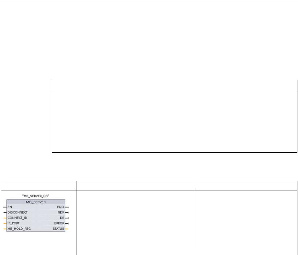
Communication processor and Modbus TCP
13.8 Legacy Modbus TCP communication
S7-1200 Programmable controller
System Manual, V4.2, 09/2016, A5E02486680-AK 1257
13.8.3.2
MB_SERVER (Communicate using PROFINET as Modbus TCP server)
The "MB_SERVER" instruction communicates as Modbus TCP server through the
PROFINET connector on the S7-1200 CPU. The "MB_SERVER" instruction processes
connection requests of a Modbus TCP client, receives and processes Modbus requests, and
sends responses.
To use the instruction, you do not require an additional hardware module.
NOTICE
Security information
Note that each client of the network is given read and write access to the process image
inputs and outputs and to the data block or bit memory area defined by the Modbus holding
register.
The option is available to restrict access to an IP address to prevent unauthorized read and
write operations. Note, however, that the shared address can also be used for unauthorized
access.
Table 13- 135 MB_SERVER instruction
LAD / FBD
SCL
Description
"MB_SERVER_DB"(
DISCONNECT:=_bool_in_,
CONNECT_ID:=_uint_in_,
IP_PORT:=_uint_in_,
NDR=>_bool_out_,
DR=>_bool_out_,
ERROR=>_bool_out_,
STATUS=>_word_out_,
MB_HOLD_REG:=_variant_inout_);
MB_SERVER communicates as a Mod-
bus TCP server through the PROFINET
connector on the S7-1200 CPU. No
additional communication hardware
module is required.
MB_SERVER can accept a request to
connect with Modbus TCP client, receive
a Modbus function request, and send a
response message.

Communication processor and Modbus TCP
13.8 Legacy Modbus TCP communication
S7-1200 Programmable controller
1258 System Manual, V4.2, 09/2016, A5E02486680-AK
Table 13- 136 Data types for the parameters
Parameter and type
Data type
Description
DISCONNECT IN Bool MB_SERVER attempts to make a "passive" connection with a partner device.
This means that the server is passively listening for a TCP connection request
from any requesting IP address.
If DISCONNECT = 0 and a connection does not exist, then a passive connec-
tion can be initiated.
If DISCONNECT = 1 and a connection exists, then a disconnect operation is
initiated. This allows your program to control when a connection is accepted.
Whenever this input is enabled, no other operation will be attempted.
CONNECT_ID IN UInt CONNECT_ID uniquely identifies each connection within the PLC. Each
unique instance of the MB_CLIENT or MB_SERVER instruction must contain a
unique CONNECT_ID parameter.
IP_PORT IN UInt Default value = 502: The IP port number that identifies the IP port that will be
monitored for a connection request from a Modbus client.
These TCP port numbers are not allowed for a MB_SERVER passive connec-
tion: 20, 21, 25, 80, 102, 123, 5001, 34962, 34963, and 34964.
MB_HOLD_REG IN_OUT Variant Pointer to the MB_SERVER Modbus holding register: The holding register
must either be a non-optimized global DB or a M memory address. This
memory area is used to hold the values a Modbus client is allowed to access
using Modbus register functions 3 (read), 6 (write), and 16 (write).
NDR OUT Bool New Data Ready: 0 = No new data, 1 = Indicates that new data has been
written by a Modbus client
DR OUT Bool Data Read: 0 = No data read, 1 = Indicates that data has been read by a
Modbus client.
ERROR OUT Bool The ERROR bit is TRUE for one scan, after MB_SERVER execution was
terminated with an error. The error code value at the STATUS parameter is
valid only during the single cycle where ERROR = TRUE.
STATUS
OUT
Word
Execution condition code
MB_SERVER allows incoming Modbus function codes (1, 2, 4, 5, and 15) to read or write
bits and words directly in the input process image and output process image of the S7-1200
CPU. For data transfer function codes (3, 6, and 16), the MB_HOLD_REG parameter must
be defined as a data type larger than a byte. The following table shows the mapping of
Modbus addresses to the process image in the CPU.
Table 13- 137 Mapping of Modbus addresses to the process image
Modbus functions
S7-1200
Codes
Function
Data area
Address range
Data area
CPU address
01
Read bits
Output
1
To
8192
Output Process Image
Q0.0 to Q1023.7
02
Read bits
Input
10001
To
18192
Input Process Image
I0.0 to I1023.7
04
Read words
Input
30001
To
30512
Input Process Image
IW0 to IW1022
05
Write bit
Output
1
To
8192
Output Process Image
Q0.0 to Q1023.7
15
Write bits
Output
1
To
8192
Output Process Image
Q0.0 to Q1023.7

Communication processor and Modbus TCP
13.8 Legacy Modbus TCP communication
S7-1200 Programmable controller
System Manual, V4.2, 09/2016, A5E02486680-AK 1259
Incoming Modbus message function codes function codes (3, 6, and 16) read or write words
in a Modbus holding register which can be an M memory address range or a data block. The
type of holding register is specified by the MB_HOLD_REG parameter.
Note
MB_HOLD_REG parameter assignment
The Modbus Holding Register can be in a non
-optimized global DB or an M memory
address.
For A Modbus holding register in M memory, use the standard Any Pointer
format. This is in
the format P#"Bit Address" "Data Type" "Length". An example would be P#M1000.0 WORD
500
The following table shows examples of Modbus address to holding register mapping used for
Modbus function codes 03 (read words), 06 (write word), and 16 (write words). The actual
upper limit of DB addresses is determined by the maximum work memory limit and M
memory limit, for each CPU model.
Table 13- 138 Mapping examples of Modbus address to CPU memory address
Modbus Address
MB_HOLD_REG parameter examples
P#M100.0 Word 5
P#DB10.DBx0.0 Word 5
"Recipe".ingredient
40001
MW100
DB10.DBW0
"Recipe".ingredient[1]
40002
MW102
DB10.DBW2
"Recipe".ingredient[2]
40003
MW104
DB10.DBW4
"Recipe".ingredient[3]
40004
MW106
DB10.DBW6
"Recipe".ingredient[4]
40005
MW108
DB10.DBW8
"Recipe".ingredient[5]

Communication processor and Modbus TCP
13.8 Legacy Modbus TCP communication
S7-1200 Programmable controller
1260 System Manual, V4.2, 09/2016, A5E02486680-AK
Multiple server connections
Multiple server connections may be created. This permits a single PLC to establish
concurrent connections to multiple Modbus TCP clients.
A Modbus TCP server can support concurrent connections up to the maximum number of
Open User Communications connections allowed by the PLC. The total number of
connections for a PLC, including Modbus TCP Clients and Servers, must not exceed the
maximum number of supported Open User Communications connections (Page 801). The
Modbus TCP connections may be shared between Client and/or Server type connections.
Individual server connection must follow these rules:
● Each MB_SERVER connection must use a distinct instance DB.
● Each MB_SERVER connection must be established with a unique IP port number. Only 1
connection per port is supported.
● Each MB_SERVER connection must use a unique connection ID.
● The MB_SERVER must be called individually for each connection (with its respective
instance DB).
The Connection ID must be unique for each individual connection. This means a single,
unique Connection ID must only be used with each individual instance DB. In summary, the
instance DB and the Connection ID are paired together and must be unique for every
connection.
Table 13- 139 Modbus diagnostic function codes
MB_SERVER Modbus diagnostic functions
Codes
Sub-function
Description
08 0x0000 Return query data echo test: The MB_SERVER will echo back to a Modbus client a word of data
that is received.
08 0x000A Clear communication event counter: The MB_SEVER will clear out the communication event
counter that is used for Modbus function 11.
11 Get communication event counter: The MB_SERVER uses an internal communication event
counter for recording the number of successful Modbus read and write requests that are sent to
the Modbus server. The counter does not increment on any Function 8 or Function 11 requests. It
is also not incremented on any requests that result in a communication error.
The broadcast function is not available for Modbus TCP, because only one client-server connec-
tion exists at any one time.

Communication processor and Modbus TCP
13.8 Legacy Modbus TCP communication
S7-1200 Programmable controller
System Manual, V4.2, 09/2016, A5E02486680-AK 1261
MB_SERVER variables
This table shows the public static variables stored in the MB_SERVER instance data block
that can be used in your program
Table 13- 140 MB_SERVER public static variables
Variable
Data type
Default
value
Description
HR_Start_Offset
Word
0
Assigns the starting address of the Modbus Holding register
Request_Count Word 0 The number of all requests received by this server.
Server_Message_Count
Word
0
The number of requests received for this specific server.
Xmt_Rcv_Count Word 0 The number of transmissions or receptions that have encountered an
error. Also, incremented if a message is received that is an invalid
Modbus message.
Exception_Count
Word
0
Modbus specific errors that require a returned exception
Success_Count Word 0 The number of requests received for this specific server that has no
protocol errors.
Connected Bool 0 Indicates whether the connection to the assigned client is connected or
disconnected: 1=connected, 0=disconnected
Your program can write values to the HR_Start_Offset and control Modbus server
operations. The other variables can be read to monitor Modbus status.
HR_Start_Offset
Modbus holding register addresses begin at 40001. These addresses correspond to the
beginning PLC memory address of the holding register. However, you can configure the
"HR_Start_Offset" variable to start the beginning Modbus holding register address at another
value instead of 40001.
For example, if the holding register is configured to start at MW100 and is 100 words long.
An offset of 20 specifies a beginning holding register address of 40021 instead of 40001.
Any address below 40021 and above 40119 will result in an addressing error.
Table 13- 141 Example of Modbus holding register addressing
HR_Start_Offset
Address
Minimum
Maximum
0
Modbus address (Word)
40001
40099
S7-1200 address
MW100
MW298
20
Modbus address (Word)
40021
40119
S7-1200 address
MW100
MW298
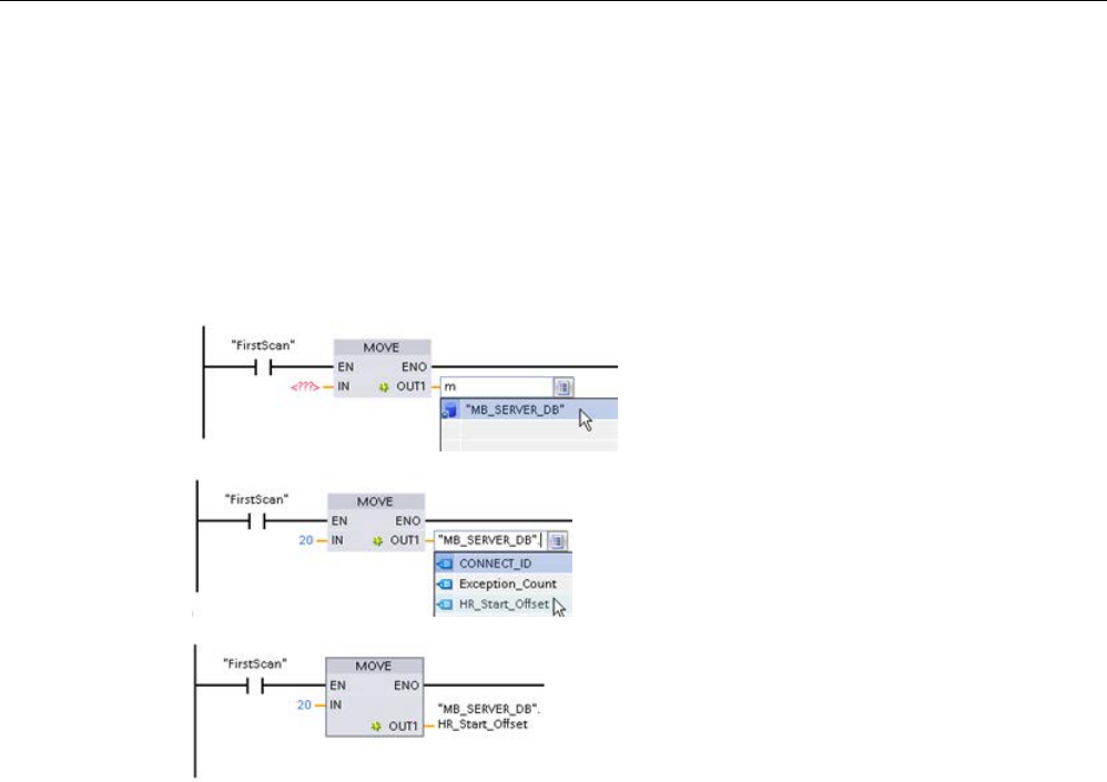
Communication processor and Modbus TCP
13.8 Legacy Modbus TCP communication
S7-1200 Programmable controller
1262 System Manual, V4.2, 09/2016, A5E02486680-AK
HR_Start_Offset is a word value that specifies the starting address of the Modbus holding
register and is stored in the MB_SERVER instance data block. You can set this public static
variable value by using the parameter helper drop-list, after MB_SERVER is placed in your
program.
For example, after MB_SERVER is placed in a LAD network, you can go to a previous
network and assign the HR_Start_Offset value. The value must be assigned prior to
execution of MB_SERVER.
Entering a Modbus server
variable using the default DB name:
1.
Set the cursor in the parameter field and
type an m character.
2.
Select "MB_SERVER_DB" from the drop-
list of DB names.
3.
Select
"MB_SERVER_DB.HR_Start_Offset" from
the drop-list of DB variables.

Communication processor and Modbus TCP
13.8 Legacy Modbus TCP communication
S7-1200 Programmable controller
System Manual, V4.2, 09/2016, A5E02486680-AK 1263
Table 13- 142 MB_SERVER execution condition codes 1
STATUS
(W#16#)
Response code to
Modbus server
(B#16#)
Modbus protocol errors
7001 MB_SERVER is waiting for a Modbus client to connect to the assigned TCP port. This
code is reported on the first execution of a connect or disconnect operation.
7002 MB_SERVER is waiting for a Modbus client to connect to the assigned TCP port. This
code is reported for any subsequent executions, while waiting for completion of a con-
nect or disconnect operation.
7003
A disconnect operation has successfully completed (Only valid for one PLC scan).
8187
Invalid pointer to MB_HOLD_REG: area is too small
818C Pointer to an optimized MB_HOLD_REG area (must be a non-optimized DB area or M
memory area) or Blocked process timeout exceeds the limit of 55 seconds. (S7-1200
specific)
8381
01
Function code not supported
8382
03
Data length error
8383
02
Data address error or access outside the bounds of the MB_HOLD_REG address area
8384
03
Data value error
8385
03
Data diagnostic code value not supported (function code 08)
1 In addition to the MB_SERVER errors listed above, errors can be returned from the
underlying T block communication instructions (TCON, TDISCON, TSEND, and TRCV
(Page 857)).
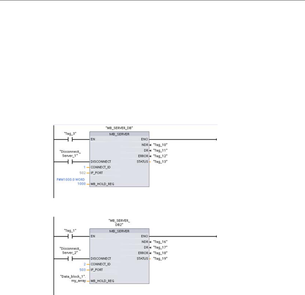
Communication processor and Modbus TCP
13.8 Legacy Modbus TCP communication
S7-1200 Programmable controller
1264 System Manual, V4.2, 09/2016, A5E02486680-AK
13.8.4
Legacy Modbus TCP examples
13.8.4.1
Example: Legacy MB_SERVER Multiple TCP connections
You can have multiple Modbus TCP server connections. To accomplish this, MB_SERVER
must be independently executed for each connection. Each connection must use an
independent instance DB, connection ID, and IP port. The S7-1200 allows only one
connection per IP port.
For best performance, MB_SERVER should be executed every program cycle, for each
connection.
Network 1:
Connection #1 with independent IP_PORT, connection ID, and instance DB
Network 2:
Connection #2 with independent IP_PORT, connection ID, and instance DB
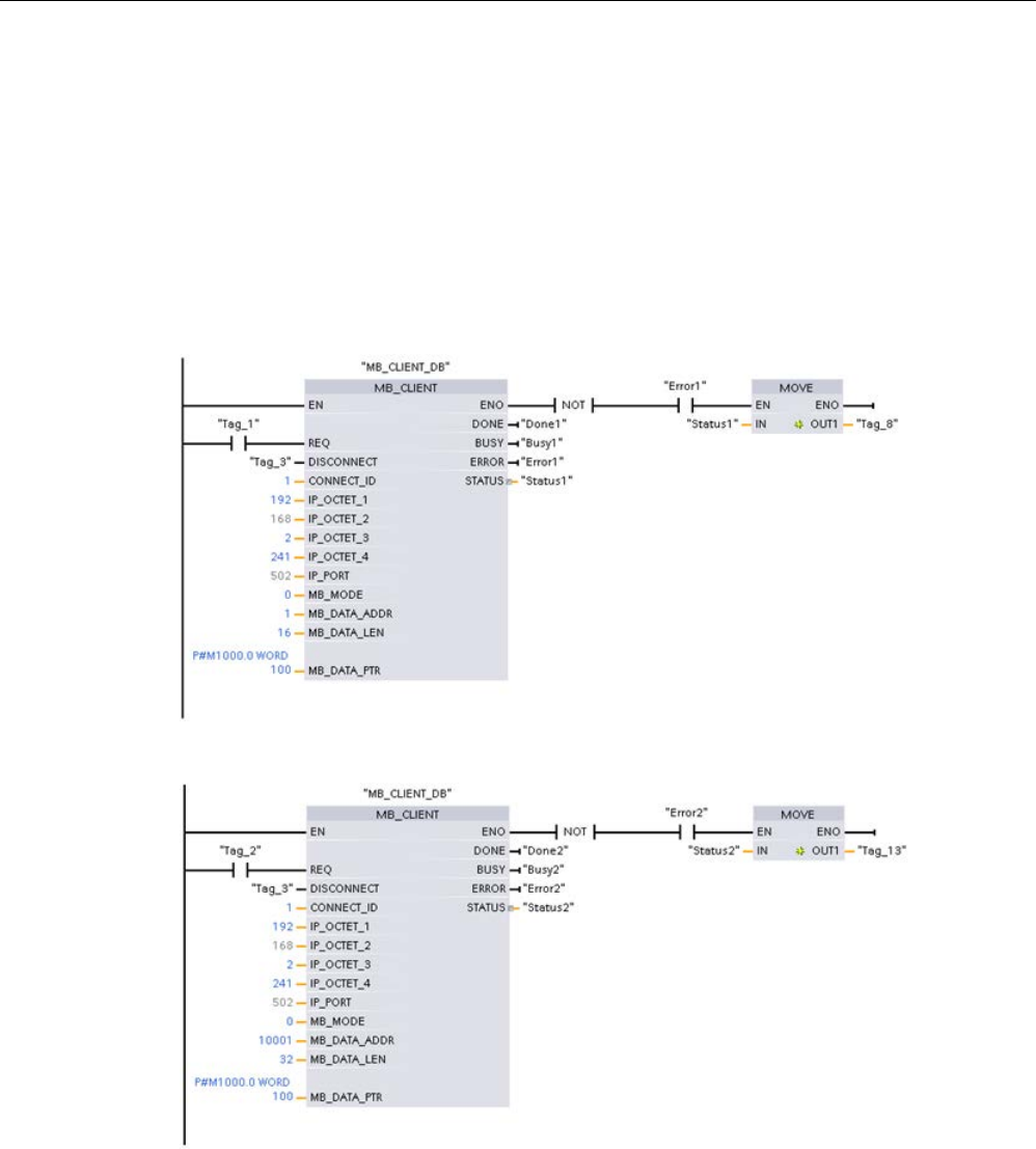
Communication processor and Modbus TCP
13.8 Legacy Modbus TCP communication
S7-1200 Programmable controller
System Manual, V4.2, 09/2016, A5E02486680-AK 1265
13.8.4.2
Example: Legacy MB_CLIENT 1: Multiple requests with common TCP connection
Multiple Modbus client requests can be sent over the same connection. To accomplish this,
use the same instance DB, connection ID, and port number.
Only 1 client can be active at any given time. Once a client completes its execution, the next
client begins execution. Your program is responsible for the order of execution.
The example shows both clients writing to the same memory area. Also, a returned error is
captured which is optional.
Network 1:
Modbus function 1 - Read 16 output image bits
Network 2:
Modbus function 2 - Read 32 input image bits
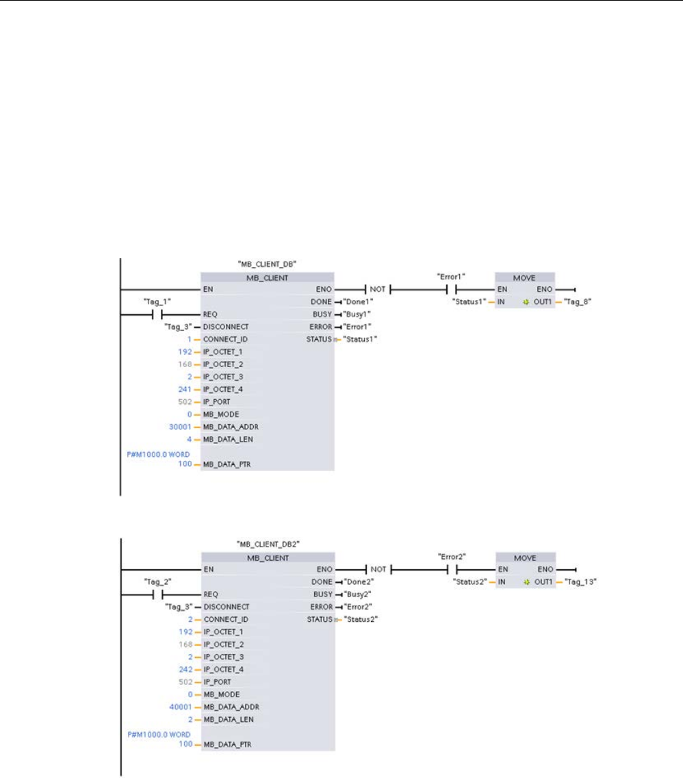
Communication processor and Modbus TCP
13.8 Legacy Modbus TCP communication
S7-1200 Programmable controller
1266 System Manual, V4.2, 09/2016, A5E02486680-AK
13.8.4.3
Example: Legacy MB_CLIENT 2: Multiple requests with different TCP connections
Modbus client requests can be sent over different connections. To accomplish this, different
instance DBs, IP addresses, and connection IDs must be used.
The port number must be different if the connections are established to the same Modbus
server. If the connections are on different servers, there is no port number restriction.
The example shows both clients writing to the same memory area. Also, a returned error is
captured which is optional.
Network 1:
Modbus function 4 - Read input words (in S7-1200 memory)
Network 2:
Modbus function 3 - Read holding register words from a Modbus TCP server
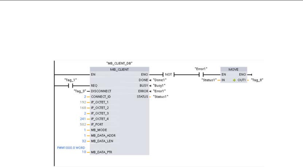
Communication processor and Modbus TCP
13.8 Legacy Modbus TCP communication
S7-1200 Programmable controller
System Manual, V4.2, 09/2016, A5E02486680-AK 1267
13.8.4.4
Example: Legacy MB_CLIENT 3: Output image write request
This example shows a Modbus client request to write the S7-1200 output image.
Network 1:
Modbus function 15 - Write S7-1200 output image bits
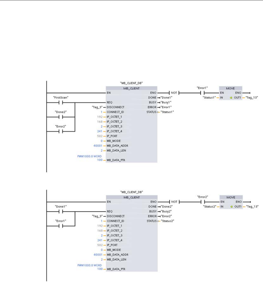
Communication processor and Modbus TCP
13.8 Legacy Modbus TCP communication
S7-1200 Programmable controller
1268 System Manual, V4.2, 09/2016, A5E02486680-AK
13.8.4.5
Example: Legacy MB_CLIENT 4: Coordinating multiple requests
You must ensure that each individual Modbus TCP request finishes execution. This
coordination must be provided by your program. The example below shows how the outputs
of the first and second client requests can be used to coordinate execution.
The example shows both clients writing to the same memory area. Also, a returned error is
captured which is optional.
Network 1:
Modbus function 3 - Read holding register words
Network 2:
Modbus function 3 - Read holding register words

Communication processor and Modbus TCP
13.9 Legacy Modbus RTU communication (CM/CB 1241 only)
S7-1200 Programmable controller
System Manual, V4.2, 09/2016, A5E02486680-AK 1269
13.9
Legacy Modbus RTU communication (CM/CB 1241 only)
13.9.1
Overview
Prior to the release of STEP 7 V13 SP1 and the S7-1200 V4.1 CPUs, the Modbus RTU
communication instructions existed with different names, and in some cases, slightly
different interfaces. The general concepts apply to both sets of instructions. Refer to the
individual legacy Modbus RTU instructions for programming information.
13.9.2
Selecting the version of the Modbus RTU instructions
There are two versions of the legacy Modbus RTU instructions available in STEP 7:
● Legacy version 1.3: Compatible with all CPU and CP versions
● Legacy version 2.2: Compatible with all CPU and CP versions
(Note: The version 2.2 design adds REQ and DONE parameters to MB_COMM_LOAD.
Also, the MB_ADDR parameter for MB_MASTER and MB_SLAVE now allows a UInt
value for extended addressing.)
For compatibility and ease of migration, you can choose which instruction version to insert
into your user program.
You cannot use both versions of the instructions with the same module, but two different
modules can use different versions of the instructions. Your program's Modbus RTU
instructions must have the same major version number (
1
.x,
2
.y, or
V
.z). The individual
instructions within a major version group may have different minor versions (1.
x
).
Click the icon on the instruction tree task card to enable the headers and columns
of the instruction t
ree.
To change the version of the Modbus i
n-
structions, select the version from the drop
-
down list. You can select the group or ind
i-
vidual instructions.
When you use the instruction tree to place a Modbus instruction in your program, a new FB
instance is created in the project tree. You can see new FB instance in the project tree under
PLC_x > Program blocks > System blocks > Program resources.
To verify the version of a Modbus instruction in a program, you must inspect project tree
properties and not the properties of a box displayed in the program editor. Select a project
tree Modbus FB instance, right-click, select "Properties", and select the "Information" page to
see the Modbus instruction version number.
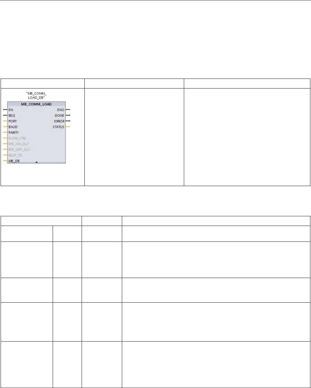
Communication processor and Modbus TCP
13.9 Legacy Modbus RTU communication (CM/CB 1241 only)
S7-1200 Programmable controller
1270 System Manual, V4.2, 09/2016, A5E02486680-AK
13.9.3
Legacy Modbus RTU instructions
13.9.3.1
MB_COMM_LOAD (Configure port on the PtP module for Modbus RTU)
Table 13- 143 MB_COMM_LOAD instruction
LAD / FBD
SCL
Description
"MB_COMM_LOAD_DB"(
REQ:=_bool_in,
PORT:=_uint_in_,
BAUD:=_udint_in_,
PARITY:=_uint_in_,
FLOW_CTRL:=_uint_in_,
RTS_ON_DLY:=_uint_in_,
RTS_OFF_DLY:=_uint_in_,
RESP_TO:=_uint_in_,
DONE=>_bool_out,
ERROR=>_bool_out_,
STATUS=>_word_out_,
MB_DB:=_fbtref_inout_);
The MB_COMM_LOAD instruction configures a
PtP port for Modbus RTU protocol communica-
tions. Modbus port hardware options: Install up
to three CMs (RS485 or RS232), plus one CB
(R4845). An instance data block is assigned
automatically when you place the
MB_COMM_LOAD instruction in your program.
Table 13- 144 Data types for the parameters
Parameter and type
Data type
Description
REQ IN Bool A low to high (positive edge) signal starts the operation.
(Version 2.0 only)
PORT IN Port After you install and configure a CM or CB communication device, the
port identifier appears in the parameter helper drop-list available at the
PORT box connection. The assigned CM or CB port value is the device
configuration property "hardware identifier". The port symbolic name is
assigned in the "System constants" tab of the PLC tag table.
BAUD IN UDInt Baud rate selection:
300, 600, 1200, 2400, 4800, 9600, 19200, 38400, 57600, 76800, 115200,
all other values are invalid
PARITY IN UInt Parity selection:
• 0 – None
• 1 – Odd
• 2 – Even
FLOW_CTRL 1 IN UInt Flow control selection:
• 0 – (default) no flow control
• 1 – Hardware flow control with RTS always ON (does not apply to
RS485 ports)
• 2 – Hardware flow control with RTS switched

Communication processor and Modbus TCP
13.9 Legacy Modbus RTU communication (CM/CB 1241 only)
S7-1200 Programmable controller
System Manual, V4.2, 09/2016, A5E02486680-AK 1271
Parameter and type
Data type
Description
RTS_ON_DLY 1 IN UInt RTS ON delay selection:
• 0 – (default) No delay from RTS active until the first character of the
message is transmitted
• 1 to 65535 – Delay in milliseconds from RTS active until the first char-
acter of the message is transmitted (does not apply to RS485 ports).
RTS delays shall be applied independent of the FLOW_CTRL selec-
tion.
RTS_OFF_DLY 1 IN UInt RTS OFF delay selection:
• 0 – (default) No delay from the last character transmitted until RTS
goes inactive
• 1 to 65535 – Delay in milliseconds from the last character transmitted
until RTS goes inactive (does not apply to RS485 ports). RTS delays
shall be applied independent of the FLOW_CTRL selection.
RESP_TO 1 IN UInt Response timeout:
Time in milliseconds allowed by MB_MASTER for the slave to respond. If
the slave does not respond in this time period, MB_MASTER will retry the
request or terminate the request with an error when the specified number
of retries has been sent.
5 ms to 65535 ms (default value = 1000 ms).
MB_DB IN Variant A reference to the instance data block used by the MB_MASTER or
MB_SLAVE instructions. After MB_SLAVE or MB_MASTER is placed in
your program, the DB identifier appears in the parameter helper drop-list
available at the MB_DB box connection.
DONE OUT Bool The DONE bit is TRUE for one scan, after the last request was completed
with no error. (Version 2.0 only)
ERROR OUT Bool The ERROR bit is TRUE for one scan, after the last request was termi-
nated with an error. The error code value at the STATUS parameter is
valid only during the single scan where ERROR = TRUE.
STATUS
OUT
Word
Execution condition code
1
Optional parameters for MB_COMM_LOAD (V 2.x or later). Click the arrow at the bottom of a LAD/FBD box to expand
the box and include these parameters.
MB_COMM_LOAD is executed to configure a port for the Modbus RTU protocol. Once a port
is configured for the Modbus RTU protocol, it can only be used by either the MB_MASTER or
MB_SLAVE instructions.
One execution of MB_COMM_LOAD must be used to configure each communication port
that is used for Modbus communication. Assign a unique MB_COMM_LOAD instance DB for
each port that you use. You can install up to three communication modules (RS232 or
RS485) and one communication board (RS485) in the CPU. Call MB_COMM_LOAD from a
startup OB and execute it one time or use the first scan system flag (Page 110) to initiate the
call to execute it one time. Only execute MB_COMM_LOAD again if communication
parameters like baud rate or parity must change.
An instance data block is assigned for MB_MASTER or MB_SLAVE when you place these
instructions in your program. This instance data block is referenced when you specify the
MB_DB parameter for the MB_COMM_LOAD instruction.

Communication processor and Modbus TCP
13.9 Legacy Modbus RTU communication (CM/CB 1241 only)
S7-1200 Programmable controller
1272 System Manual, V4.2, 09/2016, A5E02486680-AK
MB_COMM_LOAD data block variables
The following table shows the public static variables stored in the instance DB for the
MB_COMM_LOAD that can be used in your program.
Table 13- 145 Static variables in the instance DB
Variable
Data type
Description
ICHAR_GAP UInt Delay for Inter-character gap between characters. This parameter is specified
in milliseconds and is used to increase the expected amount of time between
received characters. The corresponding number of bit times for this parameter
is added to the Modbus default of 35 bit times (3.5 character times).
RETRIES UInt
Number of retries that the master will attempt before returning the no response
error code 0x80C8.
STOP_BITS
USInt
Number of stop bits used in framing each character. Valid values are 1 and 2.
Table 13- 146 MB_COMM_LOAD execution condition codes 1
STATUS (W#16#)
Description
0000
No error
8180
Invalid port ID value (wrong port/hardware identifier for communication module)
8181
Invalid baud rate value
8182
Invalid parity value
8183
Invalid flow control value
8184
Invalid response timeout value (response timeout less than the 5 ms minimum)
8185 MB_DB parameter is not an instance data block of a MB_MASTER or MB_SLAVE instruc-
tion.
1
In addition to the MB_COMM_LOAD errors listed above, errors can be returned from the underlying PtP communication
instructions.
13.9.3.2
MB_MASTER (Communicate using the PtP port as Modbus RTU master)
Table 13- 147 MB_MASTER instruction
LAD / FBD
SCL
Description
"MB_MASTER_DB"(
REQ:=_bool_in_,
MB_ADDR:=_uint_in_,
MODE:=_usint_in_,
DATA_ADDR:=_udint_in_,
DATA_LEN:=_uint_in_,
DONE=>_bool_out_,
BUSY=>_bool_out_,
ERROR=>_bool_out_,
STATUS=>_word_out_,
DATA_PTR:=_variant_inout_);
The MB_MASTER instruction communicates as a
Modbus master using a port that was configured by
a previous execution of the MB_COMM_LOAD
instruction. An instance data block is assigned
automatically when you place the MB_MASTER
instruction in your program. This MB_MASTER
instance data block is used when you specify the
MB_DB parameter for the MB_COMM_LOAD in-
struction.

Communication processor and Modbus TCP
13.9 Legacy Modbus RTU communication (CM/CB 1241 only)
S7-1200 Programmable controller
System Manual, V4.2, 09/2016, A5E02486680-AK 1273
Table 13- 148 Data types for the parameters
Parameter and type
Data type
Description
REQ IN Bool 0=No request
1= Request to transmit data to Modbus slave
MB_ADDR IN V1.0: USInt
V2.0: UInt
Modbus RTU station address:
Standard addressing range (1 to 247)
Extended addressing range (1 to 65535)
The value of 0 is reserved for broadcasting a message to all Modbus
slaves. Modbus function codes 05, 06, 15 and 16 are the only function
codes supported for broadcast.
MODE IN USInt Mode Selection: Specifies the type of request (read, write, or diagnostic).
See the Modbus functions table below for details.
DATA_ADDR IN UDInt
Starting Address in the slave: Specifies the starting address of the data to
be accessed in the Modbus slave. See the Modbus functions table below
for valid addresses.
DATA_LEN IN UInt Data Length: Specifies the number of bits or words to be accessed in this
request. See the Modbus functions table below for valid lengths.
DATA_PTR IN Variant Data Pointer: Points to the M or DB address (non-optimized DB type) for
the data being written or read.
DONE OUT Bool
The DONE bit is TRUE for one scan, after the last request was completed
with no error.
BUSY OUT Bool • 0 – No MB_MASTER operation in progress
• 1 – MB_MASTER operation in progress
ERROR OUT Bool The ERROR bit is TRUE for one scan, after the last request was termi-
nated with an error. The error code value at the STATUS parameter is
valid only during the single scan where ERROR = TRUE.
STATUS
OUT
Word
Execution condition code

Communication processor and Modbus TCP
13.9 Legacy Modbus RTU communication (CM/CB 1241 only)
S7-1200 Programmable controller
1274 System Manual, V4.2, 09/2016, A5E02486680-AK
Modbus master communication rules
● MB_COMM_LOAD must be executed to configure a port before a MB_MASTER
instruction can communicate with that port.
● If a port is to be used to initiate Modbus master requests, that port should not be used by
MB_SLAVE. One or more instances of MB_MASTER execution can be used with that
port, but all MB_MASTER execution must use the same MB_MASTER instance DB for
that port.
● The Modbus instructions do not use communication interrupt events to control the
communication process. Your program must poll the MB_MASTER instruction for transmit
and receive complete conditions.
● It is recommended that you call all MB_MASTER execution for a given port from a
program cycle OB. Modbus master instructions may execute in only one of the program
cycle or cyclic/time delay execution levels. They must not execute in both execution
priority levels. Pre-emption of a Modbus Master instruction by another Modbus master
instruction in a higher priority execution priority level will result in improper operation.
Modbus master instructions must not execute in the startup, diagnostic or time error
execution priority levels.
● Once a master instruction initiates a transmission, this instance must be continually
executed with the EN input enabled until a DONE=1 state or ERROR=1 state is returned.
A particular MB_MASTER instance is considered active until one of these two events
occurs. While the original instance is active, any call to any other instance with the REQ
input enabled will result in an error. If the continuous execution of the original instance
stops, the request state remains active for a period of time specified by the static variable
Blocked_Proc_Timeout. Once this period of time expires, the next master instruction
called with an enabled REQ input will become the active instance. This prevents a single
Modbus master instance from monopolizing or locking access to a port. If the original
active instance is not enabled within the period of time specified by the static variable
"Blocked_Proc_Timeout", then the next execution by this instance (with REQ not set) will
clear the active state. If (REQ is set), then this execution initiates a new master request
as if no other instance was active.
REQ parameter
0 = No request; 1 = Request to transmit data to Modbus Slave
You may control this input either through the use of a level or edge triggered contact.
Whenever this input is enabled, a state machine is started to ensure that no other
MB_MASTER using the same instance DB is allowed to issue a request, until the current
request is completed. All other input states are captured and held internally for the current
request, until the response is received or an error detected.
If the same instance of MB_MASTER is executed again with REQ input = 1 before the
completion of the current request, then no subsequent transmissions are made. However,
when the request is completed, a new request is issued whenever MB_MASTER is executed
again with REQ input = 1.

Communication processor and Modbus TCP
13.9 Legacy Modbus RTU communication (CM/CB 1241 only)
S7-1200 Programmable controller
System Manual, V4.2, 09/2016, A5E02486680-AK 1275
DATA_ADDR and MODE parameters select the Modbus function type
DATA_ADDR (starting Modbus address in the slave): Specifies the starting address of the
data to be accessed in the Modbus slave.
The MB_MASTER instruction uses a MODE input rather than a Function Code input. The
combination of MODE and Modbus address determine the Function Code that is used in the
actual Modbus message. The following table shows the correspondence between parameter
MODE, Modbus function code, and Modbus address range.
Table 13- 149 Modbus functions
MODE
Modbus
Function
Data length
Operation and data
Modbus
Address
0 01 1 to 2000
1 to 1992
1
Read output bits:
1 to (1992 or 2000) bits per request
1 to 9999
0 02 1 to 2000
1 to 1992 1
Read input bits:
1 to (1992 or 2000) bits per request
10001 to 19999
0 03 1 to 125
1 to 124
1
Read Holding registers:
1 to (124 or 125) words per request
40001 to 49999 or
400001 to 465535
0 04 1 to 125
1 to 124
1
Read input words:
1 to (124 or 125) words per request
30001 to 39999
1 05 1 Write one output bit:
One bit per request
1 to 9999
1 06 1 Write one holding register:
1 word per request
40001 to 49999 or
400001 to 465535
1 15 2 to 1968
2 to 1960
1
Write multiple output bits:
2 to (1960 or 1968) bits per request
1 to 9999
1 16 2 to 123
2 to 122
1
Write multiple holding registers:
2 to (122 or 123) words per request
40001 to 49999 or
400001 to 465535
2 15 1 to 1968
2 to 1960
1
Write one or more output bits:
1 to (1960 or 1968) bits per request
1 to 9999
2 16 1 to 123
1 to 122
1
Write one or more holding registers:
1 to (122 or 123) words per request
40001 to 49999 or
400001 to 465535
11 11 0 Read the slave communication status word and event
counter. The status word indicates busy (0 – not busy,
0xFFFF - busy). The event counter is incremented for
each successful completion of a message.
Both the DATA_ADDR and DATA_LEN operands of
MB_MASTER are ignored for this function.
80 08 1 Check slave status using data diagnostic code 0x0000
(Loopback test – slave echoes the request)
1 word per request

Communication processor and Modbus TCP
13.9 Legacy Modbus RTU communication (CM/CB 1241 only)
S7-1200 Programmable controller
1276 System Manual, V4.2, 09/2016, A5E02486680-AK
MODE
Modbus
Function
Data length
Operation and data
Modbus
Address
81 08 1 Reset slave event counter using data diagnostic code
0x000A
1 word per request
3 to 10,
12 to 79,
82 to 255
Reserved
1
For "Extended Addressing" mode the maximum data lengths are reduced by 1 byte or 1 word depending upon the data
type used by the function.
DATA_PTR parameter
The DATA_PTR parameter points to the DB or M address that is written to or read from. If
you use a data block, then you must create a global data block that provides data storage for
reads and writes to Modbus slaves.
Note
The DATA_PTR data block type must allow direct addressing
The data block must allow both direct (absolute) and symbolic addressing. When you create
the data block the "Standard" access attribute must be selected.
Data block structures for the DATA_PTR parameter
● These data types are valid for
word reads
of Modbus addresses 30001 to 39999, 40001
to 49999, and 400001 to 465536 and also for
word writes
to Modbus addresses 40001 to
49999 and 400001 to 465536.
– Standard array of WORD, UINT, or INT data types
– Named WORD, UINT, or INT structure where each element has a unique name and
16 bit data type.
– Named complex structure where each element has a unique name and a 16 or 32 bit
data type.
● For
bit reads
and writes of Modbus addresses 00001 to 09999 and bit reads of 10001 to
19999.
– Standard array of Boolean data types.
– Named Boolean structure of uniquely named Boolean variables.
● Although not required, it is recommended that each MB_MASTER instruction have its
own separate memory area. The reason for this recommendation is that there is a greater
possibility of data corruption if multiple MB_MASTER instructions are reading and writing
to the same memory area.
● There is no requirement that the DATA_PTR data areas be in the same global data block.
You can create one data block with multiple areas for Modbus reads, one data block for
Modbus writes, or one data block for each slave station.

Communication processor and Modbus TCP
13.9 Legacy Modbus RTU communication (CM/CB 1241 only)
S7-1200 Programmable controller
System Manual, V4.2, 09/2016, A5E02486680-AK 1277
Modbus master data block variables
The following table shows the public static variables stored in the instance DB for
MB_MASTER that can be used in your program.
Table 13- 150 Static variables in the instance DB
Variable
Data type
Initial value
Description
Blocked_Proc_T
imeout
Real 3.0 Amount of time (in seconds) to wait for a blocked Modbus Master instance
before removing this instance as being ACTIVE. This can occur, for example,
when a Master request has been issued and then the program stops calling
the Master function before it has completely finished the request. The time
value must be greater than 0 and less than 55 seconds, or an error occurs.
The default value is .5 seconds.
Extend-
ed_Addressing
Bool False Configures single or double-byte slave addressing. The default value = 0.
(0=single byte address, 1=double-byte address)
Your program can write values to the Blocked_Proc_Timeout and Extended_Addressing
variables to control Modbus master operations. See the MB_SLAVE topic description of
HR_Start_Offset and Extended_Addressing for an example of how to use these variables in
the program editor and details about Modbus extended addressing (Page 1278).
Condition codes
Table 13- 151 MB_MASTER execution condition codes (communication and configuration errors) 1
STATUS (W#16#)
Description
0000
No error
80C8
Slave timeout. Check baud rate, parity, and wiring of slave.
80D1 The receiver issued a flow control request to suspend an active transmission and never re-
enabled the transmission during the specified wait time.
This error is also generated during hardware flow control when the receiver does not assert
CTS within the specified wait time.
80D2
The transmit request was aborted because no DSR signal is received from the DCE.
80E0
The message was terminated because the receive buffer is full.
80E1
The message was terminated as a result of a parity error.
80E2
The message was terminated as a result of a framing error.
80E3
The message was terminated as a result of an overrun error.
80E4
The message was terminated as a result of the specified length exceeding the total buffer size.
8180
Invalid port ID value or error with MB_COMM_LOAD instruction
8186
Invalid Modbus station address
8188
Invalid Mode specified for broadcast request
8189 Invalid Data Address value
818A
Invalid Data Length value
818B Invalid pointer to the local data source/destination: Size not correct
818C Invalid pointer for DATA_PTR or invalid Blocked_Proc_Timeout: The data area must be a DB
(that allows both symbolic and direct access) or M memory.
8200
Port is busy processing a transmit request.
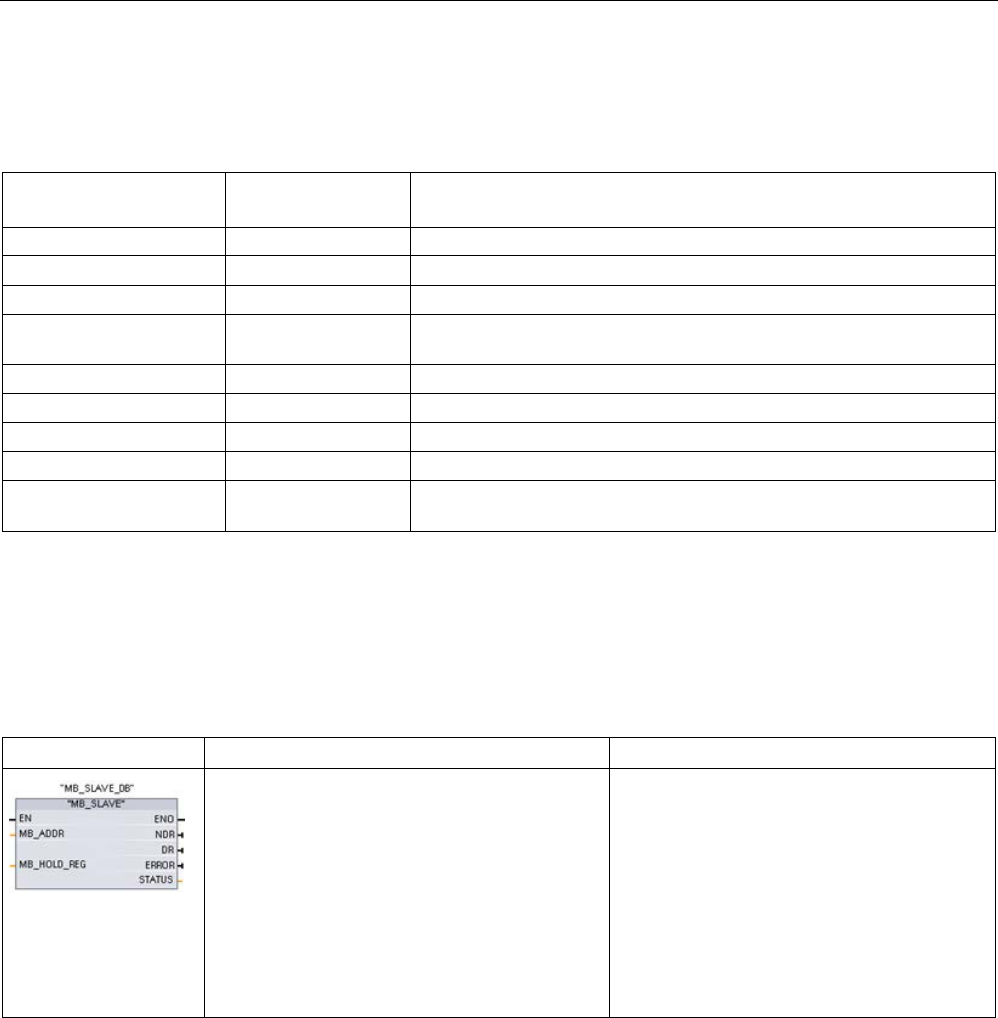
Communication processor and Modbus TCP
13.9 Legacy Modbus RTU communication (CM/CB 1241 only)
S7-1200 Programmable controller
1278 System Manual, V4.2, 09/2016, A5E02486680-AK
Table 13- 152 MB_MASTER execution condition codes (Modbus protocol errors) 1
STATUS (W#16#)
Response code from
slave
Modbus protocol errors
8380
-
CRC error
8381 01 Function code not supported
8382
03
Data length error
8383 02 Data address error or address outside the valid range of the
DATA_PTR area
8384
Greater than 03
Data value error
8385
03
Data diagnostic code value not supported (function code 08)
8386
-
Function code in the response does not match the code in the request.
8387
-
Wrong slave responded
8388 - The slave response to a write request is incorrect. The write request
returned by the slave does not match what the master actually sent.
1
In addition to the MB_MASTER errors listed above, errors can be returned from the underlying PtP communication
instructions.
13.9.3.3
MB_SLAVE (Communicate using the PtP port as Modbus RTU slave)
Table 13- 153 MB_SLAVE instruction
LAD / FBD
SCL
Description
"MB_SLAVE_DB"(
MB_ADDR:=_uint_in_,
NDR=>_bool_out_,
DR=>_bool_out_,
ERROR=>_bool_out_,
STATUS=>_word_out_,
MB_HOLD_REG:=_variant_inout_);
The MB_SLAVE instruction allows your pro-
gram to communicate as a Modbus slave
through a PtP port on the CM (RS485 or
RS232) and CB (RS485). When a remote
Modbus RTU master issues a request, your
user program responds to the request by
MB_SLAVE execution. STEP 7 automatically
creates an instance DB when you insert the
instruction. Use this MB_SLAVE_DB name
when you specify the MB_DB parameter for
the MB_COMM_LOAD instruction.

Communication processor and Modbus TCP
13.9 Legacy Modbus RTU communication (CM/CB 1241 only)
S7-1200 Programmable controller
System Manual, V4.2, 09/2016, A5E02486680-AK 1279
Table 13- 154 Data types for the parameters
Parameter and type
Data type
Description
MB_ADDR IN V1.0: USInt
V2.0: UInt
The station address of the Modbus slave:
Standard addressing range (1 to 247)
Extended addressing range (0 to 65535)
MB_HOLD_REG IN Variant Pointer to the Modbus Holding Register DB: The Modbus holding
register can be M memory or a data block.
NDR OUT Bool New Data Ready:
• 0 – No new data
• 1 – Indicates that new data has been written by the Modbus
master
DR OUT Bool Data Read:
• 0 – No data read
• 1 – Indicates that data has been read by the Modbus master
ERROR OUT Bool The ERROR bit is TRUE for one scan, after the last request was
terminated with an error. If execution is terminated with an error,
then the error code value at the STATUS parameter is valid only
during the single scan where ERROR = TRUE.
STATUS
OUT
Word
Execution error code
Modbus communication function codes (1, 2, 4, 5, and 15) can read and write bits and words
directly in the input process image and output process image of the CPU. For these function
codes, the MB_HOLD_REG parameter must be defined as a data type larger than a byte.
The following table shows the example mapping of Modbus addresses to the process image
in the CPU.
Table 13- 155 Mapping of Modbus addresses to the process image
Modbus functions
S7-1200
Codes
Function
Data area
Address range
Data area
CPU address
01
Read bits
Output
1
to
8192
Output Process Image
Q0.0 to Q1023.7
02
Read bits
Input
10001
to
18192
Input Process Image
I0.0 to I1023.7
04
Read words
Input
30001
to
30512
Input Process Image
IW0 to IW1022
05
Write bit
Output
1
to
8192
Output Process Image
Q0.0 to Q1023.7
15
Write bits
Output
1
to
8192
Output Process Image
Q0.0 to Q1023.7
Modbus communication function codes (3, 6, 16) use a Modbus holding register which can
be an M memory address range or a data block. The type of holding register is specified by
the MB_HOLD_REG parameter on the MB_SLAVE instruction.
Note
MB_HOLD_REG data block type
A Modbus holding register data block must allow both direct (absolute) and symbolic
addre
ssing. When you create the data block the "Standard" access attribute must be
selected.

Communication processor and Modbus TCP
13.9 Legacy Modbus RTU communication (CM/CB 1241 only)
S7-1200 Programmable controller
1280 System Manual, V4.2, 09/2016, A5E02486680-AK
The following table shows examples of Modbus address to holding register mapping that is
used for Modbus function codes 03 (read words), 06 (write word), and 16 (write words). The
actual upper limit of DB addresses is determined by the maximum work memory limit and M
memory limit, for each CPU model.
Table 13- 156 Mapping of Modbus addresses to CPU memory
Modbus Master
Address
MB_HOLD_REG parameter examples
MW100
DB10.DBw0
MW120
DB10.DBW50
"Recipe".ingredient
40001
MW100
DB10.DBW0
MW120
DB10.DBW50
"Recipe".ingredient[1]
40002
MW102
DB10.DBW2
MW122
DB10.DBW52
"Recipe".ingredient[2]
40003 MW104 DB10.DBW4 MW124 DB10.DBW54 "Recipe".ingredient[3]
40004
MW106
DB10.DBW6
MW126
DB10.DBW56
"Recipe".ingredient[4]
40005
MW108
DB10.DBW8
MW128
DB10.DBW58
"Recipe".ingredient[5]
Table 13- 157 Diagnostic functions
S7-1200 MB_SLAVE Modbus diagnostic functions
Codes
Sub-function
Description
08 0000H Return query data echo test: The MB_SLAVE will echo back to a Modbus master a
word of data that is received.
08 000AH Clear communication event counter: The MB_SLAVE will clear out the communication
event counter that is used for Modbus function 11.
11 Get communication event counter: The MB_SLAVE uses an internal communication
event counter for recording the number of successful Modbus read and write requests
that are sent to the Modbus slave. The counter does not increment on any Function 8,
Function 11, or broadcast requests. It is also not incremented on any requests that
result in a communication error (for example, parity or CRC errors).
The MB_SLAVE instruction supports broadcast write requests from any Modbus master as
long as the request is for accessing valid addresses. MB_SLAVE will produce error code
0x8188 for function codes not supported in broadcast.
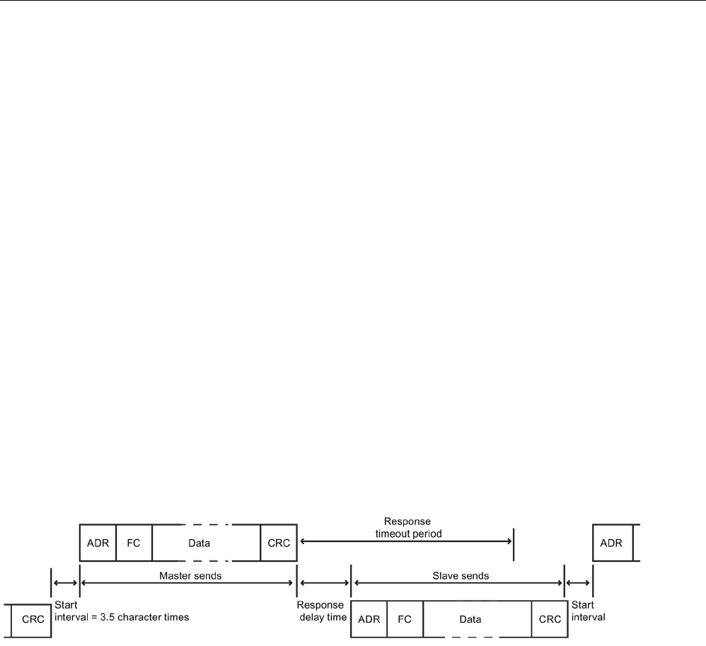
Communication processor and Modbus TCP
13.9 Legacy Modbus RTU communication (CM/CB 1241 only)
S7-1200 Programmable controller
System Manual, V4.2, 09/2016, A5E02486680-AK 1281
Modbus slave communication rules
● MB_COMM_LOAD must be executed to configure a port, before a MB_SLAVE instruction
can communicate through that port.
● If a port is to respond as a slave to a Modbus master, then do not program that port with
the MB_MASTER instruction.
● Only one instance of MB_SLAVE can be used with a given port, otherwise erratic
behavior may occur.
● The Modbus instructions do not use communication interrupt events to control the
communication process. Your program must control the communication process by
polling the MB_SLAVE instruction for transmit and receive complete conditions.
● The MB_SLAVE instruction must execute periodically at a rate that allows it to make a
timely response to incoming requests from a Modbus master. It is recommended that you
execute MB_SLAVE every scan from a program cycle OB. Executing MB_SLAVE from a
cyclic interrupt OB is possible, but is not recommended because of the potential for
excessive time delays in the interrupt routine to temporarily block the execution of other
interrupt routines.
Modbus signal timing
MB_SLAVE must be executed periodically to receive each request from the Modbus master
and then respond as required. The frequency of execution for MB_SLAVE is dependent
upon the response timeout period of the Modbus master. This is illustrated in the following
diagram.
The response timeout period RESP_TO is the amount of time a Modbus master waits for the
start of a response from a Modbus slave. This time period is not defined by the Modbus
protocol, but is a parameter of each Modbus master. The frequency of execution (the time
between one execution and the next execution) of MB_SLAVE must be based on the
particular parameters of your Modbus master. At a minimum, you should execute
MB_SLAVE twice within the response timeout period of the Modbus master.

Communication processor and Modbus TCP
13.9 Legacy Modbus RTU communication (CM/CB 1241 only)
S7-1200 Programmable controller
1282 System Manual, V4.2, 09/2016, A5E02486680-AK
Modbus slave variables
This table shows the public static variables stored in the MB_SLAVE instance data block that
can be used in your program
Table 13- 158 Modbus slave variables
Variable
Data type
Description
Request_Count
Word
The number of all requests received by this slave
Slave_Message_Count Word The number of requests received for this specific slave
Bad_CRC_Count
Word
The number of requests received that have a CRC error
Broadcast_Count
Word
The number of broadcast requests received
Exception_Count
Word
Modbus specific errors that require a returned exception
Success_Count Word The number of requests received for this specific slave that have no protocol
errors
HR_Start_Offset
Word
Specifies the starting address of the Modbus Holding register (default = 0)
Extended_Addressing Bool Configures single or double-byte slave addressing
(0=single byte address, 1=double-byte address, default = 0)
Your program can write values to the HR_Start_Offset and Extended_Addressing variables
and control Modbus slave operations. The other variables can be read to monitor Modbus
status.
HR_Start_Offset
Modbus holding register addresses begin at 40001 or 400001. These addresses correspond
to the beginning PLC memory address of the holding register. However, you can configure
the "HR_Start_Offset" variable to start the beginning Modbus holding register address at
another value instead of 40001 or 400001.
For example, if the holding register is configured to start at MW100 and is 100 words long.
An offset of 20 specifies a beginning holding register address of 40021 instead of 40001.
Any address below 40021 and above 400119 will result in an addressing error.
Table 13- 159 Example of Modbus holding register addressing
HR_Start_Offset
Address
Minimum
Maximum
0
Modbus address (Word)
40001
40099
S7-1200 address
MW100
MW298
20
Modbus address (Word)
40021
40119
S7-1200 address
MW100
MW298
HR_Start_Offset is a word value that specifies the starting address of the Modbus holding
register and is stored in the MB_SLAVE instance data block. You can set this public static
variable value by using the parameter helper drop-list, after MB_SLAVE is placed in your
program.
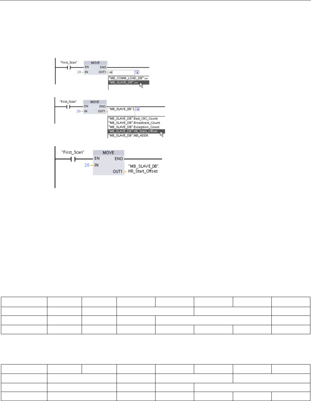
Communication processor and Modbus TCP
13.9 Legacy Modbus RTU communication (CM/CB 1241 only)
S7-1200 Programmable controller
System Manual, V4.2, 09/2016, A5E02486680-AK 1283
For example, after MB_SLAVE is placed in a LAD network, you can go to a previous network
and assign the HR_Start_Offset value. The value must be assigned prior to execution of
MB_SLAVE.
Entering a Modbus slave variable using the
default DB name:
1.
Set the cursor in the parameter field and
type an m character.
2.
Select "MB_SLAVE_DB" from the drop-list.
3.
Set the cursor at the right side of the DB
name (after the quote character) and enter
a period character.
4.
Select "MB_SLAVE_DB.HR_Start_Offset"
from the drop list.
Extended_Addressing
The Extended_Addressing variable is accessed in a similar way as the HR_Start_Offset
reference discussed above except that the Extended_Addressing variable is a Boolean
value. The Boolean value must be written by an output coil and not a move box.
Modbus slave addressing can be configured to be either a single byte (which is the Modbus
standard) or double byte. Extended addressing is used to address more than 247 devices
within a single network. Selecting extended addressing allows you to address a maximum of
64000 addresses. A Modbus function 1 frame is shown below as an example.
Table 13- 160 Single-byte slave address (byte 0)
Function 1
Byte 0
Byte 1
Byte 2
Byte 3
Byte 4
Byte 5
Request
Slave addr.
F code
Start address
Length of coils
Valid Response Slave addr. F code Length Coil data
Error response
Slave addr.
0x81
E code
Table 13- 161 Double-byte slave address (byte 0 and byte 1)
Byte 0
Byte 1
Byte 2
Byte 3
Byte 4
Byte 5
Byte 6
Request Slave address F code Start address Length of coils
Valid Response
Slave address
F code
Length
Coil data
Error response Slave address 0x81 E code

Communication processor and Modbus TCP
13.9 Legacy Modbus RTU communication (CM/CB 1241 only)
S7-1200 Programmable controller
1284 System Manual, V4.2, 09/2016, A5E02486680-AK
Condition codes
Table 13- 162 MB_SLAVE execution condition codes (communication and configuration errors) 1
STATUS (W#16#)
Description
80D1 The receiver issued a flow control request to suspend an active transmission and never re-
enabled the transmission during the specified wait time.
This error is also generated during hardware flow control when the receiver does not assert
CTS within the specified wait time.
80D2
The transmit request was aborted because no DSR signal is received from the DCE.
80E0
The message was terminated because the receive buffer is full.
80E1
The message was terminated as a result of a parity error.
80E2
The message was terminated as a result of a framing error.
80E3
The message was terminated as a result of an overrun error.
80E4 The message was terminated as a result of the specified length exceeding the total buffer
size.
8180
Invalid port ID value or error with MB_COMM_LOAD instruction
8186
Invalid Modbus station address
8187
Invalid pointer to MB_HOLD_REG DB: Area is too small
818C Invalid MB_HOLD_REG pointer to M memory or DB (DB area must allow both symbolic and
direct address)
Table 13- 163 MB_SLAVE execution condition codes (Modbus protocol errors) 1
STATUS (W#16#)
Response code from
slave
Modbus protocol errors
8380
No response
CRC error
8381
01
Function code not supported or not supported within broadcasts
8382
03
Data length error
8383 02 Data address error or address outside the valid range of the
DATA_PTR area
8384
03
Data value error
8385 03 Data diagnostic code value not supported (function code 08)
1
In addition to the MB_SLAVE errors listed above, errors can be returned from the underlying PtP communication in-
structions.
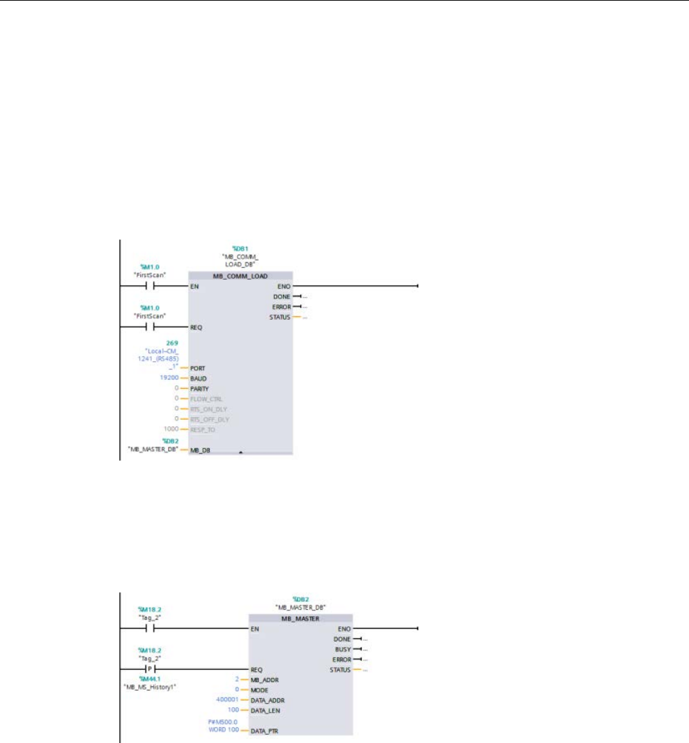
Communication processor and Modbus TCP
13.9 Legacy Modbus RTU communication (CM/CB 1241 only)
S7-1200 Programmable controller
System Manual, V4.2, 09/2016, A5E02486680-AK 1285
13.9.4
Legacy Modbus RTU examples
13.9.4.1
Example: Legacy Modbus RTU master program
MB_COMM_LOAD is initialized during start-up by using the first scan flag. Execution of
MB_COMM_LOAD in this manner should only be done when the serial port configuration will
not change at runtime.
Network 1
: Configure/initialize the RS485 module communications port only once during the
first scan.
One MB_MASTER instruction is used in the program cycle OB to communicate with a single
slave. Additional MB_MASTER instructions can be used in the program cycle OB to
communicate with other slaves, or one MB_MASTER FB could be re-used to communicate
with additional slaves.
Network 2
: Read 100 words of holding register data from location 400001 on slave #2 to
memory location MW500-MW698.
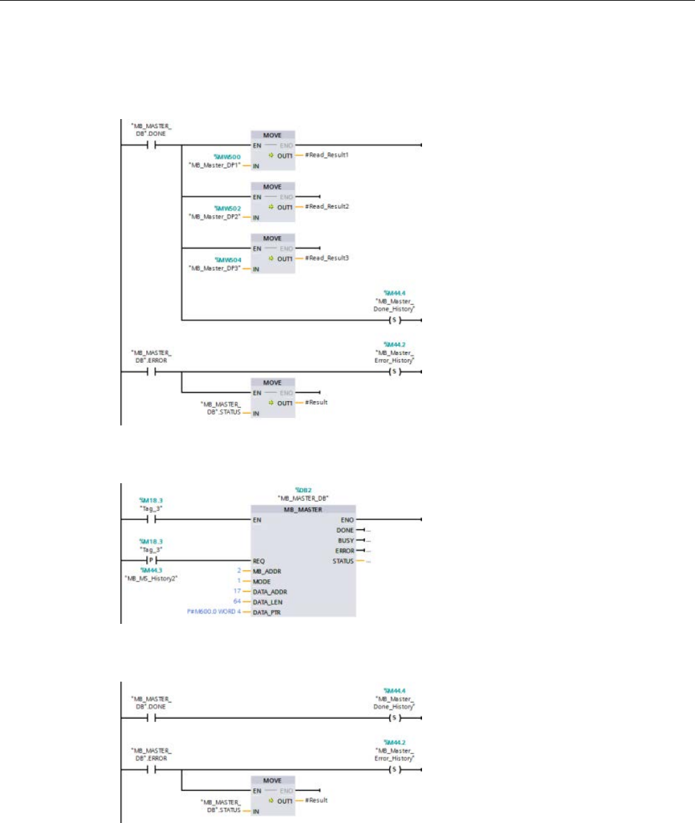
Communication processor and Modbus TCP
13.9 Legacy Modbus RTU communication (CM/CB 1241 only)
S7-1200 Programmable controller
1286 System Manual, V4.2, 09/2016, A5E02486680-AK
Network 3
: Move the first 3 words of the holding register data that has been read to some
other location, and set a DONE history bit. This network also sets an ERROR history bit and
saves the STATUS word to another location in the event of an error.
Network 4
: Write 64 bits of data from MW600-MW607 to output bit locations 00017 to 00081
on slave #2.
Network 5
: Set a DONE history bit when the write is complete. If an error occurs, the
program sets an ERROR history bit and saves the STATUS code.
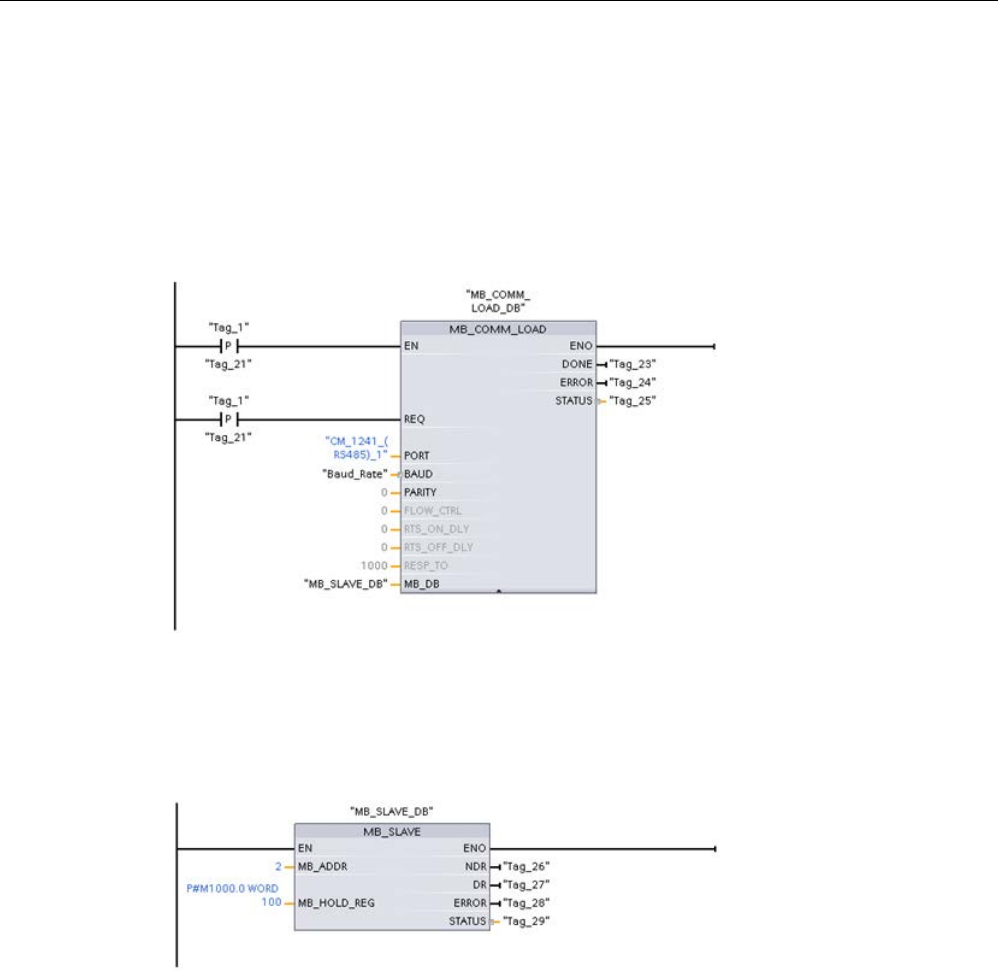
Communication processor and Modbus TCP
13.9 Legacy Modbus RTU communication (CM/CB 1241 only)
S7-1200 Programmable controller
System Manual, V4.2, 09/2016, A5E02486680-AK 1287
13.9.4.2
Example: Legacy Modbus RTU slave program
MB_COMM_LOAD shown below is initialized each time "Tag_1" is enabled.
Execution of MB_COMM_LOAD in this manner should only be done when the serial port
configuration will change at runtime, as a result of HMI configuration.
Network 1
: Initialize the RS485 module parameters each time they are changed by an HMI
device.
MB_SLAVE shown below is placed in a cyclic OB that is executed every 10ms. While this
does not give the absolute fastest response by the slave, it does provide good performance
at 9600 baud for short messages (20 bytes or less in the request).
Network 2
: Check for Modbus master requests during each scan. The Modbus holding
register is configured for 100 words starting at MW1000.

Communication processor and Modbus TCP
13.10 Industrial Remote Communication (IRC)
S7-1200 Programmable controller
1288 System Manual, V4.2, 09/2016, A5E02486680-AK
13.10
Industrial Remote Communication (IRC)
13.10.1
Telecontrol CPs overview
Industrial Remote Communication provides access to widely distributed machines, plants,
and applications of different sizes securely and economically. Industrial Remote
Communications includes the following means of communication through CP modules:
● TeleControl: Telecontrol is the connection of process stations (Remote Terminal
Units/RTUs) that are distributed over a wide geographical area to one or more central
process control systems for the purpose of monitoring and control. Various different
transmission components in the Remote Networks product spectrum support remote
communication over a range of public and private networks. Special telecontrol protocols
perform event-driven or cyclic exchange of process data, which permits efficient control of
the overall process.
● TeleService: Teleservice involves data exchange with distant technical systems
(machines, plants, computers, etc.) for the purpose of error detection, diagnostics,
maintenance, repair or optimization.
● Additional applications for remote communication, for example surveillance, smart grid
applications, and condition monitoring.
TeleControl CPs for the S7-1200
For TeleControl applications, the following communications processors, many of which also
provide access to the S7-1200 Web server (Page 1010), are available:
●
CP 1243-1:
– Article number: 6GK7 243-1BX30-0XE0
– Communications processor for connecting the SIMATIC S7-1200 using the public
infrastructure (for example, DSL) to a control center with TeleControl Server Basic
(TCSB version V3)
– With the help of VPN technology and the firewall, the CP allows protected access to
the S7-1200.
– You can use the CP as an additional Ethernet interface of the CPU for S7
communication.
– You communicate between the CP and CPU using configurable data points that
access PLC tags.
●
CP 1243-1 DNP3:
– Article number: 6GK7 243-1JX30-0XE0
– Communications processor for connecting the SIMATIC S7-1200 to control centers
using the DNP3 protocol
– You communicate between the CP and CPU using configurable data points that
access PLC tags.

Communication processor and Modbus TCP
13.10 Industrial Remote Communication (IRC)
S7-1200 Programmable controller
System Manual, V4.2, 09/2016, A5E02486680-AK 1289
●
CP 1243-1 IEC:
– Article number: 6GK7 243-1PX30-0XE0
– Communications processor for connecting SIMATIC S7-1200 to control centers using
the IEC 60870-5 protocol
– You communicate between the CP and CPU using configurable data points that
access PLC tags.
●
CP 1243-1 PCC:
– Article number: 6GK7 243-1HX30-0XE0
– Communications processor for connecting SIMATIC S7-1200 to control centers using
Plant Cloud Communication (PCC)
– You communicate between the CP and CPU using configurable data points that
access PLC tags.
●
CP 1242-7:
– Article number: 6GK7 242-7KX31-0XE0
– Communications processor for connecting the SIMATIC S7-1200 to a control center
with TeleControl Server Basic using mobile wireless (GPRS) and the public
infrastructure (DSL)
●
CP 1242-7 GPRS V2:
– Article number: 6GK7 242-7KX31-0XE0
– Communications processor for connecting the SIMATIC S7-1200 to a control center
with TeleControl Server Basic (TCSB version v3) using mobile wireless (GPRS) and
the public infrastructure (DSL)
– With the help of VPN technology and the firewall, the CP allows protected access to
the S7-1200.
– You can use the CP as an additional Ethernet interface of the CPU for S7
communication.
– You communicate between the CP and CPU using configurable data points that
access PLC tags.

Communication processor and Modbus TCP
13.10 Industrial Remote Communication (IRC)
S7-1200 Programmable controller
1290 System Manual, V4.2, 09/2016, A5E02486680-AK
●
CP 1243-7 LTE-xx:
– Communications processor for connecting the SIMATIC S7-1200 to a control center
with TeleControl Server Basic (TCSB version v3) using mobile wireless (GPRS) and
the public infrastructure (DSL)
– Support of the following mobile wireless specifications: GSM/GPRS, UMTS (G3), LTE
– To cover countries with different mobile wireless specifications, the CP is available in
two variants:
- CP 1243-7 LTE-US:
- North American standard
- Article number: 6GK7 243-7SX30-0XE0
- CP 1243-7 LTE-EU:
- Western European standard
- Article number: 6GK7 243-7KX30-0XE0
– With the help of VPN technology and the firewall, the CP allows protected access to
the S7-1200.
– You can use the CP as an additional Ethernet interface of the CPU for S7
communication.
– You communicate between the CP and CPU using configurable data points that
access PLC tags.
●
CP 1243-8 IRC:
– Article number: 6GK7 242-8RX30-0XE0
– Communications processor for connecting the SIMATIC S7-1200 to an ST7 network,
data point configuration, and VPN
Note
You must have TeleControl Server Basic software for TeleControl applications for CPs other
than the CP 1243
-1.

Communication processor and Modbus TCP
13.10 Industrial Remote Communication (IRC)
S7-1200 Programmable controller
System Manual, V4.2, 09/2016, A5E02486680-AK 1291
Secure communication
The well-proven SINAUT ST7 protocol or the standardized DNP3 or IEC 60870-5 protocol
adds security to Industrial Remote Communication
(http://w3app.siemens.com/mcms/infocenter/dokumentencenter/sc/ic/InfocenterLanguagePa
cks/Netzwerksicherheit/6ZB5530-1AP02-0BA4_BR_Network_Security_en_112015.pdf). The
TeleControl solution provides comprehensive measures to prevent data falsification and
loss. Each transmission module has a large memory for several thousand data frames,
which offers the ability to bridge downtimes in the transmission link. Dedicated VPN solutions
protect special IP-based networks.
The CP 1243-1 communications processor securely connects the SIMATIC S7-1200
controller to Ethernet networks. With its integrated firewall (Stateful Inspection) and VPN
protocol (IPsec) security functions, the communications processor helps protect S7-1200
stations and lower-level networks against unauthorized access and helps protect data
transmission against manipulation and espionage by encryption. Furthermore, the CP can
also be used for integrating the S7-1200 station into the TeleControl Server Basic control
center software using IP-based remote networks.
13.10.2
Connection to a GSM network
IP-based WAN communication via GPRS
Using the CP 1242-7 communications processor, the S7-1200 can be connected to GSM
networks. The CP 1242-7 allows WAN communication from remote stations with a control
center and inter-station communication.
Inter-station communication is possible only via a GSM network. For communication
between a remote station and a control room, the control center must have a PC with
Internet access.
The CP 1242-7 supports the following services for communication via the GSM network:
● GPRS (General Packet Radio Service)
The packet-oriented service for data transmission "GPRS" is handled via the GSM
network.
● SMS (Short Message Service)
The CP 1242-7 can receive and send SMS messages. The communications partner can
be a mobile phone or an S7-1200.
The CP 1242-7 is suitable for use in industry worldwide and supports the following frequency
bands:
● 850 MHz
● 900 MHz
● 1,800 MHz
● 1,900 MHz

Communication processor and Modbus TCP
13.10 Industrial Remote Communication (IRC)
S7-1200 Programmable controller
1292 System Manual, V4.2, 09/2016, A5E02486680-AK
Requirements
The equipment used in the stations or the control center depends on the particular
application.
● For communication with or via a central control room, the control center requires a PC
with Internet access.
● Apart from the station equipment, a remote S7-1200 station with a CP 1242-7 must meet
the following requirements to be able to communicate via the GSM network:
– A contract with a suitable GSM network provider
If GPRS is used, the contract must allow the use of the GPRS service.
If there is to be direct communication between stations only via the GSM network, the
GSM network provider must assign a fixed IP address to the CPs. In this case,
communication between stations is not via the control center.
– The SIM card belonging to the contract
The SIM card is inserted in the CP 1242-7.
– Local availability of a GSM network in the range of the station

Communication processor and Modbus TCP
13.10 Industrial Remote Communication (IRC)
S7-1200 Programmable controller
System Manual, V4.2, 09/2016, A5E02486680-AK 1293
13.10.3
Applications of the CP 1242-7
The CP 1242-7 can be used for the following applications:
Telecontrol applications
● Sending messages by SMS
Via the CP 1242-7, the CPU of a remote S7-1200 station can receive SMS messages
from the GSM network or send messages by SMS to a configured mobile phone or an
S7-1200.
● Communication with a control center
Remote S7-1200 stations communicate via the GSM network and the Internet with a
telecontrol server in the master station. For data transfer using GPRS, the
"TELECONTROL SERVER BASIC" application is installed on the telecontrol server in the
master station. The telecontrol server communicates with a higher-level central control
system using the integrated OPC server function.
● Communication between S7-1200 stations via a GSM network
Communication between remote stations with a CP 1242-7 can be handled in two
different ways:
– Inter-station communication via a master station
In this configuration, a permanent secure connection between S7-1200 stations that
communicate with each other and the telecontrol server is established in the master
station. Communication between the stations is via the telecontrol server. The
CP 1242-7 operates in "Telecontrol" mode.
– Direct communication between the stations
For direct communication between stations without the detour via the master station,
SIM cards with a fixed IP address are used that allow the stations to address each
other directly. The possible communications services and security functions (for
example VPN) depend on what is offered by the network provider. The CP 1242-7
operates in "GPRS direct" mode.
TeleService via GPRS
A TeleService connection can be established between an engineering station with STEP 7
and a remote S7-1200 station with a CP 1242-7 via the GSM network and the Internet. The
connection runs from the engineering station via a telecontrol server or a TeleService
gateway that acts as an intermediary forwarding frames and establishing the authorization.
These PCs use the functions of the "TELECONTROL SERVER BASIC" application.
You can use the TeleService connection for the following purposes:
● Downloading configuration or program data from the STEP 7 project to the station
● Querying diagnostics data on the station

Communication processor and Modbus TCP
13.10 Industrial Remote Communication (IRC)
S7-1200 Programmable controller
1294 System Manual, V4.2, 09/2016, A5E02486680-AK
13.10.4
Other properties of the CP 1242-7
Other services and functions of the CP 1242-7
● Time-of-day synchronization of the CP via the Internet
You can set the time on the CP as follows:
– In "Telecontrol" mode, the time of day is transferred by the telecontrol server. The CP
uses this to set its time.
– In "GPRS direct" mode, the CP can request the time using SNTP.
To synchronize the CPU time, you can read out the current time from the CP using a
block.
● Interim buffering of messages to be sent if there are connection problems
● Increased availability thanks to the option of connecting to a substitute telecontrol server
● Logging the volume of data
The volumes of data transferred are logged and can be evaluated for specific purposes.
13.10.5
Further information
The CP manuals, associated documentation, and product information documents provide
detailed information:
● CP 1242-7 (http://support.automation.siemens.com/WW/view/en/45605894)
● CP 1243-7 LTE (https://support.industry.siemens.com/cs/ww/en/ps/15924)
● CP 1243-1 DNP3 (https://support.industry.siemens.com/cs/ww/en/ps/15938)
● CP 1243-8 IRC (https://support.industry.siemens.com/cs/ww/en/ps/21162)
● CP 1243-1 IEC (https://support.industry.siemens.com/cs/ww/en/ps/15942)
● Firmware updates as available
(https://support.industry.siemens.com/cs/ww/en/view/109482530)

Communication processor and Modbus TCP
13.10 Industrial Remote Communication (IRC)
S7-1200 Programmable controller
System Manual, V4.2, 09/2016, A5E02486680-AK 1295
13.10.6
Accessories
The ANT794-4MR GSM/GPRS antenna
The following antennas are available for use in GSM/GPRS networks and can be installed
both indoors and outdoors:
● Quadband antenna ANT794-4MR
(http://support.automation.siemens.com/WW/view/en/23119005)
Short name
Order no.
Explanation
ANT794-4MR 6NH9 860-1AA00 Quadband antenna (900, 1800/1900 MHz, UMTS);
weatherproof for indoor and outdoor areas; 5 m
connecting cable connected permanently to the
antenna; SMA connector, including installation
bracket, screws, wall plugs
● Flat antenna ANT794-3M
Short name
Order no.
Explanation
ANT794-3M 6NH9 870-1AA00 Flat antenna (900, 1800/1900 MHz); weatherproof
for indoor and outdoor areas; 1.2 m connecting cable
connected permanently to the antenna; SMA con-
nector, including adhesive pad, screws mounting
possible
The antennas must be ordered separately.

Communication processor and Modbus TCP
13.10 Industrial Remote Communication (IRC)
S7-1200 Programmable controller
1296 System Manual, V4.2, 09/2016, A5E02486680-AK
13.10.7
Configuration examples for telecontrol
Below, you will find several configuration examples for stations with a CP 1242-7.
Sending messages by SMS
A SIMATIC S7-1200 with a CP 1242-7 can send messages by SMS to a mobile phone or a
configured S7-1200 station.
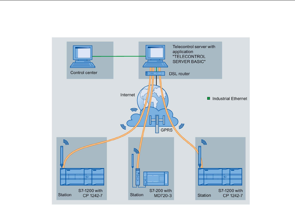
Communication processor and Modbus TCP
13.10 Industrial Remote Communication (IRC)
S7-1200 Programmable controller
System Manual, V4.2, 09/2016, A5E02486680-AK 1297
Telecontrol by a control center
Figure 13-1 Communication between S7-1200 stations and a control center
In telecontrol applications, SIMATIC S7-1200 stations with a CP 1242-7 communicate with a
control center via the GSM network and the Internet. The "TELECONTROL SERVER
BASIC" (TCSB) application is installed on the telecontrol server in the master station. This
results in the following use cases:
● Telecontrol communication between station and control center
In this use case, data from the field is sent by the stations to the telecontrol server in the
master station via the GSM network and Internet. The telecontrol server is used to
monitor remote stations.
● Communication between a station and a control room with OPC client
As in the first case, the stations communicate with the telecontrol server. Using its
integrated OPC server, the telecontrol server exchanges data with the OPC client of the
control room.
The OPC client and telecontrol server can be located on a single computer, for example
when TCSB is installed on a control center computer with WinCC.
● Inter-station communication via a control center
Inter-station communication is possible with S7 stations equipped with a CP 1242-7.
To allow inter-station communication, the telecontrol server forwards the messages of the
sending station to the receiving station.
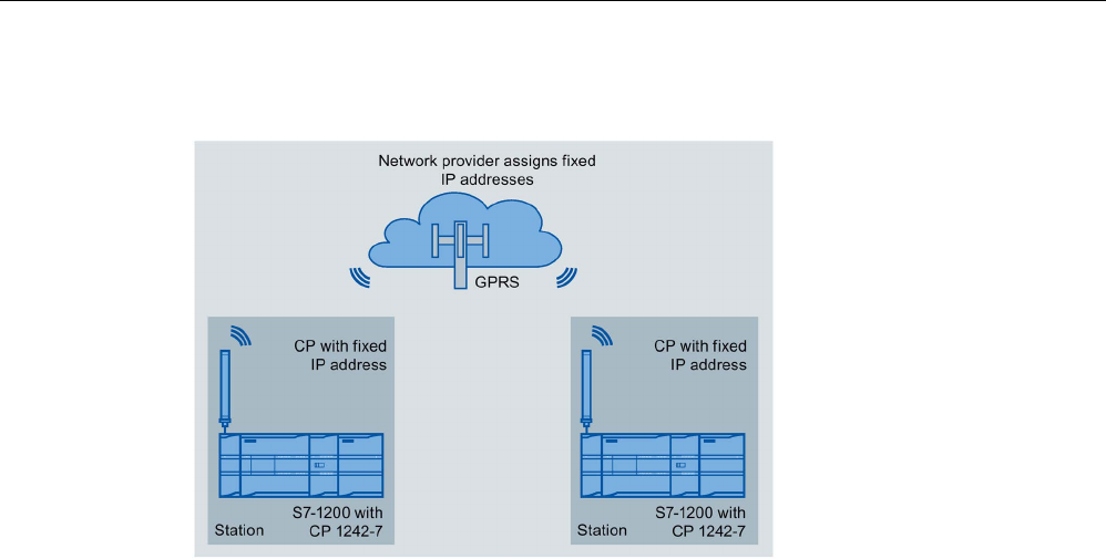
Communication processor and Modbus TCP
13.10 Industrial Remote Communication (IRC)
S7-1200 Programmable controller
1298 System Manual, V4.2, 09/2016, A5E02486680-AK
Direct communication between stations
Figure 13-2 Direct communication between two S7-1200 stations
In this configuration, two SIMATIC S7-1200 stations communicate directly with each other
using the CP 1242-7 via the GSM network. Each CP 1242-7 has a fixed IP address. The
relevant service of the GSM network provider must allow this.
TeleService via GPRS
In TeleService via GPRS, an engineering station on which STEP 7 is installed communicates
via the GSM network and the Internet with the CP 1242-7 in the S7-1200.
Since a firewall is normally closed for connection requests from the outside, a switching
station between the remote station and the engineering station is required. This switching
station can be a telecontrol server or, if there is no telecontrol server in the configuration, a
TeleService gateway.
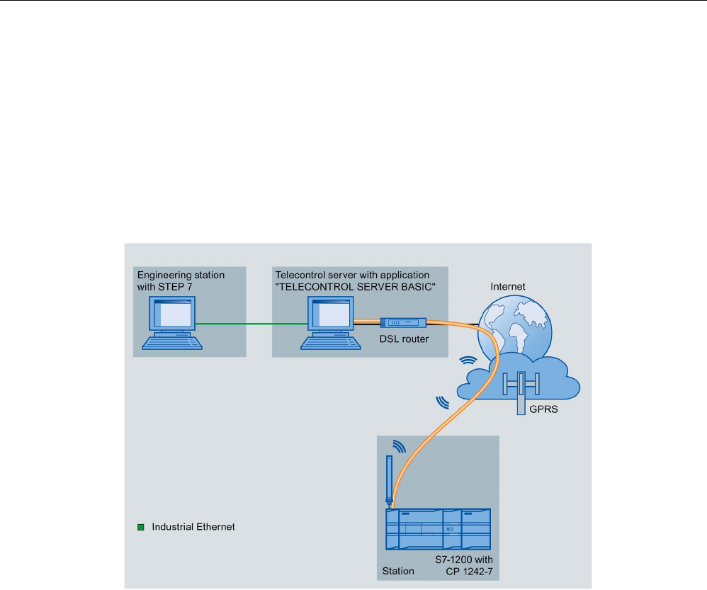
Communication processor and Modbus TCP
13.10 Industrial Remote Communication (IRC)
S7-1200 Programmable controller
System Manual, V4.2, 09/2016, A5E02486680-AK 1299
TeleService with telecontrol server
The connection runs via the telecontrol server.
● The engineering station and telecontrol server are connected via the Intranet (LAN) or
Internet.
● The telecontrol server and remote station are connected via the Internet and via the GSM
network.
The engineering station and telecontrol server can also be the same computer; in other
words, STEP 7 and TCSB are installed on the same computer.
Figure 13-3 TeleService via GPRS in a configuration with telecontrol server
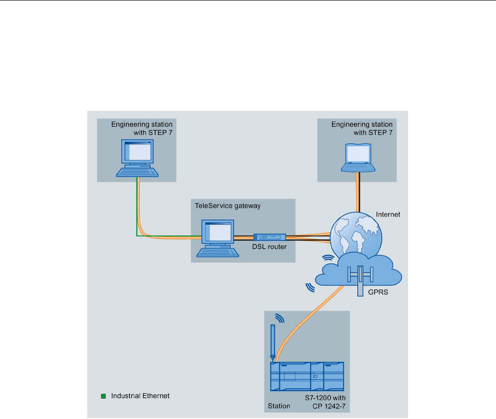
Communication processor and Modbus TCP
13.10 Industrial Remote Communication (IRC)
S7-1200 Programmable controller
1300 System Manual, V4.2, 09/2016, A5E02486680-AK
TeleService without a telecontrol server
The connection runs via the TeleService gateway.
The connection between the engineering station and the TeleService gateway can be local
via a LAN or via the Internet.
Figure 13-4 TeleService via GPRS in a configuration with TeleService gateway
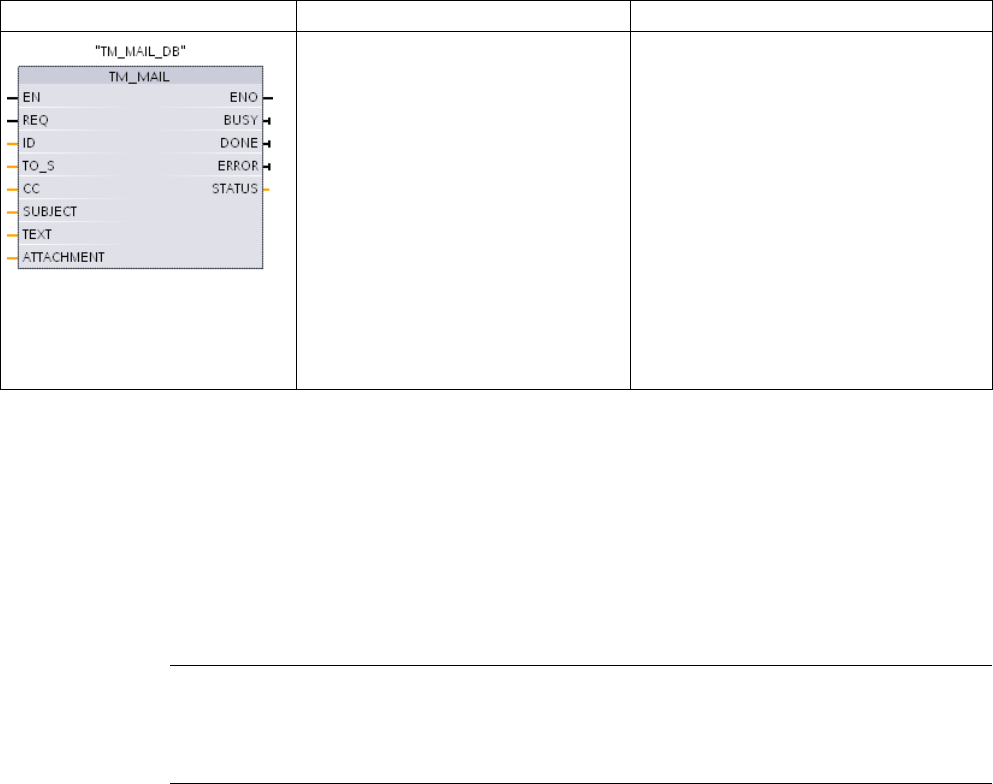
S7-1200 Programmable controller
System Manual, V4.2, 09/2016, A5E02486680-AK 1301
TeleService communication (SMTP email)
14
14.1
TM_Mail (Send email) instruction
Table 14- 1 TM_MAIL instruction
LAD / FBD
SCL
Description
"TM_MAIL_DB"(
REQ:=_bool_in_,
ID:=_int_in_,
TO_S:=_string_in_,
CC:=_string_in_,
SUBJECT:=_string_in_,
TEXT:= _string_in_,
ATTACHMENT:=_variant_in_,
BUSY=>_bool_out_,
DONE=>_bool_out_,
ERROR=>_bool_out_,
STATUS=>_word_out_,);
The TM_MAIL instruction sends an email
message using the SMTP (Simple Mail
Transfer Protocol) over TCP/IP via the
CPU Industrial Ethernet connection. Where
Ethernet-based Internet connectivity is not
available, an optional Teleservice adapter
can be used for connection with telephone
land lines. TM_MAIL executes asynchro-
nously and the job extends over multiple
TM_MAIL calls. When you call TM_MAIL,
you must assign an instance DB.
The
in-
stance
DB retentive attribute must not be
set
. This ensures that the instance DB is
initialized in the transition of the CPU from
STOP to RUN and that a new TM_MAIL
operation can be triggered.
1 STEP 7 automatically creates the instance DB when you insert the instruction.
You start sending an email with a positive edge change from 0 to 1, at input parameter REQ.
The following table shows the relationship between BUSY, DONE and ERROR. You can
monitor the progress of TM_MAIL execution and detect completion, by evaluating these
parameters in successive calls.
The output parameters DONE, ERROR, STATUS, and SFC_STATUS are valid for only one
cycle, when the state of the output parameter BUSY changes from 1 to 0. Your program
logic must save temporary output state values, so you can detect state changes in
subsequent program execution cycles.
Note
TM_MAIL sends a mail message over TCP/IP using the Ethernet interface of the CPU. To
send a mail message over a CP interface (with or without SS
L) use the instruction TMAIL_C
(Send an email using the Ethernet interface of the CPU) instruction
(Page 885).

TeleService communication (SMTP email)
14.1 TM_Mail (Send email) instruction
S7-1200 Programmable controller
1302 System Manual, V4.2, 09/2016, A5E02486680-AK
Table 14- 2 Interaction of the Done, Busy and Error parameters
DONE
BUSY
ERROR
Description
Irrelevant
1
Irrelevant
Job is in progress.
1 0 0 The job was completed successfully.
0 0 1 The job was terminated with an error. For the cause of the error, refer to the
STATUS parameter.
0 0 0 No job in progress
If the CPU is changed to STOP mode while TM_MAIL is active, then the communication
connection to the email server is terminated. The communication connection to the email
server is also lost if problems occur in CPU communication on the Industrial Ethernet bus. In
these cases, the send process is suspended and the email does not reach the recipient.
NOTICE
Modifying user programs
Deletion and replacement of program blocks, the calls to TM_MAIL, or calls to the instance
DBs of TM_MAIL can break the linking of program blocks. If you fail to maintain linked
program blocks, then the TPC/IP communication functions can enter an undefined state,
possibly resulting in property damage. After transferring a modified program block, you
would have to perform a CPU restart (warm) or cold start.
To avoid breaking the linking of program blocks, only change the parts of your user
program that directly affect the TM_MAIL calls in the following cases:
• The CPU in the STOP mode
• No email is sent (REQ and BUSY = 0)
Data consistency
The input parameter ADDR_MAIL_SERVER is read when the operation is started. A new
value does not take effect until the current operation is complete and a new TM_MAIL
operation is initiated.
In contrast, the parameters WATCH_DOG_TIME, TO_S, CC, FROM, SUBJECT, TEXT,
ATTACHMENT, USERNAME and PASSWORD are read during the execution of TM_MAIL
and may be changed only when the job is finished (BUSY = 0)

TeleService communication (SMTP email)
14.1 TM_Mail (Send email) instruction
S7-1200 Programmable controller
System Manual, V4.2, 09/2016, A5E02486680-AK 1303
Dial-up connection: Configuring the TS adapter IE parameters
You must configure the Teleservice adapter IE parameters for outgoing calls to connect with
the dial-up server of your Internet Service Provider. If you set the call "on demand" attribute,
then the connection is established only when an e-mail will be sent. For an analog modem
connection, more time is required for the connection process (approx. a minute longer). You
must include the extra time, in the WATCH_DOG_TIME value.
Table 14- 3 Data types for the parameters
Parameter and type
Data types
Description
REQ
IN
Bool
A low to high (positive edge) signal starts the operation.
ID IN Int Connection identifier: See the ID parameter of the instruc-
tions TCON, TDISCON, TSEND and TRCV.
A number that is not used for any additional instances of this
instruction in the user program must be used.
TO_S IN String Recipient addresses: STRING data with a maximum length
of 240 characters
CC IN String CC copy to recipient addresses (optional): STRING data
with a maximum length of 240 characters
SUBJECT IN String Subject name of the email: STRING data with a maximum
length 240 characters.
TEXT IN String Text message of the email (optional): STRING data with a
maximum length of 240 characters.
If this parameter is an empty string, then the email will be
sent without message text.
ATTACHMENT IN Variant Pointer to email attachment data: Byte, word, or double
word data with a maximum length of 65534 bytes.
If no value is assigned, then the email sent without an at-
tachment.
DONE OUT Bool • 0 - Job not yet started or still executing.
• 1 - Job was executed error-free.
BUSY OUT Bool • 0 - No operation in progress
• 1- Operation in progress
ERROR OUT Bool The ERROR bit =1 for one scan, after the last request was
terminated with an error. The error code value at the
STATUS output is valid only during the single scan where
ERROR = 1.
STATUS OUT Word Return value or error information of the TM_MAIL instruc-
tion.

TeleService communication (SMTP email)
14.1 TM_Mail (Send email) instruction
S7-1200 Programmable controller
1304 System Manual, V4.2, 09/2016, A5E02486680-AK
Parameter and type
Data types
Description
ADDR_MAIL_SERVER 1 Static DWord IP address of the mail server: You must assign each IP
address fragment as an octet of two 4-bit hexadecimal char-
acters. If the IP address fragment = decimal value 10 which
equals hexadecimal value A, then you must enter "0A" for
that octet.
For example: IP address = 192.168.0.10
ADDR_MAIL_SERVER = DW#16#C0A8000A, where:
• 192 = 16#C0,
• 168 =16#A8
• 0 = 16#00
• 10 = 16#0A
WATCH_DOG_TIME 1 Static Time The maximum time allowed for TM_MAIL to complete the
entire SMTP process, from the initiation of the connection to
the SMTP to the end of the SMTP transmission. If this time
is exceeded, then TM_MAIL execution ends with an error.
The actual time delay until TM_MAIL ends and the error is
issued may exceed the WATCH_DOG_TIME, because of
the additional time required for the disconnect operation.
At first you should set a time of 2 minutes. This time can be
much smaller for an ISDN phone connection.
USERNAME 1 Static String Mail account user name: STRING data with a maximum
length 180 characters.
PASSWORD 1 Static String Mail server password: STRING data with a maximum length
180 characters.
FROM 1 Static String Sender address: STRING with a maximum length of 240
characters
SFC_STATUS 1 Static Word Execution condition code of the called communication
blocks
1
The values of these parameters are not modified at every call of TM_MAIL. The values are assigned in the TM_MAIL
instance data block and are only referenced once, on the first call of TM_MAIL.
SMTP authentication
TM_MAIL supports the SMTP AUTH LOGIN authentication method. For information on this
authentication method, please refer to the manual of the mail server or the website of your
internet service provider.
The AUTH LOGIN authentication method uses the TM_MAIL USERNAME and PASSWORD
parameters to connect with the mail server. The user name and password must be
previously set up on an email account at an email server.
If no value is assigned for the USERNAME parameter, then the AUTH LOGIN authentication
method is not used and the email is sent without authentication.

TeleService communication (SMTP email)
14.1 TM_Mail (Send email) instruction
S7-1200 Programmable controller
System Manual, V4.2, 09/2016, A5E02486680-AK 1305
TO_S:, CC:, and FROM: parameters
The parameters TO_S:, CC: and FROM: are strings, as shown in the following examples:
TO: <wenna@mydomain.com>, <ruby@mydomain.com>,
CC: <admin@mydomain.com>, <judy@mydomain.com>,
FROM: <admin@mydomain.com>
The following rules must be used when entering these character strings:
● The characters "TO:", "CC:" and "FROM:" must be entered, including the colon character.
● A space character and an opening angle bracket "<" must precede each address. For
example, there must be a space character between "TO:" and <email address>.
● A closing angle bracket ">" must be entered after each address.
● A comma character "," must be entered after each email address for the TO_S: and CC:
addresses. For example, the comma after the single email address is required in "TO:
<email address>,".
● Only one email address may be used for the FROM: entry, with no comma at the end.
Because of run-time mode and memory usage, a syntax check is not performed on the
TM_MAIL TO_S:, CC: and FROM: data. If the format rules above are not followed exactly.
The SMTP email server transaction will fail.
STATUS and SFC_STATUS parameters
The execution condition codes returned by TM_MAIL can be classified as follows:
● W#16#0000: Operation of TM_MAIL was completed successfully
● W#16#7xxx: Status of TM_MAIL operation
● W#16#8xxx: An error in an internal call to a communication device or the mail server
The following table shows the execution condition codes of TM_MAIL with the exception of
the error codes from internally called communication modules.
Note
Email server requirements
TM_MAIL can only communicate with an email server using SMTP via port 25. The assigned
port number cannot be changed.
Most IT departments and external email servers now block port 25 to prevent a PC infected
with a virus from becoming a rogue email
generator.
You can connect to an internal mail server via SMTP and let the internal server manage the
current security enhancements that are required to relay email through the Internet to an
external mail server.

TeleService communication (SMTP email)
14.1 TM_Mail (Send email) instruction
S7-1200 Programmable controller
1306 System Manual, V4.2, 09/2016, A5E02486680-AK
Example: Internal email server configuration
If you use Microsoft Exchange as an internal mail server, then you can configure the server
to allow SMTP access from the IP address assigned the S7-1200 PLC. Configure the
Exchange management console: Server configuration > Hub transport > Receive connectors
> IP relay. On the Network tab, there is a box named "Receive mail from remote servers that
have these IP addresses". This is where you put the IP address of the PLC that is executing
the TM_MAIL instruction. No authentication is required for this type of connection with an
internal Microsoft Exchange server.
Email server configuration
TM_MAIL can only use an email server that allows port 25 communication, SMTP, and
AUTH LOGIN authentication (optional).
Configure a compatible email server account to accept remote SMTP log in. Then edit the
instance DB for TM_MAIL to put in the TM_MAIL USERNAME and PASSWORD character
strings that are used to authenticate the connection with your email account.
Table 14- 4 Condition codes
STATUS
(W#16#...):
SFC_STATUS
(W#16#...):
Description
0000 - The TM_MAIL operation completed without error. This zero STATUS code does
not guarantee that an email was actually sent (See the first item in the note fol-
lowing this table).
7001 - TM_MAIL is active (BUSY = 1).
7002
7002
TM_MAIL is active (BUSY = 1).
8xxx xxxx The TM_MAIL operation was completed with an error in the internal communica-
tion instruction calls. For more information about the SFC_STATUS parameter,
see the descriptions of the STATUS parameter of the underlying PROFINET
open user communication instructions.
8010 xxxx
Failed to connect: For more information about the SFC_STATUS parameter, see
the STATUS parameter of the TCON instruction.
8011 xxxx Error sending data: For more information about SFC_STATUS parameter, see
the STATUS parameter of the TSEND instruction.
8012 xxxx Error while receiving data: For more information about the SFC_STATUS pa-
rameter, see the STATUS parameter descriptions of the TRCV instruction.
8013 xxxx Failed to connect: For more information for evaluating the SFC_STATUS param-
eter, see the STATUS parameter descriptions of the TCON and TDISCON in-
structions.
8014 - Failed to connect: You may have entered an incorrect mail server IP address
(ADDR_MAIL_SERVER) or too little time (WATCH_DOG_TIME) for the connec-
tion. It is also possible that the CPU has no connection to the network or the
CPU configuration is incorrect.
8015 - Invalid pointer for ATTACHMENT parameter: Use a variant pointer with a data
type and length assignment. For example, "P#DB.DBX0.0" is incorrect and
"P#DB.DBX0.0 byte 256" is correct.
82xx, 84xx,
85xx
-
The error message comes from the mail server and corresponds to error number
"8" of the SMTP protocol. See the second item in the note following this table.
8450
-
Operation does not run: Mailbox is not available; try again later.

TeleService communication (SMTP email)
14.1 TM_Mail (Send email) instruction
S7-1200 Programmable controller
System Manual, V4.2, 09/2016, A5E02486680-AK 1307
STATUS
(W#16#...):
SFC_STATUS
(W#16#...):
Description
8451
-
Operation aborted: Local error in processing, try again later.
8500 - Command syntax error: The cause may be that the email server does not sup-
port the LOGIN authentication process. Check the parameters of TM_MAIL. Try
to send an email without authentication. Try replacing the parameter
USERNAME with an empty string.
8501 - Syntax error: Incorrect parameter or argument; you may have typed an incorrect
address in the TO_S or CC parameters.
8502 - Command is unknown or not implemented: Check your entries, especially the
parameter FROM. Perhaps this is incomplete and you have omitted the "@" or
"." characters.
8535 - SMTP authentication is incomplete. You may have entered an incorrect
username or password.
8550 -
The mail server cannot be reached, or you have no access rights. You may have
entered an incorrect username or password or your mail server does not support
log in access. Another cause of this error could be an erroneous entry of the
domain name after the "@" character in the TO_S or CC parameters.
8552
-
Operation aborted: Exceeded the allocated memory size; try again later.
8554
-
Transmission failed: Try again later.
Note
Possible unreported email transmission errors
•
Incorrect entry of a recipient address does not generate a STATUS error for TM_MAIL. In
this case, there is no guarantee that additional recipients (with correct email addresses),
will receive the email.
•
More information on SMTP error codes can be found on the internet or in the error
documentation for the mail server. You can also read the last error message from the
mail server. The error message is stored in buffer1parameter of the instance DB for
TM_MAIL.

TeleService communication (SMTP email)
14.1 TM_Mail (Send email) instruction
S7-1200 Programmable controller
1308 System Manual, V4.2, 09/2016, A5E02486680-AK
S7-1200 Programmable controller
System Manual, V4.2, 09/2016, A5E02486680-AK 1309
Online and diagnostic tools
15
15.1
Status LEDs
The CPU and the I/O modules use LEDs to provide information about either the operational
status of the module or the I/O.
Status LEDs on a CPU
The CPU provides the following status indicators:
● STOP/RUN
– Solid yellow indicates STOP mode
– Solid green indicates RUN mode
– Flashing (alternating green and yellow) indicates that the CPU is in STARTUP mode
● ERROR
– Flashing red indicates an error, such as an internal error in the CPU, an error with the
memory card, or a configuration error (mismatched modules)
– Defective state:
- Solid red indicates defective hardware
- All LEDs flash if the defect is detected in the firmware
● MAINT (Maintenance) flashes whenever you insert a memory card. The CPU then
changes to STOP mode. After the CPU has changed to STOP mode, perform one of the
following functions to initiate the evaluation of the memory card:
– Change the CPU to RUN mode
– Perform a memory reset (MRES)
– Power-cycle the CPU
You can also use the LED instruction (Page 450) to determine the status of the LEDs.

Online and diagnostic tools
15.1 Status LEDs
S7-1200 Programmable controller
1310 System Manual, V4.2, 09/2016, A5E02486680-AK
Table 15- 1 Status LEDs for a CPU
Description
STOP/RUN
Yellow / Green
ERROR
Red
MAINT
Yellow
Power is off
Off
Off
Off
Startup, self-test, or firmware
update
Flashing
(alternating yellow and green)
- Off
Stop mode
On (yellow)
-
-
Run mode On (green) - -
Remove the memory card
On (yellow)
-
Flashing
Error
On (either yellow or green)
Flashing
-
Maintenance requested
• Forced I/O
• Battery replacement re-
quired (if battery board in-
stalled)
On (either yellow or green) - On
Defective hardware
On (yellow)
On
Off
LED test or defective CPU
firmware
Flashing
(alternating yellow and green)
Flashing Flashing
Unknown or incompatible
version of CPU configuration
On (yellow) Flashing Flashing
Note
"Unknown or incompatible version of CPU configuration" error
Attempting to download an S7
-1200 V3.0 program to an S7-1200 V4.0 CPU causes a CPU
error, and the CPU displays a corresponding error message in the diagnostic buffer. If you
reached this state by using a
n invalid version program transfer card (Page 142), then
remove the card, perform a STOP to RUN transition, a memory reset (MRES) or cycle
power. I
f you reach this state by an invalid program download, reset the CPU to factory
settings
(Page 1317). After you recover the CPU from the error condition, you can download
a valid V4.0 CPU program.
The CPU also provides two LEDs that indicate the status of the PROFINET communications.
Open the bottom terminal block cover to view the PROFINET LEDs.
● Link (green) turns on to indicate a successful connection
● Rx/Tx (yellow) turns on to indicate transmission activity
The CPU and each digital signal module (SM) provide an I/O Channel LED for each of the
digital inputs and outputs. The I/O Channel (green) turns on or off to indicate the state of the
individual input or output.

Online and diagnostic tools
15.1 Status LEDs
S7-1200 Programmable controller
System Manual, V4.2, 09/2016, A5E02486680-AK 1311
S7-1200 behavior following a fatal error
If the CPU firmware detects a fatal error it attempts a defect-mode restart, and if successful,
signals the defective mode by continually flashing the STOP/RUN, ERROR and MAINT
LEDs. The user program and hardware configuration are not loaded following the defect-
mode restart.
If the CPU successfully completes the defect-mode restart, the CPU and signal board
outputs are set to 0, and the outputs of central rack signal modules and distributed I/O are
set to the configured "Reaction to CPU STOP".
If the defect-mode restart fails, (for example, due to a hardware fault), the STOP and
ERROR LEDs are ON and the MAINT LED is OFF.
WARNING
Operation in defect state cannot be guaranteed
Control devices can fail in an unsafe condition, resulting in unexpected operation of
controlled equipment. Such unexpected operations could result in death or serious injury to
personnel, and/or damage to equipment.
Use an emergency stop function, electromechanical overrides or other redundant
safeguards that are independent of the PLC.
Status LEDs on an SM
In addition, each digital SM provides a DIAG LED that indicates the status of the module:
● Green indicates that the module is operational
● Red indicates that the module is defective or non-operational
Each analog SM provides an I/O Channel LED for each of the analog inputs and outputs.
● Green indicates that the channel has been configured and is active
● Red indicates an error condition of the individual analog input or output
In addition, each analog SM provides a DIAG LED that indicates the status of the module:
● Green indicates that the module is operational
● Red indicates that the module is defective or non-operational
The SM detects the presence or absence of power to the module (field-side power, if
required).

Online and diagnostic tools
15.1 Status LEDs
S7-1200 Programmable controller
1312 System Manual, V4.2, 09/2016, A5E02486680-AK
Table 15- 2 Status LEDs for a signal module (SM)
Description
DIAG
(Red / Green)
I/O Channel
(Red / Green)
Field-side power is off
Flashing red
Flashing red
Not configured or update in progress Flashing green Off
Module configured with no errors
On (green)
On (green)
Error condition
Flashing red
-
I/O error (with diagnostics enabled)
-
Flashing red
I/O error (with diagnostics disabled)
-
On (green)
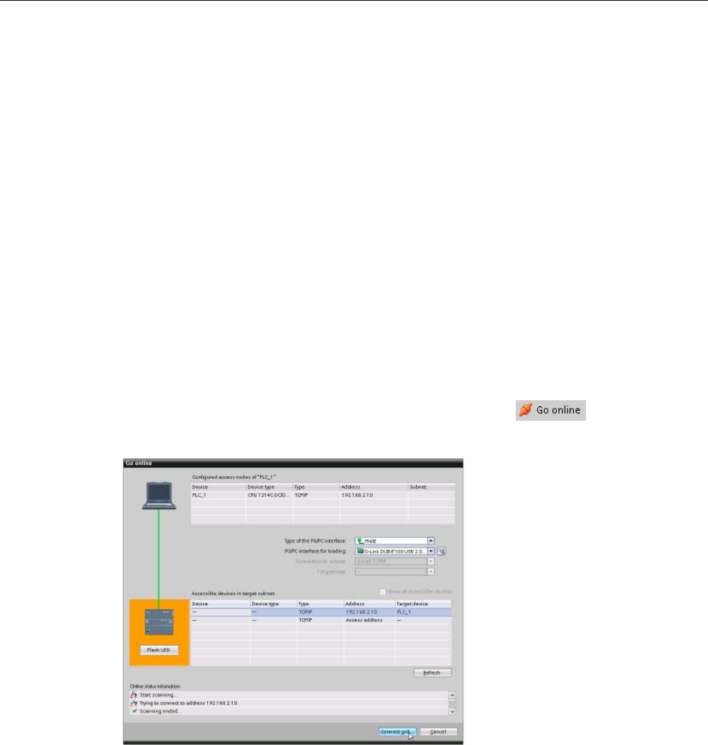
Online and diagnostic tools
15.2 Going online and connecting to a CPU
S7-1200 Programmable controller
System Manual, V4.2, 09/2016, A5E02486680-AK 1313
15.2
Going online and connecting to a CPU
You must establish an online connection between the programming device and CPU for
loading programs and project engineering data as well as for activities such as the following:
● Testing user programs
● Displaying and changing the operating mode of the CPU (Page 1321)
● Displaying and setting the date and time of day of the CPU (Page 1316)
● Displaying the module information
● Comparing and synchronizing (Page 1323) offline to online program blocks
● Uploading and downloading program blocks
● Displaying diagnostics and the diagnostics buffer (Page 1322)
● Using a watch table (Page 1329) to test the user program by monitoring and modifying
values
● Using a force table to force values in the CPU (Page 1332)
To establish an online connection to a configured CPU, click
the CPU from the Project Navigation tree and
click the "Go
online" button from the Project View:
If this is the first time to go
online with this CPU, you
must select the type of PG/PC
interface and the specific
PG/PC interface from the Go
Online dialo
g before estab-
lis
h
ing an online connection to
a CPU found on that inte
r-
face.
You have now connected your programming device to the CPU. The orange color frames
indicate an online connection. You can now use the Online & diagnostics tools from the
Project tree and the Online tools task card.
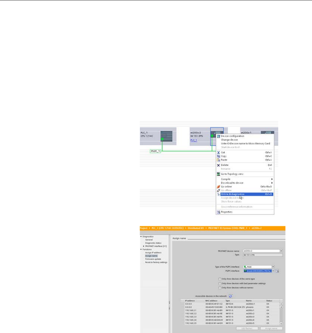
Online and diagnostic tools
15.3 Assigning a name to a PROFINET IO device online
S7-1200 Programmable controller
1314 System Manual, V4.2, 09/2016, A5E02486680-AK
15.3
Assigning a name to a PROFINET IO device online
The devices on your PROFINET network must have an assigned name before you can
connect with the CPU. Use the "Devices & networks" editor to assign names to your
PROFINET devices if the devices have not already been assigned a name or if the name of
the device is to be changed.
For each PROFINET IO device, you must assign the same name to that device in both the
STEP 7 project and, using the "Online & diagnostics" tool, to the PROFINET IO device
configuration memory (for example, an ET200 S interface module configuration memory). If
a name is missing or does not match in either location, the PROFINET IO data exchange
mode will not run.
1. In the "Devices & networks"
editor, right
-click on the re-
quired PROFINET IO device,
and select "Online & diagno
s-
tics".
2. In the "Online & di
agnos-
tics" dialog, make the following
menu selections:
•
"Functions"
•
"Assign PROFINET device
name"
Click the "Update list" button
to display all of the PROFINET
IO devices on the network.
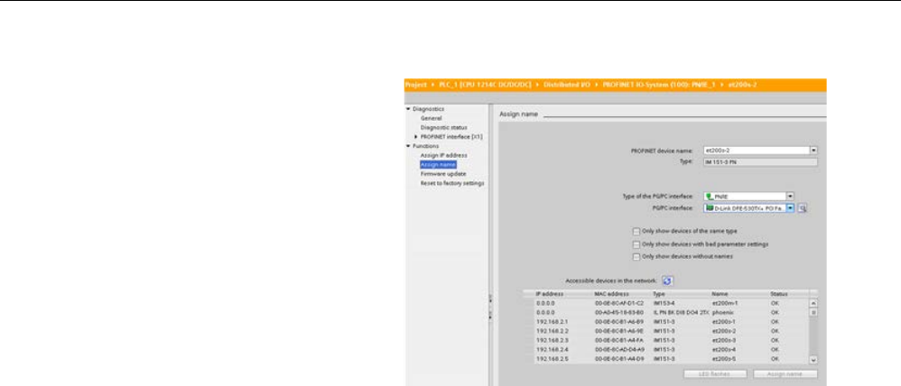
Online and diagnostic tools
15.3 Assigning a name to a PROFINET IO device online
S7-1200 Programmable controller
System Manual, V4.2, 09/2016, A5E02486680-AK 1315
3. In the list that is displayed,
click the r
equired PROFINET
IO device, and click the "A
s-
sign name" button to write the
name to the PROFINET IO
device configuration memory.

Online and diagnostic tools
15.4 Setting the IP address and time of day
S7-1200 Programmable controller
1316 System Manual, V4.2, 09/2016, A5E02486680-AK
15.4
Setting the IP address and time of day
You can set the
IP address (Page 813) and time of day in the online CPU. After accessing
"Online & diagnostics" from the Project tree for an online CPU, you can display or change
the IP address. You can also display or set the time and date parameters of the online CPU.
Note
This feature is available only for a CPU that either has only a MAC address (has not yet
been assigned an IP address) or has been reset to factory settings.

Online and diagnostic tools
15.5 Resetting to factory settings
S7-1200 Programmable controller
System Manual, V4.2, 09/2016, A5E02486680-AK 1317
15.5
Resetting to factory settings
You can reset an S7-1200 to its original factory settings under the following conditions:
● The CPU has an online connection.
● The CPU is in STOP mode.
Note
If the CPU is in RUN mode and you star
t the reset operation, you can place it in STOP
mode after acknowledging a confirmation prompt.
Procedure
To reset a CPU to its factory settings, follow these steps:
1. Open the Online and Diagnostics view of the CPU.
2. Select "Reset to factory settings" from the "Functions" folder.
3. Select the "Retain IP address" check box if you want to retain the IP address or the
"Delete IP address" check box if you want to delete the IP address.
4. Click the "Reset" button.
5. Acknowledge the confirmation prompt with "OK".
Result
The module switches to STOP mode if necessary, and it resets the factory settings. The
CPU performs the following actions:
With memory card installed in CPU
Without memory card installed in CPU
• Clears the diagnostics buffer
• Resets the time of day
• Restores work memory from the memory card
• Sets all operand areas to configured initial
values
• Sets all parameters to their configured values
• Retains or deletes the IP address based on
the selection you made. (The MAC address is
fixed and is never changed.)1
• Deletes the control data record (Page 159), if
present
• Clears the diagnostics buffer
• Resets the time of day
• Clears the work memory and internal load
memory
• Sets all operand areas to configured initial
values
• Sets all parameters to their configured values
• Retains or deletes the IP address based on
the selection you made. (The MAC address is
fixed and is never changed.)1
• Deletes the control data record, if present
1
If you selected "Retain IP address", the CPU sets the IP address, subnet mask, and router ad-
dress (if used) to the settings in your hardware configuration, unless you have modified these val-
ues from the user program or another tool, in which case the CPU restores the modified values.

Online and diagnostic tools
15.6 Updating firmware
S7-1200 Programmable controller
1318 System Manual, V4.2, 09/2016, A5E02486680-AK
15.6
Updating firmware
You can update the firmware of a connected CPU from the STEP 7 online and diagnostics
tools, by one of two methods:
● Updating from the CPU in the project
● Updating from the accessible devices in the project tree
Updating the firmware of a CPU in your project
To perform a firmware update, follow these steps:
1. Open the CPU in the Project Tree that corresponds to the connected CPU.
2. Open the Online and Diagnostics view of the connected CPU.
3. Select "Firmware update" from the "Functions" folder.
4. From the "Firmware loader" section, click the Browse button and navigate to the location
that contains the firmware update file. This could be a location on your hard drive to
which you have downloaded an S7-1200
(http://support.automation.siemens.com/WW/view/en/34612486/133100) firmware update
file from the Siemens Industry Online Support Web site
(http://support.industry.siemens.com).
5. Select a file that is compatible with your module. For a selected file, the table displays the
compatible modules.
6. Click the "Run update" button. Follow the dialogs, if necessary, to change the operating
mode of your CPU.
STEP 7 displays progress dialogs as it loads the firmware update. When it finishes, it
prompts you to start the module with the new firmware.
Note
If you do no
t choose to start the module with the new firmware, the previous firmware
remains active until you reset the module, for example by cycling power. The new firmware
becomes active only after you reset the module.

Online and diagnostic tools
15.6 Updating firmware
S7-1200 Programmable controller
System Manual, V4.2, 09/2016, A5E02486680-AK 1319
Updating the firmware from the accessible devices
To perform a firmware update for one or more accessible devices, follow these steps:
1. Open "Online access" from the project tree.
2. Open the communications interface to which your CPU is connected.
3. Double-click "Update accessible devices" and wait for STEP 7 to display the online
devices.
4. Expand the CPU that you want to update and double-click "Online & diagnostics".
5. Expand "Firmware update" from the "Functions" folder. You will see the PLC as well as
local modules for the PLC. From either the "PLC" or "Local modules" selection, you can
proceed with updating firmware from the "Firmware loader" section as described above.
You can also perform a firmware update by one of the following methods:
● Using a SIMATIC memory card (Page 148)
● Using the Web server "Module Information" standard Web page (Page 1023)
● Using the SIMATIC Automation Tool
(https://support.industry.siemens.com/cs/ww/en/view/98161300)

Online and diagnostic tools
15.7 Formatting a SIMATIC memory card from STEP 7
S7-1200 Programmable controller
1320 System Manual, V4.2, 09/2016, A5E02486680-AK
15.7
Formatting a SIMATIC memory card from STEP 7
You can format the memory card in a connected CPU from the STEP 7 online and diagnostic
tools. To do so, follow these steps:
1. Ensure the CPU is in STOP mode. Note that if the CPU is in RUN mode and you start a
formatting operation, STEP 7 prompts you to allow STEP 7 to put the CPU in STOP
mode.
2. Insert a memory card into the connected CPU.
3. Open Online & diagnostics for the connected CPU from either the CPU in the project or
from the accessible devices in Online access in the project tree.
4. If the CPU is not online, select "Go online" for the connected CPU.
5. Select "Format memory card" from the "Functions" menu.
6. Click "Format".
7. Confirm the prompt with "Yes".
STEP 7 then formats the memory card and displays a message in the Info window when
complete. The CPU is in STOP at the completion of the format operation with the STOP and
MAINT lights blinking. You cannot go to RUN mode at this point; you must take one of the
following actions:
● Remove the memory card and restart the CPU: If the internal load memory of the CPU
contains a program, the CPU starts with the program.
● Restart the CPU without removing the memory card: If the internal load memory of the
CPU contains a program, the CPU copies it to the memory card and starts with that
program. If the internal load memory has no program, the CPU changes the memory card
to a Program card (Page 145) and waits for a download.
Note
Formatting a memory card has no effect on the contents of internal load memory.
If the CPU was using internal load memory when you inserted the memory card and you did
not restart the CPU be
tween inserting the card and executing the format operation, the CPU
retains the contents of internal load memory.
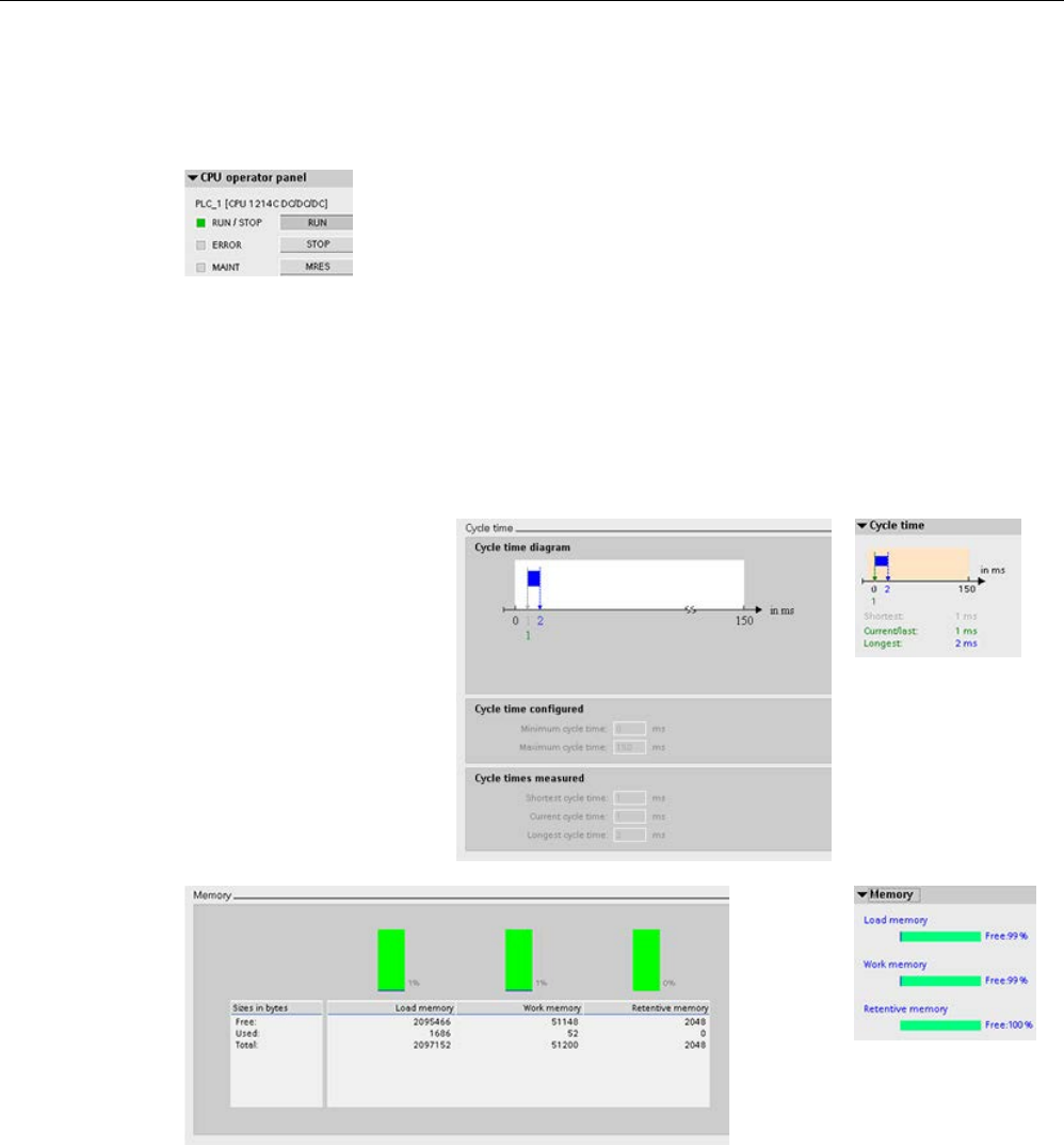
Online and diagnostic tools
15.8 CPU operator panel for the online CPU
S7-1200 Programmable controller
System Manual, V4.2, 09/2016, A5E02486680-AK 1321
15.8
CPU operator panel for the online CPU
The "CPU operator panel" displays the operating mode (STOP or
RUN) of the o
nline CPU. The panel also shows whether the CPU has
an error or if values are being forced.
Use the CPU operating panel of the Online Tools task card to change the operating mode of
an online CPU. The Online Tools task card is accessible whenever the CPU is online.
15.9
Monitoring the cycle time and memory usage
You can monitor the cycle
time and me
mory usage of
an online CPU.
After connecting to the
online CPU, open the Online
tools task card to view the
follo
wing measurements:
•
Cycle time
•
Memory usage
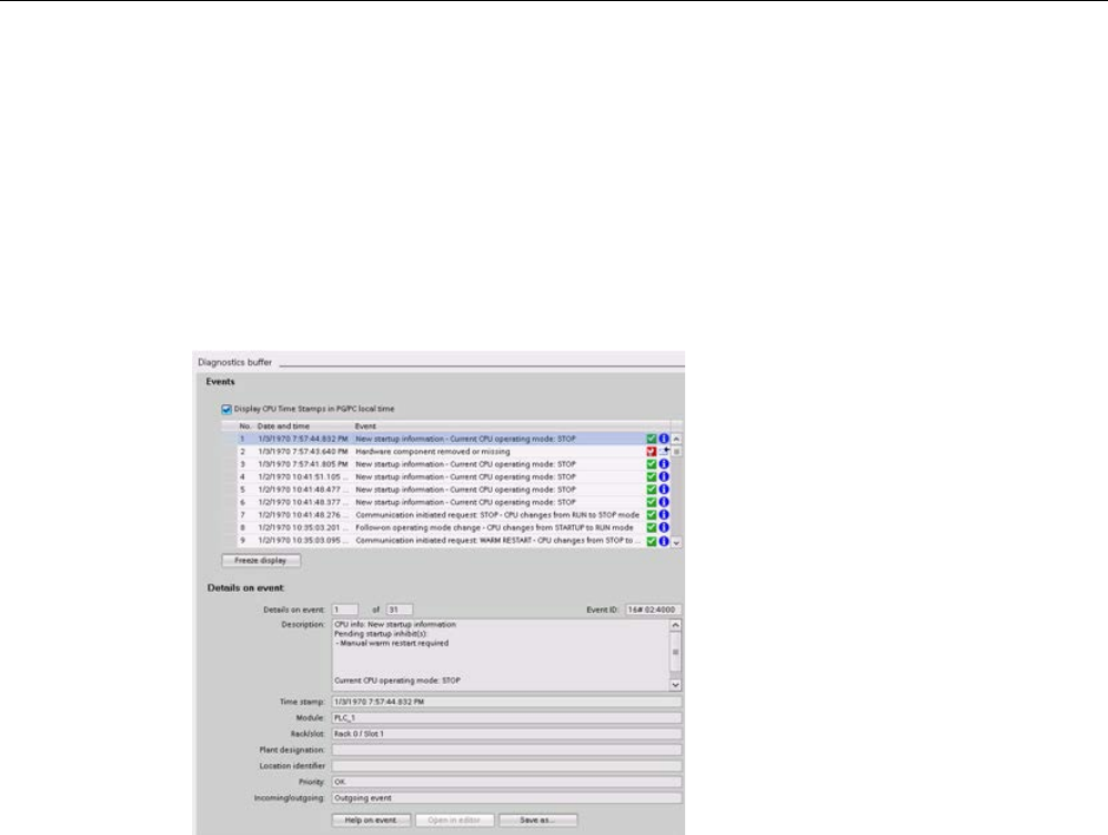
Online and diagnostic tools
15.10 Displaying diagnostic events in the CPU
S7-1200 Programmable controller
1322 System Manual, V4.2, 09/2016, A5E02486680-AK
15.10
Displaying diagnostic events in the CPU
Use the diagnostics buffer to review the recent activity in the CPU. The diagnostics buffer is
accessible from "Online & Diagnostics" for an online CPU in the Project tree. It contains the
following entries:
● Diagnostic events
● Changes in the CPU operating mode (transitions to STOP or RUN mode)
The first entry contains the latest event.
Each entry
in the diagnostic buffer con-
tains the date and time the event was
logged, and a description.
The maximum number of entries is d
e-
pendent on the CPU. A maximum of 50
entries is supported.
Only the 10 most recent events in the
diagnostic buffer are stored pe
rmanent-
ly. Resetting the CPU to the factory se
t-
tings resets the diagnostic buffer by
deleting the entries.
You can also use the GET_DIAG instruction (Page 480) to collect the diagnostic information.
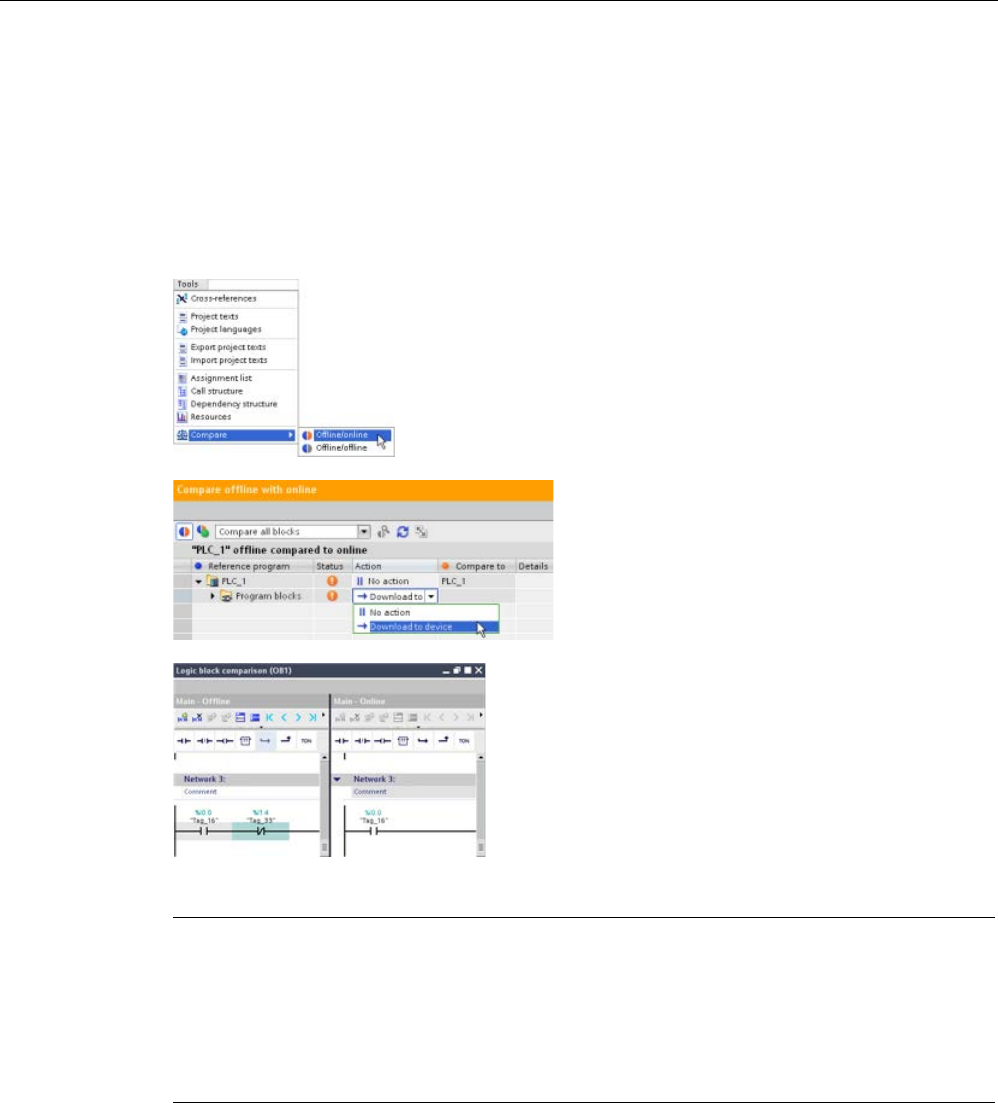
Online and diagnostic tools
15.11 Comparing offline and online CPUs
S7-1200 Programmable controller
System Manual, V4.2, 09/2016, A5E02486680-AK 1323
15.11
Comparing offline and online CPUs
You can compare the code blocks in an online CPU with the code blocks in your project. If
the code blocks of your project do not match the code blocks of the online CPU, the
"Compare" editor allows you to synchronize your project with the online CPU by downloading
the code blocks of your project to the CPU, or by deleting blocks from the project that do not
exist in the online CPU.
Select the CPU in your project.
Use the "Compare Offline/online" command to open the "Co
m-
pare" editor. (Access the command either from the "Tools"
menu or by right
-clicking the CPU in your project.)
Click in the "Action" column for an object to
select whether to delete the object, take no
action, or download the object to the device.
Click the "Synchronize" button to load the code
blocks.
Right
-click an object in the "Compare to" column and
select "Start detailed comparison" button to show the
code blocks side
-by-side.
The detailed comparison highlights the differences
b
etween the code blocks of online CPU and the code
blocks of the CPU in your project.
Note
Read access required on protected CPU for the Offline/Online compare operations
For STEP 7 V14 or later versions, the "HMI access" security level is insufficient to perform
the Offline/Online compare operations. You must have "Read access" or "Full access", to do
Offline/Online compare operations.
See also
Access protection for the CPU (Page 210)
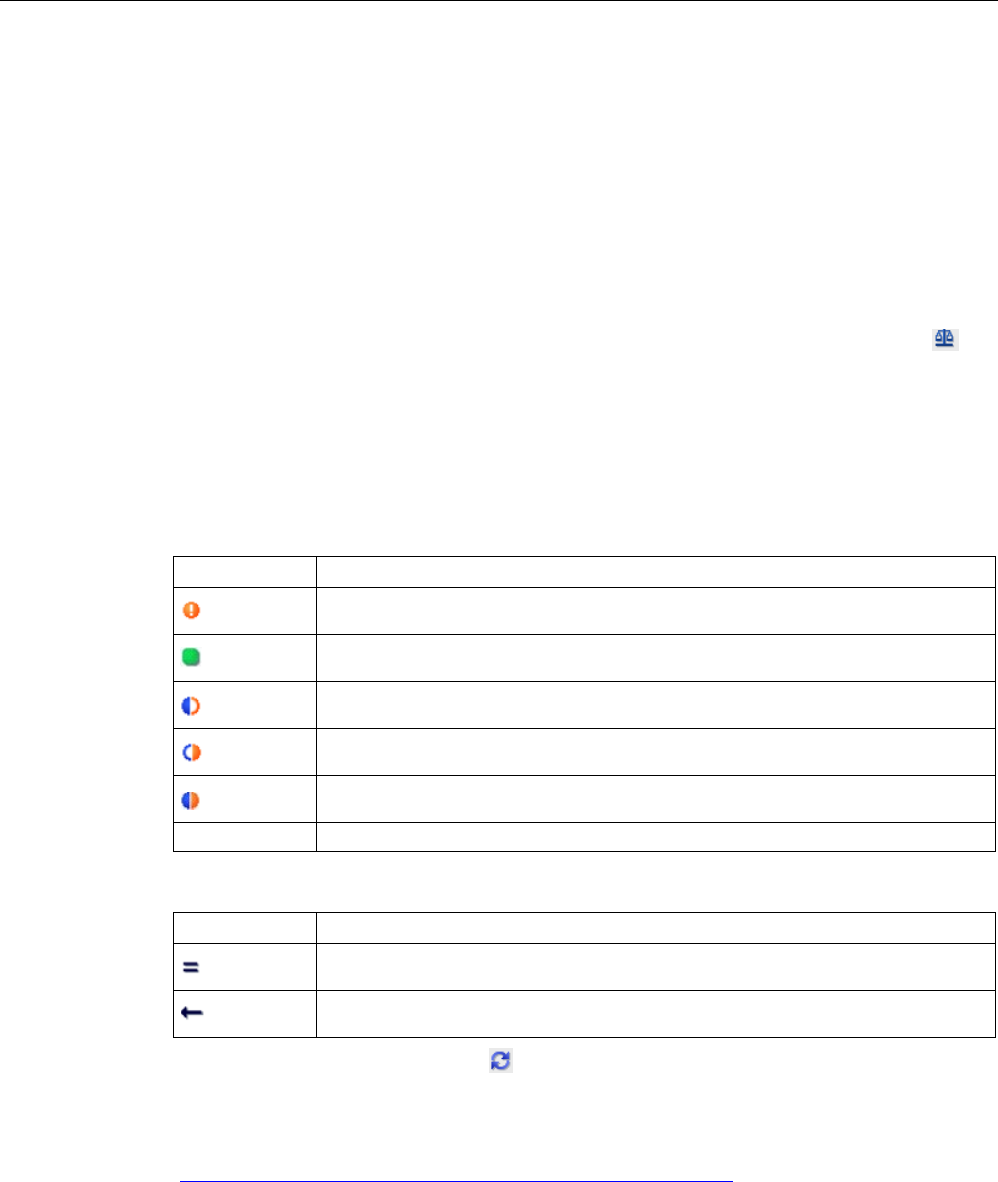
Online and diagnostic tools
15.12 Performing an online/offline topology comparison
S7-1200 Programmable controller
1324 System Manual, V4.2, 09/2016, A5E02486680-AK
15.12
Performing an online/offline topology comparison
From the topology overview in STEP 7, you can compare the configured offline topology with
the actual online topology.
Procedure
To find the differences between the configured and thee actual topology, follow these steps:
1. Display the topology overview table of the topology view.
2. Click the "Offline/online comparison" button in the toolbar of the topology overview:
Result
STEP 7 removes the "Partner station, "Partner interface" and "Cable data" columns in the
topology overview table and inserts comparison columns for "Status", and "Action". For each
device or port in the topology overview, the Status column displays the comparison status as
follows:
Icon
Meaning
Differing topology in at least one lower-level component
Identical topology
Topology information is only available offline, or device is disabled
Topology information is only available online
Differing topology
Device does not support topology functions
For each compared port or device, the Action column provides these possible choices:
Icon
Meaning
No action possible
Adopt the online interconnection
To repeat the comparison, click the toolbar button on the topology overview.
For additional information on the topology view, the topology overview, and online/offline
topology comparisons, refer to the STEP 7 Information System. Also you can find additional
information in the PROFINET with STEP 7 V13 manual
(https://support.industry.siemens.com/cs/ww/en/view/49948856).

Online and diagnostic tools
15.13 Monitoring and modifying values in the CPU
S7-1200 Programmable controller
System Manual, V4.2, 09/2016, A5E02486680-AK 1325
15.13
Monitoring and modifying values in the CPU
STEP 7 provides online tools for monitoring the CPU:
● You can display or monitor the current values of the tags. The monitoring function does
not change the program sequence. It presents you with information about the program
sequence and the data of the program in the CPU.
● You can also use other functions to control the sequence and the data of the user
program:
– You can modify the value for the tags in the online CPU to see how the user program
responds.
– You can force a peripheral output (such as Q0.1:P or "Start":P) to a specific value.
– You can enable outputs in STOP mode.
Note
Always exercise caution when using control functions. These functions can seriously
influence the execution of the user/system program.
Table 15- 3 Online capabilities of the STEP 7 editors
Editor
Monitor
Modify
Force
Watch table
Yes
Yes
No
Force table
Yes
No
Yes
Program editor Yes Yes No
Tag table
Yes
No
No
DB editor
Yes
No
No
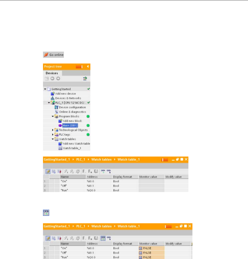
Online and diagnostic tools
15.13 Monitoring and modifying values in the CPU
S7-1200 Programmable controller
1326 System Manual, V4.2, 09/2016, A5E02486680-AK
15.13.1
Going online to monitor the values in the CPU
To monitor the tags, you must have an online connection to the CPU. Simply click the "Go
online" button in the toolbar.
When you have connected to the CPU, STEP 7 turns the headers of
the work areas orange.
The p
roject tree displays a comparison of the offline project and the
online CPU. A green circle means that the CPU and the project are
synchronized, meaning that both have the same configuration and
user program.
Tag tables show the tags. Watch tables can als
o show the tags, as
well as direct addresses.
To monitor the execution of the user program and to display the values of the tags,
click the "Monitor all" button in the toolbar.
The "Monitor value" field shows the value for each tag.
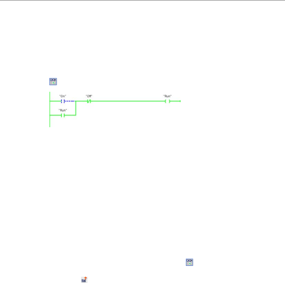
Online and diagnostic tools
15.13 Monitoring and modifying values in the CPU
S7-1200 Programmable controller
System Manual, V4.2, 09/2016, A5E02486680-AK 1327
15.13.2
Displaying status in the program editor
You can monitor the status of up to 50 tags in the LAD and FBD program editors. Use the
editor bar to display the LAD editor. The editor bar allows you to change the view between
the open editors without having to open or close the editors.
In the toolbar of the program editor, click the "Monitoring on/off" button to display the status
of your user program.
The network in the program editor displays power flow in green.
You can also right-click on the instruction or parameter to modify the value for the instruction.
15.13.3
Capturing a snapshot of the online values of a DB for restoring values
You can capture a snapshot of the actual values of data block tags from an online CPU for
later use.
Note the following prerequisites:
● You must have an online connection to the CPU.
● You must have the DB open in STEP 7.
Capturing a snapshot
To capture a snapshot, follow these steps:
1. In the DB editor, click the "Monitor all tags" button: The "Monitor value" column
displays the actual data values.
2. Click the button to capture a snapshot of the actual values and display them in the
"Snapshot" column.
You can use this snapshot at a later time to update the actual CPU values or to replace the
start values.

Online and diagnostic tools
15.13 Monitoring and modifying values in the CPU
S7-1200 Programmable controller
1328 System Manual, V4.2, 09/2016, A5E02486680-AK
Copying the snapshot values to the CPU
To copy the snapshot values to the actual values of the data block tags in the CPU, click the
following button:
The online CPU loads the snapshot values into the actual values. The Monitor value column
shows the actual values in the CPU. The scan cycle might subsequently change the values
in the CPU from the snapshot values, but at the time you make the copy, the CPU loads the
snapshot values in a consistent download.
Note
Be aware that if your snapshot contains state information, timer values, or calculated
information, the CPU restores those values as of the time you made the snapshot.
Copying the snapshot values to the start values
To copy the snapshot values to the start values of the data block tags, click the following
button:
After you compile the DB and download it to the CPU, the DB uses the new start values
when the CPU goes to RUN mode.
Copying individual snapshot or monitor values to start values
The data block editor also lets you copy individual values and paste them over start values.
Simply right-click a value in any value column and select Copy to place it in the Windows
clipboard. Then, you can right-click on any start value and select paste to replace that value
with the value in the clipboard.
After you compile the DB and download it to the CPU, the DB uses the new start values
when the CPU goes to RUN mode.
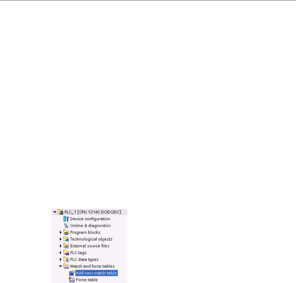
Online and diagnostic tools
15.13 Monitoring and modifying values in the CPU
S7-1200 Programmable controller
System Manual, V4.2, 09/2016, A5E02486680-AK 1329
15.13.4
Using a watch table to monitor and modify values in the CPU
A watch table allows you to perform monitoring and control functions on data points as the
CPU executes your program. These data points can be process image (I or Q), M, DB or
physical inputs (I_:P), depending on the monitor or control function. You cannot accurately
monitor the physical outputs (Q_:P) because the monitor function can only display the last
value written from Q memory and does not read the actual value from the physical outputs.
The monitoring function does not change the program sequence. It presents you with
information about the program sequence and the data of the program in the CPU.
Control functions enable the user to control the sequence and the data of the program. You
must exercise caution when using control functions. These functions can seriously influence
the execution of the user/system program. The three control functions are Modify, Force and
Enable Outputs in STOP.
With the watch table, you can perform the following online functions:
● Monitoring the status of the tags
● Modifying values for the individual tags
You select when to monitor or modify the tag:
● Beginning of scan cycle: Reads or writes the value at the beginning of the scan cycle
● End of scan cycle: Reads or writes the value at the end of the scan cycle
● Switch to stop
To create a watch table:
1.
Double-click "Add new watch table" to open a new
watch table.
2.
Enter the tag name to add a tag to the watch table.
The
following options are available for monitoring tags:
•
Monitor all: This command starts the monitoring of
the visible tags in the active watch table.
•
Monitor now: This command starts the monitoring
of the visible tags in the active watch table. The
watch table monitors the tags immediately and
once only.
The following options are available for modifying tags:
● "Modify to 0" sets the value of a selected address to "0".
● "Modify to 1" sets the value of a selected address to "1".
● "Modify now" immediately changes the value for the selected addresses for one scan
cycle.
● "Modify with trigger" changes the values for the selected addresses.
This function does not provide feedback to indicate that the selected addresses were
actually modified. If feedback of the change is required, use the "Modify now" function.
● "Enable peripheral outputs" disables the command output disable and is available only
when the CPU is in STOP mode.
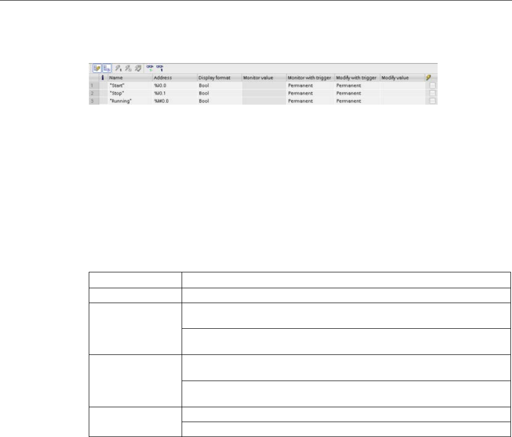
Online and diagnostic tools
15.13 Monitoring and modifying values in the CPU
S7-1200 Programmable controller
1330 System Manual, V4.2, 09/2016, A5E02486680-AK
To monitor the tags, you must have an online connection to the CPU.
You use the buttons at the top of the watch table to select the various functions.
Enter the tag name to monitor and select a display format from the dropdown selection. With
an online connection to the CPU, click the "Monitor" button to display the actual value of the
data point in the "Monitor value" field.
15.13.4.1
Using a trigger when monitoring or modifying PLC tags
Triggering determines at what point in the scan cycle the selected address will be monitored
or modified.
Table 15- 4 Types of triggers
Trigger
Description
Permanent
Continuously collects the data
At scan cycle start Permanent: Continuously collects the data at the start of the scan cycle, after
the CPU reads the inputs
Once: Collects the data at the start of the scan cycle, after the CPU reads the
inputs
At scan cycle end Permanent: Continuously collects the data at the end of the scan cycle, before
the CPU writes the outputs
Once: Collects the data once at the end of the scan cycle, before the CPU
writes the outputs
At transition to
STOP
Permanent: Continuously collects data when the CPU transitions to STOP
Once: Collects the data once after the CPU transitions to STOP
For modifying a PLC tag at a given trigger, select either the start or the end of cycle.
● Modifying an output: The best trigger event for modifying an output is at the end of the
scan cycle, immediately before the CPU writes the outputs.
Monitor the value of the outputs at the beginning of the scan cycle to determine what
value is written to the physical outputs. Also, monitor the outputs before the CPU writes
the values to the physical outputs in order to check program logic and to compare to the
actual I/O behavior.
● Modifying an input: The best trigger event for modifying an input is at the start of the
cycle, immediately after the CPU reads the inputs and before the user program uses the
input values.
If you suspect values are changing during the scan, you might want to monitor the value
of the inputs at the end of the scan cycle to ensure that the value of the input at the end
the scan cycle has not changed from the start of the scan cycle. If there is a difference in
the values, your user program might be erroneously writing to inputs.
To diagnose why the CPU might have gone to STOP, use the "Transition to STOP" trigger to
capture the last process values.

Online and diagnostic tools
15.13 Monitoring and modifying values in the CPU
S7-1200 Programmable controller
System Manual, V4.2, 09/2016, A5E02486680-AK 1331
15.13.4.2
Enabling outputs in STOP mode
The watch table allows you to write to the outputs when the CPU is in STOP mode. This
functionality allows you to check the wiring of the outputs and verify that the wire connected
to an output pin initiates a high or low signal to the terminal of the process device to which it
is connected.
WARNING
Risks in writing to physical outputs in STOP mode
Even though the CPU is in STOP mode, enabling a physical output can activate the
process point to which it is connected, possibly resulting in unexpected equipment
operation. Unexpected equipment operation can cause death or severe personal injury.
Before writing to an output from the watch table, ensure that changing the physical output
cannot cause unexpected equipment operation. Always observe safety precautions for your
process equipment.
You can change the state of the outputs in STOP mode when the outputs are enabled. If the
outputs are disabled, you cannot modify the outputs in STOP mode. To enable the
modification in STOP mode of the outputs from the watch table, follow these steps:
1. Select the "Expanded mode" menu command from the "Online" menu.
2. Select the "Enable peripheral outputs" option of the "Modify" command of the "Online"
menu, or from the context menu after right-clicking the row of the Watch table.
You cannot enable outputs in STOP mode if you have configured distributed I/O. An error is
returned when you try to do this.
Setting the CPU to RUN mode disables "Enable peripheral outputs" option.
If any inputs or outputs are forced, the CPU is not allowed to enable outputs while in STOP
mode. The force function must first be cancelled.
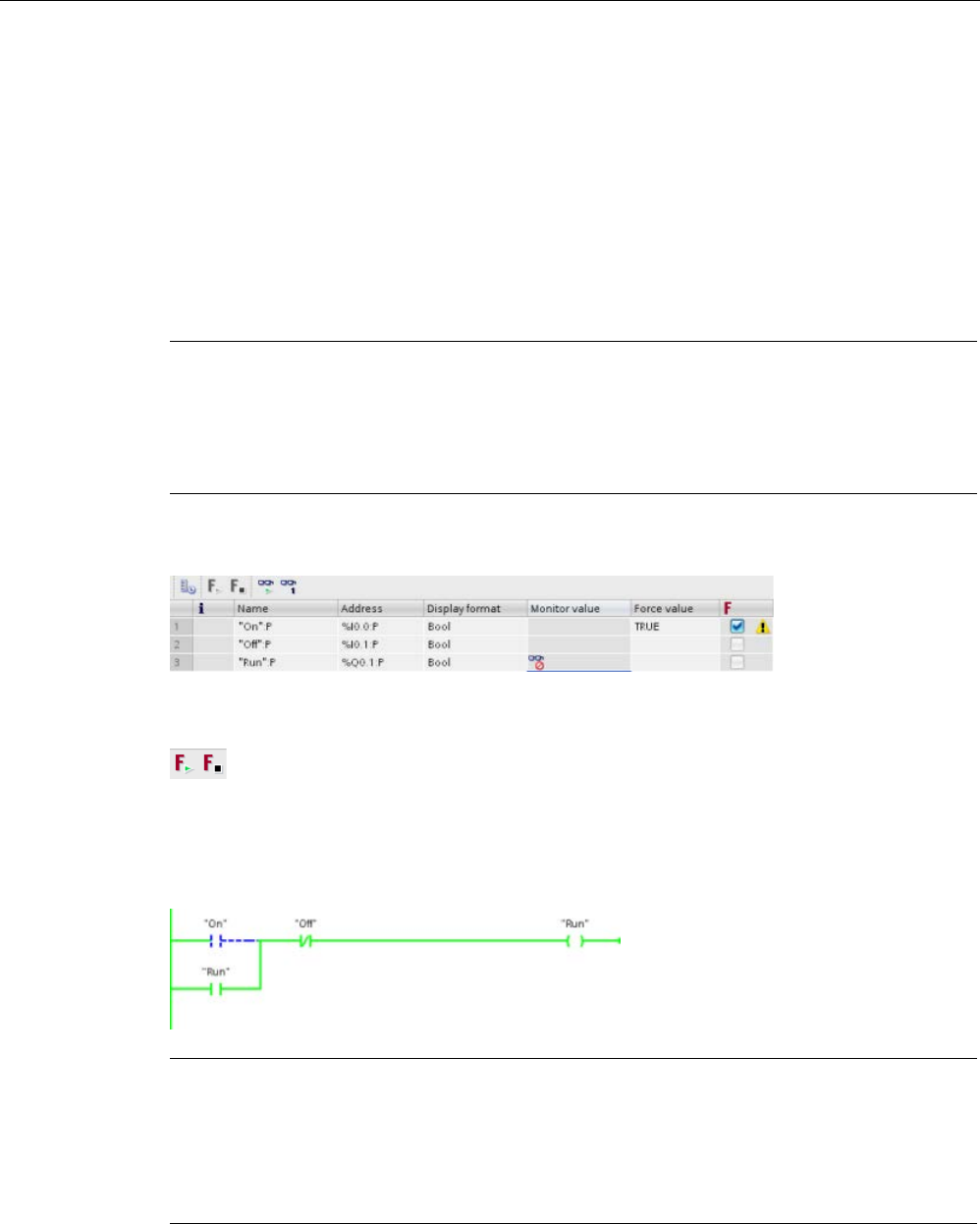
Online and diagnostic tools
15.13 Monitoring and modifying values in the CPU
S7-1200 Programmable controller
1332 System Manual, V4.2, 09/2016, A5E02486680-AK
15.13.5
Forcing values in the CPU
15.13.5.1
Using the force table
A force table provides a "force" function that overwrites the value for an input or output point
to a specified value for the peripheral input or peripheral output address. The CPU applies
this forced value to the input process image prior to the execution of the user program and to
the output process image before the outputs are written to the modules.
Note
The force values are stored in the CPU and not in the force table.
You cannot force an input (or "I" address) or an output (or "Q" address). However, you can
force a peripheral input or peripheral output. The force table automatically
appends a ":P" to
the address (for example: "On":P or "Run":P).
In the "Force value" cell, enter the value for the input or output to be forced. You can then
use the check box in the "Force" column to enable forcing of the input or output.
Use the "Start or replace forcing" button to force the value of the tags in the force
table. Click the "Stop forcing" button to reset the value of the tags.
In the force table, you can monitor the status of the forced value for an input. However, you
cannot monitor the forced value of an output.
You can also view the status of the forced value in the program editor.
Note
When an input or output is forced in a force table, the force actions
become part of the
project configuration. If you close STEP
7, the forced elements remain active in the CPU
program until they are cleared. To clear these forced elements, you must use STEP
7 to
connect with the online CPU and then use the force table to turn off or stop the force function
for those elements.

Online and diagnostic tools
15.13 Monitoring and modifying values in the CPU
S7-1200 Programmable controller
System Manual, V4.2, 09/2016, A5E02486680-AK 1333
15.13.5.2
Operation of the Force function
The CPU allows you to force input and output point(s) by specifying the physical input or
output address (I_:P or Q_:P) in the force table and then starting the force function.
In the program, reads of physical inputs are overwritten by the forced value. The program
uses the forced value in processing. When the program writes a physical output, the output
value is overwritten by the force value. The forced value appears at the physical output and
is used by the process.
When an input or output is forced in the force table, the force actions become part of the
user program. Even though the programming software has been closed, the force selections
remain active in the operating CPU program until they are cleared by going online with the
programming software and stopping the force function. Programs with forced points loaded
on another CPU from a memory card will continue to force the points selected in the
program.
If the CPU is executing the user program from a write-protected memory card, you cannot
initiate or change the forcing of I/O from a watch table because you cannot override the
values in the write-protected user program. Any attempt to force the write-protected values
generates an error. If you use a memory card to transfer a user program, any forced
elements on that memory card will be transferred to the CPU.
Note
Digital I/O points assigned to HSC, PWM, and PTO cannot be forced
The digital I/O points used by the high
-speed counter (HSC), pulse-
width modulation (PWM),
and pulse
-train output (PTO) devices are assigned during device configuration. When digital
I/O point addresses are assigned to these devices, the values of the assigned I/O point
addresses cannot be modified by the force function of the force table.

Online and diagnostic tools
15.13 Monitoring and modifying values in the CPU
S7-1200 Programmable controller
1334 System Manual, V4.2, 09/2016, A5E02486680-AK
Startup
RUN
A The clearing of the I memory area is not
affected by the Force function.
①
While writing Q memory to the physical out-
puts, the CPU applies the force value as the
outputs are updated.
B The initialization of the outputs values is
not affected by the Force function.
②
When reading the physical inputs, the CPU
applies the force values just prior to copying
the inputs into I memory.
C During the execution of the startup OBs,
the CPU applies the force value when
the user program accesses the physical
input.
③
During the execution of the user program
(program cycle OBs), the CPU applies the
force value when the user program accesses
the physical input or writes the physical out-
put.
D The storing of interrupt events into the
queue is not affected.
④
Handling of communication requests and self-
test diagnostics are not affected by the Force
function.
E The enabling of the writing to the out-
puts is not affected.
⑤
The p
rocessing of interrupts during any part of
the scan cycle is not affected.

Online and diagnostic tools
15.14 Downloading in RUN mode
S7-1200 Programmable controller
System Manual, V4.2, 09/2016, A5E02486680-AK 1335
15.14
Downloading in RUN mode
The CPU supports "Download in RUN mode". This capability is intended to allow you to
make small changes to a user program with minimal disturbance to the process being
controlled by the program. However, implementing this capability also allows massive
program changes that could be disruptive or even dangerous.
WARNING
Risks with downloading in RUN mode
When you download changes to the CPU in RUN mode, the changes immediately affect
process operation. Changing the program in RUN mode can result in unexpected system
operation, which could cause death or serious injury to personnel, and/or damage to
equipment.
Only authorized personnel who understand the effects of RUN mode changes on system
operation should perform a download in RUN mode.
The "Download in RUN mode" feature allows you to make changes to a program and
download them to your CPU without switching to STOP mode:
● You can make minor changes to your current process without having to shut down (for
example, change a parameter value).
● You can debug a program more quickly with this feature (for example, invert the logic for
a normally open or normally closed switch).
You can make the following program block and tag changes and download them in RUN
mode:
● Create, overwrite, and delete Functions (FC), Function Blocks (FB), and Tag tables.
● Create, delete, and overwrite Data Blocks (DB) and instance data blocks for Function
Blocks (FB). You can add to DB structures and download them in RUN mode. The CPU
can maintain the values of existing block tags and initialize the new data block tags to
their initial values, or the CPU can set all data block tags to initial values, depending on
your configuration settings (Page 1341). You cannot download a web server DB (control
or fragment) in RUN mode.
● Overwrite Organization Blocks (OB); however, you cannot create or delete OBs.
You can download a maximum number of twenty blocks in RUN mode at one time. If you
must download more than twenty blocks, you must place the CPU in STOP mode.
If you download changes to a real process (as opposed to a simulated process, which you
might do in the course of debugging a program), it is vital to think through the possible safety
consequences to machines and machine operators before you download.
Note
If the CPU is in RUN mode and program changes have been made, STEP 7 always tries to
download in RUN first. If you do not want this to happen, yo
u must put the CPU into STOP.
If the changes made are not supported in "Download in RUN", STEP 7 prompts the user that
the CPU must go to STOP.

Online and diagnostic tools
15.14 Downloading in RUN mode
S7-1200 Programmable controller
1336 System Manual, V4.2, 09/2016, A5E02486680-AK
15.14.1
Prerequisites for "Download in RUN mode"
To be able to download your program changes to a CPU that is in RUN mode, you must
meet these prerequisites:
● Your CPU version is V3.0 or later
Note
Your CPU version must be V4.0 or later to
modify the extended block interface in RUN
mode.
(Page 1341)
● Your program must compile successfully.
● You must have successfully established communication between the programming
device where you are running STEP 7 and the CPU.
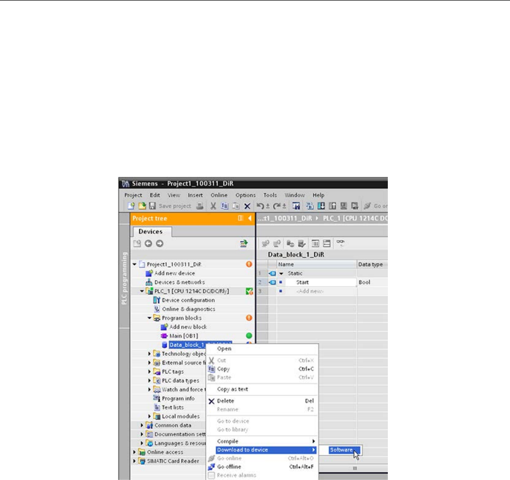
Online and diagnostic tools
15.14 Downloading in RUN mode
S7-1200 Programmable controller
System Manual, V4.2, 09/2016, A5E02486680-AK 1337
15.14.2
Changing your program in RUN mode
To change the program in RUN mode, you must first ensure that the CPU and program meet
the prerequisites (Page 1336), and then follow these steps:
1. To download your program in RUN mode, select one of the following methods:
– Select the "Download to device" command from the "Online" menu.
– Click the "Download to device" button in the toolbar.
– In the "Project tree", right-click "Program blocks" and select the "Download to device >
Software" command.
If the program compiles successfully, STEP 7 starts to download the program to the CPU.
2. When STEP 7 prompts you to load your program or cancel the operation, click "Load" to
download the program to the CPU.
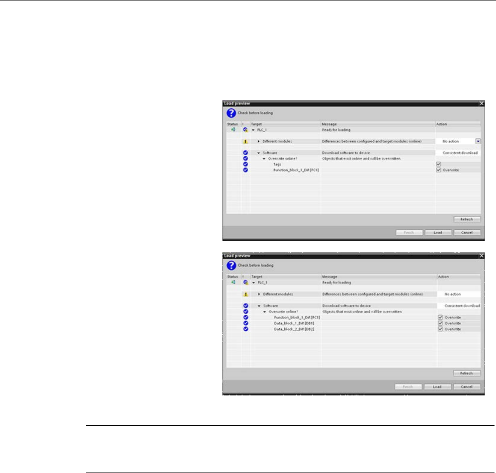
Online and diagnostic tools
15.14 Downloading in RUN mode
S7-1200 Programmable controller
1338 System Manual, V4.2, 09/2016, A5E02486680-AK
15.14.3
Downloading selected blocks
From the Program blocks folder, you can select a single block or a selection of blocks for
downloading.
If you select a single block for
downloading, then the only
option in the "Action" column
is "Consistent download".
You can expand the category
line to be sure what blocks are
to be loaded. In this example,
a small change was
made to
the offline block, and no other
blocks need to be loaded.
In this example, more than
one block is needed for dow
n-
loading.
Note
You
can download a maximum number of twenty blocks in RUN mode at one time. If you
must download more than twenty blocks, you must place the CPU in STOP mode.
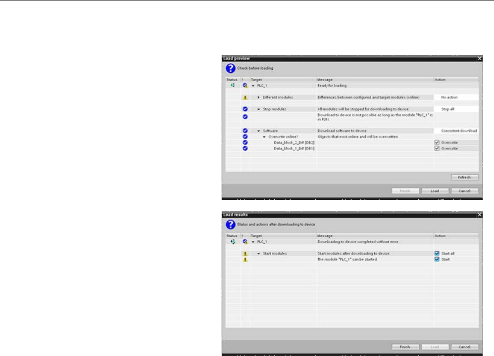
Online and diagnostic tools
15.14 Downloading in RUN mode
S7-1200 Programmable controller
System Manual, V4.2, 09/2016, A5E02486680-AK 1339
If you attempt to download in
RUN, but the system detects
that this is not possible prior to
th
e actual download, then the
Stop modules category line
appears in the dialog.
Click the "Load" button, and
the "Load results" dialog a
p-
pears. Click the "Finish" button
to complete the download.
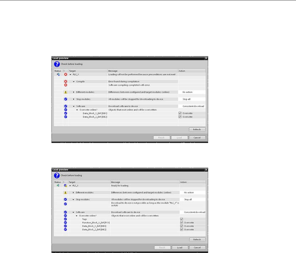
Online and diagnostic tools
15.14 Downloading in RUN mode
S7-1200 Programmable controller
1340 System Manual, V4.2, 09/2016, A5E02486680-AK
15.14.4
Downloading a single selected block with a compile error in another block
If you attempt a consistent download with a compile error in another block, then the dialog
indicates an error, and the load button is disabled.
You must correct the compile error in the other block. Then, the "Load" button becomes
active.
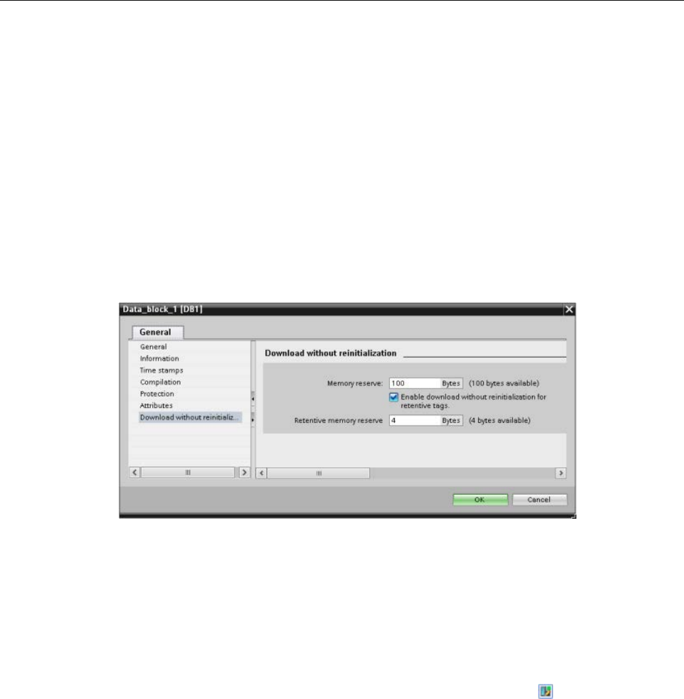
Online and diagnostic tools
15.14 Downloading in RUN mode
S7-1200 Programmable controller
System Manual, V4.2, 09/2016, A5E02486680-AK 1341
15.14.5
Modifying and downloading existing blocks in RUN mode
The Download in Run feature allows you to add and modify tags in data blocks and function
blocks and then download the changed block to the CPU in RUN mode.
Download without reinitialization
Each DB and FB has an amount of reserved memory, which you can use for adding tags to
the block that you can subsequently download in RUN mode. By default, the initial size of the
memory reserve is 100 bytes. You can add additional tags to your data up to the size of the
memory reserve and download the extended block to the CPU in RUN mode. You can also
increase the memory reserve if you need more memory for additional tags in your block. If
you add more tags than the amount of memory you have allocated, you cannot download the
extended block to the CPU in RUN mode.
The "Download without reinitialization" feature allows you to extend a data block by adding
more data block tags and download the extended data block in RUN mode. In this way, you
can add tags to a data block and download it without reinitializing your program. The CPU
retains the values of the existing data block tags and initializes the newly-added tags to their
start values.
To enable this function for an online project with a CPU in RUN mode, follow these steps:
1. From the Program blocks folder in the STEP 7 project tree, open the block.
2. Click the "Download without reinitialization" toggle button in the block editor to enable the
function. (The icon has a box around it when you have enabled it: )
3. Click OK on the prompt to confirm your choice.
4. Add tags to the block interface and download the block in RUN mode. You can add and
download as many new tags as your memory reserve allows.

Online and diagnostic tools
15.14 Downloading in RUN mode
S7-1200 Programmable controller
1342 System Manual, V4.2, 09/2016, A5E02486680-AK
If you have added more bytes to your block than you have configured for the memory
reserve, STEP 7 displays an error when you attempt to download the block in RUN mode.
You must edit the block properties to increase the amount. You cannot delete existing
entries or modify the “Memory reserve” of the block while the “Download without
reinitialization” function is enabled. To disable the "Download without reinitialization"
function, follow these steps:
1. Click the "Download without reinitialization" toggle button in the block editor to disable the
function. (The icon does not have a box around it when you have disabled it: )
2. Click OK on the prompt to confirm your choice.
3. Download the block. On the download dialog, you must select "reinitialize" in order to
download the extended block.
The download then reinitializes all existing and new block tags to their start values.
Downloading retentive block tags
Downloading retentive block tags in RUN mode requires the allocation of a retentive memory
reserve. To configure this retentive memory reserve, follow these steps:
1. From the Program blocks folder in the STEP 7 project tree, right-click the block and select
"Properties" from the context menu.
2. Select the "Download without reinitialization" property.
3. Select the check box for "Enable download without reinitialization for retentive tags".
4. Configure the number of bytes available for the retentive memory reserve.
5. Click OK to save your changes.
6. Add retentive data block tags to the data block and download the data block in RUN
mode. You can add and download as many new retentive data block tags as your
retentive memory reserve allows.
If you have added more retentive bytes to your data block than you have configured for the
retentive memory reserve, STEP 7 displays an error when you attempt to download the
block in RUN mode. You can only add retentive block tags up to the retentive memory
reserve in order to be able to download them in RUN mode.
When you download the extended retentive block tags, the tags contain their current values.
Configuring amount of reserved memory for new blocks
The default memory reserve size for new data blocks is 100 bytes. When you create a new
block, it has 100 bytes available in reserve. If you want the memory reserve size to be
different for new blocks, you can change the setting in the PLC programming settings:
1. From STEP 7, select the
Options > Settings
menu command.
2. From the Settings dialog, expand "PLC programming" and select "General".
3. In the "Download without reinitialization" section, enter the number of bytes for the
memory reserve.
When you create new blocks, STEP 7 uses the memory reserve configuration that you
entered for the new blocks.

Online and diagnostic tools
15.14 Downloading in RUN mode
S7-1200 Programmable controller
System Manual, V4.2, 09/2016, A5E02486680-AK 1343
Restrictions
The following restrictions apply to editing and downloading blocks in RUN mode:
● Extending the block interface by adding new tags and downloading in RUN mode is only
available for optimized blocks (Page 192).
● You cannot change the structure of a block and download the changed block in RUN
mode without reinitializing. Adding new members to a Struct (Page 133) tag, changing
tag names, array sizes, data types, or retentive status all require that you reinitialize the
block if you download it in RUN mode. The only modifications to existing block tags that
you can perform and still download the block in RUN mode without reinitialization are
changes to start values (data blocks), default values (function blocks) or comments.
● You cannot download more new block tags in RUN mode than the memory reserve can
accommodate.
● You cannot download more new retentive block tags in RUN mode than the retentive
memory reserve can accommodate.
See also
Exchanging a V3.0 CPU for a V4.2 CPU (Page 1571)
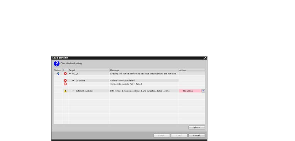
Online and diagnostic tools
15.14 Downloading in RUN mode
S7-1200 Programmable controller
1344 System Manual, V4.2, 09/2016, A5E02486680-AK
15.14.6
System reaction if the download process fails
During the initial Download in RUN operation, if a network connection failure occurs, STEP 7
displays the following "Load preview" dialog:

Online and diagnostic tools
15.14 Downloading in RUN mode
S7-1200 Programmable controller
System Manual, V4.2, 09/2016, A5E02486680-AK 1345
15.14.7
Considerations when downloading in RUN mode
Before downloading the program in RUN mode, consider the effect of a RUN-mode
modification on the operation of the CPU for the following situations:
● If you deleted the control logic for an output, the CPU maintains the last state of the
output until the next power cycle or transition to STOP mode.
● If you deleted a high-speed counter or pulse output functions which were running, the
high-speed counter or pulse output continues to run until the next power cycle or
transition to STOP mode.
● Any logic that is conditional on the state of the first scan bit will not be executed until the
next power cycle or transition from STOP to RUN mode. The first scan bit is set only by
the transition to RUN mode and is not affected by a download in RUN mode.
● The current values of data blocks (DB) and/or tags can be overwritten.
Note
Before you can download your program in RUN mode, the CPU must support changes in
RUN mode, the program must compile with no errors, and
the communication between
STEP
7, and the CPU must be error-free.
You can make the following changes in program blocks and tags and download them in
RUN mode:
•
Create, overwrite, and delete Functions (FC), Function Blocks (FB), and Tag tables.
•
Create and delete Data Blocks (DB); however, DB structure changes cannot be
overwritten. Initial DB values can be overwritten. You cannot download a web server
DB (control or fragment) in RUN mode.
•
Overwrite Organization Blocks (OB); however, you cannot create or delete OBs.
You can download a maximum number of twenty blocks in RUN mode at one time. If you
must download more than twenty blocks, you must place the CPU in STOP mode.
Once you initiate a download, you cannot perform other tasks in STEP
7 until the
downloa
d completes.

Online and diagnostic tools
15.14 Downloading in RUN mode
S7-1200 Programmable controller
1346 System Manual, V4.2, 09/2016, A5E02486680-AK
Instructions that might fail due to "Download in RUN mode"
The following instructions might experience a temporary error when download in run
changes are being activated in the CPU. The error occurs when the instruction is initiated
while the CPU is preparing to activate the downloaded changes. During this time, the CPU
suspends initiation of user-program access to the Load Memory, while it completes in-
progress user-program access to Load Memory. This is done so that downloaded changes
can be activated consistently.
Instruction
Response while Activation is Pending
DataLogCreate
STATUS = W#16#80C0, ERROR = TRUE
DataLogOpen STATUS = W#16#80C0, ERROR = TRUE
DataLogWrite
STATUS = W#16#80C0, ERROR = TRUE
DataLogClose
STATUS = W#16#80C0, ERROR = TRUE
DataLogNewFile
STATUS = W#16#80C0, ERROR = TRUE
DataLogClear
STATUS = W#16#80C0, ERROR = TRUE
DataLogDelete
STATUS = W#16#80C0, ERROR = TRUE
READ_DBL
RET_VAL = W#16#82C0
WRIT_DBL
RET_VAL = W#16#82C0
Create_DB
RET_VAL = W#16#80C0
Delete_DB
RET_VAL = W#16#80C0
RTM
RET_VAL = 0x80C0
In all cases the RLO output from the instruction will be false when the error occurs. The error
is temporary. If it occurs, the instruction should be retried later.
Note
You must not retry the operation in the c
urrent execution of the OB.
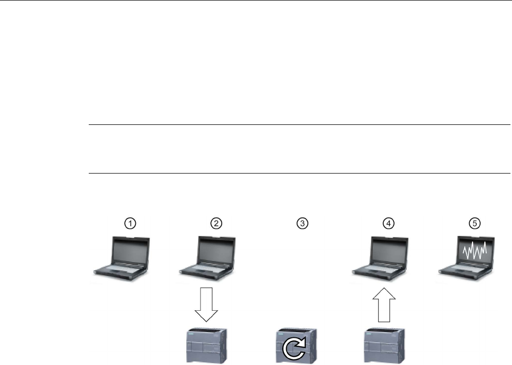
Online and diagnostic tools
15.15 Tracing and recording CPU data on trigger conditions
S7-1200 Programmable controller
System Manual, V4.2, 09/2016, A5E02486680-AK 1347
15.15
Tracing and recording CPU data on trigger conditions
STEP 7 provides trace and logic analyzer functions with which you can configure variables
for the PLC to trace and record. You can then upload the recorded trace measurement data
to your programming device and use STEP 7 tools to analyze, manage, and graph your
data. You use the Traces folder in the STEP 7 project tree to create and manage traces.
Note
The tr
ace measurement data is available only within the STEP 7 project and is not available
for processing by other tools.
The following figure shows the various steps of the trace feature:
①
Configure the trace in the trace editor of STEP 7. You can configure the following options:
• Data values to record
• Recording duration
• Recording frequency
• Trigger condition
②
Transfer the trace configuration from STEP 7 to the PLC.
③
The PLC executes the program, and when the trigger condition occurs, begins recording the
trace data.
④
Transfer the recorded values from the PLC to STEP 7.
⑤
Use the tools in STEP 7 to analyze, graphically display, and save the data.
The S7-1200 supports two trace jobs with a maximum of 16 variables captured per trigger
event. Each trace job provides 524288 bytes of RAM for the recording of trace values and
the overhead associated with those values, for example variable addresses and time
stamps.
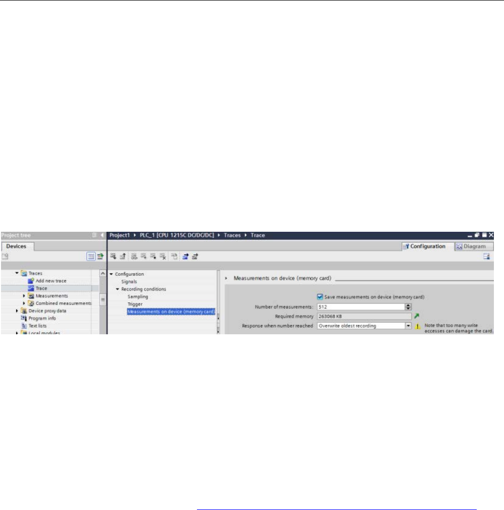
Online and diagnostic tools
15.15 Tracing and recording CPU data on trigger conditions
S7-1200 Programmable controller
1348 System Manual, V4.2, 09/2016, A5E02486680-AK
Saving trace measurements to the memory card
The S7-1200 CPU can only save trace measurements to the SIMATIC memory card. If you
do not have a memory card in your CPU, the CPU will log a diagnostic buffer entry if the
program attempts to save trace measurements with no SIMATIC memory card present in the
CPU. The CPU limits the space allocated to trace measurements such that 1 MB of external
load memory must always be available. If a trace measument would require more memory
than the maximum allowance, the CPU will not save the measurement and will log a
diagnostic buffer entry.
In addition, if you select "Overwrite oldest recording" in STEP 7, the continual writing can
reduce the lifetime of load memory. When you select "Overwrite oldest recording", the CPU
replaces the oldest measurement with the newest measurement after it has stored the
configured number of trace measurements, and continues tracing and saving
measurements. Overwriting the oldest measurements is useful in capturing intermittent
problems.
The CPU supports a maximum of 999 trace measurement results. During the time that the
CPU is saving the trace measurements to load memory, the CPU does not check the trigger
condition for the trace job. Once the CPU finishes saving the trace measurements, the CPU
resumes checking for trigger conditions.
Access to examples
See the STEP 7 information system for details about how to program a trace, how to
download the configuration, upload the trace data, and display the data in the logic analyzer.
You can find detailed examples there in the "Using online and diagnostics functions > Using
the trace and logic analyzer function" chapter.
In addition, the online manual "Industry Automation SINAMICS/SIMATIC Using the trace and
logic analyzer function" (https://support.industry.siemens.com/cs/ww/en/view/64897128) is
an excellent reference.

Online and diagnostic tools
15.16 Determining the type of wire break condition from an SM 1231 module
S7-1200 Programmable controller
System Manual, V4.2, 09/2016, A5E02486680-AK 1349
15.16
Determining the type of wire break condition from an SM 1231
module
As described in the topic Measurement ranges of the analog inputs for voltage and current
(SB and SM) (Page 1471), the SM 1231 module returns an analog input value of 32767
(16#7FFF) for both a wire break condition or an overflow condition. If you want to determine
which of these two conditions occurred, you can include logic in your STEP 7 program to
make the determination. The method to determine the condition type consists of these tasks:
● Create a Diagnostic error interrupt OB to be called whenever there is an incoming or
outgoing diagnostic event.
● Include a call to the RALRM instruction.
● Set up an array of bytes for the AINFO parameter, which includes the information about
the condition type.
● Evaluate bytes 32 and 33 of the AINFO structure of the RALRM_DB when the CPU
triggers the Diagnostic Interrupt OB..
Creating a Diagnostic error interrupt OB
To be able to determine when a wire break condition occurs, create a Diagnostic error
interrupt OB. The CPU will call this OB whenever an incoming or outgoing diagnostic event
occurs.
When the CPU calls the Diagnostic error interrupt OB, the input parameter LADDR will
contain the hardware identifier for the module with the error. You can find the hardware
identifier for the SM 1231 module in the STEP 7 device configuration for the SM 1231
module.
Calling the RALRM instruction
To program the RALRM instruction call, follow these steps:
1. Add a call to RALRM in your STEP 7 program.
2. Set the F_ID input parameter to the hardware identifier in the LADDR parameter of the
Diagnostic error interrupt OB.
3. Use an array of bytes for the TINFO and AINFO input parameters. Use an array size of
34 bytes or greater.

Online and diagnostic tools
15.16 Determining the type of wire break condition from an SM 1231 module
S7-1200 Programmable controller
1350 System Manual, V4.2, 09/2016, A5E02486680-AK
Interpreting AINFO after a diagnostic interrupt has occurred
The AINFO byte array will contain the information about the module diagnostics after the
Diagnostic error interrupt OB executes.
Bytes 0 - 25 are header information. The bytes pertaining to the module diagnostic are as
follows:
Byte
Description
26 and 27
Word value 16#8000 - indicates the diagnostic is a Profinet style diagnostic
28 and 29 Word containing channel number responsible for this diagnostic
30
Bit pattern aaabb000 that indicates the type of channel (aaa) and type of error (bb)
aaa
bb
000: reserved
00: reserved
001: input channel
01: incoming error
010: output channel
10: outgoing error
011: input/output channel
11: outgoing error, other errors present
31 Indication of data format
0: Free data format
1: Bit
2: Two bits
3: Four bits
4: Byte
5: Word (two bytes)
6: Double word (four bytes)
7: Two double words (eight bytes)
32 and 33 Word that defines the type of error:
16#0000: reserved
16#0001: short circuit
16#0002: undervoltage
16#0003: overvoltage
16#0004: overload
16#0005: over temperature
16#0006: wire break
16#0007: high limit exceeded
16#0008: low limit exceeded
16#0009: error

Online and diagnostic tools
15.16 Determining the type of wire break condition from an SM 1231 module
S7-1200 Programmable controller
System Manual, V4.2, 09/2016, A5E02486680-AK 1351
For example, consider bytes 26 - 33 of this AINFO structure:
● The Word at bytes 26 and 27 is 16#8000, which indicates that this is a Profinet style
diagnostic.
● The Word at bytes 28 and 29 indicates this is a diagnostic for channel 0 or the module.
● Byte 30 is 16#28, which when interpreted as the bit pattern aaa bb 00 is 001 01 000. This
value indicates that this diagnostic is for an input channel and is an incoming error.
● Byte 31 is 5, which indicates a Word value
● The word value at bytes 32 and 33 is 16#0007, which indicates high limit exceeded.
By caputuring the AINFO information from a Diagnostic error interrupt event, you can thus
determine the nature of the diagnostic event.

Online and diagnostic tools
15.17 Backing up and restoring a CPU
S7-1200 Programmable controller
1352 System Manual, V4.2, 09/2016, A5E02486680-AK
15.17
Backing up and restoring a CPU
15.17.1
Backup and restore options
You will make a number of changes to your automation system over time, for example, add
new devices, replace existing devices or adapt the user program. If these changes were to
result in undesirable behavior, you can restore the automation plant to an earlier version if
you have a backup. STEP 7 and the S7-1200 CPU offer different options for backing up and
restoring the hardware configuration and software.
Backup options
The table below provides an overview of the backup and restoration options of S7 CPUs:
Snapshot of the moni-
tored values
Upload from device
(software)
Upload device as new
station (hardware and
software)
Download backup from
online device
Use case
Restoring a specific
status of a data block.
The actual values of
data blocks including
time stamp are ac-
cepted in the project.
Upload blocks from a
CPU to the project.
Upload of hardware
configuration and
software from a device
to the project.
Create a complete
backup of a CPU as a
restore point. The
backup copy is con-
sistent and cannot be
changed or opened.
Requirement
The CPU exists in a
project. The data
blocks must be identi-
cal online and offline.
The CPU exists in the
project.
The device is available
in the hardware cata-
log of TIA Portal. Any
necessary HSPs or
GSD files are installed.
-
Possible in mode
RUN, STOP
RUN, STOP
RUN, STOP
STOP
Possible for F-CPUs
Yes
Yes
No
Yes
Backup can be edited
Yes
Yes
Yes
No

Online and diagnostic tools
15.17 Backing up and restoring a CPU
S7-1200 Programmable controller
System Manual, V4.2, 09/2016, A5E02486680-AK 1353
Backup contents
The table below shows which data you can download and back up with which options:
Snapshot of the moni-
tored values
Upload from device
(software)
Upload device as new
station (hardware and
software)
Download backup from
online device
Actual values of the
data blocks
Snapshot is possible Download is possible Download is possible Backup is possible
Software blocks
-
Download is possible
Download is possible
Backup is possible
PLC tags (names of
tags and constants)
- Download is possible Download is possible Backup is possible
Technology objects
-
Download is possible
Download is possible
Backup is possible
Hardware configura-
tion
- - Download is possible Backup is possible
Monitoring tables
(Web server)
- - Download is not pos-
sible
Backup is possible
Local data, bit memo-
ries, timers, counters
and process picture
Snapshot is not possi-
ble
Download is not pos-
sible
Download is not pos-
sible
Backup is possible
Archives and recipes
(PLC)
- - - Backup is possible
General data on the
SIMATIC memory
card, for example, help
for program blocks or
GSD files
- - - Backup is possible
Special considerations during backup of actual values
The "Backup from online device" type of backup backs up the actual values of the tags that
are set as retentive. To ensure consistency of the retentive data, disable all write access to
retentive data during the backup.
A transition from STOP to RUN mode sets actual values of the non-retentive data to their
start values. A CPU backup contains only the start values of non-retentive data.

Online and diagnostic tools
15.17 Backing up and restoring a CPU
S7-1200 Programmable controller
1354 System Manual, V4.2, 09/2016, A5E02486680-AK
15.17.2
Backing up an online CPU
Making a backup of your configuration can be useful if you want to return to a specific
configuration. You can restore the current configuration at a later time.
Prerequisites
You can create as many backups as you want and store a variety of configurations for a
CPU. To make a backup, you must meet the following prerequisites:
● You have already created the CPU in the STEP 7 project.
● You have connected the CPU to the programming device/PC directly using the
PROFINET interface of the CPU. Backup and restore operations do not support the
PROFIBUS interfaces of the CMs.
● The CPU is online. (If there is no online connection, the backup process establishes an
online connection.)
● The CPU is in "STOP" mode. (If the CPU is not in STOP mode, the backup process
prompts you to allow the CPU to go to STOP mode.)
Procedure
To create a backup of the current configuration of a CPU, follow these steps:
1. Select the CPU in the project tree.
2. Select the "Backup from online device" command in the "Online" menu.
If necessary, you must enter the password for read access to the CPU and confirm that
the CPU should enter "STOP" mode.
Result
The backups are named with the name of the CPU and the time and date of the backup. The
backup includes all data that are needed to restore a particular configuration of a CPU. The
CPU backs up the following data:
● Contents of the memory card if one is present
● Retentive memory areas of data blocks, counters, and bit memory
● Other retentive memory contents, such as IP address parameters
The backup contains the current values of the CPU but does not include the diagnostic
buffer.
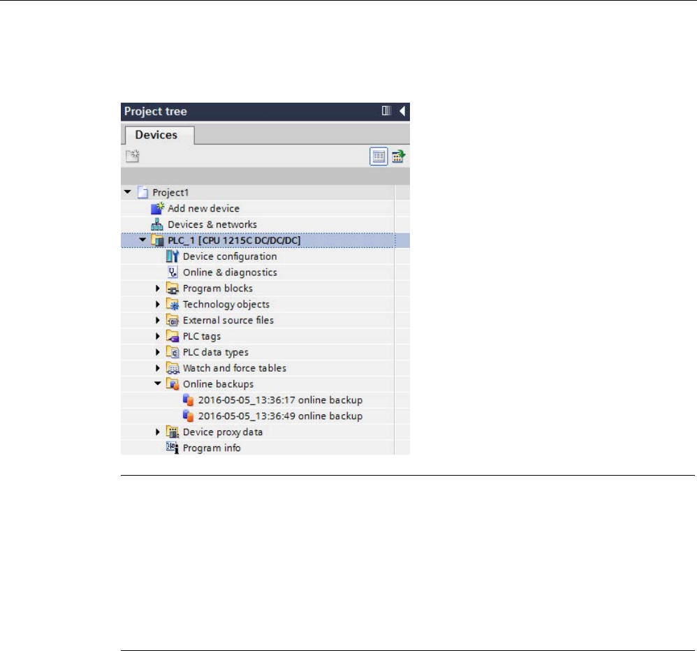
Online and diagnostic tools
15.17 Backing up and restoring a CPU
S7-1200 Programmable controller
System Manual, V4.2, 09/2016, A5E02486680-AK 1355
You can find the backup in the project tree under the CPU in the "Online backups" folder.The
following figure shows an S7-1200 CPU for which two backups have been created:
Note
Note that you can also back up the online CPU from the SIMATIC Automation Tool (SAT) or
the
Web server Online backup standard Web page (Page 1035).
When you back files up from STEP
7, STEP 7 stores the files within the STEP 7 project.
When
you back files up from the Web server, your PC or device saves the backup files in the
default folder for downloads. You cannot restore STEP
7 backup files from the Web server
and you cannot restore Web server backup files from STEP
7. You can, however, save
STEP
7 backup files directly to the download folder of your PC or device. If you do so, then
you can restore these files from the Web server.
Saving backup files to your PC or device
To save a backup file to your PC or device, follow these steps:
1. Right-click a file from the Online backups folder in the project tree.
2. Select "Save as" from the context menu.
3. Navigate to the folder where you want to save the file, for example the default folder for
downloads on your PC or device.
4. Click Save.

Online and diagnostic tools
15.17 Backing up and restoring a CPU
S7-1200 Programmable controller
1356 System Manual, V4.2, 09/2016, A5E02486680-AK
15.17.3
Restoring a CPU
If you have backed up the configuration of a CPU at an earlier point in time, you can transfer
the backup to the CPU. The CPU goes to STOP while restoring a backup. If an access level
is configured for the CPU, you must supply the password for read access to the CPU.
WARNING
Restoring backups with unknown content
If you restore a backup with unknown content, you can cause serious damage or injuries in
case of malfunctions or program errors.
Make sure that the backup consists of a configuration with known content.
Prerequisites
To restore a backup, you must meet the following prerequisites:
● The STEP 7 project includes a configuration for the CPU and a previously-made backup.
● The CPU is connected to the programming device/PC directly through the PROFINET
interface of the CPU.
● The CPU is in "STOP" mode.
● You know the password for full access to the CPU, if an access level was configured.

Online and diagnostic tools
15.17 Backing up and restoring a CPU
S7-1200 Programmable controller
System Manual, V4.2, 09/2016, A5E02486680-AK 1357
Procedure
To restore a backup, follow these steps:
1. Open the CPU in the project tree to display the lower-level objects.
2. Select the backup you want to restore from the "Online backups" folder.
3. From the "Online" menu, select the "Download to device" command.
– If you had previously established an online connection (Page 1313), the "Load
preview" dialog opens. This dialog displays alarms and recommends actions needed
for the loading operation.
– If you had not previously established an online connection, the "Extended download to
device" dialog opens, and you must first select the interface from which you want to
establish the online connection to the CPU.
4. Check the alarms in the "Load preview" dialog, and select the actions in the "Action"
column, if necessary.
5. Click the "Load" button (The "Load" button is selectable as soon as downloading is
possible.)
6. STEP 7 restores the backup to the CPU. From the "Load results" dialog, you can check
whether or not the loading operation was successful and take any further action that
might be necessary.
7. After reviewing the "Load results" dialog, click the "Finish" button.
If prompted, enter the password for full access to the CPU and confirm that the CPU can
enter "STOP" mode.
STEP 7 restores the contents of the backup to the CPU and restarts the CPU.
Note
Note that you can also restore a CPU backup from the
Web server Online backup standard
Web page
(Page 1035).

Online and diagnostic tools
15.17 Backing up and restoring a CPU
S7-1200 Programmable controller
1358 System Manual, V4.2, 09/2016, A5E02486680-AK

S7-1200 Programmable controller
System Manual, V4.2, 09/2016, A5E02486680-AK 1359
Technical specifications
A
A.1
Siemens Online Support website
Technical information for these products is available at the Siemens Industry Online Support
website (https://support.industry.siemens.com/cs/us/en/).
A.2
General technical specifications
Standards compliance
The S7-1200 automation system design conforms with the following standards and test
specifications. The test criteria for the S7-1200 automation system are based on these
standards and test specifications.
Note that not all S7-1200 models may be certified to these standards, and certification status
may change without notification. It is your responsibility to determine applicable certifications
by referring to the ratings marked on the product. Consult your local Siemens representative
if you need additional information related to the latest listing of exact approvals by part
number.
CE approval
The S7-1200 Automation System satisfies requirements and safety related objectives
according to the EC directives listed below, and conforms to the harmonized European
standards (EN) for the programmable controllers listed in the Official Journals of the
European Community.
● EC Directive 2006/95/EC (Low Voltage Directive) "Electrical Equipment Designed for Use
within Certain Voltage Limits"
– EN 61131-2 Programmable controllers - Equipment requirements and tests
● EC Directive 2004/108/EC (EMC Directive) "Electromagnetic Compatibility"
– Emission standard
EN 61000-6:+A1: Industrial Environment
– Immunity standard
EN 61000-6-2: Industrial Environment
● EC Directive 94/9/EC (ATEX) "Equipment and Protective Systems Intended for Use in
Potentially Explosive Atmosphere"
– EN 60079-0:+A11
– EN 60079-15: Type of Protection 'n'
Technical specifications
A.2 General technical specifications
S7-1200 Programmable controller
1360 System Manual, V4.2, 09/2016, A5E02486680-AK
The CE Declaration of Conformity is held on file available to competent authorities at:
Siemens AG
Sector Industry
DF FA AS DH AMB
Postfach 1963
D-92209 Amberg
Germany
cULus approval
Underwriters Laboratories Inc. complying with:
● Underwriters Laboratories, Inc.: UL 508 Listed (Industrial Control Equipment)
● Canadian Standards Association: CSA C22.2 Number 142 (Process Control Equipment)
Note
The SIMATIC S7
-1200 series meets the CSA standard.
The cULus logo indicates that the S7
-1200 has been examined and certified by
Underwriters Laboratories (UL) to standards UL 508 and CSA 22.2 No. 142.
FM approval
Factory Mutual Research (FM)
Approval Standard Class Number 3600 and 3611
Approved for use in:
Class I, Division 2, Gas Group A, B, C, D, Temperature Class T3C Ta = 60 °C
Class I, Zone 2, IIC, Temperature Class T3 Ta = 60 °C
Canadian Class I, Zone 2 Installation per CEC 18-150
IMPORTANT EXCEPTION: See Technical Specifications for the number of inputs or outputs
allowed on simultaneously. Some models are de-rated for Ta = 60 °C.
WARNING
Substitution of components can impair the suitability for Class I, Division 2 and Zone 2.
Repair of units should only be performed by an authorized Siemens Service Center.

Technical specifications
A.2 General technical specifications
S7-1200 Programmable controller
System Manual, V4.2, 09/2016, A5E02486680-AK 1361
IECEx approval
EN 60079-0: Explosive Atmospheres – General Requirements
EN60079-15: Electrical Apparatus for Potentially Explosive Atmospheres;
Type of protection ‘nA’
IECEX FMG14.0012X
Ex nA IIC Tx Gc
IECEx rating information may appear on the product with the FM Hazardous Location
information.
Only products marked with an IECEx rating are approved. Consult your local Siemens
representative if you need additional information related to the latest listing of exact
approvals by part number.
Relay models are not included in IECEx approvals.
Refer to specific product marking for temperature rating.
Install modules in a suitable enclosure providing a minimum degree of protection of IP54
according to IEC 60079-15.
ATEX approval
ATEX approval applies to DC models only. ATEX approval does not apply to AC and Relay
models.
EN 60079-0: Explosive Atmospheres - General Requirements
EN 60079-15: Electrical Apparatus for Potentially Explosive Atmospheres;
Type of protection 'nA'
II 3 G Ex nA IIC T4 or T3 Gc
Special conditions for safe use:
Install modules in a suitable enclosure providing a minimum degree of protection of IP54
according to EN 60529, or in a location providing an equivalent degree of protection.
Attached cables and conductors should be rated for the actual temperature measured under
rated conditions.
Provisions should be made to prevent the rated voltage at the power supply terminals from
being exceeded by transient disturbances of more than 119 V.
Australia and New Zealand - RCM Mark (Regulatory Compliance Mark)
The S7-1200 automation system satisfies requirements of standards to AS/NZS 61000.6.4
and IEC 610000-6-4 (Class A).
Korea Certification
The S7-1200 automation system satisfies the requirements of the Korean Certification (KC
Mark). It has been defined as Class A Equipment and is intended for industrial applications
and has not been considered for home use.

Technical specifications
A.2 General technical specifications
S7-1200 Programmable controller
1362 System Manual, V4.2, 09/2016, A5E02486680-AK
Eurasian Customs Union approval (Belarus, Kazakhstan, Russian Federation)
EAC (Eurasion Conformity): Declaration of Conformity according to Technical Regulation of
Customs Union (TR CU)
Maritime approval
The S7-1200 products are periodically submitted for special agency approvals related to
specific markets and applications. Consult your local Siemens representative if you need
additional information related to the latest listing of exact approvals by part number.
Classification societies:
● ABS (American Bureau of Shipping): U.S.A.
● BV (Bureau Veritas): France
● DNV (Det Norske Veritas): Norway
● GL (Germanischer Lloyd): German
● LRS (Lloyds Register of Shipping): England
● Class NK (Nippon Kaiji Kyokai): Japan
● Korean Register of Shipping: Korea
● CSS (China Classification Society): China
Industrial environments
The S7-1200 automation system is designed for use in industrial environments.
Table A- 1 Industrial environments
Application field
Emission requirements
Immunity requirements
Industrial
EN 61000-6-4:2007+A1
EN 61000-6-2:2005

Technical specifications
A.2 General technical specifications
S7-1200 Programmable controller
System Manual, V4.2, 09/2016, A5E02486680-AK 1363
Note
The S7
-1200 automation system is intended for use in industrial areas; use in residential
areas can have an impact on radio or TV reception. If you use the S7
-1200 in residential
areas, you must ensure that its radio inte
rference emission complies with the limit value
Class B in accordance with EN 55011.
Examples of suitable measures for achieving RF interference, level Class B include:
-
Installation of the S7-1200 in a grounded control cabinet
-
Use of noise filters in the supply lines
Ensure that the radio interference emission complies with Class B in accordance with EN
55011.
Individual acceptance is required (final installation must meet all safety and EMC
requirements of a residential installation).
Electromagnetic compatibility
Electromagnetic Compatibility (EMC) is the ability of an electrical device to operate as
intended in an electromagnetic environment and to operate without emitting levels of
electromagnetic interference (EMI) that may disturb other electrical devices in the vicinity.
Table A- 2 Immunity per EN 61000-6-2
Electromagnetic compatibility - Immunity per EN 61000-6-2
EN 61000-4-2
Electrostatic discharge
8 kV air discharge to all surfaces
6 kV contact discharge to exposed conductive surfaces
EN 61000-4-3
Radiated, radio-frequency, elec-
tromagnetic field immunity test
80 to 1000 MHz, 10 V/m, 80% AM at 1 kHz
1.4 to 2.0 GHz, 3 V/m, 80% AM at 1 kHz
2.0 to 2.7 GHz, 1 V/m, 80% AM at 1 kHz
EN 61000-4-4
Fast transient bursts
2 kV, 5 kHz with coupling network to AC and DC system power
2 kV, 5 kHz with coupling clamp to I/O
EN 6100-4-5
Surge immunity
AC systems - 2 kV common mode, 1 kV differential mode
DC systems - 2 kV common mode, 1 kV differential mode
For DC systems, refer to Surge immunity below
EN 61000-4-6
Conducted disturbances
150 kHz to 80 MHz, 10 V RMS, 80% AM at 1kHz
EN 61000-4-11
Voltage dips
AC systems
0% for 1 cycle, 40% for 12 cycles and 70% for 30 cycles at 60
Hz

Technical specifications
A.2 General technical specifications
S7-1200 Programmable controller
1364 System Manual, V4.2, 09/2016, A5E02486680-AK
Table A- 3 Conducted and radiated emissions per EN 61000-6-4
Electromagnetic compatibility - Conducted and radiated emissions per EN 61000-6-4
Conducted Emissions
EN 55016, Class A, Group 1
0.15 MHz to 0.5 MHz
<79dB (μV) quasi-peak; <66 dB (μV) average
0.5 MHz to 5 MHz <73dB (μV) quasi-peak; <60 dB (μV) average
5 MHz to 30 MHz
<73dB (μV) quasi-peak; <60 dB (μV) average
Radiated Emissions
EN 55016, Class A, Group 1
30 MHz to 230 MHz <40dB (μV/m) quasi-peak; measured at 10m
230 MHz to 1 GHz
<47dB (μV/m) quasi-peak; measured at 10m
1 GHz to 3 GHz
< 76dB (uV/m) quasi peak, measured at 10m
Surge immunity
Wiring systems subject to surges from lightning strike coupling must be equipped with
external protection. One specification for evaluation of protection from lightning type surges
is found in EN 61000-4-5, with operational limits established by EN 61000-6-2. S7-1200 DC
CPUs and signal modules require external protection to maintain safe operation when
subject to surge voltages defined by this standard.
Listed below are some devices that support the needed surge immunity protection. These
devices only provide the protection if they are properly installed according to the
manufacturer's recommendations. Devices manufactured by other vendors with the same or
better specifications can also be used:
Table A- 4 Devices that support surge immunity protection
Sub-system
Protection device
+24 V DC power
BLITZDUCTOR VT, BVT AVD 24, Part Number 918 422
Industrial Ethernet
DEHNpatch DPA M CLE RJ45B 48, Part Number 929 121
RS-485
BLITZDUCTOR XT, Basic Unit BXT BAS, Part Number 920 300
BLITZDUCTOR XT, Module BXT ML2 BD HFS 5, Part Number 920 271
RS-232
BLITZDUCTOR XT, Basic Unit BXT BAS, Part Number 920 300
BLITZDUCTOR XT, Module BXT ML2 BE S 12, Part Number 920 222
+24 V DC digital inputs
DEHN, Inc., Type DCO SD2 E 24, Part Number 917 988
+24 V DC digital outputs
and sensor supply
DEHN, Inc., Type DCO SD2 E 24, Part Number 917 988
Analog IO
DEHN, Inc., Type DCO SD2 E 12, Part Number 917 987
Relay outputs
None required

Technical specifications
A.2 General technical specifications
S7-1200 Programmable controller
System Manual, V4.2, 09/2016, A5E02486680-AK 1365
Environmental conditions
Table A- 5 Transport and storage
Environmental conditions - Transport and storage
EN 60068-2-2, Test Bb, Dry heat and
EN 60068-2-1, Test Ab, Cold
-40 °C to +70 °C
EN 60068-2-30, Test Db, Damp heat
25 °C to 55 °C, 95% humidity
EN 60068-2-14, Test Na, temperature
shock
-40 °C to +70 °C, dwell time 3 hours, 2 cycles
EN 60068-2-32, Free fall
0.3 m, 5 times, product packaging
Atmospheric pressure 1080 to 660 hPa (corresponding to an altitude of -1000
to 3500 m)
Table A- 6 Operating conditions
Environmental conditions - Operating
Ambient temperature range
(Inlet Air 25 mm below unit)
-20 °C to 60 °C horizontal mounting
-20 °C to 50 °C vertical mounting
95% non-condensing humidity
Unless otherwise specified
Atmospheric pressure 1080 to 795 hPa (corresponding to an altitude of -1000
to 5000 m)
Concentration of contaminants
S02: < 0.5 ppm; H2S: < 0.1 ppm; RH < 60% non-
condensing
ISA-S71.04 severity level G1, G2, G3
EN 60068-2-14, Test Nb, temperature
change
5 °C to 55 °C, 3 K/minute
EN 60068-2-27 Mechanical shock
15 g, 11 ms pulse, 6 shocks in each of 3 axis
EN 60068-2-6 Sinusoidal vibration DIN rail mount: 3.5 mm from 5-9 Hz, 1G from 8.4 - 150
Hz
Panel Mount: 7.0 mm from 5-8.4 Hz, 2G from 8.4 to 150
Hz
10 sweeps each axis, 1 octave per minute
Contamination level/overvoltage category according to IEC 61131-2
● Polution degree 2
● Overvoltage category: II
Protection class
● Protection Class II according to EN 61131-2 (Protective conductor not required)

Technical specifications
A.2 General technical specifications
S7-1200 Programmable controller
1366 System Manual, V4.2, 09/2016, A5E02486680-AK
Degree of protection
● IP20 Mechanical Protection, EN 60529
● Protects against finger contact with high voltage as tested by standard probe. External
protection required for dust, dirt, water and foreign objects of < 12.5mm in diameter.
Rated voltages
Table A- 7 Rated voltages
Rated voltage
Tolerance
24 V DC
20.4 V DC to 28.8 V DC
120/230 V AC 85 V AC to 264 V AC, 47 to 63 Hz
Note
When a mechanical contact turns on output power to the S7
-1200 CPU, or any digital
expansion module, it sends a "1
" signal to the digital outputs for approximately 50
microseconds. This could cause unexpected machine or process operation which could
result in death or serious injury to personnel and/or damage to equipment. You must plan for
this, especially if you are
using devices which respond to short duration pulses.
Reverse voltage protection
Reverse voltage protection circuitry is provided on each terminal pair of +24 V DC power or
user input power for CPUs, signal modules (SMs), and signal boards (SBs). It is still possible
to damage the system by wiring different terminal pairs in opposite polarities.
Some of the 24 V DC power input ports in the S7-1200 system are interconnected, with a
common logic circuit connecting multiple M terminals. For example, the following circuits are
interconnected when designated as "not isolated" in the data sheets: the 24 V DC power
supply of the CPU, the sensor power of the CPU, the power input for the relay coil of an SM,
and the power supply for a non-isolated analog input. All non-isolated M terminals must
connect to the same external reference potential.
WARNING
Connecting non-isolated M terminals to different reference potentials will cause unintended
current flows that may cause damage or unpredictable operation in the PLC and any
connected equipment.
Failure to comply with these guidelines could cause damage or unpredictable operation
which could result in death or severe personal injury and/or property damage.
Always ensure that all non-isolated M terminals in an S7-1200 system are connected to the
same reference potential.

Technical specifications
A.2 General technical specifications
S7-1200 Programmable controller
System Manual, V4.2, 09/2016, A5E02486680-AK 1367
DC Outputs
Short -circuit protection circuitry is not provided for DC outputs on CPUs, signal modules
(SMs) and signal boards (SBs).
Relay electrical service life
The typical performance data estimated from sample tests is shown below. Actual
performance may vary depending upon your specific application. An external protection
circuit that is adapted to the load will enhance the service life of the contacts. N.C. contacts
have a typical service life of about one-third that of the N.O. contact under inductive and
lamp load conditions.
An external protective circuit will increase the service life of the contacts.
Table A- 8 Typical performance data
Data for selecting an actuator
Continuous thermal current
2 A max.
Switching capacity and life of the contacts
For ohmic load Voltage Current Number of operating cycles
(typical)
24 V DC 2.0 A 0.1 million
24 V DC
1.0 A
0.2 million
24 V DC
0.5 A
1.0 million
48 V AC
1.5 A
1.5 million
60 V AC
1.5 A
1.5 million
120 V
AC
2.0 A 1.0 million
120 V
AC
1.0 A 1.5 million
120 V
AC
0.5 A 2.0 million
230 V
AC
2.0 A 1.0 million
230 V
AC
1.0 A 1.5 million
230 V
AC
0.5 A 2.0 million
For inductive load (according to
IEC 947-5-1 DC13/AC15)
Voltage Current Number of operating cycles
(typical)
24 V DC
2.0 A
0.05 million
24 V DC
1.0 A
0.1 million
24 V DC
0.5 A
0.5 million
24 V AC
1.5 A
1.0 million
48 V AC
1.5 A
1.0 million
60 V AC
1.5 A
1.0 million
120 V
AC
2.0 A 0.7 million

Technical specifications
A.2 General technical specifications
S7-1200 Programmable controller
1368 System Manual, V4.2, 09/2016, A5E02486680-AK
Data for selecting an actuator
120 V
AC
1.0 A 1.0 million
120 V
AC
0.5 A 1.5 million
230 V
AC
2.0 A 0.7 million
230 V
AC
1.0 A 1.0 million
230 V
AC
0.5 A 1.5 million
Activating a digital input
Possible
Switching frequency
Mechanical
Max. 10 Hz
At ohmic load
Max. 1 Hz
At inductive load (according to IEC
947-5-1 DC13/AC15)
Max. 0.5 Hz
At lamp load
Max. 1Hz
Internal CPU memory retention
● Lifetime of retentive data and data log data: 10 years
● Power down retentive data, Write cycle endurance: 2 million cycles
● Data log data, up to 2 KB per data log entry, Write cycle endurance: 500 million data log
entries
Note
Effect of data logs on internal CPU memory
Each data log write consumes at a minimum 2 KB of memory. If your program writes small
amounts of data frequently, it is consuming at least 2 KB of memory on each write. A better
implementation would be to accumulate the small
data items in a data block (DB), and to
write the data block to the data log at less frequent intervals.
If your program writes many data log entries at a high frequency, consider using a
replaceable SD memory card.
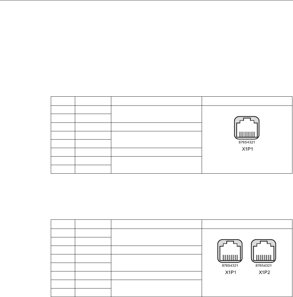
Technical specifications
A.3 PROFINET interface X1 port pinouts
S7-1200 Programmable controller
System Manual, V4.2, 09/2016, A5E02486680-AK 1369
A.3
PROFINET interface X1 port pinouts
The S7-1200 CPU connects to the PROFINET network using a standard female RJ45 jack.
The connector pinout depends on the CPU type.
Single-port CPUs
Single-port CPUs (CPU 1211C, CPU 1212C and CPU 1214C) have a standard Ethernet MDI
pin configuration as follows:
Pin
Signal name
Description
RJ45 female jack pinout
1
TD+
Transmit data
2 TD-
3
RD+
Receive data
4 GND Ground
5
GND
6
RD-
Receive data
7
GND
Ground
8
GND
Dual-port CPUs
The ports of a dual-port CPU (CPU 1215C and CPU1217C) have a standard Ethernet MDI-X
pin configuration as follows:
Pin
Signal name
Description
RJ45 female jack pinout
1
RD+
Receive data
2
RD-
3
TD+
Transmit data
4
GND
Ground
5
GND
6
TD-
Transmit data
7
GND
Ground
8
GND
Autonegotiation
If the port’s configuration enables autonegotiation, the S7-1200 CPU automatically detects
the cable type and swaps the transmit/receive lines, if needed. If the port’s configuration
disables autonegotiation, the CPU also disables this automatic swap. You configure a port’s
autonegotiation setting in the TIA Portal’s port options dialog. This is a port-specific
advanced option for the PROFINET interface (X1) of the CPU’s properties. Refer to
"Configuring the PROFINET port" in Section 11.2.3.4: "Configuring an IP address for a CPU
in your project" (Page 814) for further information.

Technical specifications
A.4 CPU 1211C
S7-1200 Programmable controller
1370 System Manual, V4.2, 09/2016, A5E02486680-AK
A.4
CPU 1211C
A.4.1
General specifications and features
Table A- 9 General specifications
Technical data
CPU 1211C
AC/DC/Relay
CPU 1211C
DC/DC/Relay
CPU 1211C
DC/DC/DC
Article number
6ES7211-1BE40-0XB0
6ES7211-1HE40-0XB0
6ES7211-1AE40-0XB0
Dimensions W x H x D (mm) 90 x 100 x 75
Shipping weight
420 grams
380 grams
370 grams
Power dissipation 10 W 8 W
Current available (CM bus)
750 mA max. (5 V DC)
Current available (24 V DC)
300 mA max. (sensor power)
Digital input current consumption
(24 V DC)
4 mA/input used
Table A- 10 CPU features
Technical data
Description
User memory
(Refer to "General
technical specifica-
tions"
(Page 1359), "In-
ternal CPU
memory reten-
tion".)
Work
50 Kbytes
Load
1 Mbyte internal, expandable up to SD card size
Retentive 10 Kbytes
On-board digital I/O
6 inputs/4 outputs
On-board analog I/O
2 inputs
Process image size
1024 bytes of inputs (I) /1024 bytes of outputs (Q)
Bit memory (M)
4096 bytes
Temporary (local) memory • 16 Kbytes for startup and program cycle (including associated FBs and
FCs)
• 6 Kbytes for each of the other interrupt priority levels (including FBs and
FCs)
Signal modules expansion
none
SB, CB, BB expansion
1 max.
Communication module expansion
3 CMs max.
High-speed counters Up to 6 configured to use any built-in or SB inputs. Refer to "Hardware input
pin assignment" (Page 580) for CPU 1211C: HSC default address assign-
ments.
100/
1
80 kHz (Ia.0 to Ia.5)

Technical specifications
A.4 CPU 1211C
S7-1200 Programmable controller
System Manual, V4.2, 09/2016, A5E02486680-AK 1371
Technical data
Description
Pulse outputs2 Up to 4 configured to use any built-in or SB outputs
100 kHz (Qa.0 to Qa.3)
Pulse catch inputs
6
Time delay interrupts
4 total with 1 ms resolution
Cyclic interrupts 4 total with 1 ms resolution
Edge interrupts
6 rising and 6 falling (10 and 10 with optional signal board)
Memory card
SIMATIC memory card (optional)
Real time clock accuracy
+/- 60 seconds/month
Real time clock retention time
20 days typ./12 days min. at 40 °C (maintenance-free Super Capacitor)
1
The slower speed is applicable when the HSC is configured for quadrature mode of operation.
2 For CPU models with relay outputs, you must install a digital signal board (SB) to use the pulse outputs.
Table A- 11 Performance
Type of instruction
Execution speed
Direct addressing (I, Q and M)
DB accesses
Boolean
0.08 μs/instruction
Move
Move_Bool
0.3 μs/instruction
1.17 μs/instruction
Move_Word
0.137 μs/instruction
1.0 μs/instruction
Move_Real
0.72 μs/instruction
1.0 μs/instruction
Real Math
Add Real
1.48 μs/instruction
1.78 μs/instruction
Note
Many variables affect measured times. The above performance times are for the fastest
instructions in this category and error
-free programs.

Technical specifications
A.4 CPU 1211C
S7-1200 Programmable controller
1372 System Manual, V4.2, 09/2016, A5E02486680-AK
A.4.2
Timers, counters, and code blocks supported by CPU 1211C
Table A- 12 Blocks, timers and counters supported by CPU 1211C
Element
Description
Blocks
Type
OB, FB, FC, DB
Size 30 Kbytes
Quantity
Up to 1024 blocks total (OBs + FBs + FCs + DBs)
Address range for FBs, FCs,
and DBs
FB and FC: 1 to 65535 (such as FB 1 to FB 65535)
DB: 1 to 59999
Nesting depth 16 from the program cycle or startup OB
6 from any interrupt event OB
Monitoring
Status of 2 code blocks can be monitored simultaneously
OBs
Program cycle
Multiple
Startup
Multiple
Time-delay interrupt
4 (1 per event)
Cyclic interrupts
4 (1 per event)
Hardware interrupts
50 (1 per event)
Time error interrupts
1
Diagnostic error interrupts
1
Pull or plug of modules
1
Rack or station failure
1
Time of day
Multiple
Status
1
Update
1
Profile
1
MC-Interpolator
1
MC-Servo 1
MC-PreServo
1
MC-PostServo 1
Timers
Type
IEC
Quantity
Limited only by memory size
Storage
Structure in DB, 16 bytes per timer
Counters
Type
IEC
Quantity
Limited only by memory size
Storage Structure in DB, size dependent upon count type
• SInt, USInt: 3 bytes
• Int, UInt: 6 bytes
• DInt, UDInt: 12 bytes

Technical specifications
A.4 CPU 1211C
S7-1200 Programmable controller
System Manual, V4.2, 09/2016, A5E02486680-AK 1373
Table A- 13 Communication
Technical data
Description
Number of ports
1
Type Ethernet
HMI device
4
Programming device (PG) 1
Connections • 8 for Open User Communication (active or passive): TSEND_C,
TRCV_C, TCON, TDISCON, TSEND, and TRCV
• 3 for server GET/PUT (CPU-to-CPU) S7 communication
• 8 for client GET/PUT (CPU-to-CPU) S7 communication
Data rates
10/100 Mb/s
Isolation (external signal to logic)
Transformer isolated, 1500 V AC (type test)
1
Cable type
CAT5e shielded
Interfaces
Number of PROFINET interfaces
1
Number of interfaces PROFIBUS
0
Interface
Interface Hardware
Number of ports
1
Integrated switch
No
RJ-45 (Ethernet)
Yes; X1
Protocols
PROFINET IO controller
Yes
PROFINET IO device
Yes
SIMATIC communication
Yes
Open IE communication
Yes
Web server
Yes
Media redundancy No
PROFINET IO controller
Services
PG/OP communication
Yes
S7 routing
Yes
Isochronous mode
No
Open IE communication
Yes
IRT
No
MRP
No
PROFIenergy Yes. The S7-1200 CPU only supports the PROFIenergy entity (with I-
device functionality).
Prioritized startup
Yes (max. 16 PROFINET devices)
Number of connectable I/O devices max.
16
Number of IO devices that you can connect for
RT, max.
16
Of which are in line, max.
16

Technical specifications
A.4 CPU 1211C
S7-1200 Programmable controller
1374 System Manual, V4.2, 09/2016, A5E02486680-AK
Technical data
Description
Number of IO devices that can be activated/ deac-
tivated simultaneously, max.
8
Update times The minimum value of the update time also depends on the commu-
nication component set for PROFINET IO, on the number of IO devic-
es, and the quantity of configured user data.
With RT
Send clock of 1 ms
1 ms to 512 ms
PROFINET IO device
Services
PG/OP communication
Yes
S7 routing
Yes
Isochronous mode
No
Open IE communication
Yes
IRT, supported
No
MRP, supported
No
PROFIenergy
Yes
Shared device
Yes
Number of IO controllers with shared device, max.
2
SIMATIC communication
S7 communication, as server
Yes
S7 communication, as client
Yes
User data per job, max.
See online help (S7 communication, user data size)
Open IE communication
TCP/IP: Yes
Data length, max.
8 KB
Several passive connections per port,
supported
Yes
ISO-on-TCP (RFC1006):
Yes
Data length, max.
8 KB
UDP
Yes
Data length, max.
1472 bytes
DHCP
No
SNMP
Yes
DCP
Yes
LLDP
Yes
1
Ethernet port isolation is designed to limit hazard during short term network faults to hazardous voltages. It does not
conform to safety requirements for routine AC line voltage isolation.

Technical specifications
A.4 CPU 1211C
S7-1200 Programmable controller
System Manual, V4.2, 09/2016, A5E02486680-AK 1375
Table A- 14 Power supply
Technical data
CPU 1211C
AC/DC/Relay
CPU 1211C
DC/DC/Relay
CPU 1211C
DC/DC/DC
Voltage range
85 to 264 V AC
20.4 V DC to 28.8 V DC
Line frequency 47 to 63 Hz --
Input current CPU only at max. load 60 mA at 120 V AC
30 mA at 240 V AC
300 mA at 24 V DC 300 mA at 24 V DC
CPU with all expansion
accessories at max. load
180 mA at 120 V AC
90 mA at 240 V AC
900 mA at 24 V DC
Inrush current (max.)
20 A at 264 V AC
12 A at 28.8 V DC
Isolation (input power to logic)
1500 V AC
Not isolated
Ground leakage, AC line to functional
earth
0.5 mA max. --
Hold up time (loss of power) 20 ms at 120 V AC
80 ms at 240 V AC
10 ms at 24 V DC
Internal fuse, not user replaceable
3 A, 250 V, slow blow
Table A- 15 Sensor power
Technical data
CPU 1211C
AC/DC/Relay
CPU 1211C
DC/DC/Relay
CPU 1211C
DC/DC/DC
Voltage range
20.4 to 28.8 V DC
L+ minus 4 V DC min.
Output current rating (max.)
300 mA (short-circuit protected)
Maximum ripple noise (<10 MHz)
< 1 V peak to peak
Same as input line
Isolation (CPU logic to sensor power)
Not isolated

Technical specifications
A.4 CPU 1211C
S7-1200 Programmable controller
1376 System Manual, V4.2, 09/2016, A5E02486680-AK
A.4.3
Digital inputs and outputs
Table A- 16 Digital inputs
Technical data
CPU 1211C AC/DC/Relay, CPU 1211C DC/DC/Relay, and
CPU 1211C DC/DC/DC
Number of inputs
6
Type Sink/Source (IEC Type 1 sink)
Rated voltage
24 V DC at 4 mA, nominal
Continuous permissible voltage 30 V DC, max.
Surge voltage
35 V DC for 0.5 sec.
Logic 1 signal (min.)
15 V DC at 2.5 mA
Logic 0 signal (max.)
5 V DC at 1 mA
Isolation (field side to logic)
707 V DC (type test)
Isolation groups
1
Filter times us settings: 0.1, 0.2, 0.4, 0.8, 1.6, 3.2, 6.4, 10.0, 12.8, 20.0
ms settings: 0.05, 0.1, 0.2, 0.4, 0.8, 1.6, 3.2, 6.4, 10.0, 12.8, 20.0
HSC clock input rates (max.)
(Logic 1 Level = 15 to 26 V DC)
100/80 kHz (Ia.0 to Ia.5)
Number of inputs on simultaneously
6 at 60 °C horizontal, 50 °C vertical
Cable length (meters)
500 m shielded, 300 m unshielded, 50 m shielded for HSC inputs
Table A- 17 Digital outputs
Technical data
CPU 1211C AC/DC/Relay and
CPU 1211C DC/DC/Relay
CPU 1211C DC/DC/DC
Number of outputs
4
Type
Relay, mechanical
Solid state - MOSFET (sourcing)
Voltage range
5 to 30 V DC or 5 to 250 V AC
20.4 to 28.8 V DC
Logic 1 signal at max. current
--
20 V DC min.
Logic 0 signal with 10 KΩ load
--
0.1 V DC max.
Current (max.)
2.0 A
0.5 A
Lamp load
30 W DC / 200 W AC
5 W
ON state resistance 0.2 Ω max. when new 0.6 Ω max.
Leakage current per point
--
10 μA max.
Surge current
7 A with contacts closed
8 A for 100 ms max.
Overload protection
No
Isolation (field side to logic) 1500 V AC
(coil to contact)
None (coil to logic)
707 V DC (type test)
Isolation groups
1
Inductive clamp voltage
--
L+ minus 48 V DC, 1 W dissipation
Maximum relay switching frequency
1 Hz
--

Technical specifications
A.4 CPU 1211C
S7-1200 Programmable controller
System Manual, V4.2, 09/2016, A5E02486680-AK 1377
Technical data
CPU 1211C AC/DC/Relay and
CPU 1211C DC/DC/Relay
CPU 1211C DC/DC/DC
Switching delay (Qa.0 to Qa.3) 10 ms max. 1.0 μs max., off to on
3.0 μs max., on to off
Pulse Train Output rate Not recommended 1 100 kHz (Qa.0 to Qa.3)2, 2 Hz min.
Lifetime mechanical (no load)
10,000,000 open/close cycles
--
Lifetime contacts at rated load
100,000 open/close cycles
--
Behavior on RUN to STOP Last value or substitute value
(default value 0)
Number of outputs on simultaneously
4 at 60 °C horizontal, 50 °C vertical
Cable length (meters) 500 m shielded,
150 m unshielded
1
For CPU models with relay outputs, you must install a digital signal board (SB) to use the pulse outputs.
2
Depending on your pulse receiver and cable, an additional load resistor (at least 10% of rated current) may improve
pulse signal quality and noise immunity.
A.4.4
Analog inputs
Table A- 18 Analog inputs
Technical data
Description
Number of inputs
2
Type
Voltage (single-ended)
Full-scale range
0 to 10 V
Full-scale range (data word)
0 to 27648
Overshoot range
10.001 to 11.759 V
Overshoot range (data word)
27649 to 32511
Overflow range
11.760 to 11.852 V
Overflow range (data word)
32512 to 32767
Resolution
10 bits
Maximum withstand voltage
35 V DC
Smoothing None, Weak, Medium, or Strong
See the table for Step response (ms) for the analog inputs of the CPU
(Page 1378).
Noise rejection
10, 50, or 60 Hz
Impedance ≥100 KΩ
Isolation (field side to logic)
None
Accuracy (25 °C / -20 to 60 °C)
3.0% / 3.5% of full-scale
Cable length (meters)
100 m, shielded twisted pair

Technical specifications
A.4 CPU 1211C
S7-1200 Programmable controller
1378 System Manual, V4.2, 09/2016, A5E02486680-AK
A.4.4.1
Step response of the built-in analog inputs of the CPU
Table A- 19 Step Response (ms), 0 V to 10 V measured at 95%
Smoothing selection (sample averaging)
Rejection frequency (Integration time)
60 Hz
50 Hz
10 Hz
None (1 cycle): No averaging 50 ms 50 ms 100 ms
Weak (4 cycles): 4 samples
60ms
70 ms
200 ms
Medium (16 cycles): 16 samples
200 ms
240 ms
1150 ms
Strong (32 cycles): 32 samples
400 ms
480 ms
2300 ms
Sample time
4.17 ms
5 ms
25 ms
A.4.4.2
Sample time for the built-in analog ports of the CPU
Table A- 20 Sample time for built-in analog inputs of the CPU
Rejection frequency (Integration time selection)
Sample time
60 Hz (16.6 ms)
4.17 ms
50 Hz (20 ms)
5 ms
10 Hz (100 ms)
25 ms
A.4.4.3
Measurement ranges of the analog inputs for voltage (CPUs)
Table A- 21 Analog input representation for voltage (CPUs)
System
Voltage Measuring Range
Decimal
Hexadecimal
0 to 10 V
32767
7FFF
11.852 V
Overflow
32512
7F00
32511
7EFF
11.759 V
Overshoot range
27649
6C01
27648
6C00
10 V
Rated range
20736
5100
7.5 V
34
22
12 mV
0
0
0 V
Negative values Negative values are not sup-
ported
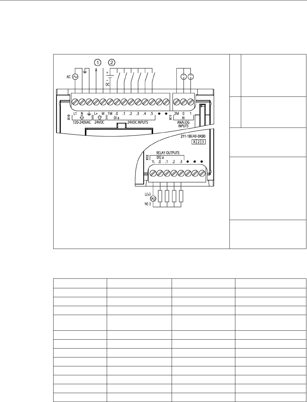
Technical specifications
A.4 CPU 1211C
S7-1200 Programmable controller
System Manual, V4.2, 09/2016, A5E02486680-AK 1379
A.4.5
CPU 1211C wiring diagrams
Table A- 22 CPU 1211C AC/DC/Relay (6ES7211-1BE40-0XB0)
①
24 V DC Sensor Power
Out
For additional noise
immunity, connect "M" to
chassis ground even if
not using sensor supply.
②
For sinking inputs, con-
nect "-" to "M" (shown).
For sourcing inputs,
connect "+" to "M".
Note 1: X11 connectors must
be gold. See Appendix C,
Spare Parts for article num-
ber.
Note 2: Either the L1 or N
(L2) terminal can be con-
nected to a voltage source
up to 240 V AC. The N ter-
minal can be considered L2
and is not required to be
grounded. No polarization is
required for L1 and N (L2)
terminals.
Note 3: See Device Configu-
ration (Page 153) for infor-
mation about the Ethernet
port of the CPU.
Table A- 23 Connector pin locations for CPU 1211C AC/DC/Relay (6ES7211-1BE40-0XB0)
Pin
X10
X11 (gold)
X12
1
L1 / 120-240 V AC
2 M
1L
2
N / 120-240 V AC
AI 0
DQ a.0
3
Functional Earth
AI 1
DQ a.1
4 L+ / 24 V DC Sensor
Out
-- DQ a.2
5
M / 24 V DC Sensor Out
--
DQ a.3
6
1M
--
No connection
7
DI a.0
--
No connection
8
DI a.1
--
No connection
9
DI a.2
--
--
10
DI a.3
--
--
11
DI a.4
--
--
12
DI a.5
--
--
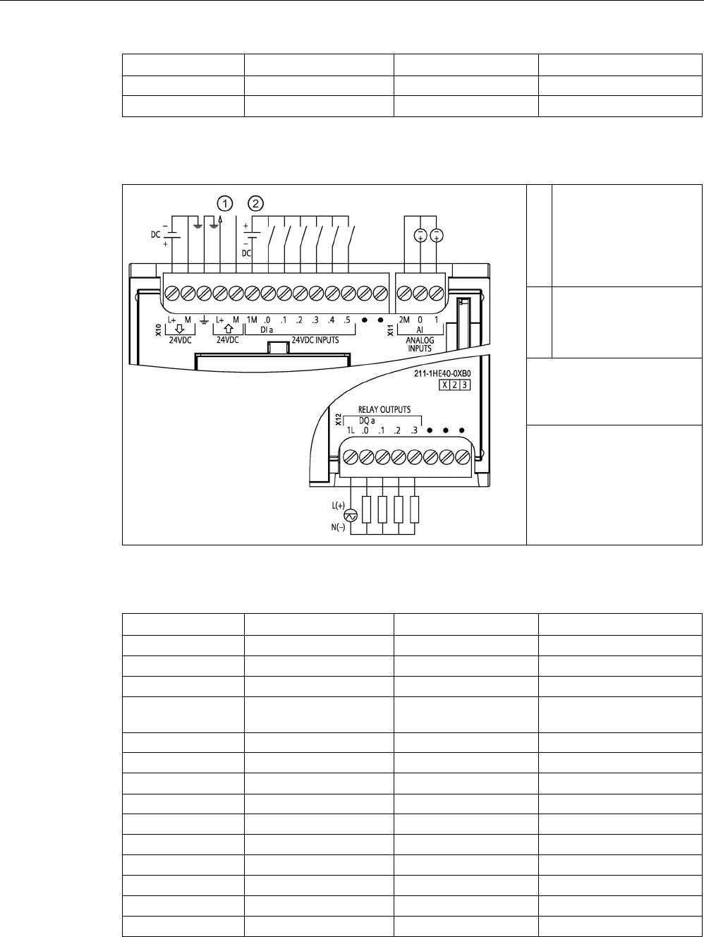
Technical specifications
A.4 CPU 1211C
S7-1200 Programmable controller
1380 System Manual, V4.2, 09/2016, A5E02486680-AK
Pin
X10
X11 (gold)
X12
13
No connection
--
--
14 No connection -- --
Table A- 24 CPU 1211C DC/DC/Relay (6ES7211-1HE40-0XB0)
①
24 V DC Sensor Power
Out
For additional noise
immunity, connect "M" to
chassis ground even if
not using sensor supply.
②
For sinking inputs, con-
nect "-" to "M" (shown).
For sourcing inputs,
connect "+" to "M".
Note 1: X11 connectors must
be gold. See Appendix C,
Spare Parts for article num-
ber.
Note 2: See Device Configu-
ration (Page 153) for infor-
mation about the Ethernet
port of the CPU.
Table A- 25 Connector pin locations for CPU 1211C DC/DC/Relay (6ES7211-1HE40-0XB0)
Pin
X10
X11 (gold)
X12
1
L+ / 24 V DC
2 M
1L
2
M / 24 V DC
AI 0
DQ a.0
3
Functional Earth
AI 1
DQ a.1
4 L+ / 24 V DC Sensor
Out
-- DQ a.2
5
M / 24 V DC Sensor Out
--
DQ a.3
6
1M
--
No connection
7 DI a.0 -- No connection
8
DI a.1
--
No connection
9
DI a.2
--
--
10
DI a.3
--
--
11
DI a.4
--
--
12
DI a.5
--
--
13
No connection
--
--
14
No connection
--
--
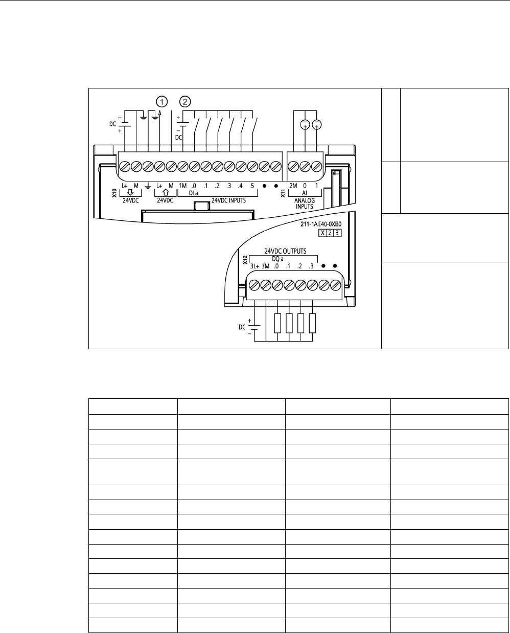
Technical specifications
A.4 CPU 1211C
S7-1200 Programmable controller
System Manual, V4.2, 09/2016, A5E02486680-AK 1381
Table A- 26 CPU 1211C DC/DC/DC (6ES7211-1AE40-0XB0)
①
24 V DC Sensor Power
Out
For additional noise
immunity, connect "M" to
chassis ground even if
not using sensor supply.
②
For sinking inputs, con-
nect "-" to "M" (shown).
For sourcing inputs,
connect "+" to "M".
Note 1: X11 connectors must
be gold. See Appendix C,
Spare Parts for article num-
ber.
Note 2: See Device Configu-
ration (Page 153) for infor-
mation about the Ethernet
port of the CPU.
Table A- 27 Connector pin locations for CPU 1211C DC/DC/DC (6ES7211-1AE40-0XB0)
Pin
X10
X11 (gold)
X12
1
L+ / 24 V DC
2 M
3L+
2
M / 24 V DC
AI 0
3M
3
Functional Earth
AI 1
DQ a.0
4 L+ / 24 V DC Sensor
Out
-- DQ a.1
5
M / 24 V DC Sensor Out
--
DQ a.2
6
1M
--
DQ a.3
7 DI a.0 -- No connection
8
DI a.1
--
No connection
9
DI a.2
--
--
10
DI a.3
--
--
11
DI a.4
--
--
12
DI a.5
--
--
13
No connection
--
--
14
No connection
--
--

Technical specifications
A.5 CPU 1212C
S7-1200 Programmable controller
1382 System Manual, V4.2, 09/2016, A5E02486680-AK
Note
Unused analog inputs should be shorted.
A.5
CPU 1212C
A.5.1
General specifications and features
Table A- 28 General
Technical data
CPU 1212C
AC/DC/Relay
CPU 1212C
DC/DC/Relay
CPU 1212C
DC/DC/DC
Article number
6ES7212-1BE40-0XB0
6ES7212-1HE40-0XB0
6ES7212-1AE40-0XB0
Dimensions W x H x D (mm)
90 x 100 x 75
Shipping weight
425 grams
385 grams
370 grams
Power dissipation
11 W
9 W
Current available
(SM and CM bus)
1000 mA max. (5 V DC)
Current available (24 V DC)
300 mA max. (sensor power)
Digital input current consumption
(24 V DC)
4 mA/input used
Table A- 29 CPU features
Technical data
Description
User memory
(Refer to "General
technical specifica-
tions
(Page 1359)",
"Internal CPU
memory reten-
tion".)
Work
75 Kbytes
Load
2 Mbytes internal, expandable up to SD card size
Retentive 10 Kbytes
On-board digital I/O
8 inputs/6 outputs
On-board analog I/O
2 inputs
Process image size
1024 bytes of inputs (I)/1024 bytes of outputs (Q)
Bit memory (M)
4096 bytes
Temporary (local) memory • 16 Kbytes for startup and program cycle (including associated FBs and FCs)
• 6 Kbytes for each of the other interrupt priority levels (including FBs and FCs)
Signal modules expansion
2 SMs max.
SB, CB, BB expansion
1 max.

Technical specifications
A.5 CPU 1212C
S7-1200 Programmable controller
System Manual, V4.2, 09/2016, A5E02486680-AK 1383
Technical data
Description
Communication module expansion
3 CMs max.
High-speed counters Up to 6 configured to use any built-in or SB inputs. Refer to "Hardware input pin
assignment" (Page 580) for CPU 1212C: HSC default address assignments.
• 100/180 kHz (Ia.0 to Ia.5)
• 30 /120 kHz (Ia.6 to Ia.7)
Pulse outputs2 Up to 4 configured to use any built-in or SB outputs
• 100 kHz (Qa.0 to Qa.3)
• 20 kHz (Qa.4 to Qa.5)
Pulse catch inputs 8
Time delay interrupts
4 total with 1 ms resolution
Cyclic interrupts
4 total with 1 ms resolution
Edge interrupts
8 rising and 8 falling (12 and 12 with optional signal board)
Memory card
SIMATIC memory card (optional)
Real time clock accuracy
+/- 60 seconds/month
Real time clock retention time
20 days typ./12 days min. at 40 °C (maintenance-free Super Capacitor)
1
The slower speed is applicable when the HSC is configured for quadrature mode of operation.
2 For CPU models with relay outputs, you must install a digital signal board (SB) to use the pulse outputs.
Table A- 30 Performance
Type of instruction
Execution speed
Direct addressing (I, Q and M)
DB accesses
Boolean
0.08 μs/instruction
Move
Move_Bool
0.3 μs/instruction
1.17 μs/instruction
Move_Word
0.137 μs/instruction
1.0 μs/instruction
Move_Real
0.72 μs/instruction
1.0 μs/instruction
Real Math
Add Real
1.48 μs/instruction
1.78 μs/instruction
Note
Many var
iables affect measured times. The above performance times are for the fastest
instructions in this category and error
-free programs.

Technical specifications
A.5 CPU 1212C
S7-1200 Programmable controller
1384 System Manual, V4.2, 09/2016, A5E02486680-AK
A.5.2
Timers, counters, and code blocks supported by CPU 1212C
Table A- 31 Blocks, timers and counters supported by CPU 1212C
Element
Description
Blocks
Type
OB, FB, FC, DB
Size 50 Kbytes
Quantity
Up to 1024 blocks total (OBs + FBs + FCs + DBs)
Address range for FBs, FCs,
and DBs
FB and FC: 1 to 65535 (such as FB 1 to FB 65535)
DB: 1 to 59999
Nesting depth 16 from the program cycle or startup OB
6 from any interrupt event OB
Monitoring
Status of 2 code blocks can be monitored simultaneously
OBs
Program cycle
Multiple
Startup
Multiple
Time-delay interrupt
4 (1 per event)
Cyclic interrupts
4 (1 per event)
Hardware interrupts
50 (1 per event)
Time error interrupts
1
Diagnostic error interrupts
1
Pull or plug of modules
1
Rack or station failure
1
Time of day
Multiple
Status
1
Update
1
Profile
1
MC-Interpolator
1
MC-Servo 1
MC-PreServo
1
MC-PostServo 1
Timers
Type
IEC
Quantity
Limited only by memory size
Storage
Structure in DB, 16 bytes per timer
Counters
Type
IEC
Quantity
Limited only by memory size
Storage Structure in DB, size dependent upon count type
• SInt, USInt: 3 bytes
• Int, UInt: 6 bytes
• DInt, UDInt: 12 bytes

Technical specifications
A.5 CPU 1212C
S7-1200 Programmable controller
System Manual, V4.2, 09/2016, A5E02486680-AK 1385
Table A- 32 Communication
Technical data
Description
Number of ports
1
Type Ethernet
HMI device
4
Programming device (PG) 1
Connections • 8 for Open User Communication (active or passive): TSEND_C,
TRCV_C, TCON, TDISCON, TSEND, and TRCV
• 3 for server GET/PUT (CPU-to-CPU) S7 communication
• 8 for client GET/PUT (CPU-to-CPU) S7 communication
Data rates
10/100 Mb/s
Isolation (external signal to logic)
Transformer isolated, 1500 V AC (type test)
1
Cable type
CAT5e shielded
Interfaces
Number of PROFINET interfaces
1
Number of interfaces PROFIBUS
0
Interface
Interface Hardware
Number of ports
1
Integrated switch
No
RJ-45 (Ethernet)
Yes; X1
Protocols
PROFINET IO controller
Yes
PROFINET IO device
Yes
SIMATIC communication
Yes
Open IE communication
Yes
Web server
Yes
Media redundancy No
PROFINET IO controller
Services
PG/OP communication
Yes
S7 routing
Yes
Isochronous mode
No
Open IE communication
Yes
IRT
No
MRP
No
PROFIenergy Yes. The S7-1200 CPU only supports the PROFIenergy entity (with I-
device functionality).
Prioritized startup
Yes (max. 16 PROFINET devices)
Number of connectable I/O devices max.
16
Number of IO devices that you can connect for
RT, max.
16
Of which are in line, max.
16

Technical specifications
A.5 CPU 1212C
S7-1200 Programmable controller
1386 System Manual, V4.2, 09/2016, A5E02486680-AK
Technical data
Description
Number of IO devices that can be activated/ deac-
tivated simultaneously, max.
8
Update times The minimum value of the update time also depends on the commu-
nication component set for PROFINET IO, on the number of IO devic-
es, and the quantity of configured user data.
With RT
Send clock of 1 ms
1 ms to 512 ms
PROFINET IO device
Services
PG/OP communication
Yes
S7 routing
Yes
Isochronous mode
No
Open IE communication
Yes
IRT, supported
No
MRP, supported
No
PROFIenergy
Yes
Shared device
Yes
Number of IO controllers with shared device, max.
2
SIMATIC communication
S7 communication, as server
Yes
S7 communication, as client
Yes
User data per job, max.
See online help (S7 communication, user data size)
Open IE communication
TCP/IP: Yes
Data length, max.
8 KB
Several passive connections per port,
supported
Yes
ISO-on-TCP (RFC1006):
Yes
Data length, max.
8 KB
UDP
Yes
Data length, max.
1472 bytes
DHCP
No
SNMP
Yes
DCP
Yes
LLDP
Yes
1
Ethernet port isolation is designed to limit hazard during short term network faults to hazardous voltages. It does not
conform to safety requirements for routine AC line voltage isolation.

Technical specifications
A.5 CPU 1212C
S7-1200 Programmable controller
System Manual, V4.2, 09/2016, A5E02486680-AK 1387
Table A- 33 Power supply
Technical data
CPU 1212C
AC/DC/Relay
CPU 1212C
DC/DC/Relay
CPU 1212C
DC/DC/DC
Voltage range
85 to 264 V AC
20.4 V DC to 28.8 V DC
Line frequency 47 to 63 Hz --
Input current
(max. load)
CPU only 80 mA at 120 V AC
40 mA at 240 V AC
400 mA at 24 V DC
CPU with all expansion
accessories
240 mA at 120 V AC
120 mA at 240 V AC
1200 mA at 24 V DC
Inrush current (max.)
20 A at 264 V AC
12 A at 28.8 V DC
Isolation (input power to logic)
1500 V AC
Not isolated
Ground leakage, AC line to functional earth
0.5 mA max.
--
Hold up time (loss of power) 20 ms at 120 V AC
80 ms at 240 V AC
10 ms at 24 V DC
Internal fuse, not user replaceable
3 A, 250 V, slow blow
Table A- 34 Sensor power
Technical data
CPU 1212C
AC/DC/Relay
CPU 1212C
DC/DC/Relay
CPU 1212C
DC/DC/DC
Voltage range 20.4 to 28.8 V DC L+ minus 4 V
DC min.
Output current rating (max.)
300 mA (short-circuit protected)
Maximum ripple noise (<10 MHz)
< 1 V peak to peak
Same as input line
Isolation (CPU logic to sensor power)
Not isolated

Technical specifications
A.5 CPU 1212C
S7-1200 Programmable controller
1388 System Manual, V4.2, 09/2016, A5E02486680-AK
A.5.3
Digital inputs and outputs
Table A- 35 Digital inputs
Technical data
CPU 1212C AC/DC/Relay, DC/DC/Relay, and DC/DC/DC
Number of inputs
8
Type Sink/Source (IEC Type 1 sink)
Rated voltage
24 V DC at 4 mA, nominal
Continuous permissible voltage 30 V DC, max.
Surge voltage
35 V DC for 0.5 sec.
Logic 1 signal (min.)
15 V DC at 2.5 mA
Logic 0 signal (max.)
5 V DC at 1 mA
Isolation (field side to logic)
707 V DC (type test)
Isolation groups
1
Filter times us settings: 0.1, 0.2, 0.4, 0.8, 1.6, 3.2, 6.4, 10.0, 12.8, 20.0
ms settings: 0.05, 0.1, 0.2, 0.4, 0.8, 1.6, 3.2, 6.4, 10.0, 12.8, 20.0
HSC clock input rates (max.)
(Logic 1 Level = 15 to 26 V DC)
100/80 kHz (Ia.0 to Ia.5)
30 /20 kHz (Ia.6 to Ia.7)
Number of inputs on simultaneously 4 (no adjacent points) at 60 °C horizontal or 50 °C vertical
8 at 55 °C horizontal or 45 °C vertical
Cable length (meters)
500 m shielded, 300 m unshielded, 50 m shielded for HSC inputs
Table A- 36 Digital outputs
Technical data
CPU 1212C AC/DC/Relay
and DC/DC/Relay
CPU 1212C
DC/DC/DC
Number of outputs
6
Type
Relay, mechanical
Solid state - MOSFET (sourcing)
Voltage range
5 to 30 V DC or 5 to 250 V AC
20.4 to 28.8 V DC
Logic 1 signal at max. current
--
20 V DC min.
Logic 0 signal with 10 KΩ load
--
0.1 V DC max.
Current (max.)
2.0 A
0.5 A
Lamp load
30 W DC / 200 W AC
5 W
ON state resistance
0.2 Ω max. when new
0.6 Ω max.
Leakage current per point
--
10 μA max.
Surge current 7 A with contacts closed 8 A for 100 ms max.
Overload protection
No
Isolation (field side to logic) 1500 V AC (coil to contact)
None (coil to logic)
707 V DC (type test)
Isolation groups
2
1
Isolation (group-to-group)
1500 V AC
1
--
Inductive clamp voltage
--
L+ minus 48 V DC, 1 W dissipation
Switching delay (Qa.0 to Qa.3) 10 ms max. 1.0 μs max., off to on
3.0 μs max., on to off

Technical specifications
A.5 CPU 1212C
S7-1200 Programmable controller
System Manual, V4.2, 09/2016, A5E02486680-AK 1389
Technical data
CPU 1212C AC/DC/Relay
and DC/DC/Relay
CPU 1212C
DC/DC/DC
Switching delay (Qa.4 to Qa.5) 10 ms max. 5 μs max., off to on
20 μs max., on to off
Maximum relay switching frequency
1 Hz
--
Pulse Train Output rate Not recommended2 100 kHz (Qa.0 to Qa.3)3, 2 Hz min.
20 kHz (Qa.4 to Qa.5)
3
Lifetime mechanical (no load)
10,000,000 open/close cycles
--
Lifetime contacts at rated load
100,000 open/close cycles
--
Behavior on RUN to STOP Last value or substitute value
(default value 0)
Last value or substitute value (default
value 0)
Number of outputs on simultaneously 3 (no adjacent points) at 60 °C horizontal or 50 °C vertical
6 at 55 °C horizontal, or 45 °C vertical
Cable length (meters) 500 m shielded,
150 m unshielded
1
Relay group-to-group isolation separates line voltage from SELV/PELV and separates different phases up to 250 V AC
line to ground.
2
For CPU models with relay outputs, you must install a digital signal board (SB) to use the pulse outputs.
3
Depending on your pulse receiver and cable, an additional load resistor (at least 10% of rated current) may improve
pulse signal quality and noise immunity.

Technical specifications
A.5 CPU 1212C
S7-1200 Programmable controller
1390 System Manual, V4.2, 09/2016, A5E02486680-AK
A.5.4
Analog inputs
Table A- 37 Analog inputs
Technical data
Description
Number of inputs
2
Type Voltage (single-ended)
Full-scale range
0 to 10 V
Full-scale range (data word) 0 to 27648
Overshoot range
10.001 to 11.759 V
Overshoot range (data word)
27649 to 32511
Overflow range
11.760 to 11.852 V
Overflow range (data word)
32512 to 32767
Resolution
10 bits
Maximum withstand voltage
35 V DC
Smoothing None, Weak, Medium, or Strong
See the table for Step response (ms) for the analog inputs of the CPU
(Page 1390).
Noise rejection
10, 50, or 60 Hz
Impedance
≥100 KΩ
Isolation (field side to logic)
None
Accuracy (25 °C / -20 to 60 °C)
3.0% / 3.5% of full-scale
Cable length (meters)
100 m, shielded twisted pair
A.5.4.1
Step response of the built-in analog inputs of the CPU
Table A- 38 Step Response (ms), 0 V to 10 V measured at 95%
Smoothing selection (sample averaging)
Rejection frequency (Integration time)
60 Hz
50 Hz
10 Hz
None (1 cycle): No averaging
50 ms
50 ms
100 ms
Weak (4 cycles): 4 samples
60ms
70 ms
200 ms
Medium (16 cycles): 16 samples
200 ms
240 ms
1150 ms
Strong (32 cycles): 32 samples 400 ms 480 ms 2300 ms
Sample time
4.17 ms
5 ms
25 ms

Technical specifications
A.5 CPU 1212C
S7-1200 Programmable controller
System Manual, V4.2, 09/2016, A5E02486680-AK 1391
A.5.4.2
Sample time for the built-in analog ports of the CPU
Table A- 39 Sample time for built-in analog inputs of the CPU
Rejection frequency (Integration time selection)
Sample time
60 Hz (16.6 ms)
4.17 ms
50 Hz (20 ms)
5 ms
10 Hz (100 ms)
25 ms
A.5.4.3
Measurement ranges of the analog inputs for voltage (CPUs)
Table A- 40 Analog input representation for voltage (CPUs)
System
Voltage Measuring Range
Decimal
Hexadecimal
0 to 10 V
32767
7FFF
11.852 V
Overflow
32512
7F00
32511
7EFF
11.759 V
Overshoot range
27649
6C01
27648
6C00
10 V
Rated range
20736
5100
7.5 V
34
22
12 mV
0
0
0 V
Negative values Negative values are not sup-
ported
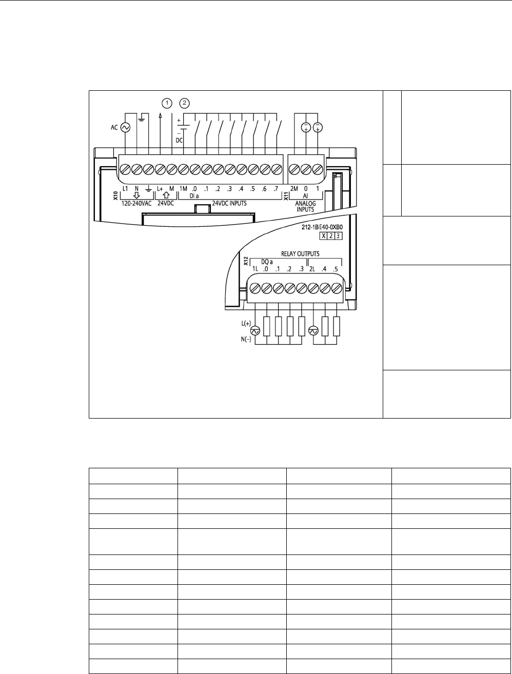
Technical specifications
A.5 CPU 1212C
S7-1200 Programmable controller
1392 System Manual, V4.2, 09/2016, A5E02486680-AK
A.5.5
CPU 1212C wiring diagrams
Table A- 41 CPU 1212C AC/DC/Relay (6ES7212-1BE40-0XB0)
①
24 V DC Sensor Power
Out
For additional noise
immunity, connect "M" to
chassis ground even if
not using sensor supply.
②
For sinking inputs, con-
nect "-" to "M" (shown).
For sourcing inputs,
connect "+" to "M".
Note 1: X11 connectors must
be gold. See Appendix C,
Spare Parts for article num-
ber.
Note 2: Either the L1 or N
(L2) terminal can be con-
nected to a voltage source
up to 240 V AC. The N ter-
minal can be considered L2
and is not required to be
grounded. No polarization is
required for L1 and N (L2)
terminals.
Note 3: See Device Configu-
ration (Page 153) for infor-
mation about the Ethernet
port of the CPU.
Table A- 42 Connector pin locations for CPU 1212C AC/DC/Relay (6ES7212-1BE40-0XB0)
Pin
X10
X11 (gold)
X12
1
L1 / 120-240 V AC
2 M
1L
2
N / 120-240 V AC
AI 0
DQ a.0
3
Functional Earth
AI 1
DQ a.1
4 L+ / 24 V DC Sensor
Out
-- DQ a.2
5
M / 24 V DC Sensor Out
--
DQ a.3
6
1M
--
2L
7
DI a.0
--
DQ a.4
8
DI a.1
--
DQ a.5
9
DI a.2
--
--
10
DI a.3
--
--
11
DI a.4
--
--
12
DI a.5
--
--
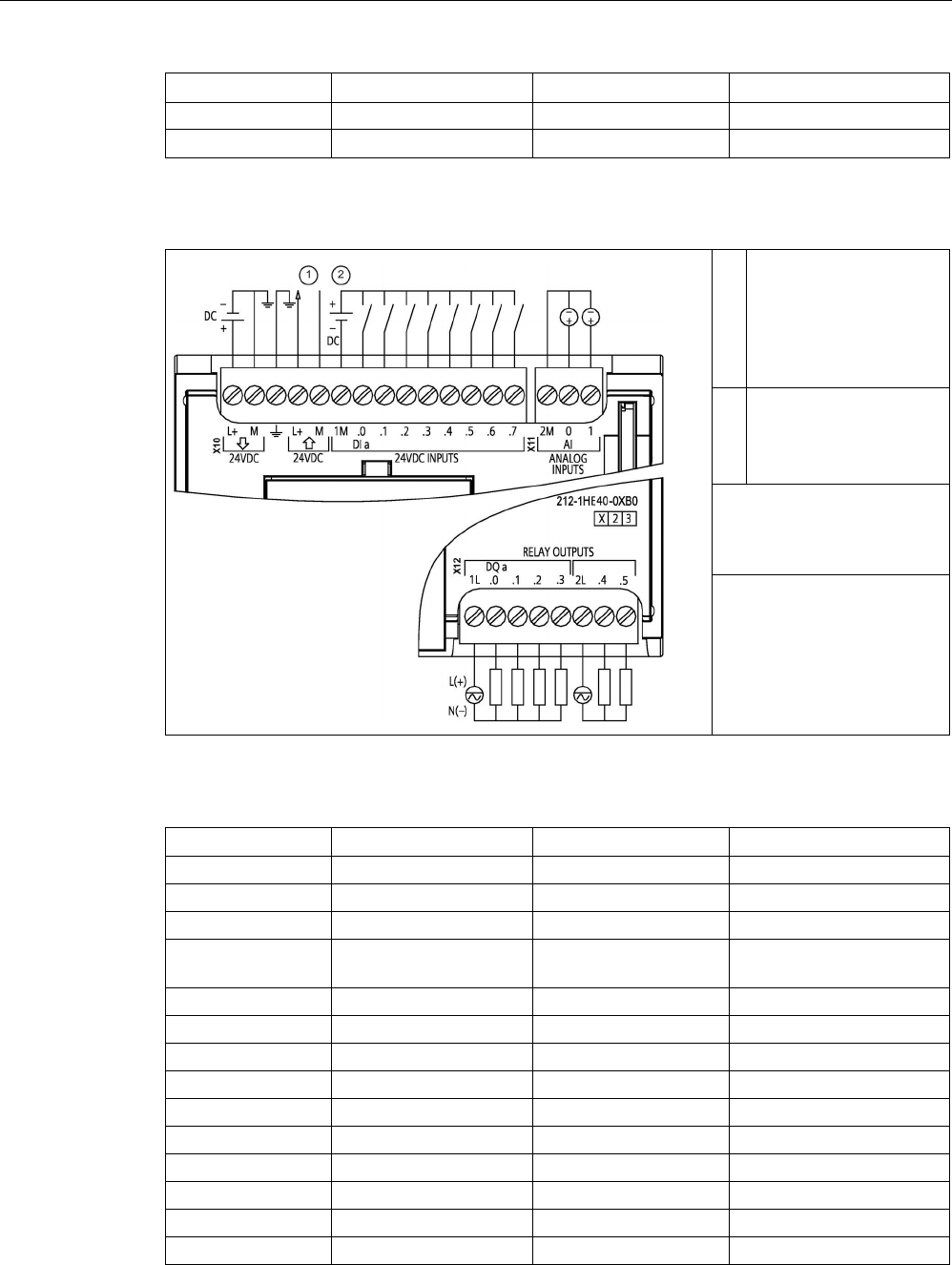
Technical specifications
A.5 CPU 1212C
S7-1200 Programmable controller
System Manual, V4.2, 09/2016, A5E02486680-AK 1393
Pin
X10
X11 (gold)
X12
13
DI a.6
--
--
14 DI a.7 -- --
Table A- 43 CPU 1212C DC/DC/Relay (6ES7212-1HE40-0XB0)
①
24 V DC Sensor Power
Out
For additional noise
immunity, connect "M" to
chassis ground even if
not using sensor supply.
②
For sinking inputs, con-
nect "-" to "M" (shown).
For sourcing inputs,
connect "+" to "M".
Note 1: X11 connectors must
be gold. See Appendix C,
Spare Parts for article num-
ber.
Note 2: See Device Configu-
ration (Page 153) for infor-
mation about the Ethernet
port of the CPU.
Table A- 44 Connector pin locations for CPU 1212C DC/DC/Relay (6ES7212-1HE40-0XB0)
Pin
X10
X11 (gold)
X12
1
L+ / 24 V DC
2 M
1L
2
M / 24 V DC
AI 0
DQ a.0
3
Functional Earth
AI 1
DQ a.1
4 L+ / 24 V DC Sensor
Out
-- DQ a.2
5
M / 24 V DC Sensor Out
--
DQ a.3
6
1M
--
2L
7
DI a.0
--
DQ a.4
8
DI a.1
--
DQ a.5
9
DI a.2
--
--
10
DI a.3
--
--
11
DI a.4
--
--
12
DI a.5
--
--
13
DI a.6
--
--
14
DI a.7
--
--
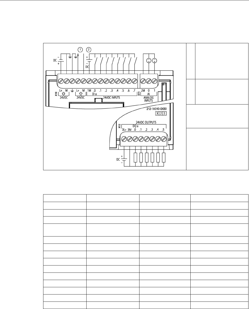
Technical specifications
A.5 CPU 1212C
S7-1200 Programmable controller
1394 System Manual, V4.2, 09/2016, A5E02486680-AK
Table A- 45 CPU 1212C DC/DC/DC (6ES7212-1AE40-0XB0)
①
24 V DC Sensor Power
Out
For additional noise
immunity, connect "M" to
chassis ground even if
not using sensor supply.
②
For sinking inputs, con-
nect "-" to "M" (shown).
For sourcing inputs,
connect "+" to "M".
Note 1: X11 connectors must
be gold. See Appendix C,
Spare Parts for article num-
ber.
Note 2: See Device Configu-
ration (Page 153) for infor-
mation about the Ethernet
port of the CPU.
Table A- 46 Connector pin locations for CPU 1212C DC/DC/DC (6ES7212-1AE40-0XB0)
Pin
X10
X11 (gold)
X12
1 L+ / 24 V DC 2 M 3L+
2
M / 24 V DC
AI 0
3M
3
Functional Earth
AI 1
DQ a.0
4 L+ / 24 V DC Sensor
Out
-- DQ a.1
5
M / 24 V DC Sensor Out
--
DQ a.2
6
1M
--
DQ a.3
7
DI a.0
--
DQ a.4
8
DI a.1
--
DQ a.5
9
DI a.2
--
--
10
DI a.3
--
--
11
DI a.4
--
--
12
DI a.5
--
--
13
DI a.6
--
--
14
DI a.7
--
--

Technical specifications
A.6 CPU 1214C
S7-1200 Programmable controller
System Manual, V4.2, 09/2016, A5E02486680-AK 1395
Note
Unused analog input
s should be shorted.
A.6
CPU 1214C
A.6.1
General specifications and features
Table A- 47 General
Technical data
CPU 1214C
AC/DC/Relay
CPU 1214C
DC/DC/Relay
CPU 1214C
DC/DC/DC
Article number 6ES7214-1BG40-0XB0 6ES7214-1HG40-0XB0 6ES7214-1AG40-0XB0
Dimensions W x H x D (mm)
110 x 100 x 75
Shipping weight
475 grams
435 grams
415 grams
Power dissipation
14 W
12 W
Current available (SM and CM bus)
1600 mA max. (5 V DC)
Current available (24 V DC)
400 mA max. (sensor power)
Digital input current consumption
(24 V DC)
4 mA/input used
Table A- 48 CPU features
Technical data
Description
User memory
(Refer to "General
technical specifica-
tions",
(Page 1359) "In-
ternal CPU
memory reten-
tion".)
Work
100 Kbytes
Load
4 Mbytes internal, expandable up to SD card size
Retentive 10 Kbytes
On-board digital I/O
14 inputs/10 outputs
On-board analog I/O
2 inputs
Process image size
1024 bytes of inputs (I)/1024 bytes of outputs (Q)
Bit memory (M)
8192 bytes
Temporary (local) memory • 16 Kbytes for startup and program cycle (including associated FBs and FCs)
• 6 Kbytes for each of the other interrupt priority levels (including FBs and FCs)
Signal modules expansion
8 SMs max.

Technical specifications
A.6 CPU 1214C
S7-1200 Programmable controller
1396 System Manual, V4.2, 09/2016, A5E02486680-AK
Technical data
Description
SB, CB, BB expansion
1 max.
Communication module expansion 3 CMs max.
High-speed counters Up to 6 configured to use any built-in or SB inputs. Refer to "Hardware input pin
assignment" (Page 580) for CPU 1214C: HSC default address assignments.
• 100/180 kHz (Ia.0 to Ia.5)
• 30/120 kHz (Ia.6 to Ib.5)
Pulse outputs2 Up to 4 configured to use any built-in or SB outputs
• 100 kHz (Qa.0 to Qa.3)
• 20 kHz (Qa.4 to Qb.1)
Pulse catch inputs
14
Time delay interrupts
4 total with 1 ms resolution
Cyclic interrupts
4 total with 1 ms resolution
Edge interrupts
12 rising and 12 falling (16 and 16 with optional signal board)
Memory card
SIMATIC memory card (optional)
Real time clock accuracy
+/- 60 seconds/month
Real time clock retention time
20 days typ./12 days min. at 40 °C (maintenance-free Super Capacitor)
1
The slower speed is applicable when the HSC is configured for quadrature mode of operation.
2 For CPU models with relay outputs, you must install a digital signal board (SB) to use the pulse outputs.
Table A- 49 Performance
Type of instruction
Execution speed
Direct addressing (I, Q and M)
DB accesses
Boolean
0.08 μs/instruction
Move
Move_Bool
0.3 μs/instruction
1.17 μs/instruction
Move_Word
0.137 μs/instruction
1.0 μs/instruction
Move_Real
0.72 μs/instruction
1.0 μs/instruction
Real Math
Add Real
1.48 μs/instruction
1.78 μs/instruction
Note
Many variables affect measured times
. The above performance times are for the fastest
instructions in this category and error
-free programs.

Technical specifications
A.6 CPU 1214C
S7-1200 Programmable controller
System Manual, V4.2, 09/2016, A5E02486680-AK 1397
A.6.2
Timers, counters and code blocks supported by CPU 1214C
Table A- 50 Blocks, timers and counters supported by CPU 1214C
Element
Description
Blocks
Type
OB, FB, FC, DB
Size 64 Kbytes
Quantity
Up to 1024 blocks total (OBs + FBs + FCs + DBs)
Address range for FBs, FCs,
and DBs
FB and FC: 1 to 65535 (such as FB 1 to FB 65535)
DB: 1 to 59999
Nesting depth 16 from the program cycle or startup OB
6 from any interrupt event OB
Monitoring
Status of 2 code blocks can be monitored simultaneously
OBs
Program cycle
Multiple
Startup
Multiple
Time-delay interrupts
4 (1 per event)
Cyclic interrupts
4 (1 per event)
Hardware interrupts
50 (1 per event)
Time error interrupts
1
Diagnostic error interrupts
1
Pull or plug of modules
1
Rack or station failure
1
Time of day
Multiple
Status
1
Update
1
Profile
1
MC-Interpolator
1
MC-Servo 1
MC-PreServo
1
MC-PostServo 1
Timers
Type
IEC
Quantity
Limited only by memory size
Storage
Structure in DB, 16 bytes per timer
Counters
Type
IEC
Quantity
Limited only by memory size
Storage Structure in DB, size dependent upon count type
• SInt, USInt: 3 bytes
• Int, UInt: 6 bytes
• DInt, UDInt: 12 bytes

Technical specifications
A.6 CPU 1214C
S7-1200 Programmable controller
1398 System Manual, V4.2, 09/2016, A5E02486680-AK
Table A- 51 Communication
Technical data
Description
Number of ports
1
Type Ethernet
HMI device
4
Programming device (PG) 1
Connections • 8 for Open User Communication (active or passive): TSEND_C,
TRCV_C, TCON, TDISCON, TSEND, and TRCV
• 3 for server GET/PUT (CPU-to-CPU) S7 communication
• 8 for client GET/PUT (CPU-to-CPU) S7 communication
Data rates
10/100 Mb/s
Isolation (external signal to logic)
Transformer isolated, 1500 V AC (type test)
1
Cable type
CAT5e shielded
Interfaces
Number of PROFINET interfaces
1
Number of interfaces PROFIBUS
0
Interface
Interface Hardware
Number of ports
1
Integrated switch
No
RJ-45 (Ethernet)
Yes; X1
Protocols
PROFINET IO controller
Yes
PROFINET IO device
Yes
SIMATIC communication
Yes
Open IE communication
Yes
Web server
Yes
Media redundancy No
PROFINET IO controller
Services
PG/OP communication
Yes
S7 routing
Yes
Isochronous mode
No
Open IE communication
Yes
IRT
No
MRP
No
PROFIenergy Yes. The S7-1200 CPU only supports the PROFIenergy entity (with I-
device functionality).
Prioritized startup
Yes (max. 16 PROFINET devices)
Number of connectable I/O devices max.
16
Number of IO devices that you can connect for
RT, max.
16
Of which are in line, max.
16

Technical specifications
A.6 CPU 1214C
S7-1200 Programmable controller
System Manual, V4.2, 09/2016, A5E02486680-AK 1399
Technical data
Description
Number of IO devices that can be activated/ deac-
tivated simultaneously, max.
8
Update times The minimum value of the update time also depends on the commu-
nication component set for PROFINET IO, on the number of IO devic-
es, and the quantity of configured user data.
With RT
Send clock of 1 ms
1 ms to 512 ms
PROFINET IO device
Services
PG/OP communication
Yes
S7 routing
Yes
Isochronous mode
No
Open IE communication
Yes
IRT, supported
No
MRP, supported
No
PROFIenergy
Yes
Shared device
Yes
Number of IO controllers with shared device, max.
2
SIMATIC communication
S7 communication, as server
Yes
S7 communication, as client
Yes
User data per job, max.
See online help (S7 communication, user data size)
Open IE communication
TCP/IP: Yes
Data length, max.
8 KB
Several passive connections per port,
supported
Yes
ISO-on-TCP (RFC1006):
Yes
Data length, max.
8 KB
UDP
Yes
Data length, max.
1472 bytes
DHCP
No
SNMP
Yes
DCP
Yes
LLDP
Yes
1
Ethernet port isolation is designed to limit hazard during short term network faults to hazardous voltages. It does not
conform to safety requirements for routine AC line voltage isolation.

Technical specifications
A.6 CPU 1214C
S7-1200 Programmable controller
1400 System Manual, V4.2, 09/2016, A5E02486680-AK
Table A- 52 Power supply
Technical data
CPU 1214C
AC/DC/Relay
CPU 1214C
DC/DC/Relay
CPU 1214C
DC/DC/DC
Voltage range
85 to 264 V AC
20.4 V DC to 28.8 V DC
Line frequency 47 to 63 Hz --
Input current
(max. load)
CPU only 100 mA at 120 V AC
50 mA at 240 V AC
500 mA at 24 V DC
CPU with all expansion
accessories
300 mA at 120 V AC
150 mA at 240 V AC
1500 mA at 24 V DC
Inrush current (max.)
20 A at 264 V AC
12 A at 28.8 V DC
Isolation (input power to logic)
1500 V AC
Not isolated
Ground leakage, AC line to functional
earth
0.5 mA max. -
Hold up time (loss of power) 20 ms at 120 V AC
80 ms at 240 V AC
10 ms at 24 V DC
Internal fuse, not user replaceable
3 A, 250 V, slow blow
Table A- 53 Sensor power
Technical data
CPU 1214C
AC/DC/Relay
CPU 1214C
DC/DC/Relay
CPU 1214C
DC/DC/DC
Voltage range
20.4 to 28.8 V DC
L+ minus 4 V DC min.
Output current rating (max.)
400 mA (short-circuit protected)
Maximum ripple noise (<10 MHz)
< 1 V peak to peak
Same as input line
Isolation (CPU logic to sensor power)
Not isolated

Technical specifications
A.6 CPU 1214C
S7-1200 Programmable controller
System Manual, V4.2, 09/2016, A5E02486680-AK 1401
A.6.3
Digital inputs and outputs
Table A- 54 Digital inputs
Technical data
CPU 1214C
AC/DC/Relay
CPU 1214C
DC/DC/Relay
CPU 1214C
DC/DC/DC
Number of inputs
14
Type Sink/Source (IEC Type 1 sink)
Rated voltage
24 V DC at 4 mA, nominal
Continuous permissible voltage 30 V DC, max.
Surge voltage
35 V DC for 0.5 sec.
Logic 1 signal (min.)
15 V DC at 2.5 mA
Logic 0 signal (max.)
5 V DC at 1 mA
Isolation (field side to logic)
707 V DC (type test)
Isolation groups
1
Filter times us settings: 0.1, 0.2, 0.4, 0.8, 1.6, 3.2, 6.4, 10.0, 12.8, 20.0
ms settings: 0.05, 0.1, 0.2, 0.4, 0.8, 1.6, 3.2, 6.4, 10.0, 12.8, 20.0
HSC clock input rates (max.)
(Logic 1 Level = 15 to 26 V DC)
100/80 kHz (Ia.0 to Ia.5)
30/20 kHz (Ia.6 to Ib.5
Number of inputs on simultaneously • 7 (no adjacent points) at 60 °C horizontal or 50 °C vertical
• 14 at 55 °C horizontal or 45 °C vertical
Cable length (meters)
500 m shielded, 300 m unshielded, 50 m shielded for HSC inputs
Table A- 55 Digital outputs
Technical data
CPU 1214C AC/DC/Relay
and DC/DC/Relay
CPU 1214C
DC/DC/DC
Number of outputs
10
Type
Relay, mechanical
Solid state - MOSFET (sourcing)
Voltage range
5 to 30 V DC or 5 to 250 V AC
20.4 to 28.8 V DC
Logic 1 signal at max. current
--
20 V DC min.
Logic 0 signal with 10 KΩ load
--
0.1 V DC max.
Current (max.)
2.0 A
0.5 A
Lamp load
30 W DC / 200 W AC
5 W
ON state resistance
0.2 Ω max. when new
0.6 Ω max.
Leakage current per point
--
10 μA max.
Surge current 7 A with contacts closed 8 A for 100 ms max.
Overload protection
No
Isolation (field side to logic) 1500 V AC (coil to contact)
None (coil to logic)
707 V DC (type test)
Isolation groups
2
1
Isolation (group-to-group)
1500 V AC
1
--
Inductive clamp voltage -- L+ minus 48 V DC,
1 W dissipation

Technical specifications
A.6 CPU 1214C
S7-1200 Programmable controller
1402 System Manual, V4.2, 09/2016, A5E02486680-AK
Technical data
CPU 1214C AC/DC/Relay
and DC/DC/Relay
CPU 1214C
DC/DC/DC
Switching delay (Qa.0 to Qa.3) 10 ms max. 1.0 μs max., off to on
3.0 μs max., on to off
Switching delay (Qa.4 to Qb.1) 10 ms max. 5 μs max., off to on
20 μs max., on to off
Maximum relay switching frequency
1 Hz
--
Pulse Train Output rate
Not recommended 2 100 kHz (Qa.0 to Qa.3)3, 2 Hz min.
20 kHz (Qa.4 to Qb.1)3
Lifetime mechanical (no load)
10,000,000 open/close cycles
--
Lifetime contacts at rated load
100,000 open/close cycles
--
Behavior on RUN to STOP
Last value or substitute value (default value 0)
Number of outputs on simultaneously • 5 (no adjacent points) at 60 °C horizontal or 50 °C vertical
• 10 at 55 °C horizontal or 45 °C vertical
Cable length (meters)
500 m shielded, 150 m unshielded
1
Relay group-to-group isolation separates line voltage from SELV/PELV and separates different phases up to 250 V AC
line to ground.
2
For CPU models with relay outputs, you must install a digital signal board (SB) to use the pulse outputs.
3
Depending on your pulse receiver and cable, an additional load resistor (at least 10% of rated current) may improve
pulse signal quality and noise immunity.

Technical specifications
A.6 CPU 1214C
S7-1200 Programmable controller
System Manual, V4.2, 09/2016, A5E02486680-AK 1403
A.6.4
Analog inputs
Table A- 56 Analog inputs
Technical data
Description
Number of inputs
2
Type Voltage (single-ended)
Full-scale range
0 to 10 V
Full-scale range (data word) 0 to 27648
Overshoot range
10.001 to 11.759 V
Overshoot range (data word)
27649 to 32511
Overflow range
11.760 to 11.852 V
Overflow range (data word)
32512 to 32767
Resolution
10 bits
Maximum withstand voltage
35 V DC
Smoothing None, Weak, Medium, or Strong
See the table for Step response (ms) for the analog inputs of the CPU
(Page 1403).
Noise rejection
10, 50, or 60 Hz
Impedance
≥100 KΩ
Isolation (field side to logic)
None
Accuracy (25 °C / -20 to 60 °C)
3.0% / 3.5% of full-scale
Cable length (meters)
100 m, shielded twisted pair
A.6.4.1
Step response of the built-in analog inputs of the CPU
Table A- 57 Step Response (ms), 0 V to 10 V measured at 95%
Smoothing selection (sample averaging)
Rejection frequency (Integration time)
60 Hz
50 Hz
10 Hz
None (1 cycle): No averaging
50 ms
50 ms
100 ms
Weak (4 cycles): 4 samples
60ms
70 ms
200 ms
Medium (16 cycles): 16 samples
200 ms
240 ms
1150 ms
Strong (32 cycles): 32 samples 400 ms 480 ms 2300 ms
Sample time
4.17 ms
5 ms
25 ms

Technical specifications
A.6 CPU 1214C
S7-1200 Programmable controller
1404 System Manual, V4.2, 09/2016, A5E02486680-AK
A.6.4.2
Sample time for the built-in analog ports of the CPU
Table A- 58 Sample time for built-in analog inputs of the CPU
Rejection frequency (Integration time selection)
Sample time
60 Hz (16.6 ms)
4.17 ms
50 Hz (20 ms)
5 ms
10 Hz (100 ms)
25 ms
A.6.4.3
Measurement ranges of the analog inputs for voltage (CPUs)
Table A- 59 Analog input representation for voltage (CPUs)
System
Voltage Measuring Range
Decimal
Hexadecimal
0 to 10 V
32767
7FFF
11.852 V
Overflow
32512
7F00
32511
7EFF
11.759 V
Overshoot range
27649
6C01
27648
6C00
10 V
Rated range
20736
5100
7.5 V
34
22
12 mV
0
0
0 V
Negative values Negative values are not sup-
ported

Technical specifications
A.6 CPU 1214C
S7-1200 Programmable controller
System Manual, V4.2, 09/2016, A5E02486680-AK 1405
A.6.5
CPU 1214C wiring diagrams
Table A- 60 CPU 1214C AC/DC/Relay (6ES7214-1BG40-0XB0)
①
24 V DC Sensor Power
Out
For additional noise
immunity, connect "M" to
chassis ground even if
not using sensor supply.
②
For sinking inputs, con-
nect "-" to "M" (shown).
For sourcing inputs,
connect "+" to "M".
Note 1: X11 connectors must
be gold. See Appendix C,
Spare Parts for article num-
ber.
Note 2: Either the L1 or N
(L2) terminal can be con-
nected to a voltage source
up to 240 V AC. The N ter-
minal can be considered L2
and is not required to be
grounded. No polarization is
required for L1 and N (L2)
terminals.
Note 3: See Device Configu-
ratio (Page 153)n for infor-
mation about the Ethernet
port of the CPU.
Table A- 61 Connector pin locations for CPU 1214C AC/DC/Relay (6ES7214-1BG40-0XB0)
Pin
X10
X11 (gold)
X12
1
L1 / 120-240 V AC
2 M
1L
2
N / 120-240 V AC
AI 0
DQ a.0
3
Functional Earth
AI 1
DQ a.1
4
L+ / 24 V DC Sensor Out
--
DQ a.2
5
M / 24 V DC Sensor Out
--
DQ a.3
6
1M
--
DQ a.4
7
DI a.0
--
2L
8
DI a.1
--
DQ a.5
9
DI a.2
--
DQ a.6
10
DI a.3
--
DQ a.7
11
DI a.4
--
DQ b.0
12
DI a.5
--
DQ b.1
13
DI a.6
--
--
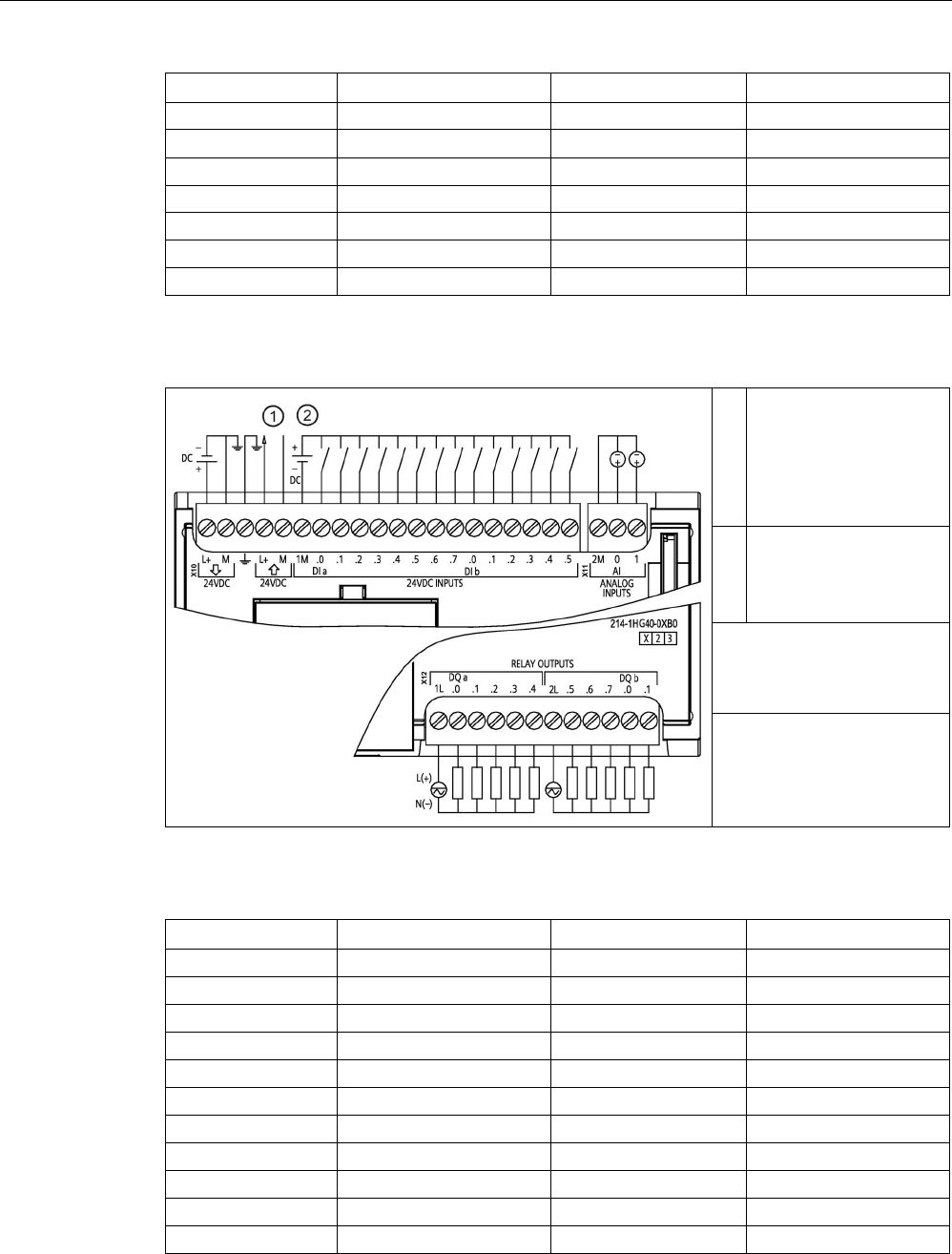
Technical specifications
A.6 CPU 1214C
S7-1200 Programmable controller
1406 System Manual, V4.2, 09/2016, A5E02486680-AK
Pin
X10
X11 (gold)
X12
14
DI a.7
--
--
15 DI b.0 -- --
16
DI b.1
--
--
17 DI b.2 -- --
18
DI b.3
--
--
19
DI b.4
--
--
20
DI b.5
--
--
Table A- 62 CPU 1214C DC/DC/Relay (6ES7214-1HG40-0XB0)
①
24 V DC Sensor Power
Out
For additional noise
immunity, connect "M" to
chassis ground even if
not using sensor supply.
②
For sinking inputs, con-
nect "-" to "M" (shown).
For sourcing inputs,
connect "+" to "M".
Note 1: X11 connectors must
be gold. See Appendix C,
Spare Parts for article num-
ber.
Note 2: See Device Configu-
ration (Page 153) for infor-
mation about the Ethernet
port of the CPU.
Table A- 63 Connector pin locations for CPU 1214C DC/DC/Relay (6ES7214-1HG40-0XB0)
Pin
X10
X11 (gold)
X12
1
L+ / 24 V DC
2 M
1L
2
M / 24 V DC
AI 0
DQ a.0
3
Functional Earth
AI 1
DQ a.1
4
L+ / 24 V DC Sensor Out
--
DQ a.2
5
M / 24 V DC Sensor Out
--
DQ a.3
6
1M
--
DQ a.4
7
DI a.0
--
2L
8
DI a.1
--
DQ a.5
9
DI a.2
--
DQ a.6
10
DI a.3
--
DQ a.7
11
DI a.4
--
DQ b.0
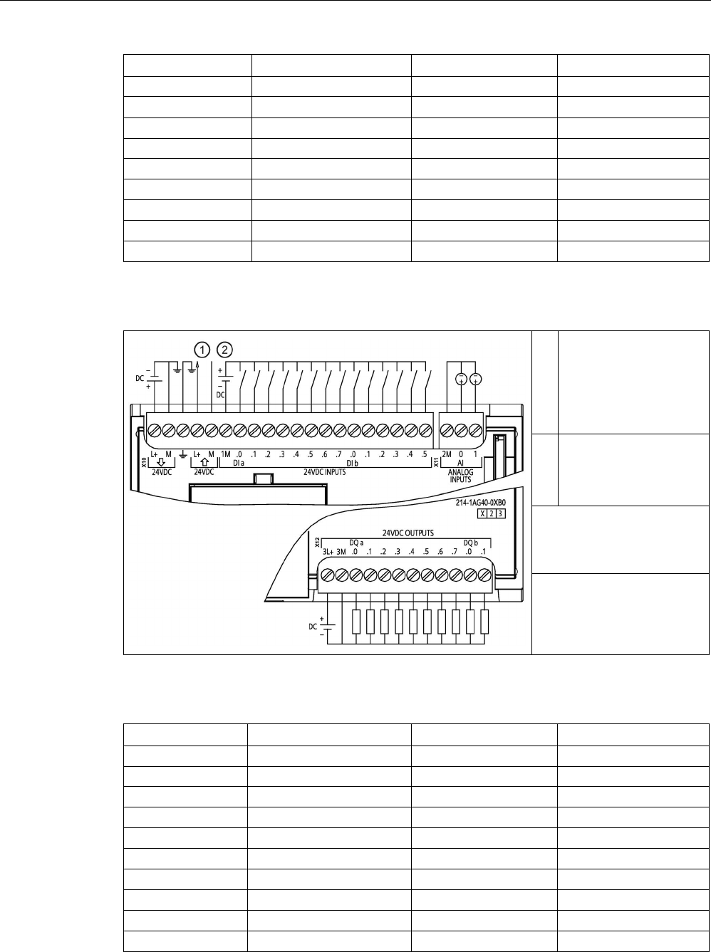
Technical specifications
A.6 CPU 1214C
S7-1200 Programmable controller
System Manual, V4.2, 09/2016, A5E02486680-AK 1407
Pin
X10
X11 (gold)
X12
12
DI a.5
--
DQ b.1
13 DI a.6 -- --
14
DI a.7
--
--
15 DI b.0 -- --
16
DI b.1
--
--
17
DI b.2
--
--
18
DI b.3
--
--
19
DI b.4
--
--
20
DI b.5
--
--
Table A- 64 CPU 1214C DC/DC/DC (6ES7214-1AG40-0XB0)
①
24 V DC Sensor Power
Out
For additional noise
immunity, connect "M" to
chassis ground even if
not using sensor supply.
②
For sinking inputs, con-
nect "-" to "M" (shown).
For sourcing inputs,
connect "+" to "M".
Note 1: X11 connectors must
be gold. See Appendix C,
Spare Parts for article num-
ber.
Note 2: See Device Configu-
ration (Page 153) for infor-
mation about the Ethernet
port of the CPU.
Table A- 65 Connector pin locations for CPU 1214C DC/DC/DC (6ES7214-1AG40-0XB0)
Pin
X10
X11 (gold)
X12
1
L+ / 24 V DC
2 M
3L+
2 M / 24 V DC AI 0 3M
3
Functional Earth
AI 1
DQ a.0
4
L+ / 24 V DC Sensor Out
--
DQ a.1
5
M / 24 V DC Sensor Out
--
DQ a.2
6
1M
--
DQ a.3
7
DI a.0
--
DQ a.4
8
DI a.1
--
DQ a.5
9
DI a.2
--
DQ a.6
10
DI a.3
--
DQ a.7

Technical specifications
A.6 CPU 1214C
S7-1200 Programmable controller
1408 System Manual, V4.2, 09/2016, A5E02486680-AK
Pin
X10
X11 (gold)
X12
11
DI a.4
--
DQ b.0
12 DI a.5 -- DQ b.1
13
DI a.6
--
--
14 DI a.7 -- -
15
DI b.0
--
--
16
DI b.1
--
--
17
DI b.2
--
--
18
DI b.3
--
--
19
DI b.4
--
--
20
DI b.5
--
--
Note
Unused analog inputs sho
uld be shorted.

Technical specifications
A.7 CPU 1215C
S7-1200 Programmable controller
System Manual, V4.2, 09/2016, A5E02486680-AK 1409
A.7
CPU 1215C
A.7.1
General specifications and features
Table A- 66 General
Technical data
CPU 1215C
AC/DC/Relay
CPU 1215C
DC/DC/Relay
CPU 1215C
DC/DC/DC
Article number
6ES7215-1BG40-0XB0
6ES7215-1HG40-0XB0
6ES7215-1AG40-0XB0
Dimensions W x H x D (mm) 130 x 100 x 75
Shipping weight
585 grams
550 grams
520 grams
Power dissipation 14 W 12 W
Current available (SM and CM bus)
1600 mA max. (5 V DC)
Current available (24 V DC)
400 mA max. (sensor power)
Digital input current consumption
(24 V DC)
4 mA/input used
Table A- 67 CPU features
Technical data
Description
User memory
(Refer to "General
technical specifica-
tions
(Page 1359)",
"Internal CPU
memory reten-
tion".)
Work
125 Kbytes
Load
4 Mbytes, internal, expandable up to SD card size
Retentive 10 Kbytes
On-board digital I/O
14 inputs/10 outputs
On-board analog I/O
2 inputs/2 outputs
Process image size
1024 bytes of inputs (I)/1024 bytes of outputs (Q)
Bit memory (M)
8192 bytes
Temporary (local) memory • 16 Kbytes for startup and program cycle (including associated FBs and FCs)
• 6 Kbytes for each of the other interrupt priority levels (including FBs and FCs)
Signal modules expansion
8 SMs max.
SB, CB, BB expansion
1 max.
Communication module expansion
3 CMs max.
High-speed counters Up to 6 configured to use any built-in or SB inputs. Refer to "Hardware input pin
assignment" (Page 580) for CPU 1215C: HSC default address assignments.
• 100/180 kHz (Ia.0 to Ia.5)
• 30/120 kHz (Ia.6 to Ib.5)

Technical specifications
A.7 CPU 1215C
S7-1200 Programmable controller
1410 System Manual, V4.2, 09/2016, A5E02486680-AK
Technical data
Description
Pulse outputs2 Up to 4 configured to use any built-in or SB outputs
• 100 kHz (Qa.0 to Qa.3)
• 20 kHz (Qa.4 to Qb.1)
Pulse catch inputs 14
Time delay interrupts
4 total with 1 ms resolution
Cyclic interrupts
4 total with 1 ms resolution
Edge interrupts
12 rising and 12 falling (16 and 16 with optional signal board)
Memory card
SIMATIC memory card (optional)
Real time clock accuracy
+/- 60 seconds/month
Real time clock retention time
20 days typ./12 days min. at 40 °C (maintenance-free Super Capacitor)
1
The slower speed is applicable when the HSC is configured for quadrature mode of operation.
2 For CPU models with relay outputs, you must install a digital signal board (SB) to use the pulse outputs.
Table A- 68 Performance
Type of instruction
Execution speed
Direct addressing (I, Q and M)
DB accesses
Boolean
0.08 μs/instruction
Move
Move_Bool
0.3 μs/instruction
1.17 μs/instruction
Move_Word
0.137 μs/instruction
1.0 μs/instruction
Move_Real
0.72 μs/instruction
1.0 μs/instruction
Real Math
Add Real
1.48 μs/instruction
1.78 μs/instruction
Note
Many variables affect measured t
imes. The above performance times are for the fastest
instructions in this category and error
-free programs.

Technical specifications
A.7 CPU 1215C
S7-1200 Programmable controller
System Manual, V4.2, 09/2016, A5E02486680-AK 1411
A.7.2
Timers, counters and code blocks supported by CPU 1215C
Table A- 69 Blocks, timers and counters supported by CPU 1215C
Element
Description
Blocks
Type
OB, FB, FC, DB
Size 64 Kbytes
Quantity
Up to 1024 blocks total (OBs + FBs + FCs + DBs)
Address range for FBs, FCs,
and DBs
FB and FC: 1 to 65535 (such as FB 1 to FB 65535)
DB: 1 to 59999
Nesting depth 16 from the program cycle or startup OB
6 from any interrupt event OB
Monitoring
Status of 2 code blocks can be monitored simultaneously
OBs
Program cycle
Multiple
Startup
Multiple
Time-delay interrupts
4 (1 per event)
Cyclic interrupts
4 (1 per event)
Hardware interrupts
50 (1 per event)
Time error interrupts
1
Diagnostic error interrupts
1
Pull or plug of modules
1
Rack or station failure
1
Time of day
Multiple
Status
1
Update
1
Profile
1
MC-Interpolator
1
MC-Servo 1
MC-PreServo
1
MC-PostServo 1
Timers
Type
IEC
Quantity
Limited only by memory size
Storage
Structure in DB, 16 bytes per timer
Counters
Type
IEC
Quantity
Limited only by memory size
Storage Structure in DB, size dependent upon count type
• SInt, USInt: 3 bytes
• Int, UInt: 6 bytes
• DInt, UDInt: 12 bytes

Technical specifications
A.7 CPU 1215C
S7-1200 Programmable controller
1412 System Manual, V4.2, 09/2016, A5E02486680-AK
Table A- 70 Communication
Technical data
Description
Number of ports
2
Type Ethernet
HMI device
4
Programming device (PG) 1
Connections • 8 for Open User Communication (active or passive): TSEND_C,
TRCV_C, TCON, TDISCON, TSEND, and TRCV
• 3 for server GET/PUT (CPU-to-CPU) S7 communication
• 8 for client GET/PUT (CPU-to-CPU) S7 communication
Data rates
10/100 Mb/s
Isolation (external signal to logic)
Transformer isolated, 1500 V AC (type test)
1
Cable type
CAT5e shielded
Interfaces
Number of PROFINET interfaces
1
Number of interfaces PROFIBUS
0
Interface
Interface hardware
Number of ports
2
Integrated switch
Yes
RJ-45 (Ethernet)
Yes; X1
Protocols
PROFINET IO controller
Yes
PROFINET IO device
Yes
SIMATIC communication
Yes
Open IE communication
Yes
Web server
Yes
Media redundancy Yes
PROFINET IO controller
Services
PG/OP communication
Yes
S7 routing
Yes
Isochronous mode
No
Open IE communication
Yes
IRT
No
MRP
Yes as MRP client
PROFIenergy Yes. The S7-1200 CPU only supports the PROFIenergy entity (with I-
device functionality).
Prioritized startup
Yes (max. 16 PROFINET devices)
Number of connectable I/O devices max.
16
Number of IO devices that you can connect for
RT, max.
16
Of which are in line, max.
16

Technical specifications
A.7 CPU 1215C
S7-1200 Programmable controller
System Manual, V4.2, 09/2016, A5E02486680-AK 1413
Technical data
Description
Number of IO devices that can be activated/
deactivated simultaneously, max.
8
Update times The minimum value of the update time also depends on the communi-
cation component set for PROFINET IO, on the number of IO devices,
and the quantity of configured user data.
With RT
Send clock of 1 ms
1 ms to 512 ms
PROFINET IO device
Services
PG/OP communication
Yes
S7 routing
Yes
Isochronous mode
No
Open IE communication
Yes
IRT, supported
No
MRP, supported
Yes
PROFIenergy
Yes
Shared device
Yes
Number of IO controllers with shared device,
max.
2
SIMATIC communication
S7 communication, as server
Yes
S7 communication, as client
Yes
User data per job, max. See online help (S7 communication, user data size)
Open IE communication
TCP/IP: Yes
Data length, max.
8 KB
Several passive connections per port,
supported
Yes
ISO-on-TCP (RFC1006):
Yes
Data length, max.
8 KB
UDP:
Yes
Data length, max.
1472 bytes
DHCP
No
SNMP
Yes
DCP
Yes
LLDP
Yes
1
Ethernet port isolation is designed to limit hazard during short term network faults to hazardous voltages. It does not
conform to safety requirements for routine AC line voltage isolation.

Technical specifications
A.7 CPU 1215C
S7-1200 Programmable controller
1414 System Manual, V4.2, 09/2016, A5E02486680-AK
Table A- 71 Power supply
Technical data
CPU 1215C
AC/DC/Relay
CPU 1215C
DC/DC/Relay
CPU 1215C
DC/DC/DC
Voltage range
85 to 264 V AC
20.4 V DC to 28.8 V DC
Line frequency 47 to 63 Hz --
Input current
(max. load)
CPU only 100 mA at 120 V AC
50 mA at 240 V AC
500 mA at 24 V DC
CPU with all expansion
accessories
300 mA at 120 V AC
150 mA at 240 V AC
1500 mA at 24 V DC
Inrush current (max.)
20 A at 264 V AC
12 A at 28.8 V DC
Isolation (input power to logic)
1500 V AC
Not isolated
Ground leakage, AC line to functional
earth
0.5 mA max. -
Hold up time (loss of power) 20 ms at 120 V AC
80 ms at 240 V AC
10 ms at 24 V DC
Internal fuse, not user replaceable
3 A, 250 V, slow blow
Table A- 72 Sensor power
Technical data
CPU 1215C
AC/DC/Relay
CPU 1215C
DC/DC/Relay
CPU 1215C
DC/DC/DC
Voltage range
20.4 to 28.8 V DC
L+ minus 4 V DC min.
Output current rating (max.)
400 mA (short-circuit protected)
Maximum ripple noise (<10 MHz)
< 1 V peak to peak
Same as input line
Isolation (CPU logic to sensor power)
Not isolated

Technical specifications
A.7 CPU 1215C
S7-1200 Programmable controller
System Manual, V4.2, 09/2016, A5E02486680-AK 1415
A.7.3
Digital inputs and outputs
Table A- 73 Digital inputs
Technical data
CPU 1215C
AC/DC/Relay
CPU 1215C
DC/DC/Relay
CPU 1215C
DC/DC/DC
Number of inputs
14
Type Sink/Source (IEC Type 1 sink)
Rated voltage
24 V DC at 4 mA, nominal
Continuous permissible voltage 30 V DC, max.
Surge voltage
35 V DC for 0.5 sec.
Logic 1 signal (min.)
15 V DC at 2.5 mA
Logic 0 signal (max.)
5 V DC at 1 mA
Isolation (field side to logic)
707 V DC (type test)
Isolation groups
1
Filter times us settings: 0.1, 0.2, 0.4, 0.8, 1.6, 3.2, 6.4, 10.0, 12.8, 20.0
ms settings: 0.05, 0.1, 0.2, 0.4, 0.8, 1.6, 3.2, 6.4, 10.0, 12.8, 20.0
HSC clock input rates (max.)
(Logic 1 Level = 15 to 26 V DC)
100/80 kHz (Ia.0 to Ia.5)
30/20 kHz (Ia.6 to Ib.5)
Number of inputs on simultaneously • 7 (no adjacent points) at 60 °C horizontal or 50 °C vertical
• 14 at 55 °C horizontal or 45 °C vertical
Cable length (meters)
500 m shielded, 300 m unshielded, 50 m shielded for HSC inputs

Technical specifications
A.7 CPU 1215C
S7-1200 Programmable controller
1416 System Manual, V4.2, 09/2016, A5E02486680-AK
Table A- 74 Digital outputs
Technical data
CPU 1215C AC/DC/Relay
and CPU 1215C DC/DC/Relay
CPU 1215C DC/DC/DC
Number of outputs
10
Type Relay, mechanical Solid state - MOSFET (sourcing)
Voltage range
5 to 30 V DC or 5 to 250 V AC
20.4 to 28.8 V DC
Logic 1 signal at max. current
--
20 V DC min.
Logic 0 signal with 10 KΩ load
--
0.1 V DC max.
Current (max.)
2.0 A
0.5 A
Lamp load
30 W DC / 200 W AC
5 W
ON state resistance
0.2 Ω max. when new
0.6 Ω max.
Leakage current per point
--
10 μA max.
Surge current
7 A with contacts closed
8 A for 100 ms max.
Overload protection
No
Isolation (field side to logic) 1500 V AC (coil to contact)
None (coil to logic)
707 V DC (type test)
Isolation groups
2
1
Isolation (group-to-group)
1500 V AC
1
--
Inductive clamp voltage -- L+ minus 48 V DC,
1 W dissipation
Switching delay (Qa.0 to Qa.3) 10 ms max. 1.0 μs max., off to on
3.0 μs max., on to off
Switching delay (Qa.4 to Qb.1) 10 ms max. 5 μs max., off to on
20 μs max., on to off
Maximum relay switching frequency
1 Hz
--
Pulse Train Output rate Not recommended 2 100 kHz (Qa.0 to Qa.3)3, 2 Hz min.
20 kHz (Qa.4 to Qb.1)
3
Lifetime mechanical (no load)
10,000,000 open/close cycles
--
Lifetime contacts at rated load
100,000 open/close cycles
--
Behavior on RUN to STOP
Last value or substitute value (default value 0)
Number of outputs on simultaneously • 5 (no adjacent points) at 60 °C horizontal or 50 °C vertical
• 10 at 55 °C horizontal or 45 °C vertical
Cable length (meters)
500 m shielded, 150 m unshielded
1
Relay group-to-group isolation separates line voltage from SELV/PELV and separates different phases up to 250 V AC
line to ground.
2
For CPU models with relay outputs, you must install a digital signal board (SB) to use the pulse outputs.
3
Depending on your pulse receiver and cable, an additional load resistor (at least 10% of rated current) may improve
pulse signal quality and noise immunity.

Technical specifications
A.7 CPU 1215C
S7-1200 Programmable controller
System Manual, V4.2, 09/2016, A5E02486680-AK 1417
A.7.4
Analog inputs and outputs
Table A- 75 Analog inputs
Technical data
Description
Number of inputs
2
Type Voltage (single-ended)
Full-scale range
0 to 10 V
Full-scale range (data word) 0 to 27648
Overshoot range
10.001 to 11.759 V
Overshoot range (data word)
27649 to 32511
Overflow range
11.760 to 11.852 V
Overflow range (data word)
32512 to 32767
Resolution
10 bits
Maximum withstand voltage
35 V DC
Smoothing None, Weak, Medium, or Strong
See the table for Step response (ms) for the analog inputs of the CPU
(Page 1417).
Noise rejection
10, 50, or 60 Hz
Impedance
≥100 KΩ
Isolation (field side to logic)
None
Accuracy (25 °C / -20 to 60 °C)
3.0% / 3.5% of full-scale
Cable length (meters)
100 m, shielded twisted pair
A.7.4.1
Step response of built-in analog inputs of the CPU
Table A- 76 Step Response (ms), 0 V to 10 V measured at 95%
Smoothing selection (sample averaging)
Rejection frequency (Integration time)
60 Hz
50 Hz
10 Hz
None (1 cycle): No averaging
50 ms
50 ms
100 ms
Weak (4 cycles): 4 samples
60ms
70 ms
200 ms
Medium (16 cycles): 16 samples
200 ms
240 ms
1150 ms
Strong (32 cycles): 32 samples 400 ms 480 ms 2300 ms
Sample time
4.17 ms
5 ms
25 ms

Technical specifications
A.7 CPU 1215C
S7-1200 Programmable controller
1418 System Manual, V4.2, 09/2016, A5E02486680-AK
A.7.4.2
Sample time for the built-in analog ports of the CPU
Table A- 77 Sample time for built-in analog inputs of the CPU
Rejection frequency (Integration time selection)
Sample time
60 Hz (16.6 ms)
4.17 ms
50 Hz (20 ms)
5 ms
10 Hz (100 ms)
25 ms
A.7.4.3
Measurement ranges of the analog inputs for voltage (CPUs)
Table A- 78 Analog input representation for voltage (CPUs)
System
Voltage Measuring Range
Decimal
Hexadecimal
0 to 10 V
32767
7FFF
11.852 V
Overflow
32512
7F00
32511
7EFF
11.759 V
Overshoot range
27649
6C01
27648
6C00
10 V
Rated range
20736
5100
7.5 V
34
22
12 mV
0
0
0 V
Negative values Negative values are not sup-
ported

Technical specifications
A.7 CPU 1215C
S7-1200 Programmable controller
System Manual, V4.2, 09/2016, A5E02486680-AK 1419
A.7.4.4
Analog output specifications
Table A- 79 Analog outputs
Technical data
Description
Number of outputs
2
Type
Current
Full-scale range
0 to 20 mA
Full-scale range (data word) 0 to 27648
Overshoot range
20.01 to 23.52 mA
Overshoot range (data word)
27649 to 32511
Overflow range
see footnote
1
Overflow range data word
32512 to 32767
Resolution
10 bits
Output drive impedance
≤500 Ω max.
Isolation (field side to logic)
None
Accuracy (25 °C / -20 to 60 °C)
3.0% / 3.5% of full-scale
Settling time
2 ms
Cable length (meters)
100 m, shielded twisted pair
1
In an overflow condition, analog outputs will behave according to the device configuration properties settings. In the
"Reaction to CPU STOP" parameter, select either: "Use substitute value" or "Keep last value".
Table A- 80 Analog output representation for current (CPU 1215C and CPU 1217C)
System
Current output range
Decimal
Hexadecimal
0 mA to 20 mA
32767
7FFF
See note 1
Overflow
32512
7F00
See note 1
32511
7EFF
23.52 mA
Overshoot range
27649
6C01
27648 6C00 20 mA Rated range
20736
5100
15 mA
34
22
0.0247 mA
0
0
0 mA
Negative values Negative values are not
supported
1
In an overflow condition, analog outputs will behave according to the device configuration properties settings. In the
"Reaction to CPU STOP" parameter, select either: "Use substitute value" or "Keep last value".
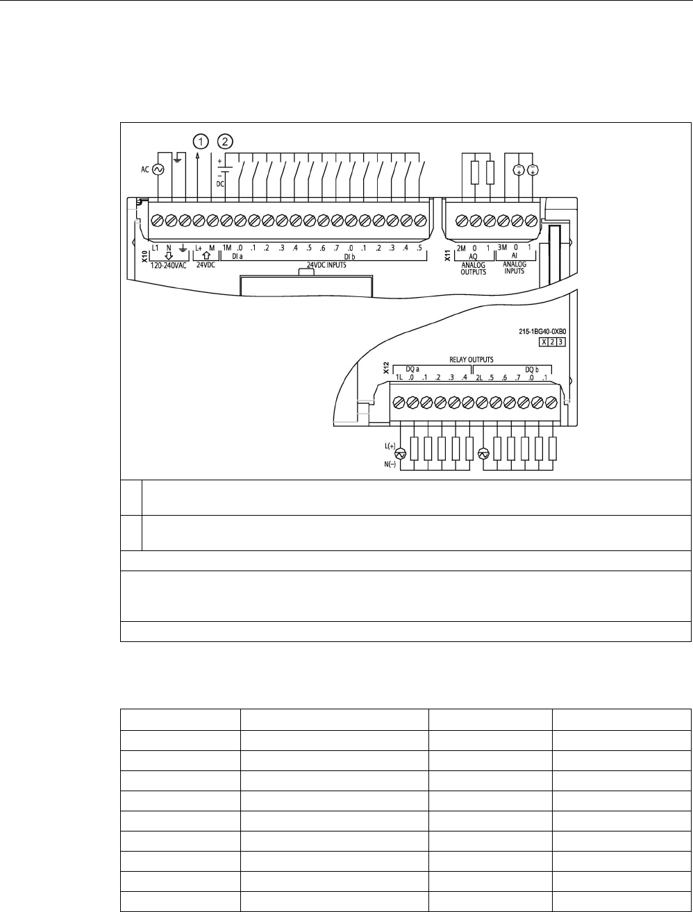
Technical specifications
A.7 CPU 1215C
S7-1200 Programmable controller
1420 System Manual, V4.2, 09/2016, A5E02486680-AK
A.7.5
CPU 1215C wiring diagrams
Table A- 81 CPU 1215C AC/DC/Relay (6ES7215-1BG40-0XB0)
①
24 V DC Sensor Power Out
For additional noise immunity, connect "M" to chassis ground even if not using sensor supply.
②
For sinking inputs, connect "-" to "M" (shown).
For sourcing inputs, connect "+" to "M".
Note 1: X11 connectors must be gold. See Appendix C, Spare Parts for article number.
Note 2: Either the L1 or N (L2) terminal can be connected to a voltage source up to 240 V AC. The N
terminal can be considered L2 and is not required to be grounded. No polarization is required for L1
and N (L2) terminals.
Note 3: See Device Configuration (Page 153) for information about the Ethernet port of the CPU.
Table A- 82 Connector pin locations for CPU 1215C AC/DC/Relay (6ES7215-1BG40-0XB0)
Pin
X10
X11 (gold)
X12
1
L1 /120-240 V AC
2 M
1L
2
N / 120 - 240 V AC
AQ 0
DQ a.0
3
Functional Earth
AQ 1
DQ a.1
4
L+ / 24 V DC Sensor Out
3M
DQ a.2
5
M / 24 V DC Sensor Out
AI 0
DQ a.3
6
1M
AI 1
DQ a.4
7
DI a.0
--
2L
8
DI a.1
--
DQ a.5
9
DI a.2
--
DQ a.6
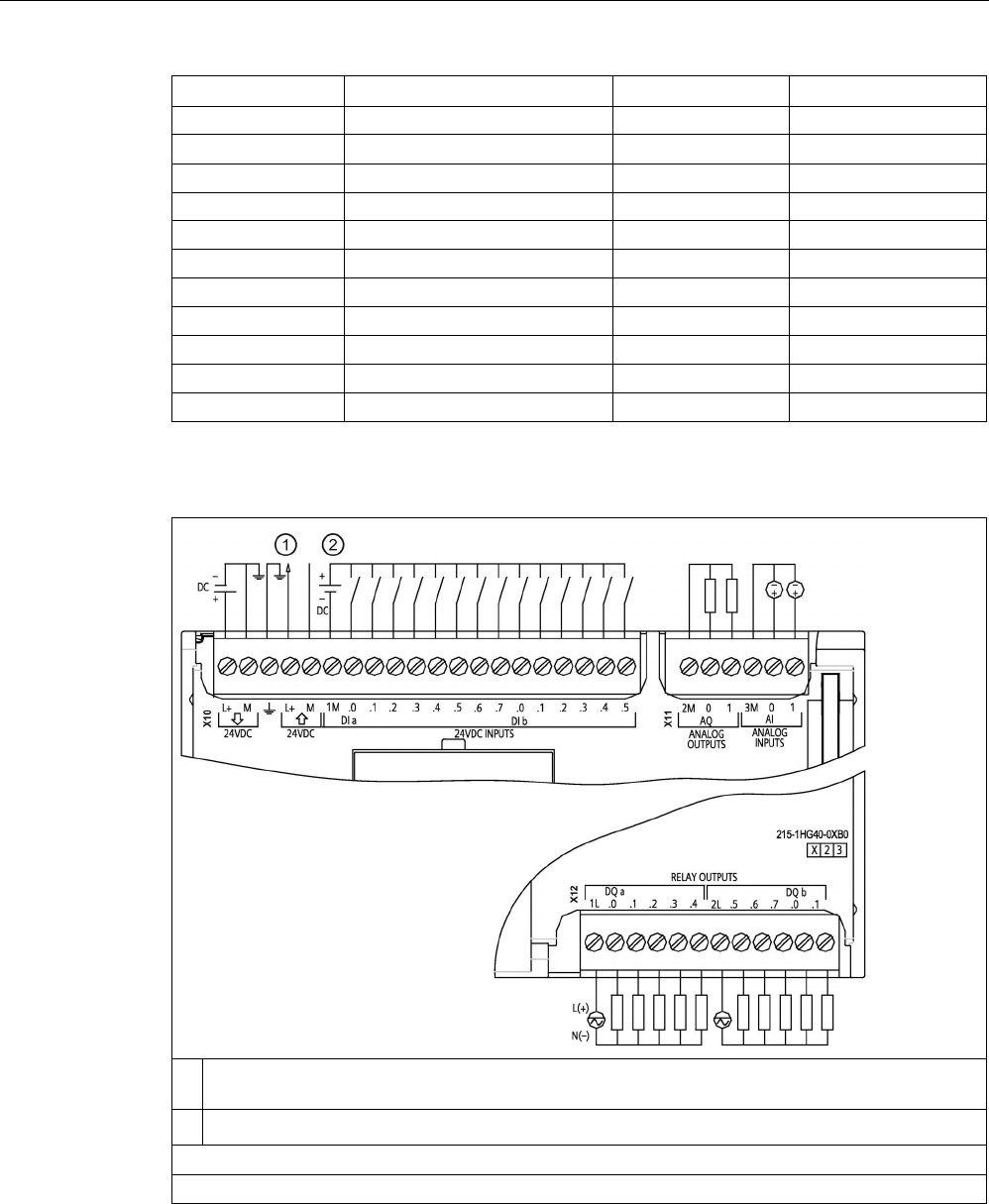
Technical specifications
A.7 CPU 1215C
S7-1200 Programmable controller
System Manual, V4.2, 09/2016, A5E02486680-AK 1421
Pin
X10
X11 (gold)
X12
10
DI a.3
--
DQ a.7
11 DI a.4 -- DQ b.0
12
DI a.5
--
DQ b.1
13 DI a.6 -- --
14
DI a.7
--
--
15
DI b.0
--
--
16
DI b.1
--
--
17
DI b.2
--
--
18
DI b.3
--
--
19
DI b.4
--
--
20
DI b.5
--
--
Table A- 83 CPU 1215C DC/DC/Relay (6ES7215-1HG40-0XB0)
①
24 V DC Sensor Power Out
For additional noise immunity, connect "M" to chassis ground even if not using sensor supply.
②
For sinking inputs, connect "-" to "M" (shown). For sourcing inputs, connect "+" to "M".
Note 1: X11 connectors must be gold. See Appendix C, Spare Parts for article number.
Note 2: See Device Configuration (Page 153) for information about the Ethernet port of the CPU.

Technical specifications
A.7 CPU 1215C
S7-1200 Programmable controller
1422 System Manual, V4.2, 09/2016, A5E02486680-AK
Table A- 84 Connector pin locations for CPU 1215C DC/DC/Relay (6ES7215-1HG40-0XB0)
Pin
X10
X11 (gold)
X12
1
L+ / 24 V DC
2 M
1L
2 M / 24 V DC AQ 0 DQ a.0
3
Functional Earth
AQ 1
DQ a.1
4 L+ / 24 V DC Sensor Out 3M DQ a.2
5
M / 24 V DC Sensor Out
AI 0
DQ a.3
6
1M
AI 1
DQ a.4
7
DI a.0
--
2L
8
DI a.1
--
DQ a.5
9
DI a.2
--
DQ a.6
10
DI a.3
--
DQ a.7
11
DI a.4
--
DQ b.0
12
DI a.5
--
DQ b.1
13
DI a.6
--
--
14
DI a.7
--
--
15
DI b.0
--
--
16
DI b.1
--
--
17
DI b.2
--
--
18
DI b.3
--
--
19
DI b.4
--
--
20
DI b.5
--
--
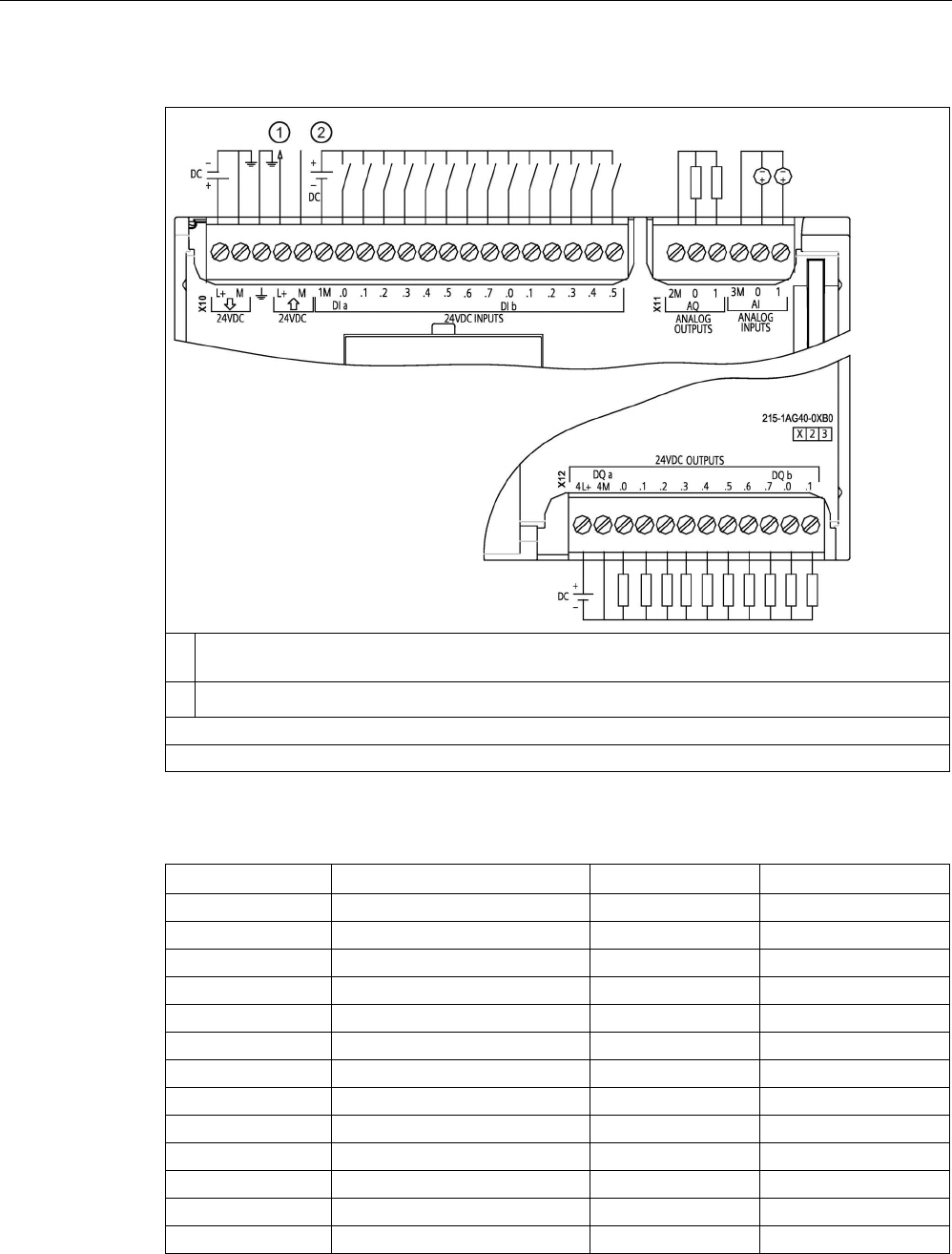
Technical specifications
A.7 CPU 1215C
S7-1200 Programmable controller
System Manual, V4.2, 09/2016, A5E02486680-AK 1423
Table A- 85 CPU 1215C DC/DC/DC (6ES7215-1AG40-0XB0)
①
24 V DC Sensor Power Out
For additional noise immunity, connect "M" to chassis ground even if not using sensor supply.
②
For sinking inputs, connect "-" to "M" (shown). For sourcing inputs, connect "+" to "M".
Note 1: X11 connectors must be gold. See Appendix C, Spare Parts for article number.
Note 2: See Device Configuration (Page 153) for information about the Ethernet port of the CPU.
Table A- 86 Connector pin locations for CPU 1215C DC/DC/DC (6ES7215-1AG40-0XB0)
Pin
X10
X11 (gold)
X12
1
L1 / 24 V DC
2 M
4L+
2 M / 24 V DC AQ 0 4M
3
Functional Earth
AQ 1
DQ a.0
4
L+ / 24 V DC Sensor Out
3M
DQ a.1
5
M / 24 V DC Sensor Out
AI 0
DQ a.2
6
1M
AI 1
DQ a.3
7
DI a.0
--
DQ a.4
8
DI a.1
--
DQ a.5
9
DI a.2
--
DQ a.6
10
DI a.3
--
DQ a.7
11
DI a.4
--
DQ b.0
12
DI a.5
--
DQ b.1
13
DI a.6
--
--

Technical specifications
A.7 CPU 1215C
S7-1200 Programmable controller
1424 System Manual, V4.2, 09/2016, A5E02486680-AK
Pin
X10
X11 (gold)
X12
14
DI a.7
--
--
15 DI b.0 -- --
16
DI b.1
--
--
17 DI b.2 -- --
18
DI b.3
--
--
19
DI b.4
--
--
20
DI b.5
--
--
Note
Unused analog inputs
should be shorted.

Technical specifications
A.8 CPU 1217C
S7-1200 Programmable controller
System Manual, V4.2, 09/2016, A5E02486680-AK 1425
A.8
CPU 1217C
A.8.1
General specifications and features
Table A- 87 General
Technical data
CPU 1217C DC/DC/DC
Article number
6ES7217-1AG40-0XB0
Dimensions W x H x D (mm) 150 x 100 x 75
Shipping weight
530 grams
Power dissipation 12 W
Current available (SM and CM bus)
1600 mA max. (5 V DC)
Current available (24 V DC)
400 mA max. (sensor power)
Digital input current consumption
(24 V DC)
4 mA/input used
Table A- 88 CPU features
Technical data
Description
User memory
(Refer to "General
technical specifica-
tions
(Page 1359)",
Internal CPU
memory reten-
tion".)
Work
150 Kbytes
Load
4 Mbytes, internal, expandable up to SD card size
Retentive 10 Kbytes
On-board digital I/O
14 inputs/ 10 outputs
On-board analog I/O
2 inputs/ 2 outputs
Process image size
1024 bytes of inputs (I) / 1024 bytes of outputs (Q)
Bit memory (M)
8192 bytes
Temporary (local) memory • 16 Kbytes for startup and program cycle (including associated FBs and FCs)
• 6 Kbytes for each of the other interrupt priority levels (including FBs and FCs)
Signal modules expansion
8 SMs max.
SB, CB, BB expansion
1 max.
Communication module expansion
3 CMs max.
High-speed counters Up to 6 configured to use any built-in or SB inputs (refer to CPU 1217C Digital
input (DI) H/W configuration table) (Page 1430)
• 1 MHz (Ib.2 to Ib.5)
• 100/180 kHz (Ia.0 to Ia.5)
• 30/120 kHz (Ia.6 to Ib.1)

Technical specifications
A.8 CPU 1217C
S7-1200 Programmable controller
1426 System Manual, V4.2, 09/2016, A5E02486680-AK
Technical data
Description
Pulse outputs Up to 4 configured to use any built-in or SB outputs (refer to CPU 1217C Digital
output (DQ) H/W configuration table) (Page 1430)
• 1 MHz (Qa.0 to Qa.3)
• 100 kHz (Qa.4 to Qb.1)
Pulse catch inputs
14
Time delay interrupts
4 total with 1 ms resolution
Cyclic interrupts 4 total with 1 ms resolution
Edge interrupts
12 rising and 12 falling (16 and 16 with optional signal board)
Memory card
SIMATIC memory card (optional)
Real time clock accuracy
+/- 60 seconds/month
Real time clock retention time
20 days typ./12 days min. at 40 °C (maintenance-free Super Capacitor)
1 The slower speed is applicable when the HSC is configured for quadrature mode of operation.
Table A- 89 Performance
Type of instruction
Execution speed
Direct addressing (I, Q and M)
DB accesses
Boolean
0.08 μs/instruction
Move
Move_Bool
0.3 μs/instruction
1.17 μs/instruction
Move_Word
0.137 μs/instruction
1.0 μs/instruction
Move_Real
0.72 μs/instruction
1.0 μs/instruction
Real Math
Add Real
1.48 μs/instruction
1.78 μs/instruction
Note
Many variables affect measured times. The above performance times are for the fastest
instructions in this category and error
-free programs.

Technical specifications
A.8 CPU 1217C
S7-1200 Programmable controller
System Manual, V4.2, 09/2016, A5E02486680-AK 1427
A.8.2
Timers, counters and code blocks supported by CPU 1217C
Table A- 90 Blocks, timers and counters supported by CPU 1217C
Element
Description
Blocks
Type
OB, FB, FC, DB
Size 64 Kbytes
Quantity
Up to 1024 blocks total (OBs + FBs + FCs + DBs)
Address range for FBs, FCs,
and DBs
FB and FC: 1 to 65535 (such as FB 1 to FB 65535)
DB: 1 to 59999
Nesting depth 16 from the program cycle or startup OB
6 from any interrupt event OB
Monitoring
Status of 2 code blocks can be monitored simultaneously
OBs
Program cycle
Multiple
Startup
Multiple
Time-delay interrupts
4 (1 per event)
Cyclic interrupts
4 (1 per event)
Hardware interrupts
50 (1 per event)
Time error interrupts
1
Diagnostic error interrupts
1
Pull or plug of modules
1
Rack or station failure
1
Time of day
Multiple
Status
1
Update
1
Profile
1
MC-Interpolator
1
MC-Servo 1
MC-PreServo
1
MC-PostServo 1
Timers
Type
IEC
Quantity
Limited only by memory size
Storage
Structure in DB, 16 bytes per timer
Counters
Type
IEC
Quantity
Limited only by memory size
Storage Structure in DB, size dependent upon count type
• SInt, USInt: 3 bytes
• Int, UInt: 6 bytes
• DInt, UDInt: 12 bytes

Technical specifications
A.8 CPU 1217C
S7-1200 Programmable controller
1428 System Manual, V4.2, 09/2016, A5E02486680-AK
Table A- 91 Communication
Technical data
Description
Number of ports
2
Type Ethernet
HMI device
4
Programming device (PG) 1
Connections • 8 for Open User Communication (active or passive): TSEND_C,
TRCV_C, TCON, TDISCON, TSEND, and TRCV
• 3 for server GET/PUT (CPU-to-CPU) S7 communication
• 8 for client GET/PUT (CPU-to-CPU) S7 communication
Data rates
10/100 Mb/s
Isolation (external signal logic)
Transformer isolated, 1500 V AC (type test)
1
Cable type
CAT5e shielded
Interfaces
Number of PROFINET interfaces
1
Number of interfaces PROFIBUS
0
Interface
Interface hardware
Number of ports
2
Integrated switch
Yes
RJ-45 (Ethernet)
Yes; X1
Protocols
PROFINET IO controller
Yes
PROFINET IO device
Yes
SIMATIC communication
Yes
Open IE communication
Yes
Web server
Yes
Media redundancy Yes
PROFINET IO controller
Services
PG/OP communication
Yes
S7 routing
Yes
Isochronous mode
No
Open IE communication
Yes
IRT
No
MRP
Yes as MRP client
PROFIenergy Yes. The S7-1200 CPU only supports the PROFIenergy entity (with I-
device functionality).
Prioritized startup
Yes (max. 16 PROFINET devices)
Number of connectable I/O devices max.
16
Number of IO devices that you can connect for
RT, max.
16
Of which are in line, max.
16

Technical specifications
A.8 CPU 1217C
S7-1200 Programmable controller
System Manual, V4.2, 09/2016, A5E02486680-AK 1429
Technical data
Description
Number of IO devices that can be activated/
deactivated simultaneously, max.
8
Update times The minimum value of the update time also depends on the communi-
cation component set for PROFINET IO, on the number of IO devices,
and the quantity of configured user data.
With RT
Send clock of 1 ms
1 ms to 512 ms
PROFINET IO device
Services
PG/OP communication
Yes
S7 routing
Yes
Isochronous mode
No
Open IE communication
Yes
IRT, supported
No
MRP, supported
Yes
PROFIenergy
Yes
Shared device
Yes
Number of IO controllers with shared device,
max.
2
SIMATIC communication
S7 communication, as server
Yes
S7 communication, as client
Yes
User data per job, max. See online help (S7 communication, user data size)
Open IE communication
TCP/IP: Yes
Data length, max.
8 KB
Several passive connections per port,
supported
Yes
ISO-on-TCP (RFC1006):
Yes
Data length, max.
8 KB
UDP:
Yes
Data length, max.
1472 bytes
DHCP
No
SNMP
Yes
DCP
Yes
LLDP
Yes
1
Ethernet port isolation is designed to limit hazard during short term network faults to hazardous voltages. It does not
conform to safety requirements for routine AC line voltage isolation.

Technical specifications
A.8 CPU 1217C
S7-1200 Programmable controller
1430 System Manual, V4.2, 09/2016, A5E02486680-AK
Table A- 92 Power supply
Technical data
CPU 1217C DC/DC/DC
Voltage range
20.4 V DC to 28.8 V DC
Line frequency --
Input current (max. load)
CPU only
600 mA at 24 V DC
CPU with all
expansion
accessories
1600 mA at 24 V DC
Inrush current (max.)
12 A at 28.8 V DC
Isolation (input power to logic)
Not isolated
Hold up time (from loss of power)
10 ms at 24 V DC
Internal fuse, not user replaceable
3 A, 250 V, slow blow
Table A- 93 Sensor power
Technical data
CPU 1217C DC/DC/DC
Voltage range
L+ minus 4 V DC min.
Output current rating (max.)
400 mA (short-circuit protected)
Maximum ripple noise (<10 MHz)
Same as input line
Isolation (CPU logic to sensor power)
Not isolated
A.8.3
Digital inputs and outputs
Table A- 94 Digital inputs
Technical data
CPU 1217C DC/DC/DC
Number of inputs 14: total:
10: Sink/source (IEC Type 1 sink)
4: Differential (RS422/RS485)
Type: Sink/source
(IEC Type 1 sink)
Ia.0 to Ia.7, Ib.0 to Ib.1
Rated voltage
24 V DC at 4 mA, nominal
Continuous permissible voltage
30 V DC, max.
Surge voltage
35 V DC for 0.5 sec.
Logic 1 signal (min.)
15 V DC at 2.5 mA
Logic 0 signal (max.)
5 V DC at 1 mA
Isolation (field side to logic)
707 V DC (type test)
Isolation groups 1
Filter times us settings: 0.1, 0.2, 0.4, 0.8, 1.6, 3.2, 6.4, 10.0, 12.8, 20.0
ms settings: 0.05, 0.1, 0.2, 0.4, 0.8, 1.6, 3.2, 6.4, 10.0, 12.8, 20.0
HSC clock input rates (max.)
(Logic 1 Level = 15 to 26 V DC)
100/80 kHz (Ia.0 to Ia.5)
30/20 kHz (Ia.6 to Ib.1)

Technical specifications
A.8 CPU 1217C
S7-1200 Programmable controller
System Manual, V4.2, 09/2016, A5E02486680-AK 1431
Technical data
CPU 1217C DC/DC/DC
Type: Differential input
(RS422/RS485)
Ib.2 to Ib.5 (.2+ .2- to .5+ .5-)
Common mode voltage range -7 V to +12 V, 1 second, 3 VRMS continuous (RS422/RS485 characteristics)
Built-in termination and bias 390 Ω to 2M on Ib'-', 390 Ω to +5 V on Ib'-', (biased OFF when T/B open-circuit)
220 Ω between Ib'+' and Ib'-'
Receiver input impedance
100 Ω including bias and termination
Differential receiver
threshold/sensitivity
+/- 0.2 V min., 60 mV typical hysteresis (RS422/RS485 characteristics)
Isolation (field side to logic)
707 V DC (type test)
Isolation groups
1
Filter times us settings: 0.1, 0.2, 0.4, 0.8, 1.6, 3.2, 6.4, 10.0, 12.8, 20.0
ms settings: 0.05, 0.1, 0.2, 0.4, 0.8, 1.6, 3.2, 6.4, 10.0, 12.8, 20.0
HSC clock input rates (max.) Single phase: 1 MHz (Ib.2 to Ib.5)
Quadrature phase: 1 MHz (Ib.2 to Ib.5)
Differential input channel-to-channel
skew
40 ns max.
General specifications (all digital
inputs)
Number of inputs on simultaneously 5 Sink/source inputs (no adjacent points) and 4 differential inputs at 60 °C horizon-
tal or 50 °C vertical
14 at 55 °C horizontal or 45 °C vertical
Cable length (meters) 500 m shielded, 300 m unshielded
50 m shielded for HSC inputs (sink/source)
50 m shielded, twisted pair for all differential inputs

Technical specifications
A.8 CPU 1217C
S7-1200 Programmable controller
1432 System Manual, V4.2, 09/2016, A5E02486680-AK
Table A- 95 CPU 1217C Digital input (DI) H/W configuration table
Input
Type and rate
DIa.0 Type: 24 V, source-sink Type 1 input
High-speed counter input rate: 100 kHz max.
DIa.1 Type: 24 V, source-sink Type 1 input
High-speed counter input rate: 100 kHz max.
DIa.2 Type: 24 V, source-sink Type 1 input
High-speed counter input rate: 100 kHz max.
DIa.3 Type: 24 V, source-sink Type 1 input
High-speed counter input rate: 100 kHz max.
DIa.4 Type: 24 V, source-sink Type 1 input
High-speed counter input rate: 100 kHz max.
DIa.5 Type: 24 V, source-sink Type 1 input
High-speed counter input rate: 100 kHz max.
DIa.6 Type: 24 V, source-sink Type 1 input
High-speed counter input rate: 30 kHz max.
DIa.7 Type: 24 V, source-sink Type 1 input
High-speed counter input rate: 30 kHz max.
DIb.0 Type: 24 V, source-sink Type 1 input
High-speed counter input rate: 30 kHz max.
DIb.1 Type: 24 V, source-sink Type 1 input
High-speed counter input rate: 30 kHz max.
DIb.2+ .2- Type: RS422/RS485 differential input
High-speed counter input rate: 1 MHz max.
DIb.3+ .3- Type: RS422/RS485 differential input
High-speed counter input rate: 1 MHz max.
DIb.4+ .4- Type: RS422/RS485 differential input
High-speed counter input rate: 1 MHz max.
DIb.5+ .5- Type: RS422/RS485 differential input
High-speed counter input rate: 1 MHz max.

Technical specifications
A.8 CPU 1217C
S7-1200 Programmable controller
System Manual, V4.2, 09/2016, A5E02486680-AK 1433
Table A- 96 Digital outputs
Technical data
CPU 1217C DC/DC/DC
Number of outputs 10 total
6: Solid state - MOSFET (sourcing)
4: Differential (RS422/RS485)
Type: Solid state - MOSFET
(sourcing output)
Qa.4 to Qb.1
Voltage range
20.4 to 28.8 V DC
Logic 1 signal at max. current
20 V DC min.
Logic 0 signal with 10 KΩ load
0.1 V DC max.
Current (max.)
0.5 A
Lamp load
5 W
ON state resistance
0.6 Ω max.
Leakage current per point
10 μA max.
Surge current
8 A for 100 ms max.
Overload protection
No
Isolation (field side to logic)
707 V DC (type test)
Isolation groups
1
Inductive clamp voltage
L+ minus 48 V DC, 1 W dissipation
Switching delay (Qa.4 to Qb.1) 1.0 μs max., off to on
3.0 μs max., on to off
Maximum relay switching frequency
--
Pulse Train Output rate
100 kHz max. (Qa.4 to Qb.1)1, 2 Hz min.
Type: Differential output
(RS422/RS485)
Qa.0 to Qa.3 (.0+ 0- to .3+ .3-)
Common mode voltage range
-7 V to +12 V, 1 second, 3 VRMS continuous (RS422/RS485 characteristics)
Transmitter differential output voltage
2 V min. at RL = 100 Ω, 1.5 V min. at RL = 54 Ω (RS422/RS485 characteristics)
Built-in termination
100 Ω between Qa'+' and Qa'-'
Driver output impedance
100 Ω including termination
Isolation (field side to logic)
707 V DC (type test)
Isolation groups
1
Switching delay (DQa.0 to DQa.3)
100 ns max.
Differential output channel-to-channel
skew
40 ns max.
Pulse train output rate
1 MHz (Qa.0 to Qa.3), 2 Hz min.
General specifications
(all digital outputs)
Behavior on RUN to STOP
Last value or substitute value (default value 0)

Technical specifications
A.8 CPU 1217C
S7-1200 Programmable controller
1434 System Manual, V4.2, 09/2016, A5E02486680-AK
Technical data
CPU 1217C DC/DC/DC
Number of outputs on simultaneously 3 Solid state - MOSFET (sourcing) outputs (no adjacent points) and 4 differential
outputs at 60 °C horizontal or 50 °C vertical
10 at 55 °C horizontal or 45 °C vertical
Cable length (meters) 500 m shielded, 150 m unshielded
1
Depending on your pulse receiver and cable, an additional load resistor (at least 10% of rated current) may improve
pulse signal quality and noise immunity.
Table A- 97 CPU 1217C Digital output (DQ) H/W configuration table
Output
Type and rate
DQa.0+ .0- Type: RS422/RS485 differential output
Pulse train output rate: 1 MHz max., 2 Hz min.
DQa.1+ .1- Type: RS422/RS485 differential output
Pulse train output rate: 1 MHz max., 2 Hz min.
DQa.2+ .2- Type: RS422/RS485 differential output
Pulse train output rate: 1 MHz max., 2 Hz min.
DQa.3+ .3- Type: RS422/RS485 differential output
Pulse train output rate: 1 MHz max., 2 Hz min.
DQa.4 Type: 24 V Sourcing output
Pulse train output rate: 100 kHz max., 2 Hz min.
DQa.5 Type: 24 V Sourcing output
Pulse train output rate: 100 kHz max., 2 Hz min.
DQa.6 Type: 24 V Sourcing output
Pulse train output rate: 100 kHz max., 2 Hz min.
DQa.7 Type: 24 V Sourcing output
Pulse train output rate: 100 kHz max., 2 Hz min.
DQb.0 Type: 24 V Sourcing output
Pulse train output rate: 100 kHz max., 2 Hz min.
DQb.1 Type: 24 V Sourcing output
Pulse train output rate: 100 kHz max., 2 Hz min.

Technical specifications
A.8 CPU 1217C
S7-1200 Programmable controller
System Manual, V4.2, 09/2016, A5E02486680-AK 1435
A.8.4
Analog inputs and outputs
A.8.4.1
Analog input specifications
Table A- 98 Analog inputs
Technical data
Description
Number of inputs
2
Type Voltage (single-ended)
Full-scale range
0 to 10 V
Full-scale range (data word)
0 to 27648
Overshoot range
10.001 to 11.759 V
Overshoot range (data word)
27649 to 32511
Overflow range
11.760 to 11.852 V
Overflow range (data word)
32512 to 32767
Resolution
10 bits
Maximum withstand voltage
35 V DC
Smoothing None, Weak, Medium, or Strong
See the table for Step response (ms) for the analog inputs of the CPU
(Page 1435).
Noise rejection
10, 50, or 60 Hz
Impedance
≥100 KΩ
Isolation (field side to logic)
None
Accuracy (25 °C / -20 to 60 °C)
3.0% / 3.5% of full-scale
Cable length (meters)
100 m, shielded twisted pair
A.8.4.2
Step response of built-in analog inputs of the CPU
Table A- 99 Step Response (ms), 0 V to 10 V measured at 95%
Smoothing selection (sample averaging)
Rejection frequency (Integration time)
60 Hz
50 Hz
10 Hz
None (1 cycle): No averaging
50 ms
50 ms
100 ms
Weak (4 cycles): 4 samples
60ms
70 ms
200 ms
Medium (16 cycles): 16 samples
200 ms
240 ms
1150 ms
Strong (32 cycles): 32 samples
400 ms
480 ms
2300 ms
Sample time
4.17 ms
5 ms
25 ms

Technical specifications
A.8 CPU 1217C
S7-1200 Programmable controller
1436 System Manual, V4.2, 09/2016, A5E02486680-AK
A.8.4.3
Sample time for the built-in analog ports of the CPU
Table A- 100 Sample time for built-in analog inputs of the CPU
Rejection frequency (Integration time selection)
Sample time
60 Hz (16.6 ms)
4.17 ms
50 Hz (20 ms)
5 ms
10 Hz (100 ms)
25 ms
A.8.4.4
Measurement ranges of the analog inputs for voltage (CPUs)
Table A- 101 Analog input representation for voltage (CPUs)
System
Voltage Measuring Range
Decimal
Hexadecimal
0 to 10 V
32767
7FFF
11.852 V
Overflow
32512
7F00
32511
7EFF
11.759 V
Overshoot range
27649
6C01
27648
6C00
10 V
Rated range
20736
5100
7.5 V
34
22
12 mV
0
0
0 V
Negative values Negative values are not sup-
ported
A.8.4.5
Analog output specifications
Table A- 102 Analog outputs
Technical data
Description
Number of outputs
2
Type
Current
Full-scale range
0 to 20 mA
Full-scale range (data word)
0 to 27648
Overshoot range
20.01 to 23.52 mA
Overshoot range (data word)
27649 to 32511
Overflow range
see footnote
1
Overflow range data word
32512 to 32767
Resolution
10 bits
Output drive impedance ≤500 Ω max.
Isolation (field side to logic)
None
Accuracy (25 °C / -20 to 60 °C)
3.0% / 3.5% of full-scale

Technical specifications
A.8 CPU 1217C
S7-1200 Programmable controller
System Manual, V4.2, 09/2016, A5E02486680-AK 1437
Technical data
Description
Settling time
2 ms
Cable length (meters) 100 m, shielded twisted pair
1
In an overflow condition, analog outputs will behave according to the device configuration properties settings. In the
"Reaction to CPU STOP" parameter, select either: "Use substitute value" or "Keep last value".
Table A- 103 Analog output representation for current (CPU 1215C and CPU 1217C)
System
Current output range
Decimal
Hexadecimal
0 mA to 20 mA
32767
7FFF
See note 1
Overflow
32512
7F00
See note 1
32511
7EFF
23.52 mA
Overshoot range
27649
6C01
27648
6C00
20 mA
Rated range
20736
5100
15 mA
34
22
0.0247 mA
0
0
0 mA
Negative values Negative values are not
supported
1
In an overflow condition, analog outputs will behave according to the device configuration properties settings. In the
"Reaction to CPU STOP" parameter, select either: "Use substitute value" or "Keep last value".
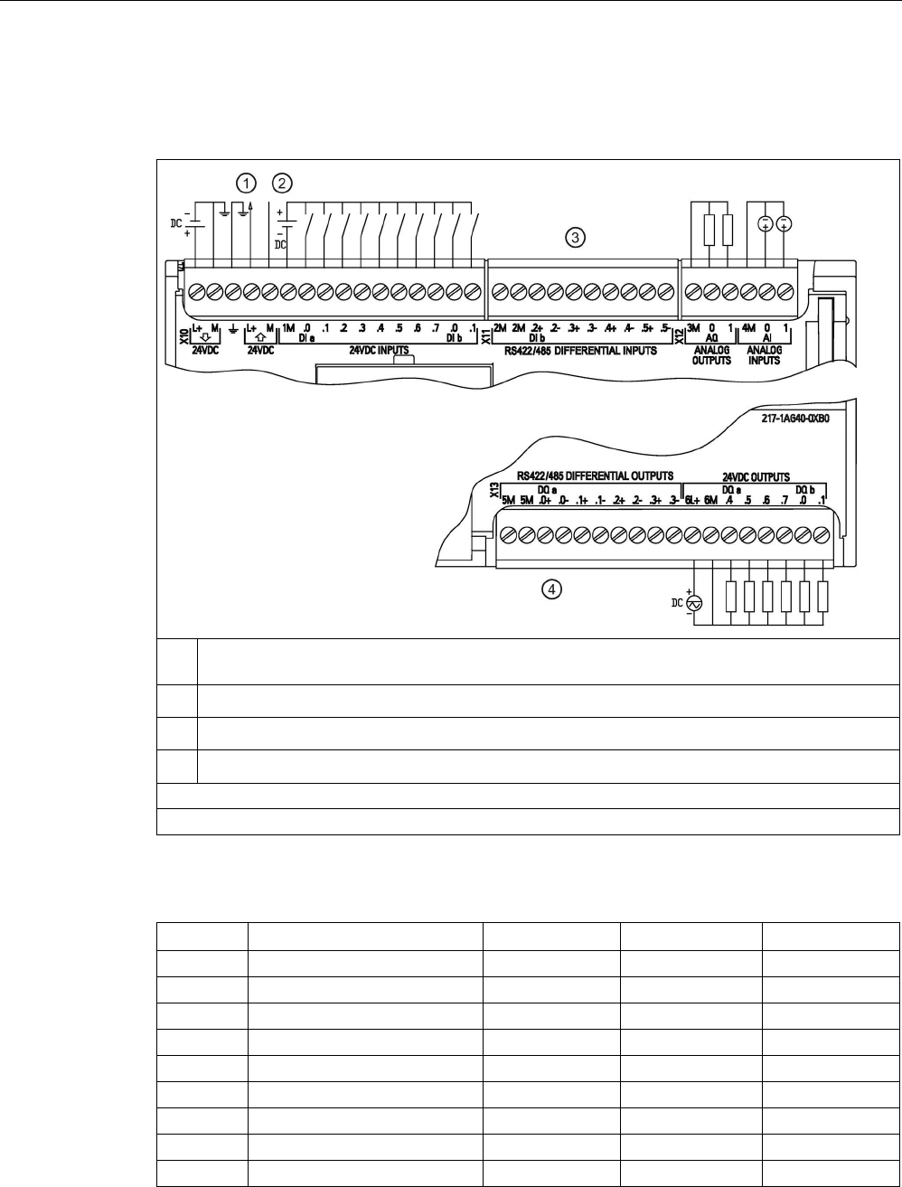
Technical specifications
A.8 CPU 1217C
S7-1200 Programmable controller
1438 System Manual, V4.2, 09/2016, A5E02486680-AK
A.8.5
CPU 1217C wiring diagrams
Table A- 104 CPU 1217C DC/DC/DC (6ES7217-1AG40-0XB0)
①
24 V DC Sensor Power Out
For additional noise immunity, connect "M" to chassis ground even if not using sensor supply.
②
For sinking inputs, connect "-" to "M" (shown). For sourcing inputs, connect "+" to "M".
③
See CPU 1217C Differential input (DI) detail and application example (Page 1440).
④
See CPU 1217C Differential output (DQ) detail and application example (Page 1441).
Note 1: X12 connectors must be gold. See Appendix C, Spare Parts (Page 1564) for article number.
Note 2: See Device configuration (Page 153) for information about the Ethernet port of the CPU.
Table A- 105 Connector pin locations for CPU 1217C DC/DC/DC (6ES7217-1AG40-0XB0)
Pin
X10
X11
X12 (gold)
X13
1
L+ / 24 V DC
2M
3M
5M
2
M / 24 V DC
2M
AQ 0
5M
3
Functional Earth
DI b.2+
AQ 1
DQ a.0+
4
L+ / 24 V DC Sensor Out
DI b.2-
4M
DQ a.0-
5
M / 24 V DC Sensor Out
DI b.3+
AI 0
DQ a.1+
6
1M
DI b.3-
AI 1
DQ a.1-
7
DI a.0
DI b.4+
--
DQ a.2+
8
DI a.1
DI b.4-
--
DQ a.2-
9
DI a.2
DI b.5+
--
DQ a.3+

Technical specifications
A.8 CPU 1217C
S7-1200 Programmable controller
System Manual, V4.2, 09/2016, A5E02486680-AK 1439
Pin
X10
X11
X12 (gold)
X13
10
DI a.3
DI b.5-
--
DQ a.3-
11 DI a.4 -- -- 6L+
12
DI a.5
--
--
6M
13 DI a.6 -- -- DQ a.4
14
DI a.7
--
--
DQ a.5
15
DI b.0
--
--
DQ a.6
16
DI b.1
--
--
DQ a.7
17
--
--
--
DQ b.0
18
--
--
--
DQ b.1
Note
Unused analog inputs should be shorted.
See also
Analog inputs and outputs (Page 1417)
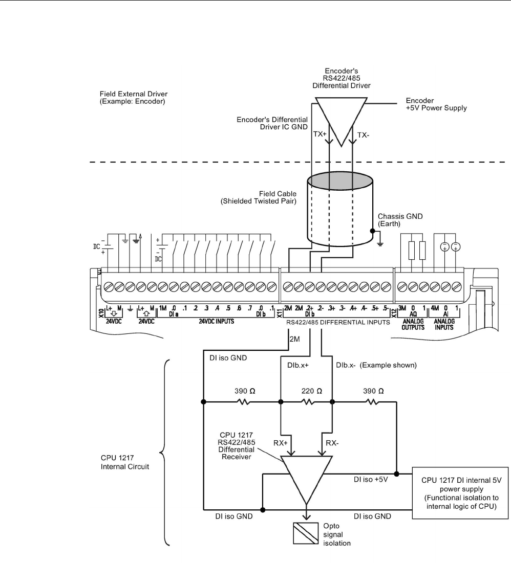
Technical specifications
A.8 CPU 1217C
S7-1200 Programmable controller
1440 System Manual, V4.2, 09/2016, A5E02486680-AK
A.8.6
CPU 1217C Differential Input (DI) detail and application example
Notes
• Each differential DI is biased "OFF" when terminal block screws are open-circuit.
• Built-in DI Termination and Bias = 100 Ω equivalent impedance.
• Built-in DI Termination and Bias resistors limit the continuous common mode voltage
range. See electrical specifications for detail.
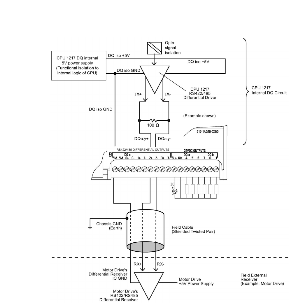
Technical specifications
A.8 CPU 1217C
S7-1200 Programmable controller
System Manual, V4.2, 09/2016, A5E02486680-AK 1441
A.8.7
CPU 1217C Differential Output (DQ) detail and application example
Note
• Built-in DQ Termination resistor limits the continuous common mode voltage range. See
electrical specifications for detail.

Technical specifications
A.9 Digital signal modules (SMs)
S7-1200 Programmable controller
1442 System Manual, V4.2, 09/2016, A5E02486680-AK
A.9
Digital signal modules (SMs)
A.9.1
SM 1221 digital input specifications
Table A- 106 General specifications
Model
SM 1221 DI 8 x 24 V DC
SM 1221 DI 16 x 24 V DC
Article number
6ES7221-1BF32-0XB0
6ES7221-1BH32-0XB0
Dimensions W x H x D (mm) 45 x 100 x 75
Weight
170 grams
210 grams
Power dissipation 1.5 W 2.5 W
Current consumption (SM Bus)
105 mA
130 mA
Current consumption (24 V DC)
4 mA / input used
Table A- 107 Digital inputs
Model
SM 1221 DI 8 x 24 V DC
SM 1221 DI 16 x 24 V DC
Number of inputs
8
16
Type
Sink/Source (IEC Type 1 sink)
Rated voltage
24 V DC at 4 mA, nominal
Continuous permissible voltage
30 V DC, max.
Surge voltage
35 V DC for 0.5 sec.
Logic 1 signal (min.)
15 V DC at 2.5 mA
Logic 0 signal (max.)
5 V DC at 1 mA
Isolation (field side to logic)
707 V DC (type test)
Isolation groups
2
4
Filter times 0.2, 0.4, 0.8, 1.6, 3.2, 6.4, and 12.8 ms
(selectable in groups of 4)
0.2, 0.4, 0.8, 1.6, 3.2, 6.4, and 12.8 ms
(selectable in groups of 4)
Number of inputs on simultaneously
8
16
Cable length (meters)
500 m shielded, 300 unshielded
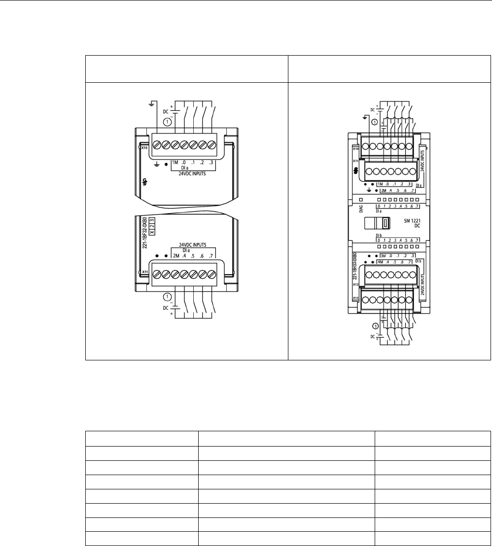
Technical specifications
A.9 Digital signal modules (SMs)
S7-1200 Programmable controller
System Manual, V4.2, 09/2016, A5E02486680-AK 1443
Table A- 108 Wiring diagrams for the digital input SMs
SM 1221 DI 8 x 24 V DC (6ES7221-1BF32-
0XB0)
SM 1221 DI 16 x 24 V DC (6ES7221-1BH32-
0XB0)
① For sinking inputs, connect "-" to "M" (shown). For sourcing inputs, connect "+" to "M".
Table A- 109 Connector pin locations for SM 1221 DI 8 x 24 V DC (6ES7221-1BF32-0XB0)
Pin
X10
X11
1
Functional Earth
No connection
2
No connection
No connection
3
1M
2M
4
DI a.0
DI a.4
5 DI a.1 DI a.5
6
DI a.2
DI a.6
7
DI a.3
DI a.7

Technical specifications
A.9 Digital signal modules (SMs)
S7-1200 Programmable controller
1444 System Manual, V4.2, 09/2016, A5E02486680-AK
Table A- 110 Connector pin locations for SM 1221 DI 16 x 24 V DC (6ES7221-1BH32-0XB0)
Pin
X10
X11
X12
X13
1
No connection
Functional Earth
No connection
No connection
2 No connection No connection No connection No connection
3
1M
2M
3 M
4 M
4 DI a.0 DI a.4 DI b.0 DI b.4
5
DI a.1
DI a.5
DI b.1
DI b.5
6
DI a.2
DI a.6
DI b.2
DI b.6
7
DI a.3
DI a.7
DI b.3
DI b.7
A.9.2
SM 1222 8-point digital output specifications
Table A- 111 General specifications
Model
SM 1222 DQ 8 x Relay
SM 1222 DQ 8 Relay
Changeover
SM 1222 DQ 8 x 24 V DC
Article number
6ES7222-1HF32-0XB0
6ES7222-1XF32-0XB0
6ES7222-1BF32-0XB0
Dimensions W x H x D (mm)
45 x 100 x 75
70 x 100 x 75
45 x 100 x 75
Weight
190 grams
310 grams
180 grams
Power dissipation
4.5 W
5 W
1.5 W
Current consumption (SM Bus)
120 mA
140 mA
120 mA
Current consumption (24 V DC)
11 mA / Relay coil used
16.7 mA/Relay coil used
50 mA
Table A- 112 Digital outputs
Model
SM 1222 DQ 8 x Relay
SM 1222 DQ 8 Relay
Changeover
SM 1222 DQ 8 x 24 V DC
Number of outputs
8
8
8
Type Relay, mechanical Relay change over con-
tact
Solid state - MOSFET
(sourcing)
Voltage range 5 to 30 V DC or
5 to 250 V AC
5 to 30 V DC or
5 to 250 V AC
20.4 to 28.8 V DC
Logic 1 signal at max. current
--
--
20 V DC min.
Logic 0 signal with 10K Ω load
--
--
0.1 V DC max
Current (max.) 2.0 A 2.0 A 0.5 A
Lamp load
30 W DC/200 W AC
30 W DC/200 W AC
5 W
ON state contact resistance
0.2 Ω max. when new
0.2 Ω max. when new
0.6 Ω max.
Leakage current per point
--
--
10 μA max.
Surge current
7 A with contacts closed
7 A with contacts closed
8 A for 100 ms max.
Overload protection
No
No
Isolation (field side to logic) 1500 V AC (coil to contact)
None (coil to logic)
1500 V AC (coil to con-
tact)
707 V DC (type test)

Technical specifications
A.9 Digital signal modules (SMs)
S7-1200 Programmable controller
System Manual, V4.2, 09/2016, A5E02486680-AK 1445
Model
SM 1222 DQ 8 x Relay
SM 1222 DQ 8 Relay
Changeover
SM 1222 DQ 8 x 24 V DC
Isolation groups
2
8
1
Current per common (max.) 10 A 2 A 4 A
Inductive clamp voltage -- -- L+ minus 48 V, 1 W dis-
sipation
Switching delay 10 ms max. 10 ms max. 50 μs max. off to on
200 μs max. on to off
Maximum relay switching frequency
1 Hz
1 Hz
--
Lifetime mechanical (no load) 10,000,000 open/close
cycles
10,000,000 open/close
cycles
--
Lifetime contacts at rated load (N.O.
contact)
100,000 open/close cycles 100,000 open/close cy-
cles
--
Behavior on RUN to STOP Last value or substitute
value (default value 0)
Last value or substitute
value (default value 0)
Last value or substitute
value (default value 0)
Number of outputs on simultaneously 8 • 4 (no adjacent points)
at 60 °C horizontal or
50 °C vertical
• 8 at 55 °C horizontal
or 45 °C vertical
8
Cable length (meters) 500 m shielded,
150 m unshielded
500 m shielded,
150 m unshielded
500 m shielded,
150 m unshielded

Technical specifications
A.9 Digital signal modules (SMs)
S7-1200 Programmable controller
1446 System Manual, V4.2, 09/2016, A5E02486680-AK
A.9.3
SM 1222 16-point digital output specifications
Table A- 113 General specifications
Model
SM 1222 DQ 16 x Relay
SM 1222 DQ 16 x 24 V DC
Article number
6ES7222-1HH32-0XB0
6ES7222-1BH32-0XB0
Dimensions W x H x D (mm) 45 x 100 x 75 45 x 100 x 75
Weight
260 grams
220 grams
Power dissipation 8.5 W 2.5 W
Current consumption (SM Bus)
135 mA
140 mA
Current consumption (24 V DC)
11 mA / Relay coil used
100 mA
Table A- 114 Digital outputs
Model
SM 1222
DQ 16 x Relay
SM 1222
DQ 16 x 24 V DC
Number of outputs
16
16
Type
Relay, mechanical
Solid state - MOSFET (sourcing)
Voltage range
5 to 30 V DC or 5 to 250 V AC
20.4 to 28.8 V DC
Logic 1 signal at max. current
-
20 V DC min.
Logic 0 signal with 10K Ω load
-
0.1 V DC max.
Current (max.)
2.0 A
0.5 A
Lamp load
30 W DC/200 W AC
5 W
ON state contact resistance
0.2 Ω max. when new
0.6 Ω max.
Leakage current per point
--
10 μA max.
Surge current
7 A with contacts closed
8 A for 100 ms max.
Overload protection
No
Isolation (field side to logic) 1500 V AC (coil to contact)
None (coil to logic)
707 V DC (type test)
Isolation groups
4
1
Current per common (max.)
10 A
8 A
Inductive clamp voltage
-
L+ minus 48 V, 1 W dissipation
Switching delay 10 ms max. 50 μs max. off to on
200 μs max. on to off
Maximum relay switching frequency
1 Hz
-
Lifetime mechanical (no load)
10,000,000 open/close cycles
-
Lifetime contacts at rated load (N.O.
contact)
100,000 open/close cycles -
Behavior on RUN to STOP Last value or substitute value (default
value 0)
Last value or substitute value (default
value 0)
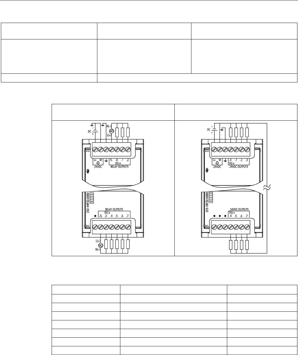
Technical specifications
A.9 Digital signal modules (SMs)
S7-1200 Programmable controller
System Manual, V4.2, 09/2016, A5E02486680-AK 1447
Model
SM 1222
DQ 16 x Relay
SM 1222
DQ 16 x 24 V DC
Number of outputs on simultaneously • 8 (no adjacent points) at 60 °C
horizontal or 50 °C vertical
• 16 at 55 °C horizontal or 45 °C
vertical
16
Cable length (meters)
500 m shielded, 150 m unshielded
Table A- 115 Wiring diagrams for the 8-point digital output SMs
SM 1222 DQ 8 x Relay
(6ES7222-1HF32-0XB0)
SM 1222 DQ 8 x 24 V DC
(6ES7222-1BF32-0XB0)
Table A- 116 Connector pin locations for SM 1222 DQ 8 x Relay (6ES7222-1HF32-0XB0)
Pin
X10
X11
1
L+ / 24 V DC
No connection
2
M / 24 V DC
2L
3
Functional Earth
DQ a.3
4
1L
DQ a.4
5
DQ a.0
DQ a.5
6
DQ a.1
DQ a.6
7
DQ a.2
DQ a.7
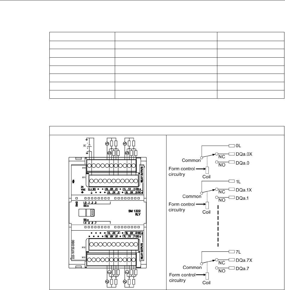
Technical specifications
A.9 Digital signal modules (SMs)
S7-1200 Programmable controller
1448 System Manual, V4.2, 09/2016, A5E02486680-AK
Table A- 117 Connector pin locations for SM 1222 DQ 8 x 24 V DC (6ES7222-1BF32-0XB0)
Pin
X10
X11
1
L+ / 24 V DC
No connection
2 M / 24 V DC No connection
3
Functional Earth
No connection
4 DQ a.0 DQ a.4
5
DQ a.1
DQ a.5
6
DQ a.2
DQ a.6
7
DQ a.2
DQ a.7
Table A- 118 Wiring diagram for the 8-point digital output relay changeover SM
SM 1222 DQ 8 x Relay Changeover (6ES7222-1XF32-0XB0)
A changeover relay output controls two circuits using a common terminal: one normally
closed contact, and one normally open contact. Using output "0" as an example, when the
output point is OFF, the common (0L) is connected to the normally closed contact (.0X) and
disconnected from the normally open contact (.0). When the output point is ON, the common
(0L) is disconnected from the normally closed contact (.0X) and connected to the normally
open contact (.0).
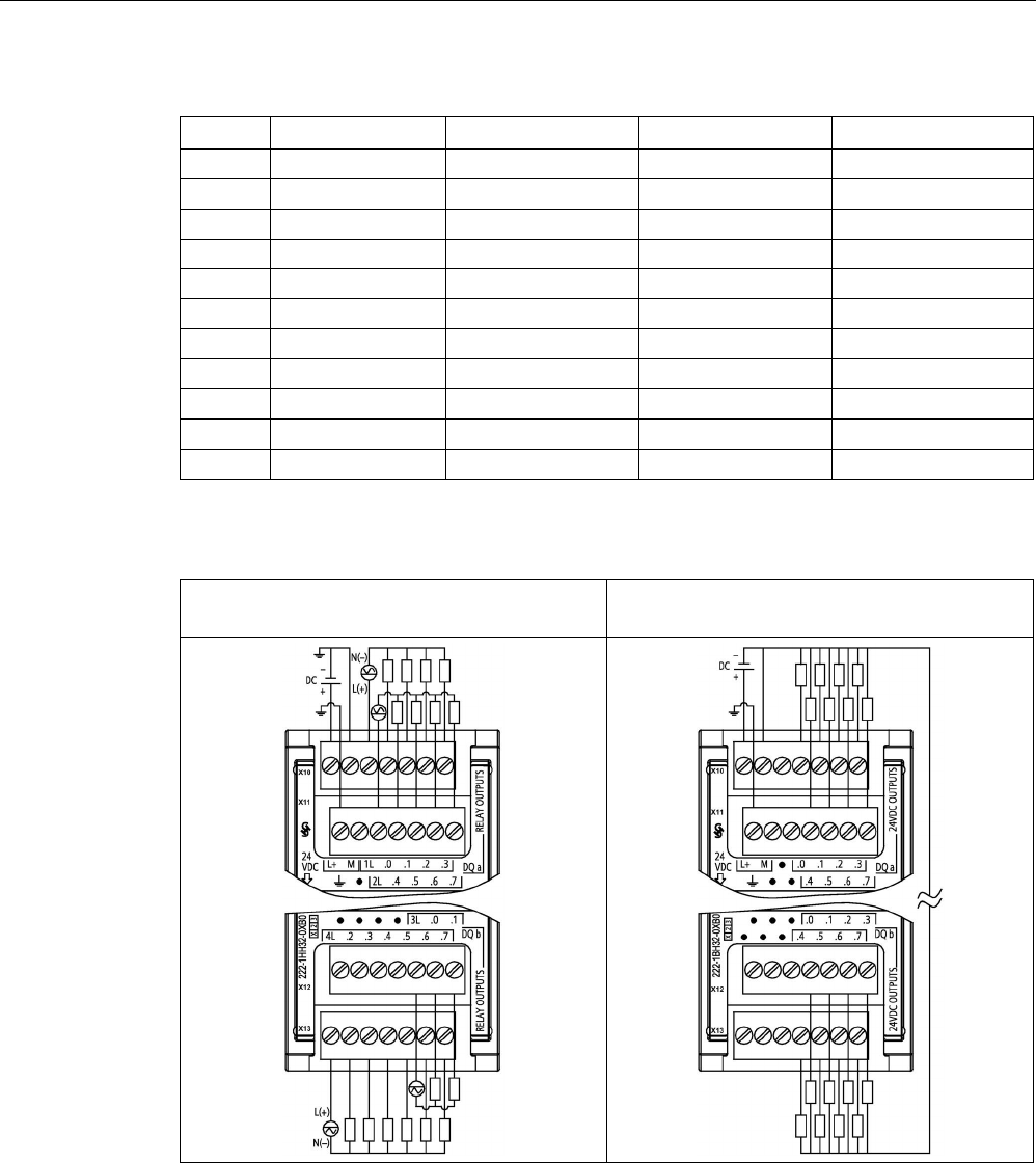
Technical specifications
A.9 Digital signal modules (SMs)
S7-1200 Programmable controller
System Manual, V4.2, 09/2016, A5E02486680-AK 1449
Table A- 119 Connector pin locations for SM 1222 DQ 8 x Relay Changeover (6ES7222-1XF32-0XB0)
Pin
X10
X11
X12
X13
1
L+ / 24 V DC
Functional Earth
No connection
No connection
2 M / 24 V DC No connection No connection No connection
3
No connection
No connection
No connection
No connection
4 No connection No connection No connection No connection
5
0L
2L
4L
6L
6
DQ a.0X
DQ a.2X
DQ a.4X
DQ a.6X
7
DQ a.0
DQ a.2
DQ a.4
DQ a.6
8
No connection
No connection
No connection
No connection
9
1L
3L
5L
7L
10
DQ a.1X
DQ a.3X
DQ a.5X
DQ a.7X
11
DQ a.1
DQ a.3
DQ a.5
DQ a.7
Table A- 120 Wiring diagrams for the 16-point digital output SMs
SM 1222 DQ 16 x Relay (6ES7222-1HH32-
0XB0)
SM 1222 DQ 16 x 24 V DC (6ES7222-1BH32-
0XB0)

Technical specifications
A.9 Digital signal modules (SMs)
S7-1200 Programmable controller
1450 System Manual, V4.2, 09/2016, A5E02486680-AK
Table A- 121 Connector pin locations for SM 1222 DQ 16 x Relay (6ES7222-1HH32-0XB0)
Pin
X10
X11
X12
X13
1
L+ / 24 V DC
Functional Earth
No connection
4L
2 M / 24 V DC No connection No connection DQ b.2
3
1L
2L
No connection
DQ b.3
4 DQ a.0 DQ a.4 No connection DQ b.4
5
DQ a.1
DQ a.5
3L
DQ b.5
6
DQ a.2
DQ a.6
DQ b.0
DQ b.6
7
DQ a.3
DQ a.7
DQ b.1
DQ b.7
Table A- 122 Connector pin locations for SM 1222 DQ 16 x 24 V DC (6ES7222-1BH32-0XB0)
Pin
X10
X11
X12
X13
1
L+ / 24 V DC
Functional Earth
No connection
No connection
2
M / 24 V DC
No connection
No connection
No connection
3
No connection
No connection
No connection
No connection
4
DQ a.0
DQ a.4
DQ b.0
DQ b.4
5
DQ a.1
DQ a.5
DQ b.1
DQ b.5
6
DQ a.2
DQ a.6
DQ b.2
DQ b.6
7
DQ a.3
DQ a.7
DQ b.3
DQ b.7

Technical specifications
A.9 Digital signal modules (SMs)
S7-1200 Programmable controller
System Manual, V4.2, 09/2016, A5E02486680-AK 1451
A.9.4
SM 1223 digital input/output V DC specifications
Table A- 123 General specifications
Model
SM 1223
DI 8 x 24 V DC,
DQ 8 x Relay
SM 1223
DI 16 x 24 V DC,
DQ 16 x Relay
SM 1223
DI 8 x 24 V DC,
DQ 8 x 24 V DC
SM 1223
DI 16 x 24 V DC,
DQ 16 x 24 V DC
Article number 6ES7223-1PH32-
0XB0
6ES7223-1PL32-
0XB0
6ES7223-1BH32-
0XB0
6ES7223-1BL32-
0XB0
Dimensions W x H x D (mm)
45 x 100 x 75
70 x 100 x 75
45 x 100 x 75
70 x 100 x 75
Weight
230 grams
350 grams
210 grams
310 grams
Power dissipation
5.5 W
10 W
2.5 W
4.5 W
Current consumption (SM Bus)
145 mA
180 mA
145 mA
185 mA
Current consumption (24 V DC) 4 mA / Input used
11 mA / Relay coil used
150 mA 200 mA
Table A- 124 Digital inputs
Model
SM 1223
DI 8 x 24 V DC,
DQ 8 x Relay
SM 1223
DI 16 x 24 V DC,
DQ 16 x Relay
SM 1223
DI 8 x 24 V DC, DQ
8 x 24 V DC
SM 1223
DI 16 x 24 V DC,
DQ 16 x 24 V DC
Number of inputs
8
16
8
16
Type Sink/Source
(IEC Type 1 sink)
Sink/Source (IEC
Type 1 sink)
Sink/Source
(IEC Type 1
sink)
Sink/Source (IEC
Type 1 sink)
Rated voltage 24 V DC at 4 mA,
nominal
24 V DC at 4 mA,
nominal
24 V DC at 4
mA, nominal
24 V DC at 4 mA,
nominal
Continuous permissible voltage
30 V DC max.
30 V DC max.
30 V DC max.
30 V DC max.
Surge voltage 35 V DC for 0.5
sec.
35 V DC for 0.5
sec.
35 V DC for 0.5
sec.
35 V DC for 0.5
sec.
Logic 1 signal (min.) 15 V DC at 2.5
mA
15 V DC at 2.5
mA
15 V DC at 2.5
mA
15 V DC at 2.5 mA
Logic 0 signal (max.)
5 V DC at 1 mA
5 V DC at 1 mA
5 V DC at 1 mA
5 V DC at 1 mA
Isolation (field side to logic) 707 V DC (type
test)
707 V DC (type
test)
707 V DC (type
test)
707 V DC (type
test)
Isolation groups 2 2 2 2
Filter times 0.2, 0.4, 0.8, 1.6,
3.2, 6.4, and 12.8
ms, selectable in
groups of 4
0.2, 0.4, 0.8, 1.6,
3.2, 6.4, and 12.8
ms, selectable in
groups of 4
0.2, 0.4, 0.8,
1.6, 3.2, 6.4,
and 12.8 ms,
selectable in
groups of 4
0.2, 0.4, 0.8, 1.6,
3.2, 6.4, and 12.8
ms, selectable in
groups of 4

Technical specifications
A.9 Digital signal modules (SMs)
S7-1200 Programmable controller
1452 System Manual, V4.2, 09/2016, A5E02486680-AK
Model
SM 1223
DI 8 x 24 V DC,
DQ 8 x Relay
SM 1223
DI 16 x 24 V DC,
DQ 16 x Relay
SM 1223
DI 8 x 24 V DC, DQ
8 x 24 V DC
SM 1223
DI 16 x 24 V DC,
DQ 16 x 24 V DC
Number of inputs on simultaneously 8 • 8 (no adjacent
points) at 60 °C
horizontal or
50 °C vertical
• 16 at 55 °C
horizontal or
45 °C vertical
8 16
Cable length (meters) 500 m shielded,
300 m unshielded
500 m shielded,
300 m unshielded
500 m shielded,
300 m un-
shielded
500 m shielded,
300 m unshielded
Table A- 125 Digital outputs
Model
SM 1223
DI 8 x 24 V DC,
DQ 8 x Relay
SM 1223
DI 16 x 24 V DC,
DQ 16 x Relay
SM 1223
DI 8 x 24 V DC,
DQ 8 x 24 V DC
SM 1223
DI 16 x 24 V DC,
DQ 16 x 24 V DC
Number of outputs
8
16
8
16
Type Relay, mechanical Relay, mechanical Solid state -
MOSFET (sourc-
ing)
Solid state -
MOSFET (sourcing)
Voltage range 5 to 30 V DC or
5 to 250 V AC
5 to 30 V DC or 5
to 250 V AC
20.4 to 28.8 V DC 20.4 to 28.8 V DC
Logic 1 signal at max. current
--
--
20 V DC, min.
20 V DC, min.
Logic 0 signal with 10 KΩ load
--
--
0.1 V DC, max.
0.1 V DC, max.
Current (max.)
2.0 A
2.0 A
0.5 A
0.5 A
Lamp load 30 W DC / 200 W
AC
30 W DC / 200 W
AC
5 W 5 W
ON state contact resistance 0.2 Ω max. when
new
0.2 Ω max. when
new
0.6 Ω max. 0.6 Ω max.
Leakage current per point
--
--
10 μA max.
10 μA max.
Surge current 7 A with contacts
closed
7 A with contacts
closed
8 A for 100 ms
max.
8 A for 100 ms max
Overload protection
No
No
No
No
Isolation (field side to logic) 1500 V AC (coil to
contact)
None (coil to logic)
1500 V AC (coil to
contact)
None (coil to logic)
707 V DC (type
test)
707 V DC (type
test)
Isolation groups 2 4 1 1
Current per common
10A
8 A
4 A
8 A
Inductive clamp voltage -- -- L+ minus 48 V,
1 W dissipation
L+ minus 48 V,
1 W dissipation
Switching delay 10 ms max. 10 ms max. 50 μs max. off to
on
200 μs max. on to
off
50 μs max. off to
on200 μs max. on
to off

Technical specifications
A.9 Digital signal modules (SMs)
S7-1200 Programmable controller
System Manual, V4.2, 09/2016, A5E02486680-AK 1453
Model
SM 1223
DI 8 x 24 V DC,
DQ 8 x Relay
SM 1223
DI 16 x 24 V DC,
DQ 16 x Relay
SM 1223
DI 8 x 24 V DC,
DQ 8 x 24 V DC
SM 1223
DI 16 x 24 V DC,
DQ 16 x 24 V DC
Maximum relay switching frequency
1 Hz
1 Hz
--
1 Hz
Lifetime mechanical (no load) 10,000,000
open/close cycles
10,000,000
open/close cycles
-- --
Lifetime contacts at rated load (N.O.
contact)
100,000
open/close cycles
100,000
open/close cycles
-- --
Behavior on RUN to STOP Last value or sub-
stitute value (de-
fault value 0)
Last value or sub-
stitute value (de-
fault value 0)
Last value or sub-
stitute value (de-
fault value 0)
Last value or substi-
tute value (default
value 0)
Number of outputs on simultaneously 8 • 8 (no adjacent
points) at 60 °C
horizontal or
50 °C vertical
• 16 at 55 °C
horizontal or
45 °C vertical
8 16
Cable length (meters) 500 m shielded,
150 m unshielded
500 m shielded,
150 m unshielded
500 m shielded,
150 m unshielded
500 m shielded, 150
m unshielded

Technical specifications
A.9 Digital signal modules (SMs)
S7-1200 Programmable controller
1454 System Manual, V4.2, 09/2016, A5E02486680-AK
Table A- 126 Wiring diagrams for the digital input V DC/output relay SMs
SM 1223 DI 8 x 24 V DC, DQ 8 x Relay
(6ES7223-1PH32-0XB0)
SM 1223 DI 16 x 24 V DC, DQ 16 x Relay
(6ES7223-1PL32-0XB0)
Notes
① For sinking
inputs, connect "-"
to "M" (shown).
For sourcing inputs,
connect "+" to "M".
Table A- 127 Connector Pin Locations for SM 1223 DI 8 x 24 V DC, DQ 8 x Relay (6ES7223-1PH32-
0XB0)
Pin
X10
X11
X12
X13
1
L+ / 24 V DC
Functional Earth
No connection
No connection
2
M / 24 V DC
No connection
No connection
No connection
3
1M
2M
1L
2L
4
DI a.0
DI a.4
DQ a.0
DQ a.4
5
DI a.1
DI a.5
DQ a.1
DQ a.5
6
DI a.2
DI a.6
DQ a.2
DQ a.6
7
DI a.3
DI a.7
DQ a.3
DQ a.7
Table A- 128 Connector Pin Locations for SM 1223 DI 16 x 24 V DC, DQ 16 x Relay (6ES7223-
1PL32-0XB0)
Pin
X10
X11
X12
X13
1 L+ / 24 V DC Functional Earth 1L 3L
2
M / 24 V DC
No connection
DQ a.0
DQ b.0
3 1M 2M DQ a.1 DQ b.1
4
DI a.0
DI b.0
DQ a.2
DQ b.2
5
DI a.1
DI b.1
DQ a.3
DQ b.3
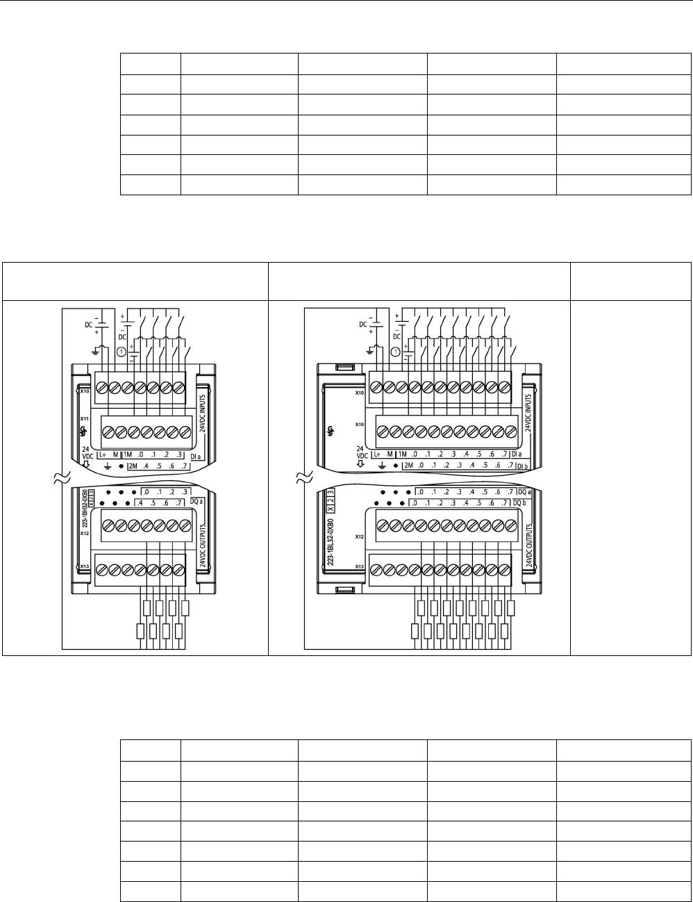
Technical specifications
A.9 Digital signal modules (SMs)
S7-1200 Programmable controller
System Manual, V4.2, 09/2016, A5E02486680-AK 1455
Pin
X10
X11
X12
X13
6
DI a.2
DI b.2
No connection
No connection
7 DI a.3 DI b.3 2L 4L
8
DI a.4
DI b.4
DQ a.4
DQ b.4
9 DI a.5 DI b.5 DQ a.5 DQ b.5
10
DI a.6
DI b.6
DQ a.6
DQ b.6
11
DI a.7
DI b.7
DQ a.7
DQ b.7
Table A- 129 Wiring diagrams for the digital input V DC/output SMs
SM 1223 DI 8 x 24 V DC, DQ 8 x 24 V DC
(6ES7223-1BH32-0XB0)
SM 1223 DI 16 x 24 V DC, DQ 16 x 24 V DC
(6ES7223-1BL32-0XB0)
Notes
① For sinking
inputs, connect "-"
to "M" (shown).
For sourcing inputs,
connect "+" to "M".
Table A- 130 Connector Pin Locations for SM 1223 DI 8 x 24 V DC, DQ 8 x 24 V DC (6ES7223-
1BH32-0XB0)
Pin
X10
X11
X12
X13
1
L+ / 24 V DC
Functional Earth
No connection
No connection
2 M / 24 V DC No connection No connection No connection
3
1M
2M
No connection
No connection
4 DI a.0 DI a.4 DQ a.0 DQ a.4
5
DI a.1
DI a.5
DQ a.1
DQ a.5
6
DI a.2
DI a.6
DQ a.2
DQ a.6
7
DI a.3
DI a.7
DQ a.3
DQ a.7

Technical specifications
A.9 Digital signal modules (SMs)
S7-1200 Programmable controller
1456 System Manual, V4.2, 09/2016, A5E02486680-AK
Table A- 131 Connector Pin Locations for SM 1223 DI 16 x 24 V DC, DQ 16 x 24 V DC (6ES7223-
1BL32-0XB0)
Pin
X10
X11
X12
X13
1
L+ / 24 V DC
Functional Earth
No connection
No connection
2 M / 24 V DC No connection No connection No connection
3
1M
2M
No connection
No connection
4
DI a.0
DI b.0
DQ a.0
DQ b.0
5
DI a.1
DI b.1
DQ a.1
DQ b.1
6
DI a.2
DI b.2
DQ a.2
DQ b.2
7
DI a.3
DI b.3
DQ a.3
DQ b.3
8
DI a.4
DI b.4
DQ a.4
DQ b.4
9
DI a.5
DI b.5
DQ a.5
DQ b.5
10
DI a.6
DI b.6
DQ a.6
DQ b.6
11
DI a.7
DI b.7
DQ a.7
DQ b.7
A.9.5
SM 1223 digital input/output V AC specifications
Table A- 132 General specifications
Model
SM 1223 DI 8 x120/230 V AC / DQ 8 x Relay
Article number
6ES7223-1QH32-0XB0
Dimensions W x H x D (mm)
45 x 100 x 75 mm
Weight
190 grams
Power dissipation
7.5 W
Current consumption (SM Bus)
120 mA
Current consumption (24 V DC)
11 mA per output when on
Table A- 133 Digital inputs
Model
SM 1223 DI 8 x 120/230 V AC / DQ 8 x Relay
Number of inputs
8
Type
IEC Type 1
Rated voltage
120 V AC at 6 mA, 230 V AC at 9 mA
Continuous permissible voltage
264 V AC
Surge voltage
--
Logic 1 signal (min.) 79 V AC at 2.5 mA
Logic 0 signal (max.)
20 V AC at 1 mA
Leakage current (max.) 1 mA
Isolation (field side to logic)
1500 V AC
Isolation groups
1
4
Input delay times Typical: 0.2 to 12.8 ms, user selectable
Maximum: -

Technical specifications
A.9 Digital signal modules (SMs)
S7-1200 Programmable controller
System Manual, V4.2, 09/2016, A5E02486680-AK 1457
Model
SM 1223 DI 8 x 120/230 V AC / DQ 8 x Relay
Connection of 2 wire proximity sensor (Bero)
(max.)
1 mA
Cable length Unshielded: 300 meters
Shielded: 500 meters
Number of inputs on simultaneously
8
1 Channels within a group must be of the same phase.
Table A- 134 Digital outputs
Model
SM 1223 DI 8 x 120/230 V AC / DQ 8 x Relay
Number of outputs
8
Type
Relay, mechanical
Voltage range
5 to 30 V DC or 5 to 250 V AC
Logic 1 signal at max. current
--
Logic 0 signal with 10K Ω load
--
Current (max.)
2.0 A
Lamp load
30 W DC / 200 W AC
ON state contact resistance
0.2 Ω max. when new
Leakage current per point
--
Surge current
7 A with contacts closed
Overload protection
No
Isolation (field side to logic) 1500 V AC (coil to contact)
None (coil to logic)
Isolation groups 2
Current per common (max.)
10 A
Inductive clamp voltage
--
Switching delay (max.)
10 ms
Maximum relay switching frequency
1 Hz
Lifetime mechanical (no load)
10,000,000 open/close cycles
Lifetime contacts at rated load
1000,000 open/close cycles
Behavior on RUN to STOP
Last value or substitute value (default value 0)
Number of outputs on simultaneously • 4 (no adjacent points) at 60 °C horizontal or 50 °C vertical
• 8 at 55 °C horizontal or 45 °C vertical
Cable length (meters)
500 m shielded, 150 m unshielded
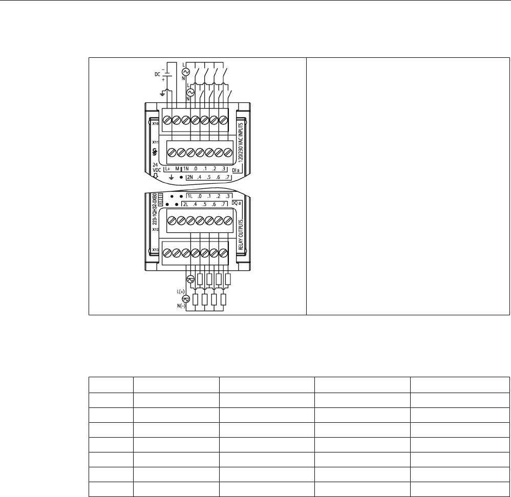
Technical specifications
A.10 Analog signal modules (SMs)
S7-1200 Programmable controller
1458 System Manual, V4.2, 09/2016, A5E02486680-AK
Table A- 135 SM 1223 DI 8 x 120/230 V AC, DQ 8 x Relay (6ES7223-1QH32-0XB0)
Table A- 136 Connector Pin Locations for SM 1223 DI 8 x 120/240 V AC, DQ 8 x Relay (6ES7223-
1QH32-0XB0)
Pin
X10
X11
X12
X13
1 L+ / 24 V DC Functional Earth No connection No connection
2
M / 24 V DC
No connection
No connection
No connection
3
1N
2N
1L
2L
4
DI a.0
DI a.4
DQ a.0
DQ a.4
5
DI a.1
DI a.5
DQ a.1
DQ a.5
6
DI a.2
DI a.6
DQ a.2
DQ a.6
7
DI a.3
DI a.7
DQ a.3
DQ a.7

Technical specifications
A.10 Analog signal modules (SMs)
S7-1200 Programmable controller
System Manual, V4.2, 09/2016, A5E02486680-AK 1459
A.10
Analog signal modules (SMs)
A.10.1
SM 1231 analog input module specifications
Table A- 137 General specifications
Model
SM 1231 AI 4 x 13 bit
SM 1231 AI 8 x 13 bit
SM 1231 AI 4 x 16 bit
Article number
6ES7231-4HD32-0XB0
6ES7231-4HF32-0XB0
6ES7231-5ND32-0XB0
Dimensions W x H x D (mm) 45 x 100 x 75
Weight
180 grams
Power dissipation 2.2 W 2.3 W 2.0 W
Current consumption (SM Bus)
80 mA
90 mA
80 mA
Current consumption (24 V DC)
45 mA
65 mA
Table A- 138 Analog inputs
Model
SM 1231 AI 4 x 13 bit
SM 1231 AI 8 x 13 bit
SM 1231 AI 4 x 16 bit
Number of inputs
4
8
4
Type Voltage or current (differential): Selectable in groups of
2
Voltage or current (differ-
ential)
Range ±10 V, ±5 V, ±2.5 V, 0 to 20 mA, or 4 mA to 20 mA ±10 V, ±5 V, ±2.5 V, ±1.25
V, 0 to 20 mA or 4 mA to
20 mA
Full scale range (data word)
-27648 to 27648 voltage / 0 to 27648 current
Overshoot/undershoot range
(data word)
Refer to the section on analog input
ranges for voltage and current
(Page 1471).
Voltage: 32511 to 27649 / -27649 to -32,512
Current: 32511 to 27649 / 0 to -4864
Overflow/underflow (data word)
Refer to the section on input rang-
es for voltage and current
(Page 1471).
Voltage: 32767 to 32512 / -32513 to -32768
Current 0 to 20 mA: 32767 to 32512 / -4865 to -32768
Current 4 to 20 mA: 32767 to 32512 (values below -4864 indicate open wire)
Resolution1
12 bits + sign bit
15 bits + sign bit
Maximum withstand voltage/current
±35 V / ±40 mA
Smoothing None, weak, medium, or strong
Refer to the section on step response times (Page 1470).
Noise rejection 400, 60, 50, or 10 Hz
Refer to the section on sample rates (Page 1470).
Input impedance ≥ 9 MΩ (voltage) / 280 Ω (current) ≥ 1 MΩ (voltage) /
<315 Ω, >280 Ω (current)

Technical specifications
A.10 Analog signal modules (SMs)
S7-1200 Programmable controller
1460 System Manual, V4.2, 09/2016, A5E02486680-AK
Model
SM 1231 AI 4 x 13 bit
SM 1231 AI 8 x 13 bit
SM 1231 AI 4 x 16 bit
Isolation
Field side to logic
Logic to 24 V DC
Field side to 24 V DC
Channel to channel
None
707 V DC (type test)
707 V DC (type test)
500 V DC (type test)
None
Accuracy (25 °C / -20 to 60 °C)
±0.1% / ±0.2% of full scale
±0.1% / ±0.3% of full scale
Measuring principle
Actual value conversion
Common mode rejection
40 dB, DC to 60 Hz
Operational signal range
1
Signal plus common mode voltage must be less than +12 V and greater than -12 V
Cable length (meters)
100 m, twisted and shielded
1 Voltages outside the operational range applied to one channel may cause interference on other channels.
Table A- 139 Diagnostics
Model
SM 1231 AI 4 x 13 bit
SM 1231 AI 8 x 13 bit
SM 1231 AI 4 x 16 bit
Overflow/underflow
Yes
24 V DC low voltage
Yes
Open wire
4 to 20 mA range only (if input is below -4164; 1.185 mA)
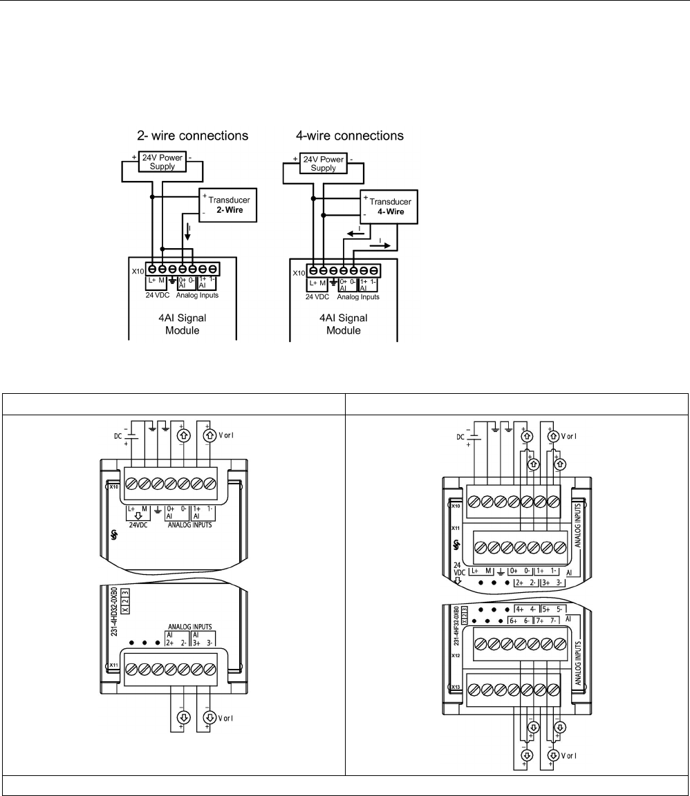
Technical specifications
A.10 Analog signal modules (SMs)
S7-1200 Programmable controller
System Manual, V4.2, 09/2016, A5E02486680-AK 1461
SM 1231 wiring current transducers
Wiring current transducers are available as 2-wire transducers and 4-wire transducers as
shown below.
Table A- 140 Wiring diagrams for the analog input SMs
SM 1231 AI 4 x 13 bit (6ES7231-4HD32-0XB0)
SM 1231 AI 8 x 13 bit (6ES7231-4HF32-0XB0)
Note: Connectors must be gold. See Appendix C, Spare Parts for article number.
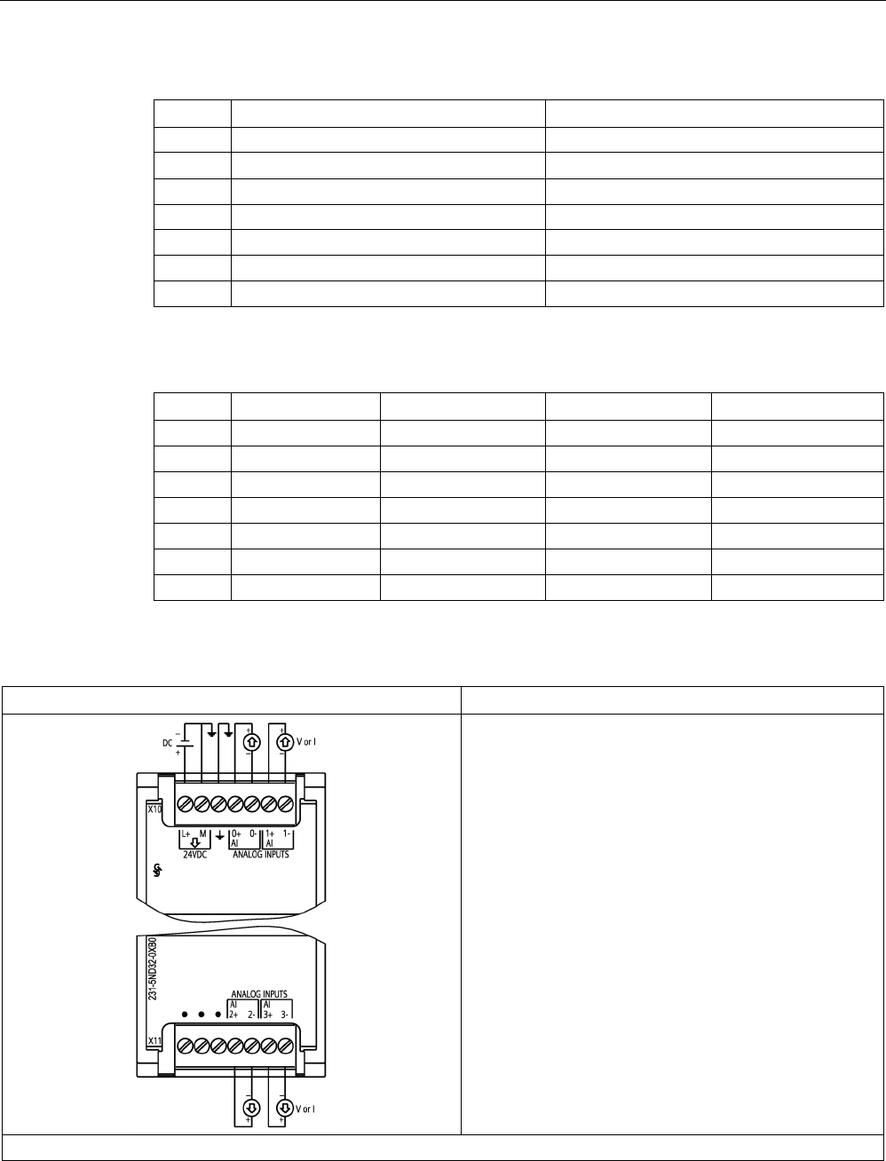
Technical specifications
A.10 Analog signal modules (SMs)
S7-1200 Programmable controller
1462 System Manual, V4.2, 09/2016, A5E02486680-AK
Table A- 141 Connector pin locations for SM 1231 AI 4 x 13 bit (6ES7231-4HD32-0XB0)
Pin
X10 (gold)
X11 (gold)
1
L+ / 24 V DC
No connection
2 M / 24 V DC No connection
3
Functional Earth
No connection
4 AI 0+ AI 2+
5
AI 0-
AI 2-
6
AI 1+
AI 3+
7
AI 1-
AI 3-
Table A- 142 Connector pin locations for SM 1231 AI 8 x 13 bit (6ES7231-4HF32-0XB0)
Pin
X10 (gold)
X11 (gold)
X12 (gold)
X13 (gold)
1
L+ / 24 V DC
No connection
No connection
No connection
2
M / 24 V DC
No connection
No connection
No connection
3
Functional Earth
No connection
No connection
No connection
4
AI 0+
AI 2+
AI 4+
AI 6+
5
AI 0-
AI 2-
AI 4-
AI 6-
6
AI 1+
AI 3+
AI 5+
AI 7+
7
AI 1-
AI 3-
AI 5-
AI 7-
Table A- 143 Wiring diagram for the analog input SM
SM 1231 AI 4 x 16 bit (6ES7231-5ND32-0XB0)
Note: Connectors must be gold. See Appendix C, Spare Parts for article number.

Technical specifications
A.10 Analog signal modules (SMs)
S7-1200 Programmable controller
System Manual, V4.2, 09/2016, A5E02486680-AK 1463
Table A- 144 Connector pin locations for SM 1231 AI 4 x 16 bit (6ES7231-5ND32-0XB0)
Pin
X10 (gold)
X11 (gold)
1
L+ / 24 V DC
No connection
2 M / 24 V DC No connection
3
Functional Earth
No connection
4 AI 0+ AI 2+
5
AI 0-
AI 2-
6
AI 1+
AI 3+
7
AI 1-
AI 3-
Note
Unused voltage input channels should be shorted.
Unused current input ch
annels should be set to the 0 to 20 mA range and/or disable broken
wire error reporting.
Inputs configured for current mode will not conduct loop current unless the module is
powered and configured.
Current input channels will not operate unless external p
ower is supplied to the transmitter.

Technical specifications
A.10 Analog signal modules (SMs)
S7-1200 Programmable controller
1464 System Manual, V4.2, 09/2016, A5E02486680-AK
A.10.2
SM 1232 analog output module specifications
Table A- 145 General specifications
Technical data
SM 1232 AQ 2 x 14 bit
SM 1232 AQ 4 x 14 bit
Article number
6ES7232-4HB32-0XB0
6ES7232-4HD32-0XB0
Dimensions W x H x D (mm) 45 x 100 x 75
Weight
180 grams
Power dissipation 1.8 W 2.0 W
Current consumption (SM Bus)
80 mA
Current consumption (24 V DC)
45 mA (no load)
Table A- 146 Analog outputs
Technical data
SM 1232 AQ 2 x 14 bit
SM 1232 AQ 4 x 14 bit
Number of outputs
2
4
Type
Voltage or current
Range
±10 V, 0 to 20 mA, or 4 mA to 20 mA
Resolution Voltage: 14 bits
Current: 13 bits
Full scale range (data word) Voltage: -27,648 to 27,648 ; Current: 0 to 27,648
Refer to the output ranges for voltage and current (Page 1472).
Accuracy (25 °C / -20 to 60 °C)
±0.3% / ±0.6% of full scale
Settling time (95% of new value) Voltage: 300 μs (R), 750 μs (1 uF)
Current: 600 μs (1 mH), 2 ms (10 mH)
Load impedance Voltage: ≥ 1000 Ω
Current: ≤ 600 Ω
Maximum output short circuit current Voltage mode: ≤ 24 mA
Current mode: ≥ 38.5 mA
Behavior on RUN to STOP
Last value or substitute value (default value 0)
Isolation (field side to logic) none
Isolation (24 V to output)
none
Cable length (meters)
100 m twisted and shielded
Table A- 147 Diagnostics
Technical data
SM 1232 AQ 2 x 14 bit
SM 1232 AQ 4 x 14 bit
Overflow/underflow
Yes
Short to ground (voltage mode only) Yes
Wire break (current mode only)
Yes
24 V DC low voltage
Yes
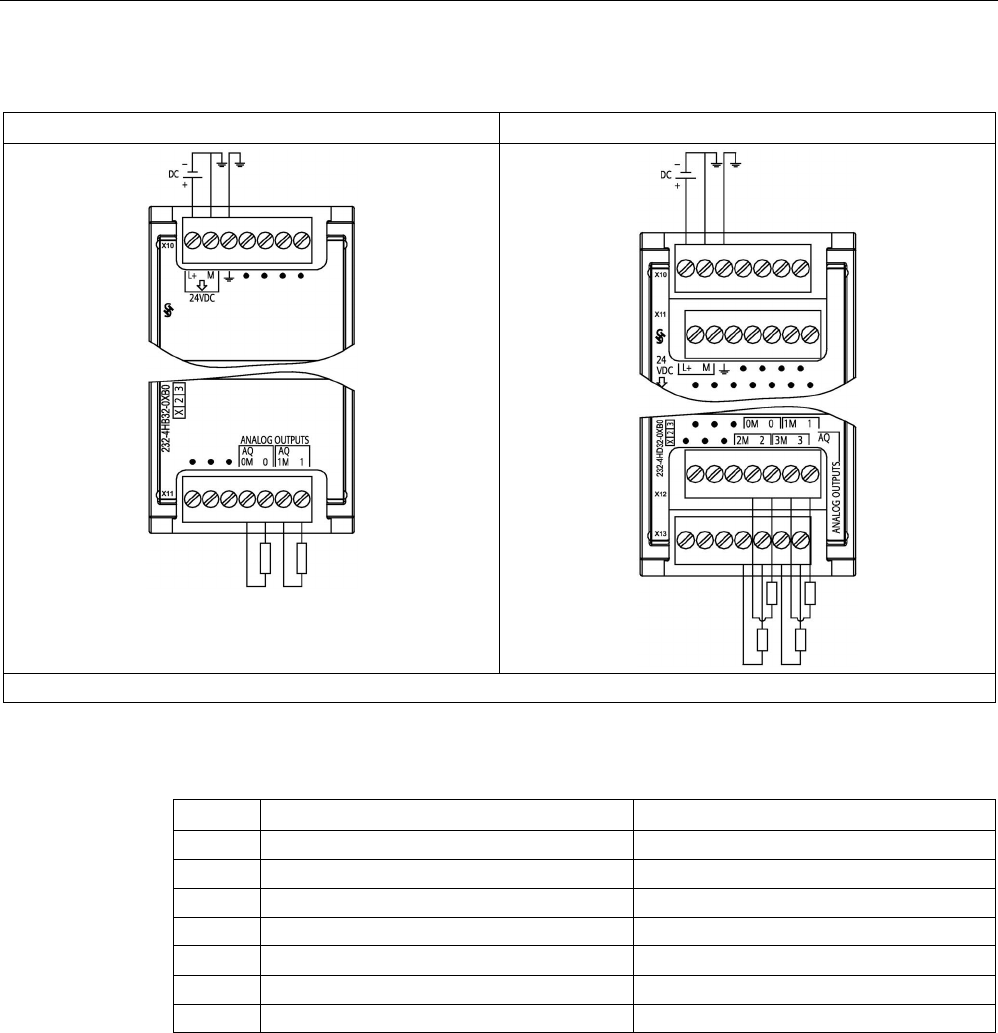
Technical specifications
A.10 Analog signal modules (SMs)
S7-1200 Programmable controller
System Manual, V4.2, 09/2016, A5E02486680-AK 1465
Table A- 148 Wiring diagrams for the analog output SMs
SM 1232 AQ 2 x 14 bit (6ES7232-4HB32-0XB0)
SM 1232 AQ 4 x 14 bit (6ES7232-4HD32-0XB0)
Note: Connectors must be gold. See Appendix C, Spare Parts for article number.
Table A- 149 Connector pin locations for SM 1232 AQ 2 x 14 bit (6ES7232-4HB32-0XB0)
Pin
X10 (gold)
X11 (gold)
1
L+ / 24 V DC
No connection
2
M / 24 V DC
No connection
3
Functional Earth
No connection
4
No connection
AQ 0M
5
No connection
AQ 0
6
No connection
AQ 1M
7 No connection AQ 1

Technical specifications
A.10 Analog signal modules (SMs)
S7-1200 Programmable controller
1466 System Manual, V4.2, 09/2016, A5E02486680-AK
Table A- 150 Connector pin locations for SM 1232 AQ 4 x 14 bit (6ES7232-4HD32-0XB0)
Pin
X10 (gold)
X11 (gold)
X12 (gold)
X13 (gold)
1
L+ / 24 V DC
No connection
No connection
No connection
2 M / 24 V DC No connection No connection No connection
3
Functional Earth
No connection
No connection
No connection
4 No connection No connection AQ 0M AQ 2M
5
No connection
No connection
AQ 0
AQ 2
6
No connection
No connection
AQ 1M
AQ 3M
7
No connection
No connection
AQ 1
AIQ 3
A.10.3
SM 1234 analog input/output module specifications
Table A- 151 General specifications
Technical data
SM 1234 AI 4 x 13 bit / AQ 2 x 14 bit
Article number
6ES7234-4HE32-0XB0
Dimensions W x H x D (mm)
45 x 100 x 75
Weight
220 grams
Power dissipation
2.4 W
Current consumption (SM Bus)
80 mA
Current consumption (24 V DC)
60 mA (no load)
Table A- 152 Analog inputs
Model
SM 1234 AI 4 x 13 bit / AQ 2 x 14 bit
Number of inputs
4
Type
Voltage or Current (differential): Selectable in groups of 2
Range
±10 V, ±5 V, ±2.5 V, 0 to 20 mA, or 4 mA to 20 mA
Full scale range (data word)
-27648 to 27648
Overshoot/undershoot range
(data word)
Voltage: 32511 to 27649 / -27649 to -32512
Current: 32511 to 27649 / 0 to -4864
Refer to the section on input ranges for voltage and current (Page 1471).
Overflow/underflow (data word) Voltage: 32767 to 32512 / -32513 to -32768
Current: 32767 to 32512 / -4865 to -32768
Refer to the section on input ranges for voltage and current (Page 1471).
Resolution
12 bits + sign bit
Maximum withstand voltage/current
±35 V / ±40 mA
Smoothing None, weak, medium, or strong
Refer to the section on step response times (Page 1470).
Noise rejection 400, 60, 50, or 10 Hz
Refer to the section on sample rates (Page 1470).
Input impedance
≥ 9 MΩ (voltage) / 280 Ω (current)

Technical specifications
A.10 Analog signal modules (SMs)
S7-1200 Programmable controller
System Manual, V4.2, 09/2016, A5E02486680-AK 1467
Model
SM 1234 AI 4 x 13 bit / AQ 2 x 14 bit
Isolation (field side to logic)
None
Accuracy (25 °C / -20 to 60 °C) ±0.1% / ±0.2% of full scale
Analog to digital conversion time
625 μs (400 Hz rejection)
Common mode rejection 40 dB, DC to 60 Hz
Operational signal range1 Signal plus common mode voltage must be less than +12 V and greater
than -12 V
Cable length (meters)
100 m, twisted and shielded
1 Voltages outside the operational range applied to one channel may cause interference on other channels.
Table A- 153 Analog outputs
Technical data
SM 1234 AI 4 x 13 bit / AQ 2 x 14 bit
Number of outputs
2
Type
Voltage or current
Range
±10 V or 0 to 20 mA
Resolution
Voltage: 14 bits ; Current: 13 bits
Full scale range (data word) Voltage: -27648 to 27648; Current: 0 to 27648
Refer to the section on output ranges for voltage and current
(Page 1472).
Accuracy (25 °C / -20 to 60 °C)
±0.3% / ±0.6% of full scale
Settling time (95% of new value) Voltage: 300 μs (R), 750 μs (1 uF)
Current: 600 μs (1 mH), 2 ms (10 mH)
Load impedance Voltage: ≥ 1000 Ω
Current: ≤ 600 Ω
Maximum output short circuit current Voltage mode: ≤ 24 mA
Current mode: ≥ 38.5 mA
Behavior on RUN to STOP Last value or substitute value (default value 0)
Isolation (field side to logic)
none
Isolation (24 V to output) none
Cable length (meters)
100 m twisted and shielded
Table A- 154 Diagnostics
Model
SM 1234 AI 4 x 13 bit / AQ 2 x 14 bit
Overflow/underflow
Yes
Short to ground (voltage mode only)
Yes on outputs
Wire break (current mode only)
Yes on outputs
24 V DC low voltage
Yes
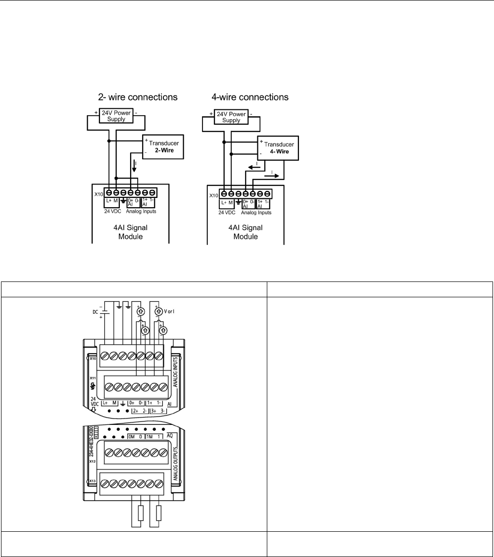
Technical specifications
A.10 Analog signal modules (SMs)
S7-1200 Programmable controller
1468 System Manual, V4.2, 09/2016, A5E02486680-AK
SM 1234 wiring current transducers
Wiring current transducers are available as 2-wire transducers and 4-wire transducers as
shown below.
Table A- 155 Wiring diagrams for the analog input/output SM
SM 1234 AI 4 x 13 Bit / AQ 2 x 14 bit (6ES7234-4HE32-0XB0)
Note: Connectors must be gold. See Appendix C, Spare Parts for
article number.

Technical specifications
A.10 Analog signal modules (SMs)
S7-1200 Programmable controller
System Manual, V4.2, 09/2016, A5E02486680-AK 1469
Table A- 156 Connector pin locations for SM 1234 AI 4 x 13 Bit / AQ 2 x 14 bit (6ES7234-4HE32-
0XB0)
Pin
X10 (gold)
X11 (gold)
X12 (gold)
X13 (gold)
1
L+ / 24 V DC
No connection
No connection
No connection
2 M / 24 V DC No connection No connection No connection
3
Functional Earth
No connection
No connection
No connection
4
AI 0+
AI 2+
No connection
AQ 0M
5
AI 0-
AI 2-
No connection
AQ 0
6
AI 1+
AI 3+
No connection
AQ 1M
7
AI 1-
AI 3-
No connection
AQ 1
Note
Unused voltage input channels should be shorted.
Unused current input channels should be set to the 0 to 20 mA range and/or disable broken
wire error reporting.
Inputs
configured for current mode will not conduct loop current unless the module is
powered and configured.
Current input channels will not operate unless external power is supplied to the transmitter.

Technical specifications
A.10 Analog signal modules (SMs)
S7-1200 Programmable controller
1470 System Manual, V4.2, 09/2016, A5E02486680-AK
A.10.4
Step response of the analog inputs
Table A- 157 Step response (ms), 0 to full-scale measured at 95%
Smoothing selection (sample averaging)
Noise reduction/rejection frequency (Integration time selection)
400 Hz (2.5 ms)
60 Hz (16.6 ms)
50 Hz (20 ms)
10 Hz (100 ms)
None (1 cycle): No averaging
4 ms
18 ms
22 ms
100 ms
Weak (4 cycles): 4 samples
9 ms
52 ms
63 ms
320 ms
Medium (16 cycles): 16 samples
32 ms
203 ms
241 ms
1200 ms
Strong (32 cycles): 32 samples
61 ms
400 ms
483 ms
2410 ms
Sample time
• 4 AI x 13 bits
• 8 AI x 13 bits
• 4 AI4 x 16 bits
• 0.625 ms
• 1.25 ms
• 0.417 ms
• 4.17 ms
• 4.17 ms
• 0.397 ms
• 5 ms
• 5 ms
• 0.400 ms
• 25 ms
• 25 ms
• 0.400 ms
A.10.5
Sample time and update times for the analog inputs
Table A- 158 Sample time and update time
Rejection frequency (Integra-
tion time)
Sample time
Module update time for all channels
4-channel SM
8-channel SM
400 Hz (2.5 ms) • 4-channel x 13 bit SM:
0.625 ms
• 8-channel x 13 bit SM:
1.250 ms
• 4-channel x 16 bit SM: 0.100
ms
0.625 ms 1.250 ms
60 Hz (16.6 ms)
4.170 ms
4.17 ms
4.17 ms
50 Hz (20 ms)
5.000 ms
5 ms
5 ms
10 Hz (100 ms)
25.000 ms
25 ms
25 ms

Technical specifications
A.10 Analog signal modules (SMs)
S7-1200 Programmable controller
System Manual, V4.2, 09/2016, A5E02486680-AK 1471
A.10.6
Measurement ranges of the analog inputs for voltage and current (SB and SM)
Table A- 159 Analog input representation for voltage (SB and SM)
System
Voltage Measuring Range
Decimal
Hexadecimal
±10 V
±5 V
±2.5 V
±1.25 V
32767
7FFF
1
11.851 V
5.926 V
2.963 V
1.481 V
Overflow
32512
7F00
32511
7EFF
11.759 V
5.879 V
2.940 V
1.470 V
Overshoot range
27649
6C01
27648 6C00 10 V 5 V 2.5 V 1.250 V Rated range
20736
5100
7.5 V
3.75 V
1.875 V
0.938 V
1
1
361.7 μV
180.8 μV
90.4 μV
45.2 μV
0
0
0 V
0 V
0 V
0 V
-1
FFFF
-20736
AF00
-7.5 V
-3.75 V
-1.875 V
-0.938 V
-27648
9400
-10 V
-5 V
-2.5 V
-1.250 V
-27649
93FF
Undershoot range
-32512
8100
-11.759 V
-5.879 V
-2.940 V
-1.470 V
-32513
80FF
Underflow
-32768
8000
-11.851 V
-5.926 V
-2.963 V
-1.481 V
1
7FFF can be returned for one of the following reasons: overflow (as noted in this table), before valid values are available
(for example immediately upon a power up), or if a wire break is detected.
Table A- 160 Analog input representation for current (SB and SM)
System
Current measuring range
Decimal
Hexadecimal
0 mA to 20 mA
4 mA to 20 mA
32767
7FFF
> 23.52 mA
> 22.81 mA
Overflow
32511
7EFF
23.52 mA
22.81 mA
Overshoot range
27649
6C01
27648
6C00
20 mA
20 mA
Nominal range
20736
5100
15 mA
16 mA
1
1
723.4 nA
4 mA + 578.7 nA
0 0 0 mA 4 mA
-1
FFFF
Undershoot range
-4864 ED00 -3.52 mA 1.185 mA
32767
1
7FFF
< 1.185 mA
Underflow (0 to 20 mA)
Wire break (4 to 20 mA)
-32768
8000
< -3.52 mA
1 The wire break value of 32767 (16#7FFF) is always returned regardless of the state of the wire break alarm.
See also
Determining the type of wire break condition from an SM 1231 module (Page 1349)

Technical specifications
A.10 Analog signal modules (SMs)
S7-1200 Programmable controller
1472 System Manual, V4.2, 09/2016, A5E02486680-AK
A.10.7
Measurement ranges of the analog outputs for voltage and current (SB and SM)
Table A- 161 Analog output representation for voltage (SB and SM)
System
Voltage Output Range
Decimal
Hexadecimal
± 10 V
32767
7FFF
See note 1
Overflow
32512
7F00
See note 1
32511
7EFF
11.76 V
Overshoot range
27649
6C01
27648 6C00 10 V Rated range
20736
5100
7.5 V
1
1
361.7 μ V
0
0
0 V
-1
FFFF
-361.7 μ V
-20736
AF00
-7.5 V
-27648
9400
-10 V
-27649
93FF
Undershoot range
-32512
8100
-11.76 V
-32513
80FF
See note 1
Underflow
-32768
8000
See note 1
1 In an overflow or underflow condition, analog outputs will take on the substitute value of the STOP mode.
Table A- 162 Analog output representation for current (SB and SM)
System
Current output range
Decimal
Hexadecimal
0 mA to 20 mA
4 mA to 20 mA
32767
7FFF
See note 1
See note 1
Overflow
32512
7F00
See note 1
See note 1
32511
7EFF
23.52 mA
22.81 mA
Overshoot range
27649
6C01
27648
6C00
20 mA
20 mA
Rated range
20736
5100
15 mA
16 mA
1 1 723.4 nA 4 mA + 578.7 nA
0
0
0 mA
4mA
-1 FFFF 4 mA to 578.7 nA Undershoot range
-6912
E500
0 mA
-6913
E4FF
Not possible. Output value limited to 0 mA.
-32512
8100
-32513
80FF
See note 1
See note 1
Underflow
-32768
8000
See note 1
See note 1
1 In an overflow or underflow condition, analog outputs will take on the substitute value of the STOP mode.

Technical specifications
A.11 Thermocouple and RTD signal modules (SMs)
S7-1200 Programmable controller
System Manual, V4.2, 09/2016, A5E02486680-AK 1473
A.11
Thermocouple and RTD signal modules (SMs)
A.11.1
SM 1231 Thermocouple
Table A- 163 General specifications
Model
SM 1231 AI 4 x 16 bit TC
SM 1231 AI 8 x 16 bit TC
Article number
6ES7231-5QD32-0XB0
6ES7231-5QF32-0XB0
Dimensions W x H x D (mm) 45 x 100 x 75
Weight
180 grams
190 grams
Power dissipation 1.5 W
Current consumption (SM Bus)
80 mA
Current consumption (24 V DC)
1
40 mA
1 20.4 to 28.8 V DC (Class 2, Limited Power, or sensor power from PLC)
Table A- 164 Analog inputs
Model
SM 1231 AI 4 x 16 bit TC
SM 1231 AI 8 x 16 bit TC
Number of inputs
4
8
Range
Nominal range (data word)
Overrange/underrange (data word)
Overflow/underflow (data word)
See Thermocouple selection table (Page 1477).
Resolution
Temperature
0.1 °C/0.1 °F
Voltage
15 bits plus sign
Maximum withstand voltage
± 35 V
Noise rejection
85 dB for selected filter setting (10 Hz, 50 Hz, 60 Hz or 400 Hz)
Common mode rejection
> 120 dB at 120 V AC
Impedance
≥ 10 MΩ
Isolation
Field to logic
707 VDC (type test)
Field to 24 V DC
707 V DC (type test)
24 V DC to logic
707 V DC (type test)
Channel to channel 120 V AC
Accuracy
See Thermocouple selection table (Page 1477).
Repeatability ±0.05% FS
Measuring principle
Integrating
Module update time
See Noise reduction selection table (Page 1477).
Cold junction error
±1.5 °C
Cable length (meters)
100 meters to sensor max.
Wire resistance
100 Ω max.
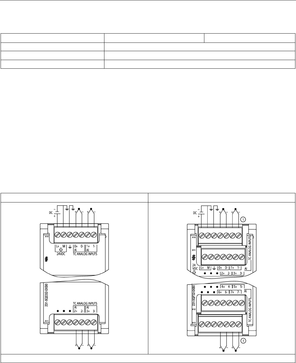
Technical specifications
A.11 Thermocouple and RTD signal modules (SMs)
S7-1200 Programmable controller
1474 System Manual, V4.2, 09/2016, A5E02486680-AK
Table A- 165 Diagnostics
Model
SM 1231 AI 4 x 16 bit TC
SM 1231 AI 8 x 16 bit TC
Overflow/underflow
1
Yes
Wire break 2, 3 Yes
24 V DC low voltage
1
Yes
1
The overflow, underflow and low voltage diagnostic alarm information will be reported in the analog data values even if
the alarms are disabled in the module configuration.
2
When wire break alarm is disabled and an open wire condition exists in the sensor wiring, the module may report ran-
dom values.
3
The module performs wire break testing every 6 seconds, which extends the update time by 9 ms for each enable
channel once every 6 seconds.
The SM 1231 Thermocouple (TC) analog signal module measures the value of voltage
connected to the module inputs. The temperature measurement type can be either
"Thermocouple" or "Voltage".
● "Thermocouple": The value will be reported in degrees multiplied by ten (for example, 25.3
degrees will be reported as decimal 253).
● "Voltage": The nominal range full scale value will be decimal 27648.
Table A- 166 Wiring diagrams for the thermocouple SMs
SM 1231 AI 4 x TC 16 bit (6ES7231-5QD32-0XB0)
SM 1231 AI 8 x TC bit (6ES7231-5QF32-0XB0)
Note: Connectors must be gold. See Appendix C, Spare Parts for article number.
① TC 2, 3, 4, and 5 not shown connected for clarity.

Technical specifications
A.11 Thermocouple and RTD signal modules (SMs)
S7-1200 Programmable controller
System Manual, V4.2, 09/2016, A5E02486680-AK 1475
Table A- 167 Connector pin locations for SM 1231 AI 4 x TC 16 bit (6ES7231-5QD32-0XB0)
Pin
X10 (gold)
X11 (gold)
1
L+ / 24 V DC
No connection
2 M / 24 V DC No connection
3
Functional Earth
No connection
4 AI 0+ /TC AI 2+ /TC
5
AI 0- /TC
AI 2- /TC
6
AI 1+ /TC
AI 3+ /TC
7
AI 1- /TC
AI 3- /TC
Table A- 168 Connector Pin Locations for SM 1231 AI 8 x TC bit (6ES7231-5QF32-0XB0)
Pin
X10 (gold)
X11 (gold)
X12 (gold)
X13 (gold)
1
L+ / 24 V DC
No connection
No connection
No connection
2
M / 24 V DC
No connection
No connection
No connection
3
Functional Earth
No connection
No connection
No connection
4
AI 0+ /TC
AI 2+ /TC
AI 4 I- /TC
AI 6 I- /TC
5
AI 0- /TC
AI 2- /TC
AI 4 I+ /TC
AI 6 I+ /TC
6
AI 1+ /TC
AI 3+ /TC
AI 5 M- /TC
AI 7 M- /TC
7
AI 1- /TC
AI 3- /TC
AI 5 M+ /TC
AI 7 M+ /TC
Note
Unused analog inputs should be shorted.
The thermocouple unused channels can be deactivat
ed. No error will occur if an unused
channel is deactivated.

Technical specifications
A.11 Thermocouple and RTD signal modules (SMs)
S7-1200 Programmable controller
1476 System Manual, V4.2, 09/2016, A5E02486680-AK
A.11.1.1
Basic operation for a thermocouple
Thermocouples are formed whenever two dissimilar metals are electrically bonded to each
other. A voltage is generated that is proportional to the junction temperature. This voltage is
small; one microvolt could represent many degrees. Measuring the voltage from a
thermocouple, compensating for extra junctions, and then linearizing the result forms the
basis of temperature measurement using thermocouples.
When you connect a thermocouple to the SM 1231 Thermocouple module, the two dissimilar
metal wires are attached to the module at the module signal connector. The place where the
two dissimilar wires are attached to each other forms the sensor thermocouple.
Two more thermocouples are formed where the two dissimilar wires are attached to the
signal connector. The connector temperature causes a voltage that adds to the voltage from
the sensor thermocouple. If this voltage is not corrected, then the temperature reported will
deviate from the sensor temperature.
Cold junction compensation is used to compensate for the connector thermocouple.
Thermocouple tables are based on a reference junction temperature, usually zero degrees
Celsius. The cold junction compensation compensates the connector to zero degrees
Celsius. The cold junction compensation restores the voltage added by the connector
thermocouples. The temperature of the module is measured internally, and then converted to
a value to be added to the sensor conversion. The corrected sensor conversion is then
linearized using the thermocouple tables.
For optimum operation of the cold junction compensation, the thermocouple module must be
located in a thermally stable environment. Slow variation (less than 0.1 °C/minute) in
ambient module temperature is correctly compensated within the module specifications. Air
movement across the module will also cause cold junction compensation errors.
If better cold junction error compensation is needed, an external iso-thermal terminal block
may be used. The thermocouple module provides for use of a 0 °C referenced or 50 °C
referenced terminal block.

Technical specifications
A.11 Thermocouple and RTD signal modules (SMs)
S7-1200 Programmable controller
System Manual, V4.2, 09/2016, A5E02486680-AK 1477
A.11.1.2
Selection tables for the SM 1231 thermocouple
The ranges and accuracy for the different thermocouple types supported by the SM 1231
Thermocouple signal module are shown in the table below.
Table A- 169 SM 1231 Thermocouple selection table
Type
Under-range
minimum1
Nominal range
low limit
Nominal range
high limit
Over-range
maximum2
Normal range 3, 4
accuracy @ 25 °C
Normal range 1, 2
accuracy -20 °C
to 60 °C
J
-210.0 °C
-150.0 °C
1200.0 °C
1450.0 °C
±0.3 °C
±0.6 °C
K
-270.0 °C
-200.0 °C
1372.0 °C
1622.0 °C
±0.4 °C
±1.0 °C
T
-270.0 °C
-200.0 °C
400.0 °C
540.0 °C
±0.5 °C
±1.0 °C
E -270.0 °C -200.0 °C 1000.0 °C 1200.0 °C ±0.3 °C ±0.6 °C
R & S
-50.0 °C
100.0 °C
1768.0 °C
2019.0 °C
±1.0 °C
±2.5 °C
B
0.0 °C
200.0 °C
800.0 °C
--
±2.0 °C
±2.5 °C
--
800.0 °C
1820.0 °C
1820.0 °C
±1.0 °C
±2.3 °C
N
-270.0 °C
-200.0 °C
1300.0 °C
1550.0 °C
±1.0 °C
±1.6 °C
C
0.0 °C
100.0 °C
2315.0 °C
2500.0 °C
±0.7 °C
±2.7 °C
TXK/XK(L)
-200.0 °C
-150.0 °C
800.0 °C
1050.0 °C
±0.6 °C
±1.2 °C
Voltage -32512 -27648
-80mV
27648
80mV
32511 ±0.05% ±0.1%
1
Thermocouple values below the under-range minimum value are reported as -32768.
2
Thermocouple values above the over-range minimum value are reported as 32767.
3
Internal cold junction error is ±1.5 °C for all ranges. This adds to the error in this table. The module requires at least 30
minutes of warm-up time to meet this specification.
4
In the presence of radiated radio frequency of 970 MHz to 990 MHz, the accuracy of the SM 1231 AI 4 x 16 bit TC may
be degraded.
Note
Thermocouple channel
Each channel on the Thermocouple signal module can be configured with a different
t
hermocouple type (selectable in the software during configuration of the module).

Technical specifications
A.11 Thermocouple and RTD signal modules (SMs)
S7-1200 Programmable controller
1478 System Manual, V4.2, 09/2016, A5E02486680-AK
Table A- 170 Noise reduction and update times for the SM 1231 Thermocouple
Rejection frequency selection
Integration time
4 Channel module update
time (seconds)
8 Channel module update
time (seconds)
400 Hz (2.5 ms)
10 ms
1
0.143
0.285
60 Hz (16.6 ms) 16.67 ms 0.223 0.445
50 Hz (20 ms)
20 ms
0.263
0.525
10 Hz (100 ms)
100 ms
1.225
2.450
1
To maintain module resolution and accuracy when 400 Hz rejection is selected, the integration time is 10 ms. This
selection also rejects 100 Hz and 200 Hz noise.
It is recommended for measuring thermocouples that a 100 ms integration time be used. The
use of smaller integration times will increase the repeatability error of the temperature
readings.
Note
After power is applied, the module performs internal calibration for the analog
-to-digital
converter. During this time the module reports a value of 32767 on each channel until valid
data is av
ailable on that channel. Your user program may need to allow for this initialization
time. Because the configuration of the module can vary the length of the initialization time,
you should verify the behavior of the module in your configuration. If requir
ed, you can
include logic in your user program to accommodate the initialization time of the module.
Representation of analog values for Thermocouple Type J
A representation of the analog values of thermocouples type J is shown in the table below.
Table A- 171 Representation of analog values of thermocouples type J
Type J in °C
Units
Type J in °F
Units
Range
Decimal
Hexadecimal
Decimal
Hexadecimal
> 1450.0
32767
7FFF
> 2642.0
32767
7FFF
Overflow
1450.0
:
1200.1
14500
:
12001
38A4
:
2EE1
2642.0
:
2192.2
26420
:
21922
6734
:
55A2
Overrange
1200.0
:
-150.0
12000
:
-1500
2EE0
:
FA24
2192.0
:
-238.0
21920
:
-2380
55A0
:
F6B4
Rated range
< -150.0 -32768 8000 < -238.0 -32768 8000 Underflow1
1 Faulty wiring (for example, polarity reversal, or open inputs) or sensor error in the negative
range (for example, wrong type of thermocouple) may cause the thermocouple module to
signal underflow.

Technical specifications
A.11 Thermocouple and RTD signal modules (SMs)
S7-1200 Programmable controller
System Manual, V4.2, 09/2016, A5E02486680-AK 1479
A.11.2
SM 1231 RTD
SM 1231 RTD specifications
Table A- 172 General specifications
Technical data
SM 1231 AI 4 x RTD x 16 bit
SM 1231 AI 8 x RTD x 16 bit
Article number
6ES7231-5PD32-0XB0
6ES7231-5PF32-0XB0
Dimensions W x H x D (mm) 45 x 100 x 75 70 x 100 x 75
Weight
220 grams
270 grams
Power dissipation 1.5 W
Current consumption (SM Bus)
80 mA
90 mA
Current consumption (24 V DC)
1
40 mA
1 20.4 to 28.8 V DC (Class 2, Limited Power, or sensor power from CPU)
Table A- 173 Analog inputs
Technical data
SM 1231 AI 4 x RTD x 16 bit
SM 1231 AI 8 x RTD x16 bit
Number of inputs
4
8
Type
Module referenced RTD and Ω
Range
Nominal range (data word)
Overshoot/undershoot range (data
word)
Overflow/underflow (data word)
See RTD Sensor selection table (Page 1482).
Resolution
Temperature
0.1 °C/0.1 °F
Resistance
15 bits plus sign
Maximum withstand voltage
± 35 V
Noise rejection
85 dB for the selected noise reduction (10 Hz, 50 Hz, 60 Hz or 400 Hz)
Common mode rejection
> 120dB
Impedance
≥ 10 MΩ
Isolation
Field side to logic
707 V DC (type test)
Field to 24 V DC
707 V DC (type test)
24 V DC to logic 707 V DC (type test)
Channel to channel isolation
none
Accuracy See RTD Sensor selection table (Page 1482).
Repeatability
±0.05% FS
Maximum sensor dissipation
0.5 m W
Measuring principle
Integrating
Module update time
See Noise reduction selection table (Page 1482).
Cable length (meters)
100 meters to sensor max.
Wire resistance
20 Ω, 2.7 Ω for 10 Ω RTD max.

Technical specifications
A.11 Thermocouple and RTD signal modules (SMs)
S7-1200 Programmable controller
1480 System Manual, V4.2, 09/2016, A5E02486680-AK
Table A- 174 Diagnostics
Technical data
SM 1231 AI 4 x RTD x 16 bit
SM 1231 AI 8 x RTD x16 bit
Overflow/underflow
1,2
Yes
Wire break 3 Yes
24 V DC low voltage
1
Yes
1
The overflow, underflow and low voltage diagnostic alarm information will be reported in the analog data values even if
the alarms are disabled in the module configuration.
2
For resistance ranges underflow detection is never enabled.
3
When wire break alarm is disabled and an open wire condition exists in the sensor wiring, the module may report ran-
dom values.
The SM 1231 RTD analog signal module measures the value of resistance connected to the
module inputs. The measurement type can be selected as either "Resistor" or "Thermal
resistor".
● "Resistor": The nominal range full scale value will be decimal 27648.
● "Thermal resistor": The value will be reported in degrees multiplied by ten (for example,
25.3 degrees will be reported as decimal 253). The climatic range values will be reported
in degrees multiplied by one hundred (for example, 25.34 degrees will be reported as
decimal 2534).
The SM 1231 RTD module supports measurements with 2-wire, 3-wire and 4-wire
connections to the sensor resistor.
Table A- 175 Wiring diagrams for the RTD SMs
SM 1231 RTD 4 x 16 bit (6ES7231-5PD32-0XB0)
SM 1231 RTD 8 x 16 bit (6ES7231-5PF32-0XB0)
①
Loop-back unused RTD inputs
②
2-wire RTD ③ 3-wire RTD ④ 4-wire RTD
NOTE: Connectors must be gold. See Appendix C, Spare Parts for article number.

Technical specifications
A.11 Thermocouple and RTD signal modules (SMs)
S7-1200 Programmable controller
System Manual, V4.2, 09/2016, A5E02486680-AK 1481
Table A- 176 Connector Pin Locations for SM 1231 RTD 4 x 16 bit (6ES7231-5PD32-0XB0)
Pin
X10 (gold)
X11 (gold)
X12 (gold)
X13 (gold)
1
L+ / 24 V DC
No connection
No connection
No connection
2 M / 24 V DC No connection No connection No connection
3
Functional Earth
No connection
No connection
No connection
4 AI 0 M+ /RTD AI 1 M+ /RTD AI 2 M+ /RTD AI 3 M+ /RTD
5
AI 0 M- /RTD
AI 1 M- /RTD
AI 2 M- /RTD
AI 3 M- /RTD
6
AI 0 I+ /RTD
AI 1 I+ /RTD
AI 2 I+ /RTD
AI 3 I+ /RTD
7
AI 0 I- /RTD
AI 1 I- /RTD
AI 2 I- /RTD
AI 3 I- /RTD
Table A- 177 Connector Pin Locations for SM 1231 RTD 8 x 16 bit (6ES7231-5PF32-0XB0)
Pin
X10 (gold)
X11 (gold)
X12 (gold)
X13 (gold)
1
L+ / 24 V DC
No connection
No connection
No connection
2
M / 24 V DC
No connection
No connection
No connection
3
Functional Earth
No connection
No connection
No connection
4
AI 0 M+ /RTD
AI 2 M+ /RTD
AI 4 M+ /RTD
AI 6 M+ /RTD
5
AI 0 M- /RTD
AI 2 M- /RTD
AI 4 M- /RTD
AI 6 M- /RTD
6
AI 0 I+ /RTD
AI 2 I+ /RTD
AI 4 I+ /RTD
AI 6 I+ /RTD
7
AI 0 I- /RTD
AI 2 I- /RTD
AI 4 I- /RTD
AI 6 I- /RTD
8
AI 1 M+ /RTD
AI 3 M+ /RTD
AI 5 M+ /RTD
A7 M+ /RTD
9
AI 1 M- /RTD
AI 3 M- /RTD
AI 5 M- /RTD
AI 7 M- /RTD
10
AI 1 I+ /RTD
AI 3 I+ /RTD
AI 5 I+ /RTD
AI 7 I+ /RTD
11
AI 1 I- /RTD
AI 3 I- /RTD
AI 5 I- /RTD
AI 7 I- /RTD
Note
The RTD unused channels can be deactivated. No er
ror will occur if an unused channel is
deactivated.
The RTD module needs to have the current loop continuous to eliminate extra stabilization
time which is automatically added to an unused channel that is not deactivated. For
consistency the RTD module sho
uld have a resistor connected (like the 2-wire RTD
connection).

Technical specifications
A.11 Thermocouple and RTD signal modules (SMs)
S7-1200 Programmable controller
1482 System Manual, V4.2, 09/2016, A5E02486680-AK
A.11.2.1
Selection tables for the SM 1231 RTD
Table A- 178 Ranges and accuracy for the different sensors supported by the RTD modules
Temperature coef-
ficient
RTD type
Under range
minimum1
Nominal
range low limit
Nominal
range high
limit
Over
range
maxi-
mum2
Normal
range ac-
curacy
@ 25 °C
Normal range
accuracy
-20 °C to
60 °C
Pt 0.003850
ITS90
DIN EN 60751
Pt 100 climat-
ic
-145.00 °C -120.00 °C 145.00 °C 155.00 °
C
±0.20 °C ±0.40 °C
Pt 10 -243.0 °C -200.0 °C 850.0 °C 1000.0 °
C
±1.0 °C ±2.0 °C
Pt 50
-243.0 °C -200.0 °C 850.0 °C 1000.0 °
C
±0.5 °C ±1.0 °C
Pt 100
Pt 200
Pt 500
Pt 1000
Pt 0.003902
Pt 0.003916
Pt 0.003920
Pt 100 -243.0 °C -200.0 °C 850.0 °C 1000.0 °
C
± 0.5 °C ±1.0 °C
Pt 200
-243.0 °C -200.0 °C 850.0 °C 1000.0 °
C
± 0.5 °C ±1.0 °C
Pt 500
Pt 1000
Pt 0.003910
Pt 10
-273.2 °C
-240.0 °C
1100.0 °C
1295 °C
±1.0 °C
±2.0 °C
Pt 50
-273.2 °C -240.0 °C 1100.0 °C 1295 °C ±0.8 °C ±1.6 °C
Pt 100
Pt 500
Ni 0.006720
Ni 0.006180
Ni 100
-105.0 °C -60.0 °C 250.0 °C 295.0 °C ±0.5 °C ±1.0 °C
Ni 120
Ni 200
Ni 500
Ni 1000
LG-Ni 0.005000 LG-Ni 1000 -105.0 °C -60.0 °C 250.0 °C 295.0 °C ±0.5 °C ±1.0 °C
Ni 0.006170
Ni 100
-105.0 °C
-60.0 °C
180.0 °C
212.4 °C
±0.5 °C
±1.0 °C
Cu 0.004270
Cu 10
-240.0 °C
-200.0 °C
260.0 °C
312.0 °C
±1.0 °C
±2.0 °C
Cu 0.004260
Cu 10
-60.0 °C
-50.0 °C
200.0 °C
240.0 °C
±1.0 °C
±2.0 °C
Cu 50
-60.0 °C -50.0 °C 200.0 °C 240.0 °C ±0.6 °C ±1.2 °C
Cu 100
Cu 0.004280
Cu 10
-240.0 °C
-200.0 °C
200.0 °C
240.0 °C
±1.0 °C
±2.0 °C
Cu 50
-240.0 °C -200.0 °C 200.0 °C 240.0 °C ±0.7 °C ±1.4 °C
Cu 100
1
RTD values below the under-range minimum value report -32768.
2 RTD values above the over-range maximum value report +32767.

Technical specifications
A.11 Thermocouple and RTD signal modules (SMs)
S7-1200 Programmable controller
System Manual, V4.2, 09/2016, A5E02486680-AK 1483
Table A- 179 Resistance
Range
Under range
minimum
Nominal range
low limit
Nominal range
high limit
Over
range
maximum1
Normal range
accuracy
@ 25 °C
Normal range accu-
racy -20 °C to 60 °C
150 Ω
n/a
0 (0 Ω)
27648 (150 Ω)
176.383 Ω
±0.05%
±0.1%
300 Ω n/a 0 (0 Ω) 27648 (300 Ω) 352.767 Ω ±0.05% ±0.1%
600 Ω
n/a
0 (0 Ω)
27648 (600 Ω)
705.534 Ω
±0.05%
±0.1%
1 Resistance values above the over-range minimum value are reported as +32767.
Note
The module reports 32767 on any activated channel with no sensor connected. If open wire
detection is also enabled, the module flashes the appropriate red LEDs.
When 5
00 Ω and 1000 Ω RTD ranges are used with other lower value resistors, the error
may increase to two times the specified error.
Best accuracy will be achieved for the 10 Ω RTD ranges if 4 wire connections are used.
The resistance of the connection wires in
2 wire mode will cause an error in the sensor
reading and therefore accuracy is not guaranteed.
Table A- 180 Noise reduction and update times for the RTD modules
Rejection frequency selec-
tion
Integration time
Update time (seconds)
4-channel module
8-channel module
400 Hz (2.5 ms) 10 ms 1 4-/2-wire: 0.142
3-wire: 0.285
4-/2-wire: 0.285
3-wire: 0.525
60 Hz (16.6 ms) 16.67 ms 4-/2-wire: 0.222
3-wire: 0.445
4-/2-wire: 0.445
3-wire: 0.845
50 Hz (20 ms) 20 ms 4-/2-wire: 0.262
3-wire: .505
4-/2-wire: 0.524
3-wire: 1.015
10 Hz (100 ms) 100 ms 4-/2-wire: 1.222
3-wire: 2.445
4-/2-wire: 2.425
3-wire: 4.845
1
To maintain module resolution and accuracy when the 400 Hz filter is selected, the integration time is 10 ms. This selec-
tion also rejects 100 Hz and 200 Hz noise.
Note
After power is applied, the module performs internal calibration for the analog
-to-digital
converter. During this time the module reports a value of 32767 on each channel until valid
data is av
ailable on that channel. Your user program may need to allow for this initialization
time. Because the configuration of the module can vary the length of the initialization time,
you should verify the behavior or the module in your configuration. If requir
ed, you can
include logic in your user program to accommodate the initialization time of the module.

Technical specifications
A.11 Thermocouple and RTD signal modules (SMs)
S7-1200 Programmable controller
1484 System Manual, V4.2, 09/2016, A5E02486680-AK
Representation of Analog values for RTDs
A representation of the digitized measured value for the RTD standard temperature range
sensors are shown in the tables below.
Table A- 181 Representation of analog values for resistance thermometers PT 100, 200, 500, 1000
and PT 10, 50, 100, 500 GOST (0.003850) standard
Pt x00 stan-
dard in °C (1
digit =
0.1 °C)
Units
Pt x00 stan-
dard in °F (1
digit =
0.1 °F)
Units
Range
Decimal
Hexadecimal
Decimal
Hexadecimal
> 1000.0
32767
7FFF
> 1832.0
32767
7FFF
Overflow
1000.0
:
850.1
10000
:
8501
2710
:
2135
1832.0
:
1562.1
18320
:
15621
4790
:
3D05
Overrange
850.0
:
-200.0
8500
:
-2000
2134
:
F830
1562.0
:
-328.0
15620
:
-3280
3D04
:
F330
Rated range
-200.1
:
-243.0
-2001
:
-2430
F82F
:
F682
-328.1
:
-405.4
-3281
:
-4054
F32F
:
F02A
Underrange
< -243.0
-32768
8000
< -405.4
-32768
8000
Underflow

Technical specifications
A.12 Technology modules
S7-1200 Programmable controller
System Manual, V4.2, 09/2016, A5E02486680-AK 1485
A.12
Technology modules
A.12.1
SM 1278 4xIO-Link Master SM
Table A- 182 General specifications
Technical data
SM 1278 4xIO-Link Master signal module
Article number
6ES7278-4BD32-0XB0
Dimensions W x H x D (mm) 45 x 100 x 75
Weight
150 grams
General information
I&M data
Yes; IM0 to IM3
Supply voltage
Rated voltage (DC)
24 V DC
Valid range low limit (DC) 19.2 V; 20.5 V if IO-Link is used (the supply voltage for
IO-Link devices on the master must be at least 20 V)
Valid range high limit (DC)
28.8 V DC
Polarity reversal protection
Yes
Input current
Current consumption
65 mA; without load
Encoder supply
Number of outputs
4
Output current, rated value
200 mA
Power loss
Power loss, typ.
1 W, excluding port loading
Digital inputs/outputs
Cable length (meters)
20 m, unshielded, max.
SDLC
Cable length (meters)
20 m, unshielded, max.
IO-Link
Number of ports
4
Number of ports which can be controlled at the same
time
4
IO-Link protocol 1.0
Yes
IO-Link protocol 1.1
Yes
Operating mode
IO-Link
Yes
DI
Yes
DQ
Yes; max. 100 mA
Connection of IO-Link devices
Port type A
Yes
Transmission rate
4.8 kBd (COM1)

Technical specifications
A.12 Technology modules
S7-1200 Programmable controller
1486 System Manual, V4.2, 09/2016, A5E02486680-AK
Technical data
SM 1278 4xIO-Link Master signal module
38.4 kBd (COM2)
230.4 kBd (COM3)
Cycle time, min.
2 ms, dynamic, dependent on the user data length
Size of process data, input per port 32 bytes; max.
Size of process data, input per module
32 bytes
Size of process data, output per port
32 bytes; max.
Size of process data, output per module
32 bytes
Memory size for device parameters
2 Kbytes
Cable length unshielded, max. (meters)
20 m
Interrupts/diagnostics/status information
Status display
Yes
Interrupts
Diagnostic interrupt
Yes; port diagnostics is only available in IO-Link mode
Diagnostic alarms
Diagnostics
Monitoring of supply voltage
Yes
Short circuit
Yes
Diagostic indicator LED
Monitoring of supply voltage
Yes; flashing red DIAG LED
Channel status display Yes; per channel one green LED for channel status Qn
(SIO mode) and PORT status Cn (IO-Link mode)
For channel diagnostics
Yes; red Fn LED
For module diagnostics
Yes; green/red DIAG LED
Electrical isolation
Electrical isolation channels
Between the channels No
Between the channels and the backplane bus
Yes
Insulation
Insulation tested with
707 V DC (type test)
Ambient conditions
Operating temperature
Min.
-20 °C
Max.
60 °C
Horizontal installation, min.
-20 °C
Horizontal installation, max.
60 °C
Vertical installation, min.
-20 °C
Vertical installation, max.
50 °C
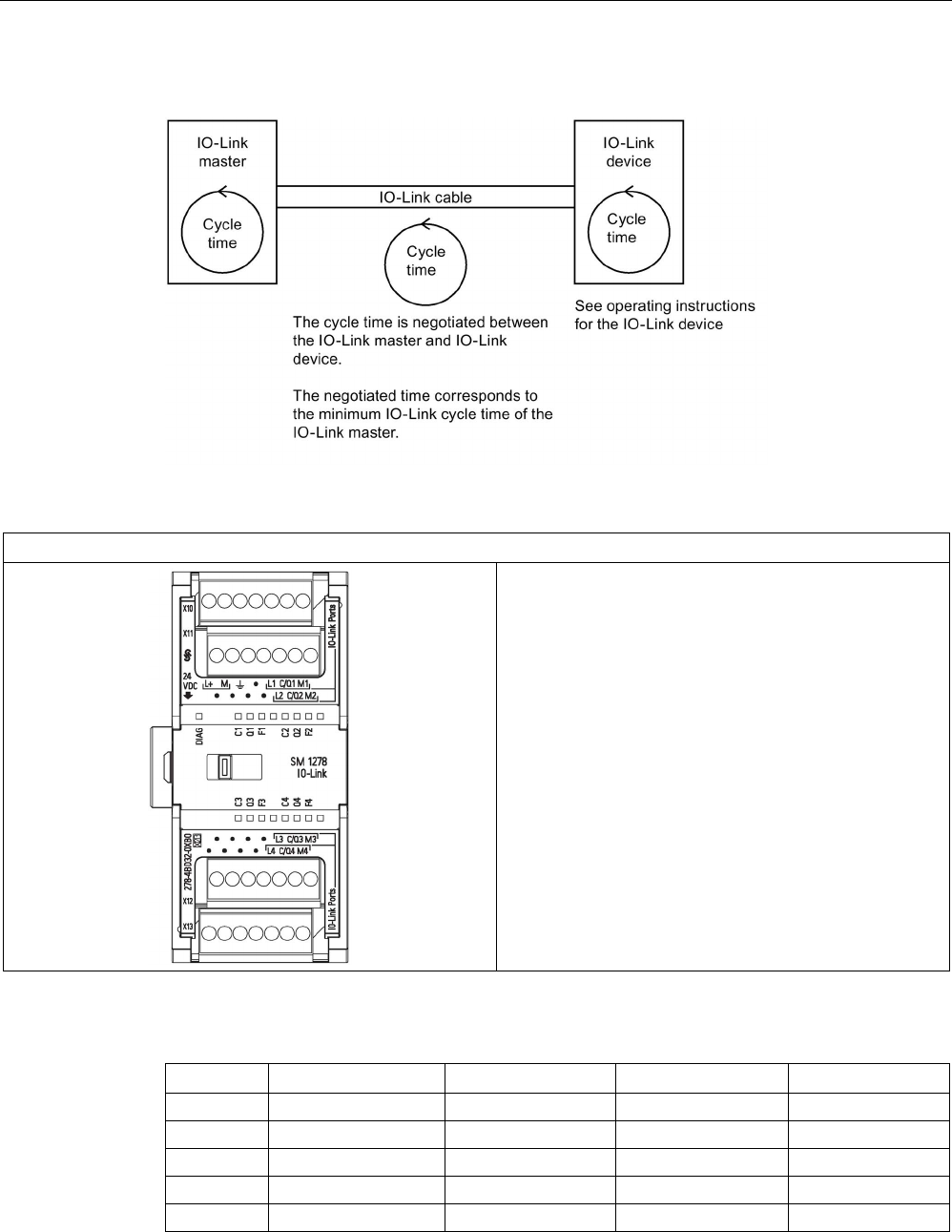
Technical specifications
A.12 Technology modules
S7-1200 Programmable controller
System Manual, V4.2, 09/2016, A5E02486680-AK 1487
Overview of the response time
Table A- 183 Wiring diagram for the SM 1278 IO-Link Master
SM 1278 IO-Link Master (6ES7278-4BD32-0XB0)
Table A- 184 Connector pin locations for SM 1278 IO-Link Master (6ES7278-4BD32-0XB0)
Pin
X10
X11
X12
X13
1
L+ / 24 V DC
No connection
No connection
No connection
2
M / 24 V DC
No connection
No connection
No connection
3
Functional Earth
No connection
No connection
No connection
4
No connection
No connection
No connection
No connection
5
L
1
L
2
L
3
L
4
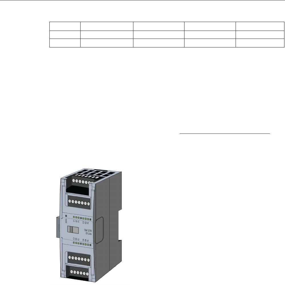
Technical specifications
A.12 Technology modules
S7-1200 Programmable controller
1488 System Manual, V4.2, 09/2016, A5E02486680-AK
Pin
X10
X11
X12
X13
6
C/Q1
C/Q2
C/Q3
C/Q4
7 M1 M2 M3 M4
A.12.1.1
SM 1278 4xIO-Link Master overview
The SM 1278 4xIO-Link Master is a 4-port module that functions as both a signal module
and a communication module. Each port can operate in the IO-Link mode, single 24 V DC
digital input or 24 V DC digital output.
The IO-Link master programs acyclic communication with an IO-Link device using the
IOL_CALL function block (FB) in your STEP 7 S7-1200 controller program. The IOL_CALL
FB indicates the IO-Link master your program uses, and which ports the master uses for
data exchange.
Visit the Siemens Industry Online Support website (http://support.industry.siemens.com) for
details on working with the IOL_CALL FB. Enter "IO-Link" in the website's search box to
access information about IO-Link products and their use.
View of the module

Technical specifications
A.12 Technology modules
S7-1200 Programmable controller
System Manual, V4.2, 09/2016, A5E02486680-AK 1489
Properties
Technical properties
● IO-Link Master according to IO-Link specification V1.1 (see the IO-Link Consortium
website (http://io-link.com/en/index.php) for details)
● Serial communication module with four ports (channels)
● Data transmission rate COM1 (4.8 kbaud), COM2 (38.4 kbaud), COM3 (230.4 kbaud)
● SIO mode (standard IO mode)
● Connection of up to four IO-Link devices (3-wire connection) or four standard actuators or
standard encoders
● Programmable diagnostics function by port
Supported functions
● I&M (installation and maintenance) identification data
● Firmware update
● IO-Link parameter assignment by means of the S7-PCT port configuration tool, STEP 7
Professional, and an S7-1200 V4.0 or later CPU
IO-Link is a point-to-point connection between a master and a device. Both conventional and
intelligent sensors/actuators can be used as devices at the IO-Link via unshielded standard
cables using proven 3-wire technology. IO-Link is backward compatible with conventional
digital sensors and actuators. The circuit state and data channel are designed in proven 24 V
DC technology.
For additional information about the SIMATIC-IO-Link technology, refer to the "IO-Link
system Function Manual" on the Siemens Industry Online Support website
(http://support.automation.siemens.com).
Note
IO-Link parameter data
When you replace the SM
4xIO-Link Master, the parameter data is not automatically
assigned to it.

Technical specifications
A.12 Technology modules
S7-1200 Programmable controller
1490 System Manual, V4.2, 09/2016, A5E02486680-AK
CAUTION
Removal and insertion
If you insert the SM 4xIO-Link Master with the load switched on, this can lead to dangerous
conditions in your plant.
Physical damage to the S7-1200 automation system may occur as a result.
Remove or insert the SM 4xIO-Link Master only when the load is switched off.
Effects of resetting to the factory settings
Use the function "Reset to factory settings" to restore the parameter assignments you made
with S7-PCT to the delivery state.
After a "Reset to factory settings", the parameters of the SM 1278 4xIO-Link module are
assigned as follows:
● The ports are in DI mode
● The ports are mapped to the relative addresses 0.0 to 0.3
● The PortQualifier is disabled
● Maintenance data 1 to 3 is deleted
Note
When you r
eset to factory settings, the device parameters are deleted and the delivery state
is restored.
If you remove an SM
1278 4xIO-
Link signal module, reset it to factory settings before you put
it into storage.
Procedure
For "Reset to factory settings", proceed as described in the S7-PCT online help under
"Master Configuration > 'Commands' tab".
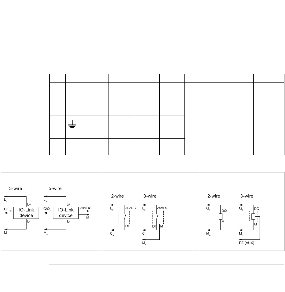
Technical specifications
A.12 Technology modules
S7-1200 Programmable controller
System Manual, V4.2, 09/2016, A5E02486680-AK 1491
A.12.1.2
Connecting
For details about pin assignment, see table, Connector pin locations for SM 1278 I/O-Link
Master (6ES 278-4BD32-0XB0). (Page 1485)
The following table shows the terminal assignments for the SM 1278 4xIO-Link Master:
Pin
X10
X11
X12
X13
Notes
BaseUnits
7
M
1
M
2
M
3
M
4
• Mn: ground to slave
• C/Qn: SDLC, DI or DQ
• Ln: 24 V DC to slave
• M: ground
• L+: 24 V DC to Master
• RES: reserved; may not
be assigned
A1
6
C/Q
1
C/Q
2
C/Q
3
C/Q
4
5
L
1
L
2
L
3
L
4
4 RES RES RES RES
3
(functional earth)
RES RES RES
2
M
RES
RES
RES
1
L+
RES
RES
RES
The following table contains illustrations of connection examples, where n = port number:
IO-Link operating mode
Operating mode DI
Operating mode DQ
Note
Connected sensors must use the device supply provided by the Master module L
n
connection.
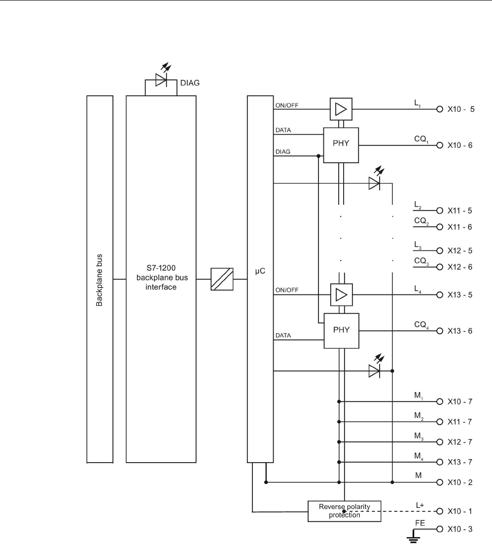
Technical specifications
A.12 Technology modules
S7-1200 Programmable controller
1492 System Manual, V4.2, 09/2016, A5E02486680-AK

Technical specifications
A.12 Technology modules
S7-1200 Programmable controller
System Manual, V4.2, 09/2016, A5E02486680-AK 1493
A.12.1.3
Parameters/address space
Configuring the SM 1278 4xIO-Link Master
For the module integration, you need the Siemens engineering tool TIA Portal V13 or later.
You also need S7-PCT V3.2 or later for the IO-Link integration.
For commissioning, you require both an engineering tool and S7-PCT V3.2 or later for
parameter assignment.
Note
TIA Portal V14 does not currently support configuration of the SM 1278 4xIO
-Link Master.
The following table shows the parameters for the SM 1278 4xIO-Link Master:
Parameters
Value range
Default
Configuration in
RUN
Efficiency range
Diagnostics port 1 • Disable
• Enable
Disable Yes Port (channel)
Diagnostics port 2 • Disable
• Enable
Disable Yes Port (channel)
Diagnostics port 3 • Disable
• Enable
Disable Yes Port (channel)
Diagnostics port 4 • Disable
• Enable
Disable Yes Port (channel)
Enable diagnostics for port 1 to port 4 parameter
This parameter allows diagnostics to be enabled for specific ports of the four IO-Link ports.
The port assignments are as follows:
Port 1 → channel 1
Port 2 → channel 2
Port 3 → channel 3
Port 4 → channel 4
The maximum size of the input and output addresses of the SM 4xIO-Link Master is 32 bytes
in each case. You assign address spaces using the S7-PCT port configuration tool.

Technical specifications
A.12 Technology modules
S7-1200 Programmable controller
1494 System Manual, V4.2, 09/2016, A5E02486680-AK
Parameter data record
Parameter assignment in the user program
You can configure the device in runtime.
Changing parameters in runtime
The module parameters are included in data record 128. You can transmit the modifiable
parameters to the module with the WRREC instruction.
When you reset (power cycle) the CPU, the CPU overwrites the parameters that were sent
to the module by the WRREC instruction during the parameterization process.
Instruction for parameter assignment
The following instruction is provided for assigning parameters to the I/O module in the user
program:
Instruction
Application
SFB 53 WRREC
Transfer of the alterable parameters to the module.
Error message
The following return value is reported in the event of an error:
Error code
Meaning
80B1
H
Error in data length
80E0
H
Error in header information
80E1H Parameter error

Technical specifications
A.12 Technology modules
S7-1200 Programmable controller
System Manual, V4.2, 09/2016, A5E02486680-AK 1495
Data record structure
The following table shows the IO-Link parameters:
Offset
Label
Type
Default
Description
0 Version 1 byte 0x02
Shows the structure of the record 0x02 for
the IO-Link Master in accordance with
IO-Link V1.1
1 Parameter length 1 byte 0x02 Parameter length (2 bytes + 2 headers)
IO-Link start parameters
2 Port diagnostics
(Port1 1 to n)
1 byte 0x00 Activating the diagnostics for port 1 to n
3
IOL properties
1 byte
0x00
Module properties
The following table shows the data record version:
Bit 7
Bit 6
Bit 5
Bit 4
Bit 3
Bit 2
Bit 1
Bit 0
Reserved
Major version (00)
Minor version (0010)
The following table shows the data record port diagnostics:
Bit 7
Bit 6
Bit 5
Bit 4
Bit 3
Bit 2
Bit 1
Bit 0
Reserved
EN_Port4
EN_Port3
EN_Port2
EN_Port1
EN_Portx:
0 = D
iagnostics deactivated
1 = Diagnostics activated
The following table shows the data record IOL properties:
Bit 7
Bit 6
Bit 5
Bit 4
Bit 3
Bit 2
Bit 1
Bit 0
Reserved
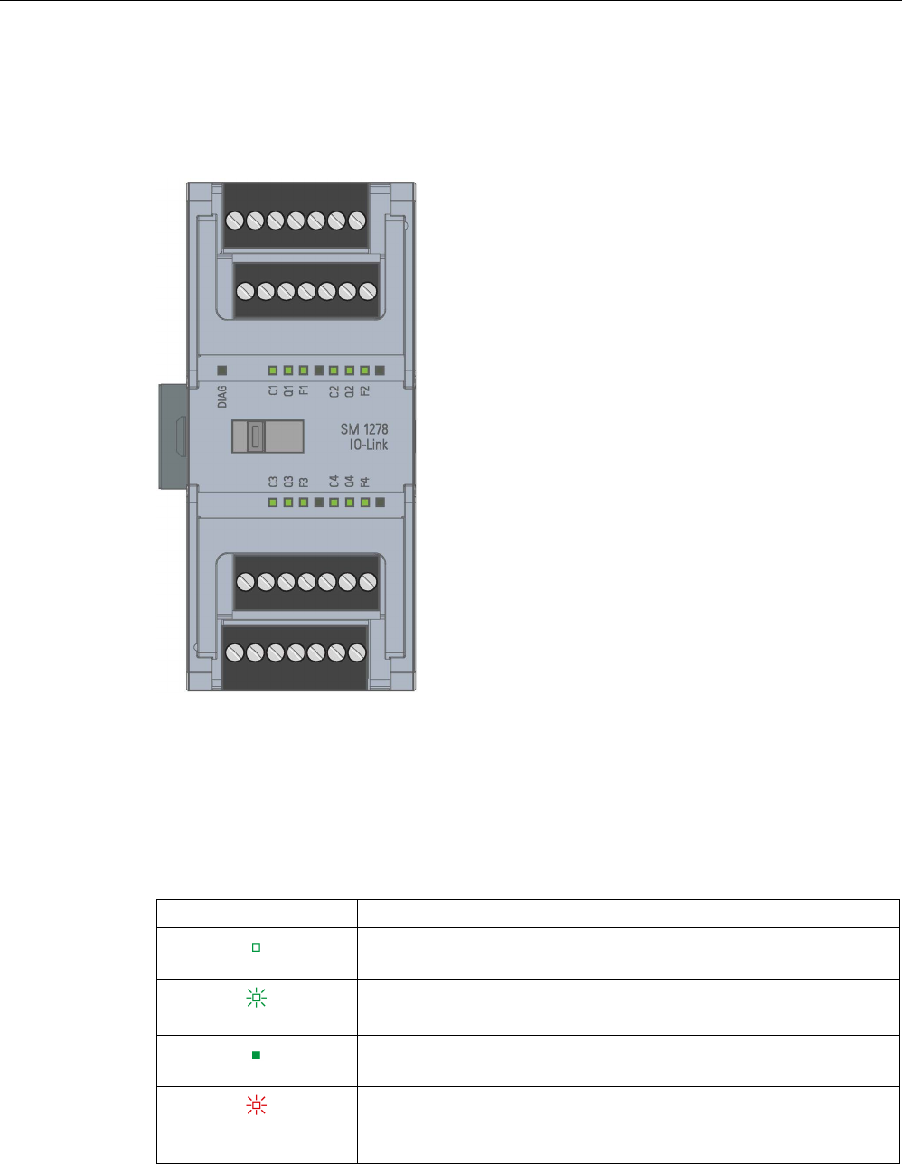
Technical specifications
A.12 Technology modules
S7-1200 Programmable controller
1496 System Manual, V4.2, 09/2016, A5E02486680-AK
A.12.1.4
Interrupt, error, and system alarms
LED display
Meaning of the LED displays
The following table explains the meaning of the status and error displays. You can find
remedial measures for diagnostic alarms in the "Diagnostic alarms" section.
LED DIAG
DIAG
Meaning
Off
Backplane bus supply of the S7-1200 not OK
Flashes
Module is not configured
On
Module parameterized and no module diagnostics
Flashes
Module parameterized and module diagnostics
OR
L+ power not connected

Technical specifications
A.12 Technology modules
S7-1200 Programmable controller
System Manual, V4.2, 09/2016, A5E02486680-AK 1497
LED port status
Valid for IO-Link port which is in IO-Link port mode.
COM/1 ... COM/4
Meaning
Off
Port deactivated
Flashes
Port activated, device not connected or
Port is not connected to the configured device
On
Port activated, device connected
LED channel status
Valid for IO-Link port which is in DI/Q mode.
DI/Q1 ... DI/Q4
Meaning
Off
Process signal = 0
On
Process signal = 1

Technical specifications
A.12 Technology modules
S7-1200 Programmable controller
1498 System Manual, V4.2, 09/2016, A5E02486680-AK
LED port error
F1 ... F4
Meaning
Off
No error
On
Error
Module errors are indicated as diagnostics (module status) only in IO-Link mode.
Diagnostic
alarm
Error code
(decimal)
STATUS
(W#16#...)
Meaning (IO-Link error code)
IO-Link
master
IO-Link
device
Short-circuit 1 1804 Short-circuit at the process cables on
the IO-Link device
X
7710
Short-circuit on IO device
X
Undervolt-
age
2 5111
5112
Supply voltage too low X
Overvoltage
3
5110
Supply voltage too high
X
Overheating 5
1805
Temperature exceeded on master
X
4000
4210
Temperature exceeded on device X
Wire break 6 1800 • No IO-Link device connected
• There is a break on the signal line
to the IO-Link device
• IO-Link device cannot communi-
cate due to a different error
X
Overflow 7 8C10
8C20
Process tag range exceeded X
8C20
Measuring range exceeded
Underflow
8
8C30
Process tag range too low
X
Error 9 --- All IO-Link error codes that are not
listed here are mapped to this
PROFIBUS DP error
X
Parameter
assignment
error
16 1882
1883
IO-Link master could not be config-
ured
X
1802
Incorrect device
1886
Storage error
6320
6321
6350
Device was not configured correctly X
Supply volt-
age missing
17
1806
L+ supply voltage for device missing
X
1807 L+ supply voltage for device too low
(<20 V)
Defective
fuse
18 5101 Fuse on device is defective X

Technical specifications
A.12 Technology modules
S7-1200 Programmable controller
System Manual, V4.2, 09/2016, A5E02486680-AK 1499
Diagnostic
alarm
Error code
(decimal)
STATUS
(W#16#...)
Meaning (IO-Link error code)
IO-Link
master
IO-Link
device
Safety shut-
down
25 1880 Serious error (master has to be re-
placed)
X
External fault 26 1809
180A
180B
180C
180D
Error in data storage X
1808 More than 6 errors are pending simul-
taneously on the IO-Link device

Technical specifications
A.13 Digital signal boards (SBs)
S7-1200 Programmable controller
1500 System Manual, V4.2, 09/2016, A5E02486680-AK
A.13
Digital signal boards (SBs)
A.13.1
SB 1221 200 kHz digital input specifications
Table A- 185 General specifications
Technical data
SB 1221 DI 4 x 24 V DC, 200 kHz
SB 1221 DI 4 x 5 V DC, 200 kHz
Article number
6ES7221-3BD30-0XB0
6ES7221-3AD30-0XB0
Dimensions W x H x D (mm) 38 x 62 x 21
Weight
35 grams
Power dissipation 1.5 W 1.0 W
Current consumption (SM Bus)
40 mA
Current consumption (24 V DC)
7 mA / input + 20 mA
15 mA / input + 15 mA
Table A- 186 Digital inputs
Technical data
SB 1221 DI 4 x 24 V DC, 200 kHz
SB 1221 DI 4 x 5 V DC, 200 kHz
Number of inputs
4
Type
Source
Rated voltage
24 V DC at 7 mA, nominal
5 V DC at 15 mA, nominal
Continuous permissible voltage
28.8 V DC
6 V DC
Surge voltage
35 V DC for 0.5 sec.
6 V
Logic 1 signal 0 V (10 mA) to L+ minus 10 V (2.9 mA) 0 V (20 mA) to L+ minus 2.0 V ( 5.1
mA)
Logic 0 signal
L+ minus 5 V (1.4 mA) to L+ (0 mA)
L+ minus 1.0 V (2.2 mA) to L + (0 mA)
HSC clock input rates (max.) Single phase: 200 kHz
Quadrature phase: 160 kHz
Isolation (field side to logic)
707 V DC (type test)
Isolation groups
1
Filter times
us settings
0.1, 0.2, 0.4, 0.8, 1.6, 3.2, 6.4, 10.0,12.8, 20.0
ms settings
0.05, 0.1, 0.2, 0.4, 0.8, 1.6, 3.2, 6.4, 10.0, 12.8, 20.0
Number of inputs on simultaneously • 2 (no adjacent points) at 60 °C
horizontal or 50 °C vertical
• 4 at 55 °C horizontal or 45 °C verti-
cal
4
Cable length (meters)
50 shielded twisted pair
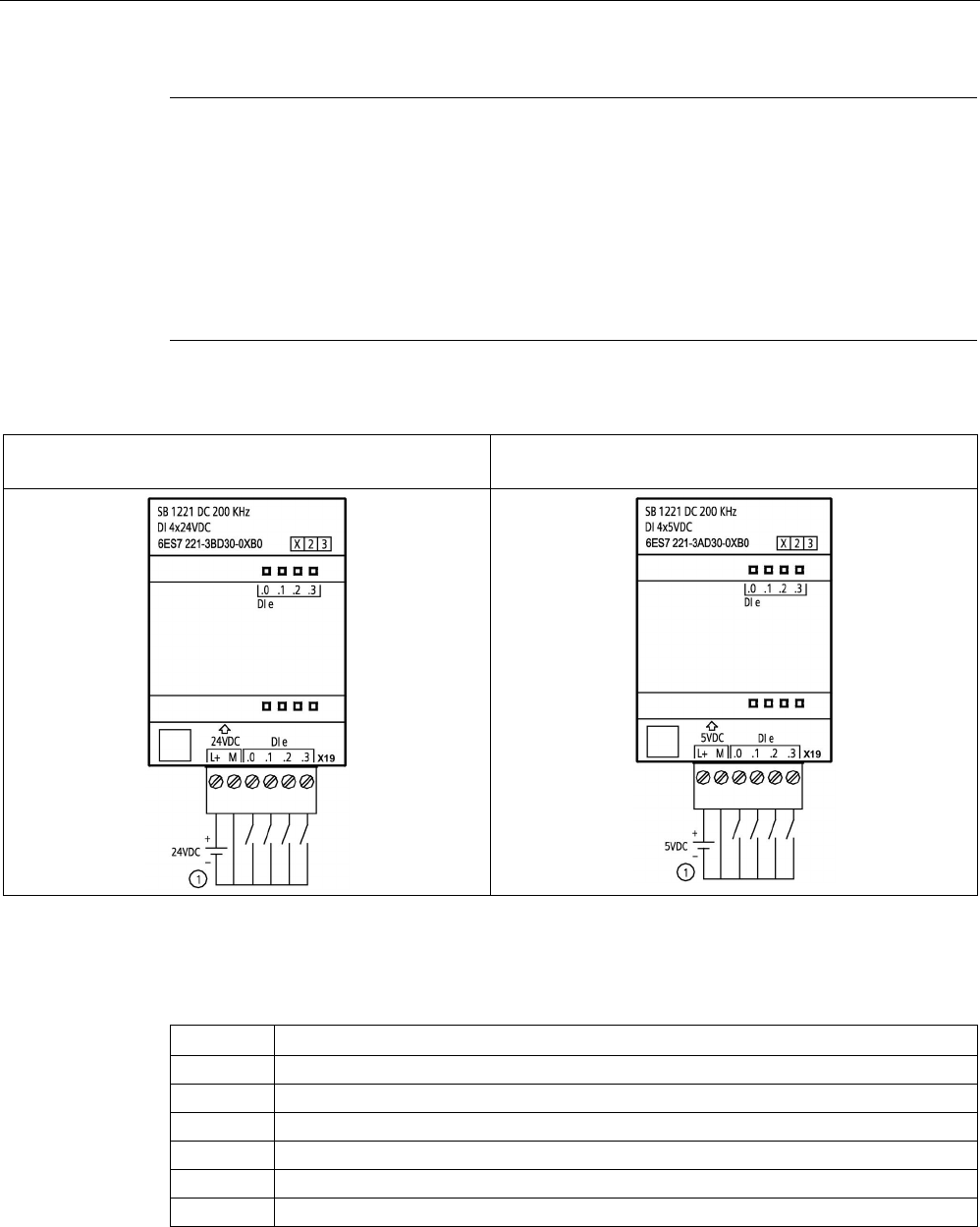
Technical specifications
A.13 Digital signal boards (SBs)
S7-1200 Programmable controller
System Manual, V4.2, 09/2016, A5E02486680-AK 1501
Note
When switching frequencies above 20 kHz, it is important that the digital inputs receive a
square wave. Consider the following options to improve the signal quality to the inputs:
•
Minimize the cable length
•
Change a driver from a sink only driver to a sinking and sourcing driver
•
Change to a higher quality cable
•
Reduce the circuit/components from 24 V to 5 V
•
Add an external load at the input
Table A- 187 Wiring diagrams for the 200 kHz digital input SBs
SB 1221 DI 4 x 24 V DC, 200 kHz
(6ES7221-3BD30-0XB0)
SB 1221 DI 4 x 5 V DC, 200 kHz
(6ES7221-3AD30-0XB0)
① Supports sourcing inputs only
Table A- 188 Connector pin locations for SB 1221 DI 4 x 24 V DC, 200 kHz (6ES7221-3BD30-0XB0)
Pin
X19
1
L+ / 24 V DC
2
M / 24 V DC
3
DI e.0
4
DI e.1
5
DI e.2
6
DI e.3

Technical specifications
A.13 Digital signal boards (SBs)
S7-1200 Programmable controller
1502 System Manual, V4.2, 09/2016, A5E02486680-AK
Table A- 189 Connector pin locations for SB 1221 DI 4 x 5 V DC, 200 kHz (6ES7221-3AD30-0XB0)
Pin
X19
1
L+ / 5 V DC
2 M / 5 V DC
3
DI e.0
4 DI e.1
5
DI e.2
6
DI e.3
A.13.2
SB 1222 200 kHz digital output specifications
Table A- 190 General specifications
Technical data
SB 1222 DQ 4 x 24 V DC, 200 kHz
SB 1222 DQ 4 x 5 V DC, 200 kHz
Article number
6ES7222-1BD30-0XB0
6ES7222-1AD30-0XB0
Dimensions W x H x D (mm)
38 x 62 x 21
Weight
35 grams
Power dissipation
0.5 W
Current consumption (SM Bus)
35 mA
Current consumption (24 V DC)
15 mA
Table A- 191 Digital outputs
Technical data
SB 1222 DQ 4 x 24 V DC, 200 kHz
SB 1222 DQ 4 x 5 V DC, 200 kHz
Number of outputs
4
Output type
Solid state - MOSFET sink and source
1
Voltage range
20.4 to 28.8 V DC
4.25 to 6.0 V DC
Logic 1 signal at max. current
L+ minus 1.5 V
L+ minus 0.7 V
Logic 0 signal at max. current
1.0 V DC, max.
0.2 V DC, max.
Current (max.)
0.1 A
Lamp load
--
On state contact resistance
11 Ω max.
7 Ω max.
Off state resistance
6 Ω max.
0.2 Ω max.
Leakage current per point
--
Pulse Train Output rate 200 kHz max., 2 Hz min.
Surge current
0.11 A
Overload protection No
Isolation (field side to logic)
707 V DC (type test)
Isolation groups
1
Currents per common
0.4 A
Inductive clamp voltage
Non

Technical specifications
A.13 Digital signal boards (SBs)
S7-1200 Programmable controller
System Manual, V4.2, 09/2016, A5E02486680-AK 1503
Technical data
SB 1222 DQ 4 x 24 V DC, 200 kHz
SB 1222 DQ 4 x 5 V DC, 200 kHz
Switching delay 1.5 μs + 300 ns rise
1.5 μs + 300 ns fall
200 ns + 300 ns rise
200 ns + 300 ns fall
Behavior on RUN to STOP Last value or substitute value (default value 0)
Number of outputs on simultaneously • 2 (no adjacent points) at 60 °C
horizontal or 50 °C vertical
• 4 at 55 °C horizontal or 45 °C verti-
cal
4
Cable length (meters) 50 shielded twisted pair
1
Because both sinking and sourcing configurations are supported by the same circuitry, the active state of a sourcing
load is opposite that of a sinking load. A source output exhibits positive logic (Q bit and LED are ON when the load has
current flow), while a sink output exhibits negative logic (Q bit and LED are OFF when the load has current flow). If the
module is plugged in with no user program, the default for this module is 0 V, which means that a sinking load will be
turned ON.
Note
When switching frequencies above 20
kHz, it is important that the digital inputs receive a
squar
e wave. Consider the following options to improve the signal quality to the inputs:
•
Minimize the cable length
•
Change a driver from a sink only driver to a sinking and sourcing driver
•
Change to a higher quality cable
•
Reduce the circuit/components from 24 V to 5 V
•
Add an external load at the input
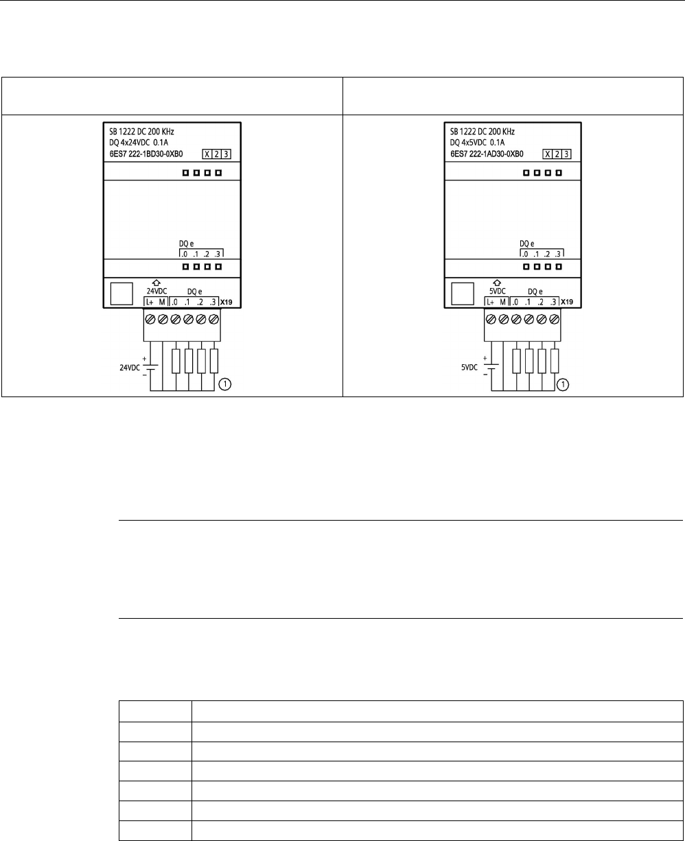
Technical specifications
A.13 Digital signal boards (SBs)
S7-1200 Programmable controller
1504 System Manual, V4.2, 09/2016, A5E02486680-AK
Table A- 192 Wiring diagrams for the 200 kHz digital output SBs
SB 1222 DQ 4 x 24 V DC, 200 kHz
(6ES7222-1BD30-0XB0)
SB 1222 DQ 4 x 5 V DC, 200 kHz
(6ES7222-1AD30-0XB0)
①
For sourcing outputs, connect "Load" to "-" (shown). For sinking outputs, connect "Load" to "+". Because both sinking
and sourcing configurations are supported by the same circuitry, the active state of a sourcing load is opposite that of a
sinking load.
A source output exhibits positive logic (Q bit and LED are ON when the load has current flow), while a sink
output exhibits negative logic (Q bit and LED are OFF when the load has current flow). If the module is plugged in with
no user program, the default for this module is 0 V, which means that a sinking load will be turned ON.
Note
Ensure that the M connection wire is securely grounded. Loss of the ground wire connection
to the high
-speed DQ SBs may allow enough leakage current to activate a DC load. If the
outputs are used for critical DC load applications, extra caution should be exercised by using
a redundant ground wire to the SB.
Table A- 193 Connector pin locations for SB 1222 DQ 4 x 24 V DC, 200 kHz (6ES7222-1BD30-0XB0)
Pin
X19
1 L+ / 24 V DC
2
M / 24 V DC
3
DQ e.0
4
DQ e.1
5
DQ e.2
6
DQ e.3

Technical specifications
A.13 Digital signal boards (SBs)
S7-1200 Programmable controller
System Manual, V4.2, 09/2016, A5E02486680-AK 1505
Table A- 194 Connector pin locations for SB 1222 DQ 4 x 5 V DC, 200 kHz (6ES7222-1AD30-0XB0)
Pin
X19
1
L+ / 5 V DC
2 M / 5 V DC
3
DQ e.0
4 DQ e.1
5
DQ e.2
6
DQ e.3
A.13.3
SB 1223 200 kHz digital input / output specifications
Table A- 195 General specifications
Technical data
SB 1223 DI 2 x 24 V DC /
DQ 2 x 24 V DC, 200 kHz
SB 1223 DI 2 x 5 V DC /
DQ 2 x 5 V DC, 200 kHz
Article number
6ES7223-3BD30-0XB0
6ES7223-3AD30-0XB0
Dimensions W x H x D (mm)
38 x 62 x 21
Weight
35 grams
Power dissipation
1.0 W
0.5 W
Current consumption (SM Bus)
35 mA
Current consumption (24 V DC)
7 mA / Input + 30 mA
15 mA / input + 15 mA
Table A- 196 Digital inputs
Technical data
SB 1223 DI 2 x 24 V DC /
DQ 2 x 24 V DC, 200 kHz
SB 1223 DI 2 x 5 V DC /
DQ 2 x 5 V DC, 200 kHz
Number of inputs
2
Type
Source
Rated voltage
24 V DC at 7 mA, nominal
5 V DC at 15 mA, nominal
Continuous permissible voltage
28.8 V DC
6 V DC
Surge voltage
35 V DC for 0.5 sec.
6 V
Logic 1 signal
0 V (10 mA) to L+ minus 10 V (2.9 mA)
0 V (20 mA) to L+ minus 2.0 V (5.1 mA)
Logic 0 signal
L+ minus 5 V (1.4 mA) to L+ (0 mA)
L+ minus 1.0 V (2.2 mA) to L + (0 mA)
HSC clock input rates (max.) Single phase: 200 kHz
Quadrature phase: 160 kHz
Isolation (field side to logic) 707 V DC (type test)
Isolation groups
1 (no isolation to outputs)
Filter times
us settings
0.1, 0.2, 0.4, 0.8, 1.6, 3.2, 6.4, 10.0, 12.8, 20.0
ms settings
0.05, 0.1, 0.2, 0.4, 0.8, 1.6, 3.2, 6.4, 10.0, 12.8, 20.0
Number of inputs on simultaneously
2
Cable length (meters)
50 shielded twisted pair

Technical specifications
A.13 Digital signal boards (SBs)
S7-1200 Programmable controller
1506 System Manual, V4.2, 09/2016, A5E02486680-AK
Table A- 197 Digital outputs
Technical data
SB 1223 DI 2 x 24 V DC /
DQ 2 x 24 V DC, 200 kHz
SB 1223 DI 2 x 5 V DC /
DQ 2 x 5 V DC, 200 kHz
Number of outputs
2
Output type Solid state - MOSFET sink and source1
Voltage range
20.4 to 28.8 V DC
4.25 to 6.0 V DC
Rated value
24 V DC
5 V DC
Logic 1 signal at max. current
L+ minus 1.5 V
L+ minus 0.7 V
Logic 0 signal at max. current
1.0 V DC, max.
0.2 V DC, max.
Current (max.)
0.1 A
Lamp load
--
On state contact resistance
11 Ω max.
7 Ω max.
Off state resistance
6 Ω max.
0.2 Ω max.
Leakage current per point
--
Pulse Train Output rate
200 kHz max., 2 Hz min.
Surge current
0.11 A
Overload protection
No
Isolation (field side to logic)
707 V DC (type test)
Isolation groups
1 (no isolation to inputs)
Currents per common
0.2 A
Inductive clamp voltage
Non
Switching delay 1.5 μs + 300 ns rise
1.5 μs + 300 ns fall
200 ns + 300 ns rise
200 ns + 300 ns fall
Behavior on RUN to STOP
Last value or substitute (default value 0)
Number of outputs on simultaneously
2
Cable length (meters)
50 shielded twisted pair
1
Because both sinking and sourcing configurations are supported by the same circuitry, the active state of a sourcing
load is opposite that of a sinking load. A source output exhibits positive logic (Q bit and LED are ON when the load has
current flow), while a sink output exhibits negative logic (Q bit and LED are OFF when the load has current flow). If the
module is plugged in with no user program, the default for this module is 0 V, which means that a sinking load will be
turned ON.
Note
When switching frequencies above 20
kHz, it is important that the digital inputs receive a
square wave. Consider the following options to improve the signal quality to the inputs
:
•
Minimize the cable length
•
Change a driver from a sink only driver to a sinking and sourcing driver
•
Change to a higher quality cable
•
Reduce the circuit/components from 24 V to 5 V
•
Add an external load at the input
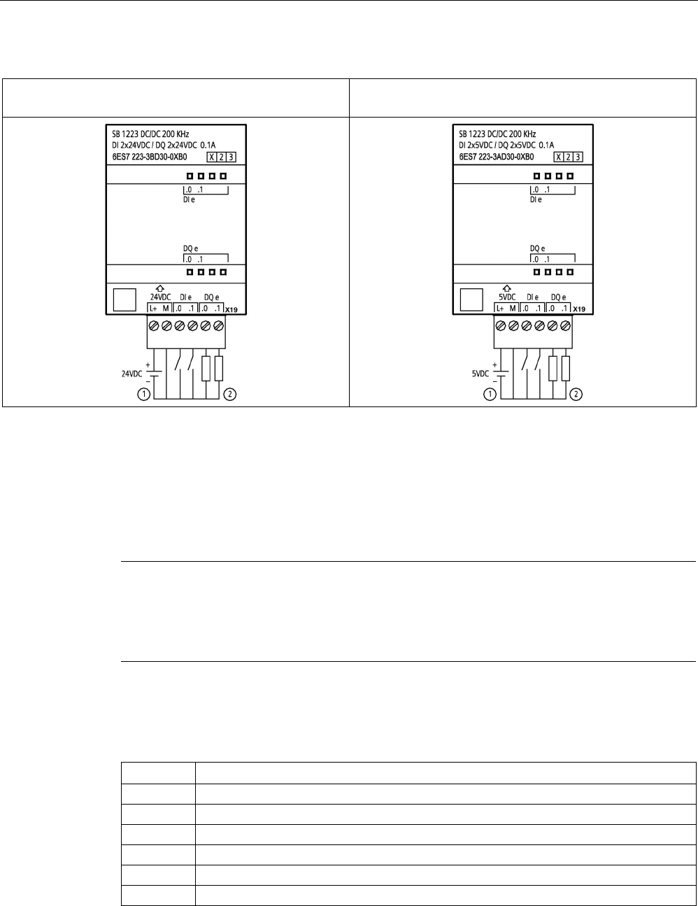
Technical specifications
A.13 Digital signal boards (SBs)
S7-1200 Programmable controller
System Manual, V4.2, 09/2016, A5E02486680-AK 1507
Table A- 198 Wiring diagrams for the 200 kHz digital input/output SBs
SB 1223 DI 2 x 24 V DC/DQ 2 x 24 V DC,
200 kHz (6ES7223-3BD30-0XB0)
SB 1223 DI 2 x 5 V DC / DQ 2 x 5 V DC,
200 kHz (6ES7223-3AD30-0XB0)
①
Supports sourcing inputs only
②
For sourcing outputs, connect "Load" to "-" (shown). For sinking outputs, connect "Load" to "+". 1 Because both sinking
and sourcing configurations are supported by the same circuitry, the active state of a sourcing load is opposite that of a
sinking load. A source output exhibits positive logic (Q bit and LED are ON when the load has current flow), while a sink
output exhibits negative logic (Q bit and LED are OFF when the load has current flow). If the module is plugged in with
no user program, the default for this module is 0 V, which means that a sinking load will be turned ON.
Note
Ensure that the M connection wire is securely grounded. Loss of the ground wire connection
to the high
-speed DQ SBs may allow enough leakage current to activate a DC load. If the
outputs are used for critical DC load applications, extra caution should be exercised by using
a redundant ground wire to the SB.
Table A- 199 Connector pin locations for SB 1223 DI 2 x 24 V DC/DQ 2 x 24 V DC, 200 kHz
(6ES7223-3BD30-0XB0)
Pin
X19
1
L+ / 24 V DC
2
M / 24 V DC
3
DI e.0
4
DI e.1
5
DQ e.0
6
DQ e.1

Technical specifications
A.13 Digital signal boards (SBs)
S7-1200 Programmable controller
1508 System Manual, V4.2, 09/2016, A5E02486680-AK
Table A- 200 Connector pin locations for SB 1223 DI 2 x 5 V DC / DQ 2 x 5 V DC, 200 kHz (6ES7223-
3AD30-0XB0)
Pin
X19
1
L+ / 5 V DC
2 M / 5 V DC
3
DI e.0
4
DI e.1
5
DQ e.0
6
DQ e.1
A.13.4
SB 1223 2 X 24 V DC input / 2 X 24 V DC output specifications
Table A- 201 General specifications
Technical Data
SB 1223 DI 2 x 24 V DC, DQ 2 x 24 V DC
Article number
6ES7223-0BD30-0XB0
Dimensions W x H x D (mm)
38 x 62 x 21
Weight
40 grams
Power dissipation
1.0 W
Current consumption (SM Bus)
50 mA
Current consumption (24 V DC)
4 mA / Input used
Table A- 202 Digital inputs
Technical Data
SB 1223 DI 2 x 24 V DC, DQ 2 x 24 V DC
Number of inputs
2
Type
IEC Type 1 sink
Rated voltage
24 V DC at 4 mA, nominal
Continuous permissible voltage
30 V DC, max.
Surge voltage
35 V DC for 0.5 sec.
Logic 1 signal (min.)
15 V DC at 2.5 mA
Logic 0 signal (max.)
5 V DC at 1 mA
HSC clock input rates (max.) Single phase: 30 kHz (15 to 26 V DC)
Quadrature phase: 20 kHz (15 to 26 V DC)
Isolation (field side to logic) 707 V DC (type test)
Isolation groups
1
Filter times
us settings
0.1, 0.2, 0.4, 0.8, 1.6, 3.2, 6.4,10.0, 12.8, 20.0
ms settings
0.05, 0.1, 0.2, 0.4, 0.8, 1.6, 3.2, 6.4, 10.0, 12.8, 20.0
Number of inputs on simultaneously
2
Cable length (meters)
500 shielded, 300 unshielded

Technical specifications
A.13 Digital signal boards (SBs)
S7-1200 Programmable controller
System Manual, V4.2, 09/2016, A5E02486680-AK 1509
Table A- 203 Digital outputs
Technical Data
SB 1223 DI 2 x 24 V DC, DQ 2 x 24 V DC
Number of outputs
2
Output type Solid state - MOSFET (sourcing)
Voltage range
20.4 to 28.8 V DC
Logic 1 signal at max. current 20 V DC min.
Logic 0 signal with 10K Ω load
0.1 V DC max.
Current (max.)
0.5 A
Lamp load
5 W
On state contact resistance
0.6 Ω max.
Leakage current per point
10 μA max.
Pulse Train Output (PTO) rate
20 kHz max., 2 Hz min.
1
Surge current
5 A for 100 ms max.
Overload protection
No
Isolation (field side to logic)
707 V DC (type test)
Isolation groups
1
Currents per common
1 A
Inductive clamp voltage
L+ minus 48 V, 1 W dissipation
Switching delay 2 μs max. off to on
10 μs max. on to off
Behavior on RUN to STOP
Last value or substitute value (default value 0)
Number of outputs on simultaneously
2
Cable length (meters)
500 m shielded, 150 m unshielded
1
Depending on your pulse receiver and cable, an additional load resistor (at least 10% of rated current) may improve
pulse signal quality and noise immunity.
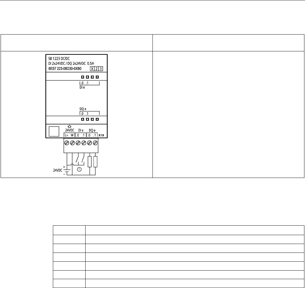
Technical specifications
A.13 Digital signal boards (SBs)
S7-1200 Programmable controller
1510 System Manual, V4.2, 09/2016, A5E02486680-AK
Table A- 204 Wiring diagram for the digital input/output SB
SB 1223 DI 2 x 24 V DC, DQ 2 x 24 V DC (6ES7223-
0BD30-0XB0)
① Supports sinking inputs only
Table A- 205 Connector pin locations for SB 1223 DI 2 x 24 V DC, DQ 2 x 24 V DC (6ES7223-0BD30-
0XB0)
Pin
X19
1
L+ / 24 V DC
2
M / 24 V DC
3
DI e.0
4
DI e.1
5
DQ e.0
6
DQ e.1

Technical specifications
A.14 Analog signal boards (SBs)
S7-1200 Programmable controller
System Manual, V4.2, 09/2016, A5E02486680-AK 1511
A.14
Analog signal boards (SBs)
A.14.1
SB 1231 1 analog input specifications
Note
To use this SB, your CPU firmware must be V2.0 or higher.
Table A- 206 General specifications
Technical data
SB 1231 AI 1 x 12 bit
Article number
6ES7231-4HA30-0XB0
Dimensions W x H x D (mm)
38 x 62 x 21
Weight
35 grams
Power dissipation
0.4 W
Current consumption (SM Bus)
55 mA
Current consumption (24 V DC)
none
Table A- 207 Analog inputs
Technical data
SB 1231 AI 1x12 bit
Number of inputs
1
Type
Voltage or current (differential)
Range
±10 V, ±5 V, ±2.5 or 0 to 20 mA
Resolution
11 bits + sign bit
Full scale range (data word)
-27648 to 27648
Over/Under range (data word) Voltage: 32511 to 27649 / -27649 to -32512
Current: 32511 to 27649 / 0 to -4864
(Refer to Analog input representation for voltage and Analog input
representation for current (Page 1516).)
Overflow/Underflow (data word) Voltage: 32767 to 32512 / -32513 to -32768
Current: 32767 to 32512 / -4865 to -32768
(Refer to Analog input representation for voltage and Analog input
representation for current (Page 1516).)
Maximum withstand voltage / current
±35 V / ±40 mA
Smoothing None, weak, medium, or strong (refer to Analog input response
times for step response time (Page 1516).)
Noise rejection 400, 60, 50, or 10 Hz (refer to Analog input response times for
sample rates (Page 1516).)
Accuracy (25 °C / -20 to 60 °C)
±0.3% / ±0.6% of full scale

Technical specifications
A.14 Analog signal boards (SBs)
S7-1200 Programmable controller
1512 System Manual, V4.2, 09/2016, A5E02486680-AK
Technical data
SB 1231 AI 1x12 bit
Input impedance
Differential
Common mode
Voltage: 220 kΩ; Current: 250 Ω
Voltage: 55 kΩ; Current: 55 kΩ
Behavior on RUN to STOP Last value or substitute value (default value 0)
Measuring principle
Actual value conversion
Common mode rejection
40 dB, DC to 60 Hz
Operational signal range Signal plus common mode voltage must be less than +35 V and
greater than -35 V
Isolation (field side to logic)
None
Cable length (meters)
100 m, twisted and shielded
Table A- 208 Diagnostics
Technical data
SB 1231 AI 1 x 12 bit
Overflow/underflow
Yes
24 V DC low voltage
no
SB 1231 wiring current transducers
Wiring current transducers are available as 2-wire transducers and 4-wire transducers as
shown below.
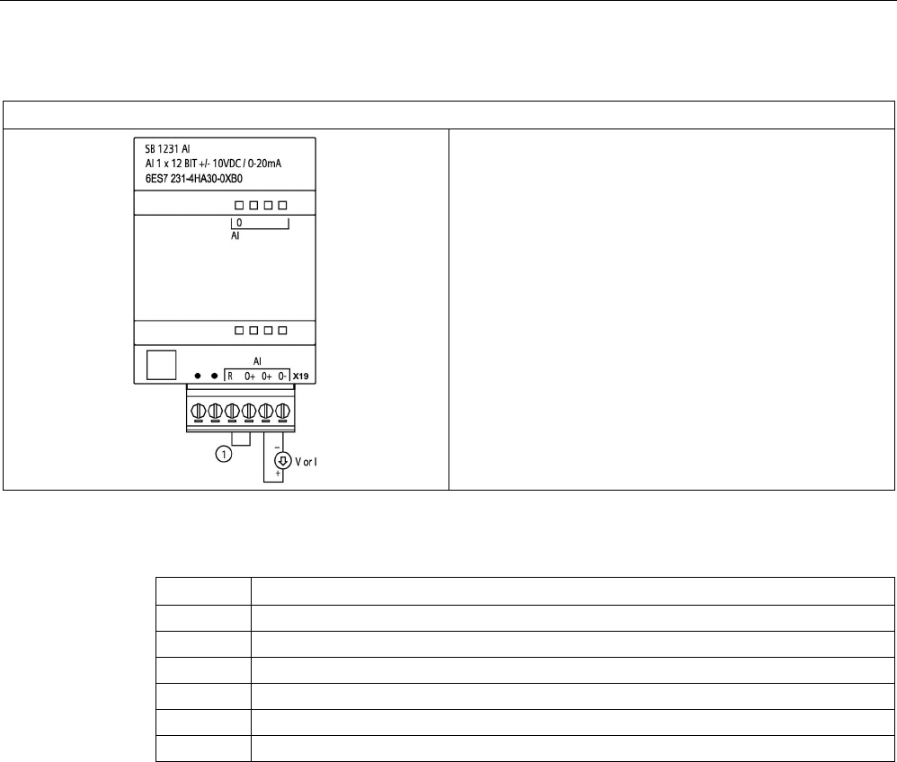
Technical specifications
A.14 Analog signal boards (SBs)
S7-1200 Programmable controller
System Manual, V4.2, 09/2016, A5E02486680-AK 1513
Table A- 209 Wiring diagram for the analog input SB
SB 1231 AI x 12 bit (6ES7231-4HA30-0XB0)
① Connect "R" and "0+" for current applications.
Note: Connectors must be gold. See Appendic C, Spare
Parts for article number.
Table A- 210 Connector pin locations for SB 1231 AI x 12 bit (6ES7231-4HA30-0XB0)
Pin
X19 (gold)
1
No connection
2
No connection
3
AI R
4
AI 0+
5
AI 0+
6 AI 0-

Technical specifications
A.14 Analog signal boards (SBs)
S7-1200 Programmable controller
1514 System Manual, V4.2, 09/2016, A5E02486680-AK
A.14.2
SB 1232 1 analog output specifications
Table A- 211 General specifications
Technical data
SB 1232 AQ 1 x 12 bit
Article number
6ES7232-4HA30-0XB0
Dimensions W x H x D (mm) 38 x 62 x 21
Weight
40 grams
Power dissipation 1.5 W
Current consumption (SM Bus)
15 mA
Current consumption (24 V DC)
40 mA (no load)
Table A- 212 Analog outputs
Technical data
SB 1232 AQ 1 x 12 bit
Number of outputs
1
Type
Voltage or current
Range
±10 V or 0 to 20 mA
Resolution Voltage: 12 bits
Current: 11 bits
Full scale range (data word)
Refer to the output ranges for voltage and current
(Page 1517).
Voltage: -27648 to 27648
Current: 0 to 27648
Accuracy (25 °C / -20 to 60 °C)
±0.5% / ±1% of full scale
Settling time (95% of new value) Voltage: 300 μs (R), 750 μs (1 uF)
Current: 600 μs (1 mH), 2 ms (10 mH)
Load impedance Voltage: ≥ 1000 Ω
Current: ≤ 600 Ω
Behavior on RUN to STOP
Last value or substitute value (default value 0)
Isolation (field side to logic)
None
Cable length (meters) 100 m, twisted and shielded
Table A- 213 Diagnostics
Technical data
SB 1232 AQ 1 x 12 bit
Overflow/underflow
Yes
Short to ground (voltage mode only)
Yes
Wire break (current mode only)
Yes
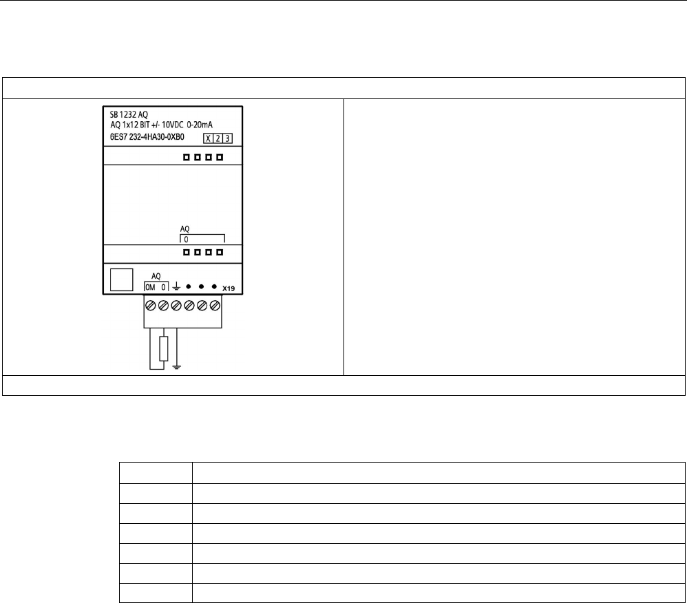
Technical specifications
A.14 Analog signal boards (SBs)
S7-1200 Programmable controller
System Manual, V4.2, 09/2016, A5E02486680-AK 1515
Table A- 214 Wiring diagram for the SB 1232 AQ 1 x 12 bit
SB 1232 AQ 1 x 12 bit (6ES7232-4HA30-0XB0)
Note: Connectors must be gold. See Appendix C, Spare Parts for article number.
Table A- 215 Connector pin locations for SB 1232 AQ 1 x 12 bit (6ES7232-4HA30-0XB0)
Pin
X19 (gold)
1
AQ 0M
2
AQ 0
3
Functional Earth
4
No connection
5 No connection
6
No connection

Technical specifications
A.14 Analog signal boards (SBs)
S7-1200 Programmable controller
1516 System Manual, V4.2, 09/2016, A5E02486680-AK
A.14.3
Measurement ranges for analog inputs and outputs
A.14.3.1
Step response of the analog inputs
Table A- 216 Step response (ms), 0 V to 10 V measured at 95%
Smoothing selection (sample averaging)
Integration time selection
400 Hz (2.5 ms)
60 Hz (16.6 ms)
50 Hz (20 ms)
10 Hz (100 ms)
None (1 cycle): No averaging
4.5 ms
18.7 ms
22.0 ms
102 ms
Weak (4 cycles): 4 samples
10.6 ms
59.3 ms
70.8 ms
346 ms
Medium (16 cycles): 16 samples 33.0 ms 208 ms 250 ms 1240 ms
Strong (32 cycles): 32 samples
63.0 ms
408 ms
490 ms
2440 ms
Sample time
0.156 ms
1.042 ms
1.250 ms
6.250 ms
A.14.3.2
Sample time and update times for the analog inputs
Table A- 217 Sample time and update time
Selection
Sample time
SB update time
400 Hz (2.5 ms)
0.156 ms
0.156 ms
60 Hz (16.6 ms)
1.042 ms
1.042 ms
50 Hz (20 ms)
1.250 ms
1.25 ms
10 Hz (100 ms)
6.250 ms
6.25 ms
A.14.3.3
Measurement ranges of the analog inputs for voltage and current (SB and SM)
Table A- 218 Analog input representation for voltage (SB and SM)
System
Voltage Measuring Range
Decimal
Hexadecimal
±10 V
±5 V
±2.5 V
±1.25 V
32767
7FFF
1
11.851 V
5.926 V
2.963 V
1.481 V
Overflow
32512
7F00
32511
7EFF
11.759 V
5.879 V
2.940 V
1.470 V
Overshoot range
27649
6C01
27648
6C00
10 V
5 V
2.5 V
1.250 V
Rated range
20736
5100
7.5 V
3.75 V
1.875 V
0.938 V
1
1
361.7 μV
180.8 μV
90.4 μV
45.2 μV
0
0
0 V
0 V
0 V
0 V
-1
FFFF
-20736
AF00
-7.5 V
-3.75 V
-1.875 V
-0.938 V
-27648
9400
-10 V
-5 V
-2.5 V
-1.250 V

Technical specifications
A.14 Analog signal boards (SBs)
S7-1200 Programmable controller
System Manual, V4.2, 09/2016, A5E02486680-AK 1517
System
Voltage Measuring Range
Decimal
Hexadecimal
±10 V
±5 V
±2.5 V
±1.25 V
-27649
93FF
Undershoot range
-32512
8100
-11.759 V
-5.879 V
-2.940 V
-1.470 V
-32513 80FF Underflow
-32768
8000
-11.851 V
-5.926 V
-2.963 V
-1.481 V
1
7FFF can be returned for one of the following reasons: overflow (as noted in this table), before valid values are available
(for example immediately upon a power up), or if a wire break is detected.
Table A- 219 Analog input representation for current (SB and SM)
System
Current measuring range
Decimal
Hexadecimal
0 mA to 20 mA
4 mA to 20 mA
32767
7FFF
> 23.52 mA
> 22.81 mA
Overflow
32511
7EFF
23.52 mA
22.81 mA
Overshoot range
27649
6C01
27648
6C00
20 mA
20 mA
Nominal range
20736
5100
15 mA
16 mA
1
1
723.4 nA
4 mA + 578.7 nA
0
0
0 mA
4 mA
-1
FFFF
Undershoot range
-4864
ED00
-3.52 mA
1.185 mA
32767
1
7FFF
< 1.185 mA
Underflow (0 to 20 mA)
Wire break (4 to 20 mA)
-32768
8000
< -3.52 mA
1 The wire break value of 32767 (16#7FFF) is always returned regardless of the state of the wire break alarm.
A.14.3.4
Measurement ranges of the analog outputs for voltage and current (SB and SM)
Table A- 220 Analog output representation for voltage (SB and SM)
System
Voltage Output Range
Decimal
Hexadecimal
± 10 V
32767
7FFF
See note 1
Overflow
32512
7F00
See note 1
32511
7EFF
11.76 V
Overshoot range
27649
6C01
27648 6C00 10 V Rated range
20736
5100
7.5 V
1 1 361.7 μ V
0
0
0 V
-1
FFFF
-361.7 μ V
-20736
AF00
-7.5 V
-27648
9400
-10 V

Technical specifications
A.14 Analog signal boards (SBs)
S7-1200 Programmable controller
1518 System Manual, V4.2, 09/2016, A5E02486680-AK
System
Voltage Output Range
Decimal
Hexadecimal
± 10 V
-27649
93FF
Undershoot range
-32512
8100
-11.76 V
-32513 80FF See note 1 Underflow
-32768
8000
See note 1
1 In an overflow or underflow condition, analog outputs will take on the substitute value of the STOP mode.
Table A- 221 Analog output representation for current (SB and SM)
System
Current output range
Decimal
Hexadecimal
0 mA to 20 mA
4 mA to 20 mA
32767
7FFF
See note 1
See note 1
Overflow
32512
7F00
See note 1
See note 1
32511
7EFF
23.52 mA
22.81 mA
Overshoot range
27649
6C01
27648
6C00
20 mA
20 mA
Rated range
20736
5100
15 mA
16 mA
1
1
723.4 nA
4 mA + 578.7 nA
0
0
0 mA
4mA
-1
FFFF
4 mA to 578.7 nA
Undershoot range
-6912
E500
0 mA
-6913
E4FF
Not possible. Output value limited to 0 mA.
-32512
8100
-32513
80FF
See note 1
See note 1
Underflow
-32768
8000
See note 1
See note 1
1 In an overflow or underflow condition, analog outputs will take on the substitute value of the STOP mode.

Technical specifications
A.14 Analog signal boards (SBs)
S7-1200 Programmable controller
System Manual, V4.2, 09/2016, A5E02486680-AK 1519
A.14.4
Thermocouple signal boards (SBs)
A.14.4.1
SB 1231 1 analog thermocouple input specifications
Note
To use this SB, your CPU firmware must
be V2.0 or higher.
Table A- 222 General specifications
Technical data
SB 1231 AI 1 x 16 bit Thermocouple
Article number
6ES7231-5QA30-0XB0
Dimensions W x H x D (mm)
38 x 62 x 21
Weight
35 grams
Power dissipation
0.5 W
Current consumption (SM Bus)
5 mA
Current consumption (24 V DC)
20 mA
Table A- 223 Analog inputs
Technical data
SB 1231 AI 1x16 bit Thermocouple
Number of inputs
1
Type
Floating TC and mV
Range
• Nominal range (data word)
• Overrange/underrange (data word)
• Overflow/underflow (data word)
See Thermocouple filter selection table (Page 1520).
Resolution
Temperature
0.1° C / 0.1° F
Voltage
15 bits plus sign
Maximum withstand voltage
±35 V
Noise rejection 85 dB for the selected filter setting
(10 Hz, 50 Hz, 60 Hz, 400 Hz)
Common mode rejection > 120 dB at 120 V AC
Impedance
≥ 10 M Ω
Accuracy See Thermocouple selection table (Page 1520).
Repeatability
±0.05% FS
Measuring principle
Integrating
Module update time
See Thermocouple filter selection table (Page 1520).
Cold junction error
±1.5° C
Isolation (field side to logic)
707 V DC (type test)

Technical specifications
A.14 Analog signal boards (SBs)
S7-1200 Programmable controller
1520 System Manual, V4.2, 09/2016, A5E02486680-AK
Technical data
SB 1231 AI 1x16 bit Thermocouple
Cable length (meters)
100 m to sensor max.
Wire resistance 100 Ω max.
Table A- 224 Diagnostics
Technical data
SB 1231 AI 1 x 16 bit Thermocouple
Overflow/underflow
1
Yes
Wire break2, 3 Yes
1
The overflow and underflow diagnostic alarm information will be reported in the analog data values even if the alarms
are disabled in the module configuration.
2
When wire break alarm is disabled and an open wire condition exists in the sensor wiring, the module may report ran-
dom values.
3
The module performs wire break testing every 6 seconds, which extends the update time by 9 ms for each enable
channel once every 6 seconds.
The SM 1231 Thermocouple (TC) analog signal module measures the value of voltage
connected to the module inputs.
The SB 1231 Thermocouple analog signal board measures the value of voltage connected
to the signal board inputs. The temperature measurement type can be either
"Thermocouple" or "Voltage".
● "Thermocouple": The value will be reported in degrees multiplied by ten (for example,
25.3 degrees will be reported as decimal 253).
● "Voltage": The nominal range full scale value will be decimal 27648.
A.14.4.2
Basic operation for a thermocouple
Thermocouples are formed whenever two dissimilar metals are electrically bonded to each
other. A voltage is generated that is proportional to the junction temperature. This voltage is
small; one microvolt could represent many degrees. Measuring the voltage from a
thermocouple, compensating for extra junctions, and then linearizing the result forms the
basis of temperature measurement using thermocouples.
When you connect a thermocouple to the SM 1231 Thermocouple module, the two dissimilar
metal wires are attached to the module at the module signal connector. The place where the
two dissimilar wires are attached to each other forms the sensor thermocouple.
Two more thermocouples are formed where the two dissimilar wires are attached to the
signal connector. The connector temperature causes a voltage that adds to the voltage from
the sensor thermocouple. If this voltage is not corrected, then the temperature reported will
deviate from the sensor temperature.
Cold junction compensation is used to compensate for the connector thermocouple.
Thermocouple tables are based on a reference junction temperature, usually zero degrees
Celsius. The cold junction compensation compensates the connector to zero degrees
Celsius. The cold junction compensation restores the voltage added by the connector
thermocouples. The temperature of the module is measured internally, and then converted to
a value to be added to the sensor conversion. The corrected sensor conversion is then
linearized using the thermocouple tables.

Technical specifications
A.14 Analog signal boards (SBs)
S7-1200 Programmable controller
System Manual, V4.2, 09/2016, A5E02486680-AK 1521
For optimum operation of the cold junction compensation, the thermocouple module must be
located in a thermally stable environment. Slow variation (less than 0.1 °C/minute) in
ambient module temperature is correctly compensated within the module specifications. Air
movement across the module will also cause cold junction compensation errors.
If better cold junction error compensation is needed, an external iso-thermal terminal block
may be used. The thermocouple module provides for use of a 0 °C referenced or 50 °C
referenced terminal block.
Selection table for the SB 1231 thermocouple
The ranges and accuracy for the different thermocouple types supported by the SB 1231
Thermocouple signal board are shown in the table below.
Table A- 225 SB 1231 Thermocouple selection table
Thermocouple
Type
Under range
minimum1
Nominal
range low limit
Nominal range
high limit
Over range
maximum2
Normal range 3
accuracy @ 25 °C
Normal range 3,
accuracy
-20 °C to 60 °C
J
-210.0 °C
-150.0 °C
1200.0 °C
1450.0 °C
±0.3 °C
±0.6 °C
K -270.0 °C -200.0 °C 1372.0 °C 1622.0 °C ±0.4 °C ±1.0 °C
T
-270.0 °C
-200.0 °C
400.0 °C
540.0 °C
±0.5 °C
±1.0 °C
E -270.0 °C -200.0 °C 1000.0 °C 1200.0 °C ±0.3 °C ±0.6 °C
R & S
-50.0 °C
100.0 °C
1768.0 °C
2019.0 °C
±1.0 °C
±2.5 °C
B
0.0 °C
200.0 °C
800.0 °C
--
±2.0 °C
±2.5 °C
--
800.0 °C
1820.0 °C
1820.0 °C
±1.0 °C
±2.3 °C
N
-270.0 °C
0.0 °C
1300.0 °C
1550.0 °C
±1.0 °C
±1.6 °C
C
0.0 °C
100.0 °C
2315.0 °C
2500.0 °C
±0.7 °C
±2.7 °C
TXK/XK(L)
-200.0 °C
-150.0 °C
800.0 °C
1050.0 °C
±0.6 °C
±1.2 °C
Voltage -32511 -27648
-80mV
27648
80mV
32511 ±0.05% ±0.1%
1
Thermocouple values below the under-range minimum value are reported as -32768.
2
Thermocouple values above the over-range minimum value are reported as 32767.
3
Internal cold junction error is ±1.5
°C for all ranges. This adds to the error in this table. The signal board requires at least
30 minutes of warm-up time to meet this specification.
Table A- 226 Filter selection table for the SB 1231 Thermocouple
Rejection frequency (Hz)
Integration time (ms)
Signal board update time (seconds)
10
100
0.306
50
20
0.066
60
16.67
0.056
400
1
10
0.036
1
To maintain module resolution and accuracy when 400 Hz rejection is selected, the integration time is 10 ms. This
selection also rejects 100 Hz and 200 Hz noise.

Technical specifications
A.14 Analog signal boards (SBs)
S7-1200 Programmable controller
1522 System Manual, V4.2, 09/2016, A5E02486680-AK
It is recommended for measuring thermocouples that a 100 ms integration time be used. The
use of smaller integration times will increase the repeatability error of the temperature
readings.
Note
After power is applied to the module, it performs internal calibration for the analog to digital
converter. During this time
, the module reports a value of 32767 on each channel until valid
data is available on that channel. Your user program may need to allow for this initialization
time.
Table A- 227 Wiring diagram for SB 1231 AI 1 x 16 thermocouple
SB 1231 AI 1 x 16 bit thermocouple (6ES7231-5QA30-0XB0)
Note: Connectors must be gold. See Appendix C, Spare Parts for article number.
Table A- 228 Connector pin locations for SB 1231 AI 1 x 16 bit thermocouple (6ES7231-5QA30-0XB0)
Pin
X19 (gold)
1
No connection
2
No connection
3
No connection
4
No connection
5
AI 0- /TC
6
AI 0+ /TC

Technical specifications
A.14 Analog signal boards (SBs)
S7-1200 Programmable controller
System Manual, V4.2, 09/2016, A5E02486680-AK 1523
A.14.5
RTD signal boards (SBs)
A.14.5.1
SB 1231 1 analog RTD input specifications
Note
To use this SB, your CPU firmware must be V2.0 or higher.
Table A- 229 General specifications
Technical data
SB 1231 AI 1 x 16 bit RTD
Article number
6ES7231-5PA30-0XB0
Dimensions W x H x D (mm)
38 x 62 x 2
Weight
35 grams
Power dissipation
0.7 W
Current consumption (SM Bus)
5 mA
Current consumption (24 V DC)
25 mA
Table A- 230 Analog inputs
Technical data
SB 1231 AI 1 x 16 bit RTD
Number of inputs
1
Type
Module referenced RTD and Ohms
Range
• Nominal range (data word)
• Overrange/underrange (data word)
• Overflow/underflow (data word)
See Selection tables (Page 1526).
Resolution
Temperature
0.1 °C/ 0.1 °F
Voltage
15 bits plus sign
Maximum withstand voltage
±35 V
Noise rejection
85 dB (10 Hz, 50 Hz, 60 Hz, 400 Hz)
Common mode rejection
> 120 dB
Impedance
≥ 10 MΩ
Accuracy See Selection tables (Page 1526).
Repeatability
±0.05% FS
Maximum sensor dissipation 0.5 m W
Measuring principle
Integrating
Module update time
See Selection table (Page 1526).
Isolation (field side to logic)
707 V DC (type test)
Cable length (meters)
100 m to sensor max.
Wire resistance
20 Ω, 2.7 for 10 Ω RTD max.

Technical specifications
A.14 Analog signal boards (SBs)
S7-1200 Programmable controller
1524 System Manual, V4.2, 09/2016, A5E02486680-AK
Table A- 231 Diagnostics
Technical data
SB 1231 AI 1 x 16 bit RTD
Overflow/underflow
1, 2
Yes
Wire break 3 Yes
1
The overflow and underflow diagnostic alarm information will be reported in the analog data values even if the alarms
are disabled in the module configuration.
2
For resistance ranges underflow detection is never enabled.
3
When wire break alarm is disabled and an open wire condition exists in the sensor wiring, the module may report ran-
dom values.
The SM 1231 RTD analog signal board measures the value of resistance connected to the
signal board inputs. The measurement type can be selected as either "Resistor" or "Thermal
resistor".
● "Resistor": The nominal range full scale value will be decimal 27648.
● "Thermal resistor": The value will be reported in degrees multiplied by ten (for example,
25.3 degrees will be reported as decimal 253). The climatic range values will be reported
in degrees multiplied by one hundred (for example, 25.34 degrees will be reported as
decimal 2534).
The SB 1231 RTD signal board supports measurements with 2-wire, 3-wire and 4-wire
connections to the sensor resistor.
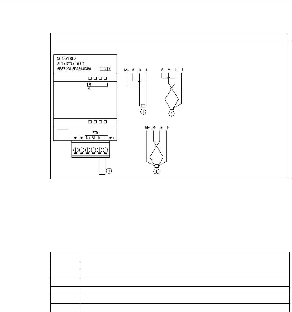
Technical specifications
A.14 Analog signal boards (SBs)
S7-1200 Programmable controller
System Manual, V4.2, 09/2016, A5E02486680-AK 1525
Table A- 232 Wiring diagram for SB 1231 AI 1 x 16 bit RTD
SB 1231 AI 1 x 16 bit RTD (6ES7231-5PA30-0XB0)
①
Loop-back unused RTD input
②
2-wire RTD
③
3-wire RTD
④
4-wire RTD
Note: Connectors must be gold. See Appendix C, Spare Parts for article number.
Table A- 233 Connector pin locations for SB 1231 AI 1 x 16 bit RTD (6ES7231-5PA30-0XB0)
Pin
X19 (gold)
1
No connection
2
No connection
3
AI 0 M+ /RTD
4
AI 0 M- /RTD
5
AI 0 I+ /RTD
6
AI 0 I- /RTD

Technical specifications
A.14 Analog signal boards (SBs)
S7-1200 Programmable controller
1526 System Manual, V4.2, 09/2016, A5E02486680-AK
A.14.5.2
Selection tables for the SB 1231 RTD
Table A- 234 Ranges and accuracy for the different sensors supported by the RTD modules
Temperature
coefficient
RTD type
Under range
minimum1
Nominal
range
low limit
Nominal
range
high limit
Over range
maximum2
Normal
range accu-
racy @
25 °C
Normal
range accu-
racy -20 °C
to 60 °C
Pt 0.003850
ITS90
DIN EN 60751
Pt 100 climatic
-145.00 °C
-120.00 °C
-145.00 °C
-155.00 °C
±0.20 °C
±0.40 °C
Pt 10
-243.0 °C
-200.0 °C
850.0 °C
1000.0 °C
±1.0 °C
±2.0 °C
Pt 50
-243.0 °C -200.0 °C 850.0 °C 1000.0 °C ±0.5 °C ±1.0 °C
Pt 100
Pt 200
Pt 500
Pt 1000
Pt 0.003902
Pt 0.003916
Pt 0.003920
Pt 100
-243.0 °C
-200.0 °C 850.0 °C 1000.0 °C ± 0.5 °C ±1.0 °C
Pt 200
Pt 500
Pt 1000
Pt 0.003910
Pt 10
-273.2 °C
-240.0 °C
1100.0 °C
1295 °C
±1.0 °C
±2.0 °C
Pt 50
-273.2 °C -240.0 °C 1100.0 °C 1295 °C ±0.8 °C ±1.6 °C
Pt 100
Pt 500
Ni 0.006720
Ni 0.006180
Ni 100
-105.0 °C -60.0 °C 250.0 °C 295.0 °C ±0.5 °C ±1.0 °C
Ni 120
Ni 200
Ni 500
Ni 1000
LG-Ni 0.005000
LG-Ni 1000
-105.0 °C
-60.0 °C
250.0 °C
295.0 °C
±0.5 °C
±1.0 °C
Ni 0.006170
Ni 100
-105.0 °C
-60.0 °C
180.0 °C
212.4 °C
±0.5 °C
±1.0 °C
Cu 0.004270 Cu 10 -240.0 °C -200.0 °C 260.0 °C 312.0 °C ±1.0 ° ±2.0 °C
Cu 0.004260
Cu 10
-60.0 °C
-50.0 °C
200.0 °C
240.0 °C
±1.0 °C
±2.0 °C
Cu 50 -60.0 °C -50.0 °C 200.0 °C 240.0 °C ±0.6 °C ±1.2 °C
Cu 100
Cu 0.004280
Cu 10
-240.0 °C
-200.0 °C
200.0 °C
240.0 °C
±1.0 °C
±2.0 °C
Cu 50
-240.0 °C -200.0 °C 200.0 °C 240.0 °C ±0.7 °C ±1.4 °C
Cu 100
1
RTD values below the under-range minimum value are reported as -32768.
2 RTD values above the over-range maximum value are reported as +32768.

Technical specifications
A.14 Analog signal boards (SBs)
S7-1200 Programmable controller
System Manual, V4.2, 09/2016, A5E02486680-AK 1527
Table A- 235 Resistance
Range
Under range
minimum
Nominal range
low limit
Nominal range
high limit
Over range
maximum1
Normal range
accuracy
@ 25 °C
Normal range
accuracy
-20 °C to 60 °C
150 Ω
n/a
0 (0 Ω)
27648 (150 Ω)
176.383 Ω
±0.05%
±0.1%
300 Ω n/a 0 (0 Ω) 27648 (300 Ω) 352.767 Ω ±0.05% ±0.1%
600 Ω
n/a
0 (0 Ω)
27648 (600 Ω)
705.534 Ω
±0.05%
±0.1%
1 Resistance values above the over-range maximum value are reported as 32767.
Note
The module reports 32767 on any activated channel with no sensor connected. If open wire
detection is also enabled, the module flashe
s the appropriate red LEDs.
Best accuracy will be achieved for the 10 Ω RTD ranges if 4 wire connections are used.
The resistance of the connection wires in 2 wire mode will cause an error in the sensor
reading and therefore accuracy is not guaranteed.
Table A- 236 Noise reduction and update times for the RTD modules
Rejection frequency
selection
Integration time
4-/2-wire, 1-channel module
Update time (seconds)
3-wire, 1-channel module
Update time (seconds)
400 Hz (2.5 ms)
10 ms
1
0.036
0.071
60 Hz (16.6 ms)
16.67 ms
0.056
0.111
50 Hz (20 ms)
20 ms
0.066
1.086
10 Hz (100 ms)
100 ms
0.306
0.611
1
To maintain module resolution and accuracy when the 400 Hz filter is selected, the integration time is 10 ms. This selec-
tion also rejects 100 Hz and 200 Hz noise.
Note
After power is applied, the module performs internal calibration for the analog
-to-digital
converter. During this time the module reports a value of 32767 on each channel until valid
data is availa
ble on that channel. Your user program may need to allow for this initialization
time. Because the configuration of the module can vary the length of the initialization time,
you should verify the behavior or the module in your configuration. If required,
you can
include logic in your user program to accommodate the initialization time of the module.

Technical specifications
A.15 BB 1297 Battery board
S7-1200 Programmable controller
1528 System Manual, V4.2, 09/2016, A5E02486680-AK
A.15
BB 1297 Battery board
BB 1297 Battery Board
The S7-1200 BB 1297 Battery Board is designed for long-term backup of the Real-time
clock. It is pluggable in the signal board slot of the S7-1200 CPU (firmware 3.0 and later
versions). You must add the BB 1297 to the device configuration and download the
hardware configuration to the CPU for the BB to be functional.
The battery (type CR1025) is not included with the BB 1297 and must be purchased by the
user.
Note
The BB 1297 is mechanically designed to fit the CPUs with the firmware 3.0 and later
versions.
Do not use the BB 1297 with earlier version CPUs as the BB 1297 connector will not plug
into the CPU.
WARNING
Installing an unspecified battery in the BB 1297, or otherwise connecting an unspecified
battery to the circuit can result in fire or component damage and unpredictable operation of
machinery.
Fire or unpredictable operation of machinery can result in death, severe personal injury, or
property damage.
Use only the specified CR1025 battery for backup of the Real-time clock.
Table A- 237 General specifications
Technical data
BB 1297 Battery Board
Article number
6ES7297-0AX30-0XA0
Dimensions W x H x D (mm)
38 x 62 x 21
Weight
28 grams
Power dissipation
0.5 W
Current consumption (SM Bus) 11 mA
Current consumption (24 V DC)
none
Battery (not included)
BB 1297 Battery Board
Hold up time
Approximately 1 year
Battery type CR1025 Refer to Installing or replacing a battery in the BB
1297 battery board (Page 63)
Nominal voltage
3 V
Nominal capacity
At least 30 mAH
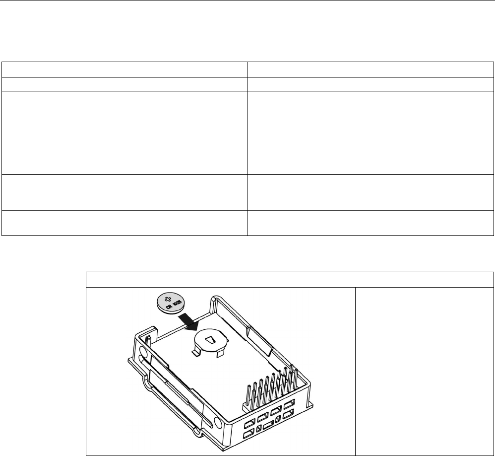
Technical specifications
A.16 Communication interfaces
S7-1200 Programmable controller
System Manual, V4.2, 09/2016, A5E02486680-AK 1529
Diagnostics
BB 1297 Battery Board
Critical battery level
< 2.5 V
Battery diagnostic Low voltage indicator:
• Low battery voltage causes the CPU MAINT LED to
illuminate with the amber light continuously ON.
• Diagnostic Buffer Event: 16#06:2700 "Submodule
maintenance demanded: At least one battery exhausted
(BATTF)"
Battery status Battery status bit provided
0 = Battery OK
1 = Battery low
Battery status update
Battery status is updated at power up and then once per day
while CPU is in RUN mode.
Table A- 238 Insertion diagram for the BB 1297 battery board
BB 1297 battery board (6ES7297-0AX30-0XA0)

Technical specifications
A.16 Communication interfaces
S7-1200 Programmable controller
1530 System Manual, V4.2, 09/2016, A5E02486680-AK
A.16
Communication interfaces
A.16.1
PROFIBUS
A.16.1.1
CM 1242-5 PROFIBUS DP SLAVE
Table A- 239 Technical specifications of the CM 1242-5
Technical specifications
Article number
6GK7242-5DX30-0XE0
Interfaces
Connection to PROFIBUS
9-pin D-sub female connector
Maximum current consumption on the PROFIBUS interface
when connecting network components (for example optical
network components)
15 mA at 5 V (only for bus termination) *)
Permitted ambient conditions
Ambient temperature
• during storage
• during transportation
• during operation with a vertical installation (DIN rail hori-
zontal)
• during operation with a horizontal installation (DIN rail
vertical)
• -40 °C to 70 °C
• -40 °C to 70 °C
• 0 °C to 55 °C
• 0 °C to 45 °C
Relative humidity at 25 °C during operation, without conden-
sation, maximum
95 %
Degree of protection
IP20
Power supply, current consumption and power loss
Type of power supply
DC
Power supply from the backplane bus
5 V
Current consumption (typical)
150 mA
Effective power loss (typical)
0.75 W
Electrical isolation
• PROFIBUS interface to ground
• PROFIBUS interface to internal circuit
710 V DC for 1 minute
Dimensions and weights
• Width
• Height
• Depth
• 30 mm
• 100 mm
• 75 mm
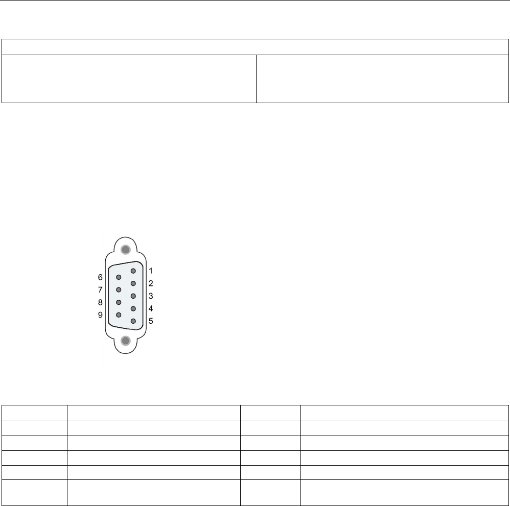
Technical specifications
A.16 Communication interfaces
S7-1200 Programmable controller
System Manual, V4.2, 09/2016, A5E02486680-AK 1531
Technical specifications
Weight
• Net weight
• Weight including packaging
• 115 g
• 152 g
*
)The current load of an external consumer connected between VP (pin 6) and DGND (pin 5) must not exceed a maximum
of 15 mA (short-circuit proof) for bus termination.
A.16.1.2
Pinout of the D-sub socket of the CM 1242-5
PROFIBUS interface
Table A- 240 Pinout of the D-sub socket
Pin
Description
Pin
Description
1
- not used -
6
P5V2: +5V power supply
2
- not used -
7
- not used -
3
RxD/TxD-P: Data line B
8
RxD/TxD-N: Data line A
4
RTS
9
- not used -
5 M5V2: Data reference potential (ground
DGND)
Housing Ground connector

Technical specifications
A.16 Communication interfaces
S7-1200 Programmable controller
1532 System Manual, V4.2, 09/2016, A5E02486680-AK
A.16.1.3
CM 1243-5 PROFIBUS DP Master
Table A- 241 Technical specifications of the CM 1243-5
Technical specifications
Article number
6GK7243-5DX30-0XE0
Interfaces
Connection to PROFIBUS
9-pin D-sub female connector
Maximum current consumption on the PROFIBUS
interface when connecting network components
(for example optical network components)
15 mA at 5 V (only for bus termination) *)
Permitted ambient conditions
Ambient temperature
• during storage
• during transportation
• during operation with a vertical installation
(DIN rail horizontal)
• during operation with a horizontal installation
(DIN rail vertical)
• -40 °C to 70 °C
• -40 °C to 70 °C
• 0 °C to 55 °C
• 0 °C to 45 °C
Relative humidity at 25 °C during operation, with-
out condensation, maximum
95 %
Degree of protection
IP20
Power supply, current consumption and power loss
Type of power supply
DC
Power supply / external
• minimum
• maximum
24 V
• 19.2 V
• 28.8 V
Current consumption (typical)
• from 24 V DC
• from the S7-1200 backplane bus
• 100 mA
• 0 mA
Effective power loss (typical)
• from 24 V DC
• from the S7-1200 backplane bus
• 2.4 W
• 0 W
Power supply 24 V DC / external
• Min. cable cross section
• Max. cable cross section
• Tightening torque of the screw terminals
• min.: 0.14 mm2 (AWG 25)
• max.: 1.5 mm2 (AWG 15)
• 0.45 Nm (4 lb-in)
Electrical isolation
• PROFIBUS interface to ground
• PROFIBUS interface to internal circuit
710 V DC for 1 minute
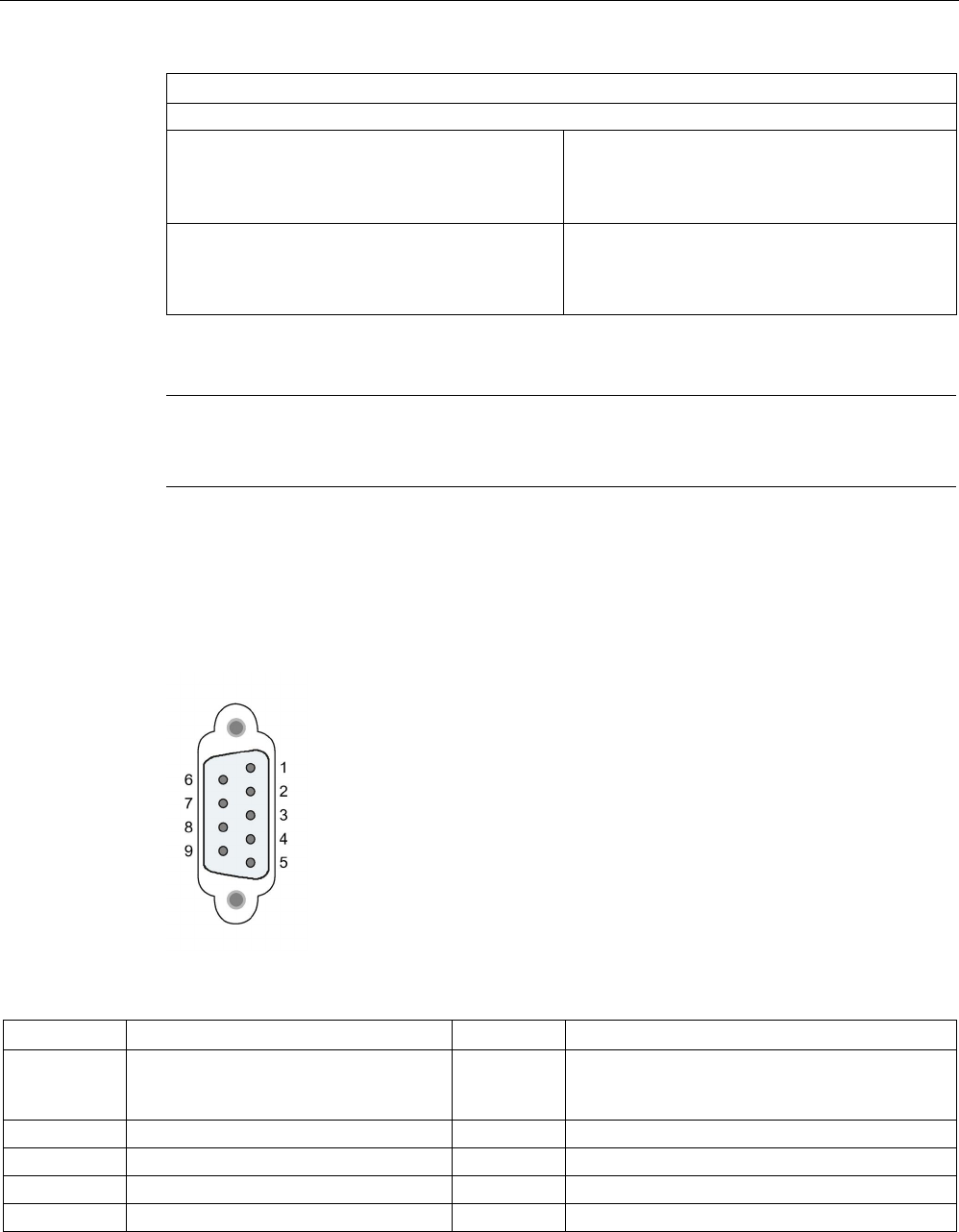
Technical specifications
A.16 Communication interfaces
S7-1200 Programmable controller
System Manual, V4.2, 09/2016, A5E02486680-AK 1533
Technical specifications
Dimensions and weights
• Width
• Height
• Depth
• 30 mm
• 100 mm
• 75 mm
Weight
• Net weight
• Weight including packaging
• 134 g
• 171 g
*
)
The current load of an external consumer connected between VP (pin 6) and DGND (pin 5) must not
exceed a maximum of 15 mA (short-circuit proof) for bus termination.
Note
The CM
1243-5 (PROFIBUS master module) must receive power from the 24 V DC sensor
supply of the CPU.
A.16.1.4
Pinout of the D-sub socket of the CM 1243-5
PROFIBUS interface
Table A- 242 Pinout of the D-sub socket
Pin
Description
Pin
Description
1 - not used - 6 VP: Power supply +5 V only for bus terminating
resistors;
not for supplying external devices
2
- not used -
7
- not used -
3
RxD/TxD-P: Data line B
8
RxD/TxD-N: Data line A
4
CNTR-P: RTS
9
- not used -
5
DGND: Ground for data signals and VP
Housing
Ground connector

Technical specifications
A.16 Communication interfaces
S7-1200 Programmable controller
1534 System Manual, V4.2, 09/2016, A5E02486680-AK
PROFIBUS cable
Note
Contacting the shield of the PROFIBUS cable
The shield of the PROFIBUS cable must be contacted.
To do this,
strip the insulation from the end of the PROFIBUS cable and connect the shield
to functional earth.
A.16.2
CP 1242-7
Note
The CP 1242-7 is not approved for Maritime applications
The CP 1242
-7 does not have Maritime approval.
Note
To use these modules,
your CPU firmware must be V2.0 or higher.
A.16.2.1
CP 1242-7 GPRS
Table A- 243 Technical specifications of the CP 1242-7 GPRS V2
Technical specifications
Article number
6GK7242-7KX3-0XE0
Wireless interface
Antenna connector
SMA socket
Nominal impedance 50 ohms
Wireless connection
Maximum transmit power • GSM 850, class 4: +33 dBm ±2dBm
• GSM 900, class 4: +33 dBm ±2dBm
• GSM 1800, class 1: +30 dBm ±2dBm
• GSM 1900, class 1: +30 dBm ±2dBm
GPRS Multislot class 10
device class B
coding scheme 1...4 (GMSK)
SMS Mode outgoing: MO
service: point-to-point

Technical specifications
A.16 Communication interfaces
S7-1200 Programmable controller
System Manual, V4.2, 09/2016, A5E02486680-AK 1535
Technical specifications
Permitted ambient conditions
Ambient temperature
• during storage
• during transportation
• during operation with a vertical installation (DIN rail hori-
zontal)
• during operation with a horizontal installation (DIN rail
vertical)
• -40 °C to 70 °C
• -40 °C to 70 °C
• 0 °C to 55 °C
• 0 °C to 45 °C
Relative humidity at 25 °C during operation, without conden-
sation, maximum
95 %
Degree of protection IP20
Power supply, current consumption and power loss
Type of power supply
DC
Power supply / external
• minimum
• maximum
24 V
• 19.2 V
• 28.8 V
Current consumption (typical)
• from 24 V DC
• from the S7-1200 backplane bus
• 100 mA
• 0 mA
Effective power loss (typical)
• from 24 V DC
• from the S7-1200 backplane bus
• 2.4 W
• 0 W
24 V DC power supply
• Min. cable cross section
• Max. cable cross section
• Tightening torque of the screw terminals
• min.: 0.14 mm2 (AWG 25)
• max.: 1.5 mm2 (AWG 15)
• 0.45 Nm (4 lb-in)
Electrical isolation
Power supply unit to internal circuit
710 V DC for 1 minute
Dimensions and weights
• Width
• Height
• Depth
• 30 mm
• 100 mm
• 75 mm
Weight
• Net weight
• Weight including packaging
• 133 g
• 170 g

Technical specifications
A.16 Communication interfaces
S7-1200 Programmable controller
1536 System Manual, V4.2, 09/2016, A5E02486680-AK
Note
Preventing CPU interference from antennas
CPU interference can occur if antenna proximity is too close, or if
you do not use
recommended antennas. For recommended antennas, refer to Antenna ANT794
-4MR for
LTE/UMTS/GSM Compact Operating Instructions
(
https://support.industry.siemens.com/cs/ww/en/view/23119005) (available in English and
German only).
A.16.2.2
GSM/GPRS antenna ANT794-4MR
Technical specifications of the ANT794-4MR GSM/GPRS antenna
ANT794-4MR
Article number
6NH9860-1AA00
Mobile wireless networks
GSM/GPRS
Frequency ranges • 824 to 960 MHz (GSM 850, 900)
• 1 710 to 1 880 MHz (GSM 1 800)
• 1 900 to 2 200 MHz (GSM / UMTS)
Characteristics
omnidirectional
Antenna gain
0 dB
Impedance
50 ohms
Standing wave ratio (SWR)
< 2,0
Max. power
20 W
Polarity
linear vertical
Connector
SMA
Length of antenna cable
5 m
External material
Hard PVC, UV-resistant
Degree of protection
IP20
Permitted ambient conditions
• Operating temperature
• Transport/storage temperature
• Relative humidity
• -40 °C through +70 °C
• -40 °C through +70 °C
• 100 %
External material
Hard PVC, UV-resistant
Construction Antenna with 5 m fixed cable and SMA male
connector
Dimensions (D x H) in mm
25 x 193
Weight
• Antenna incl. cable
• Fittings
• 310 g
• 54 g
Installation
With supplied bracket

Technical specifications
A.16 Communication interfaces
S7-1200 Programmable controller
System Manual, V4.2, 09/2016, A5E02486680-AK 1537
A.16.2.3
Flat antenna ANT794-3M
Technical specifications of the flat antenna ANT794-3M
ANT794-3M
Article number
6NH9870-1AA00
Mobile wireless networks
GSM 900
GSM 1800/1900
Frequency ranges
890 - 960 MHz
1710 - 1990 MHz
Standing wave ratio (VSWR) ≤ 2:1 ≤ 1,5:1
Return loss (Tx)
≈ 10 dB
≈ 14 dB
Antenna gain 0 dB
Impedance
50 ohms
Max. power
10 W
Antenna cable
HF cable RG 174 (fixed) with SMA male connector
Cable length
1.2 m
Degree of protection
IP64
Permitted temperature range
-40 °C to +75 °C
Flammability
UL 94 V2
External material
ABS Polylac PA-765, light gray (RAL 7035)
Dimensions (W x L x H) in mm
70.5 x 146.5 x 20.5
Weight
130 g

Technical specifications
A.16 Communication interfaces
S7-1200 Programmable controller
1538 System Manual, V4.2, 09/2016, A5E02486680-AK
A.16.3
CM 1243-2 AS-i master
A.16.3.1
Technical data for the AS-i master CM 1243-2
Table A- 244 Technical data for the AS-i master CM 1243-2
Technical data
Article number
3RK7243-2AA30-0XB0
Firmware version V1.0
Date
01.12.2011
Interfaces
Maximum current consumption
From the S7-1200 backplane bus
From the AS-i cable
Max. 250 mA,
supply voltage S7-1200 communication bus 5 V DC
Max. 100 mA
Maximum current carrying capacity between the
ASI+/ASI- terminals
8 A
Pin assignment See section Electrical connections of the AS-i master
(Page 1539)
Conductor cross-section
0.2 mm² (AWG 24) ... 3.3 mm² (AWG 12)
ASI connector tightening torque
0.56 Nm
Permissible ambient conditions
Ambient temperature
During storage
During transport
During the operating phase, with vertical installation (hori-
zontal standard mounting rail)
During the operating phase, with horizontal installation (ver-
tical standard mounting rail)
-40 °C ... 70 °C
-40 °C ... 70 °C
0 °C ... 55 °C
0 °C ... 45 °C
Relative humidity at 25 °C during operating phase, no con-
densation, maximum
95 %
Degree of protection
IP20
Power supply, current consumption, power loss
Type of power supply DC
Current consumption (typically)
From the S7-1200 backplane bus
200 mA
Total power loss (typical):
• From the S7-1200 backplane bus
• From AS-i cable
1 W
2.4 W
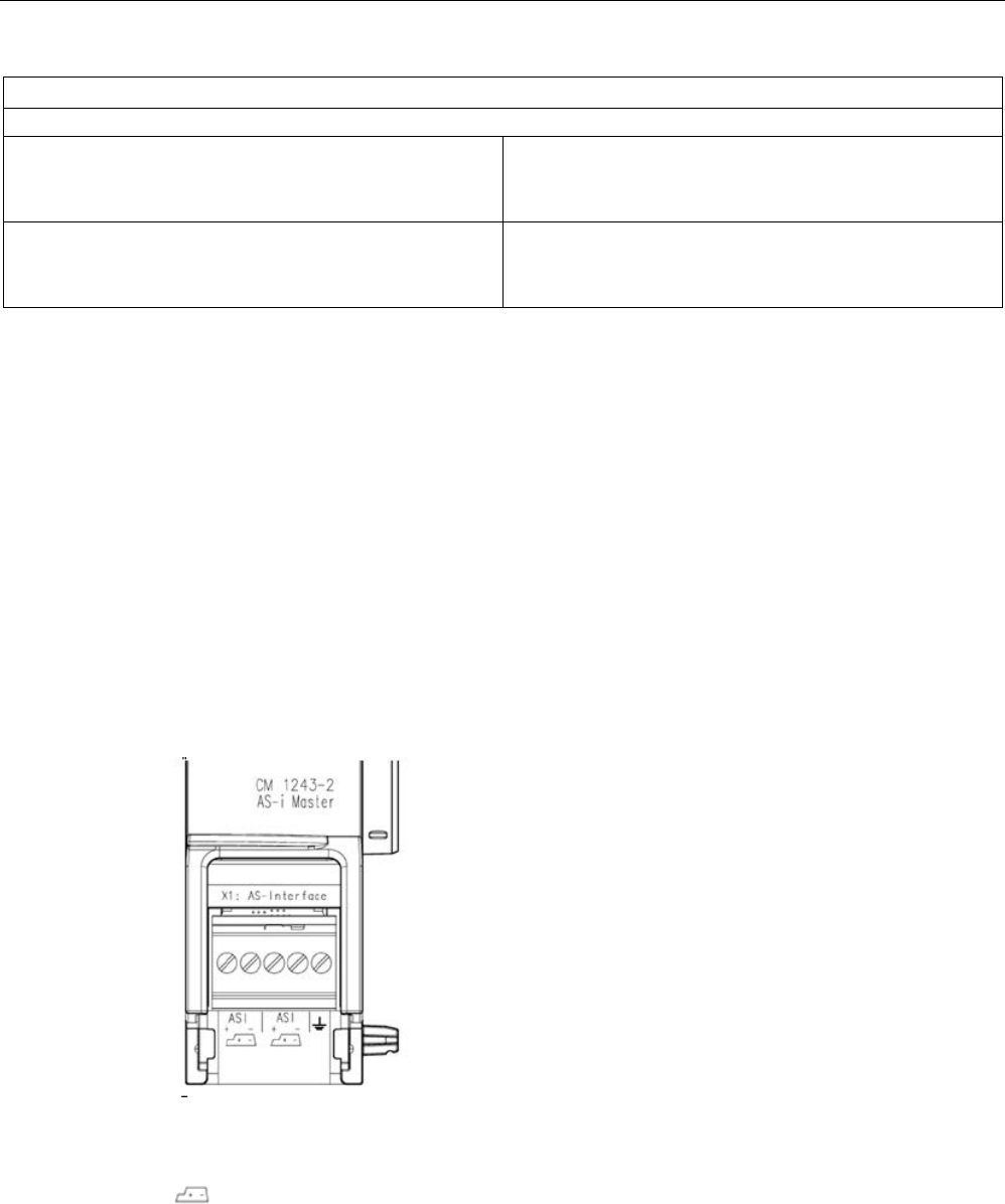
Technical specifications
A.16 Communication interfaces
S7-1200 Programmable controller
System Manual, V4.2, 09/2016, A5E02486680-AK 1539
Technical data
Dimensions and weights
Width
Height
Depth
30 mm
100 mm
75 mm
Weight
Net weight
Weight including packaging
122 g
159 g
A.16.3.2
Electrical connections of the AS-i master
Power supply of the AS-i master CM 1243-2
The AS-i master CM 1243-2 is supplied over the communications bus of the S7-1200. This
means that a diagnostics message can still be sent to the S7-1200 following failure of the
AS-i supply voltage. The connection to the communications bus is on the right-hand side of
the AS-i master CM 1243-2.
AS-Interface terminals
The removable terminal for connecting the AS-i cable is located behind the lower cover on
the front of the AS-i master CM 1243-2.
If the AS-i shaped cable is used, you can recognize the correct polarity of the cable by
means of the symbol
Information on how to remove and re-install the terminal block can be found in the
Installation chapter (Page 68).

Technical specifications
A.16 Communication interfaces
S7-1200 Programmable controller
1540 System Manual, V4.2, 09/2016, A5E02486680-AK
Note
Maximum current carrying capacity of the terminal contacts
The current carrying capacity of the connection contacts is max. 8
A. If this value is
exceeded on the AS
-i cable, the AS-i master CM 1243-2 must not be "looped in" to the AS-
i
cable, but must instead be connected via a spur line (only one connection pair assigned on
the AS
-i master CM 1243-2).
Please also ensure that the cables used are
suitable for operating temperatures of at least
75 °C if current is being conducted via the AS
-i master and currents of greater than 4
amperes are present.
You will find additional information on connecting the AS
-i cable in the section "Installation,
conn
ection and commissioning of the modules" in the manual "AS-i Master CM 1243-2 and
AS
-i data decoupling unit DCM 1271 for SIMATIC S7-1200".
Terminal assignment
Label
Meaning
ASI+
AS-i connection – positive polarity
ASI–
AS-i connection – negative polarity
Functional ground

Technical specifications
A.16 Communication interfaces
S7-1200 Programmable controller
System Manual, V4.2, 09/2016, A5E02486680-AK 1541
A.16.4
RS232, RS422, and RS485
A.16.4.1
CB 1241 RS485 specifications
Note
To use this CB, your CPU firmware must be V2.0 or higher.
Table A- 245 General specifications
Technical data
CB 1241 RS485
Article number
6ES7241-1CH30-1XB0
Dimensions W x H x D (mm)
38 x 62 x 21
Weight
40 grams
Table A- 246 Transmitter and receiver
Technical data
CB 1241 RS485
Type
RS485 (2-wire half-duplex)
Common mode voltage range
-7 V to +12 V, 1 second, 3 VRMS continuous
Transmitter differential output voltage 2 V min. at RL = 100 Ω
1.5 V min. at R
L
= 54 Ω
Termination and bias 10K to +5 V on B, RS485 Pin 3
10K to GND on A, RS485 Pin 4
Optional termination Short Pin TB to Pin T/RB, effective termination impedance is 127 Ω,
connects to RS485 Pin 3
Short Pin TA to Pin T/RA, effective termination impedance is 127 Ω,
connects to RS485 Pin 4
Receiver input impedance
5.4K Ω min. including termination
Receiver threshold/sensitivity +/- 0.2 V min., 60 mV typical hysteresis
Isolation
RS485 signal to chassis ground
RS485 signal to CPU logic common
707 V DC (type test)
Cable length, shielded
1000 m max.
Baud rate 300 baud, 600 baud, 1.2 kbits, 2.4 kbits, 4.8 kbits, 9.6 kbits (default),
19.2 kbits, 38.4 kbits, 57.6 kbits, 76.8 kbits, 115.2 kbits
Parity No parity (default), even, odd, Mark (parity bit always set to 1),
Space (parity bit always set to 0)
Number of stop bits
1 (default), 2
Flow control
Not supported
Wait time
0 to 65535 ms
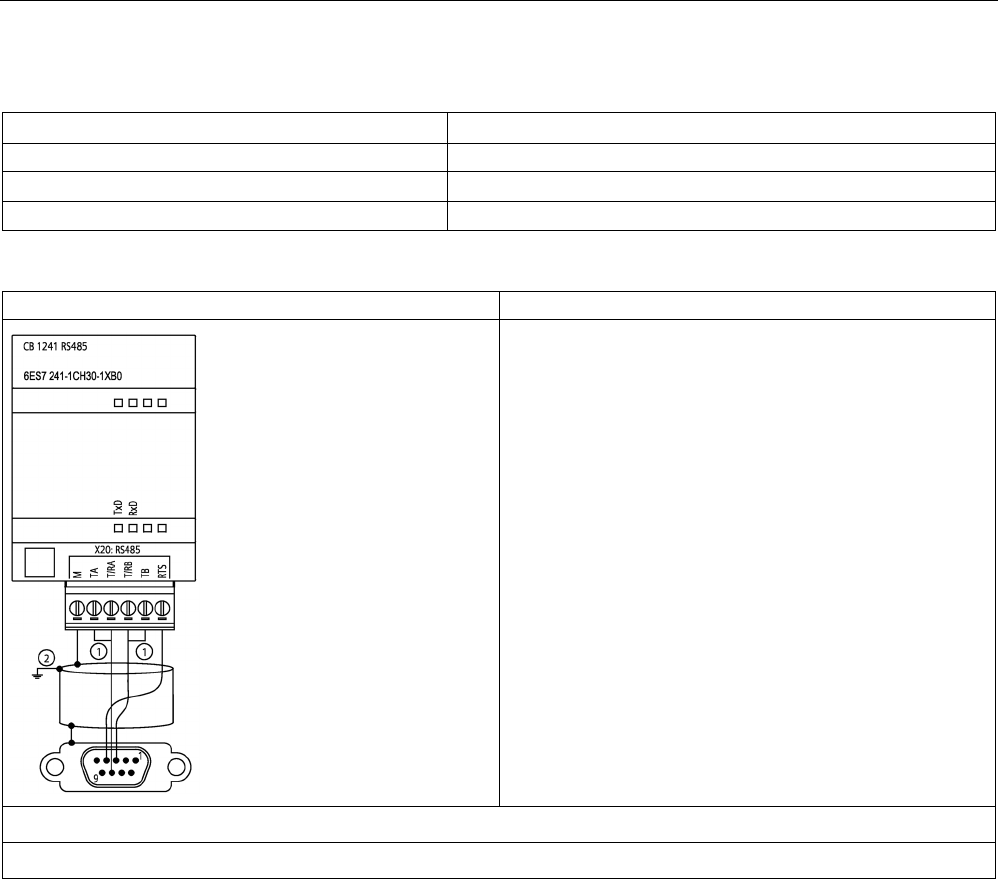
Technical specifications
A.16 Communication interfaces
S7-1200 Programmable controller
1542 System Manual, V4.2, 09/2016, A5E02486680-AK
Table A- 247 Power supply
Technical data
CB 1241 RS485
Power loss (dissipation)
1.5 W
Current consumption (SM Bus), max. 50 mA
Current consumption (24 V DC) max.
80 mA
CB 1241 RS485 (6ES7241-1CH30-1XB0)
①
Connect "TA" and TB" as shown to terminate the network. (Terminate only the end devices on the RS485 network.)
②
Use shielded twisted pair cable and connect the cable shield to ground.
You terminate only the two ends of the RS485 network. The devices in between the two end
devices are not terminated or biased. See the topic "Biasing and terminating an RS485
network connector" (Page 1088)

Technical specifications
A.16 Communication interfaces
S7-1200 Programmable controller
System Manual, V4.2, 09/2016, A5E02486680-AK 1543
Table A- 248 Connector pin locations for CB 1241 RS485 (6ES7241-1CH30-1XB0)
Pin
9-Pin connector
X20
1
RS485 / Logic GND
--
2 RS485 / Not Used --
3
RS485 / TxD+
4 - T/RB
4 RS485 / RTS 6 - RTS
5
RS485 / Logic GND
--
6
RS485 / 5 V Power
--
7
RS485 / Not used
--
8
RS485 / TxD-
3 - T/RA
9
RS485 / Not Used
--
Shell
1 - M
A.16.4.2
CM 1241 RS232 specifications
Table A- 249 General specifications
Technical data
CM 1241 RS232
Article number
6ES7241-1AH32-0XB0
Dimensions (mm)
30 x 100 x 75
Weight
150 grams
Table A- 250 Transmitter and receiver
Technical data
CM 1241 RS232
Type
RS232 (full-duplex)
Transmitter output voltage
+/- 5 V min. at R
L
= 3K Ω
Transmit output voltage
+/- 15 V DC max.
Receiver input impedance
3 K Ω min.
Receiver threshold/sensitivity 0.8 V min. low, 2.4 max. high
0.5 V typical hysteresis
Receiver input voltage
+/- 30 V DC max.
Isolation
RS 232 signal to chassis ground
RS 232 signal to CPU logic common
707 V DC (type test)
Cable length, shielded 10 m max.
Baud rate 300 baud, 600 baud, 1.2 kbits, 2.4 kbits, 4.8 kbits, 9.6 kbits (default),
19.2 kbits, 38.4 kbits, 57.6 kbits, 76.8 kbits, 115.2 kbits
Parity No parity (default), even, odd, Mark (parity bit always set to 1),
Space (parity bit always set to 0)
Number of stop bits
1 (default), 2
Flow control
Hardware, software
Wait time
0 to 65535 ms
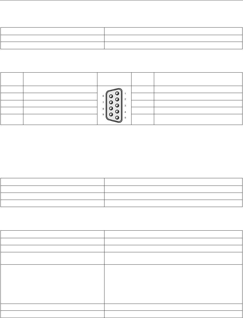
Technical specifications
A.16 Communication interfaces
S7-1200 Programmable controller
1544 System Manual, V4.2, 09/2016, A5E02486680-AK
Table A- 251 Power supply
Technical data
CM 1241 RS232
Power loss (dissipation)
1 W
From +5 V DC 200 mA
Table A- 252 RS232 connector (male)
Pin
Description
Connector
(male)
Pin
Description
1 DCD
Data carrier detect: Input
6 DSR
Data set ready: Input
2 RxD Received data from DCE: Input 7 RTS Request to send: Output
3 TxD
Transmitted data to DCE: Output
8 CTS
Clear to send: Input
4 DTR
Data terminal ready: Output
9 RI
Ring indicator (not used)
5 GND Logic ground SHELL Chassis ground
A.16.4.3
CM 1241 RS422/485 specifications
CM 1241 RS422/485 Specifications
Table A- 253 General specifications
Technical data
CM 1241 RS422/485
Article number
6ES7241-1CH32-0XB0
Dimensions W x H x H (mm)
30 x 100 x 75
Weight
155 grams
Table A- 254 Transmitter and receiver
Technical data
CM 1241 RS422/485
Type
RS422 or RS485, 9-pin sub D female connector
Common mode voltage range
-7 V to +12 V, 1 second, 3 VRMS continuous
Transmitter differential output voltage 2 V min. at RL = 100 Ω
1.5 V min. at RL = 54 Ω
Termination and bias 10K Ω to +5 V on B, PROFIBUS Pin 3
10K Ω to GND on A, PROFIBUS Pin 8
Internal bias options provided, or no internal bias. In all cases, exter-
nal termination is required, see Biasing and terminating an RS485
network connector (Page 1088) and Configuring the RS422 and
RS485 in the S7-1200 Programmable Controller System Manual
(Page 1140)
Receiver input impedance
5.4K Ω min. including termination
Receiver threshold/sensitivity +/- 0.2 V min., 60 mV typical hysteresis
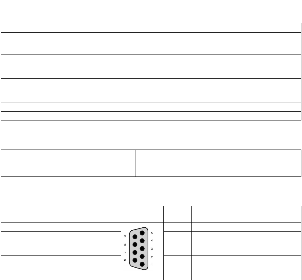
Technical specifications
A.17 TeleService (TS Adapter and TS Adapter modular)
S7-1200 Programmable controller
System Manual, V4.2, 09/2016, A5E02486680-AK 1545
Technical data
CM 1241 RS422/485
Isolation
RS485 signal to chassis ground
RS485 signal to CPU logic common
707 V DC (type test)
Cable length, shielded 1000 m max. (baud rate dependent)
Baud rate 300 baud, 600 baud, 1.2 kbits, 2.4 kbits, 4.8 kbits, 9.6 kbits (default),
19.2 kbits, 38.4 kbits, 57.6 kbits, 76.8 kbits, 115.2 kbits
Parity No parity (default), even, odd, Mark (parity bit always set to 1),
Space (parity bit always set to 0)
Number of stop bits
1 (default), 2
Flow control
XON/XOFF supported for the RS422 mode
Wait time
0 to 65535 ms
Table A- 255 Power supply
Technical data
CM 1241 RS422/485
Power loss (dissipation)
1.1 W
From +5 V DC
220 mA
Table A- 256 RS485 or RS422 connector (female)
Pin
Description
Connector
(female)
Pin
Description
1
Logic or communication ground
6 PWR
+5 V with 100 ohm series resistor: Output
2 TxD+ 1 Connected for RS422
Not used for RS485: Output
7 Not connected
3 TxD+
2
Signal B (RxD/TxD+): Input/Output
8 TXD-
2
Signal A (RxD/TxD-): Input/Output
4 RTS 3 Request to send (TTL level) Output 9 TXD- 1 Connected for RS422
Not used for RS485: Output
5 GND
Logic or communication ground
SHELL
Chassis ground
1
Pin 2 (TxD+) and Pin 9 (TxD-) are the RS422 transmit signals.
2
Pin 3 (RxD/Tx+) and Pin 8 (RxD/TxD-) are RS485 transmit and receive signals. For RS422, Pin 3 is RxD+ and Pin 8 is
RxD-.
3
The RTS is a TTL level signal and can be used to control another half duplex device based on this signal. It is active
when you transmit and is inactive all other times.

Technical specifications
A.17 TeleService (TS Adapter and TS Adapter modular)
S7-1200 Programmable controller
1546 System Manual, V4.2, 09/2016, A5E02486680-AK
A.17
TeleService (TS Adapter and TS Adapter modular)
The following manuals contain the technical specification for the TS Adapter IE Basic and
the TS Adapter modular:
● Industrial Software Engineering Tools
Modular TS Adapter
● Industrial Software Engineering Tools
TS Adapter IE Basic
For more information about this product and for the product documentation, refer to the
product catalog web site for the TS Adapter
(https://eb.automation.siemens.com/mall/en/de/Catalog/Search?searchTerm=TS%20Adapte
r%20IE%20basic&tab=).
A.18
SIMATIC memory cards
Capacity
Article Number
32 GB
6ES7954-8LT02-0AA0
2 GB 6ES7954-8LP01-0AA0
256 MB
6ES7954-8LL02-0AA0
24 MB 6ES7954-8LF02-0AA0
12 MB
6ES7954-8LE02-0AA0
4 MB
6ES7954-8LC02-0AA0
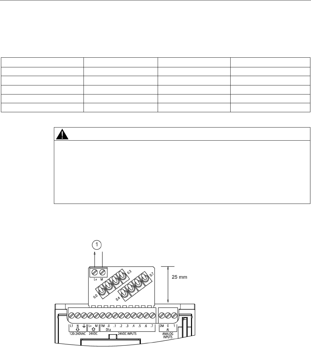
Technical specifications
A.19 Input simulators
S7-1200 Programmable controller
System Manual, V4.2, 09/2016, A5E02486680-AK 1547
A.19
Input simulators
Table A- 257 General specifications
Technical data
8 Position Simulator
14 Position Simulator
CPU 1217C Simulator
Article number
6ES7274-1XF30-0XA0
6ES7274-1XH30-0XA0
6ES7274-1XK30-0XA0
Dimensions W x H x D (mm) 43 x 35 x 23 67 x 35 x 23 93 x 40 x 23
Weight
20 grams
30 grams
43 grams
Points 8 14 14
Used with CPU
CPU 1211C, CPU 1212C
CPU 1214C, CPU 1215C
CPU 1217C
WARNING
Safe use of input simulators
These input simulators are not approved for use in Class I DIV 2 or Class I Zone 2
hazardous locations. The switches present a potential spark hazard/explosion hazard if
used in a Class I DIV 2 or Class I Zone 2 location. Unapproved use could result in death or
serious injury to personnel, and/or damage to equipment.
Use these input simulators only in non-hazardous locations. Do not use in Class I DIV 2 or
Class I Zone 2 hazardous locations.
8 Position Simulator (6ES7274-1XF30-0XA0)
①
24 V DC sensor
power out
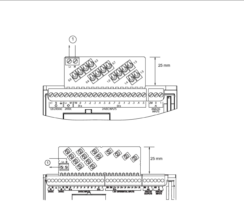
Technical specifications
A.19 Input simulators
S7-1200 Programmable controller
1548 System Manual, V4.2, 09/2016, A5E02486680-AK
14 Position Simulator (6ES7274-1XF30-0XA0)
①
24 V DC sensor
power out
CPU 1217C Simulator (6ES7274-1XK30-0XA0)
①
24 V DC sensor
power out

Technical specifications
A.20 S7-1200 Potentiometer module
S7-1200 Programmable controller
System Manual, V4.2, 09/2016, A5E02486680-AK 1549
A.20
S7-1200 Potentiometer module
The S7-1200 Potentiometer module is an accessory for S7-1200 CPU. Each potentiometer
creates an output voltage proportional to the position of the potentiometer to drive each of
the two CPU analog inputs 0 V DC to 10 V DC. To install the potentiometer:
1. Insert the circuit board ‘fingers’ into any S7-1200 CPU analog input terminal block, and
connect an external DC power supply to the 2-position connector on the potentiometer
module.
2. Use a small screwdriver to make the adjustments: turn the potentiometer clockwise (to
the right) to increase the voltage output, and counterclockwise (to the left) to decrease
the voltage output.
Note
Follow ESD guidelines when handling the S7
-1200 Potentiometer module.
Technical data
S7-1200 Potentiometer module
Article number
6ES7274-1XA30-0XA0
Used with CPU
All S7-1200 CPUs
Number of potentiometers
2
Dimensions W x H x D (mm)
20 x 33 x 14
Weight
26 grams
User-supplied voltage input at 2-position connector1
(Class 2, Limited Power, or sensor power from PLC)
16.4 V DC to 28.8 V DC
Cable length (meters)/type
<30 m, shielded twisted pair
Input current consumption
10 mA max.
Potentiometer voltage output to S7-1200 CPU analog in-
puts
1
0 V DC to 10.5 V DC min.
Isolation
Not isolated
Ambient temperature range
-20 °C to 60 °C
1
Potentiometer module output voltage stability depends on the quality of the user-supplied voltage
input at the 2-position connector - consider it as an analog input voltage.
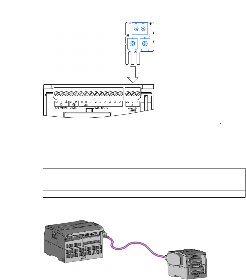
Technical specifications
A.21 I/O expansion cable
S7-1200 Programmable controller
1550 System Manual, V4.2, 09/2016, A5E02486680-AK
A.21
I/O expansion cable
Table A- 258 Expansion cables
Technical Data
Article number
6ES7290-6AA30-0XA0
Cable length
2 m
Weight
200 g
Refer to the installation section (Page 69) for information about installing and removing the
S7-1200 expansion cable.

Technical specifications
A.22 Companion products
S7-1200 Programmable controller
System Manual, V4.2, 09/2016, A5E02486680-AK 1551
A.22
Companion products
A.22.1
PM 1207 power module
The PM 1207 is a power supply module for the SIMATIC S7-1200. It provides the following
features:
● Input 120/230 V AC, output 24 V DC/2.5A
For more information about this product and for the product documentation, refer to the
product catalog web site for the PM 1207
(https://mall.industry.siemens.com/mall/en/de/Catalog/Product/6EP1332-1SH71).
A.22.2
CSM 1277 compact switch module
The CSM1277 is an Industrial Ethernet compact switch module. It can be used to multiply
the Ethernet interface of the S7-1200 to allow simultaneous communication with operator
panels, programming devices, or other controllers. It provides the following features:
● 4 x RJ45 sockets for connecting to Industrial Ethernet
● 3 pole plug in terminal strip for connection of the external 24 V DC supply on top
● LEDs for diagnostics and status display of Industrial Ethernet ports
● Article number 6GK7277-1AA00-0AA0
For more information about this product and for the product documentation, refer to the
product catalog web site for the CSM 1277
(https://eb.automation.siemens.com/mall/en/de/Catalog/Search?searchTerm=csm%201277&
tab=).

Technical specifications
A.22 Companion products
S7-1200 Programmable controller
1552 System Manual, V4.2, 09/2016, A5E02486680-AK
A.22.3
CM CANopen module
The CM CANopen module is a plug-in module between the SIMATIC S7-1200 PLC and any
device running CANopen. The CM CANopen can be configured to be both master or slave.
There are two CM CANopen modules: the CANopen module (article number 021620-B), and
the CANopen (Ruggedized) module (article number 021730-B).
The CANopen module provides the following features:
● Able to connect 3 modules per CPU
● Connects up to 16 CANopen slave nodes
● 256 byte input and 256 byte output per module
● 3 LEDs provide diagnostic information on module, network, and I/O status
● Supports storage of CANopen network configuration in the PLC
● The module is integratable in the hardware catalogue of the TIA Portal configuration suite
● CANopen configuration via included CANopen Configuration Studio (included) or via any
other externanal CANopen configuration tool
● Complies to the CANopen communication profiles CiA 301 rev. 4.2 and the CiA 302 rev.
4.1
● Supports transparent CAN 2.0A for custom protocol handling
● Pre-made function blocks available for each PLC programming in TIA portal
● CM CANopen modules include; DSUB with screw terminals for subnetwork. CM
CANopen configuration studio CD, and USB configuration cable
For more information about this product and for the product documentation, refer to the
product catalog web site for the CM CANopen.
A.22.4
RF120C communications module
The RF10C allows Siemens RFID and code reading systems to be connected directly and
easily to an S7-1200. The reader is connected to the RF120C via a point-to-point connecton.
Up to three communications modules can be connected to an S7-1200 to the left of the CPU.
The RF120C comminications module is configured via the TIA Portal. The article number for
the RF120C communications module is 6GT2002-0LA00.
For more information about this product and for the product documentation, refer to the
product catalog web site for the RF120C.

Technical specifications
A.22 Companion products
S7-1200 Programmable controller
System Manual, V4.2, 09/2016, A5E02486680-AK 1553
A.22.5
SM 1238 Energy meter module
The SM 1238 Energy Meter 480 V AC is designed for machine-level deployment in an S7-
1200 system. It records over 200 different electrical measurement and energy values. It lets
you create transparency about the energy requirements of individual components of a
production plant down to the machine level. Using the measured values provided by the SM
1238 Energy meter module, you can determine energy consumption and power demand.
For more information about this product and for the product documentation and
specifications, refer to the product catalog web site for the SM 1238 Energy meter module
(https://support.industry.siemens.com/cs/ww/en/view/109483435).
A.22.6
SIWAREX electronic weighing systems
SIWAREX WP231, WP241, and WP251
The SIWAREX WP231, WP241, and WP251 electronic weighing systems can be used in the
S7-1200. These modules use all the features of a modern automation system, such as
integrated communication, operation and monitoring, the dignostic system as well as the
configuration tools in the TIA Portal.
● The SIWAREX WP231 (https://support.industry.siemens.com/cs/us/en/view/90229056),
calibrater weighing electronic (1 channel) for strain guage load cells / full bridges (1-4
MV/V) for SIMATIC S7-1200, RS485 and Ethernet - interface, onboard I/O: 4 DI / 4 DO, 1
AO (0/4...20 MA)
● The SIWAREX WP241 (https://support.industry.siemens.com/cs/ww/en/view/90229063),
belt weigher electronic (1 channel) for strain guage load cells / full bridges (1-4 M/V) for
SIMATIC S7-1200, RS485 and Ethernet-interface, onboard I/O: 4 DI / 4 DO, 1 AO
(0/4...20 MA)
● The SIWAREX WP251, weighing electronic for batching and filling processes (1 channel)
for strain guage load cells / full bridges (1-4 MV/V) for SIMATIC S7-1200, RS485 and
Ethernet - interface, onboard I/O: 4 DI / 4 DO, 1 AO (0/4...20 MA),
See also
SIWAREX WP251 (https://support.industry.siemens.com/cs/ww/en/view/109481751)

Technical specifications
A.22 Companion products
S7-1200 Programmable controller
1554 System Manual, V4.2, 09/2016, A5E02486680-AK

S7-1200 Programmable controller
System Manual, V4.2, 09/2016, A5E02486680-AK 1555
Calculating a power budget
B
The CPU has an internal power supply that provides power for the CPU itself, for any
expansion modules, and for other 24 V DC user power requirements.
There are four types of expansion modules:
● Signal modules (SM) are installed on the right-side of the CPU. Each CPU allows a
maximum number of signal modules possible without regard to the power budget.
– CPU 1214C, CPU 1215C and CPU 1217C allows 8 signal modules
– CPU 1212C allows 2 signal modules
– CPU 1211C allows no signal modules
● Communication modules (CM) are installed on the left-side of the CPU. A maximum of 3
communication modules is allowed for any CPU without regard to the power budget.
● Signal boards (SB), communications boards (CB), and battery boards (BB) are installed
on top of the CPU. A maximum of 1 signal board, communication board, or battery board
is allowed for any CPU.
Use the following information as a guide for determining how much power (or current) the
CPU can provide for your configuration.
Each CPU supplies both 5 V DC and 24 V DC power:
● The CPU provides 5 V DC power for the expansion modules when an expansion module
is connected. If the 5 V DC power requirements for expansion modules exceed the power
budget of the CPU, you must remove expansion modules until the requirement is within
the power budget.
● Each CPU has a 24 V DC sensor supply that can supply 24 V DC for local input points or
for relay coils on the expansion modules. If the power requirement for 24 V DC exceeds
the power budget of the CPU, you can add an external 24 V DC power supply to provide
24 V DC to the expansion modules. You must manually connect the 24 V DC supply to
the input points or relay coils.
WARNING
Connecting an external 24 V DC power supply in parallel with the DC sensor supply can
result in a conflict between the two supplies as each seeks to establish its own preferred
output voltage level.
The result of this conflict can be shortened lifetime or immediate failure of one or both
power supplies, with consequent unpredictable operation of the PLC system.
Unpredictable operation could result in death, severe personal injury and/or property
damage.
The DC sensor supply on the CPU and any external power supply should provide power
to different points. A single connection of the commons is allowed.

Calculating a power budget
S7-1200 Programmable controller
1556 System Manual, V4.2, 09/2016, A5E02486680-AK
Some of the 24 V DC power input ports in the PLC system are interconnected, with a logic
common circuit connecting multiple M terminals. The CPU 24 V DC power supply input, the
SM relay coil power input, and a non-isolated analog power supply input are examples of
circuits that are interconnected when designated as not isolated in the data sheets. All non-
isolated M terminals must connect to the same external reference potential.
WARNING
Connecting non-isolated M terminals to different reference potentials will cause unintended
current flows that may cause damage or unpredictable operation in the PLC and connected
equipment.
Such damage or unpredictable operation could result in death, severe personal injury
and/or property damage.
Always be sure that all non-isolated M terminals in a PLC system are connected to the
same reference potential.
Information about the power budgets of the CPUs and the power requirements of the signal
modules is provided in the technical specifications (Page 1359).
Note
Exceeding the power budg
et of the CPU may result in not being able to connect the
maximum number of modules allowed for your CPU.
Example power budget
The following example shows a sample calculation of the power requirements for a
configuration that includes one CPU 1214C AC/DC/Relay, one SB 1223 2 x 24 V DC Input/ 2
x 24 V DC Output, one CM 1241, three SM 1223 8 DC In/8 Relay Out, and one SM 1221 8
DC In. This example has a total of 48 inputs and 36 outputs.
Note
The CPU has already allocated the power required to drive the internal relay coils. You do
not need to include the internal relay coil power requirements in a power budget calculation.

Calculating a power budget
S7-1200 Programmable controller
System Manual, V4.2, 09/2016, A5E02486680-AK 1557
The CPU in this example provides sufficient 5 V DC current for the SMs, but does not
provide enough 24 V DC current from the sensor supply for all of the inputs and expansion
relay coils. The I/O requires 456 mA and the CPU provides only 400 mA. This installation
requires an additional source of at least 56 mA at 24 V DC power to operate all the included
24 V DC inputs and outputs.
Table B- 1 Sample power budget
CPU power budget
5 V DC
24 V DC
CPU 1214C AC/DC/Relay
1600 mA
400 mA
Minus
System requirements
5 V DC
24 V DC
CPU 1214C, 14 inputs
-
14 * 4 mA = 56 mA
1 SB 1223 2 x 24 V DC Input/ 2 x 24 V
DC Output
50 mA 2 * 4 mA = 8 mA
1 CM 1241 RS422/485, 5 V power
220 mA
3 SM 1223, 5 V power
3 * 145 mA = 435 mA
-
1 SM 1221, 5 V power
1 * 105 mA = 105 mA
-
3 SM 1223, 8 inputs each
-
3 * 8 * 4 mA = 96 mA
3 SM 1223, 8 relay coils each
-
3 * 8 * 11 mA = 264 mA
1 SM 1221, 8 inputs each
-
8 * 4 mA = 32 mA
Total requirements
810 mA
456 mA
Equals
Current balance
5 V DC
24 V DC
Current balance total
790 mA
(56 mA)

Calculating a power budget
S7-1200 Programmable controller
1558 System Manual, V4.2, 09/2016, A5E02486680-AK
Form for calculating your power budget
Use the following table to determine how much power (or current) the S7-1200 CPU can
provide for your configuration. Refer to the technical specifications (Page 1359) for the
power budgets of your CPU model and the power requirements of your signal modules.
Table B- 2 Calculations for a power budget
CPU power budget
5 V DC
24 V DC
Minus
System requirements
5 V DC
24 V DC
Total requirements
Equals
Current balance
5 V DC
24 V DC
Current balance total

S7-1200 Programmable controller
System Manual, V4.2, 09/2016, A5E02486680-AK 1559
Ordering Information
C
C.1
CPU modules
Table C- 1 S7-1200 CPUs
CPU models
Article number
CPU 1211C CPU 1211C DC/DC/DC 6ES7211-1AE40-0XB0
CPU 1211C AC/DC/Relay
6ES7211-1BE40-0XB0
CPU 1211C DC/DC/Relay
6ES7211-1HE40-0XB0
CPU 1212C
CPU 1212C DC/DC/DC
6ES7212-1AE40-0XB0
CPU 1212C AC/DC/Relay
6ES7212-1BE40-0XB0
CPU 1212C DC/DC/Relay
6ES7212-1HE40-0XB0
CPU 1214C
CPU 1214C DC/DC/DC
6ES7214-1AG40-0XB0
CPU 1214C AC/DC/Relay
6ES7214-1BG40-0XB0
CPU 1214C DC/DC/Relay
6ES7214-1HG40-0XB0
CPU 1215C
CPU 1215C DC/DC/DC
6ES7215-1AG40-0XB0
CPU 1215C AC/DC/Relay
6ES7215-1BG40-0XB0
CPU 1215C DC/DC/Relay
6ES7215-1HG40-0XB0
CPU 1217C
CPU 1217C DC/DC/DC
6ES7217-1AG40-0XB0

Ordering Information
C.2 Signal modules (SMs), signal boards (SBs), and battery boards (BBs)
S7-1200 Programmable controller
1560 System Manual, V4.2, 09/2016, A5E02486680-AK
C.2
Signal modules (SMs), signal boards (SBs), and battery boards
(BBs)
Table C- 2 Signal modules (SMs)
Signal modules
Article number
Digital input
SM 1221 8 x 24 V DC Input (Sink/Source)
6ES7221-1BF32-0XB0
SM 1221 16 x 24 V DC Input (Sink/Source) 6ES7221-1BH32-0XB0
Digital output
SM 1222 8 x 24 V DC Output (Source)
6ES7222-1BF32-0XB0
SM 1222 16 x 24 V DC Output (Source) 6ES7222-1BH32-0XB0
SM 1222 8 x Relay Output
6ES7222-1HF32-0XB0
SM 1222 8 x Relay Output (Changeover)
6ES7222-1XF32-0XB0
SM 1222 16 x Relay Output
6ES7222-1HH32-0XB0
Digital input /
output
SM 1223 8 x 24 V DC Input (Sink/Source) / 8 x 24 V DC Output
(Source)
6ES7223-1BH32-0XB0
SM 1223 16 x 24 V DC Input (Sink/Source) / 16 x 24 V DC Out-
put (Source)
6ES7223-1BL32-0XB0
SM 1223 8 x 24 V DC Input (Sink/Source) / 8 x Relay Output
6ES7223-1PH32-0XB0
SM 1223 16 x 24 V DC Input (Sink/Source) / 16 x Relay Output
6ES7223-1PL32-0XB0
SM 1223 8 x 120/230 V AC Input (Sink/Source) / 8 x Relay Out-
puts
6ES7223-1QH32-0XB0
Analog input
SM 1231 4 x Analog Input
6ES7231-4HD32-0XB0
SM 1231 8 x Analog Input
6ES7231-4HF32-0XB0
SM 1231 4 x Analog Input x 16 bit (high feature)
6ES7231-5ND32-0XB0
SM 1238 Energy Meter 480 V AC
6ES7238-5XA32-0XB0
Analog output
SM 1232 2 x Analog Output
6ES7232-4HB32-0XB0
SM 1232 4 x Analog Output
6ES7232-4HD32-0XB0
Analog input /
output
SM 1234 4 x Analog Input / 2 x Analog Output 6ES7234-4HE32-0XB0
RTD and thermo-
couple
SM 1231 TC 4 x 16 bit
6ES7231-5QD32-0XB0
SM 1231 TC 8 x 16 bit 6ES7231-5QF32-0XB0
SM 1231 RTD 4 x 16 bit
6ES7231-5PD32-0XB0
SM 1231 RTD 8 x 16 bit
6ES7231-5PF32-0XB0
Technology mod-
ules
SM 1278 4xIO-Link Master
6ES7278-4BD32-0XB0
SIWAREX WP231, calibrater weighing electronic (1 channel) for
strain guage load cells / full bridges (1-4 MV/V) for SIMATIC S7-
1200, RS485 and Ethernet - interface, onboard I/O: 4 DI / 4 DO,
1 AO (0/4...20 MA)
7MH4960-2AA01
SIWAREX WP241, belt weigher electronic (1 channel) for strain
guage load cells / full bridges (1-4 M/V) for SIMATIC S7-1200,
RS485 and Ethernet-interface, onboard I/O: 4 DI / 4 DO, 1 AO
(0/4...20 MA)
7MH4960-4AA01
SIWAREX WP251, weighing electronic for batching and filling
processes (1 channel) for strain guage load cells / full bridges (1-
4 MV/V) for SIMATIC S7-1200, RS485 and Ethernet - interface,
onboard I/O: 4 DI / 4 DO, 1 AO (0/4...20MA),
7MH4960-6AA01

Ordering Information
C.3 Communication
S7-1200 Programmable controller
System Manual, V4.2, 09/2016, A5E02486680-AK 1561
Table C- 3 Signal boards (SB) and battery boards (BBs)
Signal and battery boards
Article number
Digital input
SB 1221 200 kHz 4 x 24 V DC Input (Source)
6ES7221-3BD30-0XB0
SB 1221 200 kHz 4 x 5 V DC Input (Source) 6ES7221-3AD30-0XB0
Digital output
SB 1222 200 kHz 4 x 24 V DC Output (Sink/Source)
6ES7222-1BD30-0XB0
SB 1222 200 kHz 4 x 5 V DC Output (Sink/Source)
6ES7222-1AD30-0XB0
Digital input /
output
SB 1223 2 x 24 V DC Input (Sink) / 2 x 24 V DC Output (Source)
6ES7223-0BD30-0XB0
SB 1223 200 kHz 2 x 24 V DC Input (Source) / 2 x 24 V DC
Output (Sink/Source)
6ES7223-3BD30-0XB0
SB 1223 200 kHz 2 x 5 V DC Input (Source) / 2 x 5 V DC Output
(Sink/Source)
6ES7223-3AD30-0XB0
Analog
SB 1232 1 Analog Output
6ES7232-4HA30-0XB0
SB 1231 1 Analog Input
6ES7231-4HA30-0XB0
SB 1231 1 Analog Input Thermocouple
6ES7231-5QA30-0XB0
SB 1231 1 Analog Input RTD
6ES7231-5PA30-0XB0
Battery
BB 1297 Battery Board (battery type CR1025 not included)
6ES7297-0AX30-0XA0
C.3
Communication
Table C- 4 Communication module (CM)
Communication module (CM)
Article number
RS232, RS422,
and RS485
CM 1241 RS232
RS232
6ES7241-1AH32-0XB0
CM 1241 RS422/485
RS422/485
6ES7241-1CH32-0XB0
PROFIBUS
CM 1243-5
PROFIBUS Master
6GK7243-5DX30-0XE0
CM 1242-5
PROFIBUS Slave
6GK7242-5DX30-0XE0
AS-i Master
CM 1243-2
AS-i Master
3RK7243-2AA30-0XB0
Table C- 5 Communication board (CB)
Communication board (CB)
Article number
RS485
CB 1241 RS485
RS485
6ES7241-1CH30-1XB0

Ordering Information
C.3 Communication
S7-1200 Programmable controller
1562 System Manual, V4.2, 09/2016, A5E02486680-AK
Table C- 6 Communication Processor (CP)
CP
Interface
Article number
CP 1242-7 GPRS
V2
GPRS 6GK7242-7KX31-0XE0
CP 1243-7 LTE-
EU
LTE 6GK7243-7KX30-0XE0
CP 1243-1 DNP3
IE-interface
6GK7243-1JX30-0XE0
CP 1243-1 IEC
IE-interface
6GK7243-1PX30-0XE0
CP 1243-1
IE-interface
6GK7243-1BX30-0XE0
CP 1243-1 PCC
IE-interface
6GK7243-1HX30-0XE0
CP 1243-8 IRC
IE- and serial interface
6GK7243-8RX30-0XE0
Table C- 7 TeleService
TS Adapter
Article number
TS Adapter IE Basic
6ES7972-0EB00-0XA0
TS Adapter IE Advanced
6ES7972-0EA00-0XA0
TS Module GSM
6GK7972-0MG00-0XA0
TS Module RS232
6ES7792-0MS00-0XA0
TS Module Modem
6ES7972-0MM00-0XA0
TS Module ISDN
6ES7972-0MD00-0XA0
Table C- 8 Accessories
Accessory
Article number
Antenna
ANT794-4MR
GSM/GPRS antenna
6NH9860-1AA00
ANT794-3M
Flat antenna
6NH9870-1AA00
Table C- 9 Connectors
Type of Connector
Article number
RS485
35-degree cable output, screw-terminal connection
6ES7972-0BA42-0XA0
35-degree cable output, FastConnect connection
6ES7972-0BA60-0XA0

Ordering Information
C.4 Fail-Safe CPUs and signal modules
S7-1200 Programmable controller
System Manual, V4.2, 09/2016, A5E02486680-AK 1563
C.4
Fail-Safe CPUs and signal modules
Table C- 10 Fail-Safe CPUs
Fail-Safe CPU models
Article number
CPU 1212FC
CPU 1212FC DC/DC/DC
6ES7212-1AF40-0XB0
CPU 1212FC DC/DC/Relay 6ES7212-1HF40-0XB0
CPU 1214FC
CPU 1214FC DC/DC/DC
6ES7214-1AF40-0XB0
CPU 1214FC DC/DC/Relay 6ES7214-1HF40-0XB0
CPU 1215FC
CPU 1215FC DC/DC/DC
6ES7215-1AF40-0XB0
CPU 1215FC DC/DC/Relay
6ES7215-1HF40-0XB0
Table C- 11 Fail-Safe signal modules
Functional Safety signal modules
Article number
Digital input
SM 1226 F-DI 16 x 24 V DC
6ES7226-6BA32-0XB0
Digital output
SM 1226 F-DQ 4 x 24 V DC
6ES7226-6DA32-0XB0
SM 1226 F-DQ 2 x Relay
6ES7226-6RA32-0XB0
C.5
Other modules
Table C- 12 Companion products
Item
Article number
Power supply
PM 1207 power supply
6EP1332-1SH71
Ethernet switch
CSM 1277 Ethernet switch - 4 ports
6GK7277-1AA10-0AA0
CM CANopen
CANopen for SIMATIC S7-1200
021620-B
CANopen (Ruggedized) for SIMATIC S7-1200
021730-B
RF120C
RF120C communications module
6GT2002-0LA00
C.6
Memory cards
Table C- 13 Memory cards
SIMATIC memory cards
Article number
SIMATIC MC 32 GB
6ES7954-8LT02-0AA0
SIMATIC MC 2 GB
6ES7954-8LP01-0AA0
SIMATIC MC 256 MB
6ES7954-8LL02-0AA0
SIMATIC MC 24 MB
6ES7954-8LF02-0AA0
SIMATIC MC 12 MB
6ES7954-8LE02-0AA0
SIMATIC MC 4 MB
6ES7954-8LC02-0AA0

Ordering Information
C.7 Basic HMI devices
S7-1200 Programmable controller
1564 System Manual, V4.2, 09/2016, A5E02486680-AK
C.7
Basic HMI devices
Table C- 14 HMI devices
HMI Basic Panels
Article number
KTP400 Basic (Mono, PN)
6AV2123-2DB03-0AX0
KTP700 Basic 6AV2123-2GB03-0AX0
KTP700 Basic DP
6AV2123-2GA03-0AX0
KTP900 Basic 6AV2123-2JB03-0AX0
KTP1200 Basic
6AV2123-2MB03-0AX0
KTP1200 Basic DP
6AV2123-2MA03-0AX0
C.8
Spare parts and other hardware
Table C- 15 Expansion cables, simulators, and end retainers
Item
Article number
I/O expansion
cable
I/O Expansion cable, 2 mm 6ES7290-6AA30-0XA0
I/O simulator
Simulator (1211C/1212C - 8 position)
6ES7274-1XF30-0XA0
Simulator (1214C/1215C - 14 position)
6ES7274-1XH30-0XA0
Simulator, CPU 1217C
6ES7274-1XK30-0XA0
Potentiometer
module
S7-1200 Potentiometer module 6ES7274-1XA30-0XA0
Ethernet strain
relief
Single port RJ45 strain relief, 10/100 Mbit/sec
6ES7290-3AA30-0XA0
Dual port RJ45 strain relief, 10/100 Mbit/sec
6ES7290-3AB30-0XA0
Spare door kit
CPU 1211C/1212C
6ES7291-1AA30-0XA0
CPU 1214C
6ES7291-1AB30-0XA0
CPU 1215C
6ES7291-1AC30-0XA0
CPU 1217C
6ES7291-1AD30-0XA0
Signal module, 45 mm
6ES7291-1BA30-0XA0
Signal module, 70 mm 6ES7291-1BB30-0XA0
Communication module (for use with 6ES72xx-xxx32-0XB0 and
6ES72xx-xxx30-0XB0 modules)
6ES7291-1CC30-0XA0
End Retainer End Retainer Thermoplastic, 10 MM 8WA1808
End Retainer Steel, 10.3 MM
8WA1805
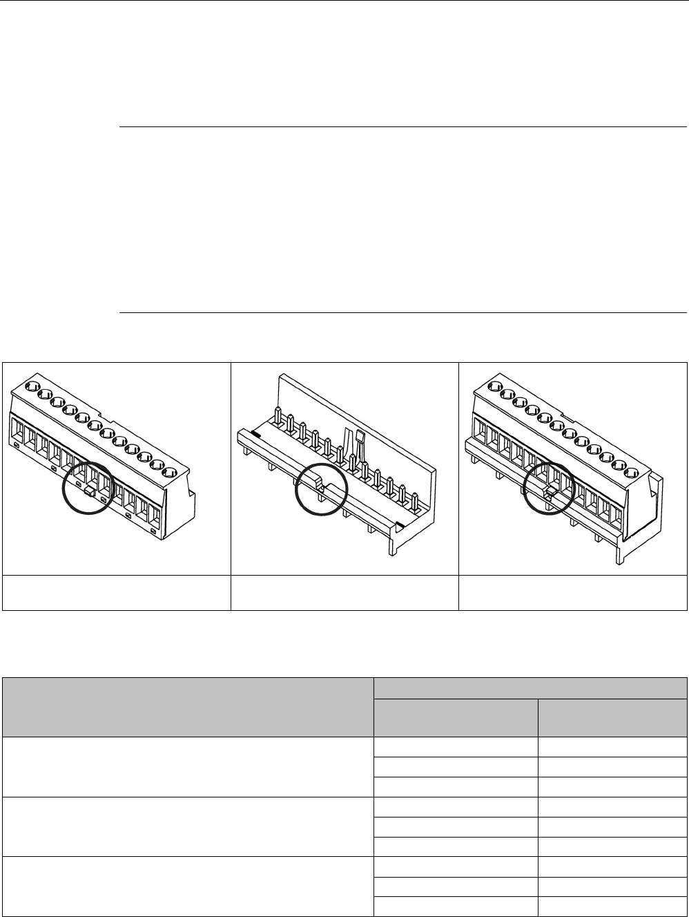
Ordering Information
C.8 Spare parts and other hardware
S7-1200 Programmable controller
System Manual, V4.2, 09/2016, A5E02486680-AK 1565
Replacing the terminal block connector
It is important to use the correct terminal block for your module. Refer to the tables below
and your module specifications to determine the correct terminal block replacement.
Note
Keyed removable terminal blocks
PLCs always require correct wiring to ensure safety and proper operation.
When replacing the terminal block in your CPU or SM, it is important that you use the correct
terminal block and correct wiring source for your modu
le.
The keyed feature helps prevent you from accidentally placing a high voltage wired terminal
block into a low voltage module, or from placing a special voltage wired terminal block into a
normal voltage module. Some terminal blocks are specifically keye
d at left, at right or at
middle.
Removable terminal block
(keyed example shown
Key on device Key on device only fits appropriate
removable terminal block
Table C- 16 S7-1200 CPU V4.0 and later - Terminal block spare kits
If you have
S7-1200 CPU V4.0 and later (article number)
Use this terminal block spare kit (4/pk)
Terminal block
article number
Terminal block
description
CPU 1211C DC/DC/DC (6ES7211-1AE40-0XB0)
6ES7292-1BC30-0XA0
3 pin, gold-plated
6ES7292-1AH30-0XA0
8 pin, tin-plated
6ES7292-1AP30-0XA0
14 pin, tin-plated
CPU 1211C DC/DC/Relay (6ES7211-1HE40-0XB0)
6ES7292-1BC30-0XA0
3 pin, gold-plated
6ES7292-1AH40-0XA0
8 pin, tin-plated, keyed
6ES7292-1AP30-0XA0
14 pin, tin-plated
CPU 1211C AC/DC/Relay (6ES7211-1BE40-0XB0) 6ES7292-1BC30-0XA0 3 pin, gold-plated
6ES7292-1AH40-0XA0
8 pin, tin-plated, keyed
6ES7292-1AP40-0XA0
14 pin, tin-plated, keyed

Ordering Information
C.8 Spare parts and other hardware
S7-1200 Programmable controller
1566 System Manual, V4.2, 09/2016, A5E02486680-AK
If you have
S7-1200 CPU V4.0 and later (article number)
Use this terminal block spare kit (4/pk)
Terminal block
article number
Terminal block
description
CPU 1212C DC/DC/DC (6ES7212-1AE40-0XB0)
6ES7292-1BC30-0XA0
3 pin, gold-plated
6ES7292-1AH30-0XA0
8 pin, tin-plated
6ES7292-1AP30-0XA0 14 pin, tin-plated
CPU 1212C DC/DC/Relay (6ES7212-1HE40-0XB0)
6ES7292-1BC30-0XA0
3 pin, gold-plated
6ES7292-1AH40-0XA0
8 pin, tin-plated, keyed
6ES7292-1AP30-0XA0
14 pin, tin-plated
CPU 1212C AC/DC/Relay (6ES7212-1BE40-0XB0)
6ES7292-1BC30-0XA0
3 pin, gold-plated
6ES7292-1AH40-0XA0
8 pin, tin-plated, keyed
6ES7292-1AP40-0XA0
14 pin, tin-plated, keyed
CPU 1214C DC/DC/DC (6ES7214-1AG40-0XB0)
6ES7292-1BC30-0XA0
3 pin, gold-plated
6ES7292-1AM30-0XA0
12 pin, tin-plated
6ES7292-1AV30-0XA0
20 pin, tin-plated
CPU 1214C DC/DC/Relay (6ES7214-1HG40-0XB0)
6ES7292-1BC30-0XA0
3 pin, gold-plated
6ES7292-1AM40-0XA0
12 pin, tin-plated, keyed
6ES7292-1AV30-0XA0
20 pin, tin-plated
CPU 1214C AC/DC/Relay (6ES7214-1BG40-0XB0)
6ES7292-1BC30-0XA0
3 pin, gold-plated
6ES7292-1AM40-0XA0
12 pin, tin-plated, keyed
6ES7292-1AV40-0XA0
20 pin, tin-plated, keyed
CPU 1215C DC/DC/DC (6ES7215-1AG40-0XB0)
6ES7292-1BF30-0XB0
6 pin, gold-plated
6ES7292-1AM30-0XB0
12 pin, tin-plated
6ES7292-1AV30-0XB0
20 pin, tin-plated
CPU 1215C DC/DC/Relay (6ES7215-1HG40-0XB0) 6ES7292-1BF30-0XB0 6 pin, gold-plated
6ES7292-1AM40-0XA0
12 pin, tin-plated, keyed
6ES7292-1AV30-0XA0
20 pin, tin-plated
CPU 1215C AC/DC/Relay (6ES7215-1BG40-0XB0)
6ES7292-1BF30-0XB0
6 pin, gold-plated
6ES7292-1AM40-0XA0
12 pin, tin-plated, keyed
6ES7292-1AV40-0XA0
20 pin, tin-plated, keyed
CPU 1217C DC/DC/DC (6ES7217-1AG40-0XB0)
6ES7292-1BF30-0XB0
6 pin, gold-plated
6ES7292-1AK30-0XA0
10 pin, pin-plated
6ES7292-1AR30-0XA0
16 pin, pin-plated
6ES7292-1AT30-0XA0
18 pin, tin-plated

Ordering Information
C.8 Spare parts and other hardware
S7-1200 Programmable controller
System Manual, V4.2, 09/2016, A5E02486680-AK 1567
Table C- 17 S7-1200 SMs V3.2 and later - Terminal block spare kits
If you have
S7-1200 SMs V3.2 and later (article number)
Use this terminal block spare kit (4/pk)
Terminal block
article number
Terminal block
description
SM 1221 DI 8 x DC (6ES7221-1BF32-0XB0)
6ES7292-1AG30-0XA0
7 pin, tin-plated
SM 1222 DQ 8 x DC (6ES7222-1BF32-0XB0)
6ES7292-1AG30-0XA0
7 pin, tin-plated
SM 1222 DQ 8 x Relay (6ES7222-1HF32-0XB0) 6ES7292-1AG40-0XA1 7 pin, tin-plated, keyed-
left
SM 1238 Energy Meter 480 V AC (6ES7238-5XA32-0XB0) for
voltage input (top)
6ES7292-1AG40-0XA2 7-pin, tin-plated, keyed-
middle
SM 1238 Energy Meter 480 V AC (6ES7238-5XA32-0XB0) for
current input (bottom)
6ES7292-1AG30-0XA0 7-pin, tin-plated
SM 1231 AI 4 x 13 bit (6ES7231-4HD32-0XB0)
6ES7292-1BG30-0XA0
7 pin, gold-plated
SM 1232 AQ 2 x 14 bit (6ES7232-4HB32-0XB0)
6ES7292-1BG30-0XA0
7 pin, gold-plated
SM 1231 AI 4 x TC (6ES7231-5QD32-0XB0)
6ES7292-1BG30-0XA0
7 pin, gold-plated
SM 1231 AI 4 x 16 bit (6ES7231-5ND32-0XB0)
6ES7292-1BG30-0XA0
7 pin, gold-plated
SM 1221 DI 16 x DC (6ES7221-1BH32-0XB0)
6ES7292-1AG30-0XA0
7 pin, tin-plated
SM 1222 DQ 16 x DC (6ES7222-1BH32-0XB0)
6ES7292-1AG30-0XA0
7 pin, tin-plated
SM 1222 DQ 16 x Relay (6ES7222-1HH32-0XB0) 6ES7292-1AG40-0XA0 7 pin, tin-plated, keyed-
right
SM 1223 DI 8 x DC/DQ 8 x DC (6ES7223-1BH32-0XB0)
6ES7292-1AG30-0XA0
7 pin, tin-plated
SM 1223 8 x DC/8 x Relay (6ES7223-1PH32-0XB0)
6ES7292-1AG30-0XA0
7 pin, tin-plated
6ES7292-1AG40-0XA0 7 pin, tin-plated, keyed-
right
SM 1223 8 x AC/8 x Relay (6ES7223-1QH32-0XB0) 6ES7292-1AG40-0XA0 7 pin, tin-plated, keyed-
right
SM 1234 AI 4 / AQ 2 (6ES7234-4HE32-0XB0)
6ES7292-1BG30-0XA0
7 pin, gold-plated
SM 1231 AI 8 x 13 BIT (6ES7231-4HF32-0XB0)
6ES7292-1BG30-0XA0
7 pin, gold-plated
SM 1232 AQ 4 x 14 bit (6ES7232-4HD32-0XB0)
6ES7292-1BG30-0XA0
7 pin, gold-plated
SM 1231 AI 4 x RTD (6ES7231-5PD32-0XB0)
6ES7292-1BG30-0XA0
7 pin, gold-plated
SM 1231 AI 8 x TC (6ES7231-5QF32-0XB0)
6ES7292-1BG30-0XA0
7 pin, gold-plated
SM 1278 IO LINK (6ES7278-4BD32 0XB0)
6ES7292-1AG30-0XA0
7 pin, tin-plated
SM 1222 DQ 8 x Relay (Changeover) (6ES7222-1XF32-0XB0)
6ES7292-1AL30-0XA0
11 pin, tin-plated
SM 1223 DI 16 x DC/DQ 16 x DC (6ES7223-1BL32-0XB0)
6ES7292-1AL30-0XA0
11 pin, tin-plated
SM 1223 DI 16 x DC/DQ 16 x Relay (6ES7223-1PL32-0XB0)
6ES7292-1AL30-0XA0
11 pin, tin-plated
6ES7292-1AL40-0XA0
11 pin, tin-plated, keyed
SM 1231 AI 8 x RTD (6ES7231-5PF32-0XB0)
6ES7292-1BL30-0XA0
11 pin, gold-plated

Ordering Information
C.8 Spare parts and other hardware
S7-1200 Programmable controller
1568 System Manual, V4.2, 09/2016, A5E02486680-AK
Table C- 18 S7-1200 SBs, CBs, and BBs - Terminal block spare kits
If you have
S7-1200 SB, CB, or BB (article number)
Use this terminal block spare kit (4/pk)
Terminal block
article number
Terminal block
description
SB 1221 DI 4 x 5 V DC (6ES7221-3AD30-0XB0)
6ES7292-1BF30-0XA0 6-pin
SB 1221 DI 4 x 5 V DC (6ES7221-3AD30-0XB0)
SB 1221 DI 4 x 24 V DC (6ES7221-3BD30-0XB0)
SB 1222 DQ 4 x 5 V DC (6ES7222-1AD30-0XB0)
SB 1222 DQ 4 x 24 V DC (6ES7222-1BD30-0XB0)
SB 1223 DI 2x24 V DC/DQ 2x24 V DC (6ES7223-0BD30-0XB0)
SB 1223 DI 2x5 V DC / DQ 2x5 V DC (6ES7223-3AD30-0XB0)
SB 1223 DI 2x24 V DC / DQ 2x24 V DC (6ES7223-3BD30-0XB0)
SB 1231 AI 1 x 12 BIT (6ES7231-4HA30-0XB0)
SB 1231 AI 1 x RTD (6ES7231-5PA30-0XB0)
SB 1231 AI 1 x TC (6ES7231-5QA30-0XB0)
SB 1232 AQ 1x12 BIT (6ES7232-4HA30-0XB0)
CB 1231 RS485 (6ES7241-1CH30-1XB0)
BB 1297 Battery (6ES7297-0AX30-0XA0)
Table C- 19 Fail-Safe CPUs - Terminal block spare kit
If you have Fail-Safe CPU (article number)
Use this terminal block spare kit (4/pk)
Terminal block
article number
Terminal block
description
CPU 1214FC DC/DC/DC (6ES7214-1AF40-0XB0)
6ES7292-1BC30-0XA0
3 pin, gold-plated
6ES7292-1AM30-0XA0
12 pin, tin-plated
6ES7292-1AV30-0XA0
20 pin, tin-plated
CPU 1214FC DC/DC/Relay (6ES7214-1HF40-0XB0)
6ES7292-1BC30-0XA0
3 pin, gold-plated
6ES7292-1AM40-0XA0
12 pin, tin-plated, keyed
6ES7292-1AV30-0XA0
20 pin, tin-plated
CPU 1215FC DC/DC/DC (6ES7215-1AF40 0XB0)
6ES7292-1BF30-0XB0
6 pin, gold-plate
6ES7292-1AM30-0XA0
12 pin, tin-plated
6ES7292-1AV30-0XA0 20 pin, tin-plated
CPU 1215FC DC/DC/Relay (6ES7215-1HF40 0XB0)
6ES7292-1BF30-0XB0
6 pin, gold-plated
6ES7292-1AM40-0XA0 2 pin, tin-plated, keyed
6ES7292-1AV30-0XA0
20 pin, tin-plated
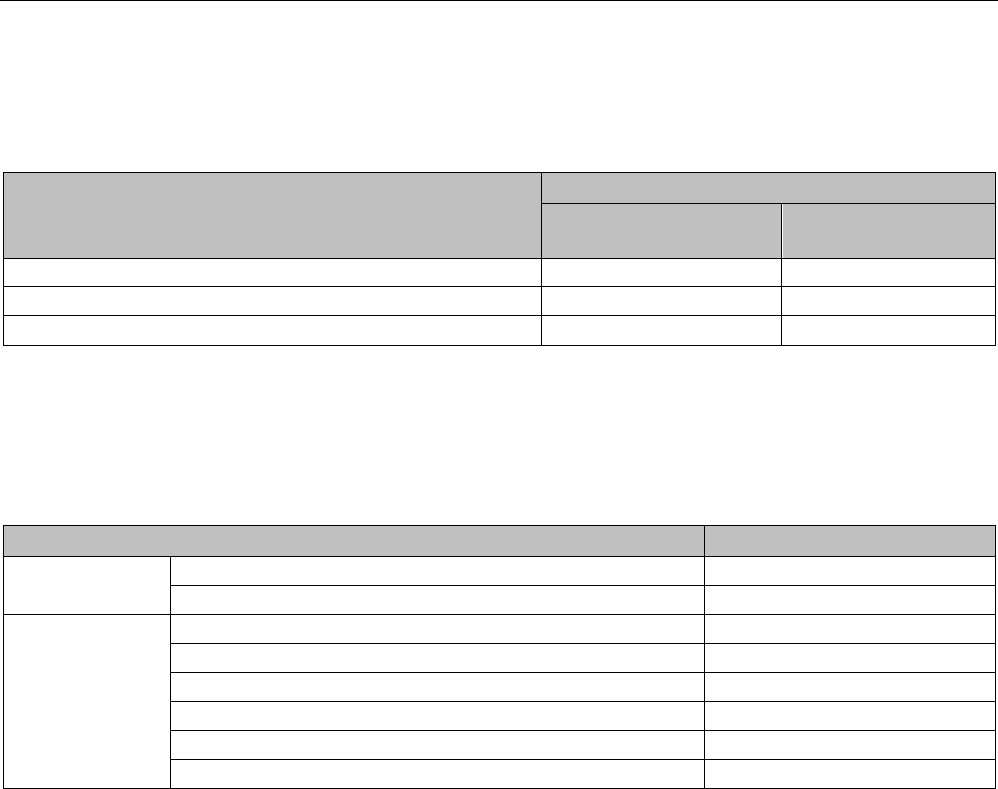
Ordering Information
C.9 Programming software
S7-1200 Programmable controller
System Manual, V4.2, 09/2016, A5E02486680-AK 1569
Table C- 20 Fail-Safe signal modules - Terminal block spare kit
If you have Fail-Safe signal module (article number)
Use this Terminal block spare kit (4/pk)
Terminal block
article number
Terminal block
description
SM 1226 F-DI (6ES7226-6BA32-0XB0)
6ES7292-1AL30-0XA0
11 pin, tin-plated
SM 1226 F-DQ (6ES7226-6DA32-0XB0)
6ES7292-1AL30-0XA0
11 pin, tin-plated
SM 1226 F-Relay (6ES7226-6RA32-0XB0) 6ES7292-1AL40-0XA0 11 pin, tin-plated, keyed
C.9
Programming software
Table C- 21 Programming software
SIMATIC software
Article number
Programming
software
STEP 7 Basic V14
6ES7822-0AA04-0YA5
STEP 7 Professional V14
6ES7822-1AA04-0YA5
Visualization soft-
ware
WinCC Basic V12 SP1
6AV2100-0AA01-0AA0
WinCC Comfort V12 SP1 6AV2101-0AA01-0AA5
WinCC Advanced V12 SP1
6AV2102-0AA01-0AA5
WinCC Professional 512 PowerTags V12 SP1
6AV2103-0DA01-0AA5
WinCC Professional 4096 PowerTags V12 SP1
6AV2103-0HA01-0AA5
WinCC Professional max. PowerTags V12 SP1
6AV2103-0XA01-0AA5

Ordering Information
C.9 Programming software
S7-1200 Programmable controller
1570 System Manual, V4.2, 09/2016, A5E02486680-AK

S7-1200 Programmable controller
System Manual, V4.2, 09/2016, A5E02486680-AK 1571
Device exchange and spare parts compatibility
D
D.1
Exchanging a V3.0 CPU for a V4.2 CPU
To upgrade a V3.0 CPU to a V4.2 CPU, you must replace the CPU hardware. You cannot
upgrade a V3.0 CPU to a V4.2 CPU by firmware update.
Then in your STEP 7 project, you can replace your V3.0 CPU with a V4.2 CPU (Page 170)
and use your existing STEP 7 project that you designed for the V3.0 CPU.
When you replace a V3.0 CPU with a V4.2 CPU, you might also want to check for and apply
firmware updates (Page 148) to your connected signal and communication modules.
Note
No device exchange possible in STEP 7 from V4.2 to V3.0
You can exchange a V3.0 CPU for a V4.2 CPU, but you cannot exchange a V4.2 CPU for a
V3.0 CPU after you download the configuration. If you want to view or otherwise use your
existing STEP
7 V3.0 project, make an archive of your STEP 7 V3.0 project prior to the
device exchange.
Note that if you have not downloaded the exchanged device configuration, you can undo it.
After downloading, however, you cannot undo the exchange from V3.0 to V4.2.

Device exchange and spare parts compatibility
D.1 Exchanging a V3.0 CPU for a V4.2 CPU
S7-1200 Programmable controller
1572 System Manual, V4.2, 09/2016, A5E02486680-AK
You need to be aware of some configuration and operational changes between the two CPU
versions:
Upgrading STEP 7 projects
You cannot upgrade STEP 7 V11 or V12 projects directly to STEP 7 V14. You must first
upgrade these projects to STEP 7 V13 SP1 and then use that project as a basis for upgrade
to STEP 7 V14.
WARNING
Risks with copying and pasting program logic from older versions of STEP 7
Copying program logic from an older version of STEP 7 such as STEP 7 V12 into STEP 7
V14 can cause unpredictable behavior in program execution or failures to compile. Different
versions of STEP 7 implement program elements differently. The compiler does not always
detect the differences if you made the changes by pasting from an older version into
STEP 7 V14. Executing unpredictable program logic could result in death or severe
personal injury if you do not correct the program.
When using program logic from a release of STEP 7 earlier than STEP 7 V14, always
upgrade the entire project to STEP 7 14. Then you can copy, cut, paste, and edit program
logic as necessary. In STEP 7 V14, you can open a project from STEP 7 V13 SP1 or later.
STEP 7 then performs the necessary compatibility conversions and upgrades the program
correctly. Such upgrade conversions and corrections are necessary for proper program
compilation and execution. If your project is older than STEP 7 V13 SP1, you must upgrade
the project incrementally to STEP 7 V14.
Organization blocks
With V4.2, you can configure OB execution to be interruptible or non-interruptible
(Page 105). For projects from former V3.0 CPUs, STEP 7 sets all OBs by default to be non-
interruptible.
STEP 7 sets all OB priorities (Page 105) to the values they were in the V3.0 CPU STEP 7
project.
You can subsequently change the interruptability or priority settings if you choose.
The Diagnostic error interrupt OB (Page 97) start information references the submodule as a
whole if no diagnostics event is pending.

Device exchange and spare parts compatibility
D.1 Exchanging a V3.0 CPU for a V4.2 CPU
S7-1200 Programmable controller
System Manual, V4.2, 09/2016, A5E02486680-AK 1573
CPU password protection
STEP 7 sets the password protection level (Page 210) for the V4.2 CPU to be the equivalent
password protection level that was set for the V3.0 CPU, and assigns the V3.0 password to
the "Full access (no protection)" password for the V4.2 CPU:
V3.0 protection level
V4.2 access level
No protection
Full access (no protection)
Write protection Read access
Write/read protection
HMI access
Note that the V4.2 access level "No access (complete protection)" did not exist for V3.0.
Web server
If you use user-defined Web pages in your V3.0 project, store them in your project
installation folder under the subfolder "UserFiles\Webserver" prior to upgrading your project.
If you store your user-defined pages at this location, saving the STEP 7 project will also save
the user-defined Web pages.
If you exchange a V3.0 CPU for a V4.2 CPU, your Web server project setting (Page 1003)
for activating the Web server and HTTPS setting will be the same as it was in V3.0. You can
then configure users, privileges, passwords (Page 1005), and languages (Page 1003) as
needed to use the Web server. If you do not configure users with additional privileges, then
you are limited as to what you can view from the standard Web pages (Page 1011). The
S7-1200 V4.2 CPU does not support the former pre-configured "admin" user and password.
The S7-1200 V3.0 Web server Data log page provided a "Download and Clear" operation.
The V4.2 Web server File browser page (Page 1037), from which you access data logs, no
longer provides this feature. Instead, the Web server provides the ability to download,
rename, and delete data log files.
Transfer card incompatibility
You cannot use a V3.0 transfer card (Page 139) to transfer a V3.0 program to a V4.2 CPU.
You must open the V3.0 project in STEP 7, change the device to a V4.2 CPU (Page 170),
and download the STEP 7 project to your V4.2 CPU. After you have changed your project to
a V4.2 project, you can then make a V4.2 transfer card for subsequent program transfers.
GET/PUT communication
By default, S7-1200 V3.0 CPUs enabled GET/PUT communication. When you replace your
V3.0 CPU with a V4.2 CPU (Page 170), you see a message in the compatibility information
section stating that GET/PUT is enabled.

Device exchange and spare parts compatibility
D.1 Exchanging a V3.0 CPU for a V4.2 CPU
S7-1200 Programmable controller
1574 System Manual, V4.2, 09/2016, A5E02486680-AK
Motion control support
S7-1200 V4.2 CPUs do not support the V1.0 and V2.0 motion libraries. If you perform a
device exchange for a STEP 7 project with V1.0 or V2.0 motion libraries, the device
exchange substitutes compatible V3.0 motion control instructions (Page 731) for the V1.0 or
V2.0 motion library instructions at compile.
If you perform a device exchange from a V3.0 CPU to a V4.2 CPU for a STEP 7 project that
contains two different motion control instruction versions (V3.0 and V5.0), the device
exchange substitutes compatible V5.0 motion control instructions (Page 731) at compile.
During a device exchange from a V3.0 CPU to a V4.2 CPU, the motion control Technological
Object (TO) version does not automatically change from V3.0 to V5.0. If you want to upgrade
to the later versions, you must go to the Instruction tree and select the required S7-1200
Motion Control version for your project as shown in the table below:
CPU version
Allowed motion control versions
V4.2 (motion control V5.0)
V5.0 or V4.0 or V3.0
V4.1 (motion control V5.0) V5.0 or V4.0 or V3.0
V4.0 (motion control V4.0)
V4.0 or V3.0
V3.0 (motion control V3.0)
V3.0
The TO structure is different between motion control versions V3.0 and V5.0. All associated
blocks change as well. Block interfaces, watch tables, and traces update to the new motion
control V5.0 structure. You can find the differences between the V3.0 CPU and V4.2 CPU
motion control axis parameters in the following two tables:
V3.0 CPU
(Motion control V3.0)
V4.2 CPU
(Motion control V5.0)
Config.General.LengthUnit
Units.LengthUnit
Config.Mechanics.PulsesPerDriveRevolution Actor.DriveParameter.PulsesPerDriveRevolution
Config.Mechanics.LeadScrew
Mechanics.LeadScrew
Config.Mechanics.InverseDirection
Actor.InverseDirection
Config.DynamicLimits.MinVelocity
DynamicLimits.MinVelocity
Config.DynamicLimits.MaxVelocity
DynamicLimits.MaxVelocity
Config.DynamicDefaults.Acceleration
DynamicDefaults.Acceleration
Config.DynamicDefaults.Deceleration
DynamicDefaults.Deceleration
Config.DynamicDefaults.EmergencyDeceleration
DynamicDefaults.EmergencyDeceleration
Config.DynamicDefaults.Jerk
DynamicDefaults.Jerk
Config.PositionLimits_SW.Active
PositionLimitsSW.Active
Config.PositionLimits_SW.MinPosition
PositionLimitsSW.MinPosition
Config.PositionLimits_SW.MaxPosition
PositionLimitsSW.MaxPosition
Config.PositionLimits_HW.Active
PositionLimitsHW.Active
Config.PositionLimits_HW.MinSwitchedLevel
PositionLimitsHW.MinSwitchLevel
Config.PositionLimits_HW.MaxSwitchedLevel
PositionLimitsHW.MaxSwitchLevel
Config.Homing.AutoReversal
Homing.AutoReversal
Config.Homing.Direction
Homing.ApproachDirection
Config.Homing.SideActiveHoming Sensor[1].ActiveHoming.SideInput

Device exchange and spare parts compatibility
D.1 Exchanging a V3.0 CPU for a V4.2 CPU
S7-1200 Programmable controller
System Manual, V4.2, 09/2016, A5E02486680-AK 1575
V3.0 CPU
(Motion control V3.0)
V4.2 CPU
(Motion control V5.0)
Config.Homing.SidePassiveHoming
Sensor[1].PassiveHoming.SideInput
Config.Homing.Offset Sensor[1].ActiveHoming.HomePositionOffset
Config.Homing.FastVelocity
Homing.ApproachVelocity
Config.Homing.SlowVelocity
Homing.ReferencingVelocity
MotionStatus.Position
Position
MotionStatus.Velocity
Velocity
MotionStatus.Distance
StatusPositioning.Distance
MotionStatus.TargetPosition
StatusPositioning.TargetPosition
StatusBits.SpeedCommand
StatusBits.VelocityCommand
StatusBits.Homing
StatusBits.HomingCommand
The only "commandtable" parameter that is renamed is the array with the commands:
V3.0
V4.2
Config.Command[]
Command[]
Note: The array "Command[]" is a UDT of the type "TO_CmdTab_Config_Command" in V3.0 and
"TO_Struct_Command" in V4.2.
Instruction changes
The following instructions have changes in parameters or behavior:
● RDREC and WRREC (Page 385)
● CONV (Page 290)
HMI panel communication
If you had one or more HMI panels (Page 32) connected to your S7-1200 V3.0 CPU, the
communication to the S7-1200 V4.2 CPU depends on the type of communication you use
and the firmware version of the HMI panel. Recompile and download your project to the CPU
and the HMI and/or update your HMI firmware.
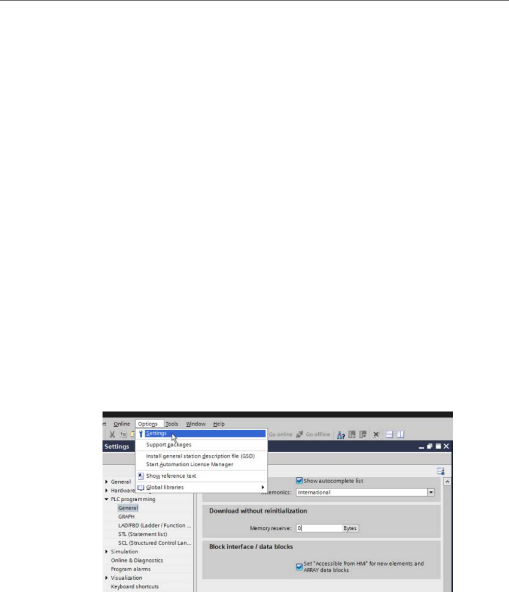
Device exchange and spare parts compatibility
D.1 Exchanging a V3.0 CPU for a V4.2 CPU
S7-1200 Programmable controller
1576 System Manual, V4.2, 09/2016, A5E02486680-AK
Requirement to recompile program blocks
After exchanging a V3.0 CPU for a V4.2 CPU, you must recompile all program blocks before
you can download them to the V4.2 CPU. Additionally, if any of the blocks have know-how
protection (Page 213) or copy protection bound to a PLC serial number (Page 214), you
must remove the protection before you compile and download the blocks. (You do not,
however, need to deactivate copy protection bound to a memory card.) After a successful
compile, you can reconfigure the know-how protection and/or PLC serial number copy
protection. Note that if your project includes any blocks with know-how protection that an
OEM (Original Equipment Manufacturer) provided, you must contact the OEM to provide
V4.2 versions of those blocks.
In general, Siemens recommends that you recompile the hardware configuration and
software in STEP 7 and download to all devices in your project after the device exchange.
Correct any errors that compiling the project finds, and recompile until you have no errors.
Then, you can download the project to the V4.2 CPU.
S7-1200 V3.0 projects might not fit in S7-1200 V4.2 CPUs
S7-1200 V4.0 and later added a reserve area of 100 bytes to each DB to support download
without reinitialization.
You can remove the 100-byte reserve area from DBs prior to attempting to download a V3.0
project to a V4.2 CPU.
To remove the 100-byte reserve area, follow these steps before you perform the device
exchange:
1. From the TIA Portal main menu, select the Options > Settings menu command.
2. From the navigation tree, open the PLC programming > General node.
3. In the "Download without reinitialization" area, set the memory reserve to 0 bytes.
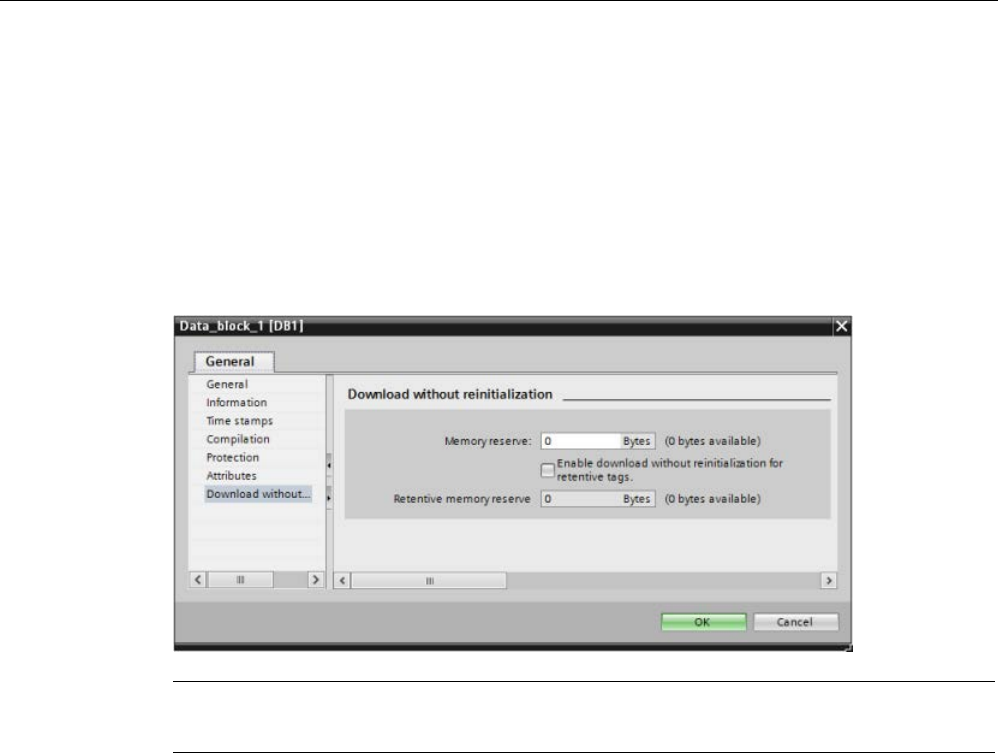
Device exchange and spare parts compatibility
D.2 S7-1200 V3.0 and earlier terminal block spare kits
S7-1200 Programmable controller
System Manual, V4.2, 09/2016, A5E02486680-AK 1577
If you have already performed the device exchange, you must remove the 100-byte reserve
from each block individually:
1. From the project tree, right-click a data block from the Program blocks folder and select
Properties from the shortcut menu.
2. In the Data block properties dialog, select the "Download without reinitialization" node.
3. Set the memory reserve to 0 bytes.
4. Repeat for each data block in your project.
Note
Projects for V4.0 and V4.1 CPUs can run without modification in V4.2 CPUs.

Device exchange and spare parts compatibility
D.2 S7-1200 V3.0 and earlier terminal block spare kits
S7-1200 Programmable controller
1578 System Manual, V4.2, 09/2016, A5E02486680-AK
D.2
S7-1200 V3.0 and earlier terminal block spare kits
Table D- 1 S7-1200 CPU V3.0 and earlier - Terminal Block spare kits
If you have
S7-1200 CPU V3.0 and earlier (article number)
Use this terminal block spare kit (4/pk)
Terminal block article number
Terminal block description
CPU 1211C DC/DC/DC (6ES7211-1AE31-0XB0)
6ES7292-1BC30-0XA0
6ES7292-1AH30-0XA0
6ES7292-1AP30-0XA0
3 pin, gold-plated
8 pin, gold-plated
14 pin, tin-plated
CPU 1211C AC/DC/Relay (6ES7211-1BE31-0XB0)
CPU 1211C DC/DC/Relay (6ES7211-1HE31-0XB0)
CPU 1212C DC/DC/DC (6ES7212-1AE31-0XB0)
CPU 1212C AC/DC/Relay (6ES7212-1BE31-0XB0)
CPU 1212C DC/DC/Relay (6ES7212-1HE31-0XB0)
CPU 1214C DC/DC/DC (6ES7214-1AG31-0XB0)
6ES7292-1BC30-0XA0
6ES7292-1AM30-0XA0
6ES7292-1AV30-0XA0
3 pin, gold-plated
12 pin, tin-plated
20 pin, tin-plated
CPU 1214C AC/DC/Relay (6ES7214-1BG31-0XB0)
CPU 1214C DC/DC/Relay (6ES7214-1HG31-0XB0)
CPU 1215C DC/DC/DC (6ES7215-1AG31-0XB0)
6ES7292-1BF30-0XB0
6ES7292-1AM30-0XA0
6ES7292-1AV30-0XA0
6 pin, gold-plated
12 pin, tin-plated
20 pin, tin-plated
CPU 1215C AC/DC/Relay (6ES7215-1BG31-0XB0)
CPU 1215C DC/DC/Relay (6ES7215-1HG31-0XB0)

Device exchange and spare parts compatibility
D.2 S7-1200 V3.0 and earlier terminal block spare kits
S7-1200 Programmable controller
System Manual, V4.2, 09/2016, A5E02486680-AK 1579
Table D- 2 S7-1200 SMs V3.0 and earlier - Terminal Block spare kits
If you have
S7-1200 SM V3.0 and earlier (article number)
Use this terminal block spare kit (4/pk)
Terminal block article number
Terminal block description
SM 1221 DI 8 x DC (6ES7221-1BF30-0XB0)
6ES7292-1AG30-0XA0
7 pin, tin-plated
SM 1222 DQ 8 x DC (6ES7222-1BF30-0XB0)
SM 1222 DQ 8 x Relay (6ES7222-1HF30-0XB0)
SM 1231 AI 4 x 13 bit (6ES7231-4HD30-0XB0)
6ES7292-1BG30-0XA0
7 pin, gold-plated
SM 1232 AQ 2 x 14 bit (6ES7232-4HB30-0XB0)
SM 1231 AI 4 x TC (6ES7231-5QD30-0XB0)
SM 1231 AI 4 x 16 bit (6ES7231-5ND30-0XB0)
SM 1221 DI 16 x DC (6ES7221-1BH30-0XB0)
6ES7292-1AG30-0XA0
7 pin, tin-plated
SM 1222 DQ 16 x DC (6ES7222-1BH30-0XB0)
SM 1222 DQ 16 x Relay (6ES7222-1HH30-0XB0)
SM 1223 DI 8 x DC/DQ 8x DC (6ES7223-1BH30-0XB0)
SM 1223 8 x DC/8 x Relay (6ES7223-1PH30-0XB0)
SM 1223 8 x AC/8 x Relay (6ES7223-1QH30-0XB0)
SM 1234 AI 4 / AQ 2 (6ES7234-4HE30-0XB0)
6ES7292-1BG30-0XA0
7 pin, gold-plated
SM 1231 AI 8 x 13 bit (6ES7231-4HF30-0XB0)
SM 1232 AQ 4 x 14 bit (6ES7232-4HD30-0XB0)
SM 1231 AI 4 x RTD (6ES7231-5PD30-0XB0)
SM 1231 AI 8 x TC (6ES7231-5QF30-0XB0)
SM 1222 DQ 8 x Relay (Changeover)
(6ES7222-1XF30-0XB0)
6ES7292-1AL30-0XA0
11 pin, tin-plated
SM 1223 DI 16 x DC/DQ 16 x DC (6ES7223-1BL30-
0XB0)
SM 1223 16 x DC/16 x Relay (6ES7223-1PL30-0XB0)
SM 1231 AI 8 x RTD (6ES7231-5PF30-0XB0) 6ES7292-1BL30-0XA0 11 pin, gold-plated

Device exchange and spare parts compatibility
D.2 S7-1200 V3.0 and earlier terminal block spare kits
S7-1200 Programmable controller
1580 System Manual, V4.2, 09/2016, A5E02486680-AK
S7-1200 Programmable controller
System Manual, V4.2, 09/2016, A5E02486680-AK 1581
Index
&
& box (FBD AND logic operation), 228
/
/= box (FBD negate assignment), 229
=
= box (FBD assignment), 229
>
>=1 box (FBD OR logic operation), 228
A
ABS (form absolute value), 260
AC
grounding, 77
isolation guidelines, 77
wiring guidelines, 76, 78
Access protection, CPU, 210
Accessible devices
formatting a memory card, 1320
Accessible devices, updating firmware, 1319
Accessing
data logs from PC, 1038
user-defined Web pages, 1061
ACOS (form arccosine value), 263
ACT_TINT (activate time of day interrupt), 430
Active/passive communication
configuring the partners, 807, 993
connection IDs, 828
parameters, 832
Active/Passive connection, 807
Ad hoc mode, TCP and ISO on TCP, 828
ADD (add), 257
Add new device
CPU, 154
detect existing hardware, 157
unspecific CPU, 157
Adding inputs or outputs to LAD or FBD
instructions, 44
Addresses
Read station address with GetStationInfo, 460
Reading out the MAC address with
GetStationInfo, 460
Addressing
Boolean or bit values, 119
individual inputs (I) or outputs (Q), 119
memory areas, 118
process image, 118
Air flow, 55
Aliases in user-defined Web pages, 1049
Analog drive, 672
Analog I/O
configuration, 177
conversion to engineering units, 43, 123, 298
input representation (current), 1471, 1517
input representation (voltage), 1471, 1516
output representation (current), 1472, 1518
output representation (voltage), 1472, 1517
status indicators, 1311
step response times
(CPU), 1378, 1390, 1403, 1417, 1435
step response times (SB), 1516
step response times (SM), 1470
Analog signal boards
SB 1231, 1511
SB 1231 RTD, 1523
SB 1231 Thermocouple, 1519
SB 1232, 1514
Analog signal modules
SM 1231, 1459
SM 1231 RTD, 1479
SM 1231 Thermocouple, 1473
SM 1232, 1464
SM 1234, 1466
AND (logic operation), 326
Approvals
ATEX, 1361
Australia and New Zealand - RCM Mark, 1361
CE, 1359
cULus, 1360
FM, 1360
Korea Certification, 1361
Maritime, 1362
Arrays, accessing members, 289
Article numbers
communication interfaces (CM, CB and
CP), 1561, 1561, 1562, 1562, 1562

Index
S7-1200 Programmable controller
1582 System Manual, V4.2, 09/2016, A5E02486680-AK
connector blocks, 1564
connectors and terminal connections, 1562
CPU 1214FC, CPU 1215FC, 1563
CPUs, 1559
CSM 1277 Ethernet switch, 1563
end retainer, 1564
expansion cables, 1564
FS signal modules, 1563
HMI basic panels, 1564
memory cards, 1563
PM 1207 power supply, 1563
programming software, 1569
signal boards, battery boards, 1561
signal modules, 1560
simulators, 1564
STEP 7, 1569
visualization software, 1569
WinCC, 1569
AS-i
add AS-i master CM1243-2 module, 976
add AS-i slave, 976
address, 979
AS-i master CM 1243-2, 975
distributed I/O instructions, 384
network connection, 977
RDREC (read data record), 385
slave configuration with STEP 7, 982
slave configuration without STEP 7, 981
system assignment, 981
system assignment of slave addresses, 981
transferring analog values, 982
transferring digital values, 982
WRREC (write data record), 385
ASIN (form arcsinevalue), 263
Assigning enum types, user-defined Web pages, 1051
AT tag overlay, 135
ATEX approval, 1361
ATH (convert ASCII string to hexadecimal
number), 359
ATTACH (attach an OB to an interrupt event), 420
ATTR_DB (Read data block attribute), 541
Australia and New Zealand - RCM Mark
approval, 1361
Autonegotiation, 817
AWP commands, 1042
combining definitions, 1054
defining an enum type, 1050
generating fragments, 1052
importing fragments, 1053
reading special variables, 1047
referencing an enum type, 1051
using an alias, 1049
writing special variables, 1048
writing variables, 1045
AWP_Enum_Def, 1050
AWP_Import_Fragment, 1053
AWP_In_Variable, 1045, 1048
AWP_Out_Variable, 1047
AWP_Start_Fragment, 1052
B
Backing up a CPU, 1354
Basic panels (HMI), 32
Battery board (BB)
BB 1297, 1528
inserting battery, 1529
Baud rate, 1094
BB 1297, 1528
Binding to a CPU, memory card, or password, 214
Bit logic
AND, OR, and XOR instructions, 228
normally open and closed coils, 229
normally open and closed contacts, 227
NOT instruction (invert RLO), 229
positive and negative edge instructions, 233
set and reset instructions, 230
Blocks
block calls, 83
calling an FB or FC with SCL, 202
consistency check, 225
copying blocks from an online CPU, 221
counters (quantity and memory
requirements), 29, 1372, 1384, 1397, 1411, 1427
data block (DB), 83
download, 216
events, 105
function (FC), 83, 190
function block (FB), 83, 190
initial value of an FB, 190
instance data block (DB), 190
interrupts, 29, 105, 1372, 1384, 1397, 1411, 1427
linear and structured programs, 185
monitoring, 29, 1372, 1384, 1397, 1411, 1427
nesting
depth, 29, 83, 1372, 1384, 1397, 1411, 1427
number of code
blocks, 29, 1372, 1384, 1397, 1411, 1427
number of
OBs, 29, 105, 1372, 1384, 1397, 1411, 1427
organization blocks
(OBs), 29, 83, 92, 105, 1372, 1384, 1397, 1411, 14
27
password protection, 213

Index
S7-1200 Programmable controller
System Manual, V4.2, 09/2016, A5E02486680-AK 1583
single instance or multi-instance DB, 190
size of the user
program, 29, 83, 1372, 1384, 1397, 1411, 1427
start-up OBs, 105
timers (quantity and memory
requirements), 29, 1372, 1384, 1397, 1411, 1427
types of, 83
types of code blocks, 83
valid FC, FB, and DB numbers, 83
Boolean or bit values, 119
Break, 1097, 1098
Browsers supported for Web server, 1002
BUFFER parameter, SEND_P2P, 1125
Bus connector, 31
C
Cable
expansion, 1550
Network communication, 1088
CALCULATE (calculate), 255
scaling analogs, 43
using for complex equations, 42
Calendar, 335
Call structure, 225
Call structure local memory allocation, 121
Calling code blocks within the user program, 187
CAN_DINT (cancel time-delay interrupt), 432
CAN_TINT (cancel time of day interrupt), 429
CANopen modules
021620-B, 021630-B, 1552
Capturing values from an online DB, 1327
Cascading PID controllers, 616
CB 1241
termination and bias, 1089
CB 1241 RS485, 1542
CE approval, 1359
CEIL (generate next higher integer from floating-point
number), 295
Certificate Import Wizard, 1085
Change device, 170
Changing settings for STEP 7, 45
Char (character data type), 130
Character position, message length, 1104
Character sequence
message end, 1102
message start, 1098
Chars_TO_Strg (convert array of CHAR to character
string), 357
Checking the connection, 880
Clearance, airflow and cooling, 55
Clock
RD_LOC_T (read local time), 339
RD_SYS_T (read time-of-day), 339
time-of-day clock, 115
WR_LOC_T (set local time), 339
WR_SYS_T (set time-of-day), 339
Clock memory byte, 113
Closed loop motion control
analog drive, 672
configuring the axis, 672
PROFIdrive, 672
Code block
binding to a CPU, memory card, or password, 214
block calls, 83
calling code blocks within the user program, 187
copy protection, 214
counters (quantity and memory
requirements), 29, 1372, 1384, 1397, 1411, 1427
DB (data block), 83, 192
FB (function block), 83, 190
FC (function), 83, 190
initial value of an FB, 190
instance data block (DB), 190
interrupts, 29, 1372, 1384, 1397, 1411, 1427
know-how protection, 213
linear and structured programs, 185
monitoring, 29, 1372, 1384, 1397, 1411, 1427
nesting depth, 29, 1372, 1384, 1397, 1411, 1427
number of code
blocks, 29, 1372, 1384, 1397, 1411, 1427
number of OBs, 29, 1372, 1384, 1397, 1411, 1427
organization blocks
(OBs), 29, 188, 1372, 1384, 1397, 1411, 1427
size of the user
program, 29, 1372, 1384, 1397, 1411, 1427
timers (quantity and memory
requirements), 29, 1372, 1384, 1397, 1411, 1427
types of code blocks, 83
valid FC, FB, and DB numbers, 83
Coils, (See Bit logic)
Cold junction compensation, thermocouple, 1476, 1521
Columns and headers in task cards, 45
Commissioning
PID_Compact and PID_3Step instructions, 640
PID_Temp instruction, 642
Communication
active/passive, 807, 832, 993
AS-i address, 979
communication load, 110
configuration, 807, 832, 993
connection IDs, 828
cycle time, 110

Index
S7-1200 Programmable controller
1584 System Manual, V4.2, 09/2016, A5E02486680-AK
flow control, 1095
hardware connection, 914
IP address, 814
loss, pull or plug of modules, 100
MAC address, 814
network, 913
network connection, 806
number of connections
(PROFINET/PROFIBUS), 802
polling architecture, 1135
PROFIBUS address, 973
PROFINET and PROFIBUS, 799
protocols, 827
send and receive parameters, 1096
TCON_Param, 832
time synchronization property (PROFINET), 823
Communication board (CB)
add modules, 158
CB 1241 RS485, 1542
comparison chart, 30
configuration of parameters, 177
device configuration, 153
installation, 63
LED indicators, 1087, 1309
overview, 31
programming, 1134
removal, 63
RS485, 1087
Communication interfaces
add modules, 158
CB 1241 RS485, 1542
CM 1241 RS232, 1543
comparison chart of the modules, 30
configuration, 1093
device configuration, 153
LED indicators, 1309
programming, 1134
RS232 and RS485, 1087
Communication interfaces, 3964(R), 1105
Communication module (CM)
add AS-i master CM1243-2 module, 976
add CM 1243-5 (DP master) module, 971
add modules, 158
CM 1241 RS232, 1543
CM 1241 RS422/RS485, 1544
comparison chart, 30
configuration for PtP example program, 1137
configuration of parameters, 177
data reception, 1126, 1229
device configuration, 153
installation, 67
LED indicators, 1087, 1309
overview, 31
power requirements, 1555
programming, 1134
removal, 67
RS232 and RS485, 1087
Communication processor (CP)
add modules, 158
comparison chart, 30
configuration of parameters, 177
device configuration, 153
overview, 31
Communication standard Web page, 1027
Compact switch module, CSM 1277, 1551
Compare values, 250
Comparing and synchronizing online/offline
CPUs, 1323
Comparison chart
CPU models, 28
HMI devices, 32
modules, 30
Compatibility, 51
Computer requirements, 38
CONCAT (combine character strings), 363
Configuration
add modules, 158
AS-i, 978
AS-i port, 977
communication interfaces, 1093
communication load, 110
CPU parameters, 170
cycle time, 109
discover, 157
download, 216
Ethernet port, 814
HSC (high-speed counter), 572
IP address, 814
MAC address, 814
modules, 177
network connection, 806
PID_Compact and PID_3Step instructions, 622
PID_Temp instructions, 625
PLC to PLC communication, 918
ports, 1093
PROFIBUS, 972
PROFIBUS address, 973
PROFINET port, 814
receive message, 1097
RS422, operating modes, 1140
RS485 operating modes, 1142
startup parameters, 142
time synchronization property (PROFINET), 823

Index
S7-1200 Programmable controller
System Manual, V4.2, 09/2016, A5E02486680-AK 1585
Configuration control (option handling), 159
control data record, 163
example, 166
Configuration of transmitted message, 1096
Configuration, 3964(R)
communication interfaces, 1105
ports, 1105
priority and protocol parameters, 1106
Configuration, user-defined Web pages
setting up multiple languages, 1078
STEP 7 configuration, 1057
Connection contacts
Maximum current carrying capacity, 1540
Connections
configuration, 832
connection IDs, 828
Ethernet protocols, 991
number of connections
(PROFINET/PROFIBUS), 802
partners, 807, 993
S7 connection, 991
types of communication, 799
types, multi-node connections, 991
Web server, 1082
Connector, installation and removal, 68
Consistency check, 225
Constraints
user-defined Web pages, 1062
Web server, 1082
Contact information, 3, 170
Contacts, (See Bit logic)
Contamination level/overvoltage category, 1365
CONTINUE, SCL, 323
Control DB for user-defined Web pages
global commands, 1078
parameter to WWW instruction, 1059
request commands and states, 1078
CONV (convert value), 290
Conversion (SCL instructions), 291
Cookie restrictions, standard Web pages, 1083
Cookie, siemens_automation_language, 1075
Cooling, 55
Copy protection
binding to a CPU, memory card, or password, 214
Copying blocks from an online CPU, 221
Copying, cutting, and pasting in STEP 7, 51
COS (form cosine value), 263
Counters
CTD (count down), 244
CTRL_HSC (control high-speed counter), 584
CTRL_HSC_EXT (Control high-speed counter
(extended)), 556
CTU (count up), 244
CTUD (count up and down), 244
HSC configuration, 572
operation (standard counters), 245
quantity, 29, 1372, 1384, 1397, 1411, 1427
size, 29, 1372, 1384, 1397, 1411, 1427
Counting modes
high-speed counter, 573
CountOfElements (Get number of ARRAY
elements), 287
CP module
access to Web server, 1010
Web server Start page, 1018
CPU
access protection, 210
add modules, 158
add new device, 154, 154
AS-i, 977
AS-i address, 979
AS-i port, 977
assigning an IP address to an online CPU, 813
backing up, 1354
capturing and resetting DB values, 1327
communication, 804
communication boards (CB), 31
communication load, 110
comparing and synchronizing blocks, 1323
comparison chart, 28
copying blocks from an online CPU, 221
cycle time configuration, 110
device configuration, 153, 153
displaying the MAC and IP addresses, 820
download, 216
download to device, 820
empty transfer card, 151
enable outputs in STOP mode, 1331
Ethernet port, 814
expansion cable, 69
force, 1332, 1333
going online, 1313
grounding, 77
HSC configuration, 572
inductive loads, 80
installation, 59, 61
IP address, 814
isolation guidelines, 77
know-how protection, 213
lamp loads, 79
LED indicators, 1309
lost password, 151
MAC address, 814, 814, 820
monitoring online, 1326

Index
S7-1200 Programmable controller
1586 System Manual, V4.2, 09/2016, A5E02486680-AK
network connection, 806
number of communication connections, 802
online, 1316
operating modes, 87
operating panel (online CPU), 1321
operator panel, 47
oveload behavior, 107
overview, 27
password protection, 210
power budget, 56
power requirements, 1555
processing the OBs, 188
PROFIBUS address, 973
PROFINET IO, 922
PROFINET port, 814
program execution, 83
pulse outputs, 492
recover from a lost password, 151
reset to factory settings, 1317
restoring a backup, 1357
RTM (runtime meters), 344
RUN/STOP buttons, 47
RUN/STOP modes, 1321
Security levels, 210, 210
signal boards (SB), 31
startup parameters, 142
startup processing, 90
terminal block connector, 68
thermal zone, 55, 58
time synchronization property, 823
types of communication, 799
unspecific CPU, 157
version compatibility, 51
watch table, 1329
wiring guidelines, 76, 78
CPU configuration
communication to HMI, 916
cycle time monitoring, 109
module properties, 177
multiple CPUs, 918
operational parameters, 170
pulse channels, 494
CPU memory card
inserting, 139
program card, 146
transfer card, 143
uses, 138
CPU properties, user-defined Web pages
setting up multiple languages, 1078
STEP 7 configuration, 1057
CPUs
CPU 1211C AC/DC/Relay, 1370
CPU 1211C DC/DC/DC, 1370
CPU 1211C DC/DC/Relay, 1370
CPU 1212C AC/DC/Relay, 1382
CPU 1212C DC/DC/DC, 1382
CPU 1212C DC/DC/Relay, 1382
CPU 1214C AC/DC/Relay, 1395
CPU 1214C DC/DC/DC, 1395
CPU 1214C DC/DC/Relay, 1395
CPU 1215C AC/DC/Relay, 1409
CPU 1215C DC/DC/DC, 1409
CPU 1215C DC/DC/Relay, 1409
CPU 1217C DC/DC/DC, 1425
step response times, 1378, 1390, 1403, 1417, 1435
CREATE_DB (Create data block), 534
Creating a network connection
between PLCs, 806
Creating user-defined Web page DBs, 1057
Creating user-defined Web pages, 1041
Cross-reference to show usage, 224
CSM 1277 compact switch module, 1551
CTD (count down), 244
CTRL_HSC (control high-speed counter), 584
CTRL_HSC_EXT (Control high-speed counter
(extended)), 556
CTS (Hardware flow control, PtP), 1095
CTU (count up), 244
CTUD (count up and down), 244
cULus approval, 1360
Customer support, 3
Cycle time
configuration, 110
monitoring, 1321
overview, 109
Cyclic interrupt OB, 94
D
D_ACT_DP, 398
Data block
capturing and resetting values, 1327
CONF_DATA, 904
creating with CREATE_DB, 534
Deleting with DELETE_DB, 542
global data block, 117, 192
importing fragments in user-defined Web
pages, 1053
instance data block, 117
optimized access, 193
organization blocks (OBs), 188
overview, 83, 192
READ_DBL (read from data block in load
memory), 538

Index
S7-1200 Programmable controller
System Manual, V4.2, 09/2016, A5E02486680-AK 1587
Reading attributes with ATTR_DB, 541
single FB with multiple instance DBs, 191
standard access, 193
structure, 83
WRIT_DBL (write to data block in load
memory), 538
Data block
synchronizing online and offline start values, 219
Data exchange between IO systems, 931
Data handling block (DHB), 192
Data log
data log overview, 509
data record structure, 509
DataLogClose (close data log), 519
DataLogCreate (create data log), 510
DataLogNewFile (data log in new file), 522
DataLogOpen (open data log), 514
DataLogWrite (write data log), 516
Deleting with DataLogDelete, 520
Empty with DataLogClear, 518
example program, 529
size limit and calculating size, 526
viewing Data logs, 525
Data Logs standard Web page, 1038
Data transmission, initiating, 1122, 1226
Data types, 125
arrays, 132
Bool, Byte, Word, and DWord, 126
characters and strings, 130
PLC data type editor, 133
Real, LReal (floating-point real), 127
Struc, 133
Time, Date, TOD (time of day), DTL (date and time
long), 128
USInt, SInt, UInt, Int, UDInt, Dint (integer), 127
Variant (pointer), 134
DataLogClear, 518
DataLogDelete, 520
Date
Date data type, 128
DTL (date and time long data type), 129
SET_TIMEZONE (set time zone), 343
T_ADD (add times), 336
T_COMBINE (combine times), 337
T_CONV (convert times and extract), 335
T_DIFF (time difference), 337
T_SUB (subtract times), 336
Daylight saving time TimeTransformationRule, 342
DB (data block), (Data block)
DB_ANY_TO_VARIANT (Convert DB_ANY to
VARIANT, 300
DC
grounding, 77
inductive loads, 80
isolation guidelines, 77
outputs, 1367
wiring guidelines, 76, 78
Debugging in RUN mode, 1345
Debugging n RUN mode, 1335
DEC (decrement), 259
DECO (decode), 327
Defining enum types, user-defined Web pages, 1050
Degree of protection, 1366
DELETE (delete characters in a character string), 365
DELETE_DB (Delete data block), 542
DEMUX (demultiplex), 330
Deserialize, 269
Designing a PLC system, 183, 185
DETACH (detach an OB from an interrupt even)t, 420
Device
PROFINET IO, 922
PROFINET IO device names, 923
shared, 939
Device configuration, 153, 914
add modules, 158
add new device, 154
AS-i, 978
AS-i port, 978
changing a device type, 170
configuring the CPU, 170
configuring the modules, 177
discover, 157
download, 216
Ethernet port, 814
network connection, 806
PROFIBUS, 972
PROFINET port, 814
time synchronization property (PROFINET), 823
unplugged modules, 50
Device exchange
procedure, 170
V3.0 CPU for a V4.2 CPU, 1571
DeviceStates (read module status of an I/O
system), 468
DeviceStates, example, 469
Diagnostic error interrupt OB, 97
Diagnostic standard Web page, 1022
Diagnostics
buffer, 114
cycle time, 1321
DeviceStates (read module status of an I/O
system), 468
diagnostics buffer, 1322

Index
S7-1200 Programmable controller
1588 System Manual, V4.2, 09/2016, A5E02486680-AK
GET_DIAG (read diagnostic information), 480
Get_IM_Data (read the identification and
maintenance data), 451
LED (read LED status), 450
LED indicators, 1309
memory usage, 1321
ModuleStates (read module status information of a
module), 474
status indicator, 113
watch table, 1329
Diagnostics standard Web page, 1019
Diagnostics, reducing security events, 114
Differences
in Modbus RTU instructions, 1191
in Modbus TCP instructions, 1169
in point-to-point instructions, 1091
in TCON, TDISCON, TSEND, and TRCV
instructions, 856
in TSEND_C and TRCV_C instructions, 836
in USS instructions, 1147
Digital I/O
configuration, 177
pulse catch, 177
status indicators, 1310
Digital input filter time, 172
Digital signal boards
SB 1221, 1500
SB 1222, 1502
SB 1223, 1505, 1508
Digital signal modules
SM 1221, 1442
SM 1222, 1444, 1446
SM 1223, 1451, 1456
DIN rail, 59
Directories, languages for user-defined Web
pages, 1074
DIS_AIRT (disable execution of higher priority
interrupts and asynchronous error events), 435
Discover to upload an online CPU, 157
Displaying the MAC and IP addresses, 820
DIV (divide), 257
Documentation, 4
Download in RUN mode
compile errors, 1340
considerations, 1345
download without reinitialization, 1341
downloading selected blocks, 1338
extended block interface, 1341
failed download, 1344
global memory reserve settings, 1342
initiating from STEP 7, 1337
memory reserve and retentive memory
reserve, 1341
overview, 1335
prerequisites, 1336
restrictions, 1343
Downloading
displaying the MAC and IP addresses, 820
firmware update, 148
project, 216
Siemens security certificate to PC, 1017, 1085
user program, 216
user-defined Web page DBs, 1060
DP standard slaves
Reading a portion of the inputs with
GETIO_PART, 390
Reading all inputs with GETIO, 388
Writing a part of the outputs with SETIO_PART, 392
Writing all outputs with SETIO, 389
DPNRM_DG, 416
DPRD_DAT (read consistent data of a DP standard
slave), 408
DPWR_DAT (write consistent data of a DP standard
slave), 408
Drag and drop between editors, 46
Drives, setting up MM4 drive, 1164
Dynamic binding, 214
E
Edge instructions, positive and negative, 233
Edit in RUN mode, (Download in RUN mode)
Electromagnetic compatibility, 1364
Electromagnetic compatibility (EMC), 1363
E-mail, sending with TMAIL_C, 885
EN and ENO (power flow), 208
EN_AIRT (enable execution of higher priority interrupts
and asynchronous error events), 435
ENCO (encode), 327
End conditions, 1101
End message character, 1102
ENDIS_PW (enable disable passwords), 307
Enum types in user-defined Web pages, 1050, 1051
Environmental
operating conditions, 1365
transport and storage conditions, 1365
EQ_ElemType (Compare data type of an ARRAY
element for UNEQUAL with the data type of a tag), 253
EQ_Type (Compare data type for EQUAL with the data
type of a tag), 253
Errors
common errors for extended instructions, 553

Index
S7-1200 Programmable controller
System Manual, V4.2, 09/2016, A5E02486680-AK 1589
diagnostic errors, 97
time errors, 96
Ethernet
ad hoc mode, 828
connection IDs, 828
CSM 1277 compact switch module, 1551
DPNRM_DG (read diagnostic data from a DP
slave), 416
DPRD_DAT (read consistent data of a DP standard
slave), 408
DPWR_DAT (write consistent data of a DP standard
slave), 408
GET (read data from a remote CPU), 986
IP address, 814
legacy TCON, TDISCON, TSEND, and TRCV
instructions, 868
legacy TRCV_C (receive data via Ethernet
(TCP)), 849
legacy TSEND_C (send data via Ethernet
(TCP)), 849
MAC address, 814
network connection, 806
number of communication connections, 802
overview, 825
PRVREC (make data record available), 413
PUT (write data to a remote CPU), 986
RALRM (receive interrupt), 394
RCVREC (receive data record), 411
RDREC (read data record), 385
T_CONFIG (configure interface), 901
TCON, 857
TDISCON, 857
TRCV, 857
TRCV_C, 837
TSEND, 857
TSEND_C, 837
TURCV (receive data via Ethernet (UDP)), 895
TUSEND (send data via Ethernet (UDP)), 895
types of communication, 799
WRREC (write data record), 385
Ethernet protocols, 825
multi-node connections, 991
Event execution and queueing, 105
Example
adding a SINAMICS S120 drive, 685
configuring edge detection on a position limit or
input homing switch, 717
selecting a passive motion reference point switch
level, 727
selecting an active motion reference point switch
level, 728
Examples, communication
AS-i slave addressing, 979
configuring a PROFIBUS S7 connection, 998
configuring a PROFINET S7 connection, 996
CPU communication over TSEND_C or TRCV_C
connections, 831
CPU communication with a common send and
receive connection, 830
CPU communication with separate send and
receive connections, 829
I-device as IO device and IO controller, 930
PROFINET communication protocols, 825
shared device, 939
shared I-device, 945
T_CONFIG, changing IP parameters, 908
T_CONFIG, changing IP parameters and
PROFINET IO device names, 910
T_CONFIG, changing IP parameters of the NTP
servers, 911
telecontrol, 1296
Examples, instructions
ATH (ASCII to hexadecimal), 359
CALCULATE, 42
CONTINUE, SCL, 323
CTRL_PWM, 496
DECO (Decode), 328
Deserialize, 270
DeviceStates, PROFIBUS and PROFINET, 469
EXIT, SCL, 324
GET_DIAG and modes, 485
GOTO (SCL), 325
HTA (Hexadecimal to ASCII), 360
LIMIT (set limit value), 262
ModuleStates, PROFIBUS and PROFINET, 476
PEEK and POKE variations, 206, 281
RETURN, SCL, 325
ROR (Rotate right), SCL, 333
RUNTIME (Measure program runtime), 315
S_CONV (convert character string), 354
Serialize, 273
SET_CINT cyclic interrupt execution and time
parameter, 424
SHL (Shift left), SCL, 332
STRG_VAL (convert string to numerical value), 355
SWAP (swap bytes), 276
timer coils, 238
TM_MAIL, 1306
VAL_STRG (convert numerical value to string), 356

Index
S7-1200 Programmable controller
1590 System Manual, V4.2, 09/2016, A5E02486680-AK
Examples, legacy Modbus
Legacy Modbus RTU, holding register
addressing, 1282
Legacy Modbus RTU, MB_HOLD_REG parameter
examples, 1280
Examples, legacy Modbus CP
MB_HOLD_REG parameter, 1259
Examples, legacy Modbus RTU
master program, 1285
slave program, 1287
Examples, legacy Modbus TCP
holding register addressing, 1261
MB_CLIENT coordinating multiple Modbus TCP
requests, 1268
MB_CLIENT multiple requests with different
Modbus TCP connections, 1266
MB_CLIENT output image write request, 1267
MB_CLIENT: multiple requests with common
Modbus TCP connection,
MB_SERVER multiple Modbus TCP
connections, 1264
Examples, Modbus
MB_CLIENT multiple requests with common
Modbus TCP connection, 1187
MB_CLIENT multiple requests with different
Modbus TCP connections, 1188
MB_SERVER multiple Modbus TCP
connections, 1185
Modbus RTU master program, 1213
Modbus RTU slave program, 1216
Modbus TCP MB_CLIENT coordinating multiple
requests, 1190
Modbus TCP MB_CLIENT ourput image write
request, 1189
Modbus TCP, holding register addressing, 1184
Modbus TCP, MB_CLIENT connection
parameters, 1176
Modbus TCP, MB_HOLD_REG parameter
examples, 1182
Modbus TCP, MB_SERVER connection
parameters, 1180
Examples, motion control
axis behavior, 761
Axis control with the TM Pulse module, 702
configuring a technology object motion command
table, 708
CPU 1211C, CPU 1212C, CPU 1214C, and CPU
1215C pulse output speed configurations, 657
CPU 1217C pulse output speed configuration, 656
jerk limit, 730
jog behavior, 768
velocity, 764
velocity characteristics of MC homing, 729
Examples, PID
PID_3Step, configuration settings, 623
PID_Compact, configuration settings, 622
PID_Temp, configuration settings, 625
Examples, PtP communication
configuration, 1137
end message condition, 1103
Legacy PtP communication, RCV_CFG, 1224
message length within message, 1104
Receive_Config, 1117
running the terminal emulator example, 1145
start message condition, 1099
STEP 7 programming, 1143
terminal emulator, 1136, 1145
Examples, runtime string instructions
GetBlockName, 383
GetInstanceName, 378
GetInstancePath, 380
GetSymbolName, 372
GetSymbolPath, 375
Examples, USS communication
legacy USS communication errors reporting, 1247
USS communication error reporting, 1161
Examples, various
accessing array elements, 289
analog value processing, 123, 298
AT tag overlay, 136
configuration control (option handling), 166
CPU 1217C Differential input and application, 1440
CPU 1217C differential output and
appplication, 1441
data log program, 529
downloading selected blocks in RUN mode, 1338
dragging and dropping between editors, 46
ENO evaluation in SCL, 209
nested CASE statements, SCL, 319
power budget calculation, 1556
recipe, 499, 506
S7-1200 IO-Link Master connection, 1491
slice of tagged data type, 135
trace and logic analyzer function, 1348
Examples, Web server
access from mobile device, 1009
aliases, 1044, 1050
combining AWP declarations, 1054
enum types, 1050, 1051, 1066
fragment DBs, 1054
reading special variables, 1047
reading variables, 1044, 1065
special characters in AWP commands, 1055

Index
S7-1200 Programmable controller
System Manual, V4.2, 09/2016, A5E02486680-AK 1591
STEP 7 program to check fragments, 1081
user-defined Web page, 1063, 1068
user-defined Web page to switch languages, 1075
writing special variables, 1049, 1068
writing variables, 1046, 1067
Exchanging a V3.0 CPU for a V4.2 CPU, 1571
Execution speeds of
instructions, 1371, 1383, 1396, 1410, 1426
EXIT, SCL, 324
EXP (form exponential value), 263
Expandable instructions, 44
Expanding the capabilities of the S7-1200, 30
Expansion cable, 1550
installation, 69
removal, 69
EXPT (exponentiate), 263
Extended block interface
download in RUN mode, 1341
F
F_TRIG (set tag on negative signal edge), 234
Factory settings reset, 1317
FAQs, 4
Favorites toolbar, 41
FB (function block)
overview, 83
FBD (function block diagram), 200
FC (function), 83, 190
Features, new, 33
FieldRead (read field), 288
FieldWrite (write field), 288
FILL_BLK (fill block), 275
Filter time, 172
FIND (find characters in a character string), 369
Firmware update
from STEP 7, 1318
from Web server, 1026
with a memory card, 148
First scan indicator, 113
Fixed length, 1102
Flexible machines (configuration control), 159
FLOOR (generate next lower integer from floating-point
number), 295
Flow control, 1094
configuration, 1094
managing, 1095
FM approval, 1360
Folders, languages for user-defined Web pages, 1074
FOR, SCL, 320
Force, 1332
I memory, 1332, 1333
inputs and outputs, 1333
memory card, 138
peripheral inputs, 1332, 1333
scan cycle, 1333
watch table, 1329
Force table
addressing peripheral inputs, 1332
force, 1332
force operation, 1333
Formatting a memory card, 1320
FRAC (return fraction), 263
Fragment DBs (user-defined Web pages)
creating from AWP command, 1052
generating, 1057
importing with AWP command, 1053
Freeport protocol, 1090
Frequency, clock bits, 113
Function (FC)
calling code blocks within the user program, 187
know-how protection, 213
linear and structured programs, 185
overview, 83, 190
valid FC numbers, 83
Function block (FB)
calling code blocks within the user program, 187
initial value, 190
instance data block, 190
know-how protection, 213
linear and structured programs, 185
output parameters, 190
overview, 83, 190
single FB with multiple instance DBs, 191
valid FB numbers, 83
Functionality, I-device, 926
G
Gen_UsrMsg (Generate user diagnostic alarms), 436
Generating user-defined Web page DBs, 1057
GEO2LOG (Determine the hardware identifier based
upon slot information), 544
GEOADDR, 551
GET (read data from a remote CPU), 986
configuring the connection, 808
GET_DIAG (read diagnostic information), 480
GET_ERROR (get error locally), 311
GET_ERROR_ID (get error ID locally), 312
Get_Features (get advanced features), 1131
Get_IM_Data (read the identification and maintenance
data), 451
GetBlockName (Read out name of the block), 381

Index
S7-1200 Programmable controller
1592 System Manual, V4.2, 09/2016, A5E02486680-AK
GetInstanceName (Read out name of block
instance), 376
GetInstancePath (Query composite global name of the
block instance), 379
GETIO, 388
GETIO_PART, 390
GetStationInfo, 460
GetSymbolName (Read out a tag on the input
parameter), 370
GetSymbolPath (Query composite global name of the
input parameter assignment), 373
Global data block, 117, 192
Global library
legacy USS protocol overview, 1234
USS protocol overview, 1146
GOTO, SCL, 325
GSD file, 935
Guidelines
CPU installation, 61
grounding, 77
inductive loads, 80
installation, 53
installation procedures, 59
isolation, 77
lamp loads, 79
wiring guidelines, 76, 78
H
Hardware configuration, 153
add modules, 158
add new device, 154
AS-i, 978
AS-i port, 978
configuring the CPU, 170
configuring the modules, 177
discover, 157
download, 216
Ethernet port, 814
network connection, 806
PROFIBUS, 972
PROFINET port, 814
Hardware flow control, 1095
Hardware interrupt OB, 95
High-speed counter, 556, 584
cannot be forced, 1333
configuration, 572
counting modes, 573
operating phase, 574
HMI devices
configuring PROFINET communication, 916
network connection, 806
overview, 32
Hotline, 3
HSC (high-speed counter
operating phase, 574
HSC (high-speed counter)
configuration, 572
counting modes, 573
HTA (convert hexadecimal number to ASCII
string), 359
HTML pages
listing, user-defined Web page example, 1068
user-defined, 1040
HTML pages, user-defined
accessing S7-1200 data, 1042
developing, 1041
language locations, 1078
page locations, 1057
refreshing, 1041
HTTP connections, Web server, 1082
I
I memory
force, 1332
force operation, 1333, 1333
force table, 1332
monitor, 1326
monitor LAD, 1327
peripheral input addresses (force table), 1332
watch table, 1326
I/O
addressing, 122
analog input representation (current), 1471, 1517
analog input representation (voltage), 1471, 1516
analog output representation (current), 1472, 1518
analog output representation (voltage), 1472, 1517
analog status indicators, 1311
digital status indicators, 1310
force operation, 1333
inductive loads, 80
monitoring status in LAD, 1327
monitoring with a watch table, 1329
step response times
(CPU), 1378, 1390, 1403, 1417, 1435
step response times (SB), 1516
step response times (SM), 1470
Identification of CPU, viewing with Web server, 1019
I-device (intelligent IO device)
configuring, 933
configuring with GSD file, 935
functionality, 926

Index
S7-1200 Programmable controller
System Manual, V4.2, 09/2016, A5E02486680-AK 1593
lower-level PN IO system, 928
Properties, 927
shared, 945
Idle line, 1097, 1098
IF-THEN, SCL, 317
Importing Siemens security certificate, 1085
IN_Range (value within range), 251
INC (increment), 259
Incompatible CPU version error, 1310
Indexing arrays with variables, 289
Inductive loads, 80
Industrial environments
approvals, 1362
Information resources, 4
Input filter time, 172
Input simulators, 1547
Inputs
pulse catch bits, 174
Inputs and outputs
monitoring, 1326
INSERT (insert characters in a character string), 366
Inserting a device
unspecific CPU, 157
Inserting instructions
drag and drop, 41
drag and drop between editors, 46
favorites, 41
Inserting the memory card into CPU, 139
Installation
air flow, 55
clearance, 55
communication board (CB), 63
communication module (CM), 67
cooling, 55
CPU, 61
expansion cable, 69
grounding, 77
guidelines, 53
inductive loads, 80
isolation guidelines, 77
lamp loads, 79
mounting dimensions, 58
overview, 53, 59
power budget, 56
requirements, 38
signal board (SB), 63
signal module (SM), 65
signal modules (SM), 31
terminal block connector, 68
thermal zone, 55, 58
TS Adapter and TS module, 71
TS Adapter on a DIN rail, 74
TS Adapter on a wall, 75
TS Adapter SIM card, 73
wiring guidelines, 76, 78
Instance data block, 117
Instruction execution
speeds, 1371, 1383, 1396, 1410, 1426
Instructions
& box (FBD AND logic operation), 228
-( )- (normally open coil), 229
-(/)- (normally closed coil), 229
-(N)- (set operand on negative signal edge), 233
-(P)- (set operand on positive signal edge), 233
-(RESET_BF) (reset bit field), 231
-(SET_BF) (set bit field), 231
/= box (FBD negate assignment), 229
-|/|- (normally closed contact), 227
-||- (normally open contact), 227
-|N|- (scan operand for negative signal edge), 233
-|P|- (scan operand for positive signal edge), 233
= box (FBD assignment), 229
>=1 box (FBD OR logic operation), 228
ABS (form absolute value), 260
ACOS (form arccosine value), 263
ACT_TINT (activate time of day interrupt), 430
ADD (add), 257
adding inputs or outputs to LAD or FBD
instructions, 44
AND (logic operation), 326
AS-i distributed I/O, 384
ASIN (form arcsine value), 263
ATAN (form arctangent value), 263
ATH (convert ASCII string to hexadecimal
number), 359
ATTACH (attach an OB to an interrupt event), 420
ATTR_DB (Read data block attribute), 541
CALCULATE, 42
CALCULATE (calculate), 255
calendar, 335
CAN_DINT (cancel time-delay interrupt), 432
CAN_TINT (cancel time of day interrupt), 429
CASE (SCL), 318
CEIL (generate next higher integer from floating-
point number), 295
Chars_TO_Strg (convert array of CHAR to
character string), 357
clock, 339
columns and
headers, 45, 836, 848, 856, 867, 1149, 1170, 1193,
1235, 1249, 1269
common parameters, 912
compare values, 250
CONCAT (combine character strings), 363

Index
S7-1200 Programmable controller
1594 System Manual, V4.2, 09/2016, A5E02486680-AK
CONTINUE (SCL), 323
CONV (convert value), 290
COS (form cosine value), 263
CountOfElements (Get number of ARRAY
elements), 287
CREATE_DB (Create data block), 534
CTD (count down), 244
CTRL_HSC (control high-speed counter), 584
CTRL_HSC_EXT (Control high-speed counter
(extended)), 556
CTRL_PTO (pulse train output), 488
CTRL_PWM (pulse width modulation), 487
CTU (count up), 244
CTUD (count up and down), 244
DataLogClose (close data log), 519
DataLogCreate (create data log), 510
DataLogNewFile (data log in new file), 522
DataLogOpen (open data log), 514
DataLogWrite (write data log), 516
date, 335
DB_ANY_TO_VARIANT (Convert DB_ANY to
VARIANT, 300
DEC (decrement), 259
DECO (decode), 327
DELETE (delete characters in a character
string), 365
DELETE_DB (Delete data block), 542
DEMUX (demultiplex), 330
Deserialize, 269
DETACH (detach an OB from an interrupt
event), 420
DeviceStates (read module status of an I/O
system), 468
DIS_AIRT (disable execution of higher priority
interrupts and asynchronous error events), 435
DIV (divide), 257
DPNRM_DG (read diagnostic data from a DP
slave), 416
DPRD_DAT (read consistent data of a DP standard
slave), 408
DPWR_DAT (write consistent data of a DP standard
slave), 408
drag and drop, 41
drag and drop between editors, 46
EN_AIRT (enable execution of higher priority
interrupts and asynchronous error events)), 435
ENCO (encode), 327
ENDIS_PW (enable disable passwords), 307
EQ_ElemType (Compare data type of an ARRAY
element for EQUAL with the data type of a tag), 253
EQ_Type (Compare data type for EQUAL with the
data type of a tag), 253
EXIT (SCL), 324
EXP (form exponential value), 263
expandable instructions, 44
EXPT (exponentiate), 263
F_TRIG (set tag on negative signal edge), 234
favorites, 41
FieldRead (read field), 288
FieldWrite (write field), 288
FILL_BLK (fill block), 275
FIND (find characters in a character string), 369
FLOOR (generate next lower integer from floating-
point number), 295
FOR (SCL), 320
force operation, 1333
FRAC (return fraction), 263
Gen_UsrMsg (Generate user diagnostic
alarms), 436
GEO2LOG (Determine the hardware identifier
based upon slot information), 544
GET (read data from a remote CPU), 986
GET_DIAG (read diagnostic information), 480
GET_ERROR (get error locally), 311
GET_ERROR_ID (get error ID locally), 312
Get_Features (get advanced features), 1131
Get_IM_Data (read the identification and
maintenance data), 451
GetBlockName (Read out name of the block), 381
GetInstanceName (Read out name of block
instance), 376
GetSInstancePath (Query composite global name
of the block instance), 379
GetSymbolName (Read out a tag on the input
parameter), 370
GetSymbolPath (Query composite global name of
the input parameter assignment), 373
GOTO (SCL), 325
HTA (convert hexadecimal number to ASCII
string), 359
IF-THEN (SCL), 317
IN_Range (value within range), 251
INC (increment), 259
INSERT (insert characters in a character
string), 366
inserting, 41
INV (create ones complement), 327
IO2MOD (Determine the hardware identifier from an
I/O address, 548
IS_ARRAY (Check for ARRAY), 254
IS_NULL (Query for EQUALS zero pointer), 254
JMP (jump if RLO = 1), 302
JMP_LIST (define jump list), 303
JMPN (jump if RLO = 0), 302

Index
S7-1200 Programmable controller
System Manual, V4.2, 09/2016, A5E02486680-AK 1595
Label (jump label), 302
LED (read LED status), 450
LEFT (read the left characters of a character
string), 364
legacy TCON, TDISCON, TSEND, and TRCV
instructions, 868
legacy TRCV_C (receive data via Ethernet
(TCP)), 849
legacy TSEND_C (send data via Ethernet
(TCP)), 849
legacy USS status codes, 1246
LEN (determine the length of a character
string), 362
LIMIT (set limit value), 262
LN (form natural logarithm), 263
LOG2GEO (Determine the slot from the hardware
identifier), 546
LOWER_BOUND (read out ARRAY low limit), 277
MAX (get maximum), 261
MAX_LEN (maximum length of a character
string), 361
MB_CLIENT, 1171
MC_ChangeDynamic (change dynamic settings for
the axis), 754
MC_CommandTable, 751
MC_Halt (pause axis), 740
MC_Home (home axis), 737
MC_MoveAbsolute (position axis absolutely), 742
MC_MoveJog (move axis in jog mode), 749
MC_MoveRelative (position axis relatively), 745
MC_MoveVelocity (move axis at predefined
velocity), 747
MC_Power (release/block axis), 733
MC_ReadParam (read parameters of a technology
object), 758
MC_Reset (confirm error), 736
MC_WriteParam (write to parameters of a
technology object), 756
MID (read the middle characters of a character
string), 364
MIN (get minimum), 261
MOD (return remainder of division), 258
Modbus_Comm_Load (Configure SIPLUS I/O or
port on the PtP module for Modbus RTU), 1194
Modbus_Master (Communicate using SIPLUS I/O
or the PtP port as Modbus RTU master), 1198
Modbus_Slave (Communicate using SIPLUS I/O or
the PtP port as Modbus RTU slave), 1206
ModuleStates (read module status information of a
module), 474
monitor, 1327
monitoring status or value, 1326
motion control, 731
MOVE (move value), 265
MOVE_BLK (move block), 265
MUL (multiply), 257
MUX (multiplex), 329
N (scan operand for negative signal edge), 233
N_TRIG (scan RLO for negative signal edge), 234
N= box and N coil (set operand on negative signal
edge), 233
NE_ElemType (Compare data type for UNEQUAL
with the data type of a tag), 253
NE_Type (Compare data type for UNEQUAL with
the data type of a tag), 253
NEG (create twos complement), 259
NORM_X (normalize), 296
NOT (invert RLO), 229
NOT_NULL (Query for UNEQUALS zero
pointer), 254
NOT_OK (check invalidity), 252
OK (check validity), 252
OR (logic operation), 326
OUT_Range (value outside range), 251
P (scan operand for positive signal edge), 233
P_TRIG (scan RLO for positive signal edge), 234
P= box and P coil (set operand on positive signal
edge), 233
P3964_Config (Configuring the 3964(R)
protocol), 1120
PEEK and POKE variations, 206, 281
PID_Compact (universal PID controller with
integrated tuning), 592
PID_Temp (universal PID controller that allows
handling of temperature control), 610
Port_Config (port configuration), 1110
PROFIBUS distributed I/O, 384
PROFINET distributed I/O, 384
program control (SCL), 316
PRVREC (make data record available), 413
PUT (write data to a remote CPU), 986
QRY_CINT (query cyclic interrupt parameters), 426
QRY_DINT (query time-delay interrupt status), 432
QRY_TINT (query status of time of day
interrupt), 431
R (reset output), 230
R_TRIG (set tag on positive signal edge), 234
RALRM (receive interupt), 394
RCVREC (receive data record), 411
RD_ADDR (determine the IO addresses from the
hardware identifier), 550
RD_LOC_T (read local time), 339
RD_SYS_T (read time-of-day), 339
RDREC (read data record), 385

Index
S7-1200 Programmable controller
1596 System Manual, V4.2, 09/2016, A5E02486680-AK
RE_TRIGR, 109
RE_TRIGR (restart cycle monitoring time), 309
READ_BIG (Read data in big little endian
format), 283
READ_DBL (read from data block in load
memory), 538
READ_LITTLE (Read data in little endian
format), 283
Receive_Config (receive configuration), 1115
Receive_P2P (receive Point-to-Point), 1126
Receive_Reset (receiver reset), 1128
RecipeExport (recipe export), 502
RecipeImport (recipe import), 504
REPEAT (SCL), 322
REPLACE (replace characters in a character
string), 367
reset output, 230
RESET_BF (reset bit field), 231
RET (return), 306
RETURN (SCL), 325
RIGHT (read the right characters of a character
string), 364
ROL (rotate left) and ROR (rotate right), 333
ROUND (round numerical value), 294
RS (reset/set flip-flop), 231
RT (reset timer), 236
RTM (runtime meters), 344
RUNTIME (Measure program runtime), 314
S (set output), 230
S_CONV (convert character string), 347
S_MOV (move chracter string), 346
SCALE_X (scale), 296
scaling analog values, 43
SCL conversion instructions, 291
SEL (select), 329
Send_Config (send configuration), 1112
Send_P2P (send Point-to-Point data), 1122
Serialize, 272
set output, 230
SET_BF (set bit field), 231
SET_CINT (set cyclic interrupt parameters), 424
Set_Features (set advanced features), 1132
SET_TIMEZONE (set time zone), 343
SET_TINTL (set date and time of day interrupt), 428
SGN_GET (get RS232 signals), 1129
SHL (shift left) and SHR (shift right), 332
Signal_Set (set RS232 signals), 1130
SIN (form sine value), 263
SQR (form square), 263
SQRT (form square root), 263
SR (set/reset flip-flop), 231
SRT_DINT (start time-delay interrupt), 432
status, 1327
STP (exit program), 310
Strg_TO_Chars (convert character string to array of
CHAR), 357
STRG_VAL (convert character string to numerical
value), 347
SUB (subtract), 257
SWAP (swap bytes), 276
SWITCH (jump distributor), 304
T_ADD (add times), 336
T_COMBINE (combine times), 337
T_CONFIG (configure interface), 901
T_CONV (convert times and extract), 335
T_DIAG, 880
T_DIFF (time difference), 337
T_RESET, 878
T_SUB (subtract times), 336
TAN (form tangent value), 263
TCON, 857
TDISCON, 857
time, 335
timer, 236
TM_MAIL (send email), 1301
TOF (off-delay timer), 236
TON (on-delay timer), 236
TONR (on-delay retentive timer), 236
TP (pulse timer), 236
TRCV, 857
TRCV_C, 837, 921
TRUNC (truncate numerical value), 294
TSEND, 857
TSEND_C, 837, 920
TURCV (receive data via Ethernet (UDP)), 895
TUSEND (send data via Ethernet (UDP)), 895
UFILL_BLK (fill block uninterruptible), 275
UMOVE_BLK (move block uninterruptible), 265
UPPER_BOUND (read out ARRAY high limit), 279
USS status codes, 1160
USS_Drive_Control (Swap data with drive), 1154
USS_Port_Scan (Edit communication via USS
network), 1153
USS_Read_Param (readout parameters from the
drive), 1157
USS_Write_Param (change parameters in the
drive), 1158
VAL_STRG (convert numerical value to character
string), 347
VARIANT_TO_DB_ANY (Convert VARIANT to
DB_ANY), 299
VariantGet (Read VARIANT tag value), 285
VariantPut (Write VARIANT tag value), 286

Index
S7-1200 Programmable controller
System Manual, V4.2, 09/2016, A5E02486680-AK 1597
versions of
instructions, 45, 836, 848, 856, 867, 1149, 1170, 11
93, 1235, 1249, 1269
WHILE (SCL), 321
WR_LOC_T (set local time), 339
WR_SYS_T (set time-of-day), 339
WRIT_DBL (write to data block in load
memory), 538
WRITE_BIG (Write data in big endian format), 283
WRITE_LITTLE (Write data in little endian
format), 283
WRREC (write data record), 385
WWW (synchronizing user-defined Web
pages), 1059
x box (FBD XOR logic operation), 228
XOR (logic operation), 326
Instructions, legacy
MB_CLIENT (communicate via PROFINET as
Modbus TCP client), 1250
MB_COMM_LOAD (configure port on the PtP
module for Modbus RTU), 1270
MB_MASTER (communicate via the PtP port as
Modbus master), 1272
MB_SERVER (communicate via PROFINET as
Modbus TCP server), 1257
MB_SLAVE (communicate via the PtP port as
Modbus slave), 1278
PORT_CFG (configure communication parameters
dynamically), 1218
RCV_CFG (configure serial receive parameters
dynamically), 1221
RCV_PTP (enable receive messages), 1229
RCV_RST (delete receive buffer), 1231
SEND_CFG (configure serial transmission
parameters dynamically), 1220
SEND_PTP (transmit send buffer data), 1226
SGN_GET (Query RS232 signals), 1232
SGN_SET (set RS-232 signals), 1233
USS_DRV (Swap data with drive), 1240
USS_PORT (Edit communication via USS
network), 1239
USS_RPM (readout parameters from the
drive), 1243
USS_WPM (change parameters in the drive), 1244
Inter-character gap, 1102
Interrupts
ATTACH (attach an OB to an interrupt event), 420
CAN_DINT (cancel time-delay interrupt), 432
DETACH (detach an OB from an interrupt
event, 420
interrupt latency, 105
overview, 92
QRY_DINT (query time-delay interrupt status), 432
SRT_DINT (start time-delay interrupt), 432
Intro standard Web page, 1017
INV (create ones complement), 327
IO system, data exchange, 931
IO2MOD (Determine the hardware identifier from an
I/O address, 548
IO-Link
address space, 1493
changing parameters in runtime, 1494
configuring, 1493
data record, 1495
device profile, 1488
device storage, 1490
diagnostics, 1498
diagram, 1492
error messages, 1494, 1496, 1498
functions, 1489
LED display, 1496
parameters, 1493
pin assignment, 1491
replacing, 1489
reset to factory settings, 1490
IO-Link Master signal module, 1485
IP address, 815, 815
assigning, 810, 819
assigning online, 813
configuring, 814
configuring the online CPU, 1316
device configuration, 170
MAC address, 814
IP router, 814
IS_ARRAY (Check for ARRAY), 254
IS_NULL (Query for EQUALS ZERO pointer), 254
ISO on TCP
ad hoc mode, 828
ISO on TCP protocol, 825
Isolation guidelines, 77
ISO-on-TCP
connection configuration, 807
connection IDs, 828
parameters, 832
J
JavaScript, standard Web pages, 1083
Jerk limit, 730
JMP (jump if RLO = 1), 302
JMP_LIST (define jump list), 303
JMPN (jump if RLO = 0), 302

Index
S7-1200 Programmable controller
1598 System Manual, V4.2, 09/2016, A5E02486680-AK
K
Know-how protection
password protection, 213
Know-how protection, viewing with Web server, 1019
Korea Certification approval, 1361
L
Label (jump label), 302
LAD (ladder logic)
monitor, 1327
monitoring status or value, 1326
overview, 199
program editor, 1327
status, 1327, 1332
Lamp loads, 79
Languages, user-defined Web pages, 1074
Latency, 105
LED (read LED status), 450
LED indicators
communication interface, 1087, 1309
CPU status, 1309
LEFT (read the left characters of a character
string), 364
Legacy TCON, TDISCON, TSEND, and TRCV
instructions, 868
Legacy TRCV_C (receive data via Ethernet
(TCP)), 849
Legacy TSEND_C (send data via Ethernet (TCP)), 849
Legacy USS protocol library
overview, 1234
requirements for using, 1236
status codes, 1246
USS_DRV (Swap data with drive), 1240
USS_PORT (Edit communication via USS
network), 1239
USS_RPM (readout parameters from the
drive), 1243
USS_WPM (change parameters in the drive), 1244
LEN (determine the length of a character string), 362
LENGTH parameter, SEND_P2P, 1125
Length, PtP message, 1104
LIMIT (set limit value), 262
Linear programming, 185
LN (form natural logarithm), 263
Load memory, 28
CPU 1211C, 1370
CPU 1212C, 1382
CPU 1214C, 1395
CPU 1215C, 1409
CPU 1217C, 1425
memory card, 138
program card, 138
transfer card, 138
user-defined Web pages, 1062
Local memory
maximum per OB priority level, 121
usage by blocks, 121
Local time
RD_LOC_T (read local time), 339
WR_LOC_T (set local time), 339
Local/Partner connection, 807
LOG2GEO (Determine the slot from the hardware
identifier), 546
Logging in/out, standard Web pages, 1014
Logic analyzer, 1347
Loss of CPU communication to modules, 100
Lost password, 151
LOWER_BOUND (read out ARRAY low limit), 277
M
MAC address, 814, 820
Manual fragment DB control, 1078
Manuals, 4
Maritime approval, 1362
Master polling architecture, 1135
Math, 42, 255, 257
MAX (get maximum), 261
MAX_LEN (maximum length of a character string), 361
Maximum message length, 1102
Maximum Web server connections, 1082
MB_CLIENT, 1171
MB_CLIENT (communicate via PROFINET as Modbus
TCP client), legacy, 1250
MB_COMM_LOAD (configure port on the PtP module
for Modbus RTU), legacy, 1270
MB_MASTER (communicate via the PtP port as
Modbus master), legacy, 1272
MB_SERVER, 1179
MB_SERVER (communicate via PROFINET as
Modbus TCP server), legacy, 1257
MB_SLAVE (communicate via the PtP port as Modbus
slave), legacy, 1278
MC_ChangeDynamic (change dynamic settings for the
axis), 754
MC_CommandTable, 751
MC_Halt (pause axis), 740
MC_Home (home axis), 737
MC_MoveAbsolute (position axis absolutely), 742
MC_MoveJog (move axis in jog mode), 749
MC_MoveRelative (position axis relatively), 745

Index
S7-1200 Programmable controller
System Manual, V4.2, 09/2016, A5E02486680-AK 1599
MC_MoveVelocity (move axis at predefined
velocity), 747
MC_Power (release/block axis), 733
MC_ReadParam (read parameters of a technology
object), 758
MC_Reset (confirm error), 736
MC_WriteParam (write to parameters of a technology
object), 756
MC-PostServo OB, 105
MC-PreServo OB, 104
Measurements, trace jobs, 1348
Media redundancy
Configuring, 959
Functions in ring topology, 955
Memory
clock memory, 112
I (process image input), 119
L (local memory), 117
load memory, 110
M (bit memory), 121
monitoring memory usage, 1321
peripheral input addresses (force table), 1332
Q (process image output), 120
retentive memory, 110
system memory, 112
Temp memory, 121
work memory, 110
Memory areas
addressing Boolean or bit values, 119
immediate access, 118
process image, 118
Memory areas, viewing with Web server, 1019
Memory card, 1546
configure the startup parameters, 142
empty transfer card for a lost password, 151
firmware update, 148
incompatibility error, 1310
inserting into CPU, 139
lost password, 151
operation, 138
overview, 138
program card, 146
transfer card, 143
Memory locations, 117, 119
Message
end, 1101
length, 1102
start, 1098
Message configuration
instructions, 1134
receive, 1097
transmit, 1096
MicroMaster drive, connecting, 1162
MID (read the middle characters of a character
string), 364
MIN (get minimum), 261
Miscellaneous PtP parameter errors, 1109
Mobile device, acessing Web server, 1009
Mobile devices
Web page layout, 1012
MOD (return remainder of division), 258
Modbus
function codes, 1166
MB_CLIENT (communicate via PROFINET as
Modbus TCP client), legacy, 1250
MB_COMM_LOAD (configure port on the PtP
module for Modbus RTU), legacy, 1270
MB_MASTER (communicate via the PtP port as
Modbus master), legacy, 1272
MB_SERVER (communicate via PROFINET as
Modbus TCP server), legacy, 1257
MB_SLAVE (communicate via the PtP port as
Modbus slave), legacy, 1278
memory addresses, 1167
Modbus_Comm_Load (Configure SIPLUS I/O or
port on the PtP module for Modbus RTU), 1194
Modbus_Master (Communicate using SIPLUS I/O
or the PtP port as Modbus RTU master), 1198
Modbus_Slave (Communicate using SIPLUS I/O or
the PtP port as Modbus RTU slave), 1206
network station addresses, 1167
RTU communication, 1167
versions, 45, 1149, 1193, 1235, 1269
MODBUS
MB_CLIENT, 1171
MB_SERVER, 1179
Modbus RTU
master program, 1213
slave example, 1216
Modbus TCP
versions, 1170, 1249
Modbus_Comm_Load (Configure SIPLUS I/O or port
on the PtP module for Modbus RTU) instruction, 1194
Modbus_Master (Communicate using SIPLUS I/O or
the PtP port as Modbus RTU master), 1198
Modbus_Slave (Communicate using SIPLUS I/O or the
PtP port as Modbus RTU slave), 1206
Modifying
program editor status, 1327
variables from Web server, 1031
watch table, 1329
Module information standard Web page, 1023
Modules
communication boards (CB), 31

Index
S7-1200 Programmable controller
1600 System Manual, V4.2, 09/2016, A5E02486680-AK
communication module (CM), 31
communication processor (CP), 31
comparison chart, 30
configuring parameters, 177
signal board (SB), 31
signal modules (SM), 31
thermal zone, 55, 58
ModuleStates, 474
ModuleStates example, 476
Monitoring
capturing and resetting DB values, 1327
cycle time, 1321
force operation, 1333
force table, 1332
LAD status, 1327
LAD status and use of watch table, 1326
memory usage, 1321
watch table, 1329
Monitoring the program, 223
Monitoring variables from Web server, 1031
Motion
Telegram 4, 684
Motion control
hardware and software limit switches, 713
homing (sequence for active homing), 729
homing configuration parameters, 724
homing the axis, 723
List of ErrorIDs and ErrorInfo, 772
MC_ChangeDynamic (change dynamic settings for
the axis), 754
MC_CommandTable, 751
MC_Halt (pause axis), 740
MC_Home (home axis), 737
MC_MoveAbsolute (position axis absolutely), 742
MC_MoveJog (move axis in jog mode), 749
MC_MoveRelative (position axis relatively), 745
MC_MoveVelocity (move axis at predefined
velocity), 747
MC_Power (release/block axis), 733
MC_ReadParam (read parameters of a technology
object), 758
MC_Reset (confirm error), 736
MC_WriteParam (write to parameters of a
technology object), 756
overview, 653
phasing, 658
TM Pulse module, 702
Motion control instructions, 731
Mounting
airflow, 55
clearance, 55
communication board (CB), 63
communication module (CM), 67
cooling, 55
CPU, 61
dimensions, 58
expansion cable, 69
grounding, 77
guidelines, 53
inductive loads, 80
isolation, 77
lamp loads, 79
overview, 59
signal board (SB), 63
signal module (SM), 65
terminal block connector, 68
thermal zone, 55, 58
wiring guidelines, 76, 78
MOVE (move value), 265
MOVE_BLK (move block), 265
Movement sequence (MC_CommandTable), 751
MRES, operator panel, 47
MUL (multiply), 257
Multi-node connections
connection types, 991
Ethernet protocols, 991
Multiple AWP variable definitions, 1054
MUX (multiplex), 329
N
N (scan operand for negative signal edge), 233
N_TRIG (scan RLO for negative signal edge), 234
N= box and N coil (set operand on negative signal
edge), 233
NE_ElemType (Compare data type for UNEQUAL with
the data type of a tag), 253
NE_Type (Compare data type for UNEQUAL with the
data type of a tag), 253
NEG (create twos complement), 259
Nesting depth, 83
Network communication, 913
bias and terminate cable, 1088
Network connection
connecting devices, 806
multiple CPUs, 917, 919, 922, 972, 977
Network time protocol (NTP), 822
New features, 33
No restart, 87
NORM_X (normalize), 296
Normalizing analog values, 298
Normally open/closed coil, 229
Normally open/closed contact, 227
NOT (invert RLO), 229

Index
S7-1200 Programmable controller
System Manual, V4.2, 09/2016, A5E02486680-AK 1601
NOT_NULL (Query for UNEQUALS ZERO
pointer), 254
NOT_OK (check invalidity), 252
Numbers
binary, 126
integer, 127
real, 127
O
OB, (Organization block)
Off-delay (TOF), 236
OK (check validity), 252
On-delay delay (TON), 236
On-delay retentive (TONR), 236
Online
assigning an IP address, 813
capturing and resetting DB values, 1327
comparing and synchronizing, 1323
cycle time, 1321
diagnostics buffer, 1322
force, 1332
force operation, 1333
going online, 1313
IP address, 1316
memory usage, 1321
monitoring status or value, 1326
operating panel, 1321
operator panel, 47
RUN/STOP buttons, 47
status, 1327
time of day, 1316
tools, 1325
watch table, 1326, 1327, 1329
Online and diagnostic tools
downloading in RUN mode, 1335
Online device names
PROFINET IO, 1314
OPC, configuration, 1297
Open loop motion control
configuring the axis, 662
PTO, 662
Open User Communication
establishing a connection and reading data with
legacy TRCV_C, 849
establishing a connection and reading data with
TRCV_C, 837
establishing a connection and sending data with
legacy TSEND_C, 849
establishing a connection and sending data with
TSEND_C, 837
Open User Communication instructions return
values, 912
Operating mode, 47, 47
changing STOP/RUN, 1321
operating modes of the CPU, 87
Operating phase
HSC (high-speed counter), 574
Operator panel, 47
operating modes of the CPU, 87
Operator panels, 32
Optimized data blocks, 193
Option handling (configuration control), 159
OR (logic operation), 326
Organization block
call, 92
calling code blocks within the user program, 187
configuring operation, 189
creating, 189
cyclic interrupt, 94
function, 92
know-how protection, 213
linear and structured programming, 185
multiple cyclic, 189
overview, 83
priority classes, 92
processing, 188, 188
startup processing, 90
temp memory allocation, 121
Organization block (OB)
Reading start information with RD_SINFO, 440
OUT_Range (value outside range), 251
Output parameters, 190
configuring pulse channels, 494
pulse outputs, 492
Overvoltage category, 1365
P
P (scan operand for positive signal edge), 233
P_TRIG (scan RLO for positive signal edge), 234
P= box and P coil (set operand on positive signal
edge), 233
P3964_Config (Configuring the 3964(R) protocol), 1120
errors, 1121
Panels (HMI), 32
Parameter assignment, 190
Parameters configuration
LENGH and BUFFER for SEND_P2P, 1125
receive, 922
transmit, 921
Parity, 1094

Index
S7-1200 Programmable controller
1602 System Manual, V4.2, 09/2016, A5E02486680-AK
Passive/active communication
configuring the partners, 807, 993
connection IDs, 828
parameters, 832
Password protection
access to the CPU, 210
binding to a CPU, memory card, or password, 214
code block, 213
copy protection, 214
CPU, 210
empty transfer card, 151
ENDIS_PW (enable disable passwords), 307
lost password, 151
PEEK, PEEK_WORD, PEEK_BOOL, PEEK_DWORD,
PEEK_BLK, 206, 281
Performance times, 1371, 1383, 1396, 1410, 1426
Phase shift, cyclic interrupt OBs, 94
Phasing, 658
PID
cascading controllers, 616
overview, 589
PID_3STEP (PID controller with tuning for
valves), 600
PID_3Step algorithm, 589
PID_3Step ErrorBit parameters, 607
PID_Compact (universal PID controller with
integrated tuning), 592
PID_Compact algorithm, 589
PID_Compact ErrorBit parameters, 597
PID_Compact process value limits, 596
PID_Temp (universal PID controller that allows
handling of temperature control), 610
PID_Temp ErrorBit parameters, 619
PLC
add modules, 158
assigning an IP address to an online CPU, 813
communication load, 110
comparing and synchronizing, 1323
copying blocks from an online CPU, 221
cycle time, 109, 110
cycle time, 109, 110
device configuration, 153
download, 216
expansion cable, 69
force, 1332
force operation, 1333
HSC configuration, 572
installation, 59, 61
know-how protection, 213
memory card, 138
monitoring, 1326
operating modes, 87
overview of the CPU, 27
power budget, 56
RTM (runtime meters), 344
startup processing, 90
system design, 183
tags, 117
terminal block connector, 68
time synchronization property, 823
using blocks, 185
watch table, 1329
PM 1207 power module, 1551
PN slave
Activating and deactivating with D_ACT_DP, 398
Pointers
Variant data type, 134
Point-to-Point communication, 1090
Point-to-Point programming, 1134
POKE, POKE_BOOL, POKE_BLK, 206, 281
Polling architecture, 1135
Polution degree, 1365
Port configuration, 1093
errors, 1112, 1219
instructions, 1134
PtP example program, 1137
Port configuration, 3964(R), 1105
Port numbers
assigning to communication partners, 825
restricted, 913
PORT_CFG (configure communication parameters
dynamically), legacy, 1218
Port_Config (port configuration), 1110
Portal view, 39
Potentiometer module
specifications, 1549
Power budget, 56
example, 1556
form for calculations, 1558
overview, 1555
Power supply module
PM1207, 1551
Priority
priority class, 92
priority in processing, 105
Process image
force, 1332
force operation, 1333
monitor, 1327
monitoring status or value, 1326
Reading inputs with GETIO, 388
Reading the process image area with
GETIO_PART, 390
status, 1327, 1332

Index
S7-1200 Programmable controller
System Manual, V4.2, 09/2016, A5E02486680-AK 1603
Transferring the process image area with
SETIO_PART, 392
Writing outputs with SETIO, 389
PROFIBUS
add CM 1243-5 (DP master) module, 971
add DP slave, 971
address, 973
address, configuring, 973
CM 1242-5 (DP slave) module, 968
CM 1243-5 (DP master) module, 968
distributed I/O instructions, 384
DPNRM_DG (read diagnostic data from a DP
slave), 416
DPRD_DAT (read consistent data of a DP standard
slave), 408
DPWR_DAT (write consistent data of a DP standard
slave), 408
GET (read data from a remote CPU), 986
master, 968
network connection, 806, 972
number of communication connections, 802
PUT (write data to a remote CPU), 986
RALRM (receive interrupt), 394
RDREC (read data record), 385
S7 connection, 991
slave, 968
WRREC (write data record), 385
PROFIBUS and PROFINET
DeviceStates example, 469
ModuleStates example, 476
PROFIdrive, 672
PROFIenergy, 419
Profile OB, 103
PROFINET
ad hoc mode, 828
configuring communication between CPU and HMI
device, 916
configuring the IP address, 170
connection IDs, 828
CPU-to-CPU communication, 918
device naming and addressing, 824
distributed I/O instructions, 384
DPRD_DAT (read consistent data of a standard DP
slave), 408
DPWR_DAT (write consistent data of a DP standard
slave), 408
Ethernet address properties, 815
GET (read data from a remote CPU), 986
IP address, 814
IP address assignment, 824
MAC address, 814
network connection, 806, 917, 919, 922
number of communication connections, 802
overview, 825
PLC-to-PLC communication, 918
PRVREC (make data record available), 413
PUT (write data to a remote CPU), 986
RALRM (receive interrupt), 394
RCVREC (receive data record), 411
RDREC (read data record), 385
resetting a connection, 878
S7 connection, 991
system start-up time, 824
testing a network, 819
time synchronization, 170
time synchronization property, 823
types of communication, 799
WRREC (write data record), 385
PROFINET instructions
legacy TCON, TDISCON, TSEND, and TRCV
instructions, 868
legacy TRCV_C (receive data via Ethernet
(TCP)), 849
legacy TSEND_C (send data via Ethernet
(TCP)), 849
T_CONFIG (configure interface), 901
T_DIAG, 880
T_RESET, 878
TCON, 857
TDISCON, 857
TRCV, 857
TRCV_C, 837, 921
TSEND, 857
TSEND_C, 837
TURCV (receive data via Ethernet (UDP)), 895
TUSEND (send data via Ethernet (UDP)), 895
PROFINET IO
Adding a device, 922
Assigning a CPU, 923
Assigning device names, 923
Assigning device names online, 1314
device names, 923
Devices, 922
Online device names, 1314
PROFINET IO devices
Reading a portion of the inputs with
GETIO_PART, 390
Writing a part of the outputs with SETIO_PART, 392
Writing all outputs with SETIO, 389
PROFINET port
autonegotiation, 817
PROFINET RT, 825
Program
binding to a CPU, memory card, or password, 214

Index
S7-1200 Programmable controller
1604 System Manual, V4.2, 09/2016, A5E02486680-AK
calling code blocks within the user program, 187
copying blocks from an online CPU, 221
download, 216
linear and structured programs, 185
memory card, 138
organization blocks (OBs), 188
password protection, 213
priority class, 92
Program card
configure the startup parameters, 142
creating, 146
inserting into CPU, 139
operation, 138
overview, 138
Program control (SCL), 316
CASE, 318
CONTINUE, 323
EXIT, 324
FOR, 320
GO TO, 325
IF-THEN, 317
REPEAT, 322
RETURN, 325
WHILE, 321
Program cycle OB, 92
Program editor
monitor, 1327
status, 1327
Program execution, 83
Program information
In the call structure, 225
Program structure, 187
Programming
adding inputs or outputs to LAD or FBD
instructions, 44
binding to a CPU, memory card, or password, 214
block calls, 83
calling code blocks within the user program, 187
comparing and synchronizing code blocks, 1323
data block (DB), 83
drag and drop between editors, 46
expandable instructions, 44
favorites, 41
FBD (function block diagram), 200
function (FC), 190
function block (FB), 83, 190
initial value of an FB, 190
inserting instructions, 41
instance data block (DB), 190
LAD (ladder), 199
linear program, 185
operating modes of the CPU, 87
PID overview, 589
PID_3STEP (PID controller with tuning for
valves), 600
PID_3Step algorithm, 589
PID_Compact (universal PID controller with
integrated tuning), 592
PID_Compact algorithm, 589
PID_Temp (universal PID controller that allows
handling of temperature control), 610
power flow (EN and ENO), 208
priority class, 92
PtP instructions, 1134
RTM (runtime meters), 344
SCL (Structured Control Language), 201, 201, 202
structured program, 185
system time, 339
types of code blocks, 83
unplugged modules, 50
unspecific CPU, 157
valid FC, FB, and DB numbers, 83
Programming user-defined Web page language
switch, 1075
Project
access protection, 210
binding to a CPU, memory card, or password, 214
comparing and synchronizing, 1323
download, 216
empty transfer card, 151
lost password, 151
program card, 146
protecting a code block, 213
restricting access to a CPU, 210
transfer card, 143
Project view, 39, 40
Protection class, 1365
Protection level
binding to a CPU, memory card, or password, 214
code block, 213
CPU, 210
lost password, 151
Protocol
communication, 1090
freeport, 1090
ISO on TCP, 825
Modbus, 1090
PROFINET RT, 825
TCP, 825
UDP, 825
USS, 1090
Protocols, communication, 827
PRVREC (make data record available), 413
PTO, 662

Index
S7-1200 Programmable controller
System Manual, V4.2, 09/2016, A5E02486680-AK 1605
PTO (pulse train output)
cannot be forced, 1333
configuring pulse channels, 494
CTRL_PTO (pulse train output), 488
CTRL_PWM (pulse width modulation), 487
operation, 492
PtP communication, 1090
configuring parameters, 1096
configuring ports, 1093
example program, 1136
example program configuration, 1137
example program, running, 1145
example program, STEP 7 programming, 1143
programming, 1134
terminal emulator for example program, 1145
PtP communication, 3964(R)
configuring ports, 1105
configuring priority and protocol parameters, 1106
PtP error classes, 1109, 1217
PtP instruction return values, 1108
Pull or plug of modules OB, 100
Pulse catch, 174, 177
Pulse catch bits, digital input configuration, 174
Pulse delay (TP), 236
Pulse outputs, 492
PUT (write data to a remote CPU), 986
configuring the connection, 808
PWM (pulse width modulation
Cycle time, 495
Pulse duration, 495
PWM (pulse width modulation)
cannot be forced, 1333
changing the Cycle time, 497
changing the Pulse duration, 497
configuring pulse channels, 494
CTRL_PTO (pulse train output), 488
CTRL_PWM (pulse width modulation), 487
I/O addresses, 497
operation, 492
Q
Q memory
configuring pulse channels, 494
pulse outputs, 492
QRY_CINT (query cyclic interrupt parameters), 426
QRY_DINT (query time-delay interrupt status), 432
QRY_TINT (query status of time of day interrupt), 431
Queueing, 105
Quotation mark conventions, Web server, 1055
R
R (reset ouput), 230
R_TRIG (set tag on positive signal edge), 234
Rack or station failure OB, 101
RALRM (receive interrupt), 394, 403
Rated voltages, 1366, 1366
RCV_CFG (configure serial receive parameters
dynamically), legacy, 1221
RCV_PTP (enable receive messages), legacy, 1229
RCV_RST (delete receive buffer), legacy, 1231
RCVREC (receive data record), 411
RD_ADDR (determine the IO addresses from the
hardware identifier), 550
RD_LOC_T (read local time), 339
RD_SINFO (Read current OB start information, 440
RD_SYS_T (read time-of-day), 339
RDREC (read data record), 385, 403
RE_TRIGR (restart cycle monitoring time), 309
READ_BIG (Read data in big endian format), 283
READ_DBL (read from data block in load
memory), 538
READ_LITTLE (Read data in little endian format), 283
Reading from DBs, I/O, or memory, 206, 281
Reading HTTP variables, 1047
Receive configuration errors, 1119, 1226
Receive message configuration
PtP device configuration, 1097
PtP example program, 1138
Receive parameters configuration, 922
Receive runtime return values, 1126, 1229
Receive_Config (receive configuration), 1115
Receive_P2P (receive Point-to-Point), 1126
Receive_Reset (receiver reset), 1128
Recipe
DB structure, 499
example program, 506
overview, 498
RecipeExport (recipe export), 502
RecipeImport (recipe import), 504
Recipe program example, 506
Redundancy
Redundancy clients, 954
Redundancy domains, 956
Referencing enum types, user-defined Web
pages, 1051
Refreshing user-defined Web pages, 1041
Relay electrical service life, 1367
REPEAT, SCL, 322
REPLACE (replace characters in a character
string), 367
Replacing modules, 50
Requirements, installation, 38

Index
S7-1200 Programmable controller
1606 System Manual, V4.2, 09/2016, A5E02486680-AK
Reset timer (RT), 236
Reset to factory settings, 1317
RESET_BF (reset bit field), 231
Resetting the values of a DB, 1327
Restoring a backup, 1357
Restricted TSAPs and port numbers, 913
RET (return), 306
Retentive block tags
download in RUN mode, 1342
Retentive memory, 28, 110
CPU 1211C, 1370
CPU 1212C, 1382
CPU 1214C, 1395
CPU 1215C, 1409
CPU 1217C, 1425
Return values
Open User Communication instructions, 912
PtP instructions, 1108
RETURN, SCL, 325
Reverse voltage protection, 1366
RIGHT (read the right characters of a character
string), 364
Ring port, 961
Ring topology, 954
ROL (rotate left) and ROR (rotate right), 333
ROUND (round numerical value), 294
Router IP address, 815
RS (reset/set flip-flop), 231
RS232 and RS485 communication modules, 1087
RS485 connector
termination and bias, 1088
RT (reset timer), 236
RTS (Hardware flow control, PtP), 1095
RTS On delay, Off delay, 1097
Run axis commands as movement sequence
(MC_CommandTable), 751
RUN mode, 87, 91, 1321
force operation, 1333
operator panel, 47
toolbar buttons, 47
RUN to STOP transition, 116
RUN/STOP buttons, 47
Runtime meters (RTM), 344
RUNTIME(Measure program runtime), 314
S
S (set ouput), 230
S_CONV (convert character string), 347
S_MOV (move chracter string), 346
S7 communication
configuring the connection, 808
S7 routing, 962
Saving backup files, 1355
SCALE_X (scale), 296
Scaling analog values, 298
Scaling analogs, 43
Scan cycle
force operation, 1333, 1333
overview, 109
SCL (Structured Control Language)
addressing, 202
bit logic, 227
calling an FB or FC, 202
calling blocks, 187
compare values, 250
conditions, 202
control statements, 202, 316
Conversion instructions, 291
EN and ENO (power flow), 208
expressions, 202
operators, 202
overview, 201
priority of operators, 202
program control, 316
program editor, 201
timers, 236
Var section, 201
Security
access protection, 210
binding to a CPU, memory card, or password, 214
copy protection, 214
CPU, 210
know-how protectionf for a code block, 213
lost password, 151
Security events in diagnostics buffer, 114
SEL (select), 329
Send message configuration, 1096
Send parameters configuration, 807, 921, 993
SEND_CFG (configure serial transmission parameters
dynamically), legacy, 1220
Send_Config (send configuration), 1112
Send_P2P (send Point-to-Point data), 1122
SEND_P2P (send Point-to-Point data)
LENGH and BUFFER parameters, 1125
SEND_PTP (transmit send buffer data), legacy, 1226
Serial communication, 1090
Serialize, 272
Service and support, 3
SET_BF (set bit field), 231
SET_CINT (set cyclic interrupt parameters), 424
Set_Features (set advanced features), 1132
SET_TIMEZONE (set time zone), 343
SET_TINTL (set date and time of day interrupt), 428

Index
S7-1200 Programmable controller
System Manual, V4.2, 09/2016, A5E02486680-AK 1607
SETIO, 389
SETIO_PART, 392
Settings, 45
SGN_GET (get RS232 signals), 1129
SGN_GET (Query RS232 signals), legacy, 1232
SGN_SET (set RS-232 signals), legacy, 1233
Shared device
concept, 936
configuration, 939
Shared I-device, configuration, 945
SHL (shift left) and SHR (shift right), 332
Siemens security certificate, Web pages, 1017, 1085
Siemens technical support, 3
siemens_automation_language cookie, 1075
Signal boards (SB)
add modules, 158
analog output representation (current), 1472, 1518
analog output representation (voltage), 1472, 1517
configuration of parameters, 177
input representation (current), 1471, 1517
input representation (voltage), 1471, 1516
installation, 63
overview, 31
power requirements, 1555
removal, 63
SB 1221 DI 4 x 24 V DC, 200 kHz, 1500
SB 1221 DI 4 x 5 V DC, 200 kHz, 1500
SB 1222 DQ 4 x 24 V DC, 200 kHz, 1502
SB 1222 DQ 4 x 5 V DC, 200 kHz, 1502
SB 1223 DI 2 x 24 V DC, DQ 2 x 24 V DC, 1508
SB 1223 DI 2 x 24 V DC/DQ 2 x 24 V DC, 200
kHz, 1505
SB 1223 DI 2 x 5 V DC/DQ 2 x 5 V DC, 200
kHz, 1505
SB 1231 AI 1 x 12 bit, 1511
SB 1231 AI 1 x 16 bit RTD, 1523
SB 1231 AI 1 x 16 bit Thermocouple, 1519
SB 1232 AQ 1 x 12 bit, 1514
Signal handling errors, 1130, 1131, 1232, 1234
Signal modules (SM)
add modules, 158
analog input representation (current), 1471, 1517
analog input representation (voltage), 1471, 1516
analog output representation (current), 1472, 1518
analog output representation (voltage), 1472, 1517
configuration of parameters, 177
expansion cable, 69
installation, 65
overview, 31
power requirements, 1555
removal, 66
SM 1221 DI 16 x 24 V DC, 1442
SM 1221 DI 8 x 24 V DC, 1442
SM 1222 DQ 16 x 24 V DC, 1446
SM 1222 DQ 16 x Relay, 1446
SM 1222 DQ 8 Relay Changeover, 1444
SM 1222 DQ 8 x 24 V DC, 1444
SM 1222 DQ 8 x Relay, 1444
SM 1223 DI 16 x 24 V DC, DQ 16 x 24 V DC, 1451
SM 1223 DI 16 x 24 V DC, DQ 16 x Relay, 1451
SM 1223 DI 8 x 120/230 V AC/DQ 8 x Relay, 1456
SM 1223 DI 8 x 24 V DC, DQ 8 x 24 V DC, 1451
SM 1223 DI 8 x 24 V DC, DQ 8 x Relay, 1451
SM 1231 AI 4 x 13 bit, 1459
SM 1231 AI 4 x 16 bit, 1459
SM 1231 AI 4 x 16 bit TC, 1473
SM 1231 AI 4 x RTD x 16 bit, 1479
SM 1231 AI 8 x 13 bit, 1459
SM 1231 AI 8 x 16 bit TC, 1473
SM 1231 AI 8 x RTD x 16 bit, 1479
SM 1232 AQ 2 x 14 bit, 1464
SM 1232 AQ 4 x 14 bit, 1464
SM 1234 AI 4 x 13 bit/AQ 2 x 14 bit, 1466
SM 1278 4xIO-Link Master, 1485
step response times, 1470
Signal_Set (set RS232 signals), 1130
Simulators, 1547
SIN (form sine value), 263
Slave polling architecture, 1135
Slice (of a tagged data type), 134
SM 1231 RTD
selection tables, 1482, 1526
SM and SB
comparison chart, 30
device configuration, 153, 153
Smart phone, accessing Web server, 1009
SMS, 1296
Snapshot of DB values, 1327
Snubber circuits for inductive loads, 80
Software flow control, 1096
Special characters
User-defined Web pages, 1055
Specifications
analog input representation (current), 1471, 1517
analog input representation (voltage), 1471, 1516
analog output representation (current), 1472, 1518
analog output representation (voltage), 1472, 1517
approvals, 1359
BB 1297, 1528
CB 1241 RS485, 1542
CM 1241 RS232, 1543
CM 1241 RS422/485, 1544
CPU 1211C AC/DC/Relay, 1370
CPU 1211C DC/DC/DC, 1370

Index
S7-1200 Programmable controller
1608 System Manual, V4.2, 09/2016, A5E02486680-AK
CPU 1211C DC/DC/Relay, 1370
CPU 1212C AC/DC/Relay, 1382
CPU 1212C DC/DC/DC, 1382
CPU 1212C DC/DC/Relay, 1382
CPU 1214C AC/DC/Relay, 1395
CPU 1214C DC/DC/DC, 1395
CPU 1214C DC/DC/Relay, 1395
CPU 1215C AC/DC/Relay, 1409
CPU 1215C DC/DC/DC, 1409
CPU 1215C DC/DC/Relay, 1409
CPU 1217C DC/DC/DC, 1425
electromagnetic compatibility (EMC), 1363
environmental conditions, 1365
general technical specifications, 1359
industrial environments, 1362
input simulators, 1547
memory cards, 1546
potentiometer module, 1549
rated voltages, 1366
SB 1221 DI 4 x 24 V DC, 200 kHz, 1500
SB 1221 DI 4 x 5 V DC, 200 kHz, 1500
SB 1222 DQ 4 x 24 V DC, 200 kHz, 1502
SB 1222 DQ 4 x 5 V DC, 200 kHz, 1502
SB 1223 DI 2 x 24 V DC, DQ 2 x 24 V DC, 1508
SB 1223 DI 2 x 24 V DC/DQ 2 x 24 V DC, 200
kHz, 1505
SB 1223 DI 2 x 5 V DC/DQ 2 x 5 V DC, 200
kHz, 1505
SB 1231 AI 1 x 12 bit, 1511
SB 1231 AI 1 x 16 bit RTD, 1523
SB 1231 AI 1 x 16 bit Thermocouple, 1519
SB 1232 AQ 1 x 12 bit, 1514
SM 1221 DI 16 x 24 V DC, 1442
SM 1221 DI 8 x 24 V DC, 1442
SM 1222 DQ 16 x 24 V DC, 1446
SM 1222 DQ 16 x Relay, 1446
SM 1222 DQ 8 Relay Changeover, 1444
SM 1222 DQ 8 x 24 V DC, 1444
SM 1222 DQ 8 x Relay, 1444
SM 1223 DI 16 x 24 V DC, DQ 16 x 24 V DC, 1451
SM 1223 DI 16 x 24 V DC, DQ 16 x Relay, 1451
SM 1223 DI 8 24 V DC, DQ 8 x Relay, 1451
SM 1223 DI 8 x 120/230 V AC/DQ 8 x Relay, 1456
SM 1223 DI 8 x 24 V DC, DQ 8 x 24 V DC, 1451
SM 1231 AI 4 x 13 bit, 1459
SM 1231 AI 4 x 16 bit, 1459
SM 1231 AI 4 x 16 bit TC, 1473
SM 1231 AI 4 x RTD x 16 bit signal module, 1479
SM 1231 AI 8 x 13 bit, 1459
SM 1231 AI 8 x 16 bit TC, 1473
SM 1231 AI 8 x RTD x 16 bit signal module, 1479
SM 1232 AQ 2 x 14 bit, 1464
SM 1232 AQ 4 x 14 bit, 1464
SM 1234 AI 4 x 13 bit/AQ 2 x 14 bit, 1466
SM 1278 4xIO-Link Master, 1485
step response times
(CPU), 1378, 1390, 1403, 1417, 1435
step response times (SB), 1516
step response times (SM), 1470
SQR (form square), 263
SQRT (form square root), 263
SR (set/reset flip-flop), 231
SRT_DINT (start time-delay interrupt), 432
Standard data blocks, 193
Standard machine projects (configuration control), 159
Standard Web pages, 1001
accessing from PC, 1007
changing operating mode, 1018
communication, 1027
cookie restrictions, 1083
Data Logs, 1038
Diagnostic, 1022
Diagnostics, 1019
Intro, 1017
JavaScript, 1083
layout, 1011
logging in and out, 1014
Module information, 1023
secure access, 1008
Start, 1018
Tag status, 1031
Start conditions, 1098
Start message character, 1098
Start standard Web page, 1018
Startup after POWER ON, 87
startup processing, 90
STARTUP mode
force operation, 1333
Startup OB, 93
Startup parameters, 142
Station
Read information with GetStationInfo, 460
Status
LED indicators, 1309
LED indicators (communication interface), 1087
Status OB, 102
STEP 7
add modules, 158
add new device, 154
Adding a PROFINET IO device, 922
adding inputs or outputs to a LAD or FBD
instruction, 44
AS-i, 978
AS-i port, 977

Index
S7-1200 Programmable controller
System Manual, V4.2, 09/2016, A5E02486680-AK 1609
assigning an IP address to an online CPU, 813
block calls, 83
calling code blocks within the user program, 187
changing the settings, 45
communication load, 110
comparing and synchronizing, 1323
configuring the CPU, 170
configuring the modules, 177
copying blocks from an online CPU, 221
cycle time, 109, 110
cycle time, 109, 110
data block (DB), 83
device configuration, 153
download, 216
drag and drop between editors, 46
Ethernet port, 814
expandable inputs or outputs, 44
favorites, 41
force, 1332
force operation, 1333
function (FC), 190
function block (FB), 83, 190
HSC configuration, 572
initial value of an FB, 190
inserting instructions, 41
instance data block (DB), 190
linear and structured programs, 185
memory card, 138
monitoring, 1326, 1327
network connection, 806
operating modes, 87
operation, 1329
operator panel, 47
password protection, 213
Portal view and Project view, 39
priority class (OB), 92
PROFIBUS, 972
PROFINET port, 814
program card, 138
RTM (run time meters), 344
RUN/STOP buttons, 47
startup processing, 90
time synchronization property (PROFINET), 823
types of code blocks, 83
unplugged modules, 50
valid FC, FB, and DB numbers, 83
version compatibility, 51
STEP 7 programming
PtP example program, 1143
user-defined Web pages, 1059
STEP 7 web pages, 4
Stop bits, 1094
STOP mode, 87, 1321
enable outputs in STOP mode, 1331
force operation, 1333
operator panel, 47
toolbar buttons, 47
STP (exit program), 310
Strg_TO_Chars (convert character string to array of
CHAR), 357
STRG_VAL (convert character string to numerical
value), 347
String
S_MOVE (move character string), 346
string data overview, 346
String data type, 130
string operations overview, 361
Structured programming, block structure, 185
SUB (subtract), 257
Subnet mask, 815
Support, 3
Suppressor circuits for inductive loads, 80
Surge immunity, 1364
SWAP (swap bytes), 276
SWITCH (jump distributor), 304
Switching languages, user-defined Web pages, 1074
Synchonizing data block start values, 219
Synchronization
time synchronization property (PROFINET), 823
System clock
RD_SYS_T (read time-of-day), 339
WR_LOC_T (set local time), 339
WR_SYS_T (set time-of-day), 339
System memory byte, 113
System requirements, 38
T
T_ADD (add times), 336
T_COMBINE (combine times), 337
T_CONFIG (configure interface), 901
T_CONV (convert times and extract), 335
T_DIAG, 880
T_DIFF (time difference), 337
T_RESET, 878
T_SUB (subtract times), 336
Tablet, accessing Web server, 1009
Tag
force operation, 1333
monitoring status or value, 1326
overlay, 135
slice, 134
Tag status standard Web page, 1031
TAN (form tangent value), 263

Index
S7-1200 Programmable controller
1610 System Manual, V4.2, 09/2016, A5E02486680-AK
Task cards
columns and
headers, 45, 836, 848, 856, 867, 1149, 1170, 1193,
1235, 1249, 1269
TCON, 857
configuration, 807
connection IDs, 828
connection parameters, 832
TCON, TDISCON, TSEND, and TRCV
versions, 856, 867
TCON_Param, 832
TCP
ad hoc mode, 828
connection configuration, 807, 807
connection IDs, 828
parameters, 832
protocol, 825
TCP/IP communication, 825
TDISCON, 857
Technical specifications, 1359
Technical support, 3
Technology instructions, 556, 584
Technology module, SM 1278 4xIO-Link Master, 1485
Technology objects
motion control, 661
PID, 590
Telecontrol, 1293
TeleControl
communication processors, 1288
TeleService adapter and module, 71
Teleservice communication
TM_MAIL (send email), 1301
TeleService via GPRS, 1293
Temp memory
maximum per OB priority level, 121
usage by blocks, 121
Terminal block connector, 68
Terminal emulator for PtP example program, 1145
Testing the program, 223
Thermal zone, 55, 58
Thermocouple
basic operation, 1476, 1521
cold junction compensation, 1476, 1521
SB 1231 AI 1 x 16 bit, 1519
SB 1231 Filter selection table, 1521
SB 1231 Thermocouple filter selection table, 1521
SM 1231 Thermocouple filter selection table, 1477
SM 1231 Thermocouple selection table, 1477
TIA Portal, Portal view and Project view, 39
Time
DTL (date and time long data type), 129
RD_LOC_T (read local time), 339
RD_SYS_T (read time-of-day), 339
SET_TIMEZONE (set time zone), 343
T_ADD (add times), 336
T_COMBINE (combine times), 337
T_CONV (convert times and extract), 335
T_DIFF (time difference), 337
T_SUB (subtract times), 336
Time data type, 128
TOD (time of day data type), 128
WR_LOC_T (set local time), 339
WR_SYS_T (set time-of-day), 339
Time delay OB, 93
Time error interrupt OB, 96
Time of day
configuring the online CPU, 1316
Time of day OB, 102
Time synchronization, 181
Time synchronization property, 823
Time-delay interrupts, 432
Timers
operation, 239
quantity, 29, 1372, 1384, 1397, 1411, 1427
RT (reset timer), 236
size, 29, 1372, 1384, 1397, 1411, 1427
TOF (off-delay timer), 236
TON (on-delay delay timer), 236
TONR (on-delay retentive) timer, 236
TP (pulse delay timer), 236
TimeTransformationRule for daylight saving time, 342
TM_MAIL (send email), 1301
TMAIL_C, 885
Topology
Ring, 954
Topology view, 39
Trace feature, 1347
Transfer (program) cards, 1546
Transfer card, 143
configure the startup parameters, 142
empty transfer card for a lost password, 151
inserting into CPU, 139
lost password, 151
operation, 138
overview, 138
Transmission block (T-block), 919
Transmit configuration errors, 1114, 1221
Transmit message configuration
PtP device configuration, 1096
PtP example program, 1137
Transmit runtime errors, 1124, 1228
TRCV, 857
connection IDs, 828

Index
S7-1200 Programmable controller
System Manual, V4.2, 09/2016, A5E02486680-AK 1611
TRCV (receive data via Ethernet (TCP))
ad hoc mode, 828
parameter configuration, 922
TRCV_C
ad hoc mode, 828
TRCV_C (receive data via Ethernet (TCP)), 837
connection IDs, 828
connection parameters, 832
TRCV_C (receive data via Ethernet (TCP))
configuration, 807
Triggering
trace, 1347
values in the watch table, 1330
Trigonometric instructions, 263
Troubleshooting
diagnostics buffer, 1322
LED indicators, 1309
TRUNC (truncate numerical value), 294
TS Adapter, 30
installing a TS module, 71
installing on a DIN rail, 74
installing on a wall, 75
SIM card, 73
TSAP (transport service access points), 809
configuring general parameters, 919, 992
definition, 826
instructions for assigning to devices, 825
restricted TSAPs and port numbers, 913
TSEND, 857
connection IDs, 828
TSEND_C (send data via Ethernet (TCP)), 837
configuration, 807
connection IDs, 828
connection parameters, 832
instruction configuration, 921
TSEND_C and TRCV_C
legacy versions, 848
versions, 836
TURCV (receive data via Ethernet (UDP)), 895
configuration, 807
connection parameters, 832
TUSEND (send data via Ethernet (UDP)), 895
configuration, 807
parameters, 832
U
UDP
connection configuration, 807
parameters, 832
UDP protocol, 825
UFILL_BLK (fill block uninterruptible), 275
UMOVE_BLK (move block uninterruptible), 265
Unknown CPU version error, 1310
Unplugged modules, 50
Unspecific CPU, 157
Update OB, 103
Updating firmware
from STEP 7, 1318
from Web server, 1026
with a memory card, 148
Updating user-defined Web pages, 1041
Upgrading a V3.0 CPU to V4.2, 1571
Uploading
copying blocks from an online CPU, 221
user program, 221
UPPER_BOUND (read out ARRAY high limit), 279
User configuration, Web server, 1005
User interface
STEP 7 project and portal views, 39
User program
adding inputs or outputs to LAD or FBD
instructions, 44
binding to a CPU, memory card, or password, 214
calling code blocks within the user program, 187
copying blocks from an online CPU, 221
download, 216
drag and drop between editors, 46
expandable instructions, 44
favorites, 41
inserting instructions, 41
linear and structured programs, 185
memory card, 138
organization blocks (OBs), 188
password protection, 213
program card, 138
transfer card, 138
User-defined Web pages, 1002, 1040
accessing from PC, 1061
activating and deactivating from control DB, 1078
AWP commands for accessing S7-1200 data, 1042
configuring, 1057
creating fragments, 1052
creating with HTML editor, 1041
deleting program blocks, 1058
downloading corresponding DBs, 1060
enabling with WWW instruction, 1059
example, 1063
generating program blocks, 1057
handling special characters, 1055
HTML listing, 1068
importing fragments, 1053
load memory constraints, 1062
manual fragment DB control, 1078

Index
S7-1200 Programmable controller
1612 System Manual, V4.2, 09/2016, A5E02486680-AK
multiple language configuration, 1078
multiple languages, 1074
programming in STEP 7, 1059
reading special variables, 1047
reading variables, 1044
refreshing, 1041
writing special variables, 1048
writing variables, 1045
USS protocol library
overview, 1146
requirements for using, 1150
status codes, 1160
USS_Drive_Control (Swap data with drive), 1154
USS_Port_Scan (Edit communication via USS
network), 1153
USS_Read_Param (readout parameters from the
drive), 1157
USS_Write_Param (change parameters in the
drive), 1158
V
VAL_STRG (convert numerical value to character
string), 347
Valve PID tuning, 600
Variable index for an array, 289
Variable status Web page (See Tag status), 1031
Variables, monitoring and modifying from Web
server, 1031
VARIANT_TO_DB_ANY (Convert VARIANT to
DB_ANY), 299
VariantGet (Read VARIANT tag value), 285
VariantPut (Write VARIANT tag value), 286
Versions of
instructions, 45, 836, 848, 856, 867, 1149, 1170, 1193,
1235, 1249, 1269
Visualization, HMI devices, 32
W
Wait time, 1094
Warm restart, 87
Watch table
enable outputs in STOP mode, 1331
force, 223
memory card, 138
monitor, 1326
operation, 1329
trigger values, 1330
Watchdog timer (RE_TRIGR instruction), 309
WChar (word character data type), 130
Web pages
STEP 7 service, support, and documentation, 4
Web server
access through CP module, 1010
appearance on mobile device, 1012
browser support, 1002
constraints, 1082
enabling, 1003
maximum HTTP connections, 1082
mobile device access, 1009
quotation mark conventions, 1055
standard Web pages, 1007
update rate, 1003
user configuration, 1005
user-defined Web pages, 1040
WHILE, SCL, 321
Wireless connection to Web server, 1009
Wiring diagrams
CB 1241 RS 485, 1542
CPU 1211C, 1379
CPU 1212C, 1392
CPU 1214C, 1405
CPU 1215C, 1420
CPU 1217C, 1438
SB 1221, 1501
SB 1222, 1504
SB 1223, 1507, 1510
SB 1231, 1513
SB 1231 RTD, 1525
SB 1231 thermocouple, 1522
SB 1232, 1515
SM 1221, 1443
SM 1222, 1447
SM 1223, 1454, 1458
SM 1231, 1461
SM 1231 RTD, 1480
SM 1231 thermocouple, 1474
SM 1232, 1465
SM 1234, 1468
SM 1278 IO-Link Master, 1487
Wiring guidelines, 78
clearance for airflow and cooling, 55
grounding, 77
prerequisites, 76
Work memory, 28
CPU 1211C, 1370
CPU 1212C, 1382
CPU 1214C, 1395
CPU 1215C, 1409
CPU 1217C, 1425
WR_LOC_T (set local time), 339
WR_SYS_T (set time-of-day), 339

Index
S7-1200 Programmable controller
System Manual, V4.2, 09/2016, A5E02486680-AK 1613
WRIT_DBL (write to data block in load memory), 538
WRITE_BIG (Write data in big endian format), 283
WRITE_LITTLE (Write data in little endian format), 283
Writing to DBs, I/O, or memory, 206, 281
WRREC (write data record), 385, 403
WString (word string data type), 130
WWW (synchronizing user-defined Web pages), 1059
X
x box (FBD EXCLUSIVE OR logic operation), 228
XON / XOFF, 1096
XOR (logic operation), 326

Index
S7-1200 Programmable controller
1614 System Manual, V4.2, 09/2016, A5E02486680-AK
