MBA Series64
User Manual: Pdf series64
Open the PDF directly: View PDF ![]() .
.
Page Count: 10
Installation, Operating, and Maintenance Instructions
Series 64.2, DN 160 - 400
VAT Vakuumventile AG, CH-9469 Haag, Switzerland
Tel +41 81 771 61 61 Fax +41 81 771 48 30 CH@vatvalve.com www.vatvalve.com
219036EJ
2013-03-04
1/10
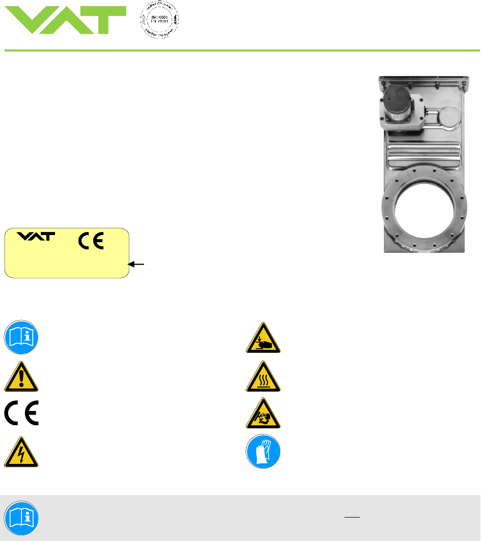
Control Gate Valve
with Direct Drive
This manual is valid for the valve ordering numbers:
642..-.E52
The respective product identification is given on each valve in the following way
(or similar):
made in Switzerland
Fabrication No.:
patented
. .
642 . . – . . . . – . . . . / . . . .
A – . . . . . .
Fabrication number
Explanation of symbols:
Read declaration carefully before you start any other
action!
Keep body parts and objects away from the valve
opening!
Attention!
Hot surfaces; do not touch!
Product is in conformity with EC guidelines,
if applicable!
Loaded springs and/or air cushions are potential
hazards!
Disconnect electrical power and compressed air
lines. Do not touch parts under voltage!
Wear gloves!
Read these «Installation, Operating & Maintenance Instructions» and the enclosed «General
Safety Instructions» carefully before you start any other action!

Installation, Operating, and Maintenance Instructions
Series 64.2, DN 160 - 400
VAT Vakuumventile AG, CH-9469 Haag, Switzerland
Tel +41 81 771 61 61 Fax +41 81 771 48 30 CH@vatvalve.com www.vatvalve.com
219036EJ
2013-03-04
2/10
Imprint:
Manufacturer
VAT Vakuumventile AG, CH-9469 Haag, Switzerland
Website
www.vatvalve.com
Phone
+41 81 771 61 61
Fax
+41 81 771 48 30
Email
CH@vatvalve.com
Publisher
VAT Vakuumventile AG, CH-9469 Haag, Switzerland
Editor
VAT Vakuumventile AG, CH-9469 Haag, Switzerland
Print
VAT Vakuumventile AG, CH-9469 Haag, Switzerland
Copyright
© VAT Vakuumventile AG 2013
No part of these Instructions may be reproduced in any way (photocopies, microfilms or any
other reproduction processes) nor may it be manipulated with electronic systems, duplicated or
distributed without written permission from VAT. Offenders are liable to pay damages.
The original VAT firmware and updated state of the art versions of the VAT firmware are
intended for use with VAT products. The VAT firmware contains a limited, time unlimited user
license. The VAT firmware may not be used for purposes other than those intended nor is it
permitted to make copies of the VAT firmware. In particular, it is strictly forbidden to give
copies of the VAT firmware to other people.
The use of trade names, brand names, trademarks, etc. in these Instructions does not entitle
third parties to consider these names to be unprotected and to use them freely. This is in
accordance with the meaning of the laws and acts covering brand names and trademarks.

Installation, Operating, and Maintenance Instructions
Series 64.2, DN 160 - 400
VAT Vakuumventile AG, CH-9469 Haag, Switzerland
Tel +41 81 771 61 61 Fax +41 81 771 48 30 CH@vatvalve.com www.vatvalve.com
219036EJ
2013-03-04
3/10
Intended Use of Product
Use product for vacuum applications under the conditions indicated in chapter "Technical Data" only! Other applications
are only allowed with the written permission of VAT.
Corrosive process gases may impact the performance of the product. Please contact VAT to assure that the product is
compatible with the process gases used in your application.
Technical data
Pressure range DN 160 - 200: 1 x 10⁻⁸ mbar to 2 bar (abs)
DN 250 - 400: to 1.2 bar (abs)
Differential pressure on the closed gate DN 160 - 200: 2 bar in either direction
DN 250 - 400: 1.2 bar in either direction
Max. differential pressure at opening 30 mbar
Admissible temperature: Valve < 150°C
Actuator < 50°C
Operation only with VAT PM-4/5 controller and connection cable
Further data according to VAT catalogue «Vacuum Valves 2016».
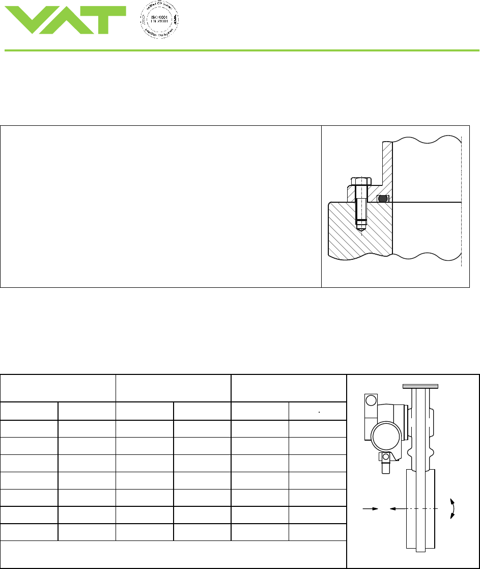
Installation into the vacuum system
The valve seat side is indicated by the symbol " " on the connection flange.
Tightening torque for mounting screws on flanges
1. Mounting with centering ring
Tighten mounting screws of the flanges uniformly in crosswise order. Observe the maximum torque levels in the following
table. Higher tightening torques deform the valve body and can lead to an improper function of the valve.
DN
max. tightening torque
(Nm)
max. tightening torque
(lbs . ft)
mm
inch
ISO-F
JIS
ASA-LP
ISO-F
JIS
ASA-LP
63/100
4
8 – 10
8 – 10
8 – 10
6 – 8
6 – 8
6 – 8
160
6
13 – 15
13 – 15
20 – 30
9 – 11
9 – 11
15 – 22
200
8
13 – 15
13 – 15
20 – 30
9 – 11
9 – 11
15 – 22
250
10
17 – 20
17 – 20
40 – 60
13 – 15
13 – 15
30 – 44
320
350
12
14
17 – 20
17 – 20
40 – 60
13 – 15
13 – 15
30 – 44
400
16
17 – 20
30 – 35
55 – 80
13 – 15
22 – 26
41 – 59
Installation, Operating, and Maintenance Instructions
Series 64.2, DN 160 - 400
VAT Vakuumventile AG, CH-9469 Haag, Switzerland
Tel +41 81 771 61 61 Fax +41 81 771 48 30 CH@vatvalve.com www.vatvalve.com
219036EJ
2013-03-04
4/10
2. Mounting with O-ring in groove
Tighten mounting screws of the flanges uniformly in crosswise order.
Observe the maximum torque according to the grade of screws and depth of
thread you use.
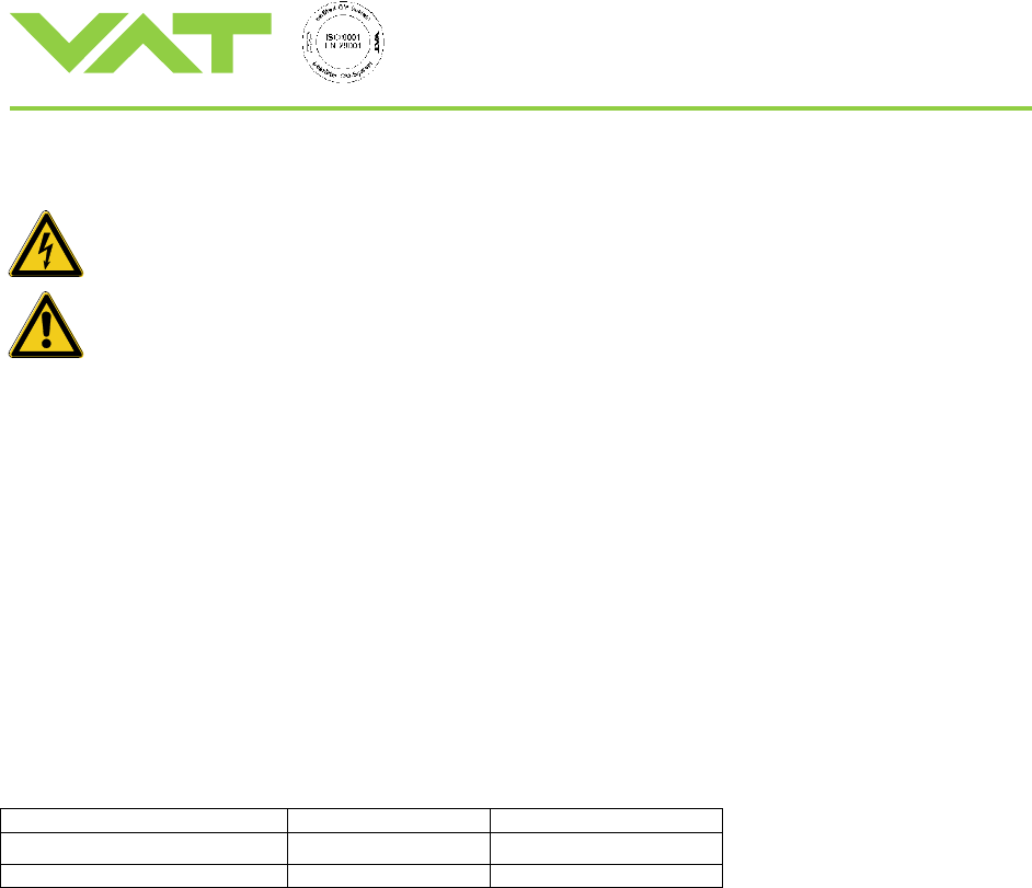
Admissible forces
Forces from evacuating the system, from the weight of other components, and from heating can lead to deformation of the
valve body and to malfunction of the valve. The stress has to be relieved by suitable means, e.g. bellows sections. The
following forces are admissible:
DN (nom. I.D.)
Axial tensile or
compressive force «FA»
Bending moment «M»
mm
inch
N
lbf
Nm
lbf ft
63
21/2
1960
440
78
58
100
4
2450
560
98
72
160
6
2940
660
147
108
200
8
2940
660
147
108
250
10
3430
770
196
145
320 / 350
12 / 14
3920
880
294
217
400
16
7840
1760
980
722
If a combination of both forces (FA and M) occurs, the values mentioned above are
invalid. Please contact VAT for more information.
F
A
M
Installation, Operating, and Maintenance Instructions
Series 64.2, DN 160 - 400
VAT Vakuumventile AG, CH-9469 Haag, Switzerland
Tel +41 81 771 61 61 Fax +41 81 771 48 30 CH@vatvalve.com www.vatvalve.com
219036EJ
2013-03-04
5/10
Electrical connection
Do not touch electrical parts under voltage!
This control valve may only be operated with a VAT PM-4 or PM-5 Adaptive Pressure Controller and the
corresponding cable supplied by VAT.
The PM-4 or PM-5 control unit has to be turned off for at least 60 seconds before connecting or
disconnecting the cable to the valve.
Operation
Operation is allowed only after the installing procedure.
Differential pressure
Do not open the valve, if the differential pressure on the gate is equal or larger than 30 mbar.
Power failure
with power-fail option
without power-fail option
Valve closed
no change
no change
Valve open or control position
will close
undefined
Installation, Operating, and Maintenance Instructions
Series 64.2, DN 160 - 400
VAT Vakuumventile AG, CH-9469 Haag, Switzerland
Tel +41 81 771 61 61 Fax +41 81 771 48 30 CH@vatvalve.com www.vatvalve.com
219036EJ
2013-03-04
6/10
Preventive maintenance
The numbers in brackets refer to the drawing on page 9
Note! The process environment of your application (i.e. corrosive gases, deposition on parts inside valve body) may
require more frequent preventive maintenance intervals than suggested below.
Heating of the valve is highly recommended for contaminating processes. VAT offers customized heater
boxes for series 64.2 valves.
For quick maintenance, VAT recommends to exchange the complete gate assembly in order to reduce
downtime of the system.
Warning! Never remove striking plate (20) from the mechanism (16)!
Recommended maintenance after every 100'000 cycles (25’000 for DN 400 vertical mounting only):
- Clean gate O-ring, clean inside surfaces
- Inspect the bonnet seal, ball bearings and crank bolt.
- Replace items (Spare part kit ‘C’), if corrosion or deposition of process by-products occured.
- In corrosive processes: Relubricate locking balls with VAT Vacuum grease. Replace and lubricate locking balls, if
corrosion has occured.
Recommended maintenance after every 200'000 (50’000 for DN 400 vertical mounting only) cycles:
In additional to the 100'000 cycles maintenance interval, VAT recommends to clean and lubricate the ball bearings
(replace, if necessary), replace the locking balls, replace the crank bolt, inspect, clean and re-lubricate the ball guide plate
(replace, if friction increased), inspect, clean and re-lubricate the feedthrough O-ring (replace it if necessary)
The following table refers to the items on page 4 and the spare parts list on page 6.
Cycles *)
Procedures
Recommended spare parts kits
Every 100’000
1., 2., 3.
A, E
For individual items see spare parts list on page 6
Every 200’000
1., 2., 3., 4., 5., 6., 7.
B, C, E
For individual items see spare parts list on page 6
*) Definition of cycle: Movement of the gate from open to closed or control position and back to open position
Procedures
1. Precondition for all maintenance work
- Vent both valve chambers
- Give ‘OPEN’ command on PM-4 or PM 5 control to open gate valve
- Turn off power to PM-4 or PM-5 control unit. If power-fail option is installed, press ‘F2’ key to disable power-fail option
temporarily and turn off power to PM-4 or PM-5 control unit within following 60 seconds
- Wait for another 60 seconds, then disconnect cable to valve actuator
2. Removal of the gate assembly (4) / Replacement of the crank bolt (6) / Replacement of the bonnet seal (3)
- Unfasten the bonnet screws (1)
- Remove the bonnet plate (2) and the bonnet seal (3)
- Pull the lever (15) a little bit out of the bonnet opening
- Loosen the hexagonal socket-head bolt (7) for the crank bolt (6)
- Remove the crank bolt (6), while lifting the gate assembly (4) a little bit if necessary
Installation, Operating, and Maintenance Instructions
Series 64.2, DN 160 - 400
VAT Vakuumventile AG, CH-9469 Haag, Switzerland
Tel +41 81 771 61 61 Fax +41 81 771 48 30 CH@vatvalve.com www.vatvalve.com
219036EJ
2013-03-04
7/10
- Slide out the gate assembly (4) carefully from the body and put it on a clean workshop place
- Re-assemble in reverse direction
- Fasten the screws (1) crosswise with equal torque: 14 Nm (10 lbf ft) with DN 63 - 100
18 Nm (13 lbf ft) with DN 160 – 400
3. Replacement of the gate O-ring (5)
- Remove O-ring carefully and avoid any damage to the groove sealing sureface
- Clean groove and sealing surface
- Install new O-ring by pressing it crosswise uniformly into the groove. Make sure, the O-ring is not twisted (pay
attention to the seam of the O-ring)
4. Replacement of the ball bearings (22)
- DN160 - 200: Replace complete ball bearing assembly (2 pcs)
- DN250 - 400: Replace each individual ball bearing (4 pcs)
5. Replacement of the locking balls (19)
- Put the gate assembly (4) carefully on a clean workshop place with the O-ring side to the bottom
- Remove the 6 hexagonal nuts (17)
- Lift off counter plate (18) and ball guide plate (16)
- Replace locking balls (19), lubricate balls with VAT vacuum grease (E) before installation
- Reassemble in reverse order, lubricate weld bolts on plate with VAT vacuum grease (E) before mounting hexagonal
nuts
6. Removal of actuator (10) for change of rotary seal (included in seal kit ‘A’)
- Remove gate assembly as per items 1 and 2
- Move the actuator to position 800 (PM control: Position mode, select 800)
- Press 'F2', if power-fail option is installed to disable the power fail option
- Turn off power to PM control unit.
- Remove roll pin (8) out of the shaft feedthrough. Use VAT assembling tool or a punch
- Remove lever (15). Note the marking "A" to be on top side when reinstalling
- Remve 4 hexagonal socket-head bolts (9) on top of the direct drive actuator (10)
- Remove complete direct drive actuator assembly (10)
- Install in reverse order
Installation, Operating, and Maintenance Instructions
Series 64.2, DN 160 - 400
VAT Vakuumventile AG, CH-9469 Haag, Switzerland
Tel +41 81 771 61 61 Fax +41 81 771 48 30 CH@vatvalve.com www.vatvalve.com
219036EJ
2013-03-04
8/10
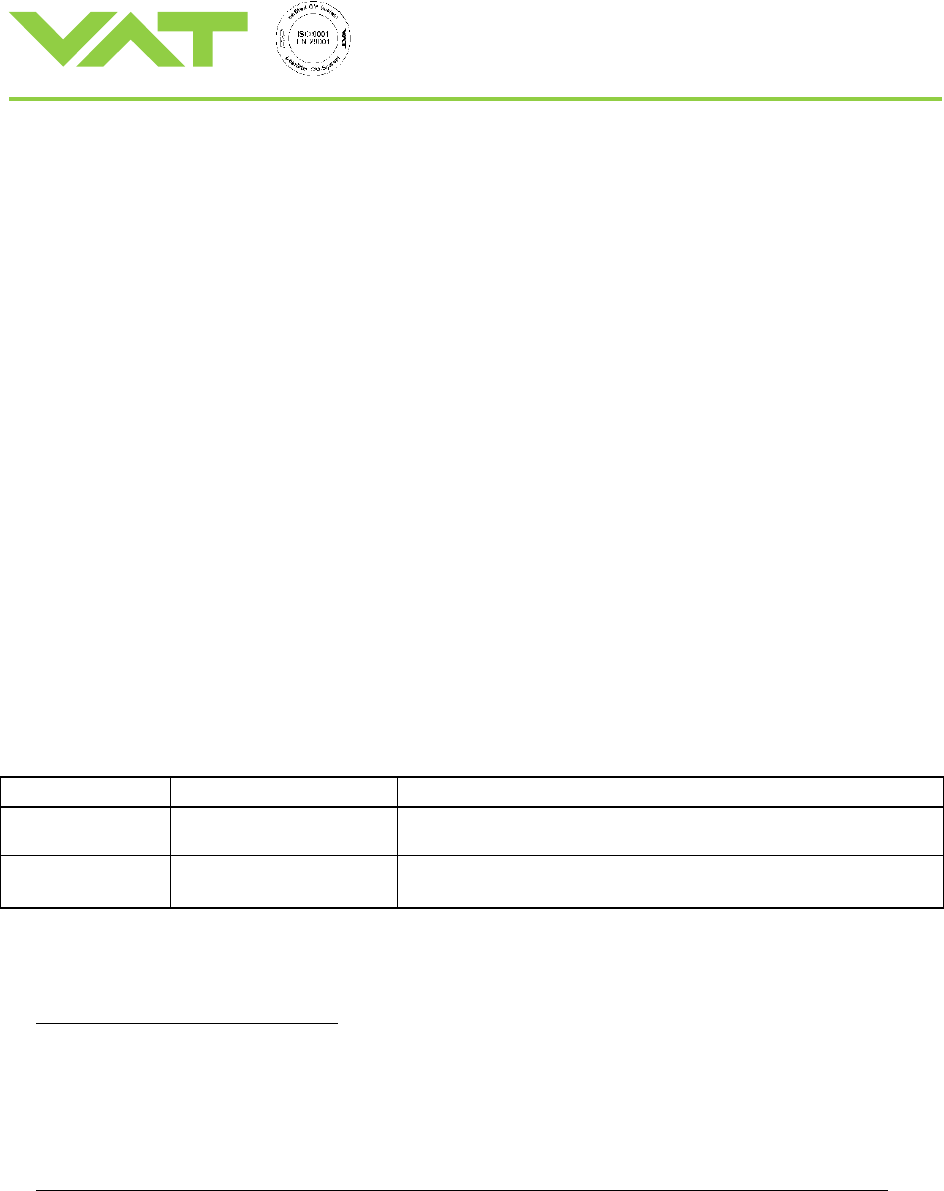
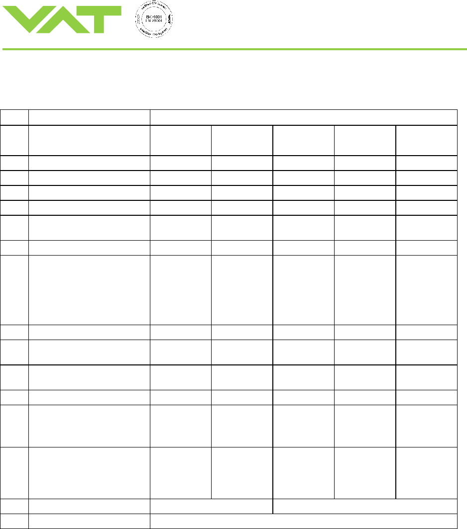
Spare parts
The item numbers refer to the assembly drawing on page 9
Item
Description
Part No.
160
200
250
320
350
400
3
Bonnet seal
77781-R1
77784-R1
N-5100-378
N-5100-382
N-5100-383
4
Gate assembly
84275-R1
84608-R1
83481-R1
209812
517637
5
Gate O-ring
N-5102-364
N-5100-372
N-5102-453
N-5102-457
N-5100-461
6
Crank bolt
79090-R1
79090-R1
85783-R1
85783-R1
87749-R1
7
Crank bolt mounting screw
with spring washer
N-6005-458
N-6162-405
N-6005-458
N-6162-405
N-6005-502
N-6162-407
N-6005-502
N-6162-407
N-6005-502
N-6162-407
8
Feedthrough connection pin
N-6097-480
N-6097-480
N-6097-509
N-6097-509
N-6097-509
10
Actuator
A-side
B-side
Actuator with interm. Pump.
A-side
B-side
247102
247103
247104
247105
247102
247103
247104
247105
232850
232851
232852
232853
232850
232851
232852
232853
232850
232851
232852
232853
11
Actuator seal
N-5100-225
N-5100-225
N-5100-228
N-5100-228
N-5100-228
19
Locking balls
N-6121-051
(18 pcs)
N-6121-051
( 24 pcs)
N-6121-081
(18 pcs)
N-6121-081
(24 pcs)
N-6121-097
(32 pcs)
22
Ball bearing assembly
84326-R1
(2 pcs)
80642-R1
(2 pcs)
99205-R1
(4 pcs)
99205-R1
(4 pcs)
77286-01
(4 pcs)
A
Seal kit
246755
246756
246757
246760
245476
B
Actuator replacement kit,
consisting of:
actuator seal, bonnet seal,
feedthrough connection pin
260150
260151
260152
260153
260154
C
Gate spare parts kit,
consisting of
gate O-ring, crank bolt, crank bolt
connection screw, ball bearings,
locking balls
88725-R1
88726-R1
88727-R1
88728-R1
88729-R1
D
Feedthrough assembling tool
240451
97381-R1
E
VAT vacuum grease (40 g)
N-6951-012
Installation, Operating, and Maintenance Instructions
Series 64.2, DN 160 - 400
VAT Vakuumventile AG, CH-9469 Haag, Switzerland
Tel +41 81 771 61 61 Fax +41 81 771 48 30 CH@vatvalve.com www.vatvalve.com
219036EJ
2013-03-04
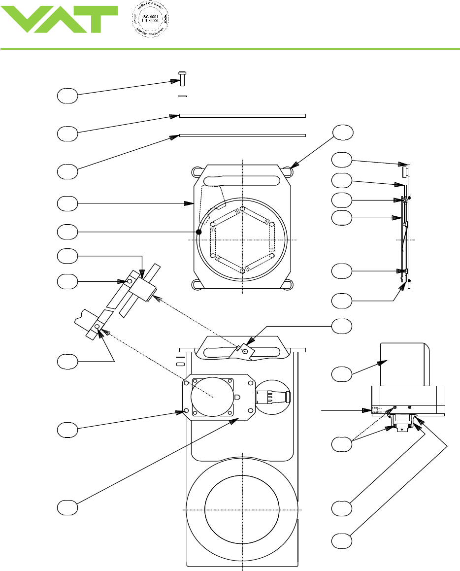
9/10
11
22
21
20
19
18
17
16
14
12
13
4
10
15
R1/8" port
OPTION:
7
9
8
6
5
3
2
1
Installation, Operating, and Maintenance Instructions
Series 64.2, DN 160 - 400
VAT Vakuumventile AG, CH-9469 Haag, Switzerland
Tel +41 81 771 61 61 Fax +41 81 771 48 30 CH@vatvalve.com www.vatvalve.com
219036EJ
2013-03-04
10/10
Trouble shooting
Valve does not close/open/control
- Is differential pressure < 30 mbar?
- Do not operate valve, while differential pressure is > 30 mbar.
Equalize pressure first.
- Is PM control unit activated (hooked up to power, switched on)?
- Is valve cable connected properly?
Pressure control does not work properly
- Please refer to Trouble Shooting section of PM contol unit
(operation instruction M64005EB)
Leak at gate
- Clean valve seat and gate!
- Check surface of seat and O-ring
- Change O-ring, if necessary
Leak at body
- Flange seals leaktight?
- Bonnet seal leaktight?
- Screws at bonnet tightened properly?
Repairs
Contact VAT for repairs or maintenance. The fabrication No. marked on the valve body has always to be specified. It has
to be individually decided whether the work can be performed by the customer or has to be carried out by VAT.
Power to the control unit has to be switched off and the cable to the valve has to be disconnected (wait at least 60
seconds) before removal/installation of the valve from/into the system.
Keep fingers and objects away from the valve opening!
Products returned to VAT for repair have to be free of harmful substances such as e.g. toxical, caustic or microbiological
ones. For radioactively contaminated products the customer has to fill in the VAT form «Contamination and Radiation
Report» and to send it with the product. The form is available at VAT. The maximum permissible values indicated in the
form must not be exceeded.
Warranty
Each product sold by VAT Vakuumventile AG (VAT) is warranted to be free from the manufacturing defects that adversely
affect the normal functioning thereof during the one-year period immediately following delivery thereof by VAT, provided
that the same is properly operated under conditions of normal use and that regular, periodic maintenance and service is
performed or replacements made, in accordance with the instructions provided by VAT. The foregoing warranty shall not
apply to any product or component that has been repaired or altered by anyone other than an authorized VAT
representative or that has been subject to improper installation or abuse, misuse, negligence or accident. VAT shall not be
liable for any damage, loss, or expense, whether consequential, special, incidental, direct or otherwise, caused by, arising
out of or connected with the manufacture, delivery (including any delay in or failure to deliver), packaging, storage or use
of any product sold or delivered by VAT shall fail to conform to the foregoing warranty or to the description thereof
contained herein, the purchaser thereof, as its exclusive remedy, shall upon prompt notice to VAT of any such defect or
failure and upon the return of the product, part or component in question to VAT at its factory, with transportation charges
prepaid, and upon VAT's inspection confirming the existence of any defect inconsistent with said warranty or any such
failure, be entitled to have such defect or failure cured at VAT's factory and at no charge therefor, by replacement or repair
of said product, as VAT may elect. VAT MAKES NO WARRANTY OR REPRESENTATION OF ANY KIND, EXPRESS OR
IMPLIED, (INCLUDING NO WARRANTY OR MERCHANTABILITY), EXCEPT FOR THE FOREGOING WARRANTY AND
THE WARRANTY THAT EACH PRODUCT SHALL CONFORM TO THE DESCRIPTION THEREOF CONTAINED
HEREIN, and no warranty shall be implied by law.
Furthermore, the «Terms of sale» at the back of the price list are applicable.
