SonTek FlowTracker2 User’s Manual
User Manual: Pdf sontek flowtracker2 manual
Open the PDF directly: View PDF ![]() .
.
Page Count: 254 [warning: Documents this large are best viewed by clicking the View PDF Link!]
- 20160215 FlowTracker2 Manual Cover
- No cover FlowTracker2 Technical Manual V3.4
- List of Tables
- List of Equations
- Section 1. Quick Overview
- Section 2. System Operation
- Section 3. Device Configuration
- Section 4. Utilities
- Section 5. Data Collection Modes
- Section 6. Quality Control
- Section 7. Measurement Process
- Section 8. Discharge Measurement
- Section 9. General Measurement
- Section 10. FlowTracker2 Hardware
- Section 11. Operational Considerations
- Section 12. FlowTracker2 File Format
- Section 13. Principle of Operations
- 13.1. FlowTracker2 Overview
- 13.2. The Doppler Shift
- 13.3. Bistatic Doppler Current Meters
- 13.4. Pulse-Coherent Processing
- 13.5. Beam Geometry and 3D Velocity Measurements
- 13.6. Sampling Volume Definition
- 13.7. Velocity Data Coordinate System
- 13.8. FlowTracker2 Data
- 13.9. Special Considerations
- 13.10. Sound Speed
- 13.11. Flow Interference
- Section 14. FlowTracker2 Desktop Software
- 14.1. Overview of Software Features and Functions
- 14.2. Installing Software
- 14.3. Changing Settings
- 14.3.1 User Interface Tab
- 14.3.2 General Tab
- 14.3.2.1 Show paired device connection options (Settings > General > Show paired device connection options)
- 14.3.2.2 Show Download Options Dialog (Settings > General > Show download options dialog)
- 14.3.2.3 Check for Crash Reports and Send to SonTek Support (Settings > General > Check for crash reports)
- 14.3.3 Units Tab
- 14.4. Utilities
- 14.4.1 FlowTracker1 Import (Utilities > FlowTracker1 Import)
- 14.4.2 Run Translator (Utilities > Run Translator)
- 14.4.3 Import Language File (Utilities > Import Language File)
- 14.4.4 New Discharge Template (Utilities > New Discharge Template)
- 14.4.5 New General Template (Utilities > New General Template)
- 14.5. Connecting to the FlowTracker2 Handheld ADV
- 14.6. Device Menu and Functions
- 14.6.1 Download Data Files (Device > [Choose your connection] > Download)
- 14.6.2 Delete Data files (Device > [Choose your connection] > Delete)
- 14.6.3 Upgrading FlowTracker2 Firmware (Device > [Choose your connection] > Upgrade)
- 14.6.4 Uploading and Downloading Templates (Device > [Choose your connection] > Templates)
- 14.6.5 Custom Localization
- 14.6.6 Disconnecting the FlowTracker2
- 14.7. Opening a Data File
- 14.8. Overview of View Data Options
- 14.9. Post-Processing FlowTracker Measurements
- 14.10. Data Export and File Formats
- Appendix A. Software Flow Diagram
- Appendix B. Site Selection Requirements
- Appendix C. Japanese Method Example
- Appendix D. Measurement Equipment List
- Appendix E. CE Declaration of Conformity
- INDEX
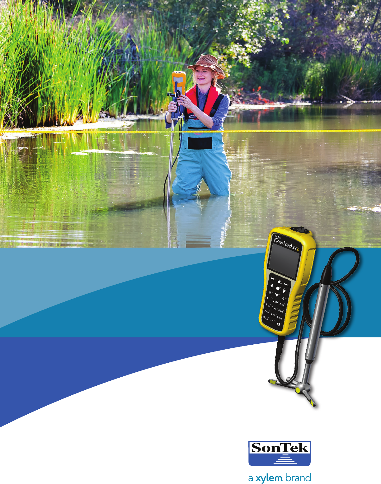
FlowTracker2
USER’S MANUAL 1.1
SOFTWARE VERSION 1.1
FIRMWARE VERSION 1.17
®
Copyright 2016 by Xylem Inc. All rights reserved. This document may not, in whole or in part, be copied,
photocopied, reproduced, translated, or reduced to any electronic medium or Machine-readable form with-
out prior consent in writing from Xylem. Every effort has been made to ensure the accuracy of this manual.
However, Xylem makes no warranties with respect to this documentation and disclaims any implied war-
ranties of merchantability and fitness for a particular purpose. Xylem shall not be liable for any errors or for
incidental or consequential damages in connection with the furnishing, performance, or use of this manual
or the examples herein. The information in this document is subject to change without notice.
9940 Summers Ridge Rd
San Diego, CA 92121
+1.858.546.8327
inquiry@sontek.com
sontek.com
For Sales & Service Contact
2650 E. 40th Ave. • Denver, CO 80205
Phone 303-320-4764 • Fax 303-322-7242
1-800-833-7958
www.geotechenv.com

SonTek – a Xylem brand
FlowTracker2 User‟s Manual (February 2016) 2
Release Notice 45-0120 Rev B
This is the February 2016 release of the FlowTracker2 User‟s Manual. During the
creation of this manual, the following were the latest versions of firmware/software. As
such, if you are using different firmware/software versions, not all aspects of this manual
may apply.
FlowTracker2 firmware version 1.17
FlowTracker2 software version 1.1
Trademarks
The terms FlowTracker2 are registered trademarks of Xylem Inc. All rights are reserved.
All other brand names are trademarks of their respective holders.
Warranty, Terms, and Conditions
Thank you for purchasing the FlowTracker2. The instrument was thoroughly tested at the
factory and found to be in excellent working condition. If the shipping crate appears damaged,
or if the system is not operating properly, please contact us immediately.
The system you have purchased is covered under a two year limited warranty that extends to all
parts and labor for any malfunction due to workmanship or errors in the manufacturing process.
The warranty does not cover shortcomings that are due to the design, nor does it cover any
form of incidental damage as a result of errors in the measurements.
If your system is not functioning properly, first try to identify the source of the problem. If
additional support is required, we encourage you to contact us immediately, and we will work to
resolve the problem as quickly as possible.
If the system needs to be returned to the factory, please contact technical support to obtain a
Service Request (SR) number. We reserve the right to refuse shipments without SR numbers.
We require the system to be shipped back in the original shipping container using the original
packing material with all delivery costs covered by the customer (including all taxes and duties).
If the system is returned without appropriate packing, the customer will be required to cover the
cost of a new packaging crate and material.
Contact Information
Any questions, concerns, or suggestions can be directed to SonTek by telephone, fax,
or email. Business hours are 8:00 a.m. to 5:00 p.m., Pacific Standard Time, Monday
through Friday.
Phone : +1 (858) 546-8327
Fax : +1 (858) 546-8150
Email : inquiry@sontek.com (General information)
sales@sontek.com (Sales information)
support@sontek.com (Support information)
Web : http://www.sontek.com
See our web site for information concerning new products and software/firmware
upgrades.

SonTek – a Xylem brand
FlowTracker2 User’s Manual (February 2016) 3
FCC INFORMATION
This device complies with part 15 of the FCC Rules. Operation is subject to the following two
conditions: (1) This device may not cause harmful interference, and (2) this device must accept
any interference received, including interference that may cause undesired operation.
The FlowTracker2 FCC license number can be found in two locations: (1) on the shipping box
label and (2) engraved on the back of the FlowTracker2. Examples of the shipping box label
and engraving are shown below.

SonTek – a Xylem brand
FlowTracker2 User’s Manual (February 2016) 4
Table of Contents
List of Tables ............................................................................................................... 13
List of Equations ......................................................................................................... 15
Quick Overview ......................................................................................... 16 Section 1.
1.1. System Components ........................................................................................ 16
1.2. Definitions and Terminology ............................................................................. 18
System Operation ...................................................................................... 20 Section 2.
2.1. On/Off Switch ................................................................................................... 20
2.2. Keypad ............................................................................................................. 20
2.3. Screen Layout .................................................................................................. 22
2.4. Main Menu ....................................................................................................... 22
Device Configuration Menu (Main Menu) ........................................................................... 23 2.4.1
Utilities (Main Menu) ........................................................................................................... 23 2.4.2
Communication (Main Menu) .............................................................................................. 24 2.4.3
System Information (Main Menu) ........................................................................................ 24 2.4.4
Measurement (Main Menu) ................................................................................................. 25 2.4.5
Data Files (Main Menu) ....................................................................................................... 26 2.4.6
Device Configuration ................................................................................ 28 Section 3.
3.1. User Interface ................................................................................................... 28
Language ............................................................................................................................ 28 3.1.1
Use Beeper ......................................................................................................................... 29 3.1.2
Color Scheme ...................................................................................................................... 29 3.1.3
Font Size ............................................................................................................................. 29 3.1.4
Font Smoothing ................................................................................................................... 30 3.1.5
3.2. Application Settings .......................................................................................... 30
Units .................................................................................................................................... 30 3.2.1
Wading Rod ......................................................................................................................... 31 3.2.2
File Naming ......................................................................................................................... 32 3.2.3
Folder Naming ..................................................................................................................... 33 3.2.4
GPS Station Tagging .......................................................................................................... 33 3.2.5
3.3. Configuration Templates .................................................................................. 35
Template Options ................................................................................................................ 35 3.3.1
Managing Templates ........................................................................................................... 36 3.3.2
Accessing Templates .......................................................................................................... 36 3.3.2.1
New Template ..................................................................................................................... 37 3.3.2.2
Selecting Template ............................................................................................................. 37 3.3.2.3
3.4. Template Functions .......................................................................................... 37
File Properties ..................................................................................................................... 38 3.4.1

SonTek – a Xylem brand
FlowTracker2 User’s Manual (February 2016) 5
Data Collection Settings ...................................................................................................... 39 3.4.2
Averaging Time ................................................................................................................... 40 3.4.2.1
Salinity ................................................................................................................................. 40 3.4.2.2
Temperature ........................................................................................................................ 41 3.4.2.3
Sound Speed ...................................................................................................................... 41 3.4.2.4
Mounting Correction ............................................................................................................ 42 3.4.2.5
Quality Control Settings ...................................................................................................... 42 3.4.3
SNR Threshold .................................................................................................................... 43 3.4.3.1
Std Error Threshold ............................................................................................................. 43 3.4.3.2
Spike Threshold .................................................................................................................. 43 3.4.3.3
Velocity Angle for Warning .................................................................................................. 44 3.4.3.4
Tilt Angle Warning ............................................................................................................... 44 3.4.3.5
Discharge Settings .............................................................................................................. 44 3.4.4
Discharge Equation ............................................................................................................. 45 3.4.4.1
Discharge Uncertainty ......................................................................................................... 46 3.4.4.2
Discharge Reference .......................................................................................................... 46 3.4.4.3
Max Station Q for Warning (%) ........................................................................................... 47 3.4.4.4
Max Depth Change for Warning (%) ................................................................................... 47 3.4.4.5
Max Spacing Change for Warning (%) ............................................................................... 47 3.4.4.6
0.6 Method Depth ................................................................................................................ 47 3.4.4.7
Displayed Velocity Methods ................................................................................................ 48 3.4.5
Utilities ....................................................................................................... 50 Section 4.
4.1. System Clock ................................................................................................... 50
Manual Change ................................................................................................................... 50 4.1.1
Sync with GPS Time ........................................................................................................... 51 4.1.2
4.2. Recorder .......................................................................................................... 52
Manage Recorder................................................................................................................ 52 4.2.1
Erase Recorder ................................................................................................................... 53 4.2.2
4.3. Battery Data ..................................................................................................... 54
Battery Type ........................................................................................................................ 54 4.3.1
Battery Voltage .................................................................................................................... 55 4.3.2
Percentage Full ................................................................................................................... 55 4.3.3
4.4. Raw Data Display ............................................................................................. 55
Velocity Raw Data ............................................................................................................... 56 4.4.1
SNR Raw Data .................................................................................................................... 57 4.4.2
Temperature Raw Data ....................................................................................................... 58 4.4.3
Tilt Raw Data ....................................................................................................................... 58 4.4.4
Battery Indicator .................................................................................................................. 58 4.4.5
4.5. Automated Beam Check .................................................................................. 59
4.6. Beam Check ..................................................................................................... 61
4.7. GPS Data ......................................................................................................... 61
4.8. System Maintenance ........................................................................................ 63
Force Probe Upgrade .......................................................................................................... 63 4.8.1
Data Collection Modes .............................................................................. 64 Section 5.

SonTek – a Xylem brand
FlowTracker2 User’s Manual (February 2016) 6
5.1. Discharge Mode ............................................................................................... 64
Measurement Technique .................................................................................................... 64 5.1.1
Discharge Calculation Methods .......................................................................................... 65 5.1.2
Mid-Section Equation .......................................................................................................... 65 5.1.2.1
Mean-Section Equation ....................................................................................................... 67 5.1.2.2
Japanese Equation ............................................................................................................. 68 5.1.2.3
Determining Mean Station Velocity ..................................................................................... 70 5.1.3
Method None ....................................................................................................................... 71 5.1.3.1
Vertical Velocity Curve ........................................................................................................ 72 5.1.3.2
Correction Factor ................................................................................................................ 73 5.1.3.3
Discharge Uncertainty Calculation ...................................................................................... 73 5.1.4
Under Ice Measurements .................................................................................................... 74 5.1.5
Weighted Gauge Height ...................................................................................................... 75 5.1.6
5.2. General Mode .................................................................................................. 76
Measurement Technique .................................................................................................... 76 5.2.1
Determining Mean Velocity ................................................................................................. 76 5.2.2
Quality Control .......................................................................................... 77 Section 6.
6.1. Quality Control Parameters .............................................................................. 77
Signal to Noise Ratio (SNR) ................................................................................................ 78 6.1.1
Velocity Standard Error ....................................................................................................... 81 6.1.2
Boundary Interference ......................................................................................................... 82 6.1.3
Velocity Spike Filter ............................................................................................................. 84 6.1.4
Velocity Angle ...................................................................................................................... 85 6.1.5
Tilt Angle ............................................................................................................................. 86 6.1.6
Station Percent Discharge .................................................................................................. 87 6.1.7
Station Water Depth ............................................................................................................ 88 6.1.8
Station Location ................................................................................................................... 88 6.1.9
Velocity Profile 0.2 \ 0.8 ...................................................................................................... 89 6.1.10
6.2. Quality Control Warning Messages .................................................................. 89
Types of Warning Messages ............................................................................................... 89 6.2.1
Timing of Warning Messages .............................................................................................. 91 6.2.2
6.3. Beam Check ..................................................................................................... 92
Beam Check Overview ........................................................................................................ 92 6.3.1
Beam Check Features ........................................................................................................ 93 6.3.2
Beam Check Operation ....................................................................................................... 94 6.3.3
Diagnosing Measurements with Beam Check .................................................................... 94 6.3.4
Low Scattering Strength ...................................................................................................... 94 6.3.4.1
Strong Scattering Strength .................................................................................................. 95 6.3.4.2
Boundary Detected within Beam Check ............................................................................. 95 6.3.4.3
Boundary in Sampling Volume ............................................................................................ 96 6.3.4.4
Measurement Process .............................................................................. 98 Section 7.
7.1. Office Procedures ............................................................................................ 98
Equipment List ..................................................................................................................... 98 7.1.1
Hardware Inspection ........................................................................................................... 99 7.1.2
Office Diagnostic ................................................................................................................. 99 7.1.3

SonTek – a Xylem brand
FlowTracker2 User’s Manual (February 2016) 7
7.2. Measurement Site Information ....................................................................... 101
7.3. Pre Measurement Diagnostics ....................................................................... 101
7.4. Measurement Procedure ................................................................................ 102
7.5. Post Measurement Requirements .................................................................. 104
Review of Measurement Site Information ......................................................................... 104 7.5.1
Review Measurement Summary ....................................................................................... 105 7.5.2
Data Management ............................................................................................................. 105 7.5.3
Storage .............................................................................................................................. 106 7.5.4
Discharge Measurement ......................................................................... 107 Section 8.
8.1. Create Measurement ..................................................................................... 107
Measurement .................................................................................................................... 107 8.1.1
New File Type ................................................................................................................... 107 8.1.2
New File Template ............................................................................................................ 108 8.1.3
New Data File .................................................................................................................... 108 8.1.4
8.2. Automated Beam Check ................................................................................ 109
Start Automated Beam Check ........................................................................................... 109 8.2.1
Evaluate Beam Check Results .......................................................................................... 110 8.2.2
8.3. Data Collection ............................................................................................... 111
Data Collection Window .................................................................................................... 112 8.3.1
Add Station ........................................................................................................................ 112 8.3.1.1
Delete Station .................................................................................................................... 113 8.3.1.2
Edit Station ........................................................................................................................ 114 8.3.1.3
Station Types .................................................................................................................... 115 8.3.2
Bank (left or right) .............................................................................................................. 116 8.3.2.1
Island Edge ....................................................................................................................... 117 8.3.2.2
Open Water ....................................................................................................................... 118 8.3.2.3
Ice ...................................................................................................................................... 119 8.3.2.4
Station Measurement ........................................................................................................ 120 8.3.3
Station Parameters ........................................................................................................... 120 8.3.3.1
Point Velocity Measurement ............................................................................................. 121 8.3.3.2
Review Point Measurement .............................................................................................. 123 8.3.3.3
Review Station Measurement ........................................................................................... 124 8.3.3.4
Data Collection Menu ........................................................................................................ 126 8.3.4
Settings ............................................................................................................................. 127 8.3.4.1
Supplemental Data ............................................................................................................ 127 8.3.4.2
Discharge Summary .......................................................................................................... 128 8.3.4.3
Station Summary ............................................................................................................... 129 8.3.4.4
Automated Beam Check ................................................................................................... 130 8.3.4.5
Complete Measurement .................................................................................................... 130 8.3.4.6
Discard Measurement ....................................................................................................... 131 8.3.4.7
Go to Home Screen .......................................................................................................... 132 8.3.4.8
8.4. Measurement Summary ................................................................................. 132
General Measurement ............................................................................. 134 Section 9.
9.1. Create Measurement ..................................................................................... 134

SonTek – a Xylem brand
FlowTracker2 User’s Manual (February 2016) 8
Measurement .................................................................................................................... 134 9.1.1
New File Type ................................................................................................................... 134 9.1.2
New File Template ............................................................................................................ 135 9.1.3
New Data File .................................................................................................................... 135 9.1.4
9.2. Automated Beam Check ................................................................................ 136
Start Automated Beam Check ........................................................................................... 136 9.2.1
Evaluate Beam Check Results .......................................................................................... 137 9.2.2
9.3. Data Collection ............................................................................................... 138
Data Collection Window .................................................................................................... 138 9.3.1
Add Station ........................................................................................................................ 139 9.3.1.1
Delete Station .................................................................................................................... 140 9.3.1.2
Station Measurement ........................................................................................................ 141 9.3.2
Point Velocity Measurement ............................................................................................. 141 9.3.2.1
Review Point Measurement .............................................................................................. 143 9.3.2.2
Review Station Measurement ........................................................................................... 144 9.3.2.3
Data Collection Menu ........................................................................................................ 145 9.3.3
Settings ............................................................................................................................. 146 9.3.3.1
Velocity Summary ............................................................................................................. 146 9.3.3.2
Automated Beam Check ................................................................................................... 147 9.3.3.3
Complete Measurement .................................................................................................... 148 9.3.3.4
Discard Measurement ....................................................................................................... 149 9.3.3.5
Go to Home Screen .......................................................................................................... 149 9.3.3.6
9.4. Measurement Summary ................................................................................. 149
FlowTracker2 Hardware ........................................................................ 152 Section 10.
10.1. ADV Probe .................................................................................................. 152
10.2. Handheld .................................................................................................... 152
10.3. Cables and Connectors .............................................................................. 154
10.4. Certifications ............................................................................................... 154
10.5. PC System Requirements ........................................................................... 154
Operational Considerations ................................................................. 156 Section 11.
11.1. Software Upgrade ....................................................................................... 156
Upgrading Handheld Software .......................................................................................... 156 11.1.1
Upgrading ADV Firmware ................................................................................................. 158 11.1.2
11.2. Mounting and Installation ............................................................................ 158
FlowTracker2 Handheld .................................................................................................... 158 11.2.1
Handheld Mounting Bracket .............................................................................................. 158 11.2.2
Probe Mounting Bracket .................................................................................................... 159 11.2.3
11.3. Routine Maintenance .................................................................................. 160
Battery Power Supply ........................................................................................................ 160 11.3.1
Cleaning Instrument .......................................................................................................... 160 11.3.2
Handheld ......................................................................................................................... 160 11.3.2.1
Transducers .................................................................................................................... 161 11.3.2.2

SonTek – a Xylem brand
FlowTracker2 User’s Manual (February 2016) 9
Cable Maintenance ........................................................................................................... 161 11.3.3
O-rings ............................................................................................................................... 162 11.3.4
Housing ........................................................................................................................... 162 11.3.4.1
Battery Cap ..................................................................................................................... 162 11.3.4.2
Condensation in FlowTracker2 Housing ........................................................................... 162 11.3.5
Zinc Anodes for Corrosion Protection ............................................................................... 162 11.3.6
11.4. Seeding ....................................................................................................... 163
Scattering Material ............................................................................................................ 163 11.4.1
Field Applications .............................................................................................................. 163 11.4.2
11.5. Troubleshooting .......................................................................................... 164
Cannot Turn System On ................................................................................................... 164 11.5.1
Cannot Communicate with the FlowTracker2 ................................................................... 164 11.5.2
Handheld ......................................................................................................................... 164 11.5.2.1
Communication ............................................................................................................... 164 11.5.2.2
Cannot Retrieve Data from Internal Recorder .................................................................. 165 11.5.3
Velocity Data Appears Noisy or Unreasonable ................................................................. 165 11.5.4
Recovery Mode ................................................................................................................. 165 11.5.5
11.6. Health and Safety ....................................................................................... 166
Planning Field Work .......................................................................................................... 166 11.6.1
Communication ................................................................................................................. 166 11.6.2
Measurement Site Conditions ........................................................................................... 167 11.6.3
FlowTracker2 File Format ..................................................................... 168 Section 12.
12.1. FlowTracker2 JSON File ............................................................................. 168
Measurement File Framework .......................................................................................... 169 12.1.1
Measurement File Structure .............................................................................................. 170 12.1.2
12.2. FlowTracker2 CSV Output .......................................................................... 178
CSV File Structure............................................................................................................. 178 12.2.1
CSV Variables ................................................................................................................... 179 12.2.2
12.3. Original FlowTracker ASCII vs JSON ......................................................... 186
Principle of Operations ......................................................................... 194 Section 13.
13.1. FlowTracker2 Overview .............................................................................. 194
13.2. The Doppler Shift ........................................................................................ 194
13.3. Bistatic Doppler Current Meters .................................................................. 195
Bistatic Doppler Operation ................................................................................................ 195 13.3.1
The FlowTracker2 Measurement Principle ....................................................................... 195 13.3.2
Signal to Noise Ratio Profile ............................................................................................. 196 13.3.3
13.4. Pulse-Coherent Processing ........................................................................ 197
13.5. Beam Geometry and 3D Velocity Measurements ....................................... 198
13.6. Sampling Volume Definition ........................................................................ 198
13.7. Velocity Data Coordinate System ............................................................... 199

SonTek – a Xylem brand
FlowTracker2 User’s Manual (February 2016) 10
2D Side-Looking Probe (Figure 30a) ................................................................................ 199 13.7.1
2D/3D Side-Looking Probe (Figure 30b) ........................................................................... 199 13.7.2
13.8. FlowTracker2 Data ...................................................................................... 199
Basic Sampling Strategy ................................................................................................... 199 13.8.1
Velocity Data ..................................................................................................................... 200 13.8.2
Accuracy of Velocity Data ................................................................................................. 200 13.8.3
Optimizing of FlowTracker2 ............................................................................................ 200 13.8.3.1
Factors Influencing Accuracy .......................................................................................... 201 13.8.3.2
Quality Control Data .......................................................................................................... 201 13.8.4
13.9. Special Considerations ............................................................................... 201
Probe Configurations ........................................................................................................ 201 13.9.1
Probe mounting ............................................................................................................... 201 13.9.1.1
Probe type ....................................................................................................................... 201 13.9.1.2
13.10. Sound Speed ........................................................................................... 202
Sound Speed Function .................................................................................................. 202 13.10.1
Compensate for Changes ............................................................................................. 202 13.10.2
Environmental Conditions ............................................................................................. 202 13.10.3
13.11. Flow Interference ..................................................................................... 203
Structures ...................................................................................................................... 203 13.11.1
Probe orientation relative to flow ................................................................................... 203 13.11.2
Mounting Correction ...................................................................................................... 204 13.11.3
No Correction ................................................................................................................ 204 13.11.3.1
Custom Correction ........................................................................................................ 204 13.11.3.2
FlowTracker2 Desktop Software .......................................................... 206 Section 14.
14.1. Overview of Software Features and Functions ........................................... 206
14.2. Installing Software ....................................................................................... 207
14.3. Changing Settings....................................................................................... 208
User Interface Tab............................................................................................................. 208 14.3.1
Changing Language (Settings > User Interface > Language) ............................................ 208 14.3.1.1
Changing Scale and Font Size (Settings > User Interface > Scale) .................................. 209 14.3.1.2
General Tab ...................................................................................................................... 209 14.3.2
Show paired device connection options (Settings > General > Show paired device 14.3.2.1
connection options)........................................................................................................................ 209
Show Download Options Dialog (Settings > General > Show download options dialog) ... 210 14.3.2.2
Check for Crash Reports and Send to SonTek Support (Settings > General > Check for 14.3.2.3
crash reports) ................................................................................................................................ 210
Units Tab ........................................................................................................................... 211 14.3.3
Changing Software Units (Settings > Units) .................................................................... 211 14.3.3.1
Changing Software Display Decimals (Settings > Units) ................................................. 212 14.3.3.2
14.4. Utilities ........................................................................................................ 213
FlowTracker1 Import (Utilities > FlowTracker1 Import) .................................................... 213 14.4.1
Run Translator (Utilities > Run Translator) ........................................................................ 214 14.4.2
Import Language File (Utilities > Import Language File) .................................................... 214 14.4.3
New Discharge Template (Utilities > New Discharge Template) ........................................ 214 14.4.4

SonTek – a Xylem brand
FlowTracker2 User’s Manual (February 2016) 11
New General Template (Utilities > New General Template) .............................................. 215 14.4.5
14.5. Connecting to the FlowTracker2 Handheld ADV ........................................ 215
USB Connection (Device > USB) ........................................................................................ 216 14.5.1
Bluetooth Connection ........................................................................................................ 216 14.5.2
14.6. Device Menu and Functions ....................................................................... 217
Download Data Files (Device > [Choose your connection] > Download) ............................ 218 14.6.1
Delete Data files (Device > [Choose your connection] > Delete) ......................................... 220 14.6.2
Upgrading FlowTracker2 Firmware (Device > [Choose your connection] > Upgrade) ........ 220 14.6.3
Uploading and Downloading Templates (Device > [Choose your connection] > Templates)14.6.4
221
Custom Localization .......................................................................................................... 222 14.6.5
Disconnecting the FlowTracker2 ....................................................................................... 222 14.6.6
14.7. Opening a Data File .................................................................................... 222
Opening FlowTracker2 Handheld ADV Data Files (.ft files) .............................................. 223 14.7.1
Opening FlowTracker2 BeamCheck Files (.ft_beamcheck) ............................................. 223 14.7.2
Opening FlowTracker2 Template Files (.ft_template) ....................................................... 224 14.7.3
Opening Original FlowTracker Handheld ADV Data Files (.WAD files) ............................ 225 14.7.4
14.8. Overview of View Data Options .................................................................. 227
Measurement Summary Pane .......................................................................................... 227 14.8.1
Main Viewing Pane ........................................................................................................... 228 14.8.2
Section ............................................................................................................................ 228 14.8.2.1
Stations ........................................................................................................................... 229 14.8.2.2
Area ................................................................................................................................. 232 14.8.2.3
Sensors ........................................................................................................................... 233 14.8.2.4
Supplemental Data .......................................................................................................... 234 14.8.2.5
Diagnostics ...................................................................................................................... 235 14.8.2.6
Summary ......................................................................................................................... 236 14.8.2.7
Settings Pane .................................................................................................................... 236 14.8.3
14.9. Post-Processing FlowTracker Measurements ............................................ 237
Enable Editing ................................................................................................................... 238 14.9.1
FlowTracker2 .ft File Editing ........................................................................................... 238 14.9.1.1
Original FlowTracker .wad File Editing ........................................................................... 239 14.9.1.2
Editing through the Settings Pane..................................................................................... 239 14.9.2
Editing by Station .............................................................................................................. 240 14.9.3
Editing Supplemental Data ................................................................................................ 243 14.9.4
14.10. Data Export and File Formats .................................................................. 243
Export Discharge Summary to PDF .............................................................................. 243 14.10.1
Export Files to ASCII ..................................................................................................... 244 14.10.2
Matlab Tools for JSON files .......................................................................................... 244 14.10.3
Appendix A. Software Flow Diagram ....................................................................... 245
Appendix B. Site Selection Requirements .............................................................. 247
Appendix C. Japanese Method Example ................................................................. 248
Appendix D. Measurement Equipment List ............................................................ 249

SonTek – a Xylem brand
FlowTracker2 User’s Manual (February 2016) 12
Appendix E. CE Declaration of Conformity ............................................................. 250
INDEX ......................................................................................................................... 252

SonTek – a Xylem brand
FlowTracker2 User’s Manual (February 2016) 13
List of Tables
Table 3:1 – FlowTracker2 Display Units ........................................................................ 31
Table 3:2 - Wading Rod Graphics ................................................................................. 32
Table 3:3 - File Naming Conventions ............................................................................ 32
Table 3:4 - GPS Status Icons ........................................................................................ 35
Table 3:5 - File Properties - Properties .......................................................................... 39
Table 3:6 - Data Collection Settings - Properties .......................................................... 39
Table 3:7 - Quality Control Settings - Properties ........................................................... 42
Table 3:8 - Discharge Settings - Properties ................................................................... 45
Table 3:9 - Displayed Velocity Methods - Properties ..................................................... 48
Table 4:1 - Date and Time - Properties ......................................................................... 51
Table 4:2 - File Types - Properties ................................................................................ 52
Table 4:3 - Raw Velocity Display ................................................................................... 56
Table 4:4 - Beam SNR Display ..................................................................................... 58
Table 4:5 – Battery Specification ................................................................................... 59
Table 4:6 - Automated Beam Check Quality Control Criteria ........................................ 59
Table 4:7 - Automated Beam Check Display ................................................................. 60
Table 4:8 - GPS Data - Properties ................................................................................ 62
Table 5:1 - Predetermination of Measuring Intervals ..................................................... 68
Table 5:2 - Determining Mean Station Velocity ............................................................. 70
Table 6:1 - Quality Control Parameters ......................................................................... 77
Table 6:2 – SNR Data Types ........................................................................................ 78
Table 6:3 – σV Data Types ........................................................................................... 81
Table 6:4 - Quality Control Warning Messages ............................................................. 90
Table 6:5 - Timing of Quality Control Warning Messages ............................................. 91
Table 7:1 - Hardware Inspection ................................................................................... 99
Table 7:2 - Office Diagnostics ..................................................................................... 100
Table 7:3 – Measure Site Information ......................................................................... 101
Table 7:4 - Pre Measurement Diagnostics .................................................................. 102
Table 8:1 - Automated Beam Check Quality Control Criteria ...................................... 110
Table 8:2 - Automated Beam Check Display ............................................................... 111
Table 8:3 - Incompatible Velocity Methods and Station Types .................................... 115
Table 8:4 - Bank Station Type - Properties ................................................................. 116
Table 8:5 - Island Edge Station Type - Properties ....................................................... 117
Table 8:6 - Open Water Station Type - Properties ...................................................... 118
Table 8:7 - Ice Station Type - Properties ..................................................................... 119
Table 8:8 - Review Point Measurement ...................................................................... 124
Table 8:9 - Review Station .......................................................................................... 125
Table 8:10 - Discharge Summary ................................................................................ 128
Table 8:11 - Station Summary ..................................................................................... 129

SonTek – a Xylem brand
FlowTracker2 User’s Manual (February 2016) 14
Table 8:12 - Measurement Summary .......................................................................... 133
Table 9:1 - Automated Beam Check Quality Control Criteria ...................................... 137
Table 9:2 - Automated Beam Check Display ............................................................... 138
Table 9:3 - Station - Properties ................................................................................... 140
Table 9:4 - Review Point Measurement ...................................................................... 143
Table 9:5 - Review Station .......................................................................................... 144
Table 9:6 - Velocity Summary ..................................................................................... 147
Table 9:7 - Measurement Summary ............................................................................ 150
Table 10:1- ADV Probe Specifications ........................................................................ 152
Table 10:2- Handheld Specifications ........................................................................... 152
Table 10:3- Cable and Connector Specifications ........................................................ 154
Table 12:1 - CSV File Types ....................................................................................... 178
Table 12:2 - CSV Row and Column ............................................................................ 178
Table 12:3 - Control File Variables .............................................................................. 179
Table 12:4 - Raw Data File Variables .......................................................................... 180
Table 12:5 - Discharge File Variables ......................................................................... 180
Table 12:6 - Summary File Variables .......................................................................... 184
Table 14:1- Units Available for Software Parameters .................................................. 211
Table 14:2. Measurement Summary Pane .................................................................. 227
Table 14:3: Station Information Values Available ........................................................ 230
Table 14:4. Summary of Settings Pane Values ........................................................... 236

SonTek – a Xylem brand
FlowTracker2 User’s Manual (February 2016) 15
List of Equations
Equation 5:1 - Mid-Section Method ............................................................................... 66
Equation 5:2 - Mean-Section Method ............................................................................ 67
Equation 5:3 - Japanese Method > 10m ....................................................................... 69
Equation 5:4 - Japanese Method < 10m ....................................................................... 69
Equation 5:5 - Discharge Weighted ............................................................................... 75
Equation 5:6 - Time Weighted ....................................................................................... 75
Equation 5:3 - Japanese Method > 10m ..................................................................... 248

SonTek – a Xylem brand
FlowTracker2 User’s Manual (February 2016) 16
Quick Overview Section 1.
1.1. System Components
Layout of FlowTracker2 and all major components are labeled in Figure 1:1.
• Probe – The FlowTracker2 probe (Figure 1:2) contains the acoustic elements to
measure velocity. See Principle of Operations for more information.
• Keypad – The FlowTracker2 keypad is designed for quick and efficient software
operation, configuration and data entry.
• Handheld - The handheld contains the processing electronics, batteries, keypad,
and LCD screen. The handheld is designed to withstand temporary submersion,
but is not intended for underwater operation.
• Battery Compartment – Battery Compartment consist of a water tight battery
cap and an AA battery cartridge for quick access and battery replacement.
• LCD Screen – The LCD screen display the FlowTracker2 handheld software and
real-time graphical display of raw data.
• Probe cable – The probe is factory mounted to a 1500mm (59-in) flexible cable.
The handheld connects to the probe cable with rugged underwater flexible
connector. The standard cable (1500mm) supplied with the FlowTracker2 can be
extended with either an 1500mm (59-in) or 3500mm (137-in) cable extension up
to maximum length of 10m (32.8-ft).
• Communication Connector – A waterproof (IP67) micro USB connector on the
bottom of the handheld connect to external communication cable
Battery Compartment
Handheld
Keypad
Communication
Connector
Figure 1:1 - FlowTracker2 with 2D
Probe
LCD Screen
Probe Cable
Probe
SonTek – a Xylem brand
FlowTracker2 User’s Manual (February 2016) 17
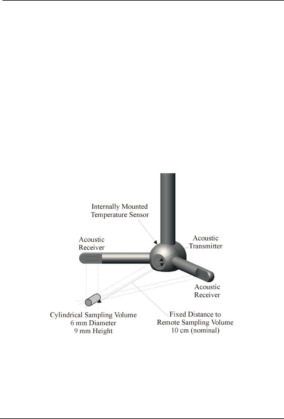
Layout of FlowTracker2 Probe and all major components are labeled in Figure 1:2
• Transmitter – The acoustic transmitter generates a short pulse of sound with the
majority of energy concentrated in a narrow beam (6 mm in diameter).
• Receivers – The acoustic receivers are mounted on arms from the central probe
head. The receivers are sensitive to a narrow beam and are focused on a
common volume located a fixed distance (10 cm; 4 in) from the probe. The
FlowTracker2 uses two or three acoustic receivers for 2D or 3D probes. See
Beam Geometry and 3D Velocity Measurements for details.
• Sampling volume – The sampling volume is the physical location of the water
velocity measurement. See Principle of Operations for details.
• Temperature sensor – The temperature sensor is mounted inside the probe.
Temperature data is used to compensate for changes in sound speed. Sound
speed is used to convert the Doppler shift to water velocity. See Hardware
Specification for details on the temperature sensor; see Principle of Operations
for details about the effect of sound speed on velocity data.
Figure 1:2 - 2D Side Looking FlowTracker2 Probe and Sampling Volume

SonTek – a Xylem brand
FlowTracker2 User’s Manual (February 2016) 18
1.2. Definitions and Terminology
This section defines terms commonly used when working with FlowTracker2
• Averaging Time – The time (in seconds) in which the FlowTracker2 records data
at each measurement location. This is a user-specified value from 10 to 1000
seconds.
• Handheld – The FlowTracker2 is controlled from the keypad on the handheld.
The LCD screen is used to display FlowTracker2 handheld software and real-
time graphical display of raw data.
• Measurement Location – At each measurement location, the FlowTracker2
records one-second velocity data for the specified averaging time, location, water
depth parameters and a variety of statistical and quality control data.
• Ping Rate – The number of pings per second (Hz). The FlowTracker2 ping rate
is 40 Hz.
• Ping – A single estimate of the 2D or 3D water velocity.
• Quality Control Data – In addition to velocity, the FlowTracker2 records several
quality control parameters. These include signal-to-noise ratio (SNR), standard
error of velocity, boundary adjustment, the number of spikes filtered from data,
and velocity angle. For details about quality control data, see Quality Control for
details.
• Salinity – Water salinity is a user-supplied value that is used for sound speed
calculations. Note: If using the system in salt water, a zinc anode should be
installed on the probe for corrosion protection described in Zinc Anodes for
Corrosion Protection.
• Sample – A sample refers to the mean of 10 pings to produce a measurement of
the 2D or 3D water velocity. A sample includes velocity and signal to noise ratio
data. The FlowTracker2 records one sample per second.
• Signal Strength – This refers to the strength of the reflected acoustic signal. It is
a function of the acoustic conditions of the water – primarily the amount and type
of suspended material (scatterers) present. This is most commonly accessed as
a signal-to-noise ratio (SNR).
• Signal-to-Noise Ratio (SNR) – SNR is the ratio of the received acoustic signal
strength to the ambient noise level. It is expressed in logarithmic units (dB), and
is the most important quality control data for the FlowTracker2, see Quality
Control for details.
• Sound Speed – Speed of sound in water (in m/s) is used to convert the Doppler
shift to velocity. See Principle of Operations regarding the effect of sound speed
on velocity data.

SonTek – a Xylem brand
FlowTracker2 User’s Manual (February 2016) 19
• Temperature – Water temperature (in °C) is measured by the internal
temperature sensor. Temperature is used for sound speed calculations.
• UTC - Coordinated Universal Time, abbreviated as UTC, is the primary time
standard by which the world regulates clocks and time
SonTek – a Xylem brand
FlowTracker2 User’s Manual (February 2016) 20
System Operation Section 2.
The System Operation section describes the keypad interface, handheld software
menus and the LCD display.
2.1. On/Off Switch
The On/Off power button for the FlowTracker2 can be accessed on the right side of
the keypad, 3rd row from the top.
a) Start system, hold the power button until the LCD screen turns on.
b) Shutdown system, hold the power button until a message is displayed to shut
down the handheld.
c) Activate sleep mode, press the power button once shutdown.
d) Wakeup system, press any button on keypad.
It’s good practice to remove the battery cartridge at the end of each workday for
inspection and or charging \ replacement.
If the system is not used or stored for long periods, remove the batteries to prevent
unnecessary draining and potential battery leakage.
2.2. Keypad
a) Navigation Keys – The handheld has a number of keys
that are assigned to operate handheld software. The
following keys are available for the user to either
navigate or select options in the software,
i). Left Soft Key – The text directly above the soft key is
associated with the key operations and allows the
user to perform the following actions,
• return to previous menu,
• select action based on text displayed,
• restart or cancel current operation.
ii). Right Soft Key - The text directly above the soft key
is associated with the key operations and allows the
user to perform the following actions,
• start a new measurement,
• accept data entry or operation,
• create new template,
• access the quality control menu.
iii). Left & Right arrow – The key allows the user to
perform the following actions,
• select different options under each parameter in
Figure 2:1 - Keypad
Layout
SonTek – a Xylem brand
FlowTracker2 User’s Manual (February 2016) 21
configuration,
• select station type or velocity method in
measurement,
• select station in data collection.
iv). Top & Bottom arrow – The key allows the user to
perform the following actions,
• scroll through the menu options,
• select files or templates,
• display graphics during data collection,
• scroll through the measurement, station and
discharge summary reports.
b) Enter Key – The enter key (square) is situated between
the four arrow keys and allow the user to perform the
following actions,
i). Select the menu item in the menus
ii). Activate or deactivate running average during the
beam-check data collection. This information is only
displayed graphically and will not be stored in the
data files.
c) Numbers (0-9) – The keys allows the user to perform
the following actions. Numbers will default to the first
option on the key if only numerical values are required in
the entry field.
i). Menu shortcut (number next to text) associated with
each menu item.
ii). Configuration of instrument such, data collection
settings, quality control parameters and discharge
settings
iii). Enter measurement data such, station location, depth
and other information.
d) Letters (A-Z) – The keys allows the user to perform the
following actions. Letters will default to the first option on
the key if letters are required in the entry field.
i). Create file and template names,
ii). Enter comments at a station, supplement data or
overall measurement.
e) Backspace – The key allows the user to perform the
following delete actions,
i). Text or values in user entry fields,
ii). Data file folder with all content or individual data files,
iii). Selected station in Discharge and General mode.
Figure 2:2 - Keypad
Layout

SonTek – a Xylem brand
FlowTracker2 User’s Manual (February 2016) 22
Text entry is done in the same manner as for mobile devices.
• numerical fields, the text entry assumes numbers first (i.e. for “2” press 2 key one
time, 2 – A – B – C);
• text fields, it assumes letters first (i.e. for “B” press 2 key two times, A – B – C)
2.3. Screen Layout
The Screen Layout of the FlowTracker2 consists of the following main features. The
options or information displayed may vary from one screen to the next based on the
software features that are used.
Instrument Time
FlowTracker2 Label
Top banner
Software window
of operation
Left Soft Key
Figure 2:3 - Screen Layout
Battery Level
Selection (yellow)
Right Soft Key
Bottom banner
2.4. Main Menu
When the FlowTracker2 handheld is switched on the FlowTracker2 image is displayed
during the startup process. Flow diagram of the handheld software is supplied in
Software Flow Diagram for both the Discharge and General modes.
FlowTracker2 software layout of the handheld is similar to the “Original FlowTracker”
consisting of the same three main groups, although the wording has changed.
The Main Menu of the handheld software is displayed after the startup process of the
FlowTracker2 is completed.
Main menu consists of four menu options,
a) Device Configuration,
b) Utilities,
c) Communication,
d) System Information
e) To select a menu option,
i). Use up or down scroll arrows keys to select
menu option,
ii). The menu option selected will be highlighted in
Figure 2:4 - Main Menu
SonTek – a Xylem brand
FlowTracker2 User’s Manual (February 2016) 23
yellow,
iii). Press the enter key to access the menu option.
There are also two additional menu options “Data Files” and “Measurement” available to
the user that is situated in the bottom banner of the screen.
f) To select Data Files or Measurement functions,
i). Data Files – Press the Left Soft Key,
ii). Measurement – Press the Right Soft Key.
The number opposite each menu option is a shortcut key (i.e. pressing “2” key will
access the Utilities menu).
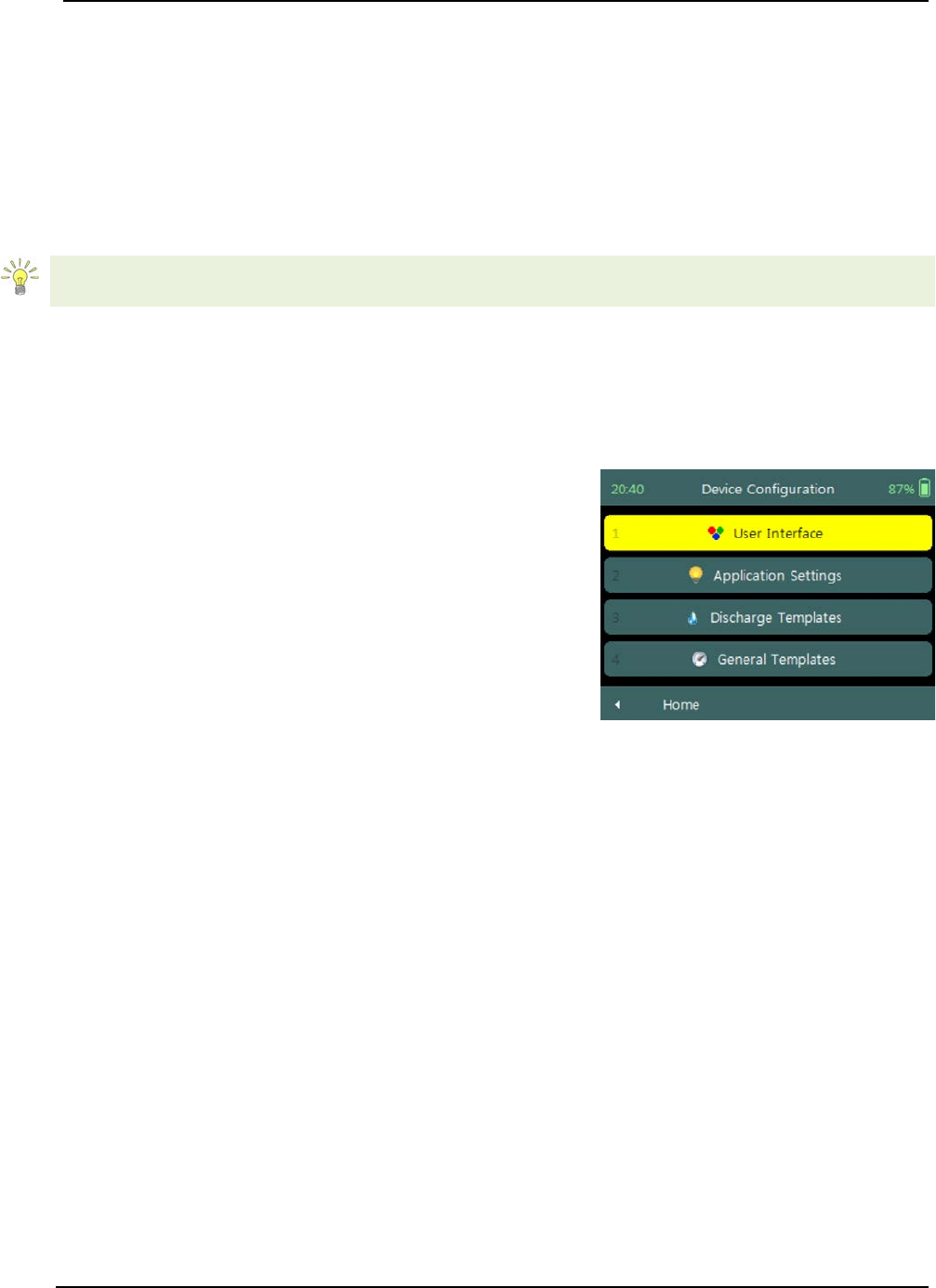
Device Configuration Menu (Main Menu) 2.4.1
The Device Configuration Menu configures how the FlowTracker2 collects data,
performs internal discharge calculations, evaluate data against data quality parameters
and finally determine uncertainty of the measurements based on the method selected.
Device Configuration menu consists of four menu
options,
a) User Interface,
b) Application Settings,
c) Discharge Templates,
d) General Templates.
e) To select a menu option,
i). Use up or down scroll arrows keys to select
menu option,
ii). The menu option selected will be highlighted in
yellow,
iii). Press the enter key to access the menu option.
f) To navigate to Main Menu,
i). Press the Left Soft Key.
Figure 2:5 - Device
Configuration Menu
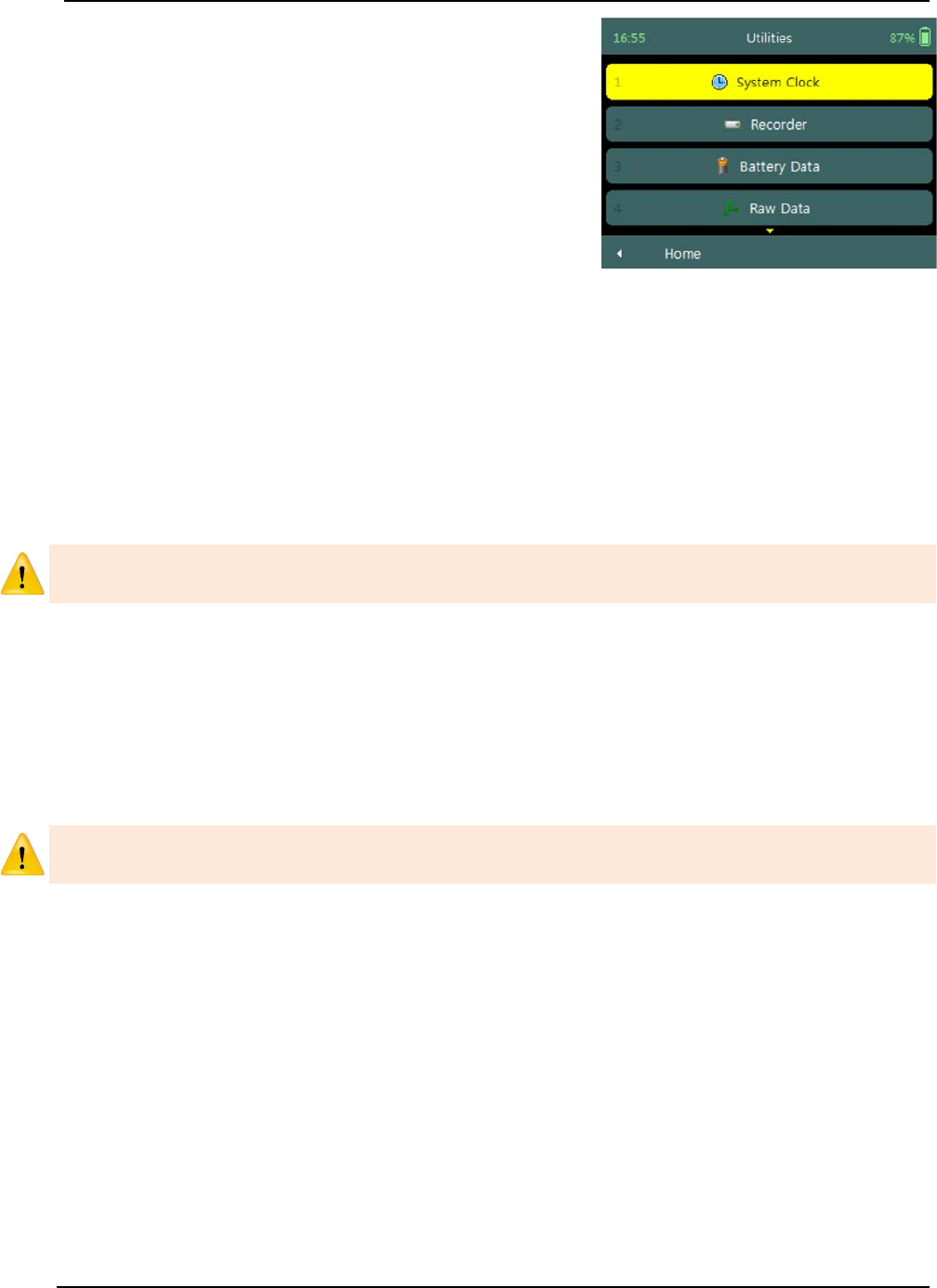
Utilities (Main Menu) 2.4.2
The Utilities Menu accesses internal system functions of the FlowTracker2. The
available functions assists with setting the internal clock and power source, management
of recorder, displaying raw velocity and GPS data and performing tests on measurement
and boundary conditions.
SonTek – a Xylem brand
FlowTracker2 User’s Manual (February 2016) 24
Utilities menu consists of the following menu options,
a) System Clock,
b) Recorder,
c) Battery Data,
d) Raw Data,
e) Automated Beam Check,
f) Beam Check,
g) GPS Data.
h) To select a menu option,
i). Use up or down scroll arrows keys to select
menu option,
ii). The menu option selected will be highlighted in
yellow,
iii). Press the enter key to access the menu option.
i) To navigate to Main Menu,
i). Press the Left Soft Key.
Figure 2:6 - Utilities Menu
The Utilities Menu provides access to functions that should be checked periodically, but
do not directly affect how data is collected.
Communication (Main Menu) 2.4.3
The Communication function permits communication between an external device
equipped with the FlowTracker2 Desktop Software and the handheld. Communication
between the desktop software and handheld can be established by using either a Micro
USB cable or Bluetooth. See Connecting to the FlowTracker2 Handheld ADV for details
of hardware and configuration requirements to enable communication.
The Communication function on the handheld software must be activated first before
the connection feature is selected on the FlowTracker2 desktop software.
System Information (Main Menu) 2.4.4
The System Information screen displays the system information of the FlowTracker2
for both the Handheld and Probe, with the serial number and firmware versions as the
key data sets.
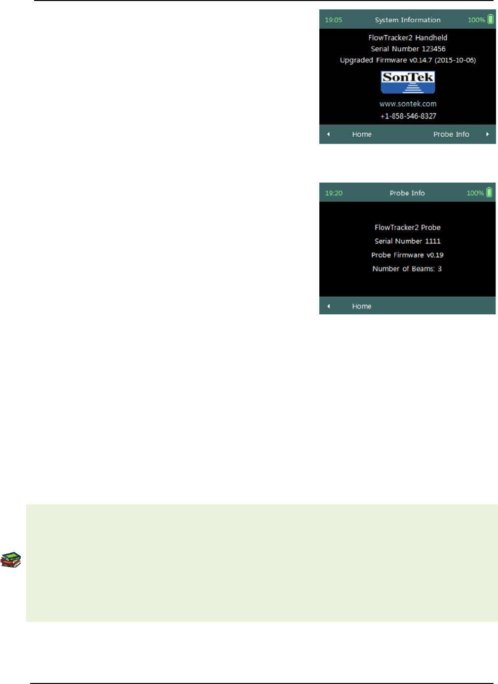
SonTek – a Xylem brand
FlowTracker2 User’s Manual (February 2016) 25
Handheld System Information of the FlowTracker2
includes the following system information,
a) Device (FlowTracker2 Handheld),
b) Serial Number (123456),
c) Upgraded Firmware (V0.14.7).
d) To navigate to Main Menu or Probe Information,
i). Main Menu – Press the Left Soft Key,
ii). Probe Information – Press the Right Soft Key.
Figure 2:7 - Handheld System
Information
Probe System Information of the FlowTracker2
includes the following system information,
a) Device (FlowTracker2 Probe),
b) Serial Number (123456),
c) Probe Firmware (V0.14.7),
d) Number of Beams (2 or 3).
e) To navigate to Main Menu,
i). Press the Left Soft Key two times.
Figure 2:8 - Probe System
Information
Measurement (Main Menu) 2.4.5
The Measurement function is the main component of the FlowTracker2 handheld
software and includes two measurement modes. The Discharge mode is for applications
where the primary goal is to measure river/stream discharge. The technique involves
taking a series of velocity measurements at different locations throughout the cross
section. These measurements are combined with location and water depth information to
compute the total discharge. The General mode is designed to perform a series of
velocity measurements at different locations, but does not provide discharge as an
output.
The methods and techniques implemented for determining the mean station velocity,
calculation of discharge and uncertainty analysis of a measurement are based on the
following literature,
• ISO 748 – 2007, Hydrometry - Measurement of liquid flow in open channels using
current meters or floats,
• WMO-No. 1044, Volume I – Fieldwork, 2010.
• IVE, Quantifying Uncertainty in Discharge Measurements: A New Approach
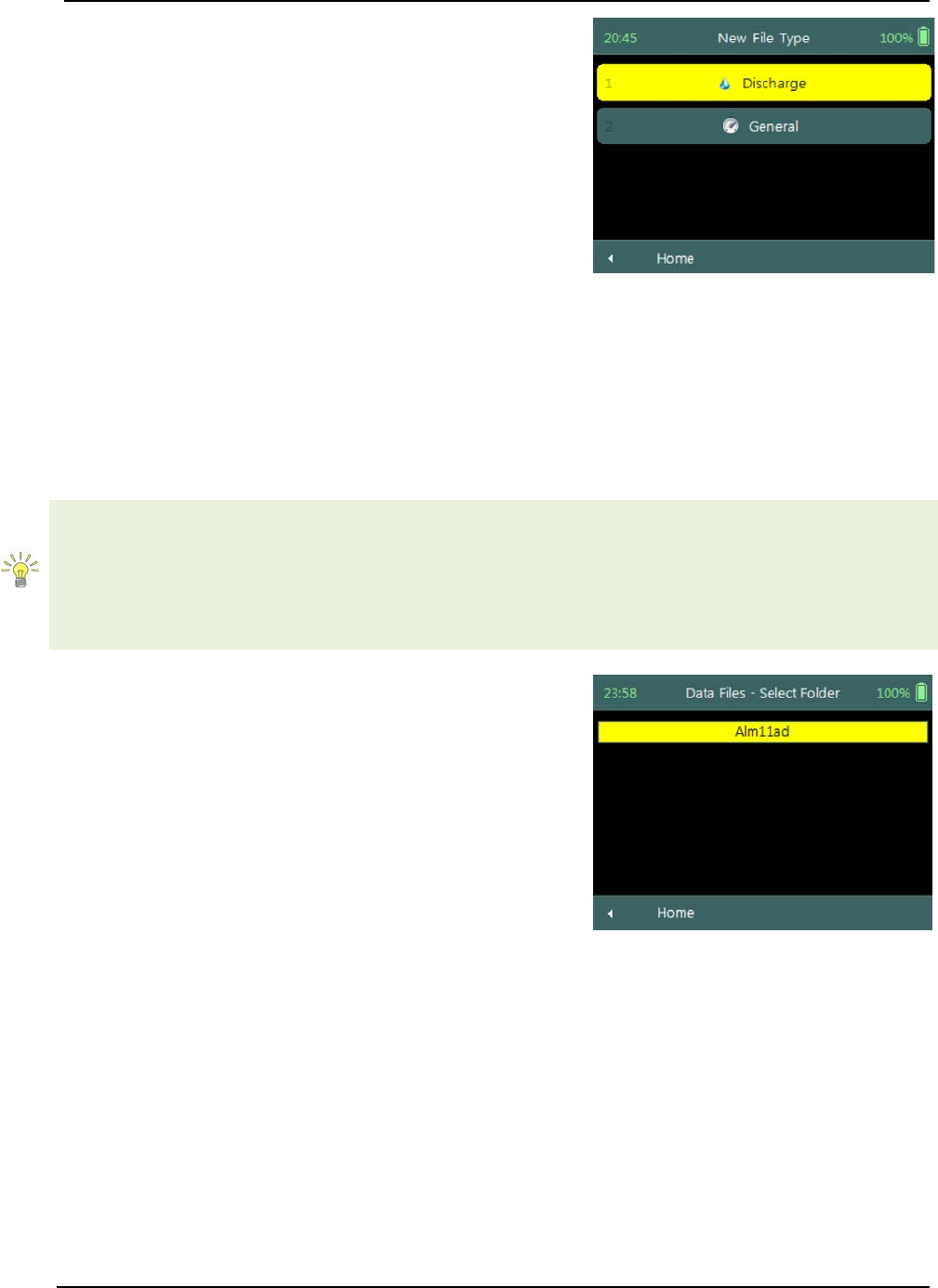
SonTek – a Xylem brand
FlowTracker2 User’s Manual (February 2016) 26
Measurement function consists of two measurement
modes in the menu,
a) Discharge,
b) General.
c) To select a menu option,
i). Use up or down scroll arrows keys to select
menu option,
ii). The menu option selected will be highlighted in
yellow,
iii). Press the enter key to access the menu option.
d) To navigate to Main Menu,
i). Press the Left Soft Key.
Figure 2:9 - Measurement
Data Files (Main Menu) 2.4.6
The Data Files function displays the recorder contents and gives the user access to
FlowTracker2 measurements files.
The FlowTracker2 measurement files can be organized in the recorder based on the
following user defined folder naming conventions,
• Site Name,
• Site Number,
• Month.
Data Files screen displays a list of folders based on
the naming convention. Each folder can consist of
either a single or multiple measurement files.
a) To select a measurement folder,
i). Use up or down scroll arrows keys to select
folder,
ii). The folder will be highlighted in yellow,
iii). Press the enter key to access the folder content,
iv). Selecting a measurement file in the folder,
follow steps i to iii.
b) To DELETE a measurement file or folder
i). Use up or down scroll arrows keys to select
folder or file,
ii). The folder or file will be highlighted in yellow,
iii). Press backspace to delete the folder or file.
iv). The operator will be requested to confirm
deletion of the files or folders.
c) To navigate to Main Menu,
i). Press the Left Soft Key.
Figure 2:10 - Data Files

SonTek – a Xylem brand
FlowTracker2 User’s Manual (February 2016) 27
Before any measurement files and or folders are deleted please ensure that the
following steps are performed,
• Download all measurement files using the FlowTracker2 desktop software,
• Ensure that measurement files are stored in a secure location on PC or Tablet,
• Create a secondary backup of the measurement files by copying to external USB
or network drive.
The delete process is irreversible and the user will not able to retrieve the measurement
files once this action is performed.

SonTek – a Xylem brand
FlowTracker2 User’s Manual (February 2016) 28
Device Configuration Section 3.
3.1. User Interface
User Interface defines the settings related to interaction (view and audio) between the
operator and the device.
User Interface screen includes the following
parameters,
a) Language,
b) Use Beeper,
c) Color Scheme,
d) Font Size,
e) Font Smoothing.
f) To select a parameter,
i). Use up or down scroll arrows keys to select a
parameter,
ii). The parameter selected will be highlighted in
yellow.
g) To navigate to Configuration Menu,
i). Press the Left Soft Key.
Figure 3:1 - User Interface
Language 3.1.1
The list of Predefined Languages supported in FlowTracker2 handheld software is
grouped under the following.
a) Default language – English (US),
b) Other – Chinese-Simplified, Chinese Traditional, French, German, Italian,
Japanese, Korean, Portuguese, Russian, Spanish and Catalan.
c) More languages will be added to FlowTracker2 in subsequent revisions as
SonTek receives translation files. Please contact SonTek if you use the
FlowTracker2 desktop software translator tool to create translation files you wish
to share.
d) To change the Language,
i). Use the left or right arrow key to scroll through the list of available languages.
ii). Press the Left Soft Key to return to Configuration for the software to accept the
change.
Additional languages can be uploaded on the FlowTracker2 handheld using the
FlowTracker2 Translator function available in the FlowTracker2 desktop software.
The process involved in creating translation files and uploading to the handheld is
described in FlowTracker2 Desktop Software.

SonTek – a Xylem brand
FlowTracker2 User’s Manual (February 2016) 29
If you selected a wrong language the menu functions can be a bit hazy! The following
steps will get you out of the gate.
i) the main menu must be displayed, ii) top menu option must be highlighted, iii) press the enter key two
times, iv) use left or right arrow key to select different language, v) press left soft key two times, vi)
handheld software will restart with new selected language.
Use Beeper 3.1.2
An internal speaker is available in the handheld for creating a “Beep” after major
functions is completed in the handheld software.
a) Functions that will create a beep sound are the following,
i). Setting the LCD brightness will result in a beep when the maximum level is
reached,
ii). Sampling completed during point velocity measurement,
iii). Sampling completed during Automated Beam Check.
b) To change the Beeper option,
i). Use the left or right arrow key to select either Yes or No,
ii). Press the Left Soft Key to return to Configuration for the software to accept the
change.
Color Scheme 3.1.3
Color Schemes give the operator the ability to improve visibility of the LCD display
under different light conditions that may be experienced during field work.
a) Color schemes implemented in FlowTracker2 are categorized under the following
schemes,
i). Light,
ii). Medium,
iii). Dark.
b) To change the Color Scheme option,
i). Use the left or right arrow key to scroll through the list of available color schemes,
ii). Press the Left Soft Key to return to Configuration for the software to accept the
change.
Font Size 3.1.4
Font Sizes give the operator the ability to improve visibility of text on the LCD display
under different light conditions that may be experienced during field work.
a) Font sizes implemented in FlowTracker2 are categorized under the following
schemes,
i). Normal,
ii). Large,
iii). Extra Large.
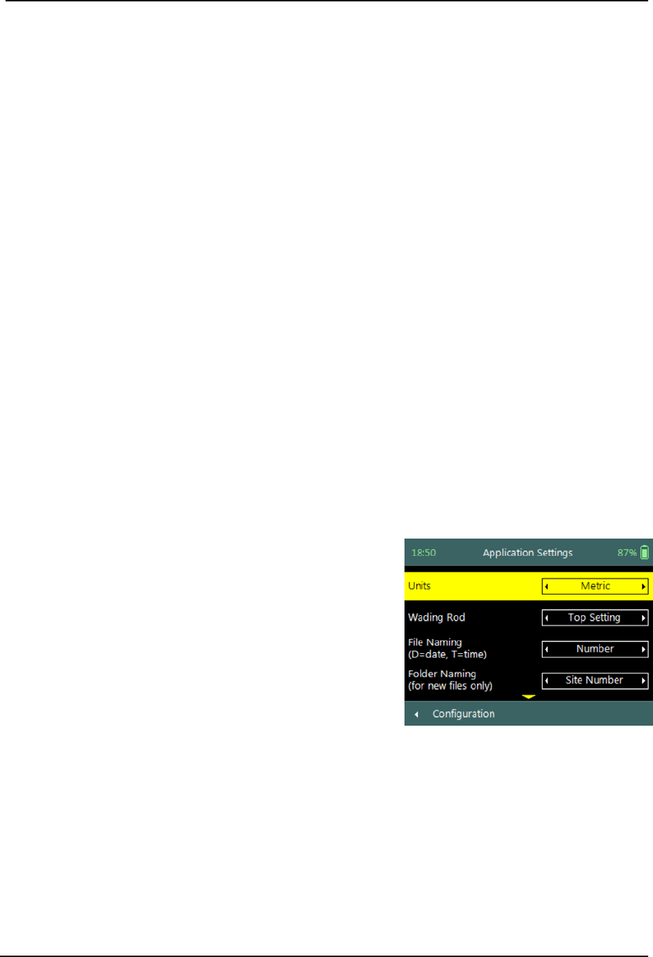
SonTek – a Xylem brand
FlowTracker2 User’s Manual (February 2016) 30
b) To change the Font Size,
i). Use the left or right arrow key to scroll through the list of available font sizes,
ii). Press the Left Soft Key to return to Configuration for the software to accept the
change.
Font Smoothing 3.1.5
The option for Font Smoothing was implemented to improve the overall font
appearance that is affected by low resolution normally associated with small LCD
displays.
a) Font smoothing options that were implemented are categorized under the
following options,
i). Enabled,
ii). Disabled.
b) To change the font Smoothing Option,
i). Use the left or right arrow key to scroll through the list of options,
ii). Press the Left Soft Key to return to Configuration for the software to accept the
change.
3.2. Application Settings
Application Settings define the operator requirements with respect to the units system
used, management of measurement files and overall GPS operation during data
collection.
Application Settings screen includes following
parameters,
a) Units,
b) Wading Rod,
c) File Naming,
d) Folder Naming,
e) GPS Station Tagging.
f) To select a parameter,
i). Use up or down scroll arrows keys to select a
parameter,
ii). The parameter selected will be highlighted in
yellow.
g) To navigate to Configuration Menu,
i). Press the Left Soft Key.
Figure 3:2 - Application Settings
Units 3.2.1
The Units function defines the Units System used for displaying and outputting
measurement data.
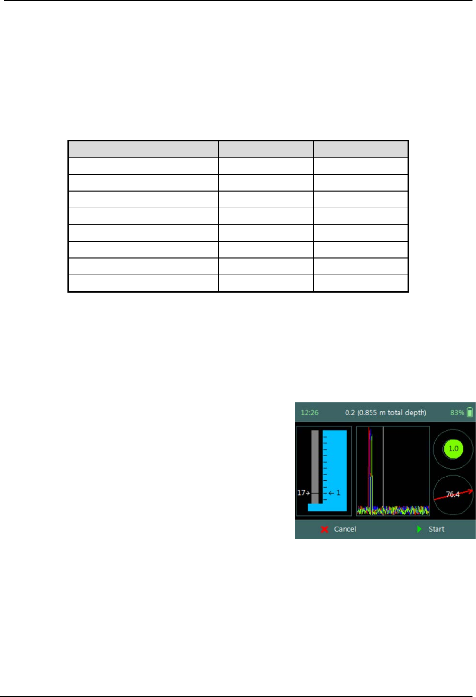
SonTek – a Xylem brand
FlowTracker2 User’s Manual (February 2016) 31
a) The Units Systems supported in FlowTracker2 is grouped under the following,
i). Metric,
ii). English,
b) The internal unit system used is Metric and this does not affect internal
calculations or data storage,
c) Table 3:1 list the units that are used for display.
Table 3:1 – FlowTracker2 Display Units
Parameter
English Units
Metric Units
Location
feet
meters
Depth
feet
meters
Pressure
dbar
dbar
Velocity
ft/s
m/s
Standard error of velocity
ft/s
m/s
Staff / Gauge height
feet
meters
Discharge
ft3/s
m3/s
SNR
dB
dB
d) To change the Unit option,
i). Use the left or right arrow key to scroll through the list of options,
ii). Press the Left Soft Key to return to Configuration for the software to accept the
change.
Wading Rod 3.2.2
Wading Rod function gives the operator the choice of
what type of wading rod is used during the
measurement. The selection of the type of wading
rod will impact what graphics are displayed during the
data collection process and what reference (water
surface or bottom) is used in determining instrument
depth.
Figure 3:3 - Top Setting Wading
Rod Graphic
a) The Wading Rods supported in FlowTracker2 are grouped under the following,
i). Top-Setting (Instrument referenced to water surface)
ii). Universal (Instrument referenced to bottom)
iii). Ice (Instrument referenced to water surface)
iv). Unknown
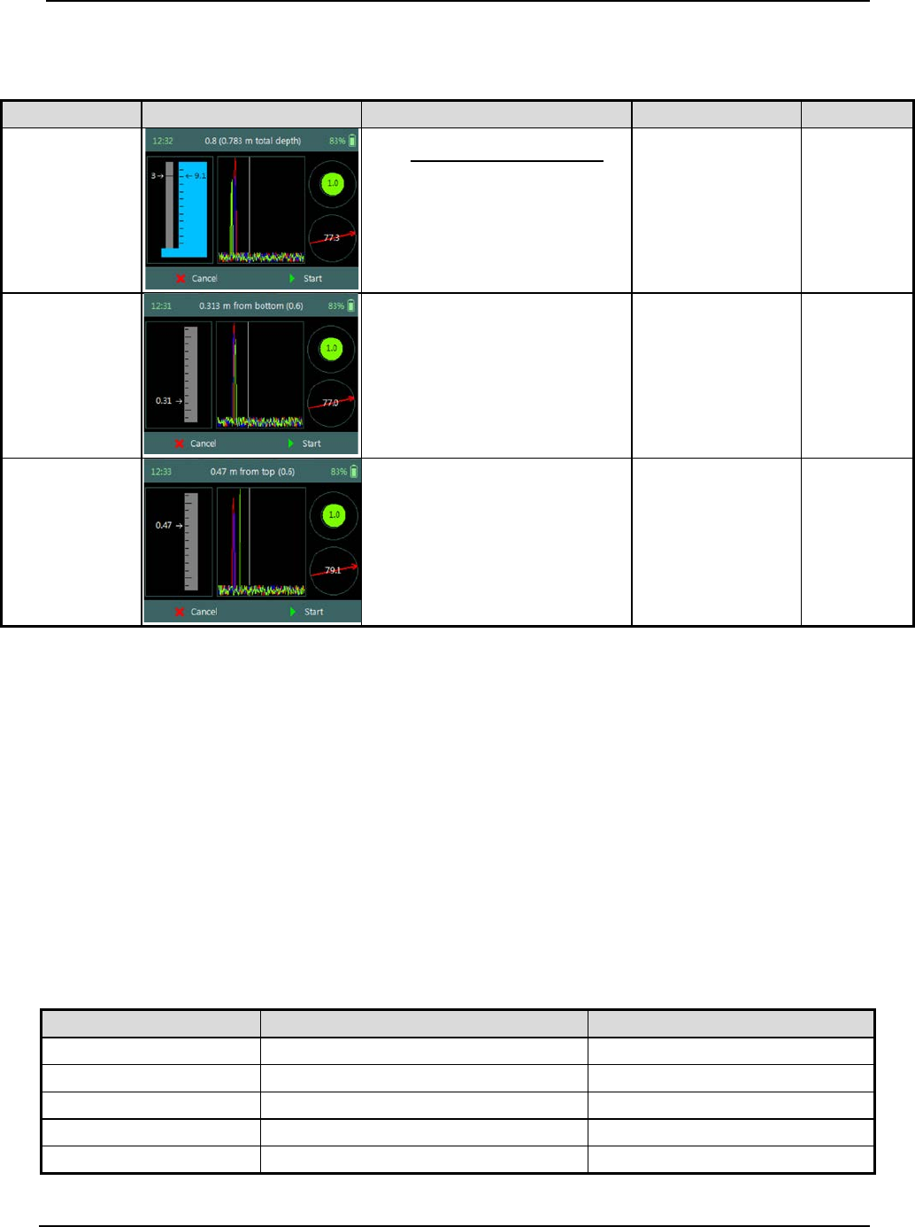
SonTek – a Xylem brand
FlowTracker2 User’s Manual (February 2016) 32
b) The graphic representation of the Wading Rods supported and the fractional
depth indicators are defined in Table 3:2,
Table 3:2 - Wading Rod Graphics
Wading Rod
Graphic
Wading Rod Setting
Example
Reference
Top Setting
=1×
0.4
fdepth – Fractional Depth
wdepth – Water Depth
w
depth
= 0.783m
fdepth = 0.8
Rod = 0.391
Water
Surface
Universal
=×
fdepth – Fractional Depth
wdepth – Water Depth
w
depth
= 0.783m
fdepth = 0.6
Rod = 0.313
Channel
Bed
Ice
=×
fdepth – Fractional Depth
wdepth – Water Depth
w
depth
= 0.783m
fdepth = 0.6
Rod = 0.469
Water
Surface
c) To change the Wading Rod type,
i). Use the left or right arrow key to scroll through the list of options,
ii). Press the Left Soft Key to return to Configuration for the software to accept the
change.
File Naming 3.2.3
The File Naming function enables the operator to assign a unique name for each
measurement file. The file naming process in FlowTracker2 ensures that existing
measurement files are not overwritten.
a) The file naming conventions that are supported in FlowTracker2 software are
listed in Table 3:3,
Table 3:3 - File Naming Conventions
Naming Convention
Description
Example
Number
Site Number
09429500
Number_Date
Site Number_yyyymmdd
09429500_20151013
Number_DT
Site Number_yyyymmdd-hhmmss
09429500_20151013-170220
Date_Number
yyyymmdd_Site Number
20151013_09429500
DT_Number
yyyymmdd-hhmmss_Site Number
20151013-170220_09429500
SonTek – a Xylem brand
FlowTracker2 User’s Manual (February 2016) 33
Naming Convention
Description
Example
Name
Site Name
Colorado
Name_Date
Site Name_yyyymmdd
Colorado_20151013
Name_DT
Site Name_yyyymmdd-hhmmss
Colorado_20151013-170220
Date_Name
yyyymmdd_Site Name
20151013_Colorado
DT_Name
yyyymmdd-hhmmss_Site Name
20151013-170220_Colorado
b) A Follow Number is incorporated at the end of the new file name, if there are files
in the recorder with the same file name. The follow number will increase
incrementally for every new file created with the same file name (e.g.
09429500_20151013_3)
d) To change the File Naming convention,
i). Use the left or right arrow key to scroll through the list of options,
ii). Press the Left Soft Key to return to Configuration for the software to accept the
change.
It’s recommended that file the naming convention used contains both the date and time.
This will ensure that an unique file name is created for each measurement and can
easily be sorted in Windows explorer when downloaded from FlowTracker2 handheld,
• yyyymmdd-hhmmss_Site Number,
• yyyymmdd-hhmmss_Site Name.
Folder Naming 3.2.4
The Folder Naming function enables the operator to organize measurement files in the
recorder by grouping by site or month.
a) The folder naming conventions that are supported in FlowTracker2 software are
grouped under the following,
i). Site Number,
ii). Site Name,
iii). yyyy-mm.
b) A folder is created automatically in the recorder when a measurement file is
created based on the folder naming convention. If all the measurement files are
deleted, the folder will be removed from the recorder.
c) To change the Folder Naming convention,
i). Use the left or right arrow key to scroll through the list of options,
ii). Press the Left Soft Key to return to Configuration for the software to accept the
change.
GPS Station Tagging 3.2.5
The GPS Station Tagging function allows the operator control over the GPS operation
during measurements.
SonTek – a Xylem brand
FlowTracker2 User’s Manual (February 2016) 34
a) The GPS options that are supported in FlowTracker2 software are grouped under
the following,
i). Automatic. The automatic option for the GPS allows the FlowTracker2 to
perform GPS measurements at each station without any additional interaction
with the software.
• The GPS receiver is Continuously Operating and receiving data from
satellites when the FlowTracker2 handheld is activated.
• If a GPS lock is not obtained before the station measurement is completed,
the software will not record positional information for the station. The GPS
status Icons are listed in Table 3:4.
• The positional information is averaged over the time a station is created to
improve the overall measurement accuracy. The software starts averaging
the positional information when the Add Station function is selected and
stops when the station is completed, from where the averaged position is
recorded against the station. The averaging process is performed for both
Discharge and General modes.
• When editing an existing station and Automatic GPS mode is selected, the
logic reverts to “Manual GPS” mode to ensure that a position is not
assigned while editing away from the actual station location.
The operator needs to ensure that the wading rod is placed in the correct position and
vertical before the “Add Station” function is selected. This will improve the overall
accuracy of the GPS measurement.
ii). Manual. The manual option provides the operator control over GPS
measurements and requires the operator to select “Record GPS Location”
function before velocity measurements are made at a station for both
Discharge and General modes.
• The GPS receiver is on Cold Start and is NOT receiving data from satellites.
• The manual GPS measurement option forms part of the “Add Station”
configuration screen and is located at the bottom of the screen. The
“Record GPS Location” function can be accessed by using the Bottom
Arrow.
• If a GPS lock is not obtained before the station measurement is completed,
the software will not record positional information for the station. The GPS
status Icons are listed in Table 3:4.
• The positional information is averaged when the “Record GPS Location”
function is selected. The period of averaging the positional information is
dependent on the user and a counter will display the number of
measurements averaged.
• The “Record GPS location” at the bottom of the configuration screen will
state “Record GPS location” if no location is assigned yet and “Update GPS
location” if a location is already assigned.
SonTek – a Xylem brand
FlowTracker2 User’s Manual (February 2016) 35
iii). Disabled. The GPS is disabled and the operator will not be able to perform
any GPS measurements.
b) The status of GPS lock is indicated by GPS icon displayed on the left corner of
the top banner of the LCD screen. The icon’s describing the GPS status in the
handheld is defined in Table 3:4,
Table 3:4 - GPS Status Icons
Icon
Description
Conditions
Attempting to acquire satellite
signal.
GPS has not acquired any satellite
signal or GPS lock and is unable to
determine positional information
Acquiring satellite signal in
progress.
GPS is acquiring additional satellite
signals, low quality positional
information available, number of
satellites < 4 and or HDOP > 2.5.
Satellite signal acquired from
available satellites.
GPS lock is obtained, high quality
positional information available.
c) The averaging of positional information from the internal GPS is based on the
following criteria,
i). Averaging is limited to 1000 records. If more than 1000 records are reported –
the oldest records are dropped.
ii). Averaging is performed only when 5 or more records are recorded, otherwise
the record with the lowest HDOP/max satellites is used.
iii). If 10 or more “high quality records” are recorded – only high quality records are
used for the averaging. Otherwise both high/low quality records are used for
the averaging.
d) To change the GPS station tagging option,
i). Use the left or right arrow key to scroll through the list of options,
ii). Press the Left Soft Key to return to Configuration for the software to accept the
change.
3.3. Configuration Templates
Template Options 3.3.1
The Templates implemented in FlowTracker2 consists of the following template options.
The templates consist of number of configuration parameters required for performing
measurements in either Discharge or General mode under the Measurement function.
• Discharge Template
• General Template
SonTek – a Xylem brand
FlowTracker2 User’s Manual (February 2016) 36
Templates are similar to configuration files where the operator defines the configuration
of the instrument, based on,
• site details,
• data collection requirements
• quality control parameters,
• measurement methods (only for discharge mode).
The operator has the ability to create a unique configuration template for a single
monitoring site, region or organization.
It’s recommended that a unique template is created for each monitoring site. The
advantage of this is twofold, operator does not have to enter in the site number and
name for every measurement, and ensure that site number and name is consistent.
Managing Templates 3.3.2
Accessing Templates 3.3.2.1
Templates are stored separately from the measurement files on the internal memory of
the FlowTracker2 handheld and are managed from the Discharge or General Template
functions under the Device Configuration Menu. The following process describes how to
create, remove or select an existing template.
Templates for Discharge and General Modes can be
accessed from the Device Configuration menu,
a) To select a Template type,
i). Use up or down scroll arrows keys to select the
template,
ii). The template option selected will be highlighted
in yellow,
iii). Press the enter key to access the template
operating screen.
b) To navigate to Main Menu,
i). Press the Left Soft Key.
Figure 3:4 - Device
Configuration Menu
Template Operating Screen will list all available
templates on the handheld or if there are no
templates available, indicate “Currently there are no
user templates defined – please use the ‘New
Template’ button to create the first template”.
a) To create a new Template,
i). Press the Right Soft Key,
ii). The software will redirect to “New Template”
screen.
b) To navigate to Configuration Menu,
i). Press the Left Soft Key.
Figure 3:5 - Template Operating
Screen
SonTek – a Xylem brand
FlowTracker2 User’s Manual (February 2016) 37
New Template 3.3.2.2
New Template screen displays two parameters that
need to be completed to create a new template,
a) Template Name is user defined. The template
name can be up to 50 characters long.
b) Base Template defines the default
configuration used for new template. The user
has the option to select the default SonTek
configuration or from existing user
configurations.
c) To accept new Template,
i). Press the Right Soft Key,
ii). The software will return to template screen.
d) To CANCEL new Template,
i). Press the Left Soft Key.
Figure 3:6 - New Template
Selecting Template 3.3.2.3
Selecting Template is performed from the template
main screen.
a) To select a Template,
i). Use up or down scroll arrows keys to select the
template,
ii). The template name selected will be highlighted
in yellow,
iii). Press the enter key to access the template
screen.
b) To navigate to Configuration or New Template,
i). Configuration - Press the Left Soft Key
ii). New Template - Press the Right Soft Key
Figure 3:7 - Selecting Template
3.4. Template Functions
The Template functions for Discharge and General Modes contain all the configuration
parameters required for performing velocity measurements, discharge calculation and
uncertainty analysis. The functions defined under each template contain site
information, data collection criteria, quality control parameters and measurement
methods (only for discharge mode).
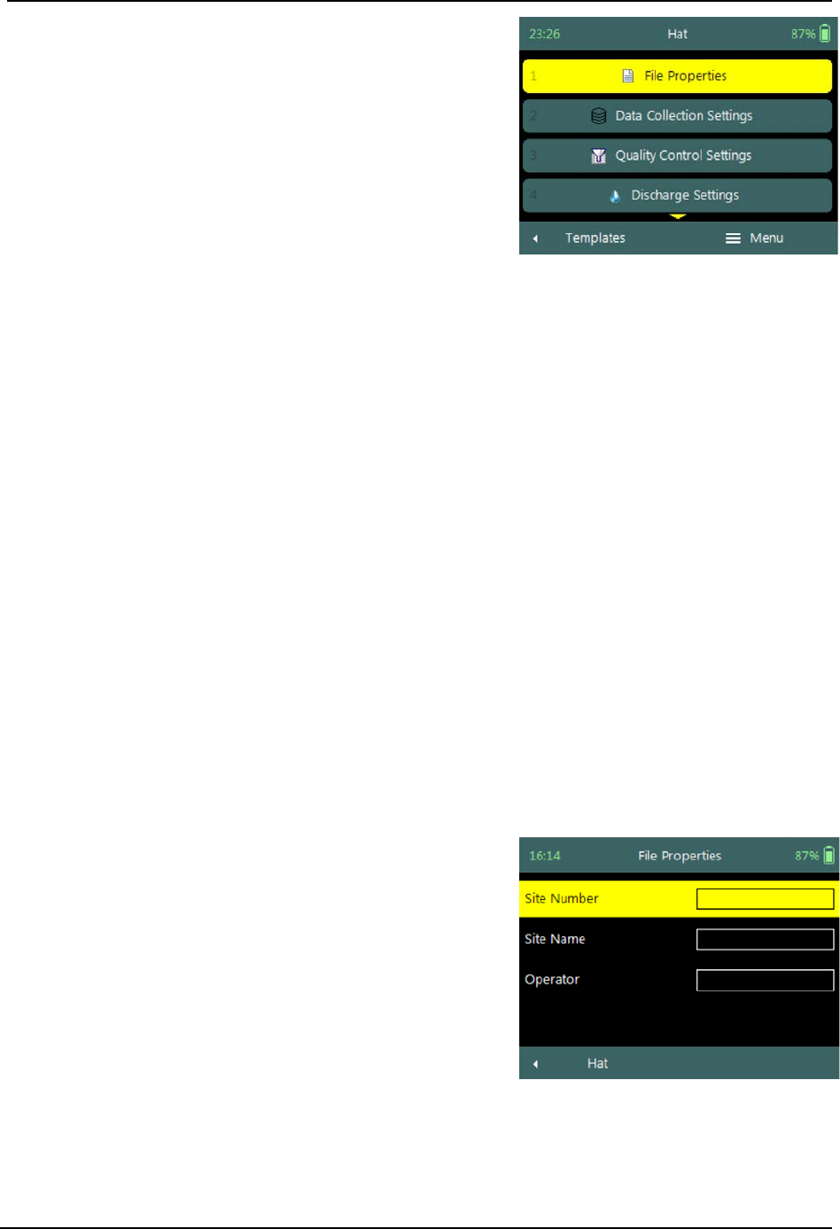
SonTek – a Xylem brand
FlowTracker2 User’s Manual (February 2016) 38
Template menu consists of the following menu
options,
a) File Properties,
b) Data Collection Settings,
c) Quality Control Settings,
d) Discharge Settings (only for discharge mode),
e) Displayed Velocity Methods (only for discharge
mode).
f) To select a menu option,
i). Use up or down scroll arrows keys to select
menu option,
ii). The menu option selected will be highlighted in
yellow,
iii). Press the enter key to access the menu option.
g) To navigate to Template Screen,
i). Press the Left Soft Key.
h) To Rename or DELETE a Template in Menu,
i). Press the Right Soft Key.
ii). To select menu option, use up or down scroll
arrows keys,
iii). The menu option selected will be highlighted in
yellow,
iv). Press the enter key to access the menu option.
Figure 3:8 - Template Menu
File Properties 3.4.1
The File Properties function contains site information applicable to the measurement
site and operator details. The file properties ensure that the required Metadata are
associated with both measurement site and data collected.
File Properties screen includes the following
parameters,
a) Site Number,
b) Site Name,
c) Operator.
d) To select a parameter,
i). Use up or down scroll arrows keys to select a
parameter,
ii). The parameter selected will be highlighted in
yellow.
e) To enter text,
i). Use the backspace key to clear current entry,
ii). Enter numerical or alphabetical characters using
Figure 3:9 - File Properties
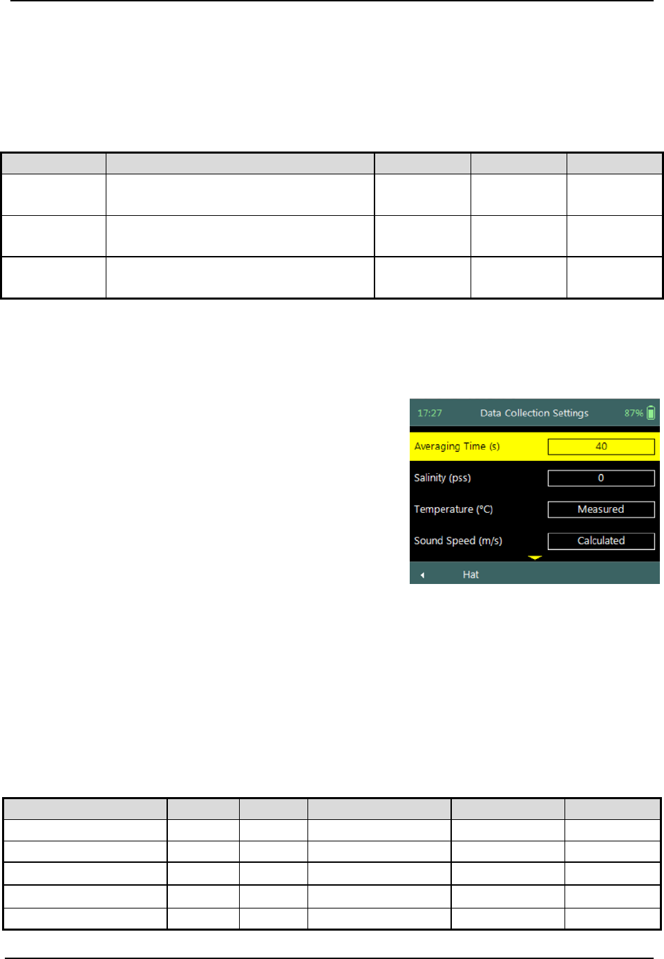
SonTek – a Xylem brand
FlowTracker2 User’s Manual (February 2016) 39
the keypad.
f) To navigate to Template Menu,
i). Press the Left Soft Key.
Properties associated with the parameters in file properties are defined in Table 3:5,
Table 3:5 - File Properties - Properties
Parameter
Description
Field Size
Default
Required
Site Number
Enter unique site number (e.g.
Hydrometric Station Number)
50
Number
keypad
No
Site Name
Enter unique site name (e.g.
Hydrometric Station Name)
50
Alphabet
keypad
No
Operator
Operator name can be entered in this
field (e.g. Bees Blaas)
50
Alphabet
keypad
No
Data Collection Settings 3.4.2
The Data Collection Settings function contains parameters required for sound speed
calculation and averaging time of velocity measurements,
Data Collection Settings screen includes the
following parameters,
a) Averaging Time,
b) Salinity,
c) Temperature,
d) Sound Speed,
e) Mounting Correction.
f) To select a parameter,
i). Use up or down scroll arrows keys to select a
parameter,
ii). The parameter selected will be highlighted in
yellow.
g) To navigate to Template Menu,
i). Press the Left Soft Key.
Figure 3:10 - Data Collection
Settings
Properties associated with the parameters in data collection settings are defined in
Table 3:6,
Table 3:6 - Data Collection Settings - Properties
Parameter
Min
Max
Default
Units
Required
Averaging Time
10
1000
40
seconds
Yes
Salinity
0
42
0
PSU
Yes
Temperature
-5
50
Internal Measured
°C or °F
Yes
Sound Speed
1400
1580
Internal Calculated
m/s or ft/s
Yes
Mounting Correction
-5
5
0
%
Yes
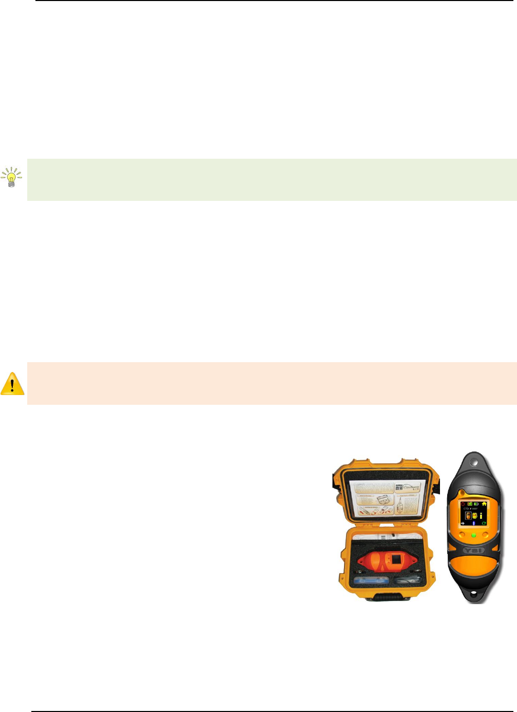
SonTek – a Xylem brand
FlowTracker2 User’s Manual (February 2016) 40
Averaging Time 3.4.2.1
The Averaging Time parameter specifies the time duration (in seconds) of data
collection during each point velocity measurement.
a) Averaging time is specified in 1-second intervals from 10 to 1000 seconds.
b) The default Averaging Time applied in FlowTracker2 is 40s.
c) To change the Averaging Time,
i). Use the backspace key to clear current entry,
ii). Type in the new value using the keypad.
The averaging time required for single point velocity measurement is usually from 40 to
60 seconds. This however is site dependent and longer averaging times are required
when measuring in turbulent flow conditions.
Salinity 3.4.2.2
The Salinity parameter specifies the salinity value in Practical Salinity Scale
(dimensionless) used to compute sound speed.
a) Salinity is specified in Practical Salinity Scale (PSS-78). Fresh water has a
salinity of 0; seawater salinity generally ranges from 31 to 39 (PSS). The PSS-78
range is 2 to 42 for a temperature range of -2°C to +35°C and hydrostatic
pressure 0 – 10000dBar.
b) The default Salinity applied in FlowTracker2 is 0 (PSS).
Where a measurement location exceeds the PSS-78 range, Salinity cannot be used for
calculation of Sound Speed. Sound Velocimeters must be used to measure the actual
sound speed of the water directly at the measurement location.
c) As a rule of thumb, a 12 (PSS) error in the value of salinity will result in a 1% error
in sound speed, which results in a 2% error in velocity data.
d) Salinity should be specified or determined
using a CTD instrument as accurately as
possible for each measurement location. The
CastAway-CTD is a lightweight, easy to use
instrument designed for quick and accurate
conductivity, temperature, and depth profiles.
Starting with a unique six-electrode
conductivity cell and fast response thermistor
the CastAway makes use of modern
technology to provide state of the art CTD
measurements.
Figure 3:11 - CastAway - CTD
e) Sound speed is used in Doppler velocity calculations. See the Principle of
Operations for details about the effect of sound speed on velocity data.
f) To change the Salinity,
i). Use the backspace key to clear current entry,
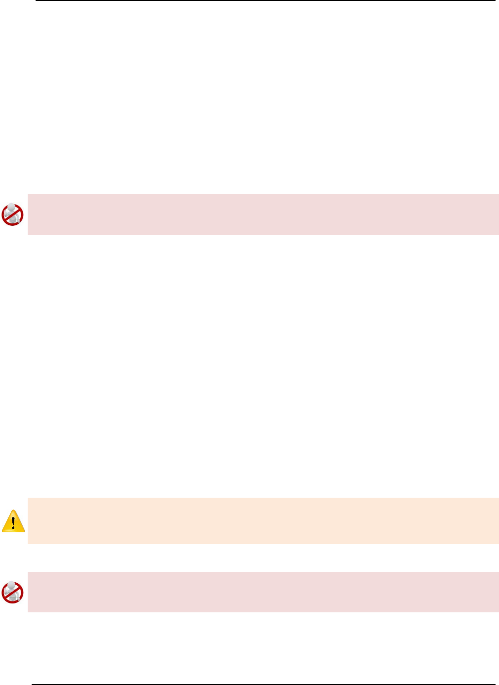
SonTek – a Xylem brand
FlowTracker2 User’s Manual (February 2016) 41
ii). Type in the new value using the keypad.
Temperature 3.4.2.3
The Temperature parameter specifies the temperature value used to compute sound
speed.
a) The temperature value used to compute sound speed is based on internal
temperature sensor by default. The temperature field will be populated with the
value “Measured” to indicate it is based on internal temperature sensor.
b) Water temperature measured by external devices can be entered in the
temperature field. The temperature value from the external sensor will then be
used for sound speed calculations.
The temperature field cannot be used to store reference temperature readings as this
will be used in the sound speed calculations. It is recommended that reference
temperature readings be documented in the comments fields.
c) Sound speed is used in Doppler velocity calculations. See the Principle of
Operations for details about the effect of sound speed on velocity data.
d) Enter external temperature reading,
i). If the default value “Measured” is displayed, start typing using keypad, otherwise,
ii). Use the backspace key to clear current entry,
iii). Type in the new value using the keypad.
Sound Speed 3.4.2.4
The Sound Speed parameter specifies the sound speed value used in Doppler velocity
calculations.
a) The sound speed value used in Doppler velocity calculations is based on internal
calculations by default. The sound speed field will be populated with the value
“Calculated” to indicate it is based internal calculations.
b) Sound Speed measured by external devices can be entered in the sound speed
field. The sound speed value from the external sensor will then be used in
Doppler velocity calculations.
Where a measurement location exceeds the PSS-78 range, Salinity cannot be used for
calculation of Sound Speed. Sound Velocimeters must be used to measure the actual
sound speed of the water directly at the measurement location.
The sound speed field cannot be used to store reference sound speed readings as this
will be used in the Doppler velocity calculations. It is recommended that reference
sound speed readings be documented in the comments fields.
c) Sound speed is used in Doppler velocity calculations. See Principle of Operations
for details about the effect of sound speed on velocity data.
d) Enter external Sound Speed reading,

SonTek – a Xylem brand
FlowTracker2 User’s Manual (February 2016) 42
i). If the default value “Calculated” is displayed, start typing using keypad, otherwise,
ii). Use the backspace key to clear current entry,
iii). Type in the new value using the keypad.
Mounting Correction 3.4.2.5
The Mounting Correction parameter specifies how to account for the device used to
hold the FlowTracker2 in the water. The type of mount may have a small impact on
velocity measurements.
a) The mounting correction allows the FlowTracker2 to account for the effect of flow
disturbances caused by the mount.
b) The default mounting correction applied in FlowTracker2 is 0%.
c) The application of a mounting correction to account for the effects of flow
disturbance on velocity measurements was researched by several independent
agencies. At present, no consensus has been reached between different
agencies in the requirement of the mounting correction. See Mounting Correction
for details about the effect of flow disturbance on velocity measurements.
d) To change the Mounting Correction,
i). Use the backspace key to clear current entry,
ii). Type in the new value using the keypad.
Quality Control Settings 3.4.3
The Quality Control Settings function contains parameters required for the Quality
Control process.
Quality Control Settings screen includes the
following parameters,
a) SNR Threshold,
b) Std Error Threshold,
c) Spike Threshold,
d) Velocity Angle for Warning,
e) Tilt Angle Warning.
f) To select a parameter,
i). Use up or down scroll arrows keys to select a
parameter,
ii). The parameter selected will be highlighted in
yellow.
g) To navigate to Template Menu,
i). Press the Left Soft Key.
Figure 3:12 - Quality Control
Settings
Properties associated with the parameters in quality control settings are defined in
Table 3:7,
Table 3:7 - Quality Control Settings - Properties

SonTek – a Xylem brand
FlowTracker2 User’s Manual (February 2016) 43
Parameter
Min
Max
Default
Units
Required
SNR Threshold
0
50
10
dB
Yes
Std Error Threshold
0.001
0.25
0.01
m/s or ft/s
Yes
Spike Threshold
0.01
50
10
%
Yes
Velocity Angle for Warning
0.1
90
20
degrees
Yes
Tilt Angle Warning
0.1
5
5
degrees
Yes
SNR Threshold 3.4.3.1
The SNR Threshold parameter is a minimum threshold placed on the SNR variable
during real-time data collection.
a) SNR is primarily a function of the amount of particulate matter in the water. For
good conditions, SNR should be at least 10 dB.
b) The system can operate effectively with SNR as low as 2-3 dB, although the noise
in individual velocity measurements will increase.
c) The default SNR Threshold applied in FlowTracker2 is 10dB.
d) To change the SNR Threshold,
i). Use the backspace key to clear current entry,
ii). Type in the new value using the keypad.
e) To DISABLE the SNR Threshold,
i). Use the backspace key to clear current entry until “Disabled” is displayed.
Std Error Threshold 3.4.3.2
The Standard Error Threshold parameter is a maximum threshold placed on the
Standard Error of velocity measurements.
a) Standard error of velocity (σV) is a direct measure of the accuracy of the mean
velocity data.
b) The default Standard Error Threshold applied in FlowTracker2 is 0.01m/s.
c) To change the Standard Error Threshold,
i). Use the backspace key to clear current entry,
ii). Type in the new value using the keypad.
d) To DISABLE the Standard Error Threshold,
i). Use the backspace key to clear current entry until “Disabled” is displayed.
Spike Threshold 3.4.3.3
The Spike Threshold parameter is the maximum threshold placed on the percentage of
spikes within a measurement.
a) Spikes in velocity data occur with any acoustic Doppler velocity sensor such as
the FlowTracker. Spikes may have a variety of causes – large particles, air
bubbles, or acoustic anomalies.
b) The default Spike Threshold applied in FlowTracker2 is 10%.
SonTek – a Xylem brand
FlowTracker2 User’s Manual (February 2016) 44
c) To change the Spikes Threshold,
i). Use the backspace key to clear current entry,
ii). Type in the new value using the keypad.
d) To DISABLE the Spikes Threshold,
i). Use the backspace key to clear current entry until “Disabled” is displayed.
Velocity Angle for Warning 3.4.3.4
The Velocity Angle for Warning parameter is the maximum threshold placed on the
velocity angle towards the probe.
a) An angle of 0° means flow direction is perpendicular to the tag line (as desired for
an ideal measurement location).
b) The default Velocity Angle for Warning applied in FlowTracker2 is 20 degrees.
c) To change the Velocity Angle for Warning,
i). Use the backspace key to clear current entry,
ii). Type in the new value using the keypad.
d) To DISABLE the Velocity Angle for Warning,
i). Use the backspace key to clear current entry until “Disabled” is displayed.
Tilt Angle Warning 3.4.3.5
The Tilt Angle Warning parameter is the maximum threshold placed on the tilt angle of
the wading rod.
a) An angle of 0° means the wading rod is vertical (as desired for an ideal mounting
position).
b) The default Tilt Angle Warning applied in FlowTracker2 is 5 degrees.
c) To change the Tilt Angle Warning,
i). Use the backspace key to clear current entry,
ii). Type in the new value using the keypad.
d) To DISABLE the Tilt Angle Warning,
i). Use the backspace key to clear current entry until “Disabled” is displayed.
Discharge Settings 3.4.4
The Discharge Settings function contains parameters required for discharge
calculations, discharge uncertainty analysis and quality control process.
Discharge settings function is only applicable to the Discharge Mode. The General
Mode does not contain any discharge calculation or uncertainty analysis.
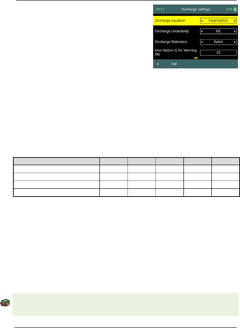
SonTek – a Xylem brand
FlowTracker2 User’s Manual (February 2016) 45
Discharge Settings screen includes the following
parameters,
a) Discharge Equation,
b) Discharge Uncertainty,
c) Discharge Reference,
d) Max Station Q for Warning,
e) Max Depth Change for Warning,
f) Max Spacing Change for Warning.
g) 0.6 Method Depth
h) To select a parameter,
i). Use up or down scroll arrows keys to select a
parameter,
ii). The parameter selected will be highlighted in
yellow.
i) To navigate to Template Menu,
i). Press the Left Soft Key.
Figure 3:13 - Discharge Settings
Properties associated with the parameters in discharge settings are defined in Table
3:8,
Table 3:8 - Discharge Settings - Properties
Parameter
Min
Max
Default
Units
Required
Max Station Q for Warning
0.01
100
10
%
Yes
Max Depth Change for Warning
0.01
200
50
%
Yes
Max Spacing Change for Warning
0.01
200
100
%
Yes
0.6 Method Depth
0
100
0.5
m or ft
Yes
Discharge Equation 3.4.4.1
The Discharge Equation parameter allows the user to specify what type of discharge
calculation method must be applied in the discharge calculation process.
a) The discharge equation calculation methods supported in FlowTracker2 software
is grouped under the following,
i). Mid-Section Method,
ii). Mean-Section Method,
iii). Japanese Method.
b) The default Discharge Equation applied in FlowTracker2 is Mid-Section.
The Arithmetic methods implemented for calculation of discharge are based on the
following literature,
• ISO 748 – 2007, Hydrometry - Measurement of liquid flow in open channels using
SonTek – a Xylem brand
FlowTracker2 User’s Manual (February 2016) 46
current meters or floats,
• WMO-No. 1044, Volume I – Fieldwork, 2010.
• Japanese Literature
c) To change the Discharge Equation method,
i). Use the left or right arrow key to scroll through the list of options,
Discharge Uncertainty 3.4.4.2
The Discharge Uncertainty parameter allows the user to specify what type of
uncertainty analysis must be applied in the discharge calculation process.
a) The discharge uncertainty analysis supported in FlowTracker2 software is
grouped under the following,
i). ISO 748 - 2007
ii). Interpolated Variance Estimator (IVE)
b) The default Discharge Uncertainty method applied in FlowTracker2 is IVE.
c) The discharge uncertainty analysis was not implemented for the Japanese
discharge equation method.
The uncertainty analysis implemented for determining the overall discharge uncertainty
are based on the following literature,
• ISO 748 – 2007, Hydrometry - Measurement of liquid flow in open channels using
current meters or floats,
• Cohn, T., Kiang, J., and Mason, R., Jr. (2013). ”Estimating Discharge Measurement
Uncertainty Using the Interpolated Variance.
d) To change the Discharge Uncertainty method,
i). Use the left or right arrow key to scroll through the list of options,
Discharge Reference 3.4.4.3
The Discharge Reference parameter allows the user to specify what discharge should be
used to determine the percentage discharge displayed at each station.
a) The discharge reference types supported for determine the percentage station
discharge are the following,
i). Rated Discharge
ii). Measured Discharge
b) The default Discharge Reference applied in FlowTracker2 is Rated Discharge.
c) To change the Discharge Reference,
i). Use the left or right arrow key to scroll through the list of options,

SonTek – a Xylem brand
FlowTracker2 User’s Manual (February 2016) 47
Max Station Q for Warning (%) 3.4.4.4
The Max Station Q for Warning parameter is the maximum threshold placed on station
discharge.
a) Station discharge less than 5% of the total discharge is ideal; between 5 – 10%
indicates that an additional station is required in the specific location, larger than
10% is not recommended.
b) The default Max Station Q for Warning applied in FlowTracker2 is 10%.
c) To change the Max Station Q for Warning,
i). Use the backspace key to clear current entry,
ii). Type in the new value using the keypad.
d) To DISABLE the Max Station Q for Warning,
i). Use the backspace key to clear current entry until “Disabled” is displayed.
Max Depth Change for Warning (%) 3.4.4.5
The Max Depth Change for Warning parameter is the maximum threshold placed on
depth change.
a) The change in depth between stations is evaluated to determine if depth may
have been entered incorrectly.
b) The default Max Depth Change for Warning applied in FlowTracker2 is 50%.
c) To change the Max Depth Change for Warning,
i). Use the backspace key to clear current entry,
ii). Type in the new value using the keypad.
d) To DISABLE the Max Depth Change for Warning,
i). Use the backspace key to clear current entry until “Disabled” is displayed.
Max Spacing Change for Warning (%) 3.4.4.6
The Max Spacing Change for Warning parameter is the maximum threshold placed on
spacing change.
a) The change in spacing between stations is evaluated to determine if depth was
not entered incorrectly.
b) The default Max Spacing Change for Warning applied in FlowTracker2 is 100%.
c) To change the Max Spacing Change for Warning,
i). Use the backspace key to clear current entry,
ii). Type in the new value using the keypad.
d) To DISABLE the Max Spacing Change for Warning,
i). Use the backspace key to clear current entry until “Disabled” is displayed.
0.6 Method Depth 3.4.4.7
The 0.6 Method Depth parameter is the threshold placed on the application of the six
tenths velocity method.

SonTek – a Xylem brand
FlowTracker2 User’s Manual (February 2016) 48
a) The six tenths velocity method is set as default method in the software when the
measured depth is below the threshold specified.
b) Different velocity method can be selected if the flow conditions are not suited for
six tenths method.
c) To change the 0.6 Method Depth,
i). Use the backspace key to clear current entry,
ii). Type in the new value using the keypad.
Displayed Velocity Methods 3.4.5
The Displayed Velocity Methods function allows the user to specify which Discharge
Velocity Methods must be displayed in the function.
Displayed Velocity Methods function is only applicable to the Discharge Mode. The
General Mode does not contain any discharge calculation or uncertainty analysis.
Displayed Velocity Methods screen includes the
following parameters,
a) 0.2/0.8/0.6 Methods
b) Kreps Methods
c) 5-Point Methods
d) 6-Point Methods
e) Vertical Velocity Curve
f) To select a velocity method,
i). Use up or down scroll arrows keys to select a
parameter,
ii). The parameter selected will be highlighted in
yellow.
g) To display a velocity method,
i). Use the left or right arrow key to select either
“Yes” or “No”
h) To navigate to Template Menu,
i). Press the Left Soft Key.
Figure 3:14 - Displayed Velocity
Methods
Discharge Velocity Methods specifies how the FlowTracker2 determines mean station
velocity at each station. See Determining Mean Station Velocity for details on the
Discharge Velocity Methods. Properties associated with the parameters in displayed
velocity methods are defined in Table 3:9,
Table 3:9 - Displayed Velocity Methods - Properties
Discharge Velocity Method
Default Display
Required
0.2/0.8/0.6 Methods
Yes
At least one
method is
required for
Kreps Methods
No
5-Point Methods
No
SonTek – a Xylem brand
FlowTracker2 User’s Manual (February 2016) 49
Discharge Velocity Method
Default Display
Required
6-Point Methods
No
Discharge Mode
Vertical Velocity Curve
No
Methods implemented for determining mean velocity in a vertical are based on the
following literature,
• ISO 748 – 2007, Hydrometry - Measurement of liquid flow in open channels using
current meters or floats,
• WMO-No. 1044, Volume I – Fieldwork, 2010.
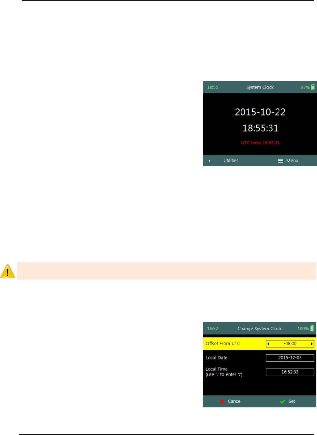
SonTek – a Xylem brand
FlowTracker2 User’s Manual (February 2016) 50
Utilities Section 4.
4.1. System Clock
System Clock function enables the setting of the internal date and time used in the
FlowTracker2 handheld software. The main data collection processes are associated
with internal date and time stamps and it is important that the instrument date and time
are configured correctly.
System Clock screen includes the following
parameters,
a) Date,
b) Time,
c) UTC Time.
d) To change internal date and time,
i). Press the Right Soft Key to select Menu,
ii). Use up or down scroll arrows keys to select an
option,
iii). Press enter key to select the parameter
highlighted in yellow.
e) To navigate to Utilities menu,
i). Press the Left Soft Key.
Figure 4:1 - System Clock
The System Clock options implemented to set the internal data and time of the
FlowTracker2 handheld are the following,
• Manual Change
• Sync with GPS Time
Setting the correct date and time in the FlowTracker2 handheld is important to ensure
that the correct metadata are associated with all measurements.
Manual Change 4.1.1
Manual Change option requires the user to enter the correct date and time based on
external references.
Change System Clock screen includes the following
parameters,
a) Offset From UTC,
b) Date,
c) Time.
d) To select a parameter,
i). Use up or down scroll arrows keys to select a
parameter,
ii). The parameter selected will be highlighted in
yellow.
Figure 4:2 - Change System
Clock
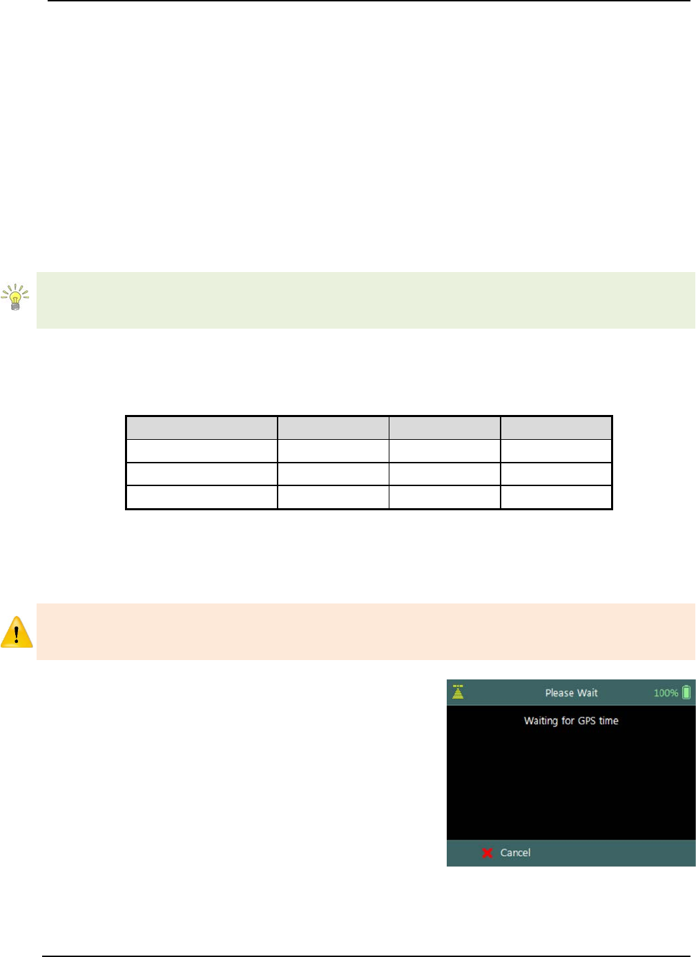
SonTek – a Xylem brand
FlowTracker2 User’s Manual (February 2016) 51
e) To change the Offset From UTC,
i). Use the left or right arrow key to scroll through the list of available offsets,
ii). Type in the new value using the keypad.
f) To change the Date or Time,
i). Use the backspace key to clear current entry,
ii). Type in the new value using the keypad.
g) To accept the new Date and Time settings,
i). Press the Right Soft Key,
ii). The software will return to System Clock screen.
h) To CANCEL change of System Clock settings,
i). Press the Left Soft Key.
The System Clock time is displayed on the left corner of the top banner of the LCD
screen in hh:mm. The time displayed can be referenced against an external reference
to determine if the instrument internal clock is correct.
The Properties associated with the date and time parameters for manual Change option
are defined in Table 4:1,
Table 4:1 - Date and Time - Properties
Parameter
Format
Separator
Example
Date
yyyy-mm-dd
-
2015-10-22
Time
hh:mm:ss
:
19:11:22
Offset From UTC
hh:mm
:
00:15
Sync with GPS Time 4.1.2
Sync with GPS Time option synchronizes the internal date and time of the
FlowTracker2 handheld to GPS date and time.
When synchronizing the System Clock with GPS the internal time will be based on UTC
time. Make sure the offset from UTC is set based on your region and select “Sync with
GPS Time” again. The GPS time will now be correct with the offset from UTC time.
a) The information displayed on Sync with GPS
Time screen includes the following,
i). Waiting for GPS time.
b) The date and time will be updated when there
are sufficient satellites in view of the handheld
to establish a GPS lock.
c) The software will Navigate to the System Clock
screen when the synchronization is complete.
d) To CANCEL Sync with GPS Time,
i). Press the Left Soft Key.
Figure 4:3 - Sync with GPS Time
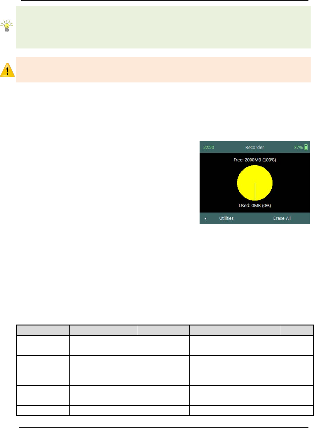
SonTek – a Xylem brand
FlowTracker2 User’s Manual (February 2016) 52
GPS On: If the internal clock is detected to be more than one minute off – the clock
text will be displayed in red and blinking. If the time difference with internal clock is less
than 1 minute – the clock will be green.
GPS off: If the time difference with internal clock is less than 1 minute – the clock will
be green.
The system clock has an internal battery that will keep time for approximately 3
months without the handheld AA battery cartridge installed. If the system is stored for a
similar or longer period of time, it will be necessary to check or change the time.
4.2. Recorder
Recorder function enables the user to manage the memory usage of the internal
recorder in the FlowTracker2 handheld. The available memory of the internal recorder is
dependent on the type, number and size of the files stored.
a) The following information is displayed on the
Recorder screen,
i). Pie chart showing percentage of free and
used recorder space,
ii). Free Space in Megabytes (MB),
iii). Used Space in Megabytes (MB).
b) The size of the internal recorder is 2000MB.
c) To ERASE internal recorder,
i). Press the Right Soft Key to select Erase All.
d) To navigate to Utilities menu,
i). Press the Left Soft Key.
Figure 4:4 - Recorder
Manage Recorder 4.2.1
The FlowTracker2 stores different file types in the internal recorder based on the
measurement method selected, templates created, configuration, firmware upgrade or
language translation. The Properties associated with the FlowTracker2 file types stored
on the internal recorder are defined in Table 4:2,
Table 4:2 - File Types - Properties
File
Type
Extension
Visible
Erase
Measurement
File
Flow Tracker 2
Measurement File
.ft
Yes
Yes
Templates
Flow Tracker 2
Configuration
Template File
.ft_template
Yes
Yes
Manual Beam
Check
Flow Tracker 2
Beam Check File
.ft_beamcheck
Yes
Yes
Configuration
not relevant/not
.dat
No
No
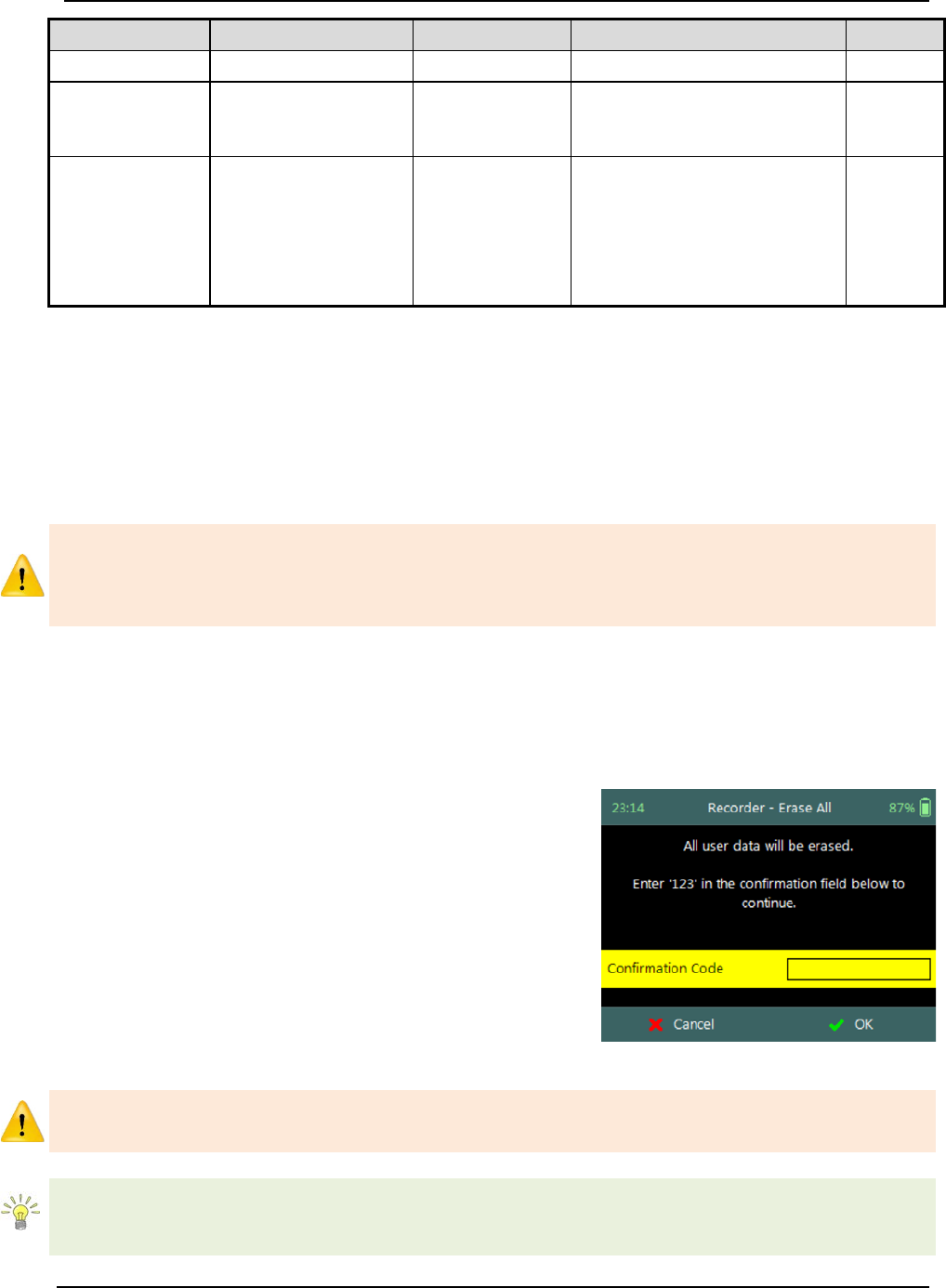
SonTek – a Xylem brand
FlowTracker2 User’s Manual (February 2016) 53
File
Type
Extension
Visible
Erase
user exposed
Firmware
Flow Tracker 2
Firmware File
.ft_firmware
1) Uploaded from PC.
2) Not visible or accessible in
HH by user.
No
Language
Flow Tracker 2
Localization File
.lang
1) Created and uploaded from
PC.
2)
Can be deleted in HH by
pressing the Delete button
while the language is
selected.
No
The management of the internal recorder is important requirement to ensure that good
data management practices are followed with regard to the following aspects,
• safe keeping of measurement files,
• discarding unwanted measurement files,
• available recorder space,
• removing hidden or corrupt files.
The internal recorder should not be used as the main storage device for safe keeping of
measurement files. It is recommended that measurements are downloaded by the end
of each day and a copy of the measurement files are stored on either a computer or
USB flash drive.
Erase Recorder 4.2.2
The Erase function allows the user to erase all Measurement, Template and Manual
Beam Check files that were stored on the internal recorder. See Table 4.2 for file types
that are impacted by the erase function.
a) Erase Recorder require the user to input
confirmation code “123”.
b) To ERASE internal recorder,
i). Enter the confirmation code using the keypad,
ii). Press the Right Soft Key to confirm.
c) To CANCEL Erase Recorder,
i). Press the Left Soft Key.
Figure 4:5 - Erase Recorder
Be certain that all data has been downloaded before erasing the recorder. Data cannot
be recovered after the recorder is erased.
Regularly erasing the recorder ensures that good data management practices are
followed. This will process will reduce the impact of unwanted or corrupt files on the
available memory.
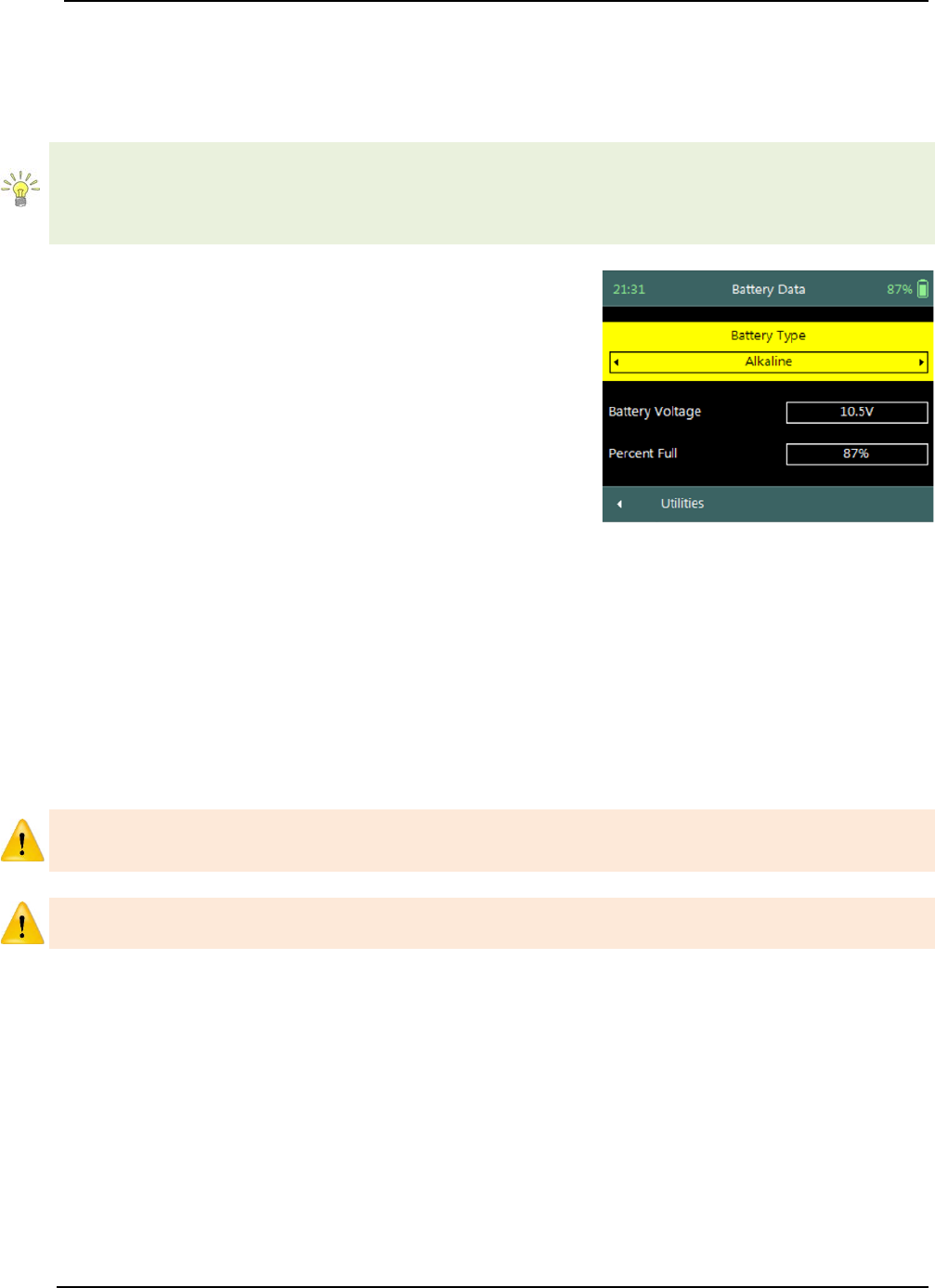
SonTek – a Xylem brand
FlowTracker2 User’s Manual (February 2016) 54
4.3. Battery Data
Battery Data function displays the battery voltage and estimated capacity of the battery
used within the FlowTracker2 handheld.
The available battery capacity is displayed on the right corner of the top banner of the
LCD screen as a percentage of the full capacity. The percentage available will guide
the user in determining if batteries need to be replaced before a new measurement is
started.
The Battery Data screen includes the following
parameters,
a) Battery Type,
b) Battery Voltage,
c) Percentage Full.
d) To change the Battery Type,
i). Use the left or right arrow key to scroll through
the list of available offsets.
e) To navigate to Utilities menu,
i). Press the Left Soft Key.
Figure 4:6 - Battery Data
Battery Type 4.3.1
The Battery Type parameter specifies the type of battery used within the FlowTracker2
handheld.
a) The Battery Types supported in FlowTracker2 is grouped under the following,
i). Alkaline: 8 x size AA/LR6 Alkaline batteries,
ii). NiMH : 8 x size AA, Type BK200AAB, 1.2Vdc, 1900mAh
Only this type of NiMH rechargeable batteries with IEC 62133 approval can be used, or
else safety protection will be void.
The use of NiMH Rechargeable Batteries is only CE certified per IEC 62133 for
FlowTracker2 part number FT2-HH-2 and above.
b) Battery specifications vary depending on brand. FlowTracker2 specifications are
based on,
i). Alkaline: Energizer Industrial EN91,
ii). NiMH: Panasonic Rechargeable BK200AAB,
iii). See also Table 4:5 – Battery Specification.
c) The typical capacity for battery types operating FlowTracker2 are the following.
This is dependent on the brand of battery used and the environmental conditions
that it is exposed to. Battery capacity estimates are based on voltage and are
only approximate, particularly for rechargeable batteries where voltage
characteristics can change significantly over the life of the batteries.
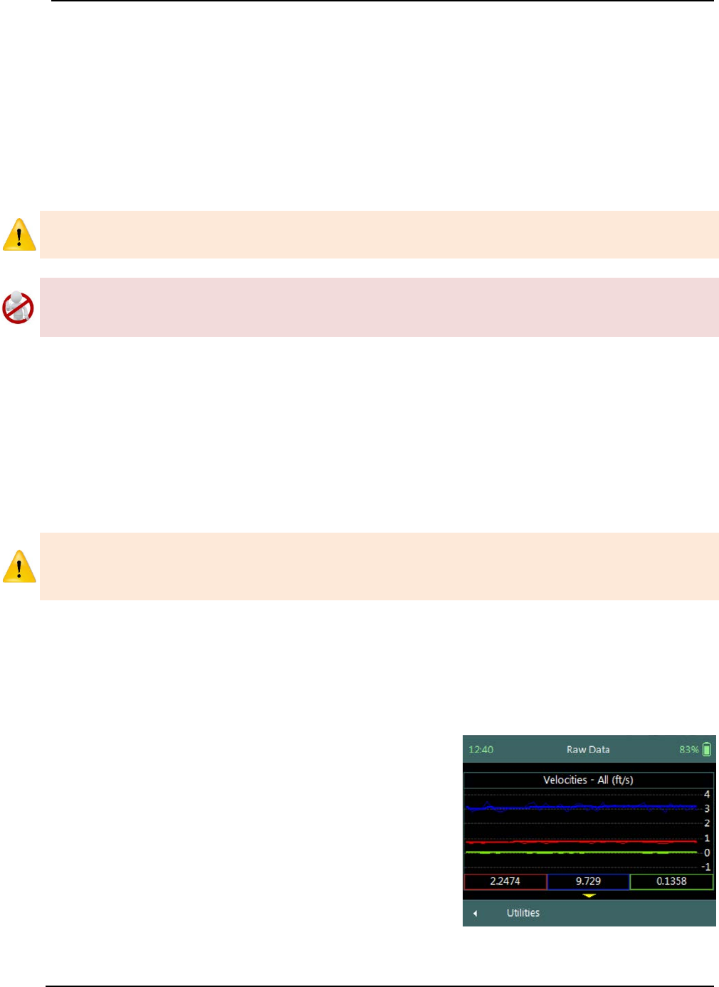
SonTek – a Xylem brand
FlowTracker2 User’s Manual (February 2016) 55
i). 8 x size AA: ≈ 15 hours continuous use with typical settings.
The typical settings used for determining the battery capacity indicated above are
based on the following,
• Operating screen at 100% brightness,
• ADV sensor pinging at 50% of the measurement time,
• No sleep periods,
• GPS off.
Cold weather can greatly affect battery voltage and capacity; always check battery
voltage after the system has acclimated to outside temperatures.
Battery manufacturer guidelines must be followed during normal use, long term storage
and charging requirements. The disposal of batteries must be done with care and it is
recommended that local authority guidelines be used.
Battery Voltage 4.3.2
The Battery Voltage displayed is the current battery voltage level available from the
batteries installed in the FlowTracker2 handheld.
Percentage Full 4.3.3
The Percentage Full is an estimate of the remaining capacity of the battery as a
percentage of the full capacity.
When the remaining capacity of the battery reaches 0%, the FlowTracker2 handheld
will supply the following message, “Battery level critically low – shutting down”. The
user will be required to replace the batteries before continuing with operations.
4.4. Raw Data Display
Raw Data function allows the graphical display of raw time series data measured by the
FlowTracker2. The raw time series data displayed are velocity and SNR data from each
beam, tilt and temperature readings.
The Raw Data screen includes the following
variables,
a) Velocity,
b) SNR,
c) Temperature,
d) Tilt,
e) Battery.
f) To select a variable,
i). Use up or down scroll arrows keys to view a
variable.
Figure 4:7 - Raw Data
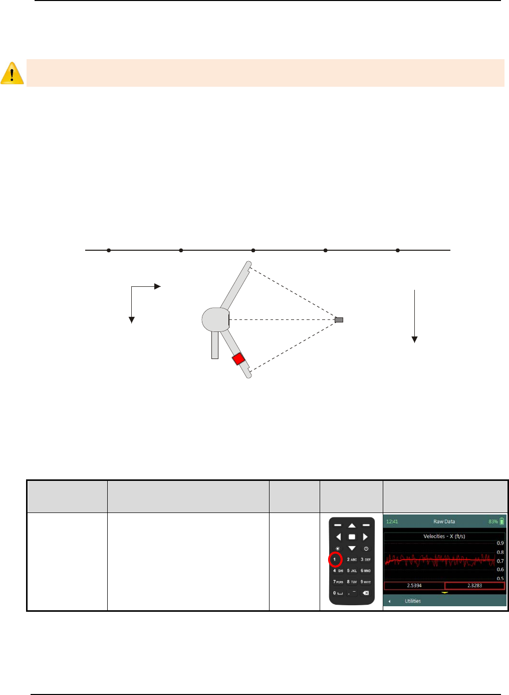
SonTek – a Xylem brand
FlowTracker2 User’s Manual (February 2016) 56
g) To navigate to Utilities menu,
i). Press the Left Soft Key.
Raw Data displayed in this function are NOT stored but enable the user to verify if the
flow conditions are ideal for measurements.
Velocity Raw Data 4.4.1
The Velocity variable displays the individual velocity components of the one second
measured raw velocity data.
a) Velocity data can be expected to show notable variations (most of which are real),
and should be indicative of the general conditions in the water,
b) The raw velocity data are updated once per second,
c) The FlowTracker2 Probe Coordinate System is outlined in Figure 4:8.
Figure 4:8 - FlowTracker2 Coordinate System
d) The velocity components of FlowTraker2 and display options for individual or all
velocity components are listed in Table 4:3. The shortcut key on the keypad
determines which velocity component will be displayed.
Table 4:3 - Raw Velocity Display
Velocity
Component
Description
Line
Color
Keypad
Key
Graphic Display
X - Velocity
The positive X-axis is
defined perpendicular to
both the probe’s stem and
the axis of the transmit
transducer in the direction
of receiver arm #1 (marked
with a red band).
Red
Sampling
Volume
Y
X
Probe
Coordinate System
Graduated Tag Line
Primary Flow
Direction
Mounting
Pin
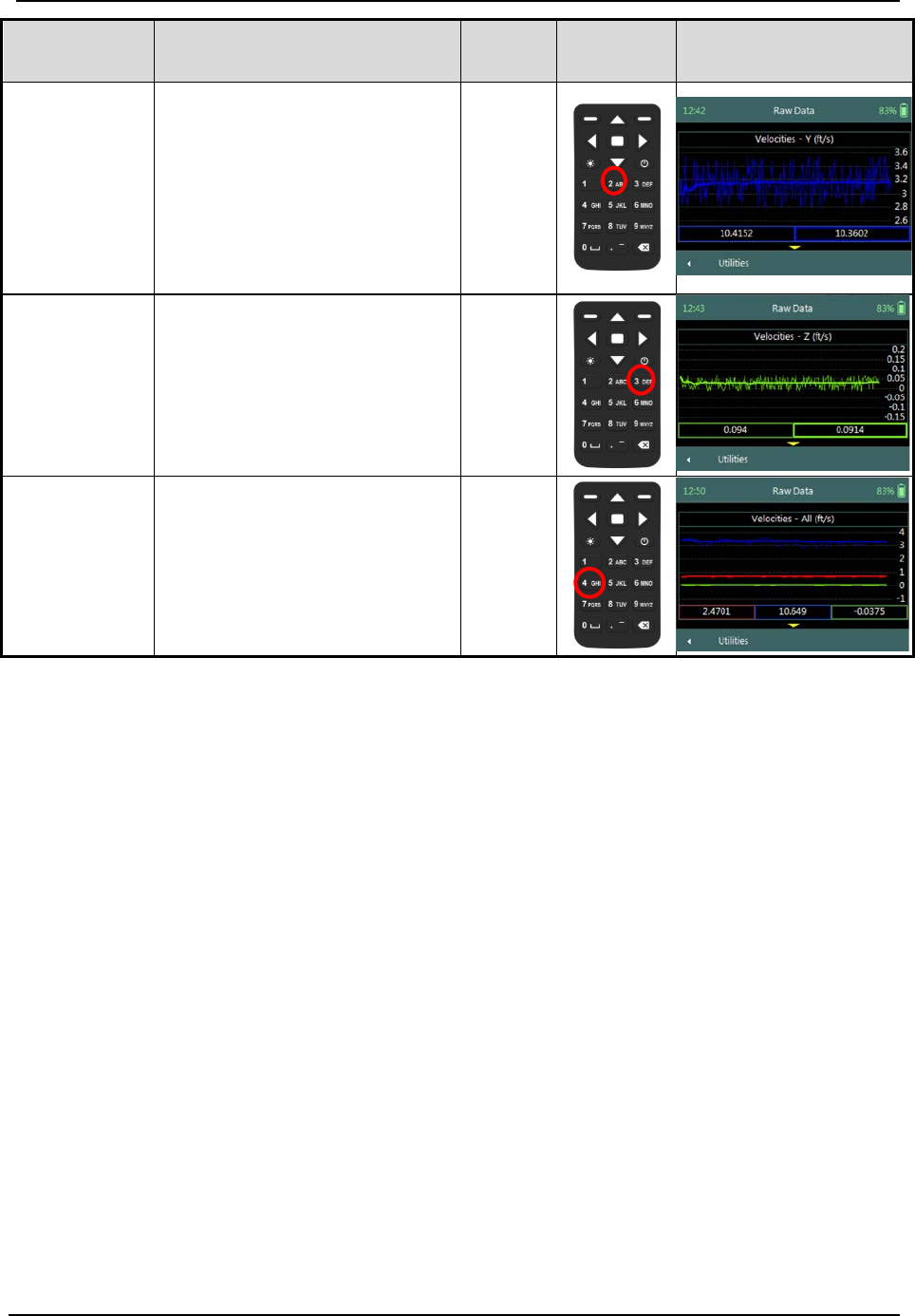
SonTek – a Xylem brand
FlowTracker2 User’s Manual (February 2016) 57
Velocity
Component
Description
Line
Color
Keypad
Key
Graphic Display
Y - Velocity
The positive Y-axis is
defined along the axis of the
transmit transducer from the
transmitter towards the
sampling volume (making a
right-handed coordinate
system).
Blue
Z - Velocity
The positive Z-axis is
defined as vertically up in
the direction of the probe’s
stem.
Green
All Velocities All of the above
Red /
Blue /
Green
e) The continuous lines displayed in the graphics are defined under the following
categories,
i). Thin continuous line represents the one second raw velocity data,
ii). Thick continuous line represents moving average of the one second raw
velocity data.
f) The velocity values displayed in the rectangular boxes for each velocity
component below the graphical display are defined under the following categories,
i). Thin box outline, instantaneous one second raw velocity data,
ii). Thick box outline, represents moving average of the one second raw velocity
data.
SNR Raw Data 4.4.2
The SNR variable displays the individual Beam SNR measurements from the one
second measured raw data.
a) SNR is primarily a function of the amount of particulate matter in the water. For
good conditions, SNR should be at least 10 dB. The system can operate
effectively with SNR as low as 2-3 dB, although the noise in individual velocity
measurements will increase,
b) The SNR data is updated once per second,

SonTek – a Xylem brand
FlowTracker2 User’s Manual (February 2016) 58
c) The display options for individual or all beam SNR values are listed in Table 4:4.
The shortcut key on the keypad determines which beam SNR will be displayed,
Table 4:4 - Beam SNR Display
Beam
SNR
Line Color
Keypad Key
Beam1
SNR1
Red
1
Beam2
SNR2
Blue
2
Beam3
SNR3
Green
3
All Beams
All SNR
All
4
d) The continuous lines displayed in the graphics are defined under the following
categories,
i). Thin continuous line represents the one second raw SNR data,
ii). Thick continuous line represents moving average of the one second raw SNR
data.
e) The SNR values displayed in the rectangular boxes for each beam below the
graphical display are defined under the following categories,
i). Thin box outline, instantaneous one second raw SNR data,
ii). Thick box outline, represents moving average of the one second raw SNR
data.
Temperature Raw Data 4.4.3
The Temperature variable displays the temperature measurements from the one second
measured raw data.
a) Temperature data are used for sound speed calculations and can affect velocity
data.
b) Check temperature data to be sure the values are reasonable for the
environment.
c) The Temperature data are updated once per second.
Tilt Raw Data 4.4.4
The Tilt variable displays the angle of the wading rod from the vertical based on one
second measured raw data.
a) The Tilt information is calculated from the internal pitch and roll sensor in the
FlowTracker2 probe.
b) The Pitch and Roll data is recorded once per second.
Battery Indicator 4.4.5
The Battery variable displays the real time battery voltage level of the batteries housed
in the FlowTracker2 handheld.
a) The FlowTracker2 uses eight AA batteries contained in a battery pack.
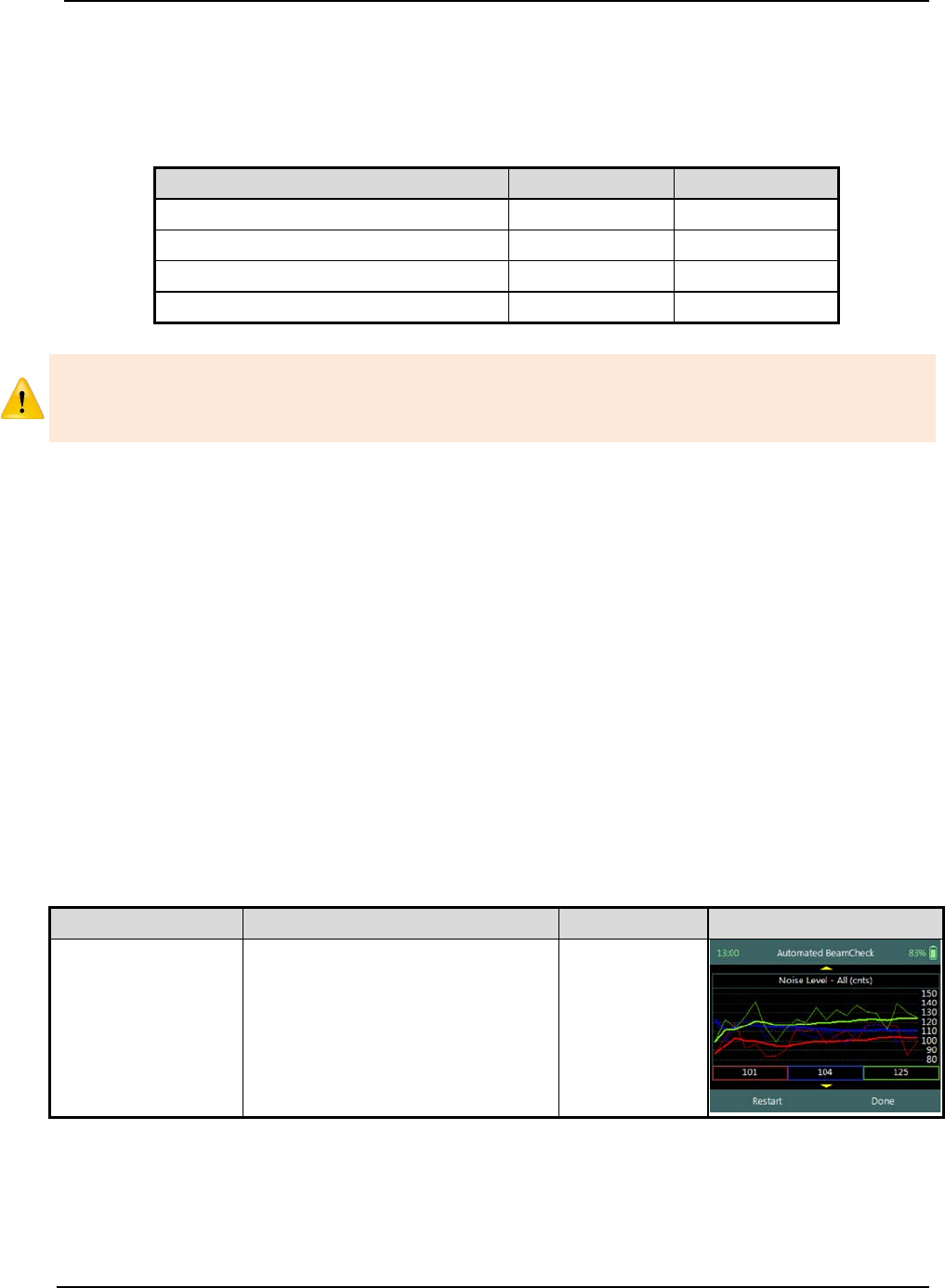
SonTek – a Xylem brand
FlowTracker2 User’s Manual (February 2016) 59
b) Cold weather can greatly affect battery voltage and capacity; always check battery
voltage after the system has acclimated to outside temperatures.
c) The Battery data are updated once per second.
d) Comparison of Battery types are listed in Table 4:5
Table 4:5 – Battery Specification
Category
Alkaline
NiMH
General description
Single use
Rechargeable
Nominal battery capacity (typical)
1500 mAh
1900mAh
New battery voltage
12V
11V
Drained battery voltage
8V
9V
When the remaining capacity of the battery reaches 0%, the FlowTracker2 handheld
will supply the following message, “Battery level critically low – shutting down”. The
user will be required to replace the batteries before continuing with operations.
4.5. Automated Beam Check
The Automated Beam Check function performs a number of quality control checks on the
Beam Check data collected during the required time frame. The Automated Beam
Check is an automated version of Beam Check function described in Beam Check. In
the Original FlowTracker, the Automated Beam Check was known as “Auto QC Test”.
a) Place the probe in moving water such that the probe is submerged and well away
from any underwater obstacles,
i). The FlowTracker2 collects data until It has 20 diagnostic samples (not time
based),
ii). The beam data are analyzed on several criteria outlined in Table 4:6.
b) The automated beam check quality control criteria used in the evaluation of the
beam check data are listed in Table 4:6,
Table 4:6 - Automated Beam Check Quality Control Criteria
Quality Control
Criteria
QC Warning
Graphic Display
Noise Level
• Measured electronics noise
level is compared to reference
data. Any significant deviation
causes a warning,
• A large change in noise level
may indicate damage to the
probe.
Noise Level >
QC

SonTek – a Xylem brand
FlowTracker2 User’s Manual (February 2016) 60
Quality Control
Criteria
QC Warning
Graphic Display
SNR
• The SNR is checked as
sufficient for reliable data
collection,
• Each beam SNR is compared
to be sure all beams perform
equally,
• A warning is issued for low
SNR < 4 dB,
• A warning is issued for 4 dB >
SNR <7dB,
•
Beam SNR values differ.
SNR
Peak Level
• The shape of the sampling
volume curve is compared to
the expected shape. Any
significant deviation causes a
warning,
• This criterion can only be
checked with sufficient SNR
(> 7 dB).
Peak Level >
QC
Peak Location
• The physical location of the
sampling volume is compared
to the expected location. Any
significant deviation causes a
warning.
• This criterion can only be
checked for sufficient SNR (>
7 dB).
Peak
Location >
QC
c) If any warnings are issued, the warnings will be displayed at the bottom of the
graphics. The user have the option to repeat the test if warnings are issued.
i). We recommend repeating the test at least once, after you verify that the probe
and sampling volume are well away from any underwater obstacles.
ii). If multiple warnings are received, run manual Beam Check to evaluate
FlowTracker2 performance in more detail.
d) The display options for individual or all beam check data are listed in Table 4:7.
The shortcut key on the keypad determines which beam SNR will be displayed,
Table 4:7 - Automated Beam Check Display
Beam
Line Color
Keypad Key
Beam1
Red
1
Beam2
Blue
2
Beam3
Green
3
All Beams
All
4
e) To select a Quality Control Criteria,
i). Use up or down scroll arrows keys to view quality control criteria.
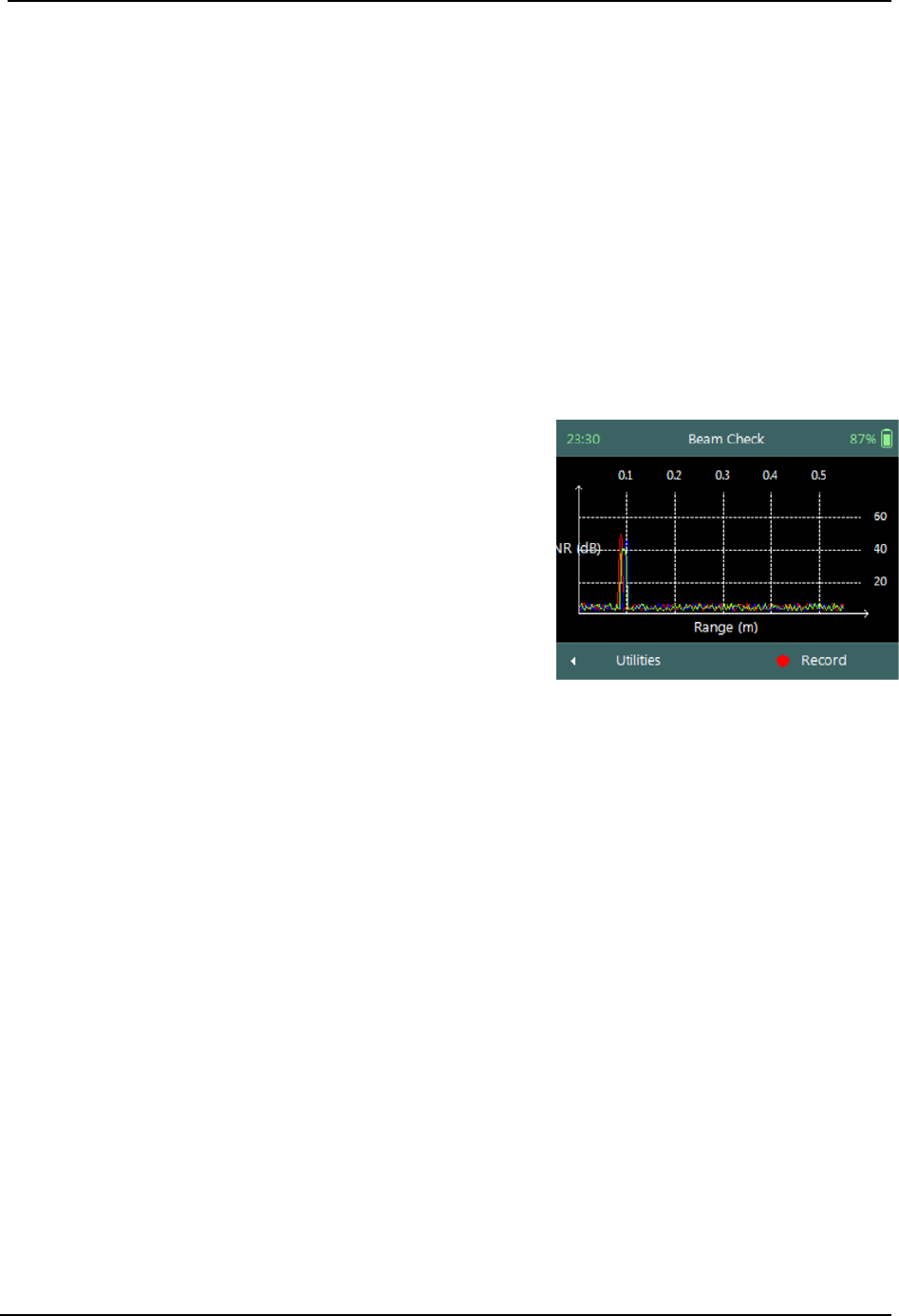
SonTek – a Xylem brand
FlowTracker2 User’s Manual (February 2016) 61
f) To accept Automated Beam Check,
i). Press the Right Soft Key,
ii). The software will continue to the Data Collection screen.
g) To RESTART Automated Beam Check,
i). Press the Left Soft Key.
4.6. Beam Check
Beam Check operates by sending a pulse of sound into the water, and then plots the
signal to noise ratio of the return signal versus range for each of the FlowTracker’s
receivers. This information can be evaluated to determine the effective measurement
range, to look for interference from boundaries/structures, to survey a deployment site,
or to observe the quality of the returned signal.
a) The Beam Check function can be accessed
from the Utilities menu,
b) Beam Check file will be recorded in the
handheld recorder for each Beam Check
performed. The file naming convention for
beam check files consists of the following,
i). File Extension: .ft_beamcheck
ii). Naming Convention: yyyymmdd-hhmmss
c) The maximum number of samples that can be
recorded during a Beam Check is 30.
Figure 4:9 – Beam Check
d) Place the probe in either a small tank, bucket of water or measurement section in
canal or river such that the probe is submerged and there is a boundary (surface,
side, or bottom) within view,
e) To record or stop recoding of Beam Check,
i). Press the Right Soft Key,
f) To navigate to Utilities menu,
i). Press the Left Soft Key.
4.7. GPS Data
GPS Data function display the Global Positioning System data received from the internal
GPS receiver in the FlowTracker2 handheld. The GPS data displayed consist of satellite
time, satellite information and coordinates.
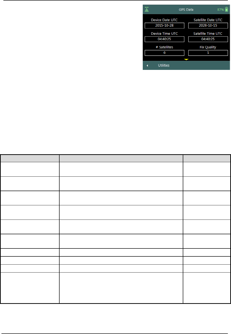
SonTek – a Xylem brand
FlowTracker2 User’s Manual (February 2016) 62
The GPS Data screen includes the following
variables,
a) Device Date UTC,
b) Device Time UTC,
c) Satellite Date UTC,
d) Satellite Time UTC,
e) # Satellites,
f) Fix Quality,
g) Latitude,
h) Longitude,
i) Altitude,
j) HDOP.
k) To navigate to Utilities menu,
i). Press the Left Soft Key.
Figure 4:10 - GPS Data
Properties associated with the variables in displayed GPS Data screen are defined in
Table 4:8,
Table 4:8 - GPS Data - Properties
Variable
Description
Format \ Units
Device Date UTC
The FlowTracker2 handheld internal date set to
Coordinated Universal Time (UTC). yyyy-mm-dd
Device Time UTC
The FlowTracker2 handheld internal time set to
Coordinated Universal Time (UTC). hh:mm:ss
Satellite Date UTC
Current satellite date based on Coordinated
Universal Time (UTC). yyyy-mm-dd
Satellite Time UTC
Current satellite time based on Coordinated
Universal Time (UTC).
hh:mm:ss
# Satellites
Number of satellites in view of GPS receiver in the
FlowTracker2 handheld n/a
Fix Quality
GPS Quality indicator (0=no fix, 1=GPS fix, 2=Dif.
GPS fix) n/a
Latitude
GPS derived Latitude
DDD° MM' SS.SS
Longitude
GPS derived Longitude
DDD° MM' SS.SS
Altitude
GPS derived altitude above mean sea level.
m
HDOP
Horizontal dilution of position is a GPS term used
to describe the geometric strength of satellite
configuration on GPS accuracy. HDOP values
are typically between 1 and 2 although the ideal is
a HDOP value of 1.
n/a

SonTek – a Xylem brand
FlowTracker2 User’s Manual (February 2016) 63
4.8. System Maintenance
System Maintenance function enables the user to perform number of maintenance
tasks on the FlowTracker2 handled and probe firmware.
System Maintenance screen includes the following
functions,
a) Force Probe Upgrade,
b) To select a variable,
i). Use up or down scroll arrows keys to view a
variable.
c) To navigate to Utilities menu,
i). Press the Left Soft Key.
Figure 4:11 – System
Maintenance
Force Probe Upgrade 4.8.1
The Force Probe Upgrade function allows the user to either upload or downgrade the
firmware on the probe. This function is normally used when communication problems
are experienced with the probe or when the probe firmware needs to be downgraded.
Warning screen of Force Probe Upgrade function
displays the warnings associated with downgrading
probe firmware,
a) To CANCEL force probe upgrade,
i). Press the Left Soft Key.
b) To continue with force probe upgrade,
i). Press the Right Soft Key.
Figure 4:12 – Force Probe
Upgrade Warning
In case where the probe firmware version is newer than the firmware installed on the
handheld, the handheld will supply a warning message before each velocity
measurement is performed: “The Probe firmware is newer than expected – please
consider upgrading the Handheld firmware to the latest version available”

SonTek – a Xylem brand
FlowTracker2 User’s Manual (February 2016) 64
Data Collection Modes Section 5.
The FlowTracker2 provides two data collection modes that the user can apply in the
collection of velocity data. The Discharge and General modes available in FlowTracker2
has different field applications and the method of each mode is described in this section.
5.1. Discharge Mode
Discharge Mode is for applications where the primary goal is to measure river/stream
discharge. The technique involves taking a series of velocity measurements at different
locations throughout the cross section. These measurements are combined with location
and water depth information to compute the total discharge.
Measurement Technique 5.1.1
The basic Measurement Technique used for performing discharge measurement using
the Discharge Mode is briefly discussed under the following points and this
measurement process should be read in conjunction with Site Selection Requirements.
a) A measurement site is selected based on criteria stipulated in Site Selection
Requirements. The site selection process is a crucial part of collecting discharge
measurement data.
i). Ideal measurement site, the flow should be perpendicular to the tag line at all
points with no flow reversals or obstructions.
ii). The measurement site should encompass the minimum measurement site and
hydraulic requirements discussed in Site Selection Requirements.
iii). Flow conditions at the measurement site are the most important factor in
determining overall accuracy of the measurement.
b) A graduated tag line is strung across the river.
c) The operator starts at one edge, recording the starting-edge location and water
depth.
d) The river cross section is split into several stations. At each station, the operator
records the station location and water depth, and then performs velocity
measurements at one or more depths to determine the mean velocity at that
station.
e) During velocity measurements, the probe’s X-axis is maintained perpendicular to
the tag line (Figure 5:1); the red band (receiver arm #1) should face downstream.
Only the X-component of velocity (Vx) is used to in the discharge calculation,
regardless of the flow direction (flow direction is also measured and recorded).
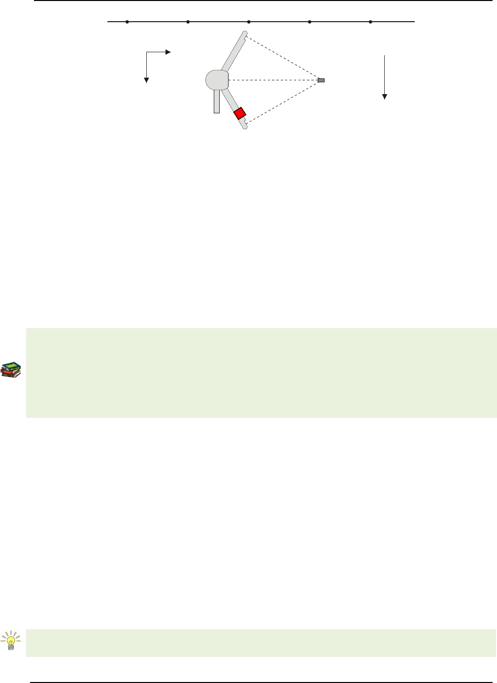
SonTek – a Xylem brand
FlowTracker2 User’s Manual (February 2016) 65
Figure 5:1 – FlowTracker2 Probe Orientation Relative to Stream Flow
f) When all station measurements are completed, the operator records the ending-
edge location and water depth.
g) The total discharge is the sum of all station discharge values.
Discharge Calculation Methods 5.1.2
The discharge calculation methods implemented in FlowTracker2 are based on
established methods that are documented in international standards and are widely used
by government agencies, hydrologists and hydrographers. The discharge calculation
methods were originally developed for current meter instruments. The FlowTracker2
makes use of the same measuring technique and for this reason the same calculation
methods can be used to determine the total discharge.
The methods implemented for calculation of discharge are based on the following
literature,
• ISO 748 – 2007, Hydrometry - Measurement of liquid flow in open channels using
current meters or floats,
• WMO-No. 1044, Volume I – Fieldwork, 2010.
• Japanese Literature
The FlowTracker2 supports several discharge calculating methods for calculating
discharge following the basic measuring technique outlined above.
• Mid-Section equation (see 5.1.2.1),
• Mean-Section equation (see 5.1.2.2),
• The Japanese equation (see 5.1.2.3).
Mid-Section Equation 5.1.2.1
The Mid-Section method is based on a measurement section that is divided into a
number of stations with panels created for each station across the section. The average
velocity of a panel is assumed to be equal to the average velocity in the vertical
calculated from the point velocity measurements made. The equation of the Mid-Section
method is given in Equation 5:1.
This method is used by the U.S. Geological Survey (USGS), the primary U.S.
government agency responsible for river discharge monitoring.
Sampling
Volume
Y
X
Probe
Coordinate System
Graduated Tag Line
Primary Flow
Direction
Mounting
Pin
SonTek – a Xylem brand
FlowTracker2 User’s Manual (February 2016) 66
Equation 5:1 - Mid-Section Method
=
+
+
Edge Open water Open Water
where, is the average velocity in the vertical or at the station,
d is the water depth measured at the station,
b is the location of the station.
The application of the Mid-Section equation within a measurement section is graphically
shown in Figure 5:2. The principle of the Mid-Section method is highlighted in the figure
below where the panel width (W2) is calculated based on the station locations (L2) with
the station as the center of the panel.
Figure 5:2 - Mid-Section Method
There are few special cases to consider when applying the Mid-Section method in
calculating of total discharge.
a) Edges
i). Edge can be either the Left Bank or Right Bank,
ii). Edge calculations are handled differently from stations in open water with
reference to the first component of Equation 5:1,
iii). The mean velocity at the edge is scaled from the adjacent station by a user
defined correction factor (CF),
iv). Edge water depth of zero will result in zero flow for the edge calculation.
b) Islands (multiple channels)
i). If a river is split into multiple channels, any internal island(s) must be
accounted for in the discharge calculation,
SonTek – a Xylem brand
FlowTracker2 User’s Manual (February 2016) 67
ii). The stations at each edge of the island(s) are treated as an Island Edge,
iii). Island edge calculations are handled the same as 66 with reference to the first
component of Equation 5:1,
iv). The mean velocity at the island edge is scaled from the adjacent station by a
user defined correction factor (CF),
v). Edge water depth of zero will result in zero flow for the edge calculation.
Mean-Section Equation 5.1.2.2
The Mean-Section method is based on a measurement section that is divided into
number of stations with panels created in between adjacent stations across the section.
The average velocity of a panel is assumed to be the average velocity of the two
adjacent stations velocities in the vertical calculated from point velocity measurements
made. The equation of the Mean-Section method is given in Equation 5:2.
Equation 5:2 - Mean-Section Method
=()+
2+
2+()+
2+
2+( ) +
2 +
2
Edge Open water Open Water
where, is the average velocity in the vertical or at the station,
d is the water depth measured at the station,
b is the location of the station.
The application of the Mean-Section equation within a measurement section is
graphically shown in Figure 5:3. The principle of the Mean-Section method is shown in
the figure below where panel width (W) is calculated based on the station locations
between adjacent stations across the section.
Figure 5:3 - Mean-Section Method

SonTek – a Xylem brand
FlowTracker2 User’s Manual (February 2016) 68
There are few special cases to consider when applying the Mean-Section method in
calculating of total discharge.
a) Edges
i). Edge can be either the Left Bank or Right Bank,
ii). Edge calculations are handled exactly the same from stations in open water
with reference to the first component of Equation 5:2,
iii). Correction factor (CF) is NOT applied in Mean-Section method to scale the
mean velocity at the edges from the adjacent station,
iv). The discharge on the edges can be determined by applying Equation 5:2 on
the assumption that the velocity at the edges is zero.
b) Islands (multiple channels)
i). If a river is split into multiple channels, any internal island(s) must be
accounted for in the discharge calculation,
ii). The stations at each edge of the island(s) are treated as an Island Edge,
iii). Island edge calculations are handled the same as 68 with reference to the first
component of Equation 5:2,
iv). Correction factor (CF) is NOT applied in Mean-Section method to scale the
mean velocity at the edges from the adjacent station,
v). The discharge on the edges can be determined by applying Equation 5:2 on
the assumption that the velocity at the edges is zero.
Japanese Equation 5.1.2.3
The Japanese method is similar to both the Mean-Section and Mid-Section methods in
some respects with its own unique measuring technique. The most significant feature of
the Japanese method is the duplicate measurements performed of each depth and point
velocity measurements at a station. The Japanese national standard guideline for
determining the measurement interval for depth and velocity are dependent on the
measurement section width and are supplied in Table 5:1.
Table 5:1 - Predetermination of Measuring Intervals
River Width, B (m)
Measuring Interval of
Depth, M (m)
Measuring Interval of
Velocity, N (m)
Less than 10m
10 – 15% of B
N=M
10-20
1
2
20-40
2
4
40-60
3
6
60-80
4
8
80-100
5
10
100-150
6
12
150-200
10
20
200 over
15
30
SonTek – a Xylem brand
FlowTracker2 User’s Manual (February 2016) 69
The Japanese method has two separate equations for determining the total discharge
based on the measurement section width. The equation of the Japanese method for
measurement section greater than 10m is given in Equation 5:3.
Equation 5:3 - Japanese Method > 10m
=()× 0.5
+
+()× 0.5
+
×
+
Edge
()× 0.5
+
+( )× 0.5
+
×
Open Water
The equation of the Japanese method for measurement section smaller than 10m is
given in Equation 5:4.
Equation 5:4 - Japanese Method < 10m
=()× 0.5
+
+
× 0.5
+
×
+
Edge
× 0.5
+
+
× 0.5
+
×
+
Open Water
× 0.5
+
+
× 0.5
+
×
Open Water
The application of the Japanese equation within a measurement section that is greater
than 10m is graphically shown in Figure 5:4.
Figure 5:4 - Japanese Method >10m
SonTek – a Xylem brand
FlowTracker2 User’s Manual (February 2016) 70
There are few special cases to consider when applying the Japanese method in
calculating of total discharge.
a) Edges
i). Edge can be either the Left Bank or Right Bank,
ii). Edge calculations are handled exactly the same from stations in open water
with reference to the first component of Equation 5:3,
iii). Correction factor (CF) is NOT applied in Japanese method to scale the mean
velocity at the edges from the adjacent station,
b) Islands (multiple channels)
i). If a river is split into multiple channels, any internal island(s) must be
accounted for in the discharge calculation,
ii). The stations at each edge of the island(s) are treated as an Island Edge,
iii). Island edge calculations are handled the same as 70 with reference to the first
component of Equation 5:3,
iv). Correction factor (CF) is NOT applied in Japanese method to scale the mean
velocity at the edges from the adjacent station,
Determining Mean Station Velocity 5.1.3
The Mean Station Velocity or Mean Velocity in a Vertical determines how mean
velocity is determined at each station. The measurement techniques used involves
variations in the number of point velocity measurements taken at a range of
measurement depts. The method used to calculate the mean velocity in a vertical
depends on the number of point velocity measurements made within a vertical.
Methods implemented for determining mean station velocity in a vertical are based on
the following literature,
• ISO 748 – 2007, Hydrometry - Measurement of liquid flow in open channels using
current meters or floats,
• WMO-No. 1044, Volume I – Fieldwork, 2010.
The methods implemented in FlowTracker2 for determining the Mean Station Velocity
are defined in Table 5:2.
Table 5:2 - Determining Mean Station Velocity
Method
Measurement Depth
Mean Velocity Equation
0.6
0.6 * depth Vmean = CF * V0.6
0.2/0.8
0.8/0.2
0.2 * depth
0.8 * depth Vmean = CF * ((V0.2 + V0.8) / 2)
.2/.6/.8
.8/.6/.2
0.2 * depth
0.6 * depth
0.8 * depth Vmean = CF * ((V0.2 + 2*V0.6 + V0.8) / 4)
SonTek – a Xylem brand
FlowTracker2 User’s Manual (February 2016) 71
Method Measurement Depth Mean Velocity Equation
Ice 0.6 0.6 * effective depth Vmean = 0.92*V0.6
(Correction Factor 0.92 can be changed by user)
Ice 0.5 0.5 * effective depth Vmean = 0.88*V0.5
(Correction Factor 0.88 can be changed by user)
Ice 2/8
Ice 8/2 0.2 * effective depth
0.8 * effective depth Vmean = CF * ((V0.2 + V0.8) / 2)
Kreps 2-
Kreps 2+ 0.0 (near surface)
0.62 * depth Vmean = CF * (0.31*V0.0 + 0.634*V0.62)
5 Point+
5 Point-
0.0 (near surface)
0.2 * depth
0.6 * depth
0.8 * depth
1.0 (near bottom)
Vmean = CF * ((V0.0 + 3*V0.2 + 3*V0.6 + 2*V0.8+ V1.0) / 10)
6 Point+
6 Point-
0.0 (near surface)
0.2 * depth
0.4 * depth
0.6 * depth
0.8 * depth
1.0 (near bottom)
Vmean = CF * ((V0.0 + 2*V0.2 + 2*V0.4+ 2*V0.6 + 2*V0.8+ V1.0) / 10)
Vertical
Velocity
Curve
Any number of points at
user-specified depths
V
mean
= CF * Integrated velocity
Measurements can be made in any order; they are sorted
by depth to calculate the integrated mean velocity. Repeat
measurements at the same depth are averaged prior to
calculating the integrated velocity.
None No velocity measurement
V
mean
=
CF *
V
adjacent
Mean velocity is based on the velocity from the adjacent
station(s), multiplied by a user-specified correction factor.
This method is used when velocity measurements cannot be
made or with the Japanese method.
Input V User input velocity
V
mean
= V
input
User enters an estimated velocity value. This method is
used when velocity measurement is not possible, most
commonly due to weed growth along a riverbank.
Methods involving more than one measurement can be done in either direction (from
surface to the bottom, or from the bottom towards the surface).
Method None 5.1.3.1
The method None is used in a number of different scenarios from assigning zero velocity
to channel banks, stations where no measurements are possible to Japanese method
where the measurement section is wider than 10m.
a) Channel Banks
i). Edges describing the left or Right bank of a channel,
ii). Island Edges describing the banks of island\s,
iii). The method None is assigned automatically for Edges and Island Edges by
the software.
SonTek – a Xylem brand
FlowTracker2 User’s Manual (February 2016) 72
b) Station Measurement not Possible
i). The measuring site conditions do not allow velocity measurement (perhaps
due to weed growth),
ii). Velocity for this station is based on the mean station velocity from the adjacent
station(s) with velocity measurements multiplied by the user-specified
correction (CF) factor for this station.
c) Japanese Method
i). Japanese measuring technique for measurement sections wider than 10m
require velocity measurements only at every second station,
ii). A velocity method of “Depth Only” is assigned to None velocity stations.
Vertical Velocity Curve 5.1.3.2
The Vertical Velocity Curve method is a series of point velocity measurements that are
well distributed between the water surface and channel bed. Normally observation is
made at 0.1 depth increments between 0.1 and 0.9 of the total water depth. Point
velocity measurements at the standard 0.2, 0.6 and 0.8 depths are required to compare
the vertical velocity curve method against standard methods.
a) For each measurement, you must manually enter the measurement depth.
b) The mean station velocity (mean velocity in vertical) is calculated by integrating all
velocity measurements considering their location as illustrated in Figure 5:5.
Figure 5:5 - Vertical Velocity Curve
c) If multiple measurements are made at the same measurement depth, these
measurements are averaged prior to calculating the velocity integration.
SonTek – a Xylem brand
FlowTracker2 User’s Manual (February 2016) 73
Correction Factor 5.1.3.3
The Correction Factor (CF) is a user supplied parameter used to scale the mean
station velocity or velocity in the vertical.
Be careful when selecting a Correction Factor, as the mean station velocity is always
scaled by this value. Incorrect use of this parameter will affect the final discharge
measurement.
a) The CF is most commonly used at edges, internal islands, and other method
None stations to scale the velocity from the adjacent station(s).
i). The default CF value is 1.00.
ii). Any value from -1.00 to 1.00, except 0.0, is allowed.
b) The CF can be entered for any station and the mean station velocity will be
multiplied by the CF.
c) Special conditions near edge measurements in very narrow streams.
i). The orientation of the FlowTracker2 probe can be reversed by 180° to allow
measurement closer to the edge.
ii). A CF of -1.00 should be entered to correct the FlowTracker2 X-velocity.
Discharge Uncertainty Calculation 5.1.4
Discharge Uncertainty Calculation is performed on every discharge measurement to
determine the overall measurement uncertainty.
a) The uncertainty calculation methods implemented in FlowTracker2 is based on
the Interpolated Variance Estimator (IVE) and ISO methods,
i). The Interpolated Variance Estimator (IVE) uncertainty calculation method
uses a method developed by researchers at the U.S. Geological Survey. The
IVE uncertainty calculation is the default method as it provides the most
reliable indicator of measurement quality,
ii). The ISO method is based on the international standard. It provides users with
the results of a published, standard technique; however, in some cases this
calculation may not provide a reliable indicator of data quality.
The uncertainty analysis implemented for determining the overall discharge uncertainty
are based on the following literature,
• ISO 748 – 2007, Hydrometry - Measurement of liquid flow in open channels using
current meters or floats,
• Cohn, T., Kiang, J., and Mason, R., Jr. (2013). ”Estimating Discharge Measurement
Uncertainty Using the Interpolated Variance.
b) The application of uncertainty calculation methods to discharge calculation
methods are defined,
i). The uncertainty calculation methods implemented are only applicable to the
“Mid-Section” and “Mean-Section” discharge calculation methods.

SonTek – a Xylem brand
FlowTracker2 User’s Manual (February 2016) 74
ii). The Japanese method does not incorporate discharge uncertainty calculations
and a method “None” is assigned.
c) The uncertainty calculations are based on several different parameters. In
addition to overall uncertainty, the FlowTracker2 also looks at the contribution of
each of the following parameters.
i). Accuracy: The accuracy of the FlowTracker2 calibration (this is generally
negligible),
ii). Depth
• In the IVE calculation, this term includes both uncertainty in the depth
measurement and the effect of changes in depth between stations,
• In the ISO calculation, this term includes only the uncertainty in depth
measurements.
iii). Velocity
• In the IVE calculation, this term includes both uncertainty in the velocity
measurement and the effect of changes in velocity between stations,
• In the ISO calculation, this term includes only the uncertainty in velocity
measurements.
iv). Width
• Estimated uncertainty in width measurements.
v). Method: Determining Mean Station Velocity.
• Use for the ISO method only.
vi). Number of stations
• Use for the ISO method only.
Under Ice Measurements 5.1.5
The discharge calculation methods discussed previously in this section are also
applicable for Under Ice Measurements. It is recommended that the operator refer to
existing literature describing under ice measurements as there are number of aspects
that need to be taken into account.
“Standard Operating Procedures for under ice discharge measurements using ADCPs”,
Water Survey of Canada, Environment Canada, is a good reference guide for
performing under ice measurements
There are a couple of additional requirements for calculating total discharge in addition to
what was discussed under Discharge Calculation Methods when performing under ice
measurements,
a) Additional measurements required during under ice measurements,
i). Ice thickness,
ii). Water surface to bottom of ice,
iii). Water surface to bottom of slush (if slush is present).
SonTek – a Xylem brand
FlowTracker2 User’s Manual (February 2016) 75
b) Calculating of effective depth. The effective
depth is defined by the distance between the
streambed and the bottom of the ice or slush
in the case slush is present,
i). 0.2 depth setting = a + 0.2C
ii). 0.8 depth setting = b – 0.2C
iii). 0.6 depth setting = b – 0.4C
c) Station area is calculated by multiplying the effective depth and station width.
Weighted Gauge Height 5.1.6
The Weighted Gauge Height during a discharge measurement is the mean water level
calculated at the monitoring site during the measurement time. It is important that an
accurate mean gauge height is determined as this is used with the discharge measured
to develop stage-discharge relationship for the monitoring site. The methods
implemented in FlowTracker2 for determining the weighted gauge height during a
discharge measurement is the average of both the Discharge Weighted and Time
Weighted gauge height.
a) The discharge weighted process is based on the discharge calculated within the
time interval associated with each set of gauge height readings. The equation of
the discharge weighted method is given in Equation 5:5.
Equation 5:5 - Discharge Weighted
= +++
where, is the mean gauge height,
Q is the total discharge,
q is the discharge measured between time interval of gauge height readings,
h is the average gauge height readings taken between time interval.
b) The time weighted process is based on the arithmetic mean of the gauge height
calculated within the time interval associated with each set of gauge height
readings.
Equation 5:6 - Time Weighted
= +++
where, is the mean gauge height,
T is the total time for the measurement,
t is the duration of time interval between gauge height readings,
h is the average gauge height readings taken between time interval.
Figure 5:6 - Effective Depth

SonTek – a Xylem brand
FlowTracker2 User’s Manual (February 2016) 76
The method for determining the weighted gauge height are based on the following
literature,
• Measurement and Computation of Stream flow: Volume 1. Measurement of Stage
and Discharge. Page 170. By S. E. RANTZ and others
5.2. General Mode
The General Mode of data collection is for applications that need a series of velocity
measurements at different locations that do not require a standard discharge output.
Measurement Technique 5.2.1
The basic Measurement Technique used for performing velocity measurements using
General Mode is briefly discussed below. The measurement technique differs from the
Discharge Mode where the objective is to determine water velocity at specific locations.
a) The measurement location is not required to comply with any measurement site or
hydraulic requirements stipulated in Site Selection Requirements.
b) The flow conditions at the measurement location should be within the
FlowTracker2 specifications.
c) Station is created for each point velocity measurement assigned a unique X and Y
coordinate.
d) Station velocity measurement performed at user defined location and depth.
Determining Mean Velocity 5.2.2
The Mean Velocity outputs generated from velocity measurements performed in
General Mode consist of Mean Station Velocity and Mean Velocity of All Stations.
a) The Mean Station Velocity is the average of the velocity measurements
performed over a user defined sampling interval at a specific measurement depth.
b) The Mean Velocity of All Stations is the average of all the station
measurements performed each at its own unique location and measurement
depth.

SonTek – a Xylem brand
FlowTracker2 User’s Manual (February 2016) 77
Quality Control Section 6.
Quality Control (QC) is continuously performed on all variables collected during a
measurement in both Discharge and General Modes. The Quality Control Parameters
are automatically reviewed at different stages of a measurement and if any values
exceed the expected criteria a warning is supplied.
6.1. Quality Control Parameters
Quality Control Parameters used to analyze the variables collected during a
measurement are discussed in the following section. The quality control parameters with
its expected values are supplied in Table 6:1. All quality control parameters can be
adjusted or disabled based on measurement site and or user requirements.
Table 6:1 - Quality Control Parameters
Parameter
Description
Expected
SNR
SNR is the most important Quality Control parameter,
• It measures the strength of the acoustic reflection
from particles in the water,
• Without sufficient SNR, the FlowTracker2 cannot
measure velocity.
Ideally > 10 dB
Minimum ≥ 4 dB
Velocity
Standard
Error
σV (velocity standard error) is a direct measure of the
accuracy of velocity data,
• It includes the effects of turbulence in the river and
instrument uncertainty.
Typically <
0.01m/s (0.03
ft/s).
Higher in
turbulent
environment.
Boundary
Interference
Boundary QC evaluates the measurement
environment for interference from underwater
obstacles,
• FAIR or POOR results may indicate significant
interference from an underwater obstacle.
• BEST,
• GOOD,
• FAIR,
• POOR.
Velocity
Spike
Filtering
Spikes in FlowTracker2 velocity data are removed
using a spike filter,
• Some spikes are common and no cause for
concern,
• Too many spikes indicate a problem in the
measurement environment (e.g., interference from
underwater obstacles or highly aerated water).
Typically < 5% of
total samples.
Should be < 10%
of total samples.
Velocity
Angle
Angle is the direction of the measured velocity
relative to the FlowTracker2 X-axis,
• Used for discharge measurements only,
• A good site should have small velocity angles,
• Large angles may be unavoidable at some sites.
Ideally < 20º
SonTek – a Xylem brand
FlowTracker2 User’s Manual (February 2016) 78
Parameter
Description
Expected
Tilt Angle
Angle of the wading rod relative to the vertical,
• Used for both discharge and general mode,
• A good measurement should have small tilt angles,
• Large tilt angles may be unavoidable at some sites.
Ideally < 5º
Station
Percent
Discharge
%Q is the percentage of the total discharge in a
single measurement station,
• Most agencies have criteria for the maximum %Q.
Typical criteria:
Ideally < 5%
Maximum < 10%
Station
Water Depth
Depth is the maximum percentage variation in depth
between adjacent stations. Typical criteria:
Maximum < 50%
Station
Location
Location is the maximum percentage variation in
location between adjacent stations.
Typical criteria:
Maximum <
100%
Velocity
Profile
0.2 \ 0.8
0.2 \ 0.8 Velocity Profile evaluated against expected
velocity distribution,
• Used for discharge measurements only,
• Suggest 0.6 depth measurement if set criteria is
complied with.
Ideally: near-
surface velocity >
n Velocity
Signal to Noise Ratio (SNR) 6.1.1
Signal to Noise Ratio (SNR) is a measure of the strength of the reflected acoustic
signal relative to the ambient noise level of the FlowTracker2. SNR is the most important
quality control data provided by the FlowTracker2.
a) SNR is reported in logarithmic units (dB). It is recorded with each one-second
velocity sample.
b) For the best operating conditions, SNR should be greater than 10 dB.
c) The FlowTracker2 can operate reliably with SNR as low as 4 dB, although the
noise in individual measurements will increase.
d) Low SNR indicates a lack of suspended material in the water. For clear water,
seeding material can be introduced to increase SNR. Seeding is typically only
required in large laboratory tanks. Most field applications have sufficient natural
scattering material.
SNR
Data
Display
e) The SNR data displayed during and after a point velocity measurement and
when a station and or stations are completed in both General and Discharge
Modes are supplied in Table 6:2. Individual beam SNR data can be accessed by
exporting the raw data in either JSON or CSV format from FlowTracker2 desktop
software,
Table 6:2 – SNR Data Types
Mode
Reporting
Type
Description
All Graphical Raw Data
One second SNR data is displayed for each
beam and color codes based on the beam
SonTek – a Xylem brand
FlowTracker2 User’s Manual (February 2016) 79
Mode
Reporting
Type
Description
number (see Table 4:4).
Moving
Average
Moving average is calculated of the one
second SNR data and is graphically displayed
with the raw SNR data.
Real Time Raw Data
Instantaneous one second raw SNR data is
displayed with the graphical display.
Discharge
Review Point
Measurement
Mean Point
Measurement
SNR
The point measurement SNR is the mean of
beam 1 and 2 at the point measurement.
Receiver 3 (if installed) is not used in the mean
calculation because we assume the probe is
side-looking (either a 2D or 2D/3D probe), and
only Vx and Vy are of interest. Receiver 3,
which is only used for Vz, is irrelevant.
Review
Station
Mean Station
SNR
The station SNR is the mean of all point
measurements at a station.
Discharge
Summary
Mean Section
SNR
The discharge summary SNR is the mean of
all the station mean SNR within the section
General
Review Point
Measurement
Mean Beam
SNR at Point
Measurement
The point measurement SNR is the mean of
one second SNR data for each individual
beam (2 or 3 depending on probe type) at the
point measurement.
Review
Station
Mean Beam
SNR at
Station
The station SNR is the mean for each
individual beam (2 or 3 depending on probe
type) of all point measurements at a station.
General
Summary Mean SNR
The general summary SNR is the mean of all
individual beam SNRs at all point
measurements.
SNR
Data
Evaluate
f) SNR is the most important quality control data provided by the FlowTracker2.
SNR is evaluated against number of quality control criteria and at the end of
each velocity point measurement, the following SNR checks are run in General
mode and Discharge mode.
i). SNR from all beams must be greater than 4 dB for reliable data collection.
ii). Low SNR. If the SNR of any beam is below 4.0 dB, “Low SNR” alert will be
given at the end of point and section measurement.
• For 2D systems, if the SNR of either beam is low, this will affect all velocity
data even if the other beam shows higher SNR values.
• For 2D/3D systems, if only the SNR of Beam 3 is low, vertical velocity data
(Vz) are affected; the horizontal velocity data (Vx and Vy) may still be valid.
This can occur if Beam 3 is out of the water in very shallow water.

SonTek – a Xylem brand
FlowTracker2 User’s Manual (February 2016) 80
iii). Approach Low SNR. If the SNR is between 4 and 7 dB, “Approach Low
SNR” alert will be given at the end of point and section measurement.
iv). Beam SNRs Not Similar. When the difference between any two beams is
greater than SNR Threshold,
• This may indicate interference from an underwater obstacle or a potential
problem with the probe,
• At the first alert, repeat the measurement (perhaps after moving probe
location),
• If the problem persists, run Beam Check to evaluate FlowTracker2
operation in more detail.
v). Large SNR Variation. When the standard deviation of the SNR of each beam
during the measurement is greater than a fixed threshold of 5 dB,
• This may indicate interference from an underwater obstacle, a highly
turbulent environment, or highly aerated water,
• At the first alert, repeat the measurement (perhaps after moving probe
location),
• If the problem persists, evaluate the measurement environment. In some
cases, large variations may be unavoidable and may not impact the quality
of velocity data.
vi). SNR Threshold Variation. When SNR for a new measurement differs from
the mean of three or more completed stations in this measurement by more
than SNR Threshold,
• This may indicate interference from an underwater obstacle or some other
dramatic change in stream conditions,
• At the first alert, repeat the measurement (perhaps after moving probe
location),
• If the problem persists, evaluate the measurement environment to look for
any potential cause for the change in SNR.
vii). SNR Threshold is checked with the completion of a point velocity
measurement and measurement section (see Timing of Warning Messages).
• User is notified of any stations that exceed the above criteria.
• If desired, user can delete suspect stations and repeat the measurements.
g) The SNR checks are re-run (Discharge mode and General mode measurement)
to ensure the warnings are set with the most current data.
h) This criterion can be adjusted or disabled under Quality Control Settings.
SNR is primarily a function of the amount and type of particulate matter in the water.
SNR cannot be immediately converted to sediment concentration, it provides an
excellent qualitative picture of sediment fluctuations and with proper calibration, SNR
can be used to estimate sediment concentration.
SonTek – a Xylem brand
FlowTracker2 User’s Manual (February 2016) 81
Velocity Standard Error 6.1.2
Standard Error of Velocity (σV) is a direct measure of the accuracy of the mean
velocity data.
a) σV can be directly interpreted as the accuracy of the mean velocity.
b) σV is calculated by dividing the standard deviation of one-second samples by the
square root of the number of samples.
c) σV is normally dominated by real variations in the flow and will vary depending on
the measurement environment (see Principle of Operations).
σV Data
Display d) The σV displayed after a point velocity measurement, station and or stations are
completed in both General and Discharge Modes are supplied in Table 6:3.
Table 6:3 – σV Data Types
Mode
Reporting
Type
Description
Discharge
Review Point
Measurement
σV Point
Measurement
X-component velocity standard error.
Review
Station
Mean Station
σV
The station σV is the mean of the X-
component velocity standard error from each
point velocity measurement.
Discharge
Summary
Mean Section
σV
The discharge summary σV is the mean of all
stations average X-component velocity
standard error.
General
Review Point
Measurement
Beam σV at
Point
Measurement
The point measurement σV for each individual
beam (2 or 3 depending on probe type) at the
point measurement.
Review
Station
Mean Beam
σV at Station
The station σV is the mean for each individual
beam (2 or 3 depending on probe type) of all
point measurements at a station.
General
Summary Mean σV
The general summary σV is the mean of all
stations average X-component velocity
standard error.
σV Data
Evaluate
e) σV is evaluated against number of quality control criteria and at the end of each
velocity point measurement, the following velocity standard error checks are run
in General mode and Discharge mode.
i). The standard error threshold for each measurement is the greater of the
following,
• σV Threshold (default 0.01 m/s / 0.033 ft/s),
• If the mean σVx for three or more completed stations measurements is
greater than σV Threshold, then increment the σV Threshold by the
mean value (Mean σVx + σV Threshold),

SonTek – a Xylem brand
FlowTracker2 User’s Manual (February 2016) 82
• If the σV Threshold is larger than 0.250m/s, then set σV Threshold equal
to 0.250m/s.
• If the mean spike filtered X-component velocity (high velocity has higher
σVx) is larger than σV Threshold then set σV Threshold to 5% of X-
component velocity.
ii). When σVx is greater than the standard error threshold for that measurement,
• This may indicate interference from an underwater obstacle, a highly
turbulent environment, or highly aerated water,
• At the first alert, repeat the measurement (perhaps after moving probe
location),
• If the problem persists, evaluate the measurement environment. In some
cases, large variations may be unavoidable (e.g., in highly turbulent
waters).
iii). σV Threshold is checked with the completion of a point velocity measurement
and measurement section (see Timing of Warning Messages).
• User is notified of any stations that exceed the above criteria.
• If desired, user can delete suspect stations and repeat the measurements.
f) If the point measurements X-component velocity standard error is 0 or if it
exceeds the updated σV Threshold then a Standard Error > QC warning is
given.
g) The velocity standard error checks are re-run (Discharge mode and General
mode measurement) to ensure the warnings are set with the most current data.
h) This criterion can be adjusted or disabled under Quality Control Settings.
Boundary Interference 6.1.3
The Boundary Interference quality control looks for interference from underwater
objects that are in or close to the FlowTracker2 sampling volume. The system tries to
avoid this interference, but you must be aware of system limitations.
a) The impact of underwater objects and or boundaries on the measurement is
related to the FlowTracker2 principle of operation.
i). Reflections can occur from the bottom, the water surface, or submerged
objects (e.g., rocks).
ii). The FlowTracker2 measures velocity in a sampling volume 10 cm (4 in) from
the probe tip.
iii). If the sampling volume is on top of or beyond an underwater object, velocity
data will be meaningless.
b) When working in very shallow water or near underwater obstacles (with the
sampling volume within 15 cm (6 in) of the obstacle), acoustic reflections can
potentially affect velocity data.
i). At each measurement location, the FlowTracker2 looks for these conditions,
and if necessary, adapts its operation to avoid interference.
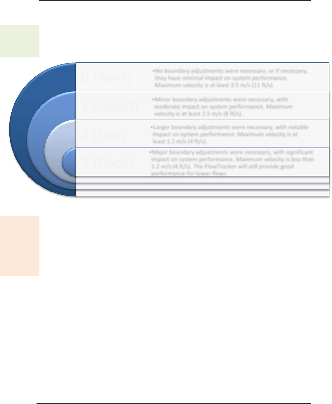
SonTek – a Xylem brand
FlowTracker2 User’s Manual (February 2016) 83
ii). For most locations, any required changes do not affect system performance.
iii). In some environments, changes may result in a lower maximum velocity.
Boundary
Display
c) The FlowTracker2 records any changes required to avoid acoustic interference.
It reports this as Boundary QC. This value describes the effect (if any) of
boundary adjustments on performance. The Boundary QC variable (Bnd) can
have the following values (0 and 1 are the most common).
Figure 6:1 - Boundary QC Conditions
Boundary
Data
Evaluate
d) The Boundary Interference check looks for interference with underwater
objects that are in or close to the FlowTracker2 sampling volume. The
FlowTracker2 automatically adapts its pinging to minimize boundary interference,
but it can only adapt so much, and the resulting pings could still be influenced by
the boundary. The FlowTracker2 software receives two values from the firmware
to use in determining the amount of boundary interference: velocity ambiguity
and the best single ping precision, both available in m/s.
i). If the Boundary QC results are FAIR or POOR, this indicates possible
interference, and the FlowTracker2 will issue an alert before the measurement
is made.
• User is prompted to consider moving the probe to avoid this interference.
• If the probe is moved, repeat the boundary test prior to data collection.
• If repeated Boundary QC tests do not give improved results, user can
proceed with the measurement, but should carefully evaluate velocity data.
ii). The Boundary Interference is checked before a point velocity measurement
is made and if the condition is not “Best”, then the Boundary Interference
warning is given (see Timing of Warning Messages).
e) This criterion can be adjusted or disabled under Quality Control Settings.
0 (Best)
1 (Good)
2 (Fair)
3 (Poor)
•No boundary adjustments were necessary, or if necessary,
they have minimal impact on system performance.
Maximum velocity is at least 3.5 m/s (11 ft/s)
•Minor boundary adjustments were necessary, with
moderate impact on system performance. Maximum
velocity is at least 2.5 m/s (8 ft/s).
•Larger boundary adjustments were necessary, with notable
impact on system performance. Maximum velocity is at
least 1.2 m/s (4 ft/s).
•Major boundary adjustments were necessary, with significant
impact on system performance. Maximum velocity is less than
1.2 m/s (4 ft/s). The FlowTracker will still provide good
performance for lower flows.

SonTek – a Xylem brand
FlowTracker2 User’s Manual (February 2016) 84
Velocity Spike Filter 6.1.4
The Velocity Spike Filter quality control is applied to each point velocity measurements
in both General mode and Discharge mode. Spikes in velocity data occur with any
acoustic Doppler velocity sensor such as the FlowTracker. Spikes may have a variety of
causes – large particles, air bubbles, or acoustic anomalies.
Filter
Method
a) The FlowTracker2 spike filter is a variation on a method called “Tukey’s Outlier.
Just like in Tukey’s method, the data are sorted in ascending order, then divided
into 4 quartiles.
i). A histogram of each velocity component is calculated.
ii). The FlowTracker2 determines the 1st Quartile (Q1) velocity value where 25%
of the samples are less than this value. The 3rd Quartile (Q3) is the velocity
value where 75% of the samples are smaller than this value. The Interquartile
Range (IQR) is defined as the spread between the 1st Quartile and the 3rd
Quartile (IQR = Q3-Q1).
iii). If the IQR is less than 0.015 m/s, IQR is set to 0.015 m/s.
iv). Any value less than (Q1–2*IQR) or greater than (Q3+2*IQR) is considered a
spike and is not used for mean velocity calculations.
b) Spikes are filtered based on all velocity components (Vx, Vy, and Vz). If any
velocity component falls outside the above limits, that sample is not used for the
mean velocity, standard deviation or velocity standard error calculation.
c) No other filtering or editing is done to FlowTracker2 velocity data.
Spike
Data
Display
d) The number of spikes is displayed and recorded at the end of each
measurement.
e) Raw, one-second velocity data are recorded with each measurement station. This
allows you to evaluate unedited velocity data for each station.
Spike
Data
Evaluate
f) The Velocity Spike Filter is applied to each point velocity measurements in both
General mode and Discharge mode, but the filter is not attempted unless there
are at least 10 samples in a measurement. The Spike Threshold (default 10%)
is used as follows to determine the number of velocity spikes present in the data.
i). If the number of spikes is a greater percentage of the total number of points
than specified by the Spike Threshold, a warning is given.
• This may indicate interference from an underwater obstacle, a highly
turbulent environment, or highly aerated water.
• At the first alert, repeat the measurement (perhaps after moving probe
location).
• If the problem persists, evaluate the measurement environment – a large
number of spikes may be unavoidable, but may not overly impact the
quality of velocity data.
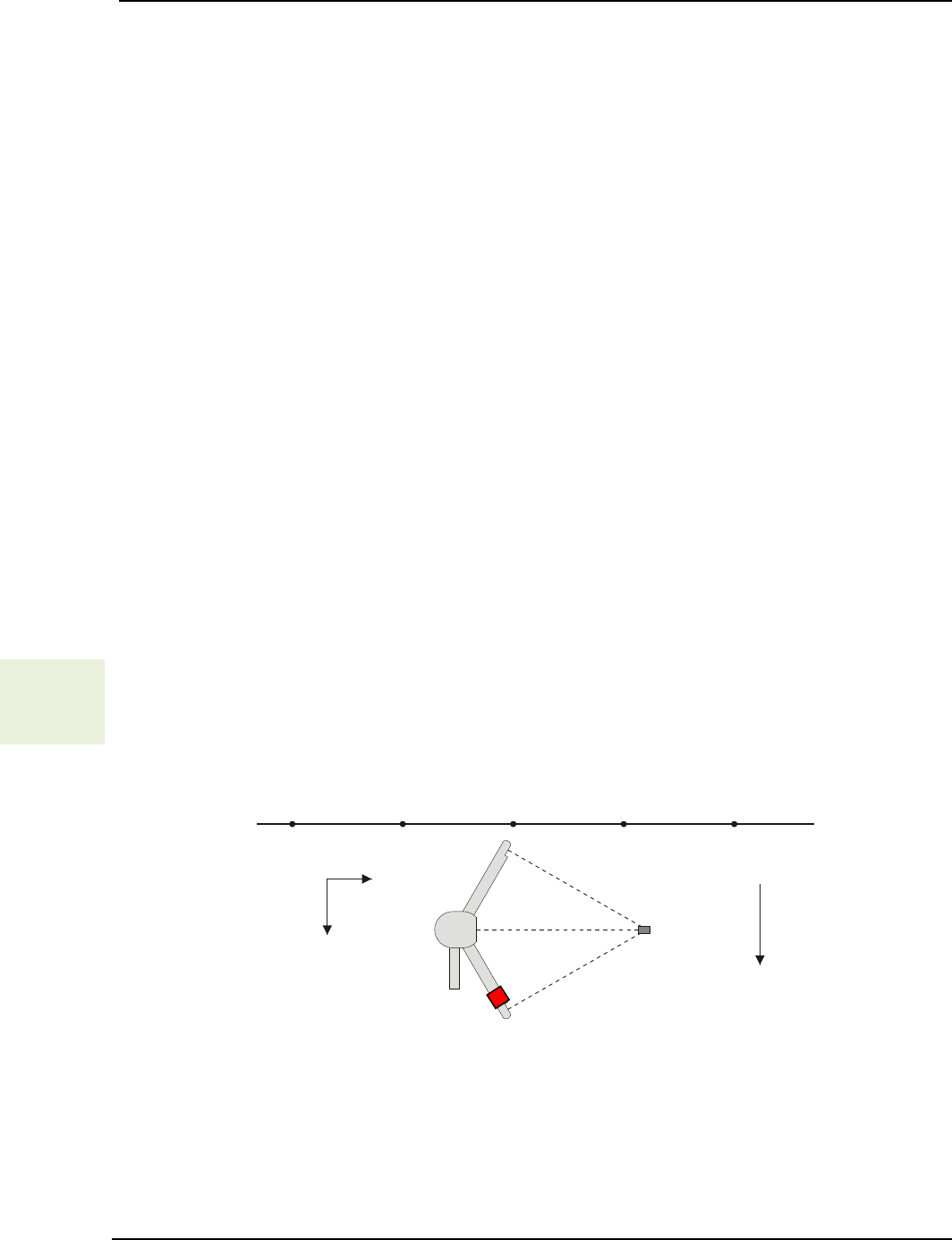
SonTek – a Xylem brand
FlowTracker2 User’s Manual (February 2016) 85
ii). The Spike Threshold is checked with the completion of a point velocity
measurement and measurement section (see Timing of Warning Messages).
• User is notified of any stations that exceed the above criteria.
• If desired, user can go back and delete suspect stations and repeat the
measurements.
g) The Velocity Spike Filter is checked at the end of each point velocity
measurement and if the number of velocity spikes is larger than allowed by the Spike
Threshold, then give the High % Spikes warning.
h) The velocity spike filter check is re-run (Discharge mode and General mode
measurement) to ensure the warnings are set with the most current data.
f) This criterion can be adjusted or disabled under Quality Control Settings.
Velocity Angle 6.1.5
The Velocity Angle quality control parameter is applied to each point velocity
measurement in Discharge mode.
a) For an ideal discharge measurement site, flow should be perpendicular to the tag
line used to define the cross section.
b) A good measurement site will typically show some flow variations, but with all
angles less than about 20°.
c) The ability of the FlowTracker2 to measure the 2D flow eliminates the need to
estimate the flow direction with each measurement, as is required for most 1D
current meters. This reduces a potential source for error in velocity
measurements.
Velocity
Angle
Method
d) Velocity angle is defined as the direction of flow relative to the X direction, and is
calculated as atan(Vy/Vx).
i). The FlowTracker’s X-axis is always held perpendicular to the tag line.
Figure 6:2 – FlowTracker2 Probe Orientation Relative to Stream Flow
ii). An angle of 0° means flow direction is perpendicular to the tag line (as desired
for an ideal measurement location).
iii). Only the X component of velocity (Vx) is used for discharge calculations. This
ensures proper discharge measurements regardless of the flow direction.
Sampling
Volume
Y
X
Probe
Coordinate System
Graduated Tag Line
Primary Flow
Direction
Mounting
Pin

SonTek – a Xylem brand
FlowTracker2 User’s Manual (February 2016) 86
Velocity
Angle
Evaluate
e) The Velocity Angle measured is evaluated to ensure reliable data collection. The
velocity angle for a point measurement is computed from the de-spiked point
measurement mean velocity components as angle = atan2(Vy, Vx). The Max
Angle criterion (default 20º) is used as follows.
i). Velocity angle is checked only if velocity is greater than a fixed threshold (0.02
m/s; 0.07 ft/s).
ii). When measured angle is greater than Max Angle, a warning is given.
• Evaluate the measurement site to verify the measured angle is reasonable.
• Consider repeating the measurement if the angle does not appear
reasonable (perhaps after moving probe location).
• For large velocity angles, consider moving the measurement site.
iii). The Max Angle is checked with the completion of a point velocity
measurement and measurement section (see Timing of Warning Messages).
• User is notified of any stations that exceed the above criteria.
• If desired, user can go back and delete suspect stations and repeat the
measurements.
f) The Velocity Angle is checked at the end of each point velocity measurement and
if the measurement’s mean velocity X component is at least 0.02 m/s and if the
velocity angle is larger than Max Velocity Angle, then give the Velocity Angle >
QC warning.
g) The velocity angle check is re-run (Discharge mode and General mode
measurement) to ensure the warnings are set with the most current data.
h) Max Angle is active only in Discharge data collection mode.
i) This criterion can be adjusted or disabled under Quality Control Settings.
Tilt Angle 6.1.6
The Tilt Angle quality control is applied to each point velocity measurements in both
General mode and Discharge mode
a) A good measurement will typically show variations in wading rod angle, but with
all angles less than about 5°.
Tilt
Method
b) Tilt angle is defined as the angle of the wading rod relative to the vertical.
i). The tilt angle of 0° means that the wading rod is vertical.
ii). The tilt angle is only an indicator and not used in any calculations
Tilt
Evaluate c) If the wading rod angle exceeds Max Wading Rod Angle, a warning is issued;
you are prompted to realign the wading rod.
i). When measured angle is greater than Max Angle, a warning is given.
• Evaluate the measurement to verify the measured angle is reasonable.

SonTek – a Xylem brand
FlowTracker2 User’s Manual (February 2016) 87
• Consider repeating the measurement if the angle does not appear
reasonable (perhaps after moving probe location).
ii). The Max Wading Rod Angle is checked with the completion of a point
velocity measurement and measurement section (see Timing of Warning
Messages).
• User is notified of any point velocity measurement that exceeds the above
criteria.
• If desired, user can go back and delete suspect point velocity
measurement and repeat the measurements.
d) The tilt angle is checked at the end of every point velocity measurement and if the
wading rod angle > Max Wading Rod Angle, then give the Velocity Angle > QC
warning.
e) The tilt angle is checked at the end of a section and reports the stations where the
tilt angle exceeds Max Wading Rod Angle.
f) This criterion can be adjusted or disabled under Discharge Settings.
Station Percent Discharge 6.1.7
Most agencies that perform discharge measurements expect that no individual station
should contain more than a certain percentage of the total discharge. The Max Station
Q criterion (default 10%) alerts you if this standard is exceeded.
% Stn Q
Method
a) The user can set the discharge reference to either “rated” or “measured”. The
reference is used when computing the discharge percent to display. When the
discharge percent is calculated,
i). The rated discharge is used only at the end of each station,
ii). The measured discharge is used only at the end of a section.
% Stn Q
Evaluate b) If the station discharge exceeds Max Station Q percent of the rated flow, a
warning is issued; you are prompted to consider adding another station.
i). If rated flow is entered, the discharge from each station is checked against this
rated value when the station is completed.
ii). Max Station Discharge is checked at the end of each station and
measurement section (see Timing of Warning Messages).
• User is notified of any stations that exceed the Max Depth Change
criterion.
• User is prompted to verify the depth value or re-enter the depth.
c) The maximum station discharge is checked at the end of a station and if the ratio
of station discharge to rated discharge > Max Station Discharge, then give the
High Stn % Discharge warning.
d) The maximum station discharge is checked at the end of a section and reports the
stations where the percent of station discharge to total discharge exceeds Max
Station Discharge.
e) Max Station Discharge is active only in Discharge data collection mode.
f) This criterion can be adjusted or disabled under Discharge Settings.

SonTek – a Xylem brand
FlowTracker2 User’s Manual (February 2016) 88
Station Water Depth 6.1.8
The Max Depth Change criterion (default 50%) is intended to avoid data entry errors.
a) It is assumed that depth changes between stations will be gradual.
Max
Depth
Evaluate
b) If the entered depth is different from a reference by more than Max Depth
Change (and at least 0.20 m; 0.66 ft) an alert is issued to be sure the depth was
not incorrectly entered.
i). If only the previous station is available, the newly entered depth is compared
to the depth from the previous station.
ii). If depth data are available on both sides of this station, the newly entered
depth is compared to an interpolated depth between the two adjacent stations.
iii). Max Depth Change is checked during station configuration and at the end of
a measurement section (see Timing of Warning Messages).
• User is notified of any stations that exceed the Max Depth Change
criterion.
• User is prompted to verify the depth value or re-enter the depth.
c) Water depth is checked of each station and if the water depth varies from the
reference depth by a percentage larger than Max Depth Change, then give the
Water Depth Change > QC warning.
d) The station water depth check is re-run (only for Discharge mode) to ensure the
warnings are set with the most current data.
e) Max Depth Change is active only in Discharge data collection mode.
f) This criterion can be adjusted or disabled under Discharge Settings.
Station Location 6.1.9
The Max Spacing Change criterion (default 100%) is intended to avoid data entry
errors.
a) It is assumed that the spacing of adjacent stations will be nearly constant across
the river.
Max
Station
Evaluate
b) If spacing between stations has changed by more than Max Spacing Change,
an alert is issued to be sure the location was not incorrectly entered. A 100%
Max Spacing Change means the new station spacing is more than two times
the previous station spacing.
i). Determine if the station location trend is expected to be increasing or
decreasing by comparing the location of the first two stations. All stations are
expected to match this trend.
ii). Any time a station location is changed, the location is compared to adjacent
value(s) to see if the station is out of order.
• If the trend in location from the previous station to this station does not
match the expected trend, then give the Station Order warning.
• If the trend in location from this station to the next station does not match
the expected trend, then give the Station Order warning.

SonTek – a Xylem brand
FlowTracker2 User’s Manual (February 2016) 89
• Collecting an out-of-order station is allowed. However, when an out-of-
order station is entered we verify the location value since the station is
sorted into the correct place within the stream.
iii). Any time a station location is changed, the location is compared to the starting
edge location. If the new location is outside the starting edge, a Location
Outside Edge warning is given.
iv). Max Station Change is checked during station configuration (see Timing of
Warning Messages).
• User is notified of any stations that exceed the Max Station Change
criterion.
• User is prompted to verify the location value or re-enter the location.
c) The expected station spacing is computed from the previous two station locations.
If the station spacing from the previous station to this location is more than Max
Spacing Change percent of the expected station spacing, then give the Stn
Spacing > QC warning. A warning will be triggered only if the station spacing is
too big (there is no warning that it is too small).
d) The station location check is re-run (only for Discharge mode) to ensure the
warnings are set with the most current data.
e) Max Spacing Change is active only in Discharge data collection mode.
f) This criterion can be adjusted or disabled under Discharge Settings.
Velocity Profile 0.2 \ 0.8 6.1.10
The Velocity Profile 0.2 \ 0.8 criterion is intended to identify unusual velocity distribution
within the measurement profile. .
a) For an ideal discharge measurement site, the velocity distribution in the
measurement profile should follow 1/6 power-law.
Velocity
Profile
Evaluate
b) The velocity measurements performed at 0.2 time depth and 0.8 time depth are
evaluated against expected velocity profile. If any of the following conditions are
true, this indicates an unusual velocity profile, and the user is given the option to
add a third velocity measurement at 0.6 time depth.
i). The magnitude of the near-surface velocity (0.2 times depth) is less than the
magnitude of the near-bottom velocity (0.8 times depth).
ii). The magnitude of the near-surface velocity (0.2 times depth) is more than two
times the magnitude of the near-bottom velocity (0.8 times depth).
iii). The near-surface velocity (0.2 times depth) and near-bottom velocity (0.8
times depth) show flow in the opposite direction.
6.2. Quality Control Warning Messages
Types of Warning Messages 6.2.1
Quality Control Warning Message is supplied when measured variable exceeds the
expected criteria of each parameter in Quality Control Parameters. The quality control

SonTek – a Xylem brand
FlowTracker2 User’s Manual (February 2016) 90
warning messages implemented in the Quality Control process are supplied in Table 6:4.
The table layout describing the quality control warning messages consist of the following
key components,
a) Warning, the warning supplied when the parameter is exceeded,
b) Reporting, aspect of the measurement process relate to the quality control
warning message,
c) QC Criteria, quality control criteria based on SonTek default values or user
specified.
Table 6:4 - Quality Control Warning Messages
Warning Reporting QC Criteria Description Suggested Action
Low SNR
Point
Velocity
Low SNR SNR below 4 dB • Improve SNR
Approach
Low SNR
Point
Velocity
Approach
Low SNR SNR between 4db and 7 dB • Improve SNR
Beam SNRs
Not Similar
Point
Velocity
SNR
Threshold
Difference in SNR for any 2
beams is > SNR Threshold.
• Look for underwater
obstacles; repeat
measurement.
• Check probe operation
Large SNR
Variation
Point
Velocity
SNR
Variation
One-second SNR data varies
more than expected during a
measurement. May indicate
underwater interference or a
highly aerated environment.
• Look for underwater
obstacles; repeat
measurement.
• Look for environmental
sources (e.g., aerated
water).
SNR
Threshold
Variation
Point
Velocity
SNR
Threshold
SNR more than SNR Threshold
different from previous
measurements; major change in
measurement conditions.
• Look for underwater
obstacles or other
changes in river
condition.
• Repeat measurement
Standard
Error > QC
Point
Velocity
σV
Threshold
σV > σV Threshold; adjusted
based on previous data and
measured velocity. May indicate
interference or a highly turbulent
environment.
• Look for underwater
obstacles or a change
in conditions.
• Consider real
turbulence levels in
river.
• Repeat measurement.
Boundary
Interference
Point
Velocity
Boundary
Interference
Boundary QC is FAIR or POOR.
Indicates possible interference
from underwater obstacles.
• Consider re-locating
probe and repeating
test.
• Measurement can
proceed if results are
consistent.
High %
Spikes
Point
Velocity
Spike
Threshold
Spikes > Spike Threshold
percent of samples. May indicate
poor measurement conditions.
• Look for underwater
obstacles or unusual
conditions (e.g.,
aerated water).
• Repeat measurement.
Velocity
Angle > QC
Point
Velocity
Max Velocity
Angle
Angle > Max Velocity Angle.
May only indicate non-ideal
measurement environment.
• Consider if measured
angle is realistic.
•
Repeat measurement if
needed.
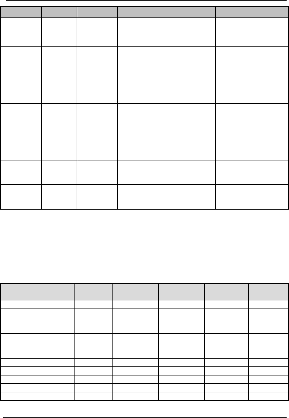
SonTek – a Xylem brand
FlowTracker2 User’s Manual (February 2016) 91
Warning Reporting QC Criteria Description Suggested Action
Rod Angle
> QC
Point
Velocity
Max Wading
Rod Angle
Angle > Max Wading Rod
Angle. May indicate non-ideal
measurement method.
• Consider if measured
angle is realistic.
• Repeat m
easurement if
needed.
High Stn %
Discharge Station Max Station
Discharge
%Q > Max Station Discharge.
Station contains a large portion of
the total discharge.
• Consider adding more
stations.
Water
Depth > QC
Station Max Depth
Change
Station depth differs from
adjacent stations by more than
Max Depth Change %. This may
indicate data entry problem.
• Verify station depth
value.
• Re-enter if needed.
Stn
Spacing >
QC
Station
Max
Spacing
Change
Spacing between stations has
changed by more than Max
Spacing Change %. This may
indicate a data entry problem.
• Verify station location
value.
• Re-enter if needed.
Station
Order Station None
Station location out of sequence
or outside river edge. This may
indicate a data entry problem.
• Verify station location
value.
• Re-enter if needed.
Location
Outside
Edge
Station None
Station location out of sequence
or outside river edge. This may
indicate a data entry problem.
• Verify station location
value.
• Re-enter if needed.
Fractional
Depth > 1
Point
Velocity None
Fractional Depth < 1. Verify ratio
between measurement depth and
total depth and this should not >1
• Verify fractional depth
value.
• Re-enter if needed.
Timing of Warning Messages 6.2.2
The quality control warning messages are supplied at certain stages of the measurement
process for both the Discharge and General Modes. The timing of the quality control
warning messages are supplied in Table 6:5. “D” indicates Discharge mode and “G”
indicates General mode.
Table 6:5 - Timing of Quality Control Warning Messages
Warning Messages
Station
Setup
Pre
Measurement
Post
Measurement
Post Station
Post
Section
Low SNR
D,G
D,G
Approach Low SNR
D,G
D,G
Beam SNRs Not
Similar
D,G
D,G
Large SNR Variation
D,G
D,G
SNR Threshold
Variation
D,G
D,G
Standard Error > QC
D,G
D,G
Boundary Interference
D,G
High % Spikes
D,G
D,G
Velocity Angle > QC
D
D
Rod Angle > QC
D,G
D,G
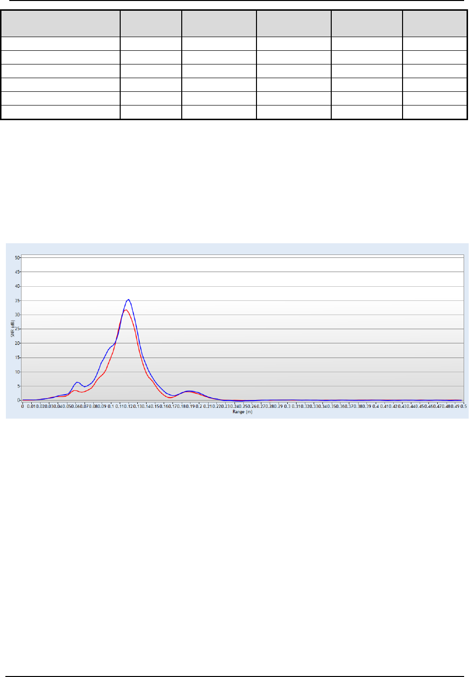
SonTek – a Xylem brand
FlowTracker2 User’s Manual (February 2016) 92
Warning Messages
Station
Setup
Pre
Measurement
Post
Measurement Post Station
Post
Section
High Stn % Discharge
D
D
Water Depth > QC
D
D
Stn Spacing > QC
D
Station Order
D
Location Outside Edge
D
Fractional Depth > 1
D,G
D,G
6.3. Beam Check
Beam Check operates by sending a pulse of sound into the water, and then plots the
signal to noise ratio of the return signal versus range for each of the FlowTracker2
receivers. This information can be evaluated to determine the effective measurement
range, to look for interference from boundaries/structures, to survey a deployment site,
or to observe the quality of the returned signal.
Figure 6:3 - Beam Check
Beam Check Overview 6.3.1
The FlowTracker2 transmits a pulse of sound, it then receives the return signal to noise
ratio for each of the 2 (or 3) receivers as a function of time following the transmit pulse.
Features in the signal to noise ratio profile verify different aspects of system
performance,
a) The horizontal axis indicates the range from the FlowTracker2 probe (in m).
b) The vertical axis is in signal to noise ratio units called SNR (in dB).
c) Ringing from the transmit pulse appears on the left side of the graph.
d) The location of the sampling volume is indicated by increased signal to noise ratio
in a bell-shaped curve,
i). The sampling volume curve corresponds to the transmit pulse passing through
the focal point of the receivers,
ii). The peak of this curve corresponds to the center of the sampling volume,

SonTek – a Xylem brand
FlowTracker2 User’s Manual (February 2016) 93
iii). The location of the sampling volume varies from probe to probe, but is typically
10-12 cm,
iv). All receivers (2 or 3) should see the peak in the same location, although there
will be variation in the height and shape of the curve.
e) A sharp spike indicates a boundary reflection (if a boundary is within range),
i). If the probe is close to a boundary, a sharp reflection should be seen,
ii). The size and shape of this reflection will vary depending on the nature of the
boundary, its distance from the FlowTracker2 and the acoustic conditions of
the water,
iii). We can estimate the distance from the probe to the boundary by the location
of the boundary reflection.
f) After the boundary reflection, the signal to noise ratio flattens out in the region
where there is no reflected signal from the water,
i). Signal to noise ratio decreases to the electronic noise level past the boundary
and is typically about 30-70 counts,
ii). An easy way to measure the instrument noise level is to run Beam Check
when the probe is not in the water. In this case, the entire plot should show a
constant return at the instrument’s noise level.
g) When using Beam Check, it is important to understand that the output plot will
vary considerably because of the nature of acoustic scattering,
i). The shape and height of the return signal, particularly the bell curve for the
sampling volume, will show considerable variation between updates,
ii). Each of the items described above should be visible (Figure 6:1),
iii). If no sampling volume peak can be seen, try adding some fine dirt or other
Seeding material and stirring the water to increase the signal to noise ratio.
iv). If the Beam Check output differs significantly from the sample shown here,
refer to Diagnosing Measurements with Beam Check for more details about
interpreting this data.
Beam Check Features 6.3.2
• Sample - Indicates the number of the transmitted pulse that is currently being
displayed on the graph and in the tabular data boxes. If real-time or previously
recorded (archived) data is being displayed, only the current sample number is
displayed.
• Sample Averaged - When Averaging has been selected, this box indicates the
number of samples that have been averaged together for the currently displayed
graph and tabular data.
• Noise Level - Shows the electronics noise level for the receiver of each beam. This
value is determined by the signal to noise ratio when the instrument is not receiving
any return reflections from the water. This value should match the signal to noise
ratio for the flat portion of the graph. The noise level is displayed in SNR.

SonTek – a Xylem brand
FlowTracker2 User’s Manual (February 2016) 94
• Peak Position - This is the location of the center of the peak for the sampling
volume for each of the receivers. The position of the peak should be about the same
for each receiver.
• Peak Level - This is the height of the peak for the sampling volume for each of the
receivers. This will vary depending on the amount of scattering material in the water.
• Graph Range (X-axis) - The graph itself shows a plot of the signal to noise ratio for
each beam as a function of range following the transmit pulse. The range portion is
shown along the graph’s X-axis and the value can be shown in centimeters, meters,
etc.
• Graph SNR (Y-axis) - The graph itself shows a plot of the signal to noise ratio (SNR)
for each beam as a function of range following the transmit pulse. The SNR portion
is shown along the graph’s Y-axis and the value is shown in SNR.
Beam Check Operation 6.3.3
Beam Check can be performed in either a small tank, bucket of water or measurement
section in canal or river such that the probe is submerged and there is a boundary
(surface, side, or bottom) within view.
a) Hold the FlowTracker2 that the boundary is located approximately 20-30 cm (8-12
in) from the probe.
b) User may need to add a small amount of fine dirt or other seeding material and
stir the bucket well for good test conditions. Regular tap water usually does not
have enough scatterers (seeding) for a valid test.
c) To perform a Beam Check,
i). Use the down scroll arrow keys to select Utilities on the main menu,
ii). Use the down scroll arrow keys to select Beam Check on the Utilities menu.
d) To record or stop recoding of Beam Check,
ii). Press the Right Soft Key,
e) To navigate to Utilities menu,
ii). Press the Left Soft Key.
Diagnosing Measurements with Beam Check 6.3.4
Beam Check function can be used to detect measurement conditions and or hardware
related issues that can affect the measurement accuracy and precision.
Low Scattering Strength 6.3.4.1
Lack of scattering material in the water normally encountered during measurements at
springs or under ice will result in a small or non-existing sampling volume peak (see
Figure 6:4). In cases where there is not sufficient backscatter, place a small amount of
seeding material in the water to act as scattering material (see Seeding).
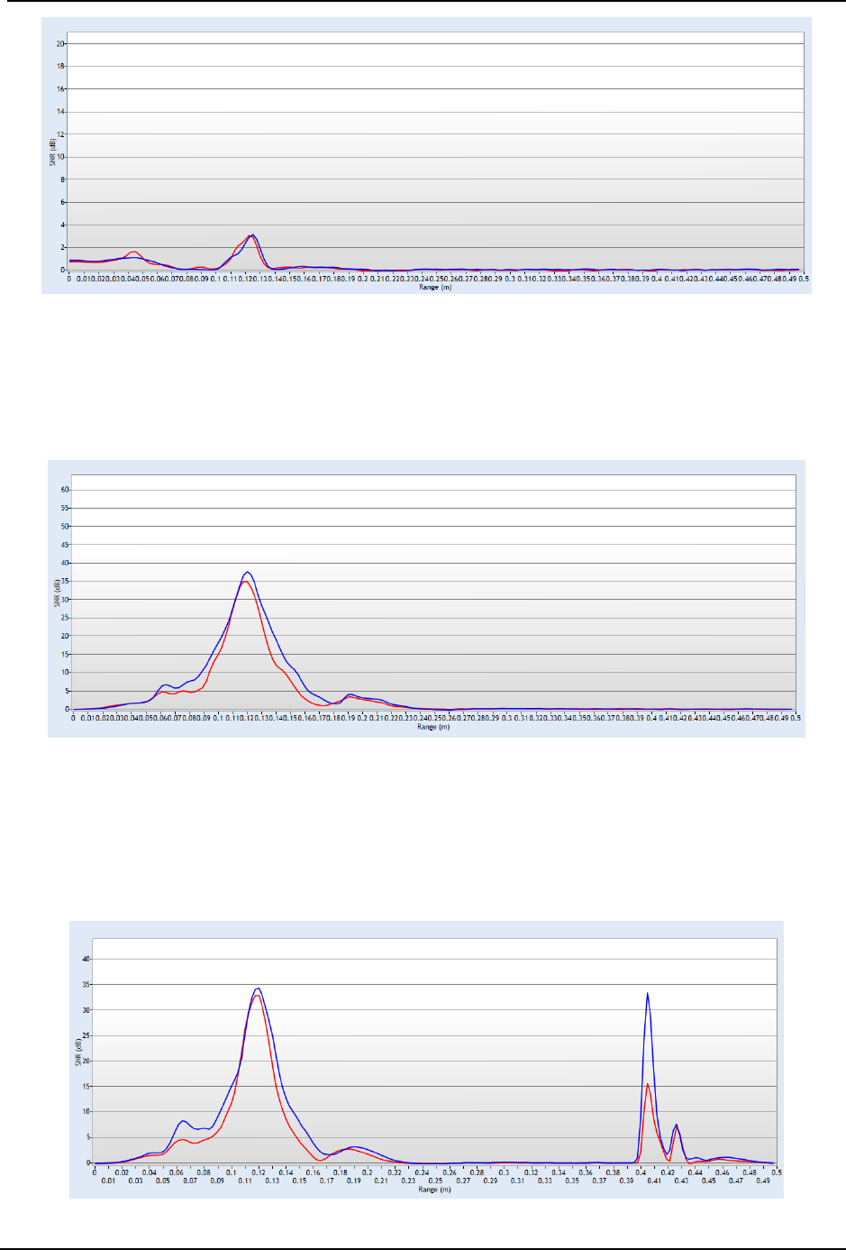
SonTek – a Xylem brand
FlowTracker2 User’s Manual (February 2016) 95
Figure 6:4 - Low Scattering Strength
Strong Scattering Strength 6.3.4.2
Most river systems and or irrigation canals have sufficient scattering material in the water
and will result in a well-defined sampling volume peak (see Figure 6:5).
Figure 6:5 - Strong Scattering Strength
Boundary Detected within Beam Check 6.3.4.3
When a boundary is within 50cm from the FlowTracker2 transducer, the boundary will be
detected by FlowTracker2 when performing a Beam Check (see Figure 6:6). The
boundary was detected about 40cm away from the transducer
Figure 6:6 - Boundary Detected - 40cm
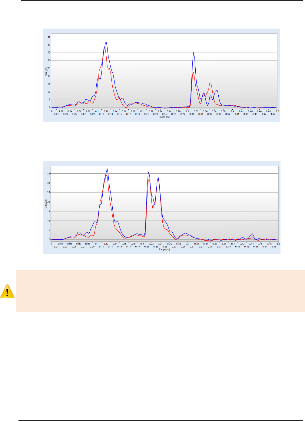
SonTek – a Xylem brand
FlowTracker2 User’s Manual (February 2016) 96
The Beam Check supplied in Figure 6:7 indicates that boundary was detected at 30cm
away from the transducer.
Figure 6:7 - Boundary Detected - 30cm
The Beam Check supplied in Figure 6:8 indicates that boundary was detected at 30cm
away from the transducer.
Figure 6:8 - Boundary Detected - 20cm
Boundary that is located within 27cm from the FlowTracker2 transducer can affect the
accuracy and precision of velocity measurement. It is recommended when working
close to boundaries to determine the location of the boundary in relation to the
transducer and sampling volume. This can be achieved by performing a manual Beam
Check or Automated Beam Check.
Boundary in Sampling Volume 6.3.4.4
Boundary in Sampling Volume occurs when the boundary is located at the same position
from the transducer than the sampling volume. There are number of unique features
shown in Figure 6:9 that can be used to identify if boundary is located within the
sampling volume.
a) The SNR of the peak located at the sampling volume is two to three times higher
than previous measurements performed.
b) Three peaks are displayed in the Beam Check, spaced at equal distances.
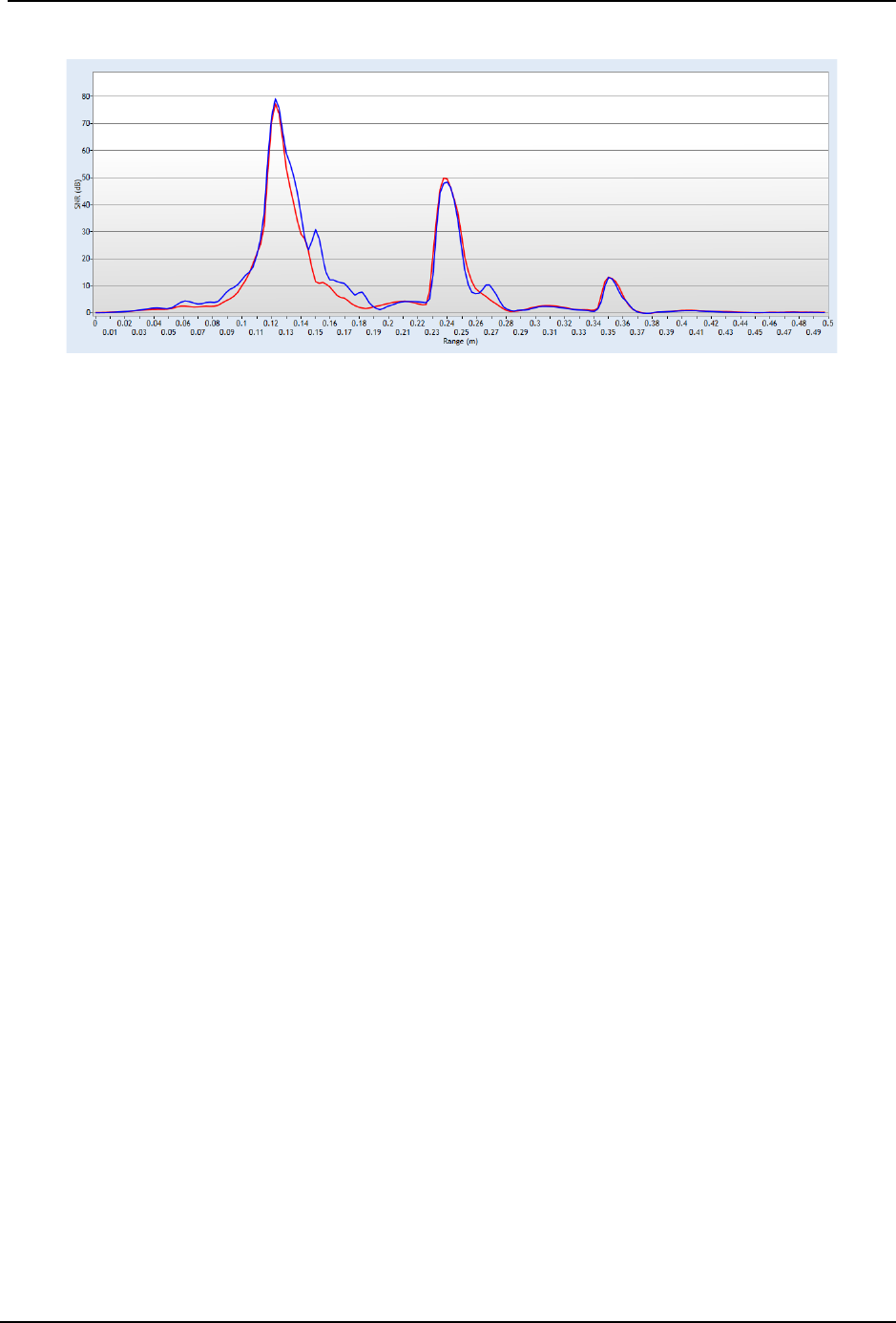
SonTek – a Xylem brand
FlowTracker2 User’s Manual (February 2016) 97
c) The SNR of each peak reduces as distance increase form the transducer.
Figure 6:9 - Boundary within Sampling Volume
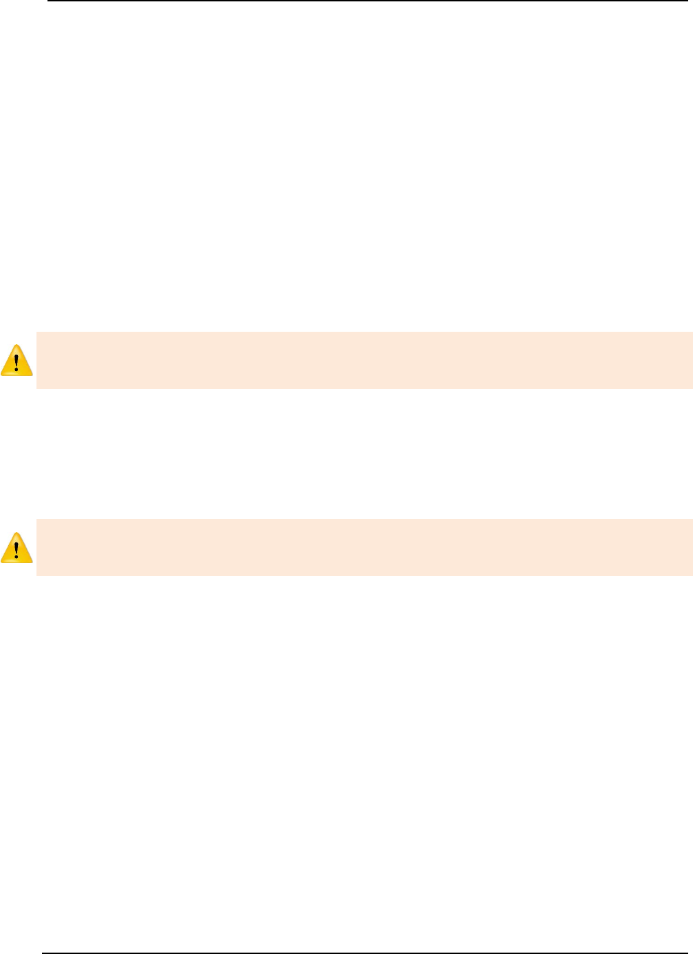
SonTek – a Xylem brand
FlowTracker2 User’s Manual (February 2016) 98
Measurement Process Section 7.
The Measurement Process involved for performing field measurements using a
FlowTracker2 instrument consists of number of components. It is important for both the
novice and experienced user that each of the components is followed to ensure that the
data collected during the measurement process is within acceptable standards and
quality. The main components that is the basis of the overall measurement process are
the following,
• Office Procedures,
• Measurement Site Information,
• Pre Measurement Diagnostics,
• Measurement Procedure,
• Post Measurement Requirements.
Components within the Measurement Process should not be neglected due to lack of
operational experience, time or workload as this will compromise the data quality and
accuracy.
7.1. Office Procedures
The Office Procedures lists the steps that need to be performed to confirm the condition
and operation of the equipment and accessories before departure for field
measurements.
The verification of instruments and accessories before leaving the office is normally
neglected. It is highly recommended that instrumentation are inspected and tested
before each field measurement exercise.
Equipment List 7.1.1
Equipment List is an essential part in the planning and preparation stages of a field
measurement exercise. It is recommended that a comprehensive list is designed based
on user and or organizational requirements as this will ensure that all equipment is
prepared and packed before departing from the office. The equipment required for field
measurements are categorized under FlowTracker2 Instrument and user defined
measurement gear.
a) The FlowTracker2 Instrument and related accessories is detailed under
FlowTracker2 Case section. A reference sheet of the contents is supplied within
the FlowTracker2 carry case.
b) The user defined measurement gear is a list of items required in addition to the
FlowTracker2 Instrument to perform a field measurement.
c) Recommended measurement equipment list containing FlowTracker2 instrument,
measurement gear, safety gear and reference instruments are supplied in
Appendix D.
SonTek – a Xylem brand
FlowTracker2 User’s Manual (February 2016) 99
The safety gear listed in Appendix D is only a recommendation. It is imperative that the
user follow their respective organization and or local authority guidelines in the use of
safety gear during field measurements.
Hardware Inspection 7.1.2
Hardware Inspection can identify any damage to the hardware components that
occurred during previous application. It is recommended that the hardware checks listed
in Table 7:1 are performed before departure from the office. Any instrument problems
experienced as a result of the damage can be resolved by exchanging the hardware
components or using a different FlowTracker2 instrument.
The FlowTracker2 probe or handheld can be exchanged with another instrument if
required. The software registers the serial number of probe and handheld with each
point velocity measurement.
Table 7:1 - Hardware Inspection
Component
Inspection
Handheld
• Inspect the handheld for any external damage to the housing, LCD screen
and keypad,
• Battery cap and O-ring,
• Connectors of battery cartridge,
• USB port.
Probe
• Mounting between receiver arms and probe body,
• Scratched transducer face,
• Dented or bent probe stem.
Probe Cable
• Kinks or dents in probe cable,
• Damaged or bent pins on probe cable connector.
Top Setting Rod
• Bent top setting rod,
• Bent S bracket or screw.
Office Diagnostic 7.1.3
Office Diagnostic is a basic verification process of the FlowTracker2 to confirm that the
instrument is operational before departure from the office. The diagnostic tests consist
of the evaluation of a number of functions to verify the internal operations and probe
performance of the FlowTracker2.
a) The functions that are evaluated during diagnostic test process are located under
the Utilities menu.
b) The diagnostic test process is mainly categorized under Internal Systems, Raw
Data and Beam Check functions.
i). Internal System functions comprise of internal clock, recorder, battery and
GPS data. These functions can be verified manually by evaluating the
information displayed or using external reference if required.
ii). Raw data function includes Velocity, SNR, Temperature, Battery and Tilt data
that is graphically displayed. These functions can be verified by manually
interpreting the information displayed or against a reference instrument.
SonTek – a Xylem brand
FlowTracker2 User’s Manual (February 2016) 100
The velocity data displayed under Raw Data for the Office Diagnostic tests should be
ignored as the data is not based on actual measurements conditions.
iii). Beam Check function is performed to verify the FlowTracker2 probe
performance. The procedure for performing a Beam Check must be followed
as stipulated in Beam Check Operation.
c) To verify the GPS Data functions place the FlowTracker2 handheld outside in an
open area with a clear view of the sky. The accuracy of the GPS data is directly
related to the number of satellites and HDOP value.
d) To verify the Raw Data and Beam Check functions place the FlowTracker2 probe
in a bucket of water (see Beam Check Operation).
e) The variables that are evaluated during the diagnostic tests are listed in Table 7:2.
Table 7:2 - Office Diagnostics
Function
Variable
Verification
System
Clock
• Date
• Time
• UTM Offset
• System Clock function show the current internal time of
the FlowTracker2 instrument,
• Verify if the internal system clock date and time is
correctly set and adjust if required.
Recorder
• Memory Available
• The Recorder function indicates the percentage of
available memory,
• If the available memory is insufficient download all
measurement files. Ensure that all measurement files
downloaded are stored in a secure area,
• Format Recorder or delete Data Files to increase
available memory.
Battery Data
• Battery Type
• Percentage Full
• Battery Data function display the type of battery, voltage
and percentage full,
• Make sure the correct battery type is selected.
GPS Data
• Latitude
• Longitude
• Altitude
• Date
• Time
• The GPS Data function displays the GPS information
from the internal GPS,
• Compare GPS data supplied with external reference
such as Survey Bench Mark, handheld GPS or mobile
device equipped with GPS.
Raw Data
Display
• Velocity
• SNR
• Temperature
• Tilt
• Battery Indicator
• The Raw Data function display raw data for each
variable,
• Evaluate each variable data that are graphically
displayed or compare against a reference instrument in
the case of temperature measurements,
Automated
Beam Check
• Peak Level
• Peak Position
• Peak Location
• The Automated Beam Check and Beam Check
functions serve two purposes, verifying the probe
performance and measurement conditions,
• Evaluate the Qua
lity Control reports supplied during the
test.
Beam Check
SonTek – a Xylem brand
FlowTracker2 User’s Manual (February 2016) 101
7.2. Measurement Site Information
Measurement Site Information or normally referred as “Metadata” should be
documented before any measurements are performed with the FlowTracker2 instrument.
In most organizations FlowTracker2 measurements are related to a measurement site
and secondary data sets and it’s essential that the information collected is accurate. The
measurement site information that should be collected during a field measurement
exercise is listed in Table 7:3.
Unique entry fields were developed in the FlowTracker2 software for the measurement
site information defined in this section. The dedicated fields ensure that information is
captured correctly and assigned to respective variables, which promote good data
management practices.
Table 7:3 – Measure Site Information
Variable
Description Unique Field
Site Number
Site number allocated to measurement site. Most
organizations use a unique number system (e.g.
associated with catchment).
File Properties
Site Name
Site name allocated for measuring site. Most
organizations use a unique naming convention (e.g.
combination of river and place name).
File Properties
Operator
Operator that performed the measurement
File Properties
Start Date and
Time
Start date and time of measurement.
Internally recorded
End Date and
Time
End date and time of measurement.
Internally Recorded
Start Staff
Gauge
Readings
Staff gauge reading taken before a FlowTracker2
measurement is performed.
Supplemental
Data
End Staff
Gauge
Readings
Staff gauge reading taken after a FlowTracker2
measurement is completed.
Supplemental
Data
GPS Position
GPS position of start and end location of measurement
Internally Recorded
Photographs
Photographs of the measurement section, upstream
conditions and downstream conditions are essential for
identifying possible influences on the field measurements.
None
Organizations that make use of hydrological databases, unique monitoring site
identifiers and import routines, would find the Site Number very useful to automatically
link the data to a specific monitoring site during the import process.
7.3. Pre Measurement Diagnostics
Pre Measurement Diagnostics is an essential step in the measurement process to
ensure accurate and consistent measurement results. The functions evaluated in pre
measurement diagnostics are the same as discussed in Office Diagnostics.
SonTek – a Xylem brand
FlowTracker2 User’s Manual (February 2016) 102
a) The functions that are evaluated during diagnostic test process are located under
the Utilities menu.
b) The functions that are of key importance during the pre-measurement diagnostic
tests are System Clock, Velocity Data, SNR Data and Beam Check functions.
c) It is recommended that Pre Measurement Diagnostics should be performed
before each measurement is started.
d) To verify the Internal System, Raw Data and Beam Check functions place the
FlowTracker2 probe in moving water well away from any underwater obstacles in
the region of the measurement section.
e) The variables that are evaluated during the diagnostic tests are listed in Table 7:4.
Table 7:4 - Pre Measurement Diagnostics
Function Verification
System
Clock
• Verify if the internal system clock date and time is correctly set and adjust if
required.
• All data sets recorded during a FlowTracker2 measurement receive a date
and time stamp,
• Date and Time is essential Metadata in the processing and application of
measurement results.
Recorder
• Verify if the available memory is sufficient for performing a measurement,
• Insufficient memory on the recorder could affect the measurement operation
and or recording of measurement file.
Battery Data
• Evaluate the battery voltage and capacity based on the battery type selected,
• Insufficient power supply could affect the measurement operation.
GPS Data
• Evaluate the GPS information received, with the focus on number of satellites,
and HDOP values. This will indicate the level of accuracy of the GPS
measurement.
Raw Data
Display
• The raw data displayed of all variables is updated once per second.
• Velocity, data should appear reasonable for the environment (short term
variations are expected and are most likely real).
• SNR, data should ideally be above 10 (units are dB), but measurements can
be made as low as 3-4 dB.
• Temperature
, data should reasonable to the environment. Temperature data
is used for sound speed calculations and can affect velocity data (see
Principle of Operations).
Automated
Beam Check
• Place the probe in moving water well away from any underwater obstacles;
follow the on screen instructions for the test. Perform Beam Check
measurement as described in Beam Check Operation.
• Automated Beam Check, review of Automated Beam Check results see
Automated Beam Check,
•
Beam Check, review of Beam Check results see Beam Check.
Beam Check
7.4. Measurement Procedure
Basic outline of the Measurement Procedure required to perform a Discharge
measurement with a FlowTracker2 instrument is supplied in the following section. The

SonTek – a Xylem brand
FlowTracker2 User’s Manual (February 2016) 103
measurement procedure is based on wading principles, which is suited for low to
medium flow conditions depending on water velocity and depth.
a) Collect and verify Measurement Site Information before discharge measurement
commences as stipulated under Measurement Site Information.
b) Select the measurement site based on the criteria stipulated under Site Selection
Requirements. Site and flow conditions does change over time and it is
recommend that existing measurement site is evaluated during each field
measurement exercise.
c) It is recommended for new measurement sites that the user perform spot checks
across the section at certain locations to get an estimation of the velocity range,
water depth and channel geometry.
d) Perform Pre Measurement Diagnostic tests in the region of the proposed
measurement section. Place the probe in moving water well away from any
underwater obstacles.
e) A graduated tagline or measuring tape should be spanned across the
measurement section to determine the station location. The graduated tagline or
measuring tape should be perpendicular to the main flow direction and channel
orientation.
f) Staff gauge readings with time should be taken at the start the discharge
measurement. If the discharge measurement is over extended period or at a
measurement site with rapid changing stage, intermediate readings should be
taken.
g) Enter Rated discharge (if applicable) of measurement site to calculate percentage
flow of each panel.
h) Divide the measurement section into a minimum of 23 stations (for sections >5m).
The number of stations required is dependent on the measurement section width
(see ISO 748 – 2007, Hydrometry - Measurement of liquid flow in open channels
using current meters or floats for recommendation of number of stations). The
flow per panel should not exceed 10% of the total flow, with 5% as the ideal
distribution.
i) The water depth at each station is measured using a top setting or universal rod.
A staff gauge board can also be used to determine the water depth at the location
of the station or sampling volume of the FlowTracker2.
j) The averaging time interval for data collection normally varies between 40 to 60
seconds for velocity measurements depending on flow conditions.
k) Determining Mean Station Velocity method for each station. The software
suggests either a six-tenths or two-point method depending on the threshold in
0.6 Method Depth and the measured water depth. The minimum distance
between the channel bed and water surface and instrument must be within the
instrument specifications.
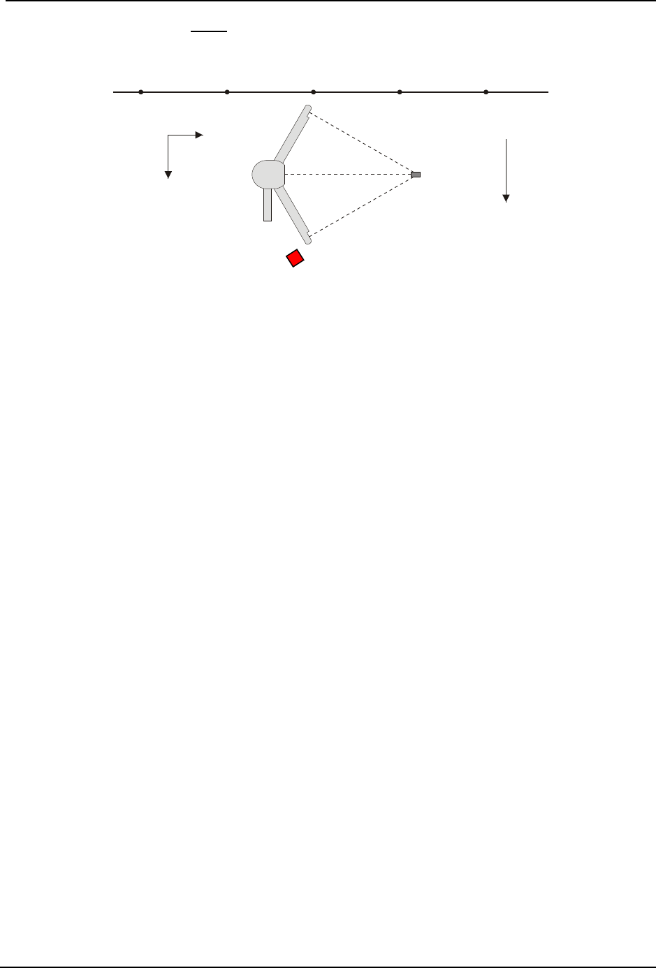
SonTek – a Xylem brand
FlowTracker2 User’s Manual (February 2016) 104
l) The FlowTracker2 must be perpendicular to the graduated tagline or measuring
tape that was setup across the measurement section.
Figure 7:1 - FlowTracker2 Probe Orientation Relative to Stream Flow
m) Keep the FlowTracker2 probe free of plant material at all times as this can impact
the velocity measurements significantly.
n) Continuously evaluate the measurement results with measurements performed at
previous stations. The variation in measurement results should reflect the flow
conditions at the measurement site.
o) Review the instrument configuration during the measurement, especially the
quality control parameters and adjust if required.
p) Automated Beam Check can be performed during any stage of the measurement
to verify the probe performance and measurement conditions.
q) Comments can be entered at each station or at the end of the discharge
measurement to describe the flow conditions or any influences that may impact
the measurement quality.
r) Staff gauge reading with time should be taken at the end of the discharge
measurement.
7.5. Post Measurement Requirements
Post Measurement Requirements consists of number of tasks that need to be
performed when a field measurement is completed. The tasks that forms the framework
of the post measurement requirements are grouped under the following main categories,
• Review of Measurement Site Information,
• Review Measurement Summary
• Data Management,
• Storage.
Review of Measurement Site Information 7.5.1
Review of Measurement Site Information before departure from the measurement site
is important to ensure that all associated Metadata is accurate. It is recommended that
Sampling
Volume
Y
X
Probe
Coordinate System
Graduated Tag Line
Primary Flow
Direction
Mounting
Pin
SonTek – a Xylem brand
FlowTracker2 User’s Manual (February 2016) 105
the user verify each variable populated during the measurement process with the main
focus on the measurement site reference.
It is not good data management practice to leave both measurement site references
empty or with abbreviate terms. It is recommended that the user makes use of
accurate site descriptions.
Review Measurement Summary 7.5.2
Review Measurement Summary is the evaluation of the measurement results and if the
results are expected from the flow conditions present at the measurement site. There
are a number of variables that can be evaluated after the measurement is completed and
it is recommended that the following process is followed during the evaluation.
The evaluation of measurement results should be performed during the measurement
and the review of measurement summary is just an overview of what was already
identified during a measurement. It is recommended to repeat a point velocity or
station measurement if any of the data collected during a measurement are not
consistent with the flow conditions present.
a) Point velocity measurements with regard to mean velocity, standard error and
quality control reports correspond within a station measurement and adjacent
stations.
b) Station measurements with regard to location, depth, mean velocity and panel
discharge correspond to adjacent stations and what is expected from the flow
conditions.
c) The total width based on station locations does that correspond with the actual
width of the measurement section.
d) The total discharge, area and mean velocity measured is within the expected flow
conditions.
e) Review measurement results against historical measurements performed at the
measurement site during similar flow conditions and or staff gauge readings (if
available).
f) Review total discharge measured against discharge reading from developed
Stage - Discharge Relationship (if available). Most organizations use a 5% error
band to determine if the measurement results are within the required
measurement standards.
The review process is a key component of overall data quality and it is recommended
that this process be completed in the field directly after the measurement. Most
organizations supply their hydrographers or hydrologists a copy of hydrological
database or other data formats to perform this process in the field.
Data Management 7.5.3
Data Management consists of the process involved in managing the information
collected during field measurements. The steps required to ensure data continuity and
safe keeping after field measurements are completed are the following.
SonTek – a Xylem brand
FlowTracker2 User’s Manual (February 2016) 106
a) Download measurement files after measurements are completed at the
measurement site or by the end of the work day using the FlowTracker2 desktop
software. The files types created during a measurement are dependent if a
measurement and or Beam Check tests were performed. For more information
on file types see Table 4:2.
b) Create a secondary backup of the measurement files at the end of each workday
by copying the files to an external USB drive. The USB drive should be stored
separately from the PC or Tablet.
c) Photographs taken with Camera or Phone during the field measurements should
also be downloaded and stored on an external USB drive.
The internal recorder of the FlowTracker2 handheld should not be used as the main
storage device for safe keeping of measurement files. It is good data management
practice to download the measurement files at least once per day.
Storage 7.5.4
Storage guidelines of FlowTracker2 instrument and accessories are essential to ensure
the safe keeping of the instrument during transport or storage at the office. The
FlowTracker2 instrument is supplied in a pelican case with foam inserts, designed to
house each individual component. The recommend guidelines for packing of instrument
in the pelican case are the following,
a) Place each component of the FlowTracker2 and accessories in the designated
foam inserts.
b) The probe cable must be disconnected form the handheld before it is placed in
the foam inserts.
c) The probe cable should be coiled in such a manner that it fits into the designated
insert. Care should be taken that the cable is not kinked or the pelican case lid is
pressing on the cable.
d) Battery cartridge should be removed from the handheld by the end of each
workday. In the case where the FlowTracker2 instrument is not used, it is
recommended that the batteries are removed from the pelican case.
Batteries should not be left in the FlowTracker2 handheld for prolonged periods as
damage can occur to the handheld if the batteries are leaking. It is recommended that
batteries are removed from the handheld if the instrument is not used.
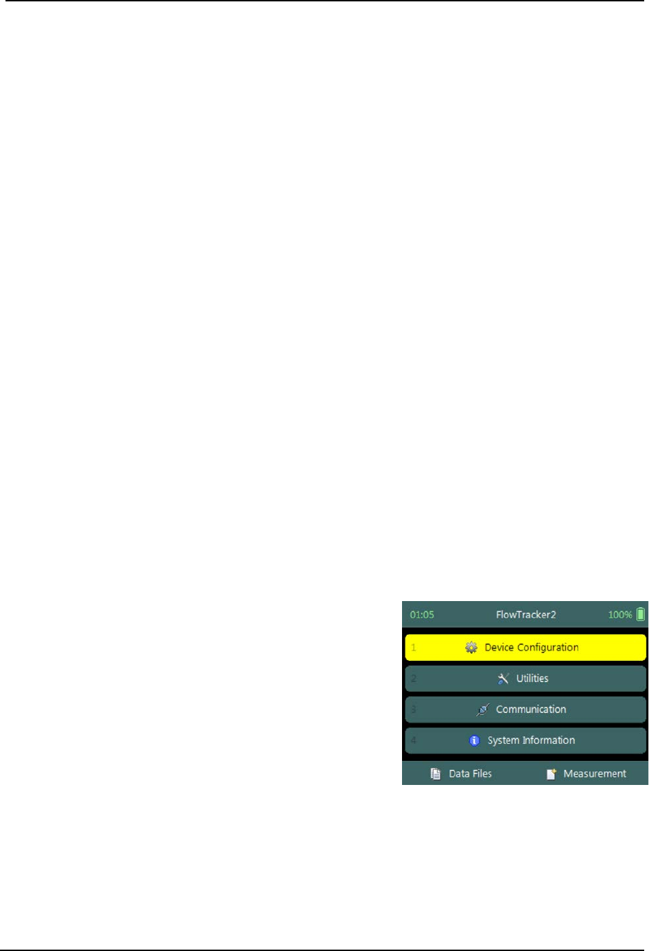
SonTek – a Xylem brand
FlowTracker2 User’s Manual (February 2016) 107
Discharge Measurement Section 8.
Discharge Measurement is the measurement technique involved in collecting data for
discharge calculation based on the Discharge Mode (see Data Collection Modes). The
data collection framework for discharge measurement is a well-designed workflow (see
Software Flow Diagram) between setting up of measurements parameters, creating a
measurement section, the collection of raw data and generating individual station and
measurement section reports. The discharge data collection process consists of the
following main components, with discussions of each component.
• Create Measurement,
• Automated Beam Check,
• Data Collection,
• Discharge Summary.
8.1. Create Measurement
Creating a new measurement consist of number of steps before the data collection can
be performed. The first step involved is to either select an existing Configuration
Template or create a new template with user defined configuration parameters. The
template then needs to be associated with a measurement file that is created by the
user. When the measurement file is created, the software is ready for data collection.
Measurement 8.1.1
The Measurement function enables the user to create a new measurement in either
Discharge or General mode. The Discharge mode used for the collection of discharge
data during field measurements will be focused on in this section.
a) The Measurement function can be accessed
from the Main Menu on the bottom banner,
b) To select the Measurement function,
i). Press the Right Soft Key.
c) The software will Navigate to the New File Type or
Mode screen.
Figure 8:1 - Main Menu
New File Type 8.1.2
The New File Type function enables the user to determine if the new measurement file
should be based on either Discharge or General mode.
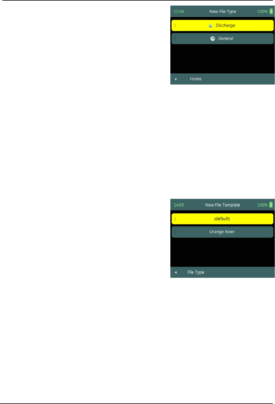
SonTek – a Xylem brand
FlowTracker2 User’s Manual (February 2016) 108
The New File Type screen consists of the following
options,
a) Discharge,
b) General,
c) To select discharge mode,
i). Use up or down scroll arrows keys to select
Discharge and press enter key.
d) The software will Navigate to the New File
Template screen.
e) To navigate to Home menu,
i). Press the Left Soft Key.
Figure 8:2 - New File Type
New File Template 8.1.3
New File Template function enables the user to create a new configuration template
based on SonTek default settings or select an existing Configuration Template created
by the user. The configuration template is based on user defined parameters that are
dependent on measurement site details, flow conditions and organizational
requirements. The configuration template selected will be assigned to the measurement
file and the parameters defined in the template will be applied during the Discharge
measurement.
The New File Template screen consists of the
following options,
a) (default), the template will be based on
SonTek default settings.
b) Configuration Templates, created under
“Device Configuration”. A list of available
templates created by the user will be displayed
under the “(default)” option.
c) To select a template,
i). Use up or down scroll arrows keys to select
template and press enter key.
d) The software will navigate to the New Data File
screen.
e) To navigate to File Type menu,
i). Press the Left Soft Key.
Figure 8:3 - New File Template
New Data File 8.1.4
New Data File function enables the user to populate the measurement site and operator
details. The information entered for each parameter should be accurate as this
information is recorded in each measurement file and used in both the File Naming and
Folder Naming conventions.

SonTek – a Xylem brand
FlowTracker2 User’s Manual (February 2016) 109
• Existing templates created under “Device Configuration”, parameters will be
prepopulated from File Properties information that was captured,
• Templates based on SonTek default configuration will have no information
populated and the user will need to enter the required details for each parameter.
It is not good data management practice for both measurement site references to be
empty or with abbreviate terms. It is recommended that the user makes use of
accurate site descriptions.
The New Data File screen consists of the following
parameters,
a) Site Number,
b) Site Name,
c) Operator,
d) Comment.
e) To select a parameter,
i). Use up or down scroll arrows keys to select a
parameter.
f) To accept the new data file configuration,
i). Press the Right Soft Key,
ii). The software will navigate to Automated Beam
Check screen.
g) To CANCEL new data file configuration,
i). Press the Left Soft Key,
ii). The software will return to New File Template.
Figure 8:4 - New Data File
8.2. Automated Beam Check
The Automated Beam Check function allows the user to perform a Beam Check in the
region of the measurement section before data collection starts. The automated beam
check perform a number of quality control checks on the data collected to determine if
the flow conditions are suitable for discharge measurements. The Automated Beam
Check is an automated version of Beam Check function described in Beam Check.
Automated Beam Check can be performed during any stage of the data collection
process. The Automated Beam Check functions are available before data collection
start and during the discharge measurement from the “Data Collection Menu” (see Data
Collection Screen).
Start Automated Beam Check 8.2.1
The FlowTracker2 probe should be placed in the region of the measurement section in
moving water such that the probe is submerged and well away from any underwater
obstacles. The FlowTracker2 collects data for about 20 seconds.
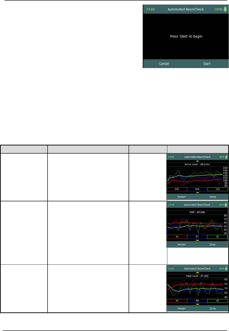
SonTek – a Xylem brand
FlowTracker2 User’s Manual (February 2016) 110
The Automated Beam check screen shows the
steps involved in performing an automated beam
check.
a) To start the automated beam check,
i). Press the Right Soft Key.
b) To CANCEL automated beam check,
i). Press the Left Soft Key,
ii). The software will navigate to Data Collection
window.
c) To accept Automated Beam Check,
i). Press the Right Soft Key,
ii). The software will navigate to the Data
Collection window.
Figure 8:5 - Automated Beam
Check
Evaluate Beam Check Results 8.2.2
The automated beam check quality control criteria used in the evaluation of the beam
check data are listed in Table 8:1,
Table 8:1 - Automated Beam Check Quality Control Criteria
Quality Control
Criteria
QC Warning
Graphic Display
Noise Level
• Measured electronics noise
level is compared to reference
data. Any significant deviation
causes a warning,
• A large change in noise level
may indicate damage to the
probe.
Noise Level >
QC
SNR
• The SNR is checked as
sufficient for reliable data
collection,
• Each beam SNR is compared
to be sure all beams perform
equally,
• A warning is issued for low
SNR < 4 dB,
• A warning is issued for 4 dB >
SNR <7dB,
• Beam SNR values differ.
SNR
Peak Level
• The shape of the sampling
volume curve is compared to
the expected shape. Any
significant deviation causes a
warning,
• This criterion can only be
checked with sufficient SNR
(> 7 dB).
Peak Level >
QC
SonTek – a Xylem brand
FlowTracker2 User’s Manual (February 2016) 111
Quality Control
Criteria
QC Warning
Graphic Display
Peak Location
• The physical location of the
sampling volume is compared
to the expected location. Any
significant deviation causes a
warning.
• This criterion can only be
checked for sufficient SNR (>
7 dB).
Peak
Location >
QC
a) If any warnings are issued, the warnings will be displayed at the bottom of the
graphics. The user have the option to repeat the test if warnings are issued.
i). We recommend repeating the test at least once, after you verify that the probe
and sampling volume are well away from any underwater obstacles,
ii). If multiple warnings are received, run manual Beam Check to evaluate
FlowTracker2 performance in more detail.
b) The display options for individual or all beam check data are listed in Table 8:2.
The shortcut key on the keypad determines which beam SNR will be displayed,
Table 8:2 - Automated Beam Check Display
Beam
Line Color
Keypad Key
Beam1
Red
1
Beam2
Blue
2
Beam3
Green
3
All Beams
All
4
c) To select a Quality Control Criteria,
i). Use up or down scroll arrows keys to view quality control criteria.
8.3. Data Collection
Data Collection function for Discharge mode is the process involved in collecting data
during a discharge measurement. The data collection process is a systematic workflow
designed to follow the actual measurement process in the field. The process consist of
the following main components that also describes each individual aspect of the field
measurement,
• Data Collection Window,
• Station Types,
• Station Measurement,
• Data Collection Menu.
SonTek – a Xylem brand
FlowTracker2 User’s Manual (February 2016) 112
Data Collection Window 8.3.1
The Data Collection Window can be defined as the “control center” of the data
collection process during a discharge measurement. All the software functions required
to perform a discharge measurement is available from the data collection screen. The
key features of the data collection window are explained in Figure 8:6.
Maximum
station depth
Edge on left
bank
Completed
Station
Station Depth
Station Location
(m or ft)
Figure 8:6 - Data Collection Window
Maximum %
station discharge
Point velocity
measurement
More completed
stations
Station is selected
Velocity X
Component plots
The operations and functions available of the Data Collection Window will be discussed
throughout this section with the main functions described in Figure 8:7.
Data Collection Window screen of the consists of
the following,
a) Station Management area defined in rectangle,
b) Add Station,
c) Data Collection Menu (Menu).
d) To add a station,
i). Press the Left Soft Key.
e) To select the data collection menu,
i). Press the Right Soft Key,
ii). The software will display a popup menu screen.
Figure 8:7 - Functions Data
Collection Window
Add Station 8.3.1.1
The Add Station function allows the user to add a station to the measurement section
based on the station types defined for Discharge Measurement technique. The
parameters required for creating a station is defined by the station type as discussed
under Station Types. There are several common parameters that are applicable to all
station types of which are listed below.
SonTek – a Xylem brand
FlowTracker2 User’s Manual (February 2016) 113
Add Station screen consist of the following common
parameters that are required for all station types,
a) Location,
b) Depth,
c) Station Type,
d) Correction Factor,
e) Comment.
The standard functions available for each station
type are,
f) Add Gauge Height,
g) Record GPS Location (function availability, see
GPS Station Tagging).
h) To add a station or start velocity measurement,
i). Press the Right Soft Key.
i) To CANCEL add station,
i). Press the Left Soft Key.
Figure 8:8 - Add Station
Delete Station 8.3.1.2
Deleting a station is performed from the Data Collection Window by selecting the
station within the viewable window.
The station delete process is not reversible and the user must ensure that the correct
station is selected. Selected station will be highlighted with a yellow background.
Delete Station is performed from the Data
Collection Window. Up to ten completed stations
will be displayed at any time,
a) To select a station,
i). Use the left or right arrow key to scroll through
the completed stations,
b) To DELETE a station,
i). Press the backspace key.
ii). The software will navigate to the Confirmation
screen.
Figure 8:9 - Select Station
Confirmation screen requests confirmation of
deleting the selected station by the FlowTracker2
handheld software.
a) To confirm station delete,
i). Press the Right Soft Key,
b) To CANCEL station delete,
i). Press the Left Soft Key,
c) The software will navigate to the Data Collection
Window.
Figure 8:10 - Confirm Delete
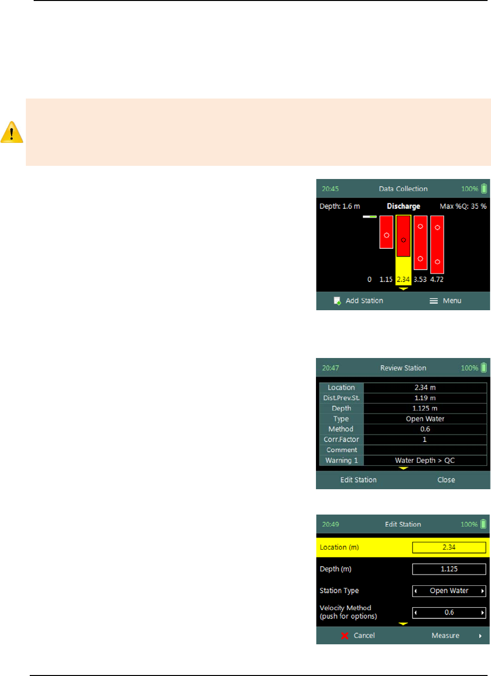
SonTek – a Xylem brand
FlowTracker2 User’s Manual (February 2016) 114
Edit Station 8.3.1.3
Editing station parameters is performed from the Data Collection Window by selecting
the station within the viewable window. The station editing process allows the user to
change all the parameters original configured when the station was created from the
“Add Station” screen.
Editing should not be performed on the Velocity Method after extended time has
passed since the initial point velocity measurements were performed. The flow
conditions could change during the lapsed time and additional point velocity
measurements will not be representative. It’s recommended that all the station
measurements be repeated if additional measurements are required.
Step 1
Open Station is performed from the Data Collection
Window. Up to ten completed stations will be
displayed at any time,
a) To select a station,
i). Use the left or right arrow key to scroll through
the completed stations,
b) To open a station,
i). Press the enter key.
c) The software will navigate to the Review Station
screen.
Figure 8:11 - Open Station
Step 2
Review Station screen display summary of the
selected station. The review station allows the user
to review the measurement results before editing is
performed.
a) To EDIT station,
i). Press the Left Soft Key.
b) To close review station or CANCEL edit station,
i). Press the Right Soft Key.
Figure 8:12 - Review Station
Step 3
Edit Station screen allows the user to change
parameters during the original configuration. The
“Edit Station” screen is similar to the “Add Station”
screen.
a) To confirm edit station,
i). Press the Right Soft Key.
b) To CANCEL edit station,
i). Press the Left Soft Key.
Figure 8:13 - Edit Station
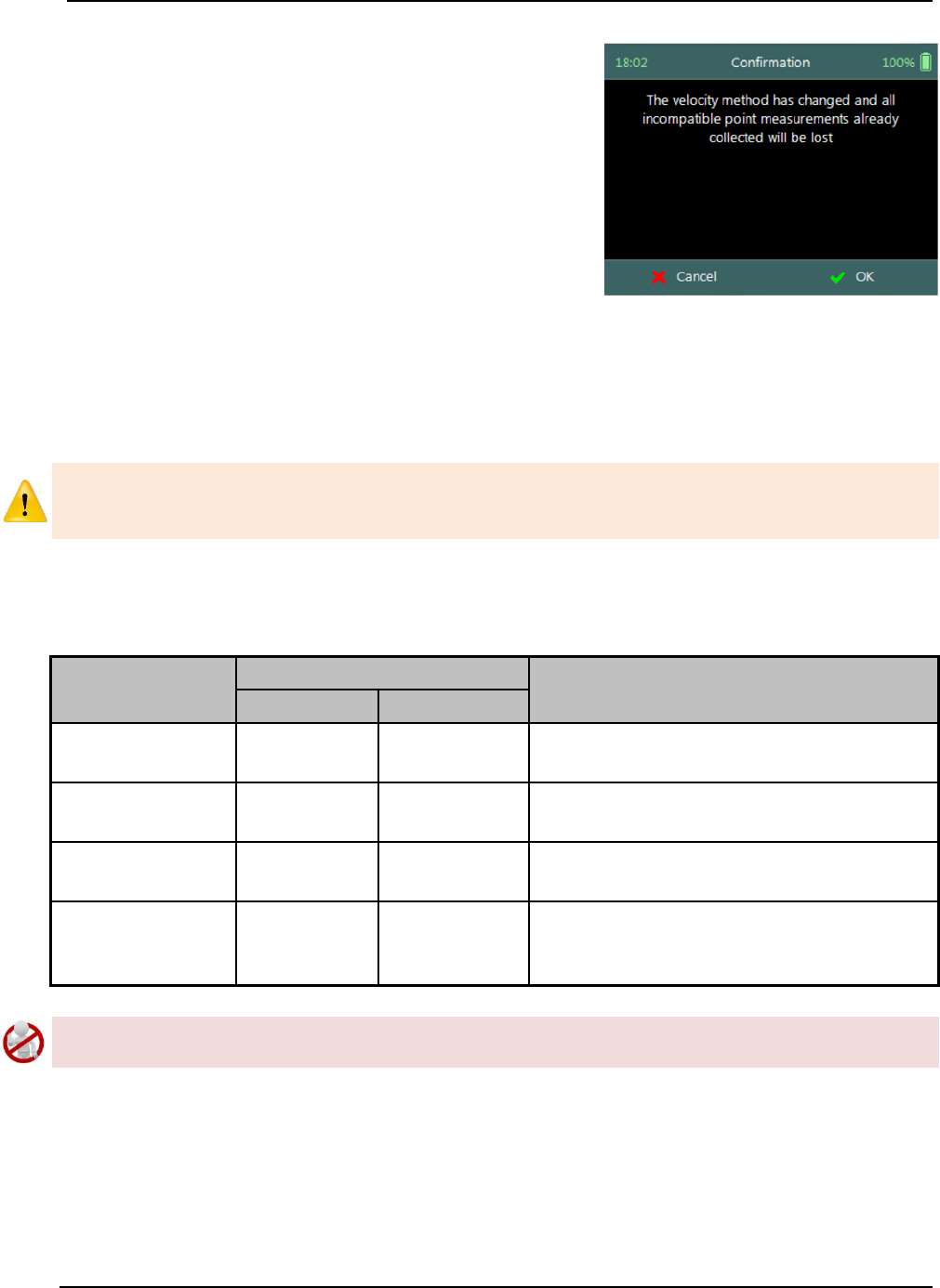
SonTek – a Xylem brand
FlowTracker2 User’s Manual (February 2016) 115
Step 4
Confirmation screen request confirmation of
discarding all incompatible point velocity
measurements by the FlowTracker2 handheld
software.
a) To confirm discarding incompatible point velocity
measurements,
i). Press the Right Soft Key.
b) The software will navigate to the Data Collection
Window.
c) To CANCEL incompatible point velocity
measurements delete,
i). Press the Left Soft Key.
Figure 8:14 - Confirmation
Discarding Measurements
When changes are made to the Velocity Method and Station Type, existing point
velocity measurements will be lost if the velocity method is incompatible with the
proposed selection.
Some scenarios of velocity measurements that could be affected if changes are made to
the Velocity Method and or Station Type are listed in Table 8:3.
Table 8:3 - Incompatible Velocity Methods and Station Types
Parameter
Configuration
Compatibility Result
Initial
Proposed
Velocity Method 0.6 0.2 / 0.8 0.6 Measurement will be discarded. The
0.2 / 0.8 measurements must be performed.
Velocity Method 0.6 0.2 / 0.6 / 0.8
0.6 Measurement will remain. The 0.2 / 0.8
measurements must be performed.
Velocity Method 0.2 / 0.8 0.6 0.2 / 0.8 Measurements will be discarded.
The 0.6 measurement must be performed.
Station Type Open water Edge All velocity measurements will be
discarded. Edge station type is assigned a
“none” velocity method.
The deleting of incompatible point velocity measurements is not reversible and the user
must be certain of the decision in changing the Velocity Method and or Station Type.
Station Types 8.3.2
The Station Types developed for the Discharge Measurement technique provides
practical solutions for the different measurement scenarios that exists during field
measurements. There are several common parameters that are applicable to all station
types as well as specific parameters, unique to each station type that will be discussed in
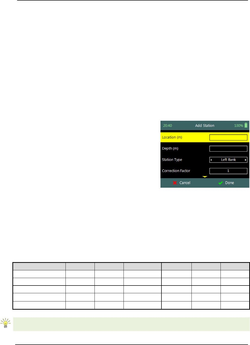
SonTek – a Xylem brand
FlowTracker2 User’s Manual (February 2016) 116
this is section. The station types implemented for the discharge measurement are the
following,
• Bank (left or right),
• Island Edge,
• Open Water,
• Ice.
Bank (left or right) 8.3.2.1
The Bank station type is used to create a station for both the left and right banks. The
one noticeable difference between the Bank station type and other station types is the
fact that no velocity measurement is performed. The Discharge Calculation Methods
implements a zero velocity on the bank when the depth is zero or against a boundary in
the case of vertical bank based on hydraulic principles.
Bank station type parameters available on the Add
Station screen consists of the following,
a) Location,
b) Depth,
c) Station Type,
d) Correction Factor,
e) Comment.
f) To select a station type,
i). Use the left or right arrow key to scroll through
the station types,
g) To add bank station,
i). Press the Right Soft Key.
h) To CANCEL add bank station,
i). Press the Left Soft Key.
Figure 8:15 - Bank Station Type
Properties associated with the parameters for bank station type are defined in Table
8:4,
Table 8:4 - Bank Station Type - Properties
Parameter
Min
Max
Default
Decimals
Units
Required
Location
-1000
1000
empty
3
m or ft
Yes
Depth
0
100
empty
3
m or ft
Yes
Station Type
Left Bank
Yes
Correction Factor
-1
1
1
2
Yes
Comment
0
250
empty
No
The Left Bank will always be displayed on the left side of the Data Collection Window
independent on which bank the measurement was started. If the measurement was
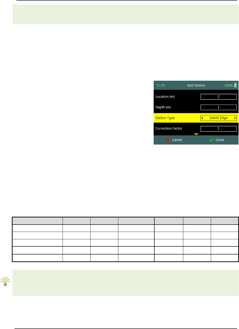
SonTek – a Xylem brand
FlowTracker2 User’s Manual (February 2016) 117
started on the left bank the data collection window will be populated from the left, if the
measurement was started on the right bank, the window will be populated from the
right.
Island Edge 8.3.2.2
The Island Edge station type is used to create a station for Island Edges. Similar to
Bank station types, the one noticeable difference between Island Edge station type and
other station types is the fact that no velocity measurement is performed. The Discharge
Calculation Methods assumes that the velocity on the bank is zero when the depth is
zero or against a boundary in the case of vertical bank.
Island Edge station type parameters available on the
Add Station screen consists of the following,
a) Location,
b) Depth,
c) Station Type,
d) Correction Factor,
e) Comment.
f) To select a station type,
i). Use the left or right arrow key to scroll through
the station types,
g) To add island edge station,
i). Press the Right Soft Key.
h) To CANCEL add island station,
i). Press the Left Soft Key.
Figure 8:16 - Island Edge
Station Type
Properties associated with the parameters for island edge station type are defined in
Table 8:5,
Table 8:5 - Island Edge Station Type - Properties
Parameter
Min
Max
Default
Decimals
Units
Required
Location
-1000
1000
empty
3
m or ft
Yes
Depth
0
100
empty
3
m or ft
Yes
Station Type
Island Edge
Yes
Correction Factor
-1
1
1
2
Yes
Comment
0
250
empty
No
The Island Edge station type is normally selected after “Open Water” or “Ice” station
types. The station type after the first Island Edge is completed will be set to “Island
Edge” by default. The station type after the second Island Edge is completed will be set
to “Open Water” by default.
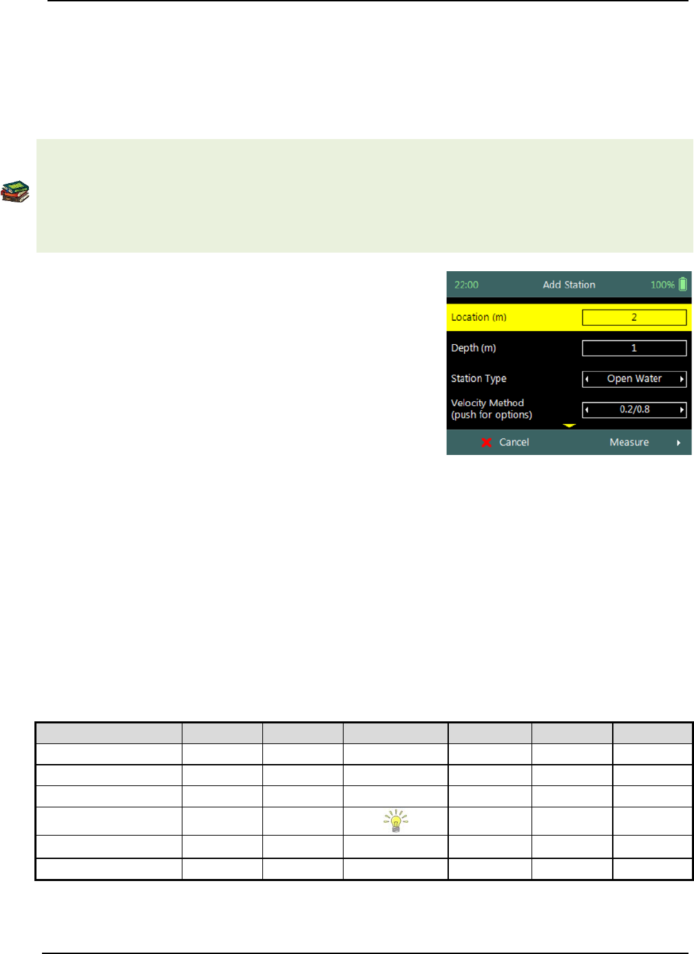
SonTek – a Xylem brand
FlowTracker2 User’s Manual (February 2016) 118
Open Water 8.3.2.3
The Open Water station type is used to create a station for open water conditions,
performing velocity measurements within a vertical at a station. Open Water is the main
station type that will be used during most discharge measurements and the number of
stations required is 23 stations for measurement sections wider than 5m.
The number of stations recommended based on measurement section width are
available in the following literature,
• ISO 748 – 2007, Hydrometry - Measurement of liquid flow in open channels using
current meters or floats,
• WMO-No. 1044, Volume I – Fieldwork, 2010.
Open Water station type parameters available on the
Add Station screen consists of the following,
a) Location,
b) Depth,
c) Station Type,
d) Velocity Method,
e) Correction Factor,
f) Comment.
g) To select a station type and or velocity method,
i). Use the left or right arrow key to scroll through
the station types and or velocity methods,
h) To add open water station and continue to velocity
measurement,
i). Press the Right Soft Key.
i) To CANCEL add open water station,
i). Press the Left Soft Key.
Figure 8:17 - Open Water
Station Type
Properties associated with the parameters for open water station type are defined in
Table 8:6,
Table 8:6 - Open Water Station Type - Properties
Parameter
Min
Max
Default
Decimals
Units
Required
Location
-1000
1000
empty
3
m or ft
Yes
Depth
0
100
empty
3
m or ft
Yes
Station Type
Open Water
Yes
Velocity Method
Yes
Correction Factor
-1
1
1
2
Yes
Comment
0
250
empty
No

SonTek – a Xylem brand
FlowTracker2 User’s Manual (February 2016) 119
The default velocity method selection is performed on two methods, the Six-Tenths and
Two-Point methods. The default method selection is based on water depth with the
following criteria,
• Six-Tenths method for water depths below user specified depth,
• Two-Point method for water depths above user specified depth.
The default velocity method is only recommendation and the user can change the
method based on their requirements.
Ice 8.3.2.4
The Ice station type is used to create a station for under ice conditions, performing
velocity measurements within a vertical at a station. Ice station type is used for
discharge measurements where an ice layer covers the water surface. The Ice station
type has specific parameters for incorporating parameters associated with the ice layer.
Ice station type parameters available on the Add
Station screen consists of the following,
a) Location,
b) Depth,
c) Station Type,
d) Velocity Method,
e) Ice Thickness,
f) Water Surface to Bottom of Ice,
g) Water Surface to Bottom of Slush
h) Correction Factor,
i) Comment.
j) To select a station type and or velocity method,
i). Use the left or right arrow key to scroll through
the station types and or velocity methods,
k) To add ice station and continue to velocity
measurement,
i). Press the Right Soft Key.
l) To CANCEL add ice station,
i). Press the Left Soft Key.
Figure 8:18 - Ice Station Type
Properties associated with the parameters for ice station type are defined in Table 8:7,
Table 8:7 - Ice Station Type - Properties
Parameter
Min
Max
Default
Decimals
Units
Required
Location
-1000
1000
empty
3
m or ft
Yes
Depth
0
100
empty
3
m or ft
Yes
Station Type
Ice
Yes
Velocity Method
Yes
Ice Thickness
0
100
empty
3
m or ft
Yes
Water Surface to
0
100
empty
3
m or ft
Yes
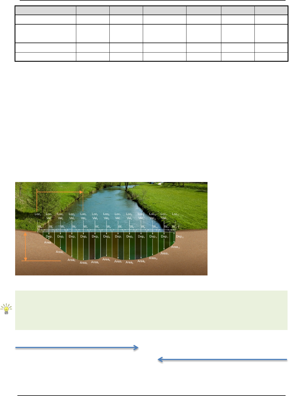
SonTek – a Xylem brand
FlowTracker2 User’s Manual (February 2016) 120
Parameter
Min
Max
Default
Decimals
Units
Required
Bottom of Ice
Water Surface to
Bottom of Slush 0 100 empty 3 m or ft No
Correction Factor
-1
1
1
2
Yes
Comment
0
250
empty
No
Station Measurement 8.3.3
Station Measurement is performed at each station that was created from the
subdivision of the measurements section into number of stations. The station
measurements consists of collecting a number of different parameters and variables
required for the Discharge Calculation Methods. Each station is unique with respect to
the selection of the location, width between adjacent stations, velocity method, averaging
interval used for velocity measurements and quality control parameters.
Station Parameters 8.3.3.1
The Station Parameters that need to be determined before a decision is made on what
velocity method will be used are the station location with respect to the starting point on
the tag line or measuring tape and the total water depth.
Figure 8:19 - Station Parameters
L
4
, is the distance from
the start location on the
tag line or measuring
tape.
D4, is the water depth
measured from the water
surface to the channel
bed.
The value of the start location on the tagline or measuring tape is not required to be
zero (0.000m). The station location can also be entered in negative direction, with the
start location at a larger value (e.g. 7.956m) and the end location at a smaller value
(e.g. 0.532m). This feature assist when a measurement is performed from the left bank
to the right bank and then back using the same tag line setup.
Start location of measurement at 0.532m
0.532 1.23 2.23 3.23 3.23 4.23 5.23 6.23 7.23 7.956
Start location of measurement at 7.956m
L4
D4
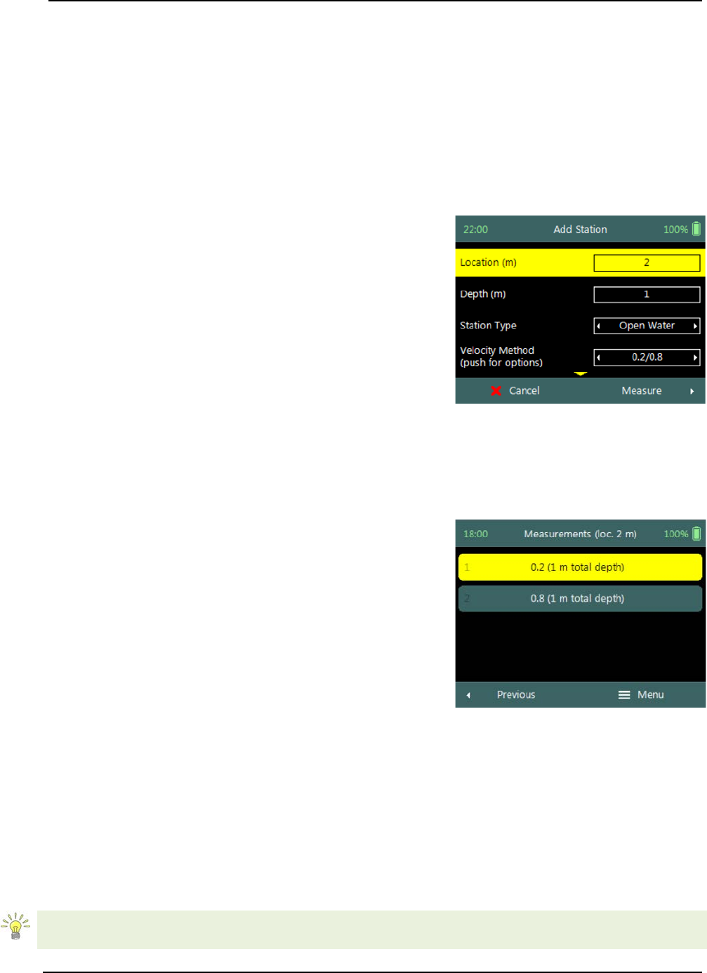
SonTek – a Xylem brand
FlowTracker2 User’s Manual (February 2016) 121
Point Velocity Measurement 8.3.3.2
The Velocity Method (see Determining Mean Station Velocity) selected for a station is
based on the water depth, hydraulic conditions and the flow distribution within the
measurement section.
• The number of point velocity measurements required within a vertical is
dependent on the type of velocity method selected.
• The point velocity measurements are performed at a defined fractional depth
based on the velocity method selected.
Step 1
Station parameters defined for Velocity
Measurement, e.g., parameters of station 2m defined
for velocity measurements are the following,
a) Station location: 2m,
b) Water Depth: 1m,
c) Station Type: “Open Water”,
d) Velocity Method: Two Point.
e) To add open water station and continue to velocity
measurement,
i). Press the Right Soft Key.
f) To CANCEL a new station,
i). Press the Left Soft Key.
Figure 8:20 - Velocity
Measurement
Step 2
Measurement screen display the point velocity
measurements required at each fractional depth, e.g.,
the fractional depths for the two point method at
station 2m with a water depth of 1m are the following,
• 0.2 x water depth, 0.2m
• 0.8 x water depth, 0.8m
a) To select a fractional measurement depth,
i). Use the up or down arrow key to scroll through
the measurement options,
b) To continue to velocity measurement,
i). Press the enter key.
c) To open data collection menu,
i). Press the Right Soft Key.
d) To REVERT to add station screen,
i). Press the Left Soft Key.
Figure 8:21 - Measurements
The order in how the point velocity measurements are performed at each fractional
depth is not set and the user can perform the measurements in any order. The
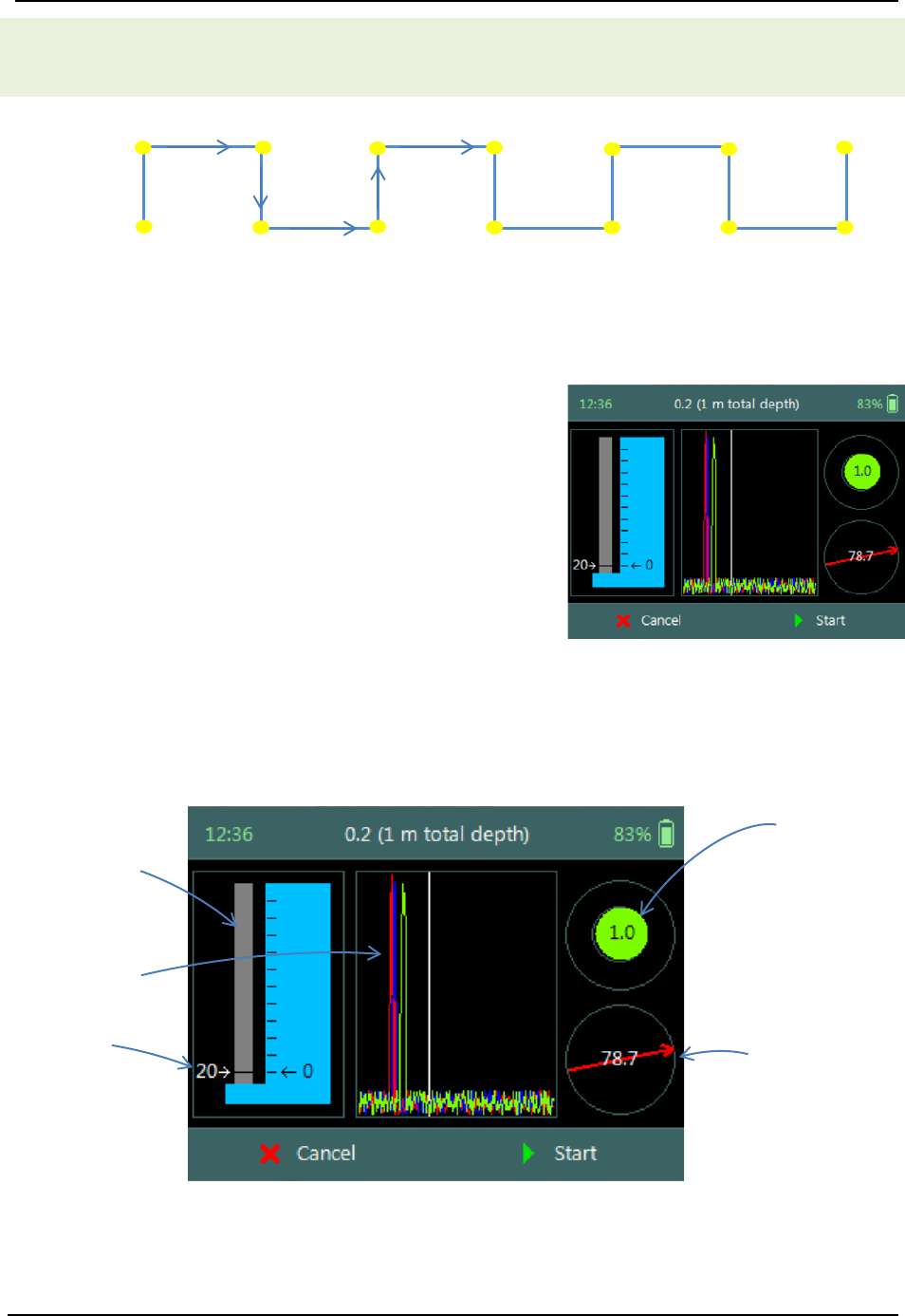
SonTek – a Xylem brand
FlowTracker2 User’s Manual (February 2016) 122
software highlights the same fractional depth that was measured at the previous
station. This method reduces the number of key strokes and unnecessary adjustments
on the wading rod.
Station
1 2 3 4 5 6 7
0.2
0.8
Selecting the same fractional depth that was measured at the previous station improves
the overall efficiency of the measurement. The example that is shown above shows a
measurement where two-point method is performed at each station, keeping the order of
measurements synced between stations improves the workflow.
Step 3
Setting Fractional Depth screen allow the setting
and placement of the wading rod before velocity
measurement is started,
a) Wading rod setting,
b) Beam Check,
c) Boundary QC,
d) Tilt,
e) Velocity angle.
f) To start a velocity measurement,
i). Press the Right Soft Key.
g) To REVERT to measurement screen,
i). Press the Left Soft Key.
Figure 8:22 - Setting
Fractional Depth
The key features of the Setting Fractional Depth are explained in Figure 8:23.
Top Setting
wading rod
Automated
Beam Check
Wading rod
setting
Figure 8:23 - Features of Setting Fractional
Depth
Tilt Bubble
Velocity Angle
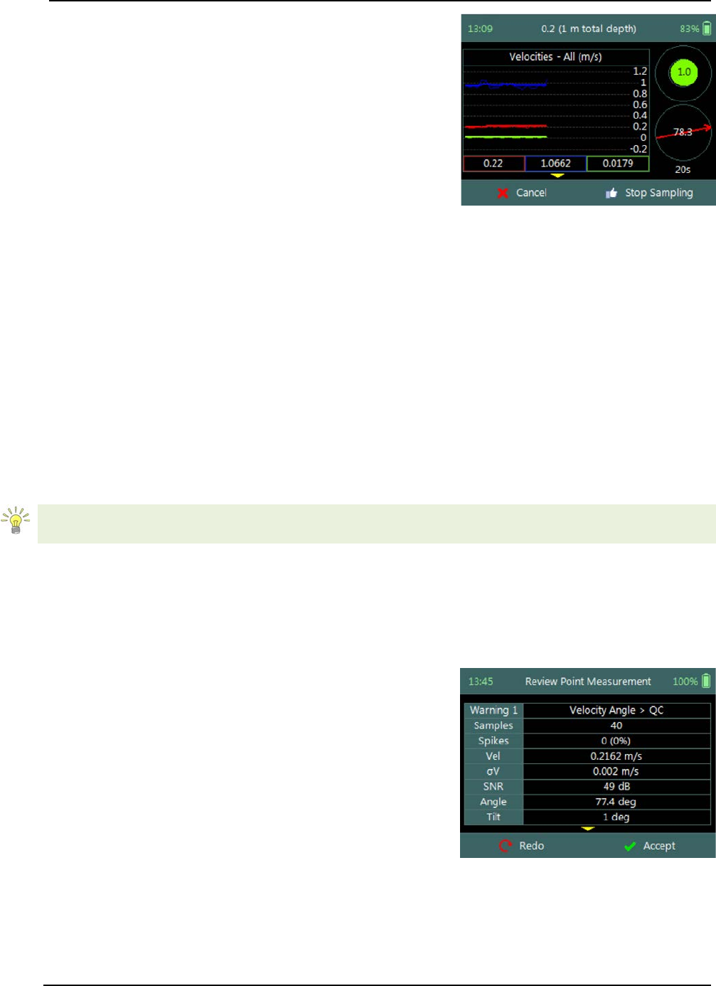
SonTek – a Xylem brand
FlowTracker2 User’s Manual (February 2016) 123
Step 4
Fractional Depth Measurement screen displays
graphical display of raw data of the following variables
during a velocity measurement,
a) Velocity,
b) SNR,
c) Temperature,
d) Battery,
e) Tilt,
Tilt and Velocity Angle indicators are situated on the
right hand side of the screen.
f) Tilt,
g) Velocity Angle,
h) Averaging Time left.
i) To select a variable graphical display,
i). Use up or down scroll arrows keys to view a
variable.
j) To stop sampling,
i). Press the Right Soft Key.
k) To CANCEL velocity measurement,
i). Press the Left Soft Key.
Figure 8:24 - Fractional
Depth Measurement
The conventions and graphic display features used for displaying Velocity and SNR raw
data are defined under Raw Data Display.
Review Point Measurement 8.3.3.3
Review Point Measurement is a report supplied at the end of each point velocity
measurement. The report consists of two components, tabular summary of numerical
calculations performed on the raw data collected and graphical display of raw data.
Review Point Measurement screen consists of the
following tabular summary and graphical displays,
Tabular Display
a) Review Point Measurement, Table 8:8
Graphical Display of raw data are based on the
following variables,
b) Velocity,
c) SNR,
d) Temperature,
e) Tilt,
f) Velocity Angle,
g) Battery.
Figure 8:25 - Review Point
Measurement
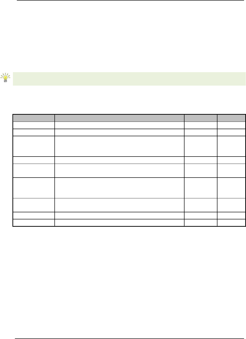
SonTek – a Xylem brand
FlowTracker2 User’s Manual (February 2016) 124
h) To select a variable,
i). Use the up or down arrow key to view a
variable.
i) To accept the velocity measurement,
i). Press the Right Soft Key.
j) To REDO velocity measurement,
i). Press the Left Soft Key.
The conventions and graphic display features used for displaying Velocity and SNR raw
data are defined under Raw Data Display.
Properties associated with the variable output from the numerical calculations
performed on raw data collected is defined in Table 8:8,
Table 8:8 - Review Point Measurement
Variable
Description
Units
Decimal
Samples
Total number of samples received.
number
n/a
Spikes
Number of spikes removed from mean velocity.
number
n/a
Vel
Mean X velocity component of all samples.
Velocity is despiked and mounting correction
applied (if applicable).
m/s or ft/s 4
σV
Standard error of X velocity component.
m/s or ft/s
4
SNR
Mean signal to noise ratio. Average of beam 1
and 2 SNR during point measurement.
dB 3
Angle
Flow angle relative to X direction. Angle
between the mean X velocity component and
mean Y velocity component.
Degree 2
Tilt
Mean wading rod angle during point velocity
measurement.
Degree 2
Temp
Mean temperature during point measurement.
°C or °F
2
Bnd
Boundary QC value.
n/a
n/a
Review Station Measurement 8.3.3.4
Review Station measurement is tabular report supplied at the completion of all point
velocity measurements at a station. The variables supplied in the report are dependent
on the features activated on the handheld, velocity method selected and the discharge
calculation method.
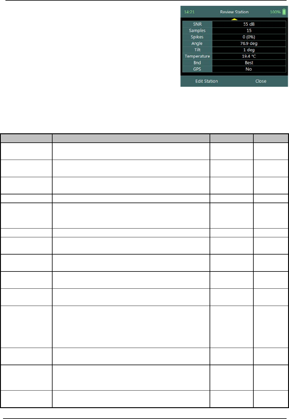
SonTek – a Xylem brand
FlowTracker2 User’s Manual (February 2016) 125
Review Station screen consists of tabular summary
of all measurements performed at the station,
a) Review Station, Table 8:9.
b) To close the review station report,
i). Press the Right Soft Key.
ii). The software will navigate to the Data
Collection Window.
c) To EDIT station,
i). Press the Left Soft Key.
Figure 8:26 - Review Station
Properties associated with the variables and numerical calculations performed on the
raw data collected at the station is defined in Table 8:9,
Table 8:9 - Review Station
Variable
Description
Units
Decimal
Location
Station location measured from the start
location on tag line or measuring tape.
m or ft 3
Dist. Prev.
St.
Distance between current and previous
station.
m or ft 3
Depth
Measured water depth or effective depth (for
Ice method).
m or ft 3
Type
Station type (see Station Types).
n/a
n/a
Method
Discharge measurement method or velocity
method (see Determining Mean Station
Velocity).
n/a n/a
Ice
Ice Thickness (only for Ice method).
m or ft
3
WS to BI
Water surface to bottom of ice (only for Ice
method).
m or ft 3
WS to BS
Water surface to bottom of slush ice (only for
Ice method).
m or ft 3
Corr. Factor
Mean station velocity (mean velocity in
vertical) correction factor.
2
Comment
Text entered in comment fields during
measurement.
n/a n/a
%Q
Station discharge as a percent of the,
• weighted rated discharge, of rated
discharge entries in supplement data or,
• measured discharge up to that station.
% 2
StnQ
Station or panel discharge, per discharge
method.
m3/s or ft3/s 4
TotalQ
Total discharge is the sum of all completed
station or panel discharges, per discharge
method.
m3/s or ft3/s 4
PanelVel
Panel velocity calculated based on discharge
calculation method.
m3/s or ft3/s 4

SonTek – a Xylem brand
FlowTracker2 User’s Manual (February 2016) 126
Variable
Description
Units
Decimal
MeanStVel
Mean Station Velocity or Mean Velocity in
Vertical, X velocity component computed per
velocity method. Velocity is despiked and
mounting correction applied (if applicable).
m/s or ft/s 4
σV
Mean standard error of X velocity component
of all point measurements.
m/s or ft/s 4
SNR
Mean signal to noise ratio of beams 1, 2 of all
point measurements.
dB 3
Samples
Total number of samples received.
number
n/a
Spikes
Total number of spikes removed from mean
velocity.
number n/a
Angle
Mean flow angle relative to X direction.
Average the velocity angle from each point
measurement.
Degree 2
Tilt
Mean wading rod angle of all point velocity
measurements.
Degree 2
Temperature
Mean Temperature of all point measurements.
°C or °F
2
Bnd
Lowest Boundary QC value.
n/a
n/a
GPS
Indicating if GPS was used during station
measurement.
n/a n/a
Data Collection Menu 8.3.4
Data Collection Menu allows the user to adjust measurement settings, enter staff gauge
readings and rated discharge data and view measurement summary. The data
collection menu can be accessed in between point velocity measurements or stations
and this ensures that the instrument is configured for current flow conditions present.
Data Collection Menu screen consists of the
following functions that are available in Discharge
Mode,
a) Settings,
b) Supplemental Data,
c) Discharge Summary,
d) Stations Summary,
e) Automated Beam Check,
f) Complete Measurement,
g) Discard Measurement,
h) Go to Home Screen.
i) To select a function,
i). Use the up or down arrow key to scroll through
the functions,
j) To open or CLOSE the data collection menu,
i).
Press the Right Soft Key.
Figure 8:27 - Data Collection
Menu

SonTek – a Xylem brand
FlowTracker2 User’s Manual (February 2016) 127
Settings 8.3.4.1
The Settings menu option gives the user access to the initial measurement settings that
were configured during the configuration of the discharge template.
Settings screen consists of the following functions for
configuring measurement settings,
a) File Properties,
b) Data Collection Settings,
c) Quality Control Settings
d) Discharge Settings.
e) To select a function,
i). Use the up or down arrow key to scroll through
the functions,
f) To CLOSE the settings menu,
i). Press the Left Soft Key.
Figure 8:28 - Settings Menu
The measurement settings functions supplied in the Settings option in data collection
menu are defined under Template Functions.
Supplemental Data 8.3.4.2
Supplemental Data function enables the user to enter staff gauge readings and rated
discharge during the discharge measurement. The staff gauge readings and rated
discharge are used to compute Weighted Gauge Height. The rated discharge is also
used to determine percentage discharge at each station or panel during a discharge
measurement.
Supplemental Data screen display the supplemental
data entered and is sorted by the time the staff gauge
readings were taken. The supplemental data can be
entered during any stage of the measurement before
the “Complete Measurement” function is selected.
a) To add supplemental data,
i). Press the Right Soft Key,
b) To CLOSE supplemental data,
i). Press the Left Soft Key.
Figure 8:29 - Supplemental Data
The time and date entered for each supplemental dataset should be the time when the
staff gauge reading was taken and not the time when the data was entered.
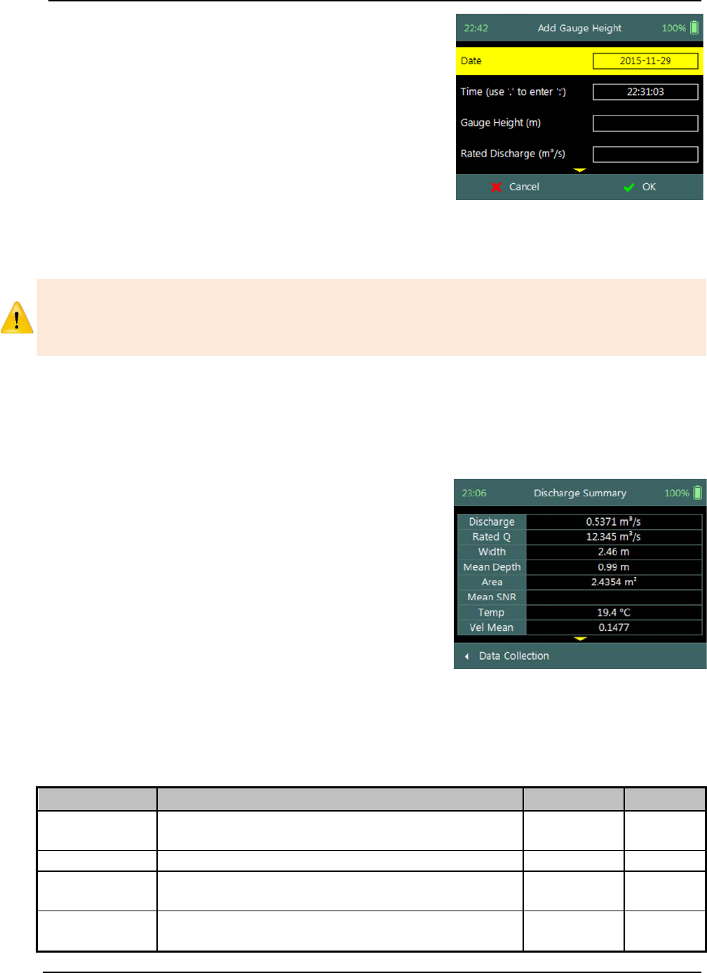
SonTek – a Xylem brand
FlowTracker2 User’s Manual (February 2016) 128
Add Gauge Height screen consists of the following
variables required in supplemental data,
a) Date,
b) Time,
c) Gauge Height,
d) Rated Discharge,
e) Comment.
c) To accept supplemental data,
i). Press the Right Soft Key,
d) To CANCEL supplemental data entry,
i). Press the Left Soft Key.
Figure 8:30 - Add Gauge Height
The staff gauge readings, rated discharge and associated data captured in
Supplemental Data should be accurate and complete. It is important that these
variables are entered correctly for accurate calculation of weighted gauge height and or
percentage discharge.
Discharge Summary 8.3.4.3
Discharge Summary from the data collection menu displays the discharge and other
variables measured from all completed stations. Discharge summary requires at least
one station with velocity measurements to populate the main variables in the table.
Discharge Summary screen consists of tabular
summary of discharge and other variables measured
up to specific point,
a) Discharge Summary, Table 8:10.
b) To close the discharge summary report,
i). Press the Left Soft Key.
ii). The software will navigate to the Data
Collection Window.
Figure 8:31 - Discharge
Summary
Properties associated with the variables and numerical calculations performed on the
raw data collected is defined in Table 8:10,
Table 8:10 - Discharge Summary
Variable
Description
Units
Decimal
Discharge
Total discharge is the sum of all station or
panel discharges, per discharge method.
m3/s or ft3/s 4
RatedQ
Rated discharge entered in supplemental data.
m3/s or ft3/s
4
Width
Total width calculated from all stations and or
panels, per discharge method.
m or ft 3
Mean Depth
Average depth calculated from the total area
and width.
m or ft 3
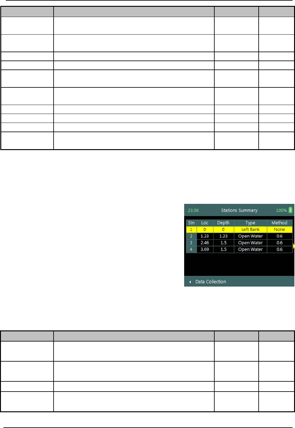
SonTek – a Xylem brand
FlowTracker2 User’s Manual (February 2016) 129
Variable
Description
Units
Decimal
Area
Total area calculated from all stations or
panels, per discharge method.
m2 or ft2 4
Mean SNR
Average SNR of all completed stations.
Require at least 3 stations.
dB n/a
Temp
Average temperature of all completed stations.
°C or °F
2
Vel Mean
Average station velocity, X velocity component
m/s or ft/s
4
Vel Min
Minimum station velocity, X velocity
component
m/s or ft/s 4
Vel Max
Maximum station velocity, X velocity
component
m/s or ft/s 4
Height, Start
Start staff gauge reading.
m or ft
3
Height, End
End staff gauge reading.
m or ft
3
Uncertainty
Uncertainty in discharge measurement.
%
2
Largest
Uncertainty
Largest uncertainty in the discharge
uncertainty calculation.
% 2
Station Summary 8.3.4.4
The Station Summary from the data collection menu displays the completed stations in
table format. The station summary is a good reference when evaluating measurements
performed at a station against adjacent stations.
Station Summary screen consists of tabular view of
all completed stations,
a) Station Summary, Table 8:11.
b) To close the discharge summary report,
i). Press the Left Soft Key.
ii). The software will navigate to the Data
Collection Window.
Figure 8:32 - Station Summary
Properties associated with the variables and numerical calculations performed on the
raw data collected is defined in Table 8:11,
Table 8:11 - Station Summary
Variable
Description
Units
Decimal
Loc
Station location measured from the start
location on tag line or measuring tape. m or ft 3
Depth
Measured water depth or effective depth (for
Ice method). m or ft 3
Type
Station type (see Station Types).
n/a
n/a
Method
Discharge measurement method or velocity
method (see Determining Mean Station n/a n/a
SonTek – a Xylem brand
FlowTracker2 User’s Manual (February 2016) 130
Variable
Description
Units
Decimal
Velocity).
Corr. Factor
Mean station velocity (mean velocity in
vertical) correction factor. None 3
Panel Vel
Panel velocity calculated based on discharge
calculation method. m/s or ft/s 4
MeanStVel
Mean Station Velocity or Mean Velocity in
Vertical, X velocity component computed per
velocity method. Velocity is despiked and
mounting correction applied (if applicable).
m/s or ft/s 4
Width
Panel width, per discharge method.
m or ft
3
Area
Panel area, per discharge method.
m2/s or ft2/s
4
Flow
Panel discharge, per discharge method.
m3/s or ft3/s
4
%Q
Station discharge as a percent of the,
• weighted rated discharge, of rated
discharge entries in supplement data or,
• measured discharge up to that station.
% 2
Angle
Mean flow angle relative to X direction.
Average the velocity angle from each point
measurement
Degree 2
Tilt
Mean wading rod angle of all point velocity
measurements. Degree 2
Temp
Mean Temperature of all point measurements.
°C or °F
2
GPS
Indicating if GPS was used during station
measurement. n/a n/a
Automated Beam Check 8.3.4.5
Automated Beam Check function in the data collection menu allows the user to perform
beam check during any stage of the discharge measurement. The Automated Beam
Check function operations, conventions and graphic display features are defined under
Automated Beam Check.
Automated Beam Checks performed during the discharge measurement are stored in
FlowTracker2 file (.ft) that was created for the measurement site.
Complete Measurement 8.3.4.6
The Complete Measurement function closes the measurement file and the user will not
be able to add additional stations and or make any changes to the data captured. The
complete measurement function is a three-step process, firstly to determine if the user is
satisfied with the discharge measurement, secondly to perform quality control checks
against all measurement data and lastly to review discharge summary.
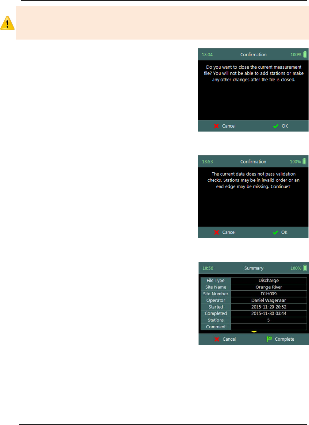
SonTek – a Xylem brand
FlowTracker2 User’s Manual (February 2016) 131
The Complete Measurement process allows the user to review the measurement data
before the complete function is selected at Summary screen. The user will not be able
to make any to changes to the measurement file from the handheld when this function
is selected.
Step 1
Confirmation screen of Complete Measurement
function confirms if the user wants to close the
measurement file. User will not be able to add
stations or make any changes to the data
a) To confirm complete measurement operation,
i). Press the Right Soft Key.
b) To CANCEL complete measurement operation,
i). Press the Left Soft Key.
Figure 8:33 - Confirmation
Complete Measurement
Step2
Confirmation screen with Quality Control warning
messages based on quality control checks performed
on measurement data.
a) To accept quality control warning messages,
i). Press the Right Soft Key.
b) To CANCEL complete measurement operation,
i). Press the Left Soft Key.
Figure 8:34 - Confirmation
Quality Control Messages
Step3
Summary screen displays the discharge summary
report before the measurement file is closed for
further data entry and editing.
a) To confirm complete measurement operation,
i). Press the Right Soft Key.
ii). The software will navigate to the Main Menu.
b) To CANCEL complete measurement operation,
i). Press the Left Soft Key.
Figure 8:35 - Summary
Discharge Measurement
Discard Measurement 8.3.4.7
The Discard Measurement function will discard all configuration settings, stations and
other data related with the measurement.
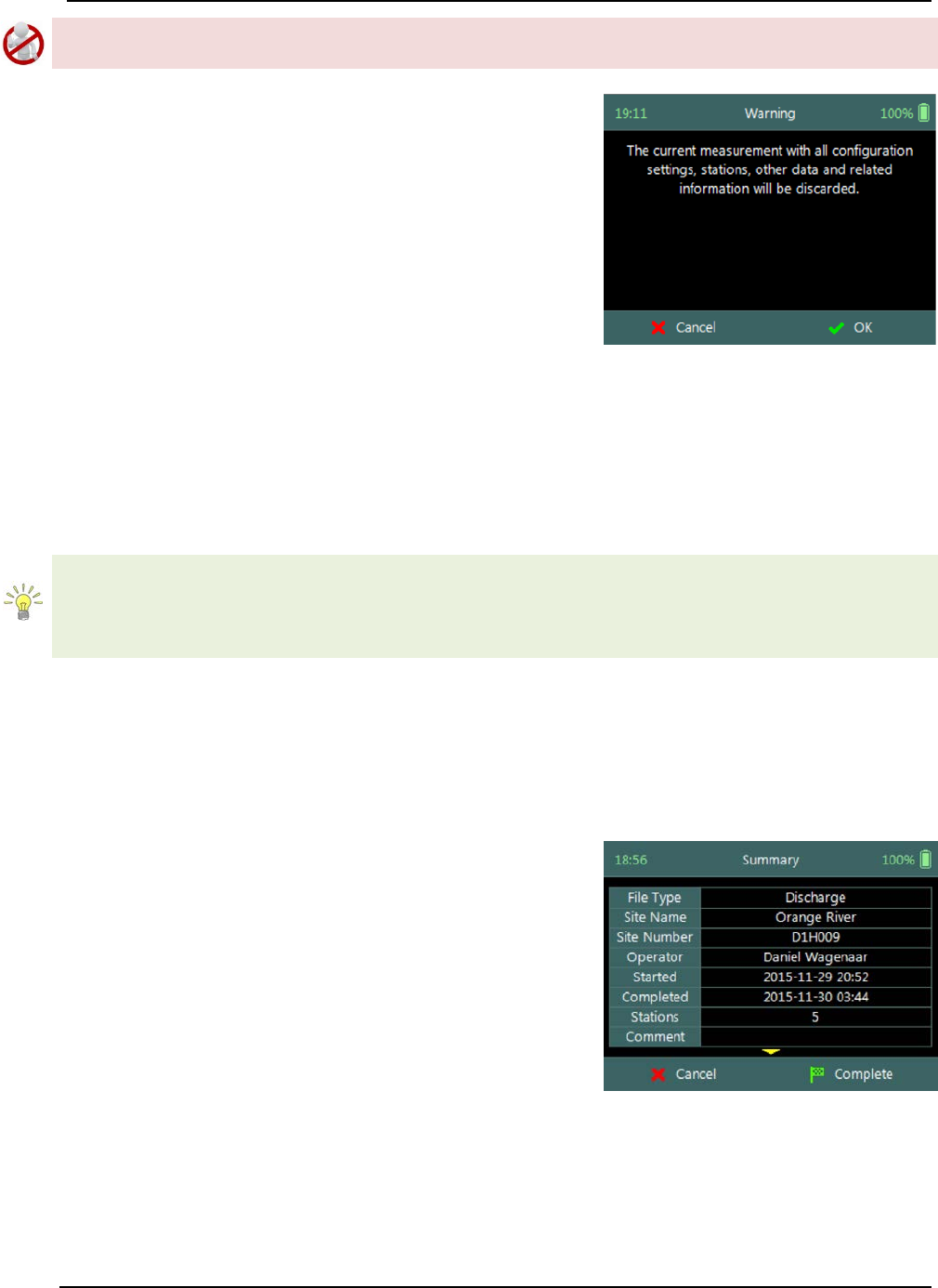
SonTek – a Xylem brand
FlowTracker2 User’s Manual (February 2016) 132
Discarding a measurement will result in deleting all data of the measurement site that is
related to the specific measurement file.
Warning screen of Discard Measurement function
displays the warnings associated with discarding
measurement file.
a) To DISCARD measurement,
i). Press the Right Soft Key.
ii). The software will navigate to the Main Menu.
b) To CANCEL discard measurement operation,
i). Press the Left Soft Key.
Figure 8:36 - Warning Discard
Measurement
Go to Home Screen 8.3.4.8
The Go to Home Screen function will navigate the software to the main menu and the
user will have the ability to access software functions that are not related to Discharge
Mode function.
The discharge measurement can be accessed during any stage by selecting the “Data
Collection” function with the Right Soft Key. The software will continue with the
measurement at the exact stage when the user navigated away from the discharge
mode.
8.4. Measurement Summary
Measurement Summary is supplied when the Complete Measurement function is
selected and displays all the measurement results. The Measurement Summary is the
last verification of the measurement results before the measurement file is closed for any
further measurements or changes.
Measurement Summary screen consists of tabular
summary of discharge measurement results,
a) Discharge Summary, Table 8:12.
b) To CANCEL the discharge summary report,
i). Press the Left Soft Key.
ii). The software will navigate to the Data
Collection Window.
c) To COMPLETE the discharge measurement,
i). Press the Right Soft Key.
ii). The software will close the measurement file
and navigate to the main menu.
Figure 8:37 - Measurement
Summary
Properties associated with the variables and numerical calculations performed on the
raw data collected is defined in Table 8:12,
SonTek – a Xylem brand
FlowTracker2 User’s Manual (February 2016) 133
Table 8:12 - Measurement Summary
Variable
Description
Units
Decimal
File Type
File type based on discharge or general mode
n/a
n/a
Site Name
Site name populated by user
n/a
n/a
Site Number
Site number populated by user
n/a
n/a
Operator
Operator name populated by user
n/a
n/a
Started
Start date and time when measurement was
created
yyyy-mm-dd hh:mm
Completed
End data and time when measurement was
completed
yyyy-mm-dd hh:mm
Stations
Total number of stations within the
measurement
n/a n/a
Comment
General comment captured against
measurement
n/a n/a
Discharge
Total discharge calculated
m3/s or ft3/s
4
Rated Q
Rated discharge entered by user
m
3
/s or ft
3
/s
4
Width
Total width of the measurement section
m or ft
3
Mean Depth
The mean depth of the measurement section
calculated from the total area and width.
m or ft 3
Area
Total area of the measurement section
m2 or ft2
4
Mean SNR
Average signal to noise ration
dB
Temp
Average temperature measured
°C or °F
Vel Mean
Average station velocity, X velocity component
m/s or ft/s
4
Vel Min
Minimum station velocity, X velocity
component
m/s or ft/s 4
Vel Max
Maximum station velocity, X velocity
component m/s or ft/s 4
Height, Start
First staff gauge reading
m or ft
3
Height, End
Last staff gauge reading
m or ft
3
Uncertainty
Uncertainty in discharge measurement
%
2
Largest
Uncertainty
Largest uncertainty in the discharge
uncertainty calculation
% 2
SonTek – a Xylem brand
FlowTracker2 User’s Manual (February 2016) 134
General Measurement Section 9.
General Measurement is the measurement technique involved in collecting velocity
data based on the General Mode (see Data Collection Modes). The data collection
framework designed for collecting velocity data is detailed in Software Flow Diagram.
Velocity data collection process consists of the following main components, with
discussions of each component.
• Create Measurement,
• Automated Beam Check,
• Data Collection,
• Discharge Summary.
9.1. Create Measurement
Creating a new measurement consist of number of steps before the data collection can
be performed. The first step involved is to either select an existing Configuration
Template or create a new template with user defined configuration parameters. The
template then needs to be associated with a measurement file that is created by the
user. When the measurement file is created, the software is ready for data collection.
Measurement 9.1.1
The Measurement function enables the user to create a new measurement in either
Discharge or General mode. The General mode used for the collection of velocity data
during field measurements will be focused on in this section.
a) The Measurement function can be accessed
from the Main Menu on the bottom banner,
b) To select the Measurement function,
i). Press the Right Soft Key.
c) The software will navigate to the New File Type or
Mode screen.
Figure 9:1 - Main Menu
New File Type 9.1.2
The New File Type function enables the user to determine if the new measurement file
should be based on either Discharge or General mode.

SonTek – a Xylem brand
FlowTracker2 User’s Manual (February 2016) 135
The New File Type screen consists of the following
options,
a) Discharge,
b) General,
c) To select discharge mode,
i). Use up or down scroll arrows keys to select
Discharge and press enter key.
d) The software will navigate to the New File
Template screen.
e) To navigate to Home menu,
i). Press the Left Soft Key.
Figure 9:2 - New File Type
New File Template 9.1.3
New File Template function enables the user to create a new configuration template
based on SonTek default settings or select an existing Configuration Template created
by the user. The configuration template is based on user defined parameters that are
dependent on measurement site details, flow conditions and organizational
requirements. The configuration template selected will be assigned to the measurement
file and the parameters defined in the template will be applied during the Velocity
measurement.
The New File Template screen consists of the
following options,
a) (default), the template will be based on
SonTek default settings.
b) Existing Templates, created under “Device
Configuration”. A list of available templates
created by the user will be displayed under the
“(default)” option.
c) To select a template,
i). Use up or down scroll arrows keys to select
template and press enter key.
d) The software will navigate to the New Data File
screen.
e) To navigate to File Type menu,
i). Press the Left Soft Key.
Figure 9:3 - New File Template
New Data File 9.1.4
New Data File function enables the user to populate the measurement site and operator
details. The information entered for each parameter should be accurate as this
information is recorded in each measurement file and used in both the File Naming and
Folder Naming conventions.

SonTek – a Xylem brand
FlowTracker2 User’s Manual (February 2016) 136
• Existing templates created under “Device Configuration”, parameters will be
prepopulated from File Properties information that was captured,
• Templates based on SonTek default configuration will have no information
populated and the user will need to enter the required details for each parameter.
It is not good data management practice for both measurement site references to be
empty or with abbreviate terms. It is recommended that the user makes use of
accurate site descriptions.
The New Data File screen consists of the following
parameters,
a) Site Number,
b) Site Name,
c) Operator,
d) Comment.
e) To select a parameter,
i). Use up or down scroll arrows keys to select a
parameter.
f) To accept the new data file configuration,
i). Press the Right Soft Key,
ii). The software will navigate to Automated Beam
Check screen.
g) To CANCEL new data file configuration,
i). Press the Left Soft Key,
ii). The software will return to New File Template.
Figure 9:4 - New Data File
9.2. Automated Beam Check
The Automated Beam Check function allows the user to perform a Beam Check in the
region of the measurement location before data collection starts. The automated beam
check perform a number of quality control checks on the data collected to determine if
the flow conditions are suitable for velocity measurements. The Automated Beam Check
is an automated version of Beam Check function described in Beam Check.
Automated Beam Check can be performed during any stage of the data collection
process. The Automated Beam Check functions are available before data collection
start and during velocity measurement from the “Data Collection Menu” (see Data
Collection Screen).
Start Automated Beam Check 9.2.1
The FlowTracker2 probe should be placed in the region of the measurement location in
moving water such that the probe is submerged and well away from any underwater
obstacles. The FlowTracker2 collects data for about 30 seconds.
SonTek – a Xylem brand
FlowTracker2 User’s Manual (February 2016) 137
The Automated Beam check screen shows the
steps involved in performing an automated beam
check.
a) To start the automated beam check,
i). Press the Right Soft Key.
b) To CANCEL automated beam check,
i). Press the Left Soft Key,
ii). The software will navigate to Data Collection
window.
c) To accept Automated Beam Check,
i). Press the Right Soft Key,
ii). The software will navigate to the Data
Collection window.
Figure 9:5 - Automated Beam
Check
Evaluate Beam Check Results 9.2.2
The automated beam check quality control criteria used in the evaluation of the beam
check data are listed in Table 9:1,
Table 9:1 - Automated Beam Check Quality Control Criteria
Quality Control
Criteria
QC Warning
Graphic Display
Noise Level
• Measured electronics noise
level is compared to reference
data. Any significant deviation
causes a warning,
• A large change in noise level
may indicate damage to the
probe.
Noise Level >
QC
SNR
• The SNR is checked as
sufficient for reliable data
collection,
• Each beam SNR is compared
to be sure all beams perform
equally,
• A warning is issued for low
SNR < 4 dB,
• A warning is issued for 4 dB >
SNR <7dB,
• Beam SNR values differ.
SNR
Peak Level
• The shape of the sampling
volume curve is compared to
the expected shape. Any
significant deviation causes a
warning,
• This criterion can only be
checked with sufficient SNR
(> 7 dB).
Peak Level >
QC

SonTek – a Xylem brand
FlowTracker2 User’s Manual (February 2016) 138
Quality Control
Criteria
QC Warning
Graphic Display
Peak Location
• The physical location of the
sampling volume is compared
to the expected location. Any
significant deviation causes a
warning.
• This criterion can only be
checked for sufficient SNR (>
7 dB).
Peak
Location >
QC
a) If any warnings are issued, the warnings will be displayed at the bottom of the
graphics. The user have the option to repeat the test if warnings are issued.
i). We recommend repeating the test at least once, after you verify that the probe
and sampling volume are well away from any underwater obstacles,
ii). If multiple warnings are received, run manual Beam Check to evaluate
FlowTracker2 performance in more detail.
b) The display options for individual or all beam check data are listed in Table 9:2.
The shortcut key on the keypad determines which beam SNR will be displayed,
Table 9:2 - Automated Beam Check Display
Beam
Line Color
Keypad Key
Beam1
Red
1
Beam2
Blue
2
Beam3
Green
3
All Beams
All
4
c) To select a Quality Control Criteria,
i). Use up or down scroll arrows keys to view quality control criteria.
9.3. Data Collection
Data Collection function for General mode is the process involved in collecting velocity
data. The data collection process is a systematic workflow designed to follow the actual
measurement process in the field. The process consist of the following main
components that also describes each individual aspect of the field measurement,
• Data Collection Window,
• Station Measurement,
• Data Collection Menu.
Data Collection Window 9.3.1
The Data Collection Window can be defined as the “control center” of the data
collection process during velocity measurements. All the software functions required to
perform velocity measurements is available from the data collection screen. The key
features and some of the variables are explained in Figure 9:6.
SonTek – a Xylem brand
FlowTracker2 User’s Manual (February 2016) 139
Station Number
Completed
Station
Station
Location(X)
Station
Location(Y)
Figure 9:6 - Data Collection Window
Station selected
Additional data
X Velocity
Component
The operations and functions available of the Data Collection Window will be discussed
throughout this section with the main functions described in Figure 8:7.
Data Collection Window screen of the consists of
the following,
a) Station Management area defined in rectangle,
b) Add Station,
c) Data Collection Menu (Menu).
d) To add a station,
i). Press the Left Soft Key.
e) To select the data collection menu,
i). Press the Right Soft Key,
ii). The software will display a popup menu screen.
Figure 9:7 - Functions Data
Collection Window
Add Station 9.3.1.1
Add Station function creates a station for each measurement location identified for
velocity measurements. The process separates point velocity measurements with the
same position and or different measurement locations.
Add Station screen consist of the following
parameters that are required to create a station,
a) Location X,
b) Location Y,
c) Water Depth,
d) Measurement Depth,
e) Comment.
The standard functions available for each station
type are,
f) Record GPS Location (function availability, see
Figure 9:8 - Add Station
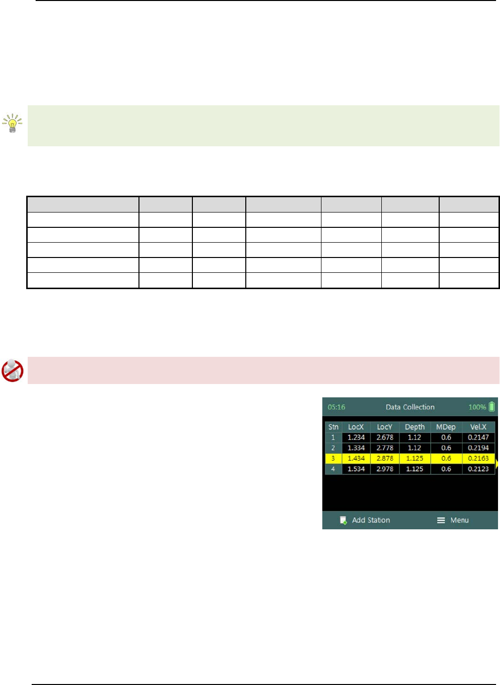
SonTek – a Xylem brand
FlowTracker2 User’s Manual (February 2016) 140
GPS Station Tagging).
g) To add a station or start velocity measurement,
i). Press the Right Soft Key.
h) To CANCEL add station,
i). Press the Left Soft Key.
Unique station number is assigned to each point velocity measurement. This allows the
user to perform multiple measurements at the same location without assigning a unique
number or name to differentiate between the measurements.
Properties associated with the parameters for station are defined in Table 9:3,
Table 9:3 - Station - Properties
Parameter
Min
Max
Default
Decimals
Units
Required
Location X
-1000
1000
empty
3
m or ft
Yes
Location Y
-1000
1000
empty
3
m or ft
Yes
Water Depth
0
100
empty
3
m or ft
Yes
Measurement Depth
0
100
empty
3
m or ft
Yes
Comment
0
250
empty
No
Delete Station 9.3.1.2
Deleting a station is performed from the Data Collection Window by selecting the
station within the viewable window.
The station delete process is not reversible and the user must ensure that the correct
station is selected. Selected station will be highlighted with a yellow background.
Delete Station is performed from the Data
Collection Window. Up to ten completed stations
will be displayed at any time,
a) To select a station,
i). Use the up or down arrow key to scroll through
the completed stations,
b) To DELETE a station,
i). Press the backspace key.
ii). The software will navigate to the Confirmation
screen.
Figure 9:9 - Select Station
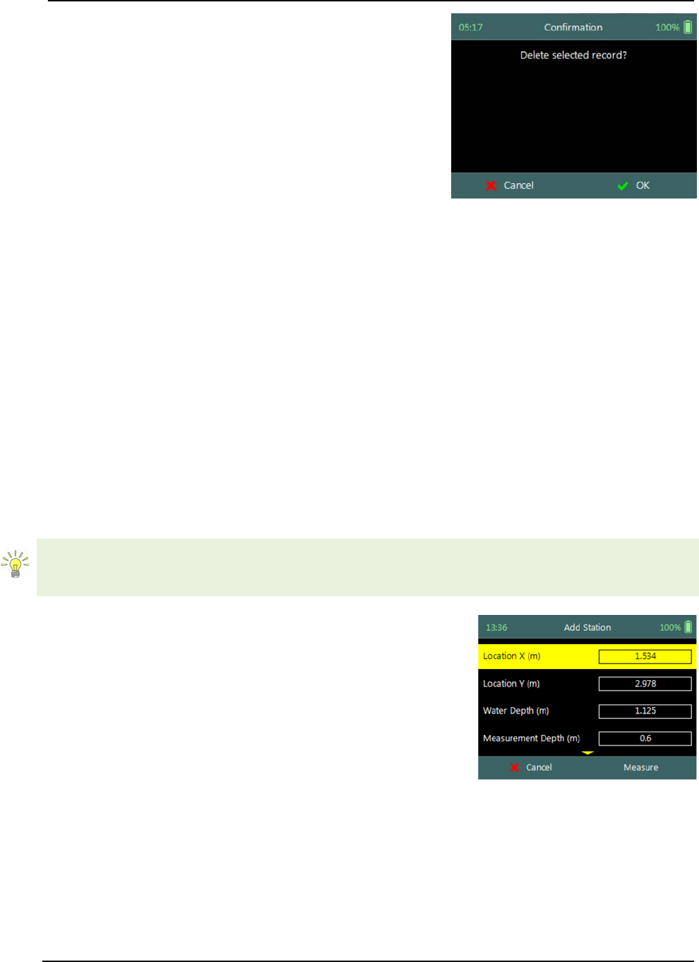
SonTek – a Xylem brand
FlowTracker2 User’s Manual (February 2016) 141
Confirmation screen requests confirmation of
deleting the selected station.
a) To confirm station delete,
i). Press the Right Soft Key,
b) To CANCEL station delete,
i). Press the Left Soft Key,
c) The software will navigate to the Data Collection
Window.
Figure 9:10 - Confirm Delete
Station Measurement 9.3.2
Station Measurement is performed at each Station based on measurement
requirements. The measurement locations can either be structured such in laboratory
environment where the position of the instrument is determined accurately or random
where velocities on channel banks are investigated. The station measurements consist
of collecting a number of different parameters and variables required by the General
mode.
Point Velocity Measurement 9.3.2.1
Point Velocity Measurement in General mode is not bound to any measurement
techniques and or guidelines as required in Discharge mode. The location of the station,
number of point velocity measurements and depth of point velocity measurements is
dependent on the user requirements.
If the velocity measurements are used to perform hydraulic analyzes of the flow
conditions in a channel, either a laboratory or natural channel, it is recommended that
ISO 748 – 2007 guidelines are used.
Step 1
Station parameters defined for Velocity Measurement,
e.g., parameters of station defined for velocity
measurement are the following,
a) Location X: 1.534m,
b) Location Y: 2.978m,
c) Water Depth: 1,125m,
d) Measurement Depth: 0.6m,
e) Velocity Method: Two Point,
f) Comment.
g) To add station and continue to velocity measurement,
i). Press the Right Soft Key.
h) To CANCEL a new station,
i). Press the Left Soft Key.
Figure 9:11 - Velocity
Measurement
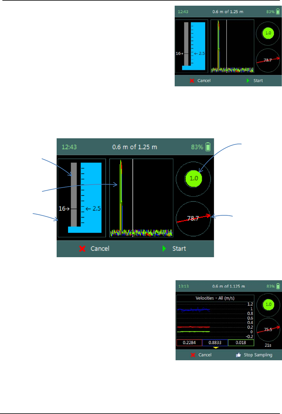
SonTek – a Xylem brand
FlowTracker2 User’s Manual (February 2016) 142
Step 2
Setting Measurement Depth screen allow the
setting and placement of the wading rod before
velocity measurement is started,
a) Wading rod setting,
b) Beam Check,
c) Boundary QC,
d) Tilt,
e) Velocity angle.
f) To start a velocity measurement,
i). Press the Right Soft Key.
g) To REVERT to measurement screen,
i). Press the Left Soft Key.
Figure 9:12 - Setting
Measurement Depth
The key features of the Setting Measurement Depth are explained in Figure 9:13.
Top Setting
wading rod
Automated
Beam Check
Wading rod
setting
Figure 9:13 - Features of Setting Measurement
Depth
Tilt Bubble
Velocity Angle
Step 4
Velocity Measurement screen displays graphical
display of raw data of the following variables during a
velocity measurement,
a) Velocity,
b) SNR,
c) Temperature,
d) Battery,
e) Tilt,
Tilt and Velocity Angle indicators are situated on the
right hand side of the screen.
f) Tilt,
g) Velocity Angle,
h) Averaging Time left.
Figure 9:14 - Velocity
Measurement

SonTek – a Xylem brand
FlowTracker2 User’s Manual (February 2016) 143
i) To select a variable graphical display,
i). Use up or down scroll arrows keys to view a
variable.
j) To stop sampling,
i). Press the Right Soft Key.
k) To CANCEL velocity measurement,
i). Press the Left Soft Key.
The conventions and graphic display features used for displaying Velocity and SNR raw
data are defined under Raw Data Display.
Review Point Measurement 9.3.2.2
Review Point Measurement is a report supplied at the end of each point velocity
measurement. The report consists of two components, tabular summary of numerical
calculations performed on the raw data collected and graphical display of raw data.
Review Point Measurement screen consists of the
following tabular summary and graphical displays,
Tabular Display
a) Review Point Measurement, Table 9:4
Graphical Display of raw data are based on the
following variables,
b) Velocity,
c) SNR,
d) Temperature,
e) Tilt,
f) Velocity Angle,
g) Battery.
h) To select a variable,
i). Use the up or down arrow key to view a
variable,
i) To accept the velocity measurement,
i). Press the Right Soft Key.
j) To REDO velocity measurement,
i). Press the Left Soft Key.
Figure 9:15 - Review Point
Measurement
The conventions and graphic display features used for displaying Velocity and SNR raw
data are defined under Raw Data Display.
Properties associated with the variable output from the numerical calculations
performed on raw data collected is defined in Table 9:4,
Table 9:4 - Review Point Measurement
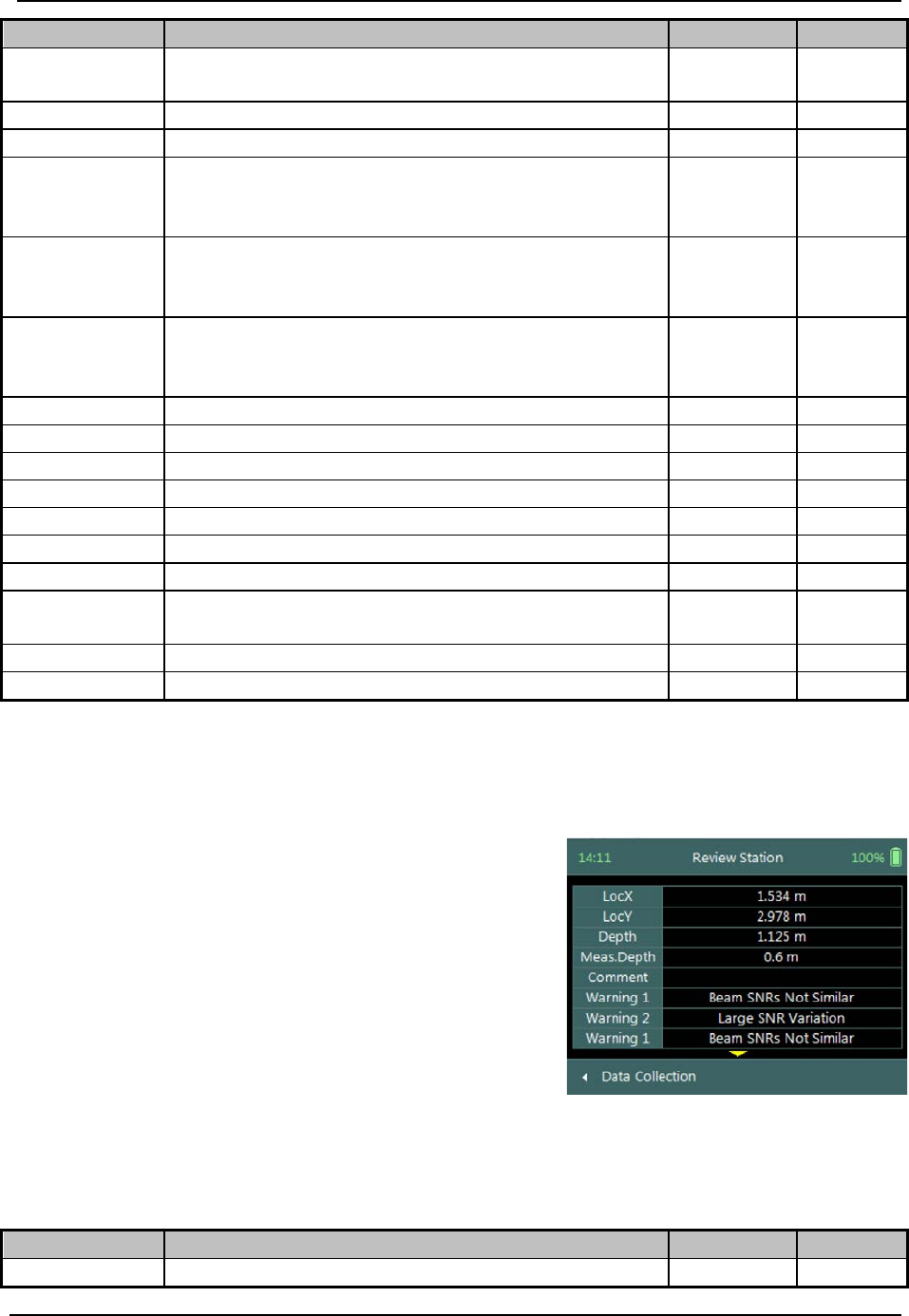
SonTek – a Xylem brand
FlowTracker2 User’s Manual (February 2016) 144
Variable
Description
Units
Decimal
Warning
Warning supplied based on quality control
criteria
n/a n/a
Samples
Total number of sample received
number
n/a
Spikes
Number of spikes removed from mean velocity
number
n/a
Vel. X
Mean X velocity component of all samples.
Velocity is despiked and mounting correction
applied (if applicable).
m/s or ft/s 4
Vel. Y
Mean Y velocity component of all samples.
Velocity is despiked and mounting correction
applied (if applicable).
m/s or ft/s 4
Vel. Z
Mean Z velocity component of all samples.
Velocity is despiked and mounting correction
applied (if applicable).
m/s or ft/s 4
σV. X
Standard error of X velocity component.
m/s or ft/s
4
σV. Y
Standard error of Y velocity component.
m/s or ft/s
4
σV. Z
Standard error of Z velocity component.
m/s or ft/s
4
SNR. 1
Signal to noise ratio of Beam 1
dB
3
SNR. 2
Signal to noise ratio of Beam 2
dB
3
SNR. 3
Signal to noise ratio of Beam 3
dB
3
Angle
Flow angle relative to X direction
Degree
2
Tilt
Mean wading rod angle during point velocity
measurement
Degree 2
Temp
Mean temperature during measurement
°C or °F
2
Bnd
Boundary QC value
n/a
n/a
Review Station Measurement 9.3.2.3
Review Station measurement is a tabular report that is available from the data collection
window at the completion of point velocity measurement of a station.
Review Station screen consists of tabular summary
of measurements performed at the station,
a) Review Station, Table 9:5.
b) To access review station report,
i). Select the station in the data collection window,
ii). Press the enter key.
c) To EXIT review station report,
i). Press the Left Soft Key.
Figure 9:16 - Review Station
Properties associated with the variables and numerical calculations performed on the
raw data collected at the station is defined in Table 9:5,
Table 9:5 - Review Station
Variable
Description
Units
Decimal
Loc X
Location X coordinate
m or ft
3
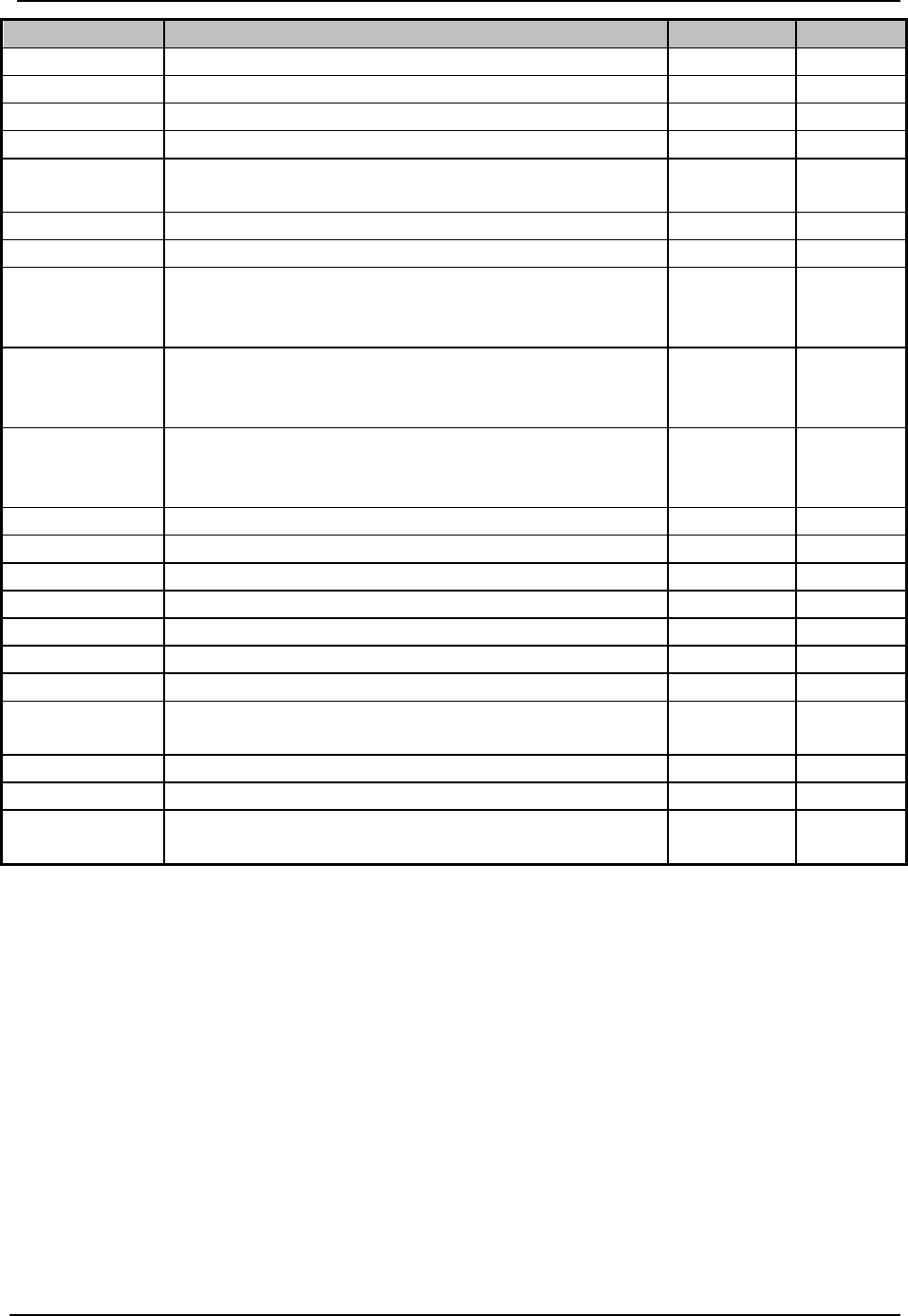
SonTek – a Xylem brand
FlowTracker2 User’s Manual (February 2016) 145
Variable
Description
Units
Decimal
Loc Y
Location Y coordinate
m or ft
3
Depth
Measured water depth
m or ft
3
Meas. Depth
Velocity measurement depth
m or ft
3
Comment
Comment supplied before the measurement
n/a
n/a
Warning
Warning supplied based on quality control
criteria
n/a n/a
Samples
Total number of sample received
number
n/a
Spikes
Number of spikes removed from mean velocity
number
n/a
Vel. X
Mean X velocity component of all samples.
Velocity is despiked and mounting correction
applied (if applicable).
m/s or ft/s 4
Vel. Y
Mean Y velocity component of all samples.
Velocity is despiked and mounting correction
applied (if applicable).
m/s or ft/s 4
Vel. Z
Mean Z velocity component of all samples.
Velocity is despiked and mounting correction
applied (if applicable).
m/s or ft/s 4
σV. X
Standard error of X velocity component.
m/s or ft/s
4
σV. Y
Standard error of Y velocity component.
m/s or ft/s
4
σV. Z
Standard error of Z velocity component.
m/s or ft/s
4
SNR. 1
Signal to noise ratio of Beam 1
dB
3
SNR. 2
Signal to noise ratio of Beam 2
dB
3
SNR. 3
Signal to noise ratio of Beam 3
dB
3
Angle
Flow angle relative to X direction
Degree
2
Tilt
Mean wading rod angle during velocity
measurement
Degree 2
Temp
Mean temperature during measurement
°C or °F
2
Bnd
Boundary QC value
n/a
n/a
GPS
Indicating if GPS was used during station
measurement
n/a n/a
Data Collection Menu 9.3.3
Data Collection Menu allows the user to adjust measurement settings, view
measurement summary, perform automated beam check and complete measurement.
The data collection menu can be accessed between station measurements and this
ensures that the instrument is configured for current flow conditions present.
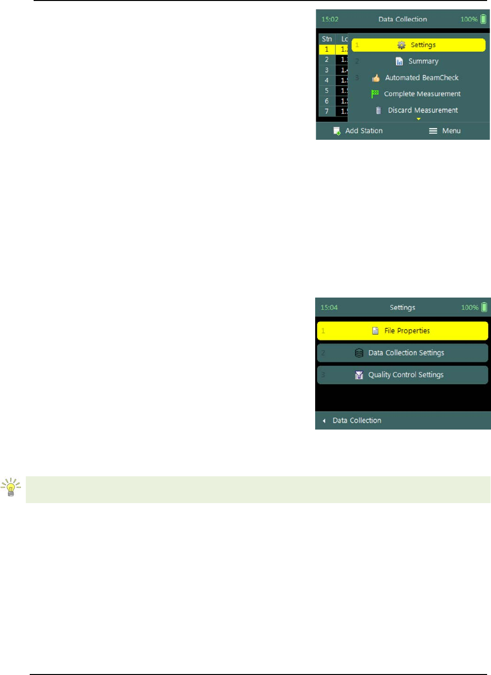
SonTek – a Xylem brand
FlowTracker2 User’s Manual (February 2016) 146
Data Collection Menu screen consists of the
following functions that are available in Discharge
Mode,
a) Settings,
b) Measurement Summary,
c) Automated Beam Check,
d) Complete Measurement,
e) Discard Measurement,
f) Go to Home Screen.
g) To select a function,
i). Use the up or down arrow key to scroll through
the functions,
h) To open or CLOSE the data collection menu,
i). Press the Right Soft Key.
Figure 9:17 - Data Collection
Menu
Settings 9.3.3.1
The Settings menu option gives the user access to the initial measurement settings that
were configured during the configuration of the general template.
Settings screen consists of the following functions for
configuring measurement settings,
a) File Properties,
b) Data Collection Settings,
c) Quality Control Settings.
d) To select a function,
i). Use the up or down arrow key to scroll through
the functions,
e) To CLOSE the settings menu,
i). Press the Left Soft Key.
Figure 9:18 - Settings Menu
The measurement settings functions supplied in the Settings option in data collection
menu are defined under Template Functions.
Velocity Summary 9.3.3.2
Velocity Summary from the data collection menu displays the mean velocity and other
variables measured from all completed stations. The velocity summary requires at least
one station with velocity measurements to populate the main variables in the table.

SonTek – a Xylem brand
FlowTracker2 User’s Manual (February 2016) 147
Velocity Summary screen consists of tabular
summary of velocity and other variables measured up
to specific point,
a) Velocity Summary, Table 8:10.
b) To close the velocity summary report,
i). Press the Left Soft Key,
ii). The software will navigate to the Data
Collection Window.
Figure 9:19 - Velocity Summary
Properties associated with the variables and numerical calculations performed on the
raw data collected is defined in Table 8:10,
Table 9:6 - Velocity Summary
Variable
Description
Units
Decimal
Vel. X Mean
Average station velocity, X velocity component
of all stations.
m/s or ft/s 4
Vel. X Min
Minimum station velocity, X velocity
component.
m/s or ft/s 4
Vel. X Max
Maximum station velocity, X velocity
component.
m/s or ft/s 4
Vel. Y Mean
Average station velocity, Y velocity component
of all stations.
m/s or ft/s 4
Vel. Y Min
Minimum station velocity, Y velocity
component.
m/s or ft/s 4
Vel. Y Max
Maximum station velocity, Y velocity
component.
m/s or ft/s 4
Vel. Z Mean
Average station velocity, Z velocity component
of all stations.
m/s or ft/s 4
Vel. Z Min
Minimum station velocity, Z velocity
component.
m/s or ft/s 4
Vel. Z Max
Maximum station velocity, Z velocity
component.
m/s or ft/s 4
σV. Mean
Average standard error, X velocity component
of all stations.
m/s or ft/s 4
σV. Min
Minimum standard error, X velocity component
of all stations. m/s or ft/s 4
σV. Max
Maximum standard error, X velocity
component of all stations.
m/s or ft/s 4
SNR Mean
Average SNR of all stations.
dB
2
Automated Beam Check 9.3.3.3
Automated Beam Check function in the data collection menu allows the user to perform
beam check during any stage of the velocity measurement. The Automated Beam
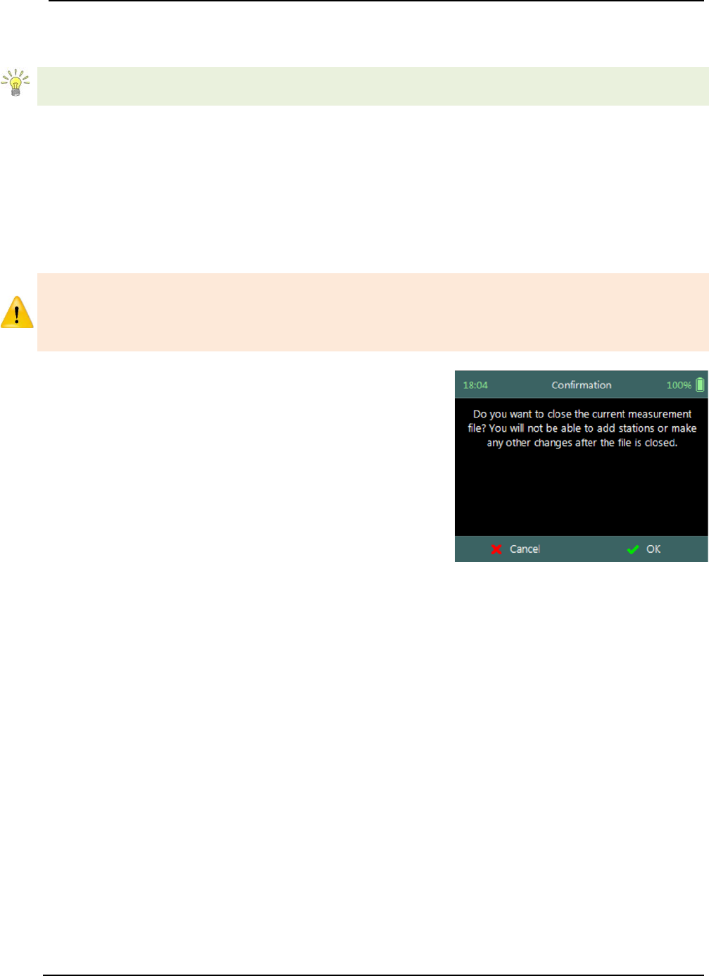
SonTek – a Xylem brand
FlowTracker2 User’s Manual (February 2016) 148
Check function operations, conventions and graphic display features are defined under
Automated Beam Check.
Automated Beam Checks performed during the discharge measurement are stored in
FlowTracker2 file (.ft) that was created for the measurement site.
Complete Measurement 9.3.3.4
The Complete Measurement function closes the measurement file and the user will not
be able to add additional stations and or make any changes to the data captured. The
complete measurement function is a three-step process, firstly to determine if the user is
satisfied with the velocity measurements, secondly to perform quality control checks
against all measurement data and lastly to review measurement summary.
The Complete Measurement process allows the user to review the measurement data
before the complete function is selected at Summary screen. The user will not be able
to make any to changes to the measurement file from the handheld when this function
is selected.
Step 1
Confirmation screen of Complete Measurement
function confirms if the user wants to close the
measurement file. User will not be able to add
stations or make any changes to the data
a) To confirm complete measurement operation,
i). Press the Right Soft Key.
b) To CANCEL complete measurement operation,
i). Press the Left Soft Key.
Figure 9:20 - Confirmation
Complete Measurement
Step2
Confirmation screen with Quality Control warning
messages based on quality control checks performed
on measurement data.
a) To accept quality control warning messages,
i). Press the Right Soft Key.
b) To CANCEL complete measurement operation,
i). Press the Left Soft Key.
Figure 9:21 - Confirmation
Quality Control Messages
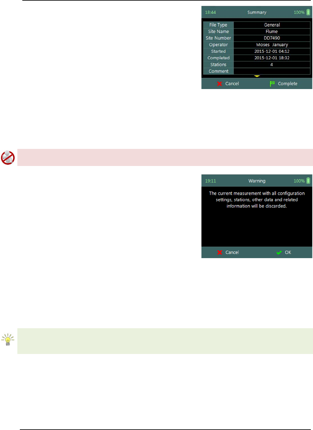
SonTek – a Xylem brand
FlowTracker2 User’s Manual (February 2016) 149
Step3
Summary screen displays the velocity summary
report before the measurement file is closed for
further data entry and editing.
a) To confirm complete measurement operation,
i). Press the Right Soft Key,
ii). The software will navigate to the Main Menu.
b) To CANCEL complete measurement operation,
i). Press the Left Soft Key.
Figure 9:22 - Summary
Discharge Measurement
Discard Measurement 9.3.3.5
The Discard Measurement function will discard all configuration settings, stations and
other data related with the measurement.
Discarding a measurement will result in deleting all data of the measurement site that is
related to the specific measurement file.
Warning screen of Discard Measurement function
displays the warnings associated with discarding
measurement file.
a) To DISCARD measurement,
i). Press the Right Soft Key.
ii). The software will navigate to the Main Menu.
b) To CANCEL discard measurement operation,
i). Press the Left Soft Key.
Figure 9:23 - Warning Discard
Measurement
Go to Home Screen 9.3.3.6
The Go to Home Screen function will navigate the software to the main menu and the
user will have the ability to access software functions that are not related to General
Mode function.
The velocity measurements can be accessed during any stage by selecting the “Data
Collection” function with the Right Soft Key. The software will continue with the
measurement at the exact stage when the user navigated away from the general mode.
9.4. Measurement Summary
Measurement Summary is supplied when the Complete Measurement function is
selected and displays all the measurement results. The Measurement Summary is the
last verification of the measurement results before the measurement file is closed for any
further measurements or changes.
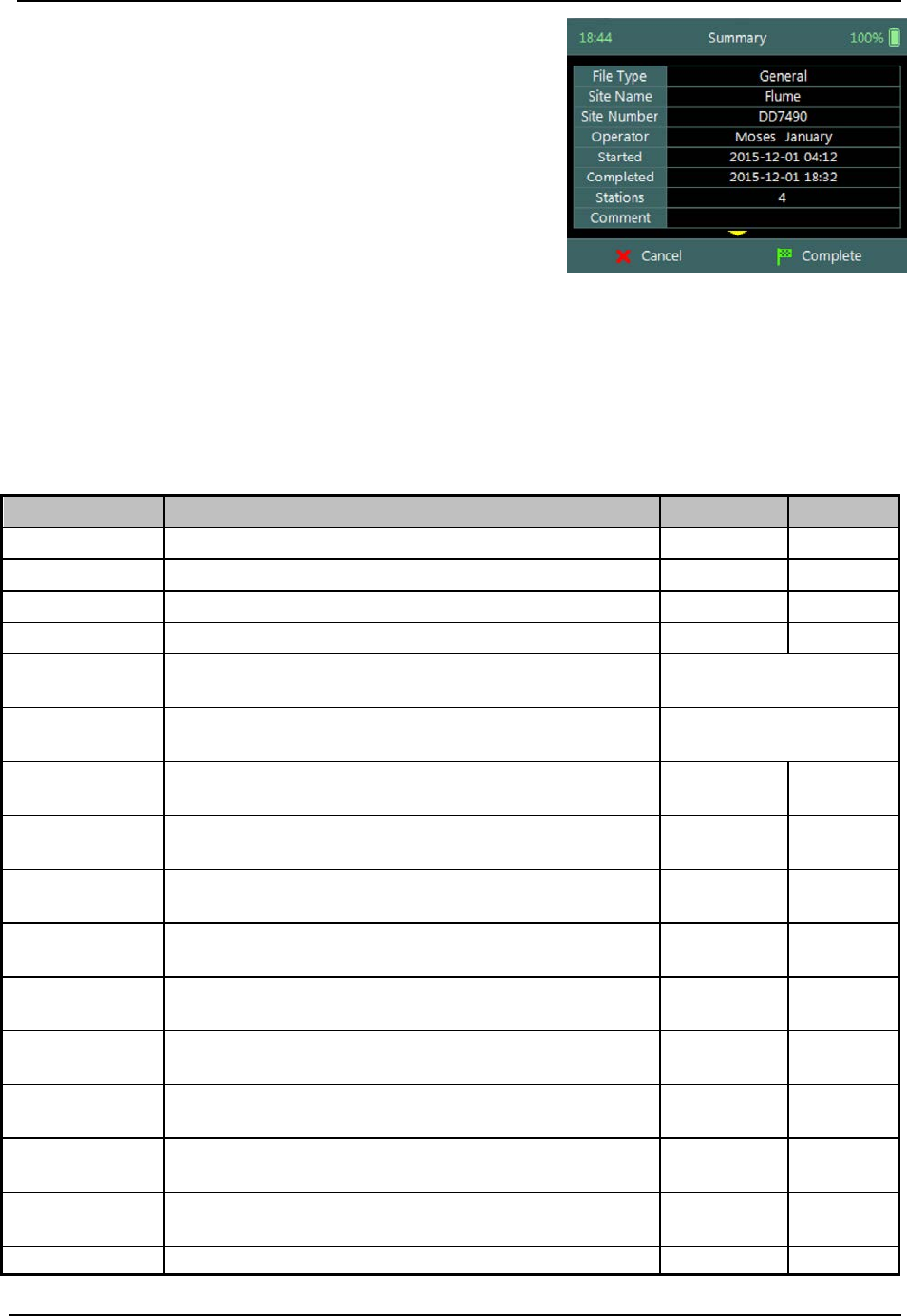
SonTek – a Xylem brand
FlowTracker2 User’s Manual (February 2016) 150
Measurement Summary screen consists of tabular
summary of velocity measurement results,
a) Velocity Summary, Table 9:7.
b) To CANCEL the general summary report,
i). Press the Left Soft Key.
ii). The software will navigate to the Data
Collection Window.
c) To COMPLETE the general measurement,
i). Press the Right Soft Key.
ii). The software will close the measurement file
and navigate to the main menu.
Figure 9:24 - Measurement
Summary
Properties associated with the variables and numerical calculations performed on the
raw data collected is defined in Table 9:7,
Table 9:7 - Measurement Summary
Variable
Description
Units
Decimal
File Type
File type based on discharge or general mode
n/a
n/a
Site Name
Site name populated by user
n/a
n/a
Site Number
Site number populated by user
n/a
n/a
Operator
Operator name populated by user
n/a
n/a
Started
Start date and time when measurement was
created
yyyy-mm-dd hh:mm
Completed
End data and time when measurement was
completed
yyyy-mm-dd hh:mm
Stations
Total number of stations within the
measurement
n/a n/a
Comment
General comment captured against
measurement
n/a n/a
Vel. X Mean
Average station velocity, X velocity component
of all stations.
m/s or ft/s 4
Vel. X Min
Minimum station velocity, X velocity
component.
m/s or ft/s 4
Vel. X Max
Maximum station velocity, X velocity
component.
m/s or ft/s 4
Vel. Y Mean
Average station velocity, Y velocity component
of all stations.
m/s or ft/s 4
Vel. Y Min
Minimum station velocity, Y velocity
component.
m/s or ft/s 4
Vel. Y Max
Maximum station velocity, Y velocity
component.
m/s or ft/s 4
Vel. Z Mean
Average station velocity, Z velocity component
of all stations.
m/s or ft/s 4
Vel. Z Min
Minimum station velocity, Z velocity
m/s or ft/s
4

SonTek – a Xylem brand
FlowTracker2 User’s Manual (February 2016) 151
Variable
Description
Units
Decimal
component.
Vel. Z Max
Maximum station velocity, Z velocity
component.
m/s or ft/s 4
σV. Mean
Average standard error, X velocity component
of all stations.
m/s or ft/s 4
σV. Min
Minimum standard error, X velocity component
of all stations. m/s or ft/s 4
σV. Max
Maximum standard error, X velocity
component of all stations. m/s or ft/s 4
SNR Mean
Average SNR of all stations.
dB
2
SonTek – a Xylem brand
FlowTracker2 User’s Manual (February 2016) 152
FlowTracker2 Hardware Section 10.
10.1. ADV Probe
The FlowTracker2 ADV Probe and internal sensors that were implemented specifications
are listed in Table 10:1,
Table 10:1- ADV Probe Specifications
Hardware
Specification
Velocity Range
±0.001 to 4.0m/s (0.003 to 13ft/s)
Velocity Resolution
0.0001m/s (0.0003ft/s)
Velocity Accuracy
±1% of measured velocity, 0.25 cm/s
Acoustic Frequency
10.0MHz
Sampling Volume Location
10cm (3.93in) from the center
transducer
Minimum Depth
0.02m (0.79in)
Temperature Sensor
Resolution: 0.01°C, Accuracy: 0.1°C
Tilt Sensor
Accuracy: 1.0°
Communication Protocol
RS-232
Temperature
Operating
-20° to 40°C (-4°F to 104°F)
Storage
-30° to 70°C (-22°F to 158°F)
Physical
Specifications
Probe Head
Dimensions
(L)13.3cm (5.22in); (W) 6.1cm (2.39in);
(H) 2.3cm (0.90in)
Standard Cable Length
1.500m (4.92ft)
Weight in Air
0.90kg (1.98lbs)
Weight in Water
0.30kg (0.66lbs)
10.2. Handheld
The FlowTracker2 Handheld and internal sensors implemented specifications are listed
in Table 10:2,
Table 10:2- Handheld Specifications
Hardware
Specification
Battery
Power
Input Battery Voltage
8 - 12 VDC
Power
Supply
Alkaline
8 x size AA/LR6 Alkaline batteries
NiMH
8 x size AA, Type BK200AAB, 1.2Vdc,
1900mAh
The use of NiMH Rechargeable Batteries is only CE certified
per IEC 62133 for FlowTracker2 part number FT2-HH-2 and
above.
Only this type of NiMH rechargeable batteries with IEC 62133
approval can be used, or else warranty and safety protection
will be void.
SonTek – a Xylem brand
FlowTracker2 User’s Manual (February 2016) 153
Hardware
Specification
Battery
Life
8 x size AA
15 hours continuous use, typical settings*
*Defined as power on with screen on at 100% brightness,
ADV sensor pinging 50% of the time, GPS off, and no
sleep periods. Actual battery life will vary depending on
FT2 settings, manner of use and brand of battery.
Power Consumption
1 W (Average)
Coin cell
Type
Coin Cell type is ML2020 Manganese Lithium
GPS
Horizontal Position
Accuracy
<2.5m (8.2ft)
Frequency
L1 (1.575 MHz), SBAS compensation (WAAS,
EGNOS, MSAS, GAGAN)
LCD
Resolution
320 X 240 TFT Trans missive
LED Backlight
Luminance
450 cd / m2
Probe
Interface
Battery Power to
Probe
8 - 12 VDC
Data Transfer
RS-232
Data Storage
16 GB. Up to 10k discharge measurements.
Up to 10 million velocity samples
Physical
Specifications
Waterproof Rating
IP-67 (1m submersible)
Handheld Dimensions
(L)10.4cm (4.1in); (W) 6.4cm (2.5in); (H)
23.7cm (9.3in)
Weight in Air
0.75kg (1.65lbs)
Weight in Water
-0.25kg (-0.55lbs)
Operating
Altitude
Maximum operating altitude is 2000m
Temperature
Operating
-20° to 40°C (-4°F to 104°F)
Storage
-30° to 70°C (-22°F to 158°F)
Remove batteries from FlowTracker2 handheld if storage
temperatures exceeds 40°C (104°F)
Bluetooth
Class
Class 2, Range = 10m (32.8ft) nominal
FCC
Intentional radiator (FCC Part 15.247
Subpart C; ANSI C-63.4-2003 RSS-210 and
ISSUE No. :8 Date :2010)
a. FCC IDENTIFIER: S7AIW03
b. Labeling requirements (FCC ID on
product & text in manual)
c. Drop in, use as intended from OEM –
use OEM’s FCC ID (eg, FlowTracker 2
Bluetooth)
d. Modify use or signal/output – Analytics
Site applies for FCC ID
• Takes 3-4 weeks through Nemko
e. Operate at specific frequency w/o
SonTek – a Xylem brand
FlowTracker2 User’s Manual (February 2016) 154
Hardware
Specification
interference
• Will require FCC license to operate
USB
Micro USB, IP-67
10.3. Cables and Connectors
The FlowTracker2 cable and connector specifications are listed in Table 10:3,
Table 10:3- Cable and Connector Specifications
Hardware
Specification
Connector type
MCIL-8-MP wet-mate able
Standard length
1.500m (4.92ft)
Extension cable lengths
1.500m (4.920ft), 3.500m (11.5ft),
8.500m (27.9ft)
Maximum operating length
10m (32.8ft)
10.4. Certifications
The FlowTracker2 and all related hardware components comply with the following
certification.
• For P/N FT2-HH-1
o CE (per IEC/EN 61010-1:2010 3rd ed, EMC directive 2004/108/EC
EN61326-1) for AA Alkaline batteries, FCC, IP-67
• For P/N FT2-HH-2
o CE (per IEC/EN 61010-1:2010 3rd ed, EMC directive 2004/108/EC
EN61326-1) for AA Alkaline batteries, FCC, IP-67
o CE (per IEC/EN 61010-1:2010 3rd ed, EMC directive 2004/108/EC
EN61326-1) for NiMH rechargeable batteries that are certified to IEC
62133*, FCC, IP-67
For further questions on certification standards, contact support@sontek.com.
Approved batteries are discussed further in Section 4.3.1.
10.5. PC System Requirements
The PC System Requirements for operating FlowTracker2 desktop software are
summarized under the following criteria,
• Microsoft Windows 7 or newer
• 1GHz processor or better (2 GHz recommended)
• 2GB memory (4GB recommended)
• 500 MB available disk space (1GB recommended)

SonTek – a Xylem brand
FlowTracker2 User’s Manual (February 2016) 155
• Monitor capable of 1024x768 resolution, or better
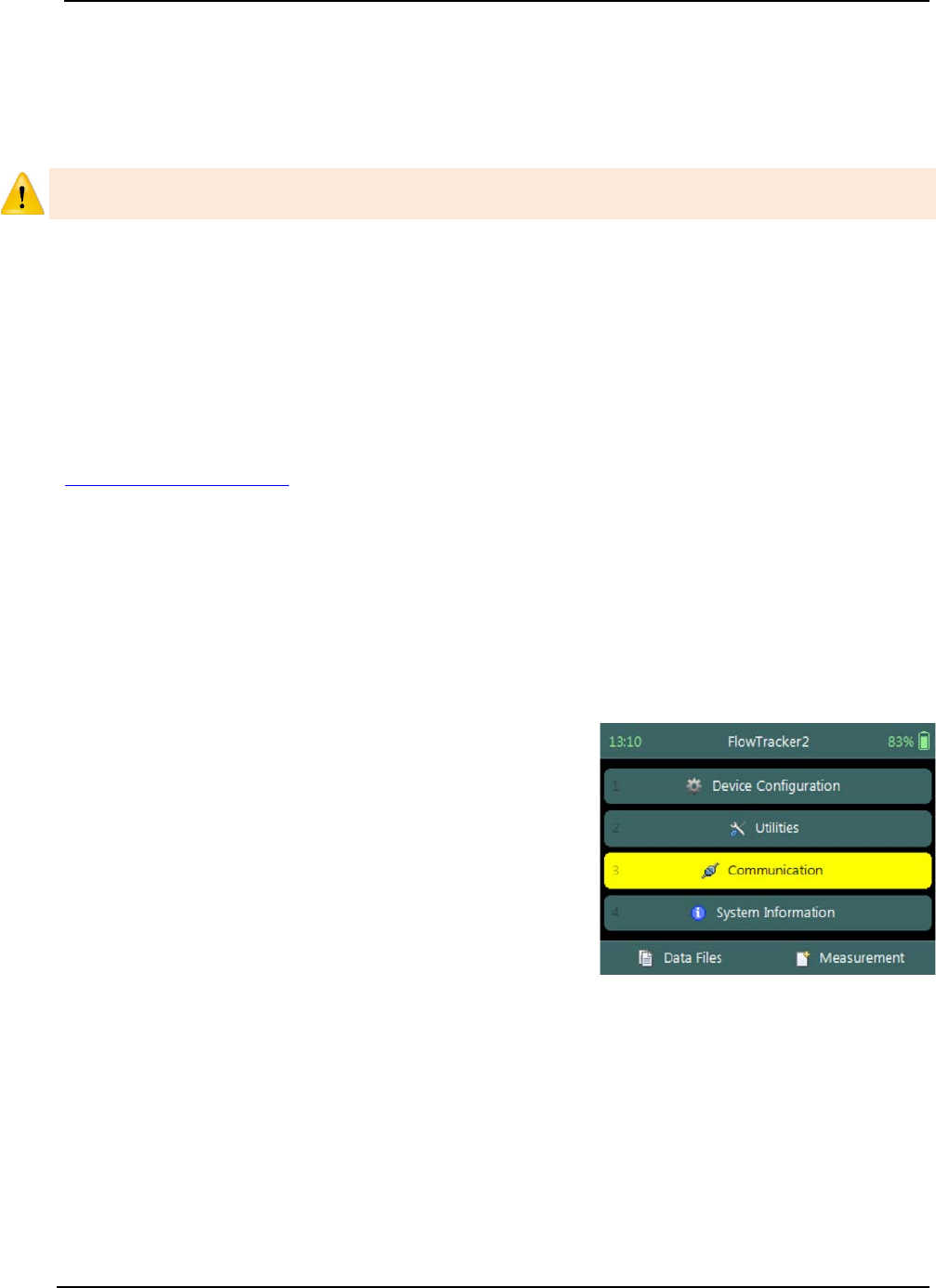
SonTek – a Xylem brand
FlowTracker2 User’s Manual (February 2016) 156
Operational Considerations Section 11.
The procedures outlined for operating of the FlowTracker2 instrument and the
maintenance requirements should be followed to ensure that the instrumentation is in a
working condition.
The user should follow operating instructions as outlined in this manual, failure to do so
can void manufacturer’s warranty.
11.1. Software Upgrade
The FlowTracker2 handheld and ADV are operating on unique software and firmware
respectively developed specifically for the FlowTracker2 instrument. Periodic updates
will be supplied by SonTek to users that are normally associated with either improvement
on existing or new features. The periodic update will consist of FlowTracker2 installation
file that includes the Desktop Software, Handheld Software and ADV Firmware files.
The FlowTracker2 installation file will be available from the SonTek website
(http://www.sontek.com) or by contacting SonTek Technical Support.
Upgrading Handheld Software 11.1.1
The upgrading of handheld software and or ADV firmware is performed by uploading a
single firmware file with .ft_firmware extension onto the handheld from the FlowTracker2
desktop software. The handheld upgrade is a three-step process, firstly activate
handheld communication function, secondly connect desktop software with handheld
using either bluetooth or USB and lastly upgrade the handheld.
Step 1 - Handheld
Activate Communication function on handheld to
allow the user to connect to FlowTracker2 desktop
software using either bluetooth or USB.
a) To select communication function,
i). Use the up or down arrow key to scroll through
the functions,
ii). Press the enter key to activate the
communication function.
Figure 11:1 - Communication
Function
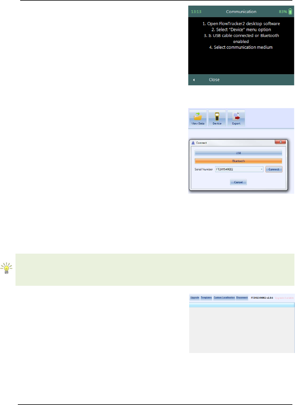
SonTek – a Xylem brand
FlowTracker2 User’s Manual (February 2016) 157
The communication window displays the following
instructions to enable connection between the
handheld and FlowTracker2 desktop software,
a) Open FlowTracker2 desktop software,
b) Select “Device” menu option,
c) Is USB cable connected or Bluetooth enabled,
d) Select communication medium.
e) To CLOSE the communication function,
i). Press the Left Soft Key.
Figure 11:2 - Communication
Window
Step2 – Desktop Software
Connect FlowTracker2 desktop software with
handheld using either USB or Bluetooth
communication.
a) Connect to FlowTracker2 handheld Device,
i). Select “Device” menu option on main menu
banner,
ii). Connection window will appear on software
window with USB and Bluetooth
communication options.
b) Select communication medium,
i). USB - Make sure USB cable is connected
before USB option is selected,
ii). Bluetooth – Select handheld serial number from
dropdown list and select the “Connect”
function.
Figure 11:3 - Device
Communication Window
If the handheld serial number is not listed, select the content in the box using mouse
and start typing the serial number. When the serial number is entered, select “Connect”
function. The desktop software will connect to the handheld using bluetooth and the
serial number will be stored for future use.
Step3 – Desktop Software
Perform Upgrade of handheld software and or ADV
firmware by selecting the upgrade function on the
FlowTracker2 desktop software.
a) Perform Upgrade of FlowTracker2 device,
i). Select “Upgrade” menu option,
ii). Open file window will appear with the available
firmware file.
iii). Select the firmware file within the “Open File”
window and select “Open” function.
b) Upgrade progress Status
Figure 11:4 - Upgrade Function
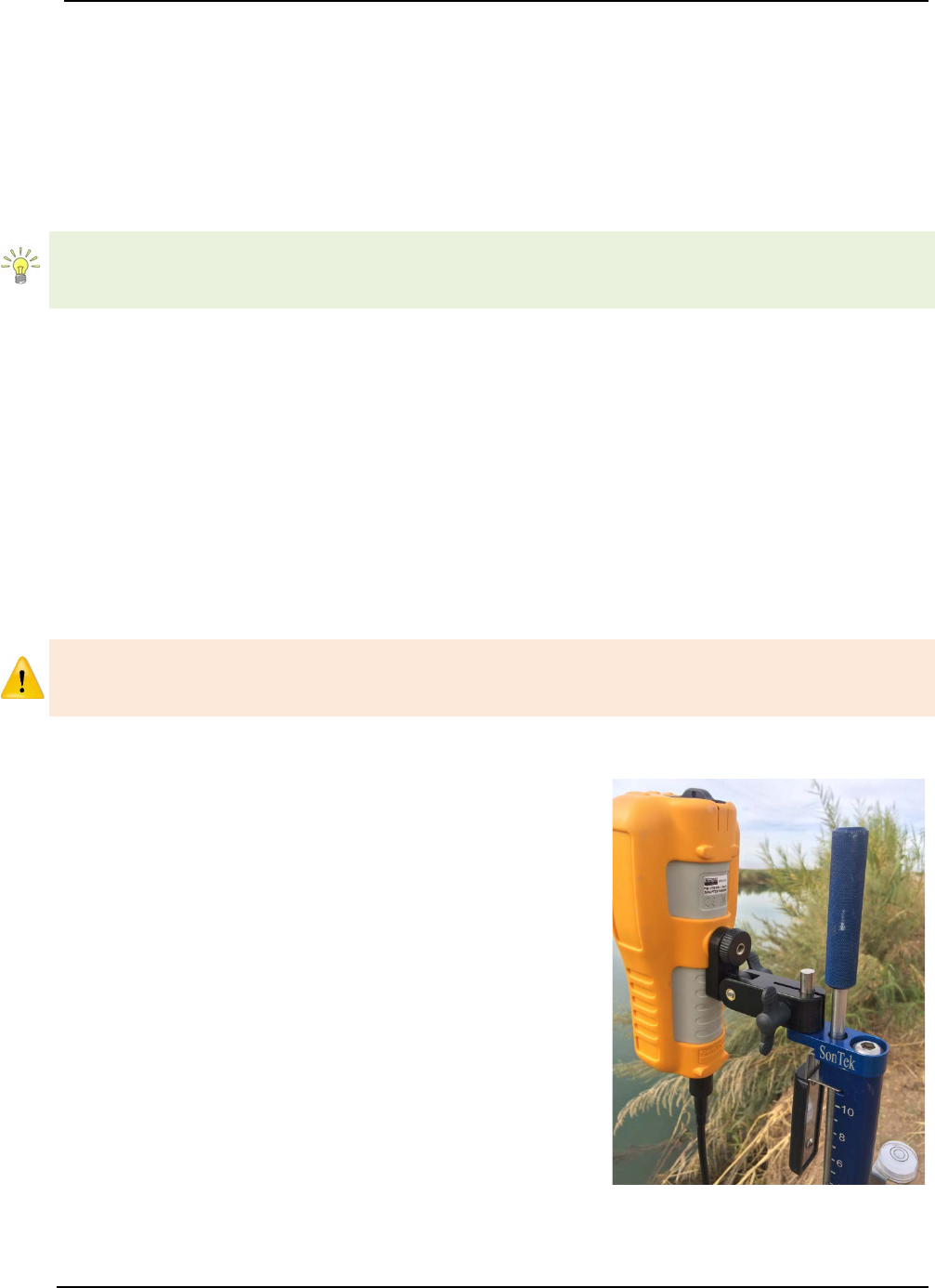
SonTek – a Xylem brand
FlowTracker2 User’s Manual (February 2016) 158
i). The FlowTracker2 desktop software gives
progress status in percentage of the upgrade.
Upgrading ADV Firmware 11.1.2
The ADV firmware upgrade is performed separately from the FlowTracker2 handheld
software upgrade. The user is required to either request system information or initiate
data collection from the ADV to activate the firmware upgrade process.
Requesting the Probe System Information under System Information (Main Menu)on
the handheld is the most efficient way of activating the ADV to initiate the ADV firmware
upgrade process.
11.2. Mounting and Installation
The FlowTracker2 is commonly mounted on a top-setting wading rod. The probe and
handheld mounting have been designed with wading rod use in mind, but the design is
flexible enough to allow a variety of mounting arrangements. Top-setting wading rods
are available from SonTek.
FlowTracker2 Handheld 11.2.1
The handheld should be secured during operation and it is recommended that the
handheld is mounted to the wading rod during measurements. If the FlowTracker2 is not
in use, the handheld should be stored in the carry case supplied.
The protective yellow jacket that is supplied with the FlowTracker2 handheld should
stay on during operation. The jacket supply protection to the handheld casing, battery
cap, USB port and LCD screen.
Handheld Mounting Bracket 11.2.2
Top Setting Rod mounting bracket to connect the
handheld to the top of top setting wading rod.
a) A mounting bracket compatible with the
mounting pin on a top-setting wading rod is
available from SonTek.
b) The handheld includes one threaded insert on
the back, which secures the SonTek-supplied
mounting brackets.
c) The handheld mounting simplifies the
measurement process and allow the user to
focus on the measurement and orientation of
the probe.
Figure 11:5 - Top Setting Rod
Handheld Mounting

SonTek – a Xylem brand
FlowTracker2 User’s Manual (February 2016) 159
Universal Rod mounting bracket to connect the
handheld to the universal wading rod.
d) A mounting bracket compatible with a 20mm
universal-style wading rod is available from
SonTek.
e) Neck/shoulder strap for the handheld which fits
the threaded insert is available from SonTek.
Figure 11:6 - Universal Rod
Handheld Mounting
The threaded insert can also be used to secure a user-supplied mounting bracket. The
size of the threaded insert is ¼-20. User-supplied mounting brackets should avoid
direct contact with the keypad and screen.
Probe Mounting Bracket 11.2.3
Top Setting Rod J-Bracket to connect the 2D or
2D/3D Flowtraker2 probe to the top setting wading
rod.
a) The J-Bracket is available for mounting the
probe from a top-setting wading rod. Both the
bracket and complete wading rods are
available from SonTek.
b) The J-Bracket offsets the probe to one side of
the wading rod, placing the sampling volume
closer to the wading rod, approximately 5 cm
(2 in) to one side.
c) The bracket allows the wading rod to be used
in its standard “forward” orientation.
Figure 11:7 - Top Setting Rod J-
Bracket
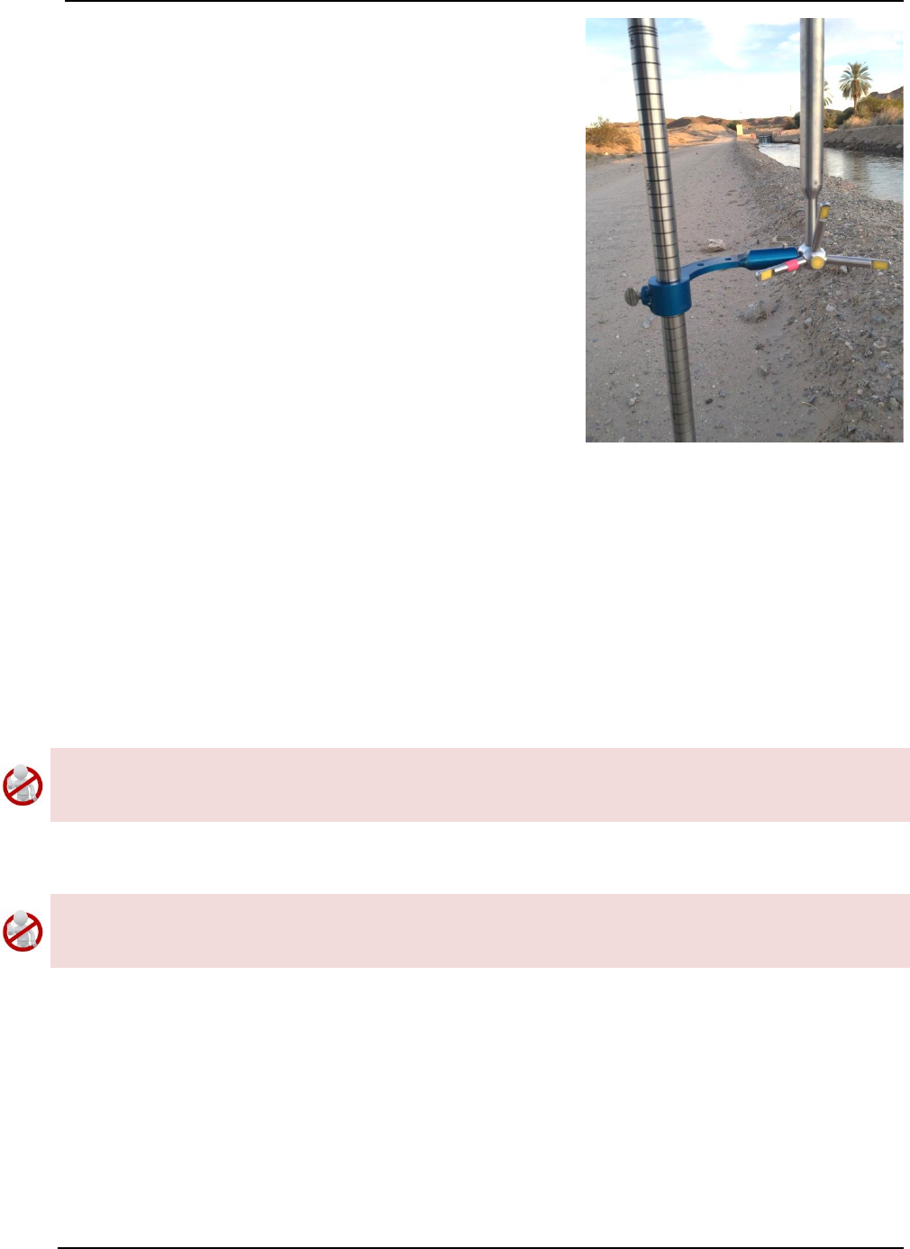
SonTek – a Xylem brand
FlowTracker2 User’s Manual (February 2016) 160
Universal Rod J-Bracket to connect the 2D or 2D/3D
Flowtraker2 probe to the universal wading rod.
d) A J-Bracket compatible with a 20mm universal-
style wading rod is available from SonTek.
Figure 11:8 – Universal Rod J-
Bracket
11.3. Routine Maintenance
Battery Power Supply 11.3.1
Batteries should be checked on a routine basis and it is recommend that the following
tasks are performed during routine maintenance and or completion of measurement
exercise,
a) The battery voltage level should be verified by using the battery raw data graphics
displayed in Battery Indicator.
Batteries should not be left in the FlowTracker2 handheld for prolonged periods as
damage can occur to the handheld if the batteries are leaking. It is recommended that
batteries are removed from the handheld if the instrument is not used.
b) The use-by date should be recorded and referenced during routine maintenance
and it is recommended that expired batteries should not be used in FlowTracker2.
Battery manufacturer guidelines must be followed during normal use, long term storage
and charging requirements. The disposal of batteries must be done with care and it is
recommended that local authority guidelines be used.
Cleaning Instrument 11.3.2
Handheld 11.3.2.1
The handheld will require some cleaning after use as the accumulation of dirt on the
handheld can damage the component such as the LCD screen, USB port, probe cable
connector and keypad. It is recommended that a cloth is used to wipe the handheld or
soft brush.
SonTek – a Xylem brand
FlowTracker2 User’s Manual (February 2016) 161
In the case where the handheld was submerged under water or where it is covered in
mud and need to be rinsed, the following guidelines should be followed,
a) Do not remove the probe cable or battery cap while the handheld is under water
or drenched.
b) Use a dry cloth and remove excess moisture on the outside of the handheld.
c) Remove the “yellow Jacket” from the handheld casing and apply a dry cloth to the
handheld casing.
d) Remove the probe cable and inspect if the connector pins are dry. This can
indicate if there was water ingress into the connector.
e) Remove the battery cap and battery cartridge. Inspect both the battery cap and
cartridge for moisture as this can indicate water ingress.
f) Remove batteries from battery cartridge and inspect for moisture.
g) Place handheld, battery cartridge, batteries and yellow jacket on a dry place (not
in direct sunlight) and allow to dry.
If water ingress was identified during inspection in the battery compartment or probe
cable connector contact SonTek. It is not recommended to use the instrument if there
is moisture in the battery compartment.
Transducers 11.3.2.2
Biological growth on the transducers does not affect velocity measurements, but can
decrease acoustic signal strength and potentially increase noise in velocity data in clear
water.
a) Periodic cleaning of the FlowTracker2 transducers may be needed to maintain
optimal performance in areas of high biological activity,
b) FlowTracker2 transducers are encapsulated in an epoxy that is impervious to
damage from barnacles or other types of growth,
c) To remove growth, simply clean with a cloth or stiff (non-metallic) brush. The
transducer epoxy is very durable and cannot be easily damaged except by direct
impact.
Cable Maintenance 11.3.3
The FlowTracker2 probe cable is often the most vulnerable part of the system.
a) The cable uses a durable polyurethane jacket that provides excellent long-term
wear and abrasion resistance,
b) Any cable is susceptible to damage and reasonable precautions should be taken,
c) Inspect the cable and all connectors on a regular basis,
d) This cable is highly noise-sensitive and should not be modified by the user.

SonTek – a Xylem brand
FlowTracker2 User’s Manual (February 2016) 162
O-rings 11.3.4
The FlowTracker2 handheld makes use of two O-ring seals and it is important that the
following guidelines are followed.
Housing 11.3.4.1
a) The handheld is designed to withstand temporary submersion, but is not intended
for underwater operation.
b) We do not recommend opening the handheld housing without specific instructions
from SonTek.
Battery Cap 11.3.4.2
a) The O-ring located on the battery cap prevents moisture entering the battery
compartment.
b) Inspection of the O-ring should be during Hardware Inspection for any cracks or
defects that may exist on the O-ring.
c) The batter cap, O-ring and battery compartment must be inspected for any
moisture, dirt or material that can damage the O-ring, battery or battery
connectors.
Condensation in FlowTracker2 Housing 11.3.5
Moisture in the air can potentially damage FlowTracker2 electronics if allowed to
condense inside the handheld housing.
a) The handheld is shipped with a desiccant pack inside to absorb moisture,
b) We do not recommend opening the handheld housing without specific instructions
from SonTek. If the housing has not been opened, the desiccant should not need
to be replaced.
Zinc Anodes for Corrosion Protection 11.3.6
When using the FlowTracker2 in salt water, additional precautions must be taken to
prevent corrosion.
a) A sacrificial zinc anode should be installed on the probe (attached to the metal
portion of the probe stem),
b) Anode condition should be inspected regularly, and the anode should be replaced
when necessary. Zinc anodes are available from SonTek,
c) To check anode condition, try to chip away part of the anode with a screwdriver. If
large portions of the anode easily fall away, the anode should be replaced,
d) The probe and cable should be thoroughly rinsed with fresh water after each use.

SonTek – a Xylem brand
FlowTracker2 User’s Manual (February 2016) 163
11.4. Seeding
Scattering Material 11.4.1
If FlowTracker2 velocity data appears “noisy”, the most common cause is a lack of
scattering material in the water.
a) Acoustic Doppler Velocimeters require scattering material for velocity
measurements (see Principle of Operations),
b) A lack of scattering material can increase noise in velocity data. If insufficient
scattering material is present, the FlowTracker2 will not be able to accurately
measure velocity,
c) In most field applications, there is sufficient scattering material naturally present,
d) Large, quiet laboratory tanks often have insufficient natural scattering material,
e) To evaluate seeding requirements, use the raw data display from the handheld
interface,
i). For ideal operating conditions, the SNR should be above 10 dB,
ii). The FlowTracker2 can operate reliably with SNR as low as 3-4 dB.
f) A lack of scattering material can be remedied by adding seeding.
Field Applications 11.4.2
For field applications, seeding can be introduced by stirring the bottom (e.g., walking
across the river upstream of the measurement location). In some situations, seeding
material will need to be introduced. An ideal seeding material should have the following
qualities.
• Neutrally buoyant (to remain in suspension for a long period),
• Mean particle diameter of 10-20 µm (for peak sensitivity of the acoustic signal),
• Inexpensive, readily available, with no adverse effects on the operating
environment.
The best seeding material we have found (from an acoustics point of view) are hollow
glass spheres with a mean diameter about 10 µm and a mean density close to that of
water.
• Small quantities of this material are available from SonTek,
• Larger quantities can be purchased from the manufacturer at the address below,
Potters Industries
Valley Forge PA USA
Phone: +1-610-651-4700
Internet: www.pottersbeads.com
Part name: Potters Sphericel
For most applications, a more practical seeding material is lime or pulverized limestone
(the chalk commonly used on athletic fields).

SonTek – a Xylem brand
FlowTracker2 User’s Manual (February 2016) 164
• Large bags are inexpensive and readily available from most hardware stores,
• While not perfect, the acoustic performance is sufficient for most applications,
• A variety of distribution arrangements can be arranged to seed even very large
tanks,
• A note of caution: repeated addition will gradually increase the pH in a tank (in
addition to creating a layer of lime/limestone on the bottom of the tank).
11.5. Troubleshooting
This section provides suggestions for diagnosing problems with the FlowTracker2. If you
have trouble finding the source of a problem, please contact SonTek.
Cannot Turn System On 11.5.1
FlowTracker power-up problems are usually related to the power supply.
a) Check or replace the existing batteries.
b) Verify that all batteries are correctly oriented as shown on the battery holder.
c) Ensure the battery cap is threaded correctly and securely screwed-down.
d) Press the On/Off power button for at least one second.
e) Try to establish direct communication using USB cable.
Cannot Communicate with the FlowTracker2 11.5.2
If you are unable to establish external communications with the FlowTracker2 using the
FlowTracker2 desktop software, the following may be helpful in identifying the cause.
Handheld 11.5.2.1
a) Verify the power supply of the FlowTracker2 handheld by reviewing the battery
indicator in the top banner or Battery Data under Utilities menu.
b) The Communication function on the main menu must be selected.
Communication 11.5.2.2
a) If using USB connection,
i). Inspect the cable and connectors for any defects,
ii). Verify both cable connectors between the FlowTracker2 and PC are securely
connected.
iii). Verify the PC’s USB port is functioning correctly by communicating with a
different USB device.
iv). If the communication is still unsuccessful use a different USB cable and or PC.
b) If using Bluetooth connection,
i). Verify the PC’s Bluetooth function is turned on and enabled.

SonTek – a Xylem brand
FlowTracker2 User’s Manual (February 2016) 165
ii). In the FlowTracker2 software, ensure the instrument serial number is typed in
correctly, in the “Connect” dialog box.
iii). Ensure the FlowTracker2 and PC is within nominal range of each other (10m
or 32.8 ft). If possible, decrease the distance between the FlowTracker2 and
PC.
iv). Verify the PC’s Bluetooth is functioning correctly by communicating with a
different Bluetooth device.
v). If communication is still unsuccessful use a different PC.
Cannot Retrieve Data from Internal Recorder 11.5.3
• Verify through the FlowTracker2 handheld screen that the data files are present on
the recorder.
• Ensure you are waiting an adequate amount of time for the download to complete.
Download times can vary with computer hardware.
Velocity Data Appears Noisy or Unreasonable 11.5.4
If the velocity data from the FlowTracker2 do not seem reasonable, the following list may
help establish the cause.
a) Lack of scattering material in the water is the most common problem (particularly
in large laboratory tanks). See the FlowTracker2 Principles of Operation for details
about seeding requirements.
b) Run Beam Check as described in Beam Check. This can address all aspects of
FlowTracker2 operation, in particular, signal strength (scattering/seeding issues)
and probe operation.
c) Inspect the FlowTracker2 to be sure debris is not fouling the probe.
d) Verify the FlowTracker2 mounting is stable and that instrument motion is not
causing noise in the velocity data.
e) Consider any possible environmental influences, particularly flow interference
from underwater structures or obstacles.
f) Consider the measurement environment. Highly turbulent or highly aerated water
will greatly affect FlowTracker2 operation. In highly aerated water, the
FlowTracker2 may not be able to operate reliably.
g) Consider the orientation of the probe with respect to the flow direction to be sure
the probe is not causing flow interference in the sampling volume.
Recovery Mode 11.5.5
The FlowTracker2 handheld software has a "recovery" feature that is used in case the
software becomes non-operational. Several precautions have been taken during the
design process of the software to minimize the possibility of this occurring. The recovery
mode process are described under the following steps,
a) Power the device ON,
SonTek – a Xylem brand
FlowTracker2 User’s Manual (February 2016) 166
b) Hold the '5' button,
c) Recovery mode will load (you need to keep holding '5' until it loads),
d) Recovery mode is only in English (not translated),
e) Enabled functions:
i). Communication - use Desktop software to download files or upgrade handheld
software and or probe firmware,
ii). Reset to factory defaults - will format the SD card and return to factory state
(all files will be deleted, the upgraded handheld software and or probe
firmware will be erased as well).
11.6. Health and Safety
Safety in the work environment is a key requirement in most organizations and this also
applies to the application of FlowTracker2 instrument. The following aspects need to be
considered when planning to perform discharge measurements using FlowTracker2
instrument.
It is imperative that the user follow their respective organization and or local authority
guidelines in Health and Safety requirements in the work environment.
Planning Field Work 11.6.1
Planning and developing a field trip itinerary is the first step of the discharge
measurement process. The following components should be included in the field trip
itinerary,
a) Contact number (mobile or satellite phone),
b) Personnel included in field trip,
c) Vehicle description (make, model, registration),
d) Departure and Return date from field trip,
e) Date of visiting measurement site and or group of sites,
f) Measurement Site Location and or Hydrographic Site Numbers,
g) Work to be performed at each measurement site,
h) Contact details of accommodation (if overnight destination is required)
Communication 11.6.2
Field communication is essential for operational purposes and it improves the Health and
Safety process. It is suggested that the following criteria be followed where feasible,
a) Contact office before and after measurement is completed. Normally this is only
required during flood events to inform the office that the measurements were
completed and all personnel is safely off the water,
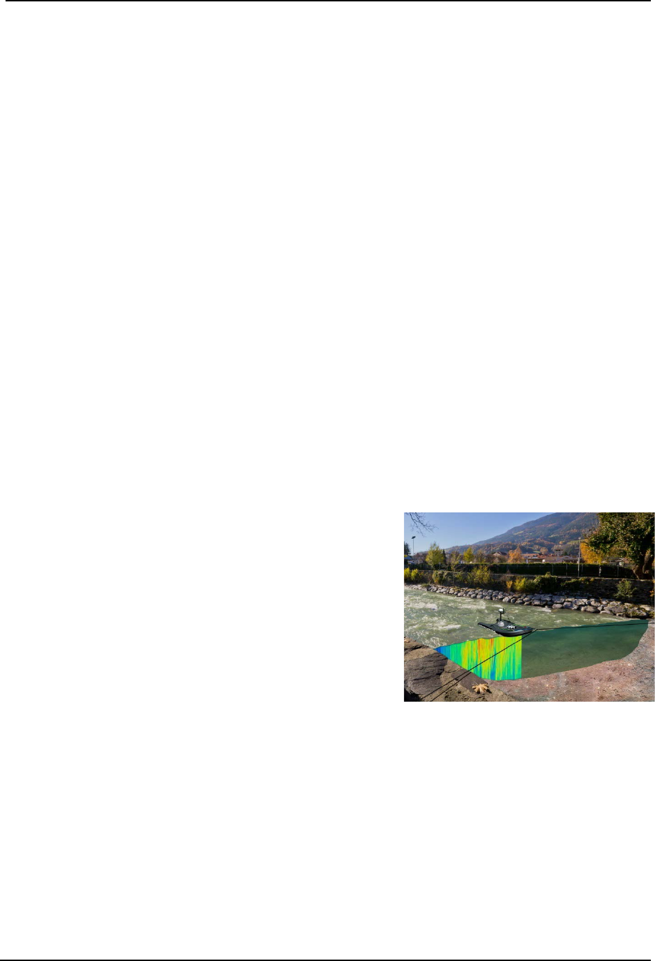
SonTek – a Xylem brand
FlowTracker2 User’s Manual (February 2016) 167
b) Contact office at scheduled times when staying overnight, e.g., 8am and or 4pm
every day. This allows the field personnel to give feedback on fieldwork and or
measurements, discussing additional work that need to be performed and verify
health and safety aspects,
c) Property owners such as farmers, local authority, etc. require persons to acquire
approval in advance before accessing their property. In certain cases it is also
required to contact the property owner when departing and this need to be verified
with the owner.
Measurement Site Conditions 11.6.3
Measurement site conditions encapsulate a number of hydraulic and physical factors that
determines if it is feasible to perform a discharge measurement. The application of the
FlowTracker2 instrument using the “wading” method is directly related to these
conditions. The following are some aspects that need to be taken into account before a
measurement is undertaken,
a) Total water depth,
b) Maximum water velocity,
c) Surface waves present,
d) Moving bed present(sediment or rocks)
e) Debris on water surface
f) Wild life (Alligators, Crocodiles, etc.)
If measurement site conditions are such that it is
unsafe to perform a wading measurement with a
FlowTracker2 instrument it is suggested that a
different approach is taken in determining the
discharge.
SonTek manufactures RiverSurveyor S5 and M9
instruments that are based on the Acoustic Doppler
Current Profiler principle. These instruments can be
used from multiple platforms such hydroboards,
manned boats or remote control boats in the following
discharge measurement methods,
i). Moving Boat Measurement,
ii). Stationary Measurement.
Figure 11:9 – RiverSurveyor M9
– Moving Boat Method
SonTek – a Xylem brand
FlowTracker2 User’s Manual (February 2016) 168
FlowTracker2 File Format Section 12.
12.1. FlowTracker2 JSON File
The FlowTracker2 measurement file was developed on the JSON format. The handheld
and desktop software uses the FlowTracker2 measurement files structure (see Table
4:2) as the primary format for the storage of system information, configuration, raw data,
calculations and post processing. The measurement files with .ft extension created from
the FlowTracker2 handheld can be directly imported into the FlowTracker2 desktop
software for evaluation and post processing if required.
The FlowTracker2 measurement file with .ft extension is essentially a ZIP file that
combines the different JSON files created during the measurement.
Changing the extension from .ft to .zip should not be performed on the original
FlowTracker2 measurement file. It is recommended that if this action is required a
duplicate copy of the measurement file is created. It is expected that this action is only
required by advanced users to extract the data in either a database or 3rd party
evaluation software.
The FlowTracker2 measurement file consists of three
different file types given below. The Beam Check and
Point measurement files are placed in sub folders to
separate from the main Data File.
a) Beam Check,
b) Point Measurements
c) Data File
Figure 12:1 - FlowTracker2
Measurement File
JSON file is created for each Beam Check and Point Measurement performed during the
FlowTracker2 measurement and stored in respective sub folders. The number of point
measurement files can be significant depending on the number of point velocity
measurement performed in Discharge or General Mode.
KISTERS developed an import script for the FlowTracker2 measurement file (JSON) for
both Hydstra and WISKI Time Series Data Management Systems. SonTek involved
KISTERS from the initial development stage of the measurement file structure to
ensure that the import of FlowTracker2 data is seaming less.
Further information on the JSON format can be accessed from the JSON website
(www.json.org/).
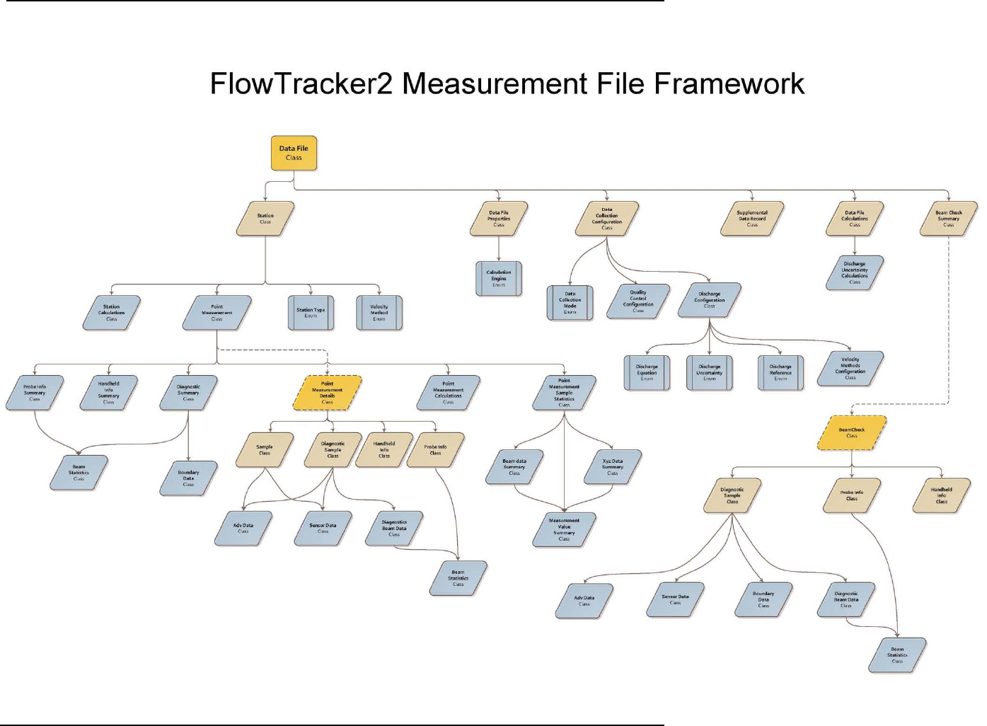
SonTek – a Xylem brand
FlowTracker2 User’s Manual (February 2016) 169
Measurement File Framework 12.1.1
SonTek – a Xylem brand
FlowTracker2 User’s Manual (February 2016) 170
Measurement File Structure 12.1.2
DataFile
Base Type Description
Main Tier
1st Tier
2nd Tier
3rd Tier
4th Tier
5th Tier
Properties: DataFileProperties
StartTime
DateTime
EndTime
DateTime
SiteNumber
String
SiteName
String
Operator
String
Comment
String
LocalTimeUtcOffset
TimeSpan
CalculationsEngine
CalculationsEngine
Configuration:
DataCollectionConfiguration
DataCollectionMode
DataCollectionMode
AveragingTime
TimeSpan
SamplingRate
Double
Salinity
Double
Temperature
Double
SoundSpeed
Double
MountingCorrection
Double
QualityControl:
QualityControlConfiguration
SnrThreshold
Double
StdErrorThreshold
Double
SpikeThreshold
Double
VelocityAngleForWarning
Double
TiltAngleForWarning
Double
Discharge:
DischargeConfiguration
(optional)
DischargeEquation
DischargeEquation
DischargeUncertainty
DischargeUncertainty
DischargeReference
DischargeReference
MaxStationDischargeForWarning
Double
MaxDepthChangeForWarning
Double
MaxSpacingChangeForWarning
Double
SixTenthsMethodDepth
Double
VelocityMethods:
VelocityMethodsConfiguration
TwoTenthsSixTenthsEightTe
nths
Boolean
Kreps
Boolean
FivePoint
Boolean
SixPoint
Boolean
VerticalVelocityCurve
Boolean
HandheldInfo: HandheldInfo
Stations: List<Station>
Id
Guid
CreationTime
DateTime
Gps
GpsRecord (optional)
Location
Double
LocationY
Double (optional)
Depth
Double
Depth2
Double (optional)
StationType
StationType
SonTek – a Xylem brand
FlowTracker2 User’s Manual (February 2016) 171
DataFile
Base Type Description
Main Tier
1st Tier
2nd Tier
3rd Tier
4th Tier
5th Tier
VelocityMethod
VelocityMethod
ManualVelocity
Double (optional)
IceThickness
Double (optional)
WaterSurfaceToBottomOfIce
Double (optional)
WaterSurfaceToBottomOfSlu
sh
Double (optional)
CorrectionFactor
Double
Comment
String
PointMeasurements:
List<PointMeasurement>(opti
onal)
Id
Guid
FractionalDepth
Double
DistanceFromBottom
Double
StartTime
DateTime
EndTime
DateTime
SampleStatistics:
PointMeasurementSampleStatisti
cs
OriginalVelocity:
XyzDataSummary
X:
MeasurementValueSummary
Min
Double
Max
Double
Average
Double
StandardDeviation
Double
Count
Int32
Y:
MeasurementValueSummary
Min
Double
Max
Double
Average
Double
StandardDeviation
Double
Count
Int32
Z:
MeasurementValueSummary
Min
Double
Max
Double
Average
Double
StandardDeviation
Double
Count
Int32
DespikedVelocity:
XyzDataSummary
X:
MeasurementValueSummary
Min
Double
Max
Double
Average
Double
StandardDeviation
Double
Count
Int32
Y:
MeasurementValueSummary
Min
Double
Max
Double
Average
Double
StandardDeviation
Double
Count
Int32
Z:
MeasurementValueSummary
Min
Double
Max
Double
Average
Double
StandardDeviation
Double
Count
Int32
Temperature:
MeasurementValueSummary
Min
Double
Max
Double

SonTek – a Xylem brand
FlowTracker2 User’s Manual (February 2016) 172
DataFile
Base Type Description
Main Tier
1st Tier
2nd Tier
3rd Tier
4th Tier
5th Tier
Average
Double
StandardDeviation
Double
Count
Int32
Pressure:
MeasurementValueSummary
Min
Double
Max
Double
Average
Double
StandardDeviation
Double
Count
Int32
BatteryVoltage:
MeasurementValueSummary
Min
Double
Max
Double
Average
Double
StandardDeviation
Double
Count
Int32
Tilt:
MeasurementValueSummary
Min
Double
Max
Double
Average
Double
StandardDeviation
Double
Count
Int32
Snr: BeamDataSummary
Beam0:
MeasurementValueSummary
Min
Double
Max
Double
Average
Double
StandardDeviation
Double
Count
Int32
Beam1:
MeasurementValueSummary
Min
Double
Max
Double
Average
Double
StandardDeviation
Double
Count
Int32
Beam2:
MeasurementValueSummary
Min
Double
Max
Double
Average
Double
StandardDeviation
Double
Count
Int32
Calculations:
PointMeasurementCalculations
Warnings
QualityControlWarnin
gs
Velocity
XyzData
VelocityStandardError
XyzData
FlowAngle
Double
Snr
BeamData
SnrStandardDeviation
BeamData
Samples
Int32
Spikes
Int32
Tilt
Double
BoundaryAvoidance
BoundaryAvoidanceS
tatus

SonTek – a Xylem brand
FlowTracker2 User’s Manual (February 2016) 173
DataFile
Base Type Description
Main Tier
1st Tier
2nd Tier
3rd Tier
4th Tier
5th Tier
Diagnostics:
DiagnosticsSummary
Boundary: BoundaryData
BoundaryRange
Double
VelocityAmbiguity
Double
VelocityResolution
Double
Beams: ReadOnlyCollection<
BeamStatistics>
NoiseLevel
Double
PeakLocation
Double
PeakLevel
Double
HandheldInfo:
HandheldInfoSummary
SoftwareVersion:
String
WadingRod
WadingRod
Units
UnitType
ProbeInfo: ProbeInfoSummary
SerialNumber
String
FirmwareVersion
String
NumberOfBeams
Int32
NominalBeamStatistics:
ReadOnlyCollection<BeamSt
atistics>
NoiseLevel
Double
PeakLocation
Double
PeakLevel
Double
Calculations:
StationCalculations
Warnings
QualityControlWarnin
gs
MeanVelocityInVertical
XyzData
MeanPanelVelocity
XyzData
Width
Double
Area
Double
Discharge
Double
FractionOfTotalDischarge
Double
Snr
BeamData
Temperature
Double
VelocityAngle
Double
BoundaryAvoidance
BoundaryAvoidanceS
tatus
Samples
Int32
Spikes
Int32
Tilt
Double
VelocityStandardError
XyzData
SupplementalDataRecord:
List<SupplementalDataRecord
> (optional)
Time
DateTime
GaugeHeight
Double
RatedDischarge
Double
Comment
String
Calculations:
DataFileCalculations
Warnings
QualityControlWarnin
gs
Area
Double
Discharge
Double
Width
Double
Velocity
XyzData
VelocityStandardError
XyzData
Depth
Double
Snr
Double
Temperature
Double

SonTek – a Xylem brand
FlowTracker2 User’s Manual (February 2016) 174
DataFile
Base Type Description
Main Tier
1st Tier
2nd Tier
3rd Tier
4th Tier
5th Tier
RatedDischarge
Double
GaugeHeight
Double
UncertaintyIso:
DischargeUncertaintyCalculat
ions
Accuracy
Double
Depth
Double
Velocity
Double
Width
Double
Method
Double
NumberOfStations
Double
Overall
Double
UncertaintyIve:
DischargeUncertaintyCalculat
ions
Accuracy
Double
Depth
Double
Velocity
Double
Width
Double
Method
Double
NumberOfStations
Double
Overall
Double
BeamChecks:
List<BeamCheckSummary>
Id
Guid
Time
DateTime
NumberofSamples
Int32
AutoQualityControlWarnings
QualityControlWarnin
gs
SonTek – a Xylem brand
FlowTracker2 User’s Manual (February 2016) 175
Point Measurement Details
Base Type Description
Main Tier
1st Tier
2nd Tier
3rd Tier
4th Tier
Id
Guid
SamplingRate
Double
Samples:
ReadOnlyCollection<Sample>
Time
DateTime
Adv: AdvData
Velocity
XyzData
Snr
Double
Sensors: SensorData
Temperature
Double
SoundSpeed
Double
Pressure
Double
Voltage
Double
Accelerometer
XyzData
Diagnostics:
DiagnosticsSample
Time
DateTime
Adv: AdvData
Velocity
XyzData
Snr
Double
Sensors: SensorData
Temperature
Double
SoundSpeed
Double
Pressure
Double
Voltage
Double
Accelerometer
XyzData
Boundary
BoundaryData
ProfileRange:
ReadOnlyCollection
Double
Beams:
ReadOnlyCollection<Diagnos
ticsBeamData>
Statistics: BeamStatistics
NoiseLevel
Double
PeakPosition
Double
PeakLevel
Double
Profile: ReadOnlyCollection
Double
DataCollectionConfiguration:
DataCollectionConfiguration
(optional)
HandheldInfo: HandheldInfo
SerialNumber
String
SoftwareVersion
String
BoardsInfo
String
CpuSerialNumber
String
OperatingSystem
String
Settings
Object (optional)
ProbeInfo: ProbeInfo
InstrumentType
String
SerialNumber
String
FirmwareVersion
String
NumberOfBeams
Int32
NominalBeamStatistics:
ReadOnlyCollection<BeamSt
atistics>
NoiseLevel
Double
PeakPosition
Double
PeakLevel
Double
RawConfiguration
Object (optional)
Spikes: ReadOnlyCollection
Int32

SonTek – a Xylem brand
FlowTracker2 User’s Manual (February 2016) 176
Beam Check
Base Type Description
Main Tier
1st Tier
2nd Tier
3rd Tier
4th Tier
Id
Guid
HandheldInfo: HandheldInfo
SerialNumber
String
SoftwareVersion
String
BoardsInfo
String
CpuSerialNumber
String
OperatingSystem
String
Settings
Object (optional)
ProbeInfo: ProbeInfo
InstrumentType
String
SerialNumber
String
FirmwareVersion
String
NumberOfBeams
Int32
NominalBeamStatistics:
ReadOnlyCollection<BeamSt
atistics>
NoiseLevel
Double
PeakPosition
Double
PeakLevel
Double
RawConfiguration
Object (optional)
Samples: ReadOnlyCollection<
DiagnosticSample>
Time
DateTime
Adv: AdvData
Velocity
XyzData
Snr
Double
Sensors: SensorData
Temperature
Double
SoundSpeed
Double
Pressure
Double
Voltage
Double
Accelerometer
XyzData
Boundary: BoundaryData
BoundaryRange
Double
VelocityAmbiguity
Double
MaxPingPrecision
Double
ProfileRange:
ReadOnlyCollection
Double
Beams:
ReadOnlyCollection<Diagnos
ticsBeamData>
Statistics: BeamStatistics
NoiseLevel
Double
PeakPosition
Double
PeakLevel
Double
Profile: ReadOnlyCollection
Double
AutoQualityControlWarnings
QualityControlWarnings

SonTek – a Xylem brand
FlowTracker2 User’s Manual (February 2016) 177
XyzData
Base Type Description
Main Tier
1st Tier
2nd Tier
3rd Tier
4th Tier
X
Double
Y
Double
Z
Double
BeamData
Base Type Description
Main Tier
1st Tier
2nd Tier
3rd Tier
4th Tier
Beam0
Double
Beam1
Double
Beam2
Double
GpsRecord
Base Type Description
Main Tier
1st Tier
2nd Tier
3rd Tier
4th Tier
DeviceTime
DateTime
SatelliteTime
TimeSpan
Latitude
Double
Longitude
Double
FixQuality
Int32
NumberOfSatellites
Int32
Hdop
Double
Altitude
Double
GeoidalSeparation
Double
SonTek – a Xylem brand
FlowTracker2 User’s Manual (February 2016) 178
12.2. FlowTracker2 CSV Output
Comma Separated Values (CSV) file format is a basic output designed for easy access
and interpretation of the data with the most common variables of FlowTracker2
incorporated.
The variables included in the CSV format are similar to Original FlowTracker2 ASCII
exports and existing users will be familiar with the layout and content.
CSV File Structure 12.2.1
The Comma Separated Values files created during the export process consists of four
CSV files, defined by unique file name that summarizes the content of the file as
described in Table 12:1.
Table 12:1 - CSV File Types
File
Name
Description
Data Layout
ctl
Control
System configuration data
Rows
dat Raw Data
Raw, one-second velocity and SNR
data
Columns
dis Discharge
Final data results in a self-
explanatory form that is easy to
integrate with database utilities
Rows,
Columns
sum Summary
Velocity and quality control data from
all measurements
Columns
The layout of the data in each of the CSV files is organized based on Rows, Columns or
a combination of both. The data descriptions for the Row or Column layout are defined
in Table 12:2.
The Desktop Software Build Version is written in the first row of each CSV file
independent if the file layout is based on Row or Columns. The units included for each
variable in the CSV files are separated from the file name and data.
Table 12:2 - CSV Row and Column
Type
Number
Description
Row \ Column
1st
Row contain Desktop Software Build version
Column
2nd
Row contain the variable \ parameter name
3rd
Row contain the units
4th
Row contain the first data line
Row
2nd
Column contain variable \ parameter name
3rd
Column contain the units
4th
Column contain X component or Beam 1
5th
Column contain Y component or Beam 2

SonTek – a Xylem brand
FlowTracker2 User’s Manual (February 2016) 179
CSV Variables 12.2.2
The Variables that are exported in each of the Comma Separated Values files are
defined in the following tables with the variable name, description and applicability to
either the Discharge or General Modes.
The Control file consists of all the system information for both the handheld and probe
and the quality control parameter settings based on either default or user configuration.
The variables exported in the control file are given in Table 12:3.
Table 12:3 - Control File Variables
Variable
Mode
Description
Desktop_Software_Build_Version
D, G
Version of desktop software
Number_Of_Stations
D, G
Station number
Start_Time
D, G
Start time of measurement
End_Time
D, G
End time of measurement
Local_Time_UTC_Offset_Hours
D, G
Local time offset for UTC in hours
Handheld_Serial_Number
D, G
Handheld serial number
Handheld_CPU_Serial_Number
D, G
Handheld CPU serial number
Handheld_Boards_Info
D, G
Handheld boards info
Handheld_Software_Version
D, G
Handheld software version
Handheld_Operating_System
D, G
Handheld operating system
Wading Rod
D
Type of wading rod
ADV_System_Frequency
D, G
ADV system frequency
ADV_Serial_Number
D, G
ADV serial number
ADV_Firmware_Version
D, G
ADV firmware version
ADV_Number_Of_Beams
D, G
ADV number of beams
ADV_Noise_Level
D, G
ADV noise level
ADV_Peak_Position
D, G
ADV peak position
ADV_Peak_Level
D, G
ADV peak level
Configuration_Data_Collection_Mode
D, G
Data collection mode
Configuration_Averaging_Time
D, G
Averaging time
Configuration_Sampling_Rate
D, G
Sampling rate
Configuration_Salinity
D, G
Salinity measured using external sensor
Configuration_Temperature
D, G
Temperature internal or external measured
Configuration_Sound_Speed
D, G
Sound Speed calculated or external measured
Configuration_Mounting_Correction
D, G
Mounting Correction in percentage
Configuration_Quality_Control_SNR_Thr
eshold D, G SNR Threshold for quality control process
Configuration_Quality_Control_Std_Error
_Threshold D, G Std Error Threshold for quality control process
Configuration_Quality_Control_Spike_Th
reshold
D, G Spike Threshold for quality control process
Configuration_Quality_Control_Velocity_
Angle_For_Warning
D, G Velocity Angle for quality control process
Configuration_Quality_Control_Tilt_Angl
e_For_Warning D, G Tilt Angle for quality control process
Configuration_Discharge_Equation
D
Discharge equation used for discharge calculation
SonTek – a Xylem brand
FlowTracker2 User’s Manual (February 2016) 180
Variable
Mode
Description
in measurement section
Configuration_Discharge_Reference D
Specify type of external discharge used to
reference discharge measurement
Configuration_Discharge_Quality_Contro
l_Max_Station_Discharge_For_Warning D Max station discharge for quality control process
Configuration_Discharge_Quality_Contro
l_Max_Depth_Change_For_Warning D Max depth change for quality control process
Configuration_Discharge_Quality_Contro
l_Max_Spacing_Change_For_Warning
D Max spacing change for quality control process
Configuration_Discharge_Velocity_Meth
ods D
Discharge velocity methods used in determining
mean velocity
The Raw Data file consists of the one second velocity, SNR and acceleration data with
date and time stamp. The variables exported in the raw data file are given in Table 12:4.
Table 12:4 - Raw Data File Variables
Variable
Mode
Description
#
D, G
Burst or measurements number
Year
D, G
Year
Month
D, G
Month
Day
D, G
Day
Hour
D, G
Hour
Minute
D, G
Minute
Second
D, G
Second
VelX
D, G
Raw 1 second X velocity
VelY
D, G
Raw 1 second Y velocity
VelZ
D, G
Raw 1 second Z velocity
SNR1
D, G
Signal-to-Noise Ratio beam 1
SNR2
D, G
Signal-to-Noise Ratio beam 2
SNR3
D, G
Signal-to-Noise Ratio beam 3
AccX
D, G
Raw 1 second X acceleration
AccY
D, G
Raw 1 second Y acceleration
AccZ
D, G
Raw 1 second Z acceleration
The Discharge file consists of system information, site details, quality control checks,
Beam Checks, uncertainty calculations, supplemental data and all station data related to
discharge measurement. The variables exported in the discharge file are given in Table
12:5.
Table 12:5 - Discharge File Variables
Variable
Mode
Description
Desktop_Software_Build_Version
D, G
Version of desktop software
Site_Name
D, G
Name of measurement site
Site_Number
D, G
Number of measurement site
Local_Start_Time
D, G
Local start time of measurement

SonTek – a Xylem brand
FlowTracker2 User’s Manual (February 2016) 181
Variable
Mode
Description
Local_End_Time
D, G
Local end time of measurement
Local_Time_UTC_Offset_Hours
D, G
Local time offset for UTC in hours
Operator
D, G
Operator
Handheld_Serial_Number
D, G
Serial number of handheld
Handheld_Software_Version
D, G
Software version of handheld
Wading Rod
D
Type of wading rod
Handheld_Units_System
D, G
Metric or English
Number_Of_Probes
D, G
Number of ADV used during measurement.
Software allows user to interchange ADV during
measurement
ADV_Serial_Number
D, G
Serial number of ADV
ADV_Firmware_Version
D, G
Firmware version of ADV
ADV_Number_Of_Beams
D, G
Number of beams
Comment
D, G
Comment entry field
Calculations_Engine
D, G
Calculation engine
Number_Of_Stations
D, G
Number of stations in a measurement
Discharge_Equation
D
Discharge equation used for calculation
Rated_Discharge
D
Rated flow based on measuring site stage
discharge relationship
Rated_Height
D
Gauge Height taken for water level reference
Minimum_Boundary_Status
D, G
Undefined or lowest of boundary conditions found
Total_Width
D
Total width of measurement section
Total_Area
D
Total area of measurement section
Total_Discharge
D
Total discharge of measurement
Mean_Depth
D, G
Average depth of the section
Mean_Velocity_Vx
D
The area-weighted panel velocity averaged over
the entire section for X velocity
G
Mean Vx is the mean of the X velocity of all point
velocity measurements.
Mean_Velocity_Vy
D
The area-weighted panel velocity averaged over
the entire section for Y velocity
G
Mean Vy is the mean of the Y velocity of all point
velocity measurements.
Mean_Velocity_Vz
D
The area-weighted panel velocity averaged over
the entire section for Z velocity
G
Mean Vz is the mean of the Z velocity of all point
velocity measurements.
Mean_SNR
D, G
Mean SNR of all point velocity measurements
Mean_VxErr
D
Mean Vx Standard Error of each station X velocity
standard error.
G
Mean Vx Standard Error is the mean of the X
velocity standard error of all point velocity
measurements.
Mean_VyErr
D
Mean Vy Standard Error of each station Y velocity
standard error.
G
Mean Vy Standard Error is the mean of the Y
velocity stand
ard error of all point velocity
SonTek – a Xylem brand
FlowTracker2 User’s Manual (February 2016) 182
Variable
Mode
Description
measurements.
Mean_VzErr
D
Mean Vz Standard Error of each station Z velocity
standard error.
G
Mean Vz Standard Error is the mean of the Z
velocity standard error of all point velocity
measurements.
Mean_Temp
D
Mean Temperature is the mean of all the station
temperature measurements
G
Mean Temperature of all point temperature
measurements
Quality_Control_Checks
D, G
Quality_Control_Checks
Station_Spacing D
Spacing between stations has changed by more
than Max Location Change
%.
Station_Order D
Station location out of sequence or outside river
edge.
Water_Depth
D, G
Station depth differs from adjacent stations by
more than Max Depth Change
%.
Boundary_Interference
D, G
Evaluates the measurement environment for
interference from underwater obstacles
Fractional_Depth
D
Verify ratio between measurement depth and
total depth and this should not >1
Low_SNR
D, G
Warning if SNR below 4dB
Approaching_Low_SNR
D, G
Warning if SNR between 4dB and 7 dB
Beam_SNRs_Not_Similar
D, G
Difference in SNR for any 2 beams is > SNR
Threshold
Large_SNR_Variation D, G
One-second SNR data varies more than expected
during a measurement along a single beam.
SNR_Threshold_Variation
D
SNR more than SNR Threshold different previous
measurements
Velocity_Standard_Error D, G
σV (standard error of velocity) is a direct measure
of the accuracy of velocity data.
Percent_Of_Spikes D, G
The percentage of spikes within a point velocity
measurement.
Velocity_Angle
D, G
The flow angle towards the ADV.
Rod_Angle
D, G
The angle of the wading rod from the vertical
Station_Discharge D
Station contains a large portion of the total
discharge.
End_Edge_Location
D
Station location out of sequence or outside river
edge.
Noise_Level D, G
Shows the electronics noise level for the receiver
of each beam
Peak_Location
D, G
The physical location of the sampling volume
Peak_Shape
D, G
The shape of the sampling volume
Pre_Calculation_Validation
D, G
Consistency check on station data (e.g. edges,
island edges, etc.)
Discharge_Uncertainty_ISO
D
Discharge_Uncertainty_ISO
Overall
D
Overall
Accuracy
D
Accuracy

SonTek – a Xylem brand
FlowTracker2 User’s Manual (February 2016) 183
Variable
Mode
Description
Depth
D
Depth
Velocity
D
Velocity
Width
D
Width
Method
D
Method
#_Stations
D
Number of Stations
Discharge_Uncertainty_IVE
D
Discharge_Uncertainty_IVE
Overall
D
Overall
Accuracy
D
Accuracy
Depth
D
Depth
Velocity
D
Velocity
Width
D
Width
Supplemental_Data
D
Supplemental_Data
Record_Number
D
Sequence number assigned to each data entry
Date_And_Time
D, G
Date and time when the supplement data was
recorded.
Gauge_Height (m)
D, G
Gauge height reading
Rated_Discharge (m³/s)
D, G
Rated flow based on stage discharge relationship
Comments
D, G
Comments regarding supplement data
Automated_BeamCheck
D, G
Automated_BeamCheck
Record_Number D, G
Sequence number assigned to each automated
beam check.
Date_And_Time
D, G
Date and time of automated beam check.
Noise_Level_Check D, G
Measured electronics noise level is compared to
reference data.
SNR_Check D, G
The SNR is checked as sufficient for reliable data
collection
Peak_Location_Check D, G
The physical location of the sampling volume is
compared to the expected location
Peak_Shape_Check
D, G
The shape of the sampling volume curve is
compared to the expected shape.
Station Data
D, G
Station Data
St
D, G
Station number
Clock
D, G
Measurement time from FlowTracker2 clock
GPSLat
D, G
GPS Latitude
GPSLon
D, G
GPS Longitude
Loc
D, G
Station location
LocY
D, G
Station location Y
FinalD
D, G
Mid and Mean Section methods, same as Depth.
Japanese method, average of Depth and Depth2
IceD
D, G
Ice thickness
WsIceD
D, G
Water surface to bottom of ice
WsSlushD
D, G
Water surface to bottom of slush
%Dep D, G
Measurement depth location, as fraction of
the effective depth
MeasD
D, G
Point measurement depth, measured form the
water surface
SonTek – a Xylem brand
FlowTracker2 User’s Manual (February 2016) 184
Variable
Mode
Description
Npts
D, G
Number of samples in measurement; one
sample collected per second
Spike
D, G
Number of spikes removed before calculating
mean values
VelX D, G
Mean X velocity component of point velocity
measurement
VelY D, G
Mean Y velocity component of point velocity
measurement
VelZ D, G
Mean Z velocity component of point velocity
measurement
Angle
D, G
Velocity angle calculated as atan (Vy/Vx)
VxErr
D, G
Standard error of X velocity
VyErr
D, G
Standard error of Y velocity
VzErr
D, G
Standard error of Z velocity
SNR1
D, G
Signal-to-Noise Ratio beam 1
SNR2
D, G
Signal-to-Noise Ratio beam 2
SNR3
D, G
Signal-to-Noise Ratio beam 3
Bnd
D, G
Boundary QC measurement
Temp
D, G
Water temperature
CorrFact
D, G
Correction factor used to scale mean station
velocity
Tilt D, G
Mean wading rod angle during point velocity
measurement
MeanV
D
Mean panel velocity based on panel discharge
and area.
G
Mean V is the mean of the X velocity of all point
velocity measurements.
Area
D
Station area
Flow
D
Station discharge
%Q
D
Percent of total discharge
The Summary file consists of the velocity method, velocity, SNR and standard error data
of each point velocity measurement. The variables exported in the summary file are
given in Table 12:6.
Table 12:6 - Summary File Variables
Variable
Mode
Description
Desktop_Software_Build_Version
D, G
Version of desktop software
#
D, G
Burst or measurements number
St
D, G
Station Number
Method
D, G
Discharge Measurement Method
%Dep
D, G
Measurement depth location, as fraction of
the effective depth
MeasD
D, G
Point measurement depth, measured form the
SonTek – a Xylem brand
FlowTracker2 User’s Manual (February 2016) 185
Variable
Mode
Description
water surface
Npts D, G
Number of samples in measurement; one
sample collected per second
Spike D, G
Number of spikes removed before calculating
mean values
CorrFact
D, G
Correction factor used to scale mean station
velocity
Loc
D, G
Station location
LocY
D, G
Station location Y
Depth1
D, G
Total Water Depth1
Depth2
D, G
Total Water Depth2
FinalD D, G
Mid and Mean Section methods, same as Depth.
Japanese method, average of Depth and Depth2
IceD
D, G
Ice thickness
WsIceD
D, G
Water surface to bottom of ice
WsSlushD
D, G
Water surface to bottom of slush
VelX D, G
Mean X velocity component of point velocity
measurement
VelY D, G
Mean Y velocity component of point velocity
measurement
VelZ D, G
Mean Z velocity component of point velocity
measurement
Angle
D, G
Velocity angle calculated as atan (Vy/Vx)
VxErr
D, G
Standard error of X velocity
VyErr
D, G
Standard error of Y velocity
VzErr
D, G
Standard error of Z velocity
SNR1
D, G
Signal-to-Noise Ratio beam 1
SNR2
D, G
Signal-to-Noise Ratio beam 2
SNR3
D, G
Signal-to-Noise Ratio beam 3
SNRStd1
D, G
Standard Deviation of Signal-to-Noise Ratio
beam 1
SNRStd2
D, G
Standard Deviation of Signal-to-Noise Ratio
beam 2
SNRStd3 D, G
Standard Deviation of Signal-to-Noise Ratio
beam 3
Temp
D, G
Water temperature
Batt
D, G
Battery Voltage
Tilt D, G
Mean wading rod angle during point velocity
measurement
SonTek – a Xylem brand
FlowTracker2 User’s Manual (February 2016) 186
12.3. Original FlowTracker ASCII vs JSON
Data File
Variable Comment
Next of Kin
Variable
Base Type
Properties: DataFileProperties
StartTime
DateTime
DIS.StartDateAndTime
EndTime
DateTime
last DAT.ymdhms, or other
SiteNumber
String
--
SiteName
String
DIS.SiteName
Operator
String
DIS.Operators
Comment
String
LocalTimeUtcOffset
TimeSpan
CalculationsEngine
CalculationsEngine
CalculationsEngine FlowTracker1
Configuration:
DataCollectionConfiguration
DataCollectionMode
DataCollectionMode
CTL.KeypadMode
AveragingTime
TimeSpan
CTL.SamplesPerBurst
SamplingRate
Double
CTL.SampleInterval
Salinity
Double
CTL.DefaultSalinity
Temperature
Double
CTL.DefaultTemperature, or NaN if
CTL.TemperatureMode is MEASURED
SoundSpeed
Double
CTL.DefaultSoundSpeed, or NaN if
CTL.TemperatureMode is MEASURED
MountingCorrection
Double
CTL.MountingCorrection
QualityControl:
QualityControlConfiguration
SnrThreshold
Double
--
StdErrorThreshold
Double
--
SpikeThreshold
Double
--
VelocityAngleForWarning
Double
--
TiltAngleForWarning
Double
--
Discharge: DischargeConfiguration
(optional)
DischargeEquation
DischargeEquation
DIS.DischargeEquation
DischargeUncertainty
DischargeUncertainty
--
Not exported (not useful)
DischargeReference
DischargeReference
DIS.Rated if any supplemental data recs, else
Measured
MaxStationDischargeForWarning
Double
--
MaxDepthChangeForWarning
Double
--
MaxSpacingChangeForWarning
Double
--
VelocityMethods:
VelocityMethodsConfiguration
TwoTenthsSixTenthsEightTenths
Boolean
--
Kreps
Boolean
--
FivePoint
Boolean
--
SixPoint
Boolean
--

SonTek – a Xylem brand
FlowTracker2 User’s Manual (February 2016) 187
Data File
Variable Comment
Next of Kin
Variable
Base Type
VerticalVelocityCurve
Boolean
--
HandheldInfo: HandheldInfo
--
Stations: List<Station>
Id
Guid
--
Not exported
CreationTime
DateTime
DIS.StartDateAndTime plus first DIS.Clock
Exported when no point measurements at this
station.
Gps
GpsRecord (optional)
--
Only GPS lat/lon exported
Location
Double
SUM.Loc (or DIS.Loc) (General mode: SUM.Loc1
or DIS.Loc1)
LocationY
Double (optional)
SUM.Loc2 or DIS.Loc2
Depth
Double
DIS.Depth or DIS.Depth1
Only final depth exported
Depth2
Double (optional)
DIS.Depth2
Only final depth exported
StationType
StationType
uses DIS.IceD, DIS.NPts, and DIS.Vel to decide
Not exported
VelocityMethod
VelocityMethod
Guessed from DIS.FractionalDepth and DIS.Vel
ManualVelocity
Double (optional)
Guessed from DIS.FractionalDepth and DIS.Vel
Not exported separately but can be inferred
IceThickness
Double (optional)
DIS.IceD
WaterSurfaceToBottomOfIce
Double (optional)
DIS.IceD
WaterSurfaceToBottomOfSlush
Double (optional)
--
CorrectionFactor
Double
DIS.CorrFact
Comment
String
--
Not exported
PointMeasurements:
List<PointMeasurement>>(optional)
Id
Guid
--
Not exported
FractionalDepth
Double
DIS.FractionalDepth
DistanceFromBottom
Double
DIS.MeasD
Distance from water surface exported
StartTime
DateTime
first DAT.ymdhms
EndTime
DateTime
last DAT.ymdhms
Not exported
OriginalVelocity:
X: MeasurementValueSummary
Min
Double
Calculated from DAT file samples
Not exported
Max
Double
Calculated from DAT file samples
Not exported
Average
Double
Calculated from DAT file samples
Not exported
StandardDeviation
Double
Calculated from DAT file samples
Not exported
Count
Int32
Calculated from DAT file samples
Not exported
StandardError
Double
Calculated from DAT file samples
Not exported
OriginalVelocity:
Y: MeasurementValueSummary
Min
Double
Calculated from DAT file samples
Not exported
Max
Double
Calculated from DAT file samples
Not exported
Average
Double
Calculated from DAT file samples
Not exported
StandardDeviation
Double
Calculated from DAT file samples
Not exported
Count
Int32
Calculated from DAT file samples
Not exported
StandardError
Double
Calculated from DAT file samples
Not exported
OriginalVelocity:
Z: MeasurementValueSummary
Min
Double
Calculated from DAT file samples
Not exported
Max
Double
Calculated from DAT file samples
Not exported

SonTek – a Xylem brand
FlowTracker2 User’s Manual (February 2016) 188
Data File
Variable Comment
Next of Kin
Variable
Base Type
Average
Double
Calculated from DAT file samples
Not exported
StandardDeviation
Double
Calculated from DAT file samples
Not exported
Count
Int32
Calculated from DAT file samples
Not exported
StandardError
Double
Calculated from DAT file samples
Not exported
DespikedVelocity:
X: MeasurementValueSummary
Min
Double
Calculated from DAT file samples
Not exported
Max
Double
Calculated from DAT file samples
Not exported
Average
Double
Calculated from DAT file samples
Export
StandardDeviation
Double
Calculated from DAT file samples
Not exported
Count
Int32
Calculated from DAT file samples
Not exported
StandardError
Double
Calculated from DAT file samples
Export
DespikedVelocity:
Y: MeasurementValueSummary
Min
Double
Calculated from DAT file samples
Not exported
Max
Double
Calculated from DAT file samples
Not exported
Average
Double
Calculated from DAT file samples
Export
StandardDeviation
Double
Calculated from DAT file samples
Not exported
Count
Int32
Calculated from DAT file samples
Not exported
StandardError
Double
Calculated from DAT file samples
Export
DespikedVelocity:
Z: MeasurementValueSummary
Min
Double
Calculated from DAT file samples
Not exported
Max
Double
Calculated from DAT file samples
Not exported
Average
Double
Calculated from DAT file samples
Export
StandardDeviation
Double
Calculated from DAT file samples
Not exported
Count
Int32
Calculated from DAT file samples
Not exported
StandardError
Double
Calculated from DAT file samples
Export
Temperature:
MeasurementValueSummary
Min
Double
Calculated from DAT file samples
Not exported
Max
Double
Calculated from DAT file samples
Not exported
Average
Double
Calculated from DAT file samples
Export
StandardDeviation
Double
Calculated from DAT file samples
Not exported
Count
Int32
Calculated from DAT file samples
Not exported
StandardError
Double
Calculated from DAT file samples
Not exported
Pressure:
MeasurementValueSummary
Min
Double
--
Not exported
Max
Double
--
Not exported
Average
Double
--
Not exported
StandardDeviation
Double
--
Not exported
Count
Int32
--
Not exported
StandardError
Double
--
Not exported
BatteryVoltage:
MeasurementValueSummary
Min
Double
Calculated from DAT file samples
Not exported
Max
Double
Calculated from DAT file samples
Not exported
Average
Double
Calculated from DAT file samples
Export
StandardDeviation
Double
Calculated from DAT file samples
Not exported
Count
Int32
Calculated from DAT file samples
Not exported

SonTek – a Xylem brand
FlowTracker2 User’s Manual (February 2016) 189
Data File
Variable Comment
Next of Kin
Variable
Base Type
StandardError
Double
Calculated from DAT file samples
Not exported
Tilt: MeasurementValueSummary
Min
Double
--
Not exported
Max
Double
--
Not exported
Average
Double
--
Export
StandardDeviation
Double
--
Not exported
Count
Int32
--
Not exported
StandardError
Double
--
Not exported
Beam0: MeasurementValueSummary
Min
Double
Calculated from DAT file samples
Not exported
Max
Double
Calculated from DAT file samples
Not exported
Average
Double
Calculated from DAT file samples
Export
StandardDeviation
Double
Calculated from DAT file samples
Export
Count
Int32
Calculated from DAT file samples
Not exported
StandardError
Double
Calculated from DAT file samples
Not exported
Beam1: MeasurementValueSummary
Min
Double
Calculated from DAT file samples
Not exported
Max
Double
Calculated from DAT file samples
Not exported
Average
Double
Calculated from DAT file samples
Export
StandardDeviation
Double
Calculated from DAT file samples
Export
Count
Int32
Calculated from DAT file samples
Not exported
StandardError
Double
Calculated from DAT file samples
Not exported
Beam2: MeasurementValueSummary
Min
Double
Calculated from DAT file samples
Not exported
Max
Double
Calculated from DAT file samples
Not exported
Average
Double
Calculated from DAT file samples
Export
StandardDeviation
Double
Calculated from DAT file samples
Export
Count
Int32
Calculated from DAT file samples
Not exported
StandardError
Double
Calculated from DAT file samples
Not exported
Calculations:
PointMeasurementCalculations
Warnings
QualityControlWarnings
--
Not exported
Velocity
XyzData
SUM.Vel (VelX, VelY, VelZ in General mode)
VelocityStandardError
XyzData
SUM.Verr (VxErr, VyErr, VzErr in General mode)
FlowAngle
Double
DIS.Angle
Snr
BeamData
SUM.Snr (Snr1, Snr2, Snr3 in General mode)
SnrStandardDeviation
BeamData
SUM.ASD1, ASD2, ASD3
Samples
Int32
DIS.NPts
Spikes
Int32
DIS.Spike
Tilt
Double
--
BoundaryAvoidance
BoundaryAvoidanceStatus
DIS.Bnd
Boundary: BoundaryData
BoundaryRange
Double
--
Not exported

SonTek – a Xylem brand
FlowTracker2 User’s Manual (February 2016) 190
Data File
Variable Comment
Next of Kin
Variable
Base Type
VelocityAmbiguity
Double
--
Not exported
VelocityResolution
Double
--
Not exported
Beams: ReadOnlyCollection<
BeamStatistics>
NoiseLevel
Double
--
PeakLocation
Double
--
PeakLevel
Double
--
HandheldInfo:
HandheldInfoSummary
SoftwareVersion:
String
DIS.SoftwareVer
Not exported (pmd value exported)
WadingRod
WadingRod
WadingRod.Unknown
Unknown is assigned, wading rod not defined
in FT1
Units
UnitType
DIS.UnitSystem
ProbeInfo: ProbeInfoSummary
SerialNumber
String
CTL.AdvSerialnumber
FirmwareVersion
String
CTL.CpuFirmwareVersion
NumberOfBeams
Int32
CTL.AdvNumberOfBeams
NominalBeamStatistics:
ReadOnlyCollection<BeamStatistics>
NoiseLevel
Double
--
PeakLocation
Double
--
PeakLevel
Double
--
Calculations: StationCalculations
Warnings
QualityControlWarnings
--
Not exported
MeanVelocityInVertical
XyzData
--
Not exported
MeanPanelVelocity
XyzData
DIS.MeanV
Only Vx is exported
Width
Double
--
Not exported
Area
Double
DIS.Area
Discharge
Double
DIS.Flow
FractionOfTotalDischarge
Double
DIS.%Q
Snr
BeamData
--
Not exported
Temperature
Double
--
Not exported
VelocityAngle
Double
--
Not exported
BoundaryAvoidance
BoundaryAvoidanceStatus
DIS.Bnd
Not exported
Samples
Int32
--
Not exported
Spikes
Int32
--
Not exported
Tilt
Double
--
Not exported
VelocityStandardError
XyzData
--
Not exported
SupplementalDataRecord:
List<SupplementalDataRecord> (optional)
Time
DateTime
record yyyy/MM/dd HH:mm:ss
GaugeHeight
Double
record GaugeHeigh
RatedDischarge
Double
record RatedDischarge
Comment
String
record Comment
Calculations: DataFileCalculations
Warnings
QualityControlWarnings
use the final DIS.BeamCheck as AutoQC, plus the
DIS.MeanBoundary as SmartQC
, plus FT2
SonTek – a Xylem brand
FlowTracker2 User’s Manual (February 2016) 191
Data File
Variable Comment
Next of Kin
Variable
Base Type
SmartQC.
Area
Double
DIS.TotalArea
Discharge
Double
DIS.TotalDischarge
Width
Double
DIS.TotalWidth
Velocity
XyzData
DIS.MeanVelocity (or DIS.MeanVelocityVx,
DIS.MeanVelocityVy in General Mode)
VelocityStandardError
XyzData
DIS.MeanVerr
Depth
Double
DIS.MeanDepth
Snr
Double
DIS.MeanSnr
Temperature
Double
DIS.MeanTemperature
RatedDischarge
Double
--
GaugeHeight
Double
--
UncertaintyIso:
DischargeUncertaintyCalculations
Accuracy
Double
DIS.UncertaintyIso.Accuracy
Depth
Double
DIS.UncertaintyIso.Depth
Velocity
Double
DIS.UncertaintyIso.Velocity
Width
Double
DIS.UncertaintyIso.Width
Method
Double
DIS.UncertaintyIso.Method
NumberOfStations
Double
DIS.UncertaintyIso.#_Stations
Overall
Double
DIS.UncertaintyIso.Overall
UncertaintyIve:
DischargeUncertaintyCalculations
Accuracy
Double
DIS.UncertaintyIve.Accuracy
Depth
Double
DIS.UncertaintyIve.Depth
Velocity
Double
DIS.UncertaintyIve.Velocity
Width
Double
DIS.UncertaintyIve.Width
Method
Double
DIS.UncertaintyIve.Method
Not exported (not in IVE)
NumberOfStations
Double
DIS.UncertaintyIve.#_Stations
Not exported (not in IVE)
Overall
Double
DIS.UncertaintyIve.Overall
BeamChecks:
List<BeamCheckSummary>
Id
Guid
--
Time
DateTime
DIS.BeamCheck
NumberofSamples
Int32
--
AutoQualityControlWarnings
QualityControlWarnings
DIS.BeamCheck
SonTek – a Xylem brand
FlowTracker2 User’s Manual (February 2016) 192
Point Measurement Details
Variable Comment
Next of Kin
Variable
Base Type
Id
Guid
--
Not exported
SamplingRate
Double
1.0/CTL.SampleInterval
Not exported
Samples:
ReadOnlyCollection<Sample>
Time
DateTime
DAT.ymdhms
Adv: AdvData
Velocity
XyzData
DAT.VelX, VelY, VelZ
Snr
Double
DAT.Snr1, Snr2, Snr3
Sensors: SensorData
Temperature
Double
SUM.Temp
Not exported
SoundSpeed
Double
--
Not exported
Pressure
Double
--
Not exported
Voltage
Double
SUM.Batt
Not exported
Accelerometer
XyzData
--
Diagnostics: DiagnosticsSample
Time
DateTime
--
Not exported
Adv: AdvData
Velocity
XyzData
--
Not exported
Snr
Double
Not exported
Sensors: SensorData
Temperature
Double
SUM.Temp
Not exported
SoundSpeed
Double
--
Not exported
Pressure
Double
--
Not exported
Voltage
Double
SUM.Batt
Not exported
Accelerometer
XyzData
--
Not exported
Diagnostics: DiagnosticsSample
Boundary
BoundaryData
--
Not exported
ProfileRange: ReadOnlyCollection
Double
--
Statistics: BeamStatistics
NoiseLevel
Double
--
Not exported
PeakPosition
Double
--
Not exported
PeakLevel
Double
--
Not exported
Beams:
ReadOnlyCollection<DiagnosticsBeamDa
ta>
Profile: ReadOnlyCollection
Double
--
Not exported
DataCollectionConfiguration:
DataCollectionConfiguration (optional)
--
HandheldInfo: HandheldInfo
SerialNumber
String
CTL.SerialNumber
SoftwareVersion
String
CTL.SoftwareVer
BoardsInfo
String
CTL.CpuBoardRev
Not exported
CpuSerialNumber
String
--
OperatingSystem
String
--
Settings
Object
--
Not exported
ProbeInfo: ProbeInfo
InstrumentType
String
CTL.AdvProbeType
Not exported
SonTek – a Xylem brand
FlowTracker2 User’s Manual (February 2016) 193
Point Measurement Details
Variable Comment
Next of Kin
Variable
Base Type
SerialNumber
String
CTL.AdvSerialNumber
Not exported
FirmwareVersion
String
CTL.CpuFirmwareVersion
Not exported
NumberOfBeams
Int32
CTL.AdvNumberOfBeams
Not exported
NominalBeamStatistics:
ReadOnlyCollection<BeamStatistic
s>
NoiseLevel
Double
--
Not exported
PeakPosition
Double
--
Not exported
PeakLevel
Double
--
Not exported
ProbeInfo: ProbeInfo
RawConfiguration
Object (optional)
--
Not exported
Spikes: ReadOnlyCollection
Int32
Set by FT2 de-spike
Not exported

SonTek – a Xylem brand
FlowTracker2 User’s Manual (February 2016) 194
Principle of Operations Section 13.
13.1. FlowTracker2 Overview
The FlowTracker2 Handheld ADV is a single-point Doppler current meter designed for
field velocity measurements. The FlowTracker2 uses the proven Doppler technology of
the SonTek Acoustic Doppler Velocimeter (ADV), the leading high-resolution velocity
sensor. ADV technology provides several advantages.
• Accurate velocity measurements in a remote sampling volume,
• 2D or 3D velocity measurements (depending on probe configuration),
• Invariant factory calibration, no periodic recalibration required,
• Rapid response time,
• Simple operation,
• Excellent performance for low and high flows – accuracy 1% of measured
velocity,
• Built-in temperature sensor.
The FlowTracker2 offers ADV performance from a simple handheld interface, allowing
rapid data collection without the use of a computer. Some common applications
include:
• River discharge measurements (using established methodology, including
USGS/ISO),
• Open-channel flow measurements,
• Current measurements in large pipes,
• Rapid, multi-point current surveys,
• Current monitoring in water treatment facilities.
13.2. The Doppler Shift
The FlowTracker2 uses a highly sophisticated form of this technique, which processes
underwater sound (sonar) reflected from particulate matter suspended in the water.
a) The Doppler principle says that if a source of sound is moving relative to the
receiver, the frequency of the sound at the receiver is shifted from the transmit
frequency.
= ×
where, Fdoppler = change in received frequency (Doppler shift),
Fsource = frequency of transmitted sound,
V = velocity of source relative to receiver,
C = speed of sound.

SonTek – a Xylem brand
FlowTracker2 User’s Manual (February 2016) 195
b) The velocity, V, represents the relative speed between source and receiver
(motion that changes the distance between the two).
i). If the distance between the two objects is decreasing, frequency increases.
ii). If the distance is increasing, frequency decreases.
iii). Motion perpendicular to the line connecting source and receiver does not
introduce a Doppler shift.
13.3. Bistatic Doppler Current Meters
Bistatic Doppler Operation 13.3.1
The FlowTracker2 is a Bistatic Doppler current meter with the 2D side looking probe
design and sampling volume shown in Figure 13:1.
a) Bistatic means separate acoustic transducers are used for transmitter and
receiver.
b) The transmitter generates sound concentrated in a narrow beam.
c) The receivers are sensitive to sound coming from a narrow beam.
d) The receivers are mounted such that the beams intersect at a volume of water
located a fixed distance (10 cm; 4 in) from the tip of the probe.
e) The beam intersection determines the location of the sampling volume (the
volume of water in which measurements are made).
The FlowTracker2 Measurement Principle 13.3.2
a) The transmitter generates a short pulse of sound at a known frequency.
b) The sound travels through the water along the transmitter beam axis.
c) As the pulse passes through the sampling volume, sound is reflected in all
directions by particulate matter (sediment, small organisms, bubbles).
d) Some portion of the reflected energy travels back along the receiver beam axes.
e) The reflected signal is sampled by the acoustic receivers.
f) The FlowTracker2 measures the change in frequency (Doppler shift) for each
receiver.
g) The Doppler shift is proportional to the velocity of the particles along the bistatic
axis of the receiver and transmitter. The bistatic axis is located halfway between
transmit and receive axes.
h) Knowing the relative orientation of the bistatic axes allows the FlowTracker2 to
calculate 2D or 3D water velocity.

SonTek – a Xylem brand
FlowTracker2 User’s Manual (February 2016) 196
Figure 13:1 - 2D Side Looking Probe and Sampling Volume
Signal to Noise Ratio Profile 13.3.3
The signal to noise ratio versus time profile plot for the FlowTracker2 is shown in Figure
13:2.
a) The horizontal axis shows time after the transmit pulse.
b) The vertical axis shows the return signal strength measured by one receiver.
c) As the transmit pulse travels through the water, sound is reflected in all
directions.
d) Immediately following the transmit pulse, reflections come from outside the
receiver beam. The receiver measures only the ambient noise level.
e) As the pulse propagates along the transmit axis, it moves closer to the receiver
beam. The receiver sees an increase in signal strength.
f) Signal strength reaches a maximum at the intersection of transmit and receive
beams.
g) By sampling the return signal at its peak, the FlowTracker2 makes
measurements in the sampling volume defined by the intersection of transmit and
receive beams.
SonTek – a Xylem brand
FlowTracker2 User’s Manual (February 2016) 197
Figure 13:2 - Signal to Noise Ratio Profile
13.4. Pulse-Coherent Processing
This section does not attempt to provide a detailed description of pulse-coherent
processing. It presents a simple overview with a focus on how this affects
FlowTracker2 operation. SonTek can provide additional information on request.
The description of FlowTracker2 operation given in Bistatic Doppler Current Meters is
an oversimplification.
• Bistatic Doppler Current Meters describes incoherent Doppler processing in
which the transducer sends a single pulse of sound and measures the frequency
change of the return signal.
• The FlowTracker2 uses a technique called pulse-coherent processing.
Pulse-coherent processing provides the best possible performance of any Doppler
processing technique. In the simplest terms, pulse-coherent processing works as
follows.
a) The FlowTracker2 sends two pulses of sound separated by a time lag (τ).
b) Each receiver measures the phase (φ) of the return signal from each pulse.
c) The change in phase (φ2 - φ1) divided by the time lag (τ) is proportional to
velocity.
d) Because of the nature of the phase measurement (which can only be determined
from -180° to +180°), the system has an inherent maximum velocity limitation.
e) The FlowTracker2 velocity algorithms have been optimized to give the best
possible performance over a wide velocity range of ±4.0 m/s (±13 ft/s).
f) FlowTracker2 processing provides unmatched results for low flows (<1 cm/s;
<0.03 ft/s).
FlowTracker2 processing has been designed to give the best possible performance in
all environments. However, there is a situation where system performance may be
affected by operating conditions.
Time after transmit pulse
Received signal strength
Center of
Receiver Axis
Ambient
Noise Level
SonTek – a Xylem brand
FlowTracker2 User’s Manual (February 2016) 198
• When working near boundaries or underwater obstacles, the system may need to
adapt its operation to avoid acoustic interference.
• This is called boundary adjustment and is performed automatically by the system
at each measurement location.
• The system reports a quality control parameter with each measurement location
that tells you if the environment has any effect on FlowTracker2 performance.
This quality control parameter is described in Boundary Interference.
13.5. Beam Geometry and 3D Velocity Measurements
A single transmit/receive pair measures the projection of the 3D water velocity onto the
bistatic axis.
a) The bistatic axis is halfway between transmit
and receive beam axes (see Figure 13:3).
b) The velocity measured by each receiver is
called the bistatic velocity.
c) The FlowTracker2 uses one transmitter and
two or three receivers (for 2D or 3D probes).
d) See Probe Configurations for other
FlowTracker2 probe configurations.
e) Receivers intersect with the transmit beam
pattern at a common sampling volume.
f) Bistatic velocities are converted to Cartesian
(XYZ) velocities using the probe geometry (the
relative angles of transmit and receive beams).
Cartesian velocities give the 2D or 3D velocity
relative of the FlowTracker2 probe.
g) During the manufacturing process, probe
geometry is precisely determined by a
calibration procedure.
h) This calibration only needs to be performed
once.
i) No periodic re-calibration is required.
Figure 13:3 - Bistatic Axis
13.6. Sampling Volume Definition
The FlowTracker2 sampling volume is defined based on the following criteria,
a) The sampling volume is nominally 10 cm (4 in) from the tip of the probe.
b) The exact location varies ±1.0 cm (±0.4 in) from probe to probe.
c) Precise sampling volume location is fixed for any given probe.

SonTek – a Xylem brand
FlowTracker2 User’s Manual (February 2016) 199
d) The physical size of the sampling volume is a cylinder 6 mm (0.24 in) in diameter
by 9mm (0.35 in) in length (see Figure 13:1).
13.7. Velocity Data Coordinate System
FlowTracker2 velocity measurements are reported using a right-hand Cartesian
coordinate system relative to the probe. The XYZ coordinate systems for each probe
type are shown below.
Figure 13:4 - FlowTracker2 Probe XYZ Coordinate System
2D Side-Looking Probe (Figure 30a) 13.7.1
a) The positive Z-axis is defined as vertically up in the direction of the probe’s stem.
b) The positive X-axis is defined perpendicular to both the probe’s stem and the
axis of the transmit transducer in the direction of receiver arm #1 (marked with a
red band).
c) The positive Y-axis is defined along the axis of the transmit transducer from the
transmitter towards the sampling volume (making a right-handed coordinate
system).
2D/3D Side-Looking Probe (Figure 30b) 13.7.2
a) The positive Z-axis is defined as vertically up in the direction of the probe’s stem.
b) The positive X-axis is defined perpendicular to both the probe’s stem and the
axis of the transmit transducer in the direction of receiver arm #1 (marked with a
red band).
c) The positive Y-axis is defined along the axis of the transmit transducer from the
transmitter towards the sampling volume (making a right-handed coordinate
system).
13.8. FlowTracker2 Data
Basic Sampling Strategy 13.8.1
The FlowTracker2 collects a burst of velocity data at each measurement location.

SonTek – a Xylem brand
FlowTracker2 User’s Manual (February 2016) 200
a) An individual measurement of the 2D or 3D velocity is referred to as a ping.
b) The FlowTracker2 pings 10 times per second, averaging these pings for a single
velocity sample.
c) Velocity data are recorded once per second during the averaging time.
d) The averaging time at each location is user-specified (10 to 1000 seconds).
e) The system collects a fixed-length time-series of velocity at each measurement
location.
f) You are prompted to enter location, depth, and other data at each measurement
location to document the data set.
g) Velocity data are collected at each measurement location over the user-specified
time. Raw one-second velocity, mean velocity, and quality control data are
recorded with each station.
h) For river discharge measurements, the FlowTracker2 combines velocity data with
station location, water depth, and other data to determine total discharge in real-
time.
When each measurement location is complete, you are presented with a summary of
the velocity and quality control data. All data are stored to the internal recorder for later
downloading to a computer for display, archiving, and further analysis.
Velocity Data 13.8.2
The FlowTracker2 provides several important performance advantages.
a) It can measure 2D or 3D water velocities from 0.0001 to 4.0 m/s (0.0003 to 13
ft/s).
b) Velocity data are accurate to 1% of the measured velocity in a one-second
sample.
c) Velocity data can be used immediately without any post processing corrections.
d) True 2D or 3D velocity data are output in Cartesian coordinates (XYZ) relative to
probe orientation.
e) The FlowTracker2 calibration will not change unless the probe is physically
damaged. No periodic calibration is required.
f) Diagnostic software is included to evaluate system performance periodically.
Accuracy of Velocity Data 13.8.3
Optimizing of FlowTracker2 13.8.3.1
The FlowTracker2 has been optimized to provide the best possible velocity data.
a) Velocity data are accurate to 1% of measured velocity for each one-second
sample.
b) Variations in velocity data are dominated by true variations in water velocity.
c) Instrument noise does not normally have an impact on velocity data.

SonTek – a Xylem brand
FlowTracker2 User’s Manual (February 2016) 201
d) The averaging time required to determine the true mean velocity at a given
location is a function of the real variations in velocity at that site.
Factors Influencing Accuracy 13.8.3.2
Two factors influence accuracy of FlowTracker2 velocity data – sound speed and probe
geometry.
a) The effect of sound speed is discussed in Sound Speed. With properly specified
salinity data, sound speed errors are negligible (less than 0.25%).
b) Probe geometry is calibrated at the factory for each FlowTracker; no recalibration
is required unless the probe has been physically damaged.
c) The FlowTracker2 calibration procedure is specified to ±1.0% of the measured
velocity.
d) There is no potential for zero offset or zero drift in velocity measurements. There
is no inherent minimum measurable velocity.
e) The FlowTracker2 is very well suited to low-flow applications to less than 1 cm/s
(0.03 ft/s).
Quality Control Data 13.8.4
In addition to velocity, the FlowTracker2 records quality control data with each
measurement station to quickly evaluate velocity data quality. The quality control
parameter details are discussed in Quality Control Parameters, Section 6, Quality
Control.
13.9. Special Considerations
Probe Configurations 13.9.1
Several FlowTracker2 probe configurations are available for different applications (see
Figure 13:4).
Probe mounting 13.9.1.1
a) The probe is mounted from a 1.500m (4.92ft) flexible cable. A 3.500m (11.5ft) or
8.500m (27.9ft) extension cable is available. However, it is not possible to
upgrade an existing system to a different cable length.
b) It is not advised to exceed an overall cable length of 10.000m (32.8ft).
c) The cable is custom built to reduce electronic noise. It should not be modified by
the user.
d) Take care to avoid damage to the cable, as this can affect system operation.
Probe type 13.9.1.2
a) Two probe types are available (see Figure 13:4).
SonTek – a Xylem brand
FlowTracker2 User’s Manual (February 2016) 202
b) The standard FlowTracker2 uses a 2D side-looking probe. The sampling volume
is located 10 cm (4 in) to the side of the probe, and can operate in as little as 2
cm (1 in) of water.
c) To work in both shallow and deeper water, a combination 2D/3D side-looking
probe is available. This has a sampling volume located 10 cm (4 in) to the side of
the probe, and can operate in as little as 2 cm (1 in) of water. It measures 2D
velocity in shallow water (with only two arms submerged), and 3D velocity in
deeper water (with all three arms submerged).
Figure 13:5 - FlowTracker2 Probe Configuration
13.10. Sound Speed
The FlowTracker2 uses sound speed to compute velocity from the measured Doppler
shift, and to precisely determine the location of the sampling volume.
Sound Speed Function 13.10.1
The speed of sound in water is primarily a function of temperature and salinity.
a) Temperatures change of 5°C (9°F) results in a sound speed change of ≈1%.
b) A salinity change of 12 results in a change in sound speed of ≈1%.
c) A 1% error in sound speed results in a ≈2% error in velocity data.
Compensate for Changes 13.10.2
To compensate for changing sound speed, the FlowTracker2 does the following.
a) The FlowTracker2 includes a temperature sensor for automatic sound speed
corrections. Resolution is ±0.01°C (±0.02°F).
b) A user-input value of salinity is used for sound speed calculations.
c) If accurate salinity data has been specified by the user (±2), sound speed
changes can be assumed to have no impact on velocity data.
Environmental Conditions 13.10.3
Doppler current meters, such as the FlowTracker2, do not measure movement of water,
but actually the movement of particles in the water,

SonTek – a Xylem brand
FlowTracker2 User’s Manual (February 2016) 203
• We must assume that the movement of the particles in the water is
representative of the movement of the water itself,
• If there are no particles (other than the water molecules themselves) present in
the water, Doppler current meters will not work. Natural streams almost always
have something else other than just “water” (even if just tiny air bubbles), and the
technology is such that even a small amount of particles in the water is usually
enough for good measurements.
Visual inspection is not an acceptable method for determining the amount of particles in
the water and no simple relationship exists with turbidity.
• We cannot say that for a given turbidity level your water is too clear for a
Doppler-based measurement.
• The amount of particles in the water is not the only factor affecting signal
amplitudes. Particle size, shape, distribution, and type also control these values,
and these conditions vary from site to site.
• Therefore, one stream may meet these conditions, but another with the same
turbidity may not.
If the site conditions seems unsuitable for FlowTracker2 measurement due to lack of
particles in the water it is recommended to perform an Automated Beam Check. If the
results are within the instrument specifications and quality control parameters user can
start with velocity measurements. The FlowTracker2 can return reliable measurements
down to about 3 dB (in SNR), although we recommend 10 dB and above for best
operating conditions.
13.11. Flow Interference
The FlowTracker measures velocity in a small sampling volume nominally located 10
cm (4 in) from the tip of the probe (see Sampling Volume Definition). The placement of
the sampling volume relative to other structures in the water must be considered when
measuring velocity to avoid flow interference.
Structures 13.11.1
a) The FlowTracker probe should be located away from any underwater structures
or obstacles, particularly those upstream.
b) Consider the size and location of nearby structures and obstacles, and the
probable magnitude and direction of flow, when choosing a measurement
location.
Probe orientation relative to flow 13.11.2
a) The FlowTracker should be oriented so the axis of the transmit transducer is
roughly perpendicular to the expected direction of flow (see Figure 13:6).
b) For side-looking probes (2D and 2D/3D), the probe should be oriented looking
across the expected direction of flow (so the X-axis aligns with the expected
flow).
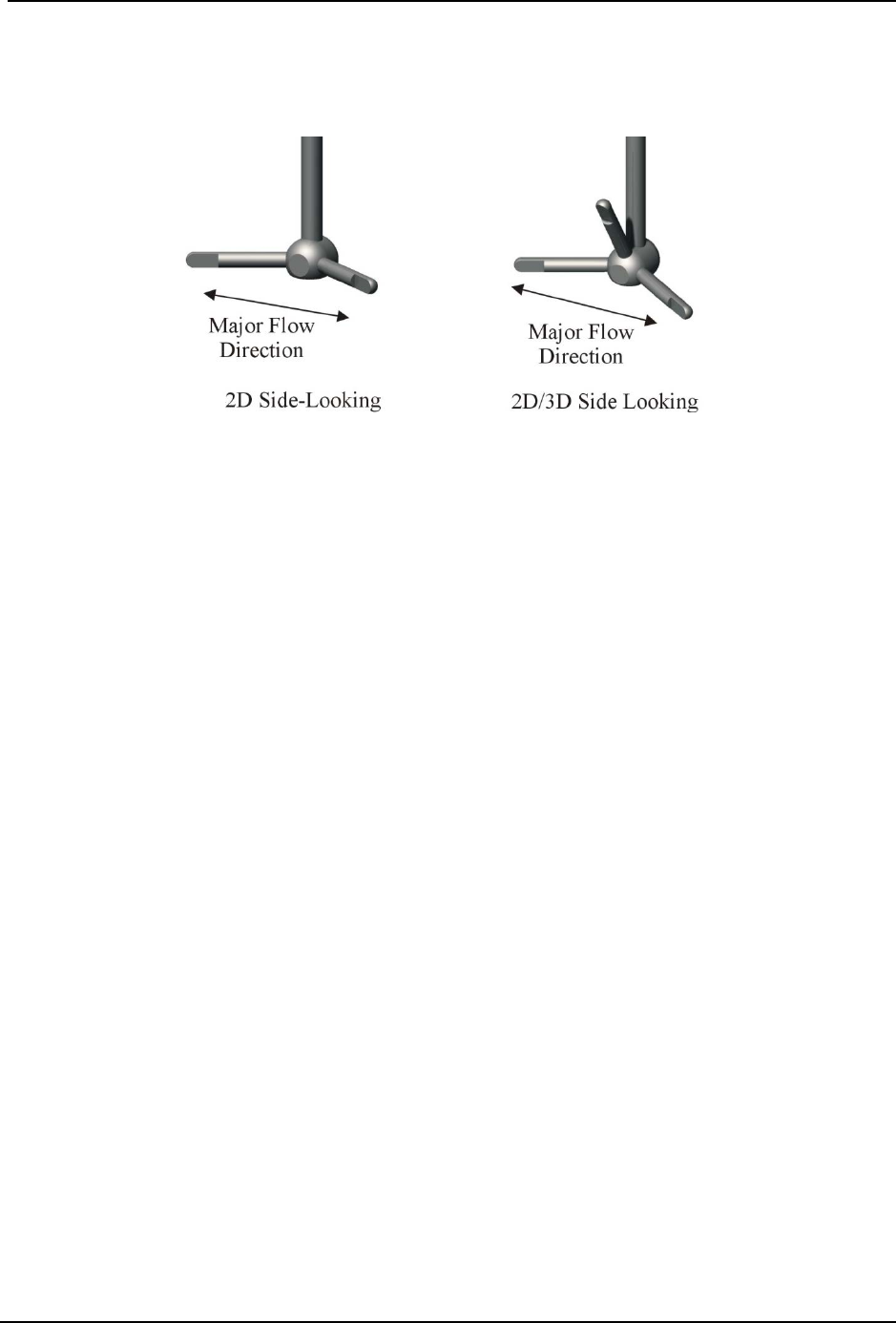
SonTek – a Xylem brand
FlowTracker2 User’s Manual (February 2016) 204
c) FlowTracker probes have been tested and have shown negligible flow
interference with the probe as much as 40-50° away from the preferred
alignment. At higher angles, the FlowTracker may see flow interference in the
sampling volume.
Figure 13:6 - Preferred Flow Direction to Avoid Flow Interference
Mounting Correction 13.11.3
Laboratory tow tank tests have indicated the FlowTracker2 probe and mount create flow
disturbance that may have a small impact (approximately 1.0%) on measured velocity
data. The mount is most commonly a top-setting wading rod using an S or J offset
bracket. Additional tests and modeling have looked at whether flowing water shows the
same flow disturbance effect seen in a tow tank (where the FlowTracker2 is towed
through a pool of stationary water).
By default, no correction for flow disturbance is applied to FlowTracker2 data. If you are
using a standard top-setting wading rod, and have decided to apply a correction,
SonTek typically recommends using a correction of 1.0%. For additional information
about the flow disturbance effect, contact SonTek directly.
To apply a flow disturbance correction, set the Mounting Correction from the Data
Collection Settings menu.
No Correction 13.11.3.1
• With the default setting of No Correction, the FlowTracker2 velocity data is used
directly without any correction for flow disturbance.
Custom Correction 13.11.3.2
• This is selected when you want to apply a correction to account for flow
disturbance from the FlowTracker mount. With this option, you must specify the
value of the Mounting Correction within the range -5% to +5%.
• When applied, the most common value for a standard top setting wading rod is
1.0%. A 1.0% correction means that measured velocity data is increased by 1.0%
to account for the effect of flow disturbance from the wading rod.

SonTek – a Xylem brand
FlowTracker2 User’s Manual (February 2016) 205
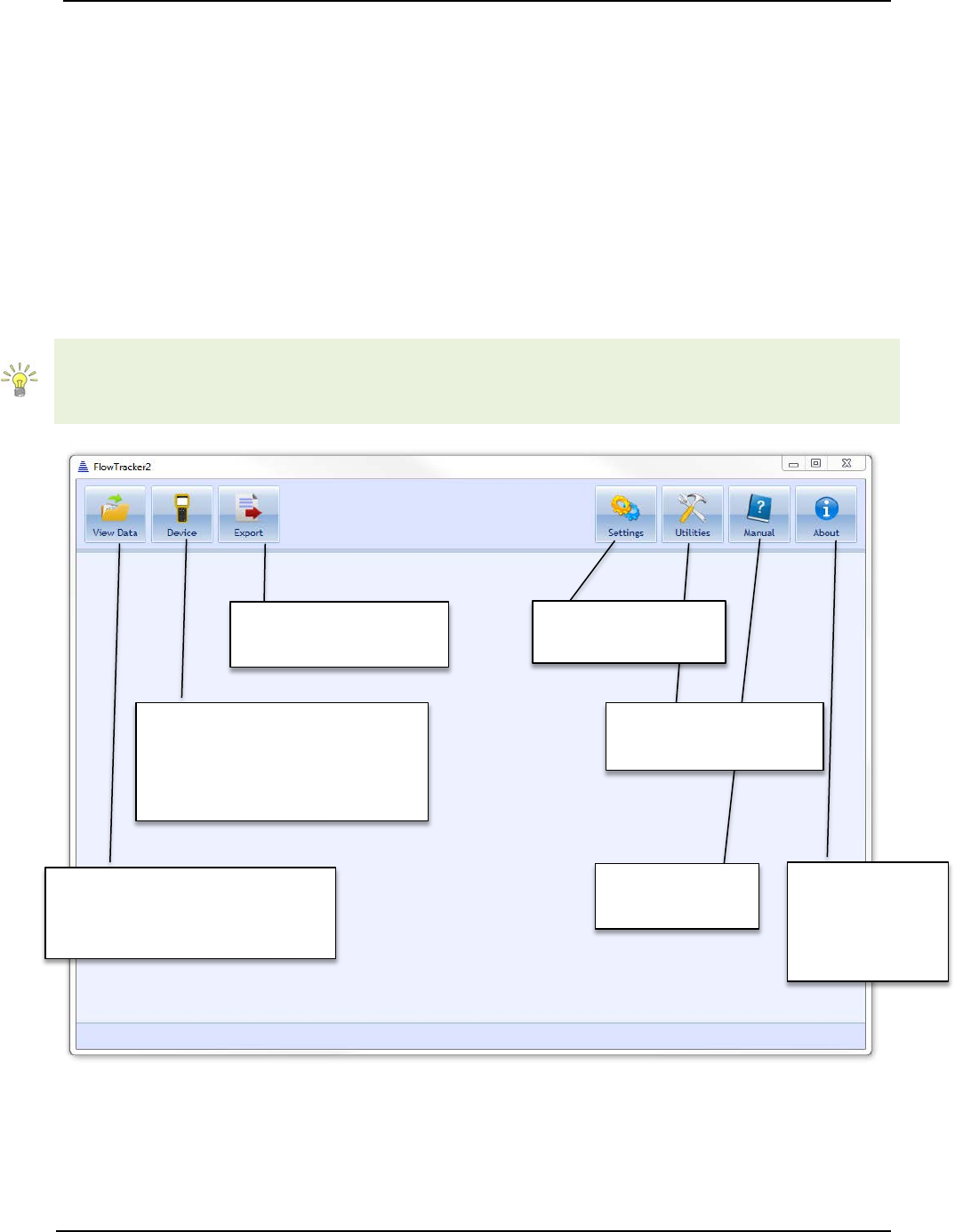
SonTek – a Xylem brand
FlowTracker2 User’s Manual (February 2016) 206
FlowTracker2 Desktop Software Section 14.
14.1. Overview of Software Features and Functions
The FlowTracker2 Desktop Software is designed to work in conjunction with the
FlowTracker2 Handheld ADV. With this software, you will be able to:
• View, post-process, and export FlowTracker Data,
• Connect to a FlowTracker Handheld ADV to download data and perform recorder
functions.
The layout of the FlowTracker2 Desktop Software upon startup is shown in Figure 14:1.
Each function and feature of the software will be addressed in the subsequent sections.
Specific software functions will have the sequence of buttons or tabs taken to reach that
function next to the function title (in blue italic font). This sequence will always start at the
startup page shown in Figure 14:1.
Figure 14:1 - Layout of FlowTracker2 Desktop Software upon startup
FlowTracker2
Manual
Export FlowTracker
data to ASCII
Connect to FlowTracker2
Handheld ADV to download
data and perform recorder
functions
View FlowTracker2 and
Original FlowTracker data,
Data post-processing
Software Utilities
(Run Translator)
About the
FlowTracker2
Desktop
Software
Change software
settings
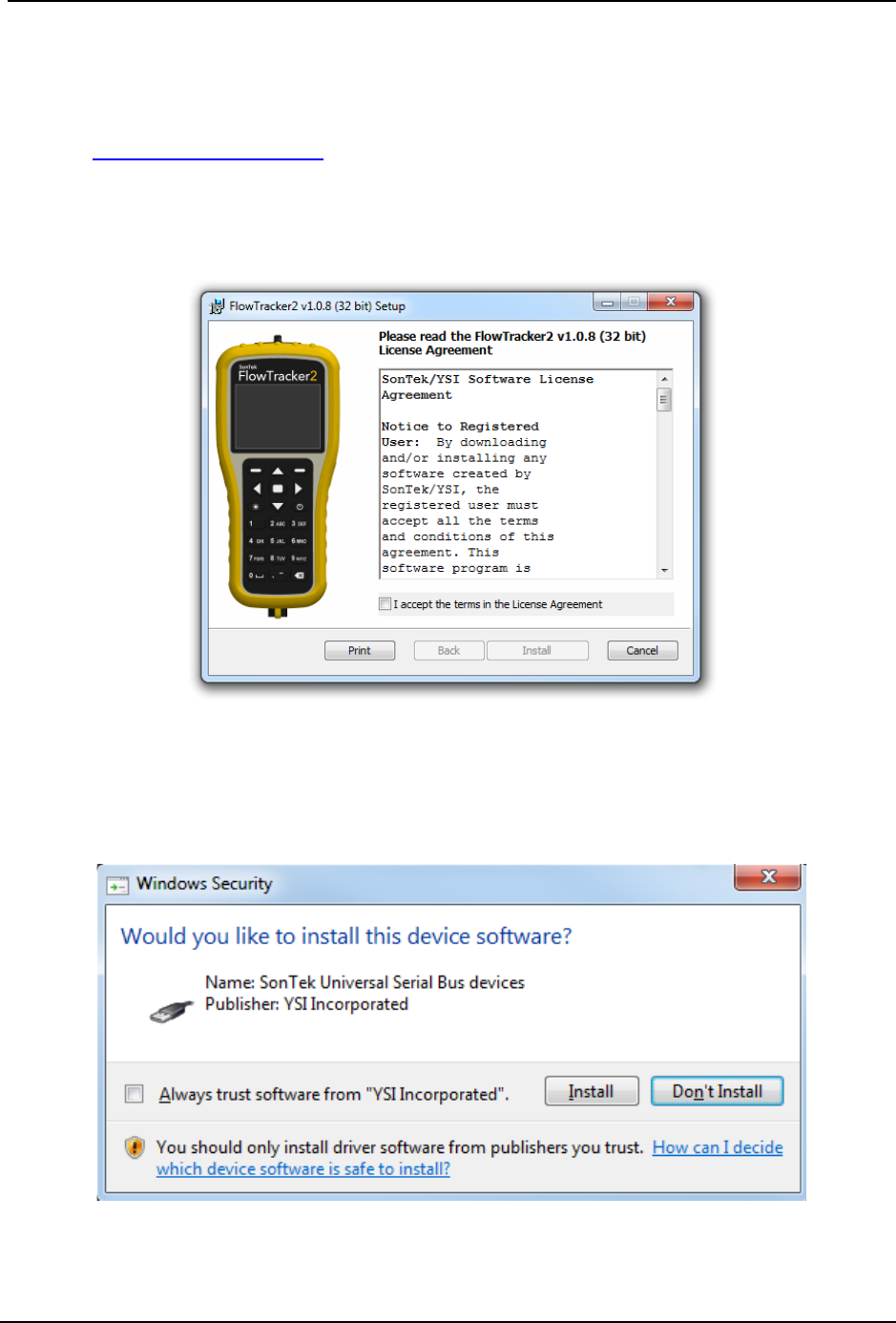
SonTek – a Xylem brand
FlowTracker2 User’s Manual (February 2016) 207
14.2. Installing Software
The FlowTracker2 Desktop Software installation file is included with the USB thumb drive
that ships with your FlowTracker2 Handheld ADV. It is also available from the SonTek
website (http://www.sontek.com). Run the Windows Installer Package (.msi) file
corresponding to the type of computer on which you wish to install the software (32-bit or
64-bit). Accept the terms in the License Agreement (shown in Figure 14:2) and click
Install.
Figure 14:2. Installation Dialog for FlowTracker2 Desktop Software
During the process, you will be prompted to install a driver with the message shown in
Figure 14:3. This driver must be installed in order to communicate with the
FlowTracker2 Handheld ADV.
Figure 14:3. Driver Installation

SonTek – a Xylem brand
FlowTracker2 User’s Manual (February 2016) 208
14.3. Changing Settings
The Settings button opens a dialog (shown in Figure 14:4) providing options to change
various software and user settings.
User Interface Tab 14.3.1
Figure 14:4. Changing User Interface Settings
Changing Language (Settings > User Interface > Language) 14.3.1.1
The software language can be changed through the User Interface tab in the Settings
dialog. The language choices include:
• Auto Detect (using your computer settings)
• Catalan
• Chinese (simplified and traditional)
• English
• French
• German
• Greek
• Italian
• Japanese
• Korean
• Portuguese
• Romanian
• Russian
• Spanish
• Custom
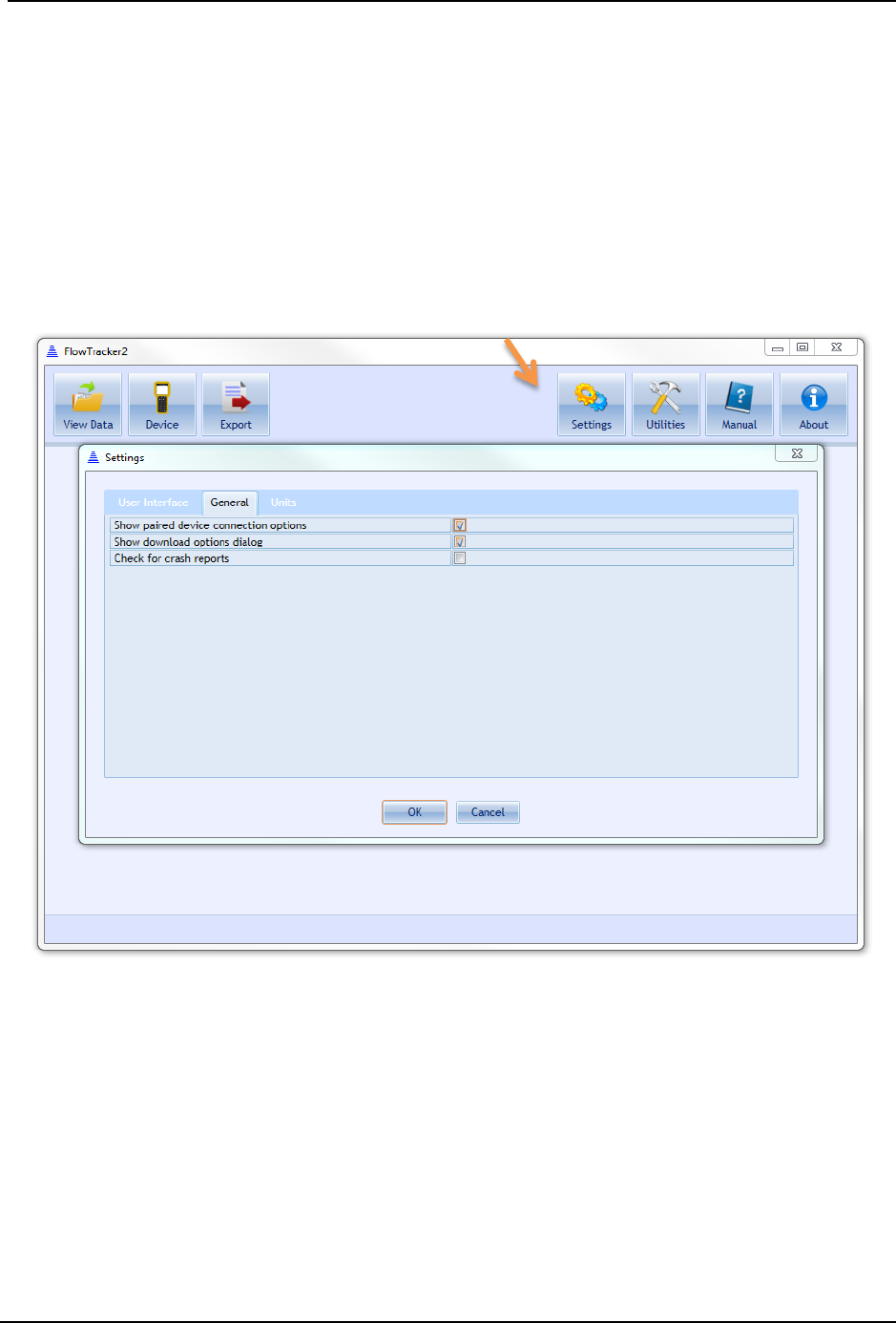
SonTek – a Xylem brand
FlowTracker2 User’s Manual (February 2016) 209
For languages not included in this list (Custom), different language tools are available.
These are described in detail in Run Translator.
Changing Scale and Font Size (Settings > User Interface > Scale) 14.3.1.2
The scale of all the text and buttons can be changed through the User Interface tab in
the Settings dialog. The font size and buttons can be increased up to 150% and
decreased down to 60%. The software will restart automatically to implement the
changes.
General Tab 14.3.2
Figure 14:5. Changing General Settings
Show paired device connection options (Settings > General > Show paired device 14.3.2.1
connection options)
Checking this box will provide more options during device communication using
Bluetooth. It allows you to select a COM port manually if you already have a Bluetooth
device paired. It is recommended that this box be left unchecked unless you are
contacting Technical Support and are troubleshooting Bluetooth connectivity issues.
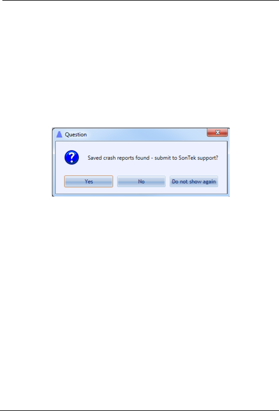
SonTek – a Xylem brand
FlowTracker2 User’s Manual (February 2016) 210
Show Download Options Dialog (Settings > General > Show download options 14.3.2.2
dialog)
When downloading data files from the FlowTracker2 Handheld ADV, a dialog with
various options appears by default. These options are described in Download Data
Files. This dialog can be enabled/disabled using this check box.
Check for Crash Reports and Send to SonTek Support (Settings > General > 14.3.2.3
Check for crash reports)
Crash reports are automatically generated by the FlowTracker2 software. If the Check
for crash reports option is toggled on, upon startup, the software will search for crash
reports. If crash reports are found, the dialog in Figure 14:6 will appear, prompting for
the option to send crash reports to SonTek Technical Support.
Figure 14:6. Crash report dialog
Toggling this option off will disable this prompt upon startup of the software. Clicking Do
not show again will uncheck the box in the General Settings tab.
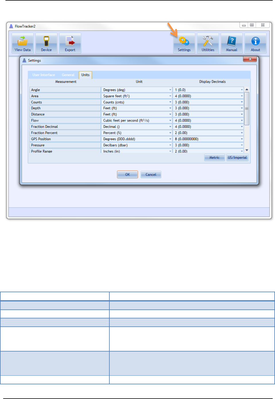
SonTek – a Xylem brand
FlowTracker2 User’s Manual (February 2016) 211
Units Tab 14.3.3
Figure 14:7. Changing Units
Changing Software Units (Settings > Units) 14.3.3.1
The units displayed by the software for various parameters can be changed
independently. Table 14:1 summarizes the changeable parameters and what unit
options are available.
Table 14:1- Units Available for Software Parameters
Measurement
Unit Options
Angle
Degrees (deg), Radians (rad)
Area
Square feet (ft2), Square meters (m2)
Counts
Counts (cnts)
Depth
Centimeters (cm), Fathoms (fms), Feet (ft), Inches
(in), Kilometers (km), Meters (m), Miles (miles),
Millimeters (mm), Yards (yd)
Distance
Centimeters (cm), Fathoms (fms), Feet (ft), Inches
(in), Kilometers (km), Meters (m), Miles (miles),
Millimeters (mm), Yards (yd)
Flow
Acre feet per day (acre ft/day), Acre feet per hour

SonTek – a Xylem brand
FlowTracker2 User’s Manual (February 2016) 212
Measurement
Unit Options
(acre ft/hour), Cubic feet per second (ft3/s), Cubic
meters per second (m3/s), Liters per second (L/s),
Megaliters per day (ML/day), Million UK gallons per
day (Million UK gallons/day), Million US gallons per
day (Million US gallons/day), UK gallons per minute
(UK gallons/min), US gallons per minute (US
gallons/min)
Fraction Decimal
Decimal (), Percent (%)
Fraction Percent
Decimal (), Percent (%)
Pressure
Bar (bar), Decibars (dbar), Feet of water (ft H
2
O),
Meters of water (m H2O), Pascal (Pa), Pound Force
per Square Inch (psi)
Salinity
Practical Salinity Scale (pss)
SNR
Decibels (dB)
Sound Speed
Centimeters per second (cm/s), Feet per second
(ft/s), Furlongs per fortnight (furlongs/fortnight),
Inches per second (in/s), Kilometers per hour
(km/h), Knots (kt), Meters per second (m/s), Miles
per hour (mph), Millimeters per second (mm/s),
Yards per second (yd/s)
Temperature
Celsius (oC), Fahrenheit (oF), Kelvin (oK)
Time Span
Seconds (s)
Voltage
Millivolts (mV), Volts (V)
Water Velocity
Centimeters per second (cm/s), Feet per second
(ft/s), Furlongs per fortnight (furlongs/fortnight),
Inches per second (in/s), Kilometers per hour
(km/h), Knots (kt), Meters per second (m/s), Miles
per hour (mph), Millimeters per second (mm/s),
Yards per second (yd/s)
To change units, click on the appropriate drop-down menu and select the unit desired.
There is an option on the lower right to change all relevant units to Metric or US/Imperial.
Click OK, and the software will automatically restart to apply the changes.
Changing Software Display Decimals (Settings > Units) 14.3.3.2
The number of decimals displayed by the software for various parameters can be
changed independently. Display decimals can be changed for all parameters listed in
Table 14:1. The display decimals range from 0 (0) to 9 (0.000000000). To change the
number of decimals displayed, click on the appropriate drop-down menu and select the
value desired. When display decimals are changed, the software will automatically
restart to apply those changes.
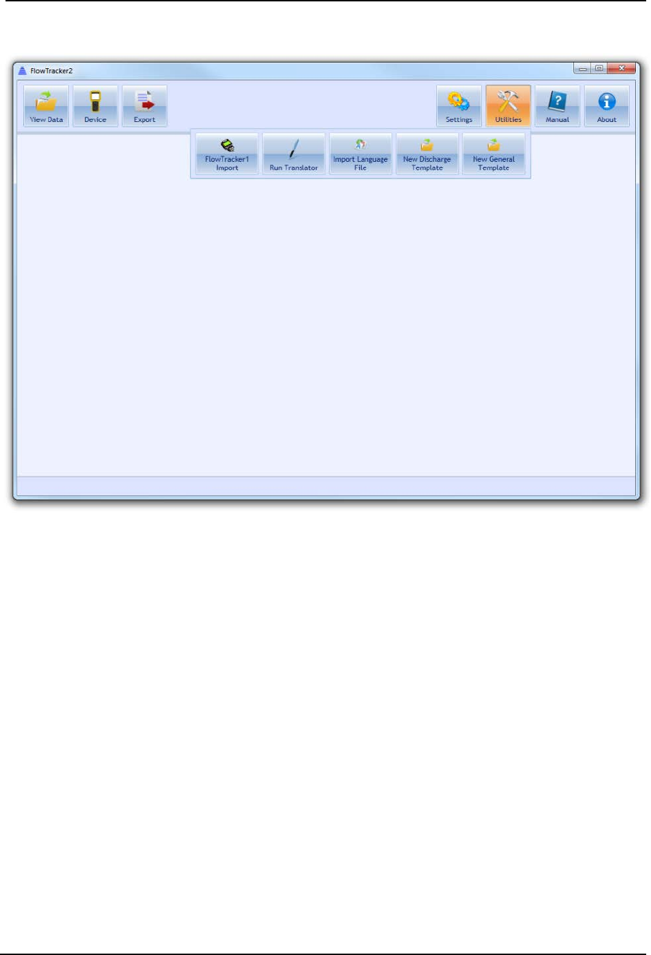
SonTek – a Xylem brand
FlowTracker2 User’s Manual (February 2016) 213
14.4. Utilities
Figure 14:8. Utilities Dialog
FlowTracker1 Import (Utilities > FlowTracker1 Import) 14.4.1
This is a conversion tool allowing users to open measurements taken by the Original
FlowTracker Handheld ADV instrument with the .wad extension. Please see Opening
Original FlowTracker Handheld ADV Data Files (.WAD files) for instructions on how to
use this feature.
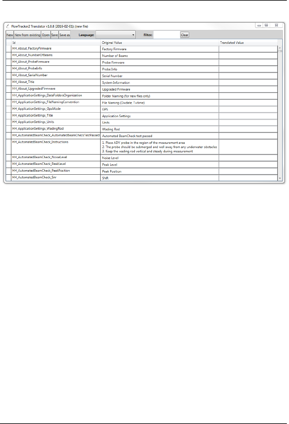
SonTek – a Xylem brand
FlowTracker2 User’s Manual (February 2016) 214
Run Translator (Utilities > Run Translator) 14.4.2
Figure 14:9 - Run Translator Dialog
The Run Translator Dialog (Figure 14:9) allows a user to customize a language
translation to suit specific purposes or to translate to a language not included in the
standard language list. An extensive list of variables used by the software appears under
the “Id” column, with its description or association in the “Original Value” column. The
user can enter their translated value into the “Translated Value” column. A “Filter”
function at the top of the dialog allows users to search for specific terms to be translated.
To save a translation file for future use, first pick a language from the drop-down menu at
the top. Then, click the “Save” or “Save As” button, and specify the name of the
language file you wish to create. A .lang file will be created in the directory of choice.
Import Language File (Utilities > Import Language File) 14.4.3
Once a .lang file is created (see previous section), this file can be applied to the software
using the Import Language File dialog. You will be prompted to open the .lang file that
you have created. The FlowTracker2 software will then restart to apply the changes
associated with the custom .lang file.
New Discharge Template (Utilities > New Discharge Template) 14.4.4
To create a new Discharge Template, press the New Discharge Template button under
the Utilities Menu. Choose a template name and destination for the template on your
computer. A new template with extension .ft_template will be created. To configure an
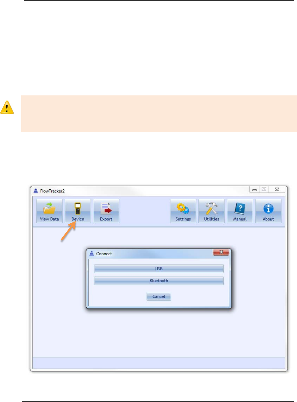
SonTek – a Xylem brand
FlowTracker2 User’s Manual (February 2016) 215
existing or new template upload to FlowTracker2 Handheld device, please refer to
Uploading and Downloading Templates.
New General Template (Utilities > New General Template) 14.4.5
To create a new General Template (template associated with General Mode
measurements), follow the same instructions in the previous section for creating a
Discharge Template.
14.5. Connecting to the FlowTracker2 Handheld ADV
The FlowTracker2 Desktop Software is designed to connect to the FlowTracker2
Handheld ADV only. User will not be able to use FlowTracker2 desktop software to
connect to an Original FlowTracker Handheld ADV. User will also not be able to use the
Original FlowTracker software or SonUtils to connect to the FlowTracker2.
The FlowTracker2 Handheld ADV can connect to your PC in two ways: using a direct
USB to micro-USB connection, or using your PC’s Bluetooth radio. To connect, click
on the Device button, shown in Figure 14:10. Instructions for each connection type
follow in the subsequent sections.
Figure 14:10. Connecting to FlowTracker2
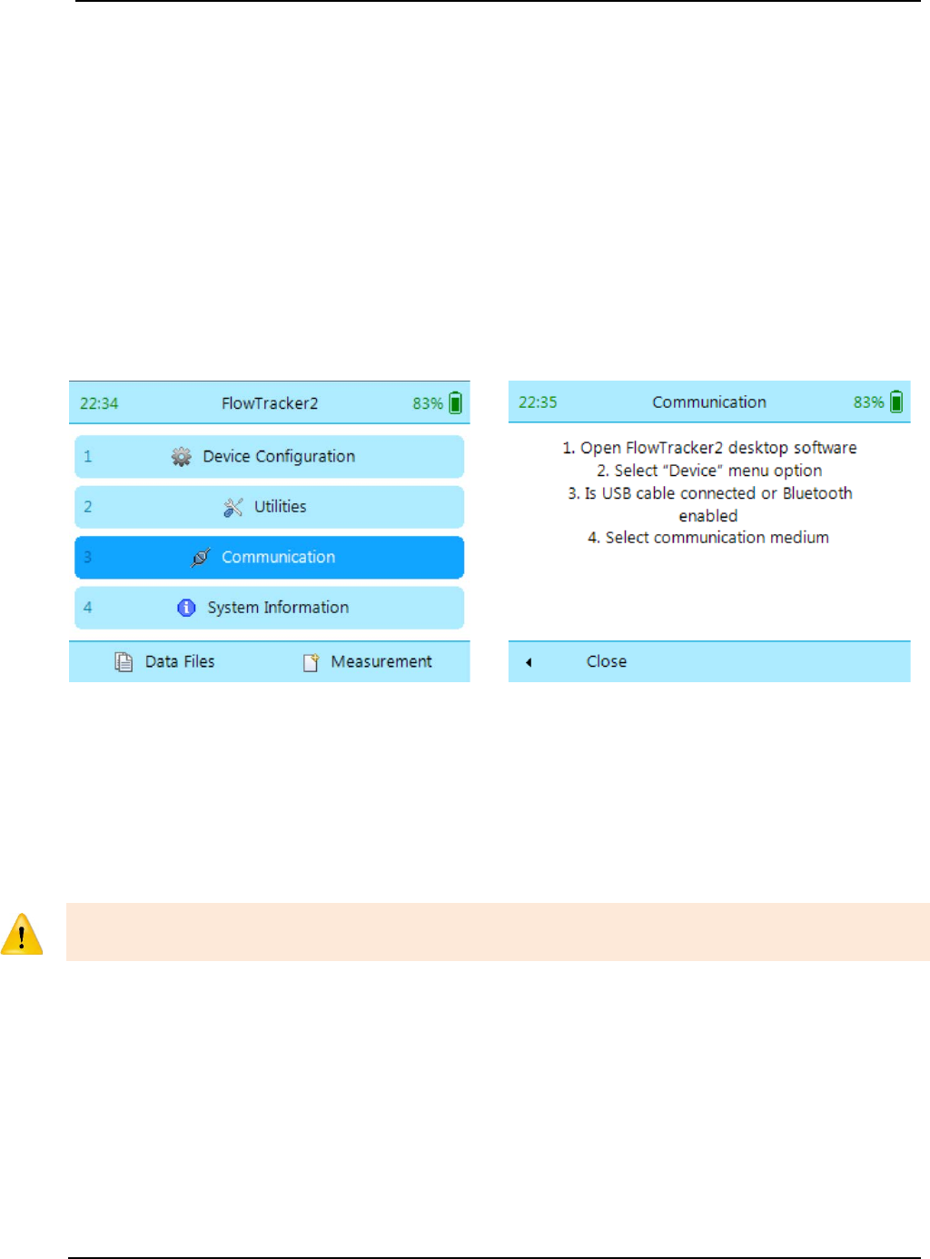
SonTek – a Xylem brand
FlowTracker2 User’s Manual (February 2016) 216
USB Connection (Device > USB) 14.5.1
To connect to the FlowTracker2 Handheld ADV using the USB to micro-USB
connection,
a) Plug the micro-USB connector to the communications connector at the bottom of
the Handheld unit (see Figure 1:1).
b) Plug the USB cable end into a USB port of your PC.
c) Ensure that you have the battery pack installed in the Handheld device with
sufficient battery power, and turn on your FlowTracker2.
d) From the main menu, navigate to the Communications button (Left panel of Figure
14:11) and click the Center Key. The FlowTracker2 will wait for a signal from the
PC, showing the screen in the right panel of Figure 14:11.
Figure 14:11. Communication dialog
e) From the FlowTracker2 Desktop Software, in the Device dialog, click the USB
button. The software will attempt to connect automatically with the FlowTracker2.
f) Once successfully connected, the FlowTracker2 data files will be listed, as shown
in Figure 14:13. The handheld will indicate that it is connected to your computer.
Bluetooth Connection 14.5.2
Do not use your Windows Bluetooth manager to pair the FlowTracker2 device to your
computer’s Bluetooth radio. The software will perform the pairing automatically.
To connect to the FlowTracker2 using Bluetooth,
a) Ensure that you have the battery pack installed in the Handheld device with
sufficient battery power, and turn on your FlowTracker2.
b) From the main menu, navigate to the Communications button (Left panel of Figure
14:11) and click the Center Key. The FlowTracker2 will wait for a signal from the
PC, showing the screen in the right panel of Figure 14:11.
c) Ensure that your computer Bluetooth radio (wireless communications) is turned
on.
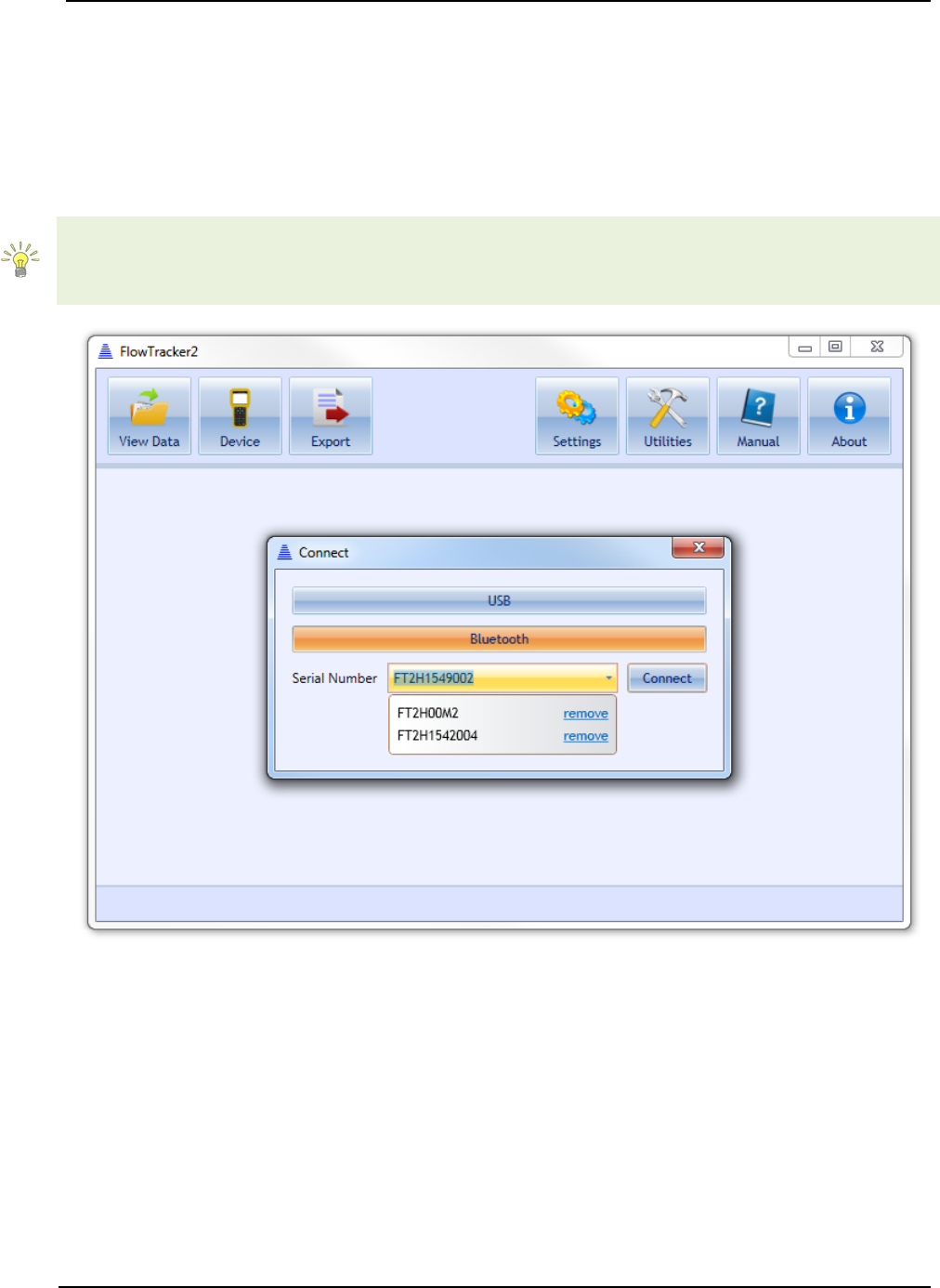
SonTek – a Xylem brand
FlowTracker2 User’s Manual (February 2016) 217
d) Enter the full serial number of your FlowTracker2 device in the Input box that
appears (see Figure 14:12).
e) Click the Connect button. A dialog will appear with updates on the Bluetooth
connection status.
f) Once successfully connected, the FlowTracker2 data files will be listed, as shown
in Figure 14:13. The handheld will indicate that it is connected to your computer.
The FlowTracker2 software will remember different devices after they are first connected
using Bluetooth. To remove a device, open the Serial Number drop-down menu and
click “remove.”
Figure 14:12. Bluetooth Connection Dialog
14.6. Device Menu and Functions
Once connected with the FlowTracker2, there are a number of functions available that
allow you to download data and interact with the handheld device. These functions are
indicated in Figure 14:13 and are described below.
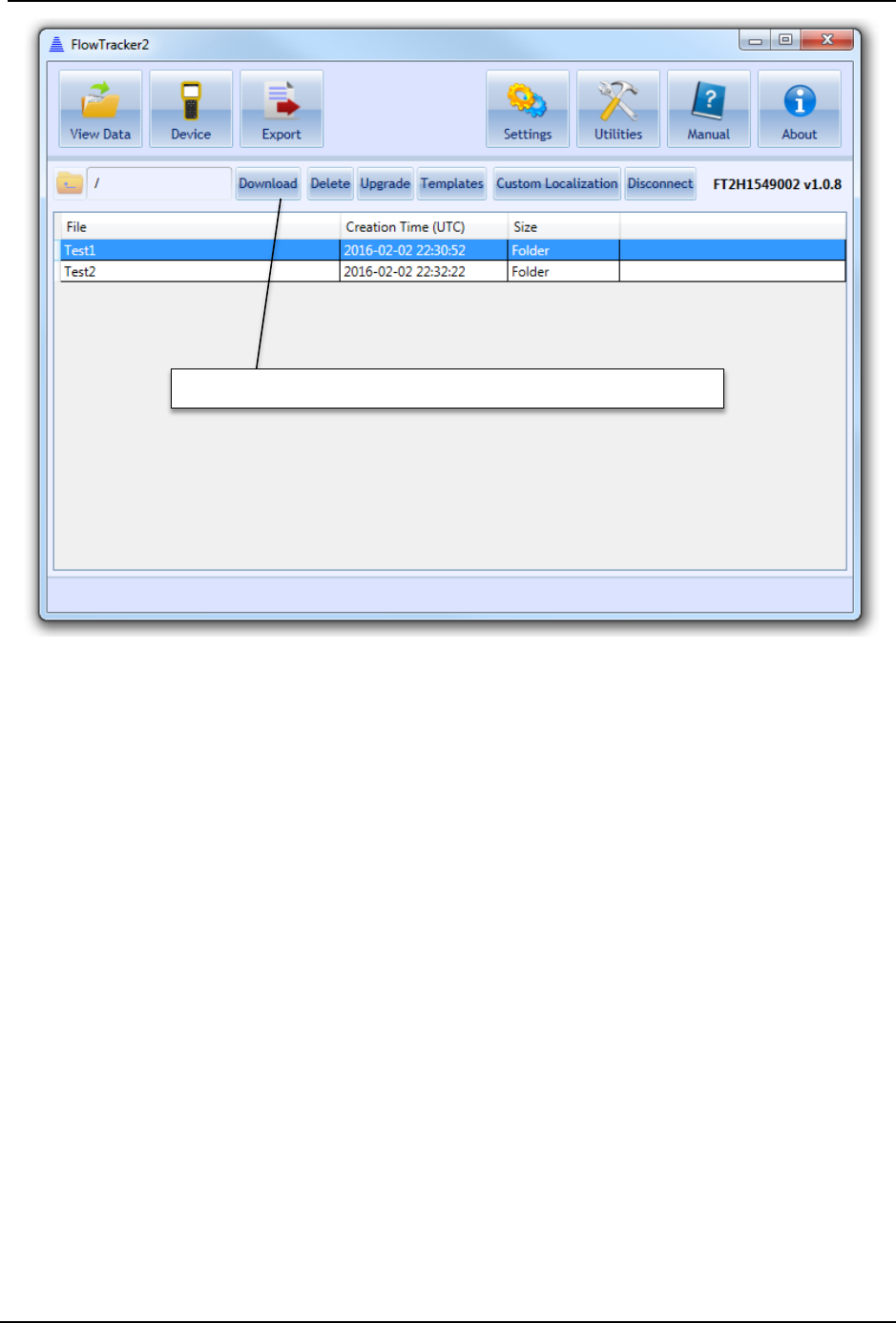
SonTek – a Xylem brand
FlowTracker2 User’s Manual (February 2016) 218
Figure 14:13. Device Menu after successful connection
Download Data Files (Device > [Choose your connection] > Download) 14.6.1
To download data files, you must click on a file or multiple files.
• To select a single file, click on that file.
• To select a range of files, hold the SHIFT key and select your files.
• To select multiple specific files, hold the CTRL key and select your files. You can
also de-select files using the CTRL key.
Once the files are selected, the Download button will be activated. Click the Download
button. The Download dialog, shown in Figure 14:14, will appear.
Function buttons when connected to FlowTracker2

SonTek – a Xylem brand
FlowTracker2 User’s Manual (February 2016) 219
Figure 14:14. Download Data dialog
a) The Download Location can be changed by clicking the folder button on the
right.
b) The Folder Organization option dictates with what type of folder structure data
files are stored:
i). Same as Device – Each data file will have its own folder with the same
naming convention as on the device.
ii). By Device Serial Number – files are stored in a folder indicated by the device
serial number.
iii). Single Folder – all files stored in single folder indicated by the Download
Location.
c) The File Name Conflict Resolution provides options when downloading a file from
the device with the same file name as one existing in the Download Location
directory. The choices are to:
i). Keep Both – both files placed in same folder and newest file will have name
with incrementally growing number extensions (i.e. “_2.ft”, “_3.ft”, etc.).
ii). Skip – skips downloading duplicate files.

SonTek – a Xylem brand
FlowTracker2 User’s Manual (February 2016) 220
iii). Overwrite – overwrites existing file on PC with newly downloaded file of same
name.
d) Checking the Remove Downloaded Files From Device box will delete any files
from the handheld recorder that have been downloaded onto the PC.
e) Checking the Do not show again box will save your downloading preferences,
and data will automatically be downloaded according to those preferences when
the Download button is pushed. To re-enable the dialog box, see Show
Download Options Dialog.
Delete Data files (Device > [Choose your connection] > Delete) 14.6.2
To delete data files from the handheld device, select the files to be removed. A prompt
will appear to confirm file deletion.
Upgrading FlowTracker2 Firmware (Device > [Choose your connection] > 14.6.3
Upgrade)
Periodic firmware updates will be released. The firmware files will be available from the
SonTek website (http://www.sontek.com) or by contacting SonTek Technical Support. If
you have upgraded your desktop software, but not your firmware, the software will notify
you that a firmware upgrade is available upon connection with the FlowTracker2 (shown
in Figure 14:15). The firmware file needs to first be downloaded and saved onto the
computer used to connect to the FlowTracker2. The Upgrade function will open a dialog
to select the FlowTracker2 firmware file. Select the appropriate file and click ‘Open’ –
the firmware upgrade will begin automatically. First, the firmware file will be uploaded to
the handheld device. Then, the handheld device will disconnect automatically from the
computer, and will perform the upgrade. When the upgrade is complete, the handheld
will restart automatically.
Occasional firmware upgrade files may or may not include an upgrade to the
FlowTracker2 probe firmware. Because the ADV probe has its own set of electronics, it
has its own firmware that may periodically need updating. When the Handheld firmware
is upgraded using the software, the probe firmware is not automatically performed until
the Handheld queries the probe. This means that when the probe is accessed (to take a
measurement, see its firmware version, perform a beam check, etc.), the probe firmware
will automatically be updated, and requires no additional steps by the user. The user will
see a pop-up on the Handheld software indicating that the probe firmware upgrade is
taking place.
Do not manually disconnect or turn off the device during a firmware upgrade process.
Doing so will interrupt the firmware upgrade and potentially cause serious corruptions on
the handheld device. It is recommended to use the USB direct connection when
upgrading firmware to avoid possible wireless connection interruptions.
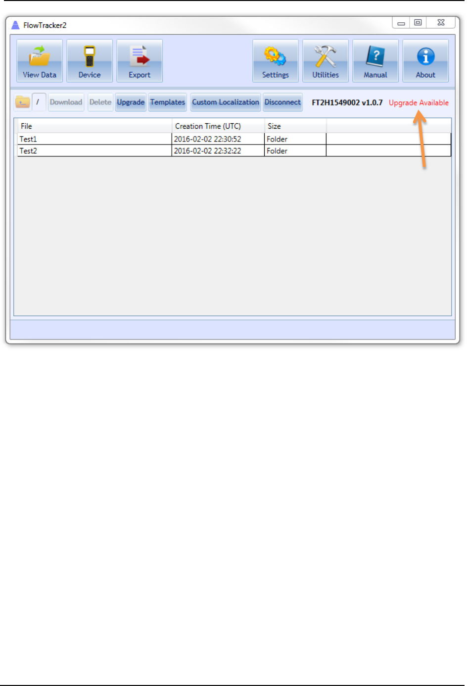
SonTek – a Xylem brand
FlowTracker2 User’s Manual (February 2016) 221
Figure 14:15. Firmware Upgrade Alert
Uploading and Downloading Templates (Device > [Choose your connection] > 14.6.4
Templates)
The ability to use templates is a new feature in the FlowTracker2 Handheld ADV
operation, allowing the user to easily store and load data that are applicable to multiple
measurements (such as site name, site number, operator, etc.). This feature allows
faster operation because the user will not need to input certain values for each
measurement. Please see Configuration Templates on how to create and manipulate
templates from the FlowTracker2 Handheld device.
To download an existing template from the FlowTracker2, click the Templates button
after connecting with a unit. The available templates stored on the device will appear.
Select the appropriate files, click Download to PC, and choose a destination on your
computer to save the files. The template files will be saved with the extension
.ft_template.
To upload an existing template from your computer to the FlowTracker2, click
Templates > Upload to Device, and select the appropriate .ft_template file. The template
file will be added to the list of templates on your device that appears.
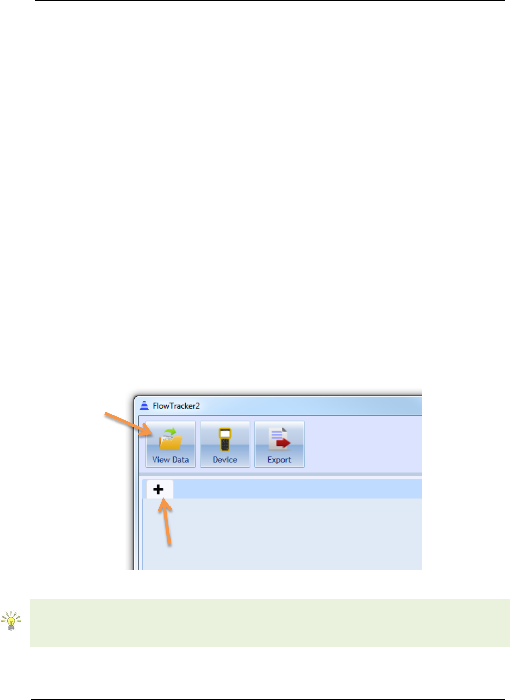
SonTek – a Xylem brand
FlowTracker2 User’s Manual (February 2016) 222
Templates can be either created on the Handheld device and modified on a computer, or
created through the desktop software and uploaded to the device. Please refer to New
Discharge Template for instructions on how to create a template file using the software.
Please refer to Opening FlowTracker2 Template Files (.ft_template) for instructions on
opening and editing template files.
Custom Localization 14.6.5
Custom Localization allows a user to import Language files onto the handheld device.
Please see Run Translator for instructions on creating a Language file (.lang).
Disconnecting the FlowTracker2 14.6.6
To disconnect the FlowTracker2 from the computer, click the Disconnect button.
14.7. Opening a Data File
To view FlowTracker data files, click the View Data button to turn View Data on. The
first time this button is clicked, a dialog will appear to select a file. To open more files,
click the ‘+’ tab shown in Figure 14:16. The Open File dialog (Figure 14:17) will appear.
The FlowTracker2 software is capable of opening the following file types:
• FlowTracker File (.ft)
• FlowTracker Beamcheck File (.ft_beamcheck)
• FlowTracker Template File (.ft_template)
.
Figure 14:16. + Tab to open additional data files
The FlowTracker2 Desktop software is capable of opening FlowTracker2 (.ft) files only.
In order to open files from the Original FlowTracker (.wad), please follow the steps
specifically for .wad files in subsequent sections.

SonTek – a Xylem brand
FlowTracker2 User’s Manual (February 2016) 223
Opening FlowTracker2 Handheld ADV Data Files (.ft files) 14.7.1
Figure 14:17. Open File Dialog.
The FlowTracker2 .ft file is the main data file that contains your Discharge or General
Mode measurement. To open a ft file from the Open File dialog, navigate to the
appropriate folder, select “All files” or “FlowTracker file” in the drop-down menu on the
lower right, select the appropriate .ft file to be opened from the list populated, and click
the Open button.
Sample data files are included with the USB that came with your FlowTracker2 package
and are located in the “FlowTracker2 Example Data” folder on the USB drive.
Opening FlowTracker2 BeamCheck Files (.ft_beamcheck) 14.7.2
During a measurement, the FlowTracker2 will save BeamCheck information within the .ft
file. The FlowTracker2 also has the option of recording a separate BeamCheck which
results in a .ft_beamcheck file.
The FlowTracker2 BeamCheck (.ft_beamcheck) file results from a user requesting a
BeamCheck to be done separately from a measurement. To open a .ft_beamcheck file,
follow the same instructions for opening a .ft file, but select “Beamcheck file
(*.ft_beamcheck)” in the drop-down menu, or select an appropriate .ft_beamcheck file
from the “All files” drop-down option.
Opening a Beamcheck file produces the screen shown in Figure 14:18. The time stamp
on the top of the file dialog corresponds to when the beam check was started, in local
time. Handheld information, probe information, beam check statistics, and quality control
warnings are displayed in the first row of panels. For each sample, Sample information
and statistics are displayed in the second row of panels. A plot of the SNR (dB) against
the distance from the ADV receiver is shown at the bottom. To toggle between samples,
press the “Previous sample” and “Next sample” buttons. “Show average” will show the
average SNR profile over all samples in the beam check file.
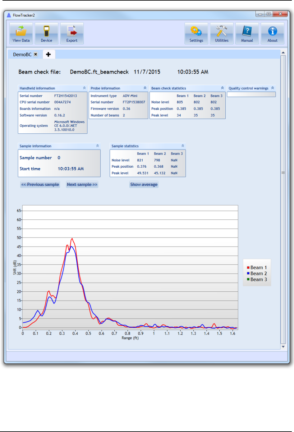
SonTek – a Xylem brand
FlowTracker2 User’s Manual (February 2016) 224
Figure 14:18. Viewing a Beamcheck File
Opening FlowTracker2 Template Files (.ft_template) 14.7.3
The FlowTracker2 software allows you to open and edit template files separately from
the Handheld unit. To open a template (.ft_template) file, follow the same instructions for
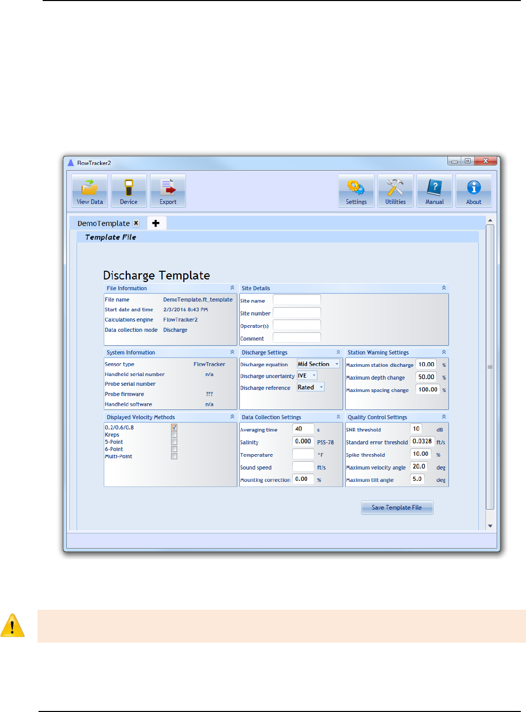
SonTek – a Xylem brand
FlowTracker2 User’s Manual (February 2016) 225
opening a .ft file, but select “FlowTracker template file (*.ft_template)” or select an
appropriate .ft_template file from the “All files” drop-down option.
When a Discharge template is opened, the screen shown in Figure 14:19 will appear.
Fields that can be edited will show input boxes. When a General Mode template is
opened, similar fields to the Discharge template will appear, with the exception that
Discharge Settings, Station Warning Settings, and Displayed Velocity Methods fields will
not be available. To save changes to the template, click the Save Template File button.
Figure 14:19 - Discharge Template
Opening Original FlowTracker Handheld ADV Data Files (.WAD files) 14.7.4
In order to open Original FlowTracker Handheld ADV Data Files (.wad), they must first
be converted to .ft files.
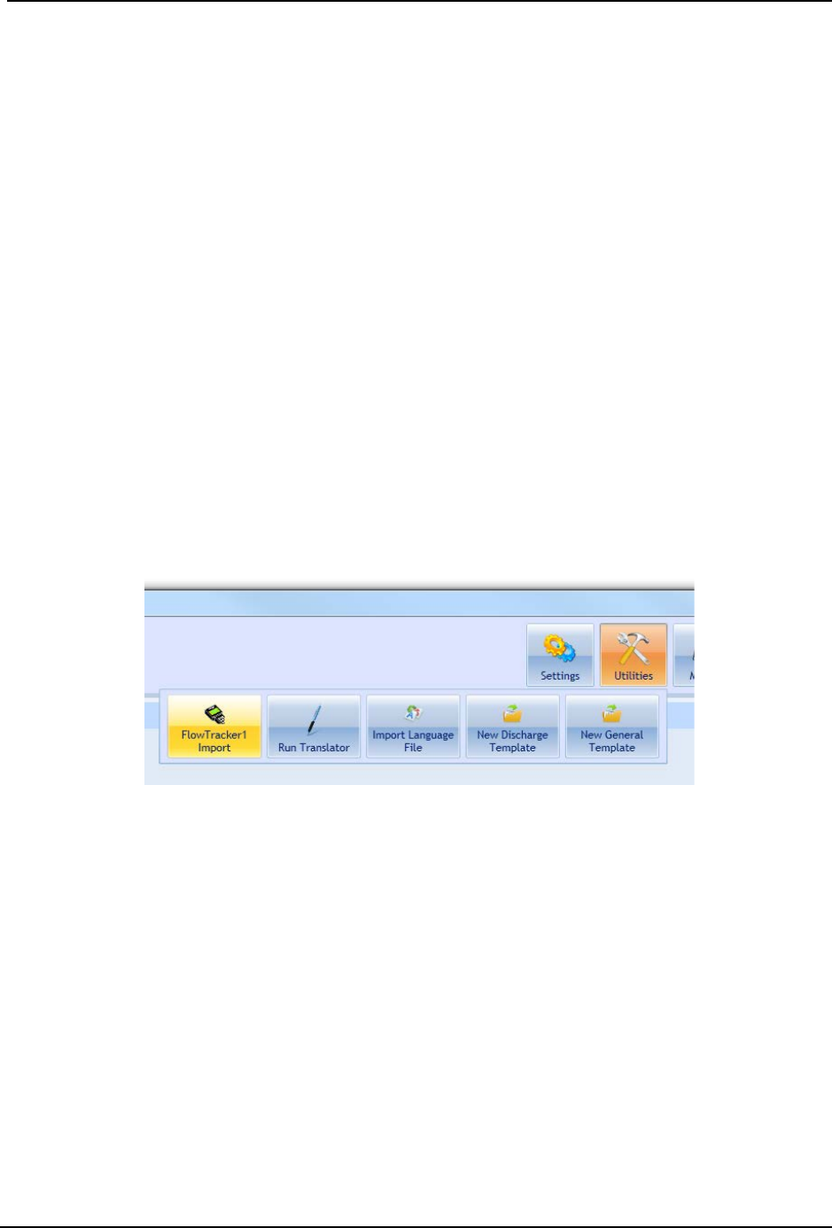
SonTek – a Xylem brand
FlowTracker2 User’s Manual (February 2016) 226
The FlowTracker2 software cannot open Original FlowTracker Handheld ADV data files
(.wad) directly. However, the software provides a tool to convert .wad files to the .ft that
can be opened using the software.
In order to use the tool, the ASCII exports associated with the .wad file must be present
in the same folder as the .wad file. The four (4) ASCII files with the following file
extensions must all be present:
• .DIS
• .SUM
• .CTL
• .DAT
These data files are exported using the Original FlowTracker desktop software. Please
refer to the manual for the Original FlowTracker for instructions on how to export these
ASCII files.
Once the ASCII files associated with the .wad file are created and are in the same folder
as the .wad file, the converter tool can be used. To access the converter, click Utilities
> FlowTracker1 Import, shown in Figure 14:20.
Figure 14:20. Original FlowTracker .wad File Conversion Tool
You will have two options: Import File or Import Folder.
• Import File – Select the .wad file you would like to convert. The ASCII exports
must be associated with this file, or you will receive an error message during the
data import. The resulting file converted will have the same file name, but the
.wad extension will be replaced with .FlowTracker1.ft.
• Import Folder – Select the folder containing multiple .wad files you would like to
convert. The tool will look within subfolders recursively to convert all .wad files
with associated ASCII exports. If the ASCII exports do not exist in the same
folder(s) as the .wad files, an error message will appear. The resulting files
converted will have the same file name, but the .wad extension will be replaced
with .FlowTracker1.ft.
You can then open the .FlowTracker1.ft file the same way you would open a regular .ft
file.
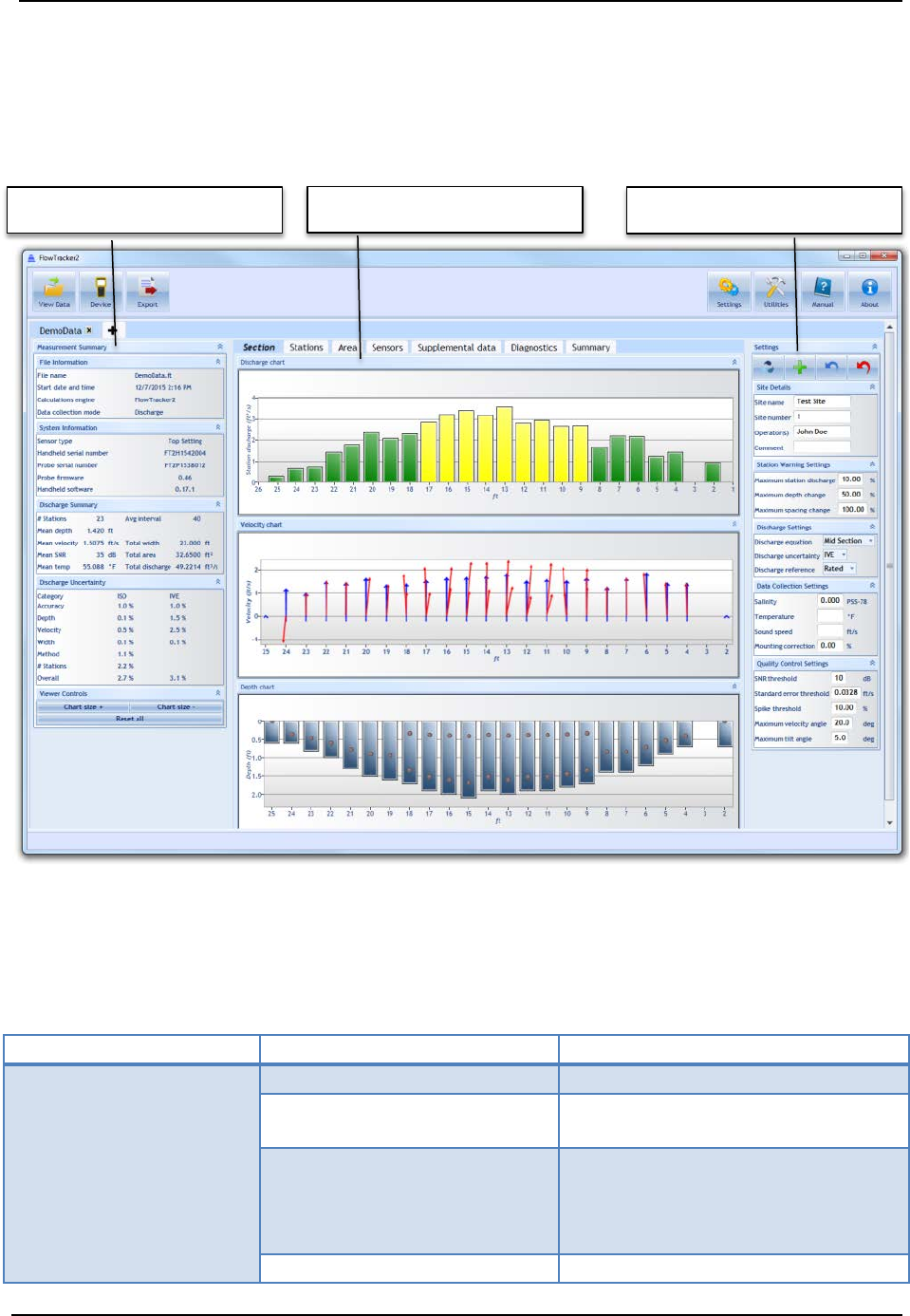
SonTek – a Xylem brand
FlowTracker2 User’s Manual (February 2016) 227
14.8. Overview of View Data Options
When a FlowTracker data file is opened, three panes will appear (Figure 14:21): the
Measurement Summary pane, the main viewing pane (including tabs offering various
views), and the Settings pane.
Figure 14:21. Layout of Data Viewing Window and Section Tab
Measurement Summary Pane 14.8.1
The Measurement Summary Pane values are summarized in Table 14:2.
Table 14:2. Measurement Summary Pane
Category
Value
Description
File Information
File name
File name
Start date and time
Start date and time of
measurement
Calculations engine
Identifies which calculation
algorithm was used: Original
FlowTracker (FlowTracker1) or
FlowTracker2
Data collection mode
Discharge or General Mode
Measurement Summary
Main Viewing Pane
Settings

SonTek – a Xylem brand
FlowTracker2 User’s Manual (February 2016) 228
Category
Value
Description
System Information
Sensor type
Top setting, Universal, or Ice
(not available with Original
FlowTracker)
Handheld serial number
Handheld device serial number
Probe serial number
Probe serial number (not
available with Original
FlowTracker)
Probe firmware
Probe firmware
Handheld software
Handheld software version
Discharge Summary
# Stations
Number of stations measured
Mean depth
Mean depth over all stations
Mean velocity
Mean velocity over all velocity
measurements
Mean SNR
Mean Signal to Noise Ratio over
all velocity measurements
Mean temp
Mean temperature over all
measurements
Avg interval
Probe averaging interval per
sample (in seconds)
Total width
Total transect width
Total area
Total transect area
Total discharge
Total discharge
Discharge
Uncertainty
Category
ISO or IVE
Accuracy
Accuracy (%)
Depth
Uncertainty on depth (%)
Velocity
Uncertainty on velocity (%)
Width
Uncertainty on width (%)
Method
Uncertainty on method used (%)
# Stations
Uncertainty on number of
stations (%)
Overall
Total uncertainty
View Controls Chart size + / Chart size -
Increase or decrease size of all
plots within software
Reset all
Reset size of all plots to default
Main Viewing Pane 14.8.2
The main viewing pane consists of seven tabular views in Discharge Mode, and 6 tabs in
General Mode. The contents of each tab are described below.
Section 14.8.2.1
The Section plots (Figure 14:21) are shown with respect to station location. The left
bank is always shown at the left regardless of whether measurements were taken
starting at the left or right bank. Plots available are:

SonTek – a Xylem brand
FlowTracker2 User’s Manual (February 2016) 229
• Station discharge – discharge per station
• Velocity – mean velocity per sample. Blue vectors indicate the mean velocity
measured (in the X-direction with respect to the ADV probe). If multiple points
exist, the blue vector represents the vertical average. The red vector(s) indicate
actual velocity measured at each point, incorporating the Y-component of flow to
indicate the skew ness of the flow with respect to the X-axis.
• Depth – depth measured at each station (from user input at each station). The
actual measurement depths are indicated by dots. Hovering over the dots
produces a pop-up showing the actual depth those measurements were made.
Stations 14.8.2.2
The Stations tab (Figure 14:22) shows detailed data for each station. The station in
active view is highlighted in blue. Clicking on a different station line will highlight that
station, and its available data will be displayed. Fields in the Station tab can be edited.
For details on how to edit various parameters, please refer to Section 8.9 .Plots/data
available are:
• Point velocities – X,Y, (and Z, if using a 3D probe) velocities measured during
that station spanning the chosen sampling period
• Point SNR – mean beam SNR measured during that station spanning the chosen
sampling period
• Station information – Station information summary. Values displayed are
described in Table 14:3. The number of rows and columns that are viewable can
be changed by using the four arrows that appear above the station information
summary table in the software.
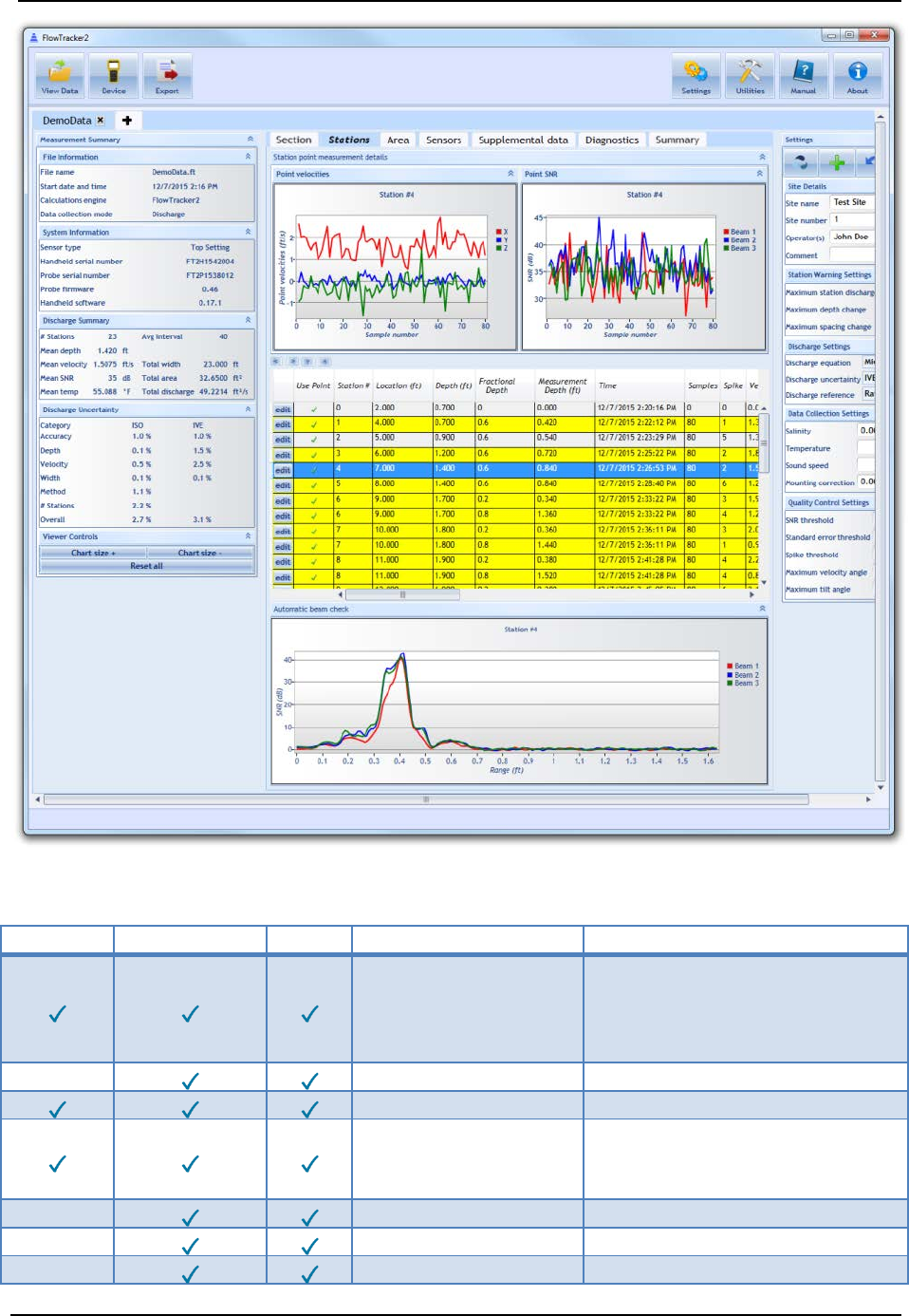
SonTek – a Xylem brand
FlowTracker2 User’s Manual (February 2016) 230
Figure 14:22. Layout of Stations Tab.
Table 14:3: Station Information Values Available
Edit
Orig. FT
FT2
Value
Description
Use Point
Indicates whether the station
is used in the discharge
calculation. This feature can
be edited.
Station #
Station number
Location
Station location along tag line
Depth
Depth at each station (from
user input during
measurement)
Fractional Depth
Fractional depth
Measurement Depth
Actual measurement depth
Time
Time at start of station
SonTek – a Xylem brand
FlowTracker2 User’s Manual (February 2016) 231
Edit
Orig. FT
FT2
Value
Description
Samples
Number of samples in station
Spike
Number of spikes during
measurement period
Velocity
Measured mean velocity
SNR
Mean SNR (all beams)
Velocity angle
Mean velocity angle with
respect to FlowTracker probe
X axis
Velocity standard
error
Velocity standard error
Boundary
interference
Boundary interference quality
parameter (Best, Good, Fair,
Poor)
Tilt
Mean Tilt
Correction factor
User entered correction factor
Width
Width of section
Area
Area of section
Mean velocity
Mean velocity calculated by
dividing discharge by area
Station discharge
Station discharge
Temperature
Mean station temperature
Warnings
Warnings associated with
each station. Stations with
warnings are highlighted in
yellow.
Comment
Comments from user input
during measurement
Station type
Station type (OpenWater,
LeftBank, RightBank,
IslandEdge, Ice)
Velocity method
Velocity method used
GPS Latitude
GPS Latitude if GPS fix was
recorded
GPS Longitude
GPS Longitude if GPS fix was
recorded
Altitude
GPS Altitude if GPS fix was
recorded
Number of satellites
GPS number of satellites if
GPS fix was recorded
Fix quality
GPS fix quality if GPS fix was
recorded
HDOP
HDOP if GPS fix was
recorded
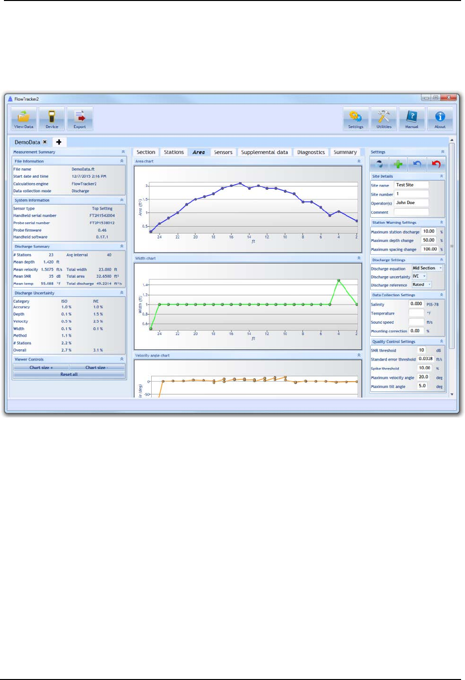
SonTek – a Xylem brand
FlowTracker2 User’s Manual (February 2016) 232
• Automatic beam check – For each station, the mean beam check data is
displayed below the station information summary table. The SNR for each ADV
beam is plotted with distance (“Range”) from the sample volume.
Area 14.8.2.3
Figure 14:23. Layout of Area Tab
The Area tab (Figure 14:23) contains the following plots:
• Area – the Area plotted with respect to the tagline location of each station
• Width – the transect Width plotted with respect to the tagline location of each
station
• Velocity angle – the angle of the flow with respect to the X-axis of the ADV probe
plotted with respect to the tagline location of each station. The mean is calculated
over all station samples. In the case of multiple point measurements per station,
a value will appear for each point measurements at a given station location.
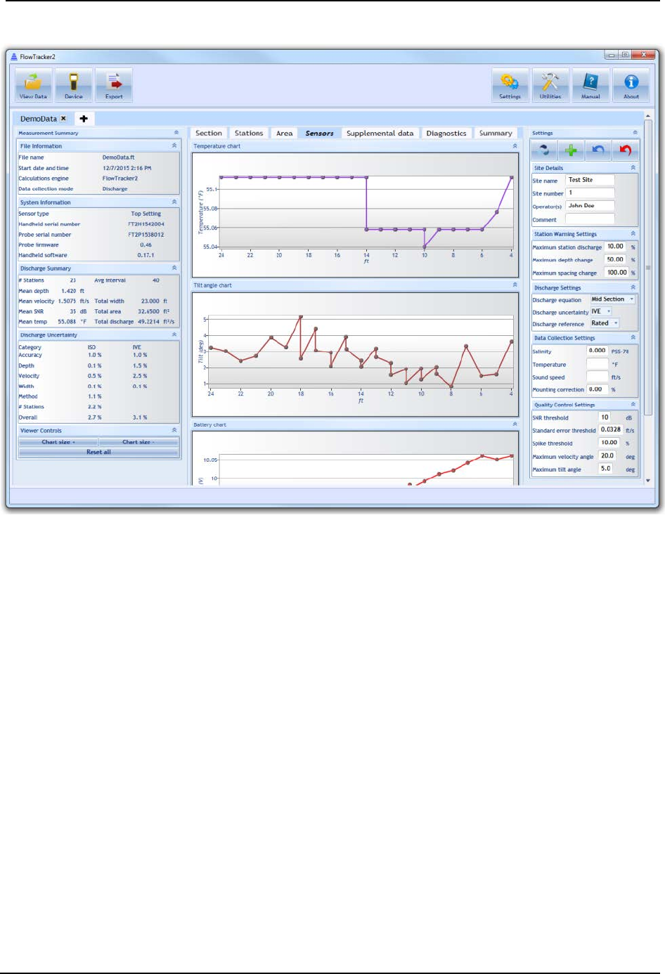
SonTek – a Xylem brand
FlowTracker2 User’s Manual (February 2016) 233
Sensors 14.8.2.4
Figure 14:24. Layout of Sensors Tab
The Sensors tab (Figure 14:24) contains the following plots:
• Temperature – the mean temperature recorded during each station plotted with
respect to the tagline location of each station. In the case of multiple point
measurements per station, a value will appear for each point measurements at a
given station location.
• Tilt – the mean tilt recorded during each station plotted with respect to the tagline
location of each station. In the case of multiple point measurements per station, a
value will appear for each point measurements at a given station location.
• Battery - the mean battery voltage recorded during each station plotted with
respect to the tagline location of each station. In the case of multiple point
measurements per station, a value will appear for each point measurements at a
given station location.
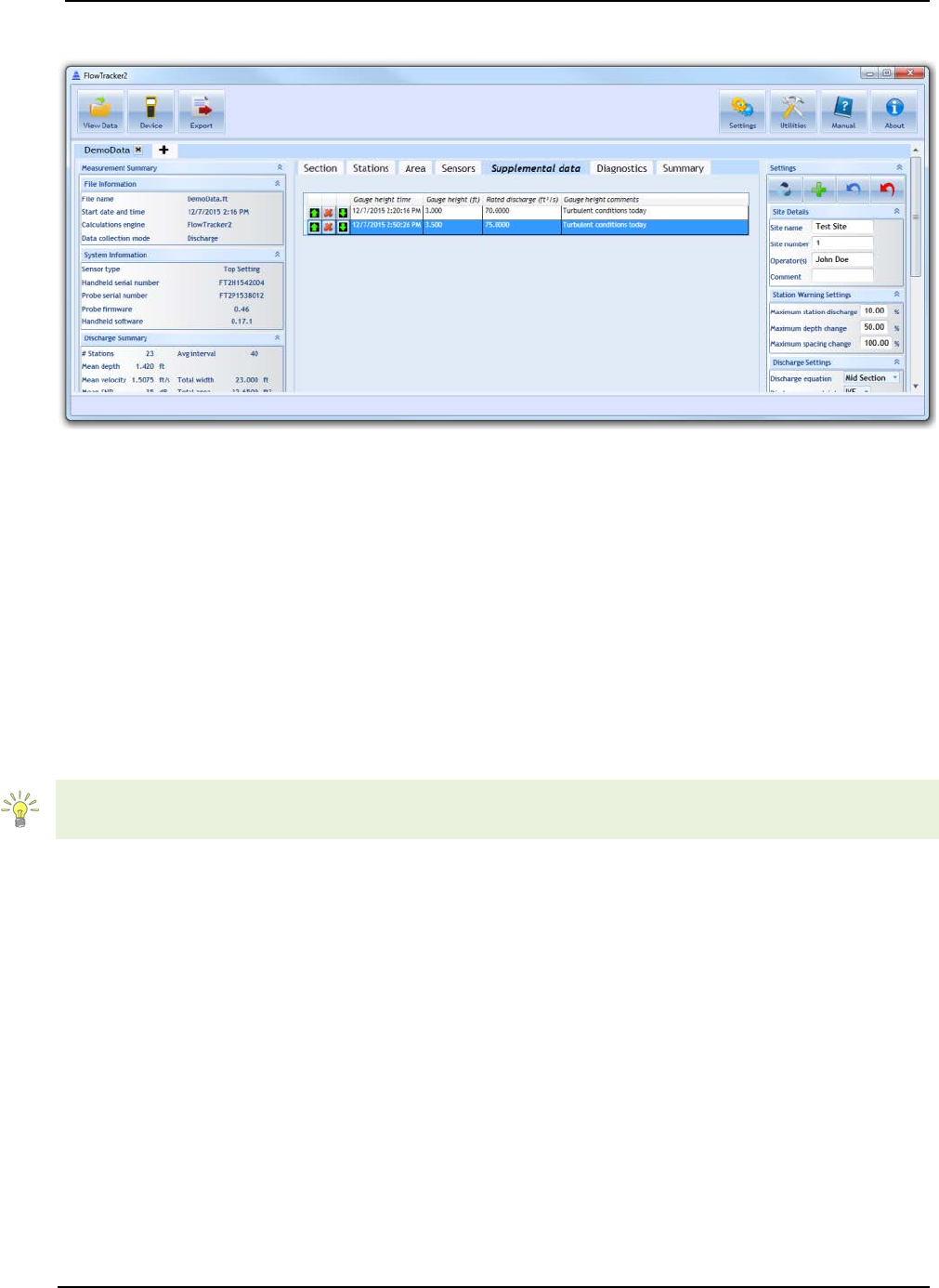
SonTek – a Xylem brand
FlowTracker2 User’s Manual (February 2016) 234
Supplemental Data 14.8.2.5
Figure 14:25. Layout of Supplemental Data Tab
Any supplemental data added during the measurement will appear in the Supplemental
Data tab (Figure 14:25). Multiple supplemental data entries can be available during a
measurement. Supplemental data values are the following:
• Gauge height time – time at which gauge height is taken
• Gauge height – gauge height read from external source
• Rated discharge – rated discharge acquired from external source
• Gauge height comments – any comments associated with gauge height or rated
discharge reading
Supplemental data can be added after the measurement is collected in Post-Processing.
Please refer to Section 14.9 for post-processing instructions.
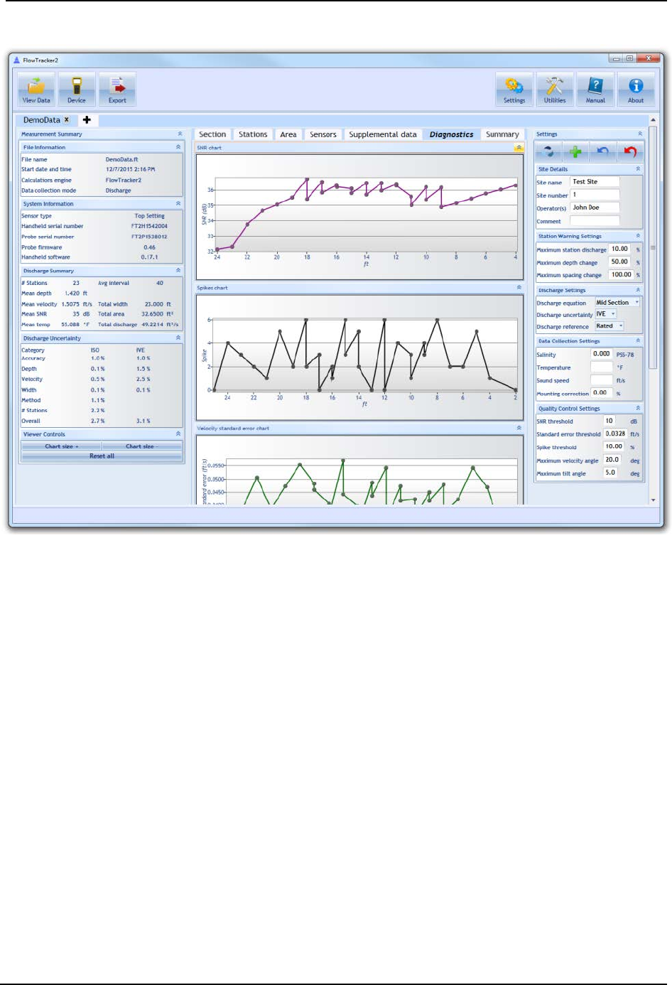
SonTek – a Xylem brand
FlowTracker2 User’s Manual (February 2016) 235
Diagnostics 14.8.2.6
Figure 14:26. Layout of Diagnostics Tab
The Diagnostics tab (Figure 14:26) shows data pertaining to the quality of the
measurement. The following plots are available:
• SNR – the mean SNR at the ADV sample volume over all samples and all beams
at each station. In the case of multiple point measurements per station, a value
will appear for each point measurements at a given station location. In the case
of multiple point measurements per station, a value will appear for each point
measurements at a given station location.
• Spike – the number of spikes that were detected over all samples at each station.
Spikes are removed from the velocity measurement. In the case of multiple point
measurements per station, a value will appear for each point measurements at a
given station location.
• Velocity standard error – the velocity standard error calculated over all samples
at each station. In the case of multiple point measurements per station, a value
will appear for each point measurements at a given station location.
• Samples – the number of samples collected per station
SonTek – a Xylem brand
FlowTracker2 User’s Manual (February 2016) 236
Summary 14.8.2.7
The Summary tab shows a comprehensive overview of the measurement. The
information presented in the other tabs and panes are summarized in this tab. Please
refer to other sections for descriptions of the specific values presented in this tab.
One feature in the Summary tab is the ability to export the measurement to a PDF file.
Please see Export Discharge Summary to PDF for details on how to use this function.
Settings Pane 14.8.3
The Settings pane contains general information about the site, the measurement, and
user input values. Much of this information is editable – please refer to Post-Processing
FlowTracker Measurements regarding how to edit these values. The information
presented in the Settings Pane is summarized in Table 14:4.
Table 14:4. Summary of Settings Pane Values
Category
Edit
Value
Description
Site Details
Site Name
Site name
Site Number
Site number
Operator(s)
Operators(s)
Comment
Comments
Station
Warning
Settings
Maximum station discharge
Maximum % discharge at
each station after which a
warning will be issued
Maximum depth change
Maximum % depth change
between consecutive stations
after which a warning will be
issued
Maximum spacing change
Maximum % spacing change
between consecutive stations
after which a warning will be
issued
Discharge
Settings
Discharge equation
Discharge equation used in
discharge calculation
(MidSection, MeanSection,
Japanese)
Discharge uncertainty
Discharge uncertainty
calculation used to calculate
uncertainty (Iso, Ive, None)
Discharge reference
Discharge reference
(Measured, Rated)
Data
Collection
Settings
Salinity
Salinity used in velocity
measurement
Temperature
Temperature used in velocity
measurement. If left blank,
will use measured
SonTek – a Xylem brand
FlowTracker2 User’s Manual (February 2016) 237
Category
Edit
Value
Description
temperature in velocity
calculation. If value is
entered, this value will be
used.
Sound speed
Sound speed used in velocity
measurement. If left blank,
will use measured
temperature and entered
salinity in calculation of sound
speed used in velocity
calculation. If value is
entered, this value will be
used.
Mounting correction
Mounting correction (%)
applied to velocity value.
Quality
Control
Settings
SNR threshold
SNR threshold (dB). If mean
SNR at sample volume is
below this value, a warning
will be issued.
Standard error threshold
Standard error threshold (in
velocity units). If standard
error over all samples at each
station exceeds this
threshold, a warning will be
issued.
Spike threshold
Spike threshold (in counts). If
number of spikes at a station
exceeds this value, a warning
will be issued.
Maximum velocity angle
Maximum velocity angle (in
degrees). If mean angle of
flow with respect to ADV X-
axis exceeds this value at a
station, a warning will be
issued.
Maximum tilt angle
Maximum tilt angle (in
degrees). If mean tilt at a
station exceeds this value, a
warning will be issued.
14.9. Post-Processing FlowTracker Measurements
A powerful new feature in the FlowTracker2 now allows the user to edit most values
associated with a measurement after the measurement is taken. This section provides
instructions on the post-processing ability of the FlowTracker2 software.
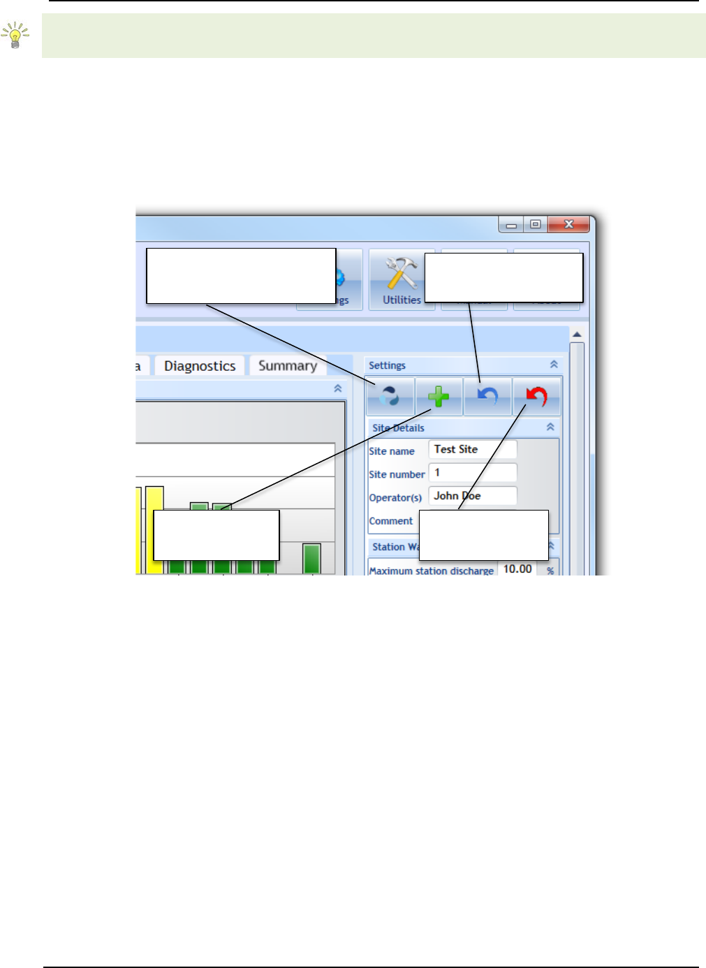
SonTek – a Xylem brand
FlowTracker2 User’s Manual (February 2016) 238
Measurements taken with the Original FlowTracker Handheld ADV can also be edited
with the FlowTracker2 software.
Enable Editing 14.9.1
FlowTracker2 .ft File Editing 14.9.1.1
By default, any measurement taken with the FlowTracker2 will have editing enabled.
The editing pane appears in the top right corner of the software, shown in Figure 14:27.
Figure 14:27. FlowTracker 2 Editing Buttons
Functions include:
• Apply Settings and Recompute Discharge – after any changes in the Settings
Pane (right pane), hitting this button will apply those changes and recalculate
discharge.
• Save Edited Data to File – after hitting the Apply Settings and Recompute
Discharge button, changes will appear in the values displayed in the software, but
these changes will not be saved to a file unless the Save Edited Data to File is
pressed. A file containing edits will be created in the same folder where the .ft file
resides with a “_edited” extension. Once this file is created, opening the .ft file will
open the edited file showing the last saved edits.
• Reload Last Saved Edits – after performing multiple edits that are not saved, this
button is used to revert back to the last saved edits.
Apply Settings and
Recompute Discharge
Save Edited
Data to File
Reload Last
Saved Edits
Revert to
Original Data
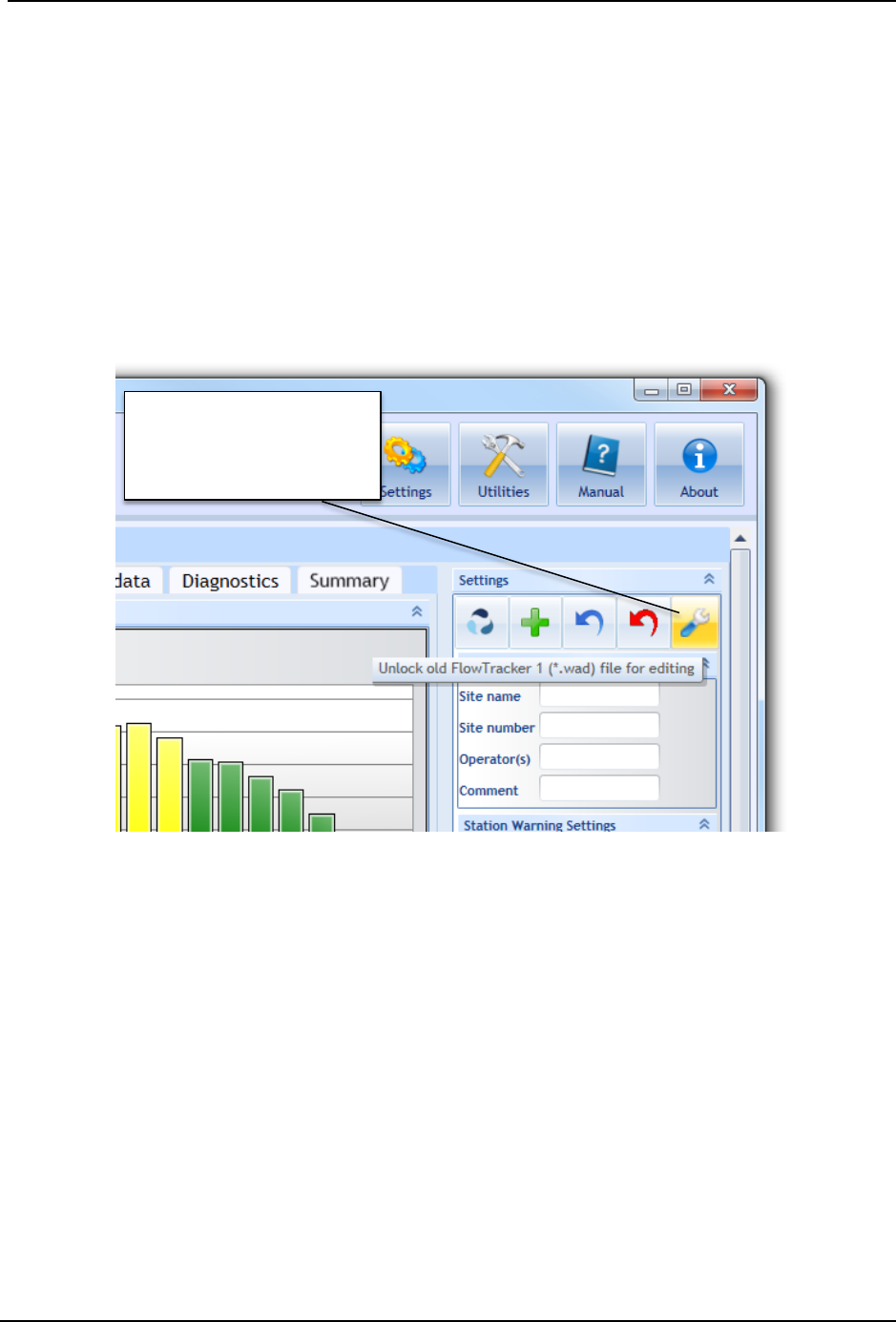
SonTek – a Xylem brand
FlowTracker2 User’s Manual (February 2016) 239
• Revert to Original Data – reverts to the original .ft file that was downloaded from
the FlowTracker2 Handheld unit. The original .ft file will always be preserved
regardless of new edits saved.
Original FlowTracker .wad File Editing 14.9.1.2
To edit .wad files produced by the Original FlowTracker, the .wad files need to first be
converted to .ft format. Please refer to Opening Original FlowTracker Handheld ADV
Data Files (.WAD files) regarding how to convert these files. Once converted, open the .ft
file. The Editing Pane will include an extra button when a .ft file is opened that was
produced by the Original FlowTracker, as shown in Figure 14:28.
Figure 14:28. Original FlowTracker Editing Buttons
The unlock button exists because the Original FlowTracker discharge calculation
algorithms differ from the FlowTracker2 discharge algorithms. Unlocking the Original
FlowTracker file for editing will result in a recalculation of the discharge with the
FlowTracker2 algorithms. To edit files created by the Original FlowTracker, first unlock
the file for editing. The editing pane will then change to the same one that appears for .ft
files taken with the FlowTracker2.
Editing through the Settings Pane 14.9.2
The values in the Settings Pane are summarized in Table 14:4. All of these values can
be edited. To edit, type in the appropriate changes in the input boxes and press the
Apply Settings and Recompute Discharge button. Changes will update all necessary
parameters displayed in all panes and tabs in the software data view. As shown in
Unlock old
FlowTracker 1 (*.wad)
file for editing
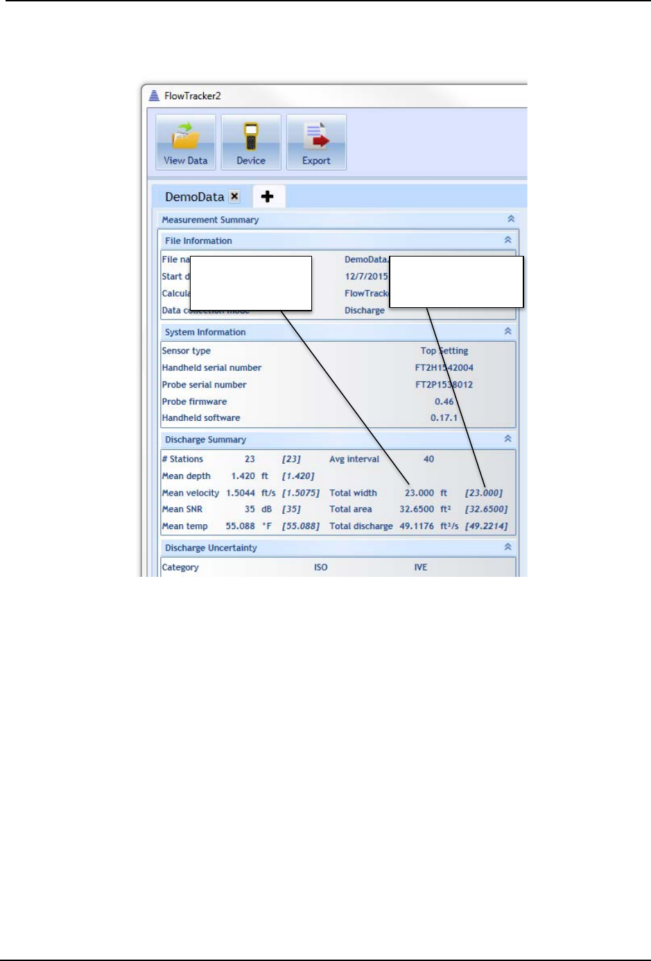
SonTek – a Xylem brand
FlowTracker2 User’s Manual (February 2016) 240
Figure 14:29, changed values will appear in the appropriate panes, with their original
value included in square brackets.
Figure 14:29. Edited Values Updated
Editing by Station 14.9.3
To edit values associated with individual stations within a measurement, first go to the
Stations tab. The editable values associated with each station are indicated in Table
14:3. Identify the station you wish to edit, and press the Edit button on the left of that
station line, shown in Figure 14:30.
Recalculated
Value
Original Value
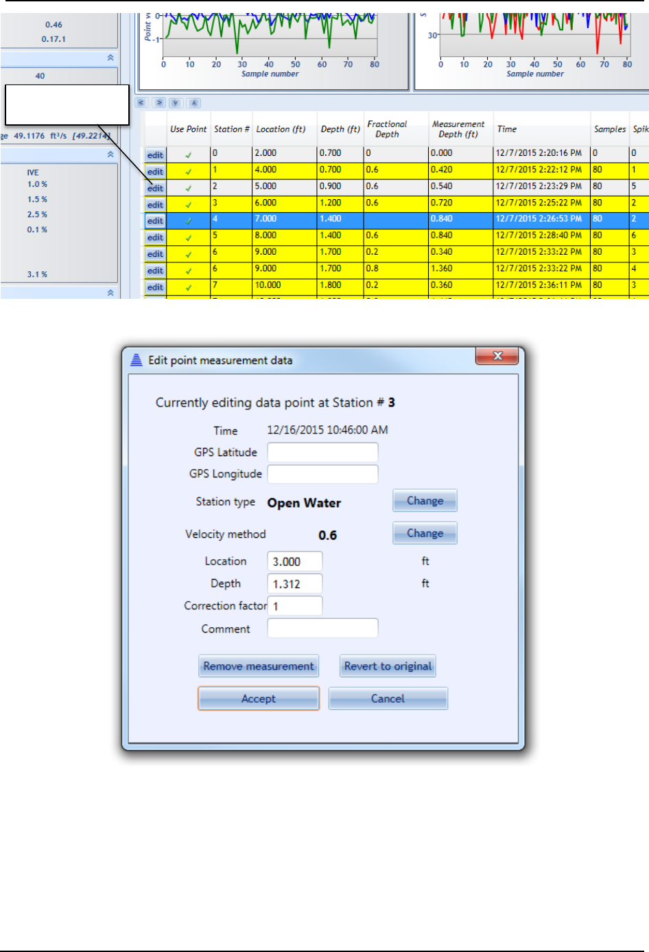
SonTek – a Xylem brand
FlowTracker2 User’s Manual (February 2016) 241
Figure 14:30. Edit by Station
Figure 14:31. Station Editing Dialog
A pop-up editing dialog will appear when the Edit button is pressed, shown in Figure
14:31. Within this dialog, the following items can be edited:
• GPS Latitude – GPS latitude if known from external source
• GPS Longitude – GPS longitude if known from external source
Edit a Station

SonTek – a Xylem brand
FlowTracker2 User’s Manual (February 2016) 242
• Station Type – Change station type (LeftBank, RightBank, IslandEdge,
OpenWater, Ice). Please note: when changing station types, there are some
station type combinations that will result in an error and the software will be
unable to compute discharge. For example, inputting two Left Bank station types
for the section will result in an error. Please refer to your discharge measurement
method guide for specific rules regarding what station types are valid for your
measurement.
• Velocity Method (enter Manual Velocity or None) – the option exists to enter a
manual velocity if it is known at the station and not measured by the ADV. To
enter a manual velocity, click the Change button and select the “Enter Velocity”
option, and hit Accept. A new input box will appear in the main dialog to enter a
manual velocity value. To select None for the Velocity Method, select the “None”
option, and hit Accept.
• Location – Change the location at which the station was taken. Please note: if
location does not satisfy the Maximum Spacing Change criteria set in the
Settings Pane, a warning will appear.
• Depth – Change the water depth at the station. Please note: if the depth does not
satisfy the Maximum Depth Change criteria set in the Settings Pane, a warning
will appear.
• Correction Factor – Change the correction factor applied to the velocity value.
The correction factor is a fraction ranging from [-1:1].
• Comment – Change or add a comment associated with station
• Remove Measurement – Removing a station removes it from being used in the
discharge calculation. Please note: some rules apply to what types of stations
can be removed, and are specific to the velocity method used. For example, if the
original measurement were a 0.2/0.8 measurement, removing the 0.2
measurement will result in an automatic removal of the 0.8 measurement. If a
0.2/0.6/0.8 measurement is taken, removing the 0.6 measurement will result in
removing the 0.6 measurement only, as a 0.2/0.8 is still a valid measurement
type. However, for this 0.2/0.6/0.8 measurement, if the 0.2 measurement is
removed, all three measurements associated with this station will be removed
(0.2, 0.6, and 0.8). Please consult the rules specific to each measurement type.
• Revert to Original – Revert to original values associated with the station when
the data file was downloaded from the FlowTracker unit.
After any changes to these editable values, click the Apply Changes button. Discharge
will be recalculated and new values will be appearing in the appropriate areas.
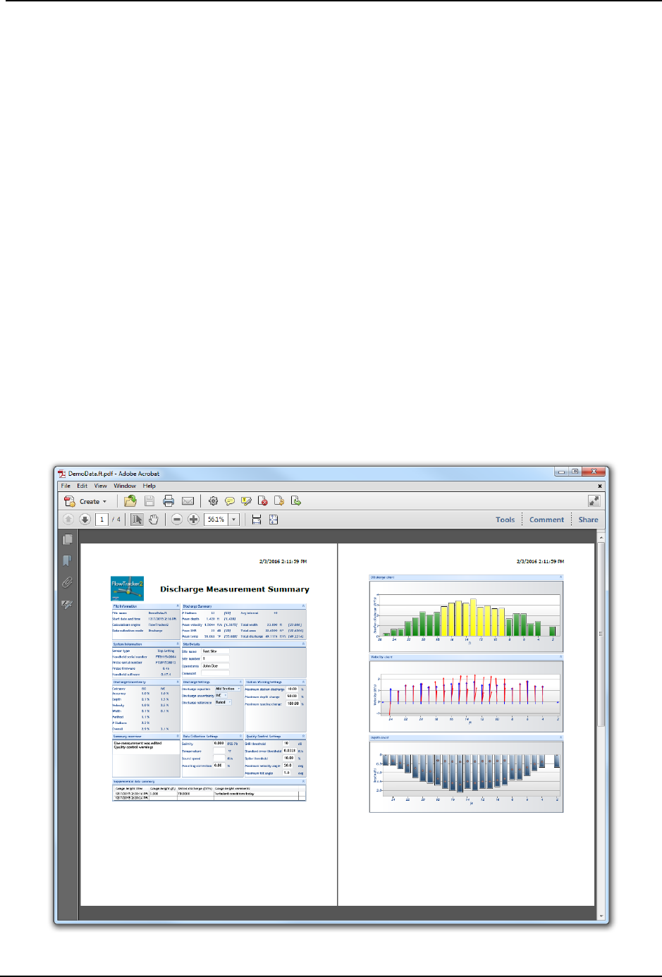
SonTek – a Xylem brand
FlowTracker2 User’s Manual (February 2016) 243
Editing Supplemental Data 14.9.4
Supplemental data can be added or edited after the measurement is taken and the file is
closed in the handheld device. To add or edit supplemental data, first navigate to the
Supplemental Data tab (Figure 14:25). To edit existing supplemental data, simply
double click on the field you wish to edit, and enter in a new value. To add a line of
supplemental data, click the Add Supplemental Data button. To add additional lines of
supplemental data, use the green up/down arrows to add rows above/below the current
line, respectively.
14.10. Data Export and File Formats
Data can be exported from the FlowTracker2 desktop software. Formats available are
PDF and ASCII files.
Export Discharge Summary to PDF 14.10.1
To export the Discharge Summary to PDF, navigate to the Summary tab and click the
Save PDF of Summary button. A PDF will be produced and opened using a PDF
viewer the user has installed on the computer. An example of a discharge summary is
shown in Figure 14:32. The user can then choose to save or print the PDF file.
Figure 14:32. PDF Discharge Summary File
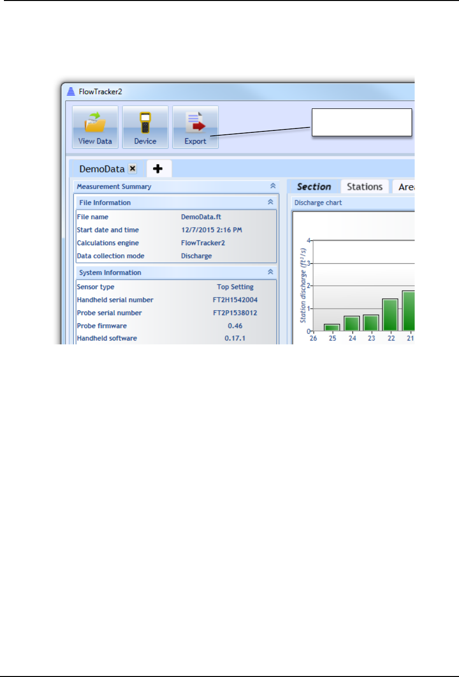
SonTek – a Xylem brand
FlowTracker2 User’s Manual (February 2016) 244
Export Files to ASCII 14.10.2
To export .ft files to ASCII format readable by text editors and spreadsheet software
(Microsoft Excel, Word, etc.), click the Export button, shown in Figure 14:33.
Figure 14:33. Export to ASCII Button
A dialog will appear with the options to Show Headers and Export in English Language.
The export function will not automatically export the data you have opened for viewing.
Instead, a dialog will appear to select the .ft file you wish to export, and following this,
you will select a folder to where the export will save the ASCII files. Four ASCII files will
be created in the selected folder. The contents and format of the ASCII files is
summarized in FlowTracker2 CSV Output.
Matlab Tools for JSON files 14.10.3
Although the FlowTracker2 software does not have a specific Matlab export, a number of
Matlab tools exist to parse and convert JSON format files to Matlab-readable format, and
are readily available through various third-party websites. If help is needed in using
Matlab to read the FlowTracker .ft files into Matlab, please contact SonTek
(support@sontek.com).
Export to ASCII

SonTek – a Xylem brand
FlowTracker2 User’s Manual (February 2016) 245
Appendix A. Software Flow Diagram
SonTek – a Xylem brand
FlowTracker2 User’s Manual (February 2016) 246

SonTek – a Xylem brand
FlowTracker2 User’s Manual (February 2016) 247
Appendix B. Site Selection Requirements
The Site Selection Requirements for performing discharge measurements using a
FlowTracker2 instrument are based on a number of measurement site and hydraulic
requirements. The measurement site and hydraulic requirements are similar to what a
Hydrologists or Hydrographer will use in the selection of monitoring site for either
natural or artificial control. The site and hydraulic requirements that need to be taken in
into account with every discharge measurement are summarized under the following
points.
a) Uniform flow conditions throughout the measurement section,
b) Straight length of channel with uniform cross-section and slope (10 times section
width).
c) Flow in the channel should be confined to a single well-defined channel with
stable banks.
d) Avoid a site with wide shallow sections or secondary side channels.
e) Bends upstream of site should be avoided as this will result in angular flow
towards tagline,
f) Steep slopes upstream should be avoided as this could result in high approach
velocities at the measurement site causing turbulent flow conditions.
g) Avoid measurement sections with deep pools as the reduction in velocity
normally diverge from uniform flow conditions,
h) Avoid prominent obstructions in a pool or excessive plant growth that can affect
the flow pattern.
i) Turbulent flow conditions should be avoided if possible.
j) Negative and or back flow should be avoided at all times.
k) Flow conditions must be within the instrument and equipment specifications
SonTek – a Xylem brand
FlowTracker2 User’s Manual (February 2016) 248
Appendix C. Japanese Method Example
The measurement example of the Japanese method given in Appendix C is based on an actual field measurement that was
manually calculated to give an overview of the various steps involved. The section of the measurement site was greater than
10m and based on the Japanese Method, the measuring technique applicable is Equation 5:3.
Equation 5:1 - Japanese Method > 10m
=()× 0.5
+
+()× 0.5
+
×
+
Edge
()× 0.5
+
+( )× 0.5
+
×
Open Water
Items to be field in the field survey
Items to be filled after survey
Stn
no
Dist
from
Bank
(m)
Depth (m)
Velocity
Velocity
Station Area
Disc.
(m3/s)
When
going When
back Average Meas
depth Sound
no.
Meas. Time (s)
Vel.
(m/s) Ave.
(m/s) Ave.
Depth Ave
Width Area
(m2) Sum
(m2)
1st 2nd Ave
0
0
0.00
0.00
0.00
0.58 2.00 1.16
1 2 1.15 1.16 1.16
0.23
9
25.0
25.6
25.3
1.20
1.16 3.32 3.85
0.92
9
26.6
28.2
27.4
1.11
1.08 2.00 2.16
2 4 1.00 1.00 1.00
0.90 2.00 1.80
3 6 0.80 0.80 0.80
0.16
9
21.8
22.0
21.9
1.38
1.20 3.26 3.91
0.64
9
30.8
29.4
30.1
1.01
0.73 2.00 1.46
4 8 0.66 0.65 0.66
0.60 2.00 1.20
5 10 0.54 0.54 0.54
0.32
6
23.1
23.0
23.0
0.88
0.88 2.20 1.94
--
--
--
--
--
--
0.50 2.00 0.92
6 12 0.45 0.45 0.45
0.46
2.00
0.92
SonTek – a Xylem brand
FlowTracker2 User’s Manual (February 2016) 249
Appendix D. Measurement Equipment List
Cat.
Items
Quantity
Description
FlowTracker2
Probe
1
FlowTracker2 probe with cable
Handheld
1 FlowTracker2 handheld
Battery Cartridge
2
Battery cartridge for FlowTracker2
Handheld Bracket
1 Handheld bracket to mount handheld to Top Setting Rod
Top Setting Rod
1
Top setting wading rod
S Bracket Screw
1
Screw to clamp probe to S bracket
USB Cable
1 USB cable to download data from FlowTracker2
Safety Gear
Mobile \ Satellite
Phone
1 Contact office, local authorities or emergency services
Drink Water
1pp
5L drink water per person per day
Night
-day Safety Vest
1pp
Required when working during low visibility or from
bridges \ culverts
Road Signs
2
Required when working from bridges \ culverts
Sun Hat
1pp
Large brim hat
Rain Jacket
1pp Only to be used when raining
Wader or Water
Boots
1pp Select type of water proof boots based on the water
depth.
Life Jacket 1pp
When entering water an approved life jacket must be
worn.
First Aid Kit
1
Require first aid certificate
Sunscreen
1
Insect repellent
1
Midge and Mosquito
Measurement
Gear
Measuring Tape
1 Measuring tape length dependent on section width.
Pocket Tape
1
Verify water depth or instrument setting.
Steel Pegs
2 To anchor the measuring tape on both banks
Hammer
1
5lb
Shovel \ Rake
1
Shovel \ Rake to clean measurement section
Camera
1
Photographs of measurement site and flow conditions
Reference
Laptop \ Tablet 1
Download measurements at measurement site to
evaluate on desktop software
1
CastAway, Verify water temperature and salinity (see
Principle of Operations
).
pp – per person

SonTek – a Xylem brand
FlowTracker2 User’s Manual (February 2016) 250
Appendix E. CE Declaration of Conformity
Declaration of Conformity
Manufacturer’s Name: SonTek, a Xylem brand
Manufacturer’s Address: 9940 Summers Ridge Road
San Diego, CA 92121-3091 U.S.A.
SonTek, a Xylem brand declares that the product(s):
Equipment Type: Flow Meter
Model: FlowTracker2 (including P/N’s FT2-HH-1, FT2-PR-1, FT2-PR-3)
Conforms to the following FCC, European Union, and Korean Directives and Standards as of
2/12/16:
FCC Part 18, CFR 47, Section 18.309
KN 61326-1 and KN 11
IEC/EN 61010-1:2010 3rd ed,
EMC Directive 2004/108/EC EN61326-1: 2013
In accordance with the following documents and standards:
-EN 55011: 2009+A1: 2010, A
-EN 61000-3-2: 2006 +A1:2009 +A2:2009
-EN 61000-3-3: 2008
-EN 61000-3-3: 2013
-EN 61000-4-2: 2009
-EN 61000-4-3: 2006 +A1:2008 +A2:2010
-EN 61000-4-4: 2004+A1:2010
-EN 61000-4-5: 2006
-EN 61000-4-6: 2009
-EN 61000-4-8: 2010
-EN 61000-4-11:2004
Hakan Erdem
General Manager
SonTek – a Xylem brand

SonTek – a Xylem brand
FlowTracker2 User’s Manual (February 2016) 251
Declaration of Conformity
Manufacturer’s Name: SonTek, a Xylem brand
Manufacturer’s Address: 9940 Summers Ridge Road
San Diego, CA 92121-3091 U.S.A.
SonTek, a Xylem brand declares that the product(s):
Equipment Type: Flow Meter
Model: FlowTracker2 (including P/N’s FT2-HH-2 and higher, FT2-PR-1,
FT2-PR-3)
Conforms to the following FCC, European Union, and Korean Directives and Standards as of
2/12/16:
FCC Part 18, CFR 47, Section 18.309
KN 61326-1 and KN 11
IEC/EN 61010-1:2010 3rd ed, for use with NiMH rechargeable batteries that are certified to IEC
62133
EMC Directive 2004/108/EC EN61326-1: 2013
In accordance with the following documents and standards:
-EN 55011: 2009+A1: 2010, A
-EN 61000-3-2: 2006 +A1:2009 +A2:2009
-EN 61000-3-3: 2008
-EN 61000-3-3: 2013
-EN 61000-4-2: 2009
-EN 61000-4-3: 2006 +A1:2008 +A2:2010
-EN 61000-4-4: 2004+A1:2010
-EN 61000-4-5: 2006
-EN 61000-4-6: 2009
-EN 61000-4-8: 2010
-EN 61000-4-11:2004
Hakan Erdem
General Manager
SonTek – a Xylem brand

SonTek – a Xylem brand
FlowTracker2 User’s Manual (February 2016) 252
INDEX
A
Accessing Templates · 36
accuracy · 199
Add Station · 112, 139
ADV Firmware · 155
Alkaline · 54
Application Settings · 30
Automated Beam Check · 59,
109, 130, 136, 147
Automatic · 34
Averaging Time · 18, 40
B
Bank (left or right) · 116
Base Template · 37
Battery Cap · 161
Battery Compartment · 16
Battery Data · 54
Battery Indicator · 58
Battery Type · 54
Battery Voltage · 55
Beam Check · 61, 92
Beam Check Features · 93
Beam Check Operation · 94
Beam Check Overview · 92
Beam Geometry · 197
Beeper · 29
bistatic · 197
bottom · 31
Bottom banner · 22
boundary adjustment · 197
C
Cable Maintenance · 160
Cartesian (xyz) · 197
CastAway-CTD · 40
Channel Banks · 71
Color Scheme · 29
Comma Separated Values ·
177
Communication · 24
Communication Connector ·
16
Complete Measurement · 130,
148
Condensation · 161
conductivity · 40
Configuration Templates · 35
Confirmation · 113, 115, 141
considerations · 200
Correction Factor · 73
Create Measurement · 107, 134
D
Data Collection · 111, 138
Data Collection Menu · 126, 145
Data Collection Modes · 64
Data Collection Settings · 39
Data Collection Window · 112,
138
Data Files · 26
Data Management · 105
Delete Station · 113, 140
Deleting · 113, 140
Depth · 74
Depth Only · 72
Desktop Software · 155
Determining Mean Station
Velocity · 70
Determining Mean Velocity · 76
Device Configuration · 23, 28
Diagnosing Measurements with
Beam Check · 94
Disabled · 35
Discard Measurement · 131, 149
Discharge · 37
Discharge Calculation Methods ·
65, 116, 117, 120
Discharge Equation · 45
Discharge Measurement · 107
Discharge Mode · 64
Discharge Reference · 46
Discharge Settings · 44
Discharge Summary · 128
Discharge Uncertainty · 46
Discharge Uncertainty
Calculation · 73
Discharge Velocity Methods ·
48
Displayed Velocity Methods · 48
E
Edges · 66, 68, 70
Edit Station · 114
Editing · 114
English · 31
Equipment List · 98
Erase Recorder · 53
Evaluate Beam Check Results ·
110, 137
F
Field Applications · 162
File Format · 167
File Framework · 168
File Naming · 32
File Properties · 38
File Structure · 169
Flow Interference · 202
Folder Naming · 33
Follow Number · 33
Font Size · 29
Font Smoothing · 30
Fractional Depth Measurement
· 123
G
General · 37
General Measurement · 134
Go to Home Screen · 132, 149
GPS Data · 61
GPS Station Tagging · 33
Graph Range · 94
Graph SNR · 94
H
Handheld · 16, 18
Handheld Mounting Bracket ·
157
Handheld Software · 155
Hardware Inspection · 99
Health and Safety · 165
Housing · 161

SonTek – a Xylem brand
FlowTracker2 User’s Manual (February 2016) 253
I
Ice · 119
Interpolated Variance Estimator ·
46
Interpolated Variance
Estimator (IVE) · 73
Island Edge · 117
Islands · 66, 68, 70
ISO · 73
ISO 748 - 2007 · 46
J
Japanese Method · 45
JSON File · 167
K
Keypad · 16, 20
L
Language · 28
LCD Screen · 16
Left Bank · 116
Left Soft Key · 22
M
Main · 22
Manage Recorder · 52
Manual · 34
Manual Change · 50
Max Depth Change for Warning
· 47
Max Spacing Change for
Warning · 47
Max Station Q for Warning · 47
Mean-Section Equation · 67
Mean-Section Method · 45
Measured Discharge · 46
Measurement · 25, 107, 134
Measurement Location · 18
Measurement Procedure · 102
Measurement Process · 98
Measurement Site Information
· 101
Measurement Summary · 132,
149
Measurement Technique · 64,
76
Method None · 71
Metric · 31
Mid-Section Equation · 65
Mid-Section Method · 45
Mounting Correction · 42
mounting, probe · 200
N
New Data File · 108, 135
New File Type · 107, 134
New Template · 37
NiMH · 54
Noise Level · 93
O
Office Diagnostic · 99
Office Procedures · 98
On/Off Switch · 20
Open Station · 114
Open Water · 118
O-rings · 161
P
Peak Level · 94
Peak Position · 94
Percentage Full · 55
Ping · 18
Ping Rate · 18
Point Velocity Measurement ·
121, 141
Post Measurement
Requirements · 104
Practical Salinity Scale · 40
Pre Measurement Diagnostics ·
101
Predefined Languages · 28
Probe · 16
Probe cable · 16
probe configurations · 200
Probe Mounting Bracket · 158
Probe orientation · 202
Properties · 39, 42, 45, 48, 51,
52, 62, 116, 117, 118, 119,
124, 125, 128, 129, 132, 140,
144, 145, 147, 150
pulse-coherent · 196
Q
quality control · 200
Quality Control · 77
Quality Control Data · 18
Quality Control Parameters · 77
Quality Control Settings · 42
Quality Control Warning
Message · 89
R
Rated Discharge · 46
Raw Data Display · 55
receivers · 194
Receivers · 17
Record GPS Location · 34
Recorder · 52
reference · 41
Review Measurement Summary
· 105
Review of Measurement Site
Information · 104
Review Point Measurement ·
123, 143
Review Station · 114
Review Station Measurement ·
124, 144
Right Soft Key · 22
Routine Maintenance · 159
S
Salinity · 18, 40
Sample · 18, 93
Sample Averaged · 93
sampling strategy · 198
sampling volume · 194
Sampling volume · 17
Sampling Volume · 197
Scattering Material · 162
Screen Layout · 22
Seeding · 162
Selecting Template · 37
Setting Fractional Depth · 122,
142
Setting Measurement Depth ·
142
Settings · 127, 146
Signal Strength · 18
Signal to Noise Ratio · 78, 195
Signal-to-Noise Ratio (SNR) ·
18

SonTek – a Xylem brand
FlowTracker2 User’s Manual (February 2016) 254
SNR · 78
SNR Raw Data · 57
SNR Threshold · 43
soft key · 20
Software Upgrade · 155
Sound Speed · 18, 41
Sound Velocimeters · 40, 41
Spike Threshold · 43
Stage - Discharge Relationship ·
105
Standard Error · 43
Start Automated Beam Check ·
109, 136
Station Measurement · 120,
141
Station Parameters · 120
Station Summary · 129
Station Type · 115
Station Types · 115
Std Error Threshold · 43
Storage · 106
Structures · 202
Supplemental Data · 127
Sync with GPS Time · 51
System Clock · 50
System Information · 24
System Maintenance · 63
System Operation · 20
T
Temperature · 19, 41
Temperature Raw Data · 58
Temperature sensor · 17
Template Functions · 37
Template Main Screen · 36
Template Name · 37
Templates · 36
The Doppler Shift · 193
Tilt Angle Warning · 44
Tilt Raw Data · 58
Timing of Warning Messages ·
91
Top banner · 22
Transducers · 160
transmitter · 194
Transmitter · 17
U
Units · 30
Units System · 30
Upgrading ADV Firmware · 157
Upgrading Handheld Software ·
155
User Interface · 28
UTC · 19
Utilities · 23, 50
V
Velocity · 74
Velocity Angle for Warning · 44
velocity data · 199
Velocity Measurement · 142
Velocity Method · 114, 115,
121
Velocity Raw Data · 56
Velocity Standard Error · 81
Velocity Summary · 146
Vertical Velocity Curve · 72
W
Wading Rod · 31
water surface · 31
Width · 74
Z
Zinc Anodes · 161
