171220_Tides Mutable Instruments Tides Quick Start Quickstart
User Manual: Pdf Mutable Instruments Tides Quick Start Mutable Instruments - Tides - Quick Start
Open the PDF directly: View PDF ![]() .
.
Page Count: 2
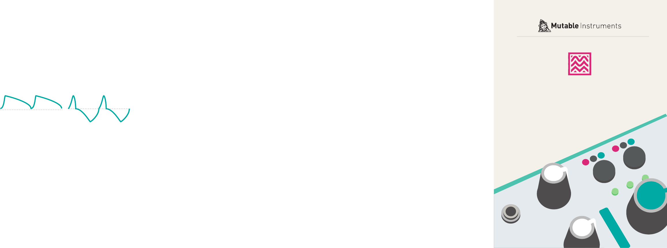
About unipolar and bipolar outputs
The bipolar output is not a mere scaled and offset
version of the unipolar output! It is made of two
bumps, a positive one occurring during the attack,
and a negative one occurring during the release.
PLL mode
Hold the frequency range (B) button for 1s. Tides
enters the PLL mode.
In PLL mode, a signal must be provided to the
CLOCK input. Tides will adjust its output frequen-
cy to match the frequency of this signal or a multi-
ple/division of it as set by the Frequency knob.
Hold the frequency range (B) button again to leave
the PLL mode.
Tips and tricks:
• Tides works wonders as a master modulator for
a classic analog VCO.
• When using Tides as an oscillator for bass
sounds, try both the unipolar and bipolar out-
puts; and the medium and high ranges - they all
sound different.
• Use the PLL mode to create just-intonation mel-
odies on top of a drone sent to the CLOCK input.
• A different fl avor of sync sounds can be ob-
tained by patching a PWM or square source into
the FREEZE input.
• Use the wavefolder on a low-frequency envelope
to create bumps and bounces.
• Use the PLL mode, and trigger the CLOCK input
from a rythmic sequencer.
• In typical Buchla fashion, the low/high tide out-
puts can be used to chain envelopes and create
complex shapes.
Calibration
1. Connect a patch cable to the FM input. Leave
the other end of the cable unplugged (this
prevents the normalling to +/-1 semitone to be
activated).
2. Connect a patch cable to the Level input. Leave
the other end of the cable unplugged (this
prevents the normalling to full amplitude to be
activated).
3. Connect a MIDI>CV interface or precision volt-
age source to the V/Oct input.
4. Hold the Mode switch (A) for one second. All
LEDs are lit in yellow.
5. Play a C2 note, or send a 1V voltage from your
CV source.
6. Press the mode switch (A). All LEDs are lit in
green.
7. Play a C4 note, or send a 3V voltage from your
CV source.
8. Press the mode switch (A).
The module is now calibrated for accurate V/Oct
operation!
Unipolar Bipolar Tides
Tidal modulator
About Tides
Tides is, depending on your point of view, a volt-
age-controlled looping AR/AD generator which
extends into the audio frequencies; or a dynami-
cally waveshaped synth voice with the ability to go
into subsonic territories.
Installation
Tides requires a -12V / +12V power supply (2x5
pins connector). The red stripe of the ribbon cable
(-12V side) must be oriented on the same side as
the “Red stripe” marking on the board.
The power consumption is as follows:
-12V: 5mA ; +12V: 55mA.
Online manual and help
The full manual can be found online at
mutable-instruments.net/modules/tides/manual
For help and discussions, head to
mutable-instruments.net/forum
A
B
CD
EFG
1 2 3
458
910 11
76
12 13
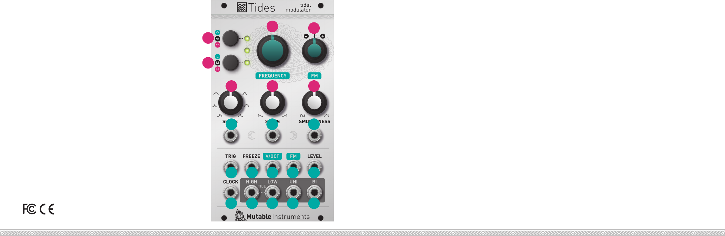
Front panel
Controls
A. Mode selection. Goes back and forth between
one-shot AD (green LED), looping (LED off), and
one-shot AR (red LED) modes.
B. Range selection. Goes back and forth between
very low (green LED), low (LED off), and audio (red
LED) range.
C. Frequency/rate control.
D. Attenuverter for the FM input. When no sig-
nal is patched into the FM input, serves as a fi ne
tuning control.
E. Waveshape of the ascending and descending
segments.
F. Ratio between the duration of the ascending and
descending segments.
G. Curve transformation. From 12 o’clock to 7
o’clock (counter-clowise), applies a 2-pole low-
pass fi lter. From 12 o’clock to 5 o’clock (clockwise),
applies a wavefolder.
Inputs and Outputs
1. 2. 3. CV inputs for shape, slope, and smoothness
controls.
4. Trigger/Gate input. On a rising edge, resets the
waveform and starts the ascent. On a falling edge,
and in AR mode, starts the descent.
5. Freeze input. A gate signal applied on this input
can stop the envelope/oscillator and hold the
signal.
6. V/Oct input. 1V/Oct frequency/rate control.
7. FM input, controlled by the attenuverter (D).
8. Waveform amplitude CV - normalled to a con-
stant 8V source.
9. Clock input for PLL operation.
10. 11. End of attack (high tide) and end of decay/
release (low tide) outputs.
12. 13. Unipolar (0 to 8V) and bipolar (-5V to 5V)
outputs.
Please refer to the online manual for detailed infor-
mation regarding compliance with EMC directives
