Turbo Instruction Manual
User Manual: Pdf turbo instruction manual
Open the PDF directly: View PDF ![]() .
.
Page Count: 22

AquiStar® Turbo
Turbidity/Temperature Smart Sensor and Datalogger
INSTRUCTION MANUAL
For Sales & Service Contact
2650 E. 40th Ave. • Denver, CO 80205
Phone 303-320-4764 • Fax 303-322-7242
1-800-833-7958
www.geotechenv.com

1
Table of Contents
Introduction ......................................................................................................................3
What is the AquiStar® Turbo Sensor? ........................................................................3
Initial Inspection and Handling .................................................................................3
Do’s and Don’ts .........................................................................................................3
Installation and Operation .................................................................................................4
Connecting the Turbo to a Computer .........................................................................4
Installing the Aqua4Plus Software .............................................................................4
Installing the Sensor ..................................................................................................5
Collecting Data ..........................................................................................................5
Maintenance ......................................................................................................................8
Trouble Shooting ...............................................................................................................9
Erratic Readings .........................................................................................................9
Grounding Issues .......................................................................................................9
Appendix A: Technical Specifi cations ............................................................................10
Appendix B: Field Calibration ......................................................................................11
Appendix C: Alternate Connection Options ...................................................................13
Connecting via RS232 Serial Port ...........................................................................13
Connecting with a USB/Serial Adapter ...................................................................13
Appendix D: Reading the AquiStar® Turbo Sensor via Direct Read ..............................15
Reading Via Modbus® .............................................................................................. 15
Setting Baud Rate ....................................................................................................15
Reading Via SDI-12 .................................................................................................17
Reordering Information ..................................................................................................18
Limited Warranty/Disclaimer - AquiStar® Turbo Turbidity/Temperature Sensor ...........19

2
Information in this document is subject to change without notice and does not
represent a commitment on the part of the manufacturer. No part of this manual may
be reproduced or transmitted in any form or by any means, electronic or mechanical,
including photocopying and recording, for any purpose without the express written
permission of the manufacturer.
©1997 - 2013 Instrumentation Northwest, Inc.
Registered trademarks and trademarks belong to their respective owners.

3
Introduction
What is the AquiStar® Turbo Sensor?
INW’s AquiStar® Turbo Smart Sensor is an integrated datalogger and turbidity/tempera-
ture sensor.This sensor networks with all of the INW AquiStar® Smart Sensor family.
Its compatibility with INW’s WaveData® Wireless Data Collection technology makes it
ideal for remote monitoring.
This industry standard digital RS485 interface device records over 250,000 records of
turbidity, temperature, and time data, operates with low power, and features easy-to-use
software with powerful features.
The unit is programmed using INW’s easy-to-use Aqua4Plus control software. Once
programmed the unit will measure and collect data on a variety of time intervals.
The internal microprocessor runs on 12 VDC and automatically turns the turbidity sens-
ing unit on and off, as needed, to conserve power. A built in wiper cleans the sensing
eye each time power is applied to the sensing unit.
Initial Inspection and Handling
Upon receipt of your smart sensor, inspect the shipping package for damage. If any
damage is apparent, note the signs of damage on the appropriate shipping form. After
opening the carton, look for concealed damage, such as a cut cable. If concealed dam-
age is found, immediately fi le a claim with the carrier.
Do’s and Don’ts
Do handle the device with care.
Do store the device in a dry, inside area
when not in use.
Do install a desiccant tube if using a gauge
sensor.
Do install the device so that the connector
end is kept dry.
Do install so wiper blade is free to move.
Don’t support the device with the connector.
Use a strain relief device to take the
tension off the connectors.
Don’t allow the device to free-fall down a
well as impact damage can occur.
Don’t bang or drop the device on hard
objects.
Don’t touch or bump the sensor “eye” or
wiper blade.
4
Installation and Operation
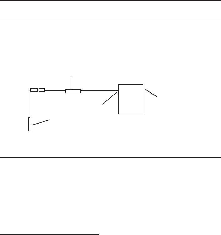
Connecting the Turbo to a Computer
The Turbo cable is terminated with a weather-resistant connector. Connect the weather-
resistant connector to your computer’s USB port as shown below. (For alternate con-
nection options, see Appendix C.)
Connect the Turbo to your PC using a USB to RS485 adapter.
(See Appendix C for alternate connection options.)
Installing the Aqua4Plus Software
The AquiStar® Turbo sensor comes with the Aqua4Plus host software that is installed
on your PC or laptop. Use this software to program the datalogger, to retrieve data
from the logger, to view collected data, and to export data to external fi les for use with
spreadsheets or databases.
Refer to the Aqua4Plus software manual for details on installing and using Aqua4Plus.
Using the Sensor Without Aqua4Plus
Most users will use the sensor with INW’s Aqua4Plus software. However, this sensor is
quite versatile, allowing you to do the following:
• Read via the Modbus® protocol using your own software.
• Read via SDI-12 protocol.
• Display readings on a panel meter.
If you want to use one of these methods, see Appendix D or contact INW for further
details.
PC or Laptop
Computer
USB Port
USB to RS485
Adapter
Turbo

5
Installing the Sensor
Lower the sensor to the desired depth. Fasten the cable to the well head using tie wraps
or a weather proof strain-relief system. When securing a vented cable, make sure not
to pinch the cable too tightly or the vent tube inside the cable jacket may be sealed off.
Take a measurement to insure the sensor is not installed below its maximum range.
Be sure the supplied cap is securely placed on the weather-resistant connector at the
top of the cable. Do not install such that the connector might become submerged with
changing weather conditions. The connector can withstand incidental splashing but is
not designed to be submerged.
Collecting Data
Following is a brief overview on using Aqua4Plus to collect data. Please refer to the
Aqua4Plus Instruction Manual for further details on confi guring and using Aqua4Plus.
Real Time Monitor
Click Single to get a single reading.
Click Start to get a reading once a second.
The unit will power up, run the wiper once, and then start taking readings.
Click Stop to stop the reading.
Note: These are snapshot readings and are not recorded on the sensor.
The Real Time Monitor gives a snapshot of the
current readings on the sensor.
6
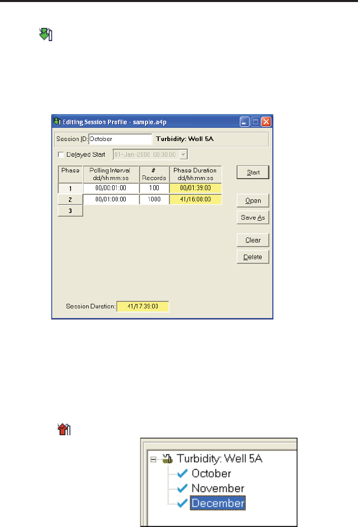
Setting up a Data Recording Session
Click the tool button. A Session Profi le Window will open. Refer to the Aqua4Plus
Instruction Manual for details in describing your session profi le. Click the Start button
to save the session to the sensor and begin recording. Before each reading, the sensor
will apply power to the turbidity sensing unit and run the wiper once. If your polling
interval is 10 seconds or less, the sensing unit will remain on and will only wipe once
when the session is fi rst started.
Using the Session Profi le Window, describe the test
steps for your particular test.
Retrieving Data from the Sensor/Datalogger
• Click on the session you want to upload.
• Click the tool button.
• Select a fi le location.
• Click Save.
• Click Start.
Select the data session
you are ready to upload.
7
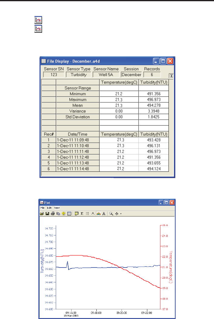
Viewing Data
• Click the tool button to view data as a table.
• Click the tool button to view data as a graph.
• Navigate to the desired fi le, then click the Open button. (If the File Open box does
not appear, click the File Menu, then select Open.)
The File Display window displays your data
in a tabular format.
The Graph Window displays your data on an XY
coordinate graph.

8
Exporting Data to .csv or .xls Files
• Using the File Display window, open the fi le you want to export.
• Click on the tool button.
• Select a fi le location and enter a name for the fi le.
• Select a fi le type.
• Click Save.
A Word About Units
Temperature readings from the sensor can be displayed in various units, such as degrees
Celsius or degrees Fahrenheit for temperature. Select the units you want from the
Options | Units menu. Turbidity is always in NTU.
Maintenance
Sensor: There are no user-serviceable parts. If problems develop with sensor stability
or accuracey, contact INW. If the unit has been exposed to hazardous materials, do not
return without notifi cation and authorization.
Cable: Cable can be damaged by abrasion, sharp objects, twisting, crimping, crushing,
or pulling. Take care during installation and use to avoid cable damage. If a section
of cable is damaged, it is recommended that you send your sensor back to replace the
cable harness assembly.
End Connections: The contact areas (pins & sockets) of the connectors will wear out
with extensive use. If your application requires repeated connections other types of
connectors can be provided. The connectors used by INW are not submersible, but are
designed to be splash-resistant.
Wiper Blades: The effectiveness of the wiper in maintaining a clean optical surface
will eventually be compromised, the rate being dependent on the water under investiga-
tion and the number of wiping cycles carried out. We recommend periodic inspection
of the wiper’s silicon pad to determine if the wiper material is deteriorating or if there
is an excessive buildup of material from bio-fouling. In addition, as a precaution we
recommend changing the wiper prior to each long term deployment. The wiper is a
consumable item. Wiper packs are available from INW (4N855/NEP-WIPE).

9
Trouble Shooting
Erratic Readings
Erratic readings can be caused by a poor connection, damaged cable, moisture in the
unit, or a damaged transmitter. In most cases, erratic readings are due to moisture
getting into the system. The fi rst thing to check is the connection. Look for moisture
between contacts or a loose or broken wire. Next, check the cable for cracking or
fraying. If the connections and cable appear OK, but the readings are still erratic, the
transmitter may be damaged. Contact INW for evaluation and repair. Erratic and
erroneous readings can also occur due to improper grounding. See Grounding Issues,
below.
Grounding Issues
It is commonly known that when using electronic equipment, both personnel and
equipment need to be protected from high power spikes that may be caused by
lightning, power line surges, or faulty equipment. Without a proper grounding system,
a power spike will fi nd the path of least resistance to earth ground – whether that path
is through sensitive electronic equipment or the person operating the equipment. In
order to ensure safety and prevent equipment damage, a grounding system must be
used to provide a low resistance path to ground.
When using several pieces of interconnected equipment, each of which may have its
own ground, problems with noise, signal interference, and erroneous readings may be
noted. This is caused by a condition known as a Ground Loop. Because of natural
resistance in the earth between the grounding points, current can fl ow between the
points, creating an unexpected voltage difference and resulting erroneous readings.
The single most important step in minimizing a ground loop is to tie all equipment
(sensors, dataloggers, external power sources and any other associated equipment) to a
single common grounding point. INW recommends connecting the shield to ground
at the connector end.
10
Appendix A: Technical Specifi cations
General Specifi cation
The AquiStar® Turbo sensor is a microprocessor based digital intelligent sensor
designed to measure and record turbidity, temperature, and time.
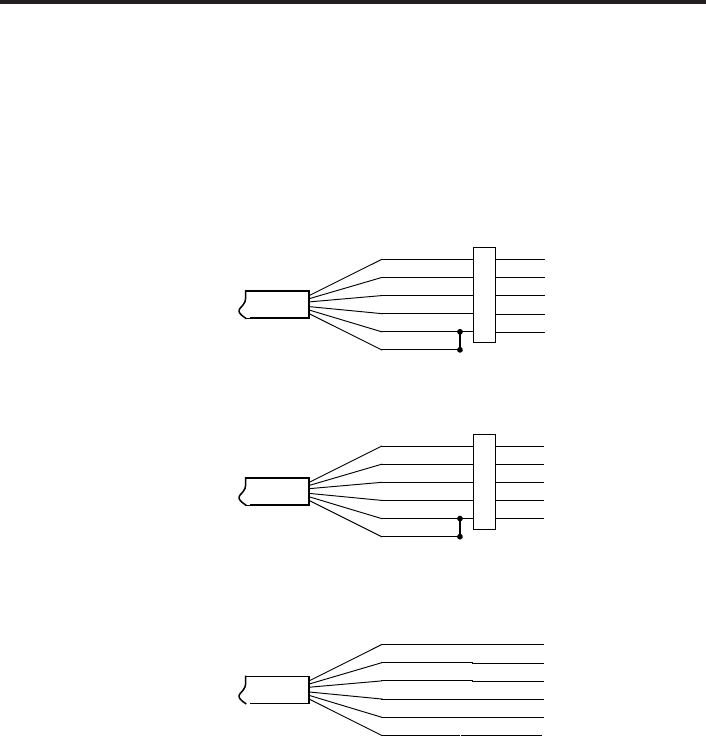
Wiring
Cable
OD 0.28” maximum
Break Strength 138 lbs.
Maximum Length 2000 feet
Weight 4 lbs. per 100 feet
Input Power 12 VDC
Range 0 - 1000 NTU (± 2.652 V)
For Modbus® —
with 5-pin connector
For SDI-12 —
with 5-pin connector
For SDI-12 —
without connector
White
Purple
Yellow
Brown
Blue
Shield
12 VDC+ (Vaux)
Modbus D-
Modbus D+
SDI-12 (Not used)
Ground
1
2
3
4
5
5-Pin
Connector
White
Purple
Yellow
Brown
Blue
Shield
12 VDC+ (Vaux)
Modbus D- (Not used)
Modbus D+ (Not used)
SDI-12 Signal
12 VDC – (Gnd)
1
2
3
4
5
5-Pin
Connector
White
Purple
Yellow
Brown
Blue
Shield
(may be green)
12 VDC+ (Vaux)
Modbus D- (Not used)
Modbus D+ (Not used)
SDI-12 Signal
12 VDC – (Gnd)
Earth ground

11
Appendix B: Field Calibration
Calibration can only be done when there are no sessions stored on the sensor. If there
are any sessions stored on the sensor, upload any data you want and then erase the
session before continuing.
One-Point Calibration:
-- Computing Calibration Value --
• Place sensor in sample to be measured. Allow time for sensor to stabilize.
• If sample is of known specifi c value, enter this value in the Ref box for the fi rst
point
• Alternately, using an accurate alternate measuring device, take a measurement.
Enter this value in the Ref box for the fi rst point.
• Click fi rst Measure button.
• When readings have stabilized to your satisfaction, click the OK button in the
pop-up box.
-- Applying Calibration Value --
• Click the Apply button to apply calibration value.
• The computed b value will be transferred to the calibration fi eld.
• Click OK to save the value to the sensor.
Two-Point Calibration:
-- First Calibration Point --
• Place sensor in sample to be measured. Allow time for sensor to stabilize.
• If sample is of known specifi c value, enter this value in the Ref box for the fi rst
point
• Alternately, using an accurate alternate measuring device, take a measurement.
Enter this value in the Ref box for the fi rst point.
• Click fi rst Measure button.
• When readings have stabilized to your satisfaction, click the OK button in the
pop-up box.
-- Second Calibration Point --
• Place sensor in sample with a different value. Allow time for sensor to stabilize.
• If sample is of known specifi c value, enter this value in the Ref box for the
second point
• Alternately, using an accurate alternate measuring device, take a measurement.
Enter this value in the Ref box for the second point.
• Click second Measure button.
• When readings have stabilized to your satisfaction, click the OK button in the
pop-up box.

12
-- Applying Calibration Values --
• Click the Apply button to apply calibration values.
• The computed m and b values will be transferred to the calibration fi elds.
• Click OK to save the values to the sensor.
13
Appendix C: Alternate Connection Options
Connecting via RS232 Serial Port
The Turbo cable is terminated with a weather-resistant connector. Connect the weather-
resistant connector to your computer’s serial port as shown below.
Connect the Turbo to your computer using an RS485/RS232
adapter and an interface cable.
Connecting with a USB/Serial Adapter
USB-to-Serial cables are readily available from many electronics and computer stores,
as well as numerous sites on the Internet. INW has tested and recommends the Keyspan
USA-19HS. It is available from INW as well as from many sites on the Internet. Install
as follows:
• Plug into USB port.
• Install the drivers provided with the particular unit.
• Determine the port number to which the adapter is assigned.
Right-click on My Computer.
From the popup menu, select Manage to open the Computer Management
window.
On left panel, click on Device Manager.
On right panel, double-click on Ports.
A list of active COM ports will be displayed. Note the COM number
assigned to the adapter you just installed.
For example:
Close Manager.
• Connect to the sensor.
• On the Aqua4Plus software, select the COM port noted above. (If you do not
see your new COM port in the dropdown box, open the Communications dialog
box from the Options menu. Increase the Highest COM port number, up to a
maximum of 15.)
PC or
Laptop
Computer
RS485/RS232
Adapter
Interface Cable
Serial Port
Turbo

14
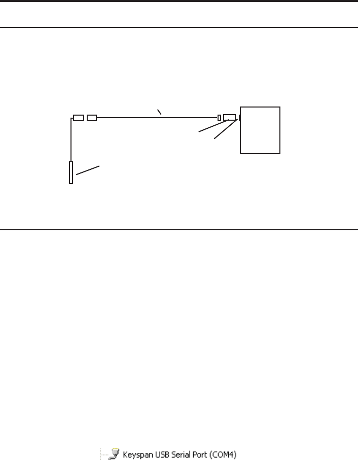
Connect the Turbo to your computer using a
USB to Serial adapter and an interface cable.
Interface
Cable
PC or Laptop
Computer
USB Port
USB-to-Serial
Adapter
RS232/RS485
Adapter
Turbo

15
Appendix D: Reading the AquiStar® Turbo Sensor
via Direct Read
While the Turbo comes with INW’s easy to use Aqua4Plus software, you can also use
standard Modbus® RTU or SDI-12 equipment to easily take readings, so as to tie into
your existing equipment or networks.
You may nee to use Aqua4Plus to set the baud rate. (You do not need to set the baud
rate for SDI-12). For Modbus you must have Turbo fi rmware version 2.0 or higher.
For SDI-12 you must have version 2.2 or higher.
Reading Via Modbus®
Setting Baud Rate
Your sensor comes confi gured to communicate at 38,400 baud, with 8 data bits, one
stop bit, and no parity. The sensor can also be set to 19,200 or 9600 baud, if needed for
your application.
If needed, set your sensor to the desired baud rate as follows:
• Click on the Confi gure menu, and then select Advanced.
• From the fl yout menu, select Sensor Baud Rate. (You may be asked for a
password. Enter admin.)
• On the popup box, click the down-arrow and select the baud rate you need, and
then click OK.
Once you have changed the baud rate on the sensor, you will not be able to talk to it
with Aqua4Plus until you change the baud rate for Aqua4Plus, as follows:
• Click the Options menu, and then select Baud Rate.
• On the popup box, click the down-arrow, select the baud rate you need, and then
click OK.
The current Aqua4Plus baud rate is displayed in the lower right corner of the main
Aqua4Plus window.
Taking Measurements
Reading Registers
Read measurements using Modbus function 03 – Read Holding Registers.
Readings are located in two registers each, starting at address 62592. (AquiStar®
register addressing is zero based, i.e., starts at zero. If your equipment uses one based
addressing, you will need to add one to the register addresses.)
Register addresses for AquiStar® Turbo Sensor
Zero Based One Based
Temperature 62592 62593
Turbidity 62594 62595

16
Data Format
The data is returned as 32-bit IEEE fl oating-point values, high word fi rst, also referred
to as big-endian or fl oat inverse.
Wiper
Before each reading, the sensor will apply power to the turbidity sensing unit and run
the wiper once. If your polling interval is 10 seconds or less, the sensing unit will
remain on and will only wipe once when fi rst started.
Power On Function
The AquiStar® Turbo Sensor requires a warm-up or stabilization time after application
of power before accurate readings can be taken.
The Power On functionality is controlled by writing a value to register 62720 (0xF500).
This is how long the sensor stays on once a reading is requested. This value represents a
quarter second and defaults to 240 (60 seconds) whenever the unit is power cycled.
• Write Power On value of 40 (40/4 = 10 seconds)
• Power turns on
• Starts sampling about two times a second
• Wait 10 seconds
• Request a reading
• Returns most recent reading
• Resets Power On to 40 (40/4 = 10 seconds)
• Write Power On value of 0
• Turns power off
• Retains last reading
This is the preferred method to ensure proper warmup/stabilization and to conserve
power as much as possible. This, however, requires that your monitoring equipment
have the ability to write to the sensor.
If you are reading your device using a meter or other device that cannot write the Power
On but simply takes readings on a specifi ed schedule, be sure to set the polling interval
to less than 60 seconds. That way the sensor is always powered up and readings should
be fresh and stable. Note that the fi rst reading when you turn on the sensor and meter
will be old but will refresh within a second
For further information and detailed Modbus examples, see INW application note,
“Modbus Direct Read on AquiStar Smart Sensors” available from our web site at
http://www.inwusa.com/appnotes.htm.

17
Reading Via SDI-12
Addressing
Default SDI-12 Address: 0
SDI-12 Command Nomenclature
<a> = Sensor address
{crc} = SDI-12 compatible 3-character CRC
<cr> = ASCII carriage return character
<lf> = ASCII line feed character
highlighted values indicate variable data
SDI-12 Commands
//*** Sensor Identifi cation
<a>I! <a>13 INWUSA ATurb2.2ssssssssss<cr><lf>
// note: 2.2 will change to refl ect current
// fi rmware revision
// ssssssssss = device serial #
//*** Acknowledge Active, Address Query
<a>! <a><cr><lf>
?! <a><cr><lf>
//*** Change Address
<a>A<b>! <b><cr><lf> // change address from <a> to <b>
//*** Request measurement
<a>M! <a>0022<cr><lf> // request all measurements
<a>D0! <a>+24.2412+458.73<cr><lf> // read: temperature and turbidity
<a>M1! <a>0021<cr><lf> // request measurements
<a>D0! <a>+24.2412<cr><lf> // read: temperature
<a>M2! <a>0021<cr><lf> // request measurements
<a>D0! <a>+458.73<cr><lf> // read: turbidity
//*** Request measurement with CRC
<a>MC! <a>0022<cr><lf> // request all measurements w/CRC
<a>D0! <a>+24.2412+458.73{crc}<cr><lf> // read: temperature and turbidity
<a>MC1! <a>0021<cr><lf> // request measurements w/CRC
<a>D0! <a>+24.2412{crc}<cr><lf> // read: temperature
<a>MC2! <a>0021<cr><lf> // request measurements w/CRC
<a>D0! <a>+458.73<cr><lf> // read: turbidity

18
//*** Concurrent measurement
<a>C! <a>0022<cr><lf> // request all measurements
<a>D0! <a>+24.2412+458.73<cr><lf> // read: temperature and turbidity
<a>C1! <a>0021<cr><lf> // request measurements
<a>D0! <a>+24.2412<cr><lf> // read: temperature
<a>C2! <a>0021<cr><lf> // request measurements
<a>D0! <a>+458.73<cr><lf> // read: turbidity
//*** Concurrent measurement with CRC
<a>CC! <a>0022<cr><lf> // request all measurements w/CRC
<a>D0! <a>+24.2412+458.73{crc}<cr><lf> // read: temperature and turbidity
<a>CC1! <a>0021<cr><lf> // request measurements w/CRC
<a>D0! <a>+24.2412{crc}<cr><lf> // read: temperature
<a>CC2! <a>0021<cr><lf> // request measurements w/CRC
<a>D0! <a>+458.73<cr><lf> // read: turbidity
For further information and SDI-12 examples, see the INW application note, “Turbo Interface
Specifi cation (SDI-12)” available from our web site at www.inwusa.com/technical-library.
Reordering Information
For sales & service offi ces, please contact:
INW
www.inwusa.com
800-776-9355

19
LIMITED WARRANTY/DISCLAIMER - AquiStar® TURBO
SUBMERSIBLE TURBIDITY / TEMPERATURE SENSOR
A. Seller warrants that products manufactured by Seller when properly installed, used
and maintained with a properly installed desiccant tube, shall be free from defects in
material and workmanship. Seller’s obligation under this warranty shall be limited to
replacing or repairing the part or parts or, at Seller’s option, the products which prove
defective in material or workmanship within ONE (1) year from the date of delivery,
provided that Buyer gives Seller prompt notice of any defect or failure and satisfactory
proof thereof. Any defective part or parts must be returned to Seller’s factory or to an
authorized service center for inspection. Buyer will prepay all freight charges to return
any products to Seller’s factory, or any other repair facility designated by Seller. Seller
will deliver replacements for defective products to Buyer (ground freight prepaid) to the
destination provided in the original order. Products returned to Seller for which Seller
provides replacement under this warranty shall become the property of Seller.
This limited warranty does not apply to lack of performance caused by abrasive materials, cor-
rosion due to aggressive fl uids, mishandling or misapplication. Seller’s obligations under this
warranty shall not apply to any product which (a) is normally consumed in operation, or (b) has a
normal life inherently shorter than the warranty period stated herein.
In the event that equipment is altered or repaired by the Buyer without prior written approval by
the Seller, all warranties are void. Equipment and accessories not manufactured by the Seller are
warranted only to the extent of and by the original manufacturer’s warranty.
THE FOREGOING WARRANTIES ARE IN LIEU OF ALL OTHER WARRANTIES, WHETH-
ER ORAL, WRITTEN, EXPRESSED, IMPLIED OR STATUTORY. IMPLIED WARRANTIES
OF FITNESS AND MERCHANTABILITY SHALL NOT APPLY. SELLER’S WARRANTY
OBLIGATIONS AND BUYER’S REMEDIES THEREUNDER (EXCEPT AS TO TITLE) ARE
SOLELY AND EXCLUSIVELY AS STATED HEREIN. IN NO CASE WILL SELLER BE
LIABLE FOR CONSEQUENTIAL DAMAGES, LABOR PERFORMED IN CONNECTION
WITH REMOVAL AND REPLACEMENT OF THE SENSOR SYSTEM, LOSS OF PRODUC-
TION OR ANY OTHER LOSS INCURRED BECAUSE OF INTERRUPTION OF SERVICE.
A NEW WARRANTY PERIOD SHALL NOT BE ESTABLISHED FOR REPAIRED OR
REPLACED MATERIAL, PRODUCTS OR SUPPLIES. SUCH ITEMS SHALL REMAIN
UNDER WARRANTY ONLY FOR THE REMAINDER OF THE WARRANTY PERIOD ON
THE ORIGINAL MATERIALS, PRODUCTS OR SUPPLIES.
B. With respect to products purchased by consumers in the United States for personal use, the
implied warranties including but not limited to the warranties of merchantability and fi tness for a
particular purpose, are limited to twelve (12) months from the date of delivery.
Some states do not allow limitations on the duration of an implied warranty, so the above limita-
tion may not apply to you. Similarly, some states do not allow the exclusion or limitation of
consequential damages, so the above limitation or exclusion may not apply to you. This limited
warranty gives you specifi c legal rights; however, you may also have other rights which may vary
from state to state.

20
Notes

8902 122nd Avenue NE
Kirkland, WA 98033 USA
425-822-4434
FAX 425-822-8384 / info@inwusa.com
INW
©1997 - 2013 by Instrumentation Northwest, Inc. All rights reserved. Instrumentation Northwest and INW
are trademarks registered with the U.S. Patent & Trademark Offi ce. Doc# 9B0870r5 08/30/13 / PN 6D293-NI
