Ubitx Manual V2
User Manual: Pdf
Open the PDF directly: View PDF ![]() .
.
Page Count: 9

USER MANUAL FOR
VFO/BFO with Si5351 and TFT touch screen for uBitx txcvr
VU2SPF, SP Bhatnagar, and VE1BWV, Joseph Basque,
Bhavnagar, INDIA Canada
(Ver 2.9bU)
Watch videos produced by Joe Basque on YouTube - Look for VU2SPF / VE1BWV.
Also on Facebook BITX group.
https://www.youtube.com/results?search_query=vu2spf
Other useful liks:
vu2spf.blogspot.com
https://github.com/sprakashb/TFT_TouchScreen_for_uBitx
ubitx.net also has some details
Main Features :
- Uses low cost Si5351 for generating three independent VFO and BFO frequencies needed by uBitx.
- Touch screen controlled UI on colour TFT for controlling functioning of uBitx.
- Two VFOs A/B and one Memory VFO.
- 100 memory channels for storing frequently used stations (more channels possible)
- Switch between VFO and Memory by touch.
- All VFO and BFOs are adjustable from screen / buttons.
- Frequency adjustments in steps of 1Hz, 10Hz, 100Hz, 1kHz, 10kHz, 100kHz and 1MHz.
- Some touch buttons are Two Sided (left and right half of button works independently) .
- Some touch buttons are Single Push (touch) type.
- Saving parameters to EEPROM on demand (not automatic, thus reducing memory write operations to
extend life of CPU).
- Uses low cost MCUFriend 2.4” / 2.8” colour display. Larger ones also work but may need minor
tweaks.
- Horizontal S-meter.
- Preset Ham Bands. Band Limits are hard coded / adjustable in program code.
- Continuous frequency output mode (frequency generator mode).
- Uses standard Arduino Mega 2560. Assembled in short time with any standard 5351 breakout board.
Minimal soldering (if external buttons needed).
- Also available all details of a special shield / PCB designed for use as a freq generator and other
control lines ( our 5351 breakout board) which connects the Arduino Mega with Si5351 and uBitx.
- Also possible to connect external rotary encoder and buttons along with Touch screen controls.
- PTT from Touch screen or external switch (mic / front panel / foot switch)
- Toggle type or continuous press type PTT.
- PTT timeout to reduce Final amplifier heating. Useful in some digital modes.
- Many user programmable parameters in the Arduino program.
- Can control bands by controlling from digital pins of Arduino Mega under Program control.
- Many digital outputs and Analog inputs for additional controls still available for other extensions.
- SPLIT mode using VFO A (Rx) and B (Tx).
- CAT control of main features. Simulated as Yaesu – FT817. Works with WSJTX, FLDIGI, HRD etc
- Auto-frequency scanning up to band edges
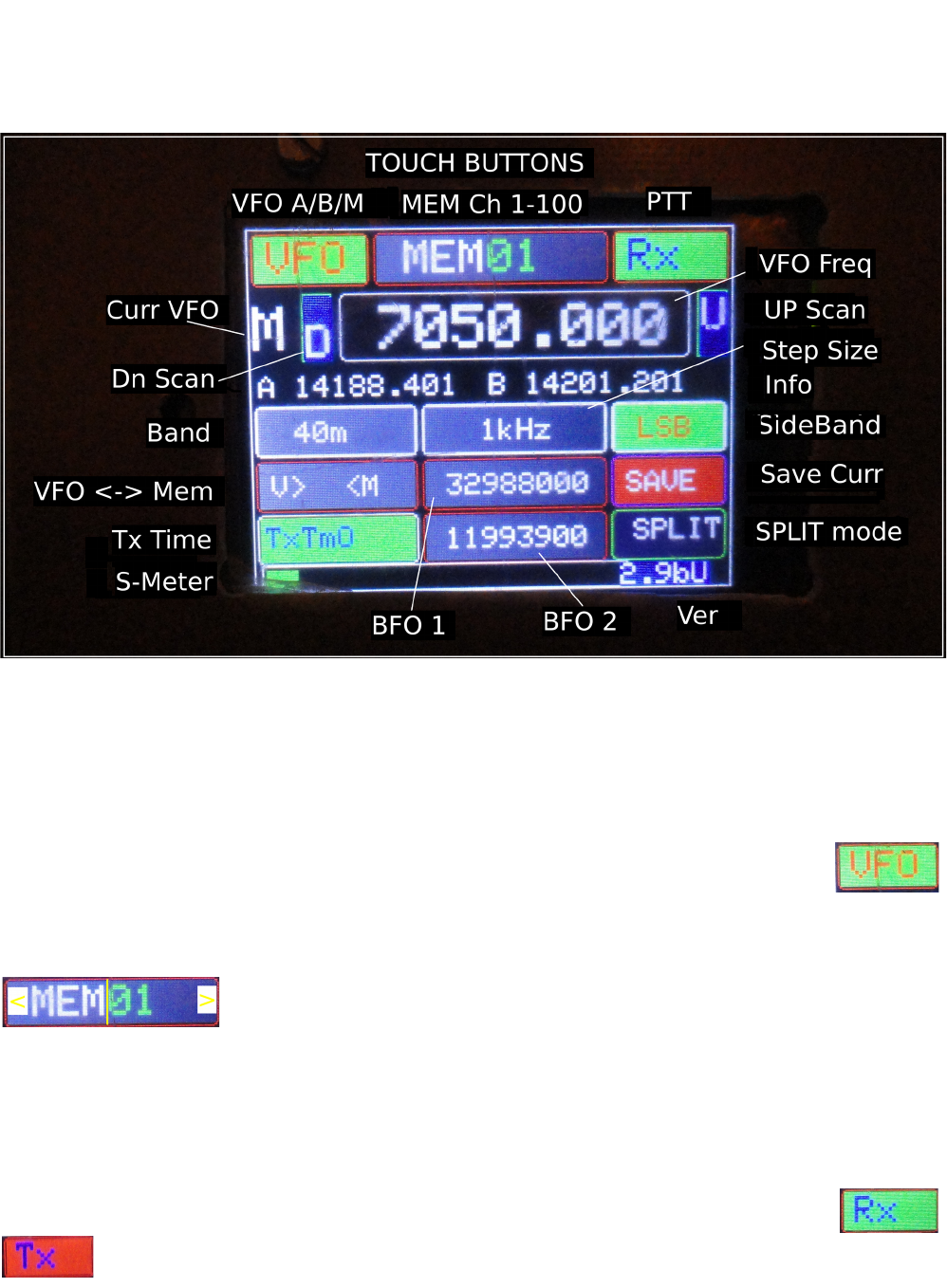
User Interface
All radio control functions are carried out by touching in the button area (except volume control!). The
screen has several touch buttons and their corresponding information is displayed on the button itself.
The function of each button is described below. Please note that for explaining the functions of buttons
I have annotated the buttons below (by ‘<’ which decreses and by ‘>’ which increases the value). The
vertical line near the center of the button is also for explaining the two halves of the double sided
buttons.
VFO button: Repeatedly touching this button rotates between VFO A, VFO B and VFO M (Memory).
This selects the VFO which will become active. A, B or M is displayed below this button
and to the left of frequency display (Curr VFO). This one is touch anywhere button.
Mem ## : Shows the currently selected memory channel number (01 to 100). On touching right half of
the button the memory channel number increases from 00 to 100. Touching the left half of this button
decreases memory channel number. On changing the memory number, the
stored information (vfo frequency, bfo frequency, sideband) from EEPROM
is read and copied to VFO M. If VFO M is current vfo then the retrieved
frequency will be output on VFO otherwise it would be displayed in the Info area below.
The contents of currently selected VFO are displayed in VFO frequency display area whereas the
frequencies of the other two VFOs are displayed in the Info area below.
Rx / Tx (PTT): on touching Rx button the PTT is activated and the button turns RED with
Tx displayed. If PTT Timeout is active (using ‘TxTmO’ button below) then it would
automatically go back to Receive mode after a preset time out (this time is user controlled in
program). In this mode the remaining time is also displayed in seconds on Red Tx button .
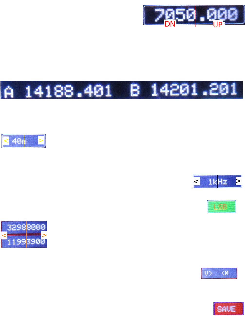
VFO Frequency Display : The selected active vfo (Current
VFO) is displayed here. On selecting a different VFO or
MemCh the display shows previously saved frequency for
that VFO. Touching anywhere in the right half of this
display button increases frequency by selected frequency
steps (which is displayed below in the center -1Hz to 1MHz). Similarly the touch in left half of button
would decrease the frequency by step Hz.
Info / Secondary Frequency Display : Below the active frequency button the other two VFOs are
displayed for information. If VFO A is active, then VFO B and Memory VFO are displayed under the
main frequency display. Similarly when Mem VFO is active the VFO A and B are displayed as below.
(These are purely for information of non active VFOs and are not active buttons and have no effect on
touching.)
Band : Displays the HAM band corresponding to current active VFO. Touching right / left half of this
button sequentially changes the bands. Band frequency limits are preset in the
program which should be changed according to the rules of the country. There is a
continuous freq generator mode for in between band frequencies. Tx works only
within defined band limits.
Steps : This button displays and changes current step size. Initial power up step size is 1KHz. Step size
can be increased or decreased by touching right half or left half of the button.
Steps are sequenced in powers of 10, from 1 Hz to 1MHz.(1Hz, 10Hz, 100Hz,
1kHz, 10kHz, 100kHz, 1MHz).
Side Band : Switching between USB and LSB is done by touching this button.
BFO 1/2: The current BFO 1/2 frequencies are displayed here and can be increased or
decreased by step size by touching on right and left half of the button. These are
the experimenter’s buttons. It is real fun listening to radio while adjusting BFO
frequencies in small steps to get best sounding station. In uBitx the bfo 1 has
broad adjustment range while the bfo 2 is very sharply tuned due to filters in the
two stages.
VFO > < Mem : (displayed as V > <M) On touching the left half of this button the currently selected
VFO (A or B) will be copied to Memory VFO ( not saved yet on EEPROM),
touching the right half of the button will copy the content of Memory VFO on the
currently selected VFO (A/B).
SAVE : Touching this button will save only the “currently active VFO” in EEPROM memory. VFOs A,
B and 100 Memory channels are kept on EEPROM. Only currently displayed VFO is
saved to its corresponding memory location. It saves vfo and bfo frequencies and current
sideband. During save process the text display changes to SAVING.

TxTmO : (PTT_Time_Out Activate button) : This button will activate the Time out function of PTT.
The PTT would automatically get deactivated after the timeout period (i.e. returns
back to Rx from Tx). The period is adjustable from within the program. Very
useful when using toggle PTT as well as in digital modes.
SPLIT : This button uses VFO A for Rx and VFO B for Tx. When this mode is selected the button
changes its colour to Yellow. On pressing the PTT the Transmit freq is that on VFO B. It
comes back to Rx on VFO A freq when PTT is undone / released.
Operating CAT
The USB port on arduino can be connected to a computer for CAT control of some parameters of
uBitx. The settings for using uBitx for CAT control are : Yaesu FT817 rig, Baud rate 38400, No parity
and 1 Stop bit. Normally a connection attempt (like Check CAT from settings in WSJTX or Initialize
from Rig Control/Hamlib in FLDIGI etc) is needed to establish connection between uBitx and
computer. PTT from CAT, Frequency, Band etc can be set from programs like WSJTX, FLDIGI, HRD
etc. It may be needed to install driver for USB chip in Arduino on the controlling computer.
The Hardware
To keep the hardware assembling at minimum we use standard off the shelf components. A standard
Arduino Mega 2560 is the base system on which compatible TFT display touch screen shield is
mounted. A standard breakout board for frequency generating chip 5351 may be connected to Arduino
using two control wires (SCL, SDA), and of course the common ground wire plus the 3 V or 5 V power
supply. A PCB for 5351 is also designed for the more adventurous hams. Details of the PCB with
schematic are given later. All buttons are connected between the appropriate pin and ground.
Though all operations of this VFO are controlled from the touch panel, for those who prefer or need
buttons and rotary encoder, it is easy to connect push buttons for almost all functions and also a
standard rotary encoder may be connected. For connecting the external encoder and buttons a number
of pins are available on Arduino board. These pins are allocated in the sketch and can be reassigned by
user in the program.
The Arduino Sketch
The arduino program or sketch accomplishes all functions related to VFO and BFO needed in a typical
transceiver like uBitx. Due to varieties in the transceiver design, the sketch is kept flexible and may be
adopted for a particular transceiver using some parameters in the program. Details are given in a
separate section below. To make the large sketch manageable, it is divided into smaller parts, all of
which must reside in the same directory. The main sketch is called TFT_VFO_SPF_vxxx.ino, where
vxxx indicated its version. This and remaining 6 parts of the sketch must be located in the same
directory/folder with the name of TFT_VFO_SPF_vxxx within the Arduino Sketch directory / folder.
The names and brief details of these sketches are :
1. TFT_VFO_SPF_vxxx.ino - the main program where the execution begins.
2. EPROMAnything.h - Handles read write to EPROM where some of the settings are saved
3. CommonFns.ino - All functions which are common for operation

4. DispPos.ino - Calculations regarding display layout
5. Displays.ino – All functions needed to display various parameters
6. saveNsetup.ino - functions for setup and various types of saves
7. Cat_cntrl.ino – functions taking care of CAT
User Programmable Parameters
Inside the TFT_VFO_SPF_vxxx.ino sketch somewhere near the beginning, there is a section named
“USER SELECTABLE DEFINITIONS”. Parameters may be changed/ adjusted as suited to hardware
and operational practice. The “#define” statements are used to select parameters, based on those, some
decisions are made later in the program. To define parameters these statements should be
uncommented. Similarly, to undefine, two slashes (//) should be put at the beginning of the line. Many
of these are hardware dependent, e.g. model of the uBitx or other transceiver. Briefly some of these are
explained below:
Display Type: Only MCUFriend type displays using kbv library are used and tested.
To accommodate available variety in TFT displays, we have to define the display type and some
parameters for different displays. A few of these displays have been tested and more may be included
soon. For example elegoo923, IL9325 and MCUF0x154 are names given by us to typical displays.
These may not be standard names. More display types may find their place in this section of the
program. One example
#define IL9325
// for IL9325 type display for which appropriate instructions are needed in program
Button Pins:
Several push buttons may be connected to preassigned Arduino pins for controlling the radio and this
allocation may be changed here in this section. One typical Example:
#define BandSelect 53
indicates that a button connected at Pin D53 will change bands (on repeated push). Similarly many
other functional buttons are defined and used. There is a short description of the function of that
Arduino pin as comments on the same line. You may chose the pin to be other than those defined here
(eg 53 may be 40).
PTT Type:
The uBitx sketch provides two different ways of PTT (1) Normal PTT which works by pressing the
PTT button continuously and (2) Toggle PTT which works by pressing PTT button briefely to shift
from Rx to Tx and again pressing briefely to toggle back from Tx to Rx. This is the behaviour of PTT
touch button on TFT also. When in Tx the button on display turns RED with Tx written on it. The
boolean type variable active_PTT decides this behaviour.
#define PTT_Input 26 // the PTT button is connected to arduino (on pressing must short to ground)
// Normal is Toggle PTT (press briefly to go from Rx to Tx & vice-versa)
bool active_PTT_in = false;
// if PTT remains continuously low during QSO (normal PTT) make it true else leave false for toggle
type PTT
Si5351correction :
This parameter is used to compensate for minor differences in output frequency of Si5351 IC.
Generally a program to calibrate and find this offset ships with the Ether kit’s 5351 library.
ts_delay - sets the delay between touch button to reduce sensitivity. Some touch buttons may trigger
several times when touched briefly, if this delay is small. May vary from model to model. (resistive
touch needs a bit of pressure to work)
Tx_timeout - set time in sec for which the Tx works continuously and then switches back to Rx in Tx
Time out mode (when activated by TxTmO button)
offset and if_offset – compensate for the difference in frequency displayed and actual frequency of
transmission, These offsets are to be determined experimentally by tuning to a known frequency
station.
Building Notes
Some Methods and Tips which have been used to put this project together
1. Using the VFO/BFO board - A separate board was developed to accompany the TFT. It
contains a Si5351 as VFO/BFO generator and also a uBitx extender, all digital I/O pins are
brought out on the edge of the board on the other side to make it easier to connect to uBitx main
board. Details are given below.
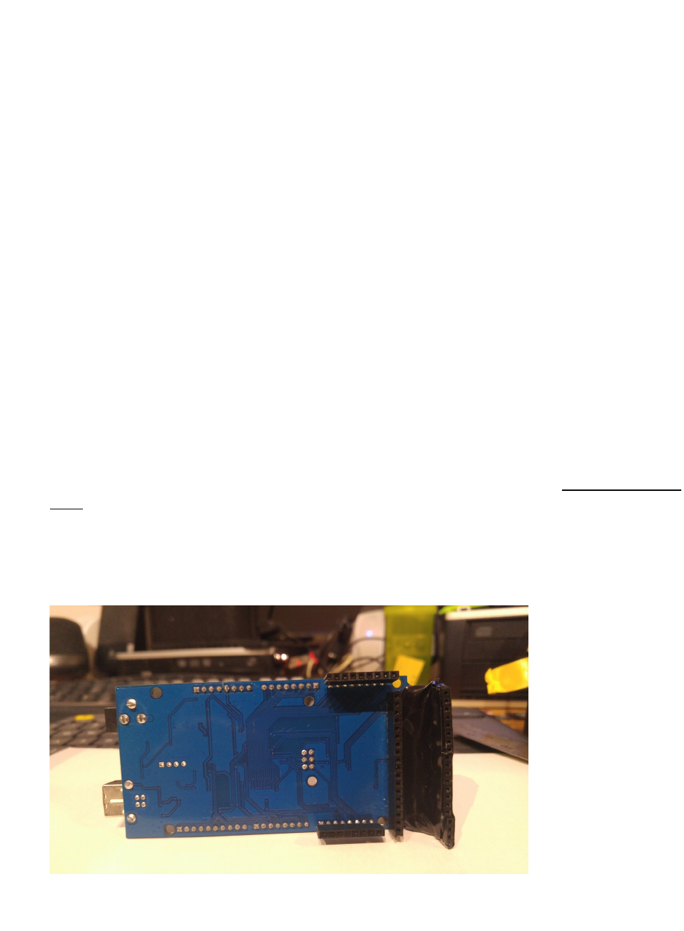
2. The second method is to use a display, and Adafruit Si5351 DDS board and a modified Atmega
2560. Using this method, you can plug the display directly into the Atmega. Next you add strip
sockets to the rear pins of the atmega.. This allows you to plug the required and or optional
external wiring to external devices and from the rear of the atmega. Without the mod the front is
mostly covered by the display which makes it difficult to get access to the atmega pins.
REAR VIEW OF MODIFIED ATMEGA2560
3. The same as method 2, except just solder wires directly to the rear of the Atmega
4. Hash or noise control - After building several versions of this project I (Joe) found digital hash
noise to be quite low. But additional filtering will make it even better. I have used simple hash
filters using a 1000mfd cap followed a 2 – 12 ohm resistor in series with another 10000mfd cap.
Basically two capacitors with a resistor in between, simple but very effective. Use shielded
cable where possible, especially from the dds output to the radio VFO connection. Also,
shielded cable from the rotary encoder is a good idea…. if you decide to add one .however,
Touch control by itself is very good.
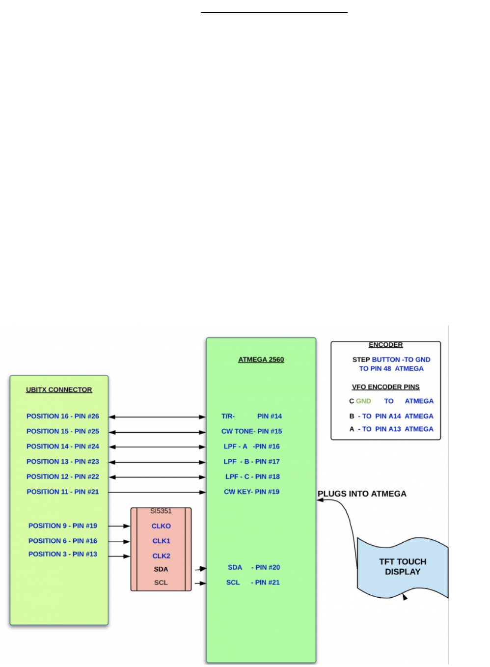
Connection / Wiring information
For employing the second or third metod as described in the building notes above using Adafruit’s
Si5351 breakout board and also for understanding the details of connections the following diagram
would be helpful.
VFO/BFO board
A separate board is developed to accompany the TFT. It contains a Si5351 as VFO/BFO generator with
supporting components and also an extender. All necessary digital I/O pins have been brought out on
the edges of the board which connects on top side to Arduino and on the other side to uBitx main
board. The shematic below shows detailed connectiions. Perhaps the pin numbers are reversed
fromuBitx connector. Will be checked and corrected. The PCB was designed using freely available
KiCad.
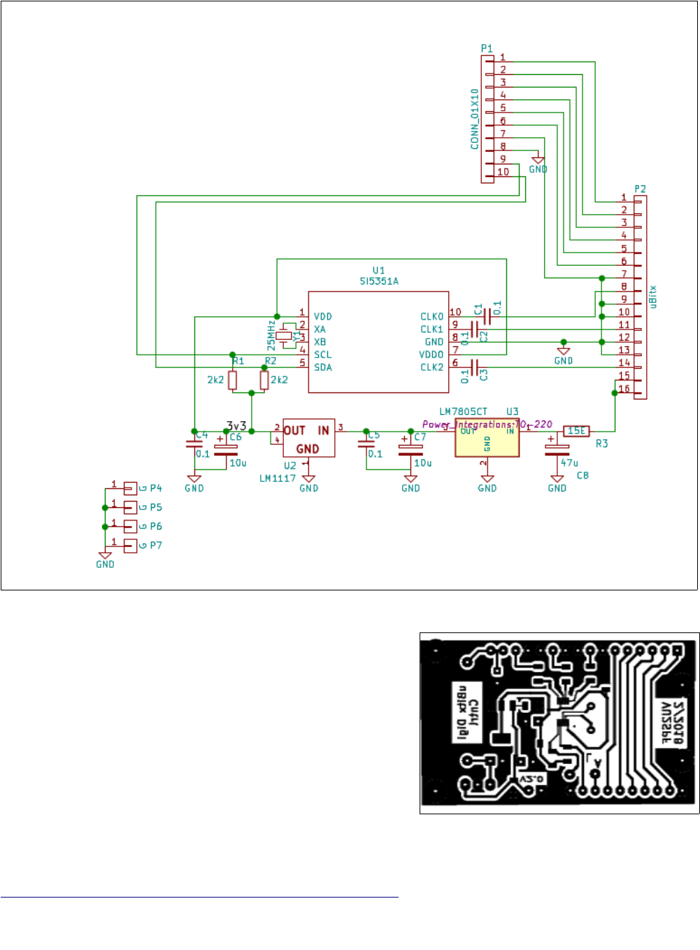
The Si5351 chip is under control of Arduino. VFO and BFO
outputs (CLK0, CLK1 amd CLK2) are available on the
connector pins through a 0.1uF capacitor. The PCB connects
to the Arduino board through a parallel 10 wire connector
(P1) while a 16 pin connector (P2) on the other side of the
PCB gets into uBitx connector.
The PCB lay out in PDF or Gerber is available from github
https://github.com/sprakashb/TFT_TouchScreen_for_uBitx
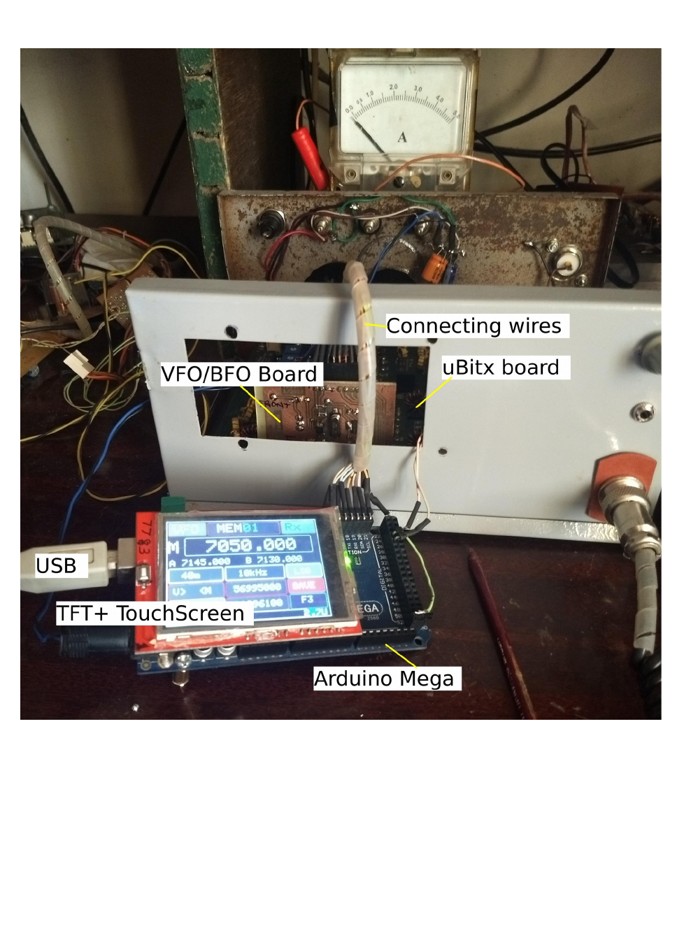
The following photo shows the connections between Arduino Mega 2560, TFT, VFO/BFO board and
uBitx
SOFTWARE NOTES
1. The arduino code has many user options. There are areas at the beginning of the code which the
user may need to change/adjust.
2. Display selections. currently some few choices, but you can add your own
3. TXTimeout Timer - is set for 20 seconds but you can just change the value 20 for whatever
transmit time you desire in seconds.
4. There are many predefined hardware buttons available within the program, just pick the one
you need and add your switch. One side to the atmega pin and the other to ground. These are
optional as the touch control has all the functions already.
[UBITX TFT VFO SPF User Manual 24/04/2018 software Ver 2.9bU ]
