GNSS Evaluation Software For Windows U Center User Guide (UBX 13005250)
ublox-u-center%20User%20Guide%20(UBX-13005250)
ublox-u-center%20User%20Guide%20(UBX-13005250)
User Manual: Pdf
Open the PDF directly: View PDF ![]() .
.
Page Count: 67
- Contents
- 1 Preface
- 2 Features
- 3 Getting Started
- 4 Concept and Philosophy
- 5 u-center Menus and Windows
- 5.1 Main frame and toolbars
- 5.2 Views and windows
- 6 NTRIP
- 7 Google Earth server
- 8 Tools
- 9 How To
- 10 Troubleshooting
- 11 Related Documents
- 12 Revision History

u-center
GNSS evaluation software for Windows
User guide
Abstract
This document leads you through the efficient use of the u-center evaluation software, the powerful and easy
to use tool from u-blox for evaluating, performance analysis and configuration of u-blox GNSS positioning chips
and modules.
www.u-blox.com
UBX-13005250 - R18
u-center-User Guide
UBX-13005250 - R18
Production Information Page 2 of 67
Document Information
Title u-center
Subtitle GNSS evaluation software for Windows
Document type User Guide
Document number UBX-13005250
Revision and date R18 04-Dec-2017
Document status Production Information
Document status explanation
Objective Specification Document contains target values. Revised and supplementary data will be published later.
Advance Information Document contains data based on early testing. Revised and supplementary data will be published later.
Early Production Information Document contains data from product verification. Revised and supplementary data may be published later.
Production Information Document contains the final product specification.
This document applies to the following products:
Product name Type number ROM/FLASH version PCN reference
u-center
u-blox reserves all rights to this document and the information contained herein. Products, names, logos and designs described herein may
in whole or in part be subject to intellectual property rights. Reproduction, use, modification or disclosure to third parties of this document
or any part thereof without the express permission of u-blox is strictly prohibited.
The information contained herein is provided "as is" and u-blox assumes no liability for the use of the information. No warranty, either express
or implied, is given with respect to, including but not limited to, the accuracy, correctness, reliability and fitness for a particular purpose of
the information. This document may be revised by u-blox at any time. For most recent documents, please visit www.u blox.com.
Copyright © 2017, u-blox AG.
u-blox is a registered trademark of u-blox Holding AG in the EU and other countries.

u-center-User Guide
UBX-13005250 - R18
Production Information Contents
Page 3 of 67
Contents
1 Preface............................................................................................................................ 5
1.1 Overview............................................................................................................................................... 5
1.2 Using this guide....................................................................................................................................5
1.3 Technical support..................................................................................................................................5
1.3.1 Worldwide Web............................................................................................................................5
1.3.2 By email........................................................................................................................................5
1.3.3 Helpful information when contacting technical support................................................................ 5
2 Features.......................................................................................................................... 6
3 Getting Started.............................................................................................................. 7
3.1 General information about displayed values..........................................................................................7
3.2 Connecting an u-blox evaluation kit to the PC..................................................................................... 7
3.3 Installing u-center................................................................................................................................. 7
3.4 Connect to the receiver........................................................................................................................ 8
3.4.1 Select the port..............................................................................................................................8
3.4.2 Select the baud rate (only for COM ports)....................................................................................9
4 Concept and Philosophy............................................................................................. 10
4.1 Color and satellite coding scheme...................................................................................................... 11
4.2 Operating modes................................................................................................................................ 12
4.2.1 Online mode............................................................................................................................... 13
4.2.2 Stop mode.................................................................................................................................. 13
4.2.3 Record mode.............................................................................................................................. 13
4.2.4 Play mode................................................................................................................................... 13
4.2.5 Relations between modes........................................................................................................... 13
4.2.6 Database limitations....................................................................................................................14
4.2.7 Receiver information................................................................................................................... 14
5 u-center Menus and Windows................................................................................... 16
5.1 Main frame and toolbars.................................................................................................................... 16
5.1.1 Standard menu bar.....................................................................................................................16
5.1.2 Standard toolbar......................................................................................................................... 24
5.1.3 Views toolbar..............................................................................................................................24
5.1.4 Communication toolbar.............................................................................................................. 24
5.1.5 Logfile toolbar.............................................................................................................................25
5.1.6 Action toolbar.............................................................................................................................25
5.1.7 Standard statusbar...................................................................................................................... 25
5.2 Views and windows............................................................................................................................26
5.2.1 Packet console............................................................................................................................ 26
5.2.2 Binary console.............................................................................................................................26
5.2.3 Text console................................................................................................................................27
5.2.4 Icons and text field of console views.......................................................................................... 28
5.2.5 Regular expression evaluation..................................................................................................... 28
5.2.6 Messages view............................................................................................................................ 30
5.2.7 Statistic view............................................................................................................................... 32
5.2.8 Table view...................................................................................................................................33

u-center-User Guide
UBX-13005250 - R18
Production Information Contents
Page 4 of 67
5.2.9 Map view....................................................................................................................................35
5.2.10 Chart view................................................................................................................................ 41
5.2.11 Histogram view......................................................................................................................... 43
5.2.12 Camera view.............................................................................................................................45
5.2.13 Deviation map...........................................................................................................................46
5.2.14 Sky view....................................................................................................................................48
6 NTRIP............................................................................................................................. 51
6.1 NTRIP Client........................................................................................................................................ 51
6.2 NTRIP Server/Caster.............................................................................................................................52
7 Google Earth server.....................................................................................................54
8 Tools..............................................................................................................................55
8.1 Firmware update.................................................................................................................................55
8.2 Legacy Firmware update u-blox 5 - 8................................................................................................. 56
8.3 Dump receiver diagnostics.................................................................................................................. 57
8.4 GNSS configuration.............................................................................................................................58
8.4.1 Read/Write configuration files..................................................................................................... 58
8.4.2 Editing configuration file.............................................................................................................59
8.5 Preferences..........................................................................................................................................59
9 How To......................................................................................................................... 60
9.1 Change baud rate of receiver............................................................................................................. 60
9.2 Save parameters to receiver non-volatile memory (BBR/Flash).............................................................. 60
9.2.1 Saving parameters with UBX-CFG-CFG....................................................................................... 60
9.2.2 Saving parameters with GNSS configuration............................................................................... 61
9.3 Recording/Playing a log file.................................................................................................................61
9.4 Conduct sensitivity tests......................................................................................................................61
9.5 Read/Write configuration files............................................................................................................. 62
9.6 Set GNSS configuration.......................................................................................................................62
9.7 Change epoch detection method........................................................................................................62
10 Troubleshooting.........................................................................................................64
11 Related Documents....................................................................................................65
12 Revision History......................................................................................................... 66

u-center-User Guide
UBX-13005250 - R18
Production Information 1 Preface
Page 5 of 67
1 Preface
1.1 Overview
u-center is u-blox's powerful GNSS evaluation and visualization tool which can be downloaded free-of-charge
from our website (www.u-blox.com). This user guide provides a description of the features of this software. It
allows end users to assess and test u-blox GNSS positioning chips and modules for navigation and positioning
performance.
The purpose of u-center is to enable users to:
• Conduct performance tests on u-blox and other GNSS devices.
• Configure u-blox GNSS positioning chips and modules.
• Update the firmware on GNSS modules.
• Test the added performance provided by u-blox's AssistNow service.
1.2 Using this guide
This guide assumes that the user has basic computer skills and is familiar with the Windows Graphical User
Interface (GUI) and GNSS receiver environments.
The following symbols are used to highlight important information:
An index finger points out key information pertaining to integration and performance.
A warning symbol indicates actions that could negatively impact the behaviour of the u-center.
1.3 Technical support
If you have questions about installing or using u-center:
• Read this user guide carefully.
• Check our homepage (https://www.u-blox.com) to ensure that your GNSS device, firmware and the u-
center software are the latest versions.
• Refer to our web based information service.
1.3.1 Worldwide Web
Our website (www.u-blox.com) is a rich pool of information. Product information and technical documents can
be accessed 24/7.
1.3.2 By email
If you have technical problems or cannot find the required information in the provided documents, contact the
closest technical support office. To ensure that we process your request as soon as possible, use our service pool
email addresses rather than personal staff email addresses. Contact details are at the end of the document.
1.3.3 Helpful information when contacting technical support
When contacting technical support, have the following information ready:
• Receiver type (e.g. NEO-7N), firmware version (e.g. 1.00), and u-center release (e.g. u-center 8.00).
• Receiver configuration and short description of the application.
• Your complete contact details.

u-center-User Guide
UBX-13005250 - R18
Production Information 2 Features
Page 6 of 67
2 Features
u-center evaluation software provides system integrators and end users with a quick and simple way to interface
with u-blox GNSS chipsets, modules and boards. It enables easy evaluation, performance testing, development
and debugging of GNSS positioning chips and modules. u-center allows easy connection to u-blox products and
provides a suite of features to view, log, and analyze performance. The features include:
• Support for u-blox's receivers using u-blox positioning technology. u-center can communicate with these
receivers using either the UBX protocol or the NMEA-0183 standard protocol.
• Support for receivers that utilize standard NMEA strings.
• u-center presents all the information collected during the operation of the GNSS device. All aspects of
GNSS data (position, velocity, time, satellite tracking, etc.) can be monitored and logged under various test
scenarios for the evaluation of a receiver. u-center software allows analysis of the collected data in order to
investigate performance issues such as accuracy, road test position and trajectory, satellite tracking, time
to first fix, etc. All processed data can be captured in ASCII format and ported into popular spreadsheets
for creating additional plots and statistics.
• Camera View: photographic data can be stored in the log file together with the navigation data and later
be replayed in the application.
• Export data files to Google Earth and Google Maps.
• Supports (Multiple GNSS) AssistNow Online and AssistNow Offline.
• Data recording and playback function.
• Structural and graphical data visualization in real-time.
• Export functionality to standard PC applications.
• Docking views (real-time cockpit instruments): Satellite constellation, compass, clock, altimeter,
speedometer, GNSS and satellite information views.
• Download firmware updates to GNSS positioning modules.
• Support for NTRIP server and NTRIP client functionality.
• Google Earth server support.
• SQLITE database support

u-center-User Guide
UBX-13005250 - R18
Production Information 3 Getting Started
Page 7 of 67
3 Getting Started
3.1 General information about displayed values
• Longitude and latitude are displayed according to the datum selected in the GNSS device (either the default
WGS-84 or based on user-defined parameters). This option can be polled and set using the UBX-CFG-
DAT message.
• Time is displayed with reference to UTC.
• Elevation is displayed with reference to either MSL (Height above Mean Sea Level or Orthometric Height)
or to HAE (Height Above WGS-84-Ellipsoid). The reference is controlled by the GNSS configuration.
3.2 Connecting an u-blox evaluation kit to the PC
This section assumes that you have purchased an u-blox evaluation kit. Should you try to connect a module or IC
receiver directly to the PC, make sure you use appropriate RS-232 level shifters.
The evaluation kit can be connected to the PC by using either an USB or a serial cable. In case of using the USB
port, a driver is required (installed by the u-center for Windows installer or downloadable from our homepage).
Be sure to install the driver before connecting the evaluation kit to the computer.
3.3 Installing u-center
The installation program guides you through the necessary steps for a successful program installation. During the
installation, you can choose the destination folder for the program.
u-center uses dynamic link libraries (DLL). The installation program will automatically install the
required DLL's into the u-center program directory. Should you try to copy a u-center installation
from one location to another after the installation, make sure you copy the DLL files as well.
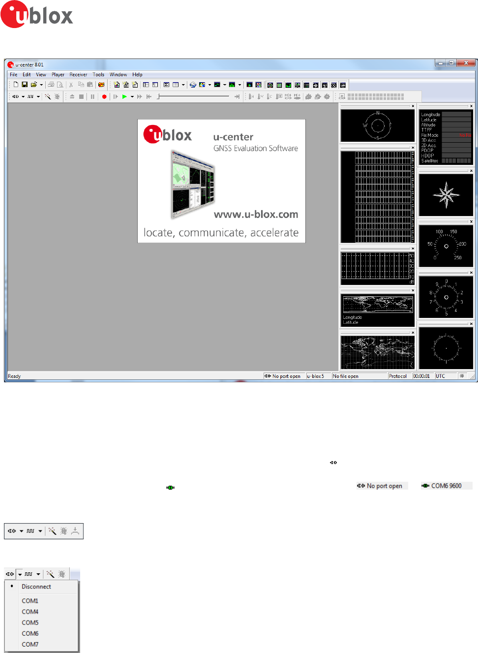
After a successful installation, u-center can be started from the Start Menu (All Programs -> u-blox -> u-center
-> u-center) and will start up as shown in Figure 1.
u-center-User Guide
UBX-13005250 - R18
Production Information 3 Getting Started
Page 8 of 67
Figure 1: Start display
3.4 Connect to the receiver
3.4.1 Select the port
Locate the communication toolbar (Figure 2) and click on the arrow beside the icon. This will show a list with all
available COM ports (Figure 3). Select the corresponding COM port where the receiver is connected. If a link could
be established, the icon will turn green and the text in the status bar changes from to
(in this example u-center is connected to COM6). This does not mean that the communication already works but
only that the port could be opened.
Figure 2: Communication Toolbar
Figure 3: List of available COM ports
u-center-User Guide
UBX-13005250 - R18
Production Information 3 Getting Started
Page 9 of 67
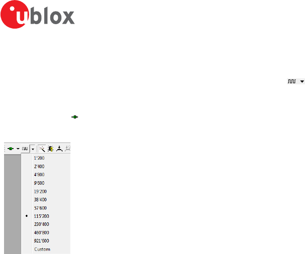
3.4.2 Select the baud rate (only for COM ports)
Again in the communication toolbar, click on the arrow beside the icon. This will show a list with all available
baud rates (Figure 4). Select the correct baud rate on which the receiver is communicating (typically 9'600 baud).
If u-center is able to decode data from the receiver, the status bar begins to blink in green as shown in the
following icon: . This means that the connection is established successfully and the communication between
the receiver and u-center is working.
Figure 4: List of available baud rates
Now you are ready to use the receiver.
u-center-User Guide
UBX-13005250 - R18
Production Information 4 Concept and Philosophy
Page 10 of 67
4 Concept and Philosophy
Understanding the basic concept behind u-center is important in order to get the highest benefit out of this
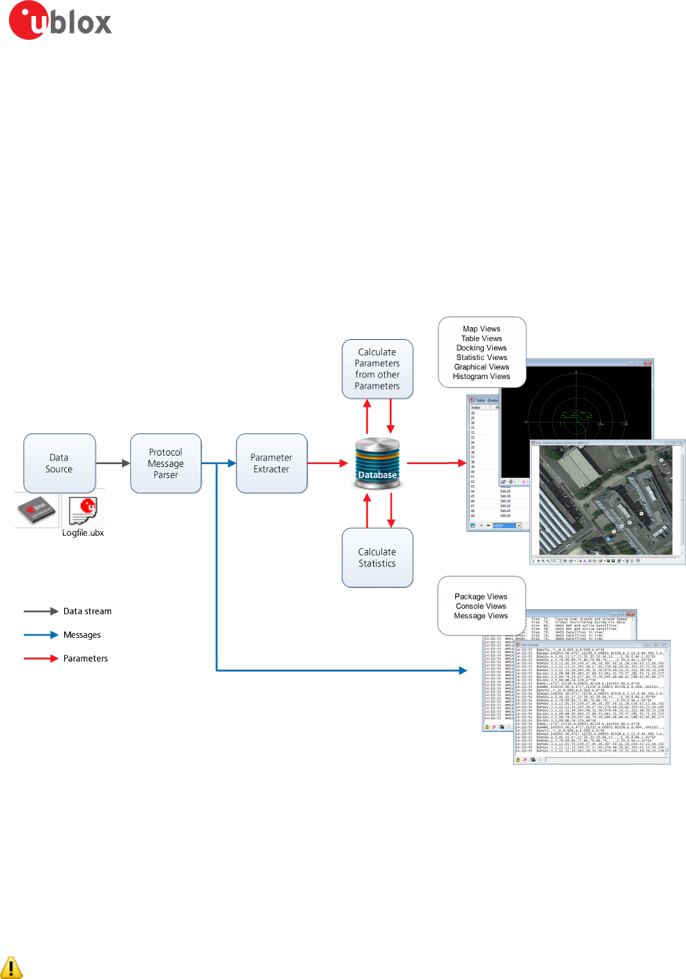
powerful evaluation software. Figure 5 depicts the architecture of the software. The program gets a data stream
from either a communication port or a log file and splits this stream into protocol messages. From the messages,
relevant parameters are extracted and inserted into the current dataset of the database that is used by the display
and analysis features of the application.
In the current dataset, statistical values of the parameters are calculated. Average, minimum, maximum and
standard deviation are calculated for most parameters. If the available messages do not provide a parameter, u-
center tries to calculate the parameter from the ones that are available. For example if velocity-north and velocity-
east are available, u-center calculates the speed over ground and course over ground, unless this data is already
available in other messages.
Figure 5: Engine Architecture
When a new epoch (change in time) is detected, the current dataset is stored as history in the database. The
database used is Sqlite and the name of the database file is ucenter.db. It can be found in the directory defined
with the environment variable named %LOCALAPPDATA%\u-blox. Every instance of u-center creates this file
with a unique timestamp added to its name. The file is not deleted after u-center closes, so the database can be
used for post-processing using the standard SQL language. However, to avoid leaving large amounts of historical
database files lying around, when u-center starts it tries to delete all database files that are currently not in use.
The database size may be adjusted. If the size is exceeded u-center keeps only the latest datasets and the oldest
ones are removed. Refer to Database limitations for the details.
Very long recordings may decrease performance of u-center.
u-center-User Guide
UBX-13005250 - R18
Production Information 4 Concept and Philosophy
Page 11 of 67
u-center provides various view classes (described below) for display and presentation. Most views take their data
from the database, but some get their data directly from the message without using the database at all. The
other views are updated when the database changes.
•Message Views display and decode a copy of every known message. These views allow observing a single
message in detail and they may also be used to configure the GNSS device. Refer to Messages view for
details. The configuration view is a subset of the message view and only displays message to configure
the receiver.
•Console Views display the messages in text form. There is also a wide range of information available
which is useful for evaluation and testing. Refer to sections Packet console, Binary console and Text console
for details.
•Graphical Views display parameters from the database in graphical form. Charts (see Chart view),
histograms (see Histogram view) and a map view (see Map view) can be created. There are two more views
(deviation map and sky view, see Deviation map and Sky view) that may be used for statistical performance
and antenna pattern analysis.
•Tabular Views show the parameters of the database in tabular form. They can be freely configured to
allow customized tables. Refer to Table view and Statistic view for details.
•Docking Windows can be docked to the frame of u-center. An analog watch, compass, world map,
altitude and speed meter are available. There are also docking windows showing the current signal power
and the constellation of the satellites received by the device as well as a summary of the GNSS status.
Displaying various views and docking windows requires computing power. Minimizing or closing them
may significantly reduce CPU usage.
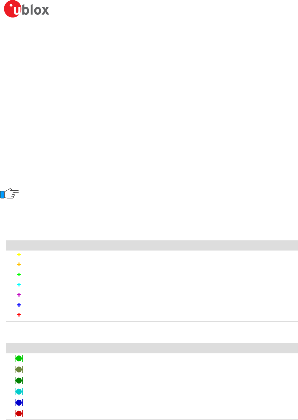
4.1 Color and satellite coding scheme
In the graphical views and some docking windows, colors are used to indicate data quality. Table 1 shows the
color codes for graphical views depending on the quality of the navigation solution.
Color Meaning
Yellow Current value
Orange Valid 3D navigation fix + Dead Reckoning
Green Valid 3D navigation fix
Cyan Valid 2D navigation fix
Magenta Dead Reckoning fix
Blue Degraded navigation fix
Red No or invalid navigation fix
Table 1: Color-coding scheme for graphical views
Table 2 gives the color-coding scheme for the docking windows and sky view. It indicates the state of each satellite.
Color Meaning
Green Satellite used in navigation (with Ephemeris)
Olive Satellite used in navigation (with Ephemeris and PPP)
Dark Green Satellite used in navigation (with aiding data: AssistNow Autonomous, AssistNow Online/Offline)
Cyan Satellite signal available, available for use in navigation
Blue Satellite signal available, not available for use in navigation
Red Satellite signal not available
Table 2: Color-coding scheme for the docking windows and sky view
u-center-User Guide
UBX-13005250 - R18
Production Information 4 Concept and Philosophy
Page 12 of 67
Table 3 gives the satellite-coding scheme for the docking windows and sky view. It indicates to which GNSS a
satellite belongs.
Code System
Gxx GPS
Rxx GLONASS
Bxx BeiDou
Exx Galileo
Sxx SBAS
Qxx QZSS
Table 3: Satellite-coding scheme for the docking windows and sky view
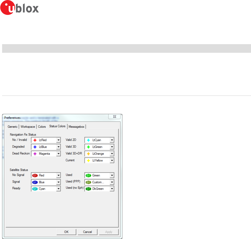
Figure 6 shows the Status Color configuration. This is available under: Tools -> Preferences -> Status Colors.
Figure 6: Color-coding configuration
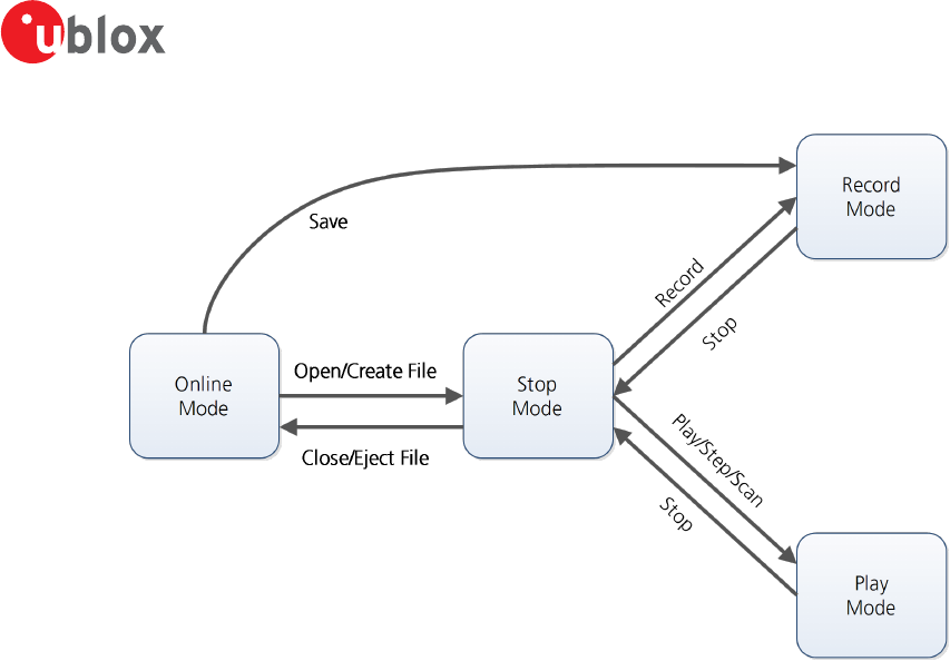
4.2 Operating modes
u-center has different operating modes (see Figure 7). The mode changes when you open or close a log file or
when you invoke the player. To be able to use the record mode you have to create a new file, save to a new
file or open an existing file. The record and play mode are only available if you have created a new file or when
you have opened a writable file.
u-center-User Guide
UBX-13005250 - R18
Production Information 4 Concept and Philosophy
Page 13 of 67
Figure 7: Relation between operating modes
4.2.1 Online mode
In this mode a GNSS device is directly connected to u-center via a COM port. u-center can control and configure
the receiver and it will display the data that the receiver is sending periodically.
4.2.2 Stop mode
In this mode no data from a receiver or a log file is forwarded to the database and views. u-center is in this mode
when a log file is open but player and recorder are not active.
4.2.3 Record mode
Record Mode is the same mode as the Online Mode, except u-center additionally creates a log file, concatenating
all the messages sent by the receiver. You enter this mode by creating a new log file or opening an existing log
file without write protection and pressing the record button. An example of using this mode would be to make
overnight measurements and evaluate the data at a later time. u-blox customer support may request a log file
from you when you are experiencing a problem with one of our receivers and will usually need this to be recorded
with debug data enabled (see Receiver.
4.2.4 Play mode
The Play Mode allows replaying a previously recorded log file step by step, in real-time or at an accelerated rate.
You enter this mode by opening a file and pressing the play, step or scan button.
4.2.5 Relations between modes
The operating mode depends on the status of the log file player. Modes are changed by user actions. Each mode
has different states that are changed by a user action or by an event (see Figure 7). In Online mode and Record
mode, u-center displays data from the receiver. In Play mode data from a log file is displayed. Play mode has
different states:
• Play reads and displays messages periodically from the log file. The user interface is derived from that of
a CD player. u-center updates the views after each message.
• Step gets one message from the log file and immediately returns to paused Play state.
• Scan reads messages periodically but the display is only updated when paused or by changing the state.
u-center-User Guide
UBX-13005250 - R18
Production Information 4 Concept and Philosophy
Page 14 of 67
Position can be set in a log file. This behaves differently in Play mode and Stop mode. In Stop mode the
position is just set and no data is read and displayed. u-center will start recording or playing from that position
when changing the mode. If position is set in Play mode, u-center will load the data up to this position from
the log file and display the contents.
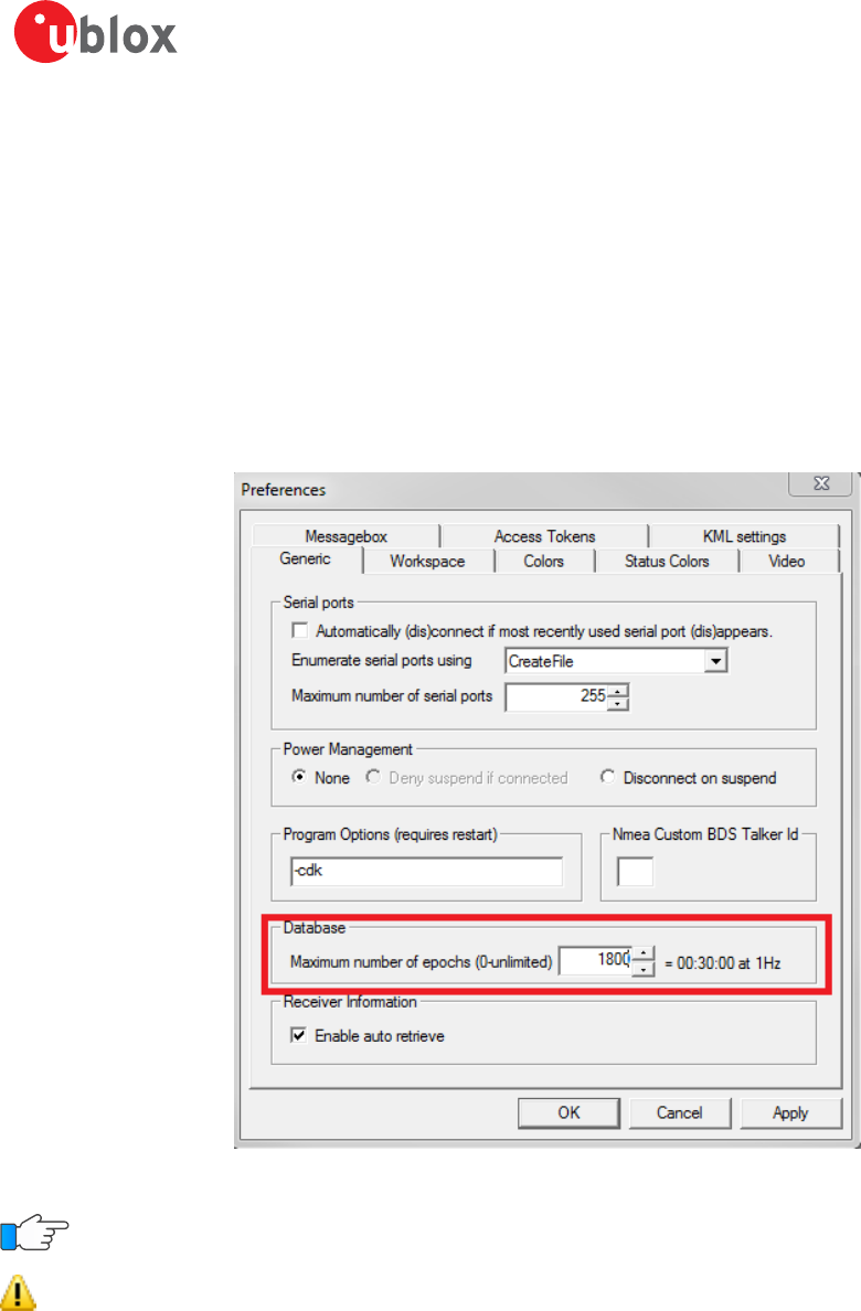
4.2.6 Database limitations
The number of epochs displayed in u-center can be limited in order to allow an efficient analysis of large log files
and not to consume too much disk space. There is a setting which controls the database limit, which is available
under: Tools -> Preferences -> General. By default the value is set to 0 which means the database size is not
limited. Any other number higher than 0 will limit the size of the database. When this limit is set, then the oldest
values will be discarded after the database reaches this limit size. Data stored to a log file is not affected by the
database limitation.
Figure 8: Example of setting maximum number of epochs to keep in database
For long-term observations, it is recommended to record the messages to a log file.
Attention If a high value of epochs is selected, the display of data in real-time cannot be guaranteed,
especially when graphical views are open.
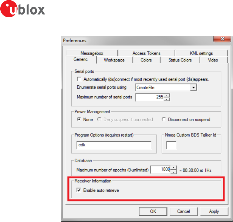
4.2.7 Receiver information
u-center will try to retrieve some information about what kind of receiver is connected by sending UBX-MON-
VER message on every successful connection. In this way certain functionality can automatically be disabled if it is
not supported by the connected receiver. In some cases this might not be the desired behavior as it might hinder
some other operation where these extra messages are not desired. There is a setting that controls if receiver
information is auto-retrieved or not, and that is available under: Tools -> Preferences -> General. By default the
auto retrieval is enabled.
u-center-User Guide
UBX-13005250 - R18
Production Information 4 Concept and Philosophy
Page 15 of 67
Figure 9: Enabling/disabling automatic receiver information retrieval
u-center-User Guide
UBX-13005250 - R18
Production Information 5 u-center Menus and Windows
Page 16 of 67
5 u-center Menus and Windows
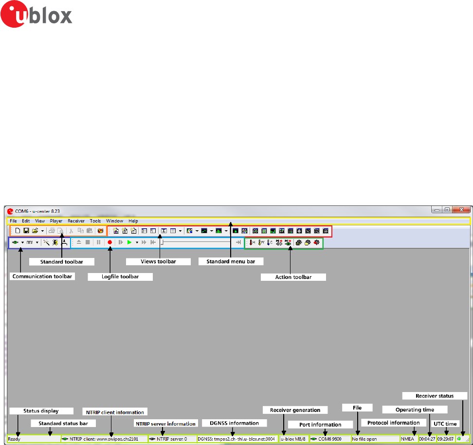
5.1 Main frame and toolbars
The main frame is the primary display screen of u-center. It displays all tool bars and some of the information
provided by the device. In the standard status bar, information about communication, UTC time, connection time,
used protocol (NMEA or UBX), used file, etc. is shown.
Button tool tip: A description about each button in the toolbars can be obtained by holding the mouse cursor
over the button for a few seconds. A tool tip message will appear near the icon with additional information while
a detailed description is displayed in the status display.
Figure 10: u-center main frame and toolbars
5.1.1 Standard menu bar
All u-center functions can be accessed through the standard menu bar. Commands can also be accessed by
shortcuts that are listed in the menus. Some often used operations are also available in the different toolbars.
u-center-User Guide
UBX-13005250 - R18
Production Information 5 u-center Menus and Windows
Page 17 of 67
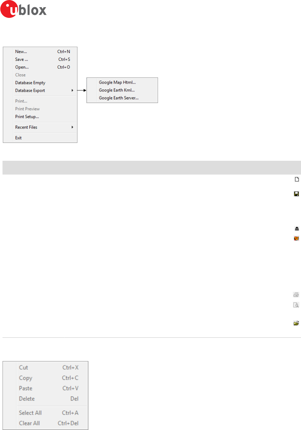
5.1.1.1 File
Figure 11: File menu entries
Function Description Shortcut /
Toolbar icon
New... Creates a new log file. No data is yet written but only the file is opened. The duration of the
logging time is displayed in the status bar field Operating time. Ctrl+N /
Save... Creates a new log file, saves the data from the internal database to the log file and starts
immediately recording all new data from the receiver. This is useful when an error or an
unexpected event occurred and no log file was recorded. The size of the ring buffer (4 MB)
is large enough to retain the data for the last hour (approx.).
Ctrl+S /
Open... Opens a stored log file to be replayed. Ctrl+O
Close Closes the active file. Ctrl+E /
Database Empty Deletes the internal database and all saved values.
Database Export Exports the internal database into HTML or KML data formats for displaying with Google
Map or Google Earth.
Google Map Html... Exports the internal database into HTML data format for displaying with Google Map.
Google Earth Kml... Exports the internal database into KML data format for displaying with Google Earth.
Google Earth Server... Starts u-center's Google Earth server which allows continuous and real time tracking to be
visualized in Google Earth.
Print... Prints the active document.
Print Preview Shows a preview of the print output.
Print Setup... Shows the setup dialog of the printer.
Recent Files Lists all recently used files.
Exit Exits u-center. Ctrl+F4
Table 4: File menu entries
5.1.1.2 Edit
Figure 12: Edit menu entries
u-center-User Guide
UBX-13005250 - R18
Production Information 5 u-center Menus and Windows
Page 18 of 67
Function Description Shortcut /
Toolbar icon
Cut Cut the current selection and put in to the clipboard. Ctrl+X / Shift
+Del /
Copy Copy the current selection to the clipboard. Ctrl+C / Ctrl-
Insert /
Paste Paste the clipboard content to the current position. Ctrl+V / Shift
+Insert /
Delete Delete the current selection. Del
Select All Select all in the current view. Ctrl+A
Clear All Clear all in the current view. Ctrl+Del
Table 5: Edit menu entries
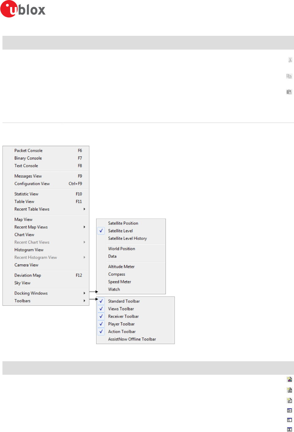
5.1.1.3 View
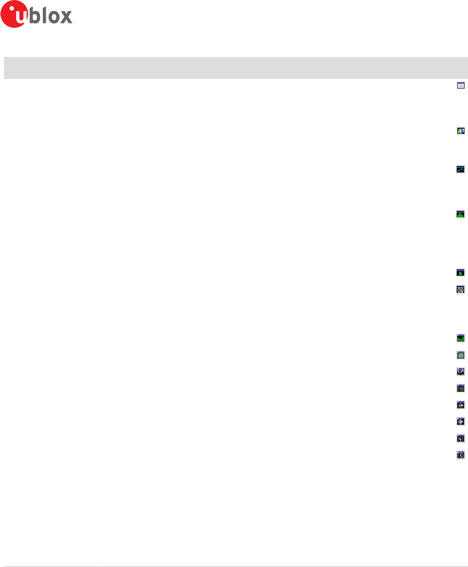
Figure 13: View menu entries
Function Description Shortcut /
Toolbar icon
Packet Console Opens the packet console. F6 /
Binary Console Opens the binary console. F7 /
Text Console Opens the text console. F8 /
Messages View Opens the dialog with all supported messages. F9 /
Configuration View Opens the dialog with all configuration messages. This is a subset of the Messages View. Ctrl-F9 /
Statistic View Opens the statistic view with all data from the internal database. F10 /
u-center-User Guide
UBX-13005250 - R18
Production Information 5 u-center Menus and Windows
Page 19 of 67
Function Description Shortcut /
Toolbar icon
Table View Opens the empty table view. All values from the internal database can be displayed
individually. F11 /
Recent Table View Lists all the table views that have been opened. This information comes from the Windows
registry and is also valid after a restart of u-center.
Map View Opens a window allowing to display a map.
Recent Map View Lists all the maps views that have been opened. This information comes from the Windows
registry and is also valid after a restart of u-center.
Chart View Opens a window with chart functionality. All values from the internal database can be
displayed individually.
Recent Chart View Lists all the chart views that have been opened. This information comes from the Windows
registry and is also valid after a restart of u-center.
Histogram View Opens a window with histogram functionality. All values from the internal database can be
displayed individually.
Recent Histogram View Lists all the histogram views that have been opened. This information comes from the
Windows registry and is also valid after a restart of u-center.
Camera View Opens a window allowing to connect to a web cam and visualize and save the image.
Deviation Map Opens a window with a position deviation map. F12 /
Sky View Opens a window with the sky view. The current position of the satellites and their values
from the internal database are shown.
Docking Windows Opens a list with all available docking windows that can be shown.
Satellite Position Shows or hide the current satellite positions.
Satellite Level Shows or hide the current satellite levels.
Satellite Level History Shows or hide the history of the satellite levels.
World Position Shows or hide the current position on the world map.
Data Shows or hide data from the navigation solution (like position, TTFF, accuracy and DOPs).
Altitude Meter Shows or hide the altitude meter.
Compass Shows or hide the compass.
Speed Meter Shows or hide the speed meter.
Watch Shows or hide the clock.
Toolbars Opens a list with all available toolbars that can be shown.
Standard Toolbar Shows or hide the standard toolbar.
Views Toolbar Shows or hide the views toolbar.
Receiver Toolbar Shows or hide the receiver toolbar.
Player Toolbar Shows or hide the player toolbar.
Action Toolbar Shows or hide the action toolbar.
AssistNow Offline
Toolbar
Shows or hide the AssistNow Offline toolbar.
Table 6: View menu entries
u-center-User Guide
UBX-13005250 - R18
Production Information 5 u-center Menus and Windows
Page 20 of 67
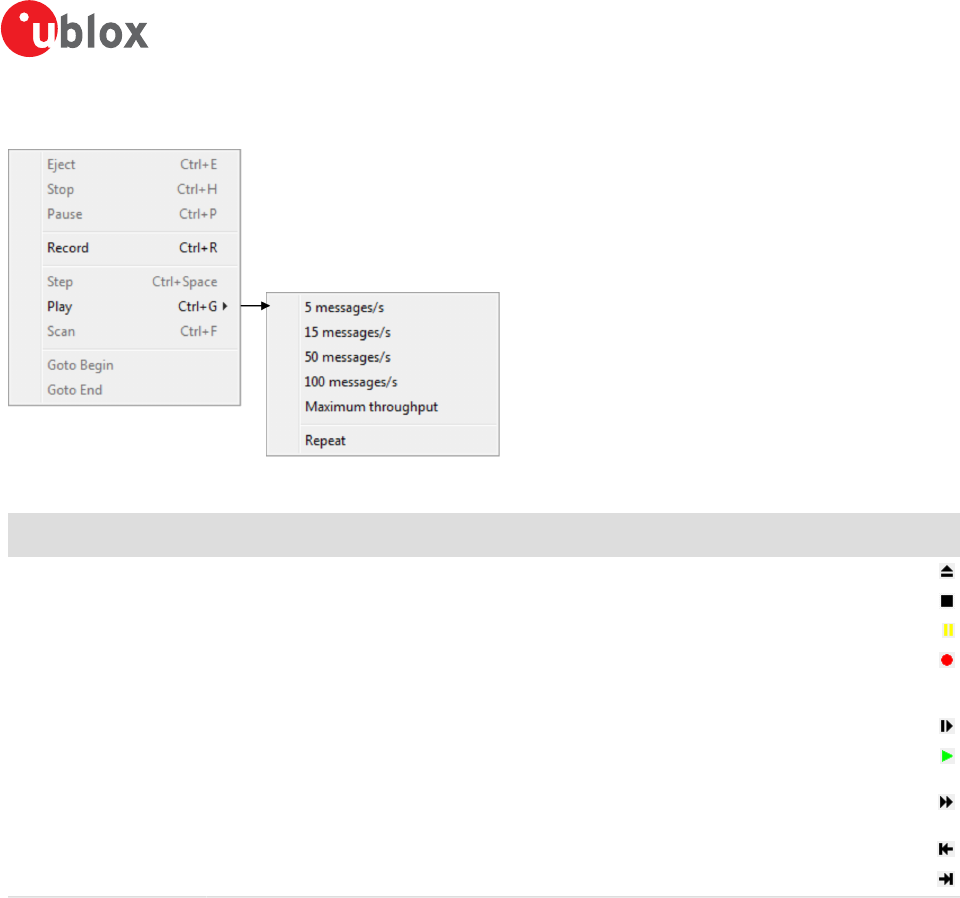
5.1.1.4 Player
Figure 14: Player menu entries
Function Description Shortcut /
Toolbar icon
Eject Closes the active log file. Ctrl+E /
Stop Stops reading or recording from the active log file. Ctrl+H /
Pause Pauses reading or recording from the active log file. Ctrl+P /
Record Starts recording to a new or already opened log file. Any data in the internal database will
not be written to the file. If you want to save this data into a log file, open the File menu
and click Save.
Ctrl+R /
Step Single step function. The next message is read. Ctrl+Space /
Play Starts reading from the active log file. The speed of the action can be chosen on the sub-
menu. Ctrl+G /
Scan Reads the entire log file into the database and updates the display at the end of the scan
period. Ctrl+F /
Goto Begin Sets the read position to the begin of the log file.
Goto End Sets the read position to the end of the log file.
Table 7: Player menu entries
u-center-User Guide
UBX-13005250 - R18
Production Information 5 u-center Menus and Windows
Page 21 of 67
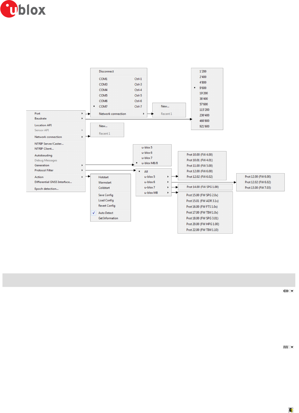
5.1.1.5 Receiver
Figure 15: Receiver menu entries
Function Description Shortcut /
Toolbar icon
Port Defines the port u-center connects to. The list is generated automatically using the
enumeration method under Tools -> Preferences -> Generic -> Serial ports. The currently
used port will be indicated.
Disconnect Disconnects from a connected receiver.
COMx Connects to COMx with the current baud rate. Ctrl+[1...9]
(if available)
Network connection Connects to a receiver through network.
Baud rate Defines the baud rate of the communication. The list is predefined and cannot be changed.
The currently set baud rate will be indicated.
Location API Connects to the receiver using the Location API of Windows 7 onwards.
Sensor API Connects to the receiver using the Sensor API of Windows 7 onwards (the USB Sensor driver
is required in this case).
NTRIP Server/Caster Enables u-center to act as a NTRIP server.
NTRIP Client Enables u-center to act as a NTRIP client.
Autobauding Enables or disables autobauding for the current communication with the receiver.
Debug Messages Enables all debug messages in the receiver. Can be requested by the u-blox support.
Generation Defines the generation of the attached u-blox GNSS receiver. u-center also tries to detect
automatically the correct generation.
Protocol Filter Sets the message filter against versions of protocol specification.
u-center-User Guide
UBX-13005250 - R18
Production Information 5 u-center Menus and Windows
Page 22 of 67
Function Description Shortcut /
Toolbar icon
Action Lists all possible actions that can be performed with the u-blox GNSS receiver.
Hot start Sends a hot start command to the receiver. No data is deleted in the receiver.
Warm start Sends a warm start command to the receiver. Only the ephemeris are deleted from the
memory.
Cold start Sends a cold start command to the receiver. All information is deleted from the memory.
Save Config Saves the current receiver configuration to the memory so that it will be loaded after a
restart.
Load Config Loads the last saved configuration from the memory.
Revert Config Deletes all configurations in the memory and reverts the receiver to the default
configuration.
Auto Detect Enable/Disables the automatic polling of the UBX-MON-VER message to allow u-center to
obtain information about the receiver. On receiving the message, the receiver information
contained within the message is extracted, stored and used by u-center for any receiver
specific features. Having this feature enabled allows u-center to automatically be aware of
the type of receiver attached. Disabling this feature is useful during times when having UBX-
MON-VER messages randomly appearing could interfer with the current user task.
Get Information Manually polls the receiver for a UBX-MON-VER message. On receiving the message, the
receiver information contained within the message is extracted, stored and used by u-center
for any receiver specific features. Typical use would be when the user needs auto detection
disabled, but would like u-center to be aware of the connected receiver's details.
Differential DGNSS
Interface…
Allows the streaming of RTCM messages to the receiver for high precision applications.
Epoch detection… Defines which time information determines the boundary of an epoch detection in u-center
(see Change epoch detection method).
Table 8: Receiver menu entries
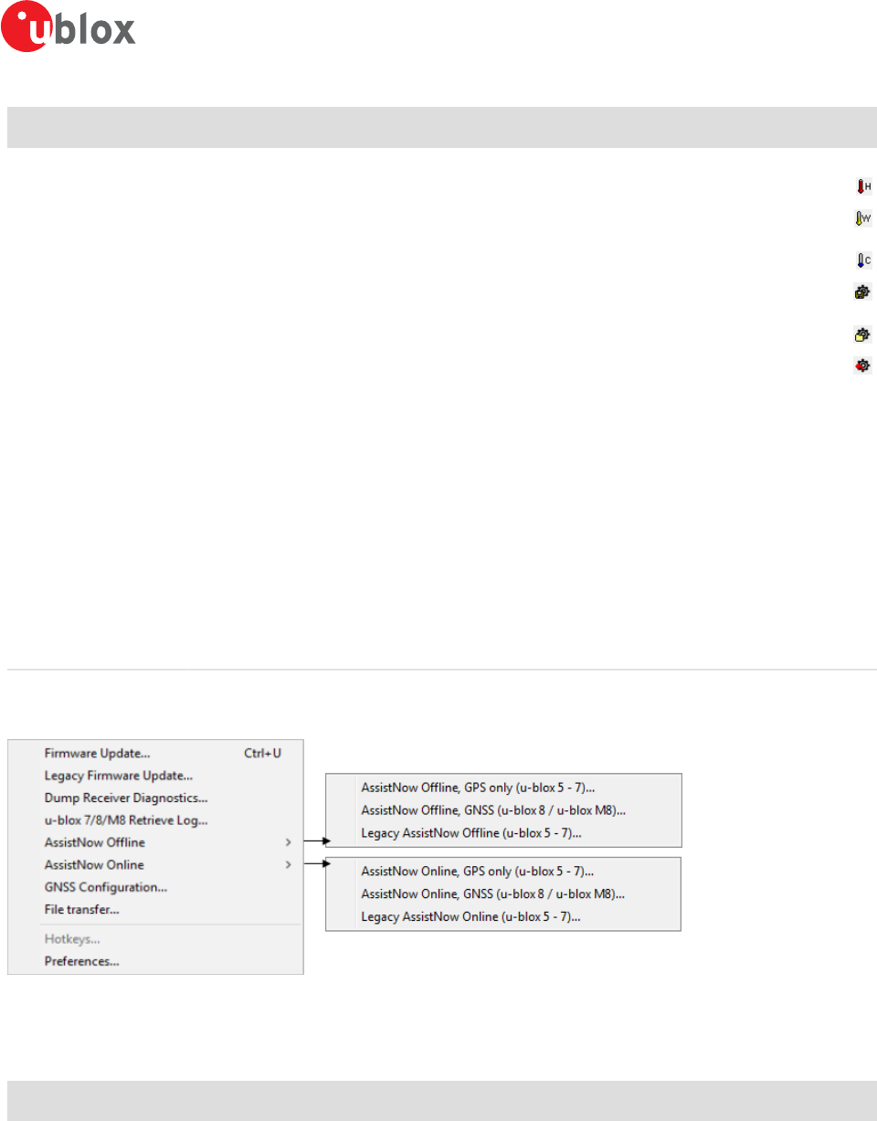
5.1.1.6 Tools
Figure 16: Tools menu entries
Some of the menu items will only be displayed when the correct receiver generation is connected and identified
by u-center. If you cannot select one option, change the receiver generation under Receiver -> Generation.
Function Description Shortcut /
Toolbar icon
Firmware Update... Update the receiver's firmware. Can be used for all u-blox generation 5 receivers and
beyond.
Ctrl+U
Legacy Firmware
Update...
Update the receiver's firmware using the legacy firmware updater. Can be used for all u-
blox generation 5 - 8 receivers.
Dump Receiver
Diagnostics...
Tool to create the receiver diagnostic. Can be requested by the u-blox support team.
u-blox 7/8/M8 Retrieve
Log...
Opens the dialog to download log information from the receiver. This is supported only by
u-blox 7 receivers and beyond.
u-center-User Guide
UBX-13005250 - R18
Production Information 5 u-center Menus and Windows
Page 23 of 67
Function Description Shortcut /
Toolbar icon
AssistNow Offline Opens the AssistNow Offline dialog. Please switch over to AssistNow Offline as the Legacy
AssistNow Offline service is marked deprecated.
AssistNow Online Opens the AssistNow Online dialog. Please switch over to AssistNow Online as the Legacy
AssistNow Online service is marked deprecated.
GNSS Configuration... Opens the dialog to save the receiver configuration to a file on the PC or to restore a
configuration from a file on the PC.
File transfer... Opens the dialog to transfer a file to the receiver.
Hotkeys... Shows the hotkey manager. Allows assigned hotkeys to be edited or deleted.
Preferences... Opens the dialog for the u-center preferences.
Table 9: Tools menu entries
5.1.1.7 Window
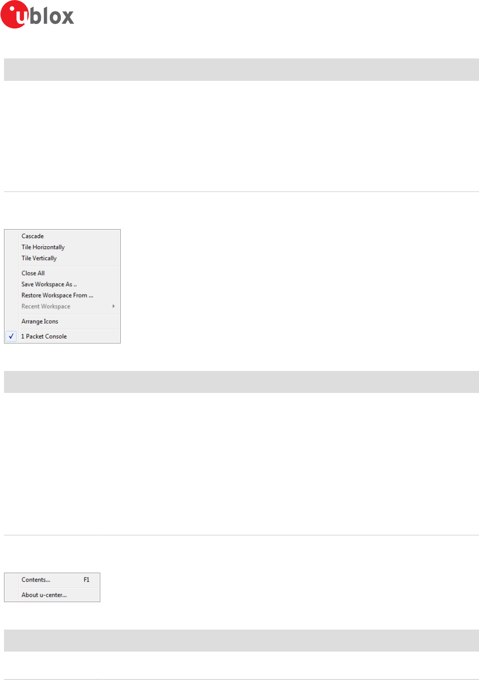
Figure 17: Window menu entries
Function Description Shortcut /
Toolbar icon
Cascade Arranges all open dialogs cascaded.
Tile Horizontally Arranges all open dialogs horizontally.
Tile Vertically Arranges all open dialogs vertically.
Close All Closes all open dialogs and windows.
Save Workspace As... Saves the position of the open dialogs and windows to a file on the computer.
Restore Workspace
From...
Restores the position of the dialogs and windows from a file on the computer.
Recent Workspace Lists all recently used workspace files.
Arrange Icons Arranges the icons at the bottom of the window.
List of dialogs and
windows
Lists all visible and hidden dialogs and windows in u-center.
Table 10: Window menu entries
5.1.1.8 Help
Figure 18: Help menu entries
Function Description Shortcut /
Toolbar icon
Contents... Gives a reference to this user guide. F1
About u-center... Shows the about dialog with the software version and the used libraries and their versions.
Table 11: Help menu entries
u-center-User Guide
UBX-13005250 - R18
Production Information 5 u-center Menus and Windows
Page 24 of 67
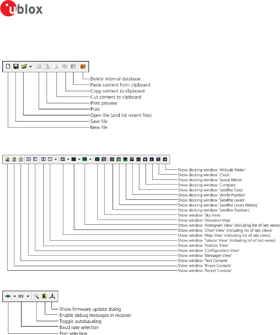
5.1.2 Standard toolbar
The standard toolbar gives access to standard operations like opening and saving files, print the current view or
empty the database.
5.1.3 Views toolbar
5.1.4 Communication toolbar
u-center-User Guide
UBX-13005250 - R18
Production Information 5 u-center Menus and Windows
Page 25 of 67
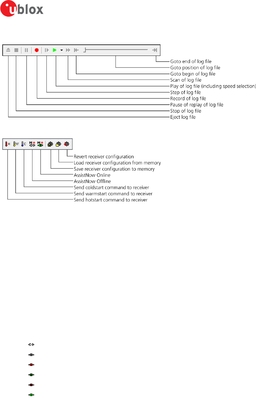
5.1.5 Logfile toolbar
5.1.6 Action toolbar
5.1.7 Standard statusbar
The standard status bar is updated automatically and shows the information about the opened file, the connection
and the time. The following fields are available:
Status display: Displays the current action or the function of a button if the mouse cursor is over the button.
NTRIP client information: Shows the connection to an NTRIP caster (only when activated through Receiver ->
NTRIP Client...). Clicking on it will show up to 100 of the last errors between u-center and connected NTRIP caster.
NTRIP server information:Shows the status and number of clients currently connected to u-center's NTRIP
caster (only when activated through Receiver -> NTRIP Server/Caster...). Clicking on it will show up to 100 of the
last errors between u-center's NTRIP caster and connected clients.
DGNSS information: Shows the connection to a DGNSS source (only when activated through Receiver ->
Differential GNSS Interface...).
Receiver generation: u-center tries to automatically detect the type of device connected and activates the
appropriate mode of operation in order to take optimal advantage of the features. The mode can also be manually
selected through the menu bar (Receiver -> Generation).
Port information: Shows the active COM port and baud rate. Color coding of the icon:
Disconnected
Waiting for first data
Data is being received but errors are detected (mostly because of wrong baud rate settings)
Last data received was valid but there is no data to collect at this time
No data is being received but errors have been detected in the past
Data is being received and collected at the correct baud rate
File: The file opened in the u-center player.
u-center-User Guide
UBX-13005250 - R18
Production Information 5 u-center Menus and Windows
Page 26 of 67
Protocol information: This box indicates the current message set that is being used to communicate with the
device.
Operating time: The time elapsed since you started u-center.
UTC time: The current time sent by the device. This field is only updated if a receiver is connected.
Receiver status: Shows the last known status of the receiver. Color coding of the icon:
Power status of receiver is unknown
Receiver is powered on
Receiver is powered off
5.2 Views and windows
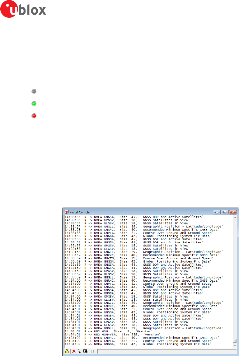
5.2.1 Packet console
The packet console lists all incoming and outgoing messages, and provides information about message length
and type. The direction of the message is shown in the following way:
R <- Indicates the message was sent to the receiver
R -> Indicates the message came from the receiver
L -> Indicates the message came from the log file
Figure 19: Packet console
Refer to Table 12 for an explanation of the icons and text field.
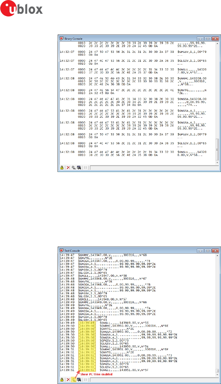
5.2.2 Binary console
The binary console lists all incoming messages in binary and ASCII format.
u-center-User Guide
UBX-13005250 - R18
Production Information 5 u-center Menus and Windows
Page 27 of 67
Figure 20: Binary console
Refer to Table 12 for an explanation of the icons and text field.
5.2.3 Text console
The text console displays the content messages in textual form such as UBX-INF or NMEA messages.
NMEA messages are shown with heading $Gxyyy, where x stands for the satellite system (P = GPS, SBAS, QZSS,
L = GLONASS, A = Galileo, B = BeiDou, N = Any combination of GNSS) and yyy for the type of message (e.g.
ZDA=Time & Date).
Figure 21: Text console displaying UBX-INF and NMEA messages. Last part has "Show PC Time" enabled
Refer to Table 12 for an explanation of the icons and text field.
u-center-User Guide
UBX-13005250 - R18
Production Information 5 u-center Menus and Windows
Page 28 of 67
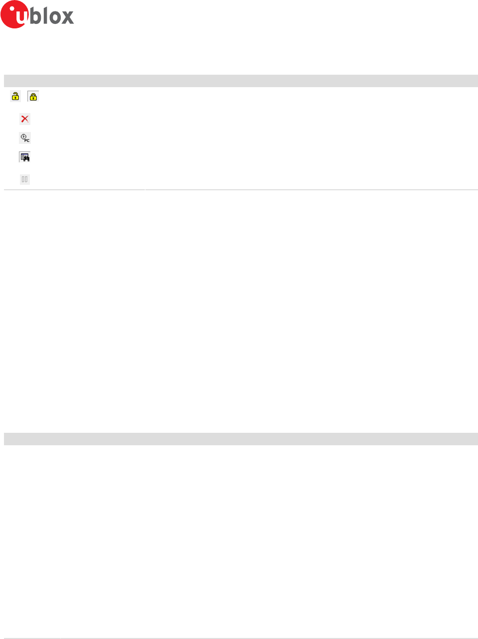
5.2.4 Icons and text field of console views
Element Name Description
/ Lock / Locked Prevents the console from being updated with new data when locked. Pause key can be used to
Lock/Unlock the current console window.
Clear All Erases all data in the console.
Show/Hide PC time Shows/Hides the PC time in the console.
Filter On/Off Filters unwanted data from the data stream. This allows searching for certain expression, e.g. all
RMC messages.
Pause player Pauses the player when the search expression is found. Only works in playback mode.
Table 12: Description of the buttons and text field of the console views
5.2.5 Regular expression evaluation
Normally, when you search for a sub-string in a string, the match should be exact. So if we search for a sub-
string "abc" then the string being searched should contain these exact letters in the same sequence for a match
to be found. We can extend this kind of search to a case insensitive search where the sub-string "abc" will find
strings like "Abc", "ABC" etc. That is, the case is ignored but the sequence of the letters should be exactly the
same. Sometimes, a case insensitive search is also not enough. For example, if we want to search for numeric
digit, then we basically end up searching for each digit independently. This is where regular expressions come
in to our help. Regular expressions are text patterns that are used for string matching. Regular expressions are
strings that contain a mix of plain text and special characters to indicate what kind of matching to do. Here's a
very brief tutorial on using regular expressions.
Suppose, we are looking for a numeric digit then the regular expression we would search for is "[0-9]". The
brackets indicate that the character being compared should match any one of the characters enclosed within the
bracket. The dash (-) between 0 and 9 indicates that it is a range from 0 to 9. Therefore, this regular expression
will match any character between 0 and 9, that is, any digit. If we want to search for a special character literally
we must use a backslash before the special character. For example, the single character regular expression "\*"
matches a single asterisk. In the table below the special characters are briefly described. A regular expression
search is case sensitive.
Character Description
^ Beginning of the string. The expression "^A" will match an "A" only at the beginning of the string.
[^ The caret (^) immediately following the left-bracket ([) has a different meaning. It is used to exclude the remaining
characters within brackets from matching the target string. The expression "[^0-9]" indicates that the target character
should not be a digit.
$ The dollar sign ($) will match the end of the string. The expression "abc$" will match the sub-string "abc" only if it is at
the end of the string.
| The alternation or logic OR character (|) allows either expression on its side to match the target string. The expression "a|
b" will match "a" as well as "b".
. The dot (.) will match any character.
* The asterisk (*) indicates that the character to the left of the asterisk in the expression should match 0 or more times.
+ The plus (+) is similar to asterisk but there should be at least one match of the character to the left of the + sign in the
expression.
? The question mark (?) matches the character to its left 0 or 1 times.
() The parenthesis affects the order of pattern evaluation.
[] Brackets ([ and ]) enclosing a set of characters indicates that any of the enclosed characters may match the target
character.
Table 13: Regular expression syntax
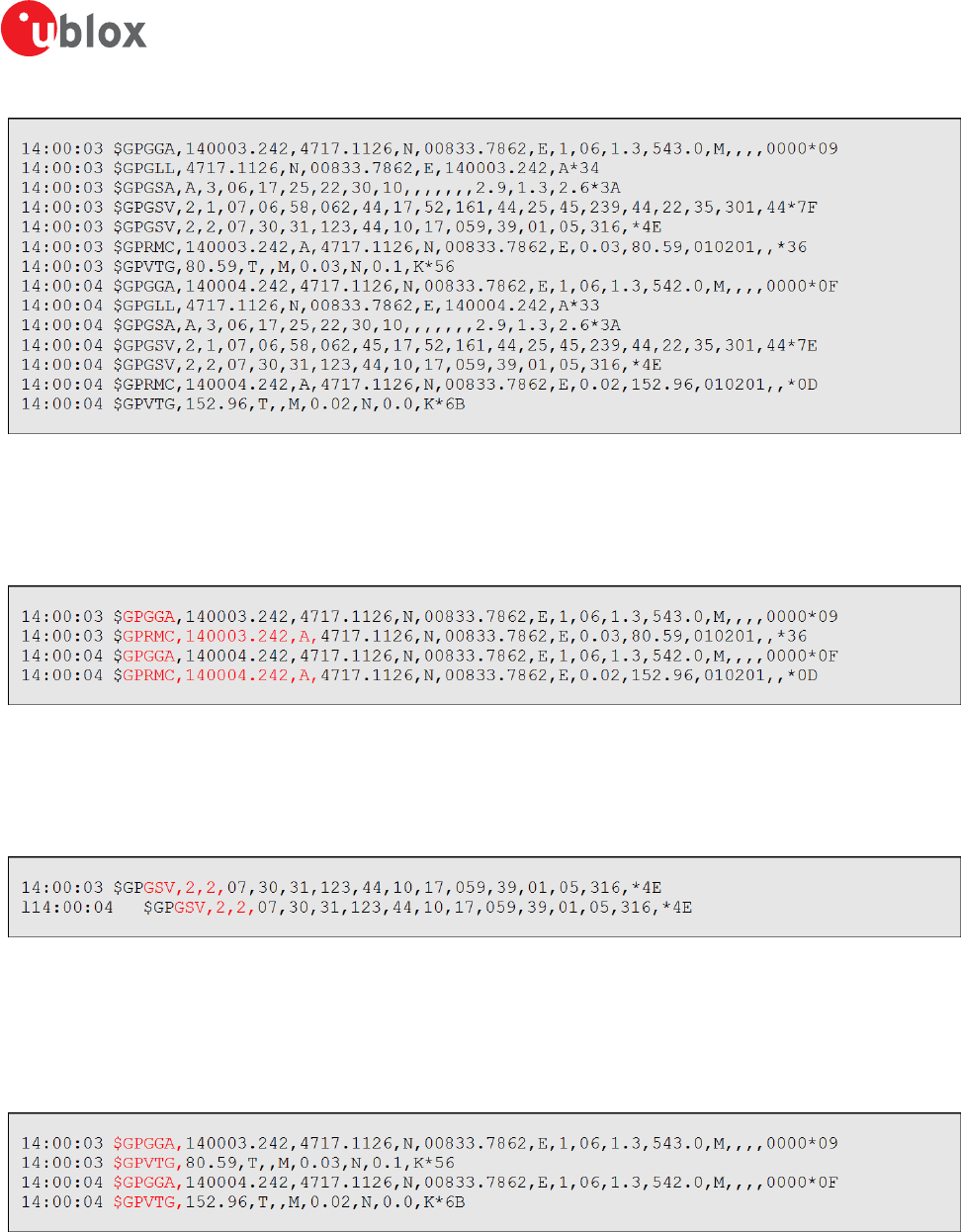
5.2.5.1 Examples
Let's assume that the lines in Figure 22 would appear in the NMEA console without filtering.
u-center-User Guide
UBX-13005250 - R18
Production Information 5 u-center Menus and Windows
Page 29 of 67
Figure 22: Regular Expression Template
5.2.5.1.1 Example 1
Searching for the RMC with a valid position and all GGA Messages:
GP(GGA|RMC,.*,A,)"
Figure 23: Regular Expression Example 1
5.2.5.1.2 Example 2
Searching for all GSV with the message index of "2" or "3":
GSV,.*,[2-3],
Figure 24: Regular Expression Example 2
5.2.5.1.3 Example 3
Searching for all messages starting with $GP, which have a "G" in the message identifier but not at the first
position:
^\$GP.+G.*,
Figure 25: Regular Expression Example 3
5.2.5.1.4 Example 4
Searching for all messages having a checksum of which the higher nibble is 3
\*3.$
u-center-User Guide
UBX-13005250 - R18
Production Information 5 u-center Menus and Windows
Page 30 of 67
Figure 26: Regular Expression Example 4
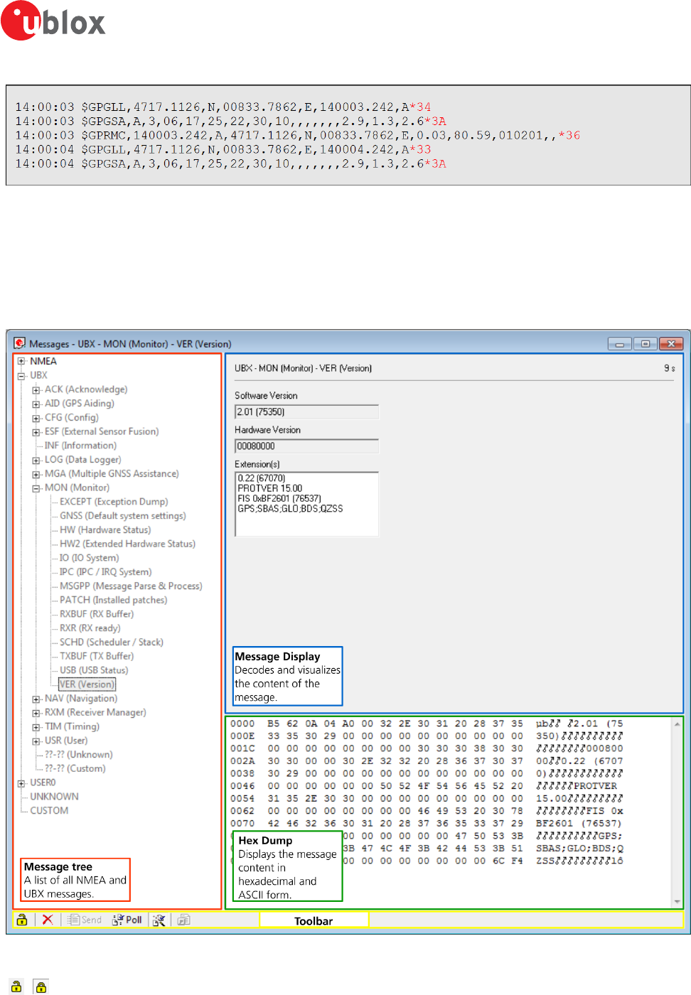
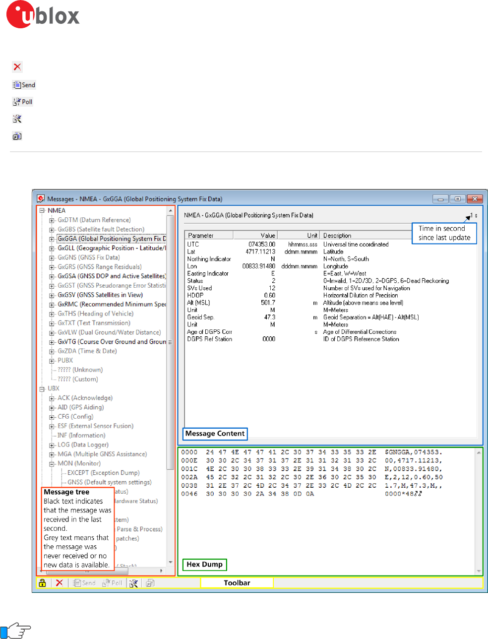
5.2.6 Messages view
The messages view is utilized to communicate with the device. Receiver output messages (e.g. navigation output,
status and debug information) are displayed; input messages (e.g. configuration messages) can be sent. There
are different sections for NMEA and UBX protocol. See Figure 27 for an overview of the different elements in
the messages view.
Figure 27: Messages view
/ Lock /
Locked
Prevents the message view from being updated with new data when locked. Pause key can be used to Lock/
Unlock the current view window.
u-center-User Guide
UBX-13005250 - R18
Production Information 5 u-center Menus and Windows
Page 31 of 67
Clear All Erases the entire message view.
Send Sends the current message to the device.
Poll Polls the selected message once.
Auto poll Automatically polls a newly selected message once.
Message
Hotkey
Assigns a hotkey to the selected message.
Table 14: Description of the buttons in the messages view toolbar
5.2.6.1 Receiver output messages
Figure 28: Message display of an output message
Double-clicking on an output message enables or disables the periodic message update if the
communication protocol is active. This feature is currently only supported for the UBX protocol.
u-center-User Guide
UBX-13005250 - R18
Production Information 5 u-center Menus and Windows
Page 32 of 67
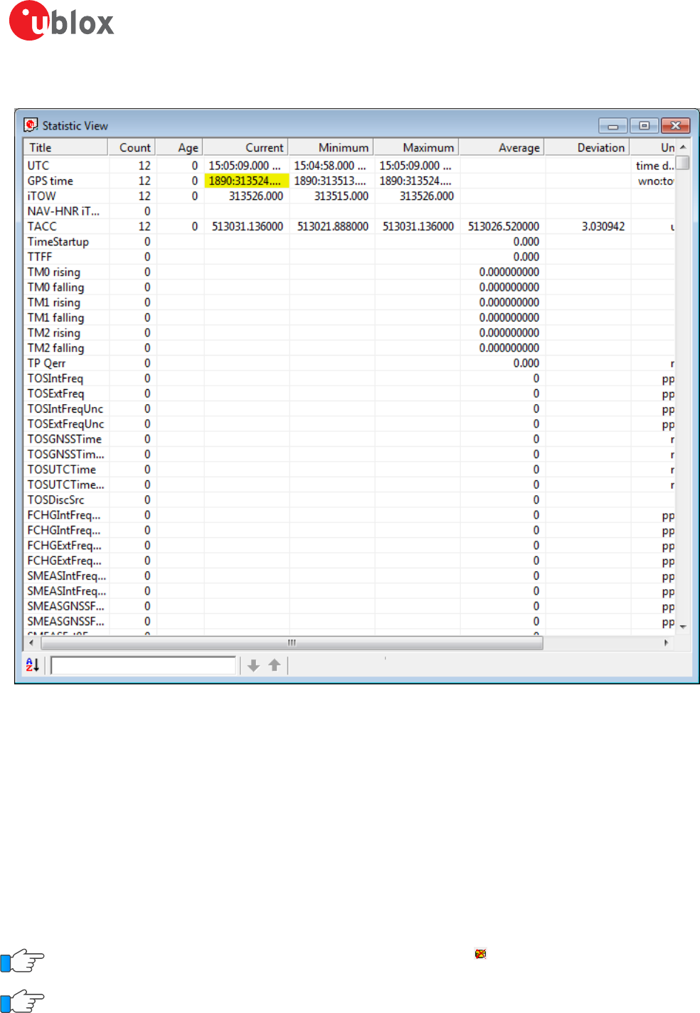
5.2.7 Statistic view
Figure 29: Statistic view
All available database values (transmitted from the device or calculated by u-center) are displayed. The following
statistics are displayed:
• Current value
• Minimum value
• Maximum value
• Average value
• Standard Deviation
The following color scheme for the values is applied:
• Grey color: The value was not set for the current epoch
• Blue color: The value was calculated by the application from other data
• Empty field: No data is available
Choosing "Database Empty" in the file menu or pressing the button clears the statistic view.
The content of the statistic view can easily be exported to other programs using Copy/Paste.
u-center-User Guide
UBX-13005250 - R18
Production Information 5 u-center Menus and Windows
Page 33 of 67
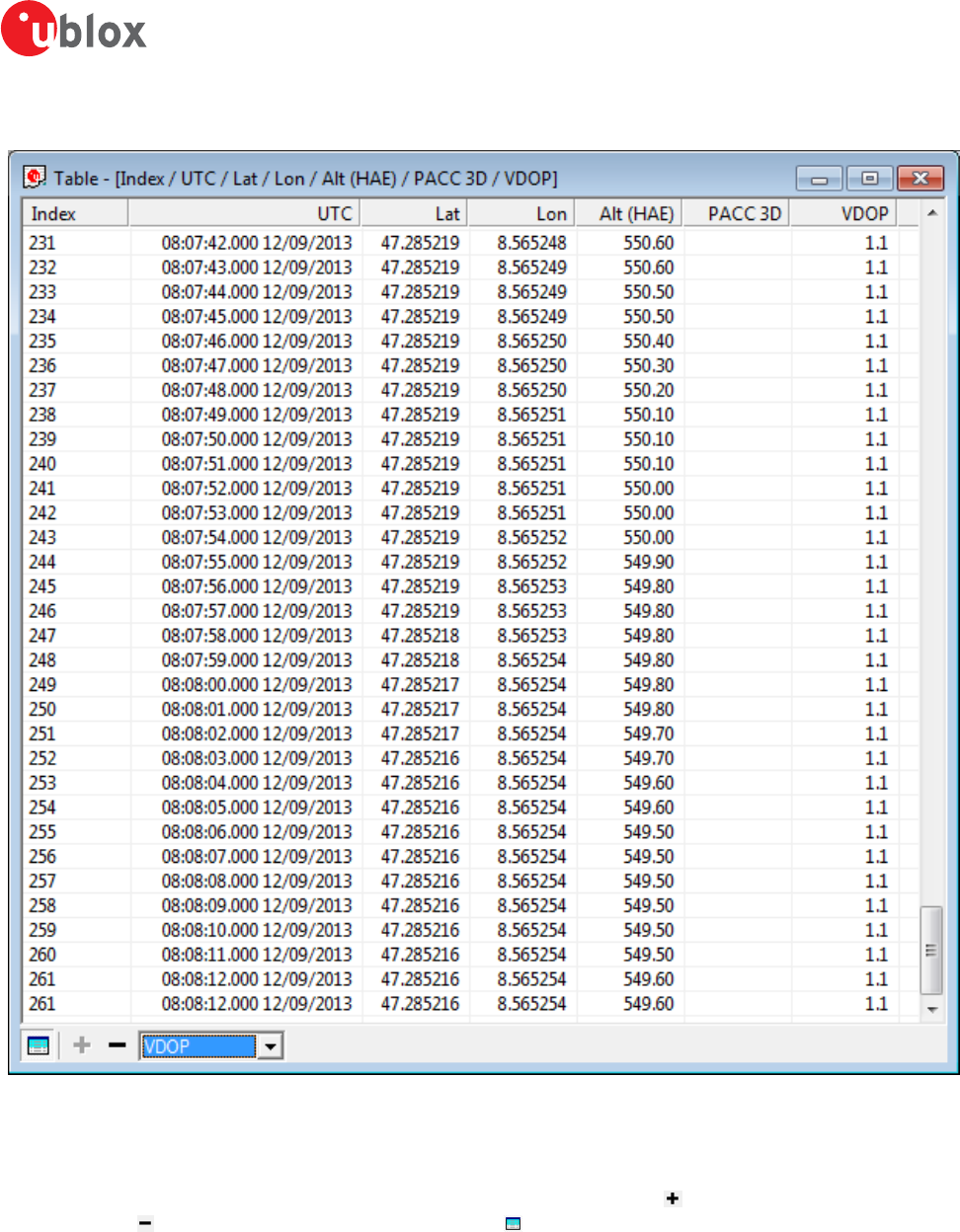
5.2.8 Table view
Figure 30: Table view
All values from the database can be displayed in a tabular form (Figure 30). This is very useful when analyzing
the log file in detail.
To add a new column, first select the desired value (Figure 31) and click the button. To remove a displayed
value, click the button. To see the table header click the button. Statistical information will be shown.
u-center-User Guide
UBX-13005250 - R18
Production Information 5 u-center Menus and Windows
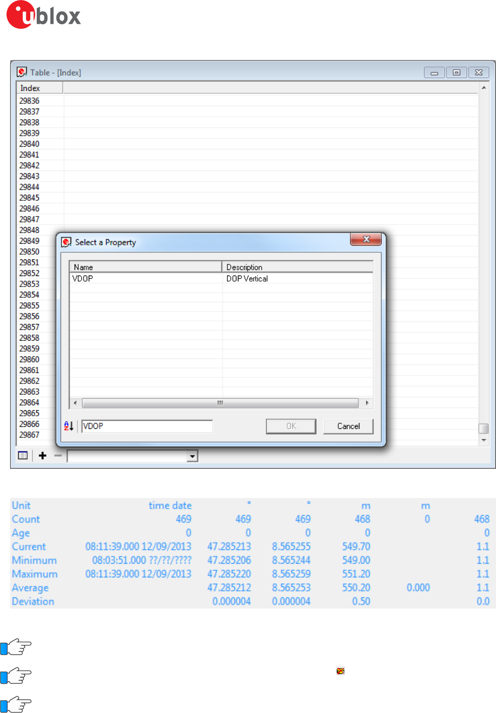
Page 34 of 67
Figure 31: Selecting a new value
Figure 32: Statistics in table view
The number of displayed epochs is set to 1800 by default.
Choosing "Database Empty" in the file menu or pressing the button clears the table view.
The content of the table view can easily be exported to other programs using Copy/Paste.
u-center-User Guide
UBX-13005250 - R18
Production Information 5 u-center Menus and Windows
Page 35 of 67
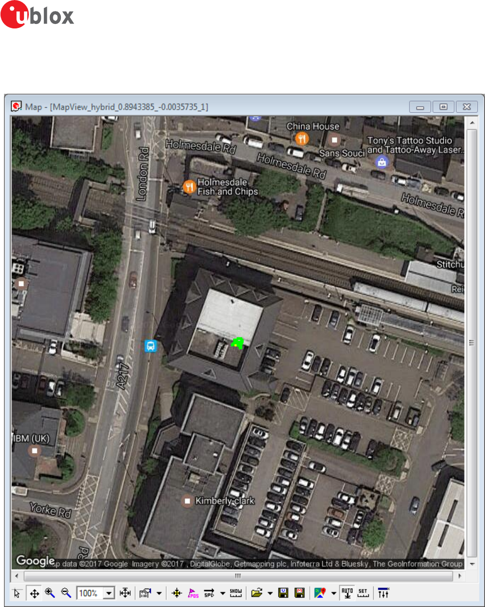
5.2.9 Map view
u-center can display positions on pre-calibrated or Google online (dynamic) maps (see Figure 33).
Figure 33: Map view with Google online map
5.2.9.1 Using map view
If you want to use the Google online maps you have to enter an API key in Tools -> Preferences -> Access Tokens.
A missing API key can lead to the output shown in Figure 34.
u-center-User Guide
UBX-13005250 - R18
Production Information 5 u-center Menus and Windows
Page 36 of 67
Figure 34: Missing online map API key
Please go to https://developers.google.com/maps/documentation/static-maps/?hl=en to get a valid Google
Static Maps API key.
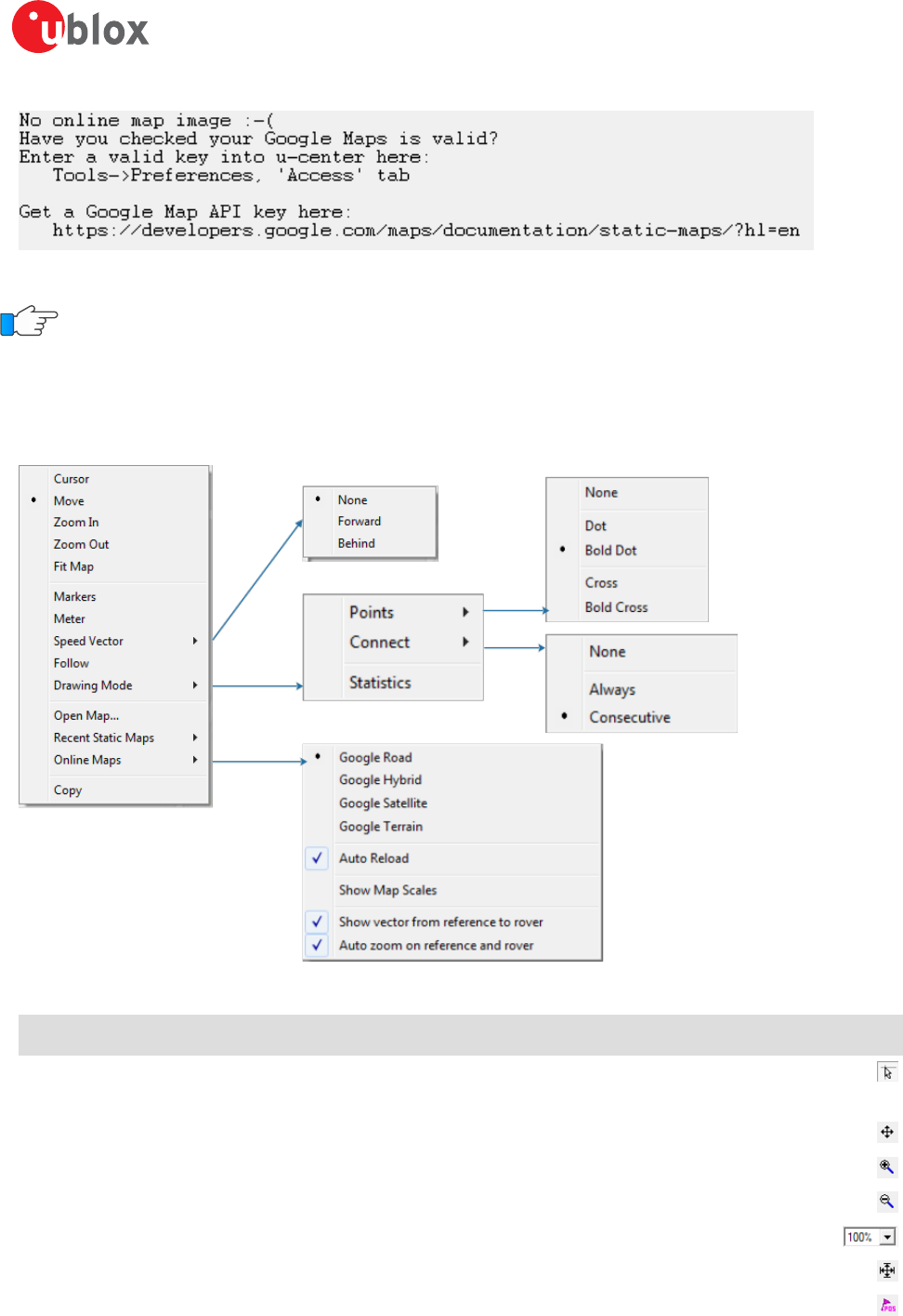
You can access the view specific commands in two different ways:
• Using the command in the tool bar below the map view.
• Holding the cursor inside the map view and pressing the right mouse button. This will open the following
context menu (see Figure 35).
Figure 35: Map view context menu
Function Description Shortcut /
Toolbar icon
Cursor The position of the cursor is shown on the lower left edge of the u-center screen
(Longitude, Latitude and Pixel-Position). By holding the left mouse button and moving the
cursor over the map you can measure distance from one position to another.
Move The map inside the map view window can be moved.
Zoom In The map is enlarged by selecting a rectangle.
Zoom Out The size of the map is decreased.
Zoom Zoom the map to a specified level.
Fit Map The map size is adjusted to fit the Map Window.
Markers Add or remove the defined markers (see also section Map calibration)
u-center-User Guide
UBX-13005250 - R18
Production Information 5 u-center Menus and Windows
Page 37 of 67
Function Description Shortcut /
Toolbar icon
Meter Show or hide the ruler.
Speedvector Show or hide the speed vectors, and select where they are drawn from.
Follow Centers the map on the current GNSS position.
Drawing Mode The size and form of the displayed position can be changed in the menu Points; the
connection line between the points can be selected in the menu Connect. To see statistical
values (average, minimum, maximum, standard deviation) directly in the map, select the
menu entry Statistic.
Open Map... / Recent
Static Maps
Open a new or one of 8 recently used static maps.
Online Maps Use online maps. Select the type in the menu and also if they should be automatically
downloaded when the current position moves out of the current map tile (Auto Reload).
The menu option Show Map Scales allows you to select a different scale of the tiles. The
menu option Show vector from reference to rover will show the vector pointing from
reference to rover if such configuration exists. In this case, auto zoom capability exists to
track the two by selecting the option Auto zoom on reference and rover.
/ /
Save map (only in
toolbar)
Save the current map view to a file (combined with all visible elements or only the map). /
Image settings (only in
toolbar)
Brightness, contrast and color saturation of map can be adjusted by moving the glides.
Table 15: Description of the buttons and context menu entries in map view
Map Views can be copied to the clipboard using the "Print Screen" function.
Choosing "Database Empty" in the file menu or pressing the button clears the statistic view.
5.2.9.2 Map calibration
To create your own map you will need a digitized map or picture with orthogonal projection in one of the
following pixel graphics formats.
png Portable Network Graphics
bmp Windows Bitmap
dib Device Independent Bitmap
gif Graphics Interchange Format
jpg/jpeg Jpeg File Interchange Format
pcx PC Paintbrush
tif Tag Image File Format
If your map is not in one of the above formats, you can simply convert it in one of the supported formats by
a third party program.
To use a map in u-center, three calibration points are needed. For these points you have to know the pixel
coordinates and the according WGS84 coordinates in the latitude/longitude format in degrees (longitude: -180.0°
to 180.0°, latitude: -90.0° to 90.0°). These points are stored in the map calibration file. The calibration file must
be stored at the same location as the bitmap itself. It has the same name but a different extension (*.mcf). The
format of the calibration file is very simple and can be edited in a simple editor like notepad.
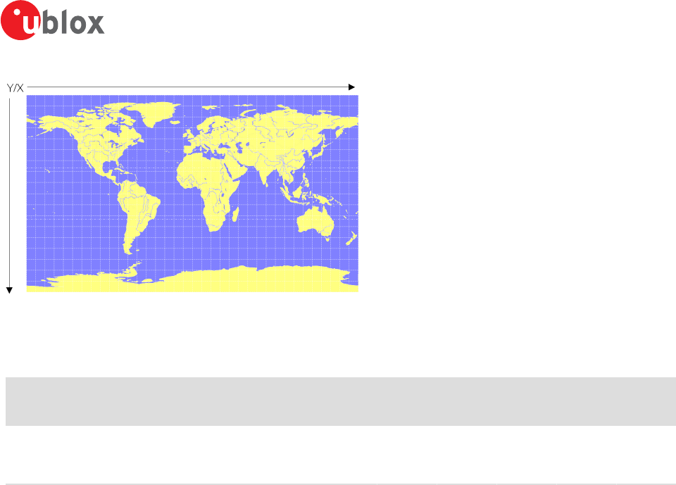
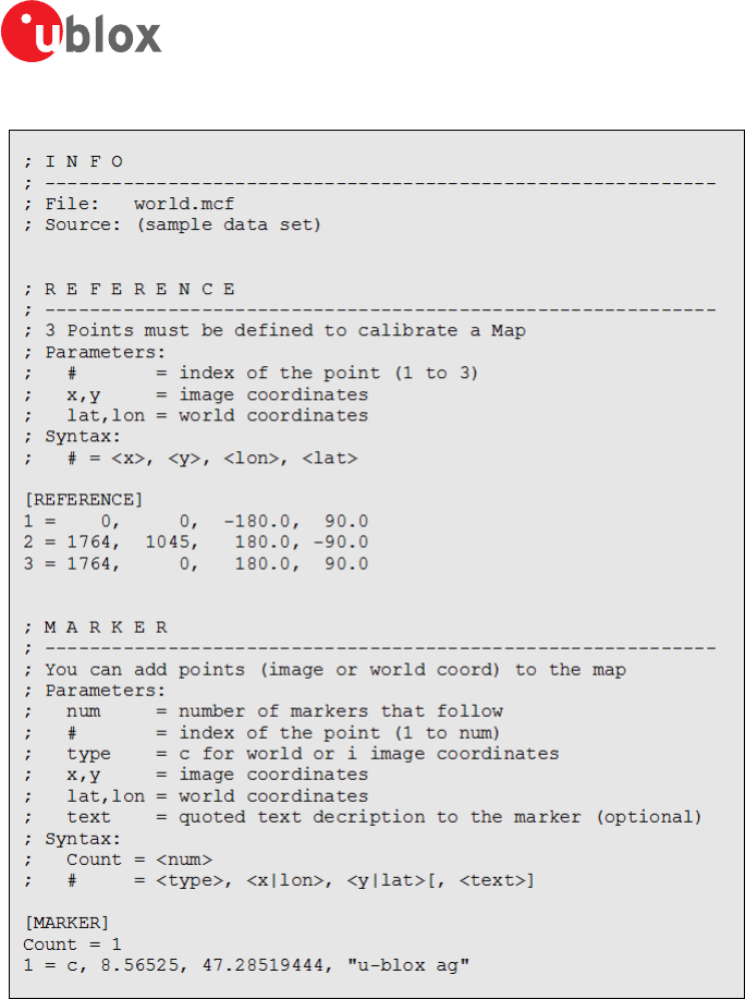
5.2.9.2.1 Example
As an example we will have a look at the virtual map file world.png and its calibration file world.mcf.
u-center-User Guide
UBX-13005250 - R18
Production Information 5 u-center Menus and Windows
Page 38 of 67
Figure 36: Digital map file: world.png
The Map has 1765 pixels (0 to 1764) in the horizontal and 1046 pixels (0 to 1045) in the vertical direction. The
origin is the upper left corner. To calibrate this map we will use the following three calibration points (#1 to #3).
Pixel WGS84
Coordinate
Reference Point # X Y Longitude Latitide
Upper Left Corner 1 0 0 -180.0 90.0
Lower Right Corner 2 1764 1045 180.0 -90.0
Upper Right Corner 3 1764 0 180.0 90.0
Table 16: Calibration reference points
To determine the exact pixel position you can use Microsoft Paint (mspaint.exe) or any other pixel-editing
program.
The calibration file is a plain ASCII text file. The file may contain comments. The file consists of two sections,
which start with keywords encapsulated in braces.
The REFERENCE section, which is mandatory, contains the three points used to calibrate a map. Each reference
point is on a single line and has the following syntax: # = <x>, <y>, <lon>, <lat> where
•# is the index of the reference point
•<x> is the horizontal image coordinate
•<y> is the vertical image coordinate
•<lat> is the latitude in degrees and WGS84
•<lon> is the longitude in degrees and WGS84.
The optional MARKER section defines additional points on the map. Each point is on a single line with the syntax:
# = i, <x>, <y>[, <text>] or # = c, <lat>, <lon>[, <text>] where
•# is the index of the marker point
•i indicates that the coordinates relate to the image
•c indicates that the coordinates relate to the world
•<x> is the horizontal image coordinate
•<y> is the vertical image coordinate
•<lat> is the latitude in degrees and WGS84
•<lon> is the longitude in degrees and WGS84.
•<text> is a optional string in quotes labeling the marker point.
The points must have a unique index from 1 to <num>. The maximum marker point index <num> is written to
the same section on a separate line with the syntax Count = <num>.
u-center-User Guide
UBX-13005250 - R18
Production Information 5 u-center Menus and Windows
Page 39 of 67
Figure 37: Map calibration file: world.mcf
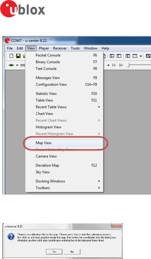
5.2.9.2.2 Map calibration tool
u-center includes a built-in calibration tool for providing coordinates to maps and photographs in supported data
formats to create u-center maps. To use the tool open the map view window as seen in Figure 38 and then open
the file of the map to be calibrated.
u-center-User Guide
UBX-13005250 - R18
Production Information 5 u-center Menus and Windows
Page 40 of 67
Figure 38: Opening map view window
If the file to be opened has not been calibrated, the message in Figure 39 will appear.
Figure 39: No calibration information found
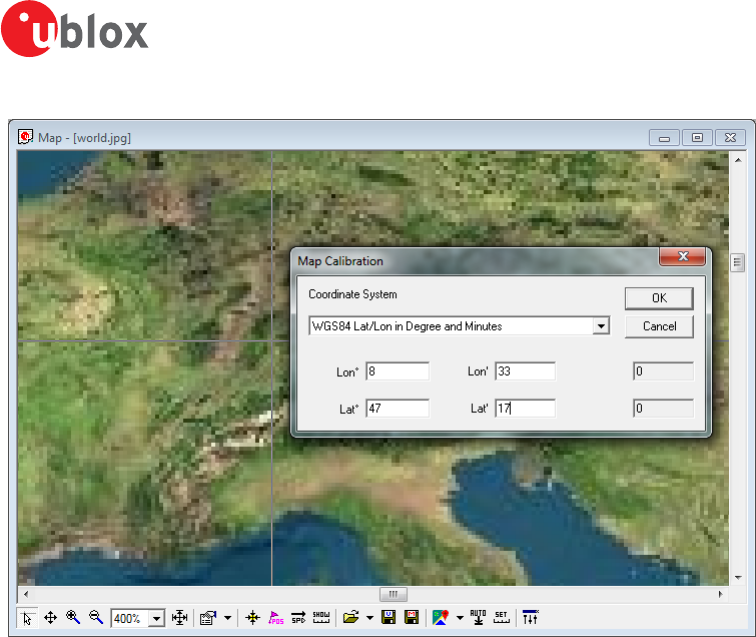
Select three points on the map and enter the calibration coordinates in the specified format as seen in Figure 40.
u-center-User Guide
UBX-13005250 - R18
Production Information 5 u-center Menus and Windows
Page 41 of 67
Figure 40: Calibrating a map using calibration tool
Following these steps the map is now calibrated and can be used with u-center.
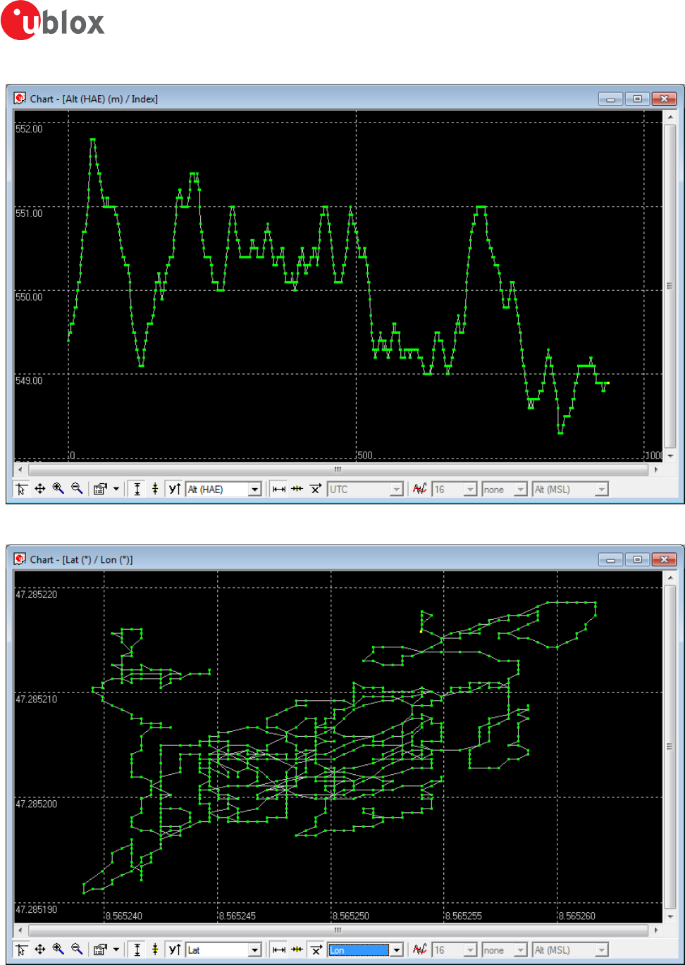
5.2.10 Chart view
Chart view allows the user to conveniently view GNSS data records in graphical form. The data can be scaled in
many different ways and formats. It's even possible to print the entire chart. The examples below illustrate two
different typical applications.
u-center-User Guide
UBX-13005250 - R18
Production Information 5 u-center Menus and Windows
Page 42 of 67
Figure 41: Altitude as a function of Index (X = Index, Y = Alt)
Figure 42: Latitude as a function of longitude (X =Longitude, Y = Latitude)
u-center-User Guide
UBX-13005250 - R18
Production Information 5 u-center Menus and Windows
Page 43 of 67
Function Description Shortcut /
Toolbar icon
Cursor The position of the cursor is shown on the lower left edge of the u-center screen
(Longitude, Latitude and Pixel-Position). By holding the left mouse button and moving the
cursor over the chart you can measure distance from one position to another.
Move The chart inside the chart view window can be moved.
Zoom In Drawing a rectangle enlarges the chart to the new view. To zoom in the chart double-click
on the chart.
Zoom Out Drawing a rectangle decreases the chart to the new view. To zoom out the chart double-
click on the chart.
Drawing Mode The size and form of the displayed values can be changed in the menu points; the
connection line between the values can be selected in the menu connect. For viewing the
statically values (average, minimum, maximum, standard deviation) directly in the chart
select the statistics menu.
Fit Y range Fits the Y range.
Follow Y Follow the most current Y value (the most current Y-value is always in the middle of the
chart).
Index or Y value Switch between the index and the Y value.
Y value Select the Y value to be displayed.
Fit X range Fit the X range.
Follow X Follow the most current X value (the most current X value is always in the middle of the
chart).
Index or X value Switch between the index and the X value.
X value Select the X value to be displayed.
Moving average Adds a moving average. The average is calculated over the number of most recent values,
specified with the parameter.
Table 17: Description of the buttons in the chart view toolbar
The number of displayed epochs is set to 1800 by default.
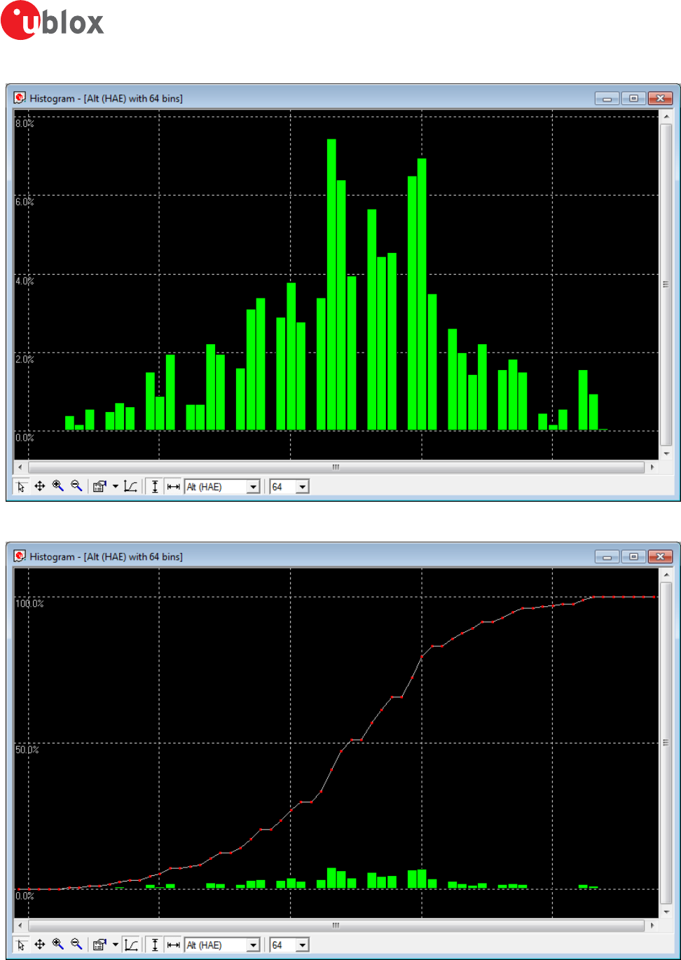
5.2.11 Histogram view
Histogram views allow the user to view GNSS data and probability distributions (see Figure 43) and print the entire
histogram if desired. The number of bins (storage containers) can be set by the user.
u-center-User Guide
UBX-13005250 - R18
Production Information 5 u-center Menus and Windows
Page 44 of 67
Figure 43: Altitude Histogram View
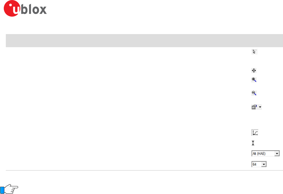
Figure 44: Probability chart
u-center-User Guide
UBX-13005250 - R18
Production Information 5 u-center Menus and Windows
Page 45 of 67
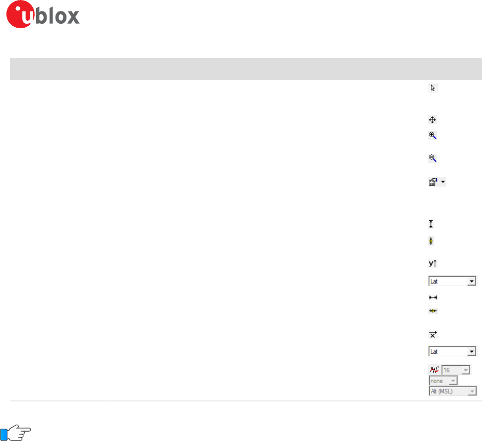
Function Description Shortcut /
Toolbar icon
Cursor The position of the cursor is shown on the lower left edge of the u-center screen
(Longitude, Latitude and Pixel-Position). By holding the left mouse button and moving the
cursor over the histogram you can measure distance from one position to another.
Move The histogram inside the histogram view window can be moved.
Zoom In Drawing a rectangle enlarges the histogram to the new view. To zoom in the histogram
double-click on the histogram.
Zoom Out Drawing a rectangle decreases the histogram to the new view. To zoom out the histogram
double-click on the histogram.
Drawing Mode The size and form of the displayed values can be changed in the menu points; the
connection line between the values can be selected in the menu connect. For viewing the
statically values (average, minimum, maximum, standard deviation) directly in the histogram
select the statistics menu.
Probability Fit the Probability range.
Fit Probability Fit the Probability range
Y value Select the Y value to be displayed.
Bins The number of bins.
Table 18: Description of the buttons in the histogram view toolbar
The number of displayed epochs is set to 1800 by default.
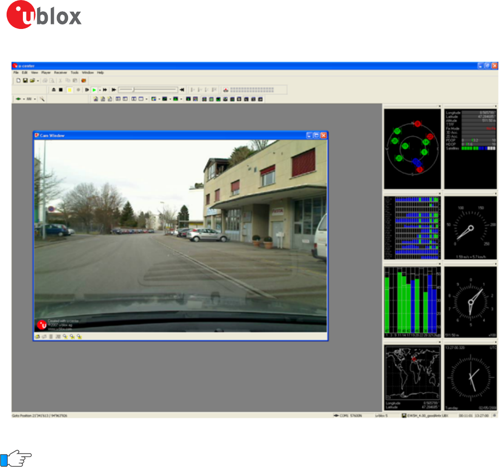
5.2.12 Camera view
The camera view function enables photographs, taken during recording of log files, to be linked to the GNSS
data stored in the corresponding log files. This allows a video depiction of the test, with a picture assigned to
a specific point of GNSS data.
u-center-User Guide
UBX-13005250 - R18
Production Information 5 u-center Menus and Windows
Page 46 of 67
Figure 45: Camera view
Using Camera View can result in very large log files and can slow down u-center when playing such files.
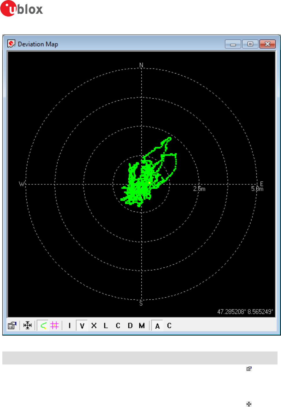
5.2.13 Deviation map
The deviation map displays positions in longitude and latitude relative to a defined reference position.
u-center-User Guide
UBX-13005250 - R18
Production Information 5 u-center Menus and Windows
Page 47 of 67
Figure 46: Deviation map
Function Description Shortcut /
Toolbar icon
Properties The reference position can be defined as:
• The average of all previously measured positions
• The current position
• A fixed, predefined value
• The radius of the outer circle can be adjusted with the Max. Deviation parameter.
Fit Automatically adjusts the reference position and the maximum deviation to fit all positions
into the deviation map.
u-center-User Guide
UBX-13005250 - R18
Production Information 5 u-center Menus and Windows
Page 48 of 67
Function Description Shortcut /
Toolbar icon
Track Show track of values from the internal database.
Statistics Show statistics of the values from the internal database.
Maximum deviation
shortcut
Shortcut for changing the scale of the deviation map to prefixed values. The icons represent
Roman numerals, with "I" corresponding to a 1 m radius of the deviation map, and "V"= 5
m, "X"= 10 m, "L"= 50 m, "C" = 100 m, "D" = 500 m, and "M" = 1000 m.
Reference position
shortcut
Shortcut for setting the reference position:
• A = average position
• C = current position
Table 19: Description of the buttons in the deviation map toolbar
The number of displayed epochs is set to 1800 by default.
You can use the mouse scroll wheel to zoom in/out on the deviation map. Holding down the Shift key
allows you to zoom in beyond the default 1 m maximum zoom.
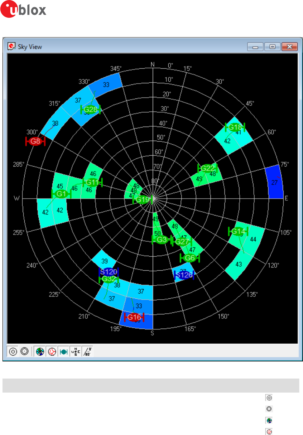
5.2.14 Sky view
Sky view is an excellent tool for analyzing the performance of antennas as well as the conditions of the satellite
observation environment. The polar plot graphically displays the averaged relative satellite signal strength (see
Figure 47), the position of satellites in the sky, identifies satellites by number and indicates which satellites are
being used in the receiver calculation. Right-clicking the mouse on sky view allows the copying of C/N0 values
in tabular form to another program.
u-center-User Guide
UBX-13005250 - R18
Production Information 5 u-center Menus and Windows
Page 49 of 67
Figure 47: Sky view
Function Description Shortcut /
Toolbar icon
Linear projection Displays the sky view with a linear projection.
Sine projection Displays the sky view with a sine projection.
C/N0 Displays or hides the averaged C/N0 values.
Orbits Displays or hides the satellite orbits.
u-center-User Guide
UBX-13005250 - R18
Production Information 5 u-center Menus and Windows
Page 50 of 67
Function Description Shortcut /
Toolbar icon
Satellites Displays or hides the current satellite positions.
Coordinates Displays or hides the caption for the azimuth.
Elevation Displays or hides the caption for the elevation.
Table 20: Description of the buttons in the sky view toolbar
u-center-User Guide
UBX-13005250 - R18
Production Information 6 NTRIP
Page 51 of 67
6 NTRIP
This section will give an overview of the NTRIP support in u-center. Currently u-center supports both NTRIP client
and NTRIP caster/server functionality. Settings for both of them can be found under "Receiver" menu.
Networked Transport of RTCM via Internet Protocol (NTRIP) is an application-level protocol that supports the
streaming of Global Navigation Satellite System (GNSS) data over the Internet. NTRIP is a generic, stateless protocol
based on the Hypertext Transfer Protocol HTTP/1.1. The HTTP objects are extended to GNSS data streams.
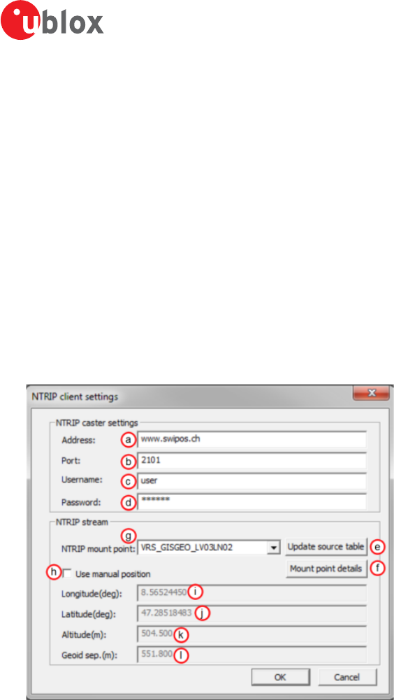
6.1 NTRIP Client
NTRIP client allows connecting to any NTRIP compliant caster and receiving RTCM correction data for receiver.
Currently version 1 of NTRIP standard is implemented.
Perform the following steps to connect to the caster (steps 10 to 14 are only needed when the mount point
requires additional NMEA message to be sent by the client):
1. Establish the communication between u-center and the device (see also Connect to the receiver).
2. Open NTRIP client settings dialog by clicking on Receiver -> NTRIP Client...
Figure 48: NTRIP client settings dialog
3. Enter the address of the NTRIP caster. See position a.
4. Enter the port number of the NTRIP caster. See position b.
5. Enter the username which will be sent to the NTRIP caster. If no authentication is required by the caster, then
leave this field empty. See position c.
6. Enter the password which will be sent to the NTRIP caster. If no authentication is required by the caster, then
leave this field empty. See position d.
7. Click on "Update source table" to get an up to date list of all available mount points from the caster. See
position e.
8. To see the detailed attributes of mount points, click on "Mount point details". This will bring up a new dialog
box listing all the mount points available and their attributes. See position f.
9. Select one of the mount points listed in the drop down box. See position g.
10.Click on "Use manual position" to enter values for position data. If this is not checked, the position data will
be retrieved directly from the receiver. See position h.
11.Enter the longitude in degrees, in either floating point or integer format. See position i.
12.Enter the latitude in degrees, in either floating point or integer format. See position j.
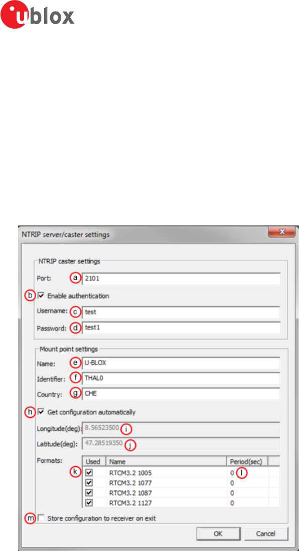
u-center-User Guide
UBX-13005250 - R18
Production Information 6 NTRIP
Page 52 of 67
13.Enter the altitude in meters in floating point or integer format. See position k.
14.Enter the geoid separation in meters in floating point or integer format. See position l.
15.Click on "OK" to start receiving correction data.
6.2 NTRIP Server/Caster
The u-center NTRIP caster is able to accept requests from NTRIP compliant clients and send them RTCM correction
data. This is implemented according to NTRIP standard version 1. The server part is not implemented according
to the standard but we are currently supporting one mount point which gets data from direct connection to
the receiver.
Perform the following steps to set up the caster:
1. Establish the communication between u-center and the device (see also Connect to the receiver).
2. Open NTRIP server/caster settings dialog by clicking on Receiver -> NTRIP Server/Caster...
Figure 49: NTRIP server settings dialog
3. Enter the port which will be used by the NTRIP caster. See position a.
4. Check "Enable authentication" if you want to enable basic authentication on your caster. See position b.
5. Enter the username which will have to be provided by the clients (only if you enabled authentication under
4). See position c.
6. Enter the password which will have to be provided by the clients (only if you enabled authentication under
4). See position d.
7. Enter the name for the mount point. See position e.
8. Enter the identifier for the mount point e.g. name of the city next to mount point location. See position f.
9. Enter the country code in ISO 3166 for the mount point. See position g.

u-center-User Guide
UBX-13005250 - R18
Production Information 6 NTRIP
Page 53 of 67
10.Check "Get configuration automatically" to use longitude, latitude and RTCM message configuration of the
currently connected receiver that will be sent out on the mount point. In this case you can go directly to 16.
See position h.
11.Enter the longitude for the mount point in integer or floating point format. See position i.
12.Enter the latitude for the mount point in integer or floating point format. See position j.
13.Select RTCM messages that will be sent by the mount point. See position k.
14.For every selected RTCM message enter the period at which messages will be sent to the clients. See position l.
15.Check "Store configuration to receiver on exit" to store the configuration of RTCM messages to the receiver
(using the UBX-CFG-MSG message ). See position m.
16.Click on "OK" to start NTRIP server/caster.
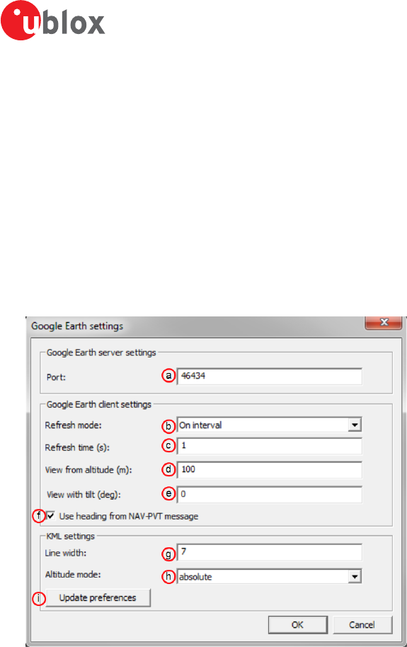
u-center-User Guide
UBX-13005250 - R18
Production Information 7 Google Earth server
Page 54 of 67
7 Google Earth server
This section gives an overview of the Google Earth server support in u-center.
The Google Earth server can continuously send positioning data in a specific format to the Google Earth
application. By hosting such a server in u-center we are able to visualize positioning data in real time.
There are only a few settings that can be set via the Google Earth server dialog. This means a lot of functionality
and behavior of the Google Earth is still configurable from the application itself and therefore out of control of
u-center's direct control.
Perform the following steps to start the Google Earth server:
1. Establish the communication between u-center and the device (see also Connect to the receiver).
2. Open Google Earth settings dialog by clicking on File -> Database Export -> Google Earth Server...
Figure 50: Google Earth settings dialog
3. Enter the port of the server. See position a.
4. Select the refresh mode. Supported modes are "On camera stop" where Google Earth will send requests only
when previous view has stabilized or "On interval" where requests from Google Earth will be sent in regular
intervals. See position b.
5. Enter the refresh time. This is the time between two consecutive requests in "On interval" mode or delay after
camera stops in "On camera stop" mode. See position c.
6. Enter the altitude in meters of the view. See position d.
7. Enter the tilt in degrees of the view. A value of 0 indicates that the view is aimed straight down toward the
earth and a value of 90 indicates that the view is aimed toward the horizon. See position e.
8. Check this field if you want the heading of the camera to follow heading information coming from UBX-NAV-
PVT message. See position f.
9. Enter the number to set the line width in the view. Higher values mean a thicker tracking line. See position g.
10.Select the altitude mode for the view. The "absolute" mode sets the altitude relative to sea level,
"relativeToGround" mode sets it relative to the actual ground elevation in a particular location and
"clampToGround" ignores the altitude specification. See position h.
11.Click on "Update preferences" if you want to permanently store information about Line width and Altitude
mode. The same can be achieved through menu "Tools->Preferences->KML settings". See position i.
12.Click on "OK" to start the server.
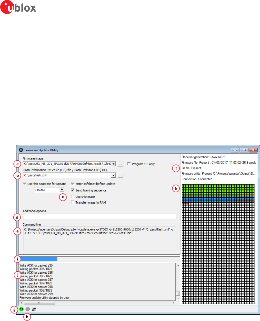
u-center-User Guide
UBX-13005250 - R18
Production Information 8 Tools
Page 55 of 67
8 Tools
This section will give an overview of the embedded tools of u-center. They can be used for different purpose
and should facilitate the usage of u-blox GNSS receivers. The tools can be found under the "Tools" menu but
some of the options are only displayed when a receiver is connected to u-center. The firmware update tools also
depend on the connected receiver generation.
8.1 Firmware update
This tool allows you to update the firmware of a receiver. In order for firmware update to work, the receiver must
have a flash memory attached as the new firmware will be stored in this location.
In previous versions of u-center, firmware update was implemented as part of the u-center application. Now
firmware update is implemented as a separate application which u-center launches and passes parameters to,
depending on the options selected in the UI. All options are supported in this new way of working, with the
exception of updating over USB. That feature will be added in the future, but for now it will be necessary to use
the legacy firmware update facility (see Legacy Firmware update u-blox 5 - 8).
To update the firmware, perform the following steps:
1. Display the firmware update tool view by clicking on Tools -> Firmware Update...
Figure 51: Firmware update view
2. Select the firmware image suitable for the connected receiver. See position a on Figure 51.

u-center-User Guide
UBX-13005250 - R18
Production Information 8 Tools
Page 56 of 67
3. Select the flash information structure file (only needed after and including u-blox receiver generation 7), or
the flash definition file (only needed before u-blox receiver generation 7). These files should be bundled with
u-center. See position b on Figure 51.
4. Select the options for your receiver. See position c on Figure 51.
Option Description Recommended
Use this Baud rate for update Selects the speed of the communication for updating the firmware on the
receiver. Only has an effect when the receiver is connected over a serial
port.
115200
Program FIS only Writes only the flash information structure (FIS) into the external memory
and does not update the firmware. This option is used for receivers running
from ROM but with an attached SQI memory (for example for logging).
Only supported after and including u-blox receiver generation 7.
disabled
Enter Safeboot before update Sends the command to enter safeboot. In this state, the receiver boots
from the internal ring oscillator and does not rely on any external
components. GNSS functionality is not started and the receiver does
not output any data. Don't use this method when having the receiver
connected over USB.
enabled
Send Training sequence Sends the training sequence after safeboot was entered. This synchronizes
the internal ring oscillator so that a communication can be established.
enabled
Use chip erase Erases the flash using an single command instead of individual sector
erases.
check support
Transfer image to RAM Transfers the firmware image directly to the receiver's RAM. Not stored to
flash.
disabled
5. The additional options field allows more command options to be specified than are presented in the UI. This
feature should only be needed if the firmware update utility launched by u-center has additional features
which the development of th UI has not caught up with yet. See position d on Figure 51.
6. The command line field displays the actual command line and parameters used to launch the firmware update
utility from u-center. This can be used to help diagnose any issues that may occur when performing a firmware
update. See position e on Figure 51.
7. The status fields display information about the connected receiver, the presence of the firmware and FIS files,
and if the firmware update utility can be found. See position f on Figure 51. If there is a problem with any of
these items, the 'Go' button, which starts the update process, will be greyed out.
8. Press the 'Go' button to start the firmware update progess. This button will only be enabled if if u-center can
see the receiver and can find the specified files. If this button is greyed out, check the status dispay to see
what is wrong. See position g on Figure 51.
9. Press the 'Stop' button to terminate the firmware update process. This will only be enabled when the update
process is running. See position h on Figure 51.
10.During firmware update, a progress bar is displayed. See position i on Figure 51.
11.A log is also displayed during the update process. See position j on Figure 51.
12.A detailed image of the flash erase and writing progress will also be shown. See position k on Figure 51.
8.2 Legacy Firmware update u-blox 5 - 8
This is the legacy receiver firmware update tool, which is built into the u-center binary. It can be used to program
u-blox 5 to u-blox 8 receivers. However futher feature development has been stopped and u-center now uses the
stand alone command line firmware update utility as the primary firmware update mechanism. This is documented
in the previous section. In the future, this legacy firmware update tool will be removed permanently from u-center.
As with the primary firmware update tool, the receiver has to have a flash memory attached as the firmware
has to be stored in this location.
Perform the following steps to update the firmware:
1. Establish the communication between u-center and the device (see also Connect to the receiver).
2. Open firmware update tool by clicking on Tools -> Legacy Firmware Update...
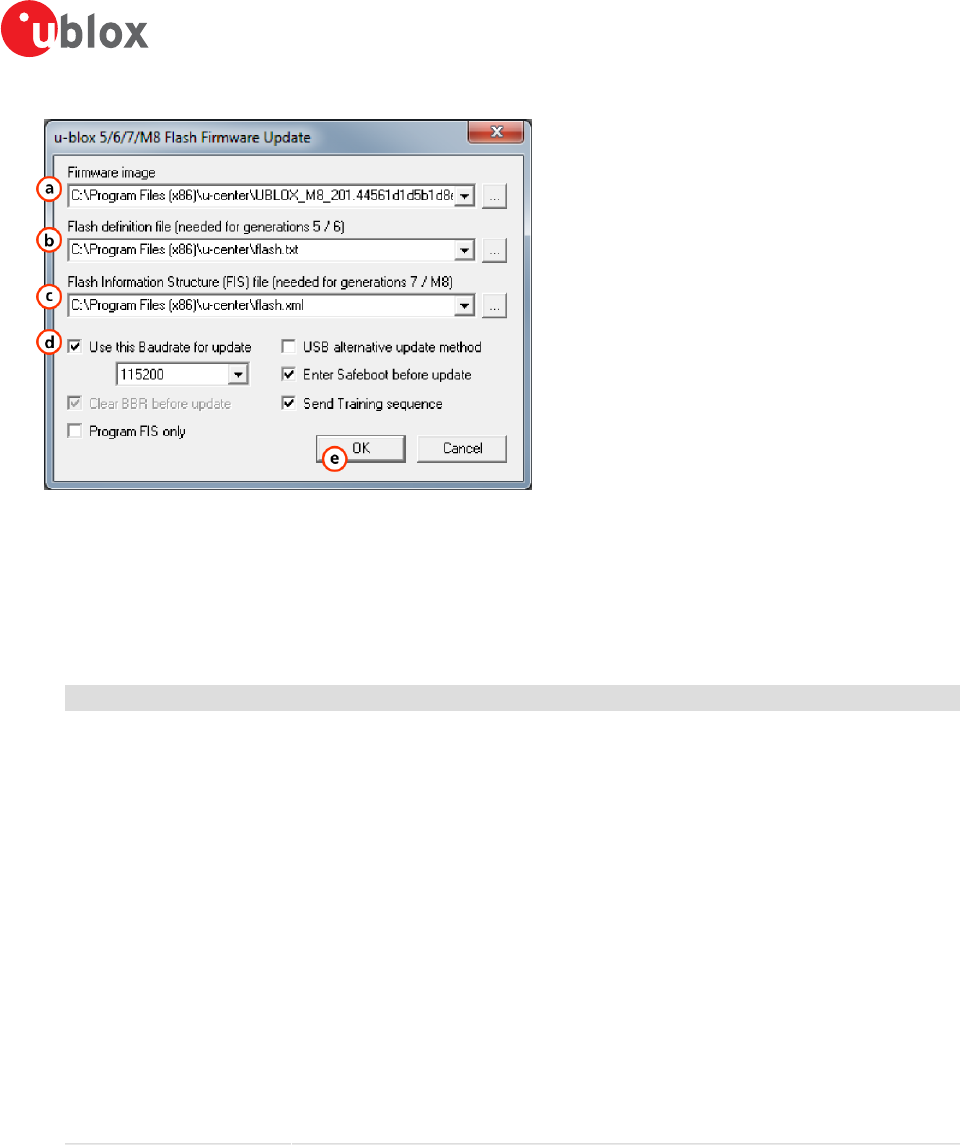
u-center-User Guide
UBX-13005250 - R18
Production Information 8 Tools
Page 57 of 67
Figure 52: Legacy firmware update window
3. Select the firmware image suitable for the connected receiver. See position a on Figure 52.
4. Select the flash definition file (only needed before u-blox receiver generation 7). This file should be provided
bundled with u-center. Point to the latest file version. See position b on Figure 52.
5. Select the flash information structure file (only needed after and including u-blox receiver generation 7). This
file should be provided bundled with u-center. Point to the latest file version. See position c on Figure 52.
6. Select the correct options for your receiver. See position d on Figure 52.
Option Description Recommended
Use this Baud rate for update Selects the speed of the communication for updating the firmware on the
receiver. Only has an effect when the receiver is connected over a serial
port.
115200
Clear BBR before update Deletes the complete battery backed memory (BBR) so that the receiver will
start with the default configuration.
enabled
Program FIS only Writes only the flash information structure (FIS) into the external memory
and does not update the firmware. This option is used for receivers running
from ROM but with an attached SQI memory (for example for logging).
Only supported after and including u-blox receiver generation 7.
disabled
USB alternative update method Erases the first sector of the flash memory and restarts the receiver.
The receiver will then start from ROM and the flash firmware can be
updated. Use this method if you want to update the firmware of a receiver
connected over USB.
disabled
Enter Safeboot before update Sends the command to enter safeboot. In this state, the receiver boots
from the internal ring oscillator and does not rely on any external
components. GNSS functionality is not started and the receiver does
not output any data. Don't use this method when having the receiver
connected over USB.
enabled
Send Training sequence Sends the training sequence after safeboot was entered. This synchronizes
the internal ring oscillator so that a communication can be established.
enabled
7. Click on “OK”.
8.3 Dump receiver diagnostics
This tool is used to dump the receiver diagnostic to a file. Use this tool if requested by the support team.
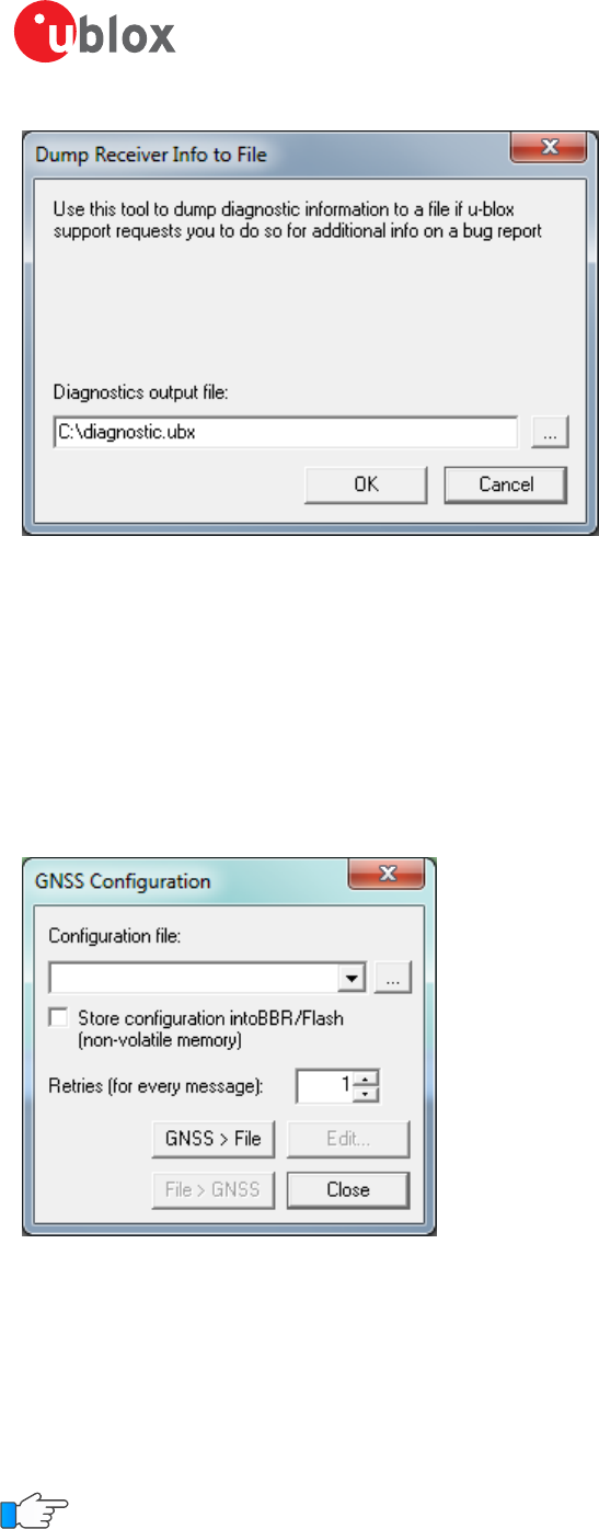
u-center-User Guide
UBX-13005250 - R18
Production Information 8 Tools
Page 58 of 67
Figure 53: Dump receiver diagnostics tool
8.4 GNSS configuration
u-center is capable of getting the actual configuration of a u-blox GNSS positioning chip or module and storing
it to an ASCII text file containing hexadecimal records. Such a file can be edited and stored to a u-blox GNSS
device again. By clicking the menu "Tools -> GNSS Configuration..." of u-center, the GNSS Configuration dialog
opens. The following functions are available:
• Specify the name of a new configuration file to store current configuration from the u-blox GNSS device
• Specify the name of an existing configuration file and load this configuration into the u-blox GNSS device
• A flag can be set to force storing the configuration into the Battery Backed RAM (BBR) or Flash.
Figure 54: GNSS configuration tool
8.4.1 Read/Write configuration files
1. Connect to the device.
2. Open Tools -> GNSS Configuration.
3. To read an existing configuration file, select the name of the file, then click on "File > GNSS" button. The
GNSS Configuration window then closes and the progress window pops up, showing the configuration being
sent to the receiver. This progress window closes after finishing the transfer without error.
Select "Store configuration into BBR/Flash" checkbox if the parameters need to be stored into the device's
non-volatile memory (BBR/Flash).
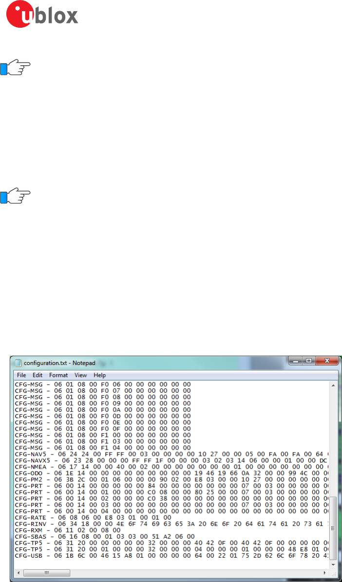
u-center-User Guide
UBX-13005250 - R18
Production Information 8 Tools
Page 59 of 67
Sending a configuration to a u-blox GNSS device may fail due to a baud rate change on the current serial
port of the receiver to which the configuration is being sent. If this happens, simply change the u-center
baud rate and send the configuration again.
To write a new configuration file, click on "GNSS > File". The GNSS Configuration window closes and the progress
window pops up, showing the configurations being polled and stored into a local file in ASCII format.
If reading or writing configuration data fails too frequently, try to increase the number of retries u-center should
do on a single message if one fails.
The user can abort the transfer by clicking the “Abort” button. It's not possible to close the window unless
transfer has completed or the user aborted it.
It is not recommended to read/write configuration while the u-blox GNSS device is in sleep mode.
8.4.2 Editing configuration file
When clicking the "Edit" button in the GNSS Configuration dialog, the Notepad editor opens (standard Windows
software). Configurations are stored the following way:
• The first line contains the version of the u-blox GNSS receiver where the configuration is from. Never
change this line!
• For the second and following lines, each line contains the same: <class ID>-<message ID> -
<hexadecimal byte code of the message>. The byte code consists of class and message IDs
(2 bytes), payload length (2 bytes), payload (payload length bytes). The sync characters and the checksum
are not included. They will be calculated automatically.
Refer to u-blox Receiver Description including Protocol Specification for detailed information and ranges.
Figure 55: Content of GNSS configuration file
8.5 Preferences
The preferences tool can be used to configure a number of u-center parameters.
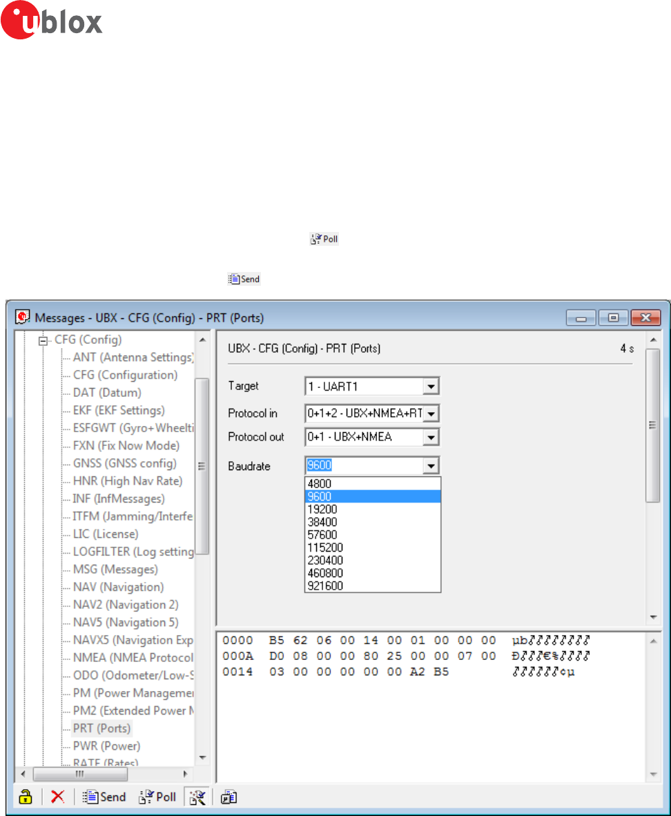
u-center-User Guide
UBX-13005250 - R18
Production Information 9 How To
Page 60 of 67
9 How To
9.1 Change baud rate of receiver
1. Connect to the device.
2. Open View / Messages View (Hotkey: F9).
3. Select UBX-CFG-PRT.
4. Poll the current configuration from the receiver ( ).
5. Change the setting to the desired baud rate.
6. Send the message to the receiver ( ).
Figure 56: Changing baud rate (using UBX-CFG-PRT)
9.2 Save parameters to receiver non-volatile memory (BBR/Flash)
There are 2 ways to save parameters to the receiver's non-volatile memory (BBR/Flash).
9.2.1 Saving parameters with UBX-CFG-CFG
1. Connect to the device.
2. Open View / Messages View (Hotkey: F9).
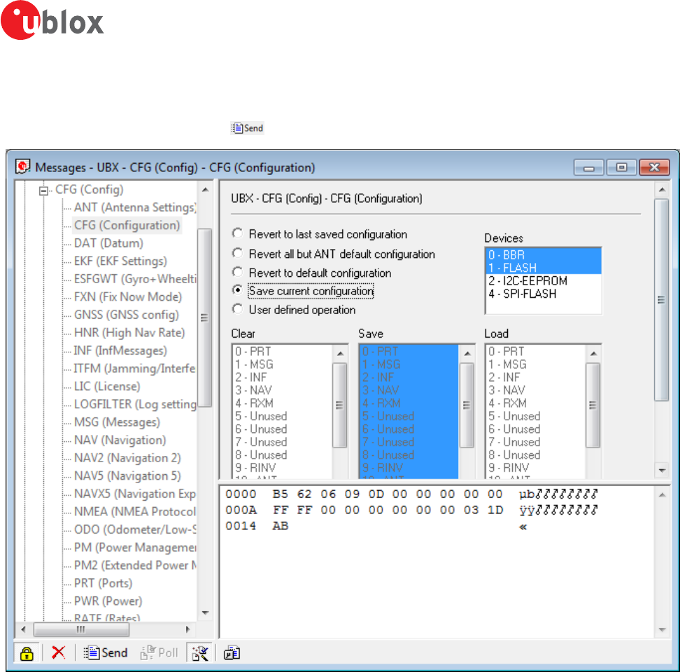
u-center-User Guide
UBX-13005250 - R18
Production Information 9 How To
Page 61 of 67
3. Select UBX-CFG-CFG.
4. Select “save current configuration” (see Figure 57).
5. Send the message to the receiver ( ).
Figure 57: Saving Parameters (using UBX-CFG-CFG)
9.2.2 Saving parameters with GNSS configuration
Refer to chapter Read/Write configuration files
9.3 Recording/Playing a log file
u-center allows recording and playing log files. Use the player controls, to record or playback a log file. Select the
log file to be opened through the file menu tool bar. The series of buttons in the player toolbar can be used to
navigate through the log file. The records will be displayed on the navigation display window, in the same way
that live GNSS data is displayed when using u-center. Refer to Player for a description of the menu items.
9.4 Conduct sensitivity tests
u-center is a useful tool for conducting sensitivity tests of GNSS positioning chips and modules and receiver
designs. To do so, under open sky conditions record a log file of the receiver to be tested and an Evaluation Kit
as reference. Make sure that the log files are recorded under the same conditions. Using the Statistic View or
Table View windows from u-center, compare the C/N0 values of the five strongest satellites. With Table view,
export the values to a spreadsheet for analysis.
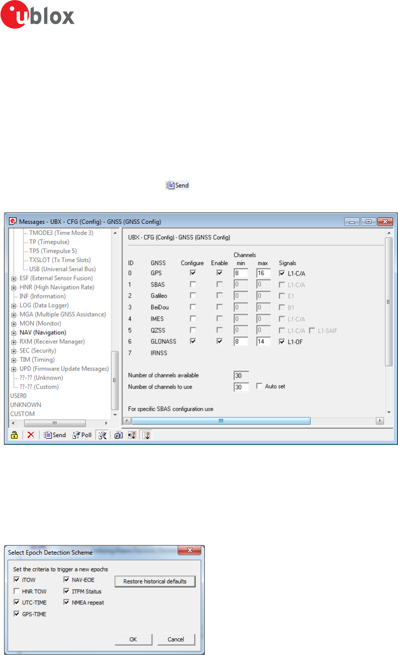
u-center-User Guide
UBX-13005250 - R18
Production Information 9 How To
Page 62 of 67
9.5 Read/Write configuration files
Refer to chapter Read/Write configuration files
9.6 Set GNSS configuration
1. Connect to the device.
2. Open View / Messages View (Hotkey: F9).
3. Select UBX-CFG-GNSS.
4. Place or remove the checkmark for the desired GNSS under "enable".
5. Send the message to the receiver ( ).
The following figure shows an example that configures the device to receive GPS and GLONASS.
Figure 58: GNSS configuration (using UBX-CFG-GNSS)
9.7 Change epoch detection method
u-center looks for epochs in the incoming messages from the receiver, and uses them as a "heartbeat" to trigger
view updates and calculate the statistics. To detect new epochs, u-center examines various groups of fields in the
incoming message stream. It is possible to specify which field groups u-center is interested in for epoch detection,
and opening the dialog under "Receiver" -> "Epoch detection..." allows the user to do this.
Figure 59: Select epoch detection method
where the following options can be configured:

u-center-User Guide
UBX-13005250 - R18
Production Information 9 How To
Page 63 of 67
Option Description Default
iTOW Monitor the "iTOW" database element. Trigger an epoch if a difference is seen. Typically
UBX-NAV messages cause this trigger.
Yes
HNR TOW Monitor the "NAV-HNR iTOW" database element. Trigger an epoch if a difference is seen.
HNR based messages cause this trigger.
No
UTC-TIME Monitor the "UTC" database element. Trigger an epoch if a difference is seen. Typically
NMEA messages cause this trigger.
Yes
GPS-TIME Monitor the "GPS time" database element. Trigger an epoch if a difference is seen. Typically
PUBX messages cause this trigger.
Yes
NAV-EOE Monitor for incoming UBX-NAV-EOE messages. Trigger an epoch if one is seen. Yes
ITFM Status Monitor the "ITFM Status" database element. Trigger an epoch if a difference is seem. The
UBX-RXM-INTF message causes this trigger.
Yes
NMEA repeat Monitor for NMEA messages. Trigger an epoch if the same NMEA message is seen twice
since the last epoch. Excluding GxGRS and GxGSA.
Yes
Table 21: Epoch detection method options
The default configuration can be restored by clicking the "Restore historical defaults" button.

u-center-User Guide
UBX-13005250 - R18
Production Information 10 Troubleshooting
Page 64 of 67
10 Troubleshooting
NMEA or UBX protocol is not available in the Messages View
u-center uses dynamic link libraries (DLL). The installation program will automatically install the required DLLs into
the u-center program directory. Should you try to copy a u-center installation from one location to another, make
sure you also copy the DLL files. Verify, the version of u-center matches the DLL version.
u-center doesn't display all messages
Make sure the baud rate is sufficient. If the bandwidth is insufficient, receivers will skip excessive messages. Some
serial port cards/adapters (i.e. USB to RS232 converter) frequently generate errors. If a communication error occurs
while u-center receives a message, the message will be discarded.
Some COM port are not shown in the port list
Only the COM ports that are available on your computer will show up in the COM port drop down list. If a COM
port is grayed out, another application in the computer is using it.
PC is very slow when u-center runs
If a high value of epochs is selected, the display in real-time cannot be guaranteed, especially when many graphical
views are open. u-center does not update minimized views and console in real-time. Close or minimize as many
of the graphical views and consoles as possible and u-center will run faster.
Log file/data are only partly displayed
The number of epochs displayed in u-center can be limited in order to allow an efficient analysis of larger logfiles.
When this limit is set then the oldest values will be discarded after the database reaches this limit size. Data stored
to a log file are not affected by the database limitation. Refer to Database limitations for instructions on how
to increase or remove this limit. When planning long-term observations, it's recommended to start recording a
log file before analysis begins.
Output messages are not updated in the Messages View
Make sure that the protocol you would like to receive is enabled. If so, double-click on the desired output message.
Double-clicking on an output message enables or disables the periodic message update if the respective protocol
is active. Alternatively, select the desired input or output message and press the "Poll" button. If you would like
to get UBX-INF-* messages in the log file, configure the receiver accordingly with the UBX-CFG-INF input
message.
No logfile is recorded
After a new logfile is created, logging will not automatically start but only after selecting the Record button in
the Player Toolbar.

u-center-User Guide
UBX-13005250 - R18
Production Information 11 Related Documents
Page 65 of 67
11 Related Documents
[1] GPS Compendium, Doc No GPS-X-02007
[2] u-blox 5 Receiver Description including Protocol Specification, Document number: GPS.G5-X-07036
[3] u-blox 6 Receiver Description including Protocol Specification, Document number: GPS.G6-SW-10018
[4] u-blox 7 Receiver Description including Protocol Specification V14, Document number: GPS.G7-SW-12001
[5] u-blox 8 / u-blox M8 Receiver Description Including Protocol Specification (Public version), Document number: UBX-13003221

u-center-User Guide
UBX-13005250 - R18
Production Information 12 Revision History
Page 66 of 67
12 Revision History
Revision Date Name Status / Comments
- 08-Oct-2008 tgri Initial release
A 22-Jul-2009 tgri New CI
A1 17-Feb-2011 tgri Third party libraries
B 01-Nov-2011 tgri Google Earth View added
C 03-Jun-2012 khir Updated for u-center 6.3. GNSS configuration added
R06 09-Dec-2013 mfre Update for u-center 8.01 and u-blox 7 and M8 generations
R07 01-Oct-2014 jbow Packet view update describing message direction indicators
R08 23-Feb-2015 yzha Updated menu pictures and shortcut key list corresponding to latest version
R09 04-Sep-2015 smos Updated Contact page
R10 12-Dec-2015 mfre Remove Google Earth support
R11 29-Mar-2016 mfre Epoch detection, DGNSS interface and receiver status icons description added, legacy
aiding marked deprecated, pictures updated
R12 15-Jul-2016 mfre Map view updated, removed EVK-6PPP how to
R13 01-Oct-2016 rsmr NTRIP support added
R14 19-Dec-2016 rsmr Google Earth server added, new RTCM messages added
R15 31-Mar-2017 rsmr Support for Sqlite database added, improved UI processing, support for moving baseline
added
R16 29-Jun-2017 jbow Limiting the database size, automatic receiver identification
R17 28-Sep-2016 msul Firmware update view modernized
R18 04-Dec-2016 msul Addition of the 'Transfer image to RAM' checkbox in firmware update window

u-center-User Guide
UBX-13005250 - R18
Production Information Page 67 of 67
Contact
For complete contact information visit us at www.u-blox.com.
u-blox Offices
North, Central and South America Headquarters Asia, Australia, Pacific
Europe, Middle East, Africa
u-blox America, Inc. u-blox AG u-blox Singapore Pte. Ltd.
Phone: +1 703 483 3180 Phone: +41 44 722 74 44 Phone: +65 6734 3811
E-mail: info_us@u-blox.com E-mail: info@u-blox.com E-mail: info_ap@u-blox.com
Support: support@u-blox.com Support: support_ap@u-blox.com
Regional Office West Coast Documentation Feedback Regional Office Australia
Phone: +1 408 573 3640 Email: docsupport@u-blox.com Phone: +61 2 8448 2016
E-mail: info_us@u-blox.com E-mail: info_anz@u-blox.com
Support: support_ap@u-blox.com
Technical Support Regional Office China (Beijing)
Phone: +1 703 483 3185 Phone: +86 10 68 133 545
E-mail: support_us@u-blox.com E-mail: info_cn@u-blox.com
Support: support_cn@u-blox.com
Regional Office China (Chongqing)
Phone: +86 23 6815 1588
E-mail: info_cn@u-blox.com
Support: support_cn@u-blox.com
Regional Office China (Shanghai)
Phone: +86 21 6090 4832
E-mail: info_cn@u-blox.com
Support: support_cn@u-blox.com
Regional Office China (Shenzhen)
Phone: +86 755 8627 1083
E-mail: info_cn@u-blox.com
Support: support_cn@u-blox.com
Regional Office India
Phone: +91 80 4050 9200
E-mail: info_in@u-blox.com
Support: support_in@u-blox.com
Regional Office Japan (Osaka)
Phone: +81 6 6941 3660
E-mail: info_jp@u-blox.com
Support: support_jp@u-blox.com
Regional Office Japan (Tokyo)
Phone: +81 3 5775 3850
E-mail: info_jp@u-blox.com
Support: support_jp@u-blox.com
Regional Office Korea
Phone: +82 2 542 0861
E-mail: info_kr@u-blox.com
Support: support_kr@u-blox.com
Regional Office Taiwan
Phone: +886 2 2657 1090
E-mail: info_tw@u-blox.com
Support: support_tw@u-blox.com
