Peerless Industries Kx Tda100 Users Manual Feature_guide
KX-TDA30 to the manual 9cd16708-4129-47e0-9ec5-cb9a20c542a5
2015-02-06
: Peerless-Industries Peerless-Industries-Kx-Tda100-Users-Manual-517547 peerless-industries-kx-tda100-users-manual-517547 peerless-industries pdf
Open the PDF directly: View PDF ![]() .
.
Page Count: 380 [warning: Documents this large are best viewed by clicking the View PDF Link!]
- Introduction
- Table of Contents
- Call Handling Features
- 1.1 Incoming Call Features
- 1.1.1 Incoming Trunk Call Features
- 1.1.1.1 Incoming Trunk Call Features—SUMMARY
- 1.1.1.2 Direct In Line (DIL)
- 1.1.1.3 Direct Inward Dialling (DID)/Direct Dialling In (DDI)
- 1.1.1.4 Multiple Subscriber Number (MSN) Ringing Service
- 1.1.1.5 Calling Line Identification (CLI) Distribution
- 1.1.1.6 Intercept Routing
- 1.1.1.7 Intercept Routing—No Destination
- 1.1.2 Internal Call Features
- 1.1.3 Incoming Call Indication Features
- 1.1.1 Incoming Trunk Call Features
- 1.2 Receiving Group Features
- 1.3 Call Forwarding (FWD)/Do Not Disturb (DND) Features
- 1.4 Answering Features
- 1.5 Making Call Features
- 1.6 Memory Dialling Features
- 1.7 Busy Line/Busy Party Features
- 1.8 Toll Restriction (TRS)/Call Barring (Barring) Features
- 1.9 Automatic Route Selection (ARS) Features
- 1.10 Conversation Features
- 1.11 Transferring Features
- 1.12 Holding Features
- 1.13 Conference Features
- 1.14 Paging Features
- 1.15 Broadcasting Features (KX-TDA30/KX- TDA100/KX-TDA200 only)
- 1.16 Optional Device Features
- 1.17 Caller ID Features
- 1.18 Message Features
- 1.19 Proprietary Telephone (PT) Features
- 1.20 Integrated Services Digital Network (ISDN) Service Features
- 1.20.1 Integrated Services Digital Network (ISDN)
- 1.20.1.1 Integrated Services Digital Network (ISDN)—SUMMARY
- 1.20.1.2 Calling/Connected Line Identification Presentation (CLIP/COLP)
- 1.20.1.3 Advice of Charge (AOC)
- 1.20.1.4 Call Forwarding (CF)—by ISDN (P-MP)
- 1.20.1.5 Call Forwarding (CF)—by ISDN (P-P)
- 1.20.1.6 Call Hold (HOLD)—by ISDN
- 1.20.1.7 Call Transfer (CT)—by ISDN
- 1.20.1.8 Three-party Conference (3PTY)—by ISDN
- 1.20.1.9 Malicious Call Identification (MCID)
- 1.20.1.10 Completion of Calls to Busy Subscriber (CCBS)
- 1.20.1.11 ISDN Extension
- 1.20.1.12 ISDN Service Access by Keypad Protocol
- 1.20.1 Integrated Services Digital Network (ISDN)
- 1.21 E1 Line Service Features (KX-TDA100/KX- TDA200 only)
- 1.22 T1 Line Service Features (KX-TDA100/KX- TDA200 only)
- 1.23 Voice Mail Features
- 1.24 Portable Station (PS) Features
- 1.25 Administrative Information Output Features
- 1.26 Extension Controlling Features
- 1.27 Audible Tone Features
- 1.28 Networking Features
- 1.29 Computer Telephony Integration (CTI) Features
- 1.1 Incoming Call Features
- System Configuration and Administration Features
- Programming Instructions
- 3.1 Introduction
- 3.2 PC Programming
- 3.3 PT Programming
- 3.3.1 Programming Instructions
- 3.3.2 Basic Programming
- Date & Time [000]
- System Speed Dialling Number [001]
- System Speed Dialling Name [002]
- Extension Number [003]
- Extension Name [004]
- Extension Personal Identification Number (PIN) [005]
- Operator Assignment [006]
- Console Paired Telephone [007]
- Absent Message [008]
- Charge Margin [010]
- Charge Tax [011]
- Charge Rate per Unit [012]
- 3.3.3 System Programming
- Flexible Numbering [100]
- Time Service Switching Mode [101]
- Time Service Starting Time [102]
- Idle Line Access (Local Access) [103]
- System Password for Administrator—for PT Programming [110]
- System Password for User—for PT Programming [111]
- Manager Password [112]
- Verified Code [120]
- Verified Code Name [121]
- Verified Code Personal Identification Number (PIN) [122]
- Verified Code COS Number [123]
- Decimal Point Position for Currency [130]
- Currency [131]
- Main Processing (MPR) Software Version Reference [190]
- 3.3.4 Time Programming
- Hold Recall Time [200]
- Transfer Recall Time [201]
- Intercept Time [203]
- Hot Line Waiting Time [204]
- Automatic Redial Repeat Times [205]
- Automatic Redial Interval [206]
- Door Open Duration Time [207]
- Call Duration Count Starting Time for LCOT [208]
- DISA Delayed Answer Time [209]
- DISA Trunk-to-Trunk Call Prolong Time [210]
- DISA Intercept Time [211]
- 3.3.5 TRS/Barring/ARS Programming
- TRS/Barring Override by System Speed Dialling [300]
- TRS/Barring Denied Code [301]
- TRS/Barring Exception Code [302]
- Special Carrier Access Code [303]
- Emergency Number [304]
- ARS Mode [320]
- ARS Leading Number [321]
- ARS Routing Plan Table Number [322]
- ARS Exception Number [325]
- ARS Routing Plan Time Table [330]
- ARS Routing Plan Table (1–16) [331–346]
- ARS Carrier Name [350]
- ARS Trunk Group for Carrier Access [351]
- ARS Removed Number of Digits for Carrier Access [352]
- ARS Carrier Access Code [353]
- 3.3.6 Trunk Programming
- LCOT/BRI Trunk Connection [400]
- LCOT/BRI Trunk Name [401]
- LCOT/BRI Trunk Group Number [402]
- LCOT/BRI Trunk Number Reference [409]
- LCOT Dialling Mode [410]
- LCOT Pulse Rate [411]
- LCOT DTMF Minimum Duration [412]
- LCOT CPC Signal Detection Time—Outgoing [413]
- LCOT CPC Signal Detection Time—Incoming [414]
- LCOT Reverse Circuit [415]
- LCOT Pause Time [416]
- LCOT Flash/Recall Time [417]
- LCOT Disconnect Time [418]
- BRI Network Type [420]
- BRI DIL/DDI/MSN Selection [421]
- BRI Subscriber Number [422]
- BRI Layer 1 Active Mode [424]
- BRI Layer 2 Active Mode [425]
- BRI Configuration [426]
- BRI TEI Mode [427]
- DIL 1:1 Destination [450]
- DID Number [451]
- DID Name [452]
- DID Destination [453]
- Trunk Group Intercept Destination [470]
- Host PBX Access Code [471]
- Extension-to-Trunk Call Duration [472]
- Trunk-to-Trunk Call Duration [473]
- DISA Silence Detection [475]
- DISA Continuous Signal Detection [476]
- DISA Cyclic Signal Detection [477]
- Caller ID Signal Type [490] (KX-TDA30/KX-TDA100/KX-TDA200 only)
- Pay Tone Signal Type [491] (KX-TDA100/KX-TDA200 only)
- 3.3.7 COS Programming
- Trunk Group Number [500]
- TRS/Barring Level [501]
- Trunk Call Duration Limitation [502]
- Call Transfer to Trunk [503]
- Call Forwarding to Trunk [504]
- Executive Busy Override [505]
- Executive Busy Override Deny [506]
- DND Override [507]
- Account Code Mode [508]
- TRS/Barring Level for System Speed Dialling [509]
- TRS/Barring Level for Extension Lock [510]
- Manager Assignment [511]
- Permission for Door Open Access [512]
- Time Service Manual Switching [514]
- Wireless XDP Parallel Mode for Paired Telephone [515]
- Programming Mode Limitation [516]
- 3.3.8 Extension Programming
- EXtra Device Port (XDP) Mode [600]
- Terminal Device Assignment [601]
- Class of Service [602]
- User Group [603]
- Extension Intercept Destination [604]
- Call Forwarding—No Answer Time [605]
- CLIP/COLP Number [606]
- Incoming Call Distribution Group Member [620]
- Incoming Call Distribution Group Delayed Ringing [621]
- Incoming Call Distribution Group Floating Extension Number [622]
- Incoming Call Distribution Group Name [623]
- Incoming Call Distribution Group Distribution Method [624]
- Destination for Overflow Time Expiration [625]
- Overflow Time [626]
- Destination When All Busy [627]
- Queuing Call Capacity [628]
- Queuing Hurry-up Level [629]
- Queuing Time Table [630]
- Sequences in Queuing Time Table [631]
- Maximum Number of Agents [632]
- User Groups of a Paging Group [640]
- External Pagers of a Paging Group [641]
- User Groups of a Pickup Group [650]
- VM Group Floating Extension Number [660]
- Idle Extension Hunting Type [680]
- Idle Extension Hunting Group Member [681]
- PS Registration [690]
- PS Termination [691]
- Personal Identification Number (PIN) for PS Registration [692]
- CS Status Reference [699]
- 3.3.9 Resource/Interface Programming
- External Pager Floating Extension Number [700]
- Music Source Selection for BGM (with the KX-TDA15/KX-TDA30)/ BGM2 (with the KX-TDA100/KX-TDA200) ...
- Music on Hold [711]
- Music for Transfer [712]
- Doorphone Call Destination [720]
- Doorphone Number Reference [729]
- Outgoing Message (OGM) Floating Extension Number [730]
- Outgoing Message (OGM) Name [731]
- DISA Security Mode [732]
- 3.3.10 SMDR & Maintenance Programming
- RS-232C Parameter—New Line Code [800]
- RS-232C Parameter—Baud Rate [800]
- RS-232C Parameter—Word Length [800]
- RS-232C Parameter—Parity Bit [800]
- RS-232C Parameter—Stop Bit Length [800]
- External Modem Control [801]
- SMDR Page Length [802]
- SMDR Skip Perforation [803]
- SMDR Outgoing Call Printing [804]
- SMDR Incoming Call Printing [805]
- Remote Programming [810]
- Modem Floating Extension Number [811]
- ISDN Remote Floating Extension Number [812]
- 3.3.11 Card Programming
- Appendix
- Index
Thank you for purchasing the Panasonic KX-TDA15/KX-TDA30/KX-TDA100/KX-TDA200, Hybrid IP-PBX.
Please read this manual carefully before using this product and save this manual for future use.
KX-TDA15/KX-TDA30/KX-TDA100/KX-TDA200: Version 1.1
KX-TDA15/KX-TDA30
Model KX-TDA100/KX-TDA200
Hybrid IP-PBX
Feature Guide

2 Feature Guide
Introduction
About this Feature Guide
This Feature Guide is designed to serve as an overall feature reference for the Panasonic
Hybrid IP-PBX.
It explains what this PBX can do, and how to obtain the most out of its many features and
facilities.
This manual contains the following sections:
Section 1, Call Handling Features
Provides details about the call handling features.
Section 2, System Configuration and Administration Features
Provides details about the system configuration and administration features.
Section 3, Programming
Provides system programming instructions.
Section 4, Appendix
Provides tables listing capacity of system resources, and tones and ring tones. It also provides
the list of abbreviations.
Index
Provide feature titles, important words to help you access the required information easily.
Terms used in this Feature Guide
Installation Manual References
The required installation instruction titles described in the Installation Manual are noted for your
reference.
Feature Guide References
The related feature titles described in this Feature Guide are noted for your reference.
User Manual References
The operation required to implement the feature described in the User Manual is noted for your
reference.
Abbreviations
There are many abbreviations used in this manual (e.g., "PT" which stands for proprietary
telephone). Please refer to the list in this manual ( 4.3 List of Abbreviations) for the meaning
of each abbreviation.
About the other manuals
Along with this Feature Guide, the following manuals are available to help you install, and use
this PBX:

Feature Guide 3
Installation Manual
Provides instructions for installing the hardware and maintenance of the PBX.
User Manual
Provides operating instructions for end users using PTs, SLTs, PSs, or DSS Consoles.
Trademarks
• Microsoft and Windows are either registered trademarks or trademarks of Microsoft
Corporation in the United States and/or other countries.
• Intel and Pentium are trademarks or registered trademarks of Intel Corporation or its
subsidiaries in the United States and other countries.
• All other trademarks identified herein are the property of their respective owners.
• Screen shots reprinted with permission from Microsoft Corporation.
Notes
• There are some optional service cards, PTs, and features which are not available in
some areas. Additionally, there are some optional service cards and features for the
KX-TDA100/KX-TDA200 which are not available for the KX-TDA15/KX-TDA30, or
vice versa. Please consult your certified Panasonic dealer for more information.
• Displays are described in English as samples.
• While all system programming can be performed through PC programming ( 2.3.1
PC Programming), PT programming can only cover a subset ( 2.3.2 PT
Programming). In Section 1 Call Handling Features and Section 2 System
Configuration and Administration Features, programming references such as "
Date & Time [000]" indicate that system programming can be done by PT
programming.
The KX-TDA15E/KX-TDA30E, the KX-TDA15NE/KX-TDA30NE, the KX-TDA15GR/KX-
TDA30GR, and the KX-TDA30CE are designed to interwork with the:
Analogue Public Switched Telephone Network (PSTN) of a European country
Pan-European Integrated Services Digital Network (ISDN) using ISDN basic rate access
The KX-TDA100E/KX-TDA200E, the KX-TDA100NE/KX-TDA200NE, the KX-TDA100GR/
KX-TDA200GR, and the KX-TDA100CE/KX-TDA200CE are designed to interwork with the:
Analogue Public Switched Telephone Network (PSTN) of a European country
Pan-European Integrated Services Digital Network (ISDN) using ISDN basic rate access
Pan-European Integrated Services Digital Network (ISDN) using ISDN primary rate access
ONP 2048 kbit/s digital structured leased lines (D2048S)
We, Panasonic Communications Co., Ltd./Panasonic Communications Company (U.K.) Ltd.,
declare that this equipment is in compliance with the essential requirements and other relevant
provisions of Directive 1999/5/EC.
If you would like to receive a copy of the original Declaration of Conformity of our products whic
h
relates to the R&TTE, please visit our web address:
http://doc.panasonic.de
Changed from:
The KX-TDA30E, the KX-TDA30NE, the KX-TDA30GR, and the
KX-TDA30CE are designed to interwork with the:

4 Feature Guide
For further details, please refer to the on-line help of the Maintenance Console (
3.2.1 Installing and Starting the Maintenance Console).
Feature Highlights
Networking Features
This PBX supports the following networking features:
TIE Line Service
A TIE line is a privately leased communication line between two or more PBXs, which
provides cost effective communications between company members at different locations.
( 1.28.1 TIE Line Service)
Virtual Private Network (VPN)
VPN is a service provided by the telephone company. It uses an existing line as if it were
a private line. ( 1.28.2 Virtual Private Network (VPN))
QSIG Network
QSIG is a protocol which is based on ISDN (Q.931) and offers enhanced PBX features in
a private network. ( 1.28.3 QSIG Network)
Voice over Internet Protocol (VoIP) Network
The PBX can connect to another PBX via a private IP network. In this case, voice signals
are converted into IP packets and sent through this network. ( 1.28.4 Voice over Internet
Protocol (VoIP) Network)
Built-in Small Call Centre Features
An incoming call distribution group ( 1.2.2 Incoming Call Distribution Group Features) can
be used as a small call centre with the following features:
Queuing Feature
When a preprogrammed number of extensions in an incoming call distribution group are
busy, additional incoming calls can wait in a queue. While calls are waiting in the queue,
the calls are handled by the Queuing Time Table, which can be assigned for each time
mode (day/lunch/break/night). ( 1.2.2.3 Queuing Feature)
Log-in/Log-out
Incoming call distribution group members can join (Log-in) or leave (Log-out) the groups
manually. While logged-in, a member extension can have a preprogrammed time period
automatically for refusing calls after completing the last call (Wrap-up). ( 1.2.2.6 Log-
in/Log-out)
VIP Call
It is possible to assign a priority to incoming call distribution groups. If an extension
belongs to multiple groups and the extension becomes idle, queuing calls in the groups
will be distributed to the extension in priority order. ( 1.2.2.4 VIP Call)
Computer Telephony Integration (CTI) Features
Connecting a personal computer (PC) to this PBX (via a DPT, or via a Server PC on a LAN)
enables extension users to make use of advanced features by using the stored data in the PC
or in the Server PC. ( 1.29.1 Computer Telephony Integration (CTI))
Voice Mail Features
This PBX supports Voice Processing Systems (VPS) with DTMF Integration as well as DPT
(Digital) Integration. ( 1.23 Voice Mail Features)

Feature Guide 5
Parallelled Telephone Features
By connecting telephones in parallel, you can increase the number of telephones connected
to the PBX without adding additional extension cards. ( 1.10.9 Parallelled Telephone)
Parallel Mode
An SLT can be connected to an APT or DPT which is connected to a Super Hybrid port of
the PBX. The SLT shares the same extension number with the APT or DPT.
EXtra Device Port (XDP) Mode
An SLT can be connected to a DPT which is connected to a Super Hybrid port of the PBX.
Unlike parallel mode, XDP mode allows each telephone to act as an independent
extension with its own extension number.
Digital XDP
A DPT can be connected to another DPT which is connected to a DPT port or a Super
Hybrid port of the PBX. Similar to XDP mode, each DPT acts as an independent extension
with its own extension number.
Portable Station (PS) Features
PSs (e.g., KX-TD7590, KX-TD7690) can be connected to this PBX. It is possible to use the
PBX features using the PS like a PT. A PS can also be used in parallel with a wired telephone
(Wireless XDP Parallel Mode). In this case, the wired telephone is the main telephone and
the PS is the sub telephone. ( 1.24 Portable Station (PS) Features)
PC Phone/PC Console Features
This PBX supports PC Phone and PC Console. These Panasonic CTI applications provide
advanced features.

6 Feature Guide
Table of Contents
1 Call Handling Features .................................................................15
1.1 Incoming Call Features........................................................................................ 16
1.1.1 Incoming Trunk Call Features................................................................................. 16
1.1.1.1 Incoming Trunk Call Features—SUMMARY......................................................................................... 16
1.1.1.2 Direct In Line (DIL)............................................................................................................................... 19
1.1.1.3 Direct Inward Dialling (DID)/Direct Dialling In (DDI)............................................................................. 21
1.1.1.4 Multiple Subscriber Number (MSN) Ringing Service........................................................................... 24
1.1.1.5 Calling Line Identification (CLI) Distribution......................................................................................... 27
1.1.1.6 Intercept Routing.................................................................................................................................. 29
1.1.1.7 Intercept Routing—No Destination....................................................................................................... 32
1.1.2 Internal Call Features............................................................................................. 33
1.1.2.1 Internal Call Features—SUMMARY..................................................................................................... 33
1.1.2.2 Internal Call Block ................................................................................................................................ 34
1.1.3 Incoming Call Indication Features .......................................................................... 36
1.1.3.1 Incoming Call Indication Features—SUMMARY .................................................................................. 36
1.1.3.2 Ring Tone Pattern Selection................................................................................................................. 37
1.1.3.3 Call Waiting.......................................................................................................................................... 38
1.2 Receiving Group Features................................................................................... 40
1.2.1 Idle Extension Hunting ........................................................................................... 40
1.2.2 Incoming Call Distribution Group Features............................................................. 42
1.2.2.1 Incoming Call Distribution Group Features—SUMMARY .................................................................... 42
1.2.2.2 Group Call Distribution......................................................................................................................... 46
1.2.2.3 Queuing Feature .................................................................................................................................. 49
1.2.2.4 VIP Call................................................................................................................................................ 51
1.2.2.5 Overflow Feature.................................................................................................................................. 52
1.2.2.6 Log-in/Log-out...................................................................................................................................... 54
1.2.2.7 Supervisory Feature............................................................................................................................. 56
1.3 Call Forwarding (FWD)/Do Not Disturb (DND) Features................................... 58
1.3.1 Call Forwarding (FWD)/Do Not Disturb (DND)....................................................... 58
1.3.1.1 Call Forwarding (FWD)/Do Not Disturb (DND)—SUMMARY...............................................................58
1.3.1.2 Call Forwarding (FWD)......................................................................................................................... 61
1.3.1.3 Do Not Disturb (DND) .......................................................................................................................... 65
1.4 Answering Features............................................................................................. 66
1.4.1 Answering Features................................................................................................ 66
1.4.1.1 Answering Features—SUMMARY........................................................................................................ 66
1.4.1.2 Line Preference—Incoming.................................................................................................................. 67
1.4.1.3 Call Pickup ........................................................................................................................................... 68
1.4.1.4 Hands-free Answerback....................................................................................................................... 69
1.5 Making Call Features ........................................................................................... 70
1.5.1 Predialling............................................................................................................... 70
1.5.2 Automatic Extension Release................................................................................. 71
1.5.3 Intercom Call .......................................................................................................... 72
1.5.4 Trunk Call Features ................................................................................................ 73
1.5.4.1 Trunk Call Features—SUMMARY ........................................................................................................ 73
1.5.4.2 Emergency Call.................................................................................................................................... 74
1.5.4.3 Account Code Entry............................................................................................................................. 75
1.5.4.4 Dial Type Selection............................................................................................................................... 76
1.5.4.5 Reverse Circuit..................................................................................................................................... 77
1.5.4.6 Pause Insertion.................................................................................................................................... 78
1.5.4.7 Host PBX Access Code (Access Code to the Telephone Company from a Host PBX)....................... 79
1.5.4.8 Special Carrier Access Code ............................................................................................................... 81
1.5.5 Seizing a Line Features.......................................................................................... 82
1.5.5.1 Seizing a Line Features—SUMMARY.................................................................................................. 82

Feature Guide 7
1.5.5.2 Line Preference—Outgoing ................................................................................................................. 83
1.5.5.3 Trunk Access ....................................................................................................................................... 84
1.6 Memory Dialling Features ....................................................................................86
1.6.1 Memory Dialling Features .......................................................................................86
1.6.1.1 Memory Dialling Features—SUMMARY .............................................................................................. 86
1.6.1.2 One-touch Dialling ............................................................................................................................... 88
1.6.1.3 KX-T7710 One-touch Dialling (KX-TDA100/KX-TDA200 only)............................................................ 89
1.6.1.4 Last Number Redial ............................................................................................................................. 90
1.6.1.5 Speed Dialling—Personal/System....................................................................................................... 91
1.6.1.6 Quick Dialling....................................................................................................................................... 92
1.6.1.7 Hot Line................................................................................................................................................ 93
1.7 Busy Line/Busy Party Features...........................................................................94
1.7.1 Automatic Callback Busy (Camp-on) ......................................................................94
1.7.2 Executive Busy Override.........................................................................................95
1.7.3 Call Monitor.............................................................................................................96
1.7.4 Second Call Notification to Busy Extension............................................................97
1.7.4.1 Second Call Notification to Busy Extension—SUMMARY ................................................................... 97
1.7.4.2 Call Waiting Tone ................................................................................................................................. 99
1.7.4.3 Off-hook Call Announcement (OHCA)............................................................................................... 100
1.7.4.4 Whisper OHCA .................................................................................................................................. 101
1.8 Toll Restriction (TRS)/Call Barring (Barring) Features....................................102
1.8.1 Toll Restriction (TRS)/Call Barring (Barring) .........................................................102
1.8.2 Budget Management.............................................................................................107
1.8.3 Extension Lock......................................................................................................108
1.8.4 Dial Tone Transfer .................................................................................................109
1.8.5 Walking COS.........................................................................................................110
1.8.6 Verified Code Entry...............................................................................................111
1.9 Automatic Route Selection (ARS) Features .....................................................113
1.9.1 Automatic Route Selection (ARS).........................................................................113
1.10 Conversation Features .......................................................................................118
1.10.1 Hands-free Operation ...........................................................................................118
1.10.2 Off-hook Monitor ...................................................................................................119
1.10.3 Mute ......................................................................................................................120
1.10.4 Headset Operation................................................................................................121
1.10.5 Data Line Security.................................................................................................122
1.10.6 Flash/Recall/Terminate .........................................................................................123
1.10.7 External Feature Access (EFA).............................................................................124
1.10.8 Trunk Call Limitation..............................................................................................125
1.10.9 Parallelled Telephone............................................................................................126
1.10.10 Calling Party Control (CPC) Signal Detection.......................................................129
1.11 Transferring Features .........................................................................................130
1.11.1 Call Transfer..........................................................................................................130
1.12 Holding Features.................................................................................................132
1.12.1 Call Hold ...............................................................................................................132
1.12.2 Call Park................................................................................................................134
1.12.3 Call Splitting ..........................................................................................................135
1.12.4 Music on Hold .......................................................................................................136
1.13 Conference Features ..........................................................................................137
1.13.1 Conference Features ............................................................................................137
1.13.1.1 Conference Features—SUMMARY.................................................................................................... 137
1.13.1.2 Conference ........................................................................................................................................ 138
1.13.1.3 Privacy Release................................................................................................................................. 140
1.14 Paging Features ..................................................................................................141

8 Feature Guide
1.14.1 Paging .................................................................................................................. 141
1.15 Broadcasting Features (KX-TDA30/KX-TDA100/KX-TDA200 only) ................ 143
1.15.1 Broadcasting (KX-TDA30/KX-TDA100/KX-TDA200 only) .................................... 143
1.16 Optional Device Features .................................................................................. 146
1.16.1 Doorphone Call .................................................................................................... 146
1.16.2 Door Open............................................................................................................ 148
1.16.3 Trunk Answer From Any Station (TAFAS)............................................................. 149
1.16.4 Background Music (BGM) .................................................................................... 150
1.16.5 Outgoing Message (OGM) ................................................................................... 151
1.16.6 Direct Inward System Access (DISA)................................................................... 153
1.17 Caller ID Features............................................................................................... 160
1.17.1 Caller ID ............................................................................................................... 160
1.17.2 Incoming Call Log................................................................................................. 165
1.18 Message Features .............................................................................................. 167
1.18.1 Message Waiting.................................................................................................. 167
1.18.2 Absent Message................................................................................................... 170
1.19 Proprietary Telephone (PT) Features ............................................................... 171
1.19.1 Fixed Buttons ....................................................................................................... 171
1.19.2 Flexible Buttons.................................................................................................... 174
1.19.3 LED Indication...................................................................................................... 177
1.19.4 Display Information............................................................................................... 180
1.20 Integrated Services Digital Network (ISDN) Service Features ....................... 182
1.20.1 Integrated Services Digital Network (ISDN) ......................................................... 182
1.20.1.1 Integrated Services Digital Network (ISDN)—SUMMARY ................................................................. 182
1.20.1.2 Calling/Connected Line Identification Presentation (CLIP/COLP) ..................................................... 186
1.20.1.3 Advice of Charge (AOC) .................................................................................................................... 188
1.20.1.4 Call Forwarding (CF)—by ISDN (P-MP)............................................................................................. 189
1.20.1.5 Call Forwarding (CF)—by ISDN (P-P)................................................................................................ 191
1.20.1.6 Call Hold (HOLD)—by ISDN .............................................................................................................. 193
1.20.1.7 Call Transfer (CT)—by ISDN.............................................................................................................. 194
1.20.1.8 Three-party Conference (3PTY)—by ISDN........................................................................................ 195
1.20.1.9 Malicious Call Identification (MCID) ................................................................................................... 196
1.20.1.10 Completion of Calls to Busy Subscriber (CCBS) ............................................................................... 197
1.20.1.11 ISDN Extension.................................................................................................................................. 198
1.20.1.12 ISDN Service Access by Keypad Protocol.........................................................................................200
1.21 E1 Line Service Features (KX-TDA100/KX-TDA200 only)............................... 201
1.21.1 E1 Line Service (KX-TDA100/KX-TDA200 only).................................................. 201
1.22 T1 Line Service Features (KX-TDA100/KX-TDA200 only) ............................... 203
1.22.1 T1 Line Service (KX-TDA100/KX-TDA200 only) .................................................. 203
1.23 Voice Mail Features ............................................................................................ 205
1.23.1 Voice Mail (VM) Group ......................................................................................... 205
1.23.2 Voice Mail DTMF Integration ................................................................................ 208
1.23.3 Voice Mail DPT (Digital) Integration...................................................................... 215
1.24 Portable Station (PS) Features.......................................................................... 220
1.24.1 Portable Station (PS) Connection......................................................................... 220
1.24.2 PS Ring Group ..................................................................................................... 222
1.24.3 PS Directory ......................................................................................................... 225
1.24.4 PS Feature Buttons .............................................................................................. 226
1.24.5 Wireless XDP Parallel Mode ................................................................................ 227
1.25 Administrative Information Output Features................................................... 230
1.25.1 Station Message Detail Recording (SMDR)......................................................... 230
1.25.2 Charge Meter ....................................................................................................... 236

Feature Guide 9
1.26 Extension Controlling Features.........................................................................239
1.26.1 Extension Personal Identification Number (PIN)...................................................239
1.26.2 Extension Feature Clear .......................................................................................241
1.26.3 Walking Extension.................................................................................................242
1.26.4 Timed Reminder ...................................................................................................243
1.26.5 Remote Extension Control by User.......................................................................244
1.27 Audible Tone Features........................................................................................245
1.27.1 Dial Tone ...............................................................................................................245
1.27.2 Confirmation Tone.................................................................................................246
1.28 Networking Features...........................................................................................247
1.28.1 TIE Line Service....................................................................................................247
1.28.2 Virtual Private Network (VPN)...............................................................................266
1.28.3 QSIG Network.......................................................................................................268
1.28.3.1 QSIG Network—SUMMARY.............................................................................................................. 268
1.28.3.2 Calling/Connected Line Identification Presentation (CLIP/COLP) and Calling/Connected Name
Identification Presentation (CNIP/CONP)—by QSIG......................................................................... 270
1.28.3.3 Call Forwarding (CF)—by QSIG ........................................................................................................ 272
1.28.3.4 Call Transfer (CT)—by QSIG ............................................................................................................. 274
1.28.3.5 Completion of Calls to Busy Subscriber (CCBS)—by QSIG.............................................................. 276
1.28.4 Voice over Internet Protocol (VoIP) Network.........................................................277
1.29 Computer Telephony Integration (CTI) Features..............................................278
1.29.1 Computer Telephony Integration (CTI)..................................................................278
2 System Configuration and Administration Features............... 281
2.1 System Configuration—Hardware.....................................................................282
2.1.1 Extension Port Configuration ................................................................................282
2.2 System Configuration—Software......................................................................283
2.2.1 Class of Service (COS).........................................................................................283
2.2.2 Group ....................................................................................................................284
2.2.3 Tenant Service ......................................................................................................287
2.2.4 Time Service.........................................................................................................290
2.2.5 Operator Features.................................................................................................294
2.2.6 Manager Features.................................................................................................295
2.3 System Data Control...........................................................................................297
2.3.1 PC Programming...................................................................................................297
2.3.2 PT Programming...................................................................................................300
2.3.3 Quick Setup...........................................................................................................302
2.3.4 Automatic Setup....................................................................................................303
2.3.5 Flexible Numbering/Fixed Numbering...................................................................305
2.3.6 Floating Extension ................................................................................................310
2.3.7 Software Upgrading ..............................................................................................311
2.4 Fault Recovery/Diagnostics...............................................................................312
2.4.1 Power Failure Transfer (KX-TDA30/KX-TDA100/KX-TDA200 only) ......................312
2.4.2 Power Failure Restart............................................................................................314
2.4.3 Local Alarm Information ........................................................................................315
3 Programming Instructions......................................................... 317
3.1 Introduction .........................................................................................................318
3.1.1 Introduction ...........................................................................................................318
3.2 PC Programming.................................................................................................319
3.2.1 Installing and Starting the Maintenance Console..................................................319
3.3 PT Programming .................................................................................................324

10 Feature Guide
3.3.1 Programming Instructions .................................................................................... 324
3.3.2 Basic Programming .............................................................................................. 329
Date & Time [000] .............................................................................................................................. 329
System Speed Dialling Number [001] ................................................................................................ 329
System Speed Dialling Name [002] ................................................................................................... 329
Extension Number [003]..................................................................................................................... 329
Extension Name [004]........................................................................................................................ 330
Extension Personal Identification Number (PIN) [005]....................................................................... 330
Operator Assignment [006] ................................................................................................................ 330
Console Paired Telephone [007]........................................................................................................ 330
Absent Message [008] ....................................................................................................................... 330
Charge Margin [010] .......................................................................................................................... 331
Charge Tax [011]................................................................................................................................ 331
Charge Rate per Unit [012] ................................................................................................................ 331
3.3.3 System Programming........................................................................................... 332
Flexible Numbering [100] ................................................................................................................... 332
Time Service Switching Mode [101]................................................................................................... 332
Time Service Starting Time [102] ...................................................................................................... 332
Idle Line Access (Local Access) [103] ............................................................................................... 333
System Password for Administrator—for PT Programming [110]....................................................... 333
System Password for User—for PT Programming [111] .................................................................... 333
Manager Password [112] ................................................................................................................... 333
Verified Code [120]............................................................................................................................. 333
Verified Code Name [121].................................................................................................................. 333
Verified Code Personal Identification Number (PIN) [122] ................................................................. 333
Verified Code COS Number [123]...................................................................................................... 334
Decimal Point Position for Currency [130].......................................................................................... 334
Currency [131].................................................................................................................................... 334
Main Processing (MPR) Software Version Reference [190]............................................................... 334
3.3.4 Time Programming............................................................................................... 335
Hold Recall Time [200]....................................................................................................................... 335
Transfer Recall Time [201] ................................................................................................................. 335
Intercept Time [203] ........................................................................................................................... 335
Hot Line Waiting Time [204]............................................................................................................... 335
Automatic Redial Repeat Times [205]................................................................................................ 335
Automatic Redial Interval [206] .......................................................................................................... 335
Door Open Duration Time [207]......................................................................................................... 335
Call Duration Count Starting Time for LCOT [208]............................................................................. 336
DISA Delayed Answer Time [209]...................................................................................................... 336
DISA Trunk-to-Trunk Call Prolong Time [210] .................................................................................... 336
DISA Intercept Time [211].................................................................................................................. 336
3.3.5 TRS/Barring/ARS Programming........................................................................... 337
TRS/Barring Override by System Speed Dialling [300]...................................................................... 337
TRS/Barring Denied Code [301] ........................................................................................................ 337
TRS/Barring Exception Code [302].................................................................................................... 337
Special Carrier Access Code [303] .................................................................................................... 337
Emergency Number [304] .................................................................................................................. 337
ARS Mode [320]................................................................................................................................. 337
ARS Leading Number [321] ............................................................................................................... 338
ARS Routing Plan Table Number [322].............................................................................................. 338
ARS Exception Number [325] ............................................................................................................ 338
ARS Routing Plan Time Table [330]................................................................................................... 338
ARS Routing Plan Table (1–16) [331–346] ........................................................................................ 339
ARS Carrier Name [350] .................................................................................................................... 339
ARS Trunk Group for Carrier Access [351] ........................................................................................339
ARS Removed Number of Digits for Carrier Access [352]................................................................. 339
ARS Carrier Access Code [353] ........................................................................................................ 339
3.3.6 Trunk Programming .............................................................................................. 340
LCOT/BRI Trunk Connection [400]..................................................................................................... 340

Feature Guide 11
LCOT/BRI Trunk Name [401]............................................................................................................. 340
LCOT/BRI Trunk Group Number [402]............................................................................................... 340
LCOT/BRI Trunk Number Reference [409] ........................................................................................ 341
LCOT Dialling Mode [410].................................................................................................................. 341
LCOT Pulse Rate [411]...................................................................................................................... 341
LCOT DTMF Minimum Duration [412] ............................................................................................... 341
LCOT CPC Signal Detection Time—Outgoing [413] ......................................................................... 341
LCOT CPC Signal Detection Time—Incoming [414] ......................................................................... 341
LCOT Reverse Circuit [415]............................................................................................................... 341
LCOT Pause Time [416] .................................................................................................................... 342
LCOT Flash/Recall Time [417]........................................................................................................... 342
LCOT Disconnect Time [418]............................................................................................................. 342
BRI Network Type [420] ..................................................................................................................... 342
BRI DIL/DDI/MSN Selection [421] ..................................................................................................... 342
BRI Subscriber Number [422]............................................................................................................ 342
BRI Layer 1 Active Mode [424] .......................................................................................................... 342
BRI Layer 2 Active Mode [425] .......................................................................................................... 343
BRI Configuration [426]...................................................................................................................... 343
BRI TEI Mode [427] ........................................................................................................................... 343
DIL 1:1 Destination [450] ................................................................................................................... 343
DID Number [451].............................................................................................................................. 343
DID Name [452] ................................................................................................................................. 344
DID Destination [453]......................................................................................................................... 344
Trunk Group Intercept Destination [470] ............................................................................................ 344
Host PBX Access Code [471] ............................................................................................................ 344
Extension-to-Trunk Call Duration [472] .............................................................................................. 344
Trunk-to-Trunk Call Duration [473] ..................................................................................................... 344
DISA Silence Detection [475]............................................................................................................. 345
DISA Continuous Signal Detection [476] ........................................................................................... 345
DISA Cyclic Signal Detection [477].................................................................................................... 345
Caller ID Signal Type [490] (KX-TDA30/KX-TDA100/KX-TDA200 only) ............................................ 345
Pay Tone Signal Type [491] (KX-TDA100/KX-TDA200 only).............................................................. 345
3.3.7 COS Programming................................................................................................346
Trunk Group Number [500] ................................................................................................................ 346
TRS/Barring Level [501]..................................................................................................................... 346
Trunk Call Duration Limitation [502]................................................................................................... 346
Call Transfer to Trunk [503] ................................................................................................................ 346
Call Forwarding to Trunk [504]........................................................................................................... 346
Executive Busy Override [505]........................................................................................................... 347
Executive Busy Override Deny [506] ................................................................................................. 347
DND Override [507] ........................................................................................................................... 347
Account Code Mode [508] ................................................................................................................. 347
TRS/Barring Level for System Speed Dialling [509] .......................................................................... 347
TRS/Barring Level for Extension Lock [510] ...................................................................................... 347
Manager Assignment [511]................................................................................................................ 347
Permission for Door Open Access [512]............................................................................................ 348
Time Service Manual Switching [514]................................................................................................ 348
Wireless XDP Parallel Mode for Paired Telephone [515]................................................................... 348
Programming Mode Limitation [516].................................................................................................. 348
3.3.8 Extension Programming........................................................................................349
EXtra Device Port (XDP) Mode [600]................................................................................................. 349
Terminal Device Assignment [601]..................................................................................................... 349
Class of Service [602]........................................................................................................................ 349
User Group [603] ............................................................................................................................... 349
Extension Intercept Destination [604] ................................................................................................ 349
Call Forwarding—No Answer Time [605]........................................................................................... 349
CLIP/COLP Number [606] ................................................................................................................. 350
Incoming Call Distribution Group Member [620]................................................................................ 350
Incoming Call Distribution Group Delayed Ringing [621]................................................................... 350

12 Feature Guide
Incoming Call Distribution Group Floating Extension Number [622].................................................. 350
Incoming Call Distribution Group Name [623]....................................................................................350
Incoming Call Distribution Group Distribution Method [624] .............................................................. 350
Destination for Overflow Time Expiration [625]..................................................................................351
Overflow Time [626] ........................................................................................................................... 351
Destination When All Busy [627]........................................................................................................ 351
Queuing Call Capacity [628] .............................................................................................................. 351
Queuing Hurry-up Level [629] ............................................................................................................ 351
Queuing Time Table [630] .................................................................................................................. 352
Sequences in Queuing Time Table [631] ...........................................................................................352
Maximum Number of Agents [632]..................................................................................................... 352
User Groups of a Paging Group [640]................................................................................................ 352
External Pagers of a Paging Group [641]........................................................................................... 352
User Groups of a Pickup Group [650]................................................................................................ 353
VM Group Floating Extension Number [660] ..................................................................................... 353
Idle Extension Hunting Type [680]...................................................................................................... 353
Idle Extension Hunting Group Member [681]..................................................................................... 353
PS Registration [690] ......................................................................................................................... 354
PS Termination [691].......................................................................................................................... 354
Personal Identification Number (PIN) for PS Registration [692]......................................................... 354
CS Status Reference [699] ................................................................................................................ 354
3.3.9 Resource/Interface Programming......................................................................... 355
External Pager Floating Extension Number [700]..............................................................................355
Music Source Selection for BGM (with the KX-TDA15/KX-TDA30)/BGM2 (with the KX-TDA100/KX-
TDA200) [710].................................................................................................................................... 355
Music on Hold [711] ........................................................................................................................... 355
Music for Transfer [712]...................................................................................................................... 355
Doorphone Call Destination [720]...................................................................................................... 356
Doorphone Number Reference [729]................................................................................................. 356
Outgoing Message (OGM) Floating Extension Number [730]............................................................ 356
Outgoing Message (OGM) Name [731] ............................................................................................. 357
DISA Security Mode [732]..................................................................................................................357
3.3.10 SMDR & Maintenance Programming ................................................................... 358
RS-232C Parameter—New Line Code [800]...................................................................................... 358
RS-232C Parameter—Baud Rate [800] ............................................................................................. 358
RS-232C Parameter—Word Length [800].......................................................................................... 358
RS-232C Parameter—Parity Bit [800]................................................................................................ 358
RS-232C Parameter—Stop Bit Length [800]...................................................................................... 358
External Modem Control [801] ........................................................................................................... 358
SMDR Page Length [802] .................................................................................................................. 358
SMDR Skip Perforation [803] ............................................................................................................. 359
SMDR Outgoing Call Printing [804] ................................................................................................... 359
SMDR Incoming Call Printing [805] ................................................................................................... 359
Remote Programming [810]............................................................................................................... 359
Modem Floating Extension Number [811]..........................................................................................359
ISDN Remote Floating Extension Number [812]................................................................................ 359
3.3.11 Card Programming ............................................................................................... 360
Slot Card Type Reference [900]......................................................................................................... 360
Slot Card Deletion [901]..................................................................................................................... 360
Slot Card Reset [902]......................................................................................................................... 360
OPB3 Option Card Type Reference [910] (KX-TDA100/KX-TDA200 only)........................................360
OPB3 Option Card Deletion [911] (KX-TDA100/KX-TDA200 only).................................................... 360
4 Appendix ......................................................................................361
4.1 Capacity of System Resources......................................................................... 362
4.1.1 Capacity of System Resources ............................................................................ 362
4.2 Tones/Ring Tones............................................................................................... 365
4.2.1 Tones/Ring Tones................................................................................................. 365

Feature Guide 13
4.3 List of Abbreviations ..........................................................................................367
4.3.1 List of Abbreviations..............................................................................................367
4.4 Revision History..................................................................................................369
4.4.1 KX-TDA100/KX-TDA200 Version 1.1....................................................................369
4.4.2 KX-TDA30 Version 1.1 ..........................................................................................371
Index .................................................................................................. 373

14 Feature Guide

Feature Guide 15
Section 1
Call Handling Features
1.1 Incoming Call Features
16 Feature Guide
1.1 Incoming Call Features
1.1.1 Incoming Trunk Call Features
1.1.1.1 Incoming Trunk Call Features—SUMMARY
Description
Incoming calls via a trunk (public line) are distributed to their destination using a suitable
distribution feature.
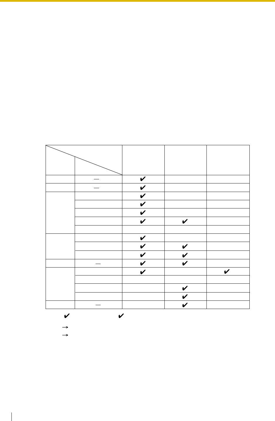
1. Available Networking Type for Each Optional Trunk Card Type
Each trunk port of an optional trunk card can be assigned its networking type: Public,
Private, or VPN (Virtual Private Network).
*1: 1.28.1 TIE Line Service
*2: 1.28.2 Virtual Private Network (VPN)
Virtual Private
Network
(VPN)*2
Private
(TIE)*1
Public
(DIL/DID/
DDI/MSN)
Networking
Type
T1
E1
E&M
LCOT
GCOT
DID
TIE (E & M)
OPX (EXTN.)
DR2
E & M-C
E & M-P
CO
Extension
QSIG-Master
QSIG-Slave
LCOT
Trunk
Card
Type
BRI/PRI
IP-GW
Channel Type
*
*
*
*
*
*
*
*
*
*
*
DID
*
*
*
*
Note: : Enable (default), : Enable
1.1 Incoming Call Features
Feature Guide 17
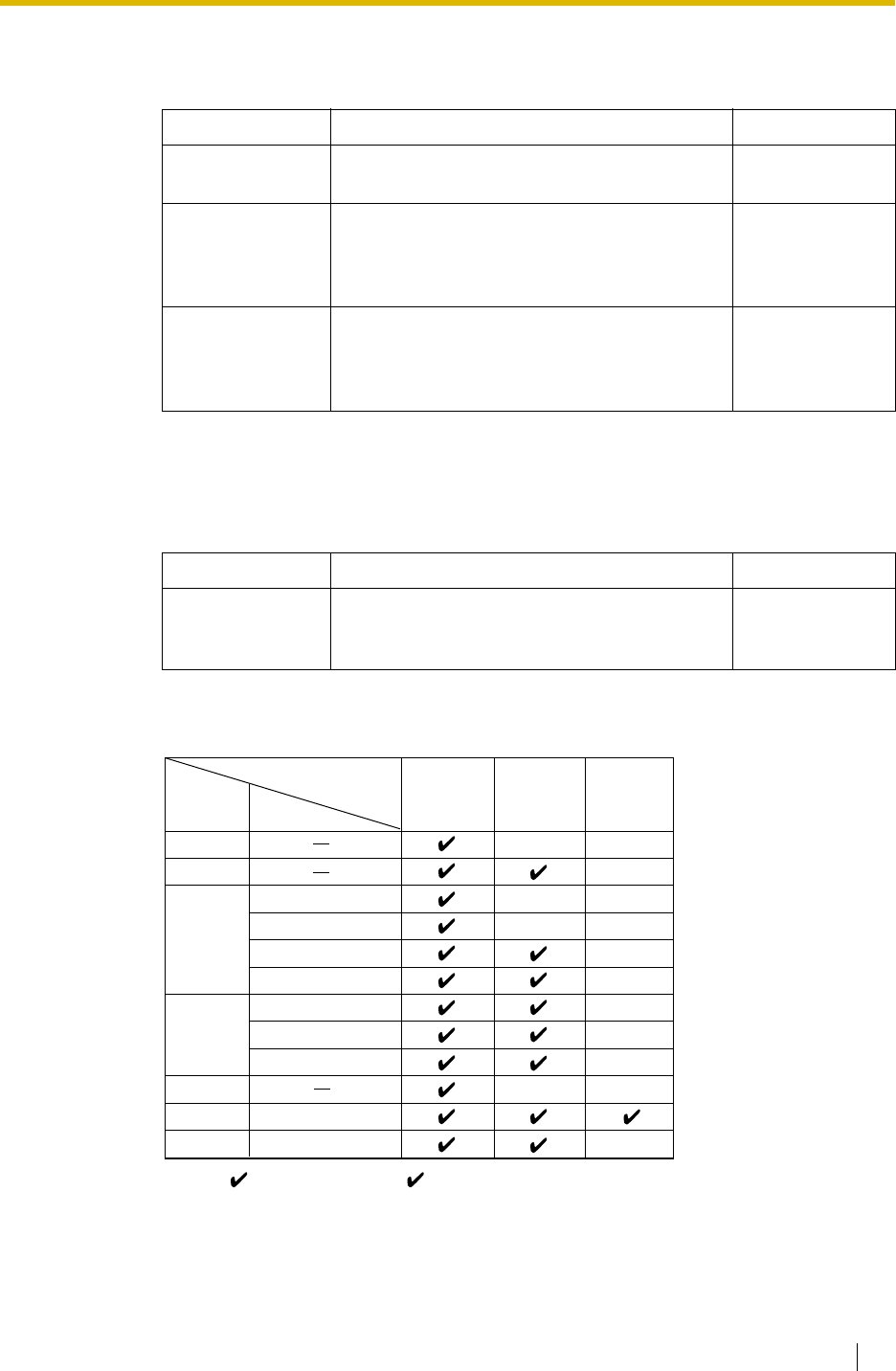
2. Distribution Feature
One of the following features can be assigned to each trunk port:
3. Destination Change with the Caller’s Identification Number
The Calling Line Identification (CLI) Distribution feature works in conjunction with the DIL/
DID/DDI/MSN features.
4. Available Distribution Feature for Each Optional Trunk Card Type
Feature Description Details in
Direct In Line
(DIL) Directs a call to a preprogrammed single
destination (e.g., Operator). • 1.1.1.2 Direct In
Line (DIL)
Direct Inward
Dialling (DID) Directs a call with a DID number from a DID
line to a preprogrammed destination.
DID is also known as Direct Dialling In (DDI).
• 1.1.1.3 Direct
Inward Dialling
(DID)/Direct
Dialling In (DDI)
Multiple
Subscriber
Number (MSN)
Ringing Service
Directs a call with an MSN from an ISDN line to
a preprogrammed destination. • 1.1.1.4 Multiple
Subscriber
Number (MSN)
Ringing Service
Feature Description Details in
Calling Line
Identification
(CLI) Distribution
Directs a call to a CLI destination if the caller’s
identification number has been assigned to the
Caller ID Table.
• 1.1.1.5 Calling
Line Identification
(CLI) Distribution
MSN
DID/DDIDIL
Feature
T1
E1
E&M
LCOT
GCOT
DID
TIE (E & M)
DR2
E & M-C
E & M-P
CO
CO
LCOT
BRI
PRI
Trunk
Card
Type
Channel Type
*
*
DID
*
*
*
*
*
*
*
*
*
*
*
Note: : Enable (default), : Enable
1.1 Incoming Call Features
18 Feature Guide
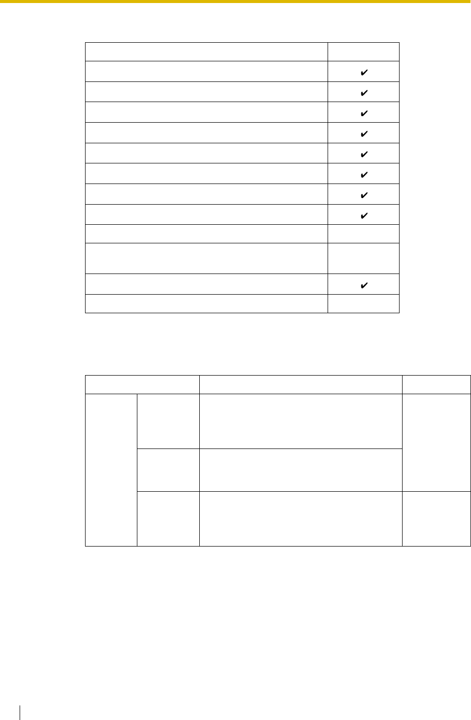
5. Available Destination
6. Intercept Routing
After distribution, the following features may be required.
Destination Availability
Wired Extension (PT/SLT/ISDN Extension/T1-OPX)
PS
Incoming Call Distribution Group
PS Ring Group
VM Group (DTMF/DPT)
External Pager (TAFAS)
DISA
Analogue/ISDN Remote Maintenance
Idle Line Access no. + Phone no.
Trunk Group Access no. + Trunk Group no. +
Phone no.
Other PBX Extension (TIE with no PBX Code)
Other PBX Extension (TIE with PBX Code)
Feature Description Details in
Intercept
Routing No Answer
(IRNA) If a called party does not answer a call within
a preprogrammed time period (Intercept
time), it is redirected to the preprogrammed
destination.
• 1.1.1.6
Intercept
Routing
Busy/DND If a called party is busy or in DND mode, the
call is redirected to the preprogrammed
destination.
No
Destination If a destination is not assigned, the call is
redirected to the operator. • 1.1.1.7
Intercept
Routing—No
Destination
1.1 Incoming Call Features
Feature Guide 19
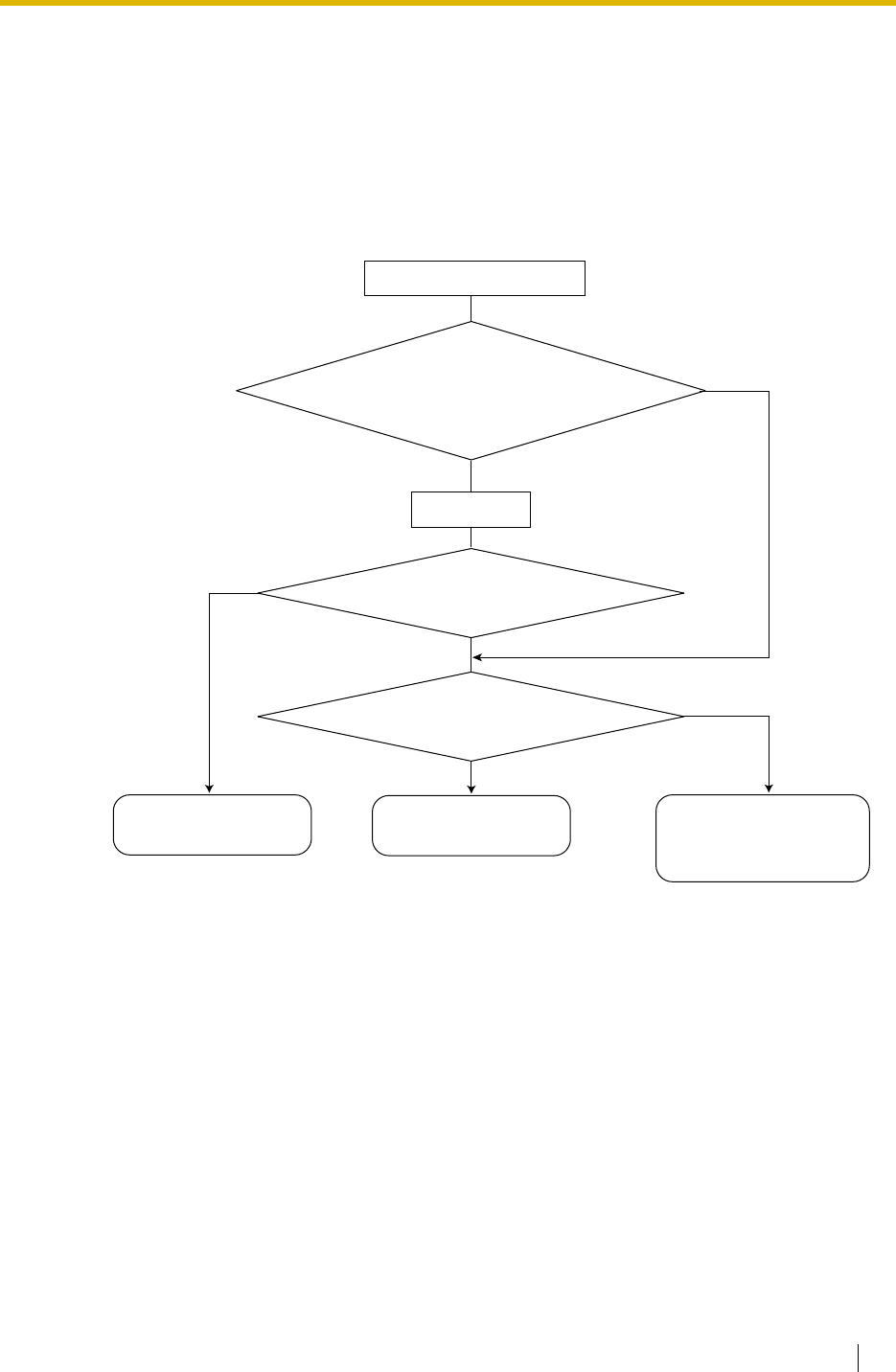
1.1.1.2 Direct In Line (DIL)
Description
Provides automatic direction of an incoming trunk call to a preprogrammed destination. Each
trunk has a destination for each time mode (day/lunch/break/night).
[Method Flowchart]
A trunk call is received.
CLI works.
Yes
Yes
No
Does the call have its CLI*
information and is CLI mode enabled
for the trunk and the time mode?
No
Is the CLI destination
assigned?
The call is routed to the
DIL destination.
The call is routed to the
CLI destination. The call is routed to the
operator (Intercept Routing
—No Destination).
Yes
Is the DIL destination of
the time mode assigned?
No
*: Calling Line Identification (CLI) Distribution:
If the CLI routing is enabled and the caller's identification number is assigned in the Caller ID
Table, the call will not be routed to the DIL destination, but routed to the CLI destination.

1.1 Incoming Call Features
20 Feature Guide
[Programming Example of DIL Table]
The table can be programmed for each trunk.
Note
Tenant number and VPS trunk group number can also be assigned in the DIL table. Tenant
number is used to determine the time mode (day/lunch/break/night) for the corresponding
trunk. VPS trunk group number is used in Voice Mail DPT (Digital) Integration ( 1.23.3
Voice Mail DPT (Digital) Integration).
Explanation:
If a trunk call is received from trunk 01;
In Day mode: CLI is enabled. Route to CLI destination.
In Lunch mode: CLI is disabled. Route to DIL destination, extension 100.
Feature Guide References
1.1.1.5 Calling Line Identification (CLI) Distribution
2.2.4 Time Service
Trunk No. CLI Destination*
Day Lunch Break Night Day Lunch Break Night
01 Enable Disable Enable Disable 101 100 101 100
02 Enable Disable Disable Disable 102 100 102 100
: ::::::::
*: DIL 1:1 Destination [450]
1.1 Incoming Call Features
Feature Guide 21
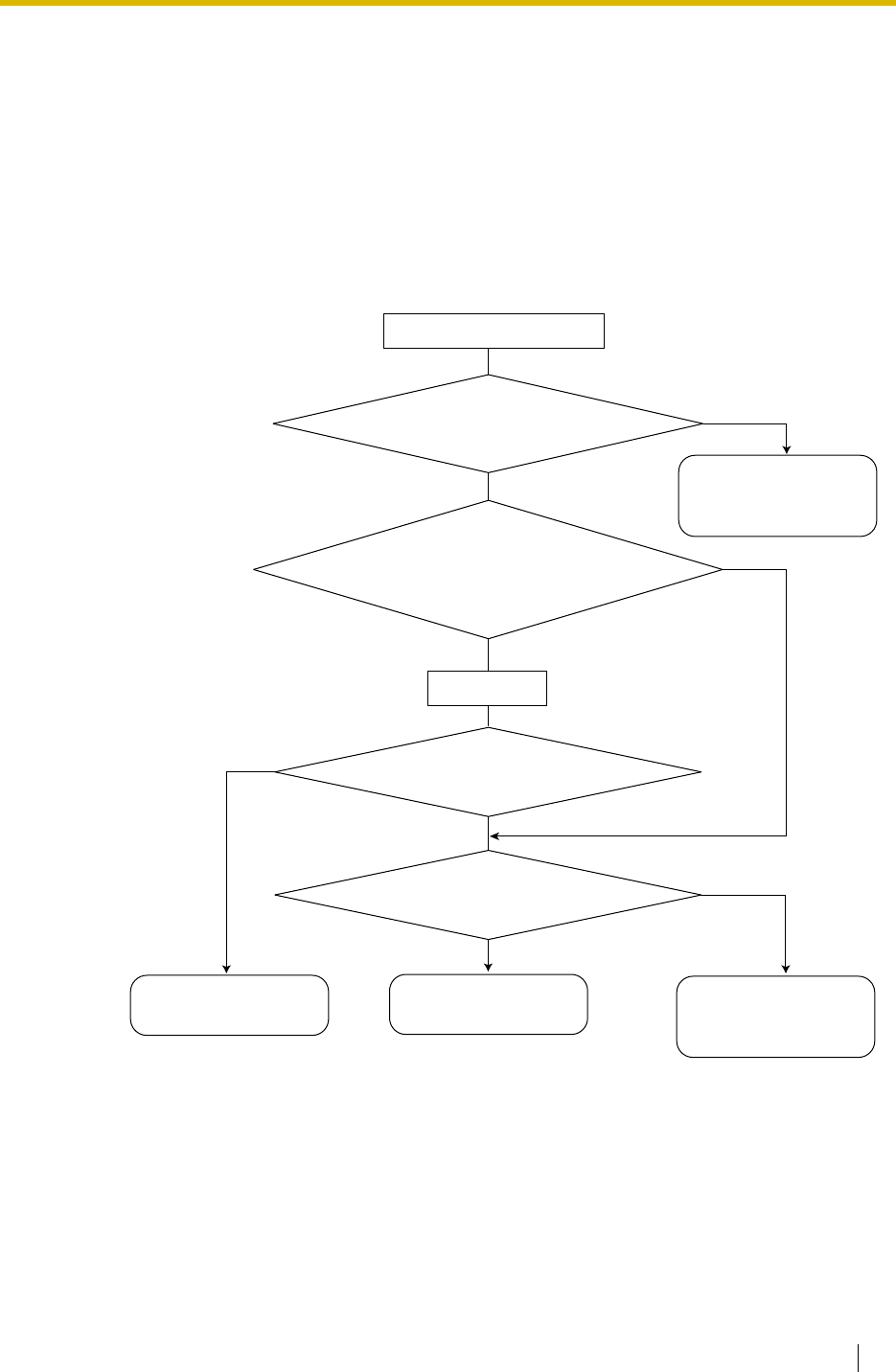
1.1.1.3 Direct Inward Dialling (DID)/Direct Dialling In (DDI)
Description
Provides automatic direction of an incoming call with a DID/DDI number to a preprogrammed
destination. Each DID/DDI number has a destination for each time mode (day/lunch/break/
night).
[Method Flowchart]
CLI works.
Yes
Yes
No
Does the call have its CLI*
information and is CLI mode
enabled for the time mode?
No
Is the CLI destination assigned?
The call is routed to the
DID/DDI destination.
The call is routed to the
CLI destination.
No
Yes
Is the DID/DDI number found in
the DID/DDI table?
Yes
Is the DID/DDI destination
for the time mode assigned? No
The call is routed to the
operator (Intercept
Routing—No Destination).
*: Calling Line Identification (CLI) Distribution:
If the CLI routing is enabled and the caller's identification number is assigned in the Caller ID
Table, the call will not be routed to the DID/DDI destination, but routed to the CLI destination.
The call is routed to the
operator (Intercept
Routing—No Destination).
A trunk call is received.

1.1 Incoming Call Features
22 Feature Guide
[Programming Example of DID/DDI Table]
DDI can be programmed as DID.
Note
Tenant number and VPS trunk group number can also be assigned in the DID/DDI table.
Tenant number is used to determine the time mode (day/lunch/break/night) for the
corresponding DID/DDI number. VPS trunk group number is used in Voice Mail DPT
(Digital) Integration ( 1.23.3 Voice Mail DPT (Digital) Integration).
Explanation:
If the DID/DDI number is "123-4567":
1. Checks the number in the table.
Matches the number in location 0001.
2. Checks the time mode.
In Day mode: CLI is enabled. Route to CLI destination.
In Lunch mode: CLI is disabled. Route to DID/DDI destination, extension 100.
Conditions
• To use this feature, the DID/DDI service must be assigned for a trunk port as the
distribution method ( BRI DIL/DDI/MSN Selection [421] *For BRI only).
•DID/DDI Number Modification
It is possible to modify a received DID/DDI number, which may be convenient when
programming the DID/DDI table. Modification method (removed number of digits/added
number) can be programmed on a trunk port basis.
[Modification Example]
Locat
ion DID/DDI
No.*1
DID/DDI
Name*2
CLI DID/DDI Destination*3
Day Lunch Break Night Day Lunch Break Night
0001 123-4567 John White Enabl
eDisabl
eEnabl
eDisabl
e105 100 105 100
0002 123-2468 Tom Smith Enabl
eDisabl
eDisabl
eDisabl
e102 100 102 100
0003 123-456 A company Enabl
eDisabl
eDisabl
eDisabl
e101 101 101 100
:: :::::::::
*1: DID Number [451]
*2: DID Name [452]
*3: DID Destination [453]
Removed number of digits: 6
Added number: 10
Received DID/DDI number: 87654321
Modified DID/DDI number: 876543 21 = 102
1
1) Remove the
first 6 digits. 2) Add "10".

1.1 Incoming Call Features
Feature Guide 23
•The Inter-digit Time
When the Inter-digit time expires, the PBX stops receiving DID/DDI number and starts to
check the DID/DDI table. (Refer to the [Programming Example of DID/DDI Table] above).
Even if the Inter-digit time does not expire, the PBX stops receiving the DID/DDI number
when the received number is found in the DID/DDI table. The PBX then routes the call to
the corresponding destination. If the received number matches several DID/DDI numbers
in the table, the DID/DDI number of the lowest numbered location has priority.
[Example] If a call is received in Lunch mode;
Feature Guide References
1.1.1.5 Calling Line Identification (CLI) Distribution
2.2.4 Time Service
Received
Number Destination Explanation
123-4567 Extn. 100 The PBX finds the match in location 0001
in the table after receiving "7". So the call
is routed to extension 100.
123-456 Extn. 101 The Inter-digit time expired after
receiving "6". The PBX finds the match in
location 0003 in the table. So the call is
routed to extension 101.
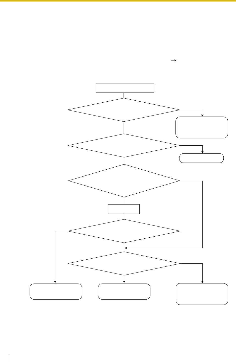
1.1 Incoming Call Features
24 Feature Guide
1.1.1.4 Multiple Subscriber Number (MSN) Ringing Service
Description
Provides automatic direction of an incoming ISDN-BRI (Basic Rate Interface) line call with an
MSN to a preprogrammed destination. One ISDN-BRI port can support a maximum of 10
MSNs. Each MSN has a destination for each time mode (day/lunch/break/night).
Point-to-multipoint must be selected for the ISDN configuration ( BRI Configuration [426]).
[Method Flowchart]
CLI works.
Yes
Yes
No
Does the call have its CLI*
information and is CLI mode
enabled for the time mode?
No
Is the CLI destination
assigned?
The call is routed to the
MSN destination.
The call is routed to the
CLI destination.
No
Yes
Yes
Is the MSN found in the
MSN table?
The call is ignored.
Is the MSN destination for
the time mode assigned?
No
*: Calling Line Identification (CLI) Distribution:
If the CLI routing is enabled and the caller's identification number is assigned in the Caller ID
Table, the call will not be routed to the MSN destination, but routed to the CLI destination.
No
Are any MSNs assigned
in the MSN table?
Yes The call is routed to the
operator (Intercept
Routing—No Destination
).
The call is routed to the
operator (Intercept
Routing—No Destination
).
A trunk call is received.
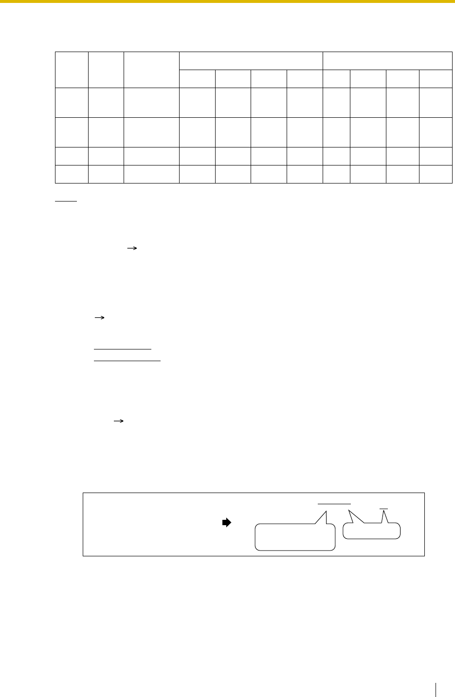
1.1 Incoming Call Features
Feature Guide 25
[Programming Example of MSN Table for ISDN BRI Port 1]
A table can be programmed for each ISDN-BRI port. Each BRI port has 10 MSN locations.
Note
Tenant number and VPS trunk group number can also be assigned in the MSN table.
Tenant number is used to determine the time mode (day/lunch/break/night) for the
corresponding MSN. VPS trunk group number is used in Voice Mail DPT (Digital)
Integration ( 1.23.3 Voice Mail DPT (Digital) Integration).
Explanation:
If the MSN "123-4567" is received from BRI port 1:
1. Checks the number in the table.
Matches the number in location 01.
2. Checks the time mode.
In Day mode: CLI is enabled. Route to CLI destination.
In Lunch mode: CLI is disabled. Route to MSN destination, extension 100.
Conditions
• To use this feature, the MSN service must be assigned for a trunk port as the distribution
method ( BRI DIL/DDI/MSN Selection [421]).
•MSN Modification
It is possible to modify a received MSN to make it shorter, which may be convenient when
programming the MSN table. Modification method (removed number of digits/added
number) can be programmed on a trunk port basis.
[Modification Example]
• When using point-to-multipoint configuration with a BRI, do not connect another ISDN
terminal device in parallel with the PBX. As only two channels can be used at one time
with the BRI, the other ISDN terminal device may monopolise both channels.
Feature Guide References
1.1.1.5 Calling Line Identification (CLI) Distribution
Locat
ion MSN MSN
Name
CLI MSN Destination
Day Lunch Break Night Day Lunch Break Night
01 123-
4567 A
Company Enable Disabl
eEnable Disabl
e101 100 101 100
02 123-
2468 C
Company Enable Disabl
eDisabl
eDisabl
e102 100 102 100
:: : ::::::::
10: : ::::::::
Removed number of digits: 6
Added number: 10
Received MSN: 87654321
Modified MSN: 876543 21 = 1021
1) Remove the first
6 digits. 2) Add "10".


1.1 Incoming Call Features
Feature Guide 27
1.1.1.5 Calling Line Identification (CLI) Distribution
Description
Directs an incoming trunk call to a destination when the caller’s identification number (e.g.,
Caller ID) matches the number in the System Speed Dialling Table which is used as the Caller
ID Table. Each Caller ID number (telephone number for each System Speed Dialling number)
can have its own destination.
CLI always works in conjunction with the following call distribution methods:
a) DIL
b) DID/DDI
c) MSN Ringing Service
Each trunk (for DIL) and the DID/DDI/MSN number can enable or disable the CLI feature for
each time mode (day/lunch/break/night) ( 2.2.4 Time Service).
When the call has its Caller ID and the CLI is enabled for the time mode, the call will be handled
by the CLI method.
[Programming Example of System Speed Dialling Table for CLI]
CLI Feature Description Details in
Caller ID (KX-TDA30/KX-
TDA100/KX-TDA200 only) Caller’s number is sent from an analogue
trunk. • 1.17.1 Caller
ID
Calling Line Identification
Presentation (CLIP) Caller’s number is sent from an ISDN line. • 1.20.1.2
Calling/
Connected
Line
Identification
Presentation
(CLIP/COLP)
Automatic Number
Identification (ANI) (KX-
TDA100/KX-TDA200 only)
Caller’s number is sent from an E1 or T1
line. • 1.21.1 E1
Line Service
(KX-TDA100/
KX-TDA200
only)
• 1.22.1 T1
Line Service
(KX-TDA100/
KX-TDA200
only)
Location
(System Speed
Dialling No.) Telephone No.*1 System Speed
Dialling Name*2 CLI Destination
000 901234567890 ABC Company 200
001 : : :
::::

1.1 Incoming Call Features
28 Feature Guide
Explanation:
If the caller’s number is "0123-456-7890" (The Trunk Access number is disregarded.):
1. Checks the number in the table.
Matches the number in location 000.
2. The call is routed to the CLI destination, extension 200.
Conditions
•Automatic Caller ID Number Modification
The Caller ID number is used after modification by the Automatic Caller ID Number
Modification. ( 1.17.1 Caller ID)
Feature Guide References
1.1.1.2 Direct In Line (DIL)
1.1.1.3 Direct Inward Dialling (DID)/Direct Dialling In (DDI)
1.1.1.4 Multiple Subscriber Number (MSN) Ringing Service
1.6.1.5 Speed Dialling—Personal/System
*1: System Speed Dialling Number [001]
*2: System Speed Dialling Name [002]

1.1 Incoming Call Features
Feature Guide 29
1.1.1.6 Intercept Routing
Description
Provides automatic redirection of incoming trunk calls. There are two types of Intercept Routing
as follows:
The available intercept destination is as follows:
Type 1: The destination assigned on the extension port which the original destination joins.
( Extension Intercept Destination [604])
Type 2: The destination assigned on the trunk group which receives the call.
( Trunk Group Intercept Destination [470])
Feature Description
Intercept Routing—No
Answer (IRNA) If a called party does not answer a call within a preprogrammed
time period (Intercept time) ( Intercept Time [203]), it is
redirected to the preprogrammed destination.
Intercept Routing—
Busy/DND If a called party is busy or in DND mode, the call is redirected to
the preprogrammed destination.
Original Destination The Available Intercept Destination
Wired Extension (PT/SLT/ISDN
Extension/T1-OPX) Type 1
PS Type 1
Incoming Call Distribution Group Intercept Routing—Overflow in an Incoming Call
Distribution Group works ( 1.2.2.5 Overflow
Feature). The overflow destination is assigned on
the incoming call distribution group which the
original destination joins ( Destination for
Overflow Time Expiration [625]).
PS Ring Group Type 2
VM Group (DTMF/DPT) Type 2
External Pager (TAFAS) Type 2
DISA Type 2*
Analogue/ISDN Remote
Maintenance Not available
Idle Line Access no. + Phone no. Not available
Trunk Group Access no. +
Trunk Group no. + Phone no. Not available
Other PBX Extension (TIE with no
PBX Code) Not available
Other PBX Extension (TIE with PBX
Code) Not available
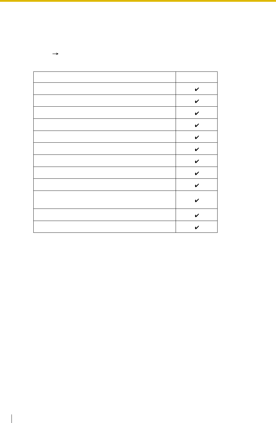
1.1 Incoming Call Features
30 Feature Guide
Each of them can have different intercept destinations for each time mode (day/lunch/break/
night) ( 2.2.4 Time Service).
[Available Intercept Destination]
Conditions
•Intercept Routing—Busy/DND on/off
Each Intercept Routing—Busy and Intercept Routing—DND can be enabled or disabled
through system programming.
If disabled, one of the following is activated depending on the trunk card type which a call
arrives through:
a) LCOT or T1 (LCOT/GCOT) Card: The incoming trunk call will ring at the original
destination while the caller hears a ringback tone.
b) Other Trunk Cards: A busy tone will be sent to the caller.
•If the intercept destination cannot receive the call:
a) Intercept Routing—No Answer: Intercept timer will restart at the original
destination, until the call is answered.
b) Intercept Routing—Busy/DND: The call will be sent back to the original destination
when the call arrives through the LCOT or T1 (LCOT/GCOT) card. When the call
arrives through other trunk cards the caller will hear a busy tone.
•Idle Extension Hunting
If an extension is a member of an idle extension hunting group, calls to that extension will
not be redirected by Intercept Routing—Busy/DND. If the extension is busy or in DND
mode, calls to that extension will be redirected to the next extension in the idle extension
hunting group.
*: This is applied only when a trunk call arrives on a DISA line but the line is busy at that time.
Once the call reaches the destination extension by using the DISA feature, the Intercept
Routing feature of the extension works.
Intercept Destination Availability
Wired Extension (PT/SLT/ISDN Extension/T1-OPX)
PS
Incoming Call Distribution Group
PS Ring Group
VM Group (DTMF/DPT)
External Pager (TAFAS)
DISA
Analogue/ISDN Remote Maintenance
Idle Line Access no. + Phone no.
Trunk Group Access no. + Trunk Group no. +
Phone no.
Other PBX Extension (TIE with no PBX Code)
Other PBX Extension (TIE with PBX Code)


1.1 Incoming Call Features
32 Feature Guide
1.1.1.7 Intercept Routing—No Destination
Description
Provides automatic redirection of an incoming trunk call which does not have a destination
assigned. The intercept destination is an operator (tenant/PBX) ( Operator Assignment [006]
*For PBX operator only).
Conditions
•Intercept Routing—No Destination on/off
The Intercept Routing—No Destination feature can be enabled or disabled through system
programming.
If disabled, reorder tone will be sent to the caller. However, the Intercept Routing—No
Destination feature always works for calls through the LCOT or T1 (LCOT/GCOT) card
even when disabled.
•If an operator (tenant/PBX) is not assigned:
The lowest jack numbered extension will be the intercept destination.
•Intercept Routing—No Destination also applies to:
Calls from doorphones.
Feature Guide References
2.2.5 Operator Features
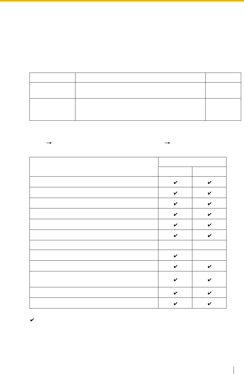
1.1 Incoming Call Features
Feature Guide 33
1.1.2 Internal Call Features
1.1.2.1 Internal Call Features—SUMMARY
Description
The following incoming calls reach their destination:
[Available Destination]
The destinations of doorphone calls can be assigned for each time mode (day/lunch/break/
night) ( 2.2.4 Time Service) on a doorphone port basis ( Doorphone Call Destination
[720]).
Feature Description Details in
Intercom Call A call from one extension to another. • 1.5.3
Intercom Call
Doorphone Call When a call from a doorphone reaches its destination,
the recipient can talk to the visitor. • 1.16.1
Doorphone
Call
Destination Calling from
Extension Doorphone
Wired Extension (PT/SLT/ISDN Extension/T1-OPX)
PS
Incoming Call Distribution Group
PS Ring Group
VM Group (DTMF/DPT)
External Pager (TAFAS)
DISA
Analogue/ISDN Remote Maintenance
Idle Line Access no. + Phone no.
Trunk Group Access no. + Trunk Group no. +
Phone no.
Other PBX Extension (TIE with no PBX Code)
Other PBX Extension (TIE with PBX Code)
:Available
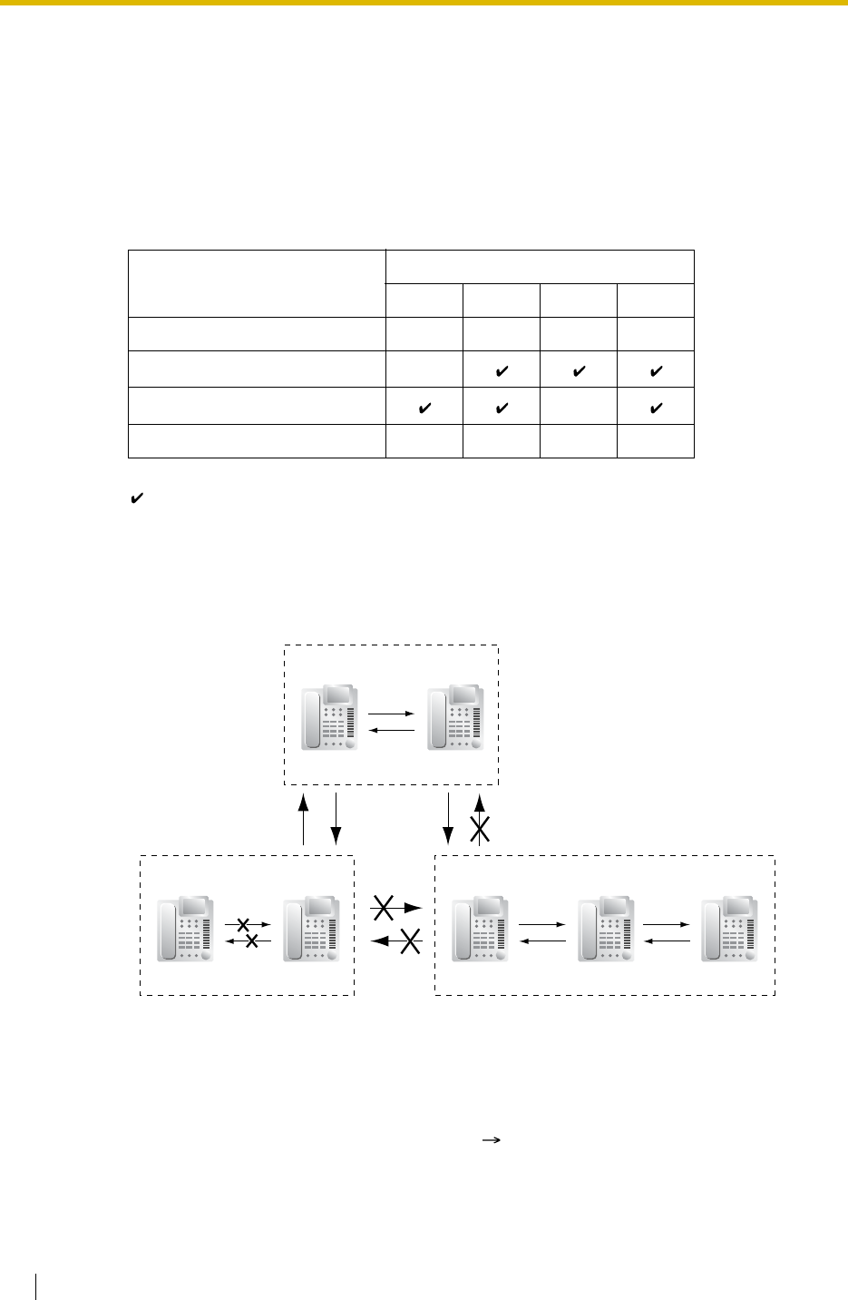
1.1 Incoming Call Features
34 Feature Guide
1.1.2.2 Internal Call Block
Description
Internal calls can be restricted on a COS basis. Each COS of the caller can enable or disable
this feature for each COS of the called party.
[Programming Example]
Explanation:
a) COS 1 can make calls to all extensions.
b) COS 2 can make calls to COS 1 only. (COS 2 cannot make calls to COS 2.)
c) COS 3 can make calls to COS 3 only.
Conditions
• Restricted extension numbers cannot be the parameter of the feature settings (e.g.,
Walking Extension).
• All extensions can make an Operator Call ( 2.2.5 Operator Features) regardless of the
Internal Call Block.
Caller Called Party
COS 1 COS 2 COS 3 ...
COS 1
COS 2
COS 3
:::::
:Block
COS 1
Extn. 100 Extn. 101
COS 2
Extn. 102 Extn. 103
COS 3
Extn. 104 Extn. 105 Extn. 106


1.1 Incoming Call Features
36 Feature Guide
1.1.3 Incoming Call Indication Features
1.1.3.1 Incoming Call Indication Features—SUMMARY
Description
Incoming calls are indicated by various methods as follows:
Type Feature Description Details in
Ring Tone Ring Tone
Pattern
Selection
A telephone rings when receiving a call. The
ring tone patterns can be changed for each
incoming call type.
• 1.1.3.2
Ring Tone
Pattern
Selection
Voice-calling Alternate
Receiving—
Ring/Voice
A PT user can select to receive intercom
calls by ring tone or by voice, through
personal programming.
• 1.5.3
Intercom
Call
LED
(LED: Light
Emitting
Diode)
LED Indication The light shows line conditions with a variety
of light patterns. • 1.19.3
LED
Indication
Display
(Caller’s
Information)
Display
Information The display shows the caller’s information. • 1.19.4
Display
Information
External Pager Trunk Answer
from Any
Station
(TAFAS)
The external pager sends a ring tone when
receiving a call. • 1.16.3
Trunk
Answer
From Any
Station
(TAFAS)
Tone/Voice
during a
Conversation
Call Waiting A busy extension hears a tone, or voice from
the handset/built-in speaker indicating that
another incoming call is waiting.
• 1.1.3.3
Call Waiting

1.1 Incoming Call Features
Feature Guide 37
1.1.3.2 Ring Tone Pattern Selection
Description
A ring tone pattern can be selected for each incoming call type on a Ring Tone Pattern Table
basis, which can be assigned for each extension.
[Ring Tone Patterns]
[Programming Example of Ring Tone Pattern Table]
There are a specified number of programmable tables each of which allows the assignment of
ring tone patterns for the following incoming call types:
For trunk calls (including trunk call hold recalls) and doorphone calls, select ring tone patterns
on a trunk group or a doorphone port basis.
Each extension can select one of the tables.
Conditions
•"PT Ring off Setting" can be enabled or disabled through system programming. If
disabled, PT users cannot set the ring off.
Table
No.
Intercom
Call/Hold
Recall
Trunk Call/Hold
Recall Doorphone Call Timed
Reminder Call
Back LCS
TRG1 TRG2 ... Port 1 Port 2 ...
1 Double Single Single
2 Single Double Double
:: :::::::::
1 280 ms
S
ingle
D
ouble
T
riple
S
-Double

1.1 Incoming Call Features
38 Feature Guide
1.1.3.3 Call Waiting
Description
Used to inform a busy extension that another incoming call is waiting. The busy extension user
can answer the second call by disconnecting the current call or placing it on hold.
The following notification method can be assigned for each extension depending on the call
waiting and the telephone type:
a) Call Waiting Tone: Tone from the handset or built-in speaker
b) OHCA: Voice from the built-in speaker
c) Whisper OHCA: Voice from the handset
d) Off: No notification.
This feature is also known as Busy Station Signalling (BSS).
Conditions
• Call Waiting call for an extension in a VM group (DPT/DTMF) is not available.
•Data Line Security
Setting Data Line Security cancels the Call Waiting setting. ( 1.10.5 Data Line Security)
•Call Waiting Tone
A PT user can hear different Call Waiting tones for trunk call and intercom call if "Tone 2"
has been selected through personal programming (Call Waiting Tone Type Selection). If
"Tone 1" has been selected, the same Call Waiting tone will be heard for both trunk call
and intercom call.
All Call Waiting tone patterns have a default ( 4.2.1 Tones/Ring Tones).
•Caller Information
With the Call Waiting tone, the caller’s information flashes on the display for five seconds
at 15-second intervals.
•Call Waiting from the Telephone Company
Besides the Call Waiting service within the PBX, the Call Waiting tone offered by an
analogue line from your telephone company informs the extension user of another
incoming trunk call that is waiting. He can answer the second call by disconnecting the
current call or placing it on hold. For details, consult your telephone company.
Call Waiting Caller ID (Visual Caller ID) (KX-TDA30/KX-TDA100/KX-TDA200 only):
With the Call Waiting tone offered by an analogue line from the telephone company, the
Caller ID number can be received and flash on the display twice for five seconds at 15-
second intervals.
Call Type Notification Method
DPT Other Telephone
Intercom Call Call Waiting tone/OHCA/
Whisper OHCA/Off Call Waiting tone/Off
Trunk Call* Call Waiting tone/Off
*: Including a doorphone call, call via an incoming call distribution group, and a transferred
trunk call from another extension.

1.1 Incoming Call Features
Feature Guide 39
Feature Guide References
1.7.4 Second Call Notification to Busy Extension
User Manual References
User Manual
1.4.4 Answering Call Waiting
1.7.3 Receiving Call Waiting (Call Waiting/Off-hook Call Announcement [OHCA]/Whisper
OHCA)
3.1.2 Settings on the Programming Mode
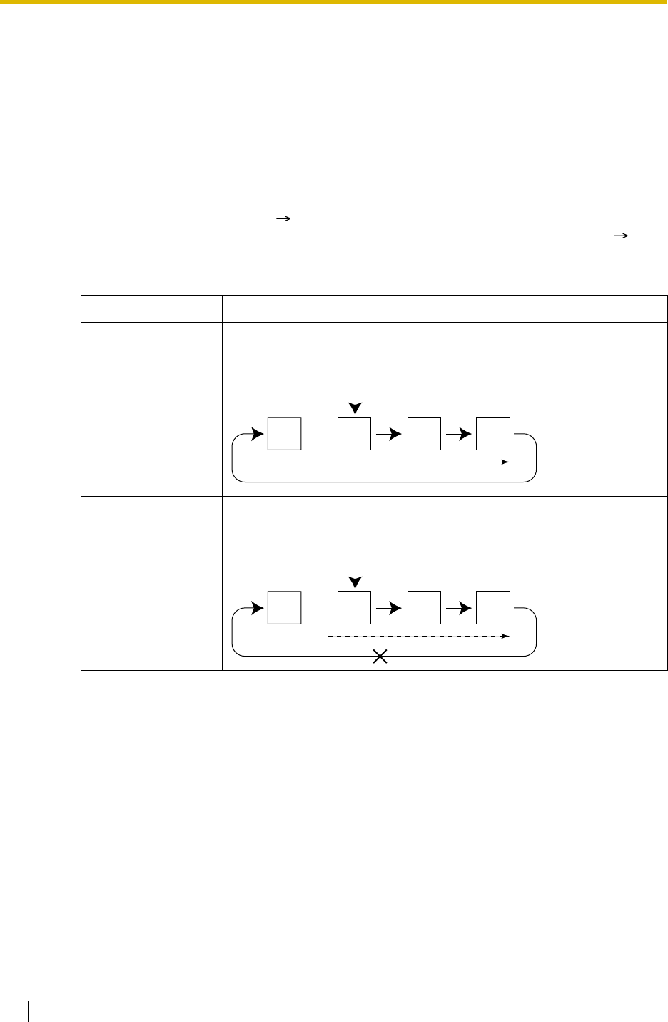
1.2 Receiving Group Features
40 Feature Guide
1.2 Receiving Group Features
1.2.1 Idle Extension Hunting
Description
If a called extension is busy or in DND mode, Idle Extension Hunting redirects the incoming call
to an idle member of the same idle extension hunting group, which can be programmed
through system programming ( Idle Extension Hunting Group Member [681]). Idle
extensions are automatically searched according to a preprogrammed hunting type ( Idle
Extension Hunting Type [680]).
This feature is also known as Station Hunting.
Conditions
•Idle Extension Hunting applies to:
Intercom, trunk, and doorphone calls to a single destination.
• An extension user can belong to only one idle extension hunting group.
Type Description
Circular Hunting An idle extension is searched for in the order specified in the idle
extension hunting group in a circular way.
Terminated Hunting An idle extension is searched for in the order specified in the idle
extension hunting group until reaching the last assigned extension.
Extn.
Incoming call
Assigned order
Busy
Extn. Extn. Extn.
Extn.
Incoming call
Assigned order
Busy
Extn. Extn. Extn.
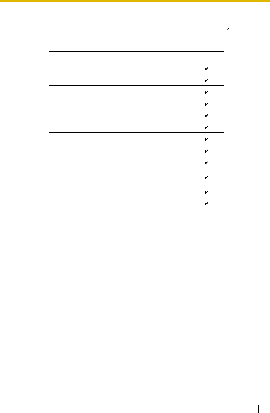
1.2 Receiving Group Features
Feature Guide 41
•If all the searched extensions are busy:
The PBX redirects the call to an overflow destination which can be assigned for each idle
extension hunting group and each time mode (day/lunch/break/night) ( 2.2.4 Time
Service).
[Available Destination]
•FWD/DND Mode
While searching for an idle extension within an idle extension hunting group, any extension
which has set FWD—All Calls or DND feature will be skipped, and the call will go to the
next extension in the group.
Feature Guide References
1.3.1 Call Forwarding (FWD)/Do Not Disturb (DND)
Destination Availability
Wired Extension (PT/SLT/ISDN Extension/T1-OPX)
PS
Incoming Call Distribution Group
PS Ring Group
VM Group (DTMF/DPT)
External Pager (TAFAS)
DISA
Analogue/ISDN Remote Maintenance
Idle Line Access no. + Phone no.
Trunk Group Access no. + Trunk Group no. +
Phone no.
Other PBX Extension (TIE with no PBX Code)
Other PBX Extension (TIE with PBX Code)
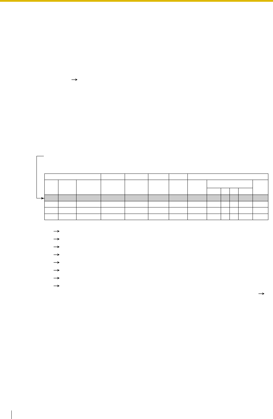
1.2 Receiving Group Features
42 Feature Guide
1.2.2 Incoming Call Distribution Group Features
1.2.2.1 Incoming Call Distribution Group Features—SUMMARY
Description
An incoming call distribution group is a group of extensions programmed through system
programming ( Incoming Call Distribution Group Member [620]). An incoming call
distribution group receives calls directed to the group. Each incoming call distribution group
has a floating extension number.
Incoming calls directed to an incoming call distribution group are distributed to the member
extensions in the group using a distribution method. When a preprogrammed number of
extensions in the group are busy, the incoming calls can wait in a queue.
Each incoming call distribution group and member extensions can be programmed as desired
to handle incoming calls. Calls to the group can be monitored by an extension assigned as a
supervisor (supervisor extension).
*1: Incoming Call Distribution Group Floating Extension Number [622]
*2: Incoming Call Distribution Group Name [623]
*3: Incoming Call Distribution Group Distribution Method [624]
*4: Maximum Number of Agents [632]
*5: Queuing Call Capacity [628]
*6: Queuing Hurry-up Level [629]
*7: Overflow Time [626]
*8: Destination for Overflow Time Expiration [625]/Destination When All Busy [627]
*9:Tenant number is required to determine the time mode (day/lunch/break/night) (
2.2.4 Time Service) and the music source (for Music on Hold) for each group.
Programming Item Example for Incoming Call Distribution Group 1 with
Diagram
A through F in the table are described in the following diagram.
Group
No.
1
2
3
:
3
Max.
Queuing
Call
Capacity
*5
Hurry-up
Level
*6
3
8
Overflow
Time
*7
60
90
Tenant
No.*9
1
5
Overflow Destination
*8
Day
100
200
...
...
...
...
...
...
Night
100
200
Group
Name
*2
Sales
Engineering
Floating
Extn. No
.
*1
290
291
Distribution
Method
*3
Ring
UCD
ABCDEF
5
11
Max. No. of
Busy
Extensions
*4
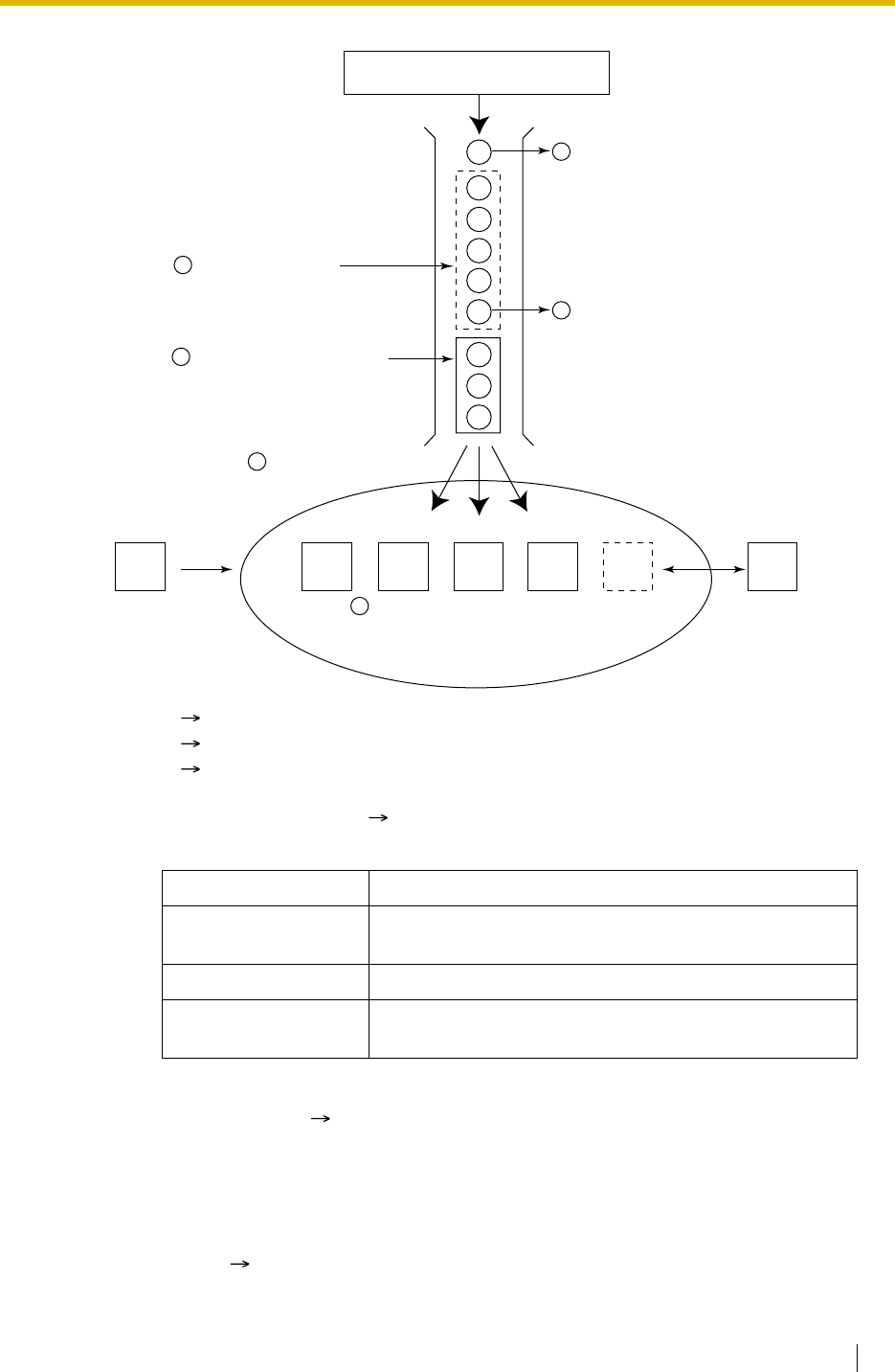
1.2 Receiving Group Features
Feature Guide 43
1. Group Call Distribution [ 1.2.2.2 Group Call Distribution]
Incoming calls are distributed using one of the following methods:
2. Queuing Feature [ 1.2.2.3 Queuing Feature]
If a preprogrammed numbers of extensions in an incoming call distribution group are busy,
a preprogrammed number of additional calls can wait in a queue.
While calls are waiting in the queue, an outgoing message (OGM) or Music on Hold can
be sent to the waiting callers.
3. VIP Call [ 1.2.2.4 VIP Call]
It is possible to assign a priority to incoming call distribution groups so that an incoming
*10: 1.2.2.3 Queuing Feature
*11: 1.2.2.7 Supervisory Feature
*12: 1.2.2.6 Log-in/Log-out
Distribution Method Description
Uniform Call
Distribution (UCD) Calls go to a different extension uniformly each time a call
is received.
Priority Hunting An idle extension is searched in the specified order.
Ring All extensions in the incoming call distribution group ring
simultaneously.
Incoming Call
Distribution Group 1
(Floating extension no.: 290,
Name: Sales)
Log-outLog-in
Extn.
101 Extn.
102 Extn.
103 Extn.
104 Extn.
105 Extn.
105
Supervisor Extension
Extn.
100
Calls arriving at incoming call
distribution group 1.
Queuing Feature
Five calls are
waiting in a queue.
Monitors or controls the
incoming call distribution
group status.
4
5
8
9
1
2
3
Group Call Distribution
Calls are distributed by the
assigned method.
(Only three extensions
[agents] can answer the
call for Busy on Busy.)
Overflow Feature
a) Sends a busy tone (Busy on Busy), o
r
b) Redirects to the overflow destination.
Manual Queue Redirection
The longest waiting call in a queue
can be redirected to the overflow
destination by pressing the Hurry-up
button. The button shows the Hurry-
up status.
D
E
F
B
A
C
*11
*12
*10
6
7

1.2 Receiving Group Features
44 Feature Guide
call can be received from the groups in priority order.
4. Overflow Feature [ 1.2.2.5 Overflow Feature]
A call is redirected to a preprogrammed destination when it cannot be answered or queued
(Intercept Routing—Overflow in an Incoming Call Distribution Group). It is also
possible to send a busy tone (Busy on Busy) or disconnect the line.
5. Incoming Call Distribution Group Controlling Feature
Conditions
• One extension can belong to multiple incoming call distribution groups.
•ICD Group button
An Incoming Call Distribution (ICD) Group button can be assigned on a flexible button for
each incoming call distribution group. It receives the incoming calls to the group.
One extension can have more than one ICD Group button of the same or different
incoming call distribution groups (Multiple ICD Group). If all ICD Group buttons in the
same incoming call distribution group are occupied, the next incoming call will be held in
a queue or will overflow. If the ICD Group button is not assigned, incoming calls will arrive
at the INTERCOM or CO button.
Even though an extension can have an ICD Group button for an incoming call distribution
group that the extension has not been programmed to be included through system
programming ( Incoming Call Distribution Group Member [620]), the ICD Group button
will not receive calls to that group.
•Group FWD
The FWD feature can be assigned on an incoming call distribution group basis.
•COS for Incoming Call Distribution Groups
Each incoming call distribution group is assigned a COS number. Group FWD to an
outside party can be enabled or disabled for each COS. The COS for incoming call
distribution groups is also used for the Internal Call Block feature; when an extension user
calls an incoming call distribution group, the PBX checks the COS of the calling extension
against the COS of the incoming call distribution group ( 1.1.2.2 Internal Call Block).
Feature Description Details in
Log-in/Log-out Member extensions can join the group to
handle calls (Log-in) or leave the group
for a break (Log-out).
They can leave the group temporarily
when they are away from their desks, to
prevent calls being sent to their
extensions.
• 1.2.2.6 Log-
in/Log-out
Supervisory
Feature Incoming
Call Queue
Monitor
The supervisor extension can monitor
various information about the incoming
calls for each incoming call distribution
group on his display.
• 1.2.2.7
Supervisory
Feature
Log-in/Log-
out Monitor
and Remote
Control
Monitor: The supervisor extension can
monitor the log-in/log-out status of the
group members.
Remote Control: The supervisor
extension can change the status of the
members.

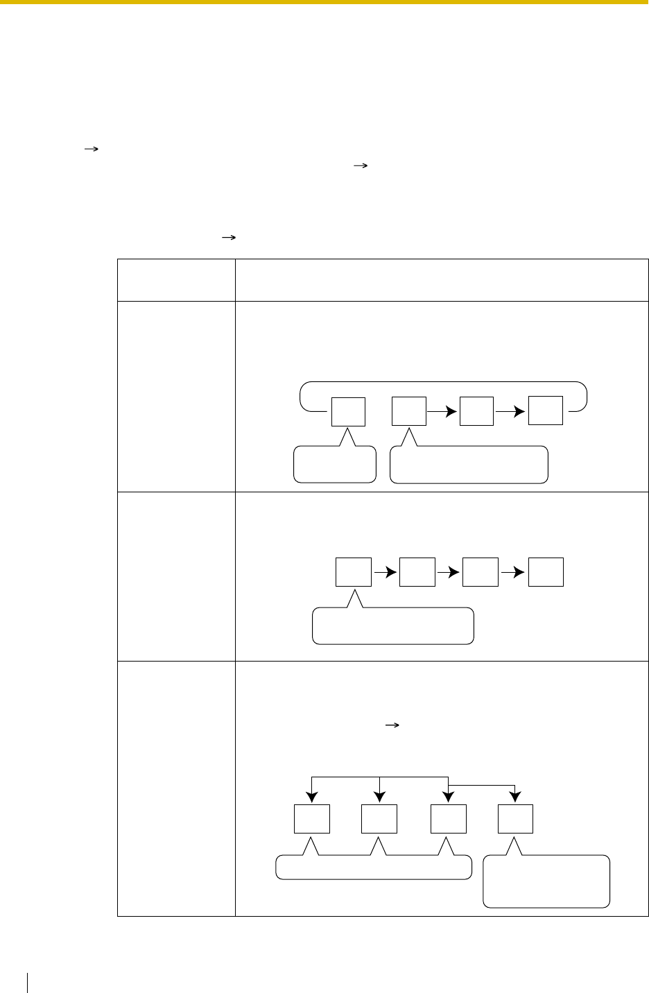
1.2 Receiving Group Features
46 Feature Guide
1.2.2.2 Group Call Distribution
Description
The Incoming calls directed to an incoming call distribution group are distributed to the member
extensions using the distribution method until a preprogrammed number of extensions (agents)
( Maximum Number of Agents [632]) are available to accept a call. When incoming calls
exceed the number, the calls enter a queue ( 1.2.2.3 Queuing Feature).
1. Distribution Method
There are three distribution methods which can be assigned to each incoming call
distribution group ( Incoming Call Distribution Group Distribution Method [624]).
Distribution
Method Description
Uniform Call
Distribution
(UCD)
Calls go to a different extension uniformly each time a call is
received. Extensions are hunted in a circular way in the
preprogrammed order for the group, starting at the extension after
the extension which received the last call.
Priority Hunting An idle extension is searched for using the preprogrammed order
for the group.
Ring All extensions in the group ring simultaneously.
Delayed Ringing:
Delayed ringing or no ringing can be programmed for each
extension in the group ( Incoming Call Distribution Group
Delayed Ringing [621]). The call can be answered by pressing the
flashing button even if no ring or a delayed time is set.
Extn.
A
Starts searching from
extn. B. (Skips extn. A.)
Received
the last call.
Extn.
BExtn.
CExtn.
D
Extn.
A
1st Priority 2nd Priority 3rd ....
Always starts searching from
the first assigned extension.
Extn.
BExtn.
CExtn.
D
Delayed Ringing:
Rings after a
specified time delay.
Rings immediately simultaneously.
Extn.
AExtn.
BExtn.
CExtn.
D
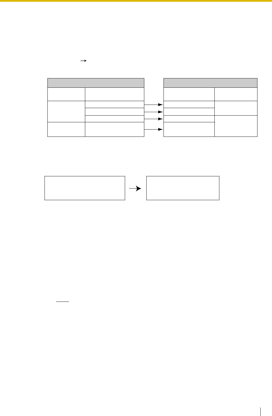
1.2 Receiving Group Features
Feature Guide 47
2. Call Waiting for Incoming Call Distribution Group (Group Call Waiting)
When there are no available extensions in an incoming call distribution group, the group
members can receive the Call Waiting tone. To use this feature:
• Select the Group Call Waiting mode through system programming. This determines
the distribution method for waiting calls.
• Member extensions must assign the Call Waiting mode individually, or they will not be
notified. ( 1.1.3.3 Call Waiting)
[How the Group Call Waiting Feature Activates]
[Example]
[ICD Group Button for Group Call Waiting]
The way that the Group Call Waiting feature works depends on the Group Call Waiting
Distribution method as follows:
a) Ring: The Group Call Waiting feature activates for all busy member extensions
(even when the extensions do not have ICD Group buttons) simultaneously for
only one incoming call — additional calls will wait in a queue.
b) UCD/Priority Hunting: The Group Call Waiting feature activates on an idle ICD
Group button located on busy member extensions in a certain order. (This order
depends on the type: UCD or Priority Hunting.) Calls will arrive at idle buttons
until all ICD Group buttons are occupied — additional calls will wait in a queue.
Note
In the method b), if an extension has one or more ICD Group buttons for an
incoming call distribution group and all the ICD Group buttons on the extension
are occupied, the Group Call Waiting feature for the group will not work at the
extension.
*: Incoming calls enter the queue immediately. Member extensions do not receive the
Call Waiting tone.
Group Call
Waiting Mode
Distribution
All
Group Call
Distribution Method
UCD
Priority Hunting
Ring
UCD/Priority Hunting/
Ring
Programming Conditions
Capable
Telephone
PT/PS with idle
ICD Group button
Any telephone
Group Call Waiting
Distribution Method
UCD
Priority Hunting
Not available*
Ring
Result
Group Call Waiting mode: All
Group call distribution method
for idle extensions: UCD
All extensions hear the Call
Waiting tone (Ring).
•
•
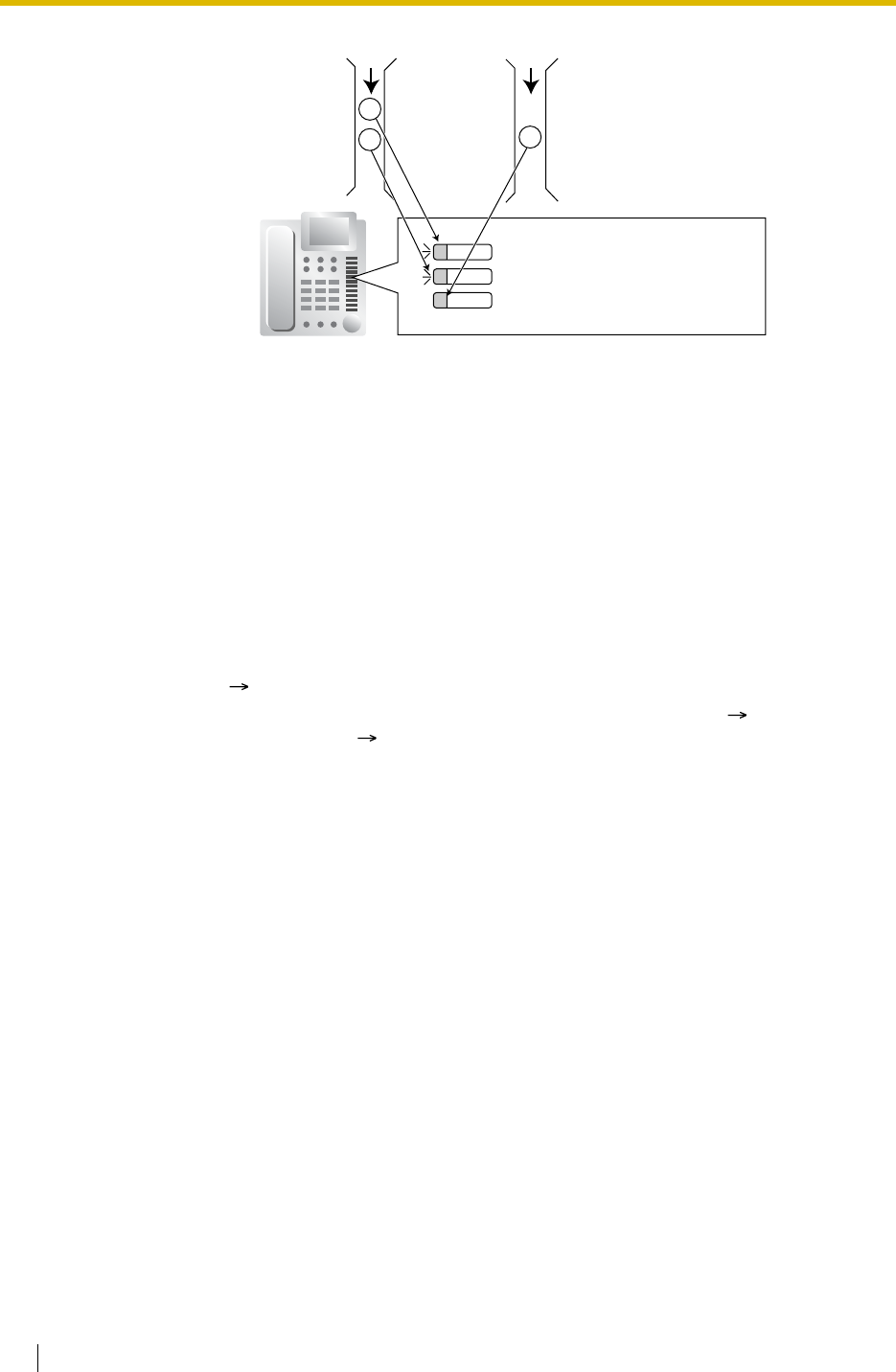
1.2 Receiving Group Features
48 Feature Guide
3. No Reply Redirection (UCD or Priority Hunting Method)
If a call received at a member extension is not answered within a preprogrammed time
period (No Answer time), the call will be redirected to the next member extension. If there
is no idle group member, the call queues at target extension until a group member
becomes available.
Conditions
•FWD/DND Extension
System programming for each incoming call distribution group is required to skip or ring
the extension which has FWD or DND feature set. If it rings, the FWD/DND settings are
ignored. ( 1.3.1 Call Forwarding (FWD)/Do Not Disturb (DND))
• Group Call Waiting feature cannot be used with the VIP Call feature ( 1.2.2.4 VIP Call)
and/or Wrap-up feature ( 1.2.2.6 Log-in/Log-out). Because to use the VIP Call feature
and/or Wrap-up feature, Call Waiting mode on each extension should be off.
Incoming Call
Distribution
Group 1
(Floating
extension
no.: 200)
Incoming Call
Distribution
Group 2
(Floating
extension
no.: 300)
ICD Group 200 (Call Waiting)
ICD Group 200 (Call Waiting)
ICD Group 300 (Answering the Call)
21
3

1.2 Receiving Group Features
Feature Guide 49
1.2.2.3 Queuing Feature
Description
When a preprogrammed number of extensions ( Maximum Number of Agents [632]) in an
incoming call distribution group are busy, additional incoming calls can wait in a queue. The
number of calls which can be in the waiting queue is programmable ( Queuing Call Capacity
[628]).
While calls are waiting in the queue, the calls are handled by the Queuing Time Table (
Queuing Time Table [630]), which can be assigned for each time mode (day/lunch/break/night)
( 2.2.4 Time Service). Each Queuing Time Table has a specified number of sequences. The
following procedures are provided to make up a Queuing Time Table:
[Procedure Table]
[Programming Example of Queuing Time Table]
Command Description Condition
OGM a An outgoing message (OGM) a
(01–64 [with the KX-TDA100/KX-
TDA200] or 01–32 [with the KX-
TDA15/KX-TDA30]) is sent to the
caller.
After the outgoing message (OGM),
Music on Hold will be sent and redirects
to the next sequence.
b × 5 s Puts the caller in the waiting
queue for b (01–16) × 5 seconds. If an outgoing message (OGM) has not
been sent to the caller, the caller hears
a ringback tone.
If an outgoing message (OGM) has
been sent to the caller, the caller hears
Music on Hold.
Sequence c Redirects to sequence c (01–16). None
Overflow Redirects to overflow destination. None
Disconnect Disconnects the line. None
None
(No command) Redirects to the next sequence. If assigned on sequence 01, the
Queuing Time Table will not be
activated.
Queuing
Time
Table
No.
Sequence*1
Sequence
01 Sequence
02 Sequence
03 Sequence
04 ... Sequence
16*2
01 OGM 01 6 × 5 s OGM 03 Overflow
02
03
:::::::
*1: Sequences in Queuing Time Table [631]
*2:The call will be disconnected if the destination is not determined after sequence 16.
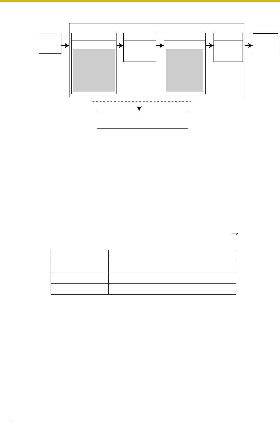
1.2 Receiving Group Features
50 Feature Guide
Explanation for Queuing Time Table 01:
Conditions
•If the call is transferred to the incoming call distribution group and is handled by the
Queuing Time Table:
Transfer Recall will not occur even if the Transfer Recall time expires.
•Manual Queue Redirection
It is possible to redirect the longest waiting call in a queue to the overflow destination by
pressing the Hurry-up button. (When the call is already ringing on any extension, the call
is not redirected.)
This feature is also known as Hurry-up Transfer.
•Hurry-up Button
A flexible button can be customised as the Hurry-up button. The number of calls queuing
before Manual Queue Redirection may be performed is programmable ( Queuing Hurry-
up Level [629]). The button shows the current status as follows:
Feature Guide References
1.2.2.5 Overflow Feature
1.19.2 Flexible Buttons
User Manual References
User Manual
1.8.3 Forwarding a Waiting Call (Manual Queue Redirection)
Light Pattern Calls in the Waiting Queue
Off No queued call
Red on At or under the assigned number for Hurry-up
Rapid red flashing Over the assigned number for Hurry-up
Sequence 02
Queuing Time Table 01
OGM 01 is sent.
Thank you for
calling Panasonic.
The department you
are calling is busy.
Please hold the line.
We will answer your
call shortly.
Sequence 01
Music on Hold
is sent for 30
seconds.
Sequence 04
Redirects to
the overflow
destination.
Overflow
destination
answers.
The call
queues.
The call is connected to the member
extension as soon as the extension
becomes available.
OGM 03 is sent.
Sequence 03
We are sorry to
keep you holding.
The department
is still busy. We
are transferring
you to the
operator.
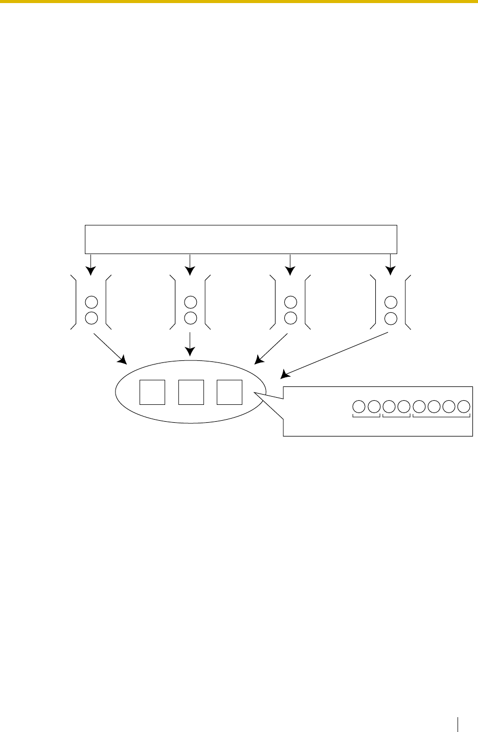
1.2 Receiving Group Features
Feature Guide 51
1.2.2.4 VIP Call
Description
It is possible to assign a priority to incoming call distribution groups. If an extension belongs to
multiple groups and the extension becomes idle, queuing calls in the groups will be distributed
to the extension in priority order.
Each incoming call distribution group can enable or disable the VIP Call mode. When multiple
groups enable the VIP Call mode, the incoming call distribution group with the lowest
numbered group has the highest priority. When multiple groups disable the VIP Call mode,
queuing calls are distributed to extensions uniformly.
[Example]
In the call centre, incoming call distribution groups 1 and 3 enable the VIP Call mode, while
incoming call distribution groups 2 and 4 disable the VIP Call mode.
Extn.
101 Extn.
102 Extn.
103
Calls have been distributed by DIL/DID/DDI/CLI.
(The number in the circle is the queuing order.)
1
6
1st
Priority 2nd
Priority
3rd
Priority
I
ncoming Call
D
istribution
G
roup 1
(
for VIP) 3
5
Incoming Call
Distribution
Group 2
(for general
customers) 2
4
Incoming Call
Distribution
Group 3
(for special
customers)
Distribution order:
From: Group 1 Group 3 Groups 2 and 4
1 6 2 4 3 7
Incoming Call
Distribution
Group 4
(for general
customers)
8
3rd
Priority
5 8
7
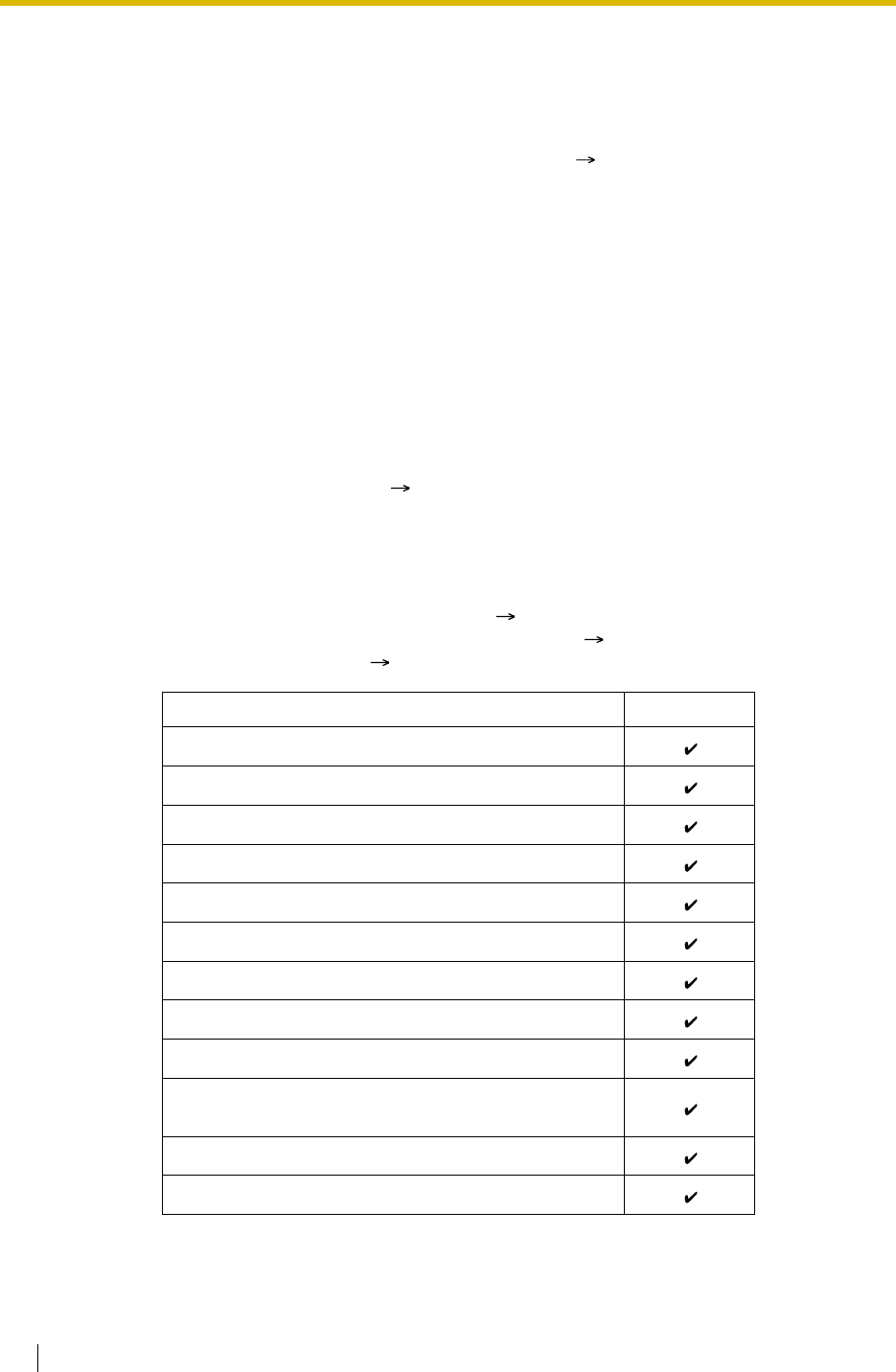
1.2 Receiving Group Features
52 Feature Guide
1.2.2.5 Overflow Feature
Description
When waiting calls exceed the waiting queue capacity ( Queuing Call Capacity [628]), they
may be redirected to a preprogrammed destination or a busy tone may be sent to the callers
by the following features:
1) Intercept Routing—Overflow in an Incoming Call Distribution Group
2) Busy on Busy
1. Intercept Routing—Overflow in an Incoming Call Distribution Group
The Intercept Routing—Overflow in an Incoming Call Distribution Group works in one of
following conditions:
a) There is no space in the waiting queue.
b) The Queuing Time Table is not assigned and there are no extensions logged-in.
c) An Overflow command is assigned to the Queuing Time Table.
d) The Overflow time ( Overflow Time [626]) expires.
e) Manual Queue Redirection is performed.
[Available Destination]
The overflow destinations can be assigned for each incoming call distribution group and
each time mode (day/lunch/break/night) ( 2.2.4 Time Service). The two different
destinations can be assigned, one for the a) and b) ( Destination When All Busy [627]),
and one for c), d), and e) ( Destination for Overflow Time Expiration [625]).
Destination Availability
Wired Extension (PT/SLT/ISDN Extension/T1-OPX)
PS
Incoming Call Distribution Group
PS Ring Group
VM Group (DTMF/DPT)
External Pager (TAFAS)
DISA
Analogue/ISDN Remote Maintenance
Idle Line Access no. + Phone no.
Trunk Group Access no. + Trunk Group no. +
Phone no.
Other PBX Extension (TIE with no PBX Code)
Other PBX Extension (TIE with PBX Code)

1.2 Receiving Group Features
Feature Guide 53
2. Busy on Busy
The Busy on Busy feature works when the destination for the Intercept Routing—Overflow
in an Incoming Call Distribution Group feature is not assigned in one of the following
conditions:
a) There is no space in the Waiting queue.
b) The Queuing Time Table is not assigned and there are no extensions logged-in.
[Example of a)]
When the answering agent number ( Maximum Number of Agents [632]) is "2", and the
queuing call number ( Queuing Call Capacity [628]) is "0":
There are five assistants in the shop. If two of them are engaged on the phone, the next
caller will hear a busy tone to prevent the caller from thinking that there is no one in the
shop or that the shop is closed.
Conditions
[Intercept Routing—Overflow in an Incoming Call Distribution Group]
•If the Overflow time expires, and the overflow destination is unavailable:
a) If the trunk call arrives through the LCOT or T1 (LCOT/GCOT) card: (1) The line is
disconnected when the call was once in a queue and an outgoing message (OGM)
was sent to the call, or when the call reached an incoming call distribution group by
using the DISA feature ( 1.16.6 Direct Inward System Access (DISA)). (2) Except
for the above, redirection is ignored and the Overflow timer activates again.
b) If the call arrives through the other cards: Redirection is ignored and the Overflow
timer activates again.
[Busy on Busy]
• If a trunk call arrives through the LCOT or T1 (LCOT/GCOT) card, a busy tone will not be
sent to the caller.
Feature Guide References
1.2.2.3 Queuing Feature
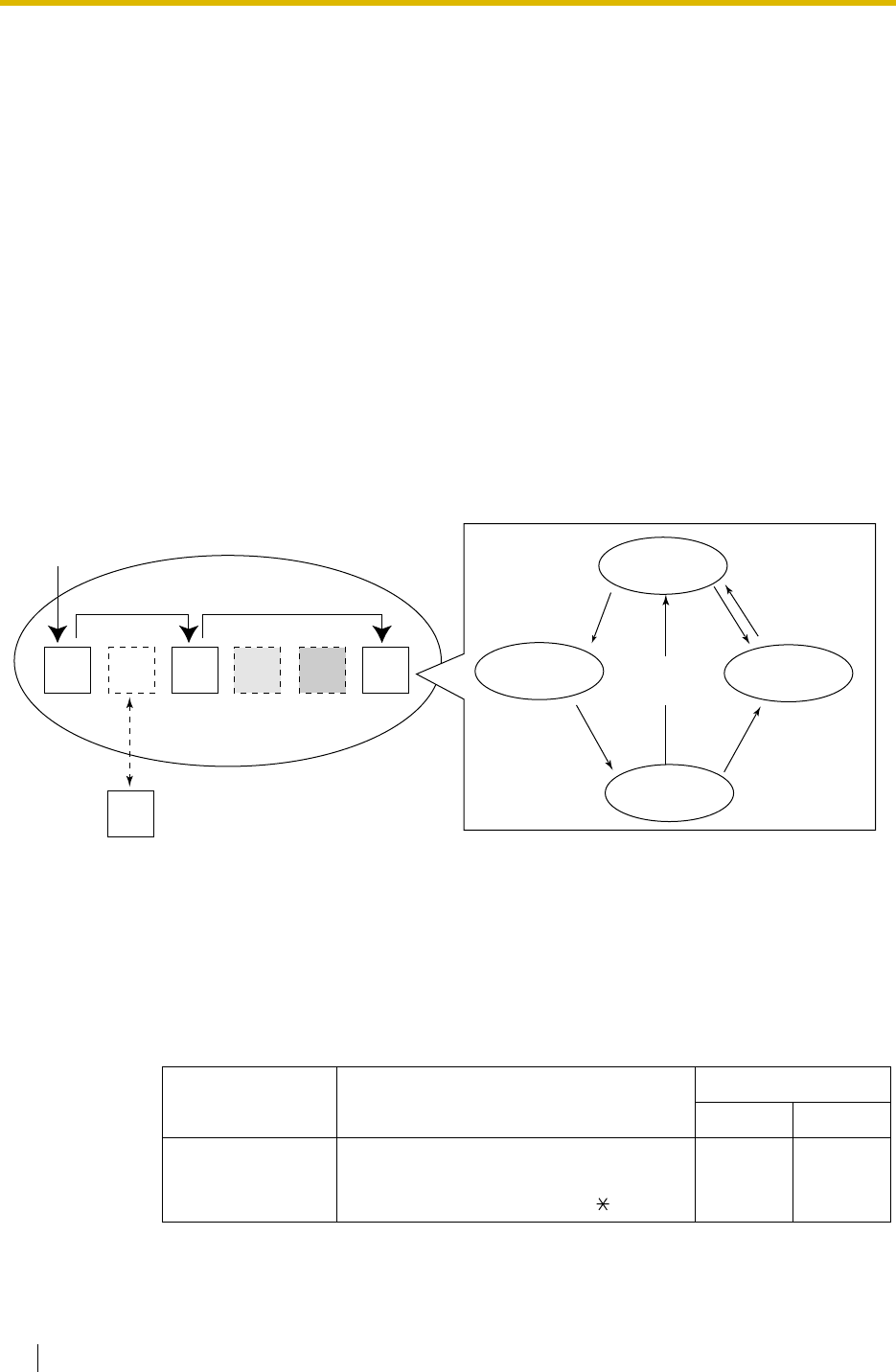
1.2 Receiving Group Features
54 Feature Guide
1.2.2.6 Log-in/Log-out
Description
Incoming call distribution group members can join (Log-in) or leave (Log-out) the groups
manually.
They can leave the group temporarily when they are away from their desks, to prevent calls
being sent to their extensions. They can return to the group when they are ready to answer
calls.
Wrap-up:
While logged-in, a member extension can have a preprogrammed time period automatically for
refusing calls after completing the last call (Wrap-up time). While Wrap-up timer is active, calls
to all incoming call distribution groups to which the extension belongs will skip the extension so
that he can make some report or etc.
Wrap-up mode can also be activated manually (Not Ready) by pressing the Wrap-up button.
[Log-in/Log-out and Wrap-up Status Example]
Conditions
• It is programmable whether the last remaining logged-in extension can log out.
•Log-in/Log-out Button
A flexible button can be customised as the Log-in/Log-out button with the following
parameters:
Parameter Usage Light Pattern
Red on Off
No parameter Used with an ICD Group button, or with a
floating extension number of an incoming
call distribution group, or with (All).
——
<When the incoming call distribution group is in Priority Hunting distribution method>
Log-out
Incoming call Log-in
Ready ReadyReady
Not Ready
Extn.
101
Extn.
102
Extn.
102 Extn.
103 Extn.
104
Wrap-up
Extn.
105 Extn.
106
Ready
Waiting for a call
After
completing
the call
Answering a call
Wrap-up
Making a report
Not Ready
Making a report/
temporary break
The Wrap-up
time expires.
Press the
Wrap-up button.
Press the
Wrap-up button.
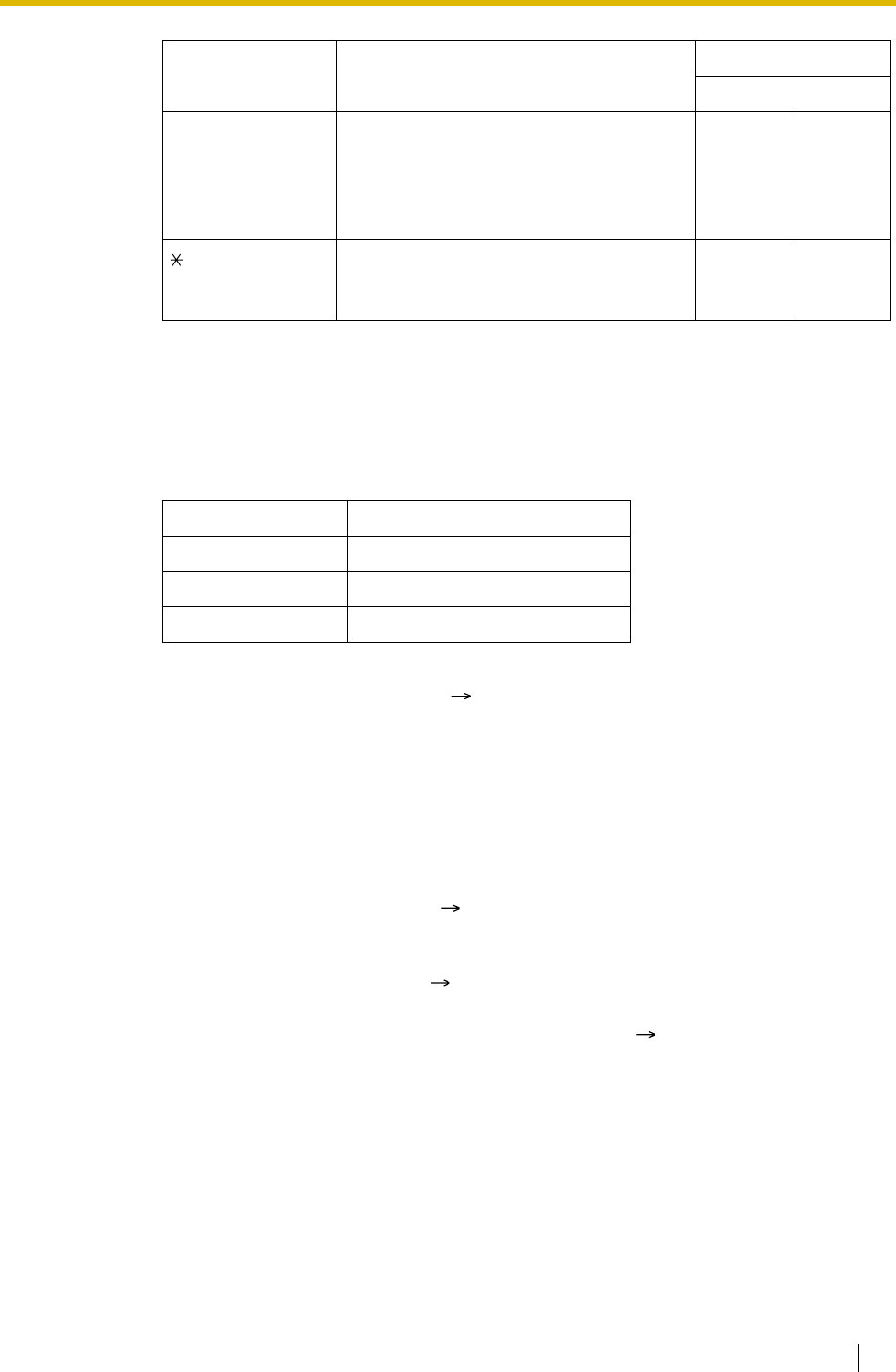
1.2 Receiving Group Features
Feature Guide 55
• If an ICD Group button is assigned, it also shows the log-in/log-out status of the
corresponding group. The light pattern is the same as the Log-in/Log-out button which
includes the group number.
•Wrap-up Button
A flexible button can be customised as the Wrap-up button. It shows the current status as
follows:
• When a PS in Wireless XDP Parallel Mode completes a call, neither the PS nor its wired
telephone can have Wrap-up time. ( 1.24.5 Wireless XDP Parallel Mode)
•Automatic Log-out
A member extension may be logged-out automatically, if the Unanswered time expires a
preprogrammed number of times consecutively. The number of consecutive unanswered
calls can be assigned for each incoming call distribution group. If the extension is a
member of more than one incoming call distribution group, the unanswered number is
counted across all corresponding incoming call distribution groups. It is possible to return
to the log-in mode manually.
Automatic Log-out feature does not work for the extension in an incoming call distribution
group in Ring distribution method ( 1.2.2.2 Group Call Distribution).
•Log-in/Log-out Monitor
The supervisor extension can monitor and control the log-in/log-out status of the incoming
call distribution group members. ( 1.2.2.7 Supervisory Feature)
•Log-in/Log-out Information on SMDR
Log-in/Log-out information can be printed out on SMDR. ( 1.25.1 Station Message
Detail Recording (SMDR))
Feature Guide References
1.19.2 Flexible Buttons
User Manual References
User Manual
1.8.1 Leaving an Incoming Call Distribution Group (Log-in/Log-out, Wrap-up)
Floating extension
number of a
specified incoming
call distribution
group
Used to log-in or log-out from the
specified incoming call distribution group. Log-out
Status Log-in
Status
(All) Used to log-in or log-out from all incoming
call distribution groups to which you
belong.
After Log-
out
Operation
After Log-
in
Operation
Light pattern Status
Slow red flashing Wrap-up
Red on Not Ready
Off Ready (Wrap-up mode cancel)
Parameter Usage Light Pattern
Red on Off
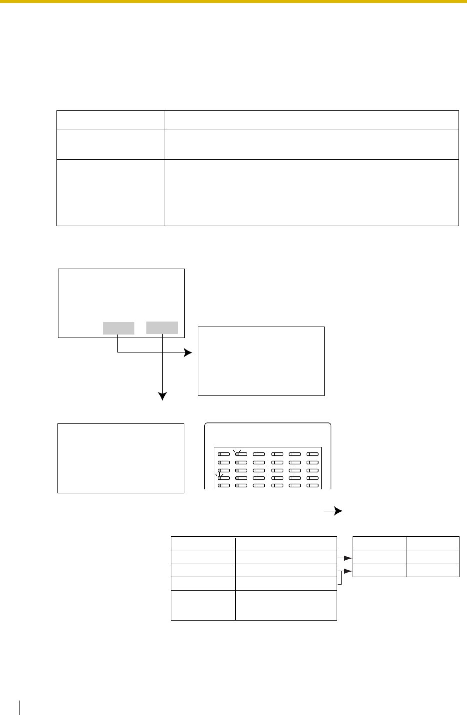
1.2 Receiving Group Features
56 Feature Guide
1.2.2.7 Supervisory Feature
Description
An extension preprogrammed as a supervisor (supervisor extension) can monitor and control
each member’s status within the incoming call distribution group using a 6-line display PT.
[Example]
Feature Description
Incoming Call Queue
Monitor The supervisor extension can monitor the status of an incoming
call distribution group with the display.
Log-in/Log-out
Monitor and Remote
Control
Monitor: The supervisor extension can monitor the log-in/log-out
status of the incoming call distribution group members through the
corresponding DSS button light.
Remote Control: The supervisor extension can change the status
of the members by pressing the corresponding DSS button.
--- Date and time
--- Floating extension number/name of incoming call distribution group
--- The number of queuing calls
--- The longest queuing time
With
<Incoming Call Queue Monitor Display>
<
Log-in/Log-out Monitor/Remote Control Mode with DSS Button light>
31 Jan. 08:13AM FRI
250:Sales Section
Waiting Calls Now :00006
Max. Waiting Time :05'10
EXIT LOG SPRVS
Log-in/Log-out Monitor
DSS buttons of the incoming call
distribution group members show
their status.
Log-in/Log-out Remote Contro
l
Pressing the button change
s
the status as follows:
Light pattern
Green on
Slow Green Flashing
Red on
Off
Status
Log-in (Ready)
Log-in (Not Ready)
Log-out
Light pattern
Red on
Green on
Status
Log-out
Log-in (Ready)
Since 29 JAN. 09:10AM
Total Calls :00996
Overflow Calls :00131
Lost Calls :00039
Average Waiting :02'12
EXIT CLEAR
31 Jan. 08:13AM FRI
250:Sales Section
Waiting Calls Now :00006
Max. Waiting Time :05'10
EXIT
--- Monitoring starting date and time
--- Total number of incoming calls
--- Total number of overflowed calls
--- The number of lost calls
--- Average queuing time
Extension in another
incoming call distribution
group

1.2 Receiving Group Features
Feature Guide 57
Conditions
•Available Extension as a Supervisor Extension
a) One supervisor extension can be assigned for each incoming call distribution group,
but it need not belong to the group.
b) One extension can be the supervisor extension of more than one incoming call
distribution group.
•Available Paired DSS Console
The KX-T7640, KX-T7440, and KX-T7441 are available for this feature.
•Accumulation Value Clear
Accumulation value (total incoming calls/total overflowed calls/lost calls/average queuing
time) can be cleared manually. The date and time of clearing is saved and it is shown on
the display (monitoring starting date and time). When the value exceeds 99999, before
clearing, "****" will be shown.
•If a call to an incoming call distribution group is overflowed:
If the display is in idle status, it will change to monitor mode for the corresponding incoming
call distribution group automatically.
If the display is monitoring another incoming call distribution group, it will not change.
•Other Features while in Monitor Mode
The supervisor extension can use other features (making calls, pressing the MESSAGE
button, etc.) even while in monitor mode. When each operation is finished, his telephone
returns to the queue monitor display.
User Manual References
User Manual
1.8.2 Monitoring and Controlling the Call Status of an Incoming Call Distribution Group
(Incoming Call Distribution Group Monitor)

1.3 Call Forwarding (FWD)/Do Not Disturb (DND) Features
58 Feature Guide
1.3 Call Forwarding (FWD)/Do Not Disturb
(DND) Features
1.3.1 Call Forwarding (FWD)/Do Not Disturb (DND)
1.3.1.1 Call Forwarding (FWD)/Do Not Disturb (DND)—
SUMMARY
Description
When an extension user cannot answer calls (e.g., busy, not at the desk), it is possible to
forward or refuse the calls using the following features:
1) Call Forwarding (FWD)
2) Do Not Disturb (DND)
1. FWD
Extensions and incoming call distribution groups can forward their incoming calls to preset
destinations. ( 1.3.1.2 Call Forwarding (FWD))
2. DND
An extension user can send the tone to let the caller know he is not available. ( 1.3.1.3
Do Not Disturb (DND))
Conditions
•FWD and DND features apply to:
Intercom calls (including doorphone calls), and trunk calls (including a call from an
extension that placed a trunk call on a consultation hold.)
•FWD/DND Button
Both the FWD and DND features for the extension can be customised on a flexible button.
Only one of the features will work at a time.
Multiple types of FWD/DND buttons can be customised on an extension.
•Group FWD Button
The FWD feature for the incoming call distribution group can be customised on a flexible
button. Multiple types of Group FWD buttons can be customised on an extension.
[FWD/DND Button and Group FWD Button Types]
Type Description
FWD/DND for
Extension FWD/DND—Internal Works for incoming intercom calls
FWD/DND—External Works for incoming trunk calls
FWD/DND—Both Works for all incoming calls
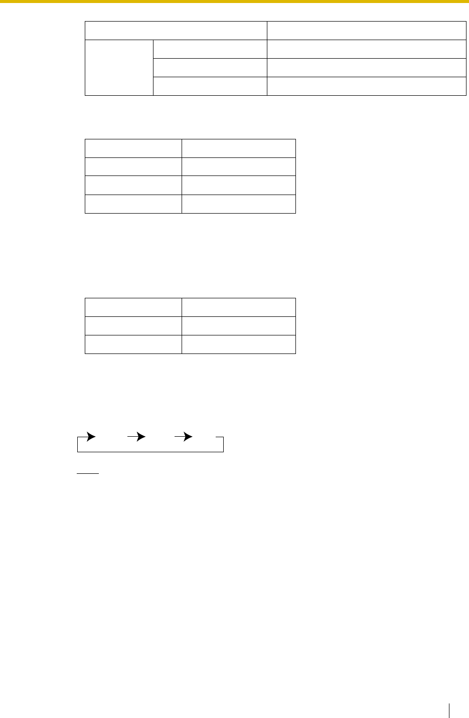
1.3 Call Forwarding (FWD)/Do Not Disturb (DND) Features
Feature Guide 59
[Button Status—FWD/DND Button]
The FWD/DND button shows the current status as follows:
The functions assigned to the "on" and "flashing" patterns can be changed through system
programming.
[Button Status—Group FWD Button]
The Group FWD button shows the current status as follows:
[Mode Change]
When either the FWD or DND feature is assigned, pressing the FWD/DND button changes
the on/off setting alternately. When both the features are assigned simultaneously,
pressing the button changes the settings as follows:
Note
Pressing the FWD/DND button (fixed button) in idle status will produce one of the
following results, selected through system programming:
When in FWD/DND Setting Mode:
Pressing the button will enter personal programming mode for the FWD/DND setting.
When in FWD/DND Cycle Switch Mode:
Pressing the button will cycle the settings as shown above in [Mode Change].
A FWD/DND button customised on a flexible button is always in FWD/DND Cycle
Switch mode, and the mode cannot be changed.
• When intercom calls are set to be handled differently from trunk calls (forwarding type,
forward destination, DND on/off), we recommend establishing buttons for both FWD/
DND—Internal and FWD/DND—External, and/or Group FWD—Internal and Group
FWD—External, because:
a) the light patterns of the FWD/DND—Both button (including FWD/DND button [fixed
button]) and the Group FWD—Both button will indicate the setting for either trunk calls
FWD for
Incoming Call
Distribution
Group
Group FWD—Internal Works for incoming intercom calls
Group FWD—External Works for incoming trunk calls
Group FWD—Both Works for all incoming calls
Light Pattern Status (default)
Red on FWD on
Slow red flashing DND on
Off FWD/DND off
Light Pattern Status (default)
Red on FWD on
Off FWD off
Type Description
FWD DND Off

1.3 Call Forwarding (FWD)/Do Not Disturb (DND) Features
60 Feature Guide
or intercom calls, but not both.
Note
The FWD and DND icons on a PS display reflect the settings for trunk calls only.
b) pressing the FWD/DND—Both button (including FWD/DND button [fixed button]) or
the Group FWD—Both button will not change the FWD or DND mode for intercom
calls and trunk calls separately.
Feature Guide References
1.19.1 Fixed Buttons
1.19.2 Flexible Buttons
User Manual References
User Manual
3.1.2 Settings on the Programming Mode
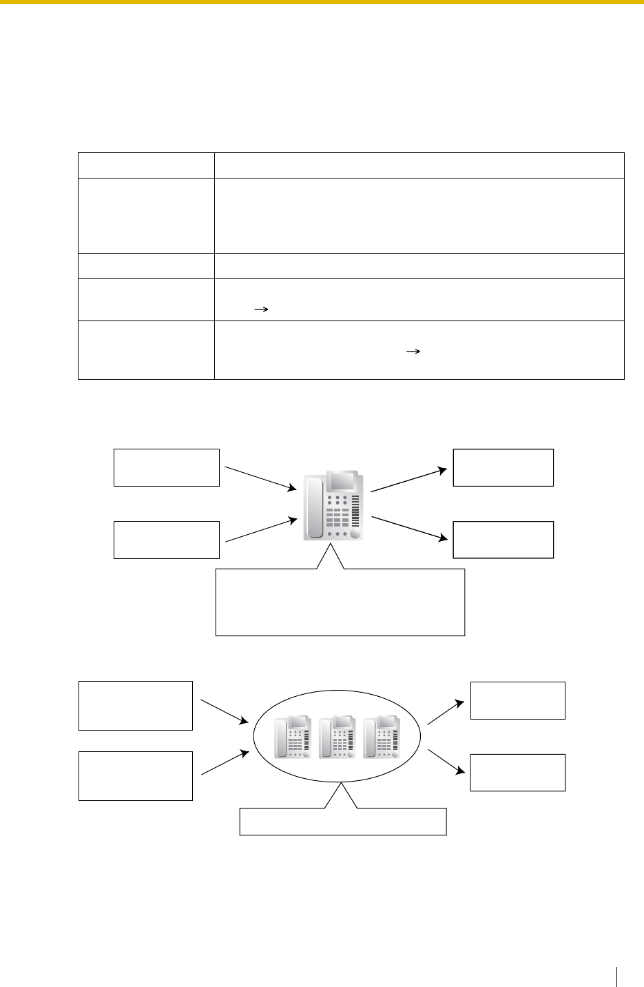
1.3 Call Forwarding (FWD)/Do Not Disturb (DND) Features
Feature Guide 61
1.3.1.2 Call Forwarding (FWD)
Description
Extensions and incoming call distribution groups can forward their calls to preset destinations.
The circumstances under which the calls are forwarded are as follows:
Depending on the type of incoming intercom or trunk calls, it is possible to set different
destination for each.
Type Circumstance
All Calls Any time
Follow Me:
When an extension user fails to set this feature before leaving the
desk, this feature can be set from the destination extension.
Busy When the extension user’s line is busy.
No Answer When the extension user does not answer within a preprogrammed
time ( Call Forwarding—No Answer Time [605]).
Busy/No Answer When the extension user’s line is busy or the user does not answer
within a preprogrammed time ( Call Forwarding—No Answer
Time [605]).
Intercom Calls
to Extension
Trunk Calls to
Extension
Forwards to
Another Extension
Intercom Calls
to Extension
Available Forwarding Type:
Forwards to
Outside Party
Extension
Intercom Calls to
Incoming Call
Distribution Group
Trunk Calls to
Incoming Call
Distribution Group
Forwards to
Another Extension
Forwards to
Outside Party
Available Forwarding Type: All Calls
Incoming Call Distribution Group
All Calls
Busy
No Answer
Busy/No Answer
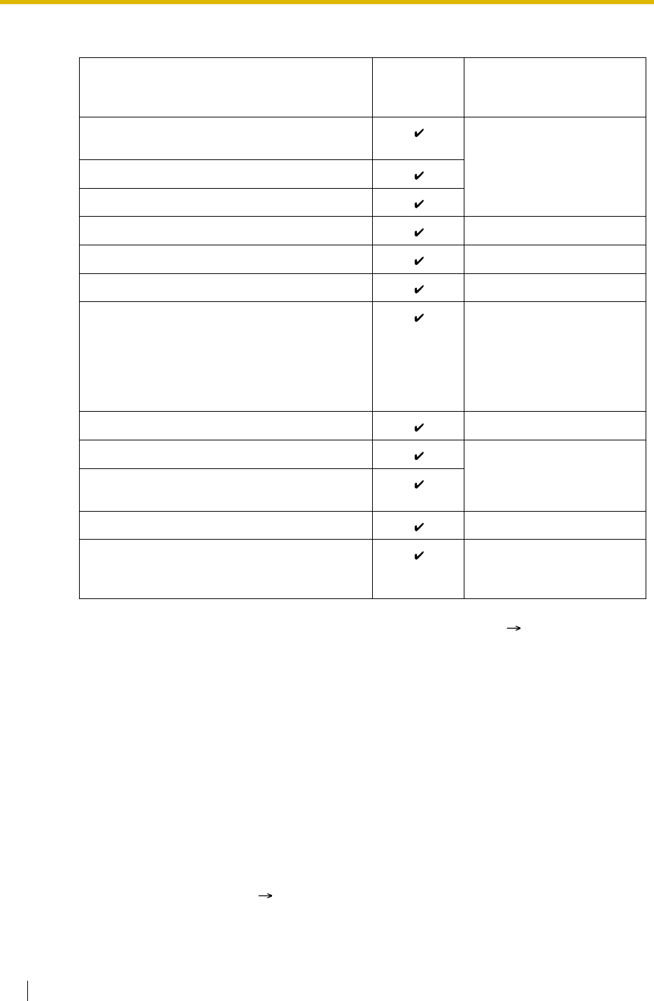
1.3 Call Forwarding (FWD)/Do Not Disturb (DND) Features
62 Feature Guide
[Available Destination]
Conditions
[General]
•FWD for Trunk Calls/Intercom Calls
The FWD feature can be set for trunk calls, for intercom calls, or for both of them by the
extension user.
•FWD from Incoming Call Distribution Group (Group FWD)
COS programming determines the incoming call distribution groups that can use this
feature.
•FWD to Trunk
COS programming determines the extensions or incoming call distribution groups that can
forward calls externally ( Call Forwarding to Trunk [504]).
The original extension’s TRS/Barring and ARS still apply to the forwarded call.
Destination Availability Condition for Original
Extension/Incoming Call
Distribution Group
Wired Extension (PT/SLT/ISDN Extension/T1-
OPX) Only available when FWD to
extension is allowed through
COS programming.*
PS
Incoming Call Distribution Group
PS Ring Group –
VM Group (DTMF/DPT) –
External Pager (TAFAS) –
DISA Only available for incoming
trunk calls. Incoming
intercom and doorphone
calls cannot be forwarded to
a DISA floating extension
number.
Analogue/ISDN Remote Maintenance –
Idle Line Access no. + Phone no. Only available when FWD to
trunk is allowed through
COS programming.
Trunk Group Access no. + Trunk Group no. +
Phone no.
Other PBX Extension (TIE with no PBX Code) –
Other PBX Extension (TIE with PBX Code) Only available when FWD to
trunk is allowed through
COS programming.
*: If an extension user cannot call certain extensions on a COS basis ( 1.1.2.2 Internal Call
Block), the FWD feature to the extension does NOT work.
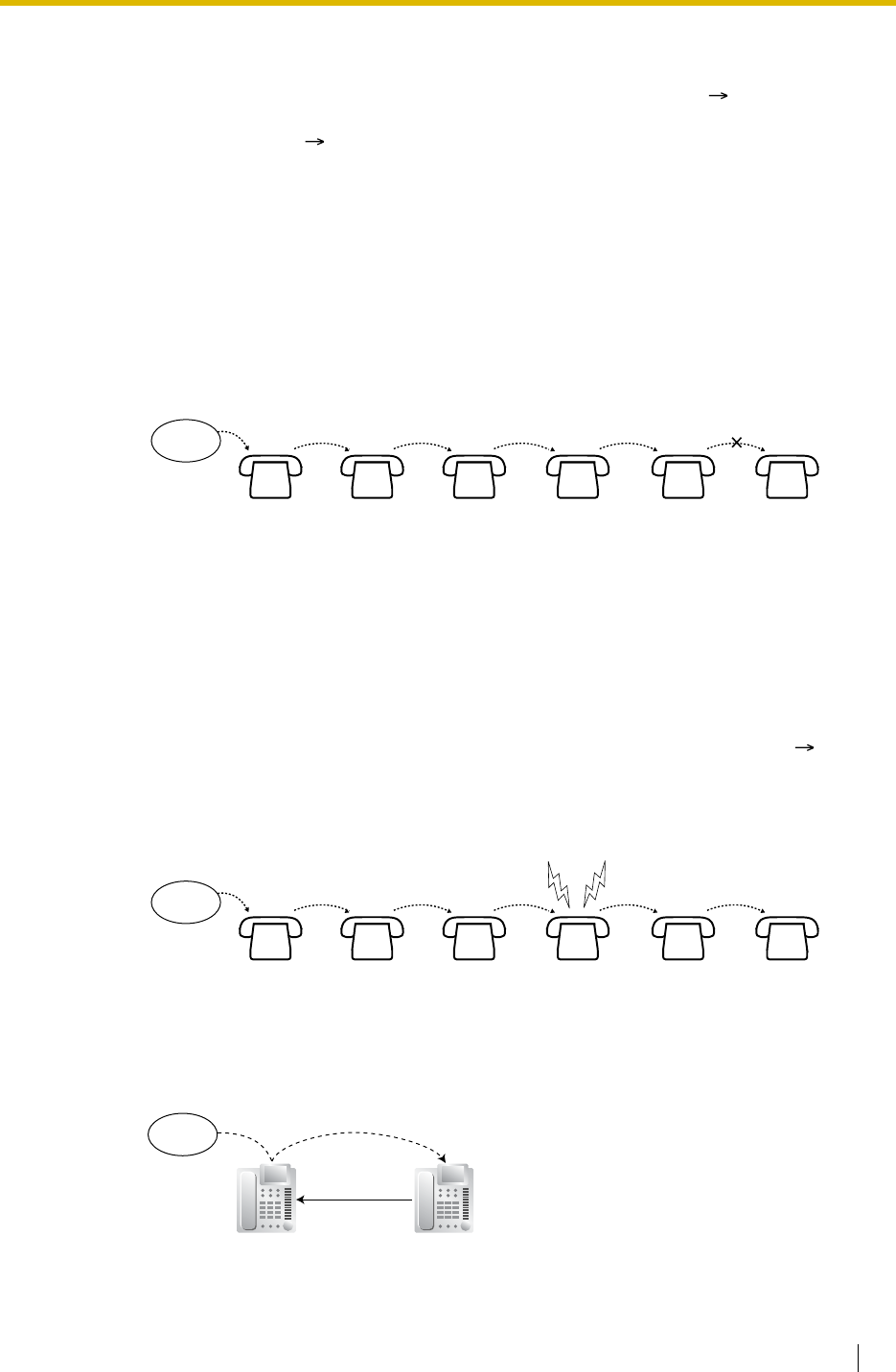
1.3 Call Forwarding (FWD)/Do Not Disturb (DND) Features
Feature Guide 63
•Trunk Call Duration
If a call between an extension user and an outside party, or between two outside parties
is established, the call duration can be restricted by a system timer ( Extension-to-Trunk
Call Duration [472] and Trunk-to-Trunk Call Duration [473]). If the timer expires, the line will
be disconnected. ( 1.10.8 Trunk Call Limitation)
•Multiple FWD
Calls can be forwarded up to four times. The following forwarding features are counted as
Multiple FWD:
In the above illustration, forwarding stops at the extension E. However, forwarding can go
farther in the following cases:
In the above cases, the forwarding counters reset to zero, and calls can be forwarded up
to four times again from the applicable extension that occurred in the case above.
•Boss & Secretary feature
It is possible to call the original extension from the destination extension regardless of the
forward setting.
– FWD—Busy or Busy/No Answer (in case a destination extension is busy), or All
Calls
– Idle Extension Hunting—Overflow
– Intercept Routing—Busy/DND (in case a destination extension is busy or in DND
mode)
– Incoming Call Distribution Group—Overflow
– If a destination extension rings, and then the call is redirected to the forward
destination by the FWD—No Answer or Busy/No Answer feature.
– If a destination extension rings, and then the call is redirected to the intercept
destination by the Intercept Routing—No Answer feature.
– If a call waits in a queue of an incoming call distribution group, and then the call
is redirected to the overflow destination by the Queuing Time Table. ( 1.2.2.3
Queuing Feature)
Original
destination
Incoming
call
A B C D EF
123 54
Original
destination
Incoming
call
A B C D EF
123 21
FWD—No Answer
FWD—All Calls
Call or
transfer a call
Boss
(Original) Secretary
(FWD destination)
Incoming
call

1.3 Call Forwarding (FWD)/Do Not Disturb (DND) Features
64 Feature Guide
•Message Waiting
While calls are forwarded, Message Waiting information is not forwarded. The Message
button light turns on at the originally called extension. ( 1.18.1 Message Waiting)
•Idle Extension Hunting
Idle Extension Hunting applies to calls forwarded to a busy extension in an idle extension
hunting group.
[All Calls and Busy]
• If the forward destination is not available to answer a call, this feature is cancelled and the
original destination will ring for the following type of call:
[No Answer and Busy/No Answer]
•No Answer Time
The number of rings before the call is forwarded is programmable for each extension (
Call Forwarding—No Answer Time [605]).
[Follow Me]
• This feature is only available when the original extension has disabled the "Deny Remote
Operation by Other Extension" setting on a COS basis.
Feature Guide References
1.1.1.6 Intercept Routing
1.2.1 Idle Extension Hunting
1.2.2.5 Overflow Feature
User Manual References
User Manual
1.5.1 Forwarding Calls
– Doorphone call
– Trunk calls via the LCOT or T1 (LCOT/GCOT) cards

1.3 Call Forwarding (FWD)/Do Not Disturb (DND) Features
Feature Guide 65
1.3.1.3 Do Not Disturb (DND)
Description
An extension user can make use of the DND feature. If this feature is set, calls will not arrive
at the extension, but arrive at other extension by using the Idle Extension Hunting feature (
1.2.1 Idle Extension Hunting) or the Intercept Routing—Busy/DND feature ( 1.1.1.6 Intercept
Routing). When a destination cannot be found, the calling extension will hear the DND tone,
while the calling outside party will hear a busy tone.
Conditions
•DND for Trunk Calls/Intercom Calls
The DND feature can be set for trunk calls, for intercom calls, or for both of them by the
extension user.
•DSS button in DND Mode
The DSS button light will turn red if the assigned extension has set DND.
•DND Override
An extension in DND mode can be called by other extension users who are allowed to
override DND in their COS ( DND Override [507]).
•Paging DND
It is programmable whether the PBX pages extensions in DND mode through system
programming. ( 1.14.1 Paging)
•Intercept Routing—Busy/DND
If a call arrives at the extension in DND mode, the call can be redirected to the
preprogrammed destination by the Intercept Routing—Busy/DND feature.
•Idle Extension Hunting
While searching for an idle extension within an idle extension hunting group, any extension
which has DND set will be skipped. The call will go to the next extension in the group, not
the Intercept Routing—Busy/DND destination.
• If (1) the trunk call via the LCOT or T1 (LCOT/GCOT) card arrives at the extension in DND
mode and (2) the Intercept Routing—Busy/DND destination is not available and (3) there
is no available extension in the idle extension hunting group, then the original extension in
DND mode will ring.
• Calls from a doorphone arrive at the extension even when the extension is in DND mode.
User Manual References
User Manual
1.2.4 When the Dialled Line is Busy or There is No Answer
1.7.2 Refusing Incoming Calls (Do Not Disturb [DND])

1.4 Answering Features
66 Feature Guide
1.4 Answering Features
1.4.1 Answering Features
1.4.1.1 Answering Features—SUMMARY
Description
An extension user can answer incoming calls by the following methods:
Destination Feature Description Details in
At the own
extension
(PT only)
Line
Preference—
Incoming
A user can select the line seized when going
off-hook. • 1.4.1.2
Line
Preference
—Incoming
Direct One-
touch
Answering
A user can answer an incoming call simply
by pressing the flashing button. –
Hands-free
Answerback A user can receive a call automatically and
establish a hands-free conversation. • 1.4.1.4
Hands-free
Answerback
At another
extension Call Pickup—
Directed/Group A user can pick up a specified extension’s
call or a call in a specified call pickup group. • 1.4.1.3 Call
Pickup

1.4 Answering Features
Feature Guide 67
1.4.1.2 Line Preference—Incoming
Description
A PT user can select the method used to answer incoming calls from the following three line
preferences:
Each of these line preferences can be assigned on each extension through personal
programming (Preferred Line Assignment—Incoming).
Conditions
[Prime Line]
• The priority of the incoming call is as follows:
1) The call arriving at a button on which the "Prime Line" is assigned.
2) The call arriving at the INTERCOM button.
User Manual References
User Manual
3.1.2 Settings on the Programming Mode
Type Description
No Line Selects a line by pressing the desired Line Access button to answer
an incoming call after you go off-hook.
Prime Line Answers a call arriving at a Flexible CO or ICD Group button (on
which the "Prime Line" is assigned) simply by going off-hook. This
works even when multiple calls are received simultaneously.
Ringing Line
(default) Answers the longest ringing call at one’s telephone simply by going
off-hook when multiple calls arrive.
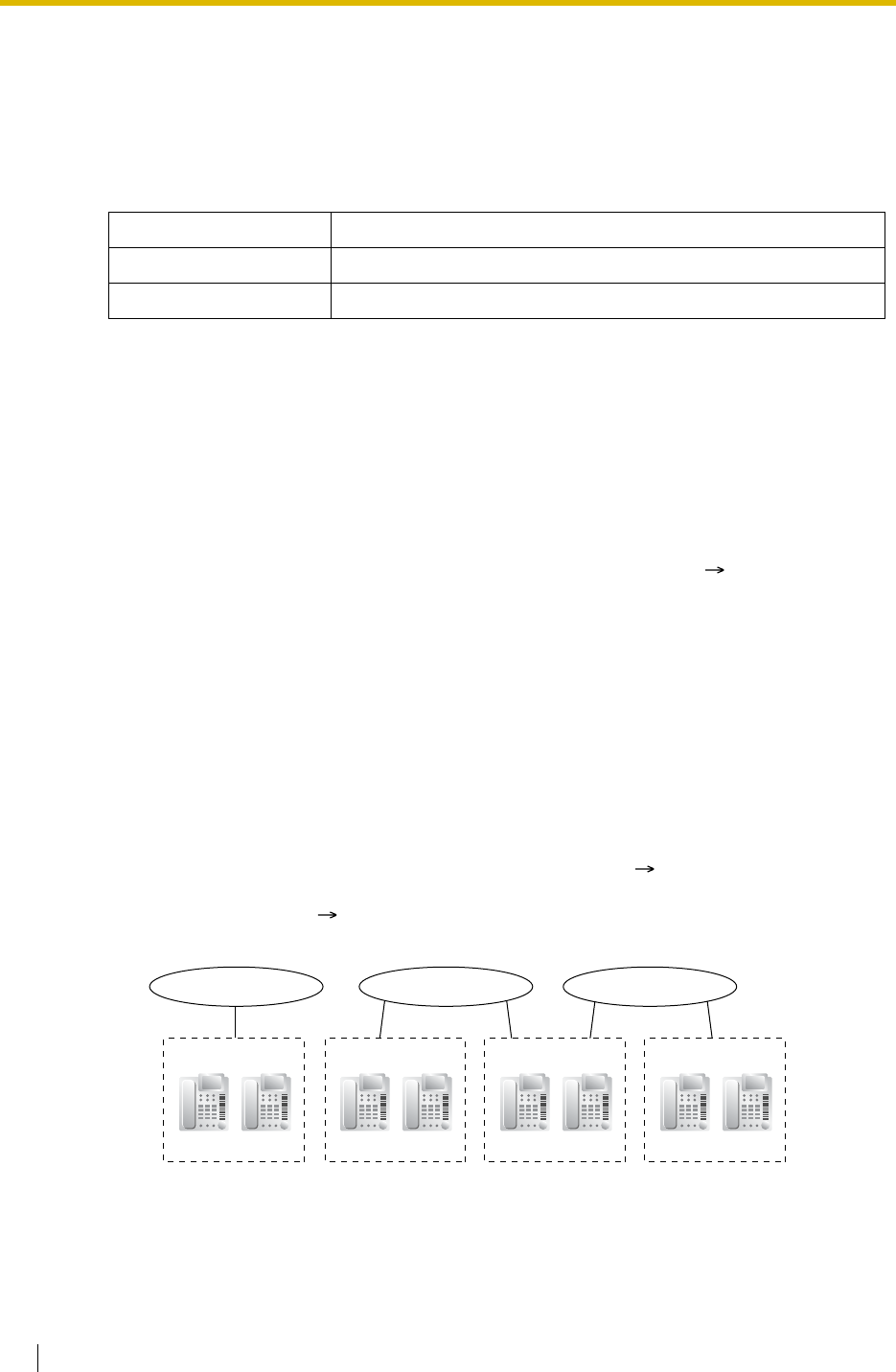
1.4 Answering Features
68 Feature Guide
1.4.1.3 Call Pickup
Description
An extension user can answer a call ringing at any other extension.
The following types are available:
Call Pickup Deny:
Preventing other extensions from picking up calls ringing at your extension is also possible.
Conditions
•Call Pickup applies to:
Intercom, trunk, and doorphone calls
•Internal Call Block
An extension which cannot call certain extensions on a COS basis ( 1.1.2.2 Internal Call
Block) also cannot pick up any calls ringing at those extensions.
[Directed Call Pickup]
• A user can also pick up a specified extension’s call (except an ISDN extension’s call and
broadcasting call) by pressing the corresponding DSS button. COS programming
determines the extensions that can use this feature.
The light pattern of a DSS button for an incoming call to an extension or incoming call
distribution group can be programmed through system programming. Call Pickup is
available only when the DSS button is red flashing.
[Group Call Pickup]
• A specified number of call pickup groups can be created ( User Groups of a Pickup
Group [650]), each of which consists of user groups. One user group can belong to several
call pickup groups. ( 2.2.2 Group)
[Example]
User Manual References
User Manual
1.3.3 Answering a Call Ringing at Another Telephone (Call Pickup)
Type Picking up Call Type
Directed A specified extension’s call.
Group A call within a specified call pickup group.
User Group 1
Call Pickup Group 1
Extn. 100 Extn. 101
User Group 2
Extn. 102 Extn. 103
User Group 3
Extn. 104 Extn. 105
Call Pickup Group 2 Call Pickup Group 3
User Group 4
Extn. 106 Extn. 107

1.4 Answering Features
Feature Guide 69
1.4.1.4 Hands-free Answerback
Description
A PT user with a speakerphone can talk to a caller without lifting the handset. If the user
receives a call in Hands-free Answerback mode, a hands-free conversation is established in
the following method:
Conditions
•Hands-free Answerback applies to:
Intercom calls and trunk calls, including calls directed to an incoming call distribution group
in UCD or Priority Hunting distribution method. ( 1.2.2.2 Group Call Distribution)
•Hands-free Answerback for Trunk Calls
System programming is required to use this feature.
•Secret Monitor
The beep tone which the called party hears before answering can be eliminated through
system programming.
•Alternate Receiving/Calling Mode (Ring/Voice) Override
Hands-free Answerback overrides the Alternate Receiving mode preset on the telephone
and the Alternate Calling mode from the caller.
•Hands-free Answerback with Headset
The Hands-free Answerback feature can also be used with a headset.
Feature Guide References
1.5.3 Intercom Call
User Manual References
User Manual
1.3.2 Answering Hands-free (Hands-free Answerback)
Type Answering Method
Intercom Call Established immediately after a beep tone at the called extension
and the caller hears a confirmation tone.
Trunk Call* Established after a specified number of rings, a called extension
hears a beep tone.
*: Including a call from an extension that placed a trunk call on a consultation hold.

1.5 Making Call Features
70 Feature Guide
1.5 Making Call Features
1.5.1 Predialling
Description
A display PT user can check and correct the number to be dialled on-hook. The call will be
initiated after going off-hook.
Conditions
•Storing the Predialled Number in the Personal Speed Dialling
The predialled number can be stored in the Personal Speed Dialling by pressing the AUTO
DIAL/STORE button. ( 1.6.1.5 Speed Dialling—Personal/System) In this case, the
extension will enter into the personal programming mode automatically so that a name can
be assigned for the stored number.
User Manual References
User Manual
3.1.2 Settings on the Programming Mode

1.5 Making Call Features
Feature Guide 71
1.5.2 Automatic Extension Release
Description
After going off-hook, if an extension user fails to dial any digits within a preprogrammed time
period, the user will hear reorder tone. This operation applies to intercom calls only.
This feature is also known as Automatic Station Release.
Conditions
• A PT/PS user hears reorder tone for a preprogrammed time period, and then the PT/PS
goes back to the idle status automatically. However, an SLT user will just hear reorder tone
until he goes on-hook.
•This feature works in one of the following cases:
When making an intercom call
a) The first digit has not been dialled within a preprogrammed time period.
b) After a digit is dialled, if subsequent digits are not dialled within a preprogrammed time
period.

1.5 Making Call Features
72 Feature Guide
1.5.3 Intercom Call
Description
An extension user can call another extension user.
Conditions
•Extension Number/Name Assignment
Extension numbers ( Extension Number [003]) and names ( Extension Name [004])
are assigned to all extensions. The assigned number and name are shown on display PTs
during intercom calls.
•DSS Button
It is possible to access another extension with one-touch by pressing the corresponding
Direct Station Selection (DSS) button. A flexible button can be customised as a DSS
button.
•Call Directory—Extension Dialling
Display PT users can make a call by selecting stored names on the display.
•Alternate Receiving—Ring/Voice
A PT user can select to receive intercom calls by ring tone or by voice, through personal
programming (Alternate Receiving—Ring/Voice). If a user selects voice-calling, the calling
party talks to the user immediately after a confirmation tone. Denying voice-calling can
also be selected.
•Alternate Calling—Ring/Voice
A caller can change the called party’s preset call receiving method (ring tone or voice). By
doing so, ring-calling is switched to voice-calling, or vice versa, at the called party. The
called party may deny voice-calling.
•Tone after Dialling
After dialling an extension number, a user will hear one of the following:
Feature Guide References
1.19.2 Flexible Buttons
User Manual References
User Manual
1.2.1 Basic Calling
1.2.6 Alternating the Calling Method (Alternate Calling—Ring/Voice)
1.11.2 Using the Directories
3.1.2 Settings on the Programming Mode
Type Description
Ringback Tone Indicates the called party is being called.
Confirmation Tone Indicates the called party has set voice-calling.
Busy Tone Indicates the called party is busy.
DND Tone Indicates the called party has set DND.

1.5 Making Call Features
Feature Guide 73
1.5.4 Trunk Call Features
1.5.4.1 Trunk Call Features—SUMMARY
Description
An extension user can use the following features when making a trunk call:
Feature Description Details in
Emergency Call A user can dial the preprogrammed emergency
numbers regardless of the restrictions imposed
on the extension.
• 1.5.4.2 Emergency
Call
Account Code
Entry A user can enter an account code to identify
outgoing calls for accounting and billing
purposes.
• 1.5.4.3 Account Code
Entry
Pulse to Tone
Conversion A user can temporarily convert the Pulse mode
to DTMF mode to access special services. • 1.5.4.4 Dial Type
Selection
Pause Insertion A user can insert a preprogrammed Pause time
into a dialling number by pressing the PAUSE
button, or it is automatically inserted between
the user-dialled code (e.g., Host PBX Access
code or Special Carrier Access code) and the
following digits.
• 1.5.4.6 Pause
Insertion
• 1.5.4.7 Host PBX
Access Code (Access
Code to the Telephone
Company from a Host
PBX)
• 1.5.4.8 Special
Carrier Access Code

1.5 Making Call Features
74 Feature Guide
1.5.4.2 Emergency Call
Description
An extension user can dial the preprogrammed emergency numbers ( Emergency Number
[304]) after seizing a trunk regardless of the restrictions imposed on the extension.
Conditions
• A specified number of emergency numbers can be stored (some may have default values).
• Emergency numbers may be called even when:
•CLIP Number Notification (KX-TDA100/KX-TDA200 only)
When dialling an emergency number, the preassigned CLIP number for the extension will
be sent as a location identification number. ( 1.20.1.2 Calling/Connected Line
Identification Presentation (CLIP/COLP))
The CLIP number assigned to the extension will be sent regardless of the settings such
as CLIR or CLIP number assigned to an ISDN port to be used. This feature is only
available when using a PRI (PRI23) line, with E911 compatible services.
– in Account Code—Forced mode ( 1.5.4.3 Account Code Entry)
– in any TRS/Barring levels ( 1.8.1 Toll Restriction (TRS)/Call Barring (Barring))
– after the preprogrammed call charge limit is reached ( 1.8.2 Budget
Management)
– in Extension Lock ( 1.8.3 Extension Lock)

1.5 Making Call Features
Feature Guide 75
1.5.4.3 Account Code Entry
Description
An account code is used to identify outgoing trunk calls for accounting and billing purposes.
The account code is appended to the SMDR call record. Therefore, for example, the firm uses
an account code for each client so that the firm can determine what calls were made for the
client, and can submit a bill to the client according to the client’s account code on the SMDR
call record.
There are two methods of entering account codes as follows:
One of the methods is selected for each extension on a COS basis ( Account Code Mode
[508]).
Conditions
• An account code can be stored into Memory Dialling (e.g., One-touch Dialling).
•Account Button
A flexible button can be customised as the Account button. The Account button is used in
place of the feature number for entering an account code. This button is useful because it
can be used at any time, while the feature number entry is allowed only when hearing a
dial tone before seizing a trunk.
• Account code entry after receiving a disconnection signal from a trunk must be done while
hearing reorder tone. Otherwise the SMDR call record is output and entry becomes
impossible afterwards.
• If the account code is entered more than once, the code entered last is printed out in the
SMDR.
• Even in Forced mode, emergency numbers can be dialled out without an account code.
( 1.5.4.2 Emergency Call)
• PT users can also enter an account code for incoming trunk calls during a conversation.
•Verified Code Entry
To identify who made a trunk call for accounting and billing purpose, a verified code is
used. This code can be used at any extension. ( 1.8.6 Verified Code Entry)
Feature Guide References
1.19.2 Flexible Buttons
1.25.1 Station Message Detail Recording (SMDR)
User Manual References
User Manual
1.2.1 Basic Calling
Mode Description
Option A user can enter an account code if needed at any time desired.
Forced A user must always enter an account code before seizing a trunk so as
not to forget entering the code.

1.5 Making Call Features
76 Feature Guide
1.5.4.4 Dial Type Selection
Description
The dialling mode (rotary or tone) can be selected for each analogue trunk through system
programming ( LCOT Dialling Mode [410]) regardless of originating extension (under
contract with the telephone company).
There are the following modes:
Conditions
•Pulse to Tone Conversion
It is possible for an extension user to temporarily convert the Pulse mode to DTMF mode
so that the user can access special services such as computer-accessed long distance
calling or voice mail services. To convert to the DTMF mode, wait for a preprogrammed
time period (Default: 5 seconds) after the trunk is connected, or press . This feature
works only on trunks set to Pulse mode. DTMF mode cannot be changed to Pulse mode.
• It is possible to select a pulse rate for the trunk port which has been set to Pulse mode (
LCOT Pulse Rate [411]). There are two pulse rates: Low (10 pps) and High (20 pps).
• It is possible to assign the minimum duration of the DTMF signal sent to the trunk port
which has been set to DTMF mode ( LCOT DTMF Minimum Duration [412]).
Mode Description
DTMF (Dual Tone
Multi-Frequency) The dialling signal from an extension is converted to tone dialling.
DTMF signals are transmitted to the trunk.
Pulse Dial (Rotary) The dialling signal from an extension is converted to rotary dialling.
Rotary pulses are transmitted to the trunk.

1.5 Making Call Features
Feature Guide 77
1.5.4.5 Reverse Circuit
Description
The circuit in the PBX can detect the reverse signal from the telephone company when an
extension user is trying to make a trunk call. This detects the start (a called party goes off-
hook) and end (the called party goes on-hook) of an outgoing trunk call. When an trunk call is
received, the circuit can also detect the reverse signal after an outside caller goes on-hook.
The duration of call can be verified on SMDR using this feature ( 1.25.1 Station Message
Detail Recording (SMDR)).
It is possible to select whether the PBX detects the reverse signal for outgoing trunk calls only,
or for both outgoing and incoming trunk calls, or for no trunk call (disable the detection) through
system programming ( LCOT Reverse Circuit [415]).

1.5 Making Call Features
78 Feature Guide
1.5.4.6 Pause Insertion
Description
A preprogrammed Pause time ( LCOT Pause Time [416]) will be inserted manually or
automatically.
Manual Insertion: Pressing the PAUSE button.
Automatic Pause Insertion: A pause will be automatically inserted between the user-dialled
codes below and the following digits.
a) Host PBX Access code ( 1.5.4.7 Host PBX Access Code (Access Code to the
Telephone Company from a Host PBX))
b) Special Carrier Access code ( 1.5.4.8 Special Carrier Access Code)
c) Second Dial Tone Waiting code
Conditions
• The Pause time is programmable for each trunk.
• Pause can be stored in Memory Dialling.
• Pressing the PAUSE button while dialling a number inserts a pause for a preprogrammed
time period.
• When a preprogrammed Second Dial Tone Waiting code is dialled after seizing a trunk,
pauses are inserted a preprogrammed number of times after the code.
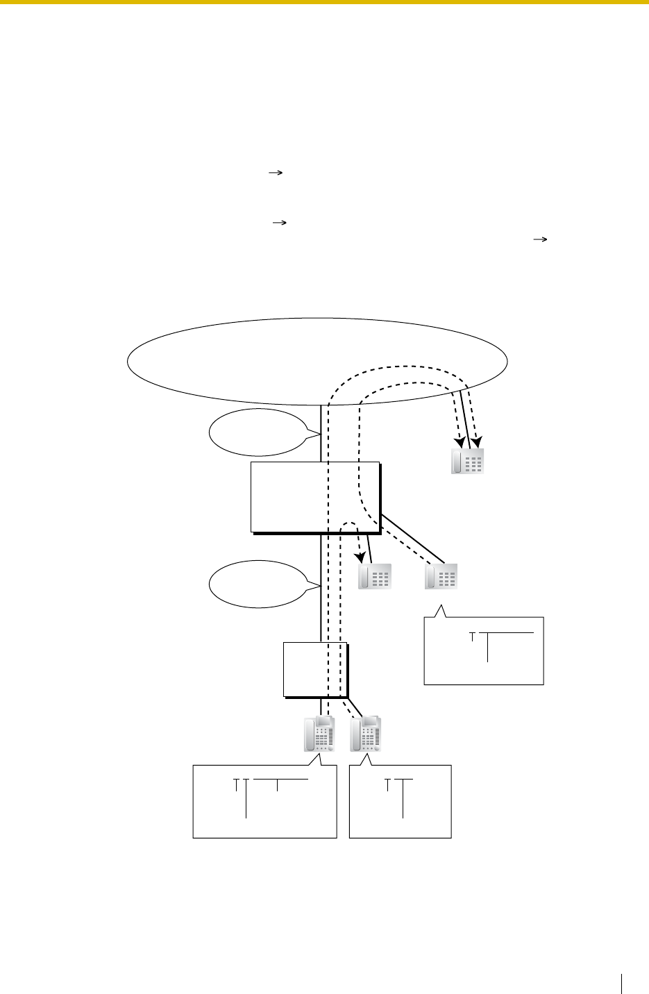
1.5 Making Call Features
Feature Guide 79
1.5.4.7 Host PBX Access Code (Access Code to the Telephone
Company from a Host PBX)
Description
This PBX can be installed behind an existing host PBX. This is performed by connecting
extension ports of the host PBX to trunk ports of this PBX. A Host PBX Access code assigned
through system programming ( Host PBX Access Code [471]) is required to access the
telephone company from the host PBX. The Trunk Access number of the host PBX should be
stored as a Host PBX Access code on a trunk group of this PBX basis.
A preprogrammed Pause time ( LCOT Pause Time [416]) will be automatically inserted
between the user-dialled Host PBX Access code and the following digits. ( 1.5.4.6 Pause
Insertion)
[Example]
Note: "0" should be assigned as a Host PBX Access code for trunk group (TRG) 1 of this PBX.
Dials "9-0-01-23-4567".
Idle Line
Access No. Telephone No.
Host PBX
Access Code
Outside Party
(01-23-4567)
Extn. 101 Extn. 102
TRG1
Telephone Company
Host PBX
PBX
Dials "9-101".
Idle Line
Access No.: 9
Idle Line
Access No.
Extn. No.
of the Host PBX
Dials "0-01-23-4567".
Host PBX
Access Code
Telephone
No.
Host PBX
Access Code: 0

1.5 Making Call Features
80 Feature Guide
Conditions
•TRS/Barring
TRS/Barring checks only the dialled telephone number excluding the Host PBX Access
code when accessing the telephone company through the host PBX. ( 1.8.1 Toll
Restriction (TRS)/Call Barring (Barring))
•SMDR
The dialled number including the Host PBX Access code can be recorded on the SMDR
when accessing the telephone company through the host PBX.
• To record on the SMDR only long distance calls (not local calls) originated via the specific
trunk group, assign the long distance call code as a Host PBX Access code to the trunk
group.
Feature Guide References
1.25.1 Station Message Detail Recording (SMDR)

1.5 Making Call Features
Feature Guide 81
1.5.4.8 Special Carrier Access Code
Description
If the PBX has access to multiple telephone companies, a Special Carrier Access code
assigned through system programming ( Special Carrier Access Code [303]) is required
every time when a trunk call is made.
A preprogrammed Pause time ( LCOT Pause Time [416]) will be automatically inserted
between the user-dialled Special Carrier Access code and the following digits. ( 1.5.4.6
Pause Insertion)
Conditions
•TRS/Barring
TRS/Barring checks only the dialled telephone number excluding the Special Carrier
Access code. ( 1.8.1 Toll Restriction (TRS)/Call Barring (Barring))
•If this PBX is installed behind an existing host PBX:
A Special Carrier Access code and a Host PBX Access code should be assigned
separately: these codes cannot be assigned together as one code. ( 1.5.4.7 Host PBX
Access Code (Access Code to the Telephone Company from a Host PBX))

1.5 Making Call Features
82 Feature Guide
1.5.5 Seizing a Line Features
1.5.5.1 Seizing a Line Features—SUMMARY
Description
An extension user can select the line seized for making calls by the following methods:
Feature Description Details in
Line Preference—
Outgoing A user can select the line seized when going
off-hook. • 1.5.5.2 Line
Preference—
Outgoing
Trunk Access A user can select the Trunk Access method
every time he makes a trunk call. • 1.5.5.3 Trunk
Access

1.5 Making Call Features
Feature Guide 83
1.5.5.2 Line Preference—Outgoing
Description
A PT user can select the outgoing line he prefers to originate calls on, from the following line
preferences, through personal programming (Preferred Line Assignment—Outgoing):
Conditions
•Line Preference Override
A user can override the preset Line Preference temporarily by pressing the desired Line
Access button or Memory Dialling button (e.g., One-touch Dialling) before going off-hook.
• To select Idle Line Preference, the trunk groups available to the extension should be
programmed on a COS basis ( Trunk Group Number [500]). Also trunk groups available
for Idle Line Access should be assigned ( Idle Line Access (Local Access) [103]).
User Manual References
User Manual
3.1.2 Settings on the Programming Mode
Feature Description
Intercom When an extension user goes off-hook, an extension line is selected
automatically.
Idle Line When an extension user goes off-hook, an idle trunk is selected
automatically from the assigned trunk groups.
No Line When an extension user goes off-hook, no line is selected. He must
select the desired line to make a call.
Prime Line When an extension user goes off-hook, the preset line is selected
automatically. A prime line can be selected from the Line Access
buttons: S-CO, G-CO, L-CO, ICD Group.

1.5 Making Call Features
84 Feature Guide
1.5.5.3 Trunk Access
Description
There are the following features to access a trunk.
Conditions
• COS programming determines the trunk groups available for making calls ( Trunk Group
Number [500]).
• Trunk numbers can be referred on a trunk port basis ( LCOT/BRI Trunk Number
Reference [409]).
•Button Assignment
A flexible button can be customised as a G-CO, L-CO, or S-CO button as follows:
It is possible to assign trunks in the following ways:
Dialling the Trunk Access number selects a CO button according to the priority: S-CO
G-CO L-CO
•Direct Trunk Access
By pressing an idle CO button, it automatically switches on the hands-free operation mode
and allows a user to use On-hook Dialling. The user need not press the SP-PHONE
button, MONITOR button, or lift the handset.
•Group Hunting Order for Idle Line Access
An idle trunk is selected from the trunk groups assigned for Idle Line Access. If multiple
trunk groups are available, the trunk group hunting sequence can be determined through
system programming.
Feature Description Accessing method
Idle Line
Access (Local
Access)
Selects an idle trunk
automatically from the assigned
trunk groups.
Dial the Idle Line Access number. Or
press a L-CO button.
Trunk Group
Access Selects an idle trunk from the
corresponding trunk group. Dial the Trunk Group Access number
and a trunk group number. Or press a
G-CO button.
S-CO Line
Access Selects the desired trunk directly. Dial the S-CO Line Access number and
the trunk number. Or press the S-CO
button.
Type Assignable parameter
Loop-CO (L-CO) No parameter (All assigned trunk groups
through system programming are applied.)
Group-CO (G-CO) A trunk group is assigned.
Single-CO (S-CO) A specified trunk is assigned.
– The same trunk to the S-CO button and to a G-CO button
– The same trunk group to more than one G-CO button
– More than one L-CO button

1.5 Making Call Features
Feature Guide 85
•Trunk Hunting Order for Idle Line Access and Trunk Group Access
The trunk hunting sequence in a trunk group; from lowest numbered trunk, from highest
numbered trunk or rotation, can be determined through system programming.
• A company name or customer name can be assigned on a trunk port basis ( LCOT/BRI
Trunk Name [401]) so that the operator or extension user can view the destination which
the caller is trying to reach before answering.
• It is possible to identify the trunk port that has a trunk connected to it ( LCOT/BRI Trunk
Connection [400]). This prevents extension users from originating a call to a trunk which
is not connected.
Feature Guide References
1.19.2 Flexible Buttons
User Manual References
User Manual
1.2.1 Basic Calling

1.6 Memory Dialling Features
86 Feature Guide
1.6 Memory Dialling Features
1.6.1 Memory Dialling Features
1.6.1.1 Memory Dialling Features—SUMMARY
Description
An extension user can store frequently dialled numbers in the PBX extension data and/or the
PBX system data. A stored number is dialled automatically with a simple operation.
1. Features
Feature Storing Method Details in
One-touch Dialling • Personal Programming
• System Programming
(PC Programming only)
• 1.6.1.2 One-
touch Dialling
KX-T7710 One-touch
Dialling (KX-TDA100/
KX-TDA200 only)
System Programming
(PC Programming only) • 1.6.1.3 KX-
T7710 One-touch
Dialling (KX-
TDA100/KX-
TDA200 only)
Last Number Redial
(Outgoing Call Log) The last dialled telephone number(s) is
automatically stored. • 1.6.1.4 Last
Number Redial
Speed
Dialling Personal • Personal Programming
• Personal Operation with the Feature
Number
• System Programming
(PC Programming only)
• 1.6.1.5 Speed
Dialling—
Personal/System
System System Programming
Quick Dialling System Programming
(PC Programming only) • 1.6.1.6 Quick
Dialling
Hot Line • Personal Programming
• Personal Operation with the Feature
Number
• System Programming
(PC Programming only)
• 1.6.1.7 Hot Line
Incoming Call Log Incoming call information is automatically
stored. • 1.17.2 Incoming
Call Log
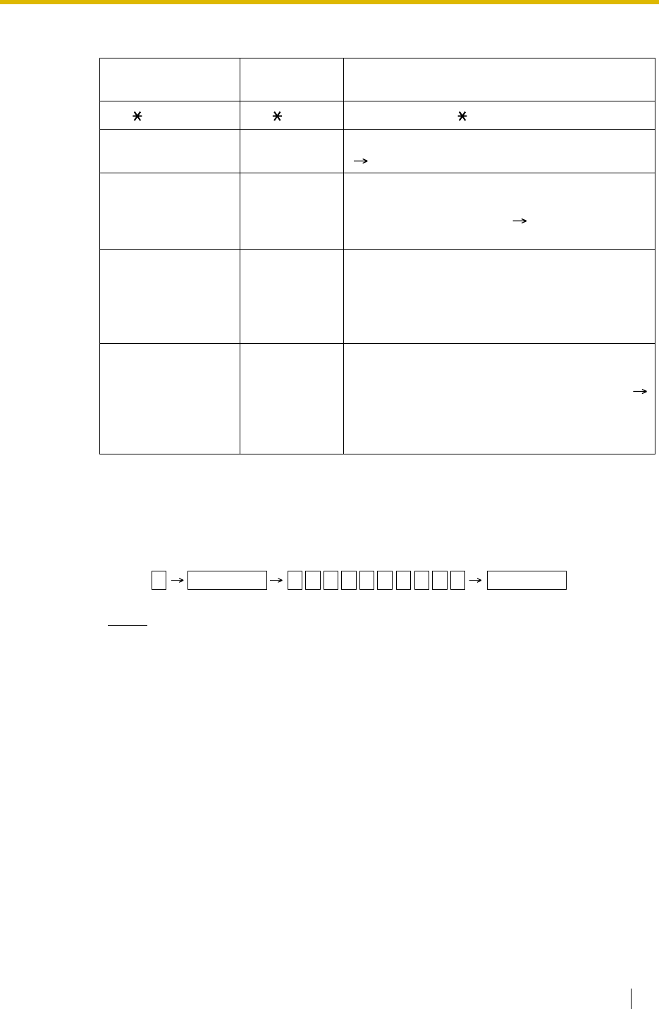
1.6 Memory Dialling Features
Feature Guide 87
2. Valid Input
[Example]
When storing the number "9-123-456-7890" and concealing the telephone number "123-
456-7890",
Notes
• It is possible to store a Memory Dialling feature number in the beginning of the
Memory Dialling numbers.
• It is possible to store several feature numbers in one Memory Dialling location.
Conditions
•Trunk Access by Memory Dialling
A specific Trunk Access number can be stored with the telephone number in Memory
Dialling. However, if Memory Dialling is done after selecting a trunk, the stored Trunk
Access number is ignored and the telephone number is sent using the selected trunk.
Input Display while
Entering Description
0–9/ /# 0–9/ /# Stores the digits, and #.
PAUSE (Pause) P Stores a pause by pressing the PAUSE button.
( 1.5.4.6 Pause Insertion)
FLASH/RECALL
(Hooking)* F Stores a flash/recall signal (EFA mode) by
pressing the FLASH/RECALL button at the
beginning of the number. ( 1.10.7 External
Feature Access (EFA))
INTERCOM
(Secret)* [/] Conceals all or part of the number by pressing the
INTERCOM button at the beginning and at the
end of the number to be concealed. It is
programmable whether the concealed part will
appear on the SMDR.
TRANSFER
(Transfer)* T Stores a transfer command by pressing the
TRANSFER button at the beginning of the
number (used only for a One-touch Dialling). (
1.11.1 Call Transfer)
[Example] Storing "T + 305"= Transferring a call
to extension 305.
*: Available only when in the system/personal programming mode
Enter
.
INTERCOM9 1 2 3 4 5 6 7 8 9 0 INTERCOM

1.6 Memory Dialling Features
88 Feature Guide
1.6.1.2 One-touch Dialling
Description
A PT user can access a person or feature by one-touch. This is activated by storing the number
(e.g., extension number, telephone number, or feature number) in a One-touch Dialling button.
Conditions
•One-touch Dialling Button
A flexible button can be customised as a One-touch Dialling button.
•Full One-touch Dialling
There is no need to go off-hook before pressing the One-touch Dialling button.
Feature Guide References
1.19.2 Flexible Buttons
User Manual References
User Manual
1.2.2 Easy Dialling

1.6 Memory Dialling Features
Feature Guide 89
1.6.1.3 KX-T7710 One-touch Dialling (KX-TDA100/KX-TDA200
only)
Description
The Message button and One-touch buttons on all KX-T7710 telephones connected to the
PBX can be customised at once through system programming. The same extension number,
telephone number, or feature number will be assigned to the same buttons on each KX-T7710,
useful for hotel room extensions or similar applications.
[Programming Example]
The MESSAGE button is programmed by default to call back a caller who left a message
waiting indication, however, the MESSAGE button can be programmed to perform other
features. The eight One-touch buttons have no default setting.
Conditions
• The KX-T7710 has two modes, NORMAL mode and PBX mode, selected by a switch on
the telephone. This feature is available only when the KX-T7710 is in the PBX mode.
• This feature is available while hearing a dial tone.
• Please refer to the Quick Reference Guide of the KX-T7710 for additional information.
Feature Guide References
1.19.2 Flexible Buttons
User Manual References
User Manual
1.2.2 Easy Dialling
Button Desired Number
MESSAGE 702 (Message Waiting [To Call Back])
One-touch Dial 01 100 (Front Desk)
One-touch Dial 02 7601 (Wake-up Call)
One-touch Dial 03 102 (Restaurant)
::

1.6 Memory Dialling Features
90 Feature Guide
1.6.1.4 Last Number Redial
Description
Every extension automatically saves the last external telephone number dialled to allow the
same number to be dialled again.
Automatic Redial:
If Last Number Redial is performed in hands-free mode and the called party is busy, redialling
will be automatically retried a preprogrammed number of times ( Automatic Redial Repeat
Times [205]) at preprogrammed intervals ( Automatic Redial Interval [206]). The Redial Call
No-answer Ring Duration time is programmable.
This feature is available only on certain PT models which have the SP-PHONE button.
Outgoing Call Log:
The last five dialled numbers are automatically stored at each extension. A display PT user can
redial easily any of the stored numbers.
Conditions
• The memorised telephone number is replaced by a new one.
• If any dialling operation is done or an incoming call is answered during Automatic Redial,
Automatic Redial is cancelled.
• Automatic Redial is not available for some countries/areas when using an analogue trunk.
•Interrupt Redial
When the called party or the seized trunk is busy, it is possible to press the REDIAL button
continuously until the called party or the trunk becomes idle. There is no need to go off-
hook, before pressing the REDIAL button.
•Outgoing Call Log Display by REDIAL Button
Pressing the REDIAL button on a display DPT while on-hook can display the Outgoing Call
Log. System programming is required for this operation.
User Manual References
User Manual
1.2.3 Redial
1.11.1 Using the Call Log

1.6 Memory Dialling Features
Feature Guide 91
1.6.1.5 Speed Dialling—Personal/System
Description
An extension user can make calls using abbreviated dialling for frequently dialled numbers
which are stored in the PBX extension data, or the PBX system data ( System Speed Dialling
Number [001]).
Personal Speed Dialling is also known as Station Speed Dialling.
Conditions
[General]
• Any number (e.g., telephone number, feature number) can be stored in a speed dialling
number. A name can be assigned to each Personal Speed Dialling number through
personal programming, and System Speed Dialling number ( System Speed Dialling
Name [002]).
•Call Directory—Speed Dialling
Display PT users can make a call by selecting stored names on the display.
[Personal Speed Dialling]
•Personal Speed Dialling Display Lock
An extension user can lock the Personal Speed Dialling number display to prevent other
users from viewing the number. In this case, the Incoming and Outgoing Call Log
information displays are also locked. An extension personal identification number (PIN) is
required to use this feature. ( 1.26.1 Extension Personal Identification Number (PIN))
[System Speed Dialling]
•TRS/Barring Override by System Speed Dialling
It is possible to override the TRS/Barring using the System Speed Dialling ( TRS/
Barring Level for System Speed Dialling [509]). ( 1.8.1 Toll Restriction (TRS)/Call
Barring (Barring))
•System Speed Dialling Display by AUTO DIAL/STORE Button
Pressing the AUTO DIAL/STORE button on a display DPT while on-hook can display the
System Speed Dialling Directory.
User Manual References
User Manual
1.2.2 Easy Dialling
1.11.1 Using the Call Log
1.11.2 Using the Directories
3.1.2 Settings on the Programming Mode
3.3 Customising Your System (System Programming)

1.6 Memory Dialling Features
92 Feature Guide
1.6.1.6 Quick Dialling
Description
An extension user can access a person or feature easily. This is enabled by storing the number
(e.g., extension number, telephone number or feature number) for Quick Dialling.
Conditions
• Quick Dialling is convenient in the following cases:
• Quick Dialling numbers follow the flexible numbering plan.
( 2.3.5 Flexible Numbering/Fixed Numbering)
• The storing example is as follows:
User Manual References
User Manual
1.2.2 Easy Dialling
– Room service calls in a hotel
– Calling another branch via the public network. The extension user needs to dial
only the extension number of another branch.
Location No. Quick Dialling No. Desired Number
Quick Dialling 01 110 9110 (Trunk Call)
Quick Dialling 02 5 3016 (Room Service)
Quick Dialling 03 2011 90123456789 (Another Branch)
:: :

1.6 Memory Dialling Features
Feature Guide 93
1.6.1.7 Hot Line
Description
An extension user can make an outgoing call by only going off-hook, if the user has previously
stored the telephone number or the extension number.
If the Hot Line feature is set and the user goes off-hook, a dial tone is generated for a specified
Waiting time assigned through system programming ( Hot Line Waiting Time [204]) and then
dialling starts. During the Waiting time the user can dial another party, overriding the Hot Line
feature.
This feature is also known as Pickup Dialling.
Conditions
•Capable Telephone
PT, SLT, T1-OPX, and PS
User Manual References
User Manual
1.2.2 Easy Dialling

1.7 Busy Line/Busy Party Features
94 Feature Guide
1.7 Busy Line/Busy Party Features
1.7.1 Automatic Callback Busy (Camp-on)
Description
If the line is busy when a call is made, callback ringing will inform the caller when the line
becomes free using this feature. After the extension answers the callback ringing, the dialled
number is automatically redialled.
Conditions
• If the callback ringing is not answered within 10 seconds, the callback is cancelled.
• If the extension hears a busy tone before dialling the telephone number, only the trunk or
trunk group is reserved. After answering the callback ringing, the extension should dial the
telephone number.
• An extension can set only one Automatic Callback Busy. The last setting is effective.
• Multiple extension users can set this feature to one trunk simultaneously.
However, a maximum of four extension users can set this feature to one extension.
• The priority of the callback is the setting order.
• This feature cannot be used for calls to a VPS or an ISDN extension.
User Manual References
User Manual
1.2.4 When the Dialled Line is Busy or There is No Answer

1.7 Busy Line/Busy Party Features
Feature Guide 95
1.7.2 Executive Busy Override
Description
Allows an extension user to interrupt an existing call to establish a three-party conference call.
Executive Busy Override Deny:
It is possible for extension users to prevent their calls from being intercepted by another
extension user.
Conditions
• COS programming determines extension users who can use the Executive Busy Override
( Executive Busy Override [505]) and set the Executive Busy Override Deny mode (
Executive Busy Override Deny [506]).
• This feature does not work when the busy extension is in one of the following conditions:
a) Executive Busy Override Deny or Data Line Security ( 1.10.5 Data Line Security)
has been set.
b) While being monitored by another extension ( 1.7.3 Call Monitor).
c) While receiving OHCA ( 1.7.4.3 Off-hook Call Announcement (OHCA)) or Whisper
OHCA ( 1.7.4.4 Whisper OHCA).
d) During a Conference call ( 1.13.1 Conference Features).
e) During a doorphone call ( 1.16.1 Doorphone Call).
f) While Live Call Screening (LCS) or Two-way Record is activated ( 1.23.3 Voice Mail
DPT (Digital) Integration).
g) During Consultation Hold.
(Consultation Hold: Allows an extension user to place a call on hold temporarily to
perform Call Transfer, Conference, or Call Splitting.)
• This feature is not available for a trunk-to-trunk call via DISA.
User Manual References
User Manual
1.2.4 When the Dialled Line is Busy or There is No Answer
1.7.7 Preventing Other People from Joining Your Conversation (Executive Busy Override
Deny)

1.7 Busy Line/Busy Party Features
96 Feature Guide
1.7.3 Call Monitor
Description
Allows an extension user to listen to the busy extension user’s existing conversation. The user
can hear the conversation, but the user’s voice is not heard. If desired, interrupting the call to
establish a three-party conference call is available.
Conditions
• COS programming determines extension users who can use this feature.
• This feature is available only when the busy extension is in a conversation with another
extension or outside party.
• This feature does not work when the busy extension is in one of the following conditions:
a) Executive Busy Override Deny ( 1.7.2 Executive Busy Override) or Data Line
Security ( 1.10.5 Data Line Security) has been set.
b) While receiving OHCA ( 1.7.4.3 Off-hook Call Announcement (OHCA)) or Whisper
OHCA ( 1.7.4.4 Whisper OHCA).
c) During a Conference call ( 1.13.1 Conference Features).
d) During a doorphone call ( 1.16.1 Doorphone Call).
e) While Live Call Screening (LCS) or Two-way Record is activated ( 1.23.3 Voice Mail
DPT (Digital) Integration).
f) During Consultation Hold.
(Consultation Hold: Allows an extension user to place a call on hold temporarily to
perform Call Transfer, Conference, or Call Splitting.)
• This feature stops when the busy extension user presses the following buttons during a
conversation ( 1.19.1 Fixed Buttons and 1.19.2 Flexible Buttons):
User Manual References
User Manual
1.2.4 When the Dialled Line is Busy or There is No Answer
– FLASH/RECALL button
– HOLD button
– TRANSFER button
– CONF (Conference) button
– DSS button
– EFA button
– Two-way Record button
– Two-way Transfer button
– One-touch Two-way Transfer button
– Voice Mail (VM) Transfer button
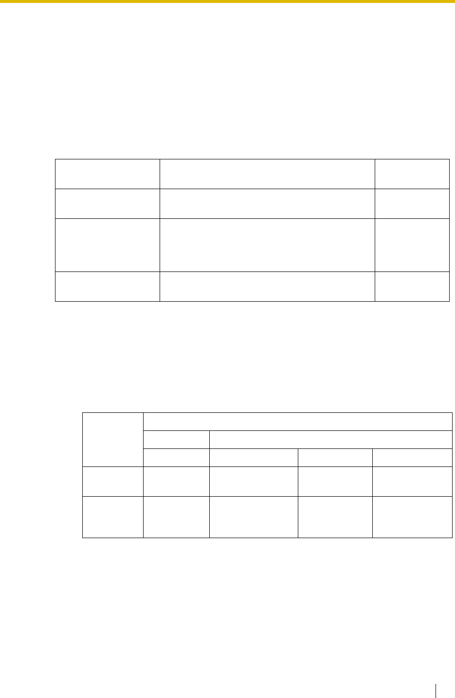
1.7 Busy Line/Busy Party Features
Feature Guide 97
1.7.4 Second Call Notification to Busy Extension
1.7.4.1 Second Call Notification to Busy Extension—SUMMARY
Description
When attempting to call a busy extension (ringing or having a conversation), an extension user
can send call waiting indication to the busy extension (Call Waiting). The notification receiving
method depends on the called extension’s personal setting and the telephone type:
Conditions
• Each extension user can choose to receive Call Waiting tone, OHCA, Whisper OHCA, or
none of these.
• OHCA and Whisper OHCA are enabled or disabled by the COS of the calling extension.
• OHCA and Whisper OHCA do not work for some telephone types. In such cases, the Call
Waiting tone will be sent to the called extension.
• The notification receiving methods (Call Waiting tone, OHCA, and Whisper OHCA) are
available when the called extension is having a conversation with other party. If not, the
calling extension will be kept waiting until the called extension becomes available to
receive the notification. Even while waiting, the calling extension will hear a ringback tone.
• If none of these notification receiving methods, Call Waiting tone, OHCA, or Whisper
OHCA is set at the called party, the caller will hear reorder tone.
Notification
Receiving Method Description Details in
Call Waiting Tone Sends the Call Waiting tone to the busy
extension. • 1.7.4.2 Call
Waiting Tone
Off-hook Call
Announcement
(OHCA)
Talk with the busy extension using the built-in
speaker and microphone of the called extension
while the existing call is made using the handset.
• 1.7.4.3 Off-
hook Call
Announcement
(OHCA)
Whisper OHCA Give a message to the busy extension through
the handset. • 1.7.4.4
Whisper OHCA
Calling
Extension’s
OHCA COS
Mode
Called Extension’s Call Waiting Mode
OFF ON
Cancel Call Waiting Tone OHCA Whisper OHCA
Disable Call Waiting
disabled Call Waiting tone Call Waiting
tone Call Waiting tone
Enable Call Waiting
disabled Call Waiting tone OHCA
(or Call Waiting
tone)
Whisper OHCA
(or Call Waiting
tone)


1.7 Busy Line/Busy Party Features
Feature Guide 99
1.7.4.2 Call Waiting Tone
Description
When an extension user attempts to call a busy extension (ringing or having a conversation),
the Call Waiting tone can be sent to the called extension to let him know another call is waiting.
Conditions
• This feature only works if the called extension has activated Call Waiting. If it is activated,
the calling extension will hear a ringback tone.
• Call Waiting tone can be selected (Tone 1 or Tone 2) through personal programming (Call
Waiting Tone Type Selection).
User Manual References
User Manual
3.1.2 Settings on the Programming Mode

1.7 Busy Line/Busy Party Features
100 Feature Guide
1.7.4.3 Off-hook Call Announcement (OHCA)
Description
An extension user can talk with a busy extension through the built-in speaker and microphone
of the called party’s PT. If the existing call is using a handset, a second conversation is made
using the speakerphone and microphone so that the called extension can talk to both parties.
Conditions
• COS programming determines which extensions can use this feature.
• This feature is available when the called extension uses one of the following telephones:
• If the KX-T7235G/FR/SL/NE are connected to the PBX, the OHCA feature for the
KX-T7235 should be disabled through system programming.
• The OHCA feature cannot be used in the following cases:
The Call Waiting tone is sent to the called extension. ( 1.7.4.2 Call Waiting Tone)
• While an extension is receiving OHCA, if the extension user places the current trunk call
on hold or transfers the current intercom call or trunk call, OHCA will become disabled and
the calling extension will start to hear a ringback tone.
• While an extension is receiving OHCA, if the extension user places the current intercom
call on hold, the called extension can talk to the calling extension through the handset.
– KX-T7625, KX-T7630, KX-T7633, KX-T7636
–KX-T7536
–KX-T7436
– KX-T7235 (except KX-T7235G/FR/SL/NE)
(a) COS or called extension's telephone type is not available for this feature.
(b) The called extension (DPT) is connected to a PC (PC Console or PC Phone)
via the USB Module.
(c) The called extension (DPT) is in the Digital XDP connection.

1.7 Busy Line/Busy Party Features
Feature Guide 101
1.7.4.4 Whisper OHCA
Description
An extension user can give a message to a busy extension through the handset.
Conditions
• COS programming determines which extensions can use this feature.
• This feature is available when the calling and called extension use one of the following
telephones:
• If the Whisper OHCA feature cannot be used due to COS or telephone type, the Call
Waiting tone will be sent to the called extension. ( 1.7.4.2 Call Waiting Tone)
• If the called extension does not use a KX-T7600, KX-T7500, or KX-T7400 series
telephone but forces Whisper OHCA, the announcement may be heard by the other party.
• It is possible to enable Whisper OHCA on any telephone. However, it may not work
properly. (e.g., The voice may be heard by the other party.)
• While an extension is receiving Whisper OHCA, if the extension user places the current
trunk call on hold or transfers the current intercom call or trunk call, the Whisper OHCA
will become disabled and the calling extension will start to hear a ringback tone.
• While an extension is receiving Whisper OHCA, if the extension user places the current
intercom call on hold, the called extension can talk to the calling extension through the
handset.
– KX-T7600 series
– KX-T7500 series
– KX-T7400 series (except KX-T7451)

1.8 Toll Restriction (TRS)/Call Barring (Barring) Features
102 Feature Guide
1.8 Toll Restriction (TRS)/Call Barring (Barring)
Features
1.8.1 Toll Restriction (TRS)/Call Barring (Barring)
Description
TRS/Barring can prohibit an extension user from making certain trunk calls by COS
programming. It is applied when the user goes off-hook, a trunk is seized and then a dialled
number is sent to the trunk.
Each COS is programmed to have a TRS/Barring level for each time mode (day/lunch/break/
night).
There are seven levels available. Level 1 is the highest level and the level 7 is the lowest. That
is, level 1 allows all trunk calls and level 7 prohibits all trunk calls. Levels 2 through 6 are used
to restrict calls by combining preprogrammed Denied and Exception Code Tables.
Denied Code Tables
An outgoing trunk call made by an extension with a level between 2 and 6 is first checked
against the applicable Denied Code Tables. If the leading digits of the dialled number (not
including the Trunk Access number) are not found in the table, the call is made. There are five
Denied Code Tables for Levels 2 through 6 respectively.
Complete every table by storing numbers that are to be prohibited. These numbers are defined
as denied codes.
Exception Code Tables
These tables are used to override a programmed denied code. A call denied by the applicable
Denied Code Tables is checked against the applicable Exception Code Tables, and if a match
is found, the call is made.
There are five Exception Code Tables for Levels 2 through 6 respectively.
Complete every table by storing numbers that are exceptions to the denied codes. These
numbers are defined as exception codes.
TRS/Barring Override by System Speed Dialling
If the call is made using System Speed Dialling, the call can override the TRS/Barring. Each
COS is programmed to have a TRS/Barring level for System Speed Dialling ( TRS/Barring
Override by System Speed Dialling [300]).
Once this feature is set, it permits all extension users to make System Speed Dialling calls with
the level for System Speed Dialling. Any extension which sets Extension Lock can also make
a call using System Speed Dialling.

1.8 Toll Restriction (TRS)/Call Barring (Barring) Features
Feature Guide 103
TRS/Barring Level
TRS/Barring level is determined by the applicable levels of Denied Code Tables and Exception
Code Tables.
[Programming Example]
Denied Code Tables*1 Exception Code Tables*2
Level 1 Not Programmable Not Programmable
Level 2 Table for Level 2 Tables for Levels 2 through 6
Level 3 Tables for Levels 2 and 3 Tables for Levels 3 through 6
Level 4 Tables for Levels 2 through 4 Tables for Levels 4 through 6
Level 5 Tables for Levels 2 through 5 Tables for Levels 5 through 6
Level 6 Tables for Levels 2 through 6 Tables for Level 6
Level 7 Not Programmable Not Programmable
*1: TRS/Barring Denied Code [301]
*2: TRS/Barring Exception Code [302]
Explanation:
Level 1: Allows all calls.
Level 2: Denies codes stored in the Denied Code Table for Level 2 except the codes
stored in Exception Code Tables for Levels 2 through 6.
Level 3: Denies codes stored in the Denied Code Tables for Levels 2 and 3 except the
codes stored in Exception Code Tables for Levels 3 through 6.
•
•
•
Level 7: Allows intercom calls only.
COS No. Level for Time Mode*1 Level for System
Speed Dialling*2
Day Lunch Break Night
1 1116 1
2 2226 1
: :::: :
*1: TRS/Barring Level [501]
*2: TRS/Barring Level for System Speed Dialling [509]

1.8 Toll Restriction (TRS)/Call Barring (Barring) Features
104 Feature Guide
[Flowchart]
An extension user makes
a trunk call.
Is the call made by System
Speed Dialling ?
What is the TRS/Barring level?
Is the dialled number found in
applicable Denied Code Tables?
Is the dialled number found in
applicable Exception Code Tables?
The call is denied.
The user hears reorder tone.
Is TRS/Barring Override by
System Speed Dialling enabled?
The call is made.
Yes
Level 7 Level 1
Levels 2, 3, 4, 5, 6
Yes
Yes
Yes
No
No
No
No
Checks the TRS/Barring
level for System Speed
Dialling of the
extension's COS.
Checks the
TRS/Barring level for
the time mode of the
extension's COS.

1.8 Toll Restriction (TRS)/Call Barring (Barring) Features
Feature Guide 105
Conditions
WARNING
The software contained in the TRS/Barring feature to allow user access to the network
must be upgraded to recognise newly established network area codes and exchange
codes as they are placed into service.
Failure to upgrade the premises PBXs or peripheral equipment to recognise the new
codes as they are established will restrict the customer and the customer’s employees
from gaining access to the network and to these codes.
KEEP THE SOFTWARE UP-TO-DATE WITH THE LATEST DATA.
• A COS should be assigned for each extension. ( Class of Service [602])
• TRS/Barring checks are applied to the following:
• It is programmable whether " " or "#" is checked by the TRS/Barring. This is useful in
preventing unauthorised calls which could be possible through certain telephone company
exchanges.
• It is programmable whether TRS/Barring checks the digits dialled after the External
Feature Access during a trunk call. ( 1.10.7 External Feature Access (EFA))
•Host PBX Access Code/Special Carrier Access Code
TRS/Barring checks for numbers dialled with a Host PBX Access code ( 1.5.4.7 Host
PBX Access Code (Access Code to the Telephone Company from a Host PBX)) or a
Special Carrier Access code ( 1.5.4.8 Special Carrier Access Code) in the following
cases:
•ARS
If ARS is applied to a dialled number, TRS/Barring will check the user-dialled number (not
the modified number by ARS). In this case, a Host PBX Access code and/or a Special
Carrier Access code will not be checked.
•Dialling Digit Restriction during Conversation
The dialling of digits can be restricted while engaged on a received trunk call. If the number
of dialled digits exceeds the preprogrammed limitation, the line will be disconnected.
• A TRS/Barring level can be changed by some features. The priority of features, when
multiple features are used, is as follows:
1) Dial Tone Transfer ( 1.8.4 Dial Tone Transfer)
2) Budget Management ( 1.8.2 Budget Management)
3) TRS/Barring Override by System Speed Dialling
–ARS
– Trunk Access (Idle Line/Trunk Group/S-CO Line)
Type Stored Not stored
Found Not found
Host PBX
Access Code Deletes the code. A
TRS/Barring check is
carried out on the
following digits.
The call is made
(excepted from TRS/
Barring).
TRS/Barring checks
the whole number.
Special Carrier
Access Code Deletes the code. A
TRS/Barring check is
carried out on the
following digits.
TRS/Barring checks
the whole number. TRS/Barring checks
the whole number.

1.8 Toll Restriction (TRS)/Call Barring (Barring) Features
106 Feature Guide
4) Walking COS/Verified Code Entry
( 1.8.5 Walking COS, 1.8.6 Verified Code Entry)
5) Extension Lock
Feature Guide References
1.5.5.3 Trunk Access
1.6.1.5 Speed Dialling—Personal/System
1.8.3 Extension Lock
1.9.1 Automatic Route Selection (ARS)
2.2.4 Time Service

1.8 Toll Restriction (TRS)/Call Barring (Barring) Features
Feature Guide 107
1.8.2 Budget Management
Description
Limits the telephone usage to a preprogrammed budget on an extension basis. If the amount
of the call charge reaches the limit, an extension user cannot make further trunk calls. An
extension assigned as the manager may increase the limit or clear the amount of the call
charge.
Conditions
• If the limit is reached, TRS/Barring Level 7 is applied. ( 1.8.1 Toll Restriction (TRS)/Call
Barring (Barring))
•Budget Management for Verified Call
If an extension user make a trunk call with a verified code, the call charge will be counted
on the verified code (not the extension). ( 1.8.6 Verified Code Entry) The limit of the call
charge can be assigned on each verified code.
• The pay tone service or ISDN Advice of Charge (AOC) service is required for this feature.
• It is possible to select whether to disconnect the line after an alarm tone or only to send
an alarm tone when the amount of the call charge reaches the preprogrammed limit during
a conversation.
User Manual References
User Manual
3.2.2 Manager Programming

1.8 Toll Restriction (TRS)/Call Barring (Barring) Features
108 Feature Guide
1.8.3 Extension Lock
Description
An extension user can change the TRS/Barring level of the telephone ( 1.8.1 Toll Restriction
(TRS)/Call Barring (Barring)) so that other users cannot make inappropriate trunk calls. An
extension personal identification number (PIN) is used to unlock the telephone ( 1.26.1
Extension Personal Identification Number (PIN)).
This feature is also known as Electronic Station Lockout.
Conditions
• This feature also restricts changing the FWD destination. ( 1.3.1.2 Call Forwarding
(FWD))
•Remote Extension Lock
Overrides Extension Lock. If an extension assigned as the manager sets Remote
Extension Lock on an extension that has already been locked by the extension user, the
user cannot unlock it. If a manager extension unlocks an extension that has been locked
by the extension user, the extension will be unlocked.
This feature is also known as Remote Station Lock Control.
•TRS/Barring Level
COS programming determines the TRS/Barring level for Extension Lock ( TRS/Barring
Level for Extension Lock [510]).
User Manual References
User Manual
1.5.3 Preventing Other People from Using Your Telephone (Extension Lock)
2.1.1 Extension Control

1.8 Toll Restriction (TRS)/Call Barring (Barring) Features
Feature Guide 109
1.8.4 Dial Tone Transfer
Description
An extension assigned as the manager can change the TRS/Barring level ( 1.8.1 Toll
Restriction (TRS)/Call Barring (Barring)) for the extension user temporarily. After that, the
extension user can make his call.
[Example] An extension user can call a manager to release the restriction on outgoing call
(e.g., international calls).
Conditions
• The changed level effects just one time.
•Toll Restriction/Call Barring Button
A manager extension must store the desired TRS/Barring level in the Toll Restriction/Call
Barring button. A flexible button can be customised as the Toll Restriction/Call Barring
button.
Feature Guide References
1.19.2 Flexible Buttons
User Manual References
User Manual
2.1.3 Restriction Level Control (Dial Tone Transfer)
(1) Call
(2) Change
TRS/Barring level
(3) Make a trunk call
Toll Restriction/
Call Barring button
Manager
Guest Room
(Trunk call
restricted)

1.8 Toll Restriction (TRS)/Call Barring (Barring) Features
110 Feature Guide
1.8.5 Walking COS
Description
An extension user can use another extension telephone with the COS assigned on his own
extension temporarily. The extension accesses his own extension from another telephone and
operates features with the same conditions which are assigned his own extension. It is one of
the remote operations. An extension personal identification number (PIN) is required to use this
feature ( 1.26.1 Extension Personal Identification Number (PIN)).
Conditions
• The following items are applied:
•Walking COS through DISA
This feature is also available through the DISA. ( 1.16.6 Direct Inward System Access
(DISA))
Feature Guide References
2.2.1 Class of Service (COS)
User Manual References
User Manual
1.2.7 Calling without Restrictions
– COS programming
– Budget Management ( 1.8.2 Budget Management)
– Itemised Billing code for ARS ( 1.9.1 Automatic Route Selection (ARS))
– Extension number recorded on the SMDR ( 1.25.1 Station Message Detail
Recording (SMDR)).

1.8 Toll Restriction (TRS)/Call Barring (Barring) Features
Feature Guide 111
1.8.6 Verified Code Entry
Description
An extension user can make a trunk call with a verified code from his own or any other
extension to change the TRS/Barring level ( 1.8.1 Toll Restriction (TRS)/Call Barring
(Barring)) or to identify the call for accounting and billing purposes. A verified code personal
identification number (PIN) is required to use this feature.
Conditions
WARNING
When a third party discovers the personal identification number (PIN) (verified code PIN/
extension PIN) of the PBX, there will be a risk that they will make fraudulent phone calls
using the telephone line, and the cost will be charged to your own account. In order to
avoid this problem, we strongly recommend the following points:
a) Carefully maintain the secrecy of the PIN.
b) Specify a complicated PIN as long and random as you can make it.
c) Change the PIN frequently.
• The following items are applied:
•Verified Code Entry through DISA
This feature is also available through the DISA. ( 1.16.6 Direct Inward System Access
(DISA))
•Verified Code PIN
A verified code PIN must be assigned for each verified code through system programming
( Verified Code Personal Identification Number (PIN) [122]) or through manager
programming.
•Verified Code PIN Lock
If the wrong PIN is entered incorrectly three times, the line will be disconnected. If the
incorrect PIN is entered a preprogrammed number of times successively, the PIN against
the verified code will be locked. Only an extension assigned as the manager can unlock it.
In this case, the PIN will be unlocked and cleared.
– COS programming
– Budget Management
– Itemised Billing code for ARS
–The + verified code recorded on the SMDR instead of the extension number
( 1.25.1 Station Message Detail Recording (SMDR)).

1.8 Toll Restriction (TRS)/Call Barring (Barring) Features
112 Feature Guide
•Budget Management for Verified Calls
A limit of the call charge can be assigned on each verified code.
[Example of Verified Codes and Their Programming]
Feature Guide References
1.8.2 Budget Management
1.9.1 Automatic Route Selection (ARS)
2.2.1 Class of Service (COS)
2.2.6 Manager Features
User Manual References
User Manual
1.2.7 Calling without Restrictions
3.2.2 Manager Programming
Location
No. Verified
Code*1
User
Name*2
Verified
Code PIN COS
No.*3
Itemised
Billing Code
for ARS
Budget
Management
0001 1111 Tom Smith 1234 1 2323 5000Yen
0002 2222 John White 9876543210 3 4545 3000Yen
:: : : : : :
*1: Verified Code [120]
*2: Verified Code Name [121]
*3: Verified Code COS Number [123]
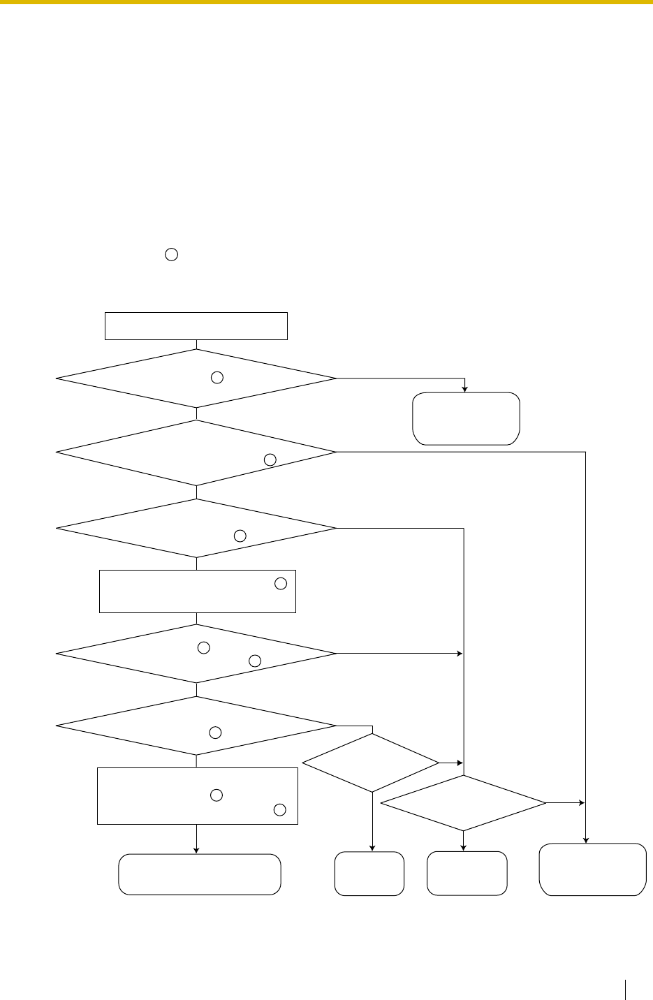
1.9 Automatic Route Selection (ARS) Features
Feature Guide 113
1.9 Automatic Route Selection (ARS) Features
1.9.1 Automatic Route Selection (ARS)
Description
ARS automatically selects the carrier available at the time an outgoing trunk call is made
according to preprogrammed settings. The dialled number will be checked and modified to
connect the appropriate carrier.
[Carrier Selection Procedure Flowchart]
The numbers in the flowchart correspond to the [Programming Procedures] on the following
pages.
X
No
No (Normal Trunk Access)
No
No
Yes
Is the ARS mode ( ) enabled?
A trunk call is made.
Sends a
reorder tone.
Sends a
busy tone.
Checks the Routing Plan Table ( )
to determine which carrier to use.
Modifies the dialled number by
removing the digits ( ) and
following the modify commands ( ).
Sends the modified number
to the trunk.
Yes
No
Is the carrier ( ) found in the
appropriate time block ( )?
Yes
Is the dialled number found in the
Leading Number Exception Table ( )?
No
Yes
(default)
Yes Is normal
Trunk Access
allowed?
Because all
trunks are busy?
1
Yes
Is the dialled number found in the
Leading Number Table ( )?
5
6
No
Is there an available
trunk group ( )?
Yes
11
12
9
2
4
3
Sends the
telephone number
by the Idle Line
Access.
Sends the telephone
number to the user-
selected carrier.
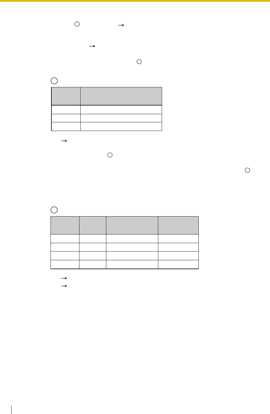
1.9 Automatic Route Selection (ARS) Features
114 Feature Guide
[Programming Procedures]
1. ARS Mode Assignment ( ARS Mode [320])
It is possible to select whether ARS operates when an extension user makes a call using
any Idle Line Access method or when an extension user makes a call using any Trunk
Access method. ( 1.5.5.3 Trunk Access)
2. Leading Number Exception Table Assignment
Store the telephone numbers that will avoid using the ARS feature.
3. Leading Number Table Assignment
Store the area codes and/or telephone numbers as leading number that will be routed by
the ARS feature. In this table, the Routing Plan (refer to "4. Routing Plan Table
Assignment") is selected for each number.
The additional (remain) number of digits must be assigned only when "#", for example, is
needed after a dialled number. The "#" is added after the assigned number of digits of
dialled number (excluding a leading number).
If a dialled number matches a leading number, the number will be modified according to
the corresponding Routing Plan Table and the modified number will be sent to the trunk
when the assigned additional (remain) number of digits are dialled.
If a dialled number matches multiple leading number entries, the leading number entry
with the lowest numbered location will have priority.
*1: ARS Exception Number [325]
*1: ARS Leading Number [321]
*2: ARS Routing Plan Table Number [322]
1
2
ARS Leading Number Exception Table
Location
No.
001
002
:
Leading No.
Exception*1
033555
06456
:
2
3
4
ARS Leading Number Table
Location
No.
0001
0002
0003
:
Routing Plan
Table No.*2
1
4
5
:
Additional (Remain)
No. of Digits
7
0
5
:
3
Leading
No.*1
039
03
0444
:
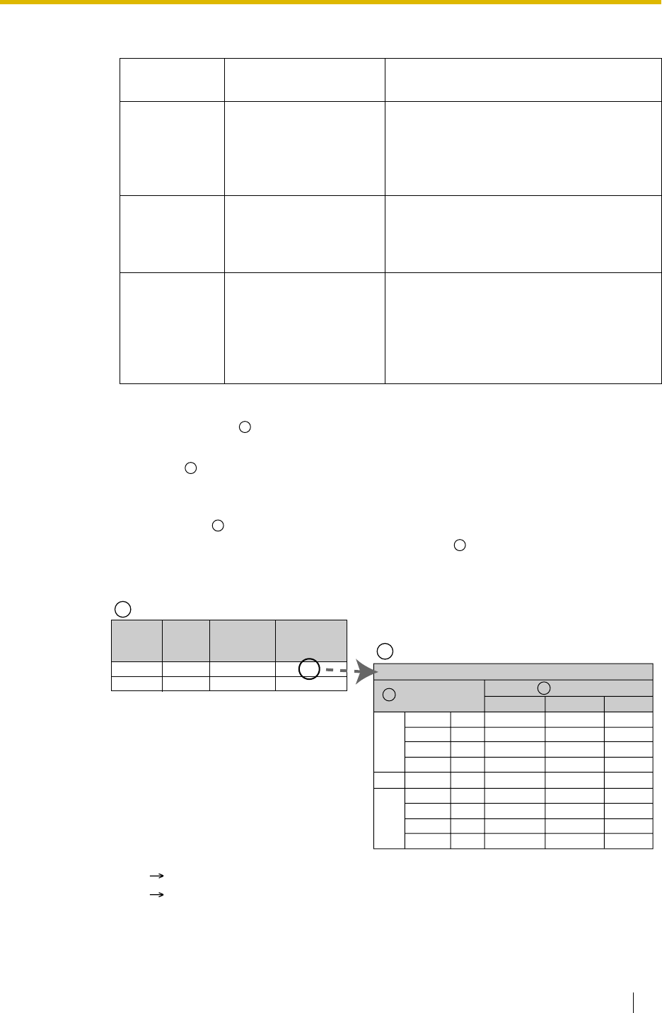
1.9 Automatic Route Selection (ARS) Features
Feature Guide 115
[Example]
4. Routing Plan Table Assignment
Arrange the time schedule as desired and store the carrier priority.
Time Table
As the best carrier may vary with the day of the week and the time of day, four time blocks
(Time-A through D) can be programmed for each day of the week.
Carrier Priority
Assign the appropriate carrier (refer to "5. Carrier Table Assignment") and their priority
in each time block. The carrier is selected in the entry order (the order in which entries are
listed).
Dialled
Number Corresponding
Routing Plan Table No. Description
039-123-4567 1 "039" is found in location 0001 and seven
digits (assigned additional [remain] number
of digits in location 0001) were dialled. The
Routing Plan Table 1 is selected just after
the seventh digit.
039-654-321 1 "039" is found in location 0001 and the
Inter-digit time expired before the seventh
digit is received. The Routing Plan Table 1
is selected after the Inter-digit time expired.
038 4 "03" is found in two locations (locations
0001 and 0002), so the PBX waits for the
next digit "8". "038" is not found in any
location, then "03" (location 0002) is
selected. The Routing Plan Table 4 is
selected.
*1: ARS Routing Plan Time Table [330]
*2: ARS Routing Plan Table (1–16) [331–346]
4
5
6
7
ARS Routing Plan Table
9:00
12:00
15:00
21:00
:
9:00
12:00
15:00
21:00
1
(A telecom)
1
(A telecom)
1
(A telecom)
3
(C telecom)
:
3
(C telecom)
3
(C telecom)
3
(C telecom)
3
(C telecom)
Time-A
Time-B
Time-C
Time-D
:
Time-A
Time-B
Time-C
Time-D
SUN
:
SAT
Time Table*1
Routing Plan Table 1
Carrier*2
Priority 1 Priority 2 ...
56
4
(D telecom)
2
(B telecom)
2
(B telecom)
1
(A telecom)
:
2
(B telecom)
1
(A telecom)
1
(A telecom)
2
(B telecom)
...
...
...
...
...
...
...
...
...
ARS Leading Number Table
0001
:
Location
No. Routing Plan
Table No.
1
:
Leading
No.
03
:
Additional
(Remain)
No. of Digits
8
:
3
4
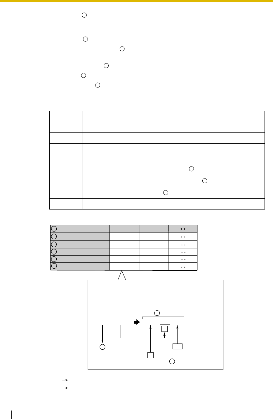
1.9 Automatic Route Selection (ARS) Features
116 Feature Guide
5. Carrier Table Assignment
A specified number of carriers can be programmed. Assign the following items for each
Carrier Table:
Carrier Name : Assign the carrier name.
Removed Number of Digits : Assign the number of digits to remove from the beginning
of the user-dialled number.
Carrier Access Code : Assign the code to access the carrier.
Trunk Group : Assign the trunk groups which connect to each carrier.
Modify Command : Assign the commands to modify the dialled number to access the
carrier.
[Command Explanation]
[Programming Example]
Command Description
Number Add the number.
C Add the Carrier Access code.
PAnalogue Line: Insert a pause.
ISDN/T1/E1 Line: Insert a pause and change to tone (DTMF) signal.
AAdd the Authorisation code for a tenant ( ).
GAdd the Authorisation code for a trunk group ( ).
IAdd the Itemised Billing code ( ).
H Add the dialled number after the digits are removed (Home position).
*1: ARS Carrier Name [350]
*2: ARS Removed Number of Digits for Carrier Access [352]
7
8
9
10
11
12
13
14
15
A telecom
6
0077
1, 2, 3
CH#12
Carrier Name*1
Removed Number of Digits
*2
Carrier Access Code
*3
Trunk Group*4
Modify Command
Carrier Table
7
9
10
11
[Example]
Dialled number: 0123456789
(Trunk Access no. is ignored.)
Modification:
012345 6789 0077 6789 #12
Remove 6 digits.
9
12
Add the Carrier Access
code ( ).
C
H
8
12
B telecom
0
0088
1, 2
CH
#12
Add the number.
12
10

1.9 Automatic Route Selection (ARS) Features
Feature Guide 117
6. Optional Assignment
Authorisation Code for a Tenant
An Authorisation code can be assigned for each carrier and each tenant.
Authorisation Code for a Trunk Group
An Authorisation code can be assigned for each trunk group and each carrier.
Itemised Billing Code
An Itemised Billing code can be assigned for each extension and for each verified code.
If a call is not made from an extension (e.g., DISA or TIE) and no verified code is used, the
Itemised Billing code assigned in the location 1 of the verified code will be used.
Conditions
WARNING
The software contained in the ARS feature to allow user access to the network must be
upgraded to recognise newly established network area codes and exchange codes as
they are placed into service.
Failure to upgrade the premises PBXs or peripheral equipment to recognise the new
codes as they are established will restrict the customer and the customer’s employees
from gaining access to the network and to these codes.
KEEP THE SOFTWARE UP-TO-DATE WITH THE LATEST DATA.
•The Dialled Number on the SMDR
It is possible to choose to print either the user-dialled number or the modified number on
the SMDR through system programming. ( 1.25.1 Station Message Detail Recording
(SMDR))
•ARS Data Download/Upload
It is possible to download or upload the following ARS data to the PBX using PC
programming:
This is useful when a carrier has changed the call charge, and the updated data can be
used for multiple customers.
• A TRS/Barring check is done before ARS is applied. ( 1.8.1 Toll Restriction (TRS)/Call
Barring (Barring))
*3: ARS Carrier Access Code [353]
*4: ARS Trunk Group for Carrier Access [351]
– ARS Leading Number Exception Table
– ARS Leading Number Table
– ARS Routing Plan Table
13
14
15
2
3
4

1.10 Conversation Features
118 Feature Guide
1.10 Conversation Features
1.10.1 Hands-free Operation
Description
A PT user can talk to another party without lifting the handset. Pressing specific buttons (e.g.,
REDIAL) automatically activate hands-free mode.
Conditions
•PTs with the MONITOR Button
PTs with the MONITOR button can only dial in hands-free mode and cannot be used for
hands-free conversations.

1.10 Conversation Features
Feature Guide 119
1.10.2 Off-hook Monitor
Description
A PT user can let others listen to the user’s conversation through the built-in speaker, during a
conversation using the handset.
Conditions
•Capable Telephone
KX-T7400 series and KX-T7500 series (display PT only), and all KX-T7600 series
telephones
To enable this feature, system programming is required. If disabled, hands-free
conversation is performed instead.
User Manual References
User Manual
1.4.7 Letting Other People Listen to the Conversation (Off-hook Monitor)

1.10 Conversation Features
120 Feature Guide
1.10.3 Mute
Description
During a conversation, a PT user can disable the speaker microphone or the handset
microphone to consult privately with others while listening to the other party on the phone
through the built-in speaker or the handset receiver. The user can hear the other party’s voice
during Mute. Only your voice will be muted.
Conditions
• This feature is available with all PTs that have the AUTO ANS/MUTE button.
User Manual References
User Manual
1.4.6 Mute

1.10 Conversation Features
Feature Guide 121
1.10.4 Headset Operation
Description
This PBX provides headset compatible PTs. A PT user can talk to another party without lifting
the handset.
For connection and operation, refer to the Operating Instructions for the headset.
This feature is also known as Handset/Headset Selection.
Conditions
• A headset is an option.
• If the headset mode is on, pressing the SP-PHONE button activates the headset, not the
built-in speaker.
• To set the headset mode on a DPT, use personal programming (Headset Operation) or
press the Headset button. To set headset mode on an APT, use the handset/headset
selector provided on the set and/or on the headset.
•Headset Button
A flexible button on a DPT can be customised as the Headset button. The Headset button
can be also assigned to a flexible button on an APT, but the button does not work.
•Answer/Release Button
A flexible button can be customised as an Answer button or a Release button. Such
buttons are useful for headset operation. It is possible to answer an incoming call by
pressing an Answer button. While hearing the Call Waiting tone during a conversation,
pressing an Answer button enables one to answer the second call by placing the current
call on hold. Pressing a Release button enables one to disconnect the line during or after
conversation, or to complete a Call Transfer.
• It is possible to switch the headset mode to the hands-free mode or vice versa during a
conversation by pressing the Headset button.
• Headset users cannot use the following features:
Feature Guide References
1.19.2 Flexible Buttons
User Manual References
User Manual
1.3.5 Using the ANSWER/RELEASE Button
1.4.8 Using the Headset (Headset Operation)
3.1.2 Settings on the Programming Mode
– Automatic Redial ( 1.6.1.4 Last Number Redial)
– Receiving OHCA ( 1.7.4.3 Off-hook Call Announcement (OHCA))
– Receiving Whisper OHCA ( 1.7.4.4 Whisper OHCA)

1.10 Conversation Features
122 Feature Guide
1.10.5 Data Line Security
Description
Once Data Line Security is set on an extension, communication between the extension and the
other party is protected from signals such as Call Waiting, Hold Recall and Executive Busy
Override. Extension which has data devices connected (e.g., fax machine) may set this feature
to maintain secure data transmission against tones or interruptions from other extensions
during communication.
User Manual References
User Manual
1.7.9 Protecting Your Line against Notification Tones (Data Line Security)

1.10 Conversation Features
Feature Guide 123
1.10.6 Flash/Recall/Terminate
Description
The FLASH/RECALL button (Flash/Recall mode or Terminate mode) or Terminate button
(Terminate mode) is used when a PT user disconnects the current call and originates another
call without hanging up first. It performs as going on-hook and then going off-hook.
[Explanation of Each Mode]
Flash/Recall Mode: Disconnects the line and the extension user hears the dial tone from the
line used last. For example, if a trunk call is disconnected, the extension user will hear a new
dial tone from the telephone company.
Terminate Mode: Disconnects the line and the extension user hears the dial tone determined
by the Line Preference—Outgoing setting. ( 1.5.5.2 Line Preference—Outgoing)
Conditions
•FLASH/RECALL Button Mode
One of the following modes can be selected for each extension through system
programming:
•Terminate Button
A flexible button can be customised as the Terminate button.
•Disconnect Time (Only for Flash/Recall Mode)
The amount of time between successive accesses to the same trunk is programmable for
each trunk port ( LCOT Disconnect Time [418]).
• This feature outputs an SMDR call record ( 1.25.1 Station Message Detail Recording
(SMDR)), restarts the call timer, inserts the automatic pause, and checks the TRS/Barring
level ( 1.8.1 Toll Restriction (TRS)/Call Barring (Barring)) again.
• If the ARS mode is on ( 1.9.1 Automatic Route Selection (ARS)) or if a trunk call is
established through the INTERCOM button or ICD Group button, the Terminate mode will
be always effective even though the Flash/Recall mode has been set.
Feature Guide References
1.19.2 Flexible Buttons
– Flash/Recall mode
– Terminate mode
– External Feature Access (EFA) mode. ( 1.10.7 External Feature Access (EFA))

1.10 Conversation Features
124 Feature Guide
1.10.7 External Feature Access (EFA)
Description
An extension user can have access to the features of a host PBX or the telephone company,
such as Transfer, Hold, Call Waiting, etc. A flash/recall signal is sent to the host PBX or the
telephone company. This is only available on trunk calls (including Host PBX Access [
1.5.4.7 Host PBX Access Code (Access Code to the Telephone Company from a Host PBX)]).
Conditions
•Flash/Recall Time
The Flash/Recall time can be assigned for each trunk port ( LCOT Flash/Recall Time
[417]).
•EFA Button
A flexible button can be customised as the EFA button.
• Pressing the FLASH/RECALL button which is set to EFA mode ( 1.10.6 Flash/Recall/
Terminate) or the EFA button performs this feature. It is also possible to perform this
feature by entering the feature number when the current call is placed on a Consultation
Hold.
(Consultation Hold: Allows an extension user to place a call on hold temporarily to
perform Call Transfer, Conference, or Call Splitting.)
Feature Guide References
1.19.2 Flexible Buttons
User Manual References
User Manual
1.9.2 If a Host PBX is Connected

1.10 Conversation Features
Feature Guide 125
1.10.8 Trunk Call Limitation
Description
Trunk calls are limited by the following features:
Conditions
• During an Unattended Conference Call, the Unattended Conference Recall time is
applied. ( 1.13.1.2 Conference)
Feature Description
Extension-to-Trunk Call
Duration If a call between an extension user and an outside party is
established, the call duration can be restricted by a system timer
selected for each trunk group ( Extension-to-Trunk Call
Duration [472]). Both parties will hear an alarm tone 15 seconds
before the time-limit at five second intervals. If the timer expires,
the line will be disconnected.
COS programming determines to enable or disable this feature
( Trunk Call Duration Limitation [502]). Whether this feature is
applied to outgoing calls only or all calls is also programmable.
Trunk-to-Trunk Call
(except Unattended
Conference Call)
Duration
If a call between two outside parties is established, the call
duration can be restricted by a system timer selected for each
trunk group ( Trunk-to-Trunk Call Duration [473]). Both parties
will hear an alarm tone 15 seconds before the time-limit at five
second intervals. If the timer expires, the line will be
disconnected.
The timer is applied for a trunk call which is made via the PBX.
If both call is made by the extension (e.g., a trunk call made by
an extension is transferred to an outside party), the shorter limit
will apply to the call.
Budget Management When the preprogrammed call charge limit is reached, an
extension user will start to hear an alarm tone three times at five
second intervals and the user cannot make further trunk calls.
Whether the line is disconnected after the alarm tone is
programmable. ( 1.8.2 Budget Management)
Dialling Digit Restriction
during Conversation While engaged on a received trunk call, the dialling of digits can
be restricted. If the number of dialled digits exceeds the
limitation, the line will be disconnected.
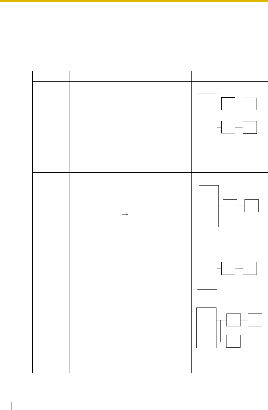
1.10 Conversation Features
126 Feature Guide
1.10.9 Parallelled Telephone
Description
Multiple telephones can be connected to the same port. This is useful to increase the number
of telephones without additional extension cards. The combinations and features of the
parallelled telephones are described below.
Features Descriptions Connections
Parallel
Mode Parallel connection allows the connection of an
SLT to an APT or a DPT that is connected to a
Super Hybrid port.
When parallel mode is enabled, the two
telephones function as follows:
• Both share one extension number
(main telephone’s extension number).
• Either telephone can make or answer
a call.
• If one goes off-hook while the other is
on a call, the call is switched to the
former.
EXtra Device
Port (XDP)
Mode
XDP mode can be used when the main
telephone in a parallel connection is a DPT
connected to a Super Hybrid port.
Unlike parallel mode, each telephone can act
as a completely different extension with its own
extension number. ( 2.1.1 Extension Port
Configuration)
Digital XDP The Digital XDP allows two DPTs to be
connected together when one of them is
connected to the following port:
• a DPT or Super Hybrid port (with the
KX-TDA30/KX-TDA100/KX-TDA200)
• a Super Hybrid port (with the KX-
TDA15)
The DPT that is connected directly to the PBX
is called the "master DPT", and the DPT
connected to the master is the "slave DPT".
Like XDP mode, each telephone can act as a
completely different extension with its own
extension number.
In addition to a slave DPT, the master DPT
(connected to a Super Hybrid port) can have an
SLT in parallel or XDP mode.
PBX
APT/DPT + SLT
SLT
DPT
Extn. 101 Extn. 101
APT
Extn. 102 Extn. 102
SLT
DPT + SLT
PBX
SLT
DPT
Extn. 101 Extn. 105
PBX
DPT + DPT
DPT
Extn. 101 Extn. 201
DPT
Master Slave
PBX
DPT
Extn. 101 Extn. 201
SLT
Extn. 101 (in Parallel Mode)
or
Extn. 105 (in XDP Mode)
DPT
Master Slave
DPT + DPT + SLT
Deleted: the

1.10 Conversation Features
Feature Guide 127
Conditions
[APT + SLT]
• If one telephone goes off-hook while the other is on a call, a three-party call is established.
If one user goes on-hook, the other user continues the call.
• An extension user cannot originate a call from the SLT if the APT is:
• The SLT will always ring for incoming calls (if its ringer is turned on). It cannot be
programmed to not ring.
[DPT + SLT]
• When in the parallel mode, the XDP mode of the Super Hybrid port should be off through
system programming.
• Whether the SLT rings for incoming calls is programmable.
Ring on: Both telephones ring except when the PT is in Hands-free Answerback mode
( 1.4.1.4 Hands-free Answerback) or voice-calling mode (Alternate Receiving Ring/
Voice) ( 1.5.3 Intercom Call).
Ring off: Only the PT rings. However, the SLT can answer the call.
• If one goes off-hook while the other is on a call, the call is switched to the former. However,
the call will not be switched in one of the following conditions:
a) While being monitored by another extension. ( 1.5.3 Intercom Call)
b) While receiving OHCA ( 1.7.4.3 Off-hook Call Announcement (OHCA)) or Whisper
OHCA. ( 1.7.4.4 Whisper OHCA)
c) During a Conference call ( 1.13.1 Conference Features).
d) While Live Call Screening (LCS) or Two-way Record is activated ( 1.23.3 Voice Mail
DPT (Digital) Integration).
Wireless
XDP Parallel
Mode
For this connection, refer to the Wireless XDP
Parallel mode feature. ( 1.24.5 Wireless XDP
Parallel Mode)
– playing background music (BGM)
– receiving a paging announcement over the built-in speaker.
Features Descriptions Connections
PBX
PS
PT
APT/DPT/SLT + PS
PS
SLT
Extn. 101
Extn. 101
Extn. 102
Extn. 102

1.10 Conversation Features
128 Feature Guide
[DPT + DPT]
•Available Telephones
KX-T7600 series (except KX-T7640)
•KX-TDA30/KX-TDA100/KX-TDA200 only
Digital XDP connection enables the maximum number of DPTs that the PBX supports to
be increased. This increase is only available when (1) the MEC card is installed and (2) a
high-capacity power supply unit (with the KX-TDA100/KX-TDA200) is installed or an
additional AC adaptor (with the KX-TDA30) is connected.
•KX-TDA15 only
Digital XDP connection is available only for a DPT that is connected to a Super Hybrid
port.
• When using Digital XDP connection, the following features cannot be used with the DPTs:
a) OHCA: A call waiting tone will be heard even if the OHCA feature is set.
b) USB Module: The DPTs will not work correctly if a USB Module is connected. Do not
connect USB Modules to the DPTs.
Note
Even if the slave DPT is disconnected, the OHCA feature and USB Module still cannot be
used with the master DPT. To use them, the DPT must be disconnected from the PBX, and
then reconnected.
[DPT + DPT + SLT]
• When an SLT is connected to the slave DPT in parallel mode, the SLT works as the parallel
extension of the master DPT.
Installation Manual References
Installation Manual
<KX-TDA100/KX-TDA200>
2.3.2 MEC Card
2.7.2 Parallel Connection of the Extensions
2.7.3 Digital EXtra Device Port (Digital XDP) Connection
<KX-TDA15/KX-TDA30>
6.5.6 MEC Card
6.6.2 Parallel Connection of the Extensions
6.6.3 Digital EXtra Device Port (Digital XDP) Connection
User Manual References
User Manual
1.7.11 Setting the Parallelled Telephone to Ring (Parallelled Telephone)

1.10 Conversation Features
Feature Guide 129
1.10.10 Calling Party Control (CPC) Signal Detection
Description
The Calling Party Control (CPC) signal is an on-hook indication (disconnect signal) sent from
the analogue trunk when the other party is hung up. To maintain efficient utilisation of trunks,
the PBX monitors their state and when CPC signal is detected from a line, the PBX disconnects
the line and alerts the extension with reorder tone.
Conditions
• CPC signal detection is programmable for incoming trunk calls ( LCOT CPC Signal
Detection Time—Incoming [414]), and for outgoing trunk calls ( LCOT CPC Signal
Detection Time—Outgoing [413]).
• If your telephone company sends signals similar to CPC, it is recommended not to enable
CPC signal detection on outgoing trunk calls.
• If CPC signal is detected during a Conference call ( 1.13.1.2 Conference), the line is
disconnected. The remaining parties stay connected.
• If CPC signal is detected during a call between a caller using the DISA feature ( 1.16.6
Direct Inward System Access (DISA)) and an extension or an outside party, the line is
disconnected.
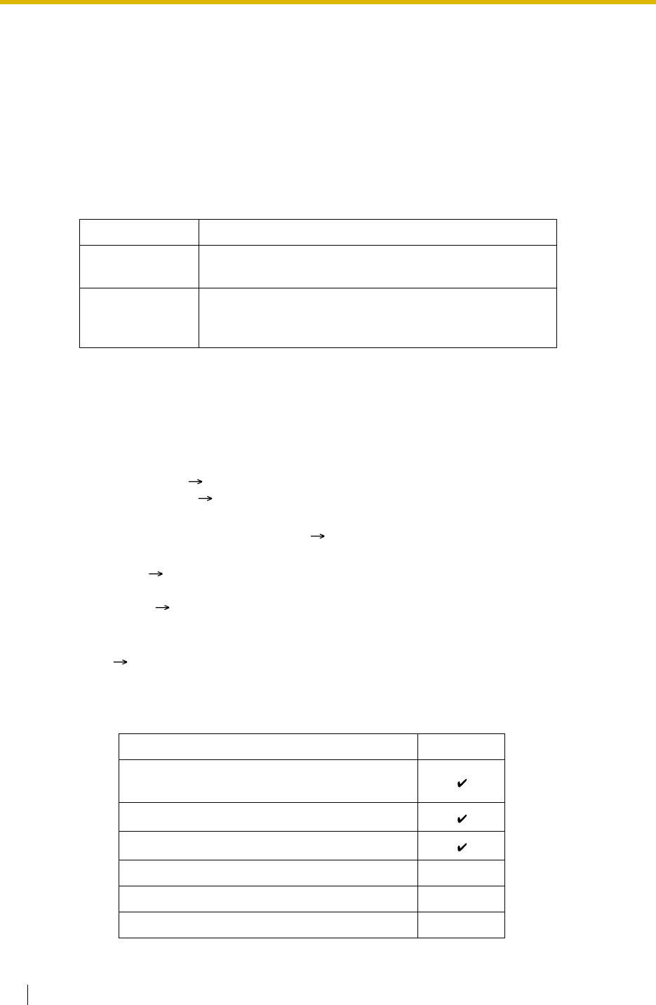
1.11 Transferring Features
130 Feature Guide
1.11 Transferring Features
1.11.1 Call Transfer
Description
An extension user can transfer a call to another extension or an outside party. The following
features are available:
Call Transfer with Announcement is also known as Call Transfer—Screened.
Call Transfer without Announcement is also known as Call Transfer—Unscreened.
Conditions
• If Music on Hold is enabled, music can be sent to the held party while the call is
transferred. ( 1.12.4 Music on Hold) It is programmable whether a ringback tone or
music is sent ( Music for Transfer [712]).
• If the transfer destination extension has set FWD to an outside party, the call will be
transferred to the outside party. ( 1.3.1.2 Call Forwarding (FWD))
• COS programming determines the extensions that are able to transfer a call to an outside
party ( Call Transfer to Trunk [503]). COS can also prohibit transferring to an extension
of another PBX via the TIE line service using the PBX Code method (Access with PBX
Code) ( 1.28.1 TIE Line Service).
•Transfer Recall for Call Transfer without Announcement
If the transfer destination does not answer within the preprogrammed Transfer Recall time
( Transfer Recall Time [201]), the call will be redirected to the Transfer Recall destination
assigned to the extension which transferred the call. If the destination is not assigned, the
call will return to the extension.
[Available destination]
Feature Transferring method
With
Announcement Transfer is completed after announcing the destination
party.
Without
Announcement
Transfer is completed without an announcement.
After dialling the destination, while hearing a ringback
tone, the originator can replace the handset.
Destination Availability
Wired Extension (PT/SLT/ISDN Extension/T1-
OPX)
PS
Incoming Call Distribution Group
PS Ring Group
VM Group (DTMF/DPT)
External Pager (TAFAS)

1.11 Transferring Features
Feature Guide 131
•One-touch Transfer
The DSS Console and the PT user can hold a call and quickly transfer it to an extension
by pressing the DSS button directly. A One-touch Dialling button can also be used if the
TRANSFER command is stored with a number ( 1.6.1 Memory Dialling Features).
User Manual References
User Manual
1.4.1 Transferring a Call (Call Transfer)
DISA
Analogue/ISDN Remote Maintenance
Idle Line Access no. + Phone no.
Trunk Group Access no. + Trunk Group no. +
Phone no.
Other PBX Extension (TIE with no PBX Code)
Other PBX Extension (TIE with PBX Code)
Destination Availability

1.12 Holding Features
132 Feature Guide
1.12 Holding Features
1.12.1 Call Hold
Description
An extension user can put a call on hold. The following features are available depending on the
result.
The result of the holding operation can be determined through system programming. Pressing
the HOLD button again just after the first time alternates the mode between General and
Exclusive Call Hold.
Conditions
• A PT user can hold an intercom call and multiple trunk calls simultaneously. An SLT user
can hold either an intercom call or a trunk call. To hold multiple intercom calls on a PT
simultaneously, use the Call Park feature ( 1.12.2 Call Park). Call Park feature can also
be used to hold multiple intercom calls and/or trunk calls simultaneously on an SLT.
•Music on Hold
Music, if available, is sent to the held party. ( 1.12.4 Music on Hold)
•Hold Recall
If a call on hold is not retrieved within a preprogrammed time period ( Hold Recall Time
[200]), Hold Recall is heard at the extension which put the call on hold. If the extension is
engaged in a call, the Hold Alarm will be heard.
• If an outside party is placed on hold and not retrieved within a preprogrammed time period,
the call is automatically disconnected. This timer starts when Hold Recall activates.
•Automatic Call Hold
A PT user can be programmed holding of the current call when pressing another CO/ICD
Group/INTERCOM button, through system programming. If this feature is not enabled, the
current call will be disconnected.
[Example]
It is possible to receive a call by pressing the flashing ICD Group button, this puts the
current intercom call (on the INTERCOM button) on hold. To return to the held call, press
the INTERCOM button.
•Call Hold Retrieve Deny
If an extension user cannot call certain extensions on a COS basis ( 1.1.2.2 Internal Call
Block), he cannot retrieve the held call which the extensions made.
•SLT Hold Mode
It is possible to choose how to hold a line and transfer a call with an SLT in the following
methods through system programming:
Feature Description
Call Hold General Any extension can retrieve a held call.
Exclusive Call Hold Only the extension user who held the call can retrieve it.

1.12 Holding Features
Feature Guide 133
If the following occurs frequently with an SLT, choose "Mode 2", "Mode 3", or "Mode 4":
a) When an SLT user receives a call, reorder tone is heard or nobody answers the
call.
b) When an SLT user goes off-hook, reorder tone is heard instead of a dial tone.
If a call is not terminated after going on-hook, the above cases occur. To avoid these
problems, choose "Mode 2", "Mode 3", or "Mode 4". Every call will be terminated unless
the Hold feature number is entered after flashing the hookswitch in Mode 2, Mode 3, and
Mode 4.
• Hold Alarm tone pattern has a default. ( 4.2.1 Tones/Ring Tones).
User Manual References
User Manual
1.4.2 Holding a Call
Hold Transfer to Trunk Transfer to Extension
Mode 1
Flashing the hookswitch
+
Going on-hook
Flashing the hookswitch
+
Trunk Access No.
Flashing the hookswitch
+
Extension No.
Mode 2
(Default)
Flashing the hookswitch
+
Hold Feature No.
+
Going on-hook
Flashing the hookswitch
+
Trunk Access No.
Flashing the hookswitch
+
Extension No.
Mode 3
Flashing the hookswitch
+
Hold Feature No.
+
Going on-hook
Flashing the hookswitch
+
Hold Feature No.
+
Trunk Access No.
Flashing the hookswitch
+
Extension No.
Mode 4
Flashing the hookswitch
+
Hold Feature No.
+
Going on-hook
Flashing the hookswitch
+
Hold Feature No.
+
Trunk Access No.
Flashing the hookswitch
+
Hold Feature No.
+
Extension No.

1.12 Holding Features
134 Feature Guide
1.12.2 Call Park
Description
An extension user can place a call into a common parking zone of the PBX. The Call Park
feature can be used as a transferring feature; this releases the user from the parked call to
perform other operations. The parked call can be retrieved by any extension user.
Conditions
•Automatic Call Park
It is possible to select an idle parking zone automatically.
•Retry
If the specified parking zone is occupied or there is no vacant zone for Automatic Call Park,
the originator will hear a busy tone. Retrying is possible while hearing the busy tone by
selecting parking zone or a vacant zone.
•Call Park Recall
If a parked call is not retrieved within a preprogrammed time period, Call Park Recall will
be heard at the Transfer Recall destination assigned to the extension which parked the
call. If the destination is engaged in a call, the Hold Alarm will be heard.
• If a parked trunk call is not retrieved within a preprogrammed time period (Default: 30
minutes), it is automatically disconnected.
•Call Park Button
Pressing the Call Park button parks or retrieves a call in a preset parking zone.
A flexible button can be customised as the Call Park button. It shows the current status of
the preset parking zone as follows:
•Call Park (Automatic Park Zone) Button
Pressing the Call Park (Automatic Park Zone) button parks a call in an idle parking zone
automatically. A flexible button can be customised as the Call Park (Automatic Park Zone)
button.
•Call Park Retrieve Deny
If an extension user cannot call certain extensions on a COS basis ( 1.1.2.2 Internal Call
Block), he cannot retrieve the parked call which the extensions made.
Feature Guide References
1.19.2 Flexible Buttons
User Manual References
User Manual
1.4.2 Holding a Call
Light pattern Status
Slow red flashing Parked in the preset parking zone
Off No parked call

1.12 Holding Features
Feature Guide 135
1.12.3 Call Splitting
Description
An extension user can alternate between two other parties. Placing the current call on hold
allows the user to have a conversation with the other party.
Conditions
• While having a conversation with one party, the other party is in Consultation Hold.
(Consultation Hold: Allows an extension user to place a call on hold temporarily to
perform Call Transfer, Conference, or Call Splitting.)
User Manual References
User Manual
1.4.3 Talking to Two Parties Alternately (Call Splitting)

1.12 Holding Features
136 Feature Guide
1.12.4 Music on Hold
Description
Music can be played to any party on hold. The following music sources are available:
a) Internal music source
b) External music source
c) Cyclic tone
[KX-TDA100/KX-TDA200]
BGM number (1 or 2) or cyclic tone can be selected for the Music on Hold ( Music on Hold
[711]).
BGM numbers are the same as the external music port numbers (e.g., External music port 1
is BGM1.) However BGM2 includes internal music sources 1 and 2 as well as external music
port 2. It is possible to choose what music source will be used as BGM2 ( Music Source
Selection for BGM (with the KX-TDA15/KX-TDA30)/BGM2 (with the KX-TDA100/KX-TDA200)
[710]).
[BGM Number and the Music Source]
[KX-TDA15/KX-TDA30]
BGM or cyclic tone can be selected for the Music on Hold ( Music on Hold [711]).
BGM includes internal music sources 1, 2 and external music port. It is possible to choose what
music source will be used as BGM ( Music Source Selection for BGM (with the KX-TDA15/
KX-TDA30)/BGM2 (with the KX-TDA100/KX-TDA200) [710]).
Conditions
•Hardware Requirement: User-supplied music source
•Volume Control
It is possible to change the volume of an internal and/or external music source.
• It is possible to choose a different music source for each tenant. ( 2.2.3 Tenant Service)
Installation Manual References
Installation Manual
<KX-TDA100/KX-TDA200>
2.11.1 Connection of Peripherals
<KX-TDA15/KX-TDA30>
6.10.1 Connection of Peripherals
BGM No. Music Source
1External music port 1
2External music port 2/Internal music source 1 or 2

1.13 Conference Features
Feature Guide 137
1.13 Conference Features
1.13.1 Conference Features
1.13.1.1 Conference Features—SUMMARY
Description
A conference call allows a conversation between three or more parties simultaneously. The
following features are available to establish a conference call:
Conditions
• One PBX supports a maximum of 32 simultaneous calls which are engaged in conference
calls. (e.g., 4 eight-party conferences, 8 three-party conferences + 2 four-party
conferences, 10 three-party conferences)
Feature Description Details in
Conference During a two-party conversation, an extension user can
add other parties to establish a conference call with up
to eight parties.
• 1.13.1.2
Conference
Executive Busy
Override An extension user can interrupt an existing call to
establish a three-party conference call. • 1.7.2
Executive
Busy
Override
Privacy Release During a conversation with an outside party on the S-
CO button, a PT/PS user can allow another extension to
join the conversation.
• 1.13.1.3
Privacy
Release

1.13 Conference Features
138 Feature Guide
1.13.1.2 Conference
Description
This PBX supports three through eight-party conference calls. During a two-party
conversation, an extension user can add other parties to their conversation, thereby
establishing a conference. More than four-party conferences are only possible when a PT user
originates the conference.
Unattended Conference:
A PT user can leave a conference to allow other parties to continue the conversation. The user
may return to the conference, if he desires.
Conditions
•CONF (Conference) Button
For a PT which does not have the CONF button, a flexible button can be customised as
the Conference button.
•Unattended Conference Call Duration
The call duration can be restricted by the Unattended Conference Recall time. The
Unattended Conference Recall time consists of the following programmable timers:
a) Unattended Conference Recall Start Time:
When the timer expires, Unattended Conference Recall starts to be heard at the
conference originator. If the originator does not return to the conference, 1st
Unattended Conference Recall Continuation time will start.
b) 1st Unattended Conference Recall Continuation Time:
When the timer expires, an alarm tone starts to be heard at parties in the Unattended
Conference. If the originator does not return to the conference, 2nd Unattended
Conference Recall Continuation time will start.
c) 2nd Unattended Conference Recall Continuation Time:
When the timer expires, the Unattended Conference call is disconnected.
If the originator returns to the conference before the Unattended Conference call is
disconnected, the timer will be cancelled. If not, Unattended Conference Recall and an
alarm tone will continue to be emitted until the Unattended Conference call is
disconnected.
•For Six or More Party Conference
The ECHO card is required. Also the Echocanceller should be enabled through system
programming.
Installation Manual References
Installation Manual
<KX-TDA100/KX-TDA200>
2.6.4 ECHO16 Card
<KX-TDA15/KX-TDA30>
6.5.3 ECHO8 Card
Feature Guide References
1.19.2 Flexible Buttons

1.13 Conference Features
Feature Guide 139
User Manual References
User Manual
1.4.5 Multiple Party Conversation

1.13 Conference Features
140 Feature Guide
1.13.1.3 Privacy Release
Description
By default, all conversations which take place on trunk, extension lines and doorphone lines
are protected by privacy (Automatic Privacy).
Privacy Release allows a PT/PS user to suspend Automatic Privacy for an existing trunk call
on the S-CO button in order to establish a three-party call.
System programming is required to enable or disable this feature.
Conditions
•S-CO Button
A flexible button can be customised as the S-CO button.
•Privacy Release Time
Privacy is released for five seconds to allow the conversation to be joined.
• This feature overrides Data Line Security ( 1.10.5 Data Line Security) and Executive
Busy Override Deny ( 1.7.2 Executive Busy Override).
Feature Guide References
1.19.2 Flexible Buttons
User Manual References
User Manual
1.4.5 Multiple Party Conversation
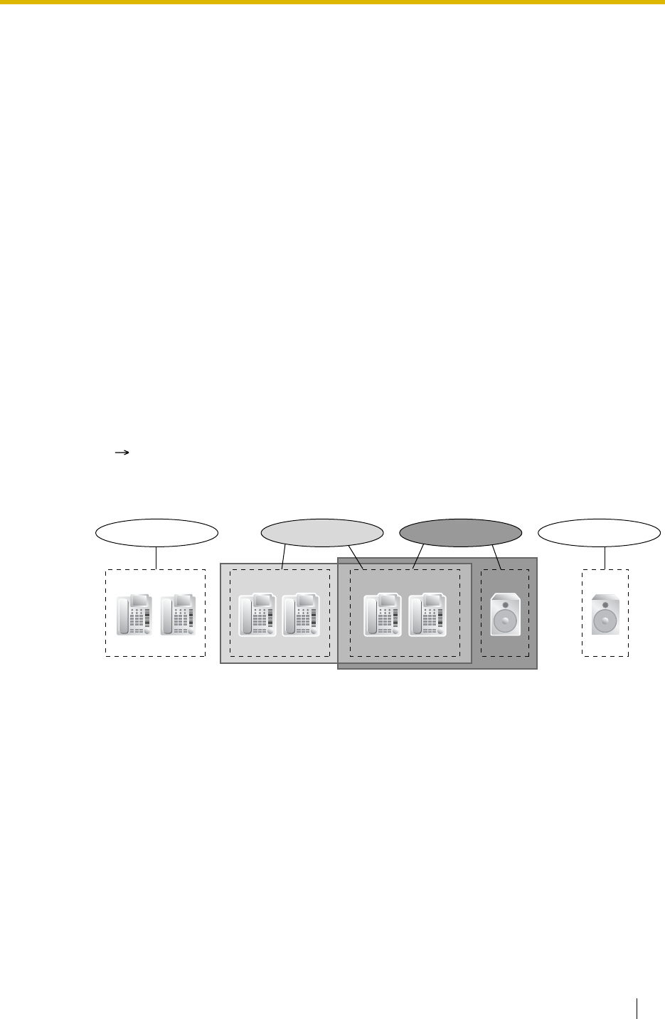
1.14 Paging Features
Feature Guide 141
1.14 Paging Features
1.14.1 Paging
Description
An extension user can make a voice announcement to many people simultaneously.
The message is announced over the built-in speakers of PT and/or external speakers (external
pagers) which belong to the paging group. (With the KX-TDA100/KX-TDA200, up to two
external pagers can be connected; with the KX-TDA15/KX-TDA30, one external pager can be
connected.)
The paged person can answer the page from a nearby telephone.
It is possible to page with a call on hold in order to transfer the call.
Paging Deny:
It is possible to deny being paged on an extension basis.
Paging Group
Each paging group consists of user groups and external pagers. One user group or
external pager can belong to several paging groups.
( 2.2.2 Group)
[Example]
User Group 1
Paging Group 01
Extn. 100 Extn. 101
User Group 2
Extn. 102 Extn. 103
User Group 3
Extn. 104 Extn. 105 Pager 2Pager 1
Paging Group 04Paging Group 02 Paging Group 03

1.14 Paging Features
142 Feature Guide
[Programming Example]
Conditions
• Extensions which cannot be paged are:
These extensions cannot be paged but can answer the page.
•External Pager Priority
External pagers can be used with the following priorities:
TAFAS Paging BGM
( 1.16.3 Trunk Answer From Any Station (TAFAS), 1.16.4 Background Music (BGM))
•Volume Control
Paging volume from the PTs and the external pagers can be changed through system
programming.
•Paging DND
When DND ( 1.3.1.3 Do Not Disturb (DND)) is set for incoming calls, it is programmable
whether your extension receives paging through system programming.
User Manual References
User Manual
1.6.1 Paging
1.6.2 Answering/Denying a Paging Announcement
Paging Group
No.
User Group No.*1 External Pager No.*2
001 002 003 ... 1 2
01 ...
02 ...
03 ...
04 ...
05 ...
: :::...: :
:Constituent
*1: User Groups of a Paging Group [640]
*2: External Pagers of a Paging Group [641]
–PSs
–SLTs
– Ringing or busy PTs
– PTs in Paging Deny mode
– PTs in Paging DND mode
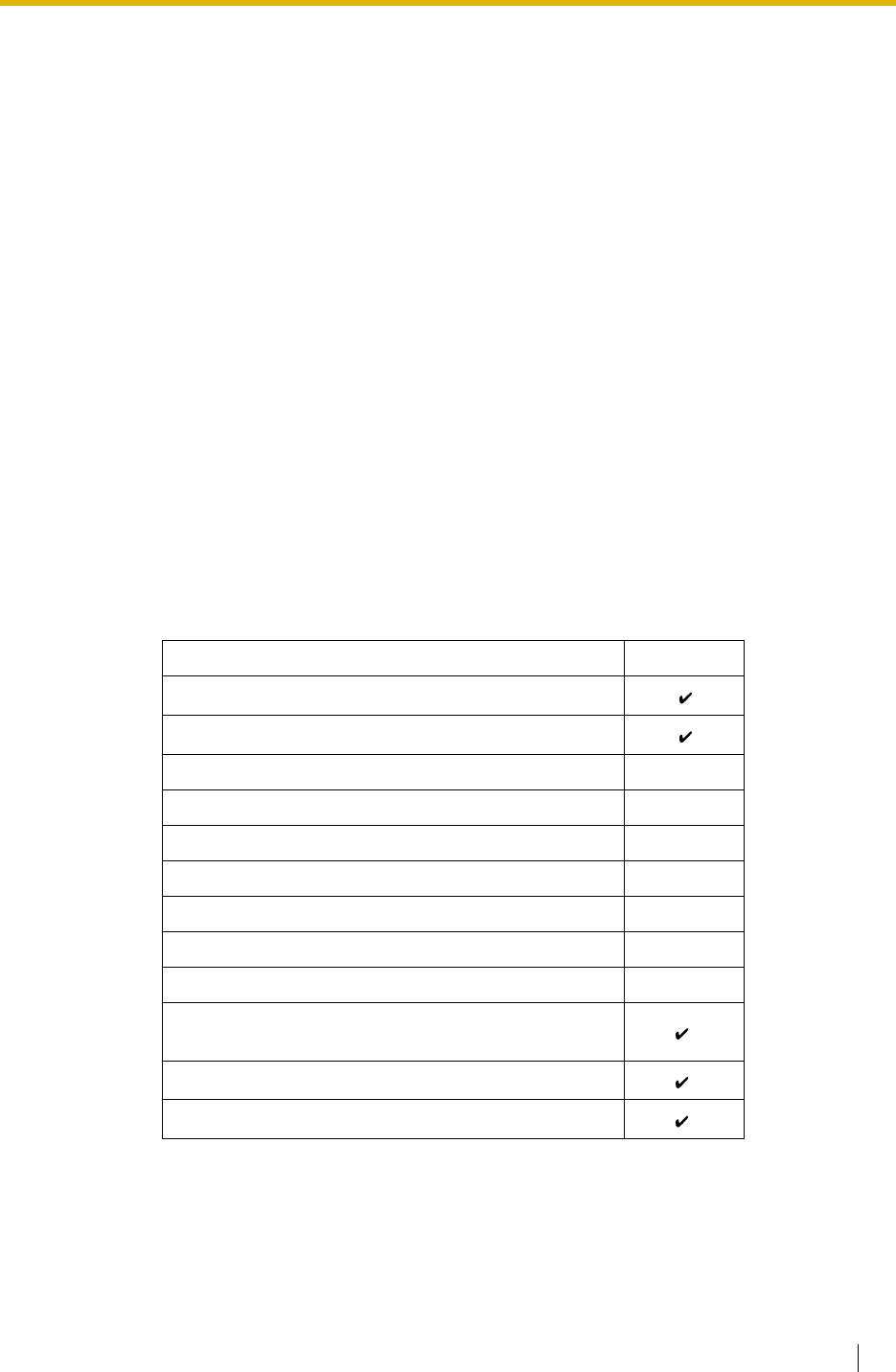
1.15 Broadcasting Features (KX-TDA30/KX-TDA100/KX-TDA200 only)
Feature Guide 143
1.15 Broadcasting Features (KX-TDA30/KX-
TDA100/KX-TDA200 only)
1.15.1 Broadcasting (KX-TDA30/KX-TDA100/KX-TDA200
only)
Description
A PT user can call multiple parties, assigned as members of a group (broadcasting group), to
make a voice announcement. After one member answers the call, the caller can begin to make
an announcement. Other members' telephones will continue to ring, and each member can
listen to the announcement by answering the call. The caller will hear a confirmation tone every
time the members answer the call.
During the announcement, the voices of members will not be heard. However, the caller can
allow specific members to speak, making a conference call. A maximum of four-party
conference call can be established. This conversation can be heard by the other members.
Broadcasting Group
There are eight broadcasting group, and a maximum of 31 members can be assigned to
each group. The available destinations as members of the broadcasting group are as
follows:
*: Only available when the networking type of the trunk is assigned as private.
Conference Call
The caller can allow members to speak, and can control the conversation using the following
buttons. Pressing the other buttons during the conversation will be ignored.
Destination Availability
Wired Extension (PT/SLT/ISDN Extension/T1-OPX)
PS
Incoming Call Distribution Group
PS Ring Group
VM Group (DTMF/DPT)
External Pager (TAFAS)
DISA
Analogue/ISDN Remote Maintenance
Idle Line Access no. + Phone no.
Trunk Group Access no. + Trunk Group no. +
Phone no. *
Other PBX Extension (TIE with no PBX Code) *
Other PBX Extension (TIE with PBX Code) *

1.15 Broadcasting Features (KX-TDA30/KX-TDA100/KX-TDA200 only)
144 Feature Guide
A member extension can inform to the caller that he wants to speak or join the conversation by
sending a notification. The caller will hear a notification tone and the requesting extension’s
information will be shown on the display for five seconds.
Conditions
•Hardware Requirement: The MEC card
• COS programming determines the extensions (PTs only) that can use this feature.
•Ring Duration
A system timer is available to limit the call ring duration at the members. When this limit is
reached, members' telephones will stop ringing. If no members have answered the call,
the caller will hear a busy tone.
• The broadcasting call will reach a member extension regardless of settings such as Call
Forwarding (except DND).
• If a member extension is busy and has Call Waiting for trunk calls activated when a
broadcasting call is made, a call waiting tone will be sent to the extension.
• The call information of the caller (not members) will be recorded on the SMDR.
• A caller cannot make a broadcasting call with a call on hold.
• Call Pickup is not available for a broadcasting call. ( 1.4.1.3 Call Pickup)
• The broadcasting call will not reach members when:
Installation Manual References
Installation Manual
<KX-TDA100/KX-TDA200>
2.3.2 MEC Card
<KX-TDA15/KX-TDA30>
6.5.6 MEC Card
Button Function
DSS Establishes a conversation with the corresponding member
extension, or remove the extension from the conversation.
CONF (Conference) Establishes a conversation with the current members in the order
assigned in the broadcasting group. Pressing this button again
will add the next available member in the group to the
conversation.
TRANSFER Removes the member who joined the conversation last. The
member can still listen to the announcement.
FLASH/RECALL
(Flash/Recall mode) Removes the member who joined the conversation last. The
member will be disconnected from the broadcasting call and hear
a reorder tone.
SP-PHONE Enables a hands-free conversation.
– the member extension has set DND for intercom calls.
– the member extension is a PS in Wireless XDP Parallel Mode. ( 1.24.5
Wireless XDP Parallel Mode)

1.15 Broadcasting Features (KX-TDA30/KX-TDA100/KX-TDA200 only)
Feature Guide 145
User Manual References
User Manual
1.6.3 Making an Announcement and Having a Multiple Party Conversation
(Broadcasting)(KX-TDA30/KX-TDA100/KX-TDA200 only)

1.16 Optional Device Features
146 Feature Guide
1.16 Optional Device Features
1.16.1 Doorphone Call
Description
A visitor using a doorphone will call a preprogrammed destination (extension or outside party).
Extension users can call a doorphone.
Conditions
•Hardware Requirement:
KX-TDA100/KX-TDA200: An optional Doorphone, the OPB card and DPH card
KX-TDA15/KX-TDA30: An optional Doorphone and the DPH card
• Each doorphone port must be assigned to one tenant. The Time Table (day/lunch/break/
night) of the tenant applies. ( 2.2.4 Time Service)
•Call Destination
The incoming doorphone call destination(s) can be assigned for each time mode (day/
lunch/break/night) for each doorphone port ( Doorphone Call Destination [720]).
Destinations can be selected. ( 1.1.2.1 Internal Call Features—SUMMARY)
• COS programming determines the doorphone ports that are able to make an outgoing
trunk call.
• Internal Call Block determines which extensions can call a doorphone. ( 1.1.2.2 Internal
Call Block)
•Ring Duration
If an incoming call is not answered within a preprogrammed time period, ringing stops and
the call is cancelled.
•Call Duration
The call duration can be restricted by a system timer. If the timer expires, the call will be
disconnected.
•Door Open
While engaged on a doorphone call, the extension user can unlock the door to let the
visitor in. ( 1.16.2 Door Open)
• A doorphone number can be referenced for each doorphone port ( Doorphone Number
Reference [729]).
•KX-TDA15/KX-TDA30 only
Doorphones 1 and 2 (or 3 and 4) cannot make a call simultaneously. If a visitor presses
the doorphone button while the other doorphone is engaged in a call, he will hear no tone.
Doorphones 1 and 2 (or 3 and 4) cannot receive a call simultaneously. If an extension user
calls a doorphone while the other doorphone is engaged in a call, he will hear a busy tone.
Installation Manual References
Installation Manual
<KX-TDA100/KX-TDA200>
2.6.1 OPB3 Card
2.6.2 DPH4 Card
2.6.3 DPH2 Card

1.16 Optional Device Features
Feature Guide 147
2.10.1 Connection of Doorphones and Door Openers
<KX-TDA15/KX-TDA30>
6.5.1 DPH4 Card
6.5.2 DPH2 Card
6.9.1 Connection of Doorphones and Door Openers
User Manual References
User Manual
1.9.1 If a Doorphone/Door Opener is Connected

1.16 Optional Device Features
148 Feature Guide
1.16.2 Door Open
Description
An extension user can unlock the door for a visitor using his telephone.
The door can be unlocked by extension users who are allowed to unlock the door in the COS
programming ( Permission for Door Open Access [512]). However, while engaged on a
doorphone call, any extension user can unlock the door to let the visitor in ( 1.16.1
Doorphone Call).
Conditions
•Hardware Requirement: A user-supplied door opener on each door.
• The door opener will unlock the door even if a doorphone is not installed.
•Door Open Duration
The door can remain unlocked for a preprogrammed time period ( Door Open Duration
Time [207]).
Installation Manual References
Installation Manual
<KX-TDA100/KX-TDA200>
2.10.1 Connection of Doorphones and Door Openers
<KX-TDA15/KX-TDA30>
6.9.1 Connection of Doorphones and Door Openers
User Manual References
User Manual
1.9.1 If a Doorphone/Door Opener is Connected

1.16 Optional Device Features
Feature Guide 149
1.16.3 Trunk Answer From Any Station (TAFAS)
Description
A ring tone is sent through the external pager when an incoming call is received. Any extension
user can answer the call.
Conditions
•Hardware Requirement: A user-supplied external pager
•Floating Extension Number
A floating extension number can be assigned for an external pager ( External Pager
Floating Extension Number [700]). It is possible to access an external pager by dialling
their floating extension numbers.
•Pager Volume
It is possible to change the volume of an external pager through system programming.
Installation Manual References
Installation Manual
<KX-TDA100/KX-TDA200>
2.11.1 Connection of Peripherals
<KX-TDA15/KX-TDA30>
6.10.1 Connection of Peripherals
User Manual References
User Manual
1.3.4 Answering a Call via an External Speaker (Trunk Answer From Any Station [TAFAS])

1.16 Optional Device Features
150 Feature Guide
1.16.4 Background Music (BGM)
Description
A PT user can listen to BGM through the built-in speaker while on-hook and idle.
BGM—External:
BGM can also be broadcast in the office through the external pagers, this can be turned on and
off by an extension assigned as the manager.
Conditions
[BGM]
•Hardware requirement: A user-supplied external music source, such as a radio
• The music through the PT is interrupted when going off-hook.
•KX-TDA100/KX-TDA200 only
Each user can set/cancel BGM, and also select the music source.
•KX-TDA15/KX-TDA30 only
Each user can only set/cancel BGM; the user cannot make a music selection.
[BGM—External]
•Hardware requirement: A user-supplied external pager
• External pagers can be used with the following priorities:
TAFAS Paging BGM
( 1.14.1 Paging, 1.16.3 Trunk Answer From Any Station (TAFAS))
Installation Manual References
Installation Manual
<KX-TDA100/KX-TDA200>
2.11.1 Connection of Peripherals
<KX-TDA15/KX-TDA30>
6.10.1 Connection of Peripherals
User Manual References
User Manual
1.7.8 Turning on the Background Music (BGM)
2.1.4 Turning on the External Background Music (BGM)
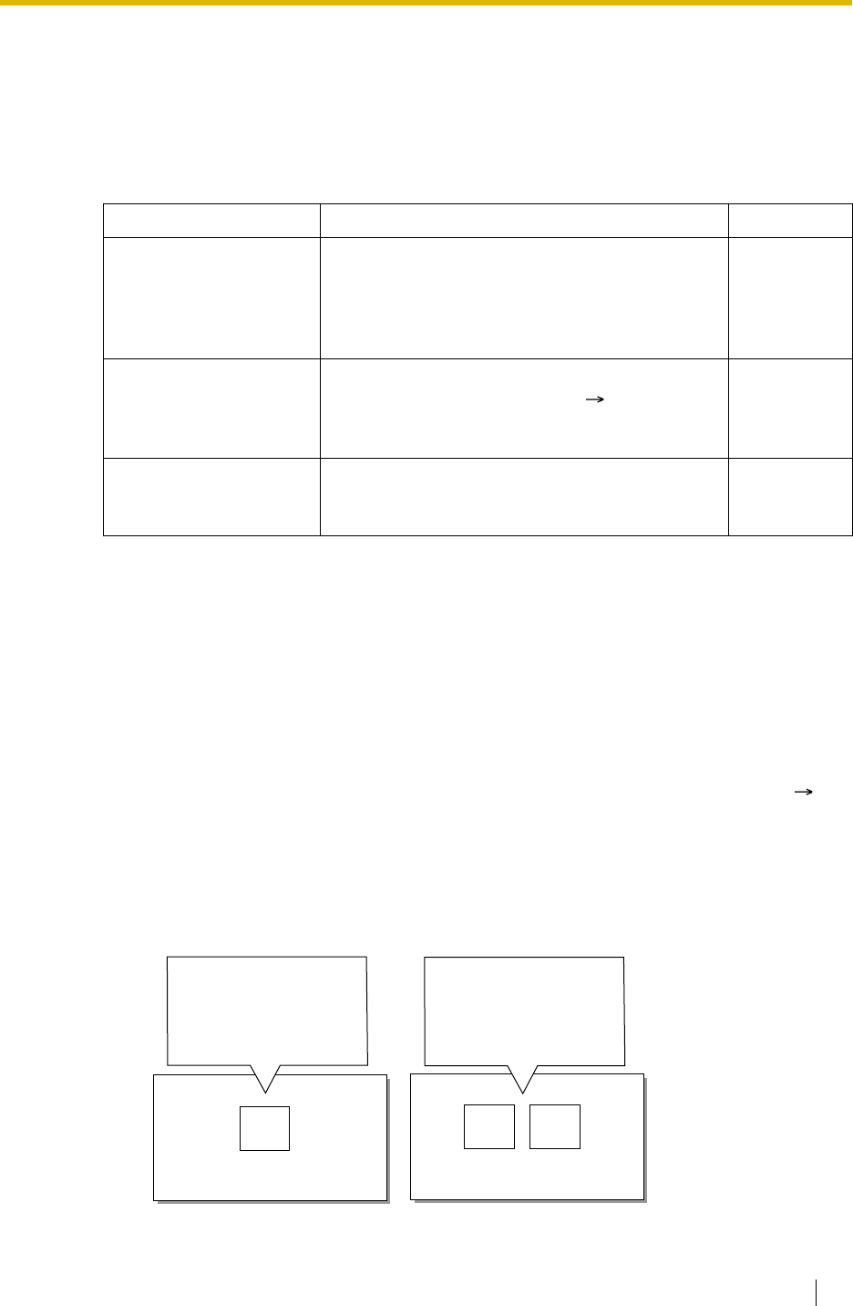
1.16 Optional Device Features
Feature Guide 151
1.16.5 Outgoing Message (OGM)
Description
An extension assigned as the manager (manager extension) can record outgoing messages
(OGMs) for the following features:
Conditions
•Hardware Requirement:
KX-TDA100/KX-TDA200: The OPB card and MSG card
KX-TDA15/KX-TDA30: The MSG card
•The Number of Messages and the Recording Time
A maximum of 64 (with the KX-TDA100/KX-TDA200) or 32 (with the KX-TDA15/KX-
TDA30) messages can be recorded. The recording time per message is a maximum of
one minute. However the total recording time in the PBX is 8 minutes.
• A floating extension number can be assigned to each outgoing message (OGM) (
Outgoing Message (OGM) Floating Extension Number [730]).
• One MSG card allows 4 (with the KX-TDA100/KX-TDA200) or 2 (with the KX-TDA15/KX-
TDA30) messages to play simultaneously. The MSG card expansion does not increase the
total recording time or the number of messages. It increases the number of messages that
can be played simultaneously.
[Example]
Feature Usage Details in
Direct Inward System
Access (DISA) When a call arrives on a DISA line, the caller will
hear a message. • 1.16.6 Direct
Inward
System
Access
(DISA)
Queuing Feature If assigned in the Queuing Time Table of the
incoming call distribution group ( Sequences in
Queuing Time Table [631]), any caller who is
waiting in a queue will hear a message.
• 1.2.2.3
Queuing
Feature
Timed Reminder When answering the Timed Reminder Alarm, the
user will hear a message. • 1.26.4
Timed
Reminder
Up to 4 (with the KX-
TDA100/KX-TDA200) or 2
(with the KX-TDA15/KX-
TDA30) messages can be
played simultaneously to
callers.
PBX
MSG
Card
Total message recording time:
8 minutes max.
PBX
Total message recording time:
8 minutes max.
MSG
Card
MSG
Card
Up to 8 (with the KX-
TDA100/KX-TDA200) or 4
(with the KX-TDA15/KX-
TDA30) messages can be
played simultaneously to
callers.

1.16 Optional Device Features
152 Feature Guide
Note
When MSG card expansion has been completed, the new MSG card is blank—all
necessary messages will need to be stored in the card. This can be done in two ways:
a) By installing the new MSG card then recording each message again. The PBX
will automatically store the new recordings in each MSG card.
b) By transferring messages from the PBX to a personal computer (PC) using the
Maintenance Console, then transferring them back to the PBX with the new MSG
card installed.
• The same message can also be played simultaneously to multiple callers.
•Recording Methods
a) Record voice messages through the extension telephone
b) Transfer prerecorded voice messages from external sound source into the PBX via an
external music port.
Note
Record voice messages only; avoid the recording of music.
• After recording messages, a manager extension can also play them back for confirmation.
• Progress tone is sent to a manager extension before recording messages during a
preprogrammed time period, or during clearing the prerecorded message stored at the
floating extension number of desired message. The longer one is applied.
• Record a message when traffic is light (early morning or late evening).
• When the manager tries to record a message, he will hear ringback tone if a message
channel is in use. When all ports of the MSG card(s) become idle, he will hear the progress
tone for a preprogrammed time period.
After that, the PBX will automatically proceed into the recording mode.
Installation Manual References
Installation Manual
<KX-TDA100/KX-TDA200>
2.6.1 OPB3 Card
2.6.5 MSG4 Card
<KX-TDA15/KX-TDA30>
6.5.4 MSG2 Card
User Manual References
User Manual
2.1.5 Recording Outgoing Messages (OGM)

1.16 Optional Device Features
Feature Guide 153
1.16.6 Direct Inward System Access (DISA)
Description
An outside caller can access specific PBX features as if the caller is an SLT extension user on
the PBX, when the incoming call destination is a DISA floating extension number assigned to
each DISA message. The caller can have direct access to features such as:
• Placing an intercom call to an extension, operator or any floating extensions (e.g.,
modem for remote system administration, an external pager for TAFAS).
• Calling an outside party via the PBX.
• Operating some PBX remote features (e.g., FWD)
Outgoing Message (OGM)
When a call arrives on a DISA line, a prerecorded DISA message will greet and guide the
caller.
Any extension assigned as the manager can record outgoing messages (OGMs). ( 1.16.5
Outgoing Message (OGM))
DISA Intercept—No Dial
If the caller fails to dial any digits within a preprogrammed time period (DISA 1st Dial Time for
Intercept) ( DISA Intercept Time [211]) following the outgoing message (OGM), the call is
redirected to the operator extension.
DISA Built-in Automated Attendant Number (DISA AA Service)
After listening to the outgoing message (OGM), the caller may dial a single digit (DISA AA
number). The destination for each DISA AA number can be assigned for each message. It is
also possible to assign other DISA floating extension number as the destination (Multistep
DISA AA Service).
If the caller dials a second digit within a preprogrammed time period (DISA 2nd Dial Time for
AA), the DISA AA service is not employed.
DISA Security Mode and Available Features
If the DISA AA service is not employed, the caller may access the PBX features by entering
the feature numbers. To prevent others from accessing the PBX features, it is possible to
assign DISA security ( DISA Security Mode [732]). The features available depend on the
preprogrammed DISA security mode as follows:

1.16 Optional Device Features
154 Feature Guide
Note
DISA AA service and Operator Call ( 2.2.5 Operator Features) are available for any
security mode.
Security Mode Override:
If the caller operates with the following features while hearing a DISA message, the security
mode can be changed to the No Security mode temporarily:
• Walking COS ( 1.8.5 Walking COS): Walking COS feature number + extension
number + extension personal identification number (PIN)
• Verified Code Entry ( 1.8.6 Verified Code Entry): Verified Code Entry feature
number + + verified code + verified code PIN
After changing mode, the mode remains in force for the duration of the call.
Available PBX Features with Security Mode Override:
After Security Mode Override is done with the Walking COS feature, the following features are
available (It regards a remote operation from the assigned extension [ 1.26.5 Remote
Extension Control by User]):
•FWD
• DND
• Log-in/Log-out ( 1.2.2.6 Log-in/Log-out)
• Absent Message ( 1.18.2 Absent Message)
• Extension Lock ( 1.8.3 Extension Lock)
• Time Service Switching Mode ( 2.2.4 Time Service)
DISA Intercept Routing—Busy/DND
If the destination called by the outside party is busy or in DND mode, and if (1) the busy
destination does not set Call Waiting, FWD, or Idle Extension Hunting or (2) the destination is
in DND mode and Idle Extension Hunting is not available, one of the following can be selected
through system programming:
a) Busy Tone: Busy tone is sent to the caller.
Security
Mode Intercom
Call
TIE Line Call
Trunk Call
Without PBX
Code With PBX
Code
All
Security
Trunk
Security
No
Security *
:Available
*:If trunk call is available, Account Code Entry ( 1.5.4.3 Account Code Entry) is also
available.

1.16 Optional Device Features
Feature Guide 155
b) Intercept Routing: Intercept Routing—Busy/DND will work and the call will be
redirected to the preprogrammed destination.
c) Outgoing Message (OGM): An outgoing message (OGM) will be sent to the caller.
The message for busy/DND mode can be assigned for each outgoing message
(OGM) which has a DISA floating extension number.
DISA Intercept Routing—No Answer
If a destination is not available to answer a DISA call within a preprogrammed time period
(DISA Intercept time) ( DISA Intercept Time [211]) after the call is reached, the call will be
redirected to the programmed destination by the Intercept feature ( Trunk Group Intercept
Destination [470] or Extension Intercept Destination [604]).
If the intercept destination is not available to answer the call within a preprogrammed time
period (DISA Disconnect Time after Intercept) after the DISA Intercept time expires, the call
will be disconnected.
SMDR
The call information for DISA is recorded as the one of the DISA floating extension numbers.
( 1.25.1 Station Message Detail Recording (SMDR))
[Programming Example]
The following items can be assigned to each outgoing message (OGM):
Outgoing
Message
(OGM) No.
Floating
Extn.
No.*1
Automated Attendant No. Busy/DND
Message No.
0123456789
01 300 100 301 200 103 202 101 102 400 104 205 04
02 301 05
: : :::::::::: :
*1: Outgoing Message (OGM) Floating Extension Number [730]
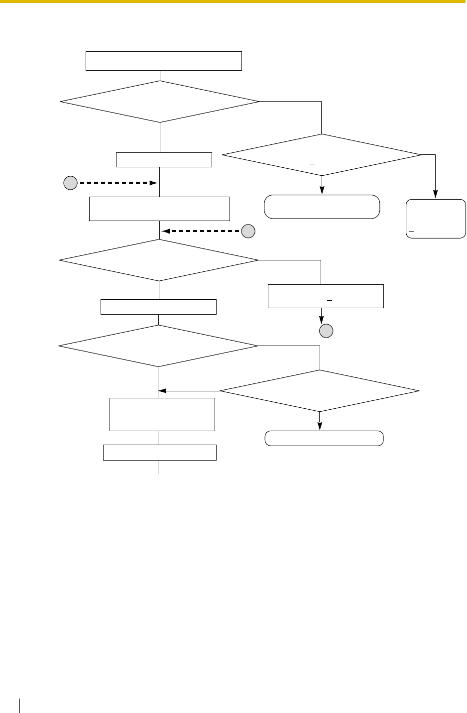
1.16 Optional Device Features
156 Feature Guide
[Flowchart]
A DISA call from an outside party is received.
No
Is there an idle port on the
MSG cards?
Does the trunk group that
received the call employ Intercept
Routing Busy DND?
Yes
No
The call is routed to the intercept
destination.
(DISA Delayed Answer Time
Time-out)
Yes
The PBX answers the call.
(DISA Mute Time
Time-out)
The outgoing message (OGM) plays and
the PBX starts to receive the DTMF signalling.
No
Is the first digit dialled?
Yes
(DISA 1st Dial Time for
Intercept Time-out)
The call is routed to the Operator.
(Intercept Routing No Destination)
The outgoing message (OGM) stops.
No
Is the second digit dialled?
Yes
(DISA 2nd Dial Time for
AA Time-out)
Is the first dialled digit assigned a
destination for the DISA AA service?
The call is routed to the destination.
Yes
The PBX receives the following
dialled digits and checks the
dialled number.
No
What is the DISA security mode?
Continued to the next page
Goes to
A
C
The call is routed
to the operator
(Intercept Routing
No Destination)
.
F
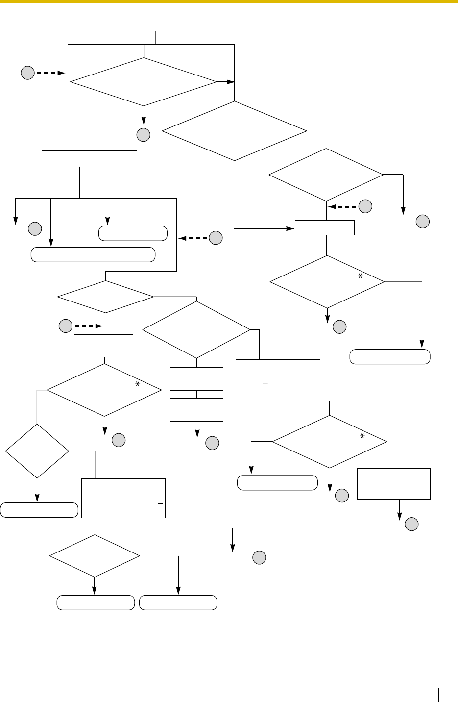
1.16 Optional Device Features
Feature Guide 157
Is the correct
personal identification number
(PIN) entered?
No
Yes
Is the extension
busy (Call Waiting
mode on) and is
not in DND mode?
Yes
No
The extension
receives the call.
The call waits
to be received.
The extension
becomes idle.
Yes
No
Goes to A
No
Yes
The call is established.
(DISA Intercept Time
Time-out)
The call is routed to the
intercept destination.
(DISA Intercept Routing
No Answer)
Does the destination
answer the call?
Does the
destination
answer
the call?
No
Yes
The call is established.
(DISA Disconnect
Time after Intercept
Time-out)
The call is disconnected.
E
Goes to E
Outgoin
g
Message
(OGM)
Intercept Routing Busy Tone
What method is assigned
for DISA Intercept
Routing Busy/DND?
(Busy Tone
Time Time-out)
Goes to
The call is disconnected.
No
A
The call is routed to
the intercept destination.
(Intercept Routing Busy/DND)
The message for
the busy/DND mode
is sent to the caller.
Yes
Goes to F
Goes to E
*:
Feature numbers are available only when the Walking COS feature is used for Security Mode Override.
Does the caller press
while hearing busy
tone (Call Retry)?
Does the caller press
while hearing reorder
tone (Call Retry)?
Does the caller press
while hearing a ringback
tone (Call Retry)?
Is the extension idle?
Is the Walking COS/Verified
Code Entry feature number dialled
for Security Mode Override?
Yes
No
No
NoneNoneNoneNoneNone All SecurityTrunk Security
Yes
Is the dialled number
an extension number or
floating extension number?
Yes
No
Extension No./
Floating
Extension No.
What is the dialled number?
Feature No.*
(e.g., FWD)
The feature is set.
Trunk Access No.
+ Telephone No.
Others
The dialled number is sent to the trunk.
(DISA Reorder Tone
Duration Time
Time-out)
Goes to
Goes to
Goes to
Goes to Reorder tone
Yes
No
A
B
B
C
C
D
D
No Security
The call is disconnected.
Continued from the previous page

1.16 Optional Device Features
158 Feature Guide
Conditions
WARNING
When you enable the Trunk-to-Trunk Call feature of DISA, and a third party discovers the
personal identification number (PIN) (verified code PIN/extension PIN) of the PBX, there
will be a risk that they will make fraudulent phone calls using the telephone line, and the
cost will be charged to your own account. In order to avoid this problem, we strongly
recommend the following points:
a) Carefully maintain the secrecy of the PIN.
b) Specify a complicated PIN as long and random as you can make it.
c) Change the PIN frequently.
•Hardware Requirement:
KX-TDA100/KX-TDA200: The OPB card and MSG card
KX-TDA15/KX-TDA30: The MSG card
•DISA Delayed Answer Time
It is possible to set the Delayed Answer time ( DISA Delayed Answer Time [209]) so that
the caller will hear a ringback tone within a preprogrammed time period first before hearing
an outgoing message (OGM).
•DISA Mute Time
It is possible to set the Mute time until the outgoing message (OGM) plays and the PBX
starts to receive the DTMF signalling after the caller reaches the DISA line.
•Trunk-to-Trunk Call Duration
If a call between two outside parties is established, the call duration can be restricted by
a system timer. ( 1.10.8 Trunk Call Limitation) If the timer expires, the line will be
disconnected unless the originating caller retries by pressing " " or extends the time by
sending any DTMF signalling. The caller can prolong the call duration within the
preprogrammed time period ( DISA Trunk-to-Trunk Call Prolong Time [210]) and
preprogramming number of times.
•Tone Detection
The following three types of tone detection can be enabled for each trunk group to
disconnect a trunk-to-trunk call via DISA.
•Call Retry
While hearing a ringback, reorder, or busy tone, retrying the call is possible by pressing
" ". During a trunk-to-trunk conversation, the result of pressing " " is programmable:
retry mode or DTMF mode.
•DISA Reorder Tone Duration
It is possible to set the DISA Reorder Tone Duration time. Reorder tone will be sent to the
caller for a preprogrammed time period. When the timer expires the call will be
disconnected. Retrying the call is possible by pressing " " during the DISA Reorder Tone
Duration time.
•Call Deny
Extensions can deny DISA calls on a COS basis.
•Verified Code PIN Lock/Extension PIN Lock
If the wrong PIN is entered incorrectly three times, the line will be disconnected. If the
incorrect PIN is entered a preprogrammed number of times successively, the PIN against
– Silence Detection ( DISA Silence Detection [475])
– Continuous Signal Detection ( DISA Continuous Signal Detection [476])
– Cyclic Signal Detection ( DISA Cyclic Signal Detection [477])

1.16 Optional Device Features
Feature Guide 159
the verified code or the extension will be locked. Only an extension assigned as the
manager can unlock it. In this case, the PIN will be unlocked and will be cleared.
• Each outgoing message (OGM) call have a name through system programming (
Outgoing Message (OGM) Name [731]) for programming reference.
Installation Manual References
Installation Manual
<KX-TDA100/KX-TDA200>
2.6.1 OPB3 Card
2.6.5 MSG4 Card
<KX-TDA15/KX-TDA30>
6.5.4 MSG2 Card
Feature Guide References
1.1.1.6 Intercept Routing
1.1.1.7 Intercept Routing—No Destination
1.3.1 Call Forwarding (FWD)/Do Not Disturb (DND)
User Manual References
User Manual
1.2.8 To Access Another Party Directly from Outside (Direct Inward System Access
[DISA])
1.2.9 Setting Your Telephone from Another Extension or through DISA (Remote Setting)

1.17 Caller ID Features
160 Feature Guide
1.17 Caller ID Features
1.17.1 Caller ID
Description
The PBX receives caller’s information, such as the caller’s name and telephone number, on
trunks assigned to receive Caller ID. A display PT user can see the information.
The PBX can modify the received number according to preprogrammed tables so that he can
call back or memorise it. For example, if the area code is sent and it is not required to return
the call, store the area code in the table so that the area code is deleted automatically.
Caller ID to SLT Port (KX-TDA15/KX-TDA30 only):
An SLT user can also see the caller’s information. This feature is available only for SLTs
compatible with FSK type Caller ID.
Note
This feature complies with ETSI (European Telecommunications Standards Institute) type
FSK and Bellcore type FSK.
1. Features
Caller ID includes the following features:
Feature Description Details in
Caller ID (KX-
TDA30/KX-TDA100/
KX-TDA200 only)
Caller’s information which is sent from
an analogue trunk.
The following Caller ID signalling types are
supported: FSK and DTMF.
–
Calling Line
Identification
Presentation (CLIP)
Caller’s information which is sent from
an ISDN line.• 1.20.1.2
Calling/
Connected Line
Identification
Presentation
(CLIP/COLP)
Automatic Number
Identification (ANI)
(KX-TDA100/KX-
TDA200 only)
Caller’s information which is sent from
an E1 or T1 line.• 1.21.1 E1 Line
Service (KX-
TDA100/KX-
TDA200 only)
• 1.22.1 T1 Line
Service (KX-
TDA100/KX-
TDA200 only)
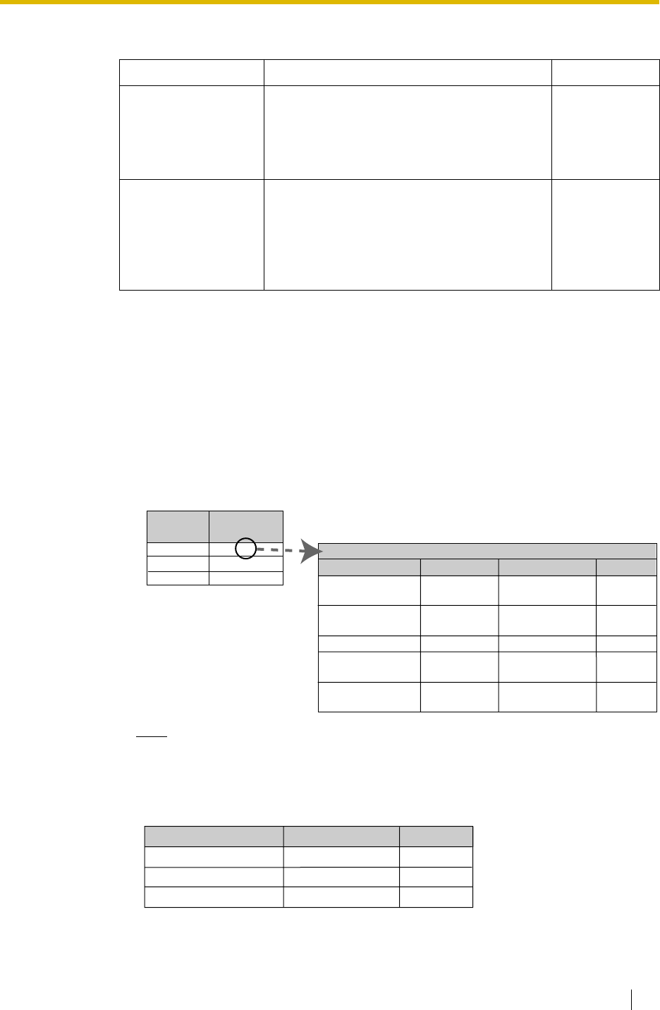
1.17 Caller ID Features
Feature Guide 161
2. Service Features
3. Number/Name Assignment
3.1 Automatic Caller ID Number Modification
This PBX automatically modifies the incoming caller’s number according to
preprogrammed tables. The modified number will be recorded for calling back.
The PBX supports a number of modification tables, and each trunk group can select
a table for use. Each table has ten locations for local/international calls and one for
long distance calls.
The PBX checks the local/international call data first. If a match is not found, the long
distance call data is applied.
[Example]
Note
When caller’s information is sent through an ISDN line and the call type is Subscriber,
National, or International, the following modification table is used instead of the above
table:
Features Description Details in
Calling Line
Identification (CLI)
Distribution
Directs a DIL/DID/DDI/MSN call to a CLI
destination if the caller’s identification (Caller
ID/CLIP/ANI) has been assigned to the Caller
ID Table.
• 1.1.1.5 Calling
Line
Identification
(CLI)
Distribution
Incoming Call Log Caller’s information is automatically recorded
in the call log of the called extension. This
information is used for confirming the caller,
calling the caller back, and/or storing the
number and name in the Personal Speed
Dialling.
• 1.17.2
Incoming Call
Log
012
Local/International
Call Data 1
Local/International
Call Data 2
:
Local/International
Call Data 10
Long Distance Call
Data 1
Area Code
Removed No. of Digits
Added No
.
Trunk
Group No.
1
2
:
Modification
Table
1
3
:
Modification Table 1
00
:
Not
programmable
3
2
0
:
001
:
Blank
0
<Table Selection>
<Modification Table>
Subscriber Call Data
National Call Data
International Call Data
Removed No. of Digits
Added No.
<Modification Table>
0
0
0
Blank
0
00
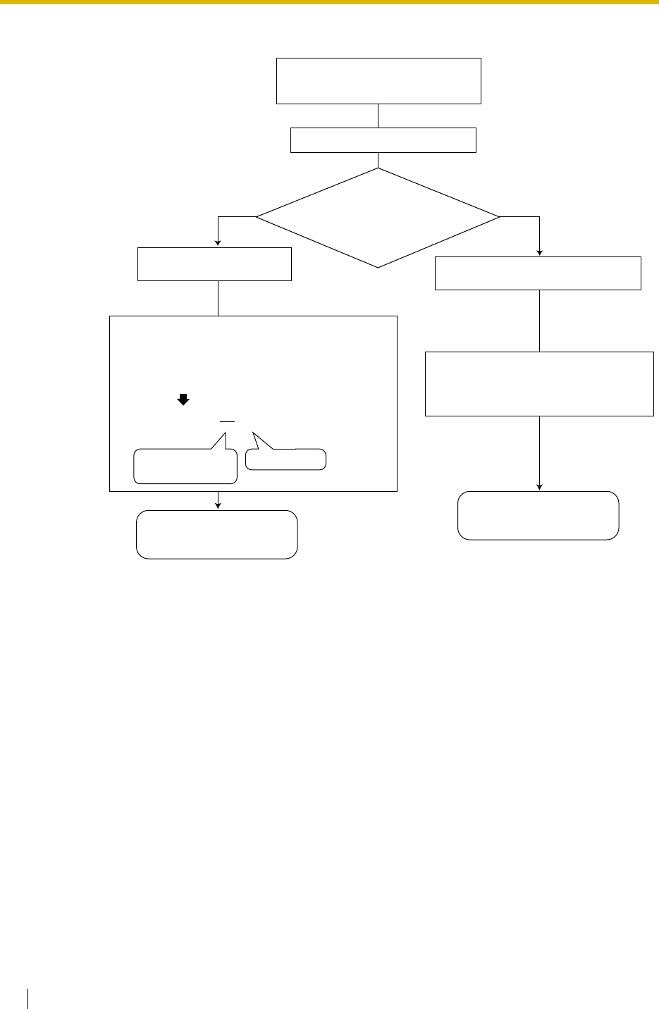
1.17 Caller ID Features
162 Feature Guide
<Modification Flowchart>
3.2 Caller ID Table Assignment
The System Speed Dialling Table is also used as the Caller ID Table.
In each location of the table, the following items can be assigned:
a) Telephone number (Trunk Access number + caller’s telephone number)
b) System Speed Dialling name (caller’s name)
(shown on the display or SMDR)
c) CLI destination
(used for CLI feature)
When a caller’s modified telephone number matches a telephone number (the Trunk
Access number is disregarded.) in the table, the call is sent to the assigned CLI
destination.
A trunk call with the caller's
information is received.
No:
e.g., 3344556677
Yes:
e.g., 00987654321
Is the area code found in
local/international call data
in the modification table?
Modifies the number as programmed.
Checks the local/
international call data.
Modification is completed:
001987654321.
Modification is completed:
03344556677.
Modifies the number as programmed.
(Removed number of digits: 0,
Added number: 0)
Checks the long distance call data.
Matches (Data 2)
Table 1
Removed number of digits: 2
Added number: 001
Received number: 00987654321
Modified number: 00987654321 = 001987654321
1) Remove the
first 2 digits. 2) Add "001".
Checks the Table Selection.

1.17 Caller ID Features
Feature Guide 163
[Example]
3.3 Caller’s Name Reference
A name can also be shown on the display or SMDR. The PBX searches for the name
in the following order:
1) Personal Speed Dialling data of the original called extension
2) System Speed Dialling (Caller ID) Table
3) Caller ID name received from the public line (Caller ID Name Reference)
If the name is not found, it will not be displayed.
Conditions
[General]
• Caller ID signalling type can be selected through system programming ( Caller ID Signal
Type [490] (KX-TDA30/KX-TDA100/KX-TDA200 only)).
• The Caller ID Name Reference is only available for calls from the public network.
•For Users in New Zealand only
Using the toll services of a company other than Telecom NZ.
If the PBX is set up to use the toll services of a company other than Telecom NZ, the
telephone numbers dialled from the Caller Display listings within the PBX will be directed
through the toll services of the other company because the telephone numbers include the
toll access digit and area code digit. A toll charge may be incurred. Please check with the
toll carrier concerned.
[Caller ID to SLT Port (KX-TDA15/KX-TDA30 only)]
•Hardware Requirement: The EXT-CID card
• Through system programming, a group of 4 SLT or Super Hybrid ports can be assigned
to receive Caller ID. Up to 2 groups can be programmed. Therefore, a maximum of 8 SLTs
can receive Caller ID.
• When the caller’s number is sent to an SLT, a Trunk Access number can be automatically
added to the telephone number through system programming for calling back.
• When the caller’s number exceeds 16 digits, the SLT receives only the first 16 digits, not
counting the preceding Trunk Access number (if it is programmed to be added).
• If a call is transferred to an SLT, the transferring extension’s information will be shown on
the SLT. If the transferring extension goes on-hook, the original caller’s information will be
shown.
• When the Caller ID has information, such as private, out of area, or long distance, the
information will be shown instead of the caller’s number and name.
Location
(System Speed
Dialling No.) Telephone No.*1 System Speed Dialling
Name*2
CLI
Destination
000 90123456789 ABC Company 200
001 : : :
:: : :
*1: System Speed Dialling Number [001]
*2: System Speed Dialling Name [002]

1.17 Caller ID Features
164 Feature Guide
• For an SLT that is connected to a DPT in parallel, Caller ID information is available only
when the SLT is set to "ring".
• Even if the caller’s name is sent, the name may not be shown depending on the type of
SLT.
• Incoming Call Log information is not shown on the SLT.
Feature Guide References
1.6.1.5 Speed Dialling—Personal/System
1.25.1 Station Message Detail Recording (SMDR)
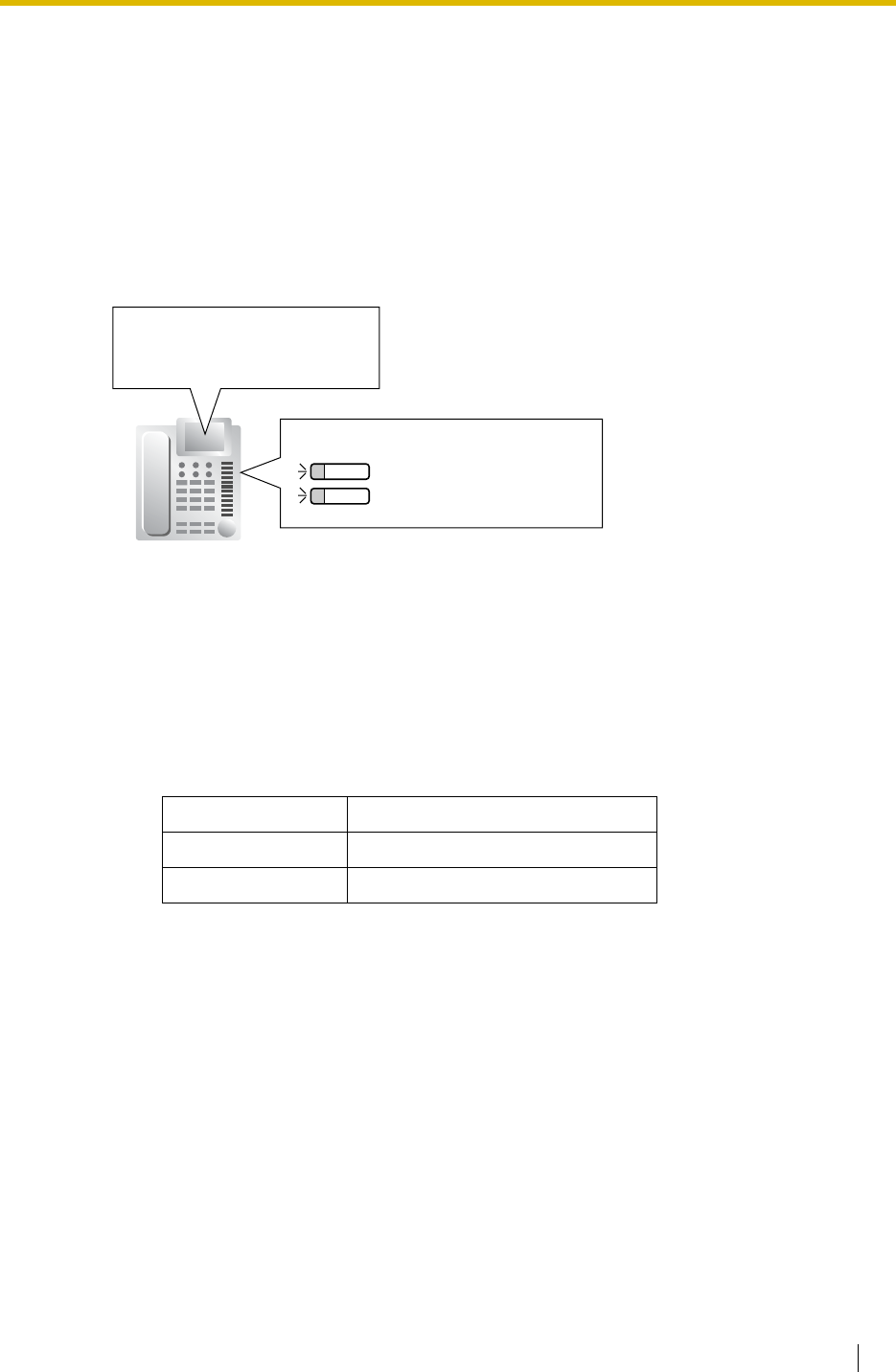
1.17 Caller ID Features
Feature Guide 165
1.17.2 Incoming Call Log
Description
When an incoming public trunk call with the caller’s information (e.g., Caller ID) is directed to
an extension, the information is automatically recorded in the call log of the called extension.
This information is shown on the telephone display and is used for confirming the caller, calling
back, or storing the number and name in the Personal Speed Dialling.
[Example]
Conditions
•Call Log Button
A flexible button can be customised as the Call Log button for the extension or an incoming
call distribution group. The button light shows the current status as follows:
•If the answering destination is not the original extension (FWD—No Answer,
Intercept Routing—No Answer, Overflow, and Call Pickup):
If a call is forwarded because of no answer or another extension picks up the call, the
information is logged in the call logs of both the original destination and the answering
destination. If a call is forwarded to several extensions before answered, the information is
logged in the call logs for all the forwarded extensions. If a call is forwarded to an incoming
call distribution group and is not answered, the information is not logged in the call log for
the incoming call distribution group.
•Call Log for Incoming Call Distribution Group Calls
If the original destination of a call is an incoming call distribution group, and the call is not
answered, the information is logged in the call log for the group. If it is answered, the
information is logged in the call log for the answering extension.
•Call Log for PS Calls
If a PS or a CS is in one of the following situations when a call arrives, the information is
logged in the call log for the PS:
Light pattern Status
Red on There is unchecked information.
Off All information has been checked.
Own extension
Incoming call distribution group
Call Log buttons
John White
123456789
12 Dec.10:00AM MON
New: Not Answered
--- Caller's name (20 digits max.)
--- Caller's number (16 digits max.)
--- Date and time of a call received
--- Answering Status*
"New" is displayed for call records which have not previously been viewed;
"Old" is displayed for call records which have previously been viewed.
*:

1.17 Caller ID Features
166 Feature Guide
a) When the PS is out of range.
b) When the PS is turned off.
c) When the CS is busy.
•Incoming Call Log Display Lock
An extension user can lock the Incoming Call Log display to prevent other users from
referring to the call information at his extension through personal programming (Directory
and Call Log Lock). In this case, the Outgoing Call Log display and the Personal Speed
Dialling number display is also locked. An extension personal identification number (PIN)
is required to use this feature. ( 1.26.1 Extension Personal Identification Number (PIN))
•Storing the Call Log Information in Personal Speed Dialling
When storing the number and name into Personal Speed Dialling from the call log
information, the Idle Line Access number is automatically attached to the telephone
number.
•Incoming Call Log Memory
The total memory for the Incoming Call Log is determined in the PBX. The maximum
number that can be logged for each extension and incoming call distribution group is also
determined through system programming. If the memory becomes full, the new call record
overwrites the oldest one.
Feature Guide References
1.6.1.5 Speed Dialling—Personal/System
1.19.2 Flexible Buttons
User Manual References
User Manual
1.11.1 Using the Call Log
3.1.2 Settings on the Programming Mode
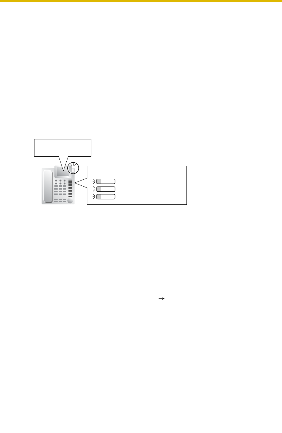
1.18 Message Features
Feature Guide 167
1.18 Message Features
1.18.1 Message Waiting
Description
An extension user can notify another extension user that he wishes to talk to the user. The
notified extension user can return the call or listen to the messages left in his mailbox of the
VPS.
When a message is left on a PT, the Message button on it lights or the Message/Ringer Lamp
on it turns on red. Pressing the lit Message button while on-hook shows the caller’s information
as shown below:
[Example]
Conditions
•Message Button
A flexible button can be customised as the Message button for the extension, other
extensions, or an incoming call distribution group.
•Distinctive Dial Tone for Message Waiting
If the Distinctive Dial mode is enabled, dial tone 4 will be sent to an extension when a
message has been left on the extension. ( 1.27.1 Dial Tone)
•SLT with a Message Waiting Lamp (KX-TDA100/KX-TDA200 only)
The lamp activates in the same way as the MESSAGE button on a PT, if an MSLC card is
connected to the PBX. The Message Waiting Lamp light pattern can be selected from the
twelve patterns shown below. System programming for each extension port is required to
use this feature.
105:Tom Smith --- Extension no. and name of who left the message
Own extension
Other extension*
*: For example, this button is useful
when the secretary checks the
message for the boss (Boss &
Secretary Feature).
Incoming call distribution group
Message buttons
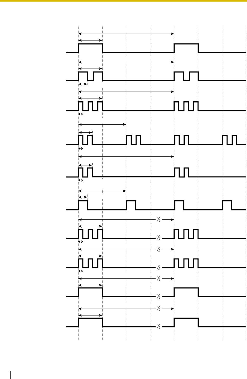
1.18 Message Features
168 Feature Guide
[SLT Message Waiting Lamp Light Patterns]
Pattern 1
Pattern 2
Pattern 4
512 ms
256 ms
1.28 s
1.28 s
5.12 s
5.12 s
2.56 s
768 ms
5.12 s
1.28 s
10.24 s
768 ms
Pattern 3
256 ms
1.28 s
5.12 s
Pattern 5
Pattern 6
ON
OFF
ON
OFF
ON
OFF
ON
OFF
ON
OFF
Pattern 7
Pattern 8
ON
OFF
ON
OFF
Pattern 9 ON
OFF
Pattern 10 ON
OFF
ON
OFF
2.56 s
512 ms
256 ms
256 ms
1.28 s
10.24 s
256 ms
1.28 s
20.48 s
1.28 s
20.48 s
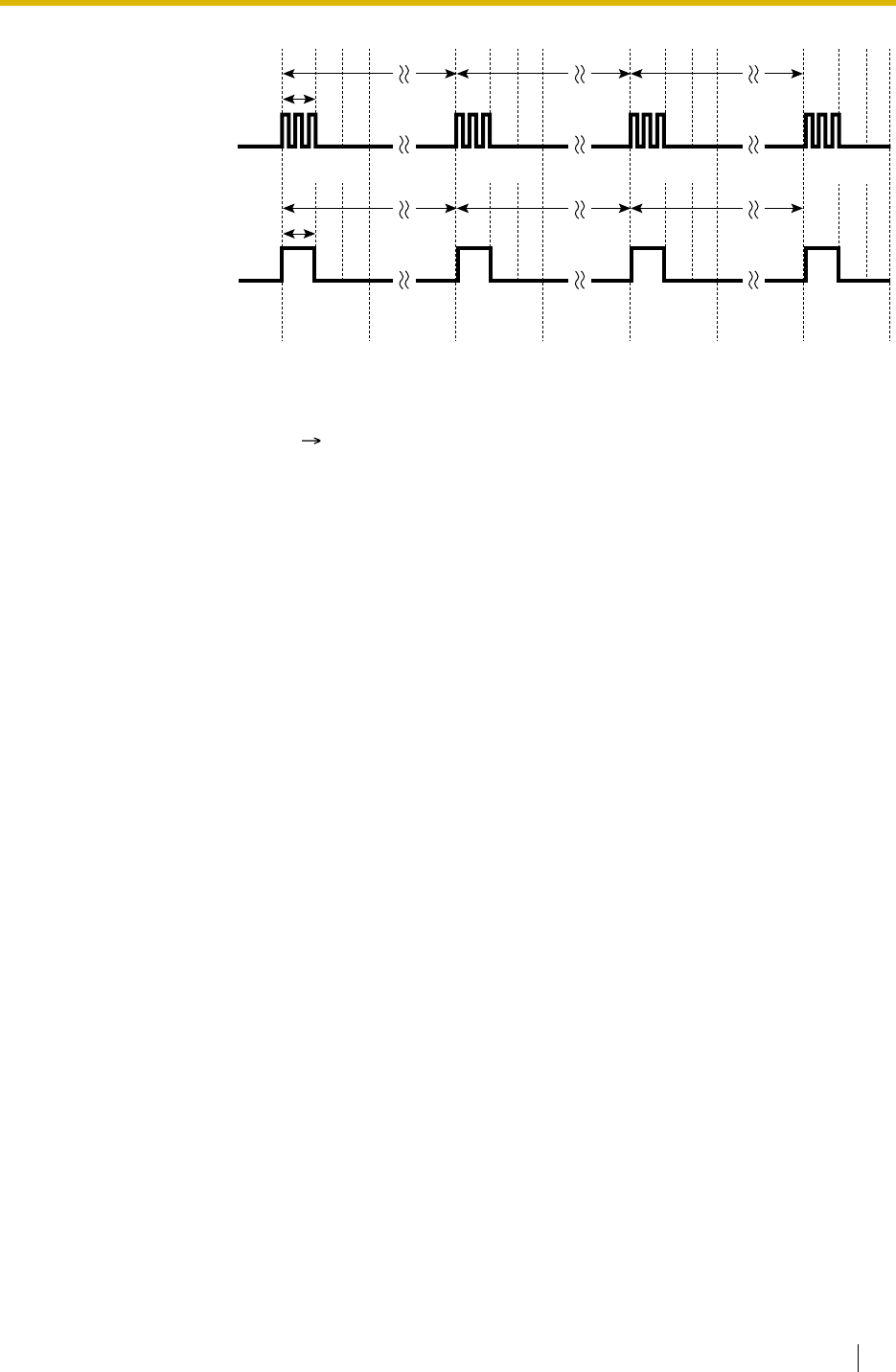
1.18 Message Features
Feature Guide 169
• It is possible to set Message Waiting while hearing a ringback tone, busy tone, or DND
tone.
• Messages are always left on the original extension. Messages cannot be sent to their
FWD destination ( 1.3.1.2 Call Forwarding (FWD)).
• Both the message sending extension and receiving extension can cancel a left message.
• If the message receiving extension calls the sending extension and is answered, the
message will be cleared automatically. However, if the message has been left on the VPS,
it depends on the VPS.
Feature Guide References
1.19.2 Flexible Buttons
User Manual References
User Manual
1.2.4 When the Dialled Line is Busy or There is No Answer
1.9.3 If a Voice Processing System is Connected
Pattern 11
Pattern 12 ON
OFF
ON
OFF
t=1.28 s
10.24 s 10.24 s 20.48 s
t
t=1.28 s
10.24 s 10.24 s 20.48 s
t

1.18 Message Features
170 Feature Guide
1.18.2 Absent Message
Description
The extension users can set the message (e.g., the reason for absence, where he is) on his
telephone. When display PT user calls the extension, the message is shown on the caller’s
telephone.
The following messages can be programmed as desired:
Note
The "%" means a parameter to be entered when assigning a message at an individual
extension.
Up to seven "%"s can be stored for each message.
Conditions
• An extension user can select only one message at a time. The selected message is
displayed at the extension while on-hook.
User Manual References
User Manual
1.5.2 Showing a Message on the Caller’s Telephone Display (Absent Message)
3.1.2 Settings on the Programming Mode
Type Message
No. Message (Example) Description
System
message 1Will Return Soon Messages may be edited
through system programming
( Absent Message [008]).
They are used for every
extension user commonly.
2Gone Home
3At Ext %%%% (Extension
Number)
4Back at %%:%% (Hour:Minute)
5Out until %%/%% (Month/Day)
6In a Meeting
7
8
Personal
message 9 A message is programmable at
each extension through
personal programming
(Personal Absent Message),
which can only be used by that
extension user.
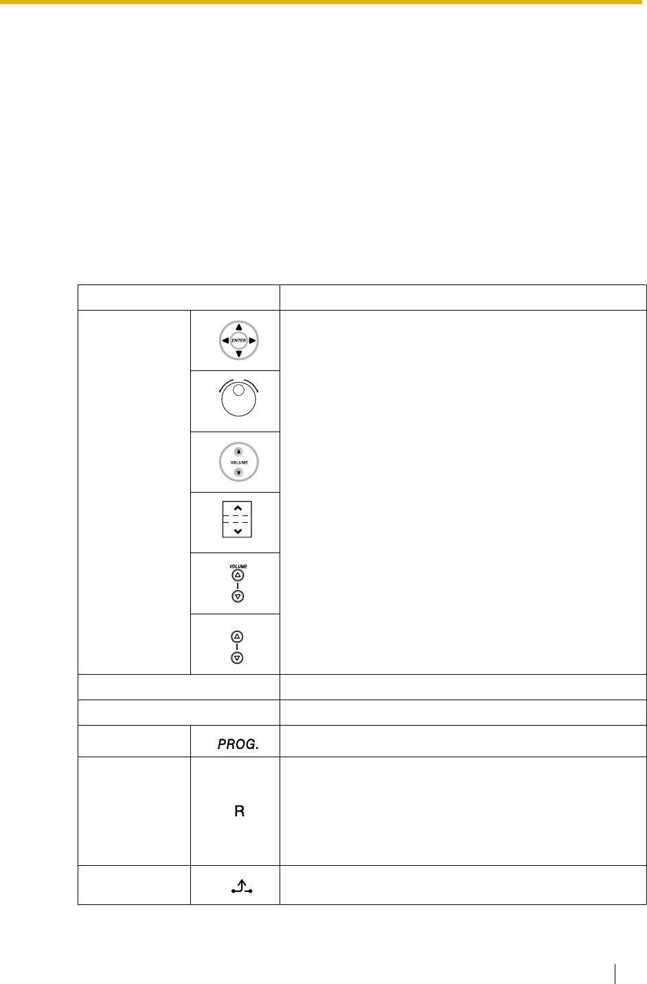
1.19 Proprietary Telephone (PT) Features
Feature Guide 171
1.19 Proprietary Telephone (PT) Features
1.19.1 Fixed Buttons
Description
PTs, DSS Consoles, and Add-on Key Modules are provided with the following feature/Line
Access buttons:
Depending on your device type, some buttons may not be provided.
As for buttons on PSs, please refer to the Operating Instructions for each PS.
[PT and Add-on Key Module]
Button Usage
Navigator Key,
Jog Dial,
Volume Key
Used to adjust the ringer, speaker, handset and headset
volume and the display contrast. Navigator Key and Jog Dial
can also be used to select data from the Call Directory and
the System Feature Access Menu on the display.
ENTER Used to confirm the selected item.
CANCEL Used to cancel the selected item.
PROGRAM Used to enter and exit the programming mode.
FLASH/
RECALL
Used to disconnect the current call and make another call
without hanging up (Flash/Recall mode or Terminate mode)
or used to send a flash/recall signal to the telephone
company or host PBX to access their features (External
Feature Access mode). This button can also be used as a
CANCEL button while on-hook.
HOLD Used to place a call on hold.
VOL
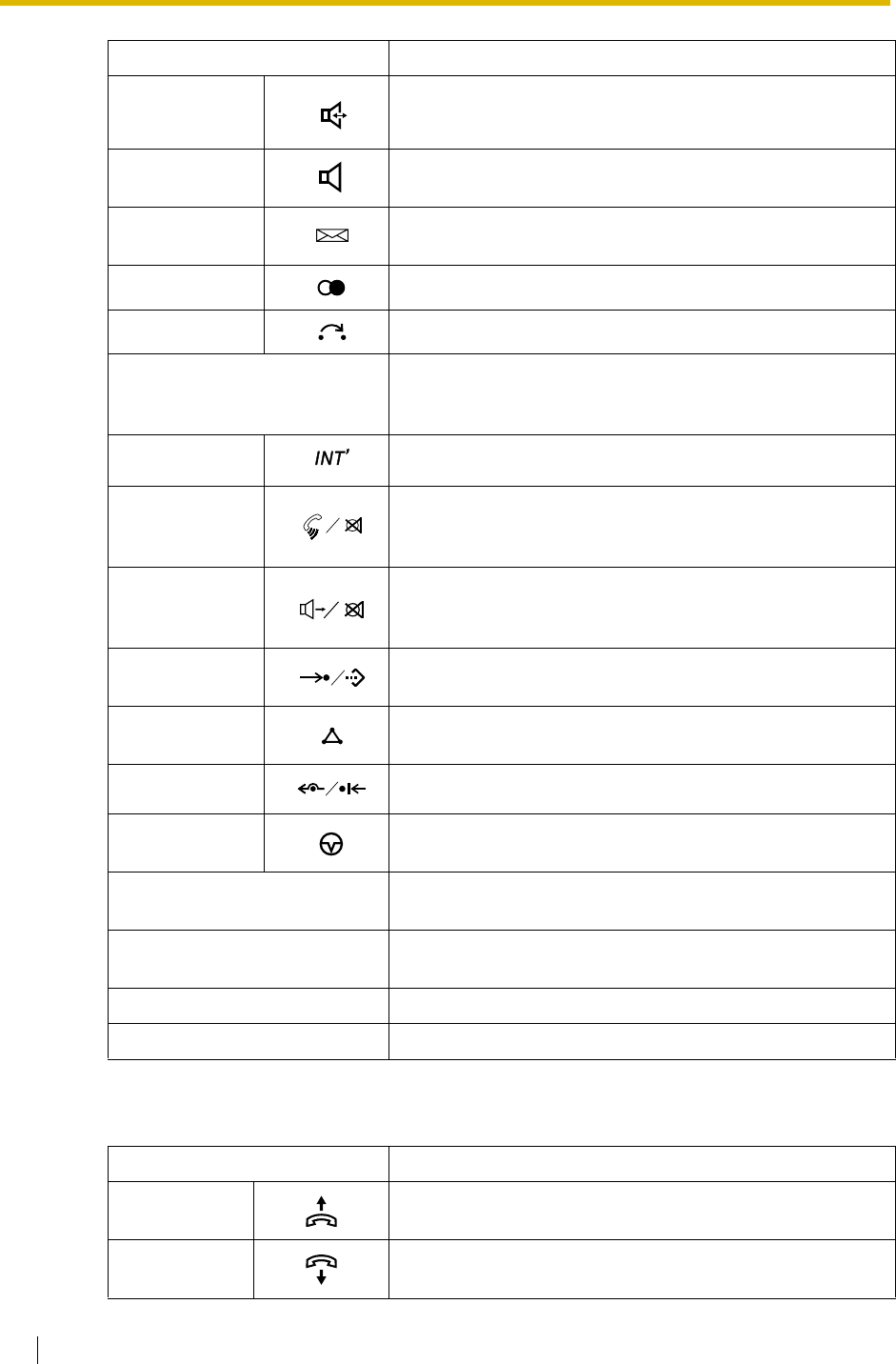
1.19 Proprietary Telephone (PT) Features
172 Feature Guide
[DSS Console]
SP-PHONE
(Speakerphone)
Used for hands-free operation. Also used to switch between
handset and hands-free operation.
MONITOR Used for a hands-free dialling. Also used to monitor the
party’s voice in hands-free mode.
MESSAGE Used to leave a message waiting indication or call back the
party who left the message waiting indication.
REDIAL Used to redial the last dialled number.
TRANSFER Used to transfer a call to another party.
Flexible CO (Trunk) Used to make or receive a trunk call or can be reassigned to
a different Trunk Access button (Default: S-CO) or to
another feature button.
INTERCOM Used to make or receive intercom calls.
AUTO ANS
(Auto Answer)/
MUTE
Used to receive an incoming call in hands-free mode, or
used for microphone or handset mute during a
conversation. (Dual feature button)
VOICE CALL/
MUTE
Used to monitor an intercom call automatically (a hands-
free conversation is not possible). Also used for handset
microphone mute during a conversation.
AUTO DIAL/
STORE Used for System/Personal Speed Dialling and storing
programme changes.
CONF
(Conference) Used to establish a multiple-party conversation.
FWD/DND Used to perform FWD or DND. (Dual feature button)
PAUSE Used to insert a pause in a stored number. With an APT, it
is used as the PROGRAM button.
Soft Used to select the item displayed on the bottom line of the
display.
SELECT Used to select the displayed item or to call the displayed
number.
SHIFT Used to access the second level of Soft button items.
MODE Used to shift the display to access various features.
Button Usage
ANSWER Used to answer an incoming call or place the current call on
hold and answer another call with one-touch.
RELEASE Used to disconnect the line during or after a conversation or
to complete a Call Transfer.
Button Usage

1.19 Proprietary Telephone (PT) Features
Feature Guide 173
Conditions
• Certain buttons are equipped with a light to show line or feature status.
Flexible CO (Trunk) Used to make or receive a trunk call or can be reassigned to
a different trunk or to another feature button.
Flexible DSS (Direct Station
Selection)
Used to access an extension with one-touch. Every button
is programmed to correspond to an extension. DSS buttons
can also be reassigned to other features.
PF (Programmable Feature) Used to access a preprogrammed feature with one-touch.
(no default)
Button Usage

1.19 Proprietary Telephone (PT) Features
174 Feature Guide
1.19.2 Flexible Buttons
Description
Flexible buttons are customised by either system or personal programming. The following
types of flexible buttons are provided on PTs, DSS Consoles, Add-on Key Modules, and/or
PSs:
a) Flexible CO buttons
b) Flexible Direct Station Selection (DSS) buttons
c) Programmable Feature (PF) buttons
[Button Usage]
Button Usage
Single-CO (S-CO) Used to access a specified trunk for making or receiving calls.
Group-CO (G-CO) Used to access an idle trunk in a specified trunk group for
making calls. Incoming calls from trunks in the assigned trunk
group arrive at this button.
Loop-CO (L-CO) Used to access an idle trunk for making calls. Incoming calls
from any trunk arrive at this button.
Direct Station Selection
(DSS) Used to access an extension with one-touch.
One-touch Dialling Used to access a preprogrammed party or feature with one-
touch.
Incoming Call Distribution
(ICD) Group Used to access a specified incoming call distribution group
for making or receiving calls.
Message Used to leave a message waiting indication or call back the
party who left the message waiting indication.
FWD/DND (External/
Internal/Both) * Used to perform the FWD or DND feature for the extension.
The feature is applied to trunk calls, intercom calls, or both.
Group FWD (External/
Internal/Both) Used to perform the FWD feature for a specified incoming call
distribution group. The feature is applied to trunk calls,
intercom calls, or both.
Account Code Entry
(Account) Used to enter an account code.
Conference Used to establish a multiparty conversation.
Terminate Used to disconnect the current call and make another call
without hanging up.
External Feature Access
(EFA) Used to send a flash/recall signal to the telephone company
or host PBX to access their features.
Charge Reference Used to check the total call charge for your own extension.
Call Park Used to park or retrieve a call in a preset PBX parking zone.
Call Park (Automatic Park
Zone) Used to park a call in an idle PBX parking zone automatically.

1.19 Proprietary Telephone (PT) Features
Feature Guide 175
Conditions
• The Flexible DSS button lights of the KX-T7040 and KX-T7240 shows only "Off" or "Red
On". If the button is customised as a button which shows other light patterns, the other light
patterns also show only as "Red On".
Call Log Used to show the incoming call information.
Log-in/Log-out * Used to switch between the log-in and log-out mode.
Hurry-up Used to redirect the longest waiting call in the queue of an
incoming call distribution group to the overflow destination.
Wrap-up * Used to switch the Wrap-up/Not Ready and Ready modes.
System Alarm Used to confirm a PBX error.
Time Service * Used to switch the assigned time modes: day, lunch, break or
night. Also used to check the current time mode status.
Answer Used to answer an incoming call.
Release Used to disconnect the line during or after a conversation, or
to complete a Call Transfer.
Toll Restriction/Call Barring Used to change the TRS/Barring level of other extension
users temporarily.
ISDN Service Used to access an ISDN service.
Calling Line Identification
Restriction (CLIR) * Used to switch between the CLIP and CLIR service.
Connected Line
Identification Restriction
(COLR) *
Used to switch between the COLP and COLR service.
ISDN Hold Used to transfer a call using the telephone company.
Headset Used to turn on/off the headset mode while idle.
Used to switch between hands-free mode and headset
modes during a conversation.
Time Service Switching
Mode (Automatic/Manual) * Used to switch between the Automatic Switching and Manual
Switching mode.
Two-way Record Used to record a conversation into your own mailbox.
Two-way Transfer Used to record a conversation into the mailbox of a specified
extension.
One-touch Two-way
Transfer Used to record a conversation into the mailbox of a specified
extension with one-touch.
Live Call Screening (LCS) Used to monitor your own voice mailbox while an incoming
caller is leaving a message and, if desired, intercept the call.
Voice Mail (VM) Transfer Used to transfer a call to the mailbox of a specified extension.
*: One-touch Feature Setting Buttons: Pressing these buttons while on-hook changes the
feature settings. The new mode will be displayed for a preprogrammed time period.
Button Usage

1.19 Proprietary Telephone (PT) Features
176 Feature Guide
User Manual References
User Manual
3.1.3 Customising the Buttons

1.19 Proprietary Telephone (PT) Features
Feature Guide 177
1.19.3 LED Indication
Description
The light (LED: Light Emitting Diode) of the Message/Ringer Lamp and following buttons (Line
Status Buttons and Corresponding Extension Status Button) show line conditions with a variety
of light patterns.
Line Status Buttons: S-CO, G-CO, L-CO, INTERCOM, ICD Group
Corresponding Extension Status Button: DSS
1. Light Pattern of the Message/Ringer Lamp
[DPT]
• Incoming call from a trunk: Red flashing
• Incoming call from another extension: Green flashing
• Message(s) present (no incoming call): Red on
• No message(s) present (no incoming call): Off
[APT]
• Incoming call: Red flashing
• Message(s) present (no incoming call): Red on
• No message(s) present (no incoming call): Off

1.19 Proprietary Telephone (PT) Features
178 Feature Guide
2. Light Pattern of the Line Status Buttons
3. Light Pattern of the Corresponding Extension Status Button
*1: Only when Call Pickup by a DSS button is disabled.
*2: Only when Call Pickup by a DSS button is enabled.
Incoming Call
Distribution
Group Line
Status
Intercom
Line Status
Trunk Status
Line Status
Button:
Red on
Off
Green on
Light
Pattern
Slow green
flashing
Moderate
green
flashing
Rapid green
flashing
Slow red
flashing
S-CO G-CO L-CO INTERCOM ICD Group
Idle
This extension is using the line.
This extension is holding the line.
This extension is holding the line using Exclusive Hold
or using the line for an Unattended Conference.
Incoming
call/Privacy
Release
Incoming
call for
another
extension/
Another
extension
is using the
line/Another
extension
has the line
on Exclusive
Hold.
Other
extensions
are using
all trunks
in the trunk
group.
Another
extension
is holding
the line.
Incoming call
––
––– –
This extension
is logged out
of the incoming
call distribution
group.
Rapid red
flashing Incoming call to the incoming call
distribution group in Ring
distribution method
––
DSS
Corresponding
Extension
Status Button
Red on
Off
Light Pattern
Rapid red flashing
Idle
Busy/Incoming call*1/DND for trunk calls
Incoming call*2
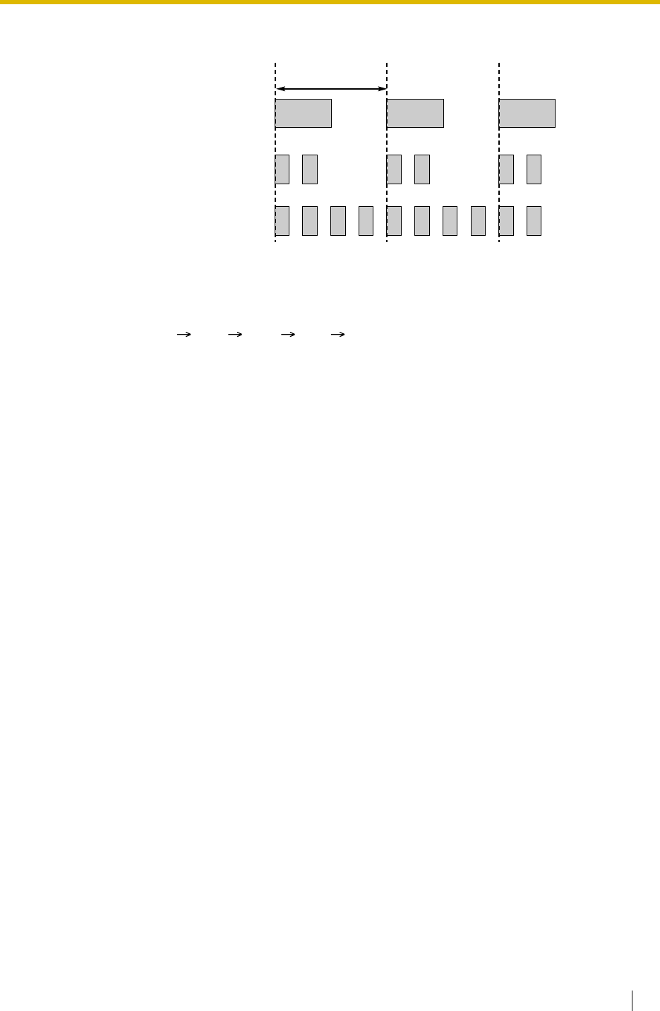
1.19 Proprietary Telephone (PT) Features
Feature Guide 179
4. Flashing Light Patterns
Conditions
• The incoming call shows on the buttons in the following priority:
ICD Group S-CO G-CO L-CO INTERCOM
• The light pattern of a DSS button for incoming call can be set to "Off" through system
programming. In this case, the DSS button light will not indicate the status of the
corresponding extension.
Feature Guide References
1.2.2.2 Group Call Distribution
1.2.2.6 Log-in/Log-out
1.3.1 Call Forwarding (FWD)/Do Not Disturb (DND)
1.12.1 Call Hold
1.13.1.2 Conference
1.13.1.3 Privacy Release
Slow Flashing
Moderate Flashing
Rapid Flashing
1 s

1.19 Proprietary Telephone (PT) Features
180 Feature Guide
1.19.4 Display Information
Description
A display PT shows the user the following information while making or receiving calls if they
are available:
Conditions
•Multilingual Display
Each extension can select its display language through personal programming (Display
Language Selection).
•Display Contrast
It is possible to adjust the display contrast through personal programming (Display
Contrast Selection). This is available only for DPTs.
•Display Backlight
Each extension can select its display backlight on or off through personal programming
(Display Backlight Selection). This is available for the KX-T7633 and KX-T7636.
• Characters (name) or digits (number) exceeding the display’s size limitation are not
displayed. In this case, information which have been programmed is hidden, but not
altered.
Display Item Display Example Condition
The extension number and name of the
calling or called extension, or incoming call
distribution group
123: Tom Smith –
Status of the called extension 123: Busy –
The number and name of the optional
device Door 02: 1st Door –
The dialled telephone number 1234567890 –
The received call information
a) Caller’s name
b) Caller’s number
c) Trunk number/name
d) Original Destination, if the call is
forwarded
e) DDI/DID/MSN name or number
ABC Company
12345678
Line 001: Sales
102:Mike
Panasonic
The first line message
can be either (a), (c),
or (e) at each
extension through
system programming.
Call charge fee during a trunk call. 12.35 The currency (
Currency [131]),
position of the
currency symbol, and
the decimal point (
Decimal Point
Position for Currency
[130]) are
programmable.
Call duration during a trunk call. Line 001 11:02’28 –

1.19 Proprietary Telephone (PT) Features
Feature Guide 181
User Manual References
User Manual
3.1.2 Settings on the Programming Mode

1.20 Integrated Services Digital Network (ISDN) Service Features
182 Feature Guide
1.20 Integrated Services Digital Network (ISDN)
Service Features
1.20.1 Integrated Services Digital Network (ISDN)
1.20.1.1 Integrated Services Digital Network (ISDN)—SUMMARY
Description
ISDN is a digital switching and transmission network. ISDN transmits voice, data, and image
in digital format. ISDN lines, if available, can be connected to public line (trunk), private line
(QSIG), or ISDN terminal devices (extension).
1. ISDN Interface and Configuration
Note
Point-to-Point (P-P):
One ISDN terminal device can be connected to one ISDN port.
Point-to-multipoint (P-MP):
A maximum of eight ISDN terminal devices can be connected to one ISDN port.
Interface Type Description Port Mode Configuration
Type*
Basic Rate
Interface (BRI) Provides two 64 kbps B channels
for communication and one 16
kbps D channel for signalling (2B
+ D).
Trunk,
Extension Point-to-Point/
Point-to-
multipoint
QSIG (Master,
Slave) Point-to-Point
Primary Rate
Interface (PRI) Provides thirty or twenty-three 64
kbps B channels for
communication and one 64 kbps
D channel for signalling (30B + D/
23B + D).
Trunk, QSIG
(Master, Slave),
Extension
Point-to-Point
*: BRI Configuration [426] *For BRI only

1.20 Integrated Services Digital Network (ISDN) Service Features
Feature Guide 183
2. ISDN Supplementary Service Table for Public Network
Service Description Details in
Direct Dialling In
(DDI) Directs a call with a DDI number to a
preprogrammed destination. (P-P only) • 1.1.1.3 Direct
Inward Dialling
(DID)/Direct
Dialling In
(DDI)
Multiple
Subscriber
Number (MSN)
One ISDN port can support a maximum of 10
MSNs for routing incoming calls. (P-MP only) • 1.1.1.4
Multiple
Subscriber
Number
(MSN) Ringing
Service
Calling Line
Identification
Presentation
(CLIP)
Sends the caller’s telephone number to the
network when making a call. The called party
can see the number on his telephone display
before answering the call.
• 1.20.1.2
Calling/
Connected
Line
Identification
Presentation
(CLIP/COLP)
Connected Line
Identification
Presentation
(COLP)
Sends the telephone number of the answered
party to the network when answering a call. The
caller can see the number on his telephone
display when the line is connected.
Calling Line
Identification
Restriction (CLIR)
Prevents the caller’s CLI being presented to the
called party by the caller.
Connected Line
Identification
Restriction
(COLR)
Prevents COLP being sent by the answered
party.
Subaddressing
(SUB) You may add digits after the telephone number.
These digits will be passed to ISDN terminal
device.
–
User-to-user
Signalling Type 1
(UUS-1)
Transmits a specified volume of the data through
the D channel between the ISDN terminal
devices of different PBXs using UUS types 1.
–
Advice of Charge
(AOC) The PBX can receive the call charge information
on ISDN lines from the telephone company. • 1.20.1.3
Advice of
Charge (AOC)
Call Forwarding
(CF)—by ISDN Forwards an incoming call to another outside
party using the ISDN service of the telephone
company.
• 1.20.1.4 Call
Forwarding
(CF)—by
ISDN (P-MP)
• 1.20.1.5 Call
Forwarding
(CF)—by
ISDN (P-P)

1.20 Integrated Services Digital Network (ISDN) Service Features
184 Feature Guide
3. ISDN Centrex Service
An extension user can have access to the features of the ISDN Centrex Service of the
telephone company (e.g., Call Transfer). This is used by putting the current ISDN call on
hold by sending a flash/recall signal. This feature is enabled or disabled for each ISDN
port.
4. Private Networking Connection (QSIG)
Private networking with QSIG is possible using an ISDN line. The QSIG mode, Master or
Slave, can be enabled on an ISDN port basis.
5. ISDN Extension ( 1.20.1.11 ISDN Extension)
An ISDN (BRI/PRI) port can be used for extension connection. While the extension
connection is enabled, ISDN terminal devices (e.g., ISDN telephone, G4 fax machine,
personal computer) or a behind PBX can be connected to the port.
When the ISDN port is in P-P configuration, one ISDN terminal device can be connected
to the port. When the ISDN port is in P-MP configuration, a maximum of eight ISDN
terminal devices can be connected to the port. However, only a maximum of two devices
can be used simultaneously.
Conditions
•Overlap/En bloc
ISDN call dialling mode, Overlap or En bloc, can be selected for each ISDN port. When
"Overlap" is selected, the PBX sends each dialled digit individually. When "En bloc" is
selected, the PBX sends all of dialled digits at once after the extension user completes
dialling. The PBX recognises end of dialling as follows:
Call Hold
(HOLD)—by ISDN Puts one ISDN call on hold. • 1.20.1.6 Call
Hold
(HOLD)—by
ISDN
Call Transfer
(CT)—by ISDN Transfers an ISDN call to an outside party. Call
Transfer with Announcement and Call Transfer
without Announcement are available.
• 1.20.1.7 Call
Transfer
(CT)—by
ISDN
Three-party
Conference
(3PTY)—by ISDN
Establishes a three-party conference call using
the ISDN service of the telephone company. • 1.20.1.8
Three-party
Conference
(3PTY)—by
ISDN
Malicious Call
Identification
(MCID)
An extension user can ask the telephone
company to trace a malicious caller. Information
on the malicious call will be received later on.
• 1.20.1.9
Malicious Call
Identification
(MCID)
Completion of
Calls to Busy
Subscriber
(CCBS)
If an outside called party is busy, an extension
can receive callback ringing when the called
party becomes free.
• 1.20.1.10
Completion of
Calls to Busy
Subscriber
(CCBS)
Service Description Details in

1.20 Integrated Services Digital Network (ISDN) Service Features
Feature Guide 185
• Some supplementary services are provided by the key protocol ( 1.20.1.12 ISDN
Service Access by Keypad Protocol).
•Extension Number
An extension number can be assigned to each ISDN port.
•Network Type
Each ISDN port can be set to the requirements of each country/area ( BRI Network
Type [420] *For BRI only).
•L1 Active Mode and L2 Data Link Mode
The active mode of Layer 1 (L1) ( BRI Layer 1 Active Mode [424] *For BRI only) and the
data link mode of Layer 2 (L2) ( BRI Layer 2 Active Mode [425] *For BRI only) can be
selected individually, Permanent or Call by Call, on an ISDN port basis.
•TEI Assignment Mode
The Terminal Endpoint Identifier (TEI) assignment mode can be selected on an ISDN port
basis ( BRI TEI Mode [427] *For BRI only).
•Bearer Mode
The bearer mode can be assigned on an extension basis.
•Automatic ISDN Configuration
ISDN (BRI) port configuration can be set automatically through system programming.
The following items will be set by making and receiving a call using the subscriber number
assigned for each ISDN (BRI) port:
Feature Guide References
1.28.3 QSIG Network
– Dialling #, if programmed
– Dialling a preprogrammed telephone number
– Inter-digit timer expires.
– L1 Active Mode
– L2 Data Link Mode
– Access Mode (Point-to-Point/Point-to-Multipoint)
– TEI Assignment Mode (Fix 00–63/Automatic)
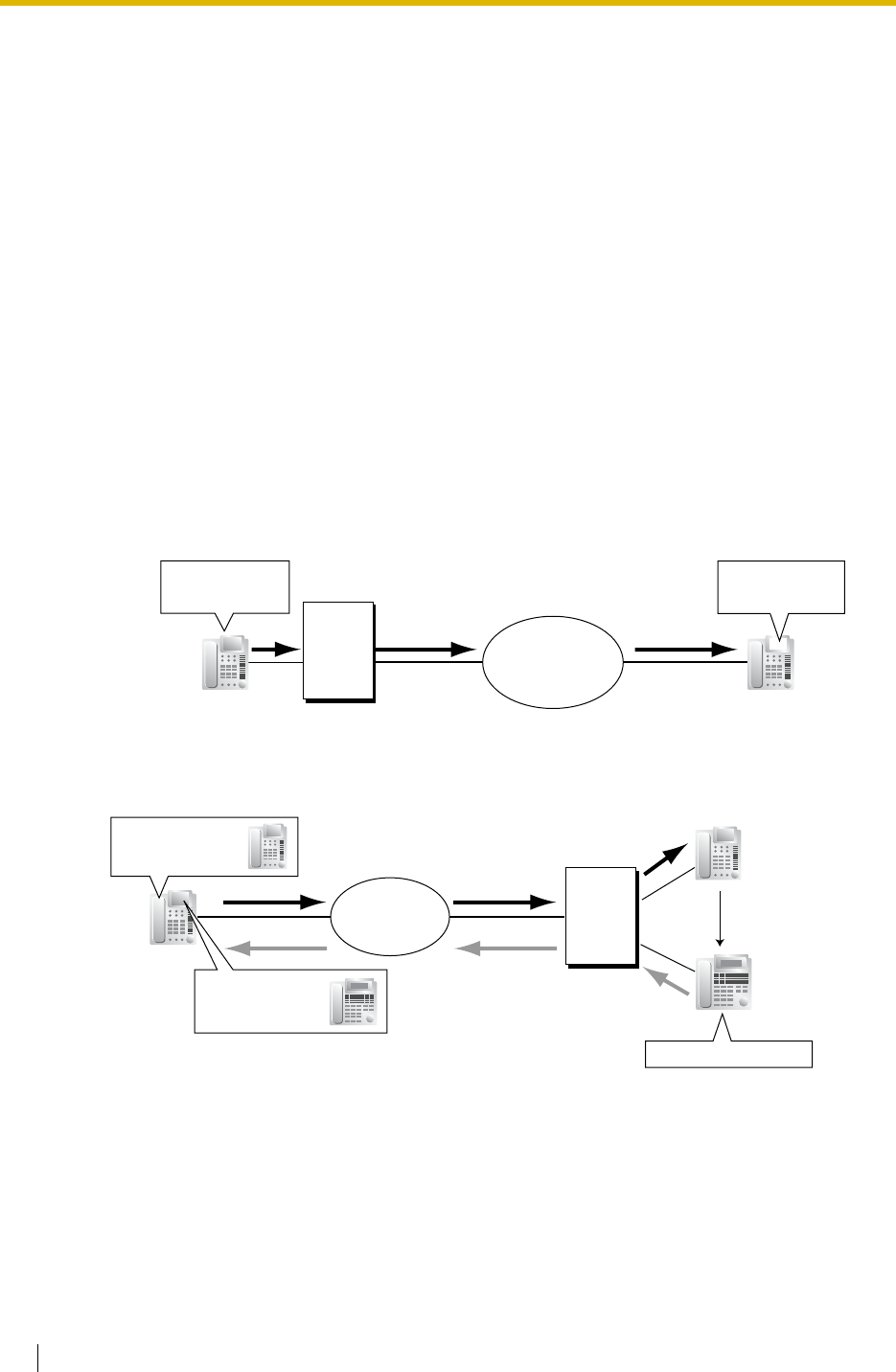
1.20 Integrated Services Digital Network (ISDN) Service Features
186 Feature Guide
1.20.1.2 Calling/Connected Line Identification Presentation
(CLIP/COLP)
Description
Calling Line Identification Presentation (CLIP):
The PBX can send a preprogrammed telephone number to the network when an extension
user makes a call. The called party can see the number on his telephone display before
answering the call.
Connected Line Identification Presentation (COLP):
The PBX sends a preprogrammed telephone number to the network when the extension user
answers an incoming call. The caller can see the number of the answering party on his
telephone display when the call is answered.
These features comply with the following European Telecommunication Standard (ETS)
specifications:
ETS 300 092 Calling Line Identification Presentation (CLIP) supplementary service.
ETS 300 097 Connected Line Identification Presentation (COLP) supplementary service.
[CLIP Example]
[COLP Example]
ISDN
1) Dials
"87654321".
Called party
(CLIP/COLP No.: 87654321)
Caller
(CLIP/COLP No.: 12345678)
2) "12345678"
is displayed.
PBX
PBX
ISDN
FWD, IRNA, etc.
1) Dials
"111222333".
2) Answers the call.
3) "111222444"
is displayed.
Caller
Called party
(CLIP/COLP No.:
111222333)
Answering party
(CLIP/COLP No.:
111222444)

1.20 Integrated Services Digital Network (ISDN) Service Features
Feature Guide 187
CLIP/COLP Number:
The telephone numbers sent to the network for CLIP/COLP can be assigned as follows:
• CLIP/COLP number for each ISDN port (subscriber’s number) ( BRI Subscriber
Number [422] *For BRI only)
• CLIP/COLP number for each extension ( CLIP/COLP Number [606])
• CLIP/COLP number for each incoming call distribution group
Each extension can select either the CLIP/COLP number for the ISDN port or the extension to
be used. The CLIP/COLP number for the incoming call distribution group is used when making
a call by pressing the ICD Group button or receiving a call which arrives at the ICD Group
button.
Calling/Connected Line Identification Restriction (CLIR/COLR):
It is possible for each extension to restrict the sending of its telephone number to the network
by pressing the CLIR button, COLR button, or entering the feature number.
These features comply with the following European Telecommunication Standard (ETS)
specifications:
ETS 300 093 Calling Line Identification Restriction (CLIR) supplementary service.
ETS 300 098 Connected Line Identification Restriction (COLR) supplementary service.
Conditions
• The availability of this feature is dependent on the contract with the telephone company.
• The CLIP/COLP number for the connected ISDN port can be used for the ISDN terminal
devices which cannot be assigned their own CLIP/COLP number, such as a doorphone.
•COLP/CLIR/COLR Assignment for Each Port
Each service can be enabled or disabled on each ISDN port of the PBX.
•CLIR Button and COLR Button
It is possible to switch between CLIP and CLIR by pressing the CLIR button, and COLP
and COLR by pressing the COLR button. A flexible button can be customised as the CLIR
or COLR button.
• The CLIP/COLP number must match the telephone number provided by the telephone
company. Otherwise it will be ignored or replaced by another number.
• When using a private network, the extension number assigned for each extension through
system programming ( Extension Number [003]) is sent for CLIP/COLP. ( 1.28.3.2
Calling/Connected Line Identification Presentation (CLIP/COLP) and Calling/Connected
Name Identification Presentation (CNIP/CONP)—by QSIG)
Feature Guide References
1.19.2 Flexible Buttons
User Manual References
User Manual
1.7.4 Displaying Your Telephone Number on the Called Party and Caller’s Telephone
(Calling/Connected Line Identification Presentation [CLIP/COLP])
1.7.5 Preventing Your Telephone Number Being Displayed on the Caller’s Telephone
(Connected Line Identification Restriction [COLR])
1.7.6 Preventing Your Number Being Displayed on the Called Party’s Telephone (Calling
Line Identification Restriction [CLIR])

1.20 Integrated Services Digital Network (ISDN) Service Features
188 Feature Guide
1.20.1.3 Advice of Charge (AOC)
Description
The PBX can receive the call charge information on ISDN lines from the telephone company.
There are the following types:
This feature complies with the following European Telecommunication Standard (ETS)
specifications: ETS 300 182 Advice of Charge (AOC) supplementary service Digital
Subscriber Signalling System No. One (DSS1) protocol.
Conditions
• A DPT user can see the call charge information on the display during the call.
•Budget Management
If the amount of call charge reaches the preprogrammed limit, an extension user cannot
make further calls. ( 1.8.2 Budget Management)
•AOC for ISDN extension
An ISDN extension also receives AOC.
Type Description
Advice of Charge During Call
(AOC-D) AOC is received during the call and when the call is
completed.
Advice of Charge
At End of Call (AOC-E) AOC is received when the call is completed.
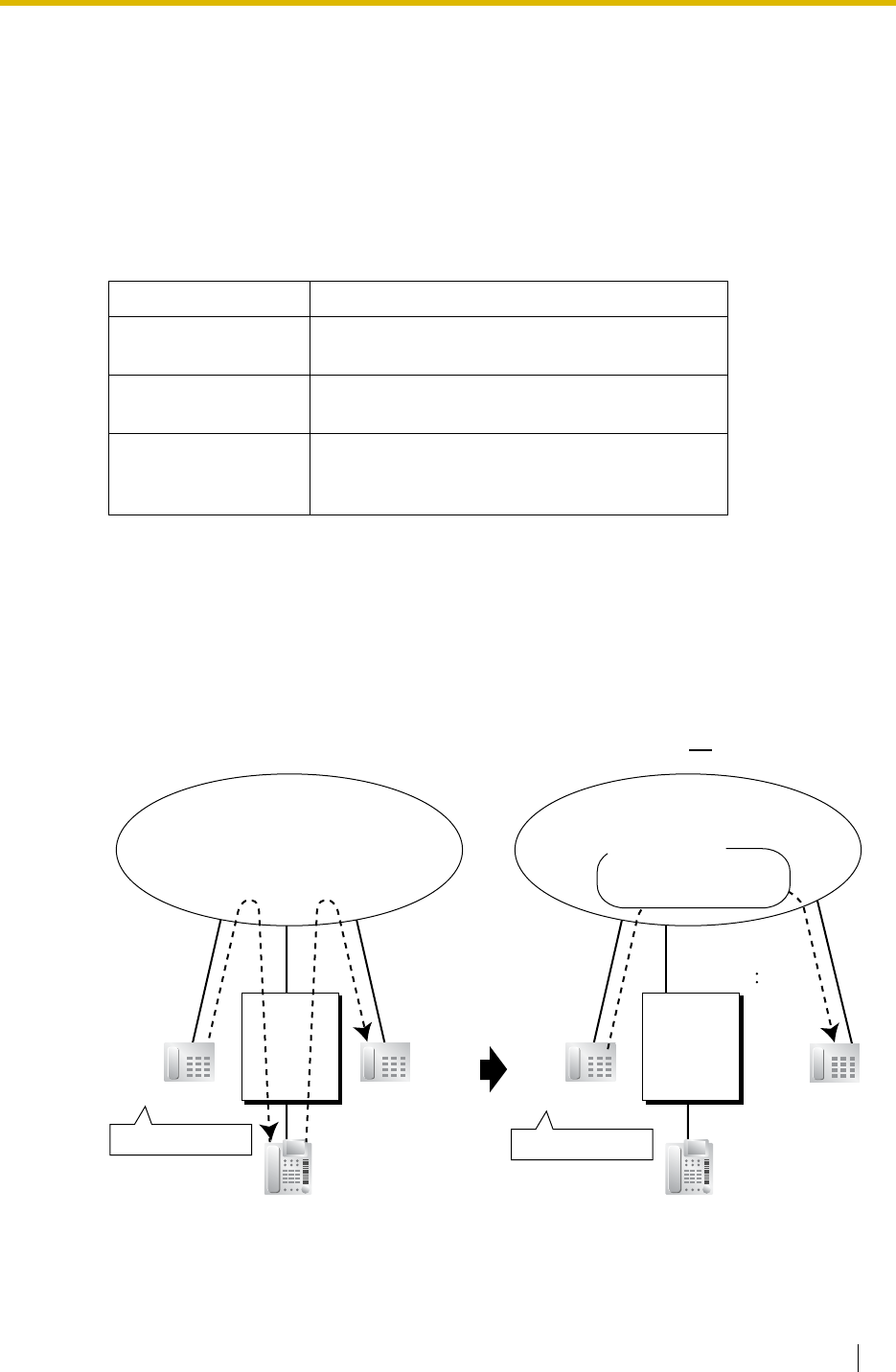
1.20 Integrated Services Digital Network (ISDN) Service Features
Feature Guide 189
1.20.1.4 Call Forwarding (CF)—by ISDN (P-MP)
Description
An extension user can forward the incoming ISDN call to another outside party using the ISDN
service of the telephone company, instead of the PBX feature, when the call is received through
an ISDN line.
Extension users can set the forward destination to the network on an MSN basis. The setting
must have been done beforehand to use this feature. There are the following types:
When the CFB or CFNR has been set, the network determines to forward the incoming call to
the preprogrammed destination after the call reached the PBX once. When the CFU has been
set, the network forwards the call directly to the preprogrammed destination.
This feature complies with the following European Telecommunication Standard (ETS)
specifications: ETS 300 207 Diversion supplementary service.
[Example]
Type Description
Call Forwarding—
Unconditional (CFU) Incoming calls are forwarded unconditionally.
Call Forwarding—
Busy (CFB) An incoming call is forwarded when the
destination on the PBX is busy.
Call Forwarding—No
Reply (CFNR) An incoming call is forwarded when the
destination on the PBX does not answer within a
preprogrammed time period.
MSN: 123-4567
987-6543
Outside Party
(01-23-4567)
Outside Party
Outside Caller
Extn. 1011
Dials "123-4567".
(MSN: 123-4567
Forward Destination
of Trunk Calls: 01-23-4567)
(01-23-4567)
ISDN
<FWD> <Call Forwarding (CF) by ISDN (P-MP)>
PBX
Outside Caller
Extn. 1011
Dials "123-4567".
ISDN
MSN:123-4567
CFU
Destination: 01-23-4567
PBX

1.20 Integrated Services Digital Network (ISDN) Service Features
190 Feature Guide
Conditions
• The availability of this feature is dependent on the contract with the telephone company.
• The feature requires the MSN service. ( 1.1.1.4 Multiple Subscriber Number (MSN)
Ringing Service)
• COS programming determines the extensions that are able to use this feature.
Feature Guide References
1.3.1.2 Call Forwarding (FWD)
User Manual References
User Manual
1.5.1 Forwarding Calls
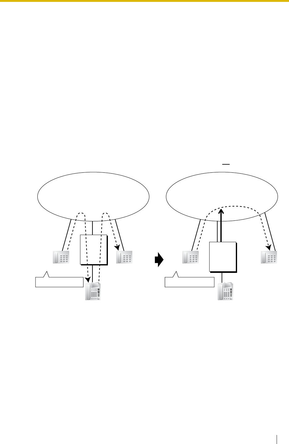
1.20 Integrated Services Digital Network (ISDN) Service Features
Feature Guide 191
1.20.1.5 Call Forwarding (CF)—by ISDN (P-P)
Description
An extension user can forward the incoming ISDN call to another outside party using the ISDN
service of the telephone company, instead of the PBX feature, when the call is received through
an ISDN line.
The network directly forwards the call to the destination which the extension user has set on
the PBX as the forward destination of trunk calls; the network is instructed by the PBX. This
feature is available only when the call is received through an ISDN port which supports this
feature.
Call Forwarding—Unconditional (CFU), Call Forwarding—Busy (CFB), and Call Forwarding—
No Reply (CFNR) are applied to this feature.
This feature complies with the following European Telecommunication Standard (ETS)
specifications: ETS 300 207 Diversion supplementary service.
[Example]
Conditions
• The availability of this feature is dependent on the contract with the telephone company.
• This feature can be enabled or disabled on each ISDN port of the PBX.
• This feature is available when the same trunk group is used for the incoming call and the
forwarded call.
Feature Guide References
1.3.1.2 Call Forwarding (FWD)
Outside PartyOutside Caller
Extn. 1011
Dials "01-45-6789".
CF Request
to 01-23-4567
(DDI No.: 01-45-6789
Forward Destination
of Trunk Calls: 01-23-4567)
(DDI No.: 01-45-6789
Forward Destination
of Trunk Calls: 01-23-4567)
(01-23-4567)
ISDN
<FWD> <Call Forwarding (CF) by ISDN (P-P)>
PBX
Outside Party
Outside Caller
Extn. 1011
Dials "01-45-6789".
(01-23-4567)
ISDN
PBX

1.20 Integrated Services Digital Network (ISDN) Service Features
192 Feature Guide
User Manual References
User Manual
1.5.1 Forwarding Calls

1.20 Integrated Services Digital Network (ISDN) Service Features
Feature Guide 193
1.20.1.6 Call Hold (HOLD)—by ISDN
Description
An ISDN call can be put on hold using the ISDN service of the telephone company, instead of
the PBX feature. This can be a part of a Call Transfer (CT)—by ISDN ( 1.20.1.7 Call Transfer
(CT)—by ISDN) and Three-party Conference (3PTY)—by ISDN ( 1.20.1.8 Three-party
Conference (3PTY)—by ISDN). This feature allows an ISDN call to be held, and a call to be
made to another outside party using only one communication channel of ISDN. A PT user can
easily use this feature by pressing the ISDN Hold button.
This feature complies with the following European Telecommunication Standard (ETS)
specifications: ETS 300 141 Call Hold (HOLD) supplementary service.
Conditions
•ISDN Hold Button
A flexible button can be customised as the ISDN Hold button.
• The availability of this feature is dependent on the contract with the telephone company.
• The TRS/Barring feature is applied when making a call after activating this feature. (
1.8.1 Toll Restriction (TRS)/Call Barring (Barring))
• ARS cannot be applied to the call dialled after activating this feature. ( 1.9.1 Automatic
Route Selection (ARS))
• It is impossible to seize any other trunk during this feature.
Feature Guide References
1.19.2 Flexible Buttons

1.20 Integrated Services Digital Network (ISDN) Service Features
194 Feature Guide
1.20.1.7 Call Transfer (CT)—by ISDN
Description
An ISDN call can be transferred to an outside party using the ISDN service of the telephone
company, instead of the PBX feature, without occupying a second ISDN line.
This feature complies with the following European Telecommunication Standard (ETS)
specifications: ETS 300 369 Explicit Call Transfer (ECT) supplementary service.
Conditions
• The availability of this feature is dependent on the contract with the telephone company.
• This feature can be enabled or disabled on an ISDN port basis.
• If an ISDN port is in P-P configuration, this feature can be used only when the network
supports the "explicit linkage" option.
• Call Transfer with Announcement and Call Transfer without Announcement is possible. (
1.11.1 Call Transfer)
• The call charges after completing this feature will not be recorded by the PBX.
User Manual References
User Manual
1.4.1 Transferring a Call (Call Transfer)

1.20 Integrated Services Digital Network (ISDN) Service Features
Feature Guide 195
1.20.1.8 Three-party Conference (3PTY)—by ISDN
Description
During a conversation using an ISDN line, an extension user can add another party and
establish a three-party conference call using the ISDN service of the telephone company,
instead of the PBX feature.
This feature complies with the following European Telecommunication Standard (ETS)
specifications: ETS 300 188 Three-Party (3PTY) supplementary service.
Conditions
• The availability of this feature is depending on the contract with the telephone company.
• This feature can be enabled or disabled on an ISDN port basis.
User Manual References
User Manual
1.4.5 Multiple Party Conversation

1.20 Integrated Services Digital Network (ISDN) Service Features
196 Feature Guide
1.20.1.9 Malicious Call Identification (MCID)
Description
An extension user can ask the telephone company to trace a malicious caller during a call or
while hearing reorder tone after the caller hangs up. Information on the malicious call will be
received later on.
This feature complies with the following European Telecommunication Standard (ETS)
specifications: ETS 300 130 Malicious Call Identification (MCID) supplementary service.
User Manual References
User Manual
1.3.6 Identifying Malicious Calling Parties (Malicious Call Identification [MCID])

1.20 Integrated Services Digital Network (ISDN) Service Features
Feature Guide 197
1.20.1.10 Completion of Calls to Busy Subscriber (CCBS)
Description
If the called party is busy and the call has been made using an ISDN line, an extension user
can set to receive callback ringing when the called party becomes free. When the user answers
the callback ringing, that party’s number is automatically dialled.
This feature complies with the following European Telecommunication Standard (ETS)
specifications: ETS 300 359 Completion of Calls to Busy Subscriber (CCBS) supplementary
service.
Conditions
• This feature is available under the following conditions:
a) The caller’s PBX is capable of using CCBS and the service is provided by the network.
b) The called party’s PBX is capable of accepting CCBS.
• To receive and send CCBS, receiving and sending CCBS must be enabled individually on
an ISDN port basis through system programming.
• An extension user can set only one CCBS. The last setting is effective.
• The CCBS setting is cancelled if there is no callback ringing within 60 minutes or callback
ringing is not answered within 10 seconds.
• If an extension user makes a call using the CCBS feature, the preassigned CLIP number
for the extension will be used even though the extension has set CLIR or the extension has
used the CLIP for the incoming call distribution group by pressing the ICD Group button
when the CCBS has set. ( 1.20.1.2 Calling/Connected Line Identification Presentation
(CLIP/COLP))
• After using the CCBS feature, using Last Number Redial will not retrieve the number
dialled by CCBS. ( 1.6.1.4 Last Number Redial)
• An extension user that has set the CCBS feature cannot receive callback ringing while the
extension is holding a call.
User Manual References
User Manual
1.2.4 When the Dialled Line is Busy or There is No Answer
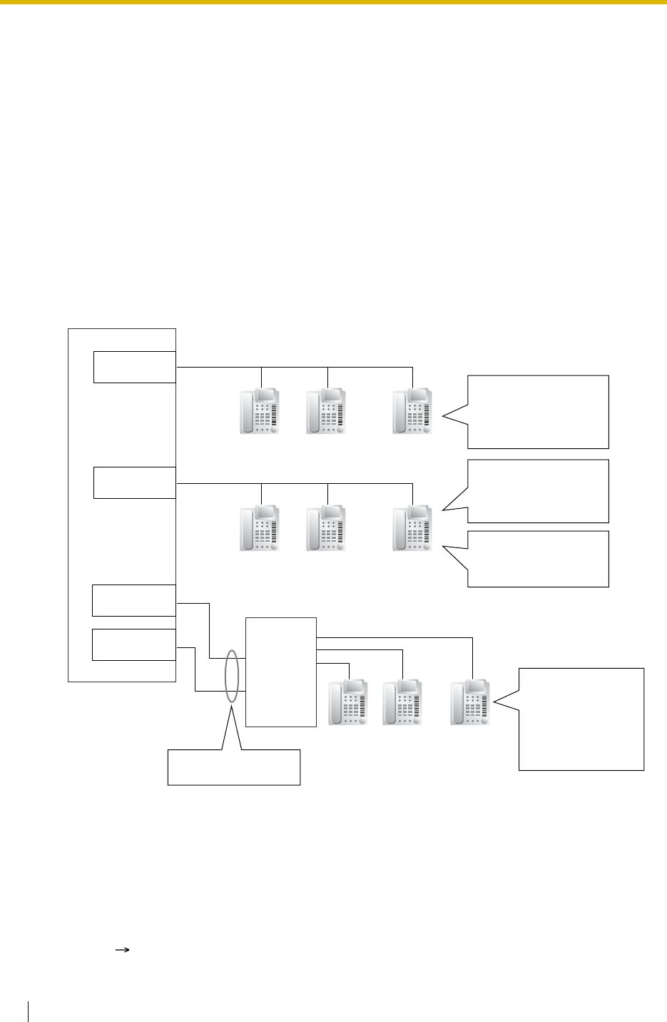
1.20 Integrated Services Digital Network (ISDN) Service Features
198 Feature Guide
1.20.1.11 ISDN Extension
Description
An ISDN (BRI/PRI) port can be used for either trunk or extension connection. When extension
connection is enabled, ISDN terminal devices (e.g., ISDN telephone, G4 fax machine, personal
computer) or a behind PBX can be connected to the port.
If the ISDN port is in point-to-point (P-P) configuration, one terminal device can be connected
to the port. If the ISDN port is in point-to-multipoint (P-MP) configuration, a maximum of eight
terminal devices can be connected to the port. However, only a maximum of two devices can
be used simultaneously.
Individual terminal devices on a behind PBX can be addressed with Multiple Subscriber
Number (MSN). The MSN consists of the ISDN extension number and an additional digit, 0
through 9 or 00 through 99.
[Example]
Conditions
•Subaddressing
Subaddressing is possible between ISDN terminal devices. The subaddress goes through
the PBX to the ISDN terminal devices directly.
• Call Transfer (PBX feature) is available only for ISDN extensions in P-MP configuration.
( 1.11.1 Call Transfer)
(131)
Extn. No.: 13X (MSN)
Extn. No.: 14XX (MSN)
Extn. No.: 15XX
(MSN)
PBX
(132) (139)
...
...
Behind
PBX
(1234)
Extn. No.: 1234
ISDN Port for
EXTN. (P-MP)
(1234) (1234)
...
...
1234:
Up to eight terminals
can be connected to
the port and receive
a call simultaneously.
131–139:
Up to eight terminals
can be connected to
the port.
130:
All terminals receive
a call simultaneously.
(1400) (1401) (1499)
...
...
1400–1499:
Each terminal
receives a call.
(Use the DDI/MSN
feature of the
behind PBX.)
Idle Extension
Hunting is available.
ISDN Port for
EXTN. (P-P/P-MP)
ISDN Port for
EXTN. (P-P/P-MP)
ISDN Port for
EXTN. (P-MP)

1.20 Integrated Services Digital Network (ISDN) Service Features
Feature Guide 199
• ISDN extensions can belong to an incoming call distribution group ( 1.2.2 Incoming Call
Distribution Group Features) or idle extension hunting group ( 1.2.1 Idle Extension
Hunting). In this case, an MSN can be assigned.
• If the last digit of the MSN is "0", all terminal devices on the same ISDN port receive the
call simultaneously, if the specification of each terminal device is available. To use the
MSN whose last digit is "0" as an individual MSN, system programming is required for
each ISDN port.
Feature Guide References
1.1.1.4 Multiple Subscriber Number (MSN) Ringing Service

1.20 Integrated Services Digital Network (ISDN) Service Features
200 Feature Guide
1.20.1.12 ISDN Service Access by Keypad Protocol
Description
ISDN provides some supplementary services by key protocol, and they may require a service
access code to be dialled.
This feature complies with the following European Telecommunication Standard (ETS)
specifications: ETS 300 122 Generic keypad protocol for the support of supplementary service
(ISDN Service Access).
Conditions
•ISDN Service Button
A flexible button can be customised as an ISDN Service button. A service access code
can also be assigned on this button for a quick operation.
• This feature is not available to an SLT.
Feature Guide References
1.19.2 Flexible Buttons
User Manual References
User Manual
1.2.5 Accessing the ISDN Service (ISDN Service Access)
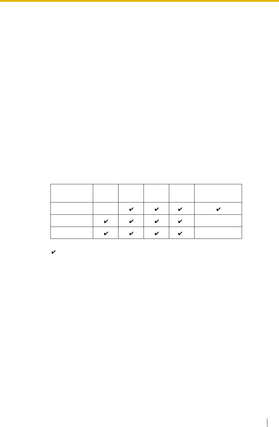
1.21 E1 Line Service Features (KX-TDA100/KX-TDA200 only)
Feature Guide 201
1.21 E1 Line Service Features (KX-TDA100/KX-
TDA200 only)
1.21.1 E1 Line Service (KX-TDA100/KX-TDA200 only)
Description
The E1 line carries thirty 64 kbps-voice channels at 2.048 Mbps transmission speed as a trunk
or private line. Voice is digitised by Pulse Code Modulation (PCM).
1. Channel Type
[DR2 (Digital System R2)/E & M-C (Continuous E & M)/E & M-P (Pulsed E & M)]
The E1 card supports three different channel types to provide connection at minimum
expense. One of the three channel types can be assigned to one of the 30 channels of the
E1 card individually according to tariffs and customer needs.
2. E1 Features
The following table shows the features available for each channel type:
[Feature Table]
Channel Type (1) TIE (2) DID (3) DIL (4) ANI (5) Call Charge
Information
DR2 *1
E & M-C *2
E & M-P *2
:Available
*1:Receiving Dial Mode should be MFC-R2.
*2:Available when this PBX is connected to the KX-TDA100, KX-TDA200, or KX-
TD500.
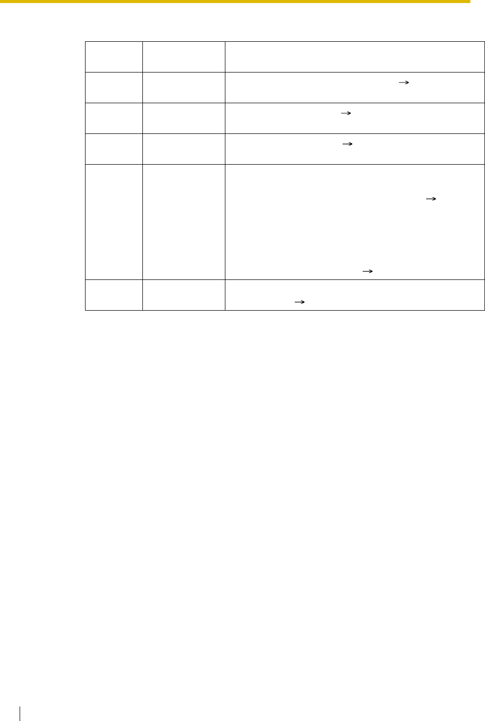
1.21 E1 Line Service Features (KX-TDA100/KX-TDA200 only)
202 Feature Guide
[Explanation]
Conditions
• If an E1 line is used as a trunk, the channel type depends on the contract with the
telephone company.
• If "MFC-R2" is selected as the Dial Mode, the PBX always sends a dial tone, instead of the
telephone company, when making a trunk call using E1 line.
Number in
the table Feature Description
(1) TIE Line Service Refer to the TIE Line Service feature. ( 1.28.1 TIE Line
Service)
(2) Direct Inward
Dialling (DID) Refer to the DID feature. ( 1.1.1.3 Direct Inward Dialling
(DID)/Direct Dialling In (DDI))
(3) Direct In Line
(DIL) Refer to the DIL feature. ( 1.1.1.2 Direct In Line (DIL))
(4) Automatic
Number
Identification
(ANI)
Outgoing ANI:
Sends the caller’s number to the E1 line. The sending
method is the same as ISDN CLIP service. ( 1.20.1.2
Calling/Connected Line Identification Presentation (CLIP/
COLP))
Incoming ANI:
Receives the caller’s number from the E1 line.
When the ANI number is received, it can be treated the
same as a Caller ID number. ( 1.17.1 Caller ID)
(5) Call Charge
Information The call charge meter pulses can be received during a
conversation. ( 1.25.2 Charge Meter)
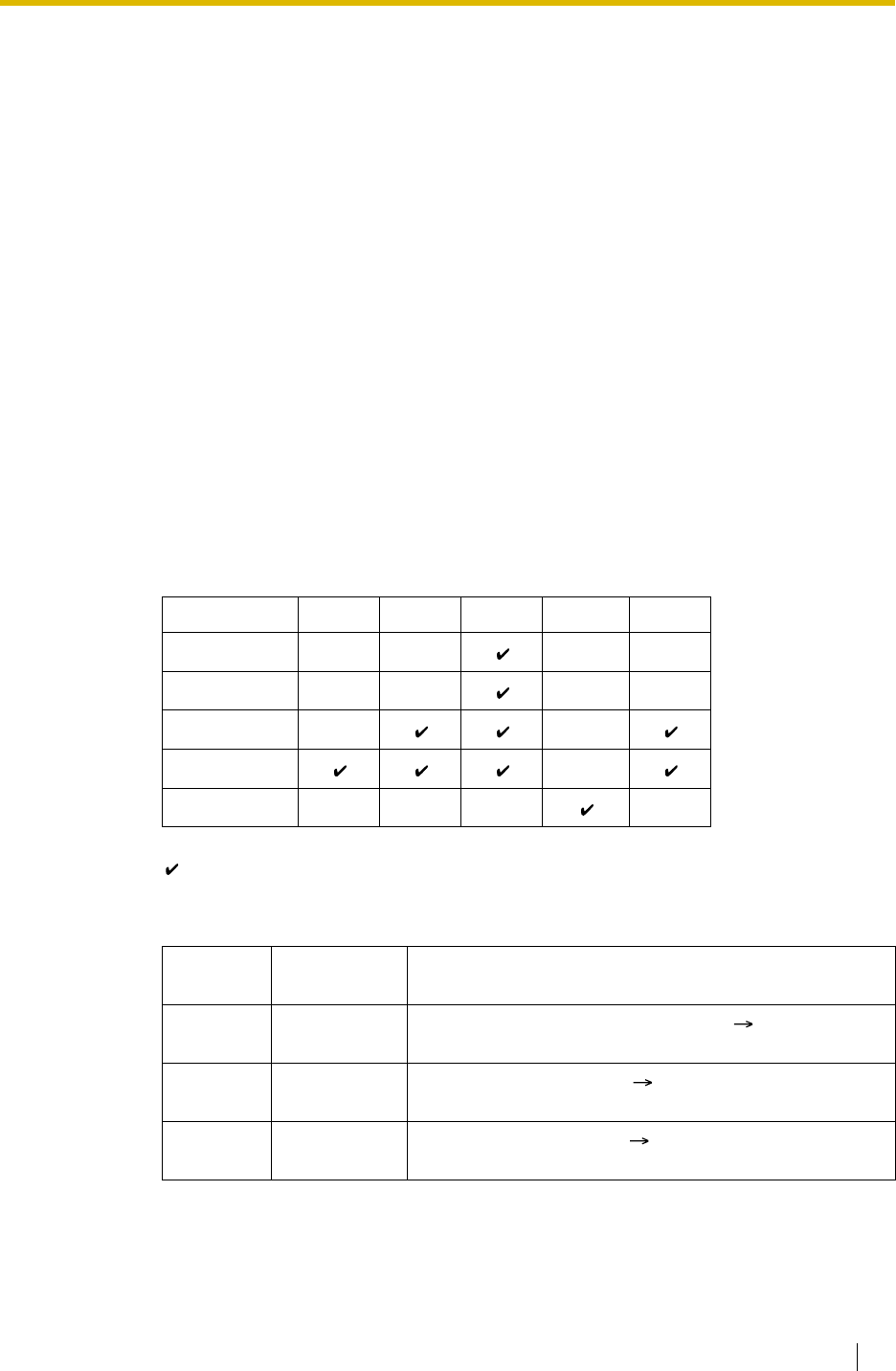
1.22 T1 Line Service Features (KX-TDA100/KX-TDA200 only)
Feature Guide 203
1.22 T1 Line Service Features (KX-TDA100/KX-
TDA200 only)
1.22.1 T1 Line Service (KX-TDA100/KX-TDA200 only)
Description
The T1 line carries twenty-four 64 kbps-voice channels at 1.5 Mbps transmission speed as a
trunk or private line. Voice is digitised by Pulse Code Modulation (PCM).
1. Channel Type
[LCOT/GCOT/DID/TIE/OPX]
The T1 card supports five different channel types to provide connection at minimum
expense. One of the five channel types can be assigned to one of the 24 channels of the
T1 card individually according to tariffs and customer needs.
2. T1 Features
The following table shows the features available for each channel type:
[Feature Table]
[Explanation]
Channel Type (1) TIE (2) DID (3) DIL (4) OPX (5) ANI
LCOT
GCOT
DID
TIE (E & M)
OPX
:Available
Number in
the Table Feature Description
(1) TIE Line
Service Refer to the TIE Line Service feature. ( 1.28.1 TIE Line
Service)
(2) Direct Inward
Dialling (DID) Refer to the DID feature. ( 1.1.1.3 Direct Inward
Dialling (DID)/Direct Dialling In (DDI))
(3) Direct In Line
(DIL) Refer to the DIL feature. ( 1.1.1.2 Direct In Line (DIL))
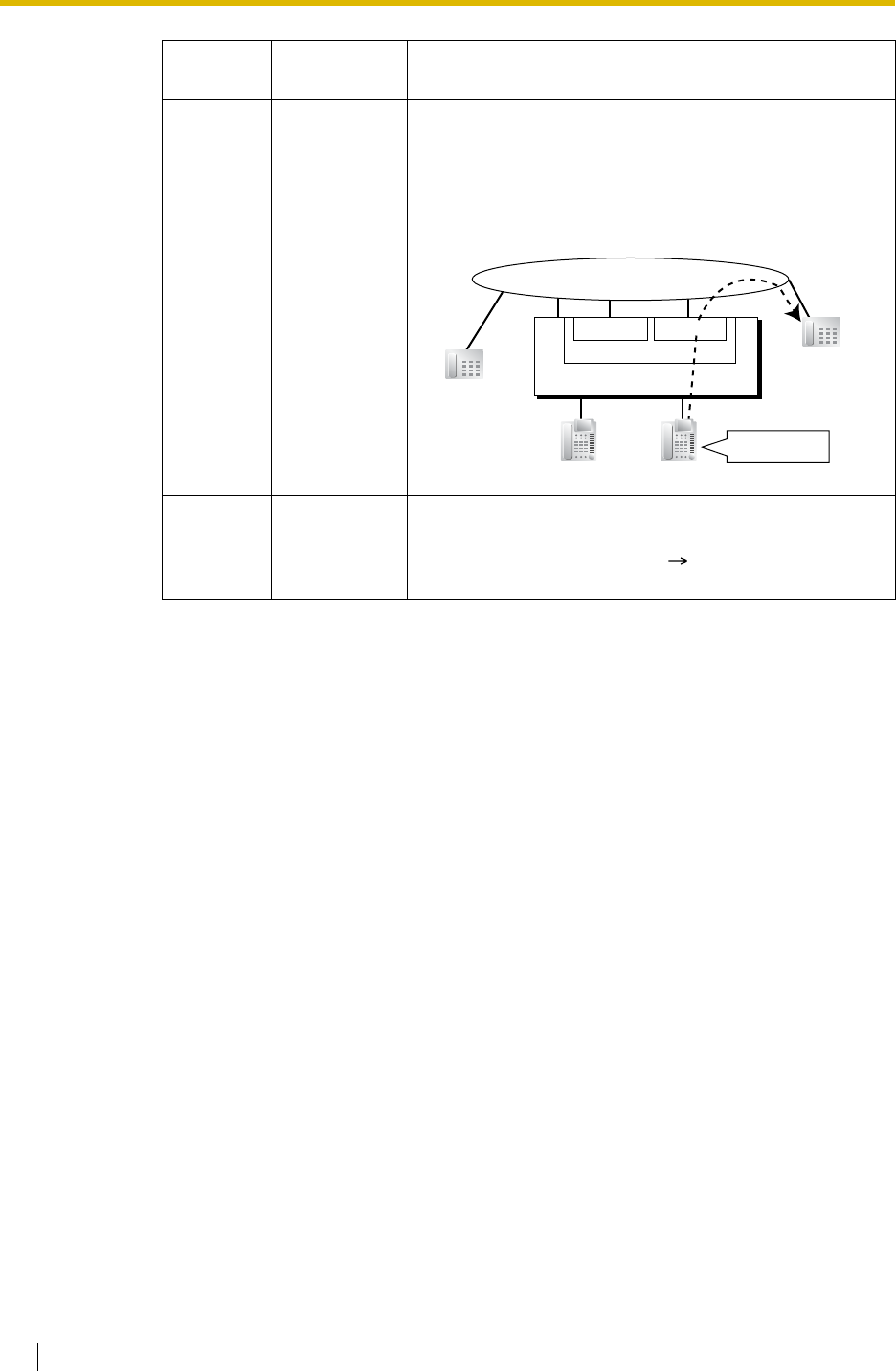
1.22 T1 Line Service Features (KX-TDA100/KX-TDA200 only)
204 Feature Guide
Conditions
• If a T1 line is used as a trunk, the channel type depends on the contract with the telephone
company.
(4) Off Premise
Extension
(OPX)
An SLT which is installed off site can perform as if it were
installed locally. The SLT makes and receives a call
through the PBX. An extension number can be given to
the OPX, and extension data such as COS is also
applied.
[Example]
(5) Automatic
Number
Identification
(ANI)
Receives the caller’s number from the T1 line.
When the ANI number is received, it can be treated the
same as a Caller ID number. ( 1.17.1 Caller ID)
Number in
the Table Feature Description
Dials "103".
Extn.101
Extn.10
3
SLT
Telephone Company
T1 LCOT
T1 Card
T1 OPX
PBX
Extn.102
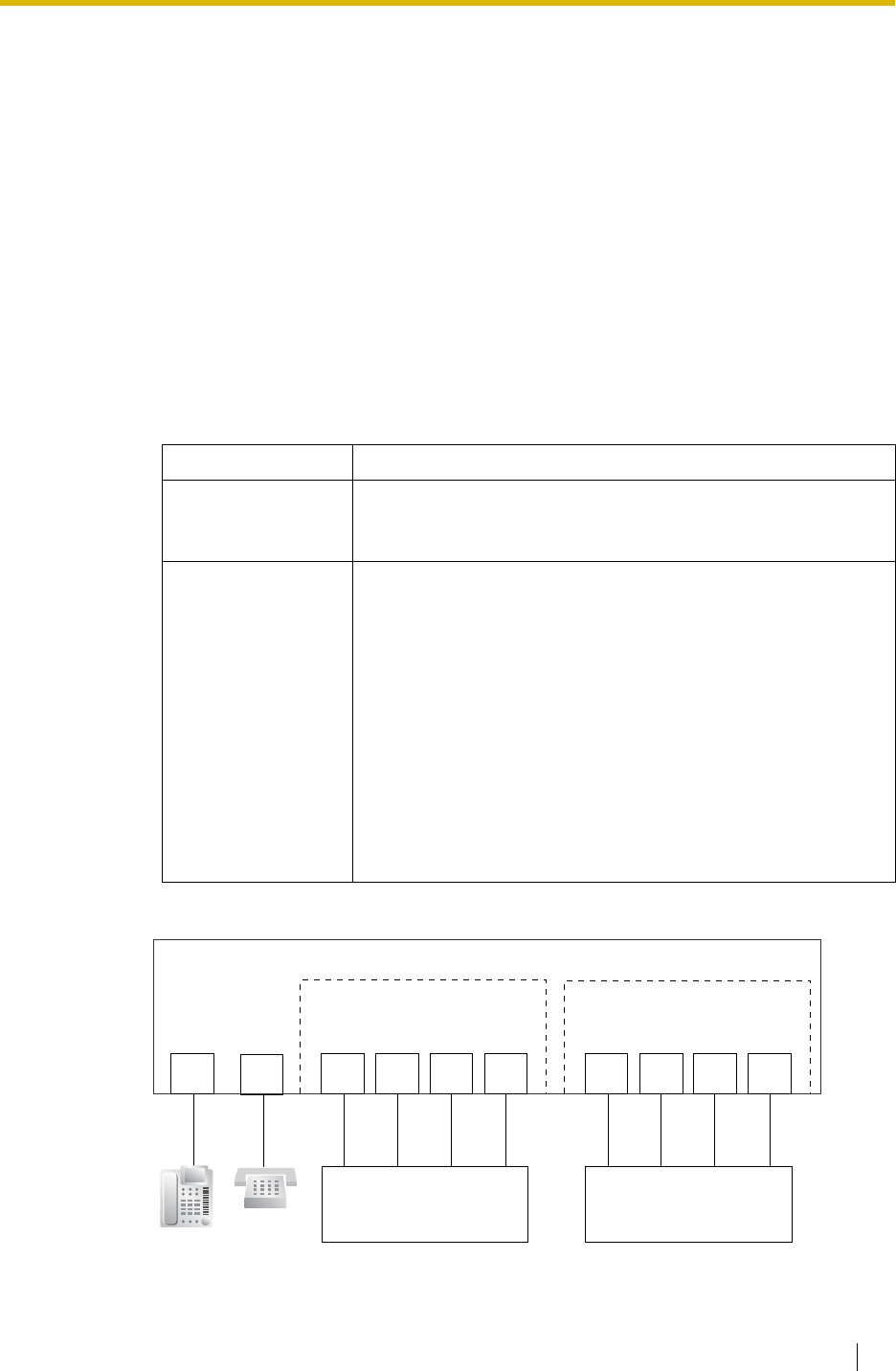
1.23 Voice Mail Features
Feature Guide 205
1.23 Voice Mail Features
1.23.1 Voice Mail (VM) Group
Description
A VPS can be connected to extension ports on the PBX. The extension ports make a group,
called a VM group. This group has a floating extension number. The VM group can be the
destination for redirected calls and incoming calls. When receiving a call, the VPS can greet
the caller offering them the option to leave a message or dial a number to reach the desired
party. The VPS can record the message for each extension and leave notification on the
corresponding extension, if the called extension is not able to answer calls.
1. VM Group Type
[Example]
Type Description
VM (DTMF) Group A group of SLT ports which use the Voice Mail DTMF Integration
features. A maximum of two VM (DTMF) groups can be
assigned.
VM (DPT) Group
A group of DPT ports which use the Voice Mail DPT (Digital)
Integration features.
With the KX-TDA100/KX-TDA200:
• A maximum of two VM (DPT) groups can be assigned.
• One Panasonic KX-TVS/KX-TVP system can be in
only one group.
• A maximum of 12 ports (24 channels) of the VPS can
form each group.
With the KX-TDA15/KX-TDA30:
• One VM (DPT) group can be assigned.
• A maximum of 4 ports (8 channels) of the VPS can
form a group.
PBX
SLT
Port SLT
Port SLT
Port SLT
Port
VPS
(DPT [Digital] Integration) VPS
(DTMF Integration)
DPT
Port DPT
Port DPT
Port DPT
Port
DPT
Port
VM (DPT) Group
Floating extn. no. 100 VM (DTMF) Group
Floating extn. no. 250
Extn.101 Extn.102 Extn.103 Extn.104 Extn.117 Extn.118 Extn.119 Extn.120
SLT
Port
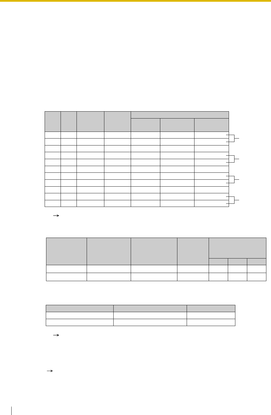
1.23 Voice Mail Features
206 Feature Guide
VM (DTMF) Group Assignment:
The VPS is connected to the SLT ports of the PBX. These SLT ports, as well as VM
(DTMF) Group settings, must be configured to allow DTMF Integration, as shown in the
following [Programming Example of Extension Port] and [Programming Example of VM
(DTMF) Group].
VM (DPT) Group Assignment:
The VPS is connected to the DPT ports of the PBX. These DPT ports, as well as VM (DPT)
group settings, must be configured to allow DPT (Digital) Integration, as shown in the
following [Programming Example of Extension Port] and [Programming Example of VM
(DPT) Group].
[Programming Example of Extension Port]
[Programming Example of VM (DTMF) Group]
[Programming Example of VM (DPT) Group]
2. Incoming Calls to VM Group
When incoming calls are received at the floating extension number of the VM group, calls
will hunt starting at the lowest VM port number. In this case, the FWD and DND settings
( 1.3.1 Call Forwarding (FWD)/Do Not Disturb (DND)) for each extension port are
disregarded.
It is programmable whether the calls queue when all extension ports in the group are busy
through system programming. If the queuing is disabled through system programming, the
*: Terminal Device Assignment [601]
*: VM Group Floating Extension Number [660]
DPT Property
VM (DPT)
Group 1
Slot
3
3
:
4
4
:
5
5
:
6
6
Port
1
2
:
1
2
:
1
2
:
1
2
Extn. No.
101
102
:
201
202
:
301
302
:
401
402
Type*
VM (DPT)
VM (DPT)
:
VM (DPT)
VM (DPT)
:
Not assignable
Not assignable
:
Not assignable
Not assignable
Unit No.
of VPS
1
1
:
2
2
:
Not assignable
Not assignable
:
Not assignable
Not assignable
Port No.
of VPS
1
2
:
1
2
:
Not assignable
Not assignable
:
Not assignable
Not assignable
Port Type
DPT
DPT
:
S-Hybrid
S-Hybrid
:
SLT
SLT
:
SLT
SLT
VM (DPT)
Group 2
VM (DTMF)
Group 1
VM (DTMF)
Group 2
VM (DTMF)
Group No.
1
2
Group
Name
Company C
Company D
Service
Mode
AA
VM
Floating
Extension
No.
300
400
1
301
401
…
…
…
Extension No. of
Port Connected to
VPS Port
2
302
402
VM (DPT) Group No.
1
2
Floating Extension No.*
100
200
Group Name
Company A
Company B

1.23 Voice Mail Features
Feature Guide 207
call will be redirected to the destination, assigned on the trunk group which receives the
call, by the Intercept Routing feature.
Conditions
[General]
• It is possible to call an extension (extension port) in a VM group directly. If the calls are
routed directly to the extension in the group, it is possible to enable some features (e.g.,
FWD, Idle Extension Hunting) on the extension in the group.
The Voice Mail DTMF/DPT (Digital) Integration (e.g., command transmit) is also available
on the extension.
•One-touch Voice Mail Feature Access
It is possible to assign a One-touch Dialling button for direct access to a Voice Mail feature.
( 1.6.1.2 One-touch Dialling) For example, to access a mailbox (mailbox number 123)
of the VPS (extension number 165) directly, assign "165#6123" to a One-touch Dialling
button. When pressing this button, the outgoing message (OGM) of the mailbox will be
heard.
[KX-TDA100/KX-TDA200]
• All ports in a VM (DPT) group must be connected to a single DHLC or DLC card.
[KX-TDA15/KX-TDA30]
• All ports in a VM (DPT) group must be connected to either the same DLC card, or to the
preinstalled Super Hybrid ports.
Feature Guide References
1.23.2 Voice Mail DTMF Integration
1.23.3 Voice Mail DPT (Digital) Integration

1.23 Voice Mail Features
208 Feature Guide
1.23.2 Voice Mail DTMF Integration
Description
The PBX and the VPS connected to the PBX can transmit commands using DTMF signals to
each other. The PBX sends preprogrammed commands using DTMF to the VPS automatically
to change the answering service between Voice Mail (VM) service mode and Automated
Attendant (AA) service mode or to inform the extension status (e.g., busy). The VPS sends the
commands to the PBX like an SLT.
The following answering services and features are available:
1. Voice Mail (VM) Service Mode
When a caller reaches the VPS, the VPS greets and guides the caller to leave a voice
message for a specified mailbox.
[Example]
The VPS sends the message to the caller, "Thank you for calling Panasonic. Please enter
the mailbox number of the person you wish to leave your message for."
The caller dials the mailbox number. Then, the dialled number is sent to the VPS via the
PBX.
The VPS sends the personal greeting to the caller, "You have reached Mike's voice mail.
I am sorry I cannot take your call right now. Please leave a message and I will call you
back."
The caller leaves a message.
If the call reroutes to the floating extension number of the VM (DTMF) Group or the
extension in the VM (DTMF) group by such as the FWD feature, when the VPS answers
the call, the PBX will dial the mailbox number of the corresponding group or extension and
any other digits required to the VPS automatically using the caller-dialled number (Follow
on ID). In this case, the caller can reach a mailbox without knowing the mailbox number.
[Available Features for Follow on ID]
a) FWD to a Mailbox
b) Intercept Routing to a Mailbox
c) Call Transfer to a Mailbox
d) Listening to a Message in a Mailbox
2. Automated Attendant (AA) Service Mode
The VPS greets and guides the caller to the desired extension directly without operator
assistance.
3. VM AA Service, AA VM Service
It is possible to switch the service mode assigned on the VPS port, from the VM service
to AA service or vice versa.
System Explanation
1. Service Mode Assignment
Assign the service mode, VM service or AA service, to the VM (DTMF) group to
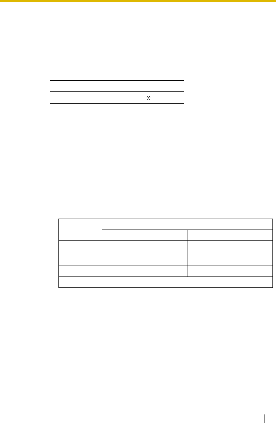
1.23 Voice Mail Features
Feature Guide 209
correspond with the assignment of the VPS.
2. DTMF Command Assignment
Assign the DTMF command to suit the VPS settings.
Note: H = Mailbox Number
3. VM Service
a) FWD to a Mailbox of the VPS
The PBX sends a mailbox number of the corresponding extension to the VPS when
a call is forwarded from an extension to the VPS. Therefore the caller can leave a
message for the called extension without knowing the mailbox number.
[FWD to the VPS Sequence Selection]
If an extension user sets FWD to the VPS, any incoming call will be forwarded to the
VPS.
It is also possible to send the AA command, even in the VM service mode, when calls
are forwarded so that the caller can be directed to an extension rather than a mailbox.
This can be performed by selecting "AA" through system programming.
b) Intercept Routing to a Mailbox of the VPS
The PBX sends a mailbox number of the corresponding extension to the VPS when
a trunk call is intercepted from an extension to the VPS. Therefore the caller can leave
a message for the called extension without knowing the mailbox number.
[Intercept Routing to the VPS Sequence Selection]
If an extension user sets Intercept Routing to the VPS, the intercepted trunk calls will
be redirected to the VPS.
It is also possible to send the AA command, even in the VM service mode, when calls
are intercepted so that the caller can be directed to an extension rather than a
mailbox. This can be performed by selecting "AA" through system programming.
Command (Default)
Switching to VM #6
Switching to AA #8
Recording message H
Listening message H
Parameter Transmitted Command
In AA Service Mode In VM Service Mode
Answer by
Mailbox
(Default)
Switching to VM command +
Recording message command
(#6 + H [H = Mailbox No.])
Recording message command
(H [H = Mailbox No.])
AA Switching to AA command (#8) Switching to AA command (#8)
None (DTMF commands are not sent. Work with default of the VPS.)
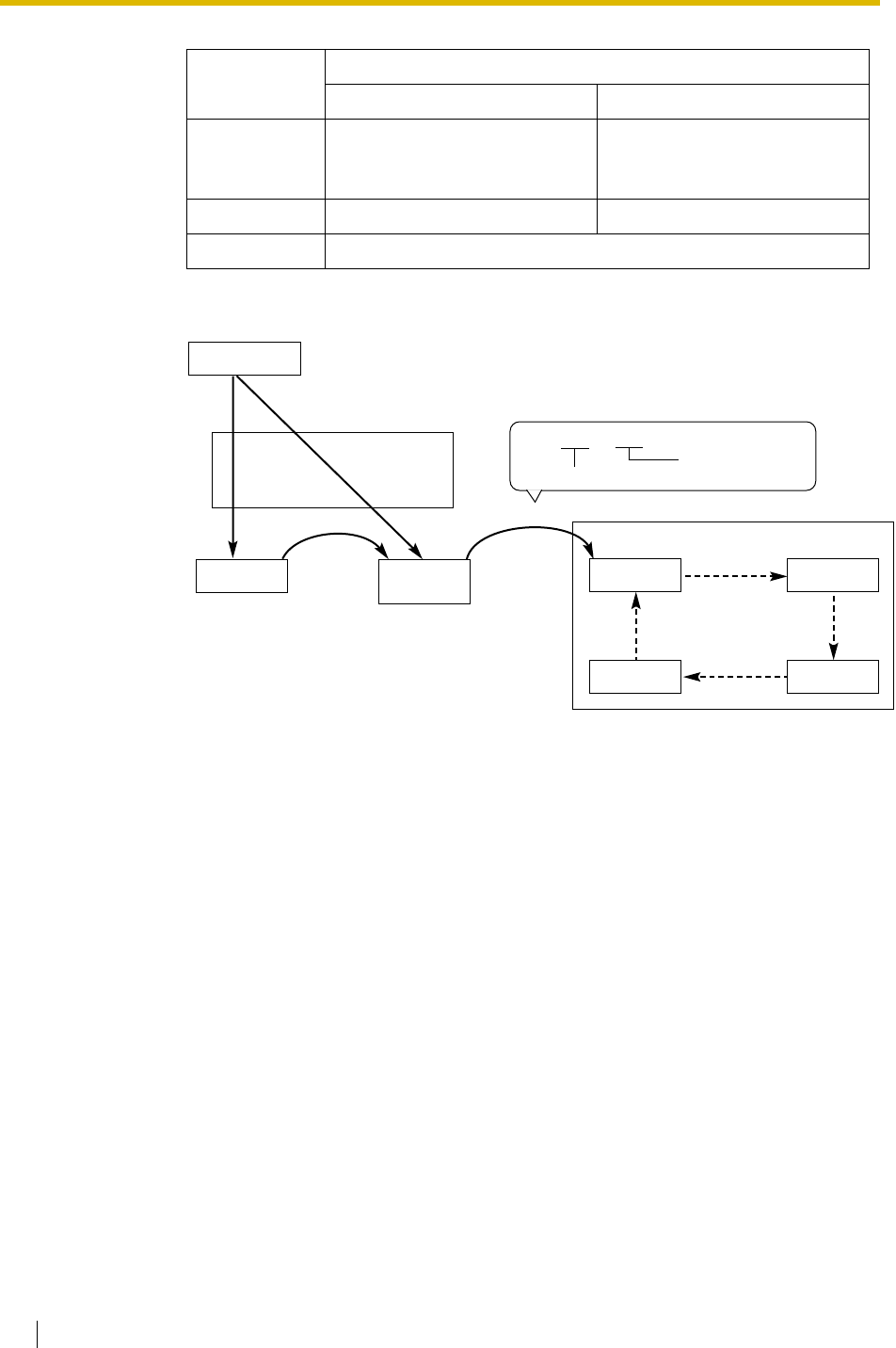
1.23 Voice Mail Features
210 Feature Guide
[Example of a) & b)]
c) Transferring to a Mailbox of the VPS
An extension user can transfer a call to a mailbox of the VPS so that the caller can
leave a message in the mailbox of the desired extension. The extension user should
use the Voice Mail (VM) Transfer button, when transferring a call to the mailbox of the
VPS. When the extension user presses this button and enters the desired extension
number, the PBX will transfer the call to the VM group and dial the mailbox number of
the desired extension with the required command (after the VPS answers the call).
Therefore the caller can leave a message without knowing the mailbox number.
Parameter Transmitted Command
In AA Service Mode In VM Service Mode
Answer by
Mailbox Switching to VM command +
Recording message command
(#6 + H [H = Mailbox No.])
Recording message command
(H [H = Mailbox No.])
AA Switching to AA command (#8) Switching to AA command (#8)
None (Default) (DTMF commands are not sent. Work with default of the VPS.)
Trunk Call
Operator Extn. 102 VM Port 1 VM Port 2
VM Port X VM Port 3
VM (DTMF)
Group
VPS (In AA service mode)
FWD, Intercept
PBX
Transfer
Sent "#6" + "102".
Switching to VM command
mailbox number
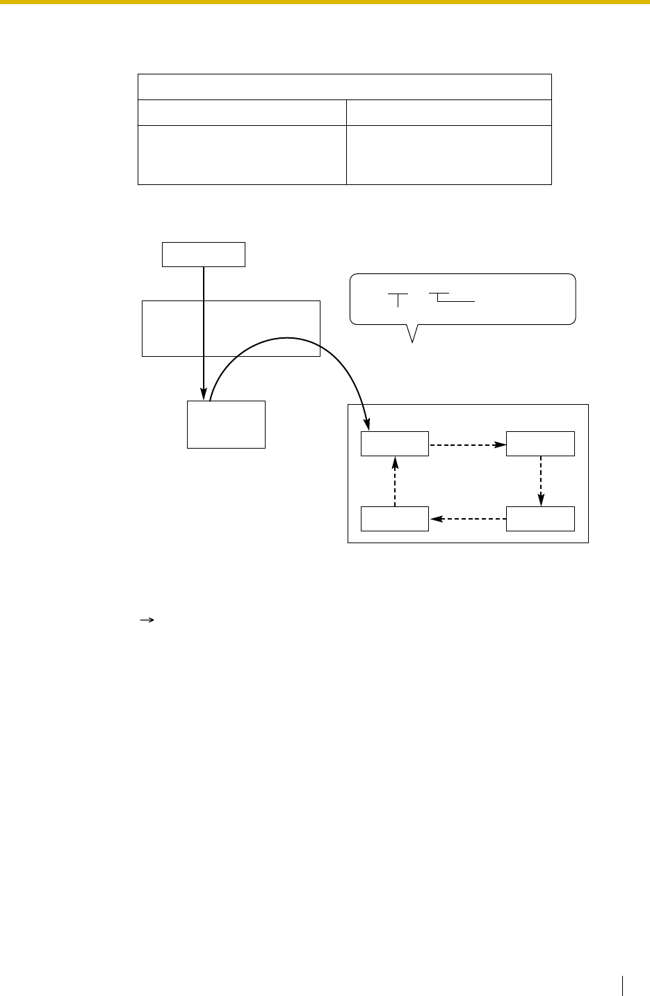
1.23 Voice Mail Features
Feature Guide 211
[Performance of Pressing the VM Transfer Button and Entering an Extension
Number]
[Example]
d) Listening to a Recorded Message
If the VPS receives a message, the VPS will set the Message Waiting feature (e.g.,
turning on the Message button light) on the corresponding telephone as notification.
( 1.18.1 Message Waiting) Thereby, the VPS notifies the extension user that there
is a message waiting in his mailbox. When the Message button light turns on,
pressing the button allows the extension user to play back the messages stored in his
mailbox without dialling such as a mailbox number. It is programmable whether the
PBX or the VPS cancels the Message Waiting feature (e.g., turning off the Message
button light). When the PBX is selected, the Message Waiting feature is cancelled
after the extension user has accessed the VPS. When the VPS is selected, the
Message Waiting feature is cancelled after the extension user has listened to
messages stored in his mailbox.
Transmitted Command
In AA Service Mode In VM Service Mode
Switching to VM command +
Recording message command
(#6 + H [H = Mailbox No.])
Recording message command
(H [H = Mailbox No.])
Trunk Call
VM Port 1 VM Port 2
VM Port X VM Port 3
VM (DTMF)
Group
VPS (In AA service mode)
PBX
Extension
(Operator)
Transfer with VM Transfer
button + extension number (103)
Sent "#6" + "103".
Switching to VM command
mailbox number
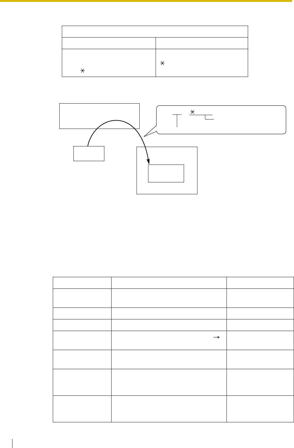
1.23 Voice Mail Features
212 Feature Guide
[Performance of Pressing the MESSAGE Button]
[Example]
4. AA Service
If the VPS transfers the call using the AA service, the PBX will inform the VPS of the status
of the called destination with the preprogrammed DTMF status signal so that the VPS can
confirm the status of the extension without listening to the system tones (e.g., ringback
tone).
Assign the DTMF status signal to suit the VPS settings.
[The DTMF Status Signal and Condition]
Transmitted Command
In AA Service Mode In VM Service Mode
Switching to VM command +
Listening message command
(#6 + H [H = Mailbox No.])
Listening message command
( H [H = Mailbox No.])
Status Condition Default Command
RBT (ringback
tone) The PBX is ringing the corresponding
extension. 1
BT (busy tone) The called extension is busy. 2
ROT (reorder tone) The dialled number is invalid. 3
DND (DND tone) The called extension has set DND. (
1.3.1.3 Do Not Disturb (DND)) 4
Answer The called extension has answered the
call. 5
FWD VM RBT
(FWD to Voice Mail
ringback tone)
The called extension has set FWD to
VPS and the PBX is calling another port
of the VPS.
6
FWD VM BT (FWD
to Voice Mail busy
tone)
The called extension has set FWD to
VPS and all ports of the VPS are busy. 7
VPS (In AA
service mode)
PBX Sent "#6" + " ", "102".Listening message
command, mailbox number
Mailbox for
Extn. 102
Pressing the
MESSAGE
button
Switching to VM command
Extn. 102
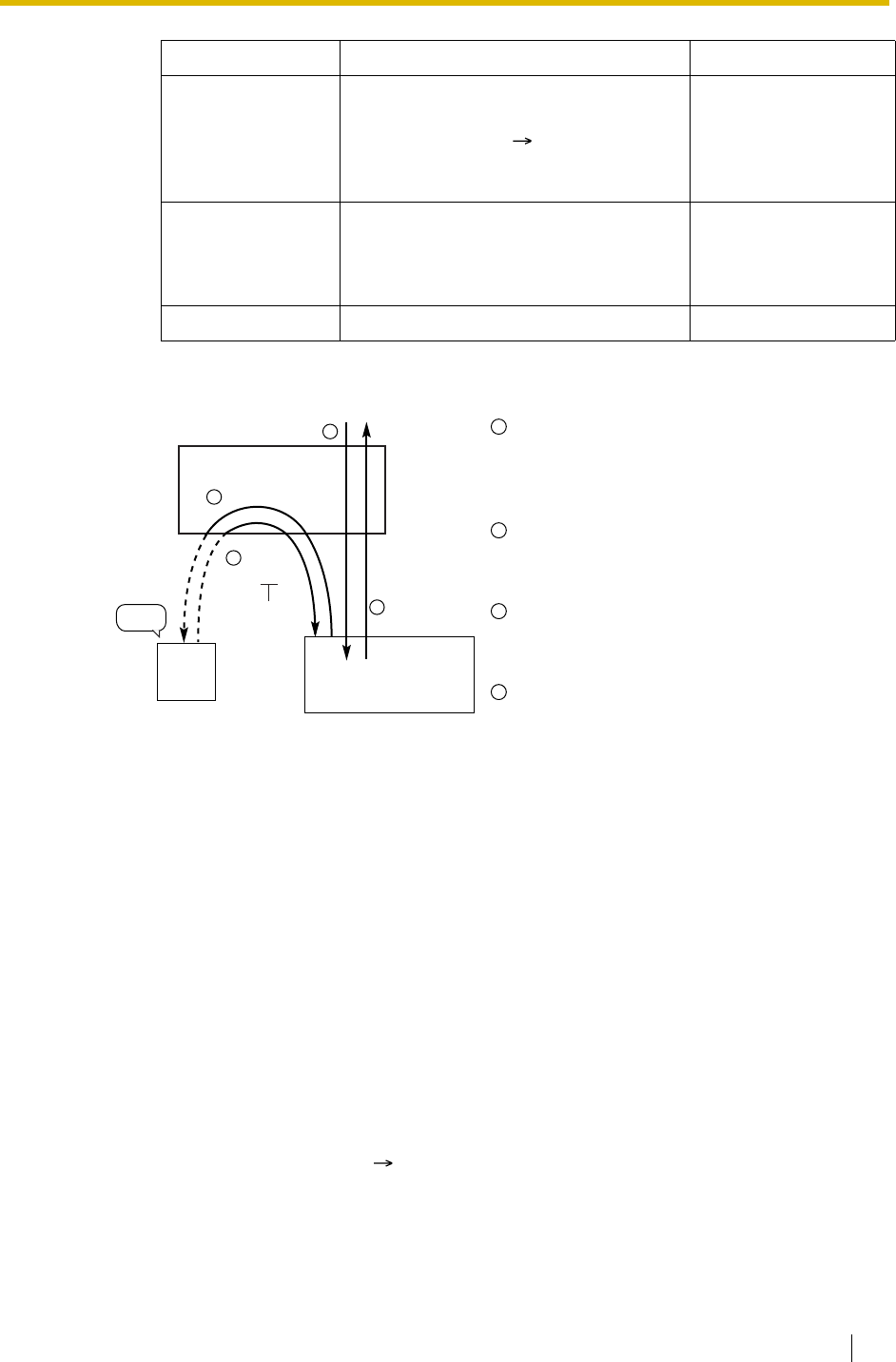
1.23 Voice Mail Features
Feature Guide 213
Conditions
•Voice Mail (VM) Transfer Button
A flexible button can be customised as the Voice Mail (VM) Transfer button with the floating
extension number of the VM group as the parameter.
• It is possible to assign the time period between when the VPS answers the call and the
PBX sends the Follow on ID to the VPS.
• It is possible to assign the time period between when the VPS transfers the call using the
AA service to the PBX and the PBX sends the DTMF status signal to the VPS.
• It is possible to select whether the mailbox number is the same as the extension number,
or the mailbox number is programmable for each extension number and incoming call
distribution group (Mailbox Access ID).
• The Inter-digit time for the DTMF command and for DTMF status signal is programmable.
• Data Line Security is set automatically on the extensions in the VM (DTMF) group to
achieve proper recording. ( 1.10.5 Data Line Security)
Feature Guide References
1.1.1.6 Intercept Routing
FWD EXT RBT
(FWD to extension
ringback tone)
The PBX is calling an extension other
than the one dialled. FWD or Idle
Extension Hunting ( 1.2.1 Idle
Extension Hunting) may be assigned by
the called extension.
8
Confirm
(confirmation tone) The PBX receives confirmation that the
feature has been successfully set or
cancelled (e.g., Message Waiting) on the
extension.
9
Disconnect The caller has hung up. #9
[Example]
An incoming call reaches the VPS. The VPS
greets the caller: "Thank you for calling
Panasonic. If you know the extension
number of the person you wish… ".
The caller dials the extension number (extn.
102). The VPS will transfer the call to the
extension via the PBX.
If the extension is not available, the PBX
sends DTMF status signal of the extension
(busy status) to the VPS.
The VPS receives the DTMF status signal
and send the appropriate message to the
caller: "Sorry. The extension is busy. Would
you like to leave a message… ".
Status Condition Default Command
VPS
Extn.
102
1
3
4
Sent "2".
Busy
Status
Busy
PBX
Transfer
2
1
2
3
4


1.23 Voice Mail Features
Feature Guide 215
1.23.3 Voice Mail DPT (Digital) Integration
Description
A Panasonic VPS that supports DPT (Digital) Integration (e.g., the KX-TVP200) can be
connected to this PBX in a tightly integrated fashion.
DPT (Digital) Integration features can be used when the VPS is connected through DPT ports
of the PBX.
Feature Explanation
1. Automatic Configuration—Quick Setup
The PBX informs the VPS of its extension numbers and the floating extension numbers of
the incoming call distribution groups so that the VPS can create mailboxes with this data
automatically.
2. FWD to a Mailbox of the VPS
If an extension user sets FWD to the VPS, incoming calls are forwarded to the VPS. (
1.3.1.2 Call Forwarding (FWD)) The PBX sends a mailbox number of the forwarding
extension to the VPS. Therefore the caller can leave a message in the mailbox of the
extension without knowing the mailbox number.
3. Intercept Routing to a Mailbox of the VPS
If an extension user sets Intercept Routing to the VPS, the intercepted trunk calls will be
redirected to the VPS. ( 1.1.1.6 Intercept Routing) If the "Intercept to Mailbox"
setting is enabled through system programming, the PBX sends the mailbox number of
the intercepted extension to the VPS. Therefore the caller can leave a message in the
mailbox of the extension without knowing the mailbox number.
4. Transferring to a Mailbox of the VPS
An extension user can transfer a call to a mailbox of the VPS so that caller can leave a
message in the mailbox of the desired extension. ( 1.11.1 Call Transfer) The extension
user should use the Voice Mail (VM) Transfer button, when transferring a call to the
mailbox of the VPS. When the extension user presses this button and enters the desired
extension number, the PBX will transfer the call to the VM group and dial the mailbox
number of the desired extension number with the required command (after the VPS
answers the call). Therefore the caller can leave a message without knowing the mailbox
number.
5. Transfer Recall to a Mailbox of the VPS
If a call is transferred to an extension via the Automated Attendant (AA) service of the VPS
and the call is not answered within a preprogrammed Transfer Recall time ( Transfer
Recall Time [201]), the PBX sends the mailbox number of the transfer destination
extension to the VPS. Therefore the caller can leave a message in the mailbox of the
extension without knowing the mailbox number. The "Transfer Recall to Mailbox"
setting should be enabled through system programming to use this feature.
6. Listening to a Recorded Message (Direct Mailbox Access)
If the VPS receives a message, the VPS will set the Message Waiting feature (e.g., turning
on the Message button light) on the corresponding telephone as notification. ( 1.18.1
Message Waiting) Thereby, the VPS notifies the extension user that there is a message
waiting in his mailbox. When the Message button light turns on, pressing the button allows
the extension user to play back the messages stored in his mailbox without dialling such
as a mailbox.
When the extension user dials an extension number of the VM (DPT) extension port or the
floating extension number of the VM (DPT) group from his extension, he can listen to the
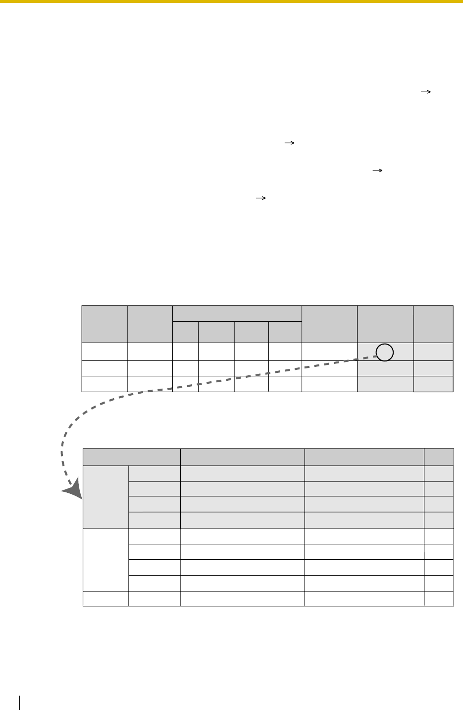
1.23 Voice Mail Features
216 Feature Guide
messages stored in his mailbox without dialling his mailbox number (Direct Mailbox
Access). It is possible to disable this feature by COS programming on the VPS.
7. VPS Trunk Service & Automatic Time Mode Notification for Incoming Call*
Multiple tenants can share a single VPS; each tenant does not require a dedicated VPS
port. If the destination of the incoming trunk call is a VM (DPT) group, the PBX sends the
VPS trunk group number and time mode (day/lunch/break/night) of the tenant ( 2.2.4
Time Service) assigned for the call to the VPS. Therefore the VPS can send the assigned
message (company greeting) to the caller. Corresponding VPS trunk group number and
tenant number are determined by the setting of the incoming trunk call as follows:
a) DIL/TIE: the setting of each trunk port ( 1.1.1.2 Direct In Line (DIL), 1.28.1 TIE
Line Service)
b) DID/DDI: the setting of each location number for DID/DDI ( 1.1.1.3 Direct
Inward Dialling (DID)/Direct Dialling In (DDI))
c) MSN: the setting of each MSN ( 1.1.1.4 Multiple Subscriber Number (MSN)
Ringing Service)
[Example]
For DID Calls:
Each location number can have its VPS trunk group number (message number) and
tenant number.
Explanation:
A DID call reaches a VM (DPT) group directly or by the Intercept Routing feature.
According to the [DID Programming Example] and [VPS Programming—Programming
Example of Trunk Group Assignment], a caller will hear a corresponding company greeting
of the VPS.
1
2
:
[DID Programming Example]
[VPS Programming—Programming Example of Trunk Group Assignment]
105
102
:
123-4567
123-2468
:
0001
0002
:
DID Destination
Day Lunch Break Night
Location
No. DID No. DID Name
John White
Tom Smith
:
1
3
:
Tenant
No.
1
2
3
4
5
6
7
8
:
Day
Lunch
Break
Night
Day
Lunch
Break
Night
:
1
2
Trunk Group No. Company Greeting No. Incoming Call Service
Custom Service 11
Custom Service 29
Custom Service 31
Custom Service 12
Custom Service 21
Custom Service 15
Custom Service 42
Custom Service 30
:
:
· ·
· ·
· ·
· ·
· ·
· ·
· ·
· ·
· ·
· ·
100
100
:
105
102
:
100
100
:
VPS Trunk
Group No.
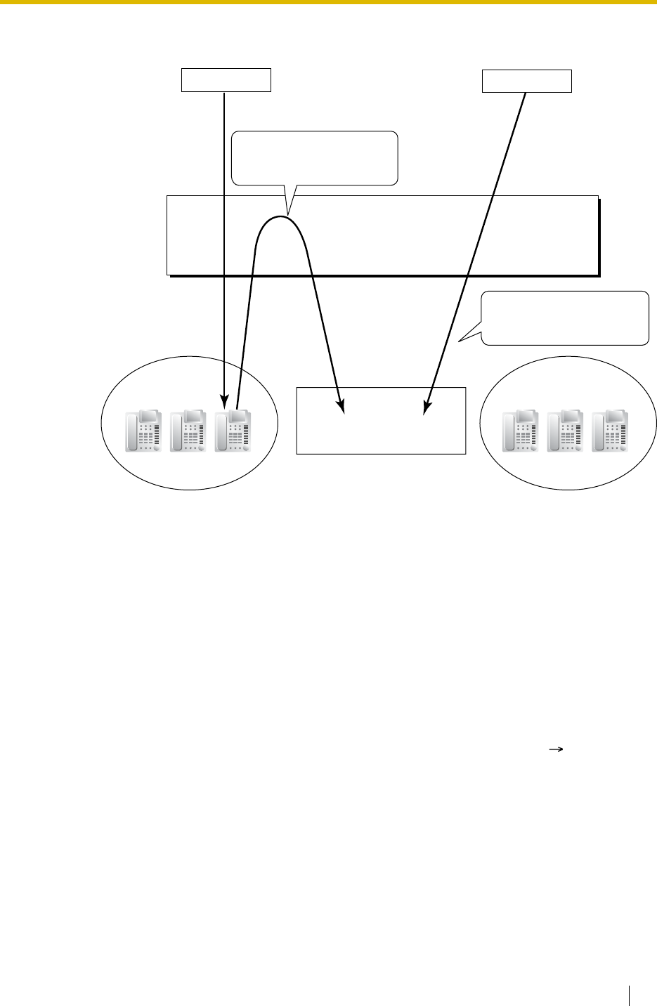
1.23 Voice Mail Features
Feature Guide 217
Time mode (day/lunch/break/night) of the preprogrammed tenant is applied to the DID
destination and company greeting number.
8. Caller’s Identification Notification to the VPS
When receiving a trunk call, the PBX sends the caller’s identification number/name to the
VPS.
9. DID Number Notification to the VPS
When receiving a trunk call with a DDI/DID number or an MSN, the PBX sends the DDI/
DID number or MSN to the VPS. The number will be sent to the VPS even if the call
reaches the VPS after redirection by, for example, the Intercept Routing feature.
10. Status Notification to the VPS
After the call is redirected by the VPS, the PBX sends the status of the redirected
extension (e.g., busy) to the VPS.
11. Paging by the VPS
The VPS can perform the Paging feature using the recorded message. ( 1.14.1 Paging)
12. Live Call Screening (LCS)
PT and PS users can monitor his own mailbox while a caller is leaving a message and, if
desired, answer the call by pressing the LCS button. When the caller is leaving a message
in the mailbox, monitoring can be carried out in two ways: each PT user can choose which
through personal programming (Live Call Screening Mode Set). PS users cannot choose
the way: only Private mode is available for them.
Hands-free mode: The user can monitor the call automatically through the built-in
speaker.
Private mode: The user will hear an alarm tone. To monitor the call, the user goes off-
hook with the handset, MONITOR button, or SP-PHONE button. However, PS users
cannot monitor the call with the speakerphone.
PBX
Tenant 1
123-4567
(Company A) Tenant 3
(Company B)
Trunk Call
Extn. 105 Extn. 102
VPS
(Floating Extn. No.100)
Intercept
123-2468
Trunk Call
Sends the following information:
· VPS Trunk Group: 1
· Time mode: Day
Sends the following information:
· VPS Trunk Group: 2
· Time mode: Night

1.23 Voice Mail Features
218 Feature Guide
13. Two-way Recording into the VPS
A PT user can record a conversation into his own mailbox or another mailbox, while talking
on the phone.
Use the Two-way Record button to record into his own mailbox. Use the Two-way Transfer
button to record into someone else’s mailbox.
Note
When you record Two-way telephone conversations, you should inform the other
party that the conversation is being recorded.
14. VPS Data Control by the PBX*
The data of date and time is controlled by the PBX.
15. Remote PBX Data Control by the VPS*
The FWD of an extension can be controlled by the VPS.
Conditions
[General]
•Voice Mail (VM) Transfer Button
A flexible button can be customised as the Voice Mail (VM) Transfer button with the floating
extension number of the VM group as the parameter.
[Live Call Screening (LCS)]
• If an SLT is connected in parallel to a PT, and if LCS is activated for the PT in Private mode,
both the PT and SLT can be used to monitor calls while in idle status. The SLT will ring to
indicate a message is being recorded. The call can be monitored with the SLT by going
off-hook. To intercept the call, press Flash/Recall button or flash the hookswitch. (
1.10.9 Parallelled Telephone)
•LCS Button
A flexible button can be customised as the LCS button.
•Extension Personal Identification Number (PIN)
To prevent unauthorised monitoring, it is recommended the LCS user assign an extension
PIN. This PIN will be required when setting LCS. ( 1.26.1 Extension Personal
Identification Number (PIN)) If the user forgets the PIN, it can be cleared by an extension
assigned as the manager.
• Each extension can be programmed to either end recording or continue recording the
conversation after the call is intercepted, through personal programming (LCS Mode Set
[After Answering]).
• To use the LCS feature on a PS in Wireless XDP Parallel Mode, LCS can only be turned
on or off from the wired telephone. In Wireless XDP Parallel Mode, setting LCS on/off from
the PS has no effect. ( 1.24.5 Wireless XDP Parallel Mode)
[Two-way Recording into the VPS]
•Two-way Record/Two-way Transfer Button
A flexible button can be customised as the Two-way Record or the Two-way Transfer
button. An extension number can be assigned to the Two-way Transfer button so that it can
be used as a one-touch record button for the mailbox of the specified extension. (One-
touch Two-way Transfer Button).
*: This feature may not be supported depending on the software version of the VPS.

1.23 Voice Mail Features
Feature Guide 219
• When all of the VPS ports are busy:
a) Pressing the Two-way Record button sends an alarm tone
b) Pressing the Two-way Transfer button followed by an extension number sends an
alarm tone.
Feature Guide References
1.19.2 Flexible Buttons
1.23.1 Voice Mail (VM) Group
User Manual References
User Manual
1.9.3 If a Voice Processing System is Connected
3.1.2 Settings on the Programming Mode
3.2.2 Manager Programming
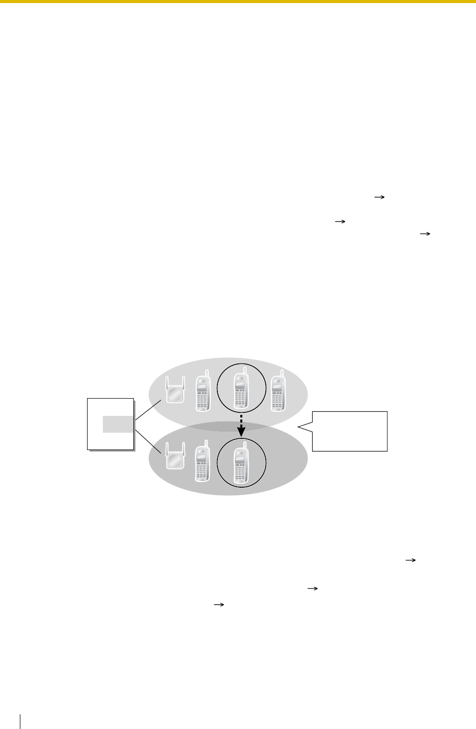
1.24 Portable Station (PS) Features
220 Feature Guide
1.24 Portable Station (PS) Features
1.24.1 Portable Station (PS) Connection
Description
This PBX supports the connection of a PS (e.g., KX-TD7590, KX-TD7690). It is possible to use
the PBX features using the PS like a PT.
Conditions
• The PS registration is required through the system programming ( PS Registration
[690]). To avoid unexpected registration to another PBX, the Personal Identification
Number (PIN) for the PBX is necessary to register a PS ( Personal Identification
Number (PIN) for PS Registration [692]). The registration can be cancelled ( PS
Termination [691]).
•Handover
Even if a PS user moves during a conversation, the PS will automatically switch between
cells without disconnecting the call (Handover).
Handover is available in any of the following cases:
a) During a conversation with an extension or outside party.
b) While a call is ringing at the PS.
c) While the PS is in idle status.
On the contrary, Handover is not available in one of the following cases:
a) When the new (Handover) CS is busy.
b) When there is no CS within range.
c) While the Live Call Screening (LCS) or Two-way Record is activated ( 1.23.3 Voice
Mail DPT (Digital) Integration).
d) While the PS user is paging other extensions ( 1.14.1 Paging).
e) During a doorphone call ( 1.16.1 Doorphone Call).
f) While the PS user is dialling digits to make a trunk call.
g) During a conversation with an extension using PC Console or PC Phone, to which the
conversation is being recorded.
• When a caller has dialled the extension number of a PS but the CS is busy, the caller hears
a busy tone.
PBX
CS
Handover:
Calls will not be
disconnected.
CS
CS
Interface

1.24 Portable Station (PS) Features
Feature Guide 221
Installation Manual References
Installation Manual
<KX-TDA100/KX-TDA200>
2.8 Connection of DECT Portable Stations — KX-TDA100/KX-TDA200
2.9 Connection of 2.4 GHz Portable Stations — KX-TDA100/KX-TDA200
<KX-TDA15/KX-TDA30>
6.7 Connection of DECT Portable Stations — KX-TDA30
6.8 Connection of 2.4 GHz Portable Stations — KX-TDA30
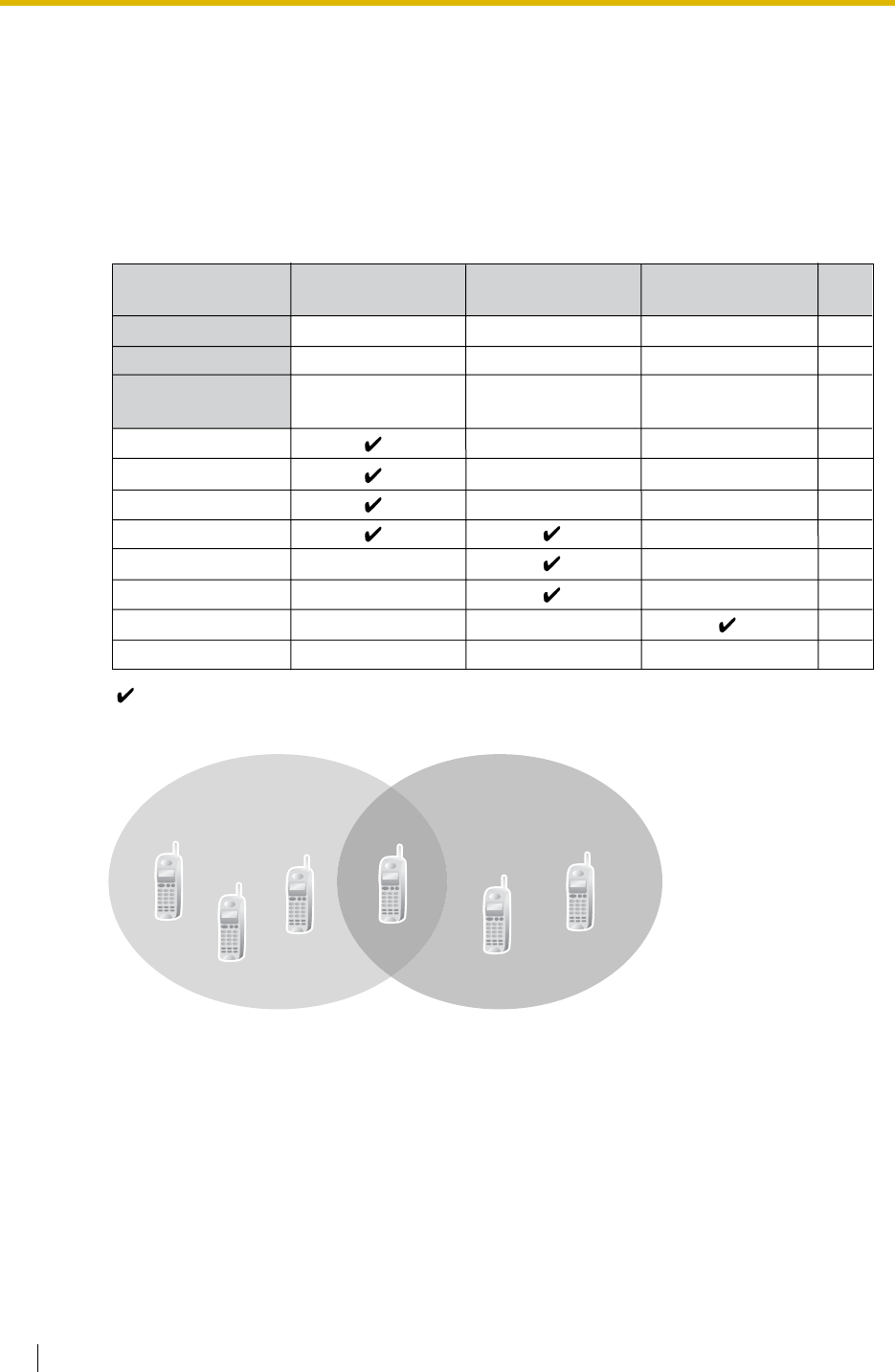
1.24 Portable Station (PS) Features
222 Feature Guide
1.24.2 PS Ring Group
Description
PS ring group is a group of PS extensions which receives incoming calls. Each group has a
floating extension number and name. One PS can belong to multiple groups.
[Programming Example]
Conditions
•PS Ring Group
A maximum of 32 groups can be created.
•Available PS
The KX-TD7580, KX-TD7590, KX-TCA155, KX-TCA255, KX-TD7680, and KX-TD7690
can join PS ring groups.
• Incoming trunk call information is shown on a PS display when a trunk call arrives at a PS
ring group which the PS joins. The display information can be selected on a PS ring group
301
Sales 1
PS Ring
Group 01
· ·
· ·
· ·
· ·
· ·
· ·
· ·
PS Ring
Group 02 PS Ring
Group 03
Floating Extn. No.
Group Name
Incoming Trunk Call
Information Display
PS01
PS02
PS03
PS04
PS05
PS06
PS07
:
302
Sales 2
303
Sales 3
::::
Called Party’s Name/
Number
Caller’s Name
/
Number
Caller’s Name
/
Number
· ·
· ·
· ·
· ·
: Constituent
PS Ring Group 1
(Floating Extn. No. 301
Name: Sales 1)
PS Ring Group 2
(Floating Extn. No. 302
Name: Sales 2)
PS01
PS02
PS03 PS04
PS05
PS06
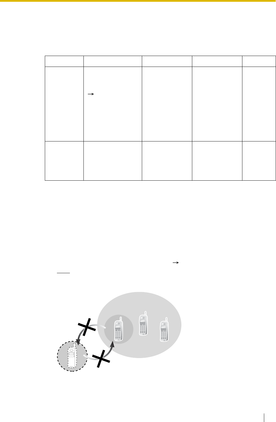
1.24 Portable Station (PS) Features
Feature Guide 223
basis through system programming: Called Party’s Name/Number or Caller’s Name/
Number.
•Calling Multiple PSs Simultaneously
There are two methods to call multiple PSs simultaneously using the floating extension
number assigned to the following groups:
• When a PS joins a PS ring group, the following personal settings are disregarded:
a) When the PS ring group is called:
b) Log-in/log-out setting (from the PS ring group/from the incoming call distribution
group which the PS ring group belongs to). ( 1.2.2.6 Log-in/Log-out)
Note
Log-in/log-out setting of the PS ring group from the incoming call distribution group is
also disregarded.
Method Assignment Merit Demerit Details in
Incoming
Call
Distribution
Group
Assign all desired
PSs to one incoming
call distribution group
( Incoming Call
Distribution Group
Member [620]), and
set the group call
distribution method
for the group to
"Ring".
All PS users in the
group can use the
Log-in/Log-out
feature, Wrap-up
feature, and ICD
Group button for
the group.
The CS may often
be busy as each
PS in the group
uses one channel
when a call
arrives at the
group.
• 1.2.2
Incoming
Call
Distribution
Group
Features
PS Ring
Group Assign all desired
PSs to one PS ring
group.
Only one channel
is used when a
call arrives at the
group.
PS users in the
group cannot use
the Log-in/Log-
out and Wrap-up
features.
–
– Delayed Ringing
– Display information when the incoming calls arrive;
The settings (e.g., display priority) are disregarded.
– The setting which is assigned on the PS (e.g., FWD)
– The status of the PS (e.g., busy)
PS Ring Group
Log-out
Log-in

1.24 Portable Station (PS) Features
224 Feature Guide
• When the PS ring group is called using the floating extension number, the group becomes
busy to other callers using the floating extension number. However, the individual group
members may be called directly using their extension number.
• If a PS in a PS ring group has set the DND feature for trunk calls, the PS will not ring when
an intercom call or a trunk call arrives at the PS ring group. ( 1.3.1.3 Do Not Disturb
(DND))
• For calls directed to PS ring groups, the PBX will handle at most two calls simultaneously.
The third call cannot arrive at a PS ring group until one of the first two calls is answered or
a caller hangs up.
PS Ring
Group
Incoming Call
Distribution Group
PS Ring Group
Log-out
Log-in
Log-out
Log-in
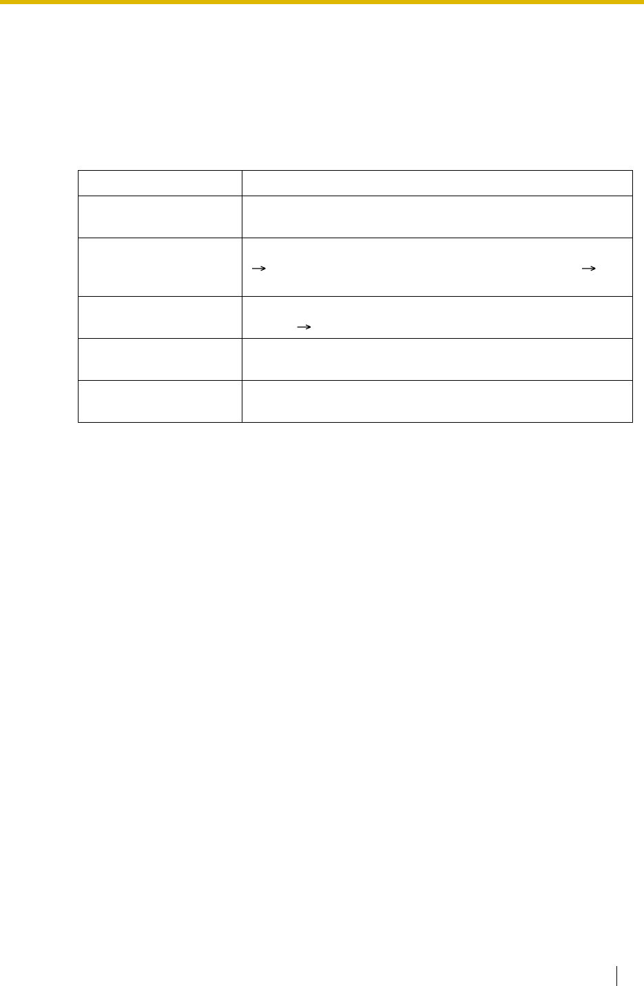
1.24 Portable Station (PS) Features
Feature Guide 225
1.24.3 PS Directory
Description
A PS user can store numbers and/or names in the directory. A stored number is dialled by
selecting a name or number in the directory.
Depending on the PS model, the PS user can use the following directories for easy operation:
Type Description
PS Dialling Directory Makes a call by selecting from a private directory of names and
telephone numbers.
System Speed Dialling
Directory Makes a call by selecting from a common directory of names
( System Speed Dialling Name [002]) and numbers (
System Speed Dialling Number [001]).
PBX Extension Dialling
Directory Makes a call by selecting from a common directory of extension
names ( Extension Name [004]).
Shortcut Directory Accesses a feature by selecting from a private directory of
feature names and numbers.
Quick Dialling Makes a call or accesses a feature easily by selecting from a
private directory of names and numbers.

1.24 Portable Station (PS) Features
226 Feature Guide
1.24.4 PS Feature Buttons
Description
A PS user can use PBX feature using a combination of buttons (button + a specified number,
, or #) and/or display operation. The flexible buttons and the display are customised through
PS programming. The button assignment is the same for PT. ( 1.19.2 Flexible Buttons).
Some special feature buttons (e.g., WAVESEARCH button) may be customised depending on
the PS type.
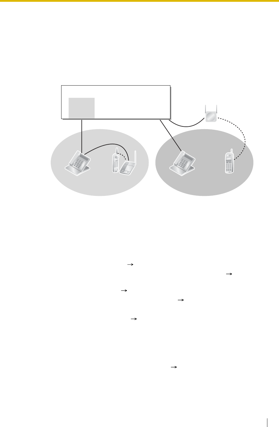
1.24 Portable Station (PS) Features
Feature Guide 227
1.24.5 Wireless XDP Parallel Mode
Description
A PS can be used in parallel with a wired telephone (PT/SLT). In this case, the wired telephone
is the main telephone and the PS is the sub telephone. When Wireless XDP Parallel Mode is
enabled, the two telephones share one extension number (main telephone’s extension
number) like XDP Parallel mode for a DPT and an SLT.
Conditions
• If one of the telephones goes off-hook while the other telephone is on a call, the call is
switched to the telephone going off-hook. However, the call is not switched in one of the
following conditions:
a) During a Conference call ( 1.13.1 Conference Features).
b) While Live Call Screening (LCS) or Two-way Record is activated ( 1.23.3 Voice Mail
DPT (Digital) Integration).
c) While receiving OHCA ( 1.7.4.3 Off-hook Call Announcement (OHCA)).
d) While being monitored by another extension ( 1.7.3 Call Monitor).
e) During Consultation Hold.
f) During a broadcasting call ( 1.15.1 Broadcasting (KX-TDA30/KX-TDA100/KX-
TDA200 only)).
(Consultation Hold: Allows an extension user to place a call on hold temporarily to
perform Call Transfer, Conference, or Call Splitting.)
• Wireless XDP Parallel Mode can only be set from a PS. The wired telephone can accept
or deny this feature through COS programming ( Wireless XDP Parallel Mode for Paired
Telephone [515]). Once this feature is set, the setting at the wired telephone cannot be
changed unless a PS changes the setting.
DPT
Cell Station
Wireless Phone
Super
Hybrid
Port
PBX
XDP Parallel Mode Wireless XDP
Parallel Mode
Extn. 102
PT/SLT PS
Extn. 103

1.24 Portable Station (PS) Features
228 Feature Guide
• The following features are not available for extensions in Wireless XDP Parallel Mode
while the PS is on a call (however, they are available for the extensions in Wireless XDP
Parallel Mode while the wired telephone is on a call):
• Most of the extension data (e.g., extension number, extension name) of the wired
telephone is used for its PS as well. However, the PS has its own extension data for the
following:
Note
To change the setting of the extension data above, the setting for the wired telephone
or the PS must be changed individually. When changing the PS setting, use the PS’s
original extension number (not the main telephone’s extension number), if required.
• When the Wireless XDP Parallel Mode has been set, the following extension data for the
wired telephone is copied to the PBX extension data for the PS and the extension data
remains there even when the Wireless XDP Parallel Mode is cancelled.
• If the Extension Feature Clear is performed, the corresponding extension data for both the
wired telephone and the PS will be cleared. ( 1.26.2 Extension Feature Clear)
• When a call arrives, both the wired telephone and the PS ring. However, in the following
cases only the person who made the setting will receive ringing:
– Executive Busy Override
– Whisper OHCA ( 1.7.4.4 Whisper OHCA)
– CCBS ( 1.20.1.10 Completion of Calls to Busy Subscriber (CCBS))
– Ring Tone Pattern Table Selection ( 1.1.3.2 Ring Tone Pattern Selection)
– Preferred Line Assignment—Incoming ( 1.4.1.2 Line Preference—Incoming)
– Preferred Line Assignment—Outgoing ( 1.5.5.2 Line Preference—Outgoing)
– Hot Line Setting ( 1.6.1.7 Hot Line)
– Transfer Recall Destination for Call Transfer and Call Park
– Display Language ( 1.19.4 Display Information)
– ISDN Bearer Mode ( 1.20.1.1 Integrated Services Digital Network (ISDN)—
SUMMARY)
– Flexible Button Assignment ( 1.19.2 Flexible Buttons)
– Call Waiting Setting ( 1.1.3.3 Call Waiting)
– FWD/DND Setting ( 1.3.1 Call Forwarding (FWD)/Do Not Disturb (DND))
– Call Pickup Deny Setting ( 1.4.1.3 Call Pickup)
– Executive Busy Override Deny Setting
– Itemised Billing Code for ARS ( 1.9.1 Automatic Route Selection (ARS))
– Transfer Recall Destination for Call Transfer and Call Park
– CLIP/COLP Number ( CLIP/COLP Number [606])
– CLIP/COLP Number Selection
– CLIR Setting
– COLR Setting
– Extension Personal Identification Number (PIN) ( Extension Personal
Identification Number (PIN) [005]) ( 1.26.1 Extension Personal Identification
Number (PIN))
– COS Programming ( Class of Service [602]) ( 2.2.1 Class of Service (COS))
– User Group ( User Group [603]) ( 2.2.2 Group)
– Automatic Callback Busy

1.24 Portable Station (PS) Features
Feature Guide 229
Feature Guide References
1.7.1 Automatic Callback Busy (Camp-on)
1.7.2 Executive Busy Override
1.10.9 Parallelled Telephone
1.11.1 Call Transfer
1.12.2 Call Park
1.20.1.2 Calling/Connected Line Identification Presentation (CLIP/COLP)
User Manual References
User Manual
1.7.12 Using Your PS in Parallel with a Wired Telephone (Wireless XDP Parallel Mode)
– Transfer Recall, Hold Recall ( 1.12.1 Call Hold), and Call Park Recall

1.25 Administrative Information Output Features
230 Feature Guide
1.25 Administrative Information Output Features
1.25.1 Station Message Detail Recording (SMDR)
Description
Automatically records detailed information for each extension.
1. SMDR Output Port
The Serial Interface (RS-232C) port can be used to output the SMDR data.
The following devices can be connected:
•Serial Interface (RS-232C) port: Personal computer (PC), printer, etc.
2. SMDR Output Data
The following data will be recorded and sent to the SMDR output port:
a) Trunk call information (incoming/outgoing)
b) Intercom call information (outgoing)
c) Log-in/Log-out information
d) PBX error log ( 2.4.3 Local Alarm Information)
Memory for SMDR: A specified number of call information can be memorised for each
PBX. If more calls are originated or received, the oldest data is overwritten by the newest
one.
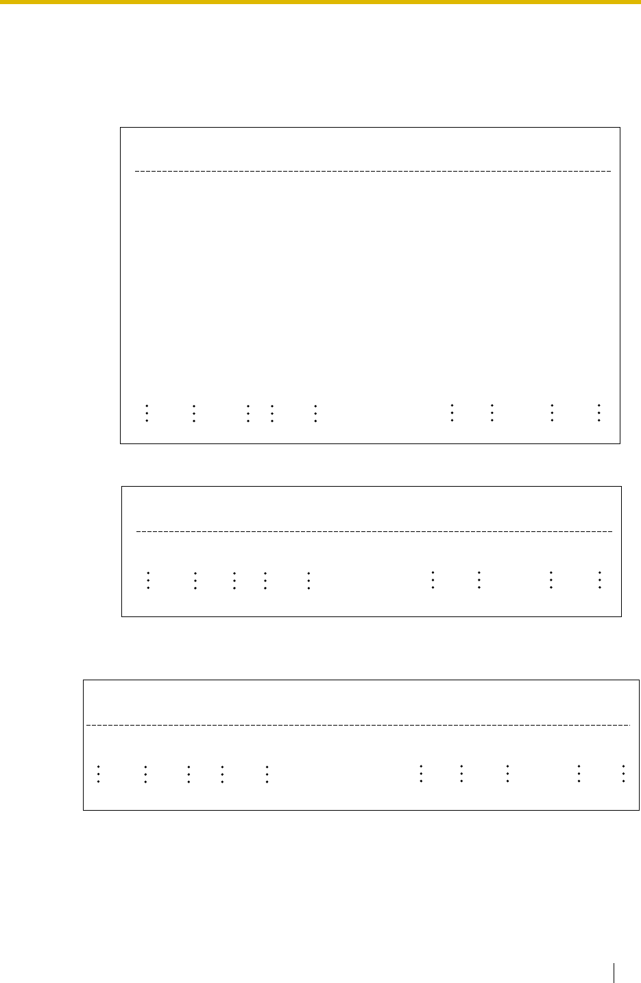
1.25 Administrative Information Output Features
Feature Guide 231
3. SMDR Format Type and Contents
There are the following three types of output format which can be selected through system
programming:
Pattern A: 80 digits without call charge information
Pattern B: 80 digits with call charge information
Pattern C: 120 digits
(1) (2) (3) (4) (5) (6) (7) (8) (9)
Duration
(8)
00:00'00
00:01'05
00:01'05
00:01'05
00:01'05
00:01'05
00:01'05
00:01'05
00:12'05
Ring
(4)
5'15
0'05
0'05
0'05
Time
(7)
10:03AM
10:07AM
10:15AM
10:30AM
01:07PM
01:07PM
01:07PM
01:07PM
01:07PM
08:33AM
01:07PM
03:35PM
03:45PM
Date
(8 digits)
01/02/02
01/02/02
01/02/02
01/02/02
01/02/02
01/02/02
01/02/02
01/02/02
01/02/02
01/02/02
01/02/02
01/02/02
01/02/02
Dial Number
(25)
<I>12345678901234567890
<I>
1234567890123456
1234567890123456
<I>ABC COMPANY12345678
<D>CDE9876<I>Q COMPANY
ABC COMPANY12345678
123..............
123456XX
In the office
LOG IN
LOG OUT
EXT12355
ACC Code
(10)
9876543210
9876543210
9876543210
9876543210
9876543210
98765
CD
(3)
NA
TR
CO
(2)
01
01
01
01
01
01
01
01
01
Ext
(4)
1200
1200
1200
*123
1234
1234
1234
1234
1234
1234
1234
1234
1234
(1) (2) (3) (4) (5) (7) (8) (9)(10)
Cost
(8+2)
00560.00EU
Duration
(8)
00:00'05
Time
(7)
10:03AM
10:07AM
Date
(8 digits)
01/02/02
01/02/02
Dial Number
(20)
<I>
12345678901234567890
ACC Code
(10)
9876543210
CD
(3)
NA
CO
(2)
01
01
Ext
(4)
1210
2005
(1) (2) (3) (4) (5) (6) (7) (8) (9)(10)
Cost
(8+3)
00560.00EUR
Duration
(8)
00:00'05
00:00'05
Time
(7)
10:03AM
10:07AM
Date
(8 digits)
01/02/02
01/02/02
Dial Number
(50)
123456789012345678901234567890
<I>ABC COMPANY123456789012345
ACC Code
(10)
9876543210
9876543210
CD
(3)
TR
TR
CO
(4)
0001
0001
Ext
(4)
1230
1230
Ring
(4)
0'05
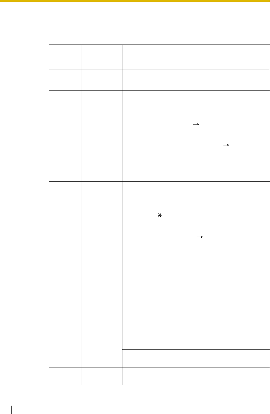
1.25 Administrative Information Output Features
232 Feature Guide
[Explanation]
The following table explains the SMDR contents which are based on the numbers in the
previous pattern examples. For the programmable items, refer to the following
[Programmable Items].
Number in
the
Pattern Item Description
(1) Date Shows the date of the call.
(2) Time Shows the end time of a call as Hour/Minute/AM or PM.
(3) Ext
(Extension) Shows the extension number, floating extension number,
etc., which was engaged in the call.
Also shows the following codes:
Dxxx: Outgoing trunk call from a doorphone
(xxx=doorphone number) ( 1.16.1 Doorphone Call)
Txxx: Outgoing trunk call by TIE line service (xxx=trunk
group number)
*xxx: Verified call (xxx=verified code) ( 1.8.6 Verified
Code Entry)
(4) CO (Trunk) Shows the trunk number used for the call.
For patterns A and B, "00" will be shown for trunk
numbers over hundred.
(5) Dial Number [Trunk Call]
Outgoing Trunk Call
Shows the dialled telephone number.
Valid digits are as follows:
0 through 9, , #
P: Pause
F: EFA signal
=: A Host PBX Access code ( 1.5.4.7 Host PBX Access
Code (Access Code to the Telephone Company from a
Host PBX))
. (dot): Secret dialling
X: Privacy dial
–: Transferred call
If the transfer destination extension enters some digits,
the entered digits will be added after "–".
Incoming Trunk Call
Shows <I> + the caller’s identification name/number.
It is also possible to show the DDI/DID/MSN call
information. In this case, <D> + DDI/DID/MSN
name/number is added before <I> .
[Outgoing Intercom Call]
Shows the dialled extension number followed by "EXT".
[Log-in/Log-out]
Shows the log-in or log-out status.
(6) Ring Shows the ring duration before answering a call in
Minutes/Seconds.
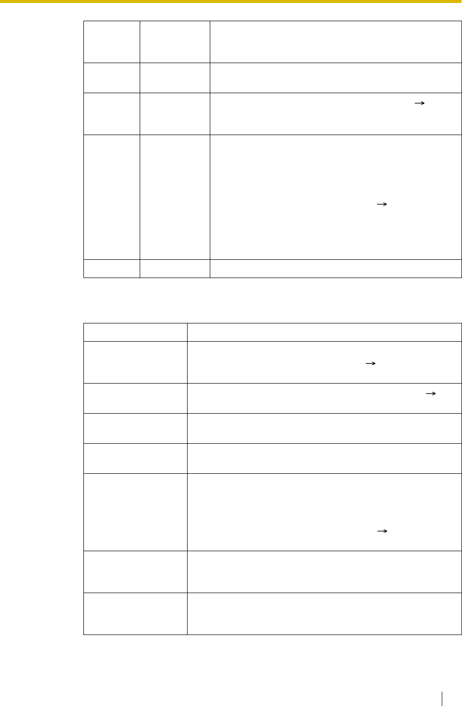
1.25 Administrative Information Output Features
Feature Guide 233
[Programmable Items]
(7) Duration Shows the duration of the trunk call in Hours/Minutes/
Seconds.
(8) Acc Code
(Account
Code)
Shows the account code appended to the call. ( 1.5.4.3
Account Code Entry)
(9) CD
(Condition
Code)
Shows other call information with the following codes:
CL: Collect call
TR: Transfer
FW: FWD to trunk
D0: Call using DISA or TIE line service
RM: Remote maintenance (modem) ( 2.3.1 PC
Programming)
NA: Not answered call
RC: Received call
AN: Answered call
(10) Cost Shows the call charge.
Item Description
Outgoing trunk call Controls whether the outgoing trunk calls are shown. This
setting is common throughout the PBX ( SMDR Outgoing
Call Printing [804]). COS programming is also required.
Incoming trunk call Controls whether the incoming trunk calls are shown (
SMDR Incoming Call Printing [805]).
Outgoing intercom
call Controls whether the outgoing intercom calls are recorded.
Log-in/Log-out
status Controls whether the log-in/log-out status is recorded.
ARS dial Controls whether the user-dialled number or the modified
number is shown.
The Host PBX Access code ("=" followed by the access code)
can be shown (as supplementary information) only when the
modified number is selected in this setting. ( 1.9.1 Automatic
Route Selection (ARS))
Caller’s
identification Controls whether the caller’s identification number, name,
number and name, or nothing is shown. If "none" is selected,
<I> will not be shown.
DID/DDI number Controls whether the DID/DDI number, name, number and
name, or nothing is shown. If "none" is selected, <D> will not
be shown.
Number in
the
Pattern Item Description

1.25 Administrative Information Output Features
234 Feature Guide
Conditions
•SMDR Format
The following SMDR format can be set through system programming in order to match the
paper size being used in the printer:
a) Page Length: determines the number of lines per page ( SMDR Page Length
[802]).
b) Skip Perforation: determines the number of lines to be skipped at the end of every
page ( SMDR Skip Perforation [803]).
The page length should be at least four lines longer than the skip perforation length.
Explanation:
• The SMDR data is not deleted even if the PBX is reset.
• If the PBX is reset during a conversation, the call will not be recorded on the SMDR.
• The following calls are regarded as two separated calls in the SMDR:
Secret dialling Controls secret dialling. If enabled, the dialled number will be
shown as dots.
This setting is effective only when the modified number is
selected in ARS dial setting above. If the user-dialled number
is selected in ARS dial setting, the dialled number will be
shown as dots regardless of this setting.
Privacy dial Enables or disables privacy dial. If enabled, the last four digits
of the dialled telephone number and any additional digits after
connection will be shown as "X". (e.g., 123-456-XXXX)
Date order The date order is changeable: month/day/year, day/month/
year, year/month/day, year/day/month.
Received call Controls whether the time of receiving an incoming trunk call
is shown.
Answered call Controls whether the time of answering an incoming trunk call
is shown.
– Calls before and after the flash/recall/EFA signal is manually sent during a
conversation
– Trunk-to-trunk calls by Call Transfer, FWD or DISA (recording each as "incoming
call" and "outgoing call")
Item Description
Skip
Perforation
Page
Length
Machine
Perforation

1.25 Administrative Information Output Features
Feature Guide 235
• The PBX waits for a preprogrammed time period ( Call Duration Count Starting Time for
LCOT [208]) between the end of dialling and start of the SMDR timer for outgoing trunk
calls. When the PBX has sent out all dialled digits to the telephone company and this timer
expires, the PBX starts counting the call. A display PT shows the elapsed time of the call.
The starting time and the total duration of the call are recorded on SMDR.
If the reverse signal detection has been set ( 1.5.4.5 Reverse Circuit), the PBX will start
counting the call after detecting the reverse signal from the telephone company regardless
of the above timer.
•Serial Interface (RS-232C) Parameters
The following communication parameters can be assigned for the Serial Interface (RS-
232C) port ( RS-232C Parameter—New Line Code [800], RS-232C Parameter—Baud
Rate [800], RS-232C Parameter—Word Length [800], RS-232C Parameter—Parity Bit
[800], RS-232C Parameter—Stop Bit Length [800]).
a) New Line Code: Select the code for the PC or printer. If the PC or printer
automatically feeds lines with carriage return, select "CR." If not, select "CR+LF."
b) Baud Rate: A baud rate code indicates the data transmission speed from the PBX to
the PC or printer.
c) Word Length: A word length code indicates how many bits compose a character.
d) Parity Bit: A parity code indicates what type of parity is used to detect an error in the
string of bits composing a character. Make an appropriate selection depending on the
requirements of the PC or printer.
e) Stop Bit Length: A stop bit code indicates the end of a bit string which composes a
character. Select an appropriate value depending on the requirements of the PC or
printer.
Installation Manual References
Installation Manual
<KX-TDA100/KX-TDA200>
2.11.1 Connection of Peripherals
<KX-TDA15/KX-TDA30>
6.10.1 Connection of Peripherals
Feature Guide References
1.1.1.3 Direct Inward Dialling (DID)/Direct Dialling In (DDI)
1.1.1.4 Multiple Subscriber Number (MSN) Ringing Service
1.2.2.6 Log-in/Log-out
1.11.1 Call Transfer
1.16.6 Direct Inward System Access (DISA)
1.28.1 TIE Line Service

1.25 Administrative Information Output Features
236 Feature Guide
1.25.2 Charge Meter
Description
The PBX receives a call charge signal during or after a conversation with an outside party. The
call charge information is shown on the telephone display and the SMDR.
1. Call Charge Signal Service
Call charge signal service from the telephone company depends on the trunk being used.
2. Call Charge Display
3. Margin/Tax Rate Assignment
It is possible to add a margin ( Charge Margin [010]) and the tax ( Charge Tax [011])
to the call charges. The call charge rate per meter indication is programmable on a trunk
group basis ( Charge Rate per Unit [012]).
[Calculation Method]
The margin or tax rate must be xx.xx % (whole number part: two digits, decimal fraction:
two digits). A calculation method depends on the information which is sent from the
telephone company: meter indication or charge.
a) Call charge with tax and margin in meter indication:
b) Call charge with tax and margin in charge:
The calculation result is rounded up to the least significant decimal digit.
Trunk Service
Analogue trunk Pay Tone (KX-TDA100/KX-TDA200 only)*
ISDN line Advice of Charge (AOC) ( 1.20.1.3 Advice of
Charge (AOC))
E1 line Meter Pulse (KX-TDA100/KX-TDA200 only)
*: When the pay tone service is used, pay tone type (12 kHz/16 kHz) should be
selected ( Pay Tone Signal Type [491] (KX-TDA100/KX-TDA200 only)).
– Up to 7 digits (e.g., 88888.75)
– The decimal point position (the number of significant decimal digits) for currency is
programmable. ( Decimal Point Position for Currency [130])
–Up to 3 currency characters are programmable. (e.g., EUR or for Euro) (
Currency [131]).
–The currency position either front or back of the call charge is programmable. (e.g.,
45.12 or 45.12 )
[Meter indication received from the telephone company] [Call Charge Rate]
[1 – Tax Rate] [1 – Margin Rate]
[Charge received from the telephone company] [Call Charge Rate]
[1 – Tax Rate] [1 – Margin Rate]
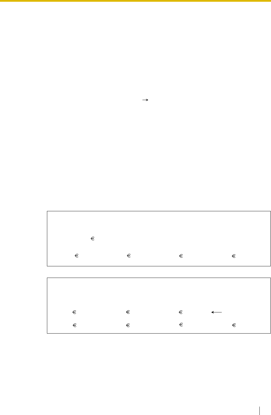
1.25 Administrative Information Output Features
Feature Guide 237
4. Total Call Charge
5. Budget Management
It is possible to limit telephone usage to a preprogrammed budget on each extension or
verified code. For example, an extension in a rented office has a prepaid limit for the
telephone usage. If the amount of the call charge reaches the limit, the extension user
cannot make further trunk calls. An extension assigned as the manager may increase the
limit or clear the previous call charge ( 1.8.2 Budget Management).
6. Call Charge Management
A manager can use the following call charge management features in manager
programming mode:
a) Call Charge Fee Reference and Clear, for Each Extension/Verified Code
b) Call Charge Fee Reference for Each Trunk
c) Call Charge Rate Set for Each Trunk Group
d) All Clear
e) Call Charge Fee Print Out
f) Budget Management for Each Extension/Verified Code.
[Examples of Call Charge Fee Reference]
Note: *XXX: Call Charge Fee Reference for a verified code (XXX = verified code)
– A PT user can show the total call charges on the display.
– The call charge is totalled on an extension, trunk, or verified code basis.
– The call charge on a verified code is not totalled for each extension.
Total Charge: 00175.95
******************************************************
* Charge Meter Print Out - Total & All CO *
******************************************************
CO Line
001: 00194.00 002: 00073.00 003: 00161.00 004: 00033.00
Extension & Verified Code
*******************************************************
* Charge Meter Print Out - All Extensions *
*******************************************************
*775: 00194.00 *102: 00073.00 *776: 00161.00
107: 00033.00
(Verified Code)
104: 00194.00 105: 00073.00 106: 00161.00

1.25 Administrative Information Output Features
238 Feature Guide
Conditions
[General]
•Call Charge Fee Reference by Charge Reference Button
A display telephone user can check the total call charge for his own extension using the
Charge Reference button. A flexible button can be customised as the Charge Reference
button.
[Pay Tone Service (KX-TDA100/KX-TDA200 only)]
• It is possible to select whether the PBX starts counting the call charge from when the PBX
detects the answer signal from the telephone company.
• It is possible to enable the PBX to send the flash/recall signal to the telephone company
after a conversation (in on-hook status) to receive the call charge information.
Feature Guide References
1.8.6 Verified Code Entry
1.19.2 Flexible Buttons
User Manual References
User Manual
3.2.2 Manager Programming

1.26 Extension Controlling Features
Feature Guide 239
1.26 Extension Controlling Features
1.26.1 Extension Personal Identification Number (PIN)
Description
Each extension user can have his own PIN through system programming ( Extension
Personal Identification Number (PIN) [005]) or personal programming (Extension PIN
[Personal Identification Number]) to set features or access his own telephone remotely.
The following features cannot be used without the PIN:
a) Live Call Screening (LCS)* ( 1.23.3 Voice Mail DPT (Digital) Integration)
b) Incoming and Outgoing Call Log Display Lock ( 1.17.2 Incoming Call Log),
Personal Speed Dialling Display Lock ( 1.6.1.5 Speed Dialling—Personal/System)
c) Walking Extension ( 1.26.3 Walking Extension)
d) Extension Lock ( 1.8.3 Extension Lock)
e) Remote Extension Control ( 1.26.5 Remote Extension Control by User) and
Walking COS ( 1.8.5 Walking COS)
f) Remote Extension Control and Walking COS using DISA ( 1.16.6 Direct Inward
System Access (DISA))
Conditions
WARNING
When a third party discovers the personal identification number (PIN) (verified code PIN/
extension PIN) of the PBX, there will be a risk that they will make fraudulent phone calls
using the telephone line, and the cost will be charged to your own account. In order to
avoid this problem, we strongly recommend the following points:
a) Carefully maintain the secrecy of the PIN.
b) Specify a complicated PIN as long and random as you can make it.
c) Change the PIN frequently.
•Extension PIN Lock
If the wrong PIN is entered incorrectly three times, the line will be disconnected. If the
incorrect PIN is entered a preprogrammed number of times successively, the PIN against
the extension will be locked. Only an extension assigned as the manager can unlock it. In
this case, the PIN will be unlocked and cleared.
This feature is also known as Station Password Lock.
•Remote Extension PIN Clear
If an extension user forgets his PIN, a manager can clear the PIN. Then the extension user
can assign a new PIN.
•Extension PIN Display
It is possible to select whether to show the extension PIN on the display through system
programming. By default, it is shown as dots.
*: If an extension user has assigned an extension PIN, this feature cannot be used without
the PIN.

1.26 Extension Controlling Features
240 Feature Guide
User Manual References
User Manual
3.1.2 Settings on the Programming Mode
3.2.2 Manager Programming

1.26 Extension Controlling Features
Feature Guide 241
1.26.2 Extension Feature Clear
Description
Extension users can clear all the following features set on their own telephone at once:
Note: The features with "*" can be programmed not to be cancelled by this feature.
This feature is also known as Station Programme Clear.
Conditions
• Extension Lock ( 1.8.3 Extension Lock) and the extension personal identification
number (PIN) ( 1.26.1 Extension Personal Identification Number (PIN)) will not be
cleared by this feature.
•For Users in Canada only
If dial tone 2 is heard after Extension Feature Clear:
After performing Extension Feature Clear, Call Waiting will be enabled if "Extension
Clear: Call Waiting" is set to "Clear" through system programming. In this case,
dial tone 2 will be heard when going off-hook. ( 1.27.1 Dial Tone)
User Manual References
User Manual
1.7.13 Clearing Features Set at Your Extension (Extension Feature Clear)
Features After Setting
Absent Message Off
BGM Off
FWD*/DND* Off
Call Pickup Deny Allow
Call Waiting* Disable (In Canada, the default setting is
"Enable" [Call Waiting tone].)
Data Line Security Off
Executive Busy Override Deny Allow
Log-in/Log-out Log-in
Message Waiting All messages left by other extensions
will be cleared.
Paging Deny Allow
Parallelled Telephone Paired SLT will ring.
Hot Line* Off
Timed Reminder Cleared

1.26 Extension Controlling Features
242 Feature Guide
1.26.3 Walking Extension
Description
It is possible to use any extension and have your extension settings available to you. Settings
such as extension number, one-touch dialling memory, and COS are all available to you at the
new location.
[Example] This feature is useful when;
• Moving location
• There is no specific desk for your use.
This feature is also known as Walking Station.
Conditions
• This feature is available by switching the telephone between PT and PT, SLT and SLT, PT
and SLT. Moving across the tenants is also possible.
• The incoming calls to your extension will also reach you at your new location.
• An extension personal identification number (PIN) is required to use this feature. (
1.26.1 Extension Personal Identification Number (PIN))
• If a DSS Console is connected to a PT and the DSS Console is continuously used with the
PT after the Walking Extension has been done, the new extension number of the PT must
be assigned as the paired extension through system programming ( Console Paired
Telephone [007]).
User Manual References
User Manual
1.10.1 Using the Same Settings as Your Previous Extension (Walking Extension)

1.26 Extension Controlling Features
Feature Guide 243
1.26.4 Timed Reminder
Description
Each extension user can set an alarm for any time as a wake-up call or reminder. This feature
can be programmed to activate only once or daily. If the user goes off-hook during the alarm,
he hears special dial tone. If a voice message is used, he hears a prerecorded voice message.
Conditions
• Be sure that the PBX clock works.
• Setting a new time clears the previous time.
•Programmable Time
The Alarm Ringing Duration time, the number of alarm repeat times, and intervals are
programmable through system programming.
•To use the voice message feature:
The MSG card is required and the message must be recorded. An extension assigned as
the manager can record messages. ( 1.16.5 Outgoing Message (OGM)) The different
message can be assigned for each time mode (day/lunch/break/night) ( 2.2.4 Time
Service).
Installation Manual References
Installation Manual
<KX-TDA100/KX-TDA200>
2.6.5 MSG4 Card
<KX-TDA15/KX-TDA30>
6.5.4 MSG2 Card
User Manual References
User Manual
1.7.1 Setting the Alarm (Timed Reminder)

1.26 Extension Controlling Features
244 Feature Guide
1.26.5 Remote Extension Control by User
Description
A user can remotely change the feature settings (e.g., FWD) and time service mode for his own
extension from inside or outside the PBX using DISA ( 1.16.6 Direct Inward System Access
(DISA)). This feature can be used only on the extensions which are allowed to be controlled
remotely on a COS basis.
The following features are available:
a) FWD/DND ( 1.3.1 Call Forwarding (FWD)/Do Not Disturb (DND))
b) Log-in/Log-out ( 1.2.2.6 Log-in/Log-out)
c) Absent Message ( 1.18.2 Absent Message)
d) Extension Lock ( 1.8.3 Extension Lock)
e) Time Service—Changing the Time Mode (day/lunch/break/night) ( 2.2.4 Time
Service)
This feature is also known as Remote Station Control by User.
Conditions
•Extension PIN
An extension personal identification number (PIN) ( Extension Personal Identification
Number (PIN) [005]) is required to use this feature. ( 1.26.1 Extension Personal
Identification Number (PIN)) If the wrong PIN is entered three times, the line will be
disconnected.
• Remote operation is not available for the extensions in the Internal Call Block mode. (
1.1.2.2 Internal Call Block)
User Manual References
User Manual
1.2.9 Setting Your Telephone from Another Extension or through DISA (Remote Setting)

1.27 Audible Tone Features
Feature Guide 245
1.27 Audible Tone Features
1.27.1 Dial Tone
Description
The following dial tones inform extensions about features activated on the extensions:
Each dial tone type has two frequencies (e.g., dial tone 1A and dial tone 1B).
Conditions
•Dial Tone Type A/B
It is possible to select dial tone type A or B for dial tones 1 through 4. If "Type A" is
selected, all dial tones 1 through 4 will become dial tone type A.
The dial tone type for the ARS feature can be selected separately. If "Type A" is selected
for the ARS, dial tone 1A will be heard. If "Type B" is selected, dial tone 1B will be heard.
•Distinctive Dial tone
Distinctive dial tone mode can be disabled. In this case, dial tone 1 will be sent.
•Dial Tone Patterns
All dial tone patterns have a default ( 4.2.1 Tones/Ring Tones).
• Only dial tone 1 is sent to the extensions in the VM (DPT/DTMF) group. ( 1.23.1 Voice
Mail (VM) Group)
Type Description
Tone 1A/1B A normal dial tone is heard when:
a) No features listed for dial tones 2 through 4 has been set, or
b) ARS is used.
Tone 2A/2B Any one of the features below is set.
• Absent Message
•BGM
•FWD
• Call Pickup Deny
• Call Waiting
• DND
• Extension Lock
• Executive Busy Override Deny
• Hot Line
• Timed Reminder
Tone 3A/3B While a called PS is being searched, or any one of the features
below is performed.
• Account Code Entry
• Consultation Hold
• Answering a Timed Reminder call with no message
Tone 4A/4B Messages are waiting for the extension.

1.27 Audible Tone Features
246 Feature Guide
1.27.2 Confirmation Tone
Description
At the end of feature operations, the PBX confirms the success of the operation by sending a
confirmation tone to extension users.
Conditions
•Confirmation Tone Patterns
All confirmation tone patterns have a default ( 4.2.1 Tones/Ring Tones).
• It is possible to eliminate each tone.
Type Description
Tone 1 a) Sent when the setting is accepted.
b) Sent when a call is received in voice-calling mode (Alternate
Receiving—Ring/Voice). The caller’s voice will be heard after
the tone.
Tone 2 a) Sent from an external paging device or an extension before
being paged.
b) Sent when a call is received in Hands-free Answerback
mode.
Tone 3-1 a) Sent before a conversation is established when using the
Paging feature.
b) Sent when a conversation is established with the extension in
the following modes after the call making operation:
• Hands-free Answerback mode
• Voice-calling mode (Alternate Receiving—Ring/Voice)
Tone 3-2 Sent just before a conversation is established when accessing
the following features by the feature numbers:
• Call Park Retrieve
• Call Pickup
•Hold Retrieve
• Paging Answer
• TAFAS
Tone 4-1 Sent when moving from a two-party call to a three-party call.
(e.g., Executive Busy Override, Conference, Privacy Release,
Two-way Record.)
Tone 4-2 Sent when moving from a three-party call to a two-party call.
(e.g., Executive Busy Override, Conference, Privacy Release,
Two-way Record.)
Tone 5 Sent when a call is placed on hold (including Consultation Hold).

1.28 Networking Features
Feature Guide 247
1.28 Networking Features
1.28.1 TIE Line Service
Description
A TIE line is a privately leased communication line between two or more PBXs, which provides
cost effective communications between company members at different locations. The TIE lines
can be used to call through the PBX to reach another switching system (PBX or telephone
company). By using TIE lines, the PBX can support not only communications with the public
network but with other company members in the private network where the PBX is included.
Interface
The following interfaces can be used to establish a private network:
A trunk which is used for a private network should be assigned "Private" as the networking
type. ( 1.1.1.1 Incoming Trunk Call Features—SUMMARY)
Explanation
1. Making a TIE Line Call
One of the following two methods can be used to make a TIE line call.
a) Extension Number Method (Access without PBX Code)
Dial the [Extension Number] only.
Interface Network Type
E & M Analogue
T1 (TIE [E & M]) Digital (64 kbps × 24 channels)
E1 (E & M) Digital (64 kbps × 30 channels)
BRI/PRI (QSIG) Digital (ISDN 2B+D/30B+D/23B+D)
VoIP Internet Protocol (IP)
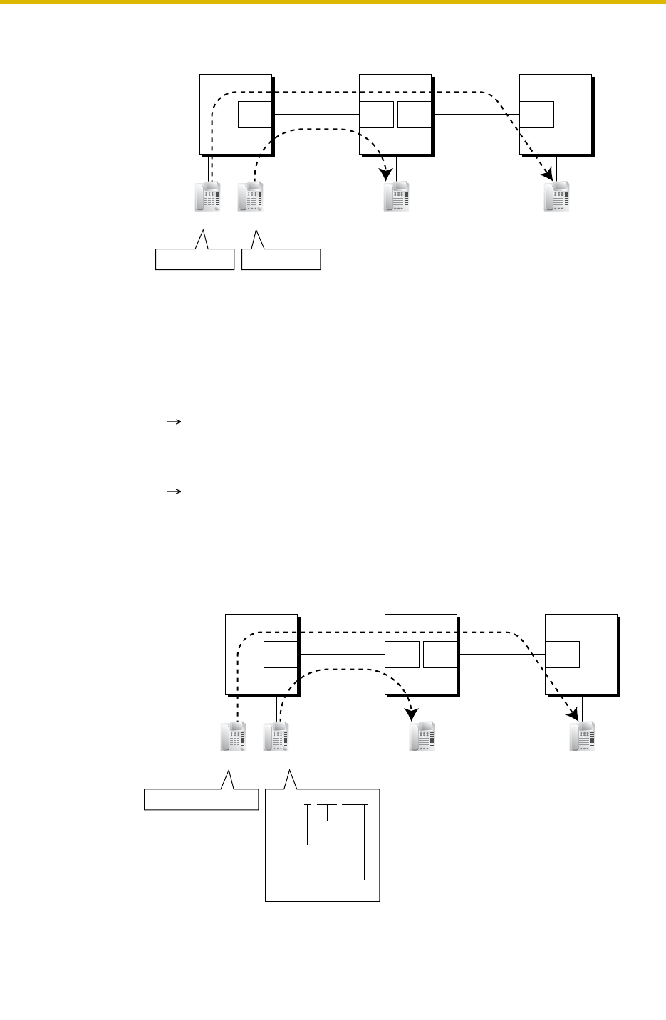
1.28 Networking Features
248 Feature Guide
[Example]
b) PBX Code Method (Access with PBX Code)
Dial the [TIE Line Access Number] + [PBX Code] + [Extension Number].
[Example]
Explanation:
To use this method, it is necessary to change the first one or two digits of extension
numbers of either PBX (e.g., 10XX for PBX-1, 20XX for PBX-2) to avoid having the
same extension number.
Case 1:
Extension 1012 of PBX-1 dials extension number "2011".
Extension 1012 of PBX-1 is connected to extension "2011" of PBX-2.
Case 2:
Extension 1011 of PBX-1 dials extension number "3011".
Extension 1011 of PBX-1 is connected to extension "3011" of PBX-3.
PBX-1
TIE Line
PBX-2
Interface InterfaceInterface
Extn. 2011
PBX-3
Extn. 3011
Extn.1011 Extn.1012
Dials "3011". Dials "2011".
TIE Line
Interface
PBX-1
PBX Code 951
PBX-2
PBX Code 952
PBX-3
PBX Code 953
TIE Line
Interface InterfaceInterface
Extn. 1011
TIE Line
Extn. 1011
Extn.1011 Extn.1012
Dials "7-953-1011". Dials "7-952-1011".
[TIE line
access no.]
[Extn. no.]
[PBX code]
Interface
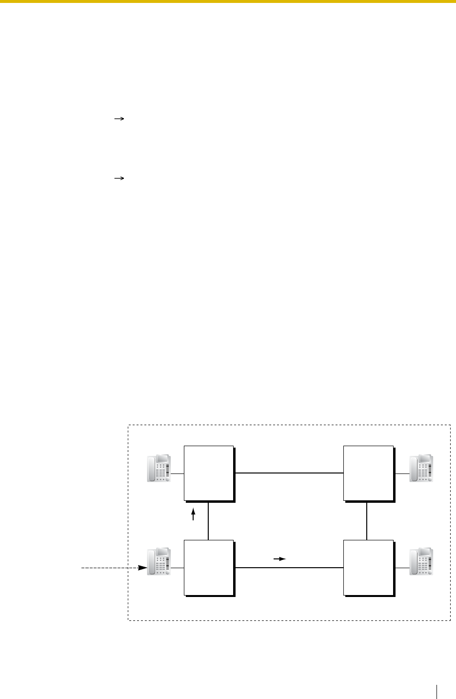
1.28 Networking Features
Feature Guide 249
2. TIE Line Routing and Modification Table
2.1 To Make a TIE Line Call
The TIE Line Routing and Modification Table is referenced by the PBX to identify the
trunk route when an extension user makes a TIE line call.
It is necessary to make unified tables with all PBXs in the TIE line network.
The routing pattern appropriate for each call is decided by the dialled number.
There are two system programmes for the tables:
TIE Line Routing Table: used to assign the leading numbers (PBX code or extension
number) and trunk group hunt sequence.
TIE Modify Removed Number of Digits/Added Number: used to remove digits
from and add a number to the dialled number of the TIE line call. This modification
may be needed depending on the TIE line network configuration.
[Programming Examples]
Your PBX is PBX-1 and there are four PBXs in your TIE line network. To identify the
trunk route as illustrated, you should make the following tables.
a) Extension Number Method (Access without PBX Code)
Explanation:
To use this method, it is necessary to know each PBX code in order to identify the
location of an extension.
Case 1:
Extension 1012 of PBX-1 dials TIE line access number "7", PBX code "952", and
extension number "1011".
Extension 1012 of PBX-1 is connected to extension "1011" of PBX-2.
Case 2:
Extension 1011 of PBX-1 dials TIE line access number "7", PBX code "953", and
extension number "1011".
Extension 1011 of PBX-1 is connected to extension "1011" of PBX-3.
PBX-1
TRG 1
a) 2xxx
PBX-2
PBX-4
TIE Line Network
Extn. 4xxx
Extn. 1xxx Extn. 2xxx
PBX-3
Extn. 3xxx
c) 4xxx
TRG 2
If you dial:
a) 2xxx
b) 3xxx
c) 4xxx
b-2nd) 3xxx
b-1st) 3xxx
(2, 3, 4: Other PBX
Extension Number
[TIE] in the Flexible
Numbering Plan)
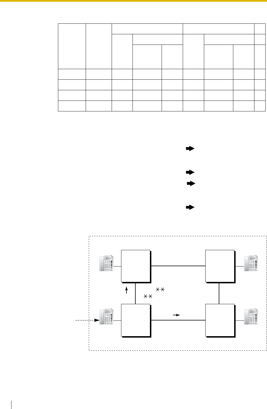
1.28 Networking Features
250 Feature Guide
[TIE Line Routing and Modification Table of PBX-1]
b) PBX Code Method (Access with PBX Code)
Location
No. Leading
No.
Priority 1 Priority 2 . .
Trunk
Group
Dial Modification
Trunk
Group
Dial Modification . .
Removed
No. of
Digits
Added
No.
Removed
No. of
Digits
Added
No. . .
01 2 1 0 . .
02 3 1 0 2 0 . .
03 4 2 0 . .
: ::::::::
Explanation:
Location 01: The hunt sequence by dialling [2XXX]:
The 1st route—trunk group (TRG) 1 Sending no. to PBX-2: 2XXX
Location 02: The hunt sequence by dialling [3XXX]:
The 1st route—trunk group (TRG) 1 Sending no. to PBX-2: 3XXX
The 2nd route—trunk group (TRG) 2 Sending no. to PBX-4: 3XXX
Location 03: The hunt sequence by dialling [4XXX]:
The 1st route—trunk group (TRG) 2 Sending no. to PBX-4: 4XXX
TRG 1
TIE Line Network
Extn. xxxx
Extn. 1xxx Extn. xxxx
Extn. xxxx
TRG 2
PBX-1
a) 952-xxxx
PBX-2
PBX-4 PBX-3
PBX Code 952PBX Code 951
PBX Code 953
b-1st) 953-xxxx
c) 954#-xxxx
If you dial:
a) 7-952-xxxx
b) 7-953-xxxx
c) 7-954-xxxx
(7: TIE Line Access
Number in the
Flexible
Numbering Plan)
PBX Code 954
b-2nd) 953#-xxxx

1.28 Networking Features
Feature Guide 251
[TIE Line Routing and Modification Table of PBX-1]
Location
No. Leading
No.
Priority 1 Priority 2 . .
Trunk
Group
Dial Modification
Trunk
Group
Dial Modification . .
Removed
No. of
Digits
Added
No.
Removed
No. of
Digits
Added
No. . .
01 952 1 0 . .
02 953 1 0 2 3 953# . .
03 954 2 3 954# . .
:::::::::
Explanation:
Location 01: The hunt sequence by dialling [7+PBX Code 952+XXXX]:
The 1st route — trunk group (TRG) 1
Sending no. to PBX-2: 952–XXXX
Location 02: The hunt sequence by dialling [7+PBX Code 953+XXXX]:
The 1st route — trunk group (TRG) 1
Sending no. to PBX-2: 953–XXXX
The 2nd route — trunk group (TRG) 2
Sending no. to PBX-4: 953#–XXXX
Location 03: The hunt sequence by dialling [7+PBX Code 954+XXXX]:
The 1st route — trunk group (TRG) 2
Sending no. to PBX-4: 954#–XXXX
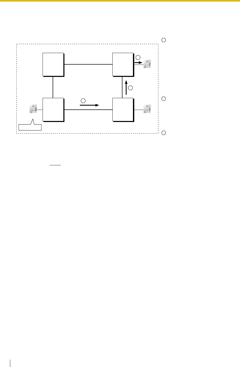
1.28 Networking Features
252 Feature Guide
2.2 To Receive a TIE Line Call
a) Extension Number Method (Access without PBX Code)
[Example]
Note
When a TIE line call is sent to a PBX from another PBX, first the PBX modifies
the number sent to the PBX according to the assignment for each trunk port of
the PBX: the removed number of digits from and/or added number to the number
sent to the PBX is determined by the assignment. Then the PBX starts to check
the number whether the number is an extension number of the PBX.
A TIE line call is sent to PBX-2
from PBX-1. If the number sent
from PBX-1 is an extension
number of PBX-2 (e.g., 2011),
the call will be received at
extension "2011". If not, PBX-2
checks the number in the TIE
Line Routing and Modified
Table of PBX-2.
If the match is found in the
table, the call will be modified
according to the table and send
to the corresponding PBX
(PBX-3).
The number sent from PBX-2
"3011" is an extension number
of PBX-3. The call is received
at extension "3011".
PBX-1 PBX-2
Extn. 1011
13011
23011
PBX-4
Extn. 2011
PBX-3
Extn. 3011
Dials "3011".
3
TIE Line Network
1
2
3
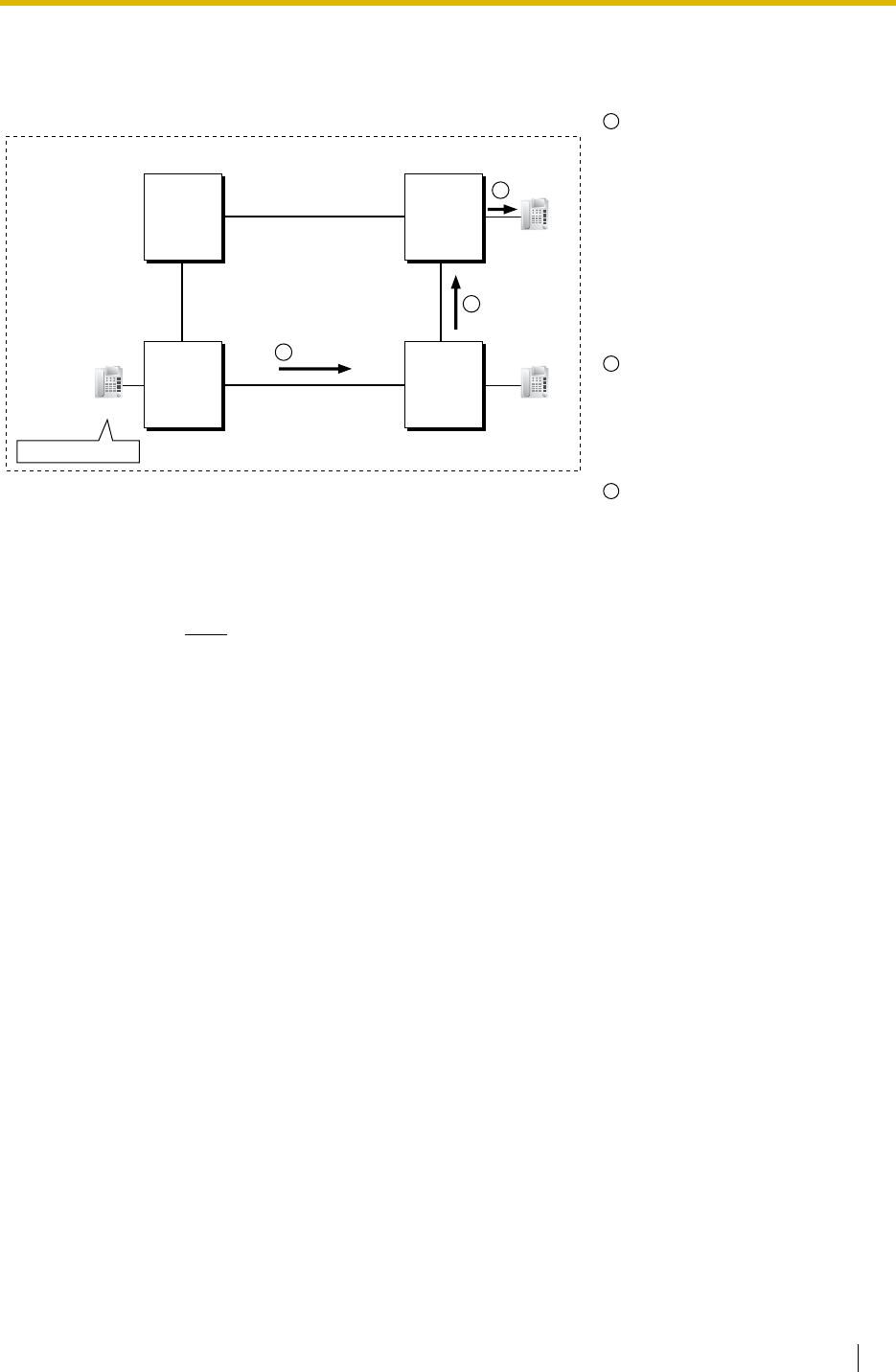
1.28 Networking Features
Feature Guide 253
b) PBX Code Method (Access with PBX Code)
[Example]
Note
When a TIE line call is sent to a PBX from another PBX, first the PBX modifies
the number sent to the PBX according to the assignment for each trunk port of
the PBX: the removed number of digits from and/or added number to the number
sent to the PBX is determined by the assignment. Then the PBX starts to check
the number whether the number has the PBX code of the PBX.
3. TIE Line and Trunk Connection
To connect the TIE line with the trunk, the following patterns are available:
1) Trunk-to-TIE Access
2) TIE-to-Trunk Access
3) Trunk-to-TIE-to-Trunk Access
3.1 Trunk-to-TIE Access
It is possible to assign an extension of another PBX as the destination of incoming
trunk calls to the own PBX.
A TIE line call is sent to PBX-2
from PBX-1. If the number sent
from PBX-1 has the PBX code
of PBX-2 "952", the call will be
received at the corresponding
extension of PBX-2 (e.g.,
1011of PBX-2). If not, PBX-2
checks the number in the TIE
Line Routing and Modified
Table of PBX-2.
If the match is found in the
table, the call will be modified
according to the table and send
to the corresponding PBX
(PBX-3).
The number sent from PBX-2
"953-1011" has the PBX code
of PBX-3 "953". The call is
received at extension "1011" of
PBX-3.
Extn. 1011
1
953-1011
953-1011
2
3
Extn. 1011
Extn. 1011
Dials "7-953-1011". PBX-1 PBX-2
PBX-4 PBX-3
PBX Code 952PBX Code 951
PBX Code 953
PBX Code 954
TIE Line Network
1
2
3
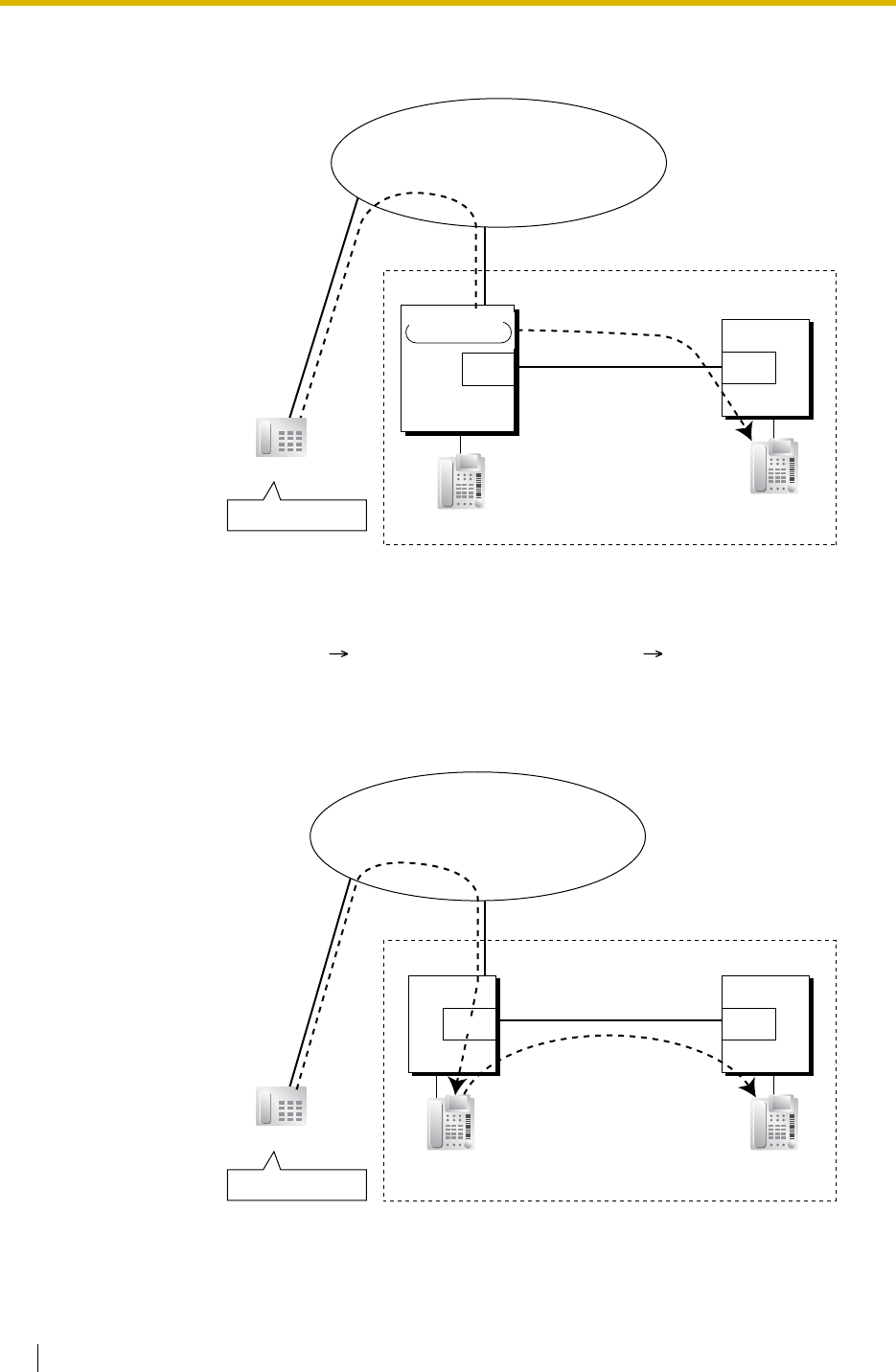
1.28 Networking Features
254 Feature Guide
a) Incoming Trunk Call Destination Assignment
[Example]
b) FWD/Call Transfer/Intercept Routing to the TIE Line
[Example]
Explanation:
An outside caller dials the DID number "123-4567". The call is sent to extension
"2011" of PBX-2 through the TIE line according to the assignment of the DID call
destination ( DID Destination [453]) of PBX-1. ( 1.1.1.3 Direct Inward
Dialling (DID)/Direct Dialling In (DDI))
PBX-1
TIE Line Network
TIE Line
PBX-2
Extn. 2011
Outside Caller
Trunk
Trunk
Interface
Dials "123-4567". (DID No.:123-4567)
Telephone Company
Destination: 2011
DID No: 123-4567
Interface
Extn. 1011
PBX-1
TIE Line Network
TIE Line
Forwarded/Transferred
/Intercepted to 2011
PBX-2
Extn. 2011
Extn. 1011
Outside Caller
Trunk
Trunk
Interface
Dials "123-4567". (DID No.: 123-4567)
Telephone Company
Interface
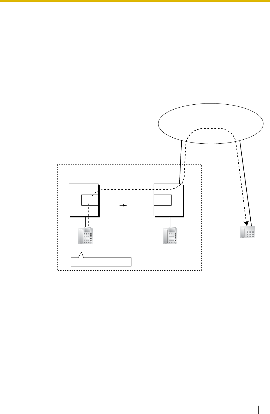
1.28 Networking Features
Feature Guide 255
3.2 TIE-to-Trunk Access
The PBX sends TIE line calls to the trunks of another PBX through the TIE lines.
a) Trunk Call through Other PBXs—by Making a TIE Line Call Method
[Example]
<Extension Number Method (Access without PBX Code)>
Explanation:
An outside caller dials the DID number "123-4567". The call reaches the
destination (extension 1011 of PBX-1), and the call is forwarded, transferred, or
intercepted to extension "2011" of PBX-2 through the TIE line.
Explanation:
1. Extension 1011 of PBX-1 dials the Trunk Group Access number of PBX-1 "8",
trunk group number "02" (TRG2), Idle Line Access number of PBX-2 "9", and
telephone number "01-23-4567".
2. PBX-1 sends the call to PBX-2 through the trunk group (TRG) 2 (TIE line).
3. PBX-2 sends the call to the outside party "01-23-4567".
TIE Line Network
TIE Line
9-01-23-4567
01-23-4567
Outside Party
Interface
Extn. 1011
Trunk Trunk
Dials "802-9-01-23-4567".
(01-23-4567)
Telephone Company
PBX-1 PBX-2
Interface
TRG 2
Extn. 2011
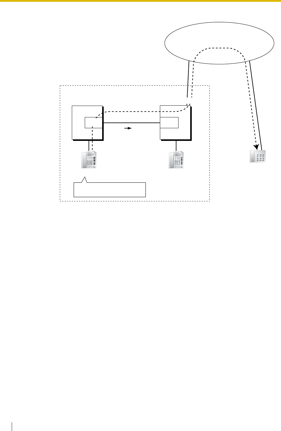
1.28 Networking Features
256 Feature Guide
<PBX Code Method (Access with PBX Code)>
Explanation:
1. Extension 1011 of PBX-1 dials the TIE line access number "7", PBX code
"952", Idle Line Access number of PBX-2 "9", and telephone number "01-23-
4567"; or dials the Trunk Group Access number of PBX-1 "8", trunk group
number "02" (TRG2), PBX code "952", Idle Line Access number of PBX-2
"9", and telephone number "01-23-4567".
2. The call is connected to the outside party "01-23-4567" through PBX-2 which
has PBX code "952".
TIE Line Network
TIE Line
952-9-01-23-4567
01-23-4567
Outside Party
Interface
Extn. 1011
Trunk Trunk
Dials "7-952-9-01-23-4567" or
"802-952-9-01-23-4567".
(01-23-4567)
Telephone Company
PBX-1
PBX Code 951 PBX-2
PBX Code 952
Interface
TRG 2
Extn. 1011
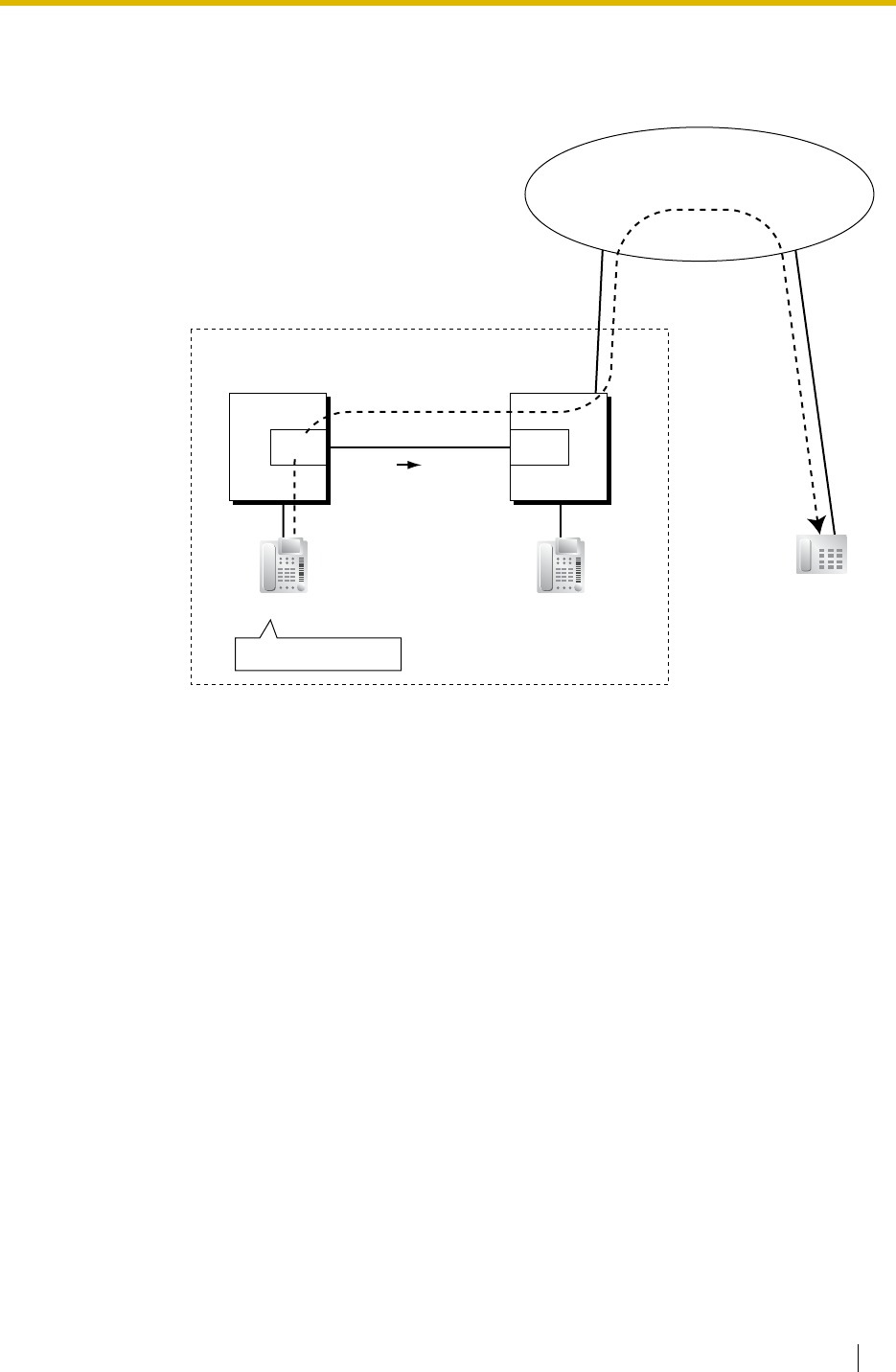
1.28 Networking Features
Feature Guide 257
b) Trunk Call through Other PBXs—by the ARS feature
[Example]
<Extension Number Method (Access without PBX Code)>
Explanation:
1. Extension 1011 of PBX-1 dials the Idle Line Access number of PBX-1 "9" and
telephone number "01-23-4567".
2. PBX-1 modifies the call (adds the Idle Line Access number of PBX-2 "9") and
sends the call to PBX-2 through the TIE line (trunk group [TRG] 2) according
to the ARS programming of PBX-1.
3. PBX-2 sends the call to the outside party "01-23-4567".
TIE Line Network
TIE Line
9-01-23-4567
01-23-4567
Outside Party
Interface
Extn. 1011
Trunk Trunk
Dials "9-01-23-4567".
(01-23-4567)
Telephone Company
PBX-1 PBX-2
Interface
TRG 2
Extn. 2011

1.28 Networking Features
258 Feature Guide
<PBX Code Method (Access with PBX Code)>
Explanation:
1. Extension 1011 of PBX-1 dials the Idle Line Access number of PBX-1 "9" and
telephone number "01-23-4567".
2. PBX-1 modifies the call (adds "952" and the Idle Line Access number of PBX-
2 "9") and sends the call to PBX-2 which has PBX code "952" through the TIE
line (trunk group [TRG] 2) according to the ARS programming of PBX-1.
3. PBX-2 sends the call to the outside party "01-23-4567".
TIE Line Network
TIE Line
952-9-01-23-4567
01-23-4567
Outside Party
Interface
Extn. 1011
Trunk Trunk
Dials "9-01-23-4567".
(01-23-4567)
Telephone Company
PBX-1
PBX Code 951 PBX-2
PBX Code 952
Interface
TRG 2
Extn. 1011
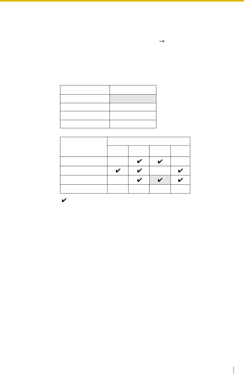
1.28 Networking Features
Feature Guide 259
[Programming Example of PBX-2]
c) Blocking of Trunk Call through Other PBXs and How to Override It
To prohibit a TIE line call to go through PBX-2 for making a trunk call, if PBX-2
is Panasonic Hybrid IP-PBX (e.g., KX-TDA100 or KX-TDA200), PBX-2 should
disable the trunk group of the outgoing call from PBX-2 against the COS of the
trunk group of the incoming call to PBX-2 ( Trunk Group Number [500]) like
the programming example shown below. TRS/Barring applies to a TIE line call
on a COS of the trunk group of the incoming call basis. To override this
prohibition, access the DISA floating extension number of PBX-2 and enter a
verified code to change the COS temporarily.
Trunk Group No.
1
2
3
:
COS No.
3
2
2
:
:
COS 1
COS 2
COS 3
Outgoing Call
TRG 2 TRG 3 …
TRG of Incoming
Call TRG 1
:::
:
: Block
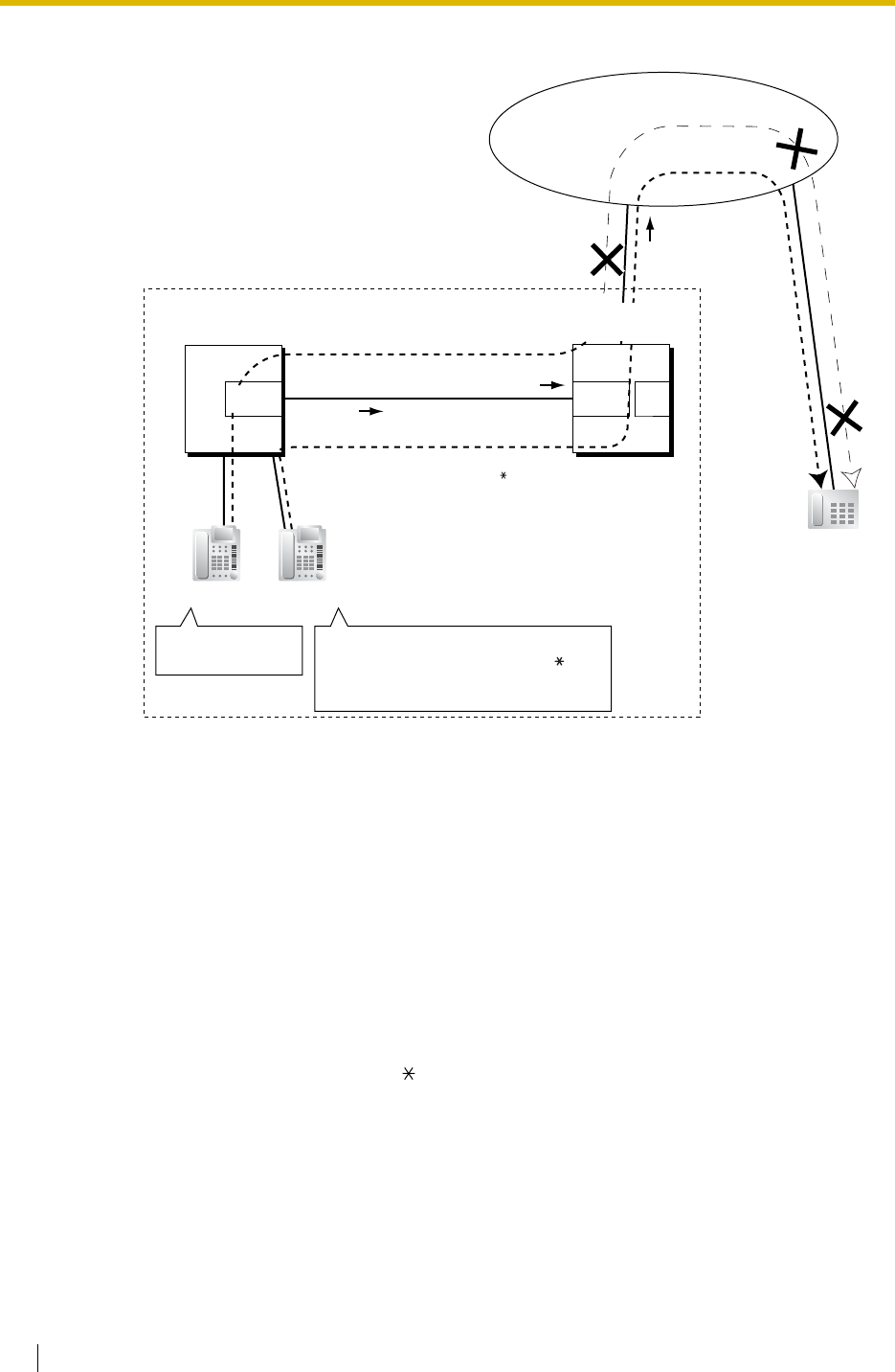
1.28 Networking Features
260 Feature Guide
[Example]
Explanation:
Case 1:
1. Extension 1011 of PBX-1 dials the TIE line access number "7", PBX code
"952", Idle Line Access number of PBX-2 "9", and telephone number "01-23-
4567".
2. The call is not connected to the outside party "01-23-4567" through PBX-2
which has PBX code "952" due to the COS assignment of the trunk groups
of PBX-2.
Case 2:
1. Extension 1012 of PBX-1 dials the TIE line access number "7", PBX code
"952", "DISA floating extension number of PBX-2 + verified code entry
feature number + + verified code + verified code personal identification
number (PIN)", Idle Line Access number of PBX-2 "9", and telephone number
"01-23-4567".
2. The call overrides the COS assignment of the trunk groups of PBX-2, and the
call is connected to the outside party "01-23-4567" through PBX-2 which has
PBX code "952".
TIE Line Network
TIE Line
952-9-01-23-4567
Outside Party
Interface
DISA
Extn. 1011
PBX-1
PBX-Code 951
Trunk Trunk
Dials "7-952-9-01-
23-4567".
(01-23-4567)
01-23-4567
Telephone Company
Extn. 1012
Dials "7-952-(DISA Floating extn. no. +
verified code entry feature no. + +
verified code + verified code PIN)
-9-01-23-4567".
952-(DISA Floating extn. no. +
verified code entry feature no. + +
verified code + verified code
PIN)-9-01-23-4567
PBX-2
PBX-Code 952
TRG 2
of PBX-1
TRG 1 (COS 3)
of PBX-2
TRG 3
of PBX-2
Interface
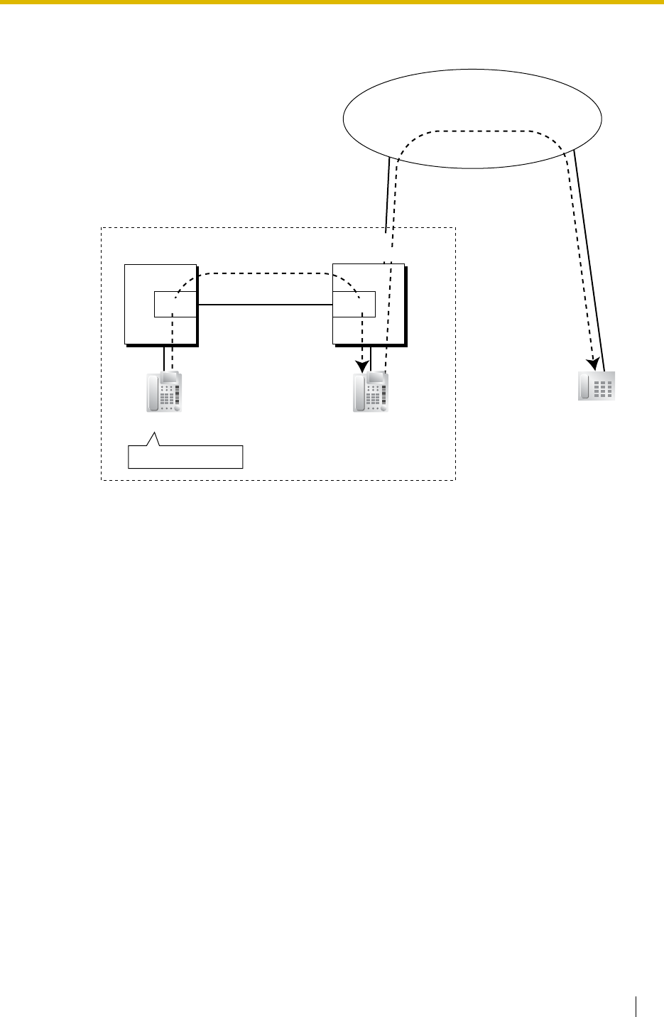
1.28 Networking Features
Feature Guide 261
d) FWD/Call Transfer/Intercept Routing to the Trunk
[Example]
Explanation:
1. Extension 1011 of PBX-1 dials the TIE line access number "7", PBX code
"952", and extension number "1011".
2. The call reaches the destination (extension 1011 of PBX-2) through the TIE
line, and the call is forwarded, transferred or intercepted to the outside party
"01-23-4567" through the trunk.
TIE Line Network
TIE Line
952-1011
Forwarded/Transferred/
Intercepted to 01-23-4567
Outside Par
ty
Extn. 1011 Extn. 1011
Trunk Trunk
Dials "7-952-1011".
(01-23-4567)
Telephone Company
PBX-1
PBX-Code 951 PBX-2
PBX-Code 952
Interface Interface
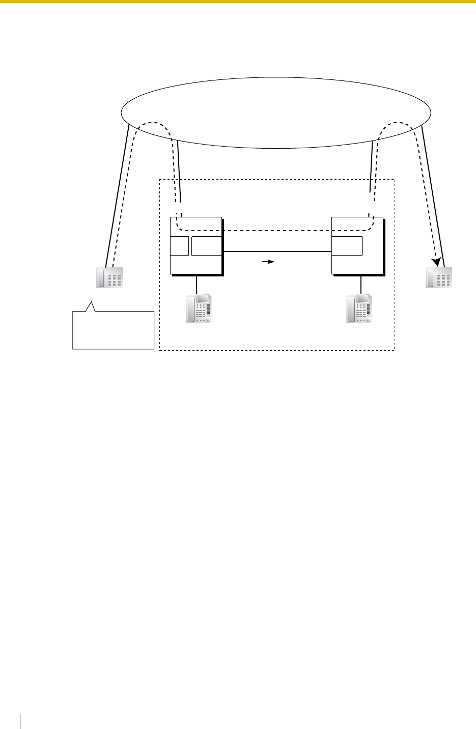
1.28 Networking Features
262 Feature Guide
3.3 Trunk-to-TIE-to-Trunk Access
An outside caller can be connected to an outside party through the TIE line by using
the DISA feature.
[Example]
Explanation:
1. The outside caller dials the "DISA phone number of PBX-1", Idle Line Access
number of PBX-1 "9", and telephone number "01-23-4567".
2. PBX-1 modifies the call (adds "952" and the Idle Line Access number of PBX-
2 "9") and sends the call to PBX-2 which has PBX code "952" through the TIE
line (trunk group [TRG] 2) according to the ARS programming of PBX-1.
3. PBX-2 sends the call to the outside party "01-23-4567".
TIE Line Network
TIE Line
952-9-01-23-4567
Outside Par
ty
Interface Interface
Extn. 1011 Extn. 1011
TrunkTrunk TrunkTrunk
Dials "(DISA phone
number)-9-01-23-
4567".
(01-23-4567)
01-23-
4567
Outside Caller
TRG 2
DISA
Telephone Company
PBX-1
PBX-Code 951 PBX-2
PBX-Code 952
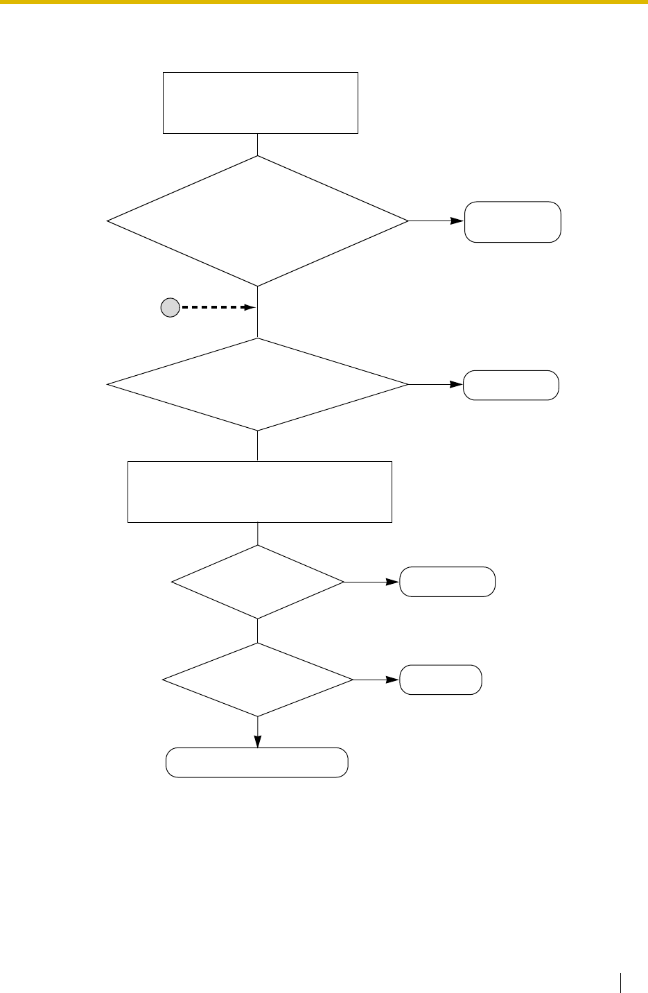
1.28 Networking Features
Feature Guide 263
4. TIE Line Routing Flowchart
[Making a TIE Line Call from an Extension]
A TIE line call is made as follows:
PBX Code Method: 7-abc-xxxx
Extension No. Method: dexx
Yes:
TIE line access no.: 7
Other PBX extension no.: de
No
No
Reorder tone
No
No
Routes to other PBX or trunk.
Yes
Yes
Is the dialled number
identified as a TIE line access no.
or an other PBX extension no. in
the flexible numbering
plan of the own PBX?
Is the trunk group
available?
Yes
Is there an idle trunk
in the trunk group?
Is the leading
number (abc or de) found in the TIE Line
Routing and Modification Table
of the own PBX?
Selects the corresponding trunk group, and
the dialled number is modified if a removed
number of digits and/or added number is assigned.
Not treated as
a TIE line call.
A
Reorder tone
Busy tone
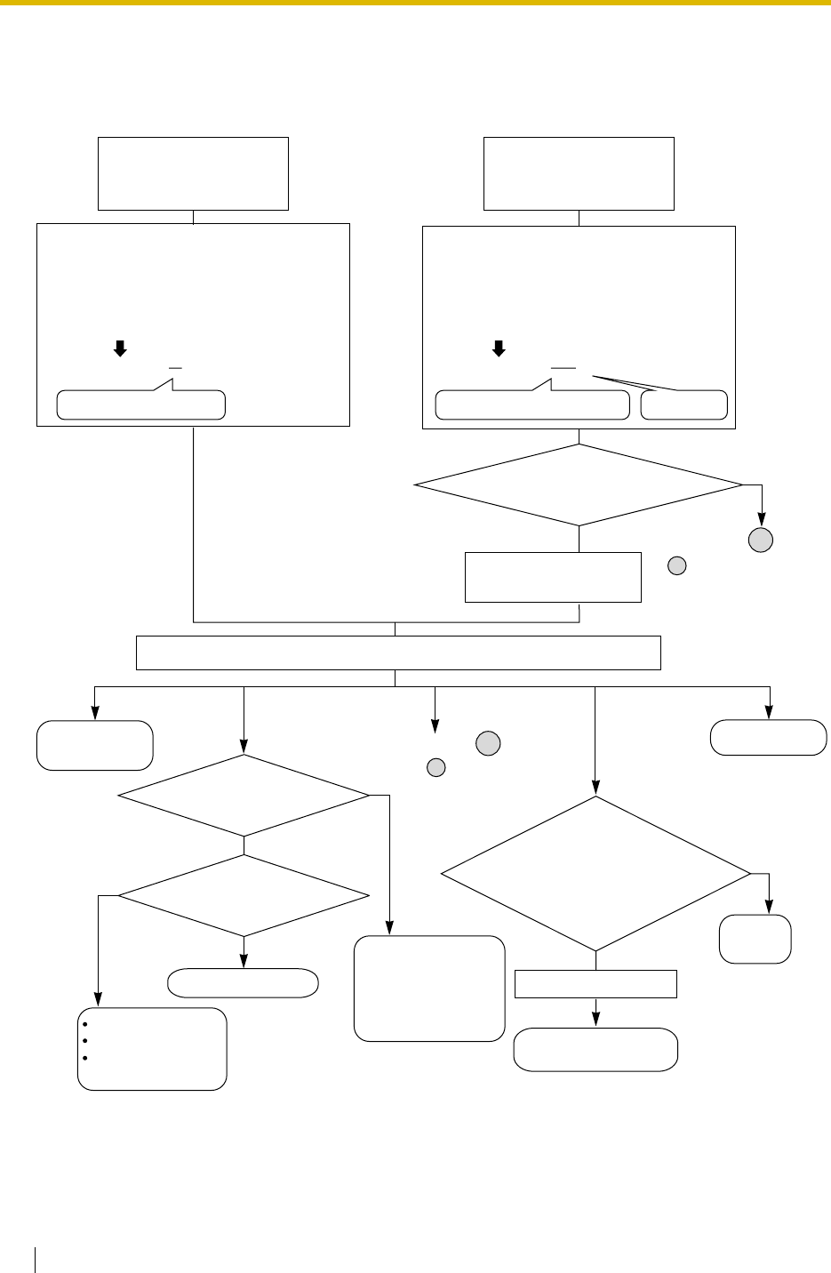
1.28 Networking Features
264 Feature Guide
[Receiving a Call through a TIE Line]
<Extension Number Method
(Access without PBX Code)>
Extension No.
of the Own PBX Extension No.
of Other PBX Idle Line
Access No.
or
Trunk Group
Access No.
A call is received through a
TIE line as follows:
The received number is modified as
programmed for each trunk port.
Removed number of digits: 1
Added number: None
Received number: # 1021
Modified number: # 1021=1021
# 1021
1021 1033
No
No
No
Yes
Yes: 9511033 Goes to
Remove the first 1 digit.
<PBX Code Method
(Access with PBX Code)>
A call is received through a
TIE line as follows:
The received number is modified as
programmed for each trunk port.
Removed number of digits: 3
Added number: 9
Received number: ## 0511033
Does the modified number have
the own PBX code "951"?
Does the corresponding
extension exist?
Removes the own PBX
code "951".
Modified number: ##0511033= 9511033
## 0511033
1) Remove the first 3 digits. 2) Add "9".
Yes
Is the corresponding
extension idle?
Checks the modified number with the flexible numbering plan of the own PBX.
Sends reorder
tone, or sends the
call to the operator
(Intercept Routing
—No Destination).
No
Reorder
tone
Call Waiting
Busy tone
Intercept Routing
—Busy/DND
Directs the call
to the operator.
Calls the extension.
A
Goes to A
( is in the flowchart of
[Making a TIE Line Call
from an Extension].)
A
( is in the
flowchart of [Making
a TIE Line Call from an
Extension].)
A
Yes
TRS/Barring applies.
Sends the call to
the trunk.
Is the trunk
group of the outgoing
call from the own PBX enabled
against the COS of the trunk group of
the incoming call
to the own PBX?
Operator Call No.
Reorder tone.
Other
s

1.28 Networking Features
Feature Guide 265
Conditions
• When a TIE line call arrives at a busy extension which has disabled Call Waiting, the caller
will hear a busy tone. If required, Intercept Routing—Busy/DND can be activated.
• The Inter-digit time can be assigned for TIE line calls.
Feature Guide References
1.1.1.6 Intercept Routing
1.3.1.2 Call Forwarding (FWD)
1.8.1 Toll Restriction (TRS)/Call Barring (Barring)
1.9.1 Automatic Route Selection (ARS)
1.11.1 Call Transfer
1.16.6 Direct Inward System Access (DISA)
2.3.5 Flexible Numbering/Fixed Numbering
User Manual References
User Manual
1.2.1 Basic Calling
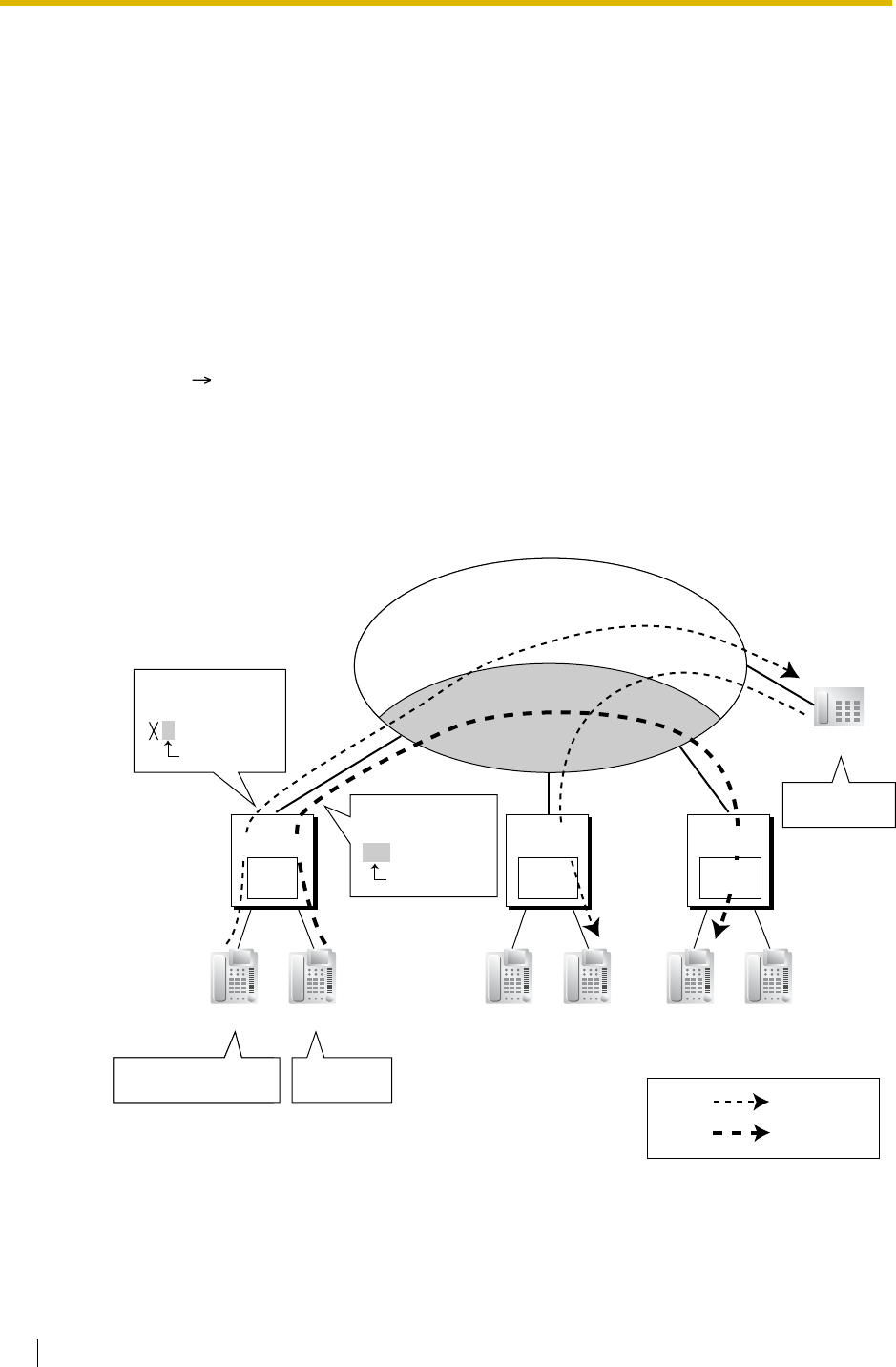
1.28 Networking Features
266 Feature Guide
1.28.2 Virtual Private Network (VPN)
Description
Virtual Private Network (VPN) is a service provided by the telephone company. It uses an
existing line as if it were a private line. There is no need to set up a private line or to lease a
line from the telephone company. Making and receiving both public and private calls is possible
using the same line.
Public/Private Discrimination:
a) When making a call: The public/private discrimination number is required before
sending the dialled number to the telephone company. The public/private
discrimination number can be dialled manually, or automatically by ARS programming
( 1.9.1 Automatic Route Selection (ARS)) and/or TIE line service programming.
b) When receiving a call: The telephone company distinguishes the call type. If it is a
private call, the call is received by the TIE line service method. If it is a public call, the
call is received by the Incoming Trunk Call Distribution method (DIL/DDI/MSN) which
is assigned on the trunk.
[Example]
Conditions
• Each trunk has its service type: public, private, or VPN. Select VPN to use this service
through system programming.
Head
Office
Extn. 201 Extn. 202 Extn. 301 Extn. 302
(DDI No.:
01-45-6789)
Extn. 401 Extn. 402
01-23-4567
VPN
Public ISDN
Dials "401".
(TIE)
Dials "9-01-23-4567".
(ARS)
Dials
"01-45-6789"
.
Branch
Office
Public Call
Note:
Private Call
<Public
Discrimination>
9-0-01-23-4567
Public No.
<Private
Discrimination>
113-401
Private No.
PBX-2
Branch
Office
PBX Code 111 PBX Code 112 PBX Code 113
PBX-3PBX-1

1.28 Networking Features
Feature Guide 267
• Even if the telephone company does not support the VPN service, it is possible to use the
same kind of service when making a call by TIE line service programming, and/or Quick
Dialling programming ( 1.6.1.6 Quick Dialling).
[Quick Dialling Programming Example]
Explanation:
When an extension user dials "2345", he is connected to extension "2345" of other PBX
whose public number is "123-4321".
Feature Guide References
1.28.1 TIE Line Service
Location No. Quick Dialling No. Desired No.
Quick Dialling 01 2345 (extension no. of
other PBX) 9-123-4321 (Public no. of
extension 2345)
:: :
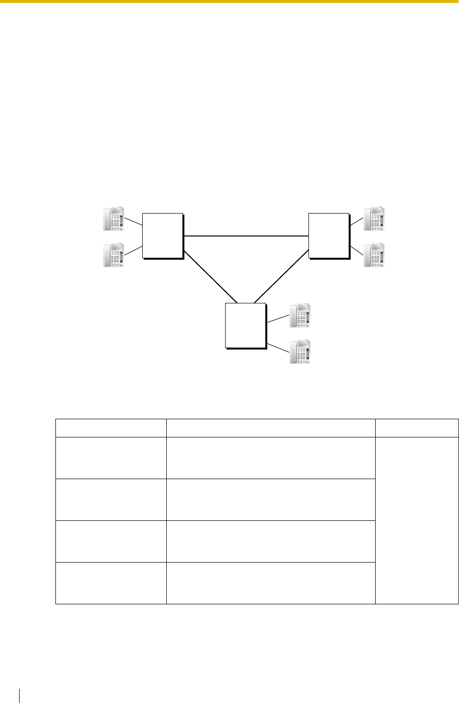
1.28 Networking Features
268 Feature Guide
1.28.3 QSIG Network
1.28.3.1 QSIG Network—SUMMARY
Description
QSIG is a protocol which is based on ISDN (Q.931) and offers enhanced PBX features in a
private network. The QSIG network supports private communications by the TIE line service
method.
Each ISDN (QSIG) connection must have a master port on one Panasonic Hybrid IP-PBX and
a slave port on the other Panasonic Hybrid IP-PBX to establish a QSIG network.
[Connection Example]
System programming controls the following services individually for each ISDN (QSIG) port.
[Service Table]
Service Description Details in
Calling Line
Identification
Presentation (CLIP)
Sends the caller’s number to the QSIG network
when making a call. • 1.28.3.2 Calling/
Connected Line
Identification
Presentation
(CLIP/COLP) and
Calling/
Connected Name
Identification
Presentation
(CNIP/CONP)—
by QSIG
Connected Line
Identification
Presentation (COLP)
Sends the number of the answered party to the
QSIG network when answering a call.
Calling Line
Identification
Restriction (CLIR)
Prevents the caller’s CLI being presented to the
called party by the caller.
Connected Line
Identification
Restriction (COLR)
Prevents COLP being sent by the answered
party.
PBX-1
PBX-3
PBX-2
Extn.1000
:
Extn.1999
Extn. 2000
:
Extn. 2999
(A) Master
(B) Master
(C) Master
QSIG Network
(A) Slave
(C) Slave
(B) Slave
Extn. 3000
:
Extn. 3999

1.28 Networking Features
Feature Guide 269
Feature Guide References
1.20.1 Integrated Services Digital Network (ISDN)
1.28.1 TIE Line Service
Calling Name
Identification
Presentation (CNIP)
Sends the caller’s name to the QSIG network
when making a call. • 1.28.3.2 Calling/
Connected Line
Identification
Presentation
(CLIP/COLP) and
Calling/
Connected Name
Identification
Presentation
(CNIP/CONP)—
by QSIG
Connected Name
Identification
Presentation (CONP)
Sends the name of the answered party to the
QSIG network when answering a call.
Calling Name
Identification
Restriction (CNIR)
Prevents the caller’s name being presented to
the called party by the caller.
Connected Name
Identification
Restriction (CONR)
Prevents CONP being sent by the answered
party.
Call Forwarding (CF)—
by QSIG*
Forwards a call to the QSIG network. • 1.28.3.3 Call
Forwarding
(CF)—by QSIG
Call Transfer (CT)—by
QSIG*
Transfers a call to the QSIG network. • 1.28.3.4 Call
Transfer (CT)—by
QSIG
Completion of Calls to
Busy Subscriber
(CCBS)—by QSIG*
Receives callback ringing when a busy called
party on the QSIG network becomes free. • 1.28.3.5
Completion of
Calls to Busy
Subscriber
(CCBS)—by
QSIG
*: This feature is not available for the PRI23 card.
Service Description Details in
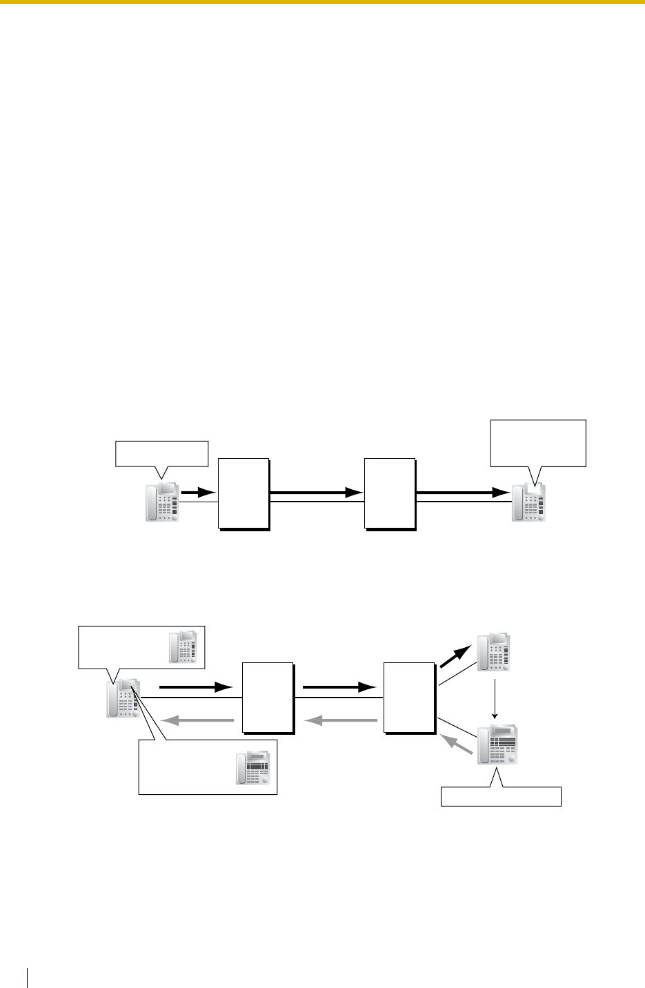
1.28 Networking Features
270 Feature Guide
1.28.3.2 Calling/Connected Line Identification Presentation
(CLIP/COLP) and Calling/Connected Name Identification
Presentation (CNIP/CONP)—by QSIG
Description
Calling Line/Name Identification Presentation (CLIP/CNIP):
The PBX can send a preprogrammed extension number and/or name to the QSIG network
when an extension user makes a call. The called party can see the number and/or name on
his telephone display before answering the call.
Connected Line/Name Identification Presentation (COLP/CONP):
The PBX sends a preprogrammed extension number and/or name to the QSIG network when
the extension user answers an incoming call. The caller can see the number and/or name of
the answering party on his telephone display when the call is answered.
These features comply with the following European Telecommunication Standard (ETS)
specifications:
CLIP/COLP: ETS 300 172 Circuit mode basis services.
CNIP/CONP: ETS 300 238 Name identification supplementary services.
[CLIP/CNIP Example]
[COLP/CONP Example]
1) Dials "202".
2) "John
101"
is displayed.
PBX-1 PBX-2
CLIP: 101
CNIP: John
Called party
(Extn. No.: 202)
Caller
(Extn. No.: 101
Extn. Name: John)
PBX-2PBX-1
FWD, IRNA, etc.
1) Dials "203".
2) Answers the call.
Caller Answering party
(Extn. No.: 204
Extn. Name: Paul)
COLP: 204
CONP: Paul
3) "Paul
204"
is displayed.
Called party
(Extn. No.: 203
Extn. Name: Tom)

1.28 Networking Features
Feature Guide 271
CLIP/COLP Number:
The extension number sent to the QSIG network for CLIP/COLP can be assigned for each
extension through system programming ( Extension Number [003]).
CNIP/CONP Name:
The extension name sent to the QSIG network for CNIP/CONP can be assigned for each
extension through system programming ( Extension Name [004]).
Calling/Connected Line Identification Restriction (CLIR/COLR):
It is possible for each extension to restrict the sending of its extension number to the QSIG
network by pressing the CLIR button, COLR button, or entering the feature number.
Calling/Connected Name Identification Restriction (CNIR/CONR):
It is possible for each extension to restrict the sending of its extension name to the QSIG
network. When CLIR is activated, CNIR becomes active automatically. When COLR is
activated, CONR becomes active automatically.
These features comply with the following European Telecommunication Standard (ETS)
specifications:
CLIR/COLR: ETS 300 172 Circuit mode basis services.
CNIR/CONR: ETS 300 238 Name identification supplementary services.
Conditions
•COLP/CLIR/COLR/CNIP/CONP/CNIR/CONR Assignment for Each Port
Each service can be enabled or disabled on each ISDN (QSIG) port of the PBX.
•CLIR Button and COLR Button
It is possible to switch between CLIP and CLIR by pressing the CLIR button, and COLP
and COLR by pressing the COLR button. A flexible button can be customised as the CLIR
or COLR button.
Feature Guide References
1.19.2 Flexible Buttons
User Manual References
User Manual
1.7.4 Displaying Your Telephone Number on the Called Party and Caller’s Telephone
(Calling/Connected Line Identification Presentation [CLIP/COLP])
1.7.5 Preventing Your Telephone Number Being Displayed on the Caller’s Telephone
(Connected Line Identification Restriction [COLR])
1.7.6 Preventing Your Number Being Displayed on the Called Party’s Telephone (Calling
Line Identification Restriction [CLIR])
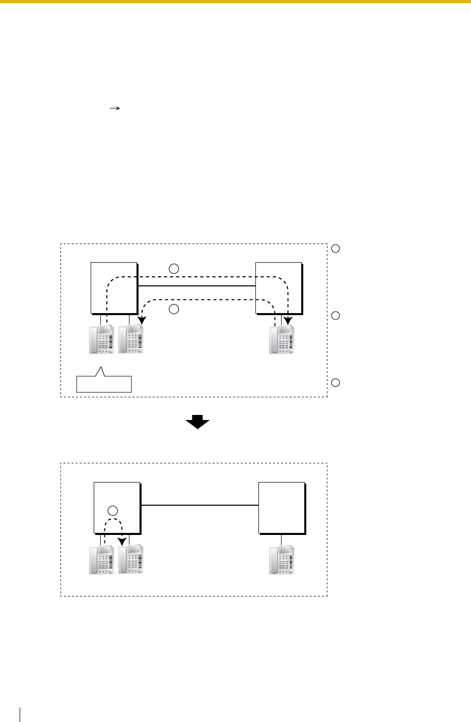
1.28 Networking Features
272 Feature Guide
1.28.3.3 Call Forwarding (CF)—by QSIG
Description
The PBX forwards the call to a destination extension in another PBX in QSIG network. The
destination can be set on your own PBX on an extension basis as the forward destination of
trunk calls ( 1.3.1.2 Call Forwarding (FWD)).
This feature complies with the following European Telecommunication Standard (ETS)
specifications: ETS 300 257 Diversion supplementary services.
If the same trunk group is used for the incoming call and the forwarded call, the following
situation will be possible.
[Example]
Conditions
• This feature can be enabled or disabled on each ISDN (QSIG) port of the PBX.
Extension 1000 of PBX-1
dials extension number
"2000", and the call is sent to
extension "2000" of PBX-2
through QSIG network.
The call is forwarded to the
forward destination of trunk
calls of extension 2000,
which is extension "1001" of
PBX-1.
The call between PBX-1 and
PBX-2 is released, and the
call is connected directly to
the forward destination of
extension 2000.
PBX-1
QSIG
PBX-2
Dials "2000".
PBX-1
QSIG
PBX-2
Extn. 1001 Extn. 2000
Extn. 1001 Extn. 2000
(Forward Destination
of Trunk Calls: 1001)
Call to 2000
1
Forwarded
to 1001
2
3
Extn. 1000
Extn. 1000
1
2
3

1.28 Networking Features
Feature Guide 273
User Manual References
User Manual
1.5.1 Forwarding Calls

1.28 Networking Features
274 Feature Guide
1.28.3.4 Call Transfer (CT)—by QSIG
Description
The PBX transfers the call to a destination extension in another PBX in QSIG network.
This feature complies with the following European Telecommunication Standard (ETS)
specifications: ETS 300 261 Call transfer supplementary service.
If the same trunk group is used for the incoming call and the transferred call, the following
situation will be possible.
[Example]
Conditions
• This feature can be enabled or disabled on an ISDN (QSIG) port basis.
• Call Transfer with Announcement and Call Transfer without Announcement is possible.
( 1.11.1 Call Transfer)
Extension 1000 of PBX-1
dials extension number
"2000", and the call is sent to
extension "2000" of PBX-2
through QSIG network.
The call is transferred from
extension 2000 to extension
"1001" of PBX-1.
The call between PBX-1 and
PBX-2 is released, and the
call is connected directly to
the transfer destination of
extension 2000.
PBX-1
QSIG
PBX-2
Dials "2000".
PBX-1
QSIG
PBX-2
Extn. 1000 Extn. 1001 Extn. 2000
Extn. 1000 Extn. 1001 Extn. 2000
Call to 2000
1
Transferred
to 1001
2
3
1
2
3

1.28 Networking Features
Feature Guide 275
User Manual References
User Manual
1.4.1 Transferring a Call (Call Transfer)

1.28 Networking Features
276 Feature Guide
1.28.3.5 Completion of Calls to Busy Subscriber (CCBS)—by
QSIG
Description
If the call has been made to an extension in another PBX in QSIG network and the called party
is busy, an extension user can set to receive callback ringing when the called party becomes
free. When the user answers the callback ringing, that party's number is automatically dialled.
This feature complies with the following European Telecommunication Standard (ETS)
specifications: ETS 300 366 Call completion supplementary services.
Conditions
• This feature is available under the following conditions:
a) The caller’s PBX is capable of using CCBS.
b) The called party's PBX is capable of accepting CCBS.
• To receive and send CCBS, receiving and sending CCBS must be enabled individually on
an ISDN (QSIG) port basis through system programming.
• An extension user can set only one CCBS. The last setting is effective.
• The CCBS setting is cancelled if there is no callback ringing within 60 minutes or callback
ringing is not answered within 10 seconds.
User Manual References
User Manual
1.2.4 When the Dialled Line is Busy or There is No Answer
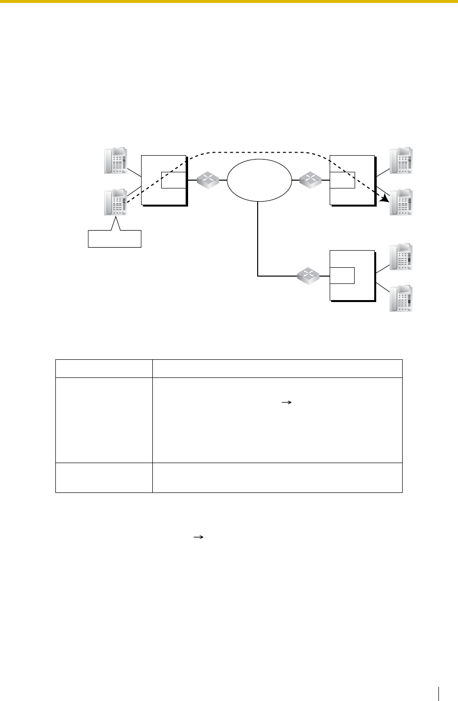
1.28 Networking Features
Feature Guide 277
1.28.4 Voice over Internet Protocol (VoIP) Network
Description
The PBX can connect to another PBX via a private IP network. In this case, voice signals are
converted into IP packets and sent through this network.
VoIP network supports the private network communications by the TIE line service method.
[Example]
[Required Programming]
Conditions
• QSIG service is available. ( 1.28.3 QSIG Network)
Feature Guide References
1.28.1 TIE Line Service
Device Programming
PBX For making a call:
• ARS programming ( 1.9.1 Automatic Route
Selection (ARS)) or TIE line service
programming
For receiving a call:
• TIE line service programming
IP-GW
(IP Gateway Circuit) • IP address assignment for the own PBX and
other PBXs.
PBX-1 PBX-2
Extn.1000
:
Extn.1999
Extn.2000
:
Extn.2999
IP-GW
Router
IP-GW
PBX-3
IP-GW
Extn.3000
:
Extn.3999
Dials "2999".
Private IP
Network Router
Router
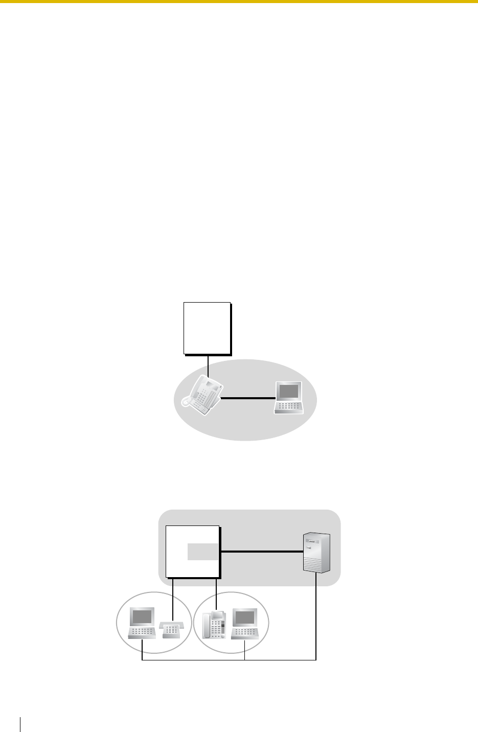
1.29 Computer Telephony Integration (CTI) Features
278 Feature Guide
1.29 Computer Telephony Integration (CTI)
Features
1.29.1 Computer Telephony Integration (CTI)
Description
Connecting a personal computer (PC) to this PBX (via a DPT with the USB Module, or via a
Server PC on a LAN) enables extension users to make use of advanced features by using the
stored data in the PC or in the Server PC.
There are two types of CTI as follows:
1) First Party Call Control
2) Third Party Call Control
1. First Party Call Control
A PC is connected to a DPT using a USB port (USB Module) attached to the DPT. The PC
monitors the status of the DPT and controls the DPT.
2. Third Party Call Control
A Server PC is connected to the PBX using the USB port on the PBX or using the CTI-
LINK card as a CTI interface. PCs monitor the status of the PBX and control the PBX via
the Server PC.
PBX
PC
USB
DPT
PBX
CTI
Interface
Server PC
PC PC
LAN
LAN or USB

1.29 Computer Telephony Integration (CTI) Features
Feature Guide 279
Conditions
•Application Programming Interface (API)/Protocol
The following interface is required for First Party Call Control and Third Party Call Control:
• The operating system of PC or Server PC required for First Party Call Control or Third
Party Call Control depends on your CTI application software. For details, refer to the
manual for your CTI application software.
• One Server PC can be connected per PBX.
Installation Manual References
Installation Manual
<KX-TDA100/KX-TDA200>
2.3.1 MPR Card
2.6.6 CTI-LINK Card
2.7.4 First Party Call Control CTI Connection
2.11.1 Connection of Peripherals
<KX-TDA15/KX-TDA30>
6.6.4 First Party Call Control CTI Connection
6.10.1 Connection of Peripherals
Type API/Protocol
First Party Call
Control • ECMA CSTA Phase 3
Third Party Call
Control • ECMA CSTA Phase 3
•TAPI 2.1

1.29 Computer Telephony Integration (CTI) Features
280 Feature Guide

Feature Guide 281
Section 2
System Configuration and Administration
Features

2.1 System Configuration—Hardware
282 Feature Guide
2.1 System Configuration—Hardware
2.1.1 Extension Port Configuration
Description
There are three types of extension ports as follows:
a) DPT Port: DPT, DSS Console, Panasonic VPS (KX-TVS/TVP series [DPT (Digital)
Integration]), or PT-interface CS (e.g., KX-TDA0141) can be connected.
b) SLT Port: SLT or KX-TVS/TVP series (DTMF Integration) can be connected.
c) Super Hybrid Port: DPT, APT, SLT, DSS Console, KX-TVS/TVP series, or PT-
interface CS can be connected.
EXtra Device Port (XDP) of Super Hybrid Ports:
A DPT and SLT can be connected to one Super Hybrid port (TR: SLT, HL: DPT). In this case,
the SLT port (TR) of the Super Hybrid port can be used as an XDP port to connect an SLT as
a sub telephone. There are two modes for the XDP port as follows:
Conditions
•Automatic Detection on Super Hybrid Port
A DPT, APT, SLT, or PT-interface CS can be connected to a Super Hybrid port without
programming.
• A DSS Console or a VPS (Panasonic KX-TVS/TVP series [DPT (Digital) Integration]) can
also be connected with an SLT in XDP mode.
•APT and SLT in Parallel Mode
An APT and an SLT can also be connected to a Super Hybrid port and used in parallel
mode.
•Digital XDP
A DPT can be connected to another DPT and act as a completely different extension. (
1.10.9 Parallelled Telephone)
•Wireless XDP Parallel Mode
A PS can be used in parallel mode with a wired telephone.
( 1.24.5 Wireless XDP Parallel Mode)
•DSS Console and Paired Telephone Assignment
When a DSS Console is connected, a paired extension must be assigned through system
programming ( Console Paired Telephone [007]). Only a PT can be a paired extension.
Mode Description
Parallel Mode The DPT and SLT have the same extension number so that they
can act as one extension. They use the main telephone’s (DPT’s)
extension data (e.g., extension number, COS).
( 1.10.9 Parallelled Telephone)
XDP Mode The DPT and SLT have different extension numbers so that they
can act as completely different extensions. To use XDP mode,
XDP mode must be enabled (on) the port through system
programming ( EXtra Device Port (XDP) Mode [600]).

2.2 System Configuration—Software
Feature Guide 283
2.2 System Configuration—Software
2.2.1 Class of Service (COS)
Description
Each extension is assigned a COS number ( Class of Service [602]). The following features
are controlled on a COS basis:
a) Internal Call Block ( 1.1.2.2 Internal Call Block)
b) FWD ( 1.3.1.2 Call Forwarding (FWD))
c) DND Override ( 1.3.1.3 Do Not Disturb (DND))
d) Call Pickup ( 1.4.1.3 Call Pickup)
e) Account Code Entry ( 1.5.4.3 Account Code Entry)
f) External Call Block ( 1.5.5.3 Trunk Access)
g) Executive Busy Override ( 1.7.2 Executive Busy Override)
h) Call Monitor ( 1.7.3 Call Monitor)
i) OHCA ( 1.7.4.3 Off-hook Call Announcement (OHCA))
j) Whisper OHCA ( 1.7.4.4 Whisper OHCA)
k) TRS/Call Barring ( 1.8.1 Toll Restriction (TRS)/Call Barring (Barring))
l) Extension Lock ( 1.8.3 Extension Lock)
m) Walking COS ( 1.8.5 Walking COS)
n) Trunk Call Limitation ( 1.10.8 Trunk Call Limitation)
o) Call Transfer ( 1.11.1 Call Transfer)
p) Door Open ( 1.16.2 Door Open)
q) DISA ( 1.16.6 Direct Inward System Access (DISA))
r) Call Forwarding (CF)—by ISDN (P-MP) ( 1.20.1.4 Call Forwarding (CF)—by ISDN
(P-MP))
s) Wireless XDP Parallel Mode ( 1.24.5 Wireless XDP Parallel Mode)
t) SMDR for Outgoing Trunk Call ( 1.25.1 Station Message Detail Recording (SMDR))
u) Time Service Switching ( 2.2.4 Time Service)
v) Manager Features ( 2.2.6 Manager Features)
w) PT Programming ( 2.3.2 PT Programming)
Conditions
•Walking COS
Extension users can make a call from other extensions of the lower level COS by using
their own higher level COS temporarily.
User Manual References
User Manual
1.2.7 Calling without Restrictions
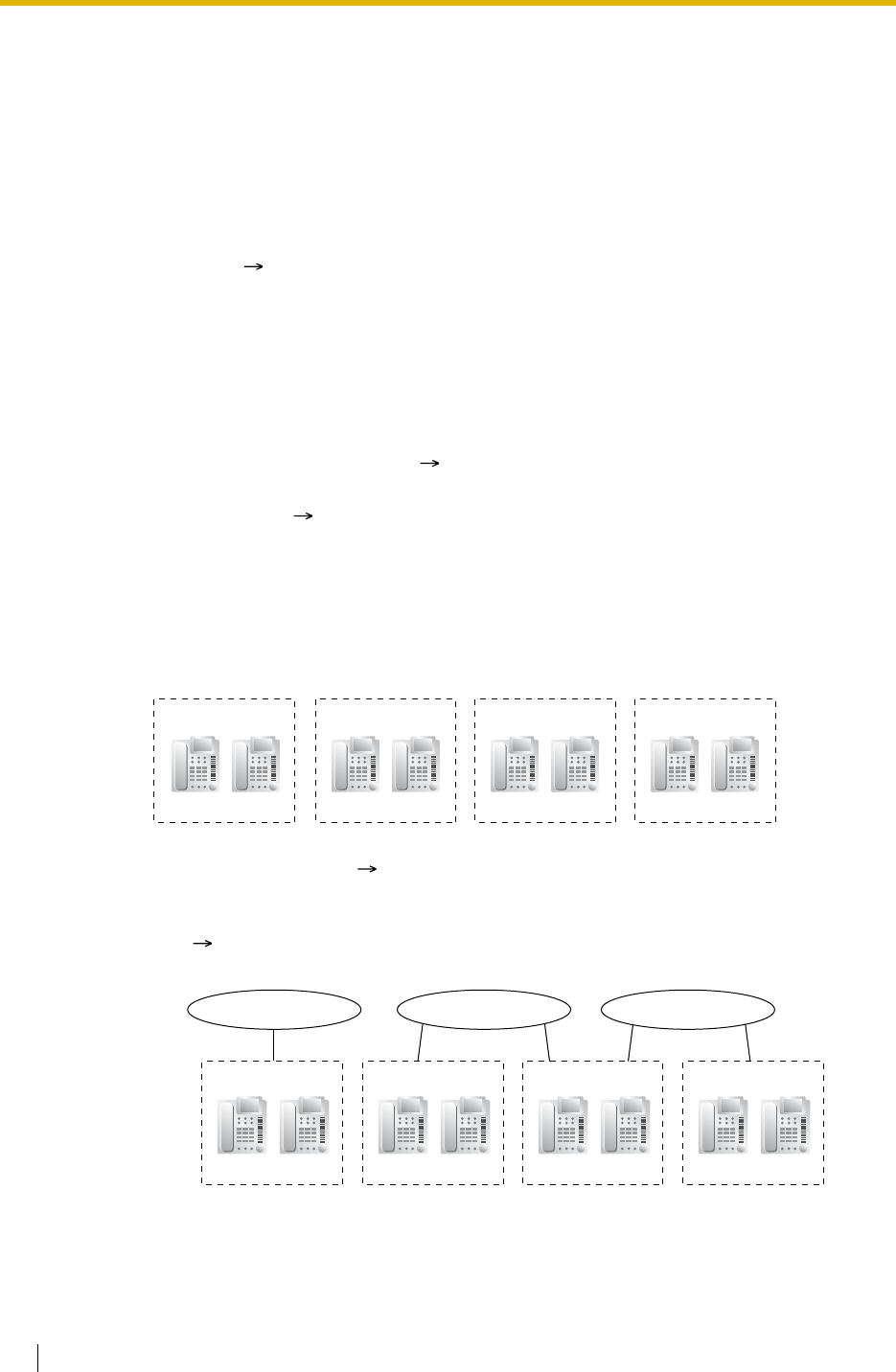
2.2 System Configuration—Software
284 Feature Guide
2.2.2 Group
Description
This PBX supports various types of groups.
1. Trunk Group
Trunks can be grouped into a specified number of trunk groups (e.g., for each carrier, trunk
type, etc.) ( LCOT/BRI Trunk Group Number [402]). Several settings can be assigned
on a trunk group basis. All trunks belonging to a trunk group follow the assignment
determined for that trunk group.
One trunk can belong to only one trunk group on a port or channel basis.
Port basis: LCOT/DID/E & M/ISDN-BRI/ISDN-PRI23/ISDN-PRI30
Channel basis: E1/T1
2. User Group
The PBX supports user groups ( User Group [603]), each of which is used to compose
the following groups:
a) Tenant ( 2.2.3 Tenant Service)
b) Call Pickup Group (See below.)
c) Paging Group (See below.)
Every extension must belong to one user group, but cannot belong to more than one user
group.
Assignable Extensions: PT/SLT/PS/ISDN Extension/T1-OPX
[Example]
2.1 Call Pickup Group ( User Groups of a Pickup Group [650])
Using the Group Call Pickup feature, extensions can answer any calls within a
specified group. One user group can belong to several call pickup groups.
( 1.4.1.3 Call Pickup)
[Example]
User Group 1
Extn. 100 Extn. 101
User Group 2
Extn. 102 Extn. 103
User Group 3
Extn. 104 Extn. 105
User Group 4
Extn. 106 Extn. 107
User Group 1
Call Pickup Group 1
Extn. 100 Extn. 101
User Group 2
Extn. 102 Extn. 103
User Group 3
Extn. 104 Extn. 105
Call Pickup Group 2 Call Pickup Group 3
User Group 4
Extn. 106 Extn. 107
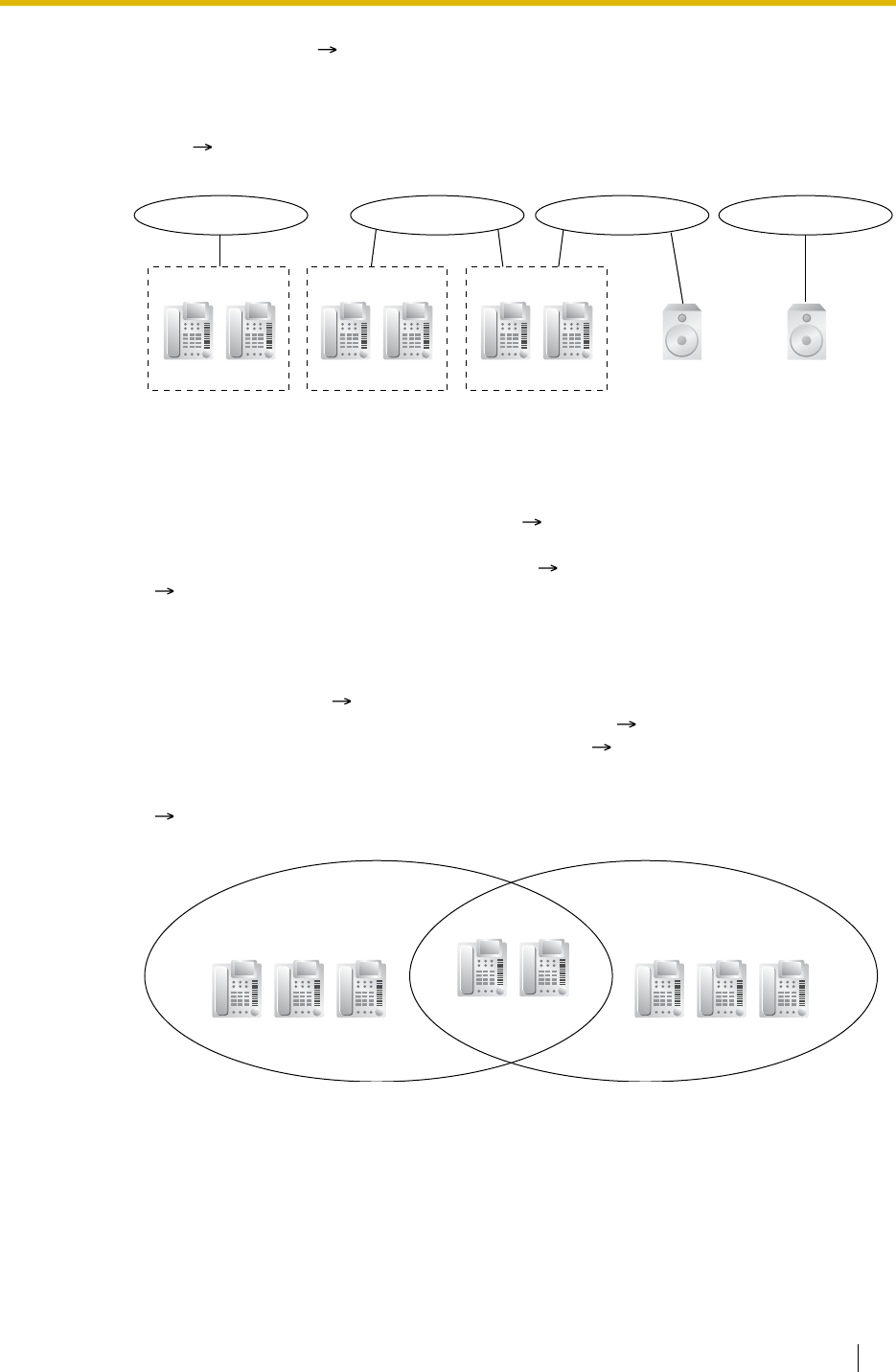
2.2 System Configuration—Software
Feature Guide 285
2.2 Paging Group ( User Groups of a Paging Group [640])
Using the Paging feature, extensions can make a page to any paging groups or
answer a page to their own groups. One user group or external pager can belong to
several paging groups.
( 1.14.1 Paging)
[Example]
3. Idle Extension Hunting Group
If a called extension is busy or in DND mode, Idle Extension Hunting redirects the
incoming call to an idle member of the same idle extension hunting group, which can be
programmed through system programming ( Idle Extension Hunting Group Member
[681]). Idle extensions are automatically searched according to a preprogrammed hunting
type: Circular Hunting or Terminated Hunting ( Idle Extension Hunting Type [680]).
( 1.2.1 Idle Extension Hunting)
4. Incoming Call Distribution Group
An incoming call distribution group is a group of extensions which receives incoming calls
directed to the group ( Incoming Call Distribution Group Member [620]). Each incoming
call distribution group has a floating extension number ( Incoming Call Distribution
Group Floating Extension Number [622]) and name ( Incoming Call Distribution Group
Name [623]). One extension can belong to multiple groups.
Assignable Extensions: PT/SLT/PS/ISDN Extension/T1-OPX/PS Ring Group
( 1.2.2 Incoming Call Distribution Group Features)
[Example]
User Group 1
Paging Group 1
Extn. 100 Extn. 101
User Group 2
Extn. 102 Extn. 103
User Group 3
Extn. 104 Extn. 105 Pager 2Pager 1
Paging Group 2 Paging Group 3 Paging Group 4
Incoming Call
Distribution Group 1
(Floating Extn. No. 280,
Name: Sales 1)
Incoming Call
Distribution Group 2
(Floating Extn. No. 290,
Name: Sales 2)
Extn. 100 Extn. 101 Extn. 102 Extn. 105 Extn. 106
Extn. 103 Extn. 104
Extn. 107
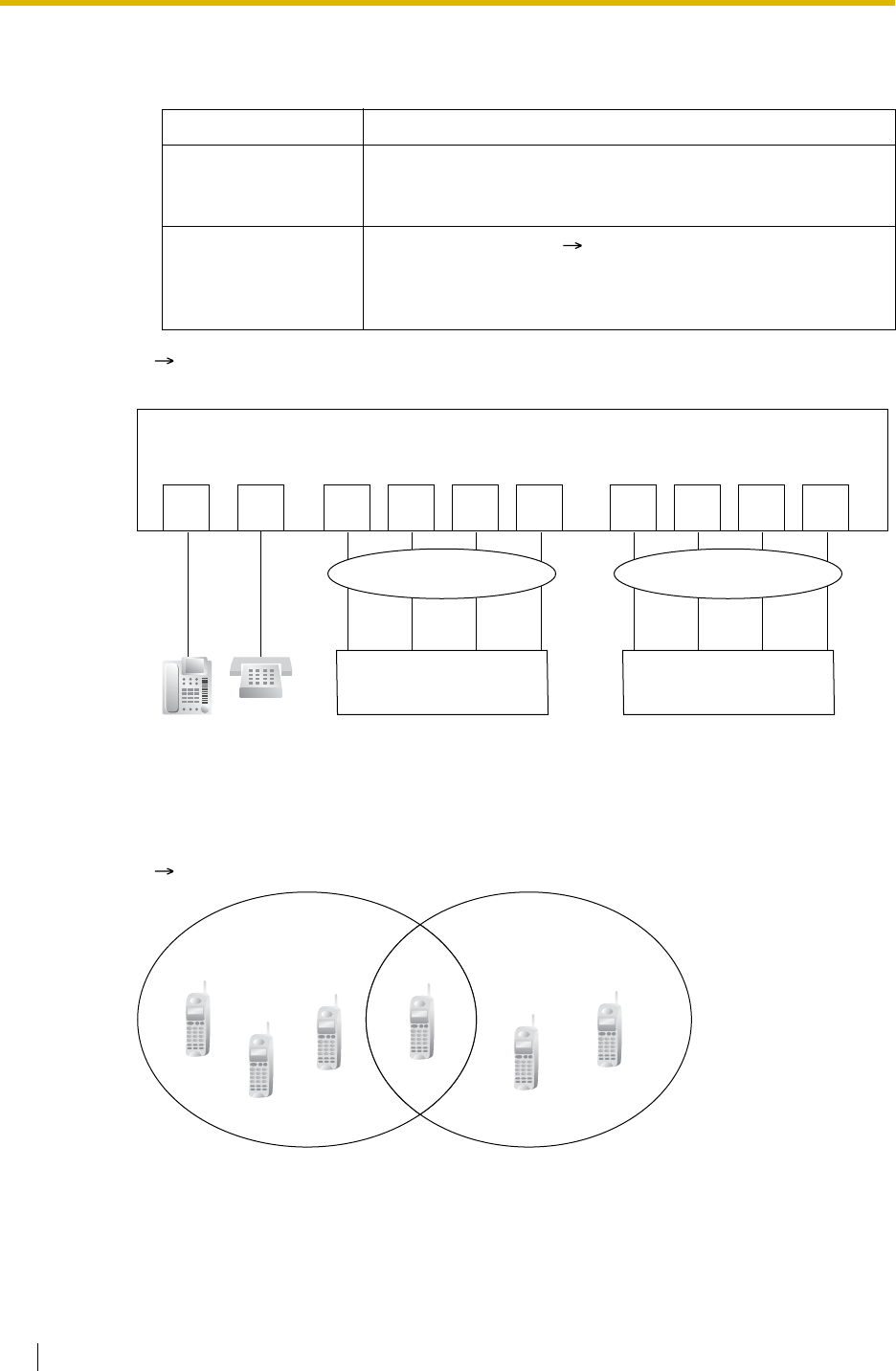
2.2 System Configuration—Software
286 Feature Guide
5. VM Group
There are two types of VM groups as follows:
( 1.23.1 Voice Mail (VM) Group)
[Example]
6. PS Ring Group
PS ring group is a group of PS extensions which receives incoming calls directed to the
group. Each group has a floating extension number and name through system
programming. One PS can belong to multiple groups.
( 1.24.2 PS Ring Group)
Type Description
VM (DTMF) Group A group of SLT ports which use the Voice Mail DTMF
Integration features.
One SLT port can belong to only one group.
VM (DPT) Group A group of DPT ports ( VM Group Floating Extension
Number [660]) which use the Voice Mail DPT (Digital)
Integration features.
One DPT port can belong to only one group.
DPT
Port
PBX
VM (DPT) Group
DPT
Port DPT
Port DPT
Port DPT
Port SLT
Port SLT
Port SLT
Port SLT
Port
VPS
(DPT [Digital] Integration)
VM (DTMF) Group
VPS
(DTMF Integration)
SLT
Port
PS Ring Group 1
(Floating Extn. No. 301,
Name: Sales 1)
PS Ring Group 2
(Floating Extn. No. 302,
Name: Sales 2)
PS01
PS02
PS03 PS04
PS05
PS06
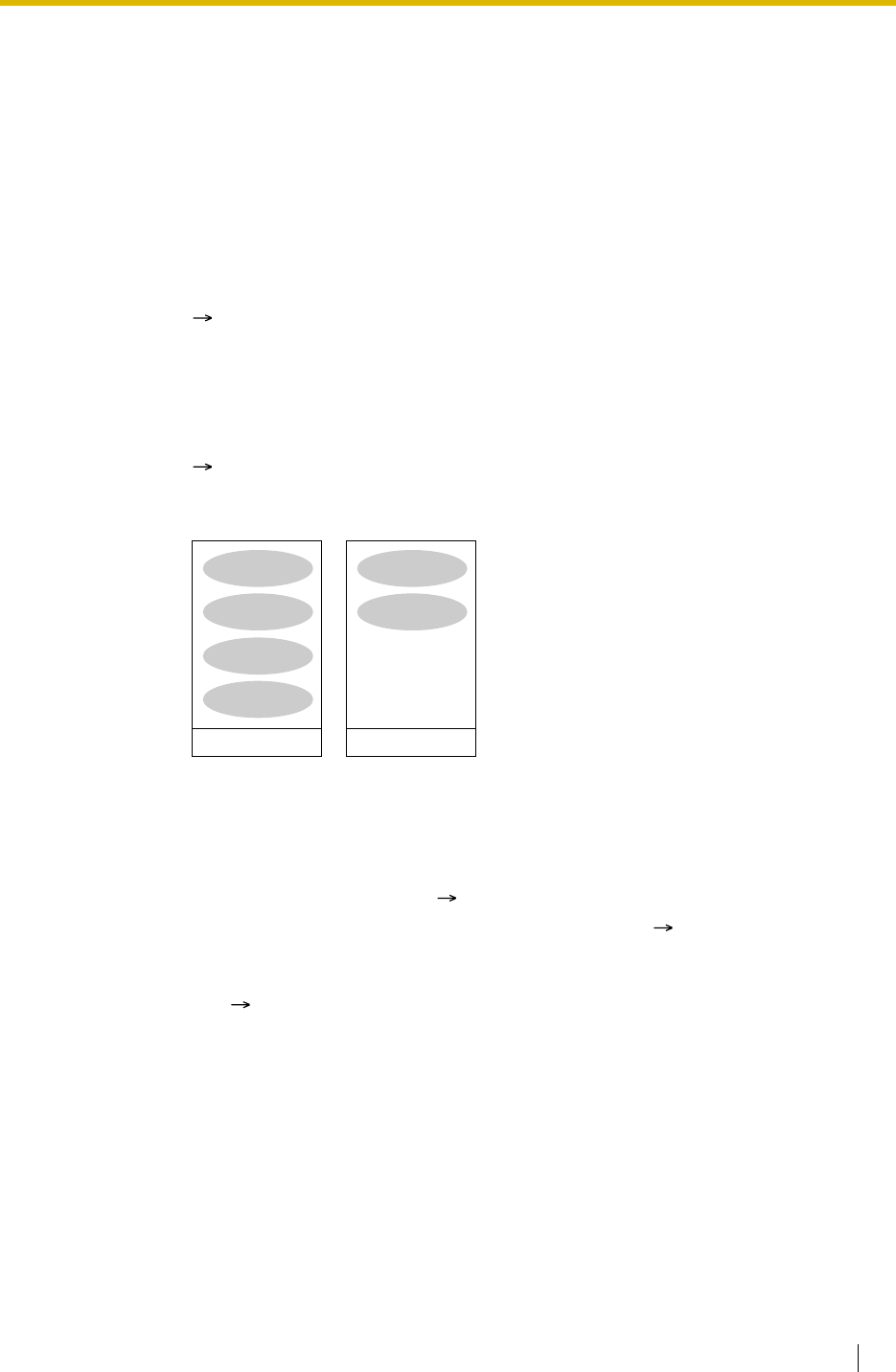
2.2 System Configuration—Software
Feature Guide 287
2.2.3 Tenant Service
Description
This PBX can be shared with certain number of tenants.
1. Tenant Configuration
1.1 Tenant Member
The tenant members consist of user groups. One user group can belong to only one
tenant. Therefore, one extension can belong to only one tenant.
( 2.2.2 Group)
1.2 Time Service
Each tenant has a Time Table. The Start and/or End time of each time mode (day/
lunch/break/night) can be set for each day of the week. The Time Table numbers
correspond to the tenant numbers respectively.
( 2.2.4 Time Service)
[Example]
2. System Management
Each of the following system management items can be assigned to each tenant.
a) Tenant Operator (extension number/floating extension number of incoming call
distribution group/none) ( 2.2.5 Operator Features)
b) ARS Mode (Off/Local Access/All Access/System) ( 1.9.1 Automatic Route
Selection (ARS))
c) Music Source for Music on Hold (System/BGM Number/Cyclic Tone)
( 1.12.4 Music on Hold)
Tenant 1
Use Time Table 1
User Group 1
User Group 2
User Group 3
User Group 4
Tenant 2
Use Time Table 2
User Group 5
User Group 6
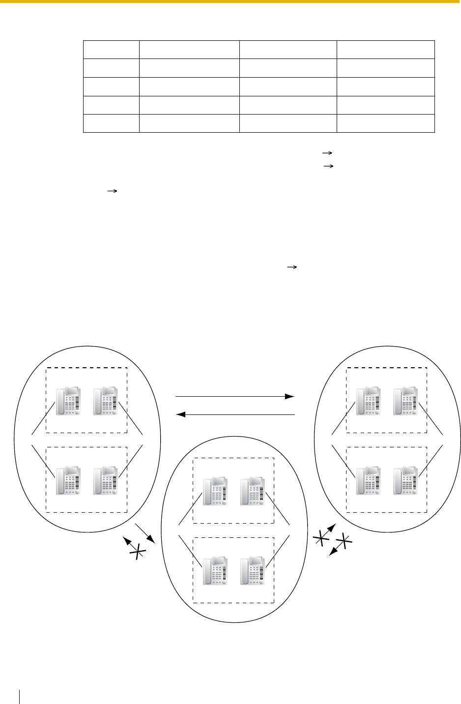
2.2 System Configuration—Software
288 Feature Guide
[Programming Example]
Conditions
•Tenant-to-Tenant Call Block
The following features can be restricted based on the COS for each extension (not based
on the tenant) by the Internal Call Block feature ( 1.1.2.2 Internal Call Block):
[Example]
Tenant No. Operator ARS Mode Music Source
1 Extn.101 Local Access System*3
2None*1 System*2 Cyclic Tone
3 Floating extn. no. 200 Off BGM1
:: : :
*1:Follows the system assignment of a PBX operator ( Operator Assignment [006])
*2:Follows the system assignment of the ARS mode ( ARS Mode [320])
*3:Follows the system assignment of the music source for the Music on Hold
( Music on Hold [711])
– Calling extensions or doorphone(s) in the restricted tenant(s)
– Picking up calls ringing in the restricted tenant(s)
– Retrieving a call held within the restricted tenant(s).
COS 4COS 1COS 2
Extension Group 1
Tenant 1
Extn. 100 Extn. 101
Extension Group 2
Extn. 103Extn. 102
COS 3
Extension Group 3
Tenant 2
Extn. 104 Extn. 105
Extension Group 4
Extn. 107Extn. 106
COS 5COS 6
Extension Group 5
Tenant 3
Extn. 108 Extn. 109
Extension Group 6
Extn. 111Extn. 110

2.2 System Configuration—Software
Feature Guide 289
[Programming Example]
Explanation:
1. Assign each extension in a tenant to a certain COS number. Each tenant must have
unique COS numbers.
Tenant 1: COS 1 and COS 2
Tenant 2: COS 3 and COS 4
Tenant 3: COS 5 and COS 6
2. Tenant-to-Tenant Call Block enables by the Internal Call Block feature.
a) Tenant 1 (COS 1 and COS 2) can make calls to both Tenant 2 (COS 3 and COS
4) and Tenant 3 (COS 5 and COS 6) as well as Tenant 1.
b) Tenant 2 (COS 3 and COS 4) can make calls to Tenant 1 (COS 1 and COS 2)
and Tenant 2.
c) Tenant 3 (COS 5 and COS 6) can make calls to Tenant 3 itself only.
• An incoming call distribution group must belong to one tenant because the following
features are determined on a tenant basis ( 1.2.2.1 Incoming Call Distribution Group
Features—SUMMARY):
Caller Called Party
COS 1 COS 2 COS 3 COS 4 COS 5 COS 6 ...
COS 1 ...
COS 2 ...
COS 3 ...
COS 4 ...
COS 5 ...
COS 6 ...
: :::::::
:Block
– Music on Hold while a call is waiting in the queue
– The Time Table which determines the overflow destination.
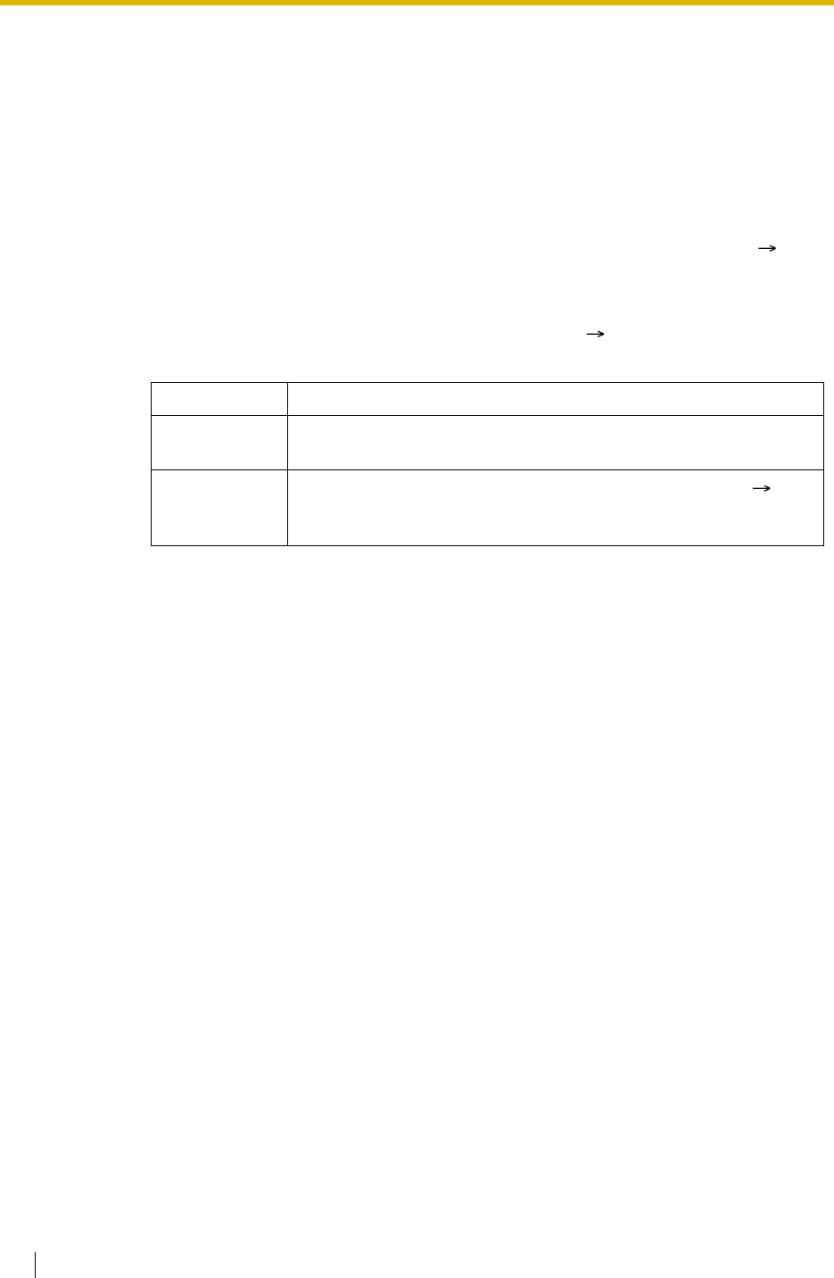
2.2 System Configuration—Software
290 Feature Guide
2.2.4 Time Service
Description
This PBX supports day, night, lunch, and break modes of operation. TRS/Barring can be
arranged separately. The destination of incoming calls can be set differently for each mode.
1. Time Service Switching Mode
Day/lunch/break/night mode can be switched either automatically or manually ( Time
Service Switching Mode [101]). The switching mode can be assigned for each tenant.
The switching mode can also be changed by pressing the Time Service Switching Mode
(Automatic/Manual) button. This can be performed by only an extension assigned as the
manager, or preprogrammed extension on a COS basis ( Time Service Manual
Switching [514]).
Even while in the Automatic Switching mode, day/lunch/break/night mode can be changed
manually.
2. Time Table
Each tenant has a Time Table used for the Automatic Switching mode. The Start and/or
End time of each mode can be set for each day of the week. The Time Table numbers
correspond to the tenant numbers respectively.
Type Description
Automatic The PBX will switch mode according to the preprogrammed Time
Table.
Manual A manager, or preprogrammed extension on a COS basis ( Time
Service Manual Switching [514]) can switch mode by dialling the
feature number or pressing the Time Service button.
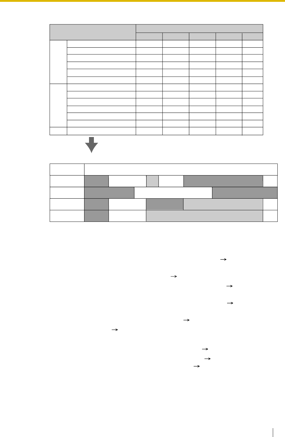
2.2 System Configuration—Software
Feature Guide 291
[Time Table Example]
3. Features Using Time Service
The following features can be set in each time mode (day/lunch/break/night):
a) Destination of incoming trunk calls (DIL/DID/DDI/MSN) ( 1.1.1 Incoming Trunk
Call Features)
b) Destination of the Intercept Routing ( 1.1.1.6 Intercept Routing)
c) Queuing Time Table for incoming call distribution groups ( 1.2.2.3 Queuing
Feature)
d) Overflow destination for incoming call distribution groups ( 1.2.2.5 Overflow
Feature)
e) Destination of incoming doorphone calls ( 1.16.1 Doorphone Call)
f) PBX operator ( 2.2.5 Operator Features)
g) COS for TRS/Barring and for Trunk Access
h) Outgoing Message (OGM) for Timed Reminder ( 1.26.4 Timed Reminder)
i) Intercept time for Intercept Routing—No Answer ( 1.1.1.6 Intercept Routing)
and for DISA Intercept Routing—No Answer ( 1.16.6 Direct Inward System
Access (DISA))
[Programming Examples of DID/DDI Table and DIL Table]
DID/DDI table can be programmed for each DID/DDI number, and a tenant (Time Table)
number is assigned to each DID/DDI number. DIL table can be programmed for each
trunk, and a tenant (Time Table) number is assigned to each trunk.
Day 1 start
Lunch start
Day 2 start
Break 1 start
Break 1 end (Day restart)
Night start
Day 1 start
Lunch start
Day 2 start
Break 1 start
Break 1 end (Day restart)
Night start
:
08:00
12:00
13:00
NONE
NONE
16:00
08:00
12:05
13:00
NONE
NONE
16:31
:
11:00
NONE
NONE
NONE
NONE
20:00
11:00
NONE
NONE
NONE
NONE
20:00
:
MON
TUE
:
Time Schedule Time Table No. (Tenant No.)
1 2 34
00:00
Time Table No.
<Time Service Image of Monday and Tuesday>
08:00 11:00 12:00 13:00 16:00 20:00
Night Day 1 Day 2
Lunch
Night
Night Day 1 Night
08:00
16:00
NONE
NONE
NONE
12:00
08:00
13:00
NONE
NONE
NONE
17:00
:
08:00
12:00
NONE
NONE
NONE
NONE
08:00
13:00
NONE
NONE
NONE
NONE
:
…
…
…
…
…
…
…
…
…
…
…
…
…
24:00 08:00
Day 1
Night
Night
Day 1
Day 1
Night
Day 1
Day 1
1
2
3
4
Lunch
Lunch
…

2.2 System Configuration—Software
292 Feature Guide
<DID/DDI Table>
<DIL Table>
Explanation:
If a trunk call with a DID number (123-4567) is received at 20:00;
1) Tenant (Time Table) number 1 will be used.
2) The call is received during night mode in Time Table 1.
3) The call will be routed to the extension 100 (VPS).
4. Holiday Mode
The holiday mode activates automatically using the Automatic Switching mode. Up to 24
holidays (start and end dates) can be stored, and one time mode can be selected for all
holidays.
5. Time Service Button
A flexible button can be customised as the following buttons:
a) Day/Night button
b) Day/Night/Lunch button
c) Day/Night/Break button
d) Day/Night/Lunch/Break button
Each of these buttons is used for switching between modes. For example, pressing the
Day/Night button switches between day and night modes. All of these buttons show the
current status as follows:
Location DID/DDI
No. Tenant
(Time
Table) No.
DID/DDI Destination
Day Lunch Break Night
001 123-4567 1 105 100 (VPS) 105 100 (VPS)
002 123-2468 1 102 100 (VPS) 102 100 (VPS)
:: :::::
Trunk No. Tenant (Time
Table) No. DIL Destination
Day Lunch Break Night
01 1 101 100 (VPS) 101 100 (VPS)
02 2 102 100 (VPS) 102 100 (VPS)
: : ::::
Light Pattern Status
Off Day mode
Red on Night mode
Green on Lunch mode
Slow green flashing Break mode
Slow red flashing Holiday mode

2.2 System Configuration—Software
Feature Guide 293
Note
Any extension user (except extension users allowed to change the mode) can only
check the current status on the display by pressing the Time Service button.
Conditions
• PT programming ( Time Service Starting Time [102]) can set the Start and/or End time
of the following:
PC programming can also set the following three time periods for break mode per day.
•Time Service Switching Mode (Automatic/Manual) Button
A flexible button can be customised as the Time Service Switching Mode (Automatic/
Manual) button.
Feature Guide References
1.8.1 Toll Restriction (TRS)/Call Barring (Barring)
1.19.2 Flexible Buttons
2.2.3 Tenant Service
User Manual References
User Manual
1.7.10 Checking the Time Service Status
2.1.2 Time Service Mode Control
– Day-1 (Day Start time)
– Lunch (Lunch Start time)
– Day-2 (Lunch End time)
– Night (Night Start time)
– Break-1 Start
– Break-1 End (Day restart)
– Break-2 Start
– Break-2 End (Day restart)
– Break-3 Start
– Break-3 End (Day restart)

2.2 System Configuration—Software
294 Feature Guide
2.2.5 Operator Features
Description
This PBX supports a PBX operator and a tenant operator. Any extension and incoming call
distribution group can be designated as a PBX and/or a tenant operator.
Operator Call:
An extension user can call an operator with a simple operation. When an operator call is made,
the call is routed to the tenant operator. If no tenant operator exists, the call will be routed to
the PBX operator. The time mode depends on the tenant of the calling extension. If neither the
tenant operator nor the PBX operator exists, the caller will hear reorder tone.
Conditions
• An extension or incoming call distribution group can be assigned as both the tenant and
PBX operator.
• A tenant operator can be assigned for multiple tenants.
Feature Guide References
2.2.3 Tenant Service
User Manual References
User Manual
1.2.1 Basic Calling
Type Description
PBX operator An extension or incoming call distribution group can be assigned
as a PBX operator for each time mode (day/lunch/break/night)
( Operator Assignment [006]).
Tenant operator An extension or incoming call distribution group can be assigned
as a tenant operator. The tenant operator may be the extension
or incoming call distribution group of another tenant.
[Example] Extension 110 in tenant 1 is the tenant operator of
tenant 3.

2.2 System Configuration—Software
Feature Guide 295
2.2.6 Manager Features
Description
An extension assigned as the manager (manager extension) is allowed to use the specified
features. COS programming determines the extensions which can use the following manager
features ( Manager Assignment [511]):
Feature Description Manager
Password Details in
Manager
Programm
ing
Manager
Password
Change
Changes the manager password. Required –
Call
Charge
Managem
ent
Sets, sees, clears, and prints the call
charge data. Required • 1.25.2
Charge Meter
Verified
Code
Personal
Identificati
on
Number
(PIN) Set
Sets a verified code PIN for each
verified code. Required • 1.8.6 Verified
Code Entry
Remote
PIN Clear Clears the extension PIN of an
extension remotely, and a verified
code PIN. PIN Lock is also unlocked.
Required • 1.26.1
Extension
Personal
Identification
Number (PIN)
• 1.8.6 Verified
Code Entry
Remote
Extension
Lock
Sets or cancels the Extension Lock
on an extension remotely. Required • 1.8.3
Extension
Lock
Dial Tone Transfer Changes the TRS/Barring level of the
extension temporarily.
[Example] An extension user can call
a manager to release the restricted
outgoing call (e.g., international call).
Not
required • 1.8.4 Dial
Tone Transfer
Outgoing Message
(OGM) Records and plays back outgoing
messages (OGMs). Not
required • 1.16.5
Outgoing
Message
(OGM)
Time Service Switches the time mode (day/lunch/
break/night) manually. Not
required • 2.2.4 Time
Service
BGM—External Sets the External BGM on and off. Not
required • 1.16.4
Background
Music (BGM)

2.2 System Configuration—Software
296 Feature Guide
Conditions
WARNING
When a third party discovers the personal identification number (PIN) (verified code PIN/
extension PIN) of the PBX, there will be a risk that they will make fraudulent phone calls
using the telephone line, and the cost will be charged to your own account. In order to
avoid this problem, we strongly recommend the following points:
a) Carefully maintain the secrecy of the PIN.
b) Specify a complicated PIN as long and random as you can make it.
c) Change the PIN frequently.
•Manager Password
One manager password can be assigned per PBX ( Manager Password [112]).
User Manual References
User Manual
2.1 Control Features
3.2.2 Manager Programming
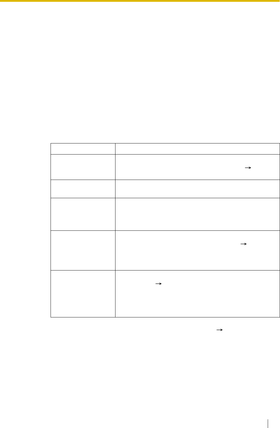
2.3 System Data Control
Feature Guide 297
2.3 System Data Control
2.3.1 PC Programming
Description
This PBX can be programmed and administered using a personal computer (PC). There are
two programming methods:
1) On-site Programming: System programming/diagnosis can be performed locally by
connecting a PC to the PBX directly.
2) Remote Programming: System programming/diagnosis and data upload can be
performed from a remote location.
1. On-site Programming:
Method Description
Using the Serial
Interface (RS-232C)
port
The PBX has a Serial Interface (RS-232C) port which can be
used for either system administration or SMDR ( 1.25.1
Station Message Detail Recording (SMDR)).
Using the USB port The PC is connected to the USB port on the PBX, or a USB
port (USB Module) attached to a DPT.
Using the LAN
interface (KX-
TDA100/KX-TDA200
only)
A CTI-LINK card must be installed.
Using a modem
through an SLT port*
(KX-TDA30/KX-
TDA100/KX-TDA200
only)
An RMT card must be installed. Assign the floating extension
number of the analogue remote maintenance ( Modem
Floating Extension Number [811]), and dial this number from
the PC to connect to the PBX.
Using an ISDN TA
interface (64 kbps)
through an ISDN
Extension Line*
Assign the floating extension number of the ISDN remote
maintenance ( ISDN Remote Floating Extension Number
[812]), and dial this number from the PC to connect to the
PBX. The RMT card is not required for this method.
This method is available only when a user-supplied ISDN TA
that supports CAPI is used.
*: If remote access is disabled through system programming ( Remote
Programming [810]), then this on site programming cannot be done.

2.3 System Data Control
298 Feature Guide
2. Remote Programming:
Conditions
• Access to system programming is allowed only one at a time.
•Programmer Code and Password for System Programming
To access system programming, a programmer code and its password must be entered.
There are three programmer codes, which are set at the factory. Each programmer code
has a unique password which is also set at the factory.
Programmer codes can be changed using the Maintenance Console, by selecting
"Programmer Code Change" from the "Tool" menu. Passwords can be changed through
system programming. If the wrong password is entered a preprogrammed number of times
(Default: None [no limitation]) remotely, access will be locked and can only be unlocked by
enabling remote access through system programming ( Remote Programming [810]).
Method Description
Using a modem
(RMT card) An RMT card must be installed. The floating extension number of
the analogue remote maintenance must be assigned ( Modem
Floating Extension Number [811]).
PC programming, using a telephone connected in parallel with the
modem, can be done in the following ways:
•Direct Access
Dial the DIL/DID/DDI number whose destination is the floating
extension number of the analogue remote maintenance.
•Through DISA
Dial the floating extension number of the analogue remote
maintenance using the DISA feature. ( 1.16.6 Direct Inward
System Access (DISA))
•Call Transfer
Call an extension (probably the operator), and request a
transfer to the floating extension number of the analogue
remote maintenance. ( 1.11.1 Call Transfer)
Using an
external modem
(Not RMT card)
An external modem can be used instead of an RMT card to perform
the remote programming. An external modem can be connected to
the Serial Interface (RS-232C) of the PBX. Connect the modem to
an extension port which is assigned as the DIL/DID/DDI/MSN
destination or to a trunk directly to connect to the PBX from the PC.
An AT command can be sent to the modem automatically when it
is connected to the Serial Interface (RS-232C) port. AT commands
can be programmed beforehand through system programming to
initialise the modem. An AT command can also be sent manually in
the PT system programming mode ( External Modem Control
[801]).
Using an ISDN
TA interface (64
kbps) through
an ISDN Trunk
The floating extension number of the ISDN remote maintenance
must be assigned ( ISDN Remote Floating Extension Number
[812]), and dial the DIL/DID/DDI/MSN number whose destination is
the floating extension number of the ISDN remote maintenance.
The RMT card is not required for this method.
This method is available only when an user-supplied ISDN TA that
supports CAPI is used.

2.3 System Data Control
Feature Guide 299
•Remote Programming Limitation
It is possible to disable remote access through system programming ( Remote
Programming [810]).
• If an extension user sets the Walking Extension feature while the extension data (e.g.,
Headset mode) is programmed through PC programming, some extension data for the
user may not be transferred properly.
Installation Manual References
Installation Manual
<KX-TDA100/KX-TDA200>
2.3.1 MPR Card
2.3.3 RMT Card
2.6.6 CTI-LINK Card
3.1 Overview — KX-TDA100/KX-TDA200
3.2 Connection — KX-TDA100/KX-TDA200
3.3 Installation of the KX-TDA Maintenance Console — KX-TDA100/KX-TDA200
<KX-TDA15/KX-TDA30>
6.5.7 RMT Card
7.1 Overview — KX-TDA30
7.2 Connection — KX-TDA30
7.3 Installation of the KX-TDA30 Maintenance Console
Feature Guide References
1.1.1.2 Direct In Line (DIL)
1.1.1.3 Direct Inward Dialling (DID)/Direct Dialling In (DDI)
1.1.1.4 Multiple Subscriber Number (MSN) Ringing Service
3.2 PC Programming
Programmer
Code Password Description
Installer Level
Programmer
Code
System Password
for Installer All system programming is accessible.
Administrator
Level
Programmer
Code
System Password
for Administrator—
for PC Programming
Permitted system programming is
accessible. Each system programming can
be determined whether to be accessed by
the administrator.
User Level
Programmer
Code
System Password
for User—for PC
Programming
Permitted system programming is
accessible. Each system programming can
be determined whether to be accessed by
the end users.

2.3 System Data Control
300 Feature Guide
2.3.2 PT Programming
Description
A PT user can perform the following programming:
a) Personal Programming: Customising the extension according to his needs.
b) System Programming: Customising the PBX according to organisational needs.
c) Manager Programming: Customising specified frequently changing items (e.g.,
Charge Management and Remote Extension Lock).
Conditions
• COS programming determines what programming can be performed ( Programming
Mode Limitation [516]):
• The extension which is connected to the lowest numbered extension port can perform both
personal programming and system programming regardless of the COS.
• The extension(s) assigned as the manager COS can perform manager programming.
• During programming, the PT is considered to be busy.
• Access to system programming and manager programming is allowed only one at a time.
However, one PBX supports up to 16 simultaneous programmers (one system
programmer + 15 personal programmers, one manager programmer + 15 personal
programmers, or 16 personal programmers).
•System Programming Password Level
To access system programming, a valid password must be entered. There are two types
of passwords, which are set at the factory, and can be changed through system
programming.
•Personal Programming Data Default Set
A user can return all of the items programmed on the telephone to default.
Feature Guide References
2.2.6 Manager Features
3.3 PT Programming
– System programming and personal programming
– Personal programming only
– No programming
Type Description
System Password
for Administrator—
for PT Programming
All system programming available for PT programming is
accessible ( System Password for Administrator—for PT
Programming [110]).
System Password
for User—for PT
Programming
Permitted system programming is accessible ( System
Password for User—for PT Programming [111]). Each access to
system programming can be controlled.

2.3 System Data Control
Feature Guide 301
User Manual References
User Manual
3.1 Customising Your Phone (Personal Programming)
3.2 Manager Programming
3.3 Customising Your System (System Programming)
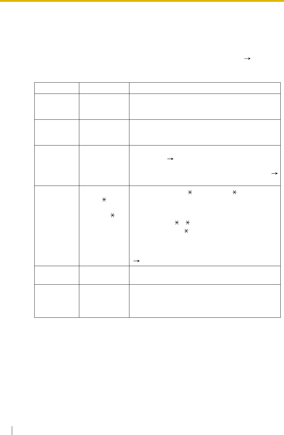
2.3 System Data Control
302 Feature Guide
2.3.3 Quick Setup
Description
It is possible to set up the basic PBX parameters using a personal computer (PC). When a PC
accesses the PBX for the first time with the Installer Level Programmer Code ( 2.3.1 PC
Programming), Quick Setup display will appear automatically. The following items can be
programmed as desired:
Item Parameter Description
Date & Time
Set Yea r/ Month/
Date/Hour/
Minute
The date and time set on the PC will be used.
System
Password for
Installer
4–10 characters Enter the system password for installer.
Operator &
Manager Extension
Number Assign the PBX operator to all time modes (day/lunch/
break/night) ( 2.2.5 Operator Features). The
extension assigned as the PBX operators is
automatically allowed to perform manager operation (
2.2.6 Manager Features).
Flexible
Numbering
Type
1. Pattern 1
(with )
2. Pattern 2
(without )
If "Pattern 1 (with )" is selected, " " must prefix all
feature numbers (except access numbers) when an
extension user wants to use a feature.
[Example] Call Pickup feature number
Pattern 1 (with ): 41
Pattern 2 (without ): 41
For default of the flexible numbers, refer to the [Flexible
Numbering Table (available while a dial tone is heard)]
( 2.3.5 Flexible Numbering/Fixed Numbering).
Operator/
Local Access 1. 0/9
2. 9/0 The feature numbers for Operator Call and Idle Line
Access can be selected. They will be "0" or "9".
Remote
Maintenance
Number
Remote
Maintenance Dial
Number
Enter the complete telephone number of the PBX
(including the country code). When necessary, this
number will be used to access the PBX from a remote
location for maintenance purposes.

2.3 System Data Control
Feature Guide 303
2.3.4 Automatic Setup
Description
There are two automatic setup features as follows:
1) Automatic ISDN Configuration
2) Automatic Time Adjustment
1. Automatic ISDN Configuration
The ISDN (BRI) port configuration can be set automatically through system programming.
The following items will be set by making and receiving a call using the subscriber number
assigned for each ISDN (BRI) port:
a) L1 Active Mode
b) L2 Data Link Mode
c) Access Mode (Point-to Point/Point-to-Multipoint)
d) TEI Assignment Mode (Fix 00–63/Automatic)
2. Automatic Time Adjustment
It is possible to adjust the PBX clock automatically in the following two ways:
a) Summer Time (Daylight Saving Time) Setting:
The start and end dates of the summer time can be programmed. The PBX clock will
be adjusted (one hour forward or backward) at 2:00AM of the programmed date, if
enabled through system programming. It means 2:00 AM will become 3:00 AM on the
start date of the summer time, and 2:00 AM will become 1:00 AM on the end date.
Note
If the Timed Reminder (Wake-up call) is set;
b) Time Information from Telephone Company:
Time information can be received on the following calls:
• An incoming or outgoing call through an ISDN line
• An incoming call through an analogue line with Caller ID which includes
the time information.
The PBX clock will be adjusted everyday with the first call after 3:05 AM, if enabled
through system programming.
Note
If the Timed Reminder (Wake-up call) is set, the setting will not happen or will ring
twice depending on the adjustment.
Conditions
• SMDR will record the call information using the PBX clock so that the recording time will
be overlapped at the end of summer time. ( 1.25.1 Station Message Detail Recording
(SMDR))
– On the summer time start date, the setting between 2:00 AM and 3:00 AM will
not happen.
– On the summer time end date, the setting between 1:00 AM and 2:00 AM will ring
twice.


2.3 System Data Control
Feature Guide 305
2.3.5 Flexible Numbering/Fixed Numbering
Description
To dial another extension user or to access PBX features, the access numbers (extension
numbers or feature numbers) are required.
There are three types of numbering plans:
1) Flexible Numbering (available while a dial tone is heard)
2) Flexible Numbering (available while busy, DND, or ringback tone is heard)
3) Fixed Numbering (available while dialling or talking)
1. Flexible Numbering (available while a dial tone is heard)
Extension numbers and feature numbers which are available while a dial tone is heard can
be customised for easy use ( Flexible Numbering [100]). The numbers must not conflict.
It is also possible to use default (Pattern 1 or Pattern 2) shown in the following table:
a) Extension Numbers (Extension Numbering Scheme 1 through 32): Up to four-
digit number (up to two-digit leading number consisting of "0 through 9" ) + additional
digits (up to two digits, default: two digits)
[Example]
If the number "3" as a leading number for the 1st extension numbering scheme and
the "2" as an additional digit have been programmed, the extension number 300
through 399 are available.
b) Feature Numbers: Up to four-digit number consisting of "0 through 9", " ", and "#"
c) Other PBX Extension Numbers (Other PBX Extension Number [TIE] -1 through
16): Up to three-digit number consisting of "0 through 9", " ", and "#"
[Flexible Numbering Table (available while a dial tone is heard)]
Feature Default
Pattern 1
(with )
Pattern 2
(without )
Extension Numbering Scheme 1—Leading
Number 1 / 2 11
Extension Numbering Scheme 2—Leading
Number 2 / 3 12
Extension Numbering Scheme 3—Leading
Number 3 / 4 13
Extension Numbering Scheme 4—Leading
Number 4 / 5 14
Extension Numbering Scheme 5—Leading
Number 5 / 6 15
Extension Numbering Scheme 6—Leading
Number 6 / None 16
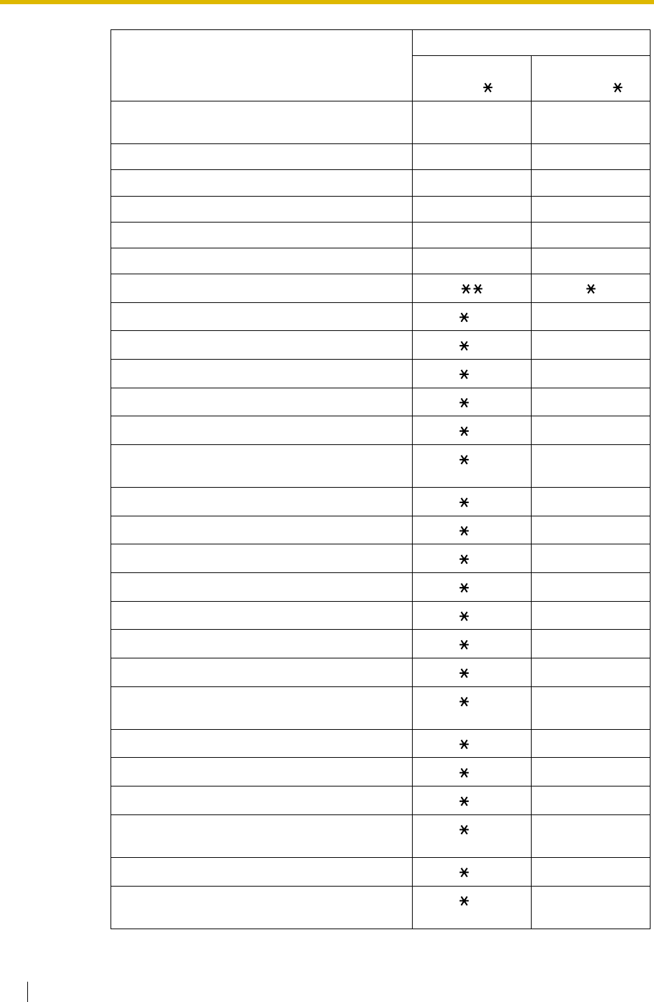
2.3 System Data Control
306 Feature Guide
Extension Numbering Scheme 7–32—Leading
Number None None
Operator Call 9 / 0 9 / 0
Idle Line Access (Local Access) 0 / 9*0 / 9
Trunk Group Access 88
TIE Line Access 7 None
Redial ##
Speed Dialling—System/Personal
Personal Speed Dialling—Programming 30 30
Doorphone Call 31 31
Broadcasting 32 32
Group Paging 33 33
External BGM on/off 35 35
Outgoing Message (OGM) playback/record/
clear 36 36
S-CO Line Access 37 37
Parallel Telephone Mode set/cancel 39 39
Group Call Pickup 40 40
Directed Call Pickup 41 41
TAFAS—Calls through an External Pager 42 42
Group Paging answer 43 43
Automatic Callback Busy cancel/CCBS cancel 46 46
User Remote Operation/Walking COS/Verified
Code Entry 47 47
Wireless XDP Parallel Mode set/cancel 48 48
Account Code Entry 49 49
Call Hold/Call Hold Retrieve 50 50
Call Hold Retrieve—Specified with a Holding
Extension Number 51 51
Call Park/Call Park Retrieve 52 52
Call Hold Retrieve—Specified with a Held Trunk
Number 53 53
Feature Default
Pattern 1
(with )
Pattern 2
(without )
deleted: 4
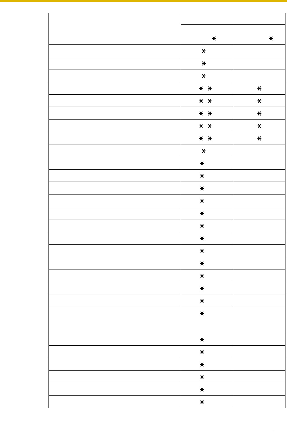
2.3 System Data Control
Feature Guide 307
Door Open 55 55
External Feature Access 60 60
ISDN Hold 62 62
COLR set/cancel 70 70
CLIR set/cancel 71 71
Switch CLIP/COLP of the Trunk/Extension 72 72
MCID 73 73
ISDN-FWD set/cancel/confirm 75 75
Message Waiting set/cancel/callback 70 70
FWD/DND set/cancel—Both 710 710
FWD/DND set/cancel—External 711 711
FWD/DND set/cancel—Internal 712 712
FWD/DND No Answer Timer set 713 713
Group FWD set/cancel—Both 714 714
Group FWD set/cancel—External 715 715
Group FWD set/cancel—Internal 716 716
Call Pickup Deny set/cancel 720 720
Paging Deny set/cancel 721 721
Walking Extension 727 727
Data Line Security set/cancel 730 730
Call Waiting for Intercom Calls set/cancel 731 731
Call Waiting for Trunk Calls (including
doorphone calls, calls for an incoming call
distribution group) set/cancel
732 732
Executive Busy Override Deny set/cancel 733 733
Not Ready Mode on/off 735 735
Log-in/Log-out 736 736
Incoming Call Queue Monitor 739 739
Hot Line programme/set/cancel 740 740
Absent Message set/cancel 750 750
Feature Default
Pattern 1
(with )
Pattern 2
(without )
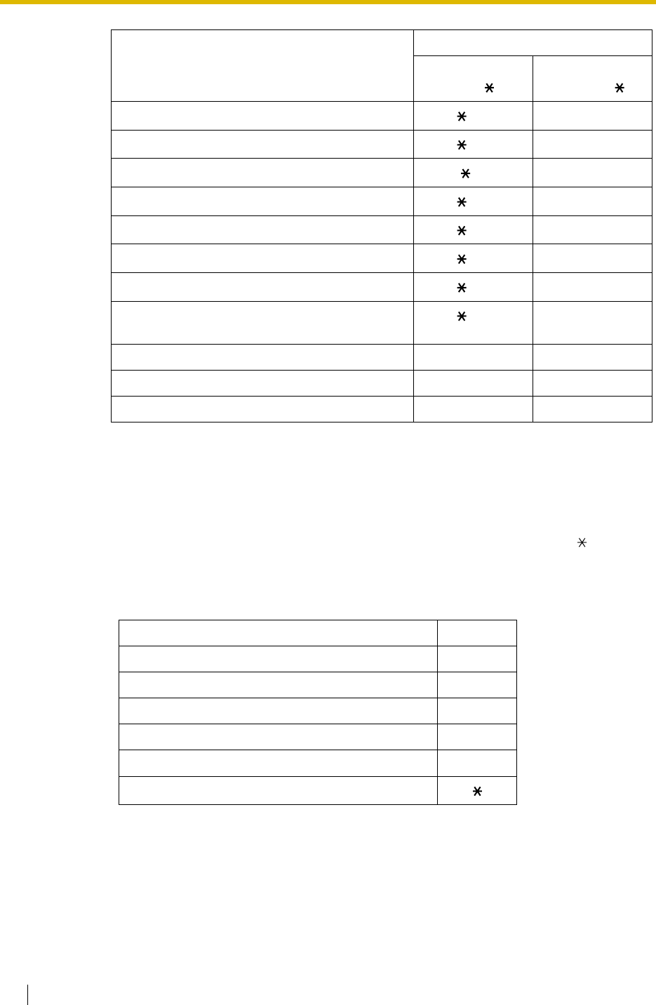
2.3 System Data Control
308 Feature Guide
2. Flexible Numbering (available while busy, DND, or ringback tone is heard)
Feature numbers which are available while busy, DND, or ringback tone is heard can be
customised for easy use. The numbers should be one digit ("0 through 9" , " ", or "#" )
and must not conflict. For default, refer to the following table:
[Flexible Numbering Table (available while busy, DND, or ringback tone is heard)]
3. Fixed Numbering (available while dialling or talking)
The features which are available while dialling or talking have fixed numbers as shown in
the following table:
BGM set/cancel 751 751
Timed Reminder set/cancel 760 760
Extension Lock set/cancel 77 77
Time Service Switch 780 780
Remote Extension Lock off 782 782
Remote Extension Lock on 783 783
Extension Feature Clear 790 790
Extension Personal Identification Number (PIN)
set/cancel 799 799
Dial Information (CTI) None None
Other PBX Extension Number (TIE) 1–16 None None
Quick Dialling 1–80 None None
*:For users in New Zealand, the default value of Idle Line Access (Local Access) is "1".
Feature Default
Call Waiting/DND Override 1 or 2*
Executive Busy Override 3
Message Waiting set 4
Call Monitor 5
Automatic Callback Busy/CCBS 6
Alternate Calling—Ring/Voice
*: To use Call Waiting/DND Override, both "1" and "2" are available by default.
Feature Default
Pattern 1
(with )
Pattern 2
(without )
deleted:
KX-T7710 MESSAGE Button
KX-T7710 One-touch Dialling 1–8
*1: For users in Germany, France,
Belgium, Norway, Sweden,
Denmark, Finland,
Portugal, Italy, and New Zealand
*2: For users in the United Kingdom
*3: For users in other
countries/areas

2.3 System Data Control
Feature Guide 309
[Fixed Numbering Table (available while dialling or talking)]
Conditions
• The PBX has default for numbers.
• The following are examples of feature number conflicts: 1 and 11, 0 and 00, 2 and 21, 10
and 101, 32 and 321, etc.
•Feature number + Additional number (Parameter)
Some flexible feature numbers require additional digits to make the feature active. For
example, to set Call Waiting, the feature number for "Call Waiting" must be followed by "1"
and to cancel it, the same feature number should be followed by "0".
• If a feature number includes " " or "#", rotary SLT users cannot use it.
• ISDN extension users cannot use the following features:
• PS users cannot use the following features:
User Manual References
User Manual
4.2.1 Feature Number Table
Feature Fixed
Numbering
Pulse to Tone Conversion
Conference 3
Door Open 5
– OGM playback/record
– Call Hold/Call Hold Retrieve (held at its own extension)
– ISDN Hold
–MCID
– Walking Extension
– Call Waiting
– Hot Line
– Timed Reminder
– Executive Busy Override
– Call Monitor
– Automatic Callback Busy/CCBS
– Personal Speed Dialling
– OGM playback/record
– S-CO Line Access
– Parallel Telephone Mode set/cancel
– Walking Extension
– BGM set/cancel
– Timed Reminder
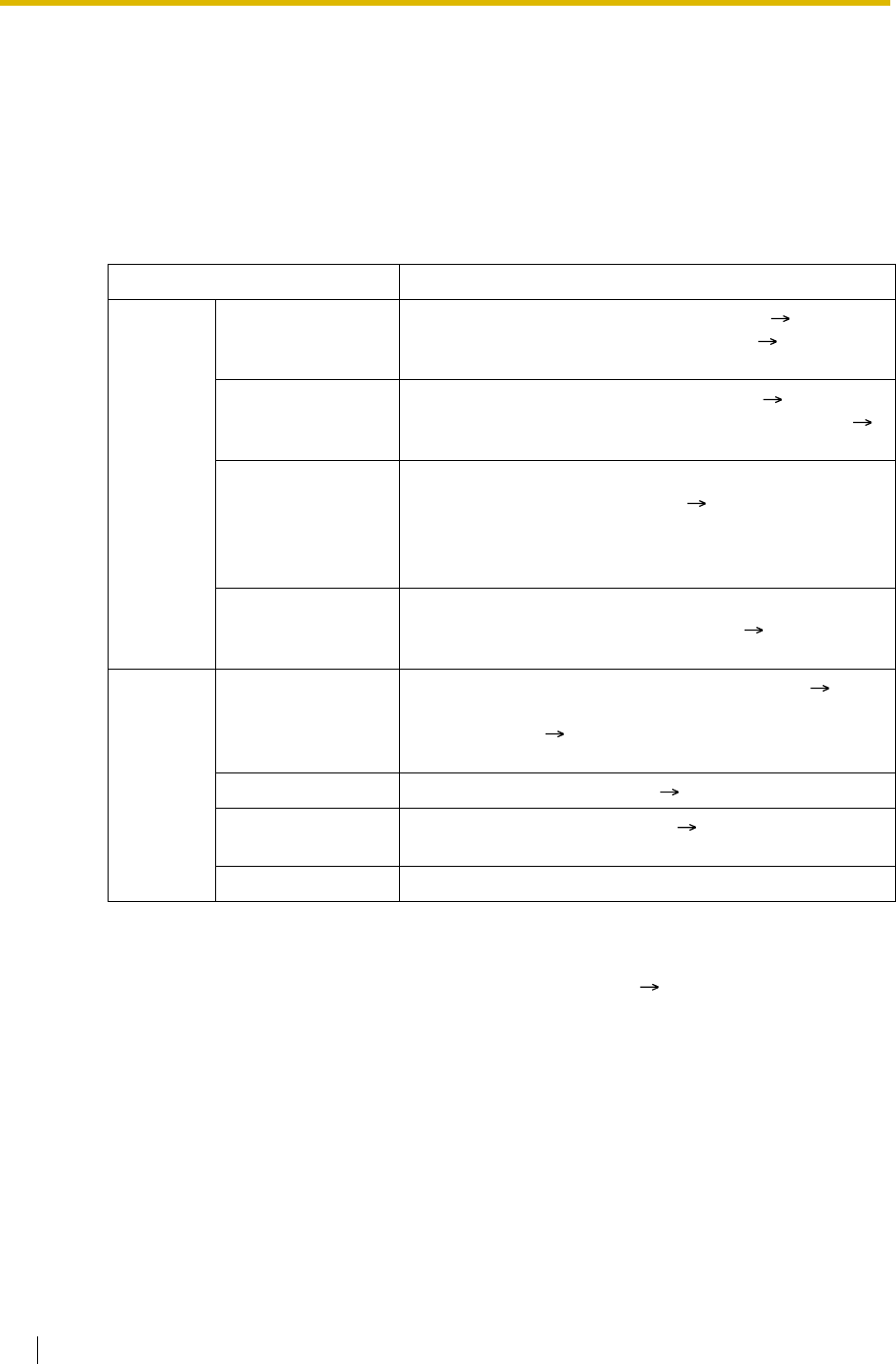
2.3 System Data Control
310 Feature Guide
2.3.6 Floating Extension
Description
Virtual extension numbers can be assigned to resources to make them appear as extensions.
These numbers are defined as floating extension numbers and can be assigned as a
destination of incoming calls etc.
This feature is also known as Floating Station.
Conditions
• It is possible to give names to floating extension numbers ( Incoming Call Distribution
Group Name [623], Outgoing Message (OGM) Name [731]).
Feature Guide References
1.23.1 Voice Mail (VM) Group
2.3.1 PC Programming
Resource Description
Device External Pager Used as the destination for TAFAS feature ( External
Pager Floating Extension Number [700]). ( 1.16.3 Trunk
Answer From Any Station (TAFAS))
Outgoing Message
(OGM) Used to send messages for DISA feature ( Outgoing
Message (OGM) Floating Extension Number [730]). (
1.16.6 Direct Inward System Access (DISA))
Analogue Remote
Maintenance (KX-
TDA30/KX-
TDA100/KX-
TDA200 only)
Used to access the PC programming mode through a
modem on a personal computer ( Modem Floating
Extension Number [811]).
ISDN Remote
Maintenance Used to access the PC programming mode through the
ISDN interface on a personal computer ( ISDN Remote
Floating Extension Number [812]).
Group Incoming Call
Distribution Group Used to call an incoming call distribution group (
Incoming Call Distribution Group Floating Extension
Number [622]). ( 1.2.2.1 Incoming Call Distribution
Group Features—SUMMARY)
PS Ring Group Used to call a PS ring group. ( 1.24.2 PS Ring Group)
VM (DPT) Group Used to call a VM (DPT) group ( VM Group Floating
Extension Number [660]).
VM (DTMF) Group Used to call a VM (DTMF) group.

2.3 System Data Control
Feature Guide 311
2.3.7 Software Upgrading
Description
It is possible to upload software from a personal computer to the PBX to upgrade the following:
Conditions
• The software version of the MPR can be confirmed through system programming ( Main
Processing (MPR) Software Version Reference [190]).
Installation Manual References
Installation Manual
<KX-TDA100/KX-TDA200>
2.3.1 MPR Card
Data File Storage Area
Main Processing (MPR)
software data Operating system data area on either the
MPR card of the KX-TDA100/KX-TDA200,
or the Main Board of the KX-TDA15/KX-
TDA30.
Default data of system
programming for each country/
area
Country/area data area on the MPR card or
Main Board
Language data for PT display Each language data area on the MPR card
or Main Board.
There are two types:
Type 1: PT display except for PT system
programming ( 2.3.2 PT Programming)
(five languages max.)
Type 2: PT system programming data (one
language max.)
LPR (software on a slot card)
software data (KX-TDA100/
KX-TDA200 only)
Flash ROM on the slot card (e.g., BRI8)
Cell Station (CS) software data Flash ROM on the CS

2.4 Fault Recovery/Diagnostics
312 Feature Guide
2.4 Fault Recovery/Diagnostics
2.4.1 Power Failure Transfer (KX-TDA30/KX-TDA100/KX-
TDA200 only)
Description
When the power supply to the PBX fails, specific SLTs and/or ISDN terminal devices are
automatically connected to specific trunks (Power Failure Connections). The PBX will switch
from normal operation to the Power Failure Connections, and all existing conversations will be
disconnected.
Only the trunks handled by Power Failure Connections can be used during a power failure.
Conditions
[General]
• Only trunk calls can be made during a power failure. All other features do not work.
•DC Power Source
If the DC power is available from backup batteries, even if the AC power fails, the PBX will
remain fully operational.
[KX-TDA100/KX-TDA200]
• The analogue trunk cards and extension cards and the number of ports which can be used
for Power Failure Connections are as follows:
Trunk Cards: LCOT16 (four ports), LCOT8 (two ports), and LCOT4 (two ports)
Extension Cards: MSLC16 (four ports), SLC16 (four ports), DHLC8 (two ports) and SLC8
(two ports).
To each trunk card, connect only one extension card.
Note
Power Failure Connections between analogue trunk cards and extension cards should be
done as per system programming so that conversation is maintained when the power is
restored and the MPR is recovering.
• The BRI8 (one port) and BRI4 (one port) cards can also be used for Power Failure
Connections. For details about Power Failure Connections, refer to the Installation Manual.
[KX-TDA30]
• Ports 1 and 2 of the LCOT card installed in the least slot number and ports 1 and 2 of the
Super Hybrid ports can be used for Power Failure Connections.
Note
The Power Failure Connections between the LCOT card and Super Hybrid ports are
automatically kept so that the conversation is maintained when the power is restored and
the Main Board is recovering.

2.4 Fault Recovery/Diagnostics
Feature Guide 313
• The BRI2 (one port) card can also be used for Power Failure Connections. For details
about Power Failure Connections, refer to the Installation Manual.
Installation Manual References
Installation Manual
<KX-TDA100/KX-TDA200>
2.2.6 Backup Batteries Connection
2.12.1 Power Failure Connections
<KX-TDA15/KX-TDA30>
6.2.6 Backup Batteries Connection
6.11.1 Power Failure Connections

2.4 Fault Recovery/Diagnostics
314 Feature Guide
2.4.2 Power Failure Restart
Description
When turning the electricity back on, the PBX restarts the stored data automatically and the
PBX will record the event (System Restart) in the error log.
Conditions
• In the event of a power failure, PBX memory is protected by a factory-provided lithium
battery. There is no memory loss except the memories of Automatic Callback Busy
(Camp-on) ( 1.7.1 Automatic Callback Busy (Camp-on)) and Call Park ( 1.12.2 Call
Park).
2.4 Fault Recovery/Diagnostics
Feature Guide 315
2.4.3 Local Alarm Information
Description
When a PBX error occurs and the PBX detects it, the System Alarm button light on the PT of
an extension, which is allowed to use this feature through system programming (a maximum
of two extensions per PBX), turns on red. Pressing the button will show the error number on
the display. If multiple errors occur, the error number will be displayed in order of highest priority
to lowest. The System Alarm button light turns off automatically after all error numbers have
been displayed.
For details about the errors and their solutions, refer to the Installation Manual.
[Error Example]
[Explanation]
Conditions
•System Alarm Button
A flexible button can be customised as the System Alarm button.
• If an extension allowed to utilise this feature uses a PC Console or PC Phone, the alarm
information will be displayed on the PC.
• If an extension allowed to utilise this feature uses a PC Console or PC Phone, the alarm
information will be sent to the preprogrammed party via the PC Console or PC Phone. The
PC Console and PC Phone use e-mail to send the information.
• The alarm information will be recorded on the SMDR, if enabled through system
programming.
• The PBX can be automatically diagnosed at a preprogrammed time everyday.
Number in the
Example Item Description
(1) Error Code Shows three-digit error code.
(2) Sub Code Shows five-digit sub code (XYYZZ).
X: Cabinet number (1–4)
YY: Slot number (00–11)
ZZ: Physical port number (01–16)
ERR #100 (10000)
(1) (2)


Feature Guide 317
Section 3
Programming Instructions

3.1 Introduction
318 Feature Guide
3.1 Introduction
3.1.1 Introduction
These Programming Instructions are designed to serve as an overall system programming
reference for the Panasonic Hybrid IP-PBX. The PBX has a default setting. You can change
the default to meet your requirements. System programming controls the PBX features
described in this Feature Guide. It allows the PBX to be customised to the requirements. Only
one person can programme at a time. Another person trying to enter programming mode will
be rejected.
Ways to Programme
There are two programming methods:
•PC (Personal Computer) Programming
All system programming can be performed. PC programming is described in Section
3.2 PC Programming.
•PT (Proprietary Telephone) Programming
A subset of system programming can be performed. PT programming is described in
Section 3.3 PT Programming. The extension user can programme by entering 3 digits
programming numbers from the PT.
Password Security
A password is required to perform programming for security purposes. Do not disclose the
password. This will avoid unauthorised access and possible dial through fraud.
Warning to the Administrator regarding the system password
1. Please inform the customer of the importance of the password and the possible
dangers.
2. Please maintain the secrecy of the password. This will avoid unauthorised
access and possible dial through fraud.
3. Please change the password periodically.
4. We strongly recommend that a password of 10 digits is used for maximum
protection against hackers.
5. If the system password is forgotten, you can examine the backup of the system
programming. Therefore, please keep your backup secure to avoid unauthorised
access.
• If you have a backup of the system data, you can find the password by loading
the backup system data onto the PC and check the password using the
programming tool. For how to back up the system data, refer to Section 3.3.4
Hybrid IP-PBX Maintenance (for KX-TDA100/KX-TDA200) or 7.3.4 Hybrid IP-
PBX Maintenance (for KX-TDA15/KX-TDA30) in the Installation Manual.
• If you do not have a backup system data, you have to set the PBX to the factory
default and reprogramme it. Therefore, we recommend that you back up the
system data.

3.2 PC Programming
Feature Guide 319
3.2 PC Programming
3.2.1 Installing and Starting the Maintenance Console
To programme and administer the PBX by personal computer (PC), you need to install the
Maintenance Console (KX-TDA Maintenance Console for the KX-TDA100/KX-TDA200 or KX-
TDA30 Maintenance Console for the KX-TDA15/KX-TDA30) onto the computer.
This section briefly describes how to install and start the Maintenance Console when the PC
and the PBX are connected by USB cable. The screenshots shown in the installation
procedure are based on the KX-TDA Maintenance Console.
System Requirements
Operating System
•Microsoft
® Windows® 98 SE, Windows Me, Windows 2000, or Windows XP
Hardware
• CPU: Intel® Pentium® 133 MHz or better microprocessor
• RAM: at least 64 megabytes (MB) of free RAM (128 MB recommended)
• HDD: at least 100 MB of hard disc space
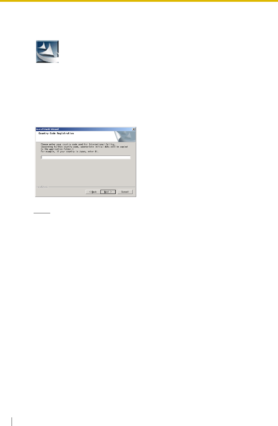
3.2 PC Programming
320 Feature Guide
Installing the Maintenance Console and Selecting the Appropriate
Country/Area Data
Notes
• To install or uninstall the software into Windows 2000 Professional or Windows XP
Professional, the user must be grouped either of "Administrators" or "Power Users".
• To connect the PC to the PBX via USB, the KX-TDA USB driver must have been
installed. Follow the instructions of the wizard to install the KX-TDA USB driver.
• The contents and design of the software are subject to change without notice.
Starting the Maintenance Console and Assigning the Basic Items
(Quick Setup)
When you start the Maintenance Console with the Installer Level Programmer Code and
connect to the PBX for the first time after initialisation (with the factory default setting), Quick
Setup will launch automatically. For details about Quick Setup items, refer to Section 2.3.3
Quick Setup.
1. a. Save the setup file of the Maintenance
Console on your PC.
b. Double-click the icon to execute the
setup file.
c. Follow the instructions of the wizard.
2. a. Type the appropriate Country Code.
The Maintenance Console will be
installed with the appropriate default
data for your country/area.
b. Click [Next].
c. Follow the instructions of the wizard.
d. Click [Finish].
e. Click [OK].
1. Connect the PC to the PBX with a USB cable.
2. Start the KX-TDA Maintenance Console or
KX-TDA30 Maintenance Console from the
start menu.
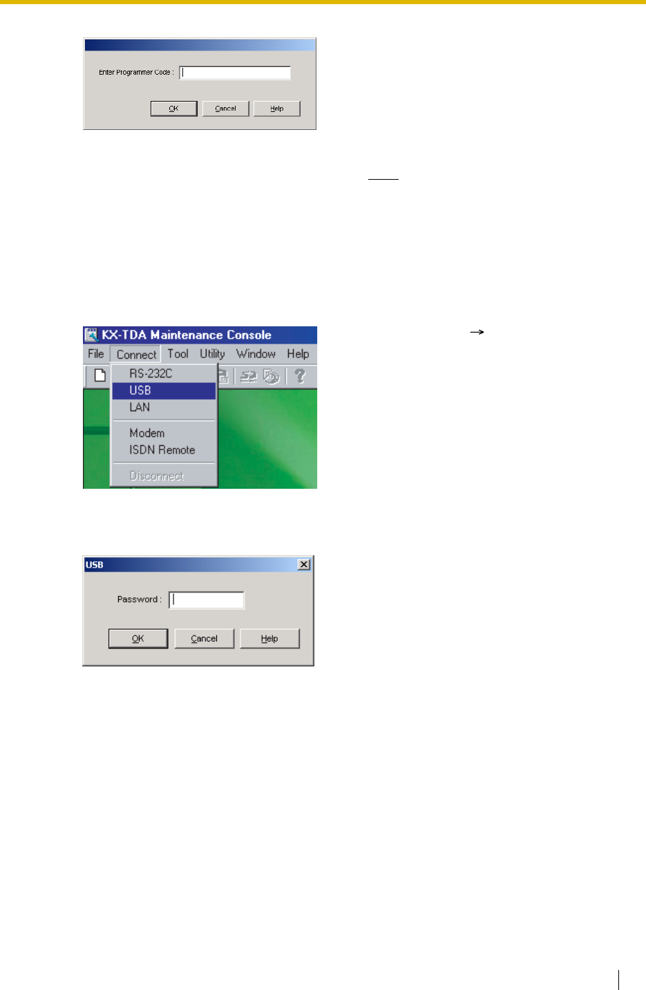
3.2 PC Programming
Feature Guide 321
3. Type the Installer Level Programmer Code
(default: 1234), then click [OK].
The Programmer Code authorises different
programming levels, and the Quick Setup is
only available when you start the
Maintenance Console with the Installer Level
Programmer Code.
Note
There are 2 other Programmer Codes
with limited authorisation: Administrator
Level (default: 1111), and User Level
(default: none).
4. Click "Connect" "USB" from the menu bar.
5. Type the system password for installer
(default: 1234), then click [OK] to log-in.
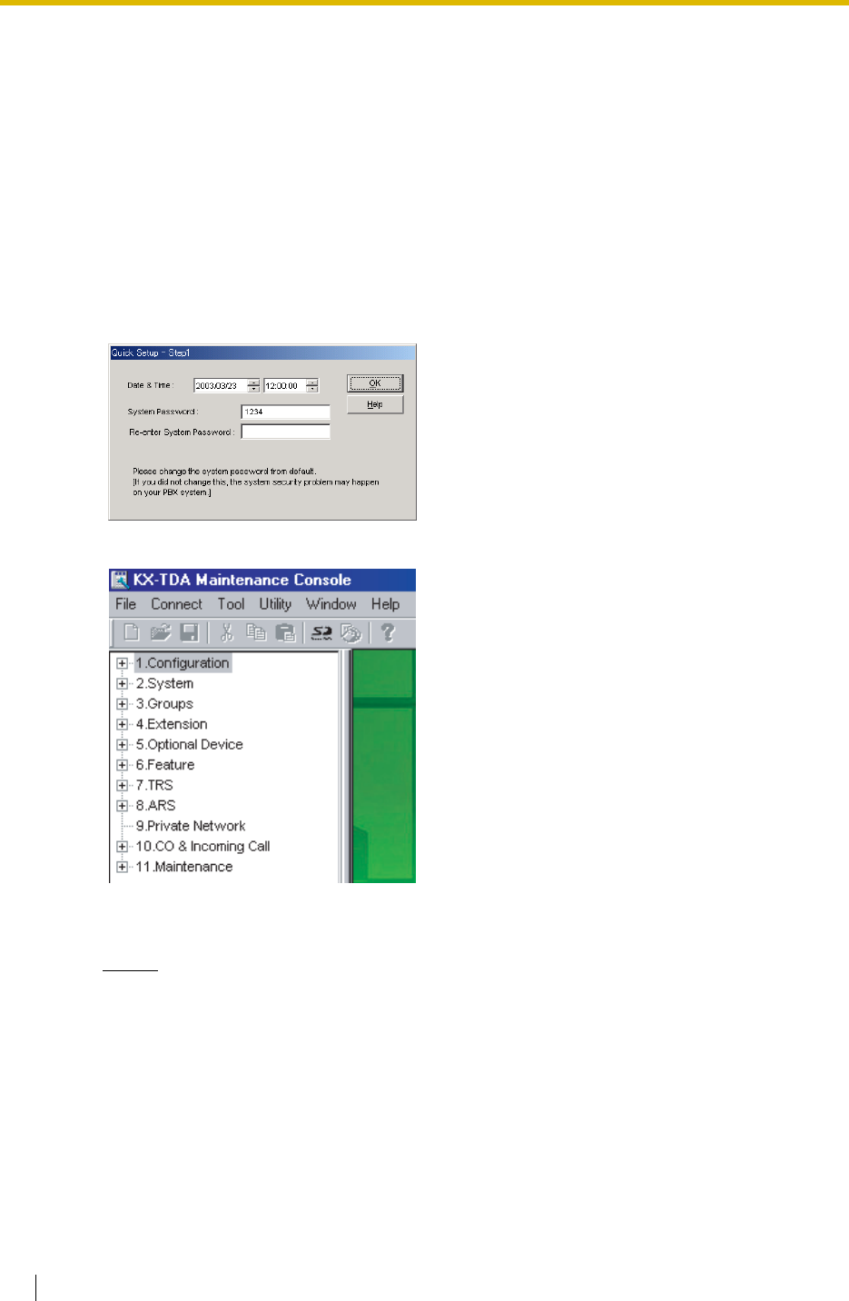
3.2 PC Programming
322 Feature Guide
Notice
1. During a long programming session, it is highly recommended that you periodically
save the system data to the SD Memory Card. You can think of system data as stored
in RAM, whereas SD Memory Card as stored on a hard disk. If the PBX undergoes a
sudden power failure or system reset for some reason, all the system data in RAM will
be lost.
To save the system data to the SD Memory Card, (1) click the "SD Memory Backup"
icon before resetting the PBX or turning off the power, or (2) exit the Maintenance
Console so that the PBX starts automatically saving the system data.
2. When the PBX is initialised, not all data is taken from the SD Memory Card. The data
for present status of extension FWD/DND buttons is taken from battery backup
memory in the PBX.
6. When country/area data do not match:
a. Click [OK] to replace the country/area
data of the PBX. Replacement may take
several minutes to complete.
b. Follow the procedure described in
Section 2.13.1 Starting the Hybrid IP-
PBX (for KX-TDA100/KX-TDA200) or
6.12.1 Starting the Hybrid IP-PBX (for
KX-TDA15/KX-TDA30) in the Installation
Manual and restart the PBX.
c. Repeat steps 2 to 4 to restart the
Maintenance Console.
7. Follow the instructions of the wizard and
assign the basic items (Quick Setup).
The programme menu appears.

3.2 PC Programming
Feature Guide 323
3. The PC will not perform any shutdown operation, or enter the power-saving system
standby mode while the Maintenance Console is connected to the PBX.
To perform either of the operations above, first close the connection to the PBX.
CAUTION
Do not remove the SD Memory Card during access to it. Doing so will damage the system
data, and in the worst case, damage the SD Memory Card.
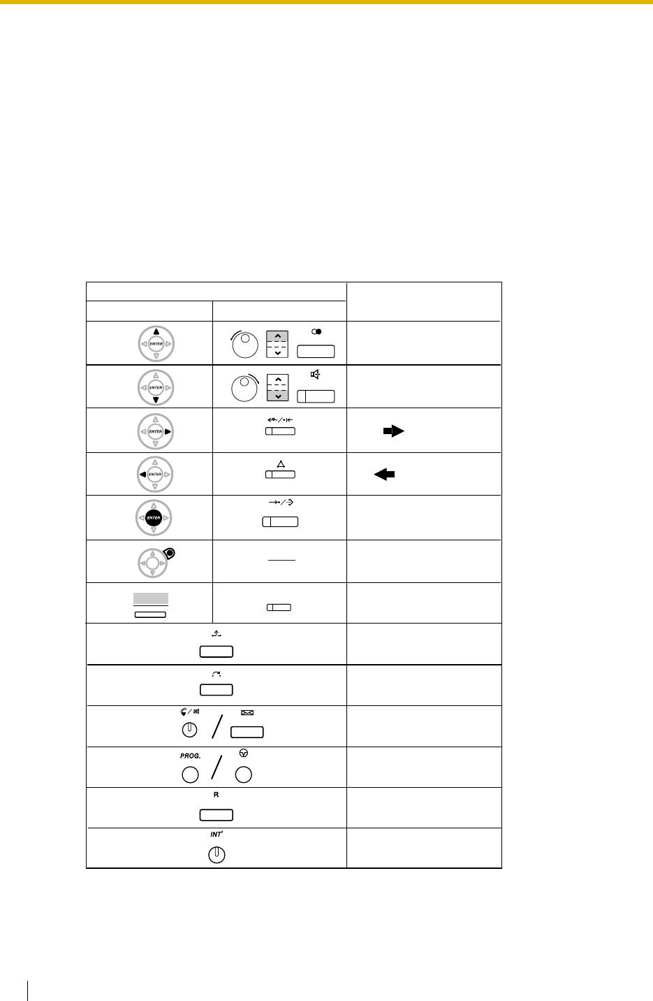
3.3 PT Programming
324 Feature Guide
3.3 PT Programming
3.3.1 Programming Instructions
Required Telephone/Extension
A PT with multiline display (e.g., KX-T7636 6-line display) is required for the system
programming. The extension must be in a COS permitted System Programming or the
extension connected to the smallest port number.
System programming allows only one extension user to enter at a time.
Buttons and Functions
Function
PREVIOUS
NEXT
END
CLEAR
SELECT
FLASH
SECRET
PROGRAM
Back to Previous Menu
Fixed Buttons
T7200/T7400/T7500T7600
(Page up)
(Page down)
HOLD
TRANSFER
AUTO ANS
MUTE
PROGRAM
FLASH/
RECALL
INTERCOM
PAUSE
SHIFT
(CANCEL)
ENTER
SHIFT
REDIAL
SP-PHONE
FWD/DND
CONF
AUTO DIAL
STORE
MESSAGE
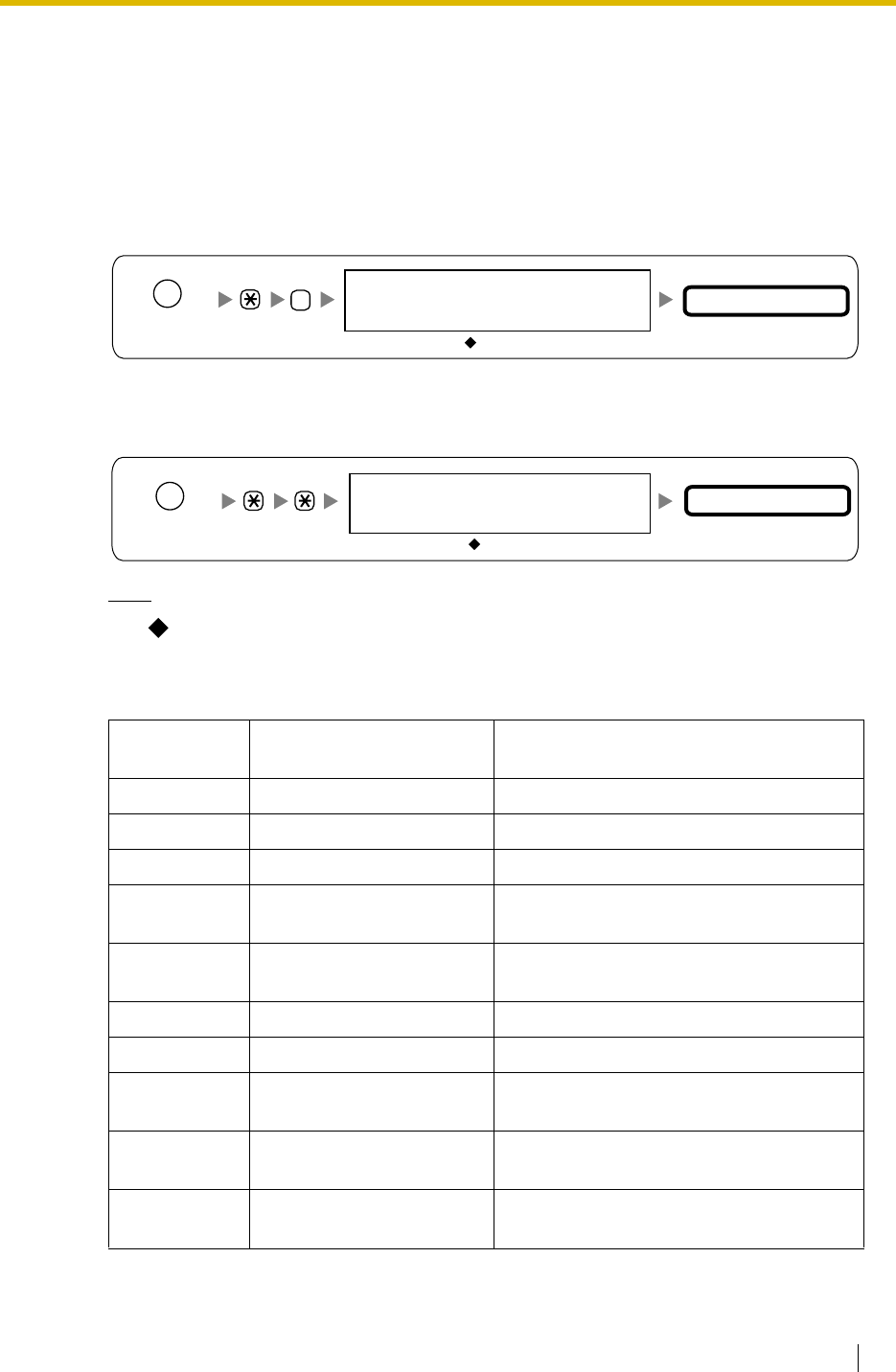
3.3 PT Programming
Feature Guide 325
Entering System Programming Mode
System programming enables the extension user to set the time, call destination and all sorts
of system conditions within the limits of available programming. The administrator or manager
can also set up desired parameters for user programming. It is necessary to enter the relevant
password to start programming. Programming has two levels: Administrator Level and User
Level.
Administrator Level:
All system programming available for PT programming is accessible.
User Level:
Permitted system programming is accessible. Each access to system programming can be
controlled.
Note
means default value throughout this manual.
Programming Structure
Programming
Number Programming Group Title Description
[0XX] Basic Programming Frequently used programming steps.
[1XX] System Programming Global system parameters.
[2XX] Time Programming Flexible system timers.
[3XX] TRS/Barring/ARS
Programming TRS/Barring and Automatic Route
Selection (ARS).
[4XX] Trunk Programming Setting of trunk, trunk group, or BRI line
features.
[5XX] COS Programming Class of Service parameters.
[6XX] Extension Programming Assignment of the extension features
[7XX] Resource/Interface
Programming Assignment of the various interfaces on
the PBX.
[8XX] SMDR & Maintenance
Programming Setting of SMDR and maintenance
features.
[9XX] Card Programming The programming used to refer to or delete
the card.
PROGRAM/
PAUSE
#
= 1234
System Password for Administrator
Programming No.
3 digits
—for PT Programming
= 1234
Programming No.
3 digits
System Password for User
—for PT Programming
PROGRAM/
PAUSE
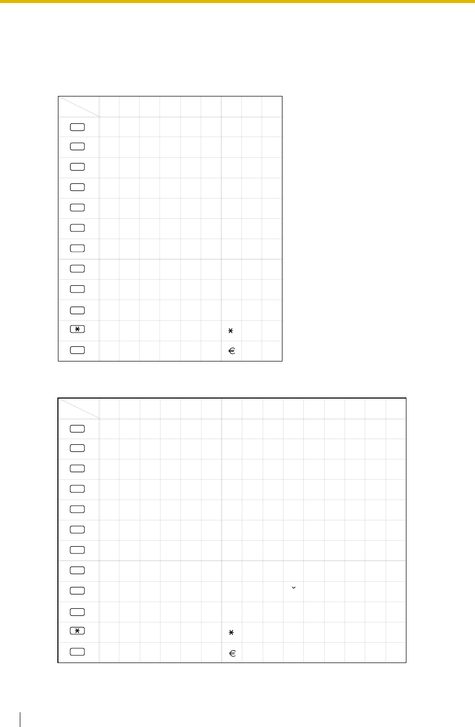
3.3 PT Programming
326 Feature Guide
Entering Characters
To store a name or message, you can enter the following characters. Those tables show you
the characters available on each button.
Table 1 (Standard mode)
Table 2 (Option mode)
Times
Buttons 123
1
456789
2
!
3
4
5
6
7
8
9
#
A
D
G
J
M
P
T
$
?1"
BCabc2
EFdef3
HIghi4
KLjkl5
NOmn 6o
QRSpqrs7
UVt8uv
.,':;0
%&@() #
/+—=<>
0
WXYZwxyz9
£
(space)
Times
Buttons 123
1
456789
2
!
3
4
5
6
7
8
9
#
A
D
G
J
M
P
T
W
$
?ä"
BCabcÀ
EFdef
HIghiÌ
KLjkl5
NOmn Ño
QRSpqrs
UVtuv
XY wxyzZ9
.,':;0
%&@() #
ö1ü
/+—=<>
0
10 11 12 13 14 15
ÁÂÃÄÅÆÇ2
ÈÉÊË3
ÍÎÏ4
ÒÓÔÕÖØŒ6
ß7
ÙÚÛÜ8
£
Ð
ý
(space)
Š
Z
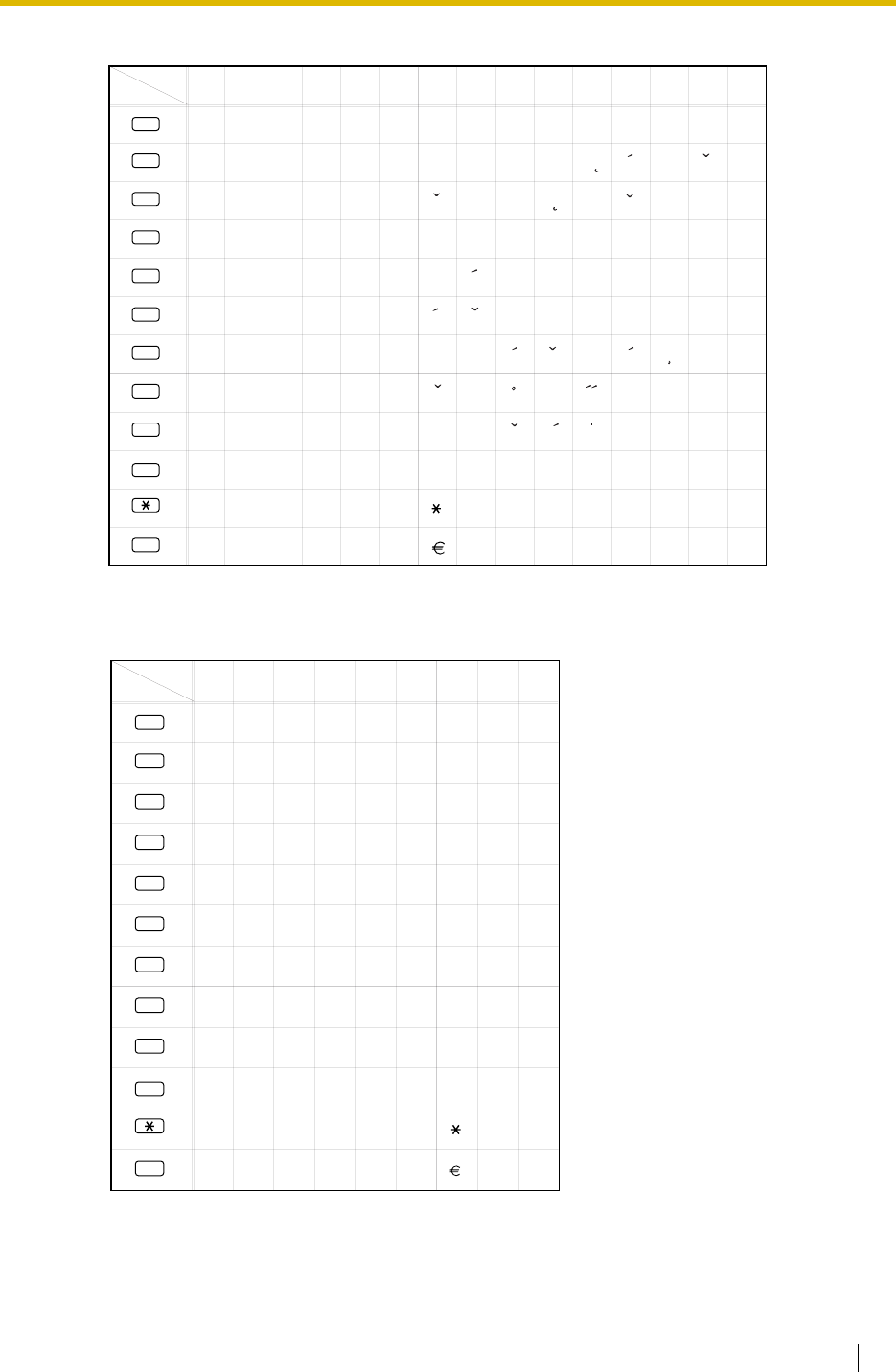
3.3 PT Programming
Feature Guide 327
Table 2 (Option mode for CE model)
Table 2 (Option mode for GR model)
Times
Buttons 123
1
456789
2
!
3
4
5
6
7
8
9
#
A
D
G
J
M
P
T
W
$
?ä"
BCabc
EFdef
HIghi
KLjkl 5
NOmno
QRSpqrs
UVtuv
XY wxyzZ9
.,':;0
%&@() #
ö1ü
/+—=<>
0
10 11 12 13 14 15
ÁÂÃÄ Ç 2
ÉË3
ÍÎ4
ÓÔÕÖ6
ß7
ÚÜ8
£
Ð
ý
(space)
C
eDE
LL
NN
SSRR
TTu
ZZZ
AC
’
Š
’
U
Times
Buttons
123
1
456789
2
!
3
4
5
6
7
8
9
#
A
∆
H
K
N
Π
T
X
$
?1"
B
Γ
2
EZ3
Θ
I4
Λ
M5
Ξ
O6
P
Σ
7
Y
Φ
8
ΨΩ
9
.,':;0
%&@() #
£
/+—=<>
0
(space)
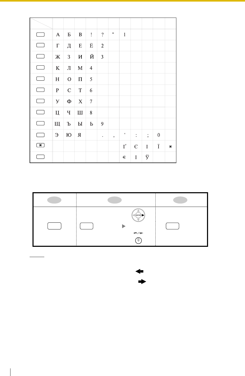
3.3 PT Programming
328 Feature Guide
Table 2 (Option mode for RU model)
[Example of Entering Characters]
To enter "Ann":
Notes
• To erase the character on the cursor, press CLEAR.
• To move the cursor to the left, press .
• To move the cursor to the right, press .
• If SELECT is pressed, the characters for each button will bring out in reverse order.
• To toggle between Table 1 and Table 2 when using KX-T7600 series, press the
leftmost soft button.
Times
Buttons
123
1
456789
2
3
4
5
6
7
8
9
#
0
10
$%&@() #
/+—=<>
(space)
11
Ann
6(5 times) 6(5 times)
2
FWD/DND
OR
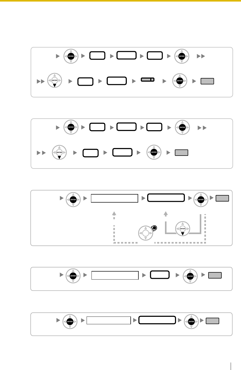
3.3 PT Programming
Feature Guide 329
3.3.2 Basic Programming
Date & Time [000]
[In 12-hour Format]
[In 24-hour Format]
System Speed Dialling Number [001]
System Speed Dialling Name [002]
Extension Number [003]
[000]
00–99
Year
01–31
Date
01–12
Hour
00–59
Minute
END
(HOLD)
ENTER ENTER
ENTER
01–12
Month
NEXT AM/PM
SELECT
(AUTO ANS/MESSAGE)
[000]
00–99
Year
01–31
Date
00–23
Hour
00–59
Minute
END
(HOLD)
ENTER ENTER
ENTER
01–12
Month
NEXT
[001]
000–999
Speed Dialling No. Telephone No.
Max. 32 digits END
ENTER ENTER
CANCEL NEXT
To the Next Speed Dialling No.
To the Desired Speed Dialling No.
[002]
Name
Max. 20 characters END
ENTER ENTER
000–999
Speed Dialling No.
[003]
New Extn. No.
1–4 digits END
1–4 digits
Current Extn. No.
ENTER ENTER
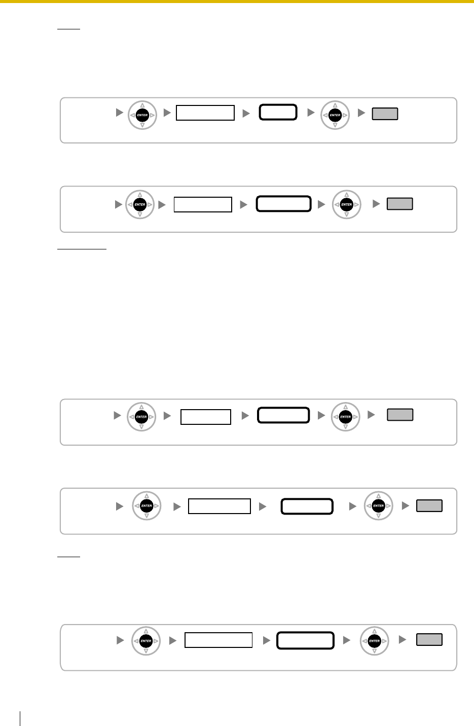
3.3 PT Programming
330 Feature Guide
Note
If a PC Phone, PC Console or CTI application software is running on the PC that is
connected to the PBX, quit it before this programme.
Extension Name [004]
Extension Personal Identification Number (PIN) [005]
WARNING
When a third party discovers the personal identification number (PIN) (verified code PIN/
extension PIN) of the PBX, there will be a risk that they will make fraudulent phone calls
using the telephone line, and the cost will be charged to your own account. In order to
avoid this problem, we strongly recommend the following points:
a) Carefully maintain the secrecy of the PIN.
b) Specify a complicated PIN as long and random as you can make it.
c) Change the PIN frequently.
Operator Assignment [006]
Console Paired Telephone [007]
Note
This programme is available after the port connected to the Console is assigned as
"Console" in Terminal Device Assignment [601].
Absent Message [008]
[004]
Name
Max. 20 characters END
1–4 digits
Extn. No.
ENTER ENTER
[005]
1–4 digits END
Max. 10 digits
PIN
ENTER ENTER
Extn. No.
[006]
END
1–4 digits
Extn. No.
ENTER ENTER
1 Day/2 Lunch/
3 Break/4 Night
Time No.
[007]
01–08
Console No.
END
ENTER ENTER
1–4 digits
Extn. No.
[008]
1–8
Location No.
END
Message
ENTER ENTER
Max. 16 characters
deleted:
[KX-TDA100/KX-TDA200]
[KX-TDA30] and its graphic
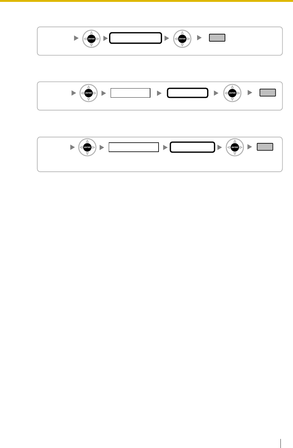
3.3 PT Programming
Feature Guide 331
Charge Margin [010]
Charge Tax [011]
Charge Rate per Unit [012]
[010]
2+2 decimal places
Margin XX.YY%
END
ENTER ENTER
[011]
01–03
Location No.
2+2 decimal places
Tax XX.YY%
END
ENTER ENTER
[012]
01–64
Trunk Group No.
Max. 8 digits
including decimal point
Charge Rate
END
ENTER ENTER
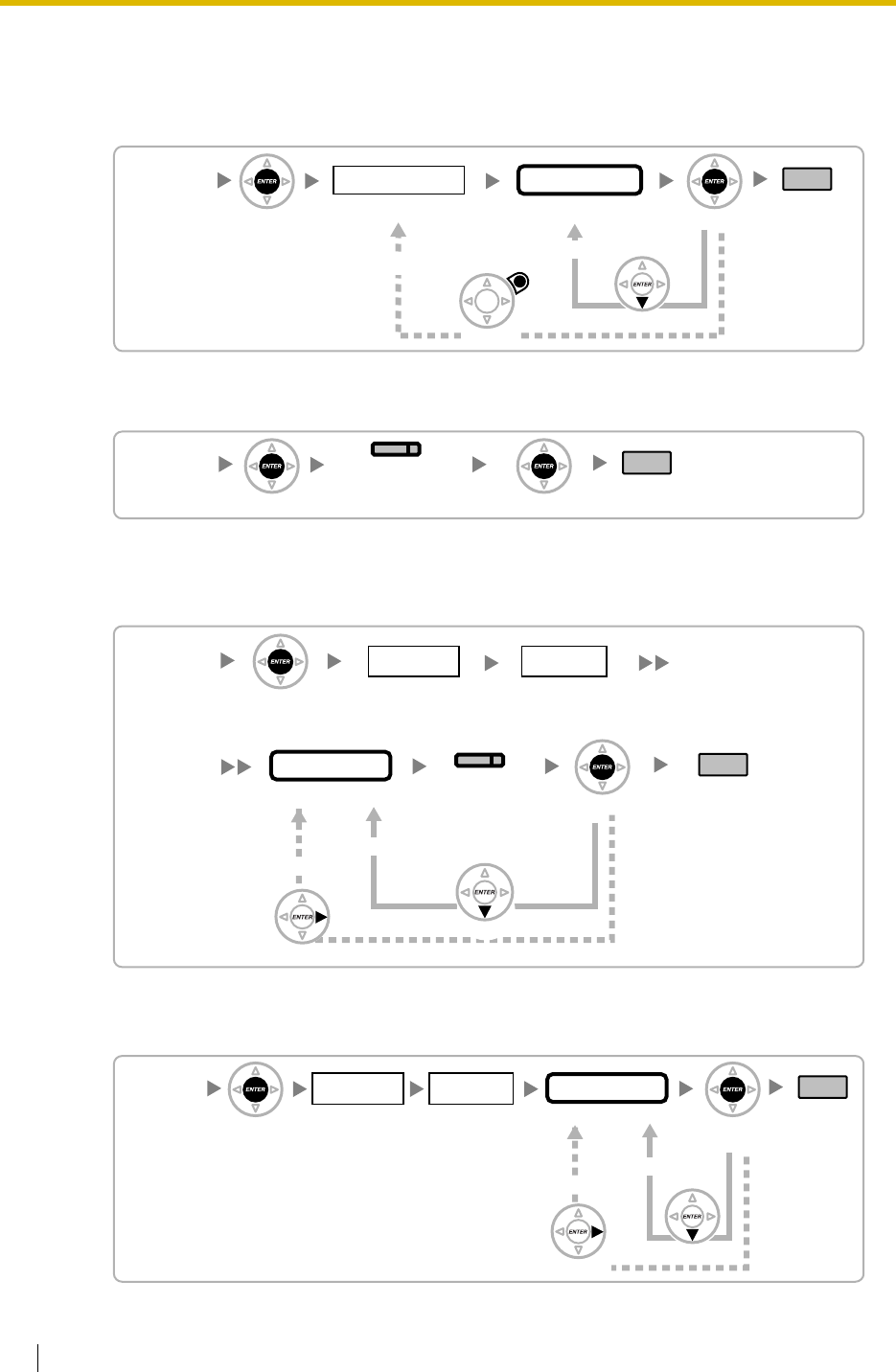
3.3 PT Programming
332 Feature Guide
3.3.3 System Programming
Flexible Numbering [100]
Time Service Switching Mode [101]
Time Service Starting Time [102]
[In 12-hour Format]
[In 24-hour Format]
[100]
01–36
Location No.
1–4 digits
Feature No.
END
(HOLD)
ENTER ENTER
CANCEL NEXT
To the Next Location No.
To the Desired Location No.
[101]
Manual/Automatic END
SELECT
(AUTO ANS/MESSAGE)
ENTER ENTER
[102]
01:00–12:59
Hour:Minute
END
ENTER
ENTER
Day No. Time No.
0 Sun/1 Mon/
2 Tue/3 Wed/
4 Thu/5 Fri/6 Sat
1 Day-1/2 Lunch/
3 Day-2/4 Night
Page up
NEXT
To the Next Time No.
To the Next Day No.
AM/PM
SELECT
[102]
00:00–23:59
Hour:Minute
END
ENTER ENTER
Day No. Time No.
0 Sun/1 Mon/
2 Tue/3 Wed/
4 Thu/5 Fri/6 Sat
1 Day-1/2 Lunch/
3 Day-2/4 Night
Page up NEXT
To the Next Time No.
To the Next Day No.
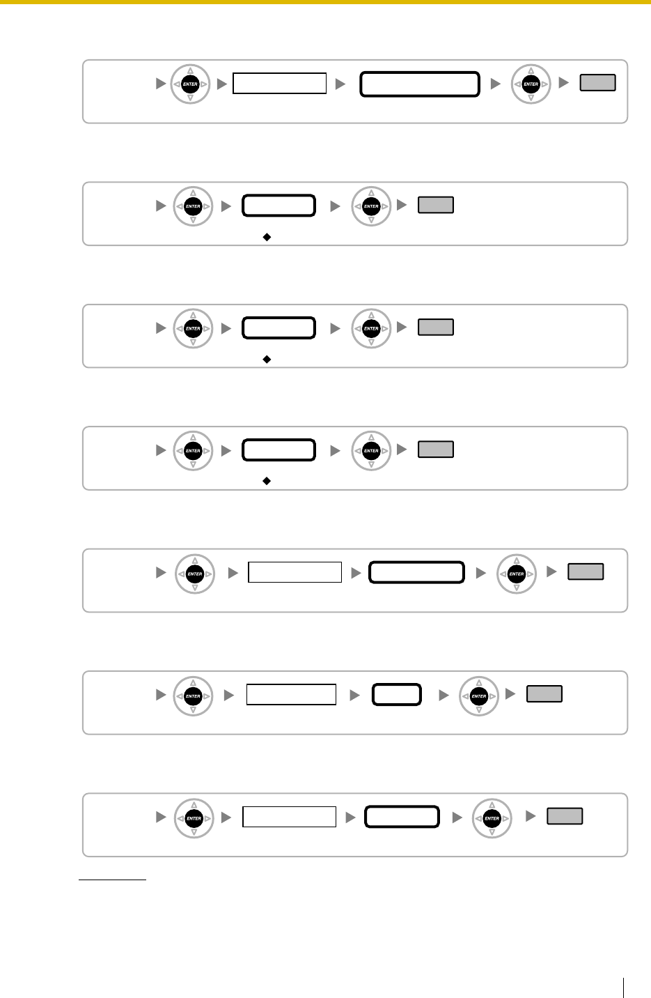
3.3 PT Programming
Feature Guide 333
Idle Line Access (Local Access) [103]
System Password for Administrator—for PT Programming [110]
System Password for User—for PT Programming [111]
Manager Password [112]
Verified Code [120]
Verified Code Name [121]
Verified Code Personal Identification Number (PIN) [122]
WARNING
When a third party discovers the personal identification number (PIN) (verified code PIN/
extension PIN) of the PBX, there will be a risk that they will make fraudulent phone calls
[103]
01–64
Location No.
01–64
Trunk Group No.
END
ENTER ENTER
[110]
4–10 digits
Password
END
ENTER ENTER
1234
[111]
4–10 digits
Password
END
ENTER ENTER
1234
[112]
4–10 digits
Password
END
ENTER ENTER
1234
[120]
0001–1000
Location No.
1–4 digits
Verified Code
END
ENTER ENTER
[121]
0001–1000
Location No.
Max. 20 characters
Name
END
ENTER ENTER
[122]
0001–1000
Location No.
Max. 10 digits
PIN
END
ENTER ENTER
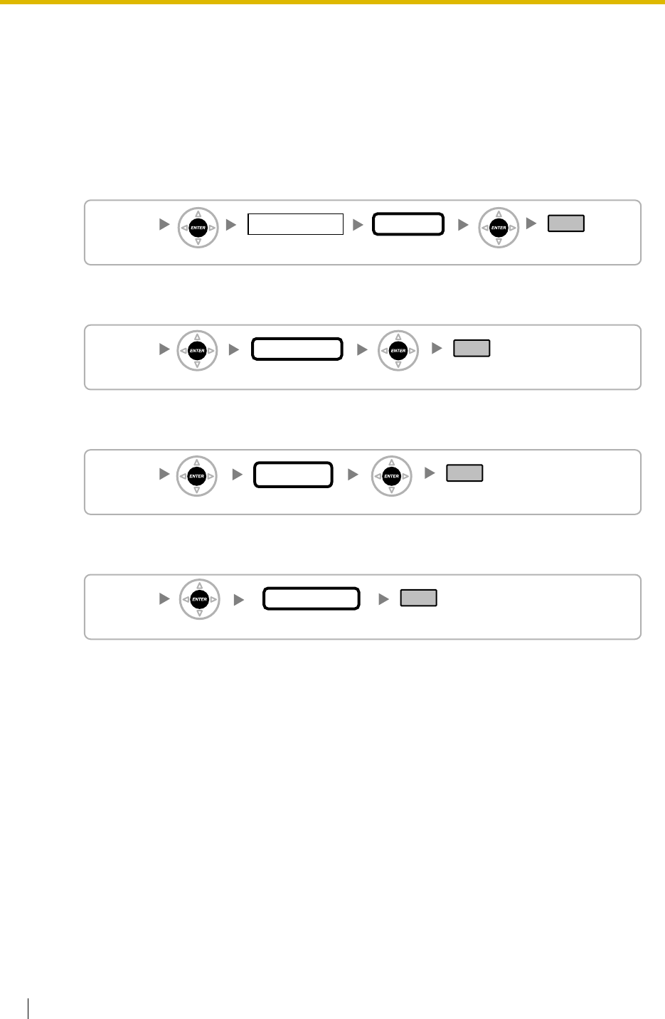
3.3 PT Programming
334 Feature Guide
using the telephone line, and the cost will be charged to your own account. In order to
avoid this problem, we strongly recommend the following points:
a) Carefully maintain the secrecy of the PIN.
b) Specify a complicated PIN as long and random as you can make it.
c) Change the PIN frequently.
Verified Code COS Number [123]
Decimal Point Position for Currency [130]
Currency [131]
Main Processing (MPR) Software Version Reference [190]
[123]
0001–1000
Location No.
01–64
COS No.
END
ENTER ENTER
[130]
0–7
Desired No.
END
ENTER ENTER
[131]
3 characters
Currency
END
ENTER ENTER
[190]
Reference only
MPR Version
END
ENTER
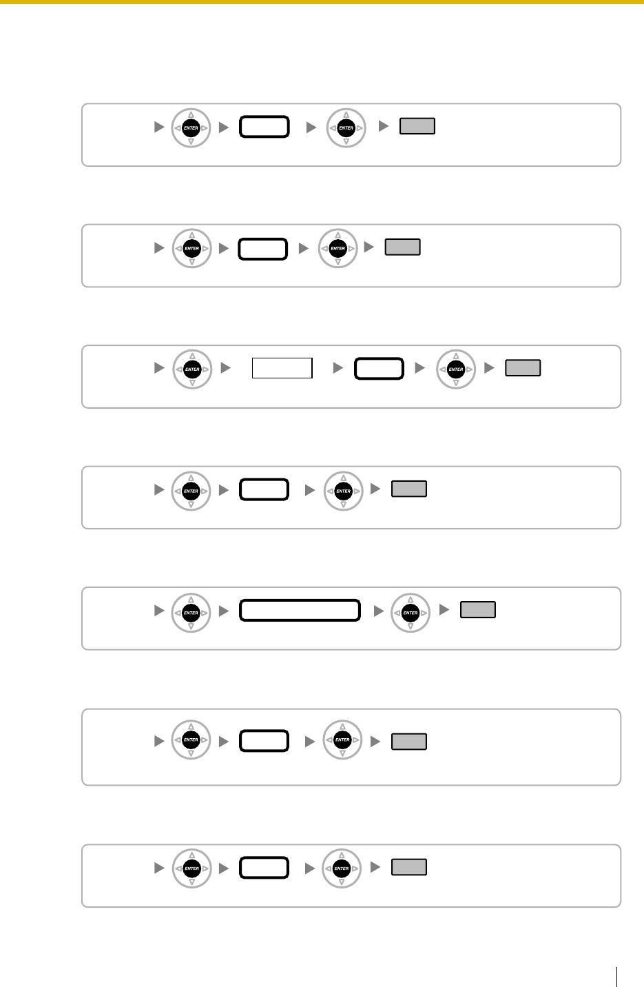
3.3 PT Programming
Feature Guide 335
3.3.4 Time Programming
Hold Recall Time [200]
Transfer Recall Time [201]
Intercept Time [203]
Hot Line Waiting Time [204]
Automatic Redial Repeat Times [205]
Automatic Redial Interval [206]
Door Open Duration Time [207]
[200]
0–240 s
Time
END
(HOLD)
ENTER ENTER
[201]
END
ENTER ENTER
1–240 s
Time
[203]
END
ENTER ENTER
1–240 s
Time
1 Day/2 Lunch
3 Break/4 Night
Time No.
Time No.
[204]
0–15 s
Time
END
ENTER ENTER
[205]
0–15
Number of Times
END
ENTER ENTER
[206]
(1–120) ×10 s
Time
END
ENTER ENTER
[207]
2–7 s
Time
END
ENTER ENTER
3.3 PT Programming
336 Feature Guide
Call Duration Count Starting Time for LCOT [208]
DISA Delayed Answer Time [209]
DISA Trunk-to-Trunk Call Prolong Time [210]
DISA Intercept Time [211]
[208]
0–60 s
Time
END
ENTER ENTER
[209]
0–30 s
Time
END
ENTER ENTER
[210]
0–7 min
Time
END
ENTER ENTER
[211]
0–60 s
Time
END
ENTER ENTER
1 Day/2 Lunch
3 Break/4 Night
Time No.
3.3 PT Programming
Feature Guide 337
3.3.5 TRS/Barring/ARS Programming
TRS/Barring Override by System Speed Dialling [300]
TRS/Barring Denied Code [301]
TRS/Barring Exception Code [302]
Special Carrier Access Code [303]
Emergency Number [304]
ARS Mode [320]
[300]
Disable/Enable END
(HOLD)
SELECT
(AUTO ANS/MESSAGE)
ENTER ENTER
ENTER ENTER
[301]
2–6
Level No.
Max. 16 digits
Denied Code
001–100
Location No.
END
CANCEL NEXT
To the Next Location No.
To the Desired Location No.
[302]
2–6
Level No.
Max. 16 digits
Exception Code
001–100
Location No.
END
ENTER ENTER
[303]
Max. 16 digits
Carrier Access Code
01–20
Location No.
END
ENTER ENTER
[304]
Max. 32 digits
Emergency No.
01–10
Location No.
END
ENTER ENTER
[320]
Off/Idle Line/
All Access END
SELECT
ENTER ENTER
3.3 PT Programming
338 Feature Guide
ARS Leading Number [321]
ARS Routing Plan Table Number [322]
ARS Exception Number [325]
ARS Routing Plan Time Table [330]
[In 12-hour Format]
[In 24-hour Format]
[321]
0001–1000
Location No.
Max. 16 digits
Leading No.
END
ENTER ENTER
[322]
0001–1000
Location No.
01–16
Plan Table No.
END
ENTER ENTER
[325]
001–200
Location No.
Max. 16 digits
Exception No.
END
ENTER ENTER
01–16
Plan Table No.
01–12/00–59
Hour:Minute
0 Sun/1 Mon/2 Tue/
3 Wed/4 Thu/5 Fri/6 Sat
Day No.
END
1 TimeA/2 TimeB/
3 TimeC/4 TimeD
ARS Time No.
ENTER
ENTER
[330]
AM/PM
SELECT
01–16
Plan Table No.
00–23/00–59
Hour:Minute
0 Sun/1 Mon/2 Tue/
3 Wed/4 Thu/5 Fri/6 Sat
Day No.
END
1 TimeA/2 TimeB/
3 TimeC/4 TimeD
ARS Time No.
ENTER
ENTER
[330]
3.3 PT Programming
Feature Guide 339
ARS Routing Plan Table (1–16) [331–346]
ARS Carrier Name [350]
ARS Trunk Group for Carrier Access [351]
ARS Removed Number of Digits for Carrier Access [352]
ARS Carrier Access Code [353]
[331–346]
Day No.
1–10/None
Carrier Table No.
1 TimeA/2 TimeB/
3 TimeC/4 TimeD
ARS Time No.
END
1–6
Priority
ENTER
ENTER
0 Sun/1 Mon/2 Tue/
3 Wed/4 Thu/5 Fri/6 Sat
[350]
01–10
Carrier Table No.
Max. 20 characters
Name
END
ENTER ENTER
Disable/
Enable
SELECT
[351]
01–10
Carrier Table No.
Trunk Group No.
END
ENTER ENTER
SELECT
01–64
[352]
01–10
Carrier Table No.
0–15
Digits to Remove
END
ENTER ENTER
[353]
01–10
Carrier Table No.
Max. 32 digits
Carrier Access Code
END
ENTER ENTER
3.3 PT Programming
340 Feature Guide
3.3.6 Trunk Programming
LCOT/BRI Trunk Connection [400]
LCOT/BRI Trunk Name [401]
LCOT/BRI Trunk Group Number [402]
LCOT/BRI Trunk Number Reference [409]
LCOT Dialling Mode [410]
LCOT Pulse Rate [411]
ENTER ENTER
[400]
No Connect/
Connect
END
(HOLD)
SELECT
(AUTO ANS/MESSAGE)
CANCEL NEXT
To the Next Port No.
To the Desired Port No.
01–10
Slot No.
01–16
Port No.
[401]
Max. 20 characters
Name
END
ENTER ENTER
3 digits
Trunk No.
[402]
01–643 digits
Trunk Group No.
END
ENTERENTER
Trunk No.
[409]
01–10 Reference only
Slot No.
01–16
Port No.
Trunk No.
END
ENTER
[410]
DTMF/Pulse END
SELECT
ENTER ENTER
01–10
Slot No.
01–16
Port No.
[411]
Low/High END
SELECT
ENTER ENTER
01–10
Slot No.
01–16
Port No.
deleted:
[KX-TDA100/KX-TDA200]
[KX-TDA30] and its graphic
3.3 PT Programming
Feature Guide 341
LCOT DTMF Minimum Duration [412]
LCOT CPC Signal Detection Time—Outgoing [413]
LCOT CPC Signal Detection Time—Incoming [414]
LCOT Reverse Circuit [415]
LCOT Pause Time [416]
LCOT Flash/Recall Time [417]
LCOT Disconnect Time [418]
[412]
80/160 ms END
SELECT
ENTER ENTER
01–10
Slot No.
01–16
Port No.
[413]
0: None/1: 6.5/
2–113: (N–1)×8 ms
END
ENTER ENTER
01–10
Slot No.
01–16
Port No. Mode No.
[414]
END
ENTER ENTER
0: None/1: 6.5/
2–113: (N–1)×8 ms
01–10
Slot No.
01–16
Port No. Mode No.
[415]
Disable/
Outgoing/Both Call
END
SELECT
ENTER ENTER
01–10
Slot No.
01–16
Port No.
[416]
1.5/2.5/
3.5/4.5 s
END
SELECT
ENTER ENTER
01–10
Slot No.
01–16
Port No.
[417]
None/80/96/112/
300/600/900/
1200 ms/option
END
SELECT
ENTER ENTER
01–10
Slot No.
01–16
Port No.
[418]
0.5/1.5/2.0/
4.0/12.0 s
END
SELECT
ENTER ENTER
01–10
Slot No.
01–16
Port No.
deleted:
[KX-TDA100/KX-TDA200]
[KX-TDA30] and its graphic
3.3 PT Programming
342 Feature Guide
BRI Network Type [420]
BRI DIL/DDI/MSN Selection [421]
BRI Subscriber Number [422]
BRI Layer 1 Active Mode [424]
Note
This programme needs Slot Card Reset [902] to enable after setting.
BRI Layer 2 Active Mode [425]
Note
This programme needs Slot Card Reset [902] to enable after setting.
BRI Configuration [426]
Note
This programme needs Slot Card Reset [902] to enable after setting.
ENTER ENTER
[420]
01–10
Slot No.
01–08
Port No.
00–56
Network Type
END
[421]
01–10
Slot No.
01–08
Port No.
DIL/DDI/MSN END
SELECT
ENTER ENTER
[422]
01–10
Slot No.
01–08
Port No.
Max. 16 digits
Subscriber No.
END
ENTER ENTER
[424]
01–10
Slot No.
01–08
Port No.
Permanent/
Call by call END
SELECT
ENTER ENTER
[425]
01–10
Slot No.
01–08
Port No.
Permanent/
Call by call END
SELECT
ENTER ENTER
[426]
01–10
Slot No.
01–08
Port No.
P-P/P-MP END
SELECT
ENTER ENTER
deleted:
[KX-TDA100/KX-TDA200]
[KX-TDA30] and its graphic
3.3 PT Programming
Feature Guide 343
BRI TEI Mode [427]
Note
This programme needs Slot Card Reset [902] to enable after setting.
DIL 1:1 Destination [450]
DID Number [451]
DID Name [452]
DID Destination [453]
Trunk Group Intercept Destination [470]
ENTERENTER
[427]
01–10
Slot No.
01–08
Port No.
00–63 (for Fix)/
TEI
END
ENTER
Clear (for Automatic)
[450]
END
ENTER
ENTER
Time No.
01–10
Slot No.
01–24
Port No.
1–4 digits
Destination No.
1 Day/2 Lunch/
3 Break/4 Night
[451]
0001–1000
Location No.
Max. 32 digits
DID No.
END
ENTER ENTER
[452]
0001–1000
Location No.
Max. 20 characters
Name
END
ENTER ENTER
[453]
0001–1000
Location No.
1–4 digits
Destination No.
END
ENTER ENTER
1 Day/2 Lunch/
3 Break/4 Night
Time No.
[470]
01–64
Trunk Group No.
Max. 32 digits
Destination No.
END
ENTER
ENTER
1 Day/2 Lunch/
3 Break/4 Night
Time No.
deleted:
[KX-TDA100/KX-TDA200]
[KX-TDA30] and its graphic
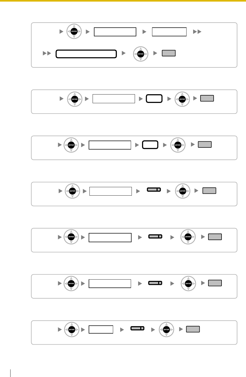
3.3 PT Programming
344 Feature Guide
Host PBX Access Code [471]
Extension-to-Trunk Call Duration [472]
Trunk-to-Trunk Call Duration [473]
DISA Silence Detection [475]
DISA Continuous Signal Detection [476]
DISA Cyclic Signal Detection [477]
Caller ID Signal Type [490] (KX-TDA30/KX-TDA100/KX-TDA200 only)
[471]
01–64
Trunk Group No.
01–10
Location No.
Max.10 digits
Host PBX Access Code
END
ENTER
ENTER
[472]
01–64
Trunk Group No.
01–60 min
Time
END
ENTER ENTER
[473]
01–64
Trunk Group No.
01–60 min
Time
END
ENTER ENTER
ENTER ENTER
[475]
01–64
Trunk Group No.
No Detect/
Detect
END
SELECT
[476]
01–64
Trunk Group No.
No Detect/
Detect
END
SELECT
ENTER ENTER
[477]
01–64
Trunk Group No.
No Detect/
Detect
END
SELECT
ENTER ENTER
ENTER ENTER
[490]
01–10
Slot No.
FSK/FSK with
Visual Caller ID/DTMF
SELECT END
deleted:
[KX-TDA100/KX-TDA200]
[KX-TDA30] and its graphic

3.3 PT Programming
Feature Guide 345
Pay Tone Signal Type [491] (KX-TDA100/KX-TDA200 only)
[491]
01–10
Slot No.
12/16 kHz
SELECT END
ENTER ENTER
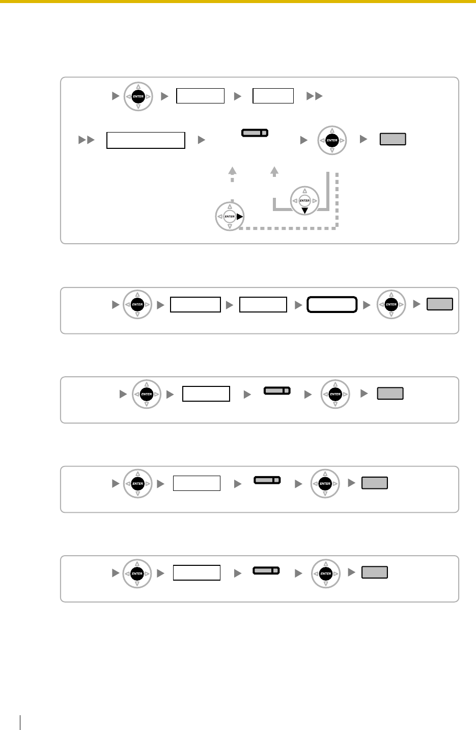
3.3 PT Programming
346 Feature Guide
3.3.7 COS Programming
Trunk Group Number [500]
TRS/Barring Level [501]
Trunk Call Duration Limitation [502]
Call Transfer to Trunk [503]
Call Forwarding to Trunk [504]
[500]
1 Day/2 Lunch/
3 Break/4 Night 01–64
COS No.Time No.
01–64
Trunk Group No.
Disable/Enable END
(HOLD)
SELECT
(AUTO ANS/MESSAGE)
ENTER
ENTER
NEXT
To the Next
Trunk Group
No.
To the Next
COS No.
Page up
[501]
01–64
COS No.Time No.
1–7
Level
END
ENTER ENTER
1 Day/2 Lunch/
3 Break/4 Night
[502]
01–64
COS No.
END
ENTER ENTER
SELECT
Disable/
Enable
[503]
01–64
COS No.
END
Disable/
Enable
SELECT
ENTER ENTER
Disable/
Enable
SELECT
[504]
01–64
COS No.
END
ENTER ENTER
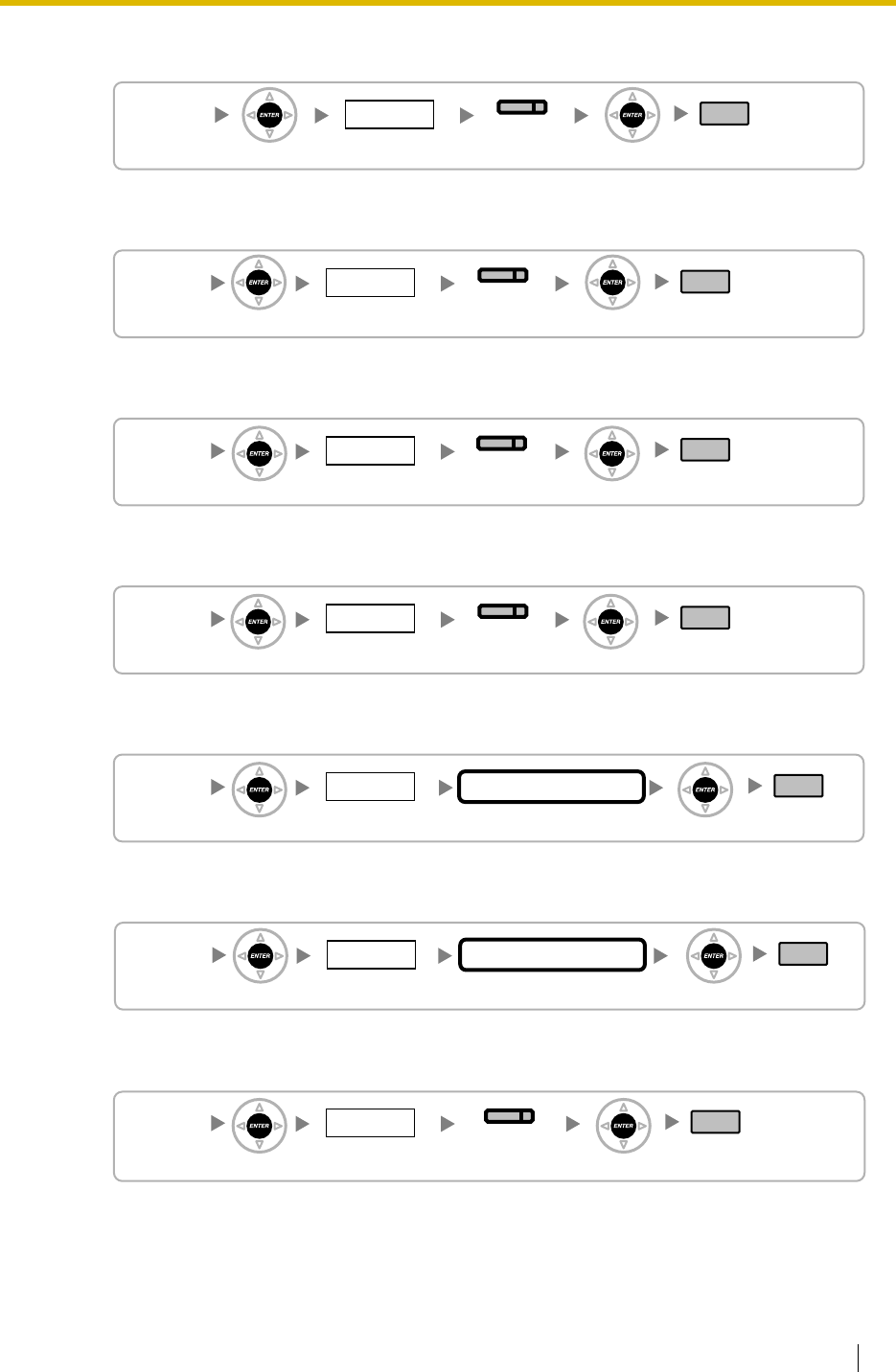
3.3 PT Programming
Feature Guide 347
Executive Busy Override [505]
Executive Busy Override Deny [506]
DND Override [507]
Account Code Mode [508]
TRS/Barring Level for System Speed Dialling [509]
TRS/Barring Level for Extension Lock [510]
Manager Assignment [511]
SELECT
Disable/
Enable
[505]
01–64
COS No.
END
ENTER ENTER
Disable/
Enable
SELECT
ENTER ENTER
[506]
01–64
COS No.
END
SELECT
Disable/
Enable
[507]
01–64
COS No.
END
ENTER ENTER
[508]
01–64
COS No.
END
Option/
Forced
SELECT
ENTER ENTER
[509]
01–64
COS No.
1–7
TRS/Barring Level
END
ENTER ENTER
[510]
01–64
COS No.
1–7 END
ENTER ENTER
TRS/Barring Level
[511]
01–64
COS No.
END
Disable/Enable
SELECT
ENTER ENTER
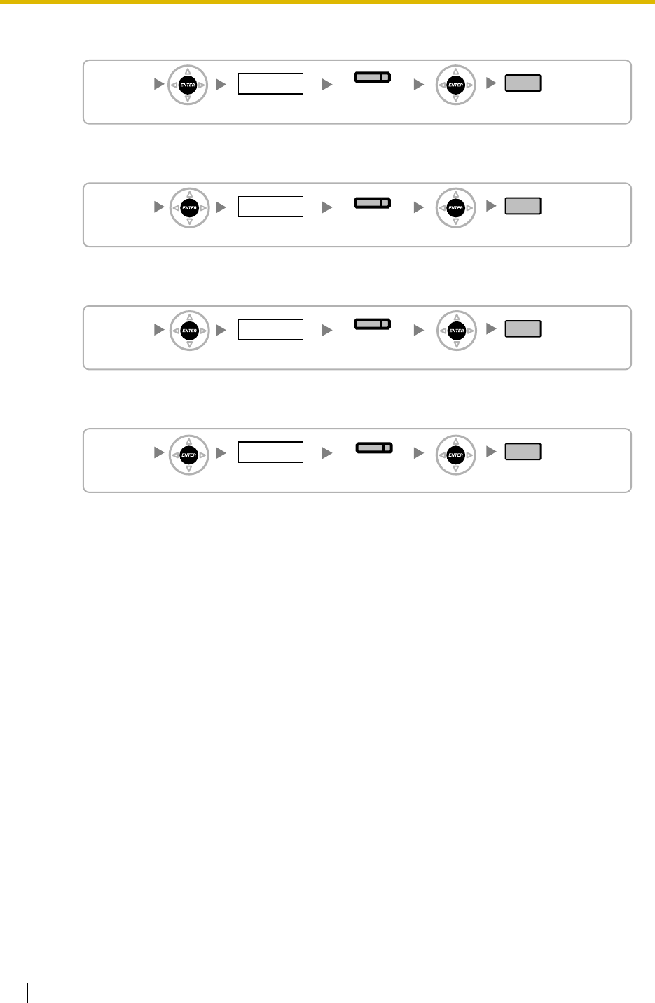
3.3 PT Programming
348 Feature Guide
Permission for Door Open Access [512]
Time Service Manual Switching [514]
Wireless XDP Parallel Mode for Paired Telephone [515]
Programming Mode Limitation [516]
Disable/
Enable
SELECT
[512]
01–64
COS No.
END
ENTER ENTER
[514]
01–64
COS No.
END
Disable/
Enable
SELECT
ENTER ENTER
SELECT
Disable/
Enable
[515]
01–64
COS No.
END
ENTER ENTER
[516]
01–64
COS No.
END
Disable/Personal/
System&Personal
SELECT
ENTER ENTER
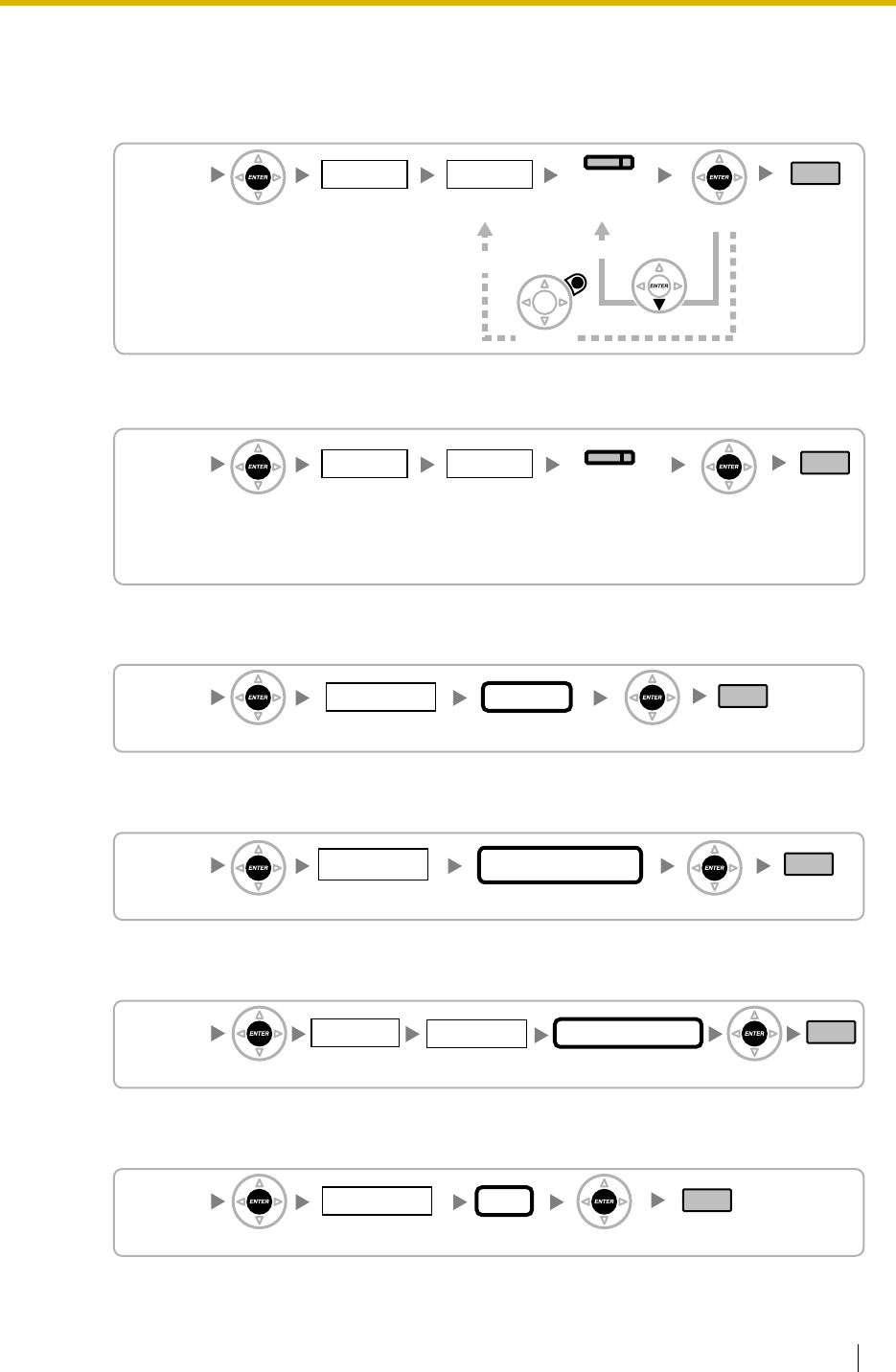
3.3 PT Programming
Feature Guide 349
3.3.8 Extension Programming
EXtra Device Port (XDP) Mode [600]
Terminal Device Assignment [601]
Class of Service [602]
User Group [603]
Extension Intercept Destination [604]
Call Forwarding—No Answer Time [605]
[600]
01–10
Slot No.
01–08
Port No.
Off/On END
(HOLD)
SELECT
(AUTO ANS/MESSAGE)
ENTER ENTER
CANCEL NEXT
To the Next Port No.
To the Desired Port No.
[601]
01–10
Slot No.
01–16
Port No.
Telephone/Console 1–8/
Voice Mail 1–(1–12)/
Voice Mail 2–(1–12)/
PC Console 1–8
END
SELECT
ENTER ENTER
[602]
01–64
COS No.
1–4 digits END
ENTER ENTER
Extn. No.
[603]
001–032
User Group No.
1–4 digits END
ENTER ENTER
Extn. No.
[604]
Max. 32 digits
Destination No.
1 Day/2 Lunch/
3 Break/4 Night
END
ENTER ENTER
Time No.
1–4 digits
Extn. No.
[605]
0–120 s
Time
1–4 digits END
ENTER ENTER
Extn. No.
deleted:
[KX-TDA100/KX-TDA200]
[KX-TDA30] and its graphic
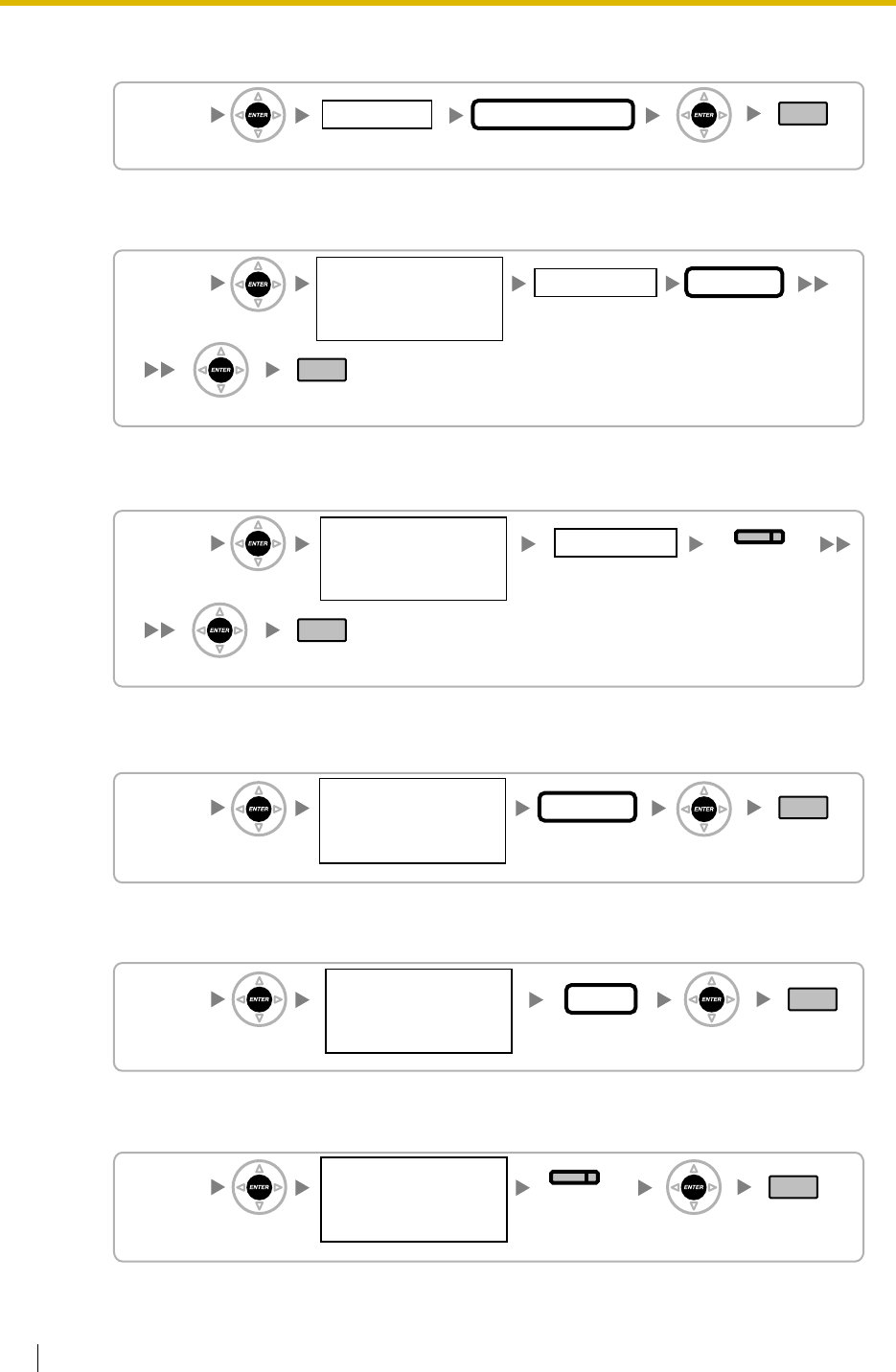
3.3 PT Programming
350 Feature Guide
CLIP/COLP Number [606]
Incoming Call Distribution Group Member [620]
Incoming Call Distribution Group Delayed Ringing [621]
Incoming Call Distribution Group Floating Extension Number [622]
Incoming Call Distribution Group Name [623]
Incoming Call Distribution Group Distribution Method [624]
[606]
Max. 16 digits
CLIP/COLP No.
1–4 digits END
ENTER ENTER
Extn. No.
[620]
01–32
Location No.
1–4 digits
01–64
Incoming Call
Distribution
Group No.
END
ENTER
ENTER
Extn. No.
[621]
01–32
Location No.
END
Immediate/
1–6 (rings)/
No ring
SELECT
ENTER
ENTER
01–64
Incoming Call
Distribution
Group No.
[622]
1–4 digits END
ENTER ENTER
Extn. No.
01–64
Incoming Call
Distribution
Group No.
[623]
Max. 20 characters
Name
END
ENTER ENTER
01–64
Incoming Call
Distribution
Group No.
[624]
END
Ring/UCD/
Priority Hunt
SELECT
ENTER ENTER
01–64
Incoming Call
Distribution
Group No.
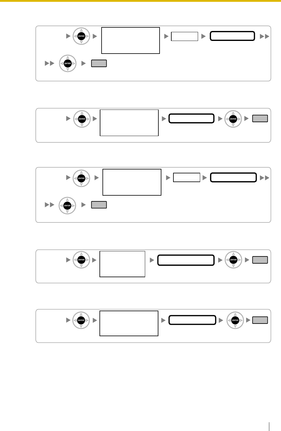
3.3 PT Programming
Feature Guide 351
Destination for Overflow Time Expiration [625]
Overflow Time [626]
Destination When All Busy [627]
Queuing Call Capacity [628]
Queuing Hurry-up Level [629]
[625]
1 Day/2 Lunch/
3 Break/4 Night Max. 32 digits
Destination No.
END
ENTER
ENTER
Time No.
01–64
Incoming Call
Distribution
Group No.
[626]
(1–125)×10 s
Overflow Time
END
ENTER ENTER
01–64
Incoming Call
Distribution
Group No.
[627]
Max. 32 digits
Destination No.
END
ENTER
ENTER
01–64
Incoming Call
Distribution
Group No.
1 Day/2 Lunch/
3 Break/4 Night
Time No.
[628]
0–30
Number in Queuing
END
ENTER ENTER
01–64
Incoming Call
Distribution
Group No.
[629]
None/1–30
Hurry-up Level
END
ENTER ENTER
01–64
Incoming Call
Distribution
Group No.
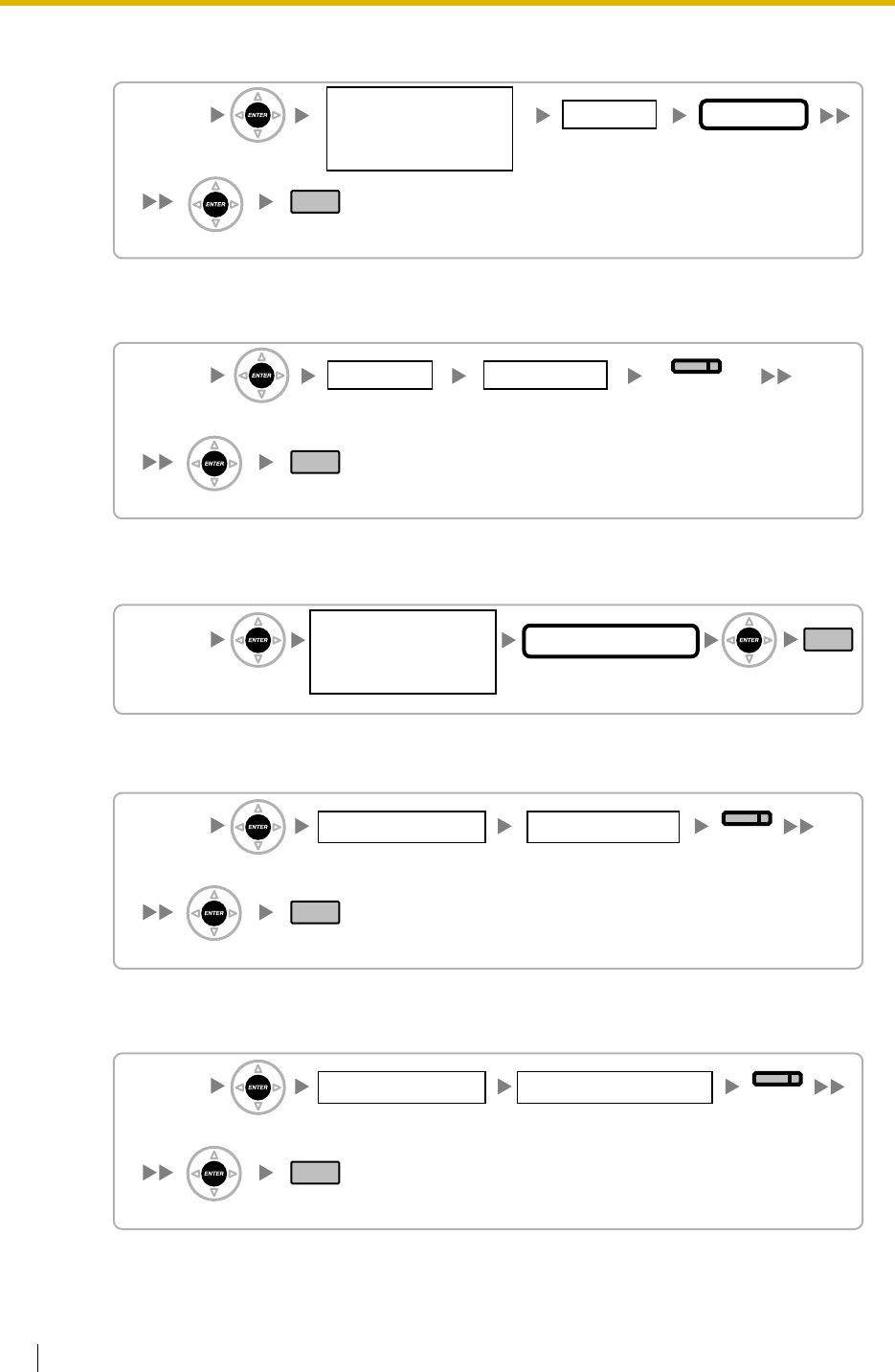
3.3 PT Programming
352 Feature Guide
Queuing Time Table [630]
Sequences in Queuing Time Table [631]
Maximum Number of Agents [632]
User Groups of a Paging Group [640]
External Pagers of a Paging Group [641]
[630]
1 Day/2 Lunch/
3 Break/4 Night None/01–64
Table No.Time No.
END
ENTER
ENTER
01–64
Incoming Call
Distribution
Group No.
[631]
01–16
* Number must be entered in the "N".
Location No.
01–64
Table No.
END
None/Overflow/
Disconnect/"N" × 5 s/
Sequence "N"/OGM "N"
SELECT
ENTER
ENTER
[632]
No Limitation/1–32
Number of Agents
END
ENTER ENTER
01–64
Incoming Call
Distribution
Group No.
[640]
001–032
User Group No.
01–32
Paging Group No.
END
No/Yes
SELECT
ENTER
ENTER
[641]
1–2
External Pager No.
01–32
Paging Group No.
END
SELECT
ENTER
ENTER
No/Yes
deleted:
[KX-TDA100/KX-TDA200]
[KX-TDA30] and its graphic
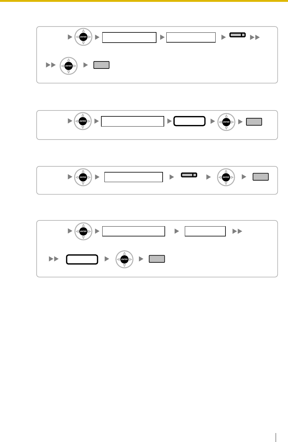
3.3 PT Programming
Feature Guide 353
User Groups of a Pickup Group [650]
VM Group Floating Extension Number [660]
Idle Extension Hunting Type [680]
Idle Extension Hunting Group Member [681]
[650]
001–032
01–64
Pickup Group No.
END
SELECT
ENTER
ENTER
No/Yes
User Group No.
[660]
1–2
VM (DPT) Group No.
1–4 digits END
ENTER ENTER
Extn. No.
[680]
01–64
Hunting Group No.
END
Circular/
Terminate
SELECT
ENTER ENTER
[681]
01–16
Location No.
01–64
Hunting Group No.
1–4 digits END
ENTER
ENTER
Extn. No.
deleted:
[KX-TDA100/KX-TDA200]
[KX-TDA30] and its graphic
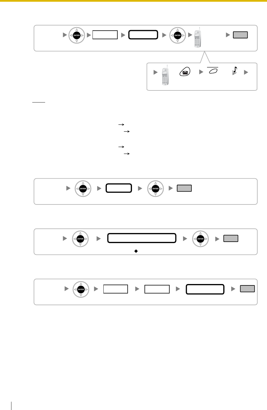
3.3 PT Programming
354 Feature Guide
PS Registration [690]
Note
Please refer to Installation Manual for the PS registration in detail.
With the KX-TDA100/KX-TDA200:
For registering the DECT PS 2.8.7 Connecting a Cell Station to the Hybrid IP-PBX
For registering the 2.4 GHz PS 2.9.7 Connecting a Cell Station to the Hybrid IP-PBX
With the KX-TDA15/KX-TDA30:
For registering the DECT PS 6.7.7 Connecting a Cell Station to the Hybrid IP-PBX
For registering the 2.4 GHz PS 6.8.7 Connecting a Cell Station to the Hybrid IP-PBX
PS Termination [691]
Personal Identification Number (PIN) for PS Registration [692]
CS Status Reference [699]
[690]
001–128
PS No.
KX-TD7690
1–4 digits END
ENTER ENTER
To the PS
operation
below
Extn. No.
Push power
button for 2
seconds.
Push F3
key for 2
seconds.
C.Tone
[691]
001–128
PS No.
END
ENTER ENTER
[692]
1–4 digits
PIN for PS Registration
END
ENTER ENTER
1234
[699]
END
01–11
Slot No.
Reference only
CS Status
ENTER 01–08
Port No.
deleted:
[KX-TDA100/KX-TDA200]
[KX-TDA30] and its graphic
deleted:
[KX-TDA100/KX-TDA200]
[KX-TDA30] and its graphic
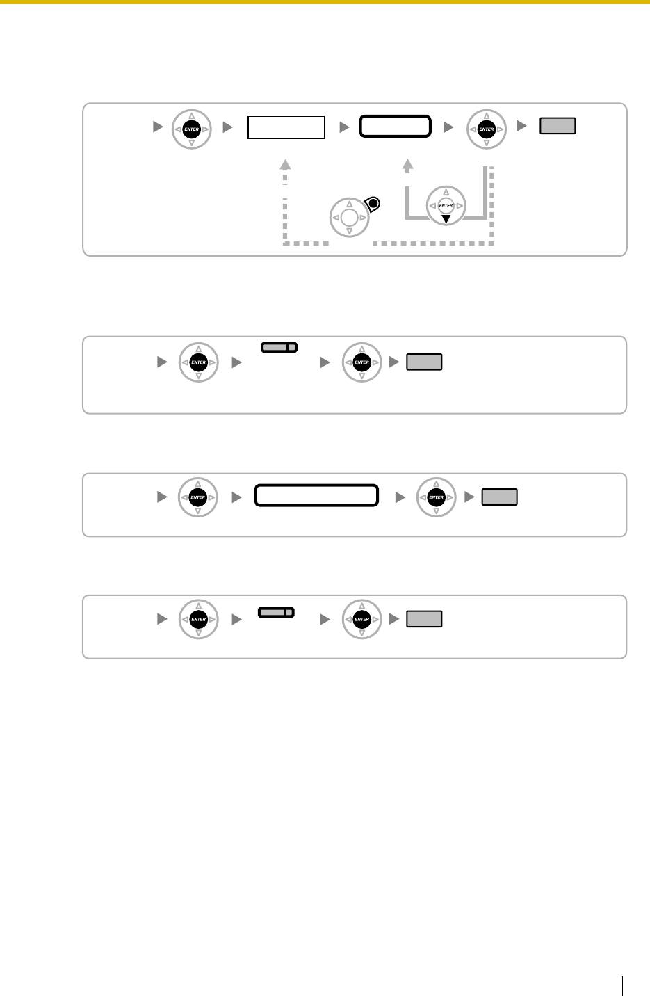
3.3 PT Programming
Feature Guide 355
3.3.9 Resource/Interface Programming
External Pager Floating Extension Number [700]
Music Source Selection for BGM (with the KX-TDA15/KX-TDA30)/
BGM2 (with the KX-TDA100/KX-TDA200) [710]
Music on Hold [711]
Music for Transfer [712]
[700]
1–2
Pager No.
1–4 digits END
(HOLD)
ENTER ENTER
CANCEL NEXT
To the Next Pager No.
To the Desired Pager No.
Extn. No.
[710]
END
External/Internal1/
Internal2
ENTER ENTER
SELECT
(AUTO ANS/
MESSAGE)
[711]
END
Beep/BGM1–2
Music Source No.
ENTER ENTER
[712]
END
Hold Music/
Ring back
SELECT
ENTER ENTER
deleted:
[KX-TDA100/KX-TDA200]
[KX-TDA30] and its graphic
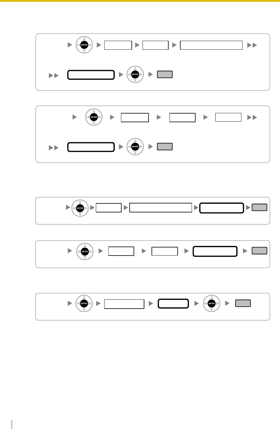
3.3 PT Programming
356 Feature Guide
Doorphone Call Destination [720]
[KX-TDA100/KX-TDA200]
[KX-TDA15/KX-TDA30]
Doorphone Number Reference [729]
[KX-TDA100/KX-TDA200]
[KX-TDA15/KX-TDA30]
Outgoing Message (OGM) Floating Extension Number [730]
[720]
END
1 Day/2 Lunch/
3 Break/4 Night 01–11
Max. 32 digits
Slot No.
1–3 1–4
Card No. and Port No.Time No.
Destination No.
ENTER
ENTER
[720]
END
1 Day/2 Lunch/
3 Break/4 Night 08–09
Max. 32 digits
Slot No.
1–4
Port No.Time No.
Destination No.
ENTER
ENTER
[729]
END
01–11
Slot No.
1–3 1–4 Reference only
Doorphone No.
ENTER
Card No. and Port No.
[729]
END
08–09
Slot No.
Reference only
Doorphone No.
ENTER 1–4
Port No.
[730]
END
01–64
Message No.
1–4 digits
ENTER ENTER
Extn. No.
deleted:
[KX-TDA100/KX-TDA200]
[KX-TDA30] and its graphic
3.3 PT Programming
Feature Guide 357
Outgoing Message (OGM) Name [731]
DISA Security Mode [732]
[731]
END
01–64
Message No.
Max. 20 characters
Name
ENTER ENTER
[732]
END
None/
Trunk/All
SELECT
ENTER ENTER
deleted:
[KX-TDA100/KX-TDA200]
[KX-TDA30] and its graphic
3.3 PT Programming
358 Feature Guide
3.3.10 SMDR & Maintenance Programming
RS-232C Parameter—New Line Code [800]
RS-232C Parameter—Baud Rate [800]
RS-232C Parameter—Word Length [800]
RS-232C Parameter—Parity Bit [800]
RS-232C Parameter—Stop Bit Length [800]
External Modem Control [801]
SMDR Page Length [802]
[800]
END
(HOLD)
CR+LF/CR
SELECT
(AUTO ANS/MESSAGE)
1
Location
ENTER ENTER
[800]
END
2400/4800/9600/
19200/38400/57600/
115200 bps
2
Location
ENTER ENTER
SELECT
[800]
END
7/8 bits
SELECT
3
Location
ENTER ENTER
[800]
END
None/Mark/
Space/Even/Odd
SELECT
4
Location
ENTER ENTER
[800]
END
1 bit/2 bits
SELECT
5
Location
ENTER ENTER
[801]
END
ENTER ENTER
Command No.
1–5
[802]
END
4–99 lines
Page length
ENTER ENTER
3.3 PT Programming
Feature Guide 359
SMDR Skip Perforation [803]
SMDR Outgoing Call Printing [804]
SMDR Incoming Call Printing [805]
Remote Programming [810]
Modem Floating Extension Number [811]
ISDN Remote Floating Extension Number [812]
[803]
END
0–95 lines
Skip Perforation
ENTER ENTER
[804]
END
No print/Print
SELECT
ENTER ENTER
[805]
END
No print/Print
SELECT
ENTER ENTER
Disable/
Enable
SELECT
[810]
END
ENTER ENTER
[811]
END
1–4 digits
ENTER ENTER
Extn. No.
[812]
END
1–4 digits
ENTER ENTER
Extn. No.
3.3 PT Programming
360 Feature Guide
3.3.11 Card Programming
Slot Card Type Reference [900]
Slot Card Deletion [901]
Slot Card Reset [902]
OPB3 Option Card Type Reference [910] (KX-TDA100/KX-TDA200
only)
OPB3 Option Card Deletion [911] (KX-TDA100/KX-TDA200 only)
[900]
01–11 Reference only
Slot No. Card Name
END
(HOLD)
ENTER
[901]
END
01–11
ENTER
Slot No. Delete
ENTER
To the Next Slot No.
To the Desired Slot No.
CANCEL NEXT
Confirming the
deleting operation.
[902]
END
01–11
Slot No. Reset
ENTER ENTER
Confirming the
resetting operation.
[910]
END
01–11
Slot No.
Reference only
Option Card Type
ENTER 1–3
Card No.
[911]
END
01–11
Slot No.
1–3
Card No. Delete
ENTER ENTER
Confirming the
deleting operation.

Feature Guide 361
Section 4
Appendix
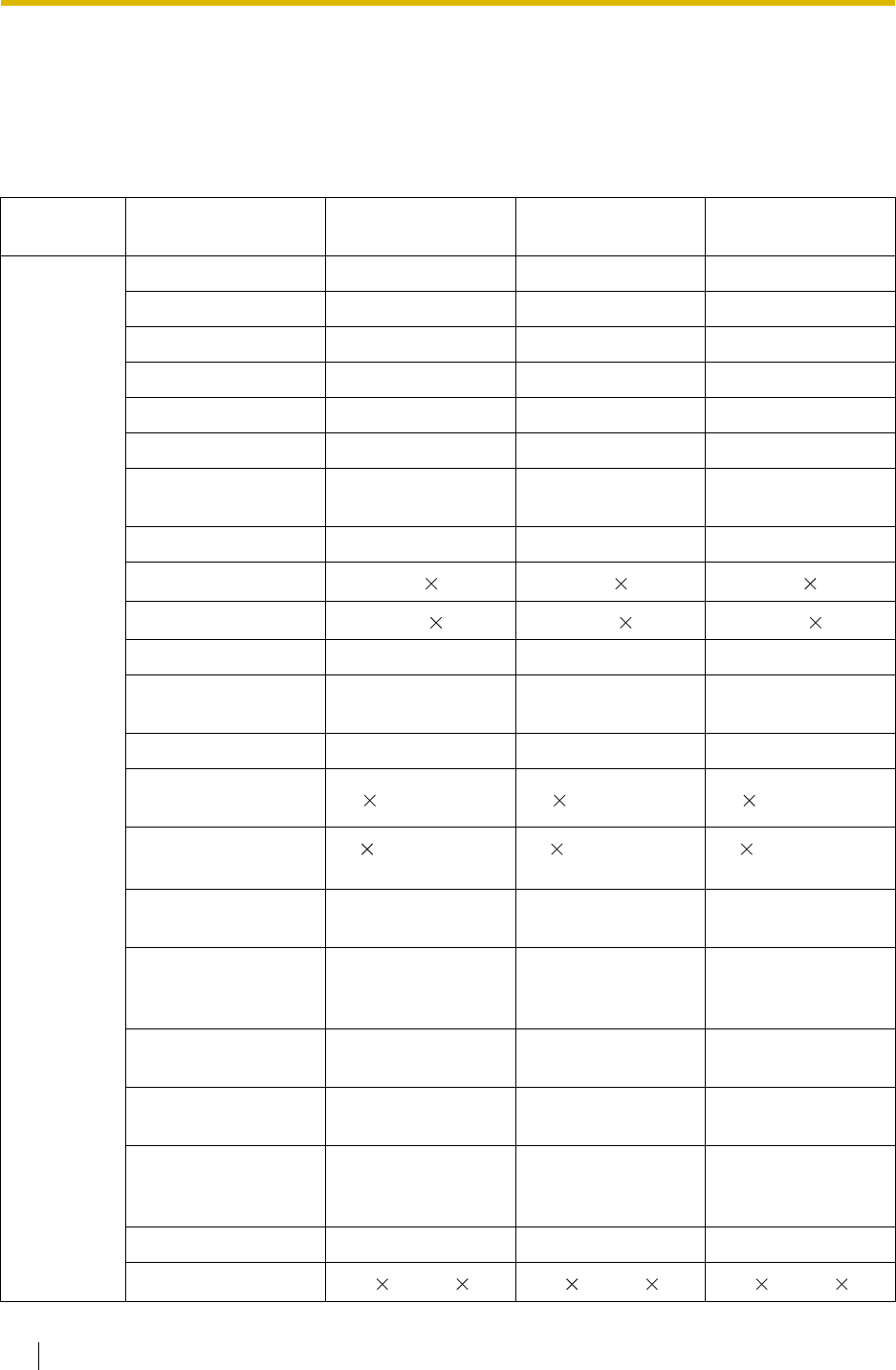
4.1 Capacity of System Resources
362 Feature Guide
4.1 Capacity of System Resources
4.1.1 Capacity of System Resources
Category Item KX-TDA15 KX-TDA30 KX-TDA100/KX-
TDA200
System Tenant 8 8 8
COS 646464
Trunk Group 64 64 64
User Group 323232
Paging Group 32 32 32
Call Pickup Group 64 64 64
Incoming Call
Distribution Group 64 (32 extensions/
group) 64 (32 extensions/
group) 64 (32 extensions/
group)
PS Ring Group 32 32 32
VM (DPT) Group 1 VPS 8 ch 1 VPS 8 ch 2 VPSs 24 ch
VM (DTMF) Group 2 groups 24 ch 2 groups 24 ch 2 groups 32 ch
Queuing Time Table646464
Idle Extension Hunting
Group 64 (16 extensions/
group) 64 (16 extensions/
group) 64 (16 extensions/
group)
Broadcasting Group — 8 8
Absent Message—
System 8 16 characters 8 16 characters 8 16 characters
Absent Message—
Extension 1 16 characters/
extn. 1 16 characters/
extn. 1 16 characters/
extn.
Message Waiting—PT
+ SLT 256 256 512
Message Waiting—PS
+ Incoming Call
Distribution Group 256 256 256
Number of Characters
of Name 20 20 20
Extension Number
Digits 1 – 4 1 – 4 1 – 4
Extension Personal
Identification Number
(PIN) 10 digits/extn. 10 digits/extn. 10 digits/extn.
Call Park Zone 100 100 100
Conference 3 10 – 8 4 3 10 – 8 4 3 10 – 8 4
deleted:
column for KX-TDA100

4.1 Capacity of System Resources
Feature Guide 363
System Verified Code 4 digits, 1 000 entries 4 digits, 1 000 entries 4 digits, 1 000 entries
Verified Code
Personal Identification
Number (PIN)
10 digits, 1 000
entries 10 digits, 1 000
entries 10 digits, 1 000
entries
Special Carrier Code 16 digits, 20 entries 16 digits, 20 entries 16 digits, 20 entries
Host PBX Access
Code 10 digits,
10 entries/trunk
group
10 digits,
10 entries/trunk
group
10 digits,
10 entries/trunk
group
DDI/DID Table 32 digits, 1 000
entries 32 digits, 1 000
entries 32 digits, 1 000
entries
SMDR 200 calls 200 calls 200 calls
Dialling Emergency Call 32 digits, 10 entries 32 digits, 10 entries 32 digits, 10 entries
Quick Dialling 4 digits, 80 entries 4 digits, 80 entries 4 digits, 80 entries
System Speed Dialling 32 digits, 1 000
entries 32 digits, 1 000
entries 32 digits, 1 000
entries
Personal Speed
Dialling 32 digits,
10 entries/extn. 32 digits,
10 entries/extn. 32 digits,
10 entries/extn.
One-touch Dialling 32 digits 32 digits 32 digits
Hot Line 32 digits 32 digits 32 digits
Key Pad Protocol Dial
(ISDN Service
Access) 32 digits 32 digits 32 digits
Redial 32 digits 32 digits 32 digits
ARS Routing Plan Table 16 entries 16 entries 16 entries
Leading Number Table 16 digits, 1 000
entries 16 digits, 1 000
entries 16 digits, 1 000
entries
Leading Number
Exception Table 16 digits, 200 entries 16 digits, 200 entries 16 digits, 200 entries
ARS Carrier 10 10 10
Itemised Billing Code 10 digits 10 digits 10 digits
Authorisation Code 10 digits 10 digits 10 digits
Networking TIE Line Routing and
Modification Table 32 entries 32 entries 32 entries
Leading Number 3 digits 3 digits 3 digits
PBX Code 7 digits 7 digits 7 digits
Category Item KX-TDA15 KX-TDA30 KX-TDA100/KX-
TDA200
deleted:
column for KX-TDA100
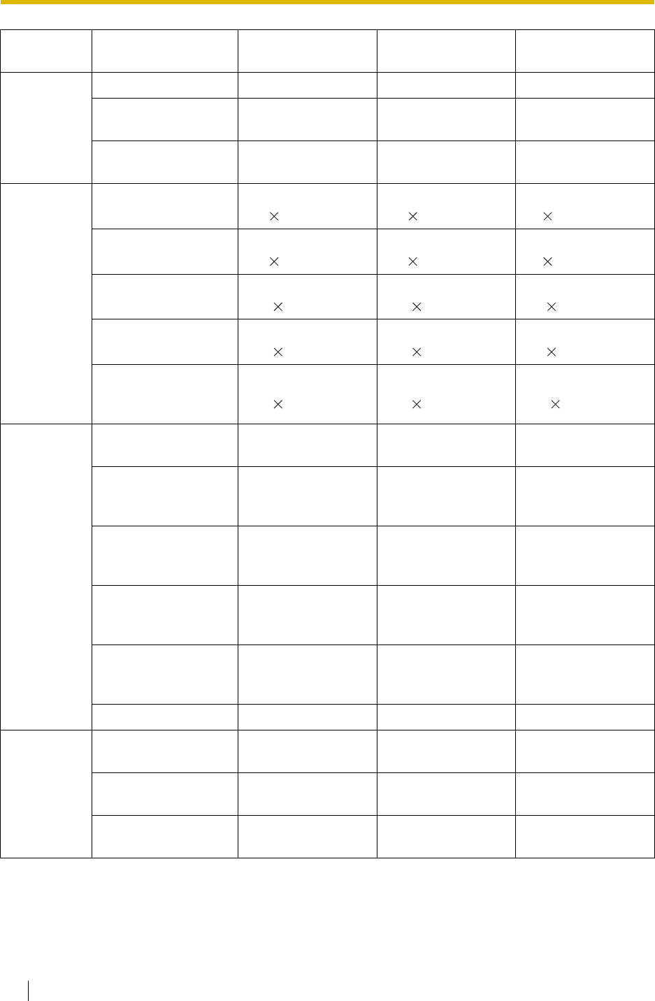
4.1 Capacity of System Resources
364 Feature Guide
TRS/Barring TRS/Barring Level 7 7 7
TRS/Barring Denied
Code 16 digits,
100 entries/level 16 digits,
100 entries/level 16 digits,
100 entries/level
TRS/Barring
Exception Code 16 digits,
100 entries/level 16 digits,
100 entries/level 16 digits,
100 entries/level
Call Log Outgoing Call Log—
PT 100 logs/extn.
5 52 logs/PBX
100 logs/extn.
5 52 logs/PBX
100 logs/extn.
5 304 logs/PBX
Outgoing Call Log—
PS 100 logs/extn.
5 28 logs/PBX
100 logs/extn.
5 28 logs/PBX
100 logs/extn.
5 128 logs/PBX
Incoming Call Log—
PT 100 logs/extn.
10 52 logs/PBX
100 logs/extn.
10 52 logs/PBX
100 logs/extn.
10 304 logs/PBX
Incoming Call Log—
PS 100 logs/extn.
10 28 logs/PBX
100 logs/extn.
10 28 logs/PBX
100 logs/extn.
10 128 logs/PBX
Incoming Call Log—
Incoming Call
Distribution Group
100 logs/group
10 64 logs/PBX
100 logs/group
10 64 logs/PBX
100 logs/group
10 64 logs/PBX
Password System Password for
Installer 4 – 10 characters 4 – 10 characters 4 – 10 characters
System Password for
Administrator—for PC
Programming 4 – 10 characters 4 – 10 characters 4 – 10 characters
System Password for
User—for PC
Programming 4 – 10 characters 4 – 10 characters 4 – 10 characters
System Password for
Administrator—for PT
Programming 4 – 10 digits 4 – 10 digits 4 – 10 digits
System Password for
User—for PT
Programming 4 – 10 digits 4 – 10 digits 4 – 10 digits
Manager Password 4 – 10 digits 4 – 10 digits 4 – 10 digits
Programmer
Code Installer Level
Programmer Code 4 – 16 characters 4 – 16 characters 4 – 16 characters
Administrator Level
Programmer Code 4 – 16 characters 4 – 16 characters 4 – 16 characters
User Level
Programmer Code 0 – 16 characters 0 – 16 characters 0 – 16 characters
Category Item KX-TDA15 KX-TDA30 KX-TDA100/KX-
TDA200
deleted:
column for KX-TDA100
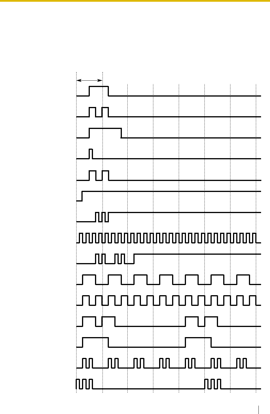
4.2 Tones/Ring Tones
Feature Guide 365
4.2 Tones/Ring Tones
4.2.1 Tones/Ring Tones
Tone Patterns (Default)
Confirmation Tone 1
1 s
Confirmation Tone 2
Confirmation Tone 3
Confirmation Tone 4
Dial Tone 1
Dial Tone 2
Dial Tone 3
Dial Tone 4
Busy Tone
Reorder Tone
Ringback Tone 1
Ringback Tone 2
Trunk Call Limit Warning
Tone
DND Tone
Confirmation Tone 5
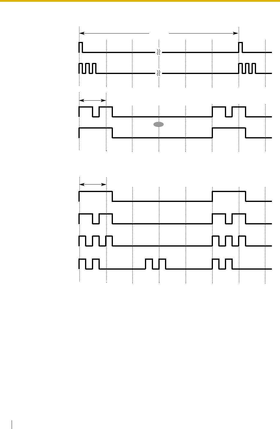
4.2 Tones/Ring Tones
366 Feature Guide
Tone Patterns (Default)
Hold Alarm Tone
15 s
Call Waiting Tone 1
Single
Double
Triple
S-Double
1 s
Call Waiting Tone 2
Ring Tone Patterns (Default)
OR
1 s

4.3 List of Abbreviations
Feature Guide 367
4.3 List of Abbreviations
4.3.1 List of Abbreviations
A
AA Automated Attendant
ANI Automatic Number Identification
AOC Advice of Charge
APT Analogue Proprietary Telephone
ARS Automatic Route Selection
B
BGM Background Music
BRI Basic Rate Interface
C
CCBS Completion of Calls to Busy Subscriber
CF Call Forwarding—by ISDN
CLI Calling Line Identification
CLIP Calling Line Identification Presentation
CLIR Calling Line Identification Restriction
CNIP Calling Name Identification Presentation
CNIR Calling Name Identification Restriction
COLP Connected Line Identification Presentation
COLR Connected Line Identification Restriction
CONP Connected Name Identification Presentation
CONR Connected Name Identification Restriction
COS Class of Service
CPC Calling Party Control
CS Cell Station
CT Call Transfer—by ISDN
CTI Computer Telephony Integration
D
DDI Direct Dialling In
DID Direct Inward Dialling
DIL Direct In Line
DISA Direct Inward System Access
DND Do Not Disturb
DPT Digital Proprietary Telephone
DSS Direct Station Selection
DTMF Dual Tone Multi-Frequency
E
EFA External Feature Access
F
FWD Call Forwarding
G
G-CO Group-CO
I
ICD Incoming Call Distribution
IRNA Intercept Routing—No Answer
ISDN Integrated Services Digital Network
L
L-CO Loop-CO
LCS Live Call Screening
LED Light Emitting Diode
M
MCID Malicious Call Identification
MSN Multiple Subscriber Number
O
OGM Outgoing Message
OHCA Off-hook Call Announcement
OPX Off Premise Extension
P
P-MP Point-to-multipoint
P-P Point-to-Point
PIN Personal Identification Number
PRI Primary Rate Interface
PS Portable Station
PT Proprietary Telephone
S
S-CO Single-CO
SLT Single Line Telephone
SMDR Station Message Detail Recording

4.3 List of Abbreviations
368 Feature Guide
T
TAFAS Trunk Answer from Any Station
TEI Terminal Endpoint Identifier
TRG Trunk Group
TRS/Barring Toll Restriction/Call Barring
U
UCD Uniform Call Distribution
V
VM Voice Mail
VoIP Voice over Internet Protocol
VPN Virtual Private Network
VPS Voice Processing System
X
XDP eXtra Device Port

4.4 Revision History
Feature Guide 369
4.4 Revision History
4.4.1 KX-TDA100/KX-TDA200 Version 1.1
New Contents
• 1.5.4.2 Emergency Call
• 1.6.1.4 Last Number Redial
• 1.6.1.5 Speed Dialling—Personal/System
• 1.10.9 Parallelled Telephone
• 1.15 Broadcasting Features (KX-TDA30/KX-TDA100/KX-TDA200 only)
• 1.20.1.8 Three-party Conference (3PTY)—by ISDN
• 1.23.3 Voice Mail DPT (Digital) Integration
Changed Contents
• 1.2.2.2 Group Call Distribution
• 1.4.1.3 Call Pickup
• 1.14.1 Paging
• 1.19.1 Fixed Buttons
• 1.19.3 LED Indication
• 1.24.1 Portable Station (PS) Connection
CLIP Number Notification
Outgoing Call Log Display by REDIAL Button
System Speed Dialling Display by AUTO DIAL/STORE Button
Digital XDP
DID Number Notification to the VPS
[How the Group Call Waiting Feature Activates]
[Directed Call Pickup]
Paging Group
FLASH/RECALL
Light Pattern of the Message/Ringer Lamp
Light Pattern of the Corresponding Extension Status Button
Handover

4.4 Revision History
370 Feature Guide
• 1.25.1 Station Message Detail Recording (SMDR)
• 2.1.1 Extension Port Configuration
• 2.2.4 Time Service
• 3.3.1 Programming Instructions
• 3.3.4 Time Programming
• 4.1.1 Capacity of System Resources
CD (Condition Code)
Features Using Time Service
Entering Characters
Intercept Time [203]
DISA Intercept Time [211]

4.4 Revision History
Feature Guide 371
4.4.2 KX-TDA30 Version 1.1
New Contents
• 1.15 Broadcasting Features (KX-TDA30/KX-TDA100/KX-TDA200 only)
• 1.20.1.8 Three-party Conference (3PTY)—by ISDN
• 1.23.3 Voice Mail DPT (Digital) Integration
Changed Contents
• 1.4.1.3 Call Pickup
• 1.10.9 Parallelled Telephone
• 1.14.1 Paging
• 1.19.3 LED Indication
• 1.24.1 Portable Station (PS) Connection
• 1.25.1 Station Message Detail Recording (SMDR)
• 2.2.4 Time Service
• 3.3.1 Programming Instructions
• 3.3.4 Time Programming
• 4.1.1 Capacity of System Resources
DID Number Notification to the VPS
[Directed Call Pickup]
Digital XDP
Paging Group
Light Pattern of the Message/Ringer Lamp
Light Pattern of the Corresponding Extension Status Button
Handover
CD (Condition Code)
Features Using Time Service
Entering Characters
Intercept Time [203]
DISA Intercept Time [211]

4.4 Revision History
372 Feature Guide

Feature Guide 373
Index

Index
374 Feature Guide
A
Absent Message
170
Absent Message [008]
330
Account Code Entry
75
Account Code Mode [508]
347
Administrative Information Output Features
230
Advice of Charge (AOC)
188
Alternate Calling—Ring/Voice
72
Alternate Receiving/Calling Mode (Ring/Voice) Override
69
Alternate Receiving—Ring/Voice
72
ANI —> Automatic Number Identification (ANI)
160
Answering Features
66
Answering Features—SUMMARY
66
AOC —> Advice of Charge (AOC)
188
Appendix
361
ARS Carrier Access Code [353]
339
ARS Carrier Name [350]
339
ARS Exception Number [325]
338
ARS Leading Number [321]
338
ARS Mode [320]
337
ARS Removed Number of Digits for Carrier Access [352]
339
ARS Routing Plan Table (1–16) [331–346]
339
ARS Routing Plan Table Number [322]
338
ARS Routing Plan Time Table [330]
338
ARS Trunk Group for Carrier Access [351]
339
ARS —> Automatic Route Selection (ARS)
113
Audible Tone Features
245
Authorisation Code
117
Automatic Call Hold
132
Automatic Call Park
134
Automatic Callback Busy (Camp-on)
94
Automatic Extension Release
71
Automatic Log-out
55
Automatic Number Identification (ANI)
160
Automatic Privacy
140
Automatic Redial
90
Automatic Redial Interval [206]
335
Automatic Redial Repeat Times [205]
335
Automatic Route Selection (ARS)
113
Automatic Route Selection (ARS) Features
113
Automatic Setup
303
Automatic Station Release —> Automatic Extension Release
71
B
Background Music (BGM)
150
Basic Programming
329
BGM —> Background Music (BGM)
150
BGM—External
150
Boss & Secretary feature
63
BRI Configuration [426]
342
BRI DIL/DDI/MSN Selection [421]
342
BRI Layer 1 Active Mode [424]
342
BRI Layer 2 Active Mode [425]
342
BRI Network Type [420]
342
BRI Subscriber Number [422]
342
BRI TEI Mode [427]
343
Broadcasting (KX-TDA30/KX-TDA100/KX-TDA200 only)
143
Broadcasting Features (KX-TDA30/KX-TDA100/KX-TDA200 only)
143
Broadcasting Group
143
Budget Management
107
Built-in Small Call Centre Features
4
Busy Line/Busy Party Features
94
Busy on Busy
53
Busy Station Signalling (BSS) —> Call Waiting
38
Buttons and Functions
324
C
Call Directory—Extension Dialling
72
Call Directory—Speed Dialling
91
Call Duration Count Starting Time for LCOT [208]
336
Call Forwarding (CF)—by ISDN (P-MP)
189
Call Forwarding (CF)—by ISDN (P-P)
191
Call Forwarding (CF)—by QSIG
272
Call Forwarding (FWD)
61
Call Forwarding (FWD)/Do Not Disturb (DND)
58
Call Forwarding (FWD)/Do Not Disturb (DND) Features
58
Call Forwarding (FWD)/Do Not Disturb (DND)—SUMMARY
58
Call Forwarding to Trunk [504]
346
Call Forwarding—No Answer Time [605]
349
Call Handling Features
15
Call Hold
132
Call Hold (HOLD)—by ISDN
193
Call Hold Retrieve Deny
132
Call Monitor
96
Call Park
134
Call Park Recall
134
Call Park Retrieve Deny
134
Call Pickup
68
Call Splitting
135
Call Transfer
130
Call Transfer (CT)—by ISDN
194
Call Transfer (CT)—by QSIG
274
Call Transfer to Trunk [503]
346
Call Transfer with Announcement
130
Call Transfer without Announcement
130
Call Transfer—Screened —> Call Transfer with Announcement
130
Call Transfer—Unscreened —> Call Transfer without Announcement
130
Call Waiting
38
Call Waiting Caller ID (Visual Caller ID)
38
Call Waiting Tone
99
Caller ID
160
Caller ID Features
160
Caller ID Signal Type [490] (KX-TDA30/KX-TDA100/KX-TDA200
only)
344
Caller ID to SLT Port
160
Calling Line Identification (CLI) Distribution
27
Calling Line Identification Presentation (CLIP)
160
Calling Party Control (CPC) Signal Detection
129
Calling/Connected Line Identification Presentation (CLIP/COLP)
186
Calling/Connected Line Identification Presentation (CLIP/COLP) and
Calling/Connected Name Identification Presentation (CNIP/
CONP)—by QSIG
270
Calling/Connected Line Identification Restriction (CLIR/COLR)
187
Capacity of System Resources
362
Card Programming
360

Index
Feature Guide 375
CCBS —> Completion of Calls to Busy Subscriber (CCBS)
197
CCBS —> Completion of Calls to Busy Subscriber (CCBS)—by
QSIG
276
CF —> Call Forwarding (CF)—by ISDN (P-MP)
189
CF —> Call Forwarding (CF)—by ISDN (P-P)
191
CF —> Call Forwarding (CF)—by QSIG
272
Charge Margin [010]
331
Charge Meter
236
Charge Rate per Unit [012]
331
Charge Tax [011]
331
Circular Hunting
40
Class of Service (COS)
283
Class of Service [602]
349
CLI —> Calling Line Identification (CLI) Distribution
27
CLIP —> Calling Line Identification Presentation (CLIP)
160
CLIP —> Calling/Connected Line Identification Presentation (CLIP/
COLP) and Calling/Connected Name Identification Presentation
(CNIP/CONP)—by QSIG
270
CLIP/COLP Number [606]
350
CLIR —> Calling/Connected Line Identification Restriction (CLIR/
COLR)
187, 271
CNIP —> Calling/Connected Line Identification Presentation (CLIP/
COLP) and Calling/Connected Name Identification Presentation
(CNIP/CONP)—by QSIG
270
CNIR —> Calling/Connected Name Identification Restriction (CNIR/
CONR)
271
COLP —> Calling/Connected Line Identification Presentation (CLIP/
COLP)
186
COLP —> Calling/Connected Line Identification Presentation (CLIP/
COLP) and Calling/Connected Name Identification Presentation
(CNIP/CONP)—by QSIG
270
COLR —> Calling/Connected Line Identification Restriction (CLIR/
COLR)
187, 271
Completion of Calls to Busy Subscriber (CCBS)
197
Completion of Calls to Busy Subscriber (CCBS)—by QSIG
276
Computer Telephony Integration (CTI)
278
Computer Telephony Integration (CTI) Features
4, 278
Conference
138
Conference Call
143
Conference Features
137
Conference Features—SUMMARY
137
Confirmation Tone
246
CONP —> Calling/Connected Line Identification Presentation (CLIP/
COLP) and Calling/Connected Name Identification Presentation
(CNIP/CONP)—by QSIG
270
CONR —> Calling/Connected Name Identification Restriction (CNIR/
CONR)
271
Console Paired Telephone [007]
330
Consultation Hold
95, 96, 124, 135, 227
Conversation Features
118
COS Programming
346
COS —> Class of Service (COS)
283
CPC —> Calling Party Control (CPC) Signal Detection
129
CS Status Reference [699]
354
CT —> Call Transfer (CT)—by ISDN
194
CT —> Call Transfer (CT)—by QSIG
274
CTI —> Computer Telephony Integration (CTI)
278
Currency [131]
334
D
Data Line Security
122
Date & Time [000]
329
DDI —> Direct Inward Dialling (DID)/Direct Dialling In (DDI)
21
Decimal Point Position for Currency [130]
334
Delayed Ringing
46
Denied Code Tables
102
Destination for Overflow Time Expiration [625]
351
Destination When All Busy [627]
351
Dial Tone
245
Dial Tone Transfer
109
Dial Type Selection
76
Dialling Digit Restriction during Conversation
125
DID Destination [453]
343
DID Name [452]
343
DID Number [451]
343
DID —> Direct Inward Dialling (DID)/Direct Dialling In (DDI)
21
Digital XDP
126
DIL 1:1 Destination [450]
343
DIL —> Direct In Line (DIL)
19
Direct In Line (DIL)
19
Direct Inward Dialling (DID)/Direct Dialling In (DDI)
21
Direct Inward System Access (DISA)
153
Direct One-touch Answering
66
Direct Trunk Access
84
Directed Call Pickup
68
DISA Built-in Automated Attendant Number (DISA AA Service)
153
DISA Continuous Signal Detection [476]
344
DISA Cyclic Signal Detection [477]
344
DISA Delayed Answer Time [209]
336
DISA Intercept Routing—Busy/DND
154
DISA Intercept Routing—No Answer
155
DISA Intercept Time [211]
336
DISA Intercept—No Dial
153
DISA Security Mode [732]
357
DISA Security Mode and Available Features
153
DISA Silence Detection [475]
344
DISA Trunk-to-Trunk Call Prolong Time [210]
336
DISA —> Direct Inward System Access (DISA)
153
Display Information
180
DND Override
65
DND Override [507]
347
DND —> Call Forwarding (FWD)/Do Not Disturb (DND)
58
Do Not Disturb (DND)
65
Door Open
148
Door Open Duration Time [207]
335
Doorphone Call
146
Doorphone Call Destination [720]
356
Doorphone Number Reference [729]
356
E
E1 Line Service (KX-TDA100/KX-TDA200 only)
201
E1 Line Service Features (KX-TDA100/KX-TDA200 only)
201
EFA —> External Feature Access (EFA)
124
Electronic Station Lockout —> Extension Lock
108
Emergency Call
74
Emergency Number [304]
337
Entering Characters
326
Entering System Programming Mode
325

Index
376 Feature Guide
Exception Code Tables
102
Exclusive Call Hold
132
Executive Busy Override
95
Executive Busy Override [505]
347
Executive Busy Override Deny
95
Executive Busy Override Deny [506]
347
Extension Controlling Features
239
Extension Feature Clear
241
Extension Intercept Destination [604]
349
Extension Lock
108
Extension Name [004]
330
Extension Number [003]
329
Extension Personal Identification Number (PIN)
239
Extension Personal Identification Number (PIN) [005]
330
Extension PIN Lock
239
Extension Port Configuration
282
Extension Programming
349
Extension-to-Trunk Call Duration
125
Extension-to-Trunk Call Duration [472]
344
External Feature Access (EFA)
124
External Modem Control [801]
358
External Pager Floating Extension Number [700]
355
External Pagers of a Paging Group [641]
352
EXtra Device Port (XDP)
282
EXtra Device Port (XDP) Mode [600]
349
F
Fault Recovery/Diagnostics
312
Feature Guide References
2
Feature Highlights
4
Fixed Buttons
171
Flash/Recall/Terminate
123
Flexible Buttons
174
Flexible Numbering [100]
332
Flexible Numbering/Fixed Numbering
305
Floating Extension
310
Floating Station —> Floating Extension
310
Full One-touch Dialling
88
FWD —> Call Forwarding (FWD)/Do Not Disturb (DND)
58
FWD—All Calls
61
FWD—Busy
61
FWD—Busy/No Answer
61
FWD—Follow Me
61
FWD—No Answer
61
G
Group
284
Group Call Distribution
46
Group Call Pickup
68
H
Handover
220
Handset/Headset Selection —> Headset Operation
121
Hands-free Answerback
69
Hands-free Operation
118
Headset Operation
121
Hold Recall
132
Hold Recall Time [200]
335
Holding Features
132
Host PBX Access Code (Access Code to the Telephone Company from
a Host PBX)
79
Host PBX Access Code [471]
344
Hot Line
93
Hot Line Waiting Time [204]
335
Hurry-up Transfer —> Manual Queue Redirection
50
I
Idle Extension Hunting
40
Idle Extension Hunting Group Member [681]
353
Idle Extension Hunting Type [680]
353
Idle Line Access (Local Access)
84
Idle Line Access (Local Access) [103]
333
Idle Line Preference
83
Incoming Call Distribution Group Delayed Ringing [621]
350
Incoming Call Distribution Group Distribution Method [624]
350
Incoming Call Distribution Group Features
42
Incoming Call Distribution Group Features—SUMMARY
42
Incoming Call Distribution Group Floating Extension Number [622]
350
Incoming Call Distribution Group Member [620]
350
Incoming Call Distribution Group Name [623]
350
Incoming Call Features
16
Incoming Call Indication Features
36
Incoming Call Indication Features—SUMMARY
36
Incoming Call Log
165
Incoming Call Log Display Lock
166
Incoming Call Queue Monitor
56
Incoming Trunk Call Features
16
Incoming Trunk Call Features—SUMMARY
16
Installation Manual References
2
Installing and Starting the Maintenance Console
319
Integrated Services Digital Network (ISDN)
182
Integrated Services Digital Network (ISDN) Service Features
182
Integrated Services Digital Network (ISDN)—SUMMARY
182
Intercept Routing
29
Intercept Routing—Busy/DND
29
Intercept Routing—No Answer (IRNA)
29
Intercept Routing—No Destination
32
Intercept Routing—Overflow in an Incoming Call Distribution Group
52
Intercept Time [203]
335
Intercom Call
72
Internal Call Block
34
Internal Call Features
33
Internal Call Features—SUMMARY
33
Interrupt Redial
90
Introduction
318
IRNA —> Intercept Routing—No Answer (IRNA)
29
ISDN Centrex Service
184
ISDN Extension
198
ISDN Remote Floating Extension Number [812]
359
ISDN Service Access by Keypad Protocol
200
ISDN —> Integrated Services Digital Network (ISDN)
182
Itemised Billing Code
117
K
KX-TDA100/KX-TDA200 Version 1.1
369
KX-TDA30 Version 1.1
371

Index
Feature Guide 377
L
Last Number Redial
90
LCOT CPC Signal Detection Time—Incoming [414]
341
LCOT CPC Signal Detection Time—Outgoing [413]
341
LCOT Dialling Mode [410]
340
LCOT Disconnect Time [418]
341
LCOT DTMF Minimum Duration [412]
341
LCOT Flash/Recall Time [417]
341
LCOT Pause Time [416]
341
LCOT Pulse Rate [411]
340
LCOT Reverse Circuit [415]
341
LCOT/BRI Trunk Connection [400]
340
LCOT/BRI Trunk Group Number [402]
340
LCOT/BRI Trunk Name [401]
340
LCOT/BRI Trunk Number Reference [409]
340
LCS —> Live Call Screening (LCS)
217
LED Indication
177
Line Preference Override
83
Line Preference—Incoming
67
Line Preference—Outgoing
83
List of Abbreviations
367
Live Call Screening (LCS)
217
Local Alarm Information
315
Log-in/Log-out
54
Log-in/Log-out Monitor
55
M
Main Processing (MPR) Software Version Reference [190]
334
Making Call Features
70
Malicious Call Identification (MCID)
196
Manager Assignment [511]
347
Manager Features
295
Manager Password [112]
333
Manual Queue Redirection
50
Maximum Number of Agents [632]
352
MCID —> Malicious Call Identification (MCID)
196
Memory Dialling Features
86
Memory Dialling Features—SUMMARY
86
Message Features
167
Message Waiting
167
Modem Floating Extension Number [811]
359
MSN —> Multiple Subscriber Number (MSN) Ringing Service
24
Multiple FWD
63
Multiple Subscriber Number (MSN) Ringing Service
24
Music for Transfer [712]
355
Music on Hold
136
Music on Hold [711]
355
Music Source Selection for BGM (with the KX-TDA15/KX-TDA30)/BGM2
(with the KX-TDA100/KX-TDA200) [710]
355
Mute
120
N
Networking Features
4, 247
No Line Preference
67, 83
O
Off-hook Call Announcement (OHCA)
100
Off-hook Monitor
119
OGM —> Outgoing Message (OGM)
151
OHCA —> Off-hook Call Announcement (OHCA)
100
One-touch Dialling
88
One-touch Transfer
131
OPB3 Option Card Deletion [911] (KX-TDA100/KX-TDA200 only)
360
OPB3 Option Card Type Reference [910] (KX-TDA100/KX-TDA200
only)
360
Operator Assignment [006]
330
Operator Call
294
Operator Features
294
Optional Device Features
146
Outgoing Call Log
90
Outgoing Message (OGM)
151
Outgoing Message (OGM) Floating Extension Number [730]
356
Outgoing Message (OGM) Name [731]
357
Overflow Feature
52
Overflow Time [626]
351
P
Paging
141
Paging Deny
141
Paging DND
65, 142
Paging Features
141
Paging Group
141
Parallelled Telephone
126
Parallelled Telephone Features
5
Password Security
318
Pause Insertion
78
Pay Tone Signal Type [491] (KX-TDA100/KX-TDA200 only)
345
PC Phone/PC Console Features
5
PC Programming
297, 319
Permission for Door Open Access [512]
348
Personal Identification Number (PIN) for PS Registration [692]
354
Personal Speed Dialling Display Lock
91
Pickup Dialling —> Hot Line
93
PIN —> Extension Personal Identification Number (PIN)
239
PIN —> Verified Code Personal Identification Number (PIN)
111
Portable Station (PS) Connection
220
Portable Station (PS) Features
5, 220
Power Failure Connections
312
Power Failure Restart
314
Power Failure Transfer (KX-TDA30/KX-TDA100/KX-TDA200 only)
312
Predialling
70
Prime Line Preference
67, 83
Priority Hunting
46
Privacy Release
140
Programming Instructions
317, 324
Programming Mode Limitation [516]
348
Programming Structure
325
Proprietary Telephone (PT) Features
171
PS Directory
225
PS Feature Buttons
226
PS Registration [690]
354
PS Ring Group
222
PS Termination [691]
354
PS —> Portable Station (PS) Features
220
PT Programming
300, 324

Index
378 Feature Guide
PT —> Proprietary Telephone (PT) Features
171
Pulse to Tone Conversion
76
Q
QSIG Network
268
QSIG Network—SUMMARY
268
Queuing Call Capacity [628]
351
Queuing Feature
49
Queuing Hurry-up Level [629]
351
Queuing Time Table [630]
352
Quick Dialling
92
Quick Setup
302
R
Receiving Group Features
40
Remote Control
56
Remote Extension Control by User
244
Remote Extension Lock
108
Remote Programming [810]
359
Remote Station Control by User —> Remote Extension Control by
User
244
Remote Station Lock Control —> Remote Extension Lock
108
Required Telephone/Extension
324
Resource/Interface Programming
355
Reverse Circuit
77
Revision History
369
Ring
46
Ring Tone Pattern Selection
37
Ringing Line Preference
67
RS-232C Parameter—Baud Rate [800]
358
RS-232C Parameter—New Line Code [800]
358
RS-232C Parameter—Parity Bit [800]
358
RS-232C Parameter—Stop Bit Length [800]
358
RS-232C Parameter—Word Length [800]
358
S
S-CO Line Access
84
Second Call Notification to Busy Extension
97
Second Call Notification to Busy Extension—SUMMARY
97
Seizing a Line Features
82
Seizing a Line Features—SUMMARY
82
Sequences in Queuing Time Table [631]
352
Slot Card Deletion [901]
360
Slot Card Reset [902]
360
Slot Card Type Reference [900]
360
SMDR & Maintenance Programming
358
SMDR Incoming Call Printing [805]
359
SMDR Outgoing Call Printing [804]
359
SMDR Page Length [802]
358
SMDR Skip Perforation [803]
359
SMDR —> Station Message Detail Recording (SMDR)
230
Software Upgrading
311
Special Carrier Access Code
81
Special Carrier Access Code [303]
337
Speed Dialling—Personal/System
91
Station Hunting —> Idle Extension Hunting
40
Station Message Detail Recording (SMDR)
230
Station Password Lock —> Extension PIN Lock
239
Station Programme Clear —> Extension Feature Clear
241
Station Speed Dialling —> Personal Speed Dialling
91
Subaddressing
198
Subaddressing (SUB)
183
Supervisory Feature
56
System Configuration and Administration Features
281
System Configuration—Hardware
282
System Configuration—Software
283
System Data Control
297
System Password for Administrator—for PT Programming [110]
333
System Password for User—for PT Programming [111]
333
System Programming
332
System Requirements
319
System Speed Dialling Name [002]
329
System Speed Dialling Number [001]
329
T
T1 Line Service (KX-TDA100/KX-TDA200 only)
203
T1 Line Service Features (KX-TDA100/KX-TDA200 only)
203
TAFAS —> Trunk Answer From Any Station (TAFAS)
149
Tenant Service
287
Tenant-to-Tenant Call Block
288
Terminal Device Assignment [601]
349
Terminated Hunting
40
Three-party Conference (3PTY)—by ISDN
195
TIE Line Service
247
Time Programming
335
Time Service
290
Time Service Manual Switching [514]
348
Time Service Starting Time [102]
332
Time Service Switching Mode [101]
332
Timed Reminder
243
Toll Restriction (TRS)/Call Barring (Barring)
102
Toll Restriction (TRS)/Call Barring (Barring) Features
102
Tones/Ring Tones
365
Transfer Recall
130
Transfer Recall Time [201]
335
Transferring Features
130
TRS/Barring Denied Code [301]
337
TRS/Barring Exception Code [302]
337
TRS/Barring Level
103
TRS/Barring Level [501]
346
TRS/Barring Level for Extension Lock [510]
347
TRS/Barring Level for System Speed Dialling [509]
347
TRS/Barring Override by System Speed Dialling
102
TRS/Barring Override by System Speed Dialling [300]
337
TRS/Barring —> Toll Restriction (TRS)/Call Barring (Barring)
Features
102
TRS/Barring/ARS Programming
337
Trunk Access
84
Trunk Answer From Any Station (TAFAS)
149
Trunk Call Duration Limitation [502]
346
Trunk Call Features
73
Trunk Call Features—SUMMARY
73
Trunk Call Limitation
125
Trunk Group Access
84
Trunk Group Intercept Destination [470]
343
Trunk Group Number [500]
346
Trunk Programming
340
Trunk-to-Trunk Call Duration
125

Index
Feature Guide 379
Trunk-to-Trunk Call Duration [473]
344
Two-way Recording into the VPS
218
U
UCD —> Uniform Call Distribution (UCD)
46
Unattended Conference
138
Uniform Call Distribution (UCD)
46
User Group [603]
349
User Groups of a Paging Group [640]
352
User Groups of a Pickup Group [650]
353
User Manual References
2
User-to-user Signalling Type 1 (UUS-1)
183
V
Verified Code [120]
333
Verified Code COS Number [123]
334
Verified Code Entry
111
Verified Code Name [121]
333
Verified Code Personal Identification Number (PIN)
111
Verified Code Personal Identification Number (PIN) [122]
333
VIP Call
51
Virtual Private Network (VPN)
266
VM Group Floating Extension Number [660]
353
VM —> Voice Mail Features
205
Voice Mail (VM) Group
205
Voice Mail DPT (Digital) Integration
215
Voice Mail DTMF Integration
208
Voice Mail Features
4, 205
Voice over Internet Protocol (VoIP) Network
277
VoIP —> Voice over Internet Protocol (VoIP) Network
277
VPN —> Virtual Private Network (VPN)
266
VPS Data Control by the PBX
218
W
Walking COS
110
Walking Extension
242
Walking Station —> Walking Extension
242
Whisper OHCA
101
Wireless XDP Parallel Mode
227
Wireless XDP Parallel Mode for Paired Telephone [515]
348
Wrap-up
54
X
XDP —> EXtra Device Port (XDP)
282

Panasonic Communications Co., Ltd.
1-62, 4-chome, Minoshima, Hakata-ku, Fukuoka 812-8531, Japan
PSQX2634VA
Copyright:
This manual is copyrighted by Panasonic Communications Co., Ltd. (PCC).
You may print out this manual solely for internal use with this model. Except above, you may not reproduce
this manual in any form, in whole or part, without the prior written consent of PCC.
2003 Panasonic Communications Co., Ltd. All Rights Reserved.
KK0203CM5074
